Honeywell MLPN9535 Bluetooth Wireless Laser Barcode Scanner User Manual
Honeywell International Inc. Bluetooth Wireless Laser Barcode Scanner
UserManual.wiki
>
Honeywell
>
MLPN9535 User Manual
users manual
Navigation menu
Upload a User Manual
Namespaces
Wiki Guide
HTML
PDF
Info
Views
User Manual
Discussion / Help
Navigation


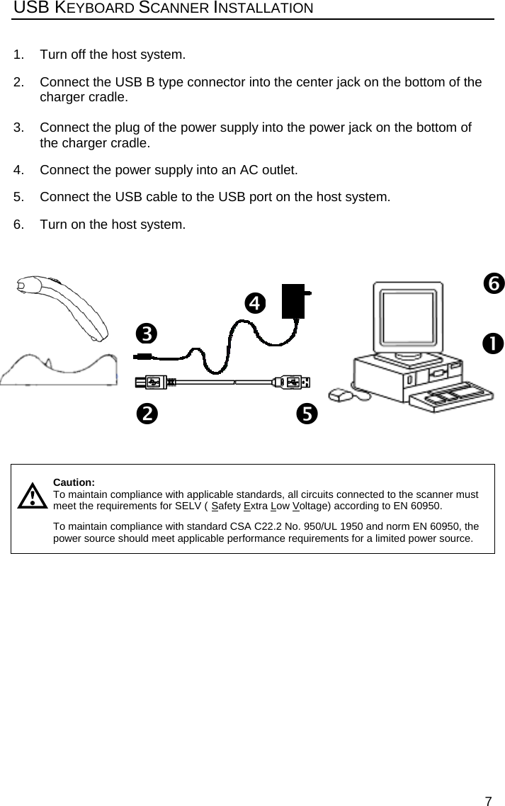
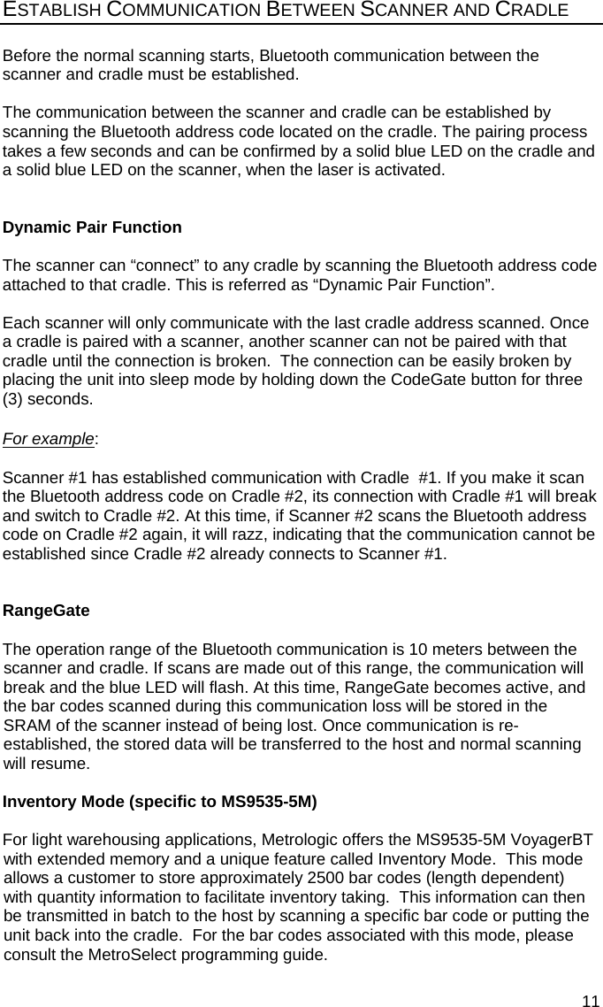

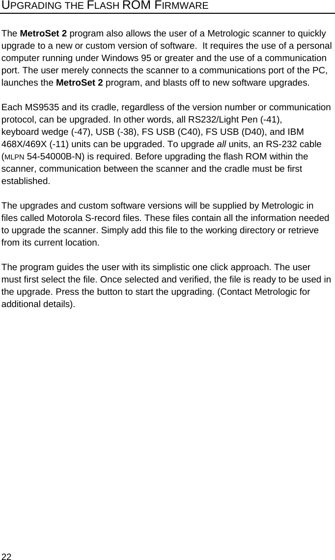

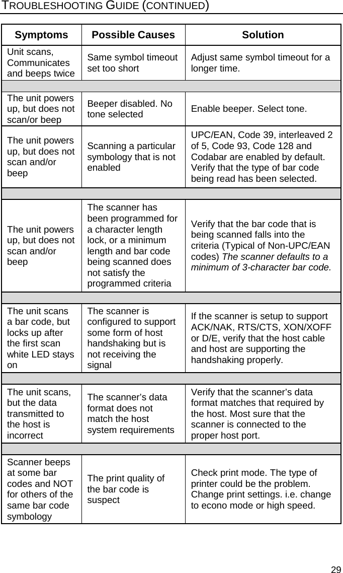
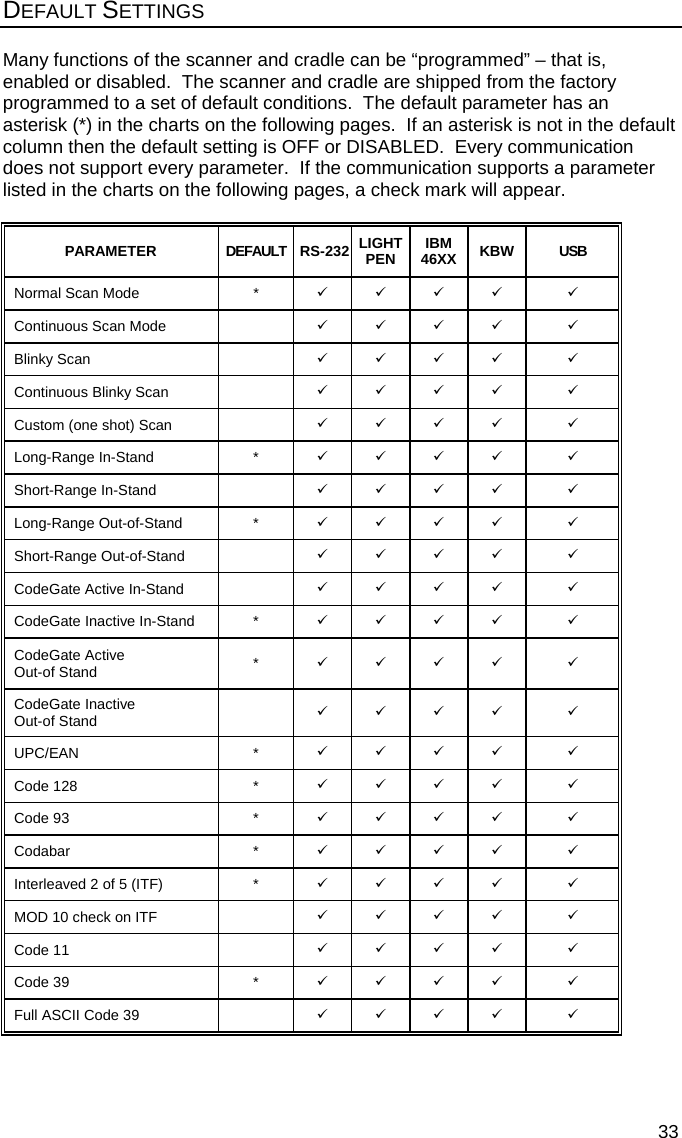
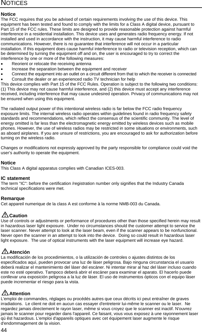
![40 CRADLE AND CABLE TERMINATIONS (CONTINUED) USB Port Pin Function 1 VCC 2 D- 3 D+ 4 Ground Cable Connector Configurations (Host End) USB Cable [MLPN 52-52828A] Pin Function 1 VCC 2 D- 3 D+ 4 Ground RS232/Light Pen Cable [MLPN 54-54000B-N] 9-pin D-type female connector to the PC Pin Function 1 Shield Ground 2 RS-232 Transmit Output 3 RS-232 Receive Input 4 DTR Input/Light Pen Source 5 Power/Signal Ground 6 Light Pen Data 7 CTS Input 8 RTS Output 9 +5VDC 9-Pin D-Type Connector9 56 1USB B Type PortUSB A Type Connector](https://usermanual.wiki/Honeywell/MLPN9535/User-Guide-637699-Page-44.png)
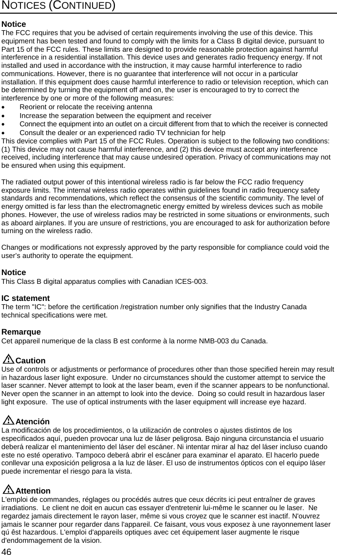
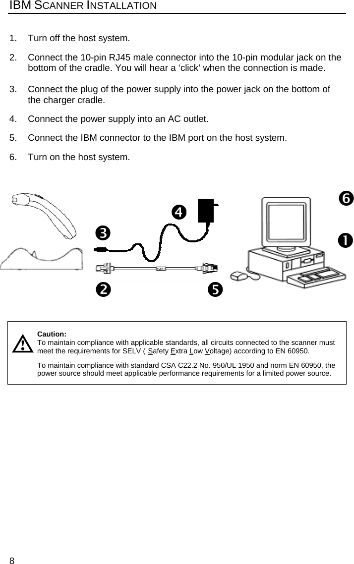
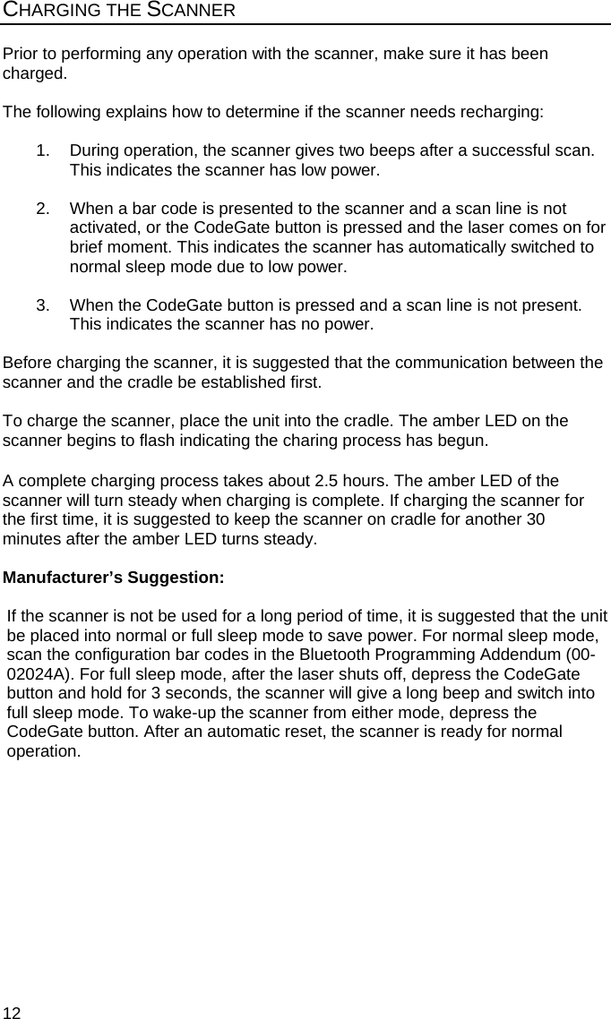
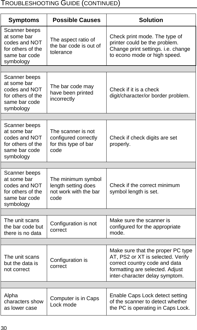
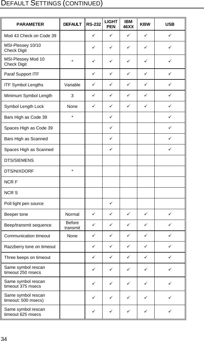
![41CRADLE AND CABLE TERMINATIONS (CONTINUED) IBM Cable [MLPN 54-54250A-N] Pin Function 1 Ground 2 IBM A+ 3 IBM B- 4 Reserved Full Speed USB Cable with power from Register [MLPN 54-54073A] Pin Function 1 +5VDC 2 D- 3 D+ 4 Ground 5 Ground 6 +12V 7 +12V 8 Ground Full Speed USB Cable with external Power Supply [MLPN 54-54200A-N] Pin Function 1 +5VDC 2 D- 3 D+ 4 Ground USB A Plus Power Type Connector USB A Plus Power Type Connector](https://usermanual.wiki/Honeywell/MLPN9535/User-Guide-637699-Page-45.png)
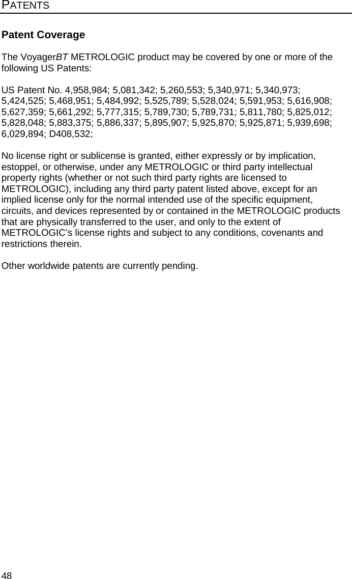
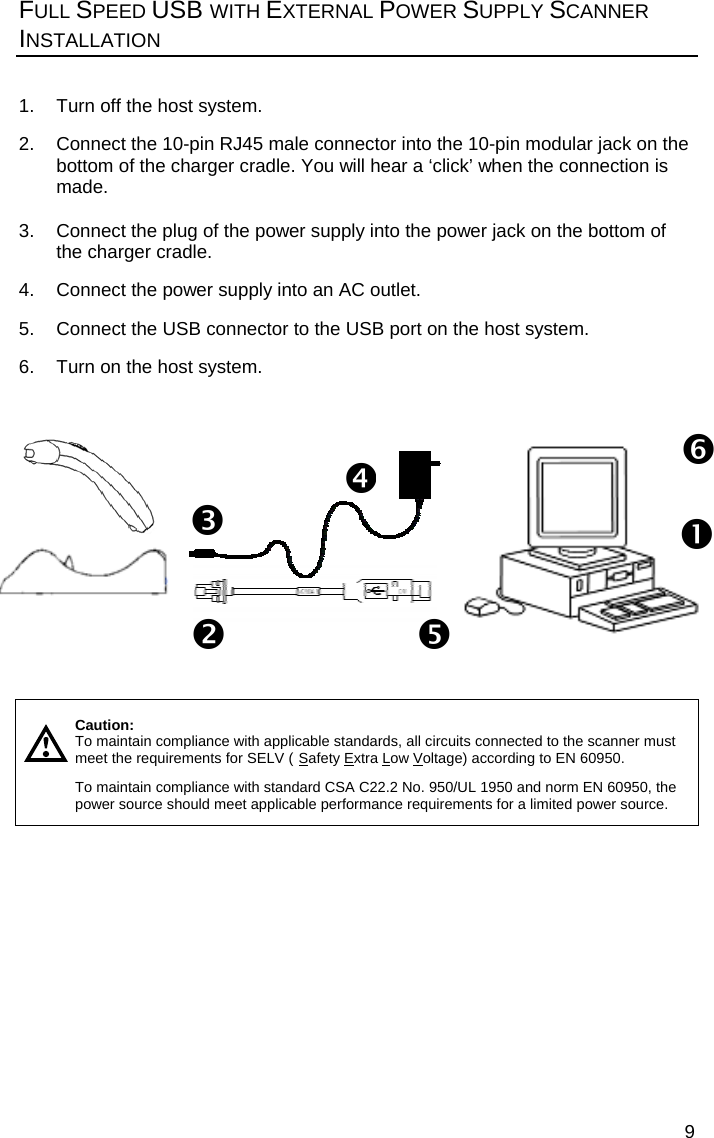
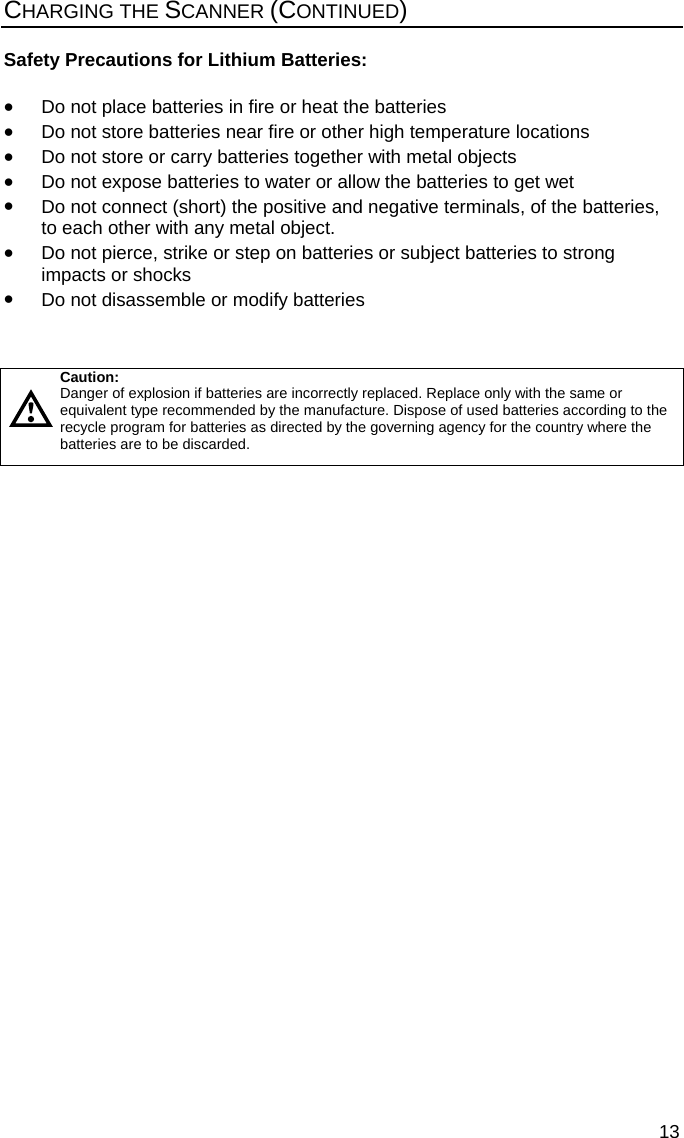
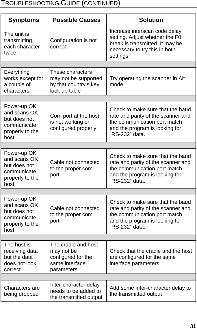
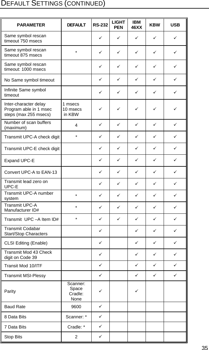
![42 CRADLE AND CABLE TERMINATIONS (CONTINUED) Cable Connector Configuration The Keyboard Wedge cable [MLPN 57-57002A] is terminated with a 5-pin DIN female connector on one end, and a 6-pin mini DIN male on the other. Metrologic will supply an adapter cable with a 5-pin DIN male connector on one end and a 6-pin mini DIN female connector on the other. According to the termination required, connect the appropriate end of the adapter cable to the main cable, leaving the necessary termination exposed for connecting to the keyboard and the keyboard port on the PC. The pin assignments are as follows: Main Cable Adapter Cable 5-pin Female DIN 5-pin Male DIN Pin Function Pin Function 1 Keyboard Clock 1 PC Clock 2 Keyboard Data 2 PC Data 3 No Connect 3 No Connect 4 Power Ground 4 Power Ground 5 +5 Volts DC 5 +5 Volts DC 6-pin Male Mini-DIN 6-pin Female Mini-DIN Pin Function Pin Function 1 PC Data 1 Keyboard Data 2 No Connect 2 No Connect 3 Power Ground 3 Power Ground 4 +5 Volts DC 4 +5 Volts DC 5 PC Clock 5 Keyboard Clock 6 No Connect 6 No Connect 6-pin Mini DIN, Female 5-Pin DIN, Male Adapter Cable 3124562 3 5 4 1 42 13656-Pin DIN, Male2 1 4 5 3 5-Pin DIN, FemaleKeyboard Wedge Cable](https://usermanual.wiki/Honeywell/MLPN9535/User-Guide-637699-Page-46.png)