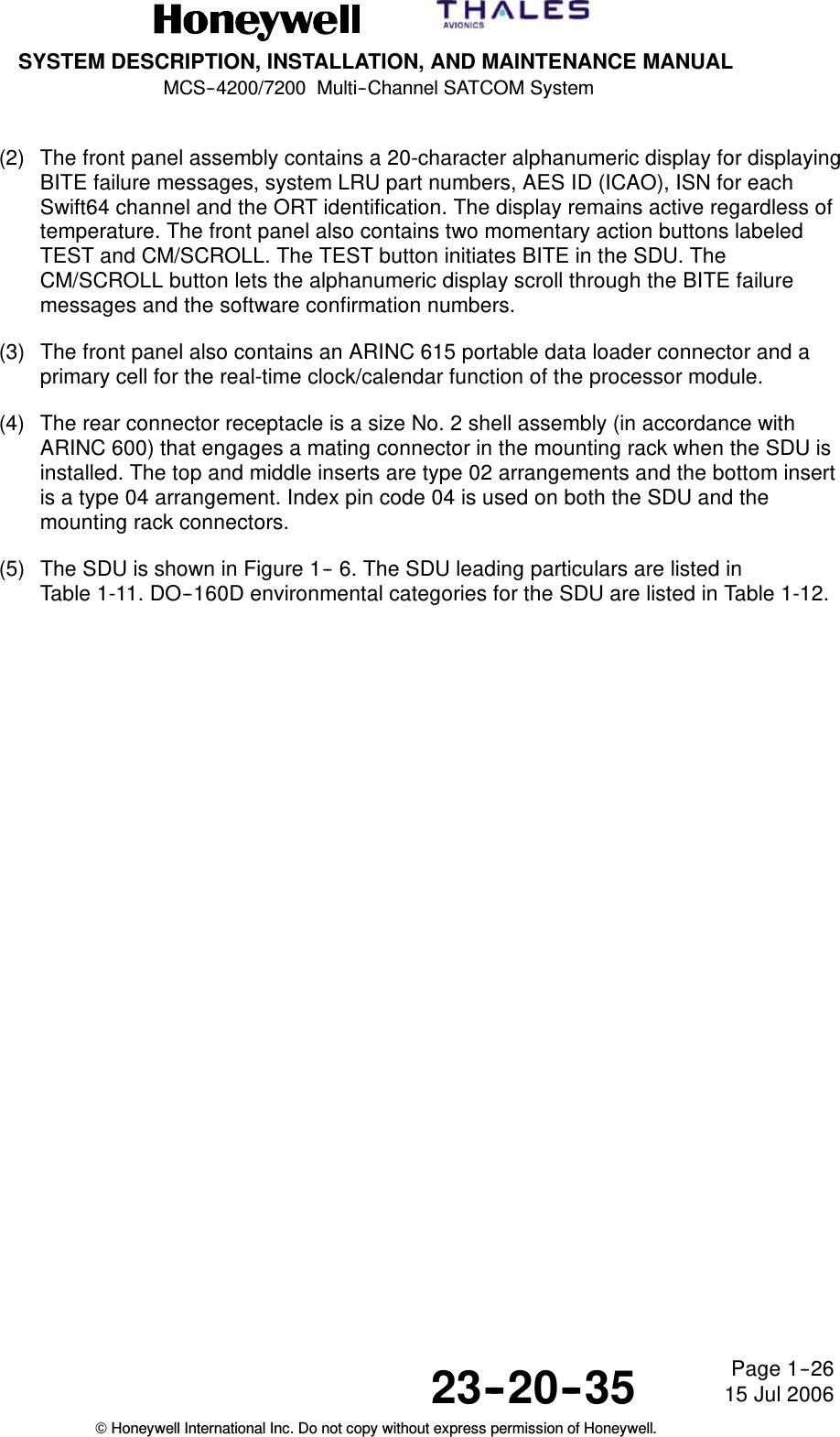
Honeywell SD-720 Satellite Data Unit for MCS-7200 SATCOM System User Manual SDIM Multi Channel SATCOM System A15 5111 010

Honeywell International Inc. Satellite Data Unit for MCS-7200 SATCOM System SDIM Multi Channel SATCOM System A15 5111 010

SD-720 Manual Part1

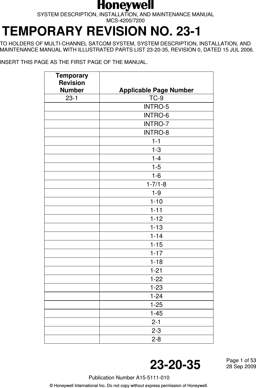
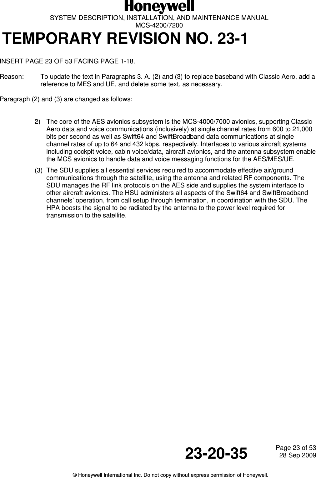
  SYSTEM DESCRIPTION, INSTALLATION, AND MAINTENANCE MANUAL  MCS-4200/7200 TEMPORARY REVISION NO. 23-123-20-35  Page 1 of 5328 Sep 2009Publication Number A15-5111-010 © Honeywell International Inc. Do not copy without express permission of Honeywell.   TO HOLDERS OF MULTI-CHANNEL SATCOM SYSTEM, SYSTEM DESCRIPTION, INSTALLATION, AND MAINTENANCE MANUAL WITH ILLUSTRATED PARTS LIST 23-20-35, REVISION 0, DATED 15 JUL 2006.  INSERT THIS PAGE AS THE FIRST PAGE OF THE MANUAL.  Temporary Revision Number   Applicable Page Number 23-1 TC-9  INTRO-5  INTRO-6  INTRO-7  INTRO-8  1-1  1-3  1-4  1-5  1-6  1-7/1-8  1-9  1-10  1-11  1-12  1-13  1-14  1-15  1-17  1-18  1-21  1-22  1-23  1-24  1-25  1-45  2-1  2-3  2-8
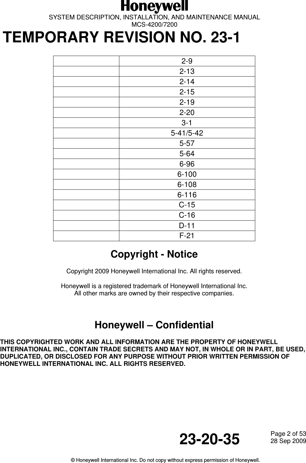
  SYSTEM DESCRIPTION, INSTALLATION, AND MAINTENANCE MANUAL  MCS-4200/7200 TEMPORARY REVISION NO. 23-1  23-20-35  Page 2 of 5328 Sep 2009  © Honeywell International Inc. Do not copy without express permission of Honeywell.   2-9  2-13  2-14  2-15  2-19  2-20  3-1  5-41/5-42  5-57  5-64  6-96  6-100  6-108  6-116  C-15  C-16  D-11  F-21  Copyright - Notice Copyright 2009 Honeywell International Inc. All rights reserved. Honeywell is a registered trademark of Honeywell International Inc. All other marks are owned by their respective companies.  Honeywell – Confidential THIS COPYRIGHTED WORK AND ALL INFORMATION ARE THE PROPERTY OF HONEYWELL INTERNATIONAL INC., CONTAIN TRADE SECRETS AND MAY NOT, IN WHOLE OR IN PART, BE USED, DUPLICATED, OR DISCLOSED FOR ANY PURPOSE WITHOUT PRIOR WRITTEN PERMISSION OF HONEYWELL INTERNATIONAL INC. ALL RIGHTS RESERVED.
This document contains technical data and is subject to U.S. export regulations. These commodities,technology, or software were exported from the United States in accordance with the export administrationregulations. Diversion contrary to U.S. law is prohibited.Honeywell International Inc.21111 N. 19th Ave.Phoenix, AZ 85027-2708U.S.A.(CAGE 55939)Publication Number A15--5111--010, Revision 00023--20--35Page T--115 Jul 2006Honeywell International Inc. Do not copy without express permission of Honeywell.Telephone: (800) 601--3099 (U.S.A.)Telephone: (602) 365--3099 (International)System Description, Installation, andMaintenance Manualwith illustrated parts listMulti--Channel SATCOM SystemSystem Designation TypeMCS--4200 4--ChannelMCS--7200 7--Channel
SYSTEM DESCRIPTION, INSTALLATION, AND MAINTENANCE MANUALMCS--4200/7200 Multi--Channel SATCOM System23--20--35 15 Jul 2006Honeywell International Inc. Do not copy without express permission of Honeywell.Page T--2Honeywell--ConfidentialTHIS COPYRIGHTED WORK AND ALL INFORMATION ARE THE PROPERTY OF HONEYWELLINTERNATIONAL INC., CONTAIN TRADE SECRETS AND MAY NOT, IN WHOLE OR IN PART, BEUSED, DUPLICATED, OR DISCLOSED FOR ANY PURPOSE WITHOUT PRIOR WRITTENPERMISSION OF HONEYWELL INTERNATIONAL INC. ALL RIGHTS RESERVED.Honeywell Materials License AgreementThe documents and information contained herein (“the Materials”) are the proprietary data ofHoneywell International Inc. and Honeywell Intellectual Properties Inc (collectively“Honeywell”). These Materials are provided for the exclusive use of Honeywell Service Centers;Honeywell--authorized repair facilities; operators of Honeywell aerospace products subject to anapplicable product support agreement, their wholly owned--subsidiaries or a formallydesignated third party service provider thereunder; and direct recipients of Materials fromHoneywell’s Aerospace Technical Publication Distribution. The terms and conditions of thisLicense Agreement govern your use of these Materials, except to the extent that any terms andconditions of another applicable agreement with Honeywell regarding the operation,maintenance, or repair of Honeywell aerospace products conflict with the terms and conditionsof this License Agreement, in which case the terms and conditions of the other agreement willgovern. However, this License Agreement will govern in the event of a conflict between itsterms and conditions and those of a purchase order or acknowledgement.1. License Grant -- If you are a party to an applicable product support agreement, a Honeywell Service Centeragreement, or an authorized repair facility agreement, Honeywell hereby grants you a limited, non--exclusive licenseto use these Materials to operate, maintain, or repair Honeywell aerospace products only in accordance with thatagreement.If you are a direct recipient of these Materials from Honeywell’s Aerospace Technical Publication Distribution and arenot a party to an agreement related to the operation, maintenance or repair of Honeywell aerospace products,Honeywell hereby grants you a limited, non--exclusive license to use these Materials to maintain or repair the subjectHoneywell aerospace products only at the facility to which these Materials have been shipped (“the LicensedFacility”). Transfer of the Materials to another facility owned by you is permitted only if the original Licensed Facilityretains no copies of the Materials and you provide prior written notice to Honeywell.2. Rights In Materials -- Honeywell retains all rights in these Materials and in any copies thereof that are notexpressly granted to you, including all rights in patents, copyrights, trademarks, and trade secrets. No license to useany Honeywell trademarks or patents is granted under this License Agreement.3. Confidentiality -- You acknowledge that these Materials contain information that is confidential and proprietary toHoneywell. You agree to take all reasonable efforts to maintain the confidentiality of these Materials.4. Assignment And Transfer -- This License Agreement may be assigned to a formally designated servicedesignee to the extent allowed under an applicable product support agreement or transferred to a subsequent owneror operator of an aircraft containing the subject Honeywell aerospace products. However, the recipient of any suchassignment or transfer must assume all of your obligations under this License Agreement. No assignment or transfershall relieve any party of any obligation that such party then has hereunder.5. Copies of Materials -- Unless you have the express written permission of Honeywell, you may not make or permitmaking of copies of the Materials. Notwithstanding the foregoing, you may make copies of only portions of theMaterial for your internal use. You agree to return the Materials and any copies thereof to Honeywell upon therequest of Honeywell.
SYSTEM DESCRIPTION, INSTALLATION, AND MAINTENANCE MANUALMCS--4200/7200 Multi--Channel SATCOM System23--20--35 15 Jul 2006Honeywell International Inc. Do not copy without express permission of Honeywell.Page T--36. Term -- This License Agreement is effective until terminated as set forth herein. This License Agreement willterminate immediately, without notice from Honeywell, if you fail to comply with any provision of this LicenseAgreement or will terminate simultaneously with the termination or expiration of your applicable product supportagreement, authorized repair facility agreement, or your formal designation as a third party service provider. Upontermination of this License Agreement, you will return these Materials to Honeywell without retaining any copies andwill have one of your authorized officers certify that all Materials have been returned with no copies retained.7. Remedies -- Honeywell reserves the right to pursue all available remedies and damages resulting from a breachof this License Agreement.8. Limitation of Liability -- Honeywell does not make any representation regarding the use, accuracy or sufficiencyof the Materials. THERE ARE NO OTHER WARRANTIES, WHETHER WRITTEN OR ORAL, EXPRESS, IMPLIEDOR STATUTORY, INCLUDING, BUT NOT LIMITED TO, (i) WARRANTIES ARISING FROM COURSE OFPERFORMANCE, DEALING, USAGE, OR TRADE, WHICH ARE HEREBY EXPRESSLY DISCLAIMED, OR (ii)WARRANTIES AGAINST INFRINGEMENT OF INTELLECTUAL PROPERTY RIGHTS OF THIRD PARTIES, EVENIF HONEYWELL HAS BEEN ADVISED OF ANY SUCH INFRINGEMENT. IN NO EVENT WILL HONEYWELL BELIABLE FOR ANY INCIDENTAL DAMAGES, CONSEQUENTIAL DAMAGES, SPECIAL DAMAGES, INDIRECTDAMAGES, LOSS OF PROFITS, LOSS OF REVENUES, OR LOSS OF USE, EVEN IF INFORMED OF THEPOSSIBILITY OF SUCH DAMAGES. TO THE EXTENT PERMITTED BY APPLICABLE LAW, THESE LIMITATIONSAND EXCLUSIONS WILL APPLY REGARDLESS OF WHETHER LIABILITY ARISES FROM BREACH OFCONTRACT, WARRANTY, TORT (INCLUDING BUT NOT LIMITED TO NEGLIGENCE), BY OPERATION OF LAW,OR OTHERWISE.9. Controlling Law -- This License shall be governed and construed in accordance with the laws of the State of NewYork without regard to the conflicts of laws provisions thereof. This license sets forth the entire agreement betweenyou and Honeywell and may only be modified by a writing duly executed by the duly authorized representatives ofthe parties.Copyright -- NoticeCopyright 2006, Honeywell International Inc. All rights reserved.
SYSTEM DESCRIPTION, INSTALLATION, AND MAINTENANCE MANUALMCS--4200/7200 Multi--Channel SATCOM System23--20--35 15 Jul 2006Honeywell International Inc. Do not copy without express permission of Honeywell.Page T--4Blank Page
SYSTEM DESCRIPTION, INSTALLATION, AND MAINTENANCE MANUALMCS--4200/7200 Multi--Channel SATCOM System23--20--35 15 Jul 2006Honeywell International Inc. Do not copy without express permission of Honeywell.Page RR--1RECORD OF REVISIONSFor each revision, put the changed pages in your manual and discard the replaced pages. Writethe revision number and date, and the date put in the manual. Put your initials in the applicablecolumns on the Record of Revisions. The initial H shows that Honeywell put the changed pages inthe manual.RevisionNumberRevisionDateDate PutIn Manual ByRevisionNumberRevisionDateDate PutIn Manual By
SYSTEM DESCRIPTION, INSTALLATION, AND MAINTENANCE MANUALMCS--4200/7200 Multi--Channel SATCOM System23--20--35 15 Jul 2006Honeywell International Inc. Do not copy without express permission of Honeywell.Page RR--2Blank Page
SYSTEM DESCRIPTION, INSTALLATION, AND MAINTENANCE MANUALMCS--4200/7200 Multi--Channel SATCOM System23--20--35 15 Jul 2006Honeywell International Inc. Do not copy without express permission of Honeywell.Page RTR--1RECORD OF TEMPORARY REVISIONSInstructions on each page of a temporary revision tell you where to put the pages in your manual.Remove temporary revision pages only when discard instructions are given. For each temporaryrevision, put the applicable data in the record columns on this page.TemporaryRevisionNumberTemporaryRevisionDateTemporaryRevisionStatusDate Putin Manual By *DateRemovedfrom Manual By ** The initial H in this column shows Honeywell has done this task.** Temporary revisions are incorporated in the manual by normal revision.
SYSTEM DESCRIPTION, INSTALLATION, AND MAINTENANCE MANUALMCS--4200/7200 Multi--Channel SATCOM System23--20--35 15 Jul 2006Honeywell International Inc. Do not copy without express permission of Honeywell.Page RTR--2Blank Page
SYSTEM DESCRIPTION, INSTALLATION, AND MAINTENANCE MANUALMCS--4200/7200 Multi--Channel SATCOM System23--20--35 15 Jul 2006Honeywell International Inc. Do not copy without express permission of Honeywell.Page SBL--1SERVICE BULLETIN LISTService BulletinIdentifiedModDate Includedin this Manual Description
SYSTEM DESCRIPTION, INSTALLATION, AND MAINTENANCE MANUALMCS--4200/7200 Multi--Channel SATCOM System23--20--35 15 Jul 2006Honeywell International Inc. Do not copy without express permission of Honeywell.Page SBL--2Blank Page
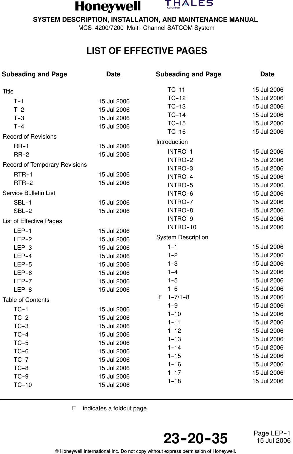
SYSTEM DESCRIPTION, INSTALLATION, AND MAINTENANCE MANUALMCS--4200/7200 Multi--Channel SATCOM System23--20--35 15 Jul 2006Honeywell International Inc. Do not copy without express permission of Honeywell.Page LEP--1LIST OF EFFECTIVE PAGESSubeading and Page Date Subeading and Page DateTitleT--1 15 Jul 2006T--2 15 Jul 2006T--3 15 Jul 2006T--4 15 Jul 2006Record of RevisionsRR--1 15 Jul 2006RR--2 15 Jul 2006Record of Temporary RevisionsRTR--1 15 Jul 2006RTR--2 15 Jul 2006Service Bulletin ListSBL--1 15 Jul 2006SBL--2 15 Jul 2006List of Effective PagesLEP--1 15 Jul 2006LEP--2 15 Jul 2006LEP--3 15 Jul 2006LEP--4 15 Jul 2006LEP--5 15 Jul 2006LEP--6 15 Jul 2006LEP--7 15 Jul 2006LEP--8 15 Jul 2006Table of ContentsTC--1 15 Jul 2006TC--2 15 Jul 2006TC--3 15 Jul 2006TC--4 15 Jul 2006TC--5 15 Jul 2006TC--6 15 Jul 2006TC--7 15 Jul 2006TC--8 15 Jul 2006TC--9 15 Jul 2006TC--10 15 Jul 2006TC--11 15 Jul 2006TC--12 15 Jul 2006TC--13 15 Jul 2006TC--14 15 Jul 2006TC--15 15 Jul 2006TC--16 15 Jul 2006IntroductionINTRO--1 15 Jul 2006INTRO--2 15 Jul 2006INTRO--3 15 Jul 2006INTRO--4 15 Jul 2006INTRO--5 15 Jul 2006INTRO--6 15 Jul 2006INTRO--7 15 Jul 2006INTRO--8 15 Jul 2006INTRO--9 15 Jul 2006INTRO--10 15 Jul 2006System Description1--1 15 Jul 20061--2 15 Jul 20061--3 15 Jul 20061--4 15 Jul 20061--5 15 Jul 20061--6 15 Jul 2006F1--7/1--8 15 Jul 20061--9 15 Jul 20061--10 15 Jul 20061--11 15 Jul 20061--12 15 Jul 20061--13 15 Jul 20061--14 15 Jul 20061--15 15 Jul 20061--16 15 Jul 20061--17 15 Jul 20061--18 15 Jul 2006F indicates a foldout page.
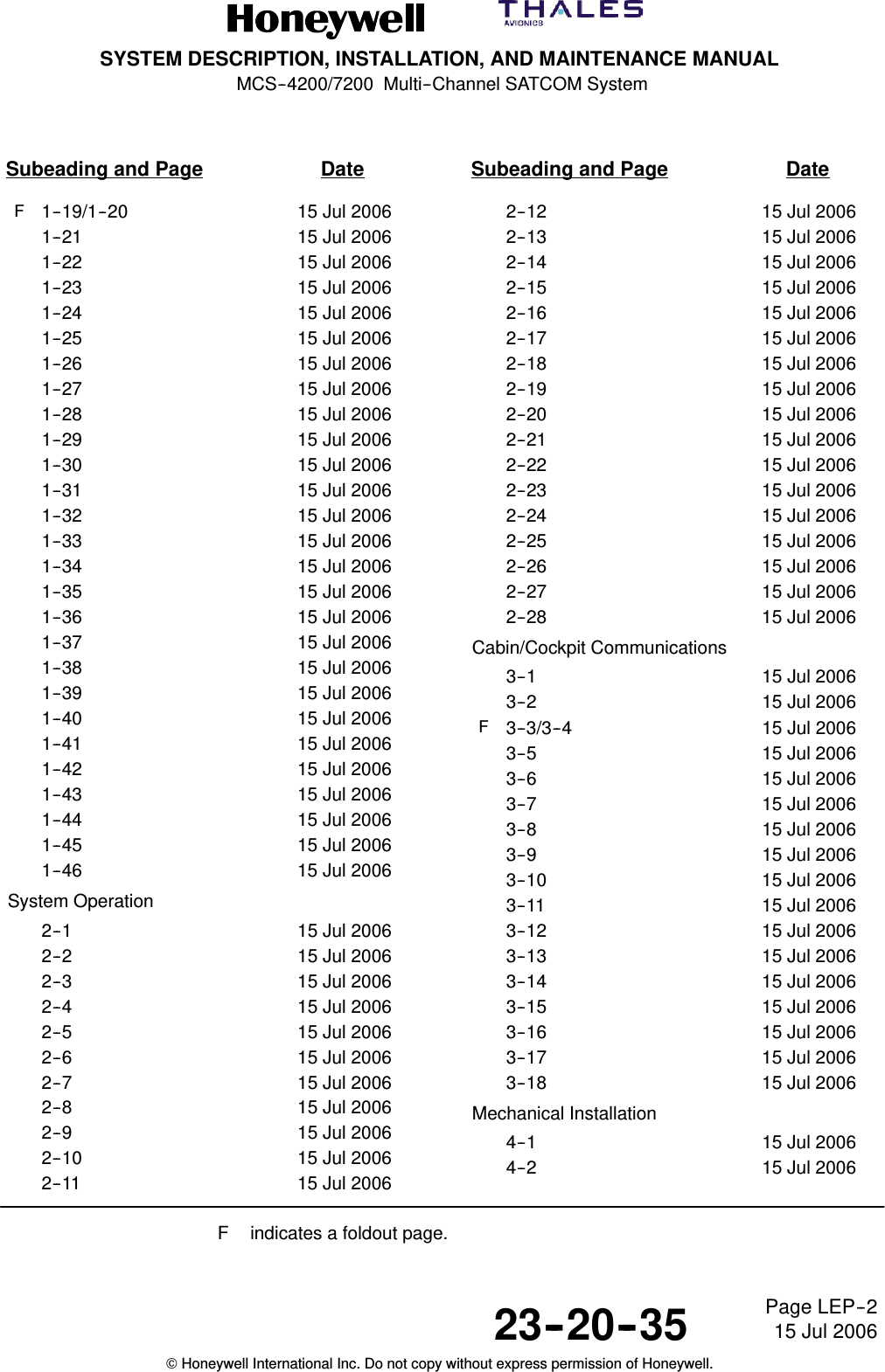
SYSTEM DESCRIPTION, INSTALLATION, AND MAINTENANCE MANUALMCS--4200/7200 Multi--Channel SATCOM System23--20--35 15 Jul 2006Honeywell International Inc. Do not copy without express permission of Honeywell.Page LEP--2Subeading and Page Date Subeading and Page DateF1--19/1--20 15 Jul 20061--21 15 Jul 20061--22 15 Jul 20061--23 15 Jul 20061--24 15 Jul 20061--25 15 Jul 20061--26 15 Jul 20061--27 15 Jul 20061--28 15 Jul 20061--29 15 Jul 20061--30 15 Jul 20061--31 15 Jul 20061--32 15 Jul 20061--33 15 Jul 20061--34 15 Jul 20061--35 15 Jul 20061--36 15 Jul 20061--37 15 Jul 20061--38 15 Jul 20061--39 15 Jul 20061--40 15 Jul 20061--41 15 Jul 20061--42 15 Jul 20061--43 15 Jul 20061--44 15 Jul 20061--45 15 Jul 20061--46 15 Jul 2006System Operation2--1 15 Jul 20062--2 15 Jul 20062--3 15 Jul 20062--4 15 Jul 20062--5 15 Jul 20062--6 15 Jul 20062--7 15 Jul 20062--8 15 Jul 20062--9 15 Jul 20062--10 15 Jul 20062--11 15 Jul 20062--12 15 Jul 20062--13 15 Jul 20062--14 15 Jul 20062--15 15 Jul 20062--16 15 Jul 20062--17 15 Jul 20062--18 15 Jul 20062--19 15 Jul 20062--20 15 Jul 20062--21 15 Jul 20062--22 15 Jul 20062--23 15 Jul 20062--24 15 Jul 20062--25 15 Jul 20062--26 15 Jul 20062--27 15 Jul 20062--28 15 Jul 2006Cabin/Cockpit Communications3--1 15 Jul 20063--2 15 Jul 2006F3--3/3--4 15 Jul 20063--5 15 Jul 20063--6 15 Jul 20063--7 15 Jul 20063--8 15 Jul 20063--9 15 Jul 20063--10 15 Jul 20063--11 15 Jul 20063--12 15 Jul 20063--13 15 Jul 20063--14 15 Jul 20063--15 15 Jul 20063--16 15 Jul 20063--17 15 Jul 20063--18 15 Jul 2006Mechanical Installation4--1 15 Jul 20064--2 15 Jul 2006F indicates a foldout page.
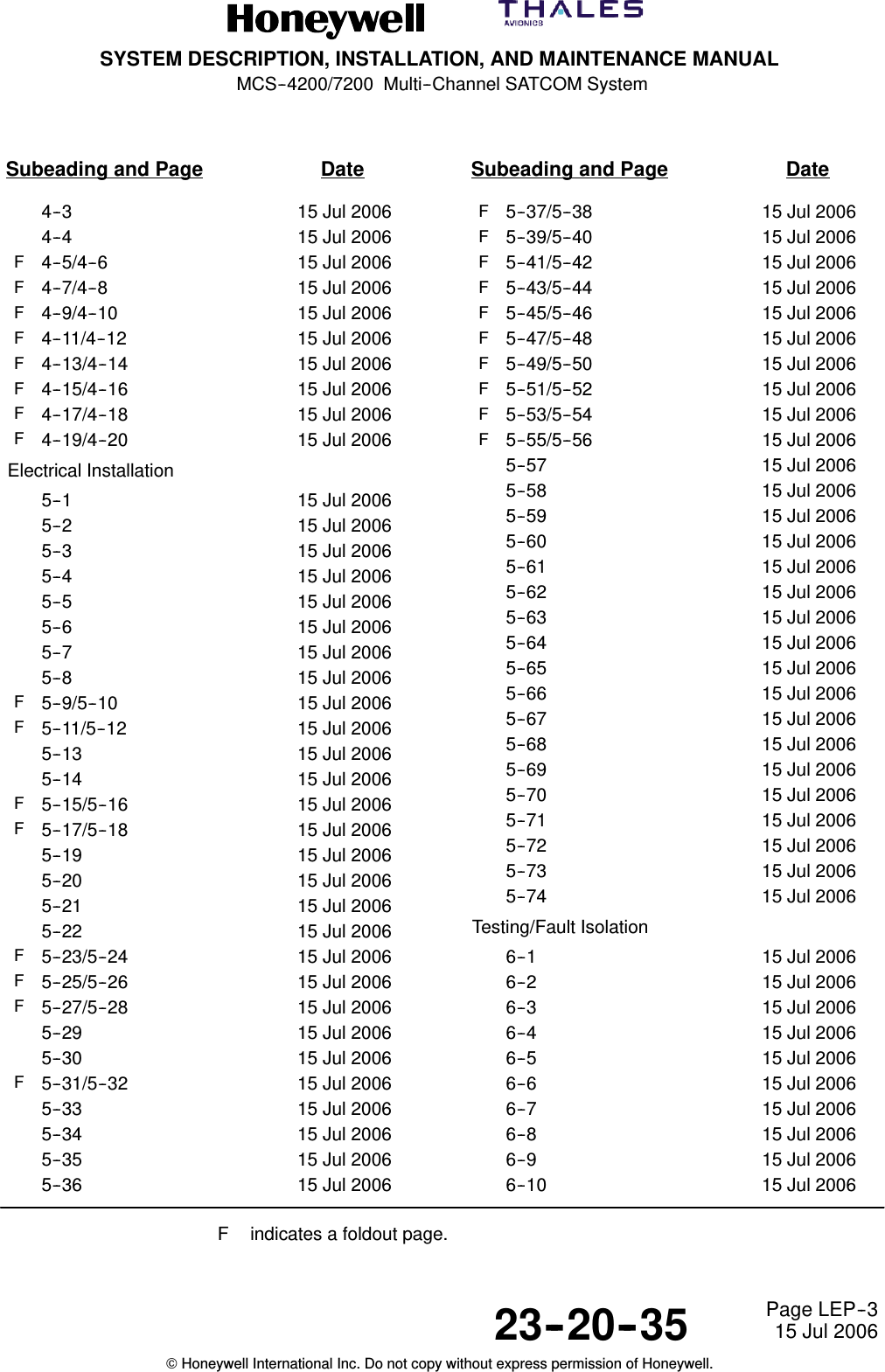
SYSTEM DESCRIPTION, INSTALLATION, AND MAINTENANCE MANUALMCS--4200/7200 Multi--Channel SATCOM System23--20--35 15 Jul 2006Honeywell International Inc. Do not copy without express permission of Honeywell.Page LEP--3Subeading and Page Date Subeading and Page Date4--3 15 Jul 20064--4 15 Jul 2006F4--5/4--6 15 Jul 2006F4--7/4--8 15 Jul 2006F4--9/4--10 15 Jul 2006F4--11/4--12 15 Jul 2006F4--13/4--14 15 Jul 2006F4--15/4--16 15 Jul 2006F4--17/4--18 15 Jul 2006F4--19/4--20 15 Jul 2006Electrical Installation5--1 15 Jul 20065--2 15 Jul 20065--3 15 Jul 20065--4 15 Jul 20065--5 15 Jul 20065--6 15 Jul 20065--7 15 Jul 20065--8 15 Jul 2006F5--9/5--10 15 Jul 2006F5--11/5--12 15 Jul 20065--13 15 Jul 20065--14 15 Jul 2006F5--15/5--16 15 Jul 2006F5--17/5--18 15 Jul 20065--19 15 Jul 20065--20 15 Jul 20065--21 15 Jul 20065--22 15 Jul 2006F5--23/5--24 15 Jul 2006F5--25/5--26 15 Jul 2006F5--27/5--28 15 Jul 20065--29 15 Jul 20065--30 15 Jul 2006F5--31/5--32 15 Jul 20065--33 15 Jul 20065--34 15 Jul 20065--35 15 Jul 20065--36 15 Jul 2006F5--37/5--38 15 Jul 2006F5--39/5--40 15 Jul 2006F5--41/5--42 15 Jul 2006F5--43/5--44 15 Jul 2006F5--45/5--46 15 Jul 2006F5--47/5--48 15 Jul 2006F5--49/5--50 15 Jul 2006F5--51/5--52 15 Jul 2006F5--53/5--54 15 Jul 2006F5--55/5--56 15 Jul 20065--57 15 Jul 20065--58 15 Jul 20065--59 15 Jul 20065--60 15 Jul 20065--61 15 Jul 20065--62 15 Jul 20065--63 15 Jul 20065--64 15 Jul 20065--65 15 Jul 20065--66 15 Jul 20065--67 15 Jul 20065--68 15 Jul 20065--69 15 Jul 20065--70 15 Jul 20065--71 15 Jul 20065--72 15 Jul 20065--73 15 Jul 20065--74 15 Jul 2006Testing/Fault Isolation6--1 15 Jul 20066--2 15 Jul 20066--3 15 Jul 20066--4 15 Jul 20066--5 15 Jul 20066--6 15 Jul 20066--7 15 Jul 20066--8 15 Jul 20066--9 15 Jul 20066--10 15 Jul 2006F indicates a foldout page.
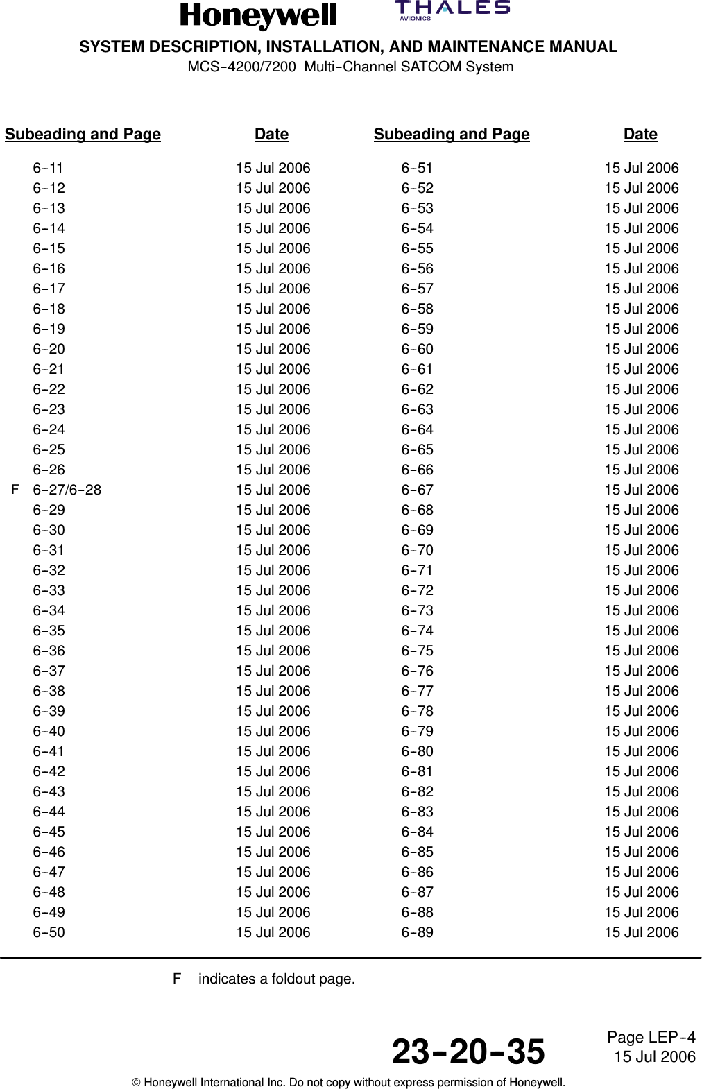
SYSTEM DESCRIPTION, INSTALLATION, AND MAINTENANCE MANUALMCS--4200/7200 Multi--Channel SATCOM System23--20--35 15 Jul 2006Honeywell International Inc. Do not copy without express permission of Honeywell.Page LEP--4Subeading and Page Date Subeading and Page Date6--11 15 Jul 20066--12 15 Jul 20066--13 15 Jul 20066--14 15 Jul 20066--15 15 Jul 20066--16 15 Jul 20066--17 15 Jul 20066--18 15 Jul 20066--19 15 Jul 20066--20 15 Jul 20066--21 15 Jul 20066--22 15 Jul 20066--23 15 Jul 20066--24 15 Jul 20066--25 15 Jul 20066--26 15 Jul 2006F6--27/6--28 15 Jul 20066--29 15 Jul 20066--30 15 Jul 20066--31 15 Jul 20066--32 15 Jul 20066--33 15 Jul 20066--34 15 Jul 20066--35 15 Jul 20066--36 15 Jul 20066--37 15 Jul 20066--38 15 Jul 20066--39 15 Jul 20066--40 15 Jul 20066--41 15 Jul 20066--42 15 Jul 20066--43 15 Jul 20066--44 15 Jul 20066--45 15 Jul 20066--46 15 Jul 20066--47 15 Jul 20066--48 15 Jul 20066--49 15 Jul 20066--50 15 Jul 20066--51 15 Jul 20066--52 15 Jul 20066--53 15 Jul 20066--54 15 Jul 20066--55 15 Jul 20066--56 15 Jul 20066--57 15 Jul 20066--58 15 Jul 20066--59 15 Jul 20066--60 15 Jul 20066--61 15 Jul 20066--62 15 Jul 20066--63 15 Jul 20066--64 15 Jul 20066--65 15 Jul 20066--66 15 Jul 20066--67 15 Jul 20066--68 15 Jul 20066--69 15 Jul 20066--70 15 Jul 20066--71 15 Jul 20066--72 15 Jul 20066--73 15 Jul 20066--74 15 Jul 20066--75 15 Jul 20066--76 15 Jul 20066--77 15 Jul 20066--78 15 Jul 20066--79 15 Jul 20066--80 15 Jul 20066--81 15 Jul 20066--82 15 Jul 20066--83 15 Jul 20066--84 15 Jul 20066--85 15 Jul 20066--86 15 Jul 20066--87 15 Jul 20066--88 15 Jul 20066--89 15 Jul 2006F indicates a foldout page.
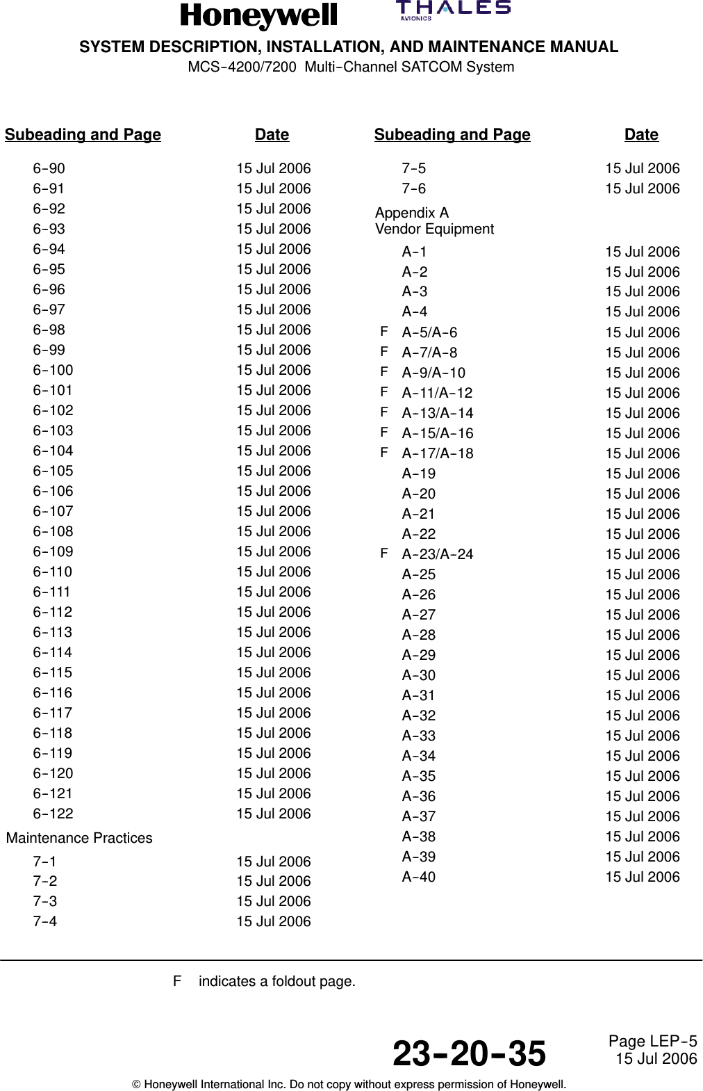
SYSTEM DESCRIPTION, INSTALLATION, AND MAINTENANCE MANUALMCS--4200/7200 Multi--Channel SATCOM System23--20--35 15 Jul 2006Honeywell International Inc. Do not copy without express permission of Honeywell.Page LEP--5Subeading and Page Date Subeading and Page Date6--90 15 Jul 20066--91 15 Jul 20066--92 15 Jul 20066--93 15 Jul 20066--94 15 Jul 20066--95 15 Jul 20066--96 15 Jul 20066--97 15 Jul 20066--98 15 Jul 20066--99 15 Jul 20066--100 15 Jul 20066--101 15 Jul 20066--102 15 Jul 20066--103 15 Jul 20066--104 15 Jul 20066--105 15 Jul 20066--106 15 Jul 20066--107 15 Jul 20066--108 15 Jul 20066--109 15 Jul 20066--110 15 Jul 20066--111 15 Jul 20066--112 15 Jul 20066--113 15 Jul 20066--114 15 Jul 20066--115 15 Jul 20066--116 15 Jul 20066--117 15 Jul 20066--118 15 Jul 20066--119 15 Jul 20066--120 15 Jul 20066--121 15 Jul 20066--122 15 Jul 2006Maintenance Practices7--1 15 Jul 20067--2 15 Jul 20067--3 15 Jul 20067--4 15 Jul 20067--5 15 Jul 20067--6 15 Jul 2006Appendix AVendor EquipmentA--1 15 Jul 2006A--2 15 Jul 2006A--3 15 Jul 2006A--4 15 Jul 2006FA--5/A--6 15 Jul 2006FA--7/A--8 15 Jul 2006FA--9/A--10 15 Jul 2006FA--11/A--12 15 Jul 2006FA--13/A--14 15 Jul 2006FA--15/A--16 15 Jul 2006FA--17/A--18 15 Jul 2006A--19 15 Jul 2006A--20 15 Jul 2006A--21 15 Jul 2006A--22 15 Jul 2006FA--23/A--24 15 Jul 2006A--25 15 Jul 2006A--26 15 Jul 2006A--27 15 Jul 2006A--28 15 Jul 2006A--29 15 Jul 2006A--30 15 Jul 2006A--31 15 Jul 2006A--32 15 Jul 2006A--33 15 Jul 2006A--34 15 Jul 2006A--35 15 Jul 2006A--36 15 Jul 2006A--37 15 Jul 2006A--38 15 Jul 2006A--39 15 Jul 2006A--40 15 Jul 2006F indicates a foldout page.
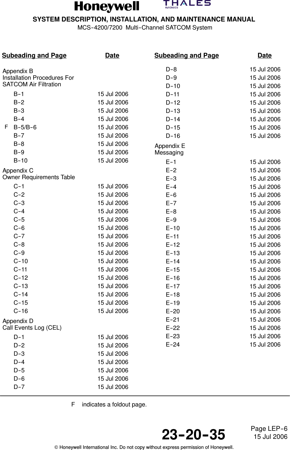
SYSTEM DESCRIPTION, INSTALLATION, AND MAINTENANCE MANUALMCS--4200/7200 Multi--Channel SATCOM System23--20--35 15 Jul 2006Honeywell International Inc. Do not copy without express permission of Honeywell.Page LEP--6Subeading and Page Date Subeading and Page DateAppendix BInstallation Procedures ForSATCOM Air FiltrationB--1 15 Jul 2006B--2 15 Jul 2006B--3 15 Jul 2006B--4 15 Jul 2006FB--5/B--6 15 Jul 2006B--7 15 Jul 2006B--8 15 Jul 2006B--9 15 Jul 2006B--10 15 Jul 2006Appendix COwner Requirements TableC--1 15 Jul 2006C--2 15 Jul 2006C--3 15 Jul 2006C--4 15 Jul 2006C--5 15 Jul 2006C--6 15 Jul 2006C--7 15 Jul 2006C--8 15 Jul 2006C--9 15 Jul 2006C--10 15 Jul 2006C--11 15 Jul 2006C--12 15 Jul 2006C--13 15 Jul 2006C--14 15 Jul 2006C--15 15 Jul 2006C--16 15 Jul 2006Appendix DCall Events Log (CEL)D--1 15 Jul 2006D--2 15 Jul 2006D--3 15 Jul 2006D--4 15 Jul 2006D--5 15 Jul 2006D--6 15 Jul 2006D--7 15 Jul 2006D--8 15 Jul 2006D--9 15 Jul 2006D--10 15 Jul 2006D--11 15 Jul 2006D--12 15 Jul 2006D--13 15 Jul 2006D--14 15 Jul 2006D--15 15 Jul 2006D--16 15 Jul 2006Appendix EMessagingE--1 15 Jul 2006E--2 15 Jul 2006E--3 15 Jul 2006E--4 15 Jul 2006E--6 15 Jul 2006E--7 15 Jul 2006E--8 15 Jul 2006E--9 15 Jul 2006E--10 15 Jul 2006E--11 15 Jul 2006E--12 15 Jul 2006E--13 15 Jul 2006E--14 15 Jul 2006E--15 15 Jul 2006E--16 15 Jul 2006E--17 15 Jul 2006E--18 15 Jul 2006E--19 15 Jul 2006E--20 15 Jul 2006E--21 15 Jul 2006E--22 15 Jul 2006E--23 15 Jul 2006E--24 15 Jul 2006F indicates a foldout page.
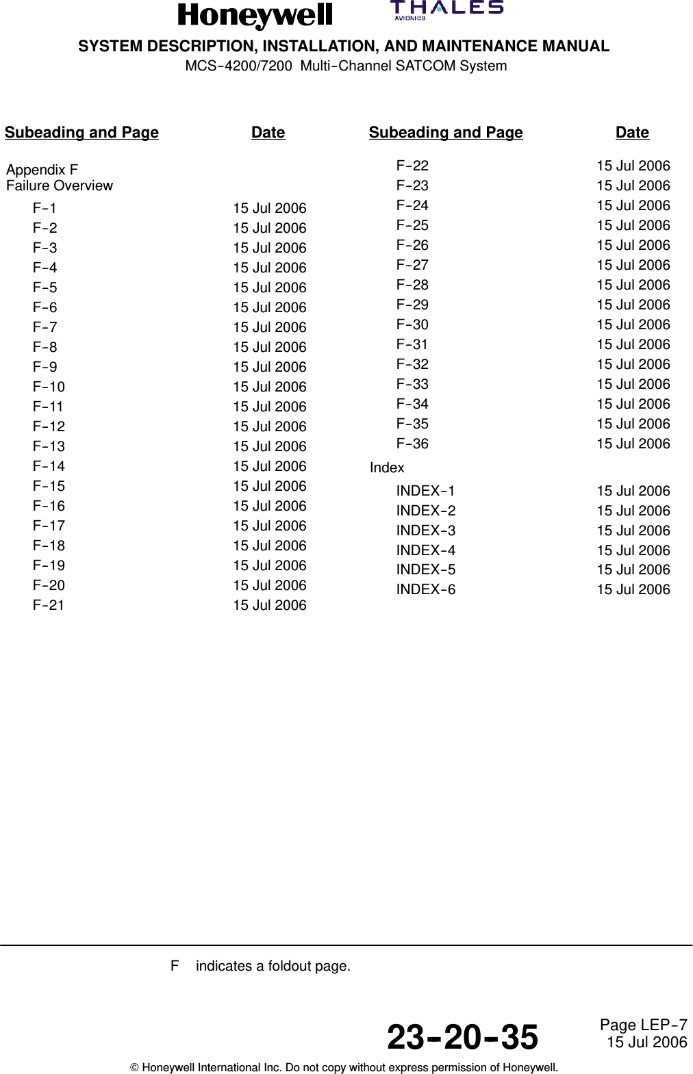
SYSTEM DESCRIPTION, INSTALLATION, AND MAINTENANCE MANUALMCS--4200/7200 Multi--Channel SATCOM System23--20--35 15 Jul 2006Honeywell International Inc. Do not copy without express permission of Honeywell.Page LEP--7Subeading and Page Date Subeading and Page DateAppendix FFailure OverviewF--1 15 Jul 2006F--2 15 Jul 2006F--3 15 Jul 2006F--4 15 Jul 2006F--5 15 Jul 2006F--6 15 Jul 2006F--7 15 Jul 2006F--8 15 Jul 2006F--9 15 Jul 2006F--10 15 Jul 2006F--11 15 Jul 2006F--12 15 Jul 2006F--13 15 Jul 2006F--14 15 Jul 2006F--15 15 Jul 2006F--16 15 Jul 2006F--17 15 Jul 2006F--18 15 Jul 2006F--19 15 Jul 2006F--20 15 Jul 2006F--21 15 Jul 2006F--22 15 Jul 2006F--23 15 Jul 2006F--24 15 Jul 2006F--25 15 Jul 2006F--26 15 Jul 2006F--27 15 Jul 2006F--28 15 Jul 2006F--29 15 Jul 2006F--30 15 Jul 2006F--31 15 Jul 2006F--32 15 Jul 2006F--33 15 Jul 2006F--34 15 Jul 2006F--35 15 Jul 2006F--36 15 Jul 2006IndexINDEX--1 15 Jul 2006INDEX--2 15 Jul 2006INDEX--3 15 Jul 2006INDEX--4 15 Jul 2006INDEX--5 15 Jul 2006INDEX--6 15 Jul 2006F indicates a foldout page.
SYSTEM DESCRIPTION, INSTALLATION, AND MAINTENANCE MANUALMCS--4200/7200 Multi--Channel SATCOM System23--20--35 15 Jul 2006Honeywell International Inc. Do not copy without express permission of Honeywell.Page LEP--8Blank Page
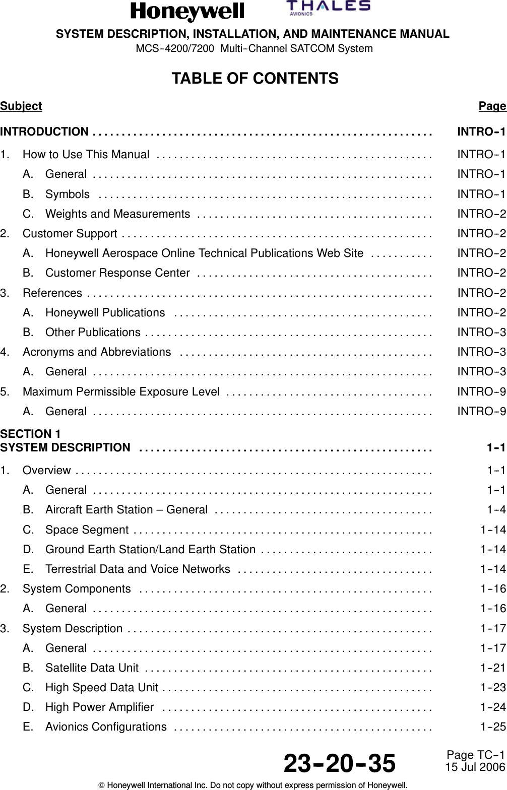
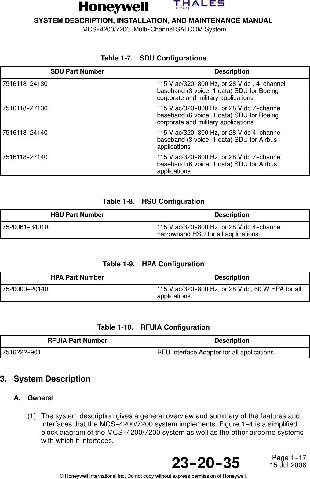
SYSTEM DESCRIPTION, INSTALLATION, AND MAINTENANCE MANUALMCS--4200/7200 Multi--Channel SATCOM System23--20--35 15 Jul 2006Honeywell International Inc. Do not copy without express permission of Honeywell.Page TC--1TABLE OF CONTENTSSubject PageINTRODUCTION INTRO--1...........................................................1. How to Use This Manual INTRO--1................................................A. General INTRO--1...........................................................B. Symbols INTRO--1..........................................................C. Weights and Measurements INTRO--2.........................................2. Customer Support INTRO--2......................................................A. Honeywell Aerospace Online Technical Publications Web Site INTRO--2...........B. Customer Response Center INTRO--2.........................................3. References INTRO--2............................................................A. Honeywell Publications INTRO--2.............................................B. Other Publications INTRO--3..................................................4. Acronyms and Abbreviations INTRO--3............................................A. General INTRO--3...........................................................5. Maximum Permissible Exposure Level INTRO--9....................................A. General INTRO--9...........................................................SECTION 1SYSTEM DESCRIPTION 1--1...................................................1. Overview 1--1..............................................................A. General 1--1...........................................................B. Aircraft Earth Station – General 1--4......................................C. Space Segment 1--14....................................................D. Ground Earth Station/Land Earth Station 1--14..............................E. Terrestrial Data and Voice Networks 1--14..................................2. System Components 1--16...................................................A. General 1--16...........................................................3. System Description 1--17.....................................................A. General 1--17...........................................................B. Satellite Data Unit 1--21..................................................C. High Speed Data Unit 1--23...............................................D. High Power Amplifier 1--24...............................................E. Avionics Configurations 1--25.............................................
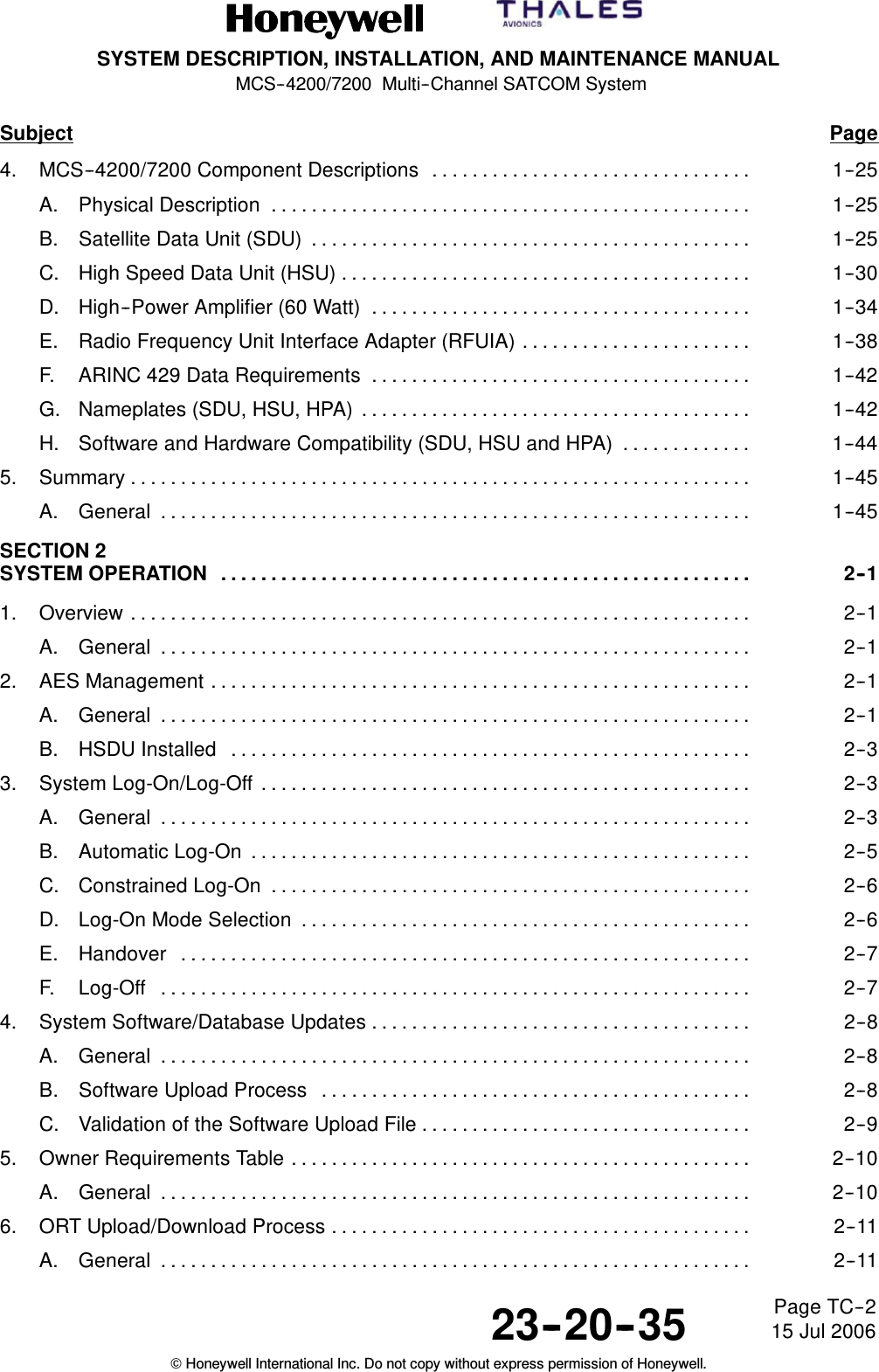
SYSTEM DESCRIPTION, INSTALLATION, AND MAINTENANCE MANUALMCS--4200/7200 Multi--Channel SATCOM System23--20--35 15 Jul 2006Honeywell International Inc. Do not copy without express permission of Honeywell.Page TC--2Subject Page4. MCS--4200/7200 Component Descriptions 1--25................................A. Physical Description 1--25................................................B. Satellite Data Unit (SDU) 1--25............................................C. High Speed Data Unit (HSU) 1--30.........................................D. High--Power Amplifier (60 Watt) 1--34......................................E. Radio Frequency Unit Interface Adapter (RFUIA) 1--38.......................F. ARINC 429 Data Requirements 1--42......................................G. Nameplates (SDU, HSU, HPA) 1--42.......................................H. Software and Hardware Compatibility (SDU, HSU and HPA) 1--44.............5. Summary 1--45..............................................................A. General 1--45...........................................................SECTION 2SYSTEM OPERATION 2--1.....................................................1. Overview 2--1..............................................................A. General 2--1...........................................................2. AES Management 2--1......................................................A. General 2--1...........................................................B. HSDU Installed 2--3....................................................3. System Log-On/Log-Off 2--3.................................................A. General 2--3...........................................................B. Automatic Log-On 2--5..................................................C. Constrained Log-On 2--6................................................D. Log-On Mode Selection 2--6.............................................E. Handover 2--7.........................................................F. Log-Off 2--7...........................................................4. System Software/Database Updates 2--8......................................A. General 2--8...........................................................B. Software Upload Process 2--8...........................................C. Validation of the Software Upload File 2--9.................................5. Owner Requirements Table 2--10..............................................A. General 2--10...........................................................6. ORT Upload/Download Process 2--11..........................................A. General 2--11...........................................................
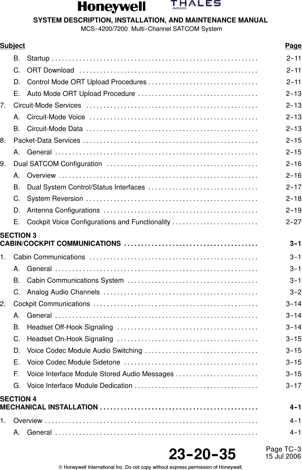
SYSTEM DESCRIPTION, INSTALLATION, AND MAINTENANCE MANUALMCS--4200/7200 Multi--Channel SATCOM System23--20--35 15 Jul 2006Honeywell International Inc. Do not copy without express permission of Honeywell.Page TC--3Subject PageB. Startup 2--11............................................................C. ORT Download 2--11....................................................D. Control Mode ORT Upload Procedures 2--11................................E. Auto Mode ORT Upload Procedure 2--13...................................7. Circuit-Mode Services 2--13..................................................A. Circuit-Mode Voice 2--13.................................................B. Circuit-Mode Data 2--13..................................................8. Packet-Data Services 2--15...................................................A. General 2--15...........................................................9. Dual SATCOM Configuration 2--16............................................A. Overview 2--16..........................................................B. Dual System Control/Status Interfaces 2--17................................C. System Reversion 2--18..................................................D. Antenna Configurations 2--19.............................................E. Cockpit Voice Configurations and Functionality 2--27.........................SECTION 3CABIN/COCKPIT COMMUNICATIONS 3--1.......................................1. Cabin Communications 3--1.................................................A. General 3--1...........................................................B. Cabin Communications System 3--1......................................C. Analog Audio Channels 3--2.............................................2. Cockpit Communications 3--14................................................A. General 3--14...........................................................B. Headset Off-Hook Signaling 3--14.........................................C. Headset On-Hook Signaling 3--15.........................................D. Voice Codec Module Audio Switching 3--15.................................E. Voice Codec Module Sidetone 3--15.......................................F. Voice Interface Module Stored Audio Messages 3--15........................G. Voice Interface Module Dedication 3--17....................................SECTION 4MECHANICAL INSTALLATION 4--1..............................................1. Overview 4--1..............................................................A. General 4--1...........................................................
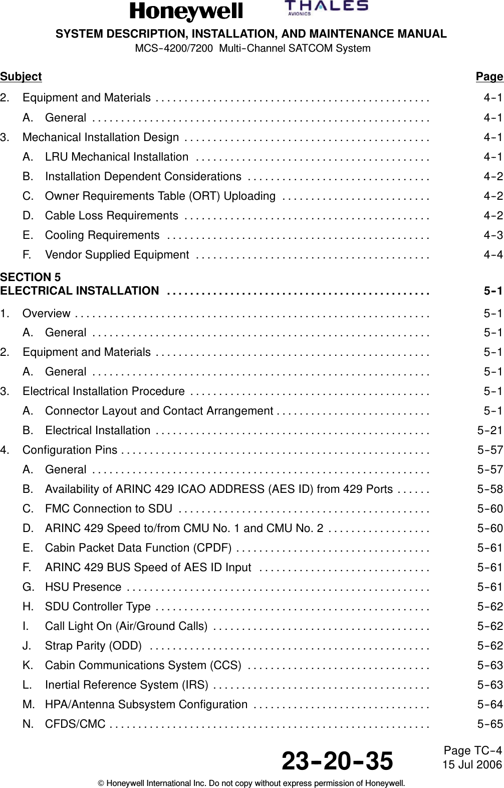
SYSTEM DESCRIPTION, INSTALLATION, AND MAINTENANCE MANUALMCS--4200/7200 Multi--Channel SATCOM System23--20--35 15 Jul 2006Honeywell International Inc. Do not copy without express permission of Honeywell.Page TC--4Subject Page2. Equipment and Materials 4--1................................................A. General 4--1...........................................................3. Mechanical Installation Design 4--1...........................................A. LRU Mechanical Installation 4--1.........................................B. Installation Dependent Considerations 4--2................................C. Owner Requirements Table (ORT) Uploading 4--2..........................D. Cable Loss Requirements 4--2...........................................E. Cooling Requirements 4--3..............................................F. Vendor Supplied Equipment 4--4.........................................SECTION 5ELECTRICAL INSTALLATION 5--1..............................................1. Overview 5--1..............................................................A. General 5--1...........................................................2. Equipment and Materials 5--1................................................A. General 5--1...........................................................3. Electrical Installation Procedure 5--1..........................................A. Connector Layout and Contact Arrangement 5--1...........................B. Electrical Installation 5--21................................................4. Configuration Pins 5--57......................................................A. General 5--57...........................................................B. Availability of ARINC 429 ICAO ADDRESS (AES ID) from 429 Ports 5--58......C. FMC Connection to SDU 5--60............................................D. ARINC 429 Speed to/from CMU No. 1 and CMU No. 2 5--60..................E. Cabin Packet Data Function (CPDF) 5--61..................................F. ARINC 429 BUS Speed of AES ID Input 5--61..............................G. HSU Presence 5--61.....................................................H. SDU Controller Type 5--62................................................I. Call Light On (Air/Ground Calls) 5--62......................................J. Strap Parity (ODD) 5--62.................................................K. Cabin Communications System (CCS) 5--63................................L. Inertial Reference System (IRS) 5--63......................................M. HPA/Antenna Subsystem Configuration 5--64...............................N. CFDS/CMC 5--65........................................................
SYSTEM DESCRIPTION, INSTALLATION, AND MAINTENANCE MANUALMCS--4200/7200 Multi--Channel SATCOM System23--20--35 15 Jul 2006Honeywell International Inc. Do not copy without express permission of Honeywell.Page TC--5Subject PageO. SDU Configuration 5--66.................................................P. SDU Number 5--66......................................................Q. CMU No. 1 and No. 2 Configuration 5--67..................................R. MCDU/WSC No. 1 thru No. 3 Configuration 5--67............................S. Priority 4 Calls to/from Cockpit 5--68.......................................T. ARINC 429 BUS Speed to MCDU No. 1/MCDU No. 2/MCDU No. 3 5--69.......U. Cockpit Voice Call Light/Chime Option 5--69................................V. SDU CODEC 1 and CODEC 2 Wiring 5--70.................................W. Cockpit Hookswitch Signaling Method 5--70................................X. CM--250 CGU Connection Configuration 5--72..............................Y. Cockpit Call Discrete Signaling Mode 5--72.................................Z. Strap Parity 5--73........................................................SECTION 6TESTING/FAULT ISOLATION 6--1...............................................1. Overview 6--1..............................................................A. General 6--1...........................................................B. Definitions 6--2.........................................................C. Failure Detection and Reporting Levels 6--3...............................D. LRU Coverage 6--3.....................................................E. Monitoring and Testing Functions 6--4.....................................F. Failure Recording 6--7..................................................G. Failure Reporting 6--8...................................................H. Miscellaneous BITE Requirements 6--20...................................I. Maintenance Activity Log 6--20............................................2. SATCOM Control and Display Unit 6--21.......................................A. General 6--21...........................................................B. SCDU Display Terminology and Basic Operation 6--21.......................C. SCDU Page Hierarchy 6--25..............................................D. SCDU Pages 6--25......................................................3. Maintenance Computer Interface 6--90.........................................A. General 6--90...........................................................B. Boeing 747--400 CMC/777 OMS 6--90.....................................C. Airbus/Douglas CFDS 6--93...............................................
SYSTEM DESCRIPTION, INSTALLATION, AND MAINTENANCE MANUALMCS--4200/7200 Multi--Channel SATCOM System23--20--35 15 Jul 2006Honeywell International Inc. Do not copy without express permission of Honeywell.Page TC--6Subject PageD. Central Aircraft Information and Maintenance System 6--94...................E. Level I Failure Messages and ATA Reference Numbers 6--95.................4. SCDU for Dual SATCOM 6--121................................................A. General 6--121...........................................................B. SATCOM Logical Channels 6--121..........................................C. SATCOM (Cross-Talk Bus Failed) 6--121....................................D. SATCOM 6--121..........................................................E. SATCOM Menus 6--121...................................................5. Maintenance Panel Assembly 6--121............................................A. General 6--121...........................................................SECTION 7MAINTENANCE PRACTICES 7--1...............................................1. Overview 7--1..............................................................A. General 7--1...........................................................2. Equipment and Materials 7--1................................................A. General 7--1...........................................................3. Procedure for Antennas 7--2.................................................A. General 7--2...........................................................B. Antenna Weather Protection 7--2.........................................C. Antenna Hardware 7--2.................................................D. General Antenna Removal Instructions 7--3................................4. Procedure for the LRUs 7--3.................................................A. LRU Removal 7--3......................................................B. LRU Installation 7--3....................................................5. Owner Requirements Table Uploading 7--4....................................A. General 7--4...........................................................6. Instructions for Continued Airworthiness, FAR 25.1529 7--5......................A. General 7--5...........................................................APPENDIX AVENDOR EQUIPMENT A--1.....................................................1. Overview A--1..............................................................A. General A--1...........................................................2. Electronic Cable Specialists A--1.............................................
SYSTEM DESCRIPTION, INSTALLATION, AND MAINTENANCE MANUALMCS--4200/7200 Multi--Channel SATCOM System23--20--35 15 Jul 2006Honeywell International Inc. Do not copy without express permission of Honeywell.Page TC--7Subject PageA. General A--1...........................................................B. Radio Frequency Components A--1.......................................C. Cable Assembly Fabrication A--1.........................................D. Cable Assembly Testing A--2.............................................E. ARINC 600 Connectors A--2.............................................F. SATCOM Avionics Unit Mounting Hardware A--4...........................G. SATCOM Hardware Component Kits A--4..................................H. Air Filtration Assemblies A--19.............................................I. SATCOM Shelf Assemblies A--19..........................................J. Additional Avionics Installation Components A--19...........................K. Antenna System Provisions A--19..........................................L. Cabin Communications System Provisions A--19............................M. Wire Harnesses A--19....................................................N. Complete Integrated SATCOM Installation Kits A--20.........................3. Hollingsead International A--20................................................A. General A--20...........................................................B. Engineering Services A--20...............................................C. LRU Mounting Requirements A--21........................................D. Installation Kit Components A--21..........................................4. Signal Conditioning Unit A--26.................................................A. General A--26...........................................................B. Operator Functions A--27.................................................C. Control Functions A--28..................................................D. System Functions A--29..................................................E. ARINC 600 Connector Pin Assignments A--33...............................APPENDIX BINSTALLATION PROCEDURES FOR SATCOM AIR FILTRATION SYSTEMS B--1.....1. Introduction B--1............................................................A. General B--1...........................................................2. Continued Airworthiness B--1................................................A. General B--1...........................................................3. Equipment and Materials B--2................................................A. General B--2...........................................................
SYSTEM DESCRIPTION, INSTALLATION, AND MAINTENANCE MANUALMCS--4200/7200 Multi--Channel SATCOM System23--20--35 15 Jul 2006Honeywell International Inc. Do not copy without express permission of Honeywell.Page TC--8Subject Page4. Installation Instructions B--4..................................................A. Top Mount Assembly B--4...............................................B. Body--Mounted Assembly B--8...........................................C. Tray--Mounted Assembly B--9............................................APPENDIX COWNER REQUIREMENTS TABLE C--1...........................................1. Overview C--1..............................................................A. General C--1...........................................................APPENDIX DCALL EVENTS LOG (CEL) D--1.................................................1. Call Events Log D--1........................................................A. General D--1...........................................................2. Commentary D--4...........................................................A. Most Significant Digit D--4...............................................B. SLCV And Detailed Code Definitions D--4.................................C. HSD ISDN Call SLCV And Detailed Codes D--9............................APPENDIX EMESSAGING E--1..............................................................1. PPPoE Messaging E--1.....................................................A. General E--1...........................................................B. PPPoE Active Discovery Offer (PADO) E--1................................C. PPPoE Active Discovery Request (PADR) E--3.............................D. PPPoE Active Discovery Session--Confirmation (PADS) E--5.................E. PPPoE Active Discovery Termination (PADT) E--5..........................APPENDIX FFAILURE OVERVIEW F--1......................................................1. Fault Codes F--1...........................................................INDEX INDEX--1....................................................................
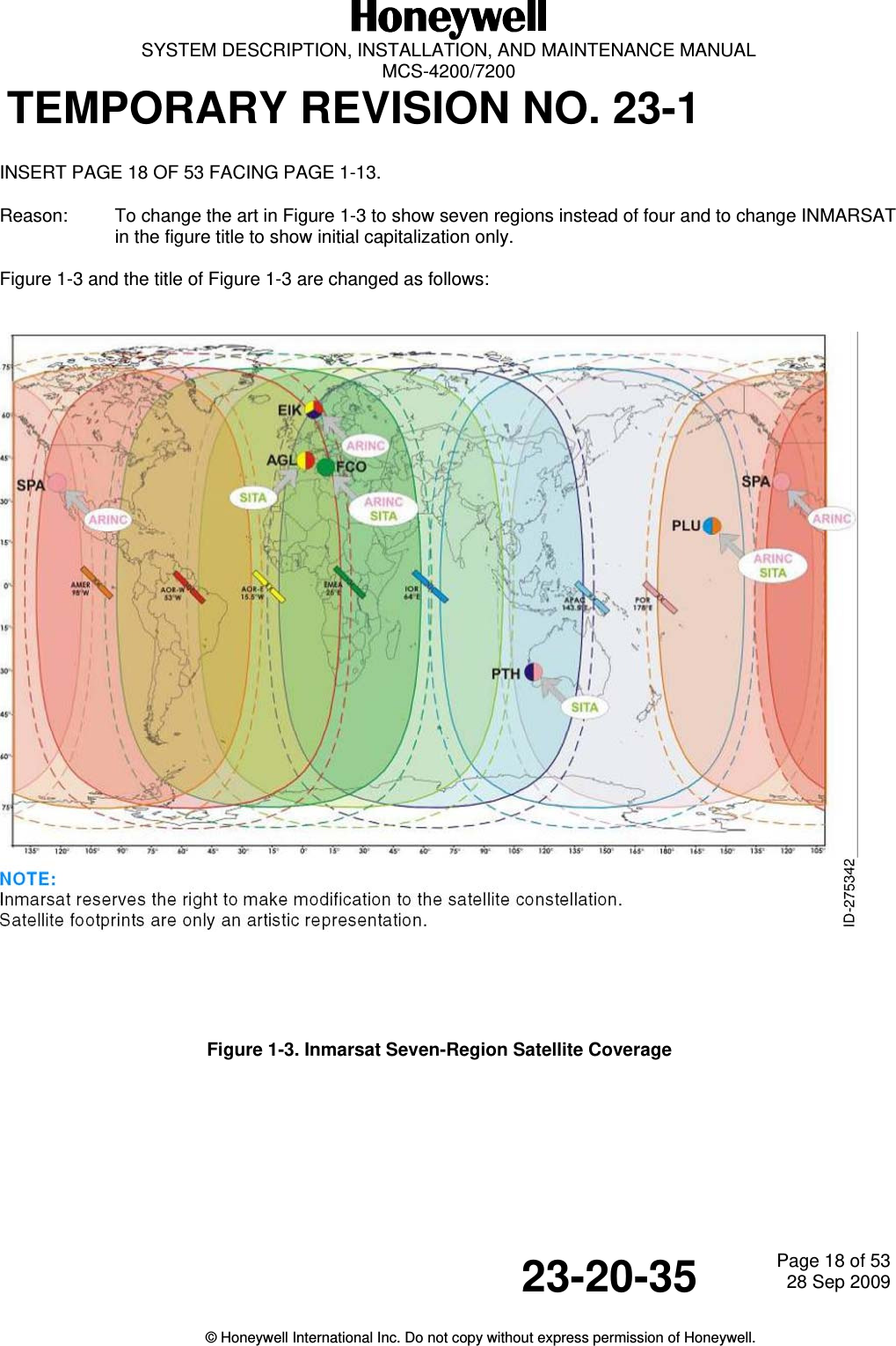
  SYSTEM DESCRIPTION, INSTALLATION, AND MAINTENANCE MANUAL  MCS-4200/7200 TEMPORARY REVISION NO. 23-1 23-20-35  Page 3 of 5328 Sep 2009  © Honeywell International Inc. Do not copy without express permission of Honeywell.   INSERT PAGE 3 OF 53 FACING PAGE TC-9. Reason:  To change Four-Region to Seven-Region and to change the capitalization of INMARSAT to Inmarsat for Figure 1-3 in the List of Illustrations in the Table of Contents.  The List of Illustrations is changed as follows:       Figure 1-3.  Inmarsat Seven-Region Satellite Coverage . . . . . . . . . . . . . . . . . . . . . . . . . . . . .. . . . . . .  . . .1-13
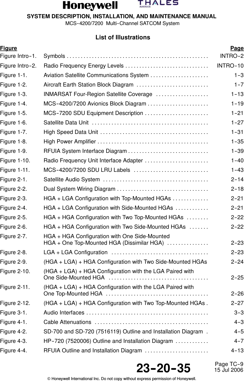
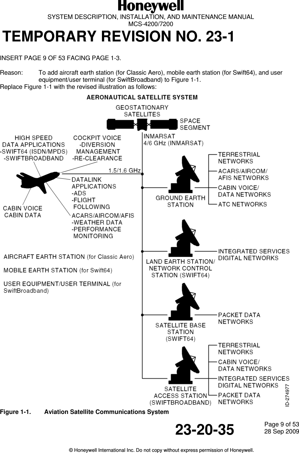
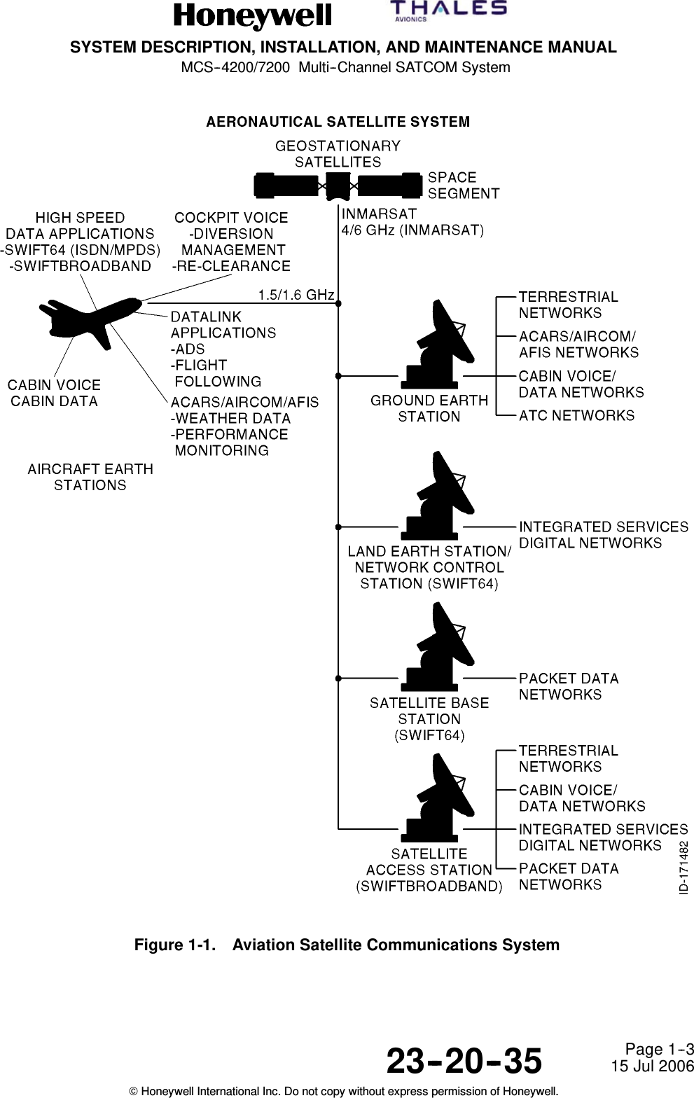
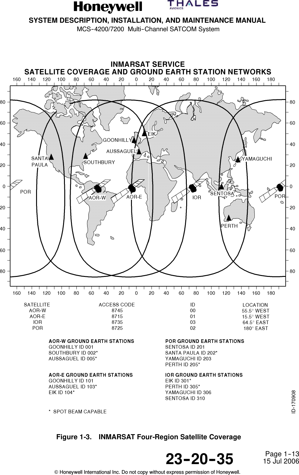
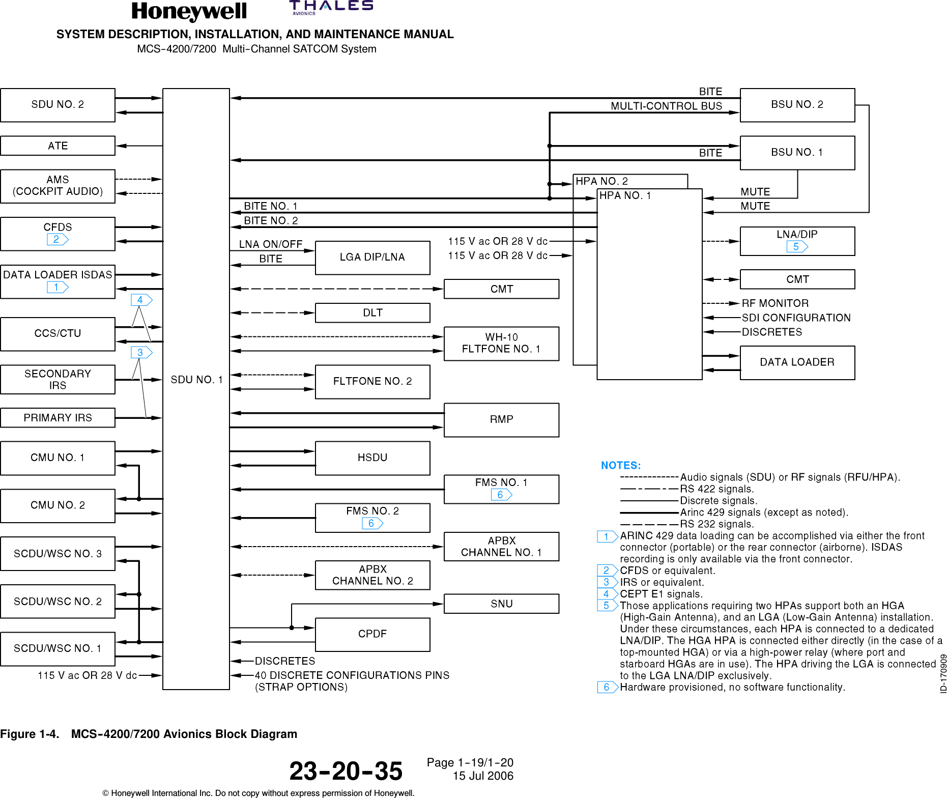
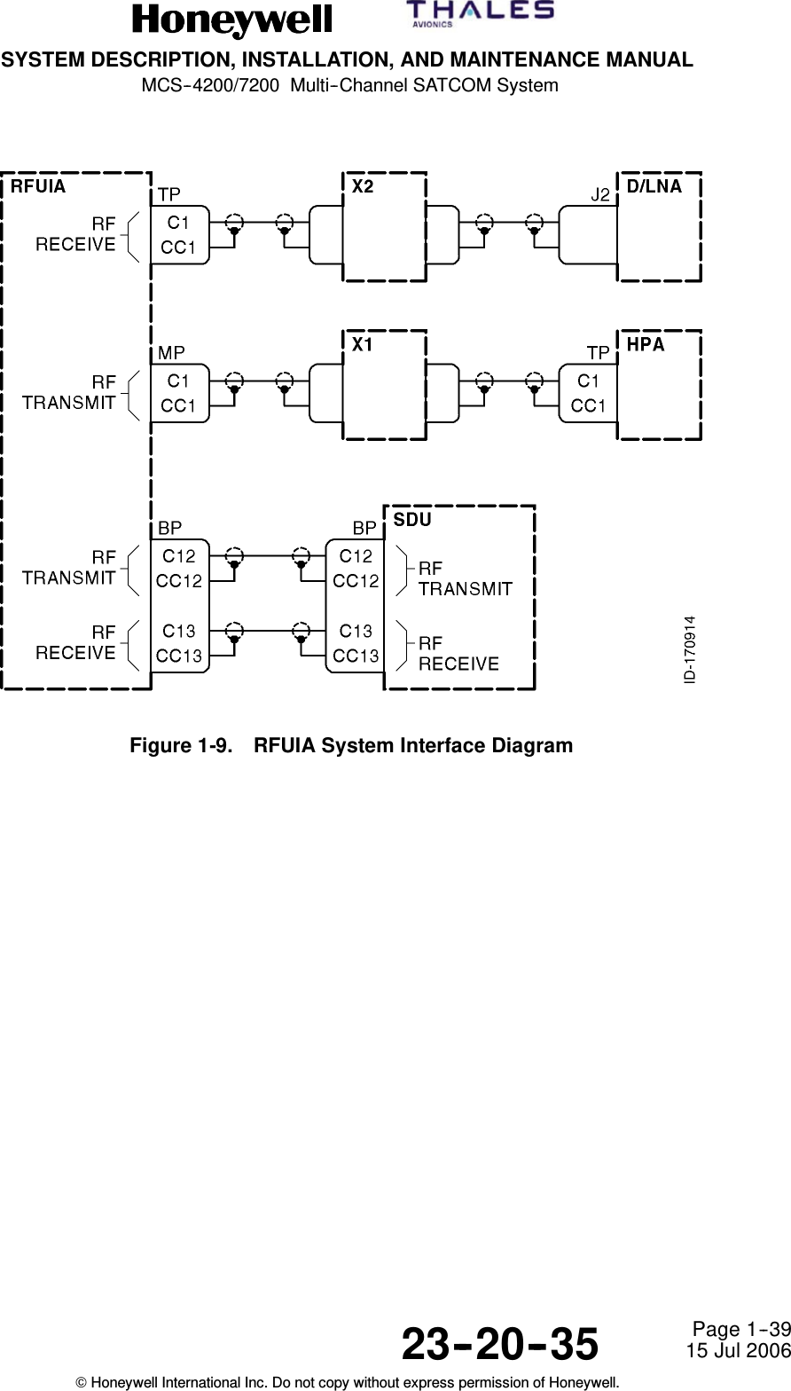
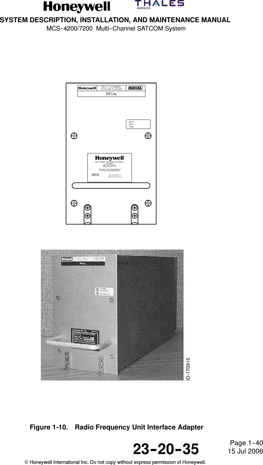
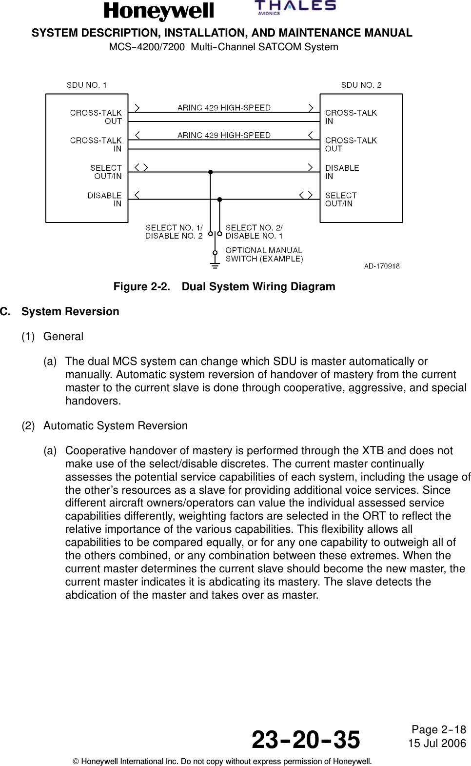
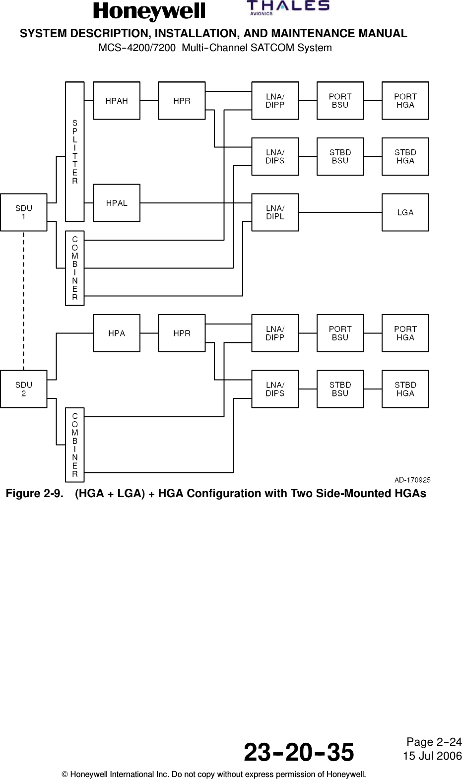
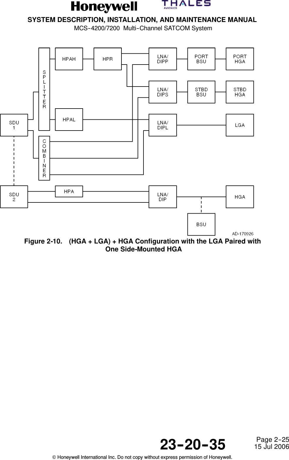
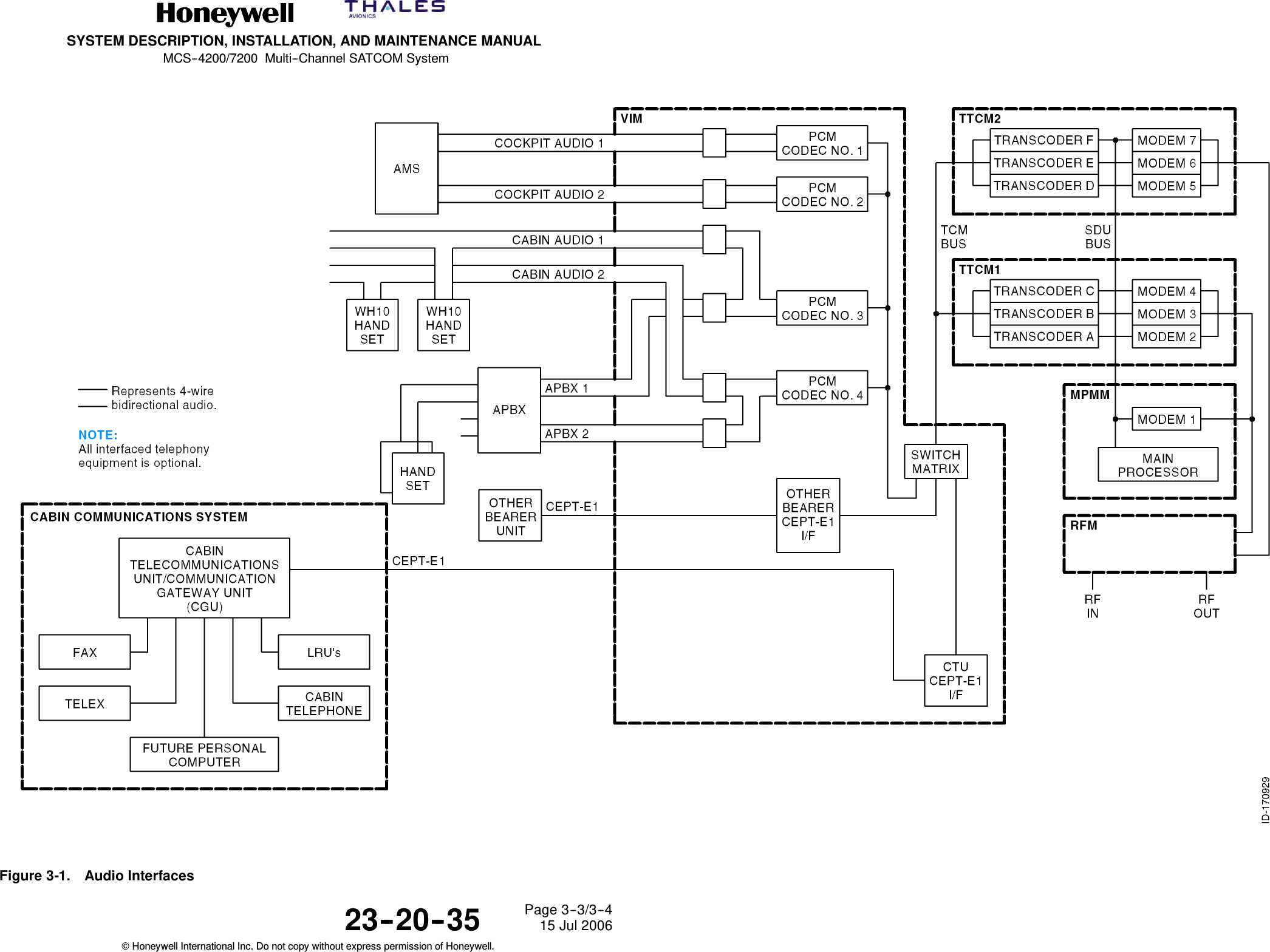
SYSTEM DESCRIPTION, INSTALLATION, AND MAINTENANCE MANUALMCS--4200/7200 Multi--Channel SATCOM System23--20--35 15 Jul 2006Honeywell International Inc. Do not copy without express permission of Honeywell.Page TC--9List of IllustrationsFigure PageFigure Intro--1. Symbols INTRO--2...................................................Figure Intro--2. Radio Frequency Energy Levels INTRO--10..............................Figure 1-1. Aviation Satellite Communications System 1--3.....................Figure 1-2. Aircraft Earth Station Block Diagram 1--7..........................Figure 1-3. INMARSAT Four-Region Satellite Coverage 1--13...................Figure 1-4. MCS--4200/7200 Avionics Block Diagram 1--19......................Figure 1-5. MCS--7200 SDU Equipment Description 1--21.......................Figure 1-6. Satellite Data Unit 1--27..........................................Figure 1-7. High Speed Data Unit 1--31.......................................Figure 1-8. High Power Amplifier 1--35........................................Figure 1-9. RFUIA System Interface Diagram 1--39.............................Figure 1-10. Radio Frequency Unit Interface Adapter 1--40.......................Figure 1-11. MCS--4200/7200 SDU LRU Labels 1--43...........................Figure 2-1. Satellite Audio System 2--14......................................Figure 2-2. Dual System Wiring Diagram 2--18.................................Figure 2-3. HGA + LGA Configuration with Top-Mounted HGAs 2--21.............Figure 2-4. HGA + LGA Configuration with Side-Mounted HGAs 2--21............Figure 2-5. HGA + HGA Configuration with Two Top-Mounted HGAs 2--22........Figure 2-6. HGA + HGA Configuration with Two Side-Mounted HGAs 2--22.......Figure 2-7. HGA + HGA Configuration with One Side-MountedHGA + One Top-Mounted HGA (Dissimilar HGA) 2--23...............Figure 2-8. LGA + LGA Configuration 2--23...................................Figure 2-9. (HGA + LGA) + HGA Configuration with Two Side-Mounted HGAs 2--24Figure 2-10. (HGA + LGA) + HGA Configuration with the LGA Paired withOne Side-Mounted HGA 2--25....................................Figure 2-11. (HGA + LGA) + HGA Configuration with the LGA Paired withOne Top-Mounted HGA 2--26.....................................Figure 2-12. (HGA + LGA) + HGA Configuration with Two Top-Mounted HGAs 2--27.Figure 3-1. Audio Interfaces 3--3............................................Figure 4-1. Cable Attenuations 4--3.........................................Figure 4-2. SD-700 and SD-720 (7516119) Outline and Installation Diagram 4--5.Figure 4-3. HP--720 (7520006) Outline and Installation Diagram 4--7............Figure 4-4. RFUIA Outline and Installation Diagram 4--13.......................
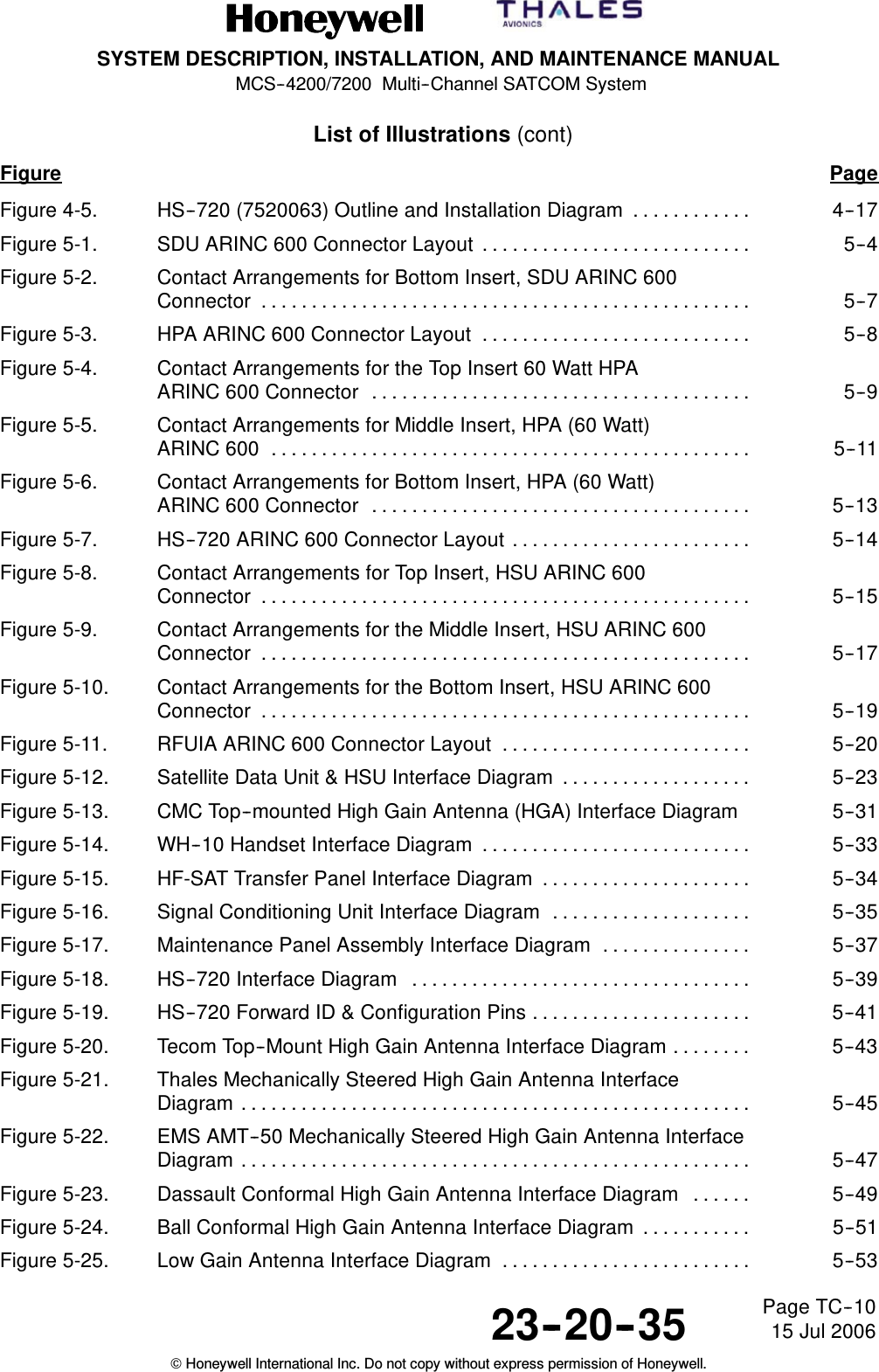
SYSTEM DESCRIPTION, INSTALLATION, AND MAINTENANCE MANUALMCS--4200/7200 Multi--Channel SATCOM System23--20--35 15 Jul 2006Honeywell International Inc. Do not copy without express permission of Honeywell.Page TC--10List of Illustrations (cont)Figure PageFigure 4-5. HS--720 (7520063) Outline and Installation Diagram 4--17............Figure 5-1. SDU ARINC 600 Connector Layout 5--4...........................Figure 5-2. Contact Arrangements for Bottom Insert, SDU ARINC 600Connector 5--7.................................................Figure 5-3. HPA ARINC 600 Connector Layout 5--8...........................Figure 5-4. Contact Arrangements for the Top Insert 60 Watt HPAARINC 600 Connector 5--9......................................Figure 5-5. Contact Arrangements for Middle Insert, HPA (60 Watt)ARINC 600 5--11................................................Figure 5-6. Contact Arrangements for Bottom Insert, HPA (60 Watt)ARINC 600 Connector 5--13......................................Figure 5-7. HS--720 ARINC 600 Connector Layout 5--14........................Figure 5-8. Contact Arrangements for Top Insert, HSU ARINC 600Connector 5--15.................................................Figure 5-9. Contact Arrangements for the Middle Insert, HSU ARINC 600Connector 5--17.................................................Figure 5-10. Contact Arrangements for the Bottom Insert, HSU ARINC 600Connector 5--19.................................................Figure 5-11. RFUIA ARINC 600 Connector Layout 5--20.........................Figure 5-12. Satellite Data Unit & HSU Interface Diagram 5--23...................Figure 5-13. CMC Top--mounted High Gain Antenna (HGA) Interface Diagram 5--31Figure 5-14. WH--10 Handset Interface Diagram 5--33...........................Figure 5-15. HF-SAT Transfer Panel Interface Diagram 5--34.....................Figure 5-16. Signal Conditioning Unit Interface Diagram 5--35....................Figure 5-17. Maintenance Panel Assembly Interface Diagram 5--37...............Figure 5-18. HS--720 Interface Diagram 5--39..................................Figure 5-19. HS--720 Forward ID & Configuration Pins 5--41......................Figure 5-20. Tecom Top--Mount High Gain Antenna Interface Diagram 5--43........Figure 5-21. Thales Mechanically Steered High Gain Antenna InterfaceDiagram 5--45...................................................Figure 5-22. EMS AMT--50 Mechanically Steered High Gain Antenna InterfaceDiagram 5--47...................................................Figure 5-23. Dassault Conformal High Gain Antenna Interface Diagram 5--49......Figure 5-24. Ball Conformal High Gain Antenna Interface Diagram 5--51...........Figure 5-25. Low Gain Antenna Interface Diagram 5--53.........................
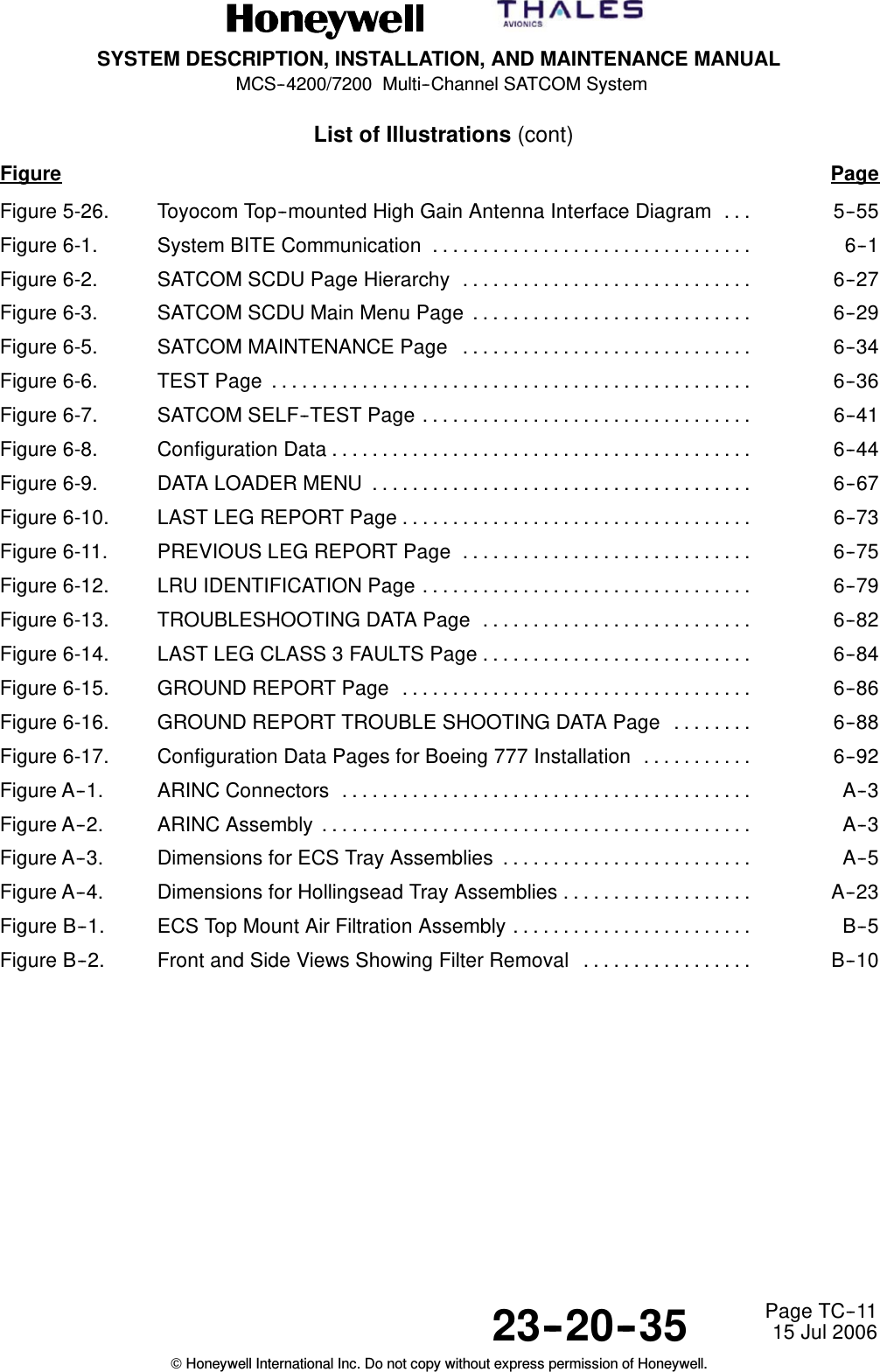
SYSTEM DESCRIPTION, INSTALLATION, AND MAINTENANCE MANUALMCS--4200/7200 Multi--Channel SATCOM System23--20--35 15 Jul 2006Honeywell International Inc. Do not copy without express permission of Honeywell.Page TC--11List of Illustrations (cont)Figure PageFigure 5-26. Toyocom Top--mounted High Gain Antenna Interface Diagram 5--55...Figure 6-1. System BITE Communication 6--1................................Figure 6-2. SATCOM SCDU Page Hierarchy 6--27.............................Figure 6-3. SATCOM SCDU Main Menu Page 6--29............................Figure 6-5. SATCOM MAINTENANCE Page 6--34.............................Figure 6-6. TEST Page 6--36................................................Figure 6-7. SATCOM SELF--TEST Page 6--41.................................Figure 6-8. Configuration Data 6--44..........................................Figure 6-9. DATA LOADER MENU 6--67......................................Figure 6-10. LAST LEG REPORT Page 6--73...................................Figure 6-11. PREVIOUS LEG REPORT Page 6--75.............................Figure 6-12. LRU IDENTIFICATION Page 6--79.................................Figure 6-13. TROUBLESHOOTING DATA Page 6--82...........................Figure 6-14. LAST LEG CLASS 3 FAULTS Page 6--84...........................Figure 6-15. GROUND REPORT Page 6--86...................................Figure 6-16. GROUND REPORT TROUBLE SHOOTING DATA Page 6--88........Figure 6-17. Configuration Data Pages for Boeing 777 Installation 6--92...........Figure A--1. ARINC Connectors A--3.........................................Figure A--2. ARINC Assembly A--3...........................................Figure A--3. Dimensions for ECS Tray Assemblies A--5.........................Figure A--4. Dimensions for Hollingsead Tray Assemblies A--23...................Figure B--1. ECS Top Mount Air Filtration Assembly B--5........................Figure B--2. Front and Side Views Showing Filter Removal B--10.................
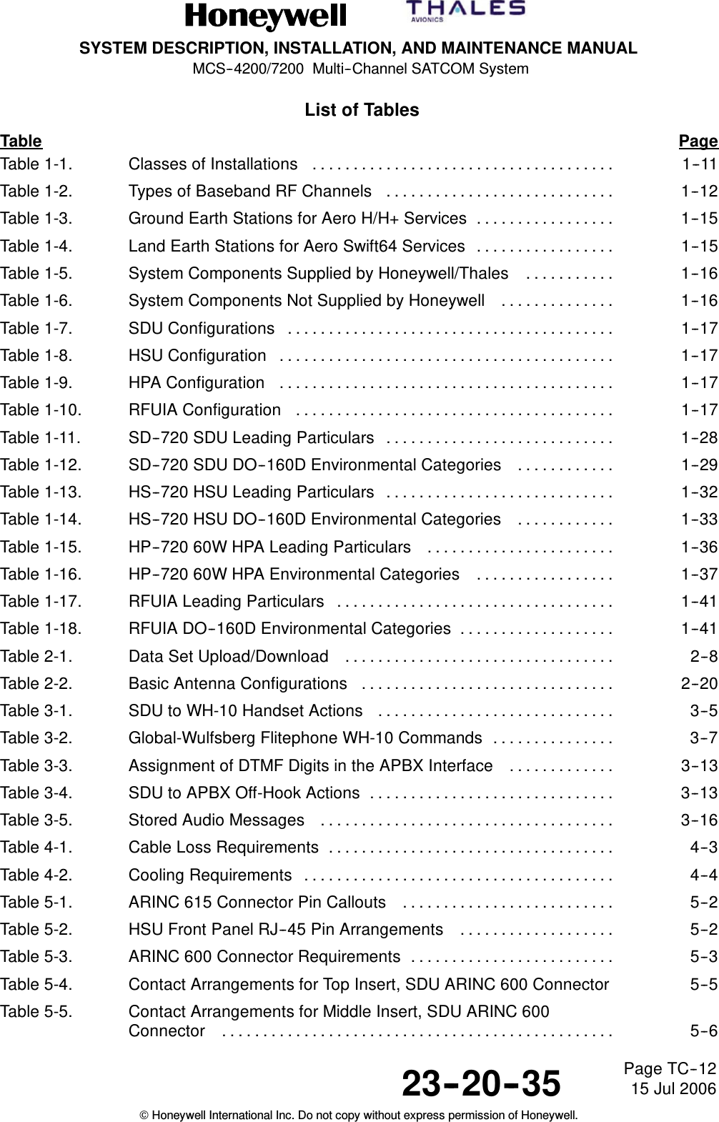
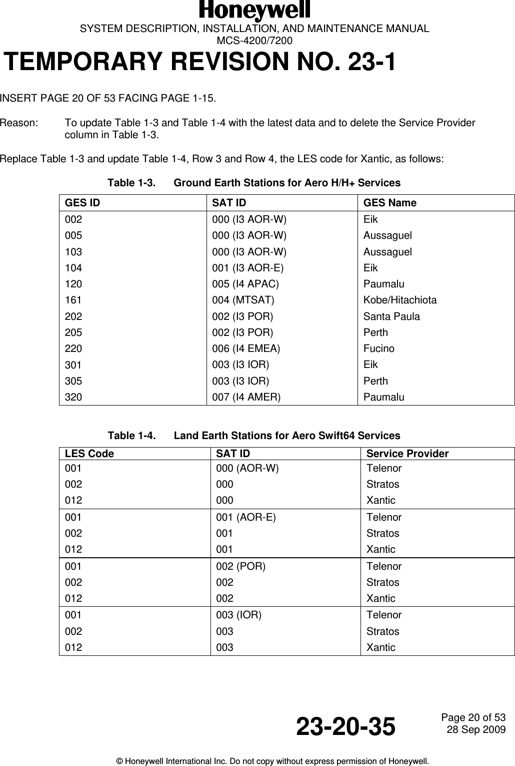
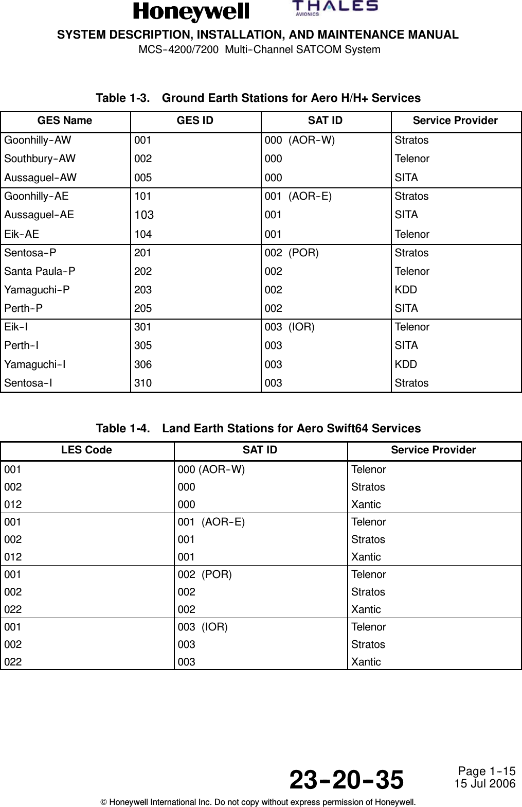
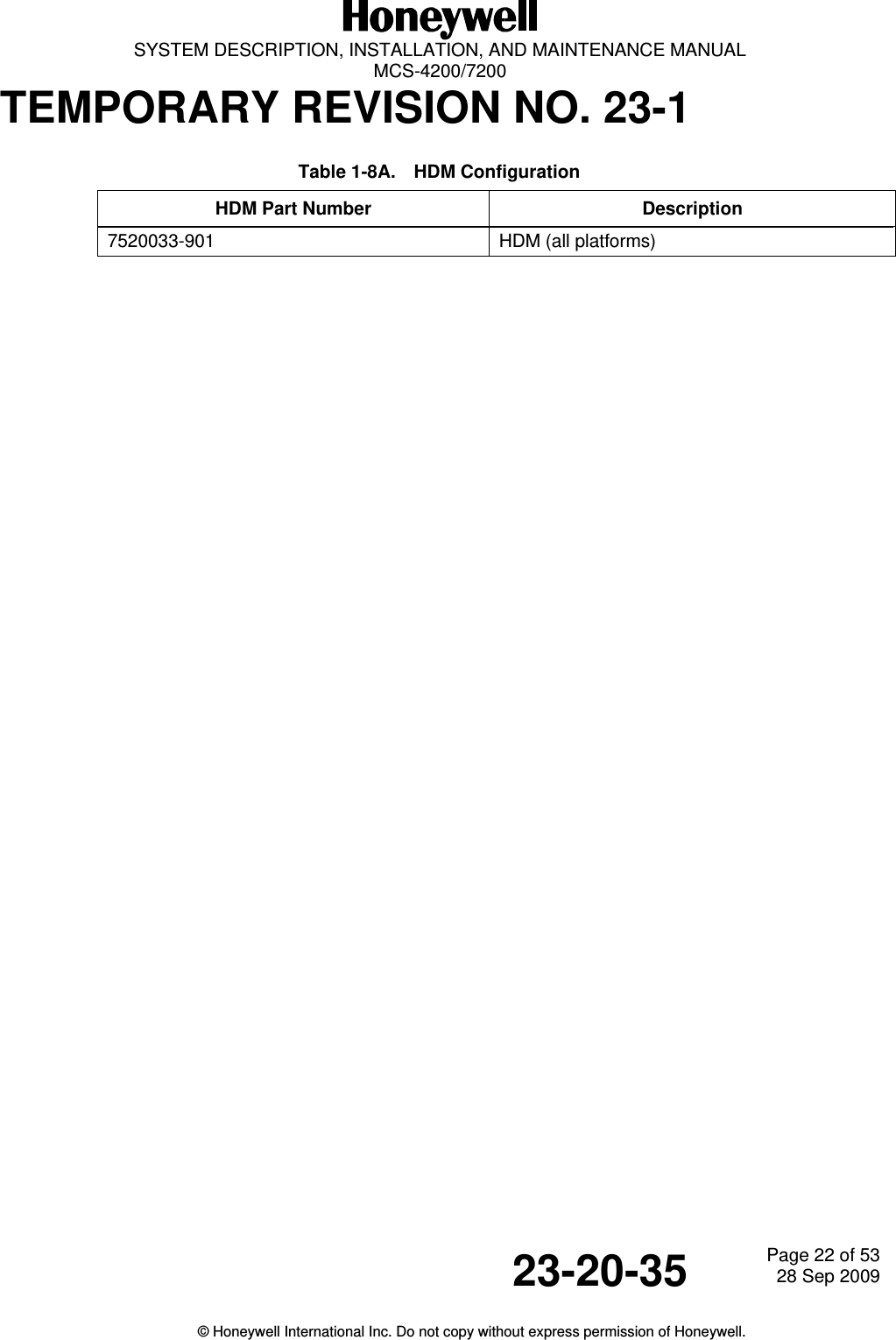
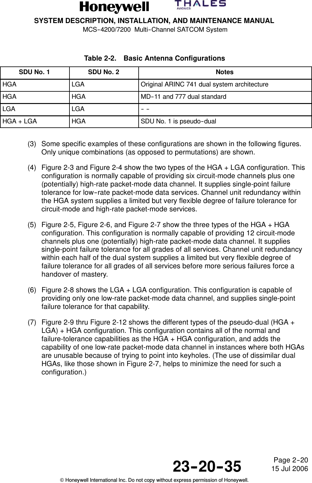
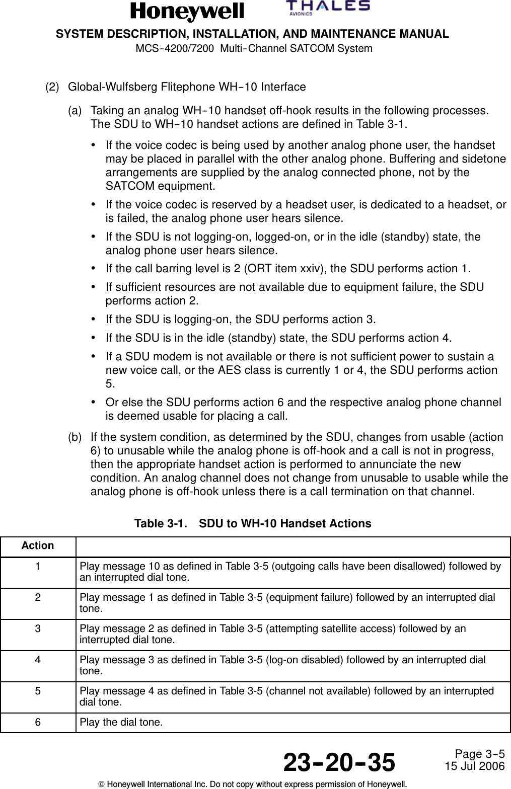
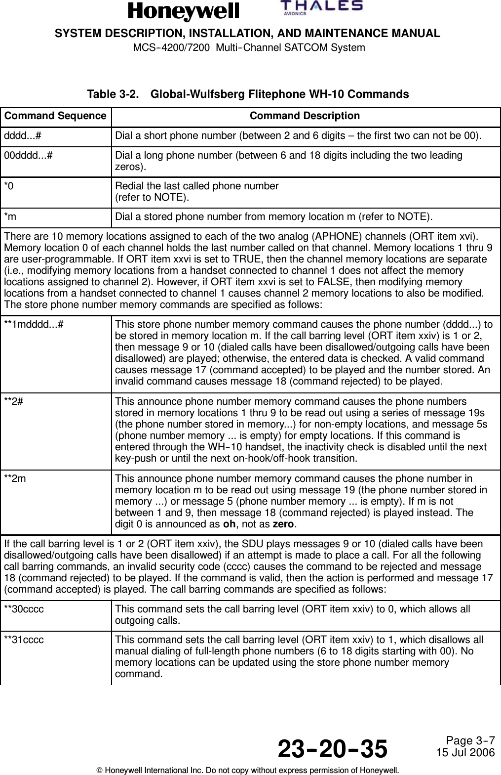
SYSTEM DESCRIPTION, INSTALLATION, AND MAINTENANCE MANUALMCS--4200/7200 Multi--Channel SATCOM System23--20--35 15 Jul 2006Honeywell International Inc. Do not copy without express permission of Honeywell.Page TC--12List of TablesTable PageTable 1-1. Classes of Installations 1--11.....................................Table 1-2. Types of Baseband RF Channels 1--12............................Table 1-3. Ground Earth Stations for Aero H/H+ Services 1--15.................Table 1-4. Land Earth Stations for Aero Swift64 Services 1--15.................Table 1-5. System Components Supplied by Honeywell/Thales 1--16...........Table 1-6. System Components Not Supplied by Honeywell 1--16..............Table 1-7. SDU Configurations 1--17........................................Table 1-8. HSU Configuration 1--17.........................................Table 1-9. HPA Configuration 1--17.........................................Table 1-10. RFUIA Configuration 1--17.......................................Table 1-11. SD--720 SDU Leading Particulars 1--28............................Table 1-12. SD--720 SDU DO--160D Environmental Categories 1--29............Table 1-13. HS--720 HSU Leading Particulars 1--32............................Table 1-14. HS--720 HSU DO--160D Environmental Categories 1--33............Table 1-15. HP--720 60W HPA Leading Particulars 1--36.......................Table 1-16. HP--720 60W HPA Environmental Categories 1--37.................Table 1-17. RFUIA Leading Particulars 1--41..................................Table 1-18. RFUIA DO--160D Environmental Categories 1--41...................Table 2-1. Data Set Upload/Download 2--8.................................Table 2-2. Basic Antenna Configurations 2--20...............................Table 3-1. SDU to WH-10 Handset Actions 3--5.............................Table 3-2. Global-Wulfsberg Flitephone WH-10 Commands 3--7...............Table 3-3. Assignment of DTMF Digits in the APBX Interface 3--13.............Table 3-4. SDU to APBX Off-Hook Actions 3--13..............................Table 3-5. Stored Audio Messages 3--16....................................Table 4-1. Cable Loss Requirements 4--3...................................Table 4-2. Cooling Requirements 4--4......................................Table 5-1. ARINC 615 Connector Pin Callouts 5--2..........................Table 5-2. HSU Front Panel RJ--45 Pin Arrangements 5--2...................Table 5-3. ARINC 600 Connector Requirements 5--3.........................Table 5-4. Contact Arrangements for Top Insert, SDU ARINC 600 Connector 5--5Table 5-5. Contact Arrangements for Middle Insert, SDU ARINC 600Connector 5--6................................................
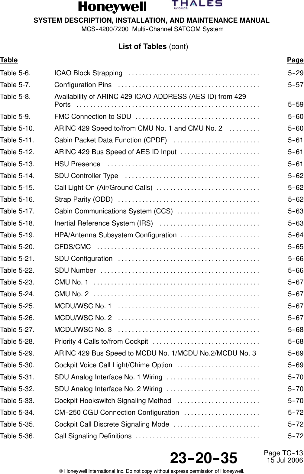
SYSTEM DESCRIPTION, INSTALLATION, AND MAINTENANCE MANUALMCS--4200/7200 Multi--Channel SATCOM System23--20--35 15 Jul 2006Honeywell International Inc. Do not copy without express permission of Honeywell.Page TC--13List of Tables (cont)Table PageTable 5-6. ICAO Block Strapping 5--29......................................Table 5-7. Configuration Pins 5--57.........................................Table 5-8. Availability of ARINC 429 ICAO ADDRESS (AES ID) from 429Ports 5--59.....................................................Table 5-9. FMC Connection to SDU 5--60....................................Table 5-10. ARINC 429 Speed to/from CMU No. 1 and CMU No. 2 5--60.........Table 5-11. Cabin Packet Data Function (CPDF) 5--61.........................Table 5-12. ARINC 429 Bus Speed of AES ID Input 5--61.......................Table 5-13. HSU Presence 5--61............................................Table 5-14. SDU Controller Type 5--62.......................................Table 5-15. Call Light On (Air/Ground Calls) 5--62..............................Table 5-16. Strap Parity (ODD) 5--62.........................................Table 5-17. Cabin Communications System (CCS) 5--63........................Table 5-18. Inertial Reference System (IRS) 5--63.............................Table 5-19. HPA/Antenna Subsystem Configuration 5--64.......................Table 5-20. CFDS/CMC 5--65...............................................Table 5-21. SDU Configuration 5--66.........................................Table 5-22. SDU Number 5--66..............................................Table 5-23. CMU No. 1 5--67................................................Table 5-24. CMU No. 2 5--67................................................Table 5-25. MCDU/WSC No. 1 5--67.........................................Table 5-26. MCDU/WSC No. 2 5--67.........................................Table 5-27. MCDU/WSC No. 3 5--68.........................................Table 5-28. Priority 4 Calls to/from Cockpit 5--68...............................Table 5-29. ARINC 429 Bus Speed to MCDU No. 1/MCDU No.2/MCDU No. 3 5--69Table 5-30. Cockpit Voice Call Light/Chime Option 5--69........................Table 5-31. SDU Analog Interface No. 1 Wiring 5--70...........................Table 5-32. SDU Analog Interface No. 2 Wiring 5--70...........................Table 5-33. Cockpit Hookswitch Signaling Method 5--70........................Table 5-34. CM--250 CGU Connection Configuration 5--72......................Table 5-35. Cockpit Call Discrete Signaling Mode 5--72.........................Table 5-36. Call Signaling Definitions 5--72....................................
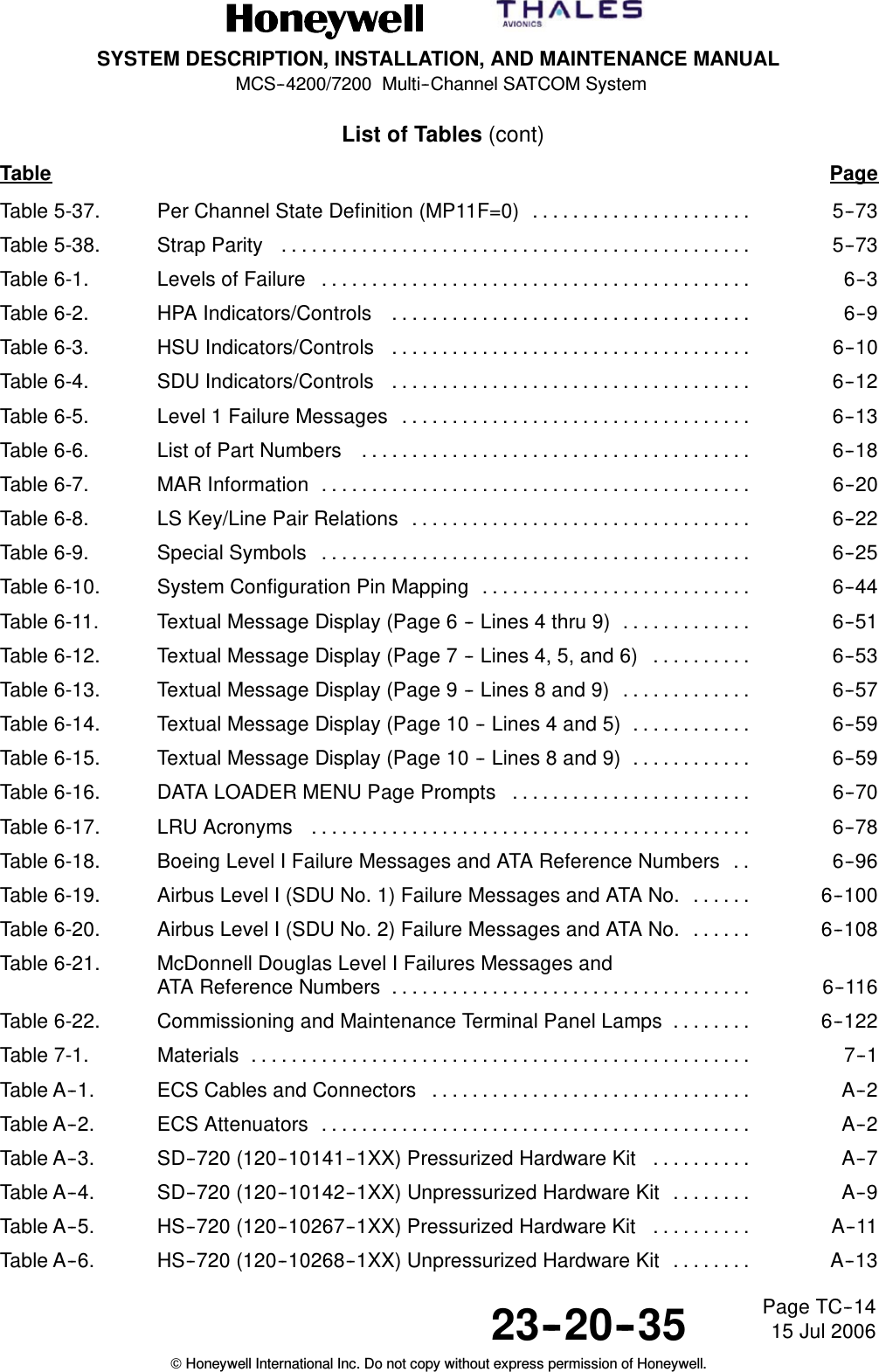
SYSTEM DESCRIPTION, INSTALLATION, AND MAINTENANCE MANUALMCS--4200/7200 Multi--Channel SATCOM System23--20--35 15 Jul 2006Honeywell International Inc. Do not copy without express permission of Honeywell.Page TC--14List of Tables (cont)Table PageTable 5-37. Per Channel State Definition (MP11F=0) 5--73......................Table 5-38. Strap Parity 5--73...............................................Table 6-1. Levels of Failure 6--3...........................................Table 6-2. HPA Indicators/Controls 6--9....................................Table 6-3. HSU Indicators/Controls 6--10....................................Table 6-4. SDU Indicators/Controls 6--12....................................Table 6-5. Level 1 Failure Messages 6--13...................................Table 6-6. List of Part Numbers 6--18.......................................Table 6-7. MAR Information 6--20...........................................Table 6-8. LS Key/Line Pair Relations 6--22..................................Table 6-9. Special Symbols 6--25...........................................Table 6-10. System Configuration Pin Mapping 6--44...........................Table 6-11. Textual Message Display (Page 6 -- Lines 4 thru 9) 6--51.............Table 6-12. Textual Message Display (Page 7 -- Lines 4, 5, and 6) 6--53..........Table 6-13. Textual Message Display (Page 9 -- Lines 8 and 9) 6--57.............Table 6-14. Textual Message Display (Page 10 -- Lines 4 and 5) 6--59............Table 6-15. Textual Message Display (Page 10 -- Lines 8 and 9) 6--59............Table 6-16. DATA LOADER MENU Page Prompts 6--70........................Table 6-17. LRU Acronyms 6--78............................................Table 6-18. Boeing Level I Failure Messages and ATA Reference Numbers 6--96..Table 6-19. Airbus Level I (SDU No. 1) Failure Messages and ATA No. 6--100......Table 6-20. Airbus Level I (SDU No. 2) Failure Messages and ATA No. 6--108......Table 6-21. McDonnell Douglas Level I Failures Messages andATA Reference Numbers 6--116....................................Table 6-22. Commissioning and Maintenance Terminal Panel Lamps 6--122........Table 7-1. Materials 7--1..................................................Table A--1. ECS Cables and Connectors A--2................................Table A--2. ECS Attenuators A--2...........................................Table A--3. SD--720 (120--10141--1XX) Pressurized Hardware Kit A--7..........Table A--4. SD--720 (120--10142--1XX) Unpressurized Hardware Kit A--9........Table A--5. HS--720 (120--10267--1XX) Pressurized Hardware Kit A--11..........Table A--6. HS--720 (120--10268--1XX) Unpressurized Hardware Kit A--13........
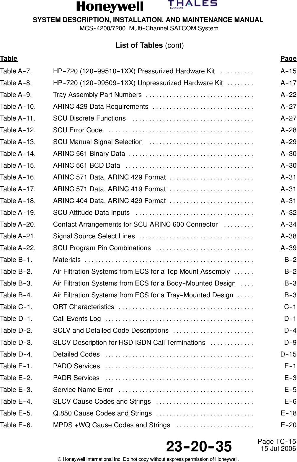
SYSTEM DESCRIPTION, INSTALLATION, AND MAINTENANCE MANUALMCS--4200/7200 Multi--Channel SATCOM System23--20--35 15 Jul 2006Honeywell International Inc. Do not copy without express permission of Honeywell.Page TC--15List of Tables (cont)Table PageTable A--7. HP--720 (120--99510--1XX) Pressurized Hardware Kit A--15..........Table A--8. HP--720 (120--99509--1XX) Unpressurized Hardware Kit A--17........Table A--9. Tray Assembly Part Numbers A--22................................Table A--10. ARINC 429 Data Requirements A--27..............................Table A--11. SCU Discrete Functions A--27....................................Table A--12. SCU Error Code A--28...........................................Table A--13. SCU Manual Signal Selection A--29...............................Table A--14. ARINC 561 Binary Data A--30.....................................Table A--15. ARINC 561 BCD Data A--30......................................Table A--16. ARINC 571 Data, ARINC 429 Format A--31.........................Table A--17. ARINC 571 Data, ARINC 419 Format A--31.........................Table A--18. ARINC 404 Data, ARINC 429 Format A--31.........................Table A--19. SCU Attitude Data Inputs A--32...................................Table A--20. Contact Arrangements for SCU ARINC 600 Connector A--34.........Table A--21. Signal Source Select Lines A--38..................................Table A--22. SCU Program Pin Combinations A--39.............................Table B--1. Materials B--2..................................................Table B--2. Air Filtration Systems from ECS for a Top Mount Assembly B--2......Table B--3. Air Filtration Systems from ECS for a Body--Mounted Design B--3....Table B--4. Air Filtration Systems from ECS for a Tray--Mounted Design B--3.....Table C--1. ORT Characteristics C--1........................................Table D--1. Call Events Log D--1............................................Table D--2. SCLV and Detailed Code Descriptions D--4........................Table D--3. SLCV Description for HSD ISDN Call Terminations D--9.............Table D--4. Detailed Codes D--15............................................Table E--1. PADO Services E--1............................................Table E--2. PADR Services E--3............................................Table E--3. Service Name Error E--5........................................Table E--4. SLCV Cause Codes and Strings E--6.............................Table E--5. Q.850 Cause Codes and Strings E--18.............................Table E--6. MPDS +WQ Cause Codes and Strings E--20.......................
SYSTEM DESCRIPTION, INSTALLATION, AND MAINTENANCE MANUALMCS--4200/7200 Multi--Channel SATCOM System23--20--35 15 Jul 2006Honeywell International Inc. Do not copy without express permission of Honeywell.Page TC--16Blank Page
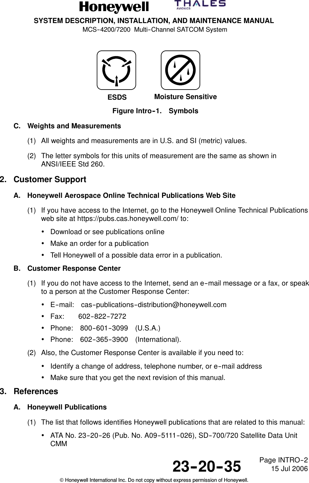
SYSTEM DESCRIPTION, INSTALLATION, AND MAINTENANCE MANUALMCS--4200/7200 Multi--Channel SATCOM System23--20--35 15 Jul 2006Honeywell International Inc. Do not copy without express permission of Honeywell.Page INTRO--1INTRODUCTION1. How to Use This ManualA. General(1) This manual gives general system description and installation information for theMCS--4200/7200 Multi--Channel SATCOM System. It also gives block diagram andinterconnect information to permit a general understanding of the system interface.(2) The purpose of this manual is to help you install, operate, maintain, and troubleshootthe MCS--4200/7200 Multi--channel SATCOM System. Common system maintenanceprocedures are not presented in this manual. The best established shop and flightline practices should be used.(3) Warnings, cautions, and notes in this manual give the data that follows:•A WARNING gives a condition that, if you do not obey, can cause injury or death.•A CAUTION gives a condition that, if you do not obey, can cause damage to theequipment.•A NOTE gives data to make the work easier or gives direction to go to aprocedure.(4) Warnings and cautions go before the applicable paragraph or step. Notes follow theapplicable paragraph or step.(5) All personnel who operate equipment and do the specified maintenance must knowand obey the safety precautions.WARNING: HIGH VOLTAGES MAY BE PRESENT ON SYSTEM INTERCONNECTCABLES. MAKE SURE THAT SYSTEM POWER IS OFF BEFORE YOUDISCONNECT LRU MATING CONNECTORS.WARNING: BEFORE YOU USE A MATERIAL, REFER TO THE MANUFACTURERS’MATERIAL SAFETY DATA SHEETS FOR SAFETY INFORMATION. SOMEMATERIALS CAN BE DANGEROUS.CAUTION: DO NOT USE MATERIALS THAT ARE NOT EQUIVALENT TOMATERIALS SPECIFIED BY HONEYWELL. MATERIALS THAT ARE NOTEQUIVALENT CAN CAUSE DAMAGE TO THE EQUIPMENT AND CANVOID THE WARRANTY.CAUTION: THE MCS--4200/7200 MULTI--CHANNEL SATCOM SYSTEM CONTAINSITEMS THAT ARE ELECTROSTATIC DISCHARGE SENSITIVE (ESDS). IFYOU DO NOT OBEY THE NECESSARY CONTROLS, A FAILURE ORUNSATISFACTORY OPERATION OF THE UNIT CAN OCCUR FROMELECTROSTATIC DISCHARGE. USE APPROVED INDUSTRYPRECAUTIONS TO KEEP THE RISK OF DAMAGE TO A MINIMUM WHENYOU TOUCH, REMOVE, OR INSERT PARTS OR ASSEMBLIES.B. Symbols(1) The symbols in Figure Intro--1 identify ESDS and moisture sensitive devices in thismanual, if applicable.
SYSTEM DESCRIPTION, INSTALLATION, AND MAINTENANCE MANUALMCS--4200/7200 Multi--Channel SATCOM System23--20--35 15 Jul 2006Honeywell International Inc. Do not copy without express permission of Honeywell.Page INTRO--2ESDS Moisture SensitiveFigure Intro--1. SymbolsC. Weights and Measurements(1) All weights and measurements are in U.S. and SI (metric) values.(2) The letter symbols for this units of measurement are the same as shown inANSI/IEEE Std 260.2. Customer SupportA. Honeywell Aerospace Online Technical Publications Web Site(1) If you have access to the Internet, go to the Honeywell Online Technical Publicationsweb site at https://pubs.cas.honeywell.com/ to:•Download or see publications online•Make an order for a publication•Tell Honeywell of a possible data error in a publication.B. Customer Response Center(1) If you do not have access to the Internet, send an e--mail message or a fax, or speakto a person at the Customer Response Center:•E--mail: cas--publications--distribution@honeywell.com•Fax: 602--822--7272•Phone: 800--601--3099 (U.S.A.)•Phone: 602--365--3900 (International).(2) Also, the Customer Response Center is available if you need to:•Identify a change of address, telephone number, or e--mail address•Make sure that you get the next revision of this manual.3. ReferencesA. Honeywell Publications(1) The list that follows identifies Honeywell publications that are related to this manual:•ATA No. 23--20--26 (Pub. No. A09--5111--026), SD--700/720 Satellite Data UnitCMM
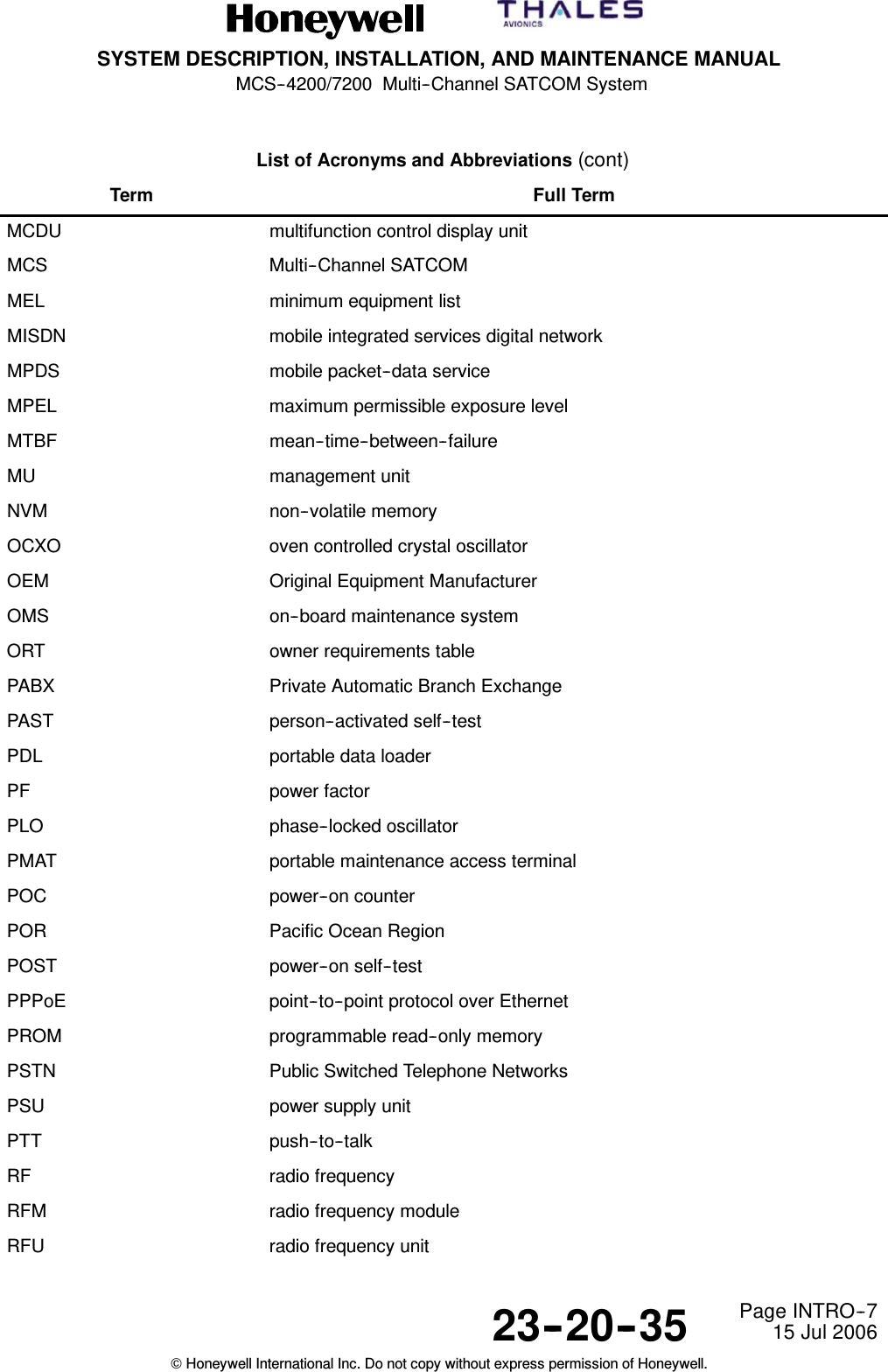
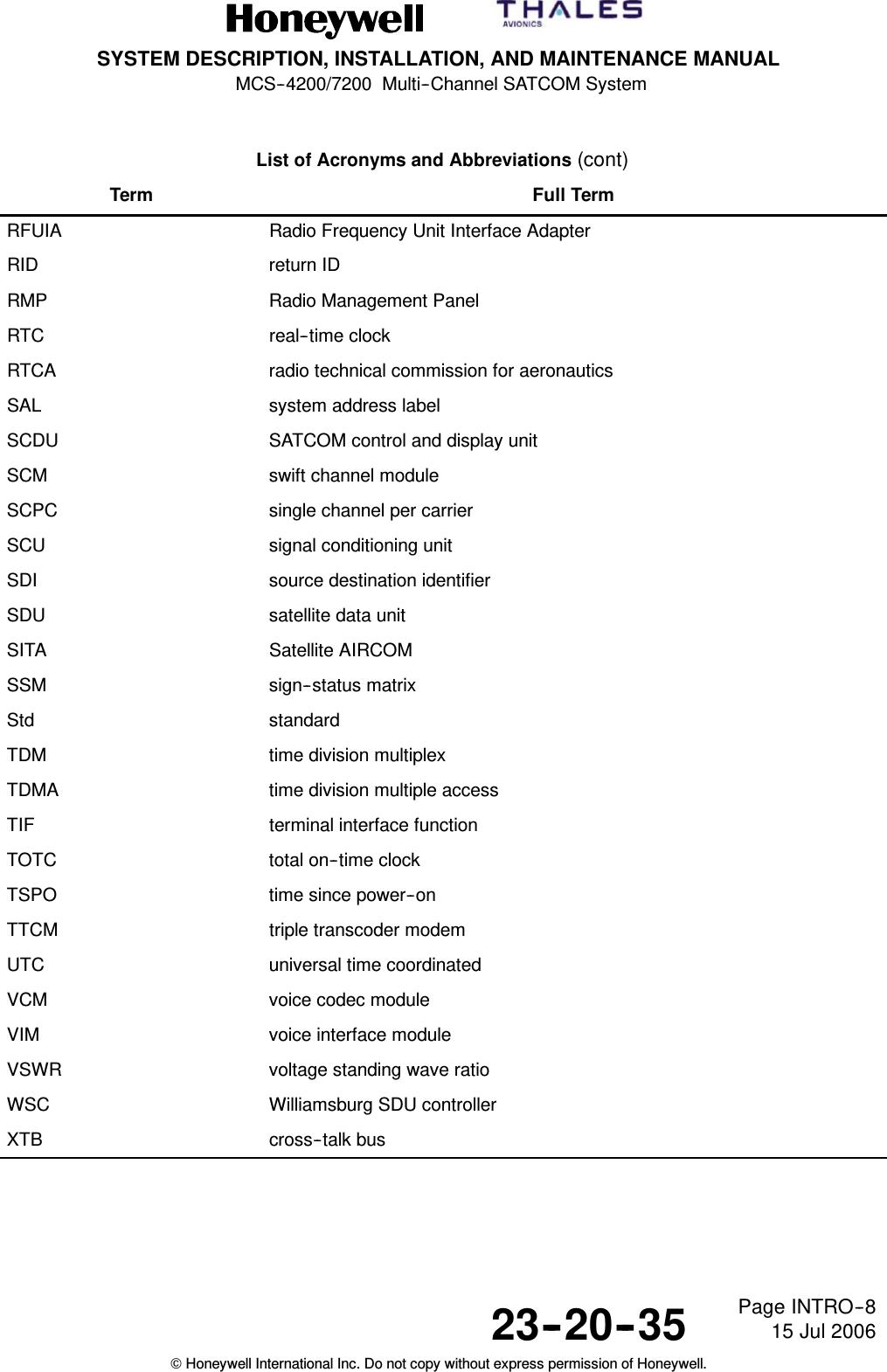
SYSTEM DESCRIPTION, INSTALLATION, AND MAINTENANCE MANUALMCS--4200/7200 Multi--Channel SATCOM System23--20--35 15 Jul 2006Honeywell International Inc. Do not copy without express permission of Honeywell.Page INTRO--3•ATA No. 23--20--50 (Pub. No. A32--5111--008), HP--720 High Power AmplifierCMM•ATA No. 23--20--52 (Pub No. A32--5111--001), HS--720 High Speed Data UnitAssembly CMM•Pub. No. A09--1100--001, Handling, Storage, and Shipping Procedures forHoneywell Avionics Equipment Instruction Manual•Pub. No. A09--1100--004, Standard Repair Procedures for Honeywell AvionicsEquipment Instruction Manual•Pub. No. A62--0119--001, Honeywell Material Number (HMN) Codes.B. Other Publications(1) These publications are standard references:•The United States Government Printing Office (GPO) Style Manual 2000(available at http://www.gpoaccess.gov/stylemanual/browse.html)•ANSI/IEEE Std 260 (1978), Standard Letter Symbols for Units of Measurement(available from the American National Standards Institute, New York, NY)•ASME Y14.38--1999 (Formerly ASME Y1.1--1989), Abbreviations for Use onDrawings and in Text (available from the American National Standards Institute,New York, NY)•ANSI/IEEE Std 315--1975 (Replaces ANSI Y32.2--1975), Graphic Symbols forElectrical and Electronics Diagrams (available from the American NationalStandards Institute, New York, NY)•ANSI/IEEE Std 91 (1984), Graphic Symbols for Logic Functions (available fromthe American National Standards Institute, New York, NY)•H4/H8 Commercial and Government Entity (CAGE) Codes (available athttp://www.dlis.dla.mil/cage_welcome.asp).4. Acronyms and AbbreviationsA. General(1) Refer to the list that follows for acronyms and abbreviations in this manual.List of Acronyms and AbbreviationsTerm Full TermAAC aeronautical administrative communicationsACARS aircraft communications addressing and reporting systemACP audio control panelACU antenna control unitADL airborne data loader
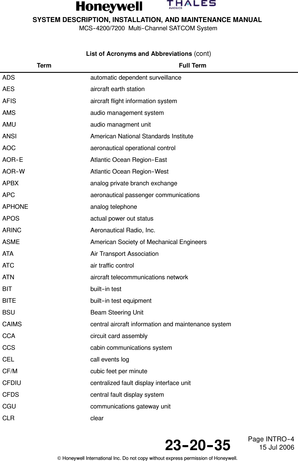
SYSTEM DESCRIPTION, INSTALLATION, AND MAINTENANCE MANUALMCS--4200/7200 Multi--Channel SATCOM System23--20--35 15 Jul 2006Honeywell International Inc. Do not copy without express permission of Honeywell.Page INTRO--4List of Acronyms and Abbreviations (cont)Term Full TermADS automatic dependent surveillanceAES aircraft earth stationAFIS aircraft flight information systemAMS audio management systemAMU audio managment unitANSI American National Standards InstituteAOC aeronautical operational controlAOR--E Atlantic Ocean Region--EastAOR--W Atlantic Ocean Region--WestAPBX analog private branch exchangeAPC aeronautical passenger communicationsAPHONE analog telephoneAPOS actual power out statusARINC Aeronautical Radio, Inc.ASME American Society of Mechanical EngineersATA Air Transport AssociationATC air traffic controlATN aircraft telecommunications networkBIT built--in testBITE built--in test equipmentBSU Beam Steering UnitCAIMS central aircraft information and maintenance systemCCA circuit card assemblyCCS cabin communications systemCEL call events logCF/M cubic feet per minuteCFDIU centralized fault display interface unitCFDS central fault display systemCGU communications gateway unitCLR clear
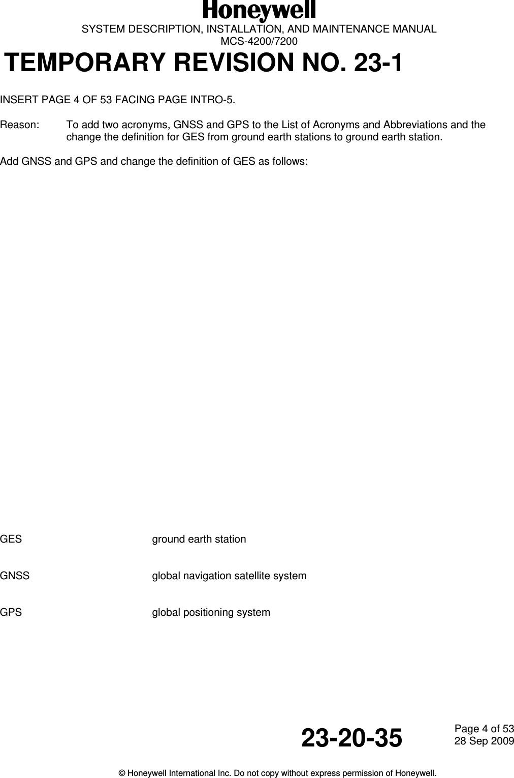
  SYSTEM DESCRIPTION, INSTALLATION, AND MAINTENANCE MANUAL  MCS-4200/7200 TEMPORARY REVISION NO. 23-1 23-20-35  Page 4 of 5328 Sep 2009  © Honeywell International Inc. Do not copy without express permission of Honeywell.   INSERT PAGE 4 OF 53 FACING PAGE INTRO-5. Reason:  To add two acronyms, GNSS and GPS to the List of Acronyms and Abbreviations and the change the definition for GES from ground earth stations to ground earth station.  Add GNSS and GPS and change the definition of GES as follows:                               GES     ground earth station   GNSS        global navigation satellite system   GPS     global positioning system
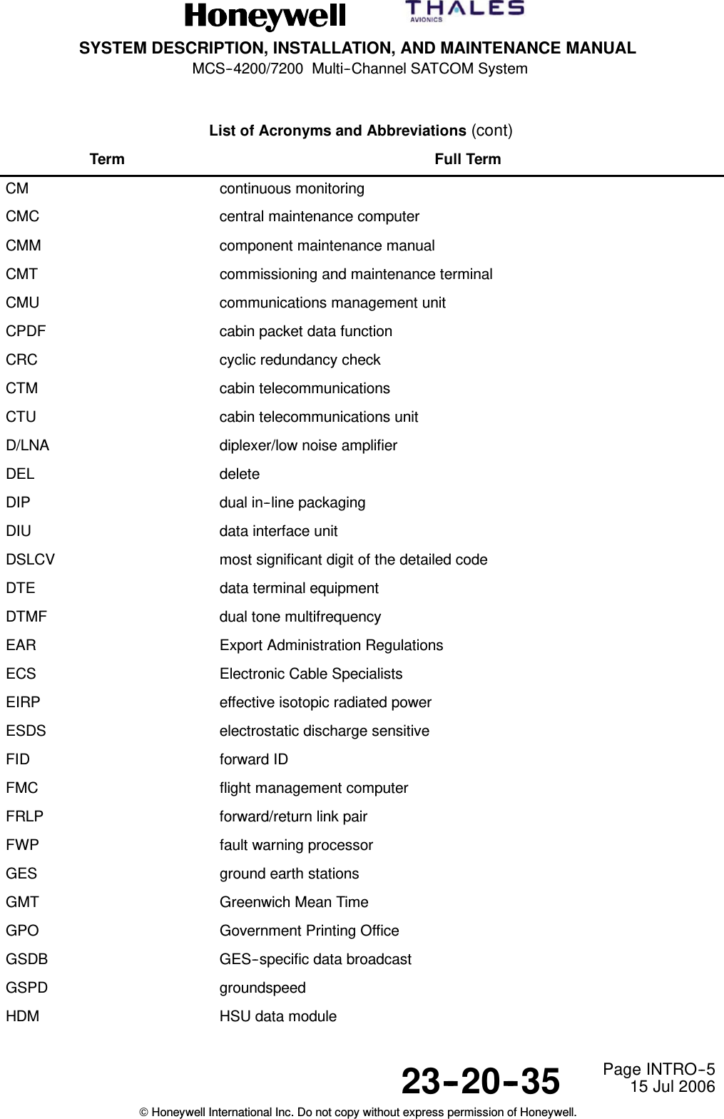
SYSTEM DESCRIPTION, INSTALLATION, AND MAINTENANCE MANUALMCS--4200/7200 Multi--Channel SATCOM System23--20--35 15 Jul 2006Honeywell International Inc. Do not copy without express permission of Honeywell.Page INTRO--5List of Acronyms and Abbreviations (cont)Term Full TermCM continuous monitoringCMC central maintenance computerCMM component maintenance manualCMT commissioning and maintenance terminalCMU communications management unitCPDF cabin packet data functionCRC cyclic redundancy checkCTM cabin telecommunicationsCTU cabin telecommunications unitD/LNA diplexer/low noise amplifierDEL deleteDIP dual in--line packagingDIU data interface unitDSLCV most significant digit of the detailed codeDTE data terminal equipmentDTMF dual tone multifrequencyEAR Export Administration RegulationsECS Electronic Cable SpecialistsEIRP effective isotopic radiated powerESDS electrostatic discharge sensitiveFID forward IDFMC flight management computerFRLP forward/return link pairFWP fault warning processorGES ground earth stationsGMT Greenwich Mean TimeGPO Government Printing OfficeGSDB GES--specific data broadcastGSPD groundspeedHDM HSU data module
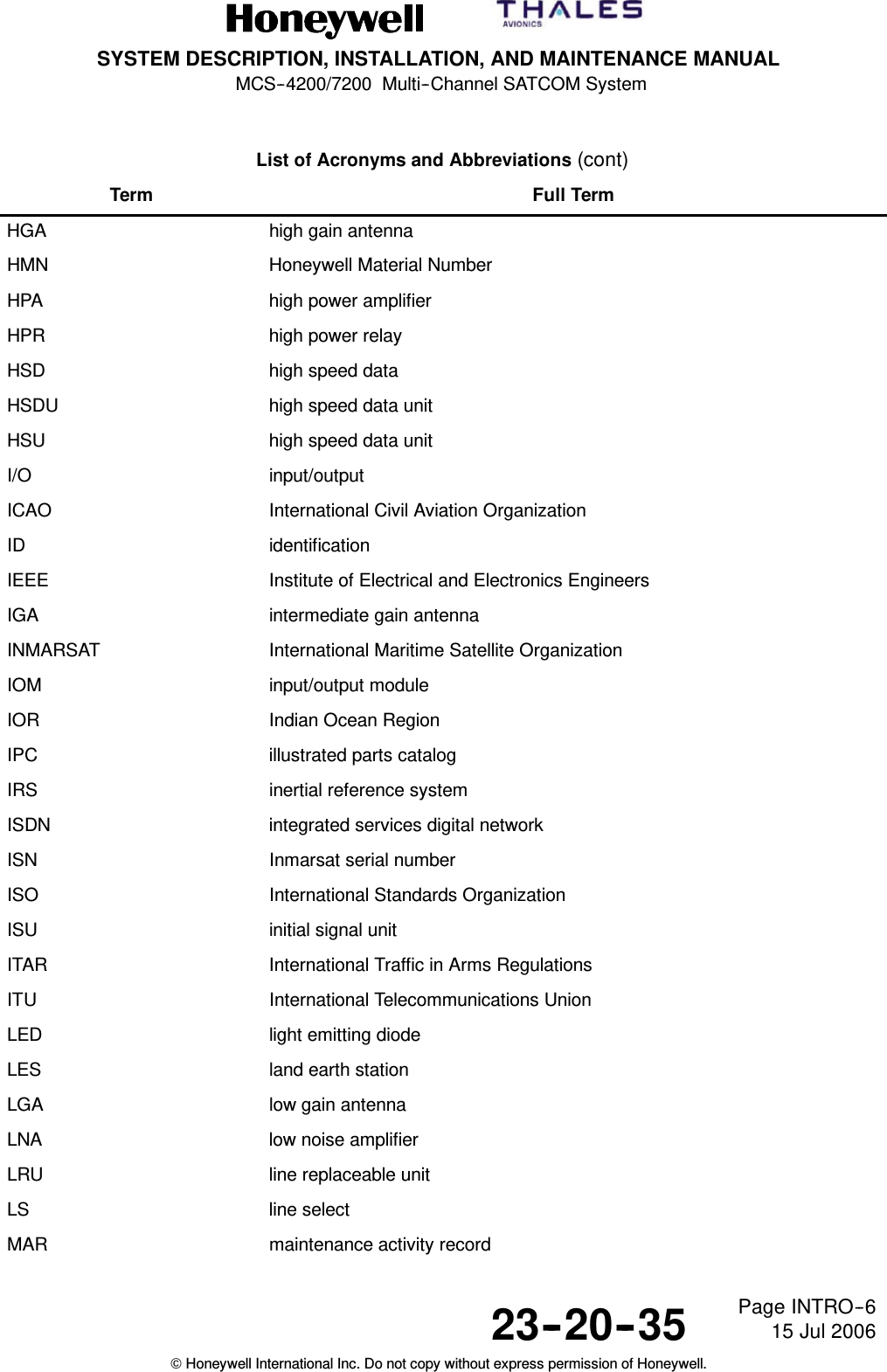
SYSTEM DESCRIPTION, INSTALLATION, AND MAINTENANCE MANUALMCS--4200/7200 Multi--Channel SATCOM System23--20--35 15 Jul 2006Honeywell International Inc. Do not copy without express permission of Honeywell.Page INTRO--6List of Acronyms and Abbreviations (cont)Term Full TermHGA high gain antennaHMN Honeywell Material NumberHPA high power amplifierHPR high power relayHSD high speed dataHSDU high speed data unitHSU high speed data unitI/O input/outputICAO International Civil Aviation OrganizationID identificationIEEE Institute of Electrical and Electronics EngineersIGA intermediate gain antennaINMARSAT International Maritime Satellite OrganizationIOM input/output moduleIOR Indian Ocean RegionIPC illustrated parts catalogIRS inertial reference systemISDN integrated services digital networkISN Inmarsat serial numberISO International Standards OrganizationISU initial signal unitITAR International Traffic in Arms RegulationsITU International Telecommunications UnionLED light emitting diodeLES land earth stationLGA low gain antennaLNA low noise amplifierLRU line replaceable unitLS line selectMAR maintenance activity record
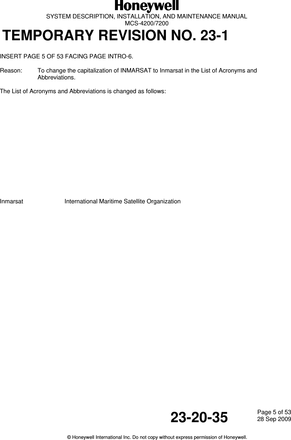
  SYSTEM DESCRIPTION, INSTALLATION, AND MAINTENANCE MANUAL  MCS-4200/7200 TEMPORARY REVISION NO. 23-1 23-20-35  Page 5 of 5328 Sep 2009  © Honeywell International Inc. Do not copy without express permission of Honeywell.   INSERT PAGE 5 OF 53 FACING PAGE INTRO-6. Reason:  To change the capitalization of INMARSAT to Inmarsat in the List of Acronyms and Abbreviations.  The List of Acronyms and Abbreviations is changed as follows:                Inmarsat    International Maritime Satellite Organization
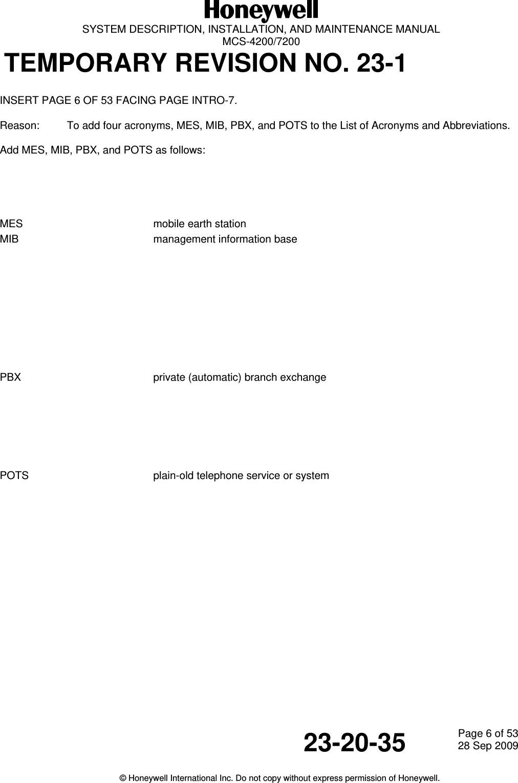
  SYSTEM DESCRIPTION, INSTALLATION, AND MAINTENANCE MANUAL  MCS-4200/7200 TEMPORARY REVISION NO. 23-1 23-20-35  Page 6 of 5328 Sep 2009  © Honeywell International Inc. Do not copy without express permission of Honeywell.   INSERT PAGE 6 OF 53 FACING PAGE INTRO-7. Reason:  To add four acronyms, MES, MIB, PBX, and POTS to the List of Acronyms and Abbreviations.  Add MES, MIB, PBX, and POTS as follows:      MES     mobile earth station MIB     management information base           PBX     private (automatic) branch exchange        POTS        plain-old telephone service or system
SYSTEM DESCRIPTION, INSTALLATION, AND MAINTENANCE MANUALMCS--4200/7200 Multi--Channel SATCOM System23--20--35 15 Jul 2006Honeywell International Inc. Do not copy without express permission of Honeywell.Page INTRO--7List of Acronyms and Abbreviations (cont)Term Full TermMCDU multifunction control display unitMCS Multi--Channel SATCOMMEL minimum equipment listMISDN mobile integrated services digital networkMPDS mobile packet--data serviceMPEL maximum permissible exposure levelMTBF mean--time--between--failureMU management unitNVM non--volatile memoryOCXO oven controlled crystal oscillatorOEM Original Equipment ManufacturerOMS on--board maintenance systemORT owner requirements tablePABX Private Automatic Branch ExchangePAST person--activated self--testPDL portable data loaderPF power factorPLO phase--locked oscillatorPMAT portable maintenance access terminalPOC power--on counterPOR Pacific Ocean RegionPOST power--on self--testPPPoE point--to--point protocol over EthernetPROM programmable read--only memoryPSTN Public Switched Telephone NetworksPSU power supply unitPTT push--to--talkRF radio frequencyRFM radio frequency moduleRFU radio frequency unit
SYSTEM DESCRIPTION, INSTALLATION, AND MAINTENANCE MANUALMCS--4200/7200 Multi--Channel SATCOM System23--20--35 15 Jul 2006Honeywell International Inc. Do not copy without express permission of Honeywell.Page INTRO--8List of Acronyms and Abbreviations (cont)Term Full TermRFUIA Radio Frequency Unit Interface AdapterRID return IDRMP Radio Management PanelRTC real--time clockRTCA radio technical commission for aeronauticsSAL system address labelSCDU SATCOM control and display unitSCM swift channel moduleSCPC single channel per carrierSCU signal conditioning unitSDI source destination identifierSDU satellite data unitSITA Satellite AIRCOMSSM sign--status matrixStd standardTDM time division multiplexTDMA time division multiple accessTIF terminal interface functionTOTC total on--time clockTSPO time since power--onTTCM triple transcoder modemUTC universal time coordinatedVCM voice codec moduleVIM voice interface moduleVSWR voltage standing wave ratioWSC Williamsburg SDU controllerXTB cross--talk bus
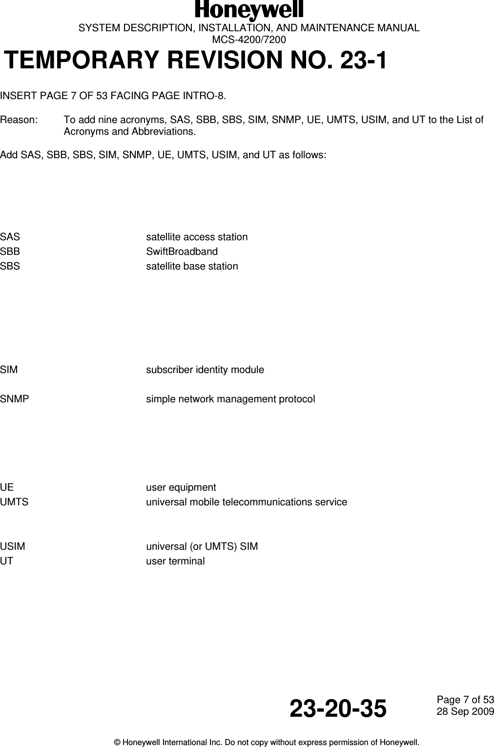
  SYSTEM DESCRIPTION, INSTALLATION, AND MAINTENANCE MANUAL  MCS-4200/7200 TEMPORARY REVISION NO. 23-1 23-20-35  Page 7 of 5328 Sep 2009  © Honeywell International Inc. Do not copy without express permission of Honeywell.   INSERT PAGE 7 OF 53 FACING PAGE INTRO-8. Reason:  To add nine acronyms, SAS, SBB, SBS, SIM, SNMP, UE, UMTS, USIM, and UT to the List of Acronyms and Abbreviations.  Add SAS, SBB, SBS, SIM, SNMP, UE, UMTS, USIM, and UT as follows:       SAS     satellite access station SBB     SwiftBroadband SBS     satellite base station       SIM     subscriber identity module  SNMP        simple network management protocol      UE     user equipment UMTS        universal mobile telecommunications service   USIM     universal (or UMTS) SIM UT     user terminal
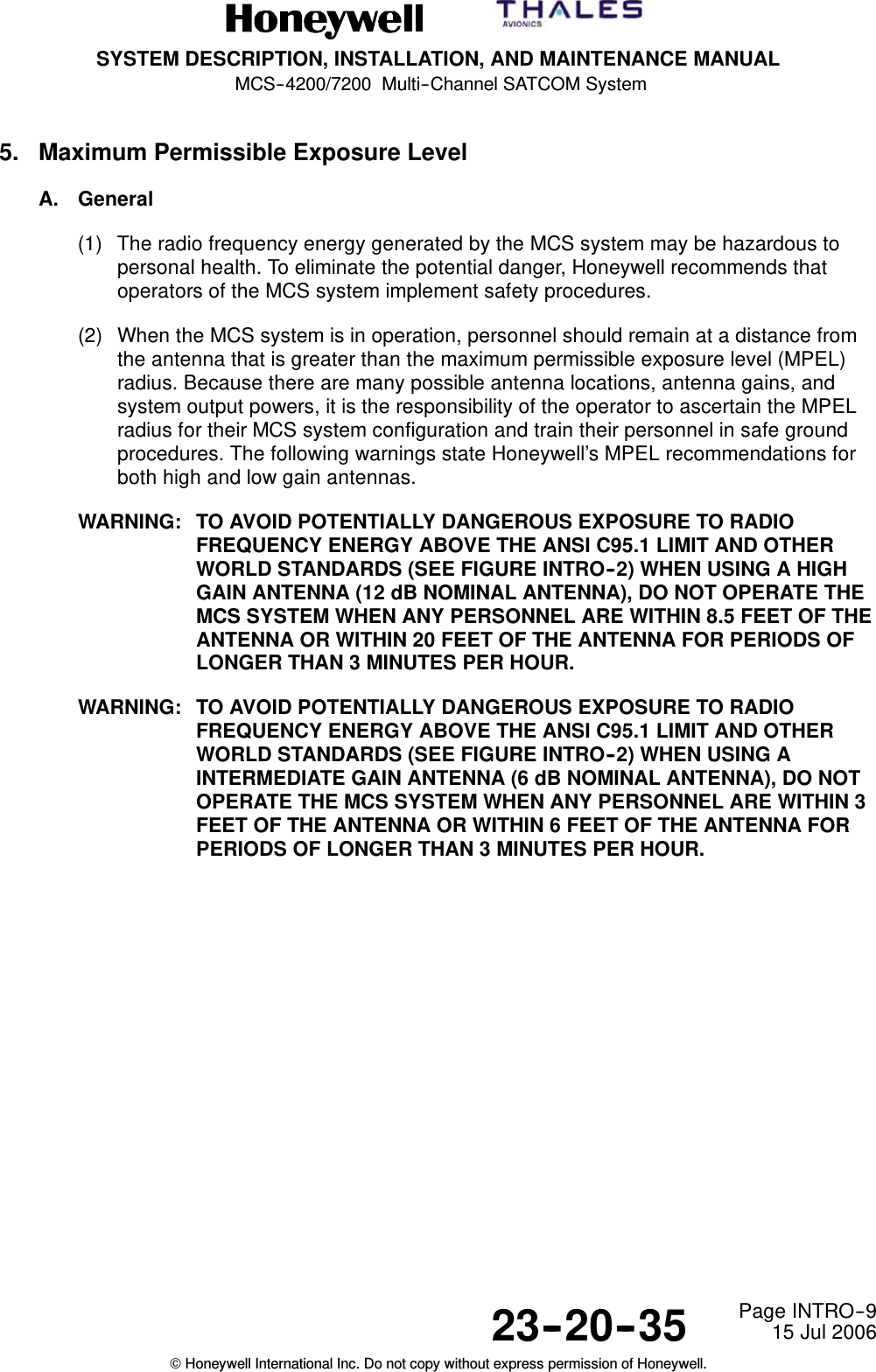
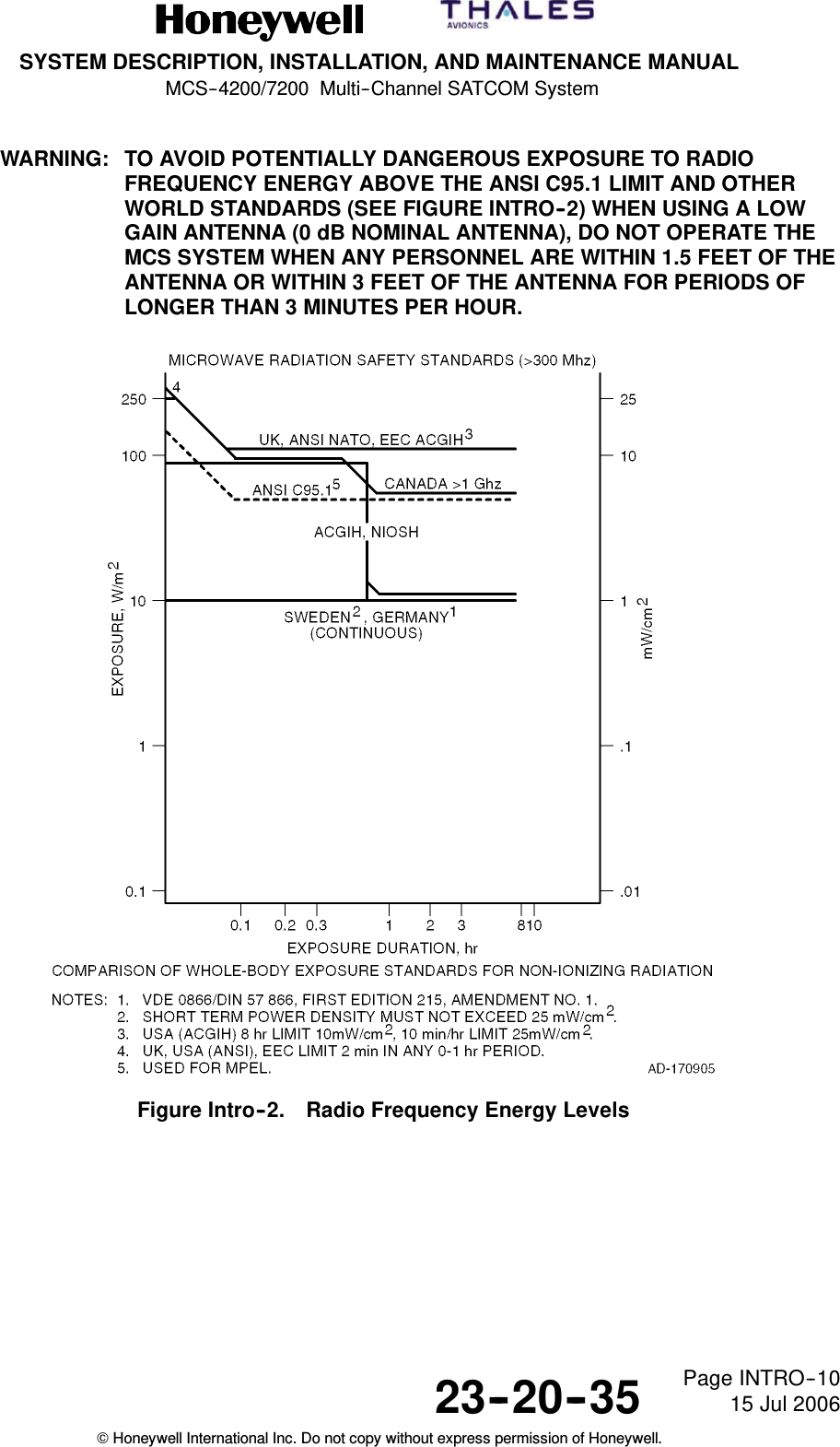
SYSTEM DESCRIPTION, INSTALLATION, AND MAINTENANCE MANUALMCS--4200/7200 Multi--Channel SATCOM System23--20--35 15 Jul 2006Honeywell International Inc. Do not copy without express permission of Honeywell.Page INTRO--95. Maximum Permissible Exposure LevelA. General(1) The radio frequency energy generated by the MCS system may be hazardous topersonal health. To eliminate the potential danger, Honeywell recommends thatoperators of the MCS system implement safety procedures.(2) When the MCS system is in operation, personnel should remain at a distance fromthe antenna that is greater than the maximum permissible exposure level (MPEL)radius. Because there are many possible antenna locations, antenna gains, andsystem output powers, it is the responsibility of the operator to ascertain the MPELradius for their MCS system configuration and train their personnel in safe groundprocedures. The following warnings state Honeywell’s MPEL recommendations forboth high and low gain antennas.WARNING: TO AVOID POTENTIALLY DANGEROUS EXPOSURE TO RADIOFREQUENCY ENERGY ABOVE THE ANSI C95.1 LIMIT AND OTHERWORLD STANDARDS (SEE FIGURE INTRO--2) WHEN USING A HIGHGAIN ANTENNA (12 dB NOMINAL ANTENNA), DO NOT OPERATE THEMCS SYSTEM WHEN ANY PERSONNEL ARE WITHIN 8.5 FEET OF THEANTENNA OR WITHIN 20 FEET OF THE ANTENNA FOR PERIODS OFLONGER THAN 3 MINUTES PER HOUR.WARNING: TO AVOID POTENTIALLY DANGEROUS EXPOSURE TO RADIOFREQUENCY ENERGY ABOVE THE ANSI C95.1 LIMIT AND OTHERWORLD STANDARDS (SEE FIGURE INTRO--2) WHEN USING AINTERMEDIATE GAIN ANTENNA (6 dB NOMINAL ANTENNA), DO NOTOPERATE THE MCS SYSTEM WHEN ANY PERSONNEL ARE WITHIN 3FEET OF THE ANTENNA OR WITHIN 6 FEET OF THE ANTENNA FORPERIODS OF LONGER THAN 3 MINUTES PER HOUR.
SYSTEM DESCRIPTION, INSTALLATION, AND MAINTENANCE MANUALMCS--4200/7200 Multi--Channel SATCOM System23--20--35 15 Jul 2006Honeywell International Inc. Do not copy without express permission of Honeywell.Page INTRO--10WARNING: TO AVOID POTENTIALLY DANGEROUS EXPOSURE TO RADIOFREQUENCY ENERGY ABOVE THE ANSI C95.1 LIMIT AND OTHERWORLD STANDARDS (SEE FIGURE INTRO--2) WHEN USING A LOWGAIN ANTENNA (0 dB NOMINAL ANTENNA), DO NOT OPERATE THEMCS SYSTEM WHEN ANY PERSONNEL ARE WITHIN 1.5 FEET OF THEANTENNA OR WITHIN 3 FEET OF THE ANTENNA FOR PERIODS OFLONGER THAN 3 MINUTES PER HOUR.Figure Intro--2. Radio Frequency Energy Levels
  SYSTEM DESCRIPTION, INSTALLATION, AND MAINTENANCE MANUAL MCS-4200/7200 TEMPORARY REVISION NO. 23-1 23-20-35  Page 8 of 5328 Sep 2009  © Honeywell International Inc. Do not copy without express permission of Honeywell.    INSERT PAGE 8 OF 53 FACING PAGE 1-1. Reason:  To change the text in Paragraphs (4) and (5) to add Classic Aero, to change the capitalization of INMARSAT to Inmarsat, and to delete text, as applicable.   Paragraphs (4) and (5) are changed as follows:                      (4)  The MCS-4200/7200 system provides seven Classic Aero communication channels capable of supporting six simultaneous full-duplex circuit mode voice connections and one channel of packet-mode data. In addition, the MCS-4200/7200 system provides multiple channels of Inmarsat Swift64 and SwiftBroadband functionality. This Swift capability is configurable to support four MISDN channels, four MPDS channels, or a mixture of each (when operating with Inmarsat-3 satellites); or a maximum of two SwiftBroadband channels when operating with Inmarsat-4 satellites.  (5)  The MCS-4200 system operates identically to the MCS-7200, except that it supports only four Classic Aero communication channels (including one packet-mode data channel) rather than the seven that are provided by the MCS-7200. The MCS system accommodates all four airborne categories of communications: •  ATC •  AOC •  AAC •  APC.
SYSTEM DESCRIPTION, INSTALLATION, AND MAINTENANCE MANUALMCS--4200/7200 Multi--Channel SATCOM System23--20--35 15 Jul 2006Honeywell International Inc. Do not copy without express permission of Honeywell.Page 1--1SECTION 1SYSTEM DESCRIPTION1. OverviewA. General(1) The MCS--4200/7200 MCS is an augmented version of the MCS--4000/7000 systemcurrently certified and in use today by hundreds of operators. The MCS--4200/7200 isa mobile avionics communications system that supplies continuous worldwide voiceand data communications services to and from the aircraft via satellite.(2) The MCS system interfaces at baseband with various avionics data equipment, aswell as with crew and passenger voice equipment onboard the aircraft. It alsoprovides narrowband connectivity to support data--intensive airborne userapplications. The MCS--4200/7200 system utilizes the antenna subsystem totransmit/receive L--band RF signals to/from satellites in geostationary orbit. Thesesatellites convey the information to and from ground stations that interface with theterrestrial telephone network.(3) The MCS system augments and/or supersedes the present HF transceiver bysupplying higher quality voice service and by supplying data services at higher bitrates needed by datalink ATN applications, such as ADS and the internationalACARS. Additional services include cockpit communications with administrative andoperational personnel and with governmental bodies such as ATS. The system isdesigned to make sure that communications involving safety and regularity of flightare not delayed by the transmission and reception of other message types.(4) The MCS--4200/7200 system provides seven baseband communication channelscapable of supporting six simultaneous full--duplex circuit mode voice connectionsand one channel of packet--mode data. In addition, the MCS--4200/7200 systemprovides multiple channels of INMARSAT Swift64 and SwiftBroadband functionality.This Swift capability is configurable to support four MISDN channels, four MPDSchannels, or a mixture of each. By late ’07 or early ’08, this functionality will beenhanced (with a software upgrade to the HSU and perhaps the SDU, combined witha system configuration strap change) to supply a maximum of two SwiftBroadbandchannels as well. This is subject to the constraint that the resources necessary tosupport one SwiftBroadband channel are reserved at the expense of two Swift64channels, and vice versa.(5) The MCS--4200 system operates identically to the MCS--7200, except that it supportsonly four baseband communication channels (including one packet--mode datachannel) rather than the seven that are provided by the MCS--7200. The MCSsystem accommodates all four airborne categories of communications:•ATC•AOC•AAC•APC.
SYSTEM DESCRIPTION, INSTALLATION, AND MAINTENANCE MANUALMCS--4200/7200 Multi--Channel SATCOM System23--20--35 15 Jul 2006Honeywell International Inc. Do not copy without express permission of Honeywell.Page 1--2(6) The four airborne communication categories are recognized by the ICAO and theITU, and are assigned priorities for communications purposes.(7) The total aviation satellite communications system, shown in Figure 1-1, is made upof the following:•Aircraft earth station (airborne avionics subsystems and antenna subsystem)•Space segment (satellite network)•Ground earth stations•Terrestrial data and voice networks.
  SYSTEM DESCRIPTION, INSTALLATION, AND MAINTENANCE MANUAL  MCS-4200/7200 TEMPORARY REVISION NO. 23-1 23-20-35  Page 9 of 5328 Sep 2009  © Honeywell International Inc. Do not copy without express permission of Honeywell.   INSERT PAGE 9 OF 53 FACING PAGE 1-3. Reason:  To add aircraft earth station (for Classic Aero), mobile earth station (for Swift64), and user equipment/user terminal (for SwiftBroadband) to Figure 1-1.  Replace Figure 1-1 with the revised illustration as follows:   Figure 1-1.  Aviation Satellite Communications System
SYSTEM DESCRIPTION, INSTALLATION, AND MAINTENANCE MANUALMCS--4200/7200 Multi--Channel SATCOM System23--20--35 15 Jul 2006Honeywell International Inc. Do not copy without express permission of Honeywell.Page 1--3Figure 1-1. Aviation Satellite Communications System
SYSTEM DESCRIPTION, INSTALLATION, AND MAINTENANCE MANUALMCS--4200/7200 Multi--Channel SATCOM System23--20--35 15 Jul 2006Honeywell International Inc. Do not copy without express permission of Honeywell.Page 1--4B. Aircraft Earth Station – General(1) General(a) The AES is fully compliant with requirements of ARINC Characteristics 741/761.Standard interfaces between the MCS--4200/7200 avionics and other aircraftavionics enables the AES to accept data and voice messages from varioussources, encode and modulate this information onto appropriate RF carrierfrequencies, and transmit these carriers to the space segment for relay to aGES. The AES also receives RF signals from a GES through the satellite,demodulates these signals, performs the necessary decoding of the encodedmessages, and outputs the data or voice message for use by the cockpit crew(pilot and copilot), the cabin crew or the passengers.(2) AES Components(a) General1A block diagram of the AES is shown in Figure 1--2. The AES is made up ofthe following components:•MCS SATCOM avionics•Antenna subsystem•Cabin communications system•Analog connected telephones•Cockpit voice sources•Aircraft avionics.(b) MCS Avionics1The MCS--4200/7200 avionics is made up of the SDU, the HSU and theHPA.2The SDU supplies the digital and analog interface to all aircraft avionics, andimplements all functionality associated with modulation/demodulation, errorcorrection, channel rate/frequency selection, and RF translation for thesystem’s seven baseband communication channels. The SDU’s sevenbaseband channels support six simultaneous full--duplex circuit--mode voiceconnections and one packet--mode channel.3The HSU incorporates the firmware necessary to support four narrowband(Swift64) channels, which provide simultaneous circuit--mode and/orpacket--mode connectivity concurrently with the SDU’s baseband channelsat rates of 64 kbps (per single channel) or 256 kbps (four combined [bondedISDN] channels). Ultimately, the HSU will be augmented – by softwareupgrade to the HSU, and perhaps the SDU, coupled with a systemconfiguration strap change – to support an additional two widebandchannels of 432 kbps (per single channel) SwiftBroadband functionality aswell. Note that when the HSU commits the resources necessary to support asingle SwiftBroadband channel, it simultaneously loses the capability toprovide two channels of Swift64 service (and vice versa).
  SYSTEM DESCRIPTION, INSTALLATION, AND MAINTENANCE MANUAL  MCS-4200/7200 TEMPORARY REVISION NO. 23-1 23-20-35  Page 10 of 5328 Sep 2009  © Honeywell International Inc. Do not copy without express permission of Honeywell.   INSERT PAGE 10 OF 53 FACING PAGE 1-4. Reason:  To update headings and text to include references to MES, UE, LES, SAS, and Classic Aero, as applicable, to Paragraphs B. (1) (a), B. (2) (a) 1, and B. (2) (b) 2 and 3.   The headings and text are changed as follows:  B.  Aircraft Earth Station/Mobile Earth Station/User Equipment – General (1) General (a)  The AES/MES/UE is fully compliant with requirements of ARINC Characteristics 741/761. Standard interfaces between the MCS-4200/7200 avionics and other aircraft avionics enable it to accept data and voice messages from various sources, encode and modulate this information onto appropriate RF carrier frequencies, and transmit these carriers to the space segment for relay to a GES/LES/SAS. The AES/MES/UE also receives RF signals from a GES/LES/SAS through the satellite, demodulates these signals, performs the necessary decoding of the encoded messages, and outputs the data or voice message for use by the cockpit crew (pilot and copilot), the cabin crew or the passengers.  (2) AES/MES/UE Components (a) General 1  A block diagram of the AES/MES/UE is shown in Figure 1-2. It is made up of the following components:  • MCS avionics        2  The SDU supplies the digital and analog interface to all aircraft avionics, and implements all functionality associated with modulation/demodulation, error correction, channel rate/frequency selection, and RF translation for the system’s seven baseband communication channels. The SDU’s seven Classic Aero channels support six simultaneous full-duplex circuit-mode voice connections and one packet-mode channel. 3  The HSU incorporates the firmware necessary to support four narrowband (Swift64) channels, which provide simultaneous circuit-mode and/or packet-mode connectivity concurrently with the SDU’s baseband channels at rates of 64 kbps (per single channel) or 256 kbps (four combined [bonded ISDN] or two channels of up to 432 kbps (per single channel) SwiftBroadband functionality. When operating through an Inmarsat-3 satellite and its GESs/LESs, Classic Aero and Swift64 services are possible; when operating through an Inmarsat-4 satellite and its GESs/SASs, Classic Aero and SwiftBroadband services are possible; i.e., only one type of Swift service is possible at any given time, depending on the type of satellite and ground station being used at any given time.
  SYSTEM DESCRIPTION, INSTALLATION, AND MAINTENANCE MANUAL  MCS-4200/7200 TEMPORARY REVISION NO. 23-1 23-20-35  Page 11 of 5328 Sep 2009  © Honeywell International Inc. Do not copy without express permission of Honeywell.   INSERT PAGE 11 OF 53 FACING PAGE 1-5. Reason:  To change the text in Paragraphs 6, 7, and 9 as applicable to the latest version of the system. Some text was deleted.  Replace the text in Paragraphs 6, 7, and 9 as follows:       6  The CMU or equivalent, route packet-data messages to and from the SDU. Cabin communications use either a CCS or an analog equivalent (cabin unit) to provide baseband voice telephone communication (including FAX and PC modem services). The HSU’s Swift64 and SwiftBroadband communication channels supporting data-intensive e-mail, web surfing, video-conferencing transmittals, and other data, are interfaced to the user by way of a server/router, which is part of the airborne network.  7  To permit operation of the MCS-4200/7200 system to be easily tailored around aircraft-specific and user-specific needs, the SDU incorporates an ORT. The ORT contains more than 100 configurable entries (each with a default value) that are individually designated as either a user or secure (that is, installation-specific) item, as well as either Airbus modifiable or Airbus non-modifiable. The ORT affects not only the operation of the conventional Aero channels but the HSU channel complement (that is, the four Swift64 channels or the two SwiftBroadband channels) as well.      9  The SDU/HSU combination supplies all essential services required to accommodate effective air/ground communications by way of satellite which use the antenna and related RF components for both the cockpit and cabin environments. The 60-Watt HPA assists in supporting multiple simultaneous channel communications by supplying linear power amplification to boost the RF signals associated with each channel to the levels required for transmission to the satellite.
SYSTEM DESCRIPTION, INSTALLATION, AND MAINTENANCE MANUALMCS--4200/7200 Multi--Channel SATCOM System23--20--35 15 Jul 2006Honeywell International Inc. Do not copy without express permission of Honeywell.Page 1--54The HPA implements the linear power amplification of the SDU’s and HSU’scombined RF signals needed to assure their successful transmission fromthe aircraft to the satellite and to the ground network.5A cockpit audio system conveys cockpit voice to and from the SDU.Messages requiring cockpit action or initiation appear on the appropriatecockpit display – RMP -- for the A380 -- or MCDU for all other platforms, withthe correct protocol selected by the SDU based on data present on thedisplay buses and/or other cockpit annunciators.6The CMU or equivalent, route packet--data messages to and from the SDU.Cabin communications use either a CCS or an analog equivalent (cabin unit)to provide baseband voice telephone communication (including FAX and PCmodem services). The HSU’s narrowband Swift64 and SwiftBroadbandcommunication channels supporting data--intensive e--mail, web surfing,video--conferencing transmittal, and other data, are interfaced to the user byway of a server/router, which is part of the airborne network.7To permit operation of the MCS--4200/7200 system to be easily tailoredaround aircraft--specific and user--specific needs, the SDU incorporates anORT. The ORT contains more than 60 configurable entries (each with adefault value) that is individually designated as either a user or secure (thatis, installation--specific) item. The ORT affects not only the operation of theconventional Aero channels but the HSU channel complement (that is, thefour Swift64 channels initially, and the two additional SwiftBroadbandchannels ultimately) as well.8The ORT is subject to configuration management to the extent that theORT’s version number is incremented whenever significant changes to thedatabase occur (for example, introduction of SwiftBroadband items). Oncemade, the ORT selections are preserved by the SDU across power and testcycles in non--volatile memory. In addition, the ORT is able to bedownloaded from or uploaded to the SDU from an external file storagemedium (such as diskettes) which serve as the file destination or file source,respectively.9The SDU/HSU combination supplies all essential services required toaccommodate effective air/ground communications by way of satellite whichuse the antenna and related RF components for both the cockpit and cabinenvironments. The 60--Watt HPA assists in supporting multiple simultaneousbaseband and narrowband (Swift64) channel communications by supplyinglinear power amplification to boost the RF signals associated with eachchannel to the levels required for transmission to the satellite.10 The extensive variety of functionality that is afforded by the MCS--4200/7200system results largely from the software direction of the hardware operation.The SDU’s hardware platform uses the MCS--4000/7000 designs, which arealready certified on various other aircraft, as the baseline.
SYSTEM DESCRIPTION, INSTALLATION, AND MAINTENANCE MANUALMCS--4200/7200 Multi--Channel SATCOM System23--20--35 15 Jul 2006Honeywell International Inc. Do not copy without express permission of Honeywell.Page 1--611 These proven platforms provide a solid structure on which theMCS--4200/7200 SATCOM enhancements (both hardware and software) arebeing built. The software that drives the MCS--4200/7200 system operationis DO--178B Level D for the SDU and HPA from their first release intoproduction. However, the initial (that is, Swift64--only) HSU will migrate toDO--178B Level D from Level E when its capabilities are upgraded tosupport full SwiftBroadband functionality.
  SYSTEM DESCRIPTION, INSTALLATION, AND MAINTENANCE MANUAL MCS-4200/7200 TEMPORARY REVISION NO. 23-1 23-20-35  Page 12 of 5328 Sep 2009  © Honeywell International Inc. Do not copy without express permission of Honeywell.    INSERT PAGE 12 OF 53 FACING PAGE 1-6. Reason:  To change the text in Paragraph 11 as applicable to the latest version of the system. Some text was deleted.  Replace the text in Paragraph 11 as follows:   11  These proven platforms provide a solid structure on which the MCS-4200/7200 SATCOM enhancements (both hardware and software) are built. The software that drives the MCS-4200/7200 system operation is DO-178B Level D for the SDU and HPA from their first release into production. However, the HSU is DO-178B Level E.
  SYSTEM DESCRIPTION, INSTALLATION, AND MAINTENANCE MANUAL  MCS-4200/7200 TEMPORARY REVISION NO. 23-1  23-20-35 Page 13 of 5328 Sep 2009  © Honeywell International Inc. Do not copy without express permission of Honeywell.  INSERT PAGE 13 OF 53 FACING PAGE 1-7/1-8. Reason:  To change Figure 1-2 to change the text of Note 1 and to add new Note 3 and Note 4.  Replace Figure 1-2 with the illustration that follows:    Figure 1-2. Aircraft Earth Station Block Diagram
SYSTEM DESCRIPTION, INSTALLATION, AND MAINTENANCE MANUALMCS--4200/7200 Multi--Channel SATCOM System23--20--35 15 Jul 2006Honeywell International Inc. Do not copy without express permission of Honeywell.Page 1--7/1--8Figure 1-2. Aircraft Earth Station Block Diagram
  SYSTEM DESCRIPTION, INSTALLATION, AND MAINTENANCE MANUAL  MCS-4200/7200 TEMPORARY REVISION NO. 23-123-20-35  Page 14 of 5328 Sep 2009Publication Number A15-5111-010 © Honeywell International Inc. Do not copy without express permission of Honeywell.   INSERT PAGE 14 OF 53 FACING PAGE 1-9. Reason:  To change INMARSAT to show initial capitalization only in Paragraph 13 and Paragraph (c) 1. To change text in Paragraphs (c) 1, 2, and 3 as applicable to add references to MES, UE, LES, SAS, ACU, Classic Aero, and additional data about SwiftBroadband operations.  Paragraph 13 and Paragraphs (c) 1, 2, and 3 are changed as follows:            13  In those applications for which the Swift64/SwiftBroadband capability is not required, an additional LRU may be necessary; this is the RFUIA. The RFUIA is used in place of the RFU in a conventional ARINC 741 system, and replaces the HSU in those installations which utilize only the MCS-4200/7200 SATCOM system’s classic Inmarsat baseband features.    1  The primary function of the antenna subsystem is to complete the communication link between the GES/LES/SAS, the space segment, and the AES/MES/UE. The D/LNA is a three-port RF device (antenna, transmit, and receive) which provides signal routing and filtering – signals in the receive band are routed from the antenna port to the receive port, and transmit signals are routed from the transmit port to the antenna port. The LNA establishes the noise floor of the communication system’s receiver by boosting the signals received from the antenna to the maximum level relative to the noise received with the signals, as well as the noise developed by the LNA itself. For SwiftBroadband operations, the D/LNA must be a Type F (or later type approved for SwiftBroadband operation). Also, the selected antenna must be an Inmarsat-approved type for SwiftBroadband operation. 2  The HGA transmits L-band RF signals from the HPA to a satellite, and receives L-band RF signals from a satellite for the SDU and HSU. When installed, the LGA supplies backup communications (packet-data only) for the HGA by providing low-rate, Classic Aero (only) packet-data communication services. 3  The BSU or ACU is used in the HGA system to convert tracking and pointing coordinates (that is, aircraft-relative azimuth and elevation) from the SDU into signals needed to select the antenna array elements in combinations that point the antenna beam in the desired direction towards the satellite.
SYSTEM DESCRIPTION, INSTALLATION, AND MAINTENANCE MANUALMCS--4200/7200 Multi--Channel SATCOM System23--20--35 15 Jul 2006Honeywell International Inc. Do not copy without express permission of Honeywell.Page 1--912 The MCS--4200/7200 system LRUs (building on their legacyMCS--4000/7000 background) maintains extensive logs of information that isuseful in the monitoring of normal system activity as well as identifying anyfailure conditions experienced during operation, whether in flight or on theground. This is accomplished through a combination of self--test suites thatare performed at POST or as the result of PAST, as well as by CM. Themaintenance logs are continuously updated, and accessible for downloadusing the ARINC 615 ADL and PDL.13 In those applications for which the Swift64/SwiftBroadband capability is notrequired, an additional LRU may be necessary; this is the RFUIA. TheRFUIA is used in place of the RFU in a conventional ARINC 741 system,and replaces the HSU in those installations which utilize only theMCS--4200/7200 SATCOM system’s classic INMARSAT baseband features.(c) Antenna Subsystem1The primary function of the antenna subsystem is to complete thecommunication link between the GES, the space segment, and the AES.The D/LNA is a three-port RF device (antenna, transmit, and receive) whichprovides signal routing and filtering -- signals in the receive band are routedfrom the antenna port to the receive port, and transmit signals are routedfrom the transmit port to the antenna port. The LNA establishes the noisefloor of the communication system’s receiver by boosting the signalsreceived from the antenna to the maximum level relative to the noisereceived with the signals, as well as the noise developed by the LNA itself.2The HGA transmits L--band RF signals from the HPA to a satellite, andreceives L--band RF signals from a satellite for the SDU and HSU. Wheninstalled, the LGA supplies backup communications (packet--data only) forthe HGA by providing low--rate, packet--data communication services.3The BSU is used in the HGA system to convert tracking and pointingcoordinates (that is, aircraft--relative azimuth and elevation) from the SDUinto signals needed to select the antenna array elements in combinationsthat point the antenna beam in the desired direction towards the satellite.(d) CCS1The CCS, in conjunction with the MCS avionics and a worldwide network ofground stations, supplies cabin services such as baseband telephone,facsimile, and PC modem communication interfaces. The CCS is partitionedinto two sections: the CTU and cabin/passenger communications equipment(digitally connected telephones).
SYSTEM DESCRIPTION, INSTALLATION, AND MAINTENANCE MANUALMCS--4200/7200 Multi--Channel SATCOM System23--20--35 15 Jul 2006Honeywell International Inc. Do not copy without express permission of Honeywell.Page 1--102The CTU performs onboard PABX telephony functions, letting the digitallyconnected telephones make the best use of resources supplied by the MCSavionics. The ARINC 746 CTU supplies the conversion interface betweenthe digitally connected phones and the ARINC 741/761 SDU, and connectsto the SDU by means of a high-speed serial bus pair (CEPT--E1) thataccommodates up to 30 digitized voice channels along with status andcontrol information.3The digitally connected phones (handsets) are primarily supplied forpassenger use and can be located throughout the aircraft. The digitalhandsets interface indirectly to the satellite communications equipment andare controlled by the CCS.(e) Airborne Server1The airborne server provides the means by which data streams from multiplecabin (or other) users are collected and processed into formats suitable forassignment onto the HSU’s narrowband or wideband channels. The HSUinterfaces with the airborne server by way of two Ethernet 10BaseT ports forMPDS/SwiftBroadband and MISDN service, and by way of two ISDN portsfor MISDN service.2When using the Ethernet port for either MISDN or MPDS services, PPPoEprotocol is used to choose the service and to give to the HSU all theparameters needed to access the correct ground service provider for theservice chosen.3A configuration discrete is used to configure the Ethernet ports so that allSwift64 channels use only one Ethernet port or both Ethernet ports.(f) Analog Connected Telephones1The SDU is provisioned to support two simultaneous analog audio channelswhich use any four--wire analog telephone (such as, Global--WulfsbergFlitephone WH--10 handsets) by way of the APBX. The WH--10 is astandalone handset with a 12--button keypad. The APBX has analog trunklines and in--line DTMF signaling.(g) Cockpit Voice Sources1The SDU supports headset interfaces for cockpit use only. These interfacesincorporate off--hook/on--hook signaling and dialing through the combinationof a control and display unit (either by the way of the MCDU or RMP), andPTT or similar switches. When the PTT switch is pushed, a microphoneaudio signal is sent to the selected voice channel and a discrete signal issent to the SDU. An audible chime combined with lit or flashing call lampsannounces call connections.
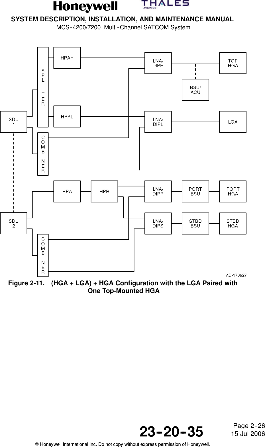
  SYSTEM DESCRIPTION, INSTALLATION, AND MAINTENANCE MANUAL  MCS-4200/7200 TEMPORARY REVISION NO. 23-1 23-20-35  Page 15 of 5328 Sep 2009  © Honeywell International Inc. Do not copy without express permission of Honeywell.   INSERT PAGE 15 OF 53 FACING PAGE 1-10. Reason:  To change the text in Paragraphs (e) 1, 2, and 3 and (f) 1 to add references to SwiftBroadband and to make other changes to the text as applicable. Some text was deleted.  Replace the text in Paragraphs (e) 1, 2, and 3 and (f) 1 as follows:     1  The airborne server provides the means by which data streams from multiple cabin (or other) users are collected and processed into formats suitable for assignment onto the HSU’s narrowband or wideband channels. The HSU interfaces with the airborne server by way of two Ethernet 10BaseT ports for MPDS, SwiftBroadband, and MISDN service, and by way of two ISDN ports for MISDN and SwiftBroadband service. 2  When using the Ethernet port for either SwiftBroadband, MISDN or MPDS services, PPPoE along with an SNMP-based ARINC MIB (in accordance with ARINC 781 Attachment 5) protocol is used to choose the service and to give to the HSU all the parameters needed to access the correct ground service provider for the service chosen. 3  A configuration discrete is used to configure the Ethernet ports so that all Swift64/SwiftBroadband channels use only one Ethernet port or both Ethernet ports.    1  The SDU is provisioned to support two simultaneous analog audio channels which use four-wire analog telephone interfaces such as Global-Wulfsberg Flitephone WH-10 handsets or an analog PBX (APBX). The WH-10 is a standalone handset with a 12-button keypad that utilizes discretes for call signaling functions. The APBX has analog trunk lines and in-line DTMF signaling.
  SYSTEM DESCRIPTION, INSTALLATION, AND MAINTENANCE MANUAL  MCS-4200/7200 TEMPORARY REVISION NO. 23-1 23-20-35  Page 16 of 5328 Sep 2009  © Honeywell International Inc. Do not copy without express permission of Honeywell.   INSERT PAGE 16 OF 53 FACING PAGE 1-11. Reason:  To change the text in Paragraphs (h) 1 (bullet 4 and bullet 7) to add a reference to GNSS and Swift64 operation, as applicable.  Replace the text in Paragraphs (h) 1 (bullet 4 and bullet 7) as follows:          •  The IRS and GNSS (GPS), where installed, to supply the SDU with navigation coordinates for positioning the antenna platform            •  The 24-bit ICAO address identifies the aircraft in which the SDU is installed. Address pins identified to take on the binary one state must be left open. Address pins identified to take on the binary zero state must be wired to address common on the airframe side of the connector. ARINC 429 interface options for the ICAO address are also supplied. Similar configuration pins on the HSU identify a 24-bit Forward ID for similar addressing purposes for Swift64 operation. Similar addressing and other functionality are handled for SwiftBroadband operations by the SIM cards in the HSU's HDM.
SYSTEM DESCRIPTION, INSTALLATION, AND MAINTENANCE MANUALMCS--4200/7200 Multi--Channel SATCOM System23--20--35 15 Jul 2006Honeywell International Inc. Do not copy without express permission of Honeywell.Page 1--11(h) Aircraft Avionics1Standard interfaces between the MCS--4200/7200 avionics and the otheraircraft avionics include the following:•CMU, or the MU of the ACARS, where installed•SCDU, implemented as either MCDUs or RMPs, where installed, tosupply an interface to the MCS system for system log--on, GES selection,cockpit voice call setup, data loading, and to access the SATCOMmaintenance pages including fault messages•CFDS, CMC, or OMS, where installed, for fault reporting•The IRS, where installed, to supply the SDU with navigation coordinatesfor positioning the antenna platform•Channels are also supplied for voice and data communication with ATCto support departure clearances by datalink, as well as ADS fornon--radar position reporting in oceanic regions•There is an ARINC 615 ADL or PDL for uploading operational softwareand the ORT. Connections are made through the front and back panelconnectors on the MCS avionics LRUs•The 24--bit ICAO address identifies the aircraft in which the SDU isinstalled. Address pins identified to take on the binary one state must beleft open. Address pins identified to take on the binary zero state must bewired to address common on the airframe side of the connector. ARINC429 interface options for the ICAO address are also supplied.(3) AES Classifications(a) Each AES is classified according to the configuration and dynamic capabilities ofits aircraft avionics baseband communications capability and antennasubsystem. Accordingly, an AES can be fitted with any combination of theclasses of installations given in Table 1-1.Table 1-1. Classes of InstallationsClass Description1A Class 1 AES installation uses a low gain antenna only and supplies low ratepacket--mode data services only.2A Class 2 AES installation uses a high gain antenna or intermediate gain antenna,and supplies telephony and optional circuit--mode services.3A Class 3 AES installation uses a high gain antenna or intermediate gain antenna,and supplies telephony services, packet--mode data services, and optionalcircuit--mode data services.4A Class 4 AES installation uses a high gain antenna or intermediate gain antenna,and supplies packet--mode data services only.
SYSTEM DESCRIPTION, INSTALLATION, AND MAINTENANCE MANUALMCS--4200/7200 Multi--Channel SATCOM System23--20--35 15 Jul 2006Honeywell International Inc. Do not copy without express permission of Honeywell.Page 1--12(4) GES Communication Links(a) The MCS--4200/7200 avionics supply access to ground--based networks throughthe GES for baseband communications. Each GES supplies systemsynchronization and coordination through ground--to--aircraft transmissions. Fourtypes of RF channels supporting baseband communications are defined for usewith the MCS--4200/7200 avionics as listed in Table 1-2.Table 1-2. Types of Baseband RF ChannelsRF Channel DescriptionP--Channel Packet--mode TDM channel used in the forward(outbound) direction (ground--to--aircraft) to carrysignaling and packet--mode data. The transmissionis continuous from each GES in the satellite network.R--Channel Random access (slotted Aloha) channel used in thereturn (inbound) direction (aircraft--to--ground) tocarry signaling and packet--mode data, specificallythe initial signals of a transaction (typically requestsignals).T--Channel Reservation TDMA channel used in the returndirection only. The receiving GES reserves time slotsfor transmissions requested by an AES according tomessage length. The sending AES transmits themessages in the reserved time slots.C--Channel Circuit--mode SCPC channel used in both forwardand return directions to carry digital voice ordata/facsimile traffic. The use of the channel iscontrolled by assignment and release signaling atthe start and end of each call or FAX transmission.
  SYSTEM DESCRIPTION, INSTALLATION, AND MAINTENANCE MANUAL  MCS-4200/7200 TEMPORARY REVISION NO. 23-1 23-20-35  Page 17 of 5328 Sep 2009  © Honeywell International Inc. Do not copy without express permission of Honeywell.   INSERT PAGE 17 OF 53 FACING PAGE 1-12. Reason:  To change the text in Paragraph (4) (a) to add a reference to Classic Aero and to delete text, as applicable.  Replace the text in Paragraph (4) (a) as follows:   (a)  The MCS-4200/7200 avionics supply access to ground-based networks through the GES for Classic Aero communications. Each GES supplies system synchronization and coordination through ground-to-aircraft transmissions. Four types of RF channels supporting baseband communications are defined for use with the MCS-4200/7200 avionics as listed in Table 1-2.
  SYSTEM DESCRIPTION, INSTALLATION, AND MAINTENANCE MANUAL  MCS-4200/7200 TEMPORARY REVISION NO. 23-1 23-20-35  Page 18 of 5328 Sep 2009  © Honeywell International Inc. Do not copy without express permission of Honeywell.   INSERT PAGE 18 OF 53 FACING PAGE 1-13. Reason:  To change the art in Figure 1-3 to show seven regions instead of four and to change INMARSAT in the figure title to show initial capitalization only.  Figure 1-3 and the title of Figure 1-3 are changed as follows:     Figure 1-3. Inmarsat Seven-Region Satellite Coverage
SYSTEM DESCRIPTION, INSTALLATION, AND MAINTENANCE MANUALMCS--4200/7200 Multi--Channel SATCOM System23--20--35 15 Jul 2006Honeywell International Inc. Do not copy without express permission of Honeywell.Page 1--13Figure 1-3. INMARSAT Four-Region Satellite Coverage
SYSTEM DESCRIPTION, INSTALLATION, AND MAINTENANCE MANUALMCS--4200/7200 Multi--Channel SATCOM System23--20--35 15 Jul 2006Honeywell International Inc. Do not copy without express permission of Honeywell.Page 1--14C. Space Segment(1) The space segment is made up of satellites placed in geostationary orbits thatsupport air-to-ground/ground-to-air packet-switched data services andcircuit-switched telephony communications on both baseband and narrowbandchannels all of which use worldwide standardized conventions and capabilities. Thesatellites function as communication transponders to support L-band links to andfrom the aircraft, and supply links to and from ground earth stations. The spacesegment supplier for airline aeronautical satellite communications is the INMARSAT,whose system provides near--worldwide coverage (that is, some problems may beencountered when the aircraft flies in Polar Regions with a latitude greater than 75degrees). The four-region satellite system supplied by INMARSAT is shown inFigure 1-3.D. Ground Earth Station/Land Earth Station(1) Each GES (and LES for Swift64) has the necessary equipment to communicate bothwith terrestrial networks and through satellites with the aircraft. The ground earthstations/land earth stations are designed to supply the airline customer with a diverserouting of national and international voice and data communications throughsubmarine cable, satellite, and microwave links to all destinations. Automatic trafficmanagement systems ensure efficient routing of communications by using optimumlinks into PSTN and avoiding multiple satellite connections whenever possible.(2) Ground earth stations/land earth stations are located strategically around the globe tosupply redundancy and diversity in the terrestrial extension of communications.Aircraft are connected to a GES or LES through an in-view satellite depending on theservice preference settings encoded in the SDU ORT.E. Terrestrial Data and Voice Networks(1) Baseband data and voice services available through satellites and ground earthstations include 9.6 and 4.8 kilobit/second (kbps) digital voice, 4.8 and 2.4 kbps FAX,2.4 kbps PC modem data, and packet-mode data at RF channel rates ranging from600 bit/second (bps) up to 10.5 kbps. Narrowband data services currently availablethrough satellites and land earth stations include 64 kbps circuit-switched ISDNchannels and 64 kbps packet--switched MPDS channels, either of which can becombined to afford the user higher data rate throughput (for example, up to 256kbps). By mid to late ’07, SwiftBroadband channels are planned to be available tosupport wideband packet--data services at rates up to 432 kbps per channel. Thepresent worldwide complement of ground earth stations providing support forbaseband services, and land earth stations providing support for narrowbandservices (including location, operator, and coverage region) are summarized inTable 1-3 and Table 1-4. Aeronautical communications through the INMARSATsatellites are transmitted to and from the terrestrial phone, and data networks throughthese ground earth stations and land earth stations. The satellite regions that servicethese ground earth stations/land earth stations are shown in Figure 1--3.
  SYSTEM DESCRIPTION, INSTALLATION, AND MAINTENANCE MANUAL  MCS-4200/7200 TEMPORARY REVISION NO. 23-1 23-20-35  Page 19 of 5328 Sep 2009  © Honeywell International Inc. Do not copy without express permission of Honeywell.   INSERT PAGE 19 OF 53 FACING PAGE 1-14. Reason:  To change Subhead D. and the text in Paragraphs C. (1), D. (1) and (2), and E. (1) as applicable to the latest version of the system; some text was deleted and INMARSAT was changed to show initial capitalization only.   Replace Subhead D. and Paragraphs C. (1), D. (1) and (2), and E. (1) as follows:   (1)  The space segment is made up of satellites placed in geostationary orbits that support air-to-ground/ground-to-air packet-switched data services and circuit-switched telephony communications on both baseband and narrowband channels all of which use worldwide standardized conventions and capabilities. The satellites function as communication transponders to support L-band links to and from the aircraft, and supply links to and from ground earth stations. The space segment supplier for airline aeronautical satellite communications is the Inmarsat, whose system provides near-worldwide coverage (that is, some problems may be encountered when the aircraft flies in Polar Regions with a latitude greater than 75 degrees). The seven-region satellite system (which includes four-each Inmarsat-3 satellites and three-each Inmarsat-4 satellites) is shown in Figure 1-3. An eighth region (not shown in Figure 1-3) is the single-functional MTSAT satellite (which consists of two satellites, one of which is a hot spare). D.  Ground Earth Station/Land Earth Station/Satellite Base Station (1)  Each GES/LES/SAS has the necessary equipment to communicate both with terrestrial networks and through satellites with the aircraft. The ground stations are designed to supply the airline customer with a diverse routing of national and international voice and data communications through submarine cable, satellite, and microwave links to all destinations. Automatic traffic management systems ensure efficient routing of communications by using optimum links into PSTN and avoiding multiple satellite connections whenever possible.  (2)  Ground stations are located strategically around the globe to supply redundancy and diversity in the terrestrial extension of communications. Aircraft are connected to one or more ground stations through an in-view satellite depending on the service preference settings encoded in the SDU ORT.   (1)  Classic Aero data and voice services available through satellites and ground earth stations include 9.6 and 4.8 kilobit/second (kbps) digital voice, 4.8 and 2.4 kbps FAX, 2.4 kbps PC modem data, and packet-mode data at RF channel rates ranging from 600 bit/second (bps) up to 10.5 kbps. Swift64 circuit- and packet-mode data services currently available through satellites and land earth stations include 64 kbps circuit-switched ISDN channels and 64 kbps packet-switched MPDS channels, either of which can be combined to afford the user higher data rate throughput (for example, up to 256 kbps). SwiftBroadband channels support circuit- and packet-data services at rates up to 432 kbps per channel. The present worldwide complement of ground stations are summarized in Table 1-3 and Table 1-4. Aeronautical communications through the Inmarsat satellites are transmitted to and from the terrestrial phone, and data networks through these ground earth stations and land earth stations. The satellite regions that service these ground stations are shown in Figure 1-3.
  SYSTEM DESCRIPTION, INSTALLATION, AND MAINTENANCE MANUAL  MCS-4200/7200 TEMPORARY REVISION NO. 23-1 23-20-35  Page 20 of 5328 Sep 2009  © Honeywell International Inc. Do not copy without express permission of Honeywell.   INSERT PAGE 20 OF 53 FACING PAGE 1-15. Reason:  To update Table 1-3 and Table 1-4 with the latest data and to delete the Service Provider column in Table 1-3.  Replace Table 1-3 and update Table 1-4, Row 3 and Row 4, the LES code for Xantic, as follows:  Table 1-3.  Ground Earth Stations for Aero H/H+ Services GES ID  SAT ID  GES Name 002 005 103 000 (I3 AOR-W) 000 (I3 AOR-W) 000 (I3 AOR-W) Eik Aussaguel Aussaguel 104 120 161 001 (I3 AOR-E) 005 (I4 APAC) 004 (MTSAT) Eik Paumalu Kobe/Hitachiota 202 205 220 002 (I3 POR) 002 (I3 POR) 006 (I4 EMEA) Santa Paula Perth Fucino 301 305 320 003 (I3 IOR) 003 (I3 IOR) 007 (I4 AMER) Eik Perth Paumalu   Table 1-4.  Land Earth Stations for Aero Swift64 Services LES Code  SAT ID  Service Provider 001 002 012 000 (AOR-W) 000 000 Telenor Stratos Xantic 001 002 012 001 (AOR-E) 001 001 Telenor Stratos Xantic 001 002 012 002 (POR) 002 002 Telenor Stratos Xantic 001 002 012 003 (IOR) 003 003 Telenor Stratos Xantic
SYSTEM DESCRIPTION, INSTALLATION, AND MAINTENANCE MANUALMCS--4200/7200 Multi--Channel SATCOM System23--20--35 15 Jul 2006Honeywell International Inc. Do not copy without express permission of Honeywell.Page 1--15Table 1-3. Ground Earth Stations for Aero H/H+ ServicesGES Name GES ID SAT ID Service ProviderGoonhilly--AW 001 000 (AOR--W) StratosSouthbury--AW 002 000 TelenorAussaguel--AW 005 000 SITAGoonhilly--AE 101 001 (AOR--E) StratosAussaguel--AE 103 001 SITAEik--AE 104 001 TelenorSentosa--P 201 002 (POR) StratosSanta Paula--P 202 002 TelenorYamaguchi--P 203 002 KDDPerth--P 205 002 SITAEik--I 301 003 (IOR) TelenorPerth--I 305 003 SITAYamaguchi--I 306 003 KDDSentosa--I 310 003 StratosTable 1-4. Land Earth Stations for Aero Swift64 ServicesLES Code SAT ID Service Provider001 000 (AOR--W) Telenor002 000 Stratos012 000 Xantic001 001 (AOR--E) Telenor002 001 Stratos012 001 Xantic001 002 (POR) Telenor002 002 Stratos022 002 Xantic001 003 (IOR) Telenor002 003 Stratos022 003 Xantic
SYSTEM DESCRIPTION, INSTALLATION, AND MAINTENANCE MANUALMCS--4200/7200 Multi--Channel SATCOM System23--20--35 15 Jul 2006Honeywell International Inc. Do not copy without express permission of Honeywell.Page 1--162. System ComponentsA. General(1) The MCS--4200/7200 system avionics consists of the following components:•SDU•HSU•HPA.(2) These components are compatible with ARINC Characteristics 741 and 761.Table 1-5 lists the MCS--4200/7200 system components to be supplied byHoneywell/Thales. Table 1-6 lists the MCS--4200/7200 system components notsupplied by Honeywell/Thales. Table 1-7, Table 1-8, Table 1-9, and Table 1-10 listsystem component configuration information.Table 1-5. System Components Supplied by Honeywell/ThalesComponent Model No. Honeywell Part No. 1Satellite Data Unit (SDU) SD--720 7516118--xxyyyHigh Speed Data Unit (HSU) HS--720 7520061--xxyyyHigh Power Amplifier (60 W) (HPA) HP--720 7520000--xxyyyRadio Frequency Unit Interface Adapter (RFUIA) 2RF--700 7516222--901NOTES:1. The five--digit dash number corresponds to the hardware/software version of the unit where the first two digitscorrespond to the hardware version and the last three digits correspond to the software version.2. The RFUIA is installed in place of the HSU to eliminate wiring changes in aircraft provisioned for the HSU’spresence.Table 1-6. System Components Not Supplied by HoneywellComponent CommentsSDU Installation Equipment (See Note) ARINC 600 6--MCU tray, cables, connectors,assemblies, mounting hardware, and kitsHSU Installation Equipment (See Note) ARINC 600 4--MCU tray, cables, connectors,assemblies, mounting hardware, and kitsHPA (60 W) Installation Equipment (See Note) ARINC 600 8--MCU tray, cables, connectors,assemblies, mounting hardware, and kitsRFUIA Installation Equipment (See Note) ARINC 600 4--MCU tray, cables, connectors,assemblies, mounting hardware, and kitsHigh Gain Antenna Equipment CMC Electronics - Canada,Chelton Inc - USA,Tecom - USA, Thales--UK, EMS -- CanadaNOTE: Installation of this equipment is dependent on the specific requirements of the operator and will involveinteraction with suppliers of this equipment (such as, ECS, EMTEQ)
  SYSTEM DESCRIPTION, INSTALLATION, AND MAINTENANCE MANUAL  MCS-4200/7200 TEMPORARY REVISION NO. 23-1  23-20-35  Page 22 of 5328 Sep 2009  © Honeywell International Inc. Do not copy without express permission of Honeywell.  Table 1-8A.  HDM Configuration HDM Part Number  Description 7520033-901 HDM (all platforms)
  SYSTEM DESCRIPTION, INSTALLATION, AND MAINTENANCE MANUAL  MCS-4200/7200 TEMPORARY REVISION NO. 23-1 23-20-35  Page 21 of 5328 Sep 2009  © Honeywell International Inc. Do not copy without express permission of Honeywell.   INSERT PAGE 21 OF 53 THRU PAGE 22 OF 53 FACING PAGE 1-17. Reason:  To update Table 1-7 to replace baseband with Classic Aero and add part numbers and descriptions applicable to the SwiftBroadband SDU. To update Table 1-8 to replace narrowband with Swift64 and add one new part number and description applicable to both Swift64 and SwiftBroadband. To add a new Table 1-8A to incorporate the HDM configuration.  Table 1-7 and Table 1-8 are changed and Table 1-8A is added as follows:  Table 1-7.  SDU Configurations SDU Part Number  Description 7516118-24130  115 V ac/320-800 Hz, or 28 V dc , 4-channel Classic Aero (3 voice, 1 data) SDU for Boeing corporate and military applications 7516118-27130  115 V ac/320-800 Hz, or 28 V dc 7-channel Classic Aero (6 voice, 1 data) SDU for Boeing corporate and military applications 7516118-24140  115 V ac/320-800 Hz, or 28 V dc 4-channel Classic Aero (3 voice, 1 data) SDU for Airbus applications 7516118-27140  115 V ac/320-800 Hz, or 28 V dc 7-channel Classic Aero (6 voice, 1 data) SDU for Airbus applications 7516118-27150  SwiftBroadband SDU for Airbus Long Range 7516118-27145  SwiftBroadband SDU for Airbus A380 7516118-24145  SwiftBroadband SDU for Airbus A380 7516118-27135  SwiftBroadband SDU for all non-Airbus, including Boeing [particularly 777] and biz jets 7516118-24135  SwiftBroadband SDU for all non-Airbus, including Boeing and biz jets  Table 1-8.  HSU Configurations HSU Part Number  Description 7520061-34010  115 V ac/320-800 Hz, or 28 V dc 4-channel Swift64 HSU for all applications 7520061-34015  115 V ac/320-800 Hz, or 28 V dc 4-channel Swift64 and SwiftBroadband HSU for all applications
SYSTEM DESCRIPTION, INSTALLATION, AND MAINTENANCE MANUALMCS--4200/7200 Multi--Channel SATCOM System23--20--35 15 Jul 2006Honeywell International Inc. Do not copy without express permission of Honeywell.Page 1--17Table 1-7. SDU ConfigurationsSDU Part Number Description7516118--24130 115 V ac/320--800 Hz, or 28 V dc , 4--channelbaseband (3 voice, 1 data) SDU for Boeingcorporate and military applications7516118--27130 115 V ac/320--800 Hz, or 28 V dc 7--channelbaseband (6 voice, 1 data) SDU for Boeingcorporate and military applications7516118--24140 115 V ac/320--800 Hz, or 28 V dc 4--channelbaseband (3 voice, 1 data) SDU for Airbusapplications7516118--27140 115 V ac/320--800 Hz, or 28 V dc 7--channelbaseband (6 voice, 1 data) SDU for AirbusapplicationsTable 1-8. HSU ConfigurationHSU Part Number Description7520061--34010 115 V ac/320--800 Hz, or 28 V dc 4--channelnarrowband HSU for all applications.Table 1-9. HPA ConfigurationHPA Part Number Description7520000--20140 115 V ac/320--800 Hz, or 28 V dc, 60 W HPA for allapplications.Table 1-10. RFUIA ConfigurationRFUIA Part Number Description7516222--901 RFU Interface Adapter for all applications.3. System DescriptionA. General(1) The system description gives a general overview and summary of the features andinterfaces that the MCS--4200/7200 system implements. Figure 1--4 is a simplifiedblock diagram of the MCS--4200/7200 system as well as the other airborne systemswith which it interfaces.
  SYSTEM DESCRIPTION, INSTALLATION, AND MAINTENANCE MANUAL  MCS-4200/7200 TEMPORARY REVISION NO. 23-1 23-20-35  Page 23 of 5328 Sep 2009  © Honeywell International Inc. Do not copy without express permission of Honeywell.   INSERT PAGE 23 OF 53 FACING PAGE 1-18. Reason:  To update the text in Paragraphs 3. A. (2) and (3) to replace baseband with Classic Aero, add a reference to MES and UE, and delete some text, as necessary.   Paragraph (2) and (3) are changed as follows:   2)  The core of the AES avionics subsystem is the MCS-4000/7000 avionics, supporting Classic Aero data and voice communications (inclusively) at single channel rates from 600 to 21,000 bits per second as well as Swift64 and SwiftBroadband data communications at single channel rates of up to 64 and 432 kbps, respectively. Interfaces to various aircraft systems including cockpit voice, cabin voice/data, aircraft avionics, and the antenna subsystem enable the MCS avionics to handle data and voice messaging functions for the AES/MES/UE. (3)  The SDU supplies all essential services required to accommodate effective air/ground communications through the satellite, using the antenna and related RF components. The SDU manages the RF link protocols on the AES side and supplies the system interface to other aircraft avionics. The HSU administers all aspects of the Swift64 and SwiftBroadband channels’ operation, from call setup through termination, in coordination with the SDU. The HPA boosts the signal to be radiated by the antenna to the power level required for transmission to the satellite.
SYSTEM DESCRIPTION, INSTALLATION, AND MAINTENANCE MANUALMCS--4200/7200 Multi--Channel SATCOM System23--20--35 15 Jul 2006Honeywell International Inc. Do not copy without express permission of Honeywell.Page 1--18(2) The core of the AES avionics subsystem is the MCS--4000/7000 avionics, supportingbaseband data and voice communications (inclusively) at single channel rates from600 to 21,000 bits per second as well as narrowband (Swift64 initially)/wideband(SwiftBroadband ultimately) data communications at single channel rates of 64 and432 Kbps, respectively. Interfaces to various aircraft systems including cockpit voice,cabin voice/data, aircraft avionics, and the antenna subsystem enable the MCSavionics to handle data and voice messaging functions for the AES.(3) The SDU supplies all essential services required to accommodate effectiveair/ground communications through the satellite, using the antenna and related RFcomponents. The SDU manages the RF link protocols on the AES side and suppliesthe system interface to other aircraft avionics. The HSU administers all aspects of thenarrowband and wideband channels’ operation, from call setup through termination,in coordination with the SDU. The HPA boosts the signal to be radiated by theantenna to the power level required for transmission to the satellite.
SYSTEM DESCRIPTION, INSTALLATION, AND MAINTENANCE MANUALMCS--4200/7200 Multi--Channel SATCOM System23--20--35 15 Jul 2006Honeywell International Inc. Do not copy without express permission of Honeywell.Page 1--19/1--20Figure 1-4. MCS--4200/7200 Avionics Block Diagram
  SYSTEM DESCRIPTION, INSTALLATION, AND MAINTENANCE MANUAL  MCS-4200/7200 TEMPORARY REVISION NO. 23-1 23-20-35  Page 24 of 5328 Sep 2009  © Honeywell International Inc. Do not copy without express permission of Honeywell.   INSERT PAGE 24 OF 53 FACING PAGE 1-21. Reason:  To change Paragraph B. (1) (a) to replace baseband with Classic Aero.  Paragraph (a) is changed as follows:  (a)  The SDU is the core element of the MCS–4200/7200 avionics and responsible for overall AES control and monitoring. The unit interfaces to many aircraft avionics (for example, CFDS, primary/secondary IRS, CMU 1/2, MCDU [or RMP] 1/2/3, ADL, etc.) and has operational functionality, including coding and decoding all system voice and data signals and defining system protocols. The SDU contains six channels capable of supplying simultaneous full-duplex Classic Aero voice communication, one channel of Classic Aero data 2/3 communication, and RF circuitry sufficient to operate the AES. Figure 1-5 shows the CCA listing and block diagram for the MCS-7200 SDU. Removal of one of the TTCM CCAs results in the MCS-4200 SDU.
SYSTEM DESCRIPTION, INSTALLATION, AND MAINTENANCE MANUALMCS--4200/7200 Multi--Channel SATCOM System23--20--35 15 Jul 2006Honeywell International Inc. Do not copy without express permission of Honeywell.Page 1--21B. Satellite Data Unit(1) General(a) The SDU is the core element of the MCS–4200/7200 avionics and responsiblefor overall AES control and monitoring. The unit interfaces to many aircraftavionics (for example, CFDS, primary/secondary IRS, CMU 1/2, MCDU [or RMP]1/2/3, ADL, etc) and has operational functionality, including coding and decodingall system voice and data signals and defining system protocols. The SDUcontains six channels capable of supplying simultaneous full--duplex basebandvoice communication, one channel of baseband data 2/3 communication, andRF circuitry sufficient to operate the AES. Figure 1--5 shows the CCA listing andblock diagram for the MCS--7200 SDU. Removal of one of the TTCM CCAsresults in the MCS--4200 SDU.Figure 1-5. MCS--7200 SDU Equipment Description
SYSTEM DESCRIPTION, INSTALLATION, AND MAINTENANCE MANUALMCS--4200/7200 Multi--Channel SATCOM System23--20--35 15 Jul 2006Honeywell International Inc. Do not copy without express permission of Honeywell.Page 1--22(b) The format for baseband voice/data encoding follows the INMARSAT systemdefinitions for voice and data transmission and reception. The INMARSATsystem uses a digital format for voice and data. The SDU digitizes the voice ordata signal and adds special codes to make the aircraft–to–ground stationconnection possible. Voice signals are transmitted at a rate designed to supplyhigh voice quality (perceived quality is close to that of a good quality publictelephone line). When signal processing is complete, the coded voice/data signalis sent to HPA. The SDU also controls the protocols for automatic call setup andclear–down. System protocols are defined so the designated GES recognizes itis being called by the AES.(c) The SDU houses the voice interface modules and transcoder modems requiredfor baseband voice and data services, and the RF transmit/receive circuitryneeded to convert modulated signals of either type to an L–band frequency (andvice versa). All AES satellite signals use digital coding and modulation, whichinclude the voice circuits. The voice interface modules translate basebandanalog voice signals to and from the 9600 bps or 4800 bps digital codingstandard. Efficient information compression and coding techniques supply highvoice quality at an economical bit rate. The modems, one for eachcommunication channel, perform all of the physical layer signal processingfunctions, including multiplexing/demultiplexing, interleaving/de--interleaving,scrambling/unscrambling, modulation/demodulation, and Doppler effectcorrection.(d) The SDU system table memory contains the location of all satellites. When aGES is selected, the SDU uses this location information and aircraft positionalinformation (through an ARINC 429 interface) from the IRS to compute theposition of the satellite relative to the aircraft. The SDU then transmits pointingand tracking coordinates (aircraft relative azimuth and elevation) to the beamsteering unit (BSU) to permit optimum signal transmission and reception betweenthe high gain antenna subsystem and the satellite.(e) The high gain antenna subsystem translates these steering commands intocontrol signals to the antenna(s). Once the beam has been steered toward thesatellite, the SDU receives the pilot tone from the satellite transponder throughits receive RF link from the antenna subsystem.(f) In the SDU, the baseband data modulates RF carriers, which are sent to theHPA for amplification, and then to the antenna subsystem for transmission to thesatellite. The SDU can adjust the transmission frequency in one--Hertzincrements to compensate for the Doppler shift caused by the speed of theaircraft. The receive mode is handled in a similar manner. Since theMCS--4200/7200 is a full--duplex system, the transmit and receive signals areprocessed simultaneously as in conventional terrestrial telephone equipment.
  SYSTEM DESCRIPTION, INSTALLATION, AND MAINTENANCE MANUAL  MCS-4200/7200 TEMPORARY REVISION NO. 23-1 23-20-35  Page 25 of 5328 Sep 2009  © Honeywell International Inc. Do not copy without express permission of Honeywell.   INSERT PAGE 25 OF 53 FACING PAGE 1-22. Reason:  To change Paragraph (b) to replace baseband with Classic Aero and to change the capitalization of INMARSAT to Inmarsat. To add the ACU and ARINC 781 antenna to Paragraph (d).  Paragraphs (b) and (d) are changed as follows:   (b)  The format for Classic Aero voice/data encoding follows the Inmarsat system definitions for voice and data transmission and reception. The Inmarsat system uses a digital format for voice and data. The SDU digitizes the voice or data signal and adds special codes to make the aircraft-to-ground station connection possible. Voice signals are transmitted at a rate designed to supply high voice quality (perceived quality is close to that of a good quality public telephone line). When signal processing is complete, the coded voice/data signal is sent to HPA. The SDU also controls the protocols for automatic call setup and clear-down. System protocols are defined so the designated GES recognizes it is being called by the AES.             (d)  The SDU system table memory contains the location of all satellites. When a GES is selected, the SDU uses this location information and aircraft positional information (through an ARINC 429 interface) from the IRS to compute the position of the satellite relative to the aircraft. The SDU then transmits pointing and tracking coordinates (aircraft relative azimuth and elevation) to the beam steering unit (BSU), antenna control unit (ACU), or ARINC 781 antenna to permit optimum signal transmission and reception between the high gain antenna subsystem and the satellite.
  SYSTEM DESCRIPTION, INSTALLATION, AND MAINTENANCE MANUAL  MCS-4200/7200 TEMPORARY REVISION NO. 23-1 23-20-35  Page 26 of 5328 Sep 2009  © Honeywell International Inc. Do not copy without express permission of Honeywell.   INSERT PAGE 26 OF 53 FACING PAGE 1-23. Reason:  To change the text of Paragraphs C. (1) (a), (b), and (c) to include additional references to SwiftBroadband and Swift64, as well as references to POTS. Some text was deleted.   Paragraphs (a), (b), and (c) are changed as follows:         (a)  The HSU provides four additional simultaneous full-duplex Swift64 64 kbps channels or two additional simultaneous full-duplex SwiftBroadband up-to-432 kbps channels to the MCS system when operated in conjunction with the SDU. The Swift64 channels accommodate digitized voice and data signals relayed to and from the airborne server at a maximum rate of 256 kbps when all four Swift64 channels are bonded to serve a single user or 128 kbps when two channels are bonded together. (b)  The channels provided by the HSU are accessed by way of the two BRI ISDN interfaces and/or the two Ethernet interfaces and/or the two POTS interfaces. The ISDN interface provides the following services: 64 kbits/s UDI, 64 kbits/s 3.1 kHz Audio, 64 kbits/s Speech and 56 kbits/s Data. The 10 Base T Ethernet interfaces are accessed through the PPPoE using PPPoE tags for service selection. (c)  A configuration discrete is provided to control the functionality of the Ethernet user interfaces, whether all channels are available on a first-come, first-served basis through either Ethernet interface, or whether half of the channels are available by way of one (and only one) of the Ethernet interfaces, and the other half of the channels are available by way of the other Ethernet interface (and only that interface). The default (open-circuit) state of this discrete is the former (first-come, first-served). The HSU supports APC calls only through its ISDN and/or Ethernet and/or POTS connections to the airborne server.
SYSTEM DESCRIPTION, INSTALLATION, AND MAINTENANCE MANUALMCS--4200/7200 Multi--Channel SATCOM System23--20--35 15 Jul 2006Honeywell International Inc. Do not copy without express permission of Honeywell.Page 1--23(2) Installation Dependent Considerations(a) General1The SDU stores the following installation dependent values to enable it toset the EIRPs accurately:•SDU to HPA loss•HPA to antenna loss•HSDU to antenna loss.C. High Speed Data Unit(1) The HSU is partitioned into functional SRUs that are electronically interconnected byway of the motherboard. The major SRUs are:•PSU -- Power Supply Unit•CP -- Control Processor•DIO -- Data Input / Output•CC -- Channel Card (2 per unit).(a) The HSU provides four additional simultaneous full--duplex Swift64 64 kbpschannels to the MCS system when operated in conjunction with the SDU. Thisexpands (with a software upgrade to the HSU and perhaps SDU, in conjunctionwith a system configuration strap change) to include two more channels ofsimultaneous full--duplex SwiftBroadband 432 kbps channels (subject to theconstraint that resources consumed by one SwiftBroadband channel precludeoperation of two Swift64 channels, and vice versa). The channels provided bythe HSU are not (in contrast to the SDU) capable of supporting analog voicetransactions directly. Instead, these channels accommodate digitized voice anddata signals relayed to and from the airborne server at a maximum rate of 256kbps when all four Swift64 channels are bonded to serve a single user.(b) The channels provided by the HSU are accessed by way of the two BRI ISDNinterfaces and/or the two Ethernet interfaces. The ISDN interface provides thefollowing services 64 kbits/s UDI, 64 kbits/s 3.1 kHz Audio, 64 kbits/s Speechand 56 kbits/s Data. The 10 Base T Ethernet interfaces are accessed throughthe PPPoE using PPPoE tags for service selection.(c) A configuration discrete is provided to control the functionality of the Ethernetuser interfaces, whether all channels are available on a first--come, first--servedbasis through either Ethernet interface, or whether half of the channels areavailable by way of one (and only one) of the Ethernet interfaces, and the otherhalf of the channels are available by way of the other Ethernet interface (andonly that interface). The default (open--circuit) state of this discrete is the former(first--come, first--served). The HSU supports APC calls only through its ISDNand/or Ethernet connections to the airborne server.
SYSTEM DESCRIPTION, INSTALLATION, AND MAINTENANCE MANUALMCS--4200/7200 Multi--Channel SATCOM System23--20--35 15 Jul 2006Honeywell International Inc. Do not copy without express permission of Honeywell.Page 1--24(2) The HSU accepts the coded voice/data signals from the airborne server andmodulates them with the proper radio frequency for transmission to the HPA (foramplification) and on to the satellite. The transmission frequency is in the L--bandrange between 1626.5 and 1660.5 MHz, with 17.5 kHz (minimum) separating eachcommunication channel. The HSU adjusts the transmission frequency in 1--Hertzincrements to compensate for the Doppler shift caused by the speed of the aircraft.Navigation information from the SDU is required for the adjustment.(3) The HSU uses two 24--bit IDs, called a FRLP, for each Swift64 channel. Each pairconsists of a FID and a RID. Each HSU contains, in an ordered tabular format, allFRLPs allocated by INMARSAT to this HSU product. The HSU is pin programmedthrough its rear connector for one 24--bit FID. The HSU assigns this FID and thethree FIDs following it in the FRLP table, along with the associated RIDs, to the fourSwift64 channels. For security reasons, the FRLP is encrypted and the table contentsare not accessible to the user.(4) Honeywell uses a secure web database to store and allocate FRLPs to aircraft whenHSUs are installed. Installers need to contact a Honeywell customer support personand provide an aircraft ICAO and tail number, aircraft type and HSU part number toobtain an FRLP allocation. Additionally, the aircraft customer name and contactinformation needs to be provided. The support person accesses the database andenters the aircraft information. The web site checks that no IDs have been assignedto any of the parameters entered and returns the four FIDs, which indicate the onethat must be strapped. The customer support person conveys the FID assignment tothe installer and the customer.(5) The HSU is provisioned with an HSU Data Module (HDM) that contains channelidentification information required for SwiftBroadband operation. The HDM slides intoand out of the HSU via the front panel. Once the SwiftBroadband channelidentification information is assigned to an aircraft, the HDM must be tethered to theairframe and separated from the HSU if the HSU requires removal. Until the HSU isupgraded for SwiftBroadband operation (available late ’07 or early ’08), no channelidentification information is contained in the HDM, and it need not be tethered.D. High Power Amplifier(1) The SDU sends such information as power amplifier on/off commands andamplification gain commands to the HPA. The bi--directional link carries status andmaintenance information to the SDU such as gain verification, standing wave ratiodata, and indication of dangerous system conditions such as temperature warningsor power supply failures.(2) The HPA supplies RF power amplification of the L-band signals generated by theSDU and HSU to a power level required for transmission to the satellite. Becausemultiple signals are transmitted through the HPA, the HPA is a linear device (that is,operating class AB) capable of amplifying more than one signal at a time. An averageof 60 Watts RF output power is developed by the HPA while passing multiple signalswithout generating excessive intermodulation products.
  SYSTEM DESCRIPTION, INSTALLATION, AND MAINTENANCE MANUAL  MCS-4200/7200 TEMPORARY REVISION NO. 23-1 23-20-35  Page 27 of 5328 Sep 2009  © Honeywell International Inc. Do not copy without express permission of Honeywell.   INSERT PAGE 27 OF 53 FACING PAGE 1-24. Reason:  To change the text of Paragraphs C. (2) and (5) to include the latest system data and to change the capitalization of INMARSAT to Inmarsat in Paragraph (3).   Paragraphs C. (2), (3), and (5) are changed as follows:  (2)  The HSU accepts the coded voice/data signals from the airborne server or analog voice/fax/PC modem signals from the POTS interfaces and modulates them with the proper radio frequency for transmission to the HPA (for amplification) and on to the satellite. The transmission frequency is in the L-band range between 1626.5 and 1660.5 MHz, with 17.5 kHz (minimum) separating each communication channel. The HSU adjusts the transmission frequency in 1-Hertz increments to compensate for the Doppler shift caused by the speed of the aircraft. Navigation information from the SDU is required for the adjustment.  (3)  The HSU uses two 24-bit IDs, called a FRLP, for each Swift64 channel. Each pair consists of a FID and a RID. Each HSU contains, in an ordered tabular format, all FRLPs allocated by Inmarsat to this HSU product. The HSU is pin programmed through its rear connector for one 24--bit FID. The HSU assigns this FID and the three FIDs following it in the FRLP table, along with the associated RIDs, to the four Swift64 channels. For security reasons, the FRLP is encrypted and the table contents are not accessible to the user.              (5)  The HSU is provisioned with an HSU Data Module (HDM). The HDM slides into and out of the HSU via the front panel. The HDM for the SwiftBroadband-capable HSU (PN 7520061-34015) contains channel identification information required for SwiftBroadband operation. Once the SwiftBroadband channel identification information is assigned to an aircraft, the SwiftBroadband HDM must remain with the airframe and be separated from the HSU if the HSU requires removal. Conversely, the HDM in the Swift64-capable HSU (PN 7520061-34010) has no channel identification information, and should not be retained with the aircraft. The Swift64 HDM must remain with the HSU if the HSU requires removal.
  SYSTEM DESCRIPTION, INSTALLATION, AND MAINTENANCE MANUAL  MCS-4200/7200 TEMPORARY REVISION NO. 23-1 23-20-35  Page 28 of 5328 Sep 2009  © Honeywell International Inc. Do not copy without express permission of Honeywell.   INSERT PAGE 28 OF 53 FACING PAGE 1-25. Reason:  To delete references to baseband, narrowband, and wideband in Paragraph E. (2) and add references to Classic Aero. To update the component descriptions in Paragraphs 4. A. (1) and (2) and change SRU to LRU, as necessary. Some text was deleted.  Paragraphs E. (2) and 4. A. (1) and (2) are changed as follows:         (2)  The MCS-4200/7200 system requires installation of an SDU, a 60-Watt HPA, and (optionally) an HSU. The SDU/HPA combination supports seven independent simultaneous channels for Classic Aero voice and data communications. One channel is dedicated to data and system management transactions. The remaining six channels are available for analog or digital voice communications. The SDU/HSU/HPA combination allows up to four Swift64 channels or up to two SwiftBroadband channels to operate concurrently with the system’s seven Classic Aero channels.     (1)  The MCS-4200/7200 system LRUs perform reliably under field conditions and permit ease of maintenance when required. Each unit is an LRU, as defined by ARINC Characteristic 600, to permit easy replacement of each unit. The internal SRUs use both digital and analog solid state circuitry constructed using a mixture of SMT and DIP technology.  (2)  All LRUs are built to standards that qualify them for both airline and business aircraft usage.
SYSTEM DESCRIPTION, INSTALLATION, AND MAINTENANCE MANUALMCS--4200/7200 Multi--Channel SATCOM System23--20--35 15 Jul 2006Honeywell International Inc. Do not copy without express permission of Honeywell.Page 1--25(3) In addition to providing RF power amplification, the HPA controls output power tosupply the desired EIRP from the AES. The SDU controls the gain of the HPA over a25-dB range in 1-dB increments through the ARINC 429 interface. This permits theautomatic adjustment of signal strength to compensate for a wide variety ofconditions. The HPA also measures output power and available power and reports tothe SDU, which uses the information to determine if additional calls can beaccommodated.(4) Under favorable propagation conditions, the full output power capability of the HPA isnot required. The HPA automatically consumes less power and dissipates less heatwhen full power is not used.E. Avionics Configurations(1) The SDU determines the configuration installed on the aircraft, including thepresence of optional peripherals, by examining the system configuration pins. TheSDU supports interaction only with those peripherals indicated as being present bythe configuration pins.(2) The MCS--4200/7200 system requires installation of an SDU, a 60--Watt HPA, and(optionally) an HSU. The SDU/HPA combination supports seven independentsimultaneous channels for baseband voice and data communications. One channelis dedicated to baseband data and system management transactions. The remainingsix channels are available for baseband analog or digital voice communications. TheSDU/HSU/HPA combination allows up to four narrowband Swift64 channels (initially)or up to two wideband SwiftBroadband channels (ultimately) to operate concurrentlywith the system’s seven baseband channels.4. MCS--4200/7200 Component DescriptionsA. Physical Description(1) The MCS--4200/7200 system LRUs perform reliably under field conditions and permitease of maintenance when required. Each LRU is a MCU, as defined by ARINCCharacteristic 600, to permit easy replacement of each SRU. The SRUs use bothdigital and analog solid state circuitry constructed using a mixture of SMT and DIPtechnology.(2) All SRUs are built to standards that qualify them for both airline and business aircraftusage.(3) The MCS--4200/7200 system components meet the requirements specified in parts Aand B of the Minimum Operational Performance Standards for Aeronautical MobileSatellite Services Document, Document No. RTCA/DO--210.B. Satellite Data Unit (SDU)(1) The SDU is packaged as an ARINC 600 6 MCU LRU suitable for mounting in theequipment bay. The mechanical chassis is constructed of lightweight aluminum alloysheet metal. Forced air which moves through the chassis in an upward or downwarddirection supplies internal cooling. Two hold-down clamps enable the unit to be firmlysecured in the mounting rack. The unit is carried by a fixed C-shaped handlemounted to the front panel assembly.
SYSTEM DESCRIPTION, INSTALLATION, AND MAINTENANCE MANUALMCS--4200/7200 Multi--Channel SATCOM System23--20--35 15 Jul 2006Honeywell International Inc. Do not copy without express permission of Honeywell.Page 1--26(2) The front panel assembly contains a 20-character alphanumeric display for displayingBITE failure messages, system LRU part numbers, AES ID (ICAO), ISN for eachSwift64 channel and the ORT identification. The display remains active regardless oftemperature. The front panel also contains two momentary action buttons labeledTEST and CM/SCROLL. The TEST button initiates BITE in the SDU. TheCM/SCROLL button lets the alphanumeric display scroll through the BITE failuremessages and the software confirmation numbers.(3) The front panel also contains an ARINC 615 portable data loader connector and aprimary cell for the real-time clock/calendar function of the processor module.(4) The rear connector receptacle is a size No. 2 shell assembly (in accordance withARINC 600) that engages a mating connector in the mounting rack when the SDU isinstalled. The top and middle inserts are type 02 arrangements and the bottom insertis a type 04 arrangement. Index pin code 04 is used on both the SDU and themounting rack connectors.(5) The SDU is shown in Figure 1-- 6. The SDU leading particulars are listed inTable 1-11. DO--160D environmental categories for the SDU are listed in Table 1-12.
SYSTEM DESCRIPTION, INSTALLATION, AND MAINTENANCE MANUALMCS--4200/7200 Multi--Channel SATCOM System23--20--35 15 Jul 2006Honeywell International Inc. Do not copy without express permission of Honeywell.Page 1--27Figure 1-6. Satellite Data Unit
SYSTEM DESCRIPTION, INSTALLATION, AND MAINTENANCE MANUALMCS--4200/7200 Multi--Channel SATCOM System23--20--35 15 Jul 2006Honeywell International Inc. Do not copy without express permission of Honeywell.Page 1--28Table 1-11. SD--720 SDU Leading ParticularsCharacteristic SpecificationDimensions (maximum):•Height 7.624 in. (193.65 mm)•Width 7.51 in. (190.75 mm)•Length 15.26 in. (337.60 mm)Weight (maximum) 25 lb. (11.4 kg)Power requirements:•AC Voltage at SDU terminals 100 to 122 V ac, 360 to 800 Hz (normal operation)92 V ac, 320 Hz minimum; 134 V ac, 800 Hzmaximum; > 96 V ac, 320 to 800 Hz (startup)•DC Voltage at SDU terminals 22.0 to 30.3 V dc (nominal operation)20.5 to 32.2 V dc (maximum)AC current requirements 1:•Nominal at 115 V ac (current/power factor) 1.3 amps/0.70 @ 400 Hz•Maximum at 92 V ac (current/power factor) 2.0 amps/0.82 @ 800 HzDC current requirements:•Nominal at 28 V dc 3.8 amps•Maximum at 20.5 V dc 7.0 ampsCircuit breaker ratings:•115 V ac circuit breaker 3 amp TYPE A•28 V dc circuit breaker 15 amp TYPE AUser replaceable parts NoneOperating temperature -- 6 7 °F(--55°C) to + 158 °F(70°C)Operating altitude to 55,000 ft (16.8 kilometers)Cooling requirements 2:•Minimum 0.15 ±0.05 in. (3.81 ±1.27 mm) of water at a flowrate of 72.8 ±2.0 lb. (33.0 ±0.9 kg) per hour•Maximum 0.25 ±0.05 in. (6.35 ±1.27 mm) of water at a flowrate of 96.2 ±2.0 lb. (43.6 ±0.9 kg) per hourPower dissipation 3:•Nominal 105 W (OCXO at nominal current draw)•Maximum 150 W (OCXO at maximum current draw)NOTES:1. All PF are leading.2. Mounting trays with integral cooling fans that meet the cooling requirements are available from suitable vendors(such as, ECS, EMTEQ).3. The SDU draws an additional 20 W during the first 10 minutes (maximum) of operation at 77 °F(25°C) because ofthe OCXO. The OCXO continuously dissipates this additional 20 W at --67 °F(--55°C).
SYSTEM DESCRIPTION, INSTALLATION, AND MAINTENANCE MANUALMCS--4200/7200 Multi--Channel SATCOM System23--20--35 15 Jul 2006Honeywell International Inc. Do not copy without express permission of Honeywell.Page 1--29Table 1-11. SD--720 SDU Leading Particulars (cont)Characteristic SpecificationMating connectors:•J1 Radiall Part No. NSXN2P201X0004•J2 Honeywell Part No. 4004295--160, ITT Part No.KJ6F18A53PMounting ARINC 600 6--MCU Tray AssemblyNOTES:1. All PF are leading.2. Mounting trays with integral cooling fans that meet the cooling requirements are available from suitable vendors(such as, ECS, EMTEQ).3. The SDU draws an additional 20 W during the first 10 minutes (maximum) of operation at 77 °F(25°C) because ofthe OCXO. The OCXO continuously dissipates this additional 20 W at --67 °F(--55°C).Table 1-12. SD--720 SDU DO--160D Environmental CategoriesEnvironmental Condition CategoryTemperature and altitude Category A2F21ZTemperature variation Category BHumidity Category AShock Category BVibration Category SBExplosion Category EWaterproofness Category XFluids susceptibility Category XSand and dust Category XFungus resistance Category XSalt spray Category XMagnetic effect Category ZPower input Category A(WF)XBZVoltage spike Category AAudio frequency susceptibility Category JZInduced signal susceptibility Category ZRadio frequency susceptibility Category RRRadio frequency emissions Category MLightning induced Category A2J33Lightning direct Category XIcing Category XElectrostatic discharge Category A
SYSTEM DESCRIPTION, INSTALLATION, AND MAINTENANCE MANUALMCS--4200/7200 Multi--Channel SATCOM System23--20--35 15 Jul 2006Honeywell International Inc. Do not copy without express permission of Honeywell.Page 1--30C. High Speed Data Unit (HSU)(1) The HSU is packaged as an ARINC 600 4 MCU LRU suitable for mounting in theequipment bay. The mechanical chassis is constructed of lightweight aluminum alloysheet metal. Forced air which moves through the chassis in an upward or downwarddirection supplies internal cooling. Two hold-down clamps enable the unit to be firmlysecured in the mounting rack. The unit is carried by a fixed C-shaped handlemounted to the front panel assembly.(2) The front panel assembly contains a PTT switch to initiate BITE and a red (FAIL) andgreen (PASS) LED to indicate BITE status. The front panel also contains an ARINC615 portable data loader connector and a test port (Ethernet). The HDM is accessedvia the front panel.(3) The rear connector receptacle is a size No. 2 shell assembly (in accordance withARINC 600) that engages a mating connector in the mounting rack when the HSU isinstalled. The top insert is a type 08 arrangement, the middle insert is a type 02arrangement, and the bottom insert is a type 04 arrangement. Index pin code 03 isused on both the HSU and the mounting rack connectors.(4) The HSU is shown in Figure 1-7. The HSU leading particulars are listed in Table 1-13.DO--160D environmental categories for the HSU are listed in Table 1-14.
SYSTEM DESCRIPTION, INSTALLATION, AND MAINTENANCE MANUALMCS--4200/7200 Multi--Channel SATCOM System23--20--35 15 Jul 2006Honeywell International Inc. Do not copy without express permission of Honeywell.Page 1--31Figure 1-7. High Speed Data Unit
SYSTEM DESCRIPTION, INSTALLATION, AND MAINTENANCE MANUALMCS--4200/7200 Multi--Channel SATCOM System23--20--35 15 Jul 2006Honeywell International Inc. Do not copy without express permission of Honeywell.Page 1--32Table 1-13. HS--720 HSU Leading ParticularsCharacteristic SpecificationDimensions (maximum):•Height 7.624 in. (193.65 mm)•Width 5.04 in. (128.02 mm)•Length 15.07 in. (382.78 mm)Weight (maximum) 16 lb. (7.3 kg)Power requirements:•AC Voltage at HSU terminals•DC Voltage at HSU terminals96 to 122 V ac, 360 to 800 Hz (normal operation) 92V ac, 320 Hz minimum; 134 V ac, 800 Hz maximum;≥96 V ac, 320 to 800 Hz (startup)22.0 to 30.3 V dc (normal operation) 20.5 V dcminimum, 32.2 V dc maximumAC current requirements 1:•Nominal at 115 V ac (current/power factor) 1.2 amps/0.70 @ 400 Hz•Maximum at 92 V ac (current/power factor) 1.8 amps/0.79 @ 800 HzDC current requirements:•Nominal at 28 V dc•Maximum at 20.5 V dc2.0 amps5.0 ampsCircuit breaker ratings:•115 V ac circuit breaker•28 V dc circuit breaker3 amp TYPE A7.5 amp TYPE AUser replaceable parts NoneOperating temperature -- 6 7 °F(--55°C) to + 158 °F(70°C)Operating altitude to 55,000 ft (16.8 kilometers)Cooling requirements 2:•Minimum 0.15 ±0.05 in. (3.81 ±1.27 mm) of water at a flowrate of 48.5 ±2.0 lb. (22.0 ±0.9 kg) per hour•Maximum 0.25 ±0.05 in. (6.35 ±1.27 mm) of water at a flowrate of 63.1 ±2.0 lb. (28.7 ±0.9 kg) per hourNOTES:1. All PFs are leading.2. Mounting trays with integral cooling fans that meet the cooling requirements are available from suitable vendors(such as, ECS, EMTEQ).3. The HSU draws an additional 20 W during the first 10 minutes (maximum) of operation at 77 °F(25°C) because ofthe OCXO. The OCXO continuously dissipates this additional 20 W at --67 °F(--55°C).
SYSTEM DESCRIPTION, INSTALLATION, AND MAINTENANCE MANUALMCS--4200/7200 Multi--Channel SATCOM System23--20--35 15 Jul 2006Honeywell International Inc. Do not copy without express permission of Honeywell.Page 1--33Table 1-13. HS--720 HSU Leading Particulars (cont)Characteristic SpecificationPower dissipation 3:•Nominal 55 W (OCXO at nominal current draw)•Maximum 100 W (OCXO at maximum current draw)Mating connectors:•J1 Radiall Part No. NSXN2P221X0003•J2 Honeywell Part No. 4004295--160, ITT Part No.KJ6F18A53PMounting ARINC 600 4--MCU Tray AssemblyNOTES:1. All PFs are leading.2. Mounting trays with integral cooling fans that meet the cooling requirements are available from suitable vendors(such as, ECS, EMTEQ).3. The HSU draws an additional 20 W during the first 10 minutes (maximum) of operation at 77 °F(25°C) because ofthe OCXO. The OCXO continuously dissipates this additional 20 W at --67 °F(--55°C).Table 1-14. HS--720 HSU DO--160D Environmental CategoriesEnvironmental Condition CategoryTemperature and altitude Category A2F2/ZTemperature variation Category BHumidity Category AShock Category BVibration Category SBExplosion Category EWaterproofness Category XFluids susceptibility Category XSand and dust Category XFungus resistance Category XSalt spray Category XMagnetic effect Category ZPower input Category A(WF)HBZVoltage spike Category AAudio frequency susceptibility Category JZInduced signal susceptibility Category ZRadio frequency susceptibility Category RRRadio frequency emissions Category M
SYSTEM DESCRIPTION, INSTALLATION, AND MAINTENANCE MANUALMCS--4200/7200 Multi--Channel SATCOM System23--20--35 15 Jul 2006Honeywell International Inc. Do not copy without express permission of Honeywell.Page 1--34Table 1-14. HS--720 HSU DO--160D Environmental Categories (cont)Environmental Condition CategoryLightning induced Category A3J33Lightning direct Category XIcing Category XElectrostatic discharge Category AD. High--Power Amplifier (60 Watt)(1) The HPA is an ARINC 600 8--MCU LRU suitable for mounting in the equipment bayor near the antenna system. The mechanical chassis is constructed of lightweightaluminum alloy sheet metal. Forced air which moves through the chassis in anupward or downward direction supplies internal cooling. Two hold-down clamps holdthe unit firmly secured in the mounting rack. The unit is carried by a fixed C-shapedhandle mounted to the front panel assembly.(2) The front panel assembly contains a PTT switch to initiate BITE and a red (FAIL) andgreen (PASS) light emitting diode (LED) to indicate BITE status. The front panel alsocontains an ARINC 615 portable data loader connector.(3) The rear connector receptacle is a size No. 2 shell assembly (in accordance withARINC 600) that engages a mating connector in the mounting rack when the HPA isinstalled. The top insert is a type 08 arrangement, the middle insert is a type 05arrangement, and the bottom insert is a type 04 arrangement. Index pin code 08 isused on both the HPA and mounting rack connectors.(4) The 60 W HPA is shown in Figure 1--8. The leading particulars for the 60 W HPA arelisted in Table 1-15. DO--160D environmental categories for the 60 W HPA are listedin Table 1-16.
SYSTEM DESCRIPTION, INSTALLATION, AND MAINTENANCE MANUALMCS--4200/7200 Multi--Channel SATCOM System23--20--35 15 Jul 2006Honeywell International Inc. Do not copy without express permission of Honeywell.Page 1--35Figure 1-8. High Power Amplifier
SYSTEM DESCRIPTION, INSTALLATION, AND MAINTENANCE MANUALMCS--4200/7200 Multi--Channel SATCOM System23--20--35 15 Jul 2006Honeywell International Inc. Do not copy without express permission of Honeywell.Page 1--36Table 1-15. HP--720 60W HPA Leading ParticularsCharacteristic SpecificationDimensions (maximum):•Height 7.813 in. (198.45 mm)•Width 10.22 in. (259.59 mm)•Length 15.20 in. (386.08 mm)Weight (maximum) 32.0 lb (14.5 kg)Power requirements:•AC voltage at HPA terminals•DC voltage96 to 122 V ac, 360 to 800 Hz (normal operation) 92V ac, 320 Hz minimum; 134 V ac, 800 Hz maximum;>96 V ac, 320 to 800 Hz (startup)22.0 to 30.3 V dc (normal operation), 20.5 V dcminimum, 32.2 V dc maximumAC current requirements1:•Nominal at 115 V ac (current/power factor) 2.5 amps/0.89 @ 400 Hz•Maximum at 92 V ac (current/power factor) 5.1 amps/0.91 @ 800 HzDC current requirements:•Nominal at 28 V dc•Maximum at 20.5 V dc9amps21 ampsRF power output:•Rated operating power 60 W (multiple carriers)•Maximum power 80 W (short duration, single carrier)Circuit breaker ratings:•15 V ac circuit breaker•28 V dc circuit breaker7.5 amp TYPE A30 amp TYPE AUser replaceable parts NoneOperating temperature -- 6 7 °F(--55°C) to + 158 °F(70°C)Operating altitude to 55,000 ft (16.8 km)Cooling requirements 2:•Minimum 0.2 ±0.12 in. (5.0 ±3.0 mm) of water at a flow rateof 121.3 ±2.0 lb (55.0 ±0.9 kg) per hour•Maximum 0.25 ±0.05 in. (6.35 ±1.27 mm) of water at a flowrate of 176.4 ±2.0 lb (80.0 ±0.9 kg) per hourPower dissipation:•Nominal 250 W for VSWR = 1.0NOTES:1. All PFs are leading.2. Mounting trays with integral cooling fans that meet the cooling requirements can be obtained from suitable vendors(such as, ECS, EMTEQ).
SYSTEM DESCRIPTION, INSTALLATION, AND MAINTENANCE MANUALMCS--4200/7200 Multi--Channel SATCOM System23--20--35 15 Jul 2006Honeywell International Inc. Do not copy without express permission of Honeywell.Page 1--37Table 1-15. HP--720 60W HPA Leading Particulars (cont)Characteristic Specification•Maximum 425 W for VSWR = 1.0Mating connectors:•J1 Radiall Part No. NSXN2P221X0008•J2 Honeywell Part No. 4004295--160, ITT Part No.KJ6F18A53P•J3 BNC PlugMounting ARINC 600 8--MCU Tray AssemblyNOTES:1. All PFs are leading.2. Mounting trays with integral cooling fans that meet the cooling requirements can be obtained from suitable vendors(such as, ECS, EMTEQ).Table 1-16. HP--720 60W HPA Environmental CategoriesEnvironmental Condition CategoryTemperature and altitude Category A2F2/ZTemperature variation Category BHumidity Category AShock Category BVibration Category SCLMYExplosion Category EWaterproofness Category XFluids susceptibility Category XSand and dust Category XFungus resistance Category XSalt spray Category XMagnetic effect Category ZPower input Category A(WF)HBZVoltage spike Category AAudio frequency susceptibility Category JZInduced signal susceptibility Category ZRadio frequency susceptibility Category RRRadio frequency emissions Category MLightning induced Category A3J33Lightning direct Category X
SYSTEM DESCRIPTION, INSTALLATION, AND MAINTENANCE MANUALMCS--4200/7200 Multi--Channel SATCOM System23--20--35 15 Jul 2006Honeywell International Inc. Do not copy without express permission of Honeywell.Page 1--38Table 1-16. HP--720 60W HPA Environmental Categories (cont)Environmental Condition CategoryIcing Category XElectrostatic discharge Category AE. Radio Frequency Unit Interface Adapter (RFUIA)(1) The RFUIA is an ARINC 600 4-MCU mounted in the equipment bay or near theantenna system. It consists of a housing assembly integrated with an ARINC 600connector on the back of the unit.(2) The RFUIA is not an operational unit and it does not contain any active internalelectronic components. No aircraft power is needed. This unit is installed in theaircraft in place of the RFU or HSU to complete the RF receive and transmit paths forthe MCS-4200/7200 system.(3) The housing is constructed of lightweight aluminum alloy sheet metal. No forced-aircooling is required. Two hold-down clamps hold the unit firmly in the mounting rack.The unit is carried by a fixed C-shaped handle mounted to the front panel assembly.(4) Figure 1--9 is a block diagram that shows how the RFUIA interfaces to the othersystem LRUs. The RFUIA is shown in Figure 1--10. The leading particulars for theRFUIA are listed in Table 1-17. DO--160D environmental categories for the RFUIAare listed in Table 1-18.
SYSTEM DESCRIPTION, INSTALLATION, AND MAINTENANCE MANUALMCS--4200/7200 Multi--Channel SATCOM System23--20--35 15 Jul 2006Honeywell International Inc. Do not copy without express permission of Honeywell.Page 1--39Figure 1-9. RFUIA System Interface Diagram
SYSTEM DESCRIPTION, INSTALLATION, AND MAINTENANCE MANUALMCS--4200/7200 Multi--Channel SATCOM System23--20--35 15 Jul 2006Honeywell International Inc. Do not copy without express permission of Honeywell.Page 1--40Figure 1-10. Radio Frequency Unit Interface Adapter
SYSTEM DESCRIPTION, INSTALLATION, AND MAINTENANCE MANUALMCS--4200/7200 Multi--Channel SATCOM System23--20--35 15 Jul 2006Honeywell International Inc. Do not copy without express permission of Honeywell.Page 1--41Table 1-17. RFUIA Leading ParticularsCharacteristic SpecificationDimensions (maximum):•Length•Width•Height12.76 in. (324.1 mm)4.90 in. (124.5 mm)7.64 in. (194.1 mm)Weight (maximum) 4lb.(1.82kg)Power requirements NoneCooling Convection, no forced air requiredTable 1-18. RFUIA DO--160D Environmental CategoriesEnvironmental Condition CategoryTemperature and altitude Category XXXTemperature variation Category XHumidity Category XShock Category BVibration Category SCLMYExplosion Category XWaterproofness Category XFluids susceptibility Category XSand and dust Category XFungus resistance Category XSalt spray Category XMagnetic effect Category ZPower input -- 115 V ac Category XVoltage spike Category XAudio frequency susceptibility -- 115 V ac Category XInduced signal susceptibility Category XRadio frequency susceptibility Category XXXRadio frequency emissions Category XLightning induced Category XXXXLightning direct Category XIcing Category XElectrostatic discharge Category X
SYSTEM DESCRIPTION, INSTALLATION, AND MAINTENANCE MANUALMCS--4200/7200 Multi--Channel SATCOM System23--20--35 15 Jul 2006Honeywell International Inc. Do not copy without express permission of Honeywell.Page 1--42F. ARINC 429 Data Requirements(1) The MCS--4200/7200 system requires ARINC 429 data for antenna pointing, antennastabilization, and Doppler frequency correction.G. Nameplates (SDU, HSU, HPA)(1) General(a) Except for the RFUIA, each MCS--4200/7200 LRU has threeexternally--displayed, front panel--mounted nameplates which consist of:•A logo nameplate•A data matrix nameplate•An identification (ID) nameplate.(b) An example of the SD--720’s actual nameplate complement is shown inFigure 1-11. The nameplates for the HS--720 and HP--720 are similar.(2) Logo Nameplate(a) Each logo nameplate contains both company logos (Honeywell and Thales), thename of the system, the LRU equipment name, and the LRU model number(such as, SD--720, HS--720, or HP--720).(3) Data Matrix Nameplate(a) Each data matrix nameplate contains the information that follows:•Name of the certifying and manufacturing company•LRU equipment name•Manufacturer’s FSCM code (MFR)•LRU serial number (SER)•LRU inspection marking•LRU inspection date (DMF).(4) Identification (ID) Nameplate(a) Each identification (ID) nameplate contains the information that follows:•Name of the manufacturing company•Model number (such as, SD--720, HS--720 or HP--720)•LRU equipment name•LRU end--item part number (including hardware and software portions)•Weight•Applicable DO--160D categories•FCC identifier•LRU hardware modification level•LRU software modification level•Applicable DO--178B software level•Applicable DO--254 hardware level.
SYSTEM DESCRIPTION, INSTALLATION, AND MAINTENANCE MANUALMCS--4200/7200 Multi--Channel SATCOM System23--20--35 15 Jul 2006Honeywell International Inc. Do not copy without express permission of Honeywell.Page 1--43Figure 1-11. MCS--4200/7200 SDU LRU Labels
SYSTEM DESCRIPTION, INSTALLATION, AND MAINTENANCE MANUALMCS--4200/7200 Multi--Channel SATCOM System23--20--35 15 Jul 2006Honeywell International Inc. Do not copy without express permission of Honeywell.Page 1--44(b) The LRU model number is a five--digit alphanumeric sequence. The first twodigits are upper--case alphabetic characters in the range AA to ZZ and the lastthree digits are numeric characters in the range 100 to 999. The LRU equipmentname is displayed with as many upper--case letters as are required to spell outthe equipment name. The LRU serial number consists of an eight--digit numericsequence.(c) The DO--160D categories applicable to the MCS–4200/7200 system consist of amix of numeric and upper case alphabetic characters. See Table 1-12,Table 1-14, or Table 1-16 for a list of environmental categories applicable to theMCS--4200/7200 LRUs.(d) The FCC identifier applicable to all MCS--4200/7200 LRUs is GB8MCS--4000 orGB8MCS--7000. The LRU hardware modification level is indicated by the set ofall marked modification level identifiers. Each modification level identifier is amaximum of two upper--case alphabetic characters that range from A to ZZ, withletters I, O, Q, and X excluded.(e) The MCS--4200/7200 LRU end item part number consists of a seven--digit basepart number and a five--digit dash number. The first two digits of the dashnumber indicate the LRU hardware configuration and consist of numeric valuesranging from 10 to 99. The last three digits of the dash number reflect the LRUsoftware configuration and consist of numeric values ranging from 001 to 999.(f) The hardware and software modification levels for any of the MCS--4200/7200LRUs each consists of a maximum of two upper--case alphabetic charactersranging from A (or “--”) to ZZ, with letters I, O, Q, and X excluded. Usage of thisnameplate characteristic reflects the implementation of minor hardware andsoftware changes in the given LRU.(g) The DO--178B software levels and DO--254 hardware levels applicable to eachMCS--4200/7200 LRU indicate the level to which a given LRU was certified. Theidentification (ID) nameplate can be removed and replaced when a softwarechange is significant enough to require the three--digit software configurationnumber be incremented or a hardware change is significant enough to requirethat the two--digit hardware configuration number be incremented.H. Software and Hardware Compatibility (SDU, HSU and HPA)(1) Provisions are included in each MCS--4200/7200 LRU to ensure hardware andsoftware compatibility. The settings for these provisions are manually changed eachtime a hardware revision is made that is not compatible with all previously releasedversions of software. The status of these settings is tested every time an LRUundergoes a cold start (power--on self--test [POST], or person--activated self--test[PAST]), and every time a software load is attempted from an ARINC 615 portabledata loader.
  SYSTEM DESCRIPTION, INSTALLATION, AND MAINTENANCE MANUAL  MCS-4200/7200 TEMPORARY REVISION NO. 23-1 23-20-35  Page 29 of 5328 Sep 2009  © Honeywell International Inc. Do not copy without express permission of Honeywell.   INSERT PAGE 29 OF 53 FACING PAGE 1-45. Reason:  To delete text that is not applicable, change the capitalization of INMARSAT to Inmarsat, and to add “and” to Paragraph 5. A. (1).  Paragraph (1) is changed as follows:           (1)  The MCS-4200/7200 SATCOM system is a powerful and versatile airborne communications system. It provides the cockpit crew, cabin crew, and passengers with access to multi-channel satellite-based telephony and packet-data functionality based on the proven ARINC 741/761 specifications. In addition, it furnishes the cabin with Inmarsat Swift64 connectivity through both the circuit-switched (ISDN) and packet-switched (MPDS) versions of that service and the newer, faster generation of SwiftBroadband services (that is, 432 kbps channel rates). In all respects, the characteristics of the MCS-4200/7200 SATCOM system – size, weight, features, timeliness of development, etc. – are well-suited to meet airline satellite communication needs well into the future.
SYSTEM DESCRIPTION, INSTALLATION, AND MAINTENANCE MANUALMCS--4200/7200 Multi--Channel SATCOM System23--20--35 15 Jul 2006Honeywell International Inc. Do not copy without express permission of Honeywell.Page 1--45(2) The MCS--4200/7200 LRU header records in the ARINC 615 data loader softwareupload file and in the operational software itself contain a list of hardware/softwarecompatibility strap codes which is compatible with the software. This list of codes iscompared with the wired hardware/software compatibility strap code in the LRU. Ifany of the codes in the software upload file match the hardware/softwarecompatibility strap code in the LRU, the software upload process will be allowed(otherwise, it will be inhibited). Similarly, if any of the codes in the software itselfmatch the strap code in the LRU, normal LRU operation will be allowed. Otherwise, itwill remain in a de--activated state.5. SummaryA. General(1) The MCS--4200/7200 SATCOM system is a powerful and versatile airbornecommunications system. It provides the cockpit crew, cabin crew, and passengerswith access to multi-channel satellite-based telephony and packet-data functionalitybased on the proven ARINC 741/761 specifications. In addition, it furnishes the cabinwith INMARSAT Swift64 connectivity through both the circuit--switched (ISDN) andpacket--switched (MPDS) versions of that service in a configuration easily modified toaccommodate the newer, faster generation of SwiftBroadband services (that is, 432kbps channel rates) planned for late ’07 or ’08. In all respects, the characteristics ofthe MCS-4200/7200 SATCOM system – size, weight, features, timeliness ofdevelopment, etc. – are well--suited to meet airline satellite communication needswell into the future.
SYSTEM DESCRIPTION, INSTALLATION, AND MAINTENANCE MANUALMCS--4200/7200 Multi--Channel SATCOM System23--20--35 15 Jul 2006Honeywell International Inc. Do not copy without express permission of Honeywell.Page 1--46Blank Page
  SYSTEM DESCRIPTION, INSTALLATION, AND MAINTENANCE MANUAL  MCS-4200/7200 TEMPORARY REVISION NO. 23-1 23-20-35  Page 30 of 5328 Sep 2009  © Honeywell International Inc. Do not copy without express permission of Honeywell.   INSERT PAGE 30 OF 53 FACING PAGE 2-1. Reason:  To add references to MES, UE, LES, SAS, and SwiftBroadband to Paragraph 1. A. (1) and to change the capitalization of INMARSAT to Inmarsat in Paragraph 2. A. (1).  Paragraphs 1. A. (1) and 2. A. (1) are changed as follows:   (1)  The AES/MES/UE accepts data and voice signals from various sources, encodes the signals, modulates the information onto the appropriate RF carrier frequencies, and transmits these carriers to a GES/LES/SAS through satellite. The AES/MES/UE also receives RF signals from the satellites, demodulates and decodes these signals, and outputs data or voice messages for passengers or flight crew members. System operation begins when the P-channel transmission from a GES in the satellite region is received. The AES then logs onto the GES to establish the uplink and exchange information. If an HSU is installed, each of the Swift64 or SwiftBroadband channels will sequentially register with an LES/SAS. System operation terminates when the AES logs off from the GES.    (1)  At any time, different satellite regions can have different satellite configurations. All satellites have the global beam capability to receive the continuous Psmc-channel transmission of every GES in view. For a spot beam satellite, each spot beam is associated with at least one GES having a continuous P-channel transmission. Selected channels from the Psmc- and Pd-channels are designated by Inmarsat for satellite and spot beam selection.
SYSTEM DESCRIPTION, INSTALLATION, AND MAINTENANCE MANUALMCS--4200/7200 Multi--Channel SATCOM System23--20--35 15 Jul 2006Honeywell International Inc. Do not copy without express permission of Honeywell.Page 2--1SECTION 2SYSTEM OPERATION1. OverviewA. General(1) The AES accepts data and voice signals from various sources, encodes the signals,modulates the information onto the appropriate RF carrier frequencies, and transmitsthese carriers to a GES through satellite. The AES also receives RF signals from thesatellites, demodulates and decodes these signals, and outputs data or voicemessages for passengers or flight crew members. System operation begins when theP--channel transmission from a GES in the satellite region is received. The AES thenlogs onto the GES to establish the uplink and exchange information. If an HSU isinstalled, each of the Swift64 channels will sequentially register with an LES. Systemoperation terminates when the AES logs off from the GES.2. AES ManagementA. General(1) At any time, different satellite regions can have different satellite configurations. Allsatellites have the global beam capability to receive the continuous Psmc--channeltransmission of every GES in view. For a spot beam satellite, each spot beam isassociated with at least one GES having a continuous P--channel transmission.Selected channels from the Psmc-- and Pd--channels are designated by INMARSATfor satellite and spot beam selection.(2) An AES logs onto a GES to enter the satellite communications system and logs off toterminate its operation in the system. Log-off is initiated automatically or by a usercommand issued as part of normal operational procedures.(3) The AES also logs off before initiating handover. The AES does not log off ifhandover is initiated because of degradation or loss of the P--channel. Handover canbe initiated by the flight crew, or can be carried out automatically by the AES withouthuman intervention. A handover procedure is followed automatically when an AESneeds to change the log-on GES or to access a different satellite.(4) When an AES receives a higher level instruction, for example, a command from theflight crew, to change its log-on to another GES operating in the same satelliteregion, any previously established data communication channels are maintained untilclearing before the handover is carried out. In the case of a user command-initiatedsatellite-to-satellite handover, the AES ensures all communication channels are clearprior to starting the handover procedure. If any connections are in progress, the AESapplies time supervision of three minutes and then clears any remaining connections.(5) Automatic handover is initiated upon detection of Pd--channel link degradationdefined as:•Error rate above 104over an averaging period of 3 minutes•More than 10 short--term interruptions (loss of P--channel clock synchronization forless than 10 seconds) in any 3 minute period.
SYSTEM DESCRIPTION, INSTALLATION, AND MAINTENANCE MANUALMCS--4200/7200 Multi--Channel SATCOM System23--20--35 15 Jul 2006Honeywell International Inc. Do not copy without express permission of Honeywell.Page 2--2(6) Automatic handover is also initiated upon detection of loss of the Pd--channel definedas:•Loss of clock synchronization for more than 10 seconds•An unsucessful log-on renewal procedure.(7) A GES-to-GES handover is carried out by logging onto a new GES in the samesatellite region. The required P--channel frequency can be found in the system table.Each GES maintains an up-to-date status table of all AESs that have logged on.Each GES also has an inter-GES signaling capability that permits the GES to set upcalls with any AES operating in the same satellite region as that GES, and managesthe AESs during handover.(8) If the AES attempts to renew its log-on and fails to log on to its previous GES or tothe preferred alternative GES after a log-on prompt, loss of P--channel quality, or alog-on renewal request from an application, the AES returns to the latter stages ofthe initial search procedure and scans the spot beam primary Pd--channels on itscurrent satellite to identify an alternative spot beam. The required P--channelfrequencies are found in the system table. Once an alternative spot beam isidentified, the AES renews its log-on automatically to a preferred GES.(9) During log-on renewal, if the AES is unable to log onto its previous GES or to anotherGES in the same satellite region, then the AES enters the search mode to select thePsmc--channel frequency of a GES operating in a new satellite region. The requiredP--channel frequency is found in the system table. Having selected a new suitablequality Psmc--channel (in another satellite region) and updating the system table forthe new satellite region (if necessary), the AES carries out a log-on procedure withthe new GES.(10) Each AES maintains a system table stored in nonvolatile memory in the SDU. Thesystem table contains the data EIRP table, the satellite and GES identifyinginformation, such as satellite Psid--channel frequencies, satellite locations andassociated GES IDs, GES capabilities, and GES Psmc--channel frequencies. Thesystem table does not lose its contents because of loss of primary power.(11) The SDU also maintains a bootstrap system table containing a default set of satelliteand GES identifying information. This information includes satellite Psid--channelfrequencies, satellite location and associated GES IDs, plus satellite inclination andright ascension, spot beam support, and GES Psmc--channel frequencies that are setto zero.(12) The bootstrap system table is loaded into the SDU as an inseparable part of theupload of executable software. The SDU defaults to the bootstrap system table in theabsence of a stored system table, or upon execution of a factory settings restart. Thedefault data for a satellite is used until that satellite is first accessed. Then a completeupdate of the data for that satellite happens. Satellite region blocks that have not yetbeen updated over the air are marked with a null revision number.
  SYSTEM DESCRIPTION, INSTALLATION, AND MAINTENANCE MANUAL  MCS-4200/7200 TEMPORARY REVISION NO. 23-1 23-20-35  Page 31 of 5328 Sep 2009  © Honeywell International Inc. Do not copy without express permission of Honeywell.   INSERT PAGE 31 OF 53 FACING PAGE 2-3. Reason:  To add references to Swift64, SwiftBroadband, and SAS, as well as incorporate other minor changes, to Paragraphs B. (1) thru (4). Some text was deleted.  Paragraphs B. (1) thru (4) are changed as follows:   (1)  If an HSDU is installed, each of its channels sequentially register for Swift64 or SwiftBroadband service when the AES achieves log-on. (2)  The LES/SAS selected for registration is based on satellite and LES/SAS preference set in the ORT. (3)  Two sets of preferences in the ORT define MPDS and ISDN preferences since service providers may be different between MPDS and ISDN. The respective MPDS or ISDN Swift64 service is only initiated if and when the service is initiated by a ground or airborne user. (4)  The registration process starts with the preferred LES/SAS. A preference level of 9 is the highest and 1 is the lowest and 0 indicates no access.
SYSTEM DESCRIPTION, INSTALLATION, AND MAINTENANCE MANUALMCS--4200/7200 Multi--Channel SATCOM System23--20--35 15 Jul 2006Honeywell International Inc. Do not copy without express permission of Honeywell.Page 2--3B. HSDU Installed(1) If an HSDU is installed, each of the four channels sequentially register for ISDNservice when the AES achieves log--on.(2) The LES selected for registration is based on satellite and LES preference set in theORT.(3) A second set of preferences in the ORT defines MPDS operation since serviceproviders may be different between MPDS and ISDN. MPDS registration only occursif and when an MPDS session is initiated.(4) The registration process starts with the preferred LES. A preference level of 9 is thehighest and 1 is the lowest and 0 indicates no access.3. System Log-On/Log-OffA. General(1) Two operational modes are available for AES log-on:•Automatic•User commanded (constrained).(2) In the automatic mode, the AES operation is fully automatic with satellite log-on andhandover procedures occurring without external control. In the user commandedmode, the flight crew or flight control system is able to select the satellite and GES forlog-on and handover, and can initiate handovers at any time. The automatic mode isconsidered the normal mode of operation.(3) The log-on/log-off of an AES to/from the satellite communications system lets theGES manage the number of AESs that can receive a P--channel (Pd) and transmit oneach R--channel (Rd). This controls the queuing delays and burst collisionprobabilities that can be experienced. When an AES is powered up, it enters a GESselection mode if the log-on policy is set to automatic. This permits the AES to selectthe most preferred GES operating in its visible satellite region (there may be one ortwo satellites visible to the AES), and that GES is selected for log-on. If the log-onpolicy is not set to automatic, the AES waits for the GES to be selected through theuser commanded mode (or for a reversion to the automatic mode).(4) After selecting a GES, the AES tries to acquire one of the identifying Psmc--channel(Psid) frequencies of the satellite contained in the initial system table. Typically thereare two frequencies per satellite (or group of satellites if several satellites supplyservice to essentially one region). The AES receives that Psmc--channel until one ofthe system table’s broadcast signal units is received, which permits the AES todetermine whether the revision number of the system table currently stored in theSDU is valid. If the revision number for the AES is out-of-date, an AES updatingprocedure is implemented.
SYSTEM DESCRIPTION, INSTALLATION, AND MAINTENANCE MANUALMCS--4200/7200 Multi--Channel SATCOM System23--20--35 15 Jul 2006Honeywell International Inc. Do not copy without express permission of Honeywell.Page 2--4(5) When the revision number is verified as correct, the AES checks for any entries in thesatellite spot beam search table. If an entry exists, the AES checks the Pd--channelfrequencies of all spot beams supported by the selected GES to identify the mostapplicable spot beam. The AES then determines which Pd--channel has the highestsignal quality. Once this task is complete, the AES is ready to log-on to the satellitecommunications system using the selected GES and the optimum spot beam, or theglobal beam if the GES does not operate a P--channel in the required spot beam.(6) The AES initiates the log-on procedure by tuning to the Psmc--channel (global beam)of the selected GES and sending a log-on request signal unit on one of thecorresponding Rsmc--channels. If the log-on request signal unit cannot be acceptedby the GES, because of reasons like GES overload, invalid message, unauthorizedaccess, etc, the GES responds with a log-on reject signal unit, which includes thecause of the rejection. Upon receipt of a log--on reject, the AES will select the nextmost preferred GES.(7) The AES uses the log-on request signal unit to supply the selected GES with its ownidentification (a 24-bit ICAO aircraft identification code), plus the identification of thespot beam where the AES is located. A zero value is used in the spot beamidentification field of the log-on message if:•No spot beam on the selected satellite•AES is out of any spot beam coverage area•Selected GES does not operate a Pd--channel in the required spot beam.(8) The AES also informs the GES of the number of C--channels the AES is equipped tohandle, the bit rate/coding algorithm in use on the voice channels, and the data bitrate capability for the R--channels, P--channels, and T--channels. Except for thenumber of C--channels and the data bit rate capability, this information is repeated inthe log-on confirm signal unit for use by other GESs.(9) An AES having circuit-mode data service capability and desiring allocation ofcircuit-mode data capable channel units at the GES for every ground-to-air call,informs the GES of the type of interface required. The interface is either analoginterconnect or digital interconnect. If the GES does not support circuit-mode dataservice, it ignores the information. If the GES supports the service, it registers theinformation in its log-on AES table and retransmits the information for use by otherGESs.(10) The AES supplies the GES with its flight identification number at log-on, if theowner/operator of the AES desires to use the aircraft flight identification as theaddress for ground originated calls. The use of this information in the GES dependsupon the services being offered, and therefore is at the discretion of the GESoperator.
SYSTEM DESCRIPTION, INSTALLATION, AND MAINTENANCE MANUALMCS--4200/7200 Multi--Channel SATCOM System23--20--35 15 Jul 2006Honeywell International Inc. Do not copy without express permission of Honeywell.Page 2--5(11) The AES selects the appropriate EIRP setting for Rd--channels and T--channels fromthe data EIRP table. The GES assigns a Pd--channel from the available channels,taking into account the loadings on the channels, the need to use a P--channel of lowpower if possible, and the need to supply some means of recovery from P--channeldegradation or failure. The ability to work with a low power P--channel is determinedby the AES class. If the GES assigns a Pd--channel different than the Psmc--channel,the GES transmits the new channel frequency to the AES using the P/R--channelcontrol signaling message following the log-on confirm.(12) If the GES is using more than one set of R--channel frequencies and assigns newRd--channels to the aircraft, the GES transmits the new channel frequencies (up toeight) to the AES using the signaling message(s) that follow the log-on confirm. Inaddition, the GES transmits from one to four T--channel frequencies to the AES ifdata services are supplied.(13) The GES assigns data channels at the highest agreeable bit rate supplied in both theAES and GES, and supported by the combination of the satellite in use and the classof AES. Subsequent log-on transactions for handover use Rsmc-- andPsmc--channels in the same manner as the initial log-on transaction.B. Automatic Log-On(1) The SDU supports two types of log-on:•Automatic•Constrained mode.(2) The SDU implements the automatic log-on mode upon user command if the AES iscurrently logged-off, AES is logging-on, or AES is logged-on in the constrained mode.Automatic log-on is also implemented by the SDU, if ORT item i (log-on policy)indicates automatic at startup. The user command can originate from either theSCDU, from the analog connected telephone handsets, or from the commissioningand maintenance terminal (CMT).(3) When the AES is in the automatic mode, the log-on GES/satellite/spot beam chosenis based on the GES preference (ORT item iii). A GES with a preference level of zerois not considered for automatic log-on. The SDU allows the use of tied GESpreferences. The SDU resolves tied preferences by selecting the GESs indescending order of satellite elevation. During GES selection, the set (as yet untied)of GESs with the highest preference are initially processed to exclude those GESsassociated with satellites not in view.(4) Satellites are deemed in view if they are above the elevation handover thresholdspecified in ORT item xxxix, or their elevation is higher than 1 degree less than theelevation of the highest satellite. If no IRS data is available and the currently selectedantenna is the low gain antenna, then all satellites are deemed to be in view. Theremainder of the GESs in the preference group are then sorted into a list by satelliteelevation and GES on the highest elevation satellite chosen for initial access. If morethan one GES in the preference group have the same satellite elevation, then thoseGESs are ordered by a pseudo-random choice algorithm with a uniform probabilitydensity.
SYSTEM DESCRIPTION, INSTALLATION, AND MAINTENANCE MANUALMCS--4200/7200 Multi--Channel SATCOM System23--20--35 15 Jul 2006Honeywell International Inc. Do not copy without express permission of Honeywell.Page 2--6C. Constrained Log-On(1) Constrained log-on is where the user manually selects the specific GES to be usedfor log-on. The user command can originate from either the SCDU, from theanalog-connected telephone handsets, or from the CMT. The GES preferencesspecified in ORT item iii have no effect in the constrained log-on mode, and it ispossible to execute a constrained log-on to a GES with a preference level of zero.(2) If the user has manually selected the log-on GES, and therefore also selected thesatellite, the SDU is constrained to search for the specific GES-related satellite Psidfrequency (or frequencies), the set of spot beam Pd frequencies where the selectedGES radiates P--channels, and the selected GES Psmc frequency during the log-onsequences. If the specific GESs satellite Psid frequencies cannot be acquired, theSDU takes no action other than to reattempt the acquisition with alternate modems. Ifnone of the GES-related spot beam Pd frequencies can be acquired, the SDU startsthe GES Psmc frequency search as it would normally do after acquiring a spot beamfrequency. If the GES Psmc frequency cannot be acquired, the SDU reattempts theacquisition indefinitely. This state of unsuccessful satellite/GES Psmc frequencyacquisition is exited either by the frequency being acquired, or by a user command toselect automatic log-on, by selection of a different satellite/GES, or to log-off.(3) Once logged-on in this mode with the GES constrained, only spot beam handovertakes place. The user is able to exit this constrained log-on mode by commandinglog-off, by selecting the automatic log-on mode, or by cycling SDU primary power (ifORT item i log--on policy is auto log--on.D. Log-On Mode Selection(1) User selection of the automatic log-on mode while the AES is logging-on in theconstrained mode causes the SDU to abort the current log-on attempt and revert tothe automatic mode. User selection of the automatic log-on mode while the AES islogged-on in the constrained mode causes the SDU to log-off from the currentconstrained GES, and to revert to the automatic mode if there are GESs in view withhigher preference levels than the current log-on GES. User selection of the automaticmode when the AES is logged-off causes the SDU to implement automatic log-on.The SDU lets the user command log-off while the AES is logging-on or logged-on inthe constrained or automatic mode.(2) The user is able to change the selected GES if the AES is logging-on or is logged onin the constrained mode. The user can enter the constrained mode by selecting aspecified GES while the SDU is logging-on or is logged-on in the automatic mode. Inboth cases, providing the constrained GES selection is different from theautomatically chosen GES, the SDU either aborts the current log-on attempt orlogs-off from the current GES before attempting to log-on to the new GES, dependingupon the current status.
SYSTEM DESCRIPTION, INSTALLATION, AND MAINTENANCE MANUALMCS--4200/7200 Multi--Channel SATCOM System23--20--35 15 Jul 2006Honeywell International Inc. Do not copy without express permission of Honeywell.Page 2--7E. Handover(1) The SDU causes the AES to initiate a handover procedure for the following reasons:•Automatic handover occurs when the AES is logged-on in the automatic orconstrained mode, because of P--channel degradation.•Automatic handover occurs when the AES is logged-on in the automatic mode,because of the log-on satellite being below the elevation handover thresholdspecified in ORT item xxxix, with another satellite being at least 1 degree higherthan the log-on satellite for more than 10 seconds.•Automatic handover occurs as specified in ORT item xxii for 10 seconds becauseof the reported HGA Tx gain being less than the threshold value when the AES islogged-on in the automatic or constrained mode.•User command is issued to select the constrained mode when the AES islogged-on (or awaiting log-on acknowledge) in the automatic mode if theconstrained selection is different from the current, automatically selected GES.•User command is issued to select the constrained mode for a particular GESwhen the AES is currently logged-on (or awaiting log-on acknowledge) to adifferent GES, but also in the constrained mode.•User command is issued to select the automatic mode when the AES is logged-on(or awaiting log-on acknowledge) in the constrained mode if a GES exists with ahigher preference level than the current log-on GES.•User command is issued to adjust the GES preference levels if the AES islogged-on (or awaiting log-on acknowledge) in the automatic mode, and theadjustment results in any GES having a higher preference level than the currentlog-on GES.(2) The SDU logs off from the current log-on GES before logging onto the new GES forall of the above handover stimuli, except for automatic handover because ofP--channel degradation and automatic handover because of the reported HGA Txgain being less than the threshold value.(3) If any modems are being used for circuit--mode voice when a handover to a GES in adifferent satellite region occurs, then the SDU terminates the current C--channel callswith an SLCV cause of 1221x. The SDU also causes a suitable voice pacifiermessage (Sorry, your call can no longer be sustained) to be sent to each currentlyin-use digital or analog headset to inform each user of the reason for the calltermination. The SDU does not clear down any ongoing C--channel calls if thehandover is local to the current satellite region.F. Log-Off(1) Log-off is initiated in the AES by a user command, either from the SCDU, from theanalog-connected telephone handset, or from the CMT. Log-off is also initiated by theSDU as part of the handover sequence, except for handovers implemented becauseof P--channel degradation.
SYSTEM DESCRIPTION, INSTALLATION, AND MAINTENANCE MANUALMCS--4200/7200 Multi--Channel SATCOM System23--20--35 15 Jul 2006Honeywell International Inc. Do not copy without express permission of Honeywell.Page 2--84. System Software/Database UpdatesA. General(1) Each MCS LRU (SDU and HPA) has an ARINC 615 Airborne Data Loader (ADL) andPDL port. The SDU and HPA are capable of transferring the data sets listed inTable 2-1 through these ports.Table 2-1. Data Set Upload/DownloadLRU Data Set Upload/DownloadSDU Operational Software Upload OnlyOwner Requirements Table Upload and DownloadEvent and Failure Logs Download OnlyMaintenance Activity Log Download OnlyPeriodic Data Logging (SDU system andoperational parameters)Download OnlyHPA Operational Software Upload Only(2) In Table 2-1, upload is defined as the transfer of a data set from the ARINC 615 dataloader to the appropriate LRU. A download is defined as the transfer of a data setfrom an appropriate LRU to the ARINC 615 data loader. The data set to betransferred is independent of the port used. If during a data transfer session the otherport becomes active, the session associated with the initially activated port continuesto completion before initiating any session with the other port. The software uploadfunction is resident in the bootstrap program and functions independently of anyuploadable software in the LRU.B. Software Upload Process(1) The uploading of the software is done by either connecting a PDL to the ARINC 615connector port on the LRU to be programmed, or (in the case of an ADL) by the userselecting the LRU to be programmed. With the data loader connected, the Link Aconnection is completed.(2) The diskette containing a configuration file and a file containing the software to beuploaded is inserted into the disk drive of the data loader. The configuration filecontains information for the data loader (ADL or PDL) to configure itself for operation.All MCS ORT download/upload diskettes contain a configuration file located in theroot directory of the diskette with the filename CONFIG.LDR. The data loader readsthe configuration file and initializes itself according to the parameters read. The dataloader then repeatedly transmits an RTS word.
  SYSTEM DESCRIPTION, INSTALLATION, AND MAINTENANCE MANUAL  MCS-4200/7200 TEMPORARY REVISION NO. 23-1 23-20-35  Page 32 of 5328 Sep 2009  © Honeywell International Inc. Do not copy without express permission of Honeywell.   INSERT PAGE 32 OF 53 FACING PAGE 2-8. Reason:  To add references to HSU to Paragraph 4. A. (1).  Paragraph 4. A. (1) is changed as follows:   (1)  Each MCS LRU (SDU, HSU, and HPA) has an ARINC 615 Airborne Data Loader (ADL) and PDL port. The SDU and HPA are capable of transferring the data sets listed in Table 2-1 through these ports. The HSU is capable of software loading through its ADL/PDL ports and via its front-panel RJ-45 Ethernet port.
  SYSTEM DESCRIPTION, INSTALLATION, AND MAINTENANCE MANUAL  MCS-4200/7200 TEMPORARY REVISION NO. 23-1 23-20-35  Page 33 of 5328 Sep 2009  © Honeywell International Inc. Do not copy without express permission of Honeywell.   INSERT PAGE 33 OF 53 FACING PAGE 2-9. Reason:  To add HSU to Paragraph (4).  Paragraph (4) is changed as follows:         (4)  The HPA and HSU software is similarly initiated only after the requirements mentioned are satisfied, except software uploading is also enabled when a valid air/ground status from the SDU is not available to the LRU.
SYSTEM DESCRIPTION, INSTALLATION, AND MAINTENANCE MANUALMCS--4200/7200 Multi--Channel SATCOM System23--20--35 15 Jul 2006Honeywell International Inc. Do not copy without express permission of Honeywell.Page 2--9(3) With the operational software running, the SDU software upload is initiated only after:•SDU senses the low impedance state on Link A.•SDU determines it is not airborne (unless the operational software is not validwhere the on-ground/airborne state is ignored).•SDU detects receiving an RTS word with a system address label (SAL) equal to307.(4) The HPA software is similarly initiated only after the requirements mentioned aresatisfied, except software uploading is also enabled when a valid air/ground statusfrom the SDU is not available to the LRU.(5) For the LRUs, the software upload is a single pass process. Upload validation checksboth the LRU and SRU header records for applicability. Each data loader block isthen transferred directly to the program store. When the software upload iscompleted, the program store CRC is checked over defined regions of the programstore. If either validation process fails, the software upload process aborts. Furtherupload attempts can only be initiated by resetting both the data loader and the LRU.When successfully validated, the LRU causes the data loader to initiate the transfercomplete function and the LRU remains in the data load state, while the Link Aconnection remains intact. When the Link A connection is removed, the HPAperforms a POST and the SDU performs a factory settings restart. A factory settingsrestart results in Category C nonvolatile data being set to default values followed byexecution of POST/PAST.C. Validation of the Software Upload File(1) The following items are validated when software is loaded:•First two bytes of each LRU/SRU header record indicates a valid record type forthe record position in the data sequence.•Company name in the LRU header record must be HONEYWELL/RACAL.•LRU name and base part number must match the current LRU specification asgiven on the LRU nameplates.•Software compatibility codes in each SRU ID PROM must appear in the list ofcompatible hardware/software codes for every SRU listed in the LRU header.
SYSTEM DESCRIPTION, INSTALLATION, AND MAINTENANCE MANUALMCS--4200/7200 Multi--Channel SATCOM System23--20--35 15 Jul 2006Honeywell International Inc. Do not copy without express permission of Honeywell.Page 2--105. Owner Requirements TableA. General(1) The ORT is stored in nonvolatile memory in the SDU. The ORT contains informationrelating to different areas of functionality like log-on and telephony. The ORT doesnot lose its contents because of the loss of SDU primary power or as a result ofPAST. All ORT contents are set to default values by a factory settings restart. TheORT contains all pilot and aircraft operator entered information preserved when theSDU is powered-down.(2) Validity of the ORT content is determined by the SDU using a checksum process.This verification is performed at the time of each power-up. An invalid checksumresults in the SDU reverting to the default values specified in TESTING/FAULTISOLATION, ORT default value usage. The contents of the ORT are specified inAppendix C.(3) The ORT items are organized into two distinct partitions:•Secured•User.(4) The individual ORT items defined in Table C--1 are assigned to a partition by thedesignation of secured or user in the attributes column.(5) The secured partition contains those items the equipment manufacturer, aircraftmanufacturers, and certification authorities have determined to beconfiguration-dependent and crucial to the proper operation of the SATCOM system.The user partition contains all other items of the ORT. The user partition typicallyincludes items the aircraft operator is able to set or modify, enabling the efficient useof the equipment in normal operation. A composite ORT file contains all items (bothpartitions) in the ORT. This version of ORT is defined to supply a consistent interface(single ORT file) to those users that do not require the additional security supplied bythe management of two partitions for essential certification.(6) The content of the ORTs in both SDUs in a dual system is intended to be identical.For the sake of ORT requirements that must be capable of being different in SDUs 1and 2, the ORT items affected are duplicated within the ORT. Each of those items iscapable of storing separate, independent entries for SDUs 1 and 2, to be used byeach particular SDU as appropriate based on the strapping of its systemconfiguration pins TP13E/F. The lone SDU in a single system uses the entry for SDU1 for duplicated items. ORT items not duplicated are said to be common, where thesingle entry applies to SDUs 1 and 2 in dual systems as well as to the lone SDU in asingle system.
SYSTEM DESCRIPTION, INSTALLATION, AND MAINTENANCE MANUALMCS--4200/7200 Multi--Channel SATCOM System23--20--35 15 Jul 2006Honeywell International Inc. Do not copy without express permission of Honeywell.Page 2--116. ORT Upload/Download ProcessA. General(1) Each ORT download/upload diskette contains a configuration file. The configurationfile contains information for the data loader (ADL or PDL) to configure itself foroperation. All MCS ORT download/upload diskettes contain a configuration filelocated in the root directory of the diskette with the filename CONFIG.LDR.(2) The ORT upload/download file is named SDU_ORT.TAB. This file is made up of anORT header record followed by the ORT data. The ORT format version in the ORTheader record is an indication of the ORT data contained in the upload/download file.B. Startup(1) ORT downloading/uploading is initiated through the SCDU page or the CMT page.The diskette containing a configuration file is inserted into the data loader, whichreads the configuration files and initializes itself according to the parameters read.The data loader then repeatedly transmits a POLL word. The LRU detects receiving aPOLL word and initiates the ORT download/upload.(2) In the event no configuration file is present or the diskette is not formatted, the dataloader solicits a subsystem identification. The SDU does not respond to thecommand and the data loader performs a change disk or a read/write fail.C. ORT Download(1) The ORT file is transferred using the control mode download sequence. If insufficientspace exists to contain an ORT, the transfer operation terminates. A file nameSDU_ORT.TAB is created on the ORT diskette. This file replaces any existing file withthe same name. An ORT header is written at the head of the file. The ORT formatversion written into the header is the latest version supported by the installedsoftware build. After transferring the header record, the ORT data is written to the fileuntil the whole data table is transferred. The file is then closed and a load completefunction is commanded. When an error is detected during the ORT download (that is,unable to create file, ARINC 615 transfer failure, etc.) the download process abortsand an ADL/PDL error status is indicated on the SCDU/CMT.D. Control Mode ORT Upload Procedures(1) Upload the ORT through the MCDU (SCDU)(a) Make sure the ADL switch in the cockpit has SDU (SAT or SATCOM) selected, ora PDL is connected to the SDU and the MCS system is logged off.(b) Insert an ORT diskette containing the ORT file SDU_ORT.TAB, plus theCONFIG.LDR file into the ADL/PDL.
SYSTEM DESCRIPTION, INSTALLATION, AND MAINTENANCE MANUALMCS--4200/7200 Multi--Channel SATCOM System23--20--35 15 Jul 2006Honeywell International Inc. Do not copy without express permission of Honeywell.Page 2--12(c) Access the SDU data loader menu from the MCDU through the following path:•MCDU main menu•SATCOM main menu•Submenu•Maintenance (Boeing aircraft only)•Data loader.(d) Make sure line 1L indicates ready.(e) Select line 2L (*UPLD OWNER REQS).(f) When the MCDU displays CONNECTED, the data upload is complete. Removethe diskette from the ADL/PDL. Disconnect the ADL/PDL from the SDU andinitiate PAST in the SDU.(2) Upload the ORT through the CMT(a) Make sure the PDL is connected to the SDU through the appropriate connectoron the interface cable, and the MCS system is logged off.(b) Insert an ORT diskette containing the ORT file SDU_ORT.TAB, plus theCONFIG.LDR file into the PDL.(c) Access the SDU data loader menu from the CMT by performing the following keyentries from the CMT main menu:•D (SDU maintenance menu)•B (data loader menu).(d) Make sure the data loader menu screen indicates PDL ready.(e) Select G (load owner requirements table from diskette).(f) When the PDL diskette activity stops, push enter and make sure the CMTdisplays ADL or PDL CONNECTED. The data upload is complete. Remove thediskette from the ADL/PDL. Disconnect the PDL from the SDU and initiate PASTin the SDU.(3) Upload the ORT through the CMTI (Windows)(a) Make sure the PDL is connected to the SDU through the appropriate connectoron the interface cable, and the MCS system is logged off.(b) Insert an ORT diskette containing the ORT file SDU_ORT.TAB, plus theCONFIG.LDR file into the PDL.(c) Access the SDU data loader menu from the CMT by performing the followingfrom the CMTI main menu:•Select the ORT menu•Select the ORT Transfer menu•Select the PDL to SDU option.
  SYSTEM DESCRIPTION, INSTALLATION, AND MAINTENANCE MANUAL  MCS-4200/7200 TEMPORARY REVISION NO. 23-1 23-20-35  Page 34 of 5328 Sep 2009  © Honeywell International Inc. Do not copy without express permission of Honeywell.   INSERT PAGE 34 OF 53 FACING PAGE 2-13. Reason:  To change the capitalization of INMARSAT to Inmarsat in Paragraph 7. A. (1).  Paragraph 7. A. (1) is changed as follows:                 (1)  The SDU supports cockpit and cabin voice services (refer to SYSTEM DESCRIPTION for a description of cabin/cockpit communications) that use the Inmarsat aeronautical satellite system. Cockpit voice services use the equipment currently found on the flight deck (that is, headsets, call lamps, chime, chime reset, push-to-talk switches, and audio control panels and audio management systems) as shown in Figure 2-1. Cabin voice services are accommodated by the following:
SYSTEM DESCRIPTION, INSTALLATION, AND MAINTENANCE MANUALMCS--4200/7200 Multi--Channel SATCOM System23--20--35 15 Jul 2006Honeywell International Inc. Do not copy without express permission of Honeywell.Page 2--13(d) Make sure the status line indicates Data Transfer in Progress.(e) When the PDL diskette activity stops, the status line should indicate TransferComplete. Remove the diskette from the ADL/PDL. Disconnect the PDL from theSDU and initiate PAST in the SDU.E. Auto Mode ORT Upload Procedure(1) Make sure the PDL is connected to the SDU through the appropriate connector onthe interface cable, and the MCS system is logged off.(2) Insert into the PDL an ORT diskette containing a CONFIG.LDR file and a ORT filecreated by the ORTool as an Auto Mode,Boeing Mode,orB777 Mode Loader FileType.(3) Make sure the status line indicates Data Transfer in Progress.(4) When the PDL diskette activity stops, the status line should indicate TransferComplete. Remove the diskette from the ADL/PDL. Disconnect the PDL from theSDU and initiate PAST in the SDU.7. Circuit-Mode ServicesA. Circuit-Mode Voice(1) The SDU supports cockpit and cabin voice services (refer to SYSTEMDESCRIPTION for a description of cabin/cockpit communications) that use theINMARSAT aeronautical satellite system. Cockpit voice services use the equipmentcurrently found on the flight deck (that is, headsets, call lamps, chime, chime reset,push-to-talk switches, and audio control panels and audio management systems) asshown in Figure 2-1. Cabin voice services are accommodated by the following:•CCS including a CTU interfacing with the SDU.•Standard interwiring interfaces reserved for cabin audio to supply priority 4services. These SDU interfaces support analog voice with in-band DTMF dialingand some discrete signaling.B. Circuit-Mode Data(1) General(a) Once a call is established and two-way communication exists using a C--channel,the C--channel can be used for purposes other than the initial (default) purposeof carrying real-time voice signals using the defined codec standard.Circuit-mode data services can be used to support a variety of communicationapplications like interactive or bulk data communication, encrypted voice/datacommunication, and facsimile transmission.
SYSTEM DESCRIPTION, INSTALLATION, AND MAINTENANCE MANUALMCS--4200/7200 Multi--Channel SATCOM System23--20--35 15 Jul 2006Honeywell International Inc. Do not copy without express permission of Honeywell.Page 2--14Figure 2-1. Satellite Audio System
  SYSTEM DESCRIPTION, INSTALLATION, AND MAINTENANCE MANUAL  MCS-4200/7200 TEMPORARY REVISION NO. 23-1 23-20-35  Page 35 of 5328 Sep 2009  © Honeywell International Inc. Do not copy without express permission of Honeywell.   INSERT PAGE 35 OF 53 FACING PAGE 2-14. Reason:  To add Classic Aero to the figure title for Figure 2-1.  The title for Figure 2-1 is changed as follows:                                          Figure 2-1.  Classic Aero Satellite Audio System
  SYSTEM DESCRIPTION, INSTALLATION, AND MAINTENANCE MANUAL  MCS-4200/7200 TEMPORARY REVISION NO. 23-1 23-20-35  Page 36 of 5328 Sep 2009  © Honeywell International Inc. Do not copy without express permission of Honeywell.   INSERT PAGE 36 OF 53 FACING PAGE 2-15. Reason:  To add Classic Aero to the subhead for Paragraph 8 and to Paragraph 8. A. (1), and to change the capitalization of INMARSAT to Inmarsat.  Paragraph 8 subhead and Paragraph 8. A. (1) are changed as follows:          8. Classic Aero Packet-Data Services   (1)  Classic Aero data services are available in the form of a standard data interface that supports Data-2 and Data-3 as defined by Inmarsat. Data-3 complies with International Standards Organization (ISO) standard 8208 for open systems interconnection. Data-3 permits the operator to connect to the MCS system any data terminal equipment (DTE) compatible with this international standard. The transmission rate available to the operator depends on the aircraft equipment, and in particular on the antenna gain. It also depends on the capabilities of the satellite serving that particular region of the earth and the GES logged-on to the satellite.
SYSTEM DESCRIPTION, INSTALLATION, AND MAINTENANCE MANUALMCS--4200/7200 Multi--Channel SATCOM System23--20--35 15 Jul 2006Honeywell International Inc. Do not copy without express permission of Honeywell.Page 2--15(2) Sub-Band Signaling(a) Support of circuit-mode data services is achieved through the use of sub-bandsignaling, and/or primary-band signaling. The call setup sequence for acircuit-mode data call is identical to a standard telephone call setup sequence,except when the AES must indicate to the GES circuit-mode data operation canbe invoked at some point during the call. Sub-band signaling circuit-mode data isimplemented using the data interface unit (DIU) technique, which is anontransparent design that uses sub-band C--channel capacity for end-to-endsignaling. These signaling transactions require diversion of the input/output (I/O)bit-stream from the SDU codecs to either a DIU (for PC modem applications) or asecure voice coding unit.(3) Primary-Band Signaling(a) Primary-band circuit-mode data is implemented using the terminal interfacefunction (TIF) technique, which uses primary-band C--channel capacity forend-to-end signaling. The TIF is integrated within the SDU codec. Allcircuit-mode data activation and deactivation procedures relating to circuit-modedata operation are automatically performed within the TIF. The TIFencodes/decodes circuit-mode PC modem data and facsimile data using analgorithm.8. Packet-Data ServicesA. General(1) Data services are available in the form of a standard data interface that supportsData-2 and Data-3 as defined by INMARSAT. Data-3 complies with InternationalStandards Organization (ISO) standard 8208 for open systems interconnection.Data-3 permits the operator to connect to the MCS system any data terminalequipment (DTE) compatible with this international standard. The transmission rateavailable to the operator depends on the aircraft equipment, and in particular on theantenna gain. It also depends on the capabilities of the satellite serving that particularregion of the earth and the GES logged-on to the satellite.(2) Within the scope of the normal mode of operation, packet mode data messages arehandled by two basic types of data service. Small messages (up to 128 bytes) arehandled by one self-contained message that includes the information required to setup and clear the circuit as well as the data itself. This connectionless messagetraverses the communication link autonomously and quickly.(3) Longer messages must be divided into a string of shorter messages for which aconnection-oriented circuit is set up. When the connection is established, allsubsequent data packets carry abbreviated address and control information. Thissupplies more efficiency for longer messages and inquiry/response data dialogueswith no limit set on the length of individual messages.
SYSTEM DESCRIPTION, INSTALLATION, AND MAINTENANCE MANUALMCS--4200/7200 Multi--Channel SATCOM System23--20--35 15 Jul 2006Honeywell International Inc. Do not copy without express permission of Honeywell.Page 2--169. Dual SATCOM ConfigurationA. Overview(1) General(a) Dual SATCOM configuration is one where two SDUs work together in amaster/slave relationship. This configuration also uses dual antenna systems.(b) Dual SATCOM systems can be used to supply backup redundancy forcircuit-mode and packet-mode safety communications, or for additionalcircuit-mode channel capability, or both. Each system in a dual system has thecapability to function without the other if necessary (as a sole single system whilethe other has failed or is disabled), or to work with the other system as acoordinated pair. There are three distinctions made for dual systems regardingthe SDUs:(2) No. 1 versus No. 2(a) This is a static distinction as determined by the programmed state of the SDUsystem configuration pin. (No. 1 and No. 2 can also be referred to as left andright, respectively, on Boeing aircraft.)(3) Master versus Slave(a) This is a logical and potentially dynamic distinction. Because an aircraft can haveonly one ICAO address assigned to it, dual MCS systems operate with a singlemaster SDU and the other as slave SDU. Each SDU is capable of providing itsservices with no assistance from the other SDU (such as, when the other SDU ispowered-down). Each SDU is capable of being the master or the slave. Thereare never two masters or two slaves (except during brief switching transients andcertain failure plus manual override conditions). The master does not depend onthe slave for any of the services supplied directly by the master.(b) The master is in control. Only the master is allowed to use the P, R, and Tpacket-mode channels for log-on and other satellite system management,Data--2, Data--3, and GES--specific data broadcast (GSDB) packet-mode dataservices, and circuit-mode call setups. The slave (which must be equipped withan HGA in order to be a true slave from the perspective of offering additionalchannel capacity) does not perform log-on or any packet-mode data function, butis only used to supply additional C-channels for circuit-mode services undercontrol of the master. The master controls all circuit-mode call setups,preemptions, and selective releases. Normal ongoing slave system callmanagement (such as, power control) and call termination are controlled by theslave SDU.(c) In a dual system made up of an HGA and an LGA, if the LGA-equipped SDU isthe master, it cannot use the HGA-equipped system as a slave. The LGA mastermust be capable of operation through its LGA and must log-on as a Class 1AES. If the slave is only equipped with an LGA, it cannot function as a true slave,but only as a standby backup system for low-rate packet-mode data services,ready to take over as master in case the original master fails.
SYSTEM DESCRIPTION, INSTALLATION, AND MAINTENANCE MANUALMCS--4200/7200 Multi--Channel SATCOM System23--20--35 15 Jul 2006Honeywell International Inc. Do not copy without express permission of Honeywell.Page 2--17(d) A system is said to be disabled when it is inhibited from making any RFtransmissions. This disabling can be because of a failure or being manuallyinhibited through the control interfaces. Any disabled SDU indicates this in bit 12of its label 276 status word. If a system is not disabled, it is enabled. When onesystem is disabled, the other is usually selected, that is, the selected system isessentially a single system and cannot use any potential slave resources in thedisabled system. It is possible both systems can be manually disabled for specialpurposes like when maintenance or deicing personnel are in close proximity tothe antennas. The master controls the system functional capability indicators andindicates itself as the master to the MU, cabin packet data function (CPDF), andCTU. This is true even when both SDUs are disabled (there must still be adesignated master).(4) This versus Other(a) This is a relational distinction where this refers to any and all SDUs in dualsystems, and other refers to the companion SDU interfaced to this SDU ARINC429 cross-talk bus (XTB) and select/disable discretes.B. Dual System Control/Status Interfaces(1) Manual and automatic control of the master/slave/select/disable attributes of the twosystems are done by using the XTB between the two SDUs (one high-speed ARINC429 bus in each direction), and by the dual system select discrete I/O and dualsystem disable discrete input discretes, which are cross-wired between the twoSDUs. Figure 2-2 shows a classic wiring diagram.(2) The select and disable discretes are normally in a high-impedance state. The selectoutput supplies a low-impedance to ground when it is asserting, and the select anddisable inputs are pulled low to be asserted. An optional external switch can also besupplied to manually select one system while disabling the other. A switch normallyleaves both discretes open-circuited, enabling fully automatic control. The optionalswitch can additionally have the enhanced capability of simultaneously disabling bothsystems while selecting neither. Manual control is also supplied through the SCDUsfor cases where the optional external switch is not supplied.(3) The disable discrete is an input only. It is automatically asserted by the other SDUselect output when attempting to perform an aggressive handover of mastery. It canalso be manually asserted when the crew has determined this system has failed.(4) The select discrete is a combination input and open-collector-type output. Activationof this discrete by the crew indicates this system should be the sole master and itmust not attempt to use the other as a slave. If an SDU detects the other system hasfailed, it can activate its own select output, which disables the other system andtypically becomes the sole master.
SYSTEM DESCRIPTION, INSTALLATION, AND MAINTENANCE MANUALMCS--4200/7200 Multi--Channel SATCOM System23--20--35 15 Jul 2006Honeywell International Inc. Do not copy without express permission of Honeywell.Page 2--18Figure 2-2. Dual System Wiring DiagramC. System Reversion(1) General(a) The dual MCS system can change which SDU is master automatically ormanually. Automatic system reversion of handover of mastery from the currentmaster to the current slave is done through cooperative, aggressive, and specialhandovers.(2) Automatic System Reversion(a) Cooperative handover of mastery is performed through the XTB and does notmake use of the select/disable discretes. The current master continuallyassesses the potential service capabilities of each system, including the usage ofthe other’s resources as a slave for providing additional voice services. Sincedifferent aircraft owners/operators can value the individual assessed servicecapabilities differently, weighting factors are selected in the ORT to reflect therelative importance of the various capabilities. This flexibility allows allcapabilities to be compared equally, or for any one capability to outweigh all ofthe others combined, or any combination between these extremes. When thecurrent master determines the current slave should become the new master, thecurrent master indicates it is abdicating its mastery. The slave detects theabdication of the master and takes over as master.
  SYSTEM DESCRIPTION, INSTALLATION, AND MAINTENANCE MANUAL  MCS-4200/7200 TEMPORARY REVISION NO. 23-1 23-20-35  Page 37 of 5328 Sep 2009  © Honeywell International Inc. Do not copy without express permission of Honeywell.   INSERT PAGE 37 OF 53 FACING PAGE 2-19. Reason:  To add a new Paragraph D. (2) and (3) to incorporate references to SBB operation and to renumber the existing Paragraph D. (2) to (4).  Paragraph (2) is renumbered to (4) and new Paragraphs D. (2) and (3) are added as follows:                  (2)  For SBB operation, the selected antenna must be an Inmarsat-approved type for this service class. (3)  For SBB operation, the selected D/LNA must be Type F (or later type that is approved for SBB operation). (4)  The basic configurations supported by the MCS dual system design are as given in Table 2-2.
SYSTEM DESCRIPTION, INSTALLATION, AND MAINTENANCE MANUALMCS--4200/7200 Multi--Channel SATCOM System23--20--35 15 Jul 2006Honeywell International Inc. Do not copy without express permission of Honeywell.Page 2--19(b) Aggressive handover of mastery (used when cooperation is impossible becauseof XTB failure, manual intervention, or other reasons) makes use of theselect/disable discretes for mastery handover. An SDU asserts its select output(connected to the Disable input of the other SDU) and commands Disable OtherSATCOM on its XTB output to the other SDU (in its Dual Control/Status word).When an SDU detects its disable discrete input has been asserted, or it hasreceived a Disable Other SATCOM command through the XTB, it immediatelyasserts its My Disable Is Asserted bit in its dual control/status word on its XTBoutput, and after being so disabled for 1 second or longer, it then inhibits RFtransmissions and asserts its This SDU Is Disabled bit in its dual control/statusword.(c) If the master SDU main processor resets itself, handover of mastery occurswhen the slave detects XTB inactive (unless the slave is externally disabled).(3) Manual System Reversion(a) The cockpit crew can manually select one system as the sole master and disablethe other system using an external select/disable switch or through the SCDUdisable other SATCOM line select key. This permits manual system reversion forspecial cases, like undetected failures. Some external select/disable switchesmay permit both systems to be disabled simultaneously for special casesinvolving close proximity to the SATCOM antennas of maintenance or deicingpersonnel.(b) The SCDU line select key makes use of the XTB as well as the select/disablediscretes to send the appropriate command to the other SDU, thus optimizing therobustness of this function.D. Antenna Configurations(1) A number of dual system antenna configurations can be assembled to addressvarious user requirements for availability and channel capability, containing variouscombinations of LGA--, HGA-- or IGA--equipped systems — that is, HGA(IGA) +HGA(IGA), HGA(IGA) + LGA, or LGA + LGA. The IGA equipment can be usedinterchangeably (when airplane installation supports) with the HGA equipment. AnyHGA in a dual (or single) system can function as a logically distinct steered LGAwhen its gain drops below 7 dB. Also possible is one pseudo-dual system plus oneHGA system — that is, (HGA+LGA) + HGA.(2) The basic configurations supported by the MCS dual system design are as given inTable 2-2.
SYSTEM DESCRIPTION, INSTALLATION, AND MAINTENANCE MANUALMCS--4200/7200 Multi--Channel SATCOM System23--20--35 15 Jul 2006Honeywell International Inc. Do not copy without express permission of Honeywell.Page 2--20Table 2-2. Basic Antenna ConfigurationsSDU No. 1 SDU No. 2 NotesHGA LGA Original ARINC 741 dual system architectureHGA HGA MD--11 and 777 dual standardLGA LGA -- --HGA + LGA HGA SDU No. 1 is pseudo--dual(3) Some specific examples of these configurations are shown in the following figures.Only unique combinations (as opposed to permutations) are shown.(4) Figure 2-3 and Figure 2-4 show the two types of the HGA + LGA configuration. Thisconfiguration is normally capable of providing six circuit-mode channels plus one(potentially) high-rate packet-mode data channel. It supplies single-point failuretolerance for low--rate packet-mode data services. Channel unit redundancy withinthe HGA system supplies a limited but very flexible degree of failure tolerance forcircuit-mode and high-rate packet-mode services.(5) Figure 2-5, Figure 2-6, and Figure 2-7 show the three types of the HGA + HGAconfiguration. This configuration is normally capable of providing 12 circuit-modechannels plus one (potentially) high-rate packet-mode data channel. It suppliessingle-point failure tolerance for all grades of all services. Channel unit redundancywithin each half of the dual system supplies a limited but very flexible degree offailure tolerance for all grades of all services before more serious failures force ahandover of mastery.(6) Figure 2-8 shows the LGA + LGA configuration. This configuration is capable ofproviding only one low-rate packet-mode data channel, and supplies single-pointfailure tolerance for that capability.(7) Figure 2-9 thru Figure 2-12 shows the different types of the pseudo-dual (HGA +LGA) + HGA configuration. This configuration contains all of the normal andfailure-tolerance capabilities as the HGA + HGA configuration, and adds thecapability of one low-rate packet-mode data channel in instances where both HGAsare unusable because of trying to point into keyholes. (The use of dissimilar dualHGAs, like those shown in Figure 2-7, helps to minimize the need for such aconfiguration.)
  SYSTEM DESCRIPTION, INSTALLATION, AND MAINTENANCE MANUAL  MCS-4200/7200 TEMPORARY REVISION NO. 23-1 23-20-35  Page 38 of 5328 Sep 2009  © Honeywell International Inc. Do not copy without express permission of Honeywell.   INSERT PAGE 38 OF 53 FACING PAGE 2-20. Reason:  To add a new Paragraph (8) to incorporate SBB operation.  Paragraph (8) is added as follows:                           (8)  For SBB operation, the selected antenna must be an Inmarsat-approved type for this service class.
SYSTEM DESCRIPTION, INSTALLATION, AND MAINTENANCE MANUALMCS--4200/7200 Multi--Channel SATCOM System23--20--35 15 Jul 2006Honeywell International Inc. Do not copy without express permission of Honeywell.Page 2--21Figure 2-3. HGA + LGA Configuration with Top-Mounted HGAsFigure 2-4. HGA + LGA Configuration with Side-Mounted HGAs
SYSTEM DESCRIPTION, INSTALLATION, AND MAINTENANCE MANUALMCS--4200/7200 Multi--Channel SATCOM System23--20--35 15 Jul 2006Honeywell International Inc. Do not copy without express permission of Honeywell.Page 2--22Figure 2-5. HGA + HGA Configuration with Two Top-Mounted HGAsFigure 2-6. HGA + HGA Configuration with Two Side-Mounted HGAs
SYSTEM DESCRIPTION, INSTALLATION, AND MAINTENANCE MANUALMCS--4200/7200 Multi--Channel SATCOM System23--20--35 15 Jul 2006Honeywell International Inc. Do not copy without express permission of Honeywell.Page 2--23Figure 2-7. HGA + HGA Configuration with One Side-Mounted HGA + One Top-MountedHGA (Dissimilar HGA)Figure 2-8. LGA + LGA Configuration
SYSTEM DESCRIPTION, INSTALLATION, AND MAINTENANCE MANUALMCS--4200/7200 Multi--Channel SATCOM System23--20--35 15 Jul 2006Honeywell International Inc. Do not copy without express permission of Honeywell.Page 2--24Figure 2-9. (HGA + LGA) + HGA Configuration with Two Side-Mounted HGAs
SYSTEM DESCRIPTION, INSTALLATION, AND MAINTENANCE MANUALMCS--4200/7200 Multi--Channel SATCOM System23--20--35 15 Jul 2006Honeywell International Inc. Do not copy without express permission of Honeywell.Page 2--25Figure 2-10. (HGA + LGA) + HGA Configuration with the LGA Paired withOne Side-Mounted HGA
SYSTEM DESCRIPTION, INSTALLATION, AND MAINTENANCE MANUALMCS--4200/7200 Multi--Channel SATCOM System23--20--35 15 Jul 2006Honeywell International Inc. Do not copy without express permission of Honeywell.Page 2--26Figure 2-11. (HGA + LGA) + HGA Configuration with the LGA Paired withOne Top-Mounted HGA
SYSTEM DESCRIPTION, INSTALLATION, AND MAINTENANCE MANUALMCS--4200/7200 Multi--Channel SATCOM System23--20--35 15 Jul 2006Honeywell International Inc. Do not copy without express permission of Honeywell.Page 2--27Figure 2-12. (HGA + LGA) + HGA Configuration with Two Top-Mounted HGAsE. Cockpit Voice Configurations and Functionality(1) System configuration pins TP13F and TP13J specify the physical wiring for thecodecs of each SDU to the possible interfaces -- a codec/channel can only beavailable to the cockpit if the wiring strap is set to Cockpit or Both (and not if thewiring is to Cabin or Neither).(2) An additional issue with dual systems is how to map the potentially available fourphysical SDU cockpit voice channels with the one or two (maximum) usable logicalcockpit channels controllable through the audio control panels (ACPs) and theSCDUs (that is, as seen by the audio management system [AMS] user). Twoconfigurations are defined, which are identified by ORT item xlviii (Cockpit ChannelInterface Type for Dual): (1) interfacing each ACP/SCDU logical channel to onephysical channel on one SDU only (fixed), and (2) interfacing an ACP/SCDU logicalchannel to one physical channel on each of the two SDUs (shared). Note theinterfacing referred to is conceptual and not necessarily physical — that is, forshared, the physical wiring can be literally paralleled, or it can be simplepoint-to-point, with some form of signal splitting/combining or paralleling beingperformed within the AMS itself. The system configuration straps for codec wiring letthe SDU determine the physical channels which are candidate channels for eachlogical channel.
SYSTEM DESCRIPTION, INSTALLATION, AND MAINTENANCE MANUALMCS--4200/7200 Multi--Channel SATCOM System23--20--35 15 Jul 2006Honeywell International Inc. Do not copy without express permission of Honeywell.Page 2--28Blank Page
  SYSTEM DESCRIPTION, INSTALLATION, AND MAINTENANCE MANUAL MCS-4200/7200 TEMPORARY REVISION NO. 23-1 23-20-35  Page 39 of 5328 Sep 2009  © Honeywell International Inc. Do not copy without express permission of Honeywell.    INSERT PAGE 39 OF 53 FACING PAGE 3-1. Reason:  To add Classic Aero to the heading of Paragraph 1.  Paragraph 1 is changed as follows:  1. Classic Aero (SDU-based) Cabin Communications
SYSTEM DESCRIPTION, INSTALLATION, AND MAINTENANCE MANUALMCS--4200/7200 Multi--Channel SATCOM System23--20--35 15 Jul 2006Honeywell International Inc. Do not copy without express permission of Honeywell.Page 3--1SECTION 3CABIN/COCKPIT COMMUNICATIONS1. Cabin CommunicationsA. General(1) Cabin communications are done with both digitally connected phones and analogconnected phones (see Figure 3-1). The user interface with digitally connectedphones is handled by the cabin communications system (CCS). The SDU hasprovisions to support up to two analog connected channels, one per installed codec.Each analog channel supports two interface types:•Global-Wulfsberg Flitephone WH--10•Analog Private Branch Exchange (APBX).B. Cabin Communications System(1) The CCS, in conjunction with the MCS avionics and a worldwide network of groundstations, supply cabin services like telephone, facsimile, and PC data interfaces. TheCCS is partitioned into two sections:•Cabin telecommunications unit (CTU)•Cabin/passenger communications equipment (digitally connected telephones).(2) The CTU performs on-board PABX telephone functions that let the digitallyconnected telephones make the best use of resources supplied by the MCS avionics.Other functions supplied by the CTU include signal processing (for example,analog-to-digital and digital-to-analog), dial tone generation, call queuing, calltransfer, call conferencing, and generating pacifier messages (like please hold, yourcall is being processed).(3) The CTU supplies the interface between the digitally connected phones and theSDU. The digital phones (handsets) are primarily supplied for passenger use andmay be located throughout the aircraft. The digital handsets interface indirectly to thesatellite communications equipment and they are controlled by the CCS. Each digitalhandset supplies all the normal functions of a domestic telephone. Some handsettypes are battery powered and can be used anywhere in the aircraft. When not inuse, handsets are stowed in a holster with a built-in battery charger for recharging thebatteries.
SYSTEM DESCRIPTION, INSTALLATION, AND MAINTENANCE MANUALMCS--4200/7200 Multi--Channel SATCOM System23--20--35 15 Jul 2006Honeywell International Inc. Do not copy without express permission of Honeywell.Page 3--2C. Analog Audio Channels(1) General(a) The SDU has provisions to support up to two analog channels. Each audiochannel supports two interface types:•Global-Wulfsberg Flitephone WH--10•Analog private branch exchange (APBX).(b) The WH--10 is a stand-alone handset with a 12-button keypad. The APBX CTUor handset has analog trunk lines and in-line DTMF signaling. The SDU cansupport both analog handsets being connected simultaneously.(c) Two in-use discrete outputs are supplied for analog channels 1 and 2. Thesediscretes are asserted (that is, turn on the call lamps) while the voice codecassociated with that analog channel is in use (off-hook) by the analog handset.(d) These interfaces can be connected to individual or up to five parallelaircraft-suitable handsets. The interface presented to the SDU must emulate asingle handset. The analog handsets, which can be located in the cabin orcockpit areas, supply only APC priority (priority 4) level service. This does notpreclude their use for other communications, but the SDU assigns an APCpriority to the call.(e) Figure 3-1 shows Audio Interfaces.
SYSTEM DESCRIPTION, INSTALLATION, AND MAINTENANCE MANUALMCS--4200/7200 Multi--Channel SATCOM System23--20--35 15 Jul 2006Honeywell International Inc. Do not copy without express permission of Honeywell.Page 3--3/3--4Figure 3-1. Audio Interfaces
SYSTEM DESCRIPTION, INSTALLATION, AND MAINTENANCE MANUALMCS--4200/7200 Multi--Channel SATCOM System23--20--35 15 Jul 2006Honeywell International Inc. Do not copy without express permission of Honeywell.Page 3--5(2) Global-Wulfsberg Flitephone WH--10 Interface(a) Taking an analog WH--10 handset off-hook results in the following processes.The SDU to WH--10 handset actions are defined in Table 3-1.•If the voice codec is being used by another analog phone user, the handsetmay be placed in parallel with the other analog phone. Buffering and sidetonearrangements are supplied by the analog connected phone, not by theSATCOM equipment.•If the voice codec is reserved by a headset user, is dedicated to a headset, oris failed, the analog phone user hears silence.•If the SDU is not logging-on, logged-on, or in the idle (standby) state, theanalog phone user hears silence.•If the call barring level is 2 (ORT item xxiv), the SDU performs action 1.•If sufficient resources are not available due to equipment failure, the SDUperforms action 2.•If the SDU is logging-on, the SDU performs action 3.•If the SDU is in the idle (standby) state, the SDU performs action 4.•If a SDU modem is not available or there is not sufficient power to sustain anew voice call, or the AES class is currently 1 or 4, the SDU performs action5.•Or else the SDU performs action 6 and the respective analog phone channelis deemed usable for placing a call.(b) If the system condition, as determined by the SDU, changes from usable (action6) to unusable while the analog phone is off-hook and a call is not in progress,then the appropriate handset action is performed to annunciate the newcondition. An analog channel does not change from unusable to usable while theanalog phone is off-hook unless there is a call termination on that channel.Table 3-1. SDU to WH-10 Handset ActionsAction1Play message 10 as defined in Table 3-5 (outgoing calls have been disallowed) followed byan interrupted dial tone.2Play message 1 as defined in Table 3-5 (equipment failure) followed by an interrupted dialtone.3Play message 2 as defined in Table 3-5 (attempting satellite access) followed by aninterrupted dial tone.4Play message 3 as defined in Table 3-5 (log-on disabled) followed by an interrupted dialtone.5Play message 4 as defined in Table 3-5 (channel not available) followed by an interrupteddial tone.6Play the dial tone.
SYSTEM DESCRIPTION, INSTALLATION, AND MAINTENANCE MANUALMCS--4200/7200 Multi--Channel SATCOM System23--20--35 15 Jul 2006Honeywell International Inc. Do not copy without express permission of Honeywell.Page 3--6(c) The commands given in Table 3-2 are executable from the analog WH--10handset. The inter-key push time-out is 15 seconds. After this time, a # sign isautomatically appended to the end of the keyed sequence by the SDU, and thecommand given by the user is parsed and executed. Commands shown in thetable as not being terminated by a # sign are parsed and executed as soon asthe valid key sequence has been entered. An invalid sequence only generatesvoicemessage18(Commandrejected)whena#isappended, either by the useror by the SDU after the 15-second time-out (Table 3-5).(d) Codec-generated pacifiers or messages issued as a direct result of the userkeying a command start with one second of silence to allow the user enoughtime to bring the handset to their ear. During the playing of any codec-generatedmessages and pacifiers, receipt of the # key immediately mutes the codec,aborting the current message sequence. The voice codec plays the appropriatedial tone (normal or interrupted) as specified in Table 3-2.(e) An inactivity check is implemented so the SDU considers an off-hook channel tobe in the on-hook state if no call has been in progress on that channel and noDTMF digits have been received for at least 120 seconds, except whereindicated in Table 3-2. A WH--10 handset in this state must have its hookswitchcycled (that is, go on-hook, then off-hook) to signal the off-hook state to the SDU.
SYSTEM DESCRIPTION, INSTALLATION, AND MAINTENANCE MANUALMCS--4200/7200 Multi--Channel SATCOM System23--20--35 15 Jul 2006Honeywell International Inc. Do not copy without express permission of Honeywell.Page 3--7Table 3-2. Global-Wulfsberg Flitephone WH-10 CommandsCommand Sequence Command Descriptiondddd...# Dial a short phone number (between 2 and 6 digits – the first two can not be 00).00dddd...# Dial a long phone number (between 6 and 18 digits including the two leadingzeros).*0 Redial the last called phone number(refer to NOTE).*m Dial a stored phone number from memory location m (refer to NOTE).There are 10 memory locations assigned to each of the two analog (APHONE) channels (ORT item xvi).Memory location 0 of each channel holds the last number called on that channel. Memory locations 1 thru 9are user-programmable. If ORT item xxvi is set to TRUE, then the channel memory locations are separate(i.e., modifying memory locations from a handset connected to channel 1 does not affect the memorylocations assigned to channel 2). However, if ORT item xxvi is set to FALSE, then modifying memorylocations from a handset connected to channel 1 causes channel 2 memory locations to also be modified.The store phone number memory commands are specified as follows:**1mdddd...# This store phone number memory command causes the phone number (dddd...) tobe stored in memory location m. If the call barring level (ORT item xxiv) is 1 or 2,then message 9 or 10 (dialed calls have been disallowed/outgoing calls have beendisallowed) are played; otherwise, the entered data is checked. A valid commandcauses message 17 (command accepted) to be played and the number stored. Aninvalid command causes message 18 (command rejected) to be played.**2# This announce phone number memory command causes the phone numbersstored in memory locations 1 thru 9 to be read out using a series of message 19s(the phone number stored in memory...) for non-empty locations, and message 5s(phone number memory ... is empty) for empty locations. If this command isentered through the WH--10 handset, the inactivity check is disabled until the nextkey-push or until the next on-hook/off-hook transition.**2m This announce phone number memory command causes the phone number inmemory location m to be read out using message 19 (the phone number stored inmemory ...) or message 5 (phone number memory ... is empty). If m is notbetween 1 and 9, then message 18 (command rejected) is played instead. Thedigit 0 is announced as oh, not as zero.If the call barring level is 1 or 2 (ORT item xxiv), the SDU plays messages 9 or 10 (dialed calls have beendisallowed/outgoing calls have been disallowed) if an attempt is made to place a call. For all the followingcall barring commands, an invalid security code (cccc) causes the command to be rejected and message18 (command rejected) to be played. If the command is valid, then the action is performed and message 17(command accepted) is played. The call barring commands are specified as follows:**30cccc This command sets the call barring level (ORT item xxiv) to 0, which allows alloutgoing calls.**31cccc This command sets the call barring level (ORT item xxiv) to 1, which disallows allmanual dialing of full-length phone numbers (6 to 18 digits starting with 00). Nomemory locations can be updated using the store phone number memorycommand.
SYSTEM DESCRIPTION, INSTALLATION, AND MAINTENANCE MANUALMCS--4200/7200 Multi--Channel SATCOM System23--20--35 15 Jul 2006Honeywell International Inc. Do not copy without express permission of Honeywell.Page 3--8Table 3-2. Global-Wulfsberg Flitephone WH-10 Commands (cont)Command Sequence Command Description**32cccc This command sets the call barring level (ORT item xxiv) to 2, which disallows alloutgoing calls, both manual and stored number. No memory locations can beupdated using the store phone number memory command.**39cccc nnn nnnn This command changes the security code to nnnn unless the first four n’s are notthe same as the second four n’s, in which case message 18 (command rejected) isplayed.**4ggg# This command causes ggg to be the GES ID used in the access request signal unitfor any calls initiated on that channel until the next on-hook.If ORT item xxiii is set to disable the analog (APHONE) system management commands, the followingcommands are rejected; i.e., the SDU responds to the commands with message 18 (command rejected).The APHONE system management commands are specified as follows:**50 This log-off/standby command sets the log-on policy (ORT item i) to UserCommanded Log-on. If already logged-on, the SDU logs off (refer to SYSTEMOPERATION). If logging-on, the SDU terminates the logging on procedure. If thecommand is valid, message 17 (command accepted) is played immediately withoutwaiting for the log-off to be achieved. If the SDU is already in the standby state,then message 18 (command rejected) is played.**51 This auto log-on command sets the log-on policy (ORT item i) to AutomaticLog-on. If the SDU is in the standby state, the SDU initiates the automatic log-onprocedure (refer to SYSTEM OPERATION). If the SDU is in the constrained log-onmode, a handover stimulus is generated to initiate automatic satellite/GESselection. If the command is valid, message 17 (command accepted) is playedimmediately without waiting for the log-on to be achieved. If the SDU is already inthe automatic mode, message 18 (command rejected) is played.**52ggg#**52gggsss#These commands set the SDU to the constrained log-on mode for selection of aspecified GES. The log-on policy (ORT item i) is set to Manual Log-on.IftheSDUis not logged-on to the GES ggg (or gggsss as appropriate), the SDU attempts alog-on to that GES alone. Any other number of digits causes message 18(command rejected) to be played. If the specified GES does exist in the systemtable, then the command is rejected. If the command is valid, message 17(command accepted) is played immediately without waiting for the log-on to beachieved. If the SDU is already constrained to GES ggg (or gggsss asappropriate), then message 18 (command rejected) is played.**59 This log-on status command causes the SDU log-on status to be announced usingmessage 20 (the SATCOM is in ...). If the SDU is logged-on, message 21(logged-on to ...) is also played. Digit 0 for the GES and satellite ID is announcedas oh.If any of the following GES preference commands are determined to be invalid, the SDU plays message 18(command rejected). If a specific message is not specified, then message 17 (command accepted) isplayed. If ORT item xxiii is set to disable the APHONE system management commands, the next threecommands (the preference changing commands) are rejected. That is, the SDU responds to the commandswith message 18 (command rejected). The GES preference commands are specified as follows.**60 This command sets the preference levels for all GESs to 1.
SYSTEM DESCRIPTION, INSTALLATION, AND MAINTENANCE MANUALMCS--4200/7200 Multi--Channel SATCOM System23--20--35 15 Jul 2006Honeywell International Inc. Do not copy without express permission of Honeywell.Page 3--9Table 3-2. Global-Wulfsberg Flitephone WH-10 Commands (cont)Command Sequence Command Description**61gggp#**61gggsssp#These commands cause the GES with ID ggg (or ggg and assigned to satellite sss)to be set to preference level p in the system table. The SDU accepts either four orseven digits following the **61... and preceding the # sign. Any other number ofdigits is interpreted to be an invalid command. If no GES listed in the system tablematches the one specified in the command, the command is invalid and the user isso informed through message 18 (command rejected).**62ggg#**62gggsss#These commands cause all current GES preference levels of 9 to be lowered to 8.The GES with ID ggg (or ggg and assigned to satellite sss) has its preference levelset to 9. The SDU accepts either three or six digits following the 62... andpreceding the # sign. Any other number of digits is interpreted to be an invalidcommand. If no GES listed in the system table matches the one specified in thecommand, the command is invalid and the user is so informed through message 18(command rejected).**69# This command causes all GES preference levels to be announced using asequence of message 22s (The preference level of GES ID...). If this command isentered through the WH--10 handset, the inactivity check is disabled until the nextkey-push, or until the next on-hook/off-hook transition.**69ggg#**69gggsss#These commands cause the SDU to announce the preference level of GES ggg or(ggg and assigned to satellite sss) using message 22 (The preference level of GESID...). The SDU accepts either three or six digits following the **69... and precedingthe # sign. Any other number of digits is interpreted to be an invalid command. If noGES listed in the ORT (item iii) matches the one specified in the command, thecommand is invalid and the user is so informed through message 18 (commandrejected).If any of the following incoming call management commands are rejected, the SDU plays message 18(command rejected); otherwise, if a specific message is not specified, then message 17 (commandaccepted) is played. If ORT item xxiii is set to disable the APHONE system management commands, thefollowing commands are rejected: that is, the SDU responds to the commands with message 18 (commandrejected). The four DDI CTid commands allow ddd to be up to three decimal digits (including leading zeros,such as, 02), validating the number to be within the range of 0 to 999. The incoming call managementcommands are specified as follows.**70# This command sets ORT item xlv for APHONE Channel 1 to the default value: noCTid assigned.**70ddd# This command sets ORT item xlv for APHONE Channel 1 to ddd, Nonexclusive,unless the configuration straps indicate Channel 1 is not wired for APHONE, or dddis already assigned as the CTid for Channel 2, or (in a dual system) ddd is alreadyassigned to one of the other SDU APHONE channels, in which case, the commandis rejected. Additionally, if ORT item xiii indicates ground-to-air Priority 4 calls aredisallowed, it is adjusted to specify routing to APHONE.**71ddd# This command sets ORT item xlv for APHONE Channel 1 to ddd, Exclusive, unlessthe configuration straps indicate Channel 1 is not wired for APHONE, or ddd isalready assigned as the CTid for Channel 2, or (in a dual system) ddd is alreadyassigned to one of the other SDU APHONE channels, in which case, the commandis rejected. Additionally, if ORT item xiii indicates ground-to-air Priority 4 calls aredisallowed, it is adjusted to specify routing to APHONE.
SYSTEM DESCRIPTION, INSTALLATION, AND MAINTENANCE MANUALMCS--4200/7200 Multi--Channel SATCOM System23--20--35 15 Jul 2006Honeywell International Inc. Do not copy without express permission of Honeywell.Page 3--10Table 3-2. Global-Wulfsberg Flitephone WH-10 Commands (cont)Command Sequence Command Description**72# This command sets ORT item xlv for APHONE Channel 2 to the default value; i.e.,no CTid assigned.**72ddd# This command sets ORT item xlv for APHONE Channel 2 to ddd, Nonexclusive,unless the configuration straps indicate Channel 2 is not wired for APHONE, or dddis already assigned as the CTid for Channel 1, or (in a dual system) ddd is alreadyassigned to one of the other SDU APHONE channels, in which case, the commandis rejected. Additionally, if ORT item xiii indicates ground-to-air Priority 4 calls aredisallowed, it is adjusted to specify routing to APHONE.**73ddd# This command sets ORT item xlv for APHONE Channel 2 to ddd, Exclusive, unlessthe configuration straps indicate Channel 2 is not wired for APHONE, or ddd isalready assigned as the CTid for Channel 1, or (in a dual system) ddd is alreadyassigned to one of the other SDU APHONE channels, in which case, the commandis rejected. Additionally, if ORT item xiii indicates ground-to-air Priority 4 calls aredisallowed, it is adjusted to specify routing to APHONE.**740# This command sets ORT item xiii to disallowed and causes message 33 to beplayed with the destination announced as disallowed.**741# This command sets ORT item xiii to APHONE and causes message 33 to beplayed with the destination announced as APHONE, unless no codec channel iswired for APHONE (as defined by the configuration straps), in which case, thecommand is rejected and the ORT item is set to Disallowed.**742# This command sets ORT item xiii to DPHONE and causes message 33 to beplayed with the destination announced as DPHONE, unless no codec channel iswired for CCS (as defined by the configuration straps), in which case, thecommand is rejected and the ORT item is set to Disallowed.**743# This command sets ORT item xiii to headset and causes message 33 to be playedwith the destination announced as headset, unless no codec channel is wired forAMS (as defined by the configuration straps), or if configuration pin TP13A is zero,in which case, the command is rejected and the ORT item is set to Disallowed.**750# This command sets ORT item x to disallow incoming circuit mode data calls andcauses message 34 to be played to announce such calls as disallowed, unlessthe SDU is logging on or logged on, in which case, the command is rejected.**751# This command sets ORT item x to allow incoming circuit mode data calls andcauses message 34 to be played to announce such calls as allowed, unless theSDU is logging on or logged on, in which case, the command is rejected.**79# This command causes the SDU to announce the DDI CTid assignment forchannels 1 and 2 using message 31, if no ID is assigned, and message 32 if an IDis assigned, where the type of ID assignment is announced as exclusive ornonexclusive.
SYSTEM DESCRIPTION, INSTALLATION, AND MAINTENANCE MANUALMCS--4200/7200 Multi--Channel SATCOM System23--20--35 15 Jul 2006Honeywell International Inc. Do not copy without express permission of Honeywell.Page 3--11Table 3-2. Global-Wulfsberg Flitephone WH-10 Commands (cont)Command Sequence Command DescriptionLegend: cSecurity code digit (0 thru 9)dDecimal digit (0 thru 9)gGES ID octal digit, where ggg is in range (000 thru 377)mMemory location (1 thru 9)nNew security code digit (0 thru 9)pGES preference level (0 thru 9), where 1 is the least preferred and9 is the most preferred, and 0 indicates never to be selected forautomatic log-onsSatellite ID octal digit, where sss is in range (000 thru 076)NOTE: There are 10 memory locations for each channel to store phone numbers (0 thru 9). Memory number 0 is usedby the SDU to store the last called phone number.(3) Call Initiation from Analog (WH--10) Phone(a) The analog phone user can initiate a call using any of the following commands:•Short number manual dialing (dd...#). Between two and six digits can bespecified, with the first two digits not 00. The 00 digits are used as thecalled–party address.•Long number manual dialing (00dddd...#). Between seven and 18 digits canbe specified including the leading 00. The 00 digits are used as thecalled–party address.•Last call redial (*0). The last phone number called by an analog phone useron a channel is used as the called-party address. If the phone number storedin memory location 0 (i.e., last number called location) is not defined (lengthfield set to zero), then message 5 (phone number memory ... is empty.) isplayed. Otherwise, the phone number is used as the called-party address.•Stored phone dialing (*m). Parameter m specifies a memory location between1 and 9. If the phone number stored in memory location m is not defined(length field set to zero), then message 5 (phone number memory ... isempty.) is played. Otherwise, the phone number is used as the called-partyaddress.(4) Analog Private Branch Exchange (APBX) Interface(a) General1The APBX/SATCOM avionics interface protocol is based on the bidirectionalDTMF tones being signaled in-band. In the APBX-to-SATCOM direction, theDTMF digits are assigned to the on- and off-hook transitions as specified inTable 3-3, and are valid only from the APBX handset. All other DTMF digitsare common to both the WH--10 and APBX interfaces.

Navigation menu