Honeywell VM2 User’s Guide (Windows CE) User Manual To The 199b625b 7234 4852 95e2 Af63e795cd70
User Manual: Honeywell VM2 to the manual
Open the PDF directly: View PDF ![]() .
.
Page Count: 270 [warning: Documents this large are best viewed by clicking the View PDF Link!]
- Thor™ VM2 User's Guide
- Disclaimer
- Trademarks
- Patents
- Table of Contents
- Thor VM2 Agency Information
- FCC Part 15 Statement
- FCC 5GHz Statement
- EMC Directive Requirements
- Canada, Industry Canada (IC) Notices
- COFETEL
- ANATEL (Brazil)
- Vehicle Power Supply Connection Safety Statement
- Li-Ion Battery
- RF Safety Notice
- Bluetooth
- Honeywell Scanning & Mobility Product Environmental Information
- CE Mark
- Dealer License - Republic of Singapore
- Oman
- United Arab Emirates (UAE)
- Getting Started
- Hardware Overview
- Vehicle Mounting and Accessory Installation
- Introduction
- Prepare for Vehicle Mounting
- Maintenance - Vehicle Mounted Devices
- Cleaning
- Place Thor VM2 in the Dock
- Install RAM Mount
- Components - RAM Mounting Kits
- Procedure - RAM Mount Assembly
- Torque Measurement
- Step 1a – Attach RAM Ball to Vehicle
- Step 1b – Mount RAM Clamp to Vehicle
- Step 1c – Attach RAM Plate to Vehicle and Attach RAM Ball
- Step 2 – Attach RAM Mount Ball to the Thor VM2 Quick Mount Smart Dock
- Step 3 – Attach Thor VM2 Assembly to RAM Mount
- Step 4 – Place the Thor VM2 into the Dock
- Step 5 – Attach Keyboard to Mounting Plate
- Step 6 – Attach Keyboard Assembly to Thor VM2 Assembly
- Install U Bracket Mount
- Connect Cables
- Strain Relief Cable Clamps
- Connect Power
- Power Cable Cautions
- 12-48 VDC Vehicles (10-60 VDC Direct Connection)
- Power Cable Identification
- 60-144 VDC Vehicles (50-150 VDC Power Supply, Screws on Side of Lid)
- Power Cable Identification
- 60-144 VDC Vehicles (50-150 VDC Power Supply, Screws on Top of Lid)
- Power Cable Identification
- VX6 / VX7 Adapter Cable
- Thor VX8 / Thor VX9 Adapter Cable
- Screen Blanking
- External AC/DC Power Supply
- Connect USB Keyboard
- Connect USB Host
- Connect USB Client
- Connect Serial Device
- Connect Headset Cable
- Connect CANbus Cable
- Install External Antenna
- Install Remote Antenna
- Apply Touch Screen Protective Film
- Disconnect UPS Battery
- Install SD Card
- Install SIM Card
- Replace Front Panel
- Software
- Introduction
- Operating System
- Windows CE Operating System
- Software Load
- Software Development
- Thor VM2 Utilities
- Desktop
- Start Menu
- Taskbar
- Thor VM2 OS Upgrade
- BIOS
- Control Panel
- About
- Accessibility
- Administration
- Battery
- Bluetooth
- Certificates
- Data Collection
- Date / Time
- Dialing
- Display
- Gobi Connection Manager
- Input Panel
- Internet Options
- Keyboard
- License Viewer
- Mixer
- Mouse
- Network and Dialup Connections
- Network Capture
- Options
- Owner
- Password
- PC Connection
- Power
- Power Configuration Mode
- Programmable Key
- Regional and Language Settings
- Registry
- Remove Programs
- Screen Control
- Screen Rotation
- Stylus
- System
- Terminal Server Client Licenses
- Volume and Sounds
- Wi-Fi
- ActiveSync
- Enabler Installation and Configuration
- Wireless Network Connections
- Key Maps
- Specifications and Reference Material
- Customer Support
- Thor VM2 Agency Information
- Manual Part Number, Date and Revision

Thor™ VM2 Vehicle-Mount Computer
with Microsoft
®
Windows
®
Embedded CE 6.0
User’s Guide

Disclaimer
Honeywell International Inc. (“HII”) reserves the right to make changes in specifications and other information contained in this
document without prior notice, and the reader should in all cases consult HII to determine whether any such changes have been
made. The information in this publication does not represent a commitment on the part of HII.
HII shall not be liable for technical or editorial errors or omissions contained herein; nor for incidental or consequential damages
resulting from the furnishing, performance, or use of this material.
HII disclaims all responsibility for the selection and use of software and/or hardware to achieve intended results.
This document contains proprietary information that is protected by copyright. All rights are reserved. No part of this document
may be photocopied, reproduced, or translated into another language without the prior written consent of HII.
© 2012-2014 Honeywell International Inc. All rights reserved.
Web Address: www.honeywellaidc.com
Trademarks
RFTerm is a trademark or registered trademark of EMS Technologies, Inc. in the United States and/or other countries.
Microsoft® Windows®, ActiveSync®, MSN, Outlook®, Windows Mobile®, the Windows logo, and Windows Media are registered
trademarks or trademarks of Microsoft Corporation in the United States and/or other countries.
Intel® and Atom™ are trademarks or registered trademarks of Intel Corporation or its subsidiaries in the United States and other
countries.
Summit Data Communications, the Laird Technologies Logo, the Summit logo, and “Connected. No Matter What” are trade-
marks of Laird Technologies, Inc.
Wi-Fi®, WMM®, Wi-Fi Mutlimedia™, Wi-Fi Protected Access®, WPA™, WPA2™ and the Wi-Fi CERTIFIED™ logo are trade-
marks or registered trademarks of Wi-Fi Alliance.
The Bluetooth® word mark and logos are owned by the Bluetooth SIG, Inc.
Symbol® is a registered trademark of Symbol Technologies. MOTOROLA, MOTO, MOTOROLA SOLUTIONS and the Stylized
M Logo are trademarks or registered trademarks of Motorola Trademark Holdings, LLC and are used under license.
Wavelink®, the Wavelink logo and tagline, Wavelink Studio™, Avalanche Management Console™, Mobile Manager™, and
Mobile Manager Enterprise™ are trademarks of Wavelink Corporation, Kirkland.
RAM® and RAM Mount™ are both trademarks of National Products Inc., 1205 S. Orr Street, Seattle, WA 98108.
Qualcomm® is a registered trademark of Qualcomm Incorporated. Gobi is a trademark of Qualcomm Incorporated.
Verizon® is a registered trademark of Verizon Trademark Services LLC.
T-MOBILE® is a registered trademark of Deutsche Telekom AG.
AT&T ® is a registered trademark of AT&T Intellectual Property.
SD and SDHC are trademarks or registered trademarks of SD-3C, LLC in the United States and/or other countries.
SanDisk® and CompactFlash® are trademarks of SanDisk Corporation, registered in the United States and other countries.
ATP is a trademark of ATP Electronics, Inc.
Acrobat® Reader © 2014 with express permission from Adobe Systems Incorporated.
Other product names or marks mentioned in this document may be trademarks or registered trademarks of other companies
and are the property of their respective owners.
Patents
For patent information, please refer to www.hsmpats.com.

1
Chapter 1 - Thor VM2 Agency Information
FCC Part 15 Statement........................................................................................................1-1
FCC 5GHz Statement ..........................................................................................................1-1
EMC Directive Requirements...............................................................................................1-1
Canada, Industry Canada (IC) Notices ................................................................................1-1
COFETEL ............................................................................................................................1-2
ANATEL (Brazil)...................................................................................................................1-2
Vehicle Power Supply Connection Safety Statement ..........................................................1-2
Li-Ion Battery........................................................................................................................1-2
RF Safety Notice..................................................................................................................1-3
Bluetooth..............................................................................................................................1-3
Honeywell Scanning & Mobility Product Environmental Information....................................1-3
CE Mark ...............................................................................................................................1-3
Dealer License - Republic of Singapore ..............................................................................1-4
Oman ...................................................................................................................................1-4
United Arab Emirates (UAE) ................................................................................................1-4
Chapter 2 - Getting Started
Overview ..............................................................................................................................2-1
About this Guide ..................................................................................................................2-1
Out of the Box ......................................................................................................................2-1
Initial Setup for Thor VM2 ....................................................................................................2-2
Hardware Setup .............................................................................................................2-2
Software .........................................................................................................................2-2
Languages and Fonts ..............................................................................................2-2
First Boot..................................................................................................................2-2
Software Setup.........................................................................................................2-2
Quick Mount Smart Dock .....................................................................................................2-3
Components.........................................................................................................................2-4
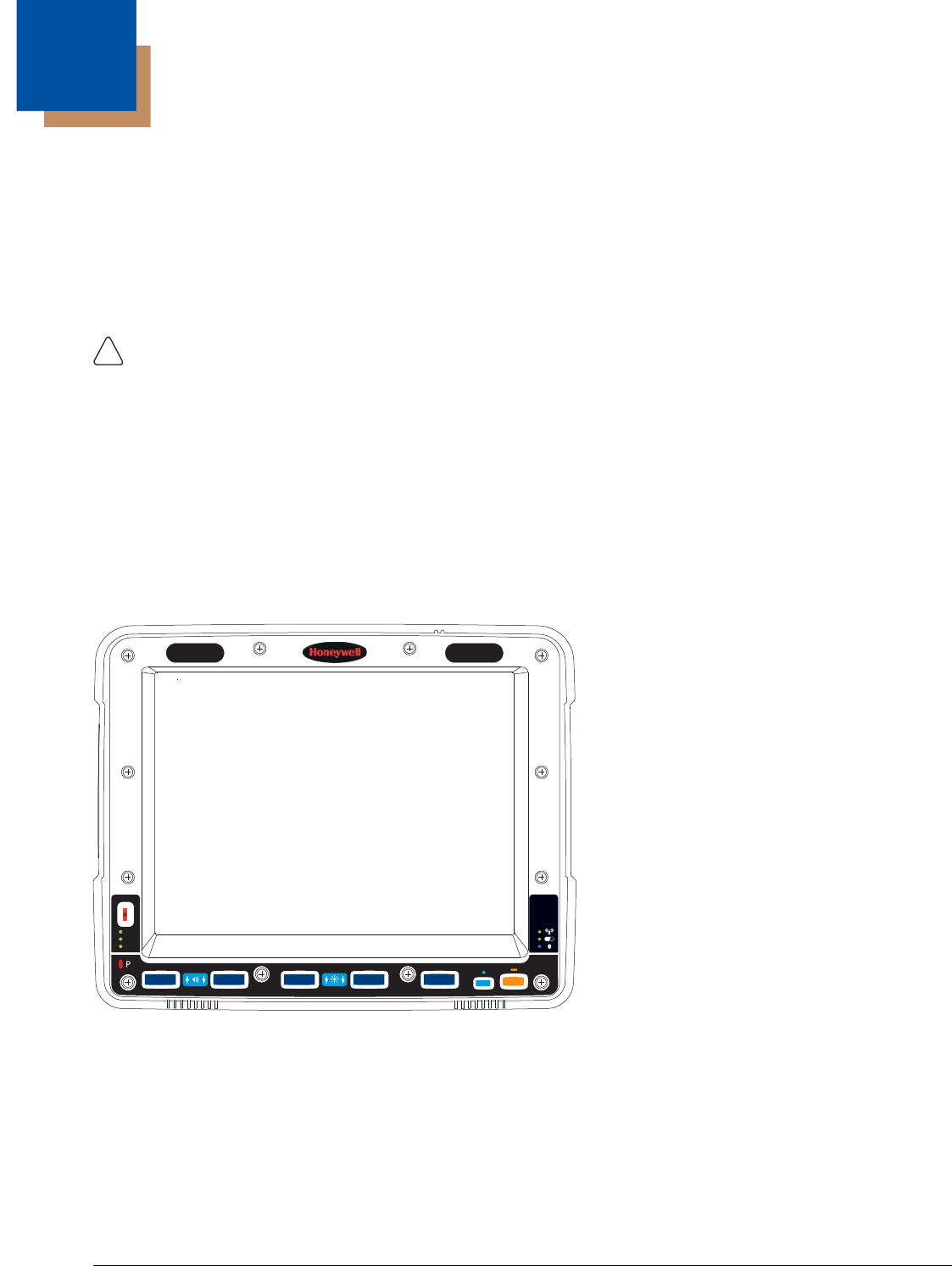
Front View ......................................................................................................................2-4
Back View with Quick Mount Smart Dock ......................................................................2-4
Access Panels...............................................................................................................2-5
Backlights and Indicators .....................................................................................................2-6
Display Backlight............................................................................................................2-6
Power Management .................................................................................................2-6
Backlight Brightness.................................................................................................2-6
Screen Blanking .......................................................................................................2-6
Keypad Backlight ...........................................................................................................2-6
Speaker Volume.............................................................................................................2-6
Power Up .............................................................................................................................2-7
Rebooting the Thor VM2 ................................................................................................2-8
Warmboot.................................................................................................................2-8
Restart......................................................................................................................2-8
Clearing Persistent Storage / Reset to Default Settings...........................................2-8
Tapping the Touch Screen with a Stylus .............................................................................2-8
Table of Contents

2
Setup Terminal Emulation Parameters................................................................................ 2-9
Cleaning the Touch Screen ................................................................................................. 2-9
Startup Help......................................................................................................................... 2-9
Chapter 3 - Hardware Overview
System Hardware ................................................................................................................ 3-1
802.11a/b/gWireless Client............................................................................................ 3-1
Central Processing Unit................................................................................................. 3-1
Input/Output Components.............................................................................................. 3-1
System Memory............................................................................................................. 3-1
Video Subsystem........................................................................................................... 3-1
Audio Interface............................................................................................................... 3-2
Card Slots......................................................................................................................3-2
CompactFlash (CF) Slot .......................................................................................... 3-2
Secure Digital (SD) Slot........................................................................................... 3-2
Bluetooth EZPair............................................................................................................ 3-2
WWAN........................................................................................................................... 3-2
GPS ............................................................................................................................... 3-2
Power .................................................................................................................................. 3-2
Vehicle DC Power Supply.............................................................................................. 3-2
External AC Power Supply ............................................................................................ 3-2
Uninterruptible Power Supply ........................................................................................ 3-3
Safe Charging Temperature Range......................................................................... 3-3
Charging Timeout .................................................................................................... 3-3
Charging and Power Management .......................................................................... 3-3
Backup Battery .............................................................................................................. 3-3
Fuse............................................................................................................................... 3-4
Power Management Modes........................................................................................... 3-4
On Mode (D0) .......................................................................................................... 3-4
User Idle / Backlight Off Mode (D1) ......................................................................... 3-4
System Idle / Display Off Mode (D2) ....................................................................... 3-4
Suspend mode (D3)................................................................................................. 3-4
Shutdown / Off Mode (D4) ....................................................................................... 3-4
Primary Events ........................................................................................................ 3-5
Power Controls .............................................................................................................. 3-6
Power Switch ........................................................................................................... 3-6
Power Button ........................................................................................................... 3-6
Power Configuration Mode ...................................................................................... 3-6
External Connectors ............................................................................................................3-7
Serial Connector (COM1 and COM2)............................................................................ 3-7
Screen Blanking...................................................................................................... 3-7
USB Connector.............................................................................................................. 3-7
CANbus / Audio Connector............................................................................................ 3-8
Power Supply Connector............................................................................................... 3-8
Antenna Connections .................................................................................................... 3-9
External Antenna Connector.................................................................................... 3-9
Internal 802.11 Antenna .......................................................................................... 3-9
External 802.11 Antenna ......................................................................................... 3-9

3
Vehicle Remote Antenna ......................................................................................... 3-9
Keyboard Options.............................................................................................................. 3-10
Integrated Keypad ....................................................................................................... 3-10
Keypad LEDs......................................................................................................... 3-10
95-Key USB Keyboard................................................................................................. 3-10
Keyboard Backlight................................................................................................ 3-10
USB Keyboard / Mouse ............................................................................................... 3-11
LED Functions ...................................................................................................................3-11
System LEDs............................................................................................................... 3-11
SYS (System Status) LED ..................................................................................... 3-11
UPS Status LED .................................................................................................... 3-12
SSD (Solid State Drive) LED ................................................................................. 3-12
Connection LEDs......................................................................................................... 3-13
WWAN LED ........................................................................................................... 3-13
Wi-Fi LED .............................................................................................................. 3-13
Bluetooth LED........................................................................................................ 3-13
Keyboard LEDs............................................................................................................ 3-14
Blue LED................................................................................................................ 3-14
Orange LED........................................................................................................... 3-14
Programmable LED ............................................................................................... 3-14
Display............................................................................................................................... 3-14
Touch Screen .............................................................................................................. 3-14
Screen Blanking........................................................................................................... 3-15
Display Backlight Control............................................................................................. 3-15
Chapter 4 - Vehicle Mounting and Accessory Installation
Introduction........................................................................................................................ 4-17
Prepare for Vehicle Mounting ............................................................................................ 4-17
Quick Start................................................................................................................... 4-17
Maintenance - Vehicle Mounted Devices .......................................................................... 4-18
Cleaning ............................................................................................................................ 4-18
Place Thor VM2 in the Dock.............................................................................................. 4-18
Dock I/O Pin Cover...................................................................................................... 4-19
Padlock ........................................................................................................................ 4-19
Laptop Security Cable ................................................................................................. 4-19
Install RAM Mount ............................................................................................................. 4-20
Components - RAM Mounting Kits .............................................................................. 4-20
Procedure - RAM Mount Assembly ............................................................................. 4-22
Torque Measurement ............................................................................................ 4-22
Step 1a – Attach RAM Ball to Vehicle ................................................................... 4-22
Step 1b – Mount RAM Clamp to Vehicle ............................................................... 4-23
Step 1c – Attach RAM Plate to Vehicle and Attach RAM Ball ............................... 4-24
Step 2 – Attach RAM Mount Ball to the Thor VM2 Quick Mount Smart Dock ....... 4-25
Step 3 – Attach Thor VM2 Assembly to RAM Mount............................................. 4-26
Step 4 – Place the Thor VM2 into the Dock........................................................... 4-26
Step 5 – Attach Keyboard to Mounting Plate......................................................... 4-27
Step 6 – Attach Keyboard Assembly to Thor VM2 Assembly................................ 4-28

4
Install U Bracket Mount ..................................................................................................... 4-29
Components - U Bracket Mounting Assembly ............................................................. 4-29
Procedure - U Bracket Assembly................................................................................. 4-29
Torque Measurement ............................................................................................ 4-29
Mounting Positions ................................................................................................ 4-30
Step 1 - Install U Bracket to Vehicle ...................................................................... 4-30
Step 2 - Remove RAM Ball.................................................................................... 4-31
Step 3 - Attach Adapter Bracket ............................................................................ 4-31
Connect Cables ................................................................................................................. 4-32
Strain Relief Cable Clamps.......................................................................................... 4-32
Connect Power ............................................................................................................ 4-33
Power Cable Cautions................................................................................................. 4-33
12-48 VDC Vehicles (10-60 VDC Direct Connection)............................................ 4-34
Power Cable Identification ..................................................................................... 4-34
60-144 VDC Vehicles (50-150 VDC Power Supply, Screws on Side of Lid) ......... 4-39
Power Cable Identification ..................................................................................... 4-40
60-144 VDC Vehicles (50-150 VDC Power Supply, Screws on Top of Lid) .......... 4-43
Power Cable Identification ..................................................................................... 4-44
VX6 / VX7 Adapter Cable ...................................................................................... 4-47
Thor VX8 / Thor VX9 Adapter Cable ..................................................................... 4-48
Screen Blanking..................................................................................................... 4-49
External AC/DC Power Supply .............................................................................. 4-52
Connect USB Keyboard............................................................................................... 4-53
Connect USB Host....................................................................................................... 4-53
Connect USB Client..................................................................................................... 4-54
Connect Serial Device ................................................................................................. 4-54
Connect a Tethered Scanner................................................................................. 4-54
Connect Headset Cable............................................................................................... 4-55
Adjust Headset / Microphone and Secure Cable................................................... 4-55
Connect CANbus Cable............................................................................................... 4-56
Install External Antenna............................................................................................... 4-56
Install Remote Antenna ............................................................................................... 4-57
802.11 Remote Mount Antenna............................................................................. 4-57
WAN Remote Mount Antenna ............................................................................... 4-59
GPS Remote Mount Antenna ................................................................................ 4-59
Apply Touch Screen Protective Film ................................................................................. 4-60
Installation....................................................................................................................4-60
Removal....................................................................................................................... 4-60
Disconnect UPS Battery .................................................................................................... 4-61
Install SD Card .................................................................................................................. 4-62
Install SIM Card ................................................................................................................. 4-63
Replace Front Panel.......................................................................................................... 4-64
Chapter 5 - Software
Introduction.......................................................................................................................... 5-1
Operating System................................................................................................................5-1

5
Windows CE Operating System .......................................................................................... 5-1
General Windows CE Keyboard Shortcuts....................................................................5-1
Save Changes to the Registry....................................................................................... 5-2
Software Load ..................................................................................................................... 5-2
Software Applications .................................................................................................... 5-2
ActiveSync..................................................................................................................... 5-2
Bluetooth........................................................................................................................ 5-2
Honeywell RFTerm (Optional) ....................................................................................... 5-2
Avalanche...................................................................................................................... 5-3
Software Development ........................................................................................................ 5-3
Thor VM2 Utilities ................................................................................................................ 5-3
LAUNCH.EXE................................................................................................................ 5-3
LAUNCH.EXE and Persistent Storage .......................................................................... 5-4
REGEDIT.EXE............................................................................................................... 5-4
REGLOAD.EXE............................................................................................................. 5-4
REGDUMP.EXE ............................................................................................................ 5-4
WARMBOOT.EXE......................................................................................................... 5-5
WAVPLAY.EXE ............................................................................................................. 5-5
Thor VM2 Command-line Utilities.................................................................................. 5-5
PrtScrn.EXE............................................................................................................. 5-5
Desktop ............................................................................................................................... 5-5
Desktop Icons................................................................................................................ 5-5
Taskbar.................................................................................................................... 5-6
My Device Folders......................................................................................................... 5-7
Wavelink Avalanche Enabler (Optional) ........................................................................ 5-7
Internet Explorer ............................................................................................................ 5-7
Start Menu ........................................................................................................................... 5-8
Communication.............................................................................................................. 5-8
Connect ................................................................................................................... 5-8
Start FTP Server / Stop FTP Server ........................................................................ 5-8
Summit........................................................................................................................... 5-9
Certs ........................................................................................................................ 5-9
Command Prompt.......................................................................................................... 5-9
eXpress Scan ................................................................................................................ 5-9
Internet Explorer ............................................................................................................ 5-9
Media Player.................................................................................................................. 5-9
File Viewers ................................................................................................................. 5-10
Microsoft WordPad ...................................................................................................... 5-10
Remote Desktop Connection....................................................................................... 5-10
Settings........................................................................................................................5-10
Transcriber................................................................................................................... 5-10
Windows Explorer........................................................................................................ 5-10
Taskbar.............................................................................................................................. 5-11
General........................................................................................................................ 5-11
Advanced..................................................................................................................... 5-11
Expand Control Panel............................................................................................5-11
Clear Contents of Document Folder ...................................................................... 5-11
Taskbar Icons ........................................................................................................ 5-11

6
Thor VM2 OS Upgrade...................................................................................................... 5-13
Introduction.................................................................................................................. 5-13
Preparation .................................................................................................................. 5-13
Procedure .................................................................................................................... 5-13
BIOS .................................................................................................................................. 5-14
Accessing the BIOS Setup .......................................................................................... 5-14
Boot Order ............................................................................................................. 5-14
Exiting BIOS Setup ................................................................................................ 5-14
Control Panel..................................................................................................................... 5-15
About ...........................................................................................................................5-17
Software................................................................................................................. 5-17
Versions................................................................................................................. 5-17
Network IP ............................................................................................................. 5-18
Accessibility ................................................................................................................. 5-18
Administration.............................................................................................................. 5-19
Setup a New Device .............................................................................................. 5-20
Administration Mode .............................................................................................. 5-20
End User Mode...................................................................................................... 5-21
Passwords ............................................................................................................. 5-21
End-User Switching Technique ............................................................................. 5-21
Application Configuration....................................................................................... 5-22
Application ............................................................................................................. 5-23
Security.................................................................................................................. 5-26
Options .................................................................................................................. 5-27
Status..................................................................................................................... 5-27
AppLock Help ........................................................................................................ 5-28
Battery .........................................................................................................................5-29
Bluetooth...................................................................................................................... 5-29
Bluetooth Devices.................................................................................................. 5-30
Settings.................................................................................................................. 5-32
Reconnect.............................................................................................................. 5-33
About ..................................................................................................................... 5-34
Using Bluetooth ..................................................................................................... 5-34
Certificates................................................................................................................... 5-39
Data Collection ............................................................................................................ 5-39
Bar Code Readers ................................................................................................. 5-39
Data Processing Overview .................................................................................... 5-40
Main ....................................................................................................................... 5-42
COM1 .................................................................................................................... 5-43
COM2 .................................................................................................................... 5-43
Data Options.......................................................................................................... 5-44
Add Prefix/Suffix Control........................................................................................ 5-48
Symbologies .......................................................................................................... 5-49
Processing ............................................................................................................. 5-53
About ..................................................................................................................... 5-54

7
Length Based Bar Code Stripping ......................................................................... 5-54
Date / Time .................................................................................................................. 5-56
Dialing.......................................................................................................................... 5-56
Display.........................................................................................................................5-57
Background............................................................................................................ 5-57
Appearance ........................................................................................................... 5-57
Backlight ................................................................................................................ 5-58
Gobi Connection Manager........................................................................................... 5-59
Initial Use ............................................................................................................... 5-59
Home ..................................................................................................................... 5-60
CDMA .................................................................................................................... 5-61
UTMS..................................................................................................................... 5-62
GPS ....................................................................................................................... 5-63
Admin..................................................................................................................... 5-64
About ..................................................................................................................... 5-65
Input Panel................................................................................................................... 5-66
Transcriber............................................................................................................. 5-66
Internet Options ........................................................................................................... 5-67
Keyboard ..................................................................................................................... 5-69
License Viewer ............................................................................................................ 5-69
Mixer............................................................................................................................ 5-70
Output Panel.......................................................................................................... 5-70
Input Panel............................................................................................................. 5-70
Mouse.......................................................................................................................... 5-71
Network and Dialup Connections ................................................................................ 5-71
Create a New Connection...................................................................................... 5-71
Network Capture.......................................................................................................... 5-72
Netlog .................................................................................................................... 5-72
NDISLog ................................................................................................................ 5-73
Options ........................................................................................................................ 5-74
Communication...................................................................................................... 5-74
Misc ....................................................................................................................... 5-74
Status Popup ......................................................................................................... 5-75
Owner .......................................................................................................................... 5-76
Password..................................................................................................................... 5-77
PC Connection............................................................................................................. 5-77
Power...........................................................................................................................5-78
Power Configuration Mode .......................................................................................... 5-80
AC/DC Mode.......................................................................................................... 5-80
Ignition Control Mode............................................................................................. 5-80
Auto-On Mode ....................................................................................................... 5-81
UPS Mode ............................................................................................................. 5-82
Programmable Key...................................................................................................... 5-83
KeyMap.................................................................................................................. 5-84
LaunchApp............................................................................................................. 5-86

8
RunCmd................................................................................................................. 5-86
Regional and Language Settings................................................................................. 5-88
Registry........................................................................................................................5-89
Remove Programs....................................................................................................... 5-89
Screen Control............................................................................................................. 5-90
Screen Blanking..................................................................................................... 5-90
Current Level ......................................................................................................... 5-91
Screen Rotation........................................................................................................... 5-91
Stylus........................................................................................................................... 5-92
Double-Tap ............................................................................................................ 5-92
Calibration.............................................................................................................. 5-92
System......................................................................................................................... 5-93
General .................................................................................................................. 5-93
Memory.................................................................................................................. 5-93
Device Name ......................................................................................................... 5-94
Copyrights.............................................................................................................. 5-94
Terminal Server Client Licenses.................................................................................. 5-94
Volume and Sounds .................................................................................................... 5-95
Good Scan and Bad Scan Sounds ........................................................................ 5-95
Wi-Fi ............................................................................................................................ 5-96
Chapter 6 - ActiveSync
Introduction.......................................................................................................................... 6-1
Initial Setup.......................................................................................................................... 6-1
Connect via USB .................................................................................................................6-1
Cable for USB ActiveSync Connection:.........................................................................6-2
Explore ................................................................................................................................ 6-2
Backup Data Files using ActiveSync ................................................................................... 6-2
Prerequisites.................................................................................................................. 6-2
Connect .........................................................................................................................6-2
Disconnect........................................................................................................................... 6-2
Thor VM2 with a Disabled Touch screen............................................................................. 6-2
Reset and Loss of Host Re-connection ............................................................................... 6-3
ActiveSync Help .................................................................................................................. 6-3
HSM Connect ...................................................................................................................... 6-3
Installation...................................................................................................................... 6-4
Using HSM Connect ...................................................................................................... 6-4
Chapter 7 - Enabler Installation and Configuration
Introduction.......................................................................................................................... 7-1
Installation ........................................................................................................................... 7-1
Installing the Enabler on Mobile Devices....................................................................... 7-1
Enabler Uninstall Process.............................................................................................. 7-1
Stop the Enabler Service............................................................................................... 7-2
Update Monitoring Overview ......................................................................................... 7-2
Mobile Device Wireless and Network Settings .............................................................. 7-2
Preparing a Device for Remote Management ............................................................... 7-3

9
Using Wavelink Avalanche to Upgrade System Baseline........................................ 7-3
User Interface ...................................................................................................................... 7-4
Enabler Configuration.......................................................................................................... 7-4
File Menu Options.......................................................................................................... 7-5
Avalanche Update using File > Settings........................................................................ 7-5
Menu Options .......................................................................................................... 7-5
Connection............................................................................................................... 7-6
Server Contact......................................................................................................... 7-7
Data ......................................................................................................................... 7-8
Preferences ............................................................................................................. 7-8
Display ..................................................................................................................... 7-9
Taskbar.................................................................................................................. 7-10
Execution ............................................................................................................... 7-10
Scan Config ........................................................................................................... 7-11
Shortcuts................................................................................................................ 7-11
SaaS ...................................................................................................................... 7-12
Adapters ................................................................................................................ 7-12
Status..................................................................................................................... 7-14
Exit......................................................................................................................... 7-14
Using Remote Management.............................................................................................. 7-15
eXpress Scan ....................................................................................................................7-15
Step 1: Create Bar Codes............................................................................................7-15
Step 2: Scan Bar Codes .............................................................................................. 7-15
Step 3: Process Completion ........................................................................................ 7-16
Chapter 8 - Wireless Network Connections
Summit Wireless Network Configuration ............................................................................. 8-1
Important Notes ................................................................................................................... 8-1
Summit Client Utility ............................................................................................................ 8-1
Help ............................................................................................................................... 8-1
Summit Tray Icon........................................................................................................... 8-1
Wireless Zero Config Utility ........................................................................................... 8-2
To Switch Control to the Wireless Zero Config Utility .............................................. 8-2
To Switch Control to SCU........................................................................................ 8-2
Main............................................................................................................................... 8-3
Auto Profile .............................................................................................................. 8-3
Admin Login............................................................................................................. 8-4
Profile............................................................................................................................. 8-5
Buttons..................................................................................................................... 8-5
Profile Parameters ................................................................................................... 8-6
Using CKIP .............................................................................................................. 8-7
Status............................................................................................................................. 8-8
Diags.............................................................................................................................. 8-9
Global ..........................................................................................................................8-10
Custom .................................................................................................................. 8-11
Global Parameters................................................................................................. 8-11

10
Sign-On vs. Stored Credentials ........................................................................................ 8-14
To Use Stored Credentials .......................................................................................... 8-14
To Use Sign On Screen............................................................................................... 8-14
Windows Certificate Store vs. Certs Path.......................................................................... 8-15
User Certificates .......................................................................................................... 8-15
Root CA Certificates .................................................................................................... 8-15
To Use the Certs Path ........................................................................................... 8-16
To Use Windows Certificate Store......................................................................... 8-16
Configuring the Profile ....................................................................................................... 8-17
No Security .................................................................................................................. 8-17
WEP.............................................................................................................................8-18
LEAP............................................................................................................................8-19
PEAP/MSCHAP........................................................................................................... 8-20
PEAP/GTC................................................................................................................... 8-22
WPA/LEAP .................................................................................................................. 8-24
EAP-FAST ................................................................................................................... 8-25
EAP-TLS...................................................................................................................... 8-27
WPA PSK .................................................................................................................... 8-29
Certificates......................................................................................................................... 8-30
Quick Start................................................................................................................... 8-30
Generate a Root CA Certificate................................................................................... 8-30
Install a Root CA Certificate......................................................................................... 8-32
Generate a User Certificate......................................................................................... 8-33
Install a User Certificate............................................................................................... 8-37
Verify Installation ................................................................................................... 8-38
Chapter 9 - Key Maps
Integrated Keypad ...............................................................................................................9-1
External 95-Key Keyboard................................................................................................... 9-2
Chapter 10 - Specifications and Reference Material
Technical Specifications .................................................................................................... 10-1
Thor VM2..................................................................................................................... 10-1
Quick Mount Smart Dock............................................................................................. 10-1
Dimensions........................................................................................................................ 10-2
Thor VM1..................................................................................................................... 10-2
Quick Mount Smart Dock............................................................................................. 10-2
Environmental Specifications ............................................................................................ 10-2
Thor VM1 and Quick Mount Smart Dock..................................................................... 10-2
Network Card Specifications ............................................................................................. 10-3
Summit 802.11a/b/g..................................................................................................... 10-3
Bluetooth...................................................................................................................... 10-3
WWAN......................................................................................................................... 10-3
Port and Connector Pinouts .............................................................................................. 10-4
Power Supply Connector............................................................................................. 10-4
COM1 and COM2 Connector ...................................................................................... 10-4
USB Connector............................................................................................................ 10-5

11
USB Y Cable.......................................................................................................... 10-5
CANbus / Audio Connector.......................................................................................... 10-6
Headset Adapter Cable ......................................................................................... 10-6
CANbus Y Cable.................................................................................................... 10-7
AppLock Error Messages .................................................................................................. 10-8
Hat Encoding ................................................................................................................... 10-13
Chapter 11 - Customer Support
Product Service and Repair............................................................................................... 11-1
Technical Assistance......................................................................................................... 11-1
Limited Warranty ............................................................................................................... 11-1

12

1 - 1
1
Thor VM2 Agency Information
Thor VM2 mobile computers meet or exceed the requirements of all applicable standards organizations for safe operation.
However as with any electrical equipment, the best way to ensure safe operation is to operate them according to the agency
guidelines that follow. Read these guidelines before using your Thor VM2.
This documentation is relevant for the following Thor models: VM2C.
FCC Part 15 Statement
This device complies with Part 15 of the FCC Rules [and with RSS-210 of Industry Canada]. Operation is subject to the follow-
ing two conditions:
1. This device may not cause harmful interference, and
2. This device must accept any interference received, including interference that may cause undesired operation.
NOTE - This equipment has been tested and found to comply with the limits for a Class B digital device, pursuant to Part 15 of
the FCC Rules. These limits are designed to provide reasonable protection against harmful interference in a residential installa-
tion. This equipment generates, uses and can radiate radio frequency energy and, if not installed and used in accordance with
the instructions, may cause harmful interference to radio communications. However, there is no guarantee that interference will
not occur in a particular installation. If this equipment does cause harmful interference to radio or television reception, which can
be determined by turning the equipment off and on, the user is encouraged to try to correct the interference by one or more of
the following measures:
• Reorient or relocate the receiving antenna.
• Increase the separation between the equipment and the receiver.
• Connect the equipment into an outlet on a circuit different from that to which the receiver is connected.
Consult the dealer or an experienced radio/TV technician for help.
Caution - Changes or modifications made to this equipment not expressly approved by Honeywell may void the FCC authoriza-
tion to operate this equipment.
FCC 5GHz Statement
LAN devices are restricted to indoor use only in the band 5150-5250 MHz.
For the band 5600-5650 MHz, no operation is permitted.
EMC Directive Requirements
This is a Class B product. In a domestic environment this product may cause radio interference in which case the user may be
required to take adequate measures.
Canada, Industry Canada (IC) Notices
This Class B digital apparatus complies with Canadian ICES-003
This device complies with Industry Canada licence-exempt RSS standard(s). Operation is subject to the following two condi-
tions: (1) this device may not cause interference, and (2) this device must accept any interference, including interference that
may cause undesired operation of the device.
Exposure of humans to RF fields (RSS-102)
The computers employ low gain integral antennas that do not emit RF field in excess of Health Canada limits for the general
population; consult Safety Code 6, obtainable from Health Canada's Web site at http://www.hc-sc.gc.ca/
When using IEEE 802.11a wireless LAN, this product is restricted to indoor use, due to its operation in the 5.15- to 5.25-
GHz Frequency range. The FCC requires this product to be used indoors for the frequency range of 5.15 GHz to 5.25
GHz to reduce the potential for harmful interference to co-channel mobile satellite systems. High-power radar is allocated
as the primary user of the 5.25- to 5.35-GHz and 5.65- to 5.85-GHz bands. These radar stations can cause interference
with and/or damage to this device.
!

1 - 2
The radiated energy from the antennas connected to the wireless adapters conforms to the IC limit of the RF exposure require-
ment regarding IC RSS-102, Issue 4 clause 4.1.
Cet appareil numérique de classe B est conforme à la norme NMB-003.
Le présent appareil est conforme aux CNR d'Industrie Canada applicables auxappareils radio exempts de licence.L'exploitation
est autorisée aux deux conditions suivantes: (1) l'appareil ne doit pas produire de brouillage, et (2) l'utilisateur de l'appareil doit
accepter tout brouillage adioélectrique subi, même si le brouillage est susceptible d'en compromettre le fonctionnement.
Conformité des appareils de radiocommunication aux limites d'exposition humaine aux radiofréquences (CNR-102)
L'ordinateur utilise des antennes intégrales à faible gain qui n'émettent pas un champ électromagnétique supérieur aux normes
imposées par Santé Canada pour la population. Consultez le Code de sécurité 6 sur le site Internet de Santé Canada à
l'adresse suivante : http://www.hc-sc.gc.ca/
L'énergie émise par les antennes reliées aux cartes sans fil respecte la limite d'exposition aux radiofréquences telle que définie
par Industrie Canada dans la clause 4.1 du document CNR-102, version 4.
COFETEL
1La operación de este equipo está sujeta a las siguientes dos condiciones: (1) es posible que este equipo o dispositivo no
cause interferencia perjudicial y (2) este equipo o dispositivo debe aceptar cualquier interferencia, incluyendo la que pueda cau-
sar su operación no deseada.
ANATEL (Brazil)
Este equipamento opera em caráter secundário, isto é, não tem direito a proteção contra interferência prejudicial, mesmo de
estações do mesmo tipo, e não causar interferência a sistema operando em caráter primário.
Vehicle Power Supply Connection Safety Statement
WARNING - For proper and safe installation, the input power cable must be connected to a fused circuit on the vehicle. If the
supply connection is made directly to the battery, the fuse should be installed in the positive lead within 5 inches of the battery’s
positive (+) terminal. The fused circuit requires a maximum time delay (slow blow) fuse with a current rating as noted below.
•For 12VDC input, use a 10A slow blow fuse that has a DC voltage rating greater than 12VDC.
•For 24VDC input, use a 6A slow blow fuse that has a DC voltage rating greater than 24VDC.
•For 36VDC input, use a 4A slow blow fuse that has a DC voltage rating greater than 36VDC.
•For 48VDC input, use a 3A slow blow fuse that has a DC voltage rating greater than 48VDC.
Note: For North America, a UL Listed fuse is to be used
Li-Ion Battery
When disposing of the Thor VM2 UPS battery, the following precautions should be observed: The battery should be disposed of
properly. The battery should not be disassembled or crushed. The battery should not be heated above 212°F (100°C) or inciner-
ated.
Safety requirements restrict the temperature at which the Li-Ion UPS battery can be charged. Charging is disabled if the ambi-
ent temperature is outside of the 0ºC to 35ºC safe charging range. In order to maintain UPS charge the Thor VM2 should have
power applied while the unit is within the safe charging range for at least an hour each day.
1 - 3
RF Safety Notice
Bluetooth
Honeywell Scanning & Mobility Product Environmental Information
Refer to www.honeywellaidc.com/environmental for the RoHS / REACH / WEEE information.
CE Mark
The CE marking on the product indicates that this device is in conformity with the following directives:
• 1995/5/EC R&TTE
• 2011/65/EU RoHS (Recast)
In addition, complies to 2006/95/EC Low Voltage Directive, when shipped with recommended power supply.
European contact:
Hand Held Products Europe BV
Nijverheidsweg 9-13
5627 BT Eindhoven
The Netherlands
Honeywell shall not be liable for use of our product with equipment (i.e., power supplies, personal computers, etc.) that is not CE
marked and does not comply with the Low Voltage Directive.
This device complies with the following harmonized European Standards:
Health: EN63211:2008
Safety: EN60950-1:2006 + A1:2010 + A11:2009 + A12:2011
EMC: EN301 489-1 V1.9.2:2011, EN301 489-17 V2.1.1:2009
Radio: EN300 328 V1.7.1:2006
The following CE marking is valid for EU harmonized telecommunications products.
This device is intended to transmit RF energy. For protection against RF exposure to humans and in accordance with
FCC rules and Industry Canada rules, this transmitter should be installed such that a minimum separation distance of at
least 20 cm (7.8 in.) is maintained between the antenna and the general population. This device can only be co-located
with FCC ID:TWG-SDCMSD30G.
Class II
EN300328 V1.7.1:2006
EN301893 V1.6.1:2011
EN62311: 2008
EN301489-1 V1.9.2:2011
EN301489-17 V2.1.1:2009
EN55022/EN55024: 2010
Part
Number
0560
1 - 4
Dealer License - Republic of Singapore
WWAN is not available in Singapore.
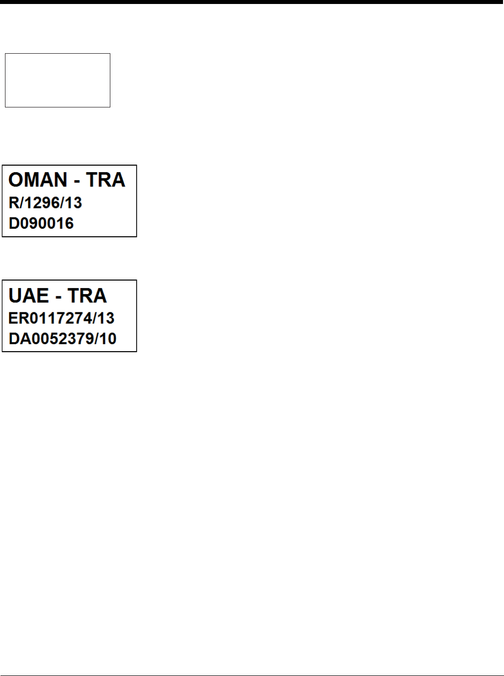
Oman
United Arab Emirates (UAE)
Republic of Singapore - Dealer License Number DA104328 complies with IDA Standards.
Oman Compliance Mark
UAE Compliance Mark
Complies with
IDA Standards
DA104328
2 - 1
2
Getting Started
Overview
The Thor VM2 Vehicle Mount Computer (VMC) is a rugged, vehicle mounted computer running a Microsoft® Windows® CE 6
operating system and capable of wireless data communications from a fork-lift truck or any properly configured vehicle. Wire-
less communications are supported over a 802.11 WLAN network and, optionally, over a WWAN network. The Bluetooth® mod-
ule supports Bluetooth printers and scanners.
The Thor VM2 is designed for use with a vehicle Quick Mount Smart Dock. The dock installs in the vehicle and connects to
vehicle power. The dock provides conditioned input power for the Thor VM2. Peripheral connections are on the dock. The Thor
VM2 is designed to easily be removed from the dock with a latch on the lower rear of the Thor VM2 housing. Since the dock
remains attached to the vehicle, the Thor VM2 computer can easily be moved from one vehicle equipped with a dock to another
vehicle equipped with a dock.
The Thor VM2 contains a UPS battery which, when fully charged, can power the Thor VM2 for a minimum of 30 minutes. This
can be when the Thor VM2 is not attached to a Quick Mount Smart Dock or when the Thor VM2 is attached to a dock but the
vehicle power is interrupted, such as when the vehicle battery is being changed.
The Thor VM2 can be used with or without an external keyboard. There are 5 programmable keys (P1-P5) on the front bezel
and, when used with the Orange modifier key, provide 5 additional programmable keys (P6-P10).
Contact Technical Assistance (page 11-1) for information on the latest upgrades for your Thor VM2.
About this Guide
This user’s guide has been developed for a Thor VM2 with a Microsoft® Windows® Embedded CE 6 operating system.
Out of the Box
The following items may be packaged separately:
• Thor VM2
• Quick Mount Smart Dock (includes 10-60VDC power cable)
• RAM or U-Bracket vehicle mount kit
CAUTION - Before shipping the Thor VM2, be sure to Disconnect UPS Battery (page 4-61) .
!
P3
P8
P4
P9
P5
P10P6
P2
P7
P1
SYS
SSD
Wi Fi
UPS
THOR
VM2

2 - 2
If you ordered additional accessories for the Thor VM2, verify they are also included with the order. Keep the original packaging
material in the event the Thor VM2 should need to be returned for service. For details, see Product Service and Repair (page
11-1).
Initial Setup for Thor VM2
This page lists a quick outline of the steps you might take when setting up a new Thor VM2. More instruction for each step is
listed later in this guide.
Contact Technical Assistance (page 11-1) if you need additional help.
Hardware Setup
1. Install RAM Mount (page 4-20) or Install U Bracket Mount (page 4-29) to the vehicle.
2. Place Thor VM2 in the Dock (page 4-18).
3. Secure the optional external keyboard to either an integrated or remote mounting bracket.
4. Connect Cables (page 4-32) for any peripherals.
5. Connect Power (page 4-33).
6. Secure all cables in Strain Relief Cable Clamps (page 4-32).
7. Press the Power Switch (page 3-6) on the dock to the on position.
8. Press the Power Button (page 3-6) on the Thor VM2.
Software
Languages and Fonts
The Thor VM2 may be shipped with an English only operating system (OS). Contact Technical Assistance (page 11-1)
for the availability of OS files for other languages. See Thor VM2 OS Upgrade (page 5-13) for OS update installation
information. The language installed is identified on the Software tab of the About (page 5-17) control panel.
First Boot
When a new Thor VM2 starts up a EULA (End User License Agreement) may be displayed on the touch screen. It
remains on the screen until the Accept or Decline button is tapped with a stylus.
Tap the Accept button to accept the EULA terms and the Thor VM2 continues the startup process. The EULA is not
presented to the user again.
Tap the Decline button to decline the EULA and the Thor VM2 reboots. It will continue to reboot until the Accept but-
ton is tapped with the stylus.
Note: The EULA will be presented after any operating system upgrade or re-installation, including language-specific
operating systems.
Software Setup
Hardware setup should be completed before starting software setup.
1. If prompted, perform touch screen Calibration (page 5-92).
2. Set Date / Time (page 5-56).
3. Set Power Configuration Mode (page 5-80) and Power (page 5-78) scheme timers.
4. Adjust Speaker Volume (page 2-6).
5. Pair Bluetooth (page 5-29) devices
6. Set Wireless client parameters using the Summit Client Utility (page 8-1).

2 - 3
7. Set terminal emulation parameters.
8. Set AppLock parameter via the Administration (page 5-19) control panel.
9. Set DCWedge parameters via the Data Collection (page 5-39) control panel.
10. Save Changes to the Registry (page 5-2).
11. Set Date / Time (page 5-56) if not set during first boot.
Quick Mount Smart Dock
The Thor VM2 assembly consists of two parts, the Thor VM2 computer and the Quick Mount Smart Dock.
The Thor VM2 contains an internal UPS battery that, once fully charged, powers the Thor VM2 for a minimum of 30 minutes
when the unit is not mounted in the dock.
The dock provides:
• A mount for the Thor VM2 computer. The dock attaches to a vehicle via a RAM or U-bracket mount or to a RAM table stand
for use in an office environment.
• Conditioned power for the Thor VM2. The dock accepts 10-60VDC power input directly or 50-150VDC power input with a DC/
DC converter.
• COM1 and COM2 serial connections for a tethered scanner, printer, PC connection, etc.
• USB host and client connections via an adapter cable.
• CANbus connection via an adapter cable.
• Headset connection via an adapter cable. When a headset is not attached, the microphone and speakers on the Thor VM2
are active.
• Strain relief cable mounts.
• Mobility of the Thor VM2, since the dock remains attached to the vehicle the Thor VM2 computer can easily be moved from
one vehicle equipped with a dock to another.
External antenna connectors may be present on the back of the Thor VM2. The connectors may include:
• 802.11 antenna connectors, used when the Thor VM2 is not equipped with internal antennas.
• External GPS antenna connector, when the Thor VM2 is equipped with GPS.
• External WWAN antenna connectors, when the Thor VM2 is equipped with WWAN. Optional WWAN radio (available in North
America, Europe, New Zealand, and Australia only).
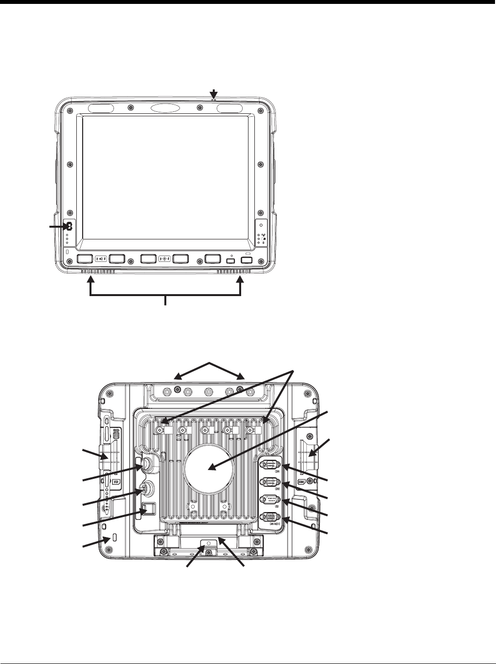
2 - 4
Components
Front View
Back View with Quick Mount Smart Dock
P
UPS
SYS
SSD
Wi Fi
Power
Button
Speakers
Microphone
Antenna Connectors
SIM Card
Access Panel
COM1 Connector
COM2 Connector
USB Connector
CANbus/Audio
Connector
Quick Release HandleProvision for Padlock
Provision for
Laptop Security
Cable
Power
Switch
Power
Connector
Fuse
SD Card
Access
Panel
RAM Ball
Strain Relief
Clamps
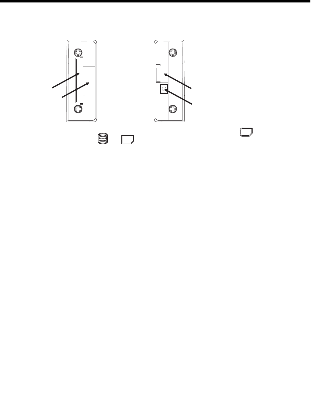
2 - 5
Access Panels
SD Card Access Panel with door removed SIM Card Access Panel with door removed
Access Panel Door is labeled with and .
Access Panel Door is labeled with .
CompactFlash
Hard Drive
SD (Secure Digital)
Memory Card Slot
SIM Card Slot
for WWAN Radio
UPS Battery
Disconnect
SSD
SD
SIM

2 - 6
Backlights and Indicators
Display Backlight
There are several configuration options for the Thor VM2 display backlight:
Power Management
The display backlight is controlled by power management. When the user activity timer expires, the display backlight is
turned off. Timeouts can be set for the available power management schemes.
See Power (page 5-78) for configuration options.
Backlight Brightness
The intensity of the display backlight can be manually configured:
1. Press the Blue key to enter Blue mode
2. Press the P3 key to increase backlight brightness or the P4 key to decrease backlight brightness.
3. Press the Blue key to exit Blue mode.
Refer to the Screen Control (page 5-90) panel for the current display brightness level.
Screen Blanking
The Thor VM2 can be configured to blank (blackout) the display while the vehicle is in motion.
Refer to the Screen Control (page 5-90) panel for information.
Keypad Backlight
By default, the integrated keypad backlight follows the display backlight. The integrated keypad backlight can be disabled.
To change this behavior, see the Misc tab of the Options (see page 5-74) control panel.
The external USB keyboard backlight is manually controlled.
Speaker Volume
The speaker volume can be adjusted via the Thor VM2 keypad:
1. Press the Blue key to enter Blue mode
2. Press the P1 key to increase speaker volume or the P2 key to decrease speaker volume.
3. Press the Blue key to exit Blue mode.
The current volume level can be viewed on the Mixer (page 5-70) control panel. This control panel can also be used to
adjust speaker volume.
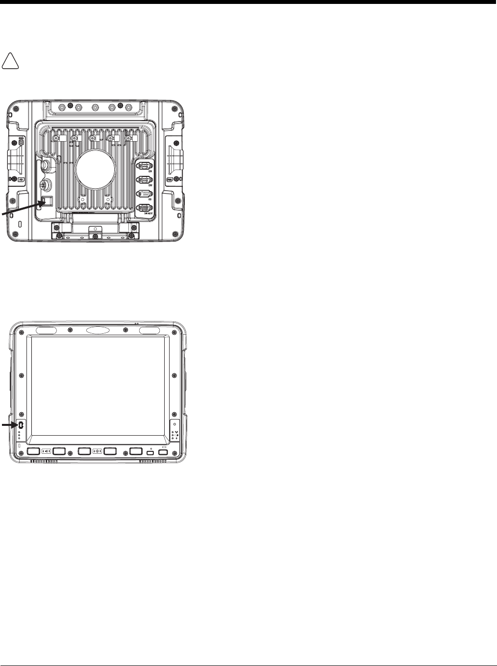
2 - 7
Power Up
The Quick Mount Smart Dock has a power switch on the back.
The “On” side of this rocker switch has a raised bump to allow the state of the switch to be determined when the switch may not
be easily viewed, for example, after the dock is mounted in a vehicle.
After external power has been connected and the Thor VM2 has been mounted in the dock, press the side of the power switch
with the raised bump to pass power from the dock to the Thor VM2.
Next locate the power button on the front of the Thor VM2.
Press the power button to turn the Thor VM2 on. When the Windows desktop is displayed or an application begins, the power up
sequence is complete.
See Power Controls (see page 3-6) for more information.
If a USB drive, such as a thumb drive is attached to the Thor VM2, the device attempts to boot from the USB drive and
cannot. Please remove the USB drive and power up the Thor VM2 again.
!
P
UPS
SYS
SSD

2 - 8
Rebooting the Thor VM2
Warmboot
A warmboot reboots the Thor VM2 without erasing any registry data. Configuration settings and data in RAM are pre-
served during a warmboot. Network sessions are lost and any data in running applications that has not been previ-
ously saved may be lost. CAB files already installed remain installed.
There are several warmboot methods available:
• Using the Registry, select Start > Settings > Control Panel > Registry and tap the Warmboot button. The Thor
VM2 immediately warmboots.
• Using the Start menu, select Start > Run and type WARMBOOT in the text box. Press Enter. The Thor VM2
immediately warmboots. The WARMBOOT text command is not case-sensitive.
• Use the P1 + P5 + Orange key press sequence to reboot the Thor VM2. The keys may be pressed in sequence;
they do not need to be held down simultaneously.
Restart
A restart reboots the Thor VM2 without erasing any registry data. Configuration settings are preserved during a
restart. Network sessions are lost and any data in running applications that has not been previously saved may be
lost. The contents of RAM are erased and the operating system and CAB files are reloaded.
To initiate a restart:
• Using the Registry, select Start > Settings > Control Panel > Registry and tap the Restart button. The Thor VM2
immediately restarts.
• Using the Start menu, select Start > Run and type RESTART in the text box. Press Enter. The Thor VM2
immediately restarts. The RESTART text command is not case-sensitive.
Clearing Persistent Storage / Reset to Default Settings
Use the Registry control panel Load Factory Defaults button to set the Thor VM2 registry back to factory defaults. No
other clearing is available or necessary.
Tapping the Touch Screen with a Stylus
Note: Always use the point of the stylus for tapping or making strokes on the touch screen.
Never use an actual pen, pencil, or sharp/abrasive object to write on the touch screen.
Hold the stylus as if it were a pen or pencil. Touch an element on the screen with the tip of the stylus then remove the stylus from
the screen.
Firmly press the stylus into the stylus holder when the stylus is not in use.
Using a stylus is similar to moving the mouse pointer then left-clicking icons on a desktop computer screen.
Using the stylus to tap icons on the touch screen is the basic action that can:
• Open applications
• Choose menu commands
• Select options in dialog boxes or drop-down boxes
• Drag the slider in a scroll bar
• Select text by dragging the stylus across the text
• Place the cursor in a text box prior to typing in data
• Place the cursor in a text box prior to retrieving data using a scanner/imager.
A right-click can be simulated by touching the touch screen with the stylus and holding it for a short time.
A stylus replacement kit is available.
If a USB drive, such as a thumb drive is attached to the Thor VM2, the device attempts to boot from the USB drive:
• If the USB drive contains a bootable sector, the Thor VM2 boots from the USB drive.
• If the USB drive does not contain a bootable sector, the Thor VM2 does not boot. Remove the USB drive and boot
the Thor VM2 again.
!

2 - 9
Setup Terminal Emulation Parameters
Note: The instructions below are for Honeywell RFTerm. If a different terminal emulation software is installed on your Thor VM2
refer to the documentation for that software.
Before you make a host connection, you will, at a minimum, need to know:
• the alias name or IP address (Host Address) and
• the port number (Telnet Port) of the host system to properly set up your host session.
1. Make sure the mobile client network settings are configured and functional. If you are connecting over wireless LAN
(802.11x), make sure your mobile client is communicating with the Access Point.
2. From Start > Program, run RFTerm or tap the RFTerm icon on the desktop.
3. Select Session > Configure from the application menu and select the “host type” that you require. This will depend on the
type of host system that you are going to connect to; i.e., 3270 mainframe, AS/400 5250 server or VT host.
4. Enter the “Host Address” of the host system that you wish to connect to. This may either be a DNS name or an IP address
of the host system.
5. Update the telnet port number, if your host application is configured to listen on a specific port. If not, just use the default
telnet port.
6. Select OK.
7. Select Session > Connect from the application menu or tap the “Connect” button on the Tool Bar. Upon a successful
connection, you should see the host application screen displayed.
To change options such as Display, Colors, Cursor, Bar Code, etc., refer to these sections in the RFTerm Reference Guide for
complete descriptions of these and other features.
Cleaning the Touch Screen
Note: These instructions are for components made of glass. If there is a removable protective film sheet on the display, remove
the film sheet before cleaning the screen.
Keep fingers and rough or sharp objects away from the bar code reader scanning aperture and the mobile device touch screen.
If the glass becomes soiled or smudged, clean only with a standard household cleaner such as Windex® without vinegar or use
isopropyl alcohol. Dampen the cloth with the cleaner and then wipe the surface.
Do not use paper towels or harsh-chemical-based cleaning fluids since they may result in damage to the glass surface. Use a
clean, damp, lint-free cloth.
Do not scrub optical surfaces. If possible, clean only those areas which are soiled. Lint and particulates can be removed with
clean, filtered canned air.
Startup Help
Contact Technical Assistance (page 11-1) if you need more help.
Touch screen is not accepting stylus
taps or needs recalibration. Press Ctrl+Esc to force the Start Menu to appear. Use the tab, backtab and arrow keys
to move the cursor from element to element.
See touch screen Calibration (page 5-92).
Thor VM2 seems to lockup as soon
as it is rebooted. There may be slight delays while the wireless client connects to the network, authoriza-
tion for voice-enabled applications complete, and Bluetooth relationships establish or re-
establish.
When an application begins, the Thor VM2 is ready for use.

2 - 10
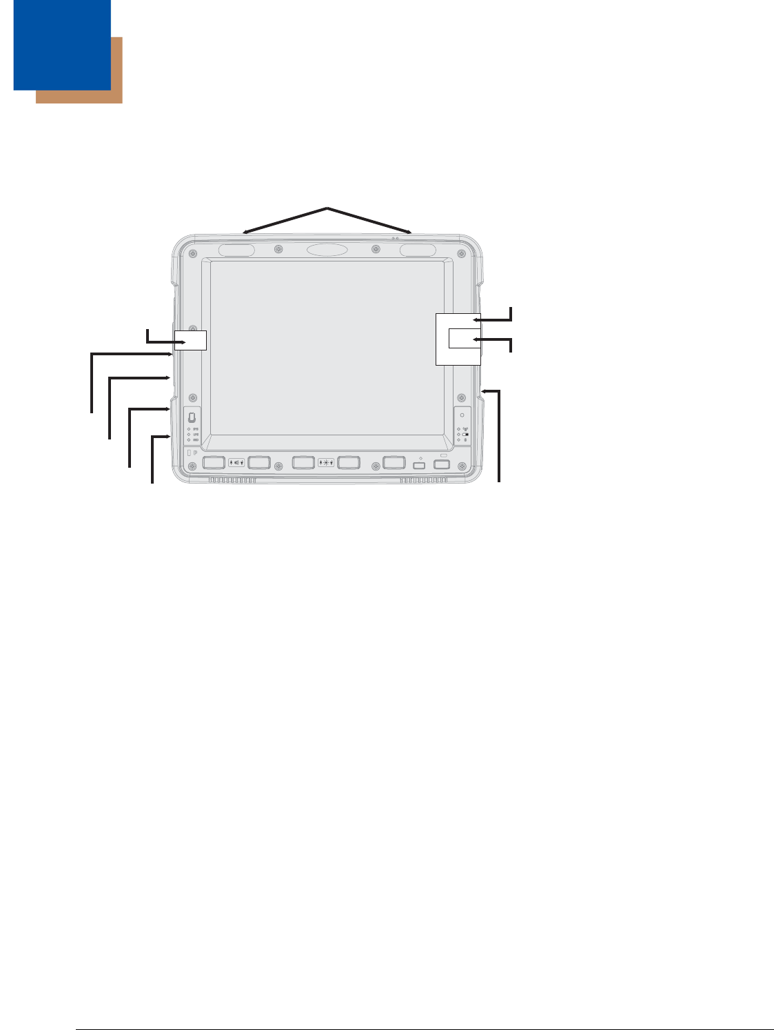
3 - 1
3
Hardware Overview
System Hardware
802.11a/b/gWireless Client
The Thor VM2 has an 802.11a/b/g network card that supports diversity with two internal or external antennas. Power man-
agement for the network card is configured with the Summit Client Utility (page 8-1).
Central Processing Unit
The CPU is a 1.6 GHz Intel Atom processor. The operating system is Microsoft Windows CE 6.0. The OS image is stored
on an internal CompactFlash memory card and is loaded into DRAM for execution.
Input/Output Components
The Thor VM2 supports the following I/O components of the core logic:
• Two 9-pin RS-232 serial ports, COM1 and COM2.
• One slot for SD memory card.
• CompactFlash (CF) memory card drive.
• Integrated keyboard with programmable keys.
• Ports available via adapter cables: USB host port, USB client port, CANbus, Audio.
System Memory
Main system memory is 1 GB SDRAM.
Video Subsystem
The Thor VM2 video subsystem consists of a color TFT display. The video subsystem complies with the VESA VL bus
standard. The resolution of this display is 1024x768 pixels. This resolution complies with the SVGA graphics industry stan-
dard.
The display supports screen blanking to eliminate driver distraction when the vehicle is in motion.
P
UPS
SYS
SSD
CF Slot
SD Slot
Antenna Connectors
CompactFlash
Hard Drive
Secure
Digital
Memory
Card
Power
Connector
SIM
Card
USB
Connector
CANbus/
Audio
Connector
Serial
Connector
COM2
Serial
Connector
COM1
SIM Slot

3 - 2
Audio Interface
Speakers are located on the bottom front of the Thor VM2. A headset adapter cable provides a connection for headset
operation. When a headset is plugged into the adapter cable, the main speakers are disabled.
A microphone is located at the upper right of the Thor VM2 display, near the Thor VM2 emblem. When a headset is
plugged into the adapter cable, the internal microphone is disabled.
Card Slots
CompactFlash (CF) Slot
The CF ATA slot is not hot swappable. The Thor VM2 must be powered down to insert or remove an ATA card. Since
the operating system is stored on the CF ATA card, the Thor VM2 cannot operate without the ATA card.
Secure Digital (SD) Slot
The SD slot accepts an SD memory card. The SD card is hot swappable.
Bluetooth EZPair
The Thor VM2 contains Bluetooth version 2.0 with Enhanced Data Rate (EDR) up to 3.0 Mbit/s over the air. Bluetooth
device connection (or pairing) can occur at distances up to 32.8 ft (10 meters) Line of Sight. The wireless client retains
wireless connectivity while Bluetooth is active.
The user cannot select PIN authentication or encryption on connections from the Thor VM2. However, the Thor VM2 sup-
ports authentication requests from pairing devices. If a pairing device requests authentication or encryption, the Thor VM2
displays a prompt for the PIN or passcode. Maximum encryption is 128 bit. Encryption is based on the length of the user’s
passcode.
Bluetooth simultaneously supports one printer as a slave Bluetooth device and one scanner, either as a slave or as a mas-
ter Bluetooth device.
• The LED on the Bluetooth scanner illuminates during a scanning operation.
• Bar code data captured by the Bluetooth scanner is manipulated by the settings in the Thor VM2 Data Collection control
panel applet.
• Multiple beeps may be heard during a bar code scan using a mobile Bluetooth scanner; beeps from the mobile Bluetooth
scanner as the bar code data is accepted/rejected, and other beeps from the Thor VM2 during final bar code data
manipulation.
WWAN
WWAN (Wireless Wide Area Networking) is available on the Thor VM2. A slot is provided for a SIM card.
GPS
GPS (Global Positioning System) is available on the Thor VM2.
Power
Vehicle DC Power Supply
Vehicle power input for the Thor VM2 dock is 10V to 60V DC and is accepted without the need to perform any manual oper-
ation within the Thor VM2 dock, see 12-48 VDC Vehicles (10-60 VDC Direct Connection) (page 4-34). The dock provides
a conditioned power output for the Thor VM2. By using a specified DC/DC power supply, input voltage of 50-150V DC can
be accepted, see 60-144 VDC Vehicles (50-150 VDC Power Supply, Screws on Top of Lid) (page 4-43) or 60-144 VDC
Vehicles (50-150 VDC Power Supply, Screws on Top of Lid) (page 4-43).
Power input is fused for protection and the fuse is externally accessible, see Fuse (page 3-4).
External AC Power Supply
If DC power is not available – for example, in an office environment – an optional external Universal Input Power Supply can
be used to convert AC wall power to an appropriate DC level. AC to DC power input for the Thor VM2 is delivered to the
Quick Mount Smart Dock via an optional external power supply and adapter cable. See External AC/DC Power Supply

3 - 3
(page 4-52).
Uninterruptible Power Supply
The Thor VM2 contains an internal UPS battery.
The UPS battery is automatically charged when the Thor VM2 is placed in a powered dock, provided the safe charging tem-
perature conditions below are met.
When external power is removed, the UPS automatically powers the Thor VM2 with no user intervention. When running on
UPS power, the power management timeouts may be different than when vehicle power is applied.
The UPS allows the Thor VM2 to continue operation when not mounted in a dock or when the vehicle battery is being
swapped. When fully charged the UPS battery is designed to power the Thor VM2 for a minimum of 30 minutes at tem-
peratures of -20ºC (-4ºF) or greater.
If operating on UPS power and the UPS battery becomes critically low, the Thor VM2 performs a controlled shutdown.
If there is no external power available, there must be 10% or greater power in the UPS battery or the Thor VM2 does not
power on.
The UPS status LED and the Battery Control Panel can be used to monitor the state of the UPS battery.
Safe Charging Temperature Range
The internal temperature of the Thor VM2 is the trigger for UPS battery charging.
• The UPS battery is not charged when the internal Thor VM2 temperature is below 0°C (32°F). This corresponds to
an ambient (room) temperature of approximately -10°C (-14°F).
• The UPS battery is not charged when the internal Thor VM2 temperature is above 45°C (113°F). This corresponds
to an ambient (room) temperature of approximately 35°C (95°F).
• If the UPS battery cannot be charged due to a temperature extreme, the UPS Status LED (page 3-12) is amber.
Move the Thor VM2 to a different location to charge the UPS battery.
When the Thor VM2 is operated in an environment where the UPS battery is not able to charge due to temperature
extremes, the Thor VM2 should be removed to a location within the safe charging temperature range during off hours.
A discharged UPS battery cannot protect against data loss in the event vehicle power is interrupted.
Charging Timeout
• A fully discharged UPS battery normally recharges in less than 4 hours when the Thor VM2 is in a powered dock and
within the safe charging temperature range.
• If the UPS battery is not charged before an 8 hour (or 4 hours for some earlier software revisions) timeout period
expires, the UPS Status LED (page 3-12) is amber.
• The charge timeout is reset if charging resumes upon application of external power.
• The charge timeout is reset if charging resumes when the Thor VM2 enters the permissible temperature range for
charging.
Charging and Power Management
• Charging does not occur when the Thor VM2 is in ignition mode and the ignition is inactive.
• Charging of the UPS battery continues when the Thor VM2 is in power management (user idle, system idle or
suspend modes).
Backup Battery
The Thor VM2 has a permanent Lithium battery installed to maintain time, date and CMOS setup information for a minimum
of 90 days. The lithium battery is not user serviceable and should last four years with normal use before it requires replace-
ment.
Note: The backup battery should only be changed by authorized service personnel.
Safety requirements restrict the temperature at which the Li-Ion UPS battery can be charged. Charging is disabled
if the ambient temperature is outside of the 0ºC to 35ºC safe charging range. In order to maintain UPS charge the
Thor VM2 should have power applied while the unit is within the safe charging range for at least an hour each day.
!

3 - 4
Fuse
Power Management Modes
The Thor VM2 supports the standard Microsoft Windows CE power management modes: On (D0), Backlight Off (D1), Dis-
play Off (D2) and Suspend (D3).
On Mode (D0)
When the Thor VM2 is attached to either vehicle power or an external power supply or is operating from the UPS bat-
tery and the power button is pressed, the Thor VM2 is in the On mode. In this mode, the keypad, touch screen and any
attached peripherals such as a scanner function normally. The display remains on until the backlight timer (if enabled)
expires.
User Idle / Backlight Off Mode (D1)
Backlight is dimmed, but display is readable. The Thor VM2 transitions to this mode from On after the User Idle time-
out period has passed without a primary even occurring.
System Idle / Display Off Mode (D2)
Backlight and display are off. The status LED is solid green. The Thor VM2 transitions to this mode from User Idle
after the System Idle timeout period has passed without a primary event occurring.
Suspend mode (D3)
All devices that are not configured as wakeup events are powered off. The status LED is blinking green if external
power is connected and off if external power is not connected. The Thor VM2 transitions to this mode from System Idle
after the Suspend timeout period has passed without a primary event occurring.
By default power is turned off to the USB port when the Thor VM2 is in Suspend. The Thor VM2 can be configured to
provide power to the USB port in Suspend using the Options (page 5-74) control panel.
Additionally the power button can be used to enter or exit Suspend mode:
• If the Thor VM2 is On, pressing the power button immediately transitions the unit to Suspend.
• If the Thor VM2 is in Suspend mode, pressing the power button transitions the unit to On.
Shutdown / Off Mode (D4)
The Thor VM2 shuts down when the Thor VM2 is operating on power and the UPS battery becomes critically low
regardless of the current power management state. The Thor VM2 remains Off until external power is applied. The
Thor VM2 may restart automatically when external power is applied or may require the user to press the Power button
depending on installation and configuration.
The Thor VM2 transitions to Off mode from Suspend after the Shutdown timeout period has passed without a primary
event occurring. If the Thor VM2 has external power applied or a sufficiently charged UPS battery the Thor VM2 may
restart automatically or may require the user to press the Power button depending on installation and configuration.
A Real Time Clock (RTC) powered by an internal battery maintains the date and time while the Thor VM2 is off.
The Thor VM2 uses an 8A time delay (slow blow), fuse that is externally accessible and user
replaceable. The fuse is located on the back of the Quick Mount Smart Dock. The fuse is accessed
by unscrewing the cap as indicated.
Should it need replacement, replace with same size, rating and type of fuse:
• Littelfuse 0215008.MXP
• Cooper Bussmann BK1/S506-8-R
• Bel Fuse 5HT 8-R
or equivalent.
Fuse has voltage on it even when power is off. Always disconnect input power before changing the
fuse.

3 - 5
Primary Events
The Primary Events described below are the default behavior. Primary events can be modified using the LXEPower-
MgrPrimaryEvents API.
Please refer to the CE API Programming Guide for API details.
User Primary Events
A User Primary Event transitions the Thor VM2 to D0 (On) mode. When no user event happens for the specified
time period, the Thor VM2 transitions to D1 (User Idle), then D2 (System Idle) and then D3 (Suspend). Timeout
periods are set via the Schemes tab in the Power control panel.
User primary events include:
• Any key press on the integrated keypad or external USB keyboard
• Touch on the touch screen
System Primary Events
A System Primary Event allows the Thor VM2 to transition to D2 (System Idle) but the Thor VM2 does not enter
D3 (Suspend) as long the system event occurs.
System primary events include:
• Serial data transfer
• USB data transfer
Wake Source Events
These events wake the Thor VM2 from suspend:
• Power button
• Touch on the touch screen
• External power connection (AC/DC, Auto-On, Ignition Control/Ignition On power modes only)
• USB client connection
• Ignition (switched from Off to On, Ignition Control/Ignition Off power mode only)
•RTC
• Serial port CTS control line
• Headset connection (this is not enabled by default, but can be configured to wake the Thor VM2)
Events generated by these actions are not processed. For example, the touch screen tap that wakes the Thor
VM2 is ignored.
The following events DO NOT wake the Thor VM2 from suspend:
• Bluetooth keyboard or mouse
• Bluetooth connection
• USB client disconnect
• USB host data (unless enabled via API)
• USB host connection
• SDIO interrupt
• Serial data
• 802.11 radio
• External power disconnect
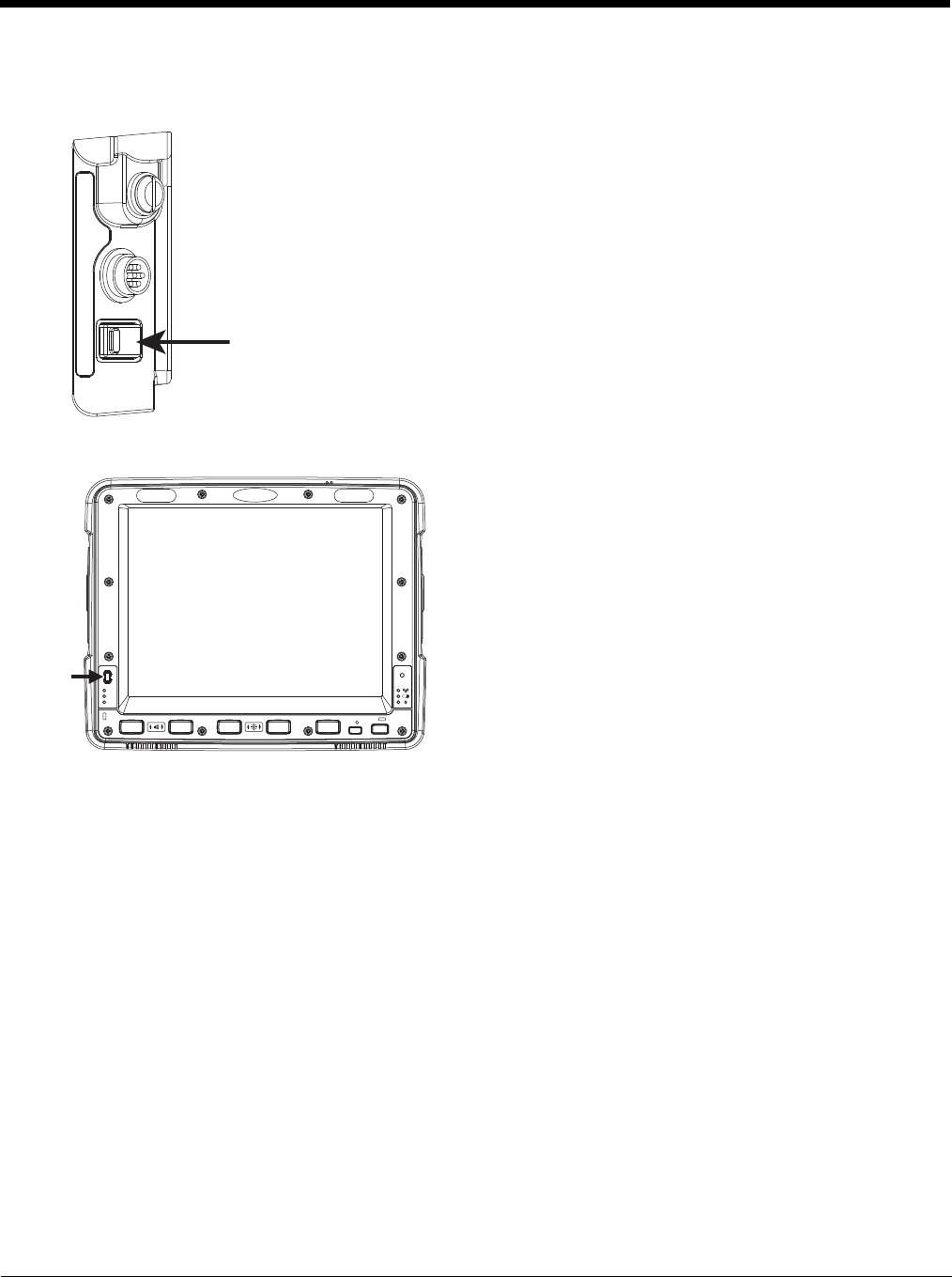
3 - 6
Power Controls
Power Switch
Power Button
Power Configuration Mode
The Power Configuration Mode control panel is used to select desired power configuration behavior.
Please refer to the Power Configuration Mode (page 5-80) control panel for complete details.
For information on the Ignition input signal see Vehicle 10-60VDC Direct Power Connection (page 4-34) and Auto-On
Control Wiring Diagram (page 4-37).
AC/DC
The Thor VM2 is powered on manually. Due to the presence of external power, longer default power management
timeouts are used.
Ignition Control
The Thor VM2 is configured to power on when the vehicle ignition is switched on. When the vehicle ignition is on,
longer default power management timeouts are used. If the vehicle ignition is turned off, shorter default power
management timeouts are used.
Auto-On
The Thor VM2 is designed to power on whenever external power is attached. Due to the presence of external
power, longer default power management timeouts are used.
After all cables are connected, the Thor VM2 can be powered on.
There is a power switch located on the back of the Quick Mount Smart Dock. The power switch
is a rocker switch.
The power switch has a raised bump to identify the switch position even when it is hidden from
view. When the side of the switch with the raised bump is pressed, the power switch is On. If
the dock is connected to external power, the dock delivers power to the Thor VM2.
Generally, once the dock is powered On, there is no need to power it off. The dock power can
remain On even when the Thor VM2 is not attached.
The power button is located at the lower left of the Thor VM2.
If the Thor VM2 is Off, pressing the power button starts the power up
sequence.
Note: This assumes that the Thor VM2 is docked in a powered
Quick Mount Smart Dock or that the internal UPS battery has
a sufficient charge to power the Thor VM2. If no external
power is available and the UPS battery does not have a
charge, pressing the power button causes no action.
If the Thor VM2 is On, pressing the power button places the unit in
Suspend.
P
UPS
SYS
SSD
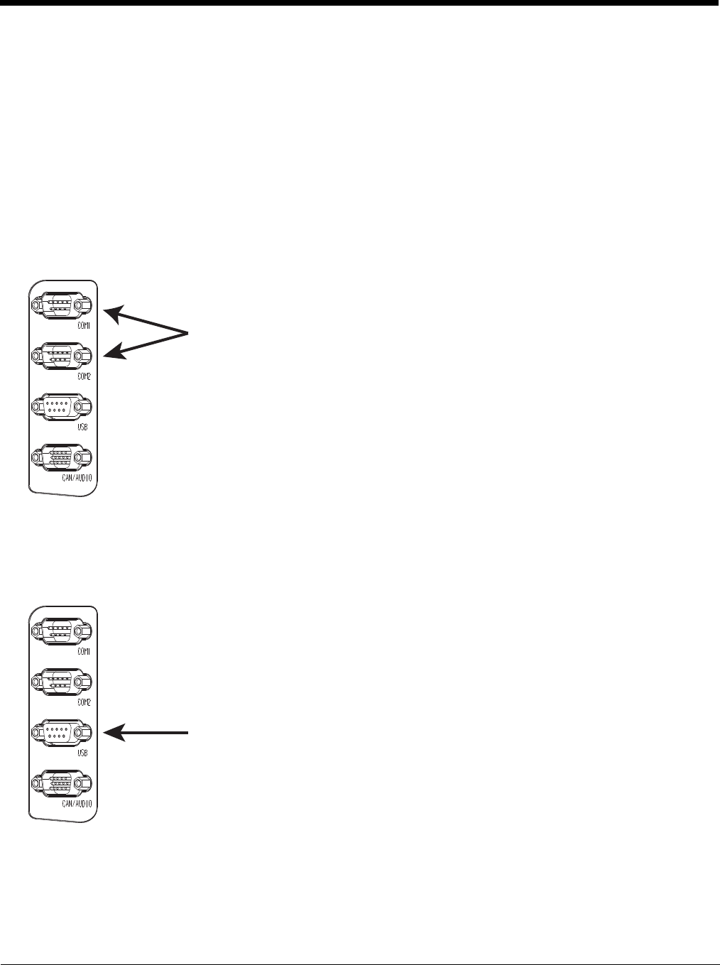
3 - 7
UPS
The Thor VM2 uses the UPS mode whenever external power is not available. Due to the absence of external
power, much shorter default power management timeouts are used.
External Connectors
Power the Thor VM2 off before attaching a cable to any port (serial, USB, Audio/CAN, etc.).
The external I/O connectors for the Thor VM2 are located on the right side of the Quick Mount Smart Dock (when viewed from
the back).
The Power Supply Connector (page 3-8) is on the left side of the dock (when viewed from the back).
Antenna connectors are located on the top rear of the Thor VM2.
Serial Connector (COM1 and COM2)
Screen Blanking
The screen blanking signal can be provided either by a Honeywell Screen Blanking Box or a user supplied switch or
relay. See Screen Blanking (page 4-49) for information on connecting screen blanking accessories.
USB Connector
The COM1 and COM2 connectors are D-9 male connectors located on the back of the Quick
Mount Smart Dock.
Power the Thor VM2 off before attaching a cable to any port (serial, USB, Audio/CAN, etc.).
The serial connectors are industry-standard RS-232, PC/AT standard 9–pin “D” male con-
nector. See COM1 and COM2 Connector (page 10-4) for connector pinout detail.
By default, Pin 9 is configured to provide +5V for an external bar code scanner. Pin 9 of
COM1 or COM2 may also be configured to provide RI.
See Connect Serial Device (page 4-54) for more information.
If a COM port is not being used for a scanner, it can be used for Screen Blanking (page 4-
49) when the vehicle is in motion.
The USB connector is a D-9 female connector located on the back of the Quick Mount Smart
Dock. See USB Connector (page 10-5) for connector pinout detail.
Power the Thor VM2 off before attaching a cable to any port (serial, USB, Audio/CAN, etc.).
See Connect USB Host (page 4-33) and Connect USB Client (page 4-34) for more informa-
tion.
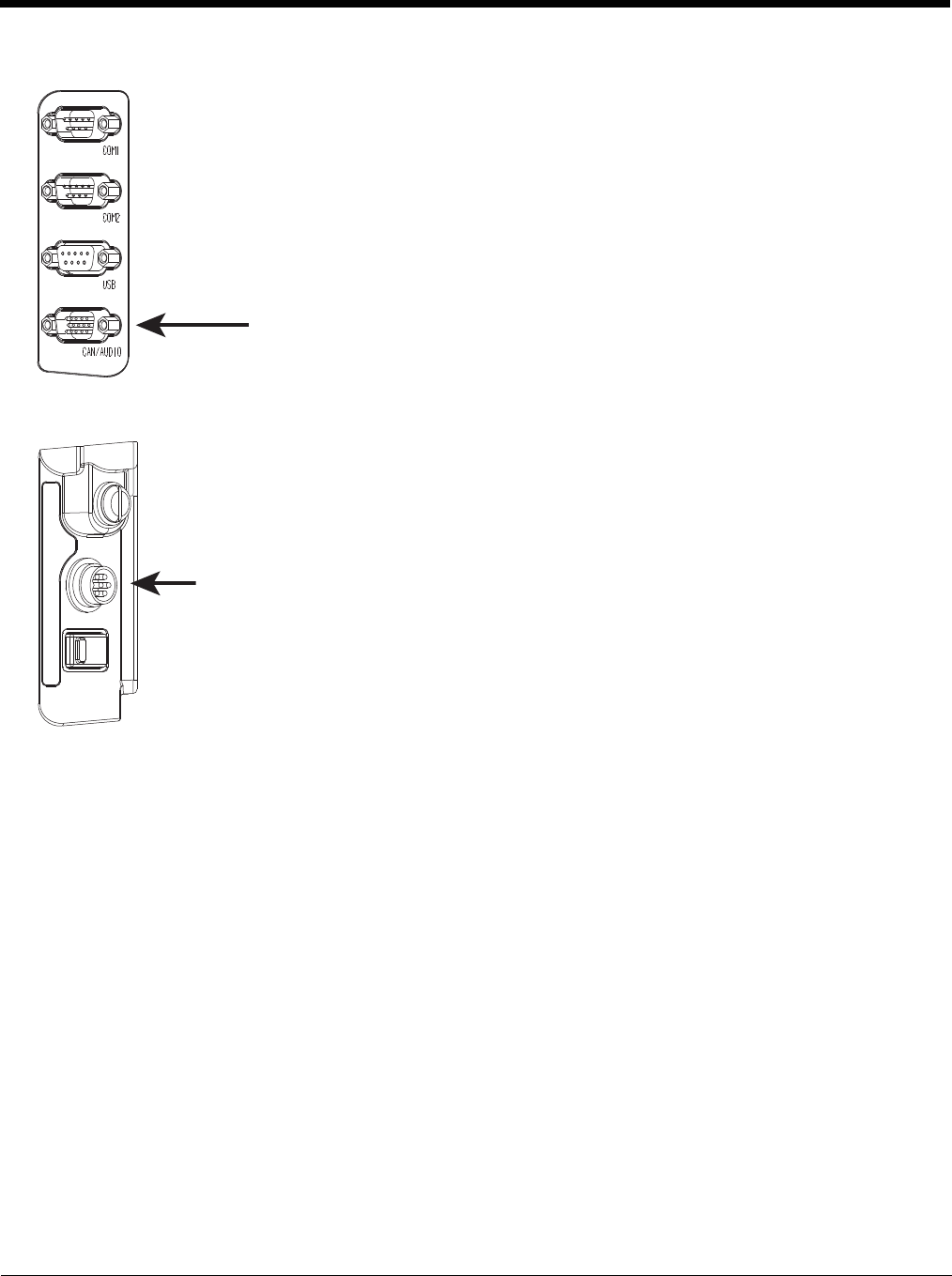
3 - 8
CANbus / Audio Connector
Power Supply Connector
The CANbus/Audio connector is a D-15 male connector located on the back of the Quick
Mount Smart Dock.
The connector supports a headset adapter cable or a CANbus cable. The Thor VM2 does
not support connecting audio and CANbus simultaneously.
See CANbus / Audio Connector (page 10-6) for connector pinout detail.
A headset cable attaches to the CANbus / Audio connector and provides a quick connect
connection for a headset. See Connect Headset Cable (page 4-55) for more information.
The CANbus Y cable has a 9 pin F SAE J1939 (Deutsch) and 9 pin M SAE J1939 (Deutsch)
connector. See Connect CANbus Cable (page 4-56) for more information.
The CANbus interface is a virtual COM9 port. This port can be accessed using standard
Windows API calls.
Power is supplied to the Thor VM2 through the power connector. Additionally this assembly pro-
vides a connection point for the vehicle’s chassis ground to be connected internally to the conduc-
tive chassis of the computer.
The Thor VM2 internal power supply can accept DC input voltages in the range of 10 to 60 Volts
DC.
See Power Supply Connector (page 10-4) for connector pinout detail. See Connect Power (page 4-
33) for more information on connecting power to the Thor VM2.

3 - 9
Antenna Connections
External Antenna Connector
Internal 802.11 Antenna
If the internal 802.11 antenna option is ordered, antennas are mounted inside the Thor VM2. The internal antennas
are not user accessible.
External 802.11 Antenna
An external whip antenna can be connected to the Wi-Fi antenna connections on the back of the Thor VM2 for the
802.11 radio. Two external antennas are used for radio diversity.
See Install External Antenna (page 4-56) for instructions.
Vehicle Remote Antenna
The external antennas can be remotely mounted on the vehicle. See Install Remote Antenna (page 4-57) for instruc-
tions. External antenna kits are available for the 802.11 Wi-Fi radio, GPS and WWAN.
The Thor VM2 is equipped with an 802.11 radio and can be ordered with
internal antennas, external antennas or external remote mount antennas.
When the Thor VM2 is ordered with internal antennas, the external antenna
connectors are not used. GPS and WWAN are optional on the Thor VM2
and require external remote mount antennas.
1. WI-FI (MAIN) (Red label) 802.11 Main External Antenna Connector
2. GPS (Green label) GPS Antenna Connector
3. MOBILE NET (Blue label) WWAN Antenna Connector
4. WI-FI (AUX) (Yellow label) 802.11 Auxiliary External Antenna
Connector
When the Thor VM2 is ordered with the internal antenna option, the 802.11 antenna connectors on
the back are not connected to the 802.11 radio. Instead the internal antenna connector is connected
to the 802.11 radio.
Remove the rubber cap, if present, from the antenna connector before connecting an external
antenna.
1 2 34

3 - 10
Keyboard Options
Integrated Keypad
The integrated keypad contains five programmable keys, a blue modifier key and an orange modifier key.
The P1 though P5 keys are user programmable.
• When used with no modifier key, P1 through P5 can be configured for a user programmable function.
• When used with the Orange modifier key, P1 through P5 provide secondary programmable keys, P6 through P10, and
can be configured for a user programmable function.
• The programmable keys can be remapped to provide a single keypress, a string of keypresses or to execute an
application or command. Key remapping is configured via the Programmable Key (page 5-83) option in the Control
Panel.
• Programmable keys persist across a warmboot or power cycle.
• When used with the Blue modifier key, P1 through P4 keys are used to adjust speaker volume and display brightness.
The Thor VM2 integrated keypad is backlit.
• By default, the integrated keypad backlight follows the display backlight. When the display backlight is on, the integrated
keypad backlight is on.
• If the display backlight brightness is increased (or decreased) the integrated keypad backlight brightness is increased (or
decreased).
• The integrated keypad backlight and the display share the same timer, which is configured in the Power (page 5-78)
control panel.
• The integrated keypad backlight can be disabled via the Misc tab of the Options (page 5-74) control panel.
Keypad LEDs
See Keyboard LEDs (page 3-14) for details.
95-Key USB Keyboard
The Thor VM2 uses an optional rugged QWERTY 95 key keyboard, designed for ease of use with the Windows CE operat-
ing system. The USB keyboard connects directly to the D9 USB connector on the Thor VM2 Quick Mount Smart Dock.
• The 95 key keyboard supports all 104 keyboard functions (101 standard keyboard plus Windows keys) and includes an
integrated pointing device and left and right mouse buttons. However, because the keyboard only has 95 keys, all
functions are not visible (or printed on the keyboard). Therefore the keyboard supports what is called hidden keys - keys
that are accessible but not visible on the keyboard.
• The 95 key keyboard keys are backlit. The keyboard backlight is manually controlled.
Keyboard Backlight
The keyboard backlight key in the top right hand corner has a light bulb icon.
P3 P8 P4 P9 P5 P1 0P6 P2 P7
P1
SYS
SSD
Wi Fi
UPS
Print
Screen
SysRq
Scroll
Lock
Pause
Break
67 BackSpace Num
Lock
ERTYUI O
P]\
[
{}|7
4
1
0
Home
DF GHJ K L ;'
:"Enter
Alt
CV B
N
M,
<.
>
/
?Shift
Alt Ctrl
Ins
End
4
$
5
%^&
9
(
0
)-
_
=
+
LR
X
Esc F3 F4 F5 F6 F7 F8 F9 F10 F11 F12F1 F2 Fn
123 /*-
Tab QW89
56
23
PgUp
Caps
Lock AS
Shift
Ctrl
PgDn
+
`
~!@#
Enter
.
Del
8
*
Z
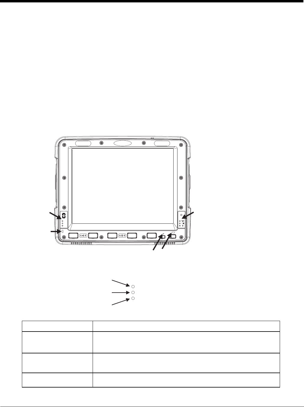
3 - 11
The keyboard keys are backlit. The keyboard backlight is manually controlled using the backlight key in the upper right
hand corner of the keyboard. Pressing the backlight key cycles the keyboard backlight through the levels of backlight
intensity: Off, Low intensity, Medium intensity, Maximum intensity, Off, etc. When the Thor VM2 is powered on, the key-
board backlight defaults to Off.
Since the keyboard is a USB device, by default the external keyboard backlight is turned off when the Thor VM2 enters
Suspend. This behavior can be changed by enabling USB power in Suspend on the Misc tab of the Options (page 5-
74) control panel.
control panel.
USB Keyboard / Mouse
A standard USB keyboard or mouse can be attached to the Thor VM2 using the appropriate adapter cable.
The Y cable attaches to the Thor VM2 and provides a USB connector. Please refer to documentation provided with the
USB keyboard or mouse for more information on their operation.
LED Functions
System LEDs
SYS (System Status) LED
LED Behavior System State
Solid Green • On
• On but Backlight Off
• On but Display Off
Green blinking very slowly
External power present
(1/2 sec. on, 4 1/2 sec. off) • Suspend
Off
External power present • Off
System LEDs Connection LEDs
Programmable LED
Blue LED Orange LED
P
UPS
SYS
SSD
UPS
SYS
SS
D
SYS (System Status) LED
UPS (Uninterruptible Power Supply) LED
SSD (Solid State Drive) LED

3 - 12
UPS Status LED
The color of the UPS LED identifies the charge level, while the behavior of the LED identifies the charging state.
Charge Level
Charging State
SSD (Solid State Drive) LED
Off
External power not present • Suspend
• Off
Green blinking slowly
External power present
(1/2 sec. on, 1 1/2 sec. off)
CPU temperature less than -20ºC, Heater warming CPU for 30 sec.
Green blinking slowly
External power not present
(1/2 sec. on, 1 1/2 sec. off)
CPU temperature less than -20ºC, Need to move unit to warmer environment
LED Color Status
Green Fully charged (>90%)
Amber • Less than fully charged, but more than 2 minutes runtime remaining
• Out of Safe Charging Temperature Range (page 3-3) Charging only occurs between
approximately -10°C and 35°C ambient temperature
• No UPS present
•Charging Timeout (page 3-3) Not fully charged after 4 or 8 hours depending on software
revision.
Red Low battery, less than 2 minutes runtime until shutdown
LED Behavior Status
Slow Blink
(1 sec. on, 3 sec. off) Charging
Fast Blink
(1/2 sec. on, 1/2 sec. off) UPS supplying power and discharging
On Neither charging or discharging
Off Unit is off or is in Suspend
LED Behavior Status
Flashing Green SSD read or write activity
Off No SSD read or write activity
LED Behavior System State

3 - 13
Connection LEDs
WWAN LED
Wi-Fi LED
Bluetooth LED
The Bluetooth LED blinks once every 6 seconds when the Bluetooth client is paired but not connected. It blinks once
for a very short time every 2 seconds when paired and connected. It blinks every second when in discovery. The LED
is off when the Bluetooth client is off.
LED Behavior Status
Solid Green Indicates a WWAN connection to a network
Off Indicates no WWAN connection
LED Behavior Status
Solid Green Indicates a connection with an IP address to an Access Point
Off Indicates no connection to an Access Point
LED Behavior Status
Blue Blinking Slowly Bluetooth is paired but not connected to a device
Blue Blinking Medium Bluetooth is paired and connected to a device
Blue Blinking Fast Bluetooth is discovering Bluetooth devices
Off Bluetooth hardware has been turned off
Wi Fi
Wi-Fi LED
Bluetooth LED
WWAN LED

3 - 14
Keyboard LEDs
The keyboard LEDs are located near the specified key.
Blue LED
Orange LED
Programmable LED
The Programmable LED is available for user applications. The LED defaults to Off unless activated by user applica-
tion.
The LED behavior is controlled by the NLedDriverSetDevice API.
Please refer to the CE API Programming Guide for API details.
Display
The display is a thin-film transistor display capable of supporting WSVGA graphics modes. Display size is 1024x768 pixels.
The display covering is designed to resist stains. The touch screen allows signature capture and touch input. The display sup-
ports screen blanking to eliminate driver distraction when the vehicle is in motion.
Touch Screen
The touch screen is a Resistive Panel with a scratch resistant finish that can detect touches by a stylus, and translate them
into computer commands. In effect, it simulates a computer mouse. Only Delrin or plastic styluses should be used. A right
mouse click is simulated by touching and holding the screen for the appropriate time interval.
When a dialog box is too large for the display, tap and drag the dialog box up or down or from side to side to view the
remainder of the dialog box.
Always use the point of the stylus for tapping or making strokes on the display. Never use an actual pen, pencil, sharp or
abrasive object to write on the touch screen.
An extra or replacement stylus may be ordered.
LED Behavior Status
Solid Blue • Indicates the Blue modifier key is active
• Pressing the Blue key a second time exits this modifier mode and turns off the LED
• Pressing the Orange key exits the Blue mode and turns off the Blue LED
• If no key other key is pressed within five seconds, the Blue key times out and turns off the
LED
• When Blue mode is active, keys P1 through P4 provide volume and brightness adjustment
functions
Off Blue mode is not invoked
LED Behavior Status
Solid Orange • Indicates the Orange modifier key is active. Orange mode is invoked for the next keypress
only
• Pressing the Orange key a second time exits this modifier mode and turns off the LED
• Pressing the Blue key exits the Orange mode and turns off the Orange LED
Off Orange mode is not invoked.
LED Behavior Status
Controlled by application Refer to application developer for LED behavior details.
Off Default mode. Refer to application developer for LED behavior details.

3 - 15
A replaceable touch screen protective film is available when the Thor VM2 is used in an abrasive environment. Contact
Technical Assistance (page 11-1) for availability.
Note: If the touch screen is disabled or looses calibration on a Thor VM2, you must use a USB mouse or keyboard attached
to the Thor VM2 to access the control panel to re-enable or recalibrate the touch screen unless a programmable key
has been assigned to that function.
Screen Blanking
Screen blanking (blackout) can be enabled when the vehicle is in motion. See Screen Blanking (page 4-49) for hardware
setup and Screen Control (page 5-90) for software setup to enable screen blanking. Once screen blanking is enabled, the
display is blanked out any time when the cable sends the signal the vehicle is in motion. If the cable is removed, screen
blanking is disabled and the display remains on.
Display Backlight Control
The display brightness can be adjusted manually, via the keypad:
1. Press the Blue key to enter Blue mode.
2. Press P3 to increase brightness or P4 to decrease brightness.
3. Press the Blue key to exit Blue mode.

3 - 16

4 - 17
4
Vehicle Mounting and Accessory Installation
Introduction
The Thor VM2 is designed to be mounted to a Quick Mount Smart Dock in a vehicle with either a RAM mount or U Bracket sys-
tem. A power cable is provided with the Thor VM2 dock. An optional USB keyboard and keyboard mount is available. Optional
communication cables are available.
Vehicle mounting brackets are specifically designed for vehicle mount applications. The vehicle mounted assembly restrains the
Thor VM2 and isolates it from shock and vibration. A RAM metal table stand is available to secure the Thor VM2 and dock when
in an office environment, for example.
The vehicle mount holds the Quick Mount Smart Dock and the Thor VM2 attaches to the dock. The dock remains attached to
the vehicle, however, the Thor VM2 has a quick release located on the lower rear side that allows the Thor VM2 to easily be
removed from the dock. The Thor VM2 can be operated for a minimum of 30 minutes from an internal UPS battery when not
attached to a dock. The Thor VM2 can be transferred from one dock equipped vehicle to another for easy portability. The dock
provides accessory attachment and conditioned power for the Thor VM2.
Overhead, dash and roof support pillar mounting is via a RAM Mount or U-bracket accessory which includes all the hardware
required for vehicle mounting.
Never put the Thor VM2 into the vehicle mounted assembly until the assembly is securely fastened to the vehicle.
Prepare for Vehicle Mounting
The Thor VM2 should be secured to an area in the vehicle where it:
• Does not obstruct the driver's vision or safe vehicle operation.
• Will be protected from rain or inclement weather.
• Will be protected from extremely high concentrations of dust or wind-blown debris.
• Can be easily accessed by a user seated in the driver's seat while the vehicle is not in operation.
Quick Start
The following list outlines, in a general way, the process to follow when mounting the Thor VM2 in a vehicle. Refer to the fol-
lowing sections in this document for more details.
1. Install RAM Mount (page 4-20) or Install U Bracket Mount (page 4-29) to the vehicle.
2. Place Thor VM2 in the Dock (page 4-18).
3. Secure the optional external keyboard to either an integrated or remote mounting bracket.
4. Adjust the Thor VM2 to the best viewing angle.
5. Install Remote Antenna (page 4-57) or Install External Antenna (page 4-56) if necessary.
6. Connect Cables (page 4-32) for any peripherals.
7. Connect vehicle power:
•12-48 VDC Vehicles (10-60 VDC Direct Connection) (page 4-34)
•60-144 VDC Vehicles (50-150 VDC Power Supply, Screws on Top of Lid) (page 4-43)
•60-144 VDC Vehicles (50-150 VDC Power Supply, Screws on Side of Lid) (page 4-39).
•Thor VX8 / Thor VX9 Adapter Cable (page 4-48)
•VX6 / VX7 Adapter Cable (page 4-47)
8. Secure all cables in Strain Relief Cable Clamps (page 4-32).
The Thor VM2 is ready for use.
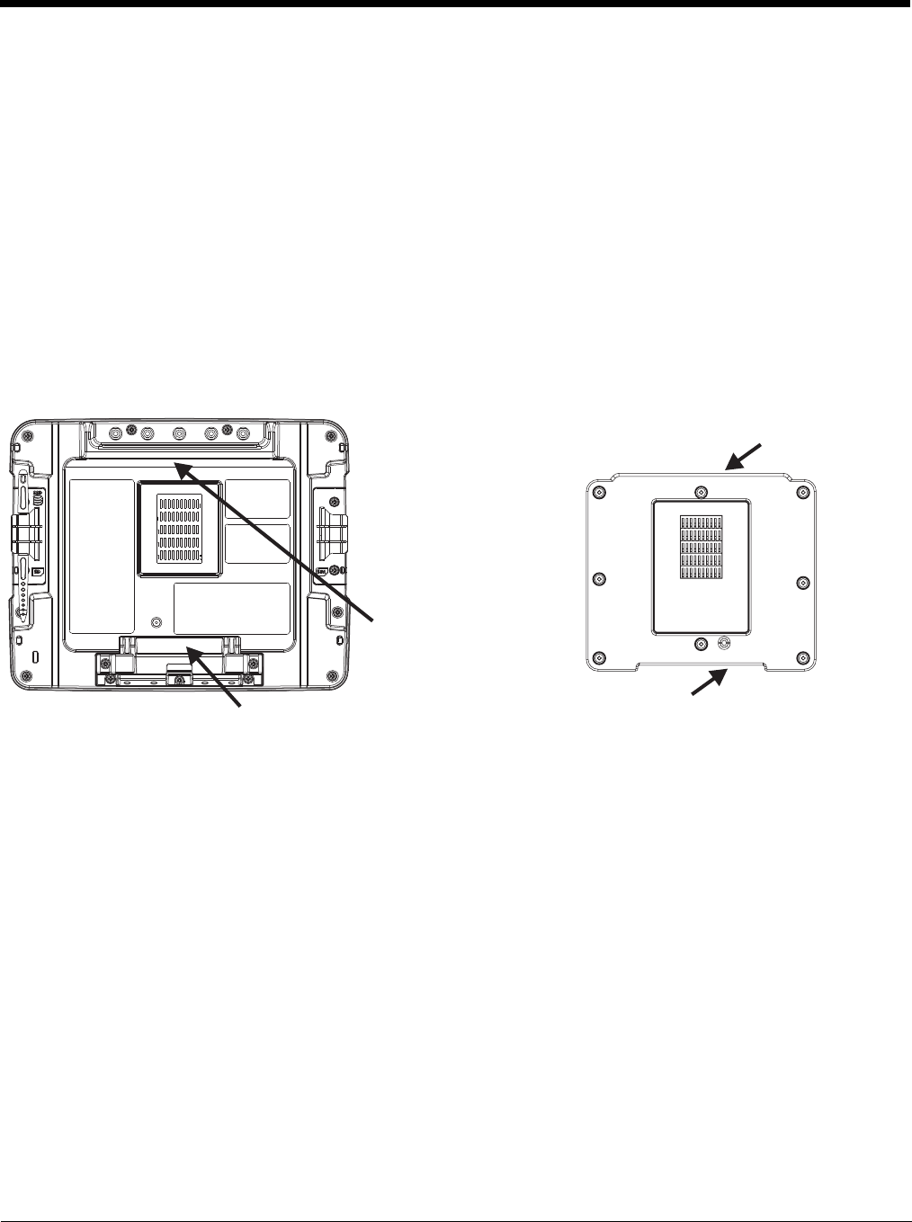
4 - 18
Maintenance - Vehicle Mounted Devices
Check the vehicle mounting hardware frequently and re-tighten if necessary.
If the vehicle mounting hardware and connections become broken, loose or cracked, the assembly must be taken out of service
and replaced. Contact Technical Assistance (page 11-1) for help.
Cleaning
Do not use paper towels or harsh-chemical-based cleaning fluids since they may result in damage to the Thor VM2 surfaces,
cables, connectors and mounting hardware.
Use a clean soft cloth to wipe any dirt, moisture or grease from the Thor VM2, connectors, cables or the vehicle mounting hard-
ware. Do not use any liquid to clean the Thor VM2, or connectors. Spray or dampen the cleaning cloth with the cleaning liquid.
If possible, clean only those areas which are soiled. Lint/particulates can be removed with clean, filtered canned air.
Place Thor VM2 in the Dock
1. Locate the notch on the upper rear of the Thor VM2.
2. Slide this notch over the top lip of the dock. Slide the Thor VM2 from side to side on the dock to make sure it fully engages
on the lip of the dock. If the Thor VM2 cannot be slid side to side, the lip is engaged.
3. Pull the quick release lever on the Thor VM2 down and push the Thor VM2 against the dock.
4. Release the quick release lever. The quick release lever catches the lower lip on the dock and secures the Thor VM2 to the
dock.
5. If necessary, adjust the viewing angle of the Thor VM2.
When the Thor VM2 is placed in the dock, the following may happen:
• If the Thor VM2 is off and power is connected to the dock, the Thor VM2 may boot when placed in the dock. The behavior
depends on the Power Configuration Mode selected. See Ignition Control Mode (page 5-80) and Auto-On Mode (page 5-81).
• If the Thor VM2 is on and power is connected to the dock, the Thor VM2 power management timers may change when the
Thor VM2 is placed in the dock. See Power (page 5-78).
When the Thor VM2 is removed from the dock, the following may happen:
• If the Thor VM2 is on and power is connected to the dock, the Thor VM2 power management timers may change when the
Thor VM2 is placed in the dock. See Power (page 5-78).
Back of Thor VM2 Front of Quick Mount Smart Dock
Notch on
Thor VM2
Release Lever
Upper Lip on Dock
Lower Lip on Dock
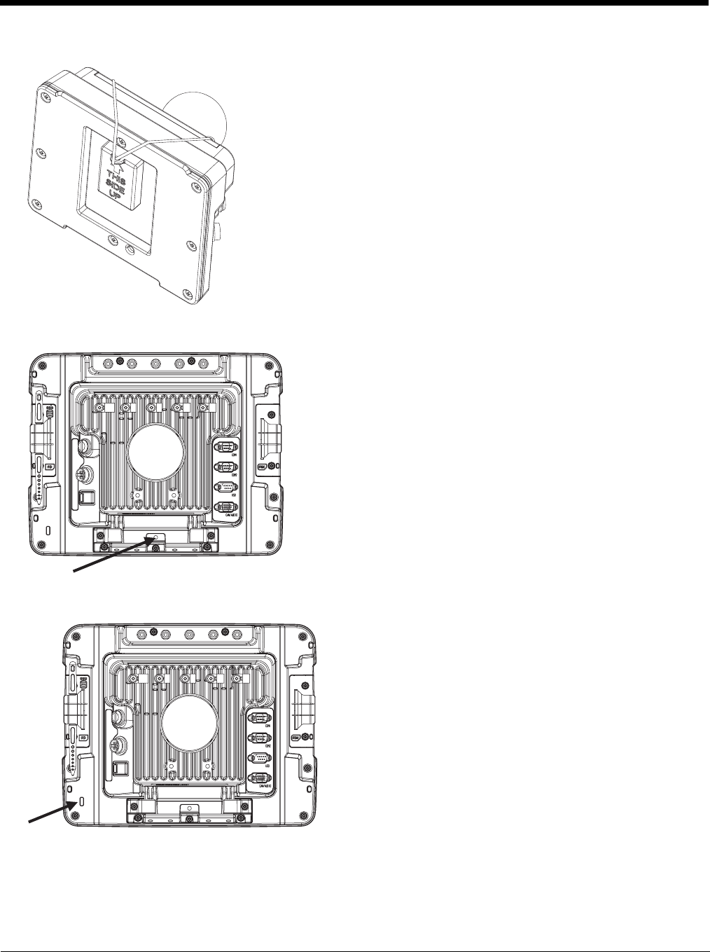
4 - 19
Dock I/O Pin Cover.
Padlock
Laptop Security Cable
The dock contains a tethered I/O Pin Cover to protect the I/O pins on the dock when
a Thor VM2 is not mounted in the dock.
• When the Thor VM2 is not installed in the dock, use the I/O Pin Cover to protect
the pins on the dock as shown.
• When a Thor VM2 is installed in the dock, the I/O Pin Cover can be placed out of
the way behind the dock.
It may be desirable to secure the Thor VM2 in the dock so it cannot be
removed from the dock. The quick release handle on the Thor VM2 is
notched to allow a user supplied standard padlock to be placed through a
hole in the bracket on the back of the Thor VM2 in the location shown
below. Once the padlock is installed, the release handle cannot be moved
so the Thor VM2 cannot be removed from the dock. The padlock shackle
must be smaller than 3/16” (4.76mm).
A cable tie wrap can be used instead of a padlock if desired.
The Thor VM2 can be secured with a standard laptop security cable
using the slot on the back of the Thor VM2.
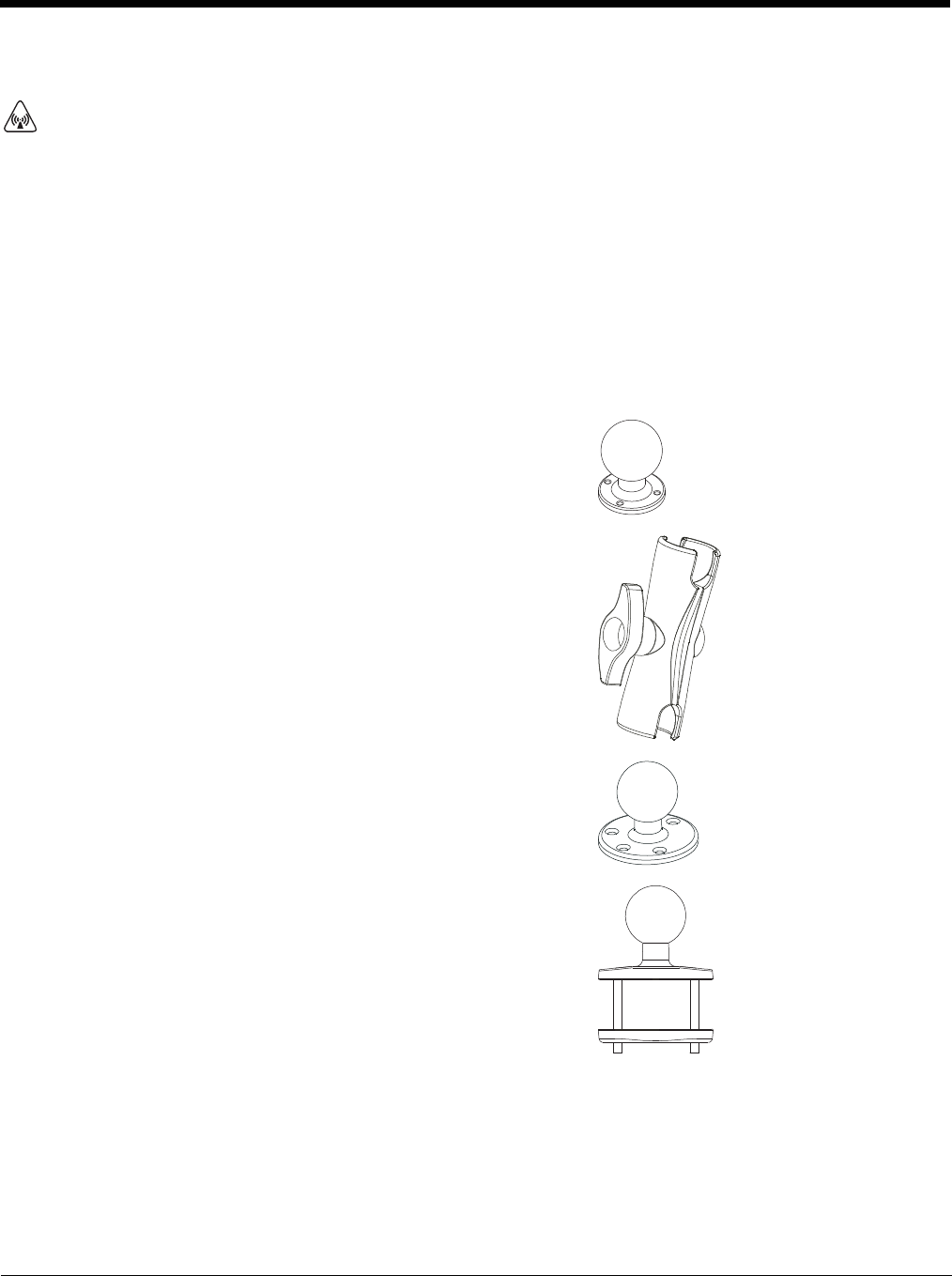
4 - 20
Install RAM Mount
Before installation begins, verify you have the applicable vehicle mounting bracket assembly components necessary, as shown
in the following figures.
Components - RAM Mounting Kits
A Thor VM1 mounting kit can be used when an external keyboard is not installed and includes the parts on this page.
A Thor VM2 mounting kit can be used when an external keyboard is installed includes the parts on this page plus the parts
on the next page.
In addition to the kits below, individual RAM mounting components are also available.
Each mounting kit contains:
CAUTION - This device is intended to transmit RF energy. For protection against RF exposure to humans and in accor-
dance with FCC rules and Industry Canada rules, this transmitter should be installed such that a minimum separation dis-
tance of at least 20 cm (7.8 in.) is maintained between the antenna and the general population. This device is not to be
co-located with other transmitters.
RAM Ball (Size D) for back of Thor VM2 Quick Mount Smart Dock with
hardware (screws and washers) to attach RAM ball to dock
RAM Arm (Size D), length varies by kit selected
One of three mounting options:
• RAM Ball mount (Size D, may include 3 cone washers), or
• RAM Clamp mount (Size D), or

4 - 21
Additionally, the kits for the Thor VM2 with an integrated keyboard include:
• RAM Plate mount with RAM Ball (Size D) with Hardware (cone washers
and nuts) to attach Ball to Plate
Thor VM2 Keyboard Mounting Bracket
RAM Ball (Size C) with hardware (nuts) to attach RAM ball to Keyboard
Mounting Bracket
RAM Arm (Size C)
Keyboard Mounting Plate with RAM Ball (Size C) and hardware (screws
and washers) to attack Keyboard to Mounting Plate
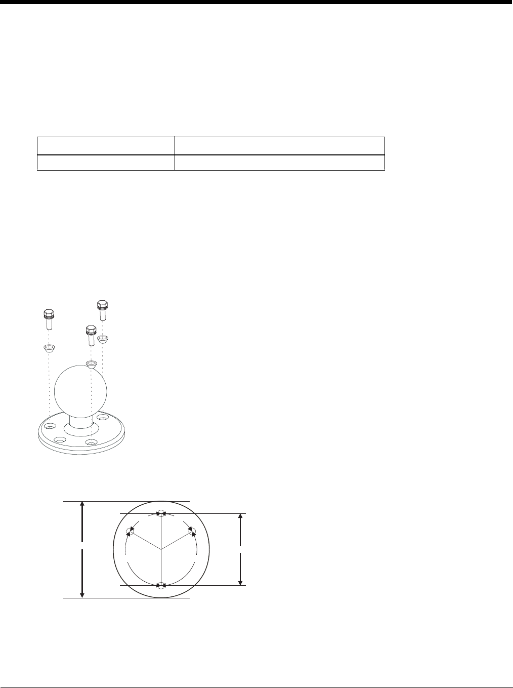
4 - 22
Procedure - RAM Mount Assembly
Equipment Needed: Sockets, screwdriver and a Torque wrench capable of measuring to 50 inch pounds (5.64±.56 N/m).
Note: Torquing tool is not supplied by Honeywell. Tools needed to attach the RAM Clamp Mount to the vehicle are not
supplied by Honeywell.
Torque Measurement
You will need a torquing tool capable of torquing to 20 inch pounds (1.10 N/m). Torque all screws and bolts according
to the following table:
Step 1a – Attach RAM Ball to Vehicle
Note: If you are using the RAM clamp mount, please go to Step 1b – Mount RAM Clamp to Vehicle (page 4-23). If
you are using the RAM plate mount, please go to Step 1c – Attach RAM Plate to Vehicle and Attach RAM Ball
(page 4-24).
1. Determine the position for mounting the RAM ball base. Be sure to position the RAM bracket to allow access to
the switches and ports on the bottom of the Thor VM2.
2. Attach the RAM ball base to the vehicle mounting surface using three or four 1/4 bolts (not included) or equivalent
fasteners. If the mounting kit includes cone washers, use those as illustrated below.
IMPORTANT: Mount to the most rigid surface available.
Mounting Dimensions
Note: Drill and tap holes for three 1/4 bolts. Drawing not to scale.
For these nuts… Torque to
10-32 lock nuts 17 - 20 in/lb (0-95 - 1.10 N/m)
120º120º
60º60º
2.75" / 69.85 mm
3.69" / 93.73 mm
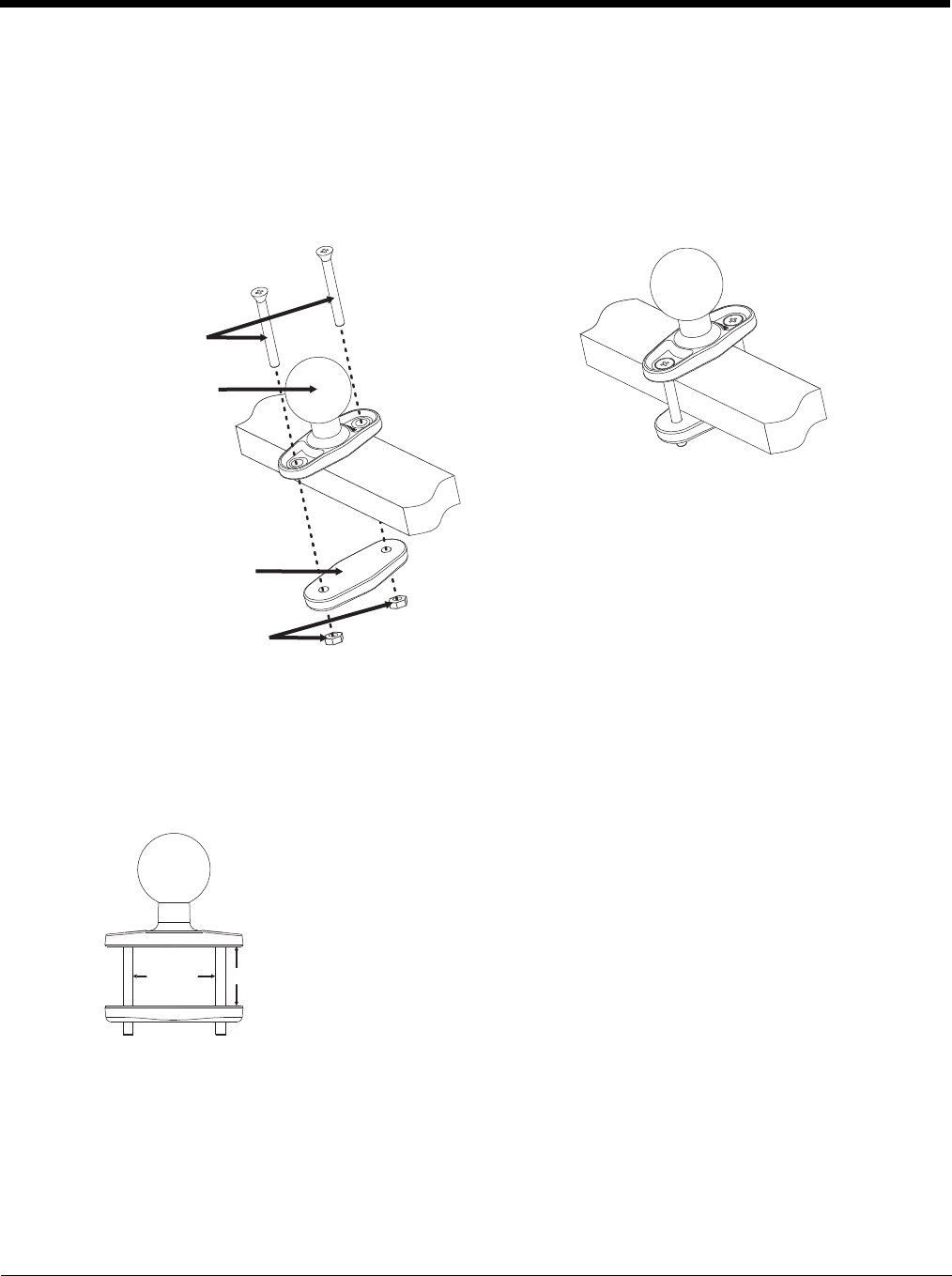
4 - 23
Step 1b – Mount RAM Clamp to Vehicle
Note: If you are using the RAM ball mount, please go to Step 1a – Attach RAM Ball to Vehicle (page 4-22). If you are
using the RAM plate mount, please go to Step 1c – Attach RAM Plate to Vehicle and Attach RAM Ball (page 4-
24).
1. Determine the position for mounting the RAM clamp mount. The clamp mount can be used on a beam (such as on
a fork lift truck) up to 2.5” (63.5 mm) wide and approximately 2” (50.8 mm) thick. The clamp may be attached to a
thicker beam by substituting longer bolts (not included). Be sure to position the RAM clamp mount to allow access
to the switches and ports on the bottom of the Thor VM2.
2. Position the upper clamp piece with ball on the beam. Place the bolts through the holes in the upper clamp piece.
3. Position the lower clamp piece below the beam. Align the bolts with the holes in the lower clamp piece.
4. Place the nylon locking nuts on the bolts and tighten the bolts.
Mounting Dimensions
Note: Drawing not to scale.
Upper clamp piece
Bolts
Lower clamp piece
Nuts
2.56” /
65.02mm
1.84” (46.74mm)
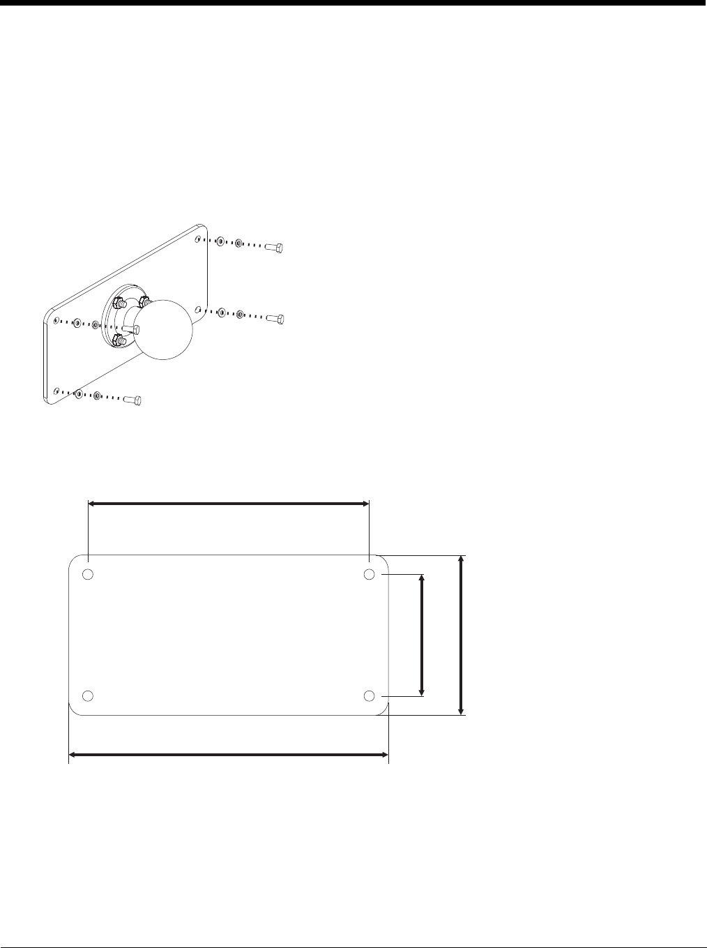
4 - 24
Step 1c – Attach RAM Plate to Vehicle and Attach RAM Ball
Note: If you are using the RAM ball mount, please go to Step 1a – Attach RAM Ball to Vehicle (page 4-22) If you are
using the RAM clamp mount, please go to Step 1b – Mount RAM Clamp to Vehicle (page 4-23).
1. Determine the position for mounting the RAM ball plate. Be sure to position the RAM plate to allow access to the
switches and ports on the bottom of the Thor VM2.
2. Attach the RAM ball plate to the vehicle mounting surface using four 1/4 bolts (not included) or equivalent fasten-
ers.
3. If not already attached, attach the RAM ball to the RAM ball plate using three M6 nuts and washers.
IMPORTANT: Mount to the most rigid surface available.
Mounting Dimensions
There are 4 mounting holes in the plate. Use four 1/4 bolts to secure the plate to the vehicle.
Note: Drawing not to scale.
176 mm
6.99”
200 mm
7.87”
76mm 2.99”
100mm 3.94
”
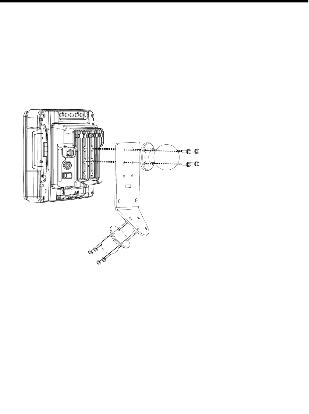
4 - 25
Step 2 – Attach RAM Mount Ball to the Thor VM2 Quick Mount Smart Dock
1. Turn the Thor VM2 off before attaching the RAM mount ball.
2. Place the Thor VM2 face down on a stable surface.
3. If using the external keyboard mount, position the Keyboard Bracket and the Size D RAM ball on the rear of the
Thor VM2 dock, aligning the holes on the back of the Thor VM2 dock with the holes on the bracket and the RAM
ball base.
4. If not using the external keyboard mount, position the RAM ball on the rear of the Thor VM2 dock, aligning the
holes on the back of the Thor VM2 dock with the holes on the RAM ball base. Attach with four M5 screws, flat
washers and lock washers.
5. If using the external keyboard mount, attach the Size C RAM ball to the Thor VM2 Keyboard bracket with four M5
nuts, flat washers and lock washers.

4 - 26
Step 3 – Attach Thor VM2 Assembly to RAM Mount
1. Slip the Size D RAM arm over the ball on the vehicle RAM mount (RAM Ball mount shown).
2. Insert the ball on the dock into the RAM arm and tighten the knob on the RAM arm using the supplied RAM
wrench.
Step 4 – Place the Thor VM2 into the Dock
If the Thor VM2 is not already mounted to the dock, Place Thor VM2 in the Dock (page 4-18)
If the optional external keyboard is not used, the mounting process is complete.
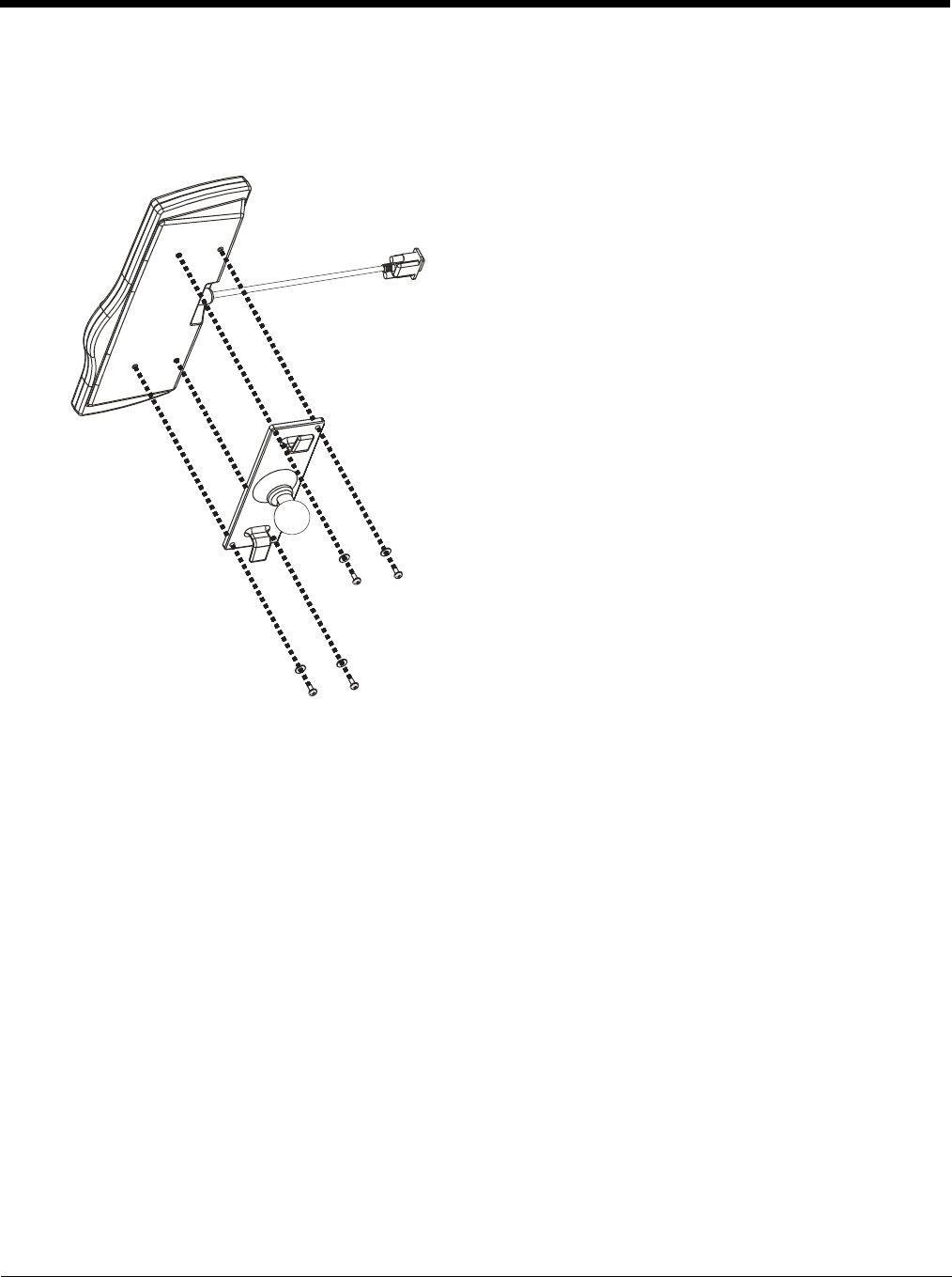
4 - 27
Step 5 – Attach Keyboard to Mounting Plate
Note: This step is only for a Thor VM2 with the optional external keyboard.
If using the optional integrated keyboard mount, attach the keyboard to keyboard mounting plate, using four #8 screws,
flat washers and lock washers.
Note: Excess keyboard cable length can be looped around the hooks on the bottom of the keyboard mounting plate.
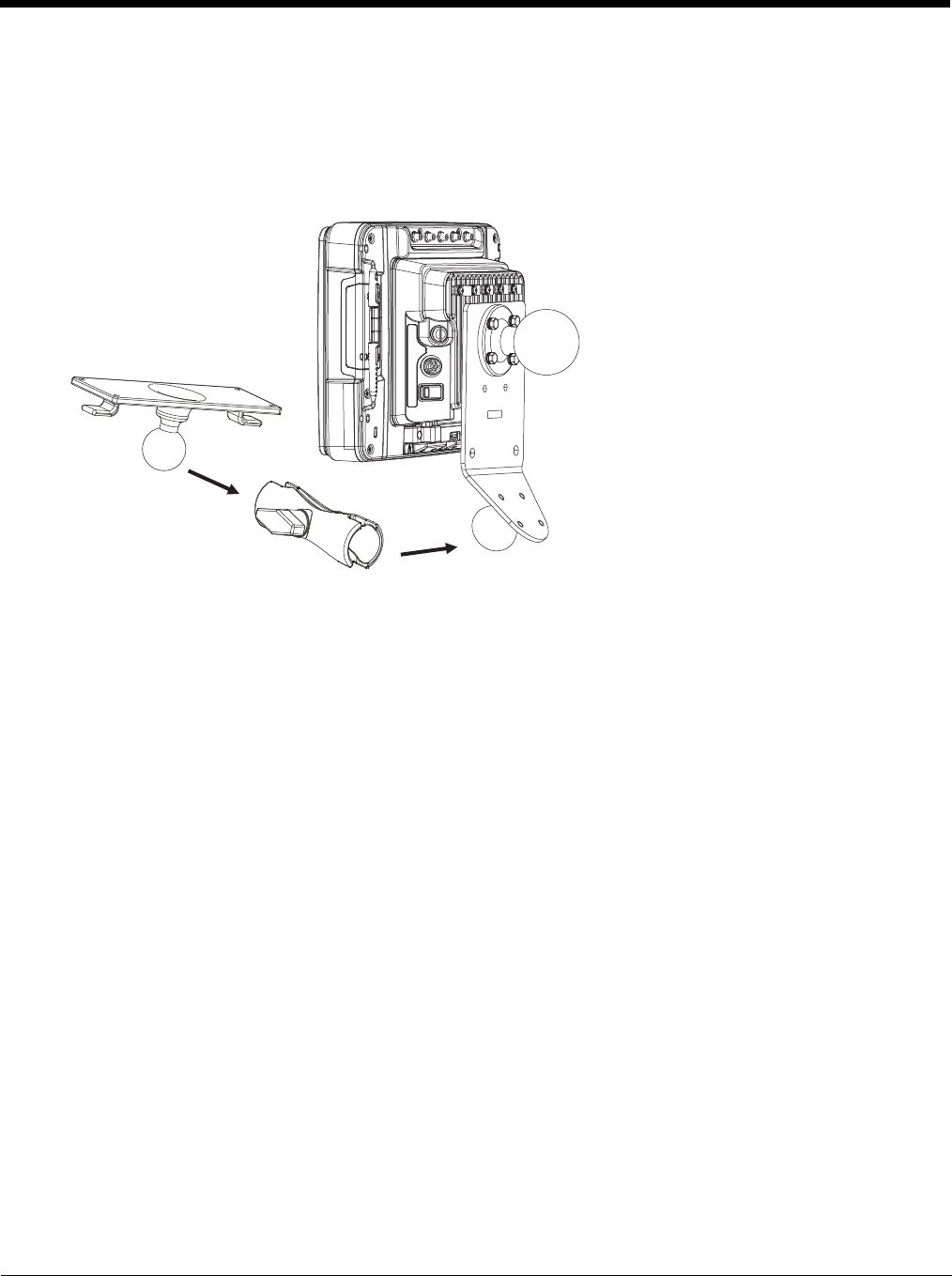
4 - 28
Step 6 – Attach Keyboard Assembly to Thor VM2 Assembly
Note: This step is only for a Thor VM2 with the optional external keyboard.
1. Slip the Size C RAM arm over the ball on the Thor VM2 Keyboard Bracket.
2. Slip the ball on the Keyboard Mounting Plate into the other end of the Size C RAM arm.
3. Tighten the knob on the RAM arm using the supplied RAM wrench.
Note: Some components omitted for detail clarity.
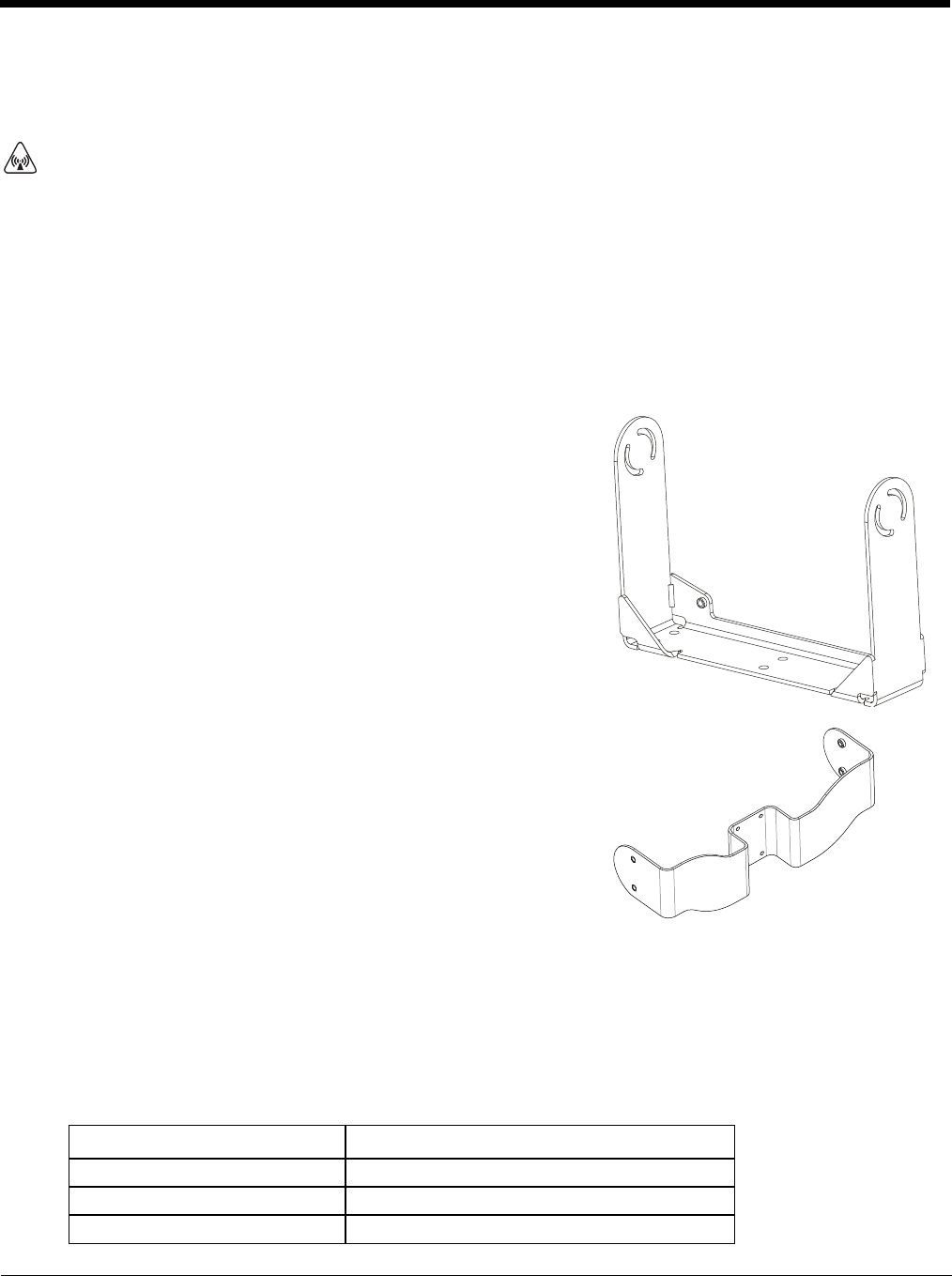
4 - 29
Install U Bracket Mount
Note: This mounting system is designed for use with a Thor VM2 without an external keyboard.
Before installation begins, verify you have the applicable vehicle mounting bracket assembly components necessary, as shown
in the following figures.
Components - U Bracket Mounting Assembly
The U bracket kit is available in two configurations:
• With a U Bracket included for new vehicle installations
• Without a U Bracket for installing the Thor VM2 in place of a previous Honeywell vehicle mounted computer, such as a
VX6 or VX7.
Procedure - U Bracket Assembly
Equipment Needed: Sockets and a Torque wrench capable of measuring to 50 inch pounds (5.64±.56 N/m).
Note: Torquing tool is not supplied by Honeywell.
Torque Measurement
You will need a torquing tool capable of torquing to 35-50 inch pounds (1.10 N/m). Torque all screws and bolts accord-
ing to the following table:
CAUTION - This device is intended to transmit RF energy. For protection against RF exposure to humans and in accor-
dance with FCC rules and Industry Canada rules, this transmitter should be installed such that a minimum separation dis-
tance of at least 20 cm (7.8 in.) is maintained between the antenna and the general population. This device is not to be
co-located with other transmitters.
U Bracket (only included in kits for new installations)
Adapter Bracket (includes screws, flat washers and lock washers to attach
Adapter Bracket to Thor VM2 and to attach Adapter Bracket to existing
U Bracket (for example, to a vehicle where a VX1, VX2, VX4, VX5, VX6 or
VX7 was previously installed)
For these bolts… Torque to
1/4-20x5/8 Bolts 50 in/lb (5.6 N/m)
M5x16mm Bolts 35 in/lb (4.0 N/m)
1/4 Bolts (user supplied) 50.0±5 in/lb (5.64±.56 N/m)
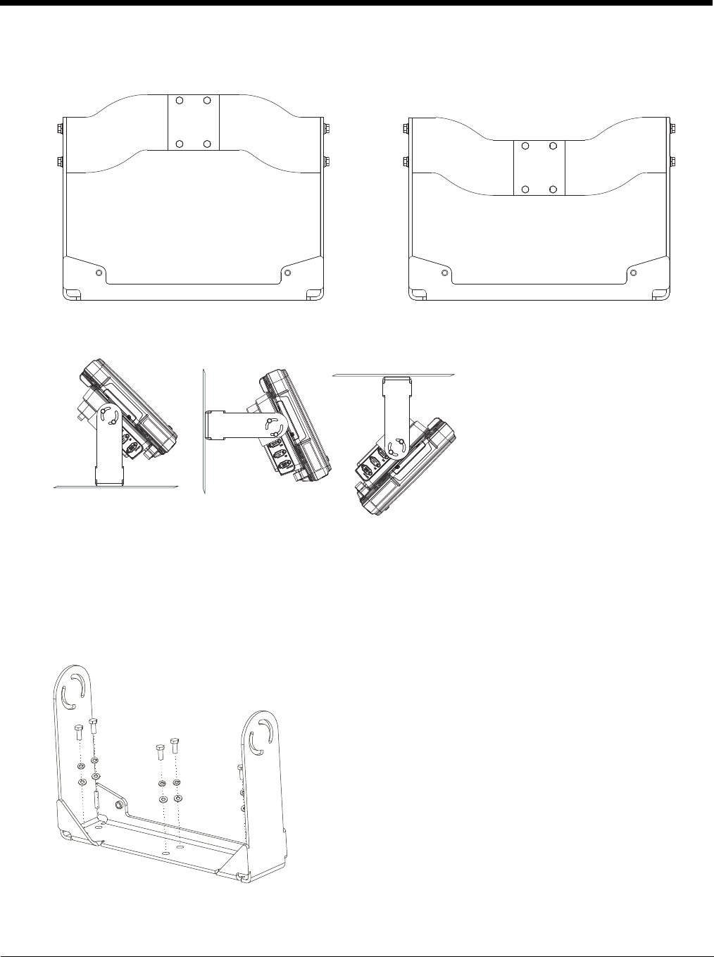
4 - 30
Mounting Positions
The adapter bracket can be mounted in a high or low position, depending on viewing position, as shown below.
Additionally, the slotted U bracket allows the Thor VM2 to be mounted vertically or tilted forward or backward for best
viewing angle.
Step 1 - Install U Bracket to Vehicle
1. Position the bracket to allow access to the switches and ports on the bottom of the Thor VM2.
2. Attach the bottom mounting bracket to the vehicle mounting surface using a minimum of four 1/4 bolts (or equiva-
lent) fasteners.
Note: 1/4 bolts and washers not included. It is recommended to use lock washers and flat washers on the fasteners.
IMPORTANT: Mount to the most rigid surface available.
After the bottom bracket has been attached to a rigid surface, you are ready to assemble the Thor VM2 bracket config-
uration.
[
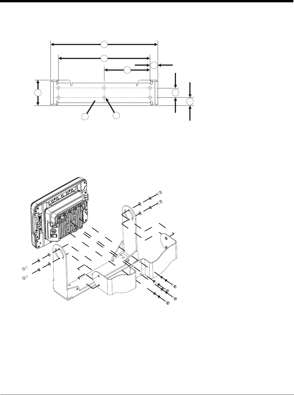
4 - 31
Mounting Dimensions
Note: Drawing not to scale.
Step 2 - Remove RAM Ball
If the Thor VM2 Quick Mount Smart Dock has a RAM ball attached, the RAM ball must be removed from the dock to
use the U Bracket mount.
Remove the RAM ball. The hardware used to attach the RAM ball to the dock is not reused for the U bracket mount.
Step 3 - Attach Adapter Bracket
Note: For the steps below, always place the lock washer on the bolt before the flat washer.
1. Attach the Adapter Bracket to the Thor VM2 dock using four each M5x16mm bolt, M5 lock washer and M5 flat
washer. Torque to 35 in/lbs (4.0 N/m).
2. Attach the Thor VM2/Adapter Bracket assembly to the U Bracket using 4 each 1/4-20x5/8 bolt, 1/4 lock washer
and 1/4 flat washer.
3. If the Thor VM2 is not already mounted to the dock, Place Thor VM2 in the Dock (page 4-18).
4. Adjust the Thor VM2 to the desired viewing angle.
5. Torque the 14-20 bolts to 50 in/lbs (5.6 N/m).
1. 14.40 in / 359.2 mm
2. 12.10 in / 307.3 mm
3. 6.05 in / 153.6 mm
4. 1.02 in / 25.9 mm
5. 3.38 in / 85.85 mm
6. Vehicle Mount Footprint
7. 0.406 in / 10.312 mm
8. 0.88 in / 22.3 mm
9. 1.25 in / 31.75 mm
1
2
34
5
67
8
9
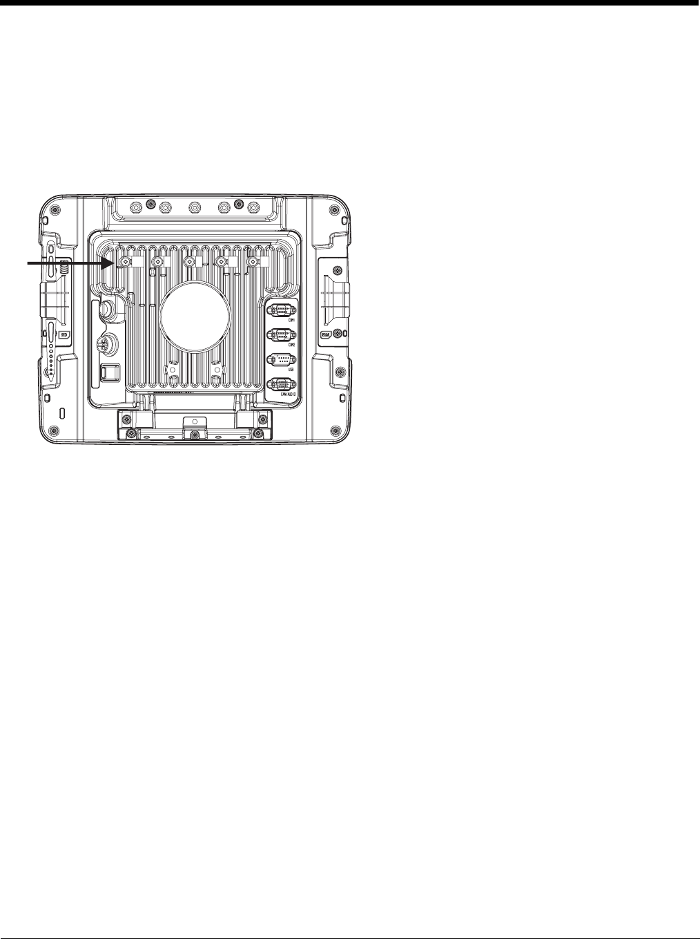
4 - 32
Connect Cables
There are many cables available for the Thor VM2 including power cables, and data/ communication cablesThor VM2.
Strain Relief Cable Clamps
Equipment Required: Phillips screwdriver (not supplied by Honeywell)
There are five strain relief cable clamps secured to the Thor VM2 Quick Mount Smart Dock.
Use the strain relief clamps to secure audio, power, and I/O cables attached to the Thor VM2 dock.
1. Determine the proper strain relief cable clamp. There are three sizes of cable clamps on the Thor VM2 which should
be matched to the cable to be secured. For example, the largest clamp (on the left when viewing the back of the Thor
VM2) is designed to secure the power cable.
2. Remove the strain relief clamp from the Thor VM2 by turning the screw counterclockwise. Put the screw aside in a
safe location.
3. Slide the strain relief clamp over the cable.
4. Using a Phillips screwdriver and the screw that was removed, refasten the clamp holding the cable to the Quick Mount.
Do not stretch the cable. Leave enough slack in the cable to allow it to be connected and disconnected easily when
needed.
5. Continue in this manner until all cables are secured to the Thor VM2 dock.
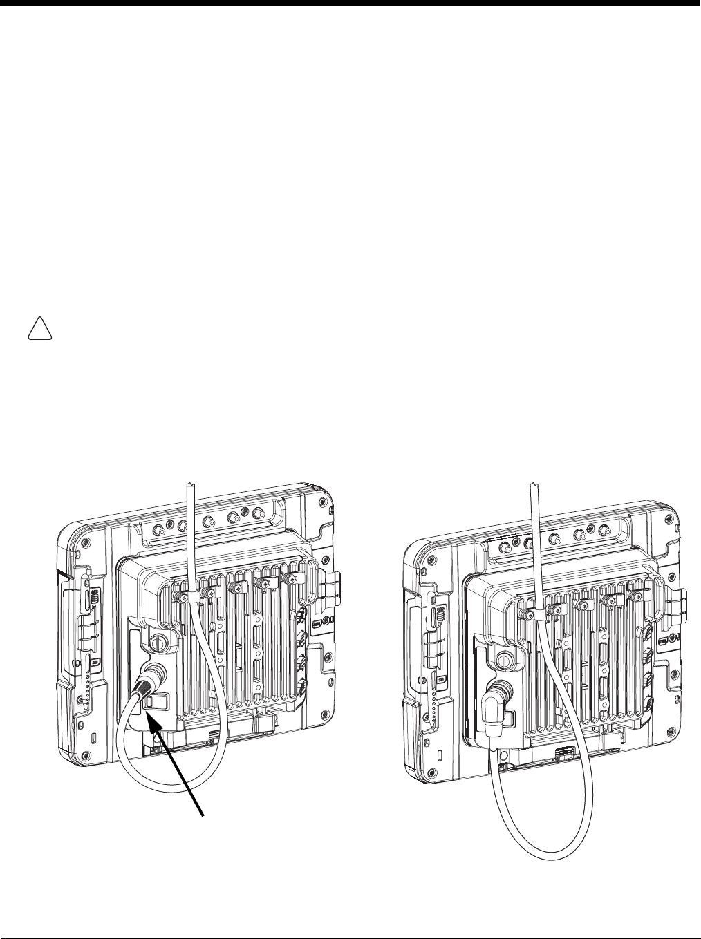
4 - 33
Connect Power
Power options include:
•12-48 VDC Vehicles (10-60 VDC Direct Connection) (see page 4-34) - Direct connection to vehicle power.
•60-144 VDC Vehicles (50-150 VDC Power Supply, Screws on Side of Lid) (see page 4-39) - Requires the use of a DC/
DC power supply.
•60-144 VDC Vehicles (50-150 VDC Power Supply, Screws on Top of Lid) (see page 4-43) - Requires the use of a DC/
DC power supply.
•VX6 / VX7 Adapter Cable (see page 4-47) - For applications where the Thor VM2 replaces a previously installed VX6 or
VX7.
•Thor VX8 / Thor VX9 Adapter Cable (see page 4-48) - For applications where the Thor VM2 replaces a previously
installed Thor VX8 or Thor VX9.
•Screen Blanking (see page 4-49) - Optional connection to blank the Thor VM2 display while the vehicle is in motion.
•External AC/DC Power Supply (see page 4-52) - For use when DC power is not available to power the Thor VM2, such
as in an office environment.
See Power Supply Connector (page 10-4) for connector pinout
Power Cable Cautions
Power Cable Routing
CAUTION - When routing the power cable:
• Route power cable away from the outside of the fork truck.
• Choose a mounting location so that the power cable does not extend outside the vehicle and that provides sufficient
clearance so that the power cable (especially the dock connector end) is not pressed against part of the vehicle.
• Use the proper Strain Relief Cable Clamps (page 4-32) to secure cable.
• The power cable is less flexible in low temperature environments. Avoid sharp bends.
Regularly inspect power cable for damage, especially in low temperature environments. Contact Technical
Assistance (page 11-1) for replacement cable options.
Power cable with straight connector Power cable with right-angle connector
!
Avoid sharp bends in this
area of the power cable
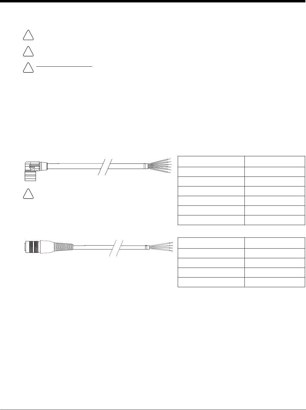
4 - 34
12-48 VDC Vehicles (10-60 VDC Direct Connection)
Power Cable Identification
The DC power cable (included with the dock) is one of the two styles below:
Note: Correct electrical polarity is required for safe and proper installation. See the figures below for additional wire
color-coding specifics.
The Thor VM2 DC input wires (Red, Red/White DC+ and Black, Black/White DC-) and the Blue ignition input wire are
galvanically isolated. The Green ground input is used for electrostatic discharge (ESD) protection.
Vehicle 10-60VDC Direct Power Connection
1. The Thor VM2 must not be mounted in the Quick Mount Smart Dock. The power switch on the dock must be
turned Off. The power cable must be UNPLUGGED from the dock.
2. While observing the Fuse Requirements (see page 4-34), connect the power cable as close as possible to the
actual battery terminals of the vehicle (if using unswitched power).
3. Use proper electrical and mechanical fastening means for terminating the cable. Properly sized “crimp” type
electrical terminals are an accepted method of termination. Please select electrical connectors sized for use
with 20AWG (0.81mm2) conductors.
4. Refer to the wiring diagrams following this section for wire colors and connections:
•Ignition Control Wiring Diagram (page 4-36)
CAUTION - For installation by trained service personnel only.
Use caution when routing the power cable. See Power Cable Cautions (page 4-33).
Fuse Requirements
WARNING - For proper and safe installation, the input power cable must be connected to a fused circuit on the
vehicle. If the supply connection is made directly to the battery, the fuse should be installed in the positive lead
within 5 inches of the battery’s positive (+) terminal. The fused circuit requires a maximum time delay (slow blow)
fuse with a current rating as noted below.
•For 12VDC input, use a 10A slow blow fuse that has a DC voltage rating greater than 12VDC.
•For 24VDC input, use a 6A slow blow fuse that has a DC voltage rating greater than 24VDC.
•For 36VDC input, use a 4A slow blow fuse that has a DC voltage rating greater than 36VDC.
•For 48VDC input, use a 3A slow blow fuse that has a DC voltage rating greater than 48VDC.
Note: For North America, a UL Listed fuse is to be used
Power cable with right angle connector and 6 wires:
Wire Color Connection
Red DC + (10-60 VDC)
Red/White DC + (10-60 VDC)
Twist the red and red/white wires together and twist the
black and black/white wires together before connecting to
vehicle power.
Black DC -
Black/White DC -
Green Ground
Blue Ignition Input (optional)
Power cable with straight connector and 4 wires:
Wire Color Connection
Red DC + (10-60 VDC)
Black DC -
Green Ground
Blue Ignition Input (optional)
!
!
!
!

4 - 35
•Auto-On Control Wiring Diagram (page 4-37)
•Manual Control Wiring Diagram (page 4-38)
5. Route the power cable the shortest way possible removing any left-over cable. The cable is rated for a maxi-
mum temperature of 105°C (221°F). Therefore, when routing this cable it should be protected from physical
damage and from surfaces that might exceed this temperature. Cable should be protected from physical
damage from moving parts. Do not expose the cable to chemicals or oil that may cause the wiring insulation
to deteriorate. Always route the cable so that it does not interfere with safe operation and maintenance of the
vehicle.
6. Provide mechanical support for the cable by securing it to the vehicle structure at approximately one foot inter-
vals, taking care not to over tighten and pinch conductors or penetrate outer cable jacket.
7. Connect the watertight connector end of the power cable to the Thor VM2 Quick Mount Smart Dock power
connector by aligning the connector pins to the power connector; push down on the watertight connector and
twist it to fasten securely.
8. Secure the power cable to the Thor VM2 using the Strain Relief Cable Clamps (page 4-32).
9. Place Thor VM2 in the Dock (page 4-18)
10. If using the Screen Blanking (page 4-49) feature, install the screen blanking box or switch.
11. Press the Power Switch (page 3-6) on the back of the Thor VM2 dock.
12. Press the Power Button (page 3-6) on the front of the Thor VM2 to turn on the Thor VM2.
Once installation is complete, remember to start the Thor VM2 and select the desired Power Configuration Mode
to enable Auto-On, Ignition Control or Manual Control of the Thor VM2 boot up process.
See the Power Configuration Mode (page 5-80) control panel.
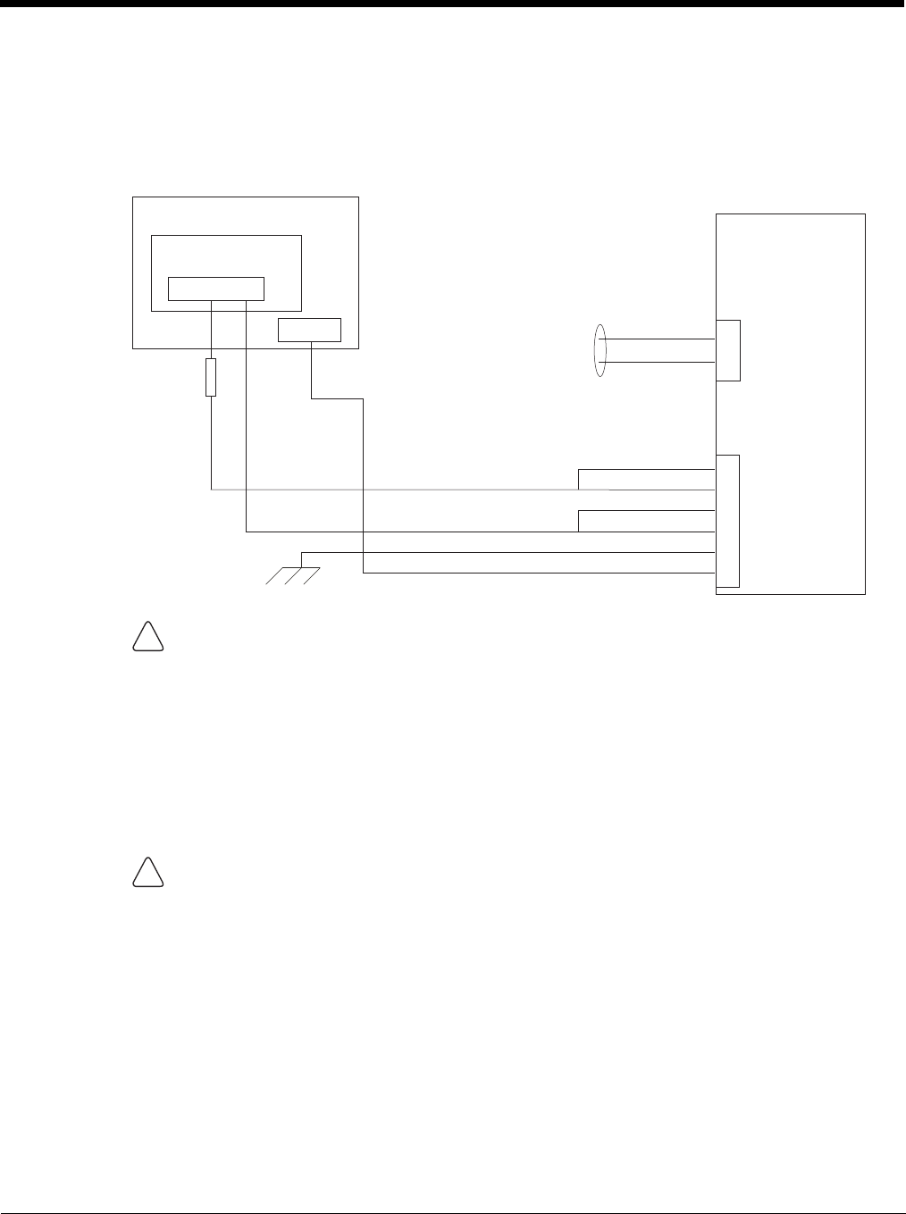
4 - 36
Ignition Control Wiring Diagram
Ignition wire must be connected and the Ignition Control power mode must be selected via the Power
Configuration Mode (page 5-80) control panel. When switched vehicle power is available the Thor VM2 igni-
tion signal wire can be connected (less than 1mA over input voltage range) to the switched circuit to allow the
Thor VM2 to power on when the vehicle is switched on. When the vehicle is switched off, more aggressive
power management settings are enabled to preserve the vehicle battery charge.
.
CAUTION
For battery powered vehicles:
• Red wire is connected to battery positive. If there is a red wire and a red/white wire, twist them
together and connect to battery positive.
• Black wire must be connected to battery negative. If there is a black wire and a black/white wire,
twist them together and connect to battery negative.
• Green wire must be connected to the vehicle chassis ground.
For internal combustion engine powered vehicles:
• Red wire is connected to battery positive. If there is a red wire and a red/white wire, twist them
together and connect to battery positive.
• Black wire must be connected to battery negative. If there is a black wire and a black/white wire,
twist them together and connect to battery negative.
• Green wire is connected to the vehicle chassis ground, which can also be battery negative.
WARNING
For proper and safe installation, the input power cable must be connected to a fused circuit on the ve-
hicle. If the supply connection is made directly to the battery, the fuse should be installed in the positive
lead within 5 inches of the battery’s positive (+) terminal. The fused circuit requires a maximum time
delay (slow blow) fuse with a current rating as noted below.
•For 12VDC input, use a 10A slow blow fuse that has a DC voltage rating greater than 12VDC.
•For 24VDC input, use a 6A slow blow fuse that has a DC voltage rating greater than 24VDC.
•For 36VDC input, use a 4A slow blow fuse that has a DC voltage rating greater than 36VDC.
•For 48VDC input, use a 3A slow blow fuse that has a DC voltage rating greater than 48VDC.
Note: For North America, a UL Listed fuse is to be used.
Existing Circuitry On Vehicle
Battery
Main Switch
-Vo
+Vo
Fuse - See
Warning
statement below
Ignition
See Caution statement below
Quick Mount
Smart Dock
Circular
Power
Connector
COM1 or COM2
Connector
Cable for optional
screen blanking
connection
Red
Black
Green
Blue
Red/White (if present)
Black/White (if present)
!
!
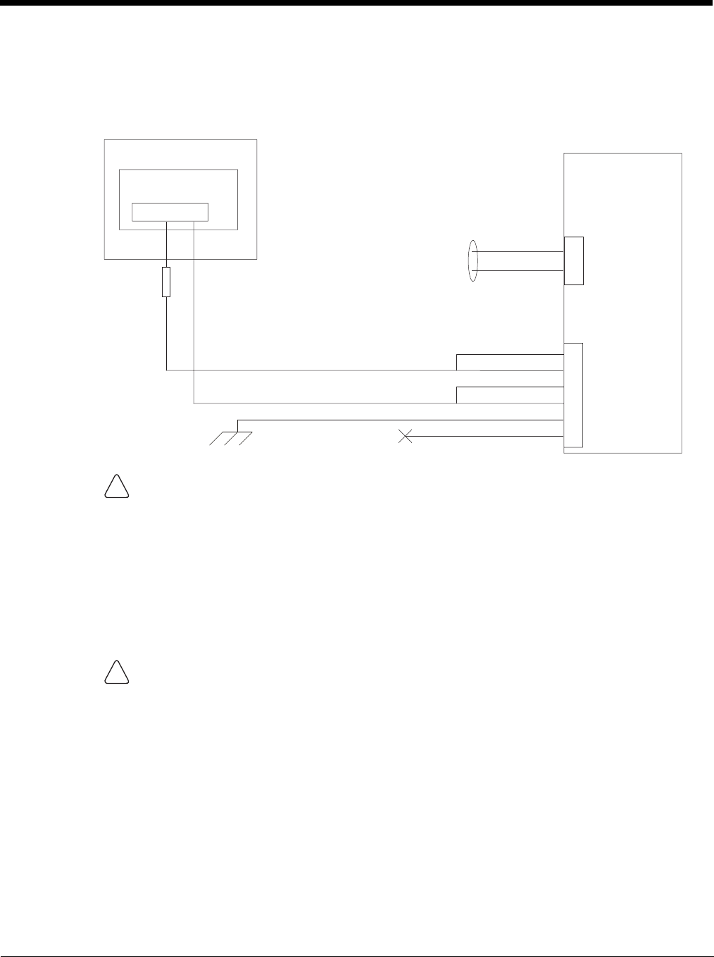
4 - 37
Auto-On Control Wiring Diagram
Auto-On power mode must be selected on the Power Configuration Mode (page 5-80) control panel. The
vehicle supply connections should be made to vehicle switched power to allow the terminal to automatically
power-up when vehicle power is switched on or when the power switch on the back of the dock is placed in
the On position. The Ignition wire is not used and should be left disconnected.
.
CAUTION
For battery powered vehicles:
• Red wire is connected to battery positive. If there is a red wire and a red/white wire, twist them
together and connect to battery positive.
• Black wire must be connected to battery negative. If there is a black wire and a black/white wire, twist
them together and connect to battery negative.
• Green wire must be connected to the vehicle chassis ground.
For internal combustion engine powered vehicles:
• Red wire is connected to battery positive. If there is a red wire and a red/white wire, twist them
together and connect to battery positive.
• Black wire is connected to battery negative. If there is a black wire and a black/white wire, twist them
together and connect to battery negative.
• Green wire is connected to the vehicle chassis ground, which can also be battery negative.
WARNING
For proper and safe installation, the input power cable must be connected to a fused circuit on the ve-
hicle. If the supply connection is made directly to the battery, the fuse should be installed in the positive
lead within 5 inches of the battery’s positive (+) terminal. The fused circuit requires a maximum time
delay (slow blow) fuse with a current rating as noted below.
•For 12VDC input, use a 10A slow blow fuse that has a DC voltage rating greater than 12VDC.
•For 24VDC input, use a 6A slow blow fuse that has a DC voltage rating greater than 24VDC.
•For 36VDC input, use a 4A slow blow fuse that has a DC voltage rating greater than 36VDC.
•For 48VDC input, use a 3A slow blow fuse that has a DC voltage rating greater than 48VDC.
Note: For North America, a UL Listed fuse is to be used.
Quick Mount
Smart Dock
Circular
Power
Connector
COM1 or COM2
Connector
Existing Circuitry On Vehicle
Battery
Main Switch
-Vo+Vo Cable for optional
screen blanking
connection
See Caution statement below
Fuse - See
Warning
statement below
(not connected)
Red
Black
Green
Blue
Red/White (if present)
Black/White (if present)
!
!
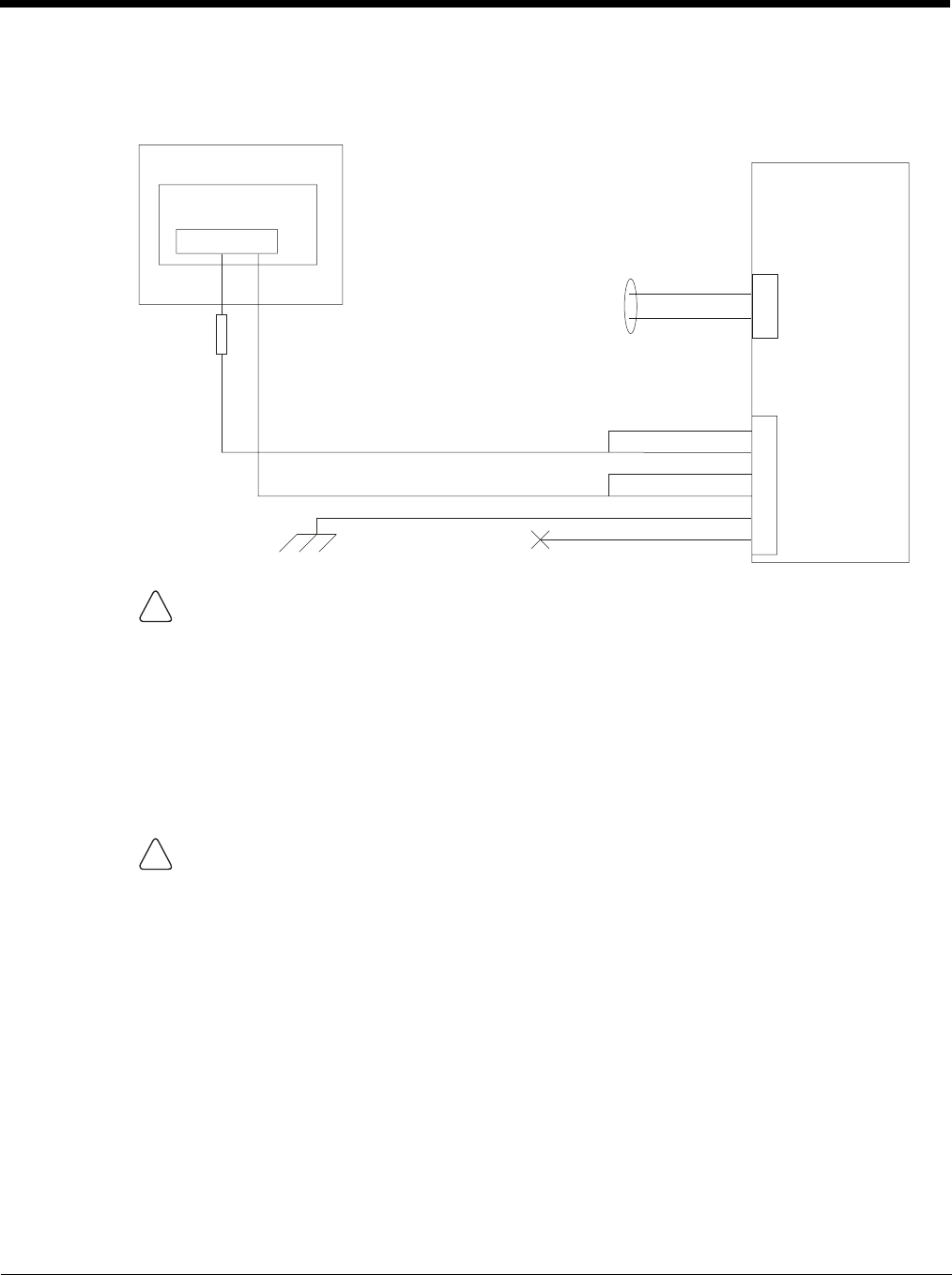
4 - 38
Manual Control Wiring Diagram
Ignition wire must be left unconnected and AC/DC power mode must be selected on the Power Configuration
Mode (page 5-80) control panel.
CAUTION
For battery powered vehicles:
• Red wire is connected to battery positive. If there is a red wire and a red/white wire, twist them
together and connect to battery positive.
• Black wire must be connected to battery negative. If there is a black wire and a black/white wire, twist
them together and connect to battery negative.
• Green wire must be connected to the vehicle chassis ground.
For internal combustion engine powered vehicles:
• Red wire is connected to battery positive. If there is a red wire and a red/white wire, twist them
together and connect to battery positive.
• Black wire is connected to battery negative. If there is a black wire and a black/white wire, twist them
together and connect to battery negative.
• Green wire is connected to the vehicle chassis ground, which can also be battery negative.
WARNING
For proper and safe installation, the input power cable must be connected to a fused circuit on the ve-
hicle. If the supply connection is made directly to the battery, the fuse should be installed in the positive
lead within 5 inches of the battery’s positive (+) terminal. The fused circuit requires a maximum time
delay (slow blow) fuse with a current rating as noted below.
•For 12VDC input, use a 10A slow blow fuse that has a DC voltage rating greater than 12VDC.
•For 24VDC input, use a 6A slow blow fuse that has a DC voltage rating greater than 24VDC.
•For 36VDC input, use a 4A slow blow fuse that has a DC voltage rating greater than 36VDC.
•For 48VDC input, use a 3A slow blow fuse that has a DC voltage rating greater than 48VDC.
Note: For North America, a UL Listed fuse is to be used.
Quick Mount
Smart Dock
Circular
Power
Connector
COM1 or COM2
Connector
Existing Circuitry On Vehicle
Battery
Main Switch
-Vo+Vo Cable for optional
screen blanking
connection
See Caution statement below
Fuse - See
Warning
statement below
(not connected)
Red
Black
Green
Blue
Red/White (if present)
Black/White (if present)
!
!
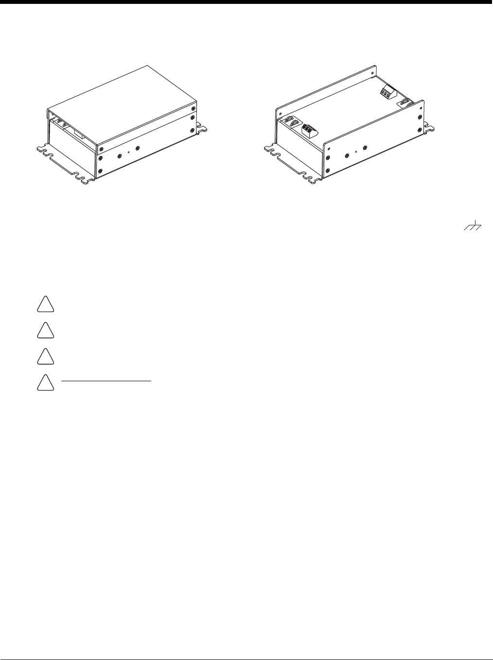
4 - 39
60-144 VDC Vehicles (50-150 VDC Power Supply, Screws on Side of Lid)
This option requires DC/DC external power supply Honeywell Part no. 9000313PWRSPLY.
If the DC/DC power supply does not have screws in the side of the lid, see 60-144 VDC Vehicles (50-150 VDC Power
Supply, Screws on Top of Lid) (page 4-43).
Shown With Lid Attached
• Lid is secured with screws on the side of lid.
Shown With Lid Removed
• Input and output connector blocks under lid.
• One positive (Vin+), negative (Vin-) and ground ( )
connection in input block.
• One positive (Vo+) and negative (Vo-) connection in
output block.
CAUTION - For installation by trained service personnel only.
CAUTION - Usage in areas where moisture can affect the power supply connections should be avoided. The
power supply should be mounted in a dry location within the vehicle or placed in a suitable protective enclosure.
Use caution when routing the power cable. See Power Cable Cautions (page 4-33).
Fuse Requirements
WARNING - For proper and safe installation, the input power cable must be connected to a fused circuit on the
vehicle. If the supply connection is made directly to the battery, the fuse should be installed in the positive lead
within 5 inches of the battery’s positive (+) terminal. The fused circuit requires a maximum time delay (slow blow)
fuse with a current rating as noted below.
•For 60VDC input, use a 6A slow blow fuse that has a DC voltage rating greater than 60VDC.
•For 72VDC input, use a 6A slow blow fuse that has a DC voltage rating greater than 72VDC.
•For 96VDC input, use a 4A slow blow fuse that has a DC voltage rating greater than 96VDC.
•For 108VDC input, use a 4A slow blow fuse that has a DC voltage rating greater than 108VDC.
•For 120VDC input, use a 4A slow blow fuse that has a DC voltage rating greater than 120VDC.
•For 132VDC input, use a 3A slow blow fuse that has a DC voltage rating greater than 132VDC.
•For 144VDC input, use a 3A slow blow fuse that has a DC voltage rating greater than 144VDC.
Note: For North America, a UL Listed fuse is to be used,
!
!
!
!
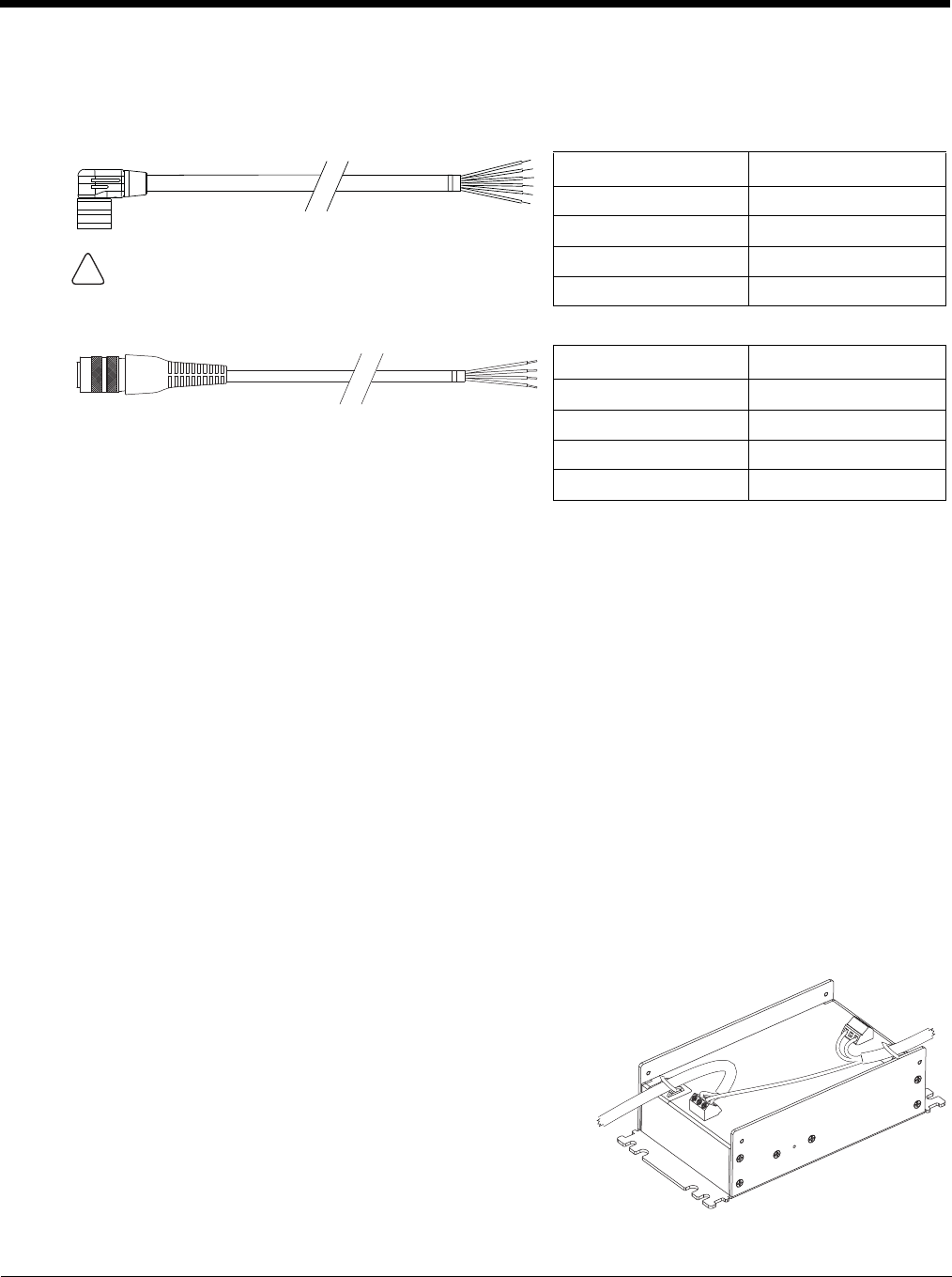
4 - 40
Power Cable Identification
The DC power cable (included with the dock) is one of the two styles below:
Note: Correct electrical polarity is required for safe and proper installation. See Wiring Diagram (page 4-42) for
additional wire color-coding specifics.
The Thor VM2 DC input wires (Red, Red/White DC+ and Black, Black/White DC-) and the Blue ignition input wire are
galvanically isolated. The Green ground input is used for electrostatic discharge (ESD) protection.
Vehicle 50-150VDC Power Connection
Please review the Wiring Diagram (page 4-42), before beginning power cable install. The Thor VM2must be pow-
ered off and the power cable disconnected from the Thor VM2. The last connection must be to the vehicle power
source before connecting the power cable to the Thor VM2.
1. Route the cable from the Thor VM2 to the DC/DC power supply. Route the power cable the shortest way pos-
sible. The cable is rated for a maximum temperature of 105°C (221°F). When routing this cable, it should be
protected from physical damage and from surfaces that might exceed this temperature. Do not expose the
cable to chemicals or oil that may cause the wiring insulation to deteriorate. Always route the cable so that it
does not interfere with safe operation and maintenance of the vehicle.
2. Cut the cable to length and strip the wire ends.
3. Remove the lid from the DC/DC power supply.
4. Connect the stripped end of the positive wires (red and red/white twisted together or a single red wire) to the
output block. See Power Cable Identification (page 4-40).
5. Connect the stripped end of the negative wires (black and black/white twisted together or a single black wire)
to the output. See Power Cable Identification (page 4-40).
Note: The input block has VIN+, VIN- and GND terminals. The
output block has VO+ and VO- terminals.
Power cable with right angle connector and 6 wires:
Wire Color Connection
Red (2 wires) DC + (10-60 VDC)
Black (2 wires) DC -
Twist the red and red/white wires together and twist the
black and black/white wires together before connecting to
vehicle power.
Green Ground
Blue Ignition Input (not used)
Power cable with straight connector and 4 wires:
Wire Color Connection
Red DC + (10-60 VDC)
Black DC -
Green Ground
Blue Ignition Input (not used)
!

4 - 41
6. Connect the ground (green) wire from the Thor VM2 to the GND terminal on the input side of the DC/DC
power supply.
7. Route the wiring from the DC/DC power supply to the vehicle’s electrical system. Do not connect to vehicle
power at this time.
8. Strip the wire ends and connect to the input side of the DC/DC power supply.
9. Use looms and wire ties to secure all wiring as shown.
10. Reattach the cover with the screws.
11. Connect the DC/DC power supply to the vehicle’s electrical system as directed below:
12. While observing the Fuse Requirements (see page 4-39) connect the power cable as close as possible to the
actual battery terminals of the vehicle. When available, always connect to unswitched terminals in the vehicle
fuse panel, after providing proper fusing.
ATTENTION: For uninterrupted power, electrical supply connections should not be made at any point
after the ignition switch of the vehicle.
13. Use proper electrical and mechanical fastening means for terminating the cable. Properly sized “crimp” type
electrical terminals are an accepted method of termination. Select electrical connectors sized for use with
18AWG (1mm2) conductors.
14. Provide mechanical support for the cable by securing it to the vehicle structure at approximately one foot inter-
vals, taking care not to over tighten and pinch conductors or penetrate the outer cable jacket.
15. Connect the watertight connector end of the power cable to the Thor VM2 Quick Mount Smart Dock power
connector by aligning the connector pins to the power connector; push down on the watertight connector and
twist it to fasten securely.Flip the power switch on the back of the dock to On.
16. Secure the power cable to the Thor VM2 using the Strain Relief Cable Clamps (page 4-32).
17. Place Thor VM2 in the Dock (page 4-18)
18. If using the Screen Blanking (page 4-49) feature, install the screen blanking box or switch.
19. Press the Power Switch (page 3-6) on the back of the Thor VM2 dock.
20. Press the Power Button (page 3-6) on the front of the Thor VM2 to turn on the Thor VM2.
Once installation is complete, remember to start the Thor VM2 and select the desired Power Configuration Mode
to enable Auto-On or Manual Control of the Thor VM2 boot up process.
See the Power Configuration Mode (page 5-80) control panel.
Note: Ignition control is not available for trucks over 60VDC.
For battery powered vehicles:
VIN+ is connected to battery positive.
ViN- must be connected to battery negative.
GND must be connected to the vehicle chassis ground.
For internal combustion engine powered vehicles:
VIN+ is connected to battery positive.
ViN- is connected to battery negative.
GND is connected to the vehicle chassis ground, which can also be battery negative.
!
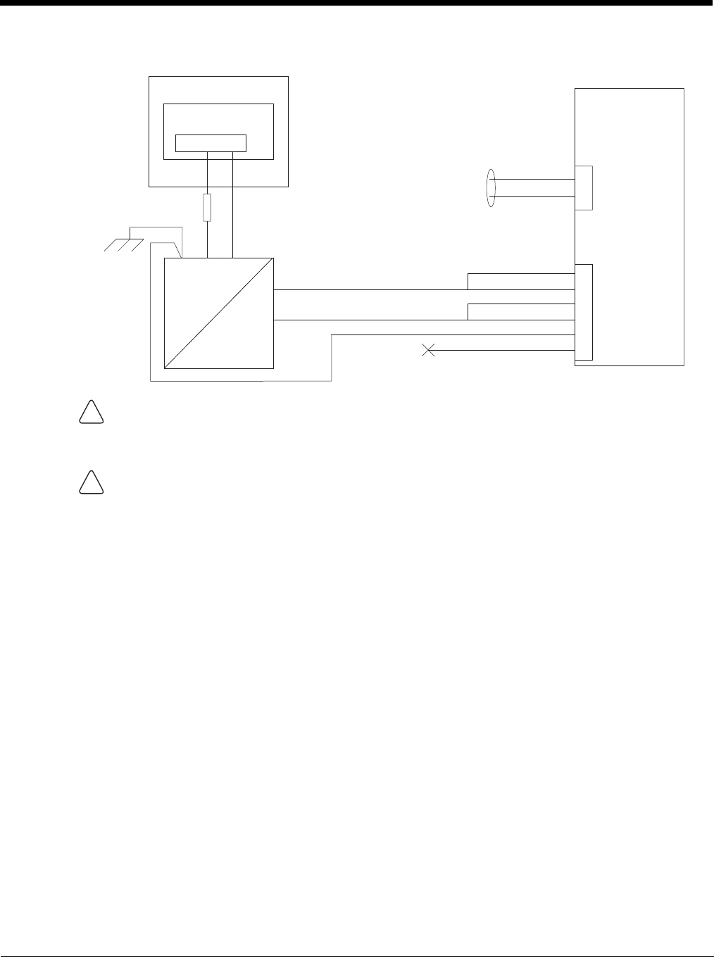
4 - 42
Wiring Diagram
CAUTION
For battery powered vehicles:
GND must be connected to the vehicle chassis ground.
For internal combustion engine powered vehicles:
GND is connected to the vehicle chassis ground, which can also be battery negative.
WARNING
For proper and safe installation, the input power cable must be connected to a fused circuit on the vehicle.
If the supply connection is made directly to the battery, the fuse should be installed in the positive lead within
5 inches of the battery’s positive (+) terminal. The fused circuit requires a maximum time delay (slow blow)
fuse with a current rating as noted below.
•For 60VDC input, use a 6A slow blow fuse that has a DC voltage rating greater than 60VDC.
•For 72VDC input, use a 6A slow blow fuse that has a DC voltage rating greater than 72VDC.
•For 96VDC input, use a 4A slow blow fuse that has a DC voltage rating greater than 96VDC.
•For 108VDC input, use a 4A slow blow fuse that has a DC voltage rating greater than 108VDC.
•For 120VDC input, use a 4A slow blow fuse that has a DC voltage rating greater than 120VDC.
•For 132VDC input, use a 3A slow blow fuse that has a DC voltage rating greater than 132VDC.
•For 144VDC input, use a 3A slow blow fuse that has a DC voltage rating greater than 144VDC.
Note: For North America, a UL Listed fuse is to be used
Main Switch
Circular
Power
Connector
on Dock
VIN-
VO-
-Vo
+Vo COM1 or COM2
Connector
on Dock
VO+
VIN+
GND
User supplied serial
cable for optional
screen blanking
connection,
see below
Existing Circuitry on Vehicle
Forklift Battery
DC/DC
Power
Supply
Fuse - See
Warning
statement below
See
Caution
statement
below
(not connected)
Black
Green
Blue
Red
Red/White (if present)
Black/White (if present)
Quick Mount
Smart Dock
!
!
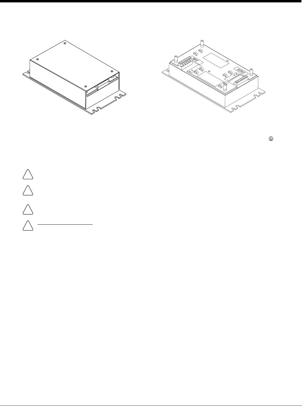
4 - 43
60-144 VDC Vehicles (50-150 VDC Power Supply, Screws on Top of Lid)
This option requires DC/DC power supply Honeywell Part no. VX89303PWRSPLY, shown below.
If the DC/DC power supply does not have screws in the top of the lid, see 60-144 VDC Vehicles (50-150 VDC Power
Supply, Screws on Side of Lid) (page 4-39).
Shown With Lid Attached
• Lid is secured with screws on the top of lid.
Shown With Lid Removed
• Input and output connector blocks under lid.
• Two positive (+), negative (-) and ground ( )
connections per terminal block
CAUTION - For installation by trained service personnel only.
CAUTION - The VX89303PWRSPLY power supply is sealed per IPXX. Usage in areas where moisture can affect
the power supply connections should be avoided. The power supply should be mounted in a dry location within
the vehicle or placed in a suitable protective enclosure.
Use caution when routing the power cable. See Power Cable Cautions (page 4-33).
Fuse Requirements
WARNING - For proper and safe installation, the input power cable must be connected to a fused circuit on the
vehicle. If the supply connection is made directly to the battery, the fuse should be installed in the positive lead
within 5 inches of the battery’s positive (+) terminal. The fused circuit requires a maximum time delay (slow blow)
fuse with a current rating as noted below.
•For 60VDC input, use a 6A slow blow fuse that has a DC voltage rating greater than 60VDC.
•For 72VDC input, use a 6A slow blow fuse that has a DC voltage rating greater than 72VDC.
•For 96VDC input, use a 4A slow blow fuse that has a DC voltage rating greater than 96VDC.
•For 108VDC input, use a 4A slow blow fuse that has a DC voltage rating greater than 108VDC.
•For 120VDC input, use a 4A slow blow fuse that has a DC voltage rating greater than 120VDC.
•For 132VDC input, use a 3A slow blow fuse that has a DC voltage rating greater than 132VDC.
•For 144VDC input, use a 3A slow blow fuse that has a DC voltage rating greater than 144VDC.
Note: For North America, a UL Listed fuse is to be used.
!
!
!
!
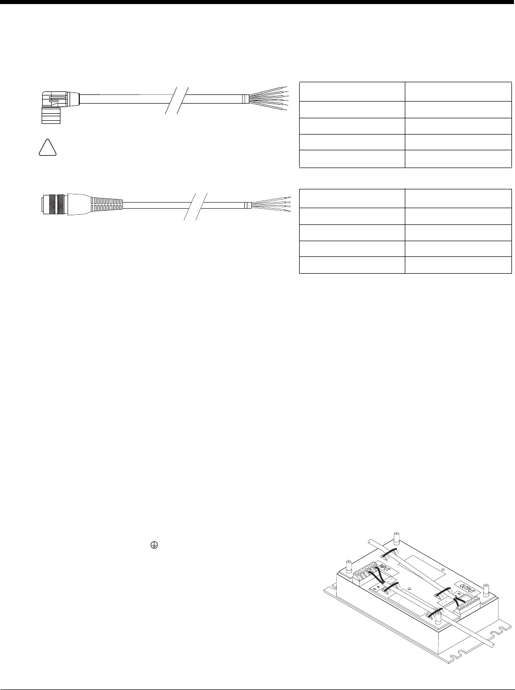
4 - 44
Power Cable Identification
The DC power cable (included with the dock) is one of the two styles below:
Note: Correct electrical polarity is required for safe and proper installation. See Wiring Diagram (page 4-46) for
additional wire color-coding specifics.
The Thor VM2 DC input wires (Red, Red/White DC+ and Black, Black/White DC-) and the Blue ignition input wire are
galvanically isolated. The Green ground input is used for electrostatic discharge (ESD) protection.
Vehicle 50-150VDC Power Connection
Please review the Wiring Diagram (page 4-46), before beginning power cable install. The Thor VM2must be pow-
ered off and the power cable disconnected from the Thor VM2. The last connection must be to the vehicle power
source before connecting the power cable to the Thor VM2.
1. Route the cable from the Thor VM2 to the DC/DC power supply. Route the power cable the shortest way pos-
sible. The cable is rated for a maximum temperature of 105°C (221°F). When routing this cable, it should be
protected from physical damage and from surfaces that might exceed this temperature. Do not expose the
cable to chemicals or oil that may cause the wiring insulation to deteriorate. Always route the cable so that it
does not interfere with safe operation and maintenance of the vehicle.
2. Cut the cable to length and strip the wire ends.
3. Remove the lid from the DC/DC power supply.
4. Connect the stripped end of the positive wires (red and red/white twisted together or a single red wire) to the
output block. See Power Cable Identification (page 4-44).
5. Connect the stripped end of the negative wires (black and black/white twisted together or a single black wire)
to the output. See Power Cable Identification (page 4-44).
Note: The input and output blocks each have two + (plus), two –
(minus) and two (ground) connectors. Either connector
in the block can be used to connect the matching polarity
wire.
Power cable with right angle connector and 6 wires:
Wire Color Connection
Red (2 wires) DC + (10-60 VDC)
Black (2 wires) DC -
Twist the red and red/white wires together and twist the
black and black/white wires together before connecting to
vehicle power.
Green Ground
Blue Ignition Input (not used)
Power cable with straight connector and 4 wires:
Wire Color Connection
Red DC + (10-60 VDC)
Black DC -
Green Ground
Blue Ignition Input (not used)
!

4 - 45
6. Route the wiring from the DC/DC power supply to the vehicle’s electrical system. Do not connect to vehicle
power at this time.
7. Strip the wire ends and connect to the input side of the DC/DC power supply.
8. Use looms and wire ties to secure all wiring as shown.
9. Reattach the cover with the screws.
10. Connect the DC/DC power supply to the vehicle’s electrical system as directed below
11. While observing the Fuse Requirements (see page 4-43), connect the power cable as close as possible to the
actual battery terminals of the vehicle. When available, always connect to unswitched terminals in the vehicle
fuse panel, after providing proper fusing.
ATTENTION: For uninterrupted power, electrical supply connections should not be made at any point
after the ignition switch of the vehicle.
12. Use proper electrical and mechanical fastening means for terminating the cable. Properly sized “crimp” type
electrical terminals are an accepted method of termination. Select electrical connectors sized for use with
18AWG (1mm2) conductors.
13. Provide mechanical support for the cable by securing it to the vehicle structure at approximately one foot inter-
vals, taking care not to over tighten and pinch conductors or penetrate the outer cable jacket.
14. Connect the watertight connector end of the power cable to the Thor VM2 Quick Mount Smart Dock power
connector by aligning the connector pins to the power connector; push down on the watertight connector and
twist it to fasten securely.Flip the power switch on the back of the dock to On.
15. Secure the power cable to the Thor VM2 using the Strain Relief Cable Clamps (page 4-32).
16. Place Thor VM2 in the Dock (page 4-18)
17. If using the Screen Blanking (page 4-49) feature, install the screen blanking box or switch.
18. Press the Power Switch (page 3-6) on the back of the Thor VM2 dock.
19. Press the Power Button (page 3-6) on the front of the Thor VM2 to turn on the Thor VM2.
Once installation is complete, remember to start the Thor VM2 and select the desired Power Configuration Mode
to enable Auto-On or Manual Control of the Thor VM2 boot up process.
See the Power Configuration Mode (page 5-80) control panel.
Note: Ignition control is not available for trucks over 60VDC.
For battery powered vehicles:
+ is connected to battery positive.
- must be connected to battery negative.:
must be connected to the vehicle chassis ground.
For internal combustion engine powered vehicles:
+ is connected to battery positive.
- is connected to battery negative.
is connected to the vehicle chassis ground, which can also be battery negative.
!
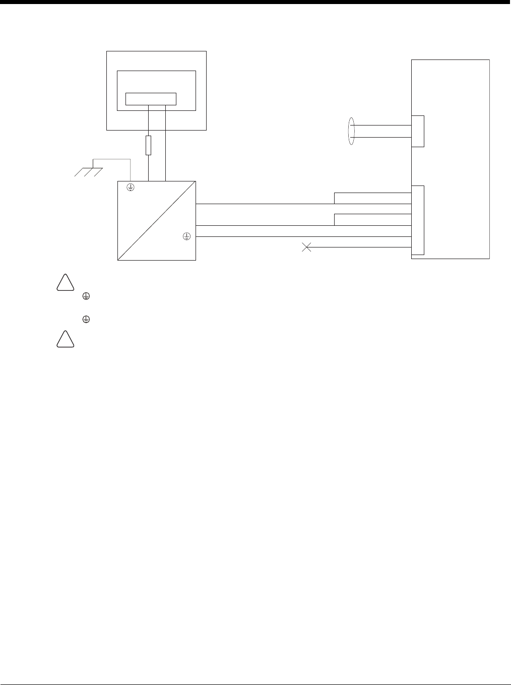
4 - 46
Wiring Diagram
CAUTION
For battery powered vehicles:
must be connected to the vehicle chassis ground.
For internal combustion engine powered vehicles:
is connected to the vehicle chassis ground, which can also be battery negative.
WARNING
For proper and safe installation, the input power cable must be connected to a fused circuit on the vehicle.
If the supply connection is made directly to the battery, the fuse should be installed in the positive lead within
5 inches of the battery’s positive (+) terminal. The fused circuit requires a maximum time delay (slow blow)
fuse with a current rating as noted below.
•For 60VDC input, use a 6A slow blow fuse that has a DC voltage rating greater than 60VDC.
•For 72VDC input, use a 6A slow blow fuse that has a DC voltage rating greater than 72VDC.
•For 96VDC input, use a 4A slow blow fuse that has a DC voltage rating greater than 96VDC.
•For 108VDC input, use a 4A slow blow fuse that has a DC voltage rating greater than 108VDC.
•For 120VDC input, use a 4A slow blow fuse that has a DC voltage rating greater than 120VDC.
•For 132VDC input, use a 3A slow blow fuse that has a DC voltage rating greater than 132VDC.
•For 144VDC input, use a 3A slow blow fuse that has a DC voltage rating greater than 144VDC.
Note: For North America, a UL Listed fuse is to be used.
Power
Connector
-
-
-Vo
Black
Green
Blue
(not connected)
+Vo COM1 or COM2
Connector
+
+
User supplied serial
cable for optional
screen blanking
connection,
see below
Existing Circuitry on Vehicle
Forklift Battery
Main Switch
Quick Mount
Smart Dock
DC/DC
Power
Supply
Fuse - See
Warning
statement below
See
Caution
statement below
Red
Red/White (if present)
Black/White (if present)
!
!

4 - 47
VX6 / VX7 Adapter Cable
An adapter cable is available to attach the Thor VM2 to a vehicle previously equipped with a VX6/VX7 DC power cable.
The adapter cable has a 5-pin connector to match with the VX6/VX7 power supply cable on one end and a 6-pin con-
nector to match to the Thor VM2 on the other end. This section assumes the VX6/VX7 power cable is properly con-
nected to vehicle power. Refer to the VX6 or VX7 Vehicle Mounting Reference Guide for details.
When this adapter cable is used, there is no provision for an ignition switch input. Therefore the vehicle ignition moni-
toring function is not available when using this cable.
Connect to VX6 / VX7 Power Cable
1. Connect the cable to the Thor VM2 power cable by aligning the connector pins to the power connector; push
down on the watertight connector and twist it to fasten securely.
2. The cable is rated for a maximum temperature of 105°C (221°F). Therefore, routing this cable it should be
protected from physical damage and from surfaces that might exceed this temperature. Cable should be pro-
tected from physical damage from moving parts. Do not expose the cable to chemicals or oil that may cause
the wiring insulation to deteriorate. Always route the cable so that it does not interfere with safe operation and
maintenance of the vehicle.
3. Provide mechanical support for the cable by securing it to the vehicle structure at approximately one foot inter-
vals, taking care not to over tighten and pinch conductors or penetrate outer cable jacket.
4. Connect the watertight connector end of the power cable to the Thor VM2 Quick Mount Smart Dock power
connector by aligning the connector pins to the power connector; push down on the watertight connector and
twist it to fasten securely.
5. Secure the power cable to the Thor VM2 using the Strain Relief Cable Clamps (page 4-32).
6. Place Thor VM2 in the Dock (page 4-18)
7. If using the Screen Blanking (page 4-49) feature, install the screen blanking box or switch.
8. Press the Power Switch (page 3-6) on the back of the Thor VM2 dock.
9. Press the Power Button (page 3-6) on the front of the Thor VM2 to turn on the Thor VM2.
CAUTION - Because the Thor supports 10-60 VDC power input, verify input voltages before using this adapt-
er cable with an existing VX6 or VX7 power connection installation.
!
To Power Connector on Dock
To VX6/VX7 Power Supply Cable
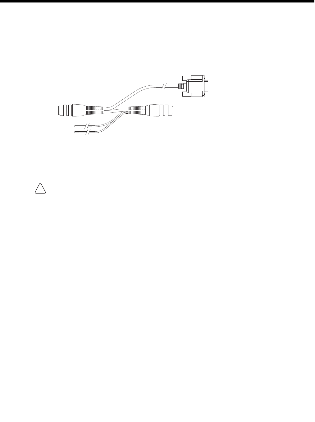
4 - 48
Thor VX8 / Thor VX9 Adapter Cable
An adapter cable is available to attach the Thor VM2 to a vehicle previously equipped with a VX8/VX9 DC power cable.
The adapter cable has a 6-pin connector to match the VX8/XVX9 power supply cable on one end and a 6-pin connec-
tor to match the Thor VM2 on the other end. The cable also has bare wires for ground and ignition sense connection
plus a D9 cable to connect to a COM port on the Thor VM2 dock to provide a screen blanking signal. This section
assumes the VX8/VX9 power cable is properly connected to vehicle power. Refer to the VX8 or VX9 Vehicle Mounting
Reference Guide for details.
Connect to Thor VX8 / VX9 Power Cable
1. Connect the cable to the Thor VX8/VX9 power cable by aligning the connector pins to the power connector;
push down on the watertight connector and twist it to fasten securely.
2. Connect the green wire to vehicle ground:
3. If ignition control will be used, connect the blue wire to an ignition switched circuit (less than 1mA over input
voltage range). If ignition control is not used, the blue wire can be left disconnected,
4. If the VX8/VX9 cable is connected to a screen blanking box or switch, connect the D9 connector to a COM
port on the dock.
5. The cable is rated for a maximum temperature of 105°C (221°F). Therefore, when routing this cable it should
be protected from physical damage and from surfaces that might exceed this temperature. Cable should be
protected from physical damage from moving parts. Do not expose the cable to chemicals or oil that may
cause the wiring insulation to deteriorate. Always route the cable so that it does not interfere with safe opera-
tion and maintenance of the vehicle.
6. Provide mechanical support for the cable by securing it to the vehicle structure at approximately one foot inter-
vals, taking care not to over tighten and pinch conductors or penetrate outer cable jacket.
7. Connect the watertight connector end of the power cable to the Thor VM2 Quick Mount Smart dock power
connector by aligning the connector pins to the power connector; push down on the watertight connector and
twist it to fasten securely.
8. Secure the power cable to the Thor VM2 using the Strain Relief Cable Clamps (page 4-32).
9. Place Thor VM2 in the Dock (page 4-18)
10. If using the Screen Blanking (page 4-49) feature, install the screen blanking box or switch if not previously
installed.
11. Press the Power Switch (page 3-6) on the back of the Thor VM2 dock.
12. Press the Power Button (page 3-6) on the front of the Thor VM2 to turn on the Thor VM2.
For battery powered vehicles:
The green wire must be connected to the vehicle chassis ground.
For internal combustion engine powered vehicles:
The green wire is connected to the vehicle chassis ground, which can also be battery negative.
To COM port
on Dock
To Power Connector
on Dock
To VX8/VX9
Power Cable
To Ground and
Ignition Sense
!
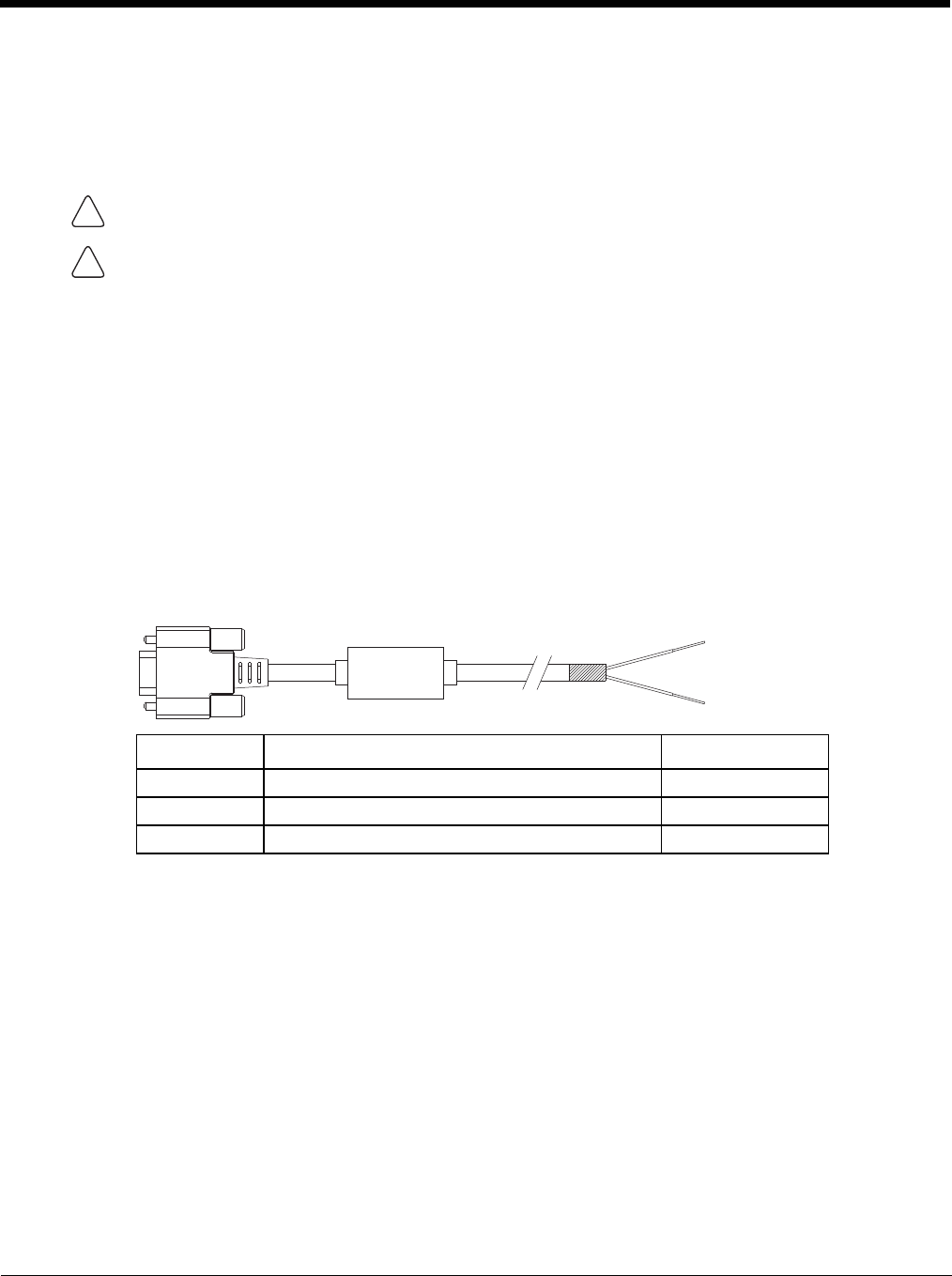
4 - 49
Screen Blanking
Prerequisite: The steps outlined in either 12-48 VDC Vehicles (10-60 VDC Direct Connection) (page 4-34), 60-144
VDC Vehicles (50-150 VDC Power Supply, Screws on Side of Lid) (page 4-39) or 60-144 VDC Vehicles (50-150 VDC
Power Supply, Screws on Top of Lid) (page 4-43) have been completed.
Screen blanking is accomplished by either a Screen Blanking Box or a user supplied switch.
Screen Blanking Cable
Refer to Screen Control (in the Windows Control Panel) to configure the Thor VM2 for screen blanking.
When routing any additional cables for screen blanking:
• Route the cable the shortest way possible removing any left-over cable
• Fuses and cabling are user supplied. Therefore, route these cables so they are protected from physical damage
and from surfaces that might exceed the cable's rated temperature threshold.
• Cable should be protected from physical damage from moving parts
• Do not expose the cable to chemicals or oil that may cause the wiring insulation to deteriorate
• Always route the cable so that it does not interfere with safe operation and maintenance of the vehicle.
• Provide mechanical support for the cable by securing it to the vehicle structure at approximately one foot
intervals, taking care not to over tighten and pinch conductors or penetrate outer cable jacket.
Honeywell Screen Blanking Box Cable
An optional Honeywell Screen Blanking Box Cable is available.
Note: Wire colors only apply to optional Honeywell Screen Blanking Box Cable, VM1080CABLE. Wire colors
may vary in a user-supplied cable.
The optional Honeywell Screen Blanking Box Cable, VM1080CABLE, is installed as follows:
1. Connect the gray wire of the cable to the switched side of the Screen Blanking Box.
2. Connect the black wire of the cable to the unswitched side of the Screen Blanking Box.
3. Connect the D9 serial connector to either COM1 or COM2 serial port on the Thor VM2 Quick Mount
Smart Dock.
CAUTION - For installation by trained service personnel only.
CAUTION - For proper and safe installation, the input power lead to the Screen Blanking Box requires a 3 Amp
maximum time delay (slow blow) high interrupting rating fuse. Note: For North America, a UL Listed fuse is to be
used.
DB9 Female Function with Screen Blanking Box Wire color
1 -6, 9 Not Used
7 (RTS) Connected to Screen Blanking Box, unswitched side Black (see note)
8 (CTS) Connected to Screen Blanking Box, switched side Gray (see note)
!
!
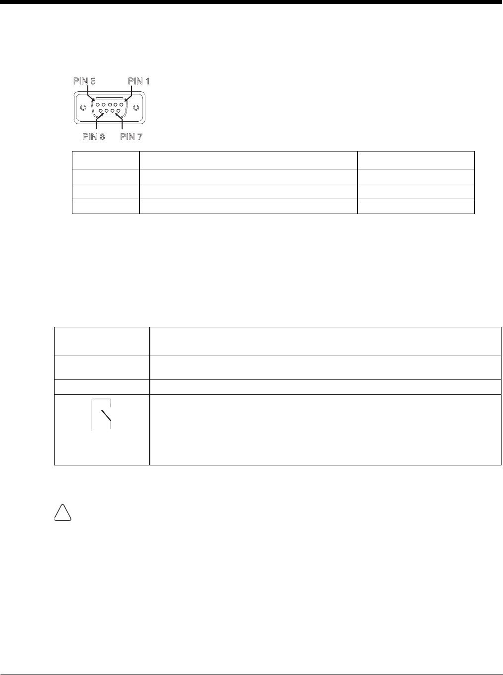
4 - 50
User-Supplied Cable
A user-supplied cable can be used as well. Pins 7 and 8 must be connected as detailed below. No other pins
are to be connected.
The user-supplied cable is installed as follows:
1. Connect the wire from Pin 8 of the cable to the switched side of the Screen Blanking Box or to a user-sup-
plied switch.
2. Connect the wire from Pin 7 of the cable to the unswitched side of the Screen Blanking Box or to a user-
supplied switch.
3. Connect the D9 serial connector to either COM1 or COM2 serial port on the Thor VM2 Quick Mount
Smart Dock.
Screen Blanking Box
It is assumed that the motion sensing circuitry in the illustrations below is powered by internal vehicle circuitry.
Please refer to the appropriate illustration below for Screen Blanking Box wiring diagrams.
DB9 Female Function with Screen Blanking Box Function with Switch
1 -6, 9 Not Used Not Used
7 (RTS) Connected to Screen Blanking Box, unswitched side Connected to Switch
8 (CTS) Connected to Screen Blanking Box, switched side Connected to Switch
Screen Blanking
Box Terminal
Connection
12-xxV Input from vehicle motion sensing circuitry.
Please refer to label on Screen Blanking Box for allowable voltage input range.
GND DC -
These two terminals are for connecting a serial cable:
• If using an optional Honeywell screen blanking cable, VM1080CABLE, connect the
gray wire to the switched side of the connection and connect the black wire to the
unswitched side.
• If using a user-supplied cable, the cable must be constructed so that Pin 7 (RTS)
connects to switched side of the connection and Pin 8 (CTS) connects to the
unswitched side.
CAUTION - Do not exceed the maximum input voltage, either 60 or 72VDC, specified on the Screen Blanking
Box label when using this configuration.
PIN7
PIN 8
PIN 5 PIN1
Unswitched Switched
!

4 - 51
Note: The black and gray wire colors in the illustration only apply to the optional Honeywell Screen Blanking Box
Cable, VM1080CABLE. The wire colors may be different in a user-supplied cable.
Screen Blanking with Switch
In applications where it is impractical to use the screen blanking box due to vehicle voltage or lack of a motion
sensing signal, screen blanking can be controlled via a user supplied switch or relay that provides an electrical
conductive connection on vehicle motion.
Pins 7 and 8 must be connected as shown in the illustration above. No other pins are to be connected.
MOTION
CIRCUITRY
To
-Vo on vehicle,
i.e. Negative
battery terminal
3A fuse
+Vi
GND
To pin 7 of COM1 or
COM2
To pin 8 of COM1 or
COM2
To pins 7 and 8
of COM1 or
COM2
port on dock
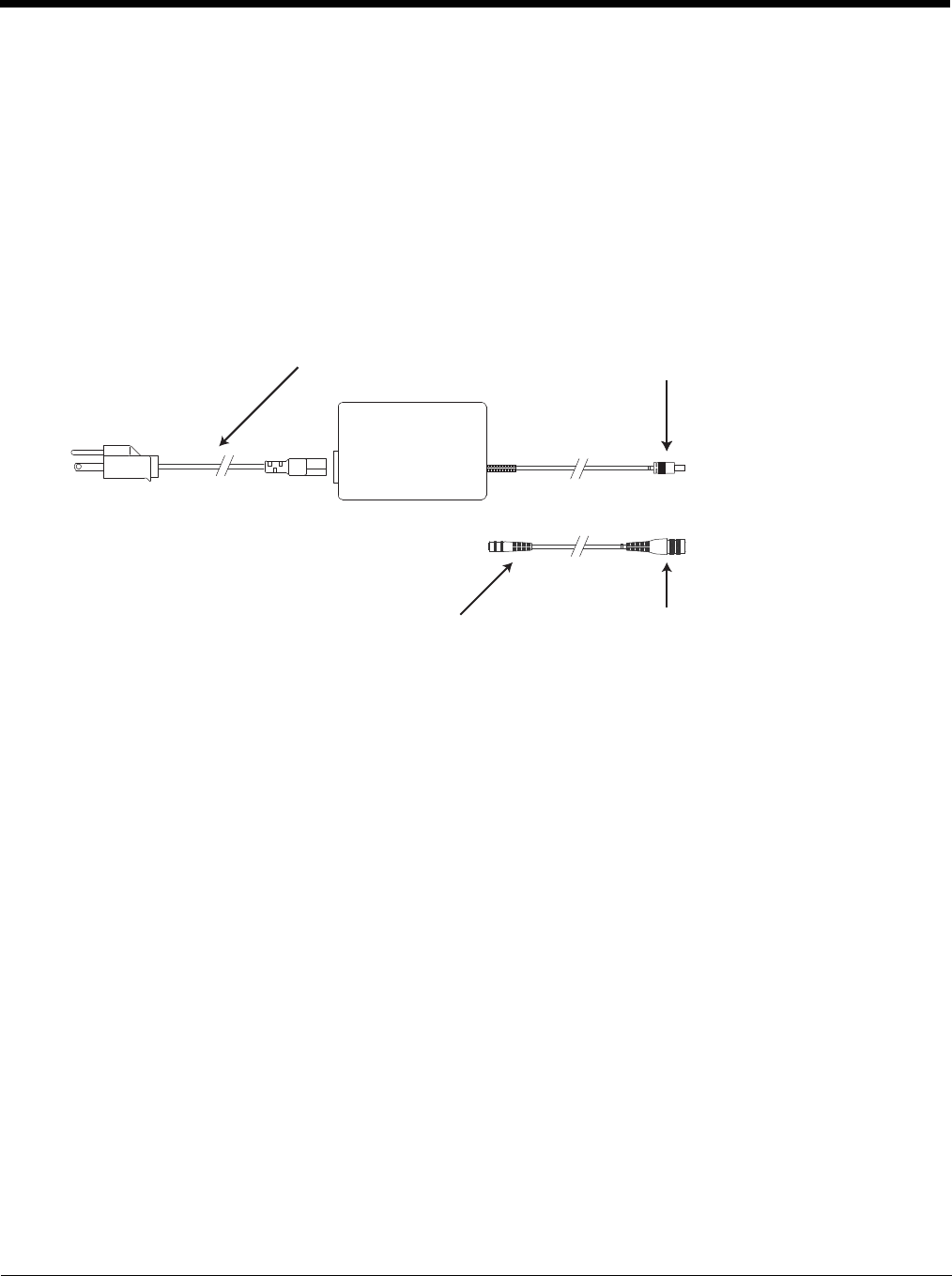
4 - 52
External AC/DC Power Supply
The optional external AC/DC power supply is for use in environments, such as an office, where DC power is not avail-
able.
Note: The Honeywell-approved AC/DC Power Supply and Adapter Cable are only intended for use in a 25ºC (77ºF)
maximum ambient temperature environment.
In North America, this unit is intended for use with a UL Listed ITE power supply with output rated 10 – 60 VDC, mini-
mum 15W. Outside North America, this unit is intended for use with an IEC certified ITE power supply with output
rated 10 – 60 VDC, minimum 15W.
The external power supply may be connected to either a 120V, 60Hz supply or, outside North America, to a 230V,
50Hz supply, using the appropriate detachable cordset. In all cases, connect to a properly grounded source of supply
provided with maximum 15 Amp overcurrent protection (10 Amp for 230V circuits).
Connect External Power Supply
1. Connect the provided detachable cordset (US only, all others must order cable separately) to the external
power supply (IEC 320 connector).
2. Plug cordset into appropriate, grounded, electrical supply receptacle (AC mains).
3. Connect the DC Output Cable end to the corresponding connector on the Adapter Cable.
4. Connect the watertight connector end of the Adapter Cable to the Thor VM2 Quick Mount Smart Dock Power
Connector by aligning the connector pins to the power connector; push down on the watertight connector and
twist it to fasten securely.
5. Press the Power Switch (page 3-6) on the back of the Thor VM2 dock.
6. Press the Power Button (page 3-6) on the front of the Thor VM2 to turn on the Thor VM2.
AC Input Cable (US only)
DC Output Cable
To DC Output Cable To Dock
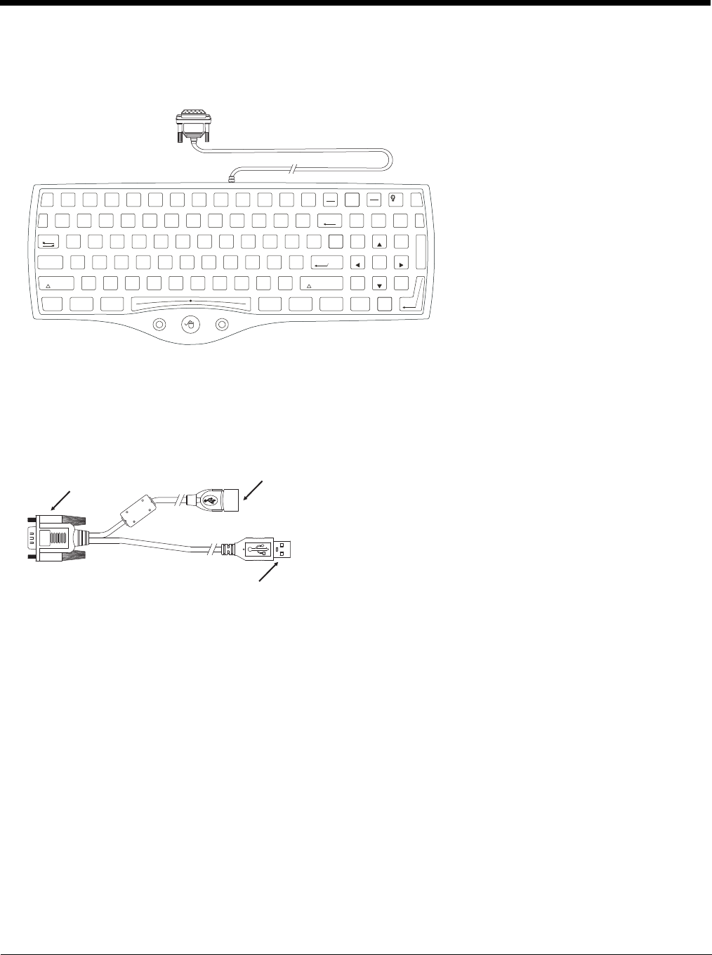
4 - 53
Connect USB Keyboard
The external keyboard (part number 164288-0001) is a USB keyboard. The keyboard has a D9 connector which attaches
to the USB port on the Thor VM2 Quick Mount Smart Dock.
1. Seat the keyboard cable connector over the USB connector on the Thor VM2 Quick Mount Smart Dock.
2. Tighten the thumbscrews in a clockwise direction. Do not over tighten.
3. Secure the cable to the Thor VM2 with Strain Relief Cable Clamps (page 4-32).
Connect USB Host
See USB Connector (page 10-5) for connector pinouts.
1. Seat the D9 connector firmly over the USB Connector on the Quick Mount Smart Dock.
2. Tighten the thumbscrews in a clockwise direction. Do not over tighten.
3. The USB-host connector provides a connector for a USB device such as a USB thumb drive.
4. Secure the cables to the Thor VM2 with Strain Relief Cable Clamps (page 4-32).
RL
1
!
2
Esc
Print
SysRq
Screen Scroll
Lock
Fn
Pause
Break
F2 F3 F4 F5 F6 F7 F8 F9 F10 F11 F12F1
3
#@
4
$
5
%
6
^
0
)
8
*
7
&
-
_
9
(
=
+
BackSpace Num
Lock
/*=
~
`
Q W E R T UY IO
Tab
A S D F G JHK
Z X C V BMN.
>
,
<
/
?
L;
:
'
"
P]
}
\
|
[
{8
PgUp
9
Home
7
2
PgDn
3
End
1
56
4
+
Ins
0
Del
.
CtrlAlt
Enter
Shift
Enter
Ctrl Alt
Shift
Caps
Lock
D9 Connector USB Host Connector
USB Client Connector
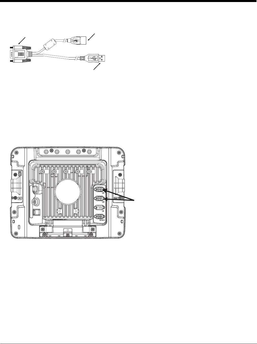
4 - 54
Connect USB Client
See USB Connector (page 10-5) for connector pinouts.
1. Seat the D9 connector firmly over the USB Connector on the Quick Mount Smart Dock.
2. Tighten the thumbscrews in a clockwise direction. Do not over tighten.
3. The USB client connector provides a client connection, such as for ActiveSync to a PC.
4. Secure the cables to the Thor VM2 with Strain Relief Cable Clamps (page 4-32).
Connect Serial Device
Note: Pin 9 of the desired COM port must be configured to provide +5V or RI as needed for the connected device. See the
Thor VM2 Reference Guide for details.
See COM1 and COM2 Connector (page 10-4) for connector pinouts.
1. Seat the cable end connector firmly over the serial COM port on the Quick Mount Smart Dock.
2. Turn the thumbscrews in a clockwise direction. Do not over tighten.
3. Secure the cables to the Thor VM2 with Strain Relief Cable Clamps (page 4-32).
4. Connect the other cable end to the desired serial device.
Connect a Tethered Scanner
1. The scanner cable is attached to either the COM1 or COM2 port on the Quick Mount Smart Dock.
2. Connect the serial cable for the scanner as directed above.
3. When the Thor VM2 is powered on, it provides power to the serial scanner.
4. Configure the Data Collection (DC) Wedge to manipulate scanned data as desired.
D9 Connector USB Host Connector
USB Client Connector
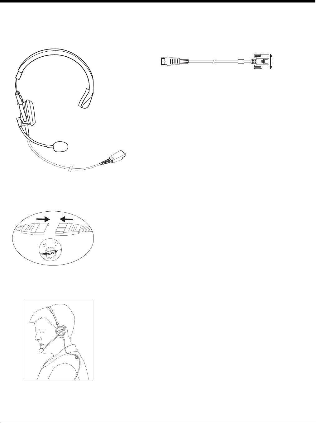
4 - 55
Connect Headset Cable
The CANbus/Audio connector supports a headset adapter cable or a CANbus cable. The Thor VM2 does not support con-
necting audio and CANbus simultaneously.
See CANbus / Audio Connector (page 10-6) for connector pinouts.
1. Seat the D15 cable end connector firmly over the CANbus/Audio Connector on the Quick Mount Smart Dock.
2. Tighten the thumbscrews in a clockwise direction. Do not over tighten.
3. Slide the cable ends together until they click shut. Do not twist or bend the connectors. The Thor VM2 internal
microphone and speakers are automatically disabled when the headset is connected.
Adjust Headset / Microphone and Secure Cable
The headset consists of an earpiece, a microphone, a clothing clip and a cable.
Headphones
Microphone To Audio cable
To Audio
connector
on dock
To headset
click!
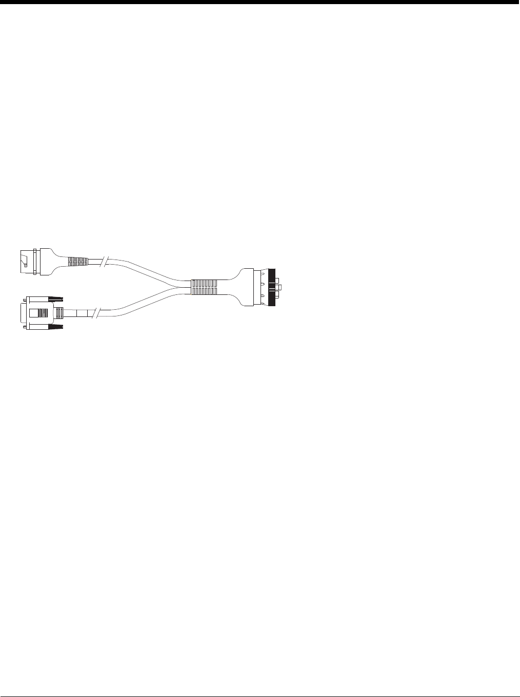
4 - 56
1. Do not twist the microphone boom when adjusting the microphone. The microphone should be adjusted to be
about two finger widths from your mouth.
2. Make sure the microphone is pointed at your mouth. Note the small “Talk” label near the mouthpiece. Make sure
the Talk label is in front of your mouth. The microphone cable can be routed over or under clothing.
3. Follow the safety guidelines below when wearing the headset.
Under Clothing
• Leave the cable exposed only at the top of the collar.
• Be sure to leave a small loop of cable to allow movement of your head.
Over Clothing
• Use clothing clips to hold the cable close to your body.
• Tuck the cable under the belt, but leave a small loop where it goes under the belt.
• Do not wear the cable on the front of your body. It may get in your way or get caught on protruding objects.
Connect CANbus Cable
The CANbus/Audio connector supports a headset adapter cable or a CANbus Y cable. The Thor VM2 does not support
connecting audio and CANbus simultaneously.
See CANbus / Audio Connector (page 10-6) for connector pinouts.
1. Seat the D15 cable end connector firmly over the CANbus/Audio Connector on the Quick Mount Smart Dock.
2. Tighten the thumbscrews in a clockwise direction. Do not over tighten.
3. The CANbus Y cable has a 9 pin F SAE J1939 (Deutsch) and 9 pin M SAE J1939 (Deutsch) connector. Connect the
appropriate cable connector as needed.
Install External Antenna
The external antenna cannot be used by devices with an internal antenna.
1. Remove the rubber cap, if present, from the antenna connector before connecting an external antenna.
2. Place the antenna over the antenna connector. If only one antenna is used, be sure to connect it to the Wi-Fi Main
connector.
3. Push down and twist the antenna base clockwise until secure.
4. Repeat for second antenna, if used.
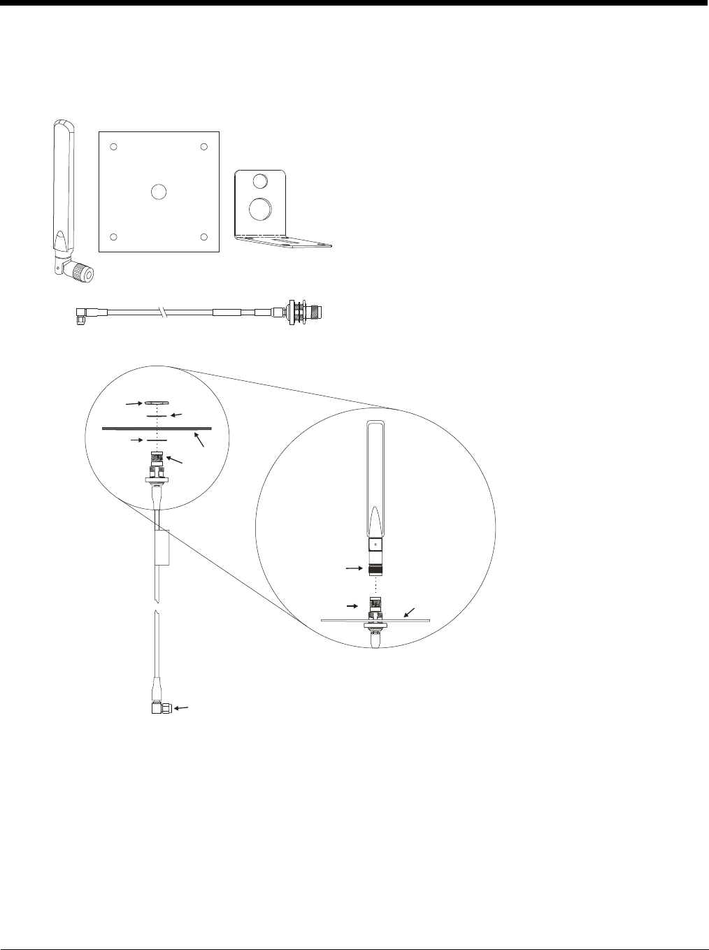
4 - 57
Install Remote Antenna
Remote antennas are available for the 802.11 WLAN radio, the WWAN radio and the GPS.
802.11 Remote Mount Antenna
Components and Mounting Diagram
The Remote Antenna Installation Kit consists of two brackets
(base plate and right angle), cable, and antenna. Tools are not
included.
The desired remote antenna bracket is mounted on the top of a
forklift, truck or other vehicle and cabled to the Thor VM2 inside
the vehicle.
The Vehicle Remote Mount Antenna cannot be used by devices
with an internal antenna.
Nut Washer
Washer Bracket
To antenna
To antenna connector on computer
Bracket
To antenna
Antenna

4 - 58
Typical Installation
Mounting Instructions
1. Attach and secure the desired mounting bracket to the highest point on the safety cage, following these pre-
cautions:
• The plate must be mounted so the antenna is not damaged while the vehicle or any of its parts are moving.
• The antenna mounting portion of the bracket must be parallel to the floor.
• If using two antennas, they must be mounted at least 12 inches (304.8mm) apart.
2. Attach the female connector of the coaxial cable to the antenna connector on the vehicle mounted Thor VM2.
3. Secure the whip antenna to the mounting bracket.
4. Connect the antenna cable to the whip antenna.
5. Use cable ties to secure the coaxial cable to the vehicle as necessary. Make sure the cable is routed so it is
not damaged by any moving parts of the vehicle.
6. Connect the cable to the antenna connector (Wi-Fi Main or Wi-Fi Aux) on the Thor VM2. If only one antenna
is used, be sure to connect it to the Wi-Fi Main connector.
7. Repeat the steps above for the second 802.11 antenna.
Antenna Mounting Bracket
Vehicle Safety Cage Cable Vehicle Mounted
Computer
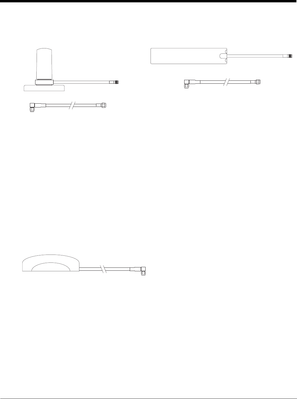
4 - 59
WAN Remote Mount Antenna
The WAN remote mount antenna can be either a magnetic mount or an adhesive mount antenna.
The Remote Antenna Installation Kit consists of the WAN antenna and an extension cable. The remote antenna is
mounted on the top of a forklift, truck or other vehicle and cabled to the Thor VM2 inside the vehicle.
1. Locate a mounting position on highest point on the vehicle, following these precautions:
• The antenna must be mounted so the antenna is not damaged while the vehicle or any of its parts are moving.
2. Clean the area where the antenna is to be mounted.
3. If using an adhesive mount antenna, remove the protective backing paper from the adhesive on the antenna.
4. Position the antenna on the vehicle.
5. Attach the one end of the coaxial cable to the antenna and the other end to the Mobile Net WWAN connector on
the vehicle mounted Thor VM2.
6. Use cable ties to secure the coaxial cable to the vehicle as necessary. Make sure the cable is routed so it is not
damaged by any moving parts of the vehicle.
GPS Remote Mount Antenna
The external GPS antenna is an adhesive mount antenna.
1. Locate a mounting position on highest point on the vehicle, following these precautions:
• The antenna must be mounted so the antenna is not damaged while the vehicle or any of its parts are moving.
2. Clean the area where the antenna is to be mounted.
3. Remove the protective backing paper from the adhesive on the antenna and position the antenna on the vehicle.
4. Attach the connector on the coaxial cable to the GPS antenna connector on the vehicle mounted Thor VM2.
5. Use cable ties to secure the coaxial cable to the vehicle as necessary. Make sure the cable is routed so it is not
damaged by any moving parts of the vehicle.
Magnetic Mount WAN Antenna Adhesive Mount WAN Antenna
The Remote Antenna Installation Kit consists of the antenna
and an integrated cable. The remote antenna is mounted on the
top of a forklift, truck or other vehicle and cabled to the Thor
VM2 inside the vehicle.
To extension cable
To antenna
To antenna
connector on
computer
To extension cable
To antenna
To antenna
connector on
computer
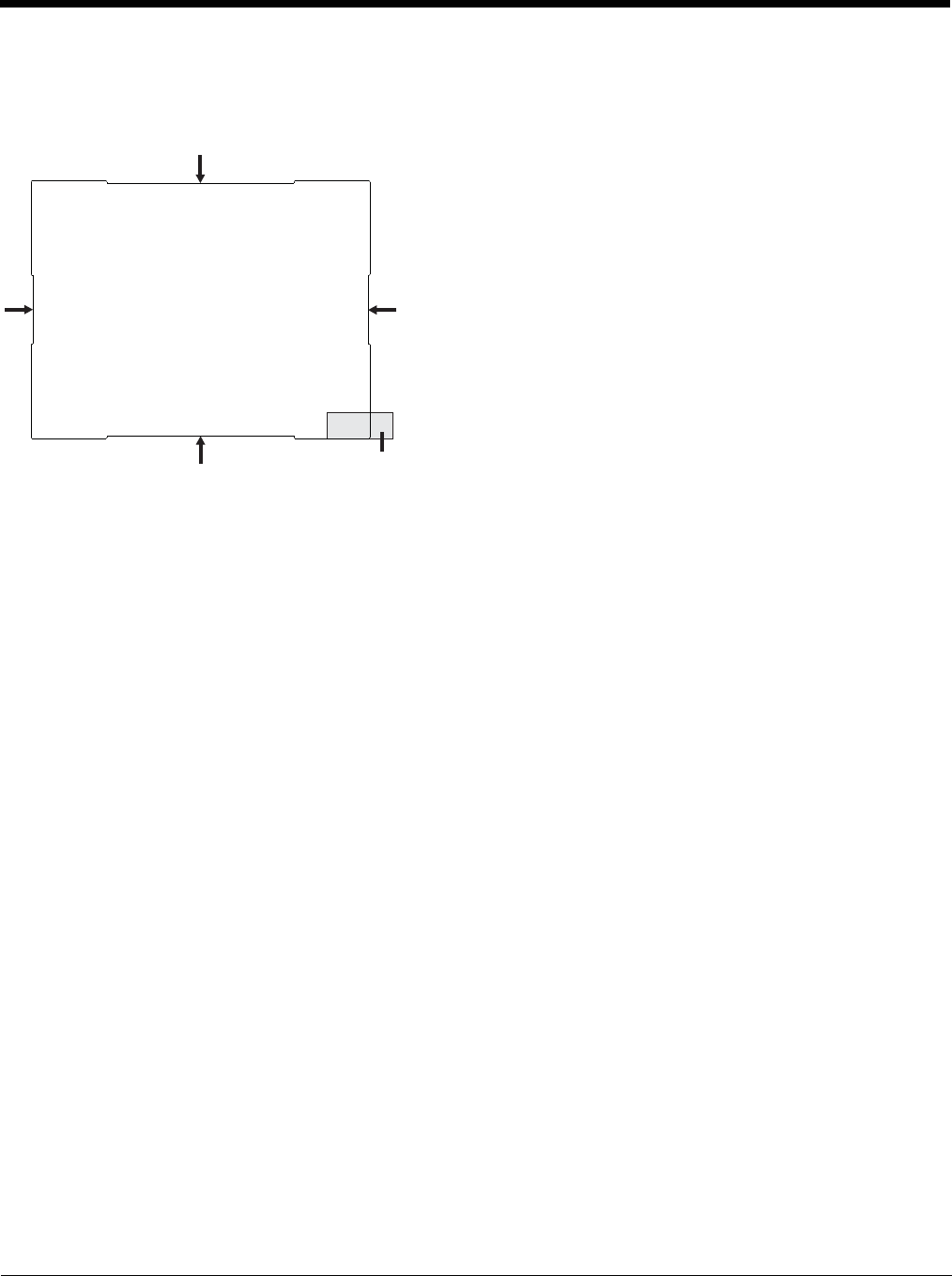
4 - 60
Apply Touch Screen Protective Film
The optional Thor VM2 touch screen protective film is shipped in packs of 10. The protective film is flexible and treated with an
anti-glare coating on the outer surface.
Installation
1. Make sure the touch screen is clean and dry before installation. See Cleaning (page 4-18) for instructions on suitable
cleaning agents.
2. Pull the release tab to separate the protective backing from the rear of the protective film. Avoid touching the rear side
of the protective film while removing the liner.
3. Place the rear side of the protective film against the Thor VM2 display, roughly centering the protective film over the
display.
4. Slide the protective film until one corner can be slid back between the touch screen and the display housing as the
protective film is re-centered on the display. It may be necessary to press the edges of the protective film against the
display to ensure the entire edge slides under the display housing. It is easiest to start with one of the bottom corners.
5. Slide the protective film away from the other bottom corner. The film may bulge sligthly away from the Reference Guide
as it is being slid. Only slide the protective film enough so that the protective film can slide under the display housing on
that corner when the protective film is returned to center.
6. Repeat with each of the top corners, sliding the protective film away from the corner just enough that the protective film
can slide under the display housing when the protective film is returned to center.
7. It may be necessary to flex the protective film during the install, however use care not to flex the protective film so much
that the protective film kinks.
8. Once all corners are secure under the display housing, adjust the protective film, if necessary, so it is centered on the
touch screen.
Removal
1. To remove the protective film, slide the protective film in one direction until the edge clears.
2. Lift up on the edge of the protective film so it does not slide between the touch screen and display housing when the
protective film is slid back to the center.
3. Repeat until all edges are free and remove the protective film.
The protective film is slightly larger than the Thor VM2 touch screen,
however the notches on the edge of the protective film (indicated by the
arrows) correspond to the display size of the Thor VM2. The protective
film is not adhesive. The corner edges are designed to fit between the
Thor VM2 display and the display housing to hold the protective film in
place.
A protective backing is applied to the rear surface of the protective film. A
pull tab is attached to the protective backing for easy removal of the pro-
tective backing from the film.
Pull Tab
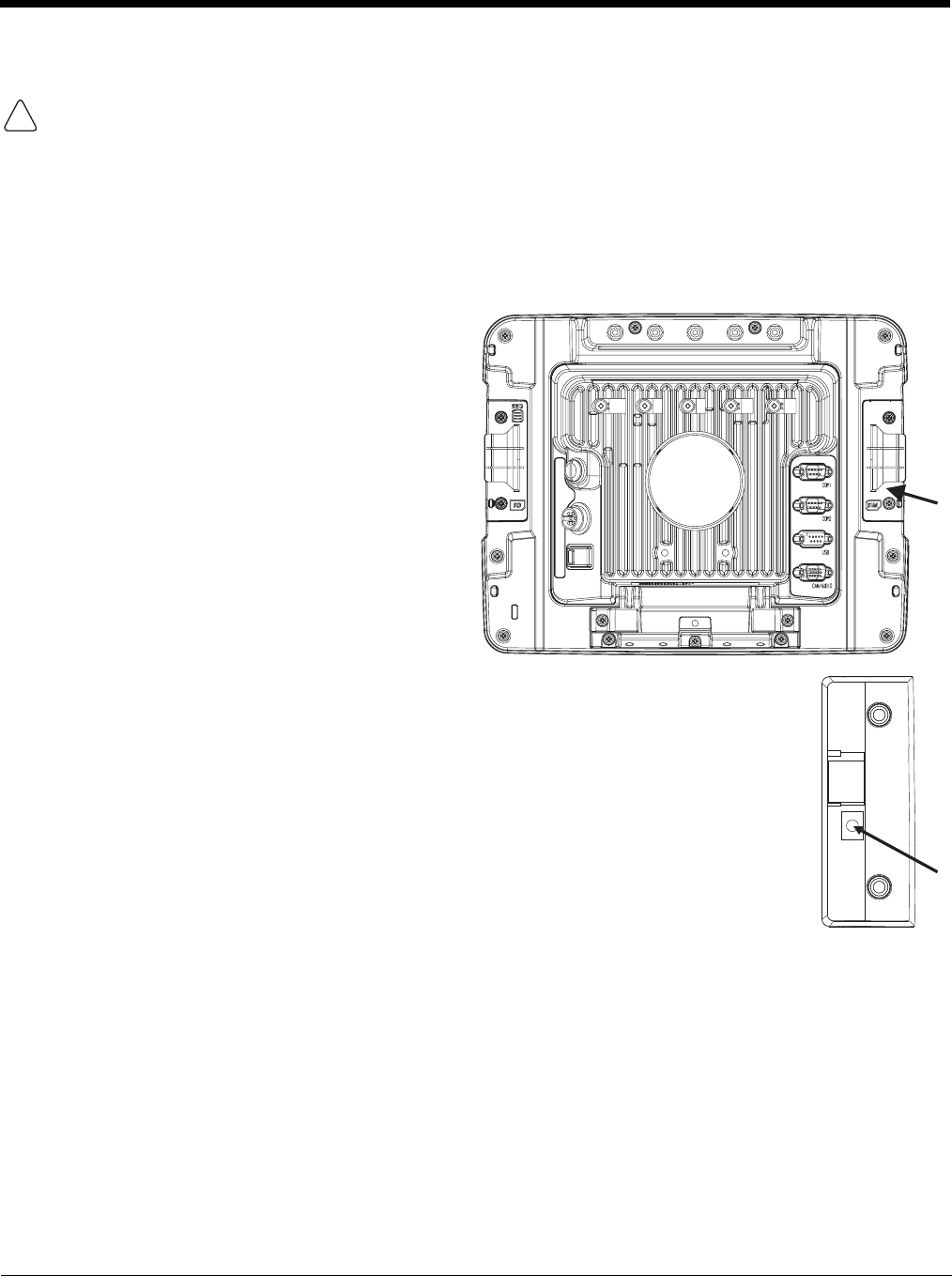
4 - 61
Disconnect UPS Battery
Equipment Required
The following equipment is user-supplied:
• Torquing tool capable of measuring inch pounds
• #2 Phillips screwdriver bit
Disconnect Procedure
CAUTION - The UPS battery must be disconnected before you ship the Thor VM2 or Replace Front Panel (page 4-64).
1. For convenience, the Thor VM2 can be removed
from the Quick Mount Smart Dock, though it is not
necessary.
2. If the Thor VM2 remains in the dock, disconnect
the power cable from the dock.
3. Place the Thor VM2 in Suspend by pressing the
Power button.
4. Place the Thor VM2 face down on a stable
surface.
5. Using a #2 Phillips bit loosen the M3 screws and
then remove the tethered access panel with the
SIM label. This panel is on the right hand side
when the Thor VM2 is face down with the top
away from the user.
6. Locate the small push button located just below the SIM card installation slot.
7. Press the push button to disconnect the UPS. The UPS battery maintains its charge but is
disconnected from the power circuitry of the Thor VM2.
8. Reattach the access panel, torquing the M3 screws to 4-5 inch pounds using a #2 Phillips bit.
9. When the Thor VM2 is attached to external power, the UPS battery is automatically
reconnected.
10. Restart the Thor VM2.
!
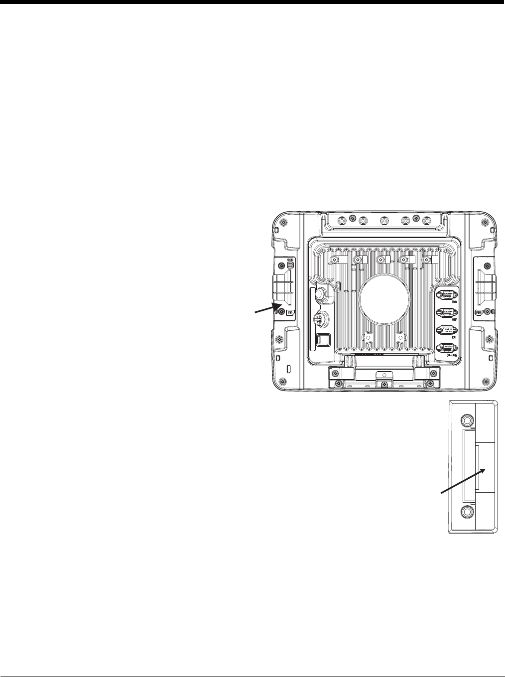
4 - 62
Install SD Card
An SD card slot is provided for storage expansion.
Equipment Required
The following equipment is user-supplied:
• Torquing tool capable of measuring inch pounds
• SD card - The following commercially available SD cards are recommended:
» ATP 2GB Industrial Grade SDHC card - AF2GSDI-5ADXX
» ATP 4GB Industrial Grade SDHC card - AF4GSDI-5ACXX
» SanDisk® 2GB SDHC card - SDSDB-2048
» SanDisk® 4GB SDHC card - SDSDB-004G
• #2 Phillips screwdriver bit
Installation Procedure
1. For convenience, the Thor VM2 can be removed
from the Quick Mount Smart Dock, though it is not
necessary.
2. If the Thor VM2 remains in the dock, disconnect the
power cable from the dock.
3. Place the Thor VM2 in Suspend by pressing the
Power button.
4. Place the Thor VM2 face down on a stable surface.
5. Using a #2 Phillips bit loosen the M3 screws and
then remove the tethered access panel with the
SIM label. This panel is on the right hand side
when the Thor VM2 is face down with the top away
from the user.
6. Locate the SD card installation slot.
7. Slide the SD card into the slot. The label side (front) of the SD card faces toward the back of the
Thor VM2.
8. Reattach the access panel, torquing the screws to 4-5 inch pounds.
9. If removed, reinstall the Thor VM2 in the dock.
10. Resume the Thor VM2 from suspend.
11. When using Windows explorer to view My Device, the SD card is identified as SD Card.
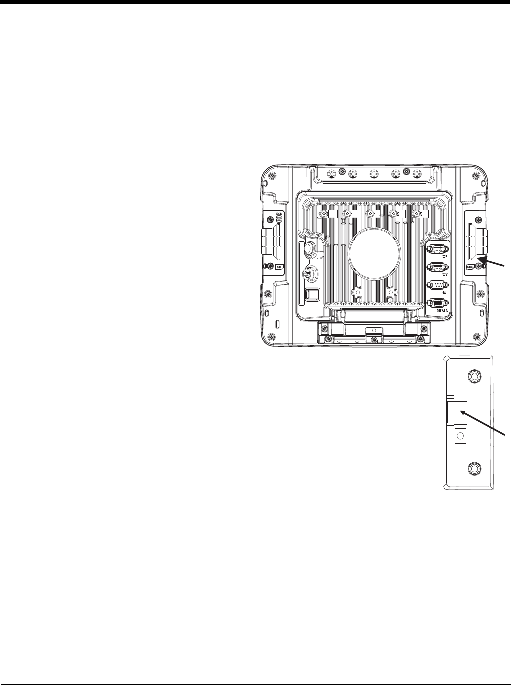
4 - 63
Install SIM Card
A SIM card may be required for WWAN.
Equipment Required
The following equipment is user-supplied:
• SIM card for desired carrier
• Torquing tool capable of measuring inch pounds
• #2 Phillips screwdriver bit
Installation Procedure
1. For convenience, the Thor VM2 can be removed
from the Quick Mount Smart Dock, though it is not
necessary.
2. If the Thor VM2 remains in the dock, disconnect the
power cable from the dock.
3. Place the Thor VM2 in Suspend by pressing the
Power button.
4. Place the Thor VM2 face down on a stable surface.
5. Using a #2 Phillips bit loosen the M3 screws and
then remove the tethered access panel with the
SIM label. This panel is on the right hand side
when the Thor VM2 is face down with the top away
from the user.
6. Locate the SIM card installation slot.
7. Slide the SIM card into the slot.
8. Reattach the access panel, torquing the screws to 4-5 inch pounds.
9. If removed, reinstall the Thor VM2 in the dock.
10. Resume the Thor VM2 from suspend.
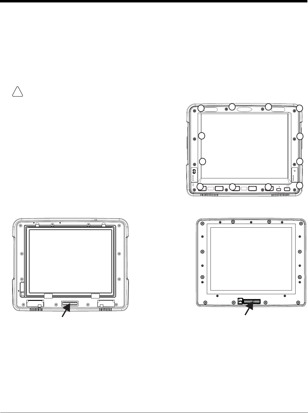
4 - 64
Replace Front Panel
Equipment Required
The following equipment is user-supplied:
• Torquing tool capable of measuring inch pounds
• #2 Phillips screwdriver bit
Replacement Procedure
6. Carefully lift the front panel away from the device.
7. Position the replacement front panel so wiring connector on the back of the front panel lines up with the connector on
the Thor VM2.
8. Gently press the front panel into place.
9. Tighten the twelve (12) captive M3 screws. In the order shown in the top figure above, use a #2 Phillips bit and torque
the screws to 6-7 inch pounds.
10. Reinstall the Thor VM2 in the Quick Mount Smart Dock.
11. When the Thor VM2 is placed in the powered dock, the UPS battery automatically reconnects.
CAUTION - Before replacing the Thor VM2 front panel, Disconnect UPS Battery (page 4-61).
1. Place the Thor VM2 on a clean, well-lit surface before perform-
ing the front panel replacement.
2. Place the Thor VM2 in Suspend by pressing the Power button.
3. Remove the Thor VM2 from the Quick Mount Smart Dock.
4. Disconnect UPS Battery (page 4-61).
5. Loosen the twelve (12) captive M3 screws holding the front
panel. Use a #2 Phillips bit.
!
10
1
2
3
4
58
911
12
67
Wiring Connector
on Thor VM2
Wiring Connector
on Front Panel

4 - 65
12. Restart the Thor VM2.

4 - 66

5 - 1
5
Software
Introduction
There are several different aspects to the setup, configuration and operation of the Thor VM2. Many of the setup and configura-
tion settings are dependent upon the optional features such as hardware and software installed on the unit. The examples
found in this section are to be used as examples only, the configuration of your specific Thor VM2 computer may vary. The fol-
lowing sections provide a general reference for the configuration of the Thor VM2 and some of its optional features.
Operating System
Your Thor VM2 operating system is Microsoft® Windows® Embedded CE 6. The Thor VM2 operating system revision is dis-
played on the Desktop. This is the default setting for the Desktop Display Background.
Windows CE Operating System
Note: For general use instruction, please refer to commercially available Windows CE user’s guides or the Windows CE on-line
Help application installed with the Thor VM2 operating system.
This segment assumes the system administrator is familiar with Microsoft Windows options and capabilities loaded on most
standard Windows computers.
Therefore, the sections that follow describe only those Windows capabilities that are unique to the Thor VM2 and its Windows
CE environment.
General Windows CE Keyboard Shortcuts
Use the keyboard shortcuts in the chart below to navigate with the Thor VM2 keyboard. These are standard keyboard
shortcuts for Windows CE applications.
The touch screen provides equivalent functionality to a mouse:
• A touch on the touch screen is equivalent to a left mouse click.
• Many items can be moved by the “drag and drop” method, touching the desired item, moving the stylus across the screen
and releasing the stylus in the desired location.
• A double stylus tap is equivalent to a double-click.
• A touch and hold is equivalent to a right mouse click. Some applications may not support this right-click method. Please
review documentation for the application to see if it provides for right mouse click configuration.
• Devices with Shift and Ctrl Keys: The Shift and Ctrl keys can be used with the touch screen for multiple selection of items.
• To select disconnected items, press the Ctrl key and then touch each item to be selected in the set. Press the Ctrl key
again to terminate this mode.
Press these keys … To …
CTRL + C Copy
CTRL + X Cut
CTRL + V Paste
CTRL + Z Undo
DELETE Delete
SHIFT with any of the arrow keys Select more than one item in a window or on the desktop, or select text
within a document.
CTRL+A Select all.
ALT+ESC Cycle through items in the order they were opened.
CTRL+ESC Display the Start menu.
ALT+Underlined letter in a menu name Display the corresponding menu.
Underlined letter in a command name on
an open menu Carry out the corresponding command.
ESC Cancel the current task.

5 - 2
• To select a connected set of items, press the Shift key, then touch the first item in the series. Touch the last item in the
series. Press the Shift key again to terminate the selection mode.
Save Changes to the Registry
The Thor VM2 saves the registry when you:
• Warmboot - either from the Registry control panel, the warmboot command or the reboot keypress sequence.
• Restart - from the Registry control panel
• Suspend/Resume - Either user initiated or upon Suspend timer expiration.
• Shutdown - The registry is saved during a controlled shutdown, such as when the UPS charge reaches a critically low
level and external power is not available.
The registry save process takes 0 – 3 seconds. If nothing has been changed, nothing is saved (e.g., 0 seconds).
Software Load
The software loaded on the Thor VM2 consists of Microsoft® Windows® Embedded CE 6 OS, hardware-specific OEM Adapta-
tion Layer, device drivers, Internet Explorer 6.0 for Windows CE browser and utilities. The software supported is summarized
below:
• Full Operating System License: Includes all operating system components, including Microsoft® Windows® Embedded CE 6
kernel, file system, communications, connectivity (for remote APIs), device drivers, events and messaging, graphics,
keyboard and touch screen input, window management, and common controls.
• Network and Device Drivers
• Bluetooth
Note: Please contact Honeywell Technical Assistance for software updates and CAB files as they are released by Honeywell.
Software Applications
The following applications are included:
• WordPad
• Data Collection Wedge (bar code result manipulation)
• ActiveSync
• Transcriber
• Internet Explorer
• Word Viewer
• Excel Viewer
•PDF Viewer
• PowerPoint Viewer
Note that the viewer applications allow viewing documents, but not editing them.
ActiveSync
ActiveSync is pre-loaded. Using Microsoft ActiveSync you can copy files from your Thor VM2 to your desktop/laptop , and
vice versa. After an ActiveSync relationship (partnership) has been established with a desktop/laptop, ActiveSync will auto-
matically startup each time the Thor VM2 is cabled to the desktop/laptop.
Bluetooth
Start > Settings > Control Panel > Bluetooth
Only installed on a Bluetooth equipped Thor VM2. The System Administrator can Discover and Pair targeted Bluetooth
devices for each Thor VM2. The System Administrator can enable / disable Bluetooth settings and assign a Computer
Friendly name for each Thor VM2.
The Bluetooth control panel can also be accessed by double-tapping the Bluetooth icon in the taskbar or on the desktop.
Honeywell RFTerm (Optional)
Start > Programs > Honeywell RFTerm
RFTerm is pre-loaded when ordered. The application can also be accessed by double-clicking the RFTerm desktop icon.

5 - 3
Avalanche
The Wavelink Avalanche Enabler installation file is loaded on the Thor VM2; however, the device is not configured to launch
the installation file automatically. The installation application must be run manually the first time Avalanche is used. Follow-
ing installation, the Wavelink Avalanche Enabler will be an auto-launch application. This behavior can be modified by
accessing the Avalanche Update Settings panel through the Enabler Interface.
Software Development
See Also: CE API Programming Guide
The CE API Programming Guide documents Honeywell-specific API calls for the Thor VM2. It is intended as an addition to Mic-
rosoft Windows CE API documentation.
A Software Developers Kit (SDK) and additional information about software development can be found on the Developer Portal.
Please Contact Technical Assistance (page 11-1) for more information.
Thor VM2 Utilities
The following files are pre-loaded.
LAUNCH.EXE
Launch works in coordination with registry settings to allow drivers or applications to be loaded automatically into DRAM at
system startup. Registry settings control what gets launched; see the App Note for information on these settings. For
examples, you can look at the registry key
HKEY_LOCAL_MACHINE \ Software \ LXE \ Persist
Launch will execute .CAB files, .BAT files, or .EXE files.
App Note
All applications to be installed into persistent memory must be in the form of Windows CE CAB files. These CAB files
exist as separate files from the main installation image, and are copied to the CE device using ActiveSync, or using a
Compact Flash ATA card. The CAB files are copied from ATA or using ActiveSync Explore into the folder System,
which is the persistent storage virtual drive. Then, information is added to the registry, if desired, to make the CAB file
auto-launch at startup.
The registry information needed is under the key HKEY_LOCAL_MACHINE \ Software \ LXE \ Persist, as follows. The
main subkey is any text, and is a description of the file. Then four mandatory values are added:
FileName is the name of the CAB file, with the path (usually \System).
Installed is a DWORD value of 0, which changes to 1 once auto-launch installs the file.
FileCheck is the name of a file to look for to determine if the CAB file is installed. This will be the name of one of the
files (with path) installed by the CAB file. Since the CAB file installs into DRAM, when memory is lost this file is lost,
and the CAB file must be reinstalled.
Order is used to force a sequence of events. Order=0 is first, and Order=99 is last. Order must be greater than 4 for
the Thor VM2. Two items which have the same order will be installed in the same pass, but not in a predictable
sequence.
There are two optional fields that may be added:
1. Delay is used to add a delay after the item is loaded, before the next is loaded. The delay is given in seconds, and
defaults to 0 if not specified. If the install fails (or the file to be installed is not found), the delay does not occur.
2. PCMCIA is used to indicate that the file (usually a CAB file) being loaded is a radio driver, and the PCMCIA slots
should be started after this file is loaded. By default, the PCMCIA slots are off on powerup, to prevent the “Uniden-
tified PCMCIA Slot” dialog from appearing. Once the drivers are loaded, the slot can be turned on. The value in
the PCMCIA field is a DWORD, representing the number of seconds to wait after installing the CAB file, but before
activating the slot (a latency to allow the thread loading the driver to finish installation). The default value of 0
means the slot is not powered on. The default values for the default radio drivers (listed below) is 1, meaning one
second elapses between the CAB file loading and the slot powering up.
The auto-launch process proceeds as follows:

5 - 4
1. The launch utility opens the registry database and reads the list of CAB files to auto-launch.
2. First it looks for FileName to see if the CAB file is present. If not, the registry entry is ignored. If it is present, and
the Installed flag is not set, auto-launch makes a copy of the CAB file (since it gets deleted by installation), and
runs the Microsoft utility WCELOAD to install it.
3. If the Installed flag is set, auto-launch looks for the FileCheck file. If it is present, the CAB file is installed, and that
registry entry is complete. If the FileCheck file is not present, memory has been lost, and the utility calls WCE-
LOAD to reinstall the CAB file.
4. Then, the whole process repeats for the next entry in the registry, until all registry entries are analyzed.
5. To force execution every time (for example, for AUTOEXEC.BAT), use a FileCheck of “dummy”, which will never
be found, forcing the item to execute.
6. For persist keys specifying .EXE or .BAT files, the executing process is started, and then Launch will continue,
leaving the loading process to run independently. For other persist keys (including .CAB files), Launch will wait for
the loading process to complete before continuing. This is important, for example, to ensure that a .CAB file is
installed before the .EXE files from the .CAB file are run.
7. Note that the auto-launch process can also launch batch files (*.BAT), executable files (*.EXE), registry setting
files (*.REG), or sound files (*.WAV). The mechanism is the same as listed above, but the appropriate CE applica-
tion is called, depending on file type.
Note: Registry entries may vary depending on software revision level and options ordered with the Thor VM2.
LAUNCH.EXE and Persistent Storage
If any of the following directories are created in the System folder, Launch automatically copies all of the files in these direc-
tories::
This function copies only the folder contents, no sub-folders.
The Windows\Startup folder is not copied on startup because copying this folder has no effect on the system or an incorrect
effect.
Files in the Startup folder are executed, but only from System\Startup. Windows\Startup is parsed too early in the boot pro-
cess so it has no effect.
Executables in System\Startup must be the actual executable, not a shortcut, because shortcuts are not parsed by Launch.
Note: Files in the Startup folder are executed, but only from System > Startup. They are not copied to another folder.
REGEDIT.EXE
Registry Editor – Use caution when editing the Registry. Make a backup copy of the registry before changes are made.
REGLOAD.EXE
Double-tapping a registry settings file (e.g., REG) causes RegLoad to open the file and make the indicated settings in the
registry.
REGDUMP.EXE
Registry dump – Saves a copy of the registry as a text file. The file, REG.TXT, is located in the root folder.
System\Desktop copied to Windows\Desktop
System\Favorites copied to Windows\Favorites
System\Fonts copied to Windows\Fonts
System\Help copied to Windows\Help
System\Programs copied to Windows\Programs
AppMgr copied to Windows\AppMgr
Recent copied to Windows\Recent

5 - 5
The Thor VM2 includes a Save User Defaults option in the Registry (page 5-89) control panel. This is the preferred method
for saving a backup of the registry. Save the registry file to the System folder on the Thor VM2 (persistent storage) or copy
the file to a PC.
WARMBOOT.EXE
Double-click this file to warm boot the computer (i.e., all RAM is preserved). It automatically saves the registry before
rebooting which means configuration changes are not lost.
WAVPLAY.EXE
Double-tapping a sound file (e.g., WAV) causes WavPlay to open the file and run it in the background.
Thor VM2 Command-line Utilities
Command line utilities can be executed by Start > Run > [program name].
PrtScrn.EXE
Command line utility which performs a screen print and saves the file in .BMP format in the \System folder. Tap Start
> Run and type prtscrn and tap OK, or press Enter. There is a 10 second delay before the screen print is made. The
device beeps and the screen captured file (scrnnnnn.bmp) is placed in the \System folder. The numeric filename is
incremented by 1 each time the PrtScrn function is activated. The command is not case-sensitive.
Desktop
Note: For general use instruction, please refer to commercially available Windows CE user’s guides or the Windows on-line Help
application installed in the mobile device.
The Thor VM2 Desktop appearance is similar to that of a desktop PC running a Windows operating system.
At the bottom of the screen is the Start button. Tapping the Start Button causes the Start Menu (page 5-8) to display. It contains
the standard Windows menu options: Programs, Favorites, Documents, Settings, Help, and Run.
Desktop Icons
At a minimum, the desktop displays icons for My Device, Internet Explorer and the Recycle Bin. Following are a few of the
other icons that may be on the Thor VM2 Desktop. Contact Technical Assistance (page 11-1) about the latest updates and
upgrades for your operating system.
Icon Function
Access files and programs.
Storage for files that are to be deleted.
Discover and then pair with nearby discoverable Bluetooth (page 5-29) devices.
Storage for downloaded files / applications.

5 - 6
Taskbar
The number and type of icons displayed are based on the device type, installed options and configuration of the Thor
VM2.
Displays web pages from the Internet/intranet.
Used for accessing the Summit Client Utility (page 8-1). This utility configures the Wi-Fi connection.
The eXpress Scan (page 7-15) utility allows an administrator to scan bar codes to provide the initial network
and Avalanche Mobile Device Server address configuration. This eliminates the need to edit radio parame-
ters manually on the Thor VM2. eXpress Scan uses bar codes created with eXpress Config.
RFTerm is an optional terminal emulation program. When RFTerm is installed, this icon is displayed on the
desktop.
A shortcut to the Remote Desktop Connection utility.
Avalanche shortcut. Wavelink® Avalanche Mobility Center™ (Avalanche MC) is a remote client manage-
ment system that is designed to distribute software and configuration updates to monitored devices. The en-
abler for Wavelink Avalanche is loaded on the Thor VM2 but not installed. When the enabler is installed the
Avalanche icon is displayed on the desktop.
The demo version of Wavelink Telnet CE may be installed. Contact Technical Assistance (page 11-1) for
licensing information. When installed, license details are maintained in the Wavelink tab in the License View-
er control panel.
Start button. Access programs, select from the Favorites listing, documents last worked on, change/view set-
tings for the control panel or taskbar, on-line help or run programs.
Icon Function

5 - 7
My Device Folders
Wavelink Avalanche Enabler (Optional)
Note: If the user is NOT using Wavelink Avalanche to manage their mobile device, the Enabler should not be installed on
the mobile device(s).
The following features are supported by the Wavelink Avalanche Enabler when used in conjunction with the Avalanche
Manager.
After configuration, Enabler files are installed upon initial bootup and after a hard reset. Network parameter configuration is
supported for:
• IP address: DHCP or static IP
• RF network SSID
• DNS hosts (primary, secondary, tertiary)
• Subnet mask
• Enabler update
Related Manual: Using Wavelink Avalanche.
The Thor VM2 has the Avalanche Enabler installation files loaded, but not installed, on the mobile device when it is
shipped. The installation files are located in the System folder on CE devices. The installation application must be run
manually the first time Avalanche is used.
After the installation application is manually run, a reboot is necessary for the Enabler to begin normal performance. Fol-
lowing this reboot, the Enabler will by default be an auto-launch application. This behavior can be modified by accessing
the Server Contact tab of the Server Contact (page 7-7) panel.
Internet Explorer
Start > Programs > Internet Explorer
There are a few changes in the Windows CE version of Internet Explorer as it relates to the general desktop Windows PC
Internet Explorer options. Tap the “?” button to access Internet Explorer Help.
Folder Description Preserved upon Reboot?
Application Data Data saved by running applications No
My Documents Storage for downloaded files / applications No
Network Mounted network drive No
Program Files Applications No
System Internal CF/SD Card (CAB file storage) Yes
Storage Card or SD Card Additional optional storage space Yes
Temp Location for temporary files No
Windows Operating System in Secure Storage No

5 - 8
Start Menu
The following list represents a typical factory default program installation. Your system may contain different items from those
shown below, based on the software and hardware options purchased.
• If installed, RFTerm runs automatically at the conclusion of each reboot.
• If installed and enabled, AppLock runs automatically at the conclusion of each reboot.
• The wireless client connects automatically during each reboot.
• Bluetooth re-connects to nearby paired devices automatically at the conclusion of each reboot.
• If installed and pre-configured, Wavelink Avalanche connects remotely and downloads updates automatically during each
reboot.
Communication
Start > Programs > Communication
Connect
ActiveSync (page 6-1) is pre-loaded on the Thor VM2. Tap the Conenct to initiate an ActiveSync connection.
Note: By default, ActiveSync is configured to connect automatically when the USB cable is conencted to a PC. SeePC
Connection (page 5-77).
Using Microsoft ActiveSync you can copy files from your Thor VM2 to your desktop computer, and vice versa.
Once an ActiveSync relationship (partnership) has been established with Connect (on a desktop computer),
ActiveSync will synchronize using USB on the Thor VM2.
Start FTP Server / Stop FTP Server
Start > Programs > Communication > Start (or Stop) FTP Server
These shortcuts call the Services Manager to start and stop the FTP server. The server defaults to Off (for security)
unless it is explicitly turned on from the menu.
Communication Stores Network communication options
Connect Run this command after setting up a connection
Start (or Stop) FTP Server Begin / end connection to FTP server
Command Prompt The command line interface in a separate window
eXpress Scan Option. Requires Wavelink Avalanche option eXpress Config.
Internet Explorer Access web pages on the Internet/Intranet
File Viewers
JETCET PDF Viewer View Adobe PDF Documents
Office 2003 Excel Viewer View Excel 2003 and compatible documents
Office 2003 PowerPoint Viewer View PowerPoint 2003 and compatible documents
Office 2003 Word Viewer View Word 2003 and compatible documents
Microsoft WordPad Opens an ASCII notepad
Remote Desktop Connection Log on to a Windows Terminal Server
Honeywell RFTerm Option. Terminal emulation application.
Settings Access to all Control Panels, a shortcut to the Network and Dialup Control Panel and
access to Taskbar options.
Summit Set Summit radio / network parameters
Transcriber Enter data using the stylus on the touch screen
Wavelink Avalanche Option. Remote management for networked devices
Windows Explorer File management program

5 - 9
Summit
Start > Settings > Control Panel > Wi-Fi
Use this option to set up radio client profiles with the Summit Client Utility (page 8-1).
The Summit Control Panel can also be accessed by double-tapping the Summit icon in the taskbar or on the desktop.
Certs
The Certs option displays a readme file containing details on how the Summit Configuration Utility (SCU) handles cer-
tificates for WPA authentication.
Command Prompt
Start > Programs > Command Prompt
Typ e help cmd at the command prompt to view valid Pocket PC (Console) commands.
Exit the command prompt by typing exit at the command prompt or tap File > Close.
eXpress Scan
The eXpress Scan (page 7-15) utility allows an administrator to scan bar codes to provide the initial network and Avalanche
Mobile Device Server address configuration. This eliminates the need to edit radio parameters manually on the Thor VM2.
eXpress Scan uses bar codes created with eXpress Config.
Internet Explorer
Start > Programs > Internet Explorer
This option requires a WLAN or WWAN card and an Internet Service Provider. There are a few changes in the Windows
CE version of Internet Explorer as it relates to the general desktop Windows PC Internet Explorer options. Tap the ? button
to access Internet Explorer Help.
Media Player
Start > Programs > Media Player
There are few changes in the Windows CE version of Media Player as it relates to the general desktop Windows PC Micro-
soft Media Player options.
After the Media Player application is running, click the ? button to access Media Player Help.

5 - 10
File Viewers
The following applications are included:
• JETCET PDF Viewer
• Office 2003 Excel Viewer
• Office 2003 PowerPoint Viewer
• Office 2003 Word Viewer
Note: The viewer applications allow viewing documents, but not editing them.
Microsoft WordPad
Start > Programs > Microsoft WordPad
Create and edit documents and templates in WordPad, using buttons and menu commands that are similar to those used in
the desktop PC version of Microsoft WordPad.
By default WordPad files are saved as .PWD files. Documents can be saved in other formats e.g., .RTF or .DOC.
Tap the ? button to access WordPad Help.
Remote Desktop Connection
Start > Programs > Remote Desktop
There are few changes in the Windows CE version of Remote Desktop as it relates to the general desktop Windows PC
Microsoft Remote Desktop options.
If installed, Remote Desktop on the Thor VM2 can be accessed by Start > Programs > Remote Desktop.
Select a computer from the drop down list or enter a host name and tap the Connect button.
Tap the Options >> button to access the General, Display, Local Resources, Programs and Experience tabs. Tap the ? but-
ton to access Remote Desktop Connection Help.
Settings
Start > Settings
The Settings menu option may include the following:
Transcriber
To make changes to the Transcriber application, tap the keyboard icon in the status bar. Select Transcriber from the pop-up
menu. Then open the Input control panel and tap the Options button. Transcriber Options (Start > Settings > Control
Panel > Input Panel) are available only when Transcriber is selected as the active input method. Tap the “?” button or the
Help button to access Transcriber Help.
Windows Explorer
Start > Programs > Windows Explorer
There are a few changes in the Windows CE version of Windows Explorer as it relates to the general desktop PC Windows
Explorer options. Tap the “?” button to access Windows Explorer Help.
Control Panel (page 5-15) All control panels
Network and Dialup
Connections (page 5-71) Shortcut to control panel. Connect to a network, create a new connection, and adjust pa-
rameters for client connections.
Taskbar (page 5-11) Set Taskbar parameters
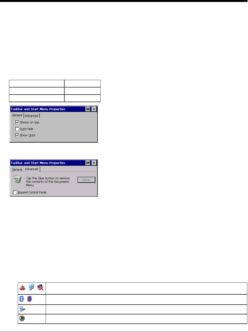
5 - 11
Taskbar
Start > Settings > Taskbar
There are a few changes in the Windows CE version of Taskbar as it relates to the general desktop PC Windows Taskbar
options.
When the taskbar is auto hidden, press the Ctrl key then the Esc key to make the Start button appear.
Clicking the Taskbar option on the Settings menu displays the General and Advanced Taskbar tabs.
General
Factory Default Settings
Advanced
Expand Control Panel
Tap the checkbox to have the Control Panel folders appear in drop down menu format from the Settings > Control
Panel menu option.
Clear Contents of Document Folder
Tap the ton to remove the contents of the Document folder.
Taskbar Icons
As Thor VM2 devices and applications open and change state, icons are placed in the Taskbar. In most cases, tapping
the icon in the Taskbar opens the related application.
Refer to Start > Help for an explanation of standard Windows CE taskbar icons.
Following are a few of the Thor VM2 taskbar icons that may appear in the Taskbar. These icons are in addition to the
Windows CE taskbar icons.
Always on Top Enabled
Auto hide Disabled
Show Clock Enabled
Wireless Zero Config Utility (page 8-2) Inactive / Connected / Not Connected.
Clicking on the icon opens the Wireless Zero Config utility.
Bluetooth (page 5-29) connected / disconnected. Clicking the icon opens the Bluetooth control panel.
ActiveSync (page 6-1)connection
Cerdisp connected, displayed when HSM Connect (page 6-3) is connected
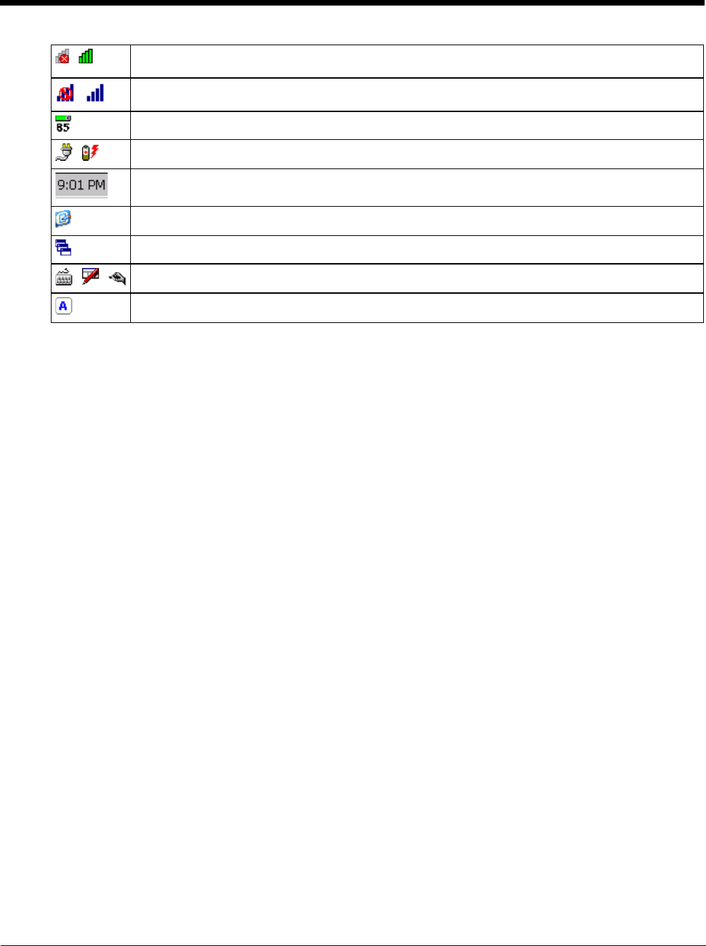
5 - 12
Summit client signal indicator no signal / excellent signal. Clicking on the icon opens the Summit Client
Utility (page 8-1).
Gobi Connection Manager (WWAN) signal indicator no signal / excellent signal. Clicking on the icon
opens the Gobi Connection Manager (page 5-59).
UPS battery charge indicator. Percent of battery charge is indicated.
External power connected / connected and UPS battery charging.
Current time. Clicking the time display opens the Date / Time (page 5-56) control panel.
Click this icon to return to the Desktop.
AppLock Switchpad (page 5-22).
Input method, keyboard / input panel / transcriber.
CapsLock active.

5 - 13
Thor VM2 OS Upgrade
Introduction
Depending on the size of the operating system, the total time required for a successful upgrade may require several min-
utes.
The OS upgrade files are unique to your Thor VM2 physical configuration and date of manufacture. OS upgrade files
designed for one device configuration should not be used on a different device configuration.
When upgrading the OS or firmware on a Thor VM2, it is best to perform the upgrade using either Wavelink Avalanche or
with an external USB keyboard attached.
There may be firmware and BIOS upgrades available for the Thor VM2. Contact Technical Assistance (page 11-1) for
upgrade information and instructions. In some cases, it may be necessary to upgrade firmware before upgrading the oper-
ating system.
Preparation
• Contact Technical Assistance (page 11-1) to get the OS upgrade files.
• Honeywell Technical Assistance may advise you that additional upgrades such as BIOS or firmware are required before
upgrading the OS. Please follow any additional upgrade instructions provided by Technical Assistance.
• Use ActiveSync to back up Thor VM2 user files and store them elsewhere before beginning an upgrade on the Thor VM2.
• Maintain an uninterrupted AC/DC power source to the Thor VM2 throughout this process.
• The CF card with the OS and systems files must be present for the Thor VM2 to boot. Removal or installation of SD or
CF cards should be performed on a clean, well-lit surface.
• Always perform OS updates when the Thor VM2 has a dependable external power source connected to the Thor VM2.
Procedure
1. Verify a dependable power source is applied to the Thor VM2 and will stay connected during the upgrade procedure.
2. Warmboot the Thor VM2 before beginning the update process.
3. Establish an ActiveSync connection between the Thor VM2 and a desktop/laptop computer.
4. Download the OS files from the desktop/laptop to the Thor VM2's System folder.
5. During the file copy process to the Thor VM2 System folder, when asked “Overwrite ?”, select Yes to All.
6. Review the files that were downloaded to the System folder.
7. Restart the Thor VM2.
8. Disconnect from ActiveSync.
9. When the OS finishes loading, check the OS update version by selecting Start > Settings > Control Panel > About >
Software tab.
The touch screen may require calibration, however most Windows OS versions save the calibration data, eliminating the
need to calibrate.
If the Thor VM2 won't boot up after the upgrade is finished, contact Technical Assistance (page 11-1) for re-imaging
options.
The Thor VM2 must be connected to external power before upgrading the BIOS, firmware or operating systems.
If the Thor VM2 is operating on UPS battery power, the upgrade process does not initiate and the Thor VM2 is not
upgraded.
!

5 - 14
BIOS
The Microsoft Windows CE operating system is installed before shipping. The default BIOS parameters are configured at that
time. In most cases, it is unnecessary to modify the BIOS parameters.
Generally, it is only necessary to enter the BIOS setup to change the boot order of the drives.
This section is not intended to detail all features of the BIOS, instead it is intended to cover the most commonly used setup
options.
Accessing the BIOS Setup
When the Embedded BIOS screen (Phoenix Technologies) is displayed press the Del key to enter BIOS setup.
Use the arrow keys to move around the screen.
To access and modify the BIOS on the Thor VM2, an external keyboard must be attached.
Boot Order
To view or edit the boot order, select the Boot tab.
By default, the first device in the boot order is USB Hard Drive.
The second device is the Windows CE Image.
Exiting BIOS Setup
To exit the BIOS setup, select the Exit tab and select one of these options:
• Save Setting and Restart
• Exit Setup without Saving Changes
• Reload Factory-Defaults and Restart
CAUTION - Be very careful when using this utility to modify BIOS Setup parameters. The Thor VM2 may generate unex-
pected results when incorrect or conflicting parameter values are entered. Selecting incorrect or invalid options may re-
quire the Thor VM2 to be returned for repairs.
The parameters should only be modified by Information Services personnel or the system administrator.
If a USB drive, such as a thumb drive, is attached to the Thor VM2 the Thor VM2 attempts to boot from the USB
drive:
• If the USB drive contains a bootable sector, the Thor VM2 boots from the USB drive.
• If the USB drive does not contain a bootable sector, the Thor VM2 does not boot. Remove the USB drive and
boot the Thor VM2 again.
!
!

5 - 15
Control Panel
Start > Settings > Control Panel or My Device > Control Panel link
Tap the ? button for Help when changing Thor VM2 Control Panel options.
Option Function
About (page 5-17) Software, hardware, versions and network IP. No user intervention allowed.
Accessibility (page 5-18) Customize the way the keyboard, audio, display or mouse function for users with hearing or
viewing difficulties.
Administration (page 5-19) AppLock Administration utility.
Battery (page 5-29) View voltage and status of the internal UPS battery.
Bluetooth (page 5-29) Set the parameters for Bluetooth device connections.
Certificates (page 5-39) Manage digital certificates used for secure communication.
Data Collection (page 5-39) Wedge utility for data collected from bar code scans. Set data collection device, data strip-
ping, and prefix/suffix options. Assign baud rate, parity, stop bits and data bits for COM1 and
COM2 ports. Assign collected data manipulation parameters.
Date / Time (page 5-56) Set Date, Time, Time Zone, and Daylight Savings.
Dialing (page 5-56) Connection setup for modem attached to COM port or CompactFlash slot. . CompactFlash
slot not available for modem use on Thor VM2.
Display (page 5-57) Set background graphic and scheme. Set touch screen and keypad backlight properties and
timers.
Gobi Connection Manager (page
5-59) Set parameters for the Wireless Wide Area Network client, if installed.
Input Panel (page 5-66) Select the current key / data input method. Select custom key maps.
Internet Options (page 5-67) Set General, Connection, Security, Privacy, Advanced and Popups options for Internet con-
nectivity.
Keyboard (page 5-69) Set key repeat delay and key repeat rate.
License Viewer (page 5-69) Displays license information for installed licensed applications.
Mixer (page 5-70) Adjust the input and output parameters – volume, sidetone, and record gain, for headphone,
software and microphone.
Mouse (page 5-71) Set the double-tap sensitivity for stylus taps on the touch screen.
Network and Dialup Connections
(page 5-71) Set network driver properties and network access properties.
Network Capture (page 5-72) Set network logging options.
Options (page 5-74) Set various device specific configuration options.
Owner (page 5-76) Set the mobile device owner details (name, phone, etc.). Enter notes. Enable / disable Own-
er display parameters. Enter Network ID for the device – user name, password, domain.
Password (page 5-77) Set OS access password properties for signon and/or screen saver.
PC Connection (page 5-77) Control the connection between the mobile device and a local desktop or laptop computer.
Power (page 5-78) Set power scheme properties. Review device status.
Power Configuration Mode (page
5-80) Set power configuration mode.
Programmable Key (page 5-83) Program P1-P5 keys on the front bezel.
Regional and Language Settings
(page 5-88) Set appearance of numbers, currency, time and date based on country region and language
settings.
Registry (page 5-89) Load or save user defaults, load factory defaults, warmboot or restart.
Remove Programs (page 5-89) Select to remove specific user installed programs in their entirety.
Screen Control (page 5-90) Configure screen blanking.

5 - 16
Screen Rotation (page 5-91) Rotate screen display.
Stylus (page 5-92) Set double-tap sensitivity properties and/or calibrate the touch panel.
System (page 5-93) Review System and Computer data and revision levels. Adjust Storage and Program mem-
ory settings. Enter device name and description. Review copyright notices.
Terminal Server Client Licenses
(page 5-94) Select a server client license from a drop down list.
Volume and Sounds (page 5-95) Enable / disable volume and sounds. Set volume parameters and assign sound WAV files
to events.
Wi-Fi (page 5-96) Set the parameters for a Summit Client Utility.
Option Function
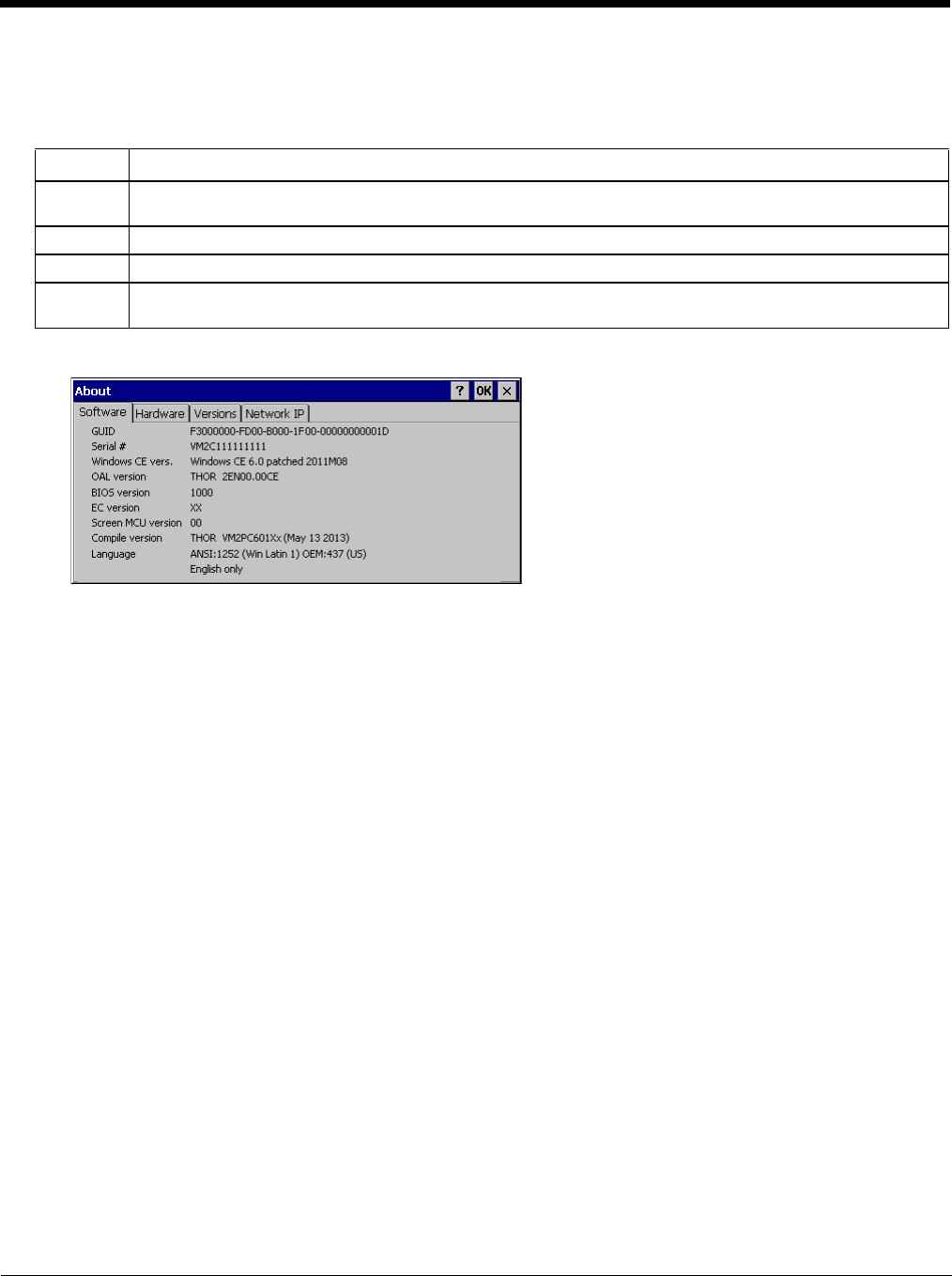
5 - 17
About
Start > Settings > Control Panel > About
The data cannot be edited by the Thor VM2 user on these panels.
Software
Firmware Versions
The Software tab lists the firmware versions installed. The BIOS, EC and Screen MCU firmware versions are
shown on this tab.
Language
The Software tab displays the localized language version of the OS image. The language is identified as English
only or + an additional language.
The languages are ordered separately and built-in to the OS image. The Thor VM2 may be pre-loaded with an
English only OS. Contact Technical Assistance (page 11-1) for information on installing an OS for a different lan-
guage. The built-in languages are added to registry entries and are available immediately upon startup.
Versions
The Versions tab displays the versions of many of the software programs installed. Not all installed software is
included in this list and the list varies depending on the applications loaded on the Thor VM2. The Image line displays
the revision of the system software installed. Refer to the last three digits to determine the revision level.
Versions Tab and the Registry
The Versions tab displays program version details from the registry.
Customized information can be displayed by modifying the Registry using the Registry Editor. Use caution when
editing the Registry and make a backup copy of the registry before changes are made.
The registry settings for the Version tab are under HKEY_LOCAL_MACHINE \ Software \ LXE \ Version in the reg-
istry.
To add a user application to the Version panel, create a new string value under the HKLM\Software\LXE\Version
key. The string name should be the Application name to appear in the Version window. The data for the value
should be the version number to appear in the Version window.
Version strings can be equal to or less than 254 characters. Because the strings are displayed in a text box, any
number can be accommodated, up to the 64K byte text box limitation.
Tab Contents
Software GUID, Serial Number, Windows CE Version, OAL Version, Compile Version, and Language. Language indi-
cates localized version.
Hardware CPU Type, Codec Type, Display, and DRAM memory
Versions Revision level of software modules and .NET Compact Framework Version.
Network IP Current network connection IP and MAC address. Only the first 2 adapters are shown (usually radio and Ac-
tiveSync). Bluetooth MAC address is shown.
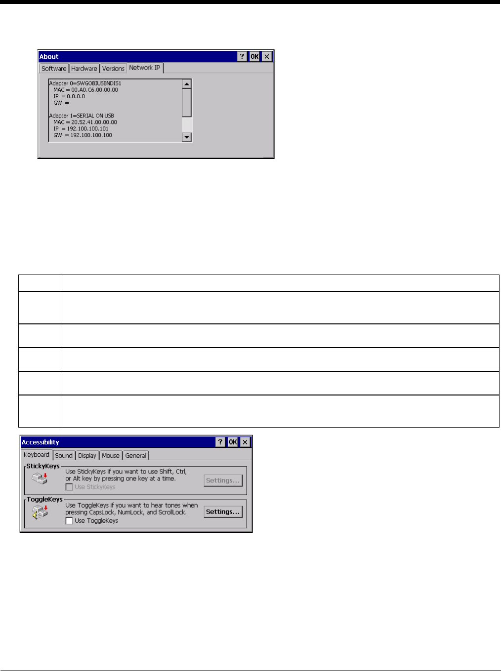
5 - 18
Network IP
MAC Address
The Network IP tab displays the MAC address of the network card(s) such as the Summit WLAN radio and the
Bluetooth module.
Accessibility
Start > Settings > Control Panel > Accessibility
Customize the way the Thor VM2 keyboard, sound, display, mouse, automatic reset and notification sounds function.
There are a few changes from general Windows desktop Accessibility options.
The following exceptions are due to a limitation in the Microsoft Windows CE operating system:
• If the ToggleKeys option is selected, please note that the ScrollLock key does not produce a sound as the CapsLock and
NumLock keys do.
• If the SoundSentry option is selected, please note that ScrollLock does not produce a visual warning as the CapsLock
and NumLock keys do.
Tab Contents
Keyboard Sticky Keys - Disabled (cannot be enabled).
ToggleKeys - Disabled by default. Tap the Use ToggleKeys checkbox to enable this option. Tap the Settings
button to view or change parameters.
Sound SoundSentry is disabled by default. Tap the Use SoundSentry checkbox to enable this option. Tap the Set-
tings button to view or change parameters.
Display High Contrast is disabled by default. Tap the Use High Contrast checkbox to enable this option. Tap the Set-
tings button to view or change parameters.
Mouse MouseKeys is disabled by default. Tap the Use MouseKeys checkbox to enable this option. Tap the Settings
button to view or change parameters.
General Automatic reset is disabled by default. Tap the Turn off accessibility features checkbox to enable this option
and use the dropdown option to assign a timer.
Notification is enabled by default. Sounds are emitted when turning a feature on or off.

5 - 19
Administration
Start > Settings > Control Panel > Administration
AppLock is designed to be run on certain certified Windows CE based devices only. The AppLock program is installed as
part of the default software load and is configured with the Administration control panel.
Configuration parameters are specified by the AppLock Administrator for the Thor VM2 end-user. AppLock is password
protected by the Administrator.
End-user mode locks the end-user into the configured application or applications. The end user can still reboot the mobile
device and respond to dialog boxes. The administrator-specified applications are automatically launched in the specified
order and run in full screen mode when the device boots up.
When the mobile device is reset to factory default values, for example after a cold reset, the Administrator may need to
reconfigure the AppLock parameters.
The assumption, in this section, is that the first user to power up a new mobile device is the system administrator.
Note: AppLock Administrator Control panel file Launch option does not inter-relate with similarly-named options contained
in other Thor VM2 Control Panels.
Note: A few applications do not follow normal procedures when closing. AppLock cannot prevent this type of application
from closing, but is notified that the application has closed. For these applications, AppLock immediately restarts the
application (see Auto Re-Launch) which causes the screen to flicker. If this type of application is being locked, the
administrator should close all other applications before switching to end-user mode to minimize the screen flicker.
AppLock is updated periodically as new options become available. Contact Technical Assistance (page 11-1) for update
availability.
Factory Default Settings - AppLock
Application (page 5-23)
Filename Blank
Title Blank
Arguments Blank
Order 1
Internet Disabled
Global Key Ctrl+Spc
Global Delay 10 sec
Input Panel Disabled
Application Launch Options (page 5-24)
Auto at Boot Enabled
Auto at Boot Retries 0
Auto at Boot Delay 10 sec
Auto Re-launch Enabled
Auto Re-launch Retries 0
Auto Re-launch Delay 0 sec
Manual Launch Disabled
Allow Close Disabled
Security (page 5-26)
Hotkey (Activation key) Shift+Ctl+A
Password Blank
Options (page 5-27)
Launch timeout 60000

5 - 20
Setup a New Device
Devices with the AppLock feature are shipped to boot in Administration mode with no default password, thus when the
Thor VM2 is first booted, the user has full access to the device and no password prompt is displayed. After the admin-
istrator specifies the applications to lock, a password is assigned and the device is rebooted or the hotkey is pressed,
the device switches to end-user mode.
Briefly, the process to configure a new device is as follows:
1. Connect an external power source to the device and press the Power button.
2. Adjust screen display, audio volume and other parameters if desired. Install accessories.
3. Tap Start > Settings > Control Panel > Administration icon.
4. Assign applications on the Control (single application) or Application (dual application) tab screen.
5. Assign a password on the Security tab screen.
6. Select a view level on the Status tab screen, if desired.
7. Tap OK
8. Press the hotkey sequence to launch AppLock and lock the configured application(s)
9. The device is now in end-user mode.
Administration Mode
Administration mode gives full access to the mobile device, hardware and software configuration options.
The administrator must enter a valid password (when a password has already been assigned) before access to Admin-
istration mode and configuration options are allowed. The administrator can configure the following options:
• Create/change the keystroke sequence to activate administrator access.
• Create/change the password for administrator access.
• Assign the name of the application, or applications, to lock.
• Select the command line of the application to lock.
In addition to these configuration options, the administrator can view and manage the status logs of AppLock sessions.
Administrator default values for this device:
Administrator Hotkey
Shift+Ctrl+A
Note: You must use an external keyboard with the Thor VM2 to enter the Administrator Hotkey.
Password
none
Application path and name
none
Application command line
none
Replace timeout 20000
Restart timeout 20000
Status (page 5-27)
Filename \System\applock.txt
View Level None
Log Level None

5 - 21
End User Mode
End-user mode locks the end-user into the configured application or applications. The end user can still reboot and
respond to dialog boxes. Each application is automatically launched and runs in full screen mode when the device
boots up.
The user cannot unintentionally or intentionally exit the application nor can the end user execute any other applica-
tions. Normal application exit or switching methods and all Microsoft defined Windows CE key combinations, such as
close (X) icon, File Exit, File Close, Alt-F4, Alt-Tab, etc. are disabled. The Windows CE desktop icons, menu bars,
task bar and system trays are not visible or accessible. Task Manager is not available.
If the end-user selects File/Exit or Close from the applications menu bar, the menu is cleared and nothing else hap-
pens; the application remains active. Nothing happens when the end-user clicks on the Close icon on the application’s
title bar and the application remains active.
Note: A few applications do not follow normal procedures when closing. AppLock cannot prevent this type of
application from closing, but is notified that the application has closed. For these applications, AppLock
immediately restarts the application which causes the screen to flicker. If this type of application is being locked,
the administrator should close all other applications before switching to end user mode to minimize the screen
flicker.
Windows accelerator keys such as Alt-F4 are disabled.
Passwords
A password must be configured. If the password is not configured, a new device switches into Administration mode
without prompting for a password. In addition to the hotkey press, a mode switch occurs if inaccurate information has
been configured or if mandatory information is missing in the configuration.
There are several situations that display a password prompt after a password has been configured.
If the configured hotkey is pressed, the password prompt is displayed. In this case the user has 30 seconds to enter a
password. If a valid password is not entered within 30 seconds, the password prompt is dismissed and the device
returns to end-user mode.
All other situations that present the password prompt do not dismiss the prompt -- this is because the other situations
result in invalid end-user operation.
These conditions include:
• If inaccurate configuration information is entered by the administrator, i.e. an application is specified that does not
exist.
• If the application name, which is mandatory for end-user mode, is missing in the configuration.
• Invalid installation of AppLock (e.g. missing DLLs).
• Corrupted registry settings.
To summarize, if an error occurs that prevents AppLock from switching to user mode, the password will not timeout and
AppLock will wait until the correct password is entered.
Forgotten password?
See AppLock Help (page 5-28).
End-User Switching Technique
Note: The touch screen must be enabled.
A checkmark indicates applications currently active or available for Launching by the user. When Keyboard is
selected, the Thor VM2 default input method (Input Panel, Transcriber, or custom input method) is activated.
The check to the left of the application name indicates that the application is active.
If the application is listed but does not have a checkmark to the left of the application name, this means the application
is configured in AppLock and can be manually launched by clicking on the application name in the list.

5 - 22
Using a Stylus Tap
When the mobile device enters end-user mode, a Switchpad icon (it looks like three tiny windows one above the
other) is displayed in the lower right corner of the display. The Switchpad is always visible on top of the application
in focus. However, if only one application is configured in AppLock and the Input Panel is disabled the Switchpad
is not visible.
Switchpad
When the user taps the Switchpad icon, a menu is displayed showing the applications available to the user.
The user can tap an application name in the popup menu and the selected application is brought to the fore-
ground. The previous application continues to run in the background. Stylus taps affect the application in
focus only. When the user needs to use the Input Panel, they tap the Keyboard option. Input Panel taps
affect the application in focus only.
See also Manual (Launch) (page 5-25)and Allow Close (page 5-25).
Using the Switch Key Sequence
One switch key sequence (or hotkey) is defined by the administrator for the end-user to use when switching
between locked applications. This is known as the Activation key. The Activation key is assigned by the Admin-
istrator using the Global Key parameter. When the switch key sequence is pressed on the keypad, the next appli-
cation in the AppLock configuration is moved to the foreground and the previous application moves to the
background. The previous application continues to run in the background. End-user key presses affect the appli-
cation in focus only.
See also Global Key (page 5-23).
Hotkey (Activation hotkey)
The default Hotkey (Activation key) is Ctrl+Spc. The key sequence switches the focus between one application
and another. Data entry affects the application running in the foreground only. Note that the system administrator
may have assigned a different key sequence to use when switching applications.
Note: You must use an external keyboard with the 12-key version of the Thor VM2 to use the Hotkey. If an external
keyboard is not attached, use the Switchpad to switch between applications.
Application Configuration
Settings > Control Panel > Administration
The default Administrator Hotkey sequence is Shift+Ctrl+A.
Administrator mode allows access to all features on the device. When the hotkey is pressed to switch into Administra-
tor mode, a password prompt is displayed (if a password has been configured). A password must be entered within 30
seconds (and within three tries) or the password prompt is removed and the device remains in end-user mode with the
focus returned to the locked application. Without entry of a valid password, the switch into Administrator mode will not
occur.
The password prompt is displayed if a password has been configured. When the valid password is entered, the Admin-
istration Control panel is displayed. When a valid password is not entered within 30 seconds, the user is returned to
the System Control Panel.
If a password has not been configured, the Administrator Control panel is displayed.

5 - 23
Application
Use the Application tab options to select the applications to launch when the device boots up in End-user Mode.
If no application is specified when the Administrator Control Panel is closed, the mobile device reboots into Administra-
tor mode. If a password has been set, but an application has not been specified, the user will be prompted for the
password before entering administration mode. The password prompt remains on the display until a valid password is
entered.
Option Explanation
Filename Default is blank. Move the cursor to the Filename text box and either type the application path or tap
the Browse button (the … button). The standard Windows CE Browse dialog is displayed. After se-
lecting the application from the Browse dialog, tap OK.
Title Default is blank. Enter the Title to be associated with the application. The assumption is that multiple
copies of the same application may need unique titles in order to differentiate them in the Switchpad
(page 5-22).
Arguments Default is blank. Enter the command line parameters for the application in the Arguments text box.
Order Default is 1. Enter the Order in which the application is to be loaded or presented to the end-user.
Applications are launched in lowest to highest number order and do not need to be sequential.
Internet Default is Disabled. Enable the Internet checkbox to use the End-user Internet Explorer (EUIE.EXE).
When the checkbox is enabled, the Internet Menu and Internet Status are available. See the section
titled End-user Internet Explorer (EUIE) for more details.
Launch... See following section titled Application Launch Options (page 5-24).
Note: AppLock Administrator Control panel file Launch option does not inter-relate with similarly-
named options contained in other Control Panels.
Global Key Default is Ctrl+Spc. Select the Global Key key sequence the end-user is to press when switching be-
tween applications. The Global Key default key sequence must be defined by the AppLock Adminis-
trator. The Global key is presented to the end-user as the Activation key.
Global Delay Default is 10 seconds. Enter the number of seconds that Applications must wait before starting to run
after reboot.
Note: Delay (Global) may not be available in all versions of AppLock. You can simulate a Global
Delay function by setting a delay for the first application (lowest Order) launched and setting
the delay to 0 for all other applications. See Boot Options.
Input Panel Default is Disabled. Enable (check) to show the Keyboard option on the Switchpad menu. When en-
abled the input panel cannot be enabled or disabled for each individual application, and is available to
the user for all configured applications.
ton Tap the ton to clear all currently displayed Filename or Application information. The Global settings
are not cleared.
Scroll Buttons Use the left and right scroll buttons to move from application setup screen to application setup screen.
The left and right buttons update the information on the screen with the previous or next configured
application respectively.

5 - 24
Application Launch Options
Tap t he Launch... button to access the application launch options. This panel displays the Launch options panel
for the Filename selected on the Administration panel.
Note: Launch order is determined by the Order specified in the Application tab. The Order value does not have
to be sequential.
Auto At Boot
Default is Enabled.
Auto At Boot
When enabled, automatically launches (subject to the specified Delay in seconds) the application after
the unit is rebooted. If a Delay in seconds is specified, AppLock waits for the specified period of time to
expire before launching the application. The Delay default value is 10 seconds; valid values are between
0 “no delay” and a maximum of 999 seconds.
Retries
This is the number of times the application launch will be retried if a failure occurs when the application is
automatically launched at bootup. Valid values are between 0 (no tries) and 99 tries or -1 for infinite.
Infinite tries ends when the application successfully launches. The default is 0 retries.
Delay
This timer is the time that AppLock waits prior to the initial launch of the selected application when it is
automatically launched at bootup. Delay default is 10 seconds. Valid values are between 0 seconds (no
delay) and 999 seconds.
The Auto At Boot delay is associated for each application; it will be either a value specified by the Admin-
istrator or it will be the delay default value. At startup, when a delay has been assigned for each applica-
tion, AppLock waits for the delay associated with the first application to expire before launching the first
application then AppLock waits for the delay associated with the second application to expire before
launching the second application. AppLock continues in this manner until all applications are launched.
Note: A “Global Delay” can be accomplished by setting a timed delay for the first application to be
launched (by lowest Order number) and no delay (0 seconds) for all other applications.
Note: Launch order is determined by the Order specified in the Application tab. The Order value does
not have to be sequential.
Auto Re-Launch
Auto Re-Launch
Default is Enabled.
When enabled for a specific application, automatically re-launches it (subject to the specified Auto Re-
Launch Delay in seconds) after it terminates. This option allows the Administrator to disable the re-
launch operation. AppLock cannot prevent all applications from closing. When an application that
AppLock cannot prevent from closing terminates, perhaps because of an error condition, AppLock re-
launches the application when this option is enabled.
Note: If Allow Close is enabled and both Auto Re-launch and Manual (Launch) are disabled, the
application cannot be restarted for the end-user or by the end-user after the application terminates.

5 - 25
Retries
Default is 0 tries. Retries is the number of times AppLock will try to re-launch the application. The retry
count is reset after an application is successfully launched and controlled by AppLock. Valid values are
between 0 (no tries) and 99 tries or -1 for infinite. Infinite tries ends when the application successfully
launches.
Delay
Default is 0 seconds (no delay). Delay is the amount of time AppLock waits prior to re-launching an
application that has terminated. The delay is specified in seconds. Valid values are between 0 (no delay)
and 99 seconds.
AppLock must also be configured to automatically re-launch an application. To AppLock, application ter-
mination by the end-user is indistinguishable from application termination for any other reason.
Manual (Launch)
Default is Disabled. Enabling this option allows the end-user to launch the specified application(s). Upon
bootup completion an application with Manual enabled is listed on the Switchpad accompanied by a check-
mark that indicates the application is currently active or available for Launching. When an application name is
tapped by the end-user, the application is launched (if inactive) and brought to the foreground.
Applications set up with Manual (Launch) enabled may or may not be launched at bootup. This function is
based on the application’s Auto At Boot setting. The applications have been listed as approved applications
for end-user manual launch using the Switchpad menu structure. The approved applications are listed on the
Switchpad. A checkmark indicates the applications active status.
When Manual (Launch) is disabled for an application, and Allow Close is enabled for the application, when the
end-user closes the specific application it is no longer available (shown) on the Switchpad.
When Auto At Boot and Manual (Launch) are both disabled for a specific application, the application is 1) not
placed on the list of approved applications for end-user manual launch and 2) never launched, and 3) not dis-
played on the Switchpad.
Allow Close
Default is Disabled. When enabled, the associated application can be closed by the end-user.
This option allows the administrator to configure applications that consume system resources to be termi-
nated if an error condition occurs or at the end-user’s request. Error conditions may generate a topmost
popup requiring an end-user response, memory resource issues requiring an end-user response, etc. Also at
the administrator’s discretion, these types of applications can be started manually (see Manual [Launch]) by
the end-user.
End User Internet Explorer (EUIE)
AppLock supports applications that utilize Internet Explorer, such as .HTML pages and JAVA applications. The
end user can run an application by entering the application name and path in Internet Explorer’s address bar.
To prevent the end user from executing an application using this method, the address bar and Options settings
dialog are restricted in Internet Explorer. This is accomplished by creating an Internet Explorer that is used in end
user mode: End-user Internet Explorer (EUIE.EXE). The EUIE executes the Internet Explorer application in full
screen mode which removes the address bar and status bar. The Options Dialog is also removed so the end user
cannot re-enable the address bar.
The administrator specifies the EUIE by checking the Internet checkbox in the Application tab of the Administrator
applet. The Internet application should then be entered in the Application text box.
When the Internet checkbox is enabled, the Menu and Status check boxes are available.
Enabling the Menu checkbox displays the EUIE menu which contains navigation functions like Back, Forward,
Home, Refresh, etc., functions that are familiar to most Internet Explorer users. When the Menu checkbox is
blank, the EUIE menu is not displayed and Navigation functions are unavailable.
When the Status checkbox is enabled, the status bar displayed by EUIE gives feedback to the end-user when they
are navigating the Internet.
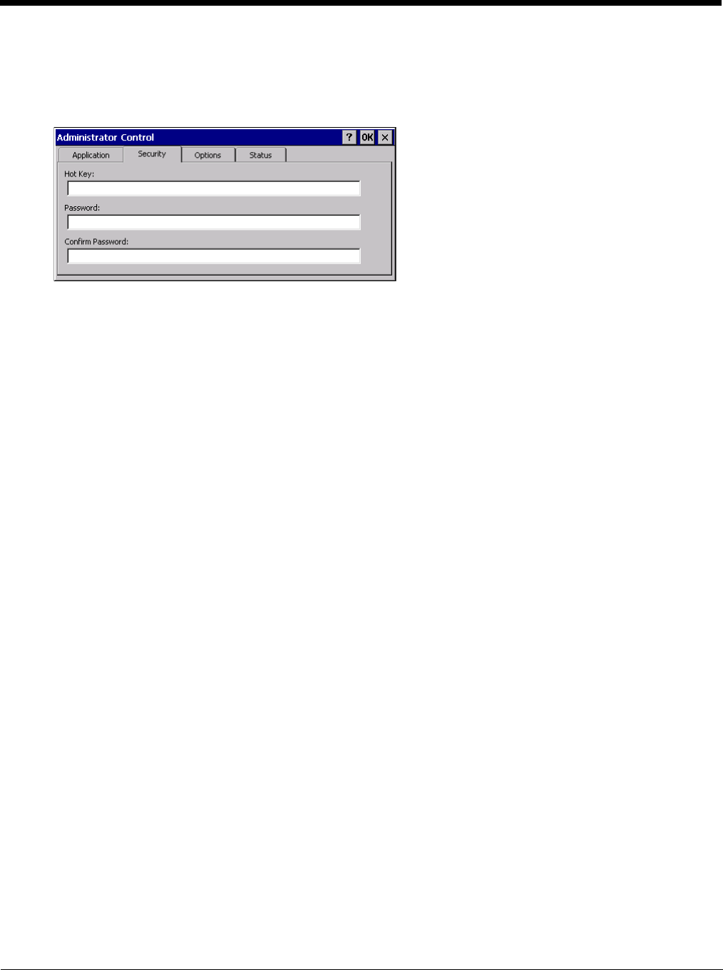
5 - 26
If the standard Internet Explorer that is shipped with the mobile device is desired, it should be treated like any
other application. This means that IEXPLORER.EXE should be specified in the Application text box and the Inter-
net application should be entered in the command line. In this case, do not check the Internet checkbox.
Security
Hotkey
Specify the hotkey sequence that triggers AppLock to switch between administrator and user modes and the pass-
word required to enter Administrator mode. The default hotkey sequence is Shift+Ctrl+A.
A 2nd key keypress is an invalid keypress for a hotkey sequence.
Move the cursor to the Hot Key text box. Enter the new hot key sequence by first pressing the Shift state key fol-
lowed by a normal key. The hotkey selected must be a key sequence that the application being locked does not
use. The hotkey sequence is intercepted by AppLock and is not passed to the application.
Input from the keyboard or Input Panel is accepted with the restriction that the normal key must be pressed from
the keyboard when switching modes. The hotkey sequence is displayed in the Hot key text box with “Shift”, “Alt”,
and “Ctrl” text strings representing the shift state keys. The normal keyboard key completes the hotkey sequence.
The hotkey must be entered via the keypad. Some hotkeys cannot be entered via the Input Panel. Also, hotkeys
entered via the SIP are not guaranteed to work properly when switching operational modes.
For example, if the ‘Ctrl’ key is pressed followed by ‘A’, “Ctrl+A” is entered in the text box. If another key is pressed
after a normal key press, the hotkey sequence is cleared and a new hotkey sequence is started.
A normal key is required for the hotkey sequence and is unlike pressing the normal key during a mode switch; this
key can be entered from the SIP when configuring the key. However, when the hotkey is pressed to switch modes,
the normal key must be entered from the keypad; it cannot be entered from the SIP.
Password
Move the cursor to the Password text box. The passwords entered in the Password and Confirm Password fields
must match. Passwords are case sensitive.
When the user exits the Administrator Control panel, the two passwords are compared to verify that they match. If
they do not match, a dialog box is displayed notifying the user of the error. After the user closes the dialog box,
the Security Panel is displayed and the password can then be entered and confirmed again. If the passwords
match, the password is encrypted and saved.
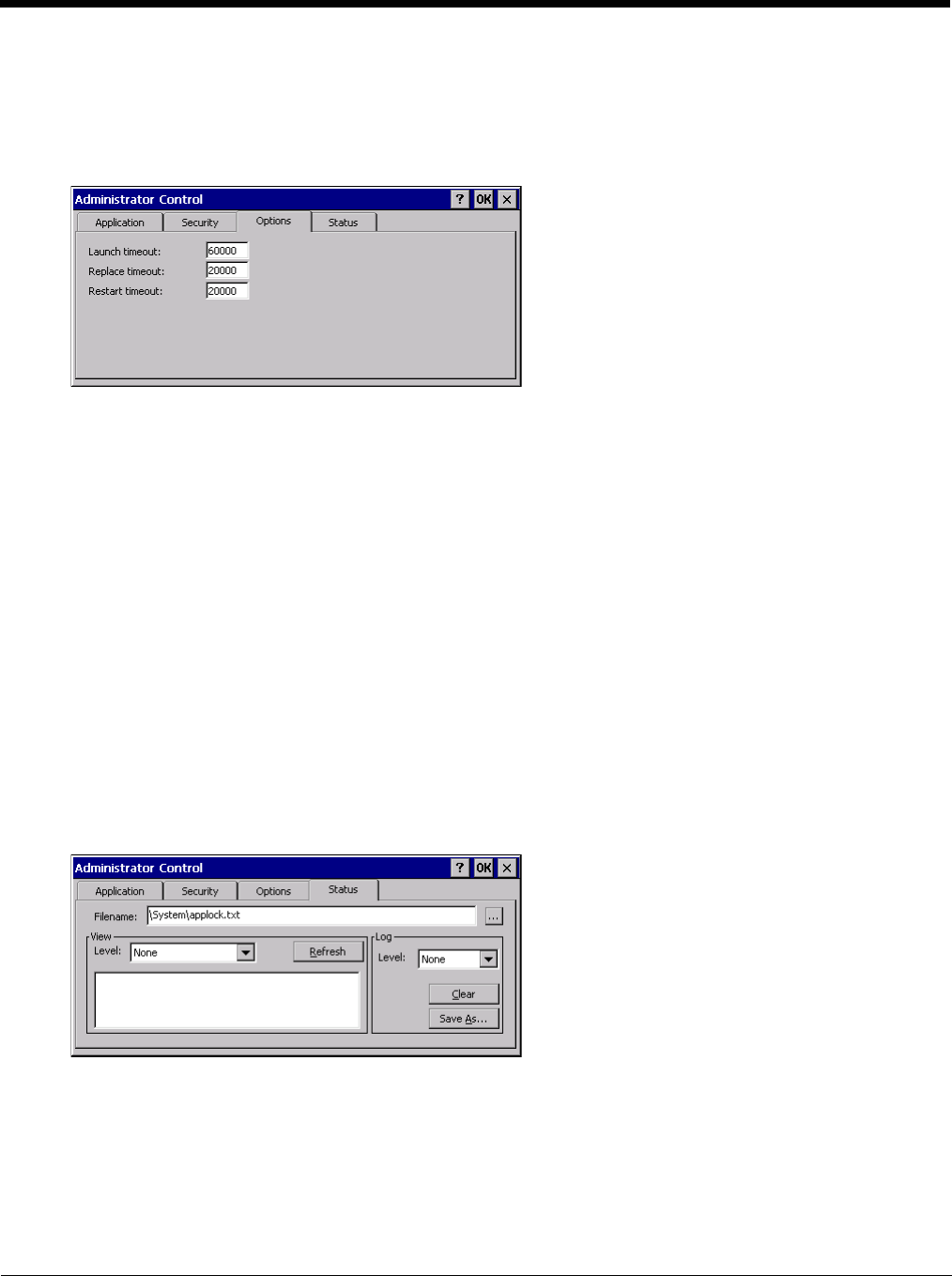
5 - 27
Options
AppLock contains several types of delays and timeouts to accommodate different applications. Please note that the
delays specified on the Application Launch Options (page 5-24) panel are delays before AppLock attempts to start the
specified application(s). The timeouts specified on this panel are delays after AppLock has attempted to launch the
application.
Launch timeout
This timeout specifies the period of time for AppLock to wait for the application to initially launch after the applica-
tion has been called. For example, if the application takes time to launch and then initialize before a display win-
dow is created, use this delay to specify the delay period.
Replace timeout
This timeout specifies the period of time for AppLock to wait after an initial screen (like a password prompt screen)
is replaced by another application window.
Restart timeout
This specifies the period of time for AppLock to wait for an application to restart. If the application fails to restart
automatically, AppLock then proceeds according to the options selected when the application was configured on
the Application (page 5-23) and Application Launch Options (page 5-24) panels.
Status
Use the Status panel to view the log of previous AppLock operations and to configure which messages are to be
recorded during AppLock operation.
Status information is stored in a specific location on the storage device and in a specific log file specified by the Admin-
istrator. For this reason, the administrator can configure the type of status information that is logged, as well as clear
the status information.
Move the cursor to the Filename text box and either type the logfile path or tap the Browse button (the … button). The
standard Windows CE Browse dialog is displayed. After selecting the logfile from the Browse dialog, tap OK.
For detail on error messages written to the log, see AppLock Error Messages (page 10-8).
Note: If your Status Panel does not look like the figure shown above, you may have the Single Application version
which does not have as many options.

5 - 28
View
Tap the Refresh button after changing from one view level to another. The filtered records are displayed, all others
are not displayed.
Log
Note: If a level higher than Error is selected, the status log should be cleared frequently by the administrator.
In addition to the three view levels the administrator can select that all status information be logged or turn off all
status information logging completely. The system default is ‘None’; however to reduce registry use, the adminis-
trator may want to select ‘None’ after verifying the configuration. Tap the ton to clear the status information from
the registry.
•None
• Error
• Processing
• Extended
•All
Save As
When the Save As… button is selected, a standard 'Save As' dialog screen is displayed. Specify the path
and filename. If the filename exists, the user is prompted whether the file should be overwritten. If the file
does not exist, it is created.
See Also: AppLock Error Messages (page 10-8).
AppLock Help
The mobile device won’t switch from Administration mode to end-user mode.
If the configuration is valid for one application but not the other, the switch to end-user mode fails. AppLock stays
in Administration mode and is stopped until the Administrator password is entered.
The hotkey sequence needed is not allowed. What does this mean?
When the Administrator is selecting a hotkey sequence to use when switching user modes, they are not allowed to
enter key combinations that are reserved by installed software applications. Only RFTerm key combinations are
validated.
When RFTerm is installed on the mobile device and an RFTerm restricted key sequence is specified as a hotkey
sequence by the Administrator, the following error message is displayed in a message box:
Selected hotkey is not allowed. Please reenter.
When RFTerm is not installed on the mobile device, the RFTerm keys are not restricted from use.
Can’t locate the password that has been set by the administrator?
Contact Technical Assistance (page 11-1) for password help.
Level Messages Displayed
Error Error status messages are logged when an error occurs and is intended to be used by the administrator
to determine why the specified application cannot be locked.
Process Processing status shows the flow control of AppLock components and is mainly intended for Customer
Service when helping users troubleshoot problems with their AppLock program.
Extended Extended status provides more detailed information than that logged by Process Logging.
All All messages are displayed.
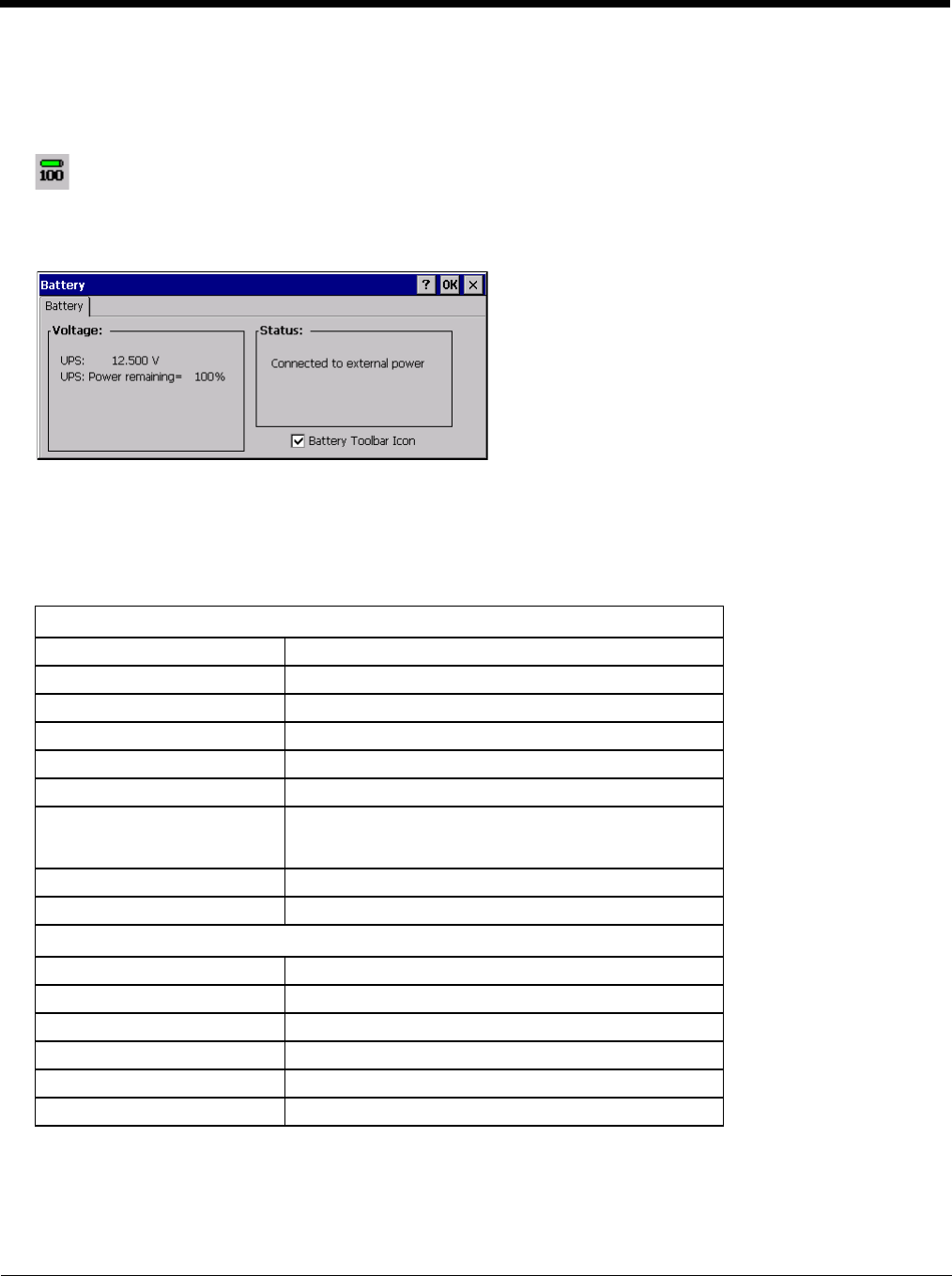
5 - 29
Battery
Start > Settings > Control Panel > Battery
This panel is used to view the status and percentage of power remaining in the Thor VM2 UPS battery.
The Status box indicates if the UPS battery is receiving external power.
Bluetooth
Start > Settings > Control Panel > Bluetooth
Discover and manage pairing with nearby Bluetooth devices.
Factory Default Settings
Bluetooth taskbar Icon state and Bluetooth device Icon states change as Bluetooth devices are discovered, paired, con-
nected and disconnected. There may be audible or visual signals as paired devices re-connect with the Thor VM2.
• The default Bluetooth setting is On.
• The Thor VM2 cannot be discovered by other Bluetooth devices when the Computer is discoverable option is disabled
(unchecked) on the Settings panel.
The battery gas gauge icon resides in the system tray and shows four levels of charge – 100%, 75%, 50%, 25%. At
a point below 25% the gas gauge icon will turn red indicating the battery is low.
The battery gauge icon is enabled by default, but can be disabled on the Thor VM2 Battery control panel. The UPS
LED turns red when there is approximately 2 minutes of run time remaining.
Settings (page 5-32)
Turn Off Bluetooth Enabled
Computer is connectable Enabled
Computer is discoverable Disabled
Prompt if devices request to pair Enabled
Continuous search Disabled
Filtered Mode Enabled
Printer Port on COM 7: Disabled (unchecked) by default in both Filtered and Non
Filtered Modes. The option is dimmed in Non Filtered
Mode.
Logging Disabled
Computer Friendly Name System Device Name
Reconnect (page 5-33)
Report lost connection Enabled
Report when reconnected Disabled
Report failure to reconnect Enabled
Clear Pairing Table on boot Disabled
Auto Reconnect on Boot Enabled
Auto Reconnect Enabled
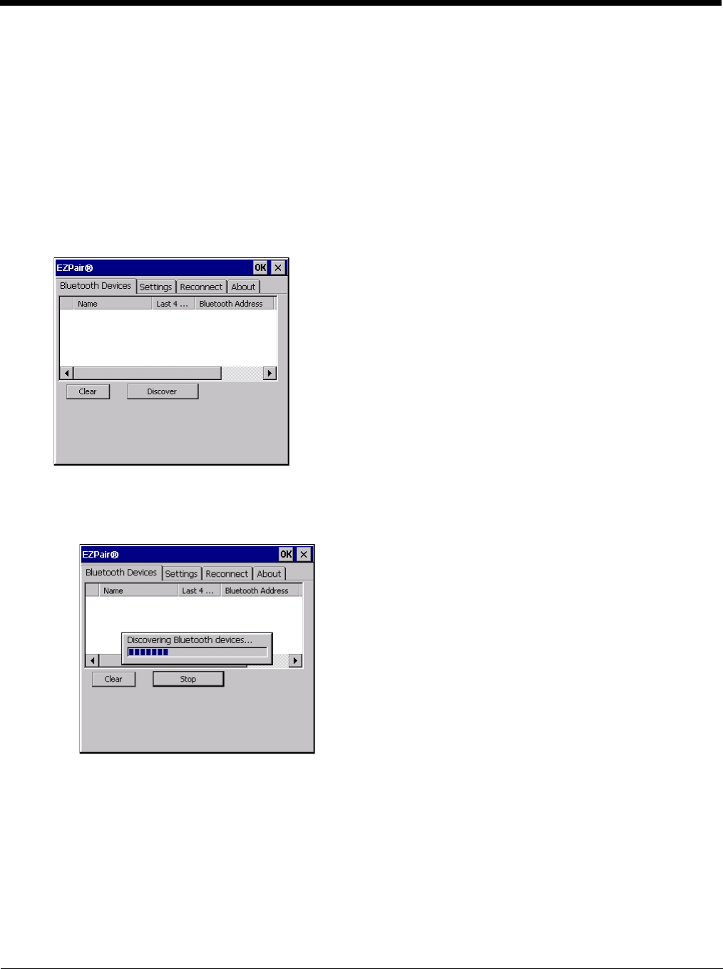
5 - 30
• Other Bluetooth devices cannot be discovered if they have been set up to be Non-Discoverable or Invisible.
• When Filtered Mode is enabled, the Thor VM2 can pair with one Bluetooth scanner and one Bluetooth printer.
• When Filtered Mode is disabled, the Thor VM2 can pair with up to four Bluetooth devices
• It is not necessary to disconnect a paired scanner and printer before a different scanner or printer is paired with the Thor
VM2.
• The target Bluetooth device should be as close as possible (up to 32.8 ft (10 meters) Line of Sight) to the Thor VM2 during
the pairing process.
Assumption: The System Administrator has Discovered and Paired targeted Bluetooth devices for the Thor VM2. The Thor
VM2 operating system has been upgraded to the revision level required for Bluetooth client operation. An application (or
API) is available that will accept data from serial Bluetooth devices.
Bluetooth Devices
The Bluetooth Devices tab displays any device previously discovered and paired with the Thor VM2.
Discover
Tap the Discover button to locate all discoverable Bluetooth devices in the vicinity. The Discovery process also
queries for the unique identifier of each device discovered.
Stop Button
Tap Stop at any time to end the Discover and Query for Unique Identifier functions. Devices not paired are not
shown after any reboot sequence.
Note: When an active paired device enters Suspend Mode, is turned Off or leaves the Thor VM2 Bluetooth
scanning range, the Bluetooth connection between the paired device and the Thor VM2 is lost. There may
be audible or visual signals as paired devices disconnect from the Thor VM2.
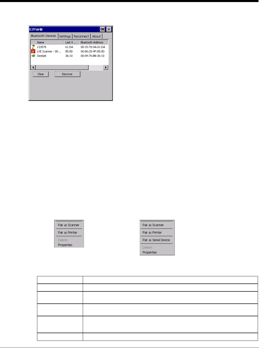
5 - 31
Bluetooth Device List
The discovered paired devices may or may not be identified with an icon. Discovered devices without an icon can
be paired as a Scanner or a Printer. The Bluetooth panel assigns an icon to the device name.
An icon with a red background indicates the device's Bluetooth connection is inactive.
An icon with a white background indicates the device is connected to the Thor VM2 and the device's Bluetooth
connection is active.
Double-tap a device in the list to open the device properties menu. The target device does not need to be active.
Clear Button
Deletes all devices from the Device table that are not currently paired. A dialog box is presented, “Delete all dis-
connected devices? Yes/No”. Tap the Yes button to remove disconnected or deleted devices from the device
table. The devices are removed from the Device table after any reboot sequence or after closing and reopening
the Bluetooth panels. Tap the No button to make no changes. See Clear Pairing Table on Boot on the Reconnect
(page 5-33) tab.
Bluetooth Device Menu
Pre-requisite: The Discover button has been clicked and there are Bluetooth devices listed.
Click on a device in the list to highlight it. Double-click the highlighted device to display the Bluetooth Device right-
click menu. The Bluetooth device does not need to be active.
Right-Click Menu Options
Filtered Mode Enabled Filtered Mode Disabled
Pair as Scanner Receive data from the highlighted Bluetooth scanner or Bluetooth imager.
Pair as Printer Send data to the highlighted Bluetooth printer.
Pair as Serial Device Communicate with the highlighted serial Bluetooth device. This option is available
when Filtered Mode is disabled.
Disconnect Stop the connection between the Thor VM2 and the highlighted paired Bluetooth de-
vice.
Delete Remove an unpaired device from the Bluetooth device list. The highlighted device
name and identifier is removed from the Thor VM2 Bluetooth Devices panel after the
user taps OK.
Properties More information on the highlighted Bluetooth device.
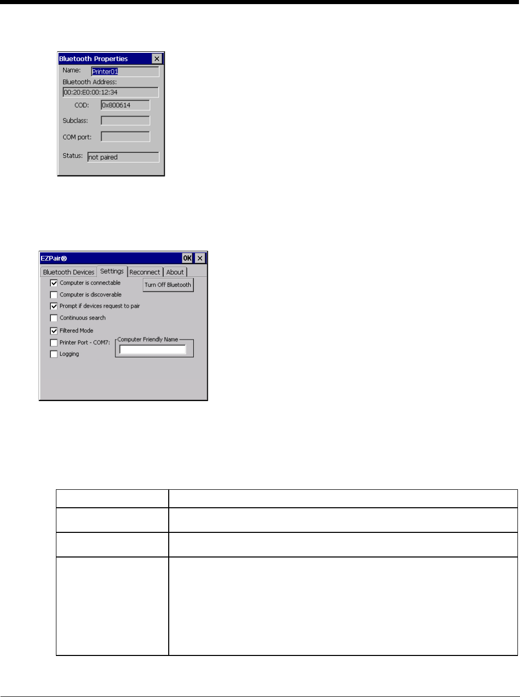
5 - 32
Bluetooth Device Properties
Data on the Bluetooth Properties panel cannot be changed by the user. The data displayed is the result of the
device Query performed during the Discovery process.
The Status dialog box reflects the current state of the highlighted device.
Settings
Note: These options can still be checked or unchecked whether Bluetooth connection is enabled or disabled.
Turn Off Bluetooth
Tap the button to toggle the Bluetooth client On or Off. The button title changes from Turn Off Bluetooth to Turn
On Bluetooth. The default value is Bluetooth On.
Options
Option Function
Computer is connectable This option is Enabled by default.
Disable this option to inhibit Thor VM2 connection initiated by a Bluetooth scanner.
Computer is discoverable This option is Disabled by default.
Enable this option to ensure other devices can discover the Thor VM2.
Prompt if devices request
to pair This option is Enabled by default.
A dialog box appears on the Thor VM2 screen notifying the user a Bluetooth device
requests to pair with the Thor VM2.
The requesting Bluetooth device does not need to have been Discovered by the Thor
VM2 before the pairing request is received.
Tap the Accept button or the Decline button to remove the dialog box from the screen.
Note: In some cases, if a Bluetooth device is already paired this setting cannot be
changed. If this is the case, an error message is displayed and the option is
not changed. The Bluetooth device must be disconnected before changing
this setting.

5 - 33
Reconnect
Note: These options can still be checked or unchecked whether Bluetooth connection is enabled or disabled.
Options
Continuous Search This option is Disabled by default.
When enabled, the Bluetooth connection never stops searching for a device it has
paired with when the connection is broken (such as the paired device entering Sus-
pend mode, going out of range or being turned off). When disabled, after being en-
abled, the Thor VM2 stops searching after 30 minutes. This option draws power from
the Main Battery.
Filtered Mode This option is Enabled by default.
Determines whether the Bluetooth client discovers and displays all serial Bluetooth
devices in the vicinity (Filtered Mode is disabled/unchecked) or the discovery result
displays Bluetooth scanners and printers only (Filtered Mode is enabled/checked).
When Filtered Mode is disabled, the Thor VM2 can pair with up to four Bluetooth de-
vices.
A Warmboot is required every time Filtered Mode is toggled on and off.
Printer Port - COM7 This option is Disabled by default.
This option assigns Bluetooth printer connection to COM7 instead of COM19. To en-
able this option, Filtered Mode must be enabled.
Logging This option is Disabled by default.
When logging is enabled, the Thor VM2 creates bt_log.txt and stores it in the /Sys-
tem folder. Bluetooth activity logging is added to the text file as activity progresses.
A bt_log_bak.txt file contains the data stored by bt_log.txt prior to reboot.
During a reboot process, the Thor VM2 renames bt_log.txt to bt_log_bak.txt. If a
file already exists with that name, the existing file is deleted, the new bt_log_bak.txt
file is added and a new bt_log.txt is created.
Computer Friendly Name Default: Computer System Name (System Panel > Device Name tab).
The name, or identifier, entered in this space by the System Administrator is used ex-
clusively by Bluetooth devices and during Bluetooth communication.
Option Function
Report when connection
lost This option is Enabled (checked) by default.
There may be an audio or visual signal when a connection between a paired, active
device is lost.
A visual signal may be a dialog box placed on the display notifying the user the con-
nection between one (or all) of the paired Bluetooth devices has stopped. Tap the ok
button to remove the dialog box from the screen.
Report when reconnected This option is Disabled (unchecked) by default.
There may be an audio or visual signal when a connection between a paired, active
device is made.
A visual signal may be a dialog box placed on the display notifying the user the con-
nection between one (or all) of the paired Bluetooth devices has resumed. Tap the
ok button to remove the dialog box from the screen.
Option Function
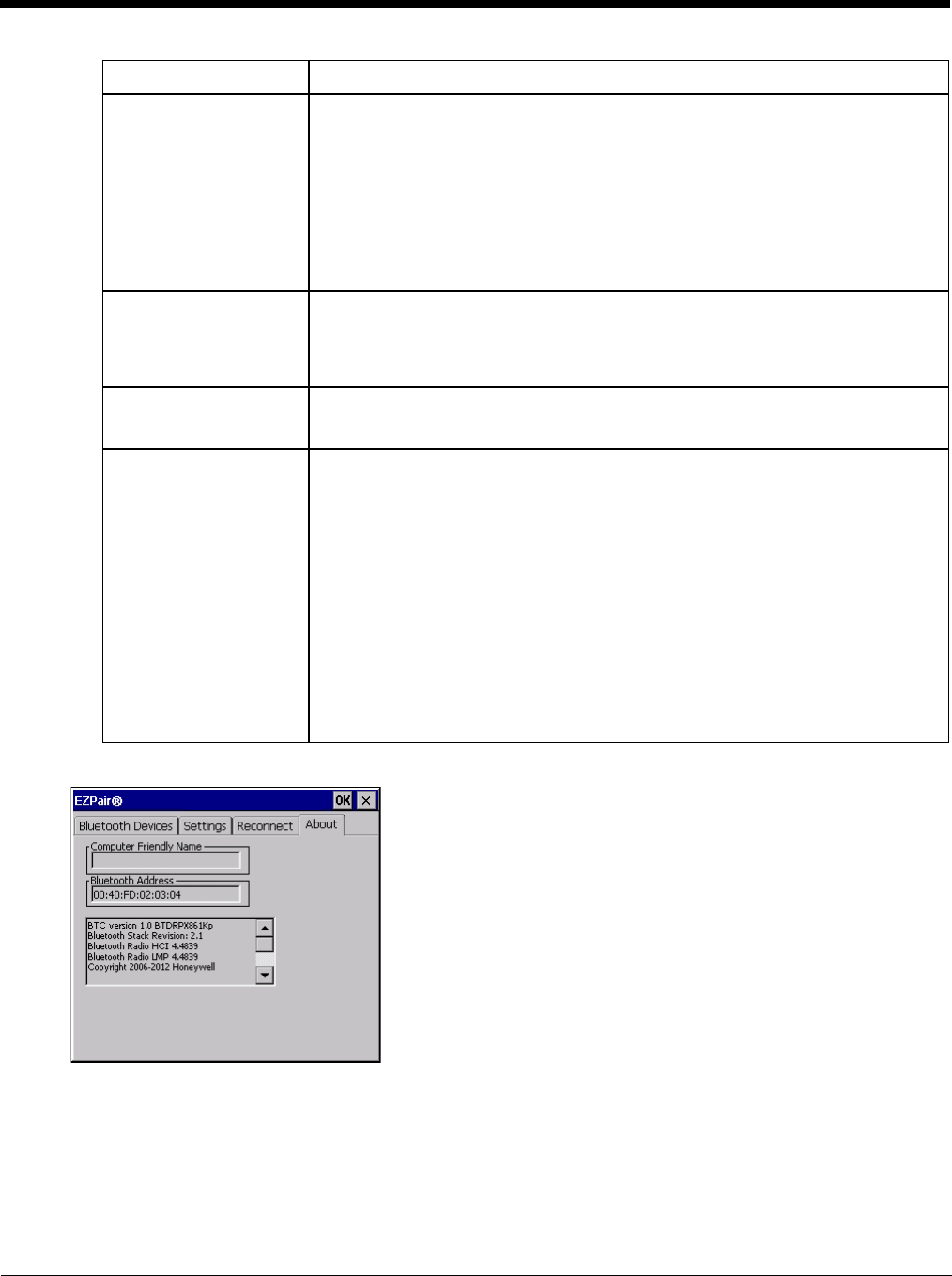
5 - 34
About
This panel lists the assigned Computer Friendly Name (that other devices may discover during their Discovery and
Query process), the Bluetooth MAC address, and software version levels. The data cannot be edited by the user.
Using Bluetooth
Start > Settings > Control Panel > Bluetooth or Bluetooth icon in taskbar or Bluetooth icon on desktop
The Thor VM2 default Bluetooth setting is Enabled.
The Thor VM2 Bluetooth® module is designed to Discover and pair with nearby Bluetooth devices.
Report failure to recon-
nect This option is Enabled (checked) by default.
The default time delay is 30 minutes. This value cannot be changed by the user.
There may be an audio or visual signal when a connection between a paired, active
device fails to re-connect. A visual signal may be a dialog box placed on the display
notifying the user the connection between one (or all) of the previously paired Blue-
tooth devices has failed.
Tap the X button or ok button to close the dialog box.
Possible reasons for failure to reconnect: Timeout expired without reconnecting; at-
tempted to pair with a device that is currently paired with another device; attempted
to pair with a known device that moved out of range or was turned off; attempted to
pair with a known device but the reason why reconnect failed is unknown.
Clear Pairing Table on
Boot This option is Disabled (unchecked) by default.
When enabled (checked), all previous paired information is deleted upon any reboot
sequence and no devices are reconnected.
When enabled (checked) “Auto Reconnect on Boot” is automatically disabled
(dimmed).
Auto Reconnect on Boot This option is Enabled (checked) by default. All previously paired devices are recon-
nected upon any reboot sequence.
When disabled (unchecked), no devices are reconnected upon any reboot sequence.
Auto Reconnect This option is Enabled (checked) by default. This option controls the overall mobile
Bluetooth device reconnect behavior.
• When Auto Reconnect is disabled (unchecked), Auto Reconnect on Boot is
automatically disabled and dimmed.
• When Auto Reconnect is disabled (unchecked), no devices are reconnected in any
situation. The status of Auto Reconnect on Boot is ignored and no devices are
reconnected on boot. The status of Clear Pairing Table on Boot controls whether
the pairing table is populated on boot.
• When Auto Reconnect is enabled (checked) and Auto Reconnect on Boot is
disabled (unchecked), devices are not reconnected on boot, but are reconnected
in other situations (example: return from out-of-range).
• When Auto Reconnect is enabled (checked) and Clear Pairing Table on Boot is
enabled (checked), devices are not reconnected on boot, but are reconnected in
other situations (example: return from out-of-range). The pairing table is cleared
on boot. The status of Auto Reconnect on Boot is ignored and the option is
automatically disabled (unchecked) and dimmed.
Option Function

5 - 35
Prerequisite: The Bluetooth devices have been setup to allow them to be “Discovered” and “Connected/Paired”. The
System Administrator is familiar with the pairing function of the Bluetooth devices.
Bluetooth Devices Display - Before Discovering Devices
Note: When Filtered Mode is enabled, only Bluetooth printers or Bluetooth scanners/imagers are recognized and
displayed in the Bluetooth panel. All other Bluetooth devices are ignored.
Initial Configuration
1. Select Start > Settings > Control Panel > Bluetooth or tap the Bluetooth icon in the taskbar or on the desk-
top.
2. Tap the Settings Tab.
3. Change the Computer Friendly Name at the bottom of the Settings display. The Bluetooth Thor VM2 default
name is determined by the factory installed software version. A unique name (up to 32 characters) should be
assigned to every Thor VM2 before Bluetooth Discovery is initiated.
4. Check or uncheck the Thor VM2 Bluetooth options on the Settings and Reconnect tabs.
5. Tap the OK button to save your changes or the X button to discard any changes.
Subsequent Use
Note: Taskbar and Bluetooth device Icon states change as Bluetooth devices are discovered, paired, connected
and disconnected. A taskbar Bluetooth icon with a red background indicates Bluetooth is active and not
paired with any device. A device icon with a red background indicates a disconnected paired device.
1. Tap the Bluetooth icon in the taskbar or on the desktop to open the Bluetooth EZPair application.
2. Tap the Bluetooth Devices tab.
3. Tap the Discover button. When the Bluetooth module begins searching for in-range Bluetooth devices, the
button name changes to Stop. Tap the Stop button to cancel the Discover function at any time.
4. The discovered devices are listed in the Bluetooth Devices window.
5. Highlight a Bluetooth device in the Discovered window and double-tap to open the device properties menu.
6. Tap Pair as Scanner to set up the Thor VM2 to receive scanner data.
7. Tap Pair as Printer to set up the Thor VM2 to send data to the printer.
8. Tap Serial Device (when Filtered mode is disabled) to set up the Thor VM2 to communicate with a Bluetooth
serial device.
9. Tap Disconnect to stop pairing with the device. Once disconnected, tap Delete to remove the device name
and data from the Thor VM2 Bluetooth Devices list. The device is deleted from the list after the OK button is
clicked.
10. Upon successful pairing, the selected device may react to indicate a successful connection. The reaction
may be an audio signal from the device, flashing LED on the device, or a dialog box is placed on the Thor
VM2 display.
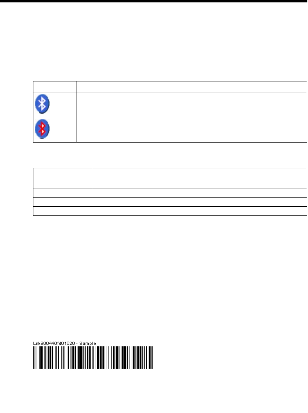
5 - 36
11. Whenever the Thor VM2 is turned On, all previously paired, live, Bluetooth devices in the vicinity are paired,
one at a time, with the Thor VM2. If the devices cannot connect to the Thor VM2 before the re-connect time-
out time period expires (default is approximately 20 seconds for each paired device) there is no indication of
the continuing disconnect state if Report Failure to Reconnect is disabled.
Bluetooth Indicators
There may be audible or visual signals as paired devices re-connect with the Thor VM2.
Only printers or scanners are recognized and displayed in the Bluetooth panel. All other Bluetooth devices are
ignored.
Note: When an active paired device enters Suspend Mode, is turned Off or leaves the Thor VM2 Bluetooth scan
range, the Bluetooth connection between the paired device and the Thor VM2 is lost. There may be audible
or visual signals as paired devices disconnect from the Thor VM2.
AppLock, if installed, does not stop the end-user from using Bluetooth applications, nor does it stop authorized
Bluetooth-enabled devices from pairing with the Thor VM2 while AppLock is in control.
Bluetooth Bar Code Reader Setup
Please refer to the Bluetooth scanner manufacturer’s User Guide; it may be available on the manufacturer’s web
site. Contact Technical Assistance (page 11-1) for Bluetooth product assistance.
Several different types of bar code readers are supported. This section describes the interaction and setup for a
mobile Bluetooth laser scanner or laser imager connected to the Thor VM2 using Bluetooth functions.
Prerequisites
• If the Thor VM2 has a Bluetooth address identifier bar code label affixed, then Bluetooth hardware and software
is installed.
• The mobile Bluetooth laser scanner / laser imager battery is fully charged.
• The Thor VM2 is connected to AC or DC (vehicle) power.
•Important: The bar code numbering examples in this segment are not real and should not be created nor
scanned with a Bluetooth scanner.
• To open theEZPair program, tap Start > Settings > Control Panel > Bluetooth or tap the Bluetooth icon on
the desktop or tap the Bluetooth icon in the taskbar.
Locate the bar code label, similar to the one shown above, attached to the Thor VM2. The label is the Bluetooth
address identifier for the Thor VM2.
The mobile Bluetooth scanner / imager requires this information before discovering, pairing, connecting or discon-
necting can occur.
Taskbar Icon Legend
Thor VM2 is connected to one or more of the targeted Bluetooth device(s).
• Thor VM2 is not connected to any Bluetooth device.
• Thor VM2 is ready to connect with any Bluetooth device.
• Thor VM2 is out of range of all paired Bluetooth device(s). Connection is inactive.
Bluetooth LED Legend
Blue, blinking slowly Bluetooth is active but not connected to a device.
Blue, blinking medium Bluetooth is paired and connected to a device.
Blue, blinking fast Bluetooth is discovering other Bluetooth devices.
Off Bluetooth hardware has been turned off or does not exist in the Thor VM2.
5 - 37
Important: The Thor VM2 Bluetooth address identifier label should remain protected from damage (rips, tears,
spills, soiling, erasure, etc.) at all times. It may be required when pairing, connecting, and disconnecting new
Bluetooth bar code readers.
Thor VM2 with Label
If the Thor VM2 has a Bluetooth address bar code label attached, follow these steps:
1. Scan the Bluetooth address bar code label, attached to the Thor VM2, with the Bluetooth mobile scanner.
2. If this is the first time the Bluetooth scanner has scanned the Thor VM2 Bluetooth label, the devices are
paired. See Bluetooth Beep and LED Indications (page 5-38). If the devices do not pair successfully, go
to the next step.
3. Open the Bluetooth (page 5-29) EZ Pair panel.
4. Tap Discover. Locate the Bluetooth scanner in the Discovery panel.
5. Double-tap the stylus on the Bluetooth scanner. The right-mouse-click menu appears.
6. Select Pair as Scanner to pair the Thor VM2 with the Bluetooth mobile scanner.
The devices are paired. The Bluetooth bar code reader responds with a series of beeps and an LED flashes.
See Bluetooth Beep and LED Indications (page 5-38).
Note: After scanning the Thor VM2 Bluetooth label, if there is no beep and no LED flash from the Bluetooth
device, the devices are currently paired.
Thor VM2 without Label
If the Thor VM2 Bluetooth address bar code label does not exist, follow these steps to create a unique Blue-
tooth address bar code for the Thor VM2:
First, locate the Thor VM2 Bluetooth on the About tab of the Bluetooth (page 5-29) control panel.
Next, create a Bluetooth address bar code label for the Thor VM2.
The format for the bar code label is as follows:
• Bar code type must be Code 128.
• FNC3 character followed by string Uppercase L, lowercase n, lowercase k, uppercase B and then the
Bluetooth address (12 hex digits, no colons). For example, LnkB0400fd002031.
Create and print the label.
Scan the Thor VM2 Bluetooth address bar code label with the Bluetooth bar code reader.
The devices are paired. The Bluetooth bar code reader responds with a series of beeps and LED flashes.
Note: After scanning the Thor VM2 Bluetooth label, if there is no beep and no LED flash from the Bluetooth
bar code reader, the devices are currently paired.
See Bluetooth Beep and LED Indications (page 5-38).

5 - 38
Bluetooth Beep and LED Indications
Upon startup, if the scanner sounds a long tone, this means the scanner has not passed its automatic Selftest
and has entered isolation mode. If the scanner is reset, the sequence is repeated. Contact Technical
Assistance (page 11-1) for assistance.
Bluetooth Printer Setup
The Bluetooth managed device should be as close as possible, in direct line of sight, with the Thor VM2
during the pairing process.
1. Open the Bluetooth EZPair Panel.
2. Tap Discover. Locate the Bluetooth printer in the Discovery panel.
3. Tap and hold the stylus (or double-tap) on the Bluetooth printer ID until the right-mouse-click menu
appears.
4. Select Pair as Printer to pair the Thor VM2 with the Bluetooth managed printer.
The devices are paired. The Bluetooth managed printer may respond with a series of beeps or LED flashes.
Please refer to the Bluetooth managed printer manufacturer’s User Guide; it may be available on the manu-
facturer’s web site. Contact Technical Assistance (page 11-1) for Bluetooth product assistance.
Note: If there is no beep or no LED flash from the Bluetooth managed printer, the Thor VM2 and the printer
are currently paired.
Easy Pairing and Auto-Reconnect
The Bluetooth module can establish relationships with new devices after the user taps the Discover button. It can
auto-reconnect to devices previously known but which have gone out of range and then returned within range.
See Reconnect (page 5-33).
Note: Configuration elements are persistent and stored in the registry.
Setup the Bluetooth module to establish how the user is notified by easy pairing and auto-reconnect events.
AppLock, if installed, does not stop the end-user from using the Bluetooth application, nor does it stop other Blue-
tooth-enabled devices from pairing with the Thor VM2 while AppLock is in control.
Beep Type from Bluetooth Device Behavior
Acknowledge label 1 beep
Label rejected 2 beeps at low frequency
Transmission error Beep will sound high-low-high-low
Link successful Beep will sound low-medium-high
Link unsuccessful Beep will sound high-low-high-low
LED on Bluetooth Device Behavior
Yellow LED blinks at 2 Hz Linking in progress
Off Disconnected or unlinked
Yellow LED blinks at 50 Hz Bluetooth transmission in progress
Yellow LED blinks at the same rate as the paging beep (1 Hz) Paging
Green LED blinks once a second Disabled indication
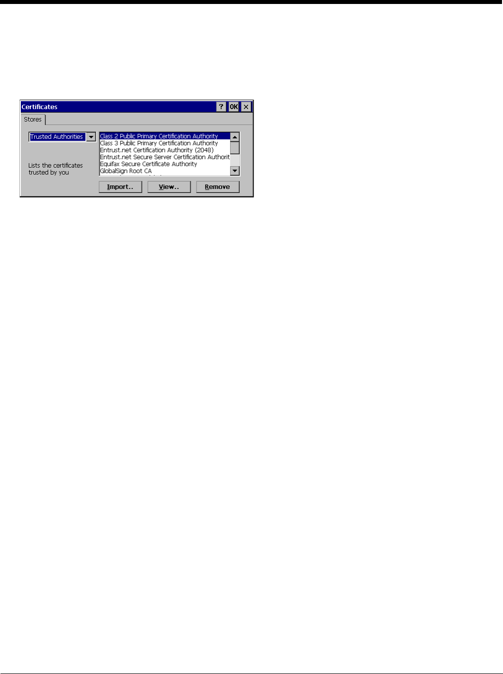
5 - 39
Certificates
Start > Settings > Control Panel > Certificates
Manage digital certificates used for secure communication.
Note: Digital certificates are date sensitive. If the date on the Thor VM2 is incorrect, wireless authentication will fail.
The Certificates stores tab lists the certificates trusted by the Thor VM2 user.
These values may change based on the type of network security resident in the client, access point or the host system.
Tap the Import button to import a digital certificate file.
Tap t he View button to view a highlighted digital certificate.
Note: Tap the Remove button to remove highlighted certificate files.
Note: Tap the ? button and follow the instructions in the Windows CE Help file when working with trusted authorities and
digital certificates.
Data Collection
Start > Settings > Control Panel > Data Collection
The Data Collection wedge (DC Wedge) software component is the interface between data collection devices such as bar
code scanners or imagers connected to a COM port on the Thor VM2 or bar code scanners wirelessly connected via Blue-
tooth to your Thor VM2. This software component collects the data from the varied sources and presents it to applications
on your Thor VM2 in a transparent manner.
Note: When a HID enabled USB scanner is connected to the Thor VM2 the scanned data is transmitted to the active window
as keystroke messages. The data bypasses the data collection wedge. Any data handling to be applied to the
scanned data, for example strip leading or trailing characters, must be programmed into the scan engine via
configuration bar codes or handled by the application accepting the data.
Use the options on the control panels to set Thor VM2 data collection keyboard wedge parameters, enable or disable
allowed symbologies and assign scan key settings.
Assign baud rate, parity, stop bits and data bits for available COM ports.
Parameters on the Main tab and the COM tab(s) apply to this device only.
Bar code manipulation parameter settings on the Data Options (page 5-44) tab are applied to the incoming data resulting
from successful bar code scans received by the Thor VM2 for processing. The successful bar code scan data may be sent
by
• a wireless Bluetooth scanner,
• or a tethered serial scanner.
Bar Code Readers
The Thor VM2 can use the following external bar code readers:
• Tethered hand-held scanners are tethered to a serial port or a USB host port on the Thor VM2 and are configured
by scanning the engine-specific bar codes in the scanner manufacturer's programming guide. The manufacturer's
guides are usually shipped with the bar code reader.
• Wireless hand-held Bluetooth scanners are configured by scanning the engine-specific bar codes in the scanner
manufacturer's programming guide. The manufacturer's guides are usually shipped with the bar code reader.
• The body worn Bluetooth Ring Scanner module may be using a Symbol 4400 Ring Imager or a Symbol 955 Ring
Scanner. The BTRS module is configured by scanning the bar codes in the Bluetooth Ring Scanner Guide.

5 - 40
By default, the Thor VM2 is pre-configured for a tethered scanner attached to the COM1 port:
•Power on Pin 9 (page 5-43) is enabled.
• The Data Collection control panel Main (page 5-42) tab is configured for COM1 on Device 2.
Return to Factory Default Settings
After scanning the engine-specific bar code to return the scanner/imager to factory default settings, the next step
is to open the bar code wedge panel on the mobile device collecting the scanned data. Click the OK button to
close the panel. This action will synchronize all scanner formats for your device.
Data Processing Overview
Bar code data processing involves several steps. Some steps may be skipped during the processing depending on
user selections on the Data Options control panels. The steps are presented below in the order they are performed on
the scanned data.
1. Scanned data is tested for a code ID and length (Min/Max). If it matches, it is processed per the rules in place for
that symbology. If the scan does not meet the criteria for that symbology, it is processed based on the settings for
All. If a code ID is not found, the bar code data is processed based on the settings for All.
2. If the symbology is disabled, the scan is rejected.
3. Strip leading data bytes unconditionally.
4. Strip trailing data bytes unconditionally.
5. Parse for, and strip if found, Data Options strings.
6. Replace any control characters with string, as configured.
7. Add prefix string to output buffer.
8. If Code ID is not stripped, add saved code ID from above to output buffer.
9. Add processed data string from above to output buffer.
10. Add suffix string to output buffer.
11. Add a terminating NUL to the output buffer, in case the data is processed as a string.
12. If key output is enabled, start the process to output keys. If control characters are encountered:
• If Translate All is set, key is translated to CTRL + char, and output.
• If Translate All is not set, and key has a valid VK code, key is output.
• Otherwise, key is ignored (not output).
13. If key output is disabled, a windows message is broadcast to notify listening applications that data is available.
The manipulated data is ready to be read by applications.

5 - 41
Factory Default Settings
Main (page 5-42)
Device 1 Disabled
Device 2 Disabled
Device 3 Disabled
Send Key Message (WEDGE) Enabled
COM1 (page 5-43)
Baud Rate 9600
Stop Bits 1
Parity None
Data Bits 8
Power on Pin 9 Enabled
COM2 (page 5-43)
Baud Rate 9600
Stop Bits 1
Parity None
Data Bits 8
Power on Pin 9 Enabled
Data Options (page 5-44)
Enable Code ID None
Symbology Settings All
Control Character Translate All Disabled
Custom IDs Name blank
Processing (page 5-53)
Enable buffered key output Enabled
Same buffer limit 32
Delay between buffers 75 ms

5 - 42
Main
Start > Settings > Control Panel > Data Collection > Main tab
The parameters shown on these panels are only those that apply to the specific mobile device.
Parameter Function
Device 1,2,3 Device 1 - Default is Disabled
Device 2 - Default is COM1
Device 3 - Default is Disabled
The data collection device (laser scanner, laser imager, external, or wireless).
Output Enable Default: Disabled.
When Output Enable is enabled, data is received from the scanner and processed via the
wedge but an application can also open the WDG0: device and write data to it. An example is
when a printer is connected to the same COM port as the scanner via a switch. Data can be
written to the WDG device and is redirected to the associated COM port. The application must
open the WDG0: port, not the COMx: port as the Wedge has exclusive rights to the COM port.
If Output Enable is not checked, the WDG0: port can still be opened, but any attempts to write
to that port fail.
Send Key Messages
(WEDGE) Default: Enabled.
When Send Key Messages (WEDGE) is checked any data collection scan is converted to key-
strokes and sent to the active window. When this checkbox is not checked, the application will
need to use the set of Scanner APIs to retrieve the data from the scanner driver. Note that this
latter method is significantly faster than using Wedge.
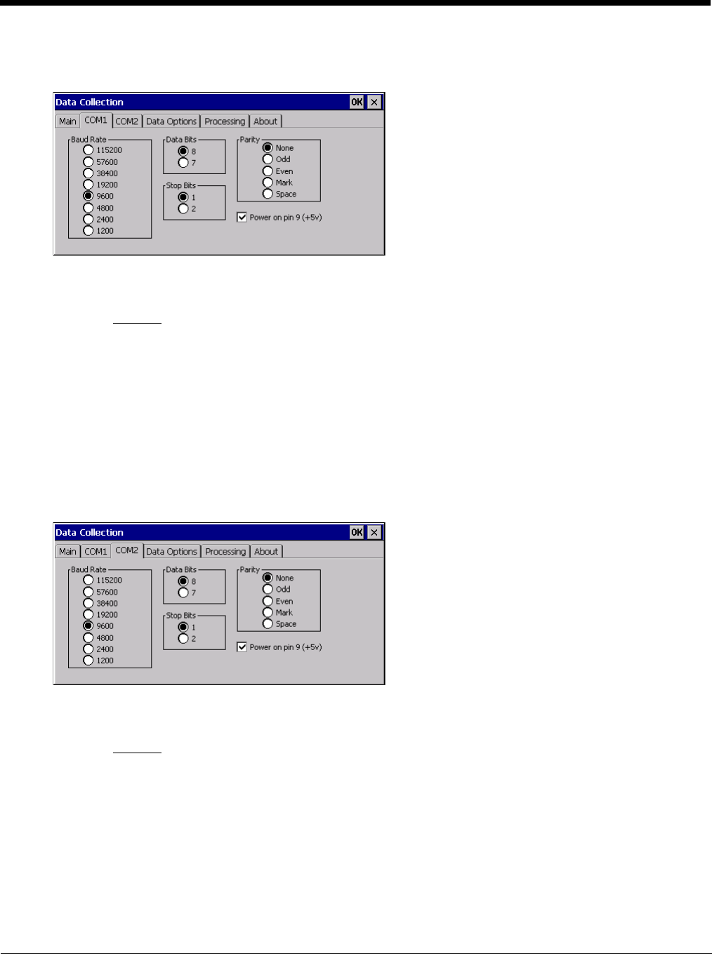
5 - 43
COM1
Start > Settings > Control Panel > Data Collection > COM1 tab
This panel sets communication parameters for any device connected to the external port.
Adjust the settings and click the OK button to save the changes. Any changes take effect immediately.
This panel does not configure the connected device. Please refer to the documentation for the external connected or
wireless device for information on configuring the device.
Note: COM default values are restored after a cold boot or operating system upgrade. COM1 supports 5V switchable
power on Pin 9 for tethered scanners.
Power on Pin 9
To configure the COM port to supply power to an external scanner tethered to the COM1 port, check the checkbox
for Power on Pin 9 (+5V). The default is On (enabled).
Wireless external scanners use their own power source.
COM2
Start > Settings > Control Panel > Data Collection > COM2 tab
This panel sets communication parameters for any device connected to the external port.
Adjust the settings and click the OK button to save the changes. Any changes take effect immediately.
This panel does not configure the connected device. Please refer to the documentation for the external connected or
wireless device for information on configuring the device.
Note: COM default values are restored after a cold boot or operating system upgrade. COM2 supports 5V switchable
power on Pin 9 for tethered scanners.
Power on Pin 9
To configure the COM port to supply power to an external scanner tethered to the COM2 port, check the checkbox
for Power on Pin 9 (+5V). The default is On (enabled).
Wireless external scanners use their own power source.
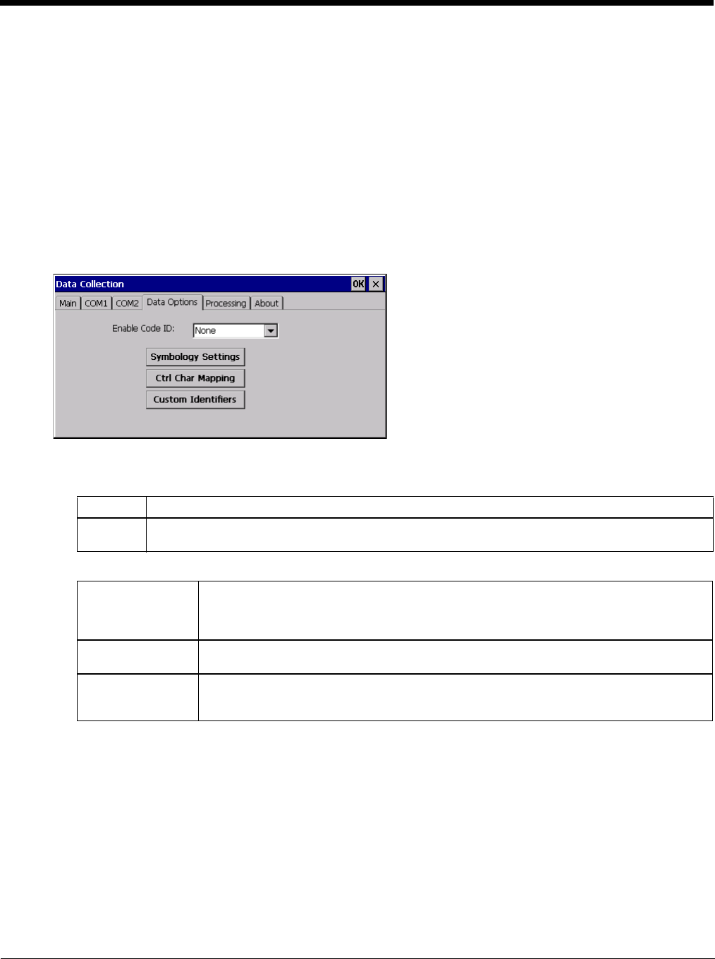
5 - 44
Data Options
Start > Settings > Control Panel >Data Collection > Data Options tab
Bar code manipulation parameter settings on this tab are applied to the incoming data resulting from successful bar
code scans sent to the Thor VM2 for processing.
Note: The Data Options tab contains only those options available for one type of decoding engine.
The Data Options tab contains several options to control bar code processing. Options include:
• Defining custom Code IDs
• Disable processing of specified bar code symbologies
• Rejecting bar code data that is too short or too long
• Stripping characters including Code ID, leading or trailing characters and specified bar code data strings
• Replacing control characters
• Adding a prefix and a suffix.
Enable Code ID
Choose an option in the Enable Code ID drop-down box:
Buttons
See Data Processing Overview (page 5-40).
Data Options - Symbology Settings
Start > Settings > Control Panel > Data Collection > Data Options tab > Symbology Settings button
The Symbology selected in the Symbology drop-down list defines the symbology for which the data is being con-
figured. The features available on the Symbology panel include the ability to
• individually enable or disable a bar code from scanning,
• set the minimum and maximum size bar code to accept,
• strip Code ID,
• strip data from the beginning or end of a bar code,
• or (based on configurable Bar Code Data) add a prefix or suffix to a bar code.
None Disables transmission of a Code ID. The only entry in the Symbology combo box is All.
Custom ID Does not change the scanner’s Code ID transmission setting. The combo box in the Symbology con-
trol panel is populated with any configured Custom code IDs.
Symbology Settings Individually enable or disable a bar code from being scanned, set the minimum and maxi-
mum size bar code to accept, strip Code ID, strip data from the beginning or end of a bar
code, or (based on configurable Bar Code Data) add a prefix or suffix to a bar code before
transmission.
Ctrl Char Mapping Define the operations the Wedge performs on control characters (values less than 0x20)
embedded in bar codes.
Custom Identifiers Defines an identifier that is at the beginning of bar code data which acts as a Code ID. After
a Custom Identifier is defined, Symbology Settings can be defined for the identifier just like
standard Code IDs.
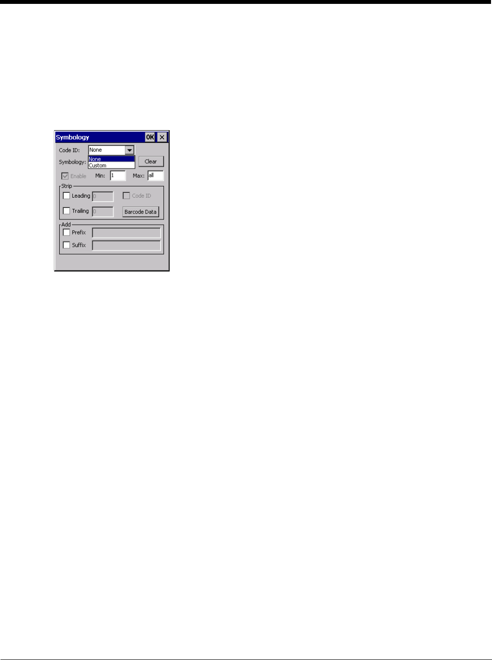
5 - 45
The Code ID drop-down box only filters the available symbologies in the Symbology drop down box by the
selected Code ID. This Code ID box does not enable or disable the Code ID as that function is controlled by the
Enable Code ID box on the Data Options tab.
The Symbology drop-down box contains all symbologies supported based on the Code ID selected above. An
asterisk appears in front of symbologies that have already been configured or have been modified from the default
value.
Each time a Symbology is changed, the settings are saved as soon as the ok button is tapped. Settings are also
saved when a new Symbology is selected from the Symbology drop-down list.
The order in which these settings are processed are:
• Min / Max
• Code ID
• Leading / Trailing
• Bar Code Data
• Prefix / Suffix
Note: When Enable Code ID is set to None on the Data Options tab and when All is selected in the Symbology
field, Enable and Strip Code ID on the Symbology panel are grayed and the user is not allowed to change
them, to prevent deactivating the scanner completely.
When All is selected in the Symbology field and the settings are changed, the settings in this dialog become the
defaults, used unless overwritten by the settings for individual symbologies. This is also true for Custom IDs,
where the code IDs to be stripped are specified by the user.
Note: In Custom mode on the Data Options tab, any Code IDs not specified by the user will not be stripped,
because they will not be recognized as Code IDs.
If a specific symbology's settings have been configured, a star (*) will appear next to it in the Symbology drop-
down box, so the user can tell which symbologies have been modified from their defaults.
If a particular symbology has been configured, the entire set of parameters from that symbologies screen are in
effect for that symbology. In other words, either the settings for the configured symbology will be used, or the
default settings are used, not a combination of the two.
If a symbology has not been configured (does not have an * next to it) the settings for All are used which is not
necessarily the default.
Clear Button
Clicking this button will erase any programmed overrides, returning to the default settings for the selected
symbology.
If Clear is pressed when All is selected as the symbology, a confirmation dialog appears:
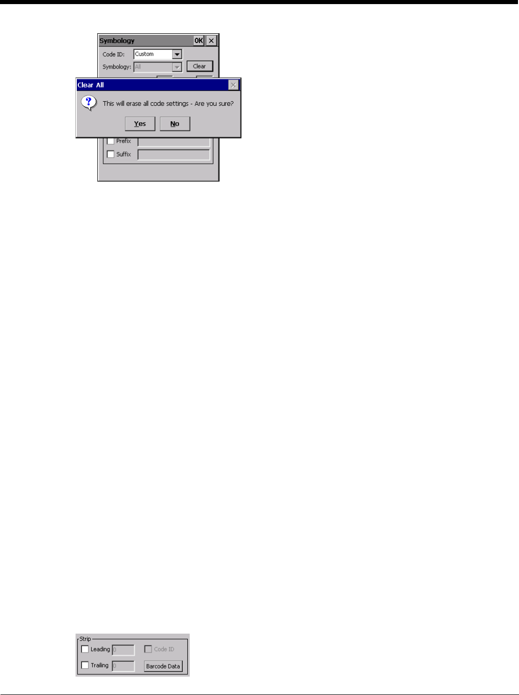
5 - 46
If confirmed, all symbologies are reset to their factory defaults, and all star (*) indications are removed from
the list of Symbologies.
Click the Yes button or the No button.
Enable, Min, Max
Enable
This checkbox enables (checked) or disables (unchecked) the symbology field.
The scanner driver searches the beginning of the bar code data for the type of ID specified in the Data
Options tab -- Enable Code ID field plus any custom identifiers.
When a code ID match is found as the scanner driver processes incoming bar code data, if the symbol-
ogy is disabled, the bar code is rejected. Otherwise, the other settings in the dialog are applied and the
bar code is processed.
If the symbology is disabled, all other fields on this dialog are dimmed.
If there are customized settings, uncheck the Enable checkbox for the All symbology. This results in dis-
abling all symbologies except the customized ones.
Min
This field specifies the minimum length that the bar code data (not including Code ID) must meet to be
processed.
Any bar code scanned that is less than the number of characters specified in the Min field is rejected.
The default for this field is 1.
Max
This field specifies the maximum length that the bar code data (not including Code ID) can be processed.
Any bar code scanned that has more characters than specified in the Max field is rejected. The default
for this field is All (9999).
If the value entered is greater than the maximum value allowed for that symbology, the maximum valid
length is used instead.
Strip Leading/Trailing Control
Start > Settings > Control Panel > Data Collection > Data Options tab > Symbology button
This group of controls determines what data is removed from the collected data before the data is buffered for
the application. When all values are set, Code ID takes precedence over Leading and Trailing; Bar Code
Data stripping is performed last. Stripping occurs before the Prefix and Suffix are added, so does not affect
them.
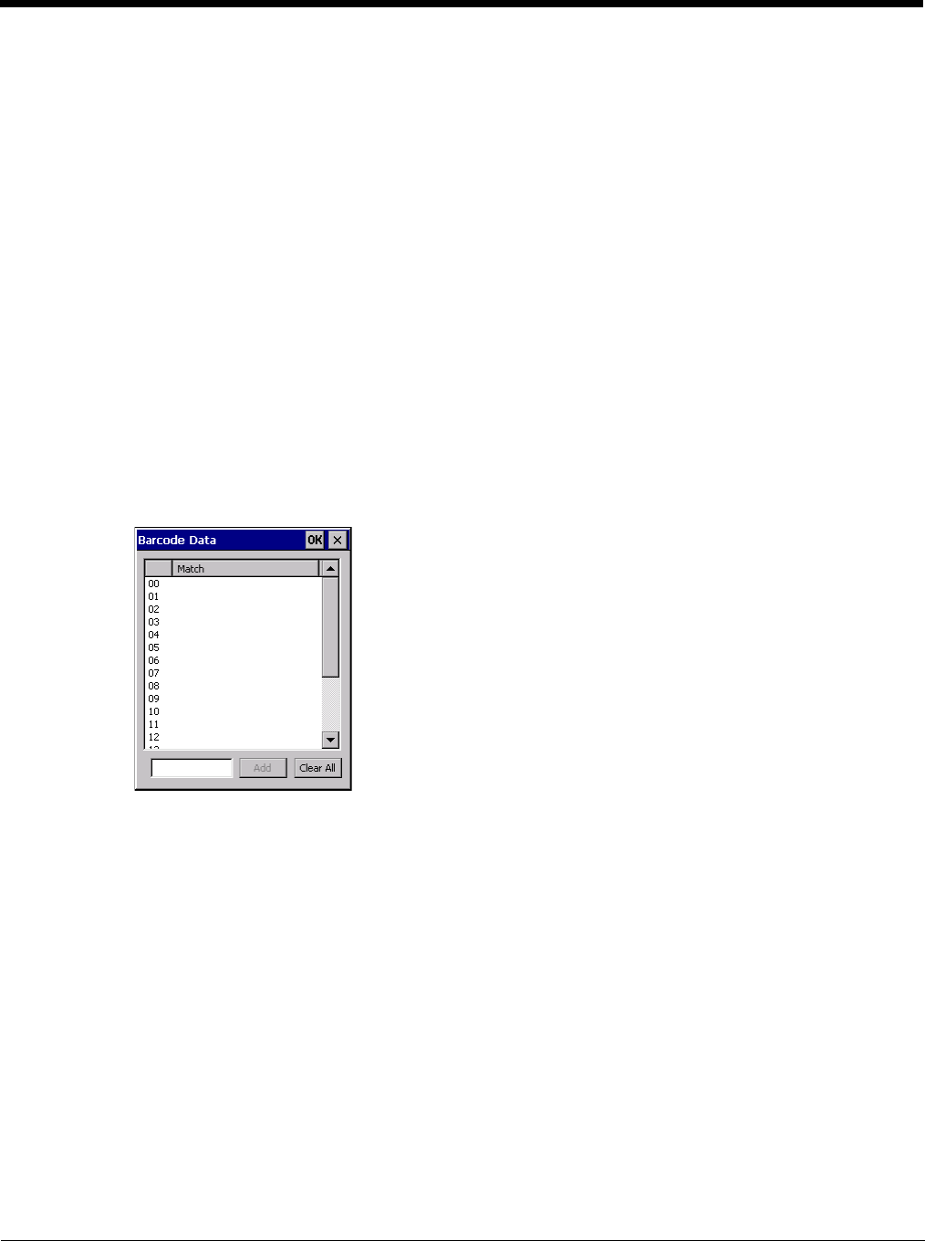
5 - 47
If the total number of characters being stripped is greater than the number of characters in the collected data,
it becomes a zero byte data string.
If, in addition, Strip Code ID is enabled, and no prefix or suffix is configured, the processing will return a zero-
byte data packet, which will be rejected.
The operation of each type of stripping is defined below:
Leading
This strips the number of characters specified from the beginning of the collected data (not including
Code ID). The data is stripped unconditionally. This action is disabled by default.
Trailing
This strips the number of characters specified from the end of the collected data (not including Code ID).
The data is stripped unconditionally. This action is disabled by default.
Code ID
Strips the Code ID based on the type code ID specified in the Enable Code ID field in the Data Options
tab. By default, Code ID stripping is enabled for every symbology (meaning code IDs will be stripped,
unless specifically configured otherwise).
Bar Code Data Match List
This panel is used to strip data that matches the entry in the Match list from the bar code. Enter the data to
be stripped in the text box and tap the Insert or Add button. The entry is added to the Match list.
To remove an entry from the Match list, highlight the entry in the list and click the Remove button.
Click the OK button to store any additions, deletions or changes.

5 - 48
Bar Code Data Match Edit Buttons
Notes
•Prefix and Suffix data is always added on after stripping is complete, and is not affected by any stripping
settings.
• If the stripping configuration results in a 0 length bar code, a good beep will still be emitted, since bar code
data was read from the scanner.
Match List Rules
The data in the match list is processed by the rules listed below:
• Strings in the list will be searched in the order they appear in the list. If the list contains ABC and AB, in
that order, incoming data with ABC will match first, and the AB will have no effect.
• When a match between the first characters of the bar code and a string from the list is found, that string is
stripped from the bar code data.
• Processing the list terminates when a match is found or when the end of the list is reached.
• If the wildcard * is not specified, the string is assumed to strip from the beginning of the bar code data. The
string ABC* strips off the prefix ABC. The string *XYZ will strip off the suffix XYZ. The string ABC*XYZ will
strip both prefix and suffix together. More than one * in a configuration string is not allowed. (The User
Interface will not prevent it, but results would not be as expected, as only the first * is used in parsing to
match the string.)
• The question mark wildcard ? may be used to match any single character in the incoming data. For
example, the data AB?D will match ABCD, ABcD, or AB0D, but not ABDE.
• The data collected is saved per symbology configured. The Symbology selected in the Symbologies dialog
defines the symbology for which the data is being configured.
• Note that the Code ID (if any are configured) is ignored by this dialog, regardless of the setting of Strip:
Code ID in the Symbologies dialog. According to the sequence of events (specified above), the Code ID
must not be included in the bar code data being matched, because when the matching test occurs, the Code
ID has already been stripped. If Strip Code ID is disabled, then the bar code data to match must include
the Code ID. If Strip Code ID is enabled, the data should not include the Code ID since it has already been
stripped.
Add Prefix/Suffix Control
Start > Settings > Control Panel > Data Collection tab > Symbology button
Use this option to specify a string of text, hex values or hat encoded values to be added to the beginning (prefix) or the
end (suffix) of the bar code data.
Up to 19 characters can be included in the string. The string can include any character from the keyboard plus charac-
ters specified by hex equivalent or entering in hat encoding. See see Hat Encoding (page 10-13) for a list of charac-
ters with their hex and hat-encoded values.
Add Entering data into the text entry box enables the Add button. Click the Add button and the
data is added to the next empty location in the Custom ID list.
Insert Click on an empty line in the Custom ID list. The Add button changes to Insert. Enter data
into both the Name and ID Code fields and click the Insert button. The data is added to the
selected line in the Custom IDs list.
Edit Double-click on the item to edit. Its values are copied to the text boxes for editing. The Add
button changes to Replace. When Replace is clicked, the values for the current item in the
list are updated.
Clear All When no item in the Custom IDs list is selected, clicking the Clear All button clears the Custom
ID list and any text written (and not yet added or inserted) in the Name and ID Code text boxes.
Remove The Clear All button changes to a Remove button when an item in the Custom IDs list is se-
lected. Click the desired line item and then click the Remove button to delete it. Line items
are Removed one at a time. Contents of the text box fields are cleared at the same time.
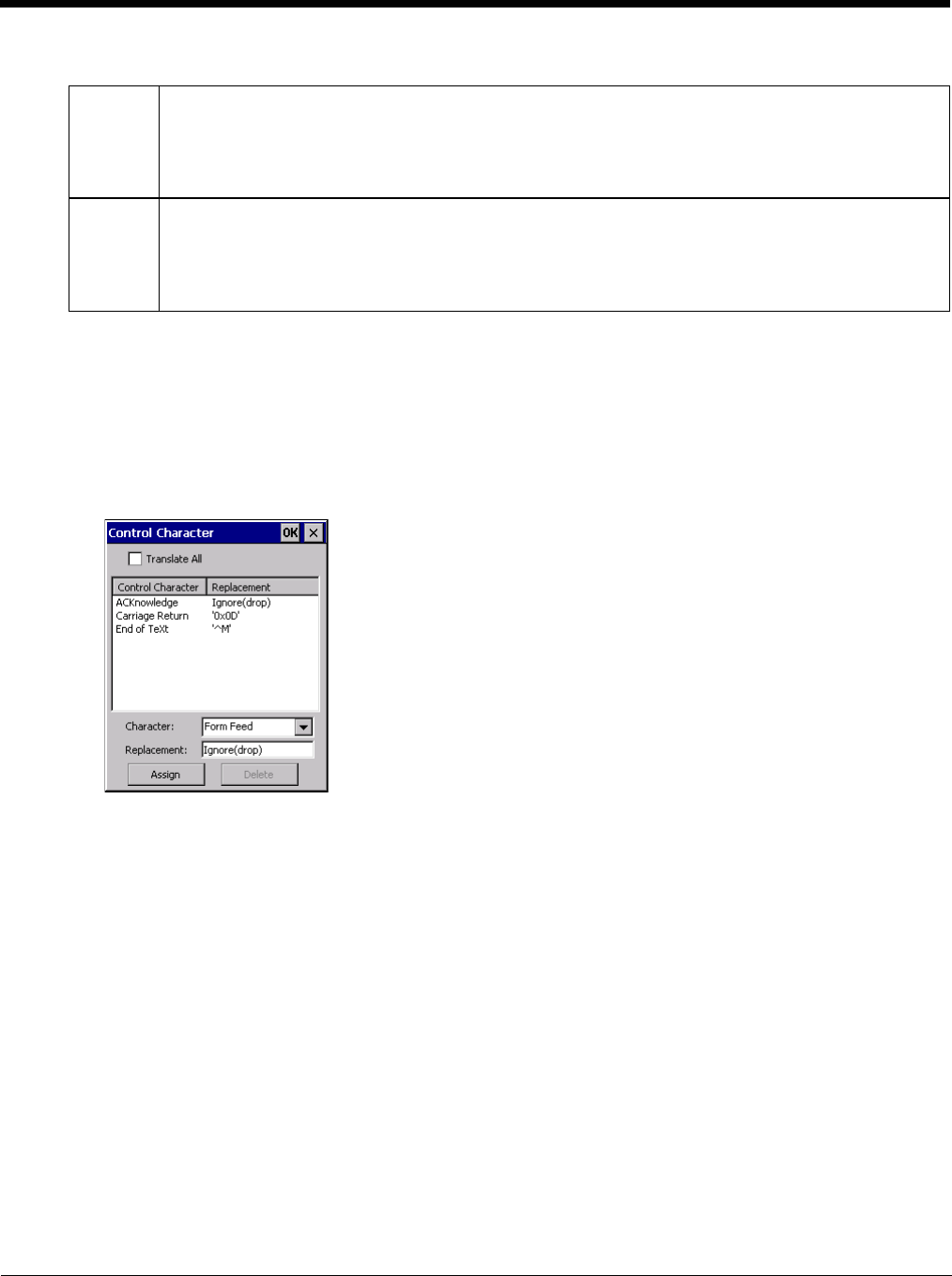
5 - 49
Use the Escape function to enter literal hex and hat values.
Note: Non-ASCII equivalent keys in Key Message mode are unavailable in this option. Non-ASCII equivalent keys
include the function keys (e.g. F1), arrow keys, Page up, Page down, Home, and End.
Symbologies
The Thor VM2 supports only Custom IDs.
Ctrl Char Mapping
The Ctrl Char Mapping button (Control Character Mapping) activates a dialog to define the operations the Data
Collection Wedge performs on control characters (values less than 0x20) embedded in bar codes.
Control characters can be replaced with user-defined text which can include hat encoded or hex encoded values.
In key message mode, control characters can also be translated to their control code equivalent key sequences.
Translate All
When Translate All is checked, unprintable ASCII characters (characters below 20H) in scanned bar codes
are assigned to their appropriate CTRL code sequence when the bar codes are sent in Character mode.
The wedge provides a one-to-one mapping of control characters to their equivalent control+character
sequence of keystrokes. If control characters are translated, the translation is performed on the bar code
data, prefix, and suffix before the keystrokes are simulated.
Parameters
Translate All
This option is grayed unless the user has Send Key Messages (WEDGE) on the Main tab selected.
In Key Message mode, when this option is enabled, control characters embedded in a scanned bar code
are translated to their equivalent control key keystroke sequence (13 [0x0d] is translated to Control+M
keystrokes as if the user pressed the CTRL, SHIFT, and m keys on the keypad).
Additionally, when Translate All is disabled, any control code which has a keystroke equivalent (enter, tab,
escape, backspace, etc.) is output as a keystroke.
Add Prefix To enable a prefix, check the Prefix checkbox and enter the desired string in the text box.
The default is disabled (unchecked) with a blank text string. When bar code data is processed, the Prefix
string is sent to the output buffer before any other data.
Because all stripping operations have already occurred, stripping settings do not affect the prefix. The
prefix is added to the output buffer for the Symbology selected from the pull-down list.
If ‘All’ is selected, the prefix is added for any symbology that has not been specifically configured.
Add Suffix To enable a suffix, check the Suffix checkbox and enter the desired string in the text box.
The default is disabled (unchecked) with a blank text string. When bar code data is processed, the Suffix
string is sent to the output buffer after the bar code data.
Because all stripping operations have already occurred, stripping settings do not affect the suffix. The suf-
fix is added to the output buffer for the Symbology selected from the pull-down list.
If ‘All’ is selected, the suffix is added for any symbology that has not been specifically configured.

5 - 50
Any control code without a keystroke equivalent is dropped.
Character
This is a drop down combo box that contains the control character name. Refer to the Character drop
down box for the list of control characters and their names.
When a character name is selected from the drop down box, the default text Ignore (drop) is shown and
highlighted in the Replacement edit control. Ignore (drop) is highlighted so the user can type a replace-
ment if the control character is not to be ignored.
Once the user types any character into the Replacement edit control, reselecting the character from the
Character drop down box redisplays the default Ignore (drop) in the Replacement edit control.
Replacement
The edit control where the user types the characters to be assigned as the replacement of the control
character.
Replacements for a control character are assigned by selecting the appropriate character from the Char-
acter drop down box, typing the replacement in the Replacement edit control (according to the formats
defined above) and then clicking the button. The assigned replacement is then added to the list box
above the Assign button.
For example, if Carriage Return is replaced by Line Feed (by specifying ^J or 0x0A) in the configuration,
the value 0x0d received in any scanned bar code (or defined in the prefix or suffix) will be replaced with
the value 0x0a.
The Wedge then sends Ctrl+J to the receiving application, rather than Ctrl+M.
List Box
The list box shows all user-defined control characters and their assigned replacements.
All replacements are enclosed in single quotes to delimit white space that has been assigned.
Assign Button
Click this button when you want to assign the characters in the Replacement text box to the character in the
Character drop down box.
Delete Button
This button is grayed unless an entry in the list box is highlighted.
When an entry (or entries) is highlighted, and the Delete button is clicked, the highlighted material is deleted
from the list box.
Custom Identifiers
Code IDs are defined by the user for external bar code scanners. These are called custom Code IDs and are
included in the Symbology drop down box in the Symbology dialog, unless Enable Code ID is set to None. When
the custom Code ID is found in a bar code, the configuration specified for the custom Code ID is applied to the bar
code data.
When Enable Code ID is set to None, custom code IDs are ignored.
Note: When Strip: Code ID is enabled, the entire custom Code ID string is stripped (i.e., treated as a Code ID).

5 - 51
The dialog box shown below allows the custom Code IDs to be configured. When incoming data is checked for a
custom ID code, the list is compared in the order displayed in this dialog box.
After adding, changing and removing items from the Custom IDs list, click the OK button to save changes and
return to the Bar Code panel.
Parameters
Name text box
Name is the descriptor that is used to identify the custom Code ID. Names must be unique from each
other; however, the Name and ID Code may have the same value. Name is used in the Symbology drop
down box to identify the custom Code ID in a user-friendly manner. Both Name and ID Code must be
specified in order to add a custom Code ID to the Custom IDs list.
ID Code text box
ID Code defines the data at the beginning of a bar code that acts as an identifier (the actual Code ID).
Both Name and ID Code must be specified in order to add a custom Code ID to the Custom IDs list.
Buttons
Add
Entering data into both the Name and ID Code fields enables the Add button. Click the Add button and
the data is added to the next empty location in the Custom ID list.
Insert
Click on an empty line in the Custom ID list. The Add button changes to Insert. Enter data into both the
Name and ID Code fields and click the Insert button. The data is added to the selected line in the Cus-
tom IDs list.
Edit
Double-click on the item to edit. Its values are copied to the text boxes for editing. The Add button
changes to Replace. When Replace is clicked, the values for the current item in the list are updated.
Clear All
When no item in the Custom IDs list is selected, clicking the Clear All button clears the Custom ID list and
any text written (and not yet added or inserted) in the Name and ID Code text boxes.
Remove
The Clear All button text changes to a Remove button when an item in the Custom IDs list is selected.
Click the desired line item and then click the Remove button to delete it. Line items are Removed one at
a time. Contents of the text box fields are cleared at the same time.

5 - 52
Control Code Replacement Examples
See Hat Encoding (page 10-13).
Bar Code Processing Examples
The following table shows examples of stripping and prefix/suffix configurations.
Configuration
Data
Translation Example
Control
Character
Example
Configuration
Translated Data
Ignore (drop) The control character is dis-
carded from the bar code da-
ta, prefix and suffix
ESCape Ignore (drop) 0x1B in the bar code is
discarded.
Printable text Text is substituted for Control
Character. Start of TeXt STX 0x02 in a bar code is con-
verted to the text STX.
Hat-encoded text The hat-encoded text is trans-
lated to the equivalent hex
value.
Carriage Re-
turn ^M Value 0x0d in a bar code
is converted to the value
0x0d.
Escaped hat-en-
coded text The hat-encoding to pass
through to the application. Horizontal Tab \^I Value 0x09 in a bar code
is converted to the text ^I.
Hex-encoded
text The hex-encoded text is
translated to the equivalent
hex value.
Carriage Re-
turn 0x0A Value 0x0D in a bar code
is converted to a value
0x0A.
Escaped hex-en-
coded text The hex-encoding to pass
through to the application. Vertical Tab \0x0A or 0\x0A Value 0x0C is a bar code
is converted to text 0x0A
Symbology
All EAN-128(]C1) EAN-13(]E0) Intrlv 2 of 5(]IO) Code93
Enable Enabled Enabled Enabled Enabled Disabled
Min length 1 4 1 1
Max length all all all 10
Strip Code ID Enabled Enabled Disabled Enabled
Strip Leading 3 0 3 3
Strip Bar Code Data *123 1* 456
Strip Trailing 0 0 3 3
Prefix aaa bbb ccc ddd
Suffix www xxx yyy zzz
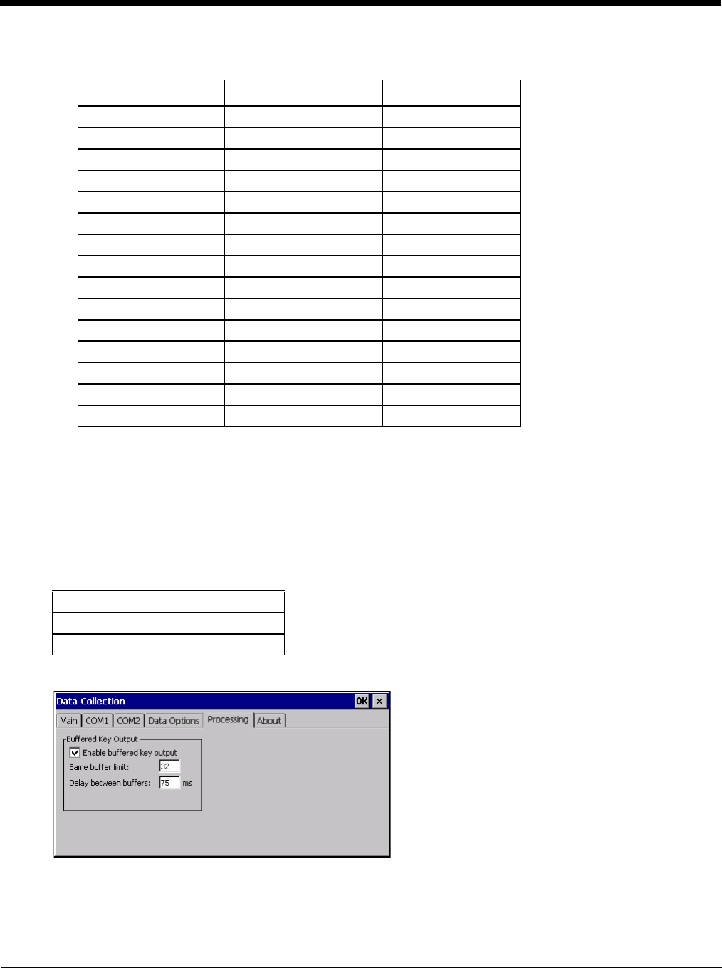
5 - 53
Provided that the wedge is configured with the above table, below are examples of scanned bar code data and
results of these manipulations.
Note: Rejected bar codes generate a bad scan beep. In some cases, the receipt of data from the scanner triggers
a good scan beep (from the external scanner), and then the rejection of scanned bar code data by the
processing causes a bad scan beep on the same data.
Processing
Start > Settings > Control Panel > Data Collection > Processing tab
The Processing tab contains a user configurable key delay that applies to scanned bar codes as they are input when
Remote Desktop is the application with the input focus.
Factory Default Settings
Note: Settings on this panel have no effect when RFTerm is the application with the input focus.
Enable buffered key output
Default is enabled (checked). Click the checkbox to turn off buffered key output.
Bar Code Symbology Raw Scanner Data Resulting Data
EAN-128 ]C11234567890123 bbb1234567890xxx
EAN-128 ]C111234567890123 bbb11234567890xxx
EAN-128 ]C1123 < rejected > (too short)
EAN-13 ]E01234567890987 ccc]E04567890yyy
EAN-13 ]E01231234567890987 ccc]E0234567890yyy
EAN-13 ]E01234 ccc]E0yyy
I2/5 ]I04444567890987654321 < rejected > (too long)
I2/5 ]I04444567890123 ddd7890zzz
I2/5 ]I0444 dddzzz
I2/5 ]I022245622 ddd45zzz
Code-93 ]G0123456 < rejected > (disabled)
Code-93 ]G0444444 < rejected > (disabled)
Code-39 ]A01234567890 aaa4567890www
Code-39 full ASCII ]A41231234567890 aaa1234567890www
Code-39 ]A4 < rejected > (too short)
Enable buffered key output Enabled
Same buffer limit (characters) 32
Delay between (key) buffers 75 ms
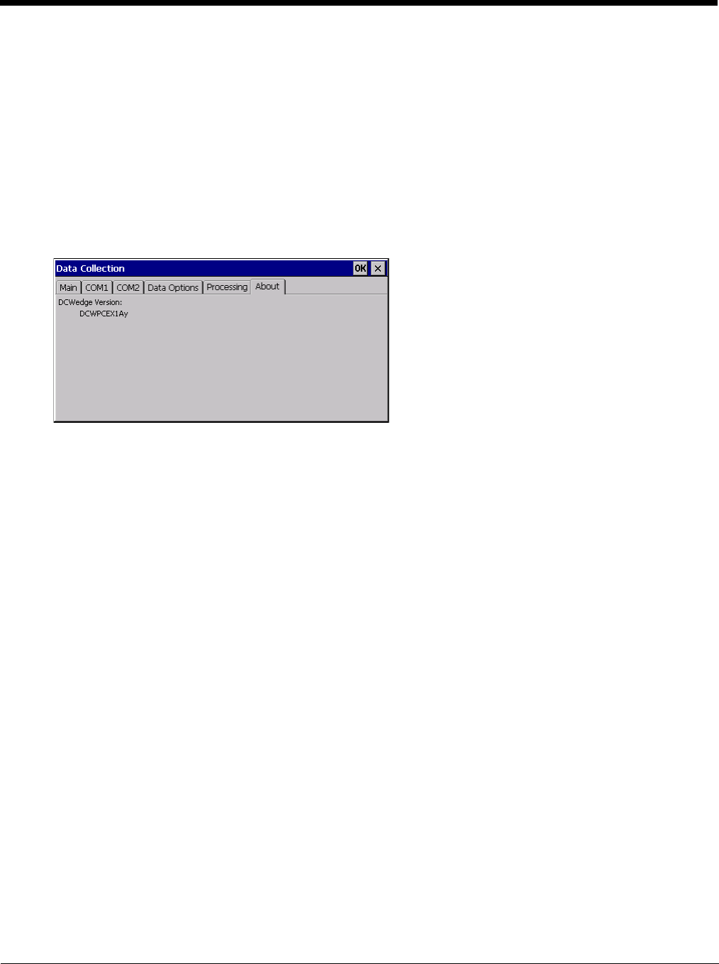
5 - 54
Same buffer limit
Default is 32 ms. Raise or lower this value as desired.
Delay between (key) buffers
Specifies the number of milliseconds to delay after each character in the scanned bar code is processed as a key-
stroke. This value may need to be adjusted depending on the network traffic in the environment. The default
value is 75 ms. Valid value is from 0 to 9999. A zero value is No Delay between characters.
About
Start > Settings > Control Panel > Data Collection > About tab
This tab displays the Data Collection Wedge driver version installed in the Thor VM2. The version number shown in
the image below is used only as an example, your version number will be different.
Length Based Bar Code Stripping
Use this procedure to create symbology rules for two bar codes with the same symbology but with different discrete
lengths. This procedure is not applicable for bar codes with variable lengths (falling between a maximum value and a
minimum value).
Example
For the purposes of this example, the following sample bar code parameters will be used – EAN 128 and Code
128 bar codes. Some of the bar codes start with ‘00’ and some start with ‘01’. The bar codes are different
lengths.
• 34 character length with first two characters = “01” (strip first 2 and last 18)
• 26 character length with first two characters = “01” (strip first 2 and last 10)
• 24 character length with first two characters = “01” (strip first 2 and last 8). This 24 character bar code is Code
128.
• 20 character length with first two characters = “00” (strip first 0 (no characters) and last 4)
On the Data Options tab, set Enable Code ID to Custom.
Create four custom IDs, using 1 for EAN 128 bar code and 0 for Code 128 bar code.
• c1 = Code = ‘]C1’
• c2 = Code = ‘]C1’
• c3 = Code = ‘]C0’ (24 character bar code is Code 128)
• c4 = Code = ‘]C1’
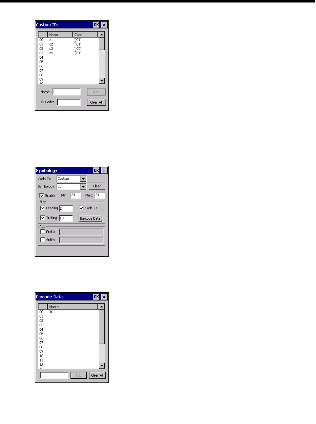
5 - 55
Custom symbology setup is assigned in the following manner:
• c1 min length = 34, max length = 34, strip leading 2, strip trailing 18, Code ID enabled, Bar Code Data = “01”
• c2 min length = 26, max length = 26, strip leading 2, strip trailing 10, Code ID enabled, Bar Code Data = “01”
• c3 min length = 24, max length = 24, strip leading 2, strip trailing 8, Code ID enabled, Bar Code Data = “01”
• c4 min length = 20, max length = 20, strip leading 0, strip trailing 4, Code ID enabled, Bar Code Data = “00”
Add the custom symbologies. Refer to the previous section Symbology Settings for instruction.
Click the Bar Code Data button.
Click the Add button.
Add the data for the match codes.
See Bar Code Data Match List (page 5-47) for instruction.
Scan a bar code and examine the result.
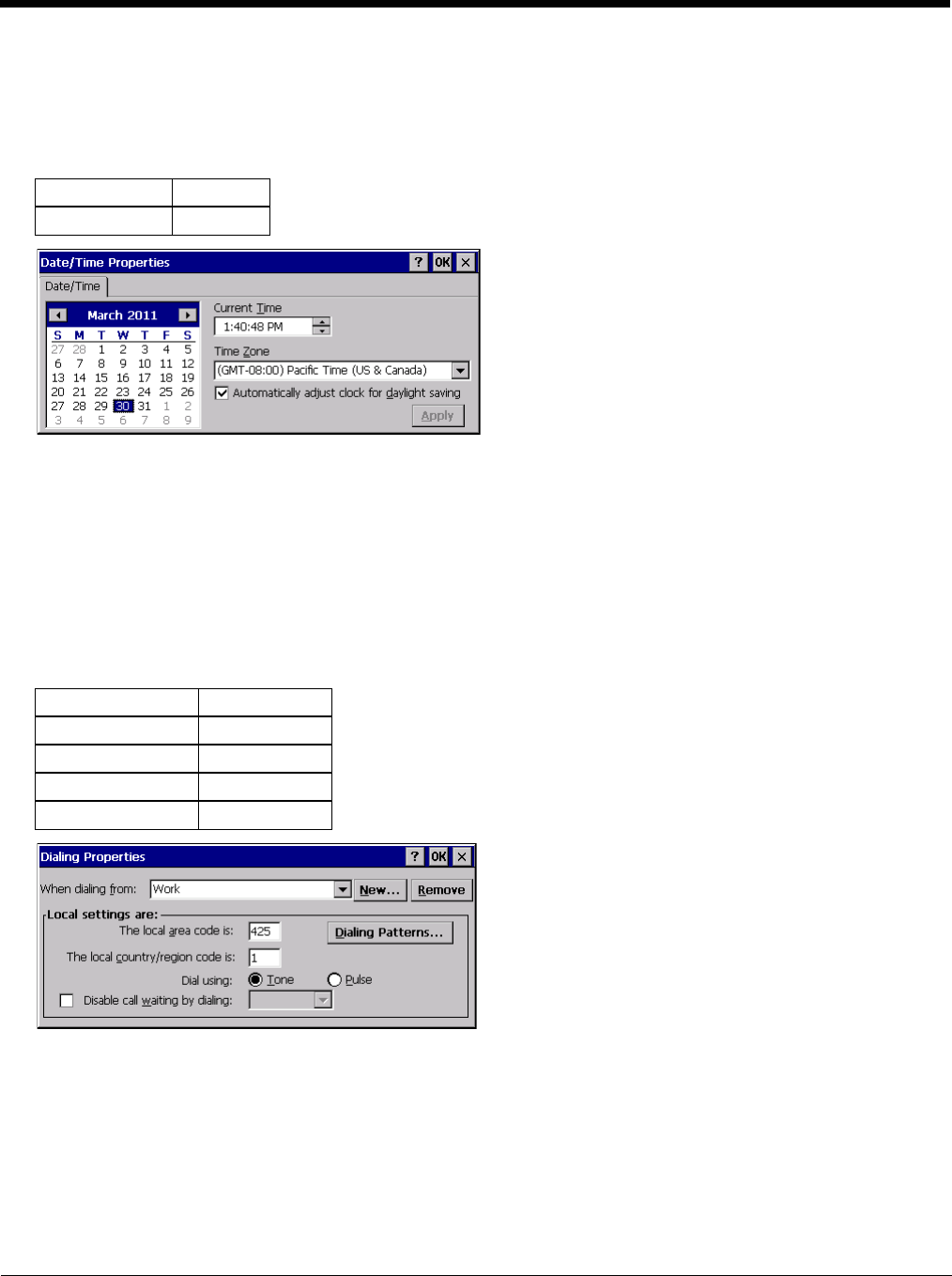
5 - 56
Date / Time
Start > Settings > Control Panel > Date/Time - or - Time in Desktop Taskbar
Use this Thor VM2 panel to set Date, Time, Time Zone, and assign a Daylight Savings location.
Factory Default Settings
There is very little functional change from general desktop or laptop Date/Time Properties options.
Double-tapping the time displayed in the Desktop Taskbar causes the Date/Time Properties screen to appear.
Date and time can be set to automatically synchronize with a time server on the Communications tab of the Options control
panel. See Autolaunch TimeSync (page 5-74).
Dialing
Start > Settings > Control Panel > Dialing
Set dialup properties for internal modems (not supplied or supported on the Thor VM2).
Factory Default Settings
Time Zone GMT-08:00
Daylight Savings Enabled
Location Work
Area Code 425
Tone Dialing Enabled
Country/Region 1
Disable Call Waiting Disabled (blank)
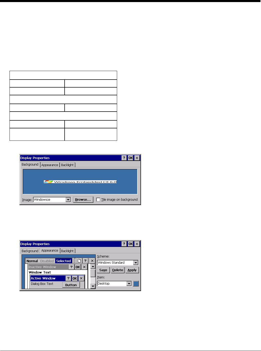
5 - 57
Display
Start > Settings > Control Panel > Display
The display might also called the touch screen.
Select the desktop background image and appearance scheme for the Thor VM2. Using the options on the Backlight tab,
set the display backlight and keypad backlight timers when running on battery or external power.
Adjust the settings and tap the OK button to save the changes. Saved changes take effect immediately.
Factory Default Settings
Background
There is very little change from general desktop PC Display Properties / Background options. Select an image from
the dropdown list (or tap the Browse button to select an image from another folder) to display on the Desktop, and then
tap the OK button to save the change. The change takes effect immediately.
Appearance
There is very little change from general desktop PC Appearance options. Select a scheme from the dropdown list and
make changes to the parameters. The default is High Contrast White for monochrome displays and Windows Stan-
dard for color displays. Tap the Save button to save any changes, renaming the scheme if desired. Tap the Delete but-
ton to delete schemes. Tap the Apply button to apply the selected scheme to the display.
Background (page 5-57)
Image Windows CE
Image on background Disabled
Appearance (page 5-57)
Schemes Windows Standard
Backlight (page 5-58)
Battery power 30 seconds
External power Varies by Power Config-
uration Mode selected

5 - 58
Backlight
When the backlight timer expires, the touch screen backlight is dimmed, not turned off. When both checkboxes are
unchecked, the backlight never turns off (or dims).
The default value for external power varies by Power Configuration Mode (page 5-80) selected (and for Ignition Con-
trol, the status of the vehicle ignition). The default value is 30 seconds when operating on the internal UPS battery.

5 - 59
Gobi Connection Manager
Start > Settings > Control Panel > Gobi Connection Manager or
Tap the Gobi Connection Manager Desktop Icon or
Tap the Gobi Connection Manager icon in the system tray or
Tap Start > Programs > GobiCM > GobiCMExe
Set parameters for optional internal WWAN module.
The Gobi Connection Manager tray icon indicates the status of the connection in dark blue bars. If you hover the mouse
pointer over the Connection Manager Taskbar icon, the current signal level and radio interface are displayed.
Note: The similar Summit Wi-Fi icon in the task bar uses red, yellow and green bars.
Initial Use
Some carriers such as AT&T and T-Mobile require a SIM card for use on their networks. Other carriers such as Verizon
use a CDMA network and must be activated. Please refer to the sections below for more details.
SIM Card Installation
Depending on the carrier, a SIM card may be necessary for WWAN connection. To install a SIM card:
1. Place the Thor VM2 in Suspend.
2. Remove the Thor VM2 from the Quick Mount Smart Dock.
3. Place the Thor VM2 face down on a stable surface.
4. Use a Phillips screwdriver (not supplied) loosen the screws and then remove the tethered access panel with
the SIM label. This panel is on the right hand side when the Thor VM2 is face down with the top away from
the user.
5. Install the SIM card in the slot.
6. Reattach the access panel, torquing the screws to 4 to 5 inch pounds.
7. Reinstall the Thor VM2 in the dock.
8. Resume the Thor VM2 from suspend.
9. If the SIM card requires a PIN or PUK, a warning message may be displayed. Dismiss the warning message
and enter the PIN or PUK on the Admin (page 5-64) tab.
Home (page 5-60) View connection status and select firmware.
CDMA (page 5-61) Use this tab to activate a CDMA carrier such as Verizon.
UTMS (page 5-62) Use this tab to test and save connection parameters.
GPS (page 5-63) View GPS statistics.
Admin (page 5-64) Enter PIN or PUK for SIM card.
About (page 5-65) View information on the WWAN card.
There is no WWAN connection present.
-105 dbm to -86 dbm signal strength
-85 dbm to -66 dbm signal strength
-65 dbm to -46 dbm signal strength
-45 dbm or higher signal strength
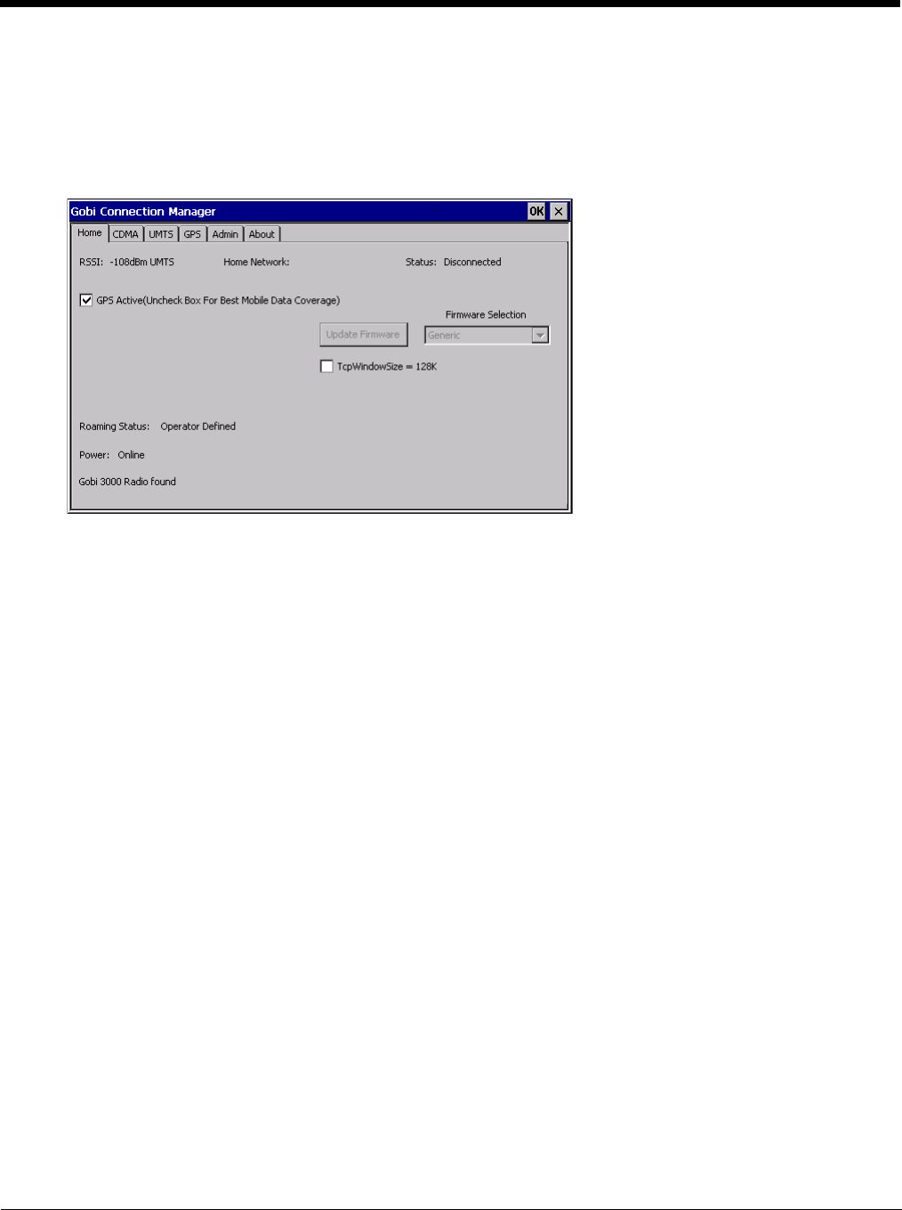
5 - 60
Activate
To activate service for a CDMA carrier such as Verizon, complete the necessary entries on the CDMA (page 5-61)
tab.
Home
Use the Home tab to update firmware and view the status of the connection.
To update firmware:
1. Select the firmware for the desired carrier from the Firmware Selection pull-down list.
2. If no firmware files are found, an error message is displayed. Contact Technical Assistance (page 11-1) for infor-
mation.
3. Tap the Update Firmware button.
4. The update process may take a minute or so to complete.
The status of the Gobi 2000 radio is displayed in the lower left corner of this tab. An error message is displayed in this
location if the firmware selected requires a SIM card and no SIM card is installed in the Thor VM2.
Connection status is at the top of this tab.
GPS Active
When the GPS Active checkbox is checked, the GPS is activated. This is the default behavior.
• When GPS is active, the WWAN radio cannot use antenna diversity and WWAN coverage may be reduced.
• When GPS in inactive, the WWAN radio can use antenna diversity for best WWAN coverage.
When GPS is in use or a WWAN connection is established, this option is inactive (grayed out) and cannot be
changed.
1. Use the Stop button on the GPS tab to stop the GPS connection.
2. Use the CDMA tab or the UMTS tab to disconnect the WWAN connection.
Once both GPS and WWAN are disconnected, the checkbox is active.
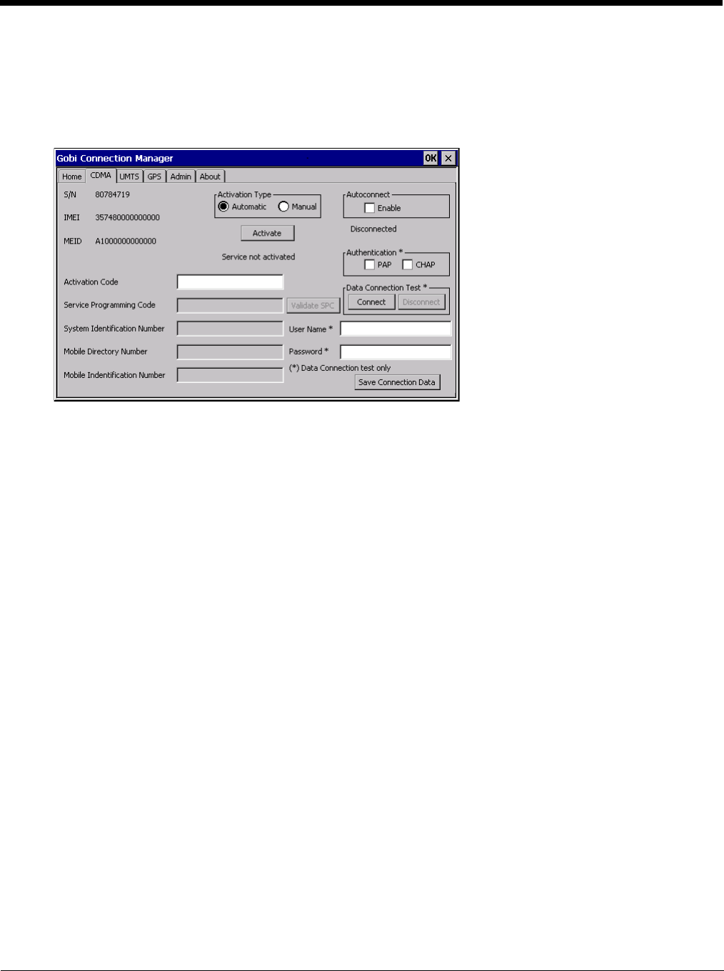
5 - 61
CDMA
Use the CDMA tab to activate the Thor VM2 for use with a CDMA carrier such as Verizon. This step is not necessary
for carriers using a SIM card.
The Serial Number, IMEI (International Mobile Equipment Identity) and MEID (Mobile Equipment ID) numbers are dis-
played on this tab as the carrier may request this information when setting up an account.
Activation Type
There are two activation methods, Automatic and Manual.
Automatic Activation
1. Select the Automatic radio button for Activation Type.
2. Automatic activation requires an Activation Code. Enter the Activation Code in the Activation Code text
box
3. Tap Save Connection Data.
4. Tap Activate.
5. All other text boxes are grayed out as no additional entries are required for automatic activation.
6. Verify the activation process is successful by reviewing the message below the Activate button.
Manual Activation
1. Select the Manual radio button for Activation Type.
2. Enter the Service Programming Code, System Identification number, Mobile Directory number and
Mobile Identification Number in the appropriate text boxes. The Activation Code text box is not used.
3. Tap Save Connection Data.
4. Tap Activate.
5. Verify the activation process is successful by reviewing the message below the Activate button.
Autoconnect
When checked, Autoconnect is enabled. The Connection Manager automatically connect when necessary, such
as when Internet Explorer is launched.
Data Connection Test
Tap the Connect button to make a temporary test connection to validate the carrier account.
Entries identified with an asterisk (*) are used to configure the test connection.
Tap the Save Connection Data button to save the connection parameters.
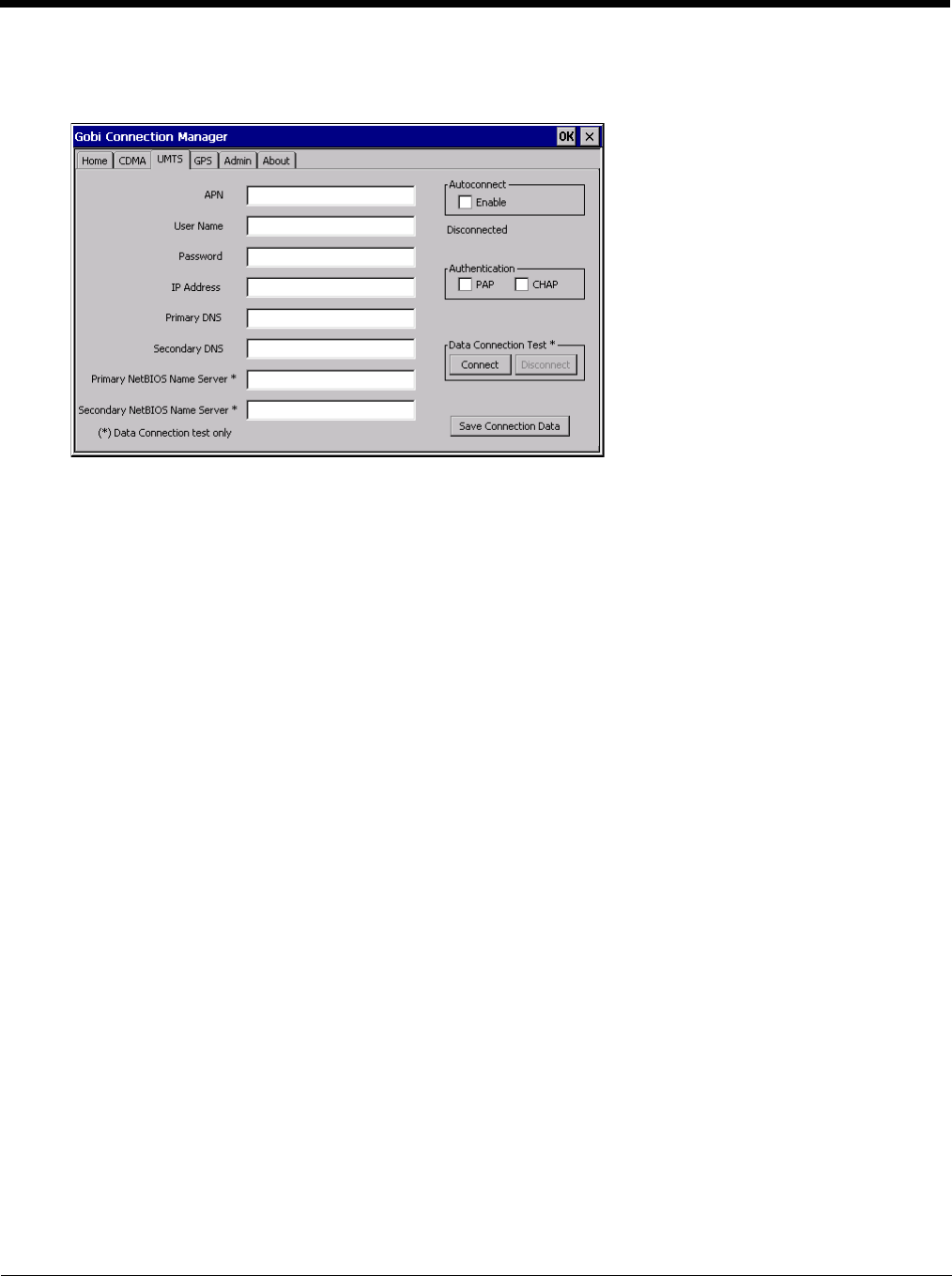
5 - 62
UTMS
Use the UTMS tab to configure the session parameters.
Autoconnect
When checked, Autoconnect is enabled. The Connection Manager automatically connects when necessary, such
as when Internet Explorer is launched.
Data Connection Test
Tap the Connect button to make a temporary test connection to validate the carrier account.
Entries identified with an asterisk (*) are used to configure the test connection.
Tap the Save Connection Data button to save the connection parameters.
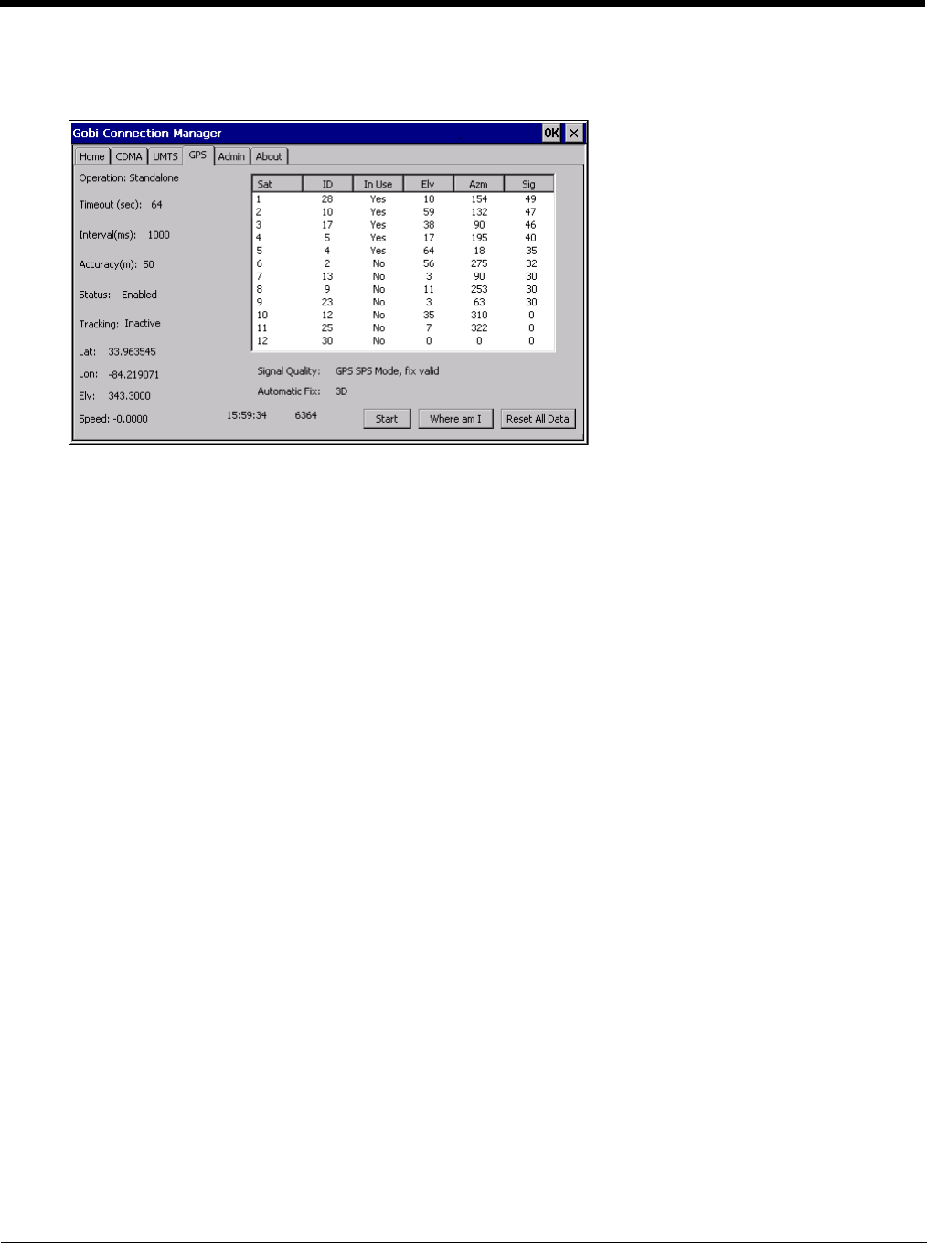
5 - 63
GPS
This tab displays the information available from the GPS built into the Gobi radio.
Tap the Start button to initiate a scan for GPS data. The information on this tab is updated every 3 seconds.
Tap the Reset All Data button to clear all GPS data from the Gobi radio. You must confirm that you want to rest the
data. Use this button with caution as it takes a longer time for the GPS to establish a valid fix after the data is cleared.
After the GPS establishes a coordinate fix, the Where am I button is active. Tapping this button activates Internet
Explore to display a Google map of the current location.
The GPS time and NMEA (National Maritime Electronics Association) string count are displayed at the bottom of this
tab.
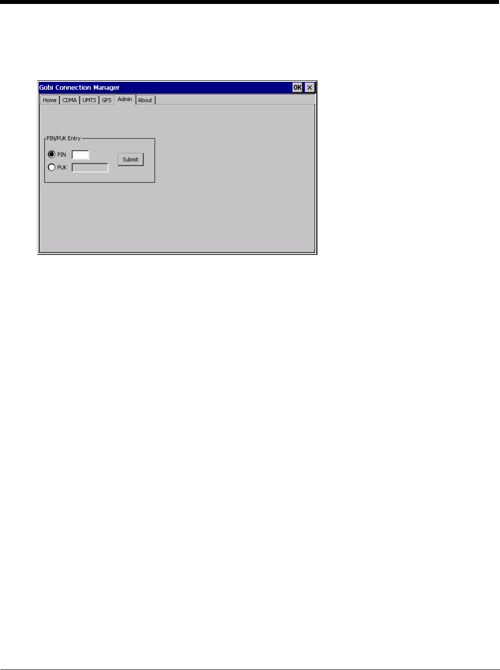
5 - 64
Admin
This tab allows for entry of a PIN or PUK for the SIM card.
The PIN or PUK entered on this tab is stored in the Thor VM2 registry.
PIN (Personal Identification Number)
The PIN is a unique sequence of numbers stored on the SIM card.
If the radio is enabled and the SIM card requires a PIN, a connection will not occur until the PIN is entered suc-
cessfully. After entering the PIN code, tap the Submit button. A message is displayed with either Success or the
number of retries allowed before the SIM card PIN number entry is locked from further use.
PUK (Personal Unblocking Key)
The PUK is a unique sequence of alpha characters displayed on the SIM card. A default PUK code is not avail-
able. After entering the PUK code, tap the Submit button. A message is displayed with either Success or the
number of retries allowed before the SIM card PUK entry is locked from further use.
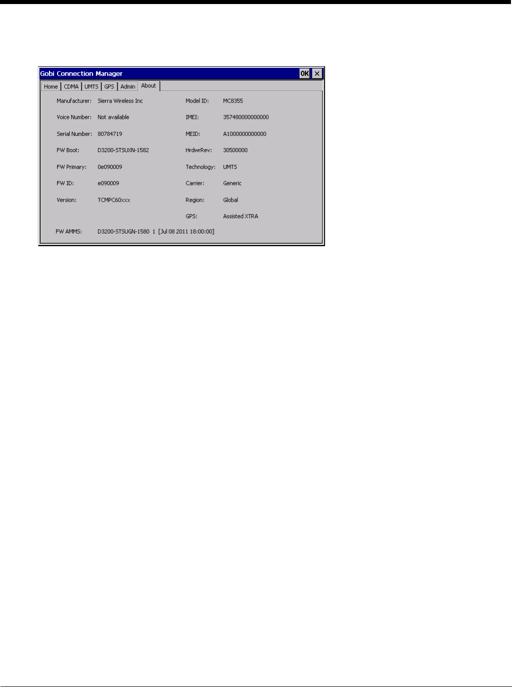
5 - 65
About
This tab displays information on the Gobi 3000 radio installed in the Thor VM2.
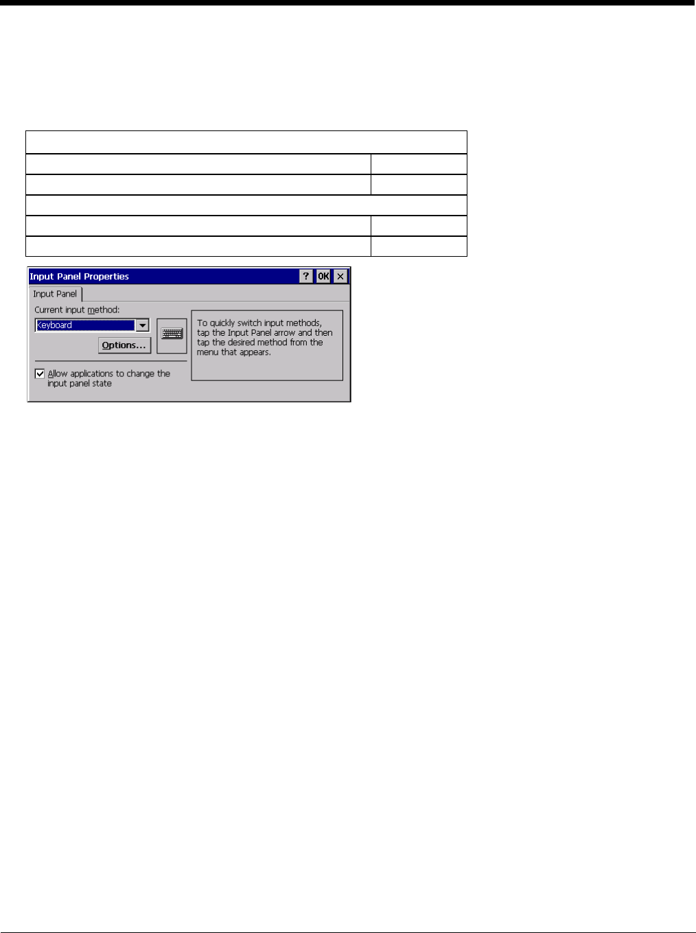
5 - 66
Input Panel
Start > Settings > Control Panel > Input Panel
Set the current Thor VM2 keys and data input method.
Factory Default Settings
Use this panel to make the Input Panel (on-screen keyboard) or the physical keypad primarily available when entering data
on any screen. Selecting Keyboard enables both.
Tap the Options button to set the size of the keys displayed on-screen and whether Transcriber gestures are enabled or dis-
abled.
Transcriber
When choosing Transcriber as the Current Input Method, first tap the Keyboard icon in the status bar. Select Tran-
scriber from the pop-up menu. Then open the Input control panel and tap the Options button. Transcriber Options
(Start > Settings > Control Panel > Input Panel) are available only when Transcriber is selected as the active input
method. Tap the “?” button or the Help button to access Transcriber Help.
Input Panel
Input Method Keyboard
Allow applications to change input panel state Enabled
Options button
Keys Small keys
Use gestures Disabled

5 - 67
Internet Options
Start > Settings > Control Panel > Internet Options
Set options for Thor VM2 Internet connectivity.
Select a tab. Tap the ? button for help using Windows CE Help installed in your mobile device. Adjust the settings and tap
the OK button. The changes take effect immediately.
Factory Default Settings
General
Start Page http://www.msn.com
Search Page http://search.msn.com
User Agent Windows CE
Cache Size 512 KB
Delete History Button enabled
Connection
Use LAN Disabled
Autodial Name USB Client
Proxy Server Disabled
Bypass Proxy Disabled
Security
Internet Default site
Privacy tab
First party cookies Accept
Third party cookies Prompt
Session cookies Always allow
Advanced
Stylesheets Enabled
Theming Support Enable
Multimedia All options enabled
Security All options enabled
Popups
Block popups Disabled
Display notification Enabled
Use same window Disabled
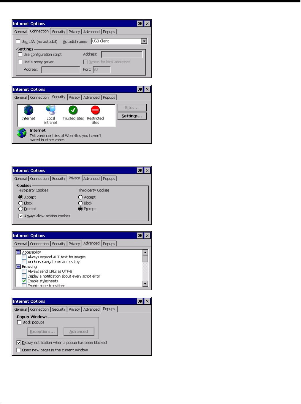
5 - 68
Security Tab: Use the Settings button to set ActiveX control, scripting and plug-in behavior for each zone (Internet, Local
intranet, Trusted Sites, Restricted Sites). Use the Site button to add sites to each zone.
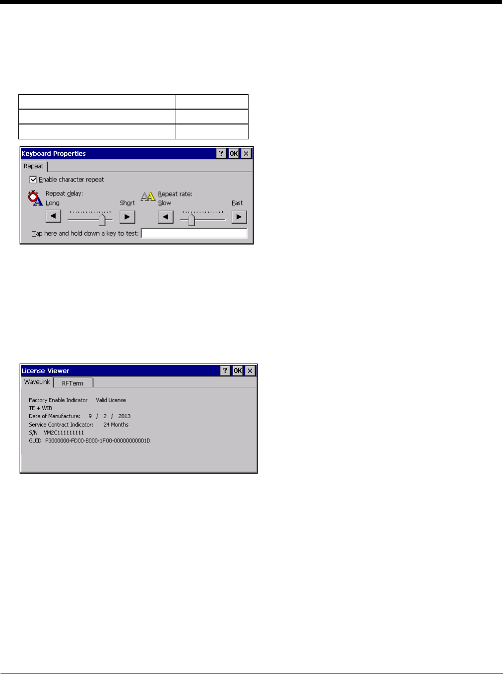
5 - 69
Keyboard
Start > Settings > Control Panel > Keyboard
Set keypad key map, keypad key repeat delay, and key repeat rate.
Factory Default Settings
License Viewer
Start > Settings > Control Panel > License Viewer
Use this option to view software license registration details, and service contract length for the Thor VM2. Information on
the License Viewer tabs is unique for each Thor VM2.
Note: Following image is a sample screen.
Your License Viewer control panel may show more tabs, e.g., RFTerm, depending on the number of software applications
running on the Thor VM2 that require a license.
Repeat character Enable
Repeat Delay Short
Repeat Rate Slow
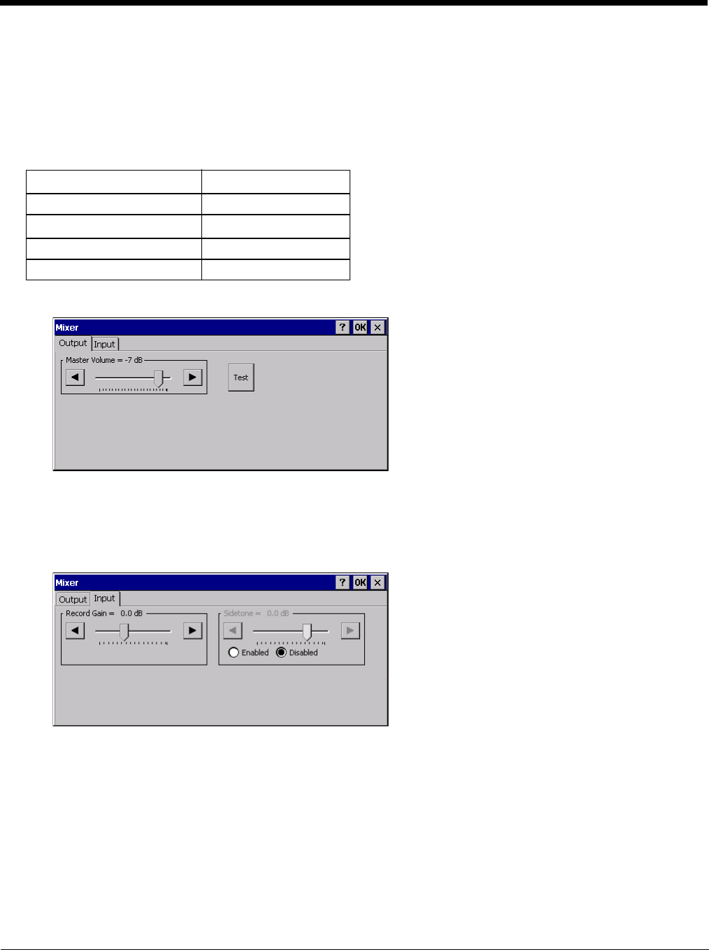
5 - 70
Mixer
Start > Settings > Control Panel > Mixer
The Thor VM2 has two speakers (located at the bottom front of the unit) and one microphone (located at the top front of the
unit).
Use the settings on these panels to adjust the master volume, record gain and sidetone.
Factory Default Settings
Output Panel
Tap and hold the Master Volume slider and move either left or right, or tap the left and right arrows, to adjust Speaker
volume decibel level.
Tap the Test button to play a sample sound at the selected volume.
Input Panel
Use the radio buttons to enable or disable the sidetone.
Tap and hold the Record Gain or Sidetone sliders and move either left or right, or tap the left and right arrows, to adjust
the levels.
Output
Master Volume -7 dB
Input
Record Gain 0.0 dB
Sidetone Disabled
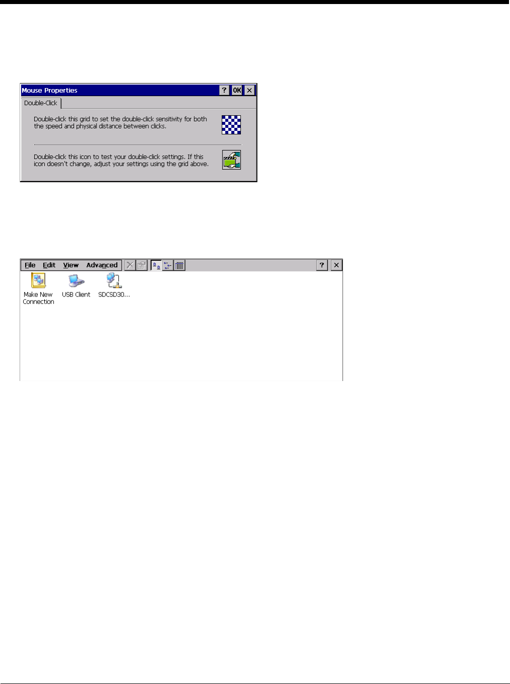
5 - 71
Mouse
Start > Settings > Control Panel > Mouse
Use this option to set the double-tap sensitivity for stylus taps on the Thor VM2 touch screen.
Network and Dialup Connections
Start > Settings > Control Panel > Network and Dialup Connections
Set Thor VM2 network driver properties and network access properties. Select a connection to use, or create a new con-
nection.
Create a New Connection
1. On the mobile device, select Start > Settings > Control Panel > Network and Dialup Connections. A window
is displayed showing the existing connections.
2. Assuming the connection you want does not exist, double-tap Make New Connection.
3. Give the new connection an appropriate name (My Connection @ 9600, etc.). Tap the Direct Connection radio
button. Tap the Next button.
4. From the popup menu, choose the port you want to connect to. Only the available ports are shown.
5. Tap the Configure... button.
6. Under the Port Settings tab, choose the appropriate baud rate. Data bits, parity, and stop bits remain at 8, none,
and 1, respectively.
7. Under the Call Options tab, be sure to turn off Wait for dial tone, since a direct connection will not have a dial
tone. Set the timeout parameter (default is 5 seconds). Tap OK.
8. TCP/IP Settings should not need to change from defaults. Tap the Finish button to create the new connection.
9. Close the Remote Networking window.
10. To activate the new connection select Start > Settings > Control Panel > PC Connection and tap the Change
Connection… button.
11. Select the new connection. Tap OK twice.
12. Close the Control Panel window.
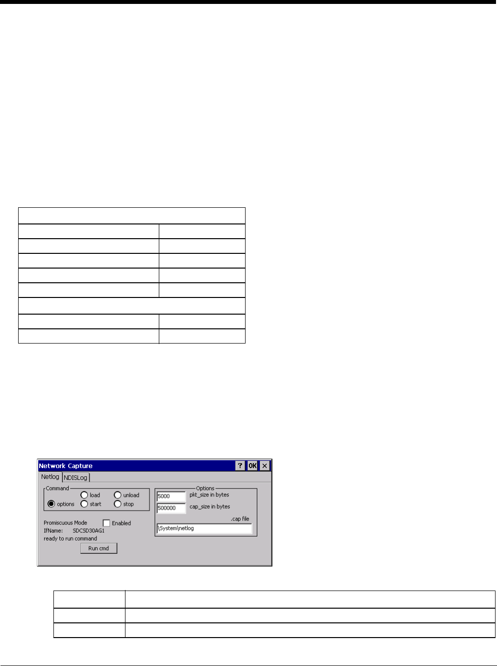
5 - 72
13. Connect the desktop PC to the mobile device with the appropriate cable.
14. Click the desktop Connect icon to test the new connection.
You can activate the connection by double-tapping on the specific connection icon in the Remote Networking window,
but this will only start an RAS (Remote Access Services) session, and does not start ActiveSync properly.
Network Capture
Start > Settings > Control Panel > Network Capture
Note: Verify the Date / Time (page 5-56) before using the logging utilities to ensure meaningful data.
The Network Capture panels provide configuration options for logging utilities. Two types of logging are configurable:
• Netlog is a Windows CE utility that monitors network traffic. Netlog creates a .CAP file that can be read using Microsoft
Windows Network Monitor or any compatible tool that supports .CAP files.
• NDISLog monitors the NDIS interface between the Summit radio and the NDIS driver. This utility creates a .TXT log file.
Factory Default Settings
Netlog
Use this control panel to configure the Netlog utility. By configuring Netlog using the control panel, Netlog remains run-
ning across a warmboot. However, please note that:
• Netlog first stores data to a file named netlog0.cap, then netlog1.cap. Any time the current file reaches maximum
size, Netlog switches to the other file.
• If the log file is stored in the root directory, any previous data is lost and a new log file started after the warmboot
• If the log file is stored in \System, all previous data is saved across the warmboot.
• If Netlog is enabled across the warmboot, a series of brief popups may be displayed during the boot cycle. No user
interaction is required.
Command
Netlog (page 5-72)
Command options
pkt_size in bytes 5000
cap_size in bytes 500000
.cap file \netlog
Promiscuous Mode Disabled
NDISLog (page 5-73)
Command stop
file \ndislog.txt
Command Function
options Specifies the option to perform. See the table below for the option parameters and values.
load Loads and starts Netlog.
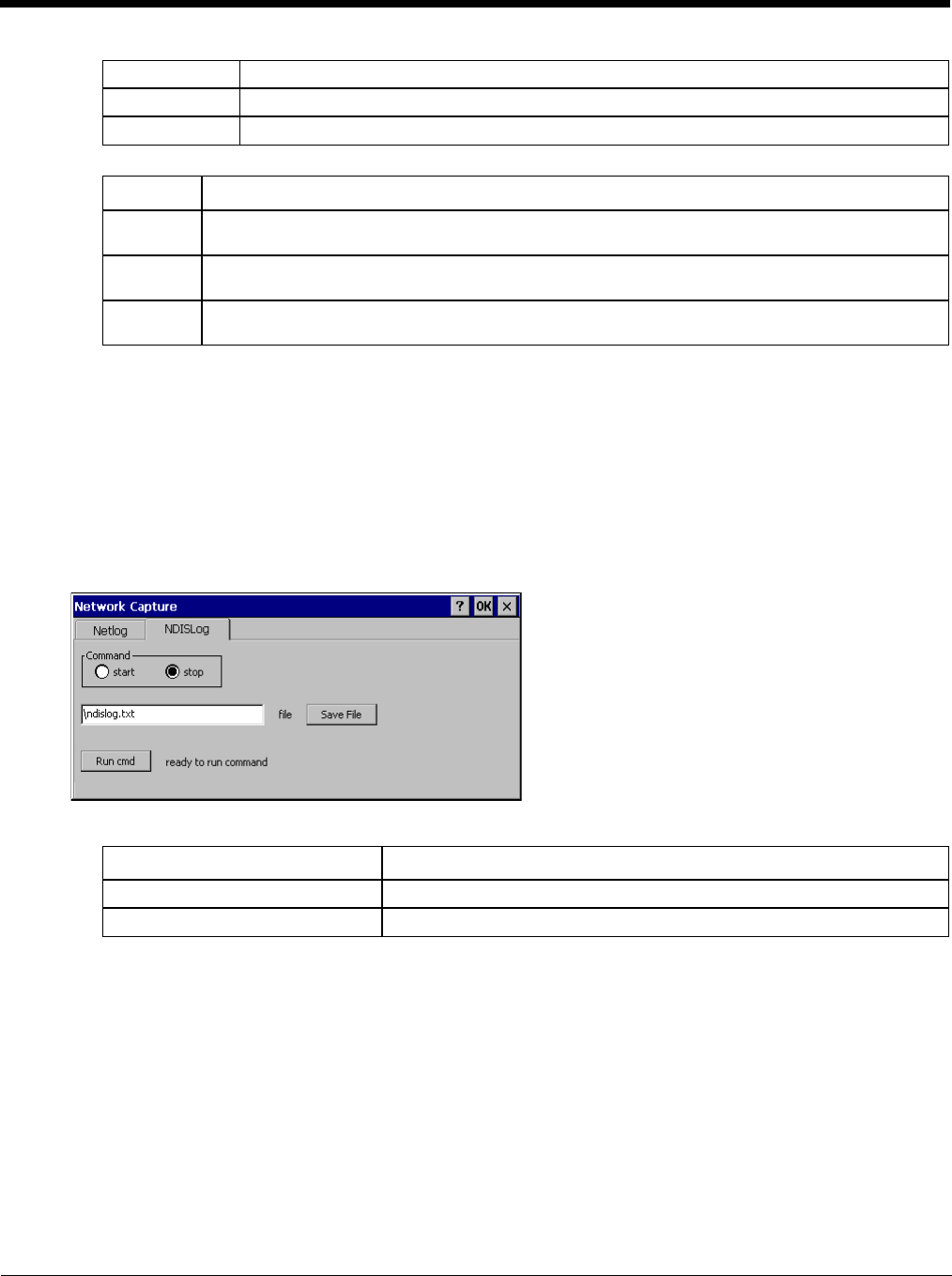
5 - 73
Options
Run cmd
Performs the command selected. For example, to run Netlog and modify the packet size do the following:
1. Select load from the Commands list and click the Run cmd button.
2. Select stop from the Commands list and click the Run cmd button.
3. Select options from the Commands list, enter the new packet size in the Options list and click the Run cmd
button.
NDISLog
NDISLog creates a .TXT file that can be viewed with any text editor program that supports .TXT files.
Command
file
Specifies the name of the file to which NDISLog information is stored.
Save File
Stores the file name.
Run cmd
Performs the selected start or stop command.
start Starts the Netlog process of logging the network traffic.
stop Stops Netlog from logging network traffic.
unload Unloads Netlog.
Options Function
pkt_size in
bytes Specifies the maximum packet size captured in bytes. This option should only be run after you have
called load and stop. Default is 5000.
cap_size in
bytes Specifies the maximum size of Netlog0.cap or Netlog1.cap in bytes. This option should only be run
after you have called load and stop. Default is 500,000.
.cap file Specifies the name of the file to which network traffic information is saved. This option should only
be run after you have called load and stop. Default is \netlog.
Command Function
start Starts logging the network traffic.
stop Stops logging network traffic.
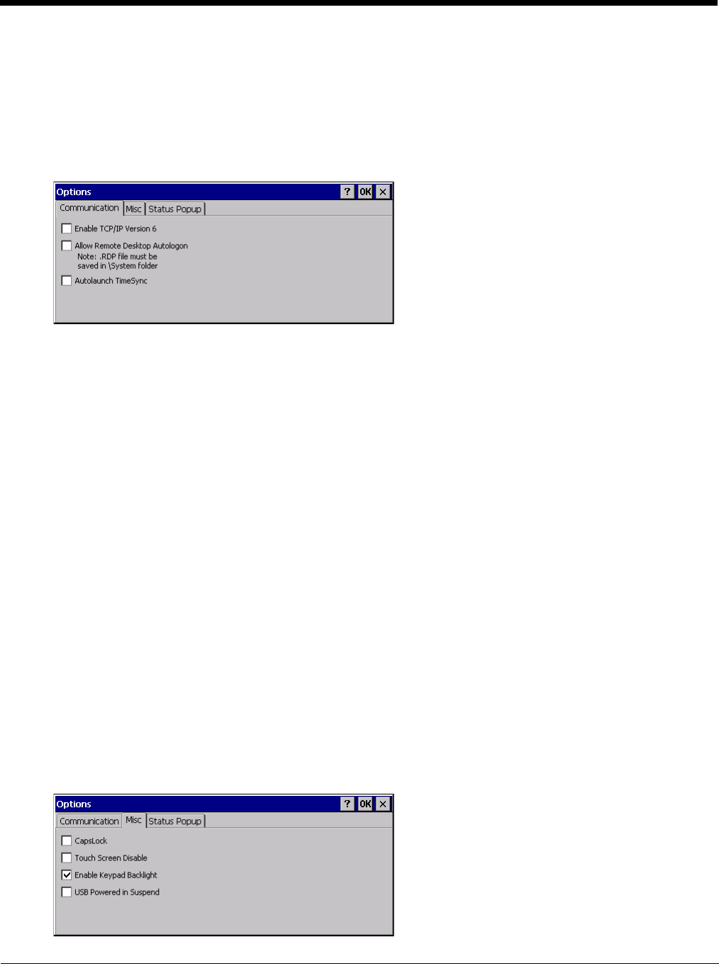
5 - 74
Options
Start > Settings > Control Panel > Options
It may be necessary to warmboot the Thor VM2 after making desired changes. A pop up window indicates if a warmboot is
required.
Communication
Options on this tab configure communication options for the Thor VM2.
Enable TCP/IP Version 6
By default, IPv6 is disabled on the Thor VM2. Check this checkbox to enable IPv6.
Allow Remote Desktop Autologon
By default, Remote Desktop Autologon is disabled. Check this checkbox to enable Remote Desktop Autologon.
Note: The .RDP file must be saved in the \System folder. When prompted, use the Save As button to save the
.RDP file is the \System directory. If the .RDP file is saved in the default root folder location, the .RDP file
will not persist across a warmboot.
Autolaunch TimeSync
By default, TimeSync does not automatically run on the Thor VM2. To enable TimeSync to run automatically on
the Thor VM2, check this checkbox.
Synchronize with a Local Time Server
By default, GrabTime synchronizes via an Internet connection. To synchronize with a local time server:
1. Use ActiveSync to copy GrabTime.ini from the My Device > Windows folder on the mobile device to the
host PC.
2. Edit the copy of GrabTime.ini on the host PC. Add the local time server’s domain name to the beginning
of the list of servers. You can optionally delete the remainder of the list.
3. Copy the modified GrabTime.ini file to the My Device > System folder on the mobile device.
The System/GrabTime.ini file takes precedence over the Windows/GrabTime.ini file. System/Grabtime.ini
also persists after a coldboot; Windows/Grabtime.ini does not persist.
Misc
Options on this tab configure device specific options. Note that options not available on the Thor VM2are dimmed or
grayed out.
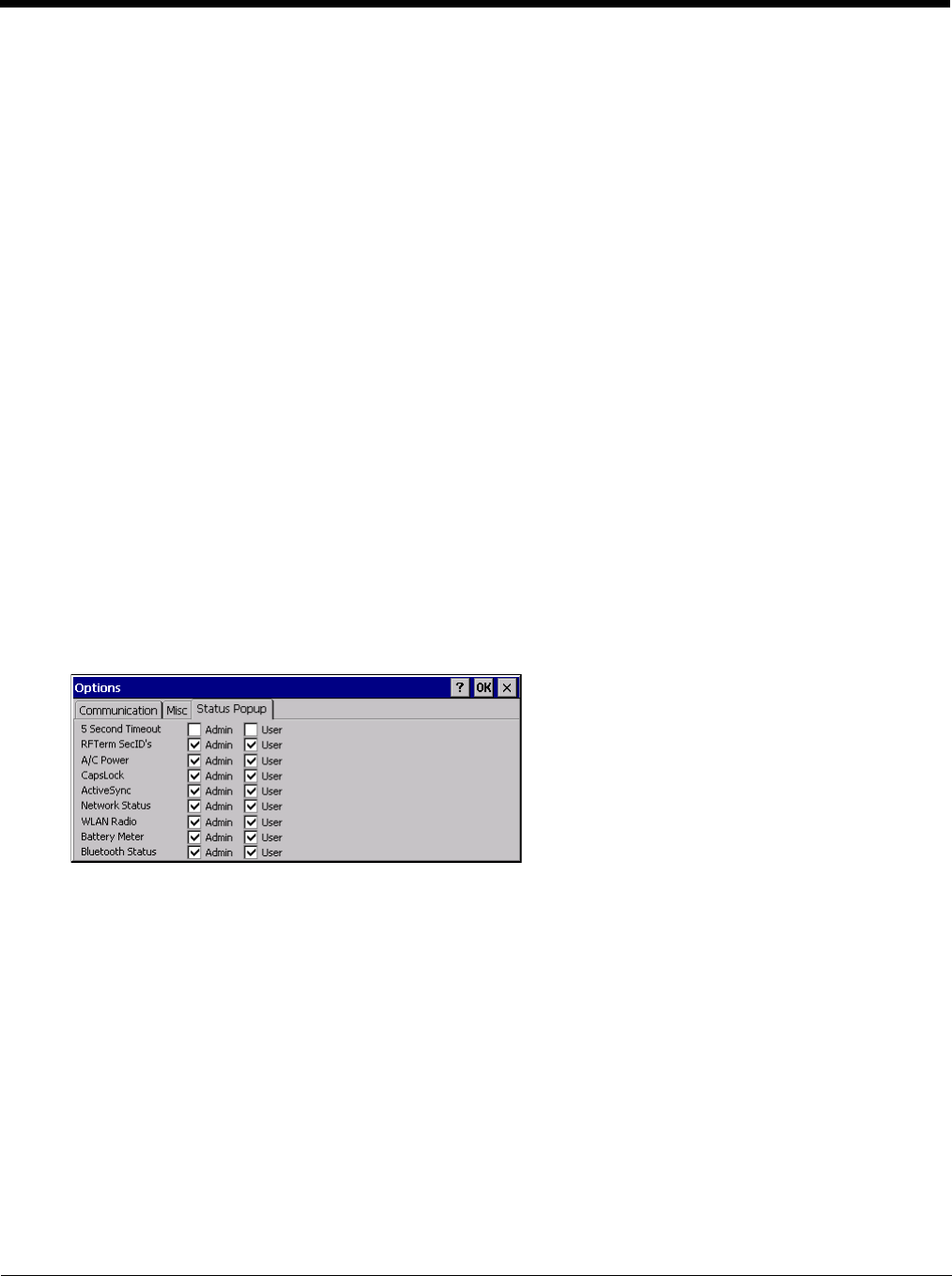
5 - 75
CapsLock
By default, CapsLock is disabled after a warmboot. To enable CapsLock after a warmboot, click this checkbox.
Touch Screen Disable
By default, the Thor VM2 touch screen is enabled. To disable the touch screen after a warmboot, click this check-
box.
Note: If the touch screen is disabled on a Thor VM2, you must use a USB mouse or keyboard attached to the Thor
VM2 to access this tab to re-enable the touch screen unless a Programmable Key (page 5-83) has been
assigned to enable the touch screen.
Enable Keypad Backlight
By default, the keypad backlight default setting is to follow the display backlight setting until it is changed by the
user.
Click the checkbox to disable the keypad backlight.
This keypad backlight setting only applies to the integrated keypad on the Thor VM2. The keyboard backlight on
an attached USB keyboard is not affected by this setting.
USB Powered in Suspend
By default, power to attached USB devices is turned off when the Thor VM2 is in Suspend mode. Check this box
to maintain power to attached USB devices in Suspend.
The external keyboard is a USB device. If USB devices are not powered in Suspend the external keyboard back-
light turns off when the Thor VM2 enters Suspend.
Status Popup
Options on this tab configure the Status Popup window. When the Status popup window is displayed, it is placed on
top of the window in focus and hides any data beneath it. It is closed by pressing the assigned Status User or Status
Admin key sequence.
Using the Programmable Key (page 5-83) control panel the System Administrator must first assign a Status User key
sequence for the end-user when they want to toggle the Status Popup Window on or off.
The System Administrator must also assign a Status Admin key sequence to perform the same function. Status
popup window display options (taskbar icons) are assigned on the Status Popup tab. E.g. AC Power, ActiveSync,
WLAN radio, CapsLock, Network status, Bluetooth status, etc.
The default for the User and Admin status popup windows is to show all status information. The 5 second timeout to
remove the status popup from the display is disabled by default for the User and Admin status popup windows.
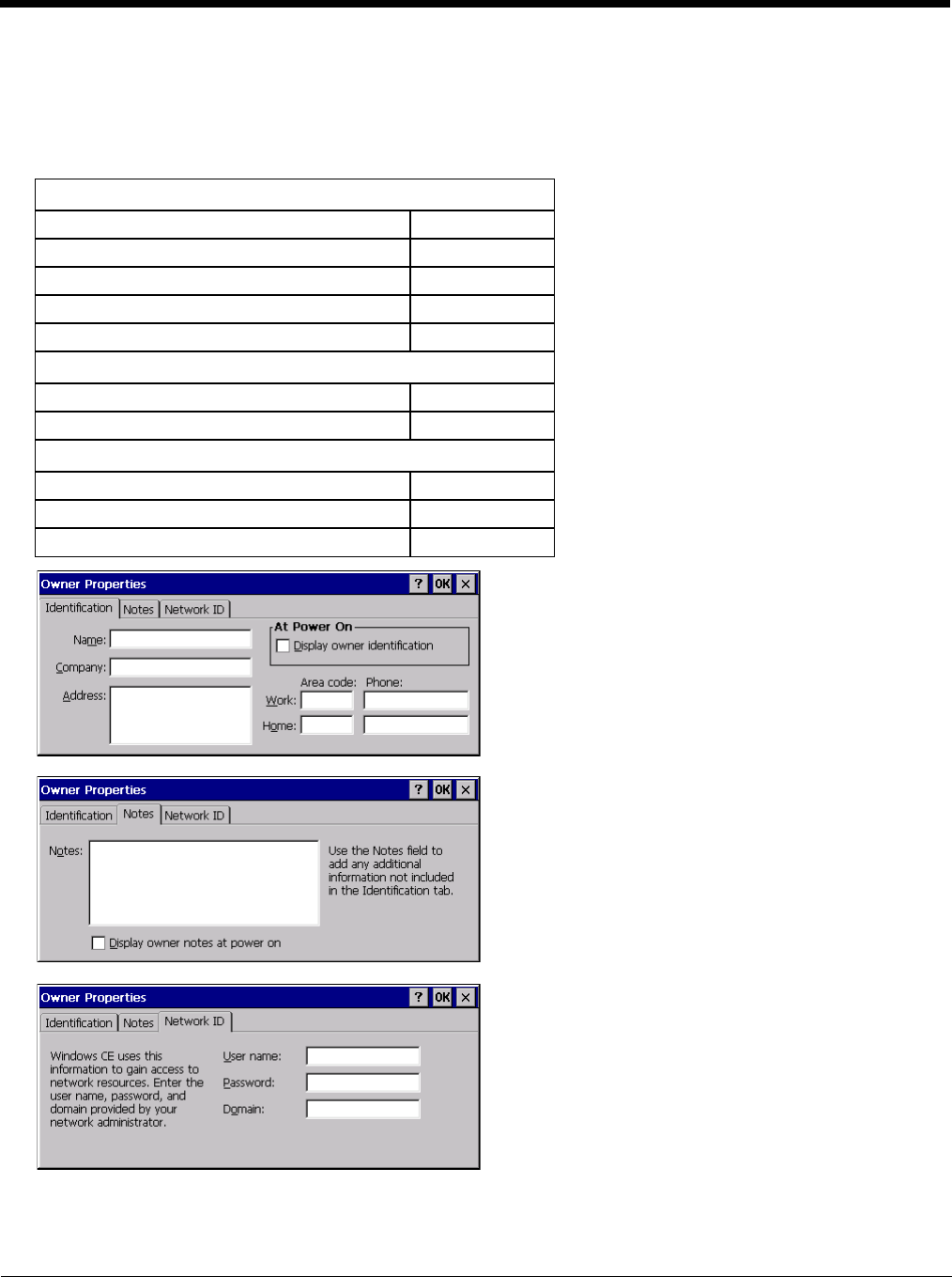
5 - 76
Owner
Start > Settings > Control Panel > Owner
Set the Thor VM2 owner details. The Network ID is used when logging into a remote network.
Factory Default Settings
Enter user name, password and domain to be used when logging into network resources.
Identification
Name Blank
Company Blank
Address Blank
Telephones Blank
Display owner ID at power-on Disabled
Notes
Notes Blank
Display notes at power-on Disabled
Network ID
User Name Blank
Password Blank
Domain Blank
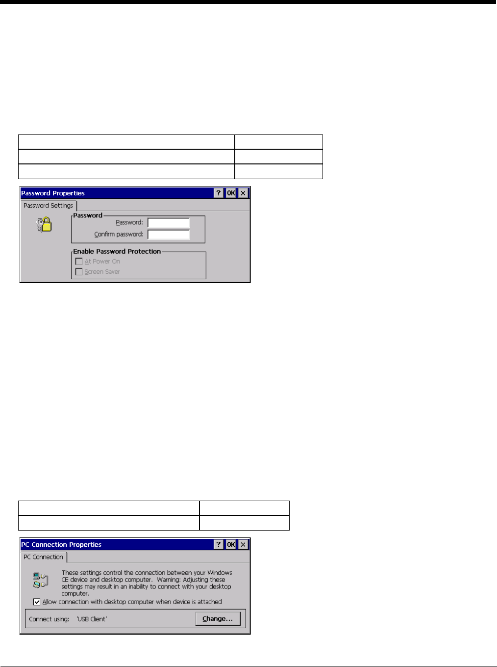
5 - 77
Password
Start > Settings > Control Panel > Password
Use this panel to set Thor VM2 user access to control panels and power up password properties.
Important: This password must be entered before performing a Load Factory Defaults.
If entering a power-on or screen saver password does not allow you to disable this password protection or perform a Load
Factory Defaults, contact Technical Assistance (page 11-1).
Factory Default Settings
• The password and password settings are saved during a warm boot and a restart.
• The screensaver password affects the Remote Desktop screensaver only.
• After a password is assigned and saved, each time a Settings > Control Panel option is selected, the user will be
required to enter the password before the Control Panel will open.
• The screensaver password is the same as the power-on password. They are not set independently.
• A screensaver password cannot be created without first enabling the “Enable password protection at power-on”
checkbox.
• The screensaver password is not automatically enabled when the “power-on” checkbox is enabled.
Enter the password in the Password text box, then press Tab and type the password again to confirm it.
Enable the power-on checkbox and, if desired, the screensaver checkbox.
A changed/saved password is in effect immediately.
PC Connection
Start > Settings > Control Panel > PC Connection
Use these options to control a cabled connection (USB, serial) between the Thor VM2 and a nearby desktop/laptop com-
puter.
Factory Default Settings
Tap the Change button to change the direct connect setting.
Password Blank
Enter password at Power On Disabled
Enter password at Remote Desktop Screen Saver Disabled
Enable direct connection Enabled
Connect using USB Client
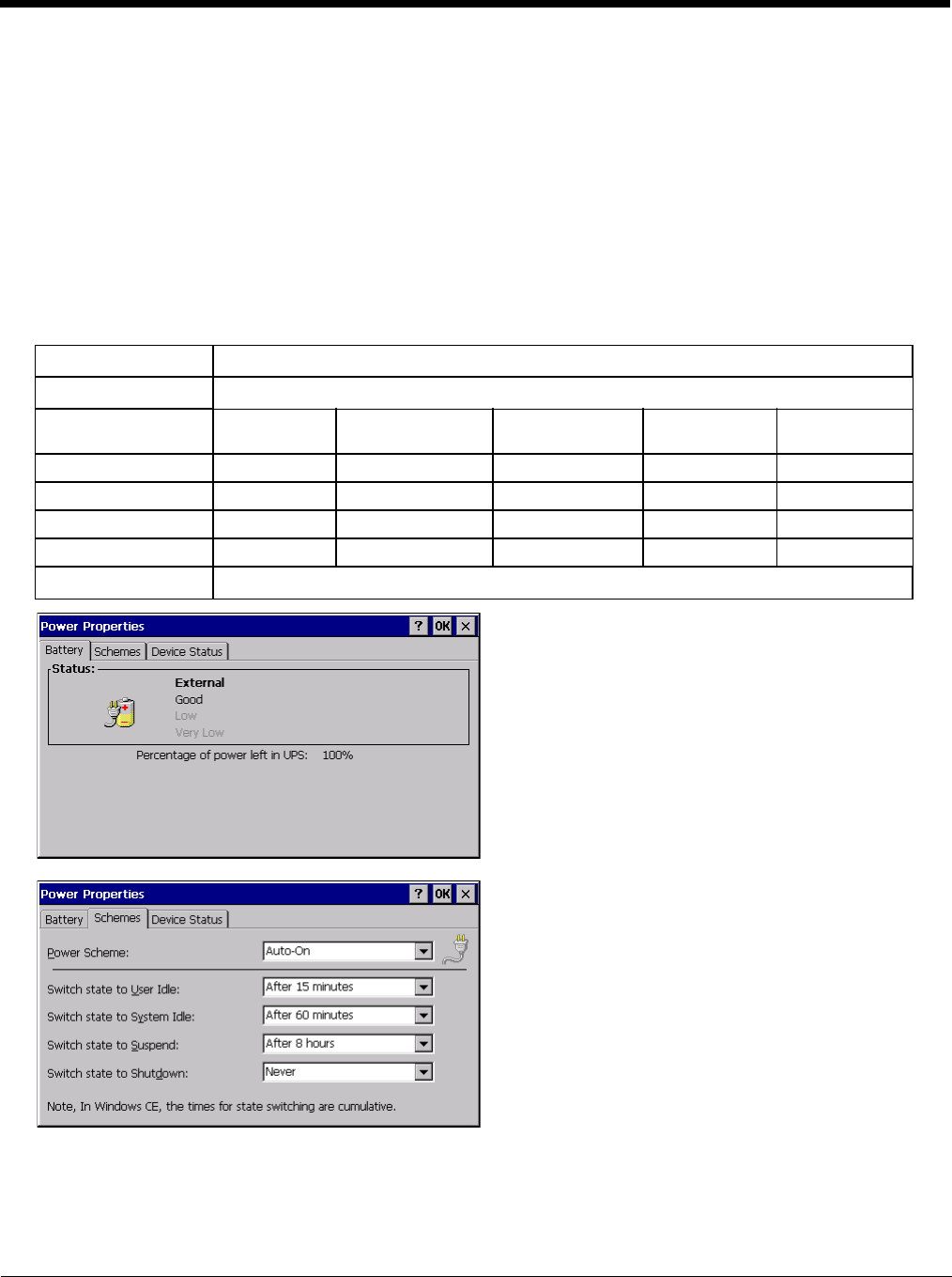
5 - 78
Tap the drop-down box to view a list of pre-configured connection settings.
Power
Start > Settings > Control Panel > Power
The Thor VM2 power mode timers are cumulative.
The System Idle timer begins the countdown after the User Idle timer has expired and the Suspend timer begins the count-
down after the System Idle timer has expired.
When the User Idle timer is set to “Never”, the power scheme timers never place the device in User Idle, System Idle or
Suspend modes (even when the device is idle).
The Display > Backlight setting is synchronized with the User Idle setting in the Schemes tab in the Power control panel.
Factory Default Settings
Battery No user interaction
Schemes The default power schemes are
AC/DC Ignition Control/
Ignition On
Ignition Control/
Ignition Off
Auto On UPS
User Idle Timeout 15 minutes 15 minutes 1 minute 15 minutes 30 seconds
System Idle Timeout 1 hour 1 hour 5 minutes 1 hour 1 minute
Suspend Timeout 8 hours 8 hours 1 hour 8 hours 10 minutes
Shutdown Timeout Never Never 8 hours Never 20 minutes
Device Status No user interaction

5 - 79
The default Power Scheme selected for the Thor VM2 depends on:
•the Power Configuration Mode (page 5-80) setting,
• if external power is connected to the Thor VM2,
• and, for ignition control, the status of the vehicle ignition signal.
The Power Schemes are defined below. The active Power Scheme depends on the user-selected power configuration
mode. However, if no external power is present, the Thor VM2 uses the UPS Power Scheme regardless of user selected
Power Configuration mode.
•AC/DC - When AC/DC has been selected for the Power Configuration mode, this Power Scheme is selected. Because
of the presence of external power, this Power Scheme has longer timeout values.
•Ignition Control/Ignition On - When either Ignition Control option has been selected for the Power Configuration mode
and the Ignition Switch is On, this Power Scheme is selected. Because of the presence of external power, this Power
Scheme has longer timeout values.
•Ignition Control/Ignition Off - When either Ignition Control option has been selected for the Power Configuration mode
and the Ignition Switch is Off, this Power Scheme is selected. This Power Scheme has shorter timeout values (compared
to Ignition On) to preserve the vehicle battery.
•Auto-On - When Auto-On has been selected for the Power Configuration mode, this Power Scheme is selected. Because
of the presence of external power, this Power Scheme has longer timeout values.
•UPS - When any Power Configuration Mode is selected but no external power is present, the UPS Power Scheme is
used. This Power Scheme has much shorter timeout values designed to shut down the Thor VM2 before the UPS battery
is depleted.
Because of the cumulative effect, if the Thor VM2 is operating from the UPS, for example:
• The backlight turns off after 30 seconds of no activity,
• The display turns off after 1 minute and 30 seconds of no activity (30 sec + 1 min),
• The Thor VM2 enters Suspend after 11 minutes and 30 seconds of no activity.
• The Thor VM2 shuts down after 31 minutes and 30 seconds of no activity.
• If the User Idle timer is set to Never, the power scheme timers never place the Thor VM2 in User Idle, System Idle or
Suspend modes.
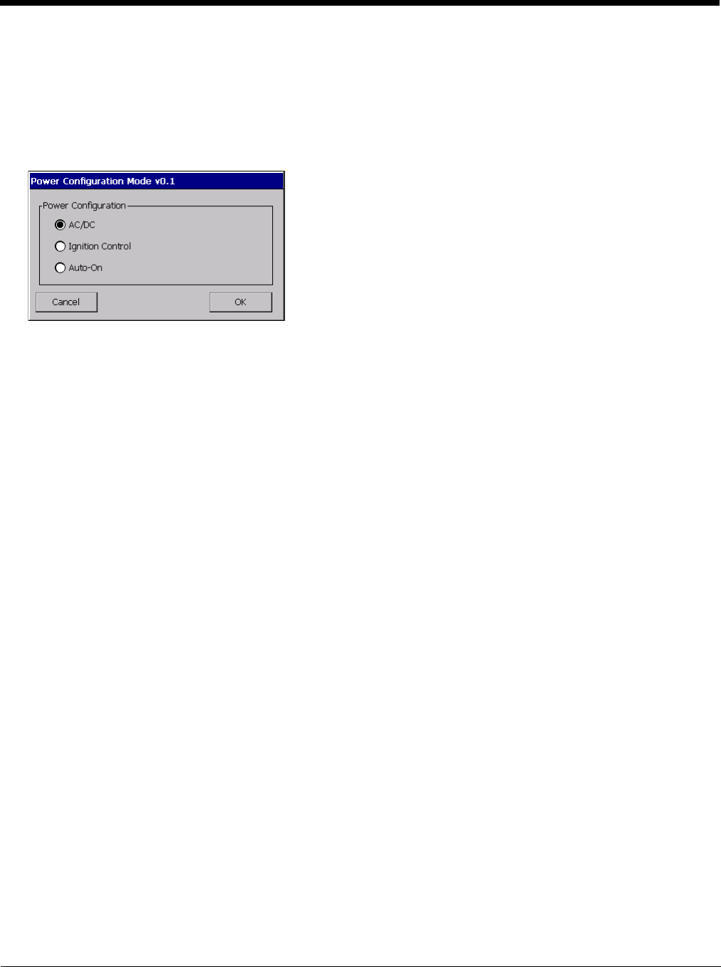
5 - 80
Power Configuration Mode
Start > Settings > Control Panel > Power Configuration Mode
There are three user selectable power configuration modes for the Thor VM2 available. Additionally a UPS power configu-
ration mode is supported and automatically selected regardless of the user selected mode any time external power is not
present.
Power (page 5-78) control panel timeout values vary by the power configuration mode selected.
AC/DC Mode
This is the default power mode. In AC/DC mode the Thor VM2 is turned On by a press of the Power button. Ignition
input is ignored when AC/DC Mode is enabled
Thor VM2 is Off
Conditions
The Thor VM2 is Off and external power is available, such as:
• Thor VM2 is installed on a powered Quick Mount Smart Dock with the dock power switch On
• Thor VM2 is already mounted to a dock and external power is applied to the dock
Result
The Thor VM2 boots when the Power button is pressed. Once booted the Thor VM2 follows the AC/DC power
scheme with timers reset after bootup.
Thor VM2 is On
Conditions
The Thor VM2 is On (but powered by the UPS battery) and gets external power, such as:
• Thor VM2 is installed on a powered dock with the dock power switch On
• Thor VM2 is already mounted to a dock with the dock power switch On and truck power is applied to the
dock
• Thor VM2 is already mounted to a dock and the dock power switch is turned On
Result
The Thor VM2 continues to run and follows the AC/DC power scheme with timers reset at power connection.
Ignition Control Mode
In Ignition mode, the Thor VM2 is turned On when the ignition switch is activated with no user interaction required. The
ignition input wire must be connected.
Thor VM2 is Off and Vehicle Ignition is Off
Conditions
The Thor VM2 is Off and vehicle ignition is Off.
Result
The Thor VM2 remains Off regardless of external power. UPS charging is disabled.

5 - 81
Conditions
The Thor VM2 has external power but vehicle ignition is Off. The Power button is pressed.
Result
The Thor VM2 boots. Once booted the Thor VM2 follows the Ignition Control/Ignition Off power scheme with
timers reset after the boot completes.
Thor VM2 is Off and Vehicle Ignition is Switched to On
Conditions
The Thor VM2 is Off and vehicle ignition changes from Off to On.
Result
The Thor VM2 boots. Once booted the Thor VM2 follows the Ignition Control/Ignition On power scheme with
timers reset after the boot completes.
Thor VM2 is On and Vehicle Ignition is Switched to On
Conditions
The Thor VM2 is On and vehicle ignition changes from Off (or not present) to On.
Result
The Thor VM2 continues to run and follows the Ignition Control/Ignition On power scheme with timers reset at
the time Ignition switched to Active.
An example of this case would be a Thor VM2 that is running on UPS and is then mounted on a dock that has
truck power and the ignition switch is already On.
Thor VM2 is On and Vehicle Ignition is Switched to Off
Conditions
The Thor VM2 is On and vehicle ignition changes from On to Off.
Result
The Thor VM2 follows the Ignition Control/Ignition Off power scheme with timers reset at the time Ignition
switched to Inactive. UPS charging is disabled.
An example of this case would be a Thor VM2 that is running on UPS and is then mounted on a dock that has
truck power and the ignition switch is already Off.
Auto-On Mode
In Auto-On mode, the Thor VM2 is turned On by the presence of external power with no user interaction
required. Ignition input is ignored when Auto-On Mode is enabled.
Thor VM2 is Off
Conditions
The Thor VM2 is Off and gets external power, such as
• Thor VM2 is installed on a powered Quick Mount Smart Dock with the dock power switch On
• Thor VM2 is already mounted to a dock and external power is applied to the dock
• Thor VM2 is already mounted to a dock and the dock power switch is turned On
Result
The Thor VM2 boots. Once booted the Thor VM2 follows the Auto-On power scheme with timers reset after
the boot completes.
Thor VM2 is On
Conditions
The Thor VM2 is On and gets external power, such as

5 - 82
• Thor VM2 is installed on a powered Quick Mount Smart Dock with the dock power switch On
• Thor VM2 is already mounted to a dock and external power is applied to the dock
• Thor VM2 is already mounted to a dock and the dock power switch is turned On
Result
The Thor VM2 continues to run and follows the Auto-On power scheme with timers reset at the time power
was connected.
UPS Mode
This mode is selected any time external power is not present, regardless of selected Power Configuration. Ignition
Input is ignored.
Thor VM2 is Off
Conditions
• The Thor VM2 is Off and the power button is pressed the Thor VM2 and both the following conditions are
met:
• UPS power is over 10% capacity
• CPU temperature is over 20ºC
Result
The Thor VM2 boots and follows the UPS power scheme with power management timers reset at boot up.
Conditions
The Thor VM2 is Off and the power button is pressed the Thor VM2 and at least one of the following condi-
tions are met:
• UPS power is under 10% capacity
• CPU temperature is under 20ºC
Results
The Thor VM2 remains Off.
Thor VM2 is On
Conditions
The Thor VM2 is On and external power is removed, such as:
• Thor VM2 is removed from a powered dock (Dock power switch On)
• Thor VM2 is mounted to a dock and truck power is removed from the dock
• Thor VM2 is mounted to a dock and the dock power switch is turned Off
Result
The Thor VM2 continues to run and follows the UPS mode power scheme with power management timers
reset at the time of power removal. UPS charging is disabled.

5 - 83
Programmable Key
Start > Settings > Control Panel > Programmable Key
Use this control panel option to assign key functions to programmable keys available on your Thor VM2, determine applica-
tion launch sequences and program command Run sequences.
Factory Default Settings
The Programmable Key panels can be used to perform the following functions:
•Remap a Key to a Single Key (page 5-84)
•Remap a Key to a Unicode Value (page 5-84)
•Remap a Key to a Key Sequence (page 5-84)
•Remap a Key to a Sequence of Unicode Values (page 5-84)
•Remap a Key to a Special Function (page 5-85)
•Remap a Key to Launch an Application (page 5-85)
•Remap a Key to Run a Command (page 5-85)
Factory Default Programmable Key Values
Note: Programmable Key Control Panel options LaunchApp and RunCmd do not inter-relate with similarly-named options
contained in other Control Panel applets. For example, the AppLock Administrator Control panel file Launch option.
KeyMap (page 5-84)
Modifier Mode None
LaunchApp (page 5-86)
App1 Empty
App2 Empty
App3 Empty
App4 Empty
App/Opt EXE
RunCmd (page 5-86)
Cmd1 Empty
Cmd2 Empty
Cmd3 Empty
Cmd4 Empty
File/Parm FILE
Programmable
Key
Default
Value
Programmable
Key
Default
Value
P1 F1 P6 (Orange + P1) <no key>
P2 F2 P7 (Orange + P2) <no key>
P3 F3 P8 (Orange + P3) <no key>
P4 F4 P9 (Orange + P4) <no key>
P5 F5 P10 (Orange + P5) <no key>
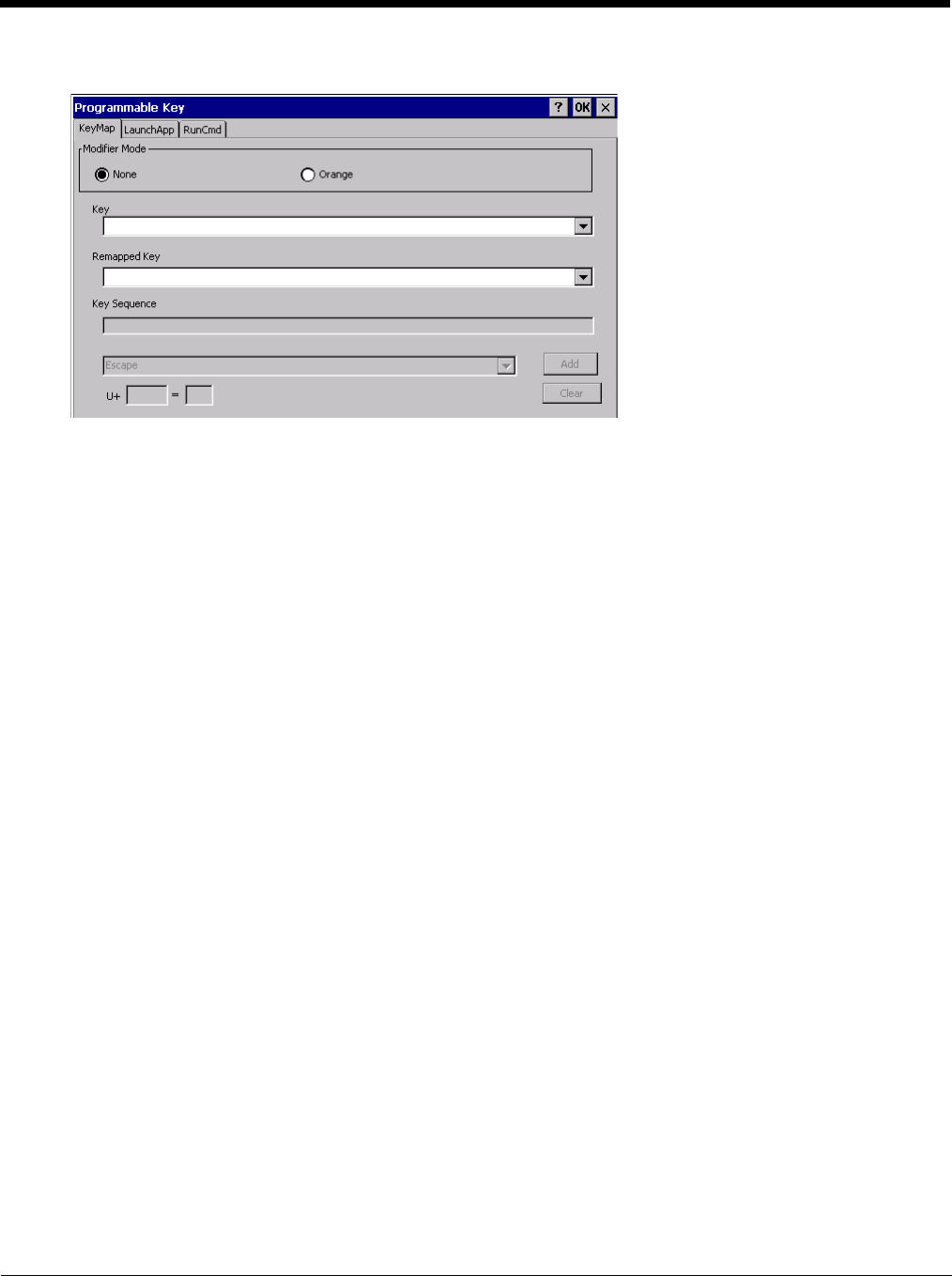
5 - 84
KeyMap
Assign settings by clicking radio buttons and selecting keys from the drop down boxes. Tap the OK button when fin-
ished. The changes take effect immediately.
Remap a Key to a Single Key
1. Select the modifier key from the Modifier Mode options.
2. Select the key to be remapped from the Key pull-down list.
3. Select the value for the remapped key from the Remapped Key pull-down list.
4. Click OK to save the result and close the control panel.
Remap a Key to a Unicode Value
1. Select the modifier key from the Modifier Mode options.
2. Select the key to be remapped from the Key pull-down list.
3. Select Unicode from the Remapped Key pull-down list.
4. There are two Unicode text boxes located on the lower part of this tab. Enter the Unicode value in the left text
box and the Unicode character is displayed in the right text box.
5. Click OK to save the result and close the control panel.
Remap a Key to a Key Sequence
Up to 16 keys may be specified for the key sequence. The sequence can consist of keys and Unicode values.
1. Select the modifier key from the Modifier Mode options.
2. Select the key to be remapped from the Key pull-down list.
3. Select Key Sequence from the Remapped Key pull-down list.
4. Select the first key for the multiple key sequence from the pull-down list.
5. Press the Add button to add the key to the multiple key sequence shown in the Key Sequence box.
6. Repeat this steps 4 and 5 until all desired keys have been added to the key sequence. If necessary, use the
ton to erase all entries in the Key Sequence box.
7. Click OK to save the result and close the control panel.
Remap a Key to a Sequence of Unicode Values
Up to 16 Unicode values may be specified for the key sequence. The sequence can consist of keys and Unicode
values.

5 - 85
1. Select the modifier key from the Modifier Mode options.
2. Select the key to be remapped from the Key pull-down list.
3. Select Key Sequence from the Remapped Key pull-down list.
4. Select Unicode from the Key Sequence pull-down list.
5. There are two Unicode text boxes located on the lower part of this tab. Enter the Unicode value in the left text
box and the Unicode character is displayed in the right text box.
6. Press the Add button to add the key to the multiple key sequence shown in the Key Sequence box.
7. Repeat this steps 4 through 7 until all desired characters have been added to the key sequence. If necessary,
use the ton to erase all entries in the Key Sequence box.
8. Click OK to save the result and close the control panel.
Remap a Key to a Special Function
1. Select the modifier key from the Modifier Mode options.
2. Select the key to be remapped from the Key pull-down list.
3. Select the special function from the remapped key from the Remapped Key pull-down list. Special functions
that can be assigned are:
• Toggle SIP (soft keyboard) state between displayed and hidden
• Toggle touch screen state between enabled and disabled
• Toggle integrated keyboard backlight state between on and off
• Launch the touch screen calibration utility
4. Click OK to save the result and close the control panel.
Remap a Key to Launch an Application
1. Select the modifier key from the Modifier Mode options.
2. Select the key to be remapped from the Key pull-down list.
3. Select Launch App1-4 from the remapped key from the Remapped Key pull-down list.
4. Click on the LaunchApp (page 5-86) tab.
5. Make sure the EXE radio button is selected.
6. In the text box (App1-4) corresponding to the number selected for Launch App1-4, enter the application to
launch.
7. If any parameters are needed for the application, click on the OPT radio button. This clears the text box
(though the application name is saved). Enter the desired parameters in the appropriate text box.
8. Click OK to save the result and close the control panel.
9. If the KeyMap tab is accessed again, the application plus any specified parameters is displayed in the Key
Sequence text box when the remapped key is again selected.
Remap a Key to Run a Command
1. Select the modifier key from the Modifier Mode options.
2. Select the key to be remapped from the Key pull-down list.
3. Select RunCmd 1-4 from the remapped key from the Remapped Key pull-down list.
4. Click on the RunCmd (page 5-86) tab.
5. Make sure the FILE radio button is selected.
6. In the text box (Cmd1-4) corresponding to the number selected for RunCmd1-4, enter the desired command.
7. If any parameters are needed for the command, click on the PARM radio button. This clears the text box
(though the command is saved). Enter the desired parameters in the appropriate text box.
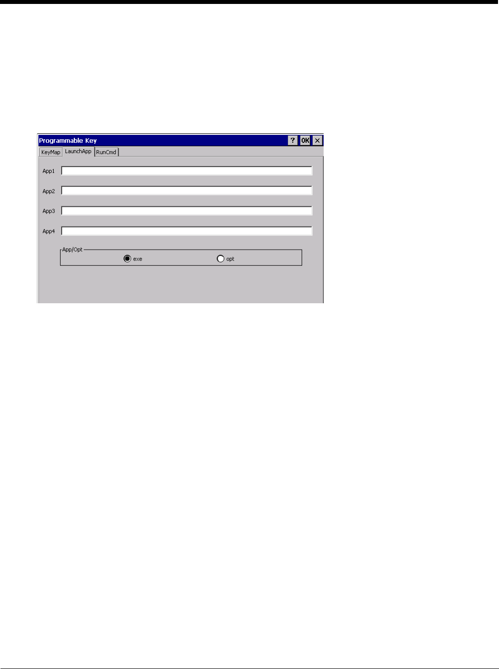
5 - 86
8. Click OK to save the result and close the control panel.
9. If the KeyMap tab is accessed again, the command plus any specified parameters is displayed in the Key
Sequence text box when the remapped key is again selected.
LaunchApp
The default for all text boxes is Null or “ ”. The text boxes accept string values only.
Note that executables and parameters are not checked for accuracy by the keyboard driver. If the launch fails, the Thor
VM2 emits a single beep, if the launch is successful, it is silent.
The Launch App command is defined for use by system administrators. These instructions are parsed and executed
directly by the keyboard driver.
1. Place the cursor in the text box next to the App you wish to run, e.g., App1, App2.
2. Enable the EXE radio button if the application is an EXE file.
3. Enter the name of the executable file.
4. Enable the OPT radio button to add options or parameters for the executable file in the same text box. Switching
from EXE to OPT clears the text box (but the information previously entered is stored), allowing parameter entry.
5. Tap the OK button when finished. The changes take effect immediately.
The result of the application (exe) and options (opt) entries are displayed on the KeyMap tab in the Key Sequence box
when the key mapped to the LauchApp is selected.
RunCmd
The default for all text boxes is Empty, Null or “ ”. The text boxes accept string values only.
Note that executables and parameters are not checked for accuracy by the keyboard driver. If the launch fails, the Thor
VM2 emits a single beep, if the launch is successful, the mobile device is silent.

5 - 87
The Run Cmd command is defined for use by system administrators. These instructions call the ShellExecuteEx API,
which opens documents directly.
1. Place the cursor in the text box next to the Cmd you wish to run, e.g., Cmd1, Cmd2.
2. Enable the file radio button and enter the name of the file.
3. Enable the PARM radio button to add parameters for file/exe execution in the same text box.
4. Tap the OK button when finished. The changes take effect immediately.
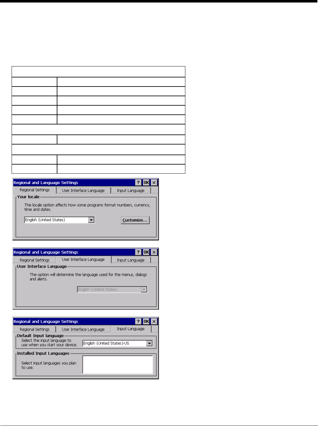
5 - 88
Regional and Language Settings
Start > Settings > Control Panel > Regional Settings
Set the appearance of numbers, currency, time and date based on regional and language settings. Set the Thor VM2 user
interface language and the default input language.
Factory Default Settings
Region
Locale English (United States)
Number 123,456,789.00 / -123,456,789.00 neg
Currency $123,456,789.00 pos / ($123,456,789.00) neg
Time h:mm:ss tt (tt=AM or PM)
Date M/d/yy short / dddd,MMMM,dd,yyyy long
Language
User Interface English (United States)
Input
Language English (United States)-US
Installed English (United States)-US
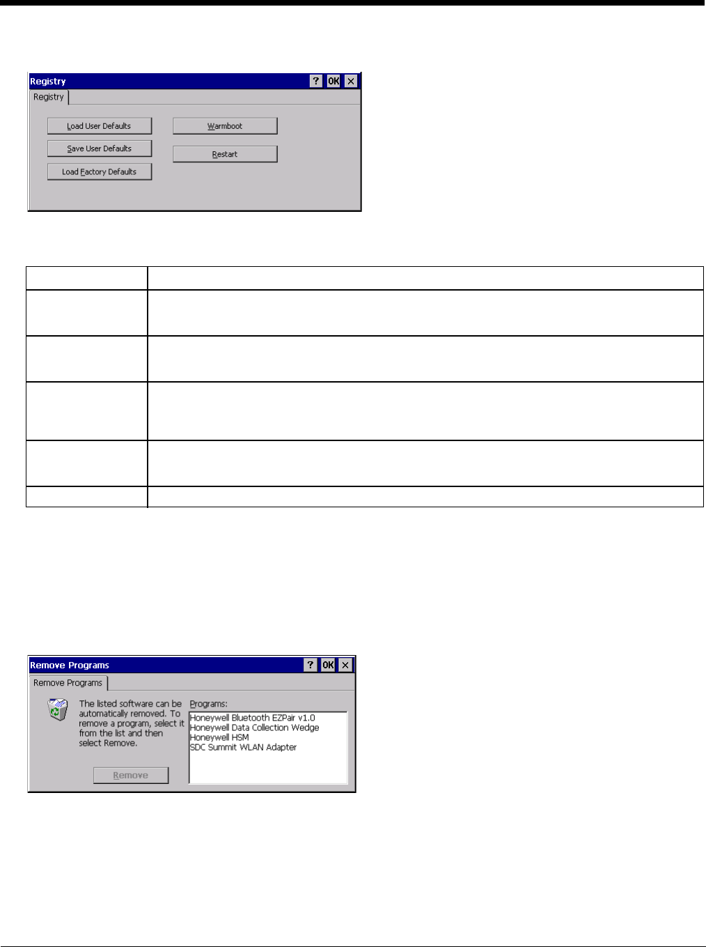
5 - 89
Registry
Start > Settings > Control Panel > Registry
Choose options for managing the registry and rebooting the Thor VM2.
Remove Programs
Start > Settings > Control Panel > Remove Programs
Note: Lists programs installed in RAM that have been marked for removal.
Select a program and tap Remove. Follow the prompts on the screen to uninstall Thor VM2 user-installed only programs.
The change takes effect immediately.
Files stored in the My Documents folder are not removed using this option.
Note: Do not remove factory installed programs using this option. Contact Technical Assistance (page 11-1) if factory
installed programs must be deleted.
Button Action
Load User Defaults When clicked, a standard load file dialog is opened, to allow the user to pick a Registry Save (.RSG)
file. The applet then copies the specified User registry file to the Active registry. The user is asked
to verify a reboot, and then the applet does a warmboot to activate the new registry.
Save User Defaults When clicked, a standard Save File dialog is opened, to allow the user to name the Registry Save
(.RSG) file. The applet then copies the Active registry to the specified User registry file and reboots
the device.
Load Factory De-
faults The applet copies the Factory Default registry from the OS to the Active registry (by deleting the cur-
rent registry). The user is asked to verify a reboot, and then the applet performs a restart to activate
the factory default registry. If a user password has been set, the applet warns the user that the pass-
word will be erased, and asks them to enter it before the reboot is allowed.
Warmboot When clicked, the OS performs a registry save (Active registry saved to Flash registry hive), and then
a warmboot. The contents of RAM are preserved. CAB files already loaded into RAM remain load-
ed.
Restart When clicked, the OS performs a registry save, and then a restart. OS and CAB files are reloaded.
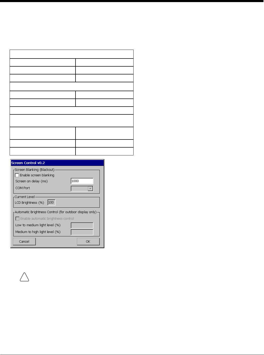
5 - 90
Screen Control
Start > Settings > Control Panel > Screen Control
Set screen properties for the Thor VM2.
Factory Default Settings
Screen Blanking
See Screen Blanking (page 4-49) for the hardware necessary for screen blanking.
Screen blanking allows the Thor VM2 display to automatically be turned off whenever the vehicle is in motion. When
the Thor VM2 display is off due to vehicle motion, the integrated keypad backlight remains on.
Screen blanking requires a user supplied cable properly connected as shown below. To enable blanking, check the
Enable screen blanking checkbox. The default is disabled.
Use the Screen on delay to specify the period of time in ms (milliseconds) between when the vehicle stops and the
Thor VM2 screen turns on. For example, use the delay if the switch end of the cable is attached to the vehicle’s accel-
erator pedal. Release of the accelerator may mean the truck is coasting to a stop rather than stationary. Configure the
delay to allow time for the vehicle to coast to a stop. The default value is 1000 ms.
Screen Blanking (Blackout)
Enable screen blanking Disabled
Screen on delay (ms) 1000
COM Port none selected
Current Level
LCD Brightness (%) 100
Ambient Light (%) (see note)
Automatic Brightness Control
Automatic brightness control is only available on the Thor
VM2.
Enable automatic brightness
control Disabled
Low to medium light level (%) 25
Medium to high light level (%) 75
Do not enable Screen Blanking until the cable is properly connected to the specified COM port.
!
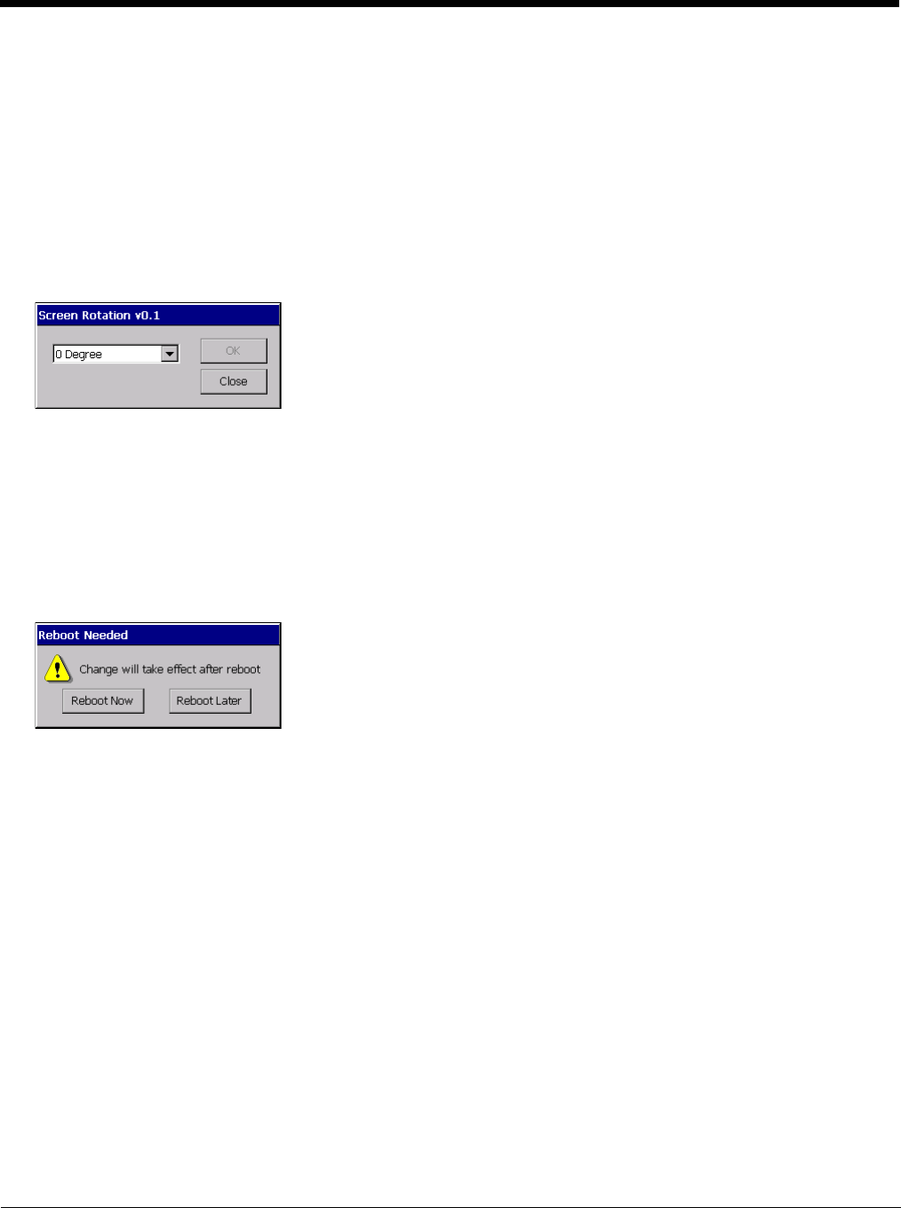
5 - 91
Specify the COM Port to which the screen blanking cable is attached, either COM1 or COM2. If a COM port is in use
by another application (such as DC Wedge), that COM port is grayed out and cannot be selected for screen blanking.
To disable screen blanking, uncheck the Enable screen blanking checkbox.
Current Level
LCD brightness displays the current LCD brightness level. The default brightness is 100%.
• LCD brightness can be manually adjusted using the Blue plus P3 or Blue plus P4 keypress sequences. Any changes
to brightness level using the keypresses are reflected in this section
Screen Rotation
Start > Settings > Control Panel > Screen Rotation
The Screen Rotation panel provides options for rotating the display:
0 Degree - Returns screen to the default orientation.
90 Degree - Rotates the screen counter clockwise 90 degrees as compared to the default orientation.
180 Degree - Rotates the screen 180 degrees as compared to the default orientation.
270 Degree - Rotates the screen counter clockwise 270 degrees as compared to the default orientation.
To exit without changing the screen rotation, tap Close.
Select the desired rotation and tap OK. A reboot confirmation is displayed.
Reboot Now - The Thor VM2immediately reboots and the new screen rotation is in effect after the reboot.
Reboot Later - The current screen rotation remains in effect until theThor VM2 is rebooted by the user at a later time. The
new screen rotation is in effect after the reboot.
To cancel the upcoming screen rotation after Reboot Later has been selected, it is necessary to access the Screen Rota-
tion control panel and select a different rotation value.
Note: Screen rotation does not affect any screens before the operating system loads. Therefore the BIOS and startup
screens are not rotated.
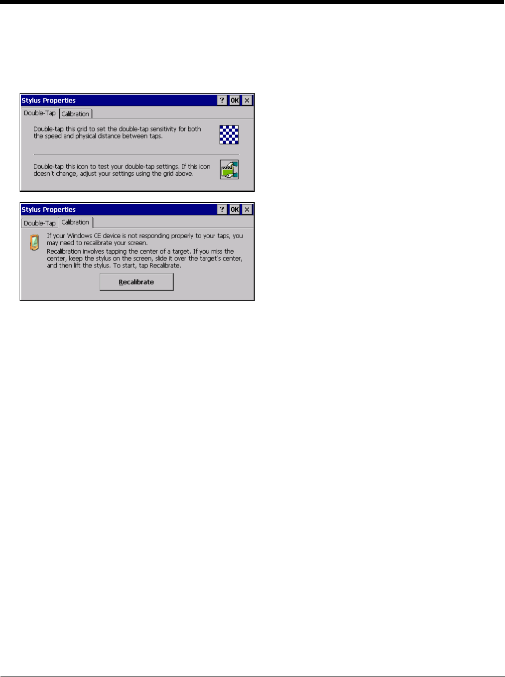
5 - 92
Stylus
Start > Settings > Control Panel > Stylus
Use this control panel option to set stylus double-tap sensitivity properties and calibrate the Thor VM2 touch panel when
needed.
Double-Tap
Follow the instructions on the screen and tap the OK button to save any double-tap changes.
Calibration
Calibration involves tapping the center of a target. If you miss the center, keep the stylus on the screen, slide it over
the target's center, and then lift the stylus.
To begin, tap the Recalibrate button on the screen with the stylus. Press and hold the stylus on the center of the tar-
get as it moves around the screen. Press the Enter key to keep the new calibration setting or press the Esc key to
revert to the previous calibration settings.
Note: If the touch screen looses calibration on a Thor VM2, you must use a USB mouse or keyboard attached to the
Thor VM2 to access this tab to recalibrate the touch screen unless a Programmable Key (page 5-83) has been
assigned to launch the calibration utility.
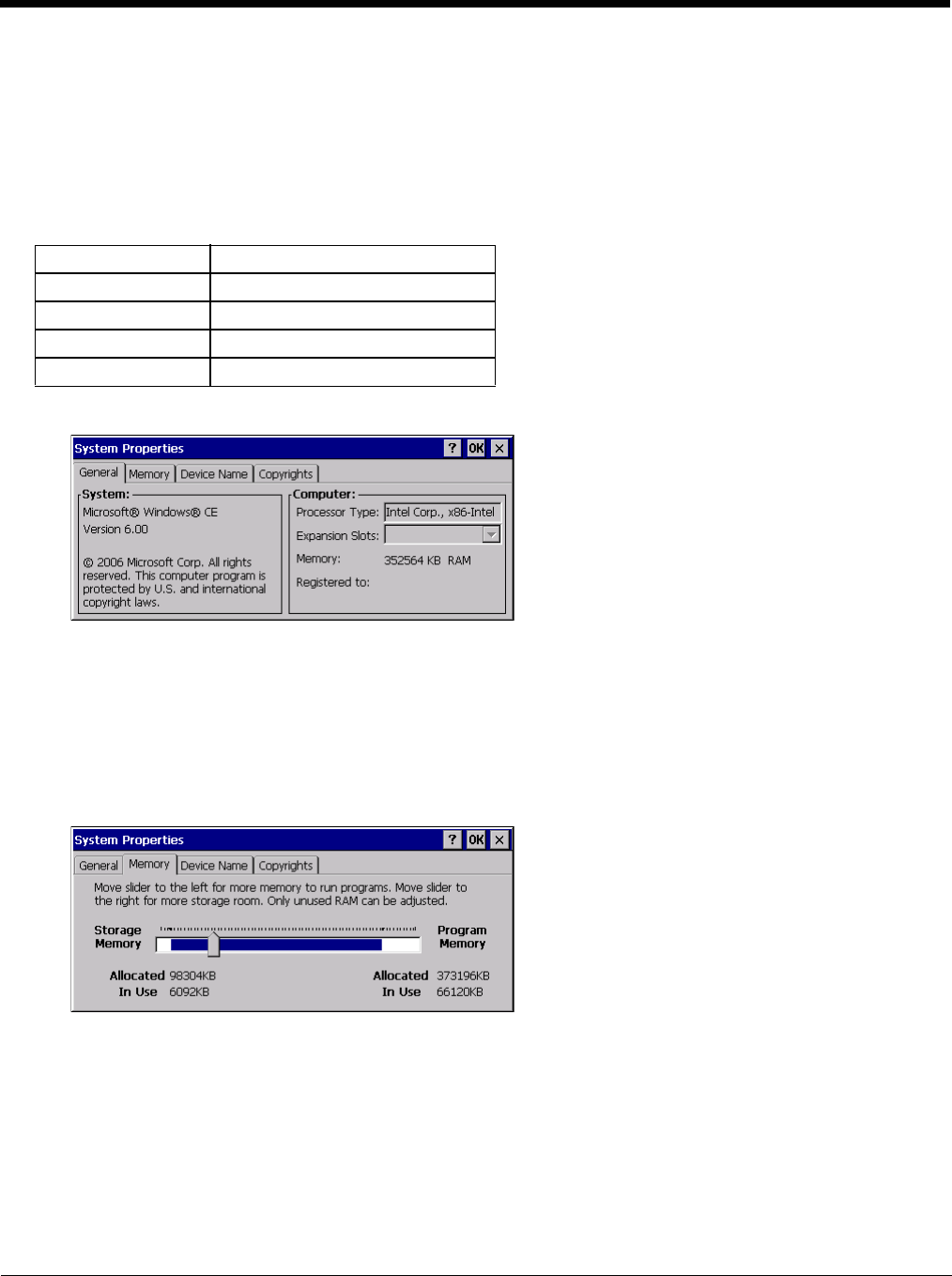
5 - 93
System
Start > Settings > Control Panel > System
Use these Thor VM2 panels to:
• Review System and mobile device data and revision levels.
• Adjust Storage and Program memory settings.
• Assign a device name and device descriptor.
Factory Default Settings
General
System: This screen is presented for information only. The System parameters cannot be changed by the user.
Computer: The processor type is listed. The type cannot be changed by the user. Total computer memory and the
identification of the registered user is listed and cannot be changed by the user.
Memory sizes given do not include memory used up by the operating system. For example, a system with 128 MB
may only report 99 MB memory, since 29 MB is used by the operating system. This is actual DRAM memory, and does
not include internal flash used for storage.
Memory
Move the slider to allocate more memory for programs or storage. If there isn’t enough space for a file, increase the
amount of storage memory. If the mobile device is running slowly, try increasing the amount of program memory.
General No user interaction
Memory 1/4 storage, 3/4 program memory
Device Name Unique to equipment type
Device Description Unique to equipment type
Copyrights No user interaction
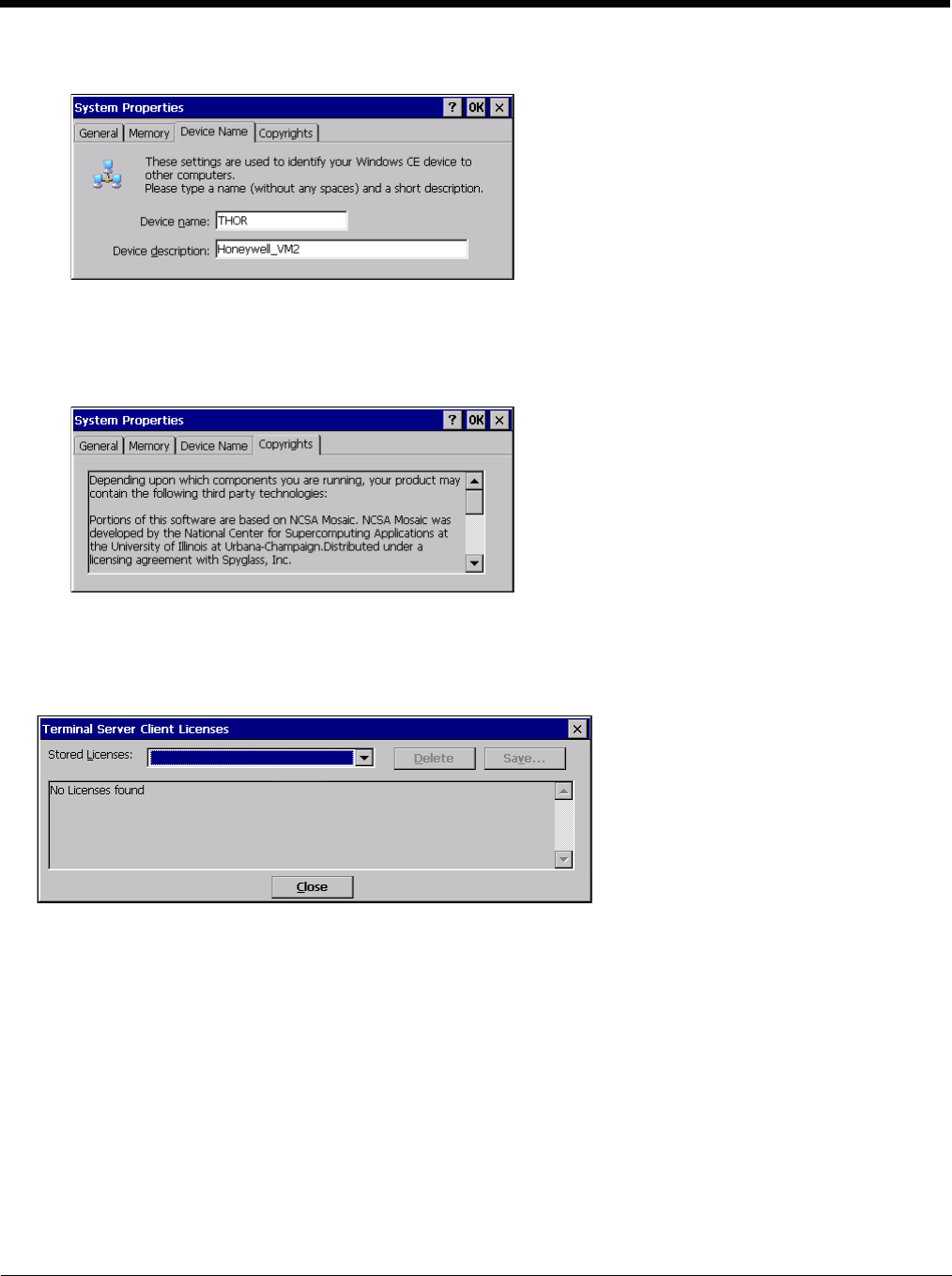
5 - 94
Device Name
The device name and description can be changed by the user. Enter the name and description using either the keypad
or the Input Panel and tap OK to save the changes. This information is used to identify the Thor VM2 to other comput-
ers and devices.
Copyrights
This screen is presented for information only. The Copyrights information cannot be changed by the user.
Terminal Server Client Licenses
Start > Settings > Control Panel > Terminal Server Client Licenses
Any licenses stored on the Thor VM2 appear in the drop-down list. Select a license and tap the Close button. The license
is available for use immediately.
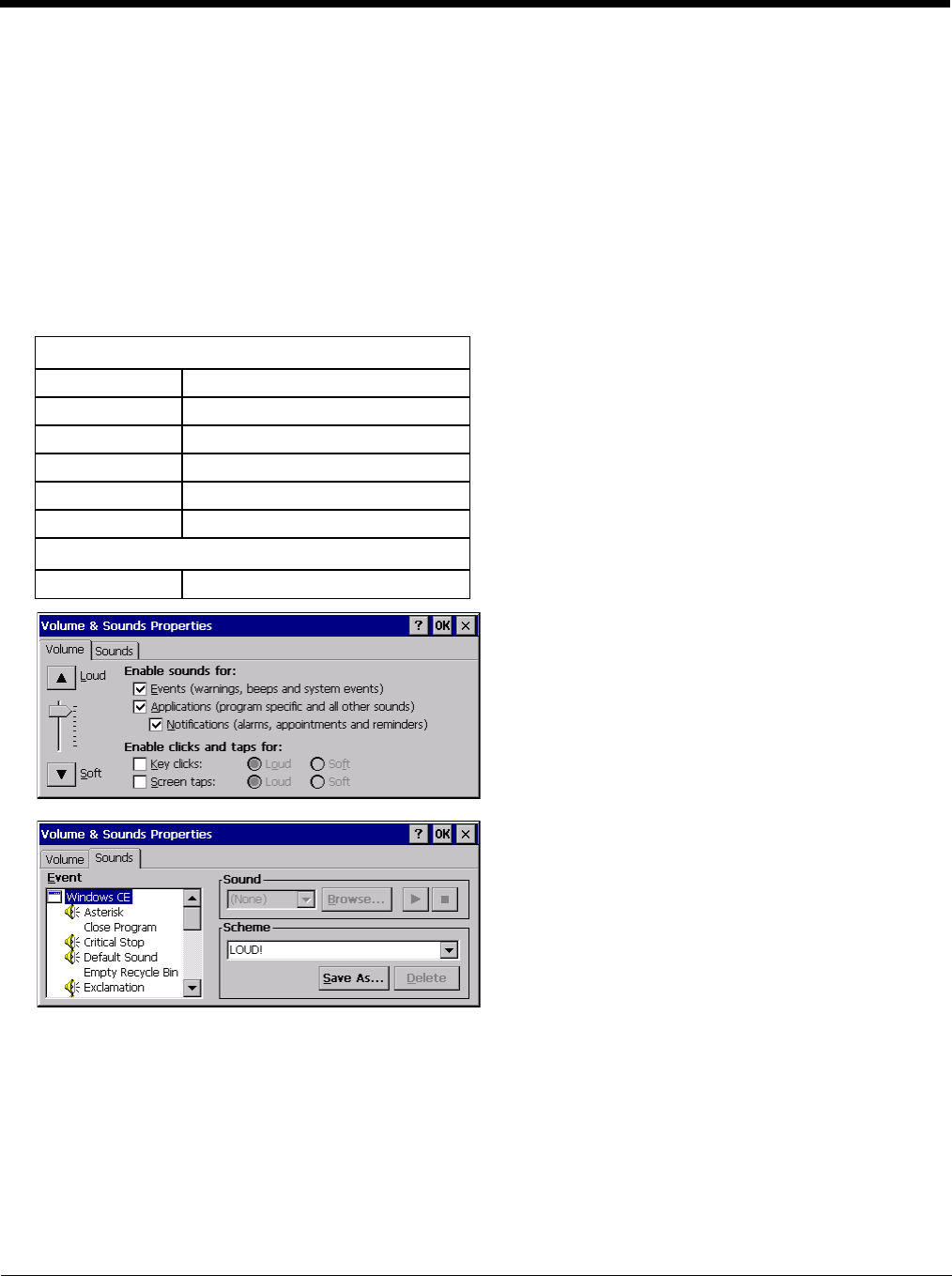
5 - 95
Volume and Sounds
Start > Settings > Control Panel > Volume & Sounds
Note: An application may override the control of the speaker volume. Turning off sounds saves power and prolongs battery
life.
Set volume parameters and assign sound WAV files to CE events using these options.
You can also select / deselect sounds for key clicks and screen taps and whether each is loud or soft.
As the volume scrollbar is moved between Loud and Soft, the Thor VM2 emits a tone each time the volume increases or
decreases.
Volume must be enabled when you want to adjust volume settings using keypad keys.
Factory Default Settings
The volume setting is stored in the registry and is recalled at power on.
Note: Rejected bar codes generate a bad scan beep. In some cases, the receipt of data from the scanner triggers a good
scan beep from a tethered scanner, and then the rejection of scanned bar code data by the bar code processing
causes a bad scan beep from the mobile device on the same data.
Good Scan and Bad Scan Sounds
Good scan and bad scan sounds are stored in the Windows directory, as SCANGOOD.WAV and SCANBAD.WAV.
These are unprotected WAV files and can be replaced by a WAV file of the user’s choice.
By default a good scan sound on the Thor VM2 is a single beep, and a bad scan sound is a double beep.
Volume
Events Enabled
Application Enabled
Notifications Enabled
Volume One level below Loud
Key click Disabled
Screen tap Disabled
Sounds
Scheme LOUD!


6 - 1
6
ActiveSync
Introduction
Requirement - ActiveSync (version 4.5 or higher for Windows XP desktop/laptop computers) must be resident on the host
(desktop/laptop) computer. Windows Mobile Device Center (version 6.1 or higher) is required for a Windows Vista/Windows
7 desktop/laptop computer. ActiveSync and Windows Mobile Device Center for the PC is available from the Microsoft website.
Follow their instructions to locate, download and install ActiveSync or Windows Mobile Device Center on your desktop com-
puter.
Note: For readability in this section, ActiveSync will be used in instructions and explanations. If you have a Windows Vista or
Windows 7 operating system on your desktop/laptop, replace ActiveSync with Windows Mobile Device Center.
Using Microsoft ActiveSync, you can synchronize information on your desktop computer with the Thor VM2 and vice versa.
Synchronization compares the data on your mobile device with your desktop computer and updates both with the most recent
data.
For example, you can:
• Back up and restore your device data.
• Copy (rather than synchronize) files between your device and desktop computer.
• Control when synchronization occurs by selecting a synchronization mode. For example, you can synchronize continually
while connected to your desktop computer or only when you choose the synchronize command.
By default, ActiveSync does not automatically synchronize all types of information. Use ActiveSync Options to specify the types
of information you want to synchronize. The synchronization process makes the data (in the information types you select) iden-
tical on both your desktop computer and your device.
When installation of ActiveSync is complete on your desktop computer, the ActiveSync Setup Wizard begins and starts the fol-
lowing processes:
• connect your device to your desktop computer,
• set up a partnership so you can synchronize information between your device and your desktop computer, and
• customize your synchronization settings.
Because ActiveSync is already installed on your device, your first synchronization process begins automatically when you finish
setting up your desktop computer in the ActiveSync wizard. For more information about using ActiveSync on your desktop com-
puter, open ActiveSync, then open ActiveSync Help.
Initial Setup
The initial setup of ActiveSync must be made via a USB connection. When there is a Connect icon on the desktop, this section
can be bypassed. Partnerships can only be created using USB cable connection.
Connect via USB
The default connection type is USB Client
This is the only connection option supported on the Thor VM2.
To verify it is set to USB, select
Start > Settings > Control Panel > PC Connection
Tap the Change button. From the popup list, choose
USB Client
This will set up the mobile device to use the USB port. Tap OK and ensure the check box for “Allow connection with desktop
computer when device is attached” is checked.
Tap OK to return to the Control Panel. If desired, any control panel windows may be closed.
Connect the USB cable to the PC (the host) and the mobile device (the client) as detailed below. USB will start automatically
when the USB cable is connected, not requiring you to select “Connect” from the start menu.
When the Thor VM2 loses connection, e.g. enters Suspend Mode, etc., the connection to ActiveSync will be lost. When the
Thor VM2 resumes, the ActiveSync session will automatically re-connect.

6 - 2
Cable for USB ActiveSync Connection:
VM1052CABLE - Thor VM2 Dongle cable provides USB type A connector.
• D9 connector connects to the USB port on the Thor VM2 dock.
• The USB type A client connector on cable connects to a USB port on a PC or laptop.
• The USB host connector on the dongle cable does not need to be connected.
Explore
• From the ActiveSync Dialog on the Desktop PC, tap the Explore button.
• From the Windows Mobile Device Center interface select File Management > Browse the contents of your device.
This function allows you to explore the Thor VM2 from the PC side, with some limitations. You can copy files to or from the
mobile device by drag-and-drop. You will not be allowed to delete files or copy files out of the \Windows folder on the mobile
device. (Technically, the only files you cannot delete or copy are ones marked as system files in the original build of the Win-
dows image. This, however, includes most of the files in the \Windows folder).
Backup Data Files using ActiveSync
Use the following information to backup data files from the Thor VM2 to a desktop or laptop PC using the appropriate cable and
Microsoft’s ActiveSync.
Prerequisites
A partnership between the mobile device and ActiveSync has been established.
• A desktop or laptop PC with an available USB port and a mobile device with a USB port. The desktop or laptop PC must
be running Windows XP or greater.
• Use the USB-specific cable as shown above.
Connect
Connect the USB cable to the PC (the host) and the mobile device (the client).
The “Get Connected” wizard on the host PC checks COM ports to establish a connection for the first time.
Note: USB synchronization will start automatically when the cable is connected.
Disconnect
• Disconnect the cable from the Thor VM2.
• Open the status bar icon in the lower right hand corner of the status bar. Then tap the Disconnect button.
When the Thor VM2 loses connection, e.g. enters Suspend Mode, etc., the connection to ActiveSync will be lost. When the
Thor VM2 resumes, the ActiveSync session will automatically re-connect.
Thor VM2 with a Disabled Touch screen
A Thor VM2 touch screen can be disabled via the Misc tab of the Options (page 5-74) control panel. In these cases, it may be
easier to configure the Thor VM2 using ActiveSync and HSM Connect rather than using the Thor VM2 keypad only.
D9 Connector USB Host Connector
USB Client Connector

6 - 3
Reset and Loss of Host Re-connection
ActiveSync assigns a partnership between a Thor VM2 (the client) and a host computer. A partnership is defined by two objects
– a unique computer name and a random number generated when the partnership is first created. An ActiveSync partnership
between a unique client can be established to two hosts.
When the mobile device is reset (return to default settings), the random number is deleted – and the partnership with the last
one of the two hosts is also deleted. The host retains the random numbers and unique names of all devices having a partner-
ship with it. Two clients cannot have a partnership with the same host if they have the same name. (Control Panel > System >
Device Name)
If the reset mobile device tries to reestablish the partnership with the same host PC, a new random number is generated for the
mobile device and ActiveSync will insist the unique name of the mobile device be changed. If the mobile device is associated
with a second host, changing the name will destroy that partnership as well. This can cause some confusion when re-establish-
ing partnerships with hosts.
ActiveSync Help
ActiveSync on the host says that a device is trying to connect, but it cannot identify it
Verify the dongle cable is attached to the Thor VM2. Disconnect and reconnect the cable from the PC.
Check that the correct connection is selected.
See Reset and Loss of Host Re-connection, above.
ActiveSync indicator on the host (disc in the toolbar tray) turns green and spins as soon as you connect the cable,
before tapping the Connect icon (or REPLLOG.EXE in the Windows directory).
One or more control lines are tied together incorrectly. This is usually a cable problem.
ActiveSync indicator on the host turns green and spins, but connection never occurs
Check that the correct connection is selected.
-or-
Incorrect or broken data lines in cable.
ActiveSync indicator on the host remains gray
Solution 1: ActiveSync icon on the PC does not turn green after connecting USB cable from Thor VM2.
1. Disconnect Thor VM2 USB cable from PC.
2. Suspend/Resume or Restart the Thor VM2.
3. In ActiveSync > File > Connection Settings on PC disable Allow USB Connections and click OK.
4. Re-enable Allow USB Connections on the PC and click OK.
5. Reconnect USB cable from Thor VM2 to PC.
Solution 2: The host doesn’t know you are trying to connect. May mean a bad cable, with no control lines connected, or an
incompatible baud rate. Try the connection again, with a known good cable.
HSM Connect
HSM Connect allows a user to view the Thor VM2 screen remotely from a PC using an ActiveSync connection.
Requirement: ActiveSync version 4.5 (or higher) must be resident on a Windows XP (desktop/laptop) host computer. Windows
Mobile Device Center (version 6.1 or higher) is required for a Windows Vista/Windows 7 desktop/laptop computer.
Note: For readability in this section, ActiveSync will be used in instructions and explanations. If you have a Windows Vista or
Windows 7 operating system on your desktop/laptop, replace ActiveSync with Windows Mobile Device Center.
ActiveSync is already installed on the Thor VM2. The Thor VM2 is preconfigured to establish a USB ActiveSync connection to
a host PC when the USB cable is attached to the Thor VM2 and the host PC.
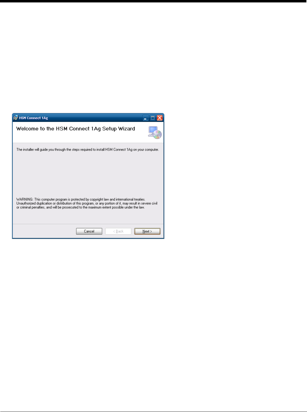
6 - 4
Installation
1. Connect the Thor VM2 to the PC using the proper connection cable.
2. If using ActiveSync, select Explore.
3. If using Windows Mobile Device Center, select File Management > Browse the contents of your device.
4. An explorer window is displayed for the Thor VM2. Browse to the \System\HSMConnect folder. Contact Customer
Support (page 11-1) for the necessary files if one of this folder is not present.
5. Select and copy the Setup.exe and HSM Connect.msi files from the Thor VM2 to the user PC. Note the location
chosen for the files.
6. Close the explorer dialog box. Do not disconnect the Thor VM2 ActiveSync connection.
7. Execute the setup.exe file that was copied to the user PC. This setup program installs the HSM Connect utility.
8. Follow the on screen installation prompts. The default installation directory depends on the PC operating system:
• C:\Program Files\Honeywell Inc\HSM Connect [version] (for 32-bit machines with HSM Connect installed)
• C:\Program Files (x86) \Honeywell Inc\HSM Connect [version] (for 64-bit machines with HSM Connect installed)
9. If desired, when the installation is complete, create a desktop shortcut to the HSM Connect.exe file at the location
indicated above. If a different directory was selected during installation, please substitute the appropriate directory.
10. HSM Connect is now installed and ready to use.
Using HSM Connect
1. Power up the Thor VM2.
2. Connect the Thor VM2 to the host PC using the USB connection cable. Once connected, the ActiveSync dialog box
appears and the ActiveSync connection is automatically established.
3. Select “No” for partnership when prompted. Dismiss any ActiveSync dialog boxes warning a partnership is not set up.
It is not necessary to establish a partnership to use HSM Connect. However, if a partnership is desired for other
reasons, one may be established now.
4. Double-click the HSM Connect icon that was created on the PC desktop.
5. HSM Connect launches.
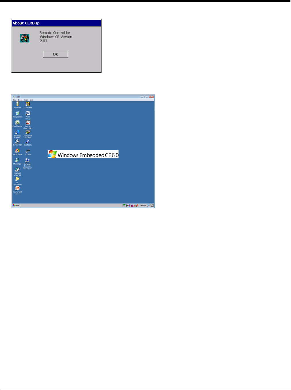
6 - 5
6. Click the OK button to dismiss the About CERDisp dialog box (either on the Thor VM2 desktop or n the HSM Connect
window on the PC desktop). The dialog box automatically times out and disappears after approximately 20 seconds.
7. The Thor VM2 can now be configured from the HSM Connect window. Input from the PC’s mouse and keyboard are
recognized as if they were attached to the Thor VM2.
8. When the remote session is completed, terminate the HSM Connect program by selecting File > Exit or clicking on the
X in the upper right hand corner to close the application, then disconnect the ActiveSync cable.

6 - 6

7 - 1
7
Enabler Installation and Configuration
Introduction
This section discusses Honeywell supported features with Wavelink Avalanche Mobile Device Servers. This section is split into
three basic areas:
• Installation
• User Interface
• Enabler Configuration
Installation
To use the Wavelink Avalanche MC System, the following items are required:
• A desktop or laptop PC on which to install the Avalanche MC Console.
• A desktop or laptop PC on which to install the Avalanche Mobile Device Server (this can be the same PC where the Avalanche
MC Console is installed).
• Wavelink Avalanche MC Console 4.2 or later.
• A Wavelink Device License for each client device.
To use Avalanche Remote Control, the follow additional items are required:
• Wavelink Remote Control plug-in, 2.0 or later
• A Wavelink Remote Control License for each client device
Installing the Enabler on Mobile Devices
Supported devices have the Avalanche Enabler installation files loaded, but not installed, on the mobile device when it is
shipped. The installation files are located in the \System folder on Windows devices.
Note: If the user is NOT using Wavelink Avalanche to manage their mobile device(s), the Enabler should not be installed
on the mobile device(s). Doing so results in unnecessary delays when booting the device.
The Avalanche Enabler installation file HSM_ENABLER.CAB (older software loads may use LXE_ENABLER.CAB instead)
is loaded on the Thor VM2 by Honeywell; however, the device is not configured to launch the Enabler installation file auto-
matically. The installation application must be run manually the first time Avalanche is used.
After installation, the Enabler runs as a background application monitoring for updates. This behavior can be modified by
accessing the Avalanche Update Settings panel through the Enabler interface.
This behavior can be modified by accessing the Avalanche Update Settings panel through the Enabler Interface.
The RMU.CE.CAB file is placed on the device during manufacturing in the \System\RMU folder.
During the Enabler installation process, the Enabler checks for the RMU.CE.CAB file in the \System folder.
• If present, it assumes the RMU.CE.CAB file is already installed and continues.
• If the file RMU.CE.CAB file is not present, it looks for the file in the \System\RMU folder.
• If present, the Enabler copies the file to the \System folder and installs it.
At this point, the OS will automatically install the Remote Management Utility (RMU) after the Thor VM2 reboots.
Enabler Uninstall Process
To remove the Avalanche Enabler from the Thor VM2:
1. Delete the Avalanche folder located in the \System directory.
2. Warm boot the Thor VM2.
The Avalanche folder cannot be deleted while the Enabler is running. See Stop the Enabler Service (page 7-2).
If sharing errors occur while attempting to delete the Avalanche folder, warm boot the Thor VM2, immediately delete the
Avalanche folder, and then perform another warm boot.

7 - 2
Stop the Enabler Service
To stop the Enabler from monitoring for updates from the Mobility Center Console:
1. Open the Enabler Settings Panels by tapping the Enabler icon on the Thor VM2 desktop.
2. Select File > Settings.
3. Select the Preferences tab.
4. Select Do not monitor to prevent automatic monitoring upon Startup.
5. Select Exit Application for an immediate shutdown of all Enabler update functionality upon exiting the user interface.
6. Click the OK button to save the changes.
7. Reboot the Thor VM2 if necessary.
Update Monitoring Overview
There are three methods by which the Enabler on the Thor VM2 can communicate with the Mobile Device Server running
on the host machine.
• Wired via a serial cable between the Mobile Device Server PC and the Thor VM2.
• Wired via a USB connection, using ActiveSync, between the Mobile Device Server PC and the Thor VM2.
• Wirelessly via the Thor VM2 2.4GHz radio and an access point
After installing the Enabler on the Thor VM2 the Enabler searches for a Mobile Device Server, first by polling all available
serial ports and then over the wireless network.
The Enabler running on the Thor VM2 will attempt to access COM1, COM2, and COM3. “Agent not found” will be reported
if the Mobile Device Server is not located or a serial port is not present or available (COM port settings can be verified using
the bar code wedge panels on the Thor VM2).
The wireless connection is made using the default wireless [radio] interface on the mobile device therefore the Thor VM2
must be actively communicating with the network for this method to succeed.
If a Mobile Device Server is found, the Enabler automatically attempts to apply all wireless and network settings from the
active profile. The Enabler also automatically downloads and processes all available packages.
If the Enabler does not automatically detect the Mobile Device Server, the IP address of the Mobile Device Server can be
entered on the Connect tab of the Enabler setup. See Enabler Configuration (page 7-4) for details.
Mobile Device Wireless and Network Settings
Once the connection to the Mobile Device Server is established, the Thor VM2 Enabler attempts to apply all network and
wireless settings contained in the active profile.
The success of the application of settings is dependent upon the local configuration of control parameters for the Enabler.
These local parameters cannot be overridden from the Avalanche MC Console.
The default Enabler adapter control settings are:
• Manage network settings – enabled
• Use Avalanche network profile – enabled
• Manage wireless settings – disabled
To configure the Avalanche Enabler management of the network and wireless settings:
1. Open the Enabler Settings Panels by tapping the Enabler icon on the desktop.
2. Select File > Settings.
3. Select the Adapters tab.
4. Choose settings for the Use Manual Settings parameter.
5. Choose settings for Manage Network Settings, Manage Wireless Settings and Use Avalanche Network Profile.
6. Click the OK button to save the changes.

7 - 3
7. Reboot the device.
Preparing a Device for Remote Management
Two additional utilities are necessary for remote management.
•The Remote Management Utility (RMU) must be installed on all mobile devices first – then you can control mobile
device reboot, storage RAM adjustment, real-time updates and Avalanche Enabler properties. If the RMU is not already
installed on the Thor VM2, see Using Wavelink Avalanche to Upgrade System Baseline, below.
If in doubt, verify RMU.CE.CAB exists in the \System folder. If the RMU.CE.CAB file is present when the Enabler is
installed, the RMU is also installed.
Important: - If the OS package includes double-byte Asian fonts, the storage RAM property of the RMU must be higher
than the default value (40MB).
If the amount of storage RAM is too low, the Enabler returns a “Mobile unit out of resources” error.
•Use the Wireless Configuration Application (WCA) when you want to remotely manage the Summit client device. This
utility is downloaded and installed in addition to the Remote Management Utility. The WCA is included when the Summit
radio driver software is updated. The WCA is automatically installed when the radio driver is updated.
If the Remote Management Utility (RMU) is not present on the Thor VM2, see Using Wavelink Avalanche to Upgrade Sys-
tem Baseline, below
Using Wavelink Avalanche to Upgrade System Baseline
This procedure assumes the Avalanche Enabler is already installed on the Thor VM2 and is already in communication
with the Avalanche MC Console.
Part 1 – Bootstrapping the RMU
1. Install the RMUCEbt package into the Avalanche MC Console. Do NOT include the Reboot option as part of
the configuration (i.e. the Reboot button in the “Reboot Options” branch must be unbolded).
2. Enable ONLY the RMUCEbt package in the Avalanche MC Console and update the devices. The RMU is
downloaded and automatically installed.
3. Disable the RMUCEbt package in the Avalanche MC Console.
4. For each device, double-click on the device to open the Client Controls dialog box.
5. Check the Delete Orphaned Packages checkbox and click the Update Now button.
6. After the sync completes, uncheck Delete Orphaned Packages and close the dialog box.
Part 2 – Installing Packages
1. Enable the RMUCE package in the Avalanche MC Console.
2. Enable all remaining packages and send them down. It is important that you include the new OS package in
this group (be sure to include the Enabler). If the radio is to be managed remotely, it is important to include
the radio package in this group so that after the reboot the radio can automatically associate. If the radio
package is not sent, the device loses connection to the network and manual configuration of the radio param-
eters is required.
3. Set the Reboot setting for the OS package to Auto.
4. After all packages are downloaded (this may take several minutes) the Remote Management Utility (RMU) is
launched. The RMU processes all the downloaded packages. If the radio package was downloaded, the
Wireless Configuration Application (WCA) is launched to process the new radio settings.
5. After the RMU finishes installing all the packages, the device is automatically coldbooted (assuming the
Reboot setting was set to Auto in Step 3).
6. After the Device completes the coldboot, the RMU is autoinstalled by the OS and the previously downloaded
packages are restored. Assuming at least one package has registry settings that were restored, and that
package was set to reboot (either auto or prompt), the RMU then performs an automatic warmboot.
7. After the warmboot, the device is configured.

7 - 4
8. If the device will no longer be monitored by Wavelink Avalanche, you may remove the Enabler to eliminate
boot up delays, if desired. Even if the Enabler is removed, the installed packages and their configurations
continue to be restored with every reboot by the RMU.
Version Information on Mobile Devices
The VersionInfo.EXE file is included in the Remote Management Utility package downloaded to the Thor VM2. It
is stored in the \Program Files\RMU folder. When VersionInfo.EXE is opened, a dialog box is presented to the
Thor VM2 user displaying:
• Remote Management Utility (RMU) version
• Wireless Configuration Application (WCA) version
VersionInfo displays the version for each utility only after that utility has been executed at least once.
User Interface
The Enabler can be configured and controlled manually through the user interface on the Thor VM2. This section details the
functionality that can be controlled by the user or system administrator.
Screen displays shown in this section are designed to present the end-user with information graphically.
Placement of information on the screen displays may be split between one or many tabbed panels.
Standard Avalanche Enabler parameters that are not supported by Honeywell may be missing or dimmed (visible but unable to
be edited) on the tabbed panels or screen displays.
Enabler Configuration
Depending on the version of the Enabler running on the Thor VM2, the desktop Enabler icon may look like one of the following:
The available configuration options and tabs may vary by Enabler version. The examples shown in this section assume the lat-
est version of the Enabler is installed on the Thor VM2.
The Enabler user interface application is launched by clicking either the Enabler icon on the desktop or Taskbar or by selecting
Avalanche Enabler from the Programs menu.
The opening screen presents the Thor VM2 user with the connection status and a navigation menu.
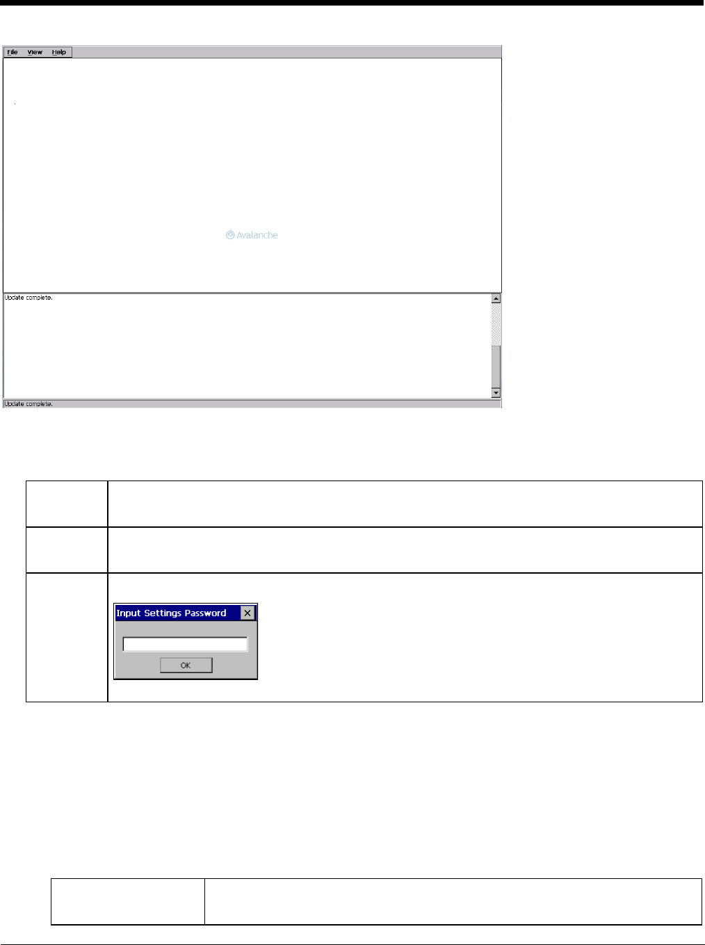
7 - 5
Note: Some parameters and features described in this section may not be available if you are not running the latest version of
the Enabler. Contact Technical Assistance (page 11-1) for upgrades.
File Menu Options
Avalanche Update using File > Settings
Use these menu options to setup the Avalanche Enabler on the Thor VM2. Change the settings and save them by reboot-
ing before connecting to the network.
Alternatively, the Mobile Device Server can be disabled until needed (refer to the Wavelink Avalanche Mobility Center
User’s Guide for details).
Menu Options
Note: Your Thor VM2 screen display may not be exactly as shown in the following menu options. Contact Technical
Assistance (page 11-1) for version information and upgrade availability.
Connect The Connect option under the File menu allows the user to initiate a manual connection to the Mobile Device
Server. The connection methods, by default, are wireless and COM connections. Any updates available
will be applied to the Thor VM2 immediately upon a successful connection.
Scan
Config
The Scan Configuration feature is not supported. The Scan Config option under the File menu allows the
user to configure Enabler settings using a special bar code that can be created using the Avalanche MC
Console utilities. Refer to the Wavelink Avalanche Mobility Center User Guide for details.
Settings The Settings option under the File menu allows the Thor VM2 user to access the control panel to locally
configure the Enabler settings. The Enabler control panel is, by default, password protected.
The default Settings password is system. The password is not case-sensitive.
Connection (page 7-6) Enter the IP Address or host name of the Mobile Device Server. Set the order in which
serial ports or RF connections are used to check for the presence of the Mobile Device
Server.
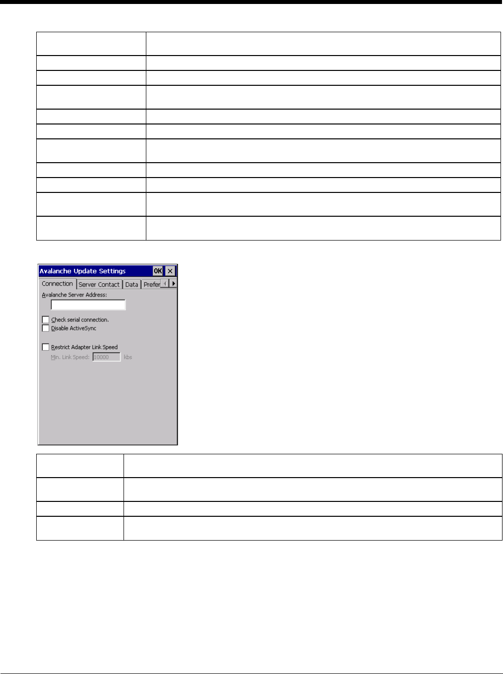
7 - 6
Connection
Server Contact (page 7-7) Setup synchronization, scheduled Mobile Device Server contact, suspend and reboot set-
tings.
Data (page 7-8) Control when data is transferred between the device and the Mobile Device Server.
Preferences (page 7-8) Set options for Enabler startup or shutdown and logging.
Display (page 7-9) Set up the Windows display at startup, on connect and during normal mode. The settings
can be adjusted by the user.
Taskbar (page 7-10) Set options for Taskbar.
Execution (page 7-10) Not available in this release. Use AppLock instead, which is resident on each device.
Scan Config (page 7-11) This option allows the user to configure Enabler settings using a special bar code that is
created by the Avalanche MC Console. Scan Config not currently supported.
Shortcuts (page 7-11) Add, delete and update shortcuts to user-allowable applications.
SaaS (page 7-12) Configure the Enabler to connect with Avalanche on Demand.
Adapters (page 7-12) Enable or disable network and wireless settings. Select an adapter and switch between
the Avalanche Network Profile and manual settings.
Status (page 7-14) View the current adapter signal strength and quality, IP address, MAC address, SSID,
BSSID and Link speed. The user cannot edit this information.
Avalanche Server
Address Enter the IP Address or host name of the Mobile Device Server assigned to the Thor VM2.
Check Serial Con-
nection Indicates whether the Enabler should first check for serial port connection to the Mobile Device
Server before checking for a wireless connection to the Mobile Device Server.
Disable ActiveSync Disable ActiveSync connection with the Mobile Device Server.
Restrict Adapter
Link Speed Default is disabled. Minimum Link Speed dimmed. When enabled, the Enabler only allows a
connection to the server if the detected link speed is greater than or equal to the specified value.
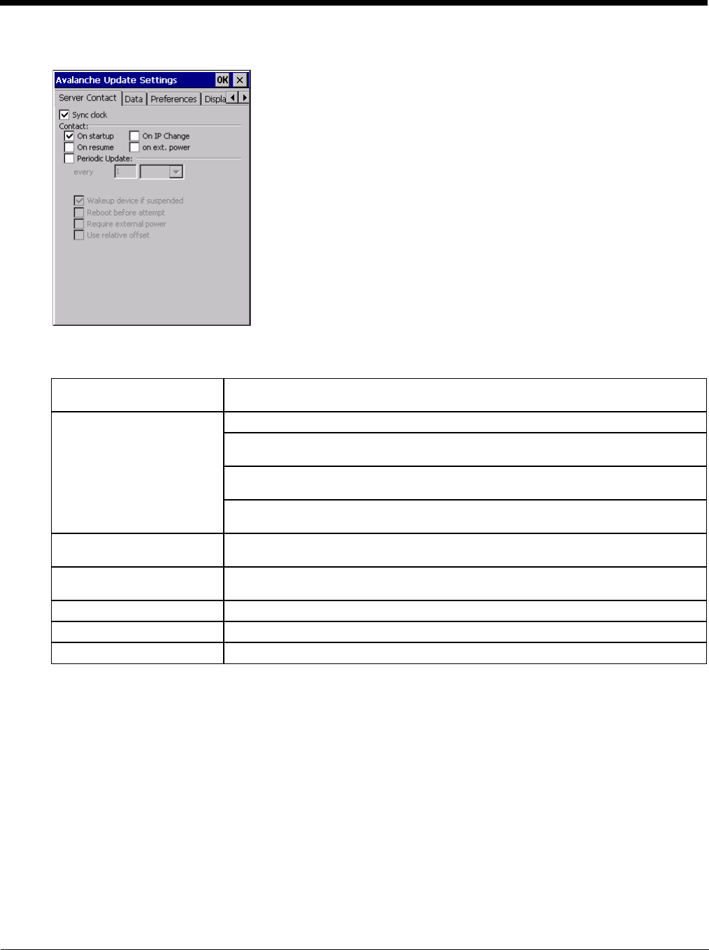
7 - 7
Server Contact
Note: Your Thor VM2 screen display may not be exactly as shown above. Contact Technical Assistance (page 11-1)
for upgrade availability and version information.
Sync Clock Reset the time on the Thor VM2 based on the time on the Mobile Device Server host
PC.
Contact On Startup – Connect to the Mobile Device Server when the Enabler is accessed.
On Resume – Connect to the Mobile Device Server when resuming from Suspend
mode.
On IP Change – Connect to the Mobile Device Server when the IP address of the Thor
VM2 changes.
On Ext. Power – Initiate connection to the Mobile Device Server when the device is
connected to an external power source, such as based on a docking event.
Contact Periodically / Period-
ic Update Allows the administrator to configure the Enabler to contact the Mobile Device Server
and query for updates at a regular interval beginning at a specific time.
Wakeup device if suspended If the time interval for periodic contact with the Mobile Device Server occurs, a mobile
device that is in Suspend Mode can wakeup and process updates.
Reboot before attempt Reboot mobile device before attempting to contact Mobile Device Server.
Require external power Only connect when the mobile device has external power.
Use relative offset Dimmed.
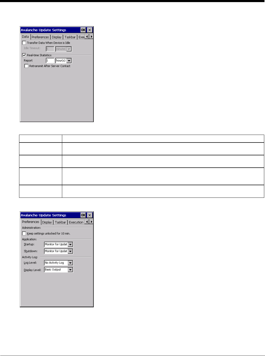
7 - 8
Data
The Data tab controls when data is transferred between the Thor VM2 and the Mobile Device Server.
Preferences
Administration
By default, Keep settings unlocked for 10 minutes is disabled (checkbox is blank).
Network When checked, the LAN/Wi-Fi network is enabled to transfer statistics.
Report Specifies the Report Interval, how frequently the Enabler reports statistics to the Mobile Device
Server.
Retransmit After
Server Contact Specifies if the device sends statistics to the Mobile Device Server immediately following a con-
nection to the server.
Restrict Band-
width to User Idle
Time
When enabled, periodic updates from the Mobile Device Server are postponed until the Thor VM2
has been idle for the specified period of time. The default is disabled.
Idle timeout Specify the length of time the device must be idle before a periodic update can run, used when
the parameter above is enabled.
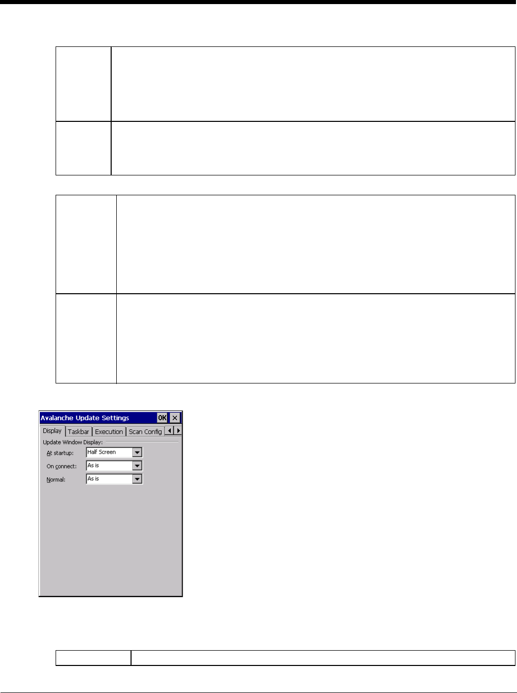
7 - 9
Application
Activity Log
Display
Update Window Display
The user interface for the Enabler can be configured to dynamically change based on the status of the Thor VM2
connection with the Mobile Device Server.
Startup Behavior of the Enabler when the Thor VM2 boots up. The default is Monitor for Updates.
• Do not Monitor - When the device boots, do not launch the Enabler application and do not attempt
to connect to the Mobile Device Server.
• Monitor for Updates - Attempt to connect to the Mobile Device Server and process any updates
that are available. Do not launch the Enabler application.
• Launch User Interface - Attempt to connect to the Mobile Device Server and process any updates
that are available. Launch the Enabler application.
Shutdown Behavior of the monitor when the Enabler is exited. The default is Monitor for Updates.
• Monitor for Updates - Attempt to connect to the Mobile Device Server and process any updates
that are available. Do not launch the Enabler application.
• Exit Application - Terminates the monitor (requires successful password entry if a password has
been configured).
Log Level Use this option to control the level of detail recorded in the log file. The default is No Activity Log.
• No Activity Log - No log file is written.
• Critical - Only critical errors written to the log files.
• Error - Communication or configuration problems are written to the log file along with critical
messages.
• Warning - Possible operation problems are written to the log file along with critical and error
messages.
• Info - Operational information is written to the log file.
• Debug - The most detailed log file.
Display Level Use this option to control the level of detail shown on the main Enabler screen. The default is Basic
Output.
• Basic Output - General information is displayed.
• Critical - Critical errors are displayed in addition to those above.
• Error - Communication or configuration problems are displayed in addition to those above.
• Warning - Possible operation problems are displayed in addition to those above.
• Info - Operational information is displayed in addition to those above.
• Debug - The most detailed list is displayed.
At startup Default is Half Screen. Options are Half screen, Hidden or Full screen.
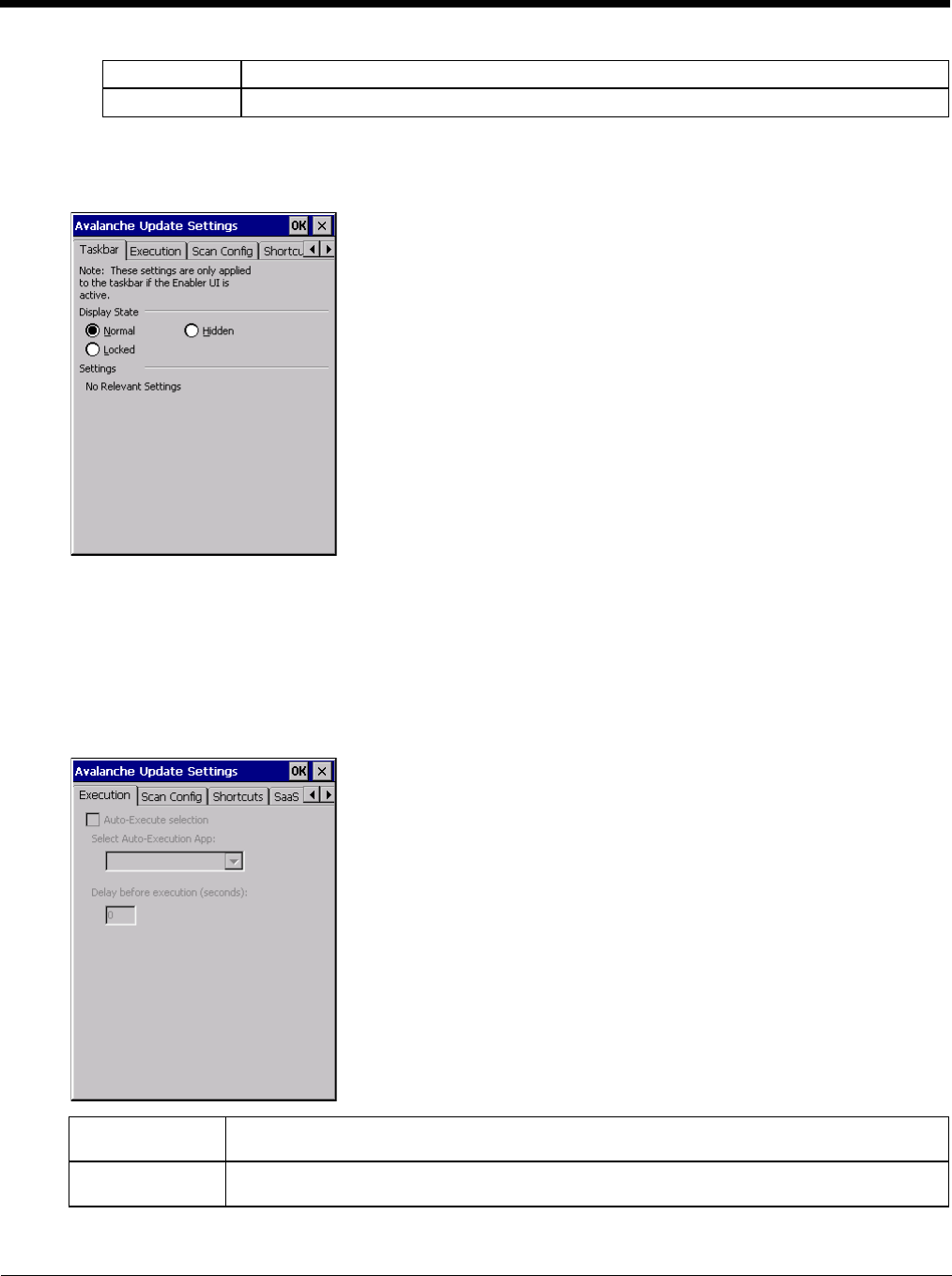
7 - 10
Taskbar
For best results, use AppLock configured via the Administration (page 5-19) control panel to manage the taskbar.
AppLock is resident on each mobile device.
The Display State options control the appearance of the taskbar while using the Enabler interface.
• Normal - taskbar is visible, taskbar icons function normally.
• Hidden - taskbar is not displayed
• Locked - taskbar is visible, but most icons are hidden or for information only.
Execution
Note the dimmed options on this Thor VM2 panel. This menu option is designed to manage downloaded applications
for automatic execution upon startup.
On connect Default is As Is. Options are As is, Half screen, or Full screen.
Normal Default is As Is. Options are Half screen, Hidden or As Is.
Auto-Execute Se-
lection An application that has been installed with the Avalanche Management system can be run auto-
matically following each boot.
Select Auto-Exe-
cute App The drop-down box provides a list of applications that have been installed with the Avalanche
Management System.
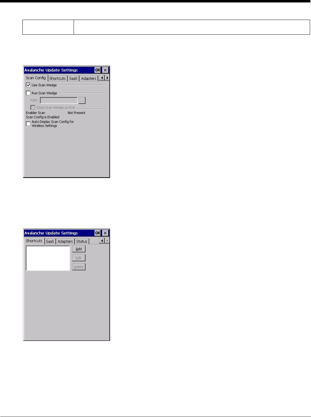
7 - 11
Scan Config
For best results, use eXpress Config and eXpress Scan (page 7-15) for this function. eXpress Scan is included with
the Thor VM2 enablers.
Scan Config functionality is a standard option of the Wavelink Avalanche MC system but is not currently supported on
the Thor VM2.
Shortcuts
For best results, use AppLock configured via the Administration (page 5-19) for this function. AppLock is resident on
each mobile device.vice.
Configure shortcuts to other applications on the Thor VM2. Shortcuts are viewed and activated in the Programs panel.
This limits the user’s access to certain applications when the Enabler is controlling the mobile device display.
Delay before exe-
cution Time delay before launching Auto-Execute application.
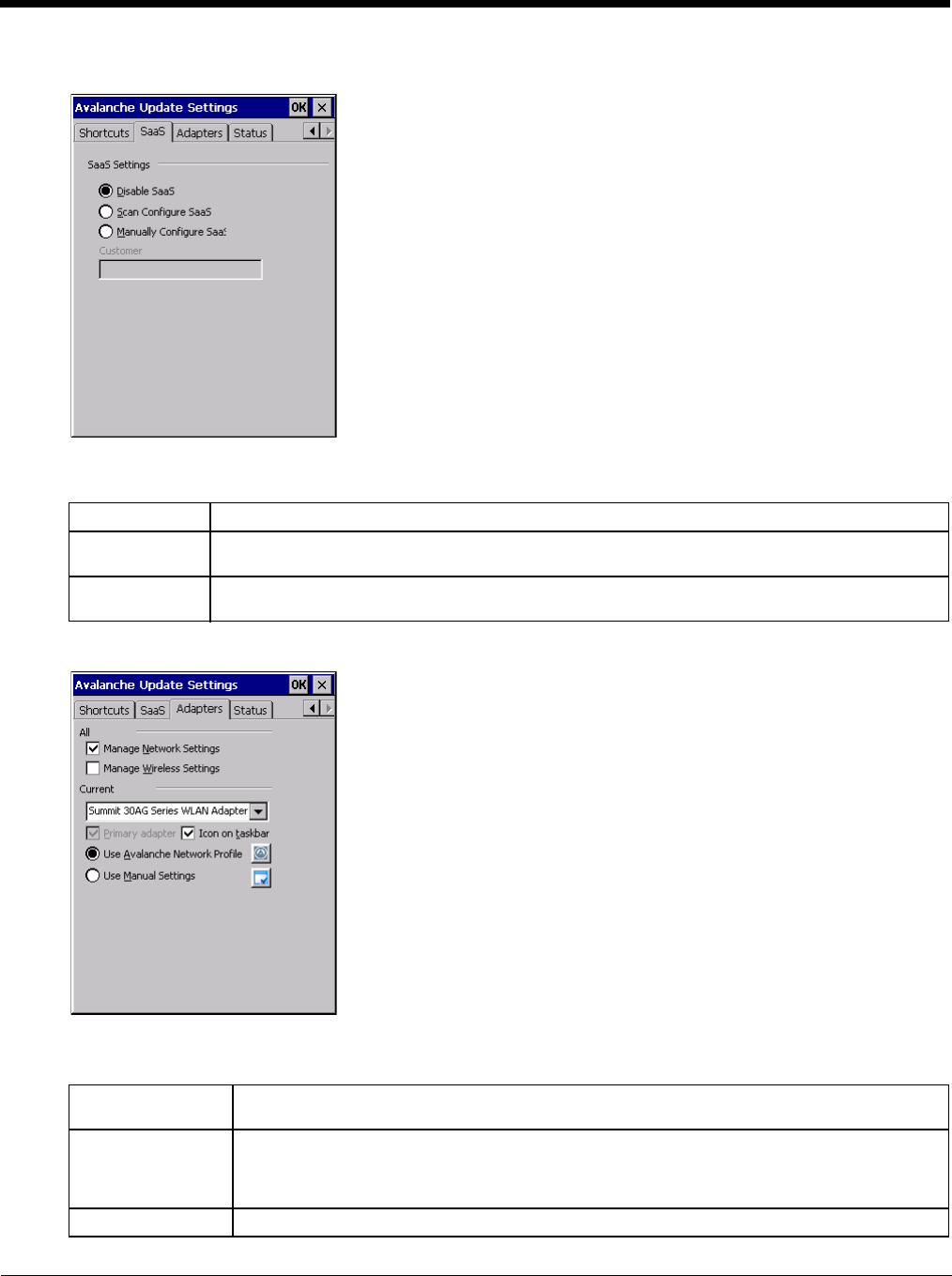
7 - 12
SaaS
Use to configure the Enabler to connect with Avalanche on Demand. This is a Software-as-a-Service version of Ava-
lanche. Using either of the SaaS configuration options below assumes the user has registered with Wavelink.
Adapters
Note: Review the network settings configuration utilities and the default values before setting All Adapters to Enable in
the Adapters applet.
Disable SaaS No SaaS connection is used.
Scan Configure
SaaS Scan bar codes printed from within the Avalanche Console to configure the Enabler for the SaaS
connection.
Manually Config-
ure SaaS Manually enter the SaaS connection information. Enter the server address on the Connection tab
and the customer ID in the Company text box.
Manage Network
Settings When enabled, the Enabler will control the network settings. This parameter cannot be config-
ured from the Avalanche Mobility Center Console and is enabled by default.
Manage Wireless
Settings When enabled, the Enabler will control the wireless settings. This parameter cannot be config-
ured from the Avalanche Mobility Center Console and is disabled by default. For Summit clients,
Manage Wireless Settings should not be checked as configuration packages provide more radio
configuration options.
Current Adapter Lists all network adapters currently installed on the Thor VM2.
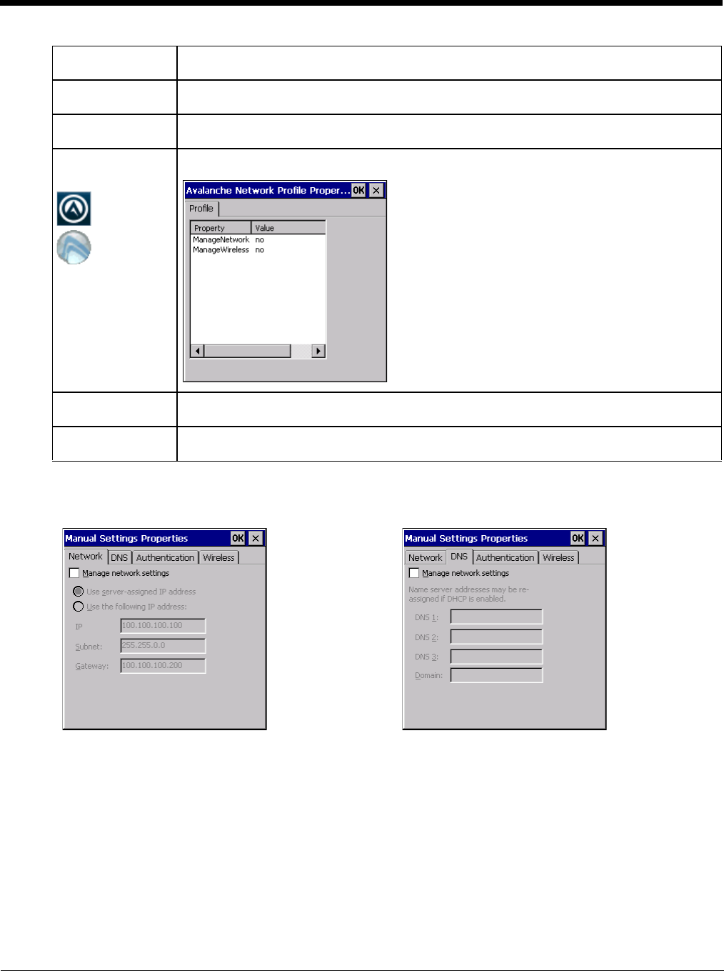
7 - 13
Note: A reboot may be required after enabling or disabling these options.
Primary Adapter Indicates if the Enabler is to attempt to configure the primary adapter (active only if there are
multiple network adapters).
Icon on taskbar Places the Avalanche icon in the Avalanche taskbar that may, optionally, override the standard
Windows taskbar.
Use Avalanche Net-
work Profile The Enabler will apply all network settings sent to it by the Mobile Device Server.
Avalanche Icon
(varies by Enabler
version)
Selecting the Avalanche Icon will access the Avalanche Network Profile tab which will display
current network settings.
Use Manual Set-
tings When enabled, the Enabler will ignore any network or wireless settings coming from the Ava-
lanche MC Console and use only the network settings on the Thor VM2.
Properties Icon Selecting the Properties icon displays the Manual Settings Properties dialog applet. From here,
the user can configure Network, DNS and Wireless parameters using the displays shown below:
Network DNS
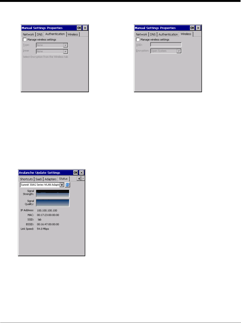
7 - 14
It is not recommend to enable “Manage Wireless Settings” for Summit Client devices.
Troubleshooting - When you download a profile that is configured to manage network and wireless settings, the
Enabler will not apply the manage network and wireless settings to the adapter unless the global Manage wireless set-
tings and Manage network settings options are enabled on the Adapters (page 7-12) panel. Until these options are
enabled, the network and wireless settings are controlled by the third-party software associated with these settings.
Status
The Status panel displays the current status of the Thor VM2 network adapter selected in the drop down box. Note the
availability of the Windows standard Refresh button.
When the Windows Refresh button is tapped, the signal strength, signal quality and link speed are refreshed for the
currently selected adapter. It also searches for new adapters and may cause a slight delay to refresh the contents of
the drop-down menu.
Link speed indicates the speed at which the signal is being sent from the adapter to the Thor VM2. Speed is depen-
dent on signal strength.
Exit
The Exit option is password protected. The default password is leave. The password is not case-sensitive.
Authentication Wireless
7 - 15
Depending on the behavior chosen for the Shutdown parameter, the following screen may be displayed:
Note: The icon on the screen above may differ based on the version of the Enabler installed on the Thor VM2.
Change the option if desired. Tap the X button to cancel Exit. Tap the OK button to exit the Avalanche applet.
Using Remote Management
1. Configure the radio to connect to the network running the Mobile Device Server. After the Thor VM2 is connected, proceed
to step 2.
2. If it is desired to configure the radio using the Summit package, add the configured package to the Wavelink Avalanche MC
Console and enable it.
3. Verify RMU.CE.CAB exists in the \System\RMU folder.
4. Double-click the Thor VM2 enabler CAB file in the \System folder.
5. The enabler automatically launches after installation and contacts the Mobile Device Server. The Avalanche MC Console
connected to that Mobile Device Server identifies the remote device and performs a sync. This downloads any available
packages available for the Thor VM2.
eXpress Scan
If the Thor VM2 has an eXpress Scan icon on the desktop, eXpress Scan may be used for the initial configuration of the device.
If the eXpress Scan icon is not present on the desktop, perform the Enabler Installation (page 7-1).
If the eXpress Scan icon is present, follow these steps to configure the Thor VM2 to connect with the wireless network and the
Mobile Device Server.
Step 1: Create Bar Codes
Bar codes are created with the eXpress Config utility on the desktop/laptop computer, not the mobile device. Depending on
the bar code length and the number of parameters selected, eXpress Config generates one or more bar codes for device
configuration. The bar codes contain configuration parameters for the wireless client in the mobile device and may also
specify the address of the Mobile Device Server.
Bar codes should be printed at a minimum of 600 dpi.
Please see Using Wavelink Avalanche for details on creating barcodes.
Step 2: Scan Bar Codes
For each mobile device to be configured, please follow these instructions.
Start eXpress Scan on the Thor VM2 by double-clicking the eXpress Scan icon.
eXpress Scan Desktop Icon
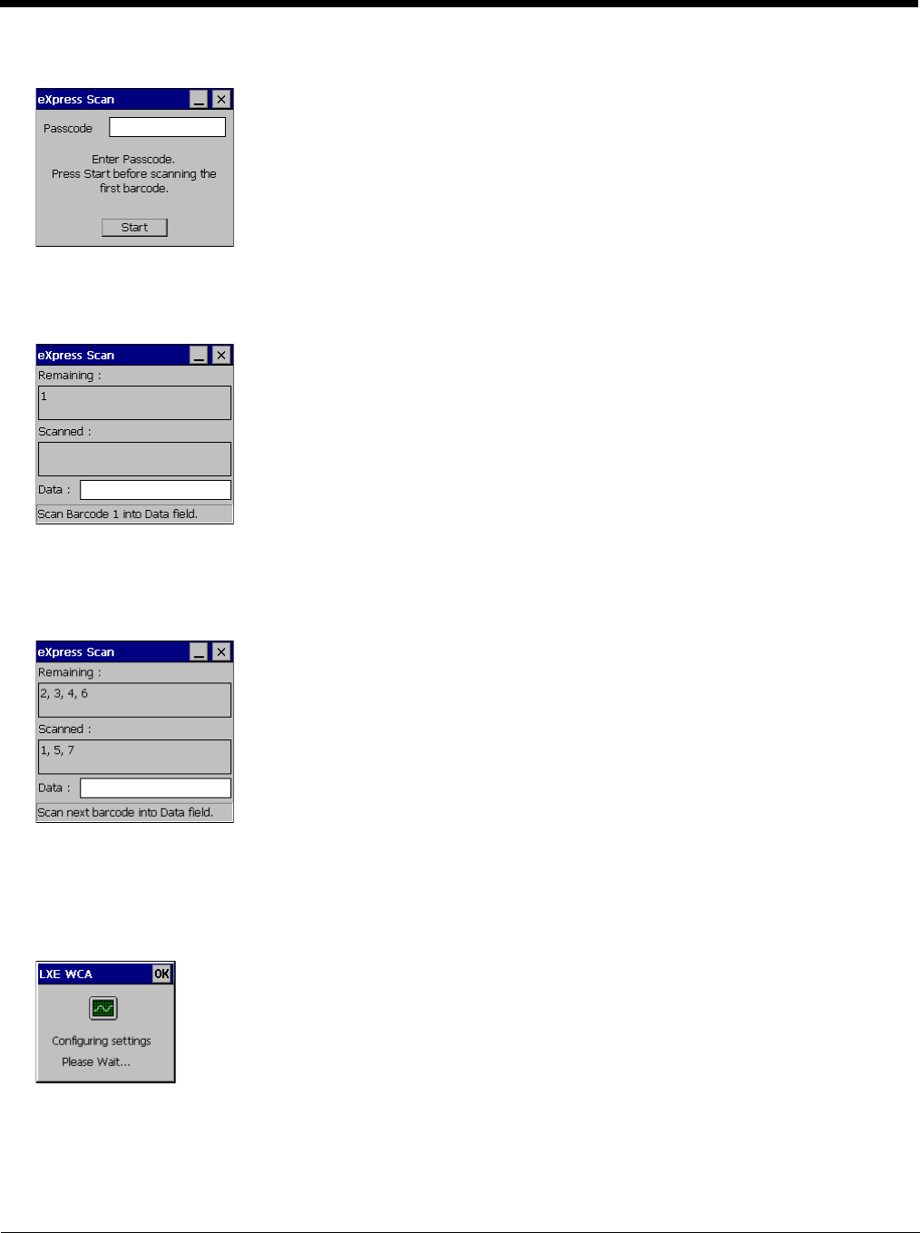
7 - 16
Enter the bar code password, if any.
Click Start.
Bar code 1 must be scanned first. The scanned data is displayed in the “Data” text box. The password, if any, entered
above is compared to the password entered when the bar codes were created.
If the passwords match, the bar code data is processed and the screen is updated to reflect the number of bar codes
included in the set.
If the passwords do not match, an error message is displayed. The current screen can be closed using the X box in the
upper right corner. The password can be re-entered and Bar Code 1 scanned again.
The remaining bar codes may be scanned in any order. After a bar code is scanned, that bar code is removed from the
“Remaining:” list and placed in the “Scanned:” list.
Step 3: Process Completion
After the last bar code is scanned, the settings are automatically applied.
Once configured, the Thor VM2 is warmbooted. Once connected to the wireless network and the Mobile Device Server,
any software updates and additional configuration data are downloaded.

8 - 1
8
Wireless Network Connections
Summit Wireless Network Configuration
The Summit client device is a Summit 802.11a/b/g radio, capable of 802.11a, 802.11b and 802.11g data rates. The radio can
be configured for no encryption, WEP encryption or WPA security.
Security Options Supported are
Important Notes
After making any changes to the wireless configuration, warmboot the Thor VM2.
Summit Client Utility
Note: When making changes to profile or global parameters, the device should be warmbooted afterwards.
Start > Programs > Summit > SCU or
SCU Icon on Desktop or
Summit Tray Icon (if present) or
Wi-FI Icon in the Windows Control Panel (if present)
The Main tab provides information, admin login and active profile selection.
Profile specific parameters are found on the Profile tab. The parameters on this tab can be set to unique values for each profile.
The Status tab contains information on the current connection.
The Diags tab provides utilities to troubleshoot the radio.
Global parameters are found on the Global tab. The values for these parameters apply to all profiles.
Help
Help is available by clicking the ? icon in the title bar on most SCU screens.
The SCU help may also be accessed by selecting Start > Help and tapping the Summit Client Utility link. The SCU does
not have to be accessed to view the help information using this option.
Summit Tray Icon
The Summit tray icon is displayed when:
• The Summit radio is installed and active
• The Windows Zero Config utility is not active
• The Tray Icon setting is On
Click the icon to launch the SCU. Use the tray icon to view the radio status:
It is important that all dates are correct on the Thor VM2 and host computers when using any type of certificate. Certifi-
cates are date sensitive and if the date is not correct authentication will fail.
It may be necessary to upgrade radio software in order to use certain Summit Client Utility (SCU) features. Contact
Technical Assistance (page 11-1) for details.
When using the 802.11a radio, the U-NII 1 band is the preferred band for indoor operation. For regulatory domains in
which the U-NII 3 band is allowed, the following channels are supported: 149, 153, 157 and 161. The AP must be con-
figured accordingly.
The Summit tray icon provides access to the SCU and is a visual indicator of radio status.
The radio is not currently associated or authenticated to an Access Point
The signal strength for the currently associated/authenticated Access Point is less than -90 dBm
!
!

8 - 2
Wireless Zero Config Utility
• The WZC utility has an icon in the toolbar that looks like a networked computer with a red X beside it, indicating that
Wireless Zero Config application is enabled but the connection is inactive at this time (the device is not connected to a
network). The WZC icon may not be visible until control is passed to the WZC utility as described below.
• You can use either the Wireless Zero Configuration Utility or the Summit Client Utility to connect to your network. The
Summit Client Utility is recommended because the Wireless Zero Configuration Utility cannot control the complete set of
security features of the radio.
To Switch Control to the Wireless Zero Config Utility
1. Select ThirdPartyConfig in the Active Profile drop down list as the active profile on the Main tab.
2. Warmboot the device.
The Summit Client Utility passes control to Wireless Zero Config and the WZC Wireless Information control panel.
Using the options in the Wireless Zero Config panels, setup radio and security settings. There may be a slight delay
before the Wireless Zero Config icon indicates the status of the connection.
To Switch Control to SCU
1. To switch back to SCU control, select any other profile in the SCU Active Config drop down list, except ThirdPar-
tyConfig.
2. Warmboot the device.
Radio control is passed to the SCU.
The signal strength for the currently associated/authenticated Access Point is -71 dBm to -90 dBm
The signal strength for the currently associated/authenticated Access Point is -51 dBm to -70 dBm
The signal strength for the currently associated/authenticated Access Point is greater than -50 dBm
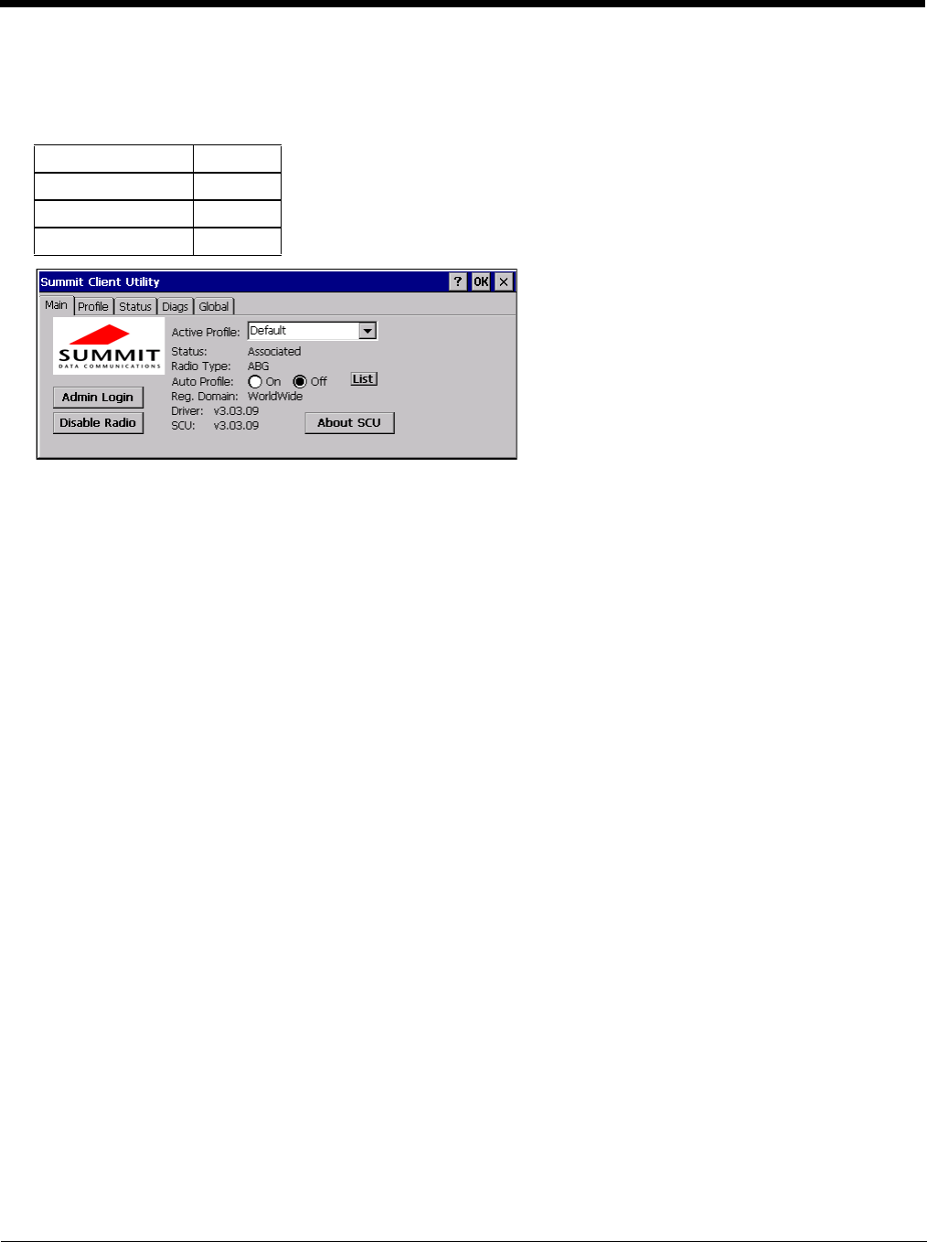
8 - 3
Main
Start > Programs > Summit > Main tab
Factory Default Settings
The Main tab displays information about the wireless client device including:
• SCU (Summit Client Utility) version
• Driver version
• Radio Type (ABG is an 802.11 a/b/g radio).
• Regulatory Domain
• Copyright Information can be accessed by tapping the About SCU button
• Active Config profile / Active Profile name
• Status of the client (Down, Associated, Authenticated, etc.).
The Active Profile can be switched without logging in to Admin mode. Selecting a different profile from the drop down list
does not require logging in to Administrator mode. The profile must already exist. Profiles can be created or edited after
the Admin login password has been entered and accepted.
When the profile named “ThirdPartyConfig” is chosen as the active profile, the Summit Client Utility passes control to Win-
dows Zero Config for configuration of all client and security settings for the network module.
The Disable Radio button can be used to disable the network card. Once disabled, the button label changes to Enable
Radio. By default the radio is enabled.
The Admin Login button provides access to editing wireless parameters. Profile and Global may only be edited after
entering the Admin Login password.
The password is case-sensitive.
Auto Profile
If the Auto Profile selection is not present on the Main tab, an SCU upgrade is necessary to support this feature on the
Thor VM2.
Auto Profile allows the user to configure a list of profiles that the SCU can search when a radio connection is lost. After
using the Profile tab to create any desired profiles, return to the Main tab. To specify which profiles are to be included
in Auto Profile, click the List button.
Admin Login SUMMIT
Radio Enabled
Active Config/Profile Default
Regulatory Domain Worldwide
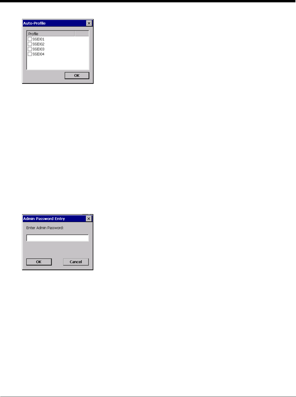
8 - 4
The Auto Profile selection screen displays all currently configured profiles. Click on the checkbox for any profiles that
are to be included in Auto Profile selection then click ok to save.
To enable Auto Profile, click the On button on the Main tab.
When Auto Profile is On, if the radio goes out of range from the currently selected profile, the radio then begins to
attempt to connect to the profiles listed under Auto Profile.
The search continues until:
• the SCU connects to and, if necessary, authenticates with, one of the specified profiles or
• the Off button is clicked to turn off Auto Profile.
Note: Do not include any profiles with an Ad Hoc radio mode this listing.
Once logged in, the button label changes to Admin Logout. To logout, either tap the Admin Logout button or exit the
SCU without tapping the Admin Logout button.
Admin Login
To login to Administrator mode, tap the Admin Login button.
Once logged in, the button label changes to Admin Logout. The admin is automatically logged out when the SCU is
exited. The Admin can either tap the Admin Logout button, or the OK button to logout.
Enter the Admin password (the default password is SUMMIT and is case sensitive) and tap OK. If the password is
incorrect, an error message is displayed.
The Administrator default password can be changed on the Global tab.
The end-user can:
• Turn the radio on or off on the Main tab.
• Select an active Profile on the Main tab.
• View the current parameter settings for the profiles on the Profile tab.
• View the global parameter settings on the Global tab.
• View the current connection details on the Status tab.
• View radio status, software versions and regulatory domain on the Main tab.
• Access additional troubleshooting features on the Diags tab.
After Admin Login, the end-user can also:
• Create, edit, rename and delete profiles on the Profile tab.
• Edit global parameters on the Global tab.
• Enable/disable the Summit tray icon in the taskbar.
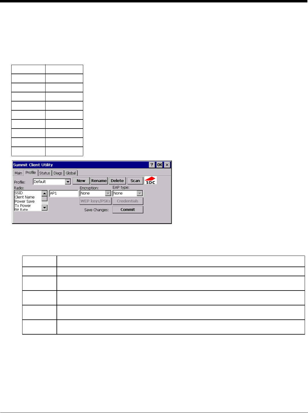
8 - 5
Profile
Start > Programs > Summit > Profile tab
Note: Tap the Commit button to save changes before leaving this panel or the SCU. If the panel is exited before tapping
the Commit button, changes are not saved!
Factory Default Settings
When logged in as an Admin use the Profile tab to manage profiles. When not logged in as an Admin, the parameters can
be viewed, and cannot be changed. The buttons on this tab are dimmed if the user is not logged in as Admin.
Buttons
Profile Default
SSID Blank
Client Name Blank
Power Save CAM
Tx Power Maximum
Bit Rate Auto
Radio Mode BGA rates full
Auth Type Open
EAP Type None
Encryption None
Button Function
Commit Saves the profile settings made on this screen. Settings are saved in the profile.
Credentials Allows entry of a username and password, certificate names, and other information required to authen-
ticate with the access point. The information required depends on the EAP type.
Delete Deletes the profile. The current active profile cannot be deleted and an error message is displayed if
a delete is attempted.
New Creates a new profile with the default settings (see Profile Parameters) and prompts for a unique name.
If the name is not unique, an error message is displayed and the new profile is not created.
Rename Assigns a new, unique name. If the new name is not unique, an error message is displayed and the
profile is not renamed.

8 - 6
Note: Unsaved Changes – The SCU will display a reminder if the Commit button is not clicked before an attempt is
made to close or browse away from this tab.
Important – The settings for Auth Type, EAP Type and Encryption depend on the security type chosen.
Profile Parameters
Scan Opens a window that lists access points that are broadcasting their SSIDs. Tap the Refresh button to
view an updated list of APs. Each AP’s SSID, its received signal strength indication (RSSI) and wheth-
er or not data encryption is in use (true or false). Sort the list by tapping on the column headers.
If the scan finds more than one AP with the same SSID, the list displays the AP with the strongest RSSI
and the least security.
If you are logged in as an Admin, tap an SSID in the list and tap the Configure button, you return to the
Profile window to recreate a profile for that SSID, with the profile name being the same as the SSID (or
the SSID with a suffix such as “_1” if a profile with the SSID as its name exists already).
WEP Keys /
PSK Keys Allows entry of WEP keys or pass phrase as required by the type of encryption.
Parameter Default Explanation
Edit Profile Default A string of 1 to 32 alphanumeric characters, establishes the name of the Profile.
Options are Default or ThirdPartyConfig.
SSID Blank A string of up to 32 alphanumeric characters. Establishes the Service Set Identifier
(SSID) of the WLAN to which the client connects.
Client Name Blank A string of up to 16 characters. The client name is assigned to the network card and
the device using the network card. The client name may be passed to networking
wireless devices, e.g. Access Points.
Power Save CAM Power save mode.
Options are: Constantly Awake Mode (CAM) power save off, Maximum (power saving
mode) and Fast (power saving mode). When using power management, use FAST
for best throughput results.
Tx Power Maximum Maximum setting regulates Tx power to the Max power setting for the current regula-
tory domain.
Options are: Maximum, 50mW, 30mW, 20mW, 10mW, 5mW, or 1mW.
Bit Rate Auto Setting the rate to Auto will allow the Access Point to automatically negotiate the bit
rate with the client device.
This parameter cannot be changed.
Auth Type Open 802.11 authentication type used when associating with the Access Point.
Options are: Open, LEAP, or Shared key.
EAP Type None Extensible Authentication Protocol (EAP) type used for 802.1x authentication to the
Access Point.
Options are: None, LEAP, EAP-FAST, PEAP-MSCHAP, PEAP-GTC, PEAP-TLS,
EAP-TTLS, or EAP-TLS.
Note: EAP Type chosen determines whether the Credentials button is active and
also determines the available entries in the Credentials pop-up window.
Button Function

8 - 7
It is important the Radio Mode parameter correspond to the AP to which the device is to connect. For example, if this
parameter is set to G rates only, the Thor VM2 may only connect to APs set for G rates and not those set for B and G
rates.
Using CKIP
Contact Technical Assistance (page 11-1) if an update to the SCU is needed to support CKIP.
To use CKIP on the Thor VM2:
1. Select WEP from the encryption list and None from the EAP type list. CKIP LEAP is not supported.
2. The Thor VM2 can connect to any AP that is configured for manual WEP or manual CKIP. The Thor VM2 auto-
matically detects whether WEP or CKIP is configured on the AP and connects accordingly.
3. All APs must be configured the same. If some APs are configured with different security types enabled, the Thor
VM2 may experience disconnects or delays when roaming.
Encryption None Type of encryption to be used to protect transmitted data. Available options may vary
by SCU version.
Options are: None, WEP (or Manual WEP), WEP EAP (or Auto WEP), WPA PSK,
WPA TKIP, WPA CCKM, WPA2 PSK, WPA2 AES, or WPA2 CCKM.
An upgrade to the SCU may be necessary to support CKIP. See Using CKIP (page
8-7) for details.
The Encryption type chosen determines if the WEP Keys / PSK Keys button is active
and also determines the available entries in the WEP or PSK pop-up window.
Radio Mode BGA Rates Full Specify 802.11a, 802.11b and/or 802.11g rates when communicating with the AP.
The options displayed for this parameter depend on the type of radio installed in the
mobile device.
Options:
B rates only (1, 2, 5.5 and 11 Mbps)
BG Rates Full (All B and G rates)
G rates only (6, 9, 12, 18, 24, 36, 48 and 54 Mbps)
BG optimized or BG subset (1, 2, 5.5, 6, 11, 24, 36 and 54 Mbps)
A rates only (6, 9, 12, 18, 24, 36, 48 and 54 Mbps)
ABG Rates Full (All A rates and all B and G rates with A rates preferred)
BGA Rates Full (All B and G rates and all A rates with B and G rates preferred)
Ad Hoc (when connecting to another client device instead of an AP)
Default:
BGA Rates Full
Parameter Default Explanation

8 - 8
Status
Start > Programs > Summit > Status tab
This screen provides information on the radio:
• The profile being used.
• The status of the radio card (down, associated, authenticated, etc.).
• Client information including device name, IP address and MAC address.
• Information about the Access Point (AP) maintaining the connection to the network including AP name, IP address and
MAC address.
• Channel currently being used for wireless traffic.
• Bit rate in Mbit.
• Current transmit power in mW.
• Beacon period – the time between AP beacons in kilomicroseconds. (one kilomicrosecond = 1,024 microseconds).
• DTIM interval – A multiple of the beacon period that specifies how often the beacon contains a delivery traffic indication
message (DTIM). The DTIM tells power saving devices a packet is waiting for them. For example, if DTIM = 3, then
every third beacon contains a DTIM.
• Signal strength (RSSI) displayed in dBm and graphically.
• Signal quality, a measure of the clarity of the signal displayed in percentage and graphically.
There are no user entries on this screen.
Note: After completing radio configuration, it is a good idea to review this screen to verify the radio has associated (no
encryption, WEP) or authenticated (LEAP, any WPA), as indicated above.

8 - 9
Diags
Start > Programs > Summit > Diags tab
The Diags screen can be used for troubleshooting network traffic and radio connectivity issues.
•(Re)connect – Use this button to apply (or reapply) the current profile and attempt to associate or authenticate to the
wireless LAN. All activity is logged in the Diagnostic Output box on the lower part of the screen.
•Release/Renew – Obtain a new IP address through release and renew. All activity is logged in the Diagnostic Output
box. If a fixed IP address has been assigned to the radio, this is also noted in the Diagnostic Output box. Note that the
current IP address is displayed above this button.
•Start Ping – Start a continuous ping to the IP address specified in the text box to the right of this button. Once the button
is clicked, the ping begins and the button label changes to Stop Ping. Clicking the button ends the ping. The ping also
ends when any other button on this screen is clicked or the user browses away from the Diags tab. The results of the
ping are displayed in the Diagnostic Output box.
•Diagnostics – Also attempts to (re)connect to the wireless LAN. However, this option provides more data in the
Diagnostic Output box than the (Re)connect option. This data dump includes radio state, profile settings, global settings,
and a list of broadcast SSID APs.
•Save To… – Use this to save the results of the diagnostics to a text file. Use the explorer window to specify the name
and location for the diagnostic file. The text file can viewed using an application such as WordPad.

8 - 10
Global
Start > Programs > Summit > Global tab
The parameters on this panel can only be changed when a logged in with the admin password. The current values for the
parameters can be viewed by the general user without requiring a password.
Note: Tap the Commit button to save changes. If the panel is exited before tapping the Commit button, changes are not
saved!
Factory Default Settings
Roam Trigger -65 dBm
Roam Delta 5 dBm
Roam Period 10 sec.
BG Channel Set Full
DFS Channels Off
DFS Scan Time 120 ms.
Ad Hoc Channel 1
Aggressive Scan On
CCX Features ABG: Optimized
WMM Off
Auth Server Type 1
TTLS Inner Method Auto-EAP
PMK Caching Standard
WAPI Off (dimmed)
TX Diversity On
RX Diversity On Start on Main
Frag Threshold 2346
RTS Threshold 2347
LED Off
Tray Icon On
Hide Passwords On
Admin Password SUMMIT (or blank)
Auth Timeout 8 seconds
Certs Path System
Ping Payload 32 bytes
Ping Timeout 5000 ms
Ping Delay ms 1000 ms

8 - 11
Custom
The parameter value is displayed as “Custom” when the operating system registry has been edited to set the Summit
parameter to a value that is not available from the parameter’s drop down list. Selecting Custom from the drop down
list has no effect. Selecting any other value from the drop down list will overwrite the “custom” value in the registry.
Global Parameters
Parameter Default Function
Roam Trigger -65 dBm If signal strength is less than this trigger value, the client looks for a dif-
ferent Access Point with a stronger signal.
Options are: -50 dBm, -55, -60, -65, -70, -75, -80, -85, -90 dBm or
Custom (page 8-11).
Roam Delta 5 dBm The amount by which a different Access Point signal strength must ex-
ceed the current Access Point signal strength before roaming to the dif-
ferent Access Point is attempted.
Options are: 5 dBm, 10, 15, 20, 25, 30, 35 dBm or Custom (page 8-11)
Roam Period ABG: 10 sec. The amount of time, after association or a roam scan with no roam, that
the radio collects Received Signal Strength Indication (RSSI) scan data
before a roaming decision is made.
Options are: 5 sec, 10, 15, 20, 25, 30, 35, 40, 45, 50, 55, 60 seconds or
Custom (page 8-11).
BG Channel Set Full Defines the 2.4GHz channels to be scanned for an AP when the radio
is contemplating roaming. By specifying the channels to search, roam-
ing time may be reduced over scanning all channels.
Options are:
Full (all channels)
1,6,11 (the most commonly used channels)
1,7,13 (for ETSI and TELEC radios only)
or Custom (page 8-11)
DFS Channels Off Support for 5GHZ 802.11a channels where support for DFS is required.
Options are: On, Off.
Not supported (always off) in some releases.
DFS Scan Time 120 ms. ABG radio only. The amount of time the radio will passively scan each
DFS channel to see if it will receive a beacon.
Recommended value is 1.5 times that of the AP's beacon period.
Ad Hoc Channel 1 Use this parameter when the Radio Mode profile parameter is set to Ad
Hoc.
Specifies the channel to be used for an Ad Hoc connection to another
client device. If a channel is selected that is not supported by the by the
radio, the default value is used.
Options are:
1 through 14 (the 2.4GHz channels)
36, 40, 44, 48 (the UNII-1 channels)
Aggressive Scan On When set to On and the current connection to an AP weakens, the radio
aggressively scans for available APs.
Aggressive scanning works with standard scanning (set through Roam
Trigger, Roam Delta and Roam Period). Aggressive scanning should
be set to On unless there is significant co-channel interference due to
overlapping APs on the same channel.
Options are: On, Off
CCX or
CCX Features ABG: Optimized Use of Cisco Compatible Extensions (CCX) radio management and AP
specified maximum transmit power features.
This parameter cannot be changed.
WMM Off Use of Wi-Fi Multimedia extensions.
Options are: On, Off
Devices running Windows XP can change the default value. Devices
running all other OS cannot change the default value.
Auth Server Type 1 Specifies the type of authentication server.
Options are: Type 1 (ACS server) and Type 2 (non-ACS server)

8 - 12
TTLS Inner Method Auto-EAP Authentication method used within the secure tunnel created by EAP-
TTLS.
Options are:
AUTO-EAP (Any available EAP method)
MSCHAPV2
MSCHAP
PAP
CHAP
EAP-MSCHAPV2
PMK Caching Standard Type of Pairwise Master Key (PMK) caching to use when WPA2 is in
use. PMK caching is designed to speed up roaming between APs by
allowing the client and the AP to cache the results of 802.1X authenti-
cations, eliminating the need to communicate with the ACS server.
Standard PMK is used when there are no controllers. The reauthenti-
cation information is cached on the original AP. The client and the AP
use the cached information to perform the four-way handshake to ex-
change keys. Opportunistic PMK (OPMK) is used when there are con-
trollers. The reauthentication information cached on the controllers.
The client and the controller behind the AP use the cached information
to perform the four-way handshake to exchange keys.
If the selected PMK caching method is not supported by the network in-
frastructure, every roam requires full 802.11X authentication, including
interaction with the ACS server.
If the active profile is using WPA2 CCKM, the global PMK Caching set-
ting is ignored and the client attempts to use CCKM.
Options are: Standard, OPMK
WAPI Off Default is Off and dimmed (cannot be changed).
TX Diversity ABG: On How to handle antenna diversity when transmitting packets to the Ac-
cess Point.
Options are: Main only (use the main antenna only), Aux only (use the
auxiliary antenna only), or On (use diversity or both antennas).
RX Diversity ABG: On Start on Main How to handle antenna diversity when receiving packets from the Ac-
cess Point.
Options are: Main Only (use the main antenna only), Aux Only (use the
auxiliary antenna only), On-start on Main (on startup, use the main an-
tenna), or On-start on Aux (on startup, use the auxiliary antenna).
Frag Thresh 2346 If the packet size (in bytes) exceeds the specified number of bytes set
in the fragment threshold, the packet is fragmented (sent as several
pieces instead of as one block). Use a low setting in areas where com-
munication is poor or where there is a great deal of wireless interfer-
ence.
This parameter cannot be changed.
RTS Thresh 2347 If the packet size exceeds the specified number of bytes set in the Re-
quest to Send (RTS) threshold, an RTS is sent before sending the pack-
et. A low RTS threshold setting can be useful in areas where many
client devices are associating with the Access Point.
This parameter cannot be changed.
LED Off The LED on the wireless card is not visible to the user when the wireless
card is installed in a sealed mobile device.
Options are: On, Off.
This parameter cannot be changed.
Tray Icon On Determines if the Summit icon is displayed in the System tray.
Options are: On, Off
Hide Password On When On, the Summit Config Utility masks passwords (characters on
the screen are displayed as an *) as they are typed and when they are
viewed. When Off, password characters are not masked.
Options are: On, Off.
Parameter Default Function

8 - 13
Note: Tap the Commit button to save changes. If this panel is closed before tapping the Commit button, changes are
not saved!
Admin Password SUMMIT
(or Blank) A string of up to 64 alphanumeric characters that must be entered when
the Admin Login button is tapped. If Hide Password is On, the password
is masked when typed in the Admin Password Entry dialog box. The
password is case sensitive. This value is masked when the Admin is
logged out.
Options are: none.
Auth Timeout 8 seconds Specifies the number of seconds the Summit software waits for an EAP
authentication request to succeed or fail.
If the authentication credentials are stored in the active profile and the
authentication times out, the association fails. No error message or
prompting for corrected credentials is displayed.
If the authentication credentials are not stored in the active profile and
the authentication times out, the user is again prompted to enter the cre-
dentials.
Options are: An integer from 3 to 60.
Certs Path System A valid directory path, of up to 64 characters, where WPA Certificate Au-
thority and User Certificates are stored on the mobile device when not
using the Windows certificates store. Ensure the Windows folder path
exists before assigning the path in this parameter. See Certificates
(page 8-30) for instructions on obtaining CA and User Certificates. This
value is masked when the Admin is logged out.
Options are: none.
For example, when the valid certificate is stored as My Computer/Sys-
tem/MYCERTIFICATE.CER, enter System in the Certs Path text box as
the Windows folder path.
Ping Payload 32 bytes Maximum amount of data to be transmitted on a ping.
Options are: 32 bytes, 64, 128, 256, 512, or 1024 bytes.
Ping Timeout ms 5000 The amount of time, in milliseconds, that a device will be continuously
pinged. The Stop Ping button can be tapped to end the ping process
ahead of the ping timeout.
Options are: Any number between 0 and 30000 ms.
Ping Delay ms 1000 The amount of time, in milliseconds, between each ping after a Start
Ping button tap.
Options are: Any number between 0 and 30000 ms.
Parameter Default Function

8 - 14
Sign-On vs. Stored Credentials
When using wireless security that requires a user name and password to be entered, the Summit Client Utility offers these
choices:
• The Username and Password may be entered on the Credentials screen. If this method is selected, anyone using the device
can access the network.
• The Username and Password are left blank on the Credentials screen. When the device attempts to connect to the network,
a sign on screen is displayed. The user must enter the Username and Password at that time to authenticate.
To Use Stored Credentials
1. After completing the other entries in the profile, click on the Credentials button.
2. Enter the Username and Password on the Credentials screen and click the OK button.
3. Click the Commit button.
4. For LEAP and WPA/LEAP, configuration is complete.
5. For PEAP-MSCHAP and PEAP-GTC, importing the CA certificate into the Windows certificate store is optional.
6. For EAP-TLS, import the CA certificate into the Windows certificate store. Also import the User Certificate into the
Windows certificate store.
7. Access the Credentials screen again. Make sure the Validate server and Use MS store checkboxes are checked.
8. The default is to use the entire certificate store for the CA certificate. Alternatively, use the Browse button next to the
CA Cert (CA Certificate Filename) on the Credentials screen to select an individual certificate.
9. For EAP-TLS, also enter the User Cert (User Certificate filename) on the credentials screen by using the Browse
button.
10. If using EAP FAST and manual PAC provisioning, input the PAC filename and password.
11. Click the OK button then the Commit button.
12. If changes are made to the stored credentials, click Commit to save those changes before making any additional
changes to the profile or global parameters.
13. Verify the device is authenticated by reviewing the Status tab. When the device is property configured, the Status tab
indicates the device is Authenticated and the method used.
Note: See Configuring the Profile (page 8-17) for more details.
Note: If invalid credentials are entered into the stored credentials, the authentication will fail. No error message is displayed.
The user may or may not be prompted to enter valid credentials.
To Use Sign On Screen
1. After completing the other entries in the profile, click on the Credentials button. Leave the Username and Password
blank. No entries are necessary on the Credentials screen for LEAP or LEAP/WPA.
2. For PEAP-MSCHAP and PEAP-GTC, importing the CA certificate into the Windows certificate store is optional.
3. For EAP-TLS, import the CA certificate into the Windows certificate store. Also import the User Certificate into the
Windows certificate store.
4. Access the Credentials screen again. Make sure the Validate server and Use MS store checkboxes are checked.
5. The default is to use the entire certificate store for the CA certificate. Alternatively, use the Browse button next to the
CA Cert (CA Certificate Filename) on the Credentials screen to select an individual certificate.
6. For EAP-TLS, also enter the User Cert (User Certificate filename) on the credentials screen by using the Browse
button.
7. Click the OK button then the Commit button.
8. When the device attempts to connect to the network, a sign-on screen is displayed.
9. Enter the Username and Password. Click the OK button.

8 - 15
10. Verify the device is authenticated by reviewing the Status tab. When the device is property configured, the Status tab
indicates the device is Authenticated and the method used.
11. The sign-on screen is displayed after a reboot.
Note: See Configuring the Profile (page 8-17) for more details.
If a user enters invalid credentials and clicks OK, the device associates but does not authenticate. The user is again
prompted to enter credentials.
If the user clicks the Cancel button, the device does not associate. The user is not prompted again for credentials until:
• the device is rebooted,
• the radio is disabled then enabled,
•the Reconnect button on the Diags tab is clicked or
• the profile is modified and the Commit button is clicked.
Windows Certificate Store vs. Certs Path
Note: It is important that all dates are correct on the Thor VM2 and host computers when using any type of certificate.
Certificates are date sensitive and if the date is not correct authentication will fail.
User Certificates
EAP-TLS authentication requires a user certificate. The user certificate must be stored in the Windows certificate store.
• To generate the user certificate, see Generate a User Certificate (page 8-33).
• To import the user certificate into the Windows certificate store, seeInstall a User Certificate (page 8-37).
• A Root CA certificate is also needed. Refer to the section below.
Root CA Certificates
Root CA certificates are required for EAP/TLS, PEAP/GTC and PEAP/MSCHAP. Two options are offered for storing these
certificates. They may be imported into the Windows certificate store or copied into the Certs Path directory.
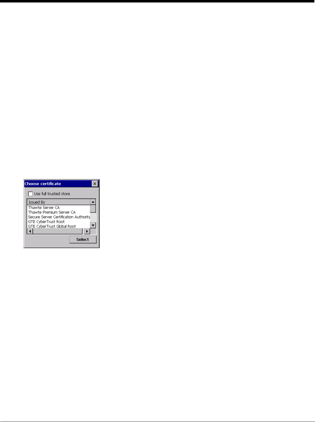
8 - 16
To Use the Certs Path
1. See Generate a Root CA Certificate (page 8-30) and follow the instructions to download the Root Certificate to a
PC.
2. Copy the certificate to specified directory on the mobile device. The default location for Certs Path is \System. A
different location may be specified by using the Certs Path global variable. Please note the location chosen for
certificate storage should persist after a reboot.
3. When completing the Credentials screen for the desired authentication, do not check the Use MS store checkbox
after checking the Validate server checkbox.
4. Enter the certificate name in the CA Cert text box.
5. Click OK to exit the Credentials screen and then Commit to save the profile changes.
To Use Windows Certificate Store
1. See Generate a Root CA Certificate (page 8-30) and follow the instructions to download the Root Certificate to a
PC.
2. To import the certificate into the Windows store, see Install a Root CA Certificate (page 8-32).
3. When completing the Credentials screen for the desired authentication, be sure to check the Use MS store check-
box after checking the Validate server checkbox.
4. The default is to use all certificates in the store. If this is OK, skip to the last step.
5. Otherwise, to select a specific certificate click on the Browse (…) button.
6. Uncheck the Use full trusted store checkbox.
7. Select the desired certificate and click the Select button to return the selected certificate to the CA Cert text box.
8. Click OK to exit the Credentials screen and then Commit to save the profile changes.
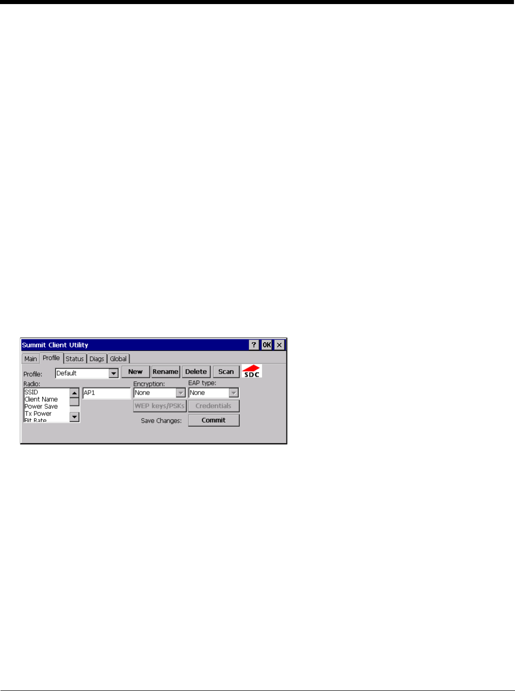
8 - 17
Configuring the Profile
Use the instructions in this section to complete the entries on the Profile tab according to the type of wireless security used by
your network. The instructions that follow are the minimum required to successfully connect to a network. Your system may
require more parameters than are listed in these instructions. Please see your system administrator for complete information
about your network and its wireless security requirements.
To begin the configuration process:
• On the Main tab click the Admin Login button and enter the password.
• If using a single profile, edit the default profile with the parameters for your network. Select the Default profile from the pull-
down menu.
• Make any desired parameter changes as described in the applicable following section determined by network security type
and click the Commit button to save the changes.
IMPORTANT – Remember to click the Commit button after making changes to ensure the changes are saved. Many versions of
the SCU display a reminder if the Commit button is not clicked before an attempt is made to close or browse away from the tab
in focus if there are unsaved changes.
If changes are made to the stored credentials, click Commit to save those changes first before making any additional changes.
No Security
To connect to a wireless network with no security, make sure the following profile options are used.
1. Enter the SSID of the Access Point assigned to this profile
2. Set EAP Type to None
3. Set Encryption to None
4. Set Auth Type to Open
Once configured, click the Commit button.
Ensure the correct Active Profile is selected on the Main tab and warmboot. The SCU Main tab shows the device is asso-
ciated after the radio connects to the network.
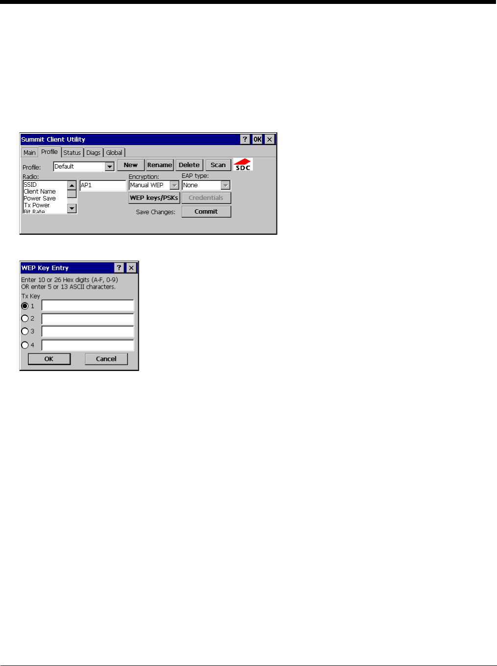
8 - 18
WEP
To connect using WEP, make sure the following profile options are used.
1. Enter the SSID of the Access Point assigned to this profile
2. Set EAP Type to None
3. Set Encryption to WEP or Manual WEP (depending on SCU version)
4. Set Auth Type to Open
Click the WEP keys/PSKs button.
Valid keys are 10 hexadecimal or 5 ASCII characters (for 40-bit encryption) or 26 hexadecimal or 13 ASCII characters (for
128-bit encryption). Enter the key(s) and click OK.
Once configured, click the Commit button.
Ensure the correct Active Profile is selected on the Main tab and warmboot. The SCU Main tab shows the device is asso-
ciated after the radio connects to the network.
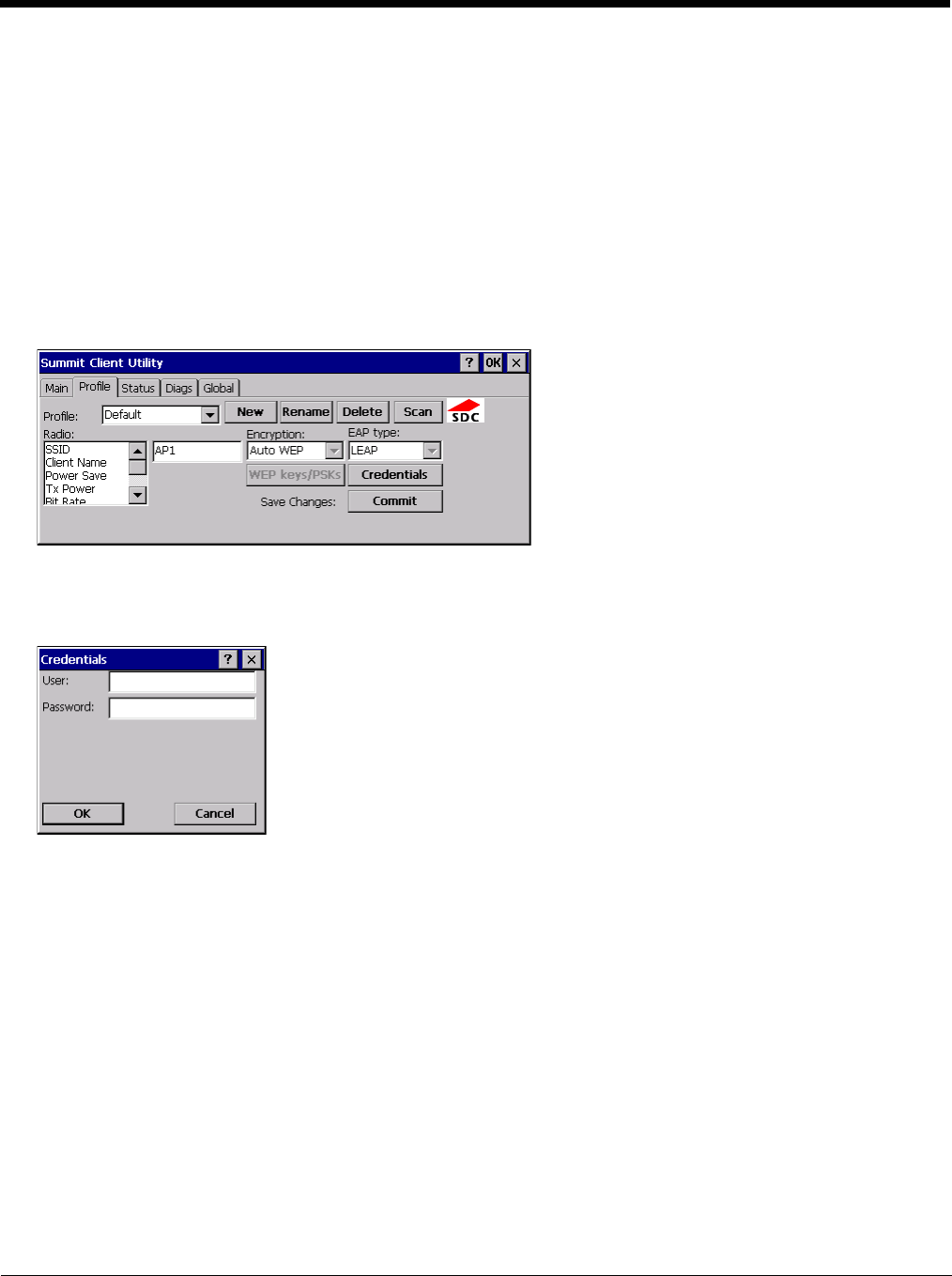
8 - 19
LEAP
To use LEAP (without WPA, also known as WEP_LEAP), make sure the following profile options are used.
1. Enter the SSID of the Access Point assigned to this profile
2. Set EAP Type to LEAP
3. Set Encryption to WEP EAP or Auto WEP (depending on SCU version)
4. Set Auth Type as follows:
5. If the Cisco/CCX certified AP is configured for open authentication, set the Auth Type radio parameter to Open.
6. If the AP is configured to use shared key or passphrase, set the Auth Type radio parameter to Shared.
7. If the AP is configured for network EAP only, set the Auth Type radio parameter to LEAP.
See Sign-On vs. Stored Credentials (page 8-14) for information on entering credentials.
To use Stored Credentials, click on the Credentials button. No entries are necessary for Sign-On Credentials as the user
will be prompted for the Username and Password when connecting to the network.
Enter the Domain\Username (if the Domain is required), otherwise enter the Username.
Enter the password. Click OK then click Commit.
Ensure the correct Active Profile is selected on the Main tab and warmboot. The SCU Main tab shows the device is asso-
ciated after the radio connects to the network.

8 - 20
PEAP/MSCHAP
To use PEAP/MSCHAP, make sure the following profile options are used.
1. Enter the SSID of the Access Point assigned to this profile
2. Set EAP Type to PEAP-MSCHAP
3. Set Encryption to WPA TKIP
4. Set Auth Type to Open
To use another encryption type, select WPA CCKM, WPA2 AES or WPA2 CCKM for encryption and complete other entries
as detailed in this section.
See Sign-On vs. Stored Credentials (page 8-14) for information on entering credentials.
Click the Credentials button.
• No entries except the CA Certificate Filename are necessary for Sign-On Credentials as the user will be prompted for the
User Name and Password when connecting to the network.
• For Stored Credentials, User, Password and the CA Certificate Filename must be entered.
Enter these items as directed below.
1. Enter the Domain\Username (if the Domain is required), otherwise enter the Username.
2. Enter the password.
3. Leave the CA Certificate File Name blank for now.
4. Click OK then click Commit. Ensure the correct Active profile is selected on the Main tab.
5. See Windows Certificate Store vs. Certs Path (page 8-15) for more information on certificate storage.
6. Once successfully authenticated, import the CA certificate into the Windows certificate store. Return to the Credentials
screen and check the Validate server checkbox.

8 - 21
If using the Windows certificate store:
1. Check the Use MS store checkbox. The default is to use the Full Trusted Store.
2. To select an individual certificate, click on the Browse button.
3. Uncheck the Use full trusted store checkbox.
4. Select the desired certificate and click Select. You are returned to the Credentials screen.
5. Click OK then click Commit
If using the Certs Path option:
1. Leave the Use MS store box unchecked.
2. Enter the certificate filename in the CA Cert text box.
3. Click OK then click Commit
The device should be authenticating the server certificate and using PEAP/MSCHAP for the user authentication.
Ensure the correct Active Profile is selected on the Main tab and warmboot. The SCU Main tab shows the device is asso-
ciated after the radio connects to the network.
Note: The date must be properly set on the device to authenticate a certificate.
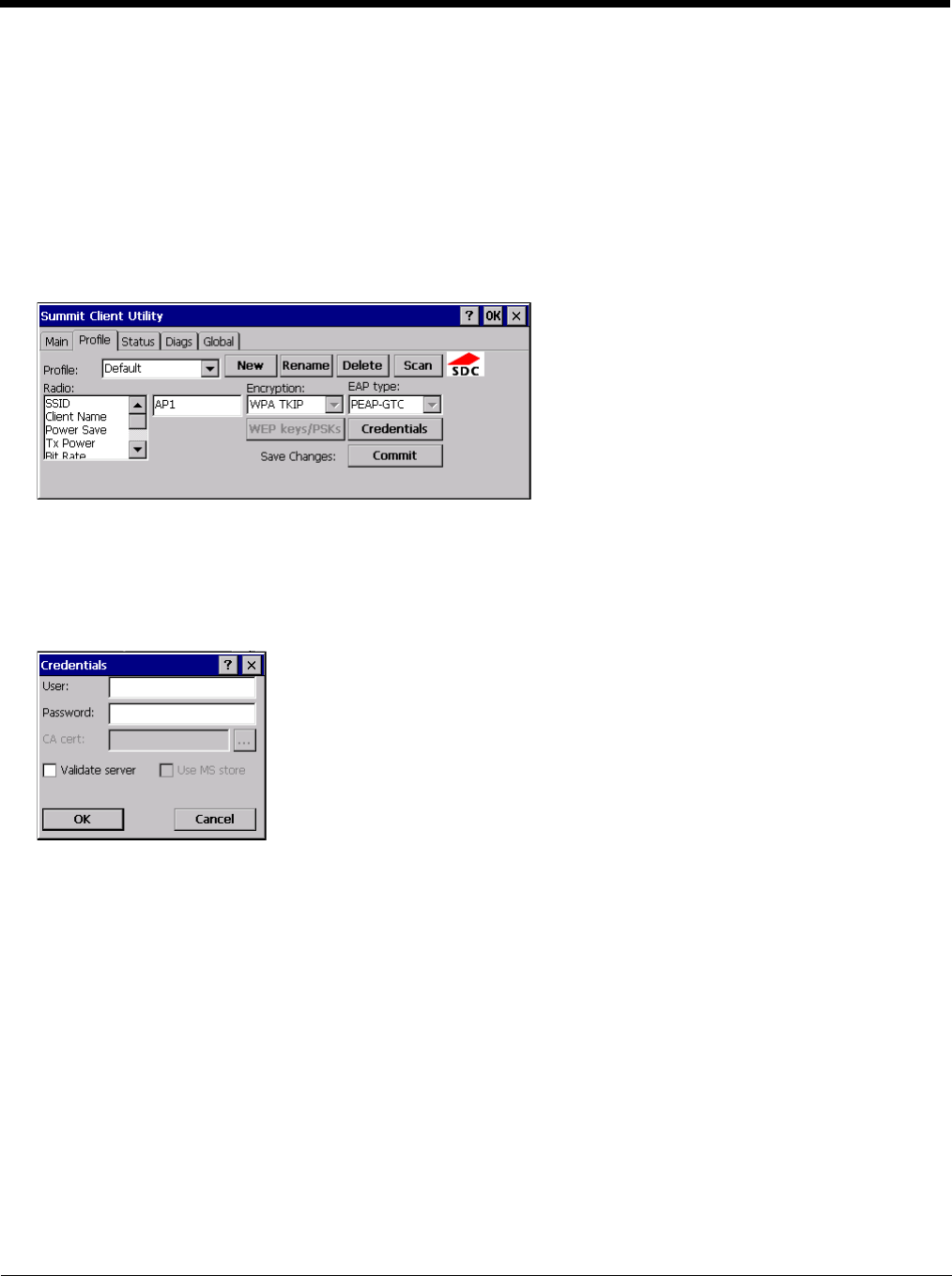
8 - 22
PEAP/GTC
To use PEAP/GTC, make sure the following profile options are used.
1. Enter the SSID of the Access Point assigned to this profile
2. Set EAP Type to PEAP-GTC
3. Set Encryption to WPA TKIP
4. Set Auth Type to Open
To use another encryption type, select WPA CCKM, WPA2 AES or WPA2 CCKM for encryption and complete other entries
as detailed in this section.
See Sign-On vs. Stored Credentials (page 8-14) for information on entering credentials.
Click the Credentials button.
• No entries except the CA Certificate Filename are necessary for Sign-On Credentials as the user will be prompted for the
User Name and Password when connecting to the network.
Enter these items as directed below.
1. Enter the Domain\Username (if the Domain is required), otherwise enter the Username.
2. Enter the password.
3. Leave the CA Certificate File Name blank for now.
4. Click OK then click Commit. Ensure the correct Active Profile is selected on the Main tab.
5. See Windows Certificate Store vs. Certs Path (page 8-15) for more information on certificate storage.
6. Once successfully authenticated, import the CA certificate into the Windows certificate store. Return to the Credentials
screen and check the Validate server checkbox.
Note: Some servers may be configured to allow only a single use of the password for PEAP/GTC. In this case, wait for the
token to update with a new password before attempting to validate the server. Then enter the new password, check
the Validate Server checkbox and proceed with the certificate process below.

8 - 23
If using the Windows certificate store:
1. Check the Use MS store checkbox. The default is to use the Full Trusted Store.
2. To select an individual certificate, click on the Browse button.
3. Uncheck the Use full trusted store checkbox.
4. Select the desired certificate and click Select. You are returned to the Credentials screen.
5. Click OK then click Commit
If using the Certs Path option:
1. Leave the Use MS store box unchecked.
2. Enter the certificate filename in the CA Cert text box.
3. Click OK then click Commit
The device should be authenticating the server certificate and using PEAP/GTC for the user authentication.
Ensure the correct Active Profile is selected on the Main tab and warmboot. The SCU Main tab shows the device is asso-
ciated after the radio connects to the network.
Note: The date must be properly set on the device to authenticate a certificate.
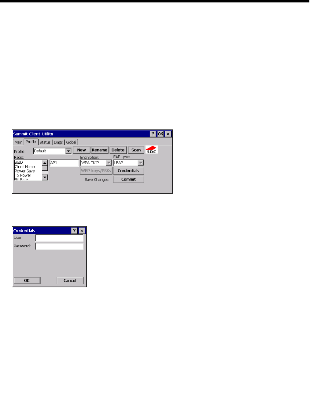
8 - 24
WPA/LEAP
To use WPA/LEAP, make sure the following profile options are used.
1. Enter the SSID of the Access Point assigned to this profile
2. Set EAP Type to LEAP
3. Set Encryption to WPA TKIP
4. Set Auth Type as follows:
5. If the Cisco/CCX certified AP is configured for open authentication, set the Auth Type radio parameter to Open.
6. If the AP is configured to use shared key or passphrase, set the Auth Type radio parameter to Shared.
7. If the AP is configured for network EAP only, set the Auth Type radio parameter to LEAP.
To use another encryption type, select WPA CCKM, WPA2 AES or WPA2 CCKM for encryption and complete other entries
as detailed in this section.
o
See Sign-On vs. Stored Credentials (page 8-14) for information on entering credentials.
To use Stored Credentials, click on the Credentials button. No entries are necessary for Sign-On Credentials as the user
will be prompted for the Username and Password when connecting to the network.
1. Enter the Domain\Username (if the Domain is required), otherwise enter the Username.
2. Enter the password.
3. Click OK then click the Commit button.
4. Ensure the correct Active Profile is selected on the Main tab and warmboot. The SCU Main tab shows the device is
associated after the radio connects to the network.
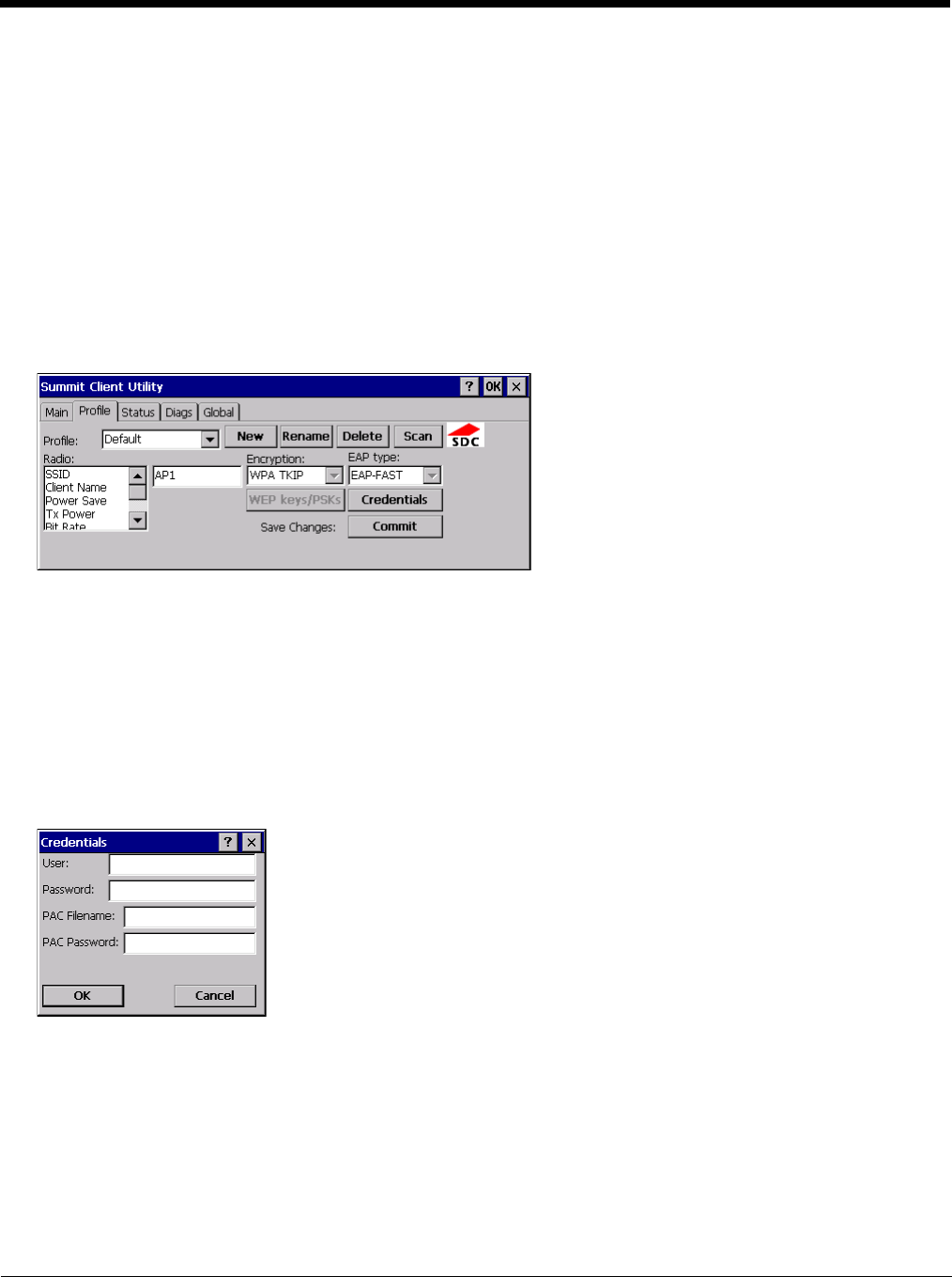
8 - 25
EAP-FAST
To use EAP-FAST, make sure the following profile options are used.
1. Enter the SSID of the Access Point assigned to this profile
2. Set EAP Type to EAP-FAST
3. Set Encryption to WPA TKIP
4. Set Auth Type to Open
To use another encryption type, select WPA CCKM, WPA2 AES or WPA2 CCKM for encryption and complete other entries
as detailed in this section.
The SCU supports EAP-FAST with automatic or manual PAC provisioning. With automatic PAC provisioning, the user cre-
dentials, whether entered on the saved credentials screen or the sign on screen, are sent to the RADIUS server. The
RADIUS server must have auto provisioning enabled to send the PAC provisioning credentials to the Thor VM2.
For automatic PAC provisioning, once a username/password is authenticated, the PAC information is stored on the Thor
VM2. The same username/password must be used to authenticate each time. See the note below for more details.
For manual PAC provisioning, the PAC filename and Password must be entered.
See Sign-On vs. Stored Credentials (page 8-14) for information on entering credentials.
The entries on the Credentials screen are determined by the type of credentials (stored or sign on) and the type of PAC pro-
visioning (automatic or manual).
Click on the Credentials button.
To use Stored Credentials, click on the Credentials button. No entries are necessary for Sign-On Credentials with auto-
matic PAC provisioning as the user will be prompted for the Username and Password when connecting to the network.
To use Sign-On credentials:
• Do not enter a User and Password as the user will be prompted for the Username and Password when connecting to the
network.
To use Stored Credentials:
• Enter the Domain\Username (if the Domain is required), otherwise enter the Username.
• Enter the password.
To use Automatic PAC Provisioning:
• No additional entries are required.

8 - 26
To use manual PAC Provisioning:
• Enter the PAC Filename and PAC Password.
• The PAC file must be copied to the directory specified in the Certs Path global variable. The PAC file must not be read
only.
Ensure the correct Active Profile is selected on the Main tab and warmboot. The SCU Main tab shows the device is asso-
ciated after the radio connects to the network.
Note: When using Automatic PAC Provisioning, once authenticated, there is a file stored in the \System directory with the
PAC credentials. If the username is changed, that file must be deleted. The filename is autoP.00.pac.
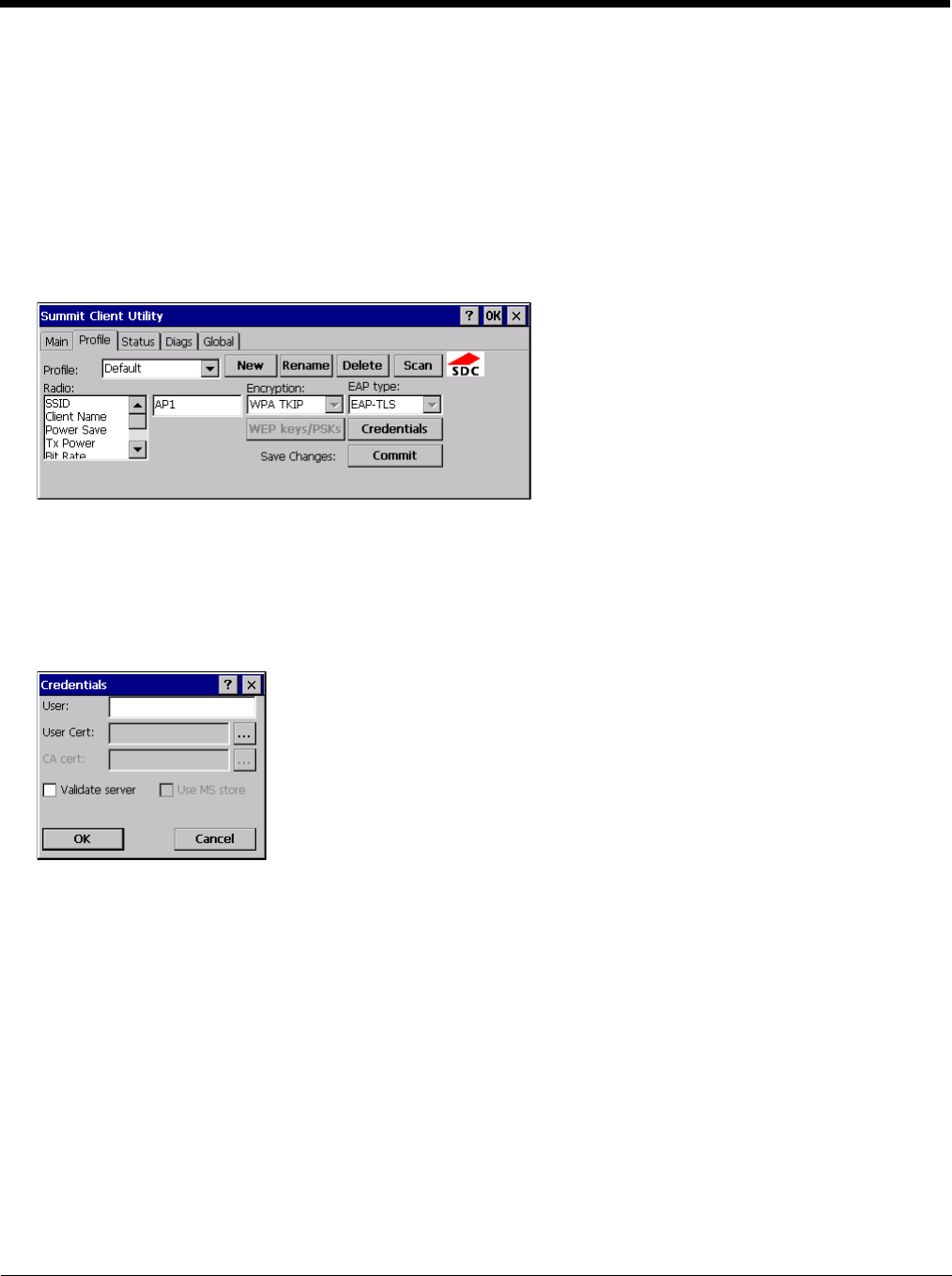
8 - 27
EAP-TLS
To use EAP-TLS, make sure the following profile options are used.
1. Enter the SSID of the Access Point assigned to this profile
2. Set EAP Type to EAP-TLS
3. Set Encryption to WPA TKIP
4. Set Auth Type to Open
To use another encryption type, select WPA CCKM, WPA2 AES or WPA2 CCKM for encryption and complete other entries
as detailed in this section.
See Sign-On vs. Stored Credentials (page 8-14) for information on entering credentials.
Click the Credentials button.
• No entries except the User Certificate Filename and the CA Certificate Filename are necessary for Sign-On Credentials
as the user will be prompted for the User Name when connecting to the network.
• For Stored Credentials, User Certificate Filename and the CA Certificate Filename must be entered.
Enter these items as directed below.
1. Enter the Domain\Username (if the Domain is required), otherwise enter the Username.
2. Select a user certificate from the Windows certificate store. Use the Browse button to locate the User Cert from the
certificate store. Highlight the desired certificate and press the Select button. The name of the certificate is displayed
in the User Cert box.
3. Some versions of the SCU require a User Cert password. If this entry field is present, enter the password for the user
certificate in the User Cert pwd box.
4. If there are no user certificates in the Windows certificate store, follow these instructions to Generate a User Certificate
(page 8-33) and Install a User Certificate (page 8-37).
5. See Windows Certificate Store vs. Certs Path (page 8-15) for more information on CA certificate storage.
6. Check the Validate server checkbox.

8 - 28
If using the Windows certificate store:
1. Check the Use MS store checkbox. The default is to use the Full Trusted Store.
2. To select an individual certificate, click on the Browse button.
3. Uncheck the Use full trusted store checkbox.
4. Select the desired certificate and click Select. You are returned to the Credentials screen.
5. Click OK then click Commit
If using the Certs Path option:
1. Leave the Use MS store box unchecked.
2. Enter the certificate filename in the CA Cert text box.
3. Click OK then click Commit
The Thor VM2 should be authenticating the server certificate and using EAP-TLS for the user authentication.
Ensure the correct Active Profile is selected on the Main tab and warmboot. The SCU Main tab shows the device is asso-
ciated after the radio connects to the network.
See Certificates (page 8-30) for information on generating a Root CA certificate or a User certificate.
Note: The date must be properly set on the device to authenticate a certificate.
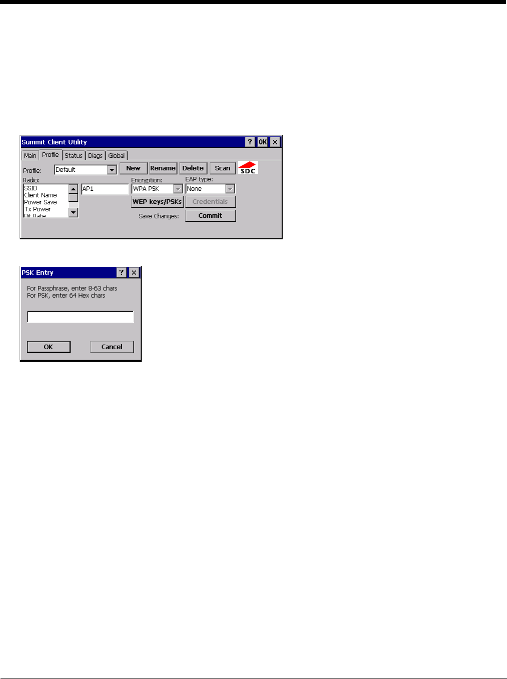
8 - 29
WPA PSK
To connect using WPA/PSK, make sure the following profile options are used:
1. Enter the SSID of the Access Point assigned to this profile
2. Set EAP Type to None
3. Set Encryption to WPA PSK or WPA2 PSK
4. Set Auth Type to Open
Click the WEP keys/PSKs button.
This value can be 64 hex characters or an 8 to 63 byte ASCII value. Enter the key and click OK.
Once configured, click the Commit button.
Ensure the correct Active Profile is selected on the Main tab and warmboot. The SCU Main tab shows the device is asso-
ciated after the radio connects to the network.
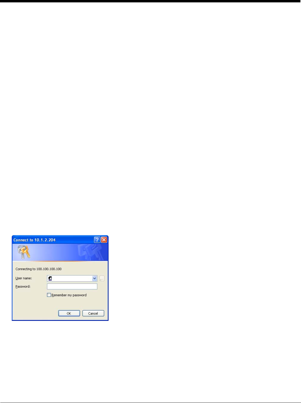
8 - 30
Certificates
Note: Please refer to the Security Primer to prepare the Authentication Server and Access Point for communication.
Note: It is important that all dates are correct on the Thor VM2 and host computers when using any type of certificate.
Certificates are date sensitive and if the date is not correct authentication will fail.
Quick Start
Root Certificates are necessary for EAP-TLS, PEAP/GTC and PEAP/MSCHAP.
1. Generate a Root CA Certificate (page 8-30) and download it to a PC.
2. Connect the Thor VM2 to the desktop PC using ActiveSync and copy the certificate to the Thor VM2 \System folder.
3. Install a Root CA Certificate (page 8-32).
User Certificates are necessary for EAP-TLS
1. Generate a User Certificate (page 8-33) and private key file and download them to a PC.
2. Connect the Thor VM2 to the desktop PC using ActiveSync and copy the certificate and private key file to the Thor VM2
\System folder.
3. Install a User Certificate (page 8-37) and the private key file.
4. After installation, perform a Suspend/Resume.
5. Verify Installation (page 8-38).
Generate a Root CA Certificate
Note: It is important that all dates are correct on the Thor VM2 and host computers when using any type of certificate.
Certificates are date sensitive and if the date is not correct authentication will fail.
The easiest way to get the root CA certificate is to use a browser on a PC to navigate to the Certificate Authority. To
request the root CA certificate, open a browser to
http://<CA IP address>/certsrv.
Sign into the CA with any valid username and password.
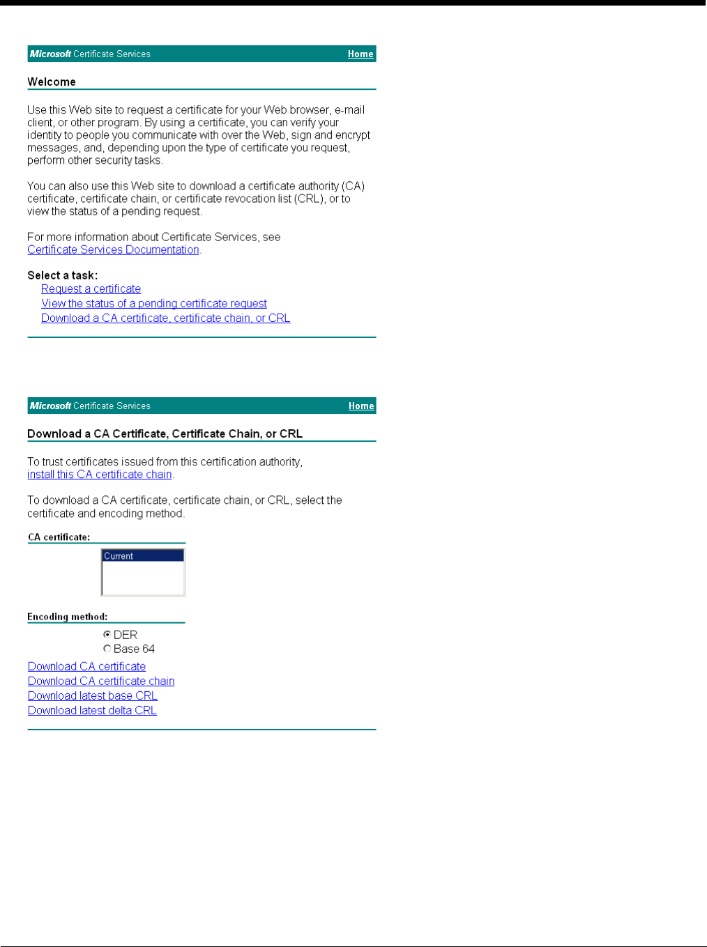
8 - 31
Click the Download a CA certificate, certificate chain or CRL link.
Make sure the correct root CA certificate is selected in the list box.
Click the DER button.
To download the CA certificate, click on the Download CA certificate link.
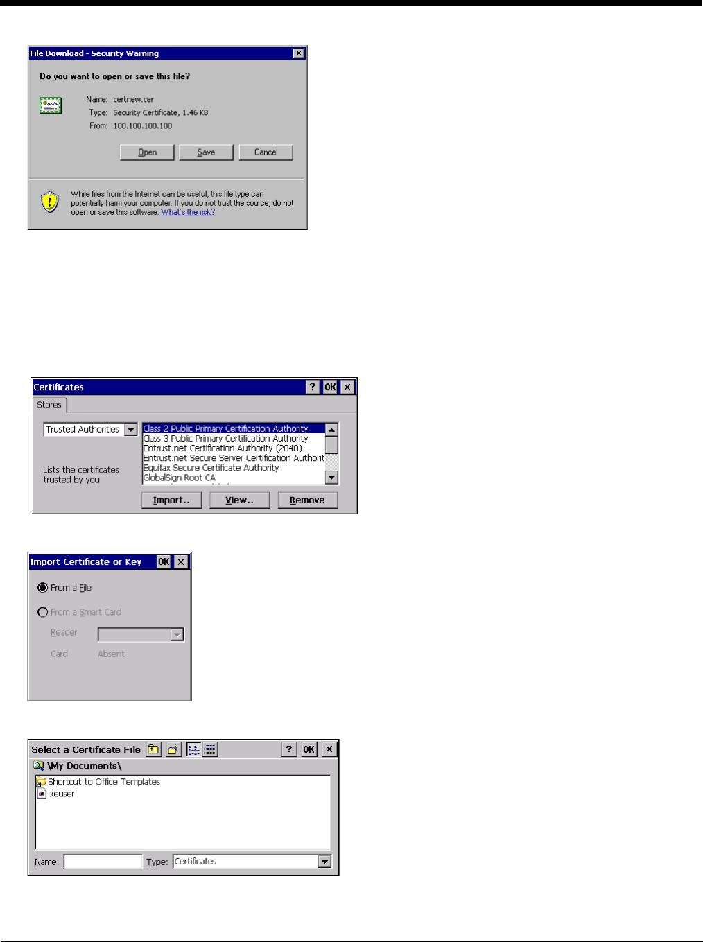
8 - 32
Click the Save button and save the certificate. Make sure to keep track of the name and location of the certificate.
Install the certificate on the Thor VM2.
Install a Root CA Certificate
Note: This section is only if the Windows certificate store is used. If the certificate store is not used, copy the certificate to
the \System folder or other path specified in the Summit Certs global parameter.
Copy the certificate file to the Thor VM2. Import the certificate by navigating to Start > Control Panel > Certificates.
Tap the Import button.
Make sure From a File is selected and tap OK.
Using the explorer buttons, browse to the location where you copied the certificate, select the certificate desired and tap
OK.
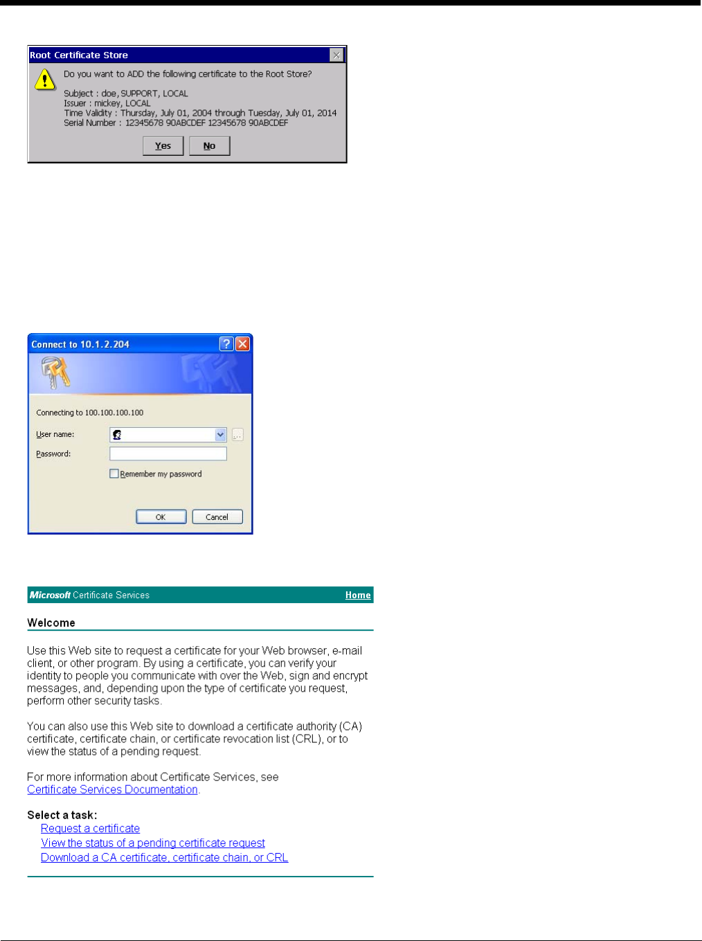
8 - 33
Tap Yes to import the certificate.
Once the certificate is installed, return to the proper authentication section, earlier in this manual.
Generate a User Certificate
The easiest way to get the user certificate is to use a browser on a PC to navigate to the Certificate Authority. To request
the user certificate, open a browser to
http://<CA IP address>/certsrv.
Sign into the CA with the username and password of the person who will be logging into the mobile device.
This process saves a user certificate and a separate private key file. Windows CE equipped devices such as the Thor VM2
require the private key to be saved as a separate file rather than including the private key in the user certificate.
Click the Request a certificate link.

8 - 34
Click on the advanced certificate request link.
Click on the Create and submit a request to this CA link.
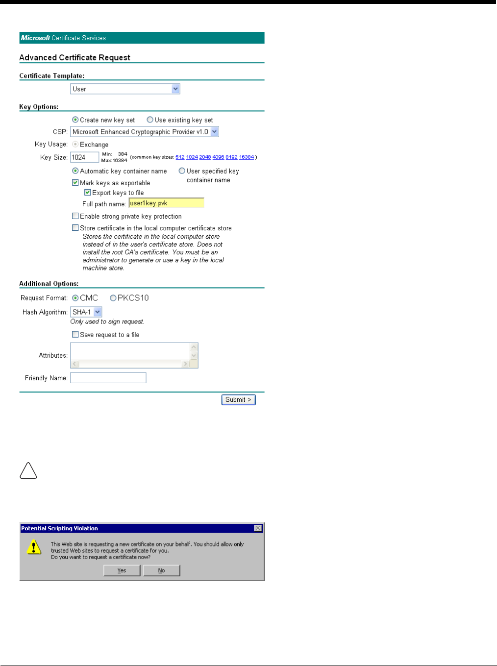
8 - 35
For the Certificate Template, select User.
Check the Mark keys as exportable and the Export keys to file checkboxes.
Type the full path on the local PC where the private key is to be copied. Also specify the private key filename.
DO NOT check to use strong private key protection.
Make any other desired changes and click the Submit button.
Be sure to note the name used for the private key file, for example AAAUSER.PVK. The certificate file created later
in this process must be given the same name, for example, AAAUSER.CER.
!
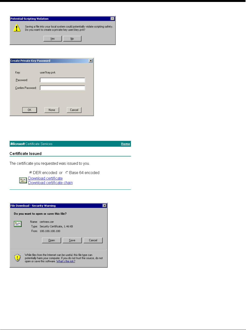
8 - 36
If any script notifications occur, click the “Yes button to continue the certificate request.
When prompted for the private key password:
• Click None if you do not wish to use a password, or
• Enter and confirm your desired password then click OK.
Click the Download certificate link.
Click Save to download and store the user certificate to the PC. Make sure to keep track of the name and location of the
certificate. The private key file is also downloaded and saved during this process.
Be sure use the same name for the certificate file as was used for the private key file. For example, it the private key was
saved as AAAUSER.PVK then the certificate file created must be given the same name, for example, AAAUSER.CER.
Install the user certificate.
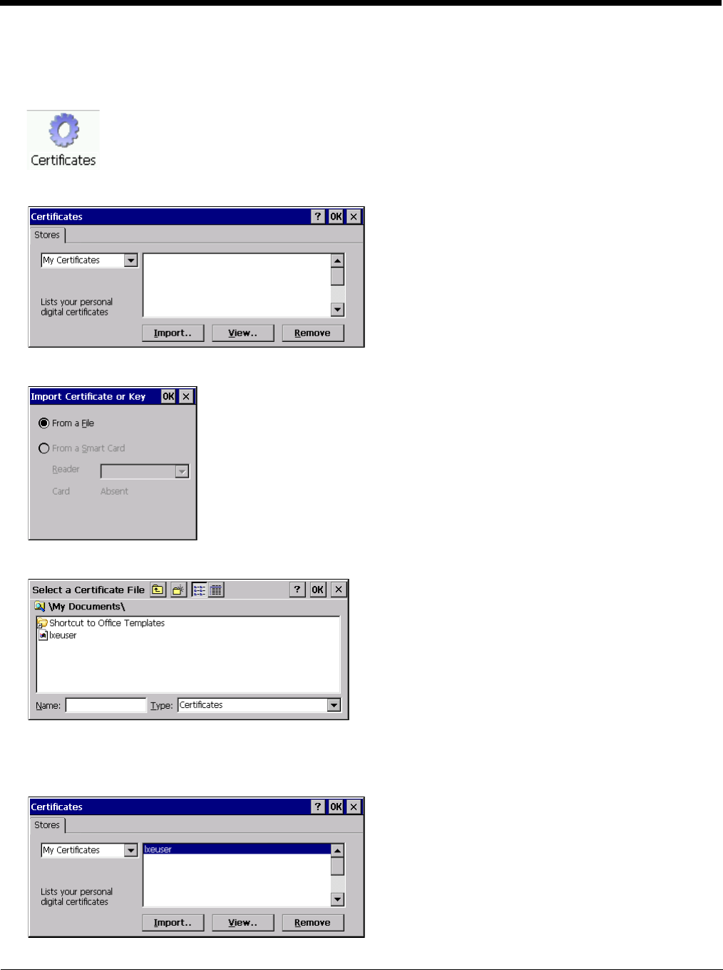
8 - 37
Install a User Certificate
Copy the certificate and private key files to the Thor VM2. Import the certificate by navigating to Start > Control Panel >
Certificates.
Select My Certificates from the pull-down list.
Tap the Import button.
Make sure From a File is selected and tap OK.
Using the explorer buttons, browse to the location where you copied the certificate, select the certificate desired and tap
OK.
The certificate is now shown in the list.
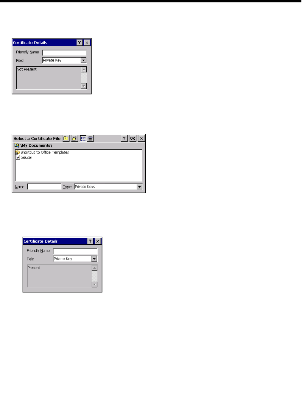
8 - 38
With the certificate you just imported highlighted, tap View.
From the Field pull-down menu, select Private Key.
• If the private key is present, the process is complete.
• If the private key is not present, import the private key.
To import the private key, tap OK to return to the Certificates screen.
Tap import.
Using the explorer buttons, browse to the location where you copied the private key file, change the Type pull-down list to
Private Keys, select the certificate desired and tap OK. Enter the password for the certificate if appropriate.
Verify Installation
Tap on View to see the certificate details again.
The private key should now say present. If it does not, there is a problem. Possible items to check:
• Make sure the certificate was generated with a separate private key file, as shown earlier in this section. If the
certificate was not generated with a separate private key file, generate a new certificate and follow the import process
again.
• Make sure the certificate and private key file have the same name, for example AAAuser.cer for the certificate and
AAAuser.pvk for the private key file. If the file names are not the same, rename the private key file and import it again.
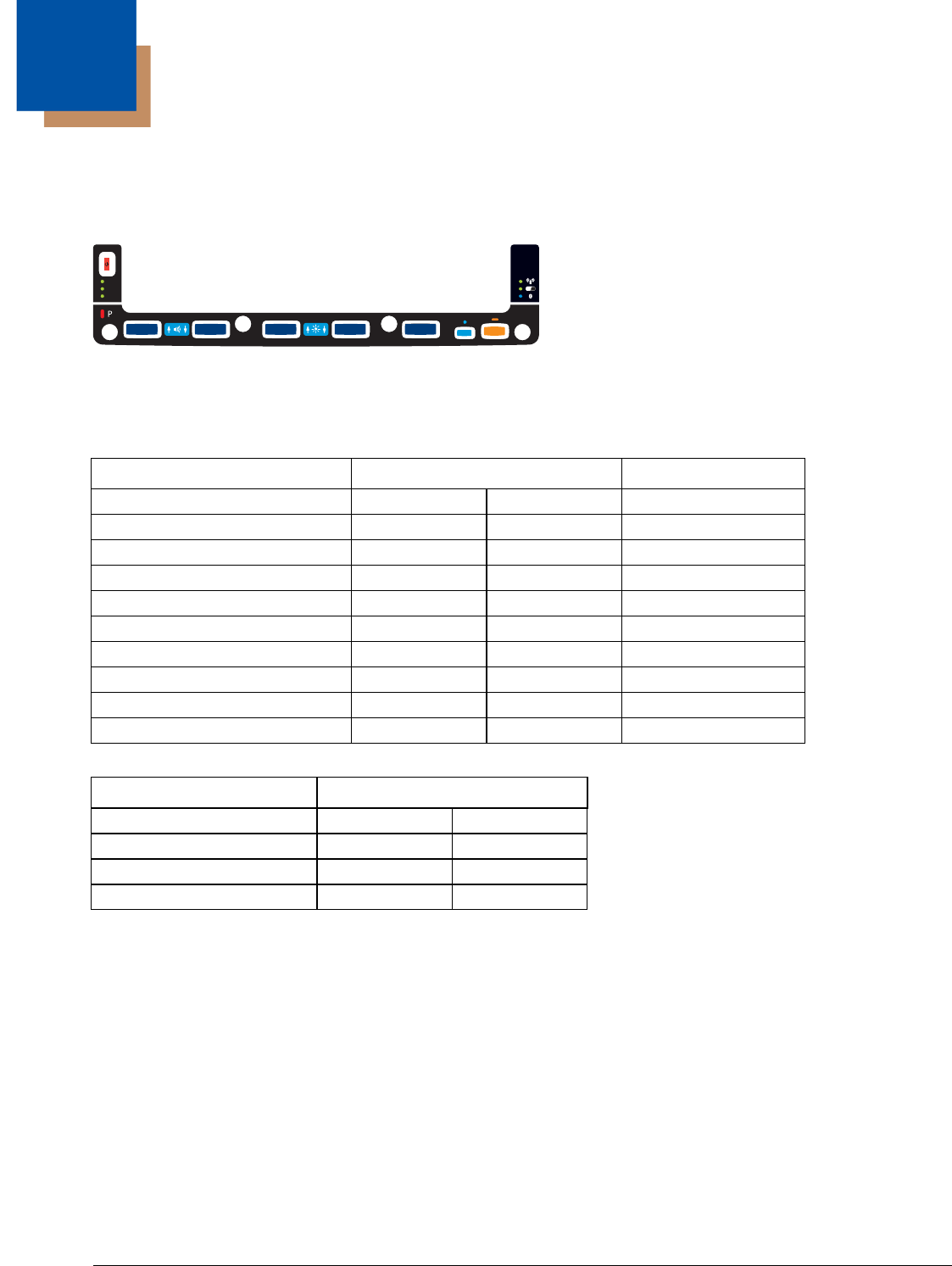
9 - 1
9
Key Maps
Integrated Keypad
There are five integrated programmable keys located on the Thor VM2 below the display. Each programmable key can be mod-
ified by the Orange key for a total of 10 programmable keys
See Programmable Key (page 5-83) to remap these keys.
.The default values for these keys are:
The following key press sequences are not programmable:
The Blue plus P5 key press sequence causes no action.
To get this Programmable Key Press These Keys in this Order Default Key Value
P1 (Programmable key 1) P1 F1
P2 (Programmable key 2) P2 F2
P3 (Programmable key 3) P3 F3
P4 (Programmable key 4) P4 F4
P5 (Programmable key 5) P5 F5
P6 (Programmable key 6) Orange P1 <none>
P7 (Programmable key 7) Orange P2 <none>
P8 (Programmable key 8) Orange P3 <none>
P9 (Programmable key 9) Orange P4 <none>
P10 (Programmable key 10) Orange P5 <none>
To get this function Press These Keys in this Order
Increase speaker volume Blue P1
Decrease speaker volume Blue P2
Increase display brightness Blue P3
Decrease display brightness Blue P4
P3 P8 P4 P9 P5 P1 0P6 P2 P7
P1
SYS
SSD
Wi Fi
UPS

9 - 2
External 95-Key Keyboard
The key map table that follows lists
the commands used for the Thor VM2. Note that since the Thor VM2 uses a Microsoft Windows CE operating system, no DOS
Terminal Emulation keypress sequences are provided.
There are 10 hidden keys on the 95 key keyboard. Each of the hidden keys is accessed by pressing the <Fn> key (located in the
top right hand corner) plus a key on the numeric keypad on the right. Additional function keys are supported as well.
To get this Key / Function Press These Keys in this Order
Insert FN 0 (numeric keypad)
Home FN 7 (numeric keypad)
Page Up FN 9 (numeric keypad)
Delete FN . (numeric keypad)
End FN 1 (numeric keypad)
Page Down FN 3 (numeric keypad)
Up Arrow FN 8 (numeric keypad)
Left Arrow FN 4 (numeric keypad)
Down Arrow FN 2 (numeric keypad)
Right Arrow FN 6 (numeric keypad)
Print
Screen
SysRq
Scroll
Lock
Pause
Break
67
BackSpace
Num
Lock
ERTYUI O
P
]\
[
{}|
7
4
1
0
Home
DF GHJ K L
;'
:"Enter
Alt
CV B
N
M,
<.
>
/
?
Shift
Alt Ctrl
Ins
End
4
$
5
%
^
&
9
(
0
)
-
_
=
+
LR
X
Esc F3 F4 F5 F6 F7 F8 F9 F10 F11 F12F1 F2 Fn
123
/*-
Tab
QW89
56
23
PgUp
Caps
Lock
AS
Shift
Ctrl
PgDn
+
`
~
!
@
#
Enter
.
Del
8
*
Z

10 - 1
10
Specifications and Reference Material
Technical Specifications
Thor VM2
Quick Mount Smart Dock
Processor Atom CPU operating at 1.6 GHz
Memory 1GB SDRAM
Mass Storage 1GB CompactFlash memory card
Storage Expansion User installable, supports 1 to 4GB SD card
Operating System Microsoft Windows CE 6.0
Radio Modules 802.11 a/b/g radio / Bluetooth
Optional GPS / WWAN
Scanner Options No integrated scanner, Optional serial, USB or Bluetooth scanners
Display Technology Intel GMA 500 graphics processor, SVGA compatible
Active matrix TFT
Resolution: 1024 x 768 pixels (maximum)
400 NIT brightness
9.7” (measured horizontally) display
Transmissive with LED backlight
Vehicle motion screen blanking available
Keyboard Integrated 5-key keypad
Optional 95-key USB keyboard
Touch Screen Impact resistive
Signature capture capability
Field replaceable front panel including touch screen
External Connectors Optional external 802.11 / GPS / WWAN antenna connectors
Additional connectors on Quick Mount Smart Dock, see below
Beeper Minimum loudness greater than 95dBm at 10 cm in front of unit
Power Supply 10 to 60 VDC isolated
Uninterruptible Power Supply Internal UPS battery, 30-minute life at -20°C (-4°F)
Backup Battery (RCT) Internal lithium battery maintains Real Time Clock
External Connectors Two external RS-232 serial ports, COM1 and COM2, with switchable power
CANbus/Audio connector supports either audio/microphone via adapter cable or J1939
Female and J1939 Male connectors via CANbus cable
USB connector supports USB client port and USB host port via adapter cable
Power Connector 6-pin connector:
Direct10-60V DC input power
Optional external converters for AC (90-240 VAC) and extended range DC (60-150
VDC)
Power Switch Sealed power switch
External Power Supply AC Adapter, 120-240VAC to 12VDC
Input Power DC Input Voltage: 10- 60 VDC
Input Current: 4.6 Amps
Input Fuse: 10A Time Delay

10 - 2
Dimensions
Thor VM1
Quick Mount Smart Dock
Note: The RAM ball is not included in the following measurements.
Environmental Specifications
Thor VM1 and Quick Mount Smart Dock
Width 10.6” (26.8 cm)
Height 8.4” (21.4 cm)
Depth 2.1” (5.3cm)
Weight 4.8lb. (2.2kg)
Length 7.1” (18.0 cm)
Width 6.1” (15.5 cm)
Height 2.5” (6.4 cm), measurement includes strain relief cable clamps
Weight 3.2 lb. (1.5 kg)
Operating Temperature -4°F to 122°F (-20°C to 50°C) [non-condensing]
Storage Temperature -22°F to 140°F (-30°C to 60°C) [non-condensing]
ESD 8 KV air, 4kV direct contact
Operating Humidity Up to 90% non-condensing at 104°F (40°C)
Water and Dust IEC 60529 compliant to IP66
ESD 15 kV
Vibration MIL-STD-810F, composite wheeled vehicles.
Crash SAE-J 1455

10 - 3
Network Card Specifications
Summit 802.11a/b/g
Bluetooth
WWAN
Bus Interface 32-bit SDIO (Secure Digital I/O)
Wireless Frequencies
(varies by regulatory domain) 2.4 to 2.4895 GHz IEEE 802.11b / 802.11g DSSS OFDM
5.15 to 5.82 GHz IEEE 802.11a DSSS OFDM
RF Data Rates 1, 2, 5.5, 6, 9, 11, 12, 18, 24, 36, 48, 54 Mbps
RF Power Level 64 mW (18dBm)
Channels FCC: 1-11, 36, 40 ,44, 48, 149, 153, 157, 161
ETSI: 1-13, 36, 40, 44 ,48
Operating Temperature Same as Thor VM2 Operating Temperature
Storage Temperature Same as Thor VM2 Storage Temperature
Connectivity TCP/IP, Ethernet, ODI
Diversity Yes
Bus Interface USB
Enhanced Data Rate Up to 3.0 Mbit/s over the air
Connection No less than 32.80 feet (10 meters) line of sight
Bluetooth Version 2.0 + EDR
Operating Frequency 2.402 - 2.480 GHz
QDID B013455
Device Gobi™ 3000 (data only)
Technology Five-band UMTS/HSPA+ (800/850/900/1900/2100MHz), quadband GSM/
GPRS/EDGE (850/900/1800/1900MHz) and dual-band EV-DO/CDMA (800/
1900)
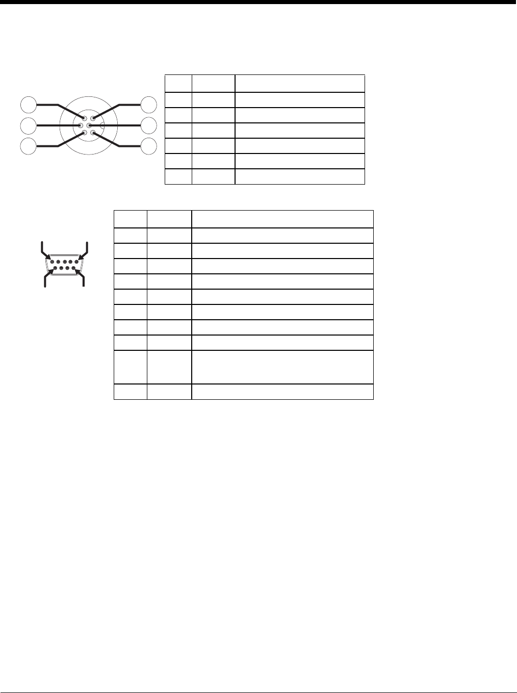
10 - 4
Port and Connector Pinouts
Power Supply Connector
COM1 and COM2 Connector
Pin Signal Description
1 V In+ 10-60V DC input +
2 V In+ 10-60V DC input +
3 V In- input -
4 V In- input -
5 GND Chassis ground
6 Ignition +0V to 60V to start terminal
Pin Signal Description
1 DCD Data Carrier Detect – Input
2 RXD Receive Data – Input
3 TXD Transmit Data – Output
4 DTR Data Terminal Ready – Output
5 GND Signal/Power Ground
6 DSR Data Set Ready – Input
7 RTS Request to Send – Output
8 CTS Clear to Send – Input
9+5VDC
or
RI
Bar Code Scanner Power - 500mA max
or
Ring Indicator - Input
Shell CGND Chassis Ground
3
1
6
5
2
4
PIN 9PIN 6
PIN 5
PIN 1
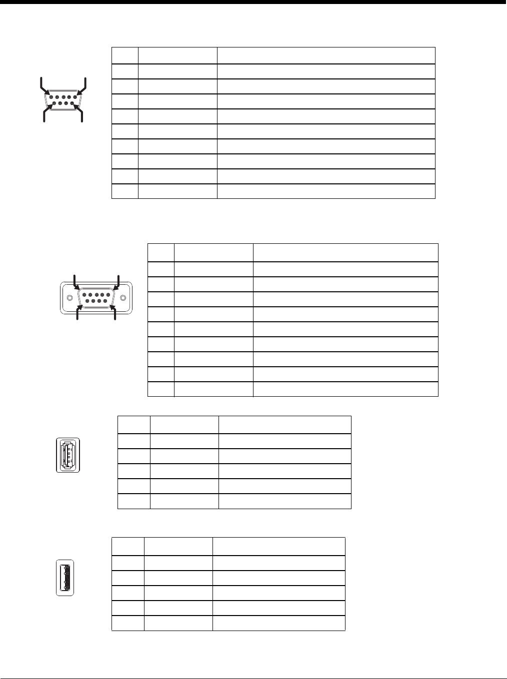
10 - 5
USB Connector
USB Y Cable
D9 Male Connector
USB Host Connector
USB Client Connector
Pin Signal Description
1 GND Common ground
2 USBC_D+ USB client data signal
3 USBC_D- USB client data signal
4 USB_H1_PWR USB host 1; 5V output power
5 GND Common ground
6 GND Common ground
7 USB_H1_D+ USB host 1 data signal
8 USB_H1_D- USB host 1 data signal
9 USBC_VBUS USB client 5V detect from attached host
Pin Signal Description
1 GND Common ground
2 USBC_D+ USB client data signal
3 USBC_D- USB client data signal
4 USB_H1_PWR USB host 5V output power
5 GND Common ground
6 GND Common ground
7 USB_H1_D+ USB host 1 data signal
8 USB_H1_D- USB host 1 data signal
9 USBC_VBUS USB client 5V detect from attached host
Pin Signal Description
1 5V_USB USB Power, Current Limited
2 USB_H1_D- USB D-
3 USB_H1_D+ USB D+
4 GND USB Power Return
Shell CGND Chassis Ground
Pin Signal Description
1 5V_USB USB Power, Current Limited
2 USB_H1_D- USB D-
3 USB_H1_D+ USB D+
4 GND USB Power Return
Shell CGND Chassis Ground
PIN 6PIN 9
PIN 1
PIN 5
PIN 9PIN 6
PIN 5
PIN 1
PIN 4
PI
N1
PI
N4
PIN 1

10 - 6
CANbus / Audio Connector
Headset Adapter Cable
D15 Female Connector
Quick Connect Headset Connector
Pin Signal Name Description
1 - CAN reserved
2 CAN_L CAN_L bus line dominant low
3 CAN_GND CAN Ground
4 - CAN reserved
5 GND Optional ground
6 Audio return Headset return
7 Audio output Headset output
8 Mic input Microphone input
9 Mic return Microphone return
10 Audio Return
11 GND Optional ground
12 CAN_SHLD
13 CAN_H CAN_H bus line dominant high
14 - CAN reserved
15 CAN_V+ Option CAN external Power Supply
Pin Signal Description
1 Not used
2 Not used
3 Not used
4 Not used
5 Not used
6 Audio return Headset return
7 Audio output Headset output
8 Mic input Microphone input
9 Mic return Microphone return
10 Not used
11 Not used
12 Not used
13 Not used
14 Not used
15 Not used
Pin Signal Description
1 Mic input Microphone input
2 Mic return Microphone return
3 Audio output Headset output
4 Audio return Headset return
PIN 15
PIN 1
0
PIN 11
PIN
6
PIN 5
PIN 1
PIN 15
PIN
10
PIN 11
PI
N6
PIN 5 PIN 1
PIN 4
PIN 1
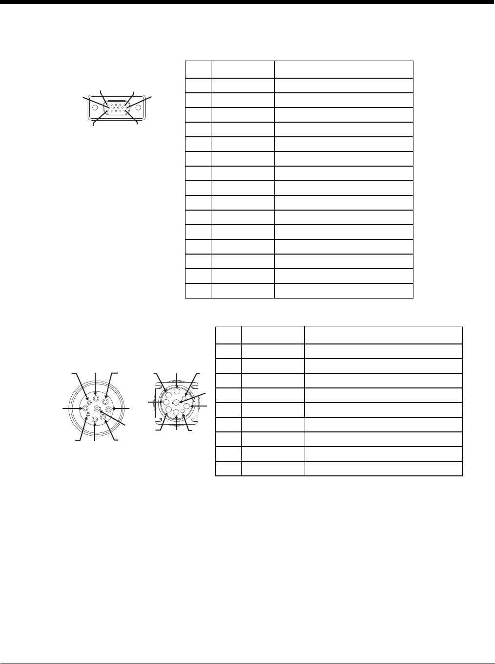
10 - 7
CANbus Y Cable
D15 Female Connector
9-Pin J1939 (Deutsch) Connectors
Pin Signal Description
1 Not Used
2 CAN_L CAN_L bus line dominant low
3 CAN_GND CAN ground
4 Not Used CAN reserved
5 GND Ground
6 Not used
7 Not used
8 Not used
9 Not used
10 Not used
11 GND Optional ground
12 CAN_SHLD
13 CAN_H CAN_H bus line dominant high
14 Not Used CAN reserved
15 CAN_V+ CAN external power supply
Pin Signal Description
Receptacle-
J1939 Female Socket
J1939 Mail 1 CAN_GND CAN Ground
2 CAN_V+ Option CAN external Power Supply
3 CAN_H CAN_H bus line dominant high
4 CAN_L CAN_L bus line dominant low
5CAN_SHLD
6 Not used
7 Not used
8 Not used
9 Not used
PIN 15
PIN
10
PIN 11
PI
N6
PIN 5 PIN 1
1
2
3
4
5
6
7
8
9
1
2
3
4
5
6
7
8
9

10 - 8
AppLock Error Messages
Any messages whose first word is an ‘ing’ word is output prior to the action described in the message. For example, “Switching
to admin-hotkey press” is logged after the administrator has pressed the hotkey but prior to starting the switch process.
For all operations that can result in an error, an Error level message is displayed when a failure occurs. These messages con-
tain the word “failure”. These messages have a partner Extended level message that is logged which contains the word “OK” if
the action completed successfully rather than with an error.
For processing level messages, “Enter…” is logged at the beginning of the function specified in the message and “Exit…” is
logged at the end (just before the return) of the function specified in the message.
Message Explanation and/or corrective action Level
Error reading hotkey The hotkey is read but not required by AppLock. LOG_EX
Error reading hotkey; using
default A hotkey is required. If there is a failure reading the hotkey, the internal factory
default is used. LOG_ERROR
App Command Line=
<Command line> Command line of the application being locked LOG_
PROCESSING
App= <Application name> Name of the application being locked LOG_
PROCESSING
dwProcessID= <#> Device ID of the application being locked LOG_EX
Encrypt exported key len
<#> Size of encrypt export key LOG_EX
Encrypt password length=
<#> The length of the encrypted password. LOG_EX
Encrypted data len <#> Length of the encrypted password LOG_EX
hProcess= <#> Handle of the application being locked LOG_EX
Key pressed = <#> A key has been pressed and trapped by the hotkey processing. LOG_EX
***************** The status information is being saved to a file and the file has been opened suc-
cessfully. LOG_EX
Address of keyboard hook
procedure failure AppLock found the kbdhook.dll, but was unable to get the address of the initial-
ization procedure. For some reason the dll is corrupted. Look in the \Windows
directory for kbdhook.dll. If it exists, delete it. Also delete AppLock.exe from the
\Windows directory and reboot the unit. Deleting AppLock.exe triggers the Ap-
pLock system to reload.
LOG_ERROR
Address of keyboard hook
procedure OK AppLock successfully retrieved the address of the keyboard filter initialization
procedure. LOG_EX
Alt pressed The Alt key has been pressed and trapped by the HotKey processing. LOG_EX
Alt Processing the hotkey and backdoor entry LOG_EX
Application handle search
failure The application being locked did not complete initialization. LOG_ERROR
Application handle search
OK The application initialized itself successfully LOG_ERROR
Application load failure The application could not be launched by AppLock; the application could not be
found or is corrupted. LOG_ERROR
Backdoor message re-
ceived The backdoor keys have been pressed. The backdoor hotkeys provide a meth-
od for customer service to get a user back into their system without editing the
registry or reloading the device.
LOG_
PROCESSING
Cannot find kbdhook.dll The load of the keyboard filter failed. This occurs when the dll is missing or is
corrupted. Look in the \Windows directory for kbdhook.dll. If it exists, delete it.
Also delete AppLock.exe from the \Windows directory and reboot the unit. De-
leting AppLock.exe triggers the AppLock system to reload.
LOG_ERROR
Converted Pwd Converted password from wide to mbs. LOG_EX

10 - 9
Could not create event
EVT_HOTKEYCHG The keyboard filter uses this event at the Administrator Control panel. The event
could not be created. LOG_ERROR
Could not hook keyboard If the keyboard cannot be controlled, AppLock cannot process the hotkey. This
failure prevents a mode switch into user mode. LOG_ERROR
Could not start thread Hot-
KeyMon The keyboard filter must watch for hot key changes. The watch process could
not be initiated. LOG_ERROR
Ctrl after L or X Processing the backdoor entry. LOG_EX
Ctrl pressed The Ctrl key has been pressed and trapped by the HotKey processing. LOG_EX
Ctrl Processing the hotkey and backdoor entry. LOG_EX
Decrypt acquire context
failure Unable to decrypt password. LOG_ERROR
Decrypt acquired context
OK Decryption process ok. LOG_EX
Decrypt create hash failure Unable to decrypt password. LOG_ERROR
Decrypt created hash OK Decryption process ok. LOG_EX
Decrypt failure Unable to decrypt password. LOG_ERROR
Decrypt import key failure Unable to decrypt password. LOG_ERROR
Decrypt imported key OK Decryption process ok. LOG_EX
Encrypt acquire context
failure Unable to encrypt password. LOG_ERROR
Encrypt acquire encrypt
context failure Unable to encrypt password. LOG_ERROR
Encrypt acquired encrypt
context OK Encrypt password process successful. LOG_EX
Encrypt create hash failure Unable to encrypt password. LOG_ERROR
Encrypt create key failure Unable to encrypt password. LOG_ERROR
Exit ToUser-Registry read
failure The AppName value does not exist in the registry so user mode cannot be en-
tered. LOG_
PROCESSING
Exit verify password-no
pwd set Exiting password verification. LOG_
PROCESSING
Exit verify password-re-
sponse from dialog Exiting password verification. LOG_
PROCESSING
Found taskbar The handle to the taskbar has been found so that AppLock can disable it in user
mode. LOG_
PROCESSING
Getting address of key-
board hook init procedure AppLock is retrieving the address of the keyboard hook. LOG_
PROCESSING
Getting configuration from
registry The AppLock configuration is being read from the registry. This occurs at initial-
ization and also at entry into user mode. The registry must be re-read at entry
into user mode in case the administration changed the settings of the application
being controlled.
LOG_
PROCESSING
Getting encrypt pwd length The length of the encrypted password is being calculated. LOG_EX
Hook wndproc failure AppLock is unable to lock the application. This could happen if the application
being locked encountered an error after performing its initialization and shut it-
self down prior to being locked by AppLock.
LOG_ERROR
Hook wndproc of open app
failure The application is open, but AppLock cannot lock it. LOG_ERROR
Hot key event creation fail-
ure The Admin applet is unable to create the hotkey notification. LOG_ERROR
Hot key pressed Processing the hotkey and backdoor entry LOG_EX
Message Explanation and/or corrective action Level

10 - 10
Hot key pressed Processing the hotkey and backdoor entry LOG_EX
Hot key set event failure When the administrator changes the hotkey configuration the hotkey controller
must be notified. This notification failed. LOG_ERROR
Hotkey press message re-
ceived The user just pressed the configured hotkey. LOG_
PROCESSING
In app hook:WM_SIZE In addition to preventing the locked application from exiting, AppLock must also
prevent the application from enabling the taskbar and resizing the application’s
window. This message traps a change in the window size and corrects it.
LOG_EX
In app hook:WM_WIN-
DOWPOSCHANGED In addition to preventing the locked application from exiting, AppLock must also
prevent the application from enabling the taskbar and resizing the application’s
window. This message traps a change in the window position and corrects it.
LOG_EX
Initializing keyboard hook
procedure AppLock is calling the keyboard hook initialization. LOG_
PROCESSING
Keyboard hook initialization
failure The keyboard filter initialization failed. LOG_ERROR
Keyboard hook loaded OK The keyboard hook dll exists and loaded successfully. LOG_EX
L after Ctrl Processing the backdoor entry. LOG_EX
Loading keyboard hook When AppLock first loads, it loads a dll that contains the keyboard hook process-
ing. This message is logged prior to the load attempt. LOG_
PROCESSING
Open failure The status information is being saved to a file and the file open has failed. This
could occur if the file is write protected. If the file does not exist, it is created. LOG_ERROR
Open registry failure If the Administration registry key does not exist, the switch to user mode fails be-
cause the AppName value in the Administration key is not available. LOG_ERROR
Opened status file The status information is being saved to a file and the file has been opened suc-
cessfully. LOG_EX
Out of memory for encrypt-
ed pwd Not enough memory to encrypt the password. LOG_ERROR
pRealTaskbarWndProc al-
ready set The taskbar control has already been installed. LOG_EX
Pwd cancelled or invalid-
remain in user mode The password prompt was cancelled by the user or the maximum number of
failed attempts to enter a password was exceeded. LOG_EX
Read registry error-hot key The hotkey registry entry is missing or empty. This is not considered an error.
The keyboard hook uses an embedded default if the value is not set in the reg-
istry.
LOG_ERROR
Read registry failure-app
name AppName registry value does not exist or is empty. This constitutes a failure for
switching into user mode. LOG_ERROR
Read registry failure-Cmd
Line AppCommandLine registry entry is missing or empty. This is not considered an
error since command line information is not necessary to launch and lock the ap-
plication.
LOG_ERROR
Read registry failure-Inter-
net The Internet registry entry is missing or empty. This is not considered an error
since the Internet value is not necessary to launch and lock the application. LOG_ERROR
Registering Backdoor MSG The AppLock system communicates with the keyboard hook via a user defined
message. Both AppLock.exe and Kbdhook.dll register the message at initializa-
tion.
LOG_
PROCESSING
Registering Hotkey MSG The AppLock system communicates with the keyboard hook via a user defined
message. Both Applock.exe and Kbdhook.dll register the message at initializa-
tion.
LOG_
PROCESSING
Registry read failure at re-
enter user mode The registry has to be read when entering user mode is the AppName is missing.
This user mode entry is attempted at boot and after a hotkey switch when the
administrator has closed the application being locked or has changed the appli-
cation name or command line.
LOG_ERROR
Message Explanation and/or corrective action Level

10 - 11
Registry read failure at re-
enter user mode The registry has to be read when switching into user mode. This is because the
administrator can change the settings during administration mode. The read of
the registry failed which means the Administration key was not found or the Ap-
pName value was missing or empty.
LOG_ERROR
Registry read failure The registry read failed. The registry information read when this message is
logged is the application information. It the Administration key cannot be opened
or if the AppName value is missing or empty, this error is logged. The other ap-
plication information is not required. If the AppName value is not available, Ap-
pLock cannot switch into user mode.
LOG_ERROR
Reset system work area
failure The system work area is adjusted when in user mode to cover the taskbar area.
The system work area has to be adjusted to exclude the taskbar area in admin-
istration mode. AppLock was unable to adjust this area.
LOG_ERROR
Shift pressed The Shift key has been pressed and trapped by the HotKey processing. LOG_EX
Shift Processing the hotkey and backdoor entry LOG_EX
Show taskbar The taskbar is now being made visible and enabled. LOG_
PROCESSING
Switching to admin-back-
door The system is currently in user mode and is now switching to admin mode. The
switch occurred because of the backdoor key presses were entered by the ad-
ministrator.
LOG_
PROCESSING
Switching to admin-hotkey
press The system is currently in user mode and is now switching to admin mode. The
switch occurred because of a hotkey press by the administrator. LOG_
PROCESSING
Switching to admin-kbd-
hook.dll not found The keyboard hook load failed, so AppLock switches to admin mode. If a pass-
word is specified, the password prompt is displayed and remains until a valid
password is entered.
LOG_
PROCESSING
Switching to admin-key-
board hook initialization
failure
If the keyboard hook initialization fails, AppLock switches to admin mode. If a
password is specified, the password prompt is displayed and remains until a val-
id password is entered.
LOG_
PROCESSING
Switching to admin-registry
read failure See the explanation of the “Registry read failure” above. AppLock is switching
into Admin mode. If a password has been configured, the prompt will be dis-
played and will not be dismissed until a valid password is entered.
LOG_
PROCESSING
Switching to Taskbar-
ScreenMode In administration mode, the taskbar is visible and enabled. LOG_EX
Switching to user mode The registry was successfully read and AppLock is starting the process to switch
to user mode. LOG_
PROCESSING
Switching to user-hotkey
press The system is currently in admin mode and is now switching to user mode. The
switch occurred because of a hotkey press by the administrator. LOG_
PROCESSING
Taskbar hook failure AppLock is unable to control the taskbar to prevent the locked application from
re-enabling it. LOG_ERROR
Taskbar hook OK AppLock successfully installed control of the taskbar. LOG_EX
Timeout looking for app
window After the application is launched, AppLock must wait until the application has ini-
tialized itself before proceeding. The application did not start successfully and
AppLock has timed out.
LOG_ERROR
ToUser after admin, not at
boot The user mode switch is attempted when the device boots and after the admin-
istrator presses the hotkey. The mode switch is being attempted after a hotkey
press.
LOG_EX
ToUser after admin-app
still open The switch to user mode is being made via a hotkey press and the administrator
has left the application open and has not made any changes in the configuration. LOG_EX
ToUser after admin-no app
or cmd line change If user mode is being entered via a hotkey press, the administrator may have left
the configured application open. If so, AppLock does not launch the application
again unless a new application or command line has been specified; otherwise,
it just locks it.
LOG_EX
Unable to move desktop The desktop is moved when switching into user mode. This prevents them from
being visible if the application is exited and restarted by the timer. This error
does not affect the screen mode switch; processing continues.
LOG_ERROR
Message Explanation and/or corrective action Level

10 - 12
Unable to move taskbar The taskbar is moved when switching into user mode. This prevents them from
being visible if the application is exited and restarted by the timer. This error
does not affect the screen mode switch; processing continues.
LOG_ERROR
Unhook taskbar wndproc
failure AppLock could not remove its control of the taskbar. This error does not affect
AppLock processing LOG_ERROR
Unhook wndproc failure AppLock could not remove the hook that allows monitoring of the application. LOG_ERROR
Unhooking taskbar In administration mode, the taskbar should return to normal operation, so Ap-
pLock’s control of the taskbar should be removed. LOG_EX
Unhooking wndproc When the administrator leaves user mode, the device is fully operational; there-
fore, AppLock must stop monitoring the locked application. LOG_EX
WM_SIZE adjusted This message denotes that AppLock has readjusted the window size. LOG_EX
X after Ctrl+L Processing the backdoor entry. LOG_EX
Ret from password <#> Return value from password dialog. LOG_EX
Decrypt data len <#> Length of decrypted password. LOG_EX
Window handle to enum-
windows=%x The window handle that is passed to the enumeration function. This message
can be used by engineering with other development tools to trouble shoot appli-
cation lock failures.
LOG_EX
WM_WINDOWPOSCHG
adjusted=%x Output the window size after it has been adjusted by AppLock LOG_EX
Message Explanation and/or corrective action Level
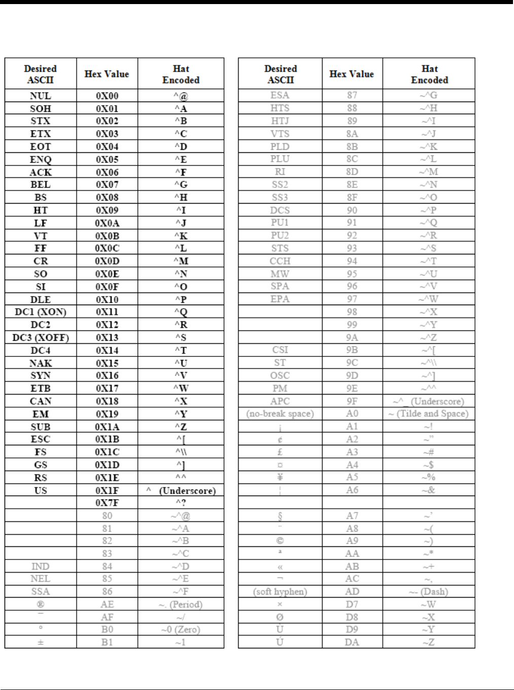
10 - 13
Hat Encoding

10 - 14

11 - 1
11
Customer Support
Product Service and Repair
Honeywell International Inc. provides service for all of its products through service centers throughout the world. To obtain war-
ranty or non-warranty service, please visit www.honeywellaidc.com and select Support > Contact Service and Repair to see
your region’s instructions on how to obtain a Return Material Authorization number (RMA #). You should do this prior to return-
ing the product.
Technical Assistance
If you need assistance installing or troubleshooting your device, please contact us by using one of the methods below:
Knowledge Base: www.hsmknowledgebase.com
Our Knowledge Base provides thousands of immediate solutions. If the Knowledge Base cannot help, our Technical Support
Portal (see below) provides an easy way to report your problem or ask your question.
Technical Support Portal: www.hsmsupportportal.com
The Technical Support Portal not only allows you to report your problem, but it also provides immediate solutions to your techni-
cal issues by searching our Knowledge Base. With the Portal, you can submit and track your questions online and send and
receive attachments.
Web form: www.hsmcontactsupport.com
You can contact our technical support team directly by filling out our online support form. Enter your contact details and the
description of the question/problem.
Telephone: www.honeywellaidc.com/locations
For our latest contact information, please check our website at the link above.
Limited Warranty
Honeywell International Inc. (“HII”) warrants its products to be free from defects in materials and workmanship and to conform
to HII’s published specifications applicable to the products purchased at the time of shipment. This warranty does not cover any
HII product which is (i) improperly installed or used; (ii) damaged by accident or negligence, including failure to follow the proper
maintenance, service, and cleaning schedule; or (iii) damaged as a result of (A) modification or alteration by the purchaser or
other party, (B) excessive voltage or current supplied to or drawn from the interface connections, (C) static electricity or electro-
static discharge, (D) operation under conditions beyond the specified operating parameters, or (E) repair or service of the prod-
uct by anyone other than HII or its authorized representatives.
This warranty shall extend from the time of shipment for the duration published by HII for the product at the time of purchase
(“Warranty Period”). Any defective product must be returned (at purchaser’s expense) during the Warranty Period to HII factory
or authorized service center for inspection. No product will be accepted by HII without a Return Materials Authorization, which
may be obtained by contacting HII. In the event that the product is returned to HII or its authorized service center within the
Warranty Period and HII determines to its satisfaction that the product is defective due to defects in materials or workmanship,
HII, at its sole option, will either repair or replace the product without charge, except for return shipping to HII.
EXCEPT AS MAY BE OTHERWISE PROVIDED BY APPLICABLE LAW, THE FOREGOING WARRANTY IS IN LIEU OF ALL
OTHER COVENANTS OR WARRANTIES, EITHER EXPRESSED OR IMPLIED, ORAL OR WRITTEN, INCLUDING, WITHOUT
LIMITATION, ANY IMPLIED WARRANTIES OF MERCHANTABILITY OR FITNESS FOR A PARTICULAR PURPOSE, OR
NON-INFRINGEMENT.
HII’S RESPONSIBILITY AND PURCHASER’S EXCLUSIVE REMEDY UNDER THIS WARRANTY IS LIMITED TO THE
REPAIR OR REPLACEMENT OF THE DEFECTIVE PRODUCT WITH NEW OR REFURBISHED PARTS. IN NO EVENT
SHALL HII BE LIABLE FOR INDIRECT, INCIDENTAL, OR CONSEQUENTIAL DAMAGES, AND, IN NO EVENT, SHALL ANY
LIABILITY OF HII ARISING IN CONNECTION WITH ANY PRODUCT SOLD HEREUNDER (WHETHER SUCH LIABILITY
ARISES FROM A CLAIM BASED ON CONTRACT, WARRANTY, TORT, OR OTHERWISE) EXCEED THE ACTUAL AMOUNT
PAID TO HII FOR THE PRODUCT. THESE LIMITATIONS ON LIABILITY SHALL REMAIN IN FULL FORCE AND EFFECT
EVEN WHEN HII MAY HAVE BEEN ADVISED OF THE POSSIBILITY OF SUCH INJURIES, LOSSES, OR DAMAGES. SOME
STATES, PROVINCES, OR COUNTRIES DO NOT ALLOW THE EXCLUSION OR LIMITATIONS OF INCIDENTAL OR CONSE-
QUENTIAL DAMAGES, SO THE ABOVE LIMITATION OR EXCLUSION MAY NOT APPLY TO YOU.

11 - 2
All provisions of this Limited Warranty are separate and severable, which means that if any provision is held invalid and unen-
forceable, such determination shall not affect the validity of enforceability of the other provisions hereof. Use of any peripherals
not provided by the manufacturer may result in damage not covered by this warranty. This includes but is not limited to: cables,
power supplies, cradles, and docking stations. HII extends these warranties only to the first end-users of the products. These
warranties are non-transferable.
The duration of the limited warranty for the Thor VM2 is 1 year.
The duration of the limited warranty for the Thor VM2 Quick Mount Smart Dock is 1 year.
The duration of the limited warranty for the Thor VM2 Vehicle Mount Assembly is 1 year.
The duration of the limited warranty for the Thor VM2 internal UPS battery is 1 year.
The duration of the limited warranty for the Thor VM2 AC power supply and cables is 1 year.
The duration of the limited warranty for the Thor VM2 DC/DC power supply is 1 year.
The duration of the limited warranty for the Thor VM2 cables (USB, Serial, Communication, Power) is 1 year.
The duration of the limited warranty for the Thor VM2 headset is 1 year.

Back Cvr - 1

