Honeywell W4ICCOMBO Wireless Smoke / Carbon Monoxide (CO) Detector User Manual Exhibit D Users Manual per 2 1033 b3
Honeywell International Inc. Wireless Smoke / Carbon Monoxide (CO) Detector Exhibit D Users Manual per 2 1033 b3
Exhibit D Users Manual per 2 1033 b3
W4-IC Combination Smoke/
Carbon Monoxide (CO) Detector
with Built-in Wireless Transmitter
INSTALLATION AND MAINTENANCE INSTRUCTIONS
3825 Ohio Avenue, St. Charles, Illinois 60174
1-800-SENSOR2, FAX: 630-377-6583
www.systemsensor.com
BEFORE INSTALLATION
Please read this manual thoroughly along with the Application Guides for Sys-
tem Sensor Smoke (A05-1003) and CO Detectors (A05-1099), which provide
detailed information on detector spacing, placement, zoning and special ap-
plications. Copies of these manuals are available at systemsensor.com.
IMPORTANT: This detector must be tested and maintained regularly following
NFPA 72/NFPA 720 requirements.
GENERAL DESCRIPTION
The W4 series is a battery-operated, system-connected, combination carbon
monoxide/smoke detector with a built-in wireless transmitter for use with
iControl wireless control panel models. It will report maintenance, tamper and
independent smoke alarm or CO alarm signals to a compatible wireless con-
trol panel. It has a speaker for vocal feedback, multi-criteria smoke detection,
and integrated side LED windows that are viewable from 360 degrees when
the detector is in an alarm condition.
FEATURES
Smoke Features
• Multi-criteria smoke sensing using a combination of photoelectric, heat,
flame flicker and carbon monoxide sensing.
• Drift compensation and noise rejection algorithms.
• Smoke test button.
• 360 degree, side viewable red LED smoke indication.
CO Features
• 10 year electrochemical CO sensor.
• Sensor end-of-life notification.
• CO test button.
• RealTest® functional gas entry test capable.
• 360 degree, side viewable blue LED CO indication.
Audible Annunciation
• Local integral sounder.
• Voice speaker provides supplemental instructions during alarm, installa-
tion and maintenance feedback.
Installation and Maintenance
• Universal mounting base.
• Audible maintenance information including smoke sensitivity.
Other Features
• Ships with 4 CR-123 lithium batteries.
• UL/ULC listed to standards 268 and 2075.
SPECIFICATIONS
Electrical Specifications
Voltage: 3 volts DC
Battery Type: CR-123 lithium
Battery Manufacturer: Duracell DL123A or Panasonic CR123A
Use of a different battery may have a detrimental effect on device operation
Number of Batteries: 4
Sensitivity 0.9 to 2.64/ft. (.27 to .80/m)
Audible Signal: 85dBA
Physical Specifications
Diameter: 5.95 inches (15.113 cm)
Height: 2.03 inches (5.1562cm)
Weight: 13.92oz (383 g)
Operating Temperature Range: 0 - 38° C (32 - 100°F)
Storage Temperature Range: -10 - 70° C (14 - 158° F)
Operating Humidity Range: 20-95% RH
This product is compatible with iControl Technicolor TCA203 control panels
*NFPA requires a UL listed sounder on the NAC circuit.
Notice: This manual shall be left with the owner/user of this equipment.
I56-5942-000
VISIBLE ANNUNCIATON
The W4 series detector has a multi-color top LED; Green, Red, and Amber.
The LED is green for supervisory indication; it blinks during power on, reset,
and during normal operation. The LED is amber to signal maintenance and
trouble events. W4 utilizes the side LED windows to indicate alarm events;
red for smoke and blue for CO.
INSTALLATION GUIDELINES
Ceiling: Detector should be at least 12 inches (30 cm) from any wall.
Wall: Detector should be no closer than 6 inches (15 cm) from ceiling.
• Do not install outdoors or in any environment that does not comply with
the detector’s environmental specifications.
• Install in accordance with NFPA 72 and 720 standards. NFPA 72 and
720 define standards for both commercial and residential installation of
smoke and CO detectors. Local laws involving CO detection should also
be considered.
• If the installation can be interpreted as residential, consult the section
of NFPA 720 that outlines residential applications. Chapter 9.4.1.1, for
example, states that carbon monoxide alarms or detectors shall be in-
stalled as follows:
• Outside each separate dwelling unit sleeping area in the immediate
vicinity of the bedroom.
• On every level of a dwelling unit, including basements.
• Consult NFPA 72, the local Authority Having Jurisdiction (AHJ), and/
or applicable codes for specific information regarding the spacing and
placement of smoke detectors.
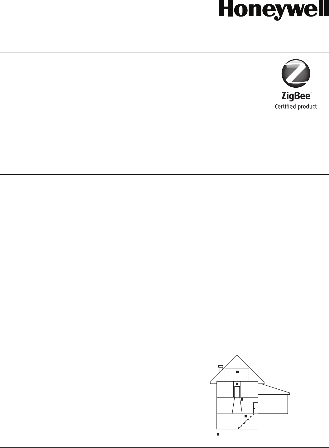
FIGURE 1: ALARM LOCATION DIAGRAM FOR RESIDENTIAL APPLICATION
LIVING
ROOM
BEDROOM BEDROOM
BEDROOM
KITCHEN
TO
BR
CLOSED
DOOR
BASEMENT
GARAGE
CARBON MONOXIDE/SMOKE ALARM
LOCATION FOR MULTI-LEVEL RESIDENCE
–
S0295-01
Global 2.4 Ghz wireless use
ZigBee® Certified is a registered
trademark of the Zigbee Alliance.
1 I56-5942-000
09-14

• Do not install detectors in the following areas:
• In or near areas where particles of combustion are normally present such as
kitchens, in garages, near furnaces, hot water heaters, or gas space heaters.
• In very cold or very hot areas that may be outside the detectors op-
erating range.
• In wet or excessively humid areas, or next to bathrooms with showers.
• In dusty, dirty, or insect-infested areas.
• Near fresh air inlets or returns or excessively drafty areas. Air con-
ditioners, heaters, fans, and fresh air intakes and returns can drive
smoke away from the detector.
INSTALLATION
Add the CO/Smoke Detector to the TouchScreen:
1. Remove detector from packaging and separate the mounting base from
the detector head.
2. On the TouchScreen, log into the Settings app with an Installer code.
3. Enter Technician Code/ID.
4. In the Settings menu, tap Sensors & Zones > Add a Sensor/Zone.
5. Remove the battery tab from the detector, making sure the batteries re-
main fully seated. The detector will run through its initialization. (See
Table 1.)
6. The base model will enter Search mode (skip to step 8). The voice model
will prompt for language selection. (Move to step 7.)
7. Press the Smoke test button to select English or the CO test button to se-
lect Spanish language settings. Once the language is selected the detector
will enter Search mode. (To reset language selection, see Restore Factory
Settings section.)
8. At the Locating Wireless Sensors screen, tap Next. A Done button ap-
pears on the screen and the TouchScreen searches for sensors that are
available to be added. As sensors are found, a grayed icon appears for
that sensor. It will indicate a Trip to Pair operation request. The tamper
feature is disabled at this time to allow time to install the detector and
mounting bracket on the ceiling or wall.
9. A sensor that has been automatically enrolled will appear on the screen
with a green check mark. If after waiting 15 seconds a green check mark
does not appear, press the respective test button to pair the sensor to the
TouchScreen. Press a test button to vocalize the signal strength status
between sensor and panel.
10. Any located sensors that were not paired are released by the TouchScreen
and can be added later. The Wireless Sensors Located screen shows the
number of wireless sensors found and paired.
11. Upon success pairing of both CO and Smoke sensors, tap Done, tap Next.
The Configure Wireless Sensors screen shows icons of the sensors that
were found and paired. Touch each sensor icon to configure the corre-
sponding device.
12. The Add Sensor/Zone Modify screen appears. To change the Smoke Icon
or CO Icon (if multiple options are available) and the 24-Hour zone func-
tion, tap the drop down arrow next to the value you wish to modify, and
then select the new value from the choices provided.
13. The Add Sensor/Zone Modify screen appears. To modify a Zone Label on
the TouchScreen, tap the field, use the onscreen keyboard to enter your
changes, and tap Done to save your changes.
14. Tap Next in the Add Sensor/Zone screen. If all of the sensors have not
been configured, the Modify screen appears for each sensor to let you
review its details. Change the details as needed or tap Next to cycle
through all sensors. The sensors are marked as configured.
MOUNTING
Physically mount the smoke detector in the desired location;
NOTE: NFPA 72 recommends the installation of detectors only after complet-
ing construction or any other dust producing activity.
Smoke detectors are not to be used with detector guards unless the combina-
tion has been evaluated and found suitable for that purpose.
1. Disconnect alarm-notification appliances, service-release devices, and
extinguishing systems.
2. Hold the smoke detector where you plan to install it. If the green LED is
blinking rapidly while off its mounting base, this indicates the RF signal
strength is adequate. Press a test button and verify the signal strength.
3. Using two supplied screws and anchors, mount the base.
4. Attach the smoke detector to the mounting base with a clockwise mo-
tion.
5. Test each detector as described in the Testing section.
6. Notify the proper authority that the system is in operation.
TESTING
Test communications between the detector and the control panel;
The detector has two test buttons; one for smoke testing and one for CO test-
ing. The detector may also be functionally tested using canned smoke and
canned CO. If the detector fails any of the test methods the detector should
be replaced.
NOTE: Testing the detector will activate the alarm and send a signal to the
panel. Before testing, notify the proper authorities to avoid any nuisance
alarms.
1. Pressing the Smoke test button for 1 second will provide audible diag-
nostic information for the homeowner on sensor status and battery life.
Pressing and holding the Smoke test button for 3 to 5 seconds will pro-
vide diagnostic information for the technician including smoke sensitiv-
ity readout and then enter smoke entry test mode. (See Smoke Entry Test
section.)
2. Pressing the CO test button for 1 second will provide diagnostic informa-
tion for the homeowner on sensor status, battery life, and CO sensor life.
Pressing and holding the CO test button for 3 to 5 seconds will enter
functional gas entry test mode. (See Functional Gas Test section.)
3. The control panel alarm and all auxiliary functions should be verified for
a complete test of the system.
TABLE 1: OPERATION MODES
MODE STATUS LED (TOP)
LED
WINDOWS
(SIDE)
SOUNDER SPEAKER
POR out-of-box Blink
red-green-amber Dark Silent Voice welcome, instructions follow POR for language selection
POR
Blink green,
2 seconds when
boot is complete.
Dark Silent Silent
Enrollment Blinks green
every 5 seconds Dark Silent Annunciates Enrollment Successful along with signal strength, or
enrollment failed after 2 minutes.
Tamper Mode
(Enrolled with panel, not mounted on base)
Blink amber
every 10 seconds Dark Silent Voice signal strength annunciation with a press of the test button.
Standby (Mounted on Base) Blink green
every 10 seconds Dark Silent Silent
Smoke Alarm Blink red Blink red Temp-3 Voice smoke warning
CO Alarm Blink red
every 10 seconds Blink blue Temp-4 Voice CO warning
Powered Down Dark Dark Silent Silent
2 I56-5942-000
09-14
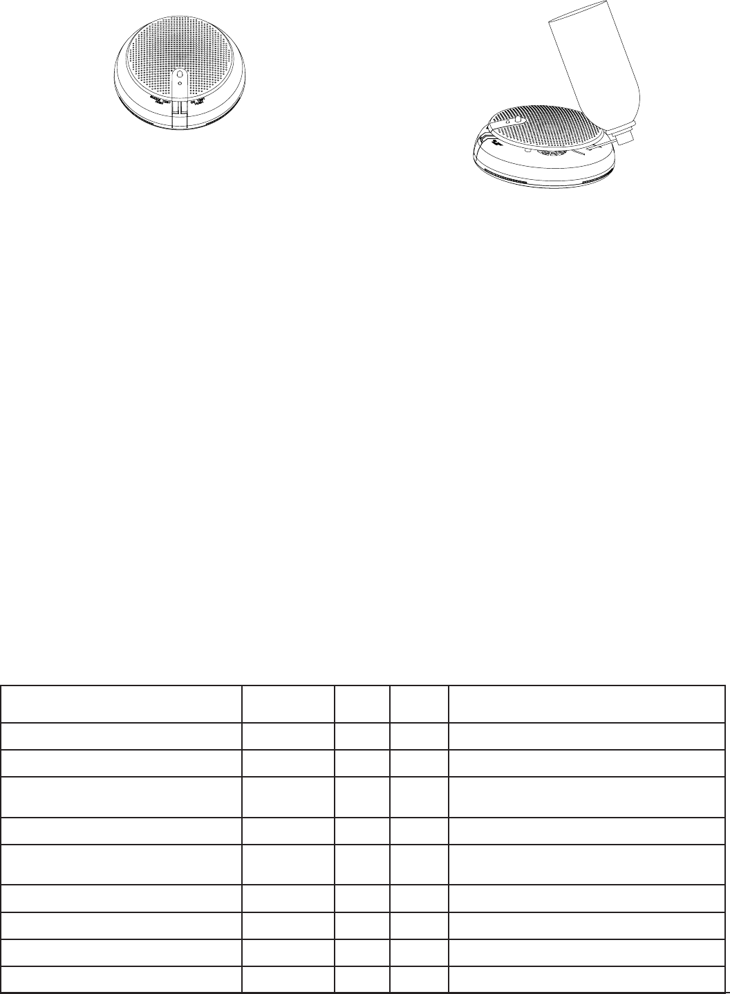
FIGURE 3: CO GAS ENTRY LOCATION
CO
S0339-00
MAINTENANCE
The W4 detector reports maintenance issues to the control panel and com-
municates them visually and audibly per Table 2.
Trouble feature: When the sensor (supervision) is in a trouble condition (such
as a detector that is dirty or CO sensor non-functioning), the detector will
send a trouble signal to the panel. Depending on the issue, the detector must
then be serviced or replaced.
CO sensor end-of-life timer feature: When the CO sensor has passed end-of-
life, a trouble signal will be sent to the panel. This indicates that the CO sensor
inside the detector must be replaced. If unresolved for 30 days, the detector
will chirp intermittently. The typical life of the CO sensor is ten years from the
date of manufacture; it is recommended to periodically check the “Replace
by” sticker located on the back of the detector head.
Batteries: WARNING: Use only Duracell DL123A or Panasonic CR123A lithium
Batteries may present risk of fire or explosion. Remove all old batteries, wait
10 seconds then insert four new batteries.
NOTE: Before performing any maintenance on the detector, notify the proper
authorities that maintenance is being performed and the system will be tem-
porarily out of service. Disable the zone or system undergoing maintenance
to prevent any unwanted alarms. Power must be removed from the detector
before performing maintenance of any kind.
CLEANING
1. Remove the detector head by turning counterclockwise.
2. Clean the outside casing with a cloth. Ensure that the holes on the front
of the alarm are not blocked with dirt and dust. Canned air can be used
to remove any dust or debris.
3. Reattach the detector head to the mounting base by rotating clockwise.
FIGURE 2: TEST BUTTON LOCATION AND OPERATION
S0338-00
SMOKE ENTRY TEST / SMOKE SENSITIVITY READOUT
To smoke test W4, because it is a multi-criteria detector), it must be put into
the smoke test mode as follows:
1. With the detector in standby mode, press and hold the smoke test button
for 3 to 5 seconds. The W4 will provide diagnostic information including
sensor status and smoke sensitivity reading and will prompt for smoke
entry and annunciate per Table 2.
2. While W4 is in smoke entry mode with its green LED flashing, spray
canned smoke into the detector. The canned smoke that can be used is
approved for test include: Home Safeguard Industries 25S, SDi CHEK02
and CHEK06, SDi SOLOA4, and SDi SMOKESABRE".
3. When the detector senses the presence of the smoke, the detector will
sound and illuminate per Table 2 and a smoke alarm signal will be sent
to the control panel with a test indication.
4. Verify the smoke alarm signal was received by the control panel.
FUNCTIONAL GAS TEST
Solo C6 brand canned CO may be used to verify the detector’s ability to sense
CO by utilizing the RealTest® feature as follows:
1. Press and hold the CO test button for 3 to 5 seconds. The green LED will
start blinking rapidly indicating tshe detector is in RealTest® mode. (If the
detector will not go into RealTest® mode, the CO sensor may be in fault
or at end-of-life.)
2. While the green LED is blinking rapidly, spray a small amount of canned
CO directly into the CO gas entry port. (See Figure 3.)
3. The detector will go into CO alarm and send an alarm to the channel
panel if the gas entry was successful and the CO sensor is detected it-
functioning properly.
4. Verify the smoke CO alarm signal was received by the control panel.
5. The CO test will automatically clear when the CO clears from the sensor
or in 30 seconds if no CO was introduced.
TABLE 2: LED INDICATION & SOUNDER DURING TEST AND MAINTENANCE
MODE STATUS LED (TOP)
LED
WINDOWS
(SIDE)
SOUNDER SPEAKER
Smoke Alarm System Test – Waiting for smoke entry
(Press and hold Smoke test button 3-5 seconds)
Blink green
once a second Dark Silent Voice instructions for testing including warning of alarm
signal
Smoke Alarm System Test (Upon successful smoke
entry)
Blink red
every 10 seconds Blink red Temp-3 Voice smoke warning
RealTest® Functional CO gas entry test - Waiting
for gas entry (Press and hold CO test button 3-5
seconds)
Blink green
once a second Dark Silent Voice instructions for testing including warning of alarm
signal
RealTest® Functional CO gas entry test -Upon
successful gas entry
Blink red
every 10 seconds Blink blue Modified
Temp-4 Voice carbon monoxide warning
Low Battery Blink Amber
every 45 sec Dark
Chirp Every
45 seconds
after 7 days
Voice instructions by pressing either test button
Smoke Maintenance Blink Amber
every 5 seconds Dark Silent Voice smoke maintenance instructions if Smoke test button
is pressed
CO Trouble Blink Amber
every 5 seconds Dark Silent Voice CO maintenance instructions if CO test button is
pressed
CO End of Life - First 29 days Blink Amber
every 3 seconds Dark Silent Voice end of life instructions if CO test button is pressed
CO End of Life - 30 days after panel notification Blink Amber
every 3 seconds Dark Chirp Every
45 Seconds Voice end of life instructions if CO test button is pressed
3 I56-5942-000
09-14
Honeywell® and RealTest® are registered trademarks of Honeywell International, Inc. ZigBee® Certified is a registered trademark of the ZigBee Alliance.
4. Test the detector to insure it is fully functional. (See Testing section.)
5. Notify the proper authorities when the system is back in service.
Do not paint, and do not use cleaning agents, bleach or polish the detector.
RESTORE FACTORY SETTINGS
The W4 detector can be restored to its factory settings by pressing and hold-
ing both the smoke and CO test switch buttons simultaneously for 10 seconds
which will cause the status LED to fast blink green. A release and repress of
both test switch buttons will reset the detector to its factory settings.
LIMITED LIFE OF CO SENSOR
This detector is manufactured with a long-life electrochemical carbon mon-
oxide sensor. Over time the sensor will lose sensitivity and will need to be
replaced. The life span of the CO sensor is approximately ten years from the
date of manufacture.
Periodically check the detector’s replacement date. Remove the detector head
and refer to the ‘replace by’ sticker placed on the underneath side of the detec-
tor. The sticker will indicate the date the detector should be replaced.
Reminder: This detector is also equipped with a feature that will signal the
panel once the CO sensor has passed the end of its’ useful life. If this occurs,
it is time to replace the detector.
What to do if the detector goes into CO alarm: If the detector goes into CO
alarm (4 beeps), immediately move to a spot where fresh air is available, pref-
erably outdoors, where the air is safe and call your security service provider.
Tell your provider the detector alarm status, and that you require professional
assistance in ridding your home of the carbon monoxide.
This detector is NOT:
• A substitute for the proper servicing of fuel-burning appliances or the
sweeping of chimneys.
• To be used on an intermittent basis or as a portable alarm for the spill-
age of combustion products from fuel-burning appliances or chimneys.
Carbon monoxide gas is a highly poisonous gas which is released when fuels
are burnt. It is invisible, has no smell and is therefore is impossible to detect
with the human senses. Under normal conditions in a room where fuel burn-
ing appliances are well maintained and correctly ventilated, the amount of
carbon monoxide released into the room by appliances should not be danger-
ous.
CO WARNING
WARNING
WARNING: Carbon Monoxide is an odorless, colorless, tasteless gas when
unit is in alarm move to fresh air immediately.
SYMPTOMS OF CARBON MONOXIDE POISONING
Carbon monoxide bonds to the hemoglobin in the blood and reduces the
amount of oxygen being circulated in the body. The following symptoms are
examples taken from NFPA 720; they represent approximate values for healthy
adults.
TABLE 3. CO EXPOSURE SYMPTOMS
CONCENTRATION
(PPM CO)
SYMPTOMS
200 Mild Headache after 2-3 hours of exposure
400 Headache and nausea after 1-2 hours of exposure
800 Headache, nausea, and dizziness after 45 minutes of
exposure; collapse and unconsciousness after 2 hours
of exposure
Many cases of reported carbon monoxide poisoning indicate that while vic-
tims are aware that they do not feel well, they become so disoriented that they
are unable to save themselves by either exiting the building or calling for as-
sistance. Also young children, elderly and pets may be the first to be affected.
CO ALARM ACTIVATION
Per UL standard 2075, the W4 series detector has been tested to the sensitivity
limits defined in UL standard 2034.
TABLE 4: CO ALARM THRESHOLDS
Parts per Million (ppm) Detector Response Time (Min.)
30+-3ppm No alarm within 30 days
70+-5ppm 60-240
150+-5ppm 10-50
400+-10ppm 4-15
FCC STATEMENT
This device complies with part 15 of the FCC Rules. Operation is subject to the following two conditions: (1) This device may not cause harmful interference, and (2) this device must
accept any interference received, including interference that may cause undesired operation.
NOTE: This equipment has been tested and found to comply with the limits for a Class B digital device, pursuant to Part 15 of the FCC Rules. These limits are designed to provide
reasonable protection against harmful interference in a residential installation. This equipment generates, uses and can radiate radio frequency energy and, if not installed and used
in accordance with the instructions, may cause harmful interference to radio communications. However, there is no guarantee that interference will not occur in a particular installa-
tion. If this equipment does cause harmful interference to radio or television reception, which can be determined by turning the equipment off and on, the user is encouraged to try
to correct the interference by one or more of the following measures:
– Reorient or relocate the receiving antenna.
– Increase the separation between the equipment and receiver.
– Connect the equipment into an outlet on a circuit different from that to which the receiver is connected.
– Consult the dealer or an experienced radio/TV technician for help.
Please refer to insert for the Limitations of Fire Alarm SystemsPlease refer to insert for the Limitations of Fire Alarm Systems
THREE-YEAR LIMITED WARRANTY
Honeywell warrants its enclosed smoke detector to be free from defects in materials
and workmanship under normal use and service for a period of three years from date of
manufacture. Honeywell makes no other express warranty for this smoke detector. No
agent, representative, dealer, or employee of the Company has the authority to increase
or alter the obligations or limitations of this Warranty. The Company’s obligation of
this Warranty shall be limited to the repair or replacement of any part of the smoke
detector which is found to be defective in materials or workmanship under normal use
and service during the three year period commencing with the date of manufacture.
Contact your local Honeywell representative to issue a Return Authorization number
(RA # ______), and arrange for return of the defective units. Please include a note
describing the malfunction and suspected cause of failure. The Company shall not be
obligated to repair or replace units which are found to be defective because of damage,
unreasonable use, modifications, or alterations occurring after the date of manufacture.
In no case shall the Company be liable for any consequential or incidental damages for
breach of this or any other Warranty, expressed or implied whatsoever, even if the loss
or damage is caused by the Company’s negligence or fault. Some states do not allow the
exclusion or limitation of incidental or consequential damages, so the above limitation
or exclusion may not apply to you. This Warranty gives you specific legal rights, and you
may also have other rights which vary from state to state.
4 I56-5942-000
©2016 Honeywell. 09-14