Honeywell WLKFRV Wireless Transceiver User Manual 62 0291 D
Honeywell International Inc Wireless Transceiver 62 0291 D
User Manual
INSTALLATION INSTRUCTIONS
62-0291-07
TR21-WS, TR23-WS, TR21-WK,
TR23-WK, WRECVR
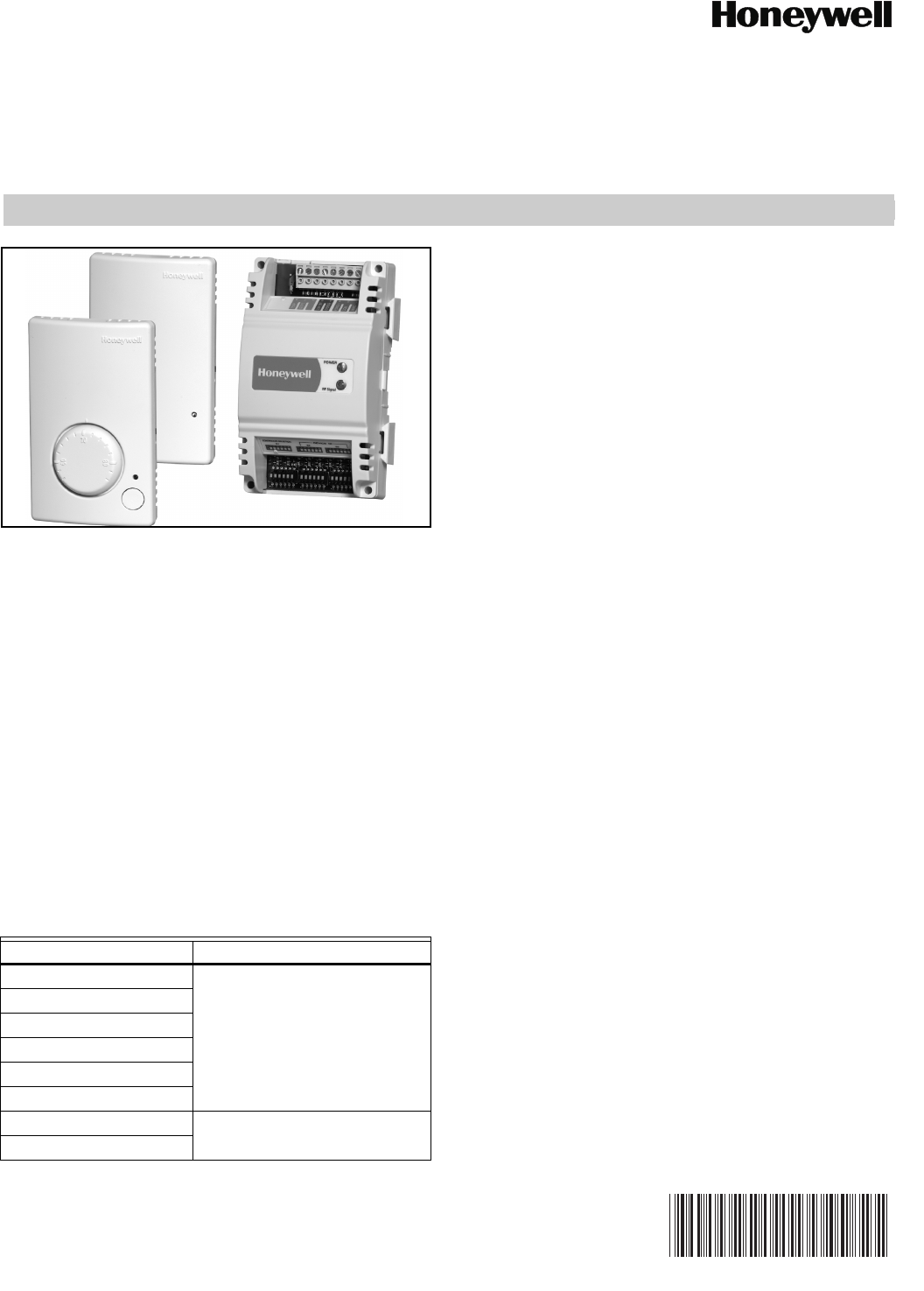
APPLICATION
The WRECVR receiver and TR21-WS, TR23-WS, TR21-WK,
and TR23-WK are a family of wireless wall modules and
receiver for use with:
— Spyder Unitary Controllers: PUL, PVL, etc.
— Excel 10 W7750, W7751, W7752, and W7753
controllers
— T7350, T7351, and TB8575 low-voltage SuitePRO™
thermostats
— Will not work with TB7220, TB8220 or TB line voltage
thermostats, XL15s, W7762, W7763 or certain other
XL controllers,
— Will work with WEBs-AX™ I/O Module products if
using a separate transformer
— Compatibility with various other non-Honeywell con-
trollers that accept 10K type2 NTC temperature inputs
NOTE: Refer to the TR21 and TR23 Wall Modules –
Specification Data, form 63-1332, for specific model
features and additional information.
FEATURES
• Wall module to Receiver (point to point) wireless kits
can replace any standard wired sensor
• Wireless Kits (wall module and receiver) are pre-bound
at the factory for quick installation
• Signal Strength LED built into the wall module
• Low battery indication
• Optional dip switches available to bind any wall
module to any receiver
• Approximate 5 year battery life with AA Alkaline
(included), 7.5 year with Lithium
• Locking screw discourages tampering and battery
theft.
SPECIFICATIONS
Models: For specific model information, see Specification
Data, form 63-1332.
Environmental Ratings:
• Wall Module Operating Temperature: 45° to 99°F
(7° to 37°C).
• Receiver Operating Temperature: -40° to 150°F
(-40° to 65.5°C).
• Storage Temperature: -40° to 150°F (-40° to 65.5°C).
• Operating Humidity: 5% to 95% RH (non-condensing)
Accuracy: +/- 1ºF (+/- 0.5ºC) across 12ºC to 30ºC
Setpoint Range for TR23: 56° to 84°F (13° to 29°C)
Accessories: 50007298-001 (pack of 12) medium, cover
plate; 6-7/8 x 5 in. (175 x 127 mm).
Power:
Receiver Voltage: 20 – 30VAC/DC, 50/60Hz; 24VAC typical
Housing:
• Wall Module: UL94-HB
• Receiver: UL94-5VA
Radio Frequency 2.4 GHz (IEEE Std 802.15.4-2003
compliant)
• Open Range: 3000 feet
• Typical Range: 100 feet
• Output power: 16dBm
• Receiver power consumption: <1.5 VA@24VAC
Model No. FCC/IC ID’s
TR21-WS
FCC ID: HS9WLKFWM
IC: 573R-WLKF
TR21-WK
TR23-WS
TR23-WK
TR21-WSU
TR23-WSU
WRECVR FCC ID: HS9WLKFRV
IC: 573R-WLKF
WRECVRU
TR21-WS, TR23-WS, TR21-WK, TR23-WK, WRECVR
62-0291—07 2
Approximate battery life under normal operating
conditions:
• 5 years with two AA Alkaline batteries (included)
• 7.5 years with two AA Lithium Batteries
Transmission interval: 30 seconds
Pressing override button or signal strength button will force an
immediate transmission.
Approvals:
This device complies with Part 15 of the FCC rules. Operation
is subject to the following two conditions:
1) this device may not cause harmful interference, and
2) this device must accept any interference received,
including interference that may cause undesired operation.
INSTALLATION
CAUTION
Erratic System Operation Hazard.
Failure to follow proper wiring practices can
introduce disruptive electrical interference (noise).
Keep wiring at least one foot away from large inductive
loads such as motors line starters, lighting ballasts,
and large power distribution panels.
Shielded cable is required in installations where these
guidelines cannot be met.
Ground shield only to grounded controller case.
IMPORTANT
All wiring must comply with local electrical codes and
ordinances or as specified on installation wiring
diagrams.
— Receiver wiring can be sized from 16 to 22 AWG
(1.31 to 0.33 sq. mm) depending on the application.
— The maximum length of wire from a device to a receiver is
100 ft. (30.5 m).
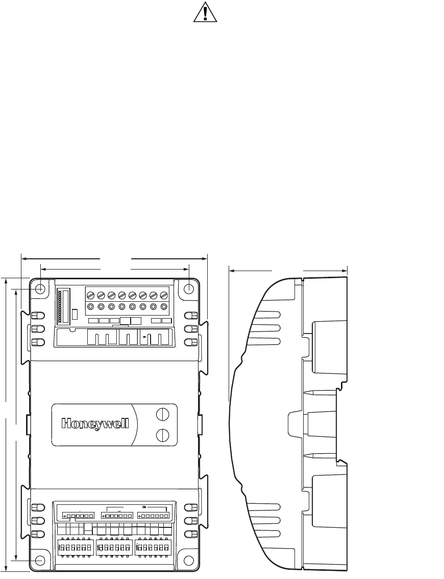
Mounting the Receiver
Fig. 1. Receiver dimensions in in. (mm).
The receiver can be mounted on any surface using screws
(No. 6 or No. 8) appropriate for the mounting surface. The
receiver can also be mounted to the Spyder controller using
the mounting slots and tabs (dovetails), and can be mounted
to a DIN rail.
M29049
POWER
RFSignal
TEMP
SETPT
LOW BAT
OVERRIDE
EGND
COM
24VAC
12345678
ON ON ON
CONTROLLER SELECTION
S1 S2 S3
DEVICE
1 2 3 4 5 6 1 2 3 4 5 61 2 3 4 5 6
1 2 3 4 5 61 2 3 4 5 6
1 2 3 4 5 6
ON
ON
ON
3-13/64 (81)
5-1/2
(140)
2-13/64 (56)
2-25/32 (71)
5-3/32
(129)
TR21-WS, TR23-WS, TR21-WK, TR23-WK, WRECVR
362-0291—07
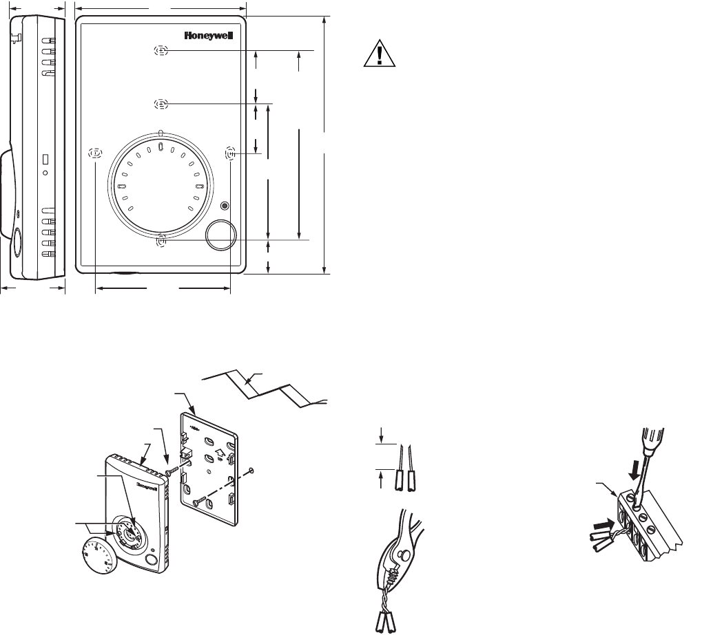
Mounting the Wall Module
Mount the wall module on an inside wall approximately 54 in.
(1372 mm) from the floor (or in the specified location) to allow
exposure to the average zone temperature. Do not mount the
wall module on an outside wall, on a wall containing water
pipes, or near air ducts. Avoid locations that are exposed to
discharge air from registers or radiation from lights,
appliances, or the sun. When mounting to drywall, use the
horizontal mounting screw locations, as shown in Fig. 3.
Fig. 2. Wall Module subbase dimensions in inches (mm)
(TR23 shown).
Fig. 3. Mounting the wall module on the wall and
temperature limit set screw locations (TR23 shown).
There is a locking screw option to prevent tampering and
access to batteries. The screw is provided with the wall
module, and screws into the slot shown in Fig. 9 after the
device is snapped onto the subbase.
If desired, insert the two red end stoppers into temperature
scale to set the desired temperature range limit. See Fig. 3.
For TR23 models, insert the desired dial through the opening
in the cover. Align the keyed shaft on the knob with the keyed
slot into the fitting on the subbase, then press down until it
snaps into place.
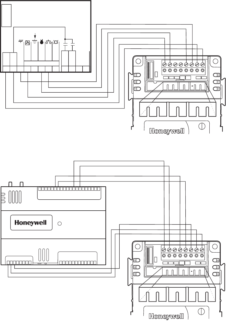
WIRING
Attach the wires from the device terminals to the appropriate
receiver terminals.
CAUTION
Improper Electrical Contact Hazard.
Screw type terminal blocks are designed to accept
no more than one 16 AWG (1.31 sq. mm)
conductor.
Connect multiple wires that are 16-18 AWG
(1.31-0.82 sq. mm) with a wire nut. Include a pigtail
with this wire group and attach the pigtail to the
individual terminal block.
Wire the terminal block as follows:
1. For single wires, strip 3/16 in. (5 mm); for multiple wires
going into one terminal, strip 1/2 in. (13 mm) insulation
from the conductor.
2. If two or more wires (18 to 22 AWG only) are being
inserted into one terminal, twist the wires together
before inserting.
NOTE: When two or more wires are being inserted
into one terminal, be sure to twist them
together. Deviation from this rule can result
in improper electrical contact. See Fig. 4.
3. Insert the wire in the required terminal location and
tighten the screw to complete the termination.
4. Review and verify the terminal connection wiring and
DIP switch settings.
Fig. 4. Attaching two wires (18 to 22 AWG) to
receiver terminals.
M29050
60
70
80
3 (77)
4-11/16
(119)
1-5/32 (29)
63/64 (25)
STANDARD
UTILITY
CONDUIT
BOX (2 X 4)
MOUNTING
HOLES
9/16 (14)
2-3/8
(60)
7/8
(22)
7/8
(22)
2-3/8 (60)
M29054
SUBBASE
NO. 6 SCREW
FRONT COVER
TEMPERATURE LIMIT
END STOPPER
LOCATIONS
END STOPPERS
WALL
1/2
(13)
STRIP 1/2 IN.
(13 MM) FROM
WIRES TO BE
ATTACHED AT
ONE TERMINAL.
1.
2.
TWIST WIRES
TOGETHER
WITH PLIERS
(A MINIMUM OF
THREE TURNS).
3.
CUT TWISTED END OF WIRES TO
3/16 IN. (5 MM) BEFORE INSERTING
INTO TERMINAL AND TIGHTENING
SCREW. THEN PULL ON EACH WIRE
IN ALL TERMINALS TO CHECK FOR
GOOD MECHANICAL CONNECTION.
M29055
CONTROLLER OR
RECEIVER
E-BUS CONNECTOR
TERMINALS
TR21-WS, TR23-WS, TR21-WK, TR23-WK, WRECVR
62-0291—07 4
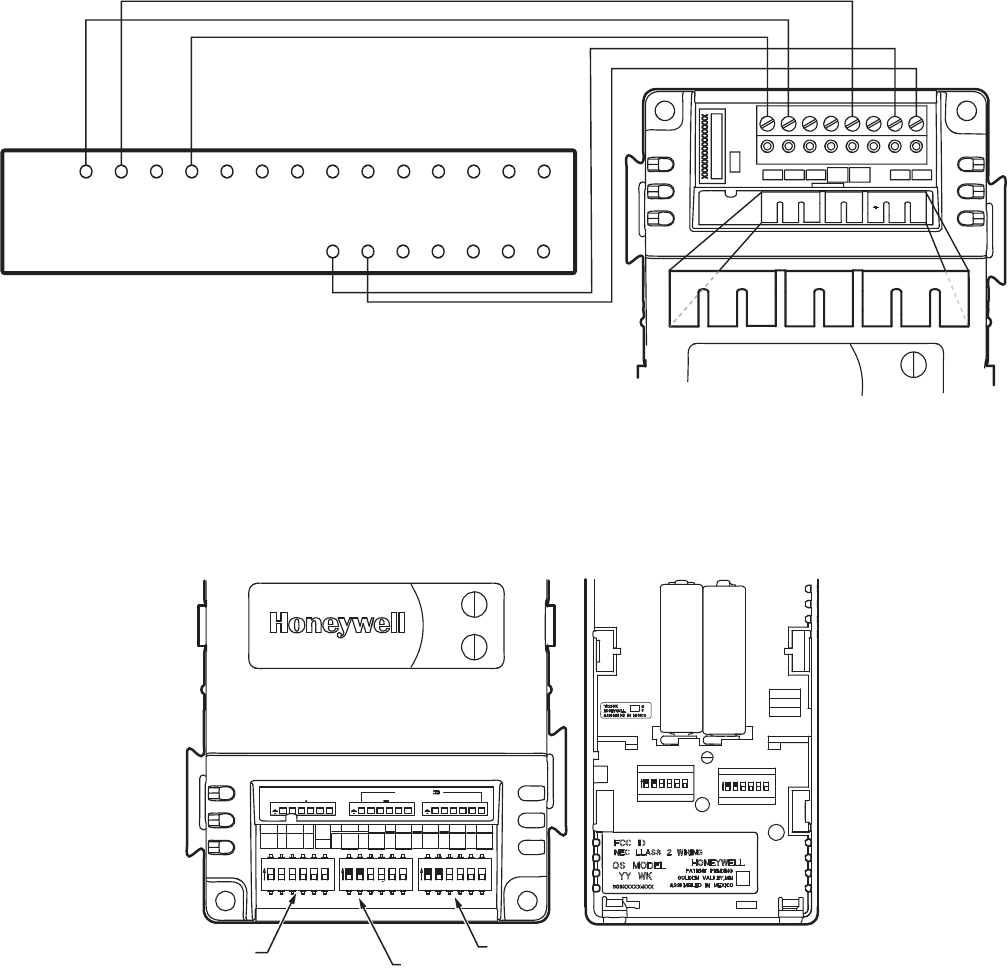
Fig. 5. Wiring receiver to Excel 10.
Fig. 6. Wiring receiver to Spyder Unitary Controller.
12345678 910
11 12
24 VAC
COM
OUT 1
OUT 2
E-BUS
W7751H
WALL MODULE
EARTH
GND
SENSOR
BYPASS
LED
NOT EARTH GROUND
MICROBRIDGE
DP SENSOR
TRIAC
EQUIVALENT
CIRCUIT
SET PT
M29051
TEMP
SETPT
LOW BAT
OVERRIDE
COM
24VAC
12345678
POWER
EGND
TEMP
SETPT
LOW BAT
OVERRIDE
COM
24VAC
12345678
EGND
EM
AC
AO-1
COM
AO-2
AO-3
COM
UI-1
COM
UI-2
UI-3
COM
UI-4
UI-5
COM
UI-6
DI-1
DI-2
COM
DI-3
20V DC
DI-4
NET-2
NET-1
SHLD
EGND
24 VAC
24VAC COM
DO-1
COM
DO-2
DO-3
DO-4
DO-5
COM
DO-6
COM
12345678 109 2345678 09
11 1111111 21
12345678 0
9
22 2222222 33
12345678 0
9
333333334
DO-7
DO-8
COM
SBUS1
SBUS2
M29052
TEMP
SETPT
LOW BAT
OVERRIDE
COM
24VAC
12345678
POWER
EGND
TEMP
SETPT
LOW BAT
OVERRIDE
COM
24VAC
12345678
EGND
EM
AC
TR21-WS, TR23-WS, TR21-WK, TR23-WK, WRECVR
562-0291—07
Fig. 7. Wiring receiver to T7350 thermostat.
DIP Switch Labels
This device is packed with tear-off DIP switch labels you can attach to the receiver and indicate which DIP switches are on and
off.
Fig. 8. Wall module DIP switches and Receiver DIP switches S1, S2, and S3. Figure shows an example of sensor DIP
switches matching S2 and S3 DIP switches on receiver.
TESTING FOR SIGNAL
STRENGTH
When the receiver is powered and batteries are placed in the
wall module, communication will begin automatically within 2
seconds. The receiver RF signal light will flash every 30
seconds to confirm each transmission. You can force
immediate communication by pressing the signal strength
button on the side of the wall module with a 1-1.6 mm
diameter probe with flat or rounded face (a common paperclip
will do) (see Fig. 9). This may be required to initiate
communication when replacing a wall module.
The signal strength LED next to the signal strength button will
light up on the side to show the relative signal strength. The
signal strength LED will initially light amber when the signal
strength button is pressed to verify that you are pressing the
signal strength button. When you release the signal strength
button, the light will behave as shown in Table 1.
M28646
TEMP
SETPT
LOW BAT
OVERRIDE
COM
24VAC
12345678
POWER
EGND
TEMP
SETPT
LOW BAT
OVERRIDE
COM
24VAC
12345678
EGND
EM
AC
RCX
SUBBASE
W1 GY1
W2 Y2
AUXRH
T5 T6 T7 T4 T3 OSOS ASAS
WHEN USING THE WIRELESS TR23 SENSOR WITH THE T7350 BE SURE TO
USE THE RELATIVE SCALE SETPOINT KNOB.
WHEN USING THE WIRELESS TR21 SENSOR WITH THE T7350, DO NOT WIRE
TERMINAL 5 AND TERMINAL 6.
NOTE 1.
NOTE 2.
S1 DIP
S2 DIP
S3 DIP
M29053
POWER
RFSignal
ON ON ON
CONTROLLER SELECTION
S1 S2 S3
DEVICE
1 2 3 4 5 6 1 2 3 4 5 61 2 3 4 5 6
1 2 3 4 5 61 2 3 4 5 6
1 2 3 4 5 6
ON
ON
ON
ON
1 2 3 4 5 6
ON
1 2 3 4 5 6
TR21-WS, TR23-WS, TR21-WK, TR23-WK, WRECVR
62-0291—07 6
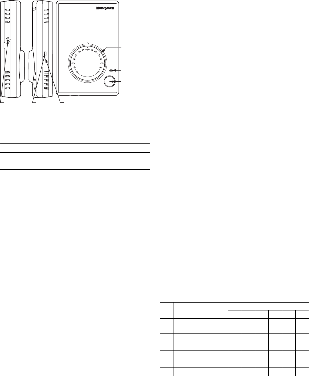
Fig. 9. Wall module features (TR23 shown).
If no signal is received, test the wall module in a different
location until a suitable signal strength is received by the
receiver. Pressing the signal strength button on the wall
module will cause a five-second flash on the RF signal LED
on the receiver, and pressing the override button will cause a
single flash on the receiver.
If communication is lost between the wall module and
receiver, the receiver will try three times to reestablish
communication. After 3 tries (90 seconds), the receiver will go
into a sleep mode, and will retry to communicate every 10
minutes. Output from the receiver will be an open circuit for
temperature and setpoint output (simulating cut wires on a
wired sensor). Communication will re-establish automatically
once signal is within range.
BINDING THE WALL MODULE
AND RECEIVER TO EACH
OTHER
The TR21-WK and TR23-WK wireless kits include a wall
module and receiver that have already been bound in the
factory to automatically communicate with each other. They
can be identified as matching by the identical bind numbers
printed on the labels. The S2 and S3 DIP switches on the
receiver (used to bind the two devices) and the 12 DIP
switches on the wall module will all be in the OFF position. As
soon as power is applied to the receiver and the batteries are
installed in the wall module, the two devices start to talk to
each other. If the two devices don’t communicate immediately,
remove and re-install one battery, leaving it out for 10 seconds
OR you can initiate communication by pressing the signal
strength button on the sensor (using paperclip).
Each wireless kit has a unique binding, so even though
multiple wireless kits have S2 and S3 switches all in the OFF
position, each device will only communicate to the device to
which it was paired and shipped as a kit.
There may be times when you want to bind a receiver to a wall
module using the DIP switches. This is done simply by
matching any S2/S3 DIP switch settings on the receiver with
the DIP switch settings on the wall module. Wall modules in
close proximity must have different DIP switch settings
(except when modules are using the all-OFF default binding).
DIP switches S2/S3 are provided for two reasons:
• If the wall module needs to be replaced, a TR21-WS or
TR23-WS wall module can be purchased. To bind any wall
module and receiver, simply set the DIP switches S2/S3 on
both the receiver and the wall module to any matching DIP
configuration. To prepare for this ahead of time, the
receiver and wall module in the WK kit can be set with a
matching dip switch configuration when mounted. The tear
off tab on the receiver allows the installer to write down the
on/off DIP configuration. Then the new wall module’s DIP
switches can be set by matching the old wall module’s DIP
switches, without having to set or check the DIP switches
on the receiver.
• If wall modules and receivers get mixed up in the field
(even though they are marked with matching numbers from
the factory), DIP switches can be used to bind any wall
module to any receiver simply by matching the S2/S3 DIP
switches. If setting DIP switches, be sure that each
wireless sensor/receiver pair in a given building has a
unique DIP switch setting to prevent cross-talk.
Fig. 8 shows matching DIP switch settings binding the wall
module and receiver.
Controller Matching
The TR21 and TR23 wireless wall modules can be used with
many different controllers. The S1 switch on the receiver can
be set for a number of different controller requirements. See
Table 2 for DIP switch settings, and see Table 3 for a
description of the controller.
Table 1. Signal Strength LED.
LED Signal Strength
Remains Green for 5 seconds Strong
Remains Amber for 5 seconds Weaker (still acceptable)
Amber blinks for 5 seconds No signal
M29048
LED
TEMPERATURE
DIAL,
FAHRENHEIT
DIAL SHOWN
BYPASS
(OVERRIDE)
BUTTON
60
70
80
SIGNAL LED SIGNAL STRENGTH BUTTON
LOCKING
SCREW SLOT
Table 2. S1 DIP Switch Settings.
Controller
S1 DIP Switches
123456
1. Spyder/ComfortPoint
20Kohm, XL10
ON OFF OFF OFF OFF OFF
2. XL600, 500, 100, 80 OFF ON OFF OFF OFF OFF
3. 10K type 2, 3-wire ON ON OFF OFF OFF OFF
4. 10K type 2, see I&I OFF OFF ON OFF OFF OFF
5. 10K type 2, 4-wire ON OFF ON OFF OFF OFF
6. 10K type 2, 3-wire OFF ON ON OFF OFF OFF

TR21-WS, TR23-WS, TR21-WK, TR23-WK, WRECVR
762-0291—07
Low Battery Signal
When there are approximately 2 months of battery life
remaining, the LED on the front of the wall module (next to the
Override button) will flash red every 15 seconds. In addition,
the LOW BAT digital output from the receiver will close. This
LOW BAT output signal can be sent to an unused DI on the
controller to let the user know that there is a low battery
condition. Replace the batteries whenever the LOW BAT
contact closes, or flashing red light is seen next to the
Override LED on the face of the wall module. Normal
operation will automatically resume.
NOTE: If the batteries go dead, the LOW BAT digital output
(open/close) signal will open again. The LOW BAT
digital output will close only when batteries are run-
ning low, not when they are completely dead, or are
not installed. This ensures that a lack of signal is not
confused with dead or missing batteries. Whenever
there is no signal, or batteries have gone completely
dead, the receiver LOWBAT output will send an open
circuit reading to the controller for temperature (and
set point, if applicable).
Override Button
To save battery life, the override button LED will only light
when the button is pressed. It will not remain lit, as on
standard wired TR23 and TR24 models. Override will still be
activated when the button is pressed. If using with the XL10,
pressing and briefly holding the override button will cause it to
behave like other standard wired TR23s. The LED will
remain lit for 9 seconds max. to confirm it has been pressed
from 1-4 seconds.
REPLACING A WALL MODULE
When replacing a wall module, set the DIP switches the same
as the wall module being replaced. If the previous wall module
DIP switches are all set to OFF, it will be necessary to reset
the S2 and S3 receiver dip switches to any configuration not
being used by other receivers in the area, and then set the
wall module DIP switches to the same setting. At least one of
the 12 DIP switches must be set to the ON (up) position.
General Rules for Installing Wireless
Wall Modules
Communication between the wall module and receiver can be
influenced by a number of factors. Type and thickness of
building materials and the way in which they are oriented in
relation to the wall module and receiver will affect
communication.
Do not place either the wall module or receiver inside metal
cabinets or enclosures.Try to orient the wall module and
receiver so that if they are separated by a wall(s), the direction
of signal travel is as perpendicular to the wall(s) as possible.
This reduces the effective wall thickness.
When mounting the receiver on a metal duct, stronger
communication is possible if the wall module is on the same
side of the duct so the signal doesn’t need to travel through
the metal duct.
Reduce as much as possible the amount of metal (ducts, file
cabinets, etc.) between the sensor and the wall module.
Standard drywall (gypsum board) does not greatly affect
signal strength.
For the most robust wireless link, install the wall module in
locations with the strong signal (Green light as described in
Table 1).
Table 3. Controller Descriptions.
Controller Description
1. Spyder/ComfortPoint
20Kohm, XL 10
Default setting. For use with Spyder and Comfort Point 20K ohm controllers
For use with XL10 VAV, W7750, W7751, etc.
2. Honeywell Other For use with XL600/500/100.
3. 10K type 2 10K ohm NTC type 2 output, 2K-3K ohm knob span:
•Common
•Temperature (Override button temporarily shorts the temperature output)
•Setpoint
4. 10K type 2 10K ohm NTC type 2 output, 1K -11K ohm knob span.
5. 10K type 2 10K ohm NTC type 2 output, 0-10K ohm knob span:
•10K out
•Common (for temperature, override, and setpoint)
•Override
•Setpoint
6. 10K type 2
(ComfortPoint 10K
ohm controllers)
10K ohm NTC type 2 output, 0-9500 ohm knob span:
•Common
•Temperature (Override button temporarily shorts the temperature output)
•Setpoint

TR21-WS, TR23-WS, TR21-WK, TR23-WK, WRECVR
Automation and Control Solutions
Honeywell International Inc. Honeywell Limited-Honeywell Limitée
1985 Douglas Drive North 35 Dynamic Drive
Golden Valley, MN 55422 Toronto, Ontario M1V 4Z9
customer.honeywell.com
® U.S. Registered Trademark
© 2009 Honeywell International Inc.
62-0291—07 E.K. Rev. 06-09
LONWORKS® is a registered trademark of Echelon® Corporation.
LONMARK® and the LonMark Logo are trademarks of the LonMark Association.
Warning: Changes or modifications not expressly approved by the party responsible for compliance could void the user’s authority to
operate the equipment.