Honeywell WNMNCM9 Multinode 802.11 Radio User Manual Multinode Users Guide
Honeywell International Inc. Multinode 802.11 Radio Multinode Users Guide
Contents
- 1. User Manual 2
- 2. User Manual
- 3. Multinode Users Guide
- 4. Pro Installation guide revised November 2008
Multinode Users Guide

OneWireless Multinode
User's Guide
OW-CDX050
R110
6/08
.

ii OneWireless Multinode User's Guide R110
6/08
Notices and Trademarks
Copyright 2007 by Honeywell International Inc.
Release 110 June 17, 2008
While this information is presented in good faith and believed to be accurate, Honeywell disclaims
the implied warranties of merchantability and fitness for a particular purpose and makes no
express warranties except as may be stated in its written agreement with and for its customers.
In no event is Honeywell liable to anyone for any indirect, special or consequential damages. The
information and specifications in this document are subject to change without notice.
Honeywell, PlantScape, Experion PKS, and TotalPlant are registered trademarks of Honeywell
International Inc.
Other brand or product names are trademarks of their respective owners.
Honeywell International
Process Solutions
2500 West Union Hills
Phoenix, AZ 85027
1-800 343-0228

R110 OneWireless Multinode User's Guide iii
6/08
About This Document
This document describes how to configure, install and operate the Honeywell Multinode/Wireless
System Gateway. The Multinode/Wireless System Gateway is one component of Honeywell’s
OneWireless network solution for industrial control.
Release Information
Document Name Document
ID Release
Number Publication
Date
OneWireless Multinode User's Guide - wmug OW-
CDX050 110 6/08
References
The following list identifies all documents that may be sources of reference for material discussed
in this publication.
Document Title
See ‘About This Guide' section for Related Documents.

About This Document
Technical Assistance and Contacts
iv OneWireless Multinode User's Guide R110
6/08
Technical Assistance and Contacts
Honeywell has technical assistance centers worldwide. Contact the office at your location.
Location and Contact Location and Contact
United States and Canada
Contact: Honeywell Solution Support Center
Phone: 1-800 822-7673.
In Arizona: 602-313-5558
Calls are answered by dispatcher between 6:00 am
and 4:00 pm Mountain Standard Time. Emergency
calls outside normal working hours are received by
an answering service and returned within one hour.
Facsimile: (602) 313-3293
Mail: Honeywell TAC, MS P13
2500 West Union Hills Drive
Phoenix, AZ, 85027
Singapore
Contact: Honeywell Global TAC -
South East Asia
Phone: +65-6580-3500
Facsimile: +65-6580-3501
+65-6445-3033
Mail: Honeywell Private Limited
Honeywell Building
17, Changi Business Park Central 1
Singapore 486073
Email: GTAC-SEA@honeywell.com
Europe
Contact: Honeywell TAC-EMEA
Phone: +32-2-728-2732
Facsimile: +32-2-728-2696
Mail: TAC-BE02
Hermes Plaza
Hermeslaan, 1H
B-1831 Diegem, Belgium
People’s Republic of China
Contact: Honeywell Global TAC - China
Phone: +86- 21-5257-4568
Mail:
Honeywell (China) Co., Ltd
33/F, Tower A, City Center, 100 Zunyi Rd.
Shanghai 200051, People’s Republic of China
Email: Global-TAC-China@honeywell.com
Pacific
Contact: Honeywell Global TAC - Pacific
Phone: 1300-300-4822
(toll free within Australia)
+61-8-9362-9559 (outside Australia)
Facsimile: +61-8-9362-9564
Mail: Honeywell Limited Australia
5 Kitchener Way
Burswood 6100, Western Australia
Email: GTAC@honeywell.com
Taiwan
Contact: Honeywell Global TAC - Taiwan
Phone: +886- 7- 536-2567
Facsimile: +886-7-536-2039
Mail: Honeywell Taiwan Ltd.
17F-1, No. 260, Jhongshan 2nd Road.
Cianjhen District
Kaohsiung, Taiwan, ROC
Email: Global-TAC-Taiwan@honeywell.com

About This Document
Declaration
R110 OneWireless Multinode User's Guide v
6/08
Location and Contact Location and Contact
India
Contact: Honeywell Global TAC - India
Phone: +91-20- 6603-9400
Facsimile: +91-20- 6603-9800
Mail: Honeywell Automation India Ltd.
56 and 57, Hadapsar Industrial Estate
Hadapsar, Pune -411 013, India
Email: Global-TAC-India@honeywell.com
Japan
Contact: Honeywell Global TAC - Japan
Phone: +81-3-6730-7160
Facsimile: +81-3-6730-7228
Mail:
Honeywell Japan Inc.
New Pier Takeshiba, South Tower Building,
20th Floor, 1-16-1 Kaigan, Minato-ku,
Tokyo 105-0022, Japan
Email:
Global-TAC-JapanJA25@honeywell.com
Korea
Contact: Honeywell Global TAC - Korea
Phone: +82-2-799-6317
+82-11-9227-6324
Facsimile: +82-2-792-9015
Mail: Honeywell Co., Ltd
17F, Kikje Center B/D,
191, Hangangro-2Ga
Yongsan-gu, Seoul, 140-702, Korea
Email: Global-TAC-Korea@honeywell.com
World Wide Web
Honeywell Solution Support Online:
http://www.honeywell.com/ps
Elsewhere
Call your nearest Honeywell office.
Training Classes
Honeywell Automation College:
http://www.automationcollege.com
Declaration
Honeywell does not recommend using devices for critical control where there is a single
point of failure or where single points of failure result in unsafe conditions. This release
of OneWireless (R110) is targeted at open loop control, supervisory control, and controls
that do not have environmental or safety consequence. As with any process control
solution the end-user must weigh the risks and benefits to determine if the products used
are the right match for the application based on security, safety, and performance.
Additionally, it is up to the end-user to ensure that the control strategy sheds to a safe
operating condition if any crucial segment of the control solution fails.
About This Document
Symbol Definitions
vi OneWireless Multinode User's Guide R110
6/08
Symbol Definitions
The following table lists those symbols used in this document to denote certain conditions.
Symbol Definition
ATTENTION: Identifies information that requires special
consideration.
TIP: Identifies advice or hints for the user, often in terms of
performing a task.
CAUTION
Indicates a situation which, if not avoided, may result in equipment
or work (data) on the system being damaged or lost, or may result in
the inability to properly operate the process.
CAUTION: Indicates a potentially hazardous situation which, if not
avoided, may result in minor or moderate injury. It may also be used
to alert against unsafe practices.
CAUTION symbol on the equipment refers the user to the product
manual for additional information. The symbol appears next to
required information in the manual.
WARNING: Indicates a potentially hazardous situation, which, if not
avoided, could result in serious injury or death.
WARNING symbol on the equipment refers the user to the product
manual for additional information. The symbol appears next to
required information in the manual.

R110 OneWireless Multinode User's Guide vii
6/08
Contents
ABOUT THIS GUIDE .............................................................................. 1
Purpose ....................................................................................................................... 1
Intended Audience ................................................................................................................. 1
How to use this guide ............................................................................................................. 1
Related documents ................................................................................................................ 2
ONEWIRELESS SYSTEM....................................................................... 3
Overview ..................................................................................................................... 3
WNSIA solution ...................................................................................................................... 3
OneWireless Network topology .............................................................................................. 4
AGENCY COMPLIANCE INFORMATION .............................................. 5
Compliance statements and restrictions ................................................................ 5
FCC compliance statements .................................................................................................. 5
IC compliance statements ...................................................................................................... 5
Radio Frequency (RF) statement ........................................................................................... 6
European Union restriction ..................................................................................................... 6
Agency approval marks .......................................................................................................... 7
Honeywell Declaration of Conformity information ................................................. 8
Multinode device DoC statement ........................................................................................... 8
Intended country usage .......................................................................................................... 9
Declaration of conformity statements ................................................................................... 10
For more information about the R&TTE Directive ................................................................ 11
THE MULTINODE/WIRELESS SYSTEM GATEWAY ........................... 13
Multinode description .............................................................................................. 13
Operating modes .................................................................................................................. 13
System security .................................................................................................................... 13
Service Set ID (SSID) .......................................................................................................... 14
Data Encryption .................................................................................................................... 14
Physical description ................................................................................................ 15
Features ............................................................................................................................... 16
LED indicators ...................................................................................................................... 18

Contents
viii OneWireless Multinode User's Guide R110
6/08
Multinode specificiations ......................................................................................... 19
Mulitnode communications radios ....................................................................................... 20
Antennas ............................................................................................................................. 21
Outdoor protection kit .............................................................................................. 22
INSTALLATION OVERVIEW ............................................................... 23
Preinstallation requirements ................................................................................... 23
Multinode/WSG installation ..................................................................................... 24
Installation tasks .................................................................................................................. 24
Installation guidelines .......................................................................................................... 26
Authenticating a multinode/WSG ........................................................................... 32
Prerequisite ......................................................................................................................... 32
CONFIGURATION ................................................................................ 35
Initial configuration .................................................................................................. 35
Multinode connection for setup ............................................................................................ 37
Verify software Version and upgrade .................................................................................. 39
Multinode Configuration Tool screens ................................................................... 41
System Configuration - General screen. ............................................................................. 42
System Configuration - Operating Mode ............................................................................. 45
System Configuration - WAN screen ................................................................................... 46
Wireless Access Point Configuration .................................................................... 47
General screen .................................................................................................................... 47
Security screen .................................................................................................................... 52
MAC Address Filtering screen ............................................................................................. 57
Rogue AP Detection screen ................................................................................................ 58
Advanced screen ................................................................................................................. 59
Wireless Mesh ........................................................................................................... 59
Services Settings ...................................................................................................... 60
SNMP Agent screen ............................................................................................................ 60
Admin User Management ........................................................................................ 63
User Management - List All Users screen ........................................................................... 63
User Management - Add New User screen ......................................................................... 64
System Administration ............................................................................................ 65
System Administration - System Upgrade ........................................................................... 65
Factory Default .................................................................................................................... 69
Remote logging ................................................................................................................... 69
Reboot ................................................................................................................................. 69
Utilities ................................................................................................................................. 69

Tables
R110 OneWireless Multinode User's Guide ix
6/08
WIRELESS MESH CONFIGURATION ................................................. 71
Introduction .............................................................................................................. 71
Wireless Mesh screens ........................................................................................... 71
General screen ..................................................................................................................... 71
Wireless Mesh - Radio screen ............................................................................................. 77
Wireless Mesh - Encryption screen ...................................................................................... 80
Wireless Mesh - MAC Address Filtering screen ................................................................... 81
Setting up wireless networks ................................................................................. 82
Point-to-Point network .......................................................................................................... 83
To set up a wireless mesh (network) .................................................................................... 86
Point-to-Multipoint network ................................................................................................... 90
Mesh network configuration ................................................................................................. 93
Repeater network configuration ........................................................................................... 94
MULTINODE AND MESH NETWORK TUNING ................................... 97
Monitoring signal strength ...................................................................................... 97
To access the monitoring tool: ............................................................................................. 97
Mesh tuning for optimal settings ........................................................................... 98
Tuning the mesh link Signal Strength threshold .................................................. 99
Tuning the mesh priority ......................................................................................... 99
Tuning MAC address filtering ............................................................................... 100
Estimating network performance ......................................................................... 100
Throughput based on signal strength ................................................................................. 101
Throughput based on "hops" .............................................................................................. 102
Throughput based on "Hops" and signal strength .............................................................. 103
MULTINODE OPERATION AND MONITORING ................................ 105
Overview ................................................................................................................. 105
Monitoring/Reports screens ................................................................................. 105
System Status .................................................................................................................... 106
Mesh Protocol Status ......................................................................................................... 107
Mesh Site Map ................................................................................................................... 108
Wireless Clients ................................................................................................................. 109
Adjacent AP Lists ............................................................................................................... 110
System and Web Access Logs ............................................................................. 110
System Logs ...................................................................................................................... 110
Web Access log ................................................................................................................. 110

Contents
x OneWireless Multinode User's Guide R110
6/08
MULTINODE MAINTENANCE ........................................................... 111
Overview .................................................................................................................. 111
Replacing a multinode/WSG .................................................................................. 111
To replace a failed multinode in a network: ....................................................................... 111
TROUBLESHOOTING ........................................................................ 113
Overview .................................................................................................................. 113
Multinode failure indications .............................................................................................. 113
Reboot multinode .............................................................................................................. 113
Restore factory default settings ......................................................................................... 114
Network Management Diagnostics tool ............................................................... 114
Data Collection ....................................................................................................... 114
Authentication Device access to multinode ....................................................................... 116
ADDENDUM ....................................................................................... 117
OneWireless Multinode - Models WNMN and WNMS ......................................... 117
Factory Mutual ................................................................................................................... 117
Canadian Standards Association ...................................................................................... 117
ATEX Directive 94/6/EC .................................................................................................... 117
Purpose and Content ............................................................................................. 118
CE Conformity ................................................................................................................... 118
Marking, ATEX Directive ................................................................................................... 119
Environmental ................................................................................................................... 119
Special conditions for safe use, NonSparking ................................................................... 119
Special conditions for safe use .......................................................................................... 120

Tables
R110 OneWireless Multinode User's Guide xi
6/08
Tables
Table 1 Multinode connections ..................................................................................... 17
Table 2 Multinode LED indicators ................................................................................. 18
Table 3 Multinode specifications .................................................................................. 19
Table 4 Multinode installation tasks .............................................................................. 24
Table 5 Multinode Configuration Tool screens ............................................................. 41
Table 6 Channel Number options ................................................................................. 50
Table 7 Advanced options ............................................................................................. 51
Table 8 IEEE 802.11i and WPA security options ......................................................... 56
Table 9 Auto Mesh screen options ............................................................................... 73
Table 10 Manual Mesh screen options ......................................................................... 75
Table 11 Radio screen options ..................................................................................... 78
Table 12 Encryption screen options ............................................................................. 81
Table 13 Point-to-point network settings for Manual Mesh .......................................... 84
Table 14 Point-to-point network settings for Auto Mesh ............................................... 84
Table 15 Point-to-Mulitpoint network setting for Auto Mesh ......................................... 91
Table 16 Point-to-Multipoint network settings for Manual Mesh................................... 92
Table 17 Repeater network settings for Manual Mesh ................................................. 95
Table 18 Repeater network setting for Auto Mesh ....................................................... 95
Table 19 System Status screen statistics ................................................................... 106
Table 20 Mesh Site Map screen statistics .................................................................. 108

Figures
xii OneWireless Multinode User's Guide R110
6/08
Figures
Figure 1 Honeywell’s OneWireless solution for Wireless Network for Secure Industrial
Applications (WNSIA) ............................................................................................... 4
Figure 2 Multinode/Wireless System Gateway ............................................................. 15
Figure 3 Multinode cable identification .......................................................................... 31
Figure 4 System Configuration - General screen .......................................................... 43
Figure 5 Wireless Access Point - General configuration screen ................................... 47
Figure 6 Wireless Access Point - Security with IEEE 802.11i and WPA selected ....... 55
Figure 7 Service Settings - SNMP Agent screen .......................................................... 61
Figure 8 Wireless Mesh - General screen (Auto Mesh mode selected) ....................... 72
Figure 9 Wireless Mesh - Radio screen ........................................................................ 77
Figure 10 Wireless Mesh - Encryption screen .............................................................. 80
Figure 11 Point-to-point network example .................................................................... 83
Figure 12 Point-to-multipoint network example ............................................................. 90
Figure 13 Repeater network example ........................................................................... 94
Figure 14 Mesh Site Map example ............................................................................. 109
R110 OneWireless Multinode User's Guide 1
6/08
About this Guide
Purpose
This guide describes the configuration, installation and integration of the
Multinode/Wireless System Gateway (WSG) and associated equipment as part of the
Honeywell’s OneWireless network solution for industrial applications.
Intended Audience
This guide is intended for people who are responsible for configuring and installing the
Honeywell wireless components, monitoring and maintaining these components
operating in a wireless network, or those that need to add a new device to an existing
system. Some experience and understanding of wireless networks is helpful when using
this document.
ATTENTION
Multinodes must be professionally installed in accordance with the
requirements specified in the OneWireless Multinode Agency Compliance
Professional Installation Guide.
How to use this guide
Information in this guide is arranged according to the task that you want perform and is
listed in the following table:
If you want to… See...
Learn more about the multinode/wireless
system gateway (WSG) The Multinode/Wireless System Gateway
on page 13.
Understand the installation tasks for
multinode/WSG installation Installation Overview on page 23.
Set the operating mode on the
multinode/WSG System Configuration - Operating Mode
on page 45.
Select the security option for the
multinode/WSG Security screen on page 52.
Update the multinode’s firmware System Administration - System
Upgrade on page 65.

About this Guide
Purpose
2 OneWireless Multinode User's Guide R110
6/08
If you want to… See...
Set up a wireless mesh and between
multinodes and wireless networks Setting up wireless networks on page 82.
Monitor multinode/WSG operation Multinode operation and Monitoring on
page 97.
Replace a multinode or WSG Multinode Maintenance on page 111.
Troubleshoot a multinode/ WSG fault Troubleshooting on page 113.
Related documents
The following documents provide supporting information for setting up and
commissioning a wireless network.
• Getting Started with Honeywell OneWireless Solution, Document OW-CDX010 -
provides a brief description of what to do when setting up a wireless network.
• OneWireless Planning Guide, Document OW-CDX030 - provides site planning
information.
• OneWireless System Administration Guide, Document OW-CDX040 - Provides
guidance for the commissioning and administration of a OneWireless system.
• OneWireless Builder User’s Guide, Document OW-CDX060 - Describes the use of
the Wireless Builder application for device node identification and configuration.
• OneWireless Builder Parameter Reference, Document OW-CDX070 - A reference
containing definitions of the user-visible parameters for defining wireless devices in
the system.
• OneWireless Field Device manuals, various documents - describes the function and
use of the various wireless field devices (sensors) that can be employed in the
system.
• OneWireless Field Network Dictionary, Document OW-CDX020 - A glossary of
terms and abbreviations used in the wireless system.
On-line help support is available when using Wireless Builder.

R110 OneWireless Multinode User's Guide 3
6/08
OneWireless System
Overview
OneWireless is Honeywell’s network solution which connects process sensors and
transmitters to the control system wirelessly in an industrial control environment.
OneWireless uses Radio Frequency (RF) communications to transfer process data
between the sensors and the control system, rather than the traditional wired connections.
WNSIA solution
There are four major components that make up Honeywell’s OneWireless network:
1. Wireless sensors (field I/O devices, such as temperature or pressure transmitters) that
provide replacement for non-electronic or legacy wired sensors.
2. Wireless network infrastructure nodes (Multinodes) that serve as the network
backbone to route wireless traffic towards the gateway and the control system.
3. Wireless System Gateways (WSGs) which act as bridges between the wireless
network and the wired plant network.
4. Wireless device configuration tools (Wireless Builder, Key Server, Network
Management and Diagnostics) allow users to configure, operate and monitor
wireless devices.
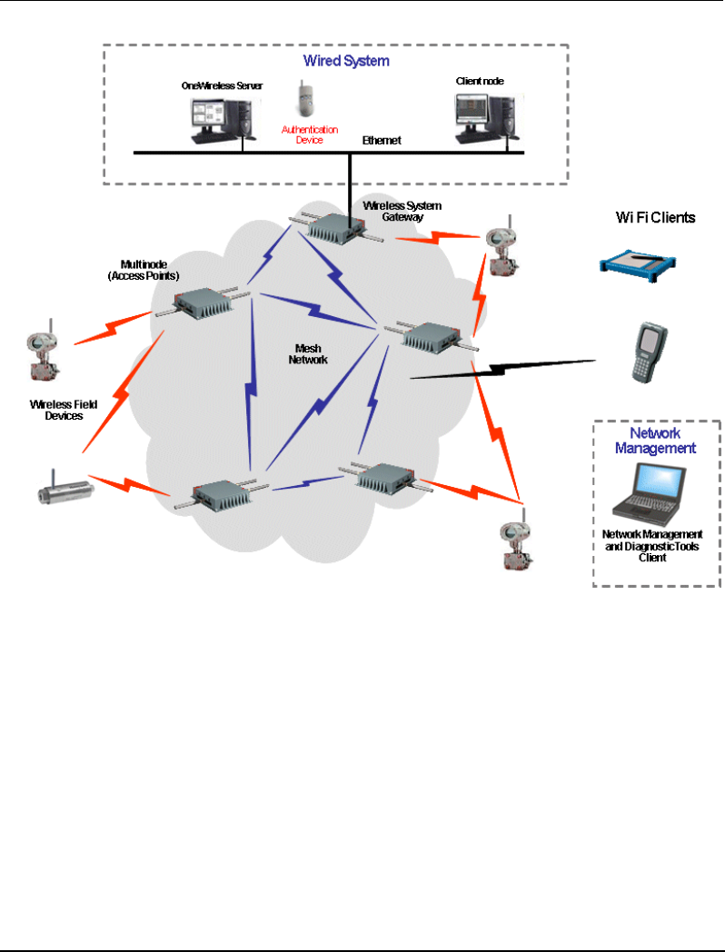
A typical OneWireless network using these components is shown in Figure 1.
OneWireless System
Overview
4 OneWireless Multinode User's Guide R110
6/08
NOTE: The Key Server and Wireless Builder are installed on the OneWireless Server.
Figure 1 Honeywell’s OneWireless solution for Wireless Network for
Secure Industrial Applications (WNSIA)
OneWireless Network topology
Honeywell uses a wireless mesh network to achieve the OneWireless solution. A mesh
network provides multiple RF communication paths between multinodes and Wireless
System Gateways to transfer data to and from the wireless field devices. For example, in
Figure 1 the WSG is connected to the wired network of the control system. Four
multinodes are operating as Access Points (APs), communicating with the field devices
and the WSG. Each multinode also is communicating with the other multinodes to form
a mesh network. Multiple communications paths are also made between any field
device and the WSG via any multinode in the network. Wi Fi clients can connect to the
network via the multinode access points.

R110 OneWireless Multinode User's Guide 5
6/08
Agency compliance information
This section contains agency compliance information for Honeywell’s OneWireless
Multinode. For additional details on compliance information, see also the OneWireless
Multinode Agency Compliance Professional Installation Guide.
Compliance statements and restrictions
This section contains the Federal Communications Commission (FCC), Industry Canada
(IC) and Radio Frequency compliance statements for the OneWireless Multinode device.
FCC compliance statements
• This device complies with Part 15 of FCC Rules and Regulations. Operation is
subject to the following two conditions: (1) This device may not cause harmful
interference and (2) this device must accept any interference received, including
interference that may cause undesired operation.
• This equipment has been tested and found to comply with the limits for a Class A
digital device, pursuant to Part 15 of the FCC Rules. These limits are designed to
provide reasonable protection against harmful interference in a residential
installation. This equipment generates, uses, and can radiate radiofrequency energy
and, if not installed and used in accordance with these instructions, may cause
harmful interference to radio communications. Operation of this equipment in a
residential area is likely to cause harmful interference in which case the user will be
required to correct the interference at their own expense.
• Intentional or unintentional changes or modifications must not be made to the
Multinode unless under the express consent of the party responsible for compliance.
Any such modifications could void the user’s authority to operate the equipment and
will void the manufacturer’s warranty.
IC compliance statements
• To reduce potential radio interference to other users, the antenna type and its gain
should be so chosen that the equivalent isotropic radiated power (EIRP) is not more
than that permitted for successful communication.
• Operation is subject to the following two conditions: (1) this device may not cause
interference, and (2) this device must accept any interference, including interference
that may cause undesired operation of the device.
• This Class A digital apparatus complies with Canadian ICES-003.
• French: Cet appareil numérique de la classe A est conforme à la norme NMB-
003 du Canada.

Agency compliance information
Compliance statements and restrictions
6 OneWireless Multinode User's Guide R110
6/08
Radio Frequency (RF) statement
To comply with FCC’s and Industry Canada’s RF exposure requirements, the following
antenna installation and device operating configurations must be satisfied.
• Remote Point-to-Multi-Point antenna(s) for this unit must be fixed and mounted on
outdoor permanent structures with a separation distance between the antenna(s) of
greater than 20cm and a separation distance of at least 20cm from all persons.
• Remote Fixed Point-to-Point antenna(s) for this unit must be fixed and mounted on
outdoor permanent structures with a separation distance between the antenna(s) of
greater than 20cm and a separation distance of at least 100cm from all persons.
• Furthermore, when using integral antenna(s) the Multinode unit must not be co-
located with any other antenna or transmitter device and have a separation distance
of at least 20cm from all persons.
European Union restriction
France restricts outdoor use to 10mW (10dBm) EIRP in the frequency range of 2,454-
2,483.5 MHz. Installations in France must limit EIRP to 10dBm, for operating modes
utilizing frequencies in the range of 2,454 - 2,483.5MHz.

Agency compliance information
Compliance statements and restrictions
R110 OneWireless Multinode User's Guide 7
6/08
Agency approval marks
The following table describes the agency approval for the Honeywell OneWireless
Multinode.
Symbol Description
The Factory Mutual® Approval mark means the equipment has
been rigorously tested and certified to be reliable.
The Canadian Standards mark means the equipment has been
tested and meets applicable standards for safety and/or
performance.
The Ex mark means the equipment complies with the requirements
of the European standards that are harmonized with the 94/9/EC
Directive (ATEX Directive, named after the French "ATmosphere
EXplosible").
For radio equipment used in the European Union in accordance
with the R&TTE Directive the CE Mark and the notified body (NB)
identification number is used when the NB is involved in the
conformity assessment procedure. The alert sign must be used
when a restriction on use (output power limit by a country at certain
frequencies) applies to the equipment and must follow the CE
marking.
The C-Tick mark is a certification trade mark registered to ACMA
(Australian Communications and Media Authority) in Australia under
the Trade Marks Act 1995 and to RSM in New Zealand under
section 47 of the NZ Trade Marks Act. The mark is only to be used
in accordance with conditions laid down by ACMA and RSM. This
mark is equal to the CE Mark used in the European Union.
N314 directly under the logo is Honeywell’s unique supplier
identification number.

Agency compliance information
Honeywell Declaration of Conformity information
8 OneWireless Multinode User's Guide R110
6/08
Honeywell Declaration of Conformity information
This section contains the Declaration of Conformity (DoC) statement for the Multinode
device and the countries it is intended to be used in. For a complete list of compliant
models, contact Honeywell.
Multinode device DoC statement
Following is Honeywell’s Declaration of Conformity (DOC) for the OneWireless
Multinode Device.
R&TTE
Directive 1999/5/EC LVD
Directive 73/23/EEC EMC
Directive 2004/108/EC ATEX
Directive 94/9/EC
Harmonized Standards
Emissions Specification and Method: EN 300 328 V1.7.1
Emissions Spec and Method: EN 301 893 V1.4.1
Immunity Specification: EN 301 489-17 V1.2.1
Immunity Method: EN 301 489-1 V1.6.1
Product Standard: IEC61326-1 (1st Edition, 2002-02, Industrial Locations)
EN 50014:1992, "Electrical Apparatus for Potentially Explosive Atmospheres –
General Requirements"
EN 50021:1999, "Electrical Apparatus for Potentially Explosive Atmospheres –
Type of Protection "n"
Manufacturer’s Name
and Address Honeywell Process Solutions
2500 West Union Hills Drive, Phoenix, AZ 85027, USA
Compliance
Statement The product herewith complies with the harmonized standards listed
above. Typical product line systems and configurations have been
tested, for compliance.

Agency compliance information
R&TTE Directive
R110 OneWireless Multinode User's Guide 9
6/08
Intended country usage
The following table lists the countries in which the Honeywell Multinode device is
intended to be used.
Country ISO 3166
2 letter code Country ISO 3166
2 letter code
North America
United States US Canada CA
Australia and New Zealand
Australia AU New Zealand NZ
European Union
Austria AT Latvia LV
Belgium BE Liechtenstein LI
Bulgaria BG Lithuania LT
Cyprus CY Malta MT
Czech Republic CZ Netherlands NL
Denmark DK Norway NO
Estonia EE Poland PL
Finland FI Portugal PT
France FR Romania RO
Germany DE Slovakia SK
Greece GR Slovenia SI
Hungary HU Spain ES
Iceland IS Sweden SE
Ireland IE Switzerland CH
Italy IT United Kingdom BG

Agency compliance information
R&TTE Directive
10 OneWireless Multinode User's Guide R110
6/08
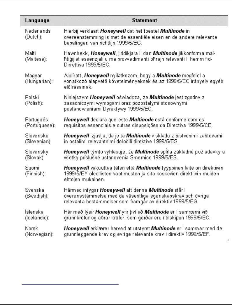
Declaration of conformity statements
Agency compliance information
R&TTE Directive
R110 OneWireless Multinode User's Guide 11
6/08
For more information about the R&TTE Directive
The following website contains additional information about the Radio and
Telecommunications Terminal Equipment (R&TTE) directive:
http://ec.europa.eu/enterprise/rtte/faq.htm

Agency compliance information
R&TTE Directive
12 OneWireless Multinode User's Guide R110
6/08

R110 OneWireless Multinode User's Guide 13
6/08
The Multinode/Wireless System Gateway
Multinode description
The Multinode is a wireless RF transmitter-receiver and router that is used to create the
wireless communications network. Communication occurs by establishing radio links
between the multinode and other wireless devices that are configured to operate as part of
the Wireless Local Area Network (WLAN). It routes network traffic between devices,
such as wireless field devices, other multinodes and wireless system gateways.
The multinode is enclosed in a weatherproof enclosure and is mounted on a pole, a wall
or near rooftop locations where it can transmit, receive and route control messages
between field devices and the WSG. Figure 2 shows the physical features of the
multinode. The multinode and the WSG are physically the same, and contain the same
internal components. The operating mode selection during configuration enables the
multinode to operate as a WSG or a multinode.
Operating modes
Multinodes can be configured to operate as either a Wireless System Gateway- in which
the multinode acts as a device connecting the wireless network with the wired control
system; or as a Multinode- which is an access point that communicates with the wireless
field devices and the WSGs in the wireless network. Note that a WSG may also be
configured to act as an access point within the wireless network. Multinodes also can be
configured to provide mesh communications where multinodes communicate with other
multinodes and WSGs to form a mesh network. The WSGs and multinodes use IEEE
802.11a/b/g communications protocol to communicate and complete the wireless
network. Multinodes may also be connected to WSGs through a wired Ethernet link.
System security
OneWireless system uses both encryption keys and secure key deployment to secure the
wireless network. Security of the multinodes operating in a mesh network use key
encryption. During multinode configuration an encryption key is created which is then
copied to the configuration of other multinodes that will operate in the same network.
Every wireless communication is encrypted using a strong security key, (see Data
Encryption for more information).
Security between multinodes and field I/O devices is achieved through secure key
deployment. Security keys are generated by the key server and then are deployed to
individual field I/O devices via an authentication device. Security keys are dynamic and
change automatically by the system following initial deployment providing a greater
level of security for the wireless network.

The Multinode/Wireless System Gateway
Physical description
14 OneWireless Multinode User's Guide R110
6/08
The Key Server is an application operating on the wireless server that stores, allocates
and manages the security keys. Authentication devices are small handheld devices
(PDAs) with an infrared port and buttons which are used to carry the security keys
around between key server and the devices to be authenticated. The authentication device
deploys the security keys to field devices to establish a trust between the device which is
being authenticated (added to the network) and the key server. A couple of button
presses is all that is required to authenticate a new device. See Getting Started for
Honeywell OneWireless Solution for more information on authentication of wireless
nodes. Additionally, the authentication device can also read and set parameters on
multinodes and field I/O devices.
Service Set ID (SSID)
The Service Set ID (SSID) is used to define a common domain (network) among
multiple wireless access points. Access points having the same SSID can communicate
with each other. Two wireless networks with different SSIDs on access points can create
overlapping wireless networks. The SSID can act as a password so that a client cannot
connect to the network without it. However, security using the SSID is easily overridden
when an access point is set to broadcast the SSID, which means that any client can
associate with the AP. SSID broadcasting can be disabled in the multinode setup menus.
Data Encryption
You can select a data encryption option to be used for multinode wireless
communications. Options include: None (no encryption), Static WEP, WPA, or AES-
CCMP, depending on the multinode’s mode of operation. The AES-CCMP encryption
option is available when operating multinodes in a wireless bridge network. Some level
of security is recommended for all modes of operation.
Wired Equivalent Privacy (WEP)
Wired Equivalent Privacy (WEP) encryption is a security protocol for Wireless Local
Area Networks (WLANs) defined in the IEEE 802.11 standard. WEP relies on the use of
identical static keys deployed on client stations and access points. Static WEP gives
you a choice of 64-bit or 128-bit encryption. A multinode configured with WEP
encryption is compatible with any 802.11b PC Card configured for WEP.
Wi-Fi Protected Access (WPA)/WPA2 with TKIP/ AES-CCMP
WPA combines several technologies which includes the use of the 802.1X standard and
the Extensible Authentication Protocol (EAP). For encryption, WPA uses the Temporal
Key Integrity Protocol (TKIP) and WEP 128-bit encryption keys. Also, a message
integrity check is used to prevent an attacker from capturing and altering or forging data
packets. In addition, it can employ a form of AES called AES-CCMP.
The Multinode/Wireless System Gateway
Physical description
R110 OneWireless Multinode User's Guide 15
6/08
WPA includes the option of using a WPA pre-shared key for key management with
either TKIP or AES-CCMP encryption
Physical description
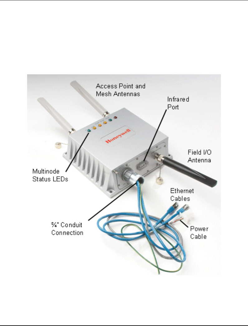
Figure 2 shows some of the physical features of the multinode which are described in the
following sections.
Figure 2 Multinode/Wireless System Gateway

The Multinode/Wireless System Gateway
Physical description
16 OneWireless Multinode User's Guide R110
6/08
Features
The Honeywell Multinode/Wireless System Gateway is a self-contained unit that is
weatherproof and conforms to IP66 waterproof specifications. The multinode contains
no user-serviceable parts inside the enclosure. External connections on the multinode
include three Type N connections for antennas. A ¾-inch conduit connection provides
access to wired connections for DC power, grounding and Ethernet cables.
On the top side of the enclosure are six LEDs that indicate power to the unit and
operating status. See Table 2 for a description of the LED indicators. A small window
on the side of the enclosure provides an optical infrared connection which is used to issue
a security key by the authentication device when commissioning the multinode.
Mounting holes are located at each corner of the multinode enclosure with a grounding
stud located on one side. The enclosure is designed to attach to a mounting panel that
enables pole mounted or wall mounted installation.
When the multinode is mounted outdoors or when approval certifications require it,
installation of lightning protection components, (such as lightning arrestors and enclosure
grounding) are necessary. See Outdoor protection kit for more information.
Refer to Table 3 Multinode specifications for more information.
Two multinode versions are available that provide two temperature ranges of operation.
Multinode model Model numbers
Multinode with Standard temperature range,
-20º to +60º C WNMN, WNMX
Multinode with Extended temperature range,
-40º to +75º C WNMF, WNMS
Note: There are some differences between multinode versions with regards to cabling,
connectors and labeling of the unit. These differences are noted where applicable.
External Connections
The multinode contains a number of connections which are described in Table 1. Note
that labeling, cabling and connector types of the unit may differ depending upon the
multinode version.

The Multinode/Wireless System Gateway
Physical description
R110 OneWireless Multinode User's Guide 17
6/08
Table 1 Multinode connections
Feature or Connector Description
ETHERNET
24V DC POWER ¾-inch conduit connection with four cable pigtails.
• Two Ethernet cables - (Labelled WLAN1 and
WLAN2) Either Ethernet cable can be used to:
− Connect to a PC for initial setup.
− Connect the WSG to the plant control
network
− Connect Ethernet-based devices, such as
switches, controllers, cameras, etc. to a
multinode or WSG.
Note: Both Ethernet ports are wired to one switch
with a single MAC Address.
• A red (or grey) cable - power cable
• A green/yellow grounding conductor.
IR PORT Infrared sensor port used for communication with the
authentication device.
FHSS ANTENNA
(Type N-female connector)
OR
FIELD I/O ANTENNA
(Type N-female connector)
Provides connection of an omni-directional antenna or
optional remote antennas for communication with
various wireless field devices.
ANTENNA
(Two reverse polarity
Type N-female connectors)
OR
AP ANTENNA and
MESH ANTENNA
(Two Type
N-female connectors)
Provides connection for two 5dBi omni-directional or
optional remote antennas that enable communication
between the multinodes, WSGs, other multinodes in
the network and other WiFi devices.
Operating/Status indicators
LEDs Six indicators located on the top of the multinode
enclosure and indicate operating status. These LEDs
are described in Table 2 on page 18.

The Multinode/Wireless System Gateway
Physical description
18 OneWireless Multinode User's Guide R110
6/08
LED indicators
The front of the enclosure features six LED indicators (Green, Yellow and Red) to
indicate the various stages of operation. Table 2 identifies the indicators and describes
the operating conditions of the unit when the indicators are lighted.
Table 2 Multinode LED indicators
LED Indicator When lit it …
Power (Green) Indicates that power is applied to the unit.
WAN (Yellow) Indicates that the unit has an active connection to the wired
network on the WAN1 port. May be steady on or blinking.
WLAN 1 (Yellow)
Activity (AP) Indicates that information is passing through the AP
connection. May be steady on or blinking.
If off, indicates that the AP radio is disabled.
WLAN 2 (Yellow)
Activity (Mesh) Indicates that information is passing through the mesh node
connection.
If off, indicates that the mesh radio is disabled.
WLAN SS (Green)
Signal Strength
(Mesh)
Indicates the signal strength of the connection with the mesh
node as defined by the MAC address of the multinode in the
mesh radio configuration page, (WLAN2). See Signal
Strength MAC in Table 9 for more information of this
indicator.
1. LED Off: No connection on the mesh, or the signal is very
weak.
2. LED blinks slowly (once every 1 second): there is a
connection, and the signal quality is poor.
3. LED blinks fast: there is a connection, and the signal
quality is good.
4. LED steady on: there is a connection, and the signal
quality is excellent.
FIPS / MODE (Red)
Indicates status depending on whether multinode is
configured as a WSG or a multinode.
• WSG - LED blinks: the WSG is not loaded with the
gateway application.
LED is steady on: the WSG is loaded and running

The Multinode/Wireless System Gateway
Multinode specificiations
R110 OneWireless Multinode User's Guide 19
6/08
LED Indicator When lit it …
with the gateway application and the WSG has been
configured in Wireless Builder.
• Multinode - LED behavior is undetermined.
NOTE: A fault in the multinode is indicated when WLAN1 and WLAN2 LEDs blink
simultaneously. The multinode software has detected a fault with the encryption
algorithm or the device configuration has not passed the integrity check. See
Troubleshooting for more information.
Multinode specificiations
Table 3 Multinode specifications
Specification Description
Enclosure Certifications: Class 1 DIV2/ZONE2 hazardous area.
IP66 waterproof
Physical dimensions: 9.25 in. x 8.25 in. x 3.0 in.
Weight: 7.0 lbs
Power requirements Power input: +24 Volts dc, -15% +10% (20.4 to 26.4Vdc)
Current requirement: 1.5 Amps, maximum.
Power output: 25 Watts, maximum
Hardware Specification: CPU: XScale IXP425 @ 533 MHz
8 MB flash
64 MB SDRAM
External Ports: Two 10/100 Mbps WAN Ethernet ports. See Note.
3 external antenna ports.
Note: Both Ethernet ports are wired to one switch with a
single MAC Address.
WAN Ethernert setting: Fixed IP
Supports: IEEE 802.3u Fast Ethernet

The Multinode/Wireless System Gateway
Multinode specificiations
20 OneWireless Multinode User's Guide R110
6/08
Specification Description
10/100 Mbps auto negotiation
Receive Sensitivity: 802.11a: -87dB@6Mbps to -71dB@54Mbps
802.11b: -94dB@1Mbps to -90dB@11Mbps
802.11g: -87dB@6Mbps to -74dB@54Mbps
RF Output Power:
802.11a/b/g: +20dBm, maximum
Note: Maximum transmit power will vary by antenna
selection, channel selection, data rate and region,
(Country Code).
Environmental: Standard Temperature Model:
Operating Temperature: -20º to +60º C
(-40º to +140º F)
Extended Temperature Model:
Operating Temperature: -40º to +75º C
(-40º to +167º F)
Other:
Storage Temperature: -40º to +85º C (-40º to +185º F)
Humidity: 0 to 100% noncondensing
EMI/Safety: FCC Class A
Lightning and surge suppressor kits (optional)
Mulitnode communications radios
The multinode contains three radios that are used for RF communications; two IEEE
802.11 radios (a client radio and a mesh radio), and one radio which is used to
communicate with the wireless field devices (field I/O radio).
• One 802.11 radio (client or AP radio) is used for communication when the multinode
is configured to operate as an access point or WSG. Radio activity is indicated by the
WLAN1 LED on the multinode enclosure.
• One 802.11 radio (mesh radio) is used with multinodes and WSGs when
implementing a wireless mesh. Mesh radio activity is indicated by the WLAN2 LED
on the multinode enclosure.

The Multinode/Wireless System Gateway
Multinode specificiations
R110 OneWireless Multinode User's Guide 21
6/08
• One field I/O radio which communicates with the various wireless field devices. A
multinode will contain one of two radio types:
− A FHSS radio which uses Frequency Hopping Spread Spectrum modulation as
the communications protocol.
− A DSSS radio which uses a Direct Sequence Spread Spectrum modulation as the
communication procotol and is based on the IEEE 802.15.4 standard.
Antennas
The multinode is supplied with three 5dBi omni-directional antennas. Two antennas are
identical and are installed to the MESH and AP connectors located on the top of the unit.
These antennas are used with the 802.11 radios for client and wireless mesh
communications. The third antenna is used with the field I/O radio for communication
with the field devices and is installed on the FIELD I/O ANTENNA (or FHSS
ANTENNA) connector.
Note: The 802.11 antennas and the field I/O radio antenna are not interchangeable.
A number of optional high gain antennas from various manufacturers also have been
qualified for use with the multinode. Antenna selection is based on a number of factors
such as frequency range, overall antenna output, and country regulations. Antenna
options also include installation of the antenna remote from the multinode. When using
one of these antennas, you must manually adjust the transmit power of the radios in the
multinode.
ATTENTION
Multinodes must be professionally installed in accordance with the
requirements specified in the OneWireless Multinode Agency Compliance
Professional Installation Guide.
If you are not using the wireless access point function then you do not need to connect
the client antenna. Make sure during your configuration set up that you go to the
Wireless Access Point-General screen and set the Tx Pwr Mode to Off, (See page 47).
Also ensure that any unused antenna port is securely covered with the attached protection
caps.
NOTE: If any part of the multinode or antenna is located outdoors, a lightning arrestor
must be installed between the unit and the antenna. See the Outdoor protection kit.

The Multinode/Wireless System Gateway
Outdoor protection kit
22 OneWireless Multinode User's Guide R110
6/08
Outdoor protection kit
If any portion of this system (multinode enclosure, antennas, cables etc.) is to be mounted
outdoors, it is recommended that you use the Outdoor Protection Kit with the installation.
This kit contains lightning arrestors and ground cables designed for installation with
multinodes.
If the system is mounted outdoors where CE Mark certification is required, use of the
Outdoor Protection Kit (or equivalent) is mandatory.

R110 OneWireless Multinode User's Guide 23
6/08
Installation Overview
First read through this section so that you have a good understanding of the tasks to
properly plan and execute installation of Multinode/WSG nodes in a wireless network.
Preinstallation requirements
The following tasks must be completed before you actually install wireless system
gateways and multinodes in a wireless network:
• Network site planning must be completed to understand how a wireless network
can be built and supported for your application using OneWireless components.
These components consist of wireless field devices, multinodes, and wireless system
gateways.
• RF site survey must be completed by a qualified professional. The RF survey is
essential for building the architecture of the wireless network. The site survey should
at a minimum include the following tasks:
− RF spectrum analysis must be conducted on the 2.40-2.49 GHz band and 5.7-5.9
GHz band (if available to be used) to detect any potential RF interference.
Strong interference sources should be addressed (removed, avoided or
minimized) before an installation. Note that some frequencies may not be
available for use in some locations and countries.
− A point-to-point 2-node mesh should be staged in various locations to measure
the RF propagation ability in the site environment. Received Signal Strength
Indicator (RSSI) can serve as one indicator of the RF environment. TCP/IP
throughput testing and UDP/IP throughput and packet drop rate testing should
be conducted in all selected locations to measure the quality of the site
environment.
− Site survey should be conducted once the factory system is operating so that
maximum possible interference is measured and addressed.
• Multinode placement should be determined through the completion of the network
planning and RF survey activities.
• Power requirements for network should be identified. Wired cable runs that
provide DC power to the WSGs and multinodes should be determined.
• Ethernet cable runs should be determined for WSGs and/or any other wired nodes
in the network.
Installation Overview
Multinode/WSG installation
24 OneWireless Multinode User's Guide R110
6/08
Multinode/WSG installation
Honeywell’s multinode/ WSG requires physical mounting and installation on site
following the execution of the preinstallation requirements. The location of all
multinodes should be determined to ensure optimum operation in a wireless network.
Installation tasks
WARNING
Multinodes and wireless system gateways must be professionally installed in
accordance with the requirements specified in the ‘OneWireless Multinode
Agency Compliance Professional Installation Guide.’ Only the specified
power settings, antenna types and gains and cable lengths (attenuation) as
outlined in the installation guide are valid for multinode installations.
Before the multinode is installed at the site location there are a number tasks which must
be completed to properly set up the unit. Table 4 outlines these tasks to be performed for
each multinode/WSG installation. For example, the site location of the multinode/WSGs
should be identified and prepared before the multinode is installed. Additionally, you
should verify that the multinode contains the latest version firmware and ensure that it is
configured properly for the network in which it is designed to operate. Follow the tasks
listed in Table 4 to complete a multinode installation. The page numbers reference
additional information and details on each task.
Table 4 Multinode installation tasks
Task Action Done
Preparing the multinode
installation site(s) a. Inspect the multinode hardware. See page 26.
b. Identify multinode site locations. See page 26.
c. Assemble and install mounting hardware. See
page 27.
d. Construct conduit and cable runs for multinode
power and Ethernet See page 27.
Initial bench configuration of
multinode e. Bench setup and connection to multinode. See
Initial Configuration on page 35.
(See Configuration section for
procedures.) f. Verify firmware version and update if
necessary. See Verify firmware version on page

Installation Overview
Multinode/WSG installation
R110 OneWireless Multinode User's Guide 25
6/08
Task Action Done
39.
g. Configure operating mode and security. See
System Configuration - Operating Mode on page
45.
h. Configure security options. See Security
screen on page 52.
i. Additional multinode configuration steps.
• Services settings (SNMP Agent) on page 60
• Set up Wireless Mesh starting on page 71.
Saving system configuration of
multinode j. Save the configuration of the multinode for
future reference. See Local Configuration
Upgrade on page 66
Selecting antennas k. Verify proper antenna selection. See antenna
selection on page 27.
Configuring transmit power and
Country Code settings l. Set transmit power settings accordingly based
on RF survey results, antenna selection and
Country Code. See Warning under Installation
Tasks.
Authenticating a multinode/WSG m. See Authenticating a multinode/WSG on page
32.
Installing the multinode at site
location(s) n. Install the Lightning arrestors (if installation site
is outdoors)
o. Grounding. See page 29.
p. Seal the antenna connections. See page 29.
q. Install multinode/Wireless System Gateway at
its installation site. See page 29
r. Complete conduit installation.
s. Connect power and Ethernet cabling See
page 29
Turn up multinodes/WSGs t. Power up WSGs and multinodes in the
network. See page 31
Installation Overview
Multinode/WSG installation
26 OneWireless Multinode User's Guide R110
6/08
Task Action Done
Field testing and tuning of
wireless network Perform field testing of the multinodes operation
and mesh network coverage. See Multinode and
Mesh Network Tuning on Page 97.
Installation guidelines
CAUTION
FCC RF exposure compliance requires that the antennas used with the
device (multinode) must be installed with a minimum separation distance of
20 cm (7.9 in.) from all persons, and must not be co-located or operated in
conjunction with any other antenna or transmitter.
Multinode/wireless system gateway installation should be accomplished using
the approved antennas, cables and connectors provided with the device or
available from Honeywell for use with this device. Changes or modifications
not expressly approved by Honeywell or the party responsible for this FCC
compliance could void the end-user’s authority to operate the equipment.
Inspect multinode and associated hardware
Open the box and examine the multinode for any signs of damage. Examine any other
hardware shipped with the multinode, such as antennas and mounting brackets. Ensure
all hardware that is necessary for completing installation of each multinode is available.
Refer to Figure 2 and Figure 3 for two views of the multinode and its associated
hardware. The multinode package includes the following items:
• Multinode/Wireless System Gateway
• 1 Client (AP) radio antenna (if required)
• 1 Mesh radio antenna
• 1 Field I/O radio antenna
Identify multinode site locations
Site location of the wireless system gateways and multinodes are identified through the
completion of the network site planning and RF survey activities. Locations can be
mapped so that site preparation for the multinodes can be started.

Installation Overview
Multinode/WSG installation
R110 OneWireless Multinode User's Guide 27
6/08
Antenna selection
Antennas play critical roles in the setup and operation of wireless mesh systems.
Depending upon results of the site survey and the requirements of the installed
environment, proper antenna type should be determined, (omni-directional vs.
directional, low-gain vs. high gain, etc.).
Assemble and install mounting hardware
The multinode can be wall mounted or pole mounted using the hardware mounting kit
supplied with the unit. When pole mounting the multinode you can assemble and install
the mounting hardware at the site. The mounting kit includes the following items:
• Mounting bracket
• U-bolts with nuts
• Screws (to attach the multinode to the mounting bracket)
Construct conduit and cable runs for multinode power and Ethernet
Power cabling from the plant must be run through conduit to a junction box installed at
the multinode installation site.
If the multinode will be connected to a wired Ethernet you must run Ethernet cabling
from the control system through the conduit to the multinode site.
Outdoor Protection Kit
An outdoor protection kit must be used to prevent lightning damage when the multinode
is mounted outdoors. The outdoor protection kit contains the following items:
• Three lengths (10, 12 and 18-inches) of 10AWG wire with #8 ring terminal on one
end and a #10 ring terminal on the other end.
• Two lightning arrestors, with Type N Male-to-Female, or two Reverse Polarity Type
N (RPN) Male-to-Female connectors for the mesh and AP radio antennas.
• One Lightning arrestor, Type N Male-to-Female connectors for Field I/O radio
antenna.
Lightning arrestor installation, (when required)
NOTE: A lightning arrestor must be installed between the antenna and the multinode
antenna connector when the unit is installed outdoors. Use the following procedure to
install lightning arrestors on the multinode.

Installation Overview
Multinode/WSG installation
28 OneWireless Multinode User's Guide R110
6/08
Step Action
1 Examine the lightning arrestors and remove and discard the following items
(if not needed).
Securing nut, washer and ring terminal (but retain the screw).
2 Attach the 10, 12, and 18-inch wires to the appropriate lightning arrestor body
ensuring that the smaller (#8) ring terminals and those wires with identifying
labels are used.
3 Secure the ring terminal to the lightning arrestor using a screwdriver.
4 Install the two lightning arrestors to the multinode by attaching one end of the
lightning arrestor to the multinode's MESH and AP connectors.
Make sure that the lightning arrestor with the 12-inch wire is mounted closer
to the ground stud and that the lightning arrestor with the 18-inch wire is
mounted on the antenna connector farther from the ground stud.
5 Secure the lightning arrestors to the Type N connectors so that they are hand
tight. Do not over tighten.
6 Install the Type N lightning arrestor with the 10-inch wire to the multinode by
attaching one end of the lightning arrestor to the multinode's Type N FIELD
I/O (or FHSS) ANTENNA connector. Hand tighten only.
Note: Steps 7 and 8 may need to be performed once the multinode is
mounted and connected at its site location.
7 Construct a grounding wire to be used for the earth ground connection. See
Grounding in the next section for additional information.
Attach the ground wire to the ring terminal attached to the multinode’s
grounding stud.
The earth ground ring terminal must be the first connection on the multinode's
grounding stud when making additional connections to the grounding stud.
8 Place the ring terminals from the lightning arrestor ground cables on the
grounding stud of the multinode enclosure and secure with a screw.
Note that the earth ground ring terminal should be attached to the multinode
before the lightning arrestor's ring terminal is attached.
It is recommended that the outdoor protection kit be replaced every three years. If the
unit is operated in an area subject to intense lightning activity, it is recommended that the
outdoor protection kit be replaced every year.

Installation Overview
Multinode/WSG installation
R110 OneWireless Multinode User's Guide 29
6/08
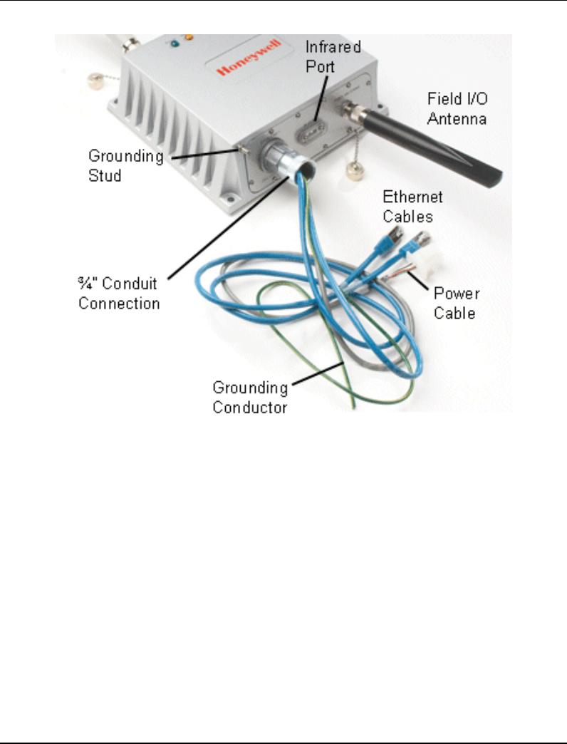
Grounding
NOTE: Users are responsible that the multinode connection to a proper earth ground is
made by certified and authorized personnel and must conform to all applicable codes and
regulations. The materials required to make a proper earth ground are defined by local
regulations and must be obtained locally to ensure that the correct safety environment is
achieved. The ground wire must be AWG 10 or heavier. The earth ground wire run
should be kept as short as possible.
Attach the earth ground wire (AWG 10 or heavier) to the ring terminal attached to the
multinode's grounding stud (see Figure 3). The ring terminal must be secure against the
unit's metal enclosure. The earth ground ring terminal must be the first connection on the
unit's grounding stud when making additional connections to the grounding stud, (such as
lightning arrestor ground wires).
Sealing Antenna Connections
Once all antennas have been installed, the connections should be sealed to protect them
from the exterior environment. First use a wrap of electrical tape over the antenna
connections. Then use a self-amalgamating polyisobutylene tape which adheres to itself
and forms a single amalgamated rubber molding. Once the tape is in place for several
hours, it forms a shaped rubber molding that is resistant to water and most solvents. Note
that if you need to remove the tape after it has sealed for 30 minutes or more, it must be
cut away.
Installing the multinode/WSG at its location
The assembled multinode, complete with antennas and lightning arrestors (if required), is
now ready to be mounted in its site location. If the multinode is to be wall mounted, it
can be secured to the wall with screws at each corner of the enclosure. When using the
mounting bracket for pole installation, secure the multinode to the bracket using the
screws supplied with the bracket kit.
Connect power cables and Ethernet cables
Conduit must be installed from the multinode ETHERNET connection to the junction
box installed at the multinode site. The power cabling, green/yellow grounding wire and
Ethernet cables from the multinode must be run through conduit to the junction box.
Note that when installation is complete, all cabling must be routed through conduit and
enclosed within the junction box.
Refer to Figure 3 for multinode cable identification.

Installation Overview
Multinode/WSG installation
30 OneWireless Multinode User's Guide R110
6/08
ATTENTION
The power cable attached to the multinode may be one of the following:
• Red cable with two wires (Red and Black)
• Grey cable with two wire pairs (Red and Green, Black and White)
The red (or grey) power cable, the Green/yellow grounding cable and Ethernet cables are
connected as follows:
Step Action
1 Ensure that all power is removed from the power cabling run to the multinode
site.
2 If the multinode is equipped with a Red power cable:
• Connect the Red wire from the multinode power cable to +24 volt dc output
of the power supply in the junction box.
• Connect the Black wire from the multinode power cable to the 24 volt
COMMON of the power supply.
If the multinode is equipped with a Grey power cable:
• Connect both the Red and Green wires from the multinode power cable to
+24 volt dc output of the power supply in the junction box.
• Connect both the Black and White wires from the multinode power cable to
the 24 volt COMMON of the power supply.
3 Cut and tie back the drain wire from the power cable.
4 Connect the Green/Yellow grounding cable from the multinode to a safety
ground point.
5 The two WAN cables, labeled WLAN1 and WLAN2 (Ethernet cables), from
the multinode are configured with the same IP address and a single MAC
address and should be regarded as a two-port Ethernet switch. Therefore, if
the control system provides connections to redundant switches, then use
both Ethernet cables to connect to the separate switches.
If only a single switch available in the control system, then use WLAN1
Ethernet cable to connect to the network switch. The two Ethernet cables
should not be connected to the same network switch.
Note: Using the WLAN1 cable enables the the WLAN LED indicator.
Installation Overview
Multinode/WSG installation
R110 OneWireless Multinode User's Guide 31
6/08
Figure 3 Multinode cable identification
Power up multinodes and WSGs
Once all multinodes/WSGs have been installed and connected at their site locations, turn
up the multinodes to verify wireless network communications. See the Getting Started
with Honeywell OneWireless Solution for more information.

Installation Overview
Authenticating a multinode/WSG
32 OneWireless Multinode User's Guide R110
6/08
Authenticating a multinode/WSG
Authenticating a multinode or WSG is the action taken to inject a wireless device with a
security key so that when the device requests access to the system, it will be recognized
and allowed to join the secure wireless network and start publishing packet information.
A handheld PDA running the authentication device software is used to inject the security
key into the multinode. Use the following procedure to authenticate multinodes and
WSGs.
Authentication order
Authentication is performed once the multinode has been configured and is ready for
deployment in a wireless network.
Authenticate the WSG first, and then authenticate additional multinodes after you verify
the gateway has been authenticated. See the Key Server event log to view authentication
status of device.
Prerequisite
• The Key Server must be active on the network that the multinode/WSG is
connecting to.
• Keys from the Key Server are loaded onto the authentication device. See Getting
Started with Honeywell OneWireless for the procedure.
To transmit a security key to multinode/WSG:
Step Action
1 If you have not already done so, power on the multinode.
2 Align the IR port of the authentication device with the IR Port of the multinode
and place the authentication device 6 to 8 inches from the multinode’s IR
port.
3 From the main menu of the authentication device, select Security and
Node Deployment and select Clear Key and Restart Node.
This clears any security keys from the multinode. The multinode LEDs will
shut off for several seconds and cycle through a reboot of the multinode.
4 Select Transmit and Connect Node.
A Security key deployed successfully message appears on the
authentication device.

Installation Overview
Authenticating a multinode/WSG
R110 OneWireless Multinode User's Guide 33
6/08
Step Action
5 Verify that you receive a message on the authentication device indicating
the multinode received the security key successfully.
If you receive a message indicating that key deployment was not
successful, repeat the procedure from step 1.
6 Select Read Device Information to determine if the multinode acquired a
network address from the wireless directory server. A valid address should
start with 0xEF or similar. (0x0000 indicates the multinode did not acquire a
valid IP address.)
TIP
After the multinode has been injected with an authentication key and
authenticated by the Key Server, you can look at the event log on the Key
Server.
• Select Start > Programs > Honeywell OneWireless >
KeyServerManager, and then click Event Log.

Installation Overview
Authenticating a multinode/WSG
34 OneWireless Multinode User's Guide R110
6/08
R110 OneWireless Multinode User's Guide 35
6/08
Configuration
Initial configuration
Once you have received the multinode and associated hardware and physically inspected
it for any damaged components, you then perform an initial setup of the unit. This
should be peformed before the multinode is installed in the network at its designated
physical location. The setup requires that you select configuration options, such as
operating mode, security encryption and IP address, which gives the unit an identity.
Also, the multinode must be given a security key to associate it with the wireless network
in which it will be installed and operate (authentication). Completing setup and
authentication will allow the multinode to join the network and communicate in the
network.
TIP
When configuring multiple multinodes using the same option settings, you
can create a template (configuration file) which contains the multinode
settings, so that the template can be loaded to the multinodes.
• First, configure a multinode using the Multinode Configuration Tool
application.
• Download the configuration file in the multinode to a local computer.
• The configuration file then can be downloaded to additional multinodes.
NOTE: The configuration file that you download to a local computer and use
to configure additional multinodes contains both configuration parameters
and some network parameters such as the IP address and hostname.
• Update the network parameters to give the multinode a valid hostname,
Description and IP Address.
See System Administration for more information on downloading
configuration files.
Configuration
Initial configuration
36 OneWireless Multinode User's Guide R110
6/08
Minimum PC system and component requirements
To complete multinode configuration, you should have at least the following
components:
• One or more PCs or laptops with one of the following operating systems installed:
Windows NT 4.0, Windows 2000, Windows XP or Windows 2003;
• An Ethernet interface on the PC or laptop to perform initial configuration.
• A Web browser program (such as Microsoft Internet Explorer 5.5 or later, or
Netscape 6.2 or later) installed on the PC or laptop to access the multinode
configuration tool.
• TCP/IP Protocol (usually comes installed on Windows PCs.)
• Additionally, A Wi-Fi compatible 802.11a/b/g interface for each PC or laptop that
you want to connect wirelessly to the network.
Prerequisites
The following information and addresses are required during the initial setup of the
multinode. Please have this information available for each multinode to be installed in
the network you are setting up before you begin setup.
Information
IP address - a list of IP addresses available on the organization's LAN that
are available to be used for assignment to the multinode(s).
Subnet Mask for the LAN.
Default IP address of the multinode, (192.168.254.254).
DNS IP addresses (if required).
SSID - an ID number/tag name that you want to use to identify all members of
the wireless LAN.
The MAC addresses of all wireless cards that will be used to access the
wireless network of access points, (if MAC address filtering is to be enabled).
This information can be recorded during initial configuration of the multinodes
and then entered when setting up MAC address filtering.
The appropriate encryption key for wireless communication. This key can be
generated during setup, but it should be recorded for future reference.

Configuration
Initial configuration
R110 OneWireless Multinode User's Guide 37
6/08
Multinode connection for setup
Initial setup is performed best on a test bench. The unit is powered up and connected via
the Ethernet cable to a PC. The PC is used to access the Multinode Configuration Tool
application, which is loaded on the multinode and contains the forms where you enter the
required addresses and configuration information.
Step Action
1 Place the multinode/WSG on a test bench.
2 Connect the power cable leads to the proper power source (24Vdc).
If the multinode is equipped with a Red power cable:
• Connect the Red wire to +24 volt dc.
• Connect the Black wire to 24 volt COMMON.
If the multinode is equipped with a Grey power cable:
• Connect both the Red and Green wires to +24 volt dc.
• Connect both the Black and White wires to the 24 volt COMMON.
3 Power on the multinode unit.
4 Connect one end of the RJ-45 Ethernet cable labeled WAN1 to an Ethernet
port on the laptop or PC.
5 Verify these settings on your PC or set as follows:
TCP/IP properties must be set to "Using the following IP address."
IP Address: 192.168.254.1
Network Mask: 255.255.255.0
To access the screen, which contains these settings on your PC, and view or
change your TCP/IP settings:
If the operating system on your computer is Windows 2000 or XP, follow the
path Start >Settings > Network and Dialup Connections > Local Area
Connection and select the Properties button. In the Properties window,
highlight the TCP/IP protocol and click Properties. Make sure that the radio
button for Using the following IP address is selected, and enter the IP
address 192.168.254.1 and the network mask 255.255.255.0.
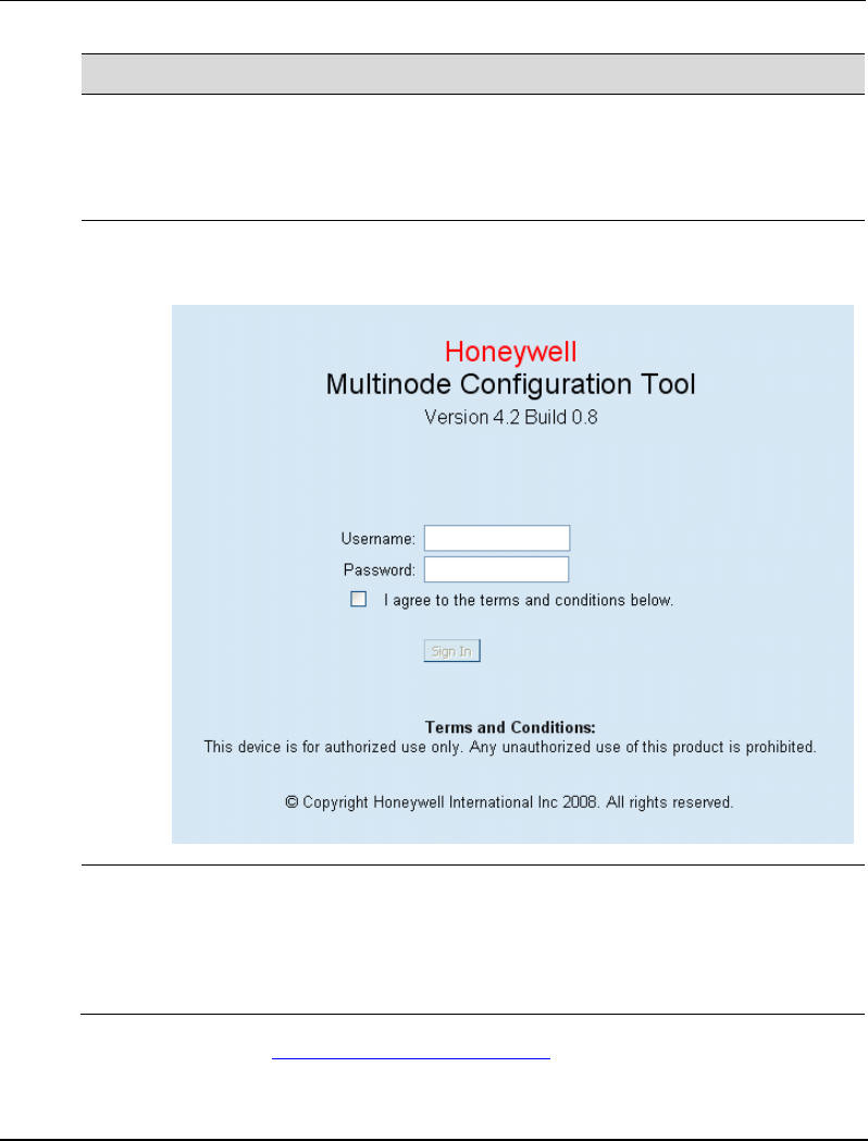
Configuration
Initial configuration
38 OneWireless Multinode User's Guide R110
6/08
Step Action
6 On your PC, open a browser window and paste the default URL for the unit’s
Local LAN in the address line. (https://192.168.254.254)
Note: For some versions of the multinode, the IP address may be
192.168.15.1
7 Enter the default Username "CryptoOfficer" and Password "CryptoFIPS" in
the opening dialog screen. (The username and password are case-sensitive.)
8 Read the terms and conditions and check the checkbox to agree to the terms
of use. Click Sign In to continue.
Note: Honeywell strongly recommends you change the default username and
password on each multinode after you initially configure it. If this username
and password does not work, review the SCN for any changes.
Once you sign in, the System Configuration - General screen appears in the browser
window. See Figure 4.

Configuration
Initial configuration
R110 OneWireless Multinode User's Guide 39
6/08
Verify software Version and upgrade
The multinode/WSG is shipped from the factory loaded with the latest released software.
Verify that the multinode contains the latest version software and then update if
necessary. The software version currently loaded on the multinode is labeled ‘Version:’
on the System Configuration - General screen and is shown circled in Figure 4.
Prerequisite
You must have access to the HPS Solution Support Online (SSOL) website. If you are a
new user, you can register for access to the Solution Support Online site at
www.honeywell.com/ps.
Step Action
1 Record the software version which is displayed in the upper right of the
Multinode Configuration Tool screen.
The version is shown as follows:
Version: Multinode/Sensor Radio - Version x.x Build x.x / RAP110.x-xx.x
2 Refer to the Software Change Notice (SCN) which is supplied with your
OneWireless software to verify the latest released version of the mesh
(multinode) software.
3 If required, obtain the latest software version from the Honeywell SSOL web
site at: http://www.honeywell.com/ps
4 Click Login to My Account, type your user name and password, and then
click Login.
5 Select Software Downloads from the SUPPORT menu.
6 Choose OneWireless.
7 Download the Mesh software and/or the Sensor radio software files.
8 At the multinode, sign-in to the Multinode Configuration Tool screen.
9 From the left pane, click System Administration > System Upgrade.
10 Update the mesh software:
• Click the top Browse button and navigate to the location of the mesh
software you downloaded in step 7.
• Click the top Upload firmware button.
The multinode will reboot after the firmware update is completed.

Configuration
Initial configuration
40 OneWireless Multinode User's Guide R110
6/08
Step Action
11 Sign-in to the Multinode Configuration Tool screen.
12 From the left pane, click System Administration > System Upgrade.
13 Update the sensor radio software:
• Click the bottom Browse button and navigate to the location of the Sensor
radio software you downloaded in step 7.
• Click the bottom Upload firmware button.
14 Wait for the message to select "Back." This confirms that the sensor software
upload has completed.

Configuration
Multinode Configuration Tool screens
R110 OneWireless Multinode User's Guide 41
6/08
Multinode Configuration Tool screens
To the left of the System Configuration screen is a tree view of the available screens that
can be accessed for initial configuration of the multinode, to monitor and view system
status, and to perform system administration functions such as adding users and updating
unit’s firmware. The screens are listed in Table 5 below. If viewing this document
online, click on the screen name to view the details and the configuration options
available on the screen.
Table 5 Multinode Configuration Tool screens
Screen Title For details
go to page
System Configuration
General 42
Operating Mode 45
WAN 46
Wireless Access Point
General 47
Security 52
MAC Address Filtering 57
Rogue AP Detection 58
Advanced 59
Wireless Mesh
General 71
Radio 77
Encryption 80
MAC Address Filtering 81
Services Settings
SNMP Agent 60

Configuration
Multinode Configuration Tool screens
42 OneWireless Multinode User's Guide R110
6/08
Screen Title For details
go to page
Admin User Management
List All Users 63
Add New User 64
Monitoring/Reports
System Status 106
Mesh Protocol Status 107
Mesh Site Map 108
Wireless Clients 109
Adjacent AP List 110
Logs
System Log 110
Web Access log 110
System Administration
System Upgrade 65
Factory Default 69
Remote Logging 69
Reboot 69
Utilities 69
System Configuration - General screen.
The System Configuration - General screen lists the firmware Version number for the
unit and allows you to set the Host Name and Domain Name as well as selecting the
system time source and other general information. (Note that Host and Domain names
are both set to ‘default’ at the factory but can be assigned a unique name for each.)
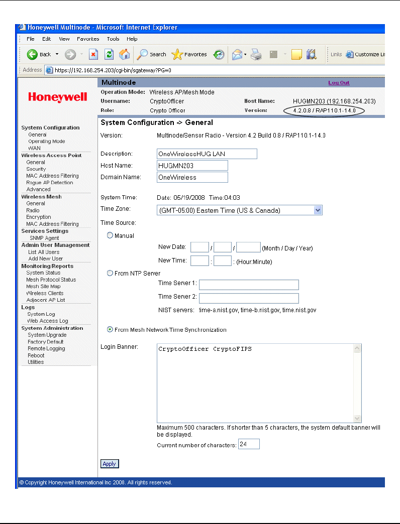
Configuration
Multinode Configuration Tool screens
R110 OneWireless Multinode User's Guide 43
6/08
Figure 4 System Configuration - General screen

Configuration
Multinode Configuration Tool screens
44 OneWireless Multinode User's Guide R110
6/08
Follow the steps to enter information for the System Configuration - General screen.
Step Action
1 Click on the System Configuration - General at the left of the screen to call
up the General screen.
2 Enter a Description that identifies the unit and/or its location.
3 Enter a Host name for the unit.
4 Enter the name of the Domain in which the unit will reside.
5 If configuring the Wireless System Gateway for the network:
a) Click the radio button to select From NTP Server.
b) Choose the correct Time Zone for your location from the drop down
selections
c) Enter the IP address of the Time Server 1. For example, 10.0.10.100.
6 If configuring a multinode:
Click the ‘From Mesh Network Time Synchronization’ radio button.
7 If you want to display a message in the log in screen, enter the text for the
Login Banner. Maximum text content is 500 characters.
The default message is "This device is for authorized use only. Any
unauthorized use of this product is prohibited."
8 When you have completed entries for the fields on the screen, click Apply.

Configuration
Multinode Configuration Tool screens
R110 OneWireless Multinode User's Guide 45
6/08
System Configuration - Operating Mode
The System Configuration - Operating Mode screen allows you to set the unit to operate
as either a WSG or a multinode. Note that if you change modes from multinode to WSG,
your configuration is not lost.
Follow the steps to make selections for the operating mode.
Step Action
1 Click on the System Configuration - Operating Mode at the left of the
screen to call up the Operating Mode screen.
2 Choose one of the following Operation Modes:
• L1/L2 Gateway - select when the multinode is to be used as a WSG to
connect the wireless network to a Level 1 or Level 2 wired network
• L3/L4 Gateway - select when the multinode is to be used as a WSG to
connect the wireless network to a Level 3 or Level 4 wired network
• Multinode - select when the multinode is to be used as a multinode to
communicate with the wireless field devices.
3 Choose Time Sync Root.
Note: When using the network time synchronization function (in the General
screen) among the mesh nodes, configure only one mesh node as the time
sync root/source. The time source of this node should be set to either
Manual or From NTP Server in the General screen.
4 When you have completed entries for all fields on the screen, click Apply.

Configuration
Wireless Access Point Configuration
46 OneWireless Multinode User's Guide R110
6/08
System Configuration - WAN screen
The System Configuration - WAN screen allows you to specify static IP Address
information that will be used to manage this network if you do not use the DHCP server
to obtain an IP address.
Step Action
1 Click on the System Configuration - WAN at the left of the screen to call up
the WAN screen.
2 Select WAN Link Auto from the drop down selections.
Note: When interfacing with Cisco switches, this setting may need to be set
to another value other than Auto.
Also see NOTE 1 below this procedure.
3 Click on the Specify a static IP address radio button.
4 Enter a valid IP Address for the WSG such as 192.168.254.254, or other
address as specified for the site.
Note that if the IP Address is changed and then applied, the PC network card
settings must be changed to log back in to the multinode.
5 Enter the Subnet Mask such as 255.255.255.0, or other subnet as specified
for the site.
6 Enter the Default Gateway such as 192.163.254.1, or other address as
specified for the site.
7 Leave DNS1 and DNS 2 fields blank unless a value is specified for the site.
8 Record the addresses entered in steps 4 through 7. They will be needed to
perform other tasks.
9 When you have completed entries for all fields on the screen, click Apply.
10 Log back into the multinode:
• Open Internet Explorer and type in https:// and the new IP address from
step 4.
• Type the username and password.
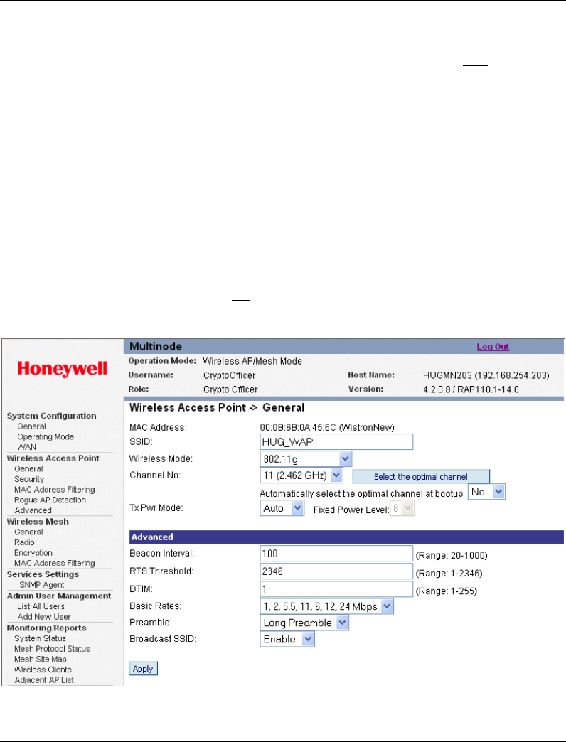
Configuration
Wireless Access Point Configuration
R110 OneWireless Multinode User's Guide 47
6/08
NOTE 1: There are two WAN ports - WAN 1, which can be set through the WAN Link
field, and WAN 2 which is always fixed to Auto. The WAN Link field only sets the link
speed and duplex mode for the WAN 1 port.
Wireless Access Point Configuration
Wireless Setup allows your computer’s PC card to communicate with the access point
(multinode). Once you have completed wireless access point configuration, you can
complete the rest of the configuration wirelessly, assuming that you have installed and
configured a wireless PC card on your computer. (If you have not done so, you will have
to do that to establish communications. Follow the manufacturer's instructions to set up
the PC card on each wireless device that will be part of the WLAN.)
General screen
Wireless Access Point - General screen shown in Figure 5 lists the MAC Address of the
Gateway card. Note that this is not the MAC Address that will be used for the Bridge
SSID for mesh setup, which is found on the Wireless Bridge - General screen.
Figure 5 Wireless Access Point - General configuration screen

Configuration
Wireless Access Point Configuration
48 OneWireless Multinode User's Guide R110
6/08
Follow the steps to enter information for the multinode configuration. See Table 6 and
Table 7 below for the details in setting these fields.
Step Action
1 Click on the Wireless Access Point - General at the left of the screen to call
up the Wireless Access Point screen.
2 MAC Address is displayed 00:0B:6B:0A:45:6C (WistronNew) as in the
example in Figure 5.
3 Enter the SSID for this network.
Note: If you are using an SSID for a wireless LAN, enter it here and in the
setup of each wireless client (multinode) in the network. The SSID must be
the same for the WSG and each wireless client in the network for them to
communicate.
4 Choose the Wireless Mode communications protocol to be used for this
network from selections in the drop down menu.
5 Choose the Channel No from the list in the drop down selections. See
Channel number description below.
Click Apply after selecting the channel number.
6 The Select the optimal channel button may appear. See Optimal channel
selection below for an explanation of this function.
An option may appear for the AP to Automatically select the optimal
channel at bootup. You can choose Yes or No.
7 Choose Auto for the TxPower Mode field. See TxPwr Mode description
below.
8 When choosing the Advanced options, you can use the default selections, or
choose values appropriate for your wireless network. See Table 7 for
description of these Advanced options.
The following values are the defaults for these fields:
Beacon Interval: 100
RTS Threshold: 2346
DTIM: 1
Basic Rates: 1, 2, 5.5, 11 Mbps (basic rates available depend upon Wireless
Mode selection)

Configuration
Wireless Access Point Configuration
R110 OneWireless Multinode User's Guide 49
6/08
Step Action
Preamble: Long Preamble
Broadcast SSID: Enable
9 When you have completed entries for all fields on the screen, click Apply.
Channel number
You can assign a channel number for the multinode to use or allow the software to select
the optimum channel for multinode communications.
The Channel Number allows you to assign frequencies to a series of access points to
minimize noise when many multinodes are used in the same WLAN. For example, there
are 11 channel numbers that may be assigned. If you assign channel number 1 to the first
wireless AP in a series, then assign channel 6 to the next AP, then channel 11, and then
continue assigning APs to channels 1, 6, 11, you will achieve the optimum frequency
spread to minimize noise.
Table 6 lists the channel numbers and frequencies used for the available wireless modes.
Note that the Country Code selection determines the available frequency bands and
channels for use in the wireless network. Therefore, all channel numbers in the table
below may not be available for use in the network location.
Optimal channel selection
If you click on the button Select the optimal channel, a popup screen will display the
available channels and the relative use of each channel in the local area as shown in the
figure. The software will select the optimal channel for you. The figure below shows that
the channel used the least in the local area is channel 6.
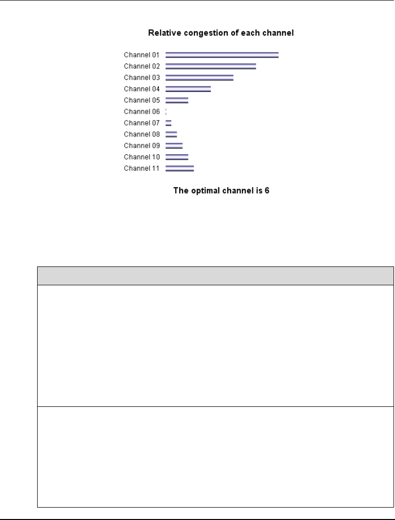
Configuration
Wireless Access Point Configuration
50 OneWireless Multinode User's Guide R110
6/08
You can also set up the AP to select the optimal channel automatically at boot up.
Table 6 Channel Number options
Wireless Mode Channel No.
802.11b
802.11g
802.11b/g Mixed
1 (2.412 GHz)
2 (2.417 GHz)
3 (2.422 GHz)
4 (2.427 GHz)
5 (2.432 GHz)
6 (2.437 GHz)
7 (2.442 GHz)
8 (2.447 GHz)
9 (2.452 GHz)
10 (2.457 GHz)
11 (2.462 GHz)
802.11a 52 (5.26 GHz)
56 (5.28 GHz)
60 (5.30 GHz)
64 (5.32 GHz)
149 (5.745 GHz)
153 (5.765 GHz)
157 (5.785 GHz)
161 (5.805 GHz)
165 (5.825 GHz)

Configuration
Wireless Access Point Configuration
R110 OneWireless Multinode User's Guide 51
6/08
Tx Pwr Mode and Fixed Pwr Level
The Tx Power Mode can be set during configuration. The default is Auto, which
provides the largest range of radio transmission power levels available under normal
conditions. The AP's broadcast range can be limited by setting the Tx Power Mode to
Fixed and then choosing a Fixed Pwr Level from 1-8, (1 being the lowest power level).
You can set the Tx Pwr Mode to Off to prevent any RF transmission, if desired.
Advanced options
The Advanced options for the Wireless Accesss Point - General screen are described in
Table 7.
Table 7 Advanced options
Configuration
Option Range/
Value Description
Beacon interval 20-1000 The time interval in milliseconds in which the
802.11 beacon is transmitted by the AP.
RTS Threshold 1-2346 The number of bytes used for the RTS/CTS
handshake boundary. When a packet size is
greater than the RTS threshold, the RTS/CTS
handshaking is performed.
DTIM 1-255 The number of beacon intervals that broadcast
and multicast traffic is buffered for a client in
power save mode.
Basic Rates The basic rates used and reported by the AP.
The highest rate specified is the rate that the AP
uses when transmitting broadcast/multicast and
management frames.
Note: The Tx rate should not exceed 12 Mbps if
the system is to operate with wireless sensors.
This is to prevent the possibility of overloading
the WSG with WiFi traffic and allow the gateway
application to operate efficiently.
Basic Rates for 802.11b and 802.11b/g Mixed -
1, 2 Mbps or 1, 2, 5.5, 11 Mbps

Configuration
Wireless Access Point Configuration
52 OneWireless Multinode User's Guide R110
6/08
Configuration
Option Range/
Value Description
Basic Rates for 802.11g -
1, 2, 5.5, 11, 6, 12, 24 Mbps or 1, 2, 5.5, 11 Mbps
Basic Rates for 802.11a -
6, 12, 24 Mbps
Preamble Short/Long
Preamble Specifies whether frames are transmitted using
a short or long preamble.
Broadcast SSID Enabled/
Disabled Enabled - the SSID is broadcast by the access
point.
When disabled, the SSID is embedded in
outgoing beacon frames so that stations cannot
obtain the SSID through passive scanning.
Also, the AP doesn’t send probe responses to
probe requests with unspecified SSIDs.
Security screen
The Wireless Access Point - Security screen displays the default factory setting of no
encryption, but encryption must be set by the CryptoOfficer for the multinode to
communicate with any client. There are three different encryption options available for
access points.
• None
• Static WEP (Wired Equivalent Privacy)
• 802.11i and WPA (Wi-Fi Protected Access)
None - No Encryption (Not Recommended)
You can choose to have no encryption of wireless communications within the network
although it is not recommended. Although no encryption is the default setting, you must
manually select None and click Apply to operate the WSG without encryption. You will
be prompted if you want to operate the WSG in Bypass mode. If you answer Yes, no
encryption is applied.
Configuration
Wireless Access Point Configuration
R110 OneWireless Multinode User's Guide 53
6/08
Static Wired Equivalent Privacy (WEP) Encryption
Wired Equivalent Privacy (WEP) encryption is a security protocol for Wireless Local
Area Networks (WLANs) defined in the IEEE 802.11 standard. WEP relies on the use of
identical static keys deployed on client stations and access points. WEP encryption does
provide some measure of security, although not the highest level of security.
To configure your network for WEP encryption, perform the following steps:
Step Action
1 Click on the Wireless Access Point - Security at the left of the screen to call
up the Security screen.
2 Choose Static WEP Encryption from the drop down selections in the
Security Method field.
The Static WEP encryption options appear on the screen.
3 Select the Authentication Type from the drop down menu.
Note: For greater security, set Authentication Type to Shared Key
4 Select the level of encryption, (either 64-bit, 128-bit or 152-bit encryption).
If using 64-bit encryption, select the Default WEP Key from the drop down
selections.
Enter the WEP keys in the appropriate fields.
The Key Generator button can be used to automatically generate a
randomized key. Note that this key is initially shown in plain text so that you
can copy or record the key. Once the key is applied, the key is no longer
displayed in plain text
Important
Record the WEP Key used in step 4.
When WEP is enabled, the same WEP key must also be applied to each
wireless device that is to become part of the wireless network, and if "shared
key" is accepted, then each wireless device must also be configured for
"shared key".
5 Once you have made the selections in the screen and recorded the WEP
key(s), if used, click Apply.
NOTE: Utilities exist for scanning for networks and logging all networks the utilities
detect, including the real SSIDs, the access point’s MAC address, the best signal-to-noise
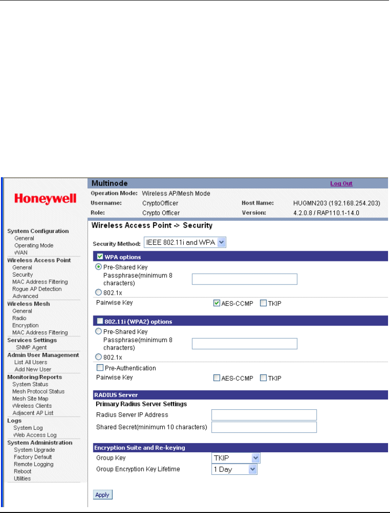
Configuration
Wireless Access Point Configuration
54 OneWireless Multinode User's Guide R110
6/08
ratio encountered, and the time the user crossed into the network’s space. These utilities
can be used to determine whether your network is unsecured.
IEEE 802.11i and WPA (Recommended)
Wi-Fi Protected Access (WPA) is designed to enable use of wireless legacy systems
employing WEP while improving security. WPA uses improved data encryption through
the Temporal Key Integrity Protocol (TKIP) which scrambles keys using a hashing
algorithm and, by adding an integrity-checking feature to ensure that the keys have not
been tampered with. Additionally, user authentication is enabled using the Extensible
Authentication Protocol (EAP).
Choosing the IEEE 802.11i and WPA Security Method will call up the following screen:

Configuration
Wireless Access Point Configuration
R110 OneWireless Multinode User's Guide 55
6/08
Figure 6 Wireless Access Point - Security with IEEE 802.11i
and WPA selected
Perform the following steps to use the IEEE 802.11i and WPA Security method. See
Table 8 below for the details in setting these fields.
Step Action
1 Click on the Wireless Access Point - Security at the left of the screen to call
up the Security screen.
2 Choose IEEE 802.11i and WPA from the drop down selections in the
Security Method field.
The IEEE 802.11i and WPA encryption options appear on the screen.
3 If you wish to use WPA on the wireless system gateway, enable either WPA
options or 802.1x (WPA2) options by adding a check to the appropriate
check box.
Note: Both options can be checked (WPA and 802.11i WPA2), so that clients
can connect to the network using either method. Be sure to set the
appropriate options for each.
4 Click the Pre-Shared Key radio button to enable this feature. See Pre-
Shared Key description in Table 8.
5 Enter the passphrase in the Passphrase field, (Passphrase minimum is 8
charracters/numeric or hexidecimals). (The passphrase limit is 63
characters.)
6 If you have selected 802.11i (WPA2) options, you may enable Pre-
Authentication by checking the box. See Pre-Authentication description in
Table 8.
7 Choose the Pairwise Key to match the encryption type used by the clients.
See Pairwise Key description in Table 8.
8 • Choose the appropriate Group Key from the selections in the drop down
list.
• Choose the Group Encryption Key Lifetime from the selections in the
drop down list. See Encryption suite and Re-keying description in Table 8.
9 Once you have selected the options you will use, click Apply.

Configuration
Wireless Access Point Configuration
56 OneWireless Multinode User's Guide R110
6/08
Table 8 IEEE 802.11i and WPA security options
Option Description
Pre-Shared Key When selected, allows input up to 63 characters, numerics
or hexadecimals in the Passphrase field.
Pairwise Key If the clients use WPA-TKIP, select TKIP as encryption type.
If the clients use WPA-AES, select AES-CCMP. If the clients
use both encryption types, select AUTO.
Pre-Authentication Enable pre-authentication to allow a client to authenticate in
advance with the AP before the client is associated with it.
Allowing the AP to pre-authenticate a client decreases the
transition time when a client roams between APs.
RADIUS Server As an alternative for business applications who have
installed Radius Servers, select WPA 802.1x and input the
Primary Radius Server settings. Use of Radius Server for
key management and authentication requires that you have
installed a separate certification system and each client must
have been issued an authentication certificate.
Encryption suite and
Re-keying Re-keying time is the frequency in which new encryption
keys are generated and distributed to the client. The more
frequent re-keying (Group Encryption Key Lifetime) - the
better the security. For highest security, select the shortest
re-keying interval.

Configuration
Wireless Access Point Configuration
R110 OneWireless Multinode User's Guide 57
6/08
MAC Address Filtering screen
The Wireless Access Point -MAC Address Filtering screen is used to set up MAC
address filtering for the APs. This feature allows you to further strengthen wireless client
access security by allowing only known clients to join the secure network. MAC address
filtering is recommended for static configurations with a small number of clients. The
default setting for MAC Address filtering is Disabled.
To enable and setup MAC Address filtering for the access points in your network:
Step Action
1 Click on the Wireless Access Point - MAC Address Filtering at the left of
the screen to call up the MAC Address Filtering screen.
2 Select Enable to enble MAC Address filtering.
3 Select Filtering Type from the drop down menu.
MAC Address filtering and filter type works as follows:
• When Filtering is enabled and the Filter Type is Deny All Except Those
Listed Below, only those devices equipped with the authorized MAC
addresses will be able to communicate with this bridge node. In this case,
input the MAC addresses of all the PC cards that will be authorized to
access this bridge node. The MAC address is engraved or printed on the
PC (PCMCIA) card.
• When Filtering is enabled and the Filter Type is Allow All Except Those
Listed Below, any device with a MAC address which has been entered in
the MAC Address list will not be able to communicate with this bridge
node. In this case, navigate to the report: Wireless Clients and copy the
MAC address of any wireless client that you want to exclude from
communication with the bridge node and then add those MAC Addresses
to the MAC Address list.
4 Enter a MAC Address with a note to the MAC Address and Note fields and
click Add to add it to the MAC Address List at the bottom of the screen.
Note that communication with the mesh nodes containing these MAC
addresses entered in this field depends upon the Filter Type selected above.

Configuration
Wireless Access Point Configuration
58 OneWireless Multinode User's Guide R110
6/08
Rogue AP Detection screen
The Wireless Access Point - Rogue AP Detection screen allows the network
administrator to set up rogue AP detection which provides another level of security to the
wireless network. Once all mesh nodes have been deployed, you can enter their MAC
addresses as described below to only allow known nodes to join the mesh network. Any
other nodes will not be able to join the network even if the nodes contain the correct
SSID and security credentials. These nodes will be detected as rogue APs and a
notification can be sent to the operator.
To set up Rogue AP detection:
Step Action
1 Click on the Wireless Access Point - Rogue AP Detection at the left of the
screen to call up the Rogue AP Detection screen.
2 Select Enable to activate Rogue AP detection.
3 Enter an email address in the To field where notifications can be sent for any
rogue or non-trusted APs that are detected.
4 Select the filtering options for the notification of any rogue APs that are
detected.
• SSID Filter - This option will send only rogue APs that match the APs
SSID or wireless bridge’s SSID.
• Channel Filter - This option will send only rogue APs that match the AP’s
channel of the wireless bridge’s channel.
Note: When both options are selected, only APs that match both the SSID
and channel are sent in the notification.
5 Click Apply to enable changes.
6 In the MAC Address field, enter the MAC Address of each AP in the network
that you want the AP being configured to accept as a trusted AP.
(You may add up to 200 APs. The MAC Address for the AP is located on the
Wireless Access Point - General screen.)
7 Click Add button to add the MAC address to the Known AP MAC Address
List.
NOTE: The Adjacent AP list screen, under Monitoring/Reports will detail any rogue
APs.

Configuration
Wireless Mesh
R110 OneWireless Multinode User's Guide 59
6/08
Advanced screen
The Wireless Access Point - Advanced screen allows you to enable or disable load
balancing between APs and control packet forwarding between clients in a network.
• The Load Balancing feature balances the wireless clients communications between
APs. For example, if two APs with similar settings are located in close proximity of
each other, all wireless clients near that location could potentially associate with the
same AP, leaving the other AP unused. Load balancing attempts to evenly distribute
the wireless clients communication on both APs.
NOTE: Load balanceing is disabled by default. If enabled, all APs in the network
should be enabled for load balancing.
• Publicly Secure Packet Forwarding (No Inter-client Communicaton) prevents
wireless clients that associate with the same AP from communicating with each
other. When this feature is enabled, wireless clients can not talk to other wireless
clients directly at Layer 2. However, both clients can have access to others that are
not associating to the same AP.
Click Apply to save changes you have made in the Advanced screen.
Wireless Mesh
Wireless mesh provides a means for multinodes to:
(1) Communicate with each other,
(2) Extend the Basic Service Set (BSS) of a single access point (multinode), and
(3) Connect two or more separate LANs without cabling.
Wireless mesh is a function that requires set up in addition to the basic access point
configuration. The screens which are used when configuring the unit for wireless mesh
are described in the following sections:
• Wireless Mesh - Describes the screens and the available options you can choose
when setting up wireless mesh. Starting on page 71.
• Setting up wireless networks - Provides typical configurations and outlines the
procedures for setting up three common types of wireless networks. Page 82.

Configuration
Services Settings
60 OneWireless Multinode User's Guide R110
6/08
Services Settings
SNMP Agent screen
The Service Settings - SNMP Agent screen allows you to set up a Simple Network
Management Protocol (SNMP) Agent. The agent is a software module that collects and
stores management information for use in a network management system (such as the
Network Management and Diagnostic tool). The unit’s integrated SNMP agent software
module translates the device’s management information into a common form for
interpretation by the SNMP Manager software, which resides on a network administra-
tor’s computer.
The SNMP Manager interacts with the SNMP Agent to execute applications that control
and manage object variables (interface features and devices) in the WSG. Common forms
of managed information include number of packets received on an interface, port status,
dropped packets, and so forth. SNMP is a simple request and response protocol, allowing
the manager to interact with the agent to either:
• Get - Allows the manager to read information about an object variable
• Set - Allows the manager to write values for object variables within an agent’s control
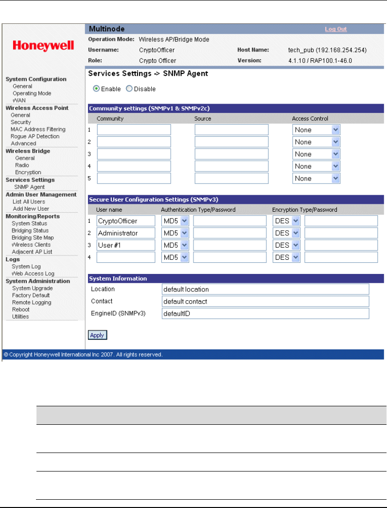
Configuration
Services Settings
R110 OneWireless Multinode User's Guide 61
6/08
Figure 7 Service Settings - SNMP Agent screen
Step Action
1 At the left of the screen, click on SNMP Agent to display the Service Settings
- SNMP Agent screen.
2 Select the Enable radio button to enable this function.
3 Enter a name in the Community field, which is a password to access the
Access Control functions.
Configuration
Services Settings
62 OneWireless Multinode User's Guide R110
6/08
Step Action
4 Enter a valid IP address in the Source field as the address where information
is accessed.
5 Select the type of Access Control from the drop down menu that defines the
permitted level of management interaction. (Set, Get and Trap)
6 If using Secure user configuration settings (SNMPv3):
• Enter a User name (minimum of 8 characters)
• Select from the drop down menu an Authentication type and enter a
password
• Select from the drop down menu the Encryption type and enter a
password. Note: DES encryption type is recommended.
This configuration information also must be entered when setting up the
Network Management and Diagnostics application.
7 Enter System Information in the following fields.
• Location
• Contact
• EngineID
8 Once you have selected the options in this screen, click Apply.

Configuration
Admin User Management
R110 OneWireless Multinode User's Guide 63
6/08
Admin User Management
User Management - List All Users screen
The User Management - List All Users screen lists the Crypto Officer and all
Administrator user accounts defined for the multinode.
To edit or delete users:
Step Action
1 Click on the List All Users at the left of the screen to call up the User
Management - List All Users screen.
2 Click the Edit button for the User ID listed on the screen.
The User Management - Edit User screen appears.
3 You can now edit any of the following fields:
• User ID: Edit or change the name of the user ID
• Password: Edit or change the password.
• Role: Edit the Role of this user.
• Note: Add or edit a descriptive note about this user.
4 When finished editing the user, click Update to apply the changes made to
the user definition.
Or
Click Reset to cancel the changes and revert to the previous user definition.
5 To delete a user, click the Delete button for the User ID in the list.

Configuration
Admin User Management
64 OneWireless Multinode User's Guide R110
6/08
User Management - Add New User screen
The User Management - Add New User screen allows you to add new Administrator user
accounts and assign and confirm the password for the user.
To add a new user:
Step Action
1 Click on the Add New User at the left of the screen to call up the User
Management - Add New User screen.
2 Enter a descriptive name to identify the user in the User ID field.
3 Enter a password that the user will use when accessing the system in the
Password field.
4 Retype the password to confirm the password entry.
5 Choose the Role assigned to this user.
• Crypto Officer - The user that performs initial setup for a multinode. The
user has full access to all system management screens.
• Administrator - The user which is assigned to administer the wireless
network node.
6 Add a descriptive note for this user in the Note field.
7 When finished entering the user information, click Add to create the new user
account and add it to the users list.
Or
Click Reset to cancel the changes.
Configuration
System Administration
R110 OneWireless Multinode User's Guide 65
6/08
System Administration
The System Administration screens provide access to system functions such as firmware
upgrades, configuration backup/restore, remote logging and utilities.
System Administration - System Upgrade
The System Administration - System Upgrade screen allows you to upload updates to the
multinode’s firmware. Configuration files also can be copied from one multinode to
another. There are three tabs on the System Upgrade screen.
The Firmware Upgrade tab allows you to browse and select new files to upgrade the
mesh (multinode) and sensor (field I/O radio) firmware.
The Local Configuration Upgrade tab and the Remote Configuration Upgrade tab
allow you transfer (copy) the system configuration file from one mulitnode to another
multinode.
Firmware Upgrade
To perform a firmware upgrade on a multinode:
Step Action
You must be logged in as the Crypto Officer to perform this procedure.
1 On the System Administration - System Upgrade screen, the Firmware
Upgrade tab is the default view.
There are two firmware upgrade choices:
• Upgrade Mesh software
• Upgrade Sensor Radio software
2 Click Browse… to navigate to the directory and select the software file to be
uploaded.
3 Click on the appropriate Upload Firmware button to begin the software
upload.
4 Either of the two events will occur to indicate successful upload of the
software:
• The multinode will reboot after the software upload is completed.

Configuration
System Administration
66 OneWireless Multinode User's Guide R110
6/08
Step Action
• A message to select "Back" confirms that the software upload is
completed.
Local Configuration Upgrade
On the System Administration - System Upgrade screen, the Local Configuration
Upgrade tab allows you to download the system configuration of a multinode to a local
computer where it is saved as a configuration file. The file contains the configuration
settings for a multinode that can be uploaded to other multinodes on the local network. A
passphrase is associated with the file to provide a password level of security to use the
file. A tag name can also be associated with the file for identification.
NOTE: The configuration file that you download to a local computer and use to
configure additional multinodes contains both configuration parameters and some
network parameters such as the IP address and hostname.
To download a configuration file from a multinode to a local computer:
Step Action
You must be logged in as the CryptoOfficer to perform this procedure.
1 On the System Administration - System Upgrade screen, click on the Local
Configuration Upgrade tab
2 Enter a Passphrase in the Option 2 field of the screen.
Record this passphrase for future use.
3 Enter a File Tag name (up to 12 characters) to be applied to the configuration
file so that it can be tracked as the file is loaded to other multinodes.
4 Click Apply to apply the tag name to the file.
5 Click the Download Configuration button to download the configurartion file
to the local computer.

Configuration
System Administration
R110 OneWireless Multinode User's Guide 67
6/08
To upload the configuration file to the multinode:
Step Action
1 Log in to the multinode that you want to upload the configuration file as the
Crypto Officer.
2 On the System Administration - System Upgrade screen, click on the Local
Configuration Upgrade tab
3 Under Option 1: click the Browse button to select a configuration file on the
local computer to upload.
4 Enter the Passphrase (recorded during download procedure) for the selected
configuration file.
5 Click the Upload Configuration button to begin the file upload.
Remote Configuration Upgrade
On the System Administration - System Upgrade screen, the Remote Configuration
Upgrade allows you to upload and download configuration files to multinodes in remote
locations which are not configured. You can transfer a configuration file to other
selected multinodes.
NOTE: Only configuration parameters that can be shared between multinodes are
downloaded in the configuration file. The WAN IP address and hostname are not
transferred in the configuration file.
To upload and download configuration files to multinodes in remote locations which are
not configured:
Step Action
1 On the System Administration - System Upgrade screen, click on the Remote
Configuration Upgrade tab
2 Click the Local File Tag radio button and select a configuration file to
transfer.
3 Check the nodes in the Site Map field that you want to transfer the file to.
4 Click Apply.
The nodes will reboot once the file has been transferred.

Configuration
System Administration
68 OneWireless Multinode User's Guide R110
6/08
Step Action
5 Click on the Update Site Map button.
6 Verify the file has been transferred to the selected nodes successfully.
The File Tag shows the status of the nodes. If the File Tag matches the Local
File Tag the transfer was successful.
To generate and transfer a randomly generated configuration file to a multinode:
Step Action
1 Click Generate button.
A random mesh configuration file is created in a temporary file and an Install
button appears.
This configuration file is used to update the bridging SSID and bridging
encryption on other devices using the existing bridging link. If the bridging key
or the bridging SSID is changed on the normal configuration screen, then the
bridging link to the other devices will be terminated, and the configuration can
not be updated.
2 Select the Disable radio button in the Automatic IP Address Configuration
field.
3 To transfer the random bridging configuration file:
• Select the Generated File radio button.
• Check the nodes in the Site Map field that you want to transfer the file.
• Click Apply.
4 Verify the file has been transferred to the selected nodes successfully.
Indicated in the Upgrade Status field of the Site Map.
5 Click Install to apply the randomly generated configuration file to the node.
Once applied, the node will reboot and start using the new configuration file.

Configuration
System Administration
R110 OneWireless Multinode User's Guide 69
6/08
Factory Default
The System Administration - Factory Default screen is used to reset the multinode to its
factory settings. You must be logged in as the CryptoOfficer to access the Restore
button.
ATTENTION
The "Restore" button is a fallback troubleshooting function that should be
used only to reset the multinode to its factory default settings.
Remote logging
The System Administration -Remote Logging screen allows you to forward the system
log data from each multinode to a central remote logging server. If you enable Remote
Logging, enter the IP addresss for the System Log Server and the System Log Server
Port. Click Apply to accept these values.
Reboot
The System Administration - Reboot screen allows you to reboot the multinode without
changing any preset functionality. Both CryptoOfficer and Administrator users have
access to this function.
Utilities
The System Administration - Utilities screen gives you access to two useful utilities: Ping
and Traceroute. Simply enter the IP Address or hostname you wish to ping or traceroute
and click either the Ping or Traceroute button, as appropriate.

Configuration
System Administration
70 OneWireless Multinode User's Guide R110
6/08

R110 OneWireless Multinode User's Guide 71
6/08
Wireless Mesh Configuration
Introduction
Wireless mesh provides a method for multinodes to communicate with each other; to
extend the Basic Service Set (BSS) of a single access point (multinode), and to connect
two or more separate LANs without cabling. The multinode contains a second WLAN
card which is used to set up the independent wireless mesh/network connection. The
multinode supports three common network types:
1. Point-to-point network of two Ethernet links
2. Point-to-multipoint network of several Ethernet links
3. Repeater mode
The following sections describe the configuration options that are available to set up your
network in the Multinode Configuration Tool screens. Setting up wireless networks
provides typical configurations and procedures for setting up the various network types.
Wireless Mesh screens
The screens that you need to modify when setting up a wireless network are in the Wire-
less Mesh section of the navigation bar in the Multinode Configuration Tool. These
screens include:
• Wireless Mesh - General
• Wireless Mesh - Radio
• Wireless Mesh - Encryption
• Wireless Mesh - MAC Address Filtering (when Auto Mesh is selected.)
General screen
The Wireless Mesh - General screen shown in Figure 8 contains wireless mesh in-
formation. This page is important in setting up the mesh/network configuration. Wireless
mesh supports two modes of operation:
Auto-forming wireless mesh (Auto Mesh) - Auto Mesh mode enables the multinode to
search for beacons from other wireless meshs/networks and identifies multinodes that
match configuration settings such as SSID and channel number. A three-way association
handshake between the wireless networks is performed to control network access to the
mesh. The maximum number links that a multinode will allow when forming the mesh
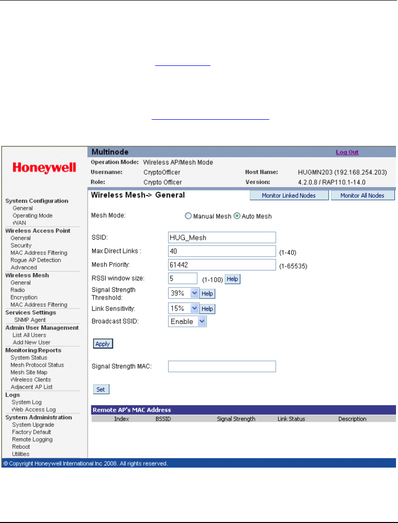
Wireless Mesh Configuration
Wireless Mesh screens
72 OneWireless Multinode User's Guide R110
6/08
link is 40. It does not limit the overall size of the mesh/network or the number of
networks.
• Manual wireless mesh (Manual Mesh) - A manual mesh/network is defined through
the wireless mesh configuration settings. Multinodes do not search for matching
wireless networks, (as in the auto mesh mode).
NOTE: This section describes the options that are available when using the Wireless
Mesh - General screen. See Setting up wireless networks in this guide for typical
multinode configurations when creating a wireless network.
Figure 8 Wireless Mesh - General screen (Auto Mesh mode selected)

Wireless Mesh Configuration
Wireless Mesh screens
R110 OneWireless Multinode User's Guide 73
6/08
Auto mesh options
When Auto Mesh mode is selected on the Wireless Mesh - General screen, the wireless
mesh searches for beacons from other wireless meshs/networks and identifies multinodes
that match configuration options such as SSID and channel number.
ATTENTION
Several of the parameters that appear in the Wireless Mesh screens are used
when tuning the mesh network (Mesh priority, Signal Strength Threshold and
MAC Address Filtering). See Multinode and Mesh NetworkTuning on page
97 for additional information on adjusting these parameters.
Instead of simply adding the multinodes with the same SSID/channel to the network, a
three-way association handshake between the wireless networks is performed to control
network access to the mesh.
Table 9 Auto Mesh screen options
Auto Mesh
Parameter Option Description
Mesh Mode Auto Mesh Auto Mesh is selected.
SSID numbers
and/or letters An alpha-numeric ID assigned by the
network administrator.
This SSID must be set on each wireless
device in the network so that the devices
can communicate with each other.
Max Direct Links 1-40 Sets the maximum number of multinode
links allowed in forming a mesh link. It does
not limit the overall size of the mesh/network
or the number of networks.
Mesh Priority 1-65535 Sets the mesh priority of the node in the
network. The number should be set to a
multiple of 4096. For example, use these
values: 4096, 8192, 12288, 16384, 20480,
24576, 28672, 32768, 36864, 40960, 45056,
49152, 53248, 57344, 61440 and 65535
A lower the value indicates a higher mesh
priority.
Note: For wired Ethernet switches, WSGs and any wired multinodes, set the mesh

Wireless Mesh Configuration
Wireless Mesh screens
74 OneWireless Multinode User's Guide R110
6/08
Auto Mesh
Parameter Option Description
priority to a value lower than all wireless multinodes in the mesh network. The lowest
value (highest mesh priority) in the network becomes the STP root. See also Tuning
the mesh priority.
RSSI window size 1 - 100 Sets the number of samples over which the
reported RSSI value is calculated. A
smaller number means that the RSSI value
changes more quickly and is affected more
by outliner values. A larger value means
that the RSSI value is not affected by
transient changes in RSSI value. This
parameter serves to smooth RSSI value.
RF signals fluctuate over time and in different operating environments and the rate of
fluctuation can vary. The RSSI value in which multinode applications use is an
average of the last window size samples. The sample rate is dependent upon the
beacon interval of the associated node. His parameter also servers to stabilize the
wireless network.
For fixed location deployment, higher values are recommended for both window-size
and beacon interval. Lower values are recommended when adjusting antennas or
distributing mobile mesh devices.
Signal Strength
Threshold 75%, 60%,
51%, 45%,
39%, 27%,
21%, 15%, 9%,
None
Sets the threshold of signal strength that
prevents the node from associating and
joining the network.
When creating a mesh link, if the signal strength is less that the threshold, the link is
not be created. Although once a link is created, it will not be broken even if the signal
goes below the threshold. This parameter helps to stabilize the network.
Link Sensitivity 75%, 60%,
51%, 45%,
39%, 27%,
21%, 15%, 9%,
None
The amount of change in the RSSI value
required before the multinode changes its
mesh link. Set this value high for good
mesh stability. It is recommended that all
nodes in a network are set to the same
value.
Once a link is created, signal strength is mapped to rapid spanning tree priority
(RSTP) path cost. Since RF signals fluctuate, path cost needs to be adjusted
accordingly. However, adjusting path cost too frequently causes network instablility.
Path cost is adjusted if the signal strength increases/decreases by link sensitivity
value since the last adjustment. If the value is set to none, evey link acts like 100%
signal and no path cost adjustment is made.

Wireless Mesh Configuration
Wireless Mesh screens
R110 OneWireless Multinode User's Guide 75
6/08
Auto Mesh
Parameter Option Description
Broadcast SSID Disable/Enable When enabled, the SSID of the network is
broadcast so that any client using the SSID
can associate with the multinode.
When disabled, the multinode hides the
SSID in outgoing beacon frames to prevent
stations from obtaining the SSID through
passive scanning. Also, the bridge doesn’t
send probe responses to probe requests
with unspecified SSIDs when disabled.
Signal Strength MAC The MAC address of a multinode. The
signal strength of the link between this
multinode and the other multinode (indicated
in the Signal Strength MAC field) will be
represented by the WLANSS LED located
on the front of the multinode. The WLANSS
LED will blink at a rate proportional to the
signal strength of the link.
Note that the MAC address may or may not
be the addresss of the bridge link used in
the mesh network. Normally, this parameter
is not configured and is used only as a
diagnostic aid.
Manual mesh options
When Manual Mesh mode is selected on the Wireless Mesh - General screen, you can
manually select MAC address of a node that represents the signal strength LED and
enable or disable spanning tree protocol. You can also add and delete remote AP's
(multinode’s) MAC addresses.
Table 10 Manual Mesh screen options
Manual Mesh
Parameter Option Description
Mesh Mode Manual Mesh Manual Mesh is selected.
Signal Strength
LED MAC Not Assigned Selects the number of one of the remote
multinodes that will be listed at the bottom of
the screen once the system is operational

Wireless Mesh Configuration
Wireless Mesh screens
76 OneWireless Multinode User's Guide R110
6/08
Manual Mesh
Parameter Option Description
(Remote AP’s MAC address). This wireless
mesh link becomes the guiding port
indicated as a signal in the WLANSS LED
on the front of the multinode.
'Not Assigned' is the default. No signal
indication of any multinode will be indicated
when option is set to 'Not Assigned.'
Spanning Tree
Protocol (STP)
802.1d
Enable/Disable Sets the Spanning Tree Protocol for this
node.
Enable STP if there is any possiblity that a
mesh loop could occur. If there is no
possibility that a mesh loop will occur, then
disable STP. Bridge communications is
faster when STP is disabled.
Mesh loop
Mesh loop is a condition that occurs where data is transmitted circularly between
multinodes in a mesh network. For example, three multinodes are operating in a mesh
network. Device data from a field device is received by one multinode which is then
passed to the second multinode and then the third multinode, because all three
multinodes are meshed together. It is possible that the device data could be passed on to
the first multinode again creating a loop. Enabling Spanning Tree Protocol will prevent
mesh loops from occurring.
Monitor Linked Nodes button
The Monitor Linked Nodes button in the upper right-hand corner of the Wireless Mesh
- General screen allows you to view a pop-up window (Wireless Mesh Information). It
shows the signal strength of all nodes linked to this multinode. Select Enable refesh, you
can set the mesh refresh interval from 5 seconds to 30 minutes. Refreshing the screen
allows you to see the effect when aiming the antenna to improve signal strength. The
signal can be trended for each node.
Monitor All Nodes button
The Monitor All Nodes button in the upper right-hand corner of the Wireless Mesh -
General screen allows you to view a pop-up window (Wireless Mesh Information). It
shows the signal strength of all nodes detected by this multinode. Select Enable refesh,
you can set the mesh refresh interval from 5 seconds to 30 minutes. Refreshing the screen
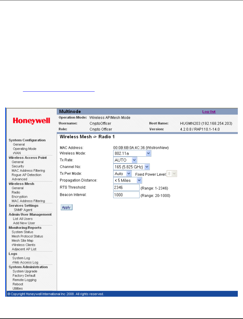
Wireless Mesh Configuration
Wireless Mesh screens
R110 OneWireless Multinode User's Guide 77
6/08
allows you to see the effect when aiming the antenna to improve signal strength. The
signal can be trended for each node.
Wireless Mesh - Radio screen
The Wireless Mesh - Radio screen, shown in Figure 9 contains wireless mesh
information including the channel number, Tx Rate, Tx Power and remote AP's BSSID.
This page is important in setting up your mesh configuration. Table 11 describes the
options appearing on the Radio screen.
NOTE: This section describes the options that are available when using this screen. See
Setting up wireless networks in this guide for typical multinode configurations when
creating a wireless mesh network.
Figure 9 Wireless Mesh - Radio screen

Wireless Mesh Configuration
Wireless Mesh screens
78 OneWireless Multinode User's Guide R110
6/08
Table 11 lists and describes the options available on the Wireless Mesh - Radio screen.
Table 11 Radio screen options
Screen Field Option Description
MAC
Address MAC address is fixed Displays the MAC address of the
multinode.
Wireless
Mode 802.11b/g Mixed
802.11a Sets the wireless mode for the wire-
less mesh.
Tx Rate For wireless mode option 802.11b/g Mixed
AUTO,
1, 2, 5.5, 11, 6, 9, 12, 18,
24, 36, 48, 54 Mbps
Sets the transmit rate for the selected
wireless mode and channel number.
When set to AUTO, the WLAN card
attempts to select the optimal rate for
the channel. If a fixed rate is
selected, the WLAN card will transmit
only at that rate.
For wireless mode option 802.11a
AUTO,
6, 9, 12, 18, 24, 36, 48, 54
Mbps
Sets the transmit rate for the selected
wireless mode and channel number.
When set to AUTO, the WLAN card
attempts to select the optimal rate for
the channel. If a fixed rate is
selected, the WLAN card will transmit
only at that rate.
Channel No.
Note:
Available
channels are
dependent
upon
Country
Code
setting.
For wireless mode option 802.11b/g Mixed
1 (2.412 GHz)
2 (2.417 GHz)
3 (2.422 GHz)
4 (2.427 GHz)
5 (2.432 GHz)
6 (2.437 GHz)
7 (2.442 GHz)
8 (2.447 GHz)
9 (2.452 GHz)
10 (2.457 GHz)
11 (2.462 GHz)
Sets the channel frequency for the
wireless mesh.

Wireless Mesh Configuration
Wireless Mesh screens
R110 OneWireless Multinode User's Guide 79
6/08
Screen Field Option Description
For wireless mode option 802.11a
52 (5.26 GHz)
56 (5.28 GHz)
60 (5.30 GHz)
64 (5.32 GHz)
149 (5.745 GHz)
153 (5.765 GHz)
157 (5.785 GHz)
161 (5.805 GHz)
165 (5.825 GHz)
Sets the channel frequency for the
wireless mesh.
Tx Pwr
Mode Off, Fixed, Auto Sets the RF transmit level of the
multinode.
The default mode is Auto which provides the widest range of RF transmission
available under ambient conditions. The wireless mesh's broadcast range can be
limited by setting the Tx Pwr Mode to Fixed and choosing a Fixed Pwr Level between
1 and 8. To prevent any RF transmission from the wireless mesh, set the Tx Pwr
Mode to Off.
RF transmissions from any associated wireless devices will not be turned off, but the
devices will not be able to communicate with the wireless mesh when Tx Pwr Mode is
set to Off.
Fixed Pwr
Level 1, 2, 3, 4, 5,6 7, 8 Sets transmit power level to a fixed
value and is active when Tx Pwr
Mode is set to Fixed.
Level 1 is the lowest power level
(Level 1 = 7dBm) and Level 8 is the
highest power level, (Level
5=15dBm)
Propagation
Distance < 5 Miles
5-10 Miles
11-15 Miles
16-20 Miles
21-25 Miles
26-30 Miles
> 30 Miles
Sets the approximate distance
between two mesh nodes.
Set Propagation Distance based on
the distance between this mesh node
and the mesh node that is furthest
from it and in the same network.
RTS
Threshold Range 1-2346 The number of bytes used for the
RTS/CTS handshake boundary.
When a packet size is greater than
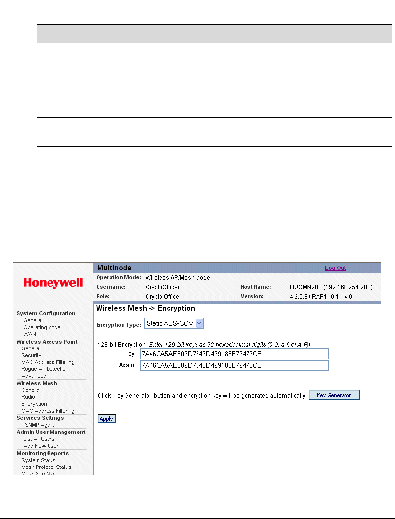
Wireless Mesh Configuration
Wireless Mesh screens
80 OneWireless Multinode User's Guide R110
6/08
Screen Field Option Description
the RTS threshold, the RTS/CTS
handshaking is performed.
Beacon
Interval Range 20 - 1000 The time interval in milliseconds in
which the 802.11 beacon is
transmitted by the AP. See also
RSSI window size in Table 9.
Note You can enter a note that defines the location of the remote mesh
node.
Wireless Mesh - Encryption screen
The Wireless Mesh - Encryption screen, shown in Figure 10 is used to select the
encryption type and generate the static encryption keys for the wireless mesh. You must
set the Encryption type and enter the encryption Key (if required) to ensure that your
mesh is working correctly. The encryption key that you use on this screen must be the
same for any mesh node connected to this network. The encryption type and key value
for Multinode 1 must be the same as for Multinode 2.
Figure 10 Wireless Mesh - Encryption screen

Wireless Mesh Configuration
Wireless Mesh screens
R110 OneWireless Multinode User's Guide 81
6/08
Table 12 Encryption screen options
Screen Field Option Description
Encryption
Type None
Static AES-CCM Sets the encryption type for the wire-
less mesh.
128-bit
encryption Hexidecimal numbers Enter a 128-bit key as hexadecimal
digits in the Key field, or click on the
Key Generator button which
automatically generates a
randomized key.
Enter the encryption key a second
time in the Again field.
Note: Record this key for future
reference.
Key
Generator button Generates a random encryption key
automatically which is entered in the
Key field.
Wireless Mesh - MAC Address Filtering screen
The Wireless Mesh -MAC Address Filtering screen is used to set up MAC address
filtering for the wireless mesh. This feature allows you to further strengthen wireless
client access security by allowing only known clients to join the mesh/network. MAC
address filtering is recommended for static configurations with a small number of clients.
The default setting for MAC Address filtering is Disabled.
NOTE: this screen is visible in the navigation tree only when Auto Mesh mode is
selected on the multinode. See Wireless Mesh - General screen to select the mesh mode.
MAC Address Filtering function for mesh works the same as it does for access point
configuration.
To enable and setup MAC Address filtering for the access points in your network:
Step Action
1 Click on the Wireless Mesh - MAC Address Filtering at the left of the
screen to call up the MAC Address Filtering screen.
2 Select Enable to enable MAC Address filtering.
3 Select Filtering Type from the drop down menu.

Wireless Mesh Configuration
Setting up wireless networks
82 OneWireless Multinode User's Guide R110
6/08
Step Action
MAC Address filtering and filter type works as follows:
• When Filtering is enabled and the Filter Type is Deny All Except Those
Listed Below, only those devices equipped with the authorized MAC
addresses will be able to communicate with this mesh node. In this case,
input the MAC addresses of all the PC cards that will be authorized to
access this mesh node. The MAC address is engraved or printed on the
PC (PCMCIA) card.
• When Filtering is enabled and the Filter Type is Allow All Except Those
Listed Below, any device with a MAC address which has been entered in
the MAC Address list will not be able to communicate with this mesh node.
In this case, navigate to the report: Wireless Clients and copy the MAC
address of any wireless client that you want to exclude from
communication with the mesh node and then add those MAC Addresses to
the MAC Address list.
4 Enter a MAC Address with a note to the MAC Address and Note fields and
click Add to add it to the MAC Address List at the bottom of the screen.
Note that communication with the mesh nodes containing these MAC
addresses entered in this field depends upon the Filter Type selected above.
Setting up wireless networks
Multinodes configured to operate as access points can also be setup to operate in a mesh
network. These multinodes require additional configuration. If the multinode is to be
used only as a bridge, some settings made during access point setup may not be
necessary.
You can set up a multinode to operate in a mesh network during initial configuration.
See Setup on page 37 for more information. The Wireless Mesh screens allow you to
setup the multinode to operate in a wireless mesh network. These screens include the
Wireless Mesh General, Radio, Encryption and MAC Address Filtering screens
The following sections describe the setup for three types of network configuration: Point-
to-Point, Point-to-Multipoint and Repeater.
NOTE: To set up a mesh network, which is most commonly used in OneWireless
networks, use the settings for Auto Mesh for the Point to Multipoint network.
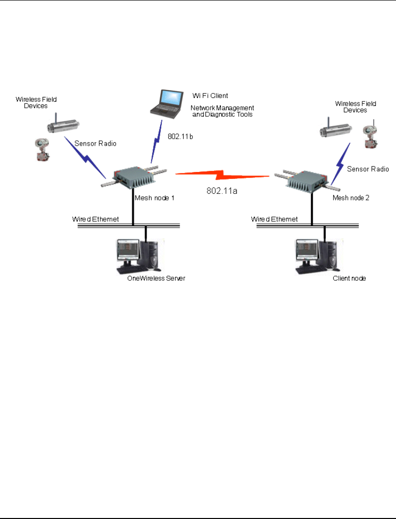
Wireless Mesh Configuration
Setting up wireless networks
R110 OneWireless Multinode User's Guide 83
6/08
Point-to-Point network
Figure 11 shows an example of a point-to-point network, which is a direct
communications link (using 802.11a protocol) between two multinodes: Mesh node 1
and Mesh node 2.
Figure 11 Point-to-point network example
For two networks to be linked and communicating properly, the multinodes must be
configured with compatible options in the Wireless Mesh setup screens. Depending upon
whether manual or auto mesh is used, Table 13 and Table 14 show typical option settings
for setting up a point-to-point network as shown in Figure 11. Make sure that the options
are set according to the values in the tables.

Wireless Mesh Configuration
Setting up wireless networks
84 OneWireless Multinode User's Guide R110
6/08
Table 13 Point-to-point network settings for Manual Mesh
Screen / Option Mesh node 1 Mesh node 2
Wireless Mesh - General screen
Mesh Mode: Manual Mesh Manual Mesh
Signal Strength LED
MAC: Not assigned (select from
drop-down list) Not Assigned (select from
drop-down list)
Spanning Tree Protocol
(STP) 802.1d: Enable (or Disable if no mesh
loop possible) Enable (or Disable if no mesh
loop possible)
Wireless Mesh - Radio screen
Wireless Mode: 802.11a 802.11a
Tx Rate: AUTO AUTO
Channel No.: Must be the same as Mesh
node 2 Must be the same as Mesh
node 1
Tx Power Mode: Auto Auto
Propagation Distance: < 5 Miles < 5 Miles
RTS Threshold: 2346 2346
Beacon Interval: 100 100
Wireless Mesh - Encryption screen
Mesh encryption options Must be the same as Mesh
node 2 Must be the same as Mesh
node 1
Table 14 Point-to-point network settings for Auto Mesh
Screen / Option Mesh node 1 Mesh node 2
Wireless Mesh - General screen
Mesh mode: Auto Mesh selected Auto Mesh selected
SSID Must be the same as Mesh
node 2 Must be the same as Mesh
node 1

Wireless Mesh Configuration
Setting up wireless networks
R110 OneWireless Multinode User's Guide 85
6/08
Screen / Option Mesh node 1 Mesh node 2
Max Direct Links: 40 (range 1 - 40) 40 (range 1 - 40)
Mesh Priority: A multiple of 4096. See Table
9 for details. A multiple of 4096. See Table
9 for details.
RSSI window size: 5 (range 1 - 100) 5 (range 1 - 100)
Signal Strength Threshold: 9% 9%
Link Sensitivity: 21% 21%
Broadcast SSID: Disable Disable
Signal Strength LED MAC: Enter from list at bottom of
screen Enter from list at bottom of
screen
Wireless Mesh - Radio screen
Wireless Mode: 802.11a 802.11a
Tx Rate: AUTO AUTO
Channel No.: Must be the same as Mesh
node 2 Must be the same as Mesh
node 1
Tx Power Mode: Auto Auto
Propagation Distance: < 5 Miles < 5 Miles
RTS Threshold: 2346 2346
Beacon Interval: 100 100
Wireless Mesh - Encryption screen
Mesh encryption options Must be the same as Mesh
node 2 Must be the same as Mesh
node 1
Wireless Mesh - MAC Address Filtering screen
Filtering: Enable/Disable Enable/Disable
Filter Type: Deny All/Allow All Deny All/Allow All
MAC Address: Add MAC address of Mesh
node links Add MAC address of Mesh
node links

Wireless Mesh Configuration
Setting up wireless networks
86 OneWireless Multinode User's Guide R110
6/08
To set up a wireless mesh (network)
The following procedure outlines the Wireless Mesh setup options for a multinode to
operate as a wireless mesh node. The procedure for setting up the three network types is
the same, although you should refer to the appropriate tables when selecting the options.
For example, If you want to set up a point-to-multipoint mesh network using auto mesh,
refer to Table 15 for the correct option settings and use the procedures below to access
the Wireless Mesh screens and select the options. Additional information for all of the
options on the Wireless Mesh screens is found in the following places:
Table 9 Auto Mesh screen options on page 73
Table 10 Manual Mesh screen options on page 75
Table 11 Radio screen options on page 78
Table 12 Encryption screen options on page 81.
This procedure assumes that the multinode is connected to a PC and that you are logged
into the Multinode Configuration Tool.
Step Action
1 At the left of the screen, click on Radio to display the Wireless Mesh - Radio
screen.
2 The MAC Address field shows the MAC address of the WLAN card for this
multinode.
Note: Record this address since it must be entered as the BSSID for other
multinodes that will be communicating with this multinode.
3 Choose the Wireless Mode to be used for wireless mesh, from the drop
down menu.
4 Choose the Tx Rate from the drop down menu.
You can choose AUTO if you want the WLAN card to attempt to select the
optimal transmit rate for the channel. Selecting a fixed Tx rate will enable the
WLAN card to transmit only at that rate.
5 Choose a Channel No. (channel number) from the drop down menu.
Note: The channel number must be set to the same frequency for each mesh
node to communicate. See Table 11 for a listing of available channels.

Wireless Mesh Configuration
Setting up wireless networks
R110 OneWireless Multinode User's Guide 87
6/08
Step Action
6 Choose the Tx Pwr Mode from the drop down menu.
Note: The Tx Pwr Mode can be set to AUTO unless the power must be
regulated. If FIXED is selected, you then must choose the Fixed Power Level
from the drop down menu. See Table 11 for more information.
7 Choose the Propogation Distance from the drop down menu.
Note: This field is set based on the distance between a mesh node and the
furthest mesh node that is connected to it.
8 Choose the RTS Threshold. See Table 11 for more information on this
option.
9 Choose the value for Beacon Interval. See Table 11 for more information on
this option.
10 After you have entered the information in the fields, click Apply to accept the
values.
11 Enter a descriptive note to identify the remote mesh node or its location.
12 Click Add button.
Select mesh mode:
Step Action
1 Click on the Wireless Mesh - General at the left of the screen to call up the
General configuration screen.
2 Select either Manual Mesh or Auto Mesh. The screen will refresh according
to the Mesh mode that was selected.
3 • If Auto Mesh is selected, go to Complete Auto Mesh on page 88 and
follow the procedure.
• If Manual Mesh is selected, go to Complete Manual Mesh on page 89 and
follow the procedure.

Wireless Mesh Configuration
Setting up wireless networks
88 OneWireless Multinode User's Guide R110
6/08
Complete auto mesh:
Step Action
1 Enter the SSID.
This SSID must be set on the wireless mesh node and each wireless device
in the network so that the devices can communicate with each other.
2 Enter a number from 1 to 40 for the Max Direct Links.
3 Next enter the Mesh Priority (range from 1-65535). See Table 9 for more
information on this option.
4 Select the RSSI window size. See Table 9 for more information on this
option.
5 Select the Signal Strength Threshold. See Table 9 for more information on
this option.
6 Select the Link Sensitivity. See Table 9 for more information on this option.
7 Either enable or disable the Broadcast SSID. See Table 9 for more
information on this option.
8 Once you have selected the options you will use, click Apply.
9 Enter the Signal Strength MAC. The signal strength of the wireless mesh
node (indicated in the window) that will be represented by the WLANSS LED
located on the front of the multinode.
10 At the left of the screen, click on Encryption to display the Wireless Mesh -
Encryption screen.
11 Choose the Encryption Type from the drop down menu. Choice is either
None or Static AES-CCM.
12 If you select AES-CCM, you must enter a 128-bit key as hexadecimal digits,
or click on the Key Generator button which automatically generates a
randomized key.
Record the key number. You will need to use it later.
Note that this key is initially shown in plain text so you have the opportunity to
copy the key. Once the key is applied, the key is no longer displayed in plain
text.
13 Once you have selected the options you will use, click Apply.
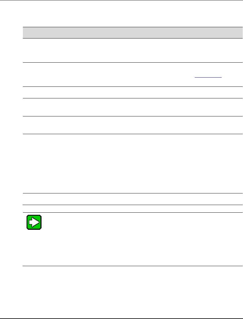
Wireless Mesh Configuration
Setting up wireless networks
R110 OneWireless Multinode User's Guide 89
6/08
Complete manual mesh:
Step Action
1 Select the Signal Strength LED MAC from the drop down menu. The
selections are also listed at the bottom of the screen. See Table 10 for more
information on this option.
2 Set Spanning Tree Protocol (STP) 802.1d to Enable unless you are sure
that there is no chance of a mesh loop. See Table 10 and Mesh loop for
more information on this option.
3 Click Apply to accept the changes made on this screen.
4 At the left of the screen, click on Encryption to display the Wireless Mesh -
Encryption screen.
5 Choose the Encryption Type from the drop down menu. Choice is either
None or Static AES-CCM.
6 If you select AES-CCM, you must enter a 128-bit key as hexadecimal digits in
the Key field, or click on the Key Generator button which automatically
generates a randomized key.
Record the key number. You will need to use it later.
Note that this key is initially shown in plain text so you have the opportunity to
record or copy the key. Once the key is applied, the key is no longer
displayed in plain text.
7 Once you have selected the options you will use, click Apply.
TIP
Configure other multinodes in the mesh network following the instructions
given for Multinode 1 above.
Be sure that you have completed configuration of the multinode by visiting the
System Configuration, Wireless Access Point and System Services screens
and choosing the configuration options applicable to the wireless network.
You must set the Encryption type and encryption key (if required) to ensure that the mesh
is working correctly. The encryption key that you use on this screen must be the same for
any mesh node connected to this network in order for communication to occur. The
encryption type and key value for Mesh node 1 must be the same as for Mesh node 2 and
any other mesh node in the network.
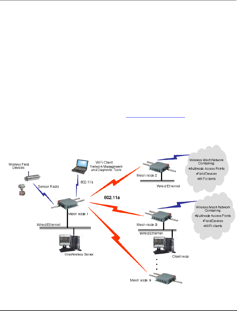
Wireless Mesh Configuration
Setting up wireless networks
90 OneWireless Multinode User's Guide R110
6/08
Point-to-Multipoint network
A point-to-multipoint network allows three or more multinode access points to
communicate wirelessly between 3 or more locations. Figure 12 shows an example of
this network type. Multinode 1 is the single access point for communication with the
other mesh nodes (Mesh nodes 2, 3, …n) in the network. For the mesh nodes to be
linked and communicating properly, they must be configured with compatible options in
their Wireless Mesh setup screens. For example, all mesh nodes must be set with the
same channel number.
When setting up this type of network, Mesh node 1 must contain the BSSIDs for all other
mesh nodes in the network, while Mesh nodes 2, 3, …n need to contain only Mesh node
1's BSSID. Table 15 and Table 16 list the option settings for creating the point-to-
multipoint network as shown in Figure 12. Use the settings in these tables if you want to
set up this type of network. The procedure to set up a wireless mesh begins on page 86.
NOTE: To set up bridging for Mesh network communications, use the settings for Auto
Mesh in Table 15.
Figure 12 Point-to-multipoint network example

Wireless Mesh Configuration
Setting up wireless networks
R110 OneWireless Multinode User's Guide 91
6/08
The network shown in Figure 12 requires that only Mesh node 1 be set in Auto Mesh
mode. You can set all multinodes to auto mesh mode, in which case each mesh node
must contain the BSSID for each of the other mesh nodes and Spanning Tree Protocol
must be Enabled.
Table 15 Point-to-Mulitpoint network setting for Auto Mesh
Screen / Option Mesh node 1 Mesh node 2, 3, …n
Wireless Mesh - General screen
Mesh mode: Auto Mesh selected Auto Mesh selected
SSID Must be the same as Mesh
nodes 2, 3, …n Must be the same as Mesh
node 1
Max Direct Links: 40 (range 1 - 40) 40 (range 1 - 40)
Mesh Priority: 65535 (range 1 - 65535) 65535 (range 1 - 65535)
RSSI window size 5 5
Signal Strength
Threshold: 9% 9%
Link Sensitivity 21% 21%
Broadcast SSID Disable Disable
Signal Strength LED
MAC: Enter from list at bottom of
screen Enter from list at bottom of
screen
Wireless Mesh - Radio screen
Wireless Mode: 802.11a 802.11a
Tx Rate: AUTO AUTO
Channel No.: Must be the same as Mesh
nodes 2, 3, …n Must be the same as Mesh
node 1
Tx Power Mode: Auto Auto
Propagation Distance: < 5 Miles < 5 Miles
RTS Threshold: 2346 2346
Beacon Interval: 100 100
Wireless Mesh - Encryption screen
Mesh encryption options Must be the same as Mesh Must be the same as Mesh

Wireless Mesh Configuration
Setting up wireless networks
92 OneWireless Multinode User's Guide R110
6/08
Screen / Option Mesh node 1 Mesh node 2, 3, …n
nodes 2, 3, …n node 1
Wireless Mesh - MAC Address Filtering screen
Filtering: Enable/Disable Enable/Disable
Filter Type: Deny All/Allow All Deny All/Allow All
MAC Address: Add MAC address of Mesh
nodes Add MAC address of Mesh
nodes
Table 16 Point-to-Multipoint network settings for Manual Mesh
Screen / Option Mesh node 1 Mesh nodes 2, 3, 4, …n
Wireless Mesh - General screen
Mesh mode: Manual Mesh selected Manual Mesh selected
Signal Strength LED
MAC: Not Assigned (select from
drop-down list) Not Assigned (select from
drop-down list)
Spanning Tree Protocol
(STP) 802.1d: Enable (or Disable if no mesh
loop possible) Enable (or Disable if no mesh
loop possible)
Wireless Mesh - Radio screen
Wireless Mode: 802.11a 802.11a
Tx Rate: AUTO AUTO
Channel No.: Must be the same as Mesh
nodes 2, 3, …n Must be the same as Mesh
node 1
Tx Power Mode: Auto Auto
Propagation Distance: < 5 Miles < 5 Miles
RTS Threshold: 2346 2346
Beacon Interval: 100 100
Wireless Mesh - Encryption screen
Mesh encryption options Must be the same as Mesh
nodes 2, 3, …n Must be the same as Mesh
node 1

Wireless Mesh Configuration
Setting up wireless networks
R110 OneWireless Multinode User's Guide 93
6/08
Mesh network configuration
A mesh network allows you to connect three or more multinodes in mesh networks mode
wirelessly. This network type is most commonly used in OneWireless networks.
NOTE: Use the option settings in Table 15 for point-to-multipoint network in auto mesh
mode when setting up a mesh network. STP is enabled automatically in auto mesh mode.
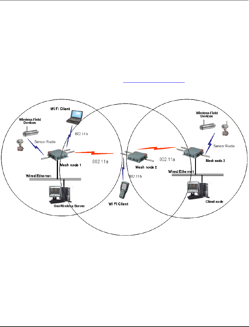
Wireless Mesh Configuration
Setting up wireless networks
94 OneWireless Multinode User's Guide R110
6/08
Repeater network configuration
A repeater network can be used to extend the wireless signal from one mesh node
connected to an Ethernet LAN wirelessly so that another mesh node can control a
wireless LAN at a distance. With this configuration, each mesh node can control a
wireless LAN. All wireless clients must have the same SSID as the mesh node on the AP
card channel. All clients can roam between the three mesh nodes. The option settings in
Table 17 and Table 18 are used when setting up a repeater network configuration as
shown in Figure 13. Use the procedure To set up wireless mesh on page 86 to set up the
network.
Figure 13 Repeater network example

Wireless Mesh Configuration
Setting up wireless networks
R110 OneWireless Multinode User's Guide 95
6/08
Table 17 Repeater network settings for Manual Mesh
Screen and Option Multinode 1 Multinode 2 Multinode 3
Wireless Mesh - General screen
Mesh mode: Manual Mesh Manual Mesh Manual Mesh
Signal Strength LED
MAC: Not assigned (select
from drop-down list) Not Assigned (select
from drop-down list) Not Assigned (select
from drop-down list)
Spanning Tree
Protocol (STP)
802.1d:
Enable (or Disable if no
mesh loop possible) Enable (or Disable if no
mesh loop possible) Enable (or Disable if no
mesh loop possible)
Wireless Mesh - Radio screen
Wireless Mode: 802.11a 802.11a 802.11a
Tx Rate: AUTO AUTO AUTO
Channel No.: Must be the same as
Multinode 2 Must be the same as
Multinode 1 Must be the same as
Multinode 1
Tx Power Mode: Auto Auto Auto
Propagation Distance: < 5 Miles < 5 Miles < 5 Miles
RTS Threshold: 2346 2346 2346
Beacon Interval: 100 100 100
Wireless Mesh - Encryption screen
Mesh encryption
options Must be the same as
other two multinodes Must be the same as
other two multinodes Must be the same as
other two multinodes
Table 18 Repeater network setting for Auto Mesh
Screen and Option Multinode 1 Multinode 2 Multinode 3
Wireless Mesh - General screen
Mesh mode: Auto Mesh selected Auto Mesh selected Auto Mesh selected
SSID Must be the same as
Multinode 2 Must be the same as
Multinode 1 Must be the same as
Multinode 1

Wireless Mesh Configuration
Setting up wireless networks
96 OneWireless Multinode User's Guide R110
6/08
Screen and Option Multinode 1 Multinode 2 Multinode 3
Max Direct Links: 40 (range 1 - 40) 40 (range 1 - 40) 40 (range 1 - 40)
Mesh Priority: 65535 (range 1 - 65535) 65535 (range 1 - 65535) 65535 (range 1 - 65535)
RSSI window size 5 5 5
Signal Strength
Threshold: 9% 9% 9%
Link Sensitivity 21% 21% 21%
Broadcast SSID: Disable Disable Disable
Signal Strength LED
MAC: Enter from list at bottom
of screen Enter from list at bottom
of screen Enter from list at bottom
of screen
Wireless Mesh - Radio screen
Wireless Mode: 802.11a 802.11a 802.11a
Tx Rate: AUTO AUTO AUTO
Channel No.: Must be the same as
Multinode 2 Must be the same as
Multinode 1 Must be the same as
Multinode 1
Tx Power Mode: Auto Auto Auto
Propagation Distance: < 5 Miles < 5 Miles < 5 Miles
RTS Threshold: 2346 2346 2346
Beacon Interval: 100 100 100
Wireless Mesh - Encryption screen
Mesh encryption
options Must be the same as
other two Multinodes Must be the same as
other two Multinodes Must be the same as
other two Multinodes
Wireless Mesh - MAC Address Filtering screen (Deleted? Not used?)
Filtering: Enable/Disable Enable/Disable Enable/Disable
Filter Type: Deny All/Allow All Deny All/Allow All Deny All/Allow All
MAC Address: Add MAC address of
multinodes Add MAC address of
multinodes Add MAC address of
multinodes

R110 OneWireless Multinode User's Guide 97
6/08
Multinode and Mesh Network Tuning
This section contains information on making adjustments to multinode parameters when
conducting a site survey of an installed wireless network. Although a site survey was
conducted during the planning phase to determine the optimal location of multinodes and
WSGs to create a wireless network, once the multinodes have been installed in their
designated locations a site survey should be conducted to measure the performance of the
wireless network and make adjustments or tune the mesh network for the best possible
and reliable wireless communication.
The Network Management and Diagnostics tool also can provide realtime feedback on
network performance. See the OneWireless System Administration Guide for a
description of the NMD tool.
Monitoring signal strength
The multinode configuration tool application contains a tool that can be used to monitor
the received signal strength of all wireless devices it can detect. The tool should be used
during the site-survey and during multinode deployment for optimal antenna positioning.
To access the monitoring tool:
Step Action
1 Open Internet Explorer and access the multinode’s configuration tool by
typing the URL for the multinode in the address line:
https:// <ip address>
Where: ip address is the IP address of the multinode.
2 From the sign-in screen, type your username and password and then click
Sign In.
3 From the left pane of the Multinode Configuration Tool, click
Monitoring/Reports > Adjacent AP List.
4 Refresh the page to get the most recent RSSI readings.
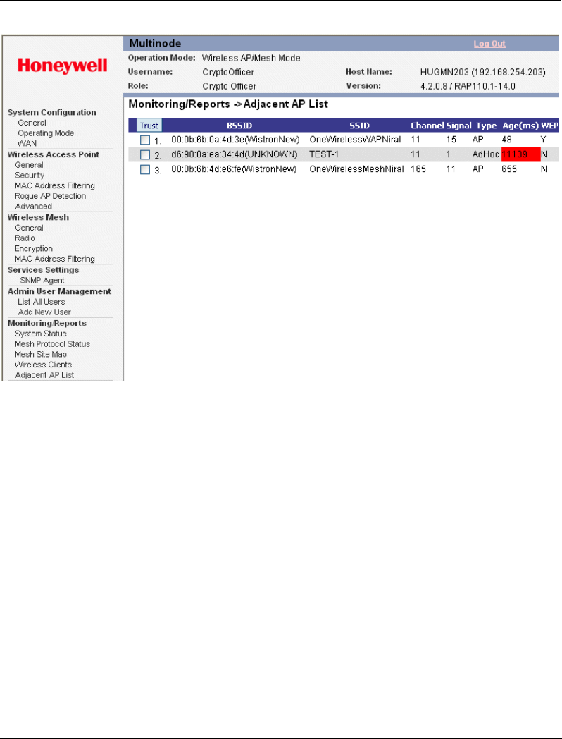
Multinode and Mesh Network Tuning
Mesh tuning for optimal settings
98 OneWireless Multinode User's Guide R110
6/08
Note: In the Adjacent AP List screen, the Signal column lists the signal strength of the received
signal (RSSI) from other access Points detected by the multinode. Signal = RSSI value.
RSSI value = dbm - 95 (Subtract 95 from the RSSI value for the dbm value)
For example: An RSSI of 15 equals -80 dbm.
An RSSI of 20 equals -75 dbm.
Mesh tuning for optimal settings
Due to the variety of installation environments, the default configuration/parameter
settings of the mesh network may not be the optimal settings for your site. The following
are important parameters contained on the Wireless Mesh screen that you can adjust to
customize the mesh for optimal performance:
• Mesh link Signal Strength Threshold
• Mesh priority
• MAC address filtering
See Table 9 for more information on these parameters.
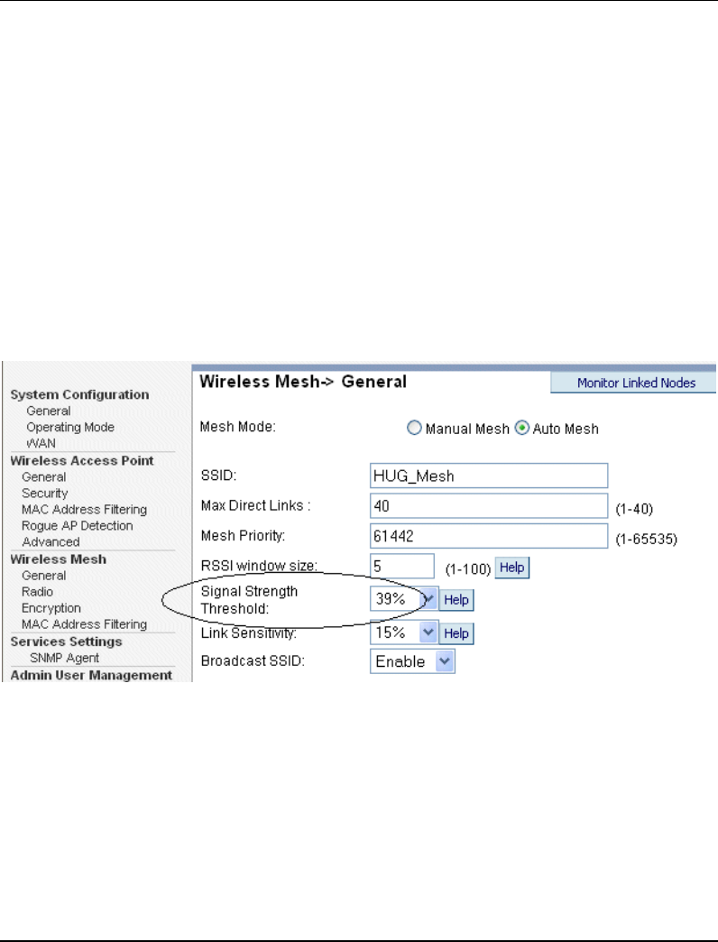
Multinode and Mesh Network Tuning
Tuning the mesh link Signal Strength threshold
R110 OneWireless Multinode User's Guide 99
6/08
Tuning the mesh link Signal Strength threshold
The Signal Strength threshold value is checked when a node tries to establishes a link
with another node. Both nodes will check the RSSI of its partner against its configured
threshold value. If the RSSI value is lower than the threshold value in either side, the link
between them will not be established.
If the signal strength threshold is too small, the node will establish links with all nodes it
can see even though some link quality may be poor. Too many links in the mesh network
can result in unnecessary and frequent changes of the network topology.
If the signal strength threshold is too large, the node may not link with any other nodes
and be isolated. This is an undesirable condition.
The proper signal strength threshold should include 2-4 links on each node.
Tuning the mesh priority
Mesh priority sets the 802.1D/ RSTP (Rapid Spanning Tree) mesh priority. The latest
revision of 802.1D requires the priority to be set to a multiple of 4096. Therefore, the
mesh priority value should be one of the following:
4096 8192 12288 16384 20480 24576 28672 32768
36864 40960 45056 49152 53248 57344 61440

Multinode and Mesh Network Tuning
Tuning MAC address filtering
100 OneWireless Multinode User's Guide R110
6/08
Further considerations should be made in setting mesh priority in a network and is
dependent upon the role the multinode (or device) plays in the network. For example, if
the mesh network includes a WSG which is then wired to a switch, the following priority
should be assigned to the nodes in the network:
Node type in network Priority Typical value
Ethernet switch that uses RSTP Highest 4096
Default gateway, WSG 2nd highest 8192
Any wired multinode directly connecting to
the mesh through a wired Ethernet link 3rd highest 12288
Wireless multinodes 4th highest 16384
The device with the lowest bridge priority becomes the ROOT node. This device can be
any RSTP compliant device (such as a switch) and not necessarily a multinode. The mesh
priority number does not affect the general topology of the mesh networks.
Tuning MAC address filtering
Wireless Mesh - MAC Address Filtering screen can be used to further customize the
mesh network (only available in auto-mesh mode)
In some cases, you may want to specifically link to one or a few nodes. You can use
MAC Address Filtering to achieve this. For example, if one multinode (A) is used to
stream video to another multinode (B) which is not the ROOT node, you can specify A to
always connect to B and maybe another node for link backup. This allows video to be
delivered using the shortest path to B.
You can also use MAC Address Filtering to specify that a set of nodes NOT to connect
to. For more information on using MAC Address filtering, see Wireless Mesh - MAC
Address Filtering screen on page 81.
Estimating network performance
The values from the two tables below, (Throughput based on signal strength and
Throughput based on "hops") are based on a best-case scenario. That is, there is little to
no 5.8GHz RF interference sources present while the data was being passed. The values
are also based on the mesh radio only. It does not take into account the stability of the
link for the Field I/O radio to the sensors nor the wireless client link to the AP radio of
the multinode.

Multinode and Mesh Network Tuning
Estimating network performance
R110 OneWireless Multinode User's Guide 101
6/08
Throughput based on signal strength
The theoretical data rates and throughput values for corresponding signal strengths for
wireless bridge connectivity are displayed in the following table. These throughput
values are based on a single point-to-point link between two multinodes.
Signal strength Data rate Throughput
> or = 72% 54 Mbps 22 Mbps
69% 48 Mbps 20 Mbps
66% 48 Mbps 20 Mbps
63% 36 Mbps 17 Mbps
60% 36 Mbps 17 Mbps
57% 24 Mbps 11 Mbps
45% 24 Mbps 11 Mbps
42% 18 Mbps 9 Mbps
36% 18 Mbps 9 Mbps
33% 12 Mbps 6 Mbps
30% 12 Mbps 6 Mbps
27% 9 Mbps 4.5 Mbps
24% 9 Mbps 4.5 Mbps
< 21% 6 Mbps 3 Mbps
<18% < 6 Mbps < 3 Mbps

Multinode and Mesh Network Tuning
Estimating network performance
102 OneWireless Multinode User's Guide R110
6/08
Throughput based on "hops"
The throughput values through a specified number of "hops" are shown in the following
table. Hops are defined as the number of devices or nodes through which the data must
pass in order to reach its destination.
Signal
strength 1 Hop 2 Hops 3 Hops 4 Hops
100% 22.0 Mbps 11.0 Mbps 7.3 Mbps 5.5 Mbps
69% 20.0 Mbps 10.0 Mbps 6.7 Mbps 5.0 Mbps
63% 17.0 Mbps 8.5 Mbps 5.7 Mbps 4.3 Mbps
57% 11.0 Mbps 5.5 Mbps 3.7 Mbps 2.8 Mbps
42% 9.0 Mbps 4.5 Mbps 3.0 Mbps 2.3 Mbps
33% 6.0 Mbps 3.0 Mbps 2.0 Mbps 1.5 Mbps
27% 4.5 Mbps 2.3 Mbps 1.5 Mbps 1.1 Mbps
21% 3.0 Mbps 1.5 Mbps 1.0 Mbps 0.8 Mbps
18% 1.0 Mbps 0.5 Mbps 0.3 Mbps 0.3 Mbps
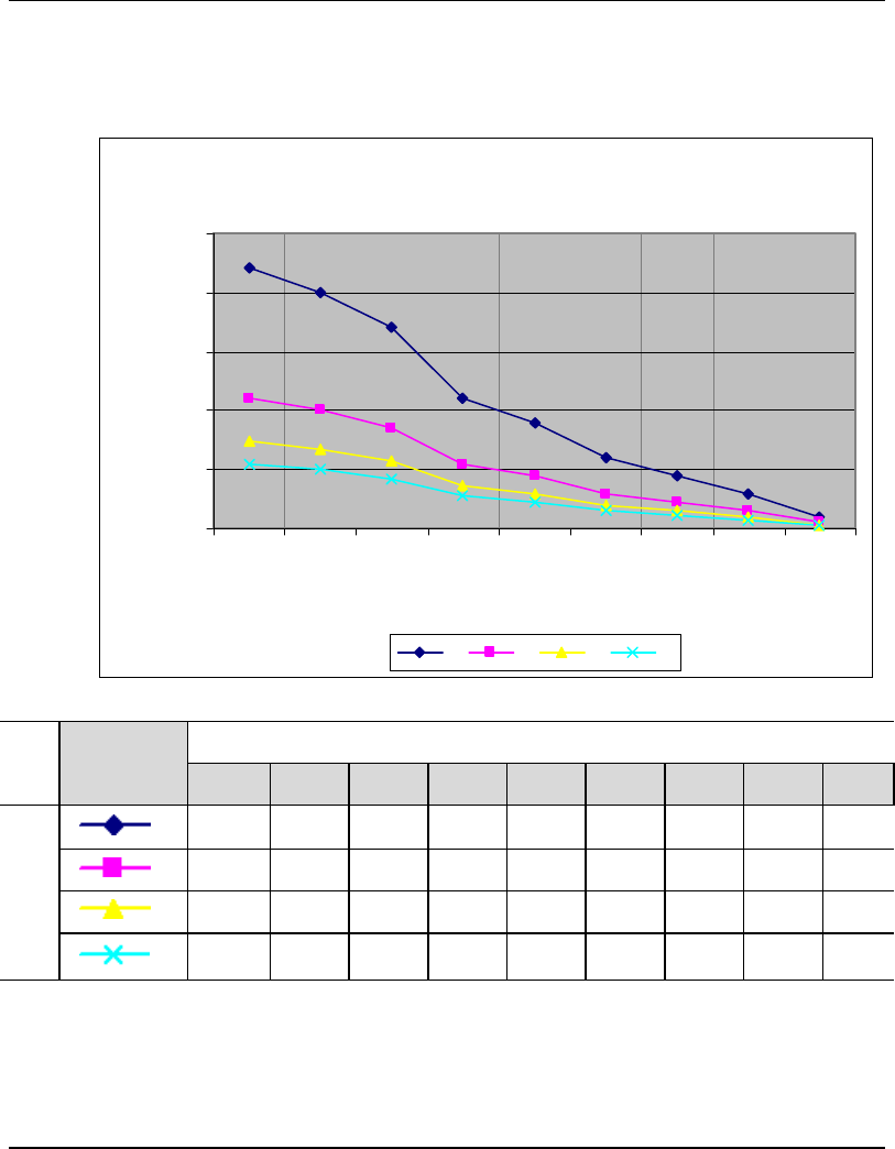
Multinode and Mesh Network Tuning
Estimating network performance
R110 OneWireless Multinode User's Guide 103
6/08
Throughput based on "Hops" and signal strength
0.0
5.0
10.0
15.0
20.0
25.0
100% 69% 63% 57% 42% 33% 27% 21% 18%
Signal Strength
Throughput in Mbps
1 2 3 4
Hops Signal Strength
100% 69% 63% 57% 42% 33% 27% 21% 18%
Throughput in
Mbps
1 22.0 20.0 17.0 11.0 9.0 6.0 4.5 3.0 1.0
2 11.0 10.0
8.5 5.5 4.5 3.0 2.3 1.5 0.5
3 7.3 6.7
5.7 3.7 3.0 2.0 1.5 1.0 0.3
4 5.5 5.0
4.3 2.8 2.3 1.5 1.1 0.8 0.3

Multinode and Mesh Network Tuning
Estimating network performance
104 OneWireless Multinode User's Guide R110
6/08

R110 OneWireless Multinode User's Guide 105
6/08
Multinode Operation and Monitoring
Overview
The status and performance of multinodes, WSGs and field devices operating in a
wireless network can be monitored a number of ways.
• In Wireless Builder, you can manage the database of your wireless nodes
(multinodes, WSGs, field devices). The Monitoring tab in the Wireless Builder
provides a tree view showing the operating status of the wireless system gateway and
field devices that are commissioned in the network. Also you can view the block
configuration of the WSGs and field devices in the network. The configuration
forms have a number of tabs that show the block configuration and operating
statistics for a network node.
• Using Multinode Configuration Tool screens (Monitoring/Reports screens) on the
WSG provides a view of the multinodes communicating in a network. You can
connect a laptop to individual multinodes to view configuration settings of the node
and operating statistics of the node within the network.
• Network Management and Diagnostics (NMD) tool provides a live graphical
interface of the wireless network nodes. You can also access, view and change
multinode configuration settings (although not all configuration settings can be
changed using this tool).
Monitoring/Reports screens
Monitoring Reports screens are accessed through the Multinode Configuration Tool on
the multinode and provide a variety of screens that show operating status and current
client lists in the network.

Multinode Operation and Monitoring
Monitoring/Reports screens
106 OneWireless Multinode User's Guide R110
6/08
System Status
Click on the System Status at the left of the screen to call up the Monitoring Reports -
System Status screen. Statistics listed on the screen are described in Table 19.
Table 19 System Status screen statistics
Statistic Description
Device Status
Current Encryption Mode: Indicates the current encryption mode that is being
used by the node.
Mesh Encryption Mode: Indicates the mesh encryption mode that is
currently being used by the node.
System Uptime: The time that the node has been running since last
reset.
Total Useable Memory Size: The total useable memory size available in the
node (in bytes).
Free Memory: The free memory that is currently available in the
node (in bytes).
Current Processes: The current number of processes that are active in
the node.
Country Code: Indicates the region of the world where this wireless
network is located. The country code enables a set
of available frequency bands and channels for use
in the wireless network which is based on that
country's regulations.
Other Information:
Buttons to access additional
statistics.
Clicking on one of these buttons opens a pop-up
window that lists a number statistics for that
particular component or function.
CPU
PCI
Interrupts
Processes
Interfaces

Multinode Operation and Monitoring
Monitoring/Reports screens
R110 OneWireless Multinode User's Guide 107
6/08
Statistic Description
Network Interface Status
WAN Ethernet MAC Address: The MAC address of the WAN card
LAN Ethernet MAC Address: The MAC address of the Local Access Network
(LAN) card in the multinode.
Primary WLAN MAC Address: The MAC address of the primary Wireless LAN
card in the multinode.
Secondary WLAN MAC
Address: The MAC address of the secondary Wireless LAN
card in the multinode.
Routing Table
Dest. LAN IP:
Subnet Mask
Default Gateway
Hop Count
Interface
Mesh Protocol Status
Click on the Monitoring Reports - Mesh Protocol Status at the left of the screen to call up
the Mesh Protocol Status screen and provides the statistics of the wireless mesh network,
such as:
• Ethernet Port STP Status
• Wireless Port 0 STP Status
• Wireless Mesh Information

Multinode Operation and Monitoring
Monitoring/Reports screens
108 OneWireless Multinode User's Guide R110
6/08
Mesh Site Map
Click on the Mesh Site Map at the left of the screen to call up the Monitoring Reports -
Mesh Site Map screen.
The Mesh Site Map shows the spanning tree network topology of both the wired and
wireless nodes connected to the network. The root STP node is always shown on top with
the other nodes shown in hierarchial tree below it. Wired links are shown with double
dotted lines and wireless links are shown with single dotted lines. To refresh the map you
must click the Update button since the map does not update dynamically. An example is
shown in Figure 14. Table 20 describes the statisitics that are shown for each node
defined in the network.
Table 20 Mesh Site Map screen statistics
Statistic or Feature Description
Update button Click this button to update the Mesh Site
map with current information.
Last Update: The time that the mesh site map was last
updated.
Current Time: The current system time.
Retrieve button Click this button to retrieve missing
network node information.
Cached Nodes Info button
Information for each node detected in the
Mesh BRG:
IP:
Radio:
Desc:
Built:
Bridge ID
The IP address
The MAC address of the
radio interface.
The node’s Description field
text
The build date of the
firmware currently loaded
and operating in the
multinode.
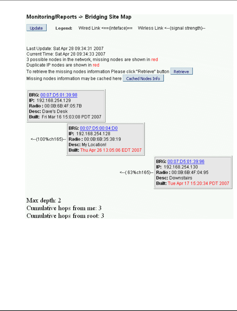
Multinode Operation and Monitoring
Monitoring/Reports screens
R110 OneWireless Multinode User's Guide 109
6/08
Figure 14 Mesh Site Map example
Wireless Clients
Click on the Wireless Clients at the left of the screen to call up the Monitoring Reports -
Wireless Clients screen.
The Wireless Clients screen displays the MAC Address of all wireless clients along with
their signal strength and transmit rate. The screen also allows you remove clients from
the current MAC Address filter list.

Multinode Operation and Monitoring
System and Web Access Logs
110 OneWireless Multinode User's Guide R110
6/08
Adjacent AP Lists
Click on the Monitoring Reports - Adjacent AP List at the left of the screen to call up the
Adjacent AP List screen.
The Monitoring Reports - Adjacent AP List screen shows all the APs detected by the
multinode's wireless card and the wireless bridge's wireless card. This list includes all
APs regardless of whether or not they are in the network.
System and Web Access Logs
There are two logs available for viewing and exporting: System Log and Web Access
Log.
System Logs
The System Log screen displays system messages with a date and time stamp. These
messages document events performed internally by the system. The System log updates
when a system event occurs. This information is helpful to System Administrators, Field
Engineers and technical support personnel.
To view the current system log, select System Log at the left of the Multinode
Configuration Tool screen.
To export the log and save it as a file on a PC, Click on Export button. Log file is
exported as an HTML file. You can then open the file in Word or WordPad to view the
log entries.
Web Access log
The Web Access Log displays system messages with date and time stamp for any actions
involving web access. For example, this log records when you set encryption mode,
change operating mode, etc., using the Multinode Configuration Tool screens. It creates a
log of what actions were performed and by what user. The Web access log updates when
a web access event occurs.
To view the current Web access log, select Web Access Log at the left of the Multinode
Configuration Tool screen
To export the log and save it as a file on a PC, Click on Export button. Log file is
exported as an HTML file. You can then open the file in Word or WordPad to view the
log entries

R110 OneWireless Multinode User's Guide 111
6/08
Multinode Maintenance
Overview
The multinode contains no user-serviceable parts inside the multinode enclosure. Any
maintenance required is limited only to the external enclosure surface, cable connections,
antennas and the firmware. A failed unit should be returned to Honeywell for mainte-
nance, repair or replacement
Replacing a multinode/WSG
If a multinode or WSG fails in an operating network, you can replace it. First it must be
configured. The system configuration file of the node that has failed can be used to
configure the replacement multinode.
To replace a failed multinode in a network:
Step Action
1 Obtain a replacement multinode.
2 Verify firmware version of the mesh and sensor radio software currently
installed on the replacement multinode is the latest version.
3 If required, Perform a Firmware Upgrade .
4 Perform a System Upgrade of the configuration file of the failed multinode.
This requires that a system configuration file of the failed unit has been saved
previously. This file can be uploaded to the replacement multinode.
5 Authenticate the replacement multinode.
6 Remove and replace the failed multinode with the new multinode.
7 Verify that the replacement multinode is operating properly in the network.
8 Return the failed unit to Honeywell.

Multinode Maintenance
Replacing a multinode/WSG
112 OneWireless Multinode User's Guide R110
6/08

R110 OneWireless Multinode User's Guide 113
6/08
Troubleshooting
Overview
If a fault or a failure is indicated or suspected in a wireless system gateway or multinode
in the network, there are a number of tools that you can use to gather information to help
diagnose a problem.
• Network Management Diagnostic (NMD) tool - This tool provides a live graphic
display of the mesh network showing multinodes and wireless field devices, the
operating status of the nodes, and the signal strength of the links between nodes.
The NMD tool allows you to access, view and change multinode configuration
options (although not all configuration options can be changed using the NMD).
• Data Collection - This is a method in which you can capture data logs from the
wireless network and Key Server activity and save the log files. These files are then
forwarded to Honeywell technical assistance for analysis.
• System and Web Access logs - These logs are available using the Multinode
Configuration Tool in the multinode. The logs can exported and saved to a PC for
later analysis. See System and Web Access Logs for more information.
• Monitoring/Report screens - A number of status screens are available in the
Multinode Confguration Tool. Multinode operating status and statistics can be
viewed and collected for analysis. See Monitoring/Reports screens for more
information.
Since the multinode contains no user-serviceable parts inside the multinode enclosure,
any failure within a multinode will require a hardware replacement.
Multinode failure indications
Failure indication may be signaled via the multinode status LEDs. The WLAN1 and
WLAN2 LEDs blink simultaneously when the system is halted. This indicates the
software has detected a problem with the encryption algorithm or the system
configuration does not pass the integrity check.
Reboot multinode
You may want to reboot the multinode if a failure is suspected. The System
Administration - Reboot screen allows you to reboot the multinode without changing any
configuration settings. Both CryptoOfficer and Administrator users have access to this
function.

Troubleshooting
Network Management Diagnostics tool
114 OneWireless Multinode User's Guide R110
6/08
If you are using the Network Management and Diagnostics (NMD) tool there is an icon
on the interface that allows you to reboot the multinode. When making changes to the
configuration settings of a multinode, you must reboot the multinode to enable the
changes.
Restore factory default settings
The System Administration - Factory Default screen is used to reset the multinode to its
factory settings. You must be logged in as the CryptoOfficer to access the Restore
button.
ATTENTION
The "Restore" button is a fallback troubleshooting function that should only be
used to reset the multinode to its factory default settings.
Network Management Diagnostics tool
The Network Management and Diagonostics tool can be use to gather event data and
operation and configuration information for troubleshooting and diagnosing a problem.
If troubleshooting a problem with a multinode, WSG, or field device, you must connect a
PC or laptop (with the NMD tool installed) to the network in which the node is operating.
Using the NMD, you can open the tool and view the nodes operating in the network and
obtain node configuration settings.
See the OneWireless System Administration Guide for a description of the NMD tool.
Data Collection
Event data can be captured and saved in files so this data can be forwarded to Honeywell
Technical Assistance for analysis. Event data is sometimes cryptic and is best analyzed
by trained Honeywell personnel. These event log files are collected from three sources:
• The WNSIA event log is collected from the server or PC.
• The Key Server Manager (KSM) event log is collected from the Key Server
• The Wirelesss Capture File (WCF) is collected from the multinode.
Event and file capture data is time stamped by the system which allows a view of the
events leading up to and immediately after the fault event. So it is important to supply
the time of the fault or failure when submitting the data files to Honeywell. Also, the
WNSIA event log and portions of the WCF are constructed as circular lists, meaning that
as new data is captured in the file, older data is deleted. Therefore, you should collect
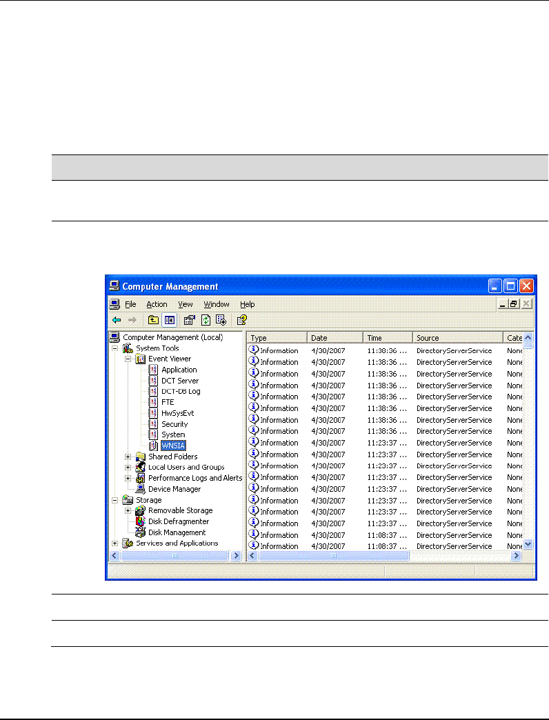
Troubleshooting
Data Collection
R110 OneWireless Multinode User's Guide 115
6/08
these files as soon as possible after the problem occurs in order to capture the events
leading up to it. Use the following procedures to capture these log files when a fault
occurs.
To capture the WNSIA event log
Step Action
1 On the Server desktop, go to My Computer. Right click and select Manage
from the menu.
2 Expand the listing under System Toolsand Event Viewer as shown in the
figure.
3 Select WNSIA. Right click ans select Save Log File as… from the menu.
4 Select a destination and save the file.

Troubleshooting
Data Collection
116 OneWireless Multinode User's Guide R110
6/08
To capture the Key Server Manager event log:
Step Action
1 On the Key Server, open Key Server Manager.
2 Select Event Log.
3 Click Export, select a destination and save the log file.
To capture the WCF capture file:
Step Action
1 From a command line prompt, type:
wcfcap <IP Address> <Login Name> <Login Password>
2 Select Save as…, select destination and save the file.
Authentication Device access to multinode
The authentication device can be used to read the IP Address or SSID of a multinode in
the case that it has been lost.

R110 OneWireless Multinode User's Guide 117
6/08
Addendum
OneWireless Multinode - Models WNMN and WNMS
This addendum applies to installation of the Model WNMN and Model WNMS
OneWireless Multinodes within hazardous locations
Factory Mutual
The Model WNMF and Model WNMS are Approved by Factory Mutual for use in Class
I, Division 2, Groups A, B, C and D hazardous locations and Class I, Zone 2, AEx nC
IIC hazardous locations. The temperature rating for both Division 2 and Zone 2
hazardous location is T4 based upon an ambient operating temperature range of -40° C to
+75° C.
Canadian Standards Association
The Model WNMF and Model WNMS are Approved by Canadian Standards Association
for use in Class I, Division 2, Groups A, B, C and D hazardous locations and Class I,
Zone 2, Ex nA IIC hazardous locations. The temperature rating for both Division 2 and
Zone 2 hazardous location is T4 based upon an ambient operating temperature range of -
40° C to +75° C.
ATEX Directive 94/6/EC
The Model WNMF and Model WNMS are ATEX Certified for use in Zone 2, II 3G Ex
nA nL IIC hazardous locations. The temperature rating is T4 based upon an ambient
operating temperature range of -40° C to +75° C
The ATEX Directive 94/6/EC is a European CE Mark directive concerning products that
are designed for use in potentially explosive environments. Only products with the
ATEX certification and with ATEX labeling will be approved for free movement in the
19 EU (European Union) and EFTA (European Free Trade Association) countries. As
defined in the directive, "free movement" refers to:
• placing a product on the market, and/or
• placing a product into service.
The ATEX Directive 94/6/EC is a living (set of) document(s), subject to further change
and refinement, whose details are beyond the scope of this addendum. Further
information can be obtained in the Official Journal of the European Communities No
L100/1, and in related publications such as Guidelines on the Application of Directive
94/9/EC. Both of these items are available at:
http://europa.eu.int/comm/enterprise/atex/index.htm

Addendum
OneWireless Multinode - Models WNMN and WNMS
118 OneWireless Multinode User's Guide R110
6/08
The Honeywell WNMF and WNMS OneWireless multinodes are now ATEX certified,
and all units manufactured currently and in the future will include labeling that includes
all markings required under the ATEX directive.
Purpose and Content
This adendum includes information relative to both the Factory Mutual Approval and
Canadian Standards Association Certification and as required under the ATEX Directive
regarding:
1. The appearance and meaning of each certification mark (CE Mark) that appears on
the label(s) affixed to the product.
2. Instructions for installation and use of the product within potentially explosive
atmospheres.
Information required for use of this product, and additional installation information, is
included in:
OW-CDX050 - OneWireless Multinode User's Guide
of which this adendum is a part.
Details regarding certification marks that appear in labeling for this product are given in
this addendum.
ATTENTION
The publications cited above and the functioning and construction (except for
labeling) of the devices described therein are essentially unchanged. The
purpose of this addendum is to provide details the purpose and appearance
of the labels attached to each device under ATEX Directive 94/6/EC.
ATTENTION
Before installing the equipment in a potentially explosive atmosphere, please
read the information provided in this addendum, which supports the ATEX
certifications for this product.
CE Conformity
The Multinode is in conformity with the protection requirements of the following
European Council Directives: 94/9/EC, the Explosive Atmospheres (ATEX) Directive
and 89/336/EEC, the Electromagnetic Compatibility (EMC) Directive and Radio and
Telecommunications Terminal Equipment (RTTE) Directive - 1999/5/EC.

Addendum
OneWireless Multinode - Models WNMN and WNMS
R110 OneWireless Multinode User's Guide 119
6/08
In conformity with the ATEX directive, the CE mark on the certification nameplate
includes the Notified Body identification number 0981 adjacent to the EC Type
Examination Certificate number.
Deviation from the installation conditions in this manual may invalidate this product’s
conformity with the Explosive Atmospheres and EMC Directives.
Conformity of this product with any other "CE Mark" Directive(s) shall not be assumed.
Marking, ATEX Directive
Honeywell’s Multinode with the nameplate has been certified to comply with Directive
94/9/EC of the European Parliament and the Council as published in the Official Journal
of the European Communities No. L 100/1 on 19-April-1994.
The following information is provided as part of the labeling of the transmitter:
• Name and Address of the manufacturer: Honeywell, Phoenix, AZ 85029 USA.
• Notified Body identification: Northwest EMC Inc.
• The serial number of the multinode is located on the label applied to the back plate
of the assembly. The first two digits of the serial number identify the year (02) and
the second two digits identify the week of the year (23); for example, 0223xxxxxxxx
indicates that the product was manufactured in 2002, in the 23 rd week.
Environmental
Ambient operating temperature: -40 to 75º C
Enclosure classification: IP 66
Special conditions for safe use, NonSparking
The multinode is nonsparking apparatus that can be installed in potentially explosive
atmospheres.
Temperature classifications: T4 up to Ta ≤ 75º C
Equipment shall be installed in a location providing a degree of protection from dust and
water equivalent to IP54
Installations specific to the ATEX Directive shall have the flying leads of the multinode
suitably protected against mechanical damage and terminated within a terminal or
junction facility suitable for the conditions of use. All other installations shall have the

Addendum
OneWireless Multinode - Models WNMN and WNMS
120 OneWireless Multinode User's Guide R110
6/08
external wiring routed through metallic conduit (via the ¾" NPT connection) and shall be
terminated within a junction rated appropriately for the conditions of the installation.
These units are non-repairable items and if faulty must be replaced. The electrical supply
must be switched off before any replacement and during any time that the wiring
terminations are being connected or disconnected.
Before commissioning of this equipment, it must be verified that the supply voltage
cannot exceed the voltage rating as identified on the product label.
The flying leads of the multinode shall be suitably protected against mechanical damage
and terminated within a terminal or junction facility suitable for the conditions of use.
Special conditions for safe use
It is the responsibility of the installer and user to ensure chemical compatibility between
the equipment with the gases and vapors to which the equipment may be exposed. The
equipment is constructed largely of the following materials:
Enclosure - Aluminum
Conduit entry - Galvanized steel
Printed Circuit Boards - FR4 epoxy-impregnated glass fiber
Wiring insulation - PVC

Addendum
OneWireless Multinode - Models WNMN and WNMS
R110 OneWireless Multinode User's Guide 121
6/08

Honeywell International
Process Solutions
2500 West Union Hills
Phoenix, AZ 85027