Hongdian H8951-LQA Cellular Wi-Fi Router User Manual H8922 4G Router
Hongdian Corporation Cellular Wi-Fi Router H8922 4G Router
UserManual.wiki
>
Hongdian
>
H8951 LQA User Manual
User manual
Navigation menu
Upload a User Manual
Namespaces
Wiki Guide
HTML
PDF
Info
Views
User Manual
Discussion / Help
Navigation
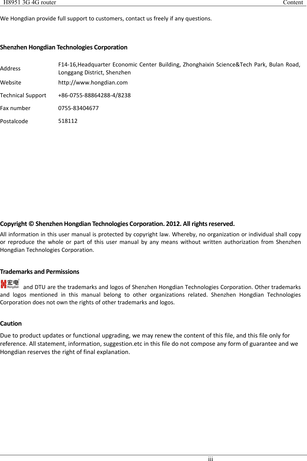
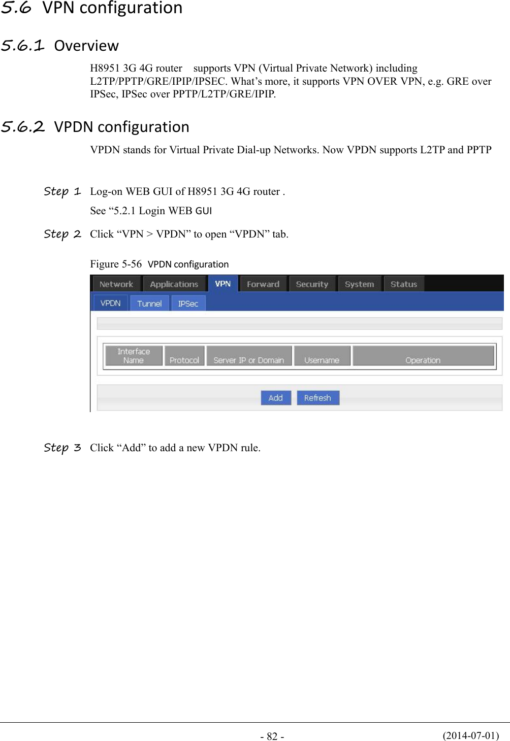
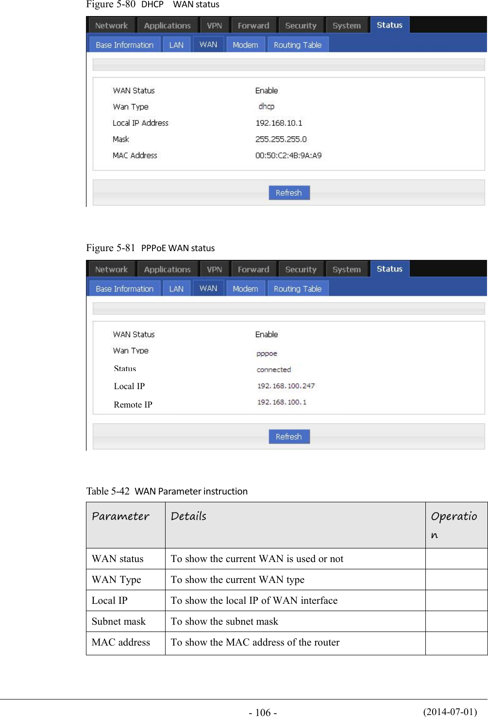
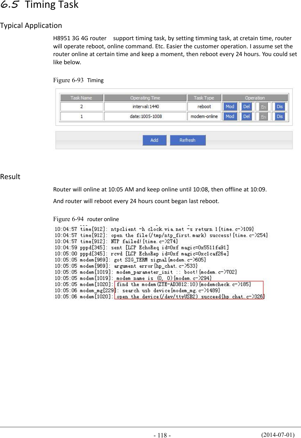
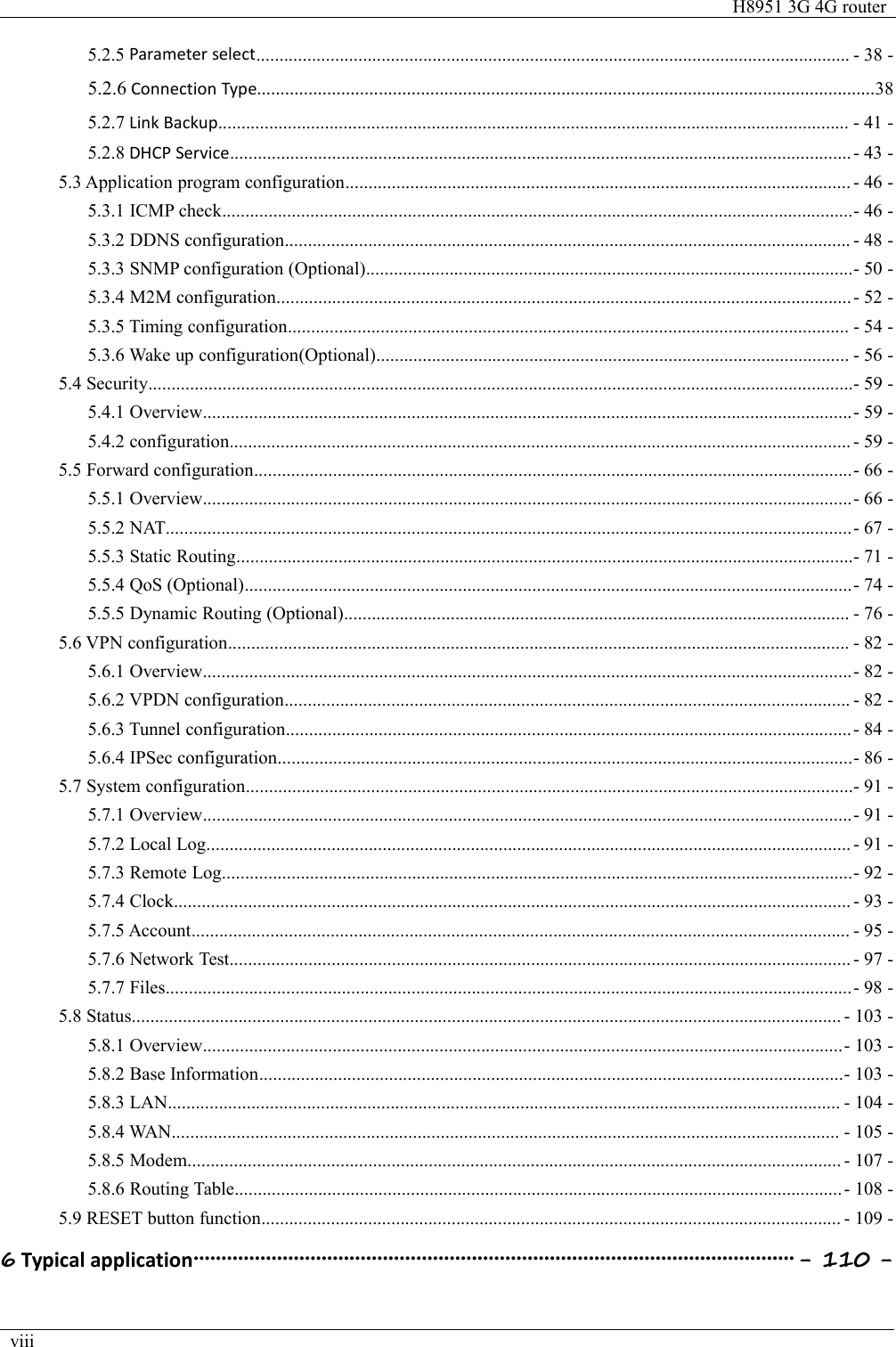
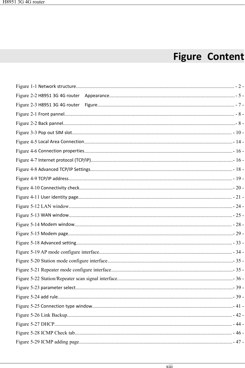
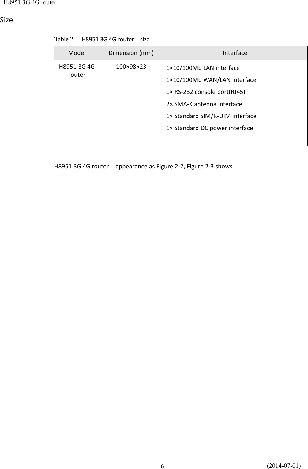
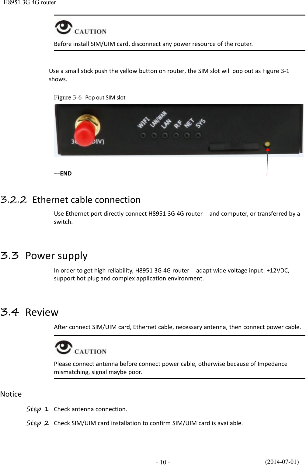
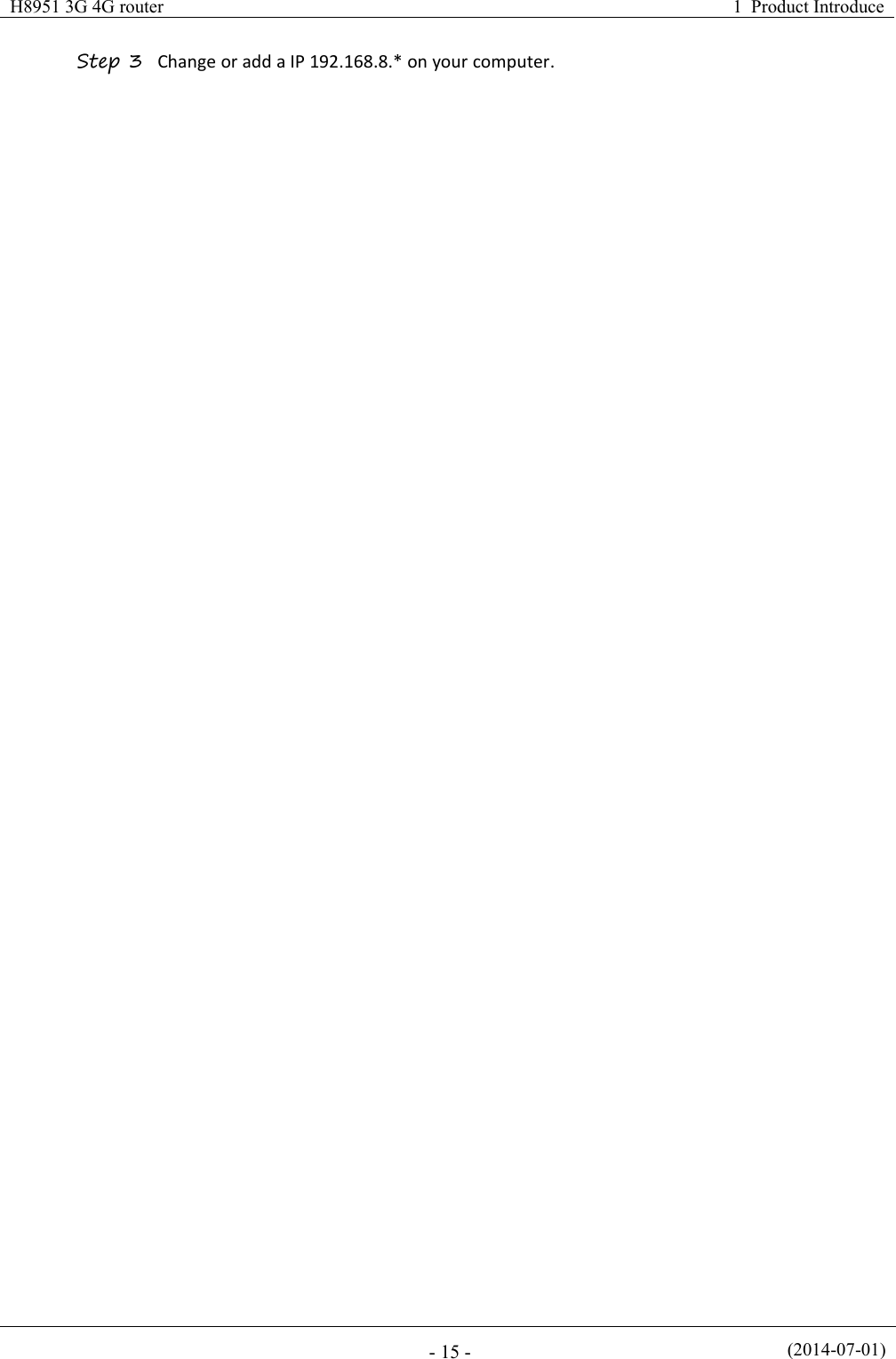
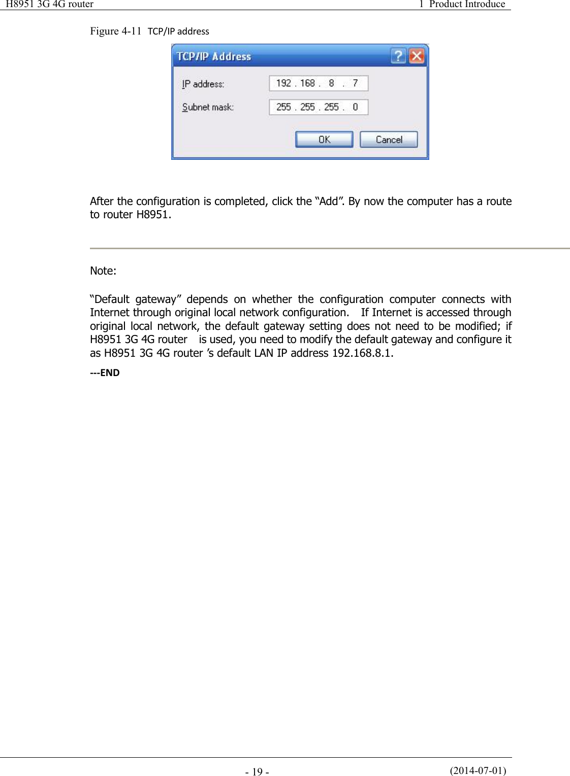
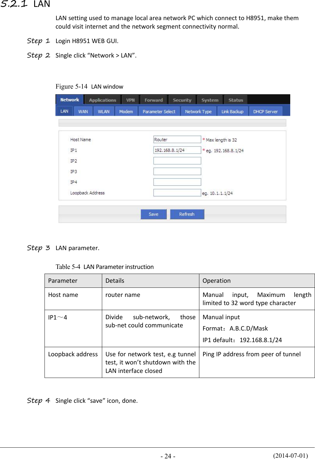
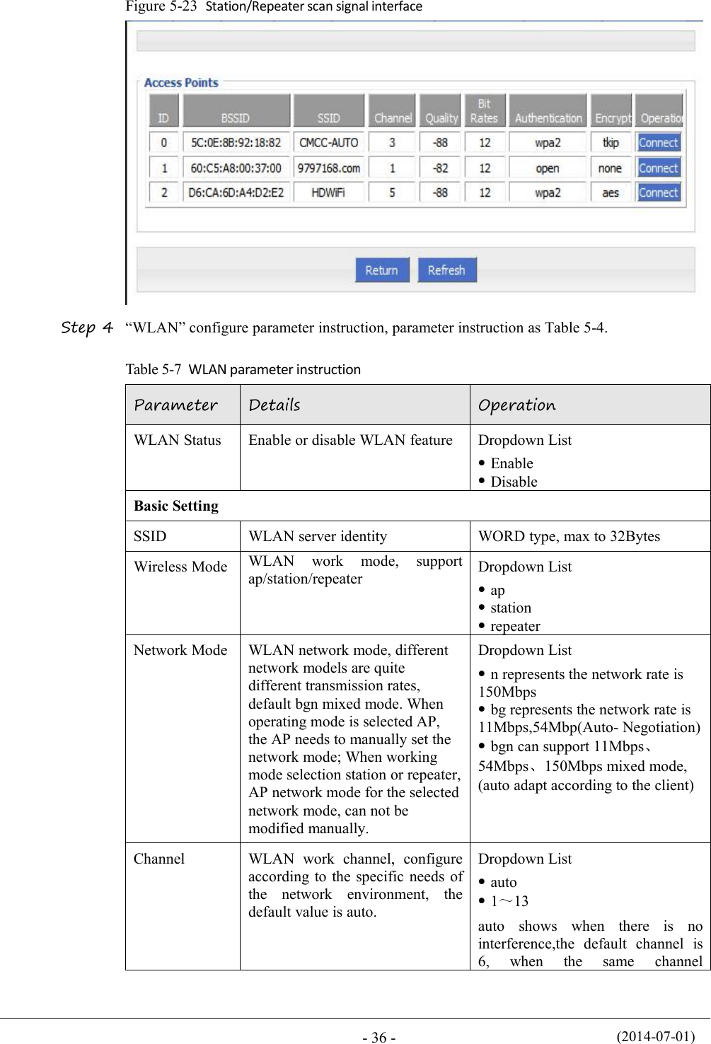
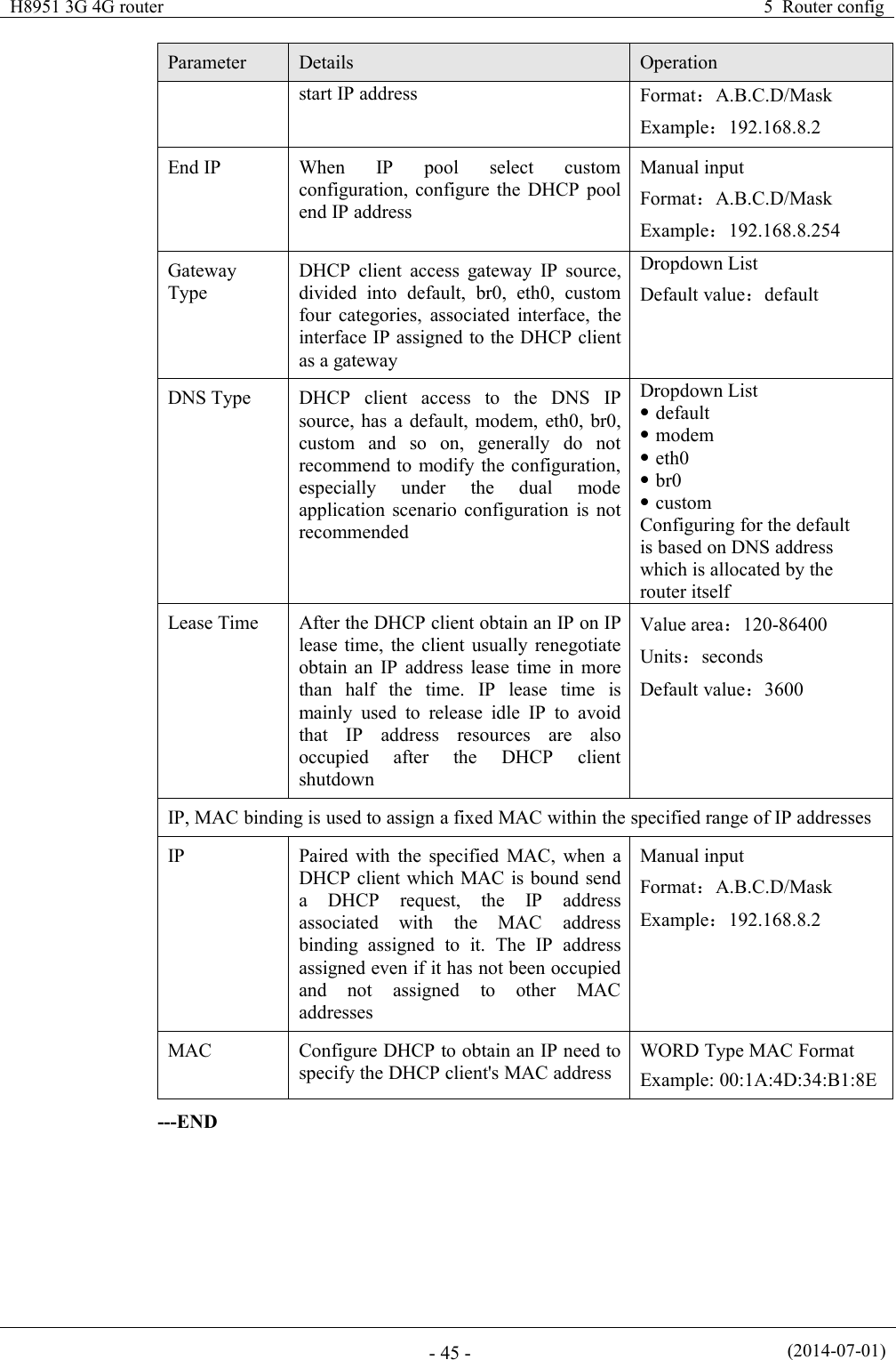
![H8951 3G 4G routerContentvConventionsSymbol ConventionsThe symbols that may be found in this document are defined as follows.SymbolDescriptionIndicates a potentially hazardous situation, which if not avoided,could result in equipment damage, data loss, performancedegradation, or unexpected results.Indicates a tip that may help you address a problem or save yourtime.Provides additional information to emphasize or supplementimportant points of the main text.Command ConventionsConventionDescriptionBoldfaceThe keywords of a command line are in boldface.ItalicCommand arguments are in italics.[ ]Items (keywords or arguments) in brackets [ ] are optional.{ x | y | ... }Optional items are grouped in braces and separated by vertical ars.One item is selected.[ x | y | ... ]Optional items are grouped in brackets and separated by verticalbars. One item is selected or no item is selected.{ x | y | ... } *Optional items are grouped in braces and separated by vertical ars.A minimum of one item or a maximum of all items can be selected.[ x | y | ... ] *Optional items are grouped in brackets and separated by verticalars. Several items or no item can be selected.&<1-n>The parameter before the & sign can be repeated 1 to n times.#A line starting with the # sign is comments.](https://usermanual.wiki/Hongdian/H8951-LQA/User-Guide-3496698-Page-5.png)
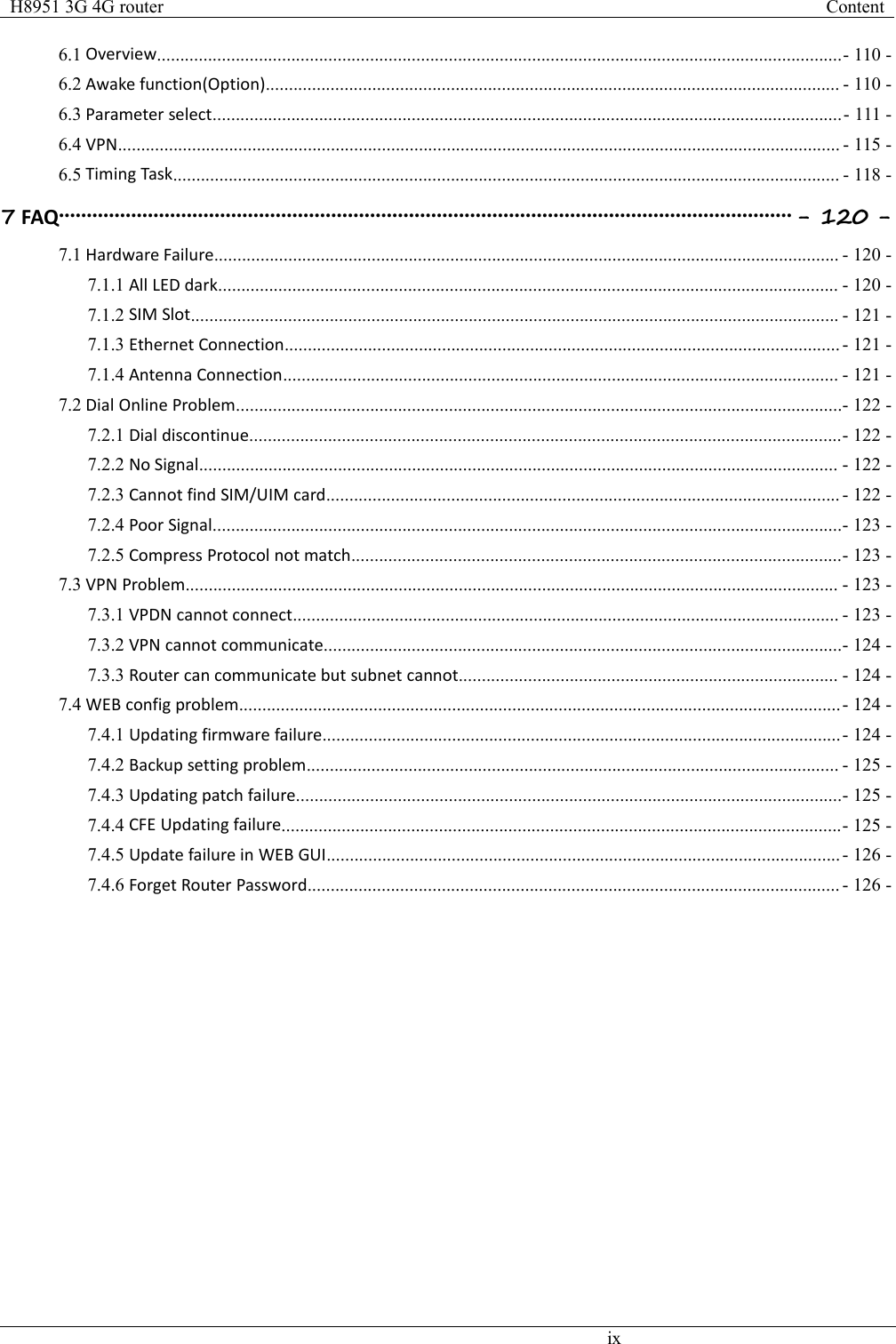
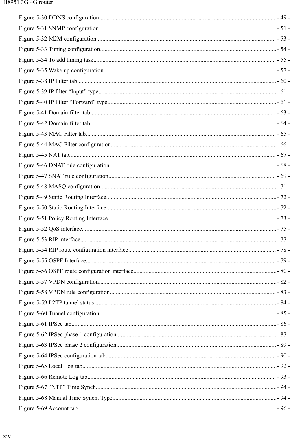
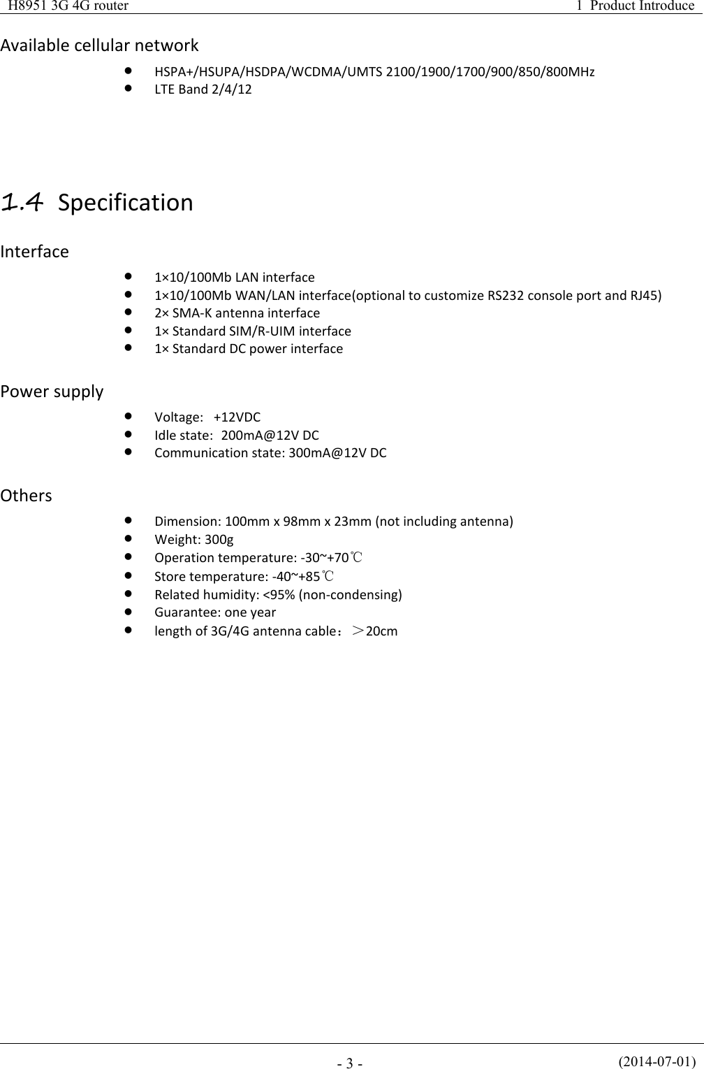
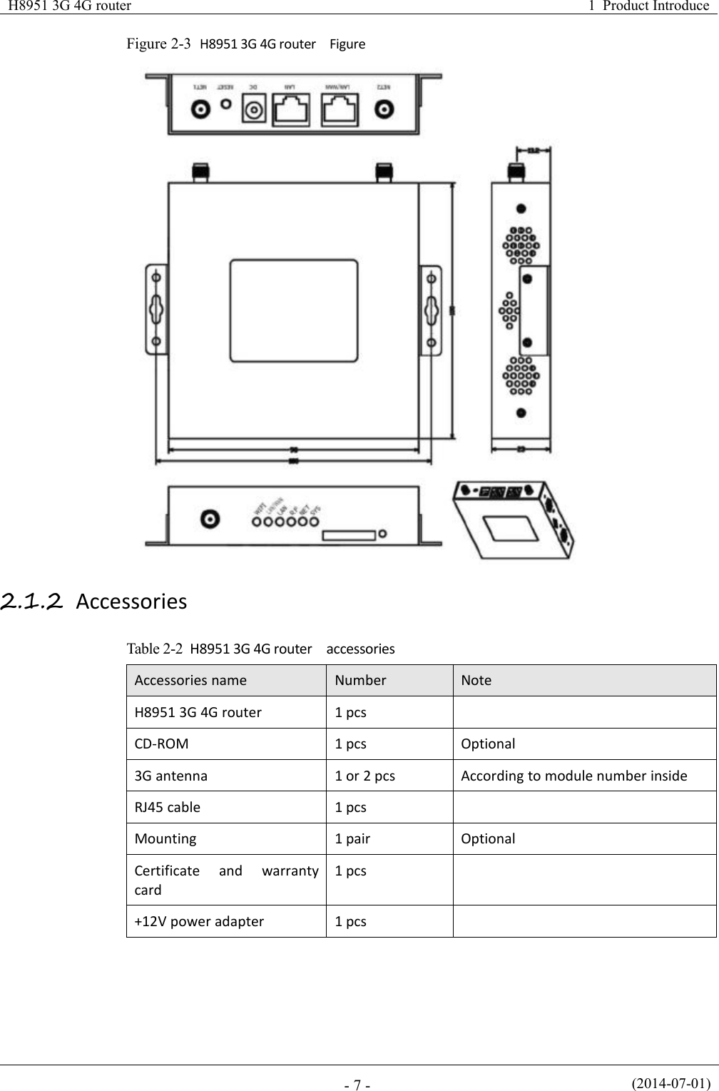
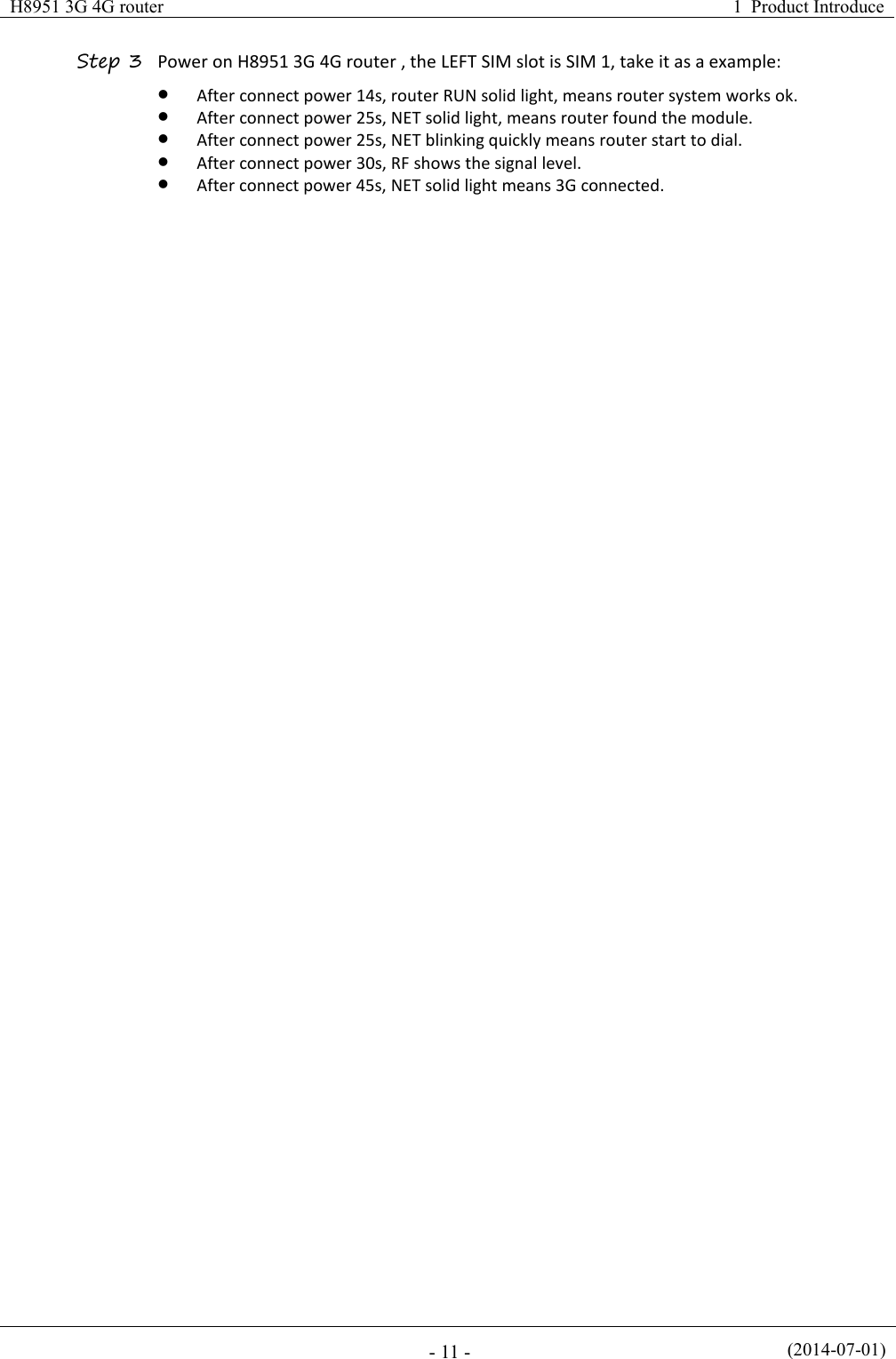
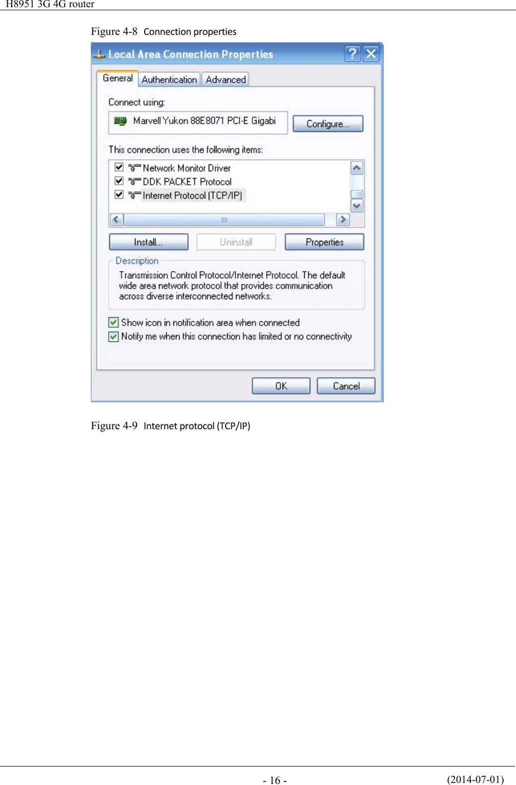
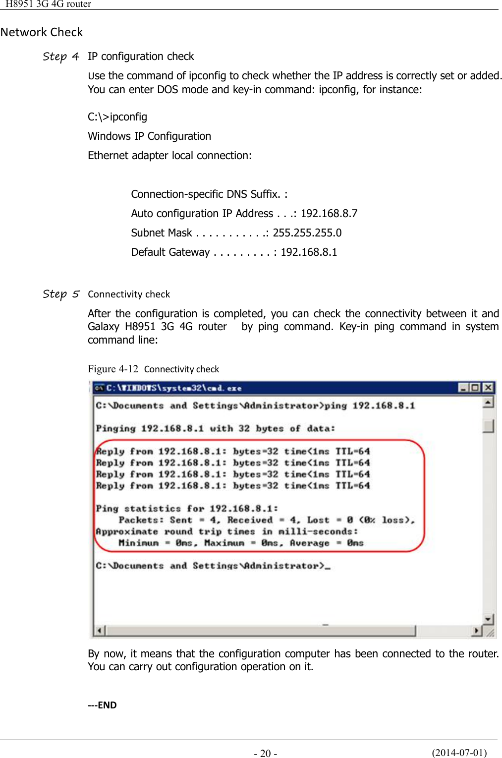
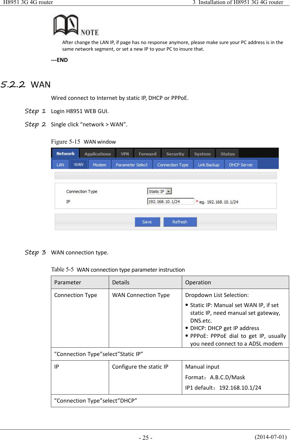
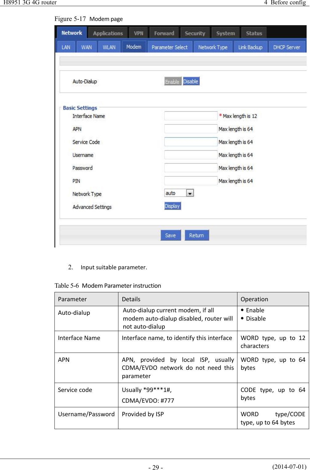
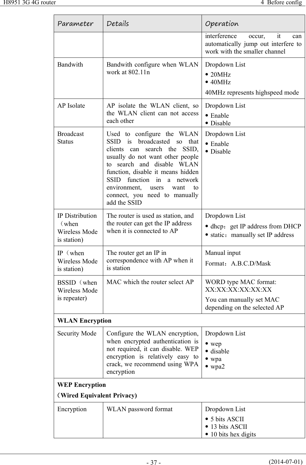
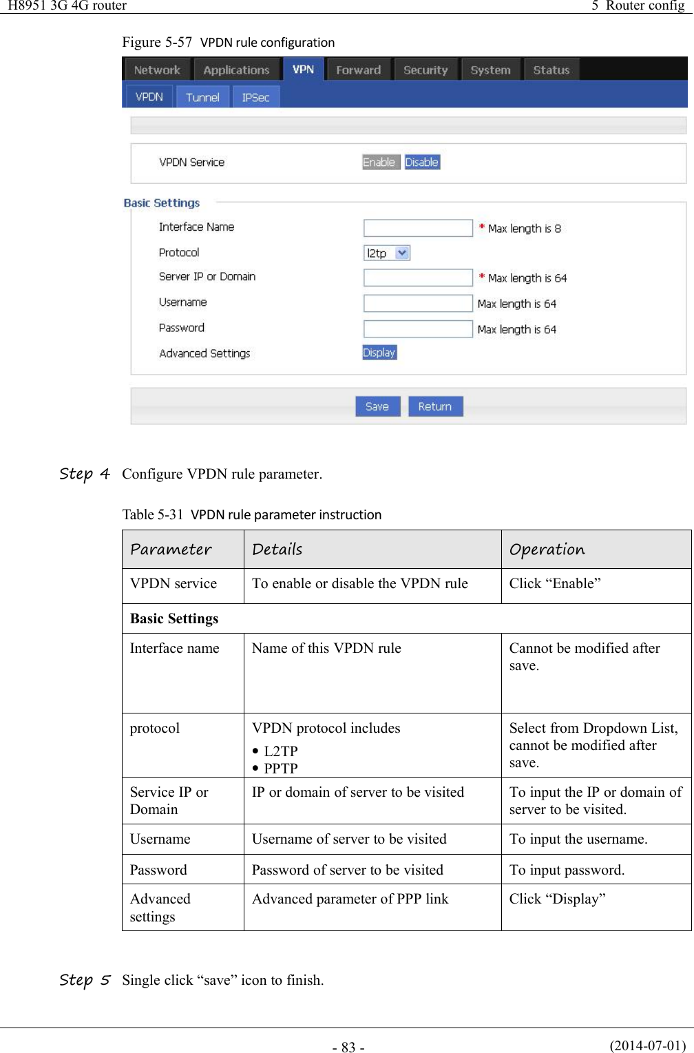
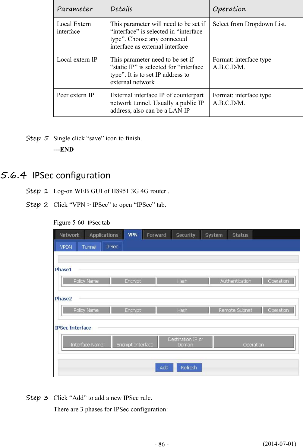
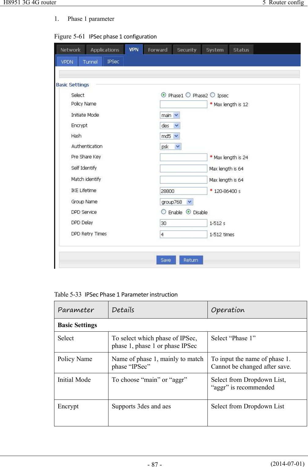
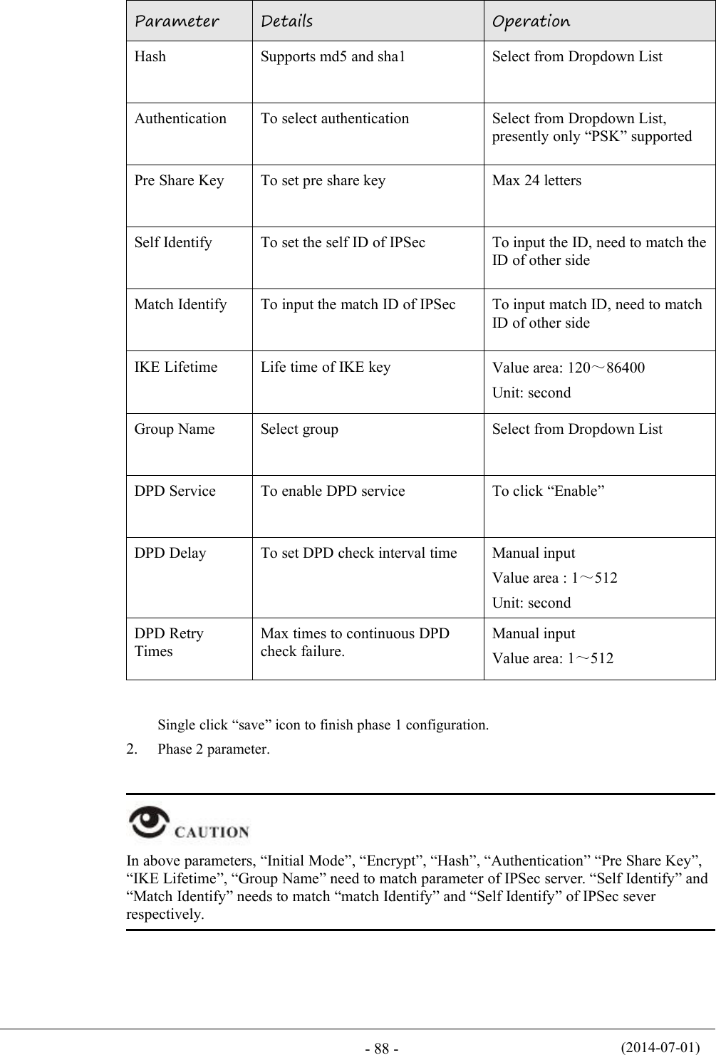
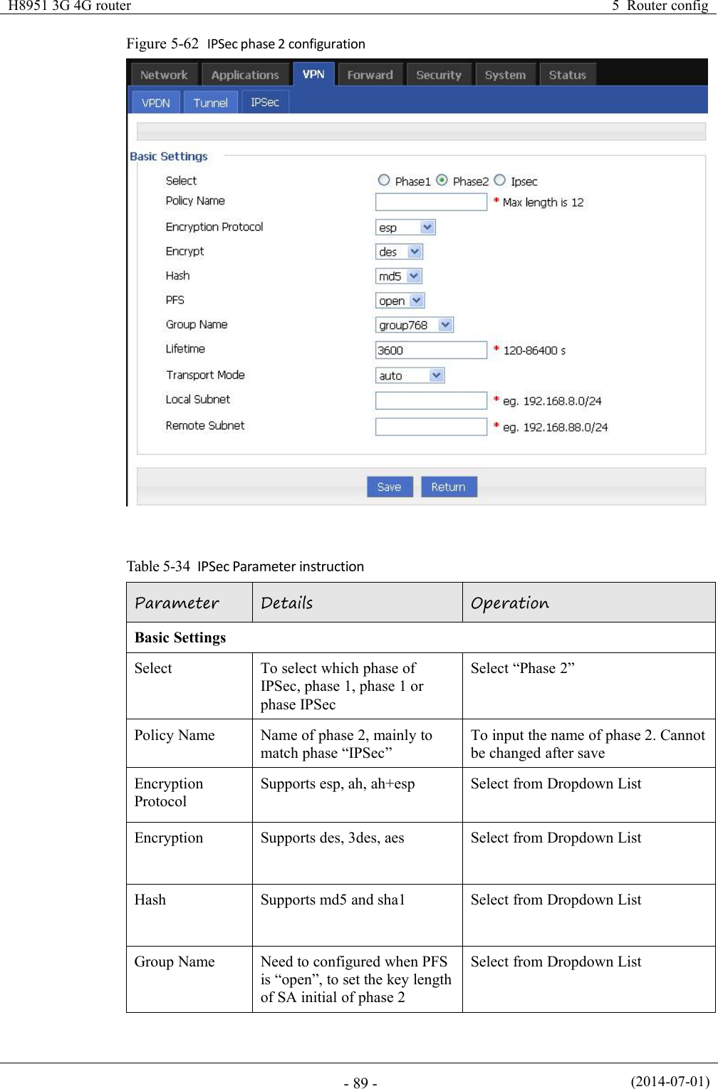
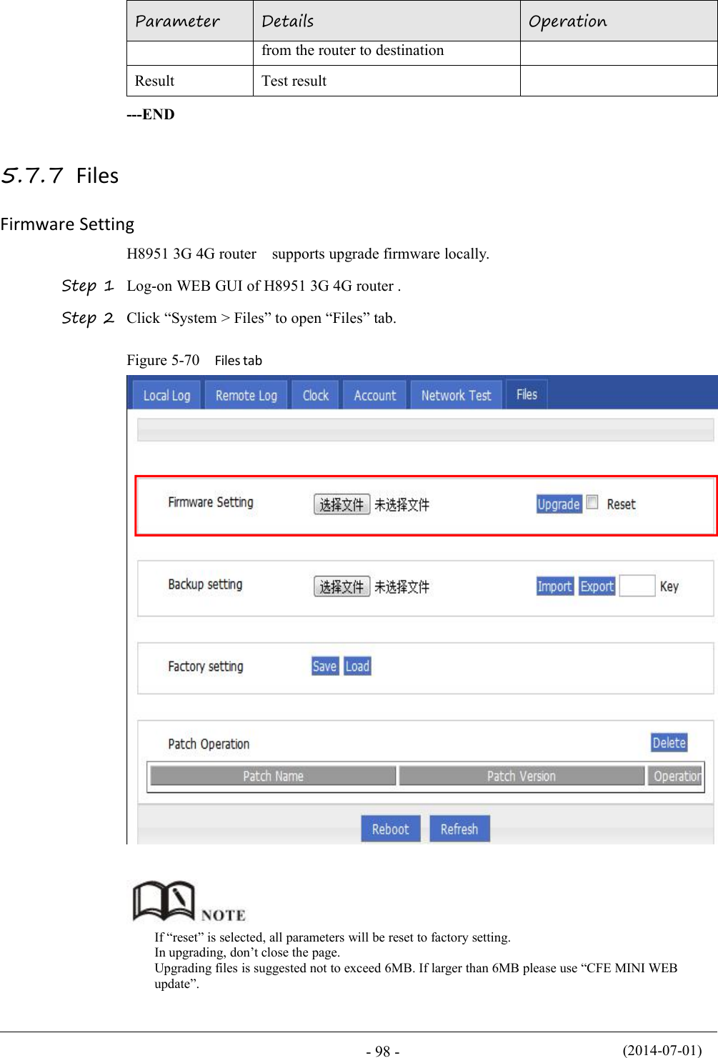
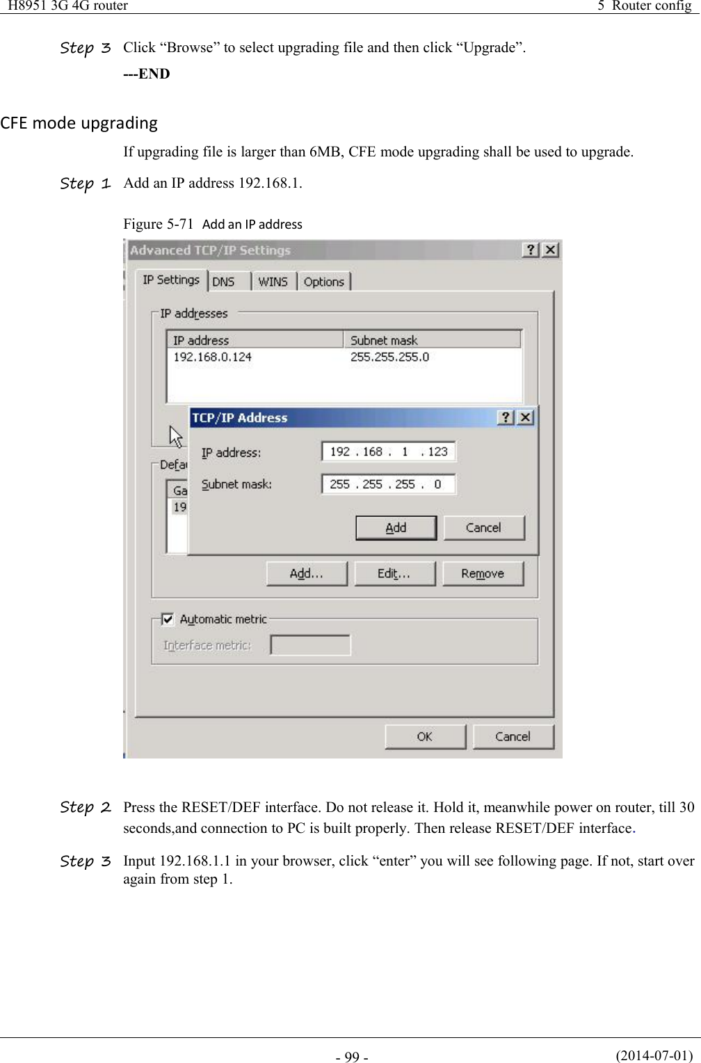
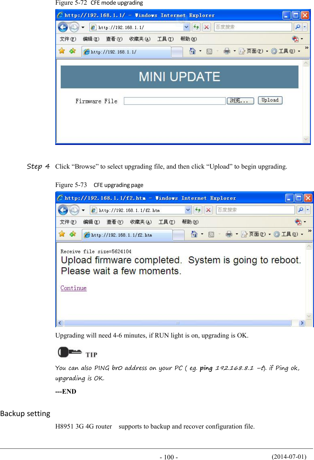
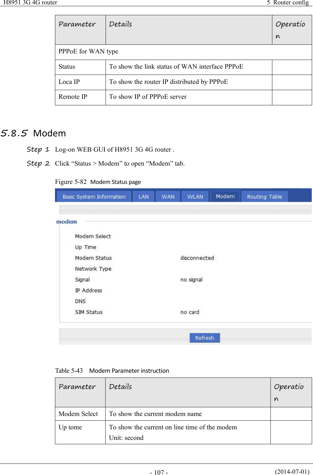
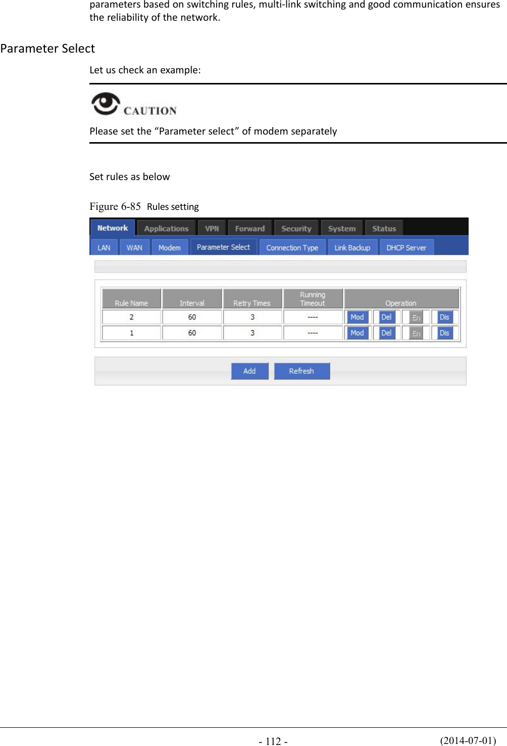
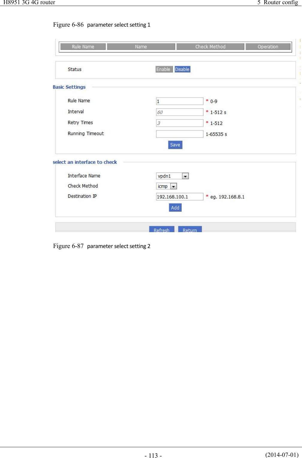
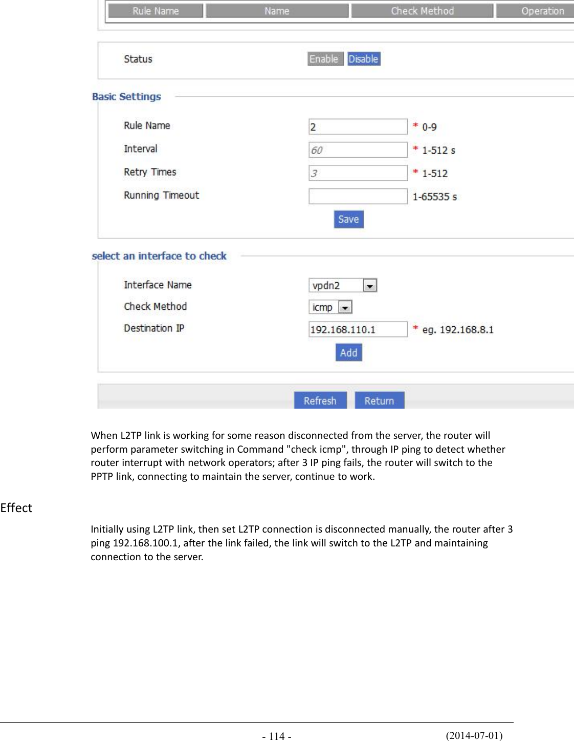
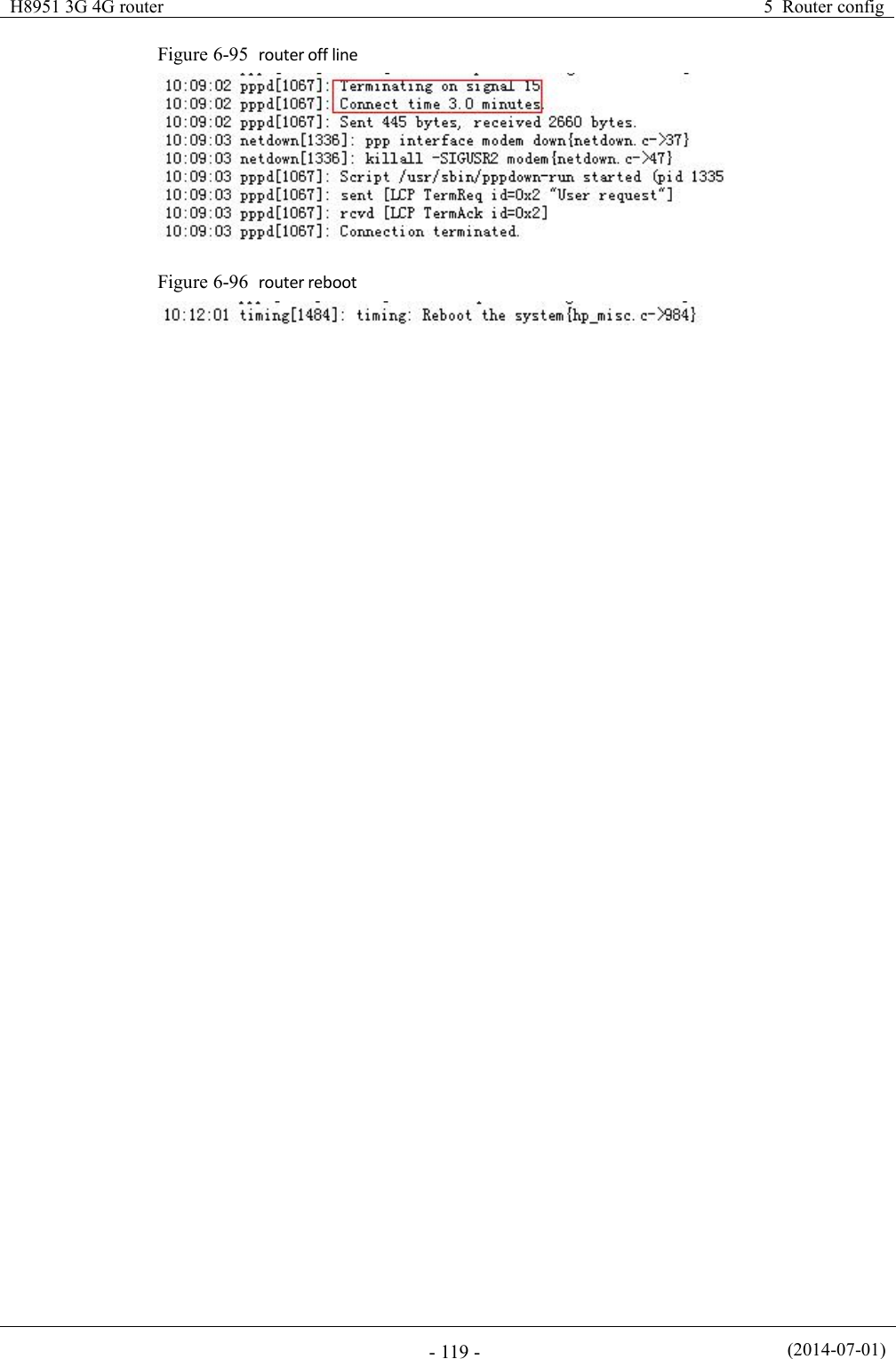
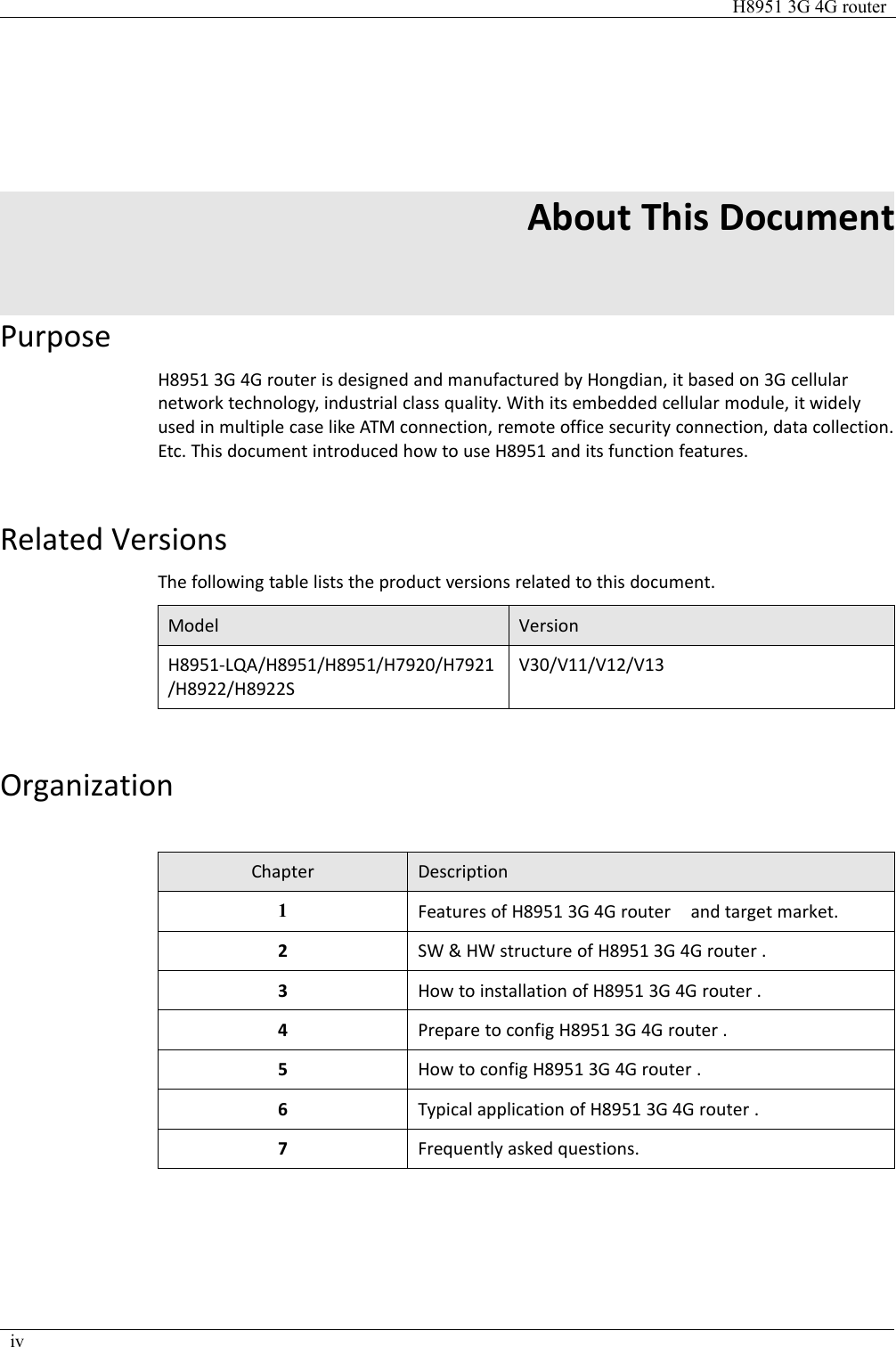
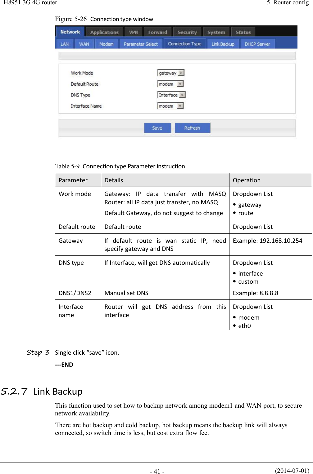
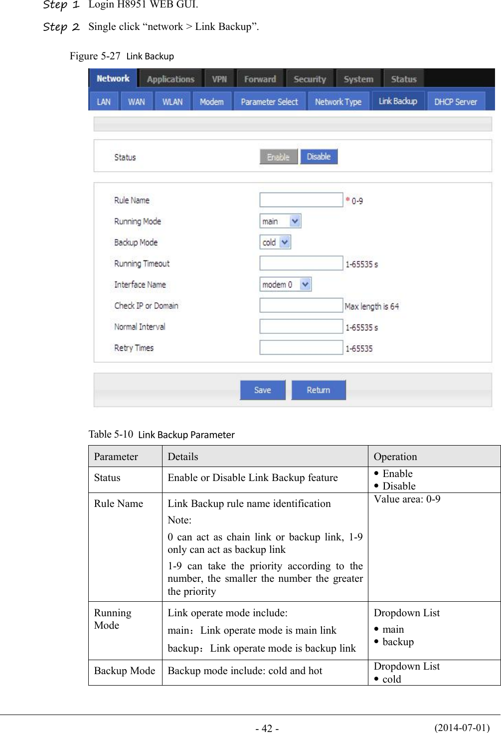
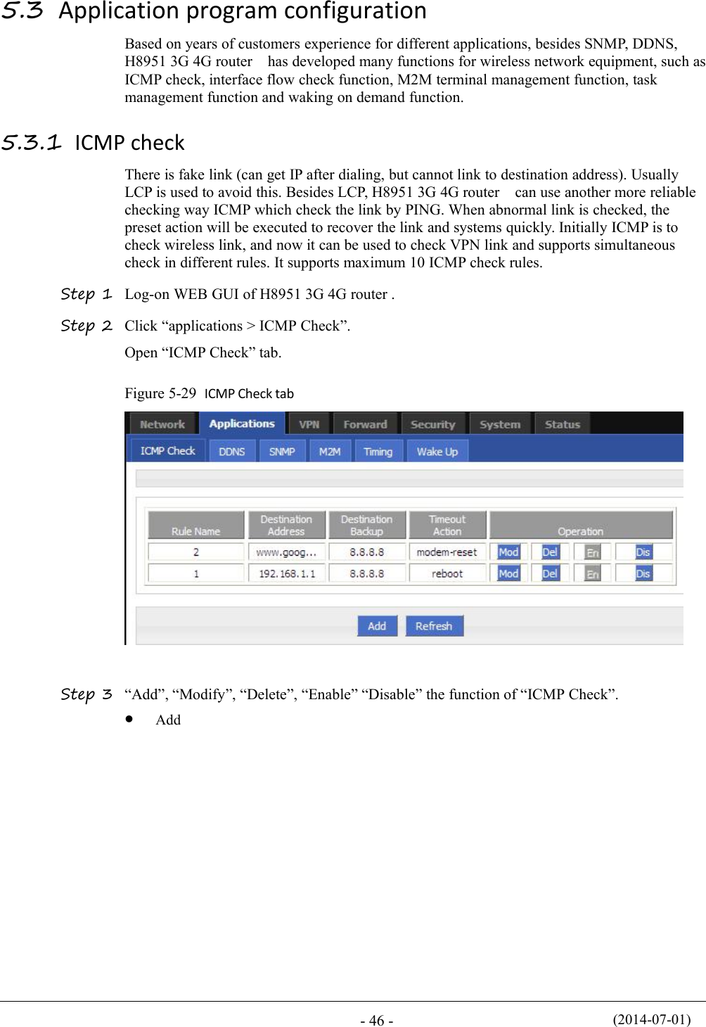
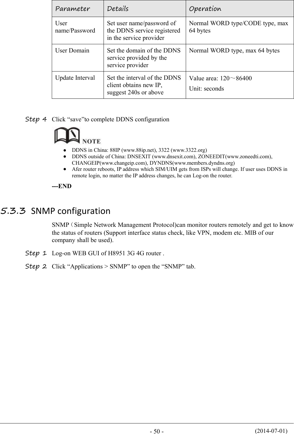
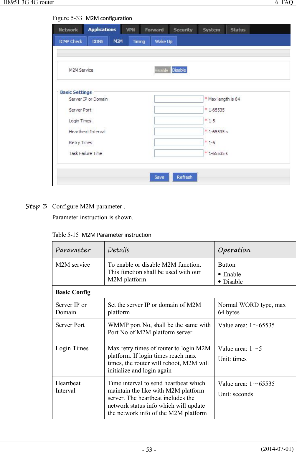
![(2014-07-01)- 40 -ParameterDetailsOperationfailed, next rule start runningFor disabled rule: all related interfacealso disabledBasic settingsRule nameName value decided running orderValue area :[0,9]Interval/RetryTimesCheck interval and retry time, if allcheck failed, switch to next ruleValue area :1~512Units: seconds/timeDefault: 60/3Running timeoutNot available for rule 0This parameter restrict current rulerunning time, when timeout, switchto rule0, if do not set, switch to nextruleValue area :1~65535Units: secondsSelect a interface to checkInterface nameSet related modem interfaceDropdown List to choose,current available optionwill show belowCheck methodIf state, router will check link stateIf ICMP, router will ping the ICMP IPaddress to checkDropdown ListstateicmpThis function is control how the router online & offline, and use which modem to online.Please notice timing task is execute a operation and keep the status, but parameterselect only execute a operation. So they do not conflict.But Link backup function may conflict with parameter select function , if you set both,final running result may not as you presume.---END5.2.6 Connection typeStep 1 Login H8951 WEB GUI.Step 2 Single click “Network > Connection type”.](https://usermanual.wiki/Hongdian/H8951-LQA/User-Guide-3496698-Page-54.png)
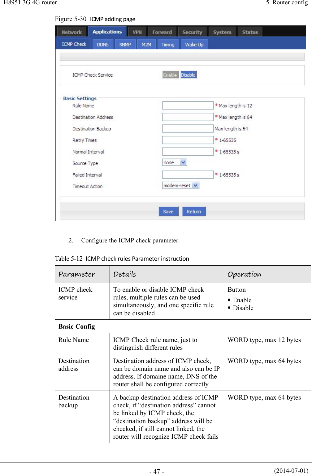
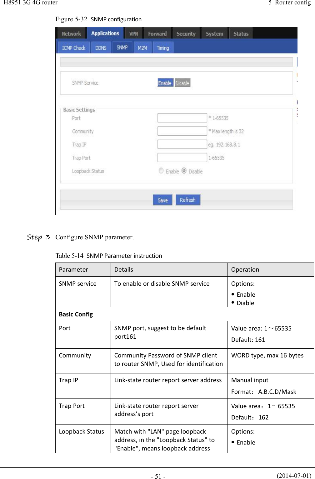
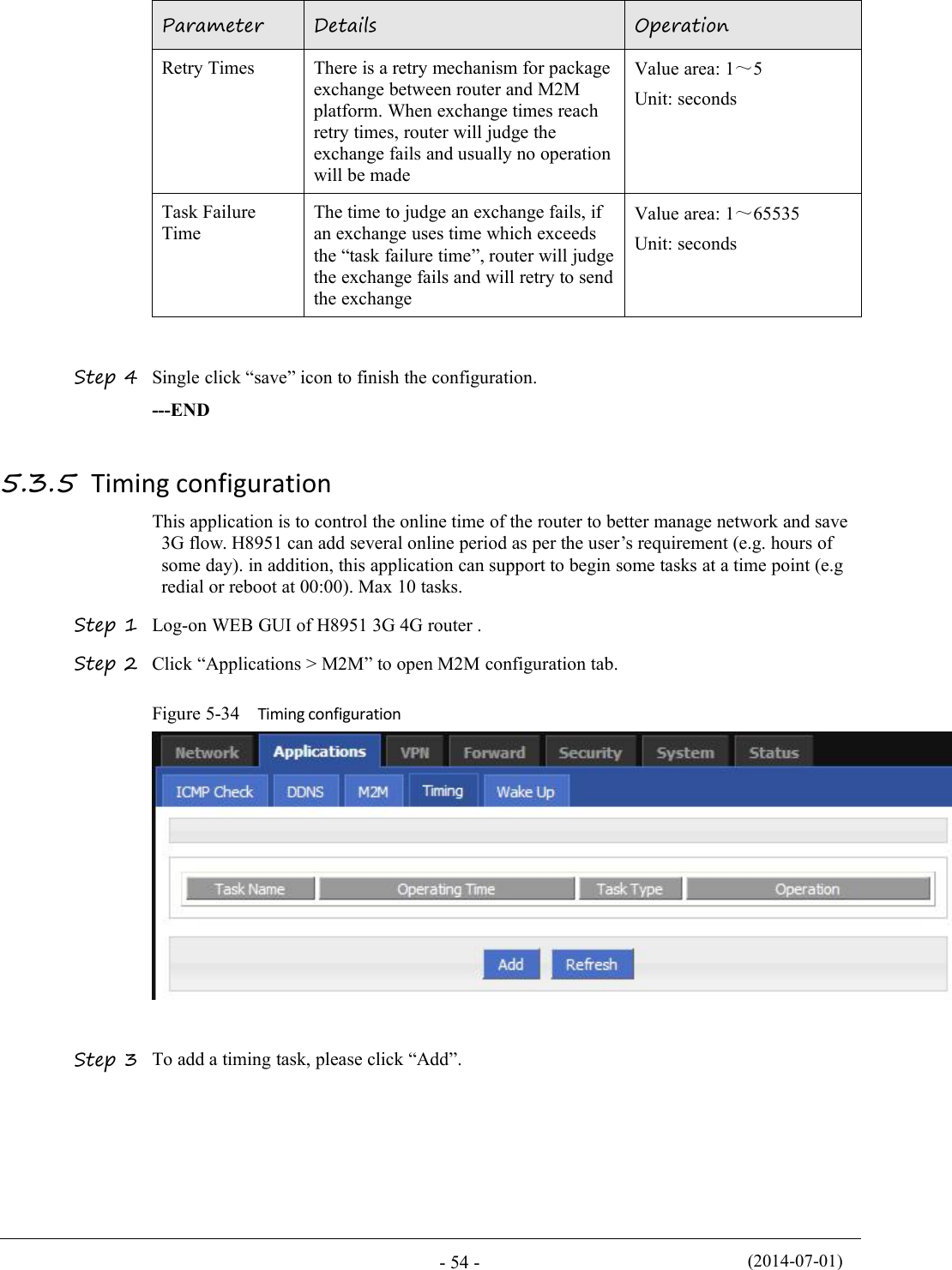
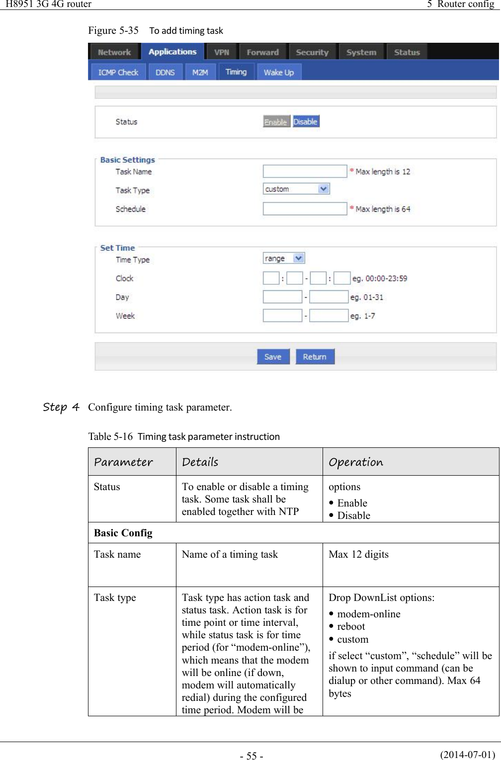
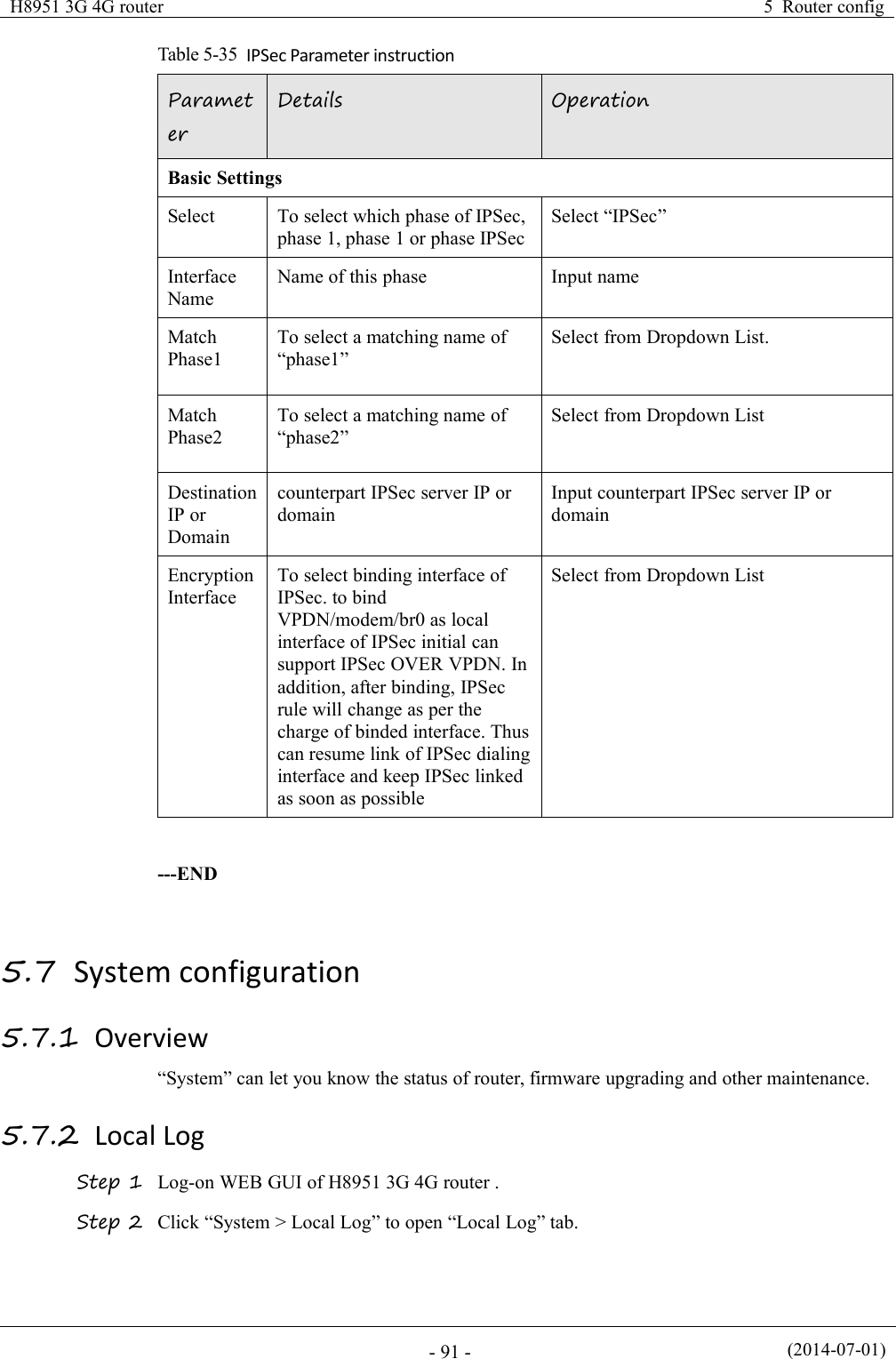
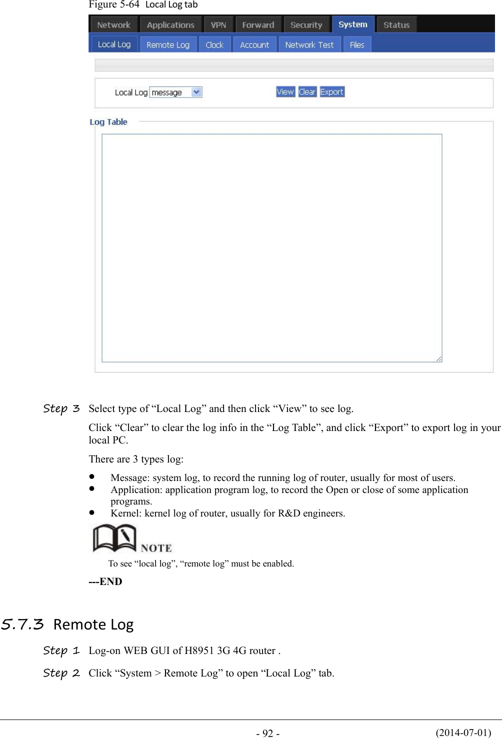
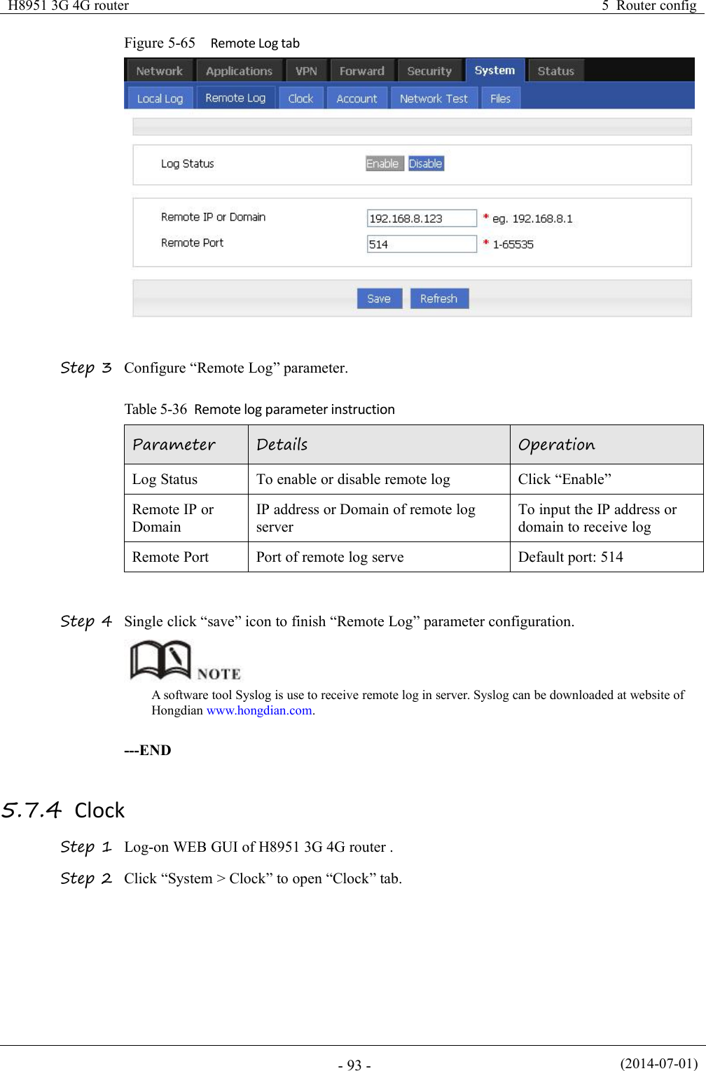
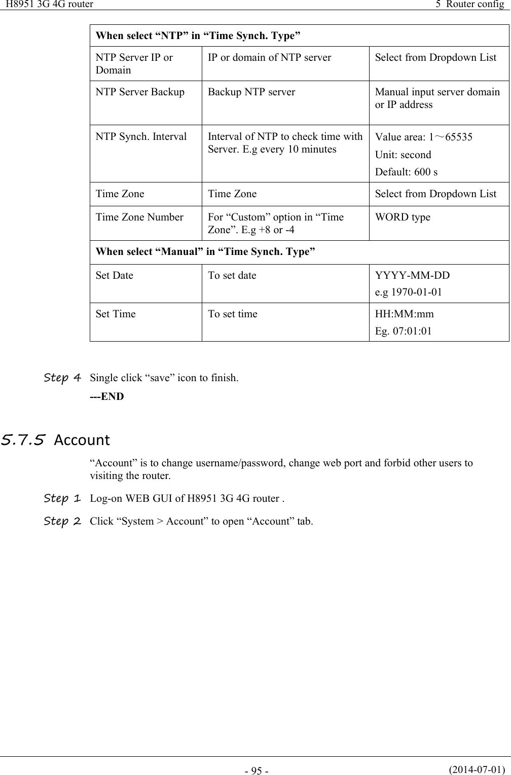
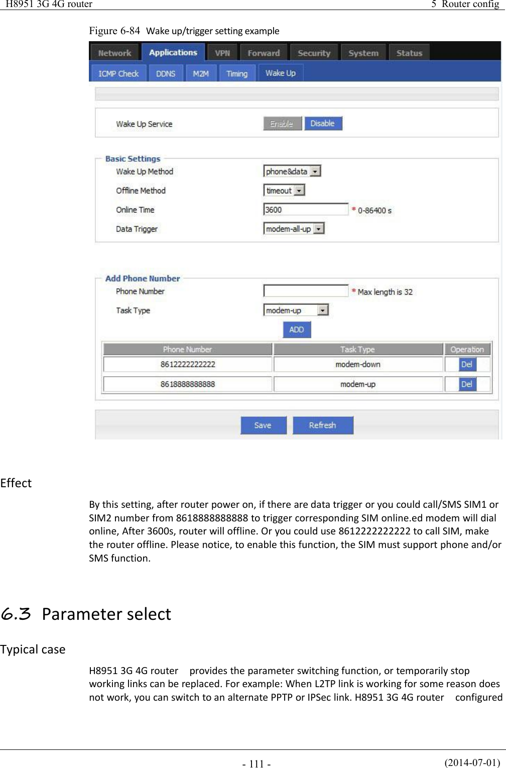
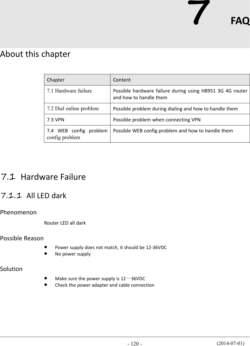
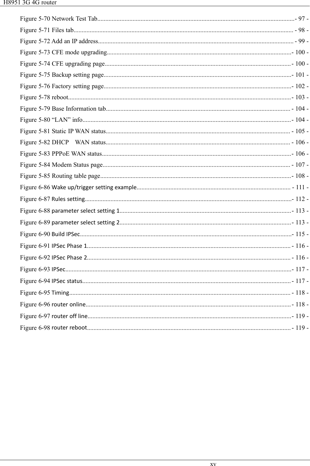
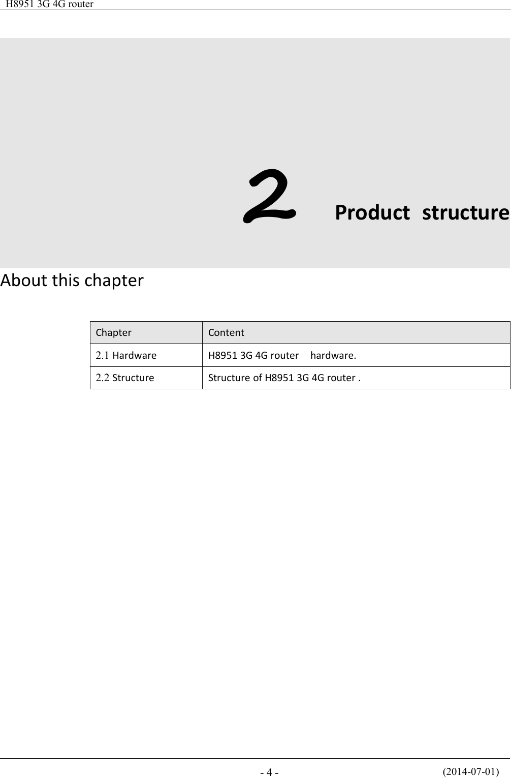
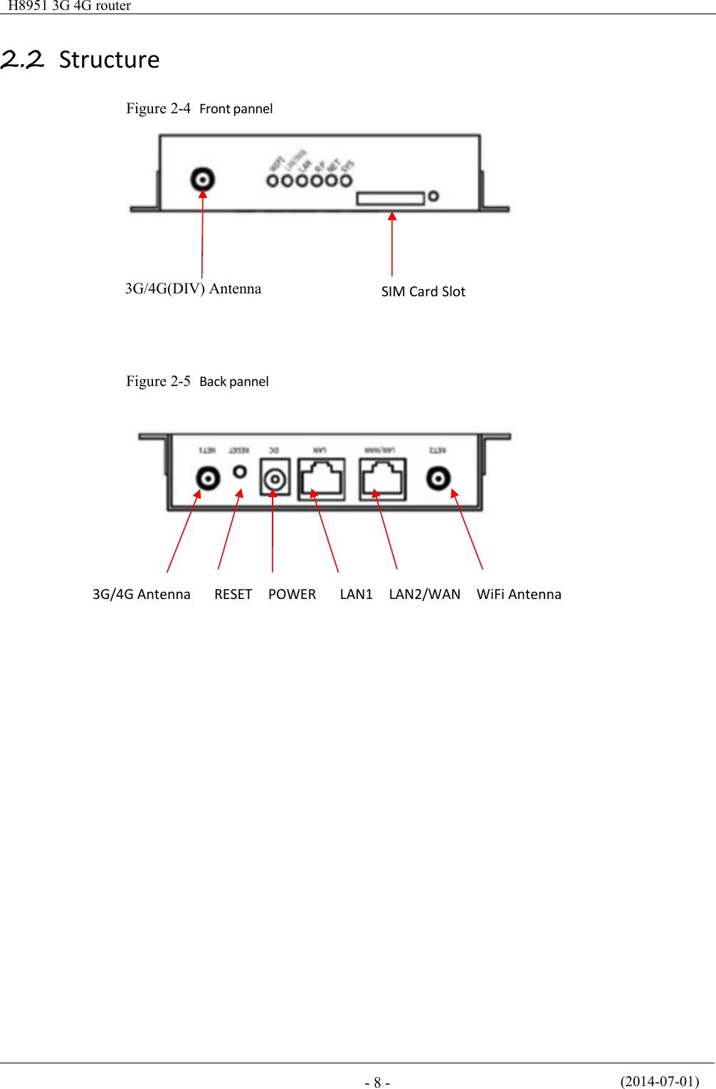
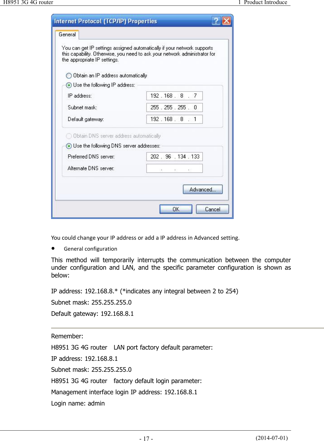
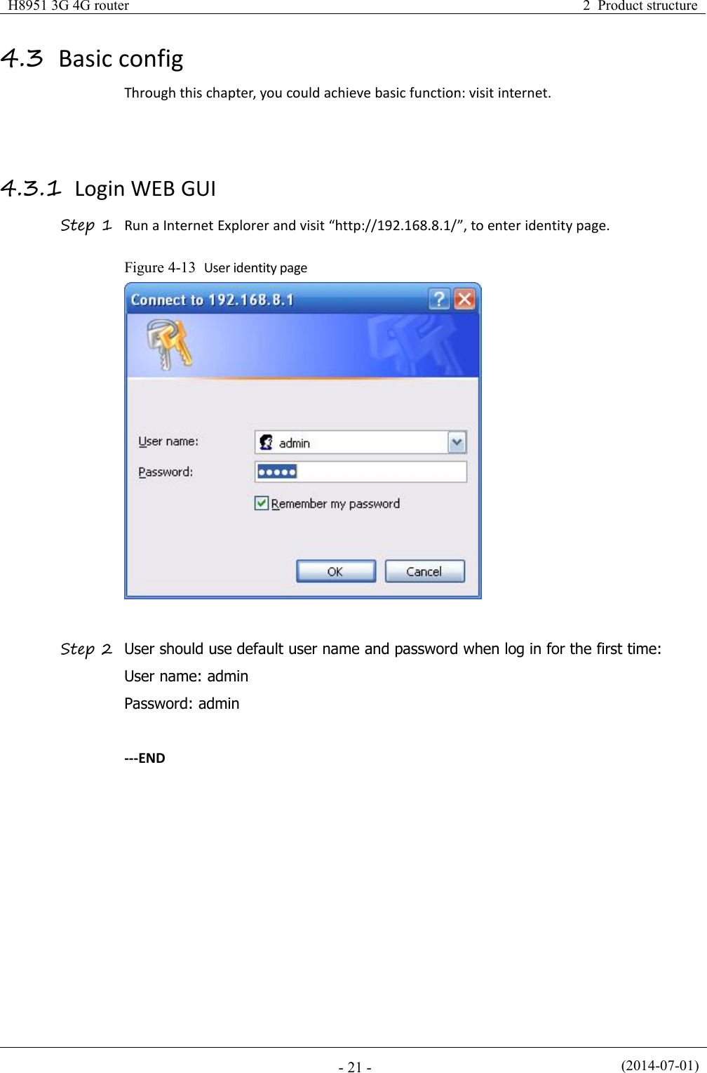
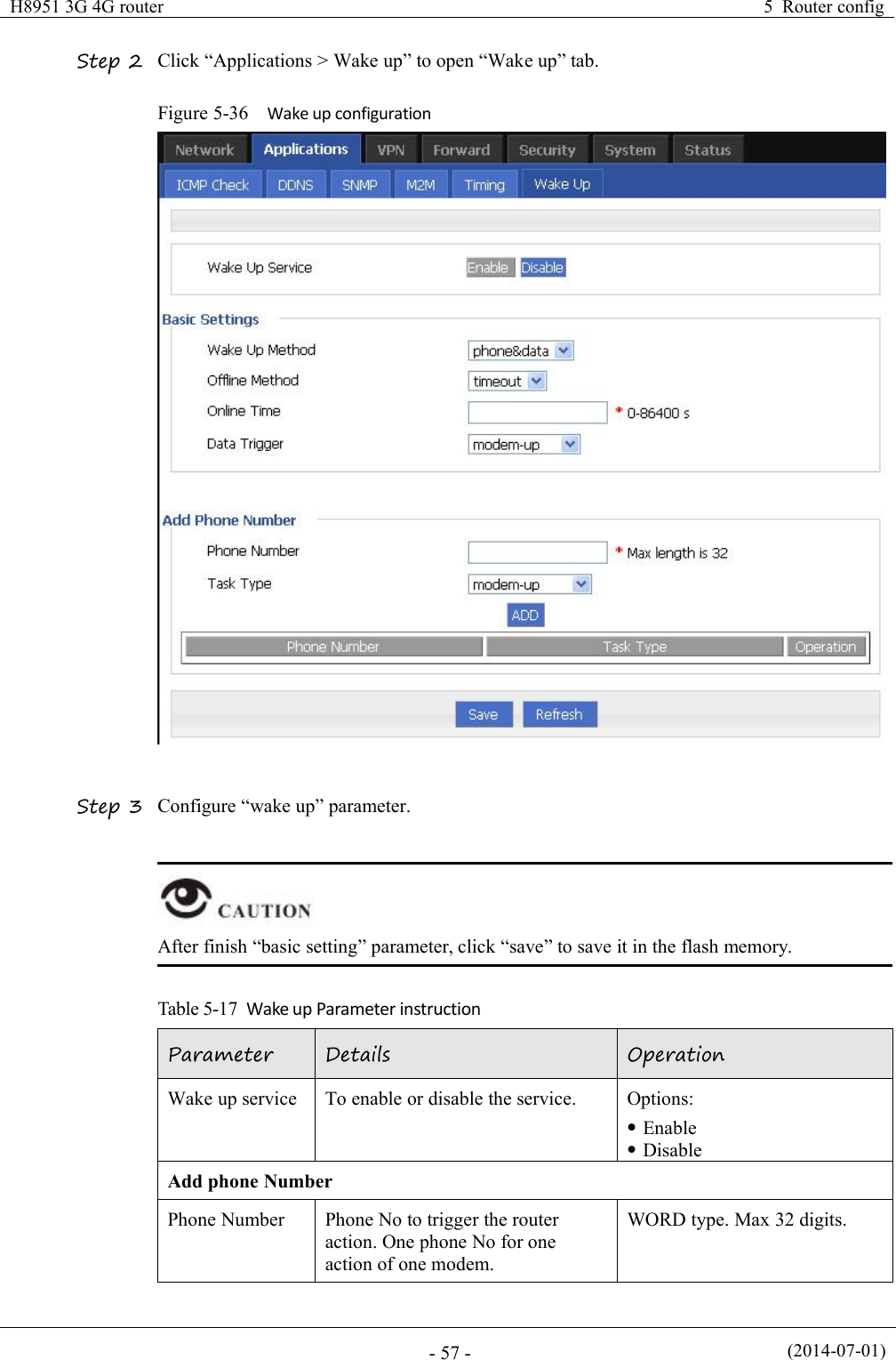
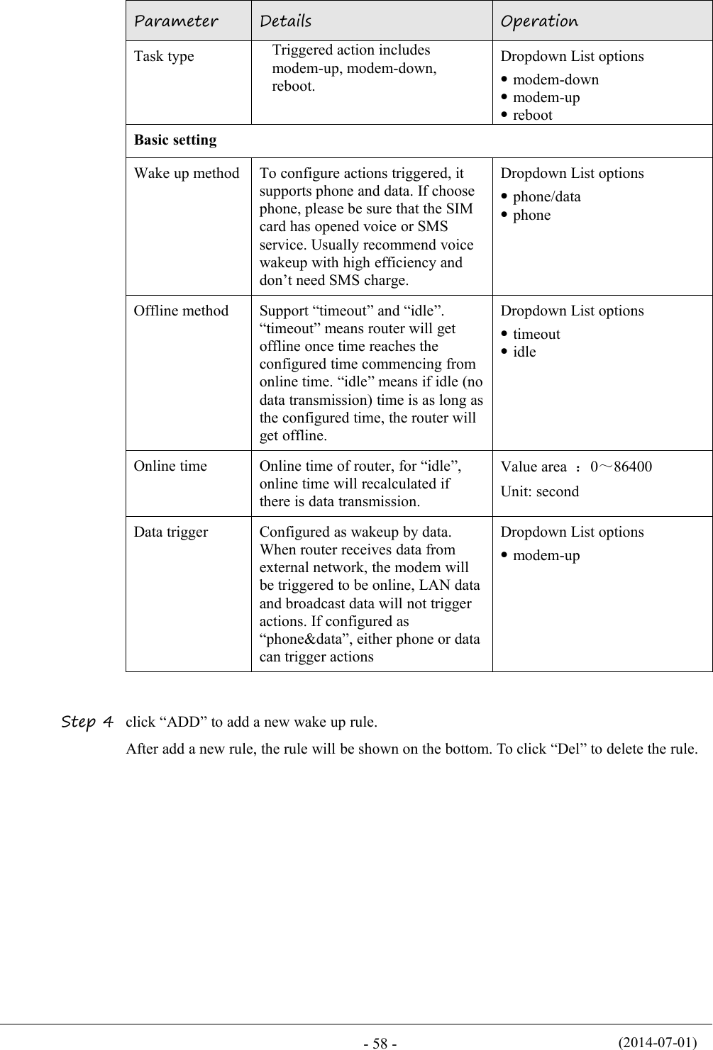
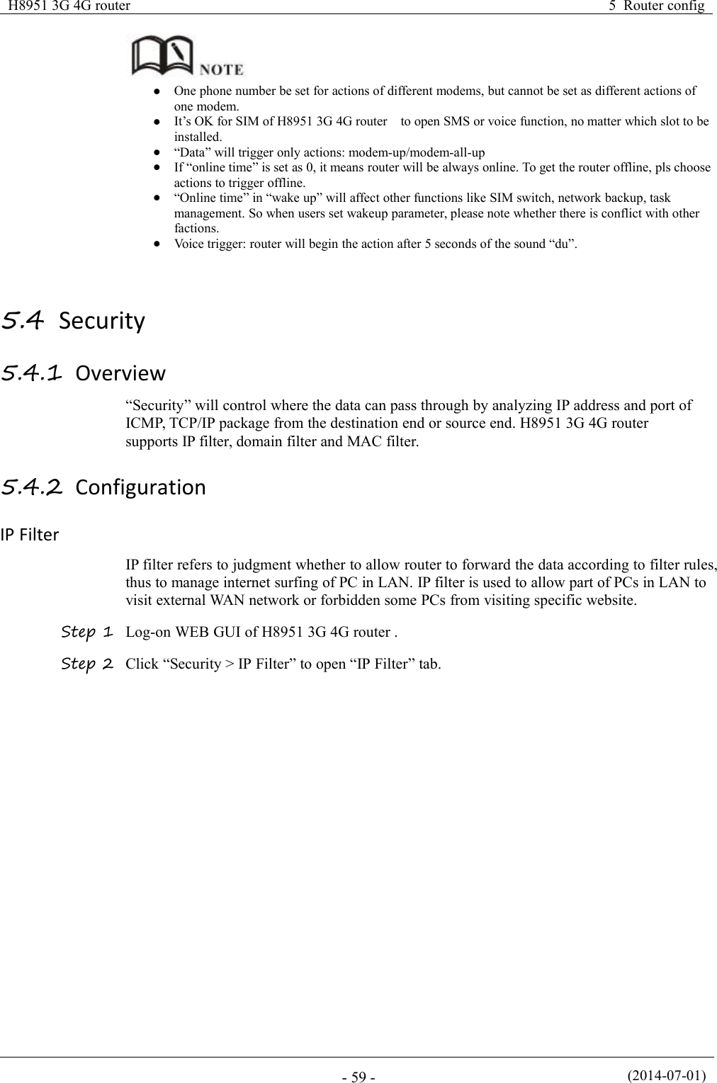
![(2014-07-01)- 56 -ParameterDetailsOperationoffline (no dialing) for othertimeScheduleThis is linux shell command.Usually suggested not to useit. In case of need, pleasecontact our technical engineersWORD type. Max 64 digitsSet timeTime typeRange or interval for statustask or action taskDropdown List options:rangeintervalWhen “time type” select “range”ClockTo input hour and minute.When beginning and end hourand minute are the same, itmeans a time point for actiontaskValue area: [00:00,23:59]Format: HH:mm-HH:mmDayDays in a month for taskValue area: [01,31]Format: XX-XXWeekDays in a week for task. When“day” and “week” are bothinput, it means only if bothconditions meet, the task willbeginValue area: [1,7]Format: X-X1 for MondayWhen “time type” select “Interval”IntervalTime interval for action taskValue area: 1~65535Unit: minutesStep 5 Single click “save” icon to finish “Timing” configurationWhen “range” is selected, NTP shall be enabled . when “interval” is selected, no suchrequirement. For “NTP” configuration---END5.3.6 Wake up configuration(Optional)3G fee is mostly based on flow. H8951 3G 4G router can get on/off line on demand. Itsupports on/offline or reboot triggered by voice, SMS or data. It supports max 10 cellphoneNos.Step 1 Log-on WEB GUI of H8951 3G 4G router .](https://usermanual.wiki/Hongdian/H8951-LQA/User-Guide-3496698-Page-70.png)
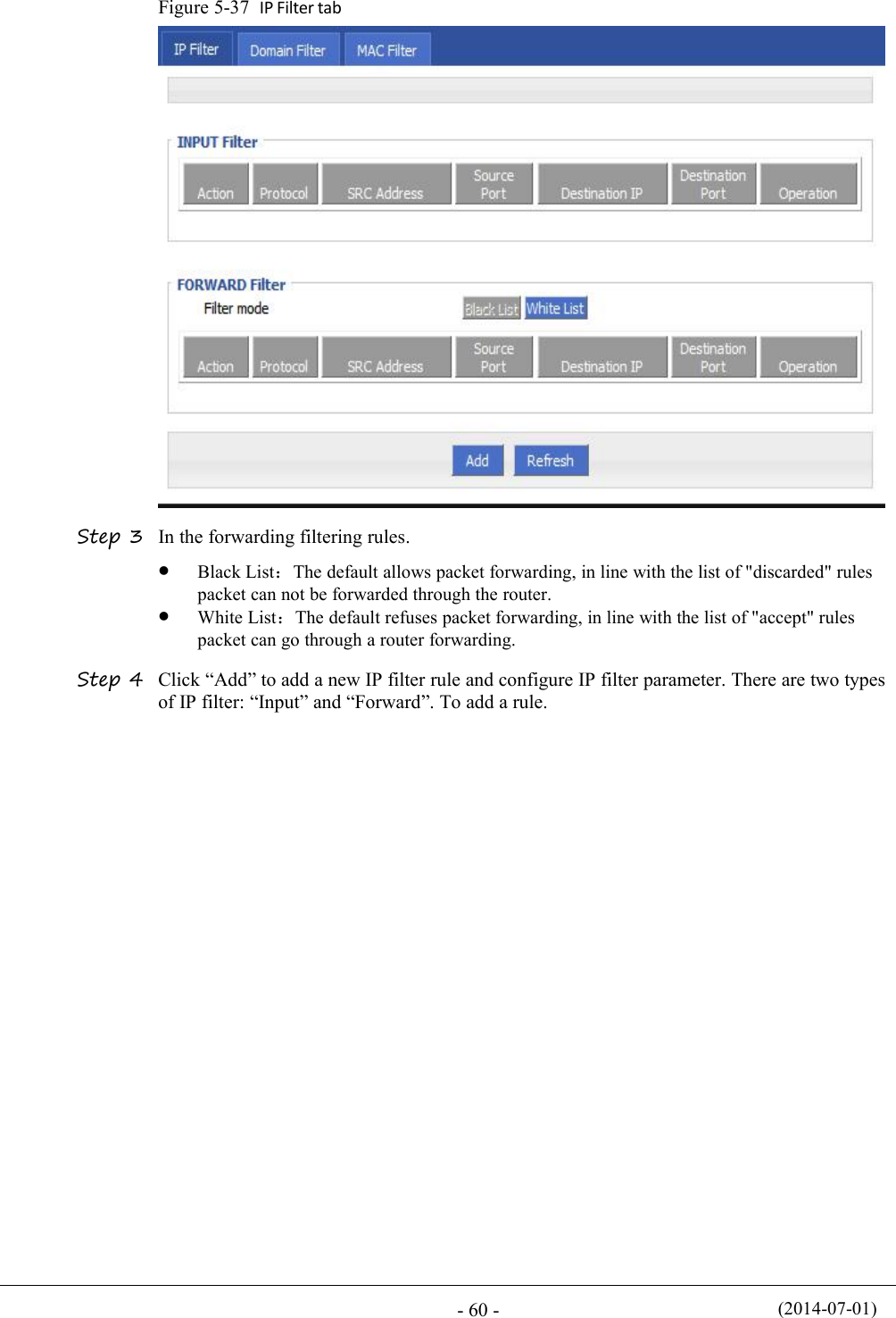
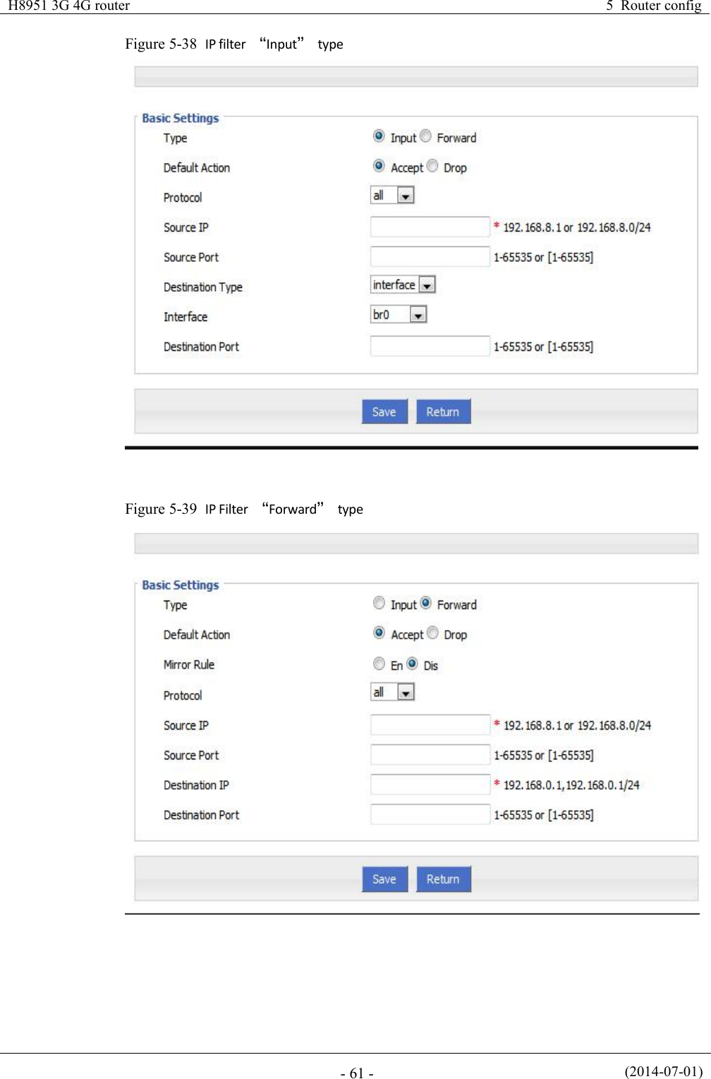
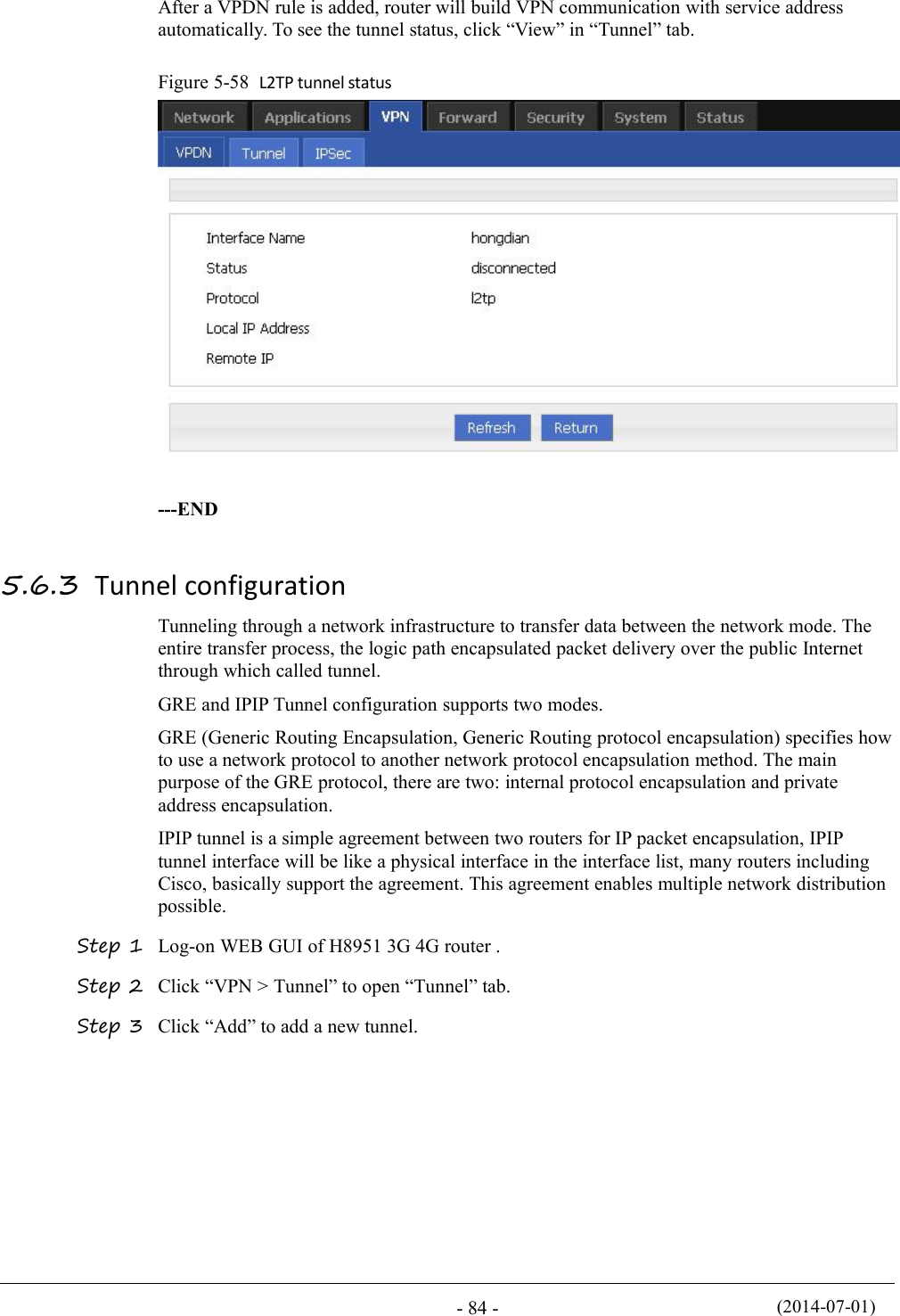
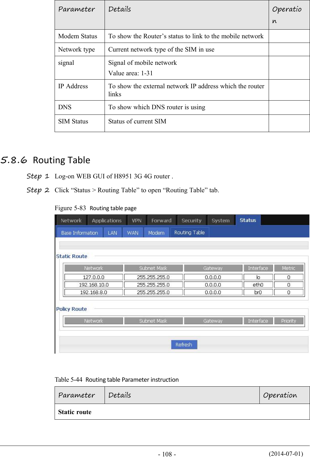
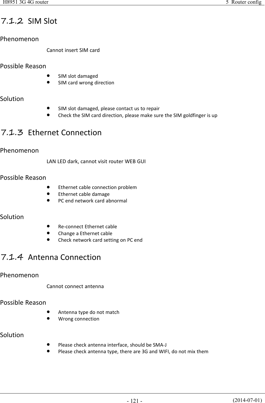
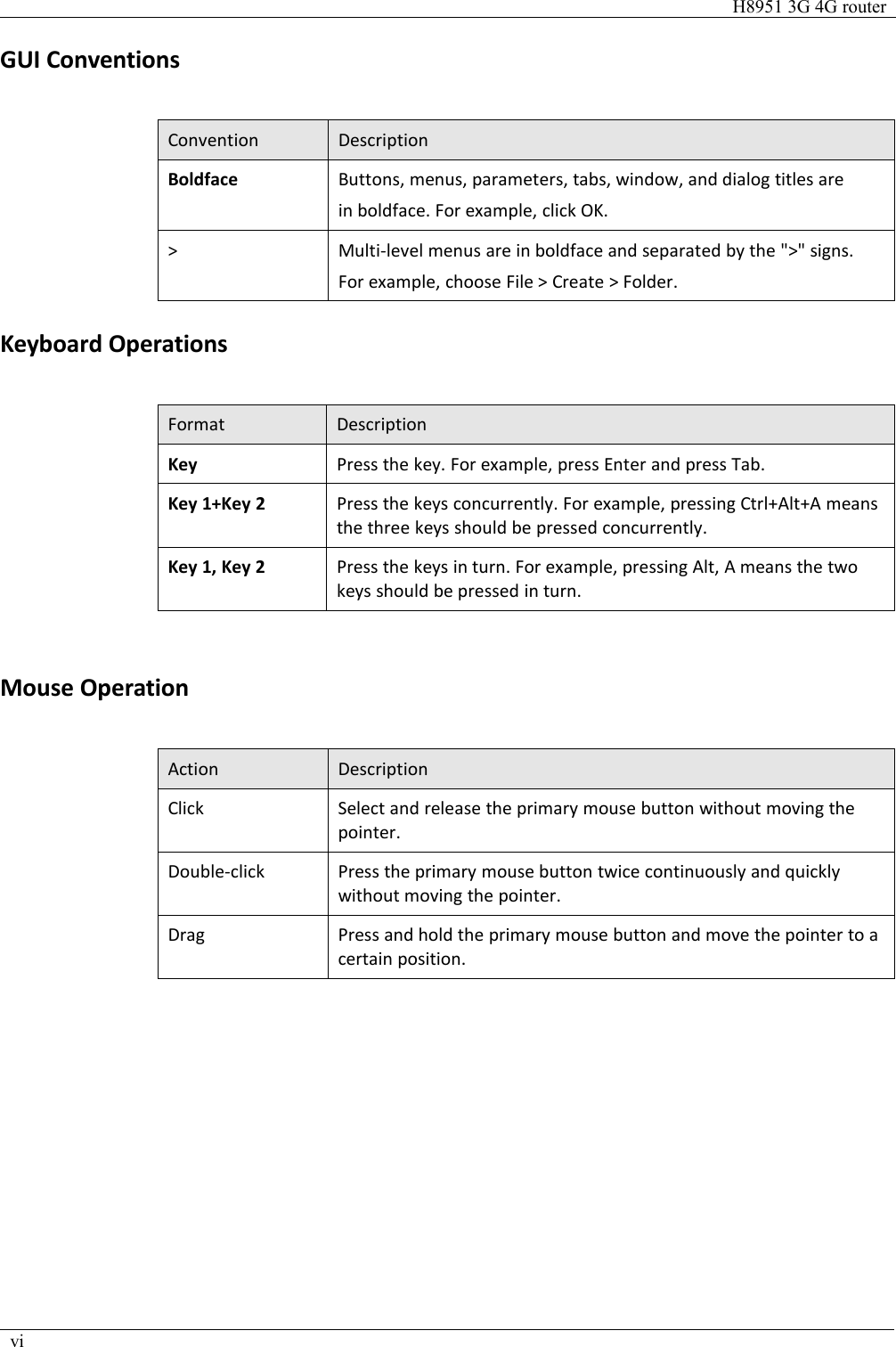
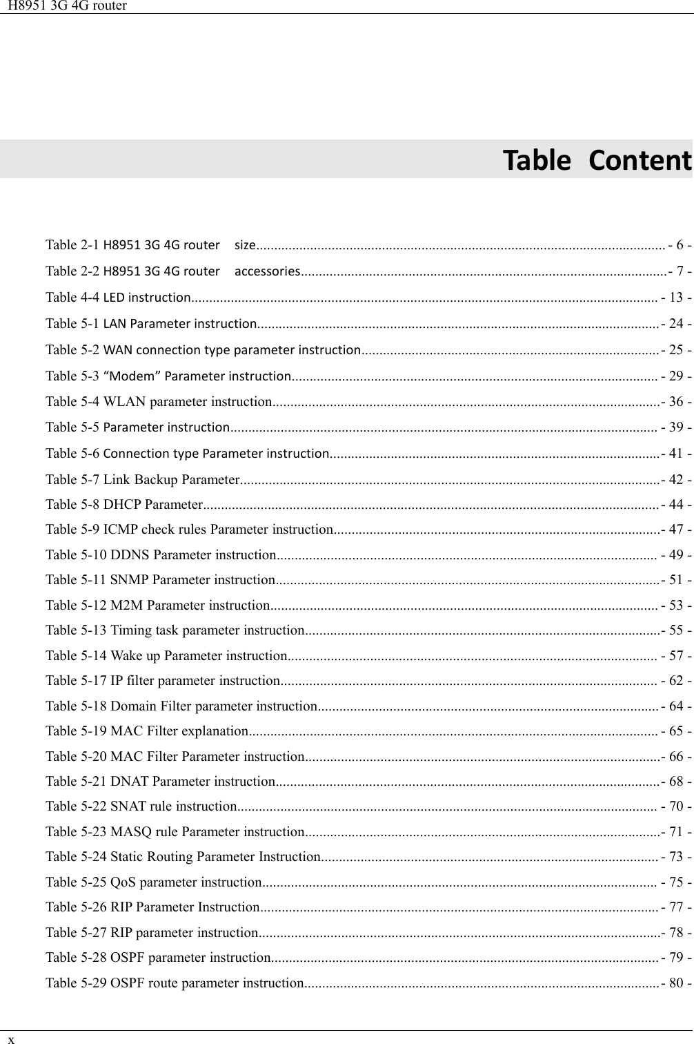
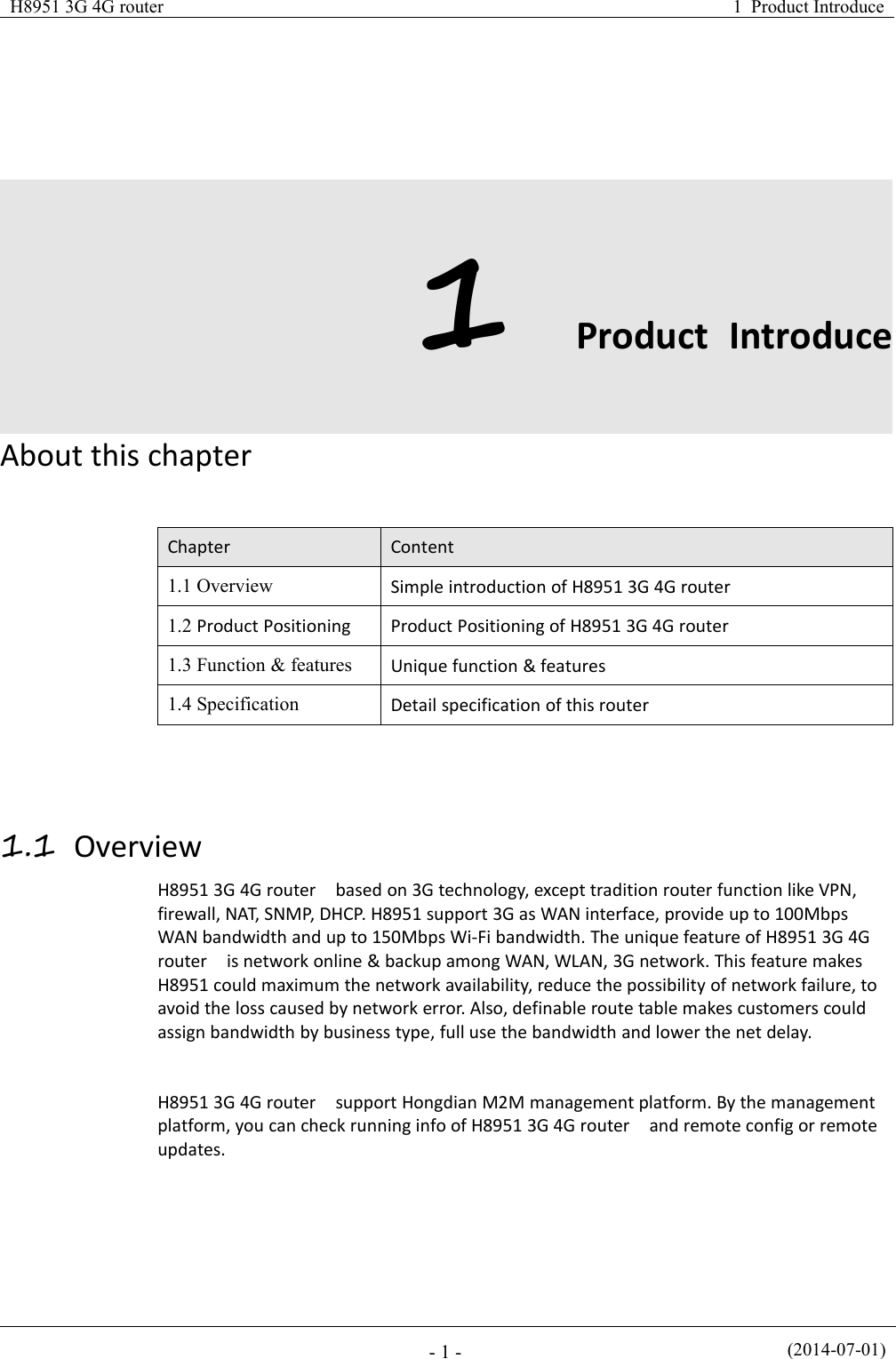
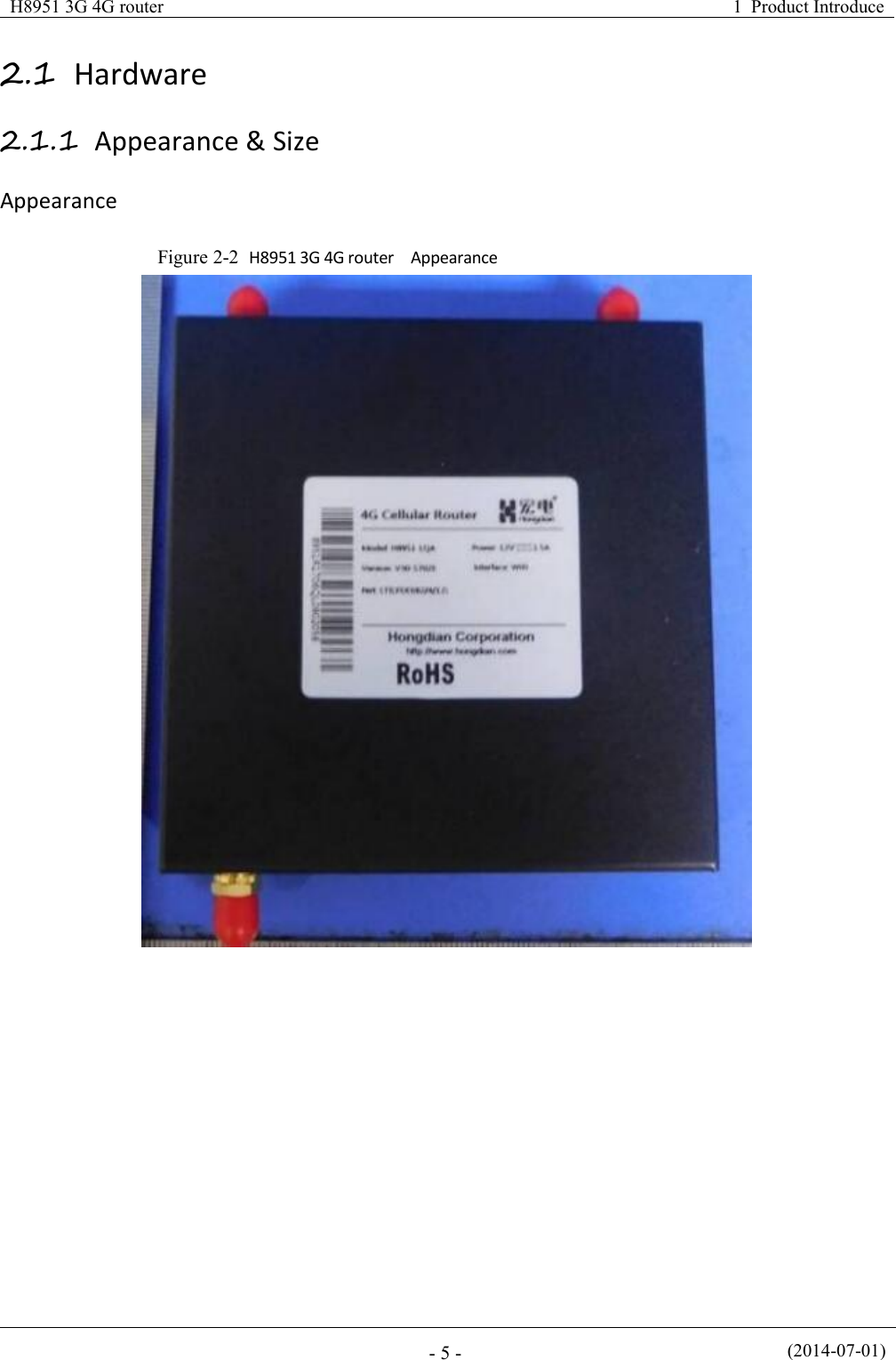
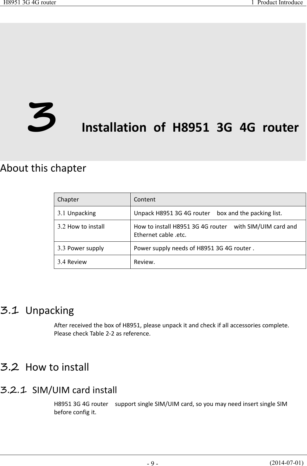
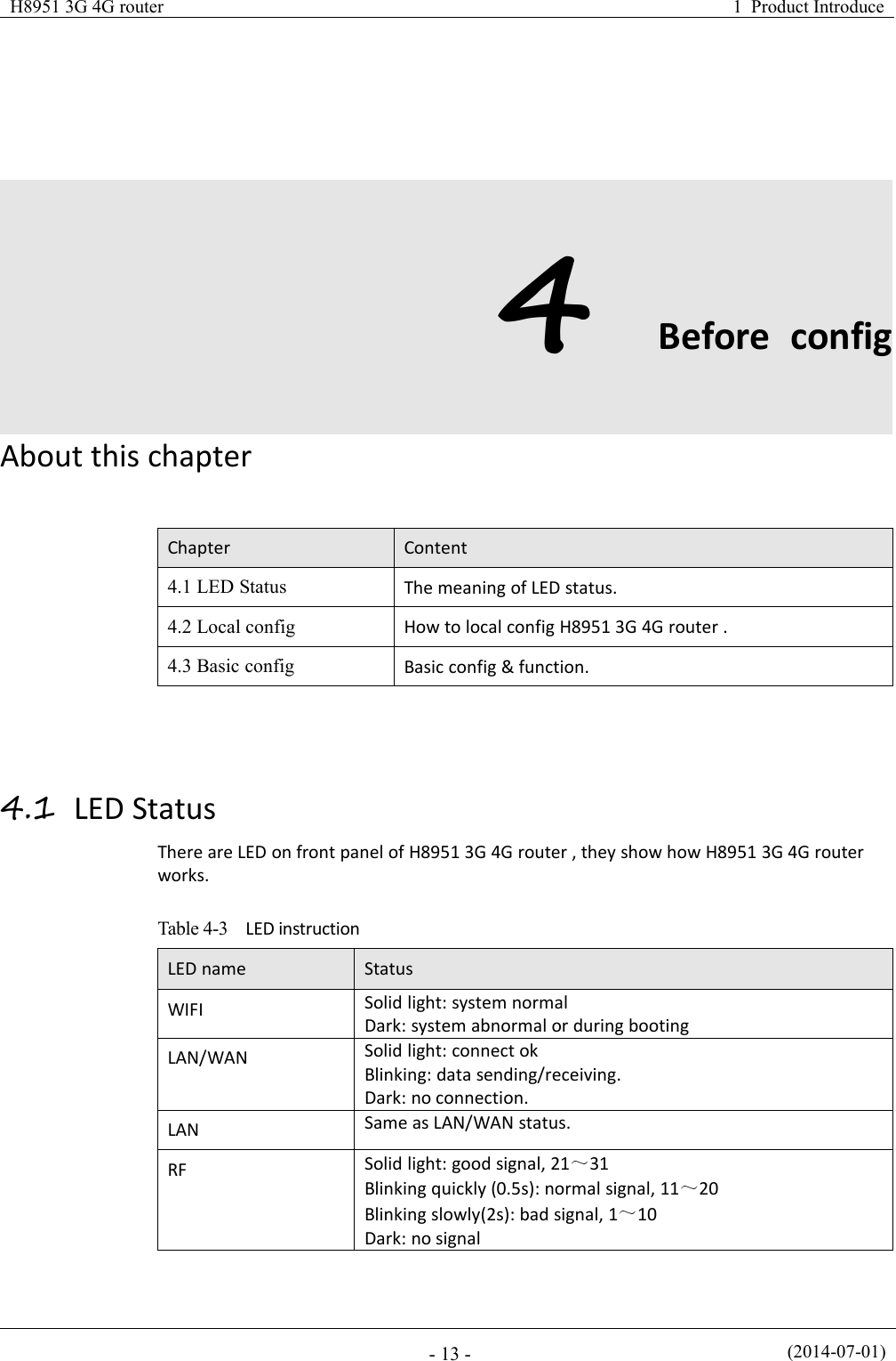
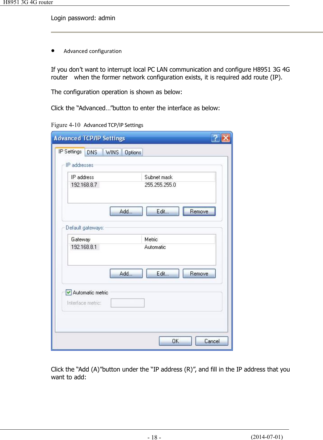
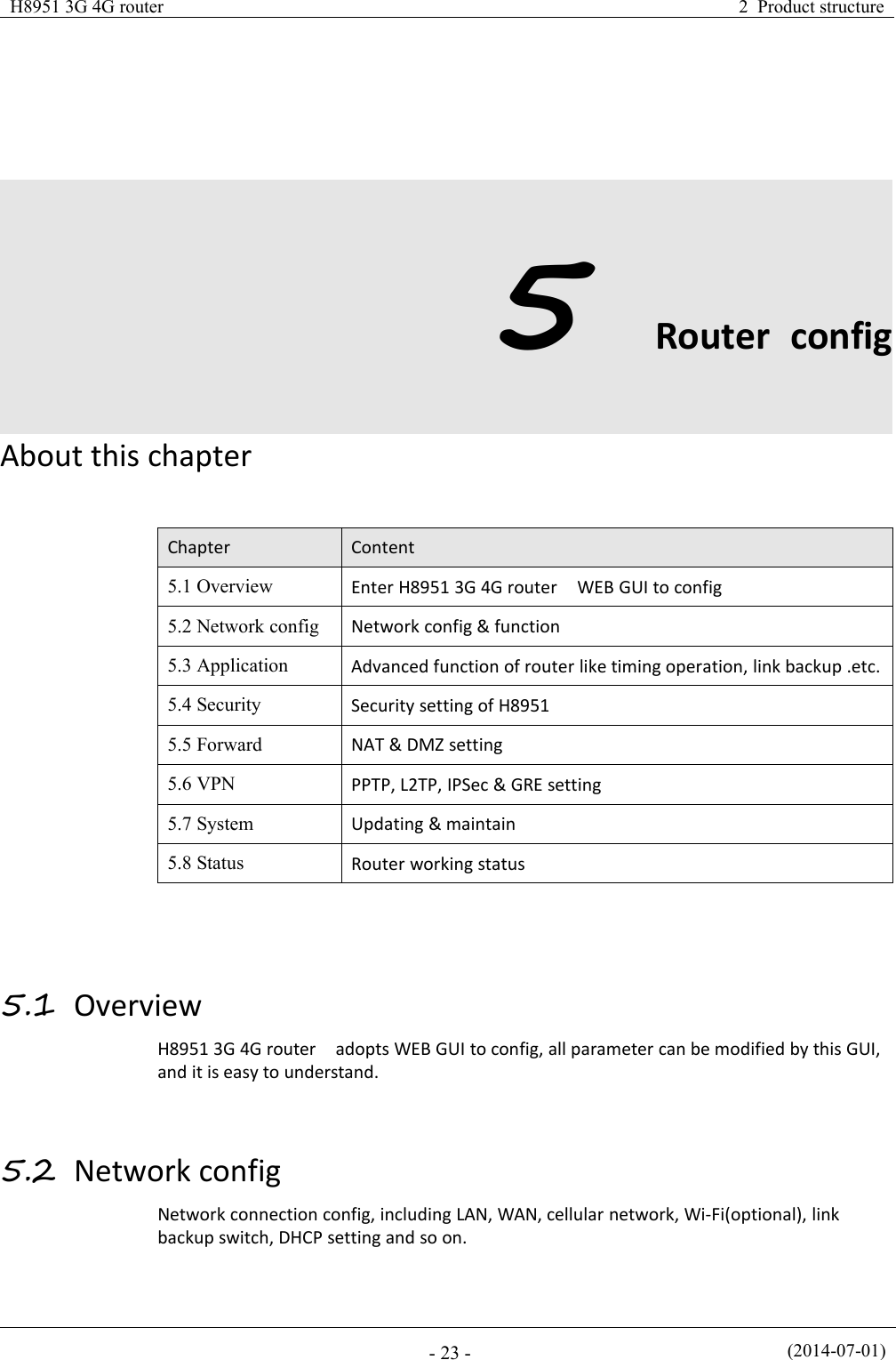
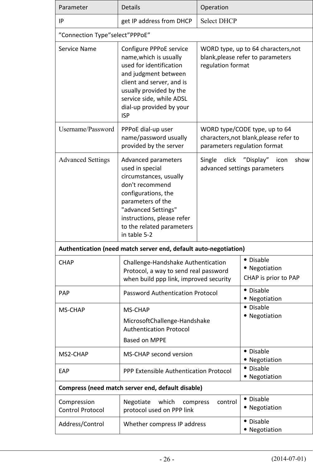
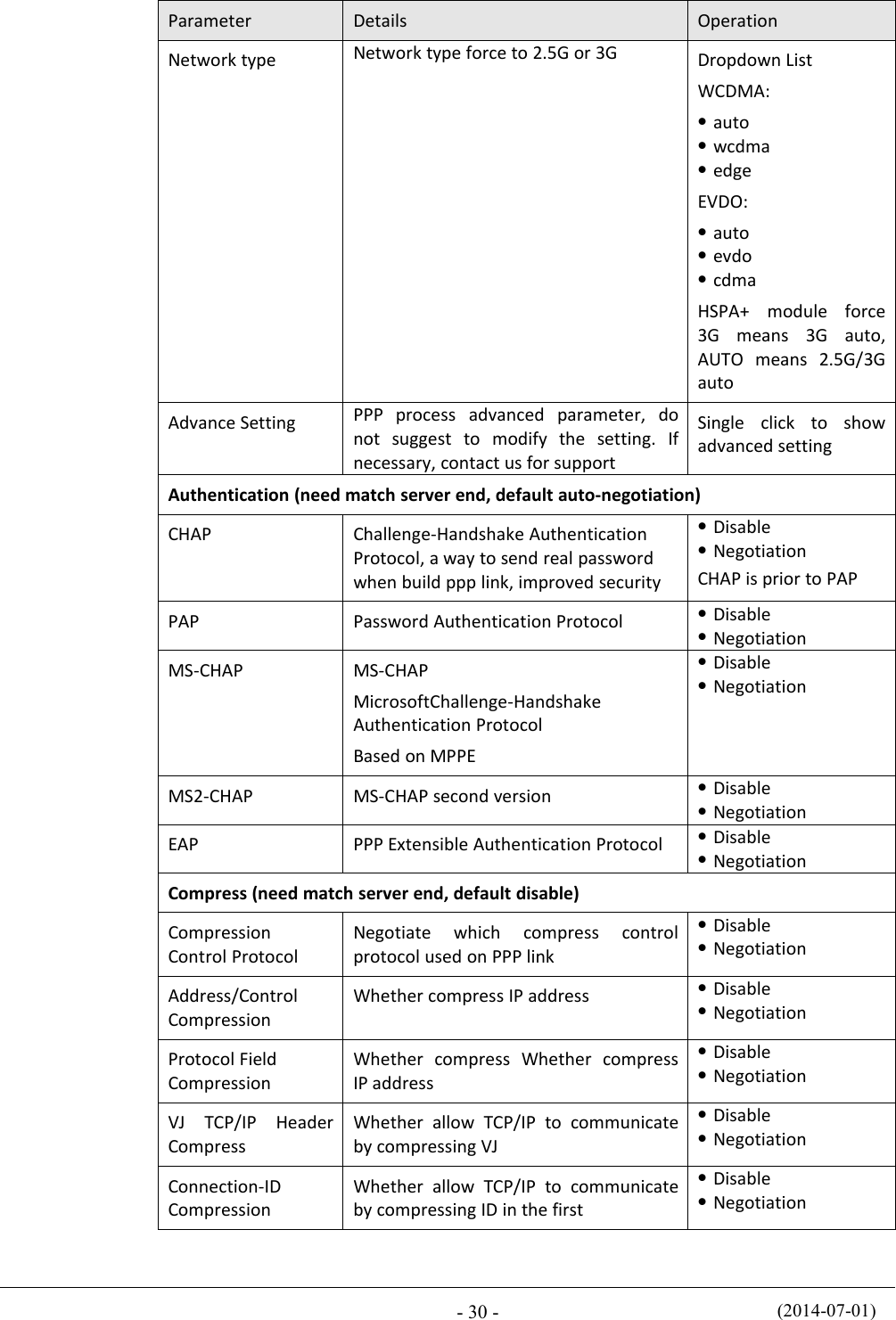
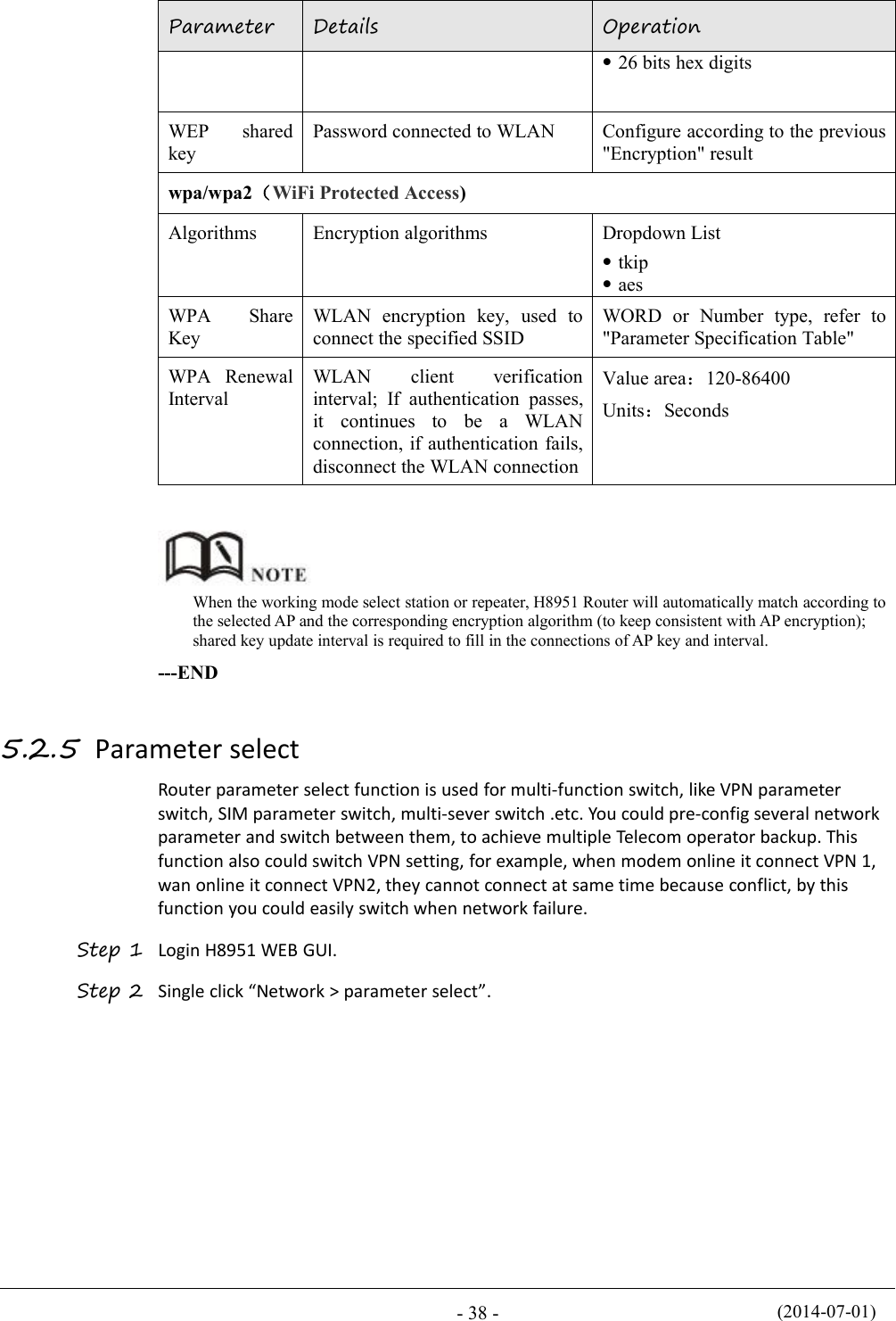
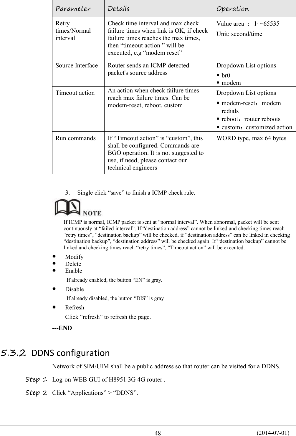
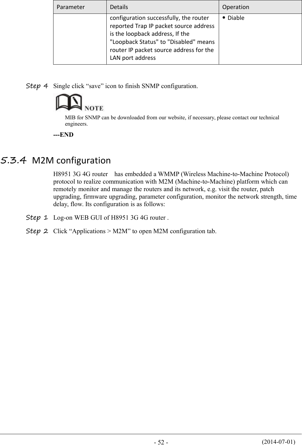
![(2014-07-01)- 62 -Table 5-18 IP filter parameter instructionParameterDetailsOperationTypeSelect a filter type, you can chooseaccording to their needs, "Input" or"Forward"Input: whether to allow access to therouterForward: whether to allow the routerforwardingDropdown List optionsDefault ActionThe default action rule. You can select"Accept" or "discard"Accept: firewall to accept the package,which can be passedDiscard: firewall discards the packetdirectlyDropdown List optionsMirror RuleWhen the filter type select "Forward", itneeds to be configuredEnable: On the basis of theconfiguration rules to add an extrasource address/port and destinationaddress/port reverse the rulesDisabled: no treatmentDropdown List optionsProtocolProtocol used by IP packetsDropdown List optionsalltcpudpicmpSource IPThe source IP address of the packetManual inputFormat:A.B.C.D/MaskSource PortThe source Port of the packet, when theprotocol choose "icmp", it don’t needto configureValue area: 1-65535 or[1-65535], it can be a range,or a single portWhen the IP Filter type select “Input”Destination TypeDesign an IP packet access routerinterfaceDropdown List optionsinterfaceanyInterfaceConfigure when Destination Typeselect “Interface”, means the IP packetaccess the router interfaceDropdown List optionsbr0modemeth0eth1](https://usermanual.wiki/Hongdian/H8951-LQA/User-Guide-3496698-Page-76.png)
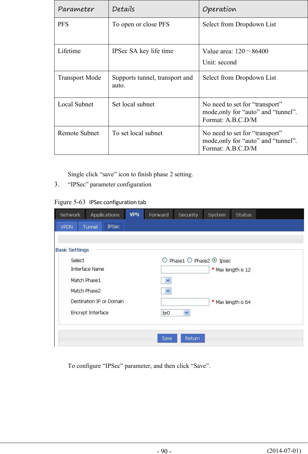
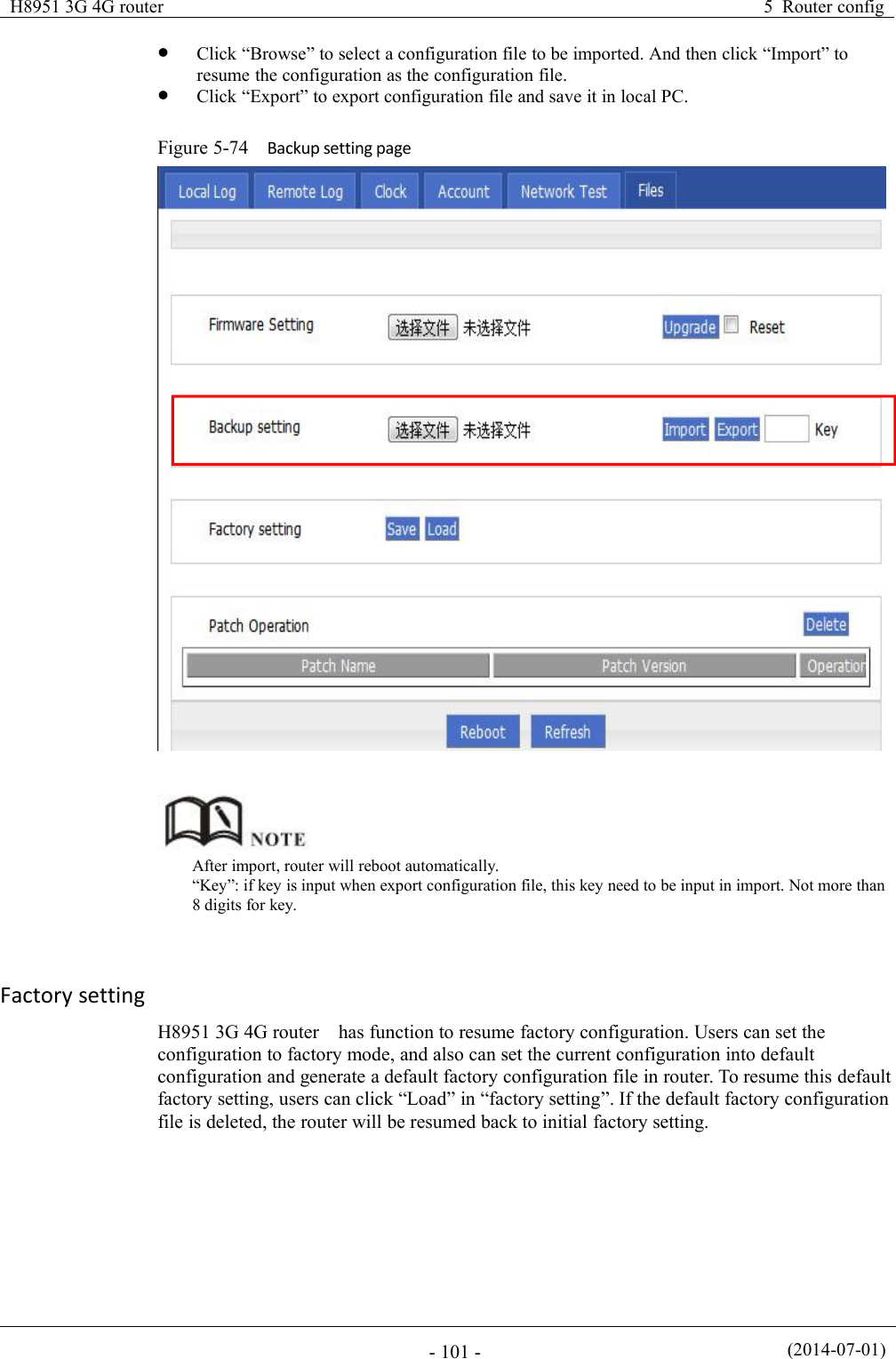
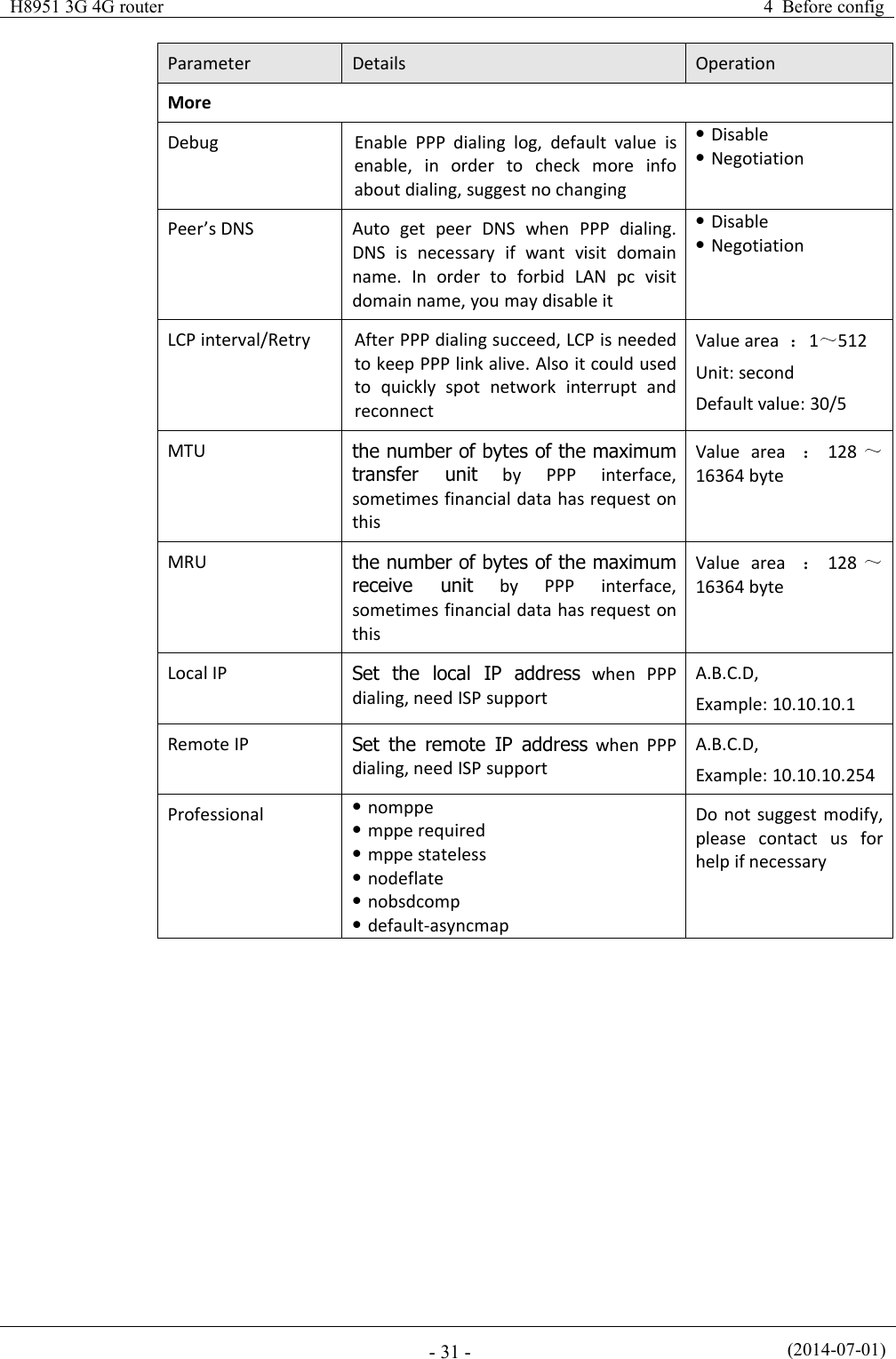
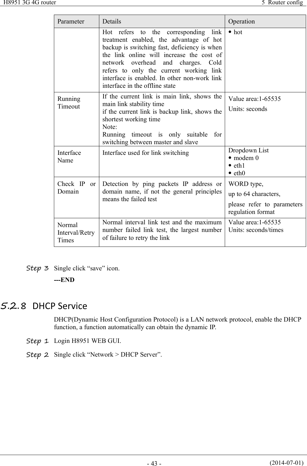
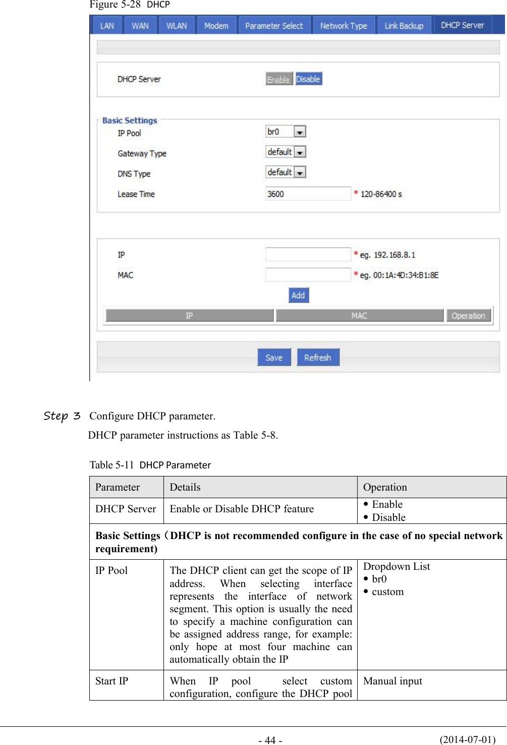
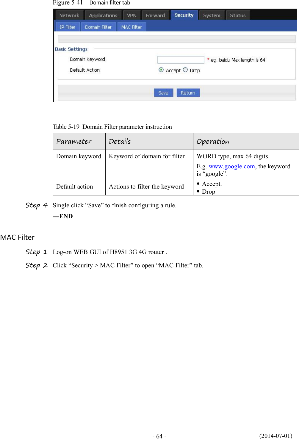
![H8951 3G 4G router5 Router config(2014-07-01)- 63 -ParameterDetailsOperationDestination PortIP packet access router ports (when theprotocol select "icmp", requires noconfiguration)Value area: 1-65535 or[1-65535], it can be a range,or a single portWhen the IP Filter type select “Forward”Destination IPIP packet destination IPManual inputFormat:A.B.C.D/MaskDestination PortIP packet destination portValue area: 1-65535 or[1-65535], it can be a range,or a single portStep 5 Single click “save” to finish.--ENDDomain FilterDomain filter support black list and white list. It is used to forbid PCs in LAN from visit somewebsites or allows them to visit specific websites.Step 1 Log-on WEB GUI of H8951 3G 4G router .Step 2 Click “Security > Domain Filter” to open “Domain Filter” tab.Figure 5-40 Domain filter tabBlack list: websites in the blacklist cannot be visited. Click “black list” to forbid visiting thewebsites in the list.White lis: only the websites in the white list can be visited, while other websites cannot bevisited. Click “White list” to activate it.Step 3 Click “ADD” to add a new domain filter rule and configure domain filtering parameter.](https://usermanual.wiki/Hongdian/H8951-LQA/User-Guide-3496698-Page-77.png)
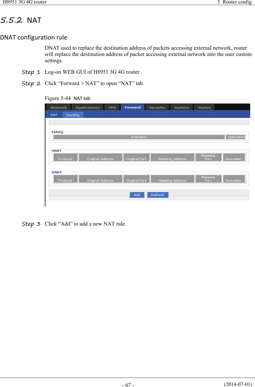
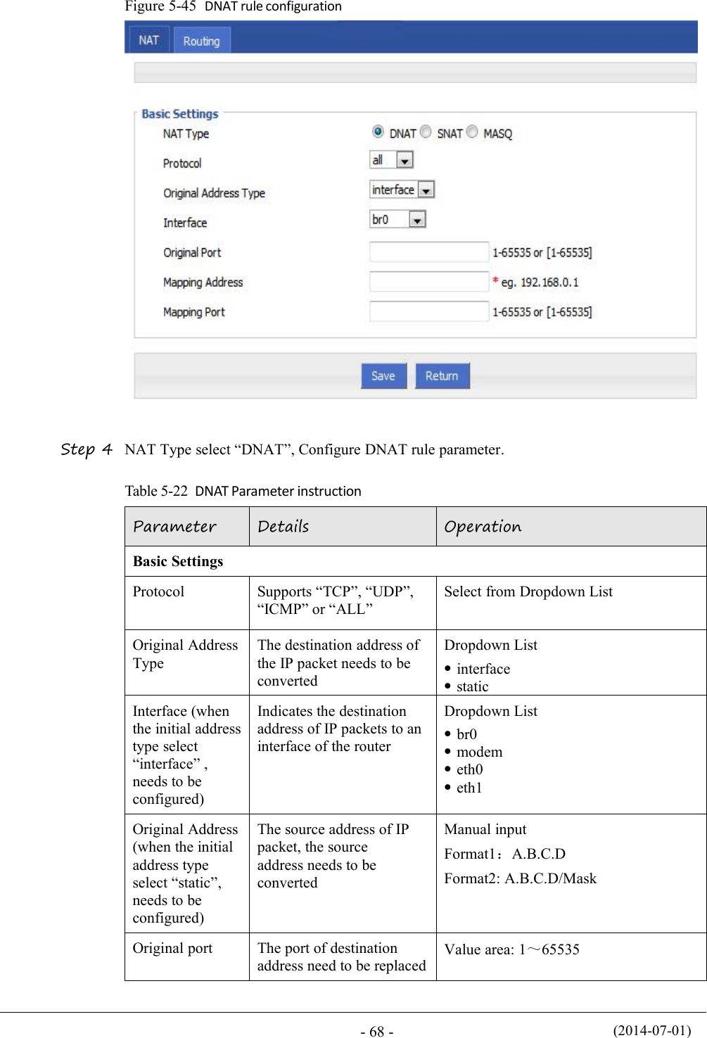
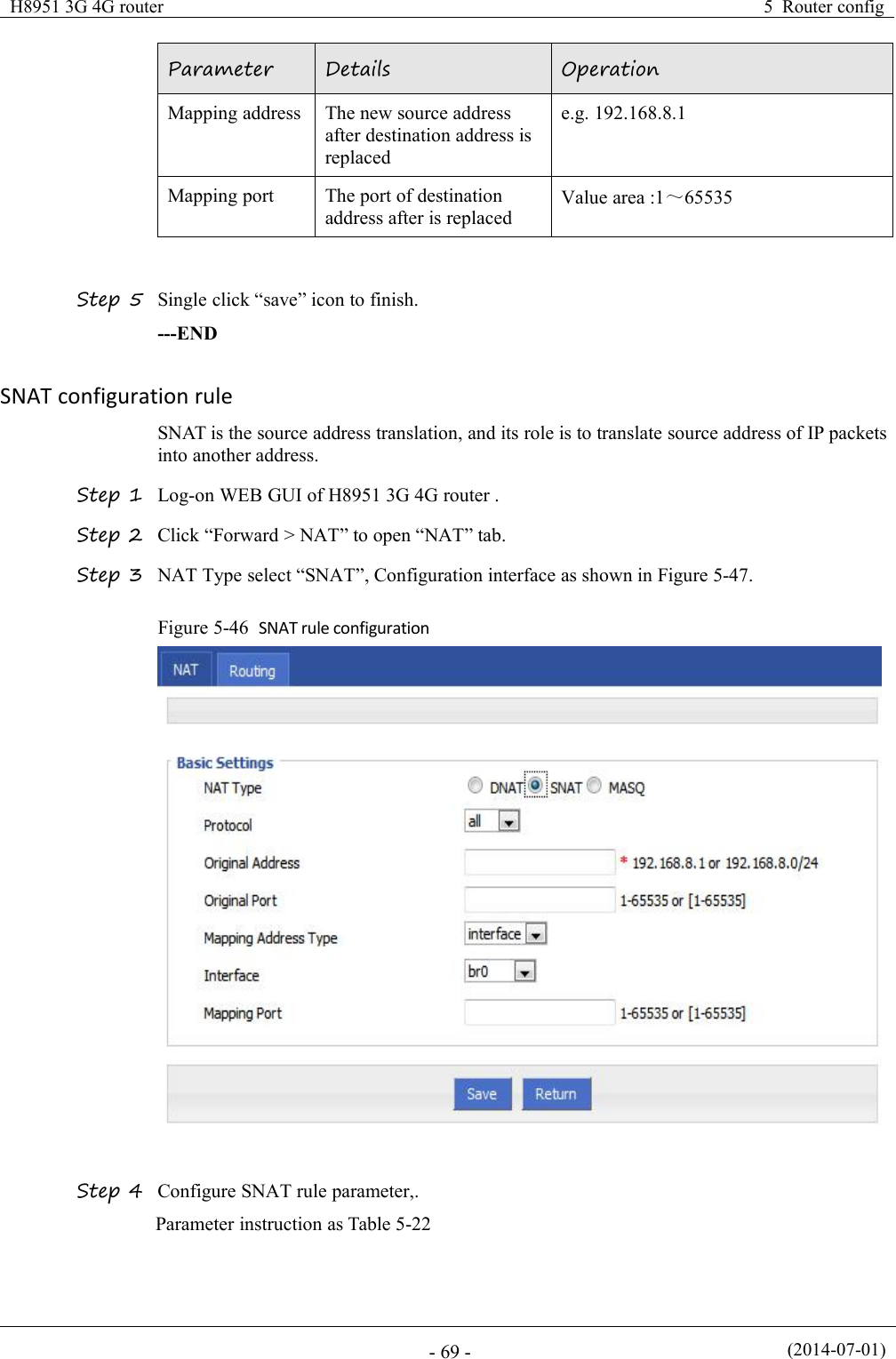
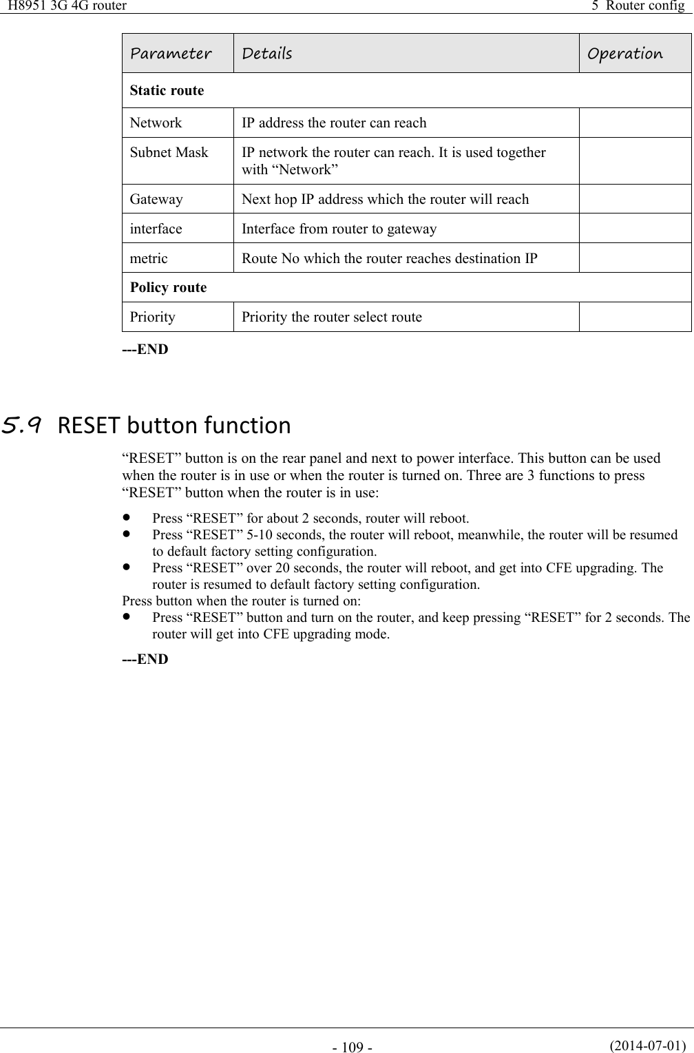
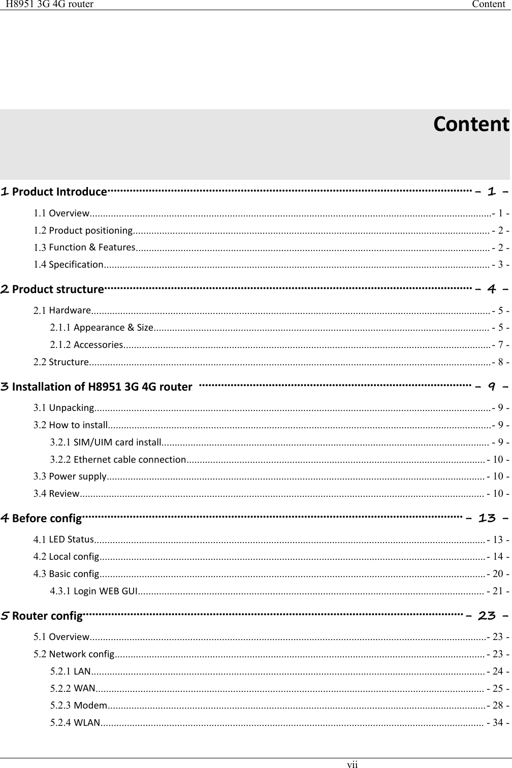
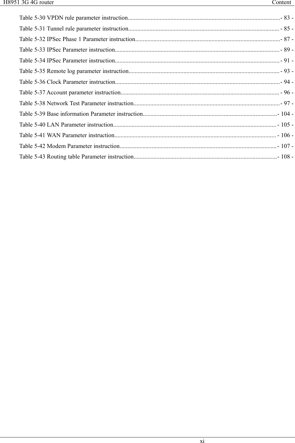
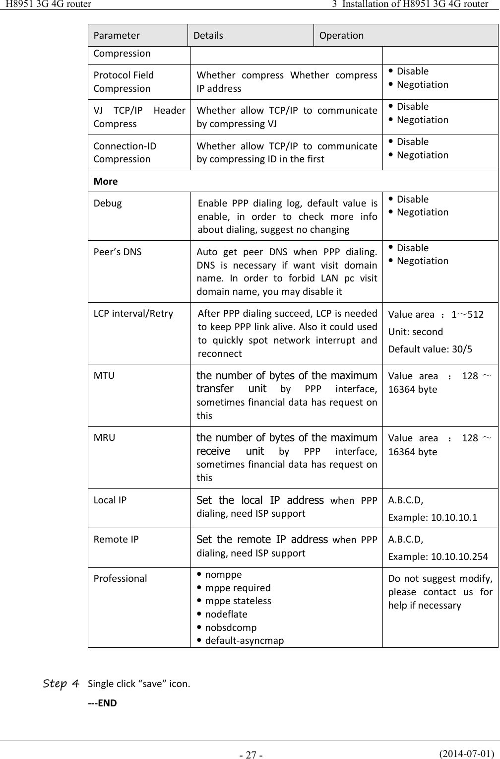
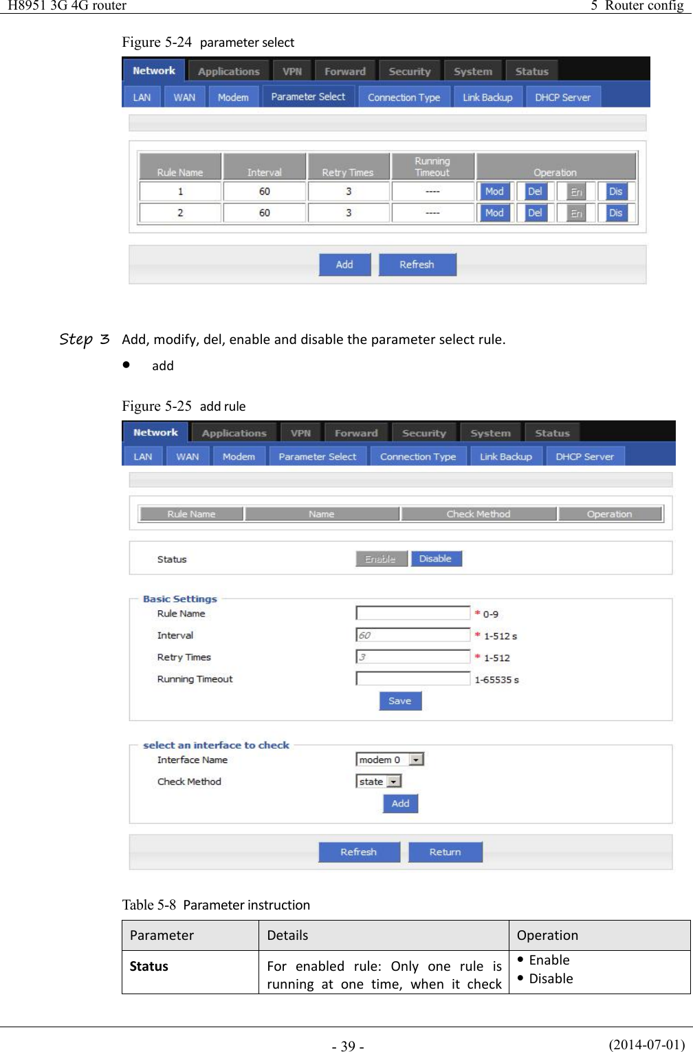
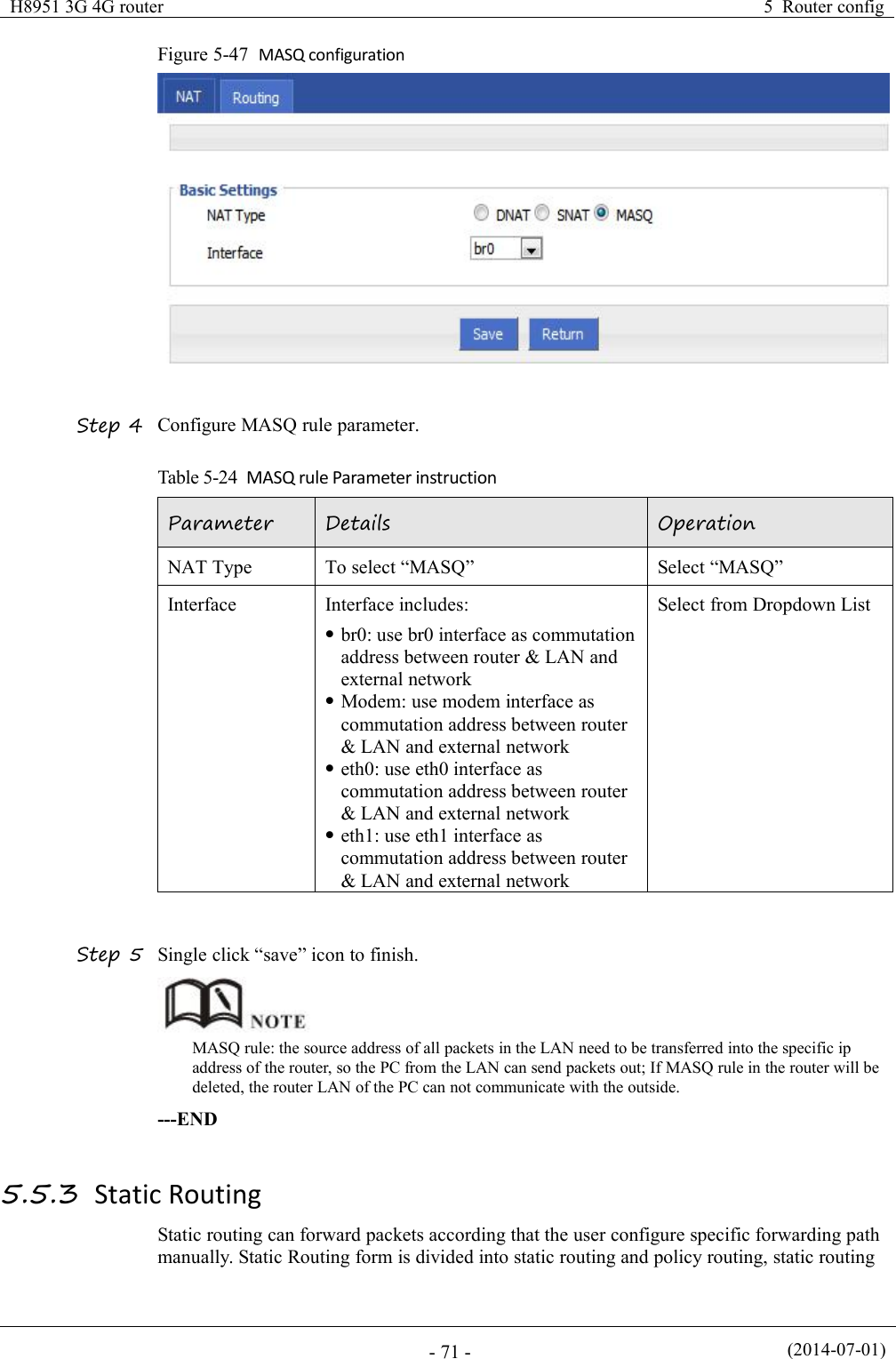
![(2014-07-01)- 70 -Table 5-23 SNAT rule instructionParameterDetailsOperationProtocolConvert some kind of protocol packetsinto addressDropdown ListalltcpudpicmpOriginal AddressThe source address need to be replacedManual inputFormat1:A.B.C.DFormat2: A.B.C.D/MaskOriginal PortThe port of source address need to bereplacedValue area: 1-65535 or[1-65535], it can be a range,or a single portMappingAddress TypeThe new source address type aftersource address is replacedDropdown ListinterfacestaticInterfaceSelect the interface of the router assource address after replacementDropdown Listbr0modemeth0eth1Mapping PortThe port of source address after isreplacedValue area: 1-65535 or[1-65535], it can be a range,or a single portStep 5 Single click “save” icon to finish.When SNAT rule is configured port, protocol select "all", said select "tcp", "udp" two protocols; whenSNAT rule is not configured port, protocol select "all", said select "tcp", "udp","icmp" three protocols.---ENDMASQ rule configurationMASQ is MASQUREADE.Step 1 Log-on WEB GUI of H8951 3G 4G router .Step 2 Click “Forward > NAT” to open “NAT” tab.Step 3 NAT Type select “MASQ”, Configuration interface as shown in Figure 5-48.](https://usermanual.wiki/Hongdian/H8951-LQA/User-Guide-3496698-Page-84.png)
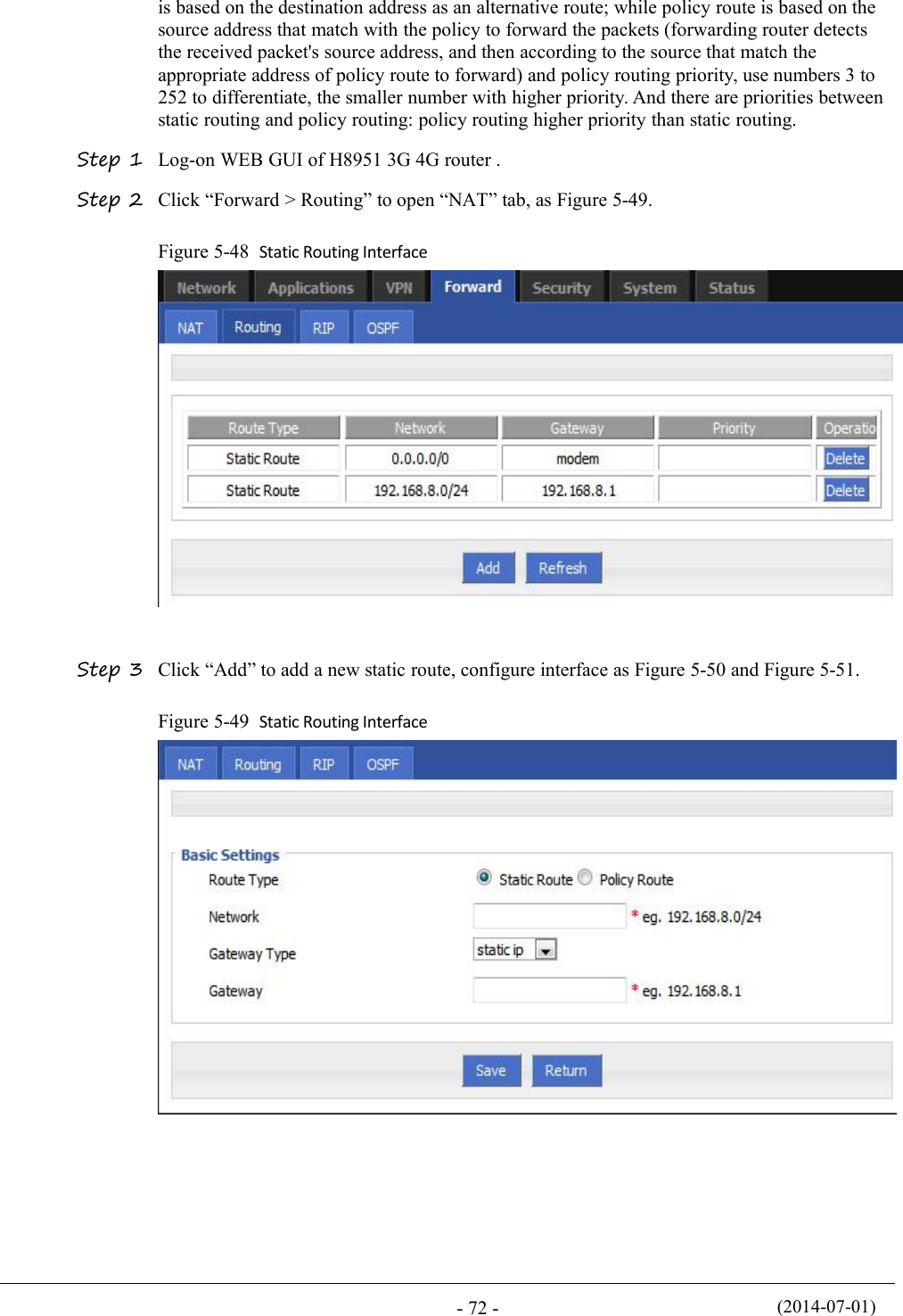
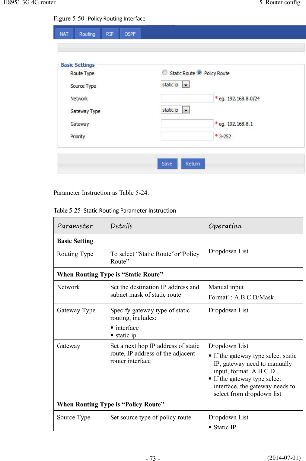
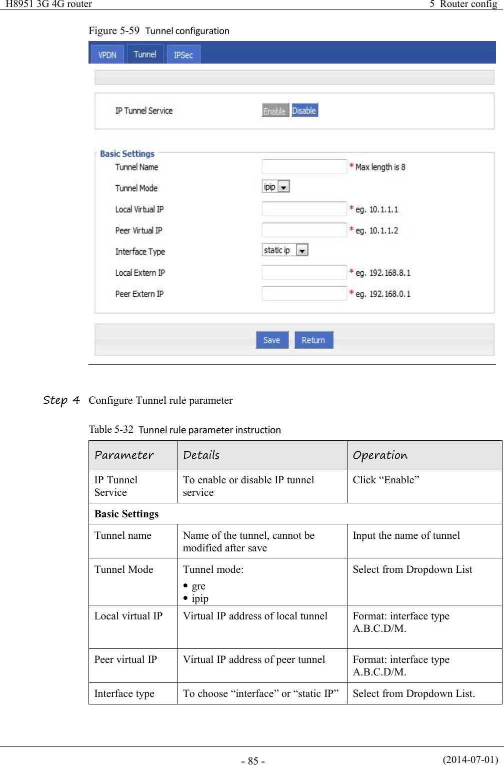
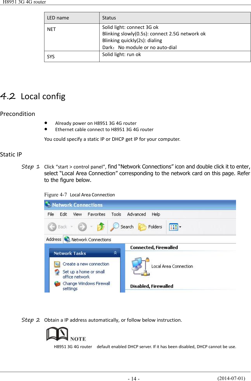
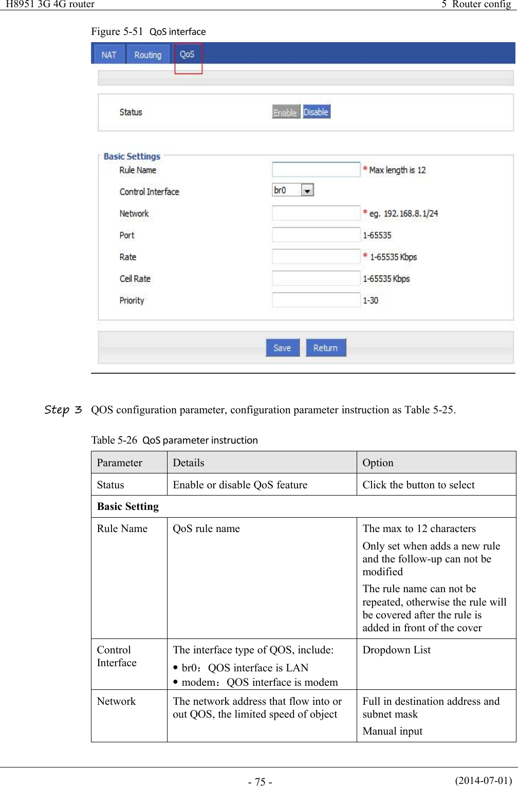
![(2014-07-01)- 74 -ParameterDetailsOperationInterfaceNetworkWhen source type is static route,need to manually set networkaddressManual inputFormat1: A.B.C.D/MaskSource InterfaceWhen source type is policy route,need to manually set sourcenetwork address of policy routerDropdown Listmodemeth0eth1Gateway TypeSet the next hop IP of policy routeDropdown Liststatic ipinterfaceGatewayWhen the gateway type select"Static IP" to fill in the IP address,when gateway type select the"interface", it will select theinterfaces as gatewayManual inputFormat1: A.B.C.D/MaskProritySet policy routing priority, thepriority lower the number, thehigher the priorityValue area:[3,252]Step 4 Single click “save” icon to finish the static routing setting.Static routing will select the route to forward according to the destination address of the packet receivefrom the router, if the router received the packet(source address is 1.1.1.1 destination address is 2.2.2.2),It will forward the packet to next hop according to the route which meet with the destinationaddress(2.2.2.2).Policy routing will forward according to the source address of the packet, if the router received thepacket(source address is 1.1.1.1 destination address is 2.2.2.2), it will forward the packet to next hopaccording to the route which meet with the source address(1.1.1.1).Policy routing higher priority than static routing, policy-based routing priority regardless of how much.---END5.5.4 QoS (Optional)QoS (Quality of Service) quality of service, is a security mechanism for the network, is atechnique to solve the network bandwidth allocation and network priority and other issues.When the network is overloaded or congested, QoS to ensure that critical traffic is not delayedor dropped, while ensuring the efficient operation of the network, our H8951 3G Routersupports custom QoS services.Step 1 Log-on WEB GUI of H8951 3G 4G router .Step 2 Click “Forward > QoS” to open “QoS” tab, as Figure 5-52.](https://usermanual.wiki/Hongdian/H8951-LQA/User-Guide-3496698-Page-88.png)
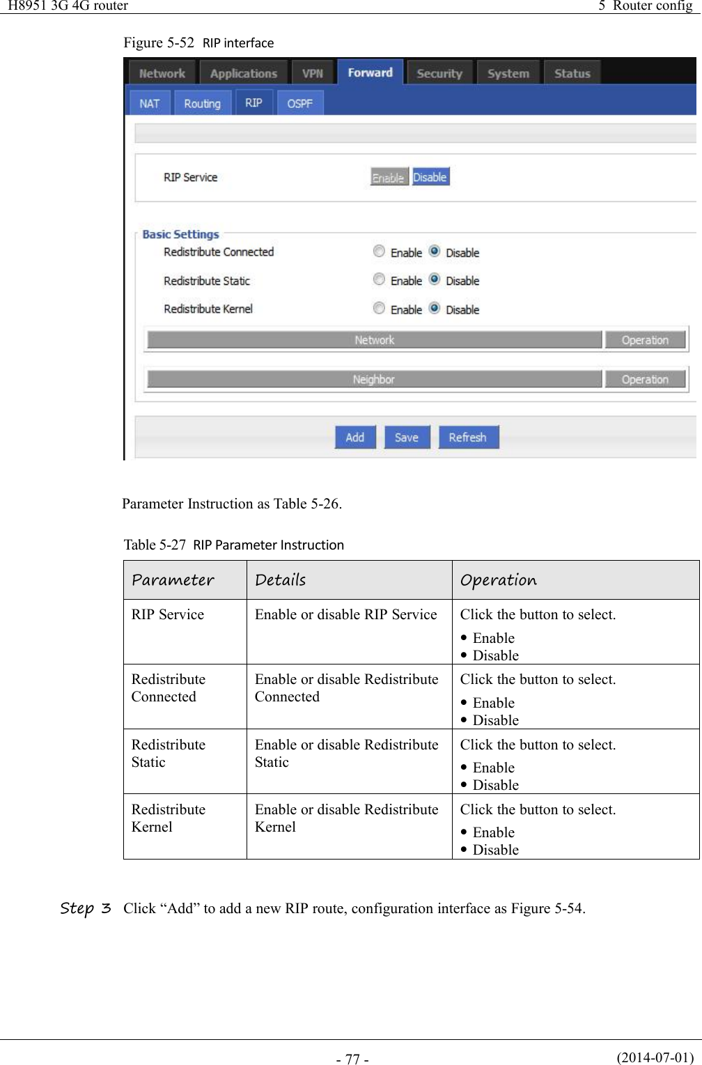
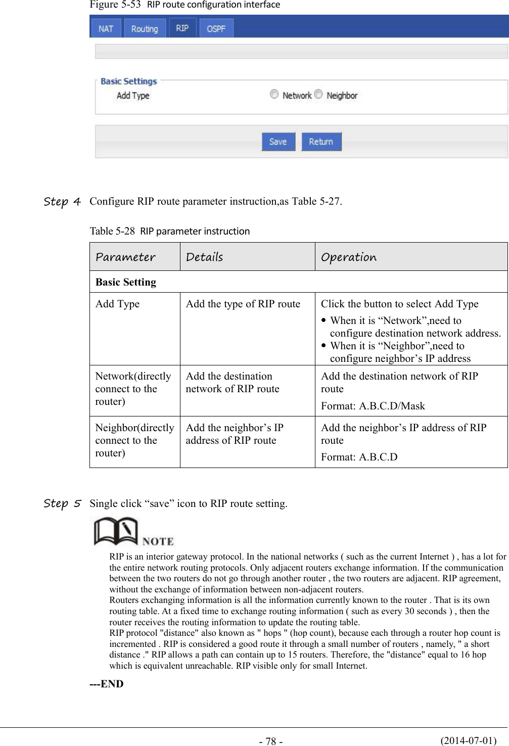
![(2014-07-01)- 76 -ParameterDetailsOptionFormat1: A.B.C.D/MaskPortThe network interface of QOSValue area: 1-65535You can not configure the port,if not the configurationrepresents all portsRateTransmission rate of the networkaddress settingsValue area:1~65535Units:KbpsCeil RateIn ensuring the basic rate and the sparebandwidth, the maximum bandwidth ofthe network address of thecommunication can be obtained withhigher priority will be given priorityredundant bandwidthValue area:1~65535Units:KbpsPrioritySet the precedence of the rulesValue area:[1,30]Step 4 Single click “save” icon to QOS setting.QOS is mainly for the average of user priority assigned route or a bandwidth of Internet users. If the router isconnected with two subnets: 192.168.8.1/24 and 192.168.9.1/24, the router QOS can control the rate of thesetwo subnets; If the router's bandwidth is relatively well-off, the router can be based on two subnets redundantbandwidth is first priority and high priority redundancy to meet the bandwidth, then meet low priority subnetredundancy bandwidth.---END5.5.5 Dynamic Routing(Optional)RIP configurationRIP protocol (Routing Information Protocol) is the most widely IGP (Interior GatewayProtocol) , it was designed for the same technology used in small networks, and thereforeadapt to most of the campus network and used in a continuous regional networks that the ratechange is not big, H8951 3G 4G router supports RIP v2 protocol. For more complexenvironments, generally do not use the RIP protocol. RIP business is based on whether theuser needs the RIP at the factory H8951 3G 4G router .Step 1 Log-on WEB GUI of H8951 3G 4G router .Step 2 Click “Forward > RIP” to open “RIP” tab, as Figure 5-53.](https://usermanual.wiki/Hongdian/H8951-LQA/User-Guide-3496698-Page-90.png)
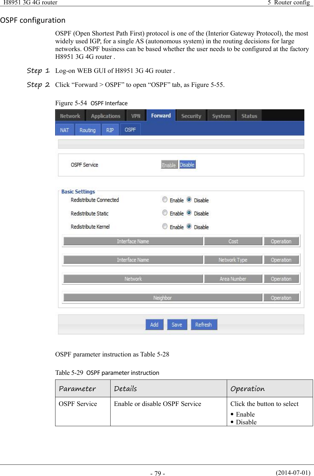
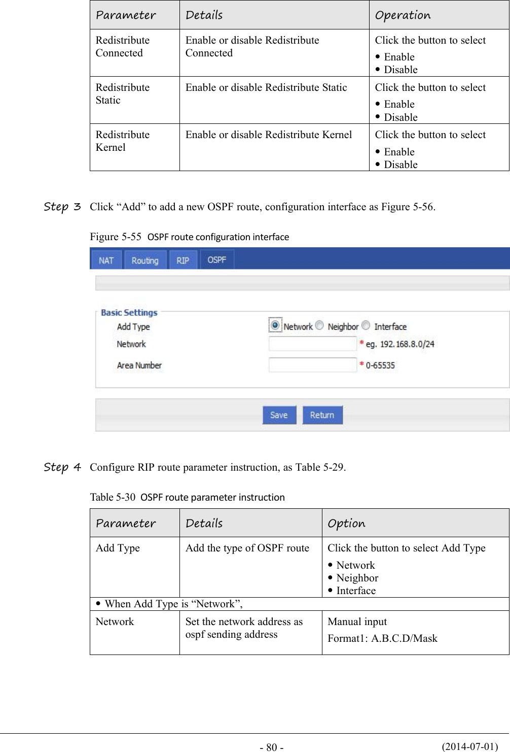
![H8951 3G 4G router5 Router config(2014-07-01)- 81 -Step 5 Single click “save” icon to OSPF route setting.Step 6 Single click “save” icon to finish.OSPF is a link-state (Link-state) routing protocol, commonly used for the same routing domain. Here,the routing domain is an autonomous system, which refers to the routers can switch routing informationthrough a unified network switching or routing protocol routing policy in the AS, all OSPF routersmaintains an identical description of the database structure AS, which is stored in the database link statusinformation corresponding routing domain, OSPF router is through this database to calculate its OSPFrouting table.As a link-state routing protocol, OSPF link state broadcast data LSA (Link State Advertisement) sent toall routers in an area, which is different from the distance vector routing protocols. Distance vectorrouting protocol passed some or all rouing information of the routing table to the adjacent routers.---ENDAS NumberUsed to identify the network(only the routers with thesame domain address canexchange routinginformation)Manual inputValue area:[0,65535]When Add Type is “Neighbor”,NeighborThe router can reach in thenext hopManual inputFormat1: A.B.C.D/MaskWhen Add Type is “Interface”,Interface NameThe interface of the routerDropdown Listbr0modemeth1eth0InterfaceAttributeConfigure the routerinterface attribute, includecost and networkClick the button to selectcostnetworkCostConfigure the cost of therouter interface, used to learnrouting tableManual inputValue area:1-65535Network Type(when theinterfaceattribute isnetwork)Configure the network typeof the router interfaceDropdown Listbroadcastnon-broadpoint-to-multipointpoint-to-point](https://usermanual.wiki/Hongdian/H8951-LQA/User-Guide-3496698-Page-95.png)