Horizon Hobby NETZS75 Z-1 transmitter Module User Manual Helios Manual E
Horizon Hobby, LLC Z-1 transmitter Module Helios Manual E
Z1 Module Oper Instructions
s
e
ru
t
a
e
Fu
n
e
M
n
i
a
M
u
ne
M
n
o
i
tc
n
u
F
noit
p
i
rc
se
Dx
ed
nI
9
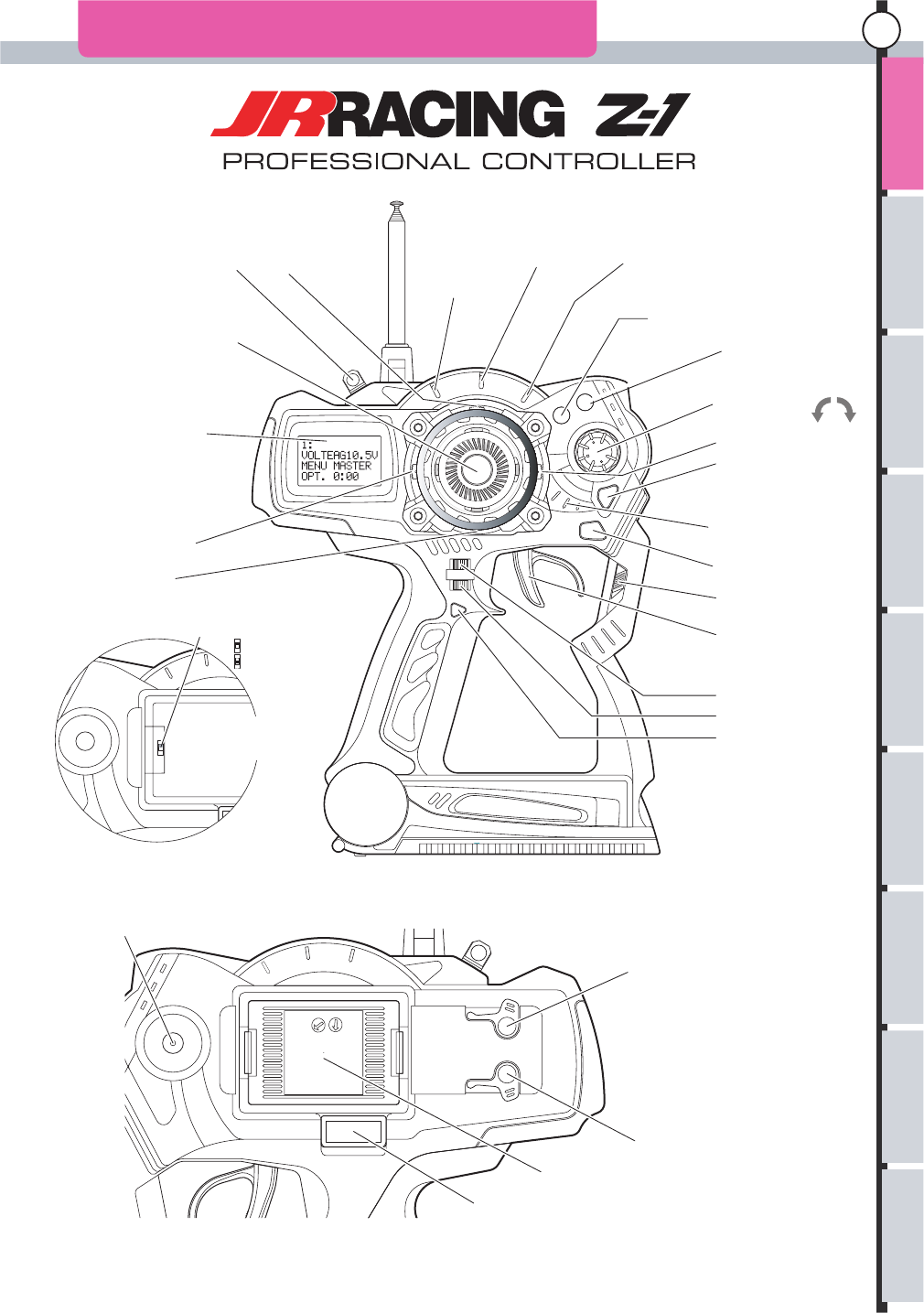
NAMES OF PARTS OF THE TRANSMITTER
Hook ET1 Lever
Antenna
Steering Wheel
12x4 LCD Display
ET2 Lever
BT2
Phone Terminal
D.S.C
(Direct Servo Control Terminal)
Multi Access Port
Charging
RF Module
Throttle Trigger
Power Switch
Back Key
Power Indicator
Enter Key
ET3 Lever
Jog Dial
(+)Plus key
(-) Minus key
(+)
(-)
Throttle Acceleration Indicator
Throttle A.B.S.
Indicator
Throttle Speed
Indicator
ET4 Lever
ET5 Lever
BT1
Mode Change Switch
High Speed
Normal
Factory Default Setting
ET1: Steering Trim
ET2: Throttle Trim
ET3: Throttle Brake
ET4: Steering Travel
ET5: Not Assigned
BT1: Not Assigned
BT2: Not Assigned
There is a switch in the back when
the RF module is removed.
Please refer to P19 for the details
eg
a
sU
e
ht f
o
r
ett
i
msn
arT
gni
t
cen
n
o
C
re
viec
Re
e
h
t
no
se
t
o
N
gni
lla
ts
n
I
s
erut
a
e
Fu
n
e
M
n
i
aM
u
ne
M
n
o
i
tc
nu
F
noitpircseD x
ed
n
I
10
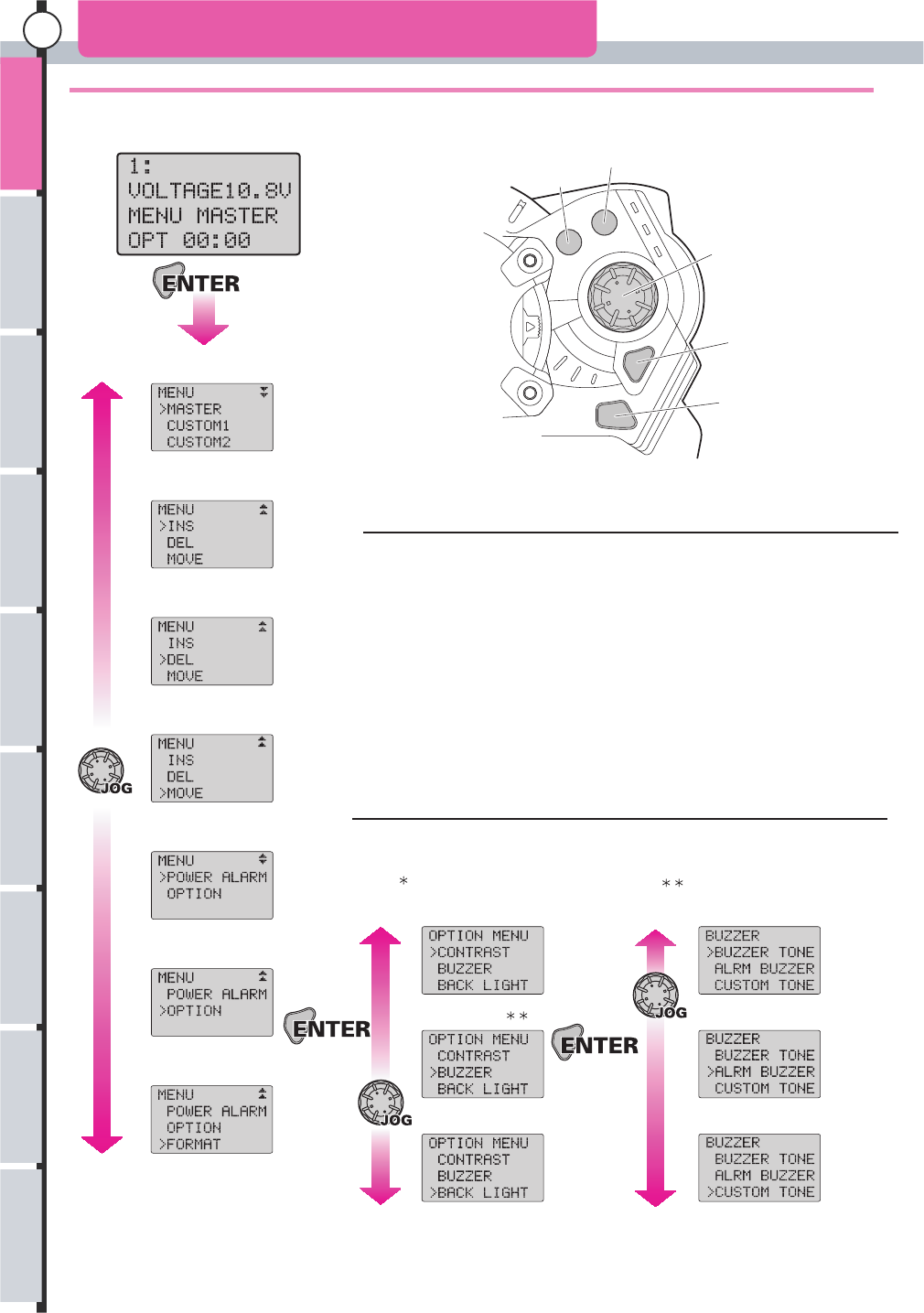
These screens are displayed when the main menu is opened.
Change Menu
Add Menu
Delete Menu
Move Menu
Power Alarm
Option Menu*
LCD Contrast
Buzzer Set
Buzzer Tone
Alarm Buzzer Set
Custom Tone Editor
Back Light
Format (note)
Initial Screen
The menu is displayed when ’Enter’ is pressed from the initial screen.
The following 11 settings are available in the main menu:
Change Menu
Add Menu
Delete Menu
Move Menu
Power Alarm
Option Menu: LCD Contrast
Option Menu: Buzzer Set: Buzzer Tone
Option Menu: Buzzer Set: Alarm Buzzer
Option Menu: Buzzer Set: Custom Tone
Option Menu: Back Light Setting
Format*
Option Menu: Option Menu: Buzzer Set:
Format is displayed only when the Data Pack is installed.
Use Jog Dial or (+) (-) keys to change each screen.
Press ’Enter’ key to open each setting screen.
Option Menu divides into three items when it is opened.
In addition, an item is divided into the buzzer settings.
P17
P26
P26
P27
P27
P28
P28
P28
P29 P29
P29
P29
P31 P30
Plus Key
Minus Key
Jog Dial
Enter Key
Back Key
Please see each reference page for a detailed operation method after each screen is opened.
SCREEN TABLE MAIN MENU
eg
a
s
U
e
ht
f
o
r
ett
i
msn
arT
no
set
o
N
gni
lla
ts
n
I
gni
t
cen
n
o
C
re
viec
Re
e
h
t
s
e
ru
t
a
e
Fu
n
e
M
n
i
a
M
u
ne
M
n
o
i
tc
n
u
F
noit
p
i
rc
se
Dx
ed
nI
11
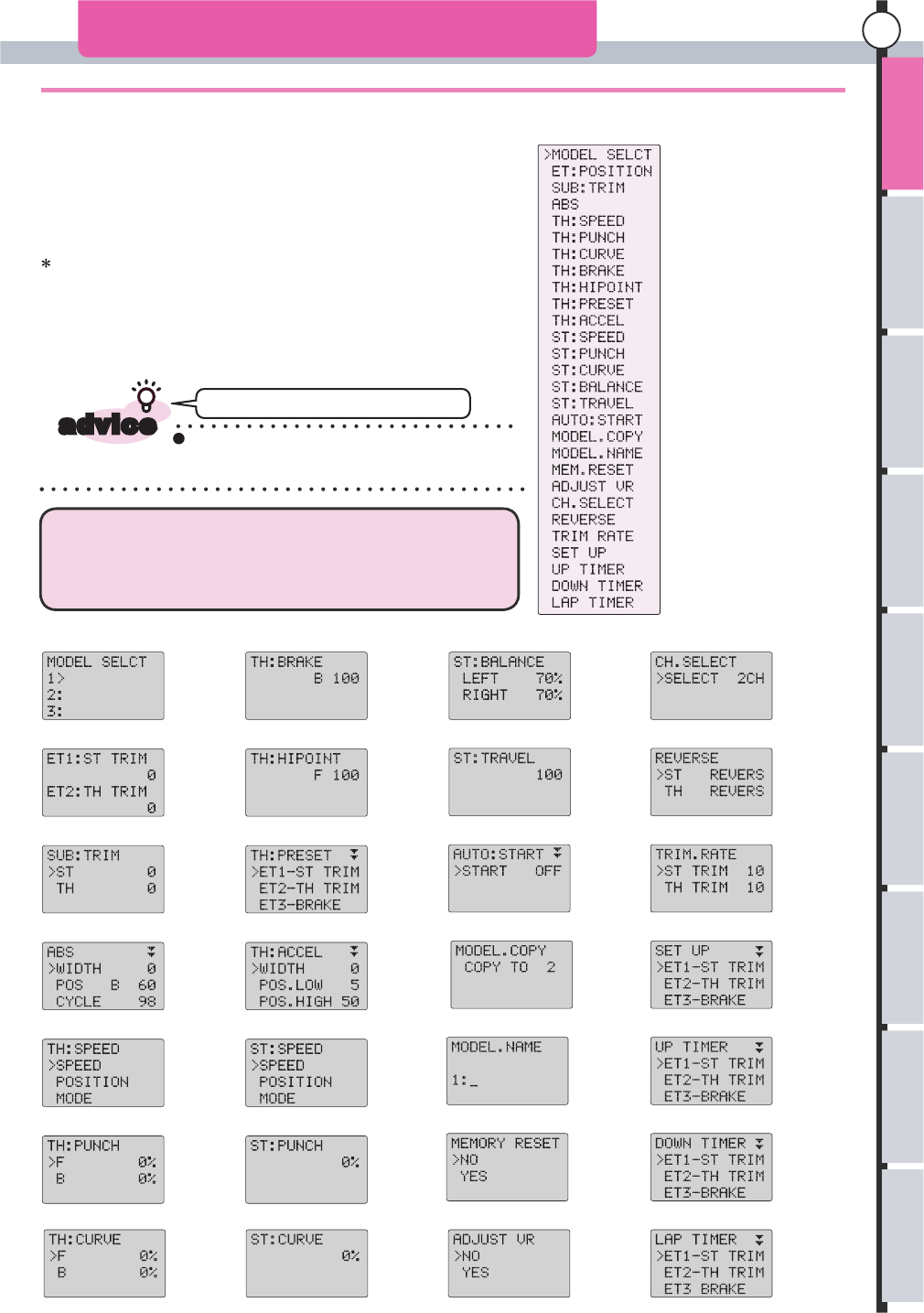
SCREEN TABLE FUNCTION MENU
These screens are displayed when the function menu is opened.
Model Select
ET Position
Sub Trim
A.B.S
Throttle Speed
Throttle Punch
Throttle Curve
Throttle Brake
Throttle High Point
Throttle Preset
Throttle Acceleration
Steering Speed
Steering Punch
Steering Curve
Steering Balance
Steering Travel
Automatic Start
Model Copy
Model Name
Memory Reset
Adjust Volume
Channel Select
Reverse Switch
Trim Rate
Select Up
Up Timer
Down Timer
Lap Timer
You can return to the initial screen if you keep
pushing the Back Key from any screen that is
displayed.
Model Select
ET Position
Sub Trim
A.B.S
Throttle Speed
Throttle Punch
Throttle Curve
Throttle Brake
Throttle Preset
Throttle High Point
Throttle Acceleration
Steering Speed
Steering Punch
Steering Curve
Steering Balance
Steering Travel
Automatic Start
Model Copy
Model Name
Memory Reset
Adjust Volume
Channel Select
Reverse Switch
Trim Rate
Setup
Down Timer
Lap Timer
Up Timer
P32
P33
P34
P35/36
P37/38
P39
P40
P41
P42
P43
P44/45
P46/47
P48
P49
P50
P51
P52
P53
P54
P55
P56
P57
P58
P59
P60
P61
P62
P63
When a function name is chosen from the display list of functions
from the menu with the Jog Dial, and 'Enter' is pressed, that particular
function opens.
The following screens will be opened when the function name is
chosen by Jog Dial or (+), (-) keys, then Enter is pressed.
Cannot return to initial screen.
All 28 function menus will be displayed when Master is selected
from the menu.
In Custom 1 and Custom 2, only the set content is displayed.
To display all, please refer t o Change Menu (P17, P26)
and return display menu to Master.
The function menu opens when Jog Dial or (+), (-) keys are operated
from an initial screen.
The 28 functions on the right make up the function menus.
Please see each reference page for a detailed operation method, after each screen is opened.
advice
eg
a
s
U
e
ht
f
o
r
ett
i
msn
arT
no
se
t
o
N
gni
lla
ts
n
I
gni
t
cen
n
o
C
re
viec
Re
e
h
t
s
erut
a
e
Fu
n
e
M
n
i
aM
u
ne
M
n
o
i
tc
nu
F
noitpircseD x
ed
n
I
12
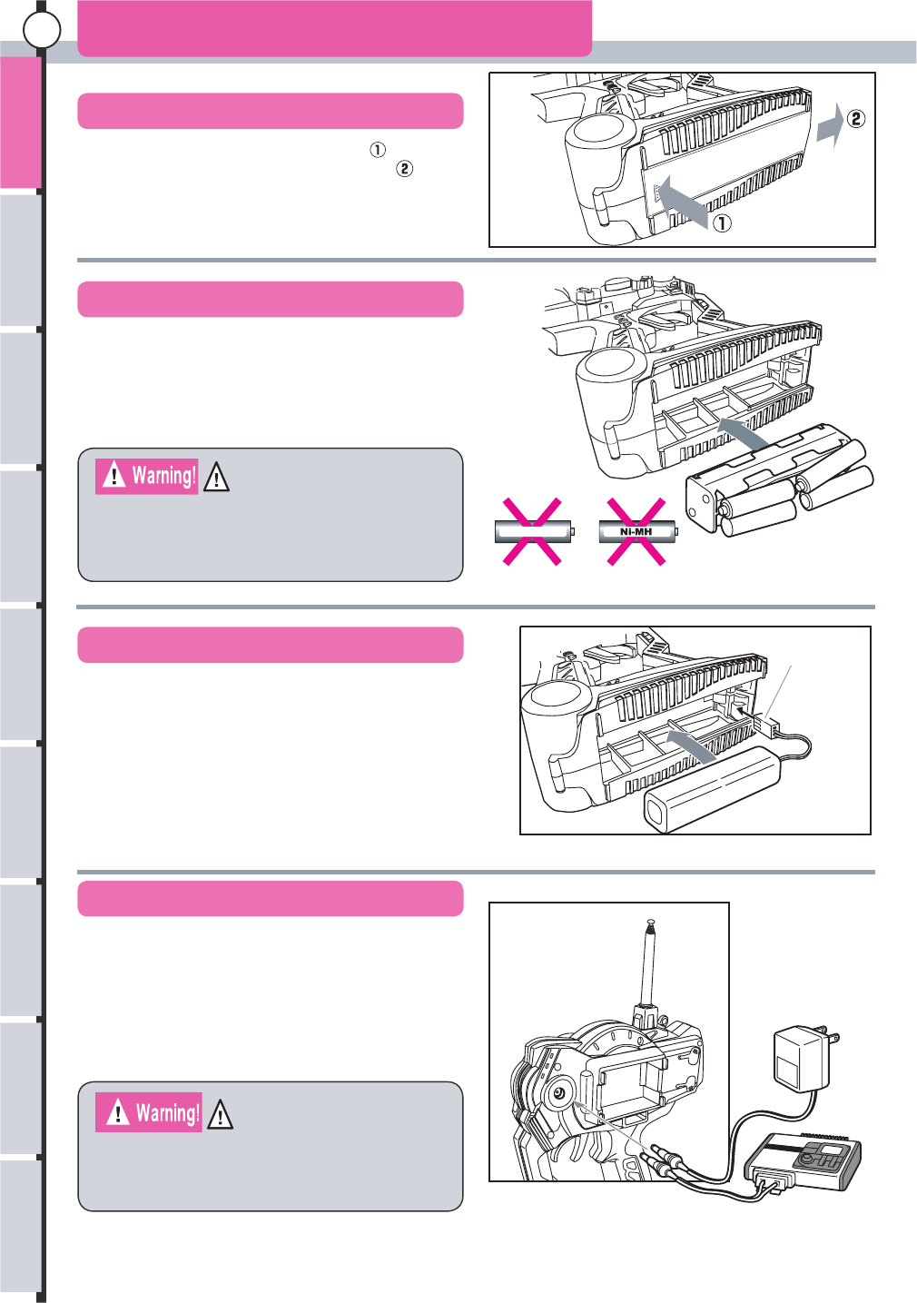
(1) While pressing in the direction of arrow
slide the battery cover in the direction of arrow .
,
How To Insert Batteries 1
Opening the Cover
Inserting Batteries (optional)
Inserting a Battery Pack (optional)
Charging Battery Packs
Do not charge AA size Ni-Cd or Ni-MH batteries
using the dry cell battery box installed in the
transmitter. Gases generated during charging
may form and corrode the inside of the transmitter.
Do not charge when dry cell batteries are used.
The transmitter will be damaged due to the liquid
leakage the explosion of cells while charging.
Facing Correct
Direction
*Please attach included sponge to the battery lid
when the battery pack is used.
The transmitter charge jack is suitable for use ONLY with
JR® Chargers. Use only a JR AC wall charger or a
12V DC charger that is capable of supplying the correct
polarity to the charge jack! (JR transmitter charge jack
polarity uses a Negative center pin and Positive barrel.)
Do NOT use any other wall charger as it may reverse
polarity and cause damage to your system.
(1) The connector is inserted noting the direction as shown in figure.
(2) Insert battery pack and close the cover.*
(3) Be careful not to trap the cord.
(1) Insert eight “AA” dry cell batteries in the corresponding
direction that matches the plus or minus signs found on the
dry cell battery box.
(2) Replace the dry cell battery box into the transmitter with
the box’s terminals matching the terminals of the transmitter.
(3) Replace the battery cover.
eg
a
s
U
e
ht
f
o
r
ett
i
msn
arT
no
se
t
o
N
gni
lla
ts
n
I
gni
t
cen
n
o
C
re
viec
Re
e
h
t
1.2V “AA” Ni-Cd
s
e
ru
t
a
e
Fu
n
e
M
n
i
a
M
u
ne
M
n
o
i
tc
n
u
F
noit
p
i
rc
se
Dx
ed
nI
13
Please note the battery pack can not be discharged using charging jack.
Please remove battery pack from main unit for discharging.
How to Insert Batteries 2
Discharging Battery Packs
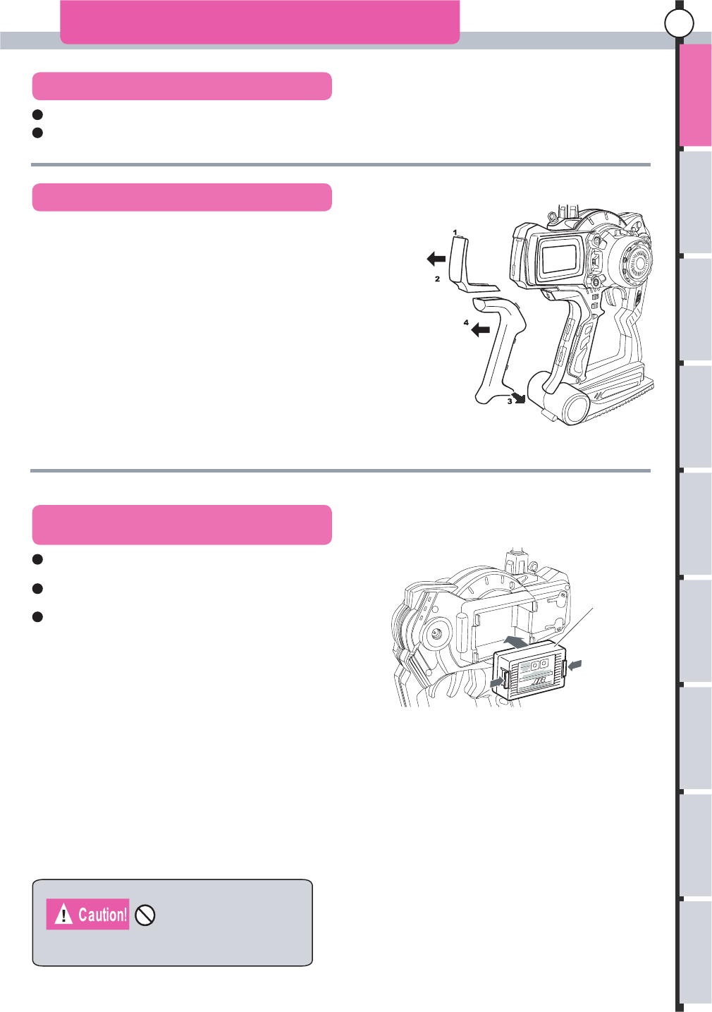
Replacing Color Pad and Grip
Changing the RF Module and Channels
Only the RF Module for Z-1 should be used.
Pad
Grip
RF Module
Be sure to turn off the power switch when changing the
RF Module or Channel
To select transmitting channel, turn the channel select dial(s)
on the synthesized module.
Once you have selected the proper channel, cycle the power
switch for the radio system to lock in the change.
Do this in the reverse order of the removal procedure. The lower side
of the pad is slid in. Then using your fingernail, the upper side (1) of
the pad is inserted into the transmittor case.
Slide the grip onto the case and then push the six tabs into the case
using your fingernails. If it is not easy to insert the tabs into the case,
push them in by using a flat screw driver. Do not use anything that
will damage the case. Finally, push the guide pins in the lower side (3) into the case.
How to attach pad or grip.
Pull in the direction of the arrow (2), and remove the pad removes using
your fingernail (1).
After expanding the lower side (3), the whole grip pulls in the direction
of the arrow (4).
How to remove pad or grip.
eg
a
s
U
e
ht
f
o
r
ett
i
msn
arT
no
se
t
o
N
gni
lla
ts
n
I
gni
t
cen
n
o
C
re
viec
Re
e
h
t