Horizon Hobby PYTHON JR Python Pistol Grip AM Radio System User Manual JRP2775M 46 Python Inst update
Horizon Hobby, LLC JR Python Pistol Grip AM Radio System JRP2775M 46 Python Inst update
Python Manual

1
2-CHANNEL DIGITAL PROPORTIONAL RADIO CONTROL SYSTEM
INSTRUCTION MANUAL
II. COMPONENTS AND SPECIFICATIONS
Your JR Python Radio includes the following items:
Transmitter ………………………………………………… NET-112L
2-Channel Receiver ………………………………………… NER-102
2 Servos ……………………………………………………… Z250 x 2
Accessories ………… B.E.C. Switch Harness and Servo Accessories
TRANSMITTER SPECIFICATIONS: PYTHON LED
Antenna Output……………………………………………… 500mW
Frequency ………………………………………………… 27/75 MHz
Modulation ………………………………………………………… AM
Power Supply ……………………………………………… 9.6V D/C
Dimensions …………………………………… 8.15"x 7.00"x 3.35"
Weight …………………………………………………………… 13 oz
RECEIVER SPECIFICATIONS: R102
Intermediate Frequency …………………………………… 455KHz
Power Supply ………………………………………… 4.8V-8.4V D/C
Dimensions…………………………………… 1.93"x 1.50"x 0.827"
Weight …………………………………………………………… 1.3 oz
SERVO SPECIFICATIONS: Z250
Torque ………………………………………………… 49 in/oz. (6V)
Speed …………………………………………………. .19 sec/60° (6V)
Dimensions …………………………………… 0.73"x 1.52"x 1.32"
Weight …………………………………………………………… 1.5 oz
BB ……………………………………………………………… Bushing
Motor …………………………………………………… 3-Pole Ferrite
III. R/C SAFETY PRECAUTIONS
For safe and reliable performance of your R/C model, please care-
fully read and follow these guidelines:
1. Radio control models are not toys. They are capable of inflict-
ing serious injury to people and property. Use caution at all
times when operating your model.
2. You are responsible for the safe operation of your R/C model.
You must properly install, test, and operate your model with a
clear sense of that responsibility. Do not take risks that might
endanger yourself or others.
3. Running an R/C car in the streets is very dangerous to both
drivers and models. Avoid running your model in areas
occupied by full-size automobiles. To locate areas where you
can safely operate your model, contact your local hobby shop
for R/C tracks or clubs in your area.
4. When running an R/C boat, keep it away from any swimmers,
full-size boats, or wildlife. Also, watch carefully for fishing
lines that can entangle the propeller.
5. Before operating your model, make sure your frequency is
clear. If someone else is operating on the same frequency, both
models will go out of control, possibly causing damage to the
models, as well as others.
6. If at any time while operating your R/C model you sense
abnormal model functioning, end your operation immedi-
ately. Do not operate your model again until you are certain
the problem has been corrected.
CAUTION: Control of your model is impossible without suffi-
cient voltage for the transmitter and receiver. A weak transmitter
battery will decrease your range of operation and a weak receiver
battery will slow servo movement and decrease your range of
operation. Check your receiver pack voltage often to avoid losing
control of your model. When using a model that operates both
the electric motor and the receiver from the same battery
(Battery Eliminating Circuitry or B.E.C.), you should discontinue
use when the top speed sharply decreases or you will quickly
lose control of your model.
I. INTRODUCTION
Congratulations on your purchase of the JR Python
2-channel radio control set which has been manufactured and
assembled with the greatest care.
We are confident that you will be delighted with your purchase.
Please read the instructions thoroughly, noting all points before
use, in order to avoid mistakes in handling and operation.
Your NER-102 Receiver has Battery Eliminator Circuitry (B.E.C.).
The receiver gets its power from the model’s NiCad battery pack,
thus saving the weight of an additional receiver battery. NiCad
batteries from 6V-8.4V (5-7 cells) can be used safely. Higher volt-
age packs may damage the receiver and servos.
ATTENTION: Make sure the male and female connectors have
the correct polarity (+/–) before connecting. The servo lead and
receiver case are molded so that the lead can only be inserted
correctly. Be sure to orient the servo plug correctly for proper
insertion.
You may use a separate battery to power the receiver (such as
for some electric boats or in gas-powered vehicles). A NiCad pack
plugged into the BATT socket on your receiver will operate your
receiver. You may also use alkaline batteries with an optional
battery holder (part no. JRPA020).
If you use a mechanical speed controller, please ensure that it
has the correct connector for a B.E.C. system (red connector).
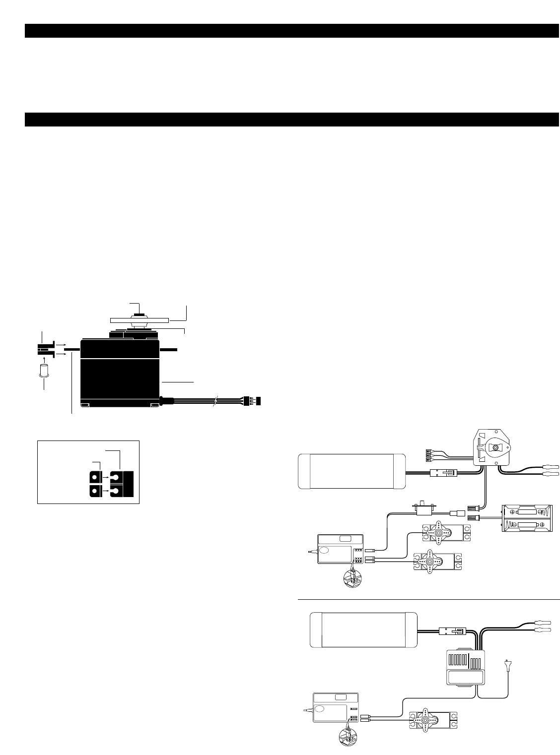
See FIGURE A for a typical setup.
Most electronic speed controllers are set up for B.E.C. operation
and plug directly into your receiver (Function 2). See FIGURE B for
a typical setup and check your speed controller’s manual for
correct installation.
You should use the black rubber servo cushions whenever possi-
ble to decrease your servo’s sensitivity to vibration.
IV. OPERATING YOUR MODEL
It is important to learn the proper sequence for switching
ON/OFF your radio system:
BEFORE OPERATION: Switch on the transmitter, then the receiver.
AFTER OPERATION:Switch off the receiver, then the transmitter.
This ensures that you will always have a signal to the receiver,
and your R/C model will not operate out of control when you
turn off the transmitter.
V. INSTALLATION
BEC
B
E
C
FIGURE A – Connections to B.E.C. receiver with mechanical speed controler. NiCad
battery, speed controller and battery holder are not included in the radio set.
To Motor
To Motor
To Resistors
BEC Connector
Optional Battery Holder
(JRPA020)
JR PYTHON WITH Z250 SERVOS
SERVO FEATURES
• A tight deadband amplifier ensures accurate neutral centering
• Low current drain
• An indirect drive feedback potentiometer gives additional
protection from vibration
• State-of-the-art surface mount technology (SMT)
• 3-pole ferrite cored motor for reliability
Z250 SERVO LAYOUT
Rubber Grommets
Servo Case
Servo Lead w/Connector
Servo Output Shaft
Servo Mounting Flange
Servo Arm/Horn
Servo Arm Retaining Screw
Servo Eyelet
Servo Mounting Flange
Rubber Grommets
TOP VIEW
FIGURE B – Connections to B.E.C. receiver
with electronic speed controler. Ni-Cad
battery and speed controller are not
included in the radio set.
2
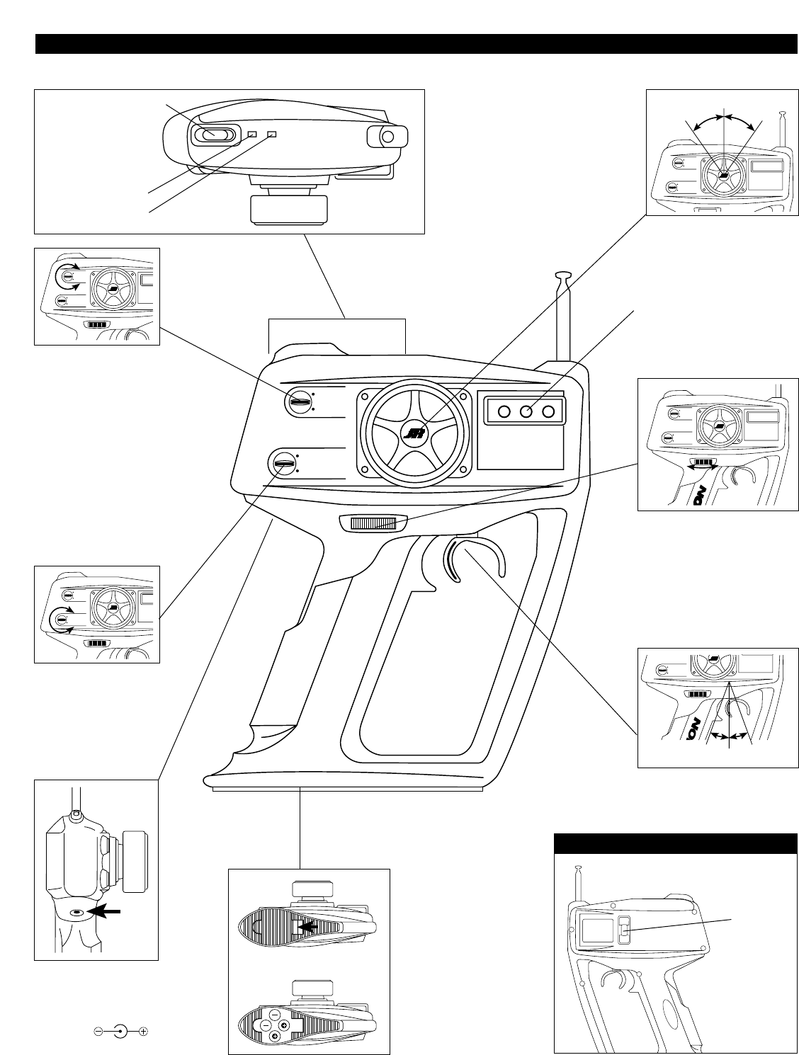
VI. IDENTIFICATION OF TRANSMITTER PARTS
PYTHON
LED VOLTAGE METER – If the meter indicates
green, your batteries are approximately full
strength. If the meter indicates orange or red,
the batteries are weak and need to be replaced
with new cells or charged if you are using
rechargeable “AA” NiCads.
STEERING REVERSING SWITCH
THROTTLE REVERSING SWITCH
POWER SWITCH
CRYSTAL
STEERING WHEEL –
The steering wheel
rotates 35° to the left
and to the right.
STEERING TRIM – Rotate the top trim
tab to adjust and obtain the neutral
position of the steering servo.
HINT: Setting your steering linkage:
1. Make sure your steering rate
adjuster (see call-out at right) is set to
the maximum position and your
steering trim is centered.
2.Turn on the power to your receiver
to center the steering servo and set
the linkage for maximum travel. Then
use the rate adjuster to adjust the
amount of travel you need.
THROTTLE TRIM – Rotate the bottom
trim knob to adjust and obtain the
neutral position of the throttle servo.
CHARGING JACK – Your Python trans-
mitter can be upgraded to NiCad
batteries using the optional Dynamite
DYN1900 NiCad Conversion Kit.
JR POLARITY:(Center pin negative)
STEERING RATE ADJUSTER – The steering rate
adjuster affects the throw of the steering servo.
The output can be adjusted from approxi-
mately 10% to 100%. The throw of the servo
decreases as you move the dial to the left.
HINT: Use this to decrease the sensitivity of
your steering on loose courses and on courses
without tight curves.
SERVO REVERSE SWITCHES–
The reverse switches allow the
rotation of the servos to be reversed.
35°35°
20°20°
THROTTLE TRIGGER – The throttle trigger moves
20° in the forward and reverse direction.
BACK OF TRANSMITTER
(FACTORY INSTALLED)
BATTERY CASE – To remove
the battery cover, slide the
tab in the direction of the
arrow while pushing the
rounded tab.
Install the 8 “AA” batteries
according to the diagram.
If the transmitter voltage
fails to register, check for
the correct installation of
the batteries and make
sure the batteries still have
a charge.
3

4
26.995........................1
27.045........................2
.095 .......................3
.145 .......................4
.195 .......................5
.255 .......................6
75.410 .....................61
.430 .....................62
.450 .....................63
.470 .....................64
.490 .....................65
.510 .....................66
75.530 .....................67
.550 .....................68
.570 .....................69
.590 .....................70
.610 .....................71
.630 .....................72
.650 .....................73
.670 .....................74
.690 .....................75
.710 .....................76
.730 .....................77
.750 .....................78
75.770 .....................79
.790 .....................80
.810 .....................81
.830 .....................82
.850 .....................83
.870 .....................84
.890 .....................85
.910 .....................86
.930 .....................87
.950 .....................88
.970 .....................89
.990 .....................90
IMPORTANT NOTE
Be sure to keep your original dated sales receipt in a safe place as
you will be required to provide proof of purchase date for the
equipment to be serviced under warranty.
WARRANTY COVERAGE
Your new JR Remote Control Radio System is warranted to the
original purchaser against manufacturer defects in material and
workmanship for 365 days from the date of purchase. During
this period, Horizon Service Center will repair or replace, at our
discretion, any component that is found to be factory defective
at no cost to the purchaser. This warranty is limited to the
original purchaser of the unit and is not transferable.
This warranty does not apply to any unit which has been
improperly installed, mishandled, abused or damaged in a crash,
or to any unit which has been repaired or altered by any
unauthorized agencies. Under no circumstances will the buyer be
entitled to consequential or incidental damages. This limited
warranty gives you specific legal rights; you also have other
rights which may vary from state to state. As with all fine
electronic equipment, do not subject your radio system to
extreme temperatures, humidity or moisture. Do not leave it in
direct sunlight for long periods of time.
REPAIR SERVICE DIRECTIONS
In the event that your JR radio needs service, please follow the
instructions listed below.
1. Check all ON/OFF switches to be sure they are off. This will
speed the repair process of checking battery condition.
2. Return your system components only (transmitter, receiver,
servos, etc.) Do not return your system installed in a model
car, boat, etc.
3. Preferably, use the original carton/packaging (molded foam
container) or equivalent to ship your system. Do not use the
system carton itself as a shipping carton. You should package
the system carton within a sturdy shipping container using
additional packing material to safeguard against damage during
transit. Include complete name and address information
inside the carton, as well as clearly writing it on the outer
label/return address area.
4. Include detailed information explaining your operation of the
system and problem(s) encountered. Provide an itemized list of
equipment enclosed and identify any particular area/function
which may better assist our technicians in addressing your
concerns. Date your correspondence, and be sure your
complete name and address appear on this enclosure.
5. Include you name, mailing address, and a phone number
where you can be reached during the business day.
6. WARRANTY REPAIRS.To receive warranty service you must
include your original dated sales receipt to verify your proof-
of-purchase date. Providing that warranty conditions have
been met, your radio will be repaired without charge.
7. NORMAL NON-WARRANTY REPAIRS.Should your repair cost
exceed 50% of the retail purchase cost, you will be provided
with an estimate advising you of your options.
Within your letter, advise us of the payment method you prefer
to use VISA or MasterCard. Please include your card number and
expiration date.
Mail your system to: Horizon Service Center
4105 Fieldstone Road
Champaign, IL 61822
Phone: (217) 355-9511
www.horizonhobby.com
VII. PARTS LISTING VIII. FREQUENCY CHART
X. WARRANTY AND SERVICE INFORMATION
FREQUENCY (MHZ)CHANNEL FREQUENCY (MHZ)CHANNEL FREQUENCY (MHZ)CHANNEL
IX. PYTHON RECEIVER CRYSTAL COMPATIBILITY
NER-102 STANDARD RECEIVER
Your Python’s NER-102 receiver has been designed to use only a
JR “green” receiver crystal (JRPXAG** TX/RX crystal set).
JR “grey” receiver crystals (JRPXAR**) are not designed to be used
with the NER-102 receiver, and will reduce the usable range of
the receiver.
R122 OPTIONAL RECEIVER
JR’s optional R122 receiver is designed for use with JR “grey”
receiver crystals only (JRPXAR**). The JR “green” receiver crystals
(JRPXAG** Tx/Rx crystal set) included with your Python system
are not compatible with the R122 receiver and should not be used.
** Replace with channel number when ordering.
JRP2775M.46
JRPA159 TX Antenna
JRPA225 Servo Grommets (20)
JRPA233 Servo Eyelets (20)
JRPA226 Servo Mounting Screws (20)
JRPA210 Offset Horn w/Screw (2)
JRPA212 Large Arm w/Screw (2)
JRPSCZ250 Servo Case
JRPSGZ250 Servo Gear Set
JRPXAG** AM Crystal Set
OPTIONAL PARTS
JRPA011 Switch Harness for BEC
JRPA020 4-Cell RX Battery Case
JRPC221 TX/RX Charger
DYN1900 NiCad Conversion Kit