Horizon Hobby XF631 XF631 6 Channel FM Radio System User Manual XF631 Manual
Horizon Hobby, LLC XF631 6 Channel FM Radio System XF631 Manual
XF631 Manual
6-CHANNEL COMPUTER RADIO


3
XF631 MANUAL • Table of Contents
QUICK START
4
I. INTRODUCTION
1. Using This Manual 6
2. Features 6
2.1 Transmitter Features 6
2.2 Receiver Features 6
2.3 Servo Features 7
2.4 Servo Layout 7
3. Specifications 8
3.1 System Specifications 8
3.2 Transmitter Specifications 8
3.3 Servo Specifications 8
3.4 Receiver Specifications 9
3.5 Charger Specifications 9
3.6 Airborne Battery Pack 9
4. Battery Charging 10
4.1 Transmitter/Receiver 10
4.2 Charger 10
5. Trainer System 11
II. XF631 MANUAL
1. Transmitter Controls 12
1.1 Control Identification and Location 12
1.2
Receiver Channel Assignment/
Transmitter Throttle ALT
12
1.3 Transmitter Rear 13
1.4 Control Stick Length Adjustment 13
1.5 Direct Servo Control (DSC) 14
1.6 Neck Strap Attachment 14
2. Connections 15
2.1 Installation Requirements 15
2.2 Connections 15
3. Key Input and Display 16
4. Battery Alarm and Display 16
5. Input Mode and Functions 17
5.1 Normal Display 17
5.2 Direct Trim Access Display 17
5.3 Mode Types 17
5.4 Throttle Cut 17
5.5 System Mode 18
5.6 Function Mode 18
6. Functions (System Mode) 19
6.1 Data Reset 19
6.2 Model Selection 20
6.3 Wing Type Selection 20
6.4 Model Name Entry 23
7. Functions (Function Mode) 24
7.1 Servo Reversing 24
7.2 Dual Rate 25
7.3 Sub Trim 26
7.4 Travel Adjustment 27
8. Data Sheets 28
III. IMPORTANT INFORMATION
1. General Notes 31
2. Daily Flight Checks 31
3. Warranty Coverage 32
4. Repair Service Instructions 32
5. Frequency Chart 33
TABLE OF CONTENTS
We strongly encourage all prospective and current R/C
aircraft pilots to join the Academy of Model Aeronautics.
The AMA is a non-profit organization that provides
services to model aircraft pilots. As an AMA member you
will receive a monthly magazine entitled Model Aviation, as
well as a liability insurance plan to cover against possible
accident or injury. All AMA charter aircraft clubs require
individuals to hold a current AMA membership prior to
operation of their models. For further information you can
contact the AMA at:
Academy of Model Aeronautics
5151 East Memorial Drive
Muncie, IN 47302
(317) 287-1256
Thank you for purchasing the JR XF631 6-Channel Radio
System. This unit has been designed to provide the
modeler with a high-quality, user-friendly radio system
that can be depended upon for years to come.
It’s important that you carefully read this manual before
attempting to operate your system. Please pay particular
attention to Page 10, Introduction 4, “Battery Charging.”
AMA INFORMATION
INTRODUCTION TO THE XF631 RADIO SYSTEM
4XF631 MANUAL Quick Start
XF631 QUICK START
In this manual you will find in-depth instructions that
detail all the steps and procedures you should follow in
order to program each of the XF631’s features. For
modelers who want to get into the air fast, we have
provided Quick Start. Quick Start covers the basic
programming information necessary to get you airborne.
Later, when you want to learn more about specific features
of the XF631, turn to the appropriate pages(s) in this
manual for more detailed programming information.
Note: Please charge the system batteries as indicated
in step 4.1 before attempting the Quick Start setup
and again before flying the model.
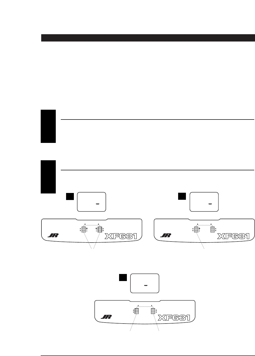
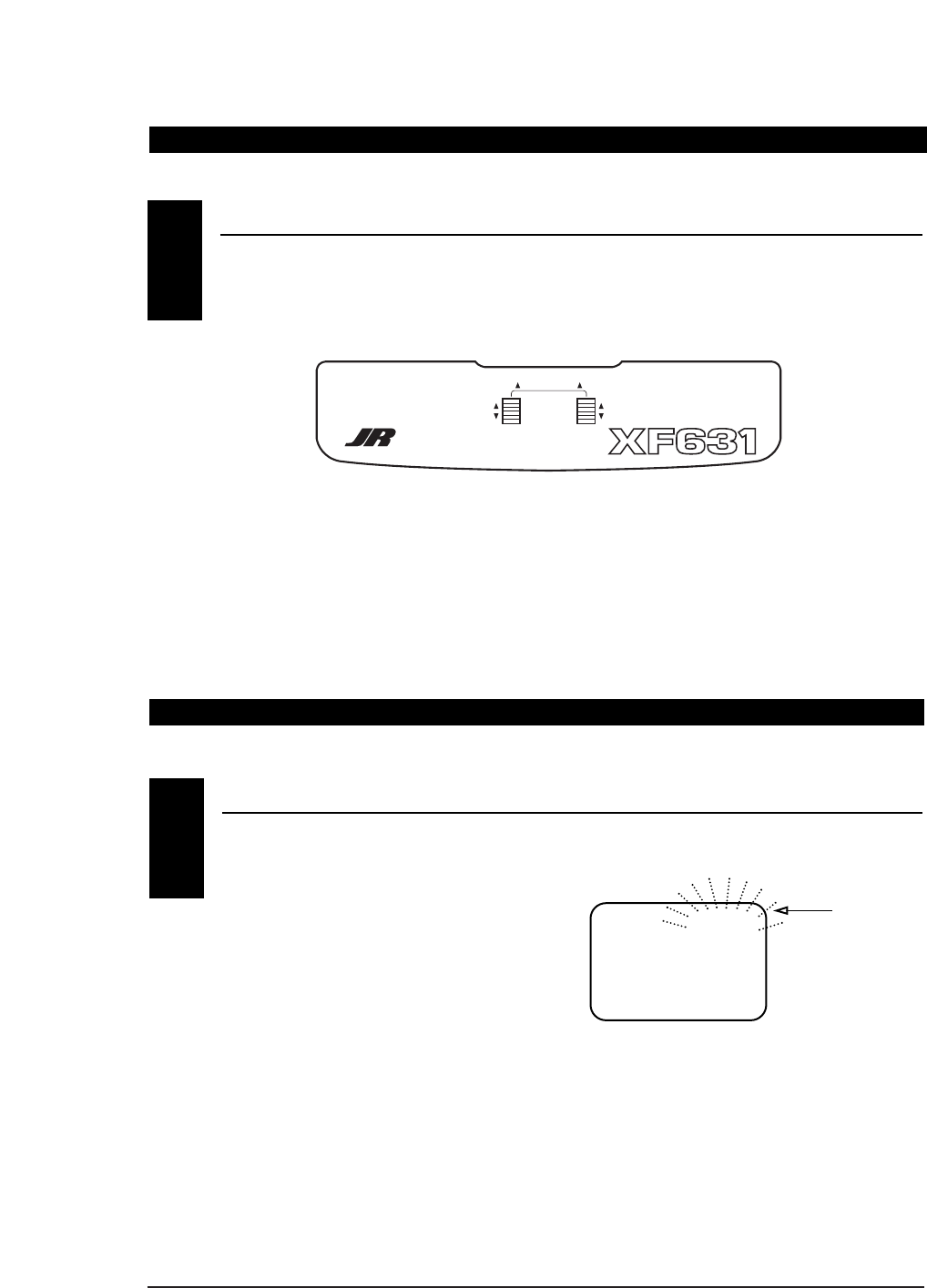
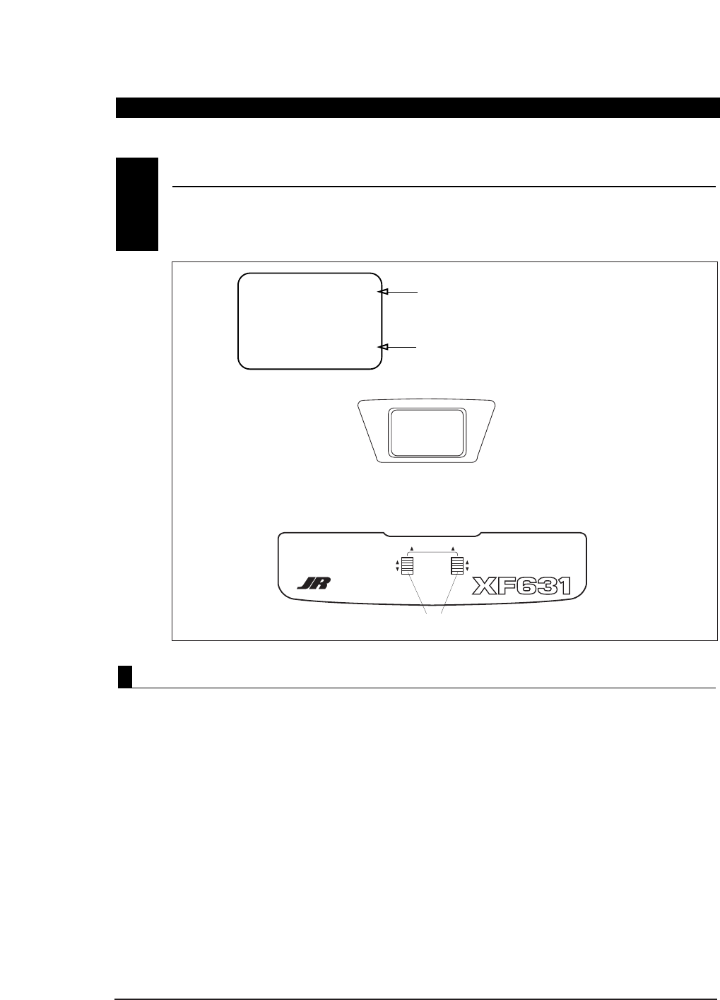
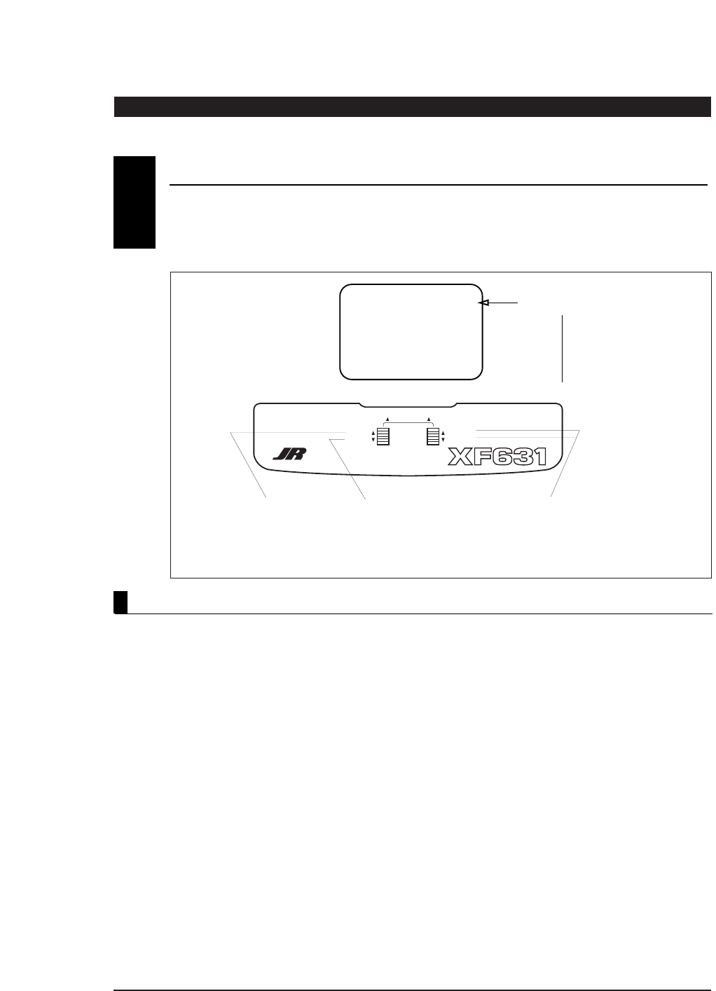
Turn on the transmitter and check to ensure that the
aileron, elevator, and rudder trim valves are set to the
0 (neutral) position.
Next, set the throttle trim valve to the full low (-40)
position by pressing the throttle trim lever down.
DIGITAL TRIM SETTINGS
1
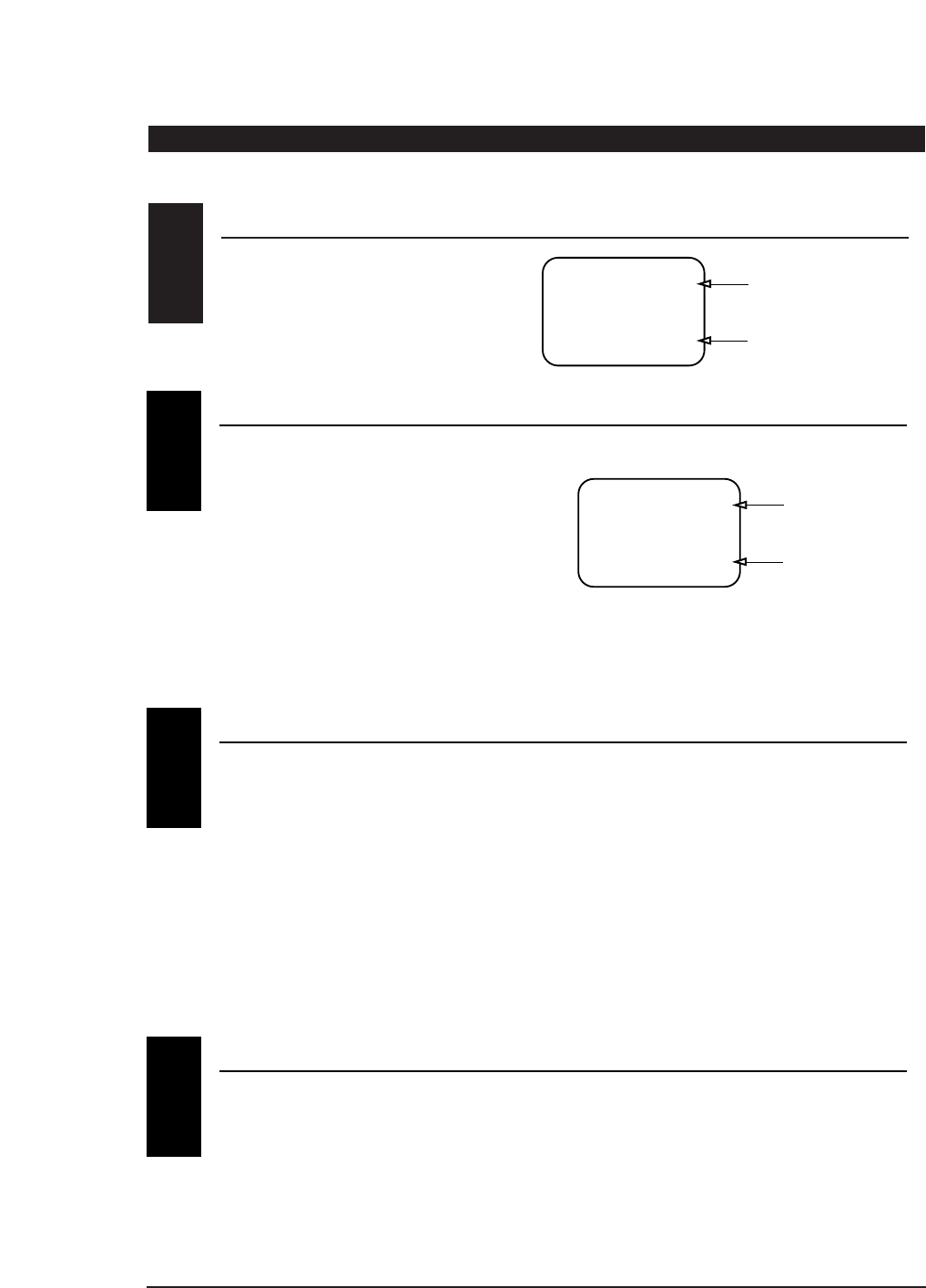
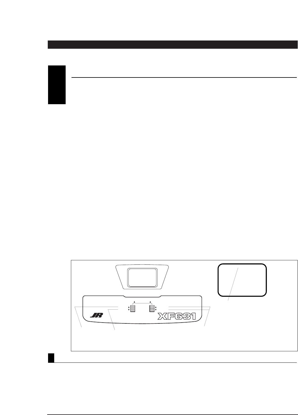
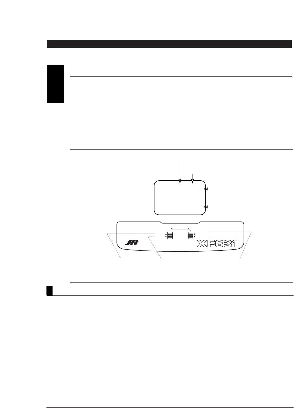
SERVO REVERSING
2
REV◆NORM
THR
CHANNEL
SCROLL INCREASE
DECREASE
ENTER
DIGITAL TRIM EQUIPPED 6 CHANNEL
MULTI-DATA COMPUTER DISPLAY SYSTEM
REV◆NORM
THR
CHANNEL
SCROLL INCREASE
DECREASE
ENTER
DIGITAL TRIM EQUIPPED 6 CHANNEL
MULTI-DATA COMPUTER DISPLAY SYSTEM
With the transmitter on, press the Scroll and Increase
buttons upward simultaneously until a beep is heard.
Press the Channel button to select
the channel you want to reverse. Press the Increase or Decrease button
to reverse the direction of the
channel you selected.
REV◆NORM
THR
CHANNEL
SCROLL INCREASE
DECREASE
ENTER
DIGITAL TRIM EQUIPPED 6 CHANNEL
MULTI-DATA COMPUTER DISPLAY SYSTEM
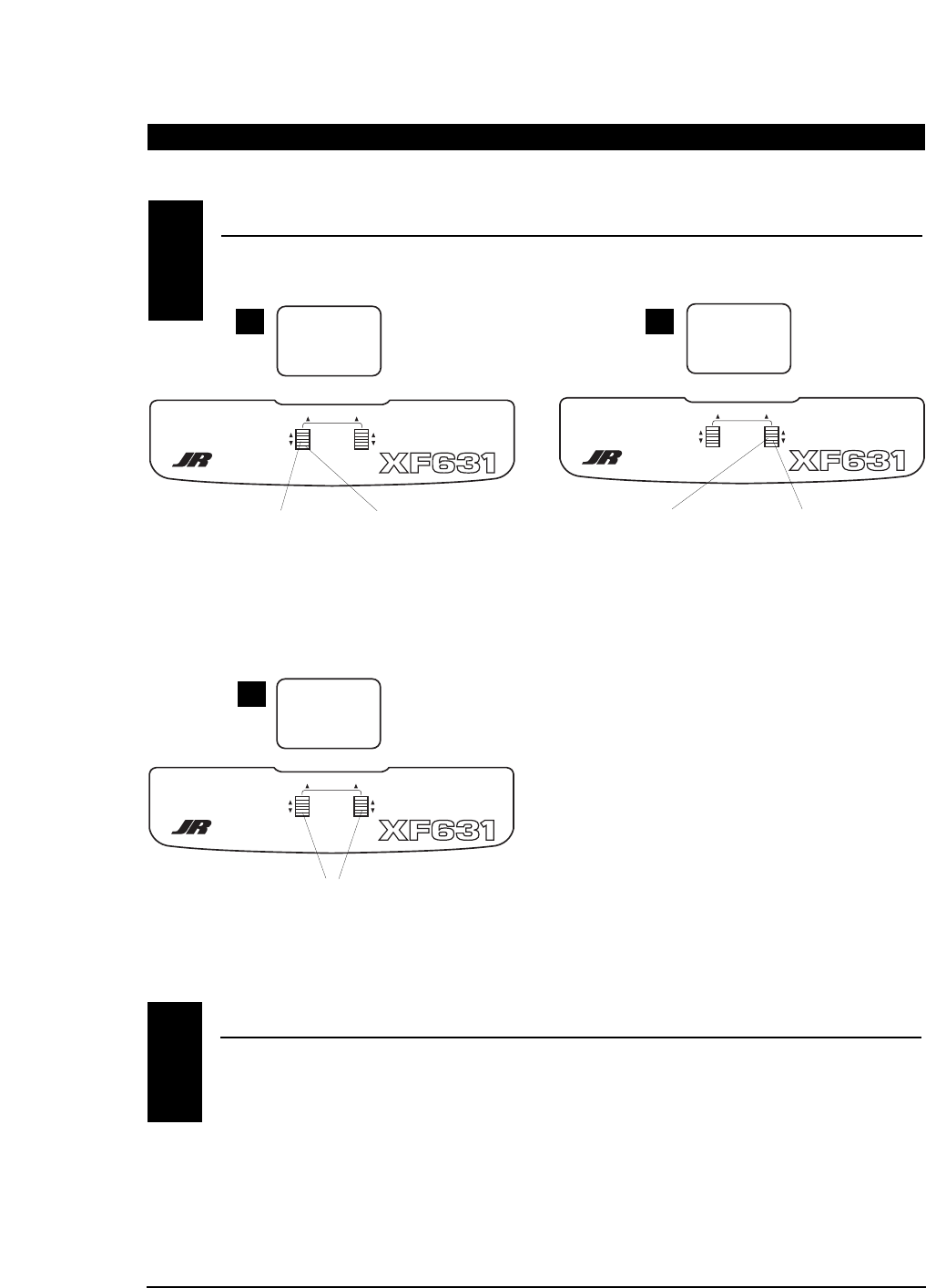
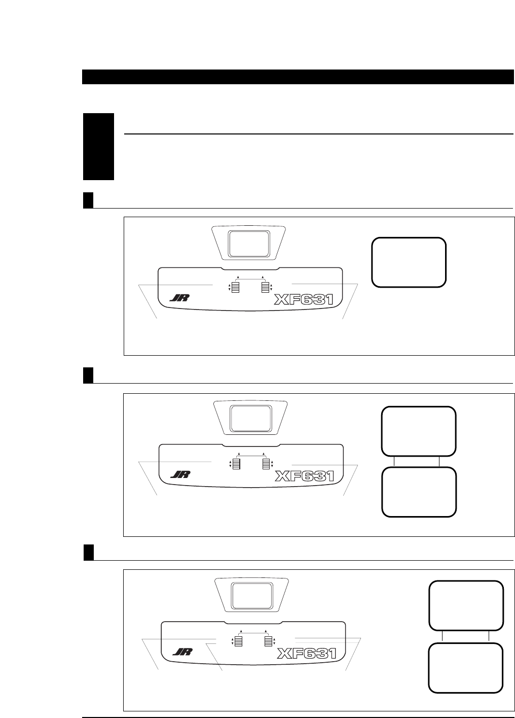
Press the Scroll button (if necessary) until
“REVERSE-NORM” appears on the screen.
AB
C
CHANNEL
SCROLL INCREASE
DECREASE
ENTER
DIGITAL TRIM EQUIPPED 6 CHANNEL
MULTI-DATA COMPUTER DISPLAY SYSTEM
TRV ADJ. AIL
+I00%
CHANNEL
SCROLL INCREASE
DECREASE
ENTER
DIGITAL TRIM EQUIPPED 6 CHANNEL
MULTI-DATA COMPUTER DISPLAY SYSTEM
TRV ADJ. AIL
+I07%
5
XF631 MANUAL Quick Start
XF631 QUICK START
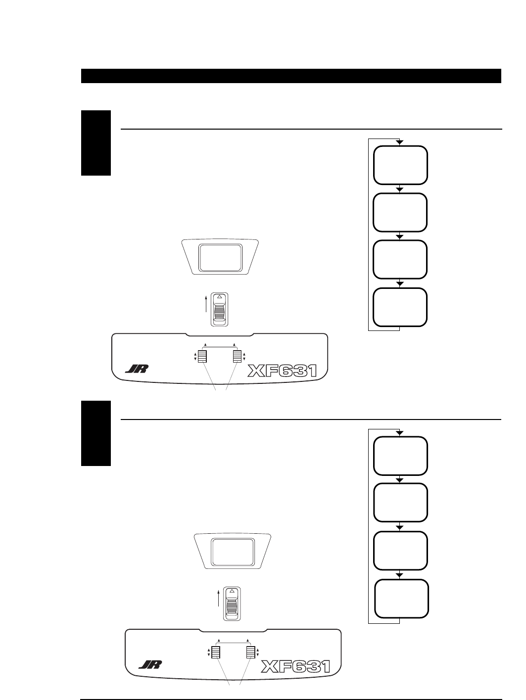
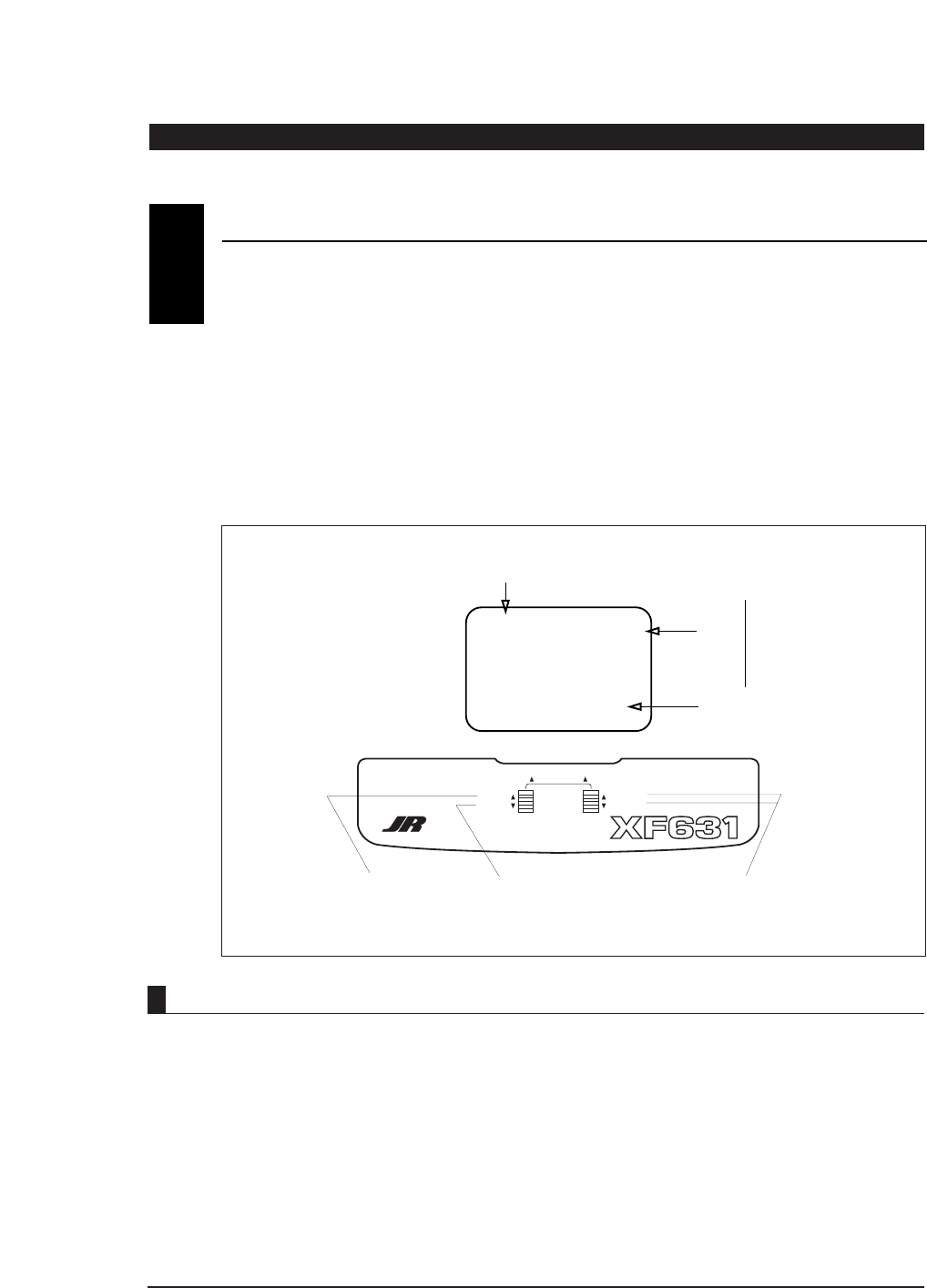
Press the Scroll
button until
“TRV ADJ” appears
on the screen.
Press the Channel button
to select the channel on
which you want the travel
adjusted.
INCREASE
To increase the travel,
move the stick (i.e. aileron)
to the right then press the
Increase button to adjust
the right travel. Release
the Increase button and
move the same stick to
the left. Press the
Increase button to adjust
the left travel.
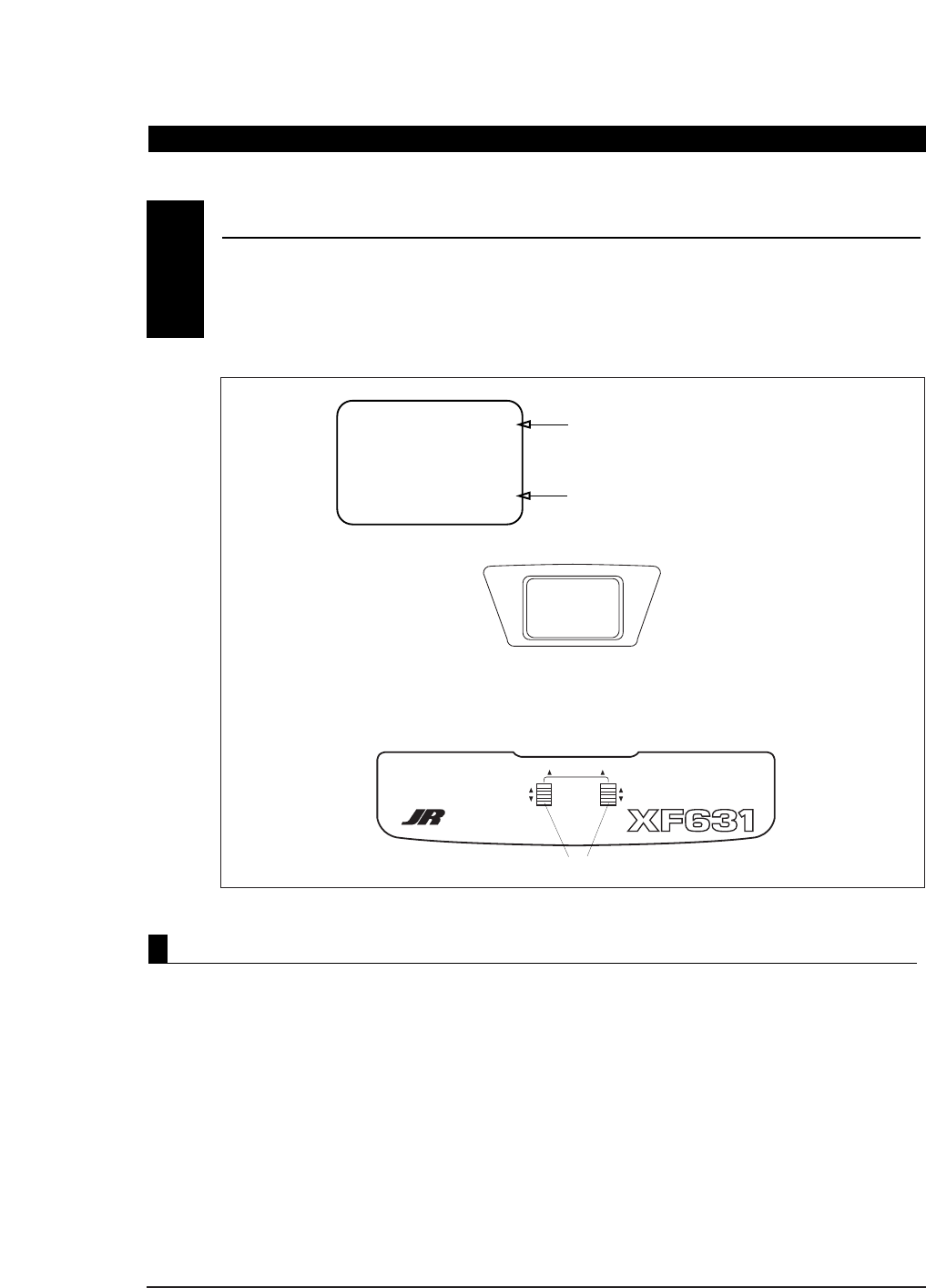
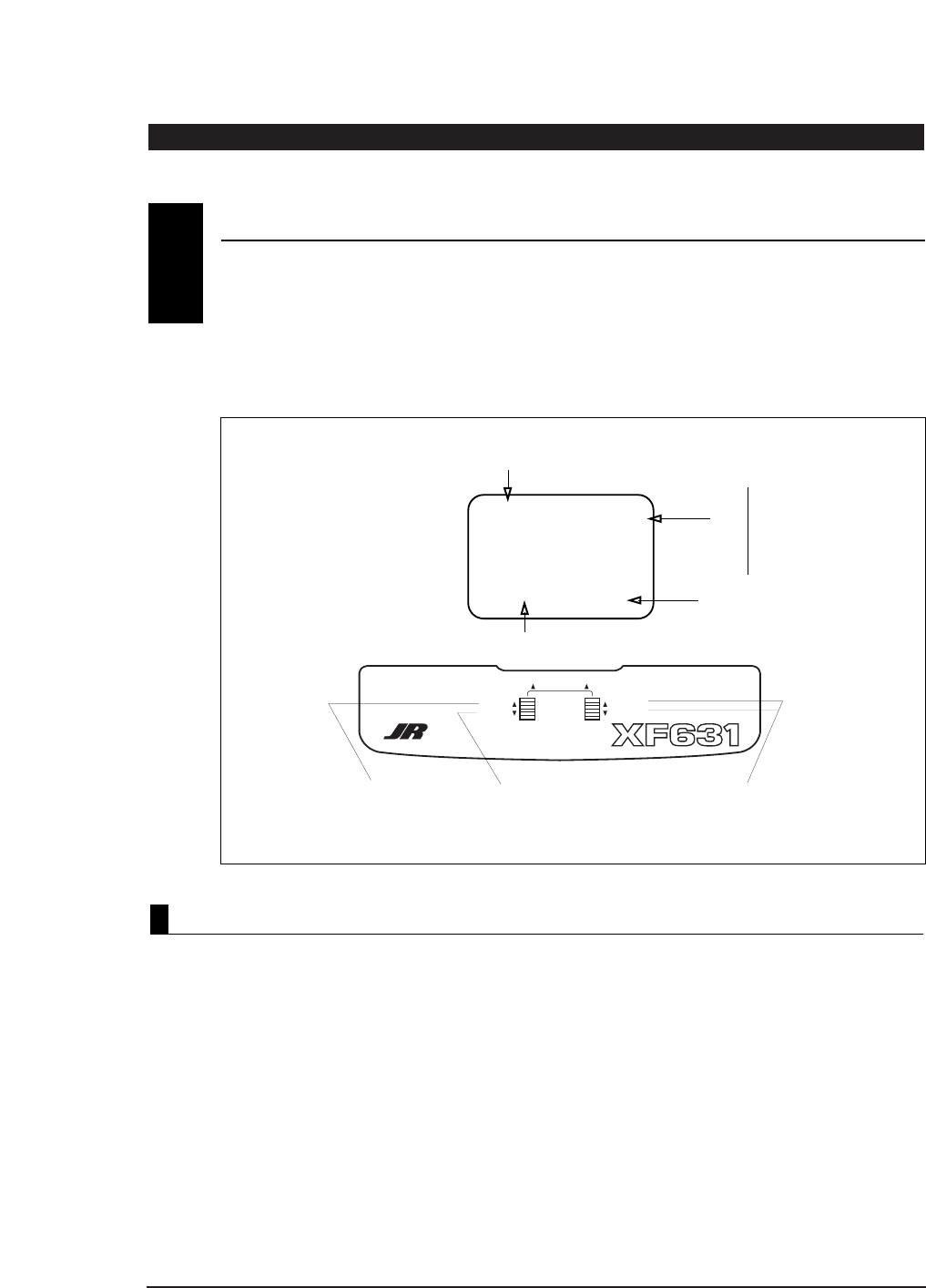
DECREASE
To decrease the travel,
move the stick (i.e. aileron)
to the right then press the
Decrease button to adjust
the right travel. Release
the Decrease button and
move the same stick to the
left. Press the Decrease
button to adjust the
left travel.
AB
C
TRAVEL ADJUSTMENT
3
CHANNEL
SCROLL INCREASE
DECREASE
ENTER
DIGITAL TRIM EQUIPPED 6 CHANNEL
MULTI-DATA COMPUTER DISPLAY SYSTEM
I0.4V
AC I
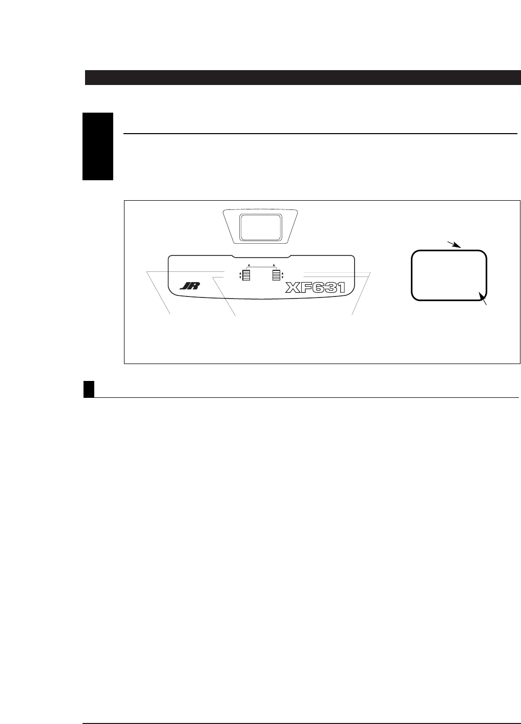
Press the Scroll and Increase buttons upwards
simultaneously to return to the main screen and exit
the Function mode.
Note: Before flying, check that the direction and travel
of all control surfaces move correctly.
Before the initial start of your model, please check
to ensure that when the Throttle Cut button is pressed,
the engine’s carburetor barrel will move to the fully
closed (engine off) position.
This safety feature ensures that the engine can
be shut off immediately in case of a problem or
safety concern.
THROTTLE AUTO CUT
4

6XF631 MANUAL • INTRODUCTION 1: Using This Manual / INTRODUCTION 2: Features
The XF631 is a full feature introductory computer
radio that can be used for airplanes.
A blank data sheet is included at the end of this
manual. Once you have input all the necessary data
into your transmitter for a particular model, we
strongly recommend that you write that information
down on a copy of the data sheet provided. This is to
ensure that, in the rare case of a memory failure, you
will not lose your data.
INTRODUCTION 1:Using This Manual
USING THIS MANUAL
1
•
Easy-to-read LCD screen
•
3-model memory
•
Trainer system compatible with most other JR
FM radios
•
2 conveniently mounted direct-access
programming levers
•
Computer designed ergonomically styled case
•
Adjustable stick length
•
Dual rates for aileron and elevator
•
Digital trims with Direct Access feature
•
Throttle trim only affects idle position
•
Two-speed scrolling—press and hold the
appropriate button to scroll quickly or press and
release to scroll in steps
•
Flaperons mixing
•
Delta wing mixing
•
V-tail mixing
•
Throttle cut safety feature
R700 Slimline Receiver
•
The R700’s extremely compact “slimline” design
allows it to fit easily in limited spaces.
•
An independent laboratory ranked the R700
receiver with JR’s patented ABC&W circuitry as
one of the best receivers ever tested in terms of
3IM, 2IM, adjacent channel rejection, signal-to-
noise ratio, and on-channel capture point.
•
A special “unwanted interference limiter” ignores
signals outside of the R700’s band width when
the receiver is on and the transmitter is off.
The limiter also prevents servos from random
glitching when other transmitters are operating
in close proximity.
•
The electrical circuitry in the R700 is state-of-the-
art surface mount technology (SMT). These SMT
components draw less current, thus increasing
flying time. Flush mounting of these components
also reduces the risk of vibration, wear, and
damage.
•
The R700 is compatible with all JR FM-
transmitting radios.
TRANSMITTER FEATURES
2.1
RECEIVER FEATURES
2.2
INTRODUCTION 2:Features
7
XF631 MANUAL • INTRODUCTION 2: Features
INTRODUCTION 2:Features continued
537 Servo
•
An ultra-tight deadband amplifier ensures
accurate neutral centering
•
Low current drain
•
Ball bearing supported ouput shaft with new
wide spacing for improved precision
•
An indirect drive feedback potentiometer gives
additional protection from vibration
SERVO FEATURES2.3
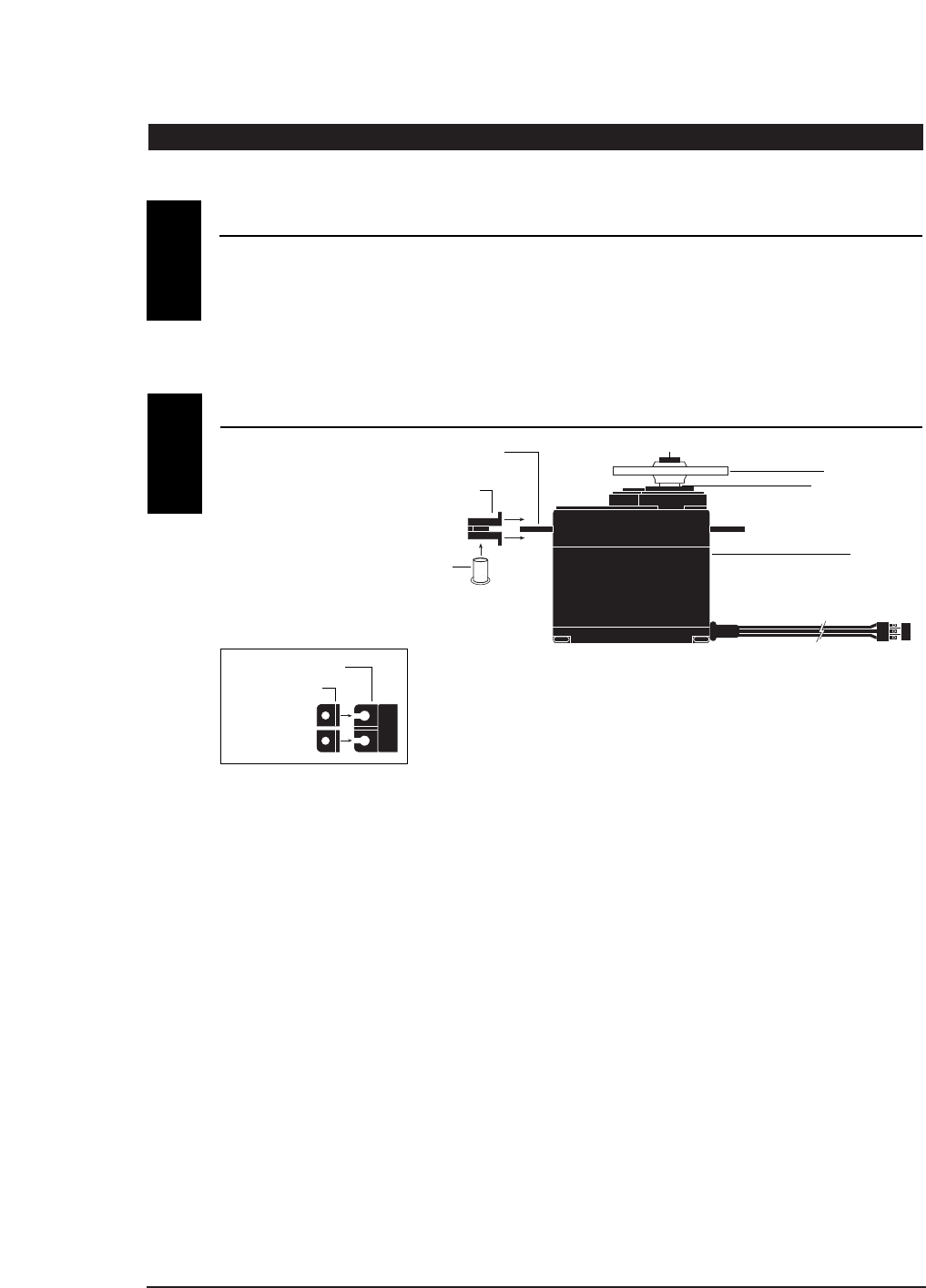
SERVO LAYOUT
2.4
Servo Mounting Flange
Rubber Grommets
Rubber Grommets
Servo Case
Servo Lead w/Connector
Servo Output Shaft
Servo Mounting Flange
Servo Arm/Horn
Servo Arm Retaining Screw
Servo Eyelet
Top View
8XF631 MANUAL • INTRODUCTION 3: Specifications
INTRODUCTION 3:Specifications
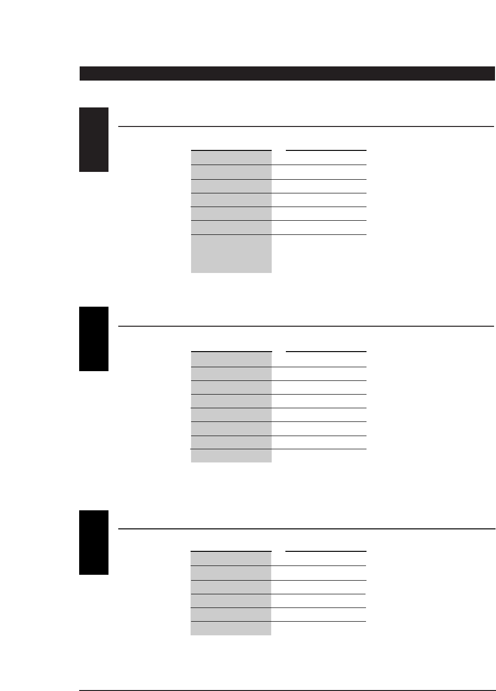
SYSTEM SPECIFICATIONS
TRANSMITTER SPECIFICATIONS
3.1
3.2
SYSTEM NAME XF631
TRANSMITTER BODY XF631
RECEIVER R700
CHARGER NEC-221
AIRBORNE BATTERY 4N-600
SERVOS NES-537BB x 4
ACCESSORIES Mini Switch
12" Aileron Extension
Servo Accessories
Instruction Manual
TYPE AIRPLANE
MODEL NUMBER XF631
ENCODER 6-Channel Computer System
RF 72 MHz
MODULATION PPM (FM)
OUTPUT POWER Approximately 1 Watt
CURRENT DRAIN 200mA
POWER SOURCE 1.2V x 8 NiCad (9.6V) 600mAh
OUTPUT PULSE 1000-2000 (1500 Neutral)
TYPE AIRPLANE
SERVO SPECIFICATIONS3.3
TORQUE (oz/in) 43
SPEED (sec/60°) .25
WEIGHT (oz) 1.37
SIZE (in) (W x L x H) 0.73 x 1.52 x 1.32
BB YES
MOTOR 3-Pole Ferite
TYPE 537BB
9
XF631 MANUAL • INTRODUCTION 3: Specifications
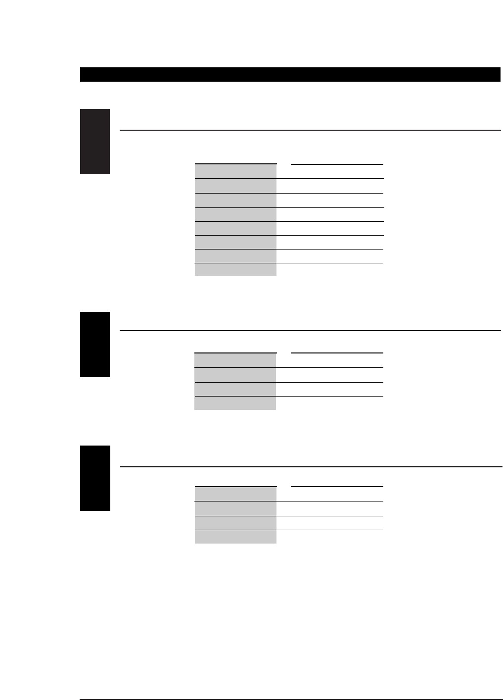
RECEIVER SPECIFICATIONS
3.4
CHARGER SPECIFICATIONS
AIRBORNE BATTERY PACK
3.5
3.6
MODEL NUMBER NER-700
TYPE 7-Ch/FM Slimline w/ABC Circuitry
FREQUENCY 50/53/72MHz
SENSITIVITY (Microseconds) 5µs Minimum
SELECTIVITY 8KHz/50dB
WEIGHT (oz) .64 oz
SIZE (in) (W x L x H) 1.84 x 0.98 x 0.61
RECEIVER ANTENNA 39" For All Aircraft Frequencies
TYPE R700 FM
MODEL NUMBER NEC-221
INPUT VOLTAGE AC 100-120V
OUTPUT CURRENT 50mAh TX/50mAh RX
CHARGING TIME 15 Hours
TYPE AIRPLANE
MODEL NUMBER 4N-600
VOLTAGE 4.8V
SIZE (in) (W x L x H) 2.24 x 0.59 x 2.05
WEIGHT (oz) 3.3
TYPE AIRPLANE
INTRODUCTION 3:Specifications continued
10 XF631 MANUAL • INTRODUCTION 4: Battery Charging
INTRODUCTION 4:Battery Charging
The pilot lamps should always be on during the
charging operation. If they are not, make sure you
have turned off both the transmitter and receiver.
Do not use the charger for equipment other than JR.
The charging plug polarity may not be the same, and
equipment damage may result.
Do not use other manufacturers’ after-market
accessories that plug into the transmitter’s charging
jack. If you do, any damage that results will not be
covered by warranty. If you are unsure of
compatibilities with your radio, seek expert advice
before doing anything to avoid possible damage.
During the charging operation, the charger’s
temperature is slightly elevated. This is normal.
CHARGER4.2
It is imperative that you fully charge both the
transmitter and the receiver battery packs prior to
each day of flying. For the initial charge, leave the
charger and batteries hooked up for 20-24 hours in
order to fully charge both battery packs to peak
capacity. For subsequent charges, leave the charger
and batteries hooked up overnight (approximately
16 hours).
The charger supplied with this system is designed to
recharge your transmitter battery at a rate of 50mA.
The receiver battery pack will charge at 50mA for the
600mAh battery pack.
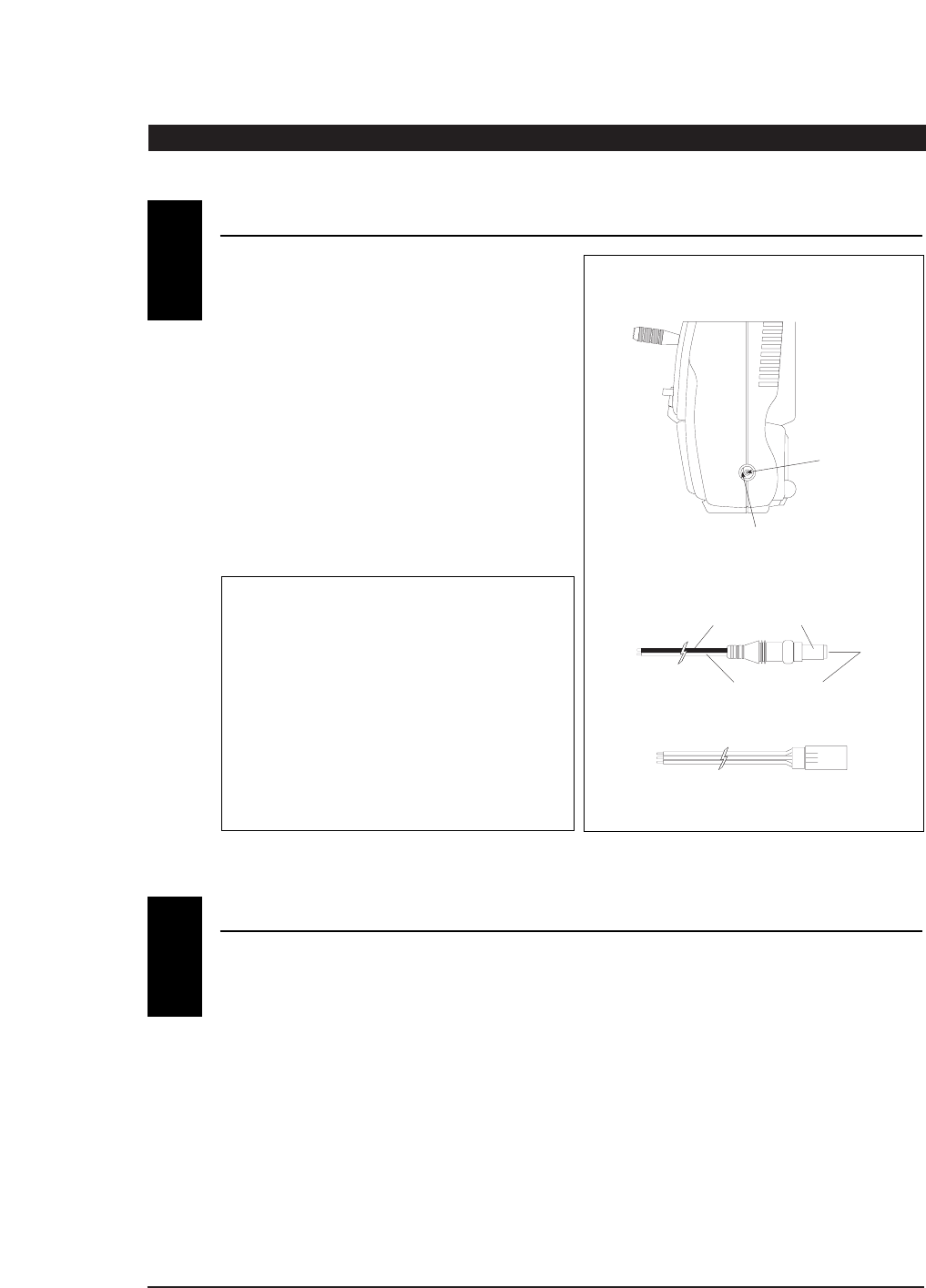
Transmitter Only
The center pin on all JR remote control systems is
negative. Therefore, the center pin on all JR
chargers is negative, not positive. This is different
from any other manufacturers’ chargers and radio
systems. Beware of improper connections based
on “color code” wire leads as they do not apply
in this instance. You must make certain that the
center pin of your JR transmitter is always
connected to the negative voltage for correct
polarity hookup.
CENTER
PIN IS
NEGATIVE
OUTSIDE IS POSITIVE
RIGHT SIDE OF TRANSMITTER
CHARGER PIGTAIL FOR RECEIVER
CHARGER PIGTAIL FOR TRANSMITTER
BLACK TO POSITIVE
RED TO NEGATIVE
RED–POSITIVE / BROWN–NEGATIVE / ORANGE–SIGNAL
TRANSMITTER / RECEIVER4.1
11
XF631 MANUAL • INTRODUCTION 5: Trainer System
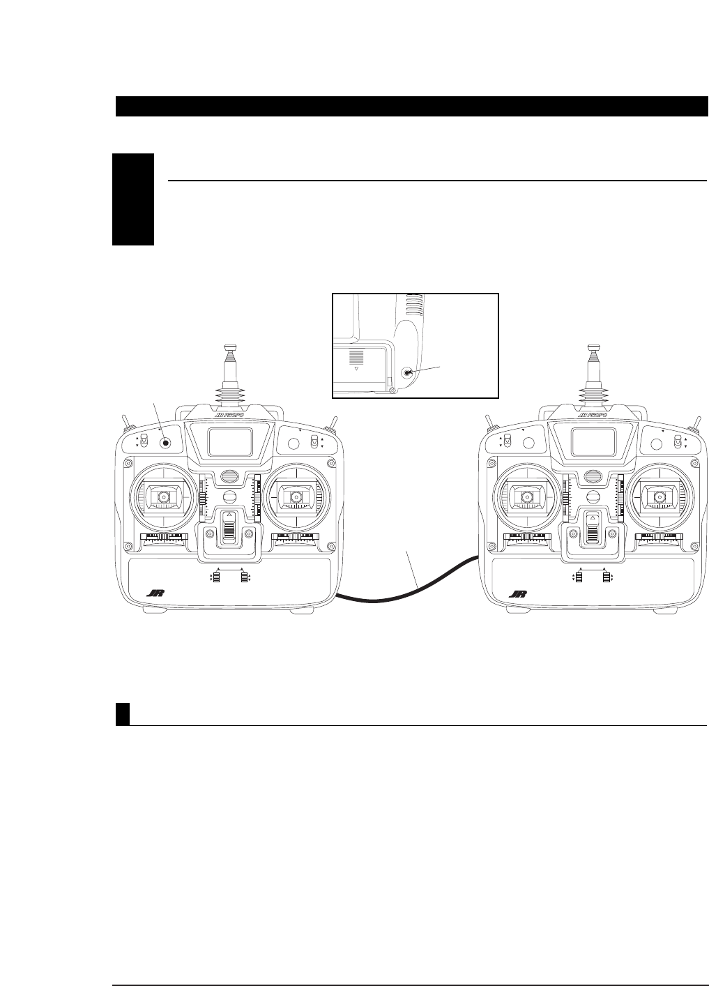
The XF631 features a built-in trainer system. The
transmitter can be used as either a master (trainer) or
as a slave (trainee). The XF631 is compatible with all
other current JR radios that have built-in trainer
systems. An optional trainer cord (JRPA130)
is needed .
1. Match the servo reversing, sub-trims, travel
adjust, and trims of both radios.
2. Plug the optional trainer cord into both
transmitters.
3. Turn on the master transmitter.
Note: The slave radio must be left off.
4. Test all the control functions on your aircraft with
the master radio.
5. Push the Trainer button on the master transmitter
and check all the control functions with the
slave radio.
INTRODUCTION 5:Trainer System
TRAINER SYSTEM5
D.S.C. TRAINER
CORD INPUT
ON
TRAINERELEVATOR D/R
0
1
0
1
AILERON D/R
SCROLL
CHANNEL
INCREASE
DECREASE
XF622
FUNCTION 3-4 1-4 FUNCTION 1-2 2-3
MULTI
DATA
DISPLAY
VOLTAGE
INDICATOR
ON
TRAINERELEVATOR D/R
GEAR
0
1
FLAP
0
1
AILERON D/R
SCROLL
CHANNEL
INCREASE
DECREASE
XF622
XF631
FUNCTION 3-4 1-4 FUNCTION 1-2 2-3
MULTI
DATA
DISPLAY
VOLTAGE
INDICATOR
TRAINER
BUTTON
OPTIONAL
TRAINER CORD
(JRPA130)
MASTER TX
POWER SWITCH ON SLAVE TX
POWER SWITCH OFF
THROTTLE CUT
DIGITAL TRIM EQUIPPED 6 CHANNEL
MULTI-DATA DISPLAY SYSTEM
ENTER ENTER
XF631
DIGITAL TRIM EQUIPPED 6 CHANNEL
MULTI-DATA DISPLAY SYSTEM
GEAR FLAP
THROTTLE CUT
Operating the Trainer System
12 XF631 MANUAL • CHAPTER 1: Transmitter Controls
1. THRO: Throttle Channel
2. AILE: Aileron Channel
3. ELEV: Elevator Channel
4. RUDD: Rudder Channel
5. GEAR: Gear Channel
6. AUX 1: Flap Channel
Transmitter Throttle ALT
The throttle ALT function makes the throttle
stick trim active only when the throttle stick is less
than half throttle. This gives easy, accurate idle
adjustments without affecting the high
throttle position.
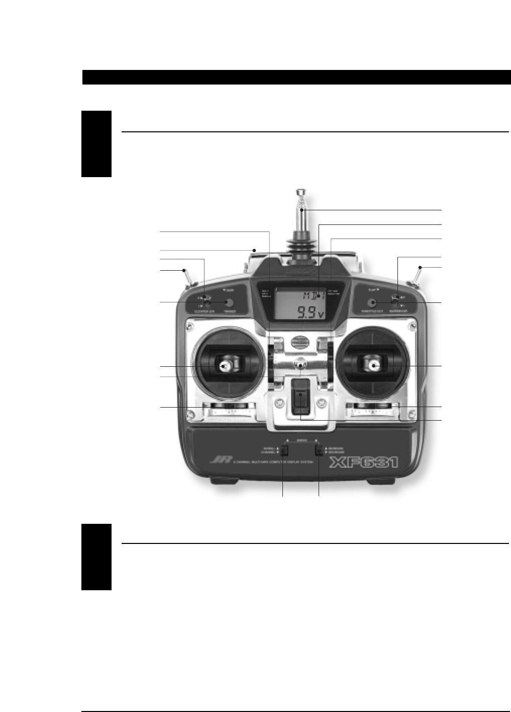
RECEIVER CHANNEL ASSIGNMENT/TRANSMITTER THROTTLE ALT1.2
CHANNEL 6 (GEAR) SWITCH
ELEVATOR DUAL RATE
ANTENNA
LCD SCREEN
CHANNEL 5 (GEAR) SWITCH
AILERON DUAL RATE
AILERON/ELEVATOR STICK
THROTTLE/RUDDER STICK
POWER SWITCH
DIGITAL AILERON TRIM
DIGITAL ELEVATOR TRIM
DIGITAL THROTTLE TRIM
DIGITAL RUDDER TRIM
NECK STRAP EYELET
CARRYING HANDLE
TRAINER SWITCH THROTTLE CUT BUTTON
PROGRAMMING INPUT LEVERS
CONTROL IDENTIFICATION AND LOCATION • Mode II
CHAPTER 1:Transmitter Controls
1.1
13
XF631 MANUAL • CHAPTER 1: Transmitter Controls
To adjust the control stick length, use a 2 mm Allen
wrench to unlock the set screw located inside the
end of the control stick. Turn the set screw counter-
clockwise to loosen it, then turn the knurled portion
of the stick to adjust the length. Counterclockwise
will lengthen the stick and clockwise will shorten it.
After the control stick(s) has been adjusted to suit
your flying style, tighten the set screw.
CONTROL STICK LENGTH ADJUSTMENT1.4
LOOSEN
TIGHTEN
SET SCREW
CHAPTER 1:Transmitter Controls continued
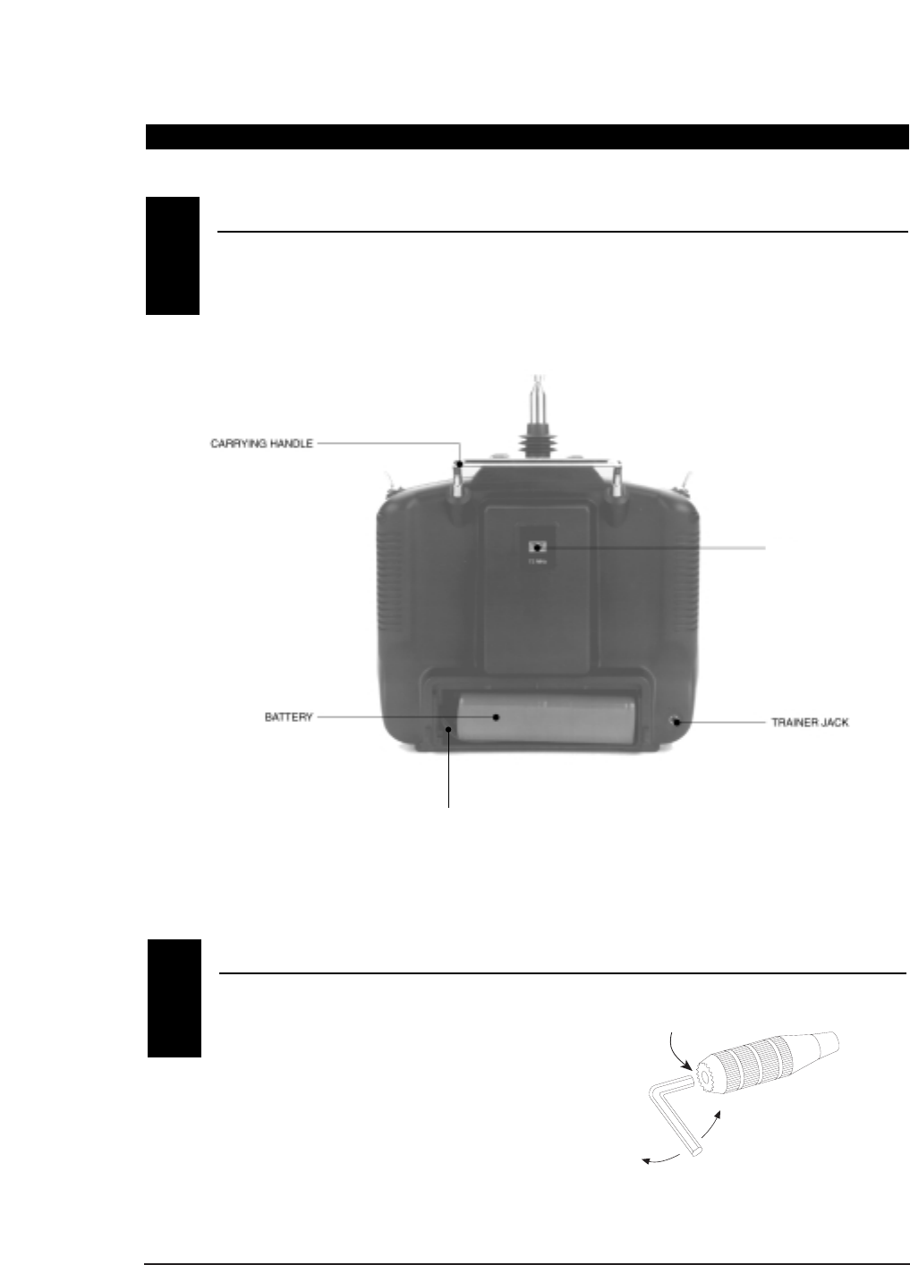
TRANSMITTER REAR1.3
Note: Your transmitter has a 5-year lithium battery
to protect your preprogrammed data against main
transmitter battery failure. If your system reads 0.0V
or has an unfamiliar display (service mode), or your
data resets to the factory defaults, return your
transmitter to Horizon Service Center (see page 28)
for a lithium battery replacement.
BATTERY CONNECTOR
Use caution when disconnecting/removing the
transmitter battery pack. If the connector is not
properly disconnected, damage to the connector
and/or the radio system can result.
CRYSTAL
(Factory installed)
14 XF631 MANUAL • CHAPTER 1: Transmitter Controls
CHAPTER 1:Transmitter Controls continued
For proper DSC hook-up and operation:
1. Leave the transmitter power switch off. The
transmitter will not transmit any radio
frequency (RF) in this position.
2. Plug the optional DSC cord (JRPA132) into
the DSC port in the rear of the transmitter.
3. The encoder section of the transmitter will now
be operational and the LCD display will be lit.
4. Plug the other end of the DSC cord into
the receiver charge receptacle. Turn on the
switch harness.
Note: When installing the optional charging
jack (JRPA024), be sure to hook the charging jack
receptacle securely into the switch harness
charge cord.
Why you should use the DSC function:
1. The DSC enables you to check the control
surfaces of your airplane without drawing the
fully operational 200mAh from your transmitter
battery pack. Instead, you will only draw 70mAh
when using the DSC function.
Note: You will need to purchase (separately)
both the DSC cord (JRPA132) and the JR Deluxe
Switch Harness (JRPA001) to make use of the
XF631 DSC function.
2. The DSC function allows you to make final
adjustments to your airplane without
transmitting any radio signals. Therefore, if
another pilot is flying on your frequency, you
can still adjust your aircraft and not interfere
with the other aircraft.
Note: Under no circumstances should you
attempt to fly your aircraft with the DSC cord
plugged in! This feature is for bench checking
your aircraft only.
There is an eye hook on the front of the transmitter
for attaching an optional neck strap (JRPA023). The
eye hook is precisely positioned (see Section 1.1)
so that the transmitter will be perfectly balanced when
a neck strap is used.
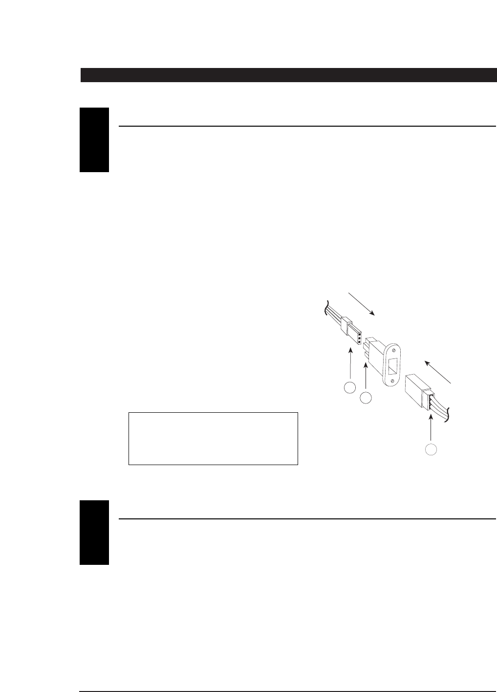
DIRECT SERVO CONTROL (DSC)1.5
A
B
C
A - Charge Cord/DSC Receptacle
B - Switch Harness Lead
C - Charger/DCS Cord
NECK STRAP ATTACHMENT1.6
15
XF631 MANUAL • CHAPTER 2: Connections
It is important to correctly install the radio system in
your model. Please read and carefully follow the
suggestions listed below.
1. For added protection, wrap the RX and the RX
NiCad in foam rubber that is at least 1/4” thick.
2. Run the RX antenna through the fuselage and
make sure it is fully extended. Never cut or
bundle your RX antenna — this will decrease
range and performance.
3. Rubber servo grommets are included with your
radio system and should be installed in the servo
flanges. The servos should then be mounted on
either hardwood rails or a plywood tray with the
mounting screws provided. Do not overtighten
the mounting screws. The flange of the brass
eyelets should face down (toward the wood).
4. All servos must be able to move freely over the
full range of their travel. Make sure the linkages
do not impede servo travel. A stalled servo will
drain the battery pack within a few minutes.
5. Before installing servo output arms, make sure
the servo is in its neutral position.
6. In the case of gas-powered model aircraft, mount
the receiver power switch on the side of the
fuselage opposite the muffler to protect the
switch from exhaust residue. With other types of
models, mount the switch in the most convenient
place. Make sure that the switch operates freely
and is capable of traveling its full distance.
7. With your model sitting on the ground and the
transmitter antenna collapsed, check that your
system works at a distance of 75 to 100 feet.
If your system stops functioning at a distance that
is shorter than listed above, please contact the
Horizon Service Center for further information
prior to flying your model.
INSTALLATION REQUIREMENTS
CHAPTER 2:Connections
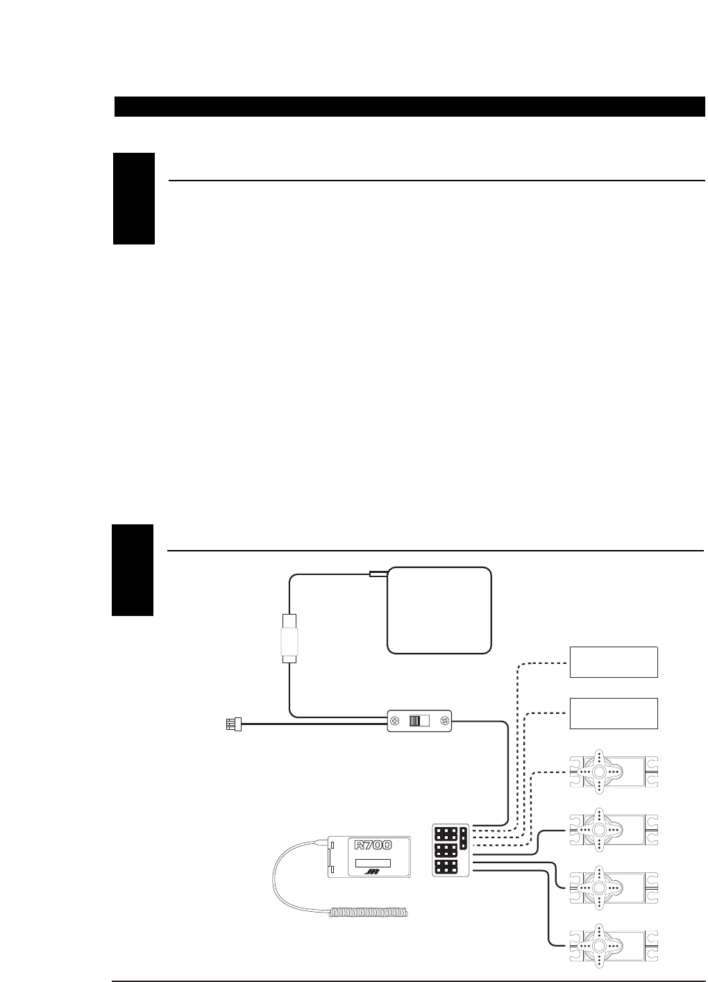
CONNECTIONS2.2
2.1
ON
OFF
GEAR
RUDDER
ELEVATOR
AILERON
THROTTLE
ON/OFF SWITCH HARNESS
(JRPA003)
RECEIVER BATTERY
4N-600
226X RECEIVER
NEW ABC & W SYSTEM
6 CHANNEL RECEIVER
BATT
AUX 1
GEAR
RUDD
ELEV
AILE
THRO
NER-226X
JAPAN REMOTE CONTROL CO., LTD
MADE IN JAPAN
7
ANTENNA
FLAP
Optional
Optional
GEAR
7 CH 72MHz FM SLIMLINE
RECEIVER
ABC&W INTERFERENCE
PROTECTION SYSTEM
BATT
RUDD
ELEV
AILE
THRO
AUX1
R700 RECEIVER
ANTENNA
16 XF631 MANUAL • CHAPTER 3: Key Input and Display / CHAPTER 4: Battery Alarm and Display
Two input keys are located at the lower right and left
faceplate of the XF631 transmitter. The keys are used
to access and program the transmitter. Each key can
be moved up or down using your thumbs.
CHAPTER 4:Battery Alarm and Display
CHAPTER 3:Key Input and Display
KEY INPUT AND DISPLAY3
When the transmitter battery drops below 9.0 volts,
the display will start to flash BAT and an audible
alarm will sound for 8 beeps. These warnings mean
you should land your aircraft immediately.
Note: During the period that the battery alarm
is flashing, the input buttons will not
function. If you are currently in the
function mode, the transmitter will exit
automatically and return to the normal
display (see Section 5.1).
BATTERY ALARM AND DISPLAY4
CHANNEL
SCROLL INCREASE
DECREASE
ENTER
DIGITAL TRIM EQUIPPED 6 CHANNEL
MULTI-DATA COMPUTER DISPLAY SYSTEM
Left button up........Scroll — Used to advance
through the menus.
Left button down...Channel — Used to advance
through the channels or features
in a given function.
Right button up........Increase — Increases value or
changes setting
(e.g., Reverse Normal).
Left button down......Decrease — Decreases value
or changes setting.
(e.g., Reverse Normal).
BAT
8.9
V
FLASHING
17
XF631 MANUAL • CHAPTER 5: Input Mode and Functions
When the power switch is turned on, the
screen will read as shown here in the
diagram. This screen is referred to as the
normal display.
CHAPTER 5:Input Mode and Functions
NORMAL DISPLAY5.1
The Direct Trim function of the XF631 can be
accessed through the use of any of the 4 digital trims
levers (throttle, aileron, elevator, or rudder).
When a trim input is given, the screen will
automatically change to show the trim value for
that particular channel. Once the trim adjustment
has been made, the screen will automatically return
to the previous screen setting after 2-3 seconds. The
maximum trim value for each channel is +/- 40 in
increments of 2.
DIRECT TRIM ACCESS DISPLAY5.2
The XF631 features two types of programming paths.
System mode includes programming functions that
are initially adjusted when the model is first set up,
like selecting wing type or the model, and is seldom
accessed after the initial setup. System modes
include:
MODEL RESET
MODEL SELECT
WING TYPE MIXING
V-TAIL MIXING
MODEL NAME
Function mode includes programming that is more
frequently changed, sometimes at the flying field.
Function Modes include:
SERVO REVERSING
DUAL RATES
SUB-TRIM
TRAVEL ADJUST
MODE TYPES5.3
THROTTLE CUT5.4
Your XF631 incorporates a special Throttle Cut button
located on the upper right face of the transmitter.
This feature is designed to immediately override any
current throttle/trim position and will immediately
return the throttle servo to the full low position. This
feature will allow the engine to be automatically
stopped in case of emergency, or in the event of a
crash. When adjusting your throttle linkage, please
check to ensure that when the Throttle Cut button is
pushed, the throttle servo will move the carburetor
barrel to the full closed position.
Note: In some cases it will be necessary to
adjust the engines barrel stop screw so that the
carburetor can be fully closed. Please refer to
your engine instructions for more detail.
MDI
10.4V
MODEL NAME
BATTERY VOLTAGE
AIL
- 2
INDICATES CHANNEL
INDICATES CURRENT
TRIM VALUE (+ OR --)
ON
To enter System Setup mode,
press both programming
levers up and turn on the
Power switch.
Power Switch
Programming Levers
RST
I
ON
To enter Function mode,
turn on the Power switch
and then press both
programming levers up.
Power Switch
THR
-
REV•NORM
18 XF631 MANUAL • CHAPTER 5: Input Mode and Functions
To enter the Function mode, turn on the transmitter. Press the Scroll
and Increase buttons up simultaneously until a beep is heard. The
display will change accordingly and show the last active function.
Press the Scroll button up to scroll down through the functions one by
one as shown in the flowchart at left. Once the appropriate function is
selected, use the Channel button to select the appropriate channel.
Use the Increase and Decrease buttons to adjust the values displayed on
the screen.
CHAPTER 5:Input Mode and Functions continued
FUNCTION MODE5.6
THR
-
REV•NORM
SERVO REVERSING
Page 24
SUB-TRIM
Page 26
TRAVEL ADJUSTMENT
Page 27
DUAL RATES
Page 25
0
THR
SB-TRIM
+I00%
THR
TRV ADJ
+I00%
AI0
To enter the System mode, press the Scroll and Increase buttons up
simultaneously while you turn on the transmitter. You can now select
any of four system mode functions shown here in the flow chart. To
exit the System mode, press the Scroll and Increase buttons
simultaneously or turn off the transmitter. Press up the Scroll button
to move through the System mode functions. Information for each
function is located on the page number listed next to the
function name.
SYSTEM MODE5.5
MODEL NAME ENTRY
Page 22
WING TYPE
SELECTION
FPR FLAPERON
DELTA
V-TAIL
Page 20–21
RST DATA RESET
Page 18
MODEL SELECTION
Page 19
I
MDL
OF
WNG
MIX
I
I
MDI
MIX
CHANNEL
SCROLL INCREASE
DECREASE
ENTER
DIGITAL TRIM EQUIPPED 6 CHANNEL
MULTI-DATA COMPUTER DISPLAY SYSTEM
CHANNEL
SCROLL INCREASE
DECREASE
ENTER
DIGITAL TRIM EQUIPPED 6 CHANNEL
MULTI-DATA COMPUTER DISPLAY SYSTEM
Programming Levers
D/R
19
XF631 MANUAL • CHAPTER 6: Functions (System Mode)
Accessing the Data Reset Function
CHAPTER 6:Functions (System Mode)
The data reset function allows you to reset all the
programming in the selected model (1,2, or 3) to the
factory settings. Before using the data reset function,
it’s important to enter the model selection function
and select the desired model number (1,2, or 3) for
which you want to reprogram to the factory settings.
The model selection function is described in
Section 6.2.
1. Press the Scroll and Increase buttons up
simultaneously and hold.
2. Turn on the transmitter to enter the
System mode.
3. Press the Scroll button up until “RST” appears
on the screen.
4. Press the Channel and Increase buttons
simultaneously to reset the data. (To confirm that
the selected model's programming has been
reset, a beep will sound and the model number
will momentarily disappear from the screen.)
5. Press the Scroll button to access the model
select function.
6. To exit, press the Scroll and Increase buttons up
simultaneously.
DATA RESET • System Mode
6.1
RST
I
Programming Levers
CHANNEL
SCROLL INCREASE
DECREASE
ENTER
DIGITAL TRIM EQUIPPED 6 CHANNEL
MULTI-DATA COMPUTER DISPLAY SYSTEM
In System Setup mode,
press the Scroll button up
until “RST”appears on
the screen.
Press the Channel button down and
Increase button up simultaneously
to reset the data (a beep will sound).
RST
1
INDICATES DATA RESET FUNCTION
MODEL NUMBER TO RESET
20 XF631 MANUAL • CHAPTER 6: Functions (System Mode)
The XF631 has memory for 3 models.
1. Press the Scroll and Increase buttons up
simultaneously and hold.
2. Turn on the transmitter to enter the
System mode.
3. Press the Scroll button until “MDL”
appears on the screen.
4. Press the Increase or Decrease button to select
model number 1,2, or 3.
5. Press the Scroll button to access the wing type
entry function.
6. To exit, press the Scroll and Increase buttons up
simultaneously.
Accessing the Model Selection Function
MODEL SELECTION • System Mode
6.2
CHAPTER 6:Functions (System Mode) continued
MDL
I
Programming Levers
CHANNEL
SCROLL INCREASE
DECREASE
ENTER
DIGITAL TRIM EQUIPPED 6 CHANNEL
MULTI-DATA COMPUTER DISPLAY SYSTEM
In System Setup mode,
press the Scroll button
until “MDL”appears on
the screen.
Press the Increase or
Decrease button to select
model number 1, 2, OR 3.
MDL
1
INDICATES MODEL SELECTION FUNCTION
MODEL NUMBER 1, 2, OR 3
21
XF631 MANUAL • CHAPTER 6: Functions (System Mode)
CHAPTER 6:Functions (System Mode) continued
OF
MIX
CHANNEL
SCROLL INCREASE
DECREASE
ENTER
DIGITAL TRIM EQUIPPED 6 CHANNEL
MULTI-DATA COMPUTER DISPLAY SYSTEM
Press the Scroll
button until
“MIX WING”appears
on the screen.
Press the Channel
button to select
Wing Type (WNG) or
V-tail (VTL) mixing.
Press the Increase or
Decrease button to turn the
flaperon (FPR), Delta (DLT) or
V-tail (VTL) mixing on or off.
OF = OFF
ON = ON
INDICATES WING TYPE FUNCTION
FPR = FLAPERON
VTL = V-TAIL
DLT = DELTA
WING = WING TYPE SELECTION
MIX
OF
Accessing the Wing Type Selection Function
1. Press the Scroll and Increase buttons up
simultaneously and hold.
2. Turn on the transmitter to enter the
System mode.
3. Press the Scroll button until the “MIX WNG”
appears on the screen.
4. Press the Channel button to select either the wing
type (WNG) or V-tail (VTL) mode.
5. Press the Scroll button to access the model
name function.
6. To exit, press the Scroll and Increase buttons
up simultaneously.
Flaperon, V-tail, and Delta mixing are available for
specialty aircraft that require those functions. The
flaperon feature mixes flaps with ailerons so the
ailerons can be drooped for takeoffs and landings
while still functioning fully as ailerons. V-tail mixing
combines rudder and elevator for V-tail operations.
The Delta wing function allows the aileron to also act
as the elevator, while retaining independent use of
both functions. The Delta wing function allows the
ailerons to also act as the elevator, while retaining
independent use of both functions.
Flaperon Setup
When using flaperon mixing, two servos (one for
each aileron) must be used. Connect the left aileron
servo to channel #6 (Flp/Aux 1) and the right aileron
servo to channel #2 (Aile) in the receiver. Individual
functions (e.g., servo reversing, sub-trims, etc.) are
still available for each of the channels. Use sub-trims
for individual neutral adjustment.
Note: When flaperon is selected, it is necessary
to reduce the travel adjust values of channel #6
0% in each direction to prevent servo over-travel
(binding). Please refer to section 7.3 for travel
adjust information.
V-Tail
V-Tail mixing requires two servos. Connect the left
tail servo to channel #3 (Elev) and the right tail servo
to channel #4 (Rudd) in the receiver. Individual
functions (e.g., servo reversing, sub-trims, etc.) are
available for each servo. Use sub-trims for individual
neutral adjustments described in Section 7.2. V-Tail
elevator travel is adjusted by elevator and rudder
travel adjust.
Delta Wing Mixing
Delta or elevon mixing, as it is commonly known, is
the final wing mixing selection in your XF631. This
style of aircraft also employs two wing servos.
However, in essence, there is not an elevator present.
Instead, at an elevator stick input, the two wing
servos function in conjunction with one another in
the same direction to create an up/down movement
of the aircraft. Also, when an aileron control is given,
the two wing servos move in opposite directions to
function as ailerons as well.
WING TYPE SELECTION • System Mode
6.3
22 XF631 MANUAL • CHAPTER 6: Functions (System Mode)
CHAPTER 6:Functions (System Mode) continued
To Activate Flaperon (FPR) Mixing (Wing Type Mode)
To Activate Delta Wing (DLT) Mixing (Wing Type Mode)
1. In System Setup mode, press
the Scroll button until “MIX
WNG”appears on the screen.
2. Press the Increase button to
activate Flaperon mixing.
OF
FPR
MIX
OF = MIX OF
ON = MIX ON
OF
ON
DLT
MIX
MIX
2. Press the Channel
button once to access
the V-tail mixing screen.
DELTA WING
MIX ON
OF
ON
VTL
MIX
MIX
To Activate V-Tail (VTL) Mixing
Note: It is also possible to
activate both the flaperon (FPR)
and V-tail (VTL) functions to
work simultaneously.
WING TYPE SELECTION • System Mode (continued)
6.3
1. In System Setup mode, press
the Scroll button until “MIX
WNG”appears on the screen.
2. Press the Decrease button to
activate Delta wing mixing.
1. In System Setup mode,
press the Scroll button
until “MIX WNG”appears
on the screen.
3. Next press either the Increase or
Decrease buttons once to activate
V-tail mixing.
OK
WNG
MIX
OK
WNG
MIX
OK
WNG
MIX
CHANNEL
SCROLL INCREASE
DECREASE
ENTER
DIGITAL TRIM EQUIPPED 6 CHANNEL
MULTI-DATA COMPUTER DISPLAY SYSTEM
CHANNEL
SCROLL INCREASE
DECREASE
ENTER
DIGITAL TRIM EQUIPPED 6 CHANNEL
MULTI-DATA COMPUTER DISPLAY SYSTEM
CHANNEL
SCROLL INCREASE
DECREASE
ENTER
DIGITAL TRIM EQUIPPED 6 CHANNEL
MULTI-DATA COMPUTER DISPLAY SYSTEM
23
XF631 MANUAL • CHAPTER 6: Functions (System Mode)
CHAPTER 6:Functions (System Mode) continued
1. Press the Scroll and Increase buttons
up simultaneously and hold.
2. Turn on the transmitter to enter the
System mode.
3. Press the Scroll button until “MD1” appears
on the screen.
4. Press the Increase or Decrease buttons to
select the correct letter/number for the first
character (flashing).
5. To adjust the remaining 2 characters, press the
Channel button until the desired character to be
adjusted is flashing.
6. Press the Scroll button to access the modulation
select function.
7. To exit, press the Scroll and Increase buttons up
simultaneously.
Accessing the Model Name Entry Function
Press the Channel
button to select the
character to be
changed (flashing).
Press the Increase or
Decrease buttons to
select the desired
character (A-Z, 1-9, etc.).
Flashing Character includes
character to be adjusted
CURRENT MODEL
NUMBER
I
ACI
In System Setup mode,
press the Scroll button
until “MD1”appears on
the screen.
The XF631 allows a 3-character name to be input for
each of the 3 models available. The current model
will be displayed in the normal display. This feature
is useful to help identify different aircraft types or
model setups.
MODEL NAME ENTRY • System Mode
6.4
MDI
I
CHANNEL
SCROLL INCREASE
DECREASE
ENTER
DIGITAL TRIM EQUIPPED 6 CHANNEL
MULTI-DATA COMPUTER DISPLAY SYSTEM
24 XF631 MANUAL • CHAPTER 7: Functions (Function Mode)
CHAPTER 7:Functions (Function Mode)
Servo reversing is a very convenient function used in
the setup of a new aircraft. It is used to change the
direction of servo rotation in relation to the
corresponding stick movement. Servo reversing is
available for all channels.
1. Turn on the transmitter.
2. Press the Scroll and Increase buttons up
simultaneously to enter the Function mode.
3. Press the Scroll button until “REV/NORM” appears
on the screen.
4. Press the Channel button until the desired channel
appears on the screen.
5. Press the Increase or Decrease button to change the
servo direction.
6. Press the Scroll button to access the sub-trim
function.
7. To exit, press the Scroll and Increase buttons up
simultaneously.
Accessing the Servo Reversing Function
SERVO REVERSING • Function Mode
7.1
CHANNEL
SCROLL INCREASE
DECREASE
ENTER
DIGITAL TRIM EQUIPPED 6 CHANNEL
MULTI-DATA COMPUTER DISPLAY SYSTEM
1 THR: THROTTLE
2 AIL: AILERON
3 ELE: ELEVATOR
4 RUD: RUDDER
5 GER: LANDING GEAR
6 FLP: FLAP (AUX 1)
Press the Increase or
Decrease button to change the
servo direction
Press the Channel
button until the desired
channel appears on
the screen.
Press the Scroll button
until “REV/NORM”
appears on the screen.
THR
REV+NORM
–
CHANNEL
25
XF631 MANUAL • CHAPTER 7: Functions (Function Mode)
CHAPTER 7:Functions (Function Mode) continued
Dual rate is available for the aileron and elevator
channels. The purpose of this function is to allow for
in-flight selection of two preset servo travels for each
of these channels. The amount of travel is adjustable
from 0-125%. The factory settings for both switch
positions (0 and 1) is 100%. Either position may be
selected as the low or high rate by placing the
switches in the desired position and adjusting the
value for that position. Different types of maneuvers
require varying amounts of control movements. Snap
rolls require large control movements, while smooth
maneuvers like long slow rolls are best performed
with smaller control movements. Dual rates allow
you to change the control movements in flight at the
flip of a switch. This allows you to execute maneuvers
requiring both radical control movements and small
control movements during a single flight.
DUAL RATE • Function Mode
7.2
1. Turn on the transmitter.
2. Press the Scroll and Increase buttons
simultaneously to enter the Function mode.
3. Press the Scroll button until “D/R” appears on
the screen.
4. Press the Channel button until the desired
channel appears on the screen. (AI = aileron or
EL = elevator).
5. The number that appears directly to the right of
the selected channel is the switch position.
There are two switch positions, 0 and 1, for each
of the channels. A “0” will appear when the
selected dual rate switch is in the uppermost
position and a “1” when the selected switch is in
the lower position.
6. The number in the center of the screen indicates
the current dual rate value for the selected switch
position and channel. Press the Increase or Decrease
button to adjust the dual rate value (0-125%).
7. After adjusting the value for the 0 switch position,
change to the 1 switch position and adjust
the rates.
8. Press the Channel button to select the other
channel and adjust the dual rate value for both
switch positions.
9. To exit, press the Scroll and Increase buttons
simultaneously.
Accessing the Servo Reversing Function
CHANNEL
SCROLL INCREASE
DECREASE
ENTER
DIGITAL TRIM EQUIPPED 6 CHANNEL
MULTI-DATA COMPUTER DISPLAY SYSTEM
Press the Scroll button
until “D/R”appears on
the screen.
Press the Channel
button until “AI”or “EL”
appears on the screen.
Press the Increase or
Decrease button to adjust
the dual rate value.
AIO
100%
MODEL NAME
CHANNEL
AI: AILERON
EL: ELEVATOR
DUAL RATE VALUE
INDICATES THE DUAL RATE FUNCTION
D/R
26 XF631 MANUAL • CHAPTER 7: Functions (Function Mode)
CHAPTER 7:Functions (Function Mode) continued
Accessing the Sub-Trim Function
Sub-trim is an electronic trim that is available for
each of the 6 channels. Sub-trim is particularly useful
as it allows the digital trim levers to be returned to
their neutral positions by adjusting /changing the
servo’s neutral position electronically, without the
need to mechanically adjust the specific control
linkage. This allows the same digital trim lever
settings between the two models you can control
with this radio system. Sub-trim can also allow
additional trim travel when digital trims do not
provide enough movement.
Note: It is recommended to use as little sub-trim
as possible for adjustment. If more that 20–30
points are required, is it suggested that a
mechanical linkage adjustment be performed.
Note: Prior to making final subtrim adjustments,
please check to make sure that the digital trim
values for aileron, elevator, and rudder are set to
the neutral position. Throttle trim value should
be set to the -40 position.
1. Turn on the transmitter.
2. Press the Scroll and Increase buttons up
simultaneously to enter the Function mode.
3. Press the Scroll button until “SB-TRIM” appears on
the screen.
4. Press the Channel button until the desired
channel appears on the screen.
5. Press the Increase or Decrease button to establish
the desired amount of sub-trim.
6. Press the Scroll button to access the travel
adjustment function.
7. To exit, press the Scroll and Increase buttons up
simultaneously.
SUB-TRIM • Function Mode
7.3
CHANNEL
SCROLL INCREASE
DECREASE
ENTER
DIGITAL TRIM EQUIPPED 6 CHANNEL
MULTI-DATA COMPUTER DISPLAY SYSTEM
Press the Scroll button
until “SB-TRIM”appears
on the screen.
Press the Channel
button until the desired
channel appears on
the screen.
Press the Increase or
Decrease button to adjust
the sub-trim value.
1 THR: THROTTLE
2 AIL: AILERON
3 ELE: ELEVATOR
4 RUD: RUDDER
5 GER: LANDING GEAR
6 FLP: FLAP (AUX 1)
THR
0
SB-TRIM
CHANNEL
INDICATES
SUB-TRIM FUNCTION
SUB-TRIM VALUE (±125)
27
XF631 MANUAL • CHAPTER 7: Functions (Function Mode)
CHAPTER 7:Functions (Function Mode) continued
The amount of servo travel is adjustable for each
direction for each of the 6 channels individually. The
adjustment range is from 0% to 150%. Travel
adjustment is factory set at 100% for all channels.
The travel adjustment value displayed on the screen
depends on the position of the stick or switch (e.g.,
flap switch, gear switch). This function is useful either
to maximize control surface travel or to reduce travel
to eliminate servo binding without the need for
mechanical adjustment.
1. Turn on the transmitter.
2. Press the Scroll and Increase buttons up
simultaneously to enter the Function Mode.
3. Press the Scroll button until “TRV ADJ.” appears on
the screen.
4. Press the Channel button until the desired
channel appears on the screen.
5. Move the selected channel stick or switch in the
direction that you want to adjust the travel.
Press the Increase or Decrease button to achieve
the desired travel. Move the stick in the
opposite direction to adjust the travel in the
opposite direction.
6. The same may be done for all channels.
7. Press the Scroll button to access the Servo
Reverse function.
8. To exit, press the Scroll and Increase buttons
up simultaneously.
Accessing the Travel Adjustment Function
TRAVEL ADJUSTMENT • Function Mode
7.4
CHANNEL
SCROLL INCREASE
DECREASE
ENTER
DIGITAL TRIM EQUIPPED 6 CHANNEL
MULTI-DATA COMPUTER DISPLAY SYSTEM
Press the Scroll button
until “TRV ADJ.”appears
on the screen.
Press the Channel
button until the desired
channel appears on
the screen.
Press the Increase or
Decrease button to adjust
the travel adjustment value.
1 THR: THROTTLE
2 AIL: AILERON
3 ELE: ELEVATOR
4 RUD: RUDDER
5 GER: LANDING GEAR
6 FLP: FLAP (AUX 1)
THR
+I00%
TRV ADJ.
CHANNEL
SERVO OPERATING DIRECTION
INDICATES THE TRAVEL
ADJUSTMENT FUNCTION
TRAVEL ADJUSTMENT VALUE

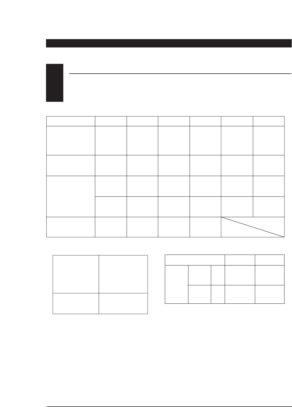
NORM NORM NORM NORM NORM NORM
••••• •
REV REV REV REV REV REV
SUB TRIM
TRAVEL ADJUST + % + % + % + % + % + %
– % – % – % – % – % – %
28 XF631 MANUAL • CHAPTER 8: DATA SHEET
V-TAIL ON • OFF
DATA SHEET
CHAPTER 8:Data Sheet
8
REVERSE SW
DIGITAL TRIM
VALUE
CHANNELS THRO (1) AIL (2) ELE (3) RUDD (4) GER (5) FLP (6)
WING TYPE
NORM
•
FLAPERON
•
DELTA
Model Number 1_____________________
Model Name ______________________
– 40% ± % ± % ± %
AILE (AI) ELEV (EL)
D/R % %
D/R % %
DUAL POS 0
RATE
POS 1

29
XF631 MANUAL • CHAMPTER 8: DATA SHEET
CHAPTER 8: Data Sheet
AILE (AI) ELEV (EL)
D/R % %
D/R % %
DUAL POS 0
RATE
POS 1
NORM NORM NORM NORM NORM NORM
••••• •
REV REV REV REV REV REV
SUB TRIM
TRAVEL ADJUST + % + % + % + % + % + %
– % – % – % – % – % – %
V-TAIL ON • OFF
DATA SHEET
8
REVERSE SW
DIGITAL TRIM
VALUE
CHANNELS THRO (1) AIL (2) ELE (3) RUDD (4) GER (5) FLP (6)
WING TYPE
NORM
•
FLAPERON
•
DELTA
Model Number 2_____________________
Model Name ______________________
– 40% ± % ± % ± %
30 XF631 MANUAL • CHAPTER 8: DATA SHEET
CHAPTER 8: Data Sheet
NORM NORM NORM NORM NORM NORM
••••• •
REV REV REV REV REV REV
SUB TRIM
TRAVEL ADJUST + % + % + % + % + % + %
– % – % – % – % – % – %
V-TAIL ON • OFF
DATA SHEET
8
REVERSE SW
DIGITAL TRIM
VALUE
CHANNELS THRO (1) AIL (2) ELE (3) RUDD (4) GER (5) FLP (6)
WING TYPE
NORM
•
FLAPERON
•
DELTA
Model Number 3_____________________
Model Name ______________________
– 40% ± % ± % ± %
AILE (AI) ELEV (EL)
D/R % %
D/R % %
DUAL POS 0
RATE
POS 1

31
XF631 MANUAL • IMPORTANT INFORMATION
IMPORTANT INFORMATION
Radio controlled models are a great source of
pleasure. Unfortunately, they can also pose a potential
hazard if not maintained and operated properly. It is
imperative that you install your radio control system
correctly. Additionally, your level of piloting
competency must be high enough to ensure that you
are able to control your aircraft under all conditions. If
you are a newcomer to radio controlled flying, please
seek help from an experienced pilot or your local
hobby shop.
Listed below are some safety “Dos and Don’ts” that
must be followed by all pilots:
• Ensure that your batteries have been properly
charged prior to initial flight.
• Keep track of the time that the system is turned
on so that you will have an idea of how long you
can safely operate your system.
• Perform a ground range check prior to the initial
flight of the day. See the “Daily Flight Checks”
section below for information on how to do so.
• Check all control surfaces prior to each takeoff.
• Use frequency flags.
• Do not fly your model near spectators, parking
areas, or at any other area that could result in
injury to people or damage of property.
• Do not fly during adverse weather conditions.
Poor visibility can cause disorientation and loss
of control of your aircraft. Strong winds can cause
similar problems.
• Do not fly unless your frequency is clear.
Warning: Only one transmitter at a time can
operate on a given frequency. If you turn on your
transmitter while someone else is operating a
model on your frequency, both pilots will lose
control of their models. Only one person can use a
given frequency at a time. It does not matter if it is
AM, FM, or PCM — only one frequency at a time.
• Do not point the transmitter antenna directly
toward the model. The radiation pattern from the
tip of the antenna is inherently low.
• Do not take chances. If at any time during flight
you observe any erratic or abnormal operation,
land immediately and do not resume flight until
the cause of the problem has been ascertained
and corrected.
1. Check the battery voltage on both the transmitter
and the receiver battery packs. Do not fly below
9.0 volts on the transmitter or below 4.7 volts on
the receiver. To do so can cause a crash of your
aircraft.
Note: When you check these batteries, ensure that
you have the polarities correct on your expanded
scale voltmeter.
2. Check all hardware (linkages, screws, nuts, bolts)
prior to each day’s flight. Be sure that binding
does not occur and that everything is properly
secured.
3. Ensure that all surfaces are moving in the proper
manner.
4. Perform a ground range check before each day’s
flying session. The range check should be as
follows:
• Do not extend the transmitter antenna at this
time. Turn the transmitter on.
• Turn the model on.
• Slowly walk away from the model while moving
the control surfaces. The aircraft should function
properly at a distance of 75–100 feet.
5. Just prior to starting your aircraft, turn off your
transmitter and then turn it back on. Do this each
time you start your aircraft. If any critical switches
are on without your knowledge, the transmitter
alarm will warn you at this time.
6. Ensure that all trim levers are in the proper
location.
7. Check to be sure that all servo pigtails and switch
harness plugs are secured in the receiver. Also,
make sure that the switch harness moves
completely in both directions.
GENERAL NOTES
1
DAILY FLIGHT CHECKS
2

32 XF631 MANUAL • WARRANTY AND SERVICE INFORMATION
Important Note: Be sure to keep your original dated sales receipt in a safe place as you will be required to provide proof-of-purchase
date for the equipment to be serviced under warranty.
WARRANTY AND SERVICE INFORMATION
WARRANTY COVERAGE
REPAIR SERVICE INSTRUCTIONS
Your new JR Remote Control Radio System is
warranted to the original purchaser against
manufacturer defects in material and workmanship
for one year from the date of purchase. During this
period, Horizon Service Center will repair or replace,
at our discretion and at no cost to the purchaser, any
component that is found to be factory defective. This
warranty is limited to the original purchaser of the
unit and is not transferable.
This warranty does not apply to any unit which has
been improperly installed, mishandled, abused, or
damaged in a crash, or to any unit which has been
repaired or altered by any unauthorized agencies.
Under no circumstances will the buyer be entitled to
consequential or incidental damages. This limited
warranty gives you specific legal rights; you also have
other rights which may vary from state to state. As
with all fine electronic equipment, do not subject
your radio system to extreme temperatures, humidity
or moisture. Do not leave it in direct sunlight for
long periods of time.
In the event that your JR radio needs service, please
follow the instructions listed below:
1. Check all on/off switches to be sure they are off.
This will speed the repair process of checking
battery condition.
2. Return your system components only (transmitter,
receiver, servos, etc). Do not return your system
installed in a model aircraft.
3. Preferably, use the original carton/packaging
(molded foam container), or equivalent, to ship
your system. Do not use the system carton itself as
a shipping carton. You should package the system
carton within a sturdy shipping container using
additional packing material to safeguard against
damage during transit. Include complete name
and address information inside the carton, as well
as clearly writing it on the outer label/return
address area.
4. Include detailed information explaining your
operation of the system and problem(s)
encountered. Provide an itemized list of equipment
enclosed and identify any particular area/function
which may better assist our technicians in
addressing your concerns. Date your
correspondence and be sure your complete name
and address appear on this enclosure.
5. Include your name, mailing address, and a phone
number where you can be reached during the
business day.
6. Warranty Repairs. To receive warranty service, you
must include your original dated sales receipt to
verify your proof-of-purchase date. Providing that
warranty conditions have been met, your radio will
be repaired without charge.
7. Normal Non-Warranty Repairs. Should your repair
cost exceed 50% of the retail purchase cost, you will
be provided with an estimate advising you of your
options.
Within your letter, advise us of the payment method
you prefer to use. Horizon Service Center accepts
VISA or MasterCard. Include your card number and
expiration date. Horizon Service Center also accepts
money orders.
Mail your system to:
Horizon Service Center
4105 Fieldstone Road
Champaign, IL 61822
Phone: (217) 355-9511
www.horizonhobby.com
3
4

33 XF631 MANUAL • FREQUENCY CHART
72MHz requires no special license to operate.
50/53MHz requires the operator to have an FCC
amateur radio license (Ham).
CH.NO. FREQUENCY
15 72.090
16 72.110
17 72.130
18 72.150
19 72.170
20 72.190
21 72.210
22 72.230
23 72.250
24 72.270
25 72.290
26 72.310
27 72.330
28 72.350
29 72.370
30 72.390
31 72.410
32 72.430
33 72.450
34 72.470
35 72.490
CH.NO. FREQUENCY
36 72.510
37 72.530
38 72.550
39 72.570
40 72.590
41 72.610
42 72.630
43 72.650
44 72.670
45 72.690
46 72.710
47 72.730
48 72.750
49 72.770
50 72.790
51 72.810
52 72.830
53 72.850
54 72.870
55 72.890
56 72.910
57 72.930
58 72.950
59 72.970
60 72.990
CH.NO. FREQUENCY
00 50.800
01 50.820
02 50.840
03 50.860
04 50.880
05 50.900
06 50.920
07 50.940
08 50.960
09 50.980
72MHz 50MHz
CH. NO. FREQUENCY FLAG COLOR
A1 53.100 Black/Brown
A2 53.200 Black/Red
A3 53.300 Black/Orange
A4 53.400 Black/Yellow
A5 53.500 Black/Green
A6 53.600 Black/Blue
A7 53.700 Black/Purple
A8 53.800 Black/Gray
53MHz
FREQUENCY CHART
5
72MHz
FREQUENCY CHART
*Channels 11–14 are not available

NOTES

NOTES

DISTRIBUTED EXCLUSIVELY BY HORIZON HOBBY DISTRIBUTORS CHAMPAIGN, IL 61822
www.horizonhobby.com
© 1999 Horizon Hobby Distributors, Inc. All Rights Reserved.
®