Horizon Hobby XR3I User Manual XR3i Manual
Horizon Hobby, LLC XR3i Manual
UserManual.wiki
>
Horizon Hobby
>
XR3I User Manual
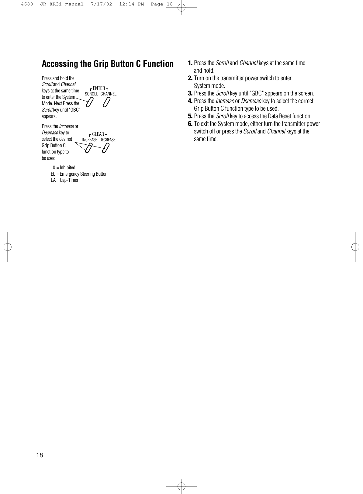
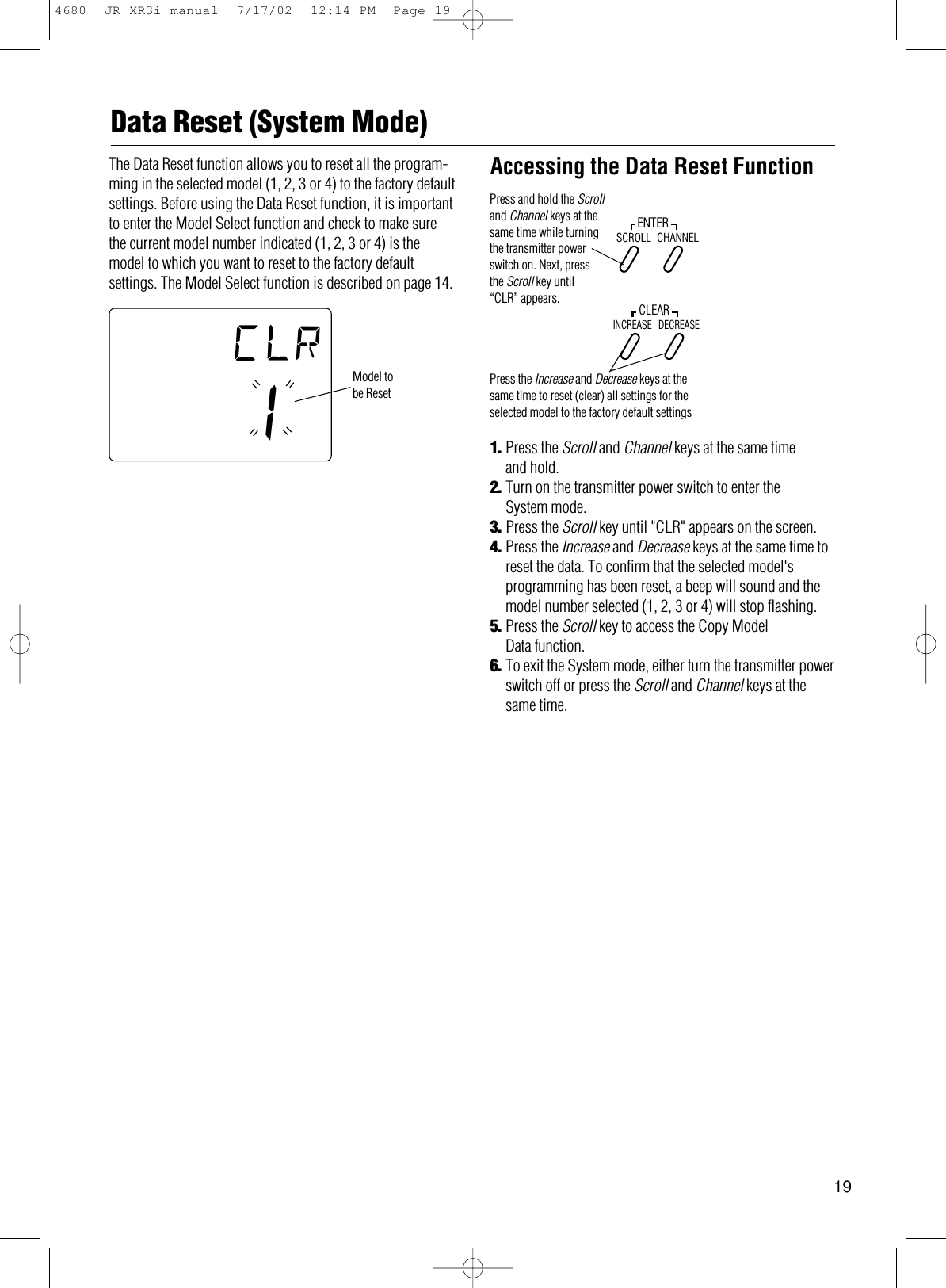
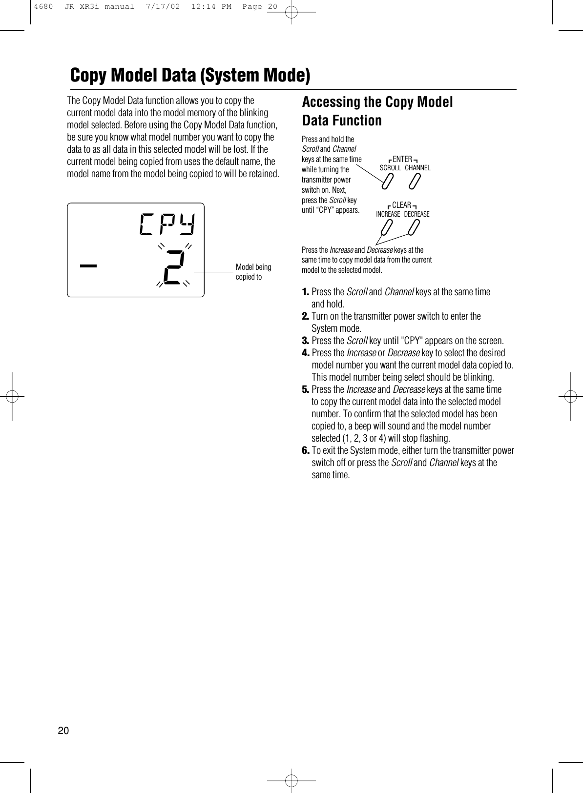
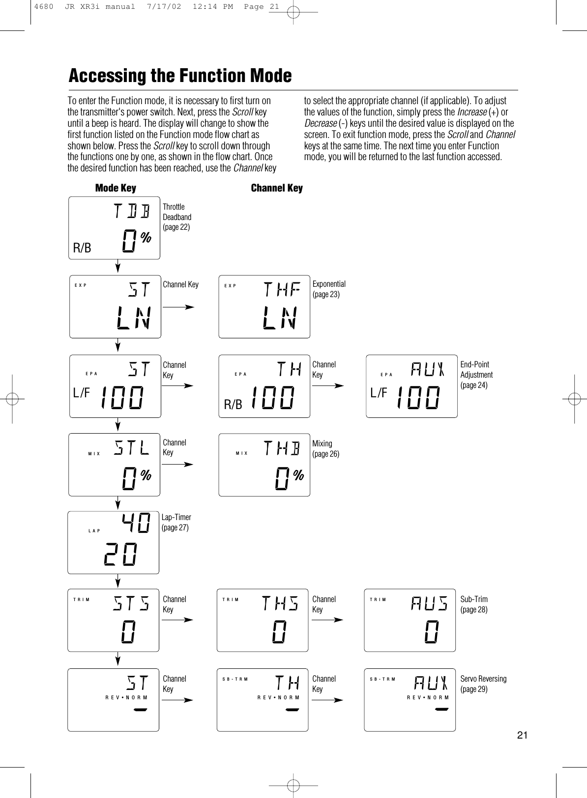
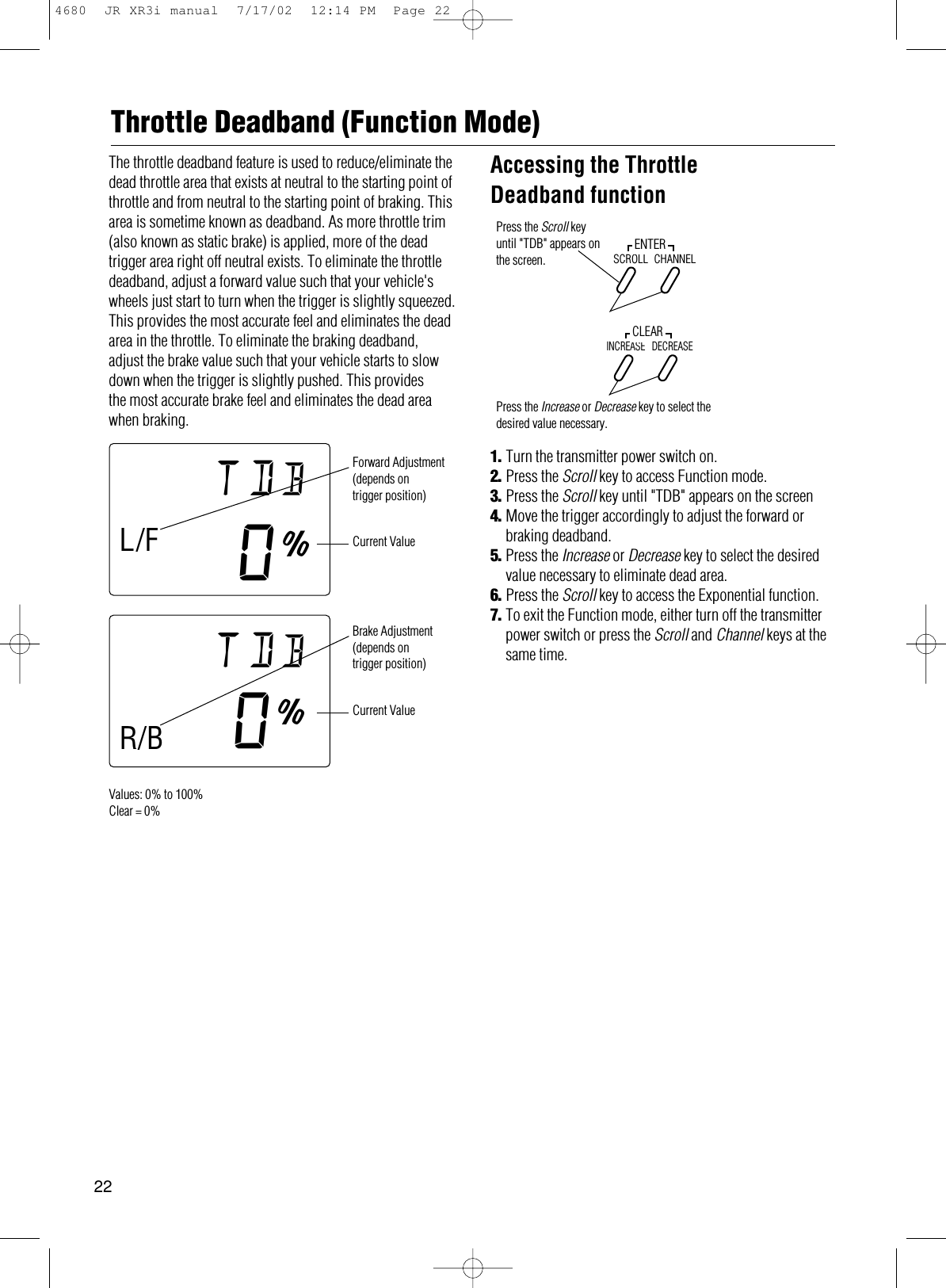
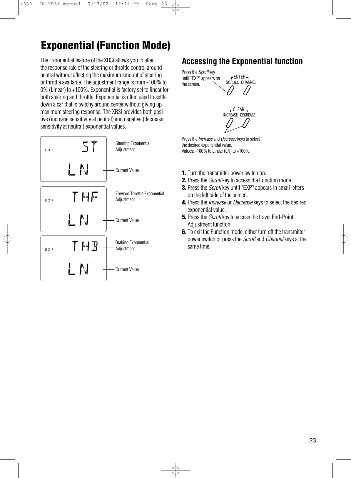
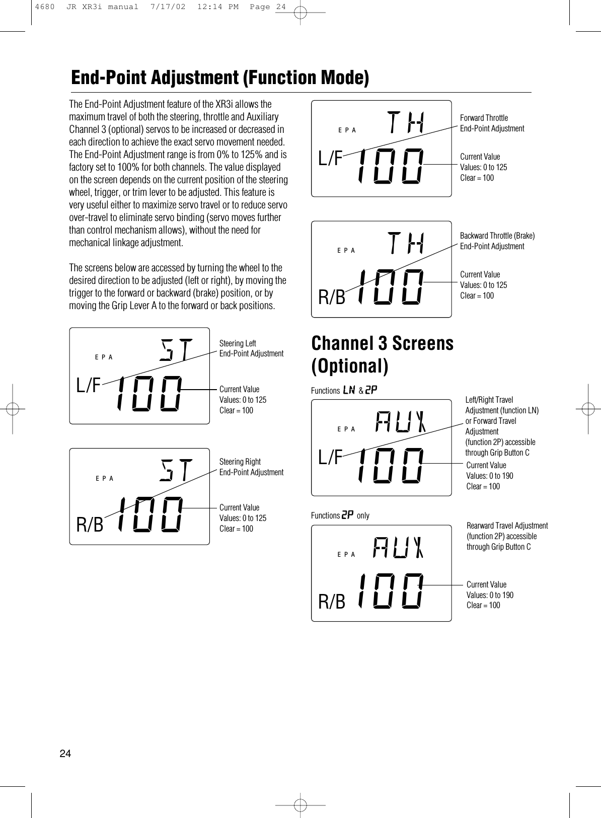
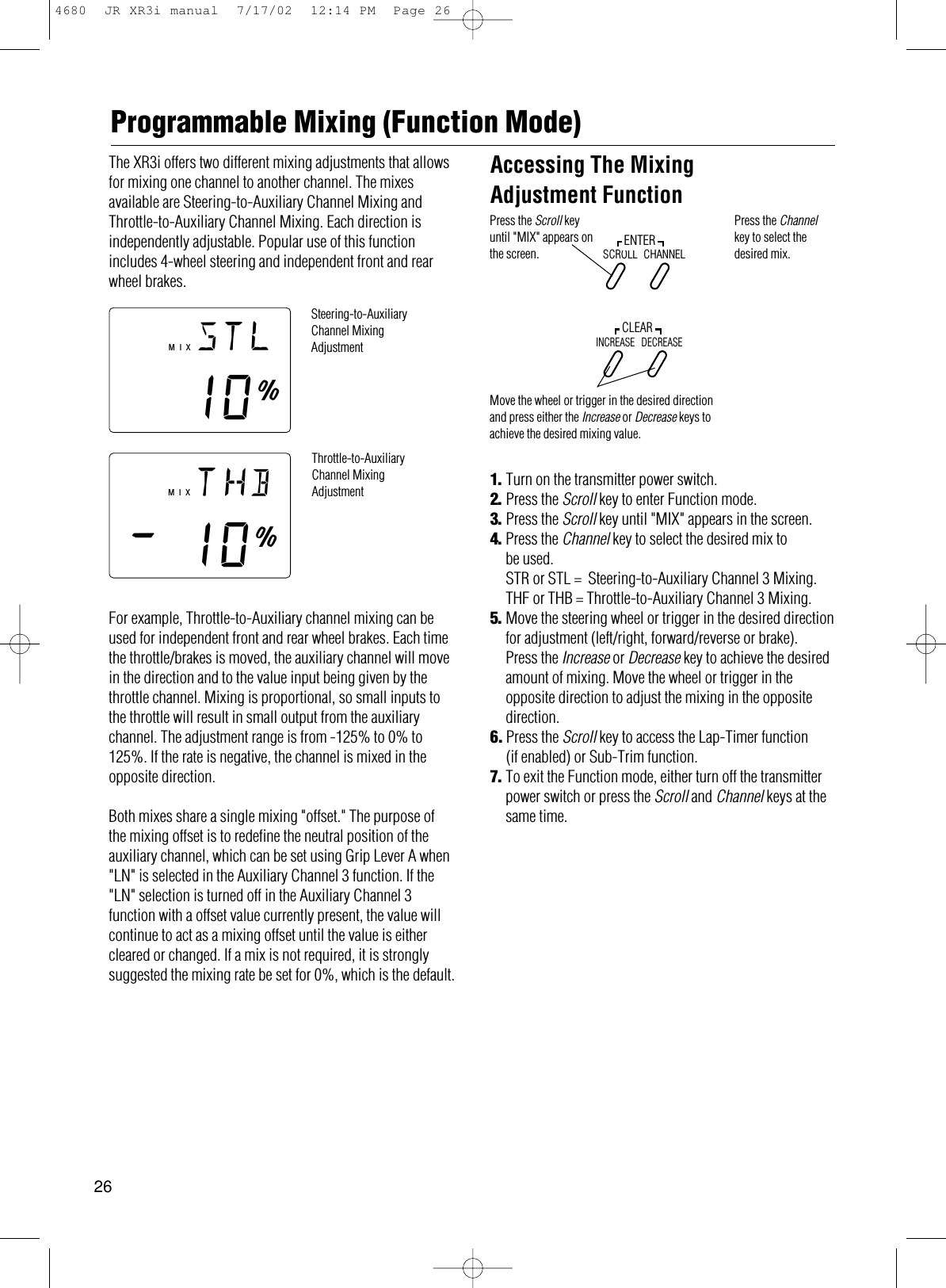
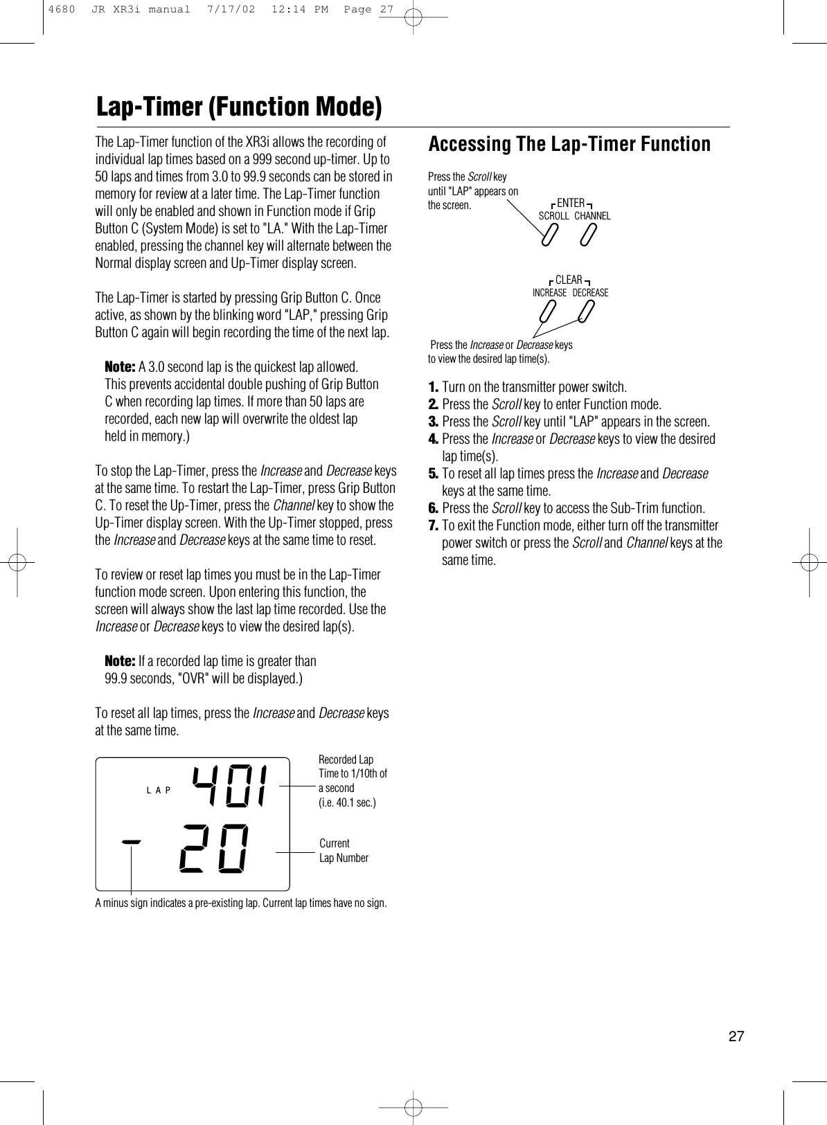
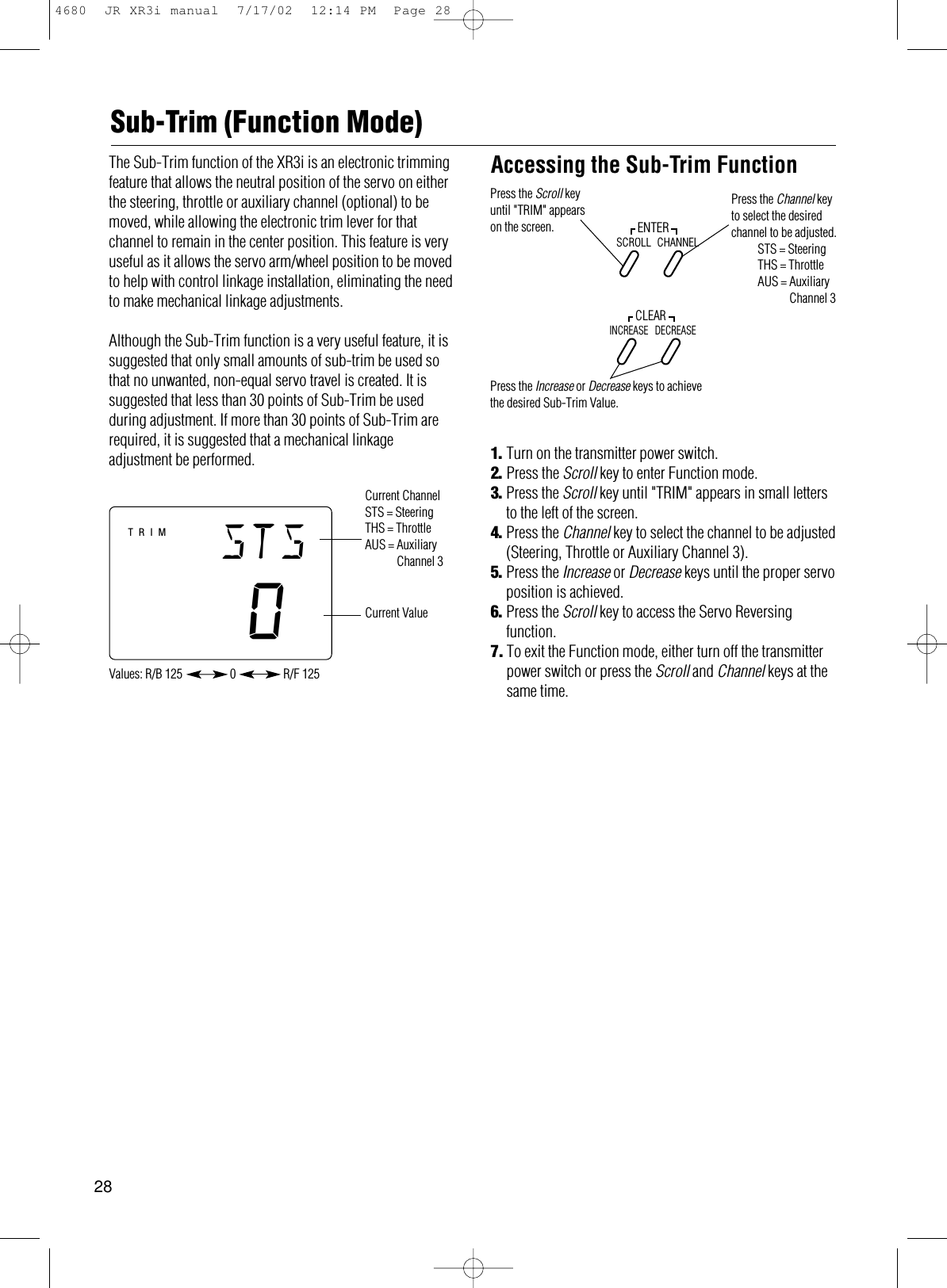
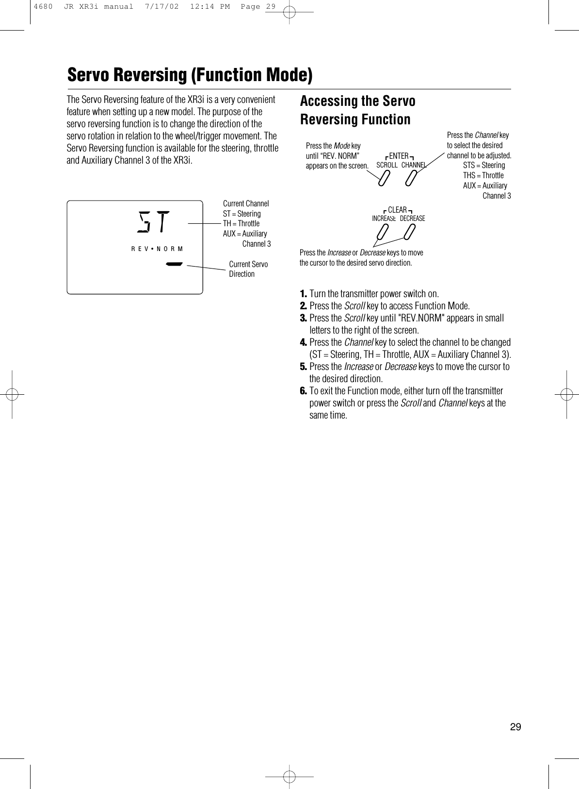
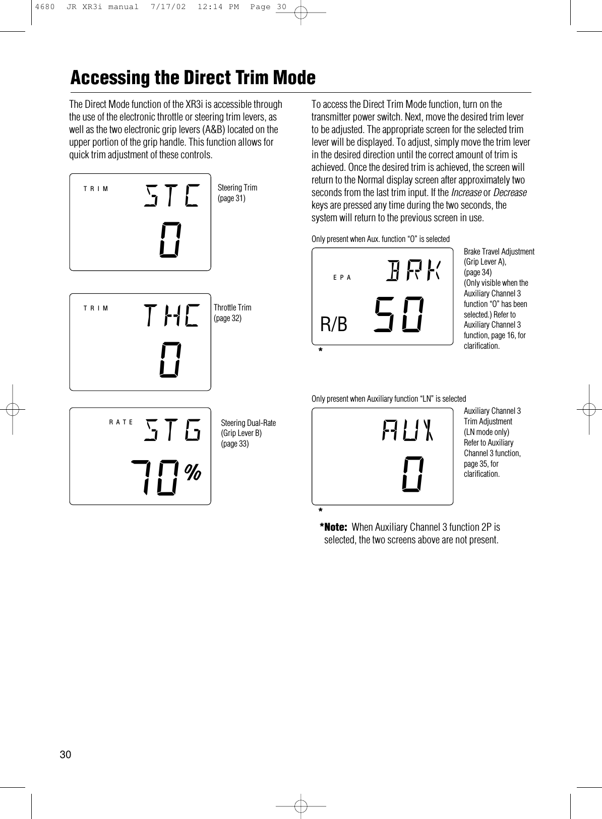
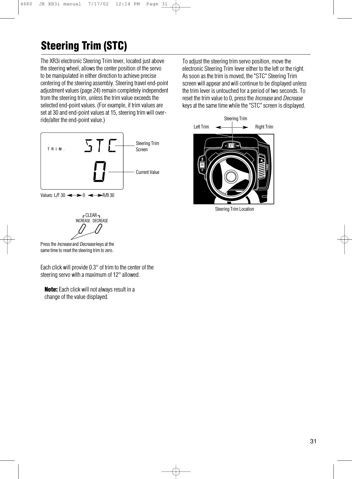
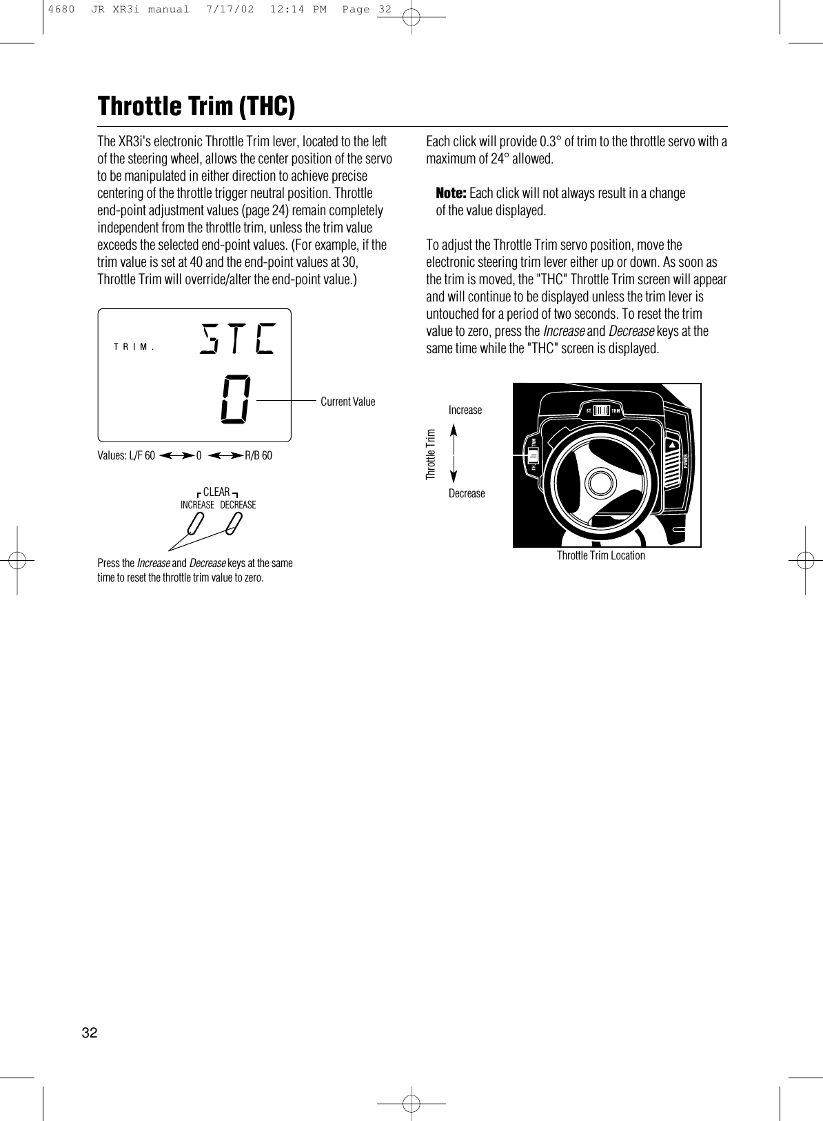
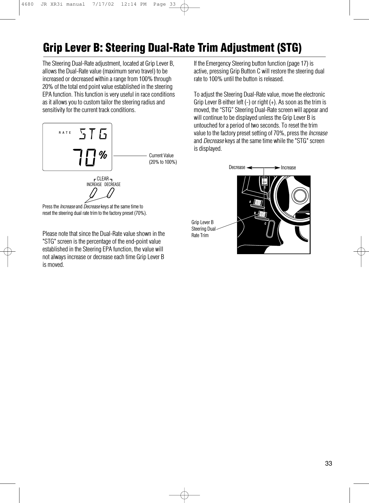
XR3i Manual
Navigation menu
Upload a User Manual
Namespaces
Wiki Guide
HTML
PDF
Info
Views
User Manual
Discussion / Help
Navigation