Hotpoint Range Jb400Dp1Bb Users Manual Presentation
Ge - Steam Clean Range - Jb400.V2 - 06.22.09 GE - Steam Clean Range - JB400.V2 - 06.22.09 GE - Steam Clean Range - JB400.V2 - 06.22.09 GE, Camco, Hotpoint, Mofat applianceservicesecretsmembership.com_manuals
JB400SPSS to the manual bd2326e4-c772-468b-b5ce-2a9731f9ea25
2015-01-24
: Hotpoint Hotpoint-Range-Jb400Dp1Bb-Users-Manual-315642 hotpoint-range-jb400dp1bb-users-manual-315642 hotpoint pdf
Open the PDF directly: View PDF ![]() .
.
Page Count: 57
- GE JB400 Steam Clean Range
- Slide Number 2
- Slide Number 3
- Slide Number 4
- Slide Number 5
- Slide Number 6
- Slide Number 7
- Oven Door Removal
- Oven Door Removal
- Oven Door Re-Installation
- Oven Door Re-Installation
- Slide Number 12
- Slide Number 13
- Slide Number 14
- Slide Number 15
- Slide Number 16
- Slide Number 17
- Slide Number 18
- Slide Number 19
- Slide Number 20
- Slide Number 21
- Slide Number 22
- Slide Number 23
- Slide Number 24
- Slide Number 25
- Slide Number 26
- Slide Number 27
- Slide Number 28
- Slide Number 29
- Slide Number 30
- Slide Number 31
- Slide Number 32
- Slide Number 33
- Slide Number 34
- Slide Number 35
- Slide Number 36
- Slide Number 37
- Slide Number 38
- Slide Number 39
- Slide Number 40
- Slide Number 41
- Slide Number 42
- Slide Number 43
- Slide Number 44
- Slide Number 45
- Slide Number 46
- Slide Number 47
- Slide Number 48
- Slide Number 49
- Slide Number 50
- Slide Number 51
- Slide Number 52
- Slide Number 53
- Slide Number 54
- Slide Number 55
- Slide Number 56
- Slide Number 57
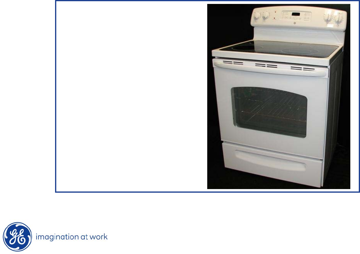
GE JB400 Steam Clean Range
Range Models:
JB400DP1WW
JB400DP1BB
JB400SPSS

2
Copyright 2009
IMPORTANT SAFETY NOTICE
The information in this presentation is intended for use by individuals
possessing adequate backgrounds of electrical, electronic, & mechanical
experience. Any attempt to repair a major appliance may result in
personal injury & property damage. The manufacturer or seller cannot be
responsible for the interpretation of this information, nor can it assume
any liability in connection with its use.
WARNING
To avoid personal injury, disconnect power before servicing this
product.
If electrical power is required for diagnosis or test purposes, disconnect
the power immediately after performing the necessary checks.
RECONNECT ALL GROUNDING DEVICES
If grounding wires, screws, straps, clips, nuts, or washers used
to complete
a path to ground are removed for service, they must be returned to their
original position & properly fastened.

3
Copyright 2009
GE Factory Service Employees are required to use safety glasses with side
shields, cut resistant (Dyneema®) gloves & steel toe shoes for all repairs.
Dyneema® Cut
Resistant Glove
Safety Glasses must be compliant with
ANSI Z87.1-2003
Prescription Safety Glasses
Plano Safety Glasses
Steel Toe Shoes
4
Copyright 2009
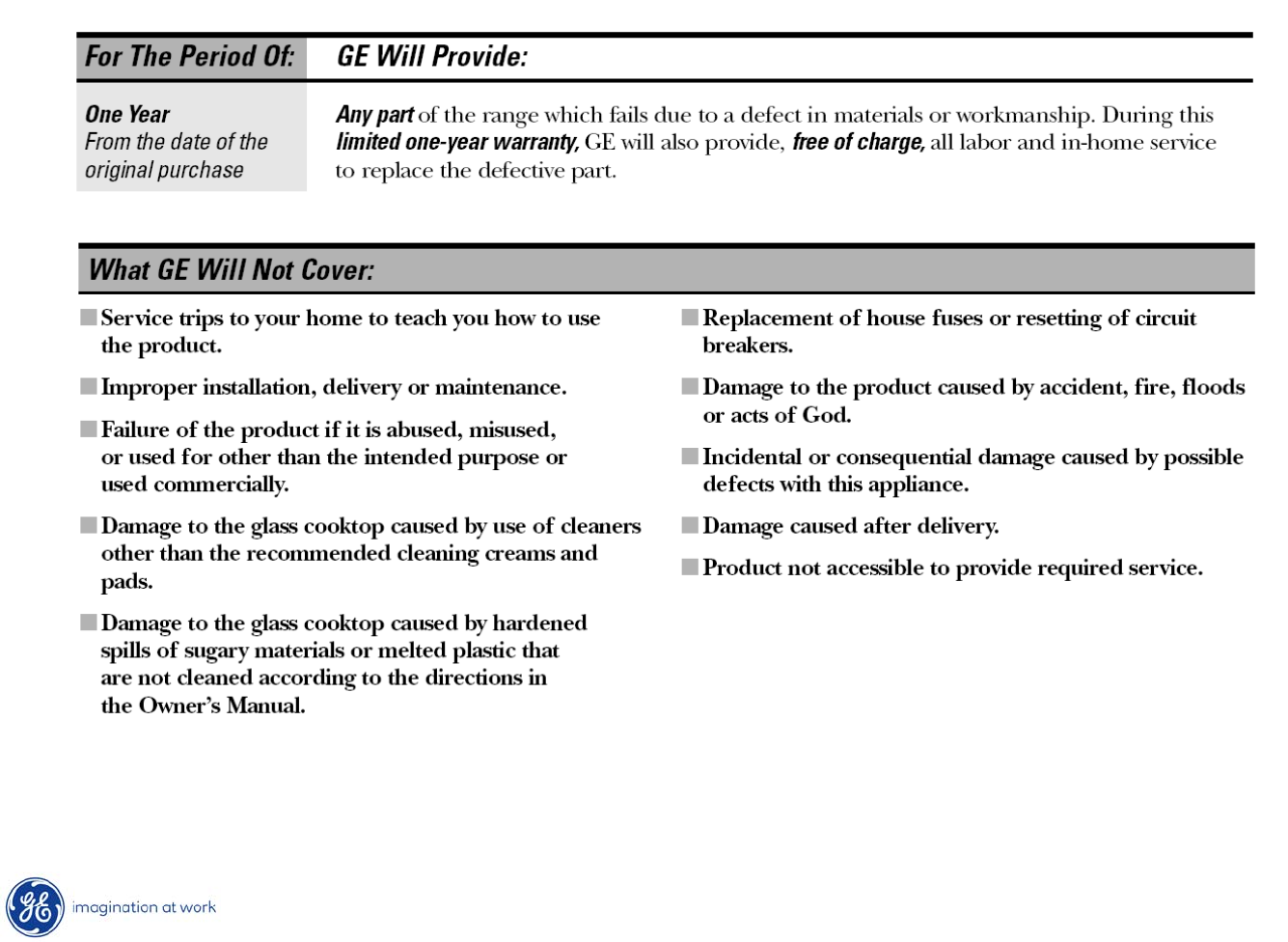
Warranty
5
Copyright 2009
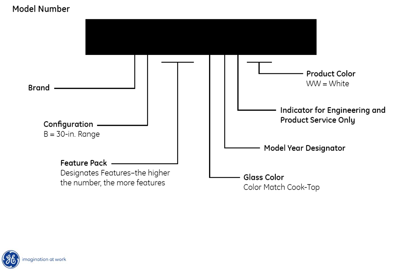
Nomenclature
J B 400 D P 1 WW
J = GE
6
Copyright 2009
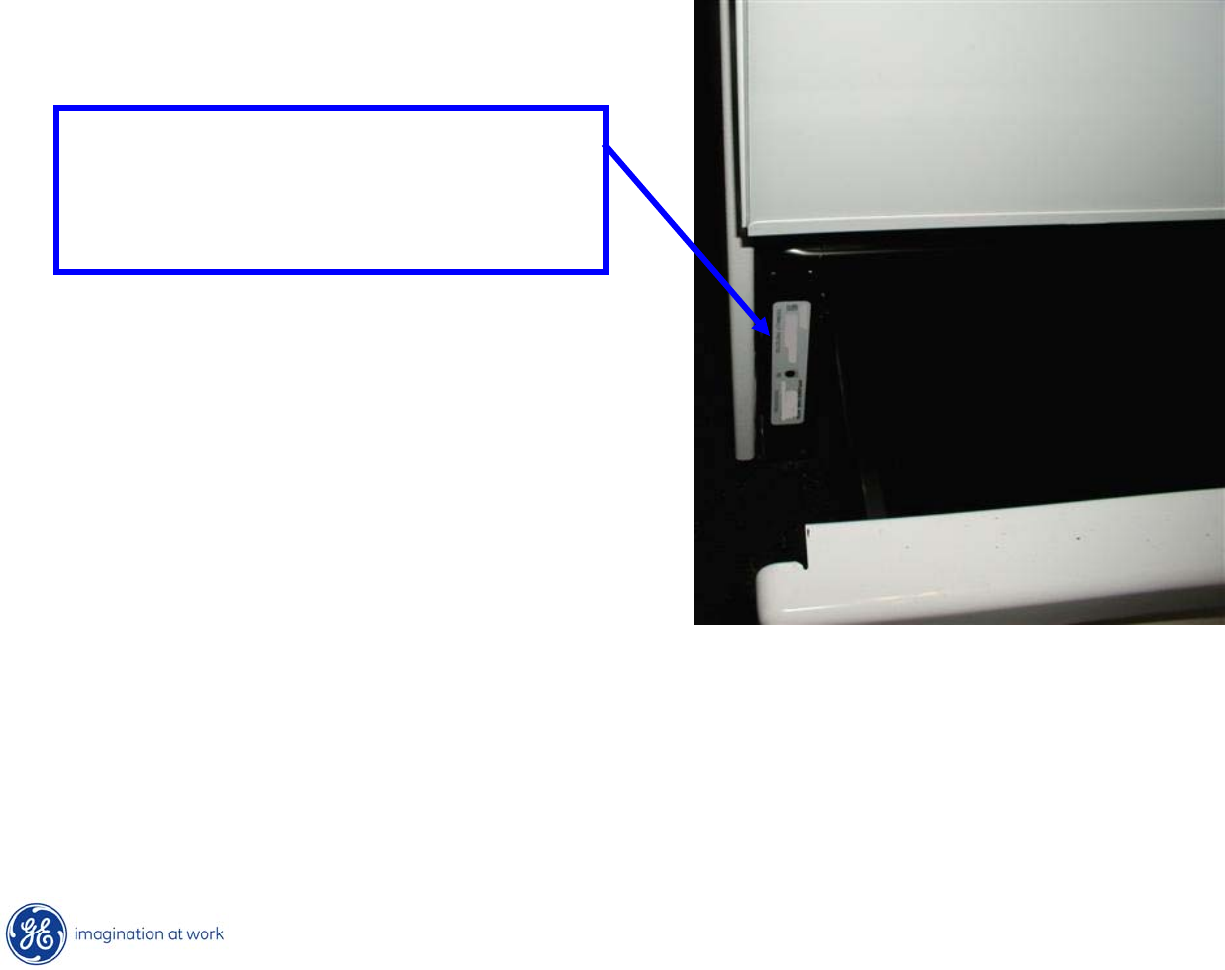
Model / Serial Number Plate
•Mini-Manual is in an envelope and located inside the left hand panel.
Model / serial plate is located
on the front frame behind the
storage drawer.
7
Copyright 2009
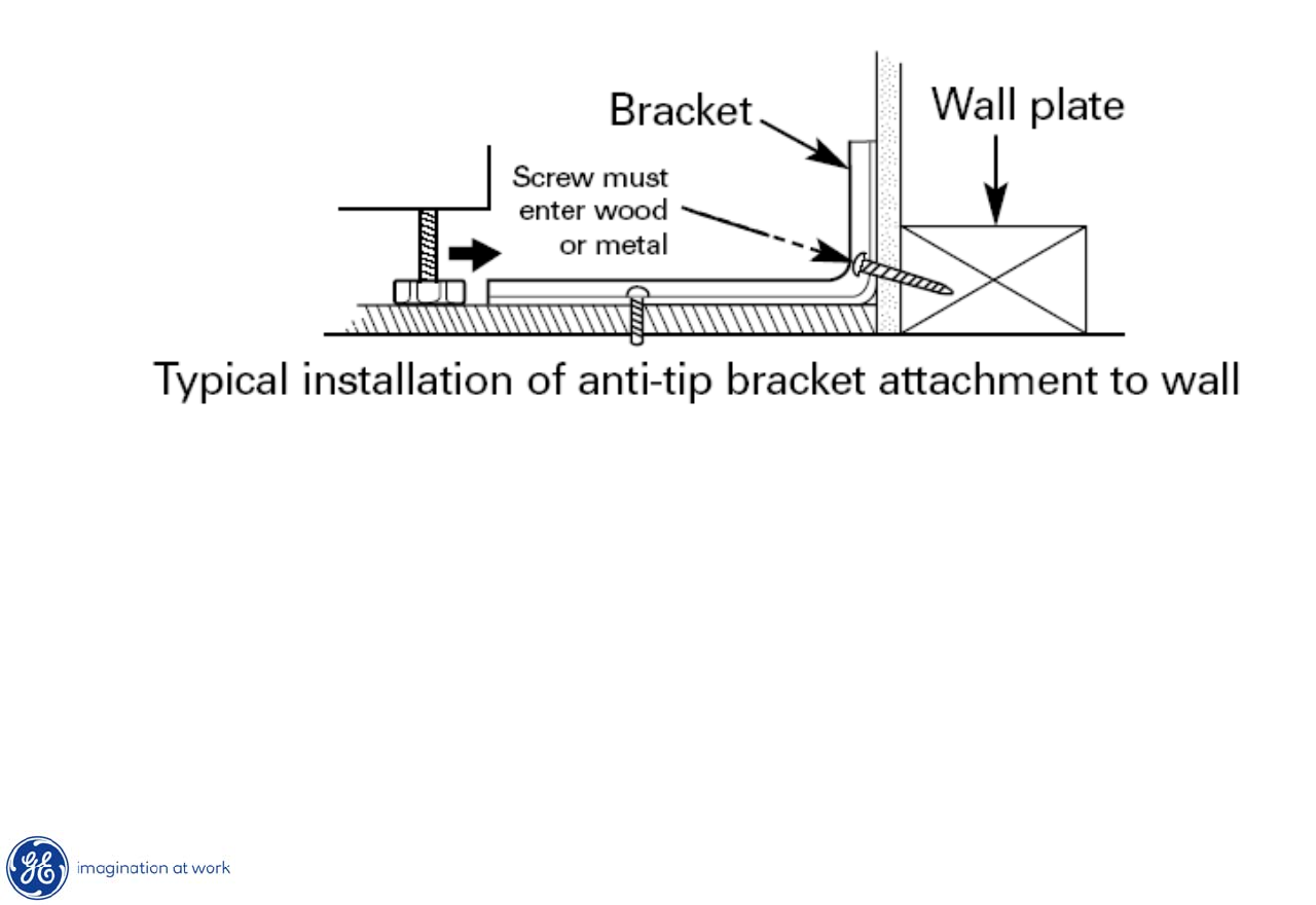
Anti-Tip Bracket
* Range must be secured by the Anti-Tip Bracket supplied.
8
Copyright 2009
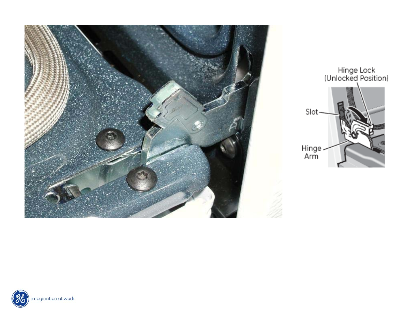
Oven Door Removal
•Fully open the door.
•Push the hinge locks down toward the door frame, to the unlocked
position. This may require a flat blade screwdriver.
9
Copyright 2009
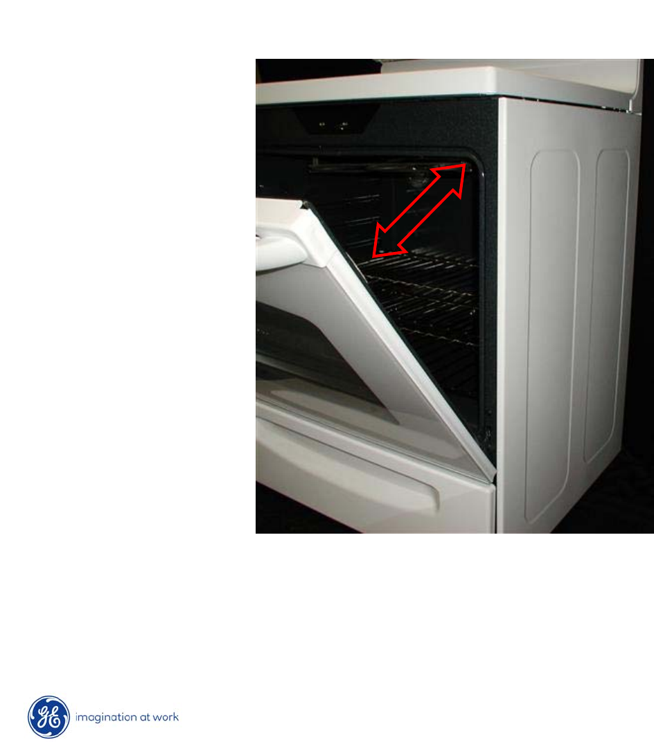
Oven Door Removal
•Close door to the door removal position.
•Firmly grasp both sides of the door at the top.
•Lift door up until the hinge arm is clear of the slot.
10
Copyright 2009
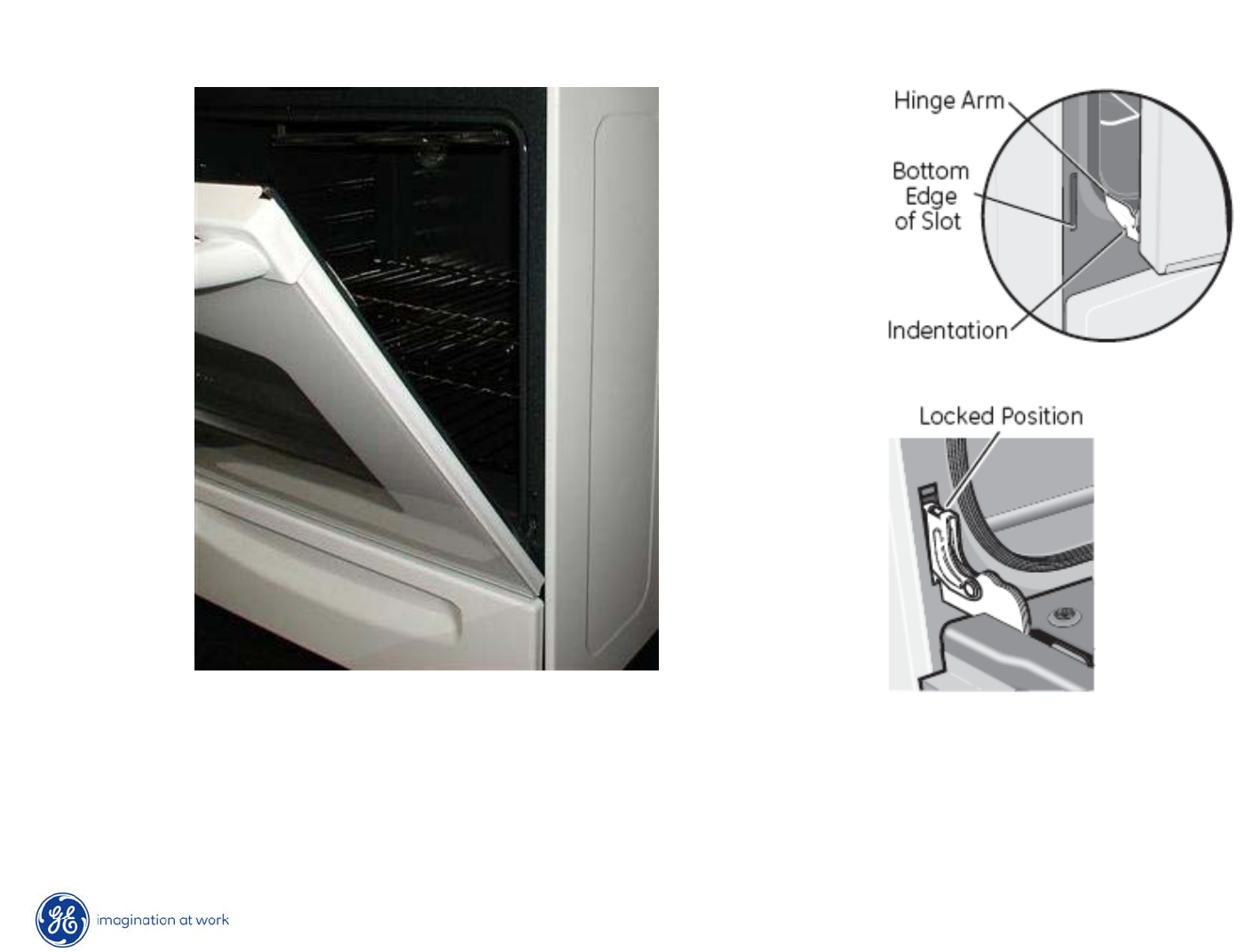
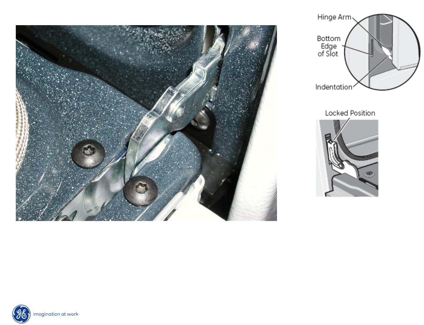
Oven Door Re-Installation
•Firmly grasp both sides of the door at the top.
•With the door at the same angle as the removal position, seat
the indentation of the hinge arm into the bottom edge of the hinge slot.
11
Copyright 2009
Oven Door Re-Installation
•Fully open the door.
•Push the hinge locks up against the front frame of the
oven cavity, to the locked position.
•Close the oven door.
12
Copyright 2009
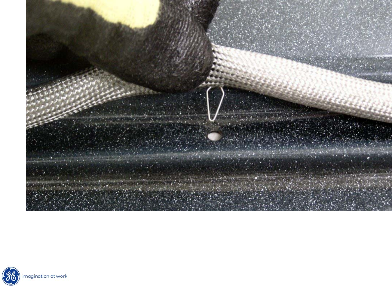
Door Gasket
Door gasket attached with spring clips around perimeter of door.
13
Copyright 2009
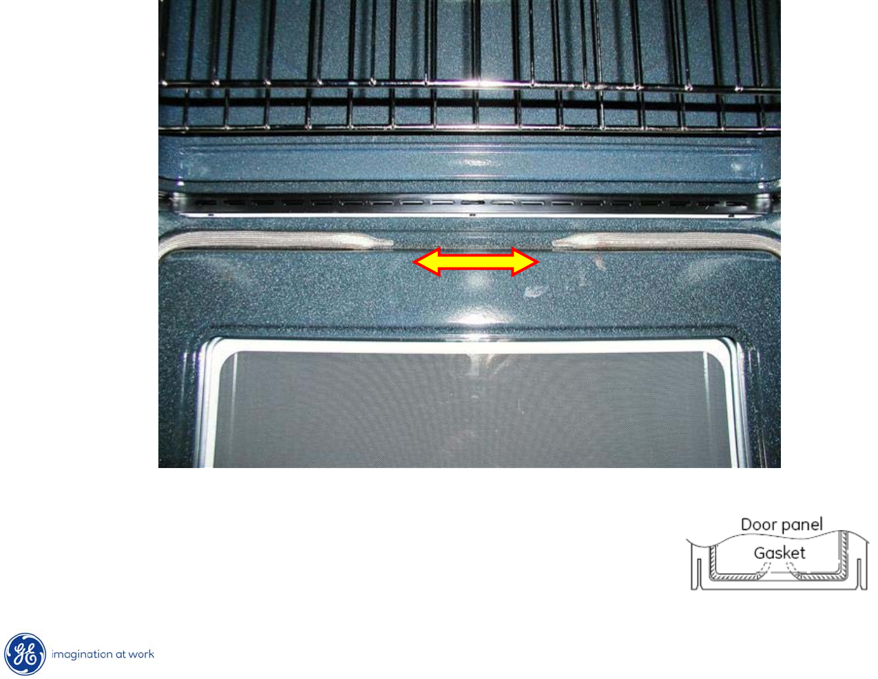
Door Gasket
A gap must be left in the gasket at the bottom
of the door. The gap is required to provide air
flow in the oven for proper baking results.
14
Copyright 2009
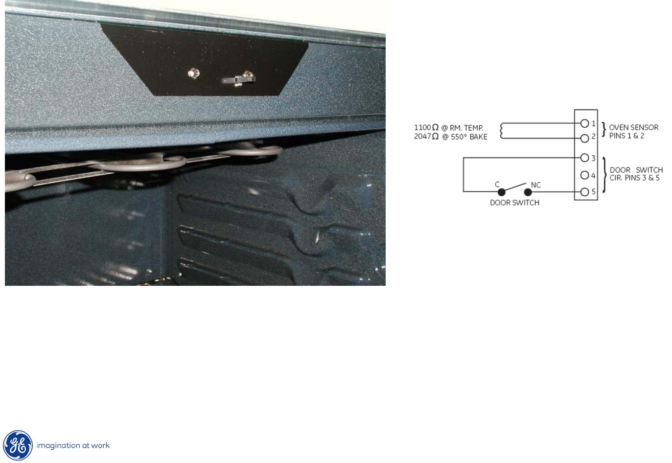
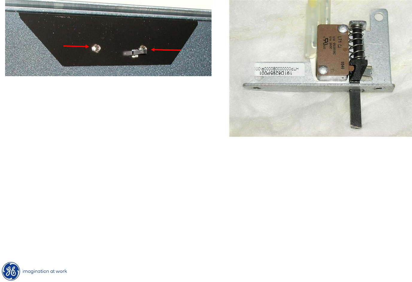
Door Switch
Door switch is merely a sensor input to the control.
It allows the control to know the status of the door position, open or closed.
Has no control over the oven light operation.
15
Copyright 2009
Door Switch Replacement
After lifting cooktop, switch assembly can be released by removing
two ¼”
hex heads securing it to the front frame of the oven.
16
Copyright 2009
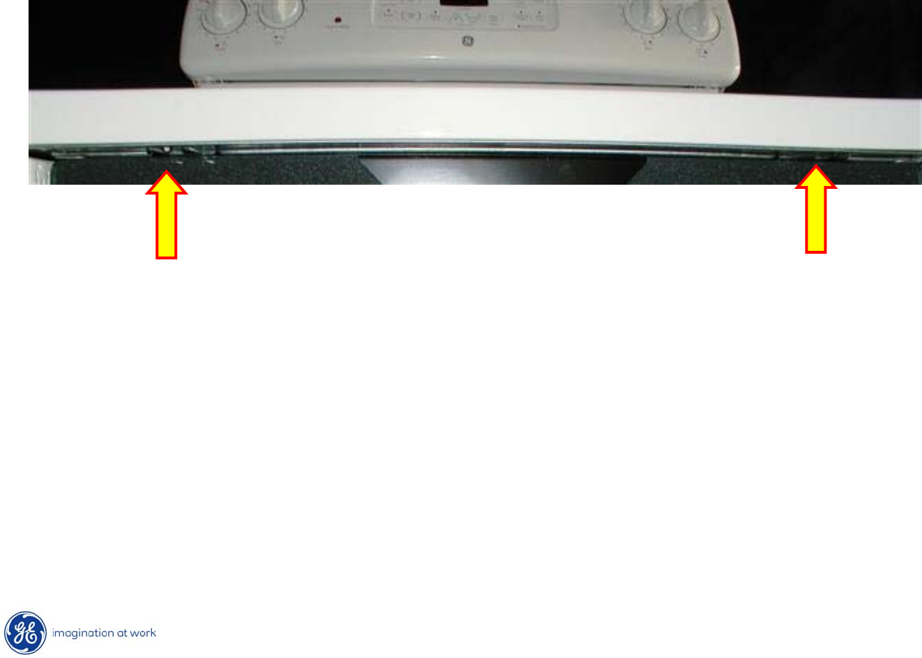
Cooktop
•Open oven door.
•Remove two ¼”
hex head screws securing cooktop to front frame.
•Lift cooktop.
•Use prop to support cooktop, if desired.
17
Copyright 2009
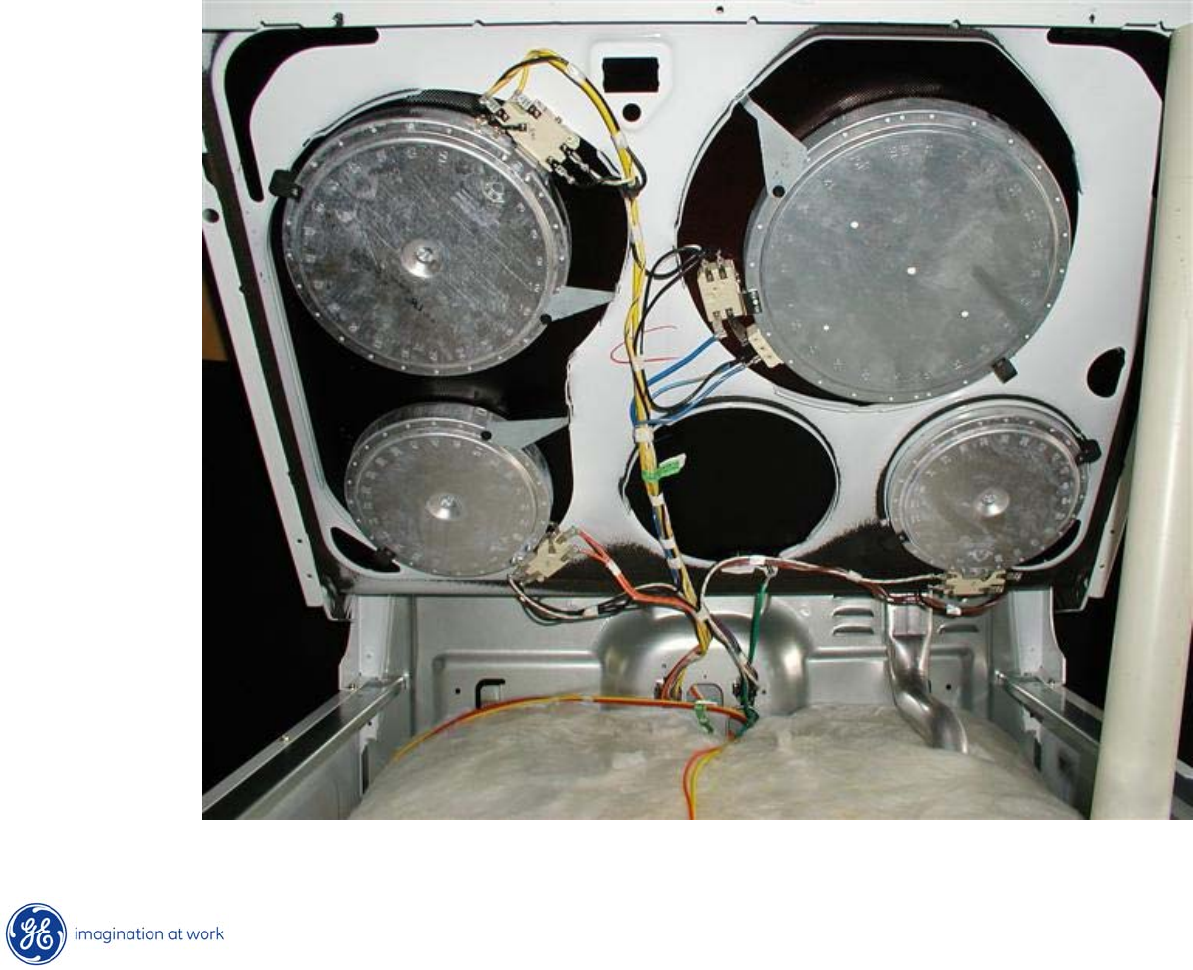
Cooktop Elements
6 Inch
1500W
6 Inch
1500W
8 Inch
2000W
10 Inch
3000W
Inner – 1400W
Outer – 1600W
18
Copyright 2009
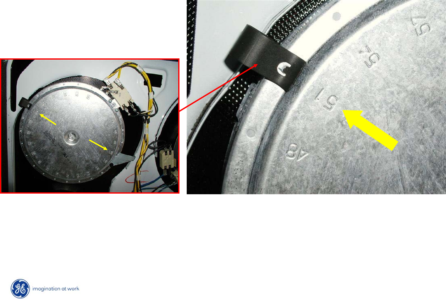
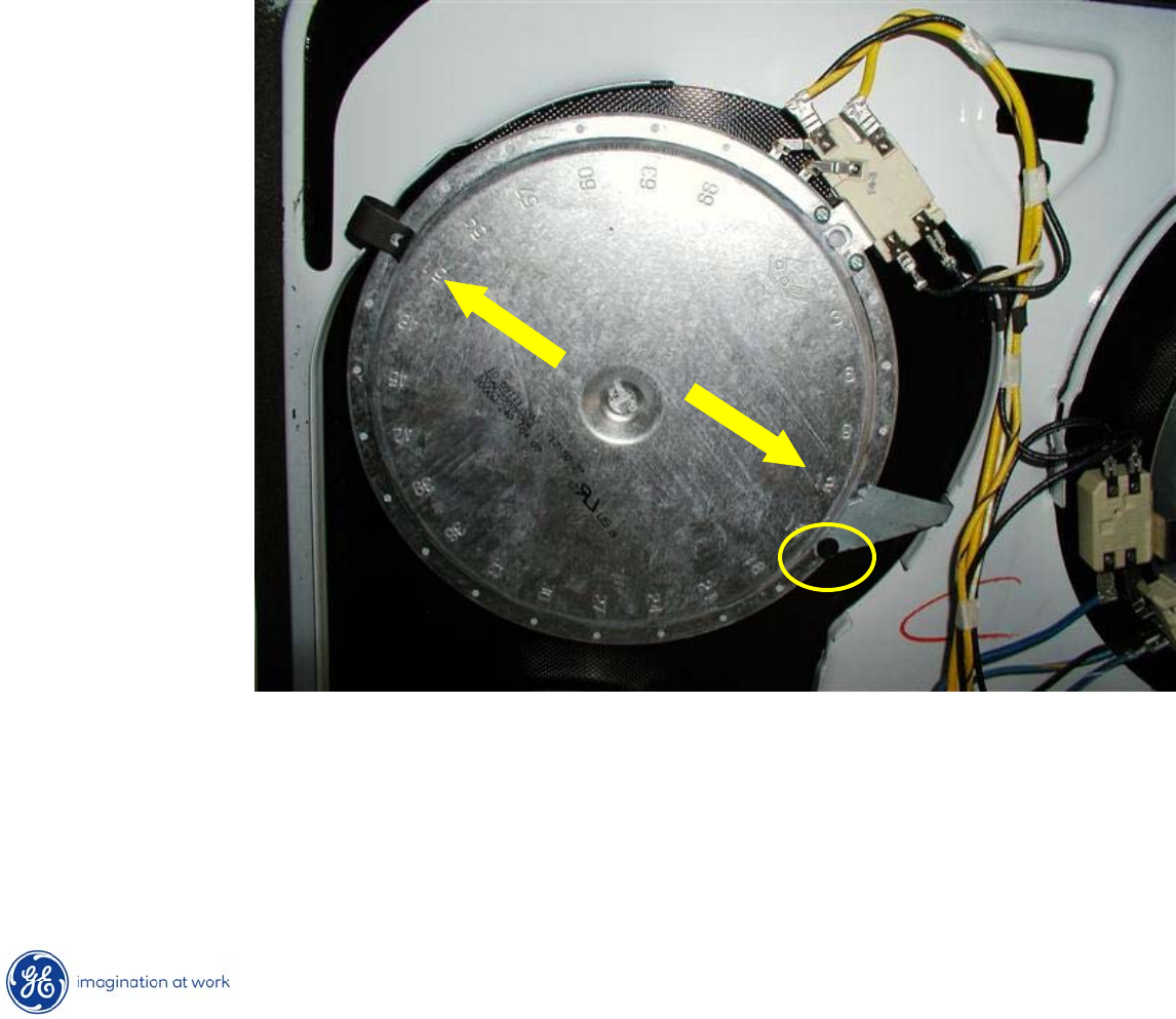
Cooktop Element Replacement
After marking the numbered holes on the burner outer case, lift up on spring clip
to disengage it from the burner.
19
Copyright 2009
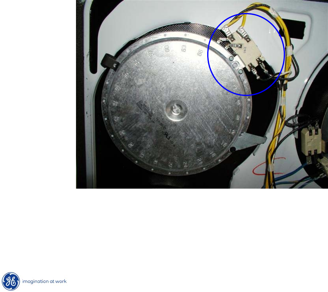
Cooktop Element Replacement
•After removing hex head from “L”
bracket, remove bracket.
•Disengage mounting clips from burner case.
•Mark and remove wires from terminals.
•Lift and remove burner from cooktop assembly
20
Copyright 2009
Temperature Limit / Hot Cooktop Light Switch
The temperature limit/hot cooktop light switch performs two functions:
1. Turns on the Hot Cooktop Light when the surface unit switch is turned on.
The hot light will remain on until the glass surface above the heating unit
has cooled below 150°F (even after the surface unit switch has been
turned off).

21
Copyright 2009
Temperature Limit / Hot Cooktop Light Switch
The temperature limit/hot cooktop light switch performs two functions:
2. Detects when glass temperature above a unit has exceeded it’s limit of
approximately 1031°F and disconnects power to that unit. When the glass
temperature cools below 1031°F, the unit will turn back on.
* The temperature limit/hot light switch cannot be calibrated.
22
Copyright 2009
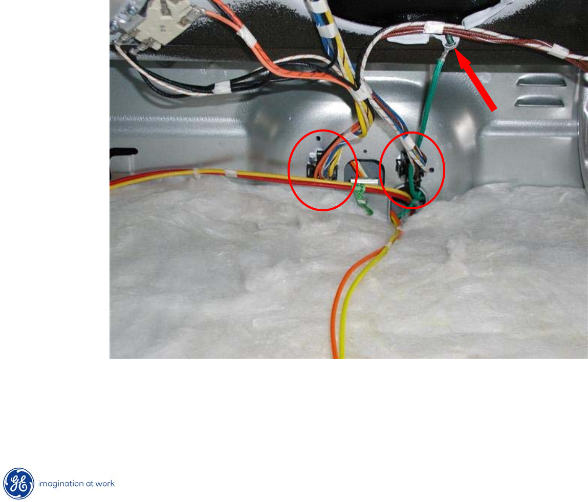
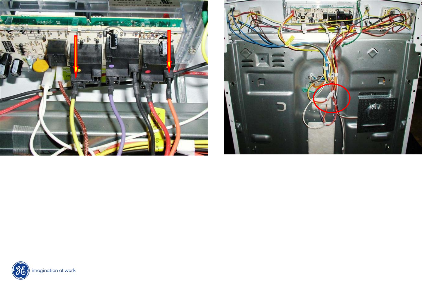
Cooktop Removal
•Begin by disconnecting two power plugs at rear of cooktop area.
•Next, remove ground wire screw at bottom of cooktop.
23
Copyright 2009
Cooktop Removal
•Return cooktop to normally closed position.
•Lift rear of cooktop @ two inches.
•Pull cooktop towards front of range to disengage hinge slots on
cooktop from hinge pins on frame.
24
Copyright 2009
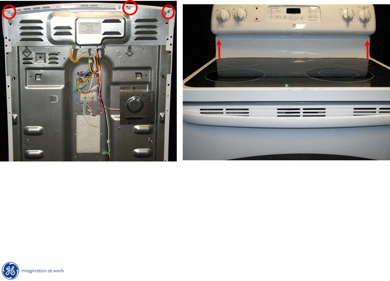
Control Panel Removal
The control panel contains the ERC & the infinite heat switches.
To Service:
1.
Remove 3 ¼”
hex heads at the top, in the back of the range.
2.
Remove 2 Phillips screws under the control panel in the front of
the
range.
25
Copyright 2009
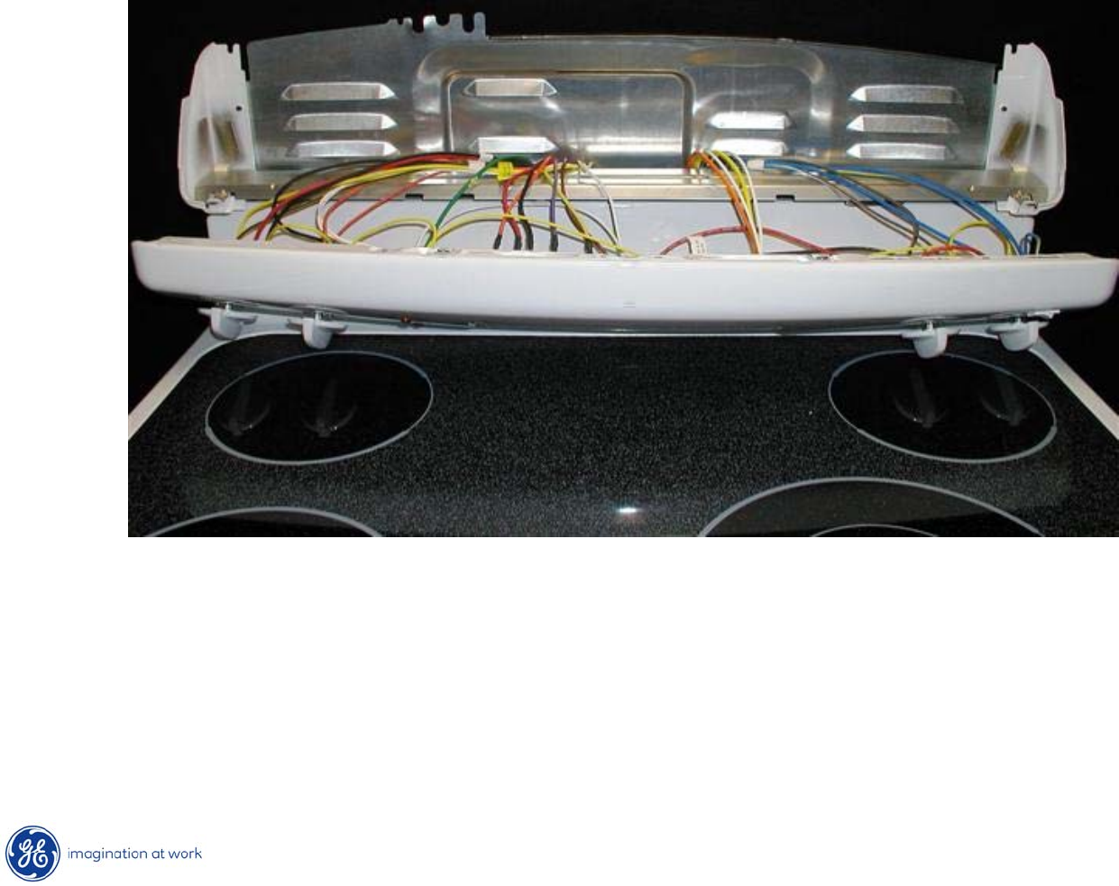
Control Panel Removal
3. Pull bottom of panel out while lifting panel up.
4. Lay panel on cooking surface.
CAUTION: Place a protective covering (such as a towel) between the
control panel and the cooking surface to avoid damage to either.
26
Copyright 2009
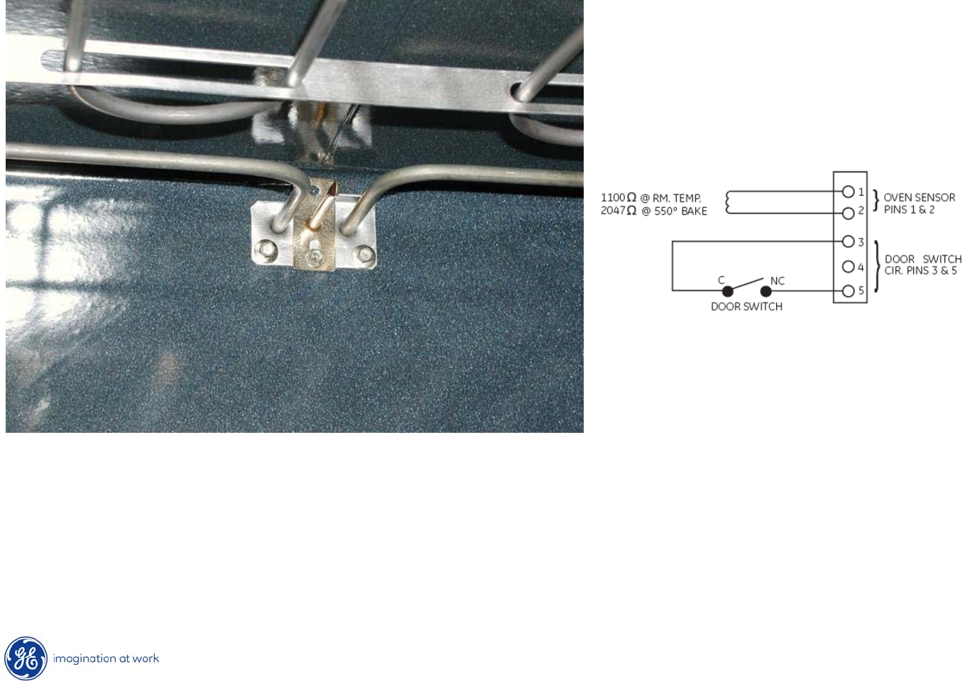
Oven Sensor
•Oven sensor should read @ 1100Ω
at room temperature.
•Resistance can be read at the ERC plug (white wires) pins 1 & 2
or
it can be read at the sensor disconnect plug behind the range.
27
Copyright 2009
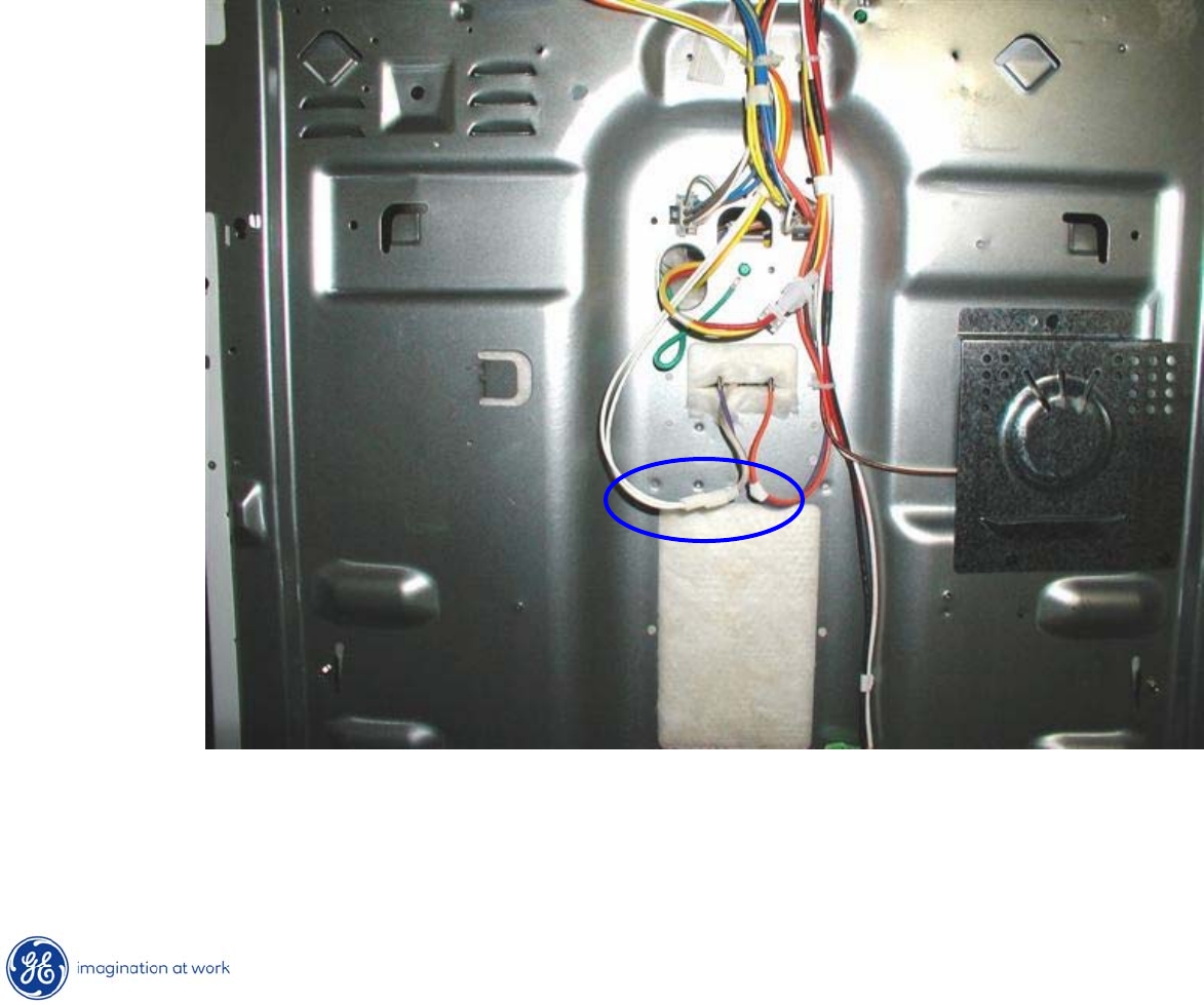
Oven Sensor
Oven sensor disconnect plug.
28
Copyright 2009
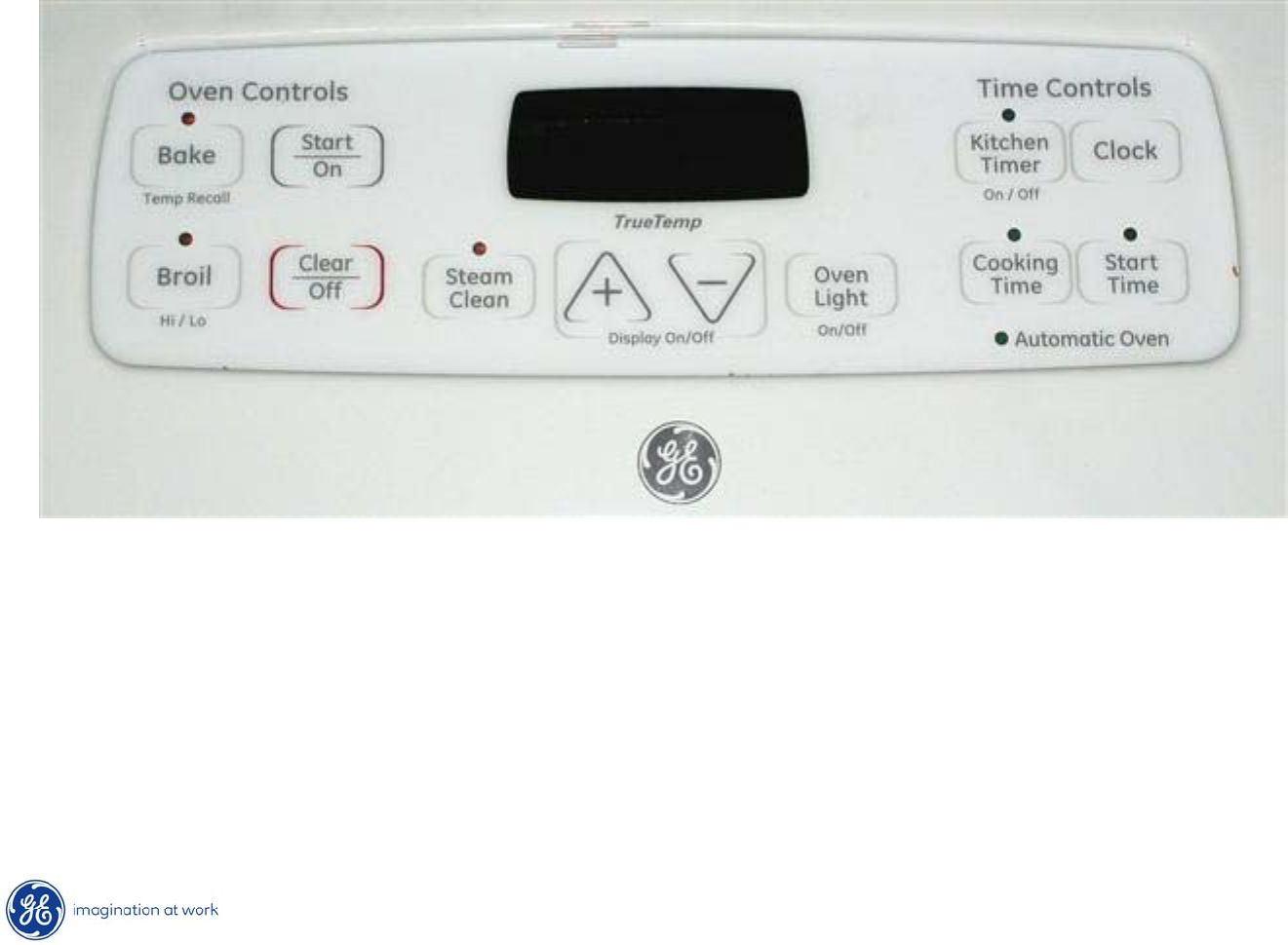
T09 Control -
ERC
The T09 Control System consists of the control, the key panel
and the oven sensor. (Control & key panel are a single component).
2:31
29
Copyright 2009
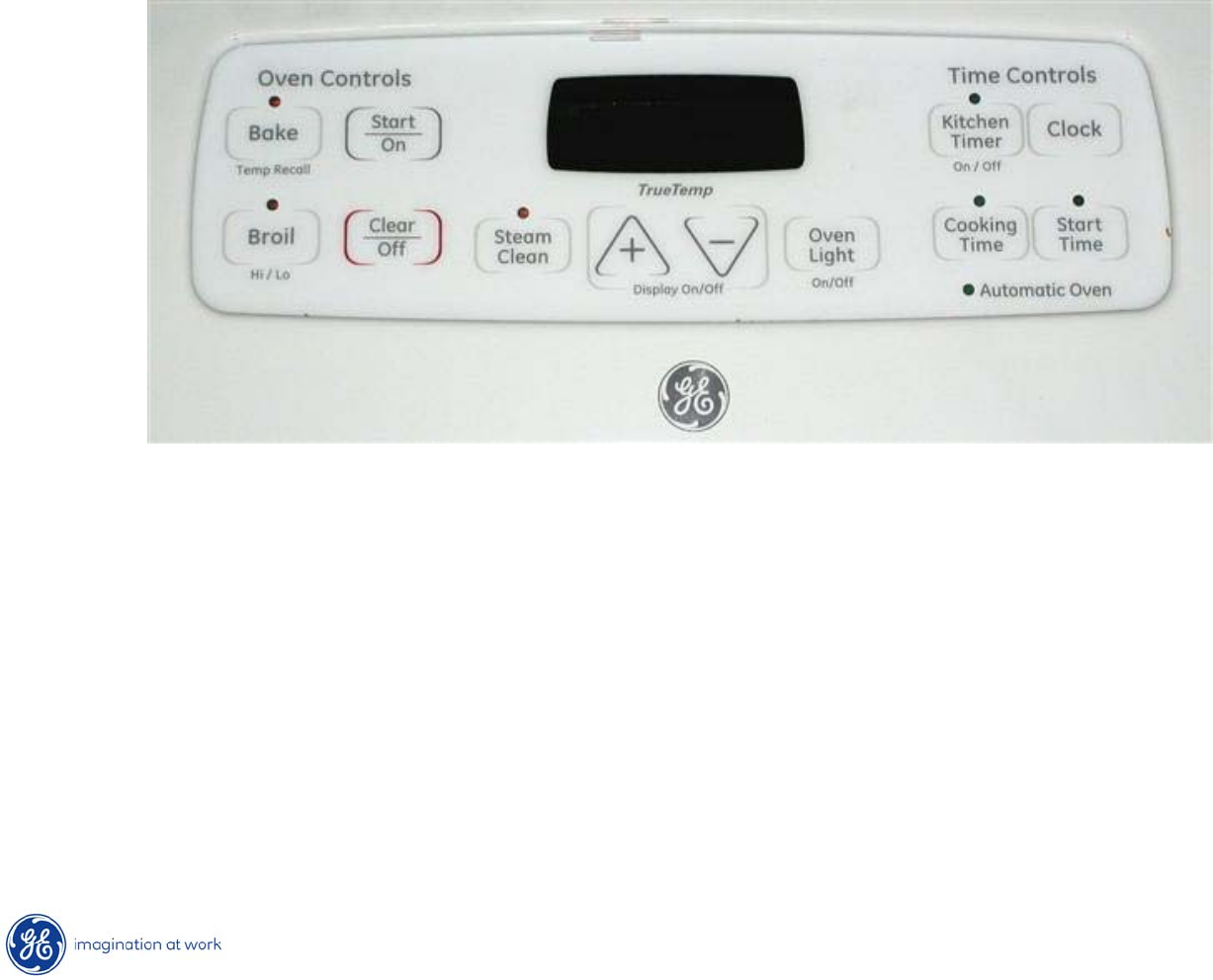
Display On / Off Feature
3:02
Note: the clock display will
go blank if the UP and DOWN arrows are
pressed
at the same time for 1 sec or less.
If the customer complains that there is no time of day clock on the range,
have them press the UP and DOWN
arrows to have the clock re-appear
30
Copyright 2009
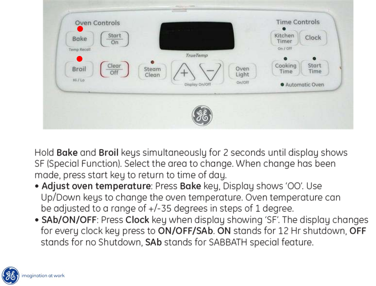
Special Functions
SF
31
Copyright 2009
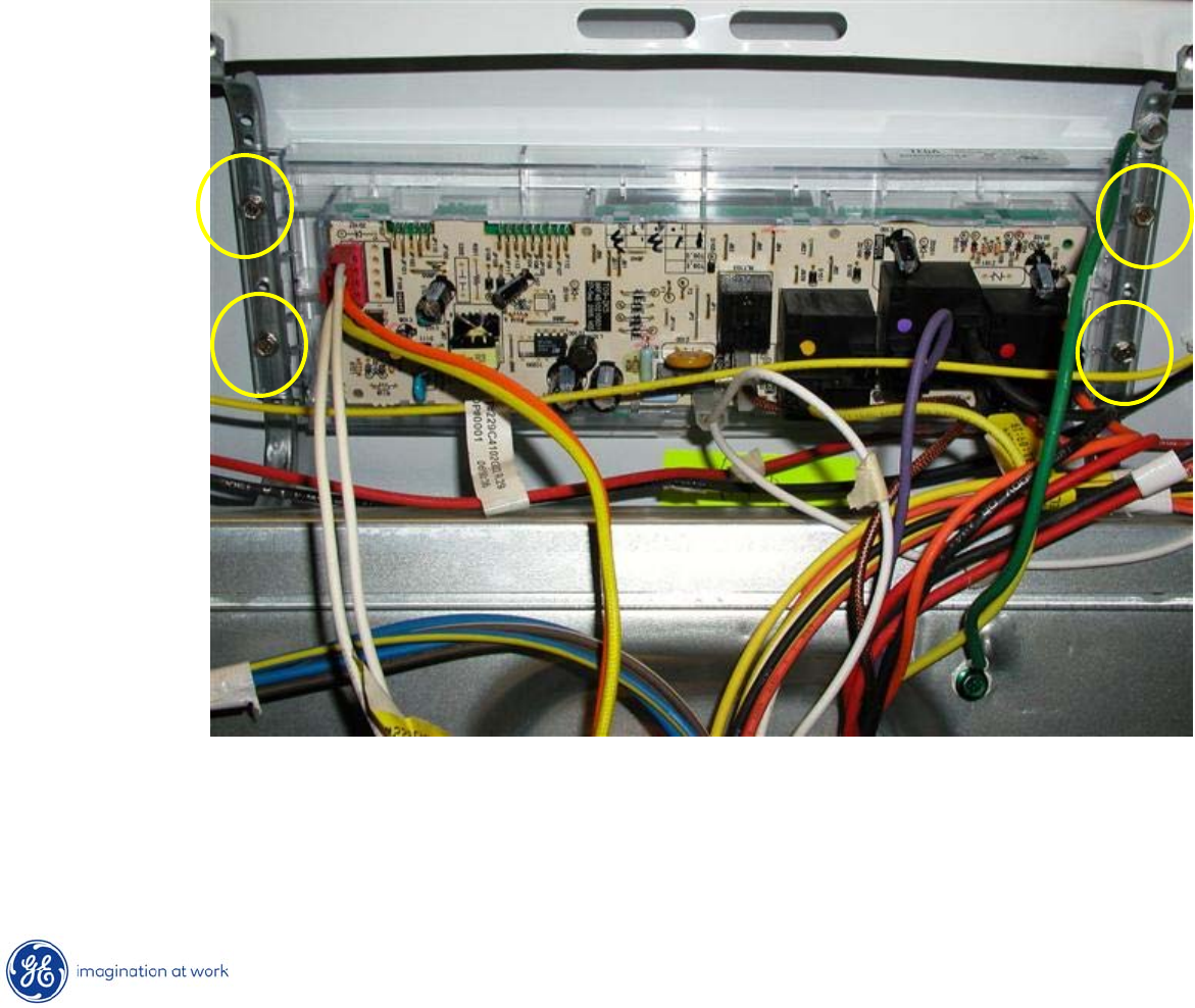
T09 Control –
ERC Removal
•To remove ERC from backsplash, remove 4 ¼”
hex heads securing
ERC to backsplash frame.
•Remove ERC from frame.
32
Copyright 2009
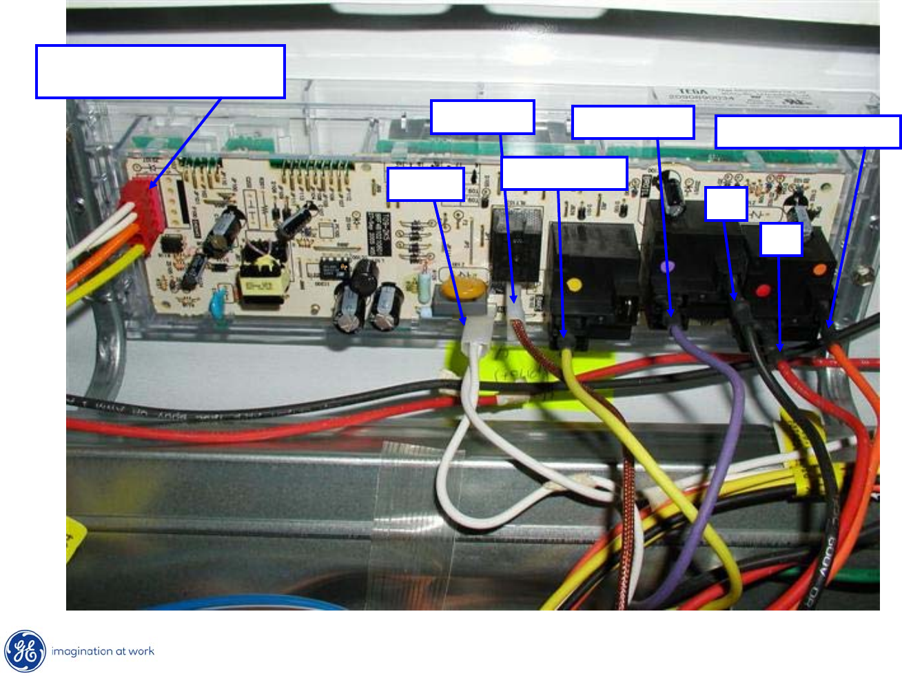
T09 Control -
ERC
2 white –
Sensor
Orange / Yellow –
Door Switch
Neutral
Oven Light
Bake Element
Broil Element
L1
L2
Bake & Broil Common

33
Copyright 2009
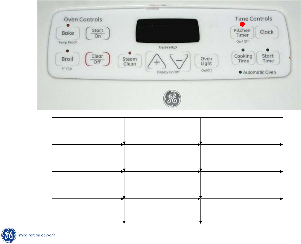
Key Panel Test
Depress each pad on the key panel individually. If the key panel is functioning
properly, the following should occur:
•Bake, Broil, Steam Clean, Kitchen Timer, Cooking Time –
Audible tone
and display showing mode of operation selected.
•Start/On, Clear/Off –
Audible tone and display shows time of day.
•Increase/Decrease pads –
No audible tone. Can only be used after another
function has been selected. Pressing both keys at the same time turns display on/off.
•Oven Light –
Audible tone and the oven light toggles on and off.
•Clock –
Audible tone and display change.
3:02
34
Copyright 2009
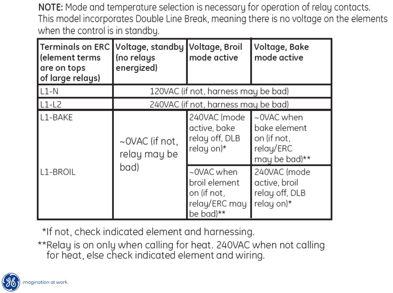
Control Voltage -
ERC
35
Copyright 2009
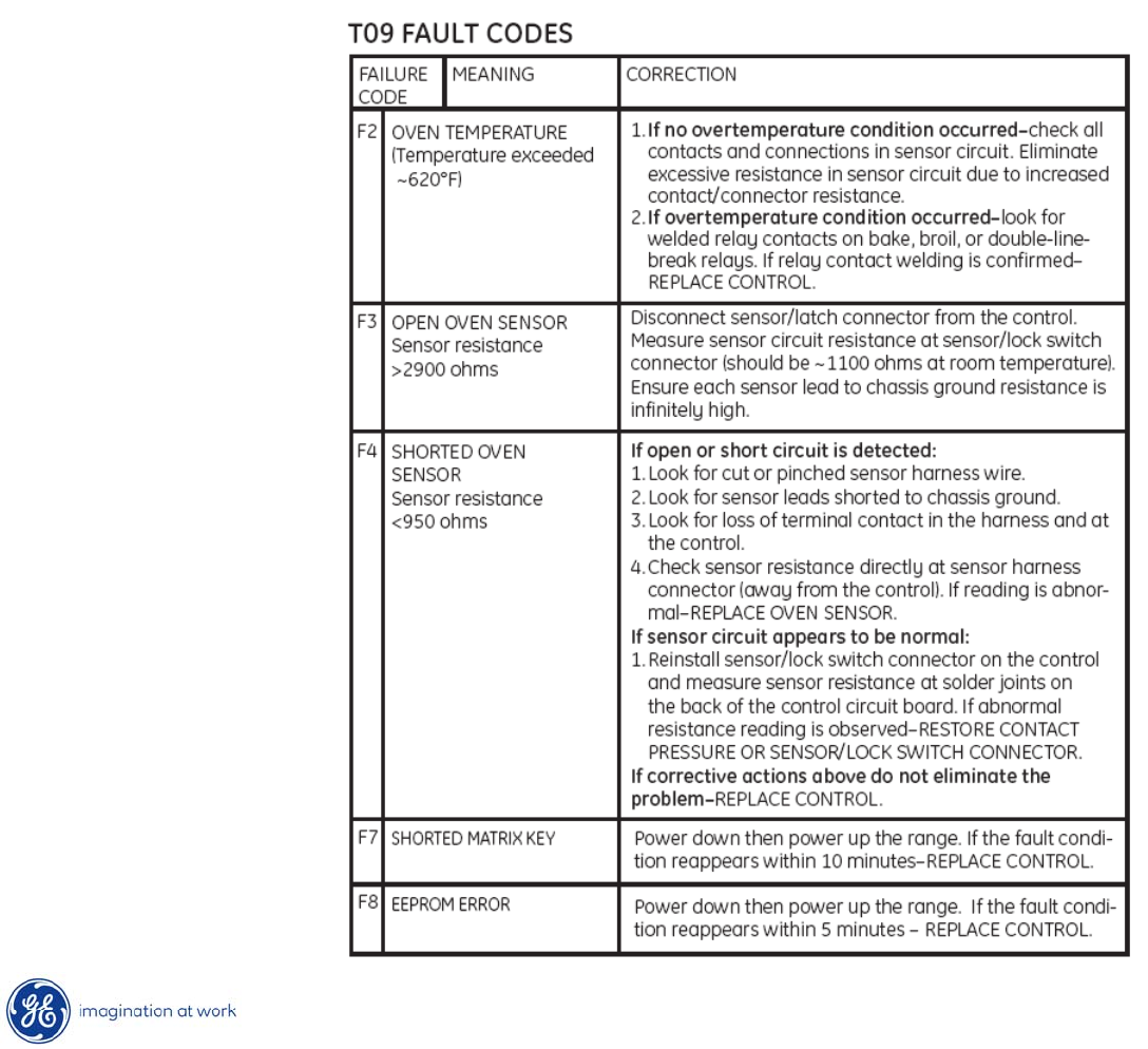
Fault Codes
--3
F-code Retrieval Mode
Function Key (s) Conditions &
Response
Code retrieval
to display
Kitchen Timer +
Up + Down
Fault codes
displayed
Clear codes Kitchen Timer +
Clock
Fault codes
cleared
Exit mode Clear/Off Return to normal
operation
36
Copyright 2009
Fault Codes
37
Copyright 2009
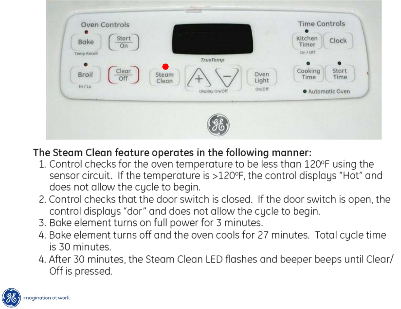
Steam Clean Operation
0:30
38
Copyright 2009
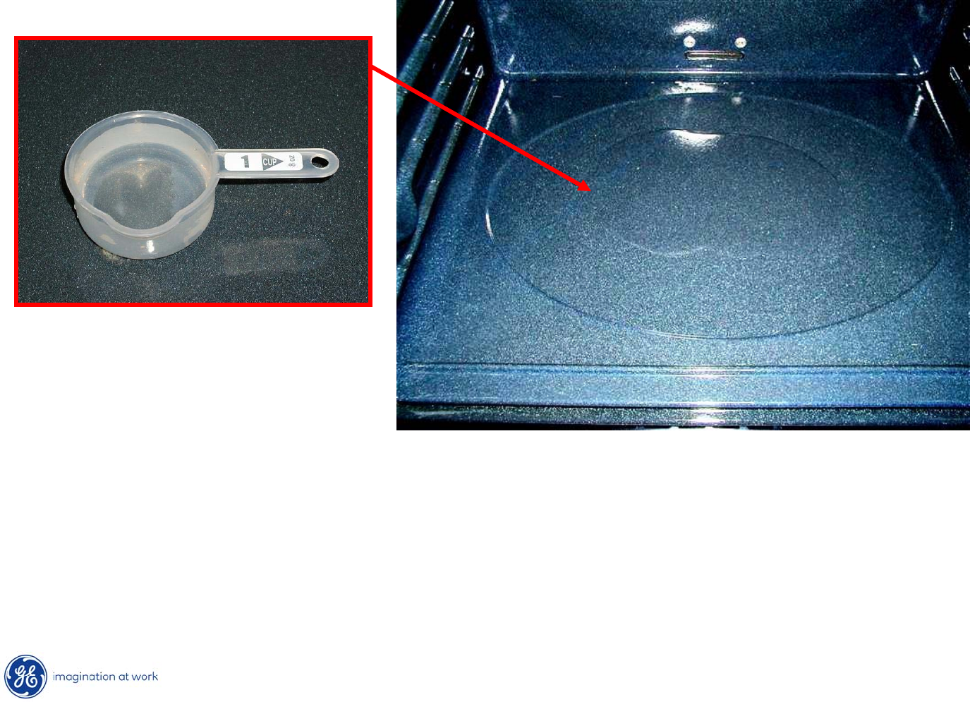
Steam Clean Procedure
To begin the steam cycle:
1. Remove racks and accessories from the oven cavity. Do not place cookware or
other items in the oven during the Steam Clean cycle.
2. Pour 1 cup (8 oz.) of room temperature water onto the recessed area of the oven
bottom. Do not add cleaning solutions or chemicals of any kind to the water.
3. Close the door.
39
Copyright 2009
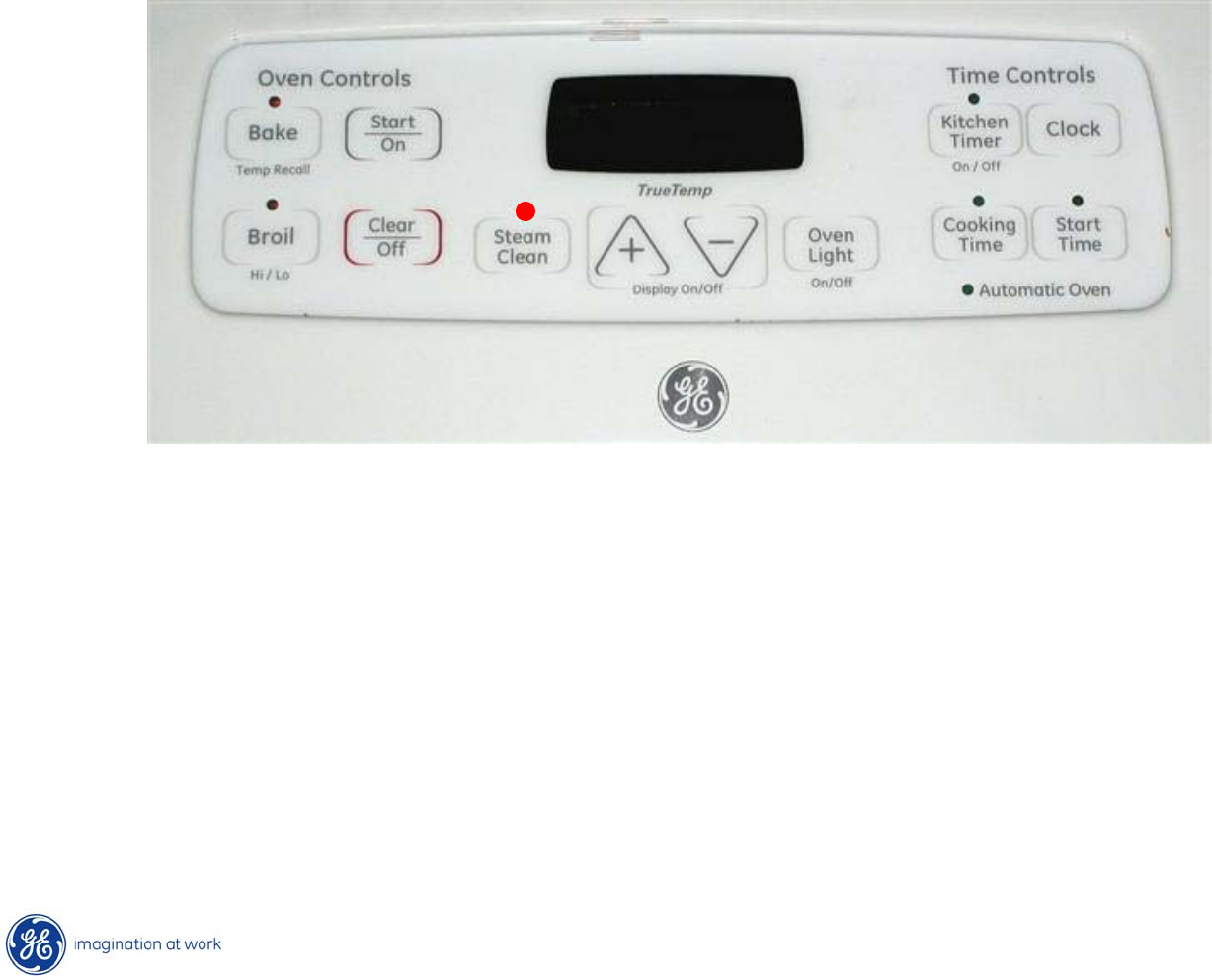
Steam Clean Procedure
0:30
4. Press the Steam Clean pad; then press Start/On.
5. A 30-minute cycle will begin to count down on the display.
6. When the Steam Clean cycle is complete, the oven control will
beep
and the Steam Clean light will blink. Press the Clear/Off pad.
40
Copyright 2009
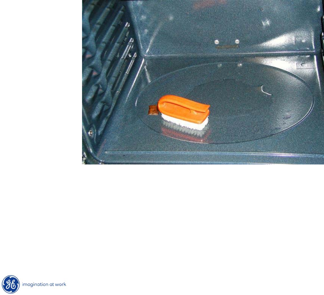
Steam Clean Procedure
7. The oven bottom and remaining water will still be very warm
at the end of the
cycle. This is normal.
8. Remove soils using a scrub brush or nylon scouring pad. A soap filled steel wool
pad may be used only on the porcelain oven interior. The use of abrasive pads
will scratch the door glass. Do not wipe soil or water onto the door gasket.
9.
Remove any remaining water with a dry cloth or sponge.
10. Leave the door open to air dry.

41
Copyright 2009
Steam Clean Procedure –
IMPORTANT NOTES
•If a steam clean cycle is initiated without water, press the Clear/Off pad to end the cycle.
Wait for the range to cool to room temperature before pouring water into the recessed area
and initiating another steam cycle.
•Do not open the door during the Steam Clean cycle. An error beep will sound upon
opening the door.
•If a steam cycle is interrupted by opening the door, oven needs
to be allowed to
cool to room temperature and another steam cycle initiated.
•Press Clear/Off pad at any time to end the cycle.
•If mineral deposits remain in the oven bottom after cleaning, use a cloth or sponge
soaked in vinegar to remove them.
•Some water may drip from the bottom of the oven door. If this happens, wipe it up
at the end of the cycle.
•The door gasket may be wet when the Steam Clean cycle finishes.
This is normal.
do not clean the gasket.
•If soil still remains after cleaning the oven, see the “Care and Cleaning of the Range”
section of the Owner’s Manual for additional options.
42
Copyright 2009
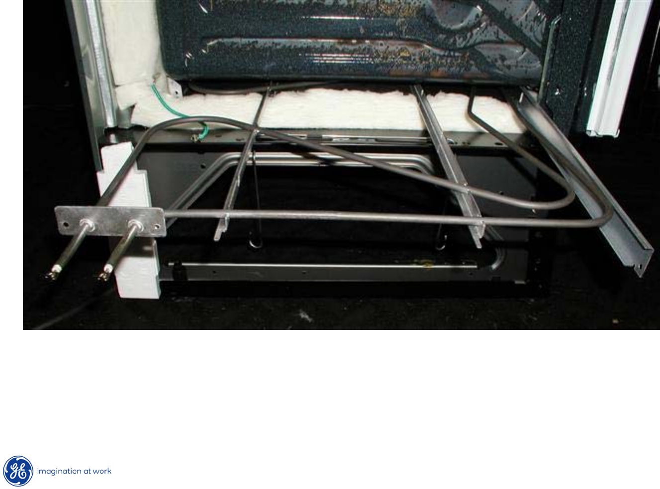
Hidden Bake Element
•If a problem is suspected with the hidden bake element, check for proper
resistance at the rear of the ERC or at the yellow / orange wire disconnect
plug before range disassembly.
•Resistance between orange and yellow wires to element should be
@ 20Ω.
43
Copyright 2009
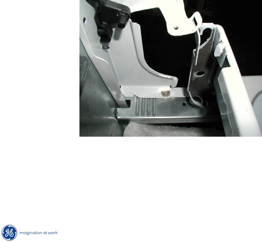
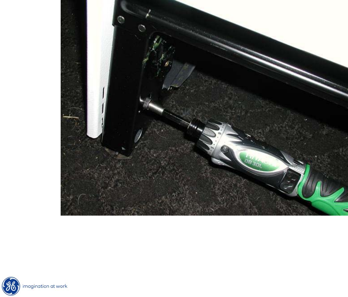
Hidden Bake Element
•If element requires replacement, range left side panel needs to
be removed.
•Begin by removing the hidden screw at bottom front after removing storage
drawer.
44
Copyright 2009
Hidden Bake Element
After lifting or removing cooktop,
remove two ¼”
hex heads and a
single Phillips screw from the
top of the side panel.

45
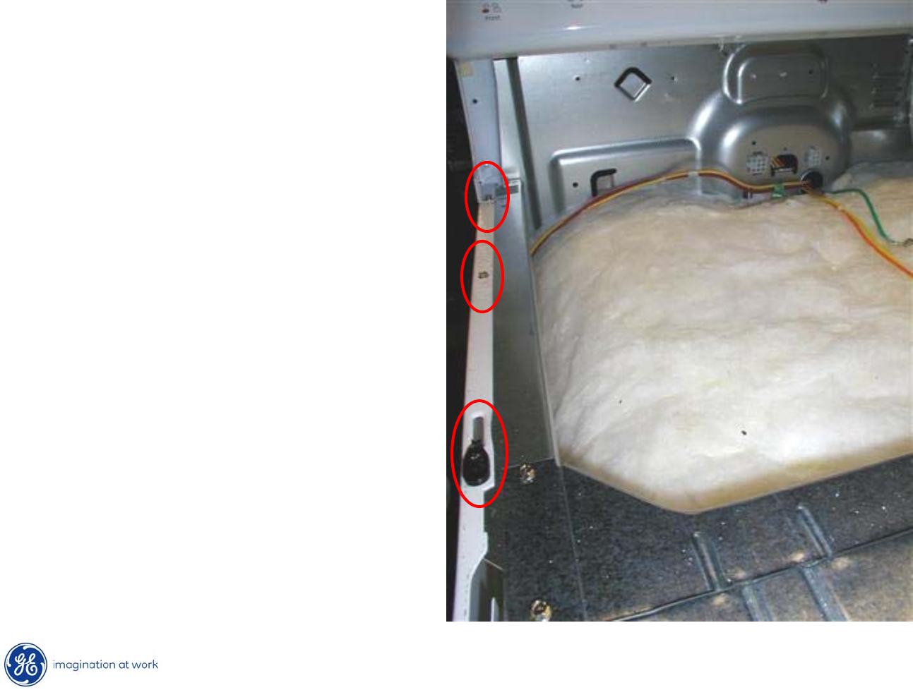
Copyright 2009
Hidden Bake Element
Next, remove 3 ¼”
hex
heads from rear of left side
panel.
46
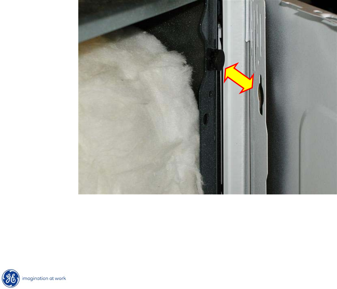
Copyright 2009
Hidden Bake Element
Finally, grasp panel and lift @ an inch to release tabs on the side of the
frame from openings in the side panel.
47
Copyright 2009
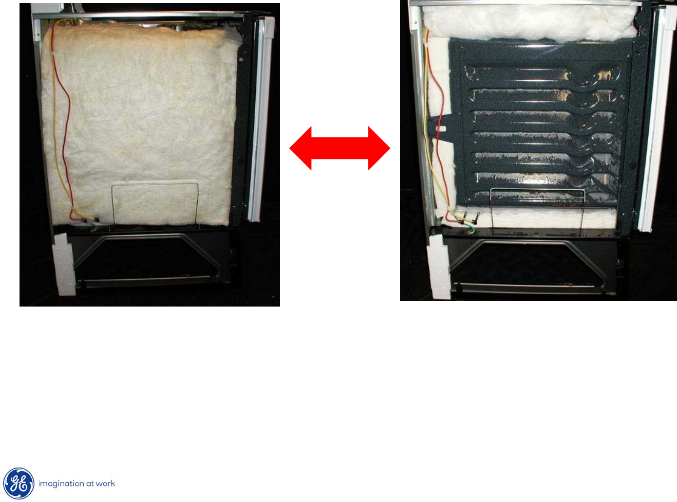
Hidden Bake Element
Carefully, lift insulation blanket and temporarily tuck it under
upper
frame to clear work area.
48
Copyright 2009
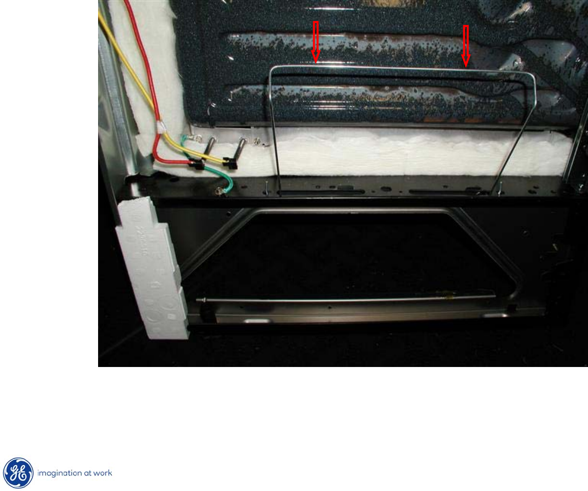
Hidden Bake Element
Push down on insulation retainer to clear it from the bake element
compartment opening.
49
Copyright 2009
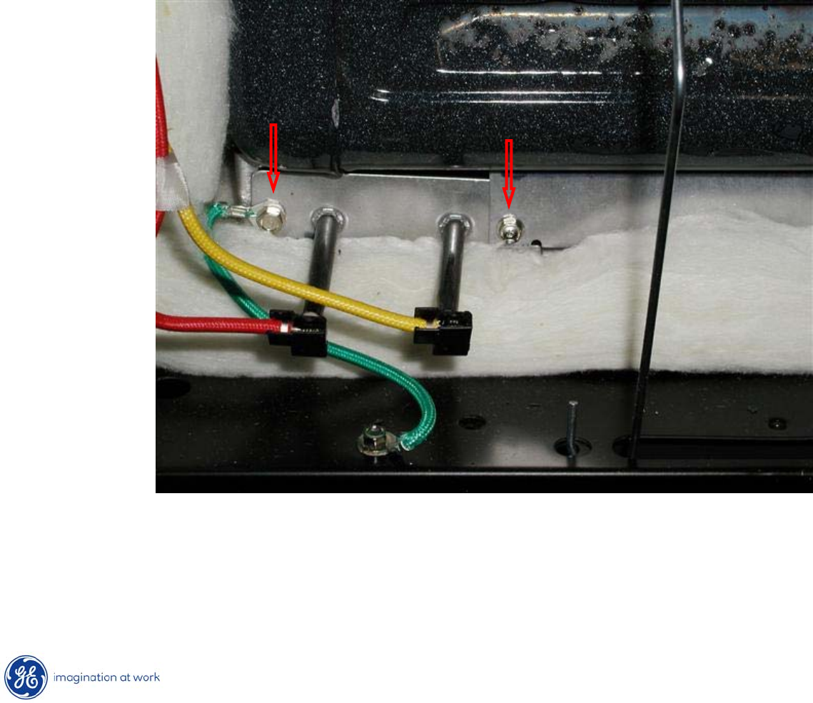
Hidden Bake Element
•Remove orange and yellow leads from bake element terminals.
•Remove two ¼”
hex heads securing element compartment
cover to frame.
50
Copyright 2009
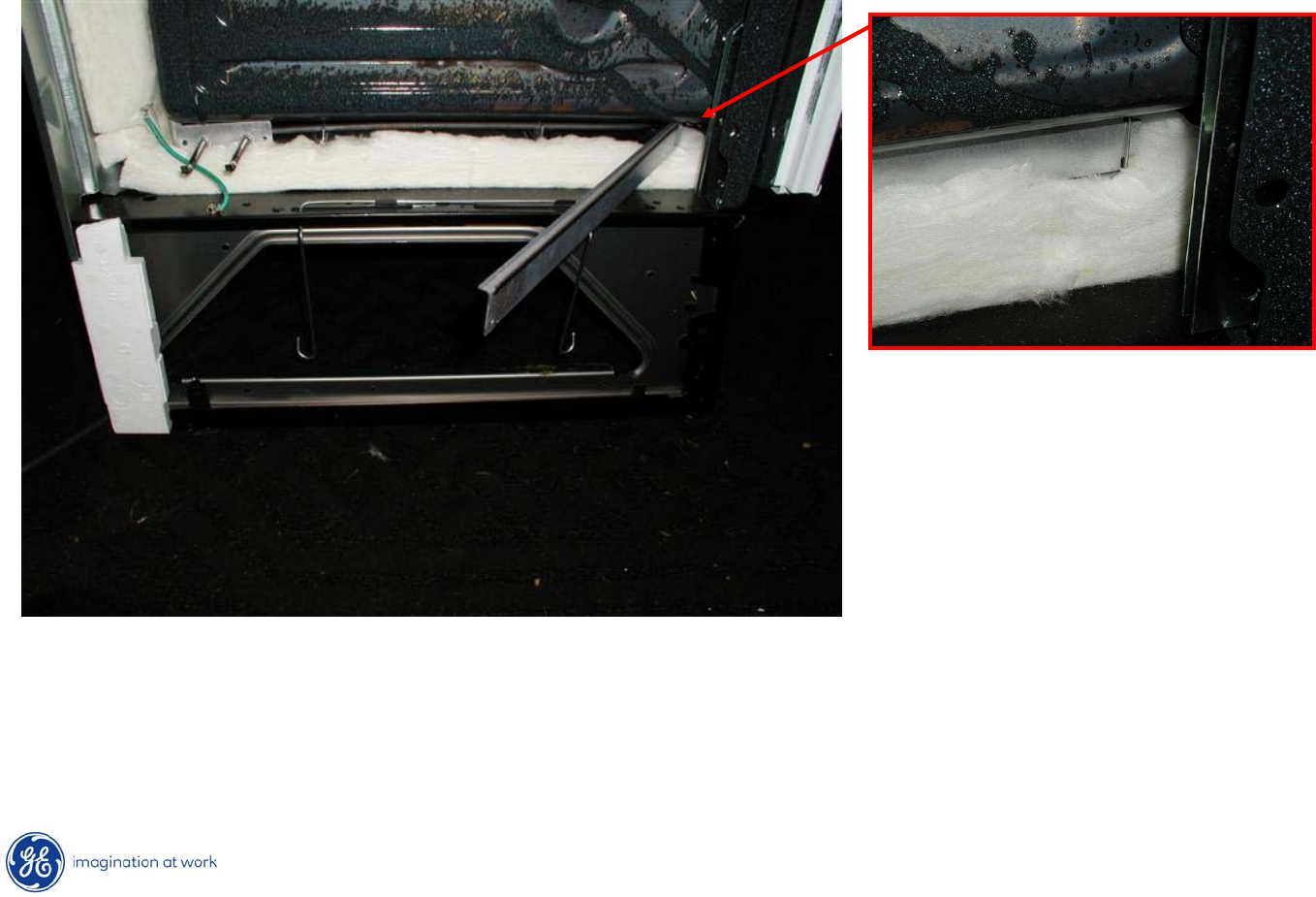
Hidden Bake Element
Fold out or completely remove compartment cover to access
hidden bake element.
51
Copyright 2009
Hidden Bake Element
Slide out element from compartment to remove.
52
Copyright 2009
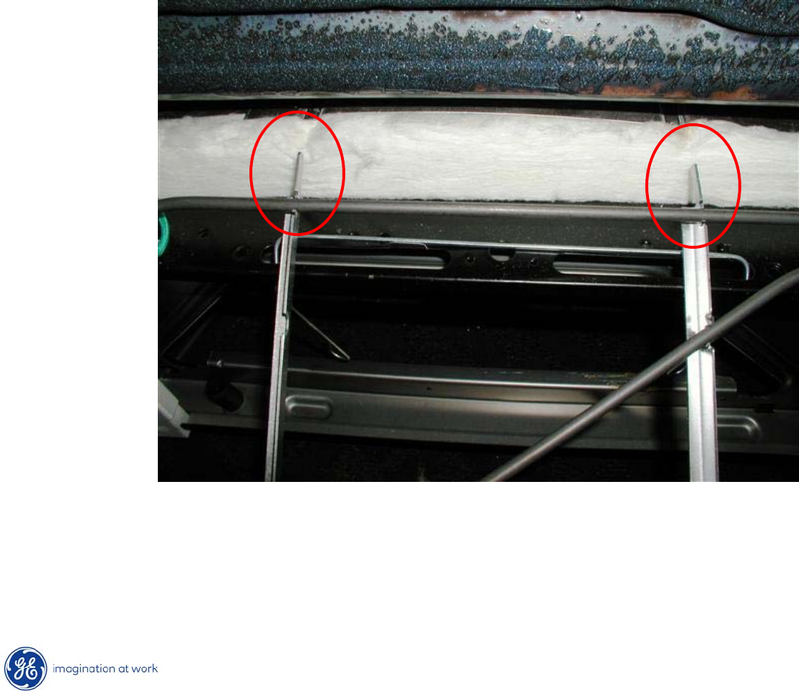
Hidden Bake Element
Upon re-insertion of bake element, tabs on assembly must align with
slots or openings on the far side of the compartment.
53
Copyright 2009
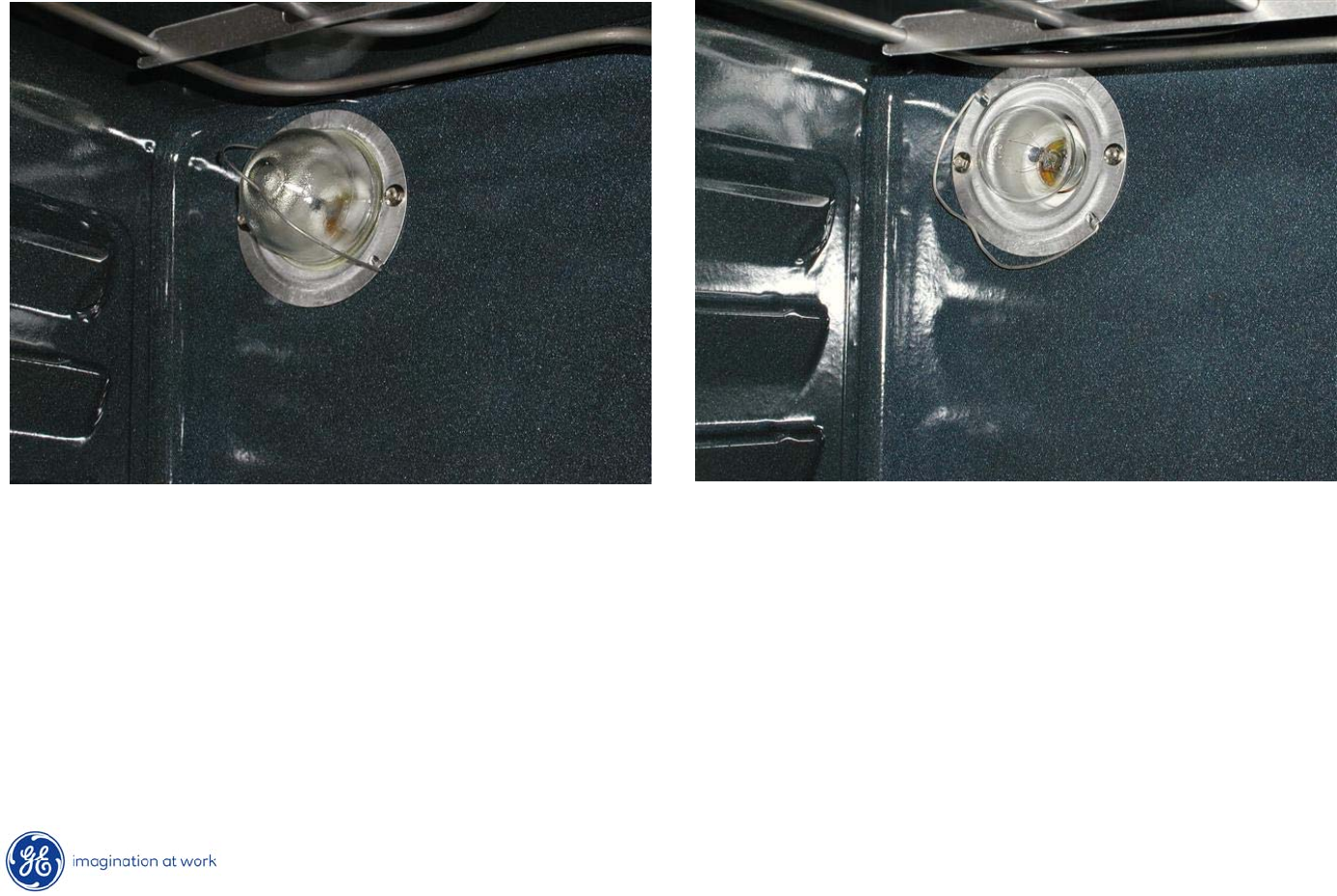
Oven Light
Oven lighting consists of a single 40w, incandescent bulb with a
clear
glass cover held in place with a spring wire.
54
Copyright 2009
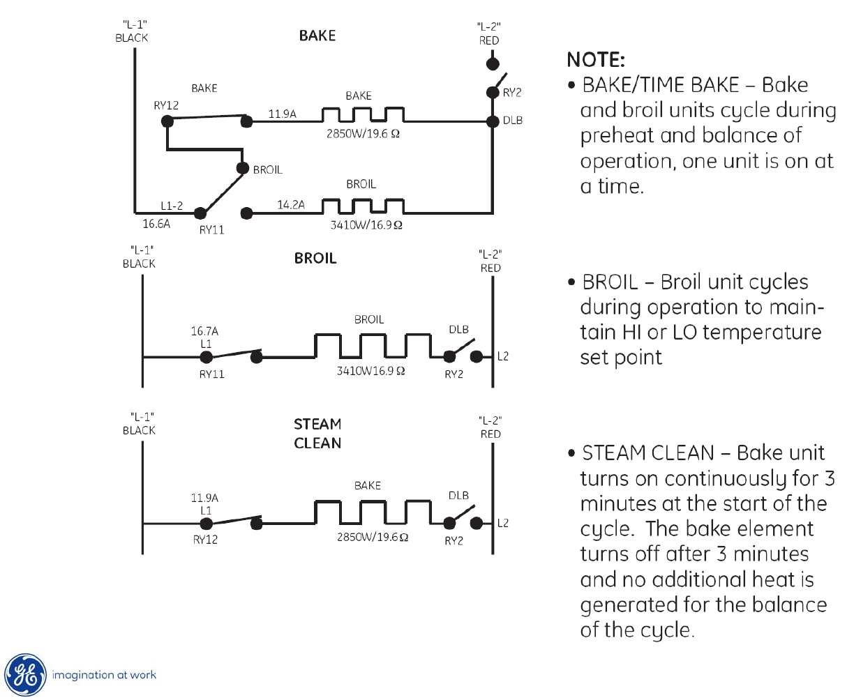
Strip Circuits
55
Copyright 2009
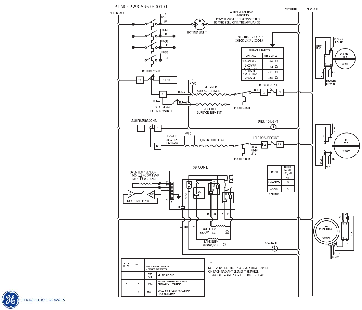
Schematic
56
Copyright 2009
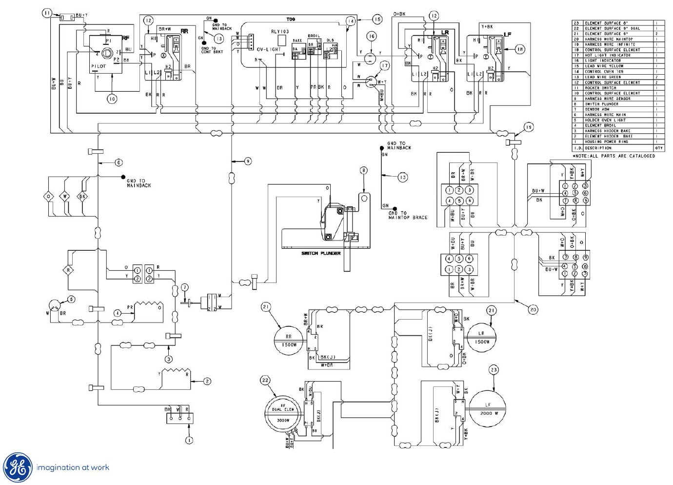
Wiring Diagram

57
Copyright 2009
END OF
PRESENTATION
