Hottinger Bruel and Kjaer T12S5 T12-S5 Torquemeter User Manual A1979 100
Hottinger Baldwin Messtechnik GmbH T12-S5 Torquemeter A1979 100
UserManual.wiki
>
Hottinger Bruel and Kjaer
>
T12S5 User Manual
User Manual
Navigation menu
Upload a User Manual
Namespaces
Wiki Guide
HTML
PDF
Info
Views
User Manual
Discussion / Help
Navigation
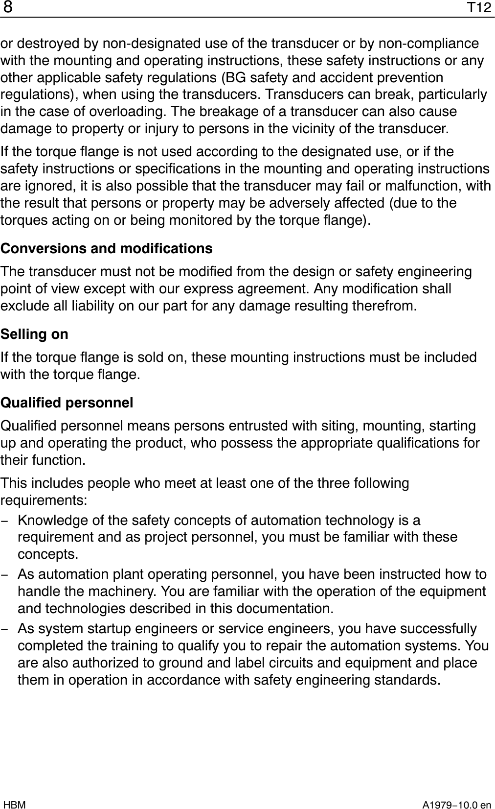

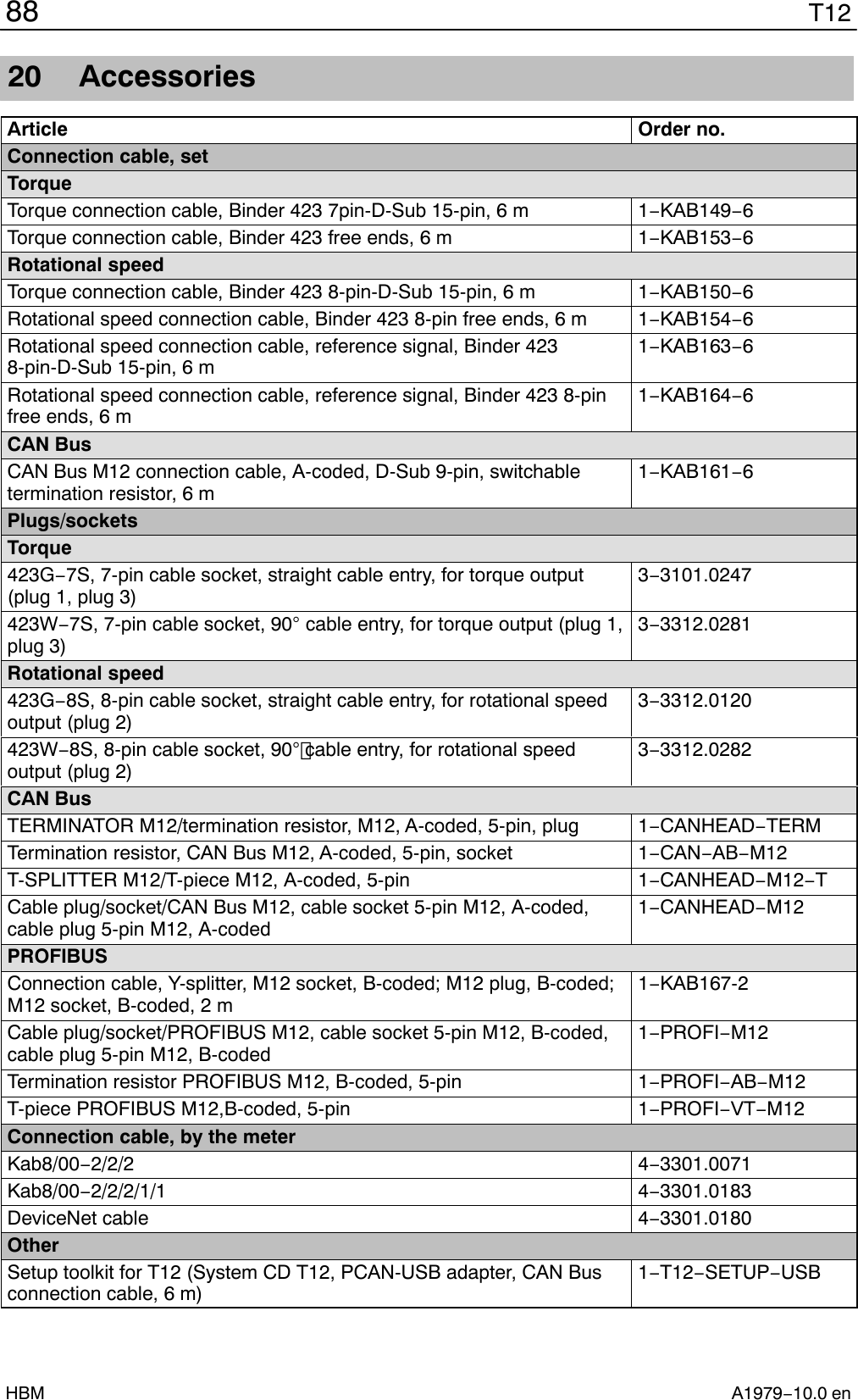
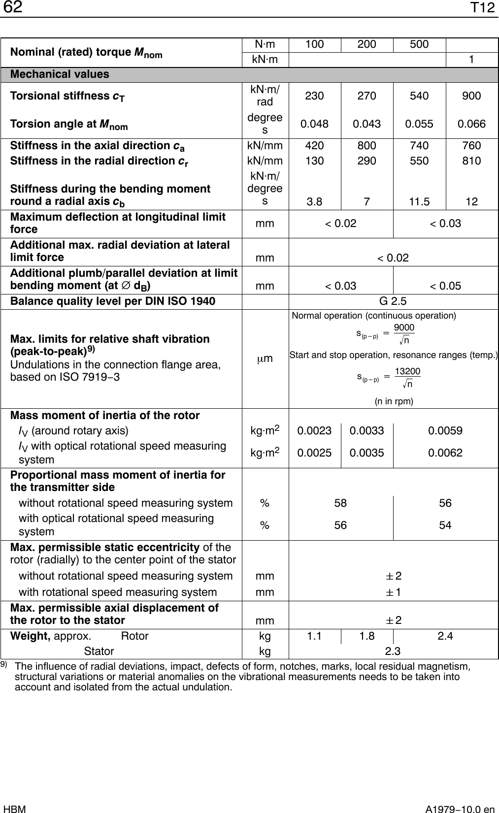
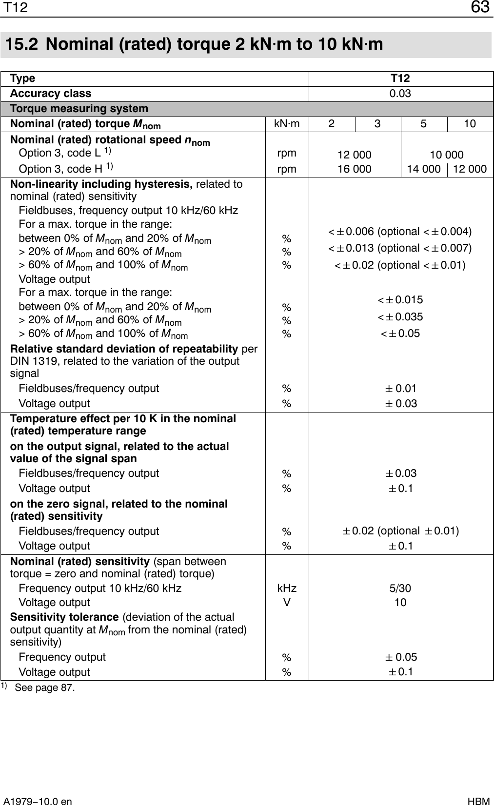
![59T12A1979−10.0 en HBMNominal (rated) torque MnomNm 100 200 500kNm 1Temperature effect per 10 K in the nominal(rated) temperature rangeon the output signal, related to the actual valueof the signal span %< 0.03on the zero signal %< 0.03Residual ripple mV < 3Angle of rotationAccuracy degrees 1 (typ. 0.1)Resolution degrees 0.01Correction of runtime deviation betweentorque LP1 and the angle of rotation for filterfrequencies Hz 4000; 2000; 1000; 500; 200; 100Measuring range degrees 0 to 360 (single-turn) to "1440(multi-turn)PerformanceMeasurement frequency range Hz 80 (−1 dB)Resolution W 1Full scale value WPmax +Mnom @nnom @p30[Mnom] in Nm[nnom] in rpmTemperature effect per 10 K in the nominal(rated) temperature range on the power signal,related to the full scale value %"0.05@n/nnomNon-linearity including hysteresis, related tothe full scale value %"0.02@n/nnomSensitivity tolerance (deviation of the actualmeasurement signal span of the power signalrelated to the full scale value) %"0.05Temperature signal of the rotorAccuracy K 1Measurement frequency range Hz 5 (−1 dB)Resolution K 0.1Physical unit −CData rateMeas.values/s40](https://usermanual.wiki/Hottinger-Bruel-and-Kjaer/T12S5/User-Guide-2442002-Page-59.png)
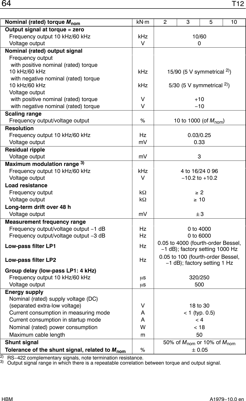

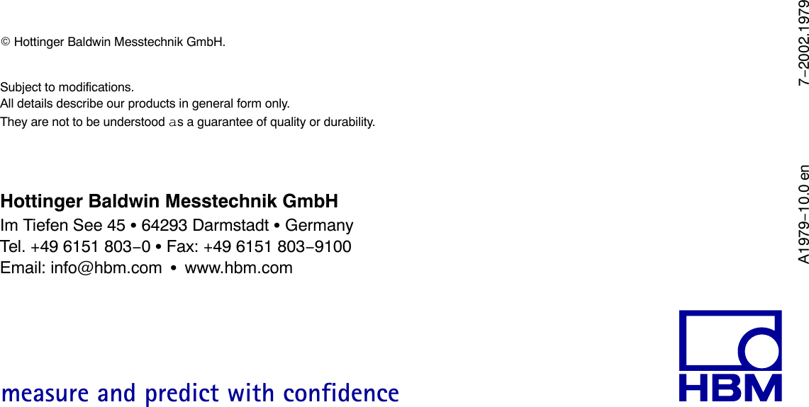
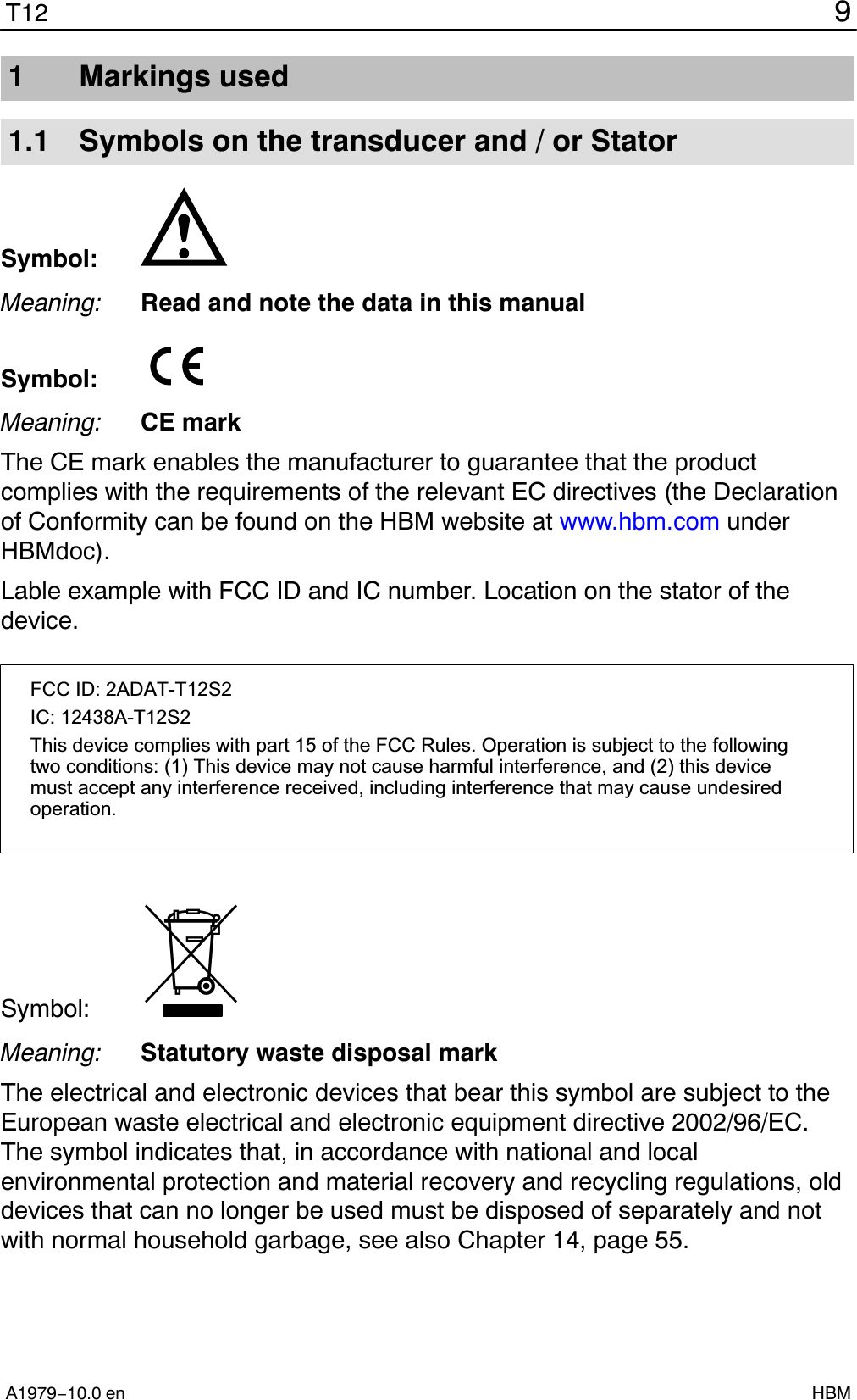
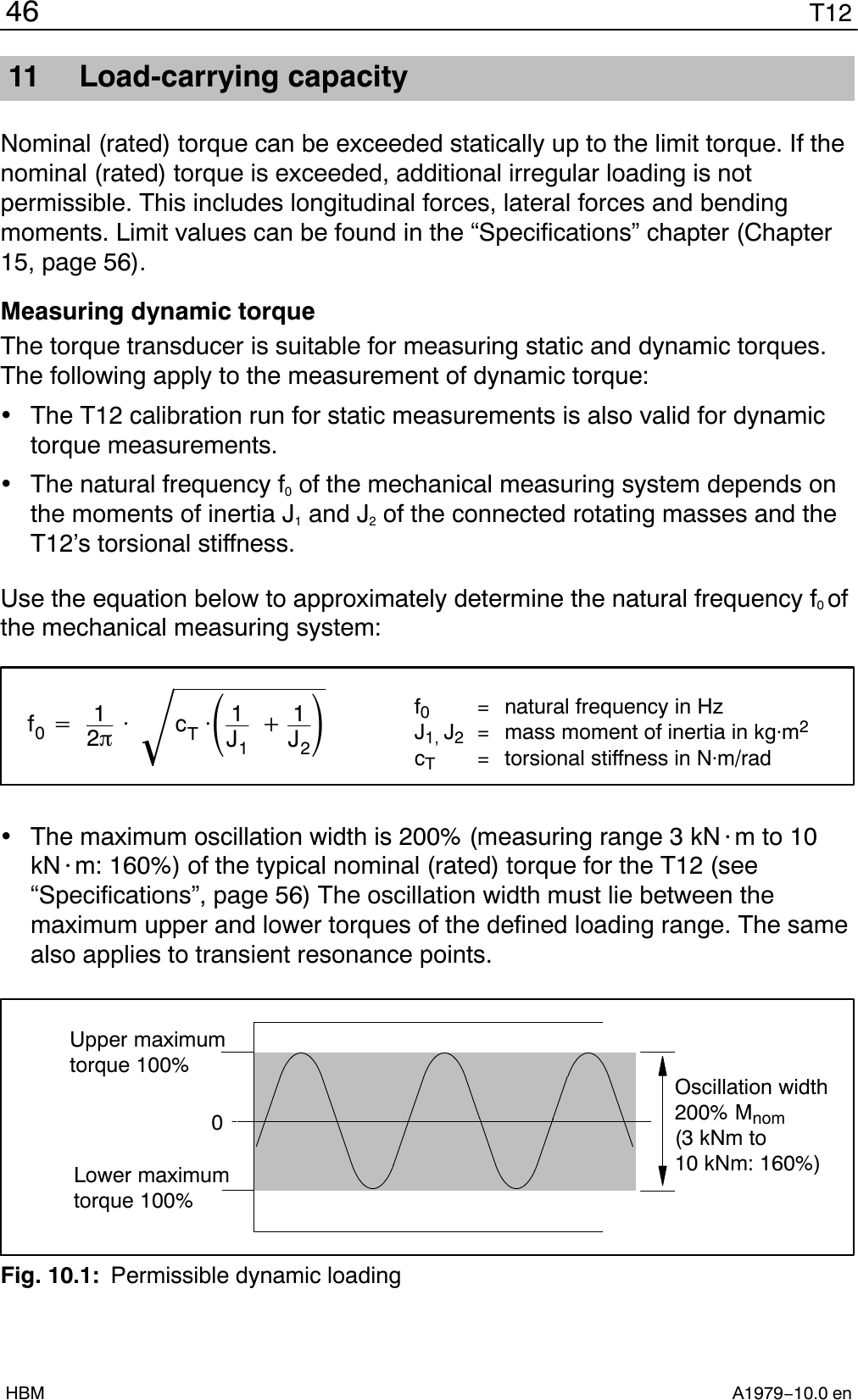
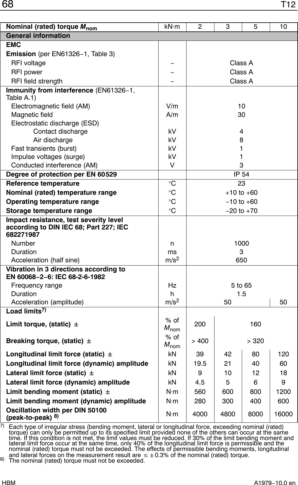
![T1266A1979−10.0 enHBMNominal (rated) torque Mnom kNm 2 3 5 10Temperature effect per 10 K in the nominal(rated) temperature rangeon the output signal, related to the actual valueof the signal span %< 0.03on the zero signal %< 0.03Residual ripple mV < 3Angle of rotationAccuracy degrees1 (typ. 0.1)Resolution degrees0.01Correction of runtime deviation betweentorque LP1 and the angle of rotation for filterfrequencies Hz 4000; 2000; 1000; 500; 200; 100Measuring range degrees0 to 360 (single-turn) to "1440(multi-turn)PerformanceMeasurement frequency range Hz 80 (−1 dB)Resolution W 1Full scale value WPmax +Mnom @nnom @p30[Mnom] in Nm[nnom] in rpmTemperature effect per 10 K in the nominal(rated) temperature range on the power signal,related to the full scale value %"0.05@n/nnomNon-linearity including hysteresis, related tothe full scale value %"0.02@n/nnomSensitivity tolerance (deviation of the actualmeasurement signal span of the power signalrelated to the full scale value) %"0.05Temperature signal of the rotorAccuracy K 1Measurement frequency range Hz 5 (−1 dB)Resolution K 0.1Physical unit −CData rateMeas.values/s40](https://usermanual.wiki/Hottinger-Bruel-and-Kjaer/T12S5/User-Guide-2442002-Page-66.png)
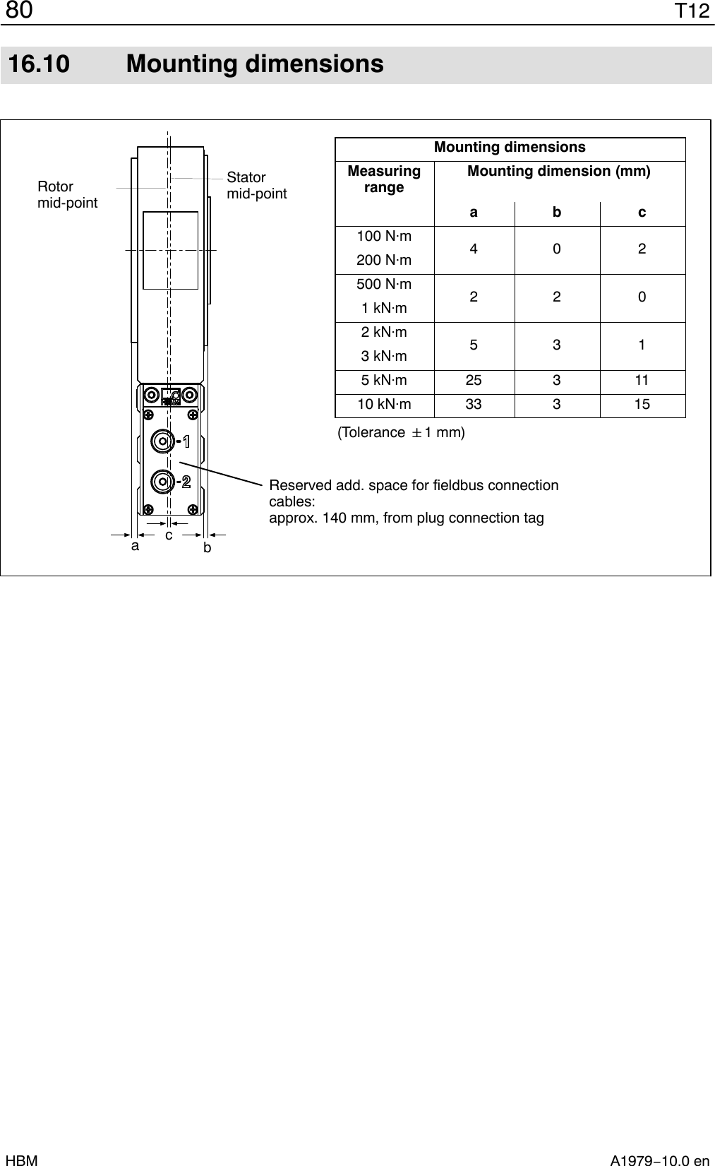
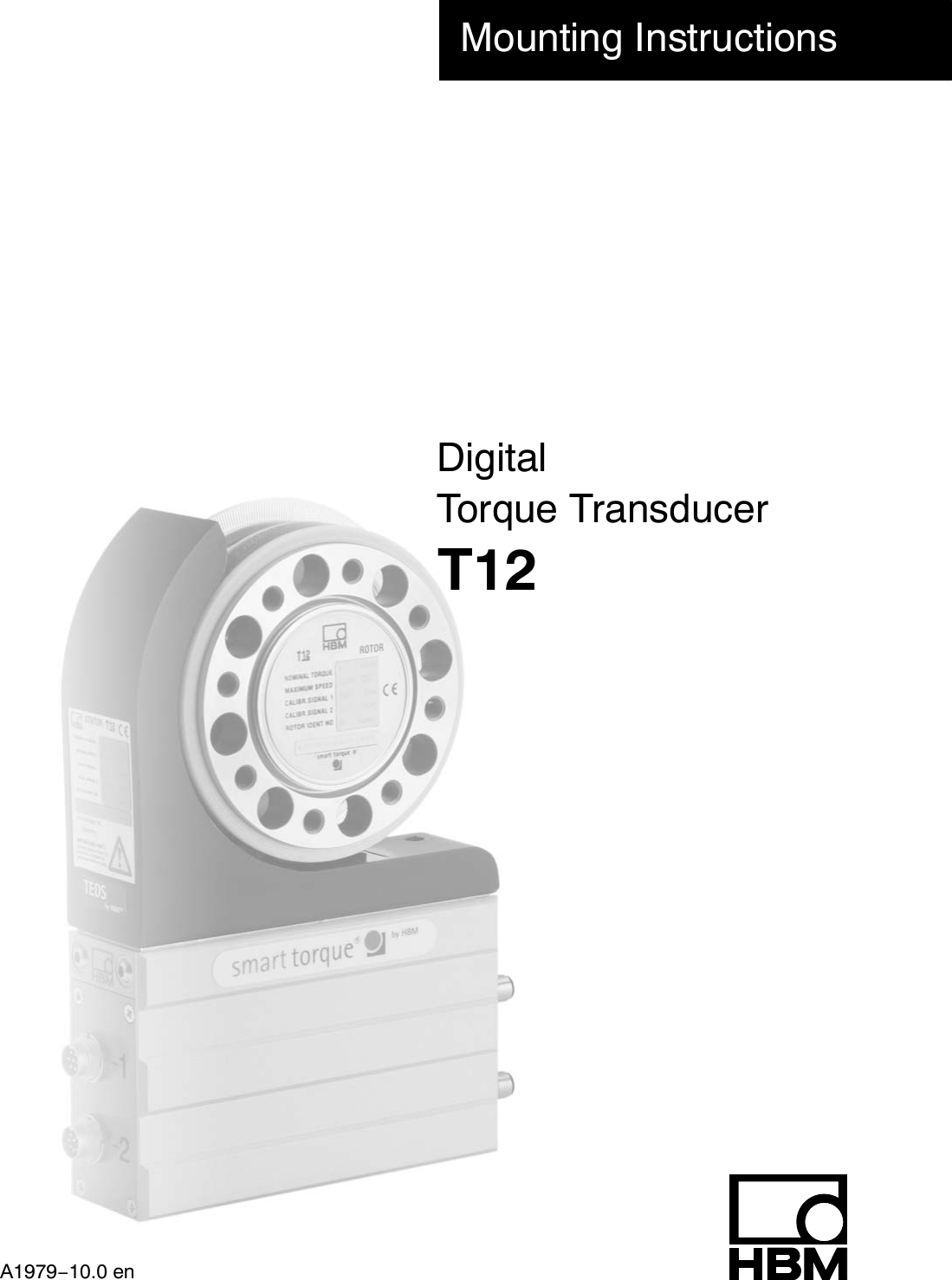
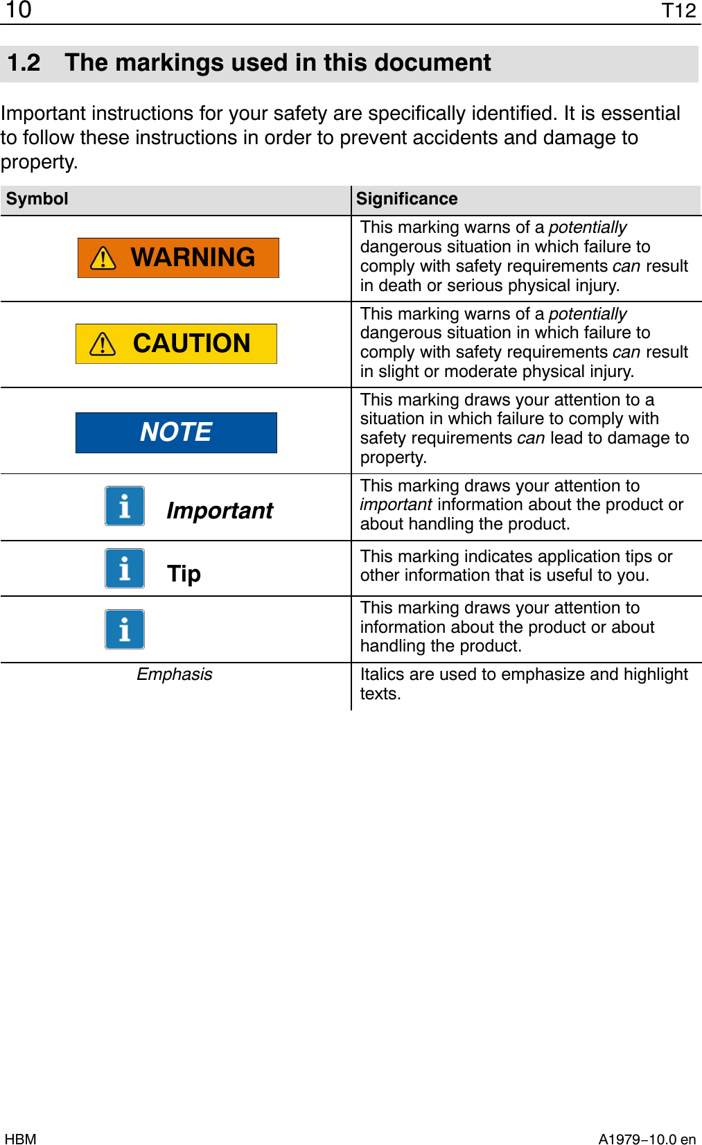
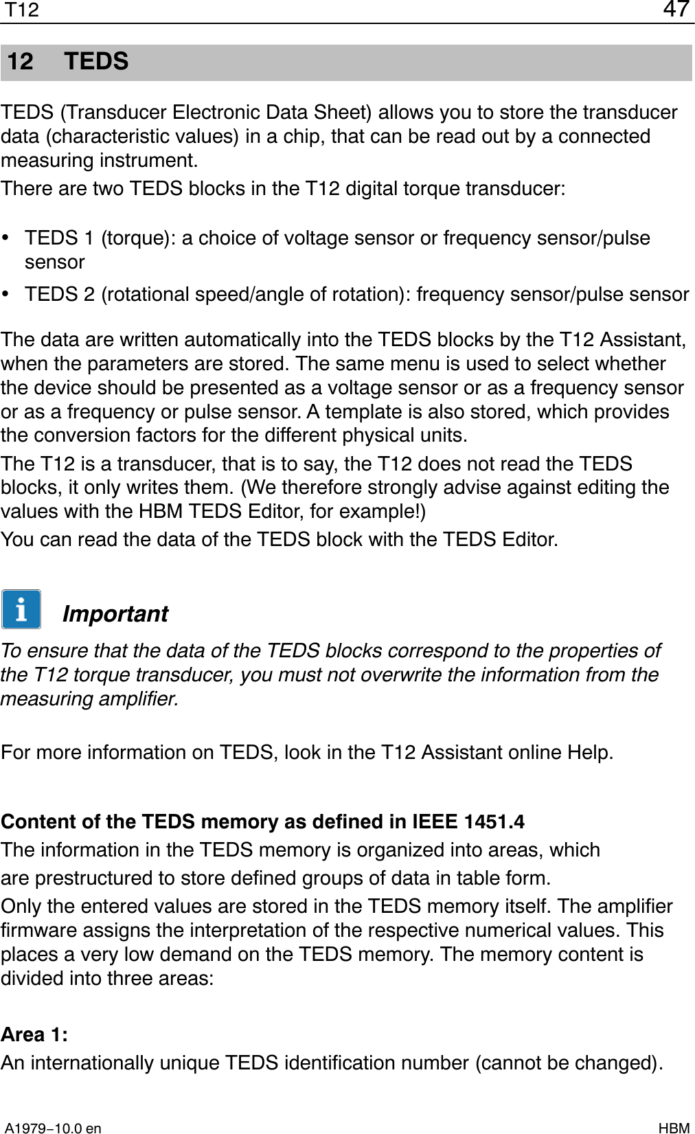
![75T12A1979−10.0 en HBM16.6 Stator 100 Nm to 200 Nm with prot. against contact Cutaway dimension (in rotational speedmeasuring system only) and withoutcutaway in the standard version (withoutrotational speed measuring system)Part of the standard version!The components on both sidesmust be removed to mount theprotective housing.Rotational speedsensor [projection][Housing]1[Covering agent]1[Covering agent]58[Protection against contact cpl.]56[Housing]58[Protection against contact cpl.]563212102.593.50.55View without housing half11830788194.589.3[Locking screw]8123BAView ADimensions in mm (1 mm = 0.03937 inches)](https://usermanual.wiki/Hottinger-Bruel-and-Kjaer/T12S5/User-Guide-2442002-Page-75.png)
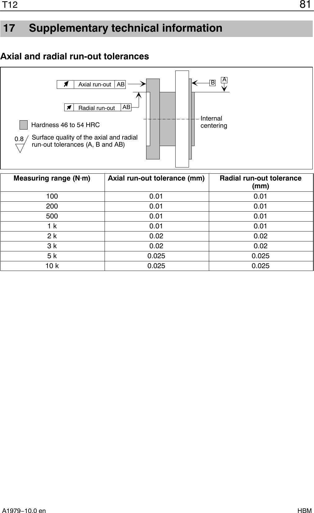
![T1276A1979−10.0 enHBM16.7 Stator 100 Nm to 200 Nm with prot. against contact6.611225+2205196185−24088View without covering agent(11)(6.6)56[Housing]43Connecting hole with countersinkingZZZZConnection holes ZView BDimensions in mm (1 mm = 0.03937 inches)](https://usermanual.wiki/Hottinger-Bruel-and-Kjaer/T12S5/User-Guide-2442002-Page-76.png)
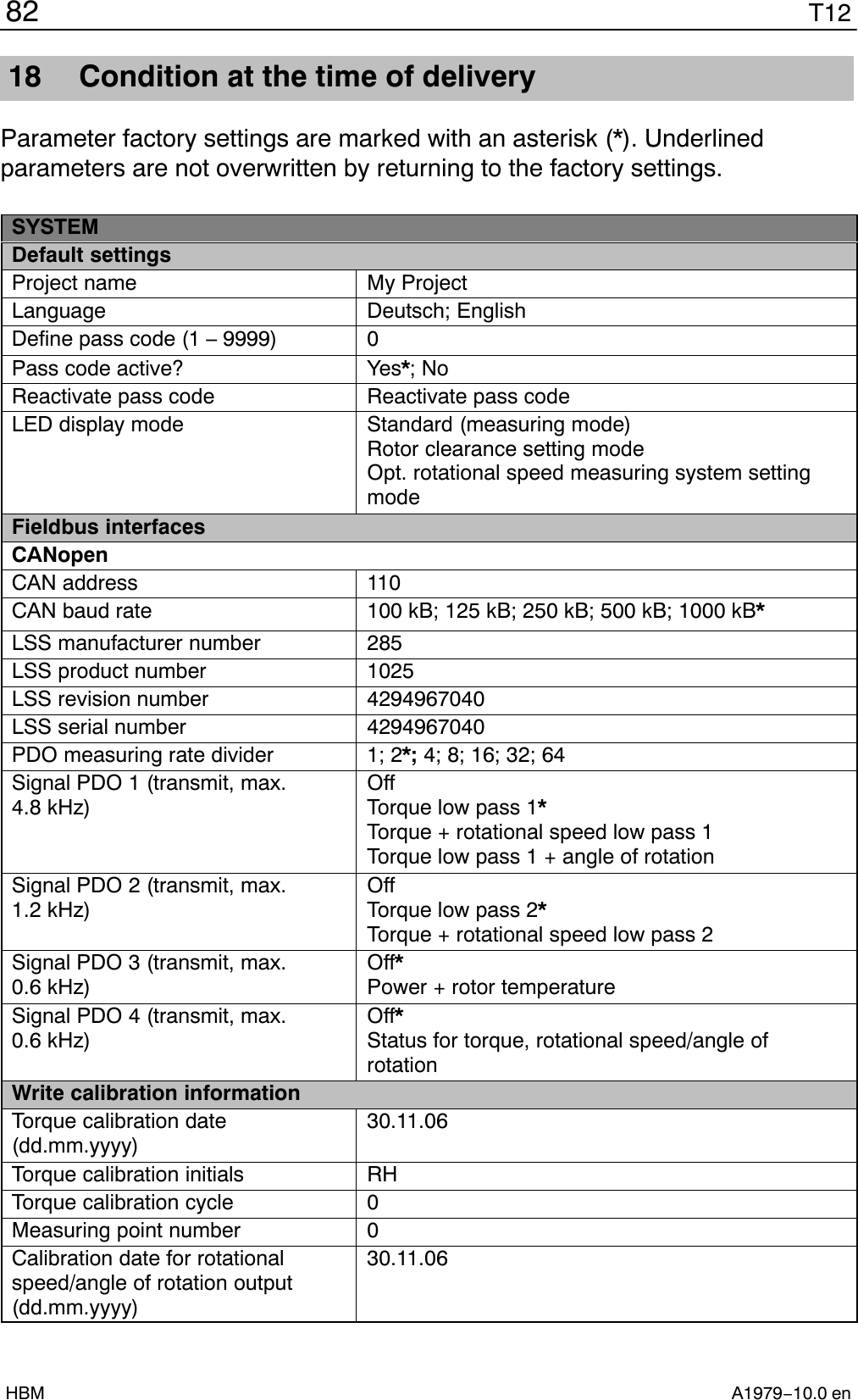
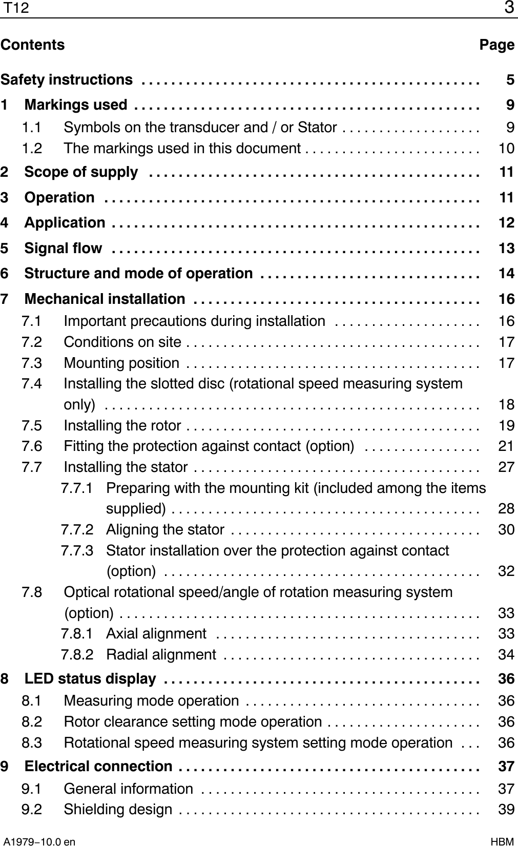
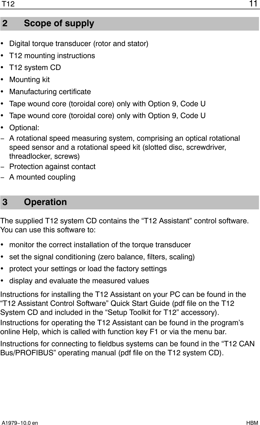
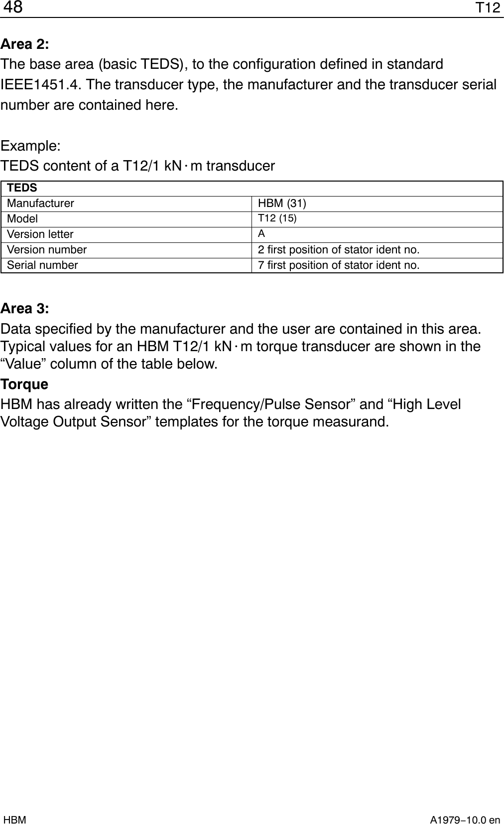
![79T12A1979−10.0 en HBM16.9.1 Protection against contact plates 100 Nm to 200 NmM3 screw headM4 screw head[Locking screw]1:4External = 7Height = 2External = 9Height = 2.5Dimensions in mm (1 mm = 0.03937 inches)16.9.2 Protection against contact plates 500 Nm to 10 kNmSpacing bolts for 5 kN@mand 10 kN@m onlyScrew head(locking screw)External = 9Height = 2.5External = 7Height = 2Screw headDimensions in mm (1 mm = 0.03937 inches)](https://usermanual.wiki/Hottinger-Bruel-and-Kjaer/T12S5/User-Guide-2442002-Page-79.png)