Hottinger Bruel and Kjaer
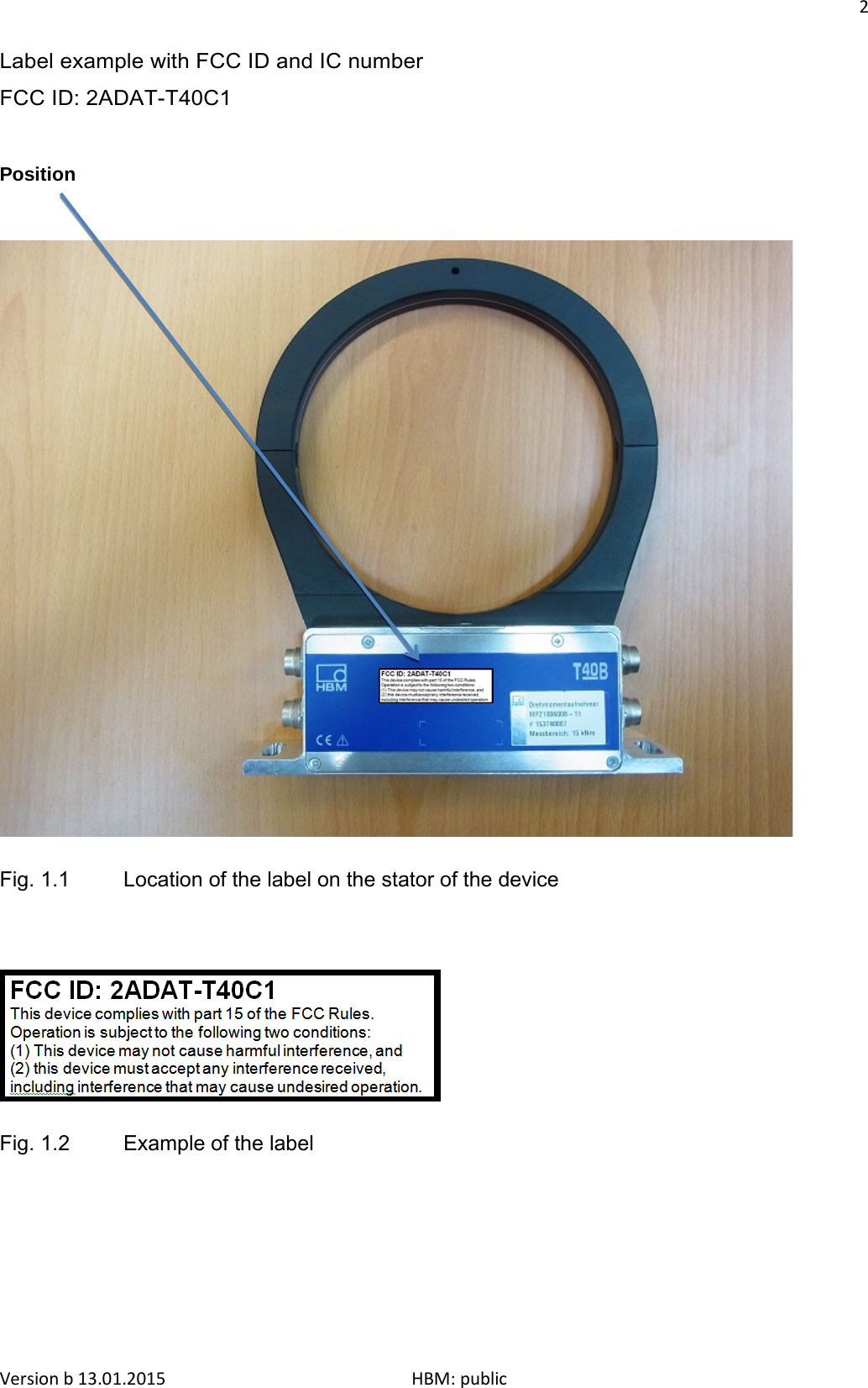
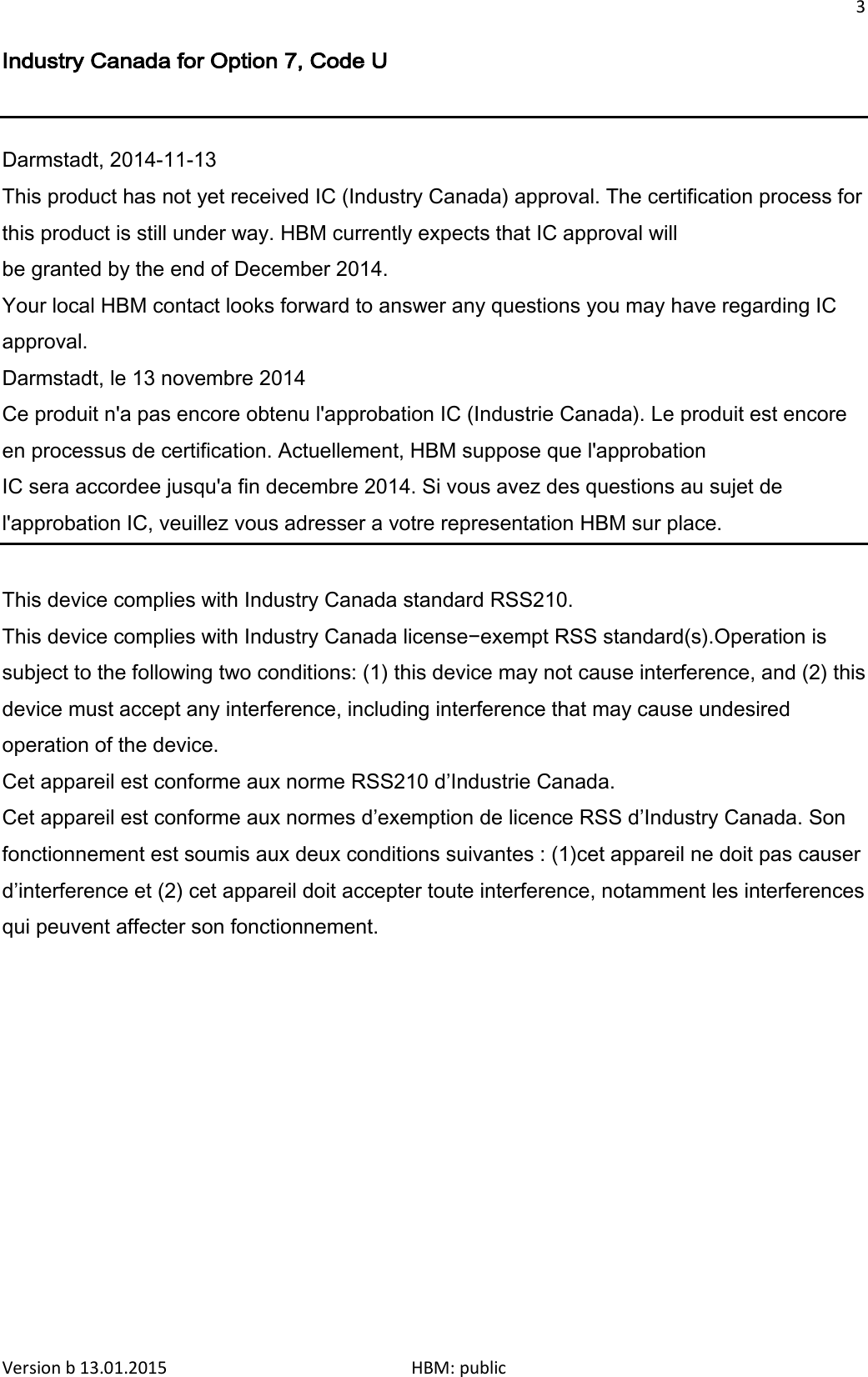
 T40C1 T40-C1 Torquemeter User Manual users manual

Hottinger Baldwin Messtechnik GmbH T40-C1 Torquemeter users manual

users manual

   Mounting instructions        Torque flange T40C1 (MPZ1006008 / MPZ1006009)                                                      Version b 13.01.2015                              HBM: public
  Table of contents 1 Safety instructions ........................................................................................ 1 2 Markings used .............................................................................................. 7 2.1 Symbols on the transducer ............................................................................................................... 7 2.2 The markings used in this document ............................................................................................ 7 3 Application .................................................................................................. 8 4 Structure and mode of operation .................................................................. 9 5 Mechanical installation ............................................................................. 11 5.1 Important precautions during installation ..................................................................................... 11 5.2 Conditions on site ............................................................................................................................. 12 5.3 Mounting position .............................................................................................................................. 12 5.4 Installation options ........................................................................................................................... 12 5.4.1 Installation without dismantling the antenna ring ................................................................................ 13 5.4.2 Installation with subsequent stator mounting ................................................................................... 14 5.5 Mounting the rotor ............................................................................................................................... 15 5.6 Mounting the stator ............................................................................................................................ 17 5.7 Speed measuring system (optional) ............................................................................................ 21 6 Electrical connection ............................................................................... 23 6.1 General instructions ......................................................................................................................... 23 6.2 EMC protection .................................................................................................................................. 23 6.3 Connector pin assignment ............................................................................................................. 25 6.4 Supply voltage ................................................................................................................................... 27 7 Shunt signal ............................................................................................. 28 8 Functionality testing ................................................................................... 29 8.1 Rotor status, LED A (upper LED) ................................................................................................... 29 Version b 13.01.2015                              HBM: public
  8.2 Stator status, LED B (lower LED) ............................................................................................... 30 9 Loading capacity ...................................................................................... 31 10  Maintenance ........................................................................................... 32 11   Waste disposal and environmental protection...................................... 32 12  Dimensions ............................................................................................. 33 12.1  Torque flange - 15kN·m ................................................................................................................. 33 12.2  Torque flange - 25kN·m .................................................................................................................... 33 13   Order numbers, accessories .................................................................. 35 14  Specifications .......................................................................................... 36 15  Supplementary technical information ........................................................ 40  Version b 13.01.2015                              HBM: public
1    1  Safety instructions  FCC Compliance & Advisory Statement for Option 7, Code U   Important  Any changes or modification not expressly approved in writing by the party responsible for compliance could void the user’s authority to operate the device. Where specified additional components or accessories elsewhere defined to be used with the installation of the product, they must be used in order to ensure compliance with FCC regulations.   This device complies with Part 15 of the FCC Rules. Operation is subject to the following two conditions: (1) this device may not cause harmful interference, and (2) this device must accept any interference received, including interference that may cause undesired operation. The FCC identifier or the unique identifier, as appropriate, must be displayed on the device.   Model Measuring range FCC ID T40C1 - MPZ1006008 15 kN·m 2ADAT-T40C1   T40C1 - MPZ1006009 25 kN·m 2ADAT-T40C1    Version b 13.01.2015                              HBM: public
2  Label example with FCC ID and IC number FCC ID: 2ADAT-T40C1    Position                                     Fig. 1.1 Location of the label on the stator of the device     Fig. 1.2 Example of the labelVersion b 13.01.2015                              HBM: public
3  Industry Canada for Option 7, Code U   Darmstadt, 2014-11-13 This product has not yet received IC (Industry Canada) approval. The certification process for this product is still under way. HBM currently expects that IC approval will be granted by the end of December 2014. Your local HBM contact looks forward to answer any questions you may have regarding IC approval.  Darmstadt, le 13 novembre 2014 Ce produit n'a pas encore obtenu l'approbation IC (Industrie Canada). Le produit est encore en processus de certification. Actuellement, HBM suppose que l'approbation IC sera accordee jusqu'a fin decembre 2014. Si vous avez des questions au sujet de l'approbation IC, veuillez vous adresser a votre representation HBM sur place.  This device complies with Industry Canada standard RSS210. This device complies with Industry Canada license−exempt RSS standard(s).Operation is subject to the following two conditions: (1) this device may not cause interference, and (2) this device must accept any interference, including interference that may cause undesired operation of the device. Cet appareil est conforme aux norme RSS210 d’Industrie Canada. Cet appareil est conforme aux normes d’exemption de licence RSS d’Industry Canada. Son fonctionnement est soumis aux deux conditions suivantes : (1)cet appareil ne doit pas causer d’interference et (2) cet appareil doit accepter toute interference, notamment les interferences qui peuvent affecter son fonctionnement.  Version b 13.01.2015                              HBM: public
4  Intended use The torque flange is used exclusively for torque, angle of rotation and power measurement tasks within the load limits stipulated in the specifications. Any other use is not the designated use. Stator operation is only permitted when the rotor is installed. The torque flange may only be installed by qualified personnel in compliance with the specifications and with the safety requirements and regulations of these mounting instructions. It is also essential to observe the applicable legal and safety regulations for the application concerned. The same applies to the use of accessories. The torque flange is not intended for use as a safety component. Please also refer to the section "Additional safety precautions". Proper and safe operation requires proper transportation, correct storage, siting and mounting, and careful operation.  Loading capacity limits The data in the technical data sheets must be complied with when using the torque flange. In particular, the respective maximum loads specified must never be exceeded. The following limits set out in the specifications must not be exceeded, e.g.: • Limit torque • Longitudinal limit force, lateral limit force or bending limit moment • Torque vibration bandwidth • Breaking torque • Temperature limits • Limits of electrical loading capacity Use as a machine element The torque flange can be used as a machine element. When used in this manner, it must be noted that, to favor greater sensitivity, the transducer is not designed with the safety factors usual in mechanical engineering. Please refer here to the section "Loading capacity limits", and to the specifications. Version b 13.01.2015                              HBM: public
5    Accident prevention According to the prevailing accident prevention regulations, once the transducers have been mounted, a covering agent or cladding has to be fitted as follows: • The covering agent or cladding must not be free to rotate. • The covering agent or cladding should prevent squeezing or shearing and provide protection against parts that might come loose. • Covers and cladding must be positioned at a suitable distance or be so arranged that there is no access to any moving parts within. • Covering agents and cladding must still be attached even if the moving parts of the torque flange are installed outside peoples' movement and working range.  The only permitted exceptions to the above requirements are if the torque flange is already fully protected by the design of the machine or by existing safety precautions. Additional safety precautions The torque flange cannot (as a passive transducer) implement any (safety-relevant) cutoffs. This requires additional components and constructive measures for which the installer and operator of the plant is responsible. The layout of the electronics conditioning the measurement signal should be such that measurement signal failure does not cause damage.  The scope of supply and performance of the transducer covers only a small area of torque measurement technology. In addition, equipment planners, installers and operators should plan, implement and respond to safety engineering considerations in such a way as to minimize residual dangers. Pertinent national and local regulations must be complied with. General dangers of failing to follow the safety instructions The torque flange is state of the art and reliable. Transducers can give rise to residual dangers if they are incorrectly operated or inappropriately mounted, installed and operated by untrained personnel. Every person involved with siting, starting-up, operating or repairing a torque flange must have read and understood the mounting instructions and in particular the technical safety instructions. The transducers can be damaged or destroyed by non-designated use of the transducer or by non-compliance with the mounting and operating instructions, these safety instructions or any other applicable safety regulations (BG safety and accident prevention regulations) when using the transducers. Transducers can break, particularly in the case of overloading. The breakage of a transducer can also cause damage to property or injury to persons in the vicinity of the transducer.  If the torque flange is not used according to the designated use, or if the safety instructions or specifications in the mounting and operating instructions are ignored, it is also possible that the transducer may fail or malfunction, with the result that persons or property may be affected (due to the torques acting on or being monitored by the torque flange). Conversions and modifications The transducer must not be modified from the design or safety engineering point of view except with our express agreement. Any modification shall exclude all liability on our part for any damage resulting therefrom.  Selling on If the torque flange is sold on, these mounting instructions must be included Version b 13.01.2015                              HBM: public
6  with the torque flange. Qualified personnel Qualified personnel means persons entrusted with siting, mounting, starting up and operating the product, who possess the appropriate qualifications for their function. This includes people who meet at least one of the three following requirements: • Knowledge of the safety concepts of automation technology is a requirement and as project personnel, you must be familiar with these concepts. • As automation plant operating personnel, you have been instructed how to handle the machinery. You are familiar with the operation of the equipment and technologies described in this documentation. • As commissioning engineers or service engineers, you have successfully completed the training to qualify you to repair the automation systems. You are also authorized to activate, ground and label circuits and equipment in accordance with safety engineering standards. Version b 13.01.2015                              HBM: public
7    2  Markings used 2.1 Symbols on the transducer     Meaning: Read and note the data in this manual  Label example Label example with FCC ID and IC number, Option 7 Code U. Location of the label on the stator device.  2.2 The markings used in this document  Important instructions for your safety are specifically identified. It is essential to follow these instructions in order to prevent accidents and damage to property.  Symbol Meaning      This marking warns of a potentially dangerous situation in which failure to comply with safety requirements could result in death or serious physical injury.  CAUTION This marking warns of a potentially dangerous situation in which failure to comply with safety requirements can result in slight or moderate physical injury.   NOTE This marking draws your attention to a situation in which failure to comply with safety requirements could lead to damage to property.   Important This marking draws your attention to information about the product or about handling the product.   Tip This marking indicates application tips or other information that is useful to you.    Version b 13.01.2015                              HBM: public
8  Symbol Meaning    This marking draws your attention to information about the product or about handling the product. Emphasis Italics are used to emphasize and highlight texts.     3 Application   The torque flange measures static and dynamic torques on stationary and rotating shafts. Test beds can be extremely compact because of the short construction of the transducer. This offers a very wide range of applications. The torque flange is reliably protected against electromagnetic interference. It has been constructed according to the relevant European standards (e.g. EMC behavior) and/or complies with US and Canadian standards. The product carries the FCC label.  This transducer is solely designed and may only be used for the following system types: • MTU Marine test benches according to Request MPZ1006008 / MPZ1006009Version b 13.01.2015                              HBM: public
9    4  Structure and mode of operation  The torque flange consists of two separate parts: the rotor and the stator. The rotor comprises the measuring body and the signal transmission elements. Strain gauges (SGs) are installed on the measuring body. The rotor electronics for transmitting the bridge excitation voltage and the measurement signal are located centrally in the flange. The transmitter coils for contactless transmission of excitation voltage and measurement signal are located on the measuring body's outer circumference. The signals are sent and received by a separable antenna ring. The antenna ring is mounted on a housing that includes the electronic system for voltage adaptation and signal conditioning.  Connectors for the torque and speed signals, the voltage supply and the digital output are located on the stator. The antenna segments (ring) should be mounted more or less concentrically around the rotor (see Chapter 5).     Antenna segments                Rotor  Connector plug   Connector plug    Identification plate Stator housing    Fig. 4.1:  Possible mechanical construction without speed measuring system  The speed sensor can be optionally mounted on the stator. The speed is measured magnetically with an AMR sensor and a magnetic ring. The magnetic ring for measurement of speed is welded to the flange. Version b 13.01.2015                              HBM: public
10              Antenna segments     Magnetic ring for speed measurement  Sensor head for measuring speed  Connector plug      Rotor   Connector plug  Stator housing  Identification plate    Fig. 4.2:  Mechanical construction with a speed measuring system Version b 13.01.2015                              HBM: public
11    5 Mechanical installation 5.1 Important precautions during installation    NOTE  A torque flange is a precision measurement element and therefore needs careful handling. Dropping or knocking the transducer may cause permanent damage. Make sure that the transducer cannot be overloaded, even while it is being mounted.     • Handle the transducer with care. • Check the effect of bending moments, critical speeds and natural torsional oscillations, to prevent the transducer being overloaded by increases in resonance. • Make sure that the transducer cannot be overloaded.   WARNING  There is a danger of the transducer breaking if it is overloaded. This can cause danger for the operating personnel of the system in which the transducer is installed. Implement appropriate safety measures to avoid overloads and to protect against resulting dangers.    • Use a screw locking device (medium strength, e.g. LOCTITE No. 242) to glue the screws into the counter thread to exclude pre-stressing loss due to screw slackening, if alternating loads are to be expected. • Comply with the mounting dimensions to enable correct operation.  An appropriate shaft flange enables the torque flange to be mounted directly. It is also possible to mount a joint shaft or relevant compensating element directly on the rotor (using an intermediate flange when required). Under no circumstances should the permissible limits specified for bending moments, lateral and longitudinal forces be exceeded. Due to the torque flange's high torsional stiffness, dynamic shaft train changes are kept to a minimum. Version b 13.01.2015                              HBM: public
12     Important  Even if the unit is installed correctly, the zero point adjustment made at the factory can shift by up to approx. 2% of the sensitivity. If this value is exceeded, we advise you to check the mounting conditions. If the residual zero offset when the unit is removed is greater than 1% of the sensitivity, please send the transducer back to the Darmstadt factory for testing.  5.2 Conditions on site   The torque flange must be protected against coarse dirt particles, dust, oil, solvents and humidity.  There is wide ranging compensation for the effects of temperature on the output and zero signals of the transducer (see Chapter "Specifications"). If there are no static temperature ratios, for example, because of the temperature differences between the measuring body and the flange, the values given in the specifications can be exceeded. In this case, ensure static temperature ratios by cooling or heating, depending on the application. As an alternative, check if thermal decoupling is possible, e.g. by means of heat radiating elements such as multiple disc couplings. 5.3 Mounting position  The torque flange can be mounted in any position. With clockwise torque, the output frequency is, depending on the option, 60 - 90 kHz, 10 - 15 kHz or 240 - 360 kHz). With HBM amplifiers or with the voltage output option, a positive output signal (0 V -+10 V) is present. In the case of the speed measuring system, an arrow must be attached to the stator housing to clearly define the direction of rotation: If the measurement flange moves in the direction of the arrow, connected HBM measuring amplifiers deliver a positive output signal.  5.4 Installation options   In principle, there are two possibilities for torque flange mounting: with the antenna ring complete or dismantled. We recommend mounting as described in Chapter 5.4.1. If mounting in accordance with Chapter 5.4.1 is not possible, (e.g. in the case of subsequent stator replacement), you will have to dismantle the antenna ring. It is essential in this case to comply with the notes on assembling the antenna segments (see Chapter 5.4.2).           Version b 13.01.2015                              HBM: public
13    5.4.1 Installation without dismantling the antenna ring                    Customer mounting    1. Mount rotor 2. Install stator      Support supplied by customer                 3. Finish installation of shaft run 4. Mount support Version b 13.01.2015                              HBM: public
14    5.4.2 Installation with subsequent stator mounting                       1. Install rotor 2. Install shaft train      Washers      Fan-type lock    washers             3. Dismantle antenna segment 4. Install antenna segment   Support supplied by customer                   4. Mount support Version b 13.01.2015                              HBM: public
15    5.5 Mounting the rotor      Tip  Usually the rotor identification plate is no longer visible after installation. This is why we include with the rotor additional stickers with the important ratings, which you can attach to the stator or any other relevant test-bench components. You can then refer to them whenever there is anything you wish to know, such as the shunt signal.    1. Prior to installation, clean the plane surfaces of the transducer flange and the counter flange. For safe torque transfer, the surfaces must be clean and free from grease. Use a piece of cloth or paper soaked in solvent. When cleaning, make sure that you do not damage the transmitter winding or the speed measuring system.                          Transmitter winding                              Speed measuring system                     without speed measuring system  Flange plane faces   with speed measuring system  Fig. 5.9:  Bolted rotor connection Version b 13.01.2015                              HBM: public
16    2. For the bolted rotor connection (see Fig. 5.9), use DIN EN ISO 4762 hexagon socket screws of the property class stated in Table 4.1, in a suitable length (dependent on the connection geometry, see Table 5.1 on Page 17). We recommend DIN EN ISO 4762 fillister head screws, blackened, smooth-headed, permitted size and shape variance in accordance with DIN ISO 4759, Part 1, product class A.     Important  Use a screw locking device (medium strength, e.g. LOCTITE No. 242) to glue the screws into the counter thread to exclude pre-stressing loss due to screw slackening, if alternating loads are to be expected.  3. Fasten all screws with the specified torque (Table 5.1 on Page 17). 4. There are tapped holes on the rotor for further mounting. Also use screws of property class 10.9 or 12.9, and fasten with the torque specified in Table 5.1.     Important  Use a screw locking device (medium strength, e.g. LOCTITE No. 242) to glue the screws into the counter thread to exclude pre-stressing loss due to screw slackening, if alternating loads are to be expected.  Version b 13.01.2015                              HBM: public
17   Measuring range Fastening screws Prescribed tightening moment kN·m  Z 1) Property class N·m 15 M16 12.9 325 M20 12.9 397 25 M20 129 397 M24 12.9 245 Table 5.1: Fastening screws 1)   DIN EN ISO 4762; black/oiled/..tot.=0.125  5.6 Mounting the stator   On delivery, the stator has already been installed and is ready for operation. The upper antenna segment can be separated from the stator, for example, for maintenance or to facilitate stator mounting. If your application does not require the stator to be dismantled, proceed as described in points 2., 5., and 6.    Antenna segment bolts with washers (M5)          Fan-type lock washers Hole for fixing the antenna segment, diameter 4.2 or 5.2 mm, depending on maximum capacity    top  Antenna segments  bottom     Stator housing        Fig. 5.10:  Bolted connection of the antenna segments on the stator Version b 13.01.2015                              HBM: public
18     Transducer without speed measuring system          Transducer with speed measuring system Sensor head for measuring speed Stator housing  Antenna wire           Lower antenna segment    Fig. 5.11:  Stator housing and lower antenna segment with antenna wire   1. Undo and remove the bolted connections (M5) on the upper antenna segment.  There are fan type lock washers between the antenna segments: Make sure that they do not get lost. 2. Use an appropriate base plate to install the stator housing in the shaft train so that there is sufficient opportunity for horizontal and vertical adjustments. Do not fully tighten the bolts yet. 3. Now use two hexagon socket screws to mount the upper antenna segment removed in Point 1 on the lower antenna segment. Make sure that the two fan type lock washers are inserted between the antenna segments (these ensure that there is a defined contact resistance)!    Important  To make sure that they function perfectly, the fan-type lock washers (A5, 3-FST DIN 6798 ZN/galvanized) must be replaced after the bolted antenna connection has been loosened three times. Version b 13.01.2015                              HBM: public
19    4. Now tighten all antenna-segment bolted connections with a tightening torque of 5 Nm. 5. Then align the antenna to the rotor in such a way that the antenna encloses the rotor more or less coaxially and the antenna wire in the axial direction shows the position and the center of the transmitter winding on the rotor. Please comply with the permissible alignment tolerances stated in the specifications.      Fig. 5.12:  Alignment of the rotor with the stator   6. Now fully tighten the bolted stator housing connection.  Prevention of stator axial oscillation Depending on the operating conditions, the stator may be excited to vibrate. This effect is dependent on: • The rotational speed • The antenna diameter (depends on the measuring range) • The design of the machine base Version b 13.01.2015                              HBM: public
20     Important  To prevent this axial oscillation, the antenna ring requires additional support by the customer. There is a hole on the upper antenna segment (with M5 internal thread), which can be used to incorporate a clamping device (see Fig. 5.13). The cable plug also requires support in this case, a construction example is shown in Fig. 5.14.                                    Fig. 5.13:  Construction example for supporting the antenna ring Version b 13.01.2015                              HBM: public
21                               Fig. 5.14:  Construction example for connector terminals (for two connectors)    5.7 Speed measuring system (optional)   The optional speed measuring system has already been integrated into the transducer at the factory, no assembly is required.        Magnetic ring for measuring the speed             Sensor head for measuring the speed       Fig. 5.15:  Torque transducer with speed measurement Version b 13.01.2015                              HBM: public
22    Speed measuring system sensor head alignment The speed measuring system is correctly aligned when the stator is precisely aligned for the torque measurement. So the two Allen screws on the sensor head (Fig. 5.16) must not be loosened.     Important You must not change the position of the sensor head.        Never loosen the screws!   Sensor head for measuring the speed             Fig. 5.16:  Torque transducer with sensor head for speed measurement Version b 13.01.2015                              HBM: public
23    6 Electrical connection  6.1 General instructions  • With cable extensions, make sure that there is a proper connection with minimum contact resistance and good insulation. • All plug connections or swivel nuts must be fully tightened.     Important  Transducer connection cables from HBM with attached connectors are identified in accordance with their intended purpose (Md or n). When cables are shortened, inserted into cable ducts or installed in control cabinets, this identification can get lost or become concealed. Mark the cables before laying them in this case.  6.2 EMC protection      Important   The product offered here is a special module for stationary plants or a transducer for installation by system integrators or plant engineers and is not intended for general sale. This product does not need an EC Declaration of Conformity or CE marking in compliance with EMVG1 §12 Paragraph 2 and directive 2004/1008/EC Article 13 Paragraph 1. The product is exclusively manufactured and intended for further processing by companies or persons with expertise in the sector of electromagnetic compatibility (EMC). Relevant EMC protection aims are met with regards to the offered product when the following instructions for installation are observed and implemented.   Special electronic coding methods are used to protect the purely digital signal transmission between the transmitter head and the rotor from electromagnetic interference.  Version b 13.01.2015                              HBM: public
24  The cable shield is connected with the transducer housing. This encloses the measurement system (without the rotor) in a Faraday cage when the shield is laid flat at both ends of the cable. With other connection techniques, an EMC-proof shield should be applied in the wire area and this shielding should also be connected extensively (see also HBM Greenline Information, brochure i1577).   Electrical and magnetic fields often induce interference voltages in the measuring circuit. Therefore: • Use shielded, low-capacitance measurement cables only (HBM cables fulfill both conditions). • Only use plugs that meet EMC guidelines. • Do not route the measurement cables parallel to power lines and control circuits. If this is not possible, protect the measurement cable with e.g. steel conduit. • Avoid stray fields from transformers, motors and contact switches. • Do not ground the transducer, amplifier and indicator more than once. • Connect all devices in the measurement chain to the same grounded conductor. • In the case of interference due to potential differences (compensating currents), supply voltage zero and housing ground must be disconnected on the amplifier and a potential equalization line established between the stator housing and the amplifier housing (copper conductor, minimum 10 mm2 wire cross-section). • Should differences in potential between the machine rotor and stator, because of unchecked leakage, for example, cause interference, this can usually be overcome by connecting the rotor definitively to ground, e.g. with a wire loop. The stator must be connected to the same (ground) potential.  Version b 13.01.2015                              HBM: public
25       Device connector    6   1 5 7   2 4   3   Top view Plug  Pin Assignment Wire color D‐Sub Plug Pin 1 Measurement signal torque (Frequency output; 5 V1),2))  wh  13 2 Supply voltage 0 V; bk  5 3 Supply voltage 18 V - 30 V bu  6 4 Measurement signal torque  rd  12 5 Meas. signal 0 V; symmetrical gy 8 6 Shunt signal resolution 5 V … 30 V gn 14 7 Shunt signal 0 V; gy  8  Shielding connected to housing ground      6.3 Connector pin assignment  The stator housing has two 7 pin connectors, an 8 pin connector and a 16 pin connector. The supply voltage connections and shunt signal connections of connectors 1 and 3 are each electrically interconnected, but are protected against compensating currents by diodes. There is also an automatically resetting fuse (multifuse) to protect the supply connections against overload by the stator.   Assignment for connector 1: Supply voltage and frequency output signal.                (Frequency output; 5 V1),2))           1) RS-422 complementary signals; with cable lengths exceeding 10 m, we recommend using a termination resistor R = 120 ohms between the (wh) and (rd) wires. 2) RS‐422: Pin 1 corresponds to A, Pin 4 corresponds to B.    NOTE  These torque flanges are only intended for operation with a DC supply voltage. They must not be connected to older HBM amplifiers with square-wave excitation. This could destroy the connection board resistances or cause other faults in the amplifiers. Version b 13.01.2015                              HBM: public
26    Assignment for connector 2: Speed output signal (optional).       Device connector   2 5 4 3  8  1 7  6   Top view Plug Pin Assignment 1 Measurement signal speed 1) (pulse string, 5 V; 0°) 2 Not in use 3 Measurement signal speed 1) (pulse string, 5 V; phase shifted by 90°) 4 Not in use 5 Not in use 6 Measurement signal speed 1) (pulse string, 5 V; 0°) 7 Measurement signal speed 1) (pulse string, 5 V; phase shifted by 90°) 8 Supply voltage zero  Shielding connected to housing ground 1) RS-422 complementary signals; with cable lengths exceeding 10 m, we recommend using a termination resistor of R = 120 ohms.  Assignment for connector 3: Supply voltage and frequency output signal.    Device connector   6  1 5  7  2 4  3      Top view Plug Pin Assignment 1 Torque measurement signal (volt. output; 0 V ) 2 Power supply 0 V; 3 Supply voltage 18 V - 30 V DC 4 Torque measurement signal (voltage output, ±10 V) 5 Not in use 6 Shunt signal resolution 5 V - 30 V 7 Shunt signal 0 V;  Shielding connected to housing ground   Assignment for connector 4: TMC - only for connection to the TIM 40 Torque Interface Module within HBM. Version b 13.01.2015                              HBM: public
27    6.4 Supply voltage   The transducer is operated with a separated extra-low voltage (nominal (rated) supply voltage 18 - 30 VDC). You can supply one or more torque flanges simultaneously within a test bench. Should the device be operated on a DC voltage network1) , additional precautions must be taken to discharge excess voltages. The information in this Chapter relates to the standalone operation of the T40FM without HBM system solutions. The supply voltage is electrically isolated from signal outputs and shunt signal inputs. Connect a separated extra-low voltage of 18 V - 30 V to pin 3 (+) and pin 2 (-)  of plug 1 or 3. We recommend that you use HBM cable KAB 8/00-2/2/2 and appropriate sockets (see Accessories). The cable can be up to 50 m long for voltages ≥24 V, otherwise it can be up to 20 m long. If the permissible cable length is exceeded, you can supply the voltage in parallel over two connection cables (connectors 1 and 3). This enables you to double the permissible length. Alternatively, install a power supply on site.     Important At the instant of power-up, a current of up to 4 A may flow, which could switch off power packs with electronic current limiters.                              Version b 13.01.2015                              HBM: public
28    7 Shunt signal   The torque flange delivers an electrical shunt signal that in measuring chains with HBM components, can be activated from the amplifier. The transducer generates a shunt signal of about 50% of the nominal (rated) torque, the precise value is specified on the type plate. After activation, adjust the amplifier output signal to the shunt signal supplied by the connected transducer to adapt the amplifier to the transducer.      The transducer should not be under load when the shunt signal is being measured, since the shunt signal is mixed additively.   Triggering the shunt signal Applying a separated extra-low voltage of 5 - 30 V to pins 6 (+) and 7 (-) at connector 1 or 3 triggers the shunt signal.  The nominal (rated) voltage for triggering the shunt signal is 5 V (triggering at U > 2.5 V), but when voltages are less than 0.7 V, the transducer is in measuring mode. The maximum permissible voltage is 30 V, current consumption at nominal (rated) voltage is approx. 2 mA and at maximum voltage, approx. 18 mA. The trigger voltage for the shunt signal is electrically isolated from the supply voltage and the measurement voltage.     Tip  The shunt signal can be triggered by the amplifier or via the operating software in HBM system solutions. Version b 13.01.2015                              HBM: public
29    8  Functionality testing  You can check the functionality of the rotor and the stator from the LEDs on the stator.            LED A rotor status    LED B stator status         Fig. 8.1:  LEDs on the stator housing  8.1 Rotor status, LED A (upper LED)   Color Meaning Green (pulsating) Internal rotor voltage values OK  Flashing orange Rotor and stator mismatched (an increasing flashing frequency indicates the degree of misalignment) => Correct the rotor/stator alignment.    Pulsating orange Rotor status cannot be defined => Correct the rotor/stator alignment. If the LED still pulsates orange, it is possible that there is a hardware defect. The measurement signals reflect the level of the defect status.    Red (pulsating) Rotor voltage values NOK. => Correct the rotor/stator alignment. If the LED still pulsates red, it is possible that there is a hardware defect. The measurement signals reflect the level of the defect status.  Pulsating means that the LED goes dark for about 20 ms every second (sign of life); making it possible to detect that the transducer is functioning. Version b 13.01.2015                              HBM: public
30    8.2 Stator status, LED B (lower LED)   Color Meaning Green (permanently lit) Measurement signal transmission and internal stator voltages OK Green, intermittently orange. For many synchronization errors: Constant orange Orange until end of defective transmission if ≥5 incorrect measured values in sequence are transmitted. The measurement signals reflect the level of the defect status for the duration of the transmission defect + approx. another 3.3 ms.  Orange (permanently lit) Permanently disrupted transmission, the measurement signals reflect the level of the defect status. (fout = 0 Hz, Uout = defect level). => Correct the rotor/stator alignment. Red (permanently lit) Internal stator defect, the measurement signals reflect the level of the defect status (fout = 0 Hz, Uout = defect level). Version b 13.01.2015                              HBM: public
31    9 Loading capacity  Nominal torque can be exceeded statically up to the limit torque. If the nominal torque is exceeded, additional irregular loading is not permissible. This includes longitudinal forces, lateral forces and bending moments. Limit values can be found in the chapter "Specifications" (Chapter 13, Page 115).  Measuring dynamic torque The torque flange can be used to measure static and dynamic torques. The following rule applies to the measurement of dynamic torque: • The transducer calibration performed for static measurements is also valid for dynamic torque measurements. • The natural frequency f0 of the mechanical measurement setup depends on the moments of inertia J1 and J2 of the connected rotating masses, and the torsional stiffness of the transducer.  Use the equation below to approximately determine the natural frequency f0 of the mechanical measuring arrangement:         • The permissible mechanical vibration bandwidth (peak-peak) can also be found in the specifications.    Nominal (rated) torque Mnom in % + Mnom Oscillation width               Oscillation width 0 time t  200% oscillation width - Mnom Oscillation width    Fig. 9.1:  Permissible dynamic loading Natural frequency in Hz  Mass moment of inertia in kg·m^2  Torsional stiffness in N m/rad Version b 13.01.2015                              HBM: public
32    10  Maintenance  The torque flanges are maintenance-free.  11 Waste disposal and environmental protection   All electrical and electronic products must be disposed of as hazardous waste. The correct disposal of old equipment prevents ecological damage and health hazards.        Symbol: Meaning: Statutory waste disposal mark The electrical and electronic devices that bear this symbol are subject to the European waste electrical and electronic equipment directive 2002/96/EC. The symbol indicates that, in accordance with national and local environmental protection and material recovery and recycling regulations, old devices that can no longer be used must be disposed of separately and not with normal household garbage.  As waste disposal regulations may differ from country to country, we ask that you contact your supplier to determine what type of disposal or recycling is legally applicable in your country.  Packaging The original packaging of HBM devices is made from recyclable material and can be sent for recycling. Store the packaging for at least the duration of the warranty. In the case of complaints, the torque flange must be returned in the original packaging. For ecological reasons, empty packaging should not be returned to us. Version b 13.01.2015                              HBM: public
33    12 Dimensions  12.1  Torque flange - 15kN·m Version b 13.01.2015                              HBM: public
34  12.2   Torque flange - 25kN·m  Version b 13.01.2015                              HBM: public
35   13 Order numbers, accessories    Accessories, to be ordered separately  Article Order No. Connection cable, set Torque connection cable, Binder 423 - D-Sub 15P, 6 m 1-KAB149-6 Torque connection cable, Binder 423 - free ends, 6 m 1-KAB153-6 Speed connection cable, Binder 423 - 8 pin, free ends, 6 m 1-KAB154-6 Speed connection cable, Binder 423 - 8 pin, D‐Sub, free ends, 6 m 1-KAB163-6 TMC connection cable, Binder 423 - 16 pin, free ends, 6 m 1-KAB174-6 Cable sockets 423G-7S, 7 pin (straight) 3-3101.0247 423W-7S, 7 pin (angle) 3-3312.0281 423G-8S, 8-pin (straight) 3-3312.0120 423W-8S, 8 pin (angle) 3-3312.0282 Connection cable, by the meter (minimum order quantity: 10 m, price per meter) Kab8/00-2/2/2 4-3301.0071   Version b 13.01.2015                              HBM: public
36  14 Specifications  Type MPZ1006008-12  /  MPZ1006009-12 Accuracy class 0.1 Torque measuring system Nominal (rated) torque Mnom  kN⋅m 15 25 Nominal (rated) sensitivity (spread between torque = zero and nominal (rated) torque) Freq. output 10 kHz / 60 kHz / 240 kHz Voltage output Sensitivity tolerance (deviation of the actual output quantity at Mnom from the nominal (rated) sensitivity) Voltage output   kHz V     %   30 10     ±0.1 Output signal at torque = zero Frequency output Voltage output  kHz V  60 0 Nominal output signal Frequency output at positive nominal (rated) torque at negative nominal (rated) torque Voltage output at positive nominal (rated) torque at negative nominal (rated) torque    kHz kHz  V V   90 2) (5 V symmetrical 4)) 30 2) (5 V symmetrical 4))  +10 -10 Load resistance Frequency output Voltage output Long-term drift over 48 h Frequency output Voltage output  kΩ kΩ  % %  ≥ 2 ≥10  <±0.03 <±0.03 Measurement frequency range, -3 dB kHz 3 2) Group delay µs <220 2) Residual ripple Voltage output 5)  mV  <40 Temperature influence per 10 K in the nominal temperature range on the output signal, related to the actual value of the signal span Frequency output Voltage output on the zero signal, related to the nominal (rated) sensitivity Frequency output Voltage output      % %   % %      ±0.05 ±0.2   ±0.05 ±0.1 Version b 13.01.2015                              HBM: public
37  Maximum level control range 6) Frequency output Voltage output  kHz V  15 - 105 2)  -12 - +12 Energy supply Nominal (rated) supply voltage (separated extra low DC voltage) Current consumption in measuring mode Current consumption in startup mode Nominal (rated) power consumption Maximum cable length   V A A W m   18 - 30 < 1 < 4 (typ. 2) 50 µs < 10 50 Linearity deviation, including hysteresis, relative to nominal (rated) sensitivity Frequency output Voltage output Rel. Standard deviation of repeatability as per DIN 1319, relative to the variation of the output signal Frequency output Voltage output    % %      % %    <±“0.03 <±“0.03    <±“0.03 <±“0.03 Shunt signal Tolerance of the shunt signal, related to Mnom Nominal (rated) trigger voltage Trigger voltage limit Shunt signal ON Shunt signal OFF   % V V V V approx. 50 % of Mnom <±“0.05 5 36 min. >2.5 max. <0.7  2) Option 5, 60±30 kHz (Code DU2) 4) Complementary signals RS-422, note termination resistor. 5) Signal frequency range 0.1 to 10 kHz 6) Output signal range in which there is a repeatable correlation between torque and output signal. Version b 13.01.2015                              HBM: public
38      General information Nominal (rated) torque Mnom N⋅m  kN⋅m 15 25 EMC Emission (per EN 61326‐1, Section 7) RFI field strength   -   C  EMC Emission (per FCC 47 Part 15, Subpart C)    RFI field strength    Interference immunity(EN 61326‐1, Table 2) Electromagnetic field (AM) Magnetic field Electrostatic discharge (ESD) Contact discharge Air discharge Rapid transients (burst) Impulse voltages (surge) Conducted interference (AM)  V/m A/m  kV kV kV kV  V  10 100  4 8 1 1 10 Degree of protection per EN 60 529  IP 54 Reference temperature Nominal (rated) temperature range Operating temperature range Storage temperature range °C °C °C °C 23 +10 - +70 -20 - +85 -40 - +85 Mechanical shockas per EN‐60068‐2‐27 10) Quantity Duration Acceleration (half sine)   n ms m/s2  1000 3 650 Vibrational stress in 3 directions as per  EN‐60068‐2‐6 10) Frequency range Duration Acceleration (amplitude)   Hz h m/s2   10 - 2000 2.5 200 Nominal (rated) speed rpm 4500 3000 Load limits 11)   Limit torque, relative to Mnom 12) % 130 Breaking torque, relative to Mnom 12) % >250 Longitudinal limit force 13) kN 60 Lateral limit force 13)  kN 50 Bending limit force 13) kN·m 6 Oscillation width as per DIN‐50100 (peak/peak) 14) % of Mnom 120 Version b 13.01.2015 HBM: public
39   Mechanical values Nominal (rated) torque Mnom   kN⋅m 15 25 Torsional stiffness cT  kN⋅m/rad 11600 15600 Torsion angle at Mnom Degree 0,074 0,092 Balancing grade acc. DIN ISO 1940   G 2,5 Mass moment of inertia of the rotor Jv (without speed measuring system)  kg*m^2 0,46 1,05 Max. permissible static eccentricity of the rotor (radial) to the center point of the stator without speed measuring system      mm      ±2  Permissible axial displacement between rotor and stator 16) without speed measuring system     mm     ±2 Weight  Rotor without speed measuring system  Stator              kg  kg                              38  1,1  57  1,1  10)  The antenna ring and connection plug must be fixed. 11) Each type of irregular stress (bending moment, lateral or longitudinal force, exceeding nominal (rated) torque) can only be permitted up to its specified static load limit provided none of the others can occur at the same time. If this condition is not met, the limit values must be reduced. If 30% of the bending limit moment and lateral limit force occur at the same time, only 40% of the longitudinal limit force is permissible and the nominal (rated) torque must not be exceeded. The permissible bending moments, longitudinal forces and lateral forces can affect the measurement result by approx. 0.3 % of the nominal (rated) torque. The load limits only apply for the nominal (rated) temperature range. At temperatures <10 C°, load limits are expected to reduce by up to 30%, because there is an increased reduction in toughness as temperatures fall. 12) With static loading. 13) Static and dynamic. 14) The nominal (rated) torque must not be exceeded. 16)  Above the nominal (rated) temperature range:  ± 1.5 mm  Version b 13.01.2015 HBM: public
40   15  Supplementary technical information                 To ensure that the torque flange retains its characteristics once it is installed, we recommend that the customer also chooses the specified form and position tolerances, surface quality and hardness for the connections provided. Measuring range (kN·m) Axial run-out tolerance (mm) Radial run-out tolerance (mm) 15 0,02 0,02 25 0,02 0,02    Axial and radial run-out tolerances Axial and radial run-out tolerances Axial run-out  AB radial run-out  AB Inner centering Hardness 46 … 54 HRC Surface quality of axial and radial run-out surfaces (a, B and AB) Version b 13.01.2015 HBM: public
41                              © Hottinger Baldwin Messtechnik GmbH.   All rights reserved. All details describe our products in general form only. They are not to be understood as express warranty and do not constitute any liability whatsoever.   Änderungen vorbehalten. Alle Angaben beschreiben unsere Produkte in allgemeiner Form. Sie stellen keine Beschaffenheits- oder Haltbarkeits- garantie im Sinne des §443 BGB dar und begründen keine Haftung.     Hottinger Baldwin Messtechnik GmbH Im Tiefen See 45 • 64293 Darmstadt • Germany Tel. +49 6151 803-0  • Fax: +49 6151 803-9100 Email: info@hbm.com  • www.hbm.com         Version b 13.01.2015 HBM: public

Navigation menu