Hottinger Bruel and Kjaer TJ1S9 TJ1S9 Torquemeter User Manual
Hottinger Baldwin Messtechnik GmbH TJ1S9 Torquemeter
User Manual
HBM: Business Document
Mounting instructions
Installation of strain gages and
telemetry system on customer
diaphragm coupling project
9HA.02
TJ1-S9 (MPZ1701032)
HBM: Business Document
Directory
1 Safety Instructions ................................................................................................................................... 3
2 Markings used ......................................................................................................................................... 1
2.1 Symbols on the transducer ............................................................................................................. 1
2.2 The markings used in this document ............................................................................................. 2
3 Application ................................................................................................................................................ 2
4 Structure and mode of operation............................................................................................................ 3
5 Mechanical installation ............................................................................................................................ 5
5.1 Important precautions during installation ....................................................................................... 5
5.2 Conditions on site ............................................................................................................................ 6
5.3 Installation orientation...................................................................................................................... 6
5.4 Installation ........................................................................................................................................ 7
5.5 Preparing for the rotor mounting (exemplary) ............................................................................... 7
5.6 Mounting the rotor ............................................................................................................................ 9
5.7 Installing the telemetry system ........................................................................................................ 10
5.7.1 Measuring setup ......................................................................................................................... 11
5.7.2 Instruction for installation ........................................................................................................... 12
5.7.3 Calibration signal........................................................................................................................ 13
5.7.4 Stator antenna ............................................................................................................................ 13
5.7.5 Evaluation unit ............................................................................................................................ 14
6 Electrical connection ............................................................................................................................ 18
6.1 Connector pin assignment ............................................................................................................ 19
6.2 Supply voltage ................................................................................................................................ 19
7 Functional testing .................................................................................................................................. 20
8 Maintenance .......................................................................................................................................... 21
9 Dimensions of the stator antenna ........................................................................................................ 22
10 Dimensions of the rotor antenna ...................................................................................................... 23
11 Declaration of conformity .................................................................................................................. 24
HBM: Business Document
1 Safety Instructions
FCC Compliance & Advisory Statement
Important
Any changes or modification not expressly approved in writing by the party
responsible for compliance could void the user’s authority to operate the device.
Where specified additional components or accessories elsewhere defined to be
used with the installation of the product, they must be used in order to ensure
compliance with FCC regulations.
This device complies with Part 15 of the FCC Rules. Operation is subject to the
following two conditions: (1) this device may not cause harmful interference, and
(2) this device must accept any interference received, including interference that
may cause undesired operation.
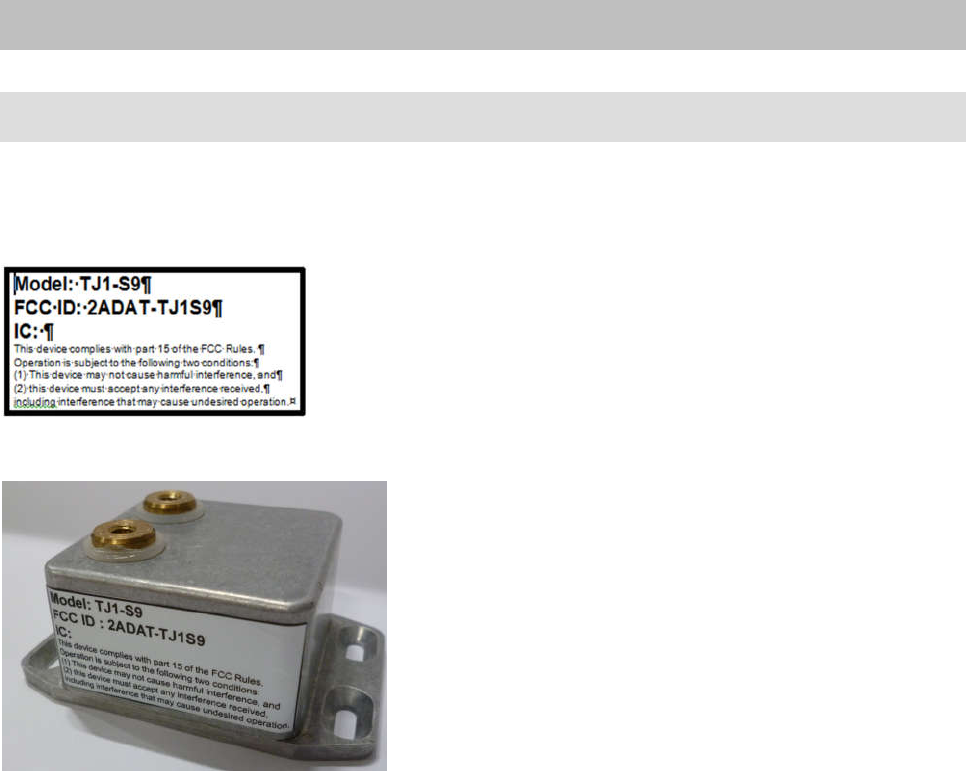
The FCC identifier or the unique identifier, as appropriate, must be displayed on
the device.
Model Measuring
range
FCC ID IC
TJ1-S9 1375kN·m 2ADAT-TJ1S9 n.a.
Label example with FCC ID.
Fig 1.1: Location of the label on the stator of the device

HBM: Business Document
Model: TJ1-S9
FCC ID: 2ADAT-TJ1S9
This device complies with part 15 of the FCC Rules.
Operation is subject to the following two conditions:
(1) This device may not cause harmful interference, and
(2) this device must accept any interference received,
including interference that may cause undesired operation.
Fig. 1.2 Example of the label
Appropriate use
The torque transducer is used exclusively for torque, angle of rotation and
power measurement tasks within the load limits stipulated in the specifica-
tions. Any other use is not the designated use.
Stator operation is only permitted when the rotor and stator antenna are
coupled.
The torque flange may only be installed by qualified personnel in compliance
with the specifications and with the safety requirements and regulations of
these mounting instructions. It is also essential to observe the applicable legal
and safety regulations for the application concerned. The same applies to the
use of accessories.
The torque flange is not intended for use as a safety component. Please also
refer to the section: “Additional safety precautions". Proper and safe operation
requires proper transportation, correct storage, siting and mounting, and care-
ful operation.
Loading capacity limits
The data in the technical data sheets must be complied with when using the
torque flange. In particular, the respective maximum loads specified must
never be exceeded. The values stated in the specifications‐must not be
exceeded, for example, for
limit torque,
longitudinal limit force, lateral limit force or limit bending moment,
torque oscillation width,
breaking torque,
temperature limits,
the limits of the electrical loading capacity.
HBM: Business Document
Use as a machine element
The torque flange can be used as a machine element. When used in this
manner, it must be noted that, to favor greater sensitivity, the transducer is not
designed with the safety factors usual in mechanical engineering. Please refer
here to the section “Loading capacity limits", and to the specifications.
Accident prevention
According to the prevailing accident prevention regulations, once the trans-
ducers have been mounted, a covering agent or cladding has to be fitted as
follows:
The covering agent or cladding must not be free to rotate.
The covering agent or cladding should prevent squeezing or shearing and
provide protection against parts that might come loose.
Covering agents and cladding must be positioned at a suitable distance or
be so arranged that there is no access to any moving parts within.
Covering agents and cladding must still be attached even if the moving
parts of the torque flange are installed outside people's movement and
working range.
The only permitted exceptions to the above requirements are if the torque
flange is already fully protected by the design of the machine or by existing
safety precautions.
Additional safety precautions
The torque flange cannot (as a passive transducer) implement any (safety‐rel
evant) cutoffs. This requires additional components and constructive meas-
ures for which the installer and operator of the plant is responsible. The layout
of the electronics conditioning the measurement signal should be such that
measurement signal failure does not cause damage.
The scope of supply and performance of the transducer covers only a small
area of torque measurement technology. In addition, equipment planners,
installers and operators should plan, implement and respond to safety engin-
eering considerations in such a way as to minimize residual dangers. Pertin-
ent national and local regulations must be complied with.
General dangers of failing to follow the safety instructions
The torque flange corresponds to the state of the art and is failsafe. Trans-
ducers can give rise to residual dangers if they are incorrectly operated or
inappropriately mounted, installed and operated by untrained personnel.
Every person involved with siting, starting‐up, operating or repairing a torque
flange must have read and understood the mounting instructions and in
particular the technical safety instructions. The transducers can be damaged or
destroyed by non-designated use of the transducer or by non-compliance with
the mounting and operating instructions, these safety instructions or any other
HBM: Business Document
applicable safety regulations (safety and accident prevention regulations),
when using the transducers. Transducers can break, particularly in the case of
overloading. The breakage of a transducer can also cause damage to prop-
erty or injury to persons in the vicinity of the transducer.
If the torque flange is not used according to the designated use, or if the
safety instructions or specifications in the mounting and operating instructions
are ignored, it is also possible that the transducer may fail or malfunction, with
the result that persons or property may be adversely affected (due to the
torques acting on or being monitored by the torque flange).
Conversions and modifications
The transducer must not be modified from the design or safety engineering
point of view except with our express agreement. Any modification shall
exclude all liability on our part for any damage resulting therefrom.
Selling on
If the torque flange is sold on, these mounting instructions must be included
with the torque flange.
Qualified personnel
Qualified personnel means persons entrusted with siting, mounting, starting
up and operating the product, who possess the appropriate qualifications for
their function.
This includes people who meet at least one of the three following require-
ments:
- Knowledge of the safety concepts of automation technology is a
requirement and as project personnel, you must be familiar with these
concepts.
- As automation plant operating personnel, you have been instructed how to
handle the machinery. You are familiar with the operation of the equipment
and technologies described in this documentation.
- As commissioning engineers or service engineers, you have successfully
completed the training to qualify you to repair the automation systems. You
are also authorized to activate, ground and label circuits and equipment in
accordance with safety engineering standards.
1
HBM: Business Document
2 Markings used
2.1 Symbols on the transducer
Label example
Label example with FCC ID number,
Location of the label on the stator unit.
2
HBM: Business Document
2.2 The markings used in this document
Important instructions for your safety are specifically identified. It is essential
to follow these instructions in order to prevent accidents and damage the
property.
Symbol Meaning
This marking warns of a potentially
dangerous situation in which failure to
comply with safety requirements can result
in death or serious physical injury.
CAUTION
This marking warns of a potentially
dangerous situation in which failure to
comply with safety requirements can result
in slight or moderate physical injury.
NOTE
This marking draws your attention to a
situation in which failure to comply with
safety requirements can lead to damage to
property.
Important
This marking draws your attention to
important information about the product or
about handling the product.
Tip
This marking indicates application tips or
other information that is useful to you.
This marking draws your attention to
information about the product or about
handling the product.
Emphasis Italics are used to emphasize and highlight
texts.
3 Application
This transducer is designed only for the following machine:
GE Company – Gas Turbine Test Stand with coupling 9HA.02 according
request MPZ1701032
3
HBM: Business Document
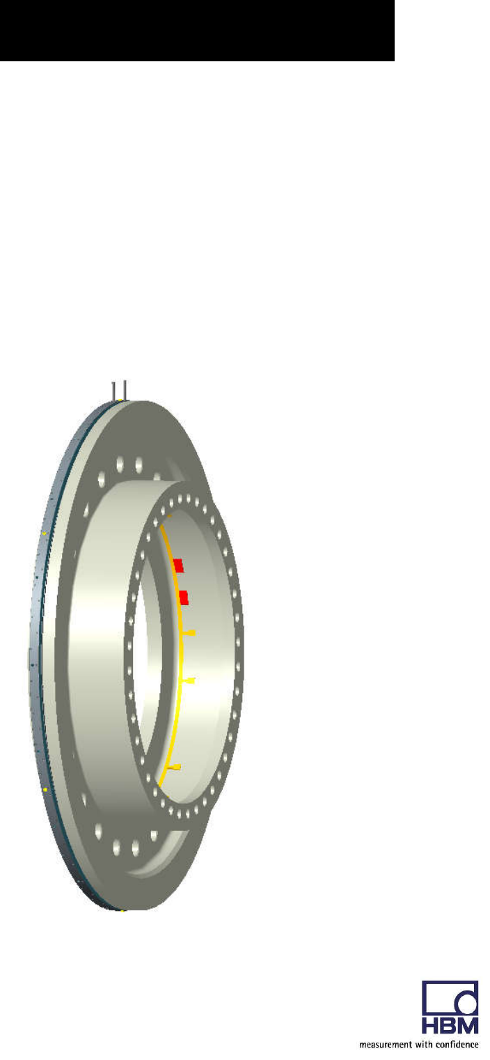
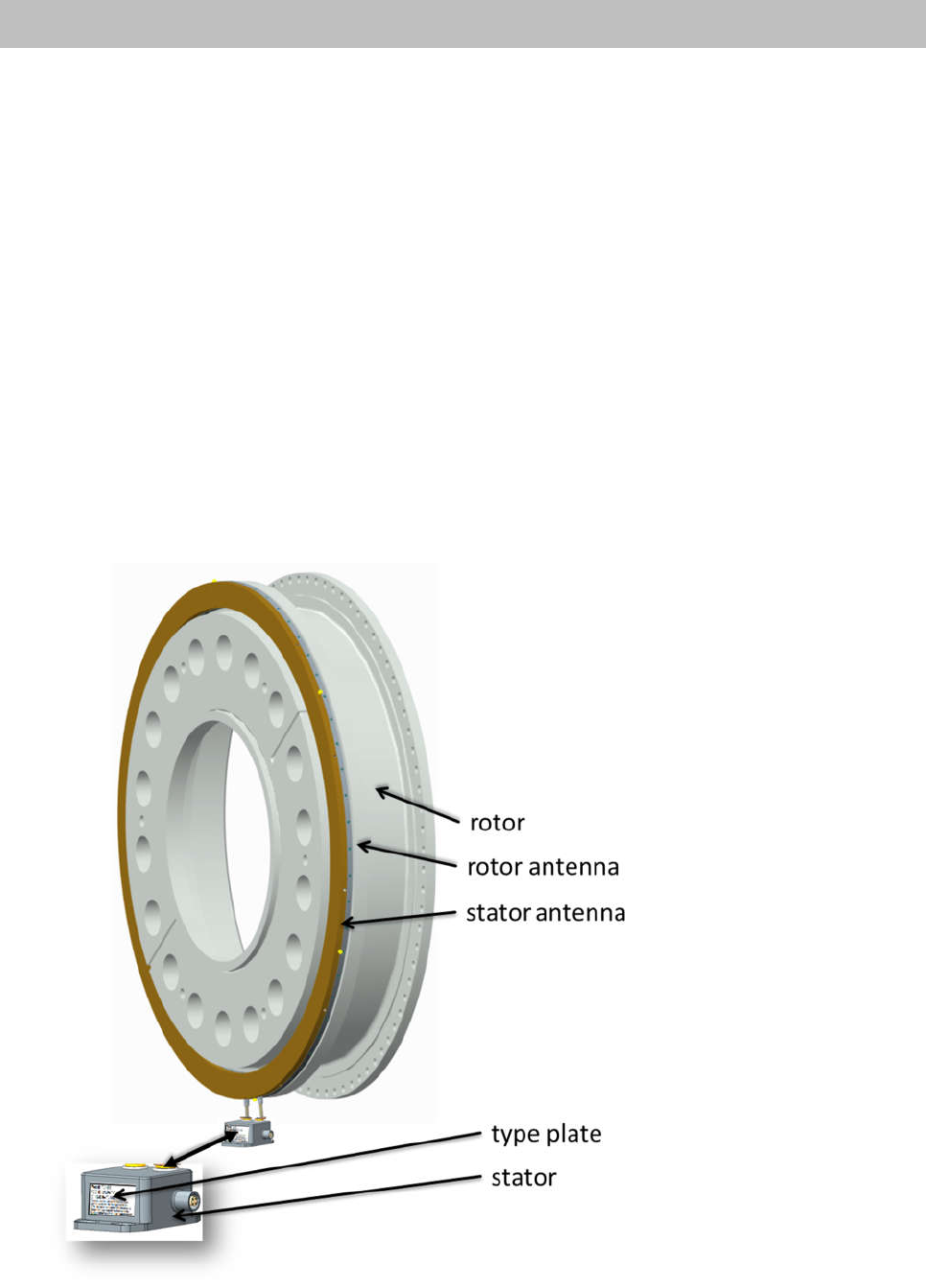
4 Structure and mode of operation
The torque flange consists of two separate parts: the rotor and the stator. The
rotor comprises the measuring body and the signal transmission elements.
Strain gauges (SGs) are installed on the measuring body. The rotor electron-
ics for transmitting the bridge excitation voltage and the measurement signal
are located centrally in the flange. The transmitter coils for contactless trans-
mission of excitation voltage and measurement signal are located on the
measuring body's outer circumference. The signals are sent and received by
a separable stator antenna. The antenna has to be mounted close to the rotor
antenna. The connection cable connects the stator antenna with the evaluation
unit which contains the electronics for voltage adaptation and the signal
conditioning.
Connector plugs for the torque signal and the voltage supply are located on
the evaluation unit. The stator antenna should be mounted tangential with
some gap to the rotor antenna (see chapter 5).
Fig 4.1: Mechanical construction in principle
4
HBM: Business Document
Fig 4.2: Mechanical construction of stator with mounted shielding
Important
The use of the shielding plates is important to ensure compliance with FCC
regulations. If the shielding plates has to be removed for any purpose (e.g.
installation or maintenance), they must be replaced in the original position
before the product is used.

5
HBM: Business Document
5 Mechanical installation
5.1 Important precautions during installation
NOTE
A torque flange is a precision measurement element and therefore needs
careful handling. Dropping or knocking the transducer may cause permanent
damage. Make sure that the transducer cannot be overloaded, even while it is
being mounted.
Handle the transducer with care.
Check the effect of bending moments, critical rotational speeds and natural
torsional oscillations, to prevent the transducer being overloaded by
increases in resonance.
Make sure that the transducer cannot be overloaded.
WARNING
There is a danger of the transducer breaking if it is overloaded. This can
cause danger for the operating personnel of the system in which the
transducer is installed.
Implement appropriate safety measures to avoid overloads and to protect
against resulting dangers.
If alternating loads are expected, use thread locker (medium strength, e.g.
LOCTITE No. 242) to fix the screws into the threaded holes to exclude
loss of tightening stress due to screw slackening.
Comply with the mounting dimensions to enable correct operation.
Under no circumstances should the permissible limits specified for bending
moments, lateral and longitudinal forces be exceeded. Due to the torque
flange's high torsional stiffness, dynamic shaft train changes are kept to a
minimum.

6
HBM: Business Document
Important
Even if the unit is installed correctly, the zero point adjustment made at the
factory can shift by up to approx. 0.5% of the sensitivity. If this value is
exceeded, we advise you to check the mounting conditions. If the residual
zero offset when the unit is removed is greater than 1% of the sensitivity,
please send the transducer back to the Darmstadt factory for testing.
5.2 Conditions on site
The torque flange must be protected against coarse dirt particles, dust,
oil, solvents and humidity.
There is wide ranging compensation for the effects of temperature on the out-
put and zero signals of the transducer (see “Specifications" section). If there
are no static temperature ratios, for example, because of the temperature
differences between the measuring body and the flange, the values given in
the specifications can be exceeded. In this case, ensure static temperature
ratios by cooling or heating, depending on the application. As an alternative,
check if thermal decoupling is possible, e.g. by means of heat radiating
elements such as multiple disc couplings.
5.3 Installation orientation
The torque flange can be installed with any orientation.
With clockwise torque load, the output signal is from 10 kHz to 15 kHz
corresponding zero to nominal torque load.
7
HBM: Business Document
5.4 Installation
Please mount the rotor & stator simultaneous to its final position, so that you
don’t need to separate the stator winding. The stator antenna should only be
separated in case of an emergency.
For dismounting instructions please contact the responsible HBM sales
engineer.
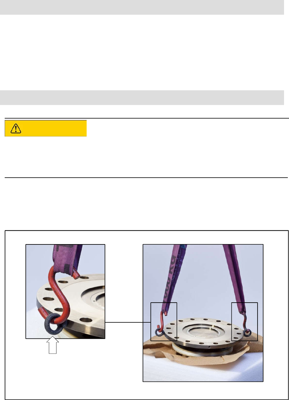
5.5 Preparing for the rotor mounting (exemplary)
CAUTION
The rotor is very heavy (approx. 370kg)!
Use a crane or other suitable lifting equipment to lift it out of its packaging and
install it.
Use flexible eye bolts as transport and mounting aids. Hook the lifting
equipment to these eye bolts as this ensures that the rotor is lifted
horizontally out of the packaging (see Fig 4.1).
Transport and mounting eye bolts
Fig 5.1: Transport and mounting eye bolts on the
rotor
8
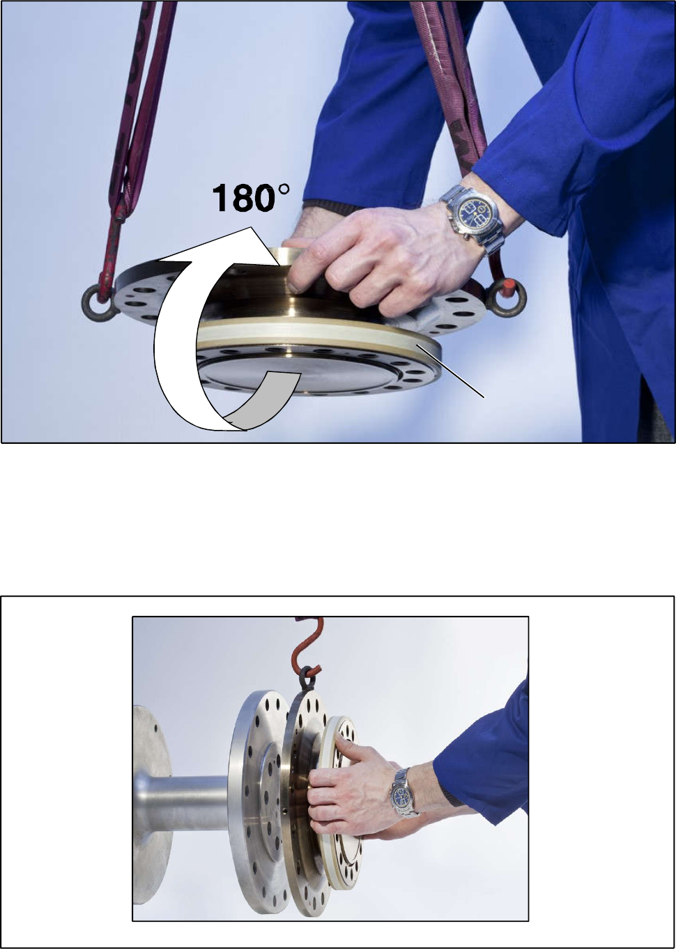
HBM: Business Document
1. Lift the rotor out of the packaging, rotate horizontally by 180°, so that
the bigger flange is pointing upwards (see exemplary Fig 5.1).
Flange B
Fig 5.2: Rotating the
rotor
2. Place the rotor carefully onto a clean and stable table.
3. If the rotor is to be installed horizontally as shown in Fig 5.3, remove one
mounting eye bolt. Both mounting eye bolts can initially remain in the
flange for vertical installation.
Fig 5.3: Rotor installation
(horizontal)

9
HBM: Business Document
4. Clean the plane surfaces of the transducer flange and the counter flange.
For safe torque transfer, the faces must be clean and free from grease.
Use a piece of cloth or paper soaked in solvent. Make sure that no solvent
drips into the inside of the transducer and that the transmitter coils are not
damaged during cleaning.
5. Fasten the lifting equipment to the mounting eye bolt(s).
6. Carefully lift up the rotor and move it to the mounting position (see Fig 5.1).
5.6 Mounting the rotor
1. Prior to installation, clean the plane faces of the transducer flange
and the counter flange.
For safe torque transfer, the faces must be clean and free from grease.
Use a piece of cloth or paper soaked in solvent. When cleaning, make
sure that you do not damage the transmitter winding.
Important
If alternating loads are expected, use thread locker (medium strength,
e.g. LOCTITE No. 242) to glue the screws into the counter thread to
exclude loss of tightening stress due to screw slackening.
3. Fasten all screws with the specified torque.
4. Now remove the ring bolts and mounting ring(s).
Important
Keep them in a safe place for future dismounting.
10
HBM: Business Document
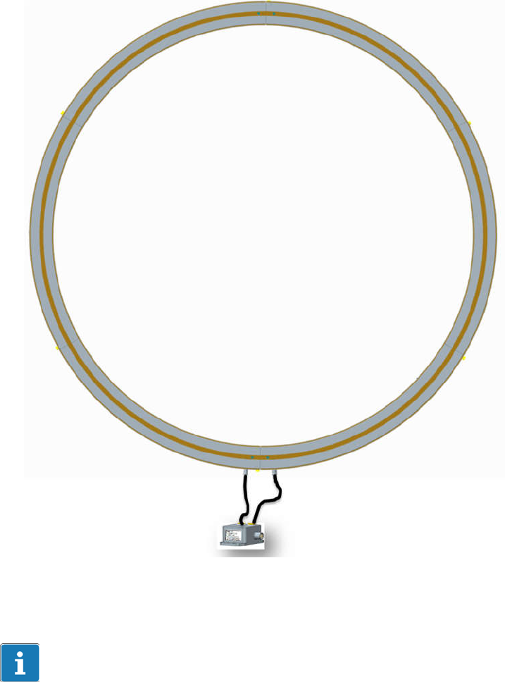
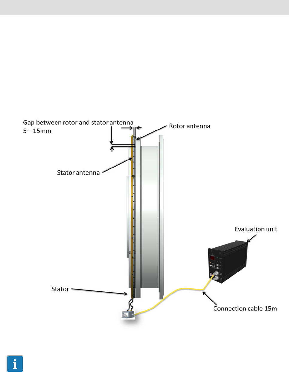
5.7 Installing the telemetry system
The telemetry system consists of the following component parts:
Rotor antenna
Stator antenna
Stator
Evaluation unit
Connection cable
Fig 5.4: Component parts
Important
Do not bend the connection cable
Do not shorten or stretch the connection cable
Do not guide the cable close to energy- or power circuit lines
The stator antenna has to be mounted directly above the rotor antenna
The stator antenna has to be mounted in the middle of the adjustment
range of the rotor antenna
11
HBM: Business Document
The stator antenna must not touch the rotor antenna
CAUTION
At all mounting- dismounting or repair operations, switch of the power
supply of the system.
Connectors must not be under electric tension while it will be connected
or disconnected
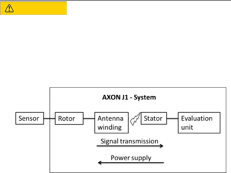
5.7.1 Measuring setup
Fig 5.5: Block diagram
12
HBM: Business Document
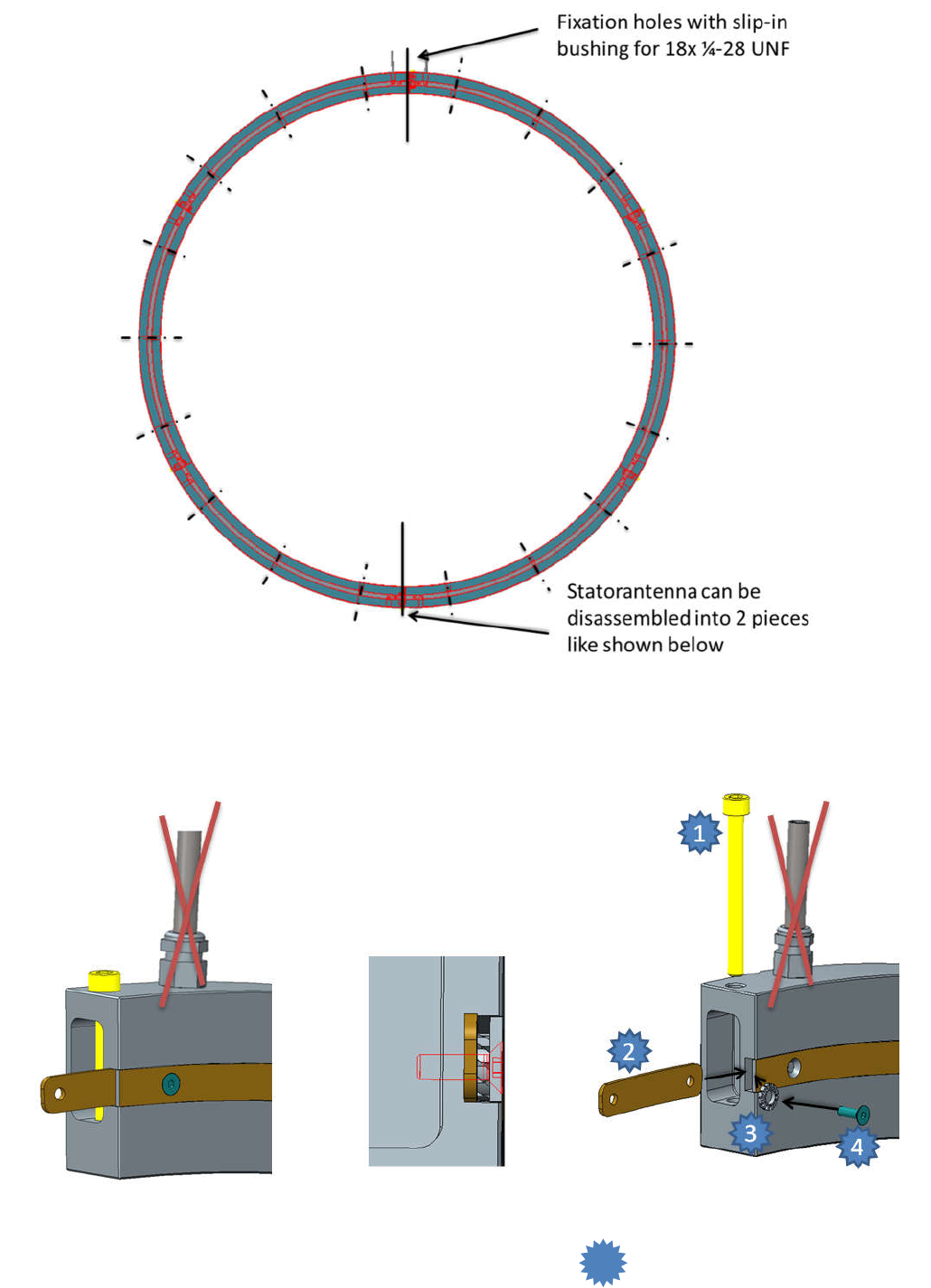
5.7.2 Instruction for installation
Fig 5.6: Stator antenna supports
Fig 5.7: Disassembling the stator antenna on lower connection.
On upper connection only needs to be removed.
1
13
HBM: Business Document
5.7.3 Calibration signal
The torque transducer delivers an electrical shunt signal that can be activated
by using switch (15) on the evaluation unit. See also 5.7.5
the transducer should not be under load when the shunt signal is being
measured, as the shunt signal is mixed additively.
5.7.4 Stator antenna
The cable connection between stator antenna and evaluation unit is realized
with a coaxial cable.
NOTE
When you connect the stator antenna, please take regard to a stress
relief
Please tighten the connection screws with the appropriate tightening
torque.
Use thread locker (medium strength, e.g. LOCTITE No. 242) to glue the
screws into the counter thread to exclude pre-stressing loss due to screw
slackening.
Allign the stator like shown in the picture below
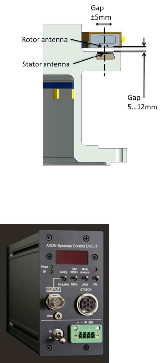
14
HBM: Business Document
Fig 5.8: Axial Alignment in principle
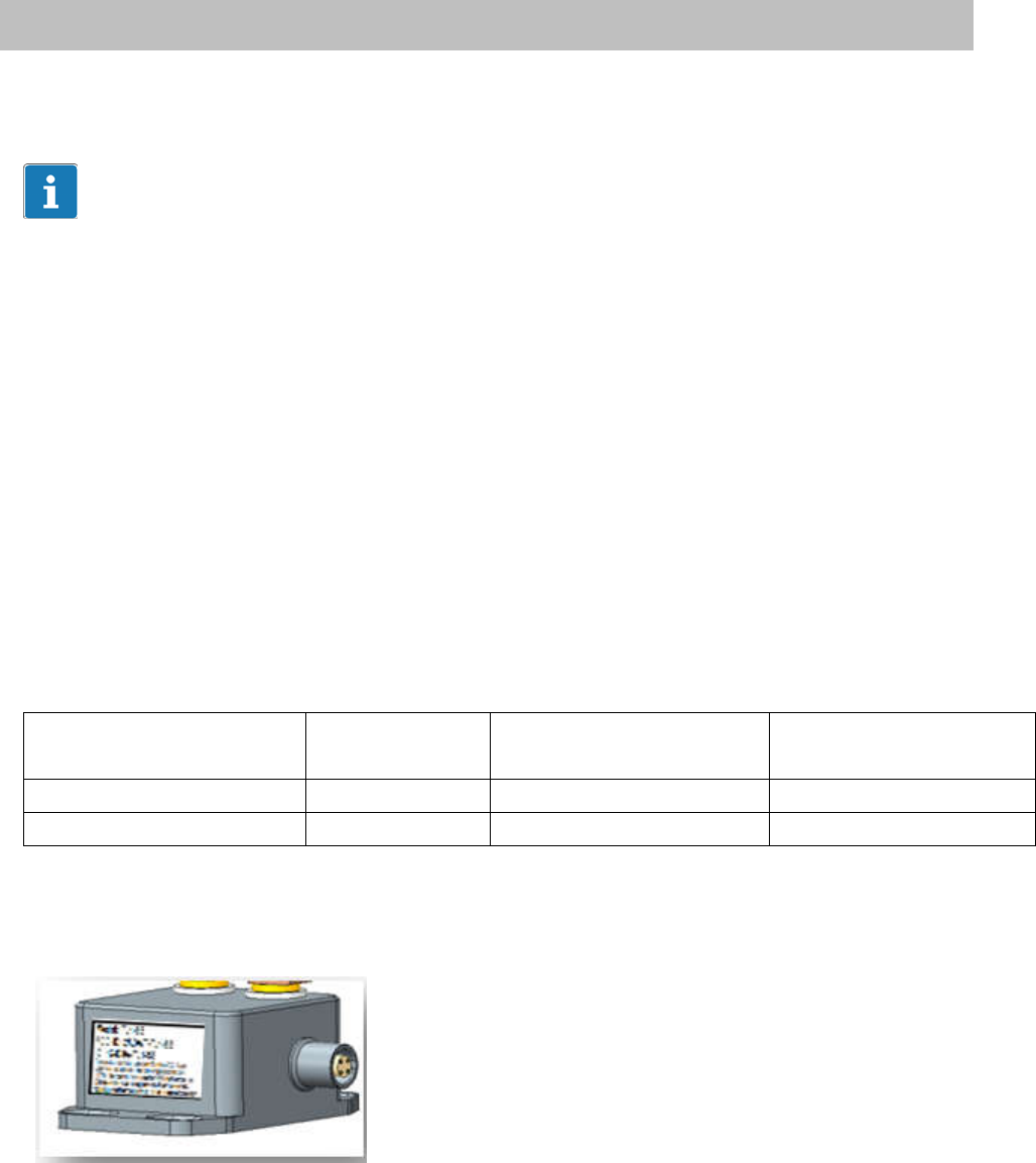
5.7.5 Evaluation unit
Fig 5.9: Control unit
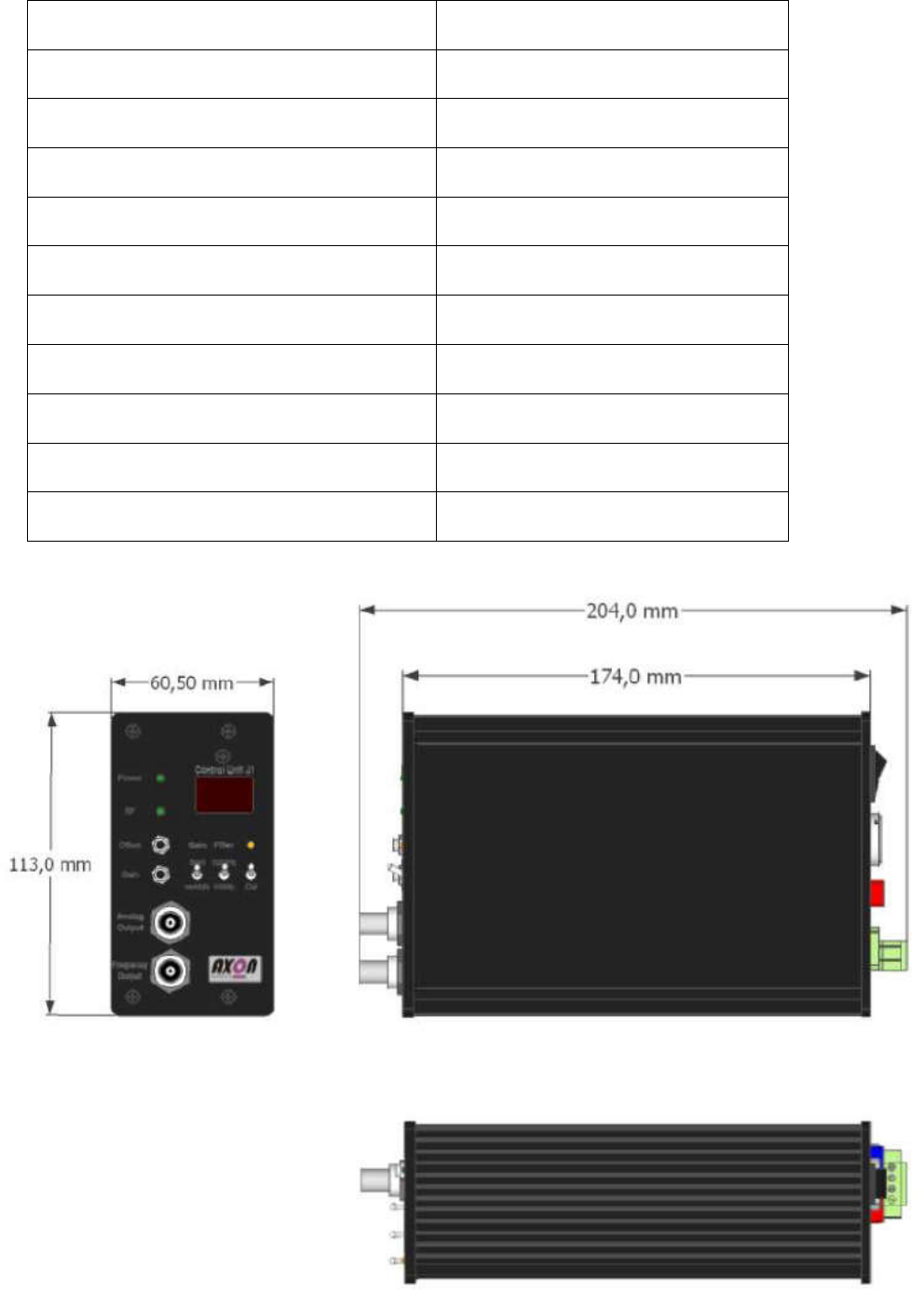
15
HBM: Business Document
Technical details
Supply voltage
9…36 VDC
Max. power consumption
30 VA
Signal bandwidth
Switchable 1000 Hz / 100Hz
Voltage output
±10 V
Frequency output
5 … 15 kHz
Signal-to-noise ratio
63dB (1000Hz) / 83dB (100Hz)
Signal transit time
450µs
Wireless shunt calibration
Key button at control unit
Protection class
IP40
Weight
approx.. 700 gramm
Temperature range
-10 … +70 °C
Fig 5.10: Dimensions of the control unit

16
HBM: Business Document
Fig 5.11: Functions of the control unit front side
1 Display
Information of Voltage or Current output. The display is only for monitoring
purposes, but doesn’t provide the accuracy of an measuring device.
2 Power on
The LED signalizes the ON / OFF status of the device
3 RF Level
The LED shows a sufficient signal level for data transmission from rotor to
stator.
4 Signal output
Analog output signal (±10V) or Frequency output (10±5kHz) with TTL level
5 Offset
Potentiometer to adjust the Offset between ±1V. This function only effects the
voltage output, not the frequency output.
6 Main Switch
ON / OFF switch
7 Screw terminal Power connection (+)
9 VDC … 36 VDC
8 Screw terminal Power connection (-)
9 VDC … 36 VDC
9 Screw terminal RF-voltage Output
Shows power of the received RF signal and should be >3,4V
10 Screw terminal earthing (GND)
Ground connection of the telemetry system
17
HBM: Business Document
11 Stator connection
Connector for stator connection
12 Mode switch output signal
Chooses the form of the output signal, that will be handed out on BNC
connector “4”
Analog: Analog voltage output ±10V
Frequency: Frequency output 10kHz±5kHz, Voltage with TTL-level
13 Filter switch
Switch for selecting the signal bandwidth.
14 Mode switch measuring mode for the analog output
With this switch you can adjust the offset of the analog output (Potentiometer
Nr.5)
Measure: Normal operating mode. Signal output (connector No. 4) shows the
zero point and by Potentiometer No.5 affected analog output signal.
Offset:
In this position the current zero point displacement of Potentiometer No.5 is
shown
15 Cal – function
Switch for activating the defined bridge detuning “Shunt Cal”. The LED lights for
approx. 5sec after activation of the switch. After 5sec the measuring system
returns self-dependent to operational mode.

18
HBM: Business Document
6 Electrical connection
The product offered is a special assembly for stationary systems that is not
available on the general market or a transducer for installation by system
integrators or plant manufacturers. According to EMVG1 §12 paragraph 2 and
Directive 2004/1008/EC article 13 paragraph 1 this product does not require an
EC declaration of conformity nor the CE marking.
This product is intended exclusively for subsequent processing by companies
or persons that are experts in the field of electromagnetic compatibility (EMC).
Relevant EMC protection requirements relating to the product offered are met
when the following Installation notes are observed and implemented.
However you have to install the shield of the connection cable at the shielded
housing of the electronics, to achieve the EMC-protection of the measuring
chain. Make sure that the transducer and shielding are connected extensively
to ground.
It is recommended to use interference suppression for the power supply of the
telemetry system to avoid parasitic inductions.
CAUTION
In order to fulfill all FCC requirements, the earthing of the rotor is mandatory.

19
HBM: Business Document
6.1 Connector pin assignment
BNC Connectors for voltage / frequency output
NOTE
This torque flange is only intended for operation with a DC supply voltage. They
must not be connected to older HBM amplifiers with square‐wave excitation.
This could destroy the connection board resistances or cause other faults in
the amplifiers.
6.2 Supply voltage
The transducer must be operated with a separated extra‐low voltage (supply
voltage 9…36 VDC).

20
HBM: Business Document
7 Functional testing
You can check the functionality of the rotor and the stator from the LEDs on
the evaluation unit.
It is not allowed to extend or reduce the length of the connection
cable between rotor and evaluation unit!!!
Don’t lay cable parallel to high voltage and control cable. If this is not
avoidable, please let a minimum gap of 50cm and lay the cable inside a
steel tube.
Avoid transformer, motor, gate, thyristor circuits and similarly leakage
fields.
Important
Check the calibration signal specified on the type label or test protocol.
To obtain stable conditions, the measurement should be started or the
calibration signal should be activated only once the transducer has been
warming up for 15 minutes.

21
HBM: Business Document
8 Maintenance
The torque transducer is maintenance‐free.
22
HBM: Business Document
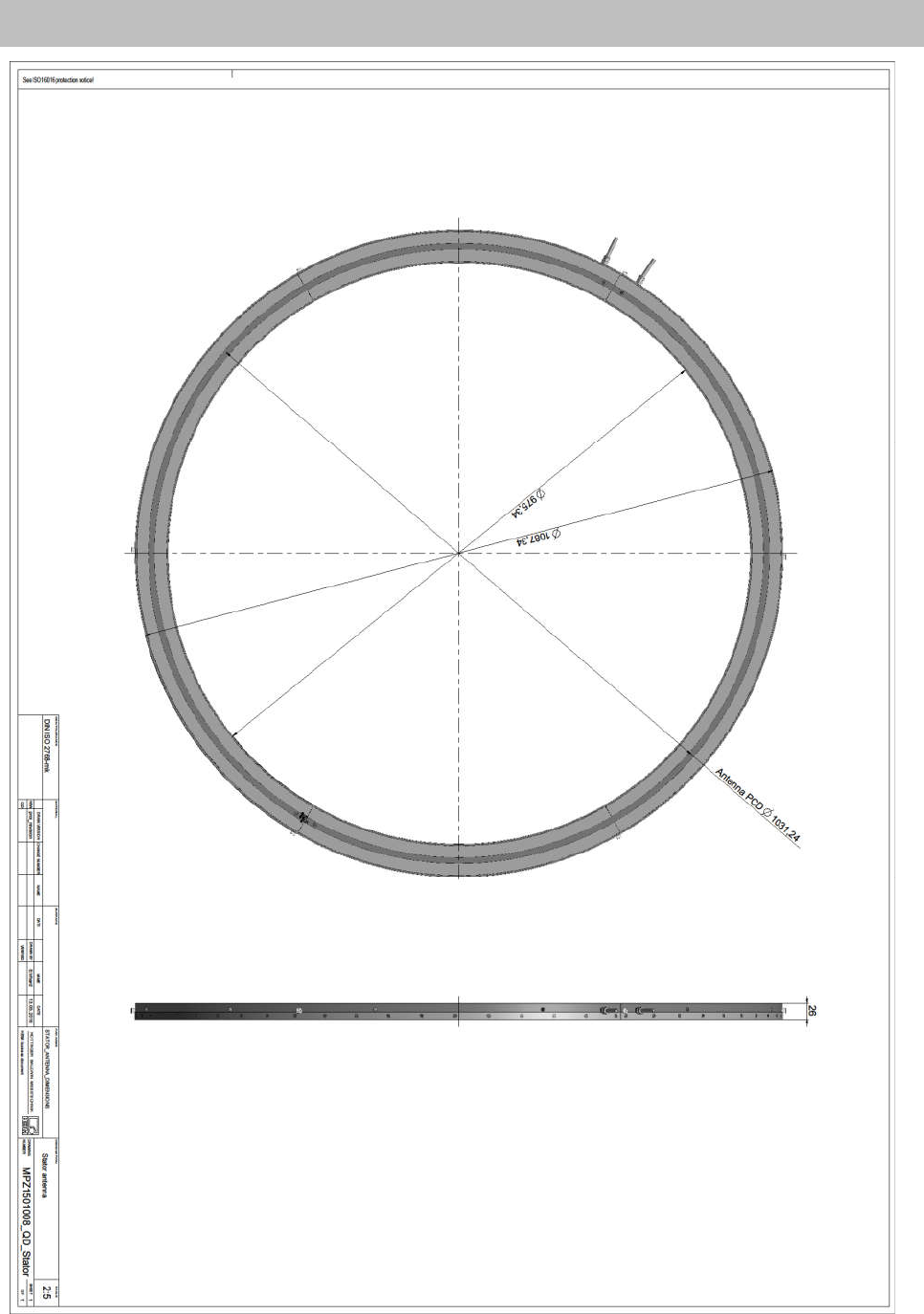
9 Dimensions of the stator antenna
23
HBM: Business Document
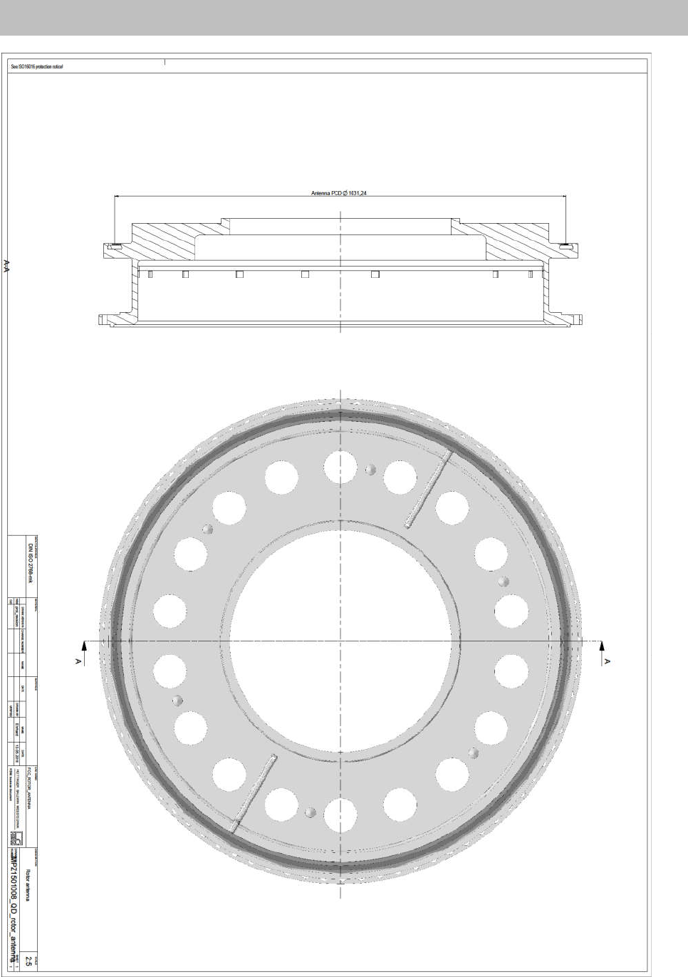
10 Dimensions of the rotor antenna

24
HBM: Business Document
11 Declaration of conformity

25
HBM: Business Document
Hottinger Baldwin Messtechnik GmbH.
Subject to modifications. All product descriptions are for
general information only. They are not to be understood
as a guarantee of quality or durability.
Hottinger Baldwin Messtechnik GmbH.
Änderungen vorbehalten. Alle Angaben beschreiben
unsere Produkte in allgemeiner Form. Sie stellen keine
Beschaffenheits- oder Haltbarkeitsgarantie im Sinne des
§443 BGB dar.
Hottinger Baldwin Messtechnik GmbH
Im Tiefen See 45 • 64293 Darmstadt •
Germany
Tel. +49 6151 803-0 • Fax: +49 6151
803-9100
Email: info@hbm.com •
www.hbm.com