Houston Radar DR1500 Doppler Speed Radar User Manual DR1500 rev1
Houston Radar LLC Doppler Speed Radar DR1500 rev1
User Manual
Page 1 of 13
Houston Radar LLC
Installation and User Manual
For
Doppler Radar DR-1500
Houston Radar LLC
13814 Sherburn Manor Dr. Cypress .TX
Http://www.Houston-Radar.com
Email: sales@Houston-Radar.com
Contact: (281) 382-7303 Rev 1, Oct 25th 2007

Page 2 of 13
This device complies with part 15 of the FCC Rules. Operation is subject to the following
two conditions: (1) this device may not cause harmful interference, and (2) this device
must accept any interference received, including interference that may cause undesired
operation.
Changes or modifications not expressly approved by the party responsible for
compliance could void the user's authority to operate the equipment.
Any modification or use other than specified in this manual will strictly void the
certification to operate the device.

Page 3 of 13
Table Of Contents
INTRODUCTION .............................................................................................................. 4
INSTALLATION ............................................................................................................... 5
Mounting:........................................................................................................................ 5
Direction Pointing:.......................................................................................................... 5
Hookup:........................................................................................................................... 5
Wire Signal Descriptions:............................................................................................... 7
USE..................................................................................................................................... 7
Infrared Remote Programming:...................................................................................... 8
DR-1500 SPECIFICATIONS........................................................................................... 13
General.......................................................................................................................... 13
Data Interfaces .............................................................................................................. 13
Mechanical.................................................................................................................... 13
Performance.................................................................................................................. 13
Advanced Statistics....................................................................................................... 13

Page 4 of 13
INTRODUCTION
Congratulations on your purchase of the Houston Radar LLC’s directional Doppler speed
radar DR-1500. This state of the art K-band microwave Doppler speed radar is
specifically designed for the license free, battery operated speed radar market, for use in
speed awareness trailers, school zones and other speed restricted traffic zone speed
awareness uses.
Utilizing the latest in high performance, ultra low power DSP (Digital Signal Processing)
technology, you will find that this high quality product meets your exacting standards for
performance and reliability.
Some of the highlights of this product include:
9 FCC approved for your convenience and piece of mind
9 Advanced DSP based performance yields consistent performance and speed detection
9 Standard serial port hookup and data format allows hassle free use in existing systems
o Use in place of existing products
o Interface to your message displays
o Use in your speed trailers
o Use in school zones
9 31mA power usage is up to 10X lower vs. competing solutions and allows use of
smaller batteries and solar panels- saving you cost
9 Ultra slim profile allows mounting in virtually any location
9 Built in clock/calendar keeps time even with DC power removed
9 Only 1 mA power consumption in standby mode
9 Optional infrared remote control allows you to change/set radar parameters including:
o Min/Max speed limit of detection
o Speed limit setting for flashing display digits
o Sensitivity setting for changing detection range
o Internal clock/calendar
o Serial port settings
o Radar built in self test
9 Now Featuring Optional integrated advanced statistics package with:
o Multi-vehicle/multi-lane tracking allows better accuracy over competing
units
o 2 months of speed as well as count statistics saved in internal memory
o Real time clock keeps stats with date/time
o Unmatched Windows™ based “Stats Analyzer” software to download,
manage, analyze and plot your stats information from all your DR-1500
radars available as option
Page 5 of 13
INSTALLATION
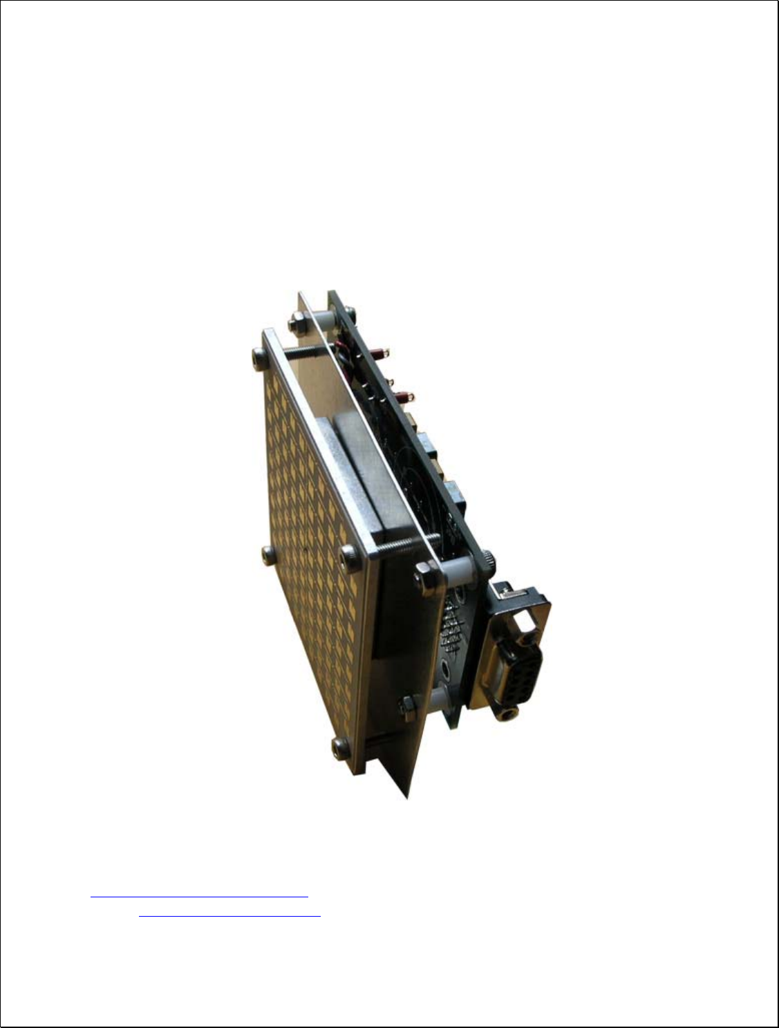
Mounting:
The DR-1500 is supplied with a mounting plate and may be conveniently mounted via 4
mounting holes inside your enclosure.
Use a “split washer” is used to ensure the mounting screw remains tight under vibration.
Direction Pointing:
The DR-1500 is directional in nature. It rejects traffic moving away from it and only
measures oncoming traffic.
If the optional stats analyzer feature is purchased with the unit, stats will
only be collected for incoming traffic. This allows you to position the unit in
a median without worry of picking up traffic on the outgoing lane
For optimal performance, keep in mind the following:
9 Radar should be mounted with the circuit board horizontal to the road.
9 Radar should be pointed into the direction of the oncoming traffic.
9 Radar should be placed along the size of the road to minimize the angle of the
oncoming traffic to the radar.
o If radar cannot be placed right along the side of the road, it should be
pointed at least 200-300 feet up the road into oncoming traffic.
9 The radar may pickup rotating fans. Avoid pointing it at fans or compressors.
9 Radar should be mounted at least 3+ feet high from the road for optimal
performance.
Hookup:
Power Input:
The DR-1500 radar can be powered from a nominal 12V DC battery and features
industry leading operational power consumption. This is up to 10X lower than competing
products.
This operational power translates directly into a longer battery life or gives you an option
to power the unit from smaller batteries that would also require smaller solar panels.

Page 6 of 13
Serial Connection:
The DR-1500 features a dual RS232 and RS485 output that are active at the same time
giving the user an option to connect serial outputs to either port (see serial port diagram).
Speed data is output serially in mph (or Kmph if set via the remote) as three ASCII digits
in the following format:
nnn\n\r
where:
nnn : The three digit ASCIII speed digits in mph/Kmph
\n\r : A new line followed by a carriage return character
This format is compatible with other industry formats including a standard RS232 serial
port on a PC, message boards and speed displays.
Log/Statistics Storage:
The DR-1500 radar has capacity to store the last 60 days of traffic statistics in 5 minute
bins and features a clock/calendar that retains time even when external power is removed.
The clock is used to time stamp the collected statistics.
This feature is an add-on software option. Please contact Houston Radar LLC for
purchase of this option.
Page 7 of 13
Wire Signal Descriptions:
The DR-1500 features an output that can wake up an external display
panel(s) to bring it out of power saving mode when a vehicle is detected. If
the panels you hook to the radar do not feature such an input, this wire
should remain unconnected.
If you use the Houston Radar LED display panels, tape off wire #’s 2,3
and 10. Connect the remainder wires to the similar # wires in the cable
supplied with the panels.
If you use other industry panels, tape off wires #3,4,6 and 10. You will only
need to connect wire #2 to the RS232 input of the panel and wire #5 to the
“ground” or –ve of the panel. Please consult the manual of the panel you
are connecting to.
USE
Turn on the power to the DR-1500 to make it operational. No other action is required.
The radar will output data over the serial port(s) whenever it detects a vehicle that is
above the programmed lower speed limit and below the programmed high limit. The
default limits are set at 5mph and 99mph at the factory.
Using the IR remote control, program the high limit to blank out the speed display above
this limit. This will prevent “racing against the radar” by denying a speed feedback
display of excessive speeds as determined by you.
Wire # Signal Name Direction Description
1 +12V DC Input Radar + Power Supply. Connect to
battery +
2 RS 232 TX Output RS232 transmit output from Radar
3 RS 232 RX Input RS232 receive input. Required only if
connected to PC to download stats from
unit
4 RS 485 + I/O RS485 “+” terminal.
5 GND Input System Ground. Connect to battery -
6 RS 485 - I/O RS485 “-” terminal.
7 Panel Power Save Output See Note 1.
8 Panel Power Save Output Connected to wire #7. See Note 1.
9 GND Input System Ground. Connected to wire #5.
10 Reserved N/A Reserved for future use. Do not connect
Page 8 of 13
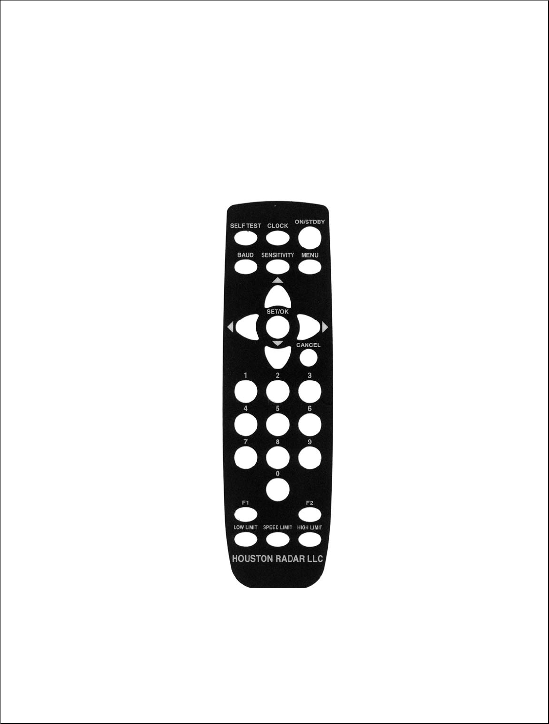
Infrared Remote Programming:
The DR-1500 operational parameters may be accessed and programmed in the field
using an optional infrared remote control. These features may only be programmed in
conjunction with speed display panels that support visual feedback of ASCII chars sent
on the serial data line. Contact the factory for availability and a list of panels that support
this feature. However, the Houston Radar LED panels do support this feature.
Optional DR-1500 Remote Control

Page 9 of 13
This section describes these features and how to program the values into the radar using
the IR remote.
Apply +12 V DC battery power to the radar power wires.
Stand in front of the radar, between 2 and 10 feet away and point the IR remote at the
front face of the radar (the IR receiver window is the small circular hole below the
rectangular window). Then execute the following steps to program the desired functions:
Speed Low Limit:
Use this feature to only give speed awareness feedback to vehicles over a certain limit,
for example the road speed limit. This would setup the system to not display the speeds
of vehicles that are below the limit, rather only display the speed of vehicles that are
above the limit. With panels that support the “power saving mode”, this can result in very
significant power savings and significantly extend operation time between battery
recharges.
1. Press the “LOW LIMIT” key once
[The current value will be displayed on the display]
2. Enter the numeric speed for the low limit (or use the Up/Down arrow keys)
3. Press “SET/OK” to save the limit in the radar or press “CANCEL” at any time
before “SET/OK” to cancel this operation
Speed High Limit:
Use this feature to blank out the speed display of vehicles over this limit. You can use
this feature to defeat “racing against the radar” issue.
1. Press the “HIGH LIMIT” key once
[The current value will be displayed on the display]
2. Enter the numeric speed for the high limit (or use the Up/Down arrow keys)
3. Press “SET/OK” to save the limit in the radar or press “CANCEL” at any time
before “SET/OK” to cancel this operation
Speed Limit:
Use this feature to flash the speed display of vehicles over this limit. You can use this
feature to draw attention to the speed of vehicles going over the set limit.
1. Press the “SPEED LIMIT” key once
[The current value will be displayed on the display]
2. Enter the numeric speed for the speed limit in effect at the current location
3. Press “SET/OK” to save the limit in the radar or press “CANCEL” at any time
before “SET/OK” to cancel this operation
Page 10 of 13
Detection Sensitivity:
Use this feature to set the detection sensitivity. This affect the distance the radar detects
objects. You may set the sensitivity from a value of “10” to “99”. Each value is an
approximate percentage of maximum detectable range (typically 500 to 600 feet for the
DR-1500). Setting the value to “99” sets the range to maximum. This is due to typically
only two display digits being used with the radar.
1. Press the “SENSITIVITY” key on the remote once
[The current value will be displayed on the display]
2. Enter the desired sensitivity as a two digit value from 10 to 99 percentage of
maximum range of the radar or use the Up/Down arrow keys
3. Press “SET/OK” to save the limit in the radar or press “CANCEL” at any time
before “SET/OK” to cancel this operation
Internal Clock:
Use this feature to set the internal clock of the radar. This is only required if you have
purchased the optional statistics collection package. The unit will keep time even with
external power removed.
It may be more convenient to set the clock of the radar by connecting a
serial cable to the radar and using the “Houston Radar Stats Analyzer”
program. A button in the program allows you to sync the radar clock with
your computer clock. However, the following steps may be used in the
field to either check or set the time of the radar
1. Press the “CLOCK” key on the remote
[The radar will display “SE”- short for seconds of the current time]
2. Press the “UP” arrow key on the display to move to the minutes option
[The radar will display “MI”- short for minutes of the current time]
3. Press the “UP” arrow key on the display to move to the hours options
[The radar will display “HO”- short for hours of the current time]
4. Press the “UP” arrow key on the display to move to the day of the month option
[The radar will display “DA”- short for day of the current day of the month]
5. Press the “UP” arrow key on the display to move to the month option
[The radar will display “MO”- short for month of the current date (January is “1”,
December is “12”)]
6. Press the “UP” arrow key on the display to move to the month option
[The radar will display “YE”- short for year of the current date (2000 is “00”,
2006 is “06” etc.)]
To set any of the above value, navigate to the desired option, then press
“SET/OK”. At this point the radar will display the current option. You may then
directly enter the desired value for the option and press “SET/OK” again.
Page 11 of 13
Press “CANCEL” to at any time or after the final “SET/OK” to exit the menu.
Self Test:
Press the “SELF TEST” key on the remote to instruct the radar to perform a self test. The
radar will display “OK” after about 6 seconds if the test passes. It will then reset and
count up from 1 to 9 and then the display will blank out.
Display Units (MPH or KMPH):
1. Press the “F1” key on the remote
[The radar will display “F1”]
2. Press the “4” key
[The radar will display the current value code. 0 = MPH, 1 = KMPH]
3. Press 0 to display speed in MPH or 1 to display speed in KMPH
4. Press “SET/OK” key to save in memory.
[Radar will restart and count up from 1 to 9 and the display will go blank. The
unit is now ready]
Reset Factor Settings:
1. Press the “F1” key on the remote
[The radar will display “F1”]
2. Press the “3” key on the remote
3. Press the “SET/OK”
[Radar will display “OK” and then restart and count up from 1 to 10 and the
display will go blank. This will reset the baud rate to 115200, display units to
MPH, low limit to 5mph, high limit to 99mph and speed limit to 99mph].
Set Serial Baud Rate:
This configuration is only required at the factory when mating the radar to
the selected speed digit display panels. Once configured, the radar keeps
the configuration even after power is removed and need not be
reconfigured.
The optional statistics package can communicate with the PC to download
saved statistics at any set baud rate. The baud rate of the radar is
automatically detected by the stats package.
Use this feature to set the baud rate of the serial data port by following the following
steps:

Page 12 of 13
Select the baud rate from the table below and note the key combination from the “Key #”
column in the table.
Press the “Set Baud “ key on the IR remote followed by the two digit numeric code from
the desired baud rate row picked in #3 above, followed by the “Select” key.
You may press cancel any time in the above procedure to cancel programming the new
baud rate. The new baud rate is not stored and changed till you press the “Select” key.
Your baud rate is now programmed in permanent memory and if you have speed display
panels hooked up, they will display the two digit key combination that you entered to
select the baud rate.
If you want to change the baud rate of the radar, you can simply follow the above
procedure and select a new baud rate any number of times.
Baud Rate (bps) # Data Bits # Stop Bits Parity Key #
1200 7 1 Even SET BAUD + 10
1200 7 1 Odd SET BAUD + 11
1200 7 1 None SET BAUD + 12
1200 8 1 None SET BAUD + 13
2400 7 1 Even SET BAUD + 20
2400 7 1 Odd SET BAUD + 21
2400 7 1 None SET BAUD + 22
2400 8 1 None SET BAUD + 23
9600 7 1 Even SET BAUD + 30
9600 7 1 Odd SET BAUD + 31
9600 7 1 None SET BAUD + 32
9600 8 1 None SET BAUD + 33
115,200 8 1 None SET BAUD + 43

Page 13 of 13
DR-1500 SPECIFICATIONS
General
Operating Band K-Band
Frequency 24.1 GHz ±5Mhz
Power Output 5mW
Antenna Beam Angle 11x11 degrees
Polarization Linear
Supply Voltage 9V DC to 18V DC
Reverse Battery Protected
Detection Range Typically 500+ feet
Nominal Current Draw 31 mA nominal (+12V DC)
Operating Temp. -22°F to +185°F
(-30°C to +85°C)
Weatherproof No
IR Remote Programmable Yes
Data Interfaces
Serial Communication RS232 and RS485
Data Rate Baud Rates from
1200 to 115200 baud
Data Format Selectable via IR Remote
(Please refer to user manual)
Mechanical
Weight 0.25 lb
Thickness .95 inches
Cable Exit DB9 from side
Mounting 4X 3mm dia holes on mounting plate
Width ~3x3 inches
Performance
Accuracy ±0.1 mph
Speed Range 5 mph to 105 mph
(8 Kmph to 168 Kmph)
Detection Range Typically 500+ feet detecting compact
car, further with larger vehicles
Advanced Statistics
Storage Last 60 days in 5 minute bins and 20 speed bins
Multi-vehicle capable Yes (in multiple lanes)
Download speed Typically 60 seconds for 60 days data