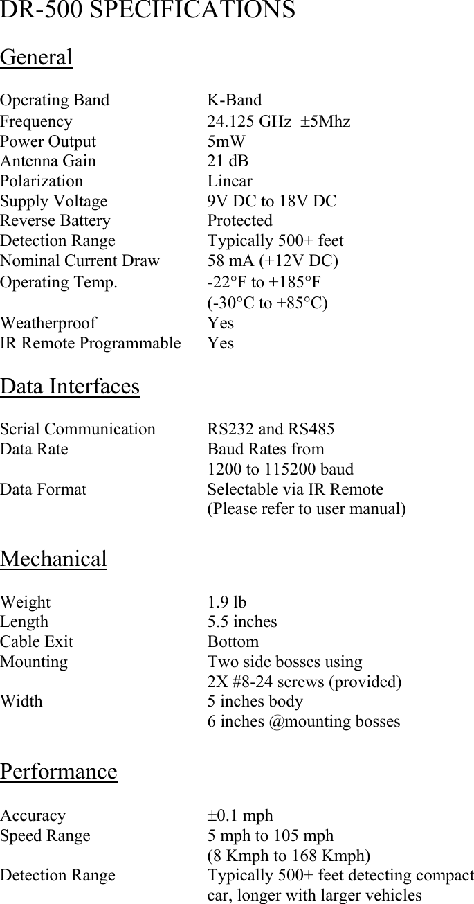
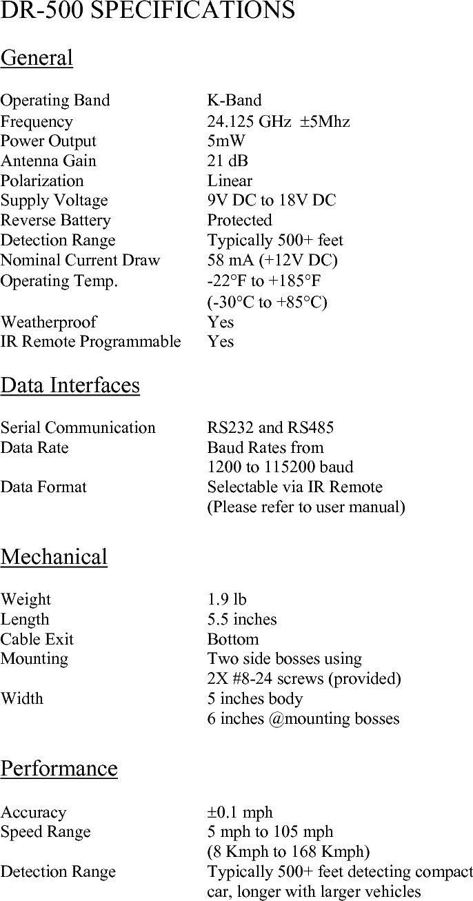
Houston Radar DR500 DR500 Doppler Radar User Manual DR500UserManual

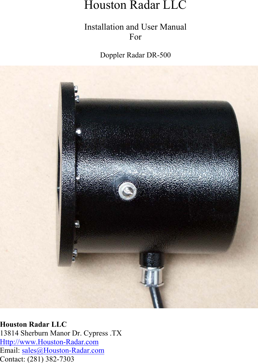
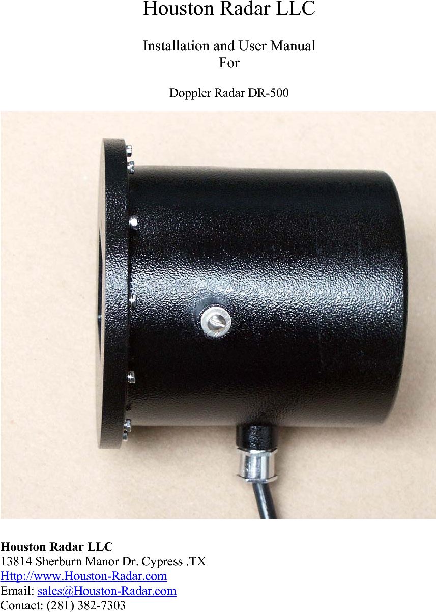
Houston Radar LLC DR500 Doppler Radar DR500UserManual

Manual

 Houston Radar LLC  Installation and User Manual For  Doppler Radar DR-500                               Houston Radar LLC 13814 Sherburn Manor Dr. Cypress .TX Http://www.Houston-Radar.com Email: sales@Houston-Radar.com Contact: (281) 382-7303
This device complies with part 15 of the FCC Rules. Operation is subject to the following two conditions: (1) this device may not cause harmful interference, and (2) this device must accept any interference received, including interference that may cause undesired operation.
  Table Of Contents  Table Of Contents........................................................................................................... 3 INTRODUCTION .............................................................................................................. 4 INSTALLATION ............................................................................................................... 4 Mounting:........................................................................................................................ 4 Direction Pointing:.......................................................................................................... 4 Hookup:........................................................................................................................... 5 USE ..................................................................................................................................... 6 Infrared Remote Programming: ...................................................................................... 6 DR-500 SPECIFICATIONS............................................................................................... 9 General............................................................................................................................ 9 Data Interfaces ................................................................................................................ 9 Mechanical......................................................................................................................9 Performance .................................................................................................................... 9
INTRODUCTION  Congratulations on your purchase of the Houston Radar LLC’s directional doppler speed radar DR-500. This state of the art K-band microwave Doppler speed radar is specifically designed for the license free, battery operated speed radar market, for use in speed awareness trailers, school zones and other speed restricted traffic zone speed awareness uses.  Utilizing the latest in high performance, ultra low power DSP (Digital Signal Processing) technology, you will find that this high quality product meets your exacting standards for performance and reliability.  Some of the highlights of this product include:  9 FCC approved for your convenience and piece of mind 9 Advanced DSP based performance yields consistent performance and speed detection 9 Standard serial port hookup and data format allows hassle free use in existing systems o Use in place of existing products o Interface to your message displays o Use in your speed trailers o Use in school zones 9 Up to 5X lower operational power consumption vs. competing solutions allows use of smaller batteries and solar panels- saving you cost 9 Rugged weatherproof enclosure features side mounts and short depth 9 Built in clock/calendar allows pre-programmed times of operation 9 Only 50 micro amps power consumption in standby mode 9 Optional infrared remote control allows you to change/set: o Min/Max speed limit of detection o Internal clock/calendar and operational times o Serial port settings  INSTALLATION  Mounting:  The DR-500 is supplied in a weatherproof enclosure and may be conveniently mounted via the side-mounting bosses, outside the speed trailer enclosure to facilitate pointing it into the oncoming traffic.  Two #8-10 size screws are required for side boss mounting (provided). Care must be take to ensure that the provided “split washer” is used to ensure the mounting screw remains tight under vibration.  Direction Pointing:
The DR-500 is directional in nature. It rejects traffic moving away from it and only measures oncoming traffic.  For optimal performance, keep in mind the following:  9 Radar should be mounted with the mounting bosses horizontal to the road. 9 Radar should be pointed into the direction of the oncoming traffic. 9 Radar should be placed along the size of the road to minimize the angle of the oncoming traffic to the radar. o If radar cannot be placed right along the side of the road, it should be pointed at least 200-300 feet up the road into oncoming traffic. 9 The radar will pickup rotating fans. Avoid pointing it at fans or compressors. 9 Radar should be mounted at least 3 feet off the road for optimal performance.  Hookup:  Power Input:  The DR-500 radar is designed to be powered from a nominal 12V DC battery and features industry leading operational power consumption, which can be as low as 5X less than other similar radar designs on the market.  This operational power translates directly into a longer battery life or gives you an option to power the unit from smaller batteries which would also require smaller solar panels for charging resulting in material cost savings in an entire solar charged battery operated speed awareness trailer.   Serial Connection:  The DR-500 features a dual RS232 and RS485 output that are active at the same time giving the user an option to connect serial outputs to either port (see serial port diagram).  Speed data is output serially in mph as three ASCII digits in the following format:  nnn\n\r  where: nnn : The three digit ASCIII speed digits in mph \n\r : A new line followed by a carriage return character  This format is compatible with other industry formats including a standard RS232 serial port on a PC, message boards and speed displays.  Log/Statistics Storage:
The DR-500 radar has capacity to store up to 4Mb of traffic statistics and features an clock/calendar that retains time even when external power is removed. The clock is used to time stamp the collected statistics.  This feature is an add-on software option. Please contact Houston Radar LLC for details and availability.   Note1: The DR-500 features an output that can power up an external display panel to bring it out of power saving mode when a vehicle is detected. If the panels you hook to the radar do not feature such an input, this wire should remain unconnected.  USE  Turn on the power to the DR-500 to make it operational. No other action is required. The radar will output data over the serial port(s) whenever it detects a vehicle that is above the programmed lower speed limit and below the programmed high limit. The default limits are set at 5mph and 99mph at the factory.  Using the IR remote control, program the high limit to blank out the speed display above this limit. This will prevent “racing against the radar” by denying a speed feedback display of excessive speeds as determined by you.   Infrared Remote Programming:  The DR-500 features various built in functions that may be accessed and programmed in the field using an optional infrared remote control. These features may only be programmed in conjunction with speed display panels that support visual feedback of ASCII chars sent on the serial data line. Contact the factory for availability and a list of panels that support this feature. Wire #  Signal Name  Direction Description 1  +12V DC  Input  Radar + Power Supply. Connect to battery +2  RS 232 TX  Output  RS232 transmit output from Radar 3  RS 232 RX  Input  RS232 receive input. Test only. 4  RS 485 +  I/O  RS485 “+” terminal. 5  GND  Input  System Ground. Connect to battery - 6  RS 485 -  I/O  RS485 “-” terminal. 7  Panel Power Save  Output  See Note 1. 8  Panel Power Save  Output  Connected to wire #7. See Note 1. 9  GND  Input  System Ground. Connected to wire #5. 10  Reserved  N/A  Reserved for future use. Do not connect
 This section describes these features and how to program the values into the radar using the IR remote.  Stand in front of the radar, between 2 and 10 feet away and point the IR remote to the front face of the radar (the IR receiver window is the small circular hole below the rectangular window). Then follow the following steps to program the following functions:  Speed Low Limit:  Use this feature to only give speed awareness feedback to vehicles over a certain limit, for example the speed limit. This would setup the system to not display the speeds of vehicles that are below the limit, rather only display the speed of vehicles that are above the limit. With panels that support the “power saving mode”, this can result in very significant power savings and significantly extended operation time between battery recharges.  1. Press the “System Configuration” button once. 2. Press the Up/Down key(s) till you see “Lo” on the display. 3. Press the “Select” key. This will display the current “Speed Low Limit” value. 4. Using the numeric keypad or the “Left/Right” keys, set the “Speed  Low Limit” that you require. 5. Press the “Select” key to save the new “Speed Low Limit” value in the radar.  Speed High Limit:  Use this feature to blank out the speed display of vehicles over this limit. You can use this feature to defeat “racing against the radar” issue.  1. Press the “System Configuration” button once. 2. Press the Up/Down key(s) till you see “Hi” on the display. 3. Press the “Select” key. This will display the current “Speed High Limit” value. 4. Using the numeric keypad or the “Left/Right” keys, set the “Speed  High Limit” that you require. 5. Press the “Select” key to save the new “Speed High Limit” value in the radar.
 Set Serial Baud Rate:  Note: This configuration is only required at the factory when mating the radar to the selected speed digit display panels. Once configured, the radar keeps the configuration even after power is removed and need not be reconfigured.  Use this feature to set the baud rate of the serial data port by following the following steps:  1. Apply +12 V DC battery power to the radar power wires 2. Stand between 2 and 10 feet from the front of the radar and point the IR remote (optional, purchase separately) at the front face of the radar 3. Select the baud rate from the table below and note the key combination from the “Key #” column in the table. 4. Press the “Set Baud “ key on the IR remote followed by the two digit numeric code from the desired baud rate row picked in #3 above, followed by the “Select” key. 5. You may press cancel any time in the above procedure to cancel programming the new baud rate. The new baud rate is not stored and changed till you press the “Select” key.  Your baud rate is now programmed in permanent memory and if you have speed display panels hooked up, they will display the two digit key combination that you entered to select the baud rate.  If you want to change the baud rate of the radar, you can simply follow the above procedure and select a new baud rate any number of times.  Baud Rate (bps)  # Data Bits  # Stop Bits  Parity  Key # 1200  7 1 Even SET BAUD + 10 1200  7 1 Odd SET BAUD + 11 1200  7 1 None SET BAUD + 12 1200  8 1 None SET BAUD + 13       2400  7 1 Even SET BAUD + 20 2400  7 1 Odd SET BAUD + 21 2400  7 1 None SET BAUD + 22 2400  8 1 None SET BAUD + 23       9600  7 1 Even SET BAUD + 30 9600  7 1 Odd SET BAUD + 31 9600  7 1 None SET BAUD + 32 9600  8 1 None SET BAUD + 33       115,200 8 1 None SET BAUD + 43
 DR-500 SPECIFICATIONS  General  Operating Band    K-Band Frequency   24.125 GHz  ±5Mhz Power Output   5mW Antenna Gain   21 dB Polarization   Linear Supply Voltage    9V DC to 18V DC Reverse Battery    Protected Detection Range    Typically 500+ feet Nominal Current Draw  58 mA (+12V DC) Operating Temp.    -22°F to +185°F     (-30°C to +85°C) Weatherproof   Yes IR Remote Programmable  Yes  Data Interfaces  Serial Communication  RS232 and RS485 Data Rate   Baud Rates from 1200 to 115200 baud Data Format      Selectable via IR Remote (Please refer to user manual)  Mechanical  Weight    1.9 lb Length    5.5 inches Cable Exit   Bottom Mounting      Two side bosses using 2X #8-24 screws (provided) Width    5 inches body 6 inches @mounting bosses  Performance  Accuracy     ±0.1 mph Speed Range      5 mph to 105 mph     (8 Kmph to 168 Kmph)  Detection Range    Typically 500+ feet detecting compact car, longer with larger vehicles
CAUTION:  Any device into which the DR-500 is installed must be labeled with “Contains FCCID:TIADR500”  Any modifications made to the DR-500 will strictly void FCC certification and a separate approval must then be obtained.

Navigation menu