Hp 16500B Users Manual 16500B/16501A Logic Analysis System Service Guide
A_16501A A_16501A
16500B to the manual e7bc2fc9-bbeb-4b85-8b08-162283e16187
2015-02-09
: Hp Hp-16500B-Users-Manual-544858 hp-16500b-users-manual-544858 hp pdf
Open the PDF directly: View PDF ![]() .
.
Page Count: 129 [warning: Documents this large are best viewed by clicking the View PDF Link!]
- HP 16500B/16501A Logic Analysis System
- In This Book
- Contents
- General Information
- Preparing for Use
- To inspect the logic analysis system
- To apply power
- To operate the user interface
- To set the line voltage
- To degauss the display
- To clean the logic analysis system
- To test the logic analysis system
- To install modules
- To install the HP 16500L interface module
- To connect the HP 16501A Expansion Frame
- To connect an external monitor
- Testing Performance
- Calibrating and Adjusting
- Troubleshooting
- Replacing Assemblies
- To remove and replace optional modules or filler panels
- To remove and replace the covers
- To remove and replace the flexible disk drive
- To remove and replace the power supply
- To remove and replace the rear fan
- To remove and replace the side fan
- To remove and replace the HP 16500L interface module
- To remove and replace the hard disk drive
- To remove and replace the microprocessor board (CPU)
- To remove and replace a SIMM memory
- To remove and replace the expansion interface board
- To remove and replace the mother board
- To remove and replace the front-panel board
- To remove and replace the color display assembly
- To return assemblies
- Replaceable Parts
- Theory of Operation
- DECLARATION OF CONFORMITY

Errata
Title & Document Type:
Manual Part Number:
Revision Date:
HP References in this Manual
This manual may contain references to HP or Hewlett-Packard. Please note that Hewlett-
Packard's former test and measurement, semiconductor products and chemical analysis
businesses are now part of Agilent Technologies. We have made no changes to this
manual copy. The HP XXXX referred to in this document is now the Agilent XXXX.
For example, model number HP8648A is now model number Agilent 8648A.
About this Manual
We’ve added this manual to the Agilent website in an effort to help you support your
product. This manual provides the best information we could find. It may be incomplete
or contain dated information, and the scan quality may not be ideal. If we find a better
copy in the future, we will add it to the Agilent website.
Support for Your Product
Agilent no longer sells or supports this product. You will find any other available
product information on the Agilent Test & Measurement website:
www.tm.agilent.com
Search for the model number of this product, and the resulting product page will guide
you to any available information. Our service centers may be able to perform calibration
if no repair parts are needed, but no other support from Agilent is available.
16500B/16501A Logic Analysis System Service Guide
16500-97011
August 1994

Service Guide
Publication number 16500-97011
First edition, August 1994
For Safety information, Warranties, and Regulatory
information, see the pages at the end of the book.
Copyright Hewlett-Packard Company 1987 – 1994
All Rights Reserved.
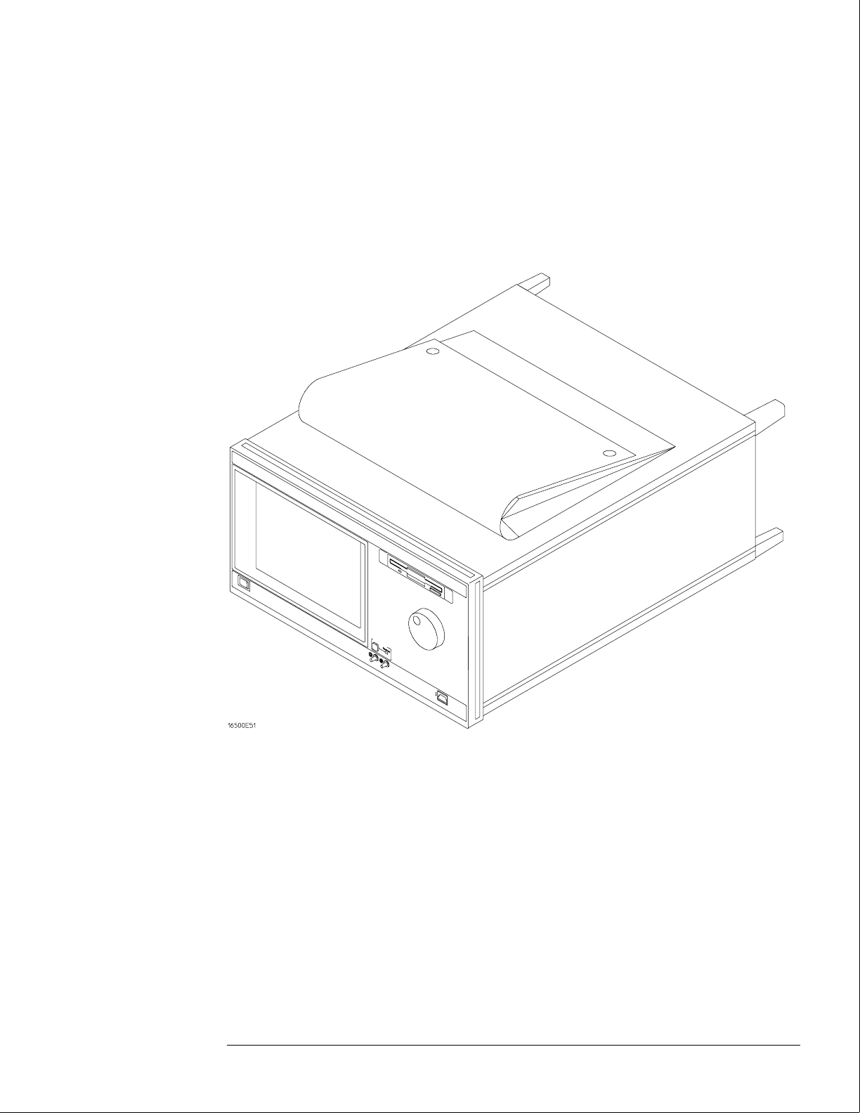
HP 16500B/16501A
Logic Analysis System

HP 16500B/16501A Logic Analysis System
The HP 16500B is the mainframe of the Logic Analysis System, and the HP 16501A is
the expansion frame. The HP 16500B/16501A is of modular structure using plug-in
cards with a wide range of data acquisition and stimulus capabilities.
Features
Some of the main features of the HP 16500B/16501A are as follows:
•Modular mainframe with five card slots
•Expansion frame, which expands the total system card slots to ten
•Touchscreen user interface
•86 Mbyte hard disk drive
•High-density 3.5-inch flexible disk drive
•Color monitor
•Intermodule triggering and time correlation of acquired data
•HP-IB, RS-232C or optional LAN interfaces for hardcopy output to a printer or
controller interface
Service Strategy
The service strategy for this instrument is the replacement of defective assemblies.
This service guide contains information for finding a defective assembly by testing
and servicing the HP 16500B/16501A.
This instrument can be returned to Hewlett-Packard for all service work, including
troubleshooting. Contact your nearest Hewlett-Packard Sales Office for more details.
ii
The HP 16500B Logic Analysis System
iii

In This Book
This book is the service guide for the HP 16500B/16501A Logic Analysis System and is divided
into eight chapters.
Chapter 1 contains information about the instrument and includes accessories for the
instrument, specifications and characteristics of the instrument, and a list of the equipment
required for servicing the instrument.
Chapter 2 tells how to prepare the instrument for use.
Chapter 3 gives instructions on how to test the performance of the instrument.
Chapter 4 contains calibration instructions for the instrument.
Chapter 5 contains self-tests and flowcharts for troubleshooting the instrument.
Chapter 6 tells how to replace the instrument and assemblies of the instrument, and how to
return them to Hewlett-Packard.
Chapter 7 lists replaceable parts, shows an exploded view, and gives ordering information.
Chapter 8 explains how the instrument works and what the self-tests are checking.
This book also contains information about the HP 16500L interface module when using an
expansion frame or an external monitor. For information about using the interface module
with a local area network, refer to the manuals for the HP 16500L.
iv

Contents
1 General Information
Accessories 1–2
Specifications 1–3
Characteristics 1–3
Recommended Test Equipment 1–6
2 Preparing for Use
To inspect the logic analysis system 2–2
To apply power 2–3
To operate the user interface 2–3
To set the line voltage 2–4
To degauss the display 2–5
To clean the logic analysis system 2–5
To test the logic analysis system 2–5
To install modules 2–6
To install the HP 16500L interface module 2–7
To connect the HP 16501A Expansion Frame 2–9
To connect an external monitor 2–10
3 Testing Performance
To perform the power-up tests 3–3
To perform the self-tests 3–4
4 Calibrating and Adjusting
To prepare the instrument 4–3
To access the test patterns 4–4
To adjust geometry 4–5
To adjust focus, landing, and convergence 4–6
To adjust white balance 4–13
5 Troubleshooting
To use the flowcharts 5–2
To check the power-up self-tests 5–18
To run the self-tests 5–19
To check the video signals 5–22
To check the power supply LEDs 5–23
To check the power supply voltages 5–24
To test the flexible disk drive voltages 5–25
To test the hard disk drive voltages 5–27
To test the expansion frame interface 5–29
v

6 Replacing Assemblies
To remove and replace the
Optional modules or filler panels 6–3
Covers 6–4
Flexible disk drive 6–5
Power supply 6–6
Rear fan 6–8
Side fan 6–9
HP 16500L interface module 6–10
Hard disk drive 6–12
Microprocessor board (CPU) 6–13
SIMM memory 6–14
Expansion interface board 6–15
Mother board 6–16
Front-panel board 6–18
Color display assembly 6–19
To return assemblies 6–22
7 Replaceable Parts
Replaceable Parts Ordering 7–2
Replaceable Parts List Description 7–3
HP 16500B Exploded View and Replaceable Parts 7–4
HP 16501A Exploded View and Replaceable Parts 7–9
8 Theory of Operation
Block-Level Theory 8–3
The HP 16500B Logic Analysis System 8–3
The Microprocessor Board 8–6
The Power-Up Routine 8–9
The Power-Up Screen 8–9
Power-Up Self-Tests 8–10
Power-Up Tasks 8–10
The System Configuration Menu 8–12
Self-Tests Description 8–13
Power-Up Self-Tests 8–13
Functional Performance Verification Tests 8–15
HP-IB 8–18
RS-232C 8–19
Contents
vi

1
Accessories 1–2
Specifications 1–3
Characteristics 1–3
Recommended Test Equipment 1–6
General Information

General Information
This chapter lists the accessories, the specifications and characteristics, and the
recommended test equipment.
Accessories
The following accessories are supplied with the HP 16500B/16501A Logic Analysis System.
Accessories Supplied Qty
Training Kit 1
Setting Up The System Guide 1
User’s Reference 1
Programming Reference 1
Service Guide 1
RS-232C Loopback Connector 1
Power cord 1
Disk pouch containing backup composite software 1
Feeling Comfortable With Logic Analyzers
1
Feeling Comfortable with Digitizing Oscilloscopes
1
Filler Panels Quantity depends on how many modules are
ordered with the HP 16500B/16501A
Accessories Available
Other accessories available for the HP 16500B/16501A Logic Analysis System are listed in the
Accessories for HP Logic Analyzers brochure.
1–2

Specifications
The specifications are the performance standards against which the product is tested. There
are no specifications for the HP 16500B or the HP 16501A.
Characteristics
These characteristics are not specifications, but are included as additional information. The
following characteristics are typical for the HP 16500B/16501A system.
Hard Disk Drive Capacity 86 Mbyte unformatted; Formatted as a Microsoft DOS disk drive IDE Interface
Bus.
Flexible Disk Drive Capacity 1.44 Mbyte formatted Microsoft DOS or LIF supported.
Programmability Instrument settings and operating modes, including automatic measurements, may be
remotely programmed via RS-232C, HP-IB (IEEE-488), or optional HP 16500L (Ethernet).
Hardcopy Output Printers Supported HP ThinkJet, HP QuietJet, HP LaserJet, HP PaintJet, HP Deskjet,
HP Deskjet C, Epson and Epson-compatible (for example, Epson FX-80) via RS-232C or
HP-IB.
RS-232C Configurations Protocols: XON/XOFF, Hardware; Data bits: 8; Stop bits: 1, 1
1/2, 2; Parity: none, odd, or even; Baud rates: 110, 300, 600, 1200, 2400, 4800, 9600, 19200.
HP-IB Interface Functions SH1, AH1, T5, TE0, L3, LE0, SR1, RL1, PP1, DC1, DT1, C0
and E2.
Input/Output
Rear Panel BNCs:
Port-in User selectable: TTL, ECL or user defined; Zin = 4 kΩ ; Maximum Vin = -6.0 V at
1.5 mA to +6 V at 1.6 mA.
Port-out Output signal is active high, TTL output level, high > 2 V into 50 Ω, low < 0.4 V
into 50 Ω.
Intermodule Bus (IMB)
Characteristics
Run Control Oscilloscope, timing, state, and pattern generation can be armed by Group
Run. Modules can run concurrently or be armed in series. Each module can arm one or
more modules.
Mixed Display Mode Any timing or oscilloscope waveform displays can be mixed.
State listings can be included with waveforms in the State/Timing Mixed Mode display.
Acquiring Data for Mixed Displays To obtain a mixed display, multiple modules must
be armed through the IMB. To include state listings in mixed mode displays, state time
tagging must be on.
General Information
Specifications
1–3

Time Interval Accuracy Between Modules Equals the sum of the channel-to-channel
time interval accuracies of each module used in the measurement, for a deskewed
measurement.
Time Correlation Resolution 2 ns (500 MHz).
Operating
Environment
Temperature
Instrument 0 °C to 50 °C (+32 °F to 122 °F).
Disk Media 10 °C to 40 °C (+50 °F to 104 °F).
Probes and Cables 0 °C to 65 °C (+32 °F to 149 °F).
Humidity
Instrument up to 95% relative humidity at 40 °C (104 °F).
Disk media and hard drive 8% to 80% relative humidity at 40 °C (104 °F).
Altitude Up to 4600 m (15 000 ft). Hard drive to 300 m (10,000 ft.).
Vibration
Operating Random vibration 5-500Hz, 10 minutes per axis, ~ 2.41 g (rms).
Non-operating Random vibration 5-500Hz, 10 minutes per axis, ~ 2.4 g (rms); and
swept sine resonant search, 5-500Hz, 0.75g (0-peak), 5 minute dwell at 4 resonances
per axis.
Weight HP 16500B
Net 18.1 kg (40 lbs) + [0.7 kg (1.6 lbs) x number of optional cards installed].
Shipping 25.9 kg (57 lbs) + [3.6 kg (8 lbs) x number of optional cards installed].
HP 16501A
Net 12.2 kg (27 lbs) + [0.7 kg (1.6 lbs) x number of optional cards installed].
Shipping 19.9 kg (44 lbs) + [3.6 kg (8 lbs) x number of optional cards installed].
Power Requirements HP 16500B 115 V/230 V, -22% to +10%, 48 to 66 Hz, 475 W max.
HP 16501A 115 V/230 V, -22% to +10%, 48 to 66 Hz, 420 W max.
General Information
Characteristics
1–4

Dimensions Refer to the following figure for dimensional detail.
Dimensional Detail
General Information
Characteristics
1–5

Recommended Test Equipment
Equipment Required
Equipment Critical Specifications Recommended
Model/Part
Use*
Oscilloscope 100 MHz Bandwidth HP 54600A T
Voltmeter HP 3478A T
RS-232C Loopback
Connector
HP Part Number
01650-63202
T
*A = Adjustment P = Performance Tests T = Troubleshooting
General Information
Recommended Test Equipment
1–6
2
To inspect the logic analysis system 2–2
To apply power 2–3
To operate the user interface 2–3
To set the line voltage 2–4
To degauss the display 2–5
To clean the logic analysis system 2–5
To test the logic analysis system 2–5
To install modules 2–6
To install the HP 16500L interface module 2–7
To connect the HP 16501A Expansion Frame 2–9
To connect an external monitor 2–10
Preparing for Use

Preparing For Use
This chapter gives you instructions for preparing the logic analysis system for use.
Power Requirements
The logic analysis system mainframe requires a power source of either 115 Vac or 230
Vac, –22 % to +10 %, single phase, 48 to 66 Hz, 475 W maximum power.
The logic analysis system expansion frame requires a power source of either 115 Vac
or 230 Vac, –22 % to +10 %, single phase, 48 to 66 Hz, 420 W maximum power.
Operating Environment
The operating environment is listed in chapter 1. Note the noncondensing humidity
limitation. Condensation within the instrument can cause poor operation or
malfunction. Provide protection against internal condensation.
The logic analysis system will operate at all specifications within the temperature and
humidity range given in chapter 1. However, reliability is enhanced when operating it
within the following ranges:
•Temperature: +20 °C to +35 °C (+68 °F to +95 °F)
•Humidity: 20% to 80% noncondensing
Storage
Store or ship the logic analysis system in environments within the following limits:
•Temperature: -40 °C to + 75 °C
•Humidity: Up to 90% at 65 °C
•Altitude: Up to 15,300 meters (50,000 feet)
Protect the system from temperature extremes which cause condensation on the
instrument.
To inspect the logic analysis system
1Inspect the shipping container for damage.
If the shipping container or cushioning material is damaged, keep them until you have
checked the contents of the shipment and checked the instrument mechanically and
electrically.
WARNING Hazardous voltages exist in this instrument. To avoid electrical shock, do not apply power to
a damaged instrument.
2–2

2Check the supplied accessories.
Accessories supplied with the logic analysis system are listed in "Accessories" in chapter 1.
3Inspect the product for physical damage.
Check the logic analysis system and the supplied accessories for obvious physical or
mechanical defects. If you find any defects, contact your nearest Hewlett-Packard Sales
Office. Arrangements for repair or replacement are made, at Hewlett-Packard’s option,
without waiting for a claim settlement.
To apply power
1Check that the line voltage selector, located on the rear panel, is on the correct
setting and the correct fuse is installed.
See also, "To set the line voltage" in this chapter.
2Connect the power cord to the instrument and to the power source.
This instrument is equipped with a three-wire power cable. When connected to an
appropriate ac power outlet, this cable grounds the instrument cabinet. The type of power
cable plug shipped with the instrument depends on the country of destination. Refer to
chapter 7, "Replaceable Parts," for option numbers of available power cables.
3Turn on the instrument line switch located on the rear panel, then turn on the power
standby switch located on the front panel.
To operate the user interface
•To select a field on the mainframe screen, use the touchscreen.
For more information about the logic analysis system interface, refer to the
HP 16500B/16501A Logic Analysis System User’s Reference.
•To set the HP-IB address or to configure for RS-232C, refer to the
HP 16500B/16501A Logic Analysis System User’s Reference.
Preparing for Use
To apply power
2–3
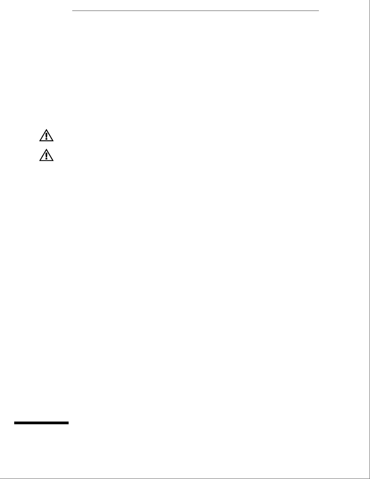
To set the line voltage
When shipped from HP, the line voltage selector is set and an appropriate fuse is installed for
operating the instrument in the country of destination. To operate the instrument from a
power source other than the one set, perform the following steps.
1Turn the front panel power switch to the STBY position, then turn the power switch
to the Off position. Remove the power cord from the instrument.
2Replace the main fuse with a 5 A/250 V fuse for 230 V operation, or a 10 A/125 V fuse
for 115 V operation.
3Set the rear panel line select switch for the desired voltage.
4Reconnect the power cord, turn on the rear panel power switch, then continue
normal operation.
5If your system includes an HP 16501A Expansion Frame, repeat this procedure for it.
The expansion frame has only one power switch, and that switch is located on the rear panel.
Line Voltage Selection
Preparing for Use
To set the line voltage
2–4

To degauss the display
•If the mainframe has been subjected to strong magnetic fields, the CRT might
become magnetized and display data might become distorted. To correct this
condition, degauss the CRT with a conventional, external-television-type degaussing
coil.
To clean the logic analysis system
•With the instrument turned off and unplugged, use mild soap and water to clean the
front and cabinet of the system. Harsh soap might damage the water-base paint.
To test the logic analysis system
The logic analysis system does not require calibration or adjustment.
•If you require a test to initially accept the operation, perform the self-tests in
chapter 3, "Testing Performance."
•If the logic analysis system does not operate correctly, go to the beginning of
chapter 5, "Troubleshooting."
Preparing for Use
To degauss the display
2–5

To install modules
The following steps give general instructions for installing modules into the mainframe or the
expansion frame of the system.
CAUTION Electrostatic discharge can damage electronic components. Use grounded wriststraps and
mats when performing any service to modules.
1Turn off the frame power switch, then unplug the power cord. Disconnect any input
or output connections.
2Plan your module configuration.
Refer to the manuals of individual modules for configuration information.
3Loosen the thumb screws.
Cards or filler panels below the slots intended for installation do not have to be removed.
Starting from the top, loosen the thumb screws on filler panels and cards that need to be
moved.
4Starting from the top, pull the cards and filler panels that need to be moved halfway
out.
All multicard modules will be cabled together. To prevent damage to the cables and
connectors, pull these cards out together.
5Remove the cards and filler panels.
Remove the cards or filler panels that are in the slots intended for the module installation.
Some modules for the logic analysis system require calibration if you move them to a different
slot. Refer to the manuals of individual modules for calibration information.
6Install the module.
You may need to push all other cards into the card cage, but not completely in, to get them
out of the way for installing the module.
Refer to the manuals of individual modules for cabling information.
7Slide the complete module into the frame, but not completely in.
Each card is firmly seated and tightened one at a time in step 9.
8Position all cards and filler panels so that the endplates overlap.
9Seat the cards and tighten the thumbscrews.
Starting with the bottom card, firmly seat the cards into the backplane connector of the
mainframe. Keep applying pressure to the center of the card endplate while tightening the
thumbscrews finger-tight. Repeat this for all cards and filler panels starting at the bottom and
moving to the top.
CAUTION For correct air circulation, filler panels must be installed in all unused card slots. Correct air
circulation keeps the instrument from overheating. Keep any extra filler panels for future use.
10 Plug in the system, then turn it on.
When you turn on the power switch, the logic analysis system performs power-up tests. After
the power-up tests are complete, the screen will show your system configuration.
See Also Service Guides for the individual modules.
Preparing for Use
To install modules
2–6
To install the HP 16500L interface module
The HP 16500L interface module is required to connect the HP 16501A Expansion Frame to
the HP 16500B mainframe.
WARNING Hazardous voltages exist on the power supply, the CRT, and the CRT driver board of the
HP 16500B mainframe. To avoid electrical shock, disconnect the power from the instrument
before performing the following procedures. After disconnecting the power, wait at least six
minutes for the capacitors on the power supply board and the CRT driver board to discharge
before servicing the instrument. However, if the AC LED on the power supply has any
illumination, a significant charge remains on the power supply capacitors.
CAUTION Electrostatic discharge can damage electronic components. Use grounded wriststraps and
mats when performing any service to this module or to the HP 16500B Logic Analysis System.
For correct orientation of the cables, match the slots on the cable connectors and on the
board connectors.
1Remove power from the HP 16500B mainframe, then remove the optional modules,
the four rear feet, and the top and bottom covers of the mainframe.
2Remove the sheetmetal plate on the rear of the mainframe covering the slot where
the HP 16500L interface module will be installed.
With the interface module installed, you will not use the plate. Save the plate to use in case
the interface module is removed.
3Remove the cable connecting the CRT module to the CPU board.
To release the cable, push the tabs on the board connector to the outside of the connector.
With the interface module installed, you will not use this cable. Save the cable to use in case
the interface module is removed.
If you need more room to replace the CRT cable, you can remove the hard disk drive. Removing
the hard disk is not necessary, but gives you more room for replacing the CRT cable. The hard
disk is connected with four screws.
4Connect one end of the new 40-pin cable to the CRT module.
Push the cable connector into the board connector until the tabs lock in the cable.
If you removed the hard disk drive, replace it before going to the next step.
Preparing for Use
To install the HP 16500L interface module
2–7
5Slide the interface module into the mainframe through the slot in the rear panel.
6Install the screws connecting the interface module to the mainframe.
Two screws through the top of the interface module connect it to the sheetmetal plate, and
four screws through the rear plate of the interface module connect it to the rear panel of the
mainframe.
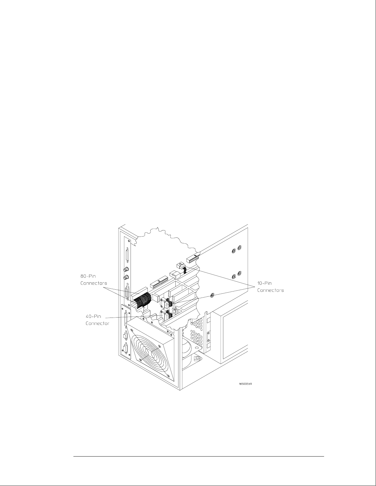
7Connect the end of the 40-pin CRT cable to the interface module.
8Connect the 80-pin cable to the CPU board and to the interface module.
aSlide the 80-pin cable halfway through the rear slot of the card cage between the
interface module and the CPU board.
bConnect the cable to the CPU board.
cConnect the cable to the interface module.
9Connect the 10-pin cable to the CPU board and to the interface module.
10 Replace the top and bottom covers, the optional modules, and the rear feet of the
mainframe.
11 Turn on the system.
aConnect a power cord to the frame.
bTurn on the line switch located on the rear panel the frame.
cTurn on the power standby switch located on the front panel of the mainframe.
When the power-up tests are complete, the mainframe screen shows "Ethernet" in the
Communications menu.
Preparing for Use
To install the HP 16500L interface module
2–8
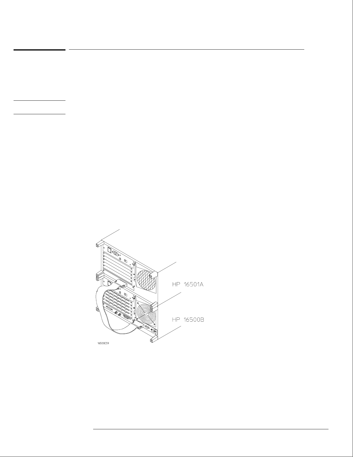
To connect the HP 16501A Expansion Frame
The HP 16501A Expansion Frame includes an interface cable and requires an HP 16500L
interface module to connect to the HP 16500B mainframe. To install the expansion frame,
you need to install the interface module into the mainframe, then connect the cable from the
module to the expansion frame.
CAUTION Electrostatic discharge can damage electronic components. Use grounded wriststraps and
mats when performing any service to this card.
1Turn off the mainframe power switch, then unplug the power cord. Disconnect any
input connections.
2Verify that the line select switch located on the rear panel of the expansion frame is
in the off position.
3Install the HP 16500L interface module into the mainframe.
The procedure for installing the HP 16500L is on page 2–7.
4Connect the interface cable to the expansion frame and to the interface module in
the mainframe.
To ensure correct insertion, the 68-pin "D" connectors on each end of the interface cable are
asymmetric in shape. They only fit into their respective ports on the cards when oriented to
match the shape of the ports.
When connecting the interface cable, you will hear two clicks. Make sure the cable connector
is properly seated into the port by pulling the connector without pressing the release tabs. If
the connector is properly seated, it will remain connected to the port.
5Turn on the system.
aConnect a power cord to each frame.
bTurn on the line switch located on the rear panel of each frame.
cTurn on the power standby switch located on the front panel of the mainframe.
When the power-up tests are complete, the mainframe screen shows "Master
Frame" in a blue field.
Preparing for Use
To connect the HP 16501A Expansion Frame
2–9
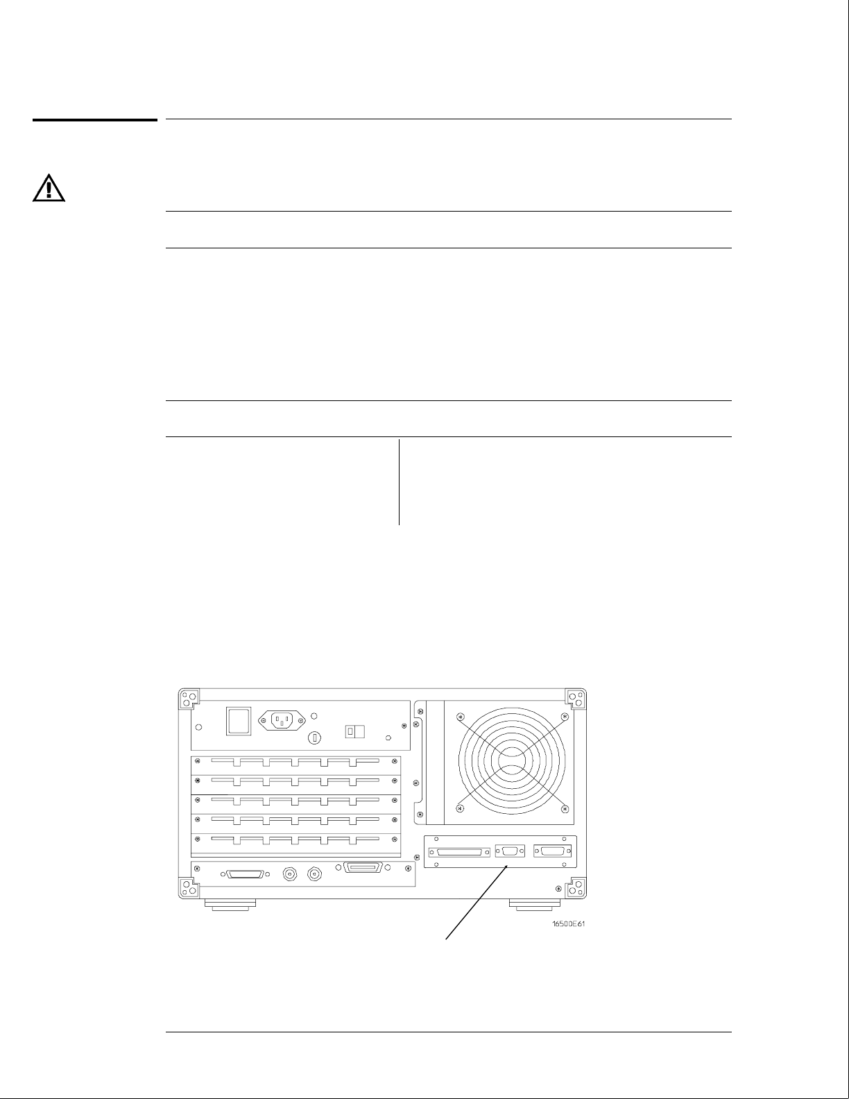
To connect an external monitor
The following tables define the signal available for external monitors at the HP 16500L
connector and pin numbers.
HP 16500L Output Signal For External Monitors
Horizontal deflection (fh) 25.0 kHz
Vertical deflection (fv) 59.95 Hz
Resolution 576 x 368 x dots x lines (WxH)
RGB video 0.714 VP-P, positive
Impedance 75 ohm , analog
External Sync Signal H TTL, negative 3.2 µS;
W TTL, negative, 120 µS
Connector Pins
Pin number Signal Pin number Signal
1 Red 6,7,8,10 Ground
2 Green 13 Horizontal Sync
3 Blue 14 Vertical Sync
1Connect your monitor to the HP 16500L interface module installed into the
HP 16500B mainframe.
2If your monitor needs adjusting, follow the manufacturer’s instructions.
Connector for
external monitor
Preparing for Use
To connect an external monitor
2–10

3
To perform the power-up tests 3–3
To perform the self-tests 3–4
Testing Performance

Testing Performance
To ensure the logic analysis system is operating correctly, you can perform software
tests (self-tests) on the system. Directions for performing the software tests are
given in this chapter.
This chapter normally tells you how to test the performance of the logic analysis
system against the specifications listed in chapter 1. Because there are no
specifications for the HP 16500B/16501A, there are no performance verification tests.
Self-Tests
The self-tests listed in this chapter check the functional operation of the mainframe
and the expansion frame. Self-tests for the optional modules installed in the frames
are listed in the individual module Service Guides.
There are two types of self-tests: self-tests that automatically run at power-up, and
self-tests that you select on the screen. For descriptions of the tests, refer to chapter
8, "Theory of Operation."
Perform the self-tests as an acceptance test when receiving the logic analysis system
or when the logic analysis system is repaired.
If a test fails, refer to chapter 5, "Troubleshooting."
Test Interval
There is no recommended test interval for the HP 16500B mainframe or the
HP 16501A expansion frame. However, each of the HP 16500-series option modules
has performance verification tests and therefore require a periodic verification of
specifications. Refer to the Service Guides of the individual modules for more
information.
The Logic Analysis System Interface
To select a field on the HP 16500B screen, use the touchscreen. For more
information about the logic analysis system interface, refer to the
HP 16500B/16501A Logic Analysis System User’s Reference.
3–2

To perform the power-up tests
The logic analysis system automatically performs power-up tests when you apply power to the
instrument. The revision number of the boot ROM shows in the upper-right corner of the
screen during these power-up tests. As each test completes, either "passed" or "failed" prints
on the screen in front of the name of each test.
1Disconnect all inputs, then insert a formatted disk into the flexible disk drive.
2Let the instrument warm up for a few minutes, then cycle power by turning off then
turning on the power switch.
If the instrument is not warmed up, the power-up test screen will complete before you can
view the screen.
3As the tests complete, check if they pass or fail.
The Flexible Disk Test reports No Disk if a disk is not in the disk drive.
If a power-up self-test fails, refer to chapter 5, "Troubleshooting."
Performing Power-Up Self-Tests
passed ROM Test
passed RAM Test
passed Interrupt Test
passed Display Test
passed HIL Controller Test
passed Front-Panel Test
passed Touchscreen Test
passed Correlator Test
passed Hard Disk Test
passed Flexible Disk Test
Loading Module Files
Testing Performance
To perform the power-up tests
3–3
To perform the self-tests
The self-tests verify the correct operation of the logic analysis system. Self-tests can
be performed all at once or one at a time. While testing the performance of the logic
analysis system, run the self-tests all at once.
1 If you just did the power-up self-tests, go to step 2.
If you did not just do the power-up self-tests, disconnect all inputs, then turn on the
power switch. Wait until the power-up tests are complete.
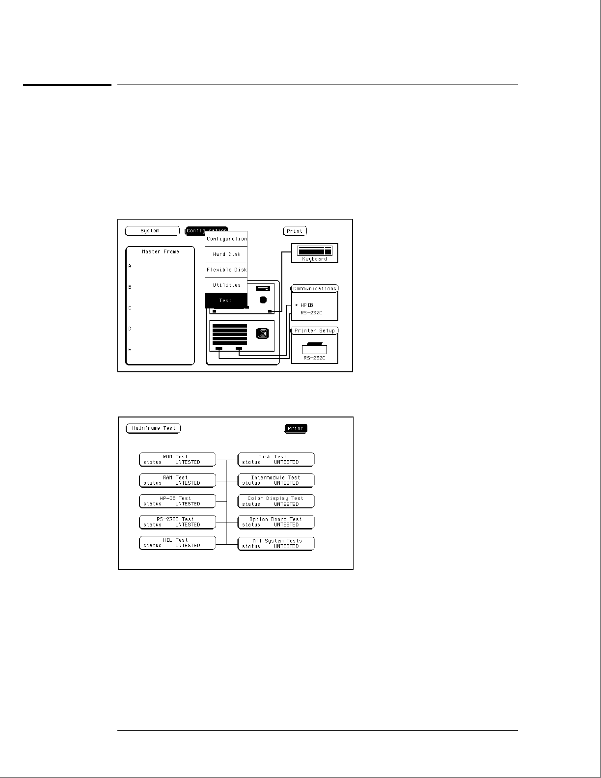
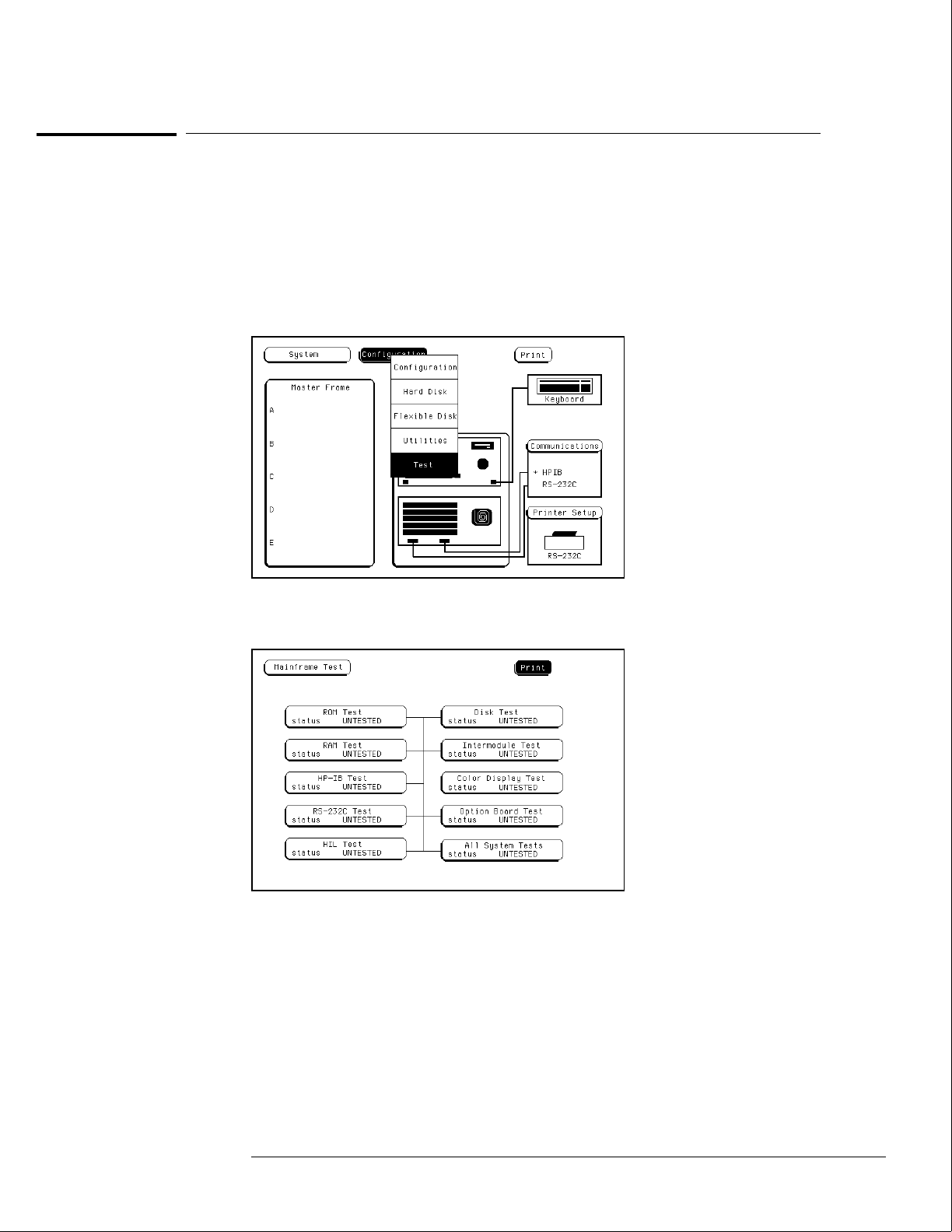
2In the System Configuration menu, select Configuration, then select Test.
3Select the box labeled Load Test System.
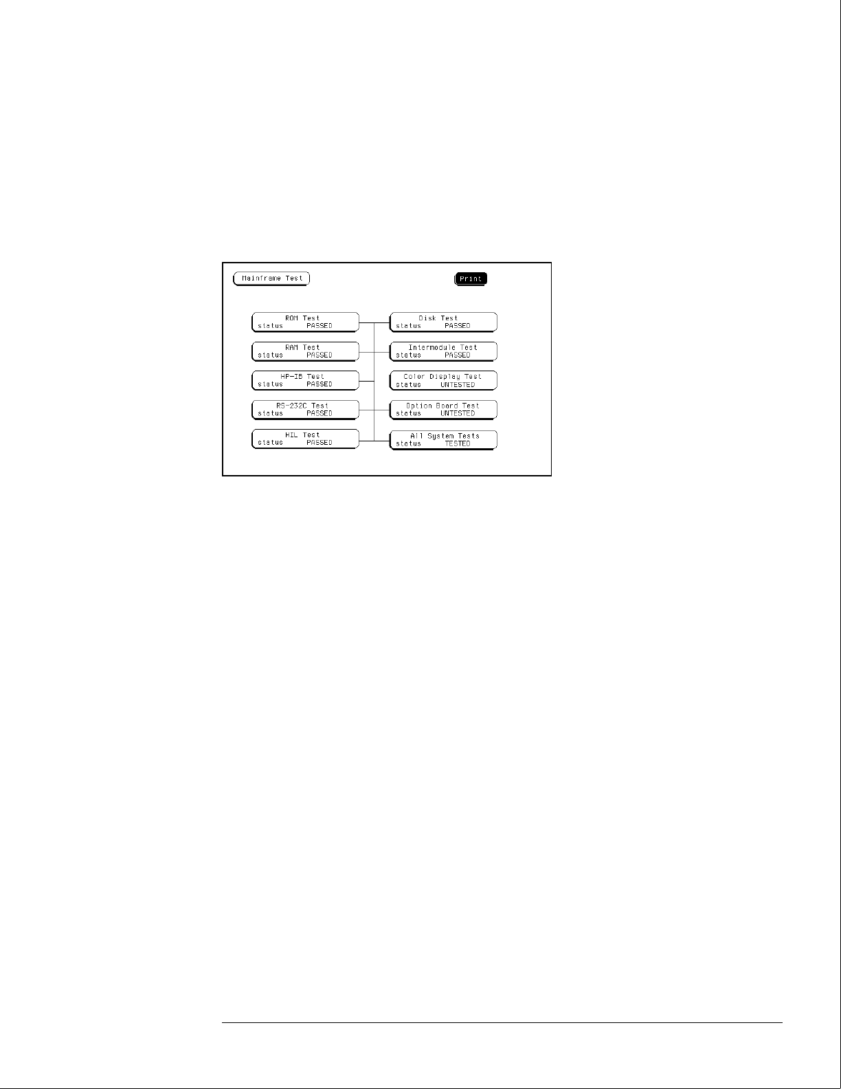
4Select Test System, then select Mainframe Test from the pop-up menu.
Testing Performance
To perform the self-tests
3–4
5Install a formatted disk that is not write protected into the flexible disk drive.
Connect an RS-232C loopback connector onto the RS-232C port.
6Select All System Tests.
You can run all tests at one time by running All System Tests. To see more details about each
test, you can run each test individually. This step shows how to run all tests at once.
The status of the tests will change from Untested to Passed or Failed. If a test fails, refer to
chapter 5, "Troubleshooting."
The Color Display Test is not normally needed. The screens are primarily used when the
color display assembly requires adjusting. For the adjustment procedure, refer to chapter 4,
"Calibrating and Adjusting."
7Exit the mainframe tests.
aIn the Mainframe Test menu, select Mainframe Test, then select Test System.
bSelect Configuration, then select Exit Test in the pop-up menu.
cSelect the field close to the center of the screen to exit the test system and to load the
mainframe operating system.
After the operating system is loaded, the System Configuration menu is displayed.
Testing Performance
To perform the self-tests
3–5

3–6

4
To prepare the instrument 4–3
To access the test patterns 4–4
To adjust geometry 4–5
To adjust focus, landing, and convergence 4–6
To adjust white balance 4–13
Calibrating and Adjusting

Calibrating and Adjusting
This chapter normally gives you instructions for calibrating and adjusting the logic
analysis system. Because the HP 16500B/16501A requires no calibration, only
adjustment instructions are included.
Adjustments
The only adjustments to the logic analysis system are adjustments to the color CRT
monitor assembly.
Use the following procedures to adjust the CRT module to compensate for magnetic
influences causing misconvergence.
WARNING Hazard voltages exist on the power supply, the CRT, and the CRT driver board. To avoid
electrical shock, read and follow the Safety and Warning considerations at the end of this
manual before performing adjustment procedures.
Adjustment Interval
DO NOT PERFORM THESE ADJUSTMENTS AS A PART OF ROUTINE
CALIBRATIONS. The following procedures are provided only for the few extreme
cases where either the earth’s magnetic field or the user’s environment cause an
unusable display due to misconvergence that cannot be corrected by degaussing the
entire CRT screen.
DO NOT perform the procedures in this chapter before first degaussing the CRT
screen using the rear-panel degaussing switch. In extreme cases of magnetism, it
may be necessary to degauss the CRT using a conventional external television-type
degaussing coil.
Adjustment Personnel
It is recommended that these adjustments be performed only by qualified personnel
who are familiar with color CRT convergence procedures.
Equipment Required
The instrument firmware supplies the display patterns necessary for adjustment.
The only tool required is a nonmetallic adjustment tool:
•Sony Part Number 4-367-065-01
•HP Part Number 8710-1355
4–2
To prepare the instrument
1Remove the rear feet and the covers from the mainframe.
2Before starting the adjustments, mark the position where the potentiometers are set.
This helps in returning the adjustments to their original positions if it becomes necessary to
restart the procedure.
3During any of the following CRT adjustments, the CRT module must face west.
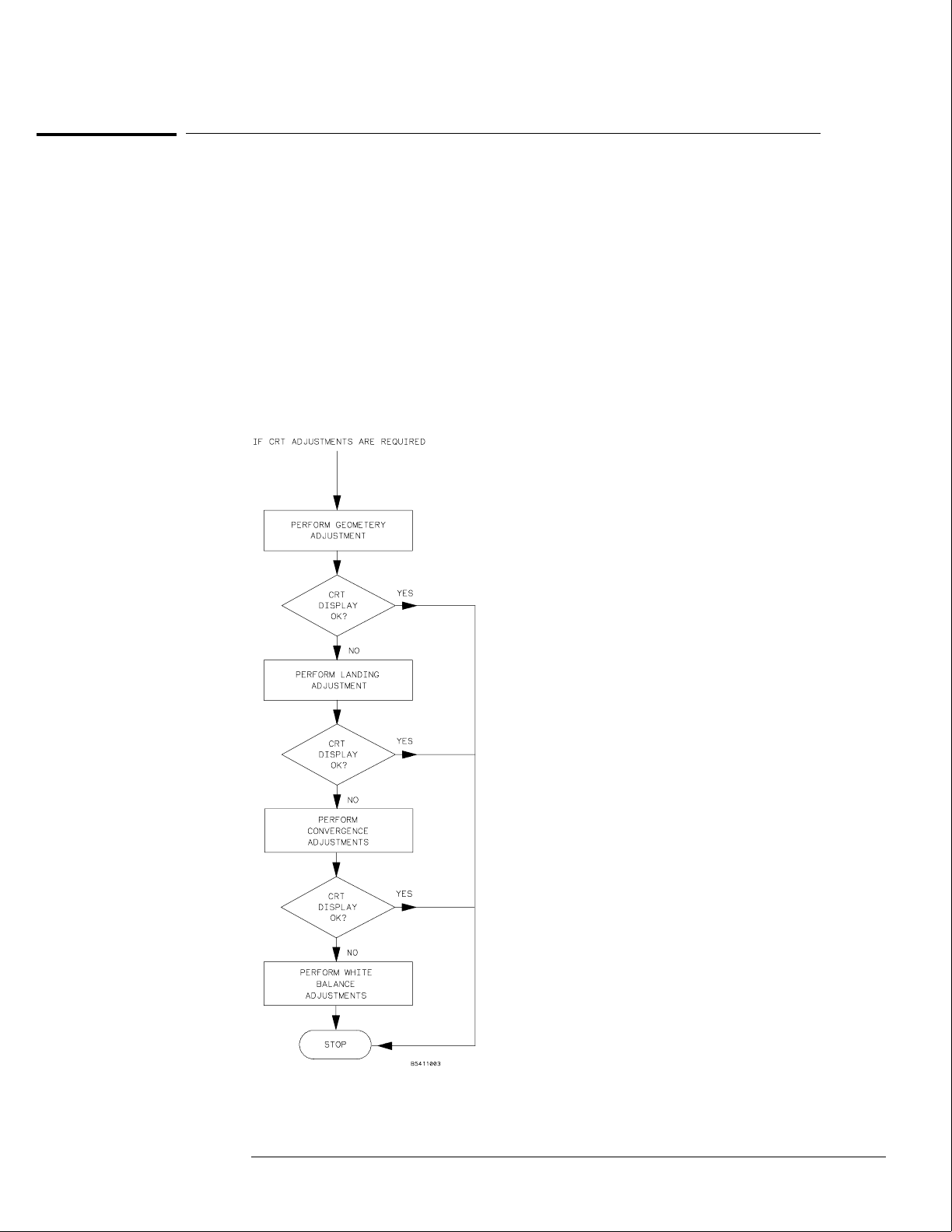
4Use the following chart to guide you with the CRT adjustment procedure.
The following CRT adjustments are broken down into adjustment groups. The adjustment
group sequence must be followed in order because of interaction and dependency. The
adjustment group sequence is shown in the adjustment flow diagram below. There will be
cases where not all of the adjustments groups will be used. For example, if the Geometry
Adjustment Group corrects the problem, this will be the only group used.
Colo
r
CRT
Mod
ule
Adju
stme
nt
Flow
Diag
ram
Calibrating and Adjusting
To prepare the instrument
4–3

To access the test patterns
Some procedures on the following pages ask you to access test patterns. This procedure tells
you how to access them and how to exit the test.
1In the System Configuration menu, touch Configuration, then select Test in the
pop-up menu.
2Touch the field near the center of the screen to load the Test System.
3In the Test System Configuration menu, touch Test System, then select Mainframe
Test in the pop-up menu.
The screen displays the Mainframe Test menu.
4Touch the Color Display Test field to display the first test pattern, which is the
white, cross-hatch pattern.
5Touch Continue to see the next test pattern.
With every touch of the Continue field, the next test pattern will be displayed. When
Continue is selected from the black raster pattern, the Mainframe Test menu will be displayed.
Notice that the status of the Display field changes to Tested.
6To exit the test system, touch the Mainframe Test field, then touch the Test System.
Touch Configuration, select test, then touch the field near the center of the screen to
exit the test system.
Calibrating and Adjusting
To access the test patterns
4–4
To adjust geometry
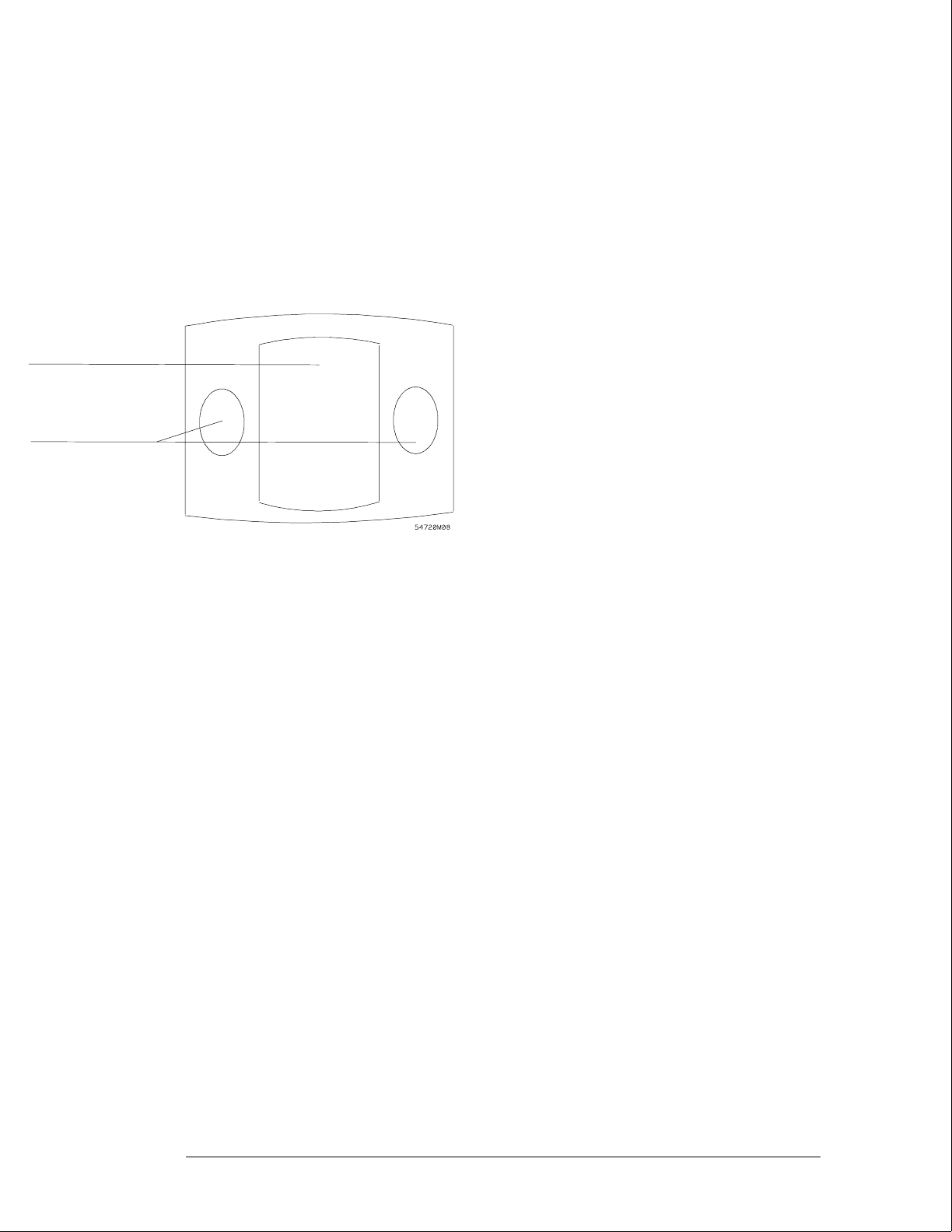
1Display the white cross-hatch test pattern on the CRT.
From the Color Display Test menu, select the white, cross-hatch pattern.
2Preset the front panel brightness control, the top of the two controls to the left of
the display, maximum clockwise.
3Preset the front panel contrast control, the bottom of the two controls to the left of
the display, to the mechanical center.
4Preset H.SUB SHIFT (RV006) and V.SUB SHIFT (RV008), located on the bottom PC
board, to the mechanical centers.
All of the following adjustment potentiometers are located on the PC board on the left side of
the display.
5Adjust the display size. Measure with a flexible ruler.
•Adjust H.SIZE (RV504) for a 161 mm (6.34 in.) width.
•Adjust V.HEIGHT (RV50) for a 120.5 mm (4.74 in.) height.
6Center the pattern.
•Adjust V.CENT (RV510) for vertical centering.
•Adjust H.CENT (RV503) for horizontal centering.
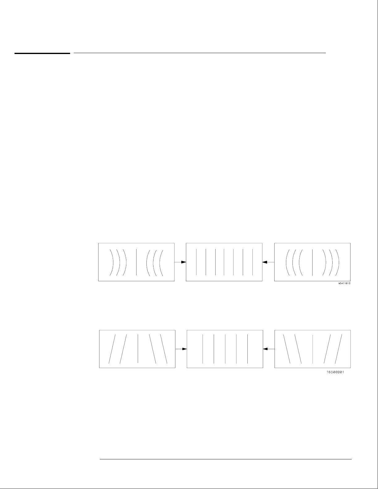
7Adjust PIN AMP (RV506) to eliminate pincushion distortion in the vertical lines of
the cross-hatch pattern as shown in the next figure.
8Remove the left, bottom rail of the mainframe.
The left, bottom rail must be removed in order to access the next adjustment.
9Adjust PIN PHASE (RV505) to eliminate pin phase distortion in the vertical lines of
the cross-hatch pattern as shown in the next figure.
10 Reinstall the bottom rail.
11 Adjust TOP PIN (RV511) so that the top horizontal line is parallel with the center
horizontal line.
12 Adjust BOTTOM PIN (RV512) so that the bottom horizontal line is parallel with the
center horizontal line.
Calibrating and Adjusting
To adjust geometry
4–5

To adjust focus, landing, and convergence
Once you have started, you will have to do all three of the procedures in this group: the focus,
the landing, and the convergence adjustments.
Initial Preparation
1Loosen the deflection yoke clamp screw.
2Remove the rear and side fans.
Refer to chapter 6, "Replacing Assemblies."
Focus Adjustment
Geometry adjustments must be performed before making the focus adjustment.
1Display the white, cross-hatch test pattern on the display.
From the Color Display Test menu, select the white, cross-hatch pattern.
2Adjust FOCUS (RV701), located on the rear PC board, for best overall focus.
Calibrating and Adjusting
To adjust focus, landing, and convergence
4–6
Landing Adjustment
1Turn the front panel BRIGHTNESS control fully clockwise.
2Degauss the CRT by momentarily pressing the DEGAUSS switch located on the
instrument rear panel.
In some cases, the user’s environment or shipping environment may have caused high levels of
magnetization in the CRT. In this case, to completely degauss the CRT you may need to use a
conventional television-type degaussing coil.
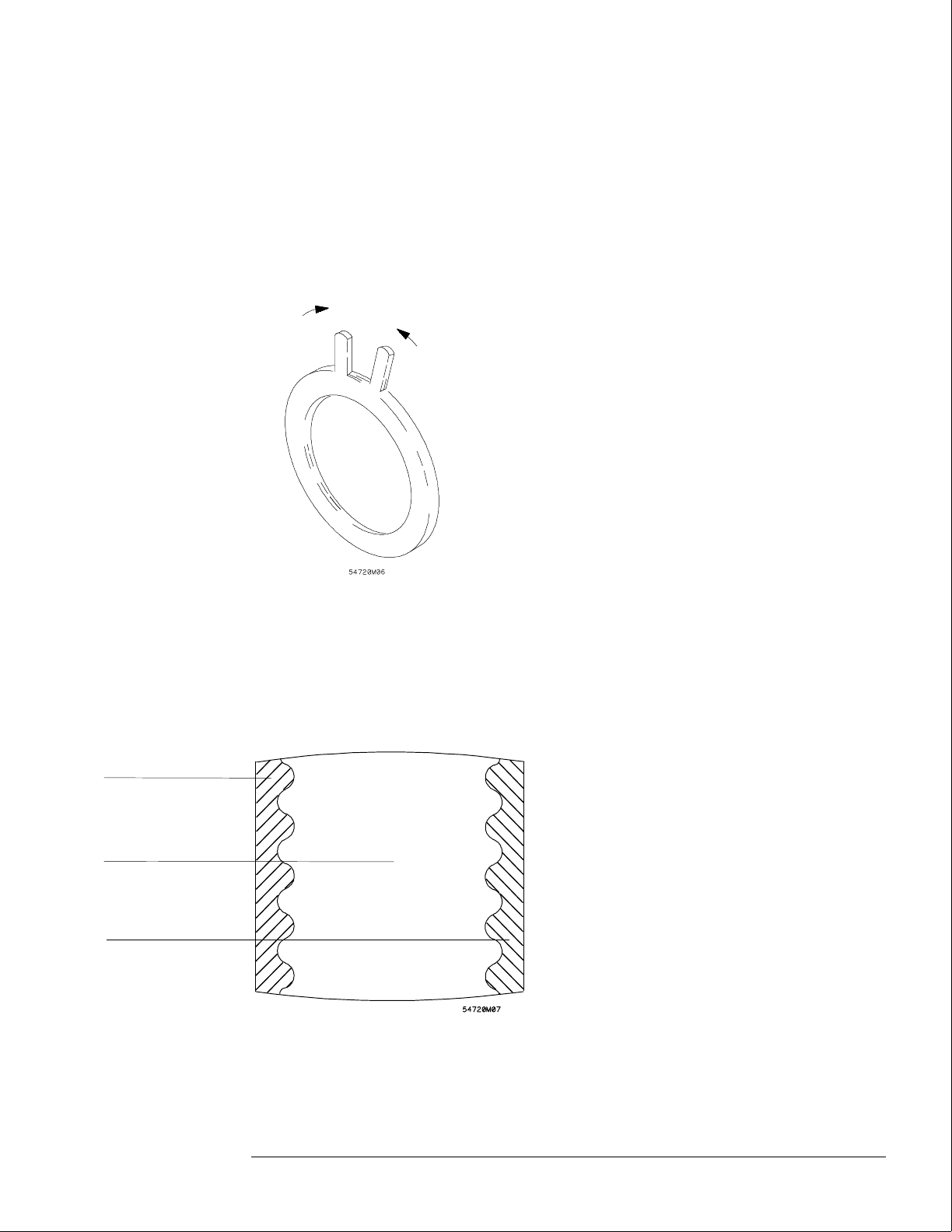
3Set the purity magnet tabs to the mechanical center. Refer to the next figure.
4Display a green raster test pattern on the display.
From the Color Display Test menu, select the green raster.
In the next steps, while moving the deflection yoke forward and rearward, rotate the yoke as
necessary to keep the edges of the raster parallel to the sides of the display.
6Move the deflection yoke rearward until the left edge of the raster turns red and the
right side of the raster turns blue.
7Adjust the purity magnets until green is in the center of the raster with red and blue
bands evenly distributed on the sides.
Blue
Red
Green
Calibrating and Adjusting
To adjust focus, landing, and convergence
4–7
8Move the deflection yoke forward until the entire raster is green.
Landing adjustment is easier if the yoke is moved all the way forward and then moved back
until the raster is completely green.
9Using the Color Purity key, replace the green raster with red and then blue raster,
each time checking for proper landing adjustment (color purity of each).
10 If the landing is not correct in step 9, repeat steps 6 through 9 for the best
compromise.
11 If the landing is not correct in step 10, readjust purity magnets for best landing of
each color.
12 When the landing adjustment is complete, tighten the deflection yoke clamp screw
just enough to keep the yoke from moving. DO NOT over tighten or you might
damage the CRT.
Deflection yoke
position corrects
these areas
Purity control
corrects this area
Calibrating and Adjusting
To adjust focus, landing, and convergence
4–8
Static Convergence
1Temporarily disconnect the power from the instrument.
2Remove the PC board shield cover from the rear of the Color CRT Module by prying
evenly on all four sides.
3Reapply power.
4Display the white, cross-hatch test pattern on the CRT.
From the Color Display Test menu, select the white, cross-hatch pattern.
5Preset front panel brightness control, the top of the two controls to the left of the
display, maximum clockwise.
6Preset front panel contrast control, the bottom of the two controls to the left of the
display, to the mechanical center.
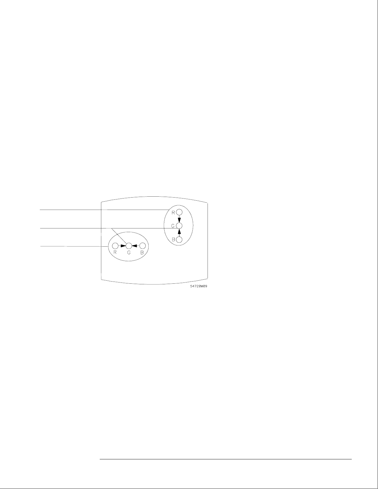
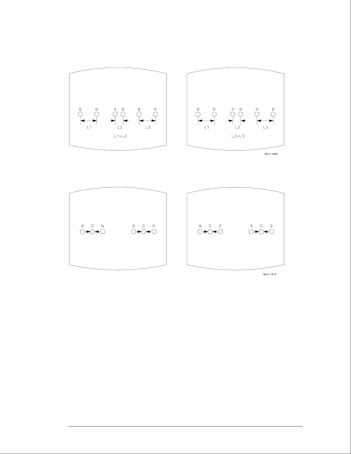
7Check the four dots which are located around the center intersection of the
cross-hatch pattern for coincidence of the blue, red, and green dots. If the dots are
not coincident, adjust H.STAT (RV703) located on the rear PC board to obtain
horizontal coincidence and V.STAT (RV803) located on the bottom PC board to
obtain vertical coincidence.
Due to interaction, the BEAM LANDING will need to be readjusted if either the H.STAT or
V.STAT adjustments are made. Once the BEAM LANDING is re-adjusted, repeat step 7 above
if necessary to obtain the center screen coincidence of the dots.
H.STAT
Center dot
V.STAT
Calibrating and Adjusting
To adjust focus, landing, and convergence
4–9
Dynamic Convergence
1Display the white, cross-hatch test pattern on the CRT.
From the Color Display Test menu, select the white, cross-hatch test pattern.
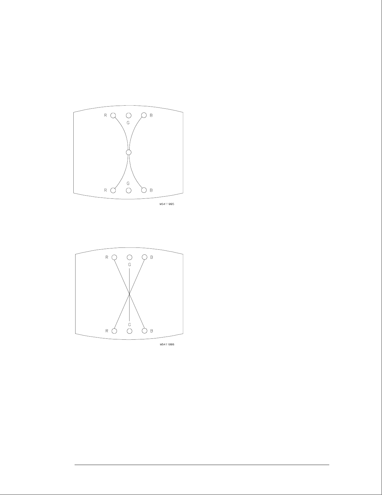
2Adjust Y BOW (RV805) located on the bottom PC board to eliminate red, green, and
blue bowing at the top and bottom of the center vertical line.
3Adjust Y CROSS (RV804) located on the bottom PC board to eliminate red, green,
and blue orthogonal misalignment at the top and bottom of the center vertical line.
Calibrating and Adjusting
To adjust focus, landing, and convergence
4–10
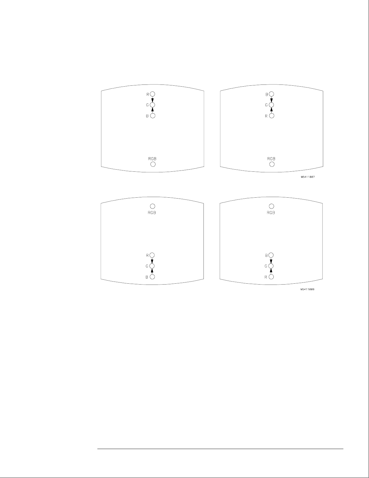
4Adjust V TOP (RV801) and V BOTTOM (RV802) to obtain coincidence of the red,
blue, and green at the intersection of the top and bottom horizontal lines with the
center vertical line. The VTOP and VBOTTOM adjustments are located on the
bottom PC board. Use the next two figures for V TOP and V BOTTOM respectively.
Calibrating and Adjusting
To adjust focus, landing, and convergence
4–11
5Adjust H.AMP (RV807) located on the bottom PC board for equal amounts of
misconvergence at the right and left sides of the screen.
6Adjust H.TILT (RV806) located on the bottom PC board for coincidence of red,
green, and blue at the right and left sides of the screen.
7If you are finished with the CRT adjustments, replace the fans.
If you need to adjust the white balance, which is the next procedure, you will
replace the fans after completing that procedure.
Calibrating and Adjusting
To adjust focus, landing, and convergence
4–12

To adjust white balance
1Provide a blank display on the CRT.
From the Color Display Test menu, select a blank (colorless) raster.
2Preset the front panel brightness and contrast controls to their mechanical centers.
3On the bottom PC board, set the following adjustments to their mechanical centers.
•SUB BRT (RV901)
•SUB CONT (RV902)
4On the bottom PC board, set the following adjustments to their mechanical centers.
•G. DRIVE (RV921)
•B. DRIVE (RV931)
•R. DRIVE (RV911)
5On the rear PC board, set the following adjustments fully counterclockwise.
•G. BKG (RV721)
•B. BKG (RV731)
•R. BKG (RV711)
6Adjust the SCREEN (RV702) located on the rear PC board until either the red, green,
or blue raster just starts to become visible. Note which color becomes visible first
and do not adjust the background control (BKG) for that color in the next step.
7Adjust the other two background controls for the best white balance.
8From the Color Display Test menu, select the white raster test pattern.
9Set the front panel brightness control to maximum.
10 On the bottom PC board, adjust the DRIVE controls (RV921, RV931 and RV911) for
the best white balance.
For a white balance reference, use an average piece of white photocopy paper and compare
the white on the CRT to the paper.
11 Repeat steps 1-3 followed by 6-10 until satisfied with the white balance.
Essentially, from this point the procedure is as follows:
aWith a blank screen, the front panel brightness set to center, and SCREEN (RV702) set
for minimum background, adjust the BKG controls (G.-RV721, B.-RV731, and
R.-RV711) for the best white balance.
bWith a white raster and the front panel brightness set to maximum, adjust the DRIVE
controls (G.-RV921, B.-RV931, and R.-RV911) for best white balance.
cRepeat until satisfied with the white balance.
12 Replace the side and rear fans.
Refer to chapter 6, "Replacing Assemblies."
Calibrating and Adjusting
To adjust white balance
4–13

4–14

5
To use the flowcharts 5–2
To check the power-up self-tests 5–18
To run the self-tests 5–19
To check the video signals 5–22
To check the power supply LEDs 5–23
To test the power supply voltages 5–24
To test the flexible disk drive voltages 5–25
To test the hard disk drive voltages 5–27
To test the expansion frame interface 5–29
Troubleshooting

Troubleshooting
This chapter helps you troubleshoot the logic analysis system to find defective
assemblies. The troubleshooting consists of flowcharts, self-test instructions, and
tests. This information is not intended for component-level repair.
If you suspect a problem, start at the top of the first flowchart. During the
troubleshooting instructions, the flowcharts will direct you to perform other tests.
The other tests are located in this chapter after the flowcharts.
The service strategy for this instrument is the replacement of defective assemblies.
This instrument can be returned to Hewlett-Packard for all service work, including
troubleshooting. Contact your nearest Hewlett-Packard Sales Office for more details.
CAUTION Electrostatic discharge can damage electronic components. Use grounded wriststraps and
mats when you perform any service to this instrument or to the cards in it.
To use the flowcharts
Flowcharts are the primary tool used to isolate defective assemblies. The flowcharts refer to
other tests to help isolate the trouble. The circled letters on the charts indicate connections
with the other flowcharts. Start your troubleshooting at the top of the first flowchart.
5–2

Main Troubleshooting Flowchart 1
Troubleshooting
To use the flowcharts
5–3
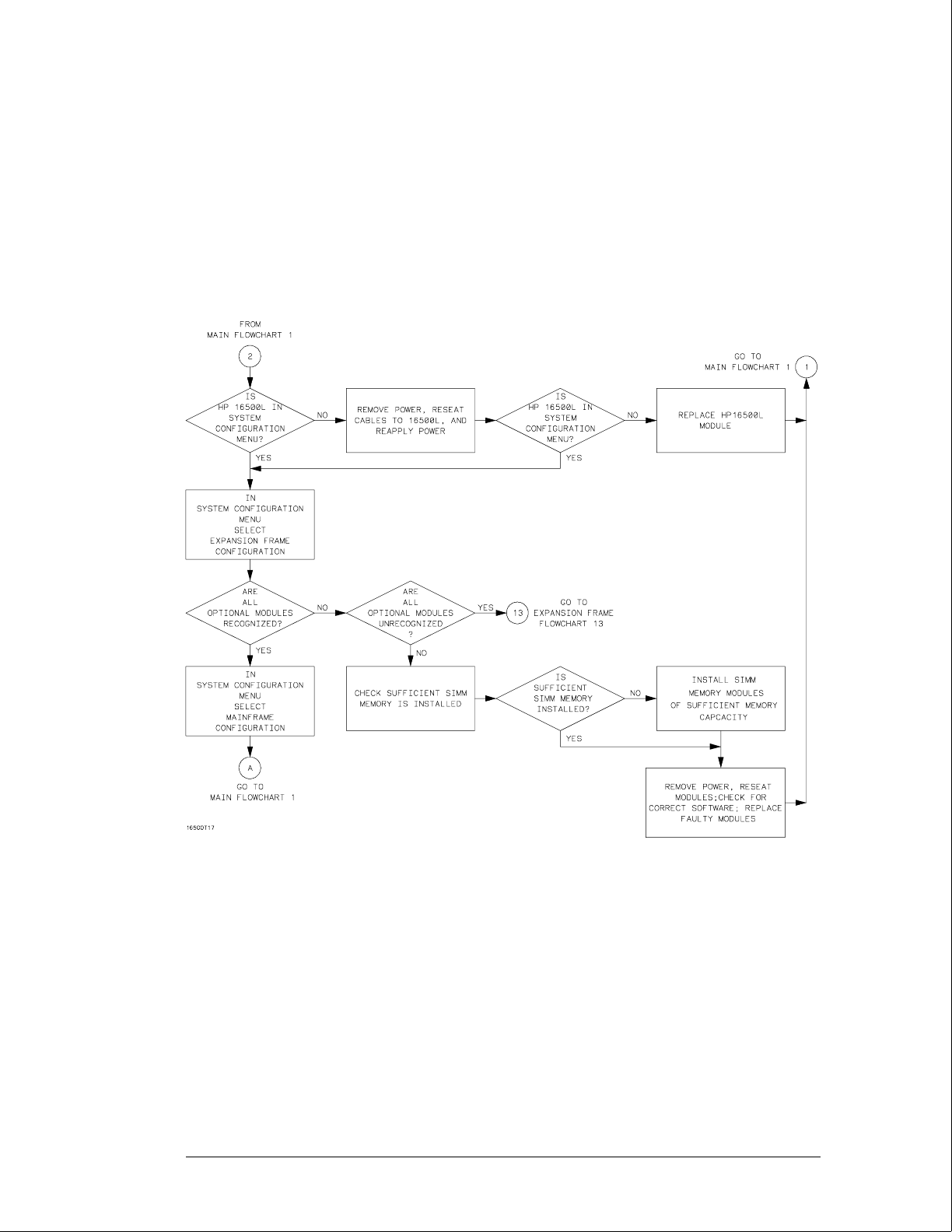
Main Troubleshooting Flowchart 2
Note: The HP 16500L
is in the System
Configuration menu if
"Master Frame" is in a
blue field and
"Ethernet" is in the
Communications field.
Troubleshooting
To use the flowcharts
5–4
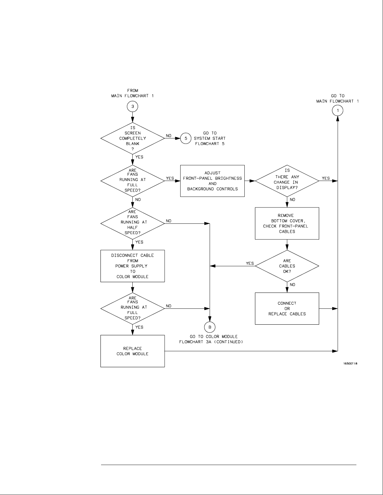
Color Module Troubleshooting Flowchart 3
Troubleshooting
To use the flowcharts
5–5
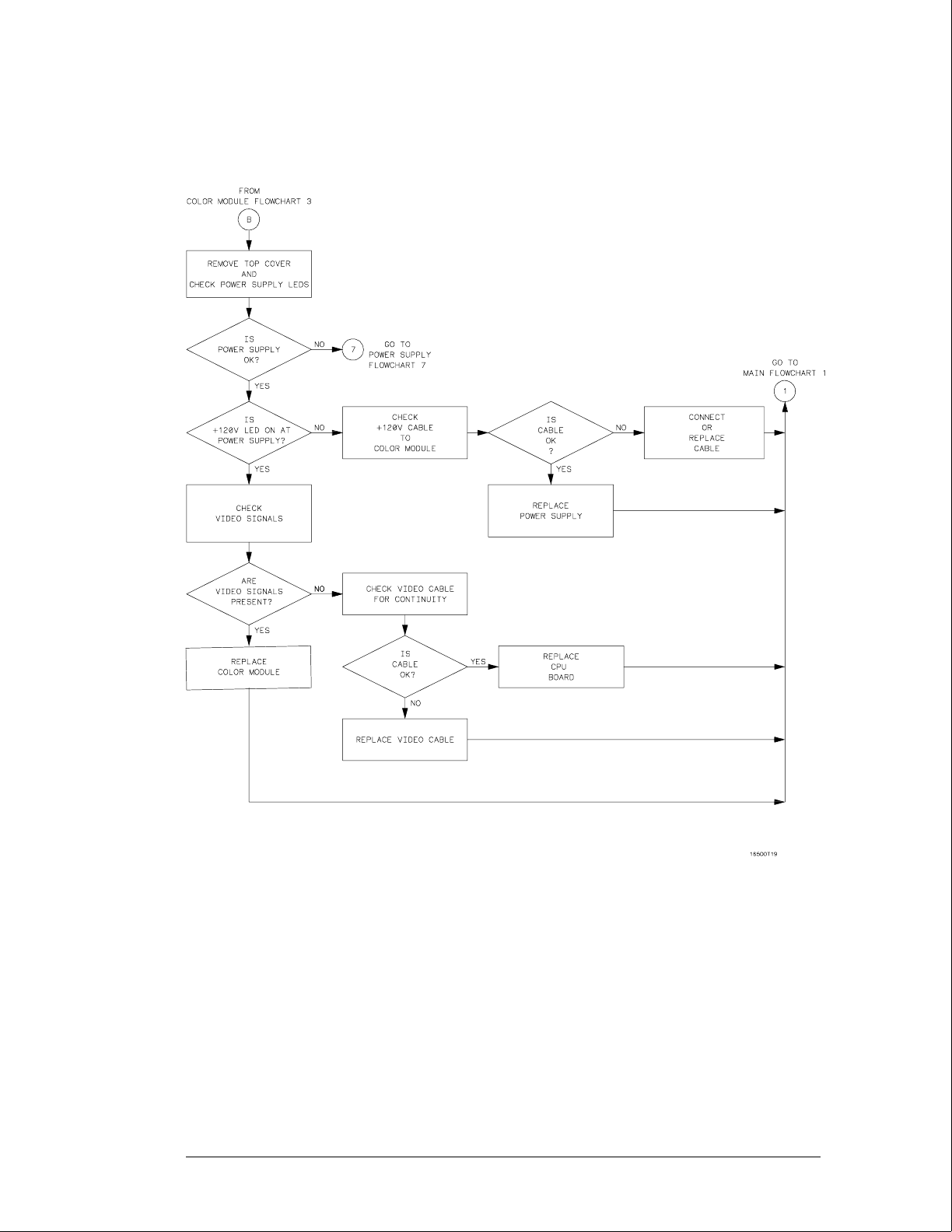
Color Module Troubleshooting Flowchart 3A (continued)
Troubleshooting
To use the flowcharts
5–6
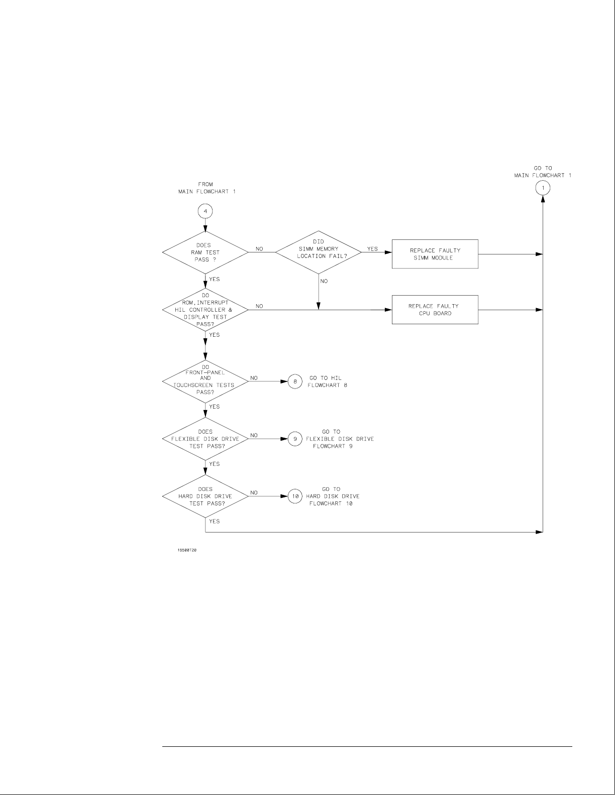
Power-Up Troubleshooting Flowchart 4
Troubleshooting
To use the flowcharts
5–7
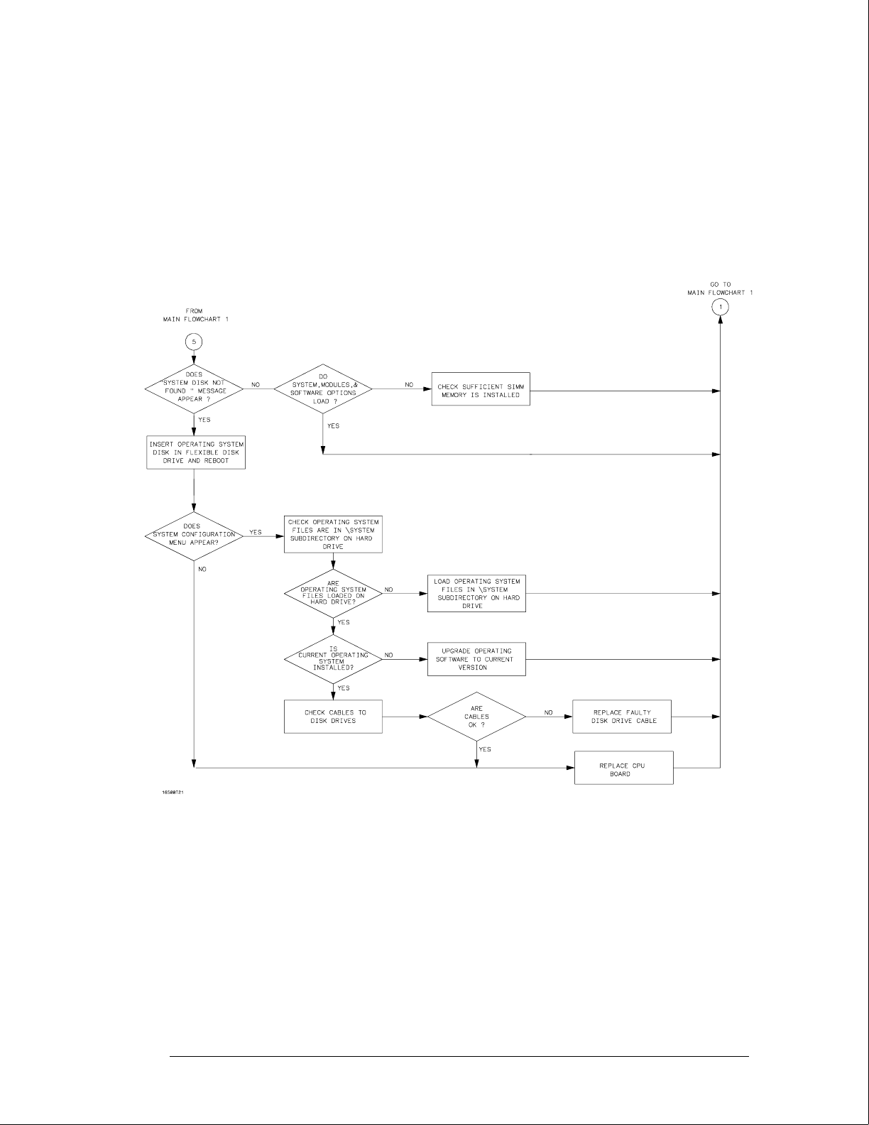
System Start Troubleshooting Flowchart 5
Troubleshooting
To use the flowcharts
5–8

Mainframe Tests Troubleshooting Flowchart 6
Troubleshooting
To use the flowcharts
5–9
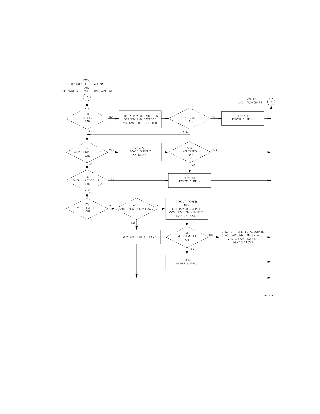
Power Supply Troubleshooting Flowchart 7
Troubleshooting
To use the flowcharts
5–10
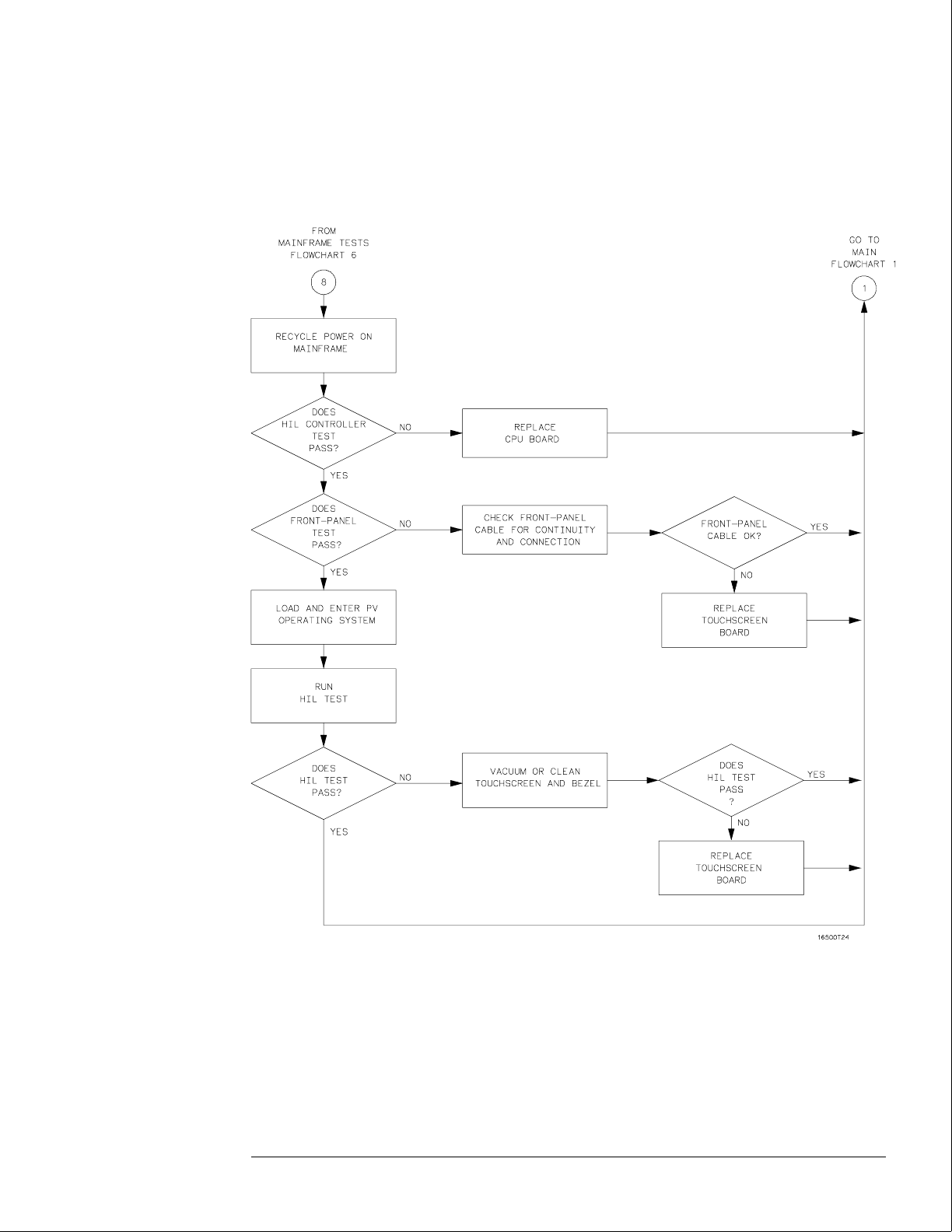
HIL Troubleshooting Flowchart 8
Troubleshooting
To use the flowcharts
5–11

Flexible Disk Drive Troubleshooting Flowchart 9
Troubleshooting
To use the flowcharts
5–12
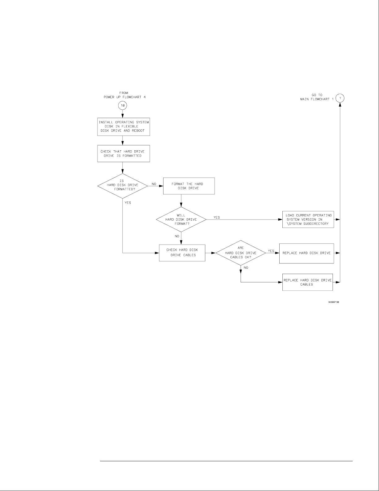
Hard Disk Drive Troubleshooting Flowchart 10
Troubleshooting
To use the flowcharts
5–13
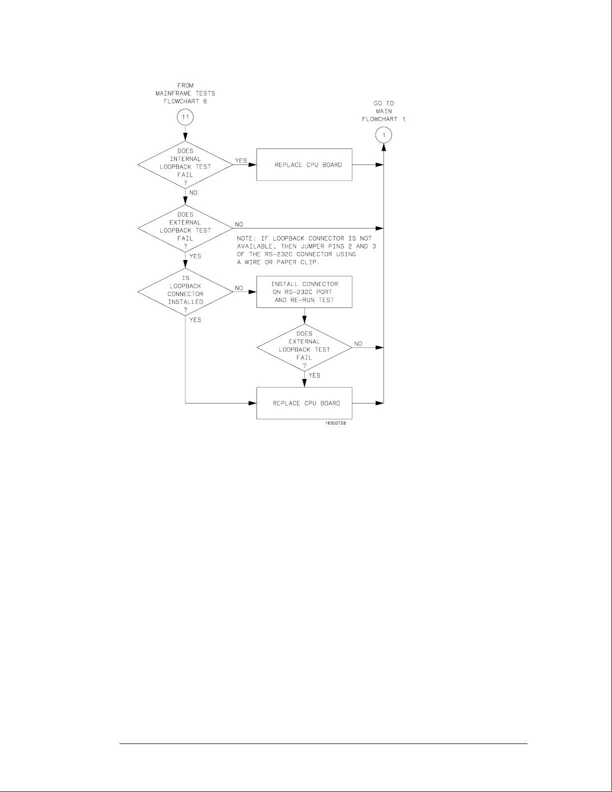
RS-232C Troubleshooting Flowchart 11
Troubleshooting
To use the flowcharts
5–14

Intermodule Troubleshooting Flowchart 12
Troubleshooting
To use the flowcharts
5–15
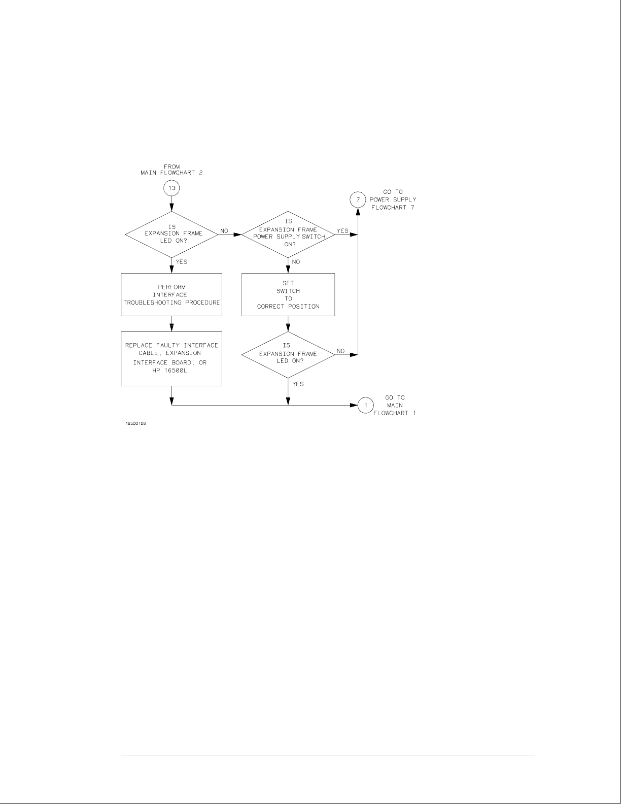
Expansion Frame Troubleshooting Flowchart 13
Troubleshooting
To use the flowcharts
5–16
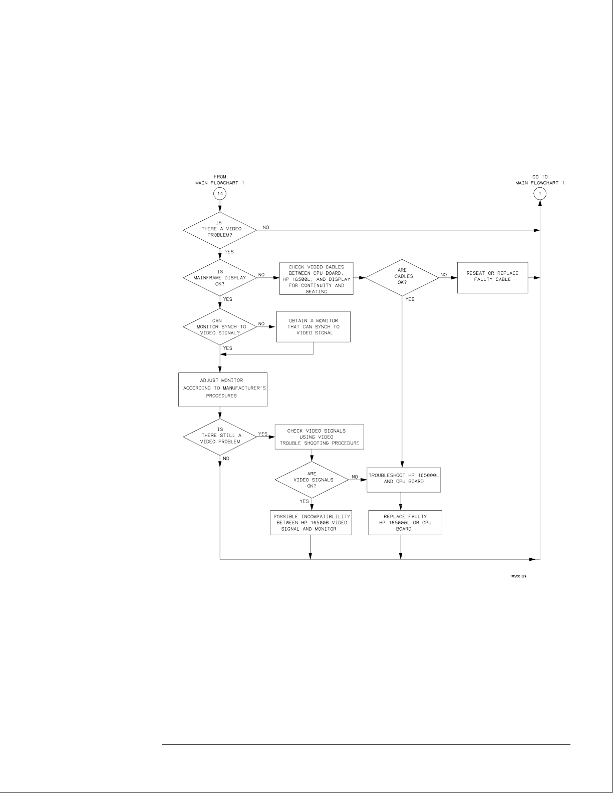
External Monitor Troubleshooting Flowchart 14
Note: Compare the
specifications of the
monitor against the
specifications of the
video signal as a way
to determine
compatibility (ability
to synch). Video
signal specifications
are listed in "To
connect an external
monitor" in chapter 2.
Troubleshooting
To use the flowcharts
5–17

To check the power-up self-tests
The logic analysis system automatically performs power-up self-tests when you apply power
to the instrument. The revision number of the operating system shows in the upper-right
corner of the screen during these power-up tests. As each test completes, either "passed" or
"failed" appears on the screen in front of the name of each test.
1Disconnect all inputs, then insert a formatted disk into the flexible disk drive.
2Let the instrument warm up for a few minutes, then cycle the power by turning off
and turning on the power switch.
If the instrument is not warmed up, the power-up test screen will complete before you can
view the screen.
3As the tests complete, check if they pass or fail, then return to the flowcharts.
The Flexible Disk Test reports No Disk if a disk is not in the disk drive. Refer to the tables
below for the screen listing after the tests are complete and for power-up error messages.
Power-Up Self-Test Screen Listing
Performing Power-Up Self-Tests
passed ROM Test
passed RAM Test
passed Interrupt Test
passed Display Test
passed HIL Controller Test
passed Front-Panel Test
passed Touchscreen Test
passed Correlator Test
passed Hard Disk Test
passed Flexible Disk Test
Loading Module Files
Error Messages at Power-Up
Message Cause Remedy
FATAL ERRORS ENCOUNTERED,
BOOT HALTED
A power-up test failed. Follow the troubleshooting
flowcharts.
SYSTEM DISK NOT FOUND The mainframe operating system
cannot be found on the hard disk
drive.
Install the operating system
software onto the hard disk drive.
Touchscreen power-up test
impaired
The touchscreen operation is
impaired.
Follow the troubleshooting
flowcharts. The touchscreen might
still operate with a minimal loss of
functionality.
See Also "The Power-Up Routine" in chapter 8.
Troubleshooting
To check the power-up self-tests
5–18
To run the self-tests
Self-tests identify the correct operation of major, functional subsystems of the instrument.
You can run all self-tests without accessing the interior of the instrument. If a self-test fails,
the troubleshooting flowcharts instruct you to change a part of the instrument.
1 If you just did the power-up self-tests, go to step 2.
If you did not just do the power-up self-tests, disconnect all inputs, then turn on the
power switch. Wait until the power-up tests are complete.
2In the System Configuration menu, select Configuration, then select Test.
3Select the box labeled Load Test System.
4Select Test System, then select Mainframe Test from the pop-up menu.
Troubleshooting
To run the self-tests
5–19
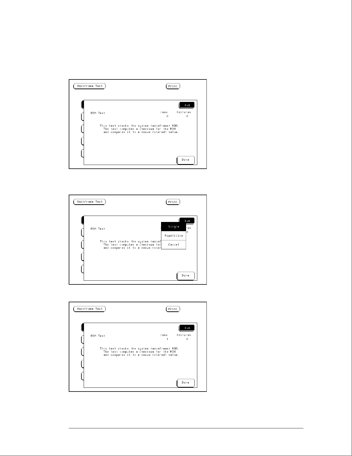
5Select ROM Test. The ROM Test screen is displayed.
You can run all tests at one time by running All System Tests. To see more details about each
test, you can run each test individually. This example shows how to run an individual test.
6Select Run, then select Single.
To run a test continuously, select Repetitive. Select Stop to halt a repetitive test.
For a Single run, the test runs one time, and the screen shows the results.
Troubleshooting
To run the self-tests
5–20
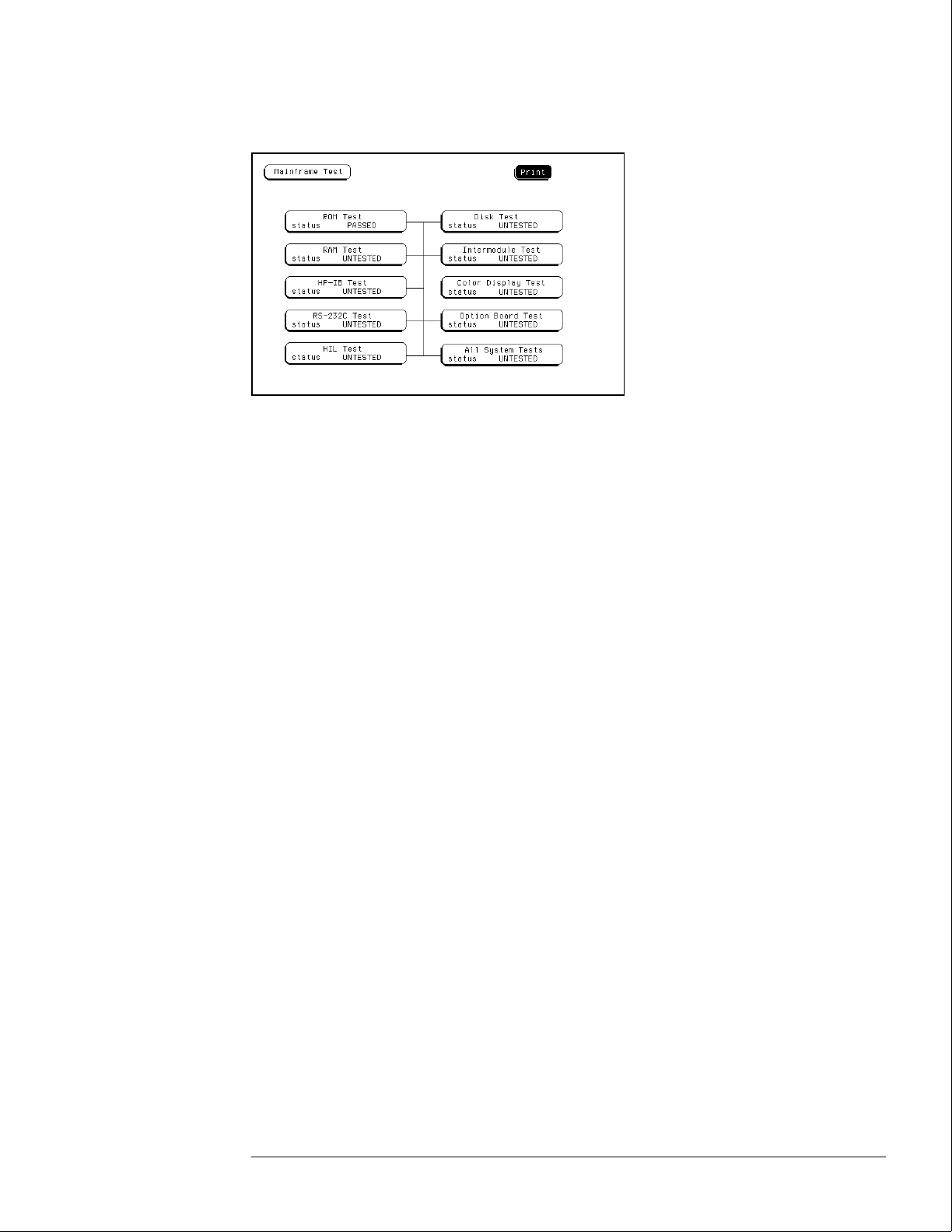
7To exit the ROM Test, select Done. Note that the status changes to Passed or Failed.
8Install a formatted disk that is not write-protected into the flexible disk drive.
Connect an RS-232C loopback connector onto the RS-232C port. Run the remaining
All System Tests in the same manner.
The Color Display Test is not part of this troubleshooting. The Color Display Test is used in
chapter 4, "Calibrating and Adjusting," to adjust the color display.
The Option Board Test is used later in this chapter to check signals to the HP 16501A
Expansion Frame.
99 Exit the mainframe tests.
aSelect Done from any test screen.
bSelect Mainframe Test, then select Test System in the pop-up menu.
cSelect Configuration, then select Exit Test in the pop-up menu.
dSelect the box near the center of the screen to exit the test system.
10 If you are performing the self-tests as part of the troubleshooting flowchart, return
to the flowchart.
Troubleshooting
To run the self-tests
5–21

To check the video signals
Refer to chapter 6, "Replacing Assemblies," for instructions on how to remove or replace
covers and assemblies.
WARNING Hazard voltages exist on the power supply, the CRT, and the CRT driver board. This
procedure is to be performed by service-trained personnel aware of the hazards involved,
such as fire and electrical shock.
1Turn off the instrument, then remove the bottom cover.
2On the color assembly, disconnect the cable that connects the microprocessor
board to the color display assembly.
3Turn on the instrument, then wait for it to power up.
4Probe the cable for the horizontal sync, vertical sync, and display data signals.
The horizontal and vertical sync signals are TTL levels that resemble the figure.
The display data signals have a baseline of approximately −1.7 V and vary in amplitude from
the baseline voltage to approximately 125 mV, depending on the characteristics of the colors
displayed.
5Reconnect the cable, then return to the color display assembly flowchart.
Cable Pin Numbers
Pin Numbers Signal
3 Vertical Sync
7 Horizontal Sync
21 Red Display Data
29 Green Display Data
37 Blue Display Data
Sync Signals
Vertical
Horizontal
Troubleshooting
To check the video signals
5–22
To check the power supply LEDs
Refer to chapter 6, "Replacing Assemblies," for instructions to remove or replace covers and
assemblies.
WARNING Hazard voltages exist on the power supply, the CRT, and the CRT driver board. This
procedure is to be performed by service-trained personnel aware of the hazards involved,
such as fire and electrical shock.
1Turn off the instrument, then remove the top cover.
2Apply power to the instrument.
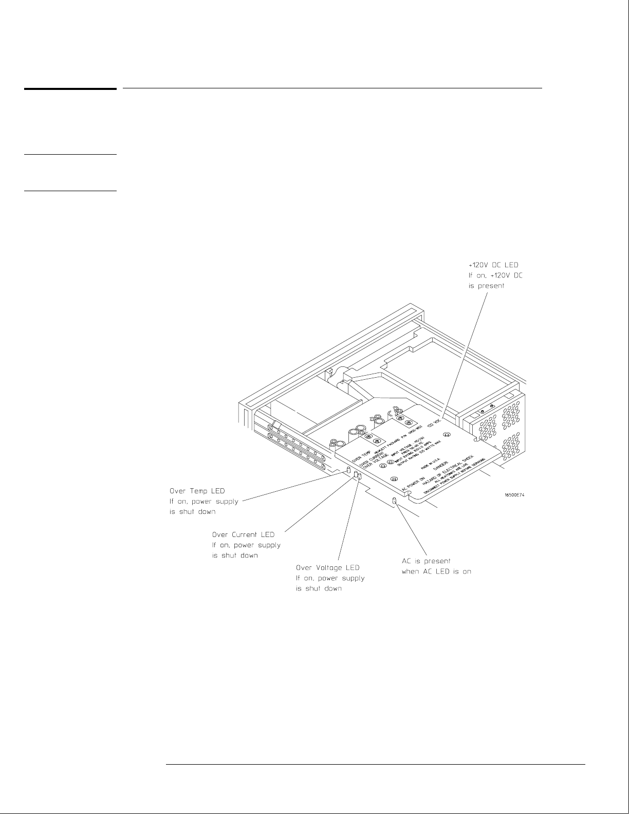
3Check the power supply LEDs.
4Note problems with the power supply, then return to the power supply flowchart.
Troubleshooting
To check the power supply LEDs
5–23
To check the power supply voltages
Refer to chapter 6, "Replacing Assemblies," for instructions to remove or replace covers and
assemblies.
WARNING Hazard voltages exist on the power supply, the CRT, and the CRT driver board. This
procedure is to be performed by service-trained personnel aware of the hazards involved,
such as fire and electrical shock.
1Turn off the instrument, disconnect the power cord, then remove the top cover.
2Apply power to the instrument.
3Using a DVM, measure the power supply voltages.
4Note problems with the power supply, then return to the power supply flowchart.
Power Supply Voltages
Pin Supply/Signal Voltage Pin Supply/Signal Voltage
1-5 5 volt +5 V 21 Ground sense 0 V
6 +5 volt remote sense +5 V 22 Power valid +5 V
7-9 +3.5 volt +3.5 V 23 −3.25 volt remote sense −3.25 V
10 +3.5 volt remote sense +3.5 V 24-30 −3.25 volt −3.25 V
11 +12 volt +12 V 31 −5.2 volt current limit +2.5 V
12 −12 volt −12 V 32 −5.2 volt remote sense −5.2 V
13 Not connected 33-37 −5.2 volt −5.2 V
14-20 Ground 0 V 38 Remote on/off +12 V
Troubleshooting
To check the power supply voltages
5–24

To test the flexible disk drive voltages
Refer to chapter 6, "Replacing Assemblies," for instructions to remove or replace covers and
assemblies.
WARNING Hazard voltages exist on the power supply, the CRT, and the CRT driver board. This
procedure is to be performed by service-trained personnel aware of the hazards involved,
such as fire and electrical shock.
Equipment Required
Equipment Critical Specification Recommended
Model/Part
Digitizing Oscilloscope > 100 MHz Bandwidth HP 54600A
1Turn off the instrument, then remove the power cable. Remove the instrument
cover and the flexible disk drive.
2Reconnect the disk drive cable to the rear of the disk drive. Turn the disk drive over
so that the solder connections of the cable socket are accessible.
3Connect the power cable, then turn on the instrument.
4In the Mainframe Test menu, select the Flexible Disk Test. Insert a disk that has
enough available bytes to run the test in the disk drive, then select Run-Repetitive.
Refer to "To run the self-tests" in this chapter if you need help accessing the test menu.
Troubleshooting
To test the flexible disk drive voltages
5–25
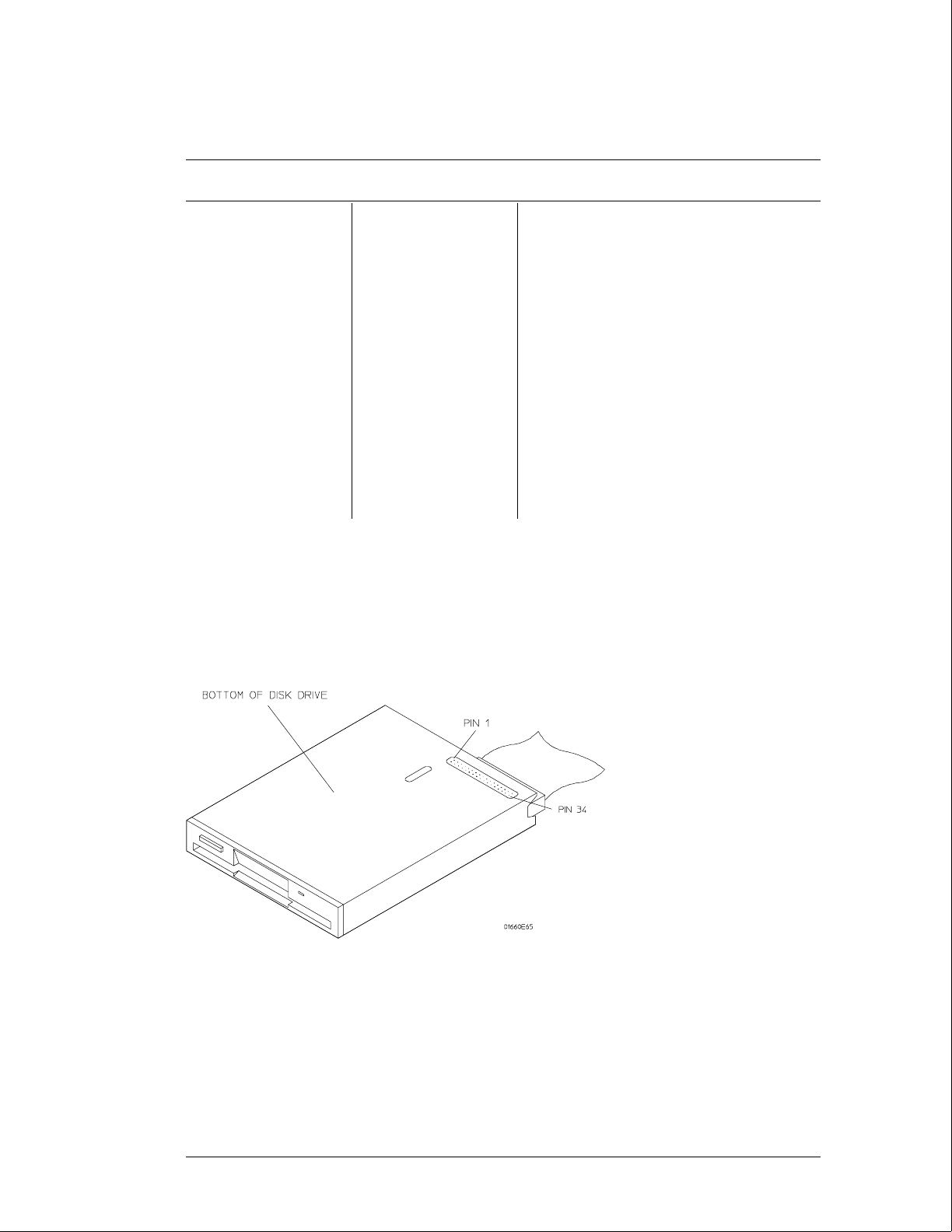
5Check for the following voltages and signals using an oscilloscope.
Disk Drive Voltages
Pin Signal
Description
Pin Signal
Description
Pin Signal Description
1 NC 13 Ground 24 Write Gate
2 Disk Change 14 NC 25 Ground
3 NC 15 Ground 26 Track 00
4 High Density 16 Motor On 27 Ground
5 NC 17 Ground 28 Write Protect
6 NC 18 Direction 29 Ground
7 +5 V 19 Ground 30 Read Data
8 Index 20 Step 31 Ground
9 +5 V 21 Ground 32 Side Select
10 Drive Select 22 Write Data 33 Ground
11 +5 V 23 Ground 34 Ready
12 NC
6Select Stop, and turn off the logic analyzer. Remove the power cable.
7Disconnect the disk drive cable and reinstall the disk drive in the mainframe.
8Reconnect the disk drive cable and install the cover on the mainframe.
Troubleshooting
To test the flexible disk drive voltages
5–26

To test the hard disk drive voltages
Refer to chapter 6, "Replacing Assemblies," for instructions to remove or replace covers and
assemblies.
WARNING Hazard voltages exist on the power supply, the CRT, and the CRT driver board. This
procedure is to be performed by service-trained personnel aware of the hazards involved,
such as fire and electrical shock.
Equipment Required
Equipment Critical Specification Recommended
Model/Part
Digitizing Oscilloscope > 100 MHz Bandwidth HP 54600A
1Turn off the instrument, then remove the power cable. Remove both the top and
bottom covers of the mainframe and set the mainframe on its side with the strap
handle facing up.
2If an HP 16500L module is installed, then remove it from the mainframe.
aDisconnect the three cables plugged into the HP 16500L by reaching through the top
of the mainframe and removing the plugs.
bRemove the screws attaching the HP 16500L to the mainframe. Refer to chapter 6 for
more complete instructions to remove the HP 16500L.
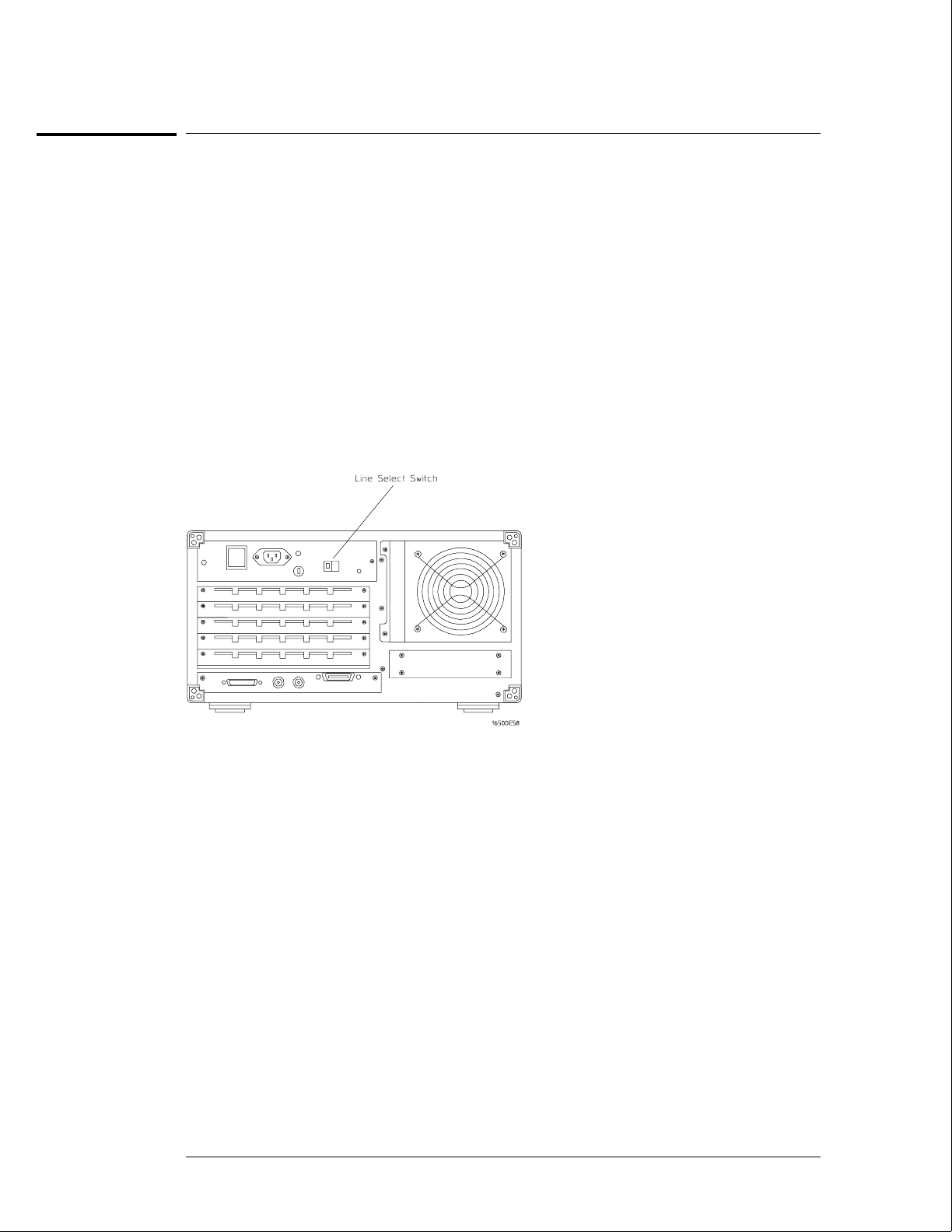
3Remove the four screws holding the hard disk drive and let the hard disk drive hang
by the power and the data cables. Do not let the hard disk drive contact the CPU
board.
4Connect the power cable and apply power to the mainframe. When the hard disk
drive begins spinning, ensure the disk drive does not contact the CPU board. When
the mainframe has powered up, enter the Test System.
5When the System Test menu appears, select Mainframe Test, then select Disk Test.
When the disk test menu appears, select Run-Repetitive.
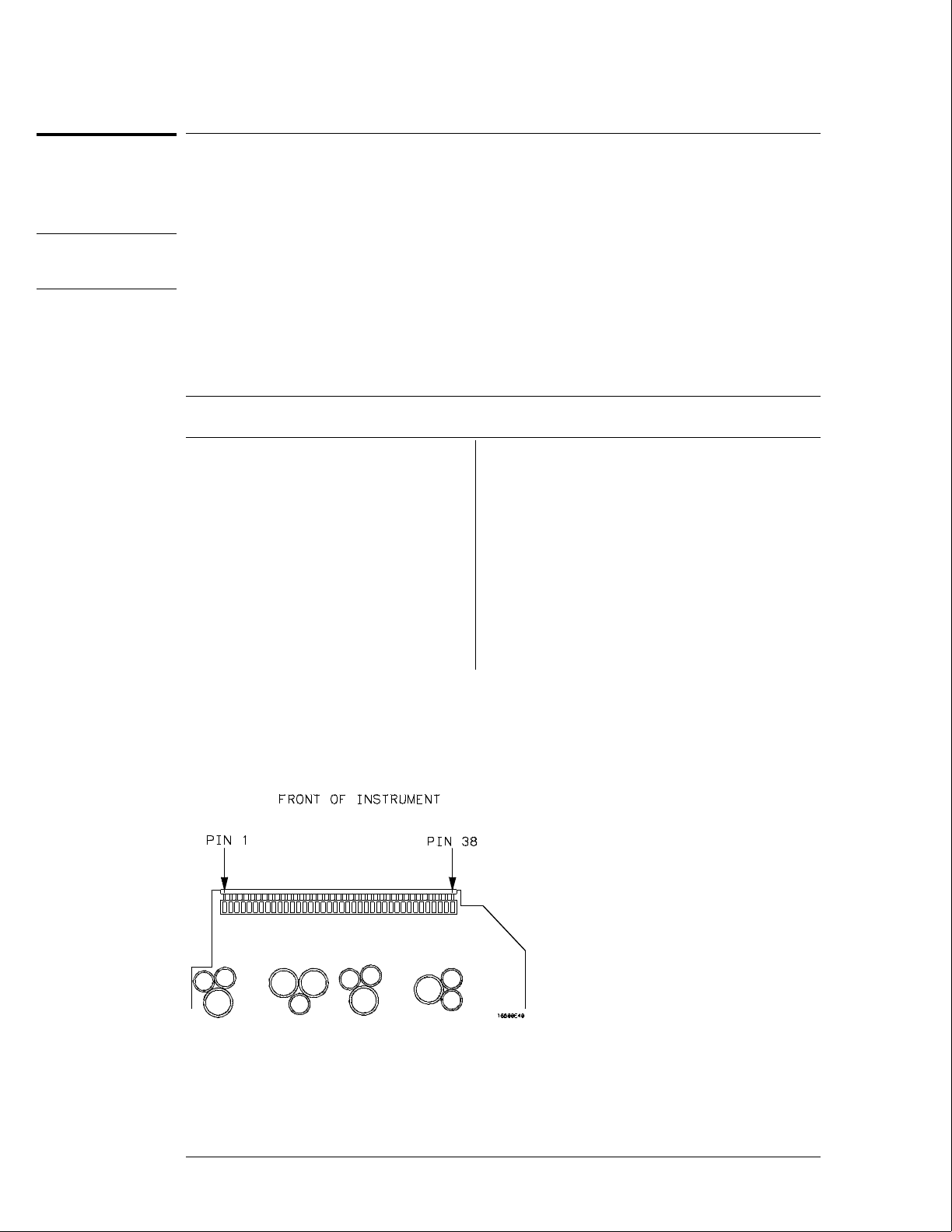
6Using an oscilloscope, check for activity on the pins. Probe the voltages on the hard
disk drive circuit board where the data cable connector is soldered. Pin 1 of the
connector is marked on the circuit board and is on the side of the connector closest
to the power cable.
Troubleshooting
To test the hard disk drive voltages
5–27

Disk Drive Voltages
Pin Signal Description Pin Signal Description Pin Signal Description
1Reset 15 Data 29 +5 V
2 Ground 16 Data 30 Ground
3 Data 17 Data 31 Interrupt Request
4 Data 18 Data 32 NC
5 Data 19 Ground 33 Address
6 Data 20 (connector key pin) 34 NC
7 Data 21 NC 35 Address
8 Data 22 Ground 36 Address
9 Data 23 Write Strobe 37 Register Select
10 Data 24 Ground 38 Register Select
11 Data 25 Read Strobe 39 NC
12 Data 26 Ground 40 Ground
13 Data 27 I/O Cycle Extend
14 Data 28 NC
7If the hard disk drive signals appear as indicated, then the hard disk drive should be
replaced. If the signals do not appear, then either the data cable or the CPU board is
suspect. J12 of the CPU board can be probed in the same manner as described
above to check for the same signals.
8Select Stop, and turn off the mainframe. Remove the power cable and replace the
faulty assembly.
9Reassemble the mainframe.
Troubleshooting
To test the hard disk drive voltages
5–28

To test the expansion frame interface
This procedure is used during troubleshooting to isolate a failed interface component, the
interface cable, the expansion frame interface card, or the HP 16500L. The Option Board Test
in the performance verification software generates bit patterns across the data, address, and
strobe lines of the interface. Isolation is done by using an oscilloscope to check activity on the
address and data buses and the strobe signal lines.
Refer to chapter 6, "Replacing Assemblies," for instructions to remove or replace covers and
assemblies.
WARNING Hazard voltages exist on the power supply, the CRT, and the CRT driver board. This
procedure is to be performed by service-trained personnel aware of the hazards involved,
such as fire and electrical shock.
Equipment Required
Equipment Critical Specification Recommended
Model/Part Number
Oscilloscope 100MHz Bandwidth HP 54600A
Before beginning this procedure, verify that the HP 16500L interface is properly installed and that
the expansion frame interface card and interface cable are properly seated.
Set up the Expansion Frame
1Remove power from the HP 16500B system and unplug the power cords from both
the mainframe and the expansion frame.
2Set the expansion frame on its side with the strap handle facing up. Remove the
bottom cover from the expansion frame.
3Plug the power cords into both the mainframe and expansion frame, then apply
power.
4In the System Configuration menu, select Configuration. Select Test , then touch the
box to load the test system.
5Select Test, then select Mainframe Tests in the pop-up menu. Select Option Board
Tests, then select Run-Repetitive.
Troubleshooting
To test the expansion frame interface
5–29
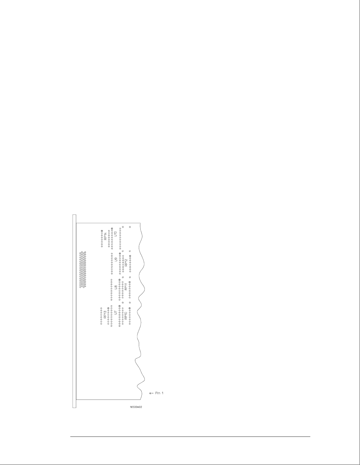
Test the Expansion Interface Card
1Ground the oscilloscope probe to the metal portion of the frame near the rear panel
of the expansion frame and check for TTL activity on the following pins.
•U7 pins 11 through 18
•U8 pins 2 through 9
•U9 pins 5 through 9
If there is TTL activity on all of the pins indicated, then the signal paths from the
mainframe CPU board and the end of the expansion frame interface card are
considered working. Go to the next step.
If one or more of the signal lines do not show activity, then go to "Test the
Mainframe CPU Board" on the next page.
2With the oscilloscope probe still grounded to the expansion frame, probe the
following pins.
•U7 pins 2 through 9
•U8 pins 11 through 18
•U9 pins 11 through 15
If all of the signal lines show TTL activity, then go to the next step.
If one or more of the signal lines do not show TTL activity, then replace the
expansion frame interface board.
Bottom Side of Expansion Interface Card
Troubleshooting
To test the expansion frame interface
5–30
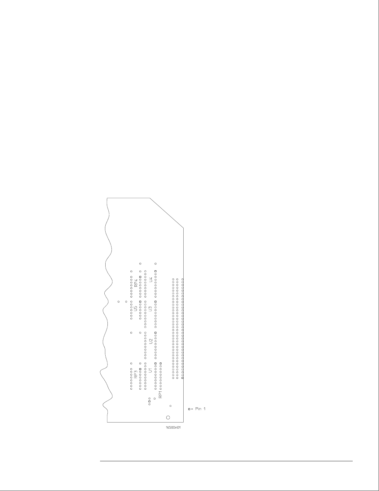
3Remove the probe ground from the frame, and reattach the probe ground to the
metal portion of the expansion frame near the front panel.
4Probe the following pins.
•U1 pins 2 through 9
•U2 pins 2 through 9
•U3 pins 5 through 9
If all of the signal lines show TTL activity, then go to the next step.
If one or more of the signal lines do not show TTL activity, then replace the
expansion frame interface board.
5With the oscilloscope probe still grounded to the frame, probe the following pins.
•U1 pins 11 through 18
•U2 pins 11 through 18
•U3 pins 11 through 15
If one or more of the signal lines do not show TTL activity, then replace the
expansion frame interface board.
Bottom Side of Expansion Interface Card
Troubleshooting
To test the expansion frame interface
5–31

Test the Mainframe CPU Board
1Remove power from the HP 16500B system and unplug the power cords from both
the mainframe and the expansion frame.
2Reinstall the bottom cover on the expansion frame. Set the mainframe on its side
with the strap handle facing up, then remove the bottom cover.
3Plug the power cords into both the mainframe and expansion frame, then apply
power.
4In the System Configuration menu, select Configuration. Select Test, then touch the
box to load the test system.
5Select Test, then select Mainframe Tests. Select Option Board Tests, then select
Run-Repetitive.
6Ground the oscilloscope probe to the metal portion of the frame near the rear panel
of the mainframe and check for TTL activity on the following pins. Reference
designator J10 is indicated on the bottom side of the CPU board.
•J10 pins 11 through 18
•J10 pins 21 through 28
•J10 pins 48 through 50
If there is TTL activity on all of the pins indicated, then the mainframe CPU board is
operational.
If one or more of the signal pins on the expansion frame interface board did not
show TTL activity, then the HP 16500L or the interface cable are suspect. Using an
ohm meter, check continuity of the interface cable.
If the interface cable is good, then replace the HP 16500L circuit board.
7Remove power from the HP 16500B system, and unplug the power cords from both
the mainframe and expansion frame. Replace the faulty components, then
reassemble the mainframe.
Troubleshooting
To test the expansion frame interface
5–32

6
To remove and replace the
Optional modules or filler panels 6-3
Covers 6–4
Flexible disk drive 6–5
Power supply 6–6
Rear fan 6–8
Side fan 6–9
HP 16500L interface module 6–10
Hard disk drive 6–12
Microprocessor board (CPU) 6–13
SIMM memory module 6–14
Expansion interface board 6–15
Mother board 6–16
Front-Panel board 6–18
Color display assembly 6–19
To return assemblies 6–22
Replacing Assemblies

Replacing Assemblies
This chapter contains the instructions for removing and replacing the assemblies of
the logic analysis system. Also in this chapter are instructions for returning
assemblies.
WARNING Hazardous voltages exist on the power supply, the CRT, and the CRT driver board. To avoid
electrical shock, disconnect the power from the instrument before performing the following
procedures. After disconnecting the power, wait at least six minutes for the capacitors on
the power supply board and the CRT driver board to discharge before servicing the
instrument. However, if the AC LED on the power supply has any illumination, a significant
charge remains on the power supply capacitors.
CAUTION Damage can occur to electronic components if you remove or replace assemblies when the
instrument is on or when the power cable is connected. Never attempt to remove or install
any assembly with the instrument on or with the power cable connected.
Replacement Strategy
These replacement procedures are organized as if disassembling the complete
instrument, from the first assembly to be removed to the last. Some procedures say
to remove other assemblies of the instrument, but do not give complete instructions.
Refer to the procedure for that specific assembly for the instructions.
CAUTION Electrostatic discharge can damage electronic components. Use grounded wriststraps and
mats when performing any service to this logic analyzer.
Tools Required
#10, #15, #25 TORX screwdrivers
#2 posidrive screwdriver
8-mm nut driver
6–2

To remove and replace optional modules or filler panels
1To reconfigure your system later in this procedure, note the configuration of your
system.
Some modules for the Logic Analysis System require calibration if you move them to a
different slot.
2Starting from the top, loosen the thumb screws on filler panels and cards in the
mainframe or the expansion frame. Starting from the top, pull the cards and filler
panels out.
All multicard modules will be cabled together. To prevent damage to the cables and
connectors, pull all multicard modules out together.
3To replace the modules, reposition all cards and filler panels so that the endplates
overlap properly.
4Firmly seat the bottom card into the backplane connector of the mainframe. Keep
applying pressure to the center of the card endplate while tightening the thumb
screws finger tight. Repeat for all cards and filler panels in a bottom to top order.
For correct air circulation, filler panels must be installed in all unused card slots. Correct air
circulation keeps the instrument from overheating. Keep any extra filler panels for future use.
See Also Service Guides for each individual module.
Replacing Assemblies
To remove and replace optional modules or filler panels
6–3
To remove and replace the covers
There are four outside covers on the HP 16500B and on the HP 16501A, a top cover, a bottom
cover, and two side covers.
When removing the covers, note where the shielding braid is located. If the shielding braid
separates from the covers, reinstall it when replacing the covers. The shielding braid helps
the instrument meet EMI (electromagnetic interference) specifications.
1Remove the four rear feet.
The screws connecting the feet to the frame are accessible through the holes in the end of the
feet.
2Remove the top and bottom covers.
To remove the covers, loosen the screw in the rear of the covers. If a captive screw was used,
loosening the screw will pull the cover back. When the screw is completely loose from the
frame, slide the cover off. To remove the bottom cover, turn the instrument on its side, then
loosen the screw in the rear of the bottom cover.
3Remove the side strap handle and side covers.
To remove the side strap handle, remove the two strap retaining screws. Slide the strap
handle cover off.
Note that the handle is rounded on the side closest to the instrument. Reinstall the handle
with the same side toward the instrument.
To remove a side cover, loosen the screw in the rear of the cover. (The side cover with a
strap handle will not have a rear screw.) If a captive screw was used, loosening the screw will
pull the cover back. When the screw is completely loose from the frame, slide the cover off.
4Replace the covers by reversing this procedure.
Replacing Assemblies
To remove and replace the covers
6–4

To remove and replace the flexible disk drive
HP 16500B
1Using previous procedures, remove the following assemblies:
•Top cover
2Remove the two disk drive mounting screws.
3Slide the flexible disk drive assembly toward the rear panel until the assembly is out
of the instrument.
4Disconnect the control cable for the disk drive.
5Remove the mounting bracket from the bottom of the assembly.
6Reverse this procedure to replace the flexible disk drive.
Replacing Assemblies
To remove and replace the flexible disk drive
6–5

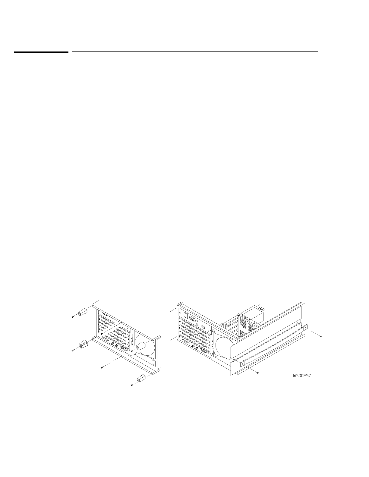
To remove and replace the power supply
WARNING Hazardous voltages exist on the power supply. To avoid electrical shock, disconnect the
power from the instrument before performing the following procedures. After disconnecting
the power, wait at least six minutes for the capacitors on the power supply board to
discharge before servicing the instrument. However, if the AC LED on the power supply has
any illumination, a significant charge remains on the capacitors.
HP 16500B
1Using previous procedures, remove the following assemblies:
•Top cover
•Flexible disk drive assembly
•Optional module card or filler panel in the top slot of the card cage
2Remove the power supply rear panel.
3Disconnect the color display to power supply cable from the power supply.
4Remove the four power supply mounting screws.
5Pull the power supply towards the rear panel of the mainframe until the power
supply disconnects from the mother board connector.
6Lift the front end of the power supply and guide it out of the mainframe.
7Reverse this procedure to install the replacement power supply.
Before pushing the power supply into place, make sure that it is properly aligned with the
front connector of the mother board and with the rail guides of the card cage.
HP 16501A
1Using previous procedures, remove the following assemblies:
•Top cover
•Optional module card or filler panel in the top slot of the card cage
22 Remove the power supply rear panel.
3Remove the four power supply mounting screws.
4Pull the power supply towards the rear panel of the expansion frame until the power
supply disconnects from the mother board connector.
5Lift the front end of the power supply and guide it out of the expansion frame.
6Reverse this procedure to install the replacement power supply.
Before pushing the power supply into place, make sure that it is properly aligned with the
front connector of the mother board and with the rail guides of the card cage.
Replacing Assemblies
To remove and replace the power supply
6–6
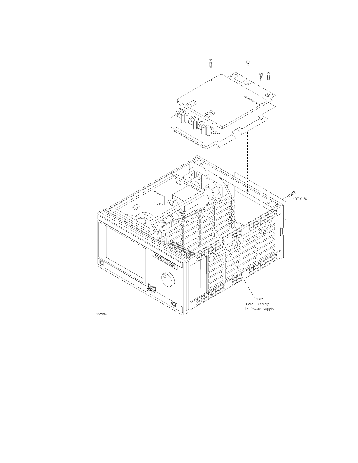
Replacing Assemblies
To remove and replace the power supply
6–7
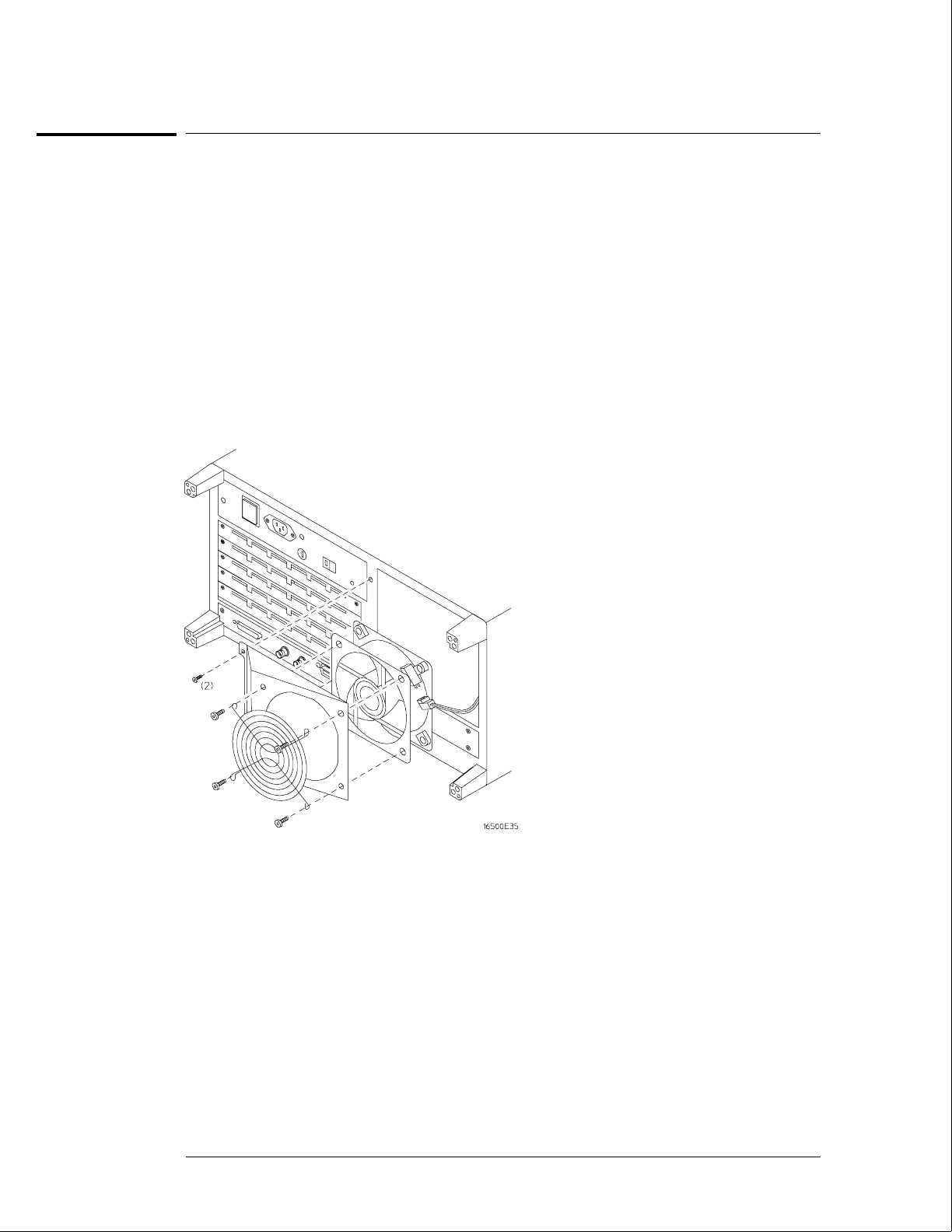
To remove and replace the rear fan
HP 16500B and HP 16501A
1Using previous procedures, remove the following assemblies:
•Top cover
2Remove the rear fan shroud mounting screws.
3Remove the complete rear fan assembly from the rear panel of the instrument.
4Disconnect the rear fan power cable.
5Remove the rear fan mounting screws and remove the fan from the fan shroud.
6Reverse this procedure to install the replacement rear fan.
Make sure that the fan power cable is dressed under and between the fans and that the cable
polarity is observed.
Replacing Assemblies
To remove and replace the rear fan
6–8
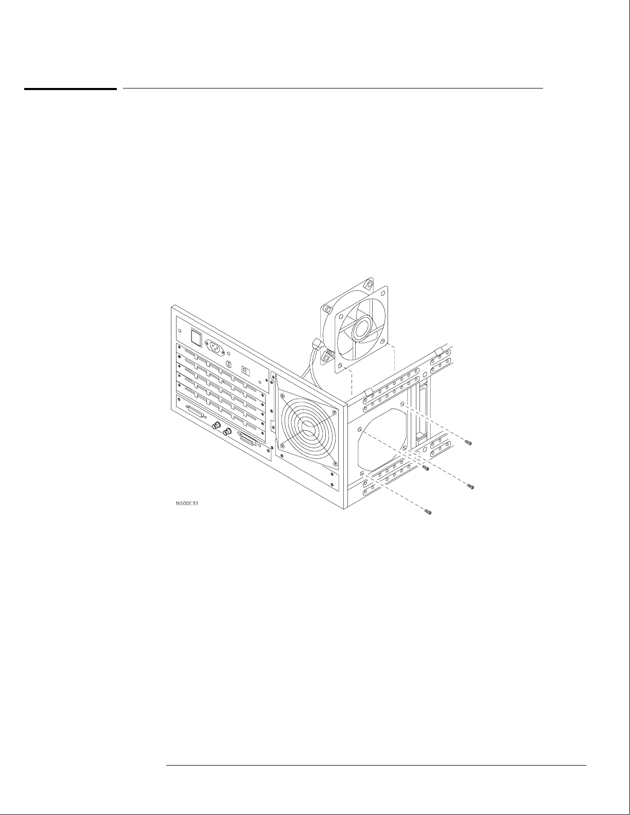
To remove and replace the side fan
HP 16500B and HP 16501A
1Using previous procedures, remove the following assemblies:
•Top cover and side cover
2Remove the four side fan mounting screws.
3Reach through the top of the instrument and disconnect the fan power cable, then
remove the fan.
4Reverse this procedure to install the replacement side fan.
Make sure that the fan power cable is dressed under and between the fans and that the cable
polarity is observed.
Replacing Assemblies
To remove and replace the side fan
6–9

To remove and replace the HP 16500L interface module
HP 16500B and HP 16500L
11 Using previous procedures, remove the following assemblies:
•Top cover
2If your system includes an expansion frame, disconnect the interface cable from the
HP 16500L interface module by pressing the release tabs on either side of the cable
connector while pulling the connector away from the card.
3Disconnect the cable from the HP 16500L interface module to the CRT monitor and
the two cables from the HP 16500L interface module to the CPU card.
4Remove the two screws connecting the HP 16500L interface module to the sheet
metal plate and the four screws connecting the HP 16500L interface module to the
mainframe rear panel.
5Slide the card out the back of the mainframe.
6Insert the replacement card in the back of the mainframe, then install the screws
and connect the cables.
The module serial number is located on the module rear panel. If you need to keep the same
serial number with your system, then remove the rear panel from the old interface module and
install it on the replacement module. The module rear panel is connected to the module circuit
board with four screws.
Replacing Assemblies
To remove and replace the HP 16500L interface module
6–10
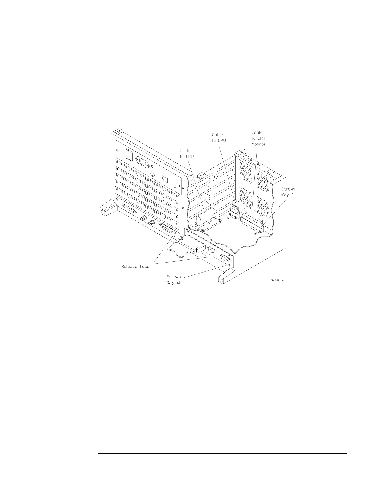
7If your system includes an expansion frame, connect the interface cable from the
expansion frame to the HP 16500L interface module located in the HP 16500B
mainframe.
In order to ensure correct connection of the interface cable, the 68-pin "D" connectors on the
cable are asymmetric in shape. They only fit into the ports on the cards when oriented to
match the shape of the ports.
When reconnecting the interface cable, make sure the cable connector is properly seated into
the port on the expansion interface card by pulling the cable connector without pressing the
release tabs. If the connector is properly seated, it will remain connected to the port.
Replacing Assemblies
To remove and replace the HP 16500L interface module
6–11

To remove and replace the hard disk drive
HP 16500B
1Using previous procedures, remove the following assemblies:
•Top and bottom covers
•HP 16500L interface module
2Reaching in from the top of the instrument, remove the four screws connecting the
hard disk drive to the bracket.
3Reaching in from the bottom of the instrument, remove the hard disk drive.
4Disconnect the two cables from the hard disk drive to the CPU board.
5Reverse this procedure to install the replacement hard disk drive.
Verify that the jumper on the underside of the hard disk is in the E1 position.
The replacement hard disk might be fastened to a mounting bracket when received. Before
installing the hard disk, remove the mounting bracket If the replacement hard disk is an
exchange assembly, attach the mounting bracket to the faulty disk drive before returning it to
Hewlett-Packard. If the replacement disk drive is a new assembly, discard the mounting
bracket.
Replacing Assemblies
To remove and replace the hard disk drive
6–12
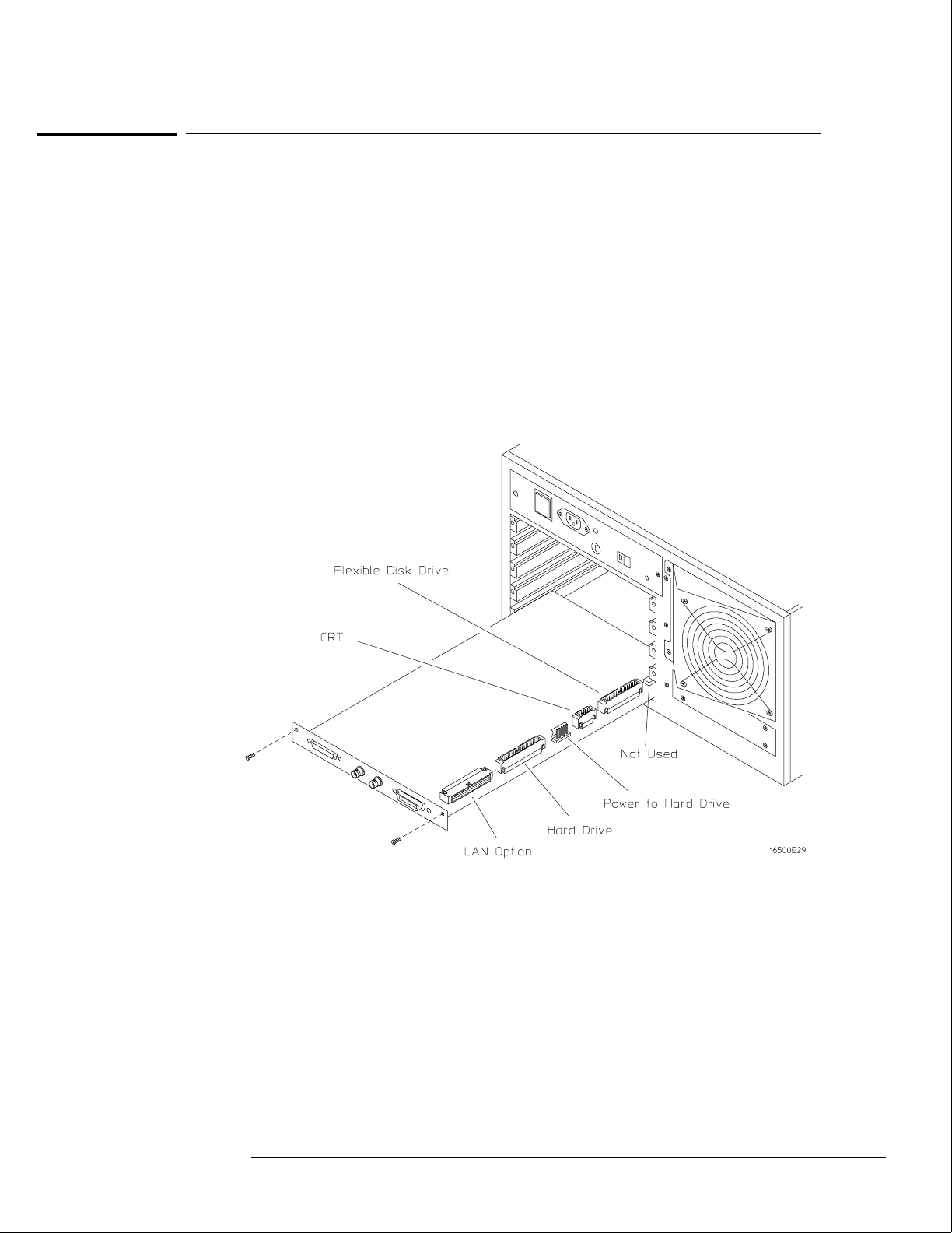
To remove and replace the microprocessor board (CPU)
HP 16500B
1Using previous procedures, remove the following assemblies:
•Top cover and left, rear foot
•All optional modules and filler panels
2Disconnect the cables from the microprocessor board.
3Remove the two screws connecting the microprocessor to the rear panel.
4Carefully slide the microprocessor board out of the mainframe.
5Reverse this procedure to install the replacement microprocessor board.
Replacing Assemblies
To remove and replace the microprocessor board (CPU)
6–13
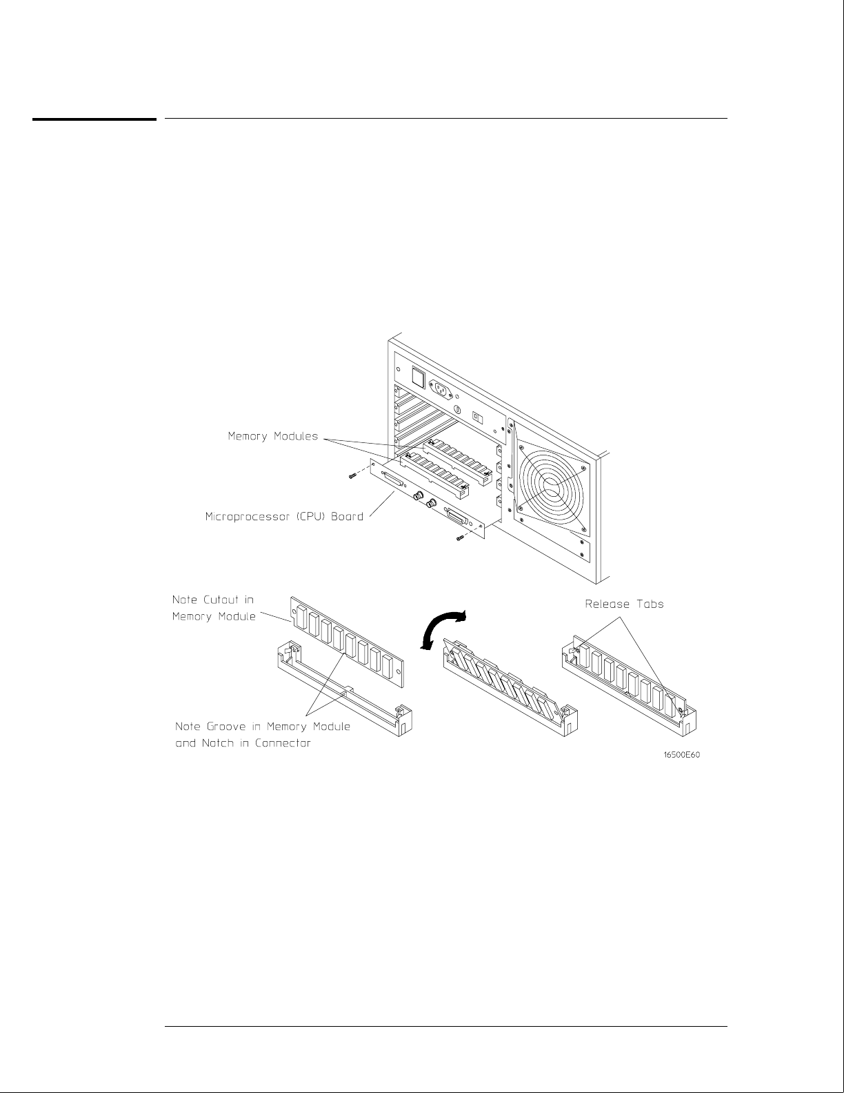
To remove and replace a SIMM memory
HP 16500B
1Using previous procedures, remove the following assemblies:
•Microprocessor (CPU) board
2Hold the release tabs away from the SIMM (single inline memory module), then pull
the module out.
3Reverse this procedure to install the replacement SIMM.
Slide the SIMM module into the connector at an angle, then push it down parallel to the
microprocessor board.
Replacing Assemblies
To remove and replace a SIMM memory
6–14
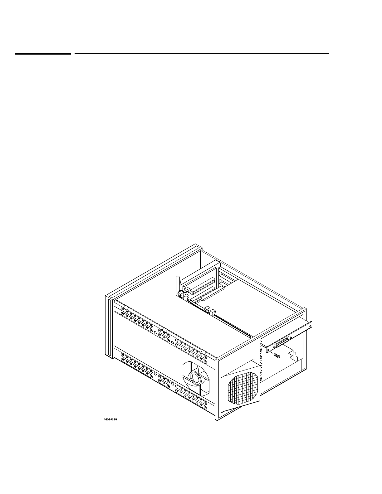
To remove and replace the expansion interface board
HP 16501A
1Using previous procedures, remove the following assemblies:
•Bottom cover
•All optional modules and filler panels
2Disconnect the interface cable by pressing the release tabs on either side of the
cable connector while pulling the cable connector away from the board.
3Disconnect the two cables on the expansion interface board. One cable is
connected to the front-panel LED and one cable is connected to the mother board.
4Remove the two screws connecting the expansion interface board to the rear panel
of the expansion frame.
5Carefully slide the expansion interface board out of the expansion frame.
6Reverse this procedure to install the replacement expansion interface board.
In order to ensure correct connection of the interface cable, the 68-pin "D" connectors on the
cable are asymmetric in shape. They only fit into the ports on the boards when oriented to
match the shape of the ports.
When reconnecting the interface cable, make sure the cable connector is properly seated into
the port on the expansion interface board by pulling the cable connector without pressing the
release tabs. If the connector is properly seated, it will remain connected to the port.
Replacing Assemblies
To remove and replace the expansion interface board
6–15

To remove and replace the mother board
HP 16500B
1Using previous procedures, remove the following assemblies:
•Top and bottom covers
•Power supply
•Microprocessor board
•All optional modules and filler panels
2Set the frame so that the bottom of the frame is facing up. This is to gain access to
the fan power cable and the front-panel cable.
3Disconnect the fan power cable and the front-panel cable from the mother board.
4Remove the six mother board mounting screws, then lift the mother board out of the
mainframe.
5Reverse this procedure to install the replacement mother board.
HP 16501A
1Using previous procedures, remove the following assemblies:
•Top and bottom covers
•Power supply
•Expansion interface board
•All optional modules and filler panels
2Set the frame so that the bottom of the frame is facing up. This is to gain access to
the fan power cable and the front-panel cable.
3Disconnect the fan power cable from the mother board.
4Remove the six mother board mounting screws, then lift the mother board out of the
expansion frame.
5Reverse this procedure to install the replacement mother board.
Replacing Assemblies
To remove and replace the mother board
6–16
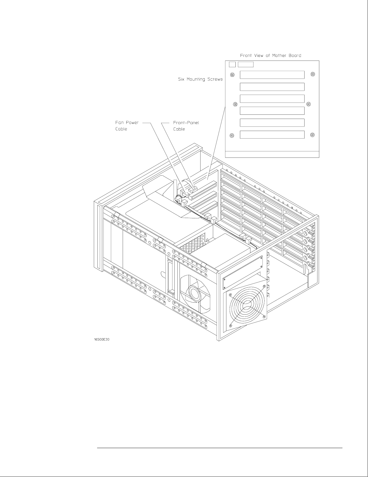
Replacing Assemblies
To remove and replace the mother board
6–17
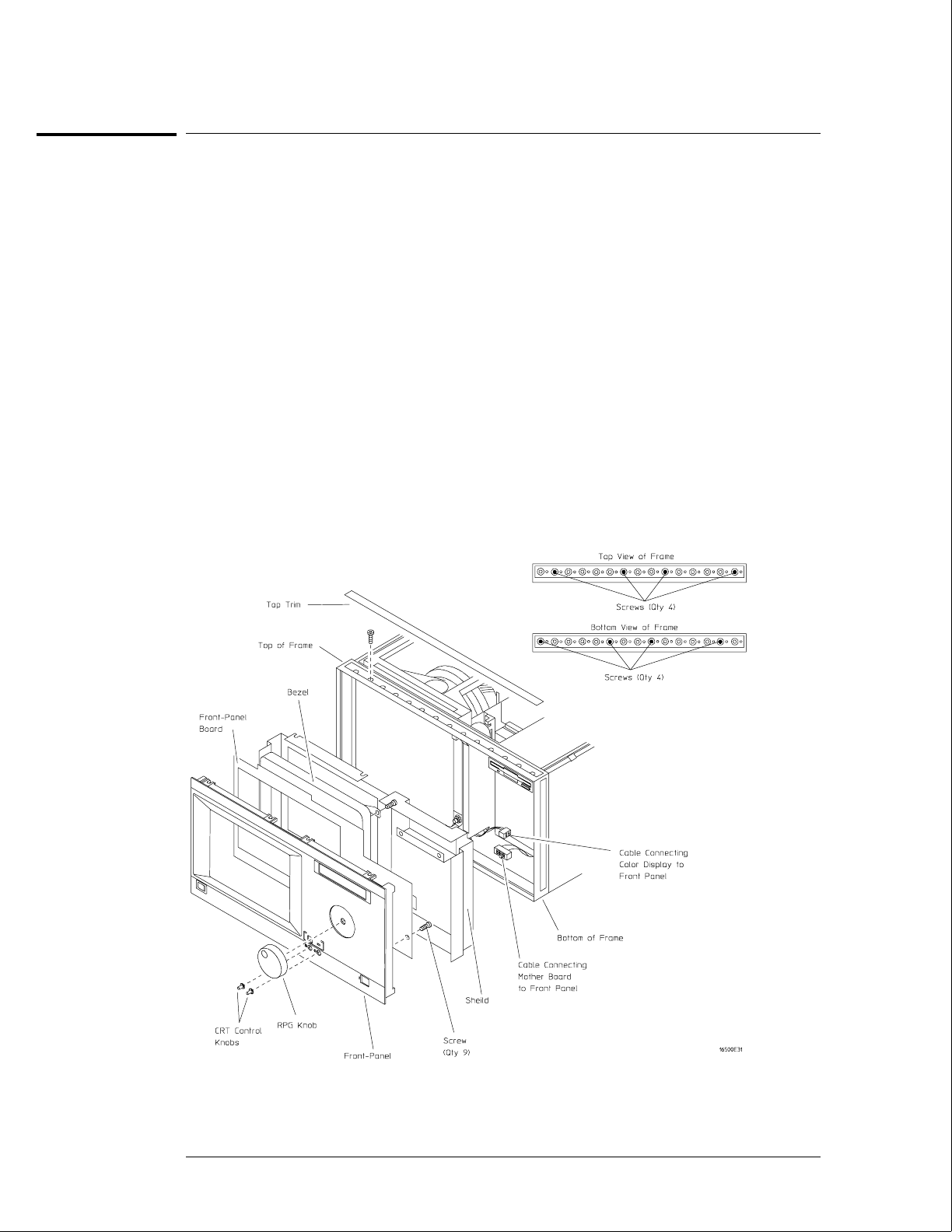
To remove and replace the front-panel board
HP 16500B
1Remove the top trim from the front frame.
2Disconnect the two cables from the front-panel board.
One cable is connected to the color display assembly and one cable is connected to the
mother board.
3Remove the screws connecting the front-panel assembly to the top and bottom of
the frame.
4Remove the front-panel assembly by pushing on the back of the assembly from
inside the instrument.
5Carefully remove the shield from the assembly.
The shield is very fragile and must be replaced if it is bent or damaged in any way.
6Remove the bezel from the front-panel board.
7Remove the RPG knob and the two CRT control knobs by pulling them away from
the front-panel.
8Remove the screws connecting the front-panel board to the front-panel, then remove
the front-panel board.
9Reverse this procedure to install the replacement front-panel board.
Replacing Assemblies
To remove and replace the front-panel board
6–18
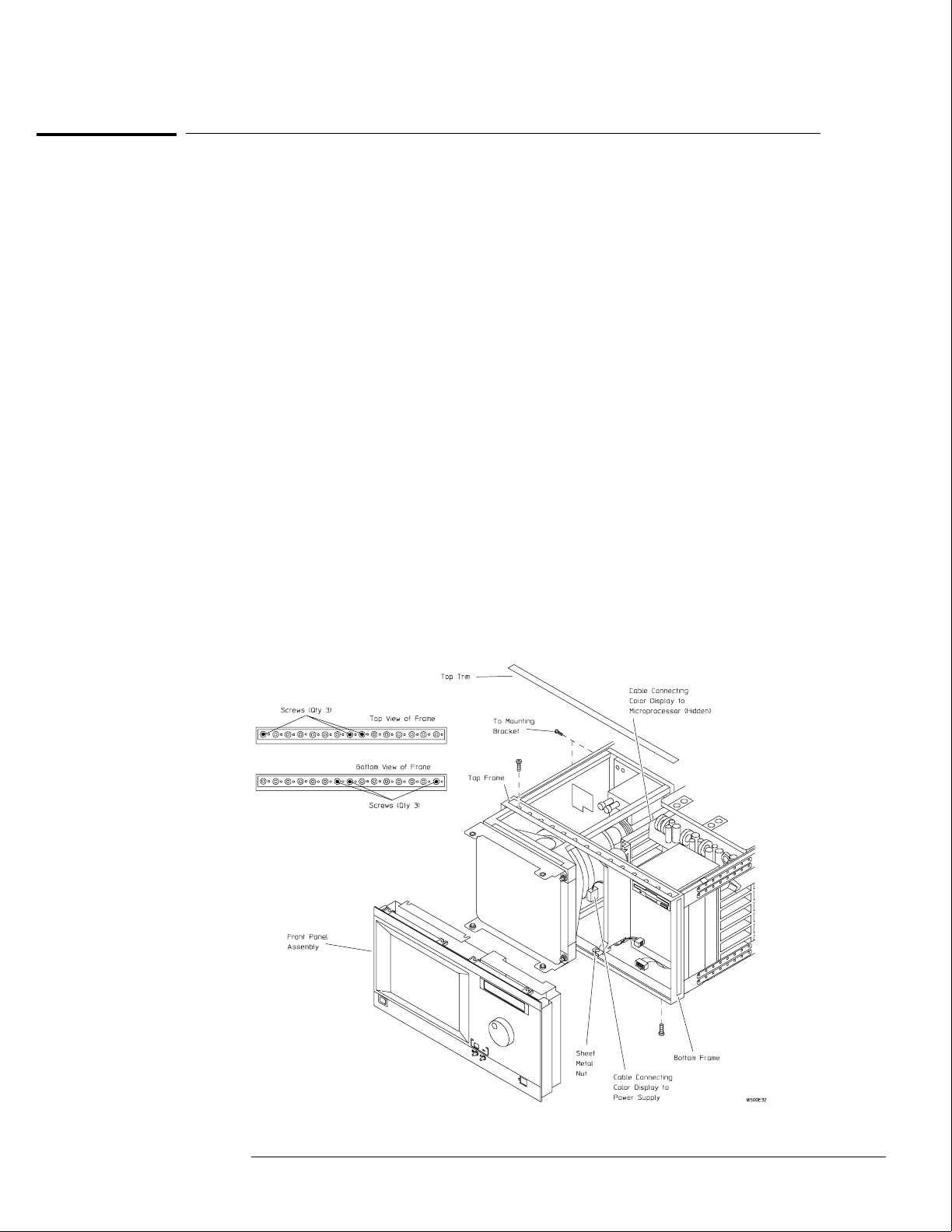
To remove and replace the color display assembly
HP 16500B
The color display assembly replacement procedure consists of three sections:
Removing the assembly from the mainframe.
Transferring parts to the replacement assembly.
Installing the assembly in the mainframe.
Removing the color display assembly from the mainframe
1Using previous procedures, remove the following assemblies:
•All covers
•Front-panel assembly
2Disconnect the color display to microprocessor cable from the microprocessor
board. Disconnect the color display to power supply cable from the power supply.
If an HP 16500L is installed, disconnect the cable from the color display to the HP 16500L.
3Remove the screws that connect the rear mounting bracket on the display assembly
to the side of the mainframe.
4Remove the screws that connect the color display to the top and bottom of the front
frame.
5Remove the screws that connect the center board guide to the front frame. Move
the sheet metal nuts, located on the center board guide, so that the display assembly
can clear the mainframe.
6Slide the complete color display assembly forward out of the mainframe. To prevent
damage to the assembly cables, make sure that they also clear the frame.
Replacing Assemblies
To remove and replace the color display assembly
6–19
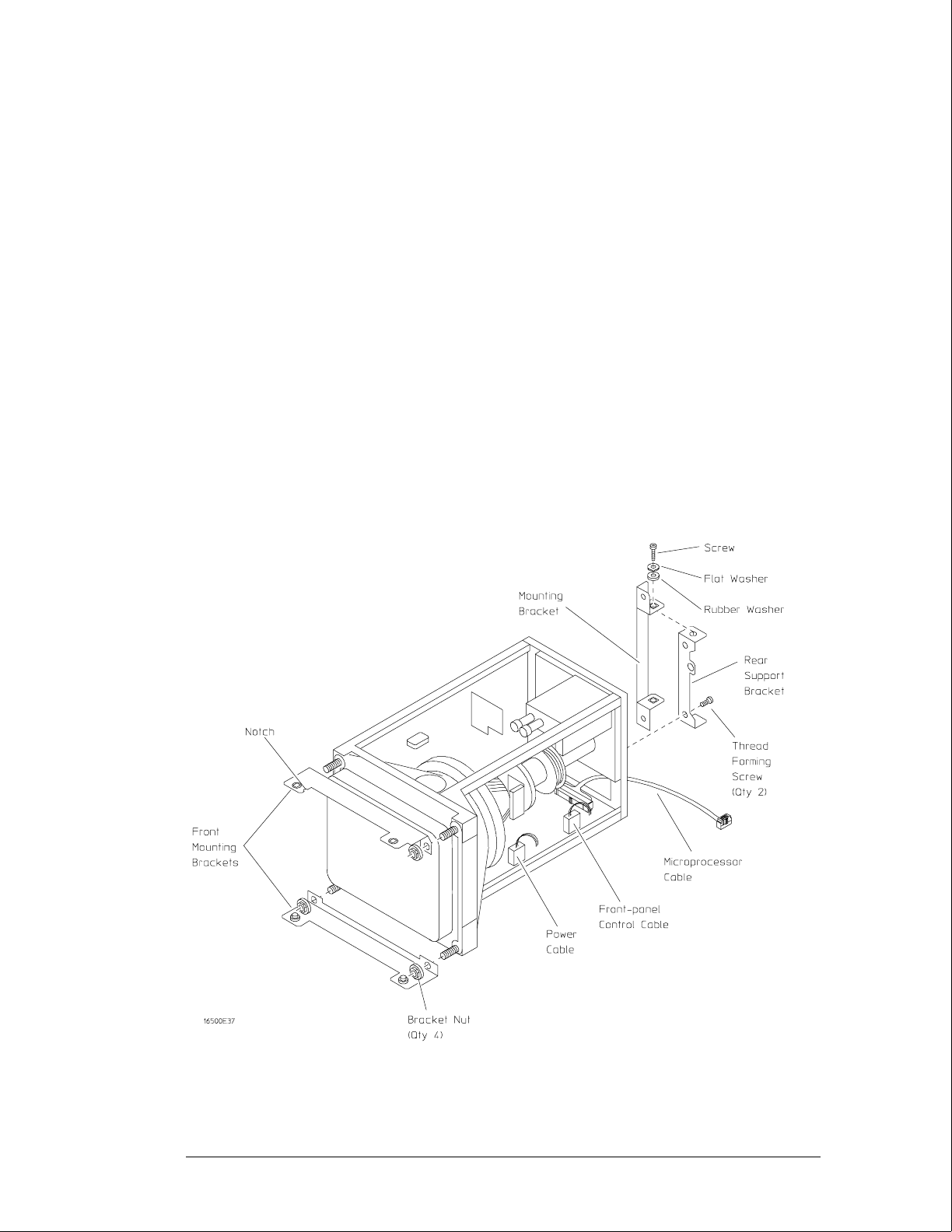
Transferring parts to the replacement assembly
The purpose of this procedure is to transfer the mechanical parts from the old assembly to the
replacement assembly.
1Remove the rear mounting bracket from the rear support bracket. Remove the rear
support bracket from the color display assembly.
2Attach the rear support bracket to the replacement assembly, using the two
thread-forming screws. Do not overtighten.
3Attach the frame mounting bracket to the rear support bracket. Install the hardware
in the following sequence: screw, flat washer, rubber washer. Do not tighten the
hardware.
4Remove the four bracket nuts connecting the front mounting brackets to the old
assembly, then remove the front mounting brackets. Reinstall the bracket nuts on
the old assembly.
5Remove the four bracket nuts from the replacement assembly. Using the four
bracket nuts, install both front mounting brackets on the replacement display
assembly. The upper bracket is identified by the notch on one edge.
6Disconnect the flat microprocessor cable, the power cable, and the front-panel
control cable from the old assembly, noting the location of the cables. Connect the
cables to the replacement assembly.
Replacing Assemblies
To remove and replace the color display assembly
6–20

Installing the replacement color display assembly
1Carefully slide the color display assembly most of the way into the mainframe. To
prevent damage to the cables, make sure that they clear the mainframe.
2Connect the color display to power supply cable to the power supply. Slide the
display assembly completely into the mainframe.
3Attach the display assembly to the front frame with four screws (two on the top
casting and two on the bottom casting). Do not tighten the screws.
4Move the sheet metal nuts, located on the front tabs of the center board guide, so
that the holes in the sheet metal nuts and the tabs line up. Attach the front tabs of
the center board guide to the front frame.
5Reinstall the front-panel assembly, connecting the front-panel cables. Make sure the
front-panel assembly is properly seated before tightening the hardware.
6Push the display assembly forward, until it is properly seated against the front-panel
assembly. Tighten the four display assembly mounting screws in the front frame.
7Attach the rear mounting bracket of the display assembly to the side frame, then
tighten the mounting bracket screws. To prevent damage to the rubber washers, do
not overtighten the screws.
8Tighten all of the display assembly mounting hardware. Reconnect the flat color
display to microprocessor cable to the microprocessor board.
If an HP 16500L is installed, connect the cable from the color display assembly to the
HP 16500L.
9Reinstall all covers.
Replacing Assemblies
To remove and replace the color display assembly
6–21

To return assemblies
Before shipping the logic analysis system or assemblies to Hewlett-Packard, contact your
nearest Hewlett-Packard sales office for additional details.
1Write the following information on a tag and attach it to the part to be returned.
•Name and address of owner
•Model number
•Serial number
•Description of service required or failure indications
2Remove accessories from the logic analysis system.
Only return accessories to Hewlett-Packard if they are associated with the failure symptoms.
3Package the logic analysis system or assemblies.
You can use either the original shipping containers, or order materials from an HP sales office.
CAUTION For protection against electrostatic discharge, package the logic analyzer in electrostatic
material.
4Seal the shipping container securely, and mark it FRAGILE.
Replacing Assemblies
To return assemblies
6–22

7
Replaceable Parts Ordering 7–2
Replaceable Parts List 7–3
HP 16500B Exploded View and Replaceable Parts 7–4
HP 16501A Exploded View and Replaceable Parts 7–9
Replaceable Parts

Replaceable Parts
This chapter contains information for identifying and ordering replaceable parts for
your logic analysis system.
Replaceable Parts Ordering
Parts listed
To order a part on the list of replaceable parts, quote the Hewlett-Packard part number,
indicate the quantity desired, and address the order to the nearest Hewlett-Packard Sales
Office.
Parts not listed
To order a part not on the list of replaceable parts, include the model number and serial
number of the module, a description of the part (including its function), and the number of
parts required. Address the order to your nearest Hewlett-Packard Sales Office.
Direct mail order system
Within the USA, Hewlett-Packard can supply parts through a direct mail order system. The
advantages to the system are direct ordering and shipment from the HP Part Center in
Mountain View, California. There is no maximum or minimum on any mail order. (There is a
minimum amount for parts ordered through a local Hewlett-Packard Sales Office when the
orders require billing and invoicing.) Transportation costs are prepaid (there is a small
handling charge for each order) and there are no invoices.
In order for Hewlett-Packard to provide these advantages, a check or money order must
accompany each order. Mail order forms and specific ordering information are available
through your local Hewlett-Packard Sales Office. Addresses and telephone numbers are
located in a separate document at the back of the Service Guide.
Exchange Assemblies
Some assemblies are part of an exchange program with Hewlett-Packard. The exchange
program allows you to exchange a faulty assembly with one that has been repaired and
performance verified by Hewlett-Packard.
After you receive the exchange assembly, return the defective assembly to Hewlett-Packard.
A United States customer has 30 days to return the defective assembly. If you do not return
the defective assembly within the 30 days, Hewlett-Packard will charge you an additional
amount. This amount is the difference in price between a new assembly and that of the
exchange assembly. For orders not originating in the United States, contact your nearest
Hewlett-Packard Sales Office for information.
See Also "To return assemblies" in chapter 6.
7–2

Replaceable Parts List Description
The replaceable parts list is organized by reference designation.
The exploded view does not show all of the parts in the replaceable parts list.
Information included for each part on the list consists of the following:
•Reference designator
•Hewlett-Packard part number
•Total quantity included with the instrument (Qty)
•Description of the part
•
Reference designators used in the parts list are as follows:
•A Assembly
•E Miscellaneous Electrical Part
•F Fuse
•H Hardware
•MP Mechanical Part
•W Cable
Replaceable Parts
Replaceable Parts List Description
7–3
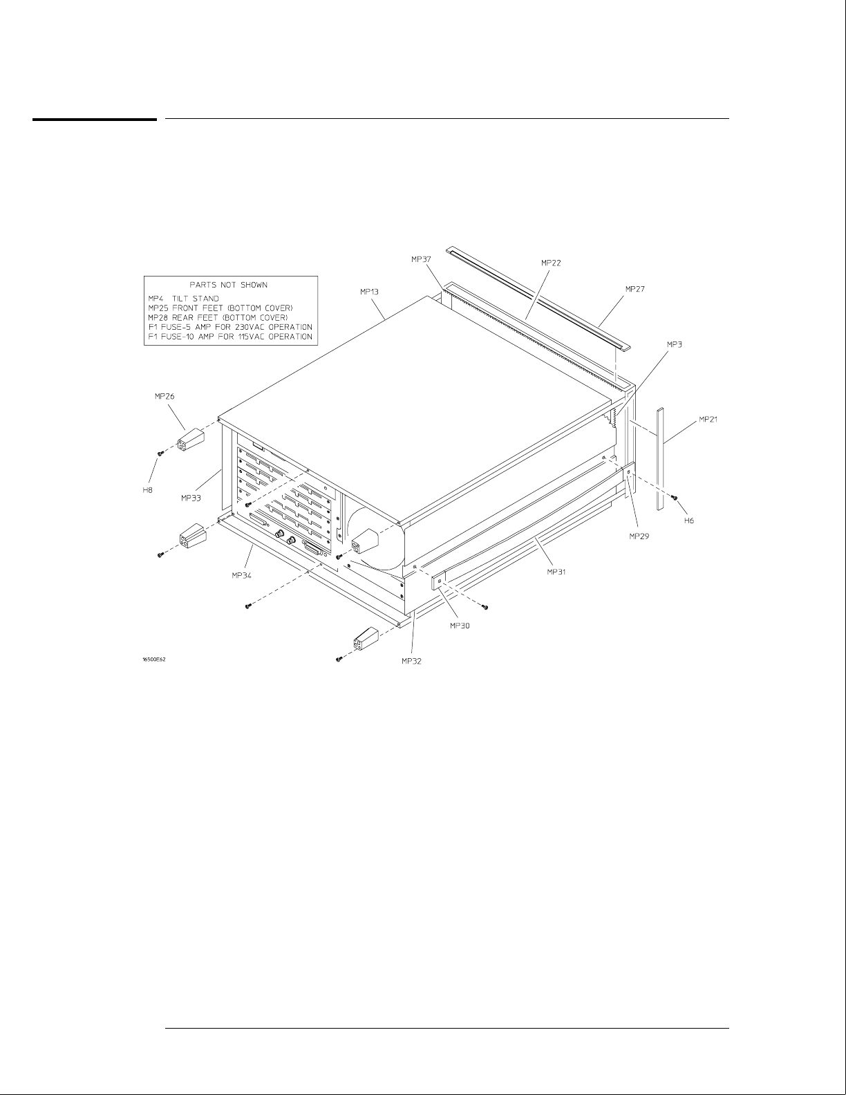
HP 16500B Exploded View and Replaceable Parts
Exploded view of the HP 16500B External Parts
Replaceable Parts
HP 16500B Exploded View and Replaceable Parts
7–4

HP 16500B Replaceable Parts
Ref.
Des.
HP Part
Number QTY Description
Exchange Assemblies
A2 16500-69512 Front-panel circuit board (exchange)
A3 16500-69509 Microprocessor board assembly (exchange)
A5 D2329-69001 Hard disk drive (exchange)
A6 16500-69500 Power supply (exchange)
A8 2095-0001 Color monitor assembly (exchange)
A9 D2156-69001 1MX36 SIMM module (exchange)
External Parts
F1 2110-0010 Fuse - 5 amp for 230 Vac operation
F1 2110-0395 Fuse - 10 amp for 115 Vac operation
H6 0515-1384 2 Screw M5 X 0.8 10 MM-LG (side handle)
H8 0515-1444 4 Screw M3.5 X 0.6 25.4MM_LG (back feet)
MP3 0363-0125 4 RFI strip - fingers (top and bottom covers)
MP4 1460-1345 2 Tilt stand
MP13 16500-04102 1 Top cover
MP21 5001-0541 2 Side trim (front frame)
MP25 5041-8801 2 Feet - front (bottom cover)
MP26 54110-40502 4 Feet - back
MP27 5041-8802 1 Top trim strip (frame)
MP28 5041-8822 2 Feet - rear (bottom cover)
MP29 5041-8819 1 Strap handle cap - front
MP30 5041-8820 1 Strap handle cap - rear
MP31 5062-3704 1 Strap handle
MP32 5062-3847 1 Cover - left side (with handle)
MP33 5062-3822 1 Cover - right side (without handle)
MP34 5062-3747 1 Cover - bottom
MP37 8160-0551 6 EMI shielding - braided
W7 8120-1521 1 Power cord - United States (7.5 ft)
W7 8120-1703 1 Power cord (Option 900-UK)
W7 8120-0696 1 Power cord (Option 901-Austl)
W7 8120-1692 1 Power cord (Option 902-Eur)
W7 8120-2296 1 Power cord (Option 906-Swit)
W7 8120-2957 1 Power cord (Option 912-Den)
W7 8120-4600 1 Power cord (Option 917-Africa)
W7 8120-4754 1 Power cord (Option 918-Japan)
01660-84501 1 Accessory pouch
0515-1245 Replacement screw for top and bottom covers
0510-1253 Replacement retaining ring for top and bottom covers
Replaceable Parts
HP 16500B Exploded View and Replaceable Parts
7–5
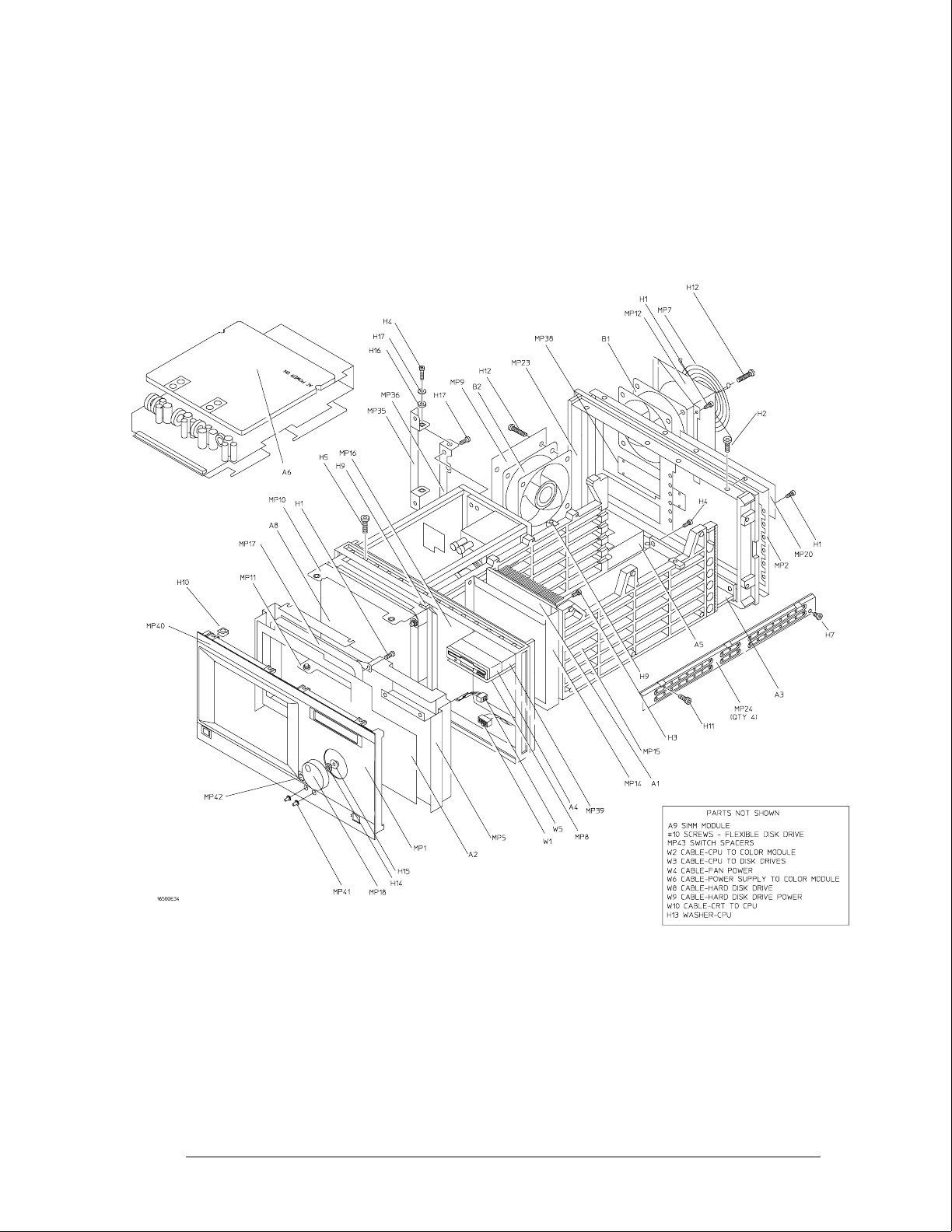
Exploded View of the HP 16500B
Replaceable Parts
HP 16500B Exploded View and Replaceable Parts
7–6

HP 16500B Replaceable Parts
Ref.
Des.
HP Part
Number QTY Description
Internal Parts
A1 16500-66501 1 Mother board assembly
A3 16500-66509 1 Microprocessor board assembly
A4 0950-2169 2 Flexible disk drive
A5 D2329-60003 Hard disk drive
A6 0950-1853 1 Power supply assembly
A8 2090-0251 1 Color CRT module assembly
A9 1818-4703 2 1MX36 SIMM module
B1 3160-0829 2 Fan - tubeaxial
B2 3160-0829 Fan - tubeaxial
H1 0515-0372 31 Screw M3 X 0.5 8MM-LG
H2 0515-0433 8 Screw M4 X 0.7 10MM-LG (rear panel, center rib)
H3 0515-0435 6 Screw M4 X 0.7 14MM-LG (center rib, power supply)
H4 0515-0664 6 Screw M3 X 0.5 12MM-LG (color monitor bracket, CPU board)
H5 0515-0943 14 Screw M4 X 0.7 12MM-LG (color monitor to frame, front-panel to frame)
H7 0515-1403 16 Screw M4 X 0.7 6MM-LG 90-Deg FH (frame)
H9 0535-0105 4 Nut - sheet metal M4 (side card guide, center rib)
H10 0515-1363 4 Screw (flexible disk drive bracket)
H11 0624-0520 9 Screw TPG 6-19 .5-IN-LG (side card guide, center rib)
H12 2510-0332 8 Screw Mach 8-32 (fans)
H13 2190-0763 2 Washer FL MTLCH NO. 6 .14-IN-ID .5-IN-OD (CPU to rear panel)
H14 2950-0043 1 Nut - hex 3/8-32-THD .094-IN-THK (RPG)
H15 3050-0188 1 Washer - spcr 3/8-IN .385-IN-ID (RPG)
H16 3050-1238 2 Washer - FL NM 9/64 .149-IN-ID .478-IN-OD (color monitor bracket)
H17 0515-0641 2 Screw (color monitor bracket)
H19 2360-0462 4 Screw 6-32 0.25in Pan (hard drive)
MP2 16500-00204 1 Rear panel
MP7 3160-0092 1 Grill - rear fan
MP8 16500-01212 1 Bracket - flexible disk
MP9 16500-01213 1 Bracket - fan/disk
MP10 16500-01205 1 Bracket - color module top
MP11 16500-01206 1 Bracket - color module bottom
MP12 16500-01207 1 Fan shroud - rear
MP14 16500-04701 1 Mother board bracket
MP15 16500-23101 1 Card guide - side
MP16 16500-23102 1 Card guide - center
MP20 16500-61202 1 Power supply cover - rear panel
MP22 5021-8407 1 Frame - front
MP23 5021-5808 1 Frame - rear
MP24 5021-5837 4 Strut - corner
MP35 54110-01210 1 Bracket - color module rear
MP36 54110-04702 1 Support - color module rear
MP38 16500-04105 1 Cover plate
MP39 16500-00605 1 Shield - flexible disk drive
W1 16500-61601 1 Cable - mother board to front panel
W2 16500-61602 1 Cable - CPU to color module
W3 16500-61609 1 Cable - CPU to flexible disk drive (34 cond)
W4 16500-61604 1 Cable - fan power
W5 16500-61605 1 Cable - front panel to color module
Replaceable Parts
HP 16500B Exploded View and Replaceable Parts
7–7

HP 16500B Replaceable Parts
Ref.
Des.
HP Part
Number QTY Description
W6 16500-61606 1 Cable - power supply to color module
W8 16500-61611 1 Cable - hard drive (40 cond)
W9 16500-61612 1 Cable - hard drive power
W10 16500-61613 1 Cable - CRT 10/40 (10 cond/40 pin, CRT to CPU)
Front-Panel Assembly Parts
A2 16500-66512 1 Board assembly - front panel
H1 0515-0372 9 MSPH M3 8 SMS10
H10 0535-0106 8 Nut - sheetmetal (clips)
MP1 16500-40203 1 Front panel
MP5 16500-00601 1 Static shield
MP17 16500-42202 1 Touch screen bezel
MP18 16500-47402 1 RPG knob
MP40 16500-94311 1 Front panel label
MP41 16500-47401 2 CRT control knob
MP42 5041-4944 1 Keycap
MP43 16500-44701 1 Switch spacer (power switch)
Miscellaneous
16500-40502 Filler panel
01650-63202 1 RS-232C loopback connector
HP 16500L Replaceable Parts
Refer to the
HP 16500L Administrator’s and Service Guide
.
Replaceable Parts
HP 16500B Exploded View and Replaceable Parts
7–8
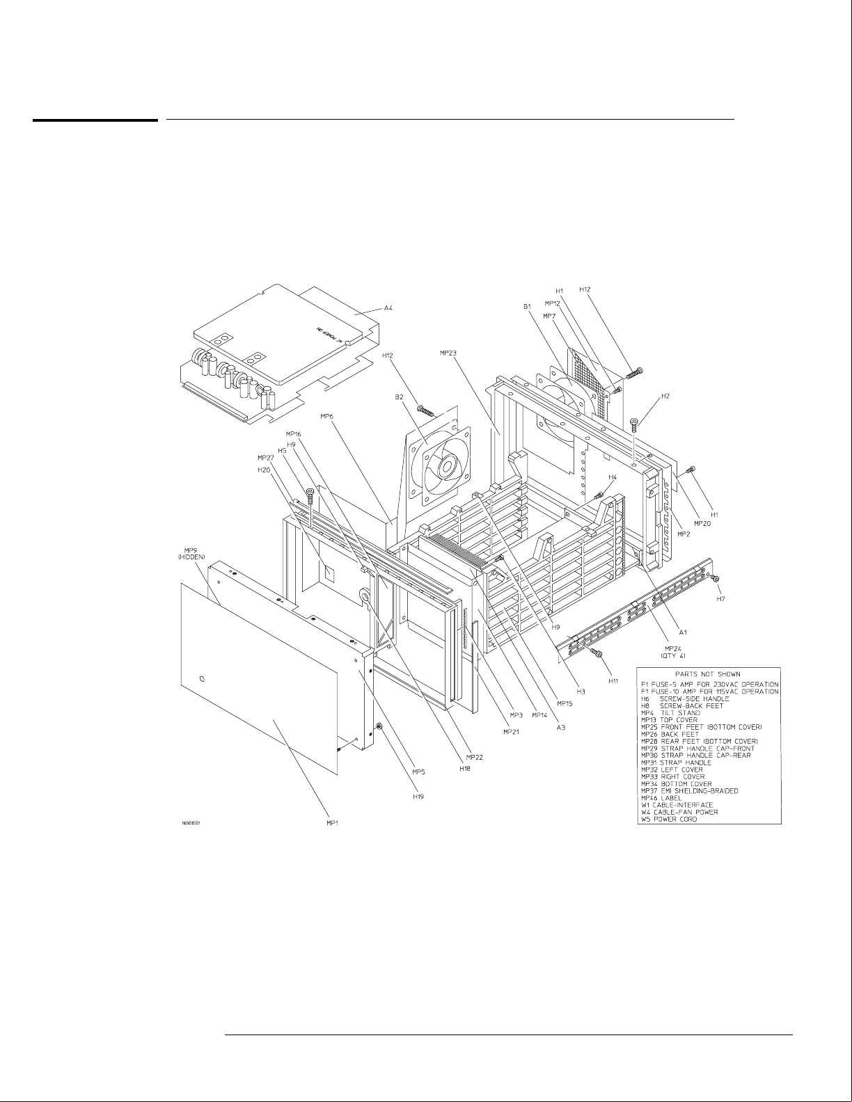
HP 16501A Exploded View and Replaceable Parts
Exploded view of the HP 16501A
Replaceable Parts
HP 16501A Exploded View and Replaceable Parts
7–9

HP 16501A Replaceable Parts
Ref.
Des.
HP Part
Number QTY Description
Exchange Assemblies
A4 16500-69500 Power supply assembly (exchange)
External Parts
F1 2110-0010
F1 2110-0395
MP1 16501-00201 1 Front-panel
MP2 16501-00203 1 Rear panel
MP3 0363-0125 4 FRI strip-fingers (top and bottom covers)
MP4 1460-1345 2 Tile stand
MP5 16501-00202 1 Sub-panel
MP7 16500-00603 1 Fan screen (rear)
MP12 16500-01207 1 Fan shroun (rear)
MP13 16500-04102 1 Top cover
MP21 5001-0541 2 Side trim-front frame
MP22 5021-8407 1 Frame-front
MP23 5021-5808 1 Frame-rear
MP24 5021-5837 4 Strut-corner
MP25 5041-8801 2 Feet-front (bottom cover)
MP26 54110-40502 4 Feet-back
MP27 5041-8802 1 Top trim strip-frame
MP28 5041-8822 2 Feet-rear (bottom cover)
MP29 5041-8819 1 Strap handle cap-front
MP30 5041-8820 1 Strap handle cap-rear
MP31 5062-3704 1 Strap handle
MP32 5062-3847 1 Cover-left side (with handle)
MP33 5062-3822 1 Cover-right side (without handle)
MP34 5062-3747 1 Cover-bottom
MP37 8160-0551 6 EMI shielding-braided
W5 8120-1521 1 Power cord-United States (7.5 ft)
Electrical Assemblies
A1 16501-66501 1 Expansion interface board
A3 16500-66501 1 Mother board
A4 0950-1853 1 Power supply assembly
B1 3160-0429 2 Fan-tubeaxial
B2 3160-0429 Fan-tubeaxial
W1 98735-61601 1 Cable assembly-interface
W2 16501-61604 1 Cable assembly-ribbon (mother board to expansion interface board)
W3 16501-61603 1 Cable assembly-LED
W4 16500-61604 1 Cable-fan power
Replaceable Parts
HP 16501A Exploded View and Replaceable Parts
7–10

HP 16501A Replaceable Parts
Ref.
Des.
HP Part
Number QTY Description
Internal Parts
H1 0515-0372 19 Screw M3 X 0.5 8MM-LG
H2 0515-0433 12 Screw M4 X 0.8 15MM-LG
H3 0515-0435 6 Screw M4 X 0.7 14MM-LG
H4 0515-0664 2 Screw M3 X 0.5 12MM-LG
H5 0515-0943 14 Screw M4 X 0.7 12MM-LG
H6 0515-1384 2 Screw M5 X 0.8 10MM-LG
H7 0515-1403 16 Screw M4 X 0.7 6MM-LG 90-DEG FH
H8 0515-1444 4 Screw M3.5 X 0.6 25.4MM-LG (back Feet)
H9 0535-0105 4 Nut Sheet Metal M4
H11 0624-0520 9 Screw TPG 6-19 .5-IN-LG
H12 2510-0332 8 Screw M3 0.5 X 20 (fan)
H18 0400-0001 2 Grommet
H19 0535-0031 6 Nut
H20 1400-0611 1 Cable clamp
MP6 16501-01201 1 Fan bracket
MP8 16501-40501 1 Module panel (expansion interface board)
MP9 1400-0560 1 CL-SET-LED-MTG (LED clamp set)
MP14 16500-04701 1 Strut-mother board
MP15 16500-23101 1 Card guide-side
MP16 16500-23102 1 Card guide-center
MP20 16500-61202 1 Power supply cover-rear panel
MP46 16501-94301 1 Label-ID (expansion interface board)
Miscellaneous
16500-40502 Filler panel
Replaceable Parts
HP 16501A Exploded View and Replaceable Parts
7–11

7–12

8
Block-Level Theory 8–3
The HP 16500B Logic Analysis System 8–3
The Microprocessor Board 8–6
The Power-Up Routine 8–9
The Power-Up Screen 8–9
Power-Up Self-Tests 8–10
Power-Up Tasks 8–10
The System Configuration Menu 8–12
Self-Tests Description 8–13
Power-Up Self Tests 8–13
Functional Performance Verification Tests 8–15
HP-IB 8–18
RS-232C 8–19
Theory of Operation

Theory of Operation
This chapter tells the theory of operation for the logic analysis system and describes
the self-tests. The information in this chapter is to help you understand how the
logic analysis system operates and what the self-tests are testing. This information is
not intended for component-level repair.
8–2
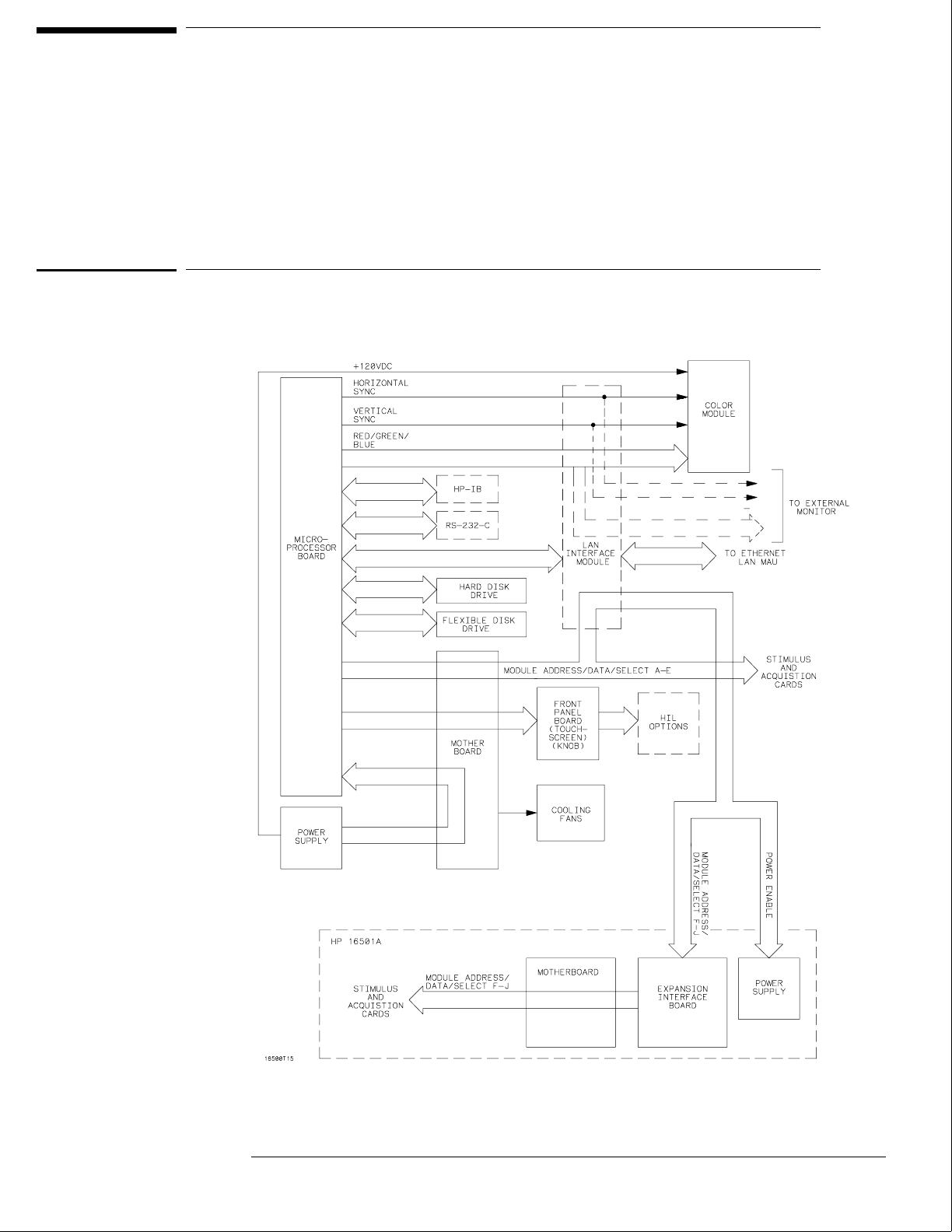
Block-Level Theory
The block-level theory is divided into two parts: theory for the logic analysis system
and theory for the microprocessor board. A block diagram is shown with each theory.
The HP 16500B Logic Analysis System
The Logic Analysis System
8–3

System Overview Theory
HP 16500B
The HP 16500B is the mainframe for the Logic Analysis System.
Microprocessor Board The microprocessor board contains all the interface circuitry
for managing data flow between the mainframe components and the optional boards. The
microprocessor used is a Motorola 68EC030.
Mother Board Located on the mother board are the intermodule bus and the fan speed
control circuit. The mother board consists of seven card slots: five are used for the
optional acquisition and stimulus boards, one for the microprocessor board, and one for
the power supply. The only active components on the mother board are for the fan speed
control circuit. The heat-sensing thermistor for the fan speed control circuit is located on
the microprocessor board.
Flexible Drive The flexible disk drive uses 3.5-inch, double-sided, double-density disks.
All of the disk drive control circuitry is located on the microprocessor board.
Hard Disk Drive The hard disk drive, located beneath the rear fans, is an 85 Mbyte
DOS-formatted high-reliability drive. The disk drive circuitry is located on the
microprocessor board and on the hard disk drive assembly.
Color Module The color module display is an eight-plane color system. Each plane has
a resolution of 576 pixels by 368 lines. The display is non-interlacing and is refreshed
every 1/60 of a second (not synchronized to the ac line). The horizontal and vertical sync
signals are generated by the CRT controller located on the microprocessor board. Color
information for the display is generated on the microprocessor board. The display RAM
and the color palette are also located on the microprocessor board.
Front-Panel Board The front-panel board is based on the Hewlett-Packard Human
Interface Link (HP-HIL) and consists of the touchscreen system, the front-panel control
knob, the optional mouse, and the optional keyboard. All of the touchscreen and knob
circuitry of the HP-HIL is located on the front-panel board and the controller for the link
is located on the microprocessor board.
Power Supply The power supply provides the following regulated voltages:
-12.0 Vdc +5.0 Vdc +3.5 Vdc
+12.0 Vdc -5.2 Vdc -3.25 Vdc
+120 Vdc
The +120.0 V supply is used only by the color module. Current limiting, overvoltage
protection, and thermal shutdown are provided for all supplies.
Theory of Operation
The HP 16500B Logic Analysis System
8–4

HP 16501A
The HP 16501A is the expansion frame for the Logic Analysis System. The expansion frame
components include the following:
•Expansion Interface Board
•Interface Cable
•Mother Board
•Power Supply
To connect the expansion frame to the mainframe, you must install an HP 16500L interface
module into the mainframe. The interface cable connects the expansion frame to the
HP 16500L in the mainframe.
The HP 16501A is an extension of the backplane of the HP 16500B mainframe. After you turn
on the mainframe, the HP 16500B microprocessor board looks for a HP 16500L interface
module. If it is present and if the interface cable connects the two frames, the microprocessor
board establishes a link between the backplanes of the two frames, which then are displayed
as a ten-slot system.
The HP 16501A power supply is identical to the HP 16500B power supply. When power is
applied to the HP 16500B, a relay allows the power supply in the HP 16501A to turn on. An
LED on the front-panel indicates that the expansion frame has turned on.
Theory of Operation
The HP 16500B Logic Analysis System
8–5
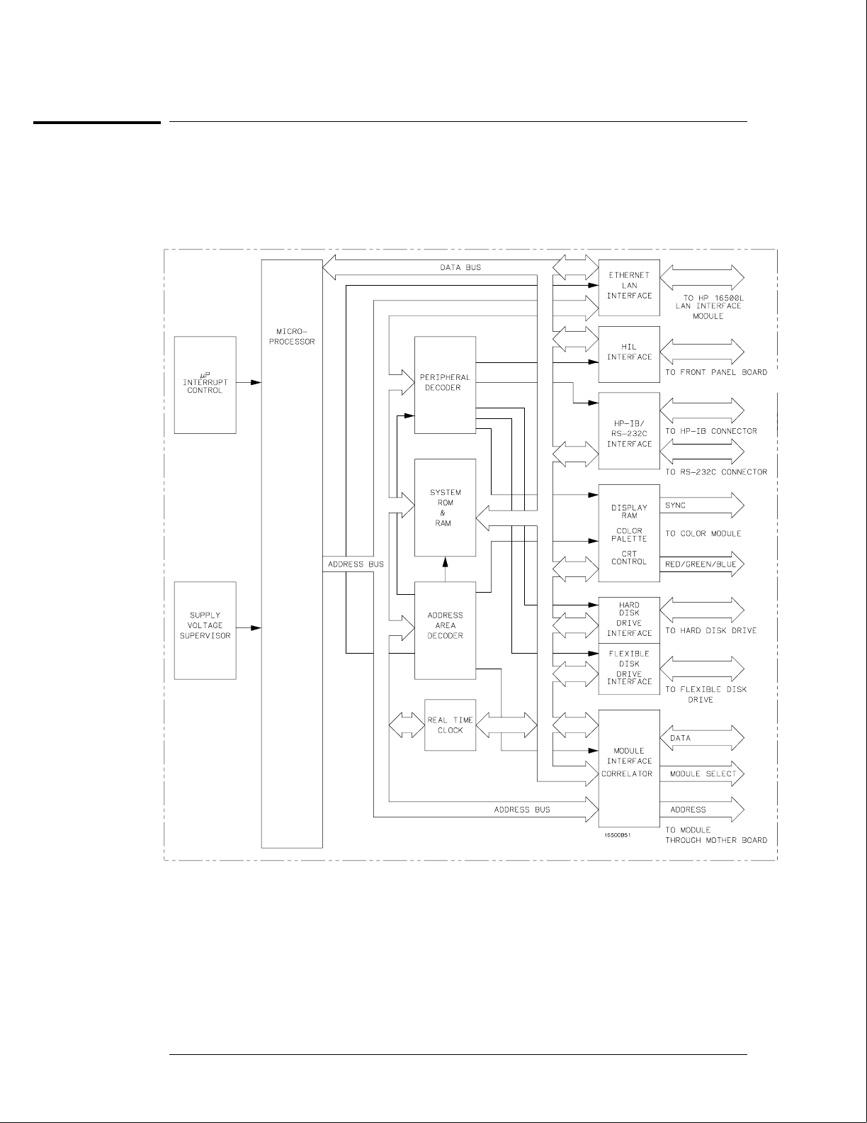
The Microprocessor Board
The Microprocessor Board
Theory of Operation
The Microprocessor Board
8–6

Microprocessor Board Theory
The microprocessor board contains the system memory, all of the interfaces for the
mainframe peripherals, the intermodule bus monitor, and the option board module interface.
Microprocessor and System ROM & RAM
The processing engine of the HP 16500B microprocessor board is a Motorola 68EC030
microprocessor. The 68EC030 is supported by 128 Kbytes of ROM and 8 Mbytes of single
inline memory module (SIMM) RAM. Stored in ROM are the power-up routines for the
mainframe including the power-up self tests and the disk drive instructions. The HIL driver is
also resident in system ROM.
Supply Voltage Supervisor
The Supply Voltage Supervisor (SVS) monitors the main power supply bus and ensures a
smooth power-up of the microprocessor system. The SVS also ensures a graceful recovery of
the system in case the line voltage drops below nominal levels.
During power-up, the SVS asserts the microprocessor L_RESET pin when the supply voltage
stabilizes. Because the voltage on the main power supply bus is affected by abnormal line
voltages, the SVS asserts the microprocessor L_HALT pin during a low line voltage condition.
When the line voltage returns to a nominal value, the L_RESET pin is then asserted by the
SVS and the HP 16500B will reboot.
Interrupt Control
The Interrupt Control circuit manages the interrupt signals asserted by the peripheral devices.
When an interrupt is received, the Interrupt Control circuit encodes the interrupt signal from
the peripheral device to the microprocessor as a prioritized microprocessor interrupt.
Address Area Decoder and Peripheral Decoder
The mainframe peripheral interfaces link the microprocessor data and address busses with the
system peripherals. The system peripherals are then selected by the microprocessor through
the address area decoder and peripheral decoder. The peripheral decoder selects all
peripherals including the HIL interface, the HP-IB and RS-232C interfaces, the color palette,
the hard disk drive interface, and the flexible disk drive interface. The address area decoder
enables access to system ROM, the display RAM, peripherals, and the HP 16500L interface
module.
Real Time Clock
The Real Time Clock provides time information to the HP 16500B microprocessor system.
The time information is used to place a time stamp on files stored on both the hard and
flexible disk drives. Time information may also be used by certain option modules to time
stamp acquired data. For more information regarding the option modules, refer to the User’s
Guide of the specific module.
Ethernet LAN Interface
Using line drivers, the Ethernet LAN Interface links the microprocessor address and data bus
with the LAN controller IC on the HP 16500L Interface Module. Consult the HP 16500L
Administrator’s and Service Guide for more information regarding the HP 16500L Interface
Module.
Theory of Operation
The Microprocessor Board
8–7

HIL Interface
The Hewlett-Packard Human Interface Link (HP-HIL) is the interface between the
microprocessor and the HP 16500B front panel. In the write mode, the interface controller
serializes the 8-bit data and transmits the data to the devices on the link. In the read mode,
the data is fed to the interface controller in serial format and to the microprocessor in parallel
format.
HP-IB and RS-232C Interface
The HP 16500B interfaces to HP-IB as defined by IEEE Standard 488.2. The interface
consists of two octal transceivers and an HP-IB controller. The controller relieves the
microprocessor of the task of maintaining HP-IB protocol. The two transceivers provide data
and control signal transfer between the bus and the controller.
The RS-232C interface is compatible with standard RS-232C protocol. The interface consists
of a controller, an input buffer and an output buffer. The controller serializes parallel data
from the microprocessor for transmission. In the receive mode, the controller converts
incoming serial data to parallel data for the microprocessor. The controller also generates all
the different baud rates and formats available with the mainframe. The input and output
buffers transfer data and control signals to and from the RS-232C communication lines.
Display RAM, Color Palette, and CRT Control
The HP 16500B CRT display is driven by a Color Palette and CRT Control supported by
256 KBytes of video RAM. A single RAMDAC functions as the Color Palette for the
eight-plane color monitor. RGB signals are provided by the RAMDAC. The RAMDAC sends
an analog signal of 0.0 to -1.0 Volts for each of the primary colors (Red, Blue, Green) to the
color module. Horizontal and vertical sync signals are provided by a CRT controller.
Hard Disk Drive Interface
The Hard Disk Drive Interface is made up of two octal transceivers and three buffers. The
octal transceivers link the hard disk drive’s 16-bit data I/O port with the microprocessor data
bus. The buffers link the hard disk drive’s control signals with both the address bus of the
microprocessor and the peripheral interface signals so that the hard disk drive resides at a
virtual address in read and write modes. The hard disk drive controller resides on the hard
disk drive.
Flexible Disk Drive Interface
The main components of the Flexible Disk Drive Interface are the disk drive controller and
buffers. The disk drive controller provides the interface between the microprocessor and the
flexible disk drive. The controller also performs all functions necessary to write or read data
to or from the disks. Data directed to the disk drive from the microprocessor is serialized by
the disk drive controller.
The buffers link the microprocessor data bus with certain flexible disk drive control signals.
The flexible disk drive informs the microprocessor through the data bus whether a flexible
disk has been changed and whether the flexible disk drive is ready to read from or write to a
flexible disk. The microprocessor can also inform the flexible disk drive to format a flexible
disk with a high-density format.
Module Interface and Correlator
The Module Interface provides microprocessor access to the acquisition and stimulus option
modules that are plugged into the mainframe. The Correlator provides the means for
time-aligning module trace data on the mainframe display.
Theory of Operation
The Microprocessor Board
8–8
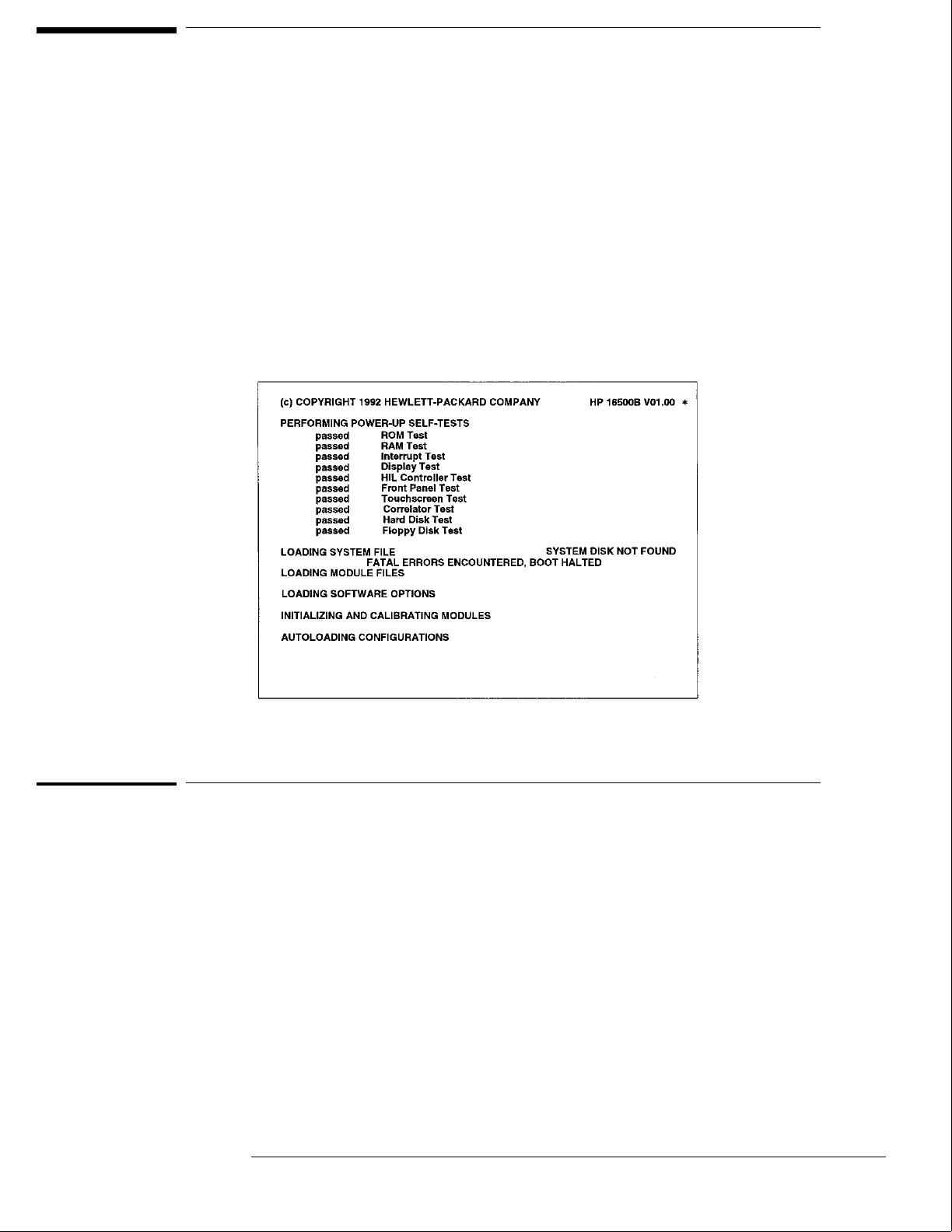
The Power-Up Routine
When power is applied to the HP 16500B Logic Analysis System mainframe, a series
of tasks called the power-up routine is performed to initialize and to verify operation
of the mainframe. The mainframe monitor reports the progress and status of the
power-up routine. Each of the tasks of the power-up routine is added to the monitor
display as the task is being performed.
The following figure shows all of the tasks and possible status reporting fields that
can be displayed on the monitor.
The Power-Up Screen
Model Number and ROM Version
The field in the upper right corner of the display shows the mainframe model number and the
version of ROM installed on the CPU board. The ROM version number is important because
the ROM code must be compatible with the version of the operating system which is stored on
the hard disk drive. The ROM and operating system versions are compatible when the
operating system version number is the same as or higher than the ROM version number.
"*"
The "*" next to the ROM version number indicates that one of the disk drives is spinning. The
"*" only appears when the boot code in ROM accesses a disk drive.
8–9

Power-Up Self-Tests
All of the power-up self tests are performed to verify the operation of the HP 16500B
mainframe. If any of the self-tests fail, then the power-up routine is halted and the FATAL
ERRORS ENCOUNTERED, BOOT HALTED message appears.
For more information about the individual self-tests, refer to "Self-Tests Description" later in
this chapter.
If any power-up self-test fails, refer to chapter 5, "Troubleshooting."
Power-Up Tasks
During the power-up routine, messages on the screen display tasks that are being performed.
The following paragraphs explain the tasks.
Loading System File
The operating system of the HP 16500B mainframe is being uploaded from the disk drive into
system RAM.
SYSTEM DISK NOT FOUND appears only when the mainframe operating system cannot be
found on the hard disk drive. The HP 16500B mainframe power-up routine will not go any
further until a mainframe operating system is present and is recognized. In this case, remove
power from the instrument and install the flexible disk containing the mainframe operating
system in the flexible disk drive. When the System Configuration menu appears, the hard disk
drive directory can be checked to see if the mainframe operating system is present and
recognized and has the correct version number.
Loading Module Files
The operating system of each of the installed modules is being uploaded from the disk drive
into system RAM.
The module operating systems are loaded beginning with the module in slot A, the top-most
module. Then, the operating system of the module in slot B is loaded, and so on.
Consequently, only the operating systems of the installed modules will be loaded into RAM.
The operating systems of modules not installed will not be uploaded from the disk drive.
The System Configuration menu will show if an installed module did not have its operating
system loaded. The message UNRECOGNIZED MODULE appears in place of the module
name next to the slot designations on the left side of the System Configuration menu.
Loading Software Options
Software options, for example the System Performance Analysis package, are being loaded
into system RAM.
The Configuration menu of the module using the software options will show if the software
option was installed. If the option was installed, it will appear in the module configuration
menu pop-up. Refer to the User’s Guide the software option for more information.
Theory of Operation
Power-Up Self-Tests
8–10

Initializing and Calibrating Modules
The installed modules are initialized and stored calibration factors are uploaded from either
the disk drive or module NV-RAM into system RAM. The configuration menu of the module
using the calibration factors will show if the calibration factors have been successfully loaded.
In some cases, a message appears the first time the module is entered. In other cases, the
operation of the module changes until a software calibration is performed to reload calibration
factors. Refer to the User’s Guide and Service Guide of the individual modules for more
information.
Autoloading Configurations
The configuration file autoload flag was detected on the disk and configuration files are being
loaded into the modules. The autoload flag was set during a previous session with the
HP 16500B Logic Analysis System. Usually a configuration is autoloaded as a shortcut if the
module configuration file is used repeatedly.
Theory of Operation
Power-Up Tasks
8–11

The System Configuration Menu
When the power-up routine is complete and the HP 16500B is operational, the System
Configuration menu is displayed. The names of the installed modules appear in fields on the
left side of the display. The fields correspond to the slot into which the module is installed.
UNRECOGNIZED MODULE
If a module field appears with the label UNRECOGNIZED MODULE, then the operating
system of the module was not uploaded from the disk drive into system RAM. One of three
things can cause an unrecognized module: the operating system file is not on the disk drive,
the operating system file is corrupted, or there is not enough RAM memory in the mainframe.
Insufficient RAM memory shows up as a number of recognized modules grouped together in
the lower slots of the mainframe or expansion frame with recognized modules in the upper
slots.
Touchscreen power-up test failed
If the touchscreen power-up self test found the touchscreen operation impaired, then a
red-bar error message "Touchscreen power-up test failed" appears at the top of the screen.
This is not a fatal error and only communicates that the touchscreen will operate with a
minimal loss of functionality.
Master Frame
If the label Master Frame appears in a blue field, then an expansion frame is recognized and
up to five more modules are present. The modules in the expansion frame can be seen by
touching the field labeled Master Frame. If the label Master Frame appears as text only, then
the HP 16500B mainframe does not recognize an expansion frame.
Ethernet
If an HP 16500L interface module is installed, the HP 16500B can be configured to work with
an Ethernet network. Network statistics can be viewed by touching the field configuration
labeled Ethernet in the Communications menu of the System Configuration menu, then
touching Ethernet Statistics. Refer to the manuals for the HP 16500L interface module for
more information.
Theory of Operation
The System Configuration Menu
8–12

Self-Tests Description
The self-tests identify the correct operation of the major sub-systems in the
HP 16500B Logic Analysis System mainframe. The self-tests are not intended for
component-level diagnostics.
Two types of tests are performed on the HP 16500B mainframe: the power-up
self-tests and the functional performance verification tests.
The power-up self-tests are performed when power is applied to the instrument.
When the power-up self- tests are completed and the mainframe sub-systems are
determined to be operational, the system configuration menu is displayed.
The functional performance verification tests are run using a separate operating
system, the performance verification (PV) operating system. The PV operating
system resides on the hard disk drive and can be accessed through the System Test
menu.
A third type of test, parametric performance verification (parametric PV), is not
performed on the HP 16500B mainframe. However, parametric PV is performed on
the modules installed in the mainframe. Consult the individual Service Guides for
each of the modules for more information about parametric performance verification.
Power-Up Self-Tests
The HP 16500B power-up tests check the mainframe circuitry only. None of the option
modules are tested at power-up. The tests run every time power is applied to the instrument
and the results of the tests are reported on the screen.
If a disk is not installed in the disk drive, the advisory "no disk" is added to the Flexible Disk
Tests.
If any of the self-tests fail, then the power-up routine is halted and the FATAL ERRORS
ENCOUNTERED, BOOT HALTED message appears. A failure indicates that one of the
mainframe sub-systems is seriously impaired to the point that reliable operation is not
possible, or that a sub-systems is non-operational. The mainframe hardware would require
servicing before the mainframe can be used.
If any power-up self-test fails, refer to chapter 5, "Troubleshooting."
The power-up tests perform the following circuit checks: ROM Test, RAM Test, Interrupt
Test, Display Test, HIL Controller Test, Front-panel Test, Touchscreen Test, Correlator Test,
Hard Disk Test, and Flexible Disk Test.
ROM Test
The ROM Test performs a checksum of both ROMs and compares the checksum value to a
stored value. The test responses are "passed," "impaired," or "failed." If the message
"impaired" is displayed, only one of the ROMs on the microprocessor board is defective. If the
message "failed" is displayed, both ROMs are defective. For ROM Test failures, you can
suspect a faulty microprocessor board.
8–13

RAM Test
The RAM Test performs an abbreviated read/write test at various memory locations. The test
returns a pass or fail message. For RAM Test failures, first you can suspect a faulty SIMM
module, then you can suspect a faulty microprocessor board.
Interrupt Test
The Interrupt Test checks the microprocessor interrupts (interrupts 1 thorough 7). This test
returns a pass or fail message. If any interrupts are active, the test fails. For Interrupt Test
failures, you can suspect a faulty microprocessor board.
Display Test
The Display Test checks the display RAM and the CRT controller. During the RAM test, the
entire address range is checked. The CRT controller ensures that an End-Of-Frame interrupt
is generated. The test will report a fail message if either the display RAMs or the controller
tests fail. For Display Test failures, you can suspect a faulty microprocessor board.
HIL Controller Test
The HIL Controller Test checks the HIL interface circuitry on the microprocessor board to
verify that the microprocessor board can talk to the front-panel board. This test reports a
pass or fail message. For HIL Test failures, you can suspect a faulty microprocessor board.
Front-Panel Test
The Front-Panel Test checks the front-panel circuitry for correct operation and reports a pass
or fail message. For Front-Panel Test failures, verify the continuity and connection of the
cable from the microprocessor board to the front-panel board. If a problem is not found with
the cable, you can suspect a faulty front-panel board.
Touchscreen Test
The Touchscreen Test checks for light pulses between LED (light emitting diode) pairs and
returns a pass, fail, or an impair message.
The impair message indicates that the touchscreen is faulty, but the instrument can still be
operated. If two to four LED pairs of the touchscreen system are defective, then the impair
message is displayed. The touchscreen can still be used to operate the instrument, except for
the touch-sensitive areas controlled by the faulty LED pairs.
The fail message indicates that the touchscreen is faulty and cannot be used to operate the
instrument. The fail message is displayed if five or more LED pairs of the touchscreen system
are defective. If the Touchscreen Test fails, you can still operate the instrument by using a
mouse.
If a mouse is connected and the Touchscreen Test fails (meaning there are five or more
defective LED pairs), then the impair message is displayed instead of the fail message and the
mouse can be used to operate the instrument. To obtain true Touchscreen Test results,
disconnect the mouse before performing the test.
For Touchscreen Test failures, clean the screen and the surrounding area and move any
objects blocking the screen at power-up. Verify the continuity and connection of the cable
from the microprocessor board to the front-panel board. If a problem is not found with the
cable and the Touchscreen Test still fails after cleaning the instrument, you can suspect a
faulty front-panel board.
Theory of Operation
Power-Up Self-Tests
8–14

Correlator Test
The correlator test verifies that the intermodule bus time correlator on the microprocessor
board is functioning properly. If the correlator is functioning, then intermodule
measurements can be time-correlated to within 2 ns. This test reports either a pass or fail
message. For Correlator Test failures, you can suspect a faulty microprocessor board.
Hard Disk Test
The Hard Disk Test reads the hard disk to see if the format is recognized. If the format is not
recognized the test is considered to have failed for the hard disk drive.
Possible problems causing a fail message include the following:
•A damaged or disconnected disk drive data cable.
•A damaged or disconnected disk drive power cable.
•Hard disk drive is not formatted.
•A faulty disk drive.
•Faulty microprocessor interface circuitry to the disk drive.
Flexible Disk Test
The Flexible Disk Test reads the flexible disk to identify the format. If the format cannot be
identified, the test is considered to have failed for the disk drive. If a flexible disk cannot be
detected, the message "no disk" is displayed instead of the pass or fail message. This
power-up disk test only checks a few tracks.
Possible problems causing a fail message include the following:
•A damaged or disconnected disk drive cable.
•Wrong disk formatting or no disk formatting.
•A faulty disk drive.
•Faulty microprocessor interface circuitry to the disk drive.
For Flexible Disk Test failures, verify the continuity and connection of the disk drive cable
and use formatted disks.
Functional Performance Verification Tests
The following paragraphs briefly describe each mainframe test. After a test is run, the status
advisory for each test changes from UNTESTED to PASSED or FAILED. Except for the Color
Display Test and the All System Tests, when a test is selected from the Mainframe Test
screen, a test screen for that specific test is displayed.
If a mainframe test fails, refer to chapter 5, "Troubleshooting."
ROM Test
This test checks the mainframe ROM on the microprocessor board. The test computes a
checksum for the ROM and compares it to a stored value. For ROM Test failures, you can
suspect a faulty microprocessor board.
Theory of Operation
Functional Performance Verification Tests
8–15

RAM Test
This test checks the mainframe RAM on the microprocessor board. The test performs a
non-destructive pattern write/read at every location. The initial RAM contents are restored
after the test. For RAM Test failures, first you can suspect a faulty SIMM module, then you
can suspect a faulty microprocessor board.
HP-IB Test
The HP-IB Test checks the basic interface functions of the HP-IB port. Only the internal
portions of the port circuitry is tested. For HP-IB Test failures, you can suspect a faulty
microprocessor board.
RS-232C Test
This test checks the basic interface functions of the RS-232C port. Both internal and external
portions of the port circuitry are tested. In order for the RS-232C test to pass, the RS-232C
loopback connector must be installed on the microprocessor board rear panel. For RS-232C
Test failures, verify the connection of the RS-232C loopback connector, then you can suspect
a faulty microprocessor board.
HIL Test
The HIL Test consists of three parts: the HIL controller test, the front-panel test, and the
touchscreen test. All three tests return a pass or a fail message. This test cannot be run
repetitively. Every time the Run field is touched the HIL test sequence is repeated.
The HIL controller test checks the control circuitry on the microprocessor board. For HIL
controller test failures, you can suspect a faulty microprocessor board.
The front-panel test checks the front-panel circuitry for correct operation. For front-panel
test failures, verify the connection and continuity of the front-panel to microprocessor board
cable. If a problem is not found with the cable, then you can suspect a faulty front-panel
board.
The touchscreen test checks for light pulses between LED (light emitting diode) pairs. For
Touchscreen Test failures, clean the screen and the surrounding area and move any objects
blocking the screen when you turn on the mainframe. Verify the continuity and connection of
the cable from the microprocessor board to the front-panel board. If a problem is not found
with the cable and the Touchscreen Test still fails after cleaning the instrument, you can
suspect a faulty front-panel board.
Disk Test
This test checks both the flexible disk drive and the hard disk drive. The drive controllers are
checked and the correct disk format is verified for both drives. Portions from each sector are
read and verified, and a test file is written, read, and then erased. Because track sparing is not
implemented, a failure in any sector or track constitutes a failure of the disk drive media.
A failure of the flexible disk drive will occur if:
•A disk is not inserted in the flexible disk drive.
•An unformatted disk is inserted in the flexible disk drive.
•A write-protected disk is inserted in the flexible disk drive.
Theory of Operation
Functional Performance Verification Tests
8–16

Possible problems causing a failed message in either the flexible disk drive or hard disk drive
include the following:
•A damaged or disconnected disk drive cable.
•Wrong disk formatting or no disk formatting.
•The disk write-protect tab set to the write-protect position.
•A faulty disk drive.
•Faulty microprocessor board interface circuitry to the disk drive.
For Flexible Disk Test failures, verify the continuity and connection of the disk drive cables,
use formatted disks, and set the write protect tab on the disks to the unprotected position.
Intermodule Test
The Intermodule Test checks the functions of the intermodule timing correlation. This test
fails if there are any connections on the input BNC. For Intermodule Test failures in a
mainframe, you can suspect a faulty microprocessor board. For Intermodule Test failures in a
mainframe connected to an expansion frame, you can suspect a faulty mainframe interface
module.
The Intermodule Test screen shows the mainframe and expansion frame card slots and the
card identification code of the module located in each slot.
Color Display Test
The Color Display Test puts screen patterns and color screens on the monitor. This test is
mainly used to check for color purity. Usually, the purity problem can be solved using a
degaussing coil. If some pixels are not colored, then there is probably a problem with the
Display RAM on the microprocessor board. For Color Display Test failures, degauss the
display. Refer to chapter 2, "Preparing for Use," for degaussing instructions. If the Color
Display Test still fails, you can suspect a faulty microprocessor board or a faulty color display
monitor.
Option Board Test
The Option Board Test is used during troubleshooting to check the data and control signals
through the HP 16501A expansion frame components. This test also verifies the functionality
of the HP 16500L LAN interface module. Refer to the manuals for the HP 16500L for more
information about the LAN interface tests.
All System Tests
The All System Test will perform all the tests listed on the screen on the Mainframe Test
menu, except for the Color Display Test and the Expander Test. When the tests are
complete, the status advisory for each test changes from UNTESTED to PASSED or FAILED.
The status advisory for the Color Display Test and for the Expander Test remains UNTESTED
and the status advisory for the All System Tests changes from UNTESTED to TESTED.
Theory of Operation
Functional Performance Verification Tests
8–17
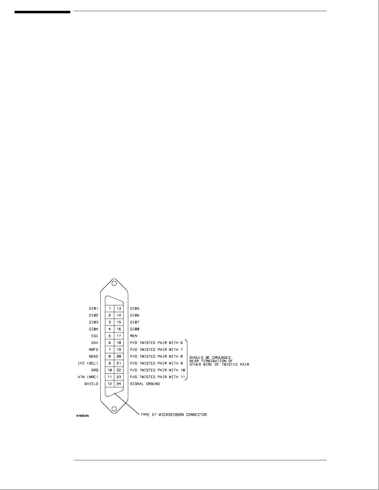
HP-IB
The Hewlett-Packard Interface Bus (HP-IB) is Hewlett-Packard’s implementation of
IEEE Standard 488-1978, "Standard Digital Interface for Programming
Instrumentation." HP-IB is a carefully defined interface that simplifies the integration
of various instruments and computers into systems. The interface makes it possible
to transfer messages between two or more HP-IB compatible devices. HP-IB is a
parallel bus of 16 active signal lines divided into three functional groups according to
function.
Eight signal lines, called data lines, are in the first functional group. The data lines
are used to transmit data in coded messages. These messages are used to program
the instrument function, transfer measurement data, and coordinate instrument
operation. Input and output of all messages, in bit parallel-byte serial form, are also
transferred on the data lines. A 7-bit ASCII code normally represents each piece of
data.
Data is transferred by means of an interlocking "Handshake" technique which permits
data transfer (asynchronously) at the rate of the slowest active device used in that
transfer. The data byte control lines coordinate the handshaking and form the
second functional group.
The remaining five general interface management lines (third functional group) are
used to manage the devices connected to the HP-IB. This includes activating all
connected devices at once, clearing the interface, and other operations.
The following figure shows the connections to the HP-IB connector located on the
rear panel.
HP-IB Interface Connector
8–18

RS-232C
The logic analysis system interfaces with RS-232C communication lines through a
standard 25 pin D connector. The logic analysis system is compatible with RS-232C
protocol. When a hardwire handshake method is used, the Data Terminal Ready
(DTR) line, pin 20 on the connector, is used to signal if space is available for more
data in the logical I/O buffer. Pin outs of the RS-232C connectors are listed in the
following table.
RS-232C Signal Definitions
Pin
Number
Function RS-232C
Standard
Signal Direction and Level
1 Protective Ground AA Not applicable
2 Transmitted Data (TD) BA Data from Mainframe
High = Space = "0" = +12 V
Low = Mark = "1" = –12 V
3 Received Data (RD) BB Data to Mainframe
High = Space = "0" = +3 V to +25 V
Low = Mark = "1" = –3 V to –25 V
4 Request to Send (RTS) CA Signal from Mainframe
High = ON = +12 V
Low = OFF = –12 V
5 Clear to Send (CTS) CB Signal to Mainframe
High = ON = +3 V to +12 V
Low = OFF = –3 V to –25 V
6 Data Set Ready (DSR) CC Signal to Mainframe
High = ON = +3 V to +25 V
Low = OFF = –3 V to –25 V
7 Signal Ground AB Not applicable
8 Data Carrier Detect (DCD) CF Signal to Mainframe
High = ON = +3 V to +25 V
Low = OFF = –3 V to –25 V
20 Data Terminal Ready (DTR) CD Signal from Mainframe
High = ON = +12 V
Low = OFF = –12 V
23 Data Signal Rate Selector CH/CI Signal from Mainframe
Always High = ON = +12 V
8–19

© Copyright Hewlett-
Packard Company 1987-1994
All Rights Reserved.
Reproduction, adaptation, or
translation without prior written
permission is prohibited, except as
allowed under the copyright laws.
Restricted Rights Legend
Use, duplication, or disclosure by
the U.S. Government is subject to
restrictions set forth in
subparagraph (C) (1) (ii) of the
Rights in Technical Data and
Computer Software Clause in
DFARS 252.227-7013.
Hewlett-Packard Company, 3000
Hanover Street, Palo Alto, CA
94304 U.S.A.
Rights for non-DOD U.S.
Government Departments and
Agencies are set forth in FAR
52.227-19(c)(1,2).
Document Warranty
The information contained in this
document is subject to change
without notice.
Hewlett-Packard makes no
warranty of any kind with
regard to this material,
including, but not limited to,
the implied warranties of
merchantability or fitness for a
particular purpose.
Hewlett-Packard shall not be liable
for errors contained herein or for
damages in connection with the
furnishing, performance, or use of
this material.
Safety
This apparatus has been designed
and tested in accordance with IEC
Publication 348, Safety
Requirements for Measuring
Apparatus, and has been supplied
in a safe condition. This is a Safety
Class I instrument (provided with
terminal for protective earthing).
Before applying power, verify that
the correct safety precautions are
taken (see the following warnings).
In addition, note the external
markings on the instrument that
are described under "Safety
Symbols."
Warning
• Before turning on the
instrument, you must connect the
protective earth terminal of the
instrument to the protective
conductor of the (mains) power
cord. The mains plug shall only be
inserted in a socket outlet
provided with a protective earth
contact. You must not negate the
protective action by using an
extension cord (power cable)
without a protective conductor
(grounding). Grounding one
conductor of a two-conductor
outlet is not sufficient protection.
• Only fuses with the required
rated current, voltage, and
specified type (normal blow, time
delay, etc.) should be used. Do not
use repaired fuses or
short-circuited fuseholders. To do
so could cause a shock of fire
hazard.
• Service instructions are for
trained service personnel. To avoid
dangerous electric shock, do not
perform any service unless
qualified to do so. Do not attempt
internal service or adjustment
unless another person, capable of
rendering first aid and
resuscitation, is present.
• If you energize this instrument
by an auto transformer (for voltage
reduction), make sure the common
terminal is connected to the earth
terminal of the power source.
• Whenever it is likely that the
ground protection is impaired, you
must make the instrument
inoperative and secure it against
any unintended operation.
• Do not operate the instrument
in the presence of flammable
gasses or fumes. Operation of any
electrical instrument in such an
environment constitutes a definite
safety hazard.
• Do not install substitute parts or
perform any unauthorized
modification to the instrument.
• Capacitors inside the instrument
may retain a charge even if the
instrument is disconnected from
its source of supply.
• Use caution when exposing or
handling the CRT. Handling or
replacing the CRT shall be done
only by qualified maintenance
personnel.
Safety Symbols
Instruction manual symbol: the
product is marked with this symbol
when it is necessary for you to
refer to the instruction manual in
order to protect against damage to
the product.
Hazardous voltage symbol.
Earth terminal symbol: Used to
indicate a circuit common
connected to grounded chassis.
WARNING
The Warning sign denotes a
hazard. It calls attention to a
procedure, practice, or the like,
which, if not correctly performed
or adhered to, could result in
personal injury. Do not proceed
beyond a Warning sign until the
indicated conditions are fully
understood and met.
CAUTION
The Caution sign denotes a hazard.
It calls attention to an operating
procedure, practice, or the like,
which, if not correctly performed
or adhered to, could result in
damage to or destruction of part or
all of the product. Do not proceed
beyond a Caution symbol until the
indicated conditions are fully
understood or met.
Hewlett-Packard
P.O. Box 2197
1900 Garden of the Gods Road
Colorado Springs, CO 80901
