Hp 2012I Users Manual StorageWorks Modular Smart Array User Guide
2012i to the manual 56262683-6f6d-40d1-bb7e-7c27aa8356ea
2015-02-09
: Hp Hp-2012I-Users-Manual-549922 hp-2012i-users-manual-549922 hp pdf
Open the PDF directly: View PDF ![]() .
.
Page Count: 86
- Contents
- About This Guide
- 1
- Before You Begin
- 2
- Installing and Cabling Enclosures
- 3
- Connecting Hosts
- 4
- Configuring a System for the First Time
- Setting Management Port IP Addresses Using the CLI
- Configuring Your Web Browser for SMU
- Logging in to SMU from a Local Management Host
- Updating Firmware
- Setting the Date and Time
- Configuring Controller Enclosure Host Ports
- Configuring Data Host Ethernet Ports
- Configuring the Microsoft iSCSI Software Initiator
- Editing Registry Values for Ethernet Adapters
- Creating Virtual Disks
- Mapping a Data Host to a Volume
- Testing the Configuration
- Logging Out of SMU
- Next Steps
- A
- Powering the System Off and On
- B
- Regulatory Compliance and Safety
- Index

HP StorageWorks
2012i Modular Smart Array
user guide
Part number: 481598-001
First edition: March, 2008
Legal and notice information
© Copyright 2008 Hewlett-Packard Development Company, L.P.
Hewlett-Packard Company makes no warranty of any kind with regard to this material, including, but not limited to, the implied
warranties of merchantability and fitness for a particular purpose. Hewlett-Packard shall not be liable for errors contained herein or for
incidental or consequential damages in connection with the furnishing, performance, or use of this material.
This document contains proprietary information, which is protected by copyright. No part of this document may be photocopied,
reproduced, or translated into another language without the prior written consent of Hewlett-Packard. The information is provided “as is”
without warranty of any kind and is subject to change without notice. The only warranties for HP products and services are set forth in the
express warranty statements accompanying such products and services. Nothing herein should be construed as constituting an
additional warranty. HP shall not be liable for technical or editorial errors or omissions contained herein.
Microsoft and Windows are U.S. registered trademarks of Microsoft Corporation.

3
Contents
About This Guide . . . . . . . . . . . . . . . . . . . . . . . . . . . . . . . . . . . . . . . . . . . . . . . . . . . 7
Intended Audience . . . . . . . . . . . . . . . . . . . . . . . . . . . . . . . . . . . . . . . . . . . . . . . . . . . 7
Prerequisites . . . . . . . . . . . . . . . . . . . . . . . . . . . . . . . . . . . . . . . . . . . . . . . . . . . . . . . . 7
Document Conventions . . . . . . . . . . . . . . . . . . . . . . . . . . . . . . . . . . . . . . . . . . . . . . . 8
Rack Stability . . . . . . . . . . . . . . . . . . . . . . . . . . . . . . . . . . . . . . . . . . . . . . . . . . . . . . . 8
HP Technical Support . . . . . . . . . . . . . . . . . . . . . . . . . . . . . . . . . . . . . . . . . . . . . . . . . 9
Customer Self Repair . . . . . . . . . . . . . . . . . . . . . . . . . . . . . . . . . . . . . . . . . . . . . . . . . 9
Product Warranties . . . . . . . . . . . . . . . . . . . . . . . . . . . . . . . . . . . . . . . . . . . . . . . . . . . 9
Subscription Service . . . . . . . . . . . . . . . . . . . . . . . . . . . . . . . . . . . . . . . . . . . . . . . . . 10
HP Websites . . . . . . . . . . . . . . . . . . . . . . . . . . . . . . . . . . . . . . . . . . . . . . . . . . . . . . . 10
Documentation Feedback . . . . . . . . . . . . . . . . . . . . . . . . . . . . . . . . . . . . . . . . . . . . . 10
1. Before You Begin . . . . . . . . . . . . . . . . . . . . . . . . . . . . . . . . . . . . . . . . . . . . . . . . . . 11
System Management Software . . . . . . . . . . . . . . . . . . . . . . . . . . . . . . . . . . . . . . . . . 12
HP StorageWorks MSA2000 Family Storage Management Utility (SMU) . . . . 12
Command-Line Interface (CLI) . . . . . . . . . . . . . . . . . . . . . . . . . . . . . . . . . . . . . 12
Hardware Components and LEDs . . . . . . . . . . . . . . . . . . . . . . . . . . . . . . . . . . . . . . 13
Controller Components and LEDs . . . . . . . . . . . . . . . . . . . . . . . . . . . . . . . . . . . 13
Drive Enclosure Components and LEDs . . . . . . . . . . . . . . . . . . . . . . . . . . . . . . 19
Installation Checklist . . . . . . . . . . . . . . . . . . . . . . . . . . . . . . . . . . . . . . . . . . . . . . . . 23
4HP StorageWorks 2012i Modular Smart Array user guide • March 2008
2. Installing and Cabling Enclosures . . . . . . . . . . . . . . . . . . . . . . . . . . . . . . . . . . . . 25
Required Tools . . . . . . . . . . . . . . . . . . . . . . . . . . . . . . . . . . . . . . . . . . . . . . . . . . . . . 25
Safety Precautions . . . . . . . . . . . . . . . . . . . . . . . . . . . . . . . . . . . . . . . . . . . . . . . . . . 26
Installing Enclosures Into a Rack . . . . . . . . . . . . . . . . . . . . . . . . . . . . . . . . . . . . . . . 27
Preparing the Rack . . . . . . . . . . . . . . . . . . . . . . . . . . . . . . . . . . . . . . . . . . . . . . 27
Rack Installation Overview and Procedure . . . . . . . . . . . . . . . . . . . . . . . . . . . . . . . 28
Attaching the Ear Caps . . . . . . . . . . . . . . . . . . . . . . . . . . . . . . . . . . . . . . . . . . . . . . 31
Connecting Controller and Drive Enclosures . . . . . . . . . . . . . . . . . . . . . . . . . . . . . 32
Connecting AC Power . . . . . . . . . . . . . . . . . . . . . . . . . . . . . . . . . . . . . . . . . . . . . . . 35
Testing the Enclosure Connections . . . . . . . . . . . . . . . . . . . . . . . . . . . . . . . . . . . . . 36
Obtaining IP Values for Your Storage System . . . . . . . . . . . . . . . . . . . . . . . . . . . . . 37
Ethernet Management Port . . . . . . . . . . . . . . . . . . . . . . . . . . . . . . . . . . . . . . . . 37
Data Host Ethernet Port . . . . . . . . . . . . . . . . . . . . . . . . . . . . . . . . . . . . . . . . . . 37
iSCSI Host Ports . . . . . . . . . . . . . . . . . . . . . . . . . . . . . . . . . . . . . . . . . . . . . . . . 37
Correcting Enclosure IDs . . . . . . . . . . . . . . . . . . . . . . . . . . . . . . . . . . . . . . . . . . . . . 38
Next Steps . . . . . . . . . . . . . . . . . . . . . . . . . . . . . . . . . . . . . . . . . . . . . . . . . . . . . . . . 38
3. Connecting Hosts . . . . . . . . . . . . . . . . . . . . . . . . . . . . . . . . . . . . . . . . . . . . . . . . . . 39
Host System Requirements . . . . . . . . . . . . . . . . . . . . . . . . . . . . . . . . . . . . . . . . . . . 39
Installing the Microsoft iSCSI Software Initiator . . . . . . . . . . . . . . . . . . . . . . . 40
Installing the MSA2000 Family SES Driver for Microsoft Windows Hosts . . . 41
Connecting Data Hosts to Controller Enclosures . . . . . . . . . . . . . . . . . . . . . . . . . . . 41
Connecting Remote Management Hosts . . . . . . . . . . . . . . . . . . . . . . . . . . . . . . . . . 43
Next Steps . . . . . . . . . . . . . . . . . . . . . . . . . . . . . . . . . . . . . . . . . . . . . . . . . . . . . . . . 43
Contents 5
4. Configuring a System for the First Time . . . . . . . . . . . . . . . . . . . . . . . . . . . . . . . 45
Setting Management Port IP Addresses Using the CLI . . . . . . . . . . . . . . . . . . . . . . 46
Configuring Your Web Browser for SMU . . . . . . . . . . . . . . . . . . . . . . . . . . . . . . . . 49
Logging in to SMU from a Local Management Host . . . . . . . . . . . . . . . . . . . . . . . . 50
Updating Firmware . . . . . . . . . . . . . . . . . . . . . . . . . . . . . . . . . . . . . . . . . . . . . . . . . . 50
Setting the Date and Time . . . . . . . . . . . . . . . . . . . . . . . . . . . . . . . . . . . . . . . . . . . . 50
Configuring Controller Enclosure Host Ports . . . . . . . . . . . . . . . . . . . . . . . . . . . . . . 52
Configuring Data Host Ethernet Ports . . . . . . . . . . . . . . . . . . . . . . . . . . . . . . . . . . . 52
Configuring the Microsoft iSCSI Software Initiator . . . . . . . . . . . . . . . . . . . . . . . . . 53
Editing Registry Values for Ethernet Adapters . . . . . . . . . . . . . . . . . . . . . . . . . . . . 55
Creating Virtual Disks . . . . . . . . . . . . . . . . . . . . . . . . . . . . . . . . . . . . . . . . . . . . . . . 58
Mapping a Data Host to a Volume . . . . . . . . . . . . . . . . . . . . . . . . . . . . . . . . . . . . . . 59
Testing the Configuration . . . . . . . . . . . . . . . . . . . . . . . . . . . . . . . . . . . . . . . . . . . . . 59
Logging Out of SMU . . . . . . . . . . . . . . . . . . . . . . . . . . . . . . . . . . . . . . . . . . . . . . . . 60
Next Steps . . . . . . . . . . . . . . . . . . . . . . . . . . . . . . . . . . . . . . . . . . . . . . . . . . . . . . . . 60
A. Powering the System Off and On . . . . . . . . . . . . . . . . . . . . . . . . . . . . . . . . . . . . . 61
B. Regulatory Compliance and Safety . . . . . . . . . . . . . . . . . . . . . . . . . . . . . . . . . . . . 63
Index . . . . . . . . . . . . . . . . . . . . . . . . . . . . . . . . . . . . . . . . . . . . . . . . . . . . . . . . . . . . 83
6HP StorageWorks 2012i Modular Smart Array user guide • March 2008

7
About This Guide
Intended Audience
This guide is intended for use by system administrators and information
professionals who are experienced with the following:
■Direct attach storage (DAS) or storage area network (SAN) management
■Network administration
■Network installation
■Storage system installation and configuration, including installing an HP rack
Prerequisites
Prerequisites for installing and configuring this product include familiarity with:
■Servers and computer networks
■Fibre Channel, iSCSI, and Ethernet protocols

8HP StorageWorks 2012i Modular Smart Array user guide • March 2008
Document Conventions
Rack Stability
Caution – To reduce the risk of personal injury or damage to the equipment:
■Extend leveling jacks to the floor.
■Ensure that the full weight of the rack rests on the leveling jacks.
■Install stabilizing feet on the rack.
■In multiple-rack installations, secure racks together.
■Extend only one rack component at a time. Racks may become unstable if more
than one component is extended.
Typeface Meaning Examples
AaBbCc123 Book title, new term, or
emphasized word See the Release Notes.
A virtual disk (vdisk) can ....
You must be an advanced user to ....
AaBbCc123 Directory or file name,
value, command, or
on-screen output
The default file name is store.logs.
The default IP address is 10.0.0.1.
Type exit.
AaBbCc123 Text you type, contrasted
with on-screen output
# set password
Enter new password:
AaBbCc123 Variable text you replace
with an actual value Use the format http://ip-address.
About This Guide 9
HP Technical Support
Telephone numbers for worldwide technical support are listed on the HP support
website: http://www.hp.com/support/.
Collect the following information before calling:
■Technical support registration number (if applicable)
■Product serial numbers
■Product model names and numbers
■Applicable error messages
■Operating system type and revision level
■Detailed, specific questions
For continuous quality improvement, calls may be recorded or monitored.
Customer Self Repair
HP customer self repair (CSR) programs allow you to repair your HP StorageWorks
product. If a CSR part needs replacing, HP ships the part directly to you so that you
can install it at your convenience. Some parts do not qualify for CSR. Your HP-
authorized service provider will determine whether a repair can be accomplished by
CSR.
For more information about CSR, contact your local service provider. For North
America, see the CSR website:
http://www.hp.com/go/selfrepair
Product Warranties
For information about HP StorageWorks product warranties, see the warranty
information website:
http://www.hp.com/go/storagewarranty
10 HP StorageWorks 2012i Modular Smart Array user guide • March 2008
Subscription Service
HP strongly recommends that customers sign up online using the Subscriber's
choice website: http://www.hp.com/go/e-updates.
Subscribing to this service provides you with e-mail updates on the latest product
enhancements, newest versions of drivers, and firmware documentation updates as
well as instant access to numerous other product resources.
HP Websites
For other product information, see the following HP websites:
■http://www.hp.com
■http://www.hp.com/go/storage
■http://www.hp.com/service_locator
■http://www.hp.com/support/manuals
■http://www.hp.com/support/downloads
Documentation Feedback
HP welcomes your feedback.
To make comments and suggestions about product documentation, please send a
message to storagedocs.feedback@hp.com. All submissions become the
property of HP.

11
CHAPTER 1
Before You Begin
The MSA2000 Family 2012i Modular Smart Array and MSA2000 Drive Enclosure
are high-performance storage solutions that combine outstanding performance with
high reliability, availability, flexibility, and manageability.
Supported configurations include a controller enclosure with or without attached
drive enclosures. A controller enclosure can contain two controllers that interact and
provide failover capability for the data path. The controller enclosure can use SATA
or SAS disk drive modules. Enclosures can be installed in standard 19-inch EIA
rack cabinets.
This chapter provides information that you must know before installing and initially
configuring your storage system:
■“System Management Software” on page 12
■“Hardware Components and LEDs” on page 13
■“Installation Checklist” on page 23
12 HP StorageWorks 2012i Modular Smart Array user guide • March 2008
System Management Software
Embedded management software includes a web-browser interface and the
command-line interface described below.
HP StorageWorks MSA2000 Family Storage
Management Utility (SMU)
SMU is the primary interface for configuring and managing the system. A web
server resides in each controller module. SMU enables you to manage the system
from a web browser that is properly configured and that can access a controller
module through an Ethernet connection.
Information about using SMU is in its online help and in the reference guide.
Command-Line Interface (CLI)
The embedded CLI enables you to configure and manage the system using
individual commands or command scripts through an out-of-band RS-232 or
Ethernet connection.
Information about using the CLI is in the CLI reference guide.

Chapter 1 Before You Begin 13
Hardware Components and LEDs
This section describes the main hardware components of your storage system
enclosures.
Controller Components and LEDs
The controller enclosure can be connected through switches to Ethernet adapters
(NICs) or host iSCSI ports. Table 1-1 describes the enclosure components.
Table 1-1 Controller Enclosure Components
Description Quantity
iSCSI controller (I/O) module 1 or 21
1 Air-management system drive blanks or I/O blanks must fill empty slots to maintain optimum airflow through the chassis.
SAS or SATA drive module 2–12 per enclosure
AC power-and-cooling module 2 per enclosure
1-Gbps Ethernet host port 2 per controller module
3-Gbps, 4-lane SAS expansion port 1 per controller module
Ethernet port (RJ-45) 1 per controller module
CLI port (RS-232 micro-DB9) 1 per controller module
Service port (RS-232 3.5-mm jack) 1 per controller module
14 HP StorageWorks 2012i Modular Smart Array user guide • March 2008
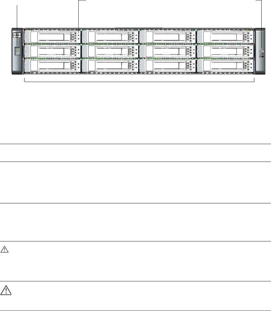
Figure 1-1 shows the components and LEDs on the front of a controller.
Figure 1-1 Controller (Front View)
Table 1-2 describes the LEDs on the front of a controller.
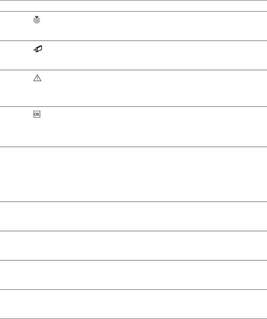
Table 1-2 Controller LEDs (Front)
LED Color
Operating
State Description
Enclosure ID Green On Shows the enclosure ID, which enables you to correlate
an enclosure with logical views presented by
management software. The enclosure ID for a controller
enclosure is zero (0); the enclosure ID for an attached
drive enclosure is nonzero.
UID
(Unit
Identification)
Blue On Identified.
Off Not identified.
Fault ID Amber Off No fault condition exists.
On Fault condition exists. Service action is required. The
event has been acknowledged but the problem needs
attention.
Heartbeat
LED Green On The enclosure is powered on with at least one power and
cooling module operating normally.
Off Both power and cooling modules are off.
Drive modules are numbered by column top to bottom: 0–2, 3–5, 6–8, 9–11
Drive module LEDs (top to bottom)Enclosure ID Status LEDs (top to bottom):
UID
Fault ID
Heartbeat
Fault/UID
Online/Activity

Chapter 1 Before You Begin 15
Table 1-3 describes the LEDs on the drive module.
Table 1-3 Drive Module LED Combinations (Front)
Online/Activity
(green)
Fault/UID
(amber/blue) Description
On Off The drive is online, but it is not currently active.
Blinking
irregularly Off The drive is active and operating normally.
Off Amber, blinking
regularly (1 Hz) Offline; the drive is not being accessed. A predictive
failure alert has been received for this device. Further
investigation is required.
On Amber, blinking
regularly (1 Hz) Online; no activity. A predictive failure alert has been
received for this device. Further investigation is
required.
Blinking
irregularly Amber, blinking
regularly (1 Hz) The drive is active, but a predictive failure alert has been
received for this drive. Further investigation is required.
Off Amber, solid Offline; no activity. A critical fault condition has been
identified for this drive.
Off Blue; solid Offline. The drive has been selected by a management
application.
On or blinking Blue; solid The drive is operating normally, and it has been selected
by a management application.
Blinking regularly
(1 Hz) Off Do not remove the drive. Removing a drive may
terminate the current operation and cause data loss.
The drive is rebuilding.
Off Off Either there is no power, the drive is offline, or the drive
is not configured.
16 HP StorageWorks 2012i Modular Smart Array user guide • March 2008
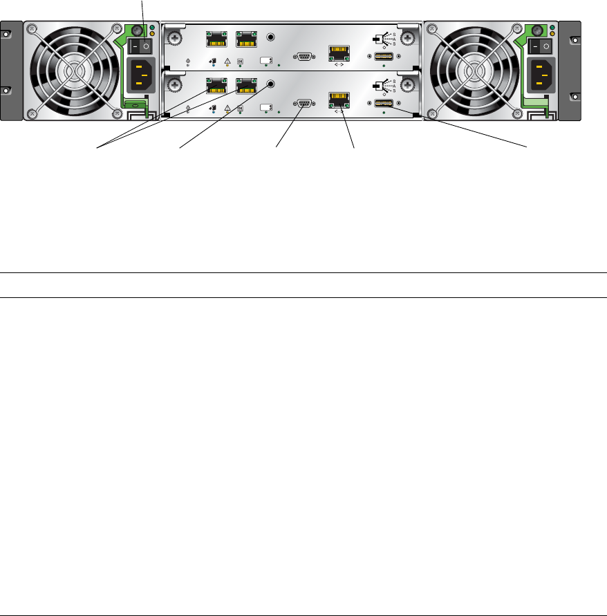
Figure 1-2 shows the ports and switches at the back of the controller.
Figure 1-2 Controller Enclosure Ports and Switches (Back View)
Table 1-4 describes the ports and switches on the back of the controller.
Table 1-4 Controller Ports and Switches (Back)
Location Port/Switch Description
Power and
cooling
module
Power switch Toggle, where:
•– is On
•O is Off
Controller
module Host ports 1-GbE Ethernet ports used to connect to data hosts through Ethernet
switches. Host port 0 and 1 correspond to host channel 0 and 1,
respectively.
Controller
module Expansion
port 3-Gbps, 4-lane (12 Gbps total) table-routed SAS Out port used to connect
drive enclosures.
Controller
module Ethernet
management
port
10/100BASE-T Ethernet port used for TCP/IP-based out-of-band
management of the RAID controller. An internal Ethernet device provides
standard 10 Mbit/second and 100 Mbit/second full-duplex connectivity.
Controller
module CLI port Micro-DB9 port used to connect the controller enclosure to a local
management host using RS-232 communication for out-of-band
configuration and management.
Controller
module Service port 3.5-mm jack port used by service technicians only.
10/100 BASE-T STATUS
ACTIVITY
DIRTY
CLEAN
CACHE
CLI
Service
LINK ACT
iSCSI
Port 0
iSCSI
Port 1
LINK ACT
10/100 BASE-T STATUS
ACTIVITY
DIRTY
CLEAN
CACHE
CLI
Service
LINK ACT
iSCSI
Port 0
iSCSI
Port 1
LINK ACT
Power switch
Host ports Expansion portCLI port
Ethernet management port
Service port
Chapter 1 Before You Begin 17
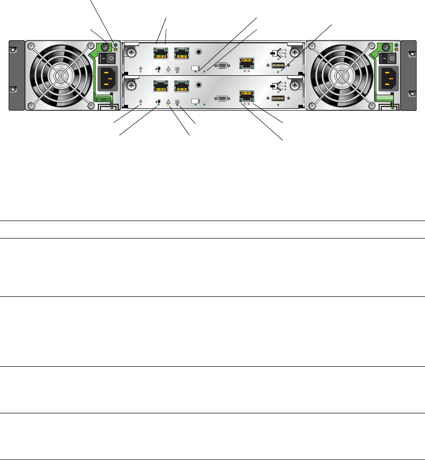
Figure 1-3 shows the LEDs at the back of the controller.
Figure 1-3 Controller LEDs (Back View)
Table 1-5 describes the LEDs on the back of the controller
Table 1-5 Controller LEDs (Back)
Location LED Color State Description
Power and
cooling
module
AC Power Good Green Off AC power is off or input voltage is below the
minimum threshold.
On AC power is on and input voltage is normal.
Power and
cooling
module
DC Voltage/
Fan Fault/
Service Required
Amber Off DC output voltage is normal.
On DC output voltage is out of range or a fan is
operating below the minimum required RPM.
Controller
module Host link status Green Off The port is empty or the link is down.
On The port link is up and connected.
Controller
module Host link activity Green Off The host port is not connected or the link is down.
On The host link is up and active.
10/100 BASE-T STATUS
ACTIVITY
DIRTY
CLEAN
CACHE
CLI
Service
LINK ACT
iSCSI
Port 0
iSCSI
Port 1
LINK ACT
10/100 BASE-T STATUS
ACTIVITY
DIRTY
CLEAN
CACHE
CLI
Service
LINK ACT
iSCSI
Port 0
iSCSI
Port 1
LINK ACT
AC Power Good
Service Required
DC Voltage/Fan Fault/ Host link status
Host link activity
Unit Locator
OK to Remove Fault/Service Required
OK
Cache status
Host activity Expansion port status
Ethernet activity
Ethernet link status
18 HP StorageWorks 2012i Modular Smart Array user guide • March 2008
Controller
module
Unit Locator White Off Normal operation.
Blink Physically identifies the controller module.
Controller
module OK to
Remove Blue Off The controller module is not prepared for removal.
On The controller module can be removed.
Controller
module Fault/Service
Required Amber On A fault has been detected or a service action is
required.
Blink Indicates a hardware-controlled power up or a
cache flush or restore error.
Controller
module OK Green Off Controller module is not OK.
On Controller module is operating normally.
Blink System is booting.
Controller
module Cache status Green Off Cache is clean (contains no unwritten data).
On Cache is dirty (contains unwritten data) and
operation is normal.
Blink A Compact Flash flush or cache self-refresh is in
progress. Indicates cache activity.
Controller
module Host activity Green Off The host ports have no I/O activity.
Blink At least one host port has I/O activity.
Controller
module Ethernet link status Green Off The Ethernet port is not connected or the link is
down.
On The Ethernet link is up.
Controller
module Ethernet activity Green Off The Ethernet link has no I/O activity.
Blink The Ethernet link has I/O activity.
Controller
module Expansion port
status Green Off The port is empty or the link is down.
On The port link is up and connected.
Table 1-5 Controller LEDs (Back) (Continued)
Location LED Color State Description

Chapter 1 Before You Begin 19
Drive Enclosure Components and LEDs
A drive enclosure can be connected to a controller enclosure or to another drive
enclosure to provide additional disk storage capacity. Table 1-6 describes the drive
enclosure components.
The components and LEDs on the front of a drive enclosure are the same as on a
controller enclosure; see Figure 1-1 and Table 1-2.
Table 1-6 Drive Enclosure Components
Description Quantity
Expansion (I/O) module 1 or 21
1 Air-management system drive blanks or I/O blanks must fill empty slots to maintain optimum airflow through the chassis.
SAS or SATA drive module 2–12 per enclosure
AC power and cooling module 2 per enclosure
3-Gbps, 4-lane SAS In port 1 per expansion module
3-Gbps, 4-lane SAS Out port 1 per expansion module
Service port (RS-232 micro-DB9) 1 per expansion module
20 HP StorageWorks 2012i Modular Smart Array user guide • March 2008
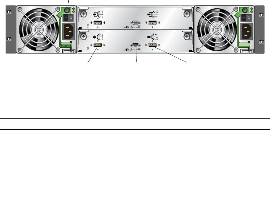
Figure 1-4 shows the ports and switches at the back of the drive enclosure.
Figure 1-4 Drive Enclosure Ports and Switches (Back View)
Table 1-7 describes the ports and switches on the back of the drive enclosure.
Table 1-7 Drive Enclosure Ports and Switches (Back)
Location Port/Switch Description
Power and
cooling module Power switch Toggle, where:
•– is On
•O is Off
Expansion
module SAS In port 3-Gbps, 4-lane (12 Gbps total) subtractive ingress port used to
connect to a controller enclosure.
Expansion
module SAS Out port 3-Gbps, 4-lane (12 Gbps total) table-routed egress port used to
connect to another drive enclosure.
Expansion
module Service port Micro-DB9 port for manufacturing technicians.
Service
0 0
Service
0 0
Service port SAS Out port
Power switch
SAS In port
Chapter 1 Before You Begin 21
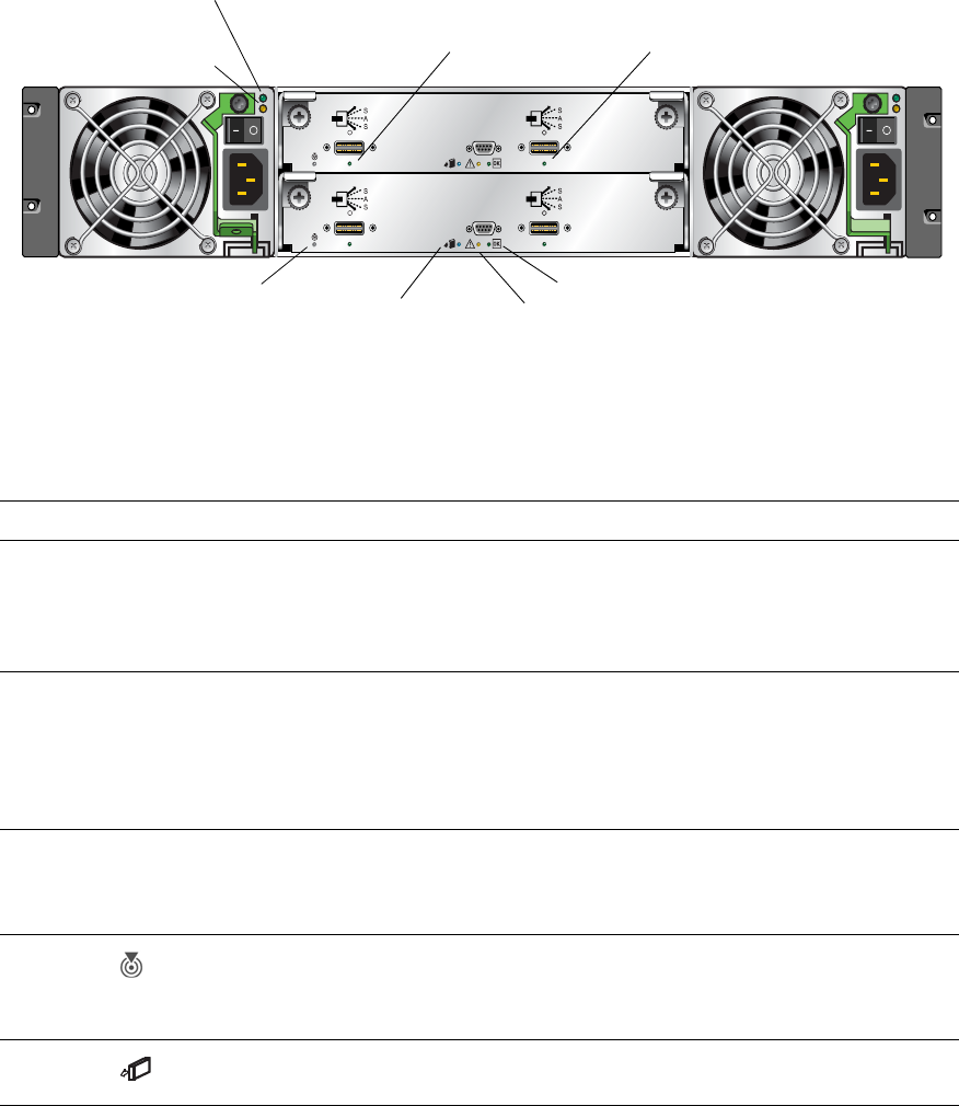
Figure 1-5 shows the LEDs at the back of the drive enclosure.
Figure 1-5 Drive Enclosure LEDs (Back View)
Table 1-8 describes the LEDs on the back of the drive enclosure.
Table 1-8 Drive Enclosure LEDs (Back)
Location LED Color State Description
Power and
cooling
module
AC Power Good Green Off AC power is off or input voltage is below the
minimum threshold.
On AC power is on and input voltage is normal.
Power and
cooling
module
DC Voltage/
Fan Fault/
Service Required
Amber Off DC output voltage is normal.
On DC output voltage is out of range or a fan is
operating below the minimum required RPM.
Expansion
module SAS In port status Green Off The port is empty or the link is down.
On The port link is up and connected.
Expansion
module Unit Locator White Off Normal operation.
Blink Physically identifies the expansion module.
Expansion
module OK to
Remove Blue Off Not implemented.
Service
0 0
Service
0 0
AC Power Good
Service Required
DC Voltage/Fan Fault/ SAS In port status SAS Out port status
Unit Locator
OK to Remove Fault/Service Required
OK
22 HP StorageWorks 2012i Modular Smart Array user guide • March 2008
Expansion
module Fault/Service
Required Amber On A fault has been detected or a service action is
required.
Blink Indicates a hardware-controlled power up or a
cache flush or restore error.
Expansion
module OK Green Off Expansion module is not OK.
On Expansion module is operating normally.
Blink System is booting.
Expansion
module SAS Out port
status Green Off The port is empty or the link is down.
On The port link is up and connected.
Table 1-8 Drive Enclosure LEDs (Back) (Continued)
Location LED Color State Description

Chapter 1 Before You Begin 23
Installation Checklist
Table 1-9 outlines the steps required to install the enclosures and initially configure
the system. To ensure a successful installation, perform the tasks in the order they
are presented.
Table 1-9 Installation Checklist
Step Installation Task Where to Find Procedure
1. Prepare the rack for installation. “Preparing the Rack” on page 27
2. Install the controller enclosure and optional drive
enclosures in the rack. “Rack Installation Overview and
Procedure” on page 28
3. Attach the ear caps. “Attaching the Ear Caps” on page 31
4. Connect the enclosures. “Connecting Controller and Drive
Enclosures” on page 32
5. Connect the power cords. “Connecting AC Power” on page 35
6. Test the enclosure connections. “Testing the Enclosure Connections” on
page 36
7. Obtain IP values. “Obtaining IP Values for Your Storage
System” on page 37
8. Install required host software and drivers, including:
•HBA drivers
• iSCSI Software Initiator
• MSA2000 Family SES Driver
“Host System Requirements” on page 39

24 HP StorageWorks 2012i Modular Smart Array user guide • March 2008
9. Connect the data hosts. “Connecting Hosts” on page 39
10. Connect the management host. “Connecting Remote Management
Hosts” on page 43
11. Perform initial configuration tasks:
• Set management port IP properties on the
controller enclosure
• Verify that controllers and enclosures have the
latest firmware
• Set the date and time on the controller enclosure
• Configure host ports on the controller enclosure
• Configure Ethernet ports on data hosts
• Configure iSCSI Software Initiator settings on
data hosts
• Edit Registry values for Ethernet adapters on data
hosts.
• Create virtual disks and map volumes
• Test the configuration
“Configuring a System for the First
Time” on page 45
Table 1-9 Installation Checklist (Continued)
Step Installation Task Where to Find Procedure

25
CHAPTER 2
Installing and Cabling Enclosures
This chapter describes how to install and cable enclosures in a standard 19-inch EIA
rack cabinet. It contains the following sections:
■“Required Tools” on page 25
■“Safety Precautions” on page 26
■“Installing Enclosures Into a Rack” on page 27
■“Rack Installation Overview and Procedure” on page 28
■“Attaching the Ear Caps” on page 31
■“Connecting Controller and Drive Enclosures” on page 32
■“Connecting AC Power” on page 35
■“Testing the Enclosure Connections” on page 36
■“Obtaining IP Values for Your Storage System” on page 37
■“Correcting Enclosure IDs” on page 38
■“Next Steps” on page 38
Required Tools
The installation procedures in this chapter require the following items:
■#2 Phillips screwdriver
■Standard screwdriver
■Antistatic protection devices
26 HP StorageWorks 2012i Modular Smart Array user guide • March 2008
Safety Precautions
For your protection, observe the following safety precautions when setting up your
equipment:
■Follow all cautions and instructions marked on the equipment.
■Ensure that the voltage and frequency of your power source match the voltage
and frequency inscribed on the equipment’s electrical rating label.
■Never push objects of any kind through openings in the equipment. Dangerous
voltages may be present. Conductive foreign objects could produce a short circuit
that could cause fire, electric shock, or damage to your equipment.
Note – Do not make mechanical or electrical modifications to the product. The
vendor is not responsible for the safety or regulatory compliance of a modified
product.
Caution – Two people are needed to lift and move the enclosure. Use care to avoid
injury. An enclosure with all drives installed can weigh 65 pounds (29.5 kilograms).
Caution – Electrostatic discharge can damage sensitive components. Be sure you
are properly grounded before touching a static-sensitive component or assembly.

Chapter 2 Installing and Cabling Enclosures 27
Installing Enclosures Into a Rack
This section describes how to install the enclosures into a standard 19-inch rack
cabinet with a 28 to 36-inch (71.12 to 91.44-cm) depth.
Note – Keep all hardware items in plastic bags until you are ready to use them. This
enables you to correctly identify the screws and avoid confusion.
Preparing the Rack
Before installing enclosures in a rack cabinet, ensure the rack is installed according
to its installation instructions and that the installation complies with local safety
codes.
1. Stabilize the rack as described in its documentation.
2. If the rack has casters, make sure the casters are locked to prevent the rack from
rolling.
3. Remove or open the top front panel and the vented back panel.
28 HP StorageWorks 2012i Modular Smart Array user guide • March 2008
Rack Installation Overview and Procedure
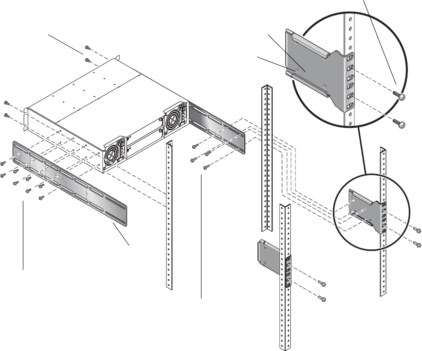
Figure 2-1 provides a visual overview of rack installation and components and
corresponds to the steps that follow.
Figure 2-1 Overview of Standard 19-Inch EIA Rackmounting Components
#10-32 x 5/8-in. Truss screws
Threaded PEMs (4)
Rear bracket connected to rack
#10-32 x 5/8-in. Truss screws
Side bracket
(Step 6)
(Step 5)
(Step 8)
(Step 9)
#8-32 x 3/16-in. flathead screws
#8-32 x 1/4-in. flathead screws

Chapter 2 Installing and Cabling Enclosures 29
Use the following procedure and refer to Figure 2-1 to install each enclosure into
the rack.
When positioning an enclosure in the rack, do not block the air vents at the front or
back of the enclosure.
Caution – If you only have one person to perform the installation, remove the
power and cooling modules and drive modules from an enclosure before
installation, and use the optional nylon front support brackets. If possible, position
the enclosure on top of another device or shelf in the rack to hold the enclosure as
you attach the front brackets.
1. Considering your system configuration and weight distribution in the rack,
determine where you will install each enclosure in the rack.
2. Confirm that you have cables of adequate length to connect to hosts and to power
outlets.
3. (Square-cut European-style racks only) Insert the cage nuts in the corresponding
holes on the front and rear of the rack.
4. (Optional-one person installation) Screw the front support brackets into position on
the rack face using #10-32 x 5/8-inch screws (two per bracket).
These brackets enable one person to easily position and support the front of the
enclosure in the rack during installation.
5. Attach the side brackets to each side of the enclosure using #8-32 x 3/16-inch
flathead screws (four to eight on each side). The right and left side brackets are
identical.
Note – To allow adjustment of the brackets, do not tighten the screws completely
until the enclosure is mounted in the rack.
a. Use the alignment marks (Figure 2-2) stamped into the side brackets to position
the brackets and screws. The alignment marks show depth in inches.
Determine the depth you require and align the rear-most alignment mark on the
side bracket with the rear-most threaded holes on the enclosure. Make sure that
the alignment mark corresponding to the depth you want lines up with both the
top and bottom holes.

30 HP StorageWorks 2012i Modular Smart Array user guide • March 2008
Figure 2-2 Side Bracket With Alignment Marks
b. On one side, insert the first two screws through the side bracket slots above and
below the alignment mark into the rear-most threaded holes in the enclosure.
For example, to mount the enclosure in a 28-inch deep rack, position the side
bracket so that the 28-inch alignment mark is aligned with the rear-most threaded
holes in the enclosure.
c. Insert up to six more screws through the side bracket slots into the other threaded
holes in the side of the enclosure.
d. Repeat Step b and Step c to attach the other side bracket to the enclosure.
6. Attach the rear brackets to the rear vertical posts of the rack using #10-32 x 5/8-inch
screws (two per bracket).
7. Lift the enclosure and slide the side brackets into the rear brackets, which are
attached to the rear posts.
Adjust the depth of the side brackets so that the slots nearest the ends of the side
brackets align with the four PEM nuts in the rear brackets.
8. Attach each side bracket to a rear bracket using #8-32 x 1/4-inch screws (four per
bracket).
9. Make sure that the enclosure is level and then secure the mounting ears on the front
of the enclosure to the rack face using #10-32 x 5/8-inch screws (two per ear).
10. Tighten the screws in the side brackets.
11. If you removed modules from the enclosure, reinsert them.
12. If you attached the optional front support nylon brackets to the rack face, remove
those brackets.
Note – When you finish installing an enclosure, you may have unused screws left
in your rack kit; extra screws are provided in case any are misplaced.
Chapter 2 Installing and Cabling Enclosures 31
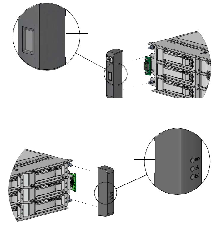
Attaching the Ear Caps
The plastic ear caps are snap-on parts that require some care when attaching or
removing them. After the enclosure has been installed in the rack cabinet, attach the
ear caps, which are located in a plastic bag included in the controller enclosure
package.
1. Remove the ear caps from the plastic package.
2. As you attach each ear cap, hold it so that its indent is closest to the chassis.
Figure 2-3 Ear Caps
3. Apply gentle pressure to snap the caps onto the chassis’ ears.
Right ear cap
Left ear cap
Indent
Indent
32 HP StorageWorks 2012i Modular Smart Array user guide • March 2008
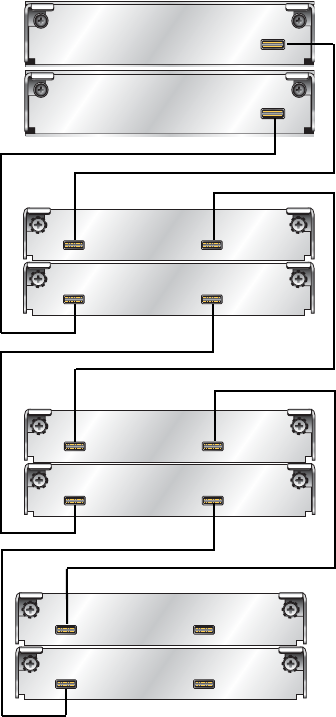
Connecting Controller and Drive Enclosures
Use the supplied SAS cables to connect a controller enclosure to up to three drive
enclosures. Figure 2-4 and Figure 2-5 show the recommended fault-tolerant cabling
patterns. In an enclosure, the upper module is designated A and the lower module is
designated B.
When connecting multiple drive enclosures, use reverse cabling to ensure the
highest level of fault tolerance. For example, Figure 2-5 shows controller A
connected to expansion module 1A, and the chain of connections continuing down.
Controller B is connected to the lower module (B) of the last drive enclosure in the
chain, with connections moving in the opposite direction.
Fault-tolerant cabling is recommended because it enables the controllers to access
remaining drive enclosures if any one drive enclosure fails. However, the system
also supports non-fault-tolerant cabling using the supplied SAS cables.
Figure 2-6 shows non-fault-tolerant cabling between a controller and up to three
drive enclosures.
Note – For clarity, the schematic illustrations of the controllers shown in this
section show only relevant details such as expansion ports. For detailed illustrations
showing all components, see “Hardware Components and LEDs” on page 13.
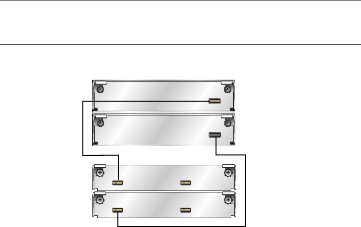
Figure 2-4 Cabling Connections Between One Controller Enclosure and One
Drive Enclosure
In Out
In Out
Controller B
Controller A
1A
1B
Chapter 2 Installing and Cabling Enclosures 33
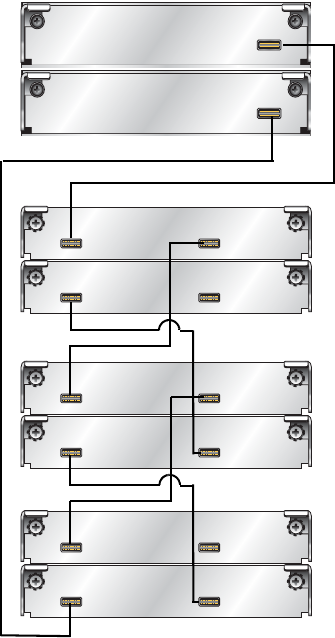
Figure 2-5 Fault-Tolerant Cabling Connections Between One Controller
Enclosure and Up to Three Drive Enclosures
In Out
In Out
In Out
In Out
Controller B
Controller A
1A
1B
2A
2B
3A
3B
In Out
In Out
34 HP StorageWorks 2012i Modular Smart Array user guide • March 2008
Figure 2-6 Non-Fault-Tolerant Cabling Connections Between One Controller
and Up to Three Drive Enclosures
In Out
In Out
In Out
In Out
In Out
In Out
Controller B
Controller A
1A
1B
2A
2B
3A
3B
Chapter 2 Installing and Cabling Enclosures 35
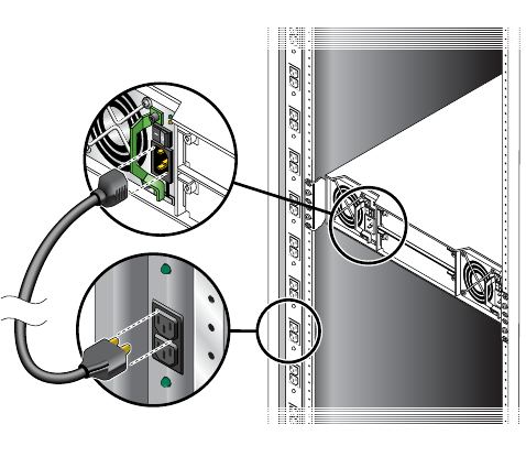
Connecting AC Power
Use this procedure to connect AC power to the enclosures.
1. Verify that both power switches are off.
2. Using the AC power cords, for each enclosure, connect one power and cooling
module to one power source in the rack, and the other power and cooling module to
a separate power source in the rack.
3. Connect the primary power cords from the rack to separate external power sources.
Power on the system as described in the topic that follows.
36 HP StorageWorks 2012i Modular Smart Array user guide • March 2008
Testing the Enclosure Connections
Use this procedure to power on the newly installed system.
1. Press the power switches at the back of each drive enclosure to the On (–) position.
This ensures that the disks in the drive enclosures have enough time to completely
spin up before being scanned by the RAID modules in the controller enclosure.
Depending on your configuration, it can take several minutes for the system to
power up.
While enclosures power up, their LEDs blink. After the LEDs stop blinking, if no
LEDs on the front and back of the enclosure are amber, the power-on sequence is
complete and no faults have been detected.
For a description of LED behavior and status, see “Hardware Components and
LEDs” on page 13.
2. Press the power switches at the back of the controller enclosure to the On (–)
position.
If the enclosure’s power-on sequence succeeds as described in Step 1, the system is
ready to use.
Chapter 2 Installing and Cabling Enclosures 37
Obtaining IP Values for Your Storage System
Use the guidelines presented in this section when requesting or assigning IP values
for your storage system.
Ethernet Management Port
Use DHCP to obtain a different IP address for each Ethernet management port (one
each for controller A and controller B). If you do not have a DHCP server, you will
need to obtain the IP addresses from your network administrator, and set them using
the CLI during initial configuration (see “Setting Management Port IP Addresses
Using the CLI” on page 46).
To obtain the IP and gateway addresses for the Ethernet management port using
DHCP:
1. Look in the DCHP server’s address for the two IP addresses assigned to an “HP
StorageWorks MSA2000 Family” storage device.
2. Use a network management utility to discover “HP StorageWorks MSA2000
Family” storage devices on the local LAN through SNMP.
3. Use a ping broadcast to try to identify the device through the host’s ARP table.
Data Host Ethernet Port
From your network administrator, obtain an IP address for each data host Ethernet
port that will be used for iSCSI connectivity. You will use these IP addresses when
you configure data host ports (see “Configuring Data Host Ethernet Ports” on
page 52). Each Ethernet port on a data host should be assigned an IP address on a
different subnet.
iSCSI Host Ports
You will need to set IP and gateway addresses for each iSCSI host port on the
controller enclosure when you configure iSCSI Software Initiator settings (see
“Configuring the Microsoft iSCSI Software Initiator” on page 53).

38 HP StorageWorks 2012i Modular Smart Array user guide • March 2008
iSCSI host ports should be assigned IP addresses that are on one or the other subnet
to which data host ports are assigned. That is, one iSCSI host port on controller A
should be on the same subnet as one of the data host ports, with the other iSCSI host
port on the subnet as the other data host port, and likewise for controller B.
Correcting Enclosure IDs
When installing a system with drive enclosures attached, the enclosure IDs might
not agree with the physical cabling order. This is because the controller might have
been previously attached to some of the same enclosures and it attempts to preserve
the previous enclosure IDs if possible. To correct this condition, make sure that both
controllers are up and perform a rescan using SMU or the CLI. This will reorder the
enclosures, but can take up to two minutes for the enclosure IDs to be corrected.
To perform a rescan using the CLI, type the following command:
To rescan using SMU, as an Advanced Manage user:
1. Select Manage > Utilities > Disk Drive Utilities > Rescan.
2. In the Rescan For Devices panel, click Rescan.
Next Steps
Now you are ready to connect the data and management hosts, as described in
Chapter 3.
rescan

39
CHAPTER 3
Connecting Hosts
This chapter describes how to connect data and management hosts to controller
enclosures. It contains the following sections:
■“Host System Requirements” on page 39
■“Connecting Data Hosts to Controller Enclosures” on page 41
■“Connecting Remote Management Hosts” on page 43
■“Next Steps” on page 43
Host System Requirements
Data hosts connected to MSA2000 Family 2012i Modular Smart Arrays must meet
the following requirements:
■Systems must have two dedicated Ethernet ports available with either HBAs or
Ethernet adapters (NIC hardware) that support iSCSI connectivity.
■For systems with iSCSI HBAs, install any HBA drivers required for your
system as specified in the MSA QuickSpecs. QuickSpecs can be found from
your HP MSA products page at http://www.hp.com/go/msa. Select MSA
SAN Arrays, and then select your product. The link for QuickSpecs will be on
the right.
■For systems using NIC hardware, you must install and configure the
Microsoft® iSCSI Software Initiator. For more information, see “Installing the
Microsoft iSCSI Software Initiator” on page 40.
■Depending on your system configuration, data host operating systems may
require that multipathing is supported. If a data host uses a single cable to attach
to the storage, then multipathing software is not required. If a data host uses
multiple cables to attach to the storage, and fault tolerance is expected, then
multipathing software is required.
To obtain the MSA2000 Family MPIO DSM, go to the HP MSA products page at
http://www.hp.com/go/msa. Select MSA SAN Arrays, select your product,
and go to Related products.

40 HP StorageWorks 2012i Modular Smart Array user guide • March 2008
■To prevent Microsoft Windows® data hosts from displaying the Found New
Hardware Wizard when the storage system is discovered, install the MSA2000
Family SCSI Enclosure Services driver. For more information, see “Installing the
MSA2000 Family SES Driver for Microsoft Windows Hosts” on page 41.
Installing the Microsoft iSCSI Software Initiator
Note – This section applies only to Microsoft Windows hosts that use Ethernet
adapters (NIC hardware) for iSCSI connectivity.
Installing the Microsoft iSCSI Software Initiator enables iSCSI connectivity on
Ethernet host ports. The software initiator must be installed in addition to standard
Microsoft Windows network and HBA drivers.
1. Locate and download the Microsoft iSCSI Software Initiator (Version 2.06) for your
host system found at:
http://www.microsoft.com/downloads/
2. Install the software initiator as directed on the download site.
If the operating system on your data host supports MPIO, select Microsoft MPIO
Multipathing Support for iSCSI as an option when running the installation wizard.
3. Complete the installation on additional data hosts.
Note – After connecting data hosts to the storage system as described later in this
chapter, you must configure the iSCSI Software Initiator on each host. For more
information, see “Configuring the Microsoft iSCSI Software Initiator” on page 53.

Chapter 3 Connecting Hosts 41
Installing the MSA2000 Family SES Driver for
Microsoft Windows Hosts
Installing the MSA2000 Family SCSI Enclosure Services (SES) driver prevents
Microsoft Windows hosts from displaying the Found New Hardware Wizard when
the storage system is discovered.
1. Download the MSA2000 Family SCSI Enclosure Services (SES) driver package
msa2000-ses-version.zip from http://www.hp.com/go/msa. Select MSA
SAN arrays, select your product, and go to Related products.
2. Extract the package contents to a temporary folder on the host.
3. In that folder, double-click Setup.exe to install the driver.
4. Click Finish.
The driver is installed.
5. Optionally, delete the extracted files and the SES driver package.
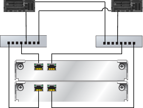
Connecting Data Hosts to Controller Enclosures
This section explains how to connect the controller enclosure to data hosts through
Ethernet switches.
The controller enclosure has four host connections, two per controller. Connect
Ethernet cables from controller hosts ports to switch ports, and from switch ports to
data hosts, as shown in the following figure.
To maintain redundancy, connect each data host through the switch or switches to
both controller A and controller B. Make sure that link speed and topology settings
on switches match those on the controller host ports to which they are connected. A
speed mismatch prevents the host from accessing the storage system.
Note – For clarity, the schematic illustrations of the controllers shown in this
section show only relevant details such as host ports. For detailed illustrations
showing all components, see “Hardware Components and LEDs” on page 13.
42 HP StorageWorks 2012i Modular Smart Array user guide • March 2008
Figure 3-1 shows the preferred high-availability dual-controller connection through
two switches to two dual-port data hosts, in which each data host has two Ethernet
ports with each port connected to a different switch.
Figure 3-1 High-Availability Connection Through Two Switches to Two Dual-
Port Data Hosts
Switch A Switch B
Controller B
Controller A

Chapter 3 Connecting Hosts 43
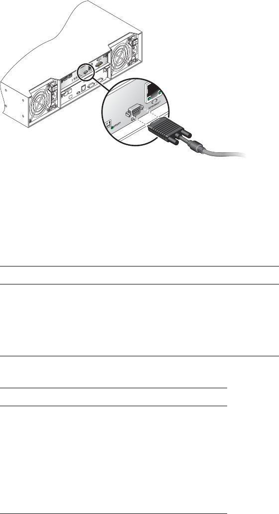
Connecting Remote Management Hosts
The management host directly manages systems out-of-band over an Ethernet
network. This section describes how to connect the Ethernet cables to the
management host.
1. Connect an Ethernet cable to the Ethernet management port on each controller.
Note – Do not confuse Ethernet management ports with Ethernet host ports, also
located on the rear panel of the controller enclosure. For a description of controller
enclosure ports, see “Hardware Components and LEDs” on page 13.
2. Connect the other end of each Ethernet cable to a network that your management
host can access (preferably on the same subnet).
Next Steps
After you have connected the management host and data hosts, you are ready to
perform first-time configuration on the storage system and data hosts as described in
Chapter 4.
44 HP StorageWorks 2012i Modular Smart Array user guide • March 2008

45
CHAPTER 4
Configuring a System for the First Time
This chapter describes how to perform first-time configuration required on both the
storage system and data hosts. It also describes how to perform basic storage
configuration to verify that your system is working.
This chapter includes the following topics:
■“Setting Management Port IP Addresses Using the CLI” on page 46
■“Configuring Your Web Browser for SMU” on page 49
■“Updating Firmware” on page 50
■“Setting the Date and Time” on page 50
■“Configuring Controller Enclosure Host Ports” on page 52
■“Configuring Data Host Ethernet Ports” on page 52
■“Configuring the Microsoft iSCSI Software Initiator” on page 53
■“Editing Registry Values for Ethernet Adapters” on page 55
■“Creating Virtual Disks” on page 58
■“Mapping a Data Host to a Volume” on page 59
■“Testing the Configuration” on page 59
■“Logging Out of SMU” on page 60
■“Next Steps” on page 60
For information about additional configuration and management tasks, including
changing the manage user’s password, refer to SMU’s online help or the reference
guide.

46 HP StorageWorks 2012i Modular Smart Array user guide • March 2008
Setting Management Port IP Addresses Using the CLI
Note – If you used DHCP to set the IP addresses, you do not have to set them using
the CLI as described in this section.
Ethernet Management ports on controller module A and controller module B are
configured with the following default values:
■Management Port IP Address: 10.0.0.2 (controller A), 10.0.0.3 (controller B)
■IP Subnet Mask: 255.255.255.0
■Gateway IP Address: 10.0.0.1
If the default IP addresses are not compatible with your network, you must set an IP
address for each management port using the command-line interface (CLI)
embedded in each controller module. The CLI enables you to access the system
using RS-232 communication and terminal emulation software.
Use the CLI commands described in the steps below to set the IP address for the
Ethernet management port on each controller module.
Once new IP addresses are set, you can change them as needed using SMU.
Note – Changing IP settings can cause management hosts to lose access to the
storage system.
1. Refer to the list of IP values you obtained before beginning installation (see
“Installation Checklist” on page 23).
Chapter 4 Configuring a System for the First Time 47
Your package contents include a micro-DB9-to-DB9 serial cable. If necessary, use a
DB9-to-DB25 adapter (not included) for connecting the serial cable to a DB25
serial port on the host computer.
2. Start and configure a terminal emulator, such as HyperTerminal or VT-100, using
the display settings in Table 4-1 and the connection settings in Table 4-2.
Table 4-1 Terminal Emulator Display Settings
Parameter Value
Terminal Emulation Mode VT-100 or ANSI (for color support)
Font Terminal
Translations None
Columns 80
Table 4-2 Terminal Emulator Connection Settings
Parameter Value
Connector COM1 (typically)
Baud rate (bits/sec) 115,200
Data bits 8
Parity None
Stop bits 1
Flow control None

48 HP StorageWorks 2012i Modular Smart Array user guide • March 2008
3. In the terminal emulator, connect to controller A.
4. Press Enter to display the CLI prompt (#).
5. At the prompt, type the following command to set the values you obtained in Step 1
for each Ethernet management port, first for controller A and then for controller B:
where:
■address is the IP address of the controller
■netmask is the subnet mask
■gateway is the IP address of the subnet router
■a|b specifies the controller whose network parameters you are setting
For example:
6. Type the following command to verify the new IP addresses:
Network parameters, including the IP address, subnet mask, and gateway address
are displayed for each controller.
7. Disconnect from the CLI and exit the emulator.
set network-parameters ip address netmask netmask gateway gateway
controller a|b
# set network-parameters ip 192.168.0.10 netmask 255.255.255.0
gateway 192.168.0.1 controller a
# set network-parameters ip 192.168.0.11 netmask 255.255.255.0
gateway 192.168.0.1 controller b
show network-parameters

Chapter 4 Configuring a System for the First Time 49
8. In the host computer's command window, type the following command to verify
Ethernet connectivity, first for controller A and then for controller B:
If you cannot your access your system for at least three minutes after changing
the IP address, your network might require you to restart the management
controller using the serial CLI. When you restart a management controller,
communication with it is temporarily lost until it successfully restarts.
Type the following command to restart the management controller on both
controllers:
Configuring Your Web Browser for SMU
Before using SMU to perform remaining steps, ensure that your web browser is
properly configured according to the following guidelines:
■Use one of the following browsers:
■Microsoft Internet Explorer 5.5 or later
■Mozilla Firefox 1.0.7 or later
■Because SMU uses popup windows to indicate the progress of user-requested
tasks, disable any browser features or tools that block popup windows.
■For optimal performance, set your browser to use stored (cached) web pages.
Note – Changing your browser cache setting might affect other sites you visit with
your browser.
■To optimize display, use a color monitor and set its color quality to the highest
setting.
■For Internet Explorer, to ensure you can navigate beyond SMU login page, set
the local-intranet security option to medium or medium-low.
ping IP-address
restart mc both
50 HP StorageWorks 2012i Modular Smart Array user guide • March 2008
Logging in to SMU from a Local Management Host
To log in to SMU from a local management host:
1. In your web browser’s address field, type the IP address of one of the controller
enclosure’s Ethernet management ports and press Enter.
The SMU Login page is displayed. If the Login page does not display, verify that
you have entered the correct IP address.
2. On the login page, type the default management user name manage and default
password !manage.
3. Click Log In.
The Status Summary page is displayed.
Updating Firmware
After installing the hardware and powering up the enclosure for the first time, be
sure to verify that the controllers and drive enclosures have the latest firmware.
SMU enables you to view the software, hardware, and other version information for
each controller and the enclosures. To view controller version information, select
Monitor > Status > Advanced Settings > Controller Versions.To view drive
enclosure information, select Manage > Update Software > Enclosure Firmware >
Show Enclosures.
For software and firmware updates, go to http://www.hp.com/go/msa. Select
MSA SAN Arrays, select your product, and go to Support.
Setting the Date and Time
You can set the date and time manually or configure the system to use Network
Time Protocol (NTP) to obtain them from a network-attached server. When NTP is
enabled, and if an NTP server is available, the system time and date can be obtained
from the NTP server. This allows multiple storage devices, hosts, log files, and so
forth to be synchronized.
Chapter 4 Configuring a System for the First Time 51
NTP server time is provided in Universal Time (UT), which provides several
options:
■If you want to synchronize the times and logs between storage devices installed
in multiple time zones, set all the storage devices to use UT.
■If you want to use the local time for the device, set its time zone appropriately.
■If a time server can provide local time rather than UT, configure the storage
devices to use that time server, with no further time adjustment.
If no NTP server is present, the date and time are maintained as if NTP had not been
enabled.
To manually set the system date and time:
1. Select Manage > General Config > Set Date/Time.
2. In the Set System Date panel, select the current month, day, and year.
3. In the Set System Time panel, type time values using a 24-hour clock (where hour 8
represents 8 a.m. and hour 20 represents 8 p.m.) and select the proper time zone.
4. Click Change Date/Time.
To obtain the date and time from an NTP server:
1. Select Manage > General Config > Set Date/Time.
2. In the Obtain Time With NTP panel, set Network Time Protocol to Enable and
optionally type the IP address of an NTP server.
If no IP server address is set, the system listens for time messages sent by an NTP
server in broadcast mode.
3. In the Set System Time panel, select the proper time zone.
4. Click Change Date/Time.
You might have to refresh the page to display updated values from the NTP server.
52 HP StorageWorks 2012i Modular Smart Array user guide • March 2008
Configuring Controller Enclosure Host Ports
To configure iSCSI host ports on the controller enclosure, complete the following
steps:
1. Select Manage > General Config > Host Port Configuration.
2. In the Controller Module Host Port Configuration panels, for each host port on
controller A and controller B, enter the following values:
■IP address. (Refer to the list of IP addresses you obtained after you installed the
enclosures.)
■Subnet mask. Set all subnet mask fields to 255.255.255.0
■Gateway IP address. Leave this field blank (set to 0.0.0.0) for all ports.
3. Click Update Host Port Configuration.
The Host Port Configuration page displays again.
Configuring Data Host Ethernet Ports
After installing the enclosures, you should have obtained from your network
administrator an IP address for each data host Ethernet port that will be used for
iSCSI connectivity. Each Ethernet port on a data host should be assigned an IP
address on a different subnet. To configure data host Ethernet ports for iSCSI
connectivity so that hosts can communicate with the storage system, complete the
following steps:
1. On the host system, click Start > Control Panel > Network Connections.
2. Select and rename each Ethernet port that will be used for iSCSI connectivity using
a descriptive name.
Examples: iSCSI_Port0_10.10.10.10 and iSCSI_Port1_10.11.10.10
3. Right click on the first port and select Properties.
4. From the This Connection Uses the Following Items list, located on the General tab,
select Internet Protocol (TCP/IP) and click Properties.
Select Use the Following IP Address and set IP properties as follows:
a. Enter an IP address that is on the same subnet as IP addresses used for one of the
iSCSI host ports on controller A and one of the iSCSI host ports on controller B.
b. Set the subnet mask for the IP address you entered.
c. Leave the Default gateway field blank.

Chapter 4 Configuring a System for the First Time 53
5. Click OK to save these settings.
6. Complete Step 3 through Step 5 for the second data host Ethernet port, selecting IP
addresses on the subnet not used for the first Ethernet port.
IP properties have been set for Ethernet ports on the data host.
7. Complete Step 1 to Step 6 on additional data hosts.
Configuring the Microsoft iSCSI Software Initiator
Now that you have connected data hosts to the storage system and set IP properties
for the controller Ethernet management port and data host Ethernet ports, you can
configure settings in the Microsoft iSCSI Software Initiator, which you installed
earlier on the data hosts.
Configuring these settings on each data host includes:
■Setting IP addresses for each iSCSI host port (called a target portal) located on
the storage system
■Logging on to iSCSI host ports on each controller module (called a target) from
the data host to initiate connectivity between the data host and the storage system
Note – Before completing the steps that follow, you must connect storage system
enclosures as described in “Installing and Cabling Enclosures” on page 25. You
must also install all software and drivers required on data hosts (see “Host System
Requirements” on page 39), and connect hosts to the storage system as described
earlier in this chapter (see “Connecting Hosts” on page 39).
1. Double-click the Microsoft iSCSI Software Initiator icon located on the desktop of
the host system.
2. In the Target Portals area of the Discovery tab, click Add.
3. Enter the IP address of an iSCSI host port on your storage system, leave the Port
field set at 3260, and click Add.
4. Repeat Step 2 and Step 3, adding IP addresses for the remaining iSCSI host ports on
the storage system.
IP addresses for storage system host ports (targets) are identified on the data host.
5. On the Targets tab, verify that two targets have been configured (.a and .b).
If two targets are not configured, one or more of the following issues may need to
be resolved:
54 HP StorageWorks 2012i Modular Smart Array user guide • March 2008
■Data host IP addresses may not be set correctly
■Controller enclosure host port addresses may not be set correctly on the data host
■Cables between the controller enclosure and/or switches and/or data hosts may
not be connected correctly
Correct the issue, return to the Targets tab and click Refresh.
6. If two targets are configured, select the first target (controller module) and click Log
On.
7. On the Log On to Target dialog, set the following options:
a. For connectivity settings to persist across system reboots, check Automatically
Restore this Connection When the System Boots.
b. For fault-tolerant configurations, select Enable Multi-path.
c. Click Advanced to set connectivity settings as follows:
i. At the Local Adapter field, select Microsoft iSCSI Initiator from the drop-
down menu.
ii. At the Source IP field, select the IP address for the local data Ethernet port
that is on the same subnet as the first target portal (iSCSI host port) to which
you want the host to connect.
iii. At the Target Portal field, select the IP address for the iSCSI host port on the
target (controller module) to which you are connecting.
iv. Repeat the log on procedure (Step i through Step iii) to initiate connectivity for
the second target portal on the selected target.
8. To allow LUN access through all available ports during failover, change default
multipathing settings as follows:
a. On the Targets tab, select the target and click Details.
b. On the Devices tab of the Target Properties dialog, select the first device and
click Advanced.
c. On the MPIO tab of the Device Details dialog, select Round Robin from the Load
Balance Policy drop-down menu and click OK.
d. Repeat Step b and Step c for all devices listed.
9. Repeat tasks in Step 6, Step 7, and Step 8 for the second target.
Chapter 4 Configuring a System for the First Time 55
10. On the Persistent Targets tab, verify that two entries appear for each controller (.a
and .b) for a total of four connections.
Configuring more than one session per controller port will use additional host
interface resources and may cause failover to function improperly.
If two persistent targets are not configured for each controller host port, complete
the following steps to remove and reconfigure targets:
a. Select each entry and click Remove.
b. Log off for each connection by selecting Targets > Details > Sessions > Log Off.
c. Verify that IP addresses were set correctly. If not, correct IP address settings.
d. Log on again for each target using the instructions in this section, starting at
Step 2.
The data host can now communicate with the controllers through iSCSI Ethernet
host ports.
Editing Registry Values for Ethernet Adapters
Note – This section applies only to Microsoft Windows hosts that use Ethernet
adapters (NIC hardware) for iSCSI connectivity.
For the iSCSI Software Initiator to communicate efficiently with the controller
enclosure, edit Microsoft Windows registry settings for Ethernet adapters on data
hosts as follows.
Caution – Use caution when editing the Windows registry. Editing the wrong entry
or setting an incorrect value for a setting can introduce errors that cause the system
to malfunction. Create a registry back up before following instructions in this
section.

56 HP StorageWorks 2012i Modular Smart Array user guide • March 2008
Optimizing NIC Hardware TCP Settings
To improve performance on single-threaded read and write actions, edit the TCP
registry settings as follows.
Note – For hosts running Windows Server 2003 SP1 or later.
1. Start the Registry Editor.
2. Locate and select the following registry subkey:
HKEY_LOCAL_MACHINE\SYSTEM\CurrentControlSet\Services\Tcpip\
Parameters\Interfaces
The interfaces will be listed below the key using automatically generated Globally
Unique Identifiers (GUIDs).
Example: 064A622F-850B-4C97-96B3-0F0E99162E56
3. Select and perform the following steps for each GUID:
a. Check the IPAddress or DhcpIPAddress parameters to determine whether the
interface is used for iSCSI traffic.
If not, skip to the next GUID.
b. If so, from the Edit menu, select New > DWORD.
c. Rename the value to TcpAckFrequency.
d. Assign a value of 1.
4. Exit the Registry Editor.
5. Restart Windows for the new settings to take effect.
Chapter 4 Configuring a System for the First Time 57
Optimizing iSCSI Initiator Parameters
To optimize performance, edit the following two iSCSI initiator registry keys:
■LinkDownTime: Edit this key to increase the amount of time that the host
allows for failover on the controller enclosure before removing the controller
from the system.
■MaxTransferLength: (Optional) The default registry setting for maximum size
per I/O transfer is 256 KB. This results in larger transfers being segmented into
multiple commands. If your application requires I/O transfers larger than 256
KB, edit this setting.
1. Locate and select the following registry subkey:
HKEY_LOCAL_MACHINE\SYSTEM\CurrentControlSet\Control\Class\
{4D36E97B-E325-11CE-BFC1-08002BE10318}
Instances will be listed below the key using automatically generated (GUIDs).
Example: 0000,0001
2. Select and perform the following steps for each instance ID:
a. Check to see whether the DriverDesc parameter is set to Microsoft iSCSI
Initiator.
If not, skip to the next interface ID.
b. If so, double-click to open the instance and then to open Parameters.
c. Edit the LinkDownTime key. The default value is 0x0f(15). Change this to
0x30(48).
d. (Optional) Edit the MaxTransferLength key value. The default value is
0x40000 (256 KB). Common values to use instead are 0x80000 (512 KB),
0x100000 (1 MB), or 0x200000 (2 MB).
3. Exit the Registry Editor.
4. Restart Windows for the new settings to take effect.
58 HP StorageWorks 2012i Modular Smart Array user guide • March 2008
Creating Virtual Disks
Two or more disk drives can be logically combined to form a virtual disk. The
combined storage capacity can then be partitioned into volumes. SMU provides both
manual and automatic methods for creating virtual disks, as described in its online
help and in the Administrator’s Guide.
As an example, the following steps use the manual method to create two virtual
disks with the following characteristics:
■RAID 5, in which parity is distributed across all disk drives in the virtual disk
■Five disk drives per virtual disk
■One spare disk drive dedicated to each virtual disk
■One volume per virtual disk, where the volume is not visible to data hosts
To create both virtual disks:
1. In SMU, select Manage > Virtual Disk Config > Create A Vdisk.
2. Select Manual Virtual Disk Creation (Detail-based).
3. Type a name for the virtual disk.
The name is case-sensitive and can include 17 characters. Allowed characters
include letters, numbers, hyphens, underscores, and spaces.
4. Select RAID 5 – Parity RAID, Parity Distributed.
5. Click Create New Virtual Disk.
6. Select five drives of the same size and type (all SAS or all SATA).
7. For the dedicated spare drive option, select Yes and click Continue.
8. Select a drive to be the spare and click Continue.
9. For the number of volumes, select 1.
Notice that by default the volume will not be exposed to (accessible by) hosts.
10. Click Create Virtual Disk.
A page is displayed that shows the progress of initializing the virtual disk.
11. Click the link to create another virtual disk.
12. Repeat Step 2 to Step 10 to create a second virtual disk with a different name.
Chapter 4 Configuring a System for the First Time 59
Mapping a Data Host to a Volume
To enable a data host to access a volume you created, you must map the volume to
the host. The host value, typically the IQN (iSCSI qualified name), of each host port
connected to the system is automatically added to the system’s global host port list.
Before mapping a data host to a volume you must identify the data host’s iSCSI
node name (IQN) and a LUN that the host is not using.
To map a data host to a volume:
1. Select Manage > Volume Management > Volume Mapping > Map Hosts To Volume.
Notice that your first virtual disk and its volume are selected, and the volume’s host
mapping values are set to None.
2. In the Assign Host Access Privileges panel:
a. Select the host port IQN value that you identified before beginning.
b. Type the LUN that you identified.
Notice that the mapped host will have read-write access through all controller
host ports.
c. Click Map It.
Testing the Configuration
To determine that your system is ready for use, test the configuration as follows:
1. In SMU, select Monitor > Vdisk Status and view the configuration information for
each virtual disk.
The virtual disk status is Critical during initialization but you can perform I/O to the
volume.
2. From the data host:
a. Make the volume an operating system partition.
b. Verify that you can access the mapped volume and the volume size shown on the
data host matches the size shown in SMU.
c. Verify that you can write data to the volume.
If the above tests succeed, your system is ready for use.
60 HP StorageWorks 2012i Modular Smart Array user guide • March 2008
3. Once you have determined that your system is ready for use, tighten the thumb
screws on all SAS cables.
4. Optionally, unmount the volume and delete the test vdisks.
Logging Out of SMU
If you do not log out of SMU when you have finished using it, other manage users
cannot log in to the same controller module and your IP address stays logged in for
30 minutes (the default auto-logout timeout setting).
To log out of SMU:
1. Click Log Off at the bottom of the menu.
The Log Off page is displayed.
2. Click Log Off.
Next Steps
You have completed the initial configuration tasks covered in this guide. For
additional information on configuring your system and performing administrative
tasks, refer to SMU’s online help or the reference guide.

61
APPENDIX A
Powering the System Off and On
This appendix describes how to power off and power on the system when needed.
Powering Off the System
The system rarely needs to be powered off. You remove power only when you plan
to physically move the system to another location.
Use this procedure when you need to power off the system.
1. Stop all I/O from hosts to the system.
2. Use SMU to shut down both controllers.
Wait until SMU indicates that processing is complete.
3. Press the power switches at the back of the controller enclosure to the Off (O)
position.
4. Press the power switches at the back of each drive enclosure to the Off (O)
position.
Powering On the System
Power on any drive enclosures before powering on the controller enclosure. This
ensures that the disks in the drive enclosures have enough time to completely spin
up before being scanned by the RAID controllers in the controller enclosure.
Depending on your configuration, it can take several minutes for the system to
power up.
Use this procedure to turn power on for all enclosures installed in a rack.
1. Press the power switches at the back of each drive enclosure to the On (–) position.
While enclosures power up, their LEDs blink. After the LEDs stop blinking, if no
LEDs on the front and back of the enclosure are amber, the power-on sequence is
complete and no faults have been detected.

63
APPENDIX B
Regulatory Compliance and Safety
Regulatory Compliance
Federal Communications Commission Notice
Part 15 of the Federal Communications Commission (FCC) Rules and Regulations
has established Radio Frequency (RF) emission limits to provide an interference-
free radio frequency spectrum. Many electronic devices, including computers,
generate RF energy incidental to their intended function and are, therefore, covered
by these rules. These rules place computers and related peripheral devices into two
classes, A and B, depending upon their intended installation. Class A devices are
those that may reasonably be expected to be installed in a business or commercial
environment. Class B devices are those that may reasonably be expected to be
installed in a residential environment (i.e., personal computers). The FCC requires
devices in both classes to bear a label indicating the interference potential of the
device as well as additional operating instructions for the user.
The rating label on the device shows which class (A or B) the equipment falls into.
Class B devices have an FCC logo or FCC ID on the label. Class A devices do not
have an FCC logo or FCC ID on the label. Once the class of the device is
determined, refer to the following corresponding statement.
Class A Equipment
This equipment has been tested and found to comply with the limits for a Class A
digital device, pursuant to Part 15 of the FCC Rules. These limits are designed to
provide reasonable protection against harmful interference when the equipment is
operated in a commercial environment. This equipment generates, uses, and can
radiate radio frequency energy and, if not installed and used in accordance with the
64 HP StorageWorks 2012i Modular Smart Array user guide • March 2008
instructions, may cause harmful interference to radio communications. Operation of
this equipment in a residential area is likely to cause harmful interference, in which
case the user will be required to correct the interference at personal expense.
Class B Equipment
This equipment has been tested and found to comply with the limits for a Class B
digital device, pursuant to Part 15 of the FCC Rules. These limits are designed to
provide reasonable protection against harmful interference in a residential
installation. This equipment generates, uses, and can radiate radio frequency energy
and, if not installed and used in accordance with the instructions, may cause harmful
interference to radio communications. However, there is no guarantee that
interference will not occur in a particular installation. If this equipment does cause
harmful interference to radio or television reception, which can be determined by
turning the equipment off and on, the user is encouraged to try to correct the
interference by one or more of the following measures:
■Reorient or relocate the receiving antenna.
■Increase the separation between the equipment and receiver.
■Connect the equipment into an outlet on a circuit that is different from that to
which the receiver is connected.
■Consult the dealer or an experienced radio or television technician for help.
Declaration of Conformity for Products Marked
With the FCC logo, United States only
This device complies with Part 15 of the FCC Rules. Operation is subject to the
following two conditions: (1) this device may not cause harmful interference, and
(2) this device must accept any interference received, including interference that
may cause undesired operation.
For questions regarding your product, visit http://www.hp.com.
For questions regarding this FCC declaration, contact us by mail or telephone:
■Hewlett-Packard Company
P.O. Box 692000, Mailstop 510101
Houston, Texas 77269-2000
■1-281-514-3333
Appendix B Regulatory Compliance and Safety 65
To identify this product, refer to the part, Regulatory Model Number, or product
number found on the product.
Modifications
The FCC requires the user to be notified that any changes or modifications made to
this device that are not expressly approved by Hewlett-Packard Company may void
the user's authority to operate the equipment.
Cables
Connections to this device must be made with shielded cables with metallic
RFI/EMI connector hoods in order to maintain compliance with FCC Rules and
Regulations.
Regulatory Compliance Identification Numbers
For the purpose of regulatory compliance certifications and identification, your
product has been assigned a unique Regulatory Model Number. The RMN can be
found on the product nameplate label, along with all required approval markings
and information. When requesting compliance information for this product, always
refer to this RMN. The Regulatory Model Number should not be confused with the
marketing name or model number of the product.
Regulatory Compliance Label Location
The Regulatory Compliance label for the 2012fc Modular Smart Array is located
behind the left ear on the side of the chassis.
Laser Device
All HP systems equipped with a laser device comply with safety standards,
including International Electrotechnical Commission (IEC) 825. With specific
regard to the laser, the equipment complies with laser product performance
standards set by government agencies as a Class 1 laser product. The product does
not emit hazardous light.
66 HP StorageWorks 2012i Modular Smart Array user guide • March 2008
Laser Safety Warning
Warning – To reduce the risk of exposure to hazardous radiation:
■Do not try to open the laser device enclosure. There are no user-serviceable
components inside.
■Do not operate controls, make adjustments, or perform procedures to the laser
device other than those specified herein.
■Allow only HP authorized service technicians to repair the laser device.
Certification and Classification Information
This product contains a laser internal to the fiber optic (FO) transceiver for
connection to the Fibre Channel communications port.
In the USA, the FO transceiver is certified as a Class 1 laser product conforming to
the requirements contained in the Department of Health and Human Services
(DHHS) regulation 21 CFR, Subchapter J. A label on the plastic FO transceiver
housing indicates the certification.
Outside the USA, the FO transceiver is certified as a Class 1 laser product
conforming to the requirements contained in IEC 825-1:1993 and EN 60825-1:1994,
including Amendment 11:1996 and Amendment 2:2001.
Laser Product Label
The optional label in Figure 4-1 or equivalent may be located on the surface of the
HP supplied laser device.
Figure 4-1 Class 1 Laser Product Label
This optional label indicates that the product is classified as a
CLASS 1 LASER PRODUCT. This label may appear on the laser
device installed in your product.
Appendix B Regulatory Compliance and Safety 67
International Notices and Statements
Canadian Notice (avis Canadien)
Class A Equipment
This Class A digital apparatus meets all requirements of the Canadian Interference-
Causing Equipment Regulations.
Cet appareil numérique de la classe A respecte toutes les exigences du Règlement
sur le matériel brouilleur du Canada.
Class B Equipment
This Class B digital apparatus meets all requirements of the Canadian Interference-
Causing Equipment Regulations.
Cet appareil numérique de la classe B respecte toutes les exigences du Règlement
sur le matériel brouilleur du Canada.
European Union Notice
Products bearing the CE marking comply with the EMC Directive (89/336/EEC)
and the Low Voltage Directive (73/23/EEC) issued by the Commission of the
European Community and if this product has telecommunication functionality, the
R&TTE Directive (1999/5/EC).
Compliance with these directives implies conformity to the following European
Norms (in parentheses are the equivalent international standards and regulations):
■EN55022 (CISPR 22) - Electromagnetic Interference
■EN55024 (IEC61000-4-2, IEC61000-4-3, IEC61000-4- 4, IEC61000-4-5,
IEC61000-4-6, IEC61000-4-8, IEC61000-4-11) - Electromagnetic Immunity
■Power Quality:
■EN61000-3-2 (IEC61000-3-2) - Power Line Harmonics
■EN61000-3-3 (IEC61000-3-3) - Power Line Flicker
■EN60950 (IEC60950) - Product Safety
68 HP StorageWorks 2012i Modular Smart Array user guide • March 2008
■Also approved under UL 60950/CSA C22.2 No. 60950-00, Safety of Information
Technology Equipment.
BSMI Notice
Japanese Notice
Appendix B Regulatory Compliance and Safety 69
Korean Notices
Safety
Battery Replacement Notice
Your computer is equipped with a lithium manganese dioxide, a vanadium
pentoxide, or an alkaline internal battery or battery pack. There is a danger of
explosion and risk of personal injury if the battery is incorrectly replaced or
mistreated. Replacement is to be done by an HP authorized service provider using
the HP spare part designated for this product. For more information about battery
replacement or proper disposal, contact an HP authorized reseller or HP authorized
service provider.
Warning – Your computer contains an internal lithium manganese dioxide, a
vanadium pentoxide, or an alkaline battery pack. There is risk of fire and burns if
the battery pack is not properly handled. To reduce the risk of personal injury:
■Do not attempt to recharge the battery.
■Do not expose to temperatures higher than 60°C.
■Do not disassemble, crush, puncture, short external contacts, or dispose of in fire
or water.
■Replace only with the HP spare part designated for this product.
70 HP StorageWorks 2012i Modular Smart Array user guide • March 2008
For more information about battery replacement or proper disposal, contact an HP
authorized reseller or service provider.
Taiwan Battery Recycling Notice
Power Cords
The power cord set must meet the requirements for use in the country where the
product was purchased. If the product is to be used in another country, purchase a
power cord that is approved for use in that country.
The power cord must be rated for the product and for the voltage and current
marked on the product electrical ratings label. The voltage and current rating of the
cord should be greater than the voltage and current rating marked on the product. In
addition, the diameter of the wire must be a minimum of 1.00 mm2 or 18 AWG, and
the length of the cord must be between 1.8 m (6 ft) and 3.6 m (12 ft). If you have
questions about the type of power cord to use, contact an HP authorized service
provider.
Note – Route power cords so that they will not be walked on and cannot be pinched
by items placed upon or against them. Pay particular attention to the plug, electrical
outlet, and the point where the cords exit from the product.
Batteries, battery packs, and accumulators should not be disposed of together with the
general household waste. To forward them to recycling or proper disposal, please use the
public collection system or return them to HP, an authorized HP Partner, or their agents.
The Taiwan EPA requires dry battery manufacturing or importing firms
in accordance with Article 15 of the Waste Disposal Act to indicate the
recovery marks on the batteries used in sales, giveaway or promotion.
Contact a qualified Taiwanese recycler for proper battery disposal.

Appendix B Regulatory Compliance and Safety 71
Japanese Power Cord Notice
Electrostatic Discharge
To prevent damage to the system, be aware of the precautions you need to follow
when setting up the system or handling parts. A discharge of static electricity from
a finger or other conductor may damage system boards or other static-sensitive
devices. This type of damage may reduce the life expectancy of the device.
Preventing Electrostatic Damage
To prevent electrostatic damage, observe the following precautions:
■Avoid hand contact by transporting and storing products in static-safe containers.
■Keep electrostatic-sensitive parts in their containers until they arrive at static-free
workstations.
■Place parts on a grounded surface before removing them from their containers.
■Avoid touching pins, leads, or circuitry.
■Always be properly grounded when touching a static-sensitive component or
assembly (see “Grounding Methods” on page 71).
Grounding Methods
There are several methods for grounding. Use one or more of the following methods
when handling or installing electrostatic-sensitive parts:
■Use a wrist strap connected by a ground cord to a grounded workstation or
computer chassis. Wrist straps are flexible straps with a minimum of 1 megohm
(±10 percent) resistance in the ground cords. To provide proper ground, wear the
strap snug against the skin.
■Use heel straps, toe straps, or boot straps at standing workstations. Wear the
straps on both feet when standing on conductive floors or dissipating floor mats.
■Use conductive field service tools.
■Use a portable field service kit with a folding static-dissipating work mat.
If you do not have any of the suggested equipment for proper grounding, have an
HP authorized reseller install the part.
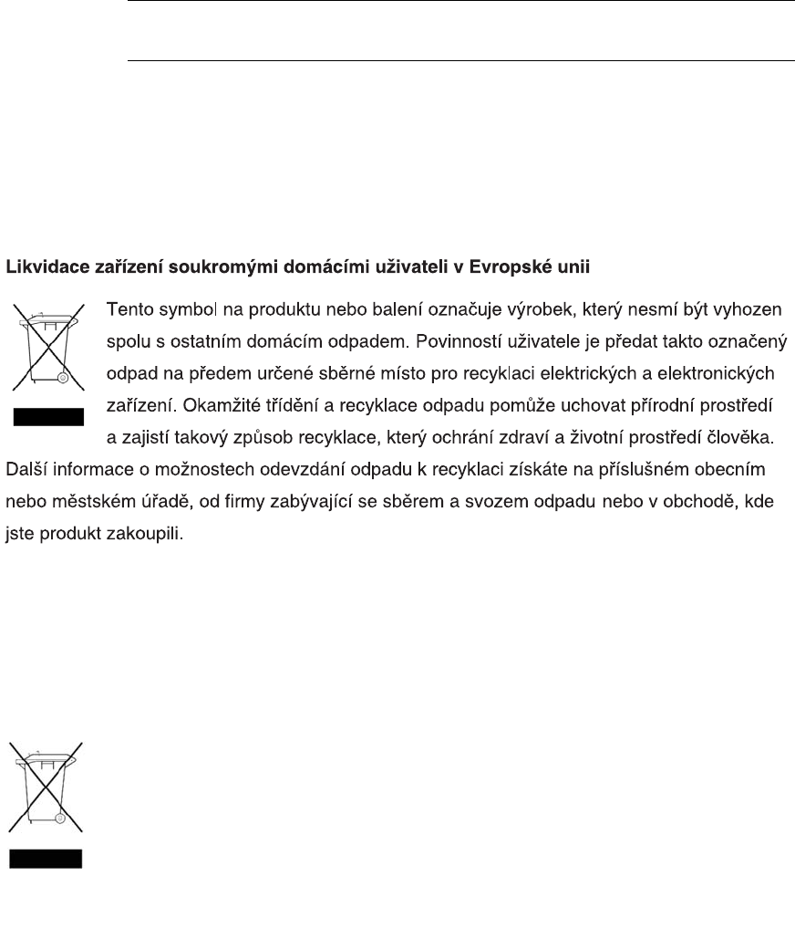
72 HP StorageWorks 2012i Modular Smart Array user guide • March 2008
Note – For more information on static electricity, or assistance with product
installation, contact your HP authorized reseller.
Waste Electrical and Electronic Equipment Directive
Czechoslovakian Notice
Danish Notice
Bortskaffelse af affald fra husstande i den Europæiske Union
Hvis produktet eller dets emballage er forsynet med dette symbol, angiver det,
at produktet ikke må bortskaffes med andet almindeligt husholdningsaffald.
I stedet er det dit ansvar at bortskaffe kasseret udstyr ved at aflevere det på den
kommunale genbrugsstation, der forestår genvinding af kasseret elektrisk og
elektronisk udstyr. Den centrale modtagelse og genvinding af kasseret udstyr
i forbindelse med bortskaffelsen bidrager til bevarelse af naturlige ressourcer
og sikrer, at udstyret genvindes på en måde, der beskytter både mennesker og miljø.
Yderligere oplysninger om, hvor du kan aflevere kasseret udstyr til genvinding, kan du få hos
kommunen, den lokale genbrugsstation eller i den butik, hvor du købte produktet.

Appendix B Regulatory Compliance and Safety 73
Dutch Notice
English Notice
Disposal of waste equipment by users in private household in the European Union
This symbol on the product or on its packaging indicates that this product must not be
disposed of with your other household waste. Instead, it is your responsibility to
dispose of your waste equipment by handing it over to a designated collection point
for recycling of waste electrical and electronic equipment. The separate collection
and recycling of your waste equipment at the time of disposal will help to conserve
natural resources and ensure that it is recycled in a manner that protects human
health and the environment. For more information about where you can drop off your
waste equipment for recycling, please contact your local city office, your household waste disposal
service, or the shop where you purchased the product.
Verwijdering van afgedankte apparatuur door privé-gebruikers in de Europese Unie
Dit symbool op het product of de verpakking geeft aan dat dit product niet
mag worden gedeponeerd bij het normale huishoudelijke afval. U bent zelf
verantwoordelijk voor het inleveren van uw afgedankte apparatuur bij een
inzamelingspunt voor het recyclen van oude elektrische en elektronische
apparatuur. Door uw oude apparatuur apart aan te bieden en te recyclen,
kunnen natuurlijke bronnen worden behouden en kan het materiaal worden
hergebruikt op een manier waarmee de volksgezondheid en het milieu worden beschermd.
Neem contact op met uw gemeente, het afvalinzamelingsbedrijf of de winkel waar u het
product hebt gekocht voor meer informatie over inzamelingspunten waar u oude apparatuur
kunt aanbieden voor recycling.
74 HP StorageWorks 2012i Modular Smart Array user guide • March 2008
Estonian Notice
Finnish Notice
Seadmete jäätmete kõrvaldamine eramajapidamistes Euroopa Liidus
See tootel või selle pakendil olev sümbol näitab, et kõnealust toodet ei tohi
koos teiste majapidamisjäätmetega kõrvaldada. Teie kohus on oma
seadmete jäätmed kõrvaldada, viies need elektri- ja elektroonikaseadmete
jäätmete ringlussevõtmiseks selleks ettenähtud kogumispunkti. Seadmete
jäätmete eraldi kogumine ja ringlussevõtmine kõrvaldamise ajal aitab kaitsta
loodusvarasid ning tagada, et ringlussevõtmine toimub viisil, mis kaitseb inimeste tervist
ning keskkonda. Lisateabe saamiseks selle kohta, kuhu oma seadmete jäätmed
ringlussevõtmiseks viia, võtke palun ühendust oma kohaliku linnakantselei,
majapidamisjäätmete kõrvaldamise teenistuse või kauplusega, kust Te toote ostsite.
Laitteiden hävittäminen kotitalouksissa Euroopan unionin alueella
Jos tuotteessa tai sen pakkauksessa on tämä merkki, tuotetta ei saa hävittää
kotitalousjätteiden mukana. Tällöin hävitettävä laite on toimitettava sähkölaitteid
ja elektronisten laitteiden kierrätyspisteeseen. Hävitettävien laitteiden erillinen
käsittely ja kierrätys auttavat säästämään luonnonvaroja ja varmistamaan, että
laite kierrätetään tavalla, joka estää terveyshaitat ja suojelee luontoa. Lisätietoja
paikoista, joihin hävitettävät laitteet voi toimittaa kierrätettäväksi, saa ottamalla
yhteyttä jätehuoltoon tai liikkeeseen, josta tuote on ostettu.
Appendix B Regulatory Compliance and Safety 75
French Notice
German Notice
Élimination des appareils mis au rebut par les ménages dans l'Union européenne
Le symbole apposé sur ce produit ou sur son emballage indique que ce produit
ne doit pas être jeté avec les déchets ménagers ordinaires. Il est de votre
responsabilité de mettre au rebut vos appareils en les déposant dans les centres
de collecte publique désignés pour le recyclage des équipements électriques
et électroniques. La collecte et le recyclage de vos appareils mis au rebut
indépendamment du reste des déchets contribue à la préservation des ressources
naturelles et garantit que ces appareils seront recyclés dans le respect de la santé humaine
et de l'environnement. Pour obtenir plus d'informations sur les centres de collecte et de
recyclage des appareils mis au rebut, veuillez contacter les autorités locales de votre région, l
es services de collecte des ordures ménagères ou le magasin dans lequel vous avez acheté
ce produit.
Entsorgung von Altgeräten aus privaten Haushalten in der EU
Das Symbol auf dem Produkt oder seiner Verpackung weist darauf hin, dass
das Produkt nicht über den normalen Hausmüll entsorgt werden darf. Benutzer
sind verpflichtet, die Altgeräte an einer Rücknahmestelle für Elektro- und
Elektronik-Altgeräte abzugeben. Die getrennte Sammlung und ordnungsgemäß
Entsorgung Ihrer Altgeräte trägt zur Erhaltung der natürlichen Ressourcen bei
und garantiert eine Wiederverwertung, die die Gesundheit des Menschen und
die Umwelt schützt. Informationen dazu, wo Sie Rücknahmestellen für Ihre Altgeräte finden
erhalten Sie bei Ihrer Stadtverwaltung, den örtlichen Müllentsorgungsbetrieben oder im
Geschäft, in dem Sie das Gerät erworben haben.
76 HP StorageWorks 2012i Modular Smart Array user guide • March 2008
Greek Notice
Hungarian Notice
. ,
.
.
,
,
.
Készülékek magánháztartásban történ selejtezése az Európai Unió területén
A készüléken, illetve a készülék csomagolásán látható azonos szimbólum annak
jelzésére szolgál, hogy a készülék a selejtezés során az egyéb háztartási
hulladéktól eltér módon kezelend . A vásárló a hulladékká vált készüléket köteles
a kijelölt gy jt helyre szállítani az elektromos és elektronikai készülékek
újrahasznosítása céljából. A hulladékká vált készülékek selejtezéskori begy jtése
és újrahasznosítása hozzájárul a természeti er források meg rzéséhez, valamint biztosítja
a selejtezett termékek környezetre és emberi egészségre nézve biztonságos feldolgozását.
A begy jtés pontos helyér l bvebb tájékoztatást a lakhelye szerint illetékes önkormányzattól,
az illetékes szemételtakarító vállalattól, illetve a terméket elárusító helyen kaphat.
Appendix B Regulatory Compliance and Safety 77
Italian Notice
Latvian Notice
Smaltimento delle apparecchiature da parte di privati nel territorio dell'Unione Europea
Questo simbolo presente sul prodotto o sulla sua confezione indica che il prodotto
non può essere smaltito insieme ai rifiuti domestici. È responsabilità dell'utente
smaltire le apparecchiature consegnandole presso un punto di raccolta designato
al riciclo e allo smaltimento di apparecchiature elettriche ed elettroniche. La raccolta
differenziata e il corretto riciclo delle apparecchiature da smaltire permette di
proteggere la salute degli individui e l'ecosistema. Per ulteriori informazioni relative
ai punti di raccolta delle apparecchiature, contattare l'ente locale per lo smaltimento dei rifiuti,
oppure il negozio presso il quale è stato acquistato il prodotto.
Nolietotu iek rtu izn cin šanas noteikumi lietot jiem Eiropas Savien bas
priv taj s m jsaimniec bs
Šds simbols uz izstr d juma vai uz t iesaiojuma nor da, ka šo
izstr d jumu nedr kst izmest kop ar citiem sadz ves atkritumiem. J s
atbildat par to, lai nolietot s iek rtas tiktu nodotas speci li iek rtotos
punktos, kas paredz ti izmantoto elektrisko un elektronisko iek rtu
savkšanai otrreiz jai p rstr dei. Atseviš a nolietoto iek rtu savkšana un
otrreiz j p rstr de paldz s saglab t dabas resursus un garant s, ka š s iek rtas tiks
otrreiz ji p rstr d tas t d veid , lai pasarg tu vidi un cilv ku vesel bu. Lai uzzin tu, kur
nolietot s iek rtas var izmest otrreiz jai p rstr dei, j vršas savas dz ves vietas
pašvald b, sadz ves atkritumu savkšanas dienest vai veikal, kur izstr d jums tika
nopirkts.
78 HP StorageWorks 2012i Modular Smart Array user guide • March 2008
Lihuanian Notice
Polish Notice
Nolietotu iek rtu izn cin šanas noteikumi lietot jiem Eiropas Savien bas
priv taj s m jsaimniec bs
Šds simbols uz izstr d juma vai uz t iesaiojuma nor da, ka šo
izstr d jumu nedr kst izmest kop ar citiem sadz ves atkritumiem. J s
atbildat par to, lai nolietot s iek rtas tiktu nodotas speci li iek rtotos
punktos, kas paredz ti izmantoto elektrisko un elektronisko iek rtu
savkšanai otrreiz jai p rstr dei. Atseviš a nolietoto iek rtu savkšana un
otrreiz j p rstr de paldz s saglab t dabas resursus un garant s, ka š s iek rtas tiks
otrreiz ji p rstr d tas t d veid , lai pasarg tu vidi un cilv ku vesel bu. Lai uzzin tu, kur
nolietot s iek rtas var izmest otrreiz jai p rstr dei, j vršas savas dz ves vietas
pašvald b, sadz ves atkritumu savkšanas dienest vai veikal, kur izstr d jums tika
nopirkts.
Pozbywanie si zu ytego sprz tu przez u ytkowników w prywatnych gospodarstwach
domowych w Unii Europejskiej
Ten symbol na produkcie lub jego opakowaniu oznacza, e produktu nie wolno
wyrzuca do zwykłych pojemników na mieci. Obowi zkiem uytkownika jest
przekazanie zuytego sprz tu do wyznaczonego punktu zbiórki w celu recyklingu
odpadów powstałych ze sprz tu elektrycznego i elektronicznego. Osobna zbiórka
oraz recykling zuytego sprz tu pomog w ochronie zasobów naturalnych
i zapewni ponowne wprowadzenie go do obiegu w sposób chroni cy zdrowie człowieka
irodowisko. Aby uzyska wi cej informacji o tym, gdzie mo na przekaza zuyty sprz t do
recyklingu, nale y si skontaktowa z urz dem miasta, zakładem gospodarki odpadami lub
sklepem, w którym zakupiono produkt.

Appendix B Regulatory Compliance and Safety 79
Portuguese Notice
Slovakian Notice
Descarte de Lixo Elétrico na Comunidade Européia
Este símbolo encontrado no produto ou na embalagem indica que o produto não
deve ser descartado no lixo doméstico comum. É responsabilidade do cliente
descartar o material usado (lixo elétrico), encaminhando-o para um ponto de
coleta para reciclagem. A coleta e a reciclagem seletivas desse tipo de lixo
ajudarão a conservar as reservas naturais; sendo assim, a reciclagem será feita
de uma forma segura, protegendo o ambiente e a saúde das pessoas. Para obter
mais informações sobre locais que reciclam esse tipo de material, entre em contato com
o escritório da HP em sua cidade, com o serviço de coleta de lixo ou com a loja em que
o produto foi adquirido.

80 HP StorageWorks 2012i Modular Smart Array user guide • March 2008
Slovenian Notice
Spanish Notice
Eliminación de residuos de equipos eléctricos y electrónicos por parte de usuarios
particulares en la Unión Europea
Este símbolo en el producto o en su envase indica que no debe eliminarse junto
con los desperdicios generales de la casa. Es responsabilidad del usuario eliminar
los residuos de este tipo depositándolos en un "punto limpio" para el reciclado
de residuos eléctricos y electrónicos. La recogida y el reciclado selectivos de
los residuos de aparatos eléctricos en el momento de su eliminación contribuirá
a conservar los recursos naturales y a garantizar el reciclado de estos residuos
de forma que se proteja el medio ambiente y la salud. Para obtener más información sobre
los puntos de recogida de residuos eléctricos y electrónicos para reciclado, póngase en
contacto con su ayuntamiento, con el servicio de eliminación de residuos domésticos o
con el establecimiento en el que adquirió el producto.

Appendix B Regulatory Compliance and Safety 81
Swedish Notice
Bortskaffande av avfallsprodukter från användare i privathushåll inom
Europeiska Unionen
Om den här symbolen visas på produkten eller förpackningen betyder det att
produkten inte får slängas på samma ställe som hushållssopor. I stället är det
ditt ansvar att bortskaffa avfallet genom att överlämna det till ett uppsamlingsställe
avsett för återvinning av avfall från elektriska och elektroniska produkter. Separat
insamling och återvinning av avfallet hjälper till att spara på våra naturresurser
och gör att avfallet återvinns på ett sätt som skyddar människors hälsa och miljön.
Kontakta ditt lokala kommunkontor, din närmsta återvinningsstation för hushållsavfall eller
affären där du köpte produkten för att få mer information om var du kan lämna ditt avfall
för återvinning.
82 HP StorageWorks 2012i Modular Smart Array user guide • March 2008

83
Index
A
accessing
SMU,50
the CLI,46
accumulators,70
Avis Canadien, regulatory compliance
notice,67
B
batteries
recycling or disposal,70
replacement
notice,69
Taiwan EPA recycling and disposal,70
boot straps, using,71
BSMI, regulatory compliance notice,68
C
cables
FCC compliance statement,65
shielded,65
Canada, regulatory compliance notice,67
certification and classification information, laser,66
Class A equipment, Canadian compliance statement,67
Class B equipment, Canadian compliance statement,67
CLI, See command-line interface
command-line interface
about,12
accessing,46
additional documentation,60
using to set controller IP address,46
configuring
switch attach configurations,41
connecting
AC power,35
controller and drive enclosures,32
controller enclosures to data hosts,41
serial cable to set IP address,46
to remote management hosts,43
using reverse cabling,32
controller enclosures
components,13
configuring host ports,52
connecting to data hosts,41
connecting to multiple drive enclosures,32
connecting to remote management hosts,43
controller modules
LEDs
cache status,18
Ethernet activity,18
Ethernet link status,18
expansion port status,18
Fault/Service Required,18
host activity,18
host link speed,17
host link status,17
OK to Remove,18
Unit Locator,18
location,16
ports
CLI,16
Ethernet,16
expansion,16
host,16
service,16
supported configurations,11
cord. See power cord
current rating,70
D
data hosts
connecting to controller enclosures
mapping to volumes,59
preparing iSCSI ports,40, 52
system requirements,39
date and time, setting,50
declaration of conformity,64
84 HP StorageWorks 2012i Modular Smart Array user guide • March 2008
disposal
waste equipment for EU private households,73
disposal, battery,70
disposal, Taiwan EPA battery,70
dissipating floor mats,71
drive enclosures
components,19
connecting to controller enclosures,32
connecting to other drive enclosures,32
drive modules
LEDs,15
location,14
E
ear caps, attaching,31
electrostatic damage prevention,71
enclosures
attaching ear caps,31
cabling configurations,32
installing in a rack,28
powering off,61
powering on,61
testing connections,36
ESD (electrostatic discharge)
prevention measures,71
storing products,71
transporting products,71
European Union, regulatory compliance
notice,67
expansion modules
LEDs
Fault/Service Required,22
FRU OK,22
OK to Remove,21
SAS In port status,21
SAS Out port status,22
Unit Locator,21
location,20
ports
SAS In,20
SAS Out,20
service,20
F
failover,11
fault tolerance, 32, 33
FCC (Federal Communications Commission)
Class A Equipment, compliance notice,63
Class B Equipment, compliance notice,64
declaration of conformity,64
modifications,65
notice,63
Federal Communications Commission. See FCC
floor mats, dissipating,71
G
ground strap specifications,71
grounding
methods,71
straps, wearing,71
suggested equipment for,71
H
heel straps, using,71
help, obtaining,10
hosts, See data hosts
HP
address for
FCC questions,64
series number,65
telephone number
FCC questions,64
HyperTerminal settings, See terminal emulator
I
indicators, See LEDs
installing enclosures
checklist,23
in a rack,28
safety precautions,26
installing required host software and drivers
iSCSI Software Initiator,40
SES driver,41
IP addresses
setting using the CLI,46
IP adresses
setting using DHCP,37
iSCSI Software Initiator, installing on data hosts,40
J
Japan
regulatory compliance notice,68
Index 85
K
Korean, regulatory compliance notice,69
L
label, laser,66
laser
international certification and classification
information,66
product label,66
radiation, warning,66
regulatory compliance notice,65
LEDs
AC Power Good, 17, 21
cache status,18
DC Voltage/Fan Fault/Service Required,17, 21
drive modules,15
Enclosure ID,14
Ethernet activity,18
Ethernet link status,18
expansion port status,18
fault ID,14
Fault/Service Required, 18, 22
FRU OK,22
heartbeat,14
host activity,18
host link speed,17
host link status,17
OK to Remove, 18, 21
SAS In port status,21
SAS Out port status,22
status,14
Unit identification (UID),14
Unit Locator,18, 21
lithium battery,69
M
managing storage systems
using SMU,12
using the CLI,12
mapping, data hosts to volumes,59
P
parts
proper handling,71
storing,71
transporting,71
ports
expansion,16
host,16
SAS In,20
SAS Out,20
service,20
power
connecting AC,35
switches,16
power and cooling modules
LEDs
AC Power Good,17, 21
DC Voltage/Fan Fault/Service Required, 17, 21
power switches,16, 20
power cord
compliance notice,70
current rating,70
replacement,70
set,70
voltage rating,70
preventing electrostatic damage,71
R
racks
installing enclosures in,28
preparing,27
recycling, battery,70
recycling, Taiwan EPA battery,70
regulatory compliance
information number,65
notices
BSMI,68
Canada,67
Class A,63
Class B,64
European Union,67
HP series number,65
Japan,68
Korean,69
lasers,65
modifications,65
shielded cables,65
remote management,43
replacing a power cord,70
reverse cabling,32
RFI/EMI connector hoods,65
86 HP StorageWorks 2012i Modular Smart Array user guide • March 2008
S
safety precautions,26
series number, regulatory compliance,65
SES driver, installing on data hosts,41
SMU
additional documentation,60
configuring,49
creating virtual disks,58
logging in,50
logging out,60
testing system configuration,59
static-dissipating work mat,71
static-safe containers
storing products,71
transporting products,71
status LEDs,14
Storage Management Utility, See SMU
storage system
configuring for the first time,45
powering off,61
powering on,61
testing configuration,59
storage website,10
straps, ground
boot,71
heel,71
toe,71
Subscriber’s choice website,10
Subscriber’s choice, HP,10
switch attach configurations,41
T
Taiwan EPA battery recycling and disposal,70
telephone numbers
FCC questions,64
terminal emulator
connection settings,47
display settings,47
toe straps, using,71
tools required for installation,25
tools, conductive type,71
U
UID LED,14
Unit identification (UID) LED,14
V
virtual disks
creating,58
viewing status,59
voltage compliance rating,70
volumes
mapping data hosts,59
verifying,59
W
warnings
lasers, radiation,66
waste equipment disposal for EU private households,73
web-browser configuration,49
websites
HP storage,10
HP Subscriber’s choice,10
work mat, static-dissipating,71
wrist straps
specifications,71
using,71
