Hp 220Mx Optical Jukebox Command Reference Guide Library SCSI 2
Hp-Storageworks-1200Mx-Optical-Jukebox-Command-Reference-Guide-157016 hp-storageworks-1200mx-optical-jukebox-command-reference-guide-157016
Hp-Surestore-80Fx-Optical-Jukebox-Command-Reference-Guide-157527 hp-surestore-80fx-optical-jukebox-command-reference-guide-157527
Hp-Surestore-600Fx-Optical-Jukebox-Command-Reference-Guide-157522 hp-surestore-600fx-optical-jukebox-command-reference-guide-157522
Hp-Surestore-1200Ex-Optical-Jukebox-Command-Reference-Guide-157506 hp-surestore-1200ex-optical-jukebox-command-reference-guide-157506
Hp-Surestore-160Ex-Optical-Jukebox-Command-Reference-Guide-157510 hp-surestore-160ex-optical-jukebox-command-reference-guide-157510
2015-01-05
: Hp Hp-220Mx-Optical-Jukebox-Command-Reference-Guide-156224 hp-220mx-optical-jukebox-command-reference-guide-156224 hp pdf
Open the PDF directly: View PDF ![]() .
.
Page Count: 378 [warning: Documents this large are best viewed by clicking the View PDF Link!]
- Optical Drive and Library SCSI-2 Command Reference
- 1 SCSI Command Overview
- 2 SCSI-2 Drive Command Set
- Numerical List of Commands
- Flag, Link, and RelAdr
- Test Unit Ready Command (00H)
- Rezero Unit Command (01H)
- Request Sense Command (03H)
- Format Unit Command (04H)
- Reassign Blocks Command (07H)
- Read (Group 0) Command (08H)
- Write (Group 0) Command (0AH)
- Seek (Group 0) Command (0BH)
- Inquiry Command (12H)
- Mode Select Command (15H)
- Reserve Command (16H)
- Release Command (17H)
- Mode Sense (Group 0) Command (1AH)
- Start/Stop Unit Command (1BH)
- Receive Diagnostic Results Command (1CH)
- Send Diagnostic Command (1DH)
- Prevent/Allow Medium Removal Command (1EH)
- Read Capacity Command (25H)
- Read (Group 1) Command (28H)
- Write (Group 1) Command (2AH)
- Seek (Group 1) Command (2BH)
- Erase (Group 1) Command (2CH)
- Write and Verify (Group 1) Command (2EH)
- Verify (Group 1) Command (2FH)
- Pre-Fetch (34H)
- Synchronize Cache (35H)
- Read Defect Data (Group 1) Command (37H)
- Write Buffer Command (3BH)
- Read Buffer Command (3CH)
- Read Long Command (3EH)
- Write Long Command (3FH)
- Log Select Command (4CH)
- Log Sense Command (4DH)
- Mode Select (Group 2) Command (55H)
- Mode Sense (Group 2) Command (5AH)
- Read (Group 5) Command (A8H)
- Write (Group 5) Command (AAH)
- Erase (Group 5) Command (ACH)
- Write and Verify (Group 5) Command (AEH)
- Verify (Group 5) Command (AFH)
- Read Defect Data (Group 5) Command (B7H)
- Read Long Command (DEH)
- Write Long Command (DFH)
- 3 Jukebox SCSI-2 Command Set
- Numerical List of Commands
- Alphabetical List of Commands
- Test Unit Ready Command (00H)
- Rezero Unit Command (01H)
- Request Sense Command (03H)
- Initialize Element Status Command (07H)
- Rotate Mailslot Command (0CH)
- Inquiry Command (12H)
- Reserve Command (16H)
- Release Command (17H)
- Mode Sense Command (1AH)
- Receive Diagnostic Results Command (1CH)
- Send Diagnostic Command (1DH)
- Prevent/Allow Medium Removal Command (1EH)
- Position To Element Command (2BH)
- Write Buffer Command (3BH)
- Read Buffer Command (3CH)
- Log Sense Command (4DH)
- Move Medium Command (A5H)
- Exchange Medium Command (A6H)
- Read Element Status Command (B8H)
- A Drive Error Codes
- B Autochanger Error Codes
- C Field Replaceable Units (FRUs)
- D Micro/Macro-Moves
- E Disconnect Timeout Settings
optical
drive and library
SCSI-2 command
reference
for models
fx, ex and mx

Optical Drive and Library SCSI-2
Command Reference
For fx, ex and mx Models
Edition 4
Manufacturing Part Number: 5969-5727
December 2001
Printed in USA
© Copyright 2001 Hewlett-Packard Company

ii
Notice
This document contains information that is protected by copyright. All
rights are reserved. No part of this document may be photocopied,
reproduced, or translated to another language without the prior written
consent of Hewlett-Packard Company. The information contained in this
document is subject to change without notice.
Hewlett-Packard makes no warranty of any kind with regard to this
printed material, including, but not limited to, the implied warranties of
merchantability and fitness for a particular purpose. Hewlett-
Packard shall not be liable for errors contained herein or for incidental or
consequential damages in connection with the furnishing,
performance, or use of this material.
Revision History
New editions of this manual incorporate all material updated since the
previous edition. The manual printing date and part number indicate the
current edition. The printing date changes when a new edition is printed.
(Minor corrections and updates incorporated at reprint do not change
this date.)
Edition 1:. February 1998
Edition 2:. April 1999
Edition 3:. June 2000
Edition 4:. December 2001

iii
Typographical Conventions
The following typographical conventions are used in this manual:
Keycap: Menu choices and screens on the jukebox.
Computer Output: Information displayed in the display window and
screen menu items that you can select.
NOTE Notes provide information that can be helpful in understanding the
operation of the product.

iv
In This Manual
Chapter 1 SCSI Command Overview: Explains SCSI
commands and how they are used with optical
drives and jukeboxes. This section does not
replace the SCSI-2 Command Specifications.
Chapter 2 SCSI-2 Drive Command Set: Lists all
supported SCSI commands and explains each
command’s structure.
Chapter 3 SCSI-2 Jukebox Command Set: Lists all
supported SCSI autochanger commands and
explains each command’s structure.
Appendix A Drive Error Codes: Lists all error codes
associated with the optical disk drive.
Appendix B Autochanger Error Codes: Lists all error codes
associated with the autochanger or optical disk
jukebox system.
Appendix C Field Replaceable Units (FRUs): Lists all the
field replaceable units for optical jukeboxes by
part number.
Appendix D Micro/Macro-Moves: Lists all micro- and
macro-moves for the optical jukeboxes.
Appendix E Programmer’s Tips: Provides information for
building optical disk and jukebox drivers, utilities
and applications.

Contents
v
1. SCSI Command Overview
Optical Drive Control Through SCSI . . . . . . . . . . . . . . . . . . . . . . . . . . . . . . . . . . . . . . . 1-2
Drive Control Commands . . . . . . . . . . . . . . . . . . . . . . . . . . . . . . . . . . . . . . . . . . . . . . . 1-3
SCSI Bus Phases . . . . . . . . . . . . . . . . . . . . . . . . . . . . . . . . . . . . . . . . . . . . . . . . . . . . . 1-3
Arbitration phase . . . . . . . . . . . . . . . . . . . . . . . . . . . . . . . . . . . . . . . . . . . . . . . . . . 1-3
Selection phase . . . . . . . . . . . . . . . . . . . . . . . . . . . . . . . . . . . . . . . . . . . . . . . . . . . . . 1-3
Reselection phase . . . . . . . . . . . . . . . . . . . . . . . . . . . . . . . . . . . . . . . . . . . . . . . . . . . 1-3
Information transfer phase . . . . . . . . . . . . . . . . . . . . . . . . . . . . . . . . . . . . . . . . . . . 1-3
Data phase . . . . . . . . . . . . . . . . . . . . . . . . . . . . . . . . . . . . . . . . . . . . . . . . . . . . . . . . 1-4
Command phase . . . . . . . . . . . . . . . . . . . . . . . . . . . . . . . . . . . . . . . . . . . . . . . . . . . . 1-4
Message phase . . . . . . . . . . . . . . . . . . . . . . . . . . . . . . . . . . . . . . . . . . . . . . . . . . . . . 1-4
Command Complete 00H . . . . . . . . . . . . . . . . . . . . . . . . . . . . . . . . . . . . . . . . . . . . . 1-6
Extended Message 01H . . . . . . . . . . . . . . . . . . . . . . . . . . . . . . . . . . . . . . . . . . . . . . 1-6
Synchronous Negotiation Started by the Initiator . . . . . . . . . . . . . . . . . . . . . . . . . 1-7
Save Data Pointer 02H . . . . . . . . . . . . . . . . . . . . . . . . . . . . . . . . . . . . . . . . . . . . . . 1-9
Restore Pointers 03H . . . . . . . . . . . . . . . . . . . . . . . . . . . . . . . . . . . . . . . . . . . . . . . . 1-9
Disconnect 04H . . . . . . . . . . . . . . . . . . . . . . . . . . . . . . . . . . . . . . . . . . . . . . . . . . . . 1-9
Initiator-Detected Error 05H . . . . . . . . . . . . . . . . . . . . . . . . . . . . . . . . . . . . . . . . . 1-9
Abort 06H . . . . . . . . . . . . . . . . . . . . . . . . . . . . . . . . . . . . . . . . . . . . . . . . . . . . . . . . 1-9
Message Reject 07H . . . . . . . . . . . . . . . . . . . . . . . . . . . . . . . . . . . . . . . . . . . . . . . 1-10
No Operation 08H . . . . . . . . . . . . . . . . . . . . . . . . . . . . . . . . . . . . . . . . . . . . . . . . . 1-11
Message Parity Error 09H . . . . . . . . . . . . . . . . . . . . . . . . . . . . . . . . . . . . . . . . . . 1-11
Linked Command Complete 0AH . . . . . . . . . . . . . . . . . . . . . . . . . . . . . . . . . . . . . 1-11
Linked Command Complete (with flag) 0BH . . . . . . . . . . . . . . . . . . . . . . . . . . . 1-11
Bus Device Reset 0CH . . . . . . . . . . . . . . . . . . . . . . . . . . . . . . . . . . . . . . . . . . . . . 1-11
Abort Tag 0DH . . . . . . . . . . . . . . . . . . . . . . . . . . . . . . . . . . . . . . . . . . . . . . . . . . . 1-11
Clear Queue 0EH . . . . . . . . . . . . . . . . . . . . . . . . . . . . . . . . . . . . . . . . . . . . . . . . . 1-12
Queue Tag Messages (20H, 21H, 22H) . . . . . . . . . . . . . . . . . . . . . . . . . . . . . . . . . 1-12
Identify 80H-FFH . . . . . . . . . . . . . . . . . . . . . . . . . . . . . . . . . . . . . . . . . . . . . . . . . . 1-13
Status Phase . . . . . . . . . . . . . . . . . . . . . . . . . . . . . . . . . . . . . . . . . . . . . . . . . . . . . . 1-14
Conditions . . . . . . . . . . . . . . . . . . . . . . . . . . . . . . . . . . . . . . . . . . . . . . . . . . . . . . . . . 1-16
Attention Condition . . . . . . . . . . . . . . . . . . . . . . . . . . . . . . . . . . . . . . . . . . . . . . . . 1-16
Reset Condition . . . . . . . . . . . . . . . . . . . . . . . . . . . . . . . . . . . . . . . . . . . . . . . . . . . 1-16
Unit Attention Condition . . . . . . . . . . . . . . . . . . . . . . . . . . . . . . . . . . . . . . . . . . . 1-17
SCSI Commands Used by the Target . . . . . . . . . . . . . . . . . . . . . . . . . . . . . . . . . . . . . . 1-18
Explanation of the Command Descriptor Block (CDB) . . . . . . . . . . . . . . . . . . . . . 1-18
2. SCSI-2 Drive Command Set

Contents
vi
Numerical List of Commands . . . . . . . . . . . . . . . . . . . . . . . . . . . . . . . . . . . . . . . . . . . . . 2-2
Flag, Link, and RelAdr . . . . . . . . . . . . . . . . . . . . . . . . . . . . . . . . . . . . . . . . . . . . . . . . 2-7
Test Unit Ready Command (00H) . . . . . . . . . . . . . . . . . . . . . . . . . . . . . . . . . . . . . . . . . 2-8
Rezero Unit Command (01H) . . . . . . . . . . . . . . . . . . . . . . . . . . . . . . . . . . . . . . . . . . . . . 2-9
Request Sense Command (03H) . . . . . . . . . . . . . . . . . . . . . . . . . . . . . . . . . . . . . . . . . . 2-10
Sense Data Format . . . . . . . . . . . . . . . . . . . . . . . . . . . . . . . . . . . . . . . . . . . . . . . . . . 2-11
Field Pointer Types . . . . . . . . . . . . . . . . . . . . . . . . . . . . . . . . . . . . . . . . . . . . . . . . . . 2-13
Format Unit Command (04H) . . . . . . . . . . . . . . . . . . . . . . . . . . . . . . . . . . . . . . . . . . . 2-15
Format Unit Command Defect List . . . . . . . . . . . . . . . . . . . . . . . . . . . . . . . . . . . . . 2-17
Reassign Blocks Command (07H) . . . . . . . . . . . . . . . . . . . . . . . . . . . . . . . . . . . . . . . . 2-19
Reassign Blocks Command Defect List . . . . . . . . . . . . . . . . . . . . . . . . . . . . . . . . . . 2-19
Read (Group 0) Command (08H) . . . . . . . . . . . . . . . . . . . . . . . . . . . . . . . . . . . . . . . . . 2-21
Write (Group 0) Command (0AH) . . . . . . . . . . . . . . . . . . . . . . . . . . . . . . . . . . . . . . . . 2-23
Seek (Group 0) Command (0BH) . . . . . . . . . . . . . . . . . . . . . . . . . . . . . . . . . . . . . . . . . 2-25
Inquiry Command (12H) . . . . . . . . . . . . . . . . . . . . . . . . . . . . . . . . . . . . . . . . . . . . . . . . 2-26
Mode Select Command (15H) . . . . . . . . . . . . . . . . . . . . . . . . . . . . . . . . . . . . . . . . . . . . 2-31
Mode Select Header . . . . . . . . . . . . . . . . . . . . . . . . . . . . . . . . . . . . . . . . . . . . . . . . . . 2-33
Read-Write Error Recovery . . . . . . . . . . . . . . . . . . . . . . . . . . . . . . . . . . . . . . . . . . . . 2-34
Disconnect-Reconnect . . . . . . . . . . . . . . . . . . . . . . . . . . . . . . . . . . . . . . . . . . . . . . . . 2-36
Caching Page 08H . . . . . . . . . . . . . . . . . . . . . . . . . . . . . . . . . . . . . . . . . . . . . . . . . . . 2-37
Control Mode Page 0AH . . . . . . . . . . . . . . . . . . . . . . . . . . . . . . . . . . . . . . . . . . . . . . 2-39
Medium Types Supported Page 0BH . . . . . . . . . . . . . . . . . . . . . . . . . . . . . . . . . . . . 2-40
Vendor Unique Format Page 20H . . . . . . . . . . . . . . . . . . . . . . . . . . . . . . . . . . . . . . . 2-42
Format Mode 03H . . . . . . . . . . . . . . . . . . . . . . . . . . . . . . . . . . . . . . . . . . . . . . . . . . . 2-43
Vendor Unique Page 21H . . . . . . . . . . . . . . . . . . . . . . . . . . . . . . . . . . . . . . . . . . . . . 2-46
Mode Page Parameter Default Values . . . . . . . . . . . . . . . . . . . . . . . . . . . . . . . . . . . 2-48
DIP Switch Locations . . . . . . . . . . . . . . . . . . . . . . . . . . . . . . . . . . . . . . . . . . . . . . . . 2-51
Reserve Command (16H) . . . . . . . . . . . . . . . . . . . . . . . . . . . . . . . . . . . . . . . . . . . . . . . 2-52
Release Command (17H) . . . . . . . . . . . . . . . . . . . . . . . . . . . . . . . . . . . . . . . . . . . . . . . 2-53
Mode Sense (Group 0) Command (1AH) . . . . . . . . . . . . . . . . . . . . . . . . . . . . . . . . . . . 2-54
Read-Write Error Recover Page . . . . . . . . . . . . . . . . . . . . . . . . . . . . . . . . . . . . . . . . 2-57
Disconnect-Reconnect Page 02H . . . . . . . . . . . . . . . . . . . . . . . . . . . . . . . . . . . . . . . . 2-59
Caching Page 08H . . . . . . . . . . . . . . . . . . . . . . . . . . . . . . . . . . . . . . . . . . . . . . . . . . . 2-60
Control Mode Page (0AH) . . . . . . . . . . . . . . . . . . . . . . . . . . . . . . . . . . . . . . . . . . . . . 2-63
Medium Types . . . . . . . . . . . . . . . . . . . . . . . . . . . . . . . . . . . . . . . . . . . . . . . . . . . . . . 2-64
Vendor Unique . . . . . . . . . . . . . . . . . . . . . . . . . . . . . . . . . . . . . . . . . . . . . . . . . . . . . . 2-66

Contents
vii
Format Mode . . . . . . . . . . . . . . . . . . . . . . . . . . . . . . . . . . . . . . . . . . . . . . . . . . . . . . . 2-67
Vendor Unique . . . . . . . . . . . . . . . . . . . . . . . . . . . . . . . . . . . . . . . . . . . . . . . . . . . . . . 2-70
Start/Stop Unit Command (1BH) . . . . . . . . . . . . . . . . . . . . . . . . . . . . . . . . . . . . . . 2-73
Receive Diagnostic Results Command (1CH) . . . . . . . . . . . . . . . . . . . . . . . . . . . . . 2-74
Send Diagnostic Command (1DH) . . . . . . . . . . . . . . . . . . . . . . . . . . . . . . . . . . . . . . 2-76
Prevent/Allow Medium Removal Command (1EH) . . . . . . . . . . . . . . . . . . . . . . . . . 2-79
Read Capacity Command (25H) . . . . . . . . . . . . . . . . . . . . . . . . . . . . . . . . . . . . . . . . 2-80
Read (Group 1) Command (28H) . . . . . . . . . . . . . . . . . . . . . . . . . . . . . . . . . . . . . . . . 2-82
Write (Group 1) Command (2AH) . . . . . . . . . . . . . . . . . . . . . . . . . . . . . . . . . . . . . . 2-84
Seek (Group 1) Command (2BH) . . . . . . . . . . . . . . . . . . . . . . . . . . . . . . . . . . . . . . . 2-87
Erase (Group 1) Command (2CH) . . . . . . . . . . . . . . . . . . . . . . . . . . . . . . . . . . . . . . 2-88
Write and Verify (Group 1) Command (2EH) . . . . . . . . . . . . . . . . . . . . . . . . . . . . . 2-90
Verify (Group 1) Command (2FH) . . . . . . . . . . . . . . . . . . . . . . . . . . . . . . . . . . . . . . 2-92
Pre-Fetch (34H) . . . . . . . . . . . . . . . . . . . . . . . . . . . . . . . . . . . . . . . . . . . . . . . . . . . . . 2-94
Synchronize Cache (35H) . . . . . . . . . . . . . . . . . . . . . . . . . . . . . . . . . . . . . . . . . . . . . 2-95
Read Defect Data (Group 1) Command (37H) . . . . . . . . . . . . . . . . . . . . . . . . . . . . . 2-96
Write Buffer Command (3BH) . . . . . . . . . . . . . . . . . . . . . . . . . . . . . . . . . . . . . . . . . 2-99
Read Buffer Command (3CH) . . . . . . . . . . . . . . . . . . . . . . . . . . . . . . . . . . . . . . . . . 2-102
Read Long Command (3EH) . . . . . . . . . . . . . . . . . . . . . . . . . . . . . . . . . . . . . . . . . . 2-104
Write Long Command (3FH) . . . . . . . . . . . . . . . . . . . . . . . . . . . . . . . . . . . . . . . . . 2-106
Log Select Command (4CH) . . . . . . . . . . . . . . . . . . . . . . . . . . . . . . . . . . . . . . . . . . 2-109
Parameter List Data . . . . . . . . . . . . . . . . . . . . . . . . . . . . . . . . . . . . . . . . . . . . . . . . 2-110
Log Sense Command (4DH) . . . . . . . . . . . . . . . . . . . . . . . . . . . . . . . . . . . . . . . . . . . . 2-111
Supported Log Pages 00H . . . . . . . . . . . . . . . . . . . . . . . . . . . . . . . . . . . . . . . . . . . . 2-112
Mode Select (Group 2) Command (55H) . . . . . . . . . . . . . . . . . . . . . . . . . . . . . . . . . . 2-122
Mode Sense (Group 2) Command (5AH) . . . . . . . . . . . . . . . . . . . . . . . . . . . . . . . . . . 2-125
Read (Group 5) Command (A8H) . . . . . . . . . . . . . . . . . . . . . . . . . . . . . . . . . . . . . . . 2-128
Write (Group 5) Command (AAH) . . . . . . . . . . . . . . . . . . . . . . . . . . . . . . . . . . . . . . . 2-131
Erase (Group 5) Command (ACH) . . . . . . . . . . . . . . . . . . . . . . . . . . . . . . . . . . . . . . 2-134
Write and Verify (Group 5) Command (AEH) . . . . . . . . . . . . . . . . . . . . . . . . . . . . . 2-137
Verify (Group 5) Command (AFH) . . . . . . . . . . . . . . . . . . . . . . . . . . . . . . . . . . . . . . 2-140
Read Defect Data (Group 5) Command (B7H) . . . . . . . . . . . . . . . . . . . . . . . . . . . . . 2-142
Read Long Command (DEH) . . . . . . . . . . . . . . . . . . . . . . . . . . . . . . . . . . . . . . . . . . . 2-145
Write Long Command (DFH) . . . . . . . . . . . . . . . . . . . . . . . . . . . . . . . . . . . . . . . . . . . 2-147
3. Jukebox SCSI-2 Command Set
Numerical List of Commands . . . . . . . . . . . . . . . . . . . . . . . . . . . . . . . . . . . . . . . . . . . . . 3-2
Alphabetical List of Commands . . . . . . . . . . . . . . . . . . . . . . . . . . . . . . . . . . . . . . . . . . . 3-4

Contents
viii
Test Unit Ready Command (00H) . . . . . . . . . . . . . . . . . . . . . . . . . . . . . . . . . . . . . . . . . 3-6
Rezero Unit Command (01H) . . . . . . . . . . . . . . . . . . . . . . . . . . . . . . . . . . . . . . . . . . . . 3-7
Request Sense Command (03H) . . . . . . . . . . . . . . . . . . . . . . . . . . . . . . . . . . . . . . . . . . . 3-8
Initialize Element Status Command (07H) . . . . . . . . . . . . . . . . . . . . . . . . . . . . . . . . . 3-12
Rotate Mailslot Command (0CH) . . . . . . . . . . . . . . . . . . . . . . . . . . . . . . . . . . . . . . . . . 3-13
Inquiry Command (12H) . . . . . . . . . . . . . . . . . . . . . . . . . . . . . . . . . . . . . . . . . . . . . . . 3-14
Inquiry Command Data . . . . . . . . . . . . . . . . . . . . . . . . . . . . . . . . . . . . . . . . . . . . . . 3-15
Vital Product Data Pages . . . . . . . . . . . . . . . . . . . . . . . . . . . . . . . . . . . . . . . . . . . . . 3-16
Reserve Command (16H) . . . . . . . . . . . . . . . . . . . . . . . . . . . . . . . . . . . . . . . . . . . . . . . 3-18
Reserve Command Element List Descriptors . . . . . . . . . . . . . . . . . . . . . . . . . . . . . 3-19
Release Command (17H) . . . . . . . . . . . . . . . . . . . . . . . . . . . . . . . . . . . . . . . . . . . . . . . 3-20
Mode Sense Command (1AH) . . . . . . . . . . . . . . . . . . . . . . . . . . . . . . . . . . . . . . . . . . . 3-21
Transport Element (Picker) . . . . . . . . . . . . . . . . . . . . . . . . . . . . . . . . . . . . . . . . . . . . 3-25
Device Capabilities . . . . . . . . . . . . . . . . . . . . . . . . . . . . . . . . . . . . . . . . . . . . . . . . . . 3-26
Receive Diagnostic Results Command (1CH) . . . . . . . . . . . . . . . . . . . . . . . . . . . . . . . 3-33
Send Diagnostic Command (1DH) . . . . . . . . . . . . . . . . . . . . . . . . . . . . . . . . . . . . . . . 3-35
Send Diagnostic Command Data . . . . . . . . . . . . . . . . . . . . . . . . . . . . . . . . . . . . . . . 3-36
Prevent/Allow Medium Removal Command (1EH) . . . . . . . . . . . . . . . . . . . . . . . . . . 3-37
Position To Element Command (2BH) . . . . . . . . . . . . . . . . . . . . . . . . . . . . . . . . . . . . 3-38
Write Buffer Command (3BH) . . . . . . . . . . . . . . . . . . . . . . . . . . . . . . . . . . . . . . . . . . . 3-39
Read Buffer Command (3CH) . . . . . . . . . . . . . . . . . . . . . . . . . . . . . . . . . . . . . . . . . . . 3-43
Log Sense Command (4DH) . . . . . . . . . . . . . . . . . . . . . . . . . . . . . . . . . . . . . . . . . . . . . 3-47
Log Sense Parameter Data . . . . . . . . . . . . . . . . . . . . . . . . . . . . . . . . . . . . . . . . . . . . 3-47
Error Logs Table Format . . . . . . . . . . . . . . . . . . . . . . . . . . . . . . . . . . . . . . . . . . . . . . 3-49
Move Success Log Table Format . . . . . . . . . . . . . . . . . . . . . . . . . . . . . . . . . . . . . . . . 3-53
Force Log Data Format . . . . . . . . . . . . . . . . . . . . . . . . . . . . . . . . . . . . . . . . . . . . . . . 3-54
Recovery Log Data Format . . . . . . . . . . . . . . . . . . . . . . . . . . . . . . . . . . . . . . . . . . . . 3-55
Drive Log Data Format . . . . . . . . . . . . . . . . . . . . . . . . . . . . . . . . . . . . . . . . . . . . . . . 3-57
Odometer Log Data Format . . . . . . . . . . . . . . . . . . . . . . . . . . . . . . . . . . . . . . . . . . . 3-58
Run-Time Log Data Format . . . . . . . . . . . . . . . . . . . . . . . . . . . . . . . . . . . . . . . . . . . 3-59
Retry Log Data Format . . . . . . . . . . . . . . . . . . . . . . . . . . . . . . . . . . . . . . . . . . . . . . . 3-61
Move History Log Data Format . . . . . . . . . . . . . . . . . . . . . . . . . . . . . . . . . . . . . . . . 3-63
Move Medium Command (A5H) . . . . . . . . . . . . . . . . . . . . . . . . . . . . . . . . . . . . . . . . . 3-64
Exchange Medium Command (A6H) . . . . . . . . . . . . . . . . . . . . . . . . . . . . . . . . . . . . . . 3-66
Read Element Status Command (B8H) . . . . . . . . . . . . . . . . . . . . . . . . . . . . . . . . . . . 3-68
Read Element Status Data . . . . . . . . . . . . . . . . . . . . . . . . . . . . . . . . . . . . . . . . . . . . 3-69

Contents
ix
Element Type Code 1H - Picker . . . . . . . . . . . . . . . . . . . . . . . . . . . . . . . . . . . . . . 3-70
Element Type Code 2H - Storage Slot . . . . . . . . . . . . . . . . . . . . . . . . . . . . . . . . . . 3-71
Element Type Code 3H - Mailslot . . . . . . . . . . . . . . . . . . . . . . . . . . . . . . . . . . . . . 3-72
Element Type Code 4H - Drive . . . . . . . . . . . . . . . . . . . . . . . . . . . . . . . . . . . . . . . 3-74
A. Drive Error Codes
Chapter Overview . . . . . . . . . . . . . . . . . . . . . . . . . . . . . . . . . . . . . . . . . . . . . . . . . . . . . .A-2
Drive Request Sense Command Values . . . . . . . . . . . . . . . . . . . . . . . . . . . . . . . . . . . .A-3
Drive Request Sense - Sense Key Values . . . . . . . . . . . . . . . . . . . . . . . . . . . . . . . . .A-3
Request Sense - Additional Sense Code Values . . . . . . . . . . . . . . . . . . . . . . . . . . . . .A-5
Internal Error Codes . . . . . . . . . . . . . . . . . . . . . . . . . . . . . . . . . . . . . . . . . . . . . . . . . . . .A-9
DSP Error Codes . . . . . . . . . . . . . . . . . . . . . . . . . . . . . . . . . . . . . . . . . . . . . . . . . . . . . .A-19
B. Autochanger Error Codes
Chapter Overview . . . . . . . . . . . . . . . . . . . . . . . . . . . . . . . . . . . . . . . . . . . . . . . . . . . . . .B-2
Request Sense Error Codes . . . . . . . . . . . . . . . . . . . . . . . . . . . . . . . . . . . . . . . . . . . . . .B-3
Additional Sense Data Format for Error Recovery For all models, EXCEPT 40fx
and 80ex. . . . . . . . . . . . . . . . . . . . . . . . . . . . . . . . . . . . . . . . . . . . . . . . . . . . . . . . . . . . . .B-8
Hardware Error Codes . . . . . . . . . . . . . . . . . . . . . . . . . . . . . . . . . . . . . . . . . . . . . . . . .B-19
Autochanger Move Error Codes . . . . . . . . . . . . . . . . . . . . . . . . . . . . . . . . . . . . . . . . . .B-29
Jukebox Micro-Move Error Codes . . . . . . . . . . . . . . . . . . . . . . . . . . . . . . . . . . . . . . . .B-32
Diagnostic Tests . . . . . . . . . . . . . . . . . . . . . . . . . . . . . . . . . . . . . . . . . . . . . . . . . . . . .B-40
C. Field Replaceable Units (FRUs)
HP Field Replaceable Units (FRUs) . . . . . . . . . . . . . . . . . . . . . . . . . . . . . . . . . . . . . . . .C-2
D. Micro/Macro-Moves
HP Surestore Optical Micro-Move IDs . . . . . . . . . . . . . . . . . . . . . . . . . . . . . . . . . . . . D-2
E. Disconnect Timeout Settings
Disconnect Timeouts . . . . . . . . . . . . . . . . . . . . . . . . . . . . . . . . . . . . . . . . . . . . . . . . . . . .E-2

Contents
x

Tables
xi
Table 1-1. Target-Supported Messages . . . . . . . . . . . . . . . . . . . . . . . . . . . . . . . . . . . . 1-5
Table 1-2. Extended Message Format . . . . . . . . . . . . . . . . . . . . . . . . . . . . . . . . . . . . . 1-6
Table 1-3. Transfer Period Values (For 9.1 and 5.2 Gbyte Drives) . . . . . . . . . . . . . . 1-8
Table 1-4. Offset Values (For 5.2 and 9.1 Gbyte Drives) . . . . . . . . . . . . . . . . . . . . . . 1-9
Table 1-5. Simple Queue Tag . . . . . . . . . . . . . . . . . . . . . . . . . . . . . . . . . . . . . . . . . . . 1-12
Table 1-6. Head of Queue Tag . . . . . . . . . . . . . . . . . . . . . . . . . . . . . . . . . . . . . . . . . . 1-13
Table 1-7. Ordered Queue Tag. . . . . . . . . . . . . . . . . . . . . . . . . . . . . . . . . . . . . . . . . . 1-13
Table 1-8. Target-Supported Status Codes . . . . . . . . . . . . . . . . . . . . . . . . . . . . . . . . 1-14
Table 2-1. Group 0 Commands (6-byte command) . . . . . . . . . . . . . . . . . . . . . . . . . . . 2-2
Table 2-2. Group 1 and 2 Commands (10-byte command) . . . . . . . . . . . . . . . . . . . . . 2-4
Table 2-3. Group 5 Commands (12-byte command) . . . . . . . . . . . . . . . . . . . . . . . . . . 2-6
Table 2-4. Test Unit Ready Command CDB . . . . . . . . . . . . . . . . . . . . . . . . . . . . . . . . 2-8
Table 2-5. Rezero Unit Command CDB . . . . . . . . . . . . . . . . . . . . . . . . . . . . . . . . . . . 2-9
Table 2-6. Request Sense Command CDB . . . . . . . . . . . . . . . . . . . . . . . . . . . . . . . . 2-10
Table 2-7. Error Code 70H or 71H Sense Data Format . . . . . . . . . . . . . . . . . . . . . . 2-11
Table 2-8. Sense Key Field Pointer Types. . . . . . . . . . . . . . . . . . . . . . . . . . . . . . . . . 2-13
Table 2-9. Progress Indication Field Bytes . . . . . . . . . . . . . . . . . . . . . . . . . . . . . . . . 2-14
Table 2-10. Format Unit Command CDB . . . . . . . . . . . . . . . . . . . . . . . . . . . . . . . . . 2-15
Table 2-11. Format Unit Defect List Header . . . . . . . . . . . . . . . . . . . . . . . . . . . . . . 2-17
Table 2-12. Physical Sector Format Defect Descriptor. . . . . . . . . . . . . . . . . . . . . . . 2-18
Table 2-13. Block Format Defect Descriptor . . . . . . . . . . . . . . . . . . . . . . . . . . . . . . . 2-18
Table 2-14. Reassign Blocks Command CDB . . . . . . . . . . . . . . . . . . . . . . . . . . . . . . 2-19
Table 2-15. Reassign Blocks Command Defect List Header . . . . . . . . . . . . . . . . . . 2-19
Table 2-16. Reassign Blocks Command Defect Descriptor. . . . . . . . . . . . . . . . . . . . 2-20
Table 2-17. Read (Group 0) Command CDB . . . . . . . . . . . . . . . . . . . . . . . . . . . . . . . 2-21
Table 2-18. Write (Group 0) Command CDB . . . . . . . . . . . . . . . . . . . . . . . . . . . . . . 2-23
Table 2-19. Seek (Group 0) Command CDB . . . . . . . . . . . . . . . . . . . . . . . . . . . . . . . 2-25
Table 2-20. Inquiry Command CDB . . . . . . . . . . . . . . . . . . . . . . . . . . . . . . . . . . . . . 2-26
Table 2-21. Vital Product Data Page Codes . . . . . . . . . . . . . . . . . . . . . . . . . . . . . . . 2-27
Table 2-22. Supported Vital Product Data Pages (00H). . . . . . . . . . . . . . . . . . . . . . 2-27
Table 2-23. Unit Serial Number Page (80H). . . . . . . . . . . . . . . . . . . . . . . . . . . . . . . 2-27
Table 2-24. Unique Media ID Page (C1H). . . . . . . . . . . . . . . . . . . . . . . . . . . . . . . . . 2-28
Table 2-25. Inquiry Command Returned Data . . . . . . . . . . . . . . . . . . . . . . . . . . . . . 2-29
Table 2-26. Mode Select (Group 0) Command CDB . . . . . . . . . . . . . . . . . . . . . . . . . 2-31

Tables
xii
Table 2-27. Mode Page Codes. . . . . . . . . . . . . . . . . . . . . . . . . . . . . . . . . . . . . . . . . . . 2-32
Table 2-28. Mode Select Header . . . . . . . . . . . . . . . . . . . . . . . . . . . . . . . . . . . . . . . . 2-33
Table 2-29. Mode Select Block Descriptor. . . . . . . . . . . . . . . . . . . . . . . . . . . . . . . . . 2-33
Table 2-30. Read-Write Error Recovery Page 01H . . . . . . . . . . . . . . . . . . . . . . . . . . 2-34
Table 2-31. Disconnect-Reconnect Page 02H . . . . . . . . . . . . . . . . . . . . . . . . . . . . . . 2-36
Table 2-32. Caching Page 08H. . . . . . . . . . . . . . . . . . . . . . . . . . . . . . . . . . . . . . . . . . 2-37
Table 2-33. Control Mode Page 0AH . . . . . . . . . . . . . . . . . . . . . . . . . . . . . . . . . . . . . 2-39
Table 2-34. Queue Algorithm Modifier . . . . . . . . . . . . . . . . . . . . . . . . . . . . . . . . . . . 2-39
Table 2-35. Medium Types Supported Page 0BH . . . . . . . . . . . . . . . . . . . . . . . . . . . 2-40
Table 2-36. Valid Medium Type Combinations. . . . . . . . . . . . . . . . . . . . . . . . . . . . . 2-41
Table 2-37. Vendor Unique Format Page 20H . . . . . . . . . . . . . . . . . . . . . . . . . . . . . 2-42
Table 2-38. Format Mode 03H - Type 0. . . . . . . . . . . . . . . . . . . . . . . . . . . . . . . . . . . 2-43
Table 2-39. Format Mode 03H - Type 1. . . . . . . . . . . . . . . . . . . . . . . . . . . . . . . . . . . 2-44
Table 2-40. Format Mode 04H . . . . . . . . . . . . . . . . . . . . . . . . . . . . . . . . . . . . . . . . . . 2-45
Table 2-41. Vendor Unique Page 21H . . . . . . . . . . . . . . . . . . . . . . . . . . . . . . . . . . . . 2-46
Table 2-42. Mode Page Parameter Default Values . . . . . . . . . . . . . . . . . . . . . . . . . . 2-48
Table 2-43. Mode Page 20H Parameter Default Values . . . . . . . . . . . . . . . . . . . . . . 2-49
Table 2-44. DIP Switch Definitions . . . . . . . . . . . . . . . . . . . . . . . . . . . . . . . . . . . . . . 2-51
Table 2-45. Reserve Command CDB . . . . . . . . . . . . . . . . . . . . . . . . . . . . . . . . . . . . . 2-52
Table 2-46. Release Command CDB . . . . . . . . . . . . . . . . . . . . . . . . . . . . . . . . . . . . . 2-53
Table 2-47. Mode Sense (Group 0) Command CDB . . . . . . . . . . . . . . . . . . . . . . . . . 2-54
Table 2-48. Mode Sense Header . . . . . . . . . . . . . . . . . . . . . . . . . . . . . . . . . . . . . . . . 2-55
Table 2-49. Mode Sense Descriptor . . . . . . . . . . . . . . . . . . . . . . . . . . . . . . . . . . . . . . 2-55
Table 2-50. Mode Page Codes. . . . . . . . . . . . . . . . . . . . . . . . . . . . . . . . . . . . . . . . . . . 2-56
Table 2-51. Read-Write Error Recovery Page 01H . . . . . . . . . . . . . . . . . . . . . . . . . . 2-57
Table 2-52. Disconnect-Reconnect Page 02H . . . . . . . . . . . . . . . . . . . . . . . . . . . . . . 2-59
Table 2-53. Caching Page 08H. . . . . . . . . . . . . . . . . . . . . . . . . . . . . . . . . . . . . . . . . . 2-60
Table 2-54. Control Mode Page (0AH) . . . . . . . . . . . . . . . . . . . . . . . . . . . . . . . . . . . . 2-63
Table 2-55. Medium Types Supported Page 0BH . . . . . . . . . . . . . . . . . . . . . . . . . . . 2-64
Table 2-56. Valid Medium Type Combinations. . . . . . . . . . . . . . . . . . . . . . . . . . . . . 2-65
Table 2-57. Vendor Unique Format Page 20H . . . . . . . . . . . . . . . . . . . . . . . . . . . . . 2-66
Table 2-58. Format Mode 03H - Type 0. . . . . . . . . . . . . . . . . . . . . . . . . . . . . . . . . . . 2-67
Table 2-59. Format Mode 03H - Type 1. . . . . . . . . . . . . . . . . . . . . . . . . . . . . . . . . . . 2-68
Table 2-60. Format Mode 04H . . . . . . . . . . . . . . . . . . . . . . . . . . . . . . . . . . . . . . . . . . 2-69

Tables
xiii
Table 2-61. Vendor Unique Page 21H . . . . . . . . . . . . . . . . . . . . . . . . . . . . . . . . . . . . 2-70
Table 2-62. Start/Stop Unit Command CDB. . . . . . . . . . . . . . . . . . . . . . . . . . . . . . . 2-73
Table 2-63. Receive Diagnostic Results Command CDB . . . . . . . . . . . . . . . . . . . . . 2-74
Table 2-64. Received Diagnostic Results Page Codes. . . . . . . . . . . . . . . . . . . . . . . . 2-74
Table 2-65. Supported Diagnostic Pages. . . . . . . . . . . . . . . . . . . . . . . . . . . . . . . . . . 2-75
Table 2-66. Controller Test 81H . . . . . . . . . . . . . . . . . . . . . . . . . . . . . . . . . . . . . . . . 2-75
Table 2-67. Send Diagnostic Command CDB . . . . . . . . . . . . . . . . . . . . . . . . . . . . . . 2-76
Table 2-68. Supported Diagnostic Pages. . . . . . . . . . . . . . . . . . . . . . . . . . . . . . . . . . 2-77
Table 2-69. Send Diagnostic Command Page Codes. . . . . . . . . . . . . . . . . . . . . . . . . 2-77
Table 2-70. Controller Test . . . . . . . . . . . . . . . . . . . . . . . . . . . . . . . . . . . . . . . . . . . . 2-78
Table 2-71. Interface Manager Diagnostic Tests . . . . . . . . . . . . . . . . . . . . . . . . . . . 2-78
Table 2-72. Prevent/Allow Medium Removal Command CDB. . . . . . . . . . . . . . . . . 2-79
Table 2-73. Read Capacity Command CDB . . . . . . . . . . . . . . . . . . . . . . . . . . . . . . . 2-80
Table 2-74. Read Capacity Command Data . . . . . . . . . . . . . . . . . . . . . . . . . . . . . . . 2-81
Table 2-75. Read (Group 1) Command CDB . . . . . . . . . . . . . . . . . . . . . . . . . . . . . . . 2-82
Table 2-76. Write (Group 1) Command CDB . . . . . . . . . . . . . . . . . . . . . . . . . . . . . . 2-84
Table 2-77. Seek (Group 1) Command CDB . . . . . . . . . . . . . . . . . . . . . . . . . . . . . . . 2-87
Table 2-78. Erase (Group 1) Command CDB . . . . . . . . . . . . . . . . . . . . . . . . . . . . . . 2-88
Table 2-79. Write and Verify (Group 1) Command CDB . . . . . . . . . . . . . . . . . . . . . 2-90
Table 2-80. Verify (Group 1) Command CDB . . . . . . . . . . . . . . . . . . . . . . . . . . . . . . 2-92
2-Table 2-81. Pre-Fetch Command . . . . . . . . . . . . . . . . . . . . . . . . . . . . . . . . . . . . . . 2-94
2-Table 2-82. Synchronize Cache Command. . . . . . . . . . . . . . . . . . . . . . . . . . . . . . . 2-95
Table 2-83. Read Defect Data (Group 1) Command CDB . . . . . . . . . . . . . . . . . . . . 2-96
Table 2-84. Read Defect Data Defect List Header . . . . . . . . . . . . . . . . . . . . . . . . . . 2-97
Table 2-85. Physical Sector Format Defect Descriptor. . . . . . . . . . . . . . . . . . . . . . . 2-98
Table 2-86. Write Buffer Command CDB . . . . . . . . . . . . . . . . . . . . . . . . . . . . . . . . . 2-99
Table 2-87. Buffer Access Mode and ID . . . . . . . . . . . . . . . . . . . . . . . . . . . . . . . . . 2-100
Table 2-88. Mode Descriptions (For 2.6 Gbyte Capacity Drives Only) . . . . . . . . . 2-100
Table 2-89. Mode Descriptions (For 9.1 and 5.2 Gbyte Capacity Drives Only). . . 2-101
Table 2-90. Read Buffer Command CDB . . . . . . . . . . . . . . . . . . . . . . . . . . . . . . . . 2-102
Table 2-91. Read Buffer Descriptor . . . . . . . . . . . . . . . . . . . . . . . . . . . . . . . . . . . . . 2-103
Table 2-92. Buffer Access Mode and ID . . . . . . . . . . . . . . . . . . . . . . . . . . . . . . . . . 2-103
Table 2-93. Mode Descriptions (For 2.6 Gbyte Capacity Drives Only) . . . . . . . . . 2-103
Table 2-94. Mode Descriptions (For 9.1 and 5.2 Gbyte Capacity Drives Only). . . 2-103

Tables
xiv
Table 2-95. Read Long Command CDB. . . . . . . . . . . . . . . . . . . . . . . . . . . . . . . . . . 2-104
Table 2-96. Write Long Command CDB . . . . . . . . . . . . . . . . . . . . . . . . . . . . . . . . . 2-106
Table 2-97. Log Select Command CDB . . . . . . . . . . . . . . . . . . . . . . . . . . . . . . . . . . 2-109
Table 2-98. Parameter List Data for Byte 8 of the Log Select Command . . . . . . . 2-110
Table 2-99. Log Select Command . . . . . . . . . . . . . . . . . . . . . . . . . . . . . . . . . . . . . . 2-110
Table 2-100. Log Sense Command CDB . . . . . . . . . . . . . . . . . . . . . . . . . . . . . . . . . 2-111
Table 2-101. Log Sense Page Codes. . . . . . . . . . . . . . . . . . . . . . . . . . . . . . . . . . . . . 2-112
Table 2-102. Supported Log Pages 00H . . . . . . . . . . . . . . . . . . . . . . . . . . . . . . . . . 2-112
Table 2-103. Error Counter Page for Write Errors 02H. . . . . . . . . . . . . . . . . . . . . 2-113
Table 2-104. Parameter Codes/Structure for Write Errors . . . . . . . . . . . . . . . . . . 2-113
Table 2-105. Error Counter Page for Read Errors 03H . . . . . . . . . . . . . . . . . . . . . 2-114
Table 2-106. Parameter Codes/Structure for Read Errors . . . . . . . . . . . . . . . . . . . 2-114
Table 2-107. Error Counter Page for Verify Errors 05H . . . . . . . . . . . . . . . . . . . . 2-115
Table 2-108. Parameter Codes/Structure for Verify Errors . . . . . . . . . . . . . . . . . . 2-115
Table 2-109. Last N Error Events Page 07H . . . . . . . . . . . . . . . . . . . . . . . . . . . . . 2-116
Table 2-110. Parameter Pointers/Structure for Last N Error Events Page . . . . . 2-117
Table 2-111. Error Event Log . . . . . . . . . . . . . . . . . . . . . . . . . . . . . . . . . . . . . . . . . 2-118
Table 2-112. Error Counter Page for Erase Errors 33H. . . . . . . . . . . . . . . . . . . . . 2-118
Table 2-113. Parameter Codes/Structure for Erase Errors . . . . . . . . . . . . . . . . . . 2-120
Table 2-114. Error Counter Page for Blank Check Errors 34H . . . . . . . . . . . . . . . 2-120
Table 2-115. Parameter Codes/Structure for Blank Check Errors . . . . . . . . . . . . 2-121
Table 2-116. Mode Select (Group 2) Command CDB . . . . . . . . . . . . . . . . . . . . . . . 2-122
Table 2-117. Mode Select Header . . . . . . . . . . . . . . . . . . . . . . . . . . . . . . . . . . . . . . 2-123
Table 2-118. Mode Select Block Descriptor. . . . . . . . . . . . . . . . . . . . . . . . . . . . . . . 2-124
Table 2-119. Mode Select (Group 2) Command CDB . . . . . . . . . . . . . . . . . . . . . . . 2-125
Table 2-120. Mode Sense Header . . . . . . . . . . . . . . . . . . . . . . . . . . . . . . . . . . . . . . 2-126
Table 2-121. Mode Sense Block Descriptor . . . . . . . . . . . . . . . . . . . . . . . . . . . . . . . 2-127
Table 2-122. Read (Group 5) Command CDB . . . . . . . . . . . . . . . . . . . . . . . . . . . . . 2-128
Table 2-123. Write (Group 5) Command CDB . . . . . . . . . . . . . . . . . . . . . . . . . . . . 2-131
Table 2-124. Erase (Group 5) Command CDB . . . . . . . . . . . . . . . . . . . . . . . . . . . . 2-134
Table 2-125. Write and Verify (Group 5) CDB . . . . . . . . . . . . . . . . . . . . . . . . . . . . 2-137
Table 2-126. Verify (Group 5) CDB . . . . . . . . . . . . . . . . . . . . . . . . . . . . . . . . . . . . . 2-140
Table 2-127. Read Defect Data (Group 5) Command CDB . . . . . . . . . . . . . . . . . . 2-142
Table 2-128. Read Defect Data Defect List Header . . . . . . . . . . . . . . . . . . . . . . . . 2-143

Tables
xv
Table 2-129. Physical Sector Format Defect Descriptor. . . . . . . . . . . . . . . . . . . . . 2-144
Table 2-130. Read Long Command CDB. . . . . . . . . . . . . . . . . . . . . . . . . . . . . . . . . 2-145
Table 2-131. Write Long Command CDB . . . . . . . . . . . . . . . . . . . . . . . . . . . . . . . . 2-147
Table 3-1. Numerical List of Commands. . . . . . . . . . . . . . . . . . . . . . . . . . . . . . . . . . . 3-2
Table 3-2. Alphabetical List of Commands . . . . . . . . . . . . . . . . . . . . . . . . . . . . . . . . . 3-4
Table 3-3. Test Unit Ready Command CDB . . . . . . . . . . . . . . . . . . . . . . . . . . . . . . . . 3-6
Table 3-4. Rezero Unit Command CDB . . . . . . . . . . . . . . . . . . . . . . . . . . . . . . . . . . . 3-7
Table 3-5. Request Sense Command CDB . . . . . . . . . . . . . . . . . . . . . . . . . . . . . . . . . 3-8
Table 3-6. Request Sense Data Parameter Block Format . . . . . . . . . . . . . . . . . . . . . 3-9
Table 3-7. Sense Key - Additional Sense Length Values . . . . . . . . . . . . . . . . . . . . . 3-10
Table 3-8. Sense Key Field = Illegal Request (05H) and SKSV Bit = 1. . . . . . . . . . 3-11
Table 3-9. Initialize Element Status Command CDB . . . . . . . . . . . . . . . . . . . . . . . 3-12
Table 3-10. Rotate Mailslot Command CDB. . . . . . . . . . . . . . . . . . . . . . . . . . . . . . . 3-13
Table 3-11. Inquiry Command CDB . . . . . . . . . . . . . . . . . . . . . . . . . . . . . . . . . . . . . 3-14
Table 3-12. Vital Product Data Page Codes . . . . . . . . . . . . . . . . . . . . . . . . . . . . . . . 3-15
Table 3-13. Standard Inquiry Data Format . . . . . . . . . . . . . . . . . . . . . . . . . . . . . . . 3-15
Table 3-14. Supported Vital Product Data Pages . . . . . . . . . . . . . . . . . . . . . . . . . . . 3-16
Table 3-15. Unit Serial Number Page . . . . . . . . . . . . . . . . . . . . . . . . . . . . . . . . . . . . 3-17
Table 3-16. Firmware Information Page . . . . . . . . . . . . . . . . . . . . . . . . . . . . . . . . . . 3-17
Table 3-17. Reserve Command CDB . . . . . . . . . . . . . . . . . . . . . . . . . . . . . . . . . . . . . 3-18
Table 3-18. Reserve Command Element List Descriptors . . . . . . . . . . . . . . . . . . . . 3-19
Table 3-19. Reserve Command CDB . . . . . . . . . . . . . . . . . . . . . . . . . . . . . . . . . . . . . 3-20
Table 3-20. Mode Sense Command CDB. . . . . . . . . . . . . . . . . . . . . . . . . . . . . . . . . . 3-21
Table 3-21. Mode Sense Allocation Lengths . . . . . . . . . . . . . . . . . . . . . . . . . . . . . . . 3-22
Table 3-22. Mode Sense Element Address Assignment Page (1DH) Format . . . . . 3-23
Table 3-23. Number of Transport Elements . . . . . . . . . . . . . . . . . . . . . . . . . . . . . . . 3-23
Table 3-24. Number of Data Transfer Elements . . . . . . . . . . . . . . . . . . . . . . . . . . . 3-23
Table 3-25. Mode Sense Transport Element Parameter Page (1EH) Format . . . . . 3-25
Table 3-26. Mode Sense Device Capabilities Page (1FH). . . . . . . . . . . . . . . . . . . . . 3-27
Table 3-27. Mode Sense Device Capabilities Page (1FH). . . . . . . . . . . . . . . . . . . . . 3-28
Table 3-28. Autochanger Configuration Mode Page (20H). . . . . . . . . . . . . . . . . . . . 3-30
Table 3-29. Receive Diagnostic Results Command CDB . . . . . . . . . . . . . . . . . . . . . 3-33
Table 3-30. Receive Diagnostic Results Command CDB . . . . . . . . . . . . . . . . . . . . . 3-34
Table 3-31. Send Diagnostic Command CDB . . . . . . . . . . . . . . . . . . . . . . . . . . . . . . 3-35

Tables
xvi
Table 3-32. Send Diagnostic Command Parameter List . . . . . . . . . . . . . . . . . . . . . 3-36
Table 3-33. Prevent/Allow Medium Removal Command CDB. . . . . . . . . . . . . . . . . 3-37
Table 3-34. Position To Element Command CDB . . . . . . . . . . . . . . . . . . . . . . . . . . . 3-38
Table 3-35. Write Buffer Command CDB . . . . . . . . . . . . . . . . . . . . . . . . . . . . . . . . . 3-39
Table 3-36. Write Buffer Mode Descriptions. . . . . . . . . . . . . . . . . . . . . . . . . . . . . . . 3-40
Table 3-37. User Accessible Buffers and Allowed Write Modes . . . . . . . . . . . . . . . 3-40
Table 3-38. Write Buffer Data Format When Buffer ID Set to Online Drive
Repair . . . . . . . . . . . . . . . . . . . . . . . . . . . . . . . . . . . . . . . . . . . . . . . . . . . . . . . . . . . . .3-41
Table 3-39. Drive Control Definition . . . . . . . . . . . . . . . . . . . . . . . . . . . . . . . . . . . . . 3-42
Table 3-40. Read Buffer Command CDB . . . . . . . . . . . . . . . . . . . . . . . . . . . . . . . . . 3-43
Table 3-41. Read Buffer Mode Descriptions . . . . . . . . . . . . . . . . . . . . . . . . . . . . . . . 3-44
Table 3-42. User Accessible Buffers and Allowed Read Modes . . . . . . . . . . . . . . . . 3-44
Table 3-43. Read Buffer Data Format When Buffer ID Set to Online Drive
Repair . . . . . . . . . . . . . . . . . . . . . . . . . . . . . . . . . . . . . . . . . . . . . . . . . . . . . . . . . . . . .3-45
Table 3-44. Drive Status Definition. . . . . . . . . . . . . . . . . . . . . . . . . . . . . . . . . . . . . . 3-46
Table 3-45. Log Sense Command CDB . . . . . . . . . . . . . . . . . . . . . . . . . . . . . . . . . . . 3-47
Table 3-46. Log Sense Parameter Data Available in Each Page . . . . . . . . . . . . . . . 3-48
Table 3-47. Error Logs Table Format . . . . . . . . . . . . . . . . . . . . . . . . . . . . . . . . . . . . 3-49
Table 3-48. Error/ Recovery/Runtime Log Data Entry Format . . . . . . . . . . . . . . . . 3-50
Table 3-49. Error Logs Table Format (For 40fx, 80ex, 125ex and 220mx models) . 3-51
Table 3-50. Error Log Entry Format (For 40fx, 80ex, 125ex and 220mx models). . 3-51
Table 3-51. Move Success Log Table Format (For 40fx, 80ex, 125ex and 220mx
models) . . . . . . . . . . . . . . . . . . . . . . . . . . . . . . . . . . . . . . . . . . . . . . . . . . . . . . . . . . . . 3-53
Table 3-52. Move Success Logs Entry Format . . . . . . . . . . . . . . . . . . . . . . . . . . . . . 3-53
Table 3-53. Force Entry Data Format . . . . . . . . . . . . . . . . . . . . . . . . . . . . . . . . . . . . 3-54
Table 3-54. Recovery Log Data Format (For all models EXCEPT 40fx, 80ex,
125ex and 220mx) . . . . . . . . . . . . . . . . . . . . . . . . . . . . . . . . . . . . . . . . . . . . . . . . . . . 3-55
Table 3-55. Recovery Log Data Format (For the 40fx, 80ex, 125ex and 220mx
models) . . . . . . . . . . . . . . . . . . . . . . . . . . . . . . . . . . . . . . . . . . . . . . . . . . . . . . . . . . . . 3-55
Table 3-56. Recovery Log Entry Format (For the 40fx, 80ex, 125ex and 220mx
models) . . . . . . . . . . . . . . . . . . . . . . . . . . . . . . . . . . . . . . . . . . . . . . . . . . . . . . . . . . . . 3-56
Table 3-57. Error Recovery State (For the 40fx, 80ex, 125ex and 220mx models) . 3-56
Table 3-58. Drive Log Data Format. . . . . . . . . . . . . . . . . . . . . . . . . . . . . . . . . . . . . . 3-57
Table 3-59. Drive Log Entry Format . . . . . . . . . . . . . . . . . . . . . . . . . . . . . . . . . . . . . 3-57

Tables
xvii
Table 3-60. Odometer Log Data Format . . . . . . . . . . . . . . . . . . . . . . . . . . . . . . . . . . 3-58
Table 3-61. Run-Time Logs Data Format (For all models, EXCEPT 40fx, 80ex,
125ex and 220mx) . . . . . . . . . . . . . . . . . . . . . . . . . . . . . . . . . . . . . . . . . . . . . . . . . . . 3-59
Table 3-62. Run-Time Logs Data Format (For the 40fx, 80ex, 125ex and 220mx
models) . . . . . . . . . . . . . . . . . . . . . . . . . . . . . . . . . . . . . . . . . . . . . . . . . . . . . . . . . . . . 3-59
Table 3-63. Run-Time Log Entry Format . . . . . . . . . . . . . . . . . . . . . . . . . . . . . . . . . 3-59
Table 3-64. Retry Log Data Format. . . . . . . . . . . . . . . . . . . . . . . . . . . . . . . . . . . . . . 3-61
Table 3-65. Retry Algorithm Codes . . . . . . . . . . . . . . . . . . . . . . . . . . . . . . . . . . . . . . 3-62
Table 3-66. Move History Log Data Format . . . . . . . . . . . . . . . . . . . . . . . . . . . . . . . 3-63
Table 3-67. Move History Log Entry Format . . . . . . . . . . . . . . . . . . . . . . . . . . . . . . 3-63
Table 3-68. Move Medium Command CDB. . . . . . . . . . . . . . . . . . . . . . . . . . . . . . . . 3-64
Table 3-69. Exchange Medium Command CDB . . . . . . . . . . . . . . . . . . . . . . . . . . . . 3-66
Table 3-70. Read Element Status Command CDB . . . . . . . . . . . . . . . . . . . . . . . . . . 3-68
Table 3-71. Read Element Status Data Header . . . . . . . . . . . . . . . . . . . . . . . . . . . . 3-69
Table 3-72. Medium Transport Element Descriptor Block . . . . . . . . . . . . . . . . . . . 3-70
Table 3-73. Read Element Status Storage Element Descriptor Block . . . . . . . . . . 3-71
Table 3-74. Read Element Status Import/Export Element Descriptor Block . . . . . 3-72
Table 3-75. Read Element Status Data Transfer Element Descriptor Block . . . . . 3-74
Table A-1. Request Sense - Sense Key Values Byte 2, Bits 3 through 0 . . . . . . . . . .A-3
Table A-2. Request Sense - Additional Sense Code Values . . . . . . . . . . . . . . . . . . . .A-5
Table A-3. Internal Error Codes . . . . . . . . . . . . . . . . . . . . . . . . . . . . . . . . . . . . . . . . . A-9
Table A-4. ODC Error Codes . . . . . . . . . . . . . . . . . . . . . . . . . . . . . . . . . . . . . . . . . . .A-15
Table A-5. ODC Error Codes . . . . . . . . . . . . . . . . . . . . . . . . . . . . . . . . . . . . . . . . . . .A-17
Table A-6. DSP Error Codes . . . . . . . . . . . . . . . . . . . . . . . . . . . . . . . . . . . . . . . . . . .A-19
Table A-7. Terms Used In the Tables . . . . . . . . . . . . . . . . . . . . . . . . . . . . . . . . . . . .A-22
Table B-1. Request Sense - Sense Key Values — Byte 2, Bits 3 through 0. . . . . . . .B-3
Table B-2. Request Sense Data (bytes 12 and 13) . . . . . . . . . . . . . . . . . . . . . . . . . . .B-3
Table B-3. Invalid Address: Sense Code 2IH . . . . . . . . . . . . . . . . . . . . . . . . . . . . . . .B-7
Table B-4. Element Full/Empty: Sense Code 3BH . . . . . . . . . . . . . . . . . . . . . . . . . . .B-7
Table B-5. Request Sense - Additional Sense Data (For all models, EXCEPT
40fx, 80ex, 125ex and 220mx) . . . . . . . . . . . . . . . . . . . . . . . . . . . . . . . . . . . . . . . . . . .B-8
Table B-6. Request Sense - Additional Sense Data (For models 40fx, 80ex,
125ex and 220mx) . . . . . . . . . . . . . . . . . . . . . . . . . . . . . . . . . . . . . . . . . . . . . . . . . . . B-14
Table B-7. Hardware Error Codes (medium and large models). . . . . . . . . . . . . . . .B-19

Tables
xviii
Table B-8. Hardware Error Codes (For the 40fx, 80ex, 125ex, and 220mx
models) . . . . . . . . . . . . . . . . . . . . . . . . . . . . . . . . . . . . . . . . . . . . . . . . . . . . . . . . . . . .B-22
Table B-9. Autochanger Move Error Codes. . . . . . . . . . . . . . . . . . . . . . . . . . . . . . . .B-29
Table B-10. Micro-Move Error Codes . . . . . . . . . . . . . . . . . . . . . . . . . . . . . . . . . . . .B-32
Table B-11. Micro-Move Error Codes (For the 40fx, 80ex, 125ex, and 220mx
models) . . . . . . . . . . . . . . . . . . . . . . . . . . . . . . . . . . . . . . . . . . . . . . . . . . . . . . . . . . . .B-32
Table B-12. Diagnostic Tests (EXCEPT for models 40fx, 80ex, 125ex, and
220mx) . . . . . . . . . . . . . . . . . . . . . . . . . . . . . . . . . . . . . . . . . . . . . . . . . . . . . . . . . . . .B-40
Table B-13. Sequence Tests (For models 40fx, 80ex, 125ex, and 220mx) . . . . . . . .B-44
Table C-1. Jukebox FRUs (For all models, EXCEPT 40fx, 80ex, 125ex, and
220mx) . . . . . . . . . . . . . . . . . . . . . . . . . . . . . . . . . . . . . . . . . . . . . . . . . . . . . . . . . . . . .C-2
Table C-2. Jukebox FRUs (For the 40fx, 80ex, 125ex and 220mx models) . . . . . . . .C-4
Table D-1. HP Surestore Optical Micro-Move ID Table (For all models, EXCEPT
40fx, 80ex, 125ex and 220mx) . . . . . . . . . . . . . . . . . . . . . . . . . . . . . . . . . . . . . . . . . . .D-2
Table D-2. HP Surestore Optical Micro-Move ID Table (For models 40fx, 80ex,
125ex and 220mx) . . . . . . . . . . . . . . . . . . . . . . . . . . . . . . . . . . . . . . . . . . . . . . . . . . .D-17
Table E-1. Timeout Settings . . . . . . . . . . . . . . . . . . . . . . . . . . . . . . . . . . . . . . . . . . . .E-2

Chapter 1 1-1
SCSI Command Overview
1 SCSI Command Overview

SCSI Command Overview
Optical Drive Control Through SCSI
Chapter 11-2
Optical Drive Control Through SCSI
The optical drive can be controlled by the commands described in this
document.
This SCSI command set complies with ANSI X3.131-1994 standards. The
role of the host computer and the target or the address of a disk is
defined in the SCSI specifications as follows:
Initiator The initiator, usually the host, issues the drive control
commands.
Target device The target, usually the drive, receives the command and
controls the device.
Addresses All SCSI commands refer to logical addresses unless
otherwise stated.

SCSI Command Overview
Drive Control Commands
Chapter 1 1-3
SCSI Command OverviewSCSI Command Overview
Drive Control Commands
This section describes all specifications, except command specifications
of the target. The “SCSI Commands Used by the Target” are described
later in this chapter.
SCSI Bus Phases
The target supports the following phases specified in the SCSI standard.
Arbitration phase
When the drive tries to reconnect to an initiator to continue command
operations, it waits for the BUS FREE phase, then enters the
ARBITRATION phase.
Selection phase
The selection phase allows an initiator to select a target for the purpose
of initiating a target function such as a read or write command. During
the selection phase the I/O signal is negated so that this phase can be
distinguished from the reselection phase. The drive examines the DATA
BUS to determine the selecting initiator SCSI ID. If it cannot detect the
ID, the drive does not respond to the selection.
Reselection phase
The reselection phase allows the target to reconnect to an initiator to
continue the command started by the initiator, but suspended by the
target.
Information transfer phase
The command, data, status, and message phases are all grouped together
as the information transfer phases because they are all used to transfer
data or control information via the data bus.

SCSI Command Overview
Drive Control Commands
Chapter 11-4
Data phase
The data phase encompasses both the “data in” phase and the “data out”
phase to transfer data to and from the drive. Synchronous and
asynchronous data transfers are supported.
The data in phase allows the target to request that data be sent to the
initiator from the target.
The data out phase allows the target to request that data be sent from
the initiator to the target.
Command phase
The command phase sends the Command Descriptor Block (CDB) from
the initiator to the drive.
Message phase
The message phase refers to a message in or a message out phase.
Multiple messages may be sent during either phase. The first byte
transferred in either of these phases is either a single-byte message or
the first byte of a multiple-byte message. Multiple-byte messages are
wholly contained within a single message phase.
Message In phase allows the target to request that messages be sent to
the initiator from the target.
Message Out phase allows the target to request that messages be sent
from the initiator to the target. The target invokes this phase in response
to the attention condition created by the initiator.
See Table 1-1 on page 1-5 for a list of supported messages.

SCSI Command Overview
Drive Control Commands
Chapter 1 1-5
SCSI Command OverviewSCSI Command Overview
Table 1-1 Target-Supported Messages
Code (hex.) Direction Description
00H In Command Complete
01H In/Out Extended Message
02H In Save Data Pointer
03H In Restore Pointers
04H In Disconnect
05H Out Initiator-Detected Error
06H Out Abort
07H In/Out Message Reject
08H Out No Operation
09H Out Message Parity Error
0AH In Linked Command Complete
0BH In Linked Command Complete (with flag)
0CH Out Bus Device Reset
0DH Out Abort Tag
0EH Out Clear Queue
20H,21H,22H In/Out Queue Tag Simple, Head, Ordered
80H-FFH In/Out Identify

SCSI Command Overview
Drive Control Commands
Chapter 11-6
Command Complete 00H
This message is sent from the target to the initiator to indicate that the
execution of a command has terminated and that valid status has been
sent to the initiator. After successfully sending this message, the target
goes to the Bus Free Phase by releasing BSY (Busy).
Extended Message 01H
This message is sent from either the initiator or the drive to indicate that
the message is an extended message. The drive supports only the
synchronous data transfer request (SDTR) message.
An SDTR message exchange will be initiated by a SCSI device when an
arranged data transfer agreement becomes invalid. The agreement
becomes invalid after an intermediate status such as:
• Hard reset condition
• BUS DEVICE RESET message
• Wide data transfer message
•Power cycle
The initiator may also initiate a SDTR message exchange when
appropriate to negotiate a new data transfer agreement (synchronous or
asynchronous).
Table 1-2 Extended Message Format
Byte 7 6 5 4 3 2 1 0
0Extended Message (01H)
1Extended Message Length (03H)
2Synchronous Data Transfer Request Code (01H)
3Transfer Period Factor (m times 4 nanoseconds)
4REQ/ACK Offset (x)

SCSI Command Overview
Drive Control Commands
Chapter 1 1-7
SCSI Command OverviewSCSI Command Overview
The transfer period is the minimum time allowed between leading edges
of successive REQ pulses and of successive ACK pulses.
The REQ/ACK offset is the maximum number of REQ pulses allowed to
be outstanding before the leading edge of its corresponding ACK pulse is
received at the target. This value prevents overflow conditions in the
device’s reception buffer and offset counter. A REQ/ACK offset value of
zero indicates asynchronous mode.
The initiator sets its values according to the rules above that permit it to
receive data successfully. If the drive can also receive data successfully
with these values (or smaller transfer period or larger REQ/ACK offset
or both), it returns the same values in its SDTR message.
Synchronous Negotiation Started by the Initiator
If the initiator recognizes that negotiation is required, it asserts the ATN
signal and sends a SDTR message to begin the negotiating process. After
successfully completing the MESSAGE OUT phase, the drive will
respond with the proper SDTR message. If an abnormal condition
prevents the drive from returning an appropriate response, both devices
will go to asynchronous mode for data transfers between the two devices.
The drive responds to each initiator requested transfer period as shown
in Table 1-3 on page 1-8.

SCSI Command Overview
Drive Control Commands
Chapter 11-8
The drive responds to each initiator requested REQ/ACK offset as show
in Table 1-4 on page 1-9.
Table 1-3 Transfer Period Values (For 9.1 and 5.2 Gbyte Drives)
Initiator Requested
Transfer Period Factor
Drive Response Transfer Period
0 <= mi <= 25 mt = 25 100 nsec
26 <= mi <= 31 mt = mi 125 nsec
32 <= mi <=37 mt = mi150 nsec
38 <= mi <=43 mt = mi175 nsec
44 <= mi <= 50 mt = mi200 nsec
51 <= mi <= 56 mt = mi225 nsec
57 <= mi <= 62 mt = mi250 nsec
63 <= mi <= 68 mt = mi275 nsec
69 <= mi <= 75 mt = mi300 nsec
76 <= mi <= 255 mt = miAsynchronous
(REQ/ACK offset 0)

SCSI Command Overview
Drive Control Commands
Chapter 1 1-9
SCSI Command OverviewSCSI Command Overview
Save Data Pointer 02H
This message is sent from the target to direct the initiator to save a copy
of the present active data pointer for the currently attached logical unit.
The drive may issue this message when it disconnects from the SCSI Bus
during data transfer.
Restore Pointers 03H
This message is sent from the target to direct the initiator to restore the
most recently saved pointers to active state. The target may send this
message when a bus error has occurred during the Data In or Status
Phase.
Disconnect 04H
This message is sent from the target to inform an initiator that the
present physical path is going to be broken, but that a later reconnect is
required to complete current operation.
Initiator-Detected Error 05H
When the target receives this message during Data In or Status Phase, it
may retry the transfer after sending a Restore Pointers message.
Abort 06H
This message is sent from the initiator to the target to clear the present
operation. All pending data and status that was made by the current
command is cleared and the target goes to the Bus Free Phase. Pending
data and status for other initiators are not cleared. No status or ending
message is sent for the operation.
Table 1-4 Offset Values (For 5.2 and 9.1 Gbyte Drives)
Initiator Requested
(REQ/ACK Offset)
Drive Response (REQ/ACK Offset)
0 <= xi <= 15 xt = xixt
0 <= xi <= 255 xt = 15 15

SCSI Command Overview
Drive Control Commands
Chapter 11-10
Message Reject 07H
This message is sent from either the initiator or the target to indicate
that the last message was inappropriate or has not been implemented.
When the target receives a MESSAGE REJECT message from the
initiator, it takes the following action based on which message was
rejected.
Command
Complete The target goes to Bus Free Phase and does not consider
this as an error.
Disconnect The target does not disconnect and continues the cur-
rent command.
Identify The target goes to the Bus Free Phase and aborts the
command. Sense Key/Additional Sense Code is set to
Hardware Error/Message Reject Error.
Linked Command
Complete The target goes to the BUS FREE phase and aborts the
command and sets Sense Key/Additional Sense Code to
Aborted Command/Message Error.
Message
Reject The target terminates the command with Check Condi-
tion status and sets the Sense Key/Additional Sense
Code to Hardware Error/Message Reject Error.
Restore
Pointers The target goes to the Bus Free Phase and sets the
Sense Key/Additional Sense Code according to the error
condition.
Save Data
Pointers The target does not disconnect and continues the cur-
rent command.

SCSI Command Overview
Drive Control Commands
Chapter 1 1-11
SCSI Command OverviewSCSI Command Overview
No Operation 08H
This message is ignored by the target.
Message Parity Error 09H
When the target receives this message, it retries the operation by
resending the original message once. If the message cannot be sent
successfully, the target immediately goes to the Bus Free Phase and
aborts the current SCSI command. No further reconnection is attempted
and no status or COMMAND COMPLETE message is returned for the
command. The target sets the Sense Key/Additional Sense Code to
Hardware Error/SCSI Interface Parity Error.
Linked Command Complete 0AH
This message is sent from the drive to an initiator to indicate the
execution of a linked command has been completed and that the status
has been sent.
Linked Command Complete (with flag) 0BH
This message is sent from the drive to an initiator to indicate the
execution of a linked command (with flag bit set to 1) has been completed
and that the status has been sent.
Bus Device Reset 0CH
This message is sent from an initiator to reset the target.
Abort Tag 0DH
The drive goes to the BUS FREE phase following successful receipt of the
ABORT TAG message and clears the current I/O process. If the drive
already started execution of the I/O process, the execution will be halted.
The medium contents may have been modified before the execution was
halted.

SCSI Command Overview
Drive Control Commands
Chapter 11-12
Clear Queue 0EH
The drive goes to the BUS FREE phase following successful receipt of the
CLEAR QUEUE message. The drive clears all I/O processes, from all
initiators, in the queue for the specified logical unit from the queue. All
active I/O processes are terminated. The medium may have been altered
by partially executed commands. All pending status and data for that
logical unit for all initiators are cleared. A unit attention condition is
generated for all other initiators with I/O processes that either were
active or were queued for that logical unit. The additional sense code is
set to Command Cleared by Another Initiator.
Queue Tag Messages (20H, 21H, 22H)
The drive supports SIMPLE QUEUE TAG, HEAD OF QUEUE TAG, and
ORDERED QUEUE TAG. The Queue Tag Messages consist of two
consecutive bytes, Message Code (20H, 21H, or 22H) and Queue Tag
(00H-FFH) to distinguish each I/O process. The Queue Tag of each I/O
process must be unique for each I/O process, but the numeric value of a
queue tag has no effect on the order of execution.
The Simple Queue Tag message specifies that the I/O process be placed
in the logical units command queue. The order of the execution may be
altered within the constraints of the queue management algorithm
specified in the control mode page.
Table 1-5 Simple Queue Tag
Byte 7 6 5 4 3 2 1 0
0Message Code (20H)
1Queue Tag (00H-FFH)
SCSI Command Overview
Drive Control Commands
Chapter 1 1-13
SCSI Command OverviewSCSI Command Overview
The Head of Queue Tag message specifies that the I/O process be placed
first in the logical unit's command queue. When the drive receives a
subsequent I/O process received with a Head of Queue Tag message, the
I/O process that has been already done is not interrupted.
The Ordered Queue Tag message specifies that the I/O process be placed
in the logical unit's command queue for execution in the order received.
All queued I/O processes for the logical unit received prior to this I/O
process are executed before this I/O process is executed. All queued I/O
processes received after this I/O process are executed after this I/O
process, except for I/O processes received with a Head of Queue Tag
message.
Identify 80H-FFH
These messages are sent by either the initiator or the target to establish
the physical path connection between initiator and target for a particular
logical unit.
Bit 7 This bit is always set to 1.
Bit 6 This bit is set to 1 by the initiator to indicate that the
initiator has the ability to accommodate the disconnec-
tion and reconnection.
Bit 5-3 Reserved.
Table 1-6 Head of Queue Tag
Byte 7 6 5 4 3 2 1 0
0Message Code (21H)
1Queue Tag (00H-FFH)
Table 1-7 Ordered Queue Tag
Byte 7 6 5 4 3 2 1 0
0Message Code (22H)
1Queue Tag (00H-FFH)

SCSI Command Overview
Drive Control Commands
Chapter 11-14
Bit 2-0 These bits specify a logical unit number. Only one logi-
cal unit number is identified for any one selection se-
quence.
Status Phase
A status byte is sent from the target to the initiator during the Status
Phase at the termination of each command unless the command is
cleared by an ABORT message, a BUS DEVICE RESET message, or a
RESET condition. The target supports the following status codes.
Good 00H
This status indicates that the target has successfully completed the
command.
Check Condition 02H
Any error, exception, or abnormal condition that causes sense data to be
set causes a Check Condition status. The Request Sense Command
should be issued following a CHECK CONDITION status to determine
the nature of the condition.
Condition Met 04H
This status or Intermediate-Condition Met is returned when the Pre-
Fetch command is satisfied.
Table 1-8 Target-Supported Status Codes
Code (hex.) Status
00H Good
02H Check Condition
04H Condition Met
08H Busy
10H Intermediate/Good
14H Intermediate Condition Met
18H Reservation Conflict
28H Queue Full

SCSI Command Overview
Drive Control Commands
Chapter 1 1-15
SCSI Command OverviewSCSI Command Overview
Busy 08H
A busy status is returned by the target during powerup until all poweron
diagnostic tests have been completed. A busy status is also returned
when multiple commands are outstanding in the target, and a media
access command is received with the DISC PRIV bit cleared in the
identify message.
Intermediate/Good 10H
Unless an error, exception, or abnormal condition causes a Check
Condition status or a Reservation Conflict status, the Intermediate Good
status is returned for every command in a series of linked commands,
excluding the last command. If this status is not returned, the chain of
linked commands is broken; no further commands in the series are
executed.
Intermediate Condition Met 14H
This status is the combination of the Condition Met and the
Intermediate statuses.
Reservation Conflict 18H
This status is returned when a SCSI device attempts to access a logical
unit that is reserved for another initiator.
Queue Full 28H
This status is returned when a Simple Queue Tag, Ordered Queue Tag,
or a Head of Queue Tag message is received and the command queue of
the drive is full. The I/O process is not placed in the command queue. The
drive can handle 32 I/O processes at a time.

SCSI Command Overview
Drive Control Commands
Chapter 11-16
Conditions
Attention Condition
The Attention Condition allows an initiator to inform the target that the
initiator has a message ready. The target gets this message at its
convenience by performing a Message Out Phase as follows:
1. If the ATN signal becomes true during a COMMAND phase, the drive
enters the MESSAGE OUT phase after transferring part or all of the
command descriptor block bytes.
2. If the ATN signal becomes true during a DATA phase, the drive
enters the MESSAGE OUT phase at the drives earliest convenience.
The initiator will continue REQ/ACK handshakes until it detects the
phase change.
3. If the ATN signal becomes true during a STATUS phase, the drive
enters the MESSAGE OUT phase after the status byte has been
acknowledged by the initiator.
4. If the ATN signal becomes true during a MESSAGE IN phase, the
drive enters the MESSAGE OUT phase before it sends another
message.
5. If the ATN signal becomes true during a SELECTION phase and
before the initiator releases the BSY signal, the drive enters the
MESSAGE OUT phase immediately after that SELECTION phase.
6. If the ATN signal becomes true during a RESELECTION phase, the
drive enters the MESSAGE OUT phase after sending its IDENTIFY
message for that RESELECTION phase.
Reset Condition
The drive implements the hard reset alternative, upon detection of the
RESET condition. When the drive creates the reset conditions, it clears
all I/O processes including queued I/O processes, releases all
reservations, returns any SCSI device operating modes (MODE SELECT,
PREVENT/ALLOW MEDIUM REMOVAL commands, etc.) to their
initial conditions, and generates UNIT ATTENTION condition.

SCSI Command Overview
Drive Control Commands
Chapter 1 1-17
SCSI Command OverviewSCSI Command Overview
Unit Attention Condition
A unit attention condition for a logical unit begins for each initiator for
any of the following conditions:
• Poweron or Reset
•Disk Loaded
• Micro Code Change
•Inquiry Data Change
• Mode Select Data Change
The unit attention condition persists for each initiator until that initiator
issues a command to the logical unit other than Request Sense or Inquiry
for which the target reports a CHECK CONDITION status. If the next
command from that initiator to the logical unit (following the CHECK
CONDITION status) is Request Sense, the Unit Attention sense key is
returned. (If any command other than Request Sense is received, the
unit attention condition is lost.)
If an Inquiry Command is received from an initiator with a pending unit
attention condition (before the target reports CHECK CONDITION
status), the target performs the Inquiry Command and does not clear the
unit attention.
If a Request Sense Command is received from an initiator with a pending
unit attention condition (before the target reports a CHECK
CONDITION status), the target discards any pending sense data,
reports a Unit Attention sense key, and clears the unit attention
condition for that initiator.
SCSI Command Overview
SCSI Commands Used by the Target
Chapter 11-18
SCSI Commands Used by the Target
This section describes detailed functions of each program supported in
the target. Entries are arranged in order of operation code.
Each entry includes:
1. Command name
2. Operation code
3. Brief description of the command
4. Command descriptor block (CDB)
5. Detailed description of the command
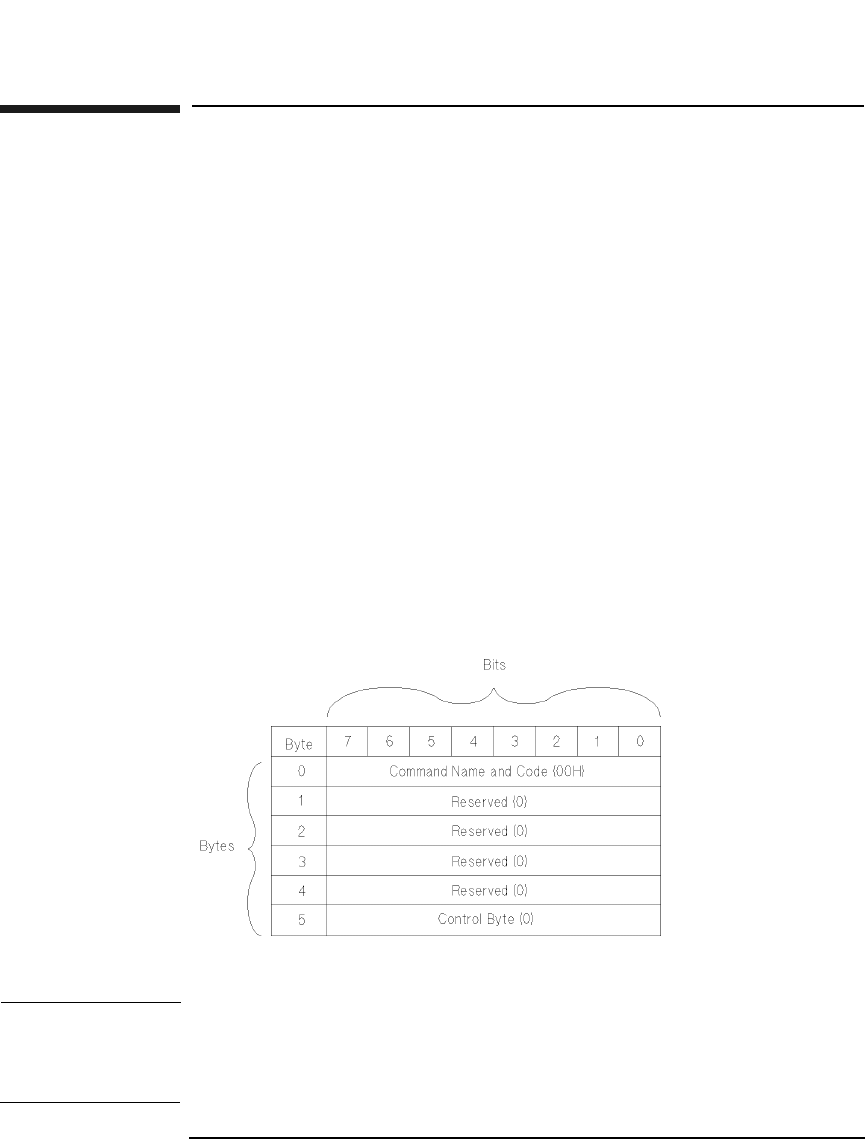
Explanation of the Command Descriptor Block (CDB)
The command descriptor block defines the byte and bit layout for each
supported drive command. Chapter 2 contains these specific
descriptions.
Figure 1-1 Example Command Descriptor Block
NOTE A Reserved field indicates that the field is reserved and must be set to 0
by the initiator.
The Reserved field for returned data contains 0 as well.

Chapter 2 2-1
Drive Commands
SCSI-2 Drive Commands
2 SCSI-2 Drive Command Set

SCSI-2 Drive Command Set
Numerical List of Commands
Chapter 22-2
Numerical List of Commands
The following tables list the SCSI-2 commands numerically, by group.
Table 2-1 Group 0 Commands (6-byte command)
Code
(hex.)
Name Description Page
Number
00H Test Unit Ready Provides a means to check if
the logical unit is ready
2-8
01H Rezero Unit Moves the optical head to its
recalibration position
2-9
03H Request Sense Requests the detailed error
information
2-10
04H Format Unit Initializes the optical disk
(done only once for
unformatted Write-Once
disks)
2-15
07H Reassign Blocks Reassigns defective sectors 2-19
08H Read Reads data from the specified
logical block address
2-21
0AH Write Writes data to the specified
logical block address
2-23
0BH Seek Moves the optical head to the
physical track where the
specified logical block exists
2-25
12H Inquiry Reads the information
related to the controller and
the drive unit
2-26
15H Mode Select Sets optical disk, drive unit,
or controller unit parameters
2-31
16H Reserve Gains the exclusive control of
a specified logical unit
2-52

SCSI-2 Drive Command Set
Numerical List of Commands
Chapter 2 2-3
SCSI-2 Drive Commands
17H Release Releases a specified logical
unit from the reservation
state
2-53
1AH Mode Sense Reads optical disk, drive unit,
or controller unit parameters
2-54
1BH Start/Stop Unit Starts or stops rotating the
optical disk, and/or ejects the
optical disk from the drive
unit
2-73
1CH Receive
Diagnostic
Results
Requests analysis data be
sent to the initiator
2-74
1DH Send Diagnostic Requests the disk controller
to perform diagnostic tests
2-76
1EH Prevent/Allow
Medium
Removal
Prevents or allows removal of
the optical disk in the logical
unit
2-79
Table 2-1 Group 0 Commands (6-byte command)
Code
(hex.)
Name Description Page
Number

SCSI-2 Drive Command Set
Numerical List of Commands
Chapter 22-4
Table 2-2 Group 1 and 2 Commands (10-byte command)
Code
(hex.)
Name Description Page
Number
25H Read Capacity Reads the capacity of the
optical disk
2-80
28H Read Reads data from the specified
logical block address
2-82
2AH Write Writes data to the specified
logical block address
2-84
2BH Seek Moves the optical head to the
physical track where the
specified logical block exists
2-87
2CH Erase Executes erase operation from
the specified logical block
address on rewritable disks
only
2-88
2EH Write and
Verify
Writes data to the optical disk
and then verifies the written
data by checking the error
correction code
2-90
2FH Verify Verifies the data starting from
the specified logical block
address by checking the error
correction code
2-92
34H Pre-Fetch Transfers the specified
number of data blocks starting
from the specified logical block
address to cache memory
2-94
35H Synchronize
Cache
Initiates the writing of all
cached write data to the
optical disk
2-95
37H Read Defect
Data
Reads the optical disk defect
information
2-96

SCSI-2 Drive Command Set
Numerical List of Commands
Chapter 2 2-5
SCSI-2 Drive Commands
3BH Write Buffer Writes data to the controller
data buffer.
2-99
3CH Read Buffer Reads data from the controller
data buffer
2-102
3EH Read Long Reads data from the specified
logical block address including
ECC data
2-104
3FH Write Long Writes data to the specified
logical block address without
using the ECC generation
circuitry
2-106
4CH Log Select Clears drive resident logs and
odometers
2-109
4DH Log Sense Reads drive resident logs and
odometers
2-111
55H Mode Select Sets optical disk, drive unit, or
controller unit parameters
2-122
Table 2-2 Group 1 and 2 Commands (10-byte command)
Code
(hex.)
Name Description Page
Number

SCSI-2 Drive Command Set
Numerical List of Commands
Chapter 22-6
Table 2-3 Group 5 Commands (12-byte command)
Code
(hex.)
Name Description Page
A8H Read Reads data from the specified
logical block address
2-128
AAH Write Writes data to the specified
logical block address
2-131
ACH Erase Executes erase operation from
the specified logical block
address on rewritable disks
only
2-134
AEH Write and Verify Writes data to the optical disk
and then verifies the written
data by checking the error
correction code
2-137
AFH Verify Verifies the data starting from
the specified logical block
address by checking the error
correction code
2-140
B7H Read Defect
Data
Reads the optical disk defect
information
2-142
DEH Read Long Reads data starting at a
specified logical block address,
including error correction code
data
2-145
DFH Write Long Writes data starting at the
specified logical block address,
without using error correction
code generation circuitry
2-147

SCSI-2 Drive Command Set
Numerical List of Commands
Chapter 2 2-7
SCSI-2 Drive Commands
Flag, Link, and RelAdr
Many commands have bits named Flag, Link and RelAdr. The definitions
of these bits are:
A Link bit of 1 indicates that the drive links to the next command upon
successful completion of the current command. When the command is
terminated successfully, the drive returns the INTERMEDIATE/GOOD
status and the LINKED COMMAND COMPLETE or the LINKED
COMMAND COMPLETE (WITH FLAG) message depending on the state
of the Flag bit. The Flag bit may be set to 1 only when the Link bit is 1. If
this bit is set to 1 with the Link bit, the drive returns the LINKED
COMMAND COMPLETE (WITH FLAG) message upon successful
completion of the command. If this bit is set to 0, it returns the LINKED
COMMAND COMPLETE message.
The Relative Address (RelAdr) bit is set to 1 to indicate that the logical
block address of the command descriptor block is a two's complement
displacement. This negative or positive displacement is added to the
logical block address last accessed on the drive to form the logical block
address for this command.

SCSI-2 Drive Command Set
Test Unit Ready Command (00H)
Chapter 22-8
Test Unit Ready Command (00H)
This command determines the READY state of a drive. If the drive is in a
READY state when it receives this command, it returns a GOOD status.
A drive is in the READY state when the optical disk is loaded and spun
up, and a read or write operation could successfully complete.
If the drive is not ready when it receives this command, it returns a
CHECK CONDITION with a sense key of NOT READY.
Table 2-4 Test Unit Ready Command CDB
Byte 76543210
0Operation Code (00H)
1Logical Unit Number
(0)
Reserved (0)
2Reserved (0)
3Reserved (0)
4Reserved (0)
5Reserved (0) Flag Link
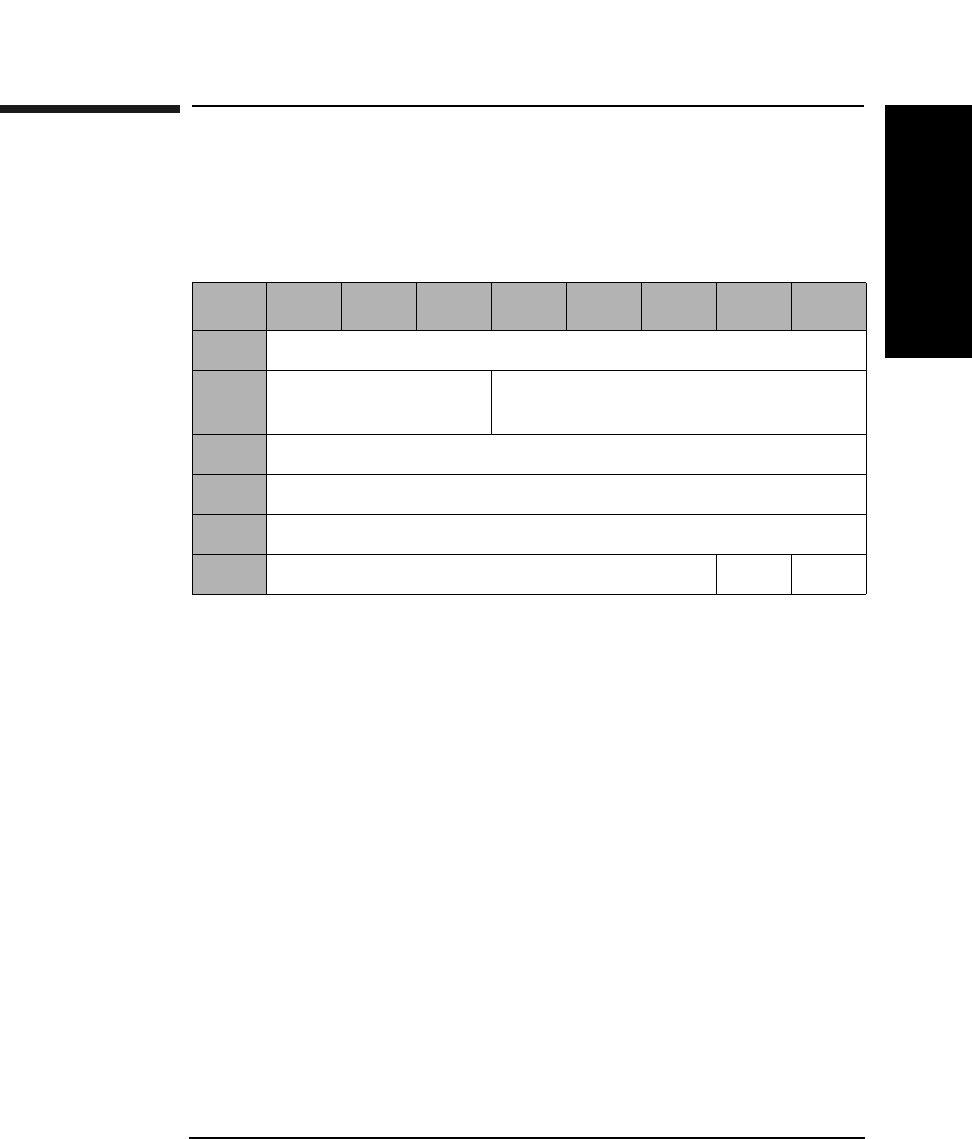
SCSI-2 Drive Command Set
Rezero Unit Command (01H)
Chapter 2 2-9
SCSI-2 Drive Commands
Rezero Unit Command (01H)
The Rezero Unit Command is identical to the Test Unit Ready Command
(see the previous page).
Table 2-5 Rezero Unit Command CDB
Byte 76543210
0Operation Code (01H)
1Logical Unit Number
(0)
Reserved (0)
2Reserved (0)
3Reserved (0)
4Reserved (0)
5Reserved (0) Flag Link
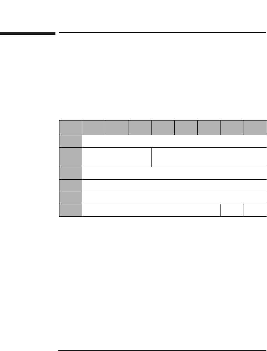
SCSI-2 Drive Command Set
Request Sense Command (03H)
Chapter 22-10
Request Sense Command (03H)
This command determines the specific error condition when a drive fails
to complete a command and returns a CHECK CONDITION status.
Sense data is preserved for the initiator until retrieved by a Request
Sense Command or until the same drive receives another command.
Internal Error Codes are used to represent the error condition and can be
used to determine what type of error recovery procedure is appropriate.
The Allocation Length indicates the number of bytes of sense data that
the drive transfers to the initiator. This drive has 22 bytes of sense data.
If an allocation length specified is less, then the allocated amount is
transferred, the remaining sense data is lost, and no error will be
reported. If an allocated length specified is greater, then only 22 bytes of
sense data are transferred and no error will be reported.
Table 2-6 Request Sense Command CDB
Byte 76543210
0Operation Code (03H)
1Logical Unit Number
(0)
Reserved (0)
2Reserved (0)
3Reserved (0)
4Allocation Length (Table 2-7 on page 2-11)
5Reserved (0) Flag Link

SCSI-2 Drive Command Set
Request Sense Command (03H)
Chapter 2 2-11
SCSI-2 Drive Commands
Sense Data Format
Table 2-7 Error Code 70H or 71H Sense Data Format
Byte 7 6 5 4 3 2 1 0
0Valid Error Code (70H or 71H)
1Reserved (0)
2Reserved (0) ILI Rsvd (0) Sense Key
3Information (MSByte)
4Information Byte
5Information Byte
6Information (LSByte)
7Additional Sense Length (0EH)
8Reserved (0)
9Reserved (0)
10 Reserved (0)
11 Reserved (0)
12 Additional Sense Code
13 Additional Sense Code Qualifier
14 Reserved (0)
15 SKSV Sense Key Specific Information
16 Sense Key Specific Information
17 Sense Key Specific Information
18 Internal Error Code (MSByte)
19 Internal Error Code
20 Internal Error Code
21 Internal Error Code (LSByte)

SCSI-2 Drive Command Set
Request Sense Command (03H)
Chapter 22-12
Valid A Valid bit of 1 indicates the information field contains
valid information.
A Valid bit of 0 indicates that the information field does
not contain valid data.
Error Code An Error Code of 70H indicates that the CHECK
CONDITION status returned is the result of an I/O
process that returned CHECK CONDITION status.
An Error Code of 71H indicates that the CHECK
CONDITION status returned is the result of an error
occurring during a previous command that returned
GOOD status.
ILI An Incorrect Length Indicator bit of 1 usually indicates
that the requested logical block length did not match
the logical block length of the data on the medium.
Information If the Valid bit is set to 1, the Information Bytes contain
one of the following:
(1) The logical block address associated with the sense
key.
(2) The difference (residue) of the requested length
minus the actual length in bytes, as determined by the
command, when the ILI bit is set.
SKSV A Sense Key Specific Valid bit of 1 indicates that the
Sense Key Specific Information is valid.
A SKSV bit of 0 indicates that there is no sense key
specific information.
Sense Key Specific
Information If the Sense Key is set to 5-Illegal Request and the
SKSV bit is set to 1, the sense key specific field is
defined in Table 2-8 on page 2-13.
If the Sense Key is set to 2-(Not Ready) and the
Additional Sense Code/Additional Sense Code Qualifier
is set to 04/04-(Logical Unit Not Ready, Format in
Progress) and the SKSV bit is set to 1, the sense key
specific field is defined in Table 2-9 on page 2-14.
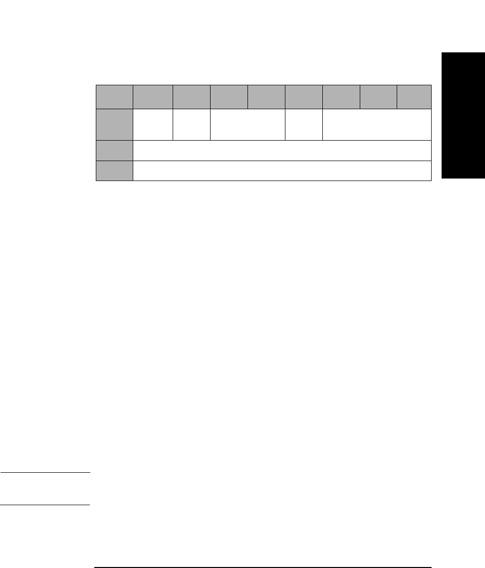
SCSI-2 Drive Command Set
Request Sense Command (03H)
Chapter 2 2-13
SCSI-2 Drive Commands
Field Pointer Types
C/D A Command Data bit of 1 indicates that the illegal
parameter is in the CDB.
A Command Data bit of 0 indicates that the illegal
parameter is in the data sent by the initiator during the
Data-Out phase.
BPV A Bit Pointer Valid bit of 1 indicates that the Bit Pointer
field specifies which bit of the byte designated by the
Field Pointer field is in error.
A Bit Pointer Valid bit of 0 indicates that the Bit Pointer
field is not valid.
Bit Pointer When the Bit Pointer Valid bit is 1, the Bit Pointer field
specifies which bit of the byte designated by the Field
Pointer field is in error. When a multiple-bit field is in
error, the pointer points to the most significant byte of
the field.
Field Pointer The Field Pointer indicates which byte of the command
descriptor block or the parameter data was in error.
Bytes are numbered starting from 0. When a multiple-
byte field is in error, the pointer points to the most-
significant byte of the field.
NOTE Bytes identified as being in error are not necessarily the bytes that need
to be changed to correct the problem.
Table 2-8 Sense Key Field Pointer Types
Byte 7 6543210
15 SKSV
(1)
C/D Reserved (0) BPV Bit Pointer
16 Field Pointer (MSByte)
17 Field Pointer (LSByte)

SCSI-2 Drive Command Set
Request Sense Command (03H)
Chapter 22-14
Progress
Indication The progress indication field value is a percent complete
indication in which the returned value is the numerator
that has 10000H as its denominator.
Internal Error
Code The Internal Error Code provides detailed information
about the failure.
Table 2-9 Progress Indication Field Bytes
Byte 7 6543210
15 SKSV
(1)
Reserved (0)
16 Progress Indication (MSByte))
17 Progress Indication (LSByte)

SCSI-2 Drive Command Set
Format Unit Command (04H)
Chapter 2 2-15
SCSI-2 Drive Commands
Format Unit Command (04H)
This command is used to initialize the optical disk surface.
NOTE The format parameters may be set using the Mode Select Commands
(15H or 55H) before executing the Format Unit Command.
NOTE The 9.1 and 5.2 Gbyte capacity drives cannot Format, Erase, Write, or
Write and Verify 650 Mbyte and 1.3-Gbyte optical disks.
The 2.6 Gbyte capacity drives cannot Format, Erase, Write, or Write and
Verify 650 Mbyte optical disks.
If this command is issued with any of these drive/media combinations, a
CHECK CONDITION status will result with the Sense Key/Additional
Sense Code set to Data Protect/Write Protected.
FmtDta A Format Data bit of 1 indicates that the command
includes a Data Out Phase consisting of a 4-byte Defect
List Header.
A FmtDta bit of 0 indicates that the command does not
include a Data Out Phase.
Table 2-10 Format Unit Command CDB
Byte 7 6 5 4 3 2 1 0
0Operation Code (04H)
1Reserved (0) FmtDta CmpLst Defect List Format
2Reserved (0) MkCDA MkPlst
3Reserved (0)
4Reserved (0)
5Rsvd ErsCntl Reserved (0) Flag Link

SCSI-2 Drive Command Set
Format Unit Command (04H)
Chapter 22-16
CmpLst A Complete List bit of 1 indicates that the previous
G-list is not used to make the defect list.
A CmpLst bit of 0 indicates the previous G-list is added
to the defect list.
Defect List
Format The Defect List Format can be either Block Format (0)
or Physical Sector Format (5).
MkCDA Has no effect on the drive.
MkPlst Has no effect on the drive.
ErsCntl An Erase Control bit of 0 indicates that an erase is
automatically performed before writing the data when
the drive is directed to perform the certify operation by
the initiator.
An Erase Control bit of 1 suppresses the erase
operation.
NOTE For Write-Once, this command can be executed only once during the
lifetime of a disk. When an initiator attempts to execute the Format Unit
command more than once for write-once media a CHECK CONDITION
status is returned. The Sense Key/Additional Sense Code is set to
ILLEGAL REQUEST/Invalid Command Operation Code.
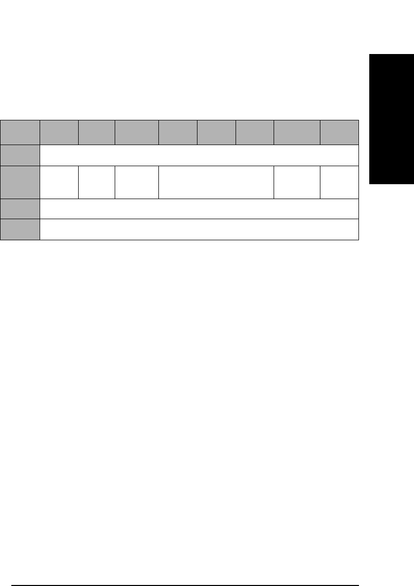
SCSI-2 Drive Command Set
Format Unit Command (04H)
Chapter 2 2-17
SCSI-2 Drive Commands
Format Unit Command Defect List
The Format Unit command Defect List consists of the Defect List Header
and zero or more multi-byte Defect Descriptor(s).
FOV A Format Options Valid bit of 1 indicates that the DCRT
(Disable Certification) and Immed (Immediate) fields
contain valid information.
A FOV bit of 0 indicates that the DCRT and Immed
fields do not contain valid information.
DCRT A Disable Certification bit of 1 indicates the drive does
not certify the optical disk during the format process.
A DCRT bit of 0 indicates that the drive certifies the
optical disk during the format process.
When the FOV bit is set to 0, the DCRT bit must also be
set to 0.
DCRT does not apply to Write-Once disks.
Immed When the Immediate bit is set to 1, it indicates a status
of GOOD is returned before the format operation is
begun.
An Immed bit of 0 indicates a GOOD status is returned
when the format is complete.
Defect List
Length The Defect List Length is the total length in bytes of the
Defect Descriptors that follow.
Table 2-11 Format Unit Defect List Header
Byte 7 6 5 4 3 2 1 0
0Reserved (0)
1FOV Rsvd
(0)
DCRT Reserved (0) Immed Rsvd
(0)
2Defect List Length (MSByte)
3Defect List Length (LSByte)

SCSI-2 Drive Command Set
Format Unit Command (04H)
Chapter 22-18
Table 2-12 Physical Sector Format Defect Descriptor
Byte 76543210
0Track Number of Defect (MSByte)
1Track Number of Defect
2Track Number of Defect (LSByte)
3Reserved (0)
4Reserved (0)
5Reserved (0)
6Reserved (0)
7Sector Number of Defect
Table 2-13 Block Format Defect Descriptor
Byte 76543210
0Reserved (0)
1Defect Block Address (MSByte)
2Defect Block Address
3Defect Block Address (LSByte)
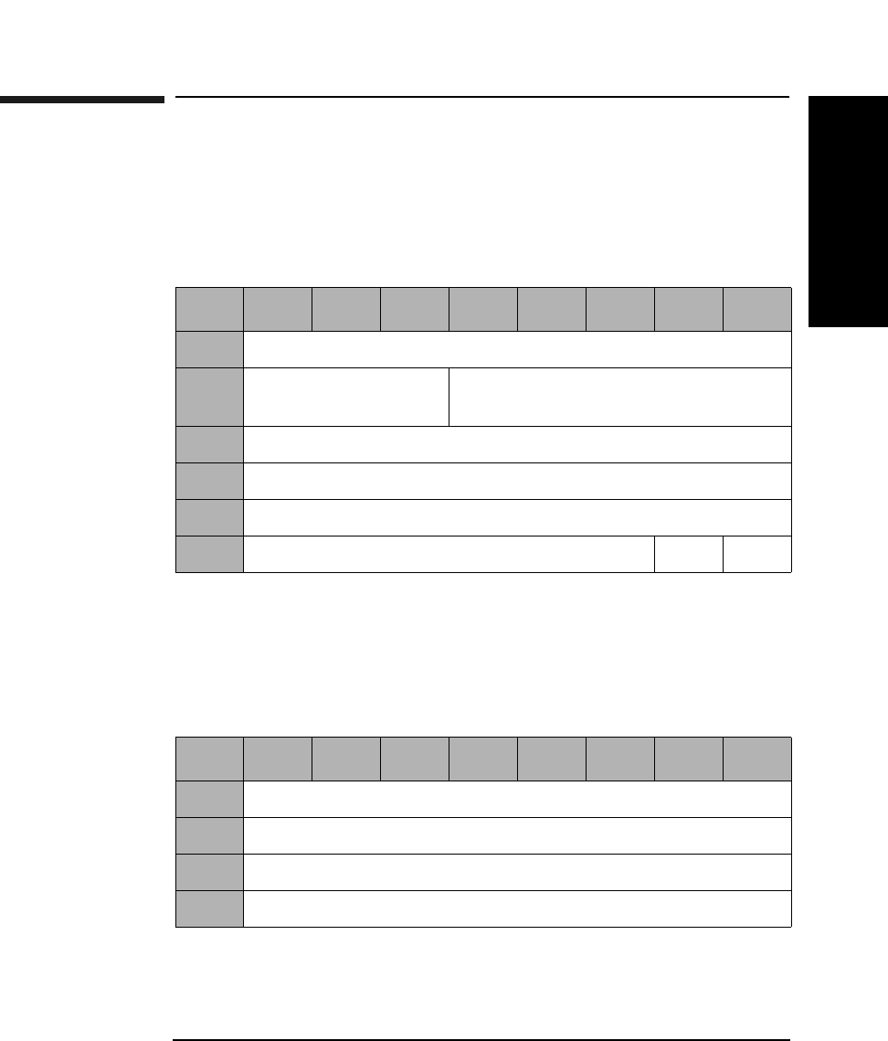
SCSI-2 Drive Command Set
Reassign Blocks Command (07H)
Chapter 2 2-19
SCSI-2 Drive Commands
Reassign Blocks Command (07H)
This command reassigns defective sectors. A defect list containing the
Logical Block Addresses to be reassigned is transferred to the drive.
Data in the defective sector is moved to the replacement sector.
Reassign Blocks Command Defect List
The Reassign Blocks command defect list is made up of a 4-byte Defect
List Header and zero or more 4-byte Defect Descriptor blocks.
Table 2-14 Reassign Blocks Command CDB
Byte 76543210
0Operation Code (07H)
1Logical Unit Number
(0)
Reserved (0)
2Reserved (0)
3Reserved (0)
4Reserved (0)
5Reserved (0) Flag Link
Table 2-15 Reassign Blocks Command Defect List Header
Byte 76543210
0Reserved (0)
1Reserved (0)
2Defect List Length (MSByte)
3Defect List Length (LSByte)

SCSI-2 Drive Command Set
Reassign Blocks Command (07H)
Chapter 22-20
Defect List
Length The Defect List Length is the total length in bytes of the
Defect Descriptors that follow.
Each defective sector is decoded to a physical block address and that
physical sector is added to the SDL (Secondary Defect List).
Table 2-16 Reassign Blocks Command Defect Descriptor
Byte 76643210
0Reserved (0)
1Defective Block Logical Address (MSByte)
2Defective Block Logical Address
3Defective Block Logical Address (LSByte)
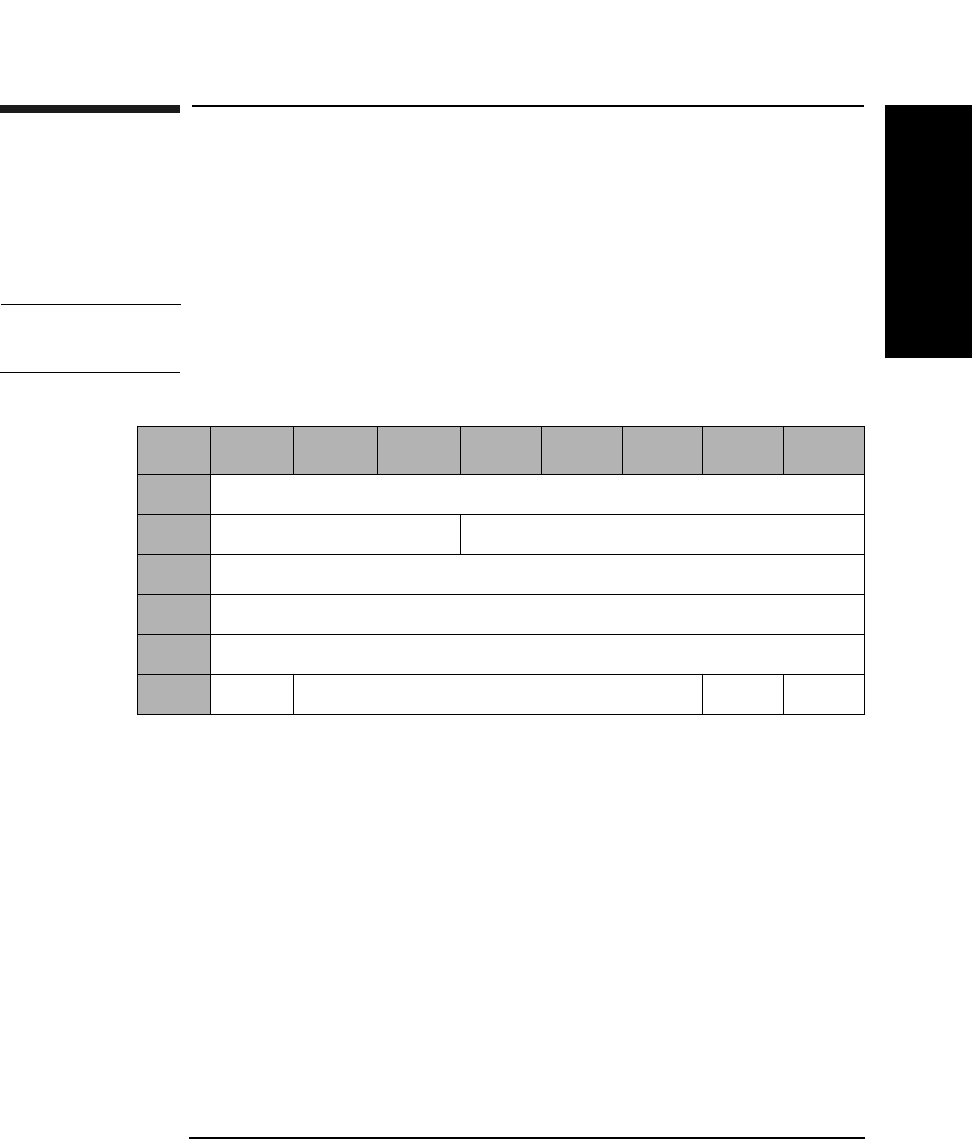
SCSI-2 Drive Command Set
Read (Group 0) Command (08H)
Chapter 2 2-21
SCSI-2 Drive Commands
Read (Group 0) Command (08H)
This command reads data from the specified logical block address. A
maximum length of 256 logical blocks can be read using the Group 0
Read Command. If the number of logical blocks exceeds 256, use the
Group 1 Read command.
NOTE The Mode Select Commands (15H or 55H) impact all read, write, format
and erase commands.
Transfer
Length The Transfer Length field specifies the number of
contiguous logical blocks of data to be read. A Transfer
Length of 0 specifies that 256 logical blocks are to be
read. Any other value specifies the number of logical
blocks to be read.
PBA A Physical Block Address bit of 1 indicates that physical
block addressing is used. A PBA bit of 0 indicates that
logical block addressing is used.
Table 2-17 Read (Group 0) Command CDB
Byte 7 6 5 4 3 2 1 0
0Operation Code (08H)
1Logical Unit Number (0) Starting Logical Block Address (MSByte)
2Starting Logical Block Address
3Starting Logical Block Address (LSByte)
4Transfer Length
5PBA Reserved (0) Flag Link

SCSI-2 Drive Command Set
Read (Group 0) Command (08H)
Chapter 22-22
NOTE When this command is used with 512 byte/sector 4X/ 8X/14X media, 1024
byte/sector 8X/14X media, or 2048 14X media, it is not possible to address
all logical blocks on the disk because those media types contain >221
logical blocks.
NOTE When this command is used with 14X 512 or 1024 byte/sector media,
setting the PBA bit will cause the drive to return a CHECK CONDITION
status. The sense key/additional sense code will be set to ILLEGAL
REQUEST/INVALID FIELD in CDB.

SCSI-2 Drive Command Set
Write (Group 0) Command (0AH)
Chapter 2 2-23
SCSI-2 Drive Commands
Write (Group 0) Command (0AH)
This command writes data starting at the specified logical block address.
NOTE The Mode Select Commands (15H or 55H) impact all read, write, format
and erase commands.
NOTE The 9.1 and 5.2 Gbyte capacity drives cannot Format, Erase, Write, or
Write and Verify 650 Mbyte and 1.3-Gbyte optical disks.
The 2.6 Gbyte capacity drives cannot Format, Erase, Write, or Write and
Verify 650 Mbyte optical disks.
If this command is issued with any of these drive/media combinations, a
CHECK CONDITION status will result with the Sense Key/Additional
Sense Code set to Data Protect/Write Protected.
NOTE For Write-Once media, byte 5, bit 6 and bit 7 are reserved.
Table 2-18 Write (Group 0) Command CDB
Byte 76543210
0Operation Code (0AH)
1Logical Unit Number
(0)
Starting Logical Block Address
(MSByte)
2Starting Logical Block Address
3Starting Logical Block Address (LSByte)
4Transfer Length
5PBA Ers
Cntl
Reserved (0 Flag Link

SCSI-2 Drive Command Set
Write (Group 0) Command (0AH)
Chapter 22-24
Transfer Length The Transfer Length field specifies the number of
contiguous logical blocks of data to be written. A
Transfer Length of 0 specifies that 256 logical blocks are
to be written.
PBA A Physical Block Address bit of 1 indicates that physical
block addressing is used.
A PBA bit of 0 indicates that logical block addressing is
used.
ErsCntl If the Erase Control bit is set to 0, an erase is
automatically performed before writing the data.
An Erase Control bit of 1 suppresses the erase
operation.
NOTE When this command is used with 512 byte/sector 4X/ 8X/14X media, 1024
byte/sector 8X/14X media, or 2048 14X media, it is not possible to address
all logical blocks on the disk because those media types contain >221
logical blocks.
NOTE For write-once optical disks, blank checking is performed before writing
data. If a written block is detected during blank checking, the drive will
return a CHECK CONDITION status. The sense key/additional sense
code will be set to BLANK CHECK/Overwrite Attempted.
NOTE When this command is used with 14X 512 OR 1024 byte/sector media,
setting the ErsCntl bit or the PBA bit will cause the drive to return a
CHECK CONDITION status. The sense key/additional sense code will be
set to ILLEGAL REQUEST/INVALID FIELD in CDB.

SCSI-2 Drive Command Set
Seek (Group 0) Command (0BH)
Chapter 2 2-25
SCSI-2 Drive Commands
Seek (Group 0) Command (0BH)
This command seeks the optical head to the physical track where the
specified logical block exists.
PBA A Physical Block Address bit of 1 indicates that physical
block addressing is used.
A PBA bit of 0 indicates that logical block addressing is
used.
NOTE When this command is used with 512 byte/sector 4X/ 8X/14X media, 1024
byte/sector 8X/14X media, or 2048 14X media, it is not possible to address
all logical blocks on the disk because those media types contain >221
logical blocks.
NOTE When this command is used with 14X 512 or 1024 byte/sector media,
setting the PBA bit will cause the drive to return a CHECK CONDITION
status. The sense key/additional sense code will be set to ILLEGAL
REQUEST/INVALID FIELD in CDB.
Table 2-19 Seek (Group 0) Command CDB
Byte 76543210
0Operation Code (0BH)
1Logical Unit Number
(0)
Logical Block Address (MSByte)
2Logical Block Address
3Logical Block Address (LSByte)
4Reserved (0)
5PBA Reserved (0) Flag Link
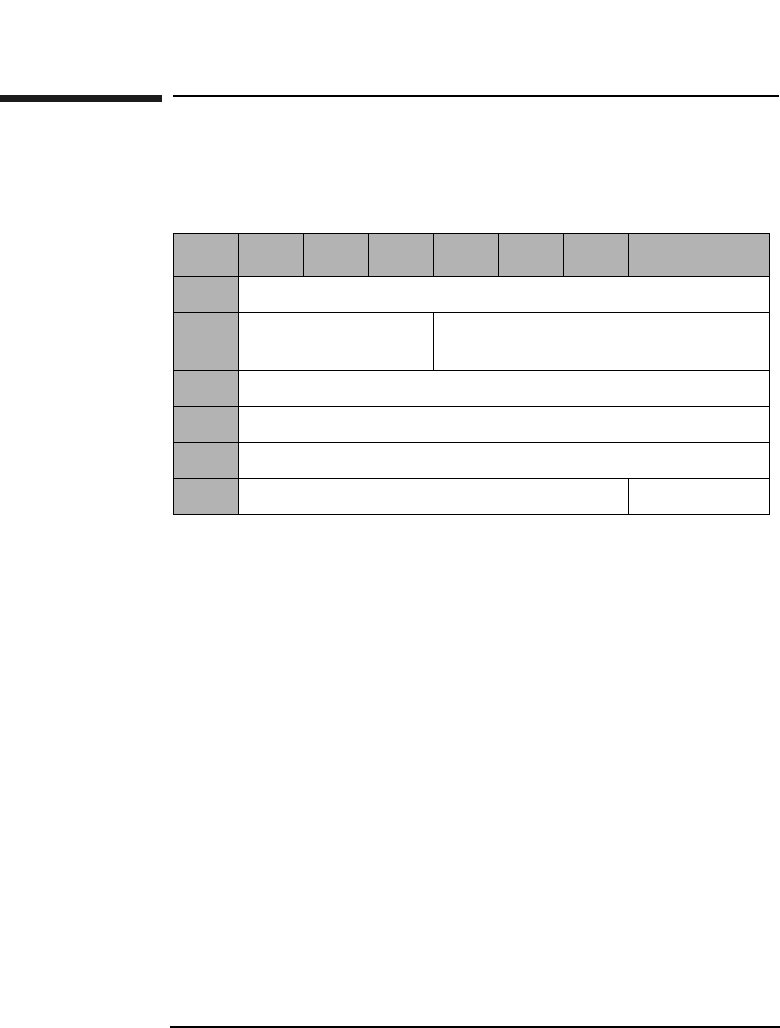
SCSI-2 Drive Command Set
Inquiry Command (12H)
Chapter 22-26
Inquiry Command (12H)
This command sends controller and drive information to the initiator.
EVPD (8X and 14X only). An enable vital product data bit of
1 specifies that the drive shall return the optional vital
product data specified by the page code field. An enable
vital product data bit of 0 specifies that the drive shall
return the standard INQUIRY data.
Page Code The page code field specifies which page of vital product
data information the drive shall return (Table 2-21).
Allocation
Length This field specifies the number of bytes that the
initiator has allocated for the return data. An Allocation
Length of 0 is not an error and indicates that no data
will be returned. The initiator will terminate the data in
phase when all available inquiry data has been
returned or when allocation length bytes have been
returned, whichever is less.
If an inquiry command is received from an initiator with
a pending UNIT ATTENTION (before the drive reports
CHECK CONDITION status), the drive performs the
INQUIRY command and does not clear the UNIT
ATTENTION condition.
Table 2-20 Inquiry Command CDB
Byte 7654321 0
0Operation Code (12H)
1Logical Unit
Number (0)
Reserved (0) EVPD
2VPD Identifier
3Reserved (0)
4Allocation Length
5Reserved (0) Flag Link

SCSI-2 Drive Command Set
Inquiry Command (12H)
Chapter 2 2-27
SCSI-2 Drive Commands
Table 2-21 Vital Product Data Page Codes
Page Code Description
00H Supported Vital Product Data Pages
80H Unit Serial Number Page
C1H Unique Media ID (UMID) Page
Table 2-22 Supported Vital Product Data Pages (00H)
Byte 76543210
0Peripheral Qualifier Peripheral Device Type
1Page Code (00H)
2Reserved (0)
3Page Length (03H)
4First Supported VPD Page (00H)
5Second Supported VPD Page (80H)
6Third Supported VPD Page (C1H)
Table 2-23 Unit Serial Number Page (80H)
Byte 76543210
0Peripheral Qualifier Peripheral Device Type
1Page Code (80H)
2Reserved (0)
3Page Length (0AH)
4-13 Product Serial Number (10 ASCII characters)

SCSI-2 Drive Command Set
Inquiry Command (12H)
Chapter 22-28
The Unique Media ID Bytes 1-2 field is “HP” in ASCII.
The Unique Media ID Bytes 3-5 field is a three-byte binary
representation of the serial number of the drive which wrote the UMID
on the media.
The Unique Media ID Bytes 6-8 field is a three-byte random number.
Table 2-24 Unique Media ID Page (C1H)
Byte 76543210
0Peripheral Qualifier Peripheral Device Type
1Page Code (C1H)
2Reserved (0)
3Page Length (08H)
4-5 Unique Media ID Bytes 1-2
6-8 Unique Media ID Bytes 3-5
9-11 Unique Media ID Bytes 6-8
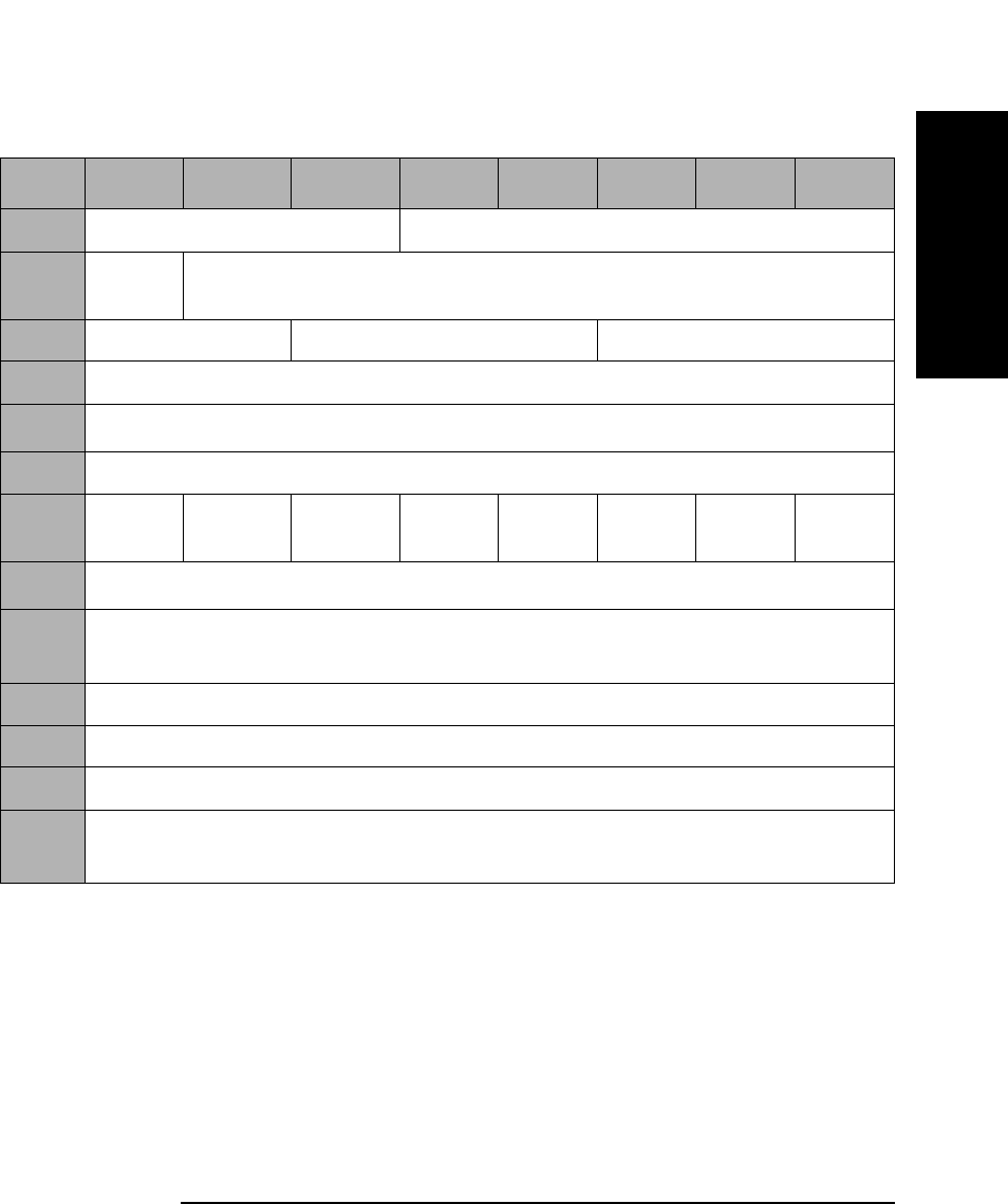
SCSI-2 Drive Command Set
Inquiry Command (12H)
Chapter 2 2-29
SCSI-2 Drive Commands
Table 2-25 Inquiry Command Returned Data
Byte 7 6 5 4 3 2 1 0
0Peripheral Qualifier Peripheral Device Type
1RMB
(1)
Device Type Modifier (0)
2ISO Version (0) ECMA Version (0) ANSI-Approved Version (2)
3Response Data Format (2)
4Additional Sense Length (33H)a
5-6 Reserved (0)
7RelAdr
(1)
WBus32
(0)
WBus16
(0)
Sync
(1)
Linked
(1)
Rsvd
(0)
Cmd
Que (1)
SftRe
(0)
8-15 Vendor Identification “HP~~~~~~” (ASCII)b
16-31 Product Identification “C1113J~~~~~~~~~~” (ASCII)b
(“C1113F~~~~~~~~~~” for 2.6 Gbyte capacity drives)
32-35 Product Revision Level (Current firmware version in ASCII)
36-39 Manufacturing Date Code (Current ASCII data)
40-49 Serial Number (Current ASCII data)
50-55 Drive Identifier “8XMO~~” (ASCII)b
(“4XMO~~” for 2.6 Gbyte capacity drives)
a.This field is always 33H.
b.The ~ represents blank spaces.

SCSI-2 Drive Command Set
Inquiry Command (12H)
Chapter 22-30
NOTE If the drive is properly connected and responds to SCSI selection, the
Peripheral Qualifier field is set to 000. If Direct Access Inquiry Response
(DAIR) has been enabled, the Peripheral Device Type field is set 00H,
(Direct Access Device). Otherwise, the Peripheral Device Type field is set
to 07H (Optical Memory Device). Because the drive does not support
logical unit 1 through 7, an Inquiry command to these logical units always
returns 011 for the Peripheral Qualifier and 1FH (Unknown Device Type)
for the Peripheral Device Type.
RMB The Removable Media Bit is set to 1 for removable
optical disks. The drive only supports removable optical
disks, so this bit is always 1.
Device Type
Modifier The drive is not using the Device Type Modifier field
and will return 0.
ISO, ECMA and
ANSI-Approved
Versions Approved Version fields indicate compliance of the
current firmware to these standards.
Additional Sense
Length This field indicates the length in bytes of the additional
parameters. This field is always 33H.
RelAdr The Relative Addressing bit is set to 1, which indicates
that the drive supports relative addressing mode.
WBus32 The Wide Bus 32 bit of 0 indicates that the drive
supports only 8-bit wide data transfers.
WBus16 The Wide Bus 16 bit of 0 indicates that the drive
supports only 8-bit wide data transfers.
Sync The Synchronous transfer bit of 1 indicates that the
drive supports synchronous data transfer.
Linked The Linked command bit of 1 indicates that the drive
supports linked commands.
CmdQue The Command queuing bit of 1 indicates that the drive
supports tagged command queuing.
SftRe The Soft Reset bit of 0 indicates that the drive responds
to the RESET condition with the hard RESET.

SCSI-2 Drive Command Set
Mode Select Command (15H)
Chapter 2 2-31
SCSI-2 Drive Commands
Mode Select Command (15H)
This command sets optical disk and drive parameters for read, write,
format, and erase commands.
SP A Save Pages bit of 1 indicates that the target performs
the specified MODE SELECT operation, and saves all
the savable pages to non-volatile RAM.
An SP bit of 0 indicates the target performs the specified
MODE SELECT operation, and does not save any
pages.
Parameter List
Length This byte indicates the number of bytes of parameter
data being transferred during the DATA OUT phase,
including the header. A length of 0 indicates that no
data will be transferred.
Table 2-26 Mode Select (Group 0) Command CDB
Byte 7 6 5 4 3 2 1 0
0Operation Code (15H)
1Logical Unit Number
(0)
PF (1) Reserved (0) SP
2Reserved (0)
3Reserved (0)
4Parameter List Length (Table 2-27 on page 2-32)
5Reserved (0) Flag Link

SCSI-2 Drive Command Set
Mode Select Command (15H)
Chapter 22-32
The Mode Select Parameter List contains a 4-byte header, followed by 0
or 1 block descriptors and 0 or more pages.
A Mode Page of 00H will be rejected and no error will be reported.
Table 2-27 Mode Page Codes
Page Code Parameter
List Length
Description
01H 12 Read-Write Error Recovery Page
(See Table 2-30 on page 2-34)
02H 16 Disconnect-Reconnect Page
(See Table 2-31 on page 2-36)
08H 12 Caching Page
(See Table 2-32 on page 2-37)
0AH 8 Control Mode Page
(See Table 2-33 on page 2-39)
0BH 8 Medium Type Supported
(See Table 2-35 on page 2-40)
20H 12 Vendor Unique Format Page
(See Table 2-37 on page 2-42)
21H 12 Vendor Unique Page
(See Table 2-41 on page 2-46)
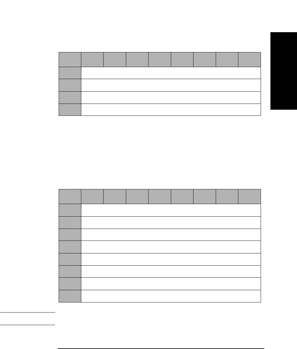
SCSI-2 Drive Command Set
Mode Select Command (15H)
Chapter 2 2-33
SCSI-2 Drive Commands
Mode Select Header
The Medium Type field shall be set to 00H (Default, only one medium
type supported), 02H (Write-once medium), or 03H (Optical Reversible or
Erasable medium). The Block Descriptor Length specifies the length in
bytes of the block descriptor. It shall be equal to 0 or 8. A Block
Descriptor Length of zero indicates that the block descriptor is not
included in the parameter list. This condition is not considered to be an
error.
NOTE All fields in the Block Descriptor have no effect on the drive.
Table 2-28 Mode Select Header
Byte 7 6 5 4 3 2 1 0
0Reserved (0)
1Medium Type
2Reserved (0)
3Block Descriptor Length
Table 2-29 Mode Select Block Descriptor
Byte 7 6 5 4 3 2 1 0
0Density Code
1Number of Blocks (MSByte)
2Number of Blocks
3Number of Blocks (LSByte)
4Reserved (0)
5Block Length (MSByte)
6Block Length
7Block Length (LSByte)
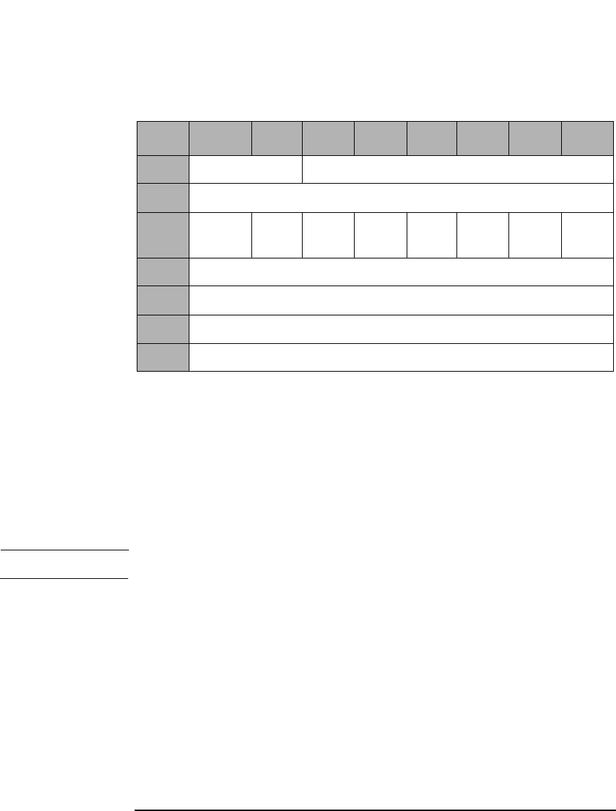
SCSI-2 Drive Command Set
Mode Select Command (15H)
Chapter 22-34
Read-Write Error Recovery
AWRE An Automatic Write Reallocation Enable bit of 1
enables the automatic reallocation of defective sectors
during the write operation of the Write commands
(0AH, 2AH, AAH), Write and Verify commands (2EH,
AEH), and Write Long (3FH, DFH).
For rewritable disks, automatic reallocation of defective
sectors occurs during these additional erase operations:
Erase 2CH and Erase ACH.
NOTE AWRE cannot be disabled on Write-Once media.
TB A Transfer Block bit of 1 indicates that a data block that
is not recovered within the recovery limits specified is
transferred to the initiator before CHECK CONDITION
status is returned.
A TB bit of 0 indicates that such a data block is not
transferred to the initiator.
RC A Read Continuous bit of 1 indicates that error
correction codes are not used for data error recovery.
A Read Continuous bit of 0 allows the use of error
correction codes for data error recovery.
Table 2-30 Read-Write Error Recovery Page 01H
Byte 7 6 5 4 3 3 1 0
0Reserved (0) Page Code (01H)
1Page Length (0AH)
2AWRE Rsvd
(0)
TB RC Rsvd
(0)
PER DTE DCR
3Read Retry Count
4-7 Reserved (0)
8Write Retry Count
9-11 Reserved (0)

SCSI-2 Drive Command Set
Mode Select Command (15H)
Chapter 2 2-35
SCSI-2 Drive Commands
PER A Post Error bit of 1 indicates that the target reports
recovered errors.
A PER bit of 0 indicates that the target does not report
recovered errors.
DTE A Disable Transfer on Error bit of 1 indicates that the
target terminates the data phase upon detection of a
recovered error.
A DTE bit of 0 indicates that the target does not
terminate the data phase upon detection of a recovered
error.
DCR A Disable Correction bit of 1 indicates that error
correction codes are not used for data error recovery.
A DCR bit of 0 allows the use of error correction codes
for data error recovery.
Read Retry
Count The Read Retry Count field specifies the number of
times the target attempts recovery of a read operation
before reporting an error.
Write Retry
Count The Write Retry Count field specifies the number of
times the target attempts recovery of a write operation
before reporting an error.

SCSI-2 Drive Command Set
Mode Select Command (15H)
Chapter 22-36
Disconnect-Reconnect
The disconnect-reconnect page provides the initiator the means to tune
the performance of the SCSI bus.
Buffer Full
Ratio This field has no effect on the drive.
Buffer Empty
Ratio This field has no effect on the drive.
Maximum Burst
Size This field indicates the maximum amount of data that
the target transfers during a data phase before
disconnecting if the initiator has granted the disconnect
privilege. This value is expressed in increments of 512
bytes (e.g. a value of one means 512 bytes, two means
1024 bytes, etc.). A value of zero indicates there is no
limit on the amount of data transferred per connection.
Table 2-31 Disconnect-Reconnect Page 02H
Byte 76543210
0Reserved (0) Page Code (02H)
1Page Length (0EH)
2Buffer Full Ratio
3Buffer Empty Ratio
4-9 Reserved (0)
10 Maximum Burst Size (MSByte)
11 Maximum Burst Size (LSByte)
12-15 Reserved (0)
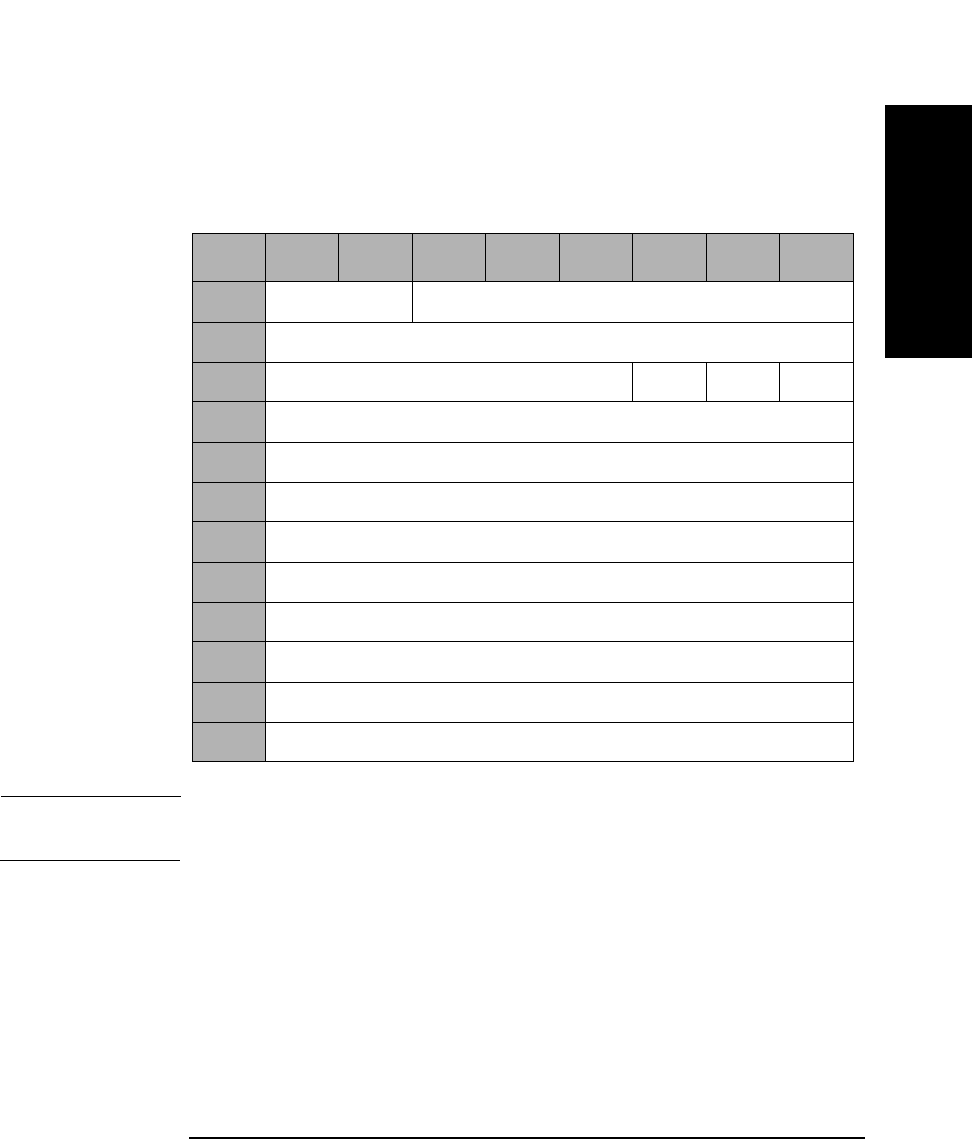
SCSI-2 Drive Command Set
Mode Select Command (15H)
Chapter 2 2-37
SCSI-2 Drive Commands
Caching Page 08H
The caching parameters table defines the parameters that affect the use
of the cache.
NOTE With write caching enabled, data integrity of the information in the buffer
is not guaranteed through power cycling.
WCE A Write Cache Enable bit of 1 indicates write caching is
enabled.
A Write Cache Enable bit of 0 indicates write caching is
disabled.
RCD A Read Cache Disable bit of 1 indicates read ahead is
disabled.
A Read Cache Disable bit of 0 indicates read ahead is
enabled.
Table 2-32 Caching Page 08H
Byte 7 6 5 4 3 2 1 0
0Reserved (0) Page Code (08H)
1Page Length (0AH)
2Reserved (0) WCE MF RCD
3Reserved (0)
4Disable Pre-fetch Transfer Length (MSByte)
5Disable Pre-fetch Transfer Length (LSByte)
6Minimum Pre-fetch (MSByte)
7Minimum Pre-fetch (LSByte)
8Maximum Pre-fetch (MSByte)
9Maximum Pre-fetch (LSByte)
10 Maximum Pre-fetch Ceiling (MSByte)
11 Maximum Pre-fetch Ceiling (LSByte)

SCSI-2 Drive Command Set
Mode Select Command (15H)
Chapter 22-38
MF The Multiplication Factor bit is set to 1 and cannot be
changed. This bit is used with the Minimum and
Maximum Pre-fetch fields during READ operations. If
this bit is set to 0 by the MODE SELECT command, a
CHECK CONDITION status is returned with the sense
key/additional sense code set to ILLEGAL REQUEST/
Invalid Parameter List.
Disable Pre-fetch
Transfer
Length This field sets the threshold value for pre-fetching data
during reads. If the number of blocks to be read is
greater than this value, no pre-fetching occurs.
Minimum
Pre-fetch The default value is 1 and cannot be changed. If this bit
is set to 0 by the MODE SELECT command, a CHECK
CONDITION status is returned with the Sense Key/
Additional Sense Code set to Illegal Request/Invalid
Parameter List. Since the MF bit is 1 and the Minimum
Pre-fetch bit is also 1, the Minimum Pre-fetch size is
equal to the READ transfer length. This field does not
affect the operation of the drive.
Maximum
Pre-fetch The default value is 1 and cannot be changed. If this bit
is set to 0 by the MODE SELECT command, a CHECK
CONDITION status is returned with the Sense Key/
Additional Sense Code set to Illegal Request/Invalid
Parameter List. Since the MF bit is 1 and the Maximum
Pre-fetch bit is also 1, the Maximum Pre-fetch size is
equal to the READ transfer length. This field does not
affect the operation of the drive.
Maximum
Pre-fetch
Ceiling The Maximum Pre-fetch Ceiling field does not affect the
operation of the drive and can be set to 32 or 64. If
another value is set, a CHECK CONDITION status is
returned with the Sense Key/Additional Sense Code set
to Illegal Request/Invalid Parameter List.

SCSI-2 Drive Command Set
Mode Select Command (15H)
Chapter 2 2-39
SCSI-2 Drive Commands
Control Mode Page 0AH
Queue Algorithm
Modifier The queue algorithm modifier field specifies restrictions
on the algorithm used for reordering commands that are
tagged with the Simple Queue Tag message.
DQue A Disabled Queuing bit of 1 indicates that command
queuing is disabled.
A Disabled Queuing bit of 0 indicates command queuing
is enabled.
A value of zero (0) in this field specifies that the target will order the
actual execution sequence of the commands with a SIMPLE QUEUE
TAG such that data integrity is maintained for that initiator.
A value of one (1) in this field specifies that the target may reorder the
actual execution of the commands with a SIMPLE QUEUE TAG in any
manner.
Table 2-33 Control Mode Page 0AH
Byte 76543210
0Reserved (0) Page Code (0AH)
1Page Length (06H)
2Reserved (0)
3Queue Algorithm ModifieraReserved DQue
4-7 Reserved (0)
a.For 9.1 and 5.2 Gbyte Capacity drives only.
Table 2-34 Queue Algorithm Modifier
Value Definition
0H Restricted reordering
01H Unrestricted reordering allowed
2H - 0FH Reserved

SCSI-2 Drive Command Set
Mode Select Command (15H)
Chapter 22-40
Medium Types Supported Page 0BH
The medium types supported page contains a list of the medium types
implemented by the target for logical units.
The code values for each medium type supported by the target (up to four
maximum) and defined in the MODE SELECT command are reported in
ascending order.
If only the default medium type is supported, 0 is reported. If less than
four medium types are supported, the unused entries are returned as 0.
Table 2-35 Medium Types Supported Page 0BH
Byte 76543210
0Reserved (0) Page Code (0BH)
1Page Length (06H)
2Reserved (0)
3Reserved (0)
4Medium Type One Supported
(02H — Optical Write-once Medium)
5Medium Type Two Supported
(03H — Optical Erasable Medium)
6Medium Type Three Supported (00H)
7Medium Type Four Supported (00H)

SCSI-2 Drive Command Set
Mode Select Command (15H)
Chapter 2 2-41
SCSI-2 Drive Commands
00H Default Rewritable optical disks only
02H Write-Once medium
03H Rewritable medium
Table 2-36 Valid Medium Type Combinations
Byte Field
Name
Setting
1
(default)
Setting
2
Setting
3
Setting
4
4Medium
Type 1
Supported
02H 00H 02H 03H
5Medium
Type 2
Supported
03H 00H 00H 00H
6Medium
Type 3
Supported
00H 00H 00H 00H
7Medium
Type 4
Supported
00H 00H 00H 00H
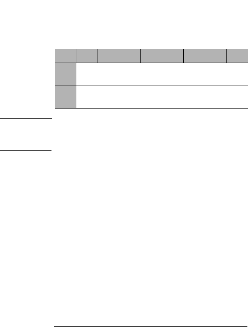
SCSI-2 Drive Command Set
Mode Select Command (15H)
Chapter 22-42
Vendor Unique Format Page 20H
NOTE The drive supports Format Mode 03H and 04H.
Format Mode 03H is for 650-Mbyte optical disks
Format Mode 04H is for 1.3-, 2.6-, 5.2-, and 9.1-Gbyte optical disks.
Table 2-37 Vendor Unique Format Page 20H
Byte 76543210
0Reserved (0) Page Code (20H)
1Page Length (0AH)
2Format Mode
3-11 Format Type Specific Data

SCSI-2 Drive Command Set
Mode Select Command (15H)
Chapter 2 2-43
SCSI-2 Drive Commands
Format Mode 03H
Format Mode 03H supports two types of format (type 0 and type 1) by
setting byte 3.
Size of User
Band The Size of User Band field indicates the length of each
user band in number of logical blocks.
Size of Spare
Band The Size of Spare Band field indicates the length of each
spare band in number of logical blocks.
Number of
Bands The Number of Bands field indicates the bands on the
disk. The drive can read and write multi-band
formatted disks, but can create only single-band disks.
Table 2-38 Format Mode 03H - Type 0
Byte 7 6 5 4 3 2 1 0
2Format Mode (03H)
3Type 00H
4Size of User Band (MSByte)
5Size of User Band
6Size of User Band
7Size of User Band (LSByte)
8Size of Spare Band (MSByte)
9Size of Spare Band (LSByte)
10 Number of Bands (MSByte)
11 Number of Bands (LSByte)

SCSI-2 Drive Command Set
Mode Select Command (15H)
Chapter 22-44
Type 1 format exists for compatibility. An initiator cannot change the
parameters of this page.
Number of
Bands The Number of Bands field indicates the bands on the
disk.
Size of Spare
Band The Size of User Band field indicates the length of each
spare band in number of logical blocks.
Table 2-39 Format Mode 03H - Type 1
Byte 7 6 5 4 3 2 1 0
2Format Mode (03H)
3Type 01H
4Reserved (0)
5Reserved (0)
6Number of Bands (MSByte)
7Number of Bands (LSByte)
8Size of Spare Bands (MSByte)
9Size of Spare Bands (LSByte)
10 Reserved (0)
11 Reserved (0)
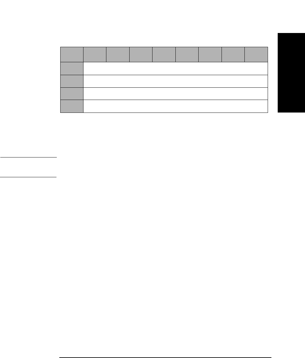
SCSI-2 Drive Command Set
Mode Select Command (15H)
Chapter 2 2-45
SCSI-2 Drive Commands
Number of
Bands The Number of Bands field indicates the bands on the
disk and can be set to 1 (01H), 16 (10H), 30 (1EH), or 34
(22H).
NOTE The Number of Bands for 9.1 and 5.2 Gbyte Capacity drives include
1 (01H), 16 (10H), 24 (18H), 30 (1EH), 34 (22H), 38 (26H), or 45 (2DH).
Table 2-40 Format Mode 04H
Byte 7 6 5 4 3 2 1 0
2Format Mode (04H)
3-9 Reserved (0)
10 Number of Bands (MSByte)
11 Number of Bands (LSByte)
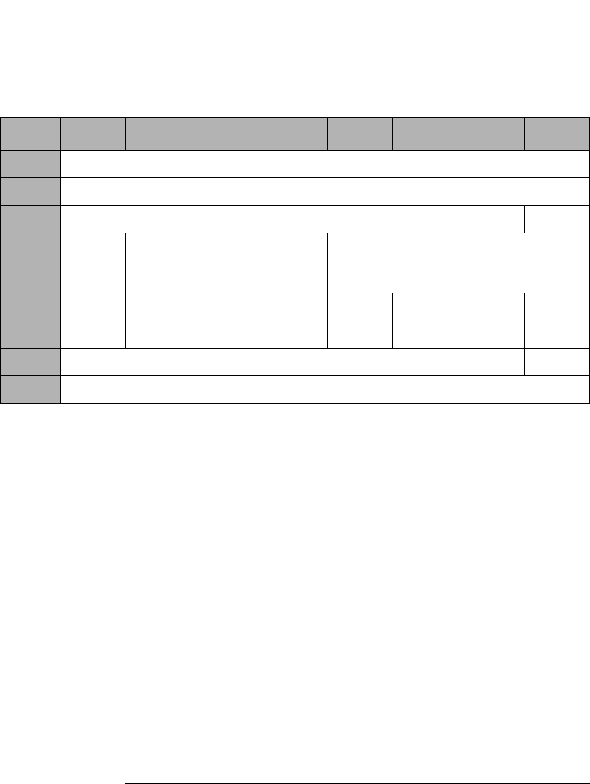
SCSI-2 Drive Command Set
Mode Select Command (15H)
Chapter 22-46
Vendor Unique Page 21H
DAIR A Direct Access Inquiry Response bit of 1 indicates the
Peripheral Device Type field in the Inquiry Data
indicates "Direct Access Device."
A DAIR bit of 0 indicates "Optical Memory Device" in
the Peripheral Device Type field in the Inquiry Data.
DWR A Disable Write Reordering bit of 1 indicates write
reordering is not enabled.
A DWR bit of 0 indicates write reordering is enabled.
Quick
Disconnect A Quick Disconnect bit of 1 enables SCSI bus
disconnection before command validation on
performance path commands (i.e. reads, writes).
A Quick Disconnect bit of 0 disables SCSI bus
disconnection before validation on performance path
commands.
Table 2-41 Vendor Unique Page 21H
Byte 7 6 5 4 3 2 1 0
0Reserved (0) Page Code (21H)
1Page Length (0AH)
2Reserved (0) DAIR
3DWR Quick
Dis-
connect
Rsvd (0) Force
Verify
Reserved (0)
4S1-8 S1-7 S1-6 S1-5 S1-4 S1-3 S1-2 S1-1
5S2-8 S2-7 S2-6 S2-5 S2-4 S2-3 S2-2 S2-1
6Reserved (0) DOM FWC
7-11 Reserved (0)

SCSI-2 Drive Command Set
Mode Select Command (15H)
Chapter 2 2-47
SCSI-2 Drive Commands
Force Verify A Force Verify bit of 1 indicates all write operations are
verified. The Write 6-, 10-, and 12-byte commands
operate as if they were Write Verify 6-, 10-, and 12-byte
commands.
A Force Verify bit of 0 indicates normal operation.
Bytes 4 and 5 Bytes 4 and 5 are used to read the setting of the DIP
switches on the drive. SX-Y refers to the setting of DIP
switch S50X-Y (see Figure 2-1 on page 2-51 and
Table 2-44 on page 2-51). If SX-Y=0, the switch is set to
the OFF position; if SX-Y=1, the switch is set to the ON
position. These fields are not changeable. The switch
setting value overrides the saved value.
DOM A drive operating mode of 0 indicates that the drive is
installed in a jukebox environment. A DOM bit of 1
indicates that the drive is installed in a stand-alone
environment.
NOTE The DOM bit is not selectable using the Mode Select command.
FWC A Force Write Calibration bit of 1 instructs the drive to
perform the Write Calibration routine at spin-up. A
Force Write Calibration bit of 0 instructs the drive to
perform the Write Calibration routine on receipt of the
first Write command or 5 minutes after spin-up.
NOTE The bits DAIR and Force Verify on this mode page can also be controlled
in HP products by changing external switch settings. In HP’s standalone
box products, this is accomplished by changing the thumb wheel settings
on the rear of the box. In HP’s library products, this is accomplished by
changing the front panel settings. In all cases, changes to the mode page
settings will override the external switch settings.

SCSI-2 Drive Command Set
Mode Select Command (15H)
Chapter 22-48
Mode Page Parameter Default Values
The default values of the Mode Page Parameters are as follows:
Table 2-42 Mode Page Parameter Default Values
Page Field Default Value
01H AWRE 1
01H TB 0
01H RC 0
01H PER 0
01H DTE 0
01H DCR 0
01H Read Retry Count 5
01H Write Retry Count 5
02H Buffer Full Ratio 20H
02H Buffer Empty Ratio 20H
02H Maximum Burst Size 20H
08H WCE 1
08H MF 1
08H RCD 0
08H Disable Pre-Fetch Transfer Length 40H
08H Minimum Pre-Fetch 01H
08H Maximum Pre-Fetch 01H
08H Maximum Pre-Fetch Ceiling 40H
0AH Que Algorithm Modifiera0
0AH DQUE 0
0BH Medium Type 1 Supported 02H

SCSI-2 Drive Command Set
Mode Select Command (15H)
Chapter 2 2-49
SCSI-2 Drive Commands
With power-on or reset and the loaded media holds no format
information in itself, the current value of the format page (20H)
parameters are set as follows:
0BH Medium Type 2 Supported 03H
0BH Medium Type 3 Supported 00H
0BH Medium Type 4 Supported 00H
21H DAIR 0
21H DWR 0
21H Quick Disconnect 0
21H Force Verify 0
a.This value is for 9.1 and 5.2 Gbyte Capacity drive only.
Table 2-42 Mode Page Parameter Default Values
Page Field Default Value
Table 2-43 Mode Page 20H Parameter Default Values
Page Field Current Value
650 Mbytes/Cartridge
20H Format Mode 3
20H Type 0
20H Number of Bands 1
20H Size of Spare Band 2048
1.3/1.2 Gbytes/Cartridge (1024/512 bytes/sector)
20H Format Mode 4
20H Number of Bands 1
2.6 Gbytes/Cartridge (1024 bytes/sector)
20H Format Mode 4

SCSI-2 Drive Command Set
Mode Select Command (15H)
Chapter 22-50
20H Number of Bands 34
2.3 Gbytes/Cartridge (512 bytes/sector)
20H Format Mode 4
20H Number of Bands 30
5.2 Gbytes/Cartridge (2048 bytes/sector)a
20H Format Mode 4
20H Number of Bands 24
4.8 Gbytes/Cartridge (512 bytes/sector)a
20H Format Mode 4
20H Number of Bands 45
4.1 Gbytes/Cartridge (512 bytes/sector)a
20H Format Mode 4
20H Number of Bands 38
9.1 Gbytes/Cartridge (4096 bytes/sector)b
20H Format Mode 4
20H Number of Bands 16
8.6 Gbytes/Cartridge (2048 bytes/sector)b
20H Format Mode 4
20H Number of Bands 30
a.This media is for 9.1 and 5.2 Gbyte capacity drives only.
b.This media is for 9.1 capacity drives only.
Table 2-43 Mode Page 20H Parameter Default Values
Page Field Current Value

SCSI-2 Drive Command Set
Mode Select Command (15H)
Chapter 2 2-51
SCSI-2 Drive Commands
DIP Switch Locations
Figure 2-1 DIP Switch Locations
Table 2-44 DIP Switch Definitions
DIP SW S501 DIP SW S502
1 Autochanger Eject
Distance Override
1 Reserved for Production
2 DAIR Enable 2 Reserved for Production
3 Reserved for HP 3 Reserved for Production
4 Reserved for HP 4 Reserved for Production
5 Reserved for Debug 5 Enable SCAM
6 Reserved for Debug 6 Force Verify for Write
Operation
7 Reserved for Debug 7 SCSI Terminator Enablea
a.For 2.6 Gbyte capacity drives, this DIP switch is Fast SCSI Enable.
8 Reserved for Debug 8 Reserved
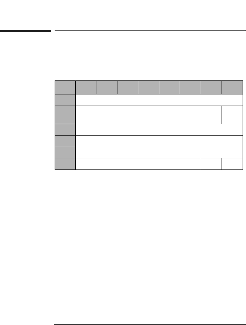
SCSI-2 Drive Command Set
Reserve Command (16H)
Chapter 22-52
Reserve Command (16H)
This command is used to reserve the drive for use by a single SCSI
initiator if and when the drive is connected to multiple initiators.
The reservation is effective until one of the following occurs:
• The Reserve initiator sends another valid Reserve Command
• The Reserve initiator releases using a Release Command
• Any initiator sends a Bus Device Reset message
• A Reset conditions occurs
Once RESERVED, other initiator commands (except Inquiry and
Request Sense) for the logical unit are rejected and result in a
"Reservation Conflict" status. A Release Command sent by another
initiator is ignored.
3rdPty A 3rd Pty bit of 1 indicates that the drive is reserved for
the SCSI device specified in the Third Party Device ID
field.
3rd Pty
Device ID 3rd Pty Device ID indicates identification of the SCSI
device for which the drive is to be reserved.
Table 2-45 Reserve Command CDB
Byte 7 6 5 4 3 2 1 0
0Operation Code (16H)
1Logical Unit Number
(0)
3rd
Pty
3rd Party Device ID Rsvd
(0)
2Reserved (0)
3Reserved (0)
4Reserved (0)
5Reserved (0) Flag Link

SCSI-2 Drive Command Set
Release Command (17H)
Chapter 2 2-53
SCSI-2 Drive Commands
Release Command (17H)
This command is sent by the Reserve Command initiator to release the
logical unit for use by other initiators.
3rdPty A 3rd Pty bit of 1 indicates that the drive is reserved for
the SCSI device specified in the Third Party Device ID
field.
3rd Pty
Device ID 3rd Pty Device ID indicates identification of the SCSI
device for which the drive is to be reserved.
Table 2-46 Release Command CDB
Byte 7 6 5 4 3 2 1 0
0Operation Code (17H)
1Logical Unit Number
(0)
3rd
Pty
3rd Party Device ID Rsvd
(0)
2Reserved (0)
3Reserved (0)
4Reserved (0)
5Reserved (0) Flag Link

SCSI-2 Drive Command Set
Mode Sense (Group 0) Command (1AH)
Chapter 22-54
Mode Sense (Group 0) Command (1AH)
This command is used to acquire optical disk, drive, and drive controller
parameters.
DBD A Disable Block Descriptors bit of 1 indicates that no
block descriptor is provided.
A DBD bit of 0 indicates that the block descriptor is
provided.
PC Page control defines the type of parameter values to be
returned as follows:
00 - Current Values
01 - Changeable Values
10 - Default Values
11 - Saved Values
Page Code Page code values are the same as for the Mode Select
command. If 00H or 3FH is specified, all pages are
returned.
Table 2-47 Mode Sense (Group 0) Command CDB
Byte 7 6 5 4 3 2 1 0
0Operation Code (1AH)
1Logical Unit Number
(0)
Rsvd
(0)
DBD Rsvd (0)
2PC Page Code (Table 2-50 on page 2-56)
3Reserved (0)
4Allocation Length
5Reserved (0) Flag Link
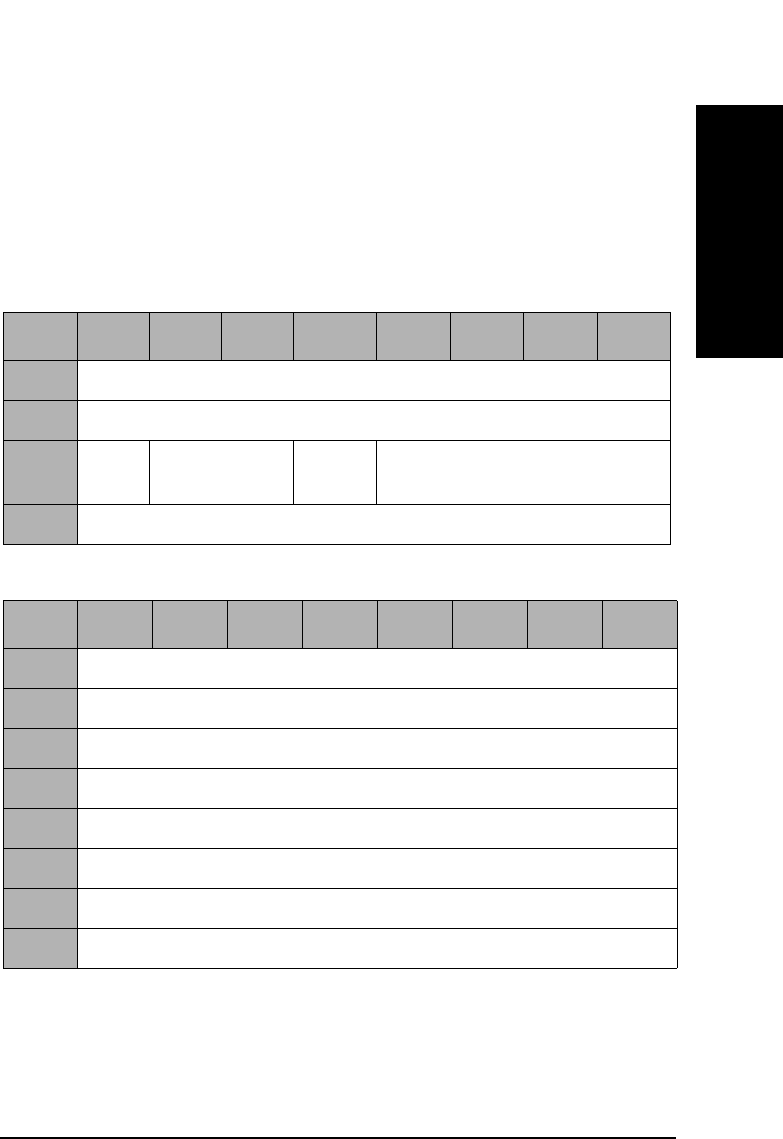
SCSI-2 Drive Command Set
Mode Sense (Group 0) Command (1AH)
Chapter 2 2-55
SCSI-2 Drive Commands
Allocation
Length This field specifies the number of bytes that the
initiator has allocated for returned data. A length of 0
indicates that no data will be returned. The drive will
terminate the data-in phase when the allocation length
has been transferred or when all available data has
been transferred to the initiator.
Table 2-48 Mode Sense Header
Byte 7 6 5 4 3 2 1 0
0Mode Data Length
1Medium Type
2WP Reserved Cache
(1)
Reserved (0)
3Block Descriptor Length
Table 2-49 Mode Sense Descriptor
Byte 76543210
0Density Codes
1Number of Blocks (MSByte)
2Number of Blocks
3Number of Blocks (LSByte)
4Reserved (0)
5Block Length (MSByte)
6Block Length
7Block Length (LSByte)

SCSI-2 Drive Command Set
Mode Sense (Group 0) Command (1AH)
Chapter 22-56
Table 2-50 Mode Page Codes
PageCode Parameter
List
Length
Description
01H 12 Read-Write Error Recovery Page
(See Table 2-51 on page 2-57)
02H 16 Disconnect-Reconnect Page
(See Table 2-52 on page 2-59)
08H 12 Caching Page
(See Table 2-53 on page 2-60)
0AH 8 Control Mode Page
(See Table 2-54 on page 2-63)
0BH 8 Medium Type Supported
(Table 2-55 on page 2-64)
20H 12 Vendor Unique Format Page
(See Table 2-57 on page 2-66)
21H 12 Vendor Unique Page
(See Table 2-61 on page 2-70)
00H,3FH 80 Request for all Pages
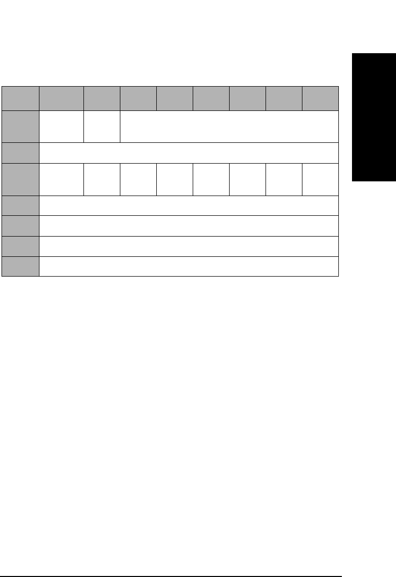
SCSI-2 Drive Command Set
Mode Sense (Group 0) Command (1AH)
Chapter 2 2-57
SCSI-2 Drive Commands
Read-Write Error Recover Page
PS The Parameters Savable bit of 1 indicates this
parameter page is savable in non-volatile RAM.
AWRE An Automatic Write Reallocation Enable bit of 1
enables the automatic reallocation of defective sectors
during the write operation of the Write commands
(0AH, 2AH, AAH), Write and Verify commands (2EH,
AEH), and WRITE LONG command (3FH).
For rewritable disks, automatic reallocation of defective
sectors occurs during these additional erase operations:
Erase 2CH and Erase ACH.
An AWRE bit of 0 does not enable automatic
reallocation of defective sectors.
TB A Transfer Block bit of 1 indicates that a data block that
is not recovered within the recovery limits specified is
transferred to the initiator before CHECK CONDITION
status is returned.
A TB bit of 0 indicates that such a data block is not
transferred to the initiator.
Table 2-51 Read-Write Error Recovery Page 01H
Byte 7 6543210
0PS (1) Rsvd
(0)
Page Code (01H)
1Page Length (0AH)
2AWRE Rsvd
(0)
TB RC Rsvd
(0)
PER DTE DCR
3Read Retry Count
4-7 Reserved (0)
8Write Retry Count
9-11 Reserved (0)

SCSI-2 Drive Command Set
Mode Sense (Group 0) Command (1AH)
Chapter 22-58
RC A Read Continuous bit of 1 indicates that error
correction codes are not used for data error recovery.
A Read Continuous bit of 0 allows the use of error
correction codes for data recovery.
PER A Post Error bit of 1 indicates that the target reports
recovered errors.
A PER bit of 0 indicates that the target does not report
recovered errors.
DTE A Disable Transfer on Error (DTE) bit of 1 indicates
that the target terminates the data phase upon
detection of a recovered error.
DTE bit of 0 indicates that the target does not terminate
the data phase upon detection of a recovered error.
DCR A Disable Correction bit of 1 indicates that error
correction codes are not used for data error recovery.
A DCR bit of 0 allows the use of error correction codes
for data error recovery.
Read Retry
Count The read retry count field specifies the number of times
the target attempts recovery of a read operation before
reporting an error.
Write Retry
Count The write retry count field specifies the number of times
the target attempts recovery of a write operation before
reporting an error.

SCSI-2 Drive Command Set
Mode Sense (Group 0) Command (1AH)
Chapter 2 2-59
SCSI-2 Drive Commands
Disconnect-Reconnect Page 02H
The disconnect-reconnect page provides the initiator the means to tune
the performance of the SCSI bus.
PS The Parameters Savable bit of 1 indicates this
parameter page is savable in non-volatile RAM.
Buffer Full
Ratio This field has no effect on the drive.
Buffer Empty
Ratio This field has no effect on the drive.
Maximum
Burst Size This field indicates the maximum amount of data that
the target transfers during a data phase before
disconnecting if the initiator has granted the disconnect
privilege. This value is expressed in increments of 512
bytes (e.g. a value of one means 512 bytes, two means
1024 bytes, etc.). A value of zero indicates there is no
limit on the amount of data transferred per connection.
Table 2-52 Disconnect-Reconnect Page 02H
Byte 7 6 5 4 3 2 1 0
0PS
(1)
Rsvd
(0)
Page Code (02H)
1Page Length (0EH)
2Buffer Full Ratio
3Buffer Empty Ratio
4-9 Reserved (0)
10 Maximum Burst Size (MSByte)
11 Maximum Burst Size (LSByte)
12-15 Reserved (0)

SCSI-2 Drive Command Set
Mode Sense (Group 0) Command (1AH)
Chapter 22-60
Caching Page 08H
PS The Parameters Savable bit of 1 indicates this
parameter page is savable in non-volatile RAM.
WCE A Write Cache Enable bit of 1 indicates write caching is
enabled.
A WCE bit of 0 indicates write caching is disabled.
MF The Multiplication Factor bit is set to 1 and cannot be
changed. This bit is set to the Minimum and Maximum
Pre-Fetch fields during READ operations. If this bit is
set to 0 by the MODE SELECT command, a CHECK
CONDITION status is returned with the sense key/
additional sense code set to ILLEGAL REQUEST/
Invalid Parameter List.
Table 2-53 Caching Page 08H
Byte 76543210
0PS
(1)
Rsvd
(0)
Page Code (08H)
1Page Length (0AH)
2Reserved (0) WCE MF RCD
3Reserved (0)
4Disable Pre-fetch Transfer Length (MSByte)
5Disable Pre-fetch Transfer Length (LSByte)
6Minimum Pre-fetch (MSByte)
7Minimum Pre-fetch (LSByte)
8Maximum Pre-fetch (MSByte)
9Maximum Pre-fetch (LSByte)
10 Maximum Pre-fetch Ceiling Length (MSByte)
11 Maximum Pre-fetch Ceiling Length (LSByte)

SCSI-2 Drive Command Set
Mode Sense (Group 0) Command (1AH)
Chapter 2 2-61
SCSI-2 Drive Commands
RCD A Read Cache Disable bit of 1 indicates read ahead is
disabled.
A RCD bit of 0 indicates read ahead is enabled.
NOTE If WCE and RCD are both set to 1, a CHECK CONDITION status is
returned with the sense key/additional sense code set to ILLEGAL
REQUEST/Invalid Parameter List.
DisablePre-fetchTransfer
Length This field sets the threshold value for pre-fetching data
during reads. If the number of blocks to be read is
greater than this value, no pre-fetching occurs.
The Disable Pre-fetch Transfer Length default setting
is 64.
Minimum
Pre-fetch If this bit is set to 0 by the MODE SELECT command, a
CHECK CONDITION status is returned with the sense
key/additional sense code set to ILLEGAL REQUEST/
Invalid Parameter List. Since the MF bit is 1 and the
Minimum Pre-Fetch bit is also 1, the minimum pre-
fetch size is equal to the READ Transfer Length. This
field does not affect the operation of the drive.
The Minimum Pre-fetch default setting is 1 and cannot
be changed.
Maximum
Pre-fetch If this bit is set to 0 by the MODE SELECT command, a
CHECK CONDITION status is returned with the sense
key/additional sense code set tot ILLEGAL REQUEST/
Invalid Parameter List. Since the MF bit is 1 and the
Maximum Pre-fetch bit is also 1, the maximum pre-
fetch size is equal to the READ Transfer Length. This
field does not affect the operation of the drive.
The Maximum Pre-fetch default setting is 1 and cannot
be changed.

SCSI-2 Drive Command Set
Mode Sense (Group 0) Command (1AH)
Chapter 22-62
MaximumPre-fetch
Ceiling The Maximum Pre-fetch Ceiling filed does not affect the
operation of the drive and can be set to 32 or 64. In
another value is set, a CHECK CONDITION status is
returned with the sense key/ additional sense code set to
ILLEGAL REQUEST/Invalid Parameter List.
NOTE With write caching enabled, data integrity of the information in the buffer
is not guaranteed through power cycling.
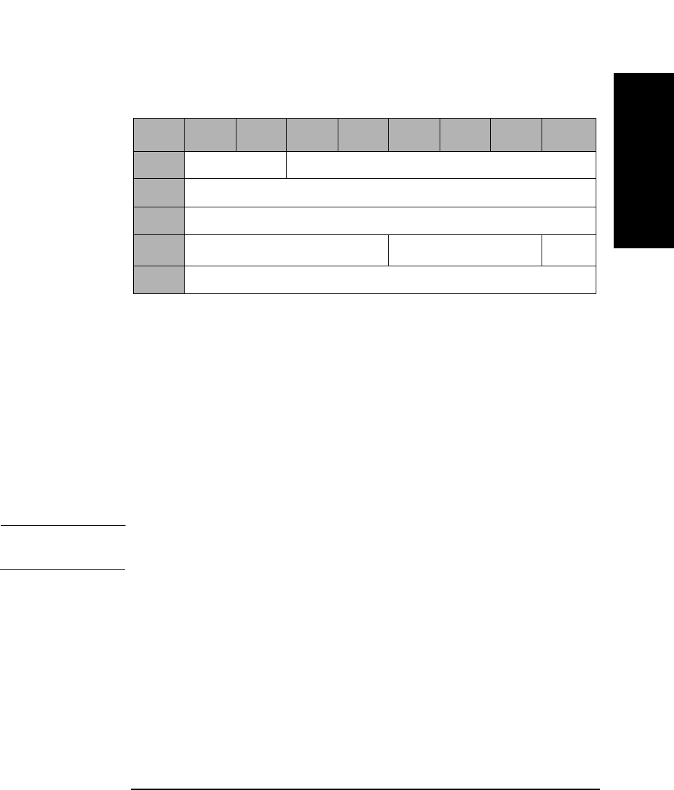
SCSI-2 Drive Command Set
Mode Sense (Group 0) Command (1AH)
Chapter 2 2-63
SCSI-2 Drive Commands
Control Mode Page (0AH)
The parameters of the Control Mode Page are all reserved and cannot be
changed by the MODE SELECT command.
PS The Parameters Savable bit of 1 indicates this
parameter page is savable in non-volatile RAM.
DQue A Disable Queuing bit of 1 indicates that command
queuing is disabled.
A Disable Queuing bit of 0 indicates that command
queuing is enabled.
NOTE For more information about the use of Byte 3 (Que Algorithm Modifier),
see Table 2-34 on page 2-39.
Table 2-54 Control Mode Page (0AH)
Byte 7 6 5 4 3 2 1 0
0Reserved (0) Page Code (0AH)
1Page Length (06H)
2Reserved (0)
3Que Algorithm ModifieraReserved (0) DQue
4 - 7 Reserved (0)
a.For 9.1 and 5.2 Gbyte capacity drives only.

SCSI-2 Drive Command Set
Mode Sense (Group 0) Command (1AH)
Chapter 22-64
Medium Types
PS The Parameters Savable bit of 1 indicates this
parameter page is savable in non-volatile RAM.
This page is used to set the medium type(s) supported by the drive. The
drive accepts the following combinations:
Table 2-55 Medium Types Supported Page 0BH
Byte 76543210
0PS
(1)
Rsvd
(0)
Page Code (0BH)
1Page Length (06H)
2Reserved (0)
3Reserved (0)
4Medium Type One Supported
(02H — Optical Write-once Medium)
5Medium Type Two Supported
(03H — Optical Erasable Medium)
6Medium Type Three Supported (00H)
7Medium Type Four Supported (00H)

SCSI-2 Drive Command Set
Mode Sense (Group 0) Command (1AH)
Chapter 2 2-65
SCSI-2 Drive Commands
00H Default (rewritable optical disks only)
02H Write-Once optical disks
03H Rewritable optical disks
Table 2-56 Valid Medium Type Combinations
Byte Field
Name
Setting 1
(default)
Setting 2 Setting 3 Setting 4
4Medium
Type 1
Supported
02H 00H 02H 03H
5Medium
Type 2
Supported
03H 00H 00H 00H
6Medium
Type 3
Supported
00H 00H 00H 00H
7Medium
Type 4
Supported
00H 00H 00H 00H
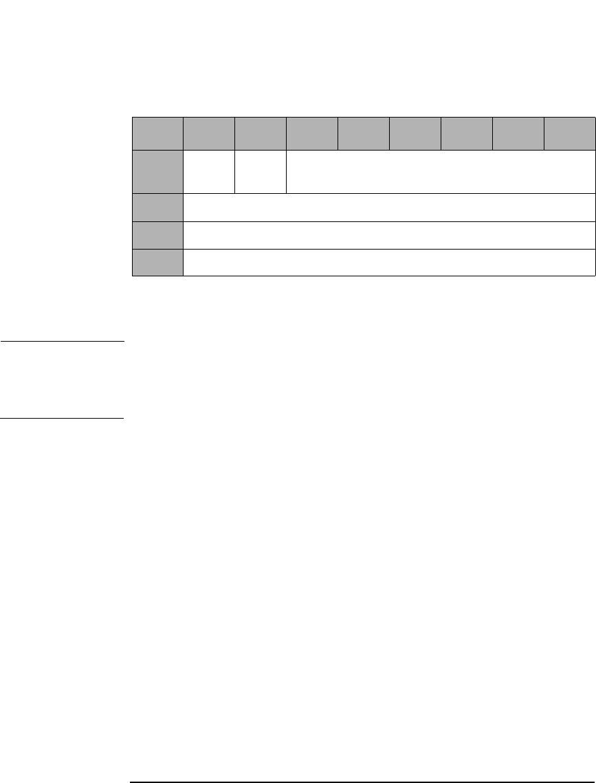
SCSI-2 Drive Command Set
Mode Sense (Group 0) Command (1AH)
Chapter 22-66
Vendor Unique
PS The Parameters Savable bit of 1 indicates this
parameter page is savable in non-volatile RAM.
NOTE The drive supports Format Mode 03H and 04H.
Format Mode 03H is for 650-Mbyte optical disks.
Format Mode 04H is for 1.3-, 2.6-, 5.2-, and 9.1-Gbyte optical disks.
Table 2-57 Vendor Unique Format Page 20H
Byte 76543210
0PS
(1)
Rsvd
(0)
Page Code (20H)
1Page Length (0AH)
2Format Mode
3-11 Format Type Specific Data

SCSI-2 Drive Command Set
Mode Sense (Group 0) Command (1AH)
Chapter 2 2-67
SCSI-2 Drive Commands
Format Mode
Format Mode 03H supports two types of format (type 0 and type 1) by
setting byte 3.
Size of User
Band The Size of User Band field indicates the length of each
user band in number of logical blocks.
Size of Spare
Band The Size of Spare Band field indicates the length of each
spare band in number of logical blocks.
Number of
Bands The Number of Bands field indicates the bands on the
disk. The drive can read and write multi-band
formatted disks, but can create only single-band disks.
Table 2-58 Format Mode 03H - Type 0
Byte 7 6 5 4 3 2 1 0
2Format Mode (03H)
3Type 00H
4Size of User Band (MSByte)
5Size of User Band
6Size of User Band
7Size of User Band (LSByte)
8Size of Spare Band (MSByte)
9Size of Spare Band (LSByte)
10 Number of Bands (MSByte)
11 Number of Bands (LSByte)

SCSI-2 Drive Command Set
Mode Sense (Group 0) Command (1AH)
Chapter 22-68
Type 1 format exists for compatibility. An initiator cannot change these
parameters.
Number of
Bands The Number of Bands field indicates the bands on the
disk.
Size of Spare
Band The Size of User Band field indicates the length of each
spare band in number of logical blocks.
Table 2-59 Format Mode 03H - Type 1
Byte 76543210
2Format Mode (03H)
3Type 01H
4Reserved (0)
5Reserved (0)
6Number of Bands (MSByte)
7Number of Bands (LSByte)
8Size of Spare Bands (MSByte)
9Size of Spare Bands (LSByte)
10 Reserved (0)
11 Reserved (0)

SCSI-2 Drive Command Set
Mode Sense (Group 0) Command (1AH)
Chapter 2 2-69
SCSI-2 Drive Commands
Number of
Bands The Number of Bands field indicates the bands on the
disk and can be set to 1 (01H), 16 (10H), 30 (1EH),
or 34 (22H).
NOTE The Number of Bands for 9.1 and 5.2 Gbyte Capacity drives include
1 (01H), 16 (10H), 24 (18H), 30 (1EH), 34 (22H), 38 (26H), or 45 (2DH).
Table 2-60 Format Mode 04H
Byte 76543210
2Format Mode (04H)
3-9 Reserved (0)
10 Number of Bands (MSByte)
11 Number of Bands (LSByte)
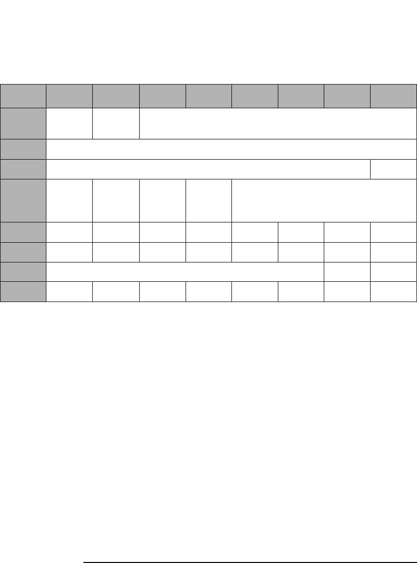
SCSI-2 Drive Command Set
Mode Sense (Group 0) Command (1AH)
Chapter 22-70
Vendor Unique
PS The Parameters Savable bit of 1 indicates this
parameter page is savable in non-volatile RAM.
DAIR A Direct Access Inquiry Response bit of 1 indicates the
Peripheral Device Type field in the Inquiry Data
indicates "Direct Access Device."
A DAIR bit of 0 indicates "Optical Memory Device" in
the Peripheral Device Type field in the Inquiry Data.
The DAIR default setting is 0.
DWR A Disable Write Reordering bit of 1 indicates write
reordering is not enabled.
A DWR bit of 0 indicates write reordering is enabled.
The DWR default setting is 0.
Table 2-61 Vendor Unique Page 21H
Byte 7 6 5 4 3 2 1 0
0PS (1) Rsvd
(0)
Page Code (21H)
1Page Length (0AH)
2Reserved (0) DAIR
3DWR Quick
Dis-
connect
Rsvd
(0)
Force
Verify
Reserved (0)
4S1-8 S1-7 S1-6 S1-5 S1-4 S1-3 S1-2 S1-1
5S2-8 S2-7 S2-6 S2-5 S2-4 S2-3 S2-2 S2-1
6Reserved (0) DOM FWC
7-11

SCSI-2 Drive Command Set
Mode Sense (Group 0) Command (1AH)
Chapter 2 2-71
SCSI-2 Drive Commands
Quick
Disconnect A Quick Disconnect bit of 1 enables SCSI bus
disconnection before command validation on
performance path commands (i.e. reads, writes).
A Quick Disconnect bit of 0 disables SCSI bus
disconnection before validation on performance path
commands (i.e. reads, writes).
The Quick Disconnect default setting is 0.
Force Verify A Force Verify bit of 1 indicates that all write operations
will be verified. The Write 6-, 10-, and 12-byte
commands will operate as if they were Write Verify 6,
10, and 12-byte commands.
A Force Verify bit of 0 indicates normal operation.
The Force Verify default setting is 0.
Bytes 4 and 5 Bytes 4 and 5 are used to read the setting of the DIP
switches on the drive. SX-Y refers to the setting of DIP
switch S50X-Y (see Figure 2-1 on page 2-51 and
Table 2-44 on page 2-51). If SX-Y=0, the switch is set to
the OFF position; if SX-Y=1, the switch is set to the ON
position. These fields are not changeable. The switch
setting value overrides the saved value.
DOM A drive operating mode of 0 indicates that the drive is
installed in a jukebox environment. A DOM bit of 1
indicates that the drive is installed in a stand-alone
environment.
NOTE The DOM bit is not selectable using the Mode Select command.

SCSI-2 Drive Command Set
Mode Sense (Group 0) Command (1AH)
Chapter 22-72
FWC A Force Write Calibration bit of 1 instructs the drive to
perform the Write Calibration routine at spin-up. A
Force Write Calibration bit of 0 instructs the drive to
perform the Write Calibration routine on receipt of the
first Write command or 5 minutes after spin-up.
NOTE The bits DAIR and Force Verify on this mode page can also be controlled
in HP products by changing external switch settings. In HP’s standalone
box products, this is accomplished by changing the thumb wheel settings
on the rear of the box. In HP’s library products, this is accomplished by
changing the front panel settings. In all cases, changes to the mode page
settings will override the external switch settings.

SCSI-2 Drive Command Set
Start/Stop Unit Command (1BH)
Chapter 2 2-73
SCSI-2 Drive Commands
Start/Stop Unit Command (1BH)
This command starts or stops rotation of the optical disk in the drive
and/or ejects the optical disk from the drive.
Immed An Immediate bit of 1 indicates that status is returned
as soon as the command descriptor block has been
validated.
An Immed bit of 0 indicates that status is returned after
the operation is completed.
LoEj A Load Eject bit of 0 requests that no action be taken
regarding loading or ejecting the media.
A Load Eject bit of 1 indicates that the media will be
unloaded if the Start bit is 0.
A Load Eject bit of 1 indicates that the media will be
loaded if the Start bit is 1.
NOTE This command is affected by the Prevent/Allow Medium Removal
command. Do not use LoEj in an autochanger environment.
Start A Start bit of 1 indicates that the drive starts rotating
the optical disk. A Start bit of 0 indicates that the drive
stops rotating the optical disk.
Table 2-62 Start/Stop Unit Command CDB
Byte 7 6 5 4 3 2 1 0
0Operation Code (1BH)
1Logical Unit Number
(0)
Reserved (0) Immed
2Reserved (0)
3Reserved (0)
4Reserved (0) LoEj Start
5Reserved (0) Flag Link
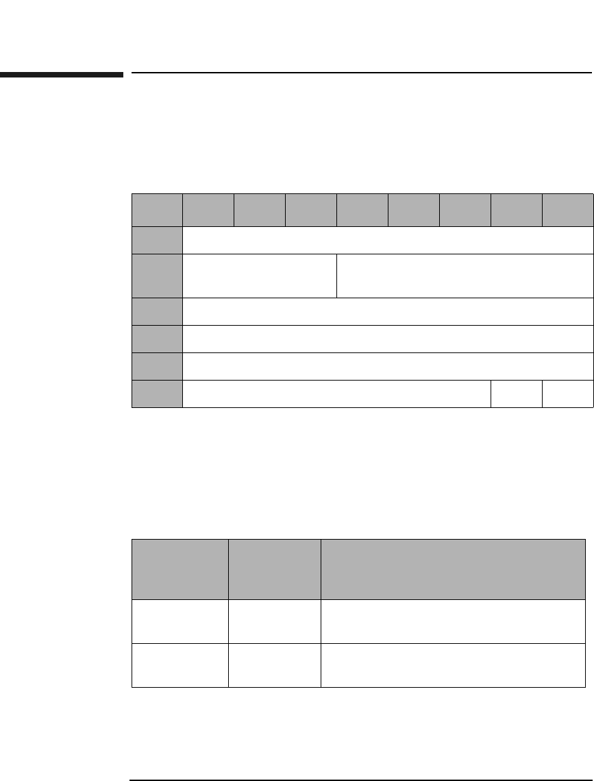
SCSI-2 Drive Command Set
Receive Diagnostic Results Command (1CH)
Chapter 22-74
Receive Diagnostic Results Command (1CH)
This command requests diagnostic test data resulting from the Send
Diagnostic Command be sent to the initiator.
Allocation
Length The Allocation Length field specifies the number of
bytes allocated for returned diagnostic data. The
controller returns the number of bytes specified or all
available diagnostic data (10 bytes), whichever is less.
Table 2-63 Receive Diagnostic Results Command CDB
Byte 76543210
0Operation Code (1CH)
1Logical Unit Number
(0)
Reserved (0)
2Reserved (0)
3Allocation Length (MSByte)
4Allocation Length (LSByte)
5Reserved (0) Flag Link
Table 2-64 Received Diagnostic Results Page Codes
Page Code Maximum
Transfer
Length
Description
00H 6 Supported Diagnostics Pages
(See Table 2-65 on page 2-75)
81H 10 Controller Test
(See Table 2-66 on page 2-75)

SCSI-2 Drive Command Set
Receive Diagnostic Results Command (1CH)
Chapter 2 2-75
SCSI-2 Drive Commands
Table 2-65 Supported Diagnostic Pages
Byte 76543210
0Page Code (00H)
1Reserved (0)
2Page Length (0) (MSByte)
3Page Length (2) (LSByte)
4Supported Page List (00H)
5Supported Page List (81H)
Table 2-66 Controller Test 81H
Byte 7 6 5 4 3 2 1 0
0Page Code (81H)
1Reserved (0)
2Page Length (0) (MSByte)
3Page Length (6) (LSByte)
4Reserved (0) Success
5Loop Count Completed
6Internal Error Code (MSByte)
7Internal Error Code
8Internal Error Code
9Internal Error Code (LSByte)
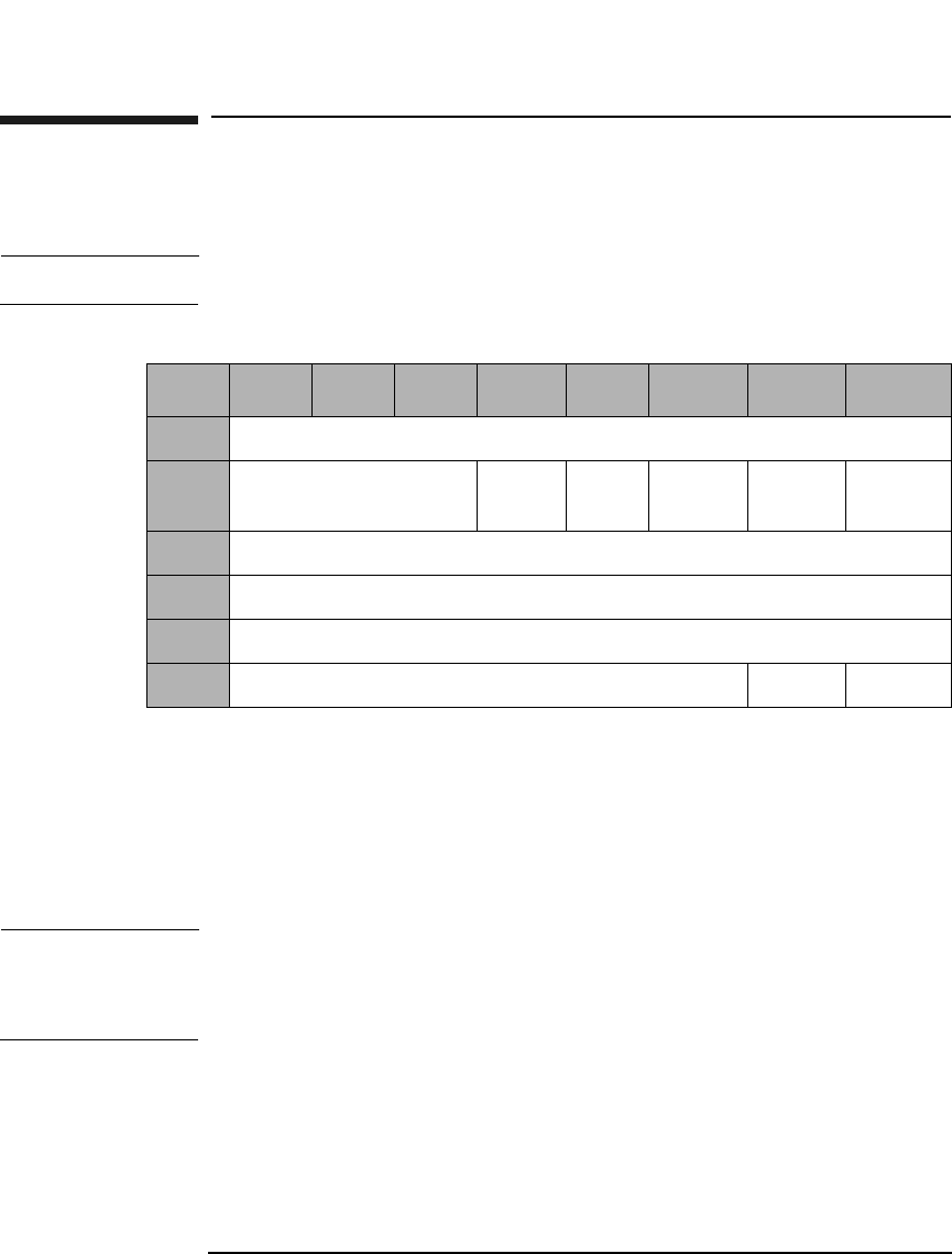
SCSI-2 Drive Command Set
Send Diagnostic Command (1DH)
Chapter 22-76
Send Diagnostic Command (1DH)
This command initiates drive diagnostic tests.
NOTE Disconnect must be allowed to run diagnostic tests.
SelfTst A Self-Test bit of 1 causes the poweron selftest to run.
This self-test is equivalent to the execution of test
sequence 1, Poweron Sequence. If this bit is 1, the
Parameter List Length must be 0.
A Self-Test bit of 0 indicates the test requested in the
Parameter List Length (See Table 2-70 on page 2-78)
NOTE A SelfTst bit of 0 should be followed by a Receive Diagnostics Results
Command.
A SelfTst bit of 1 should be followed by a Request Sense Command.
Table 2-67 Send Diagnostic Command CDB
Byte 7 6 5 4 3 2 1 0
0Operation Code (1DH)
1Logical Unit Number
(0)
PF (1) Rsvd
(0)
SelfTst DevOfl UnitOfl
2Reserved (0)
3Parameter List Length (MSByte)
4Parameter List Length (LSByte)
5Reserved (0) Flag Link

SCSI-2 Drive Command Set
Send Diagnostic Command (1DH)
Chapter 2 2-77
SCSI-2 Drive Commands
DevOfl Device Offline bit of 1 must be set for proper operation
of any test besides self-test.
UnitOfl A Unit Offline bit of 1 must be set for proper operation
of any test besides self-test.
Parameter List
Length Indicates the number of parameter bytes in the Data
Out Phase that describe the selected test. This value
must be 0 if the SelfTst bit is set to 1.
Table 2-68 Supported Diagnostic Pages
Byte 76543210
0Page Code (00H)
1Reserved (0)
2Page Length (0) (MSByte)
3Page Length (0) (LSByte)
Table 2-69 Send Diagnostic Command Page Codes
Page Code Parameter
List
Length
Description
00H 4 Supported Diagnostics Pages
(See Table 2-68 on page 2-77)
81H 12 Controller Test
(See Table 2-70 on page 2-78)
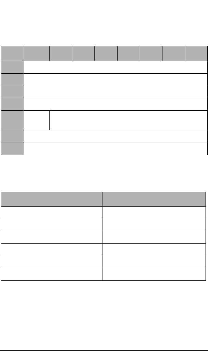
SCSI-2 Drive Command Set
Send Diagnostic Command (1DH)
Chapter 22-78
No Break The No Break bit directs the target not to terminate
looping when an error is detected.
Table 2-70 Controller Test
Byte 7 6 5 4 4 2 1 0
0Page Code (81H)
1Reserved
2Page Length (0) (MSByte)
3Page Length (8) (LSByte)
4No
Break
Test Number
(See Table 2-71 on page 2-78)
5Loop Count
6-11 Reserved (0)
Table 2-71 Interface Manager Diagnostic Tests
Diagnostic Test Name Test Number (hex.)
Selftest 0x01
ROM Checksum Test 0x02
Microprocessor RAM Test 0x03
Buffer RAM Test 0x04
ODC Chip Test 0x05
DSP Communication Test 0x06
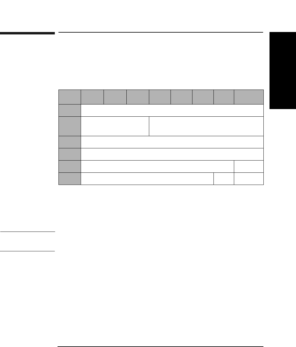
SCSI-2 Drive Command Set
Prevent/Allow Medium Removal Command (1EH)
Chapter 2 2-79
SCSI-2 Drive Commands
Prevent/Allow Medium Removal Command
(1EH)
This command prevents or allows removal of an optical disk from a drive.
Prevent A Prevent bit of 1 prevents removal of the optical disk
from a drive.
A Prevent bit of 0 allows removal of the optical disk
from a drive.
NOTE The Start/Stop Unit Command affects this command. See Table 2-62 on
page 2-73.
Table 2-72 Prevent/Allow Medium Removal Command CDB
Byte 7 6 5 4 3 2 1 0
0Operation Code (1EH)
1Logical Unit Number
(0)
Reserved (0)
2Reserved (0)
3Reserved (0)
4Reserved (0) Prevent
5Control Byte (0) Flag Link
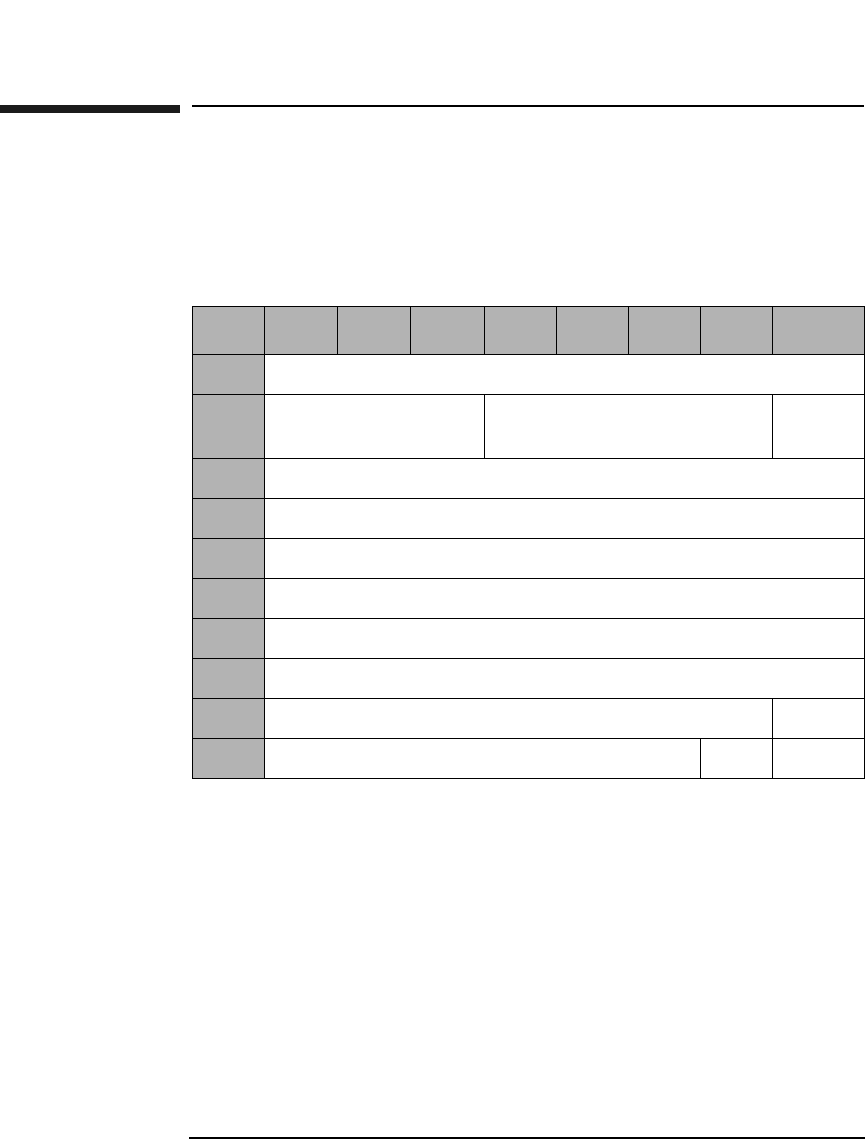
SCSI-2 Drive Command Set
Read Capacity Command (25H)
Chapter 22-80
Read Capacity Command (25H)
This command reads the capacity of the optical disk surface in the drive.
The last logical block address and block length of the medium are
returned.
PMI A Partial Medium Indicator bit of 1 indicates that the
logical block address field does not need to be set to 0.
A PMI bit of 0 indicates that the logical block address
field must be set to 0.
Table 2-73 Read Capacity Command CDB
Byte 7 6 5 4 3 2 1 0
0Operation Code (25H)
1Logical Unit Number
(0)
Reserved (0) RelAdr
2Logical Block Address (MSByte)
3Logical Block Address
4Logical Block Address
5Logical Block Address (LSByte)
6Reserved (0)
7Reserved (0)
8Reserved (0) PMI
9Reserved (0) Flag Link

SCSI-2 Drive Command Set
Read Capacity Command (25H)
Chapter 2 2-81
SCSI-2 Drive Commands
Table 2-74 Read Capacity Command Data
Byte 76543210
0Logical Block Address (MSByte)
1Logical Block Address
2Logical Block Address
3Logical Block Address (LSByte)
4Block Length (MSByte)
5Block Length
6Block Length
7Block Length (LSByte)
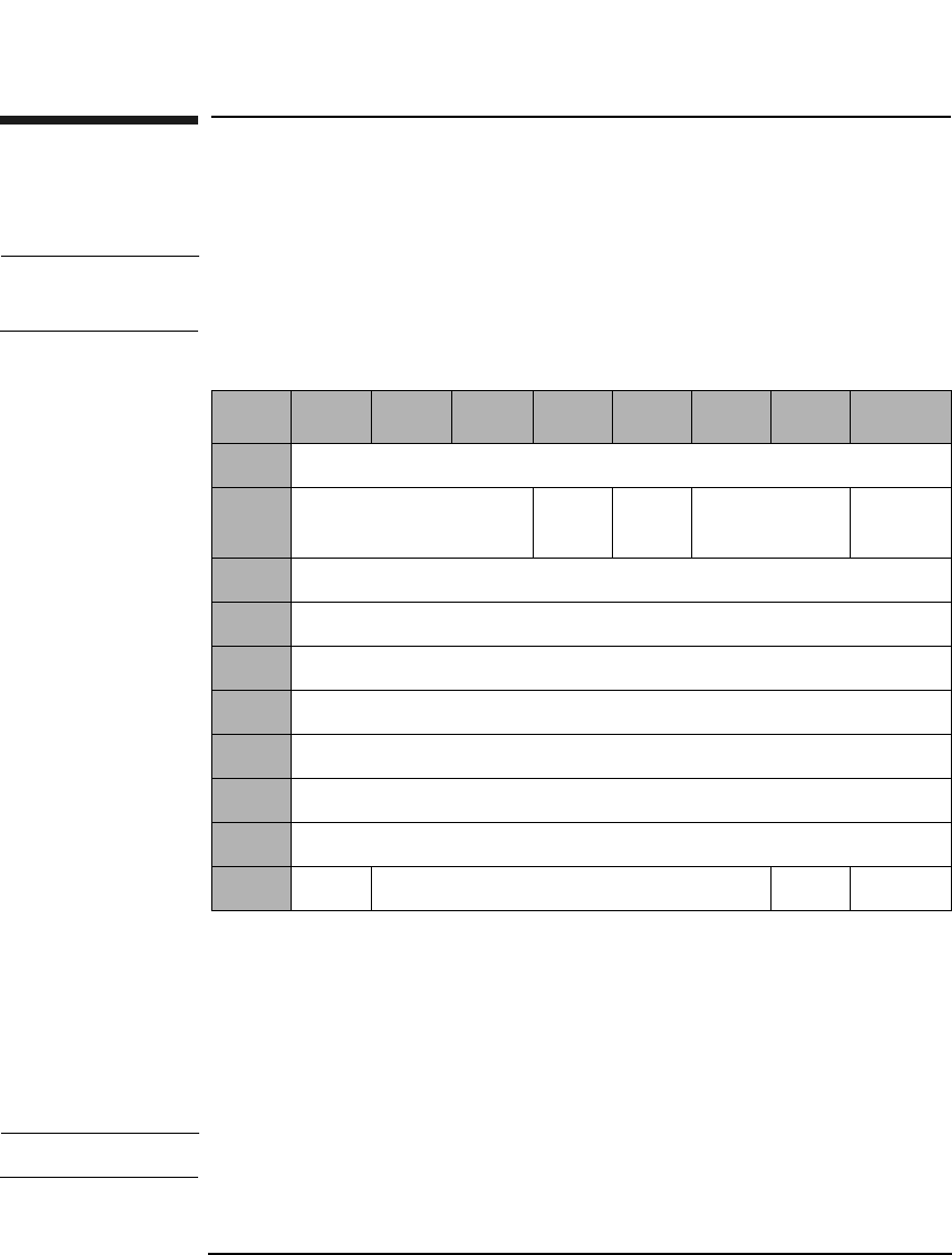
SCSI-2 Drive Command Set
Read (Group 1) Command (28H)
Chapter 22-82
Read (Group 1) Command (28H)
This command reads data from the specified logical block address.
NOTE The Mode Select Commands (15H, 55H) impact read, write, format, and
erase commands.
DPO A Disable Page Out bit of 1 instructs the target not to
store readahead data in cache after the read data has
been transferred to the initiator.
A DPO bit of 0 instructs the target it may store
readahead data in the cache after the read data has
been transferred to the initiator.
NOTE The DPO bit is ignored in 9.1 and 5.2 Gbyte capacity drives.
Table 2-75 Read (Group 1) Command CDB
Byte 7 6 5 4 3 2 1 0
0Operation Code (28H)
1Logical Unit Number
(0)
DPO FUA Reserved (0) RelAdr
2Starting Logical Block Address (MSByte)
3Starting Logical Block Address
4Starting Logical Block Address
5Starting Logical Block Address (LSByte)
6Reserved (0)
7Transfer Length (MSByte)
8Transfer Length (LSByte)
9PBA Reserved (0) Flag Link

SCSI-2 Drive Command Set
Read (Group 1) Command (28H)
Chapter 2 2-83
SCSI-2 Drive Commands
FUA A Force Unit Access bit of 1 indicates that data is read
directly from the disk.
A Force Unit Access bit of 0 indicates that the drive may
access the cache memory.
Rel Adr A relative address bit of one indicates that logical block
address specified is a two’s complement offset from the
last logical block address accessed.
A value of 0 indicates that the logical block address is an
absolute address.
Transfer
Length The Transfer Length field specifies the number of
contiguous logical blocks of data to be transferred.
A value of 0 indicates that no blocks will be transferred
and is not considered an error.
PBA A Physical Block Address bit of 1 indicates that physical
block addressing is used.
A PBA bit of 0 indicates that logical block addressing is
used.
NOTE For write-once media, blank checking is performed following a failed read.
If the sector is blank, the sense key/additional sense code will be set to
BLANK CHECK/Blank Sector Detected.
NOTE When this command is used with 14X 512 or 1024 byte/sector media,
setting the PBA bit will cause the drive to return a CHECK CONDITION
status. The sense key/additional sense code will be set to ILLEGAL
REQUEST/INVALID FIELD in CDB.
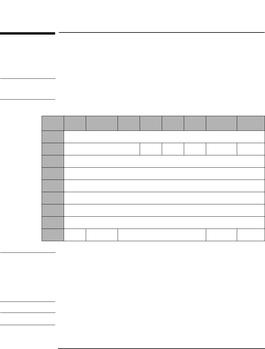
SCSI-2 Drive Command Set
Write (Group 1) Command (2AH)
Chapter 22-84
Write (Group 1) Command (2AH)
This command is used to write data starting at the specified logical block
address.
NOTE The Mode Select Commands (15H, 55H) impact read, write, format, and
erase commands.
NOTE The 9.1 and 5.2 Gbyte capacity drives cannot Format, Erase, Write, or
Write and Verify 650 Mbyte and 1.3-Gbyte optical disks. The 2.6 Gbyte
capacity drives cannot Format, Erase, Write, or Write and Verify 650
Mbyte optical disks. If this command is issued with any of these drive/
media combinations, a CHECK CONDITION status will result with the
Sense Key/Additional Sense Code set to Data Protect/Write Protected.
NOTE For Write-Once media, Byte 9, Bit 7 and Bit 6 are reserved (0).
Table 2-76 Write (Group 1) Command CDB
Byte 7 6 5 4 3 2 1 0
0Operation Code (2AH)
1Reserved (0) DPO FUA EBP Rsvd (0) RelAdr
2Logical Block Address (MSByte)
3-4 Logical Block Address
5Logical Block Address (LSByte)
6Reserved (0)
7Transfer Length (MSByte)
8Transfer Length (LSByte)
9PBA Ers Cntl Reserved (0) Flag Link

SCSI-2 Drive Command Set
Write (Group 1) Command (2AH)
Chapter 2 2-85
SCSI-2 Drive Commands
DPO A Disable Page Out bit of 1 instructs the target not to
store the data in the cache after it has been transferred
to the media.
A DPO bit of 0 instructs the target to store data in the
cache after it has been transferred to the media.
This bit is ignored.
FUA A Force Unit Access bit of 1 indicates that data is
written directly to the disk.
An FUA bit of 0 indicates that write caching is allowed.
Rel Adr A relative address bit of one indicates that logical block
address specified is a two’s complement offset from the
last logical block address accessed.
A value of 0 indicates that the logical block address is an
absolute address.
EBP An Erase By-Pass bit of 0 indicates an erase is
automatically performed before writing the data.
An EBP bit of 1 suppresses the erase operation.
Transfer Length The Transfer Length field specifies the number of
contiguous logical blocks of data to be transferred for
this command.
A value of 0 indicates that no blocks of data will be
transferred and is not considered an error.
PBA A Physical Block Address bit of 1 indicates that physical
block addressing is used.
A PBA bit of 0 indicates that logical block addressing is
used.
ErsCntl The Erase Control bit is identical to the Erase Bypass
bit.
NOTE For write-once optical disks, blank checking is performed before writing
data. If a written block is detected during blank checking, the drive will
return a CHECK CONDITION status. The sense key/additional sense
code will be set to BLANK CHECK/Overwrite Attempted.

SCSI-2 Drive Command Set
Write (Group 1) Command (2AH)
Chapter 22-86
NOTE When this command is used with 14X 512 OR 1024 byte/sector media,
setting the ErsCntl bit or the PBA bit will cause the drive to return a
CHECK CONDITION status. The sense key/additional sense code will be
set to ILLEGAL REQUEST/INVALID FIELD in CDB.

SCSI-2 Drive Command Set
Seek (Group 1) Command (2BH)
Chapter 2 2-87
SCSI-2 Drive Commands
Seek (Group 1) Command (2BH)
This command seeks the optical head to the physical track where the
specified logical block exists.
PBA A Physical Block Address bit of 1 indicates that physical
block addressing is used.
A PBA bit of 0 indicates that logical block addressing is
used.
NOTE When this command is used with 512 byte/sector 14X media or 1024 byte/
sector 14X media, setting the PBA bit will cause the drive to return a
CHECK CONDITION status. The sense key/additional sense code will be
set to ILLEGAL REQUEST/Invalid Field in CDB.
Table 2-77 Seek (Group 1) Command CDB
Byte 76543210
0Operation Code (2BH)
1Logical Unit Number
(0)
Reserved (0)
2Logical Block Address (MSByte)
3Logical Block Address
4Logical Block Address
5Logical Block Address (LSByte)
6Reserved (0)
7Reserved (0)
8Reserved (0)
9PBA Reserved (0) Flag Link
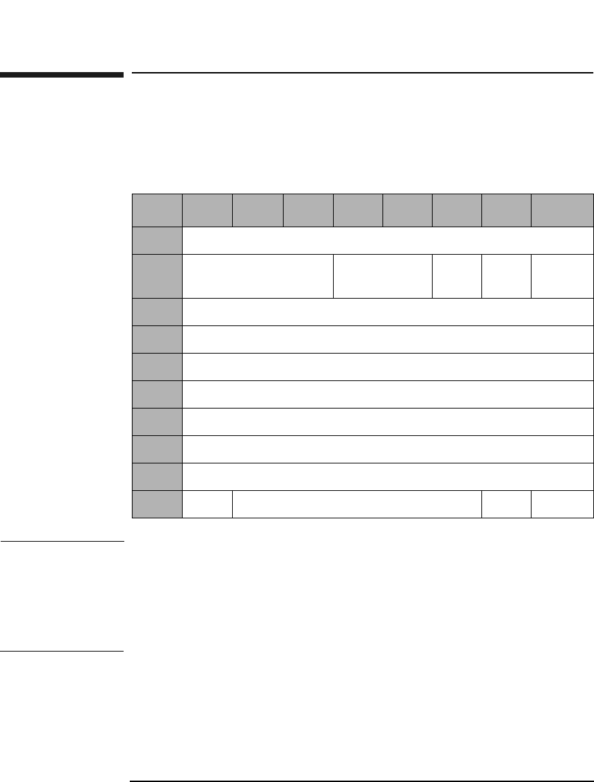
SCSI-2 Drive Command Set
Erase (Group 1) Command (2CH)
Chapter 22-88
Erase (Group 1) Command (2CH)
This command erases data from the specified logical block address. This
command can only be used with rewritable disks.
NOTE The 9.1 and 5.2 Gbyte capacity drives cannot Format, Erase, Write, or
Write and Verify 650 Mbyte and 1.3-Gbyte optical disks. The 2.6 Gbyte
capacity drives cannot Format, Erase, Write, or Write and Verify 650
Mbyte optical disks. If this command is issued with any of these drive/
media combinations, a CHECK CONDITION status will result with the
Sense Key/Additional Sense Code set to Data Protect/Write Protected.
Table 2-78 Erase (Group 1) Command CDB
Byte 7 6 5 4 3 2 1 0
0Operation Code (2CH)
1Logical Unit Number
(0)
Reserved (0) ERA Rsvd
(0)
RelAdr
2Logical Block Address (MSByte)
3Logical Block Address
4Logical Block Address
5Logical Block Address (LSByte)
6Reserved (0)
7Transfer Length (MSByte)
8Transfer Length (LSByte)
9PBA Reserved (0) Flag Link

SCSI-2 Drive Command Set
Erase (Group 1) Command (2CH)
Chapter 2 2-89
SCSI-2 Drive Commands
ERA An Erase All bit of 1 indicates that all remaining blocks
are erased, starting from the logical block address to the
end of the disk. The transfer length must be set to 0.
An ERA bit of 0 indicates that all blocks are erased,
starting from the logical block address to the end of the
specified transfer length.
Rel Adr A relative address bit of one indicates that logical block
address specified is a two’s complement offset from the
last logical block address accessed.
A value of 0 indicates that the logical block address is an
absolute address.
Transfer
Length The Transfer Length field specifies the number of
contiguous logical blocks of data to be erased. A value of
0 indicates that no blocks will be erased and is not
considered an error.
PBA A Physical Block Address bit of 1 indicates that physical
block addressing is used.
A PBA bit of 0 indicates that logical block addressing is
used.
NOTE If this command is executed for write-once disks, the drive returns a
CHECK CONDITION status with the Sense Key/Additional Sense Code
set to Illegal Request/Invalid Command Operation Code.
NOTE When this command is executed with 14X 512 or 1024 byte/sector media,
the drive will return a CHECK CONDITION status. The sense key/
additional sense code will be set to ILLEGAL REQUEST/INVALID
COMMAND.
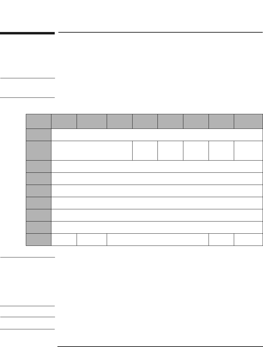
SCSI-2 Drive Command Set
Write and Verify (Group 1) Command (2EH)
Chapter 22-90
Write and Verify (Group 1) Command (2EH)
Writes data to the optical disk and then verifies the write by reading the
written data and checking the error correction code.
NOTE The Mode Select Commands (15H, 55H) impact read, write, format, and
erase commands.
NOTE The 9.1 and 5.2 Gbyte capacity drives cannot Format, Erase, Write, or
Write and Verify 650 Mbyte and 1.3-Gbyte optical disks. The 2.6 Gbyte
capacity drives cannot Format, Erase, Write, or Write and Verify 650
Mbyte optical disks. If this command is issued with any of these drive/
media combinations, a CHECK CONDITION status will result with the
Sense Key/Additional Sense Code set to Data Protect/Write Protected.
NOTE For Write-Once media, Byte 9, Bit 7 and Bit 6 are reserved (0).
Table 2-79 Write and Verify (Group 1) Command CDB
Byte 7 6 5 4 3 2 1 0
0Operation Code (2EH)
1Reserved (0) DPO Rsvd
(0)
EBP Rsvd
(0)
RelAdr
2Logical Block Address (MSByte)
3-4 Logical Block Address
5Logical Block Address (LSByte)
6Reserved (0)
7Transfer Length (MSByte)
8Transfer Length (LSByte)
9PBA ErsCntl Reserved (0) Flag Link

SCSI-2 Drive Command Set
Write and Verify (Group 1) Command (2EH)
Chapter 2 2-91
SCSI-2 Drive Commands
DPO A Disable Page Out bit of 1 instructs the target not to
store the data in the cache after it has been transferred
to the optical disk.
A DPO bit of 0 instructs the target to store the data in
the cache after it has been transferred to the optical
disk.
This bit is ignored.
EBP An Erase By-Pass bit of 0 indicates an erase
automatically performs before writing the data.
An EBP bit of 1 suppresses the erase operation.
Transfer
Length The Transfer Length field specifies the number of
contiguous logical blocks of data to be transferred for
this command. A value of 0 indicates that no blocks will
be transferred and is not considered an error.
PBA A Physical Block Address bit of 1 indicates that physical
block addressing is used.
A PBA bit of 0 indicates that logical block addressing is
used.
ErsCntl The Erase Control bit is identical to the Erase Bypass
bit.
Rel Adr A relative address bit of one indicates that logical block
address specified is a two’s complement offset from the
last logical block address accessed.
A value of 0 indicates that the logical block address is an
absolute address.
NOTE When this command is used with 14X 512 OR 1024 byte/sector media,
setting the ErsCntl bit or the PBA bit will cause the drive to return a
CHECK CONDITION status. The sense key/additional sense code will be
set to ILLEGAL REQUEST/INVALID FIELD in CDB.
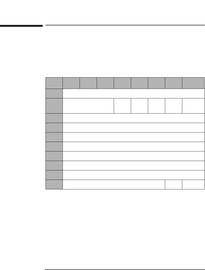
SCSI-2 Drive Command Set
Verify (Group 1) Command (2FH)
Chapter 22-92
Verify (Group 1) Command (2FH)
This command verifies previously written data integrity starting at the
specified Logical Block Address by reading the data and checking the
Error Correction Code. The verification threshold is set to approximately
half of the error correction capability.
DPO A Disable Page Out (DPO) bit of 1 instructs the target
not to retain the data in the cache after it has been
verified.
A DPO bit of 0 instructs the target to retain the data in
the cache after it has been verified.
This bit is ignored.
Table 2-80 Verify (Group 1) Command CDB
Byte 7654321 0
0Operation Code (2FH)
1Logical Unit
Number (0)
DPO Rsvd
(0)
Blk
Vfy
Rsvd
(0)
RelAdr
2Logical Block Address (MSByte)
3Logical Block Address
4Logical Block Address
5Logical Block Address (LSByte)
6Reserved (0)
7Verification Length (MSByte)
8Verification Length (LSByte)
9Reserved (0) Flag Link

SCSI-2 Drive Command Set
Verify (Group 1) Command (2FH)
Chapter 2 2-93
SCSI-2 Drive Commands
Blk Vfy A Blank Verify bit of 1 indicates the drive verifies that
sectors are erased.
A Blk Vfy bit of 0 indicates the drive verifies written
data integrity.
Verification
Length The Verification Length field specifies the number of
contiguous logical blocks of data to be verified for this
command. A value of 0 indicates that no blocks will be
verified and is not considered an error.
Rel Adr A relative address bit of one indicates that logical block
address specified is a two’s complement offset from the
last logical block address accessed.
A value of 0 indicates that the logical block address is an
absolute address.
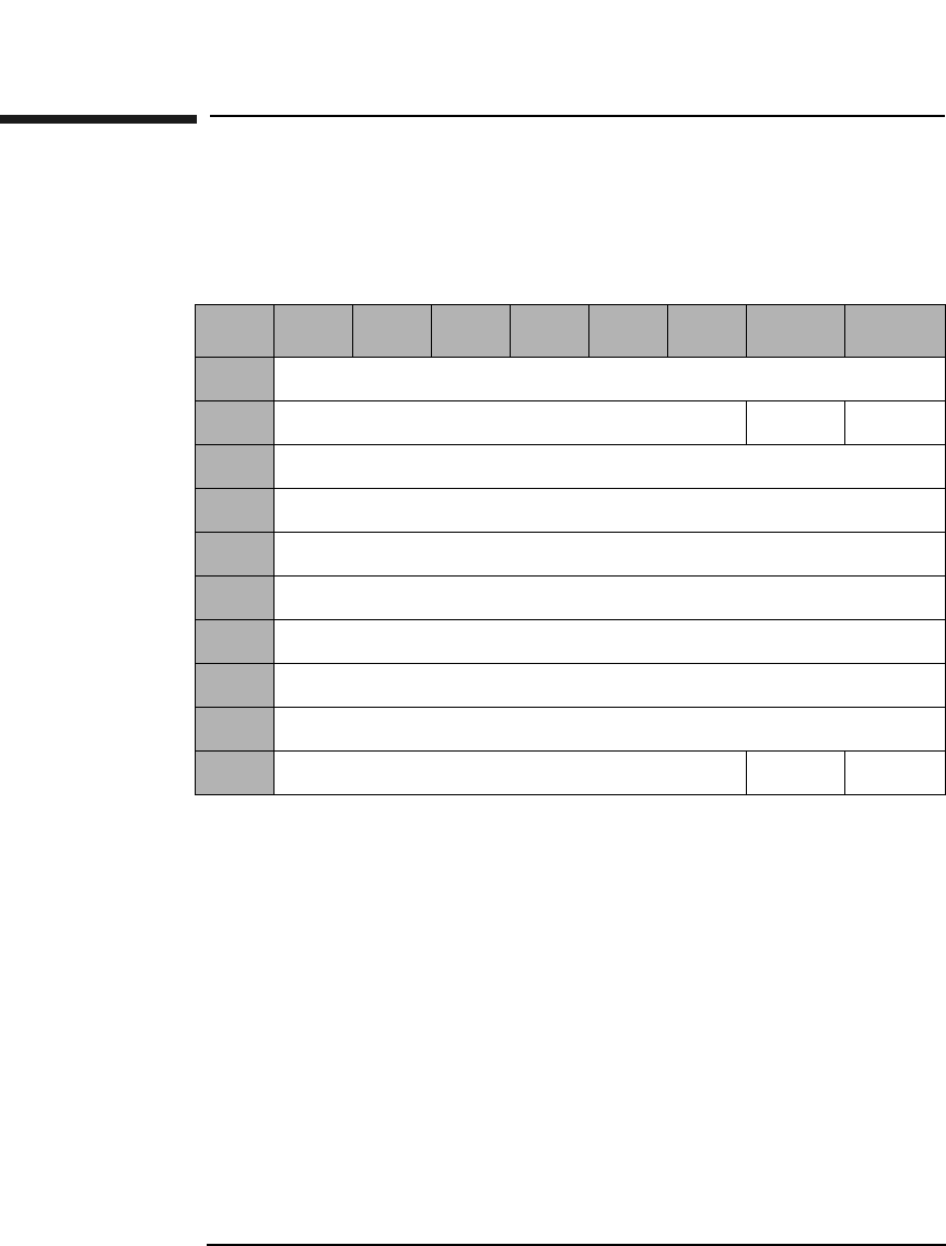
SCSI-2 Drive Command Set
Pre-Fetch (34H)
Chapter 22-94
Pre-Fetch (34H)
The Pre-Fetch command is used to transfer the specified number of data
blocks starting from the specified logical block address to cache memory.
Immed An Immediate bit of 1 indicates that the drive returns a
status as soon as the command descriptor block is
validated.
An Immed bit of 0 indicates that the status is not
returned until the operation is completed.
Transfer
Length This field indicates the number of contiguous logical
blocks of data to be transferred.
Rel Adr A relative address bit of one indicates that logical block
address specified is a two’s complement offset from the
last logical block address accessed.
A value of 0 indicates that the logical block address is an
absolute address.
Table 2-81 Pre-Fetch Command
Byte 765432 1 0
0Operation Code (34H)
1Reserved (0) Immed RelAdr
2Logical Block Address (MSByte)
3Logical Block Address
4Logical Block Address
5Logical Block Address (LSByte)
6Reserved (0)
7Transfer Length (MSByte)
8Transfer Length (LSByte)
9Reserved (0) Flag Link

SCSI-2 Drive Command Set
Synchronize Cache (35H)
Chapter 2 2-95
SCSI-2 Drive Commands
Synchronize Cache (35H)
This command initiates the writing of all cached write data to the optical
disk. Ensures that logical blocks in the cache memory, within the
specified range, have their most recent data value recorded on the optical
disk.
Immed An Immediate bit of 1 indicates that the target returns
a status as soon as the command descriptor block is
validated.
An Immed bit of 0 indicates that the status is not
returned until the operation is completed.
Number of
Blocks The Number of Blocks field specifies the total number of
contiguous logical blocks within the range. A Number of
Blocks bit of 0 indicates that all remaining logical blocks
on the logical unit are within the range. A logical block
within the specified range that is not in cache memory
is not considered an error.
Table 2-82 Synchronize Cache Command
Byte 7 6 5 4 3 2 1 0
0Operation Code (35H)
1Reserved (0) Immed Rsvd
2Logical Block Address (MSByte)
3Logical Block Address
4Logical Block Address
5Logical Block Address (LSByte)
6Reserved (0)
7Number of Blocks (MSByte)
8Number of Blocks (LSByte)
9Reserved (0) Flag Link
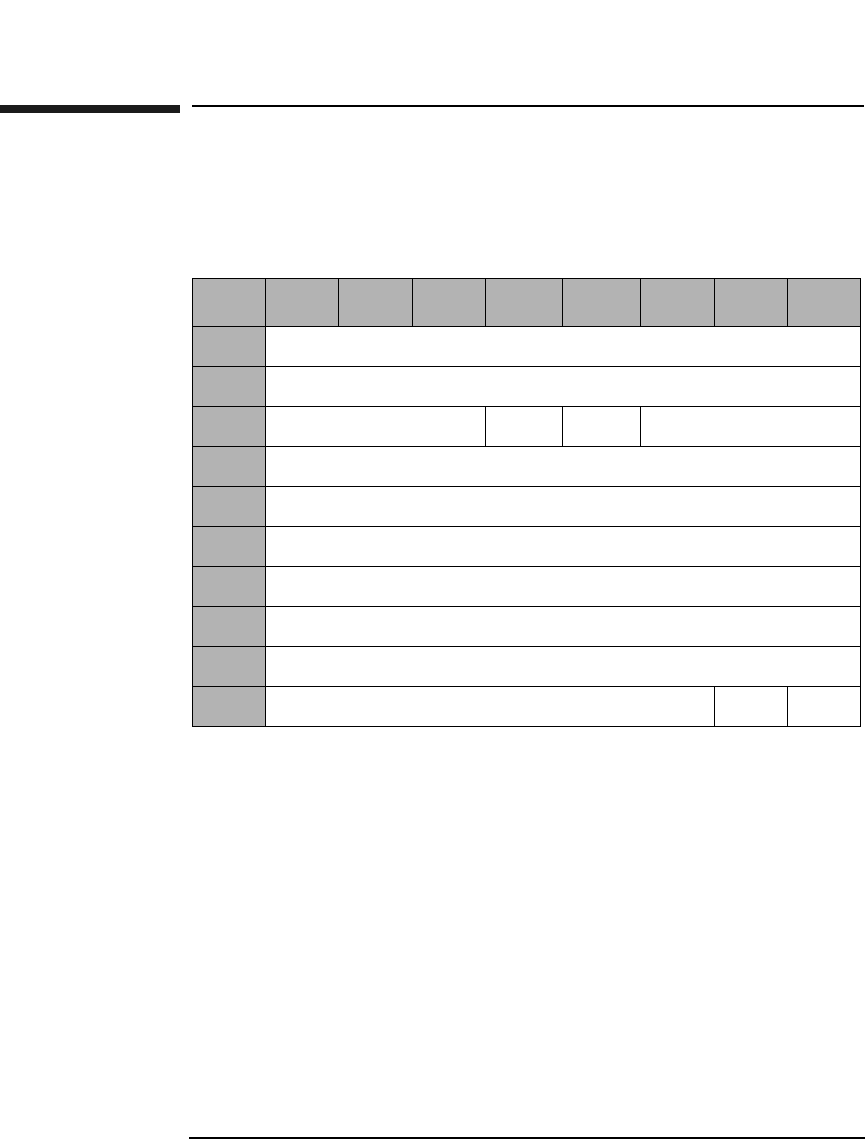
SCSI-2 Drive Command Set
Read Defect Data (Group 1) Command (37H)
Chapter 22-96
Read Defect Data (Group 1) Command (37H)
This command reads optical disk defect information. The data returned
starts with a 4-byte header, followed by one or more defect descriptors.
PList and GList A PList bit of 0 and a GList bit of 1 indicates the drive
will return the contents of the defect list (SDL).
A PList bit of 1 and a GList bit of 0 indicates the drive
will return the contents of the PDL.
A PList bit of 1 and a GList bit of 1 indicates the drive
will return the contents of the PDL and the SDL.
Table 2-83 Read Defect Data (Group 1) Command CDB
Byte 7 6 5 4 3 2 1 0
0Operation Code (37H)
1Reserved (0)
2Reserved (0) PList GList Defect List Format
3Reserved (0)
4Reserved (0)
5Reserved (0)
6Reserved (0)
7Allocation Length (MSByte)
8Allocation Length (LSByte)
9Reserved (0) Flag Link
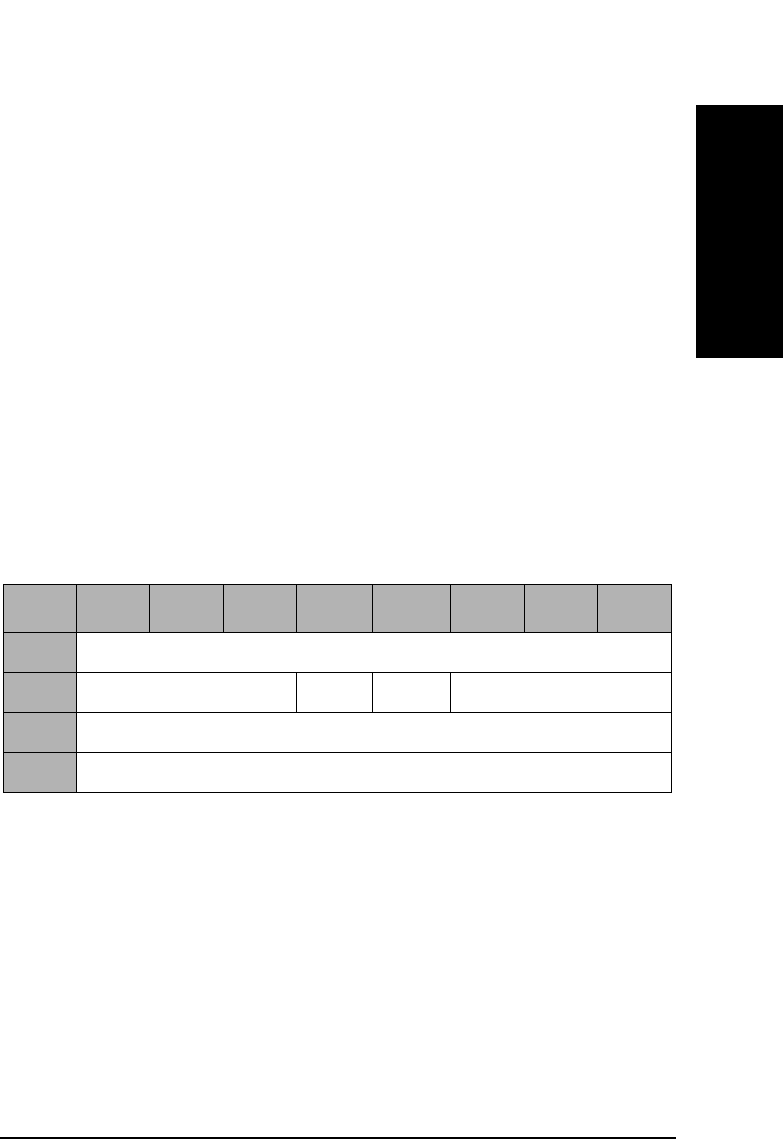
SCSI-2 Drive Command Set
Read Defect Data (Group 1) Command (37H)
Chapter 2 2-97
SCSI-2 Drive Commands
Defect List
Format This field specifies the defect list format that is
returned. Only the Physical Sector Format (5) is
supported. If the Block Format (0) is specified, the
defect list will be returned in Physical Sector Format
and a CHECK CONDITION status will be returned at
the completion of the command with the sense key/
additional sense code set to RECOVERED ERROR/
Defect List Not Available.
Allocation
Length This field specifies the number of bytes that the
initiator has allocated for the return of this data. A
length of 0 indicates that no data will be returned. This
condition is not considered an error. The drive will
terminate the data — in phase when the allocation
length has been transferred or when all available defect
data has been transferred to the initiator, whichever is
less.
PList A PList bit of 1 indicates the Primary List of defects was
returned.
GList A GList bit of 1 indicates the Grown List of defects was
returned.
Defect List
Format This field will be set to the Defect List format that was
indicated in byte 2 of the CDB, which specifies the
format of the Defect List data returned by the drive.
Defect List
Length This field specifies the length in bytes of the defect
descriptors (see Table 2-85 on page 2-98).
Table 2-84 Read Defect Data Defect List Header
Byte 7 6 5 4 3 2 1 0
0Reserved (0)
1Reserved (0) PList GList Defect List Format
2Defect List Length (MSByte)
3Defect List Length (LSByte)

SCSI-2 Drive Command Set
Read Defect Data (Group 1) Command (37H)
Chapter 22-98
Table 2-85 Physical Sector Format Defect Descriptor
Byte 76543210
0Physical Track Number of the Defect (MSByte)
1Physical Track Number of the Defect
2Physical Track Number of the Defect (LSByte)
3Reserved (0)
4Reserved (0)
5Reserved (0)
6Reserved (0)
7Defective Physical Sector Number
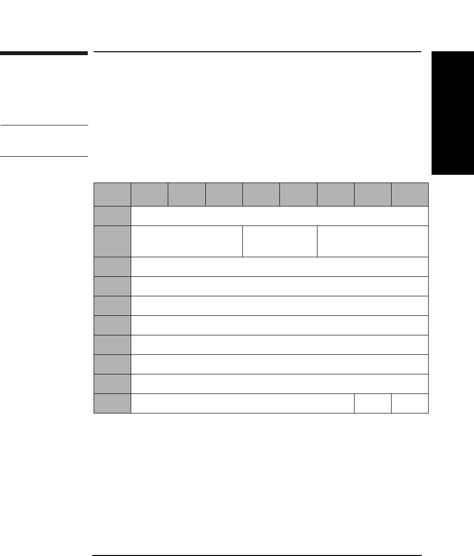
SCSI-2 Drive Command Set
Write Buffer Command (3BH)
Chapter 2 2-99
SCSI-2 Drive Commands
Write Buffer Command (3BH)
This command writes data to the drive data buffer. The transfer data
consists of a 4-byte descriptor followed by the buffer data.
CAUTION If you write data to the buffer area, you may overwrite valid information
that the drive needs for operation.
Mode Indicates which data format is used. Refer to Table 2-87
on page 2-100 for valid values.
Buffer ID Indicates which buffer is used. Refer to Table 2-87 on
page 2-100 for valid values.
Table 2-86 Write Buffer Command CDB
Byte 76543210
0Operation Code (3BH)
1Logical Unit Number
(0)
Reserved (0) Mode (Table 2-87 on
page 2-100)
2Buffer ID (See Table 2-87 on page 2-100)
3Buffer Offset (MSByte)
4Buffer Offset
5Buffer Offset (LSByte)
6Parameter List Length (MSByte)
7Parameter List Length
8Parameter List Length (LSByte)
9Reserved (0) Flag Link

SCSI-2 Drive Command Set
Write Buffer Command (3BH)
Chapter 22-100
Buffer Offset Indicates at what address the data is written, offset
from the beginning of the buffer. Must be set to 0 when
using Download Microcode ID.
Parameter List
Length Indicates the number of data bytes to be written in the
buffer.
Buffer RAM Indicates the data buffer space used for transfer to and
from the optical disk.
Download
Microcode Indicates the code the drive uses to operate.
Serial Number and
Manufacturing
Date Code Indicates the drive’s serial number and date code, which
indicates the week of manufacturing.
Customer and
Product ID Indicates the Vendor Identification and Product
Identification fields of the INQUIRY command
Response Data.
Table 2-87 Buffer Access Mode and ID
Buffer Type Buffer ID Mode
Buffer RAM 0 0
Download Microcode 1 4
Serial Number and Manufacturing Date 4 1
Customer and Product ID 15 1
Table 2-88 Mode Descriptions (For 2.6 Gbyte Capacity Drives Only)
Mode Description
1 Vendor specific
4 Download microcode
0 Data retained for subsequent read buffer command

SCSI-2 Drive Command Set
Write Buffer Command (3BH)
Chapter 2 2-101
SCSI-2 Drive Commands
Table 2-89 Mode Descriptions (For 9.1 and 5.2 Gbyte Capacity Drives Only)
Mode Description
0 Data Mode (same as Mode 2)
1 Vendor specific
2Data Mode
4 Download Microcode
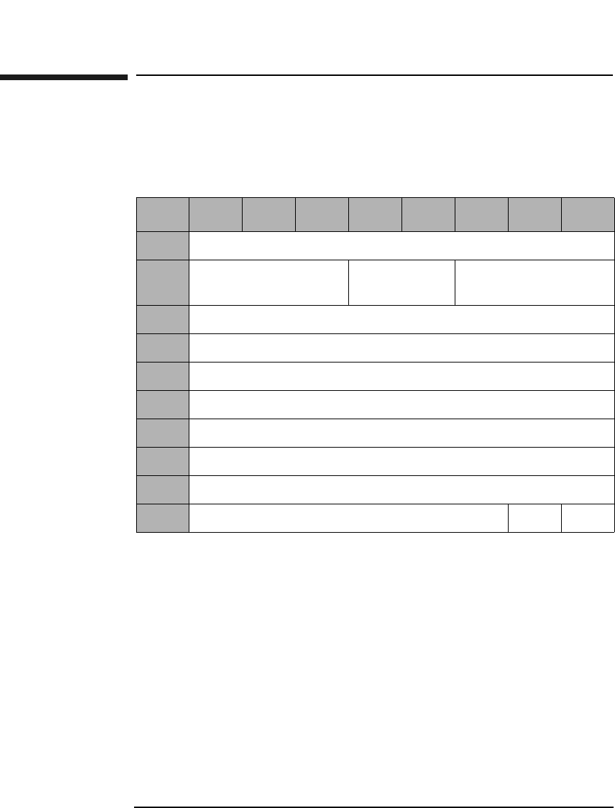
SCSI-2 Drive Command Set
Read Buffer Command (3CH)
Chapter 22-102
Read Buffer Command (3CH)
This command reads data from the drive data buffer. The transfer data
consists of a 4-byte descriptor followed by the buffer data.
Mode Indicates which data format is to be used. Refer to
Table 2-91 on page 2-103 for valid values.
Buffer ID Indicates which buffer is to be used. Refer to Table 2-91
on page 2-103 for valid values.
Buffer Offset Indicates at what address the data should be written,
offset from the beginning of the buffer.
Parameter List
Length Indicates the number of data bytes to be read from the
buffer.
Table 2-90 Read Buffer Command CDB
Byte 76543210
0Operation Code (3CH)
1Logical Unit Number
(0)
Reserved (0) Mode
2Buffer ID
3Buffer Offset (MSByte)
4Buffer Offset
5Buffer Offset (LSByte)
6Parameter List Length (MSByte)
7Parameter List Length
8Parameter List Length (LSByte)
9Reserved (0) Flag Link

SCSI-2 Drive Command Set
Read Buffer Command (3CH)
Chapter 2 2-103
SCSI-2 Drive Commands
Buffer RAM Indicates the data buffer space used for the movement
of data to and from the optical disk.
Table 2-91 Read Buffer Descriptor
Byte 76543210
0Offset Boundary
1Buffer Capacity (MSB)
2Buffer Capacity
3Buffer Capacity (LSB)
Table 2-92 Buffer Access Mode and ID
Buffer Type Buffer ID Mode
Buffer RAM 0 0
Table 2-93 Mode Descriptions (For 2.6 Gbyte Capacity Drives Only)
Mode Description
0 Data retained for subsequent read buffer command
Table 2-94 Mode Descriptions (For 9.1 and 5.2 Gbyte Capacity Drives Only)
Mode Description
0 Data Mode (same as Mode 2)
2Data Mode
3 Descriptor Mode
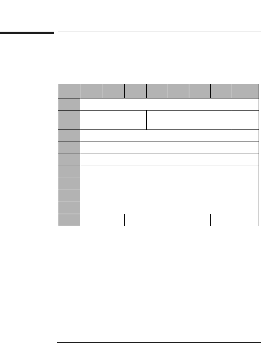
SCSI-2 Drive Command Set
Read Long Command (3EH)
Chapter 22-104
Read Long Command (3EH)
This command reads data starting at the specified Logical Block
Address, including ECC data. Read data is not corrected using ECC.
Table 2-95 Read Long Command CDB
Byte 7 6 5 4 3 2 1 0
0Operation Code (3EH)
1Logical Unit Number
(0)
Reserved (0) RelAdr
2Starting Logical Block Address (MSByte)
3Starting Logical Block Address
4Starting Logical Block Address
5Starting Logical Block Address (LSByte)
6Reserved (0)
7Transfer Length (MSByte)
8Transfer Length (LSByte)
9PBA SC Reserved (0) Flag Link

SCSI-2 Drive Command Set
Read Long Command (3EH)
Chapter 2 2-105
SCSI-2 Drive Commands
Transfer
Length The Transfer Length field specifies the number of bytes
of data and ECC information to be read:
• 4096 media = 4760 bytes (4096 data + 664 pointer,
CRC, pad, & ECC) For 9.1 Gbyte Capacity drives
only.
• 2048 media = 2380 bytes (2048 data + 332 pointer,
CRC, pad, & ECC) For 5.2 Gbyte Capacity drives
only.
• 1K media = 1200 bytes (1024 data + 176 pointer, CRC,
pad, &ECC)
• 512 media = 610 bytes (512 data + 98 pointer, CRC,
pad, &ECC)
• All other numbers are rejected unless SC = 1
PBA A Physical Block Address bit of 1 indicates that physical
block addressing is used.
A PBA bit of 0 indicates that logical block addressing is
used.
SC A Sector Count bit of 1 indicates the transfer length is
represented in sectors rather than bytes. A "sector"
consists of 2380 bytes for 2K media, 1200 bytes for 1K
media, or 610 bytes for 512 media.
A Sector Count bit of 0 indicates the transfer length is
represented in bytes.
Rel Adr A relative address bit of one indicates that logical block
address specified is a two’s complement offset from the
last logical block address accessed.
A value of 0 indicates that the logical block address is an
absolute address.
NOTE When this command is executed with 14X 512 or 1024 byte/sector media,
the drive will return a CHECK CONDITION status. The sense key/
additional sense code will be set to ILLEGAL REQUEST/INVALID
COMMAND.
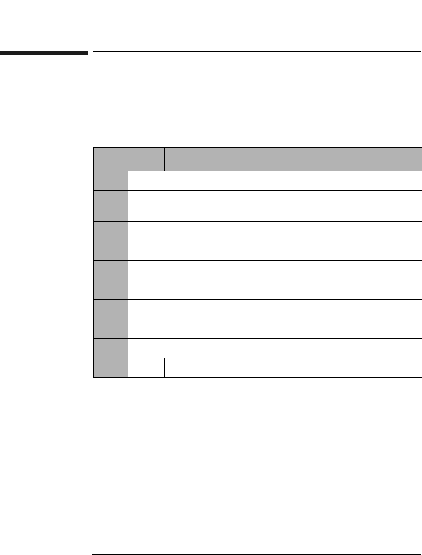
SCSI-2 Drive Command Set
Write Long Command (3FH)
Chapter 22-106
Write Long Command (3FH)
This command writes data starting at the specified Logical Block
Address, without using ECC generation circuitry. The ECC field is also
written with data transferred to the drive.
NOTE The 9.1 and 5.2 Gbyte capacity drives cannot Format, Erase, Write, or
Write and Verify 650 Mbyte and 1.3-Gbyte optical disks. The 2.6 Gbyte
capacity drives cannot Format, Erase, Write, or Write and Verify 650
Mbyte optical disks. If this command is issued with any of these drive/
media combinations, a CHECK CONDITION status will result with the
Sense Key/Additional Sense Code set to Data Protect/Write Protected.
Table 2-96 Write Long Command CDB
Byte 7 6 5 4 3 2 1 0
0Operation Code (3FH)
1Logical Unit Number
(0)
Reserved (0) RelAdr
2Starting Logical Block Address (MSByte)
3Starting Logical Block Address
4Starting Logical Block Address
5Starting Logical Block Address (LSByte)
6Reserved (0)
7Transfer Length (MSByte)
8Transfer Length (LSByte)
9PBA SC Reserved (0) Flag Link

SCSI-2 Drive Command Set
Write Long Command (3FH)
Chapter 2 2-107
SCSI-2 Drive Commands
Transfer
Length The Transfer Length field specifies the number of bytes
of data and ECC information to be written.
• 4096 media = 4760 bytes (4096 data + 664 pointer,
CRC, pad, & ECC) For 9.1 Gbyte Capacity drives
only.
• 2048 media = 2380 bytes (2048 data + 332 pointer,
CRC, pad, & ECC) For 5.2 Gbyte Capacity drives
only.
• 1K media = 1200 bytes (1024 data + 176 pointer, CRC,
pad, &ECC)
• 512 media = 610 bytes (512 data + 98 pointer, CRC,
pad, &ECC)
• All other numbers are rejected unless SC = 1
PBA A Physical Block Address bit of 1 indicates that physical
block addressing is used.
A PBA bit of 0 indicates that logical block addressing is
used.
SC A Sector Count bit of 1 indicates the transfer length is
represented in sectors rather than bytes. A "sector"
consists of 2380 bytes for 2K media, 1200 bytes for 1K
media or 610 bytes 512 media.
A Sector Count bit of 0 indicates the transfer length is
represented in bytes.
Rel Adr A relative address bit of one indicates that logical block
address specified is a two’s complement offset from the
last logical block address accessed.
A value of 0 indicates that the logical block address is an
absolute address.
NOTE If this command is executed for write-once disks, the drive returns a
CHECK CONDITION status with the Sense Key/Additional Sense Code
set to Illegal Request/Invalid Command Operation Code.

SCSI-2 Drive Command Set
Write Long Command (3FH)
Chapter 22-108
NOTE When this command is executed with 14X 512 or 1024 byte/sector media,
the drive will return a CHECK CONDITION status. The sense key/
additional sense code will be set to ILLEGAL REQUEST/INVALID
COMMAND.

SCSI-2 Drive Command Set
Log Select Command (4CH)
Chapter 2 2-109
SCSI-2 Drive Commands
Log Select Command (4CH)
This command clears drive resident logs.
NOTE Initiators should issue LOG SENSE commands prior to issuing LOG
SELECT commands to determine supported pages and page lengths.
The ONLY capability the initiator is given via the Log Select command is
to reset the cumulative logs. Parameter code and parameter information
is listed in Table 2-99 on page 2-110.
Table 2-97 Log Select Command CDB
Byte 76543210
0Operation Code (4CH)
1Reserved (0)
2PC (01H) Reserved (0)
3Reserved (0)
4Reserved (0)
5Reserved (0)
6Reserved (0)
7Parameter List Length (MSByte) (0)
8Parameter List Length (LSByte) (12)
(See Table 2-98 on page 2-110)
9Reserved (0) Flag Link

SCSI-2 Drive Command Set
Log Select Command (4CH)
Chapter 22-110
Parameter List Data
Table 2-98 Parameter List Data for Byte 8 of the Log Select Command
Byte 76543210
0Page Code (Table 2-99 on page 2-110)
1Reserved (0)
2Reserved (0)
3Page Length (08)
4Parameter Code (MSByte)
5Parameter Code (LSByte)
6Reserved (0)
7Password Parameter Length (04)
8Password Parameter Information (MSByte)
(Table 2-99 on page 2-110)
9Password Parameter Information
10 Password Parameter Information
11 Password Parameter Information (LSByte)
Table 2-99 Log Select Command
Page
Code
Description Parameter
Code
Password
Parameter
Information
2 Write Error Counter Page 8000 4A4F454C
3 Read Error Counter Page 8000 4A6F686E
5 Verify Error Counter Page 8000 45726963
7 Last N error Events Page 1000 53746576
33 Erase Error Counter Page 8000 416C5020
34 Blank Check Counter Page 8000 47657269
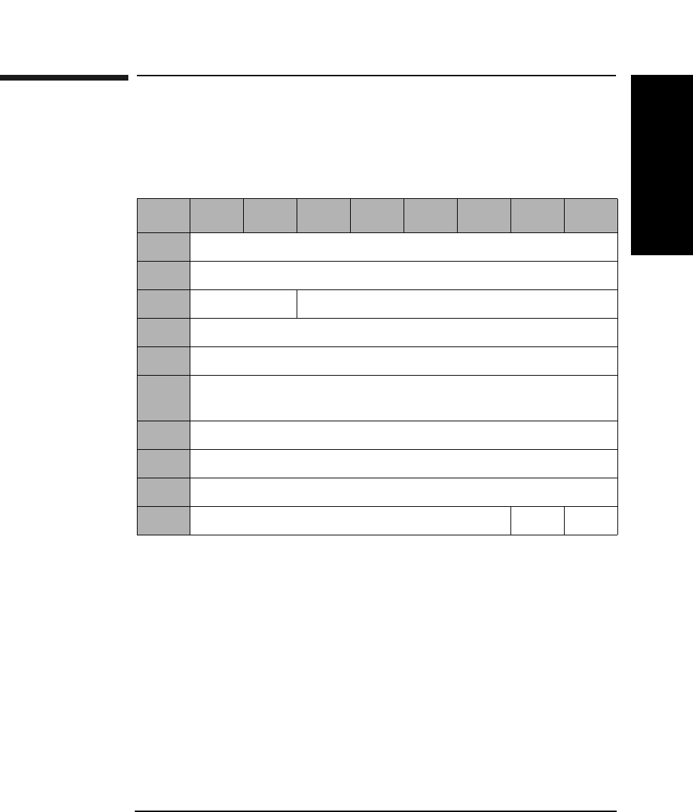
SCSI-2 Drive Command Set
Log Sense Command (4DH)
Chapter 2 2-111
SCSI-2 Drive Commands
Log Sense Command (4DH)
This command provides a means for the initiator to manage statistical
information maintained by the drive.
Allocation
Length The number of parameter bytes, including the Log Page
and the parameter structures.
Parameter
Pointer The Parameter Pointer field allows the initiator to
request parameter data beginning from a specific
parameter code to the maximum allocation length or
the maximum parameter code, whichever is less. Log
parameters within the specified log page are
transferred in ascending order according to parameter
code.
Table 2-100 Log Sense Command CDB
Byte 76543210
0Operation Code (4DH)
1Reserved (0)
2PC (01H) Page Code (See Table 2-101 on page 2-112)
3Reserved (0)
4Reserved (0)
5Parameter Pointer (MSByte)
(See Table 2-101 on page 2-112)
6Parameter Pointer (LSByte)
7Allocation Length (MSByte)
8Allocation Length (LSByte)
9Reserved (0) Flag Link

SCSI-2 Drive Command Set
Log Sense Command (4DH)
Chapter 22-112
Supported Log Pages 00H
The supported log page returns the list of log pages implemented by the
target. Targets that implement the Log Sense command use this log
page.
Table 2-101 Log Sense Page Codes
Page
Code
Description
00H Supported Log Pages
02H Error Counter Page for Write Errors
(See Table 2-103 on page 2-113)
03H Error Counter Page for Read Errors
(See Table 2-105 on page 2-114)
05H Error Counter Page for Verify Errors
(See Table 2-107 on page 2-115)
07H Last n Error Events Page (See Table 2-109 on page 2-116)
33H Error Counter Page for Erase Errors (See Table 2-112 on
page 2-119)
34H Error Counter Page for Blank Check Errors (See
Table 2-114 on page 2-120)
Table 2-102 Supported Log Pages 00H
Byte 76543210
0Rsvd (0) Page Code (00H)
1Reserved (0)
2Page Length (n-3) (MSByte)
3Page Length (n-3) (LSByte)
4Supported Page List
nSupported Page List

SCSI-2 Drive Command Set
Log Sense Command (4DH)
Chapter 2 2-113
SCSI-2 Drive Commands
Table 2-103 Error Counter Page for Write Errors 02H
Byte 76543210
0Rsvd (0) Page Code (02H)
1Reserved (0)
2Page Length (n-3) (MSByte)
3Page Length (n-3) (LSByte)
4Parameter Code (MSByte)
(See Table 2-104 on page 2-113 or Table 2-106 on page 2-114)
5Parameter Code (LSByte)
6Reserved (0)
7Parameter Length (n-7)
8Parameter Value
nParameter Value
Table 2-104 Parameter Codes/Structure for Write Errors
Param.
Code
Length
Bytes
Description
1 12 Sectors Corrected with Retries
2 12 Total Number of Retry Attempts
3 12 Total Sectors Corrected
5 14 Total Bytes Processed
6 12 Total Number of Uncorrectable Sectors
0 46 Request for all pages

SCSI-2 Drive Command Set
Log Sense Command (4DH)
Chapter 22-114
Table 2-105 Error Counter Page for Read Errors 03H
Byte 76543210
0Rsvd (0) Page Code (03H)
1Reserved (0)
2Page Length (n-3) (MSByte)
3Page Length (n-3) (LSByte)
4Parameter Code (MSByte) (See Table 2-104 on page 2-113
or Table 2-106 on page 2-114)
5Parameter Code (LSByte)
6Reserved (0)
7Parameter Length (n-7)
8Parameter Value
nParameter Value
Table 2-106 Parameter Codes/Structure for Read Errors
Param.
Code
Length
Bytes
Description
1 12 Sectors Corrected with Retries
2 12 Total Number of Retry Attempts
3 12 Total Sectors Corrected
5 14 Total Bytes Processed
6 12 Total Number of Uncorrectable Sectors
0 46 Request for all pages

SCSI-2 Drive Command Set
Log Sense Command (4DH)
Chapter 2 2-115
SCSI-2 Drive Commands
Table 2-107 Error Counter Page for Verify Errors 05H
Byte 76543210
0Rsvd (0) Page Code (05H)
1Reserved (0)
2Page Length (n-3) (MSByte)
3Page Length (n-3) (LSByte)
4Parameter Code (MSByte) (See Table 2-106 on page 2-114
or Table 2-108 on page 2-115)
5Parameter Code (LSByte)
6Reserved (0)
7Parameter Length (n-7)
8Parameter Value
nParameter Value
Table 2-108 Parameter Codes/Structure for Verify Errors
Param.
Code
Length
Bytes
Description
1 12 Sectors Corrected with Retries
2 12 Total Number of Retry Attempts
3 12 Total Sectors Corrected
5 14 Total Bytes Processed
6 12 Total Number of Uncorrectable Sectors
0 46 Request for all pages

SCSI-2 Drive Command Set
Log Sense Command (4DH)
Chapter 22-116
Table 2-109 Last N Error Events Page 07H
Byte 76543210
0Rsvd (0) Page Code (07H)
1Reserved (0)
2Page Length (n-3) (MSByte)
3Page Length (n-3) (LSByte)
4Parameter Pointer (MSByte)
(See Table 2-110 on page 2-117)
5Parameter Pointer (LSByte)
6Reserved (0)
7Parameter Length (n-7)
8Parameter Value
nParameter Value

SCSI-2 Drive Command Set
Log Sense Command (4DH)
Chapter 2 2-117
SCSI-2 Drive Commands
Table 2-110 Parameter Pointers/Structure for Last N Error Events Page
Parameter
Pointer
Length
Bytes
Description
0 10 Number of Events in the Log
(Maximum Events = 50 or 250 for 9.1
Gbyte Drives)
1 34 Most Recent Error Event Log (See
Table 2-109 on page 2-116 or
Table 2-111 on page 2-118)
2 34 Next Most Recent Event (See
Table 2-109 on page 2-116 or Table
Table 2-111 on page 2-118)
50 34 Least recent Error Event (See
Table 2-109 on page 2-116 or
Table 2-111 on page 2-118)
.
.
.
.
.
.
.
.
.
0 Up to 1510
for 50 events;
up to 7510 for
250 events
Request for all pages

SCSI-2 Drive Command Set
Log Sense Command (4DH)
Chapter 22-118
Table 2-111 Error Event Log
Byte 76543210
0Log Type (1-read, 2-write, 3-erase, 4-verify, 5-blank check,
6-spin-up error, 7-loading error, 8-check condition)
1Occurrence Count
2Long
(1)
Power On Minutes
3Half Seconds
4Half Seconds Fraction (16 uSec) (MSByte)
5Half Seconds Fraction (16 uSec) (LSByte)
6Power On Hours (MS Byte)
7Power On Hours
8Power On Hours
9Power On Hours (LSByte)
10 UMID Byte 5
11 UMID Byte 6
12 UMID Byte 7
13 UMID Byte 8
14 Internal Error Code (MSByte)
15 Internal Error Code
16 Internal Error Code
17 Internal Error Code (LSByte)
18 Logical Block Address (MSByte)
19 Logical Block Address
20 Logical Block Address

SCSI-2 Drive Command Set
Log Sense Command (4DH)
Chapter 2 2-119
SCSI-2 Drive Commands
21 Logical Block Address (LSByte)
22 Physical Block Address (MSByte)
23 Physical Block Address
24 Physical Block Address
25 Physical Block Address (LSByte)
Table 2-112 Error Counter Page for Erase Errors 33H
Byte 76543210
0Rsvd (0) Page Code (33H)
1Reserved (0)
2Page Length (n-3) (MSByte)
3Page Length (n-3) (LSByte)
4Parameter Code (MSByte) (See Table 2-113 on page 2-120 or
Table 2-115 on page 2-121)
5Parameter Code (LSByte)
6Reserved (0)
7Parameter Length (n-7)
8Parameter Value
nParameter Value
Table 2-111 Error Event Log
Byte 76543210

SCSI-2 Drive Command Set
Log Sense Command (4DH)
Chapter 22-120
Table 2-113 Parameter Codes/Structure for Erase Errors
Param.
Code
Length
Bytes
Description
1 12 Sectors Corrected with Retries
2 12 Total Number of Retry Attempts
3 12 Total Sectors Corrected
5 14 Total Bytes Processed
6 12 Total Number of Uncorrectable Sectors
0 46 Request for all pages
Table 2-114 Error Counter Page for Blank Check Errors 34H
Byte 76543210
0Rsvd (0) Page Code (34H)
1Reserved (0)
2Page Length (n-3) (MSByte)
3Page Length (n-3) (LSByte)
4Parameter Code (MSByte) (See Table 2-115 on page 2-121)
5Parameter Code (LSByte)
6Reserved (0)
7Parameter Length (n-7)
8Parameter Value
nParameter Value

SCSI-2 Drive Command Set
Log Sense Command (4DH)
Chapter 2 2-121
SCSI-2 Drive Commands
Table 2-115 Parameter Codes/Structure for Blank Check Errors
Param.
Code
Length
Bytes
Description
1 12 Sectors Corrected with Retries
2 12 Total Number of Retry Attempts
3 12 Total Sectors Corrected
5 14 Total Bytes Processed
6 12 Total Number of Uncorrectable Sectors
0 46 Request for all pages
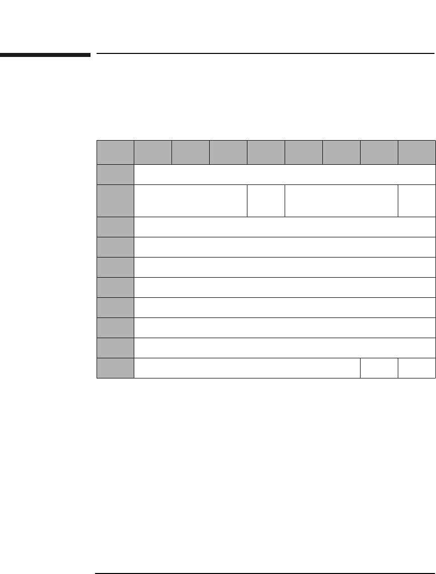
SCSI-2 Drive Command Set
Mode Select (Group 2) Command (55H)
Chapter 22-122
Mode Select (Group 2) Command (55H)
This command sets optical disk, drive unit, or controller unit
parameters.
SP A Save Pages bit of 1 indicates that the target performs
the specified MODE SELECT operation, and saves all
the savable pages to non-volatile RAM. The pages are
only saved if different from those currently saved.
A Save Pages bit of 0 indicates the target performs the
specified MODE SELECT operation, and does not save
any pages.
Table 2-116 Mode Select (Group 2) Command CDB
Byte 76543210
0Operation Code (55H)
1Logical Unit Number
(0)
PF
(1)
Reserved (0) SP
2Reserved (0)
3Reserved (0)
4Reserved (0)
5Reserved (0)
6Reserved (0)
7Parameter List Length (MSByte)
8Parameter List Length (LSByte)
9Reserved (0) Flag Link
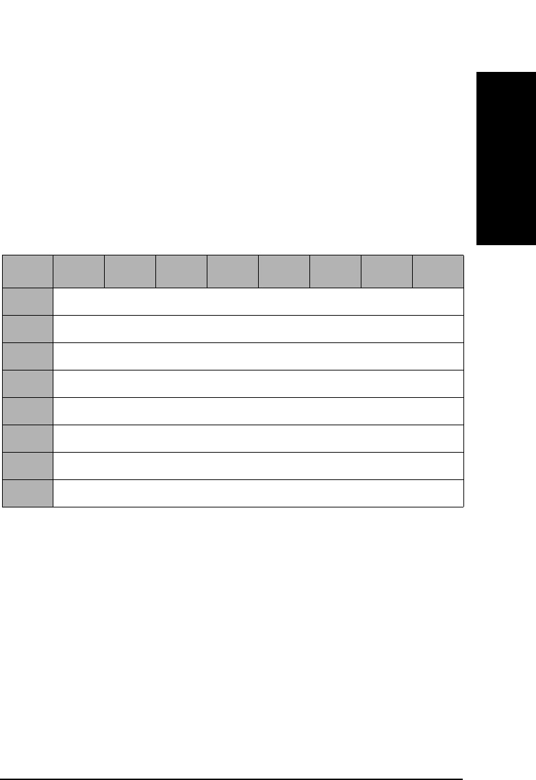
SCSI-2 Drive Command Set
Mode Select (Group 2) Command (55H)
Chapter 2 2-123
SCSI-2 Drive Commands
Parameter List
Length This field specifies the length in bytes of the MODE
SELECT parameter list that the initiator will transfer
to the drive during the DATA OUT phase. A length of 0
indicates that no data will be transferred. This
condition is not considered an error.
The Mode Select Parameter List contains an 8-byte
header followed by 0 or 1 block descriptors, and followed
by 0 or more pages (see Table 2-117 on page 2-123).
Medium Type The Medium Type field will be set to 00H (default, only
one medium type supported), 02H (write-once optical
disks) or 03H (optical reversible or erasable medium).
Block
Descriptor
Length The Block Descriptor Length specifies the length in
bytes of the block descriptor, equal to 0 or 8. A Block
Descriptor Length of 0 indicates that no block
descriptors are included in the parameter list. This
condition is not considered an error.
Table 2-117 Mode Select Header
Byte 76543210
0Reserved (0)
1Reserved (0)
2Medium Type
3Reserved (0)
4Reserved (0)
5Reserved (0)
6Block Descriptor Length (MSByte)
7Block Descriptor Length (LSByte)

SCSI-2 Drive Command Set
Mode Select (Group 2) Command (55H)
Chapter 22-124
NOTE All fields in the Block Descriptor have no effect on the drive.
Refer to “Mode Sense (Group 0) Command (1AH)” on page 2-54 for
detailed information on each page.
Table 2-118 Mode Select Block Descriptor
Byte 76543210
0Density Code
1Number of Blocks (MSByte)
2Number of Blocks
3Number of Blocks (LSByte)
4Reserved (0)
5Block Length (MSByte)
6Block Length
7Block Length (LSByte)
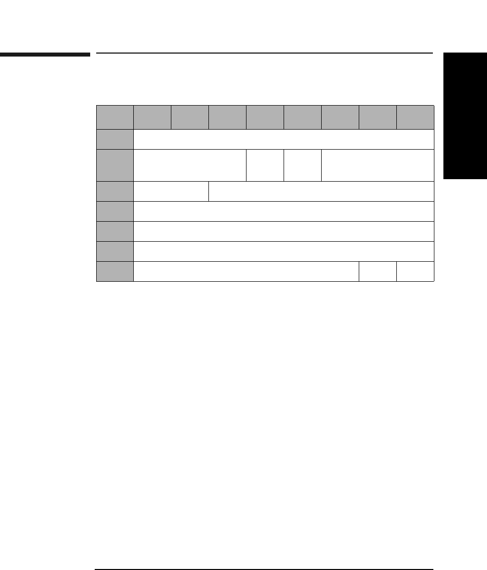
SCSI-2 Drive Command Set
Mode Sense (Group 2) Command (5AH)
Chapter 2 2-125
SCSI-2 Drive Commands
Mode Sense (Group 2) Command (5AH)
DBD A disable block descriptors (DBD) bit of 0 (default)
indicates that block descriptors are provided.
PC Page control defines the type of parameter values to be
returned as follows:
00 - Current Values
01 - Changeable Values
10 - Default Values
11 - Saved Values
Page Code Page code values are the same as for the Mode Select
(Group 0) command. If the page code is specified as 00H
or 3FH, all the pages are returned.
Allocation
Length Indicates the number of bytes that the indicator has
allocated for return of this data. A length of 0 indicates
that no data will be returned. This condition is not
considered an error. The drive will terminate the data -
in phase when the allocation length has been
transferred or when all available data has been
transferred to the initiator, whichever is less.
Table 2-119 Mode Select (Group 2) Command CDB
Byte 76543210
0Operation Code (5AH)
1Logical Unit Number
(0)
Rsvd
(0)
DBD Reserved (0)
2PC Page Code
3-6 Reserved (0)
7Allocation Length (MSByte)
8Allocation Length (LSByte)
9Reserved (0) Flag Link

SCSI-2 Drive Command Set
Mode Sense (Group 2) Command (5AH)
Chapter 22-126
Mode Data
Length This field specifies the length in bytes of the MODE
SENSE data to follow.
Medium Type The Medium Type field is set to 00H (default, only one
medium type is supported), 02H (write-once optical
disks), or 03H (rewritable optical disks), depending on
the drive condition (00H if no disk or not ready, and 02H
or 03H if it is ready to access the disk).
WP A write protect bit of 1 indicates that the optical disk in
the drive is write protected.
Table 2-120 Mode Sense Header
Byte 7 6 5 4 3 2 1 0
0Mode Data Length (MSByte)
1Mode Data Length (LSByte)
2Medium Type
3WP Reserved (0) Cache
(1)
Reserved (0)
4Reserved (0)
5Reserved (0)
6Block Descriptor Length (MSByte)
7Block Descriptor Length (LSByte)
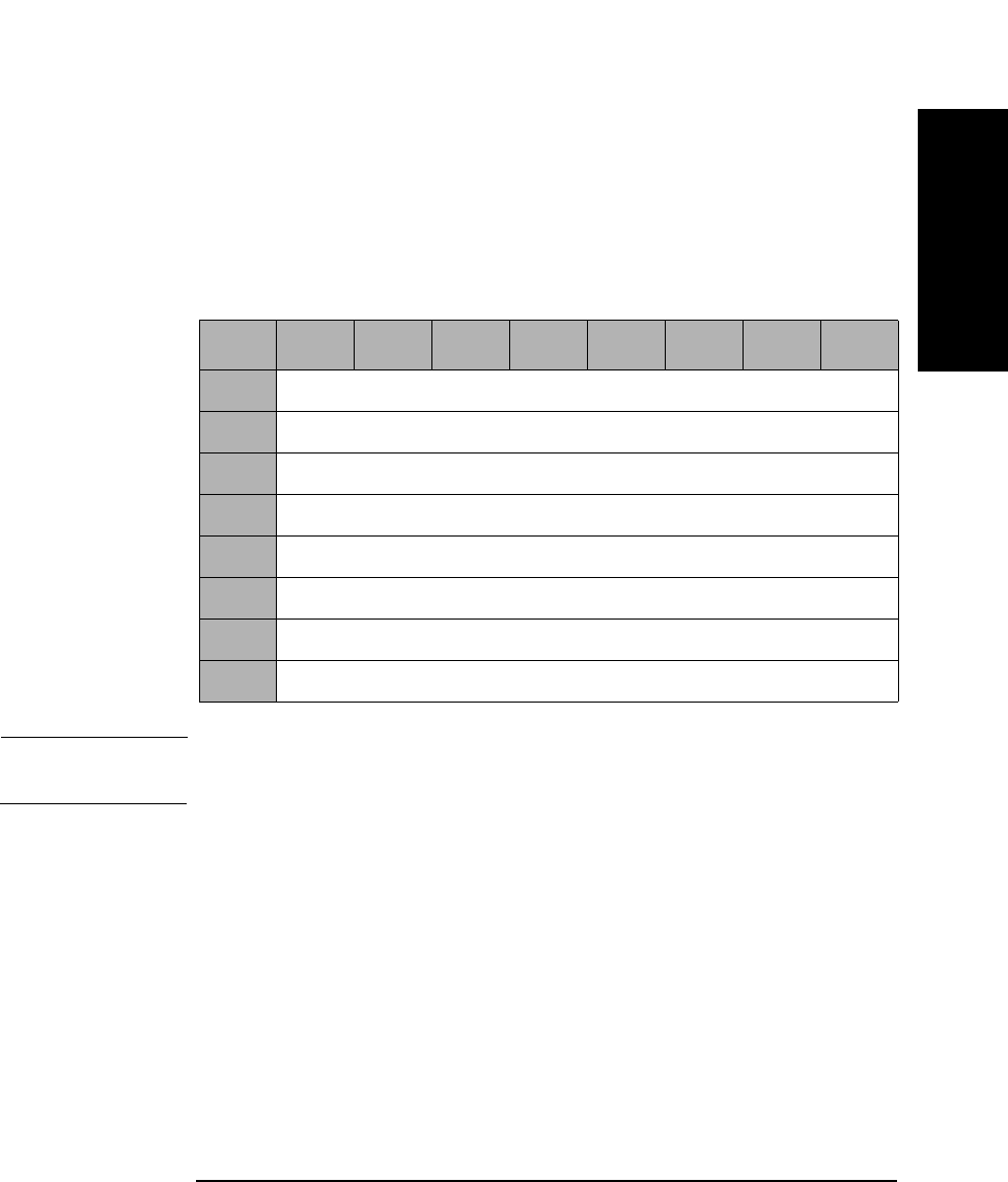
SCSI-2 Drive Command Set
Mode Sense (Group 2) Command (5AH)
Chapter 2 2-127
SCSI-2 Drive Commands
Cache The Cache bit of 1 indicates that caching is supported.
PS The Parameters Savable bit of 1 indicates this
parameter page is savable in non-volatile storage.
Block Descriptor
Length The Block Descriptor Length field specifies the length
in bytes of the block descriptor.
NOTE Descriptions of each page can be found in “Mode Sense (Group 0)
Command (1AH)” on page 2-54.
Table 2-121 Mode Sense Block Descriptor
Byte 76543210
0Density Codes
1Number of Blocks (MSByte)
2Number of Blocks
3Number of Blocks (LSByte)
4Reserved (0)
5Block Length (MSByte)
6Block Length
7Block Length (LSByte)
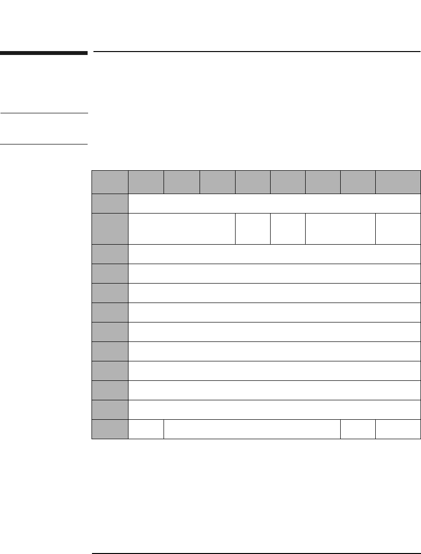
SCSI-2 Drive Command Set
Read (Group 5) Command (A8H)
Chapter 22-128
Read (Group 5) Command (A8H)
This command reads data from the specified logical block address.
NOTE The Mode Select Commands (15H, 55H) impact read, write, format, and
erase commands.
Table 2-122 Read (Group 5) Command CDB
Byte 7 6 5 4 3 2 1 0
0Operation Code (A8H)
1Logical Unit Number
(0)
DPO FUA Reserved (0) RelAdr
2Logical Block Address (MSByte)
3Logical Block Address
4Logical Block Address
5Logical Block Address (LSByte)
6Transfer Length (MSByte)
7Transfer Length
8Transfer Length
9Transfer Length (LSByte)
10 Reserved (0)
11 PBA Reserved (0) Flag Link

SCSI-2 Drive Command Set
Read (Group 5) Command (A8H)
Chapter 2 2-129
SCSI-2 Drive Commands
DPO A Disable Page Out bit of 1 instructs the target not to
store readahead data in cache after the read data has
been transferred to the initiator.
A DPO bit of 0 instructs the target it may store
readahead data in the cache after the read data has
been transferred to the initiator.
NOTE The DPO bit is ignored in 9.1 and 5.2 Gbyte capacity drives.
FUA A Force Unit Access bit of 1 indicates that the drive
reads from the disk.
An FUA bit of 0 indicates that data may come from the
cache memory.
Rel Adr A relative address bit of one indicates that logical block
address specified is a two’s complement offset from the
last logical block address accessed.
A value of 0 indicates that the logical block address is an
absolute address.
Transfer
Length The Transfer Length field specifies the number of
contiguous logical blocks of data to be transferred.
A value of 0 indicates that no blocks will be transferred
and is not considered an error.
PBA A Physical Block Address bit of 1 indicates that physical
block addressing is used.
A PBA bit of 0 indicates that logical block addressing is
used.
NOTE For Write-Once optical disks, blank checking is performed following a
failed read. If the sector is blank, the sense key/additional sense code will
be set to BLANK CHECK/Blank Sector Detected.

SCSI-2 Drive Command Set
Read (Group 5) Command (A8H)
Chapter 22-130
NOTE When this command is used with 14X 512 or 1024 byte/sector media,
setting the PBA bit will cause the drive to return a CHECK CONDITION
status. The sense key/additional sense code will be set to ILLEGAL
REQUEST/INVALID FIELD in CDB.

SCSI-2 Drive Command Set
Write (Group 5) Command (AAH)
Chapter 2 2-131
SCSI-2 Drive Commands
Write (Group 5) Command (AAH)
This command writes data starting at the specified logical block address.
NOTE The Mode Select Commands (15H, 55H) impact read, write, format, and
erase commands.
NOTE For Write-Once media, Byte 11, Bit 7 and Bit 6 are reserved (0).
DPO A Disable Page Out bit of 1 instructs the target not to
store the data in the cache after it has been transferred
to the media.
A DPO bit of 0 instructs the target to store the data in
the cache after it has been transferred to the media.
. This bit is ignored
Table 2-123 Write (Group 5) Command CDB
Byte 7 6 5 4 3 2 1 0
0Operation Code (AAH)
1Logical Unit Number
(0)
DPO FUA EBP Rsvd
(0)
RelAdr
2Logical Block Address (MSByte)
3-4 Logical Block Address
5Logical Block Address (LSByte)
6Transfer Length (MSByte)
7-8 Transfer Length
9Transfer Length (LSByte)
10 Reserved (0)
11 PBA ErsCntl Reserved (0) Flag Link

SCSI-2 Drive Command Set
Write (Group 5) Command (AAH)
Chapter 22-132
FUA A Force Unit Access bit of 1 indicates that data is
written directly to the disk.
An FUA bit of 0 indicates that write caching will be
allowed.
Rel Adr A relative address bit of one indicates that logical block
address specified is a two’s complement offset from the
last logical block address accessed.
A value of 0 indicates that the logical block address is an
absolute address.
EBP If the Erase By-Pass bit is set to 0, an erase is
automatically performed before writing the data.
An EBP bit of 1 suppresses the erase operation.
Transfer
Length The Transfer Length field indicates the number of
contiguous logical blocks to be transferred for this
command.
A value of 0 indicates that no blocks will be transferred
and is not considered an error.
PBA A Physical Block Address bit of 1 indicates that physical
block addressing is used.
A PBA bit of 0 indicates that logical block addressing is
used.
ErsCntl The Erase Control bit is identical to the Erase Bypass
bit.
NOTE The 9.1 and 5.2 Gbyte capacity drives cannot Format, Erase, Write, or
Write and Verify 650 Mbyte and 1.3-Gbyte optical disks. The 2.6 Gbyte
capacity drives cannot Format, Erase, Write, or Write and Verify 650
Mbyte optical disks. If this command is issued with any of these drive/
media combinations, a CHECK CONDITION status will result with the
Sense Key/Additional Sense Code set to Data Protect/Write Protected.

SCSI-2 Drive Command Set
Write (Group 5) Command (AAH)
Chapter 2 2-133
SCSI-2 Drive Commands
NOTE When this command is used with 14X 512 OR 1024 byte/sector media,
setting the ErsCntl bit or the PBA bit will cause the drive to return a
CHECK CONDITION status. The sense key/additional sense code will be
set to ILLEGAL REQUEST/INVALID FIELD in CDB.
NOTE For write-once optical disks, blank checking is performed before writing
data. If a written block is detected during blank checking, the drive will
return a CHECK CONDITION status. The sense key/additional sense
code will be set to BLANK CHECK/Overwrite Attempted.
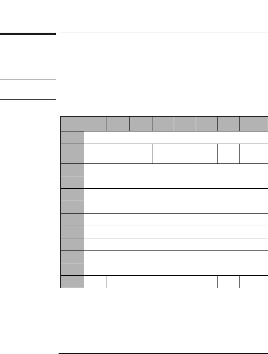
SCSI-2 Drive Command Set
Erase (Group 5) Command (ACH)
Chapter 22-134
Erase (Group 5) Command (ACH)
This command erases data from the specified logical block address. This
command can only be used with rewritable disks.
NOTE The Mode Select Commands (15H, 55H) impact read, write, format, and
erase commands.
Table 2-124 Erase (Group 5) Command CDB
Byte 7 6 5 4 3 2 1 0
0Operation Code (ACH)
1Logical Unit Number
(0)
Reserved (0) ERA Rsvd
(0)
RelAdr
2Logical Block Address (MSByte)
3Logical Block Address
4Logical Block Address
5Logical Block Address (LSByte)
6Transfer Length (MSByte)
7Transfer Length
8Transfer Length
9Transfer Length (LSByte)
10 Reserved (0)
11 PBA Reserved (0) Flag Link

SCSI-2 Drive Command Set
Erase (Group 5) Command (ACH)
Chapter 2 2-135
SCSI-2 Drive Commands
NOTE The 9.1 and 5.2 Gbyte capacity drives cannot Format, Erase, Write, or
Write and Verify 650 Mbyte and 1.3-Gbyte optical disks. The 2.6 Gbyte
capacity drives cannot Format, Erase, Write, or Write and Verify 650
Mbyte optical disks. If this command is issued with any of these drive/
media combinations, a CHECK CONDITION status will result with the
Sense Key/Additional Sense Code set to Data Protect/Write Protected.
NOTE If this command is executed for write-once disks, the drive returns a
CHECK CONDITION status with the Sense Key/Additional Sense Code
set to Illegal Request/Invalid Command Operation Code.
ERA An Erase All bit of 1 indicates that all remaining blocks
are erased, starting from the logical block address to the
end of the disk. The transfer length must be set to 0.
An ERA bit of 0 indicates that all blocks are erased,
starting from the logical block address to the end of the
specified transfer length.
Rel Adr A relative address bit of one indicates that logical block
address specified is a two’s complement offset from the
last logical block address accessed.
A value of 0 indicates that the logical block address is an
absolute address.
Transfer
Length The Transfer Length field specifies the number of
contiguous logical blocks of data to be erased for this
command. A value of 0 indicates that no blocks will be
erased and is not considered an error.
PBA A Physical Block Address bit of 1 indicates that physical
block addressing is used.
A PBA bit of 0 indicates that logical block addressing is
used.

SCSI-2 Drive Command Set
Erase (Group 5) Command (ACH)
Chapter 22-136
NOTE When this command is executed with 14X 512 or 1024 byte/sector media,
the drive will return a CHECK CONDITION status. The sense key/
additional sense code will be set to ILLEGAL REQUEST/INVALID
COMMAND.
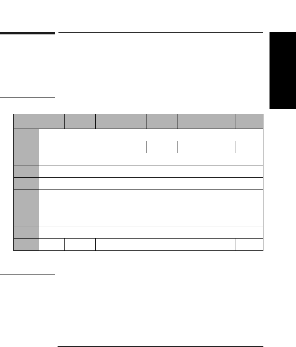
SCSI-2 Drive Command Set
Write and Verify (Group 5) Command (AEH)
Chapter 2 2-137
SCSI-2 Drive Commands
Write and Verify (Group 5) Command (AEH)
Writes data to the optical disk and then verifies the write by reading the
written data and checking the error correction code.
NOTE The Mode Select Commands (15H, 55H) impact read, write, format, and
erase commands.
NOTE For Write-Once media, Byte 11, Bit 7 and Bit 6 are reserved (0).
DPO A Disable Page Out bit of 1 instructs the target not to
store the data in the cache after it has been transferred
to the media.
A DPO bit of 0 instructs the target to store the data in
the cache after it has been transferred to the media.
This bit is ignored.
Table 2-125 Write and Verify (Group 5) CDB
Byte 7 6 5 4 3 2 1 0
0Operation Code (AEH)
1Logical Unit Number (0) DPO Rsvd (0) EBP Rsvd (0) RelAdr
2Logical Block Address (MSByte)
3-4 Logical Block Address
5Logical Block Address (LSByte)
6Transfer Length (MSByte)
7-8 Transfer Length
9Transfer Length (LSByte)
10 Reserved (0)
11 PBA ErsCntl Reserved (0) Flag Link

SCSI-2 Drive Command Set
Write and Verify (Group 5) Command (AEH)
Chapter 22-138
EBP An Erase By-Pass bit of 0 indicates an erase
automatically performs before writing the data.
An EBP bit of 1 suppresses the erase operation.
Rel Adr A relative address bit of one indicates that logical block
address specified is a two’s complement offset from the
last logical block address accessed.
A value of 0 indicates that the logical block address is an
absolute address.
Transfer
Length The Transfer Length field indicates the number of
contiguous logical blocks to be transferred for this
command. A value of 0 indicates that no blocks will be
transferred and is not considered an error.
PBA A Physical Block Address bit of 1 indicates that physical
block addressing is used.
A PBA bit of 0 indicates that logical block addressing is
used.
ErsCntl The Erase Control bit is identical to the Erase Bypass
bit.
NOTE The 9.1 and 5.2 Gbyte capacity drives cannot Format, Erase, Write, or
Write and Verify 650 Mbyte and 1.3-Gbyte optical disks. The 2.6 Gbyte
capacity drives cannot Format, Erase, Write, or Write and Verify 650
Mbyte optical disks. If this command is issued with any of these drive/
media combinations, a CHECK CONDITION status will result with the
Sense Key/Additional Sense Code set to Data Protect/Write Protected.
NOTE For write-once optical disks, blank checking is performed before writing
data. If a written block is detected during blank checking, the drive will
return a CHECK CONDITION status. The sense key/additional sense
code will be set to BLANK CHECK/Overwrite Attempted.

SCSI-2 Drive Command Set
Write and Verify (Group 5) Command (AEH)
Chapter 2 2-139
SCSI-2 Drive Commands
NOTE When this command is used with 512 byte/sector 14X media or 1025 byte/
sector 14X media, setting the PBA bit or the ErsCntl bit will cause the
drive to return a CHECK CONDITION status. The sense key/additional
sense code will be set to ILLEGAL REQUEST/Invalid Field in CDB.

SCSI-2 Drive Command Set
Verify (Group 5) Command (AFH)
Chapter 22-140
Verify (Group 5) Command (AFH)
This command verifies the data starting from the specified logical block
address by checking the error correction code.
This command has two modes of operation, depending on the value of the
BV bit. If the Blk Vfy bit is set to 0, it verifies previously written data
integrity starting at the specified Logical Block Address by reading the
data and checking the Error Correction Code. The verification threshold
is set to approximately half of the error correction capability.
Table 2-126 Verify (Group 5) CDB
Byte 7 6 5 4 3 2 1 0
0Operation Code (AFH)
1Logical Unit Number
(0)
DPO Rsvd
(0)
Blk
Vfy
Rsvd
(0)
RelAdr
2Logical Block Address (MSByte
3Logical Block Address
4Logical Block Address
5Logical Block Address (LSByte)
6Verification Length (MSByte)
7Verification Length
8Verification Length
9Verification Length (LSByte)
10 Reserved (0)
11 Reserved (0) Flag Link

SCSI-2 Drive Command Set
Verify (Group 5) Command (AFH)
Chapter 2 2-141
SCSI-2 Drive Commands
DPO A Disable Page Out bit of 1 instructs the target not to
retain the data in the cache after it has been verified.
A DPO bit of 0 instructs the target to retain the data in
the cache after it has been verified.
This bit is ignored.
Blk Vfy A Blank Verify bit of 1 indicates the drive verifies that
sectors are erased.
A Blk Vfy bit of 0 indicates the drive verifies written
data integrity.
Rel Adr A relative address bit of one indicates that logical block
address specified is a two’s complement offset from the
last logical block address accessed.
A value of 0 indicates that the logical block address is an
absolute address.
Verification
Length Specifies the number of contiguous logical blocks of data
to be verified. A value of 0 indicates that no blocks will
be verified and is not considered an error.
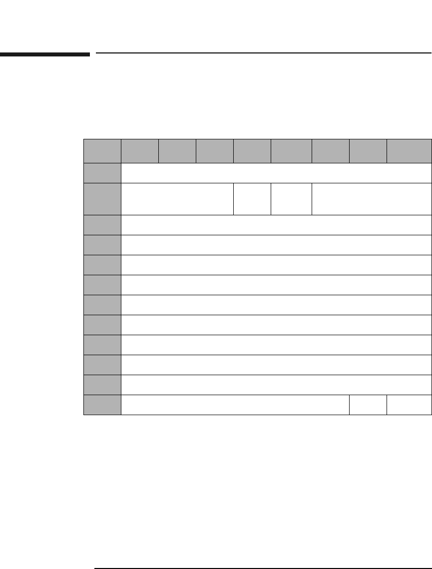
SCSI-2 Drive Command Set
Read Defect Data (Group 5) Command (B7H)
Chapter 22-142
Read Defect Data (Group 5) Command (B7H)
This command reads optical disk defect information. The data returned
starts with an 8-byte header, followed by one or more defect descriptors.
PList &GList A Primary List bit of 0 and a Grown List bit of 1
indicates the drive will return the contents of the
Primary Defect List (PDL) and the Secondary Defect
List (SDL).
A PList bit of 1 and a GList bit of 0 indicates the drive
will return the contents of PDL.
A PList bit of 1 and a GList bit of 1 indicates the drive
will return the contents of the PDL and the SDL.
Table 2-127 Read Defect Data (Group 5) Command CDB
Byte 7 6 5 4 3 2 1 0
0Operation Code (B7H)
1Logical Unit Number
(0)
PList GList Defect List Format
2Reserved (0)
3Reserved (0)
4Reserved (0)
5Reserved (0)
6Allocation Length (MSByte)
7Allocation Length
8Allocation Length
9Allocation Length (LSByte)
10 Reserved (0)
11 Reserved (0) Link Flag

SCSI-2 Drive Command Set
Read Defect Data (Group 5) Command (B7H)
Chapter 2 2-143
SCSI-2 Drive Commands
Defect List
Format This field specifies the Defect List Format that is
returned. Only the Physical Sector Format (5) is
supported. If the Block Format (0) is specified, the
defect list will be returned in Physical Sector Format
and a CHECK CONDITION status will be returned at
the completion of the command with the sense key/
additional sense code set to RECOVERED ERROR/
Defect List Not Available.
Allocation
Length Specifies the number of bytes that the initiator has
allocated for return of this data. A length of 0 indicates
that no data will be returned. This condition is not
considered an error. The drive will terminate the data
— in phase when the allocation length has been
transferred or when all defect data has been transferred
to the initiator, whichever is less.
PList A primary List bit of 1 indicates that the Primary List
of defects was returned.
GList A Grown List bit of 1 indicates that the Grown List of
defects was returned.
Table 2-128 Read Defect Data Defect List Header
Byte 7 6 5 4 3 2 1 0
0Reserved (0)
1Reserved (0) PList GList Defect List Format
2Reserved (0)
3Reserved (0)
4Defect List Length (MSByte)
5Defect List Length
6Defect List Length
7Defect List Length (LSByte)

SCSI-2 Drive Command Set
Read Defect Data (Group 5) Command (B7H)
Chapter 22-144
Defect List
Format This field will be set to the Defect List Format that was
indicated in byte 1 of the CDB, which specifies the
format of the Defect List data returned by the drive.
Defect List
Length This field specifies the total length in bytes of the defect
descriptors (see Table 2-129 on page 2-144).
Table 2-129 Physical Sector Format Defect Descriptor
Byte 76543210
0Physical Track Number of the Defect (MSByte)
1Physical Track Number of the Defect
2Physical Track Number of the Defect (LSByte)
3Reserved (0)
4Reserved (0)
5Reserved (0)
6Reserved (0)
7Defective Physical Sector Number

SCSI-2 Drive Command Set
Read Long Command (DEH)
Chapter 2 2-145
SCSI-2 Drive Commands
Read Long Command (DEH)
This command reads data starting at the specified Logical Block
Address, including ECC data. Read data is not corrected using ECC.
Table 2-130 Read Long Command CDB
Byte 7654321 0
0Operation Code (DEH)
1Reserved (0) RelAdr
2Starting Logical Block Address (MSByte)
3Starting Logical Block Address
4Starting Logical Block Address
5Starting Logical Block Address (LSByte)
6Reserved (0)
7Transfer Length (MSByte)
8Transfer Length (LSByte)
9PBA SC Reserved (0) Flag Link

SCSI-2 Drive Command Set
Read Long Command (DEH)
Chapter 22-146
Transfer
Length The Transfer Length field specifies the number of bytes
of data and ECC information to be read:
4096 media = 4760 bytes (4096 data + 664 pointer, CRC,
pad and ECC). For 9.1 Gbyte Capacity drives only.
2048 media = 2380 bytes (2048 data + 332 pointer, CRC,
pad, and ECC). For 5.2 Gbyte capacity drives only.
1K media = 1200 bytes (1024 data + 176 pointer, CRC,
pad, and ECC).
512 media = 610 bytes (512 data + 98 pointer, CRC, pad,
and ECC).
All other numbers are rejected unless SC = 1.
Rel Adr A relative address bit of one indicates that logical block
address specified is a two’s complement offset from the
last logical block address accessed.
A value of 0 indicates that the logical block address is an
absolute address.
PBA A Physical Block Address bit of 1 indicates that physical
block addressing is used.
A PBA bit of 0 indicates that logical block addressing is
used.
SC A Sector Count bit of 1 indicates the transfer length is
represented in sectors rather than bytes. A "sector"
consists of 2380 bytes for 2K media, 1200 bytes for 1K
media or 610 bytes for 512 media.
A Sector Count bit of 0 indicates the transfer length is
represented in bytes.
NOTE When this command is executed with 14X 512 or 1024 byte/sector media,
the drive will return a CHECK CONDITION status. The sense key/
additional sense code will be set to ILLEGAL REQUEST/INVALID
COMMAND.

SCSI-2 Drive Command Set
Write Long Command (DFH)
Chapter 2 2-147
SCSI-2 Drive Commands
Write Long Command (DFH)
This command writes data starting at the specified Logical Block
Address, without using ECC generation circuitry. The ECC field is also
written with data transferred to the drive.
NOTE The 9.1 and 5.2 Gbyte capacity drives cannot Format, Erase, Write, or
Write and Verify 650 Mbyte and 1.3-Gbyte optical disks. The 2.6 Gbyte
capacity drives cannot Format, Erase, Write, or Write and Verify 650
Mbyte optical disks. If this command is issued with any of these drive/
media combinations, a CHECK CONDITION status will result with the
Sense Key/Additional Sense Code set to Data Protect/Write Protected.
Table 2-131 Write Long Command CDB
Byte 7 6 5 4 3 2 1 0
0Operation Code (DFH)
1Logical Unit Number
(0)
Reserved (0) RelAdr
2Starting Logical Block Address (MSByte)
3Starting Logical Block Address
4Starting Logical Block Address
5Starting Logical Block Address (LSByte)
6Reserved (0)
7Transfer Length (MSByte)
8Transfer Length (LSByte)
9PBA SC Reserved (0) Flag Link

SCSI-2 Drive Command Set
Write Long Command (DFH)
Chapter 22-148
Transfer
Length The Transfer Length field specifies the number of bytes
of data and ECC information to be read:
4096 media = 4760 bytes (4096 data + 664 pointer, CRC,
pad, & ECC). For 9.1 Gbyte Capacity drives only.
2048 media = 2380 bytes (2048 data + 332 pointer, CRC,
pad, and ECC). For 5.2 Gbyte capacity drives only.
1K media = 1200 bytes (1024 data + 176 pointer, CRC,
pad, &ECC).
512 media = 610 bytes (512 data + 98 pointer, CRC, pad,
&ECC).
All other numbers are rejected unless SC = 1.
Rel Adr A relative address bit of one indicates that logical block
address specified is a two’s complement offset from the
last logical block address accessed.
A value of 0 indicates that the logical block address is an
absolute address.
PBA A Physical Block Address bit of 1 indicates that physical
block addressing is used.
A PBA bit of 0 indicates that logical block addressing is
used.
SC A Sector Count bit of 1 indicates the transfer length is
represented in sectors rather than bytes. A "sector"
consists of 2380 bytes for 2048 media, 1200 bytes for
1024 media or 610 bytes for 512 media.
A Sector Count bit of 0 indicates the transfer length is
represented in bytes.
NOTE If this command is executed for write-once disks, the drive returns a
CHECK CONDITION status with the Sense Key/Additional Sense Code
set to Illegal Request/Invalid Command Operation Code.

SCSI-2 Drive Command Set
Write Long Command (DFH)
Chapter 2 2-149
SCSI-2 Drive Commands
NOTE When this command is executed with 14X 512 or 1024 byte/sector media,
the drive will return a CHECK CONDITION status. The sense key/
additional sense code will be set to ILLEGAL REQUEST/INVALID
COMMAND.

SCSI-2 Drive Command Set
Write Long Command (DFH)
Chapter 22-150

Chapter 3 3-1
Jukebox SCSI-2 Commands
3 Jukebox SCSI-2 Command Set

Jukebox SCSI-2 Command Set
Numerical List of Commands
Chapter 33-2
Numerical List of Commands
Table 3-1 Numerical List of Commands
Code
(hex.)
Name Description Page
Number
00H Test Unit Ready Checks to determine if the
optical library is ready.
3-6
01H Rezero Unit Sets the library to a specific
predefined state.
3-7
03H Request Sense Determines a specific error
condition when the library
fails to successfully complete
a command.
3-8
07H Initialize
Element Status
Checks all elements for
media.
3-12
0CH Rotate Mailslot
Command
Controls
Controls mailslot rotation. 3-13
12H Inquiry Provides vendor, product,
and revision information
3-14
16H Reserve Reserves the library for use
by a single SCSI initiator.
3-18
17H Release Releases the library for use
by multiple SCSI initiators.
3-20
1AH Mode Sense Determines element
parameter information
3-21
1CH Receive
Diagnostic
Results
Retrieves diagnostic test
information resulting from
the Send Diagnostic
Command
3-33

Jukebox SCSI-2 Command Set
Numerical List of Commands
Chapter 3 3-3
Jukebox SCSI-2 CommandsJukebox SCSI-2 Commands
1DH Send Diagnostic Causes the library to
perform predefined
diagnostic test/exerciser
routines.
3-35
1EH Prevent/Allow
Medium
Removal
Prevents or allows the
manual insertion or removal
of media through the
mailslot.
3-37
2BH Position To
Element
Positions the specified
transport element in front of
the specified destination
element.
3-38
3BH Write Buffer
Command
Writes data to the jukebox 3-39
3CH Read Buffer
Command
Reads data from the jukebox 3-43
4DH Log Sense Retrieves statistical
information about the
library.
3-47
A5H Move Medium Moves media between
library elements.
3-64
A6H Exchange
Medium
Exchanges media at the
source element address with
the destination element
address.
3-66
B8H Read Element
Status
Retrieves the status of the
storage slots, mailslot,
drives, and picker.
3-68
Table 3-1 Numerical List of Commands
Code
(hex.)
Name Description Page
Number

Jukebox SCSI-2 Command Set
Alphabetical List of Commands
Chapter 33-4
Alphabetical List of Commands
Table 3-2 Alphabetical List of Commands
Code
(hex.)
Name Description Page
Number
A6H Exchange
Medium
Exchanges media at the
source element address with
the destination element
address.
3-66
07H Initialize
Element Status
Checks all elements for
media.
3-12
12H Inquiry Provides vendor, product, and
revision information
3-14
4DH Log Sense Retrieves statistical
information about the library.
3-47
1AH Mode Sense Determines element
parameter information
3-21
A5H Move Medium Moves media between library
elements.
3-64
2BH Position To
Element
Positions the specified
transport element in front of
the specified destination
element.
3-38
1EH Prevent/Allow
Medium
Removal
Prevents or allows the
manual insertion or removal
of media through the
mailslot.
3-37
3CH Read Buffer
Command
Reads data from the jukebox. 3-43
B8H Read Element
Status
Retrieves the status of the
storage slots, mailslot, drives,
and picker.
3-68

Jukebox SCSI-2 Command Set
Alphabetical List of Commands
Chapter 3 3-5
Jukebox SCSI-2 CommandsJukebox SCSI-2 Commands
NOTE Throughout this section, a Control Byte (0) is vendor unique and should
always be set to 0.
1CH Receive
Diagnostic
Results
Retrieves diagnostic test
information resulting from
the Send Diagnostic
Command
3-33
17H Release Releases the library for use by
multiple SCSI initiators.
3-20
03H Request Sense Determines a specific error
condition when the library
fails to successfully complete
a command.
3-8
16H Reserve Reserves the library for use
by a single SCSI initiator.
3-18
01H Rezero Unit Sets the library to a specific
predefined state.
3-7
0CH Rotate Mailslot
Command
Controls
Controls mailslot rotation. 3-13
1DH Send
Diagnostic
Causes the library to perform
predefined diagnostic test/
exerciser routines.
3-35
00H Test Unit
Ready
Checks to determine if the
optical library is ready.
3-6
3BH Write Buffer
Command
Writes data to the jukebox 3-39
Table 3-2 Alphabetical List of Commands
Code
(hex.)
Name Description Page
Number
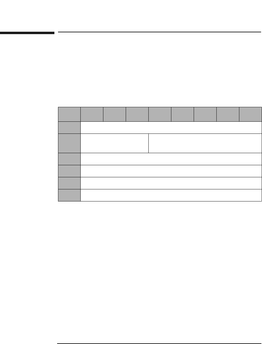
Jukebox SCSI-2 Command Set
Test Unit Ready Command (00H)
Chapter 33-6
Test Unit Ready Command (00H)
This command determines the READY state of the library. If the library
is in a ready state when it receives this command, it returns a GOOD
status. If the library is not ready when it receives the Test Unit Ready
Command, it returns a CHECK CONDITION with a sense key of NOT
READY.
Table 3-3 Test Unit Ready Command CDB
Byte 76543210
0Operation Code (00H)
1Logical Unit Number
(0)
Reserved (0)
2Reserved (0)
3Reserved (0)
4Reserved (0)
5Control Byte (0)
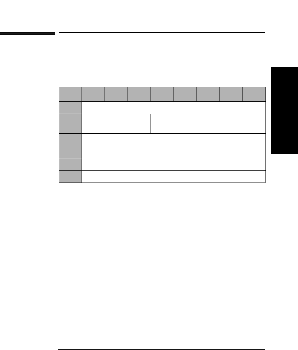
Jukebox SCSI-2 Command Set
Rezero Unit Command (01H)
Chapter 3 3-7
Jukebox SCSI-2 CommandsJukebox SCSI-2 Commands
Rezero Unit Command (01H)
This command recalibrates the mechanical system and sets the library to
a specific predefined state.
Table 3-4 Rezero Unit Command CDB
Byte 76543210
0Operation Code (01H)
1Logical Unit Number
(0)
Reserved (0)
2Reserved (0)
3Reserved (0)
4Reserved (0)
5Control Byte (0)
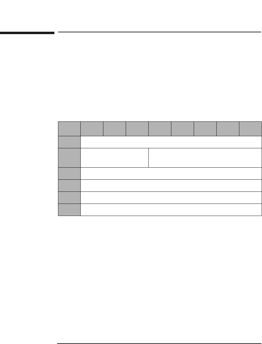
Jukebox SCSI-2 Command Set
Request Sense Command (03H)
Chapter 33-8
Request Sense Command (03H)
This command determines the specific error condition when the library
fails to successfully complete a command and returns a check condition
status. (Sense data is preserved for the initiator until retrieved by a
Request Sense Command or until the initiator sends another command.)
Codes are used to represent the error condition and this information can
be used to determine what type of error recovery procedure is
appropriate.
Allocation
Length This field contains the number of data bytes to be
returned.
Table 3-5 Request Sense Command CDB
Byte 76543210
0Operation Code (03H)
1Logical Unit Number
(0)
Reserved (0)
2Reserved (0)
3Reserved (0)
4Allocation Length
5Control Byte (0)

Jukebox SCSI-2 Command Set
Request Sense Command (03H)
Chapter 3 3-9
Jukebox SCSI-2 CommandsJukebox SCSI-2 Commands
Valid A valid bit of "1" indicates the information field contains
valid information.
Error Code Either 70H (current error) or 71H (deferred error).
Sense Key and
Additional
Sense Length See Table 3-7 on page 3-10.
Table 3-6 Request Sense Data Parameter Block Format
Byte 7 6543210
0Valid Error Code (70H or 71H)
1Reserved (0)
2Reserved (0) Sense Key (Table 3-7 on
page 3-10)
3-6 Information
7Additional Sense Length (Table 3-7 on page 3-10)
8-11 Reserved (0)
12 Additional Sense Code (Table B-2 on page B-4)
13 Additional Sense Code Qualifier (Table B-2 on page B-4)
14 Reserved (0)
15 SKSV Sense Key Specific (Table 3-8 on page 3-11)
16-17 Sense Key Specific
18-77 Additional Sense Bytes

Jukebox SCSI-2 Command Set
Request Sense Command (03H)
Chapter 33-10
Information Contains the Element address in question on an Illegal
Request during a 21H or 3BH sense code.
Additional Sense
Code The Additional Sense Code specifies detailed
information related to the error reported in the Sense
Key field. See Table B-2 on page B-4.
Additional Sense
Code Qualifier The Additional Sense Code Qualifier specifies detailed
information related to the Additional Sense Code. See
Table B-2 on page B-4.
SKSV When set to 1, the Sense Key Specific bytes contains
valid data. When set to 0, Bytes 15, 16, and 17 are zero.
Sense Key
Specific When the Sense Key field is set to Illegal Request (05H)
and SKSV is 1, the Sense Key Specific fields are defined
as shown in Table 3-8 on page 3-11.
Additional Sense
Bytes This field may contain information when the Additional
Sense Length field contains a value greater than 10. See
Table B-5 on page B-8 and Table B-6 on page B-14.
Table 3-7 Sense Key - Additional Sense Length Values
Sense Key Description Additional Sense
Length
0H No Sense 10
1H Recovered Error 70
2H Not Ready 10
4H Hardware Error 70
5H Illegal Request 10
6H Unit Attention 10
BH Aborted Command 10
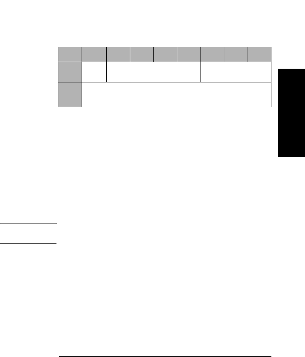
Jukebox SCSI-2 Command Set
Request Sense Command (03H)
Chapter 3 3-11
Jukebox SCSI-2 CommandsJukebox SCSI-2 Commands
C/D 1 = Illegal Parameter is in Command Descriptor Block.
0 = Illegal Parameter is in Data Out Phase.
BPV 1 = Bit pointer field is valid.
0 = Bit pointer field is invalid.
Bit Pointer Specifies which bit is in error. When a multiple bit field
is in error, the pointer points to the most significant bit
in the field.
Field Pointer Specifies which byte is in error. Bytes are numbered
starting from 0. When a multiple-byte field is in error,
the pointer points to the most significant byte of the
field.
NOTE Bytes identified as being in error are not necessarily the bytes that need
to be changed to correct the problem.
Table 3-8 Sense Key Field = Illegal Request (05H) and SKSV Bit = 1
Byte 7 6543210
15 SKSV
(1)
C/D Reserved (0) BPV Bit Pointer
16 Field Pointer (MSByte)
17 Field Pointer (LSByte)
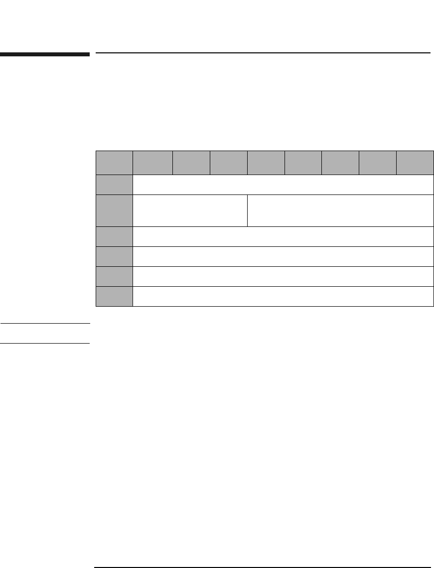
Jukebox SCSI-2 Command Set
Initialize Element Status Command (07H)
Chapter 33-12
Initialize Element Status Command (07H)
This command checks all elements for optical disks and for relevant
status. This information is retained and can be accessed through the
Read Element Status Command (B8H). Refer to Table 3-70 on page 3-68.
NOTE This command takes a few minutes to complete
Table 3-9 Initialize Element Status Command CDB
Byte 7 6 5 4 3 2 1 0
0Operation Code (07H)
1Logical Unit Number
(0)
Reserved (0)
2Reserved (0)
3Reserved (0)
4Reserved (0)
5Control Byte (0)
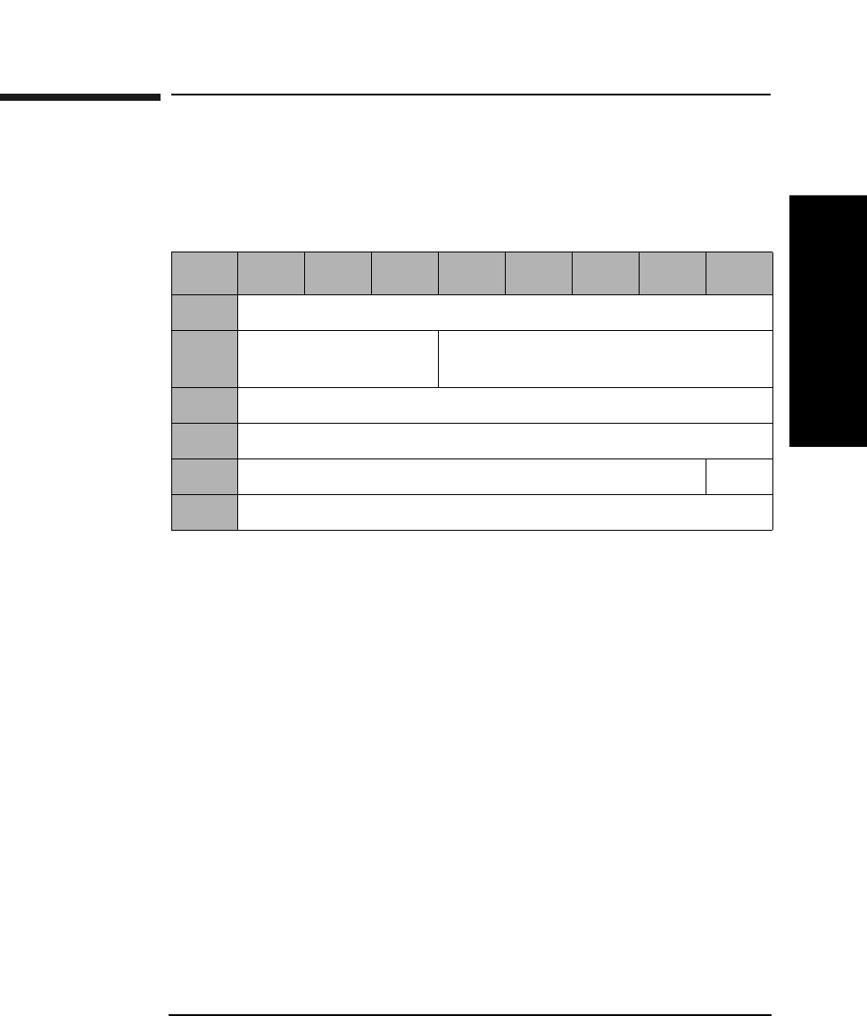
Jukebox SCSI-2 Command Set
Rotate Mailslot Command (0CH)
Chapter 3 3-13
Jukebox SCSI-2 CommandsJukebox SCSI-2 Commands
Rotate Mailslot Command (0CH)
The host system may send this SCSI vendor-unique command to the
optical disk library to control mailslot rotation.
Open An Open value of 1 causes the mailslot to rotate out. An
Open value of 0 causes the mailslot to rotate in.
There are three exceptions:
• If another device, including the front panel, already has the mailslot
prevented or reserved.
• If there is an optical disk already in the transport element (picker).
• If the optical disk library is full.
Table 3-10 Rotate Mailslot Command CDB
Byte 76543210
0Operation Code (0CH)
1Logical Unit Number
(0)
Reserved (0)
2Reserved (0)
3Reserved (0)
4Reserved (0) Open
5Control Byte (0)
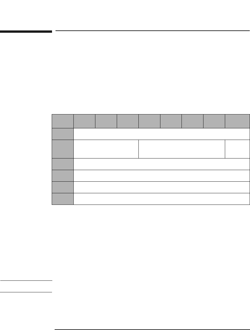
Jukebox SCSI-2 Command Set
Inquiry Command (12H)
Chapter 33-14
Inquiry Command (12H)
This command requests information describing the type of SCSI device.
This information includes the following:
•Vendor ID
• Product ID
• Product revision
EVPD A 0 in this bit requests Standard Inquiry Information.
A 1 in this bit requests the vital product data specified
by the VPD identifier field.
VPD Identifier If EVPD is 0, this field should be 0. If EVPD is 1, this
field will contain the code for the requested vital
product data page (Table 3-12 on page 3-15).
Allocation
Length The number of bytes reserved for returned data.
NOTE Vital Product data pages are not supported in “fx” model jukeboxes.
Table 3-11 Inquiry Command CDB
Byte 7 6 5 4 3 2 1 0
0Operation Code (12H)
1Logical Unit Number
(0)
Reserved (0) EVPD
2VPD Identifier
3Reserved (0)
4Allocation Length
5Control Byte (0)
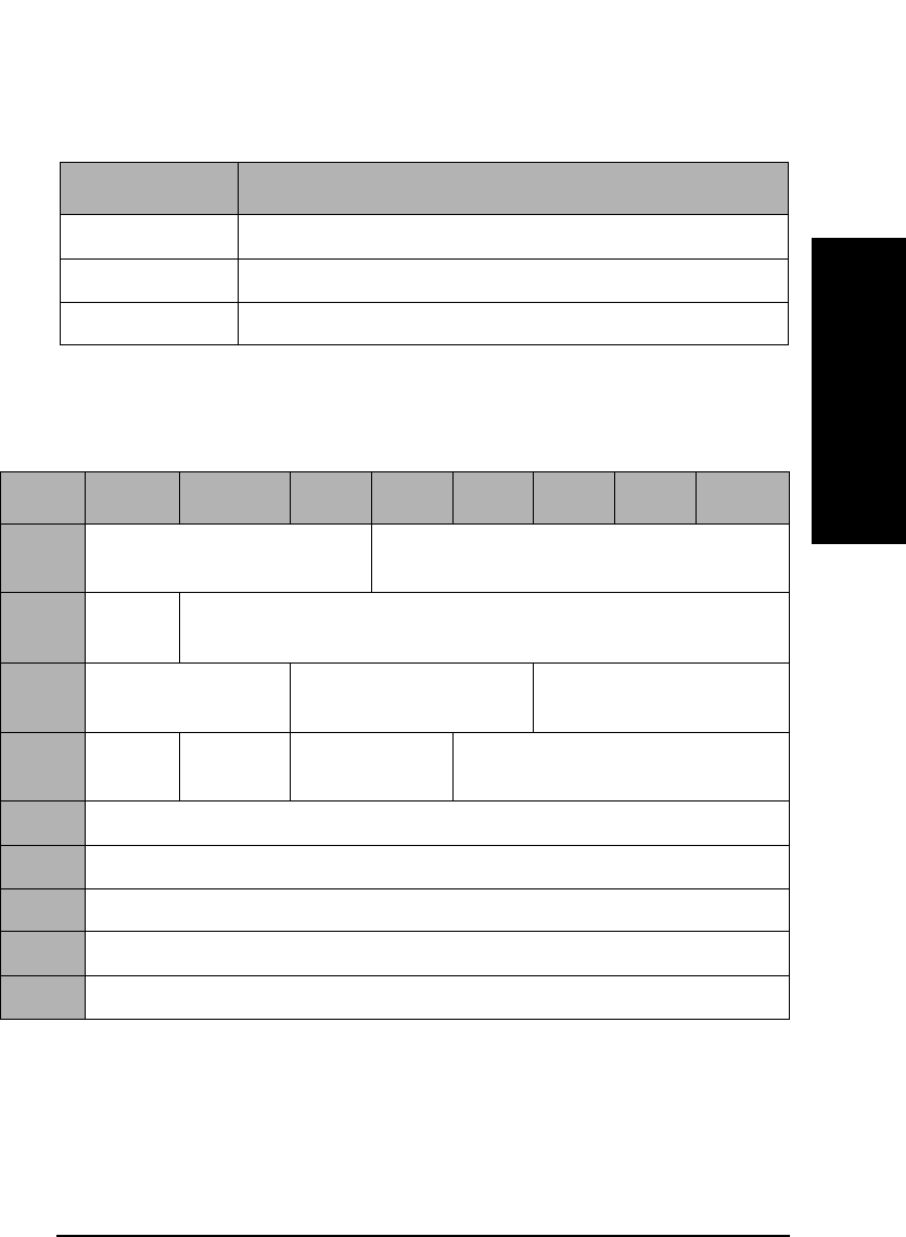
Jukebox SCSI-2 Command Set
Inquiry Command (12H)
Chapter 3 3-15
Jukebox SCSI-2 CommandsJukebox SCSI-2 Commands
Inquiry Command Data
RMB Removable medium bit. When this bit is set to 1,
medium is removable.
ANSI and
Response Data
Format The returned value of 2 indicate compliance to X3131-
199x.
Table 3-12 Vital Product Data Page Codes
Page Code Description
0 Supported vital product data pages
80H Unit serial number
C0H Firmware information page
Table 3-13 Standard Inquiry Data Format
Byte 7 6 5 4 3 2 1 0
0Peripheral Qualifier (0) Peripheral Device Type
(08H=Medium Changer).
1RMB
(1)
Device-Type Qualifier (0)
2ISO Version (0) ECMA Version (0) ANSI-Approved
Version (2)
3AENC
(0)
TrmIOP
(0)
Reserved (0) Response Data Format (2)
4Additional Length (1FH)
5-7 Reserved (0)
8-15 Vendor Identification (HP)
16-31 Product Identification
32-35 Product Revision Level

Jukebox SCSI-2 Command Set
Inquiry Command (12H)
Chapter 33-16
AENC,
TrmIOP Asynchronous event notification and the terminate I/O
process message are not supported.
Response Data
Format Indicates the inquiry data format complies with X3131-
199X.
Vendor
Identification All unused bytes are filled with a blank space. (ASCII)
Product
Identification
String All unused bytes are filled with a blank space. (ASCII)
Vital Product Data Pages
Table 3-14 Supported Vital Product Data Pages
Byte 76543210
0Peripheral Qualifier
(0)
Peripheral Device Type (08H)
1Page Code (0)
2Reserved (0)
3Page Length (03H)
40 (this page)
580H (Unit Serial Number Page)
6C0H (Firmware Information Page - Vendor Unique)
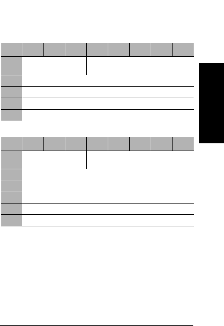
Jukebox SCSI-2 Command Set
Inquiry Command (12H)
Chapter 3 3-17
Jukebox SCSI-2 CommandsJukebox SCSI-2 Commands
Table 3-15 Unit Serial Number Page
Byte 76543210
0Peripheral Qualifier
(0)
Peripheral Device Type (08H)
1Page Code (80H)
2Reserved (0)
3Page Length (0CH)
4-15 Serial Number (ASCII)
Table 3-16 Firmware Information Page
Byte 76543210
0Peripheral Qualifier
(0)
Peripheral Device Type (08H)
1Page Code (C0H)
2Reserved (0)
3Page Length (0AH)
4-7 Controller Firmware Revision (x.xx, ASCII)
8-13 Controller Firmware Type Code (xxxxxx, ASCII)
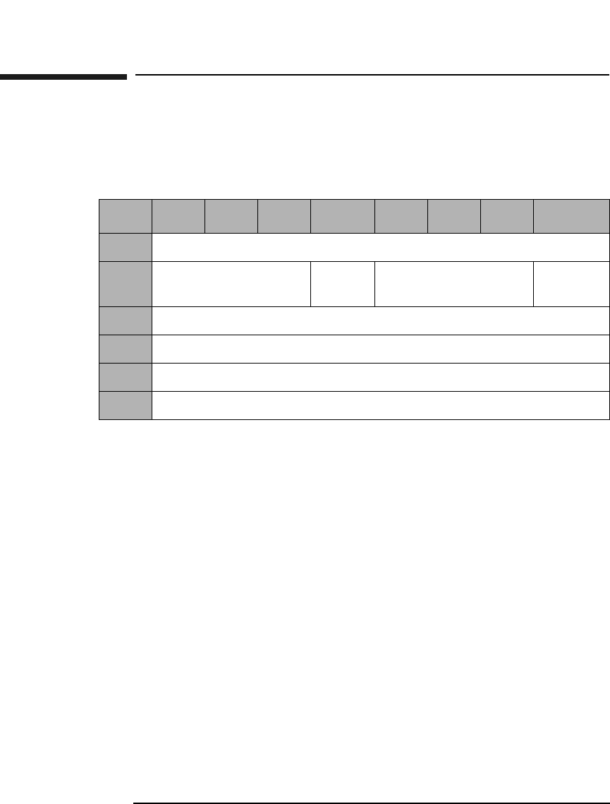
Jukebox SCSI-2 Command Set
Reserve Command (16H)
Chapter 33-18
Reserve Command (16H)
This command reserves the library for use by a single SCSI initiator
when the library is connected to multiple initiators.
3rdPty When set to 1, the library is reserved for the SCSI
device specified in the Third Party Device ID field.
Third Party
Device ID A third party device ID indicates identification of the
SCSI device the library is to be reserved for.
Element When set to 1, any valid element identified in the
element list is reserved for the initiator making the
request.
When set to 0, all elements are reserved.
Reservation
Identification Identifies each element reservation with a code word
byte.
Element List
Length Defines the size of the element list.
Table 3-17 Reserve Command CDB
Byte 7 6 5 4 3 2 1 0
0Operation Code (16H)
1Logical Unit Number
(0)
3rdPty Third Party Device
ID
Element
2Reservation Identification
3Element List Length (MSByte)
4Element List Length (LSByte)
5Control Byte (0)

Jukebox SCSI-2 Command Set
Reserve Command (16H)
Chapter 3 3-19
Jukebox SCSI-2 CommandsJukebox SCSI-2 Commands
Reserve Command Element List Descriptors
Each element list consists of zero or more descriptors. The element list
descriptor defines a series of elements beginning at the specified element
address for the specified number of elements.
If the number of elements is zero, the element list begins at the specified
element address and continues through the last element address on the
unit. However, if the Element Address is a transport device (a picker) or
an unused Element Address, a status of CHECK CONDITION, Sense
Key = ILLEGAL REQUEST is returned.
Table 3-18 Reserve Command Element List Descriptors
Byte 76543210
0Reserved (0)
1Reserved (0)
2Number of Elements (MSByte)
3Number of Elements (LSByte)
4Element Address (MSByte)
5Element Address (LSByte)
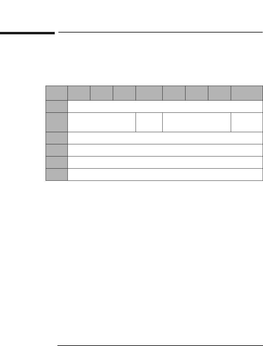
Jukebox SCSI-2 Command Set
Release Command (17H)
Chapter 33-20
Release Command (17H)
This command releases the library or element for use by another
initiator.
3rdPty When set to 1, the element or unit is released from a
previous reserve which had been made using a third
party reservation.
Element When set to 1, any reservation from the requesting
initiator with a matching reservation identification is
terminated. All other reservations remain intact.
When this bit is set to 0, the target terminates all
element and unit reservations.
Reservation
Identification Identifies each element reservation code word byte.
Table 3-19 Reserve Command CDB
Byte 7 6 5 4 3 2 1 0
0Operation Code (17H)
1Logical Unit Number
(0)
3rdPty Third Party Device
ID
Element
2Reservation Identification
3Reserved (0)
4Reserved (0)
5Control Byte (0)

Jukebox SCSI-2 Command Set
Mode Sense Command (1AH)
Chapter 3 3-21
Jukebox SCSI-2 CommandsJukebox SCSI-2 Commands
Mode Sense Command (1AH)
This command acquires element parameter information about the
library. This information includes, but is not limited to the following:
• First storage slot element address and number of storage slots.
• First input/output (mailslot) element address and number of input/
output elements.
• First medium transport element (picker) address and number of
medium transport elements.
• First optical drive element address and number of drives.
• Characteristics of the various element types.
PC Page Control defines the type of parameter values to be
returned as follows:
0 - Current Values
1 - Changeable Values
2 - Default Values
3 - Saved Values
Table 3-20 Mode Sense Command CDB
Byte 76543210
0Operation Code (1AH)
1Reserved (0)
2PC Page Code
3Reserved (0)
4Allocation Length (Table 3-21 on page 3-22)
5Control Byte (0)

Jukebox SCSI-2 Command Set
Mode Sense Command (1AH)
Chapter 33-22
Page Code Valid Page Code values are:
1DH - Element Address Assignment Page (Table 3-22
on page 3-23)
1EH - Transport Element Parameters (Table 3-25 on
page 3-25)
1FH - Device Capabilities Page (Table 3-26 on
page 3-27 or Table 3-27 on page 3-28)
3FH - All Pages
Allocation
Length The number of bytes returned for each page code are
shown in the following two tables:
Table 3-21 Mode Sense Allocation Lengths
# of Return
Bytes
Page
Code
Description Table
24 1DH Element Address
Assignment
Table 3-22 on
page 3-23
8 or 10 1EH Transport Element
Parameters
Table 3-25 on
page 3-25
24 1FH Device Capabilities Table 3-26 on
page 3-27
12 20H Configuration
Parameters
Table 3-28 on
page 3-30
62 or 64a3FH All Pages
a. All models except the 40fx, 80ex, 125ex and 220mx will run in
either single- or double- picker mode. The higher number rep-
resents double-picker mode. (Double picker mode is the
default mode).

Jukebox SCSI-2 Command Set
Mode Sense Command (1AH)
Chapter 3 3-23
Jukebox SCSI-2 CommandsJukebox SCSI-2 Commands
Table 3-22 Mode Sense Element Address Assignment Page (1DH) Format
Byte 7 6 5 4 3 2 1 0
0Sense Data Length (23)
1-3 Reserved (0)
4Reserved (0) Page Code (1DH)
5Parameter Length (12H)
6First Medium Transport Element Address (MSByte) (0)
7First Medium Transport Element Address (LSByte)
(Table 3-23 on page 3-24)
8Number Of Medium Transport Elements (MSByte) (0)
9Number Of Medium Transport Elements (LSByte)
(Table 3-23 on page 3-24)
10 First Storage Element Address (MSByte) (0)
11 First Storage Element Address (LSByte) (Table 3-24 on page 3-24)
12 Number Of Storage Elements (MSByte) (0)
13 Number Of Storage Elements (LSByte) (Table 3-24 on page 3-24)
14 First Import/Export Element Address (MSByte) (0)
15 First Import/Export Element Address (LSByte)
(Table 3-24 on page 3-24)
16 Number Of Import/Export Elements (MSByte) (0)
17 Number Of Import/Export Elements (LSByte) (1)
18 First Data Transfer Element Address (MSByte) (0)
19 First Data Transfer Element Address (LSByte) (1)
20 Number Of Data Transfer Elements (MSByte) (0)
21 Number Of Data Transfer Elements (LSByte) (Table 3-24 on page 3-24)
22-23 Reserved (0)

Jukebox SCSI-2 Command Set
Mode Sense Command (1AH)
Chapter 33-24
Table 3-23 Number of Transport Elements
Transport ModeaFirst Transport
Address
# of Transport
Elements
Dual Picker Mode 16 2
Single Picker Mode 0 1
a.All models except the 40fx, 80ex, 125ex and 220mx will run in either
single-or double-picker mode. All other jukebox models run in single-
picker mode only.
Table 3-24 Number of Data Transfer Elements
Model First
Storage
Address
Storage
Elements
First Import
Address
Data
Transfer
Elements
40fx 11 16 10 1 or 2
80fx 31 32 20 2
160fx 31 64 20 4
200fx 31 76 20 2
330fx 31 128 20 4 or 6
600fx 31 238 20 6,8,10,12
80ex 11 16 10 1 or 2
160ex 31 32 20 2
320ex 31 64 20 4
400ex 31 76 20 2
660ex 31 128 20 4 or 6
1200ex 31 238 20 4, 6, or 10
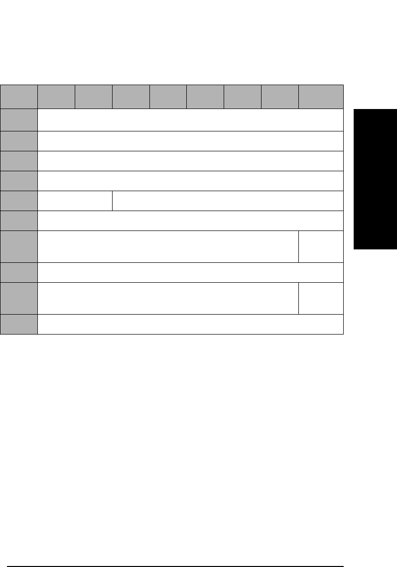
Jukebox SCSI-2 Command Set
Mode Sense Command (1AH)
Chapter 3 3-25
Jukebox SCSI-2 CommandsJukebox SCSI-2 Commands
Transport Element (Picker)
Parameter
Length Number of bytes which describe each transport element
(picker).
Rotate When set to 1, this bit indicates that the medium
transport element (picker) supports flipping double-
sided optical disks.
Table 3-25 Mode Sense Transport Element Parameter Page (1EH) Format
Byte 7 6 5 4 3 2 1 0
0Sense Data Length (7) or (9)a
1Reserved (0)
2Reserved (0)
3Reserved (0)
4Reserved (0) Page Code (1EH)
5Parameter Length (02H) or (04H)
6Reserved (0) Rotate
(1)
7Member Number In Transport Element Set (0)
8Reserved (0) Rotate
(1)
9Member Number In Transport Element Set (1)
a. All models except the 40fx, 80ex, 125ex and 220mx will run in either
single- or double-picker mode. All other jukebox models run in single-
picker mode only. In single picker mode 7 bytes will be returned; in dual-
picker mode 9 bytes will be returned.

Jukebox SCSI-2 Command Set
Mode Sense Command (1AH)
Chapter 33-26
Device Capabilities
The Device Capability Page provides information about library element
storage, Move Medium, and Exchange Medium capabilities.
The following abbreviations are used in the field names of the following
two tables:
• MT - Medium transport element (picker)
• ST - Storage element
• IE - Import/Export element (mailslot)
• DT - Data Transport element (drive)

Jukebox SCSI-2 Command Set
Mode Sense Command (1AH)
Chapter 3 3-27
Jukebox SCSI-2 CommandsJukebox SCSI-2 Commands
Table 3-26 Mode Sense Device Capabilities Page (1FH)a
Byte 7 6 5 4 3 2 1 0
0Sense Data Length (23)
1-3 Reserved (0)
4Reserved (0) Page Code (1FH)
5Parameter Length (12H)
6Reserved (0) StorDT
(0)
StorIE
(1)
StorST
(1)
StorMT
(0)
7Reserved (0)
8Reserved (0) MT->DT
(1)
MT->IE
(0)
MT->ST
(1)
MT->MT
(0)
9Reserved (0) ST->DT
(1)
ST ->IE
(1)
ST->ST
(1)
ST->MT
(1)
10 Reserved (0) IE->DT
(1)
IE ->IE
(0)
IE ->ST
(1)
IE->MT
(0)
11 Reserved (0) DT->DT
(1)
DT->IE
(1)
DT->ST
(1)
DT->MT
(1)
12-15 Reserved (0)
16 Reserved (0) MT<>DT
(1)
MT<>IE
(0)
MT<>ST
(1)
MT<>MT
(0)
17 Reserved (0) ST<>DT
(1)
ST<>IE
(1)
ST<>ST
(1)
ST<>MT
(0)
18 Reserved (0) IE<>DT
(1)
IE<>IE
(0)
IE<>ST
(1)
IE<>MT
(0)
19 Reserved (0) DT<>DT
(1)
DT<>IE
(1)
DT<>ST
(1)
DT<>MT
(0)
20-23 Reserved (0)
a. This table applies to all jukeboxes, EXCEPT the 40fx, 80ex, 125ex and 220mx models.

Jukebox SCSI-2 Command Set
Mode Sense Command (1AH)
Chapter 33-28
Table 3-27 Mode Sense Device Capabilities Page (1FH)a
Byte 7 6 5 4 3 2 1 0
0Sense Data Length (23)
1-3 Reserved (0)
4Reserved (0) Page Code (1FH)
5Parameter Length (12H)
6Reserved (0) StorDT
(0)
StorIE
(1)
StorST
(1)
StorMT
(0)
7Reserved (0)
8Reserved (0) MT->DT
(1)
MT->IE
(0)
MT->ST
(1)
MT->MT
(0)
9Reserved (0) ST->DT
(1)
ST ->IE
(1)
ST->ST
(1)
ST->MT
(1)
10 Reserved (0) IE->DT
(1)
IE ->IE
(0)
IE ->ST
(1)
IE->MT
(0)
11 Reserved (0) DT->DT
(1)
DT->IE
(1)
DT->ST
(1)
DT->MT
(1)
12-15 Reserved (0)
16 Reserved (0) MT<>DT
(1)
MT<>IE
(0)
MT<>ST
(1)
MT<>MT
(0)
17 Reserved (0) ST<>DT
(1)
ST<>IE
(1)
ST<>ST
(1)
ST<>MT
(0)
18 Reserved (0) IE<>DT
(1)
IE<>IE
(0)
IE<>ST
(1)
IE<>MT
(0)
19 Reserved (0) DT<>DT
(1)
DT<>IE
(1)
DT<>ST
(1)
DT<>MT
(0)
20-23 Reserved (0)
a. This table applies ONLY to the 40fx, 80ex, 125ex and 220mx models.

Jukebox SCSI-2 Command Set
Mode Sense Command (1AH)
Chapter 3 3-29
Jukebox SCSI-2 CommandsJukebox SCSI-2 Commands
In the descriptions below, XX and YY are abbreviations of the element
types such as MT or ST.
StorXX When this bit is set to 1, the XX element type provides
independent storage for a cartridge.
If the StorXX bit is set to 0, it indicates that elements of
that type provide virtual sources or destinations, and
the storage location of the cartridge is provided by an
element of some other type.
XX->YY - Move
Medium A returned bit value of 1 indicates that the library
supports Move Medium commands from the XX (source)
element to the YY (destination) element. See Table 3-68
on page 3-64 for additional information on the Move
Medium command.
A returned bit value of 0 indicates that Move Medium
commands from the XX element to the YY element are
not supported and will be rejected, with ILLEGAL
REQUEST.
XX<>YY -
Exchange
Medium A returned bit value of 1 indicates that the library
supports Exchange Medium commands where the
source is element type XX and destination 1 is element
type YY, and destination 2 is of the same type as the
source element.
An XX<>YY field returned bit value of 0 indicates that
these Exchange Medium commands will be rejected
with ILLEGAL REQUEST. See Table 3-69 on page 3-66
for additional information on the Exchange Medium
Command.

Jukebox SCSI-2 Command Set
Mode Sense Command (1AH)
Chapter 33-30
This Mode Page provides information on the state of the autochanger’s
configuration options. Page control requests for Current and Saved
values return the same values. Requests for changeable values return all
zeros because none of these values are changeable through a Mode
Select. Requests for Default values return the Default values.
Table 3-28 Autochanger Configuration Mode Page (20H)
Byte 7 6 5 4 3 2 1 0
0Sense Data Length (11)
1-3 Reserved (0)
4Reserved (0) Page Code (20H)
5Page Length (06H)
6Recovery Dual
Picker
Starwars
/ Bump
Check
Secure Secure
Mail
In/Out
Power
Secure
Report
Recovered
Write
Verify
7Slots
230-238
Mail
In/Out
Mail
Rotation
Reserved (0)
8Reserved (0)
9SCSI Log Conf
40
No
Break on
Fail
Reserved (0)
10 Reserved (0)
11 Reserved (0)

Jukebox SCSI-2 Command Set
Mode Sense Command (1AH)
Chapter 3 3-31
Jukebox SCSI-2 CommandsJukebox SCSI-2 Commands
The following lists the correspondences between fields of this Page and
the control panel options on the jukeboxes.
NOTE “Large Jukebox” in the following list means Models 330fx, 600fx, 660fx,
1200ex, 1200mx, and 2200mx.
“Medium Jukebox” in the following list means Models 80fx, 160fx, 200fx,
160ex, 320ex, 400ex, 300mx, 600mx, and 700mx.
“Small Jukebox” in the following list means Models 40fx and 80ex, 125ex,
and 220mx.
Recovery Large Jukebox: RECOVERY ON/OFF (1 = ON)
Medium Jukebox: RECOVERY ON/OFF (1 = ON)
Small Jukebox: CONFIG 21 ON/OFF (1 = ON)
Dual Picker Large Jukebox: DUAL PICKER ON/OFF (1 = ON)
Medium Jukebox: DUAL PICKER ON/OFF (1 = ON)
Small Jukebox: Reserved (0)
Starwars Large Jukebox: STARWARS ON/OFF (1 = ON)
Medium Jukebox: STARWARS ON/OFF (1 = ON)
Small Jukebox: CONFIG 42 ON/OFF (1 = ON)
Secure Large Jukebox: SECURE ON/OFF (1 = ON)
Medium Jukebox: SECURE ON/OFF (1 = ON)
Small Jukebox: CONFIG 15 ON/OFF (1 = ON)
Secure Mail
In/Out Large Jukebox: Reserved (0)
Medium Jukebox: SECURE MAIL IN/OUT (1 = IN)
Small Jukebox: CONFIG 31 ON/OFF (1 = ON)
Power Secure Large Jukebox: POWER SECURE ON/OFF (1 = ON)
Medium Jukebox: POWER SECURE ON/OFF (1 = ON)
Small Jukebox: CONFIG 20 ON/OFF (1 = ON)
Report
Recovered Large Jukebox: REP RECOVERED ON/OFF (1 = ON)
Medium Jukebox: REP RECOVERED ON/OFF (1=ON)
Small Jukebox: CONFIG 27 ON/OFF (1 = ON)
Write Verify Large Jukebox: WRITE VERIFY ON/OFF (1 = ON)
Medium Jukebox: WRITE VERIFY ON/OFF (1 = ON)
Small Jukebox: CONFIG 41 ON/OFF (1 = ON)

Jukebox SCSI-2 Command Set
Mode Sense Command (1AH)
Chapter 33-32
Slots 230-238 Large Jukebox: SLOTS 230-238 ON/OFF (1 = ON)
Medium Jukebox: Reserved (0)
Small Jukebox: Reserved (0)
Mail In/Out Large Jukeboxes DOOR OPEN/CLOSED 1=CLOSED
Medium Jukebox: Reserved (0)
Small Jukebox: Reserved (0)
Mail Rotation Large Jukebox: Reserved (0)
Medium Jukebox: Reserved (0)
Small Jukebox: CONFIG 32 ON/OFF (1 = ON)
SCSI Log Large Jukebox: SCSI LOG ON/OFF (1 = ON)
Medium Jukebox: SCSI LOG ON/OFF (1 = ON)
Small Jukebox: Reserved (0)
Conf 40 Large Jukebox: CONF40 ON/OFF (1 = ON)
Medium Jukebox: CONF40 ON/OFF (1 = ON)
Small Jukebox: CONF40 ON/OFF (1 = ON)
No Break on
Fail Large Jukebox: Reserved (0)
Medium Jukebox: Reserved (0)
Small Jukebox: CONFIG 8 ON/OFF (1 = ON)
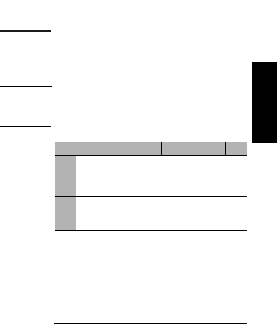
Jukebox SCSI-2 Command Set
Receive Diagnostic Results Command (1CH)
Chapter 3 3-33
Jukebox SCSI-2 CommandsJukebox SCSI-2 Commands
Receive Diagnostic Results Command (1CH)
This command retrieves the results of a library diagnostic test performed
using the Send Diagnostic Command (Table 3-31 on page 3-35). The
diagnostic test number and parameters, error codes, and FRU
information are provided.
NOTE The following tables provide information that can help with
troubleshooting failed components in a unit. The FRUs returned should
be considered pointers to the best area within the unit to check for the
fault. Simply changing the FRU listed may or may not fix the associated
problem.
Allocation
Length The maximum number of parameter bytes that may be
sent in the Data In Phase to describe the results of the
test.
Table 3-29 Receive Diagnostic Results Command CDB
Byte 76543210
0Operation Code (1CH)
1Logical Unit Number
(0)
Reserved (0)
2Reserved (0)
3Allocation Length (MSByte)
4Allocation Length (LSByte)
5Control Byte (0)

Jukebox SCSI-2 Command Set
Receive Diagnostic Results Command (1CH)
Chapter 33-34
Hardware Error
Code Code is generated only if an unrecoverable error occurs
(See Table B-7 on page B-19).
FRU 1 The FRU most likely to be at fault (See Table C-1 on
page C-2 or Table C-2 on page C-4).
FRU 2 The second most likely FRU to be at fault. (See
Table C-1 on page C-2 or Table C-2 on page C-4).
FRU 3 The third most likely FRU to be at fault (See Table C-1
on page C-2 or Table C-2 on page C-4).
Test Number The diagnostic test number. This will not be a sequence
number, but the specific test that failed. Refer to
Table B-12 on page B-40 for a list of the jukebox
diagnostic tests.
Parameters Additional parameters as defined for individual tests.
There may be several like components in a unit. These components may
have a common FRU number. When it is possible to detect which of these
FRUs may be at fault, the error code field reflects the one to check.
Table 3-30 Receive Diagnostic Results Command CDB
Byte 76543210
0Reserved (0)
1Hardware Error Code
2FRU 1
3FRU 2
4FRU 3
5Number of the Test that Failed
6-13 Parameters
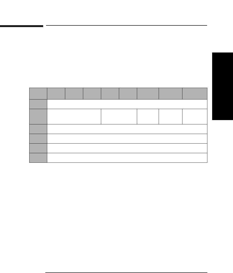
Jukebox SCSI-2 Command Set
Send Diagnostic Command (1DH)
Chapter 3 3-35
Jukebox SCSI-2 CommandsJukebox SCSI-2 Commands
Send Diagnostic Command (1DH)
This command causes the library to perform certain predefined
diagnostic test/exercise routines.
The Request Sense (Table 3-5 on page 3-8) and the Receive Diagnostic
Results (Table 3-29 on page 3-33) commands can be used to get the
results of a test.
SelfTst When set to 1, the Poweron Selftest runs. This selftest
is equivalent to running Test Sequence 1, the Poweron
Sequence. The parameter list length must be 0.
When set to 0, the diagnostic specified in the parameter
list is run.
DevOfL Must be set to 1 for any test other than Selftest.
UnitOfl Must be set to 1 for any test other than Selftest.
Parameter List
Length The number of parameter bytes in the Data Out Phase
that describes the test to be run. The valid range is
between 2 and 10, although this value must be 0 if the
Selftest bit is set to 1. See Table 3-32 on page 3-36.
Table 3-31 Send Diagnostic Command CDB
Byte 7 6 5 4 3 2 1 0
0Operation Code (1DH)
1Logical Unit Number
(0)
Reserved (0) SelfTst DevOfL UnitOfl
2Reserved (0)
3Parameter List Length (MSByte)
4Parameter List Length (LSByte)
5Control Byte (0)

Jukebox SCSI-2 Command Set
Send Diagnostic Command (1DH)
Chapter 33-36
Send Diagnostic Command Data
Test Number Diagnostic test number. See Table B-12 on page B-40 or
Table B-13 on page B-44 for a list of the jukebox
diagnostic tests.
Break Indicates how to terminate the loop count if an error
occurs.
0 - Break on first error
1 - Do not break on error
Loop Count
Identifier The number of times the test will be repeated before the
test is terminated and status is returned.
1H - Run 1 time
2H - Run 10 times
3H - Run 100 times
4H - Run 1000 times
Parameters Parameters associated with the specified tests.
Table 3-32 Send Diagnostic Command Parameter List
Byte 7 6543210
0Test Number
1Break Loop Count Identifier
2Parameters
3Parameters
4Parameters
5Parameters
6Parameters
7Parameters
8Parameters
9Parameters

Jukebox SCSI-2 Command Set
Prevent/Allow Medium Removal Command (1EH)
Chapter 3 3-37
Jukebox SCSI-2 CommandsJukebox SCSI-2 Commands
Prevent/Allow Medium Removal Command
(1EH)
This command either prevents or allows users to insert or remove optical
disks using the mailslot.
Prevent A Prevent bit of 1 prevents removal of an optical disk. A
prevent bit of 0 allows removal of an optical disk.
Default is 0.
Table 3-33 Prevent/Allow Medium Removal Command CDB
Byte 7 6 5 4 3 2 1 0
0Operation Code (1EH)
1Logical Unit Number
(0)
Reserved (0)
2Reserved (0)
3Reserved (0)
4Reserved (0) Prevent
5Control Byte (0)
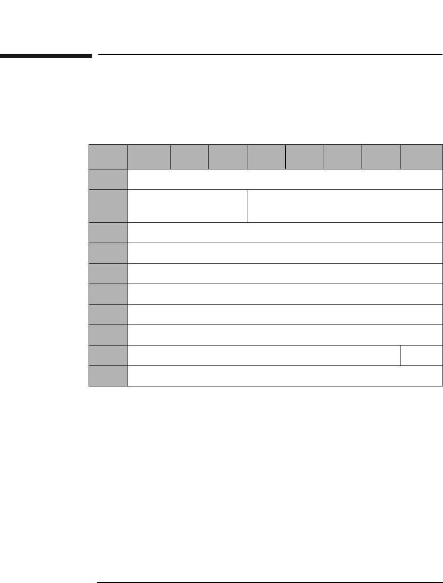
Jukebox SCSI-2 Command Set
Position To Element Command (2BH)
Chapter 33-38
Position To Element Command (2BH)
This command positions the specified transport element in front of the
specified destination element.
Transport Element
Address The default address of zero is the best address for use.
(Changing from the default could result in a decrease in
jukebox performance.) However, this field can also be
set to a specific transport element address (see Table 3-
22 on page 3-23).
Destination Element
Address See Table 3-22 on page 3-23 in the description of the
Mode Sense Command for more information about
addressing.
Invert An Invert bit value of 1 requests the transport element
be inverted (flipped) before being placed in front of the
destination element.
Table 3-34 Position To Element Command CDB
Byte 7 654321 0
0Operation Code (2BH)
1Logical Unit Number
(0)
Reserved (0)
2Transport Element Address (MSByte)
3Transport Element Address (LSByte)
4Destination Element Address (MSByte)
5Destination Element Address (LSByte)
6Reserved (0)
7Reserved (0)
8Reserved (0) Invert
9Control Byte (0)
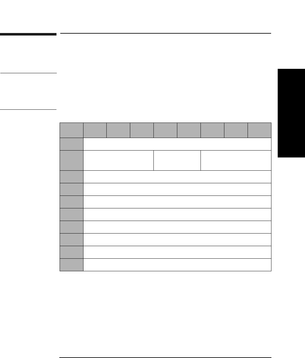
Jukebox SCSI-2 Command Set
Write Buffer Command (3BH)
Chapter 3 3-39
Jukebox SCSI-2 CommandsJukebox SCSI-2 Commands
Write Buffer Command (3BH)
This command writes data to the jukebox.
CAUTION Incorrect use of this command may cause an overwrite of critical
information needed for the jukebox to operate. If this occurs, call service.
Only Buffer IDs listed in Table 3-37 on page 3-40 are intended for use
outside of the factory.
Mode Indicates which data format is used. Refer to Table 3-37
on page 3-40 for valid values.
Buffer ID Indicates which buffer is used. Refer to Table 3-37 on
page 3-40 for valid values.
Table 3-35 Write Buffer Command CDB
Byte 76543210
0Operation Code (3BH)
1Logical Unit Number
(0)
Reserved (0) Mode (See Table 3-37
on page 3-40)
2Buffer ID (Table 3-37 on page 3-40)
3Buffer Offset (MSByte)
4Buffer Offset
5Buffer Offset (LSByte)
6Byte Transfer Length (MSByte)
7Byte Transfer Length
8Byte Transfer Length (LSByte)
9Control Byte (0)

Jukebox SCSI-2 Command Set
Write Buffer Command (3BH)
Chapter 33-40
Buffer Offset Indicates at what address the data is written, offset
from the beginning of the buffer. Must be set to 0 when
using Download Microcode ID.
Byte Transfer
Length Indicates the number of data bytes to be written in the
buffer.
NOTE Additional buffer IDs are for factory use only and are subject to change
without notice.
Table 3-36 Write Buffer Mode Descriptions
Mode Description
1 Vendor specific
4 Download microcode
5 Download microcode
Table 3-37 User Accessible Buffers and Allowed Write Modes
User-Accessible Buffers Buffer
ID
Allowed
Write Modes
Download Microcode (FLASH EPROM) 1 4,5
Customer and Product ID (NVRAM) 15 1
Online Drive Repair ID 128 1

Jukebox SCSI-2 Command Set
Write Buffer Command (3BH)
Chapter 3 3-41
Jukebox SCSI-2 CommandsJukebox SCSI-2 Commands
Table 3-38 Write Buffer Data Format When Buffer ID Set to Online Drive
Repair
Byte Description
0 Drive 1 Control
1 Drive 2 Control
2Drive 3a Control
3Drive 4a Control
4Drive 5a Control
5Drive 6a Control
6Drive 7a Control
7Drive 8a Control
8Drive 9a Control
9Drive 10a Control
10 Drive 11a Control
11 Drive 12a Control
12 Reserved
13 Reserved
14 Reserved
15 Reserved
a.Model dependent

Jukebox SCSI-2 Command Set
Write Buffer Command (3BH)
Chapter 33-42
Table 3-39 Drive Control Definition
Byte Description
00 No change to the drive state.
01 Set drive to "Online_good" state.
04 Set drive to "Offline_failed" state.
06 Set drive to "Offline_good" state.
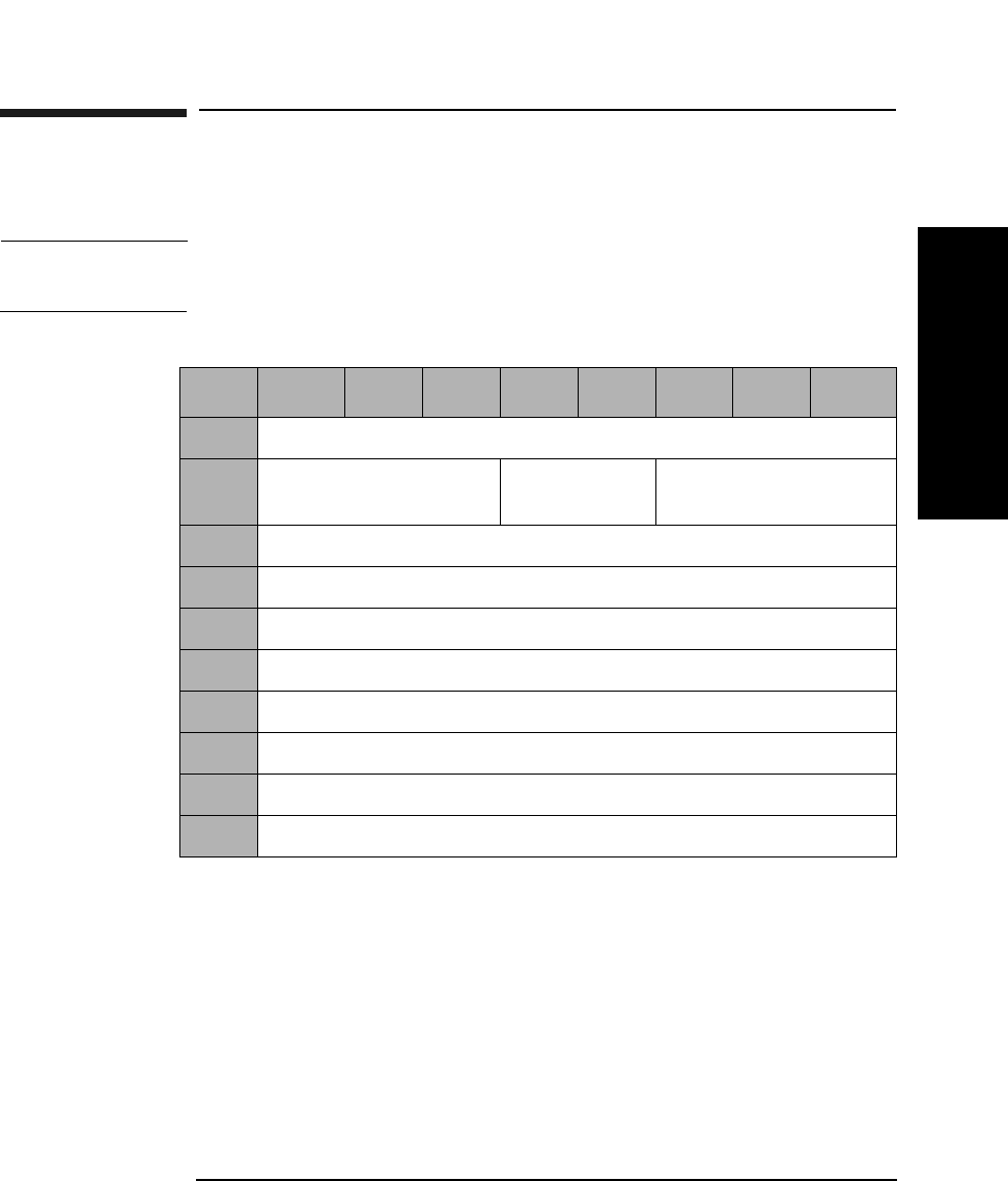
Jukebox SCSI-2 Command Set
Read Buffer Command (3CH)
Chapter 3 3-43
Jukebox SCSI-2 CommandsJukebox SCSI-2 Commands
Read Buffer Command (3CH)
This command reads data from the jukebox.
NOTE Only the Buffer IDs listed in Table 3-42 on page 3-44 are intended for use
outside of the factory.
Mode Indicates which data format is to be used. Refer to
Table 3-41 on page 3-44 for valid values.
Buffer ID Indicates which buffer is to be used. Refer to Table 3-41
on page 3-44 for valid values.
Buffer Offset Indicates at what address the data should be written,
offset from the beginning of the buffer.
Byte Transfer
Length Indicates the number of data bytes to be read from the
buffer (maximum of 65535).
Table 3-40 Read Buffer Command CDB
Byte 7 654321 0
0Operation Code (3CH)
1Logical Unit Number
(0)
Reserved (0) Mode
2Buffer ID
3Buffer Offset (MSByte)
4Buffer Offset
5Buffer Offset (LSByte)
6Byte Transfer Length (MSByte)
7Byte Transfer Length
8Byte Transfer Length (LSByte)
9Control Byte (0)

Jukebox SCSI-2 Command Set
Read Buffer Command (3CH)
Chapter 33-44
NOTE Additional Buffer IDs are for factory use only and are subject to change
without notice.
Table 3-41 Read Buffer Mode Descriptions
Mode Description
1 Vendor specific
Table 3-42 User Accessible Buffers and Allowed Read Modes
User-Accessible Buffers Buffer
ID
Allowed
Read Modes
Online Drive Repair ID 128 1

Jukebox SCSI-2 Command Set
Read Buffer Command (3CH)
Chapter 3 3-45
Jukebox SCSI-2 CommandsJukebox SCSI-2 Commands
Table 3-43 Read Buffer Data Format When Buffer ID Set to Online Drive
Repair
Byte Description
0Drive 1 Status
1Drive 2 Status
2Drive 3a Status
3Drive 4a Status
4Drive 5a Status
5Drive 6a Status
6Drive 7a Status
7Drive 8a Status
8Drive 9a Status
9Drive 10a Status
10 Drive 11a Status
11 Drive 12a Status
12 Reserved
13 Reserved
14 Reserved
15 Reserved
a.Model dependent

Jukebox SCSI-2 Command Set
Read Buffer Command (3CH)
Chapter 33-46
Table 3-44 Drive Status Definition
Byte Status Description
00 Drive is not valid
01 Online_good The drive is online and in a good
state. This is the normal state. All
accesses allowed.
02 Online_pending The drive is offline and ready to go
to the "Online_good" state. No
accesses allowed.
04 Offline_failed The drive is offline and in a failed
state. No accesses allowed. No power
is applied to the drive.
05 Offline_good_pending The drive is online but requesting to
go the "Offline_good" state. All
accesses allowed.
06 Offline_good The drive is offline but is not in a
failed state. No accesses allowed. No
power is applied to the drive.
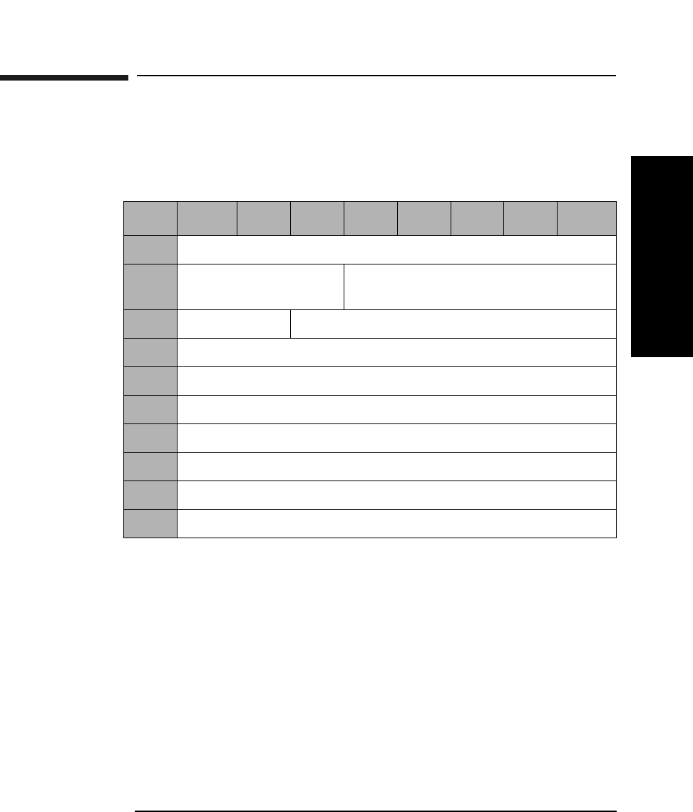
Jukebox SCSI-2 Command Set
Log Sense Command (4DH)
Chapter 3 3-47
Jukebox SCSI-2 CommandsJukebox SCSI-2 Commands
Log Sense Command (4DH)
This command retrieves statistical library information maintained by
the jukebox.
Allocation
Length The number of parameter bytes, including the Log Page
Descriptor Block and the parameter structures. Refer to
Table 3-46 on page 3-48.
Log Sense Parameter Data
Parameter data returned by the Log Sense Command is organized into
pages. The parameter data available in each page is described in
Table 3-46 on page 3-48.
Table 3-45 Log Sense Command CDB
Byte 7 654321 0
0Operation Code (4DH)
1Logical Unit Number
(0)
Reserved (0)
2Reserved (0) Page Code (Table 3-46 on page 3-48)
3Reserved (0)
4Reserved (0)
5Parameter Pointer (MSByte) (0)
6Parameter Pointer (LSByte) (0)
7Allocation Length (MSByte)
8Allocation Length (LSByte)
9Control Byte (0)

Jukebox SCSI-2 Command Set
Log Sense Command (4DH)
Chapter 33-48
All log pages are preceded by a 4-byte header that contains the page
number, a reserved byte, and the length of the data to follow the header.
(Refer to the following example.)
Table 3-46 Log Sense Parameter Data Available in Each Page
Page
Code
Length
Bytesa
Length
Bytesb
Description
016 16 List of supported pages
30H 510 366 Error log (Table 3-47 on page 3-49)
31H 72 NScMove Success log (Table 3-51 on page 3-53)
32H varied NS Force log (Table 3-53 on page 3-54)
33H 406 366 Recovery log (Table 3-54 on page 3-55)
34H 204 204 Regression (vendor unique)
35H 14-44 24-44 Drive log d (Table 3-58 on page 3-57)
36H 6 NS Byte 0 = Version #; Byte 1 = Revision #
37H 24 24 The Odometer log (Table 3-60 on page 3-58)
38H 116 366 Run-Time log (Table 3-61 on page 3-59)
39H 108 NS Retry log (Table 3-64 on page 3-61)
3AH 52 NS Move History log (Table 3-66 on page 3-63)
3BH 72 164-340 Mechanism Parameters (factory use only)
3CH 8 8 PROM Information (factory use only)
3DH 204 NS Alternate Regression (factory use only)
a. This column ONLY applies to the 40fx, 80ex, 125ex and 220mx.
b. This column applies to all models, EXCEPT 40fx, 80ex, 125ex and 220mx.
c. If "NS" appears in this field, the log is not supported for all models, EXCEPT
40fx, 80ex, 125ex and 220mx.
d. The length of the drive log depends on the number of drives in the unit. Ten
bytes per drive are available.

Jukebox SCSI-2 Command Set
Log Sense Command (4DH)
Chapter 3 3-49
Jukebox SCSI-2 CommandsJukebox SCSI-2 Commands
Error Logs Table Format
This table is accessed using the Log Sense Command (4DH), Table 3-45
on page 3-47 with page code 30H. It records hard errors that occur
during normal operation of the jukebox.
This log may be initialized before exerciser or wellness sequences are
run. This allows you to accumulate data related to the test at hand.
When you initialize the cumulative log, all data accumulated is lost.
Table 3-47 Error Logs Table Format a
Byte # Description
0Page Code 30H
1 Reserved = 0
2 Number of bytes to follow (MSByte)
3 Number of bytes to follow (LSByte)
4 Current Entry
5Number of Entries
6-366 Array of 10 log entries (36 Bytes each)
a. This table applies to all models, EXCEPT 40fx, 80ex, 125ex and
220mx.

Jukebox SCSI-2 Command Set
Log Sense Command (4DH)
Chapter 33-50
Table 3-48 Error/ Recovery/Runtime Log Data Entry Format
Byte 7 6 543210
0Reserved (0)
1Hardware Error Code (Table B-7 on page B-19)
2FRU 1 (Table C-1 on page C-2)
3FRU 2 (Table C-1 on page C-2)
4FRU 3 (Table C-1 on page C-2)
5Command Attempted
6-7 Source Element Number
8-9 Destination Element Number
10-11 Second Destination Element Number
12-16 Micro-Move ID History (Table Table D-1 on page D-2)
17 Failed Micro-Move ID (Table D-1 on page D-2)
18 Failed Micro-Move Error Code (Table B-10 on page B-32)
19 Active
Picker
Active
Thumb
Reserved (0)
20-21 Vertical Motor Commanded Position
22-23 Vertical Motor Actual Position
24-25 Plunge Motor Commanded Position
26-27 Plunge Motor Actual Position
28-29 Translate Motor Commanded Position
30-31 Translate Motor Actual Position
32-35 Odometer

Jukebox SCSI-2 Command Set
Log Sense Command (4DH)
Chapter 3 3-51
Jukebox SCSI-2 CommandsJukebox SCSI-2 Commands
Table 3-49 Error Logs Table Format (For 40fx, 80ex, 125ex and 220mx
models ONLY)
Byte Description
0Page Code 30H
1Reserved = 0
2-3 Number of bytes to follow
4-5 Current entry number (range 1 - 50)
6-7 Number of entries in the log
8-9 Log entry currently being displayed
10-509 Array of 50 log entries (10 bytes each) See Table 3-50 below.
Table 3-50 Error Log Entry Format (For 40fx, 80ex, 125ex and 220mx models
only)
Byte 76543210
0Diagnostic User Number
1Hardware Error Code (Table B-7 on page B-19)
2FRU 1 (Table C-1 on page C-2)
3FRU 2 (Table C-1 on page C-2)
4FRU 3 (Table C-1 on page C-2)
5Test Number
6Time Stamp (MSByte)
7Time Stamp
8Time Stamp
9Time Stamp (LSByte)

Jukebox SCSI-2 Command Set
Log Sense Command (4DH)
Chapter 33-52
Diagnostic User
Number 0 - Poweron
1 - Front Panel
2 - SCSI Bus
3 - FRU Isolation
4 - Error Recovery
5 - SCSI Reset
6 - SCSI Abort
FRU 1 The FRU most likely to be at fault. (See Appendix C).
FRU 2 The second most likely FRU to be at fault. (See
Appendix C).
FRU 3 The third mostly likely FRU to be at fault. (See
Appendix C).
Test Number The diagnostic test number. See Table B-12 on
page B-40 for a list of diagnostic tests.
Time Stamp Indicates when the error occurred (measured in hours
since the odometer was initialized).
NOTE The FRU numbers returned indicate the most likely cause of the error,
but these FRUs might not be the actual cause of the problem.
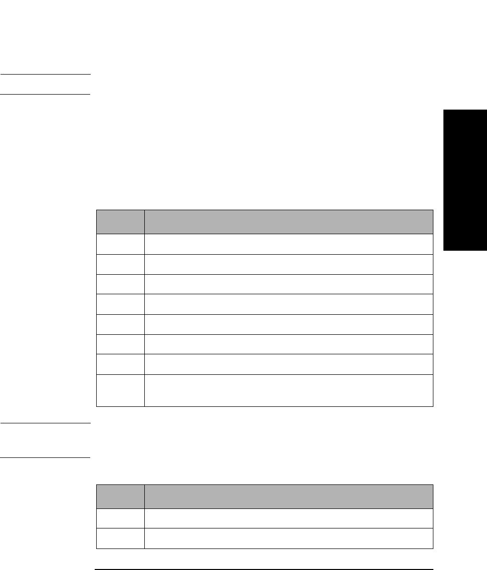
Jukebox SCSI-2 Command Set
Log Sense Command (4DH)
Chapter 3 3-53
Jukebox SCSI-2 CommandsJukebox SCSI-2 Commands
Move Success Log Table Format
NOTE This log is ONLY supported on the 40fx and 80ex models.
This table can be accessed via the Log Sense Command (4DH),
Table 3-45 on page 3-47 with page code 31H. The Move Success Log is
intended for use during normal jukebox operation, not diagnostic
operation.
Move totals and the ten most recent hard errors are recorded.
NOTE Hard errors are unrecoverable and generate a hardware error code. Soft
errors are recoverable with normal operation continuing after recovery.
Table 3-51 Move Success Log Table Format (For 40fx, 80ex, 125ex and 220mx
models ONLY)
Byte Description
0 Page Code 31H
1 Reserved = 0
2-3 Number of bytes to follow
4 Current entry number (range 1 - 10)
5 Number of entries in the log
6-9 Total number of good moves since last hard error
10-11 Total number of soft errors since last hard error
12-71 Array of 10 entries, one entry per hard error (Table 3-52 on
page 3-53
Table 3-52 Move Success Logs Entry Format
Byte Description
0-3 Current Good Move Count at time of hard error
4-5 Current Recovery Count at time of hard error

Jukebox SCSI-2 Command Set
Log Sense Command (4DH)
Chapter 33-54
Force Log Data Format
NOTE This log is ONLY supported on 40fx and 80ex models.
This table can be accessed via the Log Sense Command (4DH), Table 3-
45 on page 3-47) with page code 32H. Each cartridge move is actually a
sequence of many small moves called Micro-Moves. Each Micro-Move has
an associated ID number. For each Micro-Move ID, the log reflects the
highest force seen for that Micro-Move ID.
Table 3-53 Force Entry Data Format
Byte Description
0 Page Code 32H
1 Reserved = 0
2-3 Number of bytes to follow
4-5 Y-axis maximum force for the Micro-Move ID (Table D-1 on
page D-2 or Table D-2 on page D-17)
6-7 Z-axis maximum force for the Micro-Move ID (Table D-1 on
page D-2 or Table D-2 on page D-17)

Jukebox SCSI-2 Command Set
Log Sense Command (4DH)
Chapter 3 3-55
Jukebox SCSI-2 CommandsJukebox SCSI-2 Commands
Recovery Log Data Format
This table can be accessed via the Log Sense Command (4DH), Table 3-
45 on page 3-47, with page code 33H. It records soft errors and related
information on error recovery method and success.
It is reset to 0 before any jukebox move. Any error that occurs during a
move or during the subsequent error recovery is logged. The information
is only valid for the most recent move.
Table 3-54 Recovery Log Data Format (For all models EXCEPT 40fx, 80ex,
125ex and 220mx)
Byte Description
0 Page Code 33H
1 Reserved = 0
2 Number of bytes to follow (MSByte)
3 Number of bytes to follow (LSByte)
4 Current Entry
5Number of Entries
6-366 Array of 10 log entries (36 Bytes each) (See Table 3-48 on
page 3-50)
Table 3-55 Recovery Log Data Format (For the 40fx, 80ex, 125ex and 220mx
models ONLY)
Byte Description
0 Page Code 33H
1 Reserved = 0
2-3 Number of bytes to follow
4-5 Current entry number (range 1 - 20)
5Number of Entries
6-405 20 recovery log entries, 20 bytes each (See Table 3-56 on
page 3-56)

Jukebox SCSI-2 Command Set
Log Sense Command (4DH)
Chapter 33-56
Table 3-56 Recovery Log Entry Format (For the 40fx, 80ex, 125ex and 220mx
models ONLY)
Byte Description
0 Macro-Move ID (Table D-1 on page D-2)
1 Error Recovery State (Table 3-57 on page 3-56)
2 Micro-Move ID (Table D-2 on page D-17)
3 Micro-Move Error Code (Table B-10 on page B-32)
4-7 Y-input position from the encoder
8-11 Expected Y-input position from the encoder
12-15 Z-input position from the encoder
16-19 Expected Z-input from the encoder
Table 3-57 Error Recovery State (For the 40fx, 80ex, 125ex and 220mx
models ONLY)
Byte Description
0 First retry attempt failed
1 Second retry attempt failed
2 Third retry attempt failed
20 First restore attempt failed
21 Second restore attempt failed
22 Third restore attempt failed
97 Maximum number of retries exceeded
98 Maximum number of restores exceeded
99 Find Home failed
127 Initial entry for this failure

Jukebox SCSI-2 Command Set
Log Sense Command (4DH)
Chapter 3 3-57
Jukebox SCSI-2 CommandsJukebox SCSI-2 Commands
Drive Log Data Format
This table can be accessed via the Log Sense Command (4DH), Table 3-
45 on page 3-47 with page code 35H. It records the number of times a
drive is used by the jukebox.
Table 3-58 Drive Log Data Format
Byte Description
0 Page Code 35H
1 Reserved = 0
2-3 Number of bytes to follow
4-13 Log entry for Drive #1
14-23 Log entry for Drive #2 (Model dependent, seeTable 3-24 on
page 3-24)
24-33 Log entry for Drive # (Model dependent, see Table 3-24 on
page 3-24)
34-43 Log entry for Drive #4 (Model dependent, see Table 3-24 on
page 3-24)
Table 3-59 Drive Log Entry Format
Byte Description
0-3 Count of optical disk insertions for this drive
4-5 Media source for last move to this drive
6 Media flipped bit for last move to this drive
7 ID/LUN Valid bits for this drive
8 SCSI ID for this drive
9 SCSI LUN for this drive

Jukebox SCSI-2 Command Set
Log Sense Command (4DH)
Chapter 33-58
Odometer Log Data Format
This table can be accessed via the Log Sense Command (4DH),
Table 3-45 on page 3-47 with page code 37H. It counts the number of
times various types of moves are completed. An exchange is counted as
two moves.
Table 3-60 Odometer Log Data Format
Byte Description
0 Page Code 37H
1 Reserved = 0
2-3 Number of bytes to follow
4-7 Move Odometer
8-11 Flip Odometer
12-15 Translate Odometer
16-19 Mailslot Rotate Odometer
20-23 Poweron Hours

Jukebox SCSI-2 Command Set
Log Sense Command (4DH)
Chapter 3 3-59
Jukebox SCSI-2 CommandsJukebox SCSI-2 Commands
Run-Time Log Data Format
This table can be accessed via the Log Sense Command (4DH), Table 3-
45 on page 3-47 with page code 38H. It keeps a record of error recovery
activity. An entry is added to the Run-Time Log when a move fails or
when any type of error recovery is required. Only the last ten entries are
saved.
Table 3-61 Run-Time Logs Data Format (For all models, EXCEPT 40fx, 80ex,
125ex and 220mx)
Byte Description
0 Page Code 38H
1 Reserved = 0
2 Number of bytes to follow (MSByte)
3 Number of bytes to follow (LSByte)
4 Current Entry
5Number of Entries
6-366 Array of 10 log entries (36 Bytes each)
Table 3-62 Run-Time Logs Data Format (For the 40fx, 80ex, 125ex and 220mx
models ONLY)
Byte Description
0 Page Code 38H
1 Reserved = 0
2-3 Number of bytes to follow
4-7 Number of Macro-Move IDs since this log was reset
8-9 Number of retries done since this log was reset
10-11 Number of inline recoveries since this log was reset
12-13 Number of fatal errors since this log was reset
14 Number of entries in this log

Jukebox SCSI-2 Command Set
Log Sense Command (4DH)
Chapter 33-60
15 Number of the most current entry
16-115 10 Run-time log entries, 10 bytes each (See Table 3-63)
Table 3-63 Run-Time Log Entry Format
Byte Description
0-3 Number of Macro-Move IDs since this log was reset
4 Macro-Move ID
5 Number of entries in Recovery Log when the entry was
made
6 First Micro-Move ID in the Recovery Log (Table D-1 on
page D-2 or Table D-2 on page D-17)
7 First Micro-Move Error Code in the Recovery Log
(Table B-10 on page B-32)
8 Second Micro-Move ID in Recovery Log (Table D-1 on
page D-2 or Table D-2 on page D-17)
9 Second Micro-Move Error Code in Recovery Log (Table B-10
on page B-32)
Table 3-62 Run-Time Logs Data Format (For the 40fx, 80ex, 125ex and 220mx
models ONLY)
Byte Description
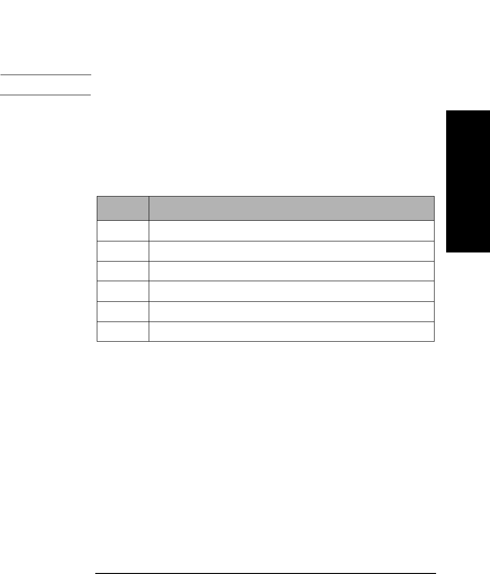
Jukebox SCSI-2 Command Set
Log Sense Command (4DH)
Chapter 3 3-61
Jukebox SCSI-2 CommandsJukebox SCSI-2 Commands
Retry Log Data Format
NOTE This log is ONLY supported on the 40fx, 80ex, 125ex and 220mx models.
This table can be accessed via the Log Sense Command (4DH),
Table 3-45 on page 3-47, with page code 39H.
Each retry algorithm code byte triggers a specific retry algorithm on the
preceding move command. The byte order is the same order in which the
retry algorithms were run.
The last four bytes may be organized as two 16 bit words. The first word
is the cumulative number of Inline Retries (since the jukebox was built),
and the second word is the cumulative number of Major Retries (since
the jukebox was built). Inline Retries are attempts to move again from
the error position. Major Retries are attempts to move again after a Find
Home command has re-zeroed the unit.
Table 3-64 Retry Log Data Format
Byte Description
0 Page Code 39H
1 Reserved = 0
2-3 Number of bytes to follow
4-103 Retry Algorithm Code (Table 3-65 on page 3-62)
104-105 Number of Inline Retries
106-107 Number of Major Retries

Jukebox SCSI-2 Command Set
Log Sense Command (4DH)
Chapter 33-62
The number of drives within a unit is model dependent. Refer to
Table 3-24 on page 3-24 for the actual number of drives within a specific
jukebox.
Table 3-65 Retry Algorithm Codes
Number Algorithm Name Type
01H Find Home and Calibrate Major
03H Z-axis Home Major
04H FRU Isolation Major
81H Mailslot Inline
91H Drive 1 Eject Inline
92H Drive 2 Eject Inline
93H Drive 3 Eject Inline
94H Drive 4 Eject Inline
A1H Drive 1 Insert Inline
A2H Drive 2 Insert Inline
A3H Drive 3 Insert Inline
A4H Drive 4 Insert Inline

Jukebox SCSI-2 Command Set
Log Sense Command (4DH)
Chapter 3 3-63
Jukebox SCSI-2 CommandsJukebox SCSI-2 Commands
Move History Log Data Format
NOTE This log is ONLY supported on the 40fx, 80ex, 125ex and 220mx models.
This table can bee accessed via the Log Sense Command (4DH), Table 3-
45 on page 3-47 with page code 3AH.
Micro-Move IDs are the last moves prior to failure, associated with Bytes
5 and 6.
Table 3-66 Move History Log Data Format
Byte Description
0Page Code 3AH
1 Reserved = 0
2-3 Number of bytes to follow
4-83 6 History Log entries, 8 bytes each (see
Table 3-67 Move History Log Entry Format
Byte Description
0 Least recent Micro-Move ID (Table D-2 on page D-17)
1 Next recent Micro-Move ID (Table D-2 on page D-17)
2 Next recent Micro-Move ID (Table D-2 on page D-17)
3 Next recent Micro-Move ID (Table D-2 on page D-17)
4 Next recent Micro-Move ID (Table D-2 on page D-17)
5 Failed Micro-Move ID (Table D-2 on page D-17)
16 Micro-Move Error Code (Table B-10 on page B-32)
7 Reserved (0)
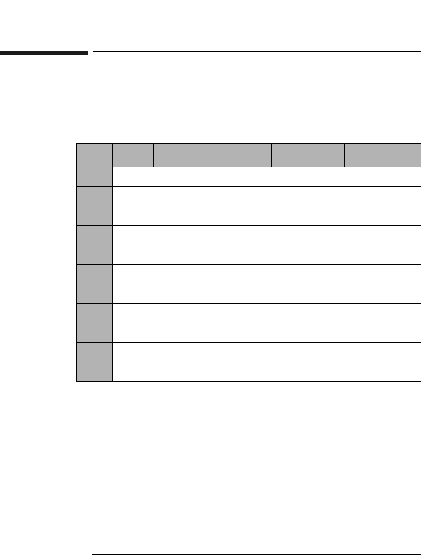
Jukebox SCSI-2 Command Set
Move Medium Command (A5H)
Chapter 33-64
Move Medium Command (A5H)
NOTE This command moves optical disks between library elements.
Transport Element
Address The default address of zero is the best address for use.
(Changing from the default could result in a decrease in
jukebox performance.) However, this field can also be
set to a specific transport element address (see
Table 3-22 on page 3-23).
Source/Destination
Element
Address See Table 3-22 on page 3-23 in the description of the
Mode Sense Command for more information about
addressing.
Table 3-68 Move Medium Command CDB
Byte 7 6 5 4 3 2 1 0
0Operation Code (A5H)
1Logical Unit Number (0) Reserved (0)
2Transport Element Address (MSByte)
3Transport Element Address (LSByte)
4Source Element Address (MSByte)
5Source Element Address (LSByte)
6Destination Element Address (MSByte)
7Destination Element Address (LSByte)
8-9 Reserved (0)
10 Reserved (0) Invert
11 Control Byte (0)

Jukebox SCSI-2 Command Set
Move Medium Command (A5H)
Chapter 3 3-65
Jukebox SCSI-2 CommandsJukebox SCSI-2 Commands
Invert An Invert bit value of 1 requests the transport element
be inverted (flipped) before putting the optical disk into
the destination element.

Jukebox SCSI-2 Command Set
Exchange Medium Command (A6H)
Chapter 33-66
Exchange Medium Command (A6H)
The optical disk in the source element is moved to the first destination
element and the optical disk that previously occupied the first
destination element is moved to the second destination element.
Transport Element
Address The default address of zero is the best address for use.
(Changing from the default could result in a decrease in
jukebox performance.) However, this field can also be
set to a specific transport element address (see
Table 3-22 on page 3-23).
Table 3-69 Exchange Medium Command CDB
Byte 7 6 5 4 3 2 1 0
0Operation Code (A6H)
1Logical Unit Number (0) Reserved (0)
2Transport Element Address (MSByte)
3Transport Element Address (LSByte)
4Source Element Address (MSByte)
5Source Element Address (LSByte)
6First Destination Element Address (MSByte)
7First Destination Element Address (LSByte)
8Second Destination Element Address (MSByte)
9Second Destination Element Address (LSByte)
10 Reserved (0) Inv2 Inv1
11 Control Byte (0)

Jukebox SCSI-2 Command Set
Exchange Medium Command (A6H)
Chapter 3 3-67
Jukebox SCSI-2 CommandsJukebox SCSI-2 Commands
Source/Destination
Element
Address See Table 3-22 on page 3-23 in description of Mode
Sense Command for more information about
addressing.
Inv2 An Inv2 bit value of 1 specifies that the optical disk will
be inverted (flipped) prior to being deposited into the
second destination element.
Inv1 An Inv1 bit value of 1 specifies that the optical disk will
be inverted (flipped) prior to being deposited into the
first destination element.
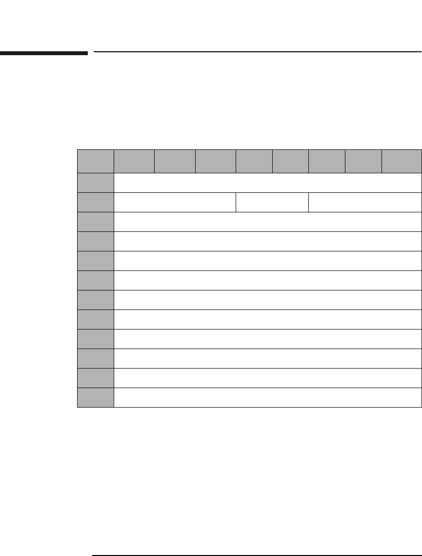
Jukebox SCSI-2 Command Set
Read Element Status Command (B8H)
Chapter 33-68
Read Element Status Command (B8H)
This command provides the exact status of the various elements
(individual storage slots, mailslot, optical drives, and picker mechanism)
within the library.
Element Type
Code Specifies the element type(s) to report.
0H - All element types reported
1H - Medium Transport Element (picker)
2H - Storage Element
3H - Import/Export Element (mailslot)
4H - Data Transfer Element (drive)
Table 3-70 Read Element Status Command CDB
Byte 7 6 5 4 3 2 1 0
0Operation Code (B8H)
1Logical Unit Number (0) Reserved (0) Element Type Code
2Starting Element Address (MSByte)
3Starting Element Address (LSByte)
4Number Of Elements (MSByte)
5Number Of Elements (LSByte)
6Reserved (0)
7Allocation Length (MSByte)
8Allocation Length (Middle Byte)
9Allocation Length (LSByte)
10 Reserved (0)
11 Control Byte (0)
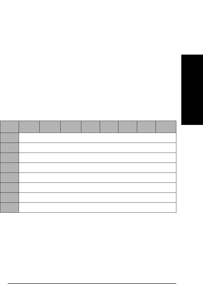
Jukebox SCSI-2 Command Set
Read Element Status Command (B8H)
Chapter 3 3-69
Jukebox SCSI-2 CommandsJukebox SCSI-2 Commands
Starting Element
Address Specifies the minimum element address to report.
Number Of
Elements Maximum number of elements to report.
Allocation
Length The number of bytes of element status to return. The
data consists of an 8-byte Element Status Page Header,
followed by one or more Element Status pages.
Read Element Status Data
Read Element Status Data consists of a data header, followed by one or
more Element Status pages.
Byte Count Report
Available The number of bytes of element status page data
available.
Table 3-71 Read Element Status Data Header
Byte 7 6 5 4 3 2 1 0
0First Element Address Reported (MSByte)
1First Element Address Reported (LSByte)
2Number of Elements Reported (MSByte)
3Number of Elements Reported (LSByte)
4Reserved (0)
5Byte Count of Report Available (MSByte)
6Byte Count of Report Available (Middle Byte)
7Byte Count of Report Available (LSByte)

Jukebox SCSI-2 Command Set
Read Element Status Command (B8H)
Chapter 33-70
Element Type Code 1H - Picker
Element Descriptor
Length The number of bytes in each Element Descriptor Block
Byte Count of
Descriptor Data
Available Element Descriptor Length for X Number of Elements
of the type shown in byte 0.
Element
Address The address of the element being reported by this
descriptor block.
Except When set to 1, the element is in an abnormal state.
Full When set to 1, the element contains a cartridge.
Table 3-72 Medium Transport Element Descriptor Block
Byte 7 6 5 4 3 2 1 0
0Element Type Code (1H)
1Reserved (0)
2Element Descriptor Length (MSByte)
3Element Descriptor Length (LSByte)
4Reserved (0)
5Byte Count of Descriptor Data Available (MSByte)
6Byte Count of Descriptor Data Available (Middle Byte)
7Byte Count of Descriptor Data Available (LSByte)
8Element Address (MSByte)
9Element Address (LSByte)
10 Reserved (0) Except Reserved
(0)
Full
11 Reserved (0)

Jukebox SCSI-2 Command Set
Read Element Status Command (B8H)
Chapter 3 3-71
Jukebox SCSI-2 CommandsJukebox SCSI-2 Commands
Element Type Code 2H - Storage Slot
Element Descriptor
Length The number of bytes in each Element Descriptor Block
Byte Count of
Descriptor
Data Element Descriptor Length for X Number of Elements
of the type shown in byte 0.
Element
Address The address of the element being reported by this
descriptor block.
Access When set to 1, access to the element by the Medium
Transport Element is allowed.
Except When set to 1, the element is in an abnormal state.
Full When set to 1, the element contains a cartridge.
Table 3-73 Read Element Status Storage Element Descriptor Block
Byte 7 6 5 4 3 2 1 0
0Element Type Code (2H)
1Reserved (0)
2Element Descriptor Length (MSByte)
3Element Descriptor Length (LSByte)
4Reserved (0)
5Byte Count of Descriptor Data Available (MSByte)
6Byte Count of Descriptor Data Available (Middle Byte)
7Byte Count of Descriptor Data Available (LSByte)
8Element Address (MSByte)
9Element Address (LSByte)
10 Reserved (0) Access Except Reserved
(0)
Full
11 Reserved (0)

Jukebox SCSI-2 Command Set
Read Element Status Command (B8H)
Chapter 33-72
Element Type Code 3H - Mailslot
Element Descriptor
Length The number of bytes in each Element Descriptor Block.
Byte Count of
Descriptor Data
Available Element Descriptor Length for X Number of Elements
of the type shown in byte 0.
Element
Address The address of the element being reported by this
descriptor block.
InEnab When set to 1, Import to the jukebox is enabled.
ExEnab When set to 1, Export from the jukebox is enabled.
Table 3-74 Read Element Status Import/Export Element Descriptor Block
Byte 7 6 5 4 3 2 1 0
0Element Type Code (1H)
1Reserved (0)
2Element Descriptor Length (MSByte)
3Element Descriptor Length (LSByte)
4Reserved (0)
5Byte Count of Descriptor Data Available (MSByte)
6Byte Count of Descriptor Data Available (Middle Byte)
7Byte Count of Descriptor Data Available (LSByte)
8Element Address (MSByte)
9Element Address (LSByte)
10 Reserved (0) In- Enab Ex-Enab Access Except Imp/Exp Full
11 Reserved (0)

Jukebox SCSI-2 Command Set
Read Element Status Command (B8H)
Chapter 3 3-73
Jukebox SCSI-2 CommandsJukebox SCSI-2 Commands
Access When set to 1, access to the element by the Medium
Transport Element is allowed.
Except When set to 1, the element is in an abnormal state.
Imp/Exp When set to 1, the operator inserted the cartridge into
the mailslot.
When set to 0, the jukebox mechanism puts the
cartridge in the mailslot.
Full When set to 1, the element contains a cartridge.

Jukebox SCSI-2 Command Set
Read Element Status Command (B8H)
Chapter 33-74
Element Type Code 4H - Drive
Table 3-75 Read Element Status Data Transfer Element Descriptor Block
Byte 7 6 5 4 3 2 1 0
0Element Type Code (4H)
1Reserved (0)
2Element Descriptor Length (MSByte)
3Element Descriptor Length (LSByte)
4Reserved (0)
5Byte Count Of Descriptor Data Available (MSByte)
6Byte Count of Descriptor Data Available (Middle Byte)
7Byte Count of Descriptor Data Available (LSByte)
8Element Address (MSByte)
9Element Address (LSByte)
10 Reserved (0) Access Except Reserved
(0)
Full
11 Reserved (0)
12 Additional Sense Code (See Table B-2 on page B-4)
13 Additional Sense Code Qualifier (See Table B-2 on page B-4.)
14 Not
Bus
Reserved
(0)
ID
Valid
LU
Valid
Reserved
(0)
Logical Unit Number
15 SCSI Bus Address
16 Reserved (0)
17 SValid Invert Reserved (0)
18 Source Storage Element Address (MSByte)
19 Source Storage Element Address (LSByte)
Jukebox SCSI-2 Command Set
Read Element Status Command (B8H)
Chapter 3 3-75
Jukebox SCSI-2 CommandsJukebox SCSI-2 Commands
Element Descriptor
Length The number of bytes in each Element Descriptor Block.
Byte Count of
Descriptor Data
Available Element Descriptor Length for X Number of Elements
of the type shown in byte 0.
Element
Address The address of the element being reported by this
descriptor block.
Access When set to 1, access to the element by the Medium
Transport Element is allowed.
Except When set to 1, the element is in an abnormal state.
Information about the abnormal state is available in the
Additional Sense Code and Additional Sense Code
Qualifier bytes. (See Table B-2 on page B-4)
Full When set to 1, the element contains a cartridge.
Not Bus When set to 1, the SCSI Bus Address and the Logical
Unit value fields are not on the SCSI Bus used to select
the library.
20-23aReserved (0)
24-33aDrive Serial Number (ASCII)
a. These fields are applicable for the 300mx, 600mx, 700mx, 1200mx and 2200mx
models only.
Table 3-75 Read Element Status Data Transfer Element Descriptor Block
Byte 7 6 5 4 3 2 1 0

Jukebox SCSI-2 Command Set
Read Element Status Command (B8H)
Chapter 33-76
IDValid When set to 1, the SCSI Bus Address field contains valid
information.
LUValid When set to 1, the logical unit number field contains
valid information.
Logical Unit
Number If valid, provides the logical unit number within the
SCSI bus address of the device served by the jukebox at
this element.
SValid When set to 1, the source storage element address field
and the invert bit information are valid.
Invert When set to 1, the cartridge in the element was inverted
by a move operation since it was last in the source
storage element.

Appendix A A-1
Drive Error Codes
A Drive Error Codes

Drive Error Codes
Chapter Overview
Appendix AA-2
Chapter Overview
This chapter contains the following information:
• Request Sense Command sense key values
• Request Sense Command additional sense code values
• Internal Error Codes
• DSP Error Codes

Drive Error Codes
Drive Request Sense Command Values
Appendix A A-3
Drive Error Codes
Drive Request Sense Command Values
The Request Sense Command (see Table 2-6 on page 2-10) returns values
for the Sense Key and Additional Sense Code.
Drive Request Sense - Sense Key Values
Table A-1 Request Sense - Sense Key Values Byte 2, Bits 3 through 0
Sense
Key
Name Abbrev. Description
0H No Sense NS The command completed
successfully.
1H Recovered Error RE The last command was
completed successfully
with some recovery action
performed by the drive/
controller.
2H Not Ready NR The drive cannot be
accessed.
3H Medium Error ME The command terminated
with an unrecovered error
condition that was caused
by a optical disk defect.
4H Hardware Error HE The drive/controller
detected a hardware error.
5H Illegal Request IR There was an illegal
parameter in the
command descriptor block
or in the additional
parameters supplied for
some commands.

Drive Error Codes
Drive Request Sense Command Values
Appendix AA-4
6H Unit Attention UA The optical disk has been
loaded, the unit has been
reset, or the Mode Select
parameters have been
changed.
7H Data Protect DP A command that writes to
the optical disk cannot be
performed due to the
write-protect condition of
the optical disk write-
protect switch.
8H Blank Check BC A blank sector was
detected during a Read
(Group 0 or 1) or Verify, or
a written sector was
detected during a Write
(Group 0 or 1) or a Write
and Verify command.
0BH Aborted
Command
AC Indicates that the drive
aborted the last command.
The initiator may be able
to recover by attempting
the command again.
Table A-1 Request Sense - Sense Key Values Byte 2, Bits 3 through 0
Sense
Key
Name Abbrev. Description

Drive Error Codes
Drive Request Sense Command Values
Appendix A A-5
Drive Error Codes
Request Sense - Additional Sense Code Values
Bytes 12 and 13
Table A-2 Request Sense - Additional Sense Code Values
Sense
Code
and
Qualifier
Sense
Key
Description
00 00 0H - NS No Additional Sense Information
03 00 4H - HE Write Fault, Write Command Failed
04 00 2H - NR Drive Not Ready
04 01 2H - NR LUN in Process of Becoming Ready
04 02 2H - NR LUN Not Ready, Initializing Command
Required
04 04 2H - NR LUN Not Ready, Format in Progress
09 01 4H - HE Tracking Servo Failure
09 02 4H - HE Focus Servo Failure
09 03 4H - HE Spindle Servo Failure
0C 01 1H - RE Write Error Recovered with Auto
Reallocation
0C 02 3H - ME Write Error - Auto Reallocation Failed
10 00 3H - ME ID CRC or ECC Error
11 00 3H - ME Unrecovered Read Error
15 00 4H - HE Random Positioning Error
16 00 3H - ME Data Synchronization Mark Error
18 00 1H - RE Recovered Read Data With ECC Procedure
18 01 1H - RE Recovered Data with Error Correction and
Retries
19 01 1H - RE Defect List Not Available

Drive Error Codes
Drive Request Sense Command Values
Appendix AA-6
1A 00 5H - IR Parameter List Length Error
1B 00 4H - HE Synchronous Data Transfer Error
1C 00 3H - ME Defect List Not Found
1C 01 3H - ME Primary Defect List Not Found
1C 02 3H - ME Grown Defect List Not Found
20 00 5H - IR Invalid Command Operation Code
21 00 5H - IR Logical Block Address out of Range
24 00 5H - IR Invalid Field In CDB
25 00 5H - IR LUN Not Supported
26 00 5H - IR Invalid Parameter List
26 01 5H - IR Parameter Not Supported
26 02 5H - IR Parameter Value Invalid
27 00 7H - DP Write Protected
28 00 6H - UA Medium Changed
29 00 6H - UA Power-On, Reset or Bus Device Reset
Occurred
2A 00 6H - UA Mode Select Parameters Changed
2F 00 6H - UA Command Cleared by Another Initiator
30 00 3H - ME Incompatible Cartridge
31 00 3H - ME Medium Format Corrupted
32 00 3H - ME No Defect Spare Location Available
32 01 3H - ME Defect List Update Error
Table A-2 Request Sense - Additional Sense Code Values
Sense
Code
and
Qualifier
Sense
Key
Description

Drive Error Codes
Drive Request Sense Command Values
Appendix A A-7
Drive Error Codes
39 00 5H - IR Saving Parameters Not Supported
3A 00 2H - NR Medium Not Present
3D 00 5H - IR Invalid Bits in Identify Message
3F 01 6H - UA Microcode Has Been Changed
40 80 4H - HE Bias Magnet Failure
40 81 4H - HE Limited Laser Life
40 84 4H - HE Temperature Alarm
40 85 4H - HE Laser Failure, No LD Power
40 86 4H - HE Read Channel Calibration Error
40 87 4H - HE Illegal Servo Signal
40 88 4H - HE Sensor Failure
40 90 4H - HE DSP Diag Error
40 91 4H - HE 12V Line Failure
40 92 4H - HE Medium Recognition Error
40 95 4H - HE Buffer Memory Test Error
40 97 4H - HE DSP Communication Diag Error
40 98 4H - HE DSP Download Error
40 99 4H - HE RAM Diag Error
40 9A 4H - HE ODC Diag Error
40 9B 4H - HE Buffer Memory Diag Error
40 9D 4H - HE Write CAL Error
43 00 BH - AC Message Error
Table A-2 Request Sense - Additional Sense Code Values
Sense
Code
and
Qualifier
Sense
Key
Description

Drive Error Codes
Drive Request Sense Command Values
Appendix AA-8
44 00 4H - HE Internal Target Failure
45 00 BH - AC Select or Reselect Failure
47 00 BH - AC SCSI Parity Error
48 00 BH - AC Initiator Detected Error Message Received
49 00 BH - AC Invalid Message Error
4E 00 BH - AC Overlapped Commands Attempted
53 00 4H - HE Media Load/Eject Failure
53 02 5H - IR Medium Removal Prevented
92 00 8H - BC Overwrite Attempted
93 00 8H - BC Blank Sector Detected
94 00 8H - BC Written Sector Detected
Table A-2 Request Sense - Additional Sense Code Values
Sense
Code
and
Qualifier
Sense
Key
Description

Drive Error Codes
Internal Error Codes
Appendix A A-9
Drive Error Codes
Internal Error Codes
NOTE The XXXX that follows the internal error code refers to the 1 byte dsp/odc
error code where available.
Table A-3 Internal Error Codes
Error
Code
(hex.)
Message
00070000 Medium was changed
00080000 Power on, reset, or bus device reset occurred (5.2 Gb drives)
00080001 Unit Attention: power on reset (9.1 Gb drives)
00080002 SCSI bus reset (9.1 Gb drives)
00080003 SCSI bus device reset message (9.1 Gb drives)
00080004 Autochanger reset (9.1 Gb drives)
00090000 Mode parameter changed
006B0000 Microcode changed
02540000 Queued command cleared by another initiator
012BXXXX An invalid SCSI message was received
012CXXXX An invalid bit of Identify message is set to 1
012DXXXX Parity error was detected while receiving a SCSI message
012EXXXX A SCSI message was rejected
012FXXXX The Attention signal was asserted after the Message Out Phase
0130XXXX A SCSI interface parity error was detected
0131XXXX The Initiator Detected Error Message was received
0133XXXX The offset of the synchronous data transfer is too large

Drive Error Codes
Internal Error Codes
Appendix AA-10
0134XXXX The period of the synchronous data transfer is too short
0139XXXX The Clear Queue message was received
013AXXXX Initiator does not respond to reselection
013BXXXX Unusual SCSI controller condition
013CXXXX Unusual SCSI controller condition
0204XXXX An invalid microcode data was received
020AXXXX An invalid operation code was specified
020BXXXX An invalid LBA range was specified
020CXXXX An invalid field in CDB was specified
020DXXXX An invalid parameter list was specified
0210XXXX Parameter list length is wrong
0211XXXX The parameter saving function is not supported
0212XXXX The parameter is not currently saved
0213XXXX Cartridge eject was prevented
0250XXXX Attempt to write data to a written sector of a write-once disk
0254XXXX A queued command is cleared by another initiator
0255XXXX A command was received for the same ITL (or ITLQ) nexus
026CXXXX An invalid command for the write-once disk was specified
02B3XXXX Invalid command when using 14x 512 b/s or 1024 b/s disk
0321XXXX Loader task ended with an unusual condition
0322XXXX Sensor failure during loader initialization
0323XXXX Failed recovery procedure during loader initialization
Table A-3 Internal Error Codes
Error
Code
(hex.)
Message

Drive Error Codes
Internal Error Codes
Appendix A A-11
Drive Error Codes
0324XXXX Cartridge loading failed
0327XXXX Cartridge unloading failed
0417XXXX The loader is being initialized
0418XXXX No cartridge is in the drive
041AXXXX The disk is being spun-up
041BXXXX The disk is being loaded
041CXXXX The disk load is complete (not an error)
041DXXXX The drive is not ready
041EXXXX A disk is being spun-down
041FXXXX A disk is being unloaded
0420XXXX Drive unable to go Ready because of an unknown reason
0425XXXX The drive is in process of becoming ready
046FXXXX The drive is in process of formatting a disk
0514XXXX The Defect List Format is not supported
0515XXXX The cartridge is write-protected
0528XXXX Invalid cartridge ID hole
0529XXXX The medium is not supported
053EXXXX PDL data is invalid
053FXXXX SDL data is invalid
0540XXXX DDS sectors were not found
0541XXXX PDL sector was not found
0542XXXX SDL sector was not found
Table A-3 Internal Error Codes
Error
Code
(hex.)
Message

Drive Error Codes
Internal Error Codes
Appendix AA-12
0543XXXX DMA sector cannot be read
0544XXXX DDS data are invalid
0545XXXX SFP sector cannot be read
0546XXXX SFP data is invalid
0547XXXX Failed in Erase/Blank Check/Write/Read/Compare test after
disk load and spin-up
0548XXXX Spare area for defective sector is full
0549XXXX Failed updating DMA sectors
054AXXXX PEP data is invalid
054BXXXX Defective sector was recovered with automatic write
reallocation procedure
054CXXXX Failed in automatic write reallocation procedure
0551XXXX A blank sector was detected
0577XXXX Automatic Write Reallocation performed due to ID Error
0578XXXX Automatic Write Reallocation performed due to uncorrectable
ECC Error
0579XXXX Automatic Write Reallocation performed due to SYNCH Error
057AXXXX Automatic Write Reallocation performed due to Servo Fault
Error
057EXXXX ID Error recovered by retry
057FXXXX Uncorrectable ECC Error recovered by retry
0580XXXX SYNCH Error recovered by retry
0581XXXX Servo Fault Error recovered by retry
Table A-3 Internal Error Codes
Error
Code
(hex.)
Message

Drive Error Codes
Internal Error Codes
Appendix A A-13
Drive Error Codes
0582XXXX ID Error reoccurs after retry even after changing ID Error
criteria
0583XXXX DMA Update failed after Automatic Reallocation
058AXXXX DMA Update Error condition
0601XXXX Received error code NN (see Table A-5 on page A-17) from ODC
chip
0664XXXX An ODC interrupt time out
0669XXXX A disk type cannot be distinguished (ID Status is CRC=NG)
066AXXXX A disk type cannot be distinguished (no ODC interrupt)
066DXXXX SFP sector cannot be read (ID Status is CRC=NG)
0670XXXX Cannot abort ODC command
0692XXXX Error Code NN received from the ODC chip
0702XXXX Received error code NN (see Table A-6 on page A-19) from the
DSP
075CXXXX Failed downloading DSP code
075EXXXX DSP request command communication error occurred
0760XXXX DSP command communication error occurred
0762XXXX Failed in the ECHO command of DSP
0767XXXX Target sector cannot be found (time out after SEEK complete)
0774XXXX Servo failure during write operation
0789XXXX LPC calibration failed
078BXXXX ID Offset Calibration failed
078CXXXX MO Offset Calibration failed
Table A-3 Internal Error Codes
Error
Code
(hex.)
Message

Drive Error Codes
Internal Error Codes
Appendix AA-14
078DXXXX VFO Offset Calibration failed
078EXXXX ID VGA Calibration failed
078FXXXX MO VGA Calibration failed
0791XXXX Focus bias calibration failed
07B4XXXX Read power calibration failed
0957XXXX Power-on diagnostic time out
0959XXXX ROM Checksum Error
095AXXXX Illegal request for DSP Interface task
095FXXXX Command Parameter Length contradiction to DSP
0961XXXX Release wait of DSP I/F task
0965XXXX ODC command was aborted
0968XXXX Illegal request to Read/Write task
096EXXXX Parameter Block data is invalid
0A4FXXXX 12V line is not supplied
0A71XXXX RAM Test Error
0A72XXXX ODC Test Error
0E03XXXX Failed updating the flash ROM
0E05XXXX Failure when updating the Parameter Block
0E56XXXX Parameter Block Error
Table A-3 Internal Error Codes
Error
Code
(hex.)
Message

Drive Error Codes
Internal Error Codes
Appendix A A-15
Drive Error Codes
Table A-4 ODC Error Codes
Code
(hex.)
Description
01 ODC command was aborted
08 Search condition does not occur
11 A number of error bytes exceeds the setting value
12 Cannot detect the SYNC
13 Both 11 and 12 error occur
14 A number of the RESYNC mis-detecting exceeds the setting
value
15 Both 11 and 14 occur
16 Both 12 and 14 occur
17 Both 13 and 14 occur
20 Sector Mark (SM) error
21 ID CRC error
22 Cannot detect the SYNC and the first RESYNC
23 DTRG (Data Transfer Read Gate) becomes non-active
before all data of a sector was transferred
24 Uncorrectable error
25 CRC error (uncorrectable)
29 Cannot follow the read data transfer from the drive
31 Cannot follow the write data transfer from the drive
32 Digital Sum Value (DSV) error
34 Written sector is detected
42 Buffer Memory Write/Read/Compare error

Drive Error Codes
Internal Error Codes
Appendix AA-16
44 Cannot proceed with error correction because the syndrome
buffer was filled
45 Cannot correct the error bytes within the time of one sector
46 A write data transfer to the encoder was too short
47 A write data transfer to the encoder was too long
48 Unexpected sequence of the error correction occurred
4E Unexpected interrupt was detected in the ODC chip
4F Unexpected firmware sequence occurred in the ODC chip
50 Asynchronous interrupt of the DSP was detected
51 Unexpected ID value was detected
52 Both unexpected and expected ID value detected on one
track
54 Target sector was passed before the current position was
detected
57 A detected ID sector number was greater than the
maximum sector number
70 A Parameter List was not prepared
71 A sector number of the Parameter List was greater than the
maximum sector number
72 A sector count of the Parameter List is set to 0 in the W/R/S
73 Undefined condition is set in the DTS, DLS command
7D Setup command was issued while executing the Identify
operation
7E A command was issued while executing another command
7F Undefined command was issued
Table A-4 ODC Error Codes
Code
(hex.)
Description

Drive Error Codes
Internal Error Codes
Appendix A A-17
Drive Error Codes
Table A-5 ODC Error Codes
Code
(hex.)
Description
01 ODC command was aborted
08 Search condition does not occur
11 A number of error bytes exceeds the setting value
12 Cannot detect the SYNC
13 Both 11 and 12 error occur
14 A number of the RESYNC mis-detecting exceeds the setting
value
15 Both 11 and 14 occur
16 Both 12 and 14 occur
17 Both 13 and 14 occur
20 Sector Mark (SM) error
21 ID CRC error
22 Cannot detect the SYNC and the first RESYNC
23 DTRG becomes non-active before all data of a sector was
transferred
24 Uncorrectable error
25 CRC error (uncorrectable)
29 Cannot follow the read data transfer from the drive
31 Cannot follow the write data transfer from the drive
32 Digital Sum Value (DSV) error
34 Written sector is detected
42 Written sector is detected

Drive Error Codes
Internal Error Codes
Appendix AA-18
44 Cannot proceed with error correction because the syndrome
buffer was filled
45 Cannot correct the error bytes within the time of one sector
46 A write data transfer to the encoder was too short
47 A write data transfer to the encoder was too long
48 Unexpected sequence of the error correction occurred
4E Unexpected interrupt was detected in the ODC chip
4F Unexpected firmware sequence occurred in the ODC chip
50 Asynchronous interrupt of the DSP was detected
51 Unexpected ID value was detected
52 Both unexpected and expected ID value detected on one
track
54 Target sector was passed before the current position was
detected
57 A detected ID sector number was greater than the
maximum sector number
70 A Parameter List was not prepared
71 A sector number of the Parameter List was greater than the
maximum sector number
72 A sector count of the Parameter List is set to 0 in the W/R/S
73 Undefined condition is set in the DTS, DLS command
7D Setup command was issued while executing the Identify
operation
7E A command was issued while executing another command
7F Undefined command was issued
Table A-5 ODC Error Codes
Code
(hex.)
Description

Drive Error Codes
DSP Error Codes
Appendix A A-19
Drive Error Codes
DSP Error Codes
Table A-6 DSP Error Codes
Code
(hex.)
Description
01 Offset measurement failed
09 AC portion of ID signal calibration failure
0B Read channel vga calibration failure (1X/2X/4X/8X)
0C Read channel vga calibration failure (1X/2X/4X/8X)
0D Read channel OST calibration failure (4X/8X)
0E Read channel MOVGAcalibration failure (1X/2X)
0F Focus failure (read channel VGA calibration) (1X/2X/4X/
8X)
10 Cannot be arranged (Read channel IDVGA calibration)
(4X/8X)
11 Medium mischuking (FCSFLR)
21 Spindle off aborted
34 Calibration request
41 Drive is not ready
43 Imitation ATT signal caused by ESD
44 Focus failed (ID search)
45 LPC Attention occurred
52 Illegal zone selected (ALTERNATE ZONE)
53 Illegal zone selected (LD READ/PEP)
54 Illegal target zone (SEEK start)
55 Illegal target zone (SEEK One-Track Jump loop)

Drive Error Codes
DSP Error Codes
Appendix AA-20
56 Illegal target zone (SEEK landing)
57 Illegal next zone (SEEK landing)
58 Illegal zone (ID search)
59 Illegal zone (ID search)
5A Illegal zone (focus search)
5B Kick inner area failed
5C Servo agc time out
61 Focus on failed
62 Focus on aborted
63 Tracking on failed
64 Tracking drive saturation
65 No ID (No SM or CRC=NG) (DON start)
66 No ID (No SM or CRC=NG) (SEEK start)
67 No ID (No SM or CRC=NG) (SEEK landing)
68 Seek slip too much
69 Voice Coil Motor and Multi-Track Jump Seek time out
6A Seek target is too far for a One Track Jump
6B Multi-Track Jump is too long
6C Focus failure
6D Tracking failure
6E Low Pull-in
6F Focus drive saturation
71 Cannot detect PEP signal
Table A-6 DSP Error Codes
Code
(hex.)
Description

Drive Error Codes
DSP Error Codes
Appendix A A-21
Drive Error Codes
72 Focus failed (PEP positioning)
74 Focus failed (searching PEP GAP)
75 Focus failed (searching PEP PA)
76 Focus failed (searching PEP data)
77 Focus on failed (before searching PEP data)
78 No PEP gap found
79 Illegal PEP format found (PEP Postamble)
7A Illegal PEP format found (PEP data)
7B PEP decoding byte count error
7C Invalid PEP SYNC found
7D No PEP SYNC found
7E PEP CRC=NG
7F First and second PEP data compare error
C1 An error occurred in the position sensor
C2 Catastrophic error in the bias magnet
C4 R/C revision error
C9 No laser diode power
CA Assert write fault for controller debug
CF Temperature alarm
D1 Illegal address selected
D3 Invalid command
D4 Communication failure
E1 Spindle Lock time out (drive on)
Table A-6 DSP Error Codes
Code
(hex.)
Description

Drive Error Codes
DSP Error Codes
Appendix AA-22
E2 Spindle off failed
E3 Medium mischuking (Spindle On Failure)
E4 Tracking failure for certifier
E5 Spindle lock time out
E6 Focus failure for certifier
F3 E/AR/C Serial Write Block = NG
F4 E/A LPC Serial Write Block = NG
F5 E/A R/C Serial Read Block = NG
Table A-7 Terms Used In the Tables
Acronym
or
Term
Used
Meaning
ATT Attention Signal
CDB Command Descriptor Block
CRC Cyclic Redundancy Check
DDS Disk Definition Standard
DMA Defect Management Area
DON Drive On
DSP Digital Signal Processor
DSV Digital Sum Value
DTRG “D” Trigger Signal
ITL Initiator Target and Logical Unit
Table A-6 DSP Error Codes
Code
(hex.)
Description

Drive Error Codes
DSP Error Codes
Appendix A A-23
Drive Error Codes
ITLAQ Initiator Target and Logical Unit and Queue Tag
LBA Logical Block Address
NG No Good
ODC Optical Drive Controller
PA Postamble
PEP Phase-Encoded Part
PDL Primary Defect List
RESYNC Resynchronization pattern
SDL Secondary Defect List
SM Sector Mark
SFP Standard Format Part
SYNC Synchronization pattern
VCM Voice Coil Motor
VGA Variable Gain Adjust
VFO Variable Frequency Oscillator
Table A-7 Terms Used In the Tables
Acronym
or
Term
Used
Meaning

Drive Error Codes
DSP Error Codes
Appendix AA-24

Appendix B B-1
Autochanger Error Codes
B Autochanger Error Codes

Autochanger Error Codes
Chapter Overview
Appendix BB-2
Chapter Overview
This chapter contains the following autochanger error code tables:
• Request Sense Codes
• Request Sense Maps
• Hardware Error Codes
• Move Error Codes
• Micro-Move Failure Type Codes
•Diagnostic Tests
An error code can be reported through the Log Sense Command (4DH),
Request Sense Command (03H), or through the control panel.
NOTE See Appendix C for a list of field replaceable units for the each of the
jukebox models.

Autochanger Error Codes
Request Sense Error Codes
Appendix B B-3
Autochanger Error Codes
Request Sense Error Codes
This section identifies each of the error responses for the autochanger
"Request Sense Command (03H)", Table 3-5 on page 3-8.
Table B-1 Request Sense - Sense Key Values — Byte 2, Bits 3 through 0
Sense
Key
Name Abbrev. Description
0H No Sense NS The command completed
successfully.
1H Recovered
Error
RE The last command was
completed successfully with
some recovery action
performed by the
autochanger/controller.
2H Not Ready NR The autochanger cannot be
accessed.
3H Medium Error ME The command terminated
with an unrecovered error
condition that was caused by
a optical disk defect.
4H Hardware
Error
HE The autochanger/controller
detected a hardware error.
5H Illegal Request IR There was an illegal
parameter in the command
descriptor block or in the
additional parameters
supplied for some commands.
6H Unit Attention UA The optical disk has been
loaded, the unit has been
reset, or the Mode Select
parameters have been
changed.

Autochanger Error Codes
Request Sense Error Codes
Appendix BB-4
0BH Aborted
Command
AC This sense key shall be
reported if a target or LUN
receives a second command
from the same initiator
before the previous command
from that initiator has
completed.
Table B-2 Request Sense Data (bytes 12 and 13)
Sense
Code
and
Qualifier
Sense
Key
Description
00 00H 0H-NS No additional sense information
00 00H 1H-RE Error recovered invoked and completed
(Table B-6 on page B-14)
04 00H 0B-AC Aborted command (boot code)
04 01H 2H-NR Autochanger becoming ready
04 02H 2H-NR Unit must first initiate element status
04 03H 2H-NR Fatal error - unit must be corrected
manually
04 88H 02-NR Firmware download needed (boot code)
04 89H 4H-HE Download checksum error
15 01H 4H-HE Move error (Check additional sense bytes)
(Table B-6 on page B-14)
1A 00H 5H-IR Invalid parameter list length
20 00H 5H-IR Unsupported command
21 01H 5H-IR Invalid address - (Table B-3 on page B-7)
Table B-1 Request Sense - Sense Key Values — Byte 2, Bits 3 through 0
Sense
Key
Name Abbrev. Description

Autochanger Error Codes
Request Sense Error Codes
Appendix B B-5
Autochanger Error Codes
22 00H 5H-IR Unsupported command
22 80H 5H-IR Drive is not online
24 00H 5H-IR Illegal field in CDB
25 00H 5H-IR Invalid LUN
26 00H 5H-IR Invalid parameter list
29 00H 6H-UA Power on sense or bus reset
2A 80H 6H-UA Online repair parameters
2F 00H 0BH-AC Command cleared by initiator
3F 01H 06H-UA Microcode has been changed
3B 0DH 5H-IR Element full - (Table B-4 on page B-7)
3B 0EH 5H-IR Source empty - (Table B-4 on page B-7)
3D 00H 5H-IR Invalid identify message in
3F 03 06-UA Inquiry data has changed
40 80H 4H-HE Diagnostic failure (Table B-6 on page B-14)
42 00H 4H-HE Poweron selftest failure
43 00H OB-AC Message parity error
44 00H 4H-HE Internal target error
45 00H 0B-AC Reselection timeout error
47 00H 0B-AC Parity error
48 00H 0B-AC Initiator detected error
4B 00H 0B-AC Bus protocol error - data phase error
Table B-2 Request Sense Data (bytes 12 and 13)
Sense
Code
and
Qualifier
Sense
Key
Description

Autochanger Error Codes
Request Sense Error Codes
Appendix BB-6
4E 00H 0B-AC Bus protocol error (second command sent
early)
53 00H 5H-IR Media load or eject failed
53 02H 5H-IR Medium removal prevented
53 82H 5H-IR Medium removal prevented on drive
55 00H 2H-NR Transaction queue is full
Table B-2 Request Sense Data (bytes 12 and 13)
Sense
Code
and
Qualifier
Sense
Key
Description

Autochanger Error Codes
Request Sense Error Codes
Appendix B B-7
Autochanger Error Codes
Table B-3 Invalid Address: Sense Code 2IH
Field Pointer Description
00 Invalid element address
02 Invalid transport element
04 Invalid source element
06 Invalid destination element
08 Invalid second destination element
Table B-4 Element Full/Empty: Sense Code 3BH
Field Pointer Description
02 Transport full
04 Source empty
06 Destination full/empty
08 Second destination full

Autochanger Error Codes
Additional Sense Data Format for Error Recovery
Appendix BB-8
Additional Sense Data Format for Error
Recovery
For all models, EXCEPT 40fx and 80ex.
Below is a description of the 60 Additional Sense Bytes returned during
the Data In Phase of the Request Sense Command (03H), (Table 3-6 on
page 3-9) from the autochanger. The overall layout of the data is
presented first, followed by a description of each byte.
Table B-5 Request Sense - Additional Sense Data
(For all models, EXCEPT 40fx, 80ex, 125ex and 220mx)
Byte 7 6 5 4 3 2 1 0
18 Reserved (0)
19 Hardware Error Code (Table B-7 on page B-19)
20 First FRU (Table A-1 on page A-2)
21 Second FRU (Table A-1 on page A-2)
22 Third FRU (Table A-1 on page A-2)
23 Move Command Attempted
24-25 Source Element Number
26-27 Destination Element Number
28-29 Second Destination Element Number
30-34 Micro-Move ID History (Table C-1 on page C-2)
35 Failed Micro-Move ID (Table C-1 on page C-2)
36 Micro-Move Error Code
37 Active
Picker
Active
Thumb
Reserved (0)
38-39 Vertical Motor Commanded Position

Autochanger Error Codes
Additional Sense Data Format for Error Recovery
Appendix B B-9
Autochanger Error Codes
Hardware Error
Code Determined by fault isolation, this error code indicates
the cause of the failure. The values of the Hardware
Error Codes are in Table B-7 on page B-19.
First FRU The most likely Field Replacable Unit to be the cause of
the failure. (See Table A-1 on page A-2)
Second FRU The second most likely Field Replacable Unit to be the
cause of the failure. (See Table A-1 on page A-2.)
Third FRU The third most likely Field Replacable Unit to be the
cause of the failure. (Table A-1 on page A-2.)
40-41 Vertical Motor Actual Position
42-43 Plunge Motor Commanded Position
44-45 Plunge Motor Actual Position
46-47 Translate Motor Commanded Position
48-49 Translate Motor Actual Position
50-53 Odometer
54 Move
Cap
Last
SCSI
Reserved (0) Cart 16 Cart 17 Reserved (0)
55 Valid Reservd
(0)
Cart
Tran
Cart
Elem
Reserved (0)
56 Valid Reservd
(0)
Cart
Tran
Cart
Elem
Reserved (0)
57 Valid Reservd
(0)
Cart
Tran
Cart
Elem
Reserved (0)
58-77 Reserved (0)
Table B-5 Request Sense - Additional Sense Data
(For all models, EXCEPT 40fx, 80ex, 125ex and 220mx)
Byte 7 6 5 4 3 2 1 0

Autochanger Error Codes
Additional Sense Data Format for Error Recovery
Appendix BB-10
NOTE The FRU numbers returned are indicators for the most likely cause of an
error, but may not be the actual cause of a problem. Simply changing the
FRU listed may or may not fix the associated problem.
Move Command
Attempted 0 - Exchange
1 - Move
2 - Seek
3 - Initialize Element
4 - Rezero
5 - Rotate Mailslot
6 - Restore
7 - Passthru
Source Element
Number The Element Number to which the source refers.
Destination
Element
Number The Element Number to which the destination refers.
Second
Destination
Number The Element Number to which the second destination
refers.
Micro-Move
ID History The last five autochanger Micro-Move IDs for the
original movement command prior to the failure. (See
Table C-1 on page C-2.)
Failed Micro-
Move ID Actual micro-move that failed. (See Table C-1 on
page C-2)
Micro-Move
Error Code The error code associated with the failed Micro-Move
ID. (See Table B-10 on page B-321.)
Active Picker This bit signifies which side of the disk transport
mechanism is active: 1= top, 0= bottom.

Autochanger Error Codes
Additional Sense Data Format for Error Recovery
Appendix B B-11
Autochanger Error Codes
Active Thumb This bit signifies which thumb is active: 0 = north, 1 =
south.
Vertical Motor
Commanded
Position The position to which the vertical motor was
commanded.
Vertical Motor
Actual
Position The actual position of the vertical motor.
Plunge Motor
Commanded
Position The position to which the plunge motor was
commanded.
Plunge Motor
Actual
Position The actual position of the plunge motor.
Translate Motor
Commanded
Position The position to which the translate motor was
commanded.
Translate Motor
Actual
Position The actual position of the translate motor.
Odometer The move odometer.
Mechanism State
Bit Map
(Byte 54) The state of the jukebox after the termination of the
retry or recovery algorithms. This byte is bit mapped
from least significant bit to most significant bit as
follows:
7 - Move Capability 1=The jukebox is capable of
performing movement commands.
6 - Last SCSI State 1=The jukebox returned cartridges
to the state they were in prior to the failed command.
5-4 Reserved

Autochanger Error Codes
Additional Sense Data Format for Error Recovery
Appendix BB-12
3 - Cartridge in Transport 16 1=a cartridge is in the
transport 16 mechanism. If the cartridge wasn't
replaced after a failure, the appropriate Element Bit
Map will indicate which cartridge is in the transport.
2 - Cartridge in Transport 17 1=a cartridge is in the
transport 17 mechanism. If the cartridge wasn't
replaced after a failure, the appropriate Element Bit
Map will indicate which cartridge is in the transport.
1-0 Reserved
Source Element
Bit Map
(Byte 55) Status of the cartridge in the specified Source Element
of the Move or Exchange command after the failure or
retry, as well as the status of the element itself, as
shown below:
7 - Valid 1 = the values in this byte and the Element
Number byte are valid.
6 - Reserved
5 - Cartridge in Transport 1 = the cartridge originally in
this element is still in the transport.
4 - Cartridge in Element 1 = after all recovery
algorithms have been exhausted, the cartridge being
moved from this element remained in this element.
3-0 Reserved

Autochanger Error Codes
Additional Sense Data Format for Error Recovery
Appendix B B-13
Autochanger Error Codes
Destination 1 Element
Bit Map
(Byte 56) Indicates the status of the element that was the First
Destination of the Exchange command after the failure
or retry of the command.
7 - Valid 1= the values in this byte and the Element
Number are valid.
6 - Reserved
5 - Cartridge in Transport 1 = the cartridge originally in
this element is still in the transport.
4 - Cartridge in Element 1 = after all recovery
algorithms have been exhausted, the cartridge being
moved from this element remained in this element.
3-0 Reserved
Destination 2 Element
Bit Map
(Byte 57) Indicates the status of the element that was the
Destination Element of a move or Second Destination of
the Exchange command after the failure or retry of the
command.
7 - Valid 1 = the values in this byte and the Element
Number are valid.
6 - Reserved
5 - Cartridge in Transport 1 = the cartridge being moved
to this element is still in the transport.
4 - Cartridge in Element 1 = the cartridge being moved
to this element is in this element after all recovery
algorithms have been exhausted.
3-0 Reserved

Autochanger Error Codes
Additional Sense Data Format for Error Recovery
Appendix BB-14
Table B-6 Request Sense - Additional Sense Data
(For models 40fx, 80ex, 125ex and 220mx ONLY)
Byte 7 6 5 4 3 2 1 0
18 Move Error (Table B-9 on page B-29)
19 Hardware Error Code (Table B-8 on page B-22)
20 First FRU (Table A-2 on page A-4)
21 Second FRU (Table A-2 on page A-4)
22 Third FRU (Table A-2 on page A-4)
23 MvCap Last Rsvd
(0)
PosLost CartIn Reserved (0)
24-25 Reserved (0)
26 DInRty DEjRty PkrRec CarAssy Reserved (0) BFHm FHR
27 Retry Count
28-29 Reserved (0)
30 DInRty DEjRty PkrRec CarAssy Reserved (0) BFHm FHR
31 Recovery Count
32-34 Reserved (0)
35 Valid ErrEn CartIn CartEl UnexpMt UnexpFl CartInv ElRty
36-37 Source Element Number
38 Valid ErrEn CartIn CartEl UnexpMt UnexpFl CartInv ElRty
39-40 Destination Element Number
41 Valid ErrEn CartIn CartEl UnexpMt UnexpFl CartInv ElRty
42-43 Secondary Source Element Number
44 Valid ErrEn CartIn CartEl UnexpMt UnexpFl CartInv ElRty
45-46 Second Destination Element Number

Autochanger Error Codes
Additional Sense Data Format for Error Recovery
Appendix B B-15
Autochanger Error Codes
Move Error
Code The movement that was being performed when the
error occurred. The values of the Move Error Codes are
in Table B-9 on page B-29.
Hardware Error
Code Determined by fault isolation, this error code indicates
the cause of the failure. The values of the Hardware
Error Codes are in Table B-8 on page B-22.
First FRU The most likely Field Replacable Unit to be the cause of
the failure. (See Table A-2 on page A-4)
Second FRU The second most likely Field Replacable Unit to be the
cause of the failure. (See Table A-2 on page A-4.)
Third FRU The third most likely Field Replacable Unit to be the
cause of the failure. (See Table A-2 on page A-4.)
NOTE The FRU numbers returned are indicators for the most likely cause of an
error, but may not be the actual cause of a problem. Simply changing the
FRU listed may or may not fix the associated problem.
47-49 Reserved (0)
50-54 Micro-Move ID History (Table C-2 on page C-17)
55 Failed Micro-Move ID (Table C-2 on page C-17)
56 Micro-Move Error Code (Table B-11 on page B-36)
57-60 Vertical Motor Commanded Position
61-64 Vertical Motor Actual Position
65-68 Horizontal Motor Commanded Position
69-72 Horizontal Motor Actual Position
73-77 Reserved (0)
Table B-6 Request Sense - Additional Sense Data
(For models 40fx, 80ex, 125ex and 220mx ONLY)
Byte 7 6 5 4 3 2 1 0

Autochanger Error Codes
Additional Sense Data Format for Error Recovery
Appendix BB-16
MvCap A Move Capable bit of 1 indicates the AC is capable of
performing move commands.
LastSCSI A Last bit of 1 indicates the AC has successfully
returned the cartridges to the state they were in before
the failed command was executed.
PosLost A Position Lost bit of 1 indicates the AC cannot
calibrate the mechanism and has lost position of the
picker.
CartIn A Cartridge in Transport bit of 1 indicates a cartridge is
in the picker mechanism.
DInRty A Drive Insert Retry bit of 1 indicates that more than
one attempt was needed to insert the cartridge into the
drive. (For Byte 26, this attempt refers to Retry
algorithm and for Byte 30 it refers to Recovery
algorithm.).
DEjRty A Drive Eject Retry bit of 1 indicates that more than one
attempt was needed to eject the cartridge from the
drive. (For Byte 26, this attempt refers to Retry
algorithm and for Byte 30 it refers to Recovery
algorithm.)
PkrRec A Picker Retracted bit of 1 indicates the picker fingers
were fully retracted after a failure. (For Byte 26, this
attempt refers to Retry algorithm and for Byte 30 it
refers to Recovery algorithm.)
CarAssy A Horizontal Carriage Locked bit of 1 indicates the
picker fingers were fully retracted after a failure and
the translate pin is engaged. (For Byte 26, this attempt
refers to Retry algorithm and for Byte 30 it refers to
Recovery algorithm.)

Autochanger Error Codes
Additional Sense Data Format for Error Recovery
Appendix B B-17
Autochanger Error Codes
BFHm A Bad Find Home bit of 1 indicates the Find Home
algorithm was started while the optical sensors were
inoperable. (For Byte 26, this attempt refers to Retry
algorithm.)
FHR A Find Home Recalibration bit of 1 Find Home
algorithm was invoked to recalibrate the mechanism
(For Byte 26, this attempt refers to Retry algorithm and
for Byte 30 it refers to Recovery algorithm).
Retry Count The total number of retry attempts that were
performed.
Recovery Count The total number of recovery attempts that were
performed.
Valid A "0" indicates that this and the next two bytes contain
invalid data. Valid in bytes 41 and 44 are only set
during the Exchange Medium Command.
ErrEn An Error Encountered bit of 1 indicates an error
occurred while the picker was enroute to this element.
CartEl A Cartridge in Element bit of 1 indicates the cartridge
associated with this move is in this element.
UnexpMt An Element Unexpected Empty bit of 1 indicates this
element was unexpectedly empty.
UnexpFl An Element Unexpected Full bit of 1 indicates this
element was unexpectedly full.
CartInv A Cartridge Inverted bit of 1 indicates the cartridge is
inverted from its state before the operation began.
ElRty An Element Required Retry bit of 1 indicates an
operation in or out of this element required one or more
retries.
Source Element
Number The Element Number to which the Source Element Bit
Map (Byte 35) refers.
Destination Element
Number The Element Number to which the Destination Element
Bit Map (Byte 38) refers.

Autochanger Error Codes
Additional Sense Data Format for Error Recovery
Appendix BB-18
Secondary Source
Element
Number The Element Number to which the Secondary Source
Element Bit Map (Byte 41) refers.
Second Destination
Element
Number The Element Number to which the Second Destination
Element Bit Map (Byte 44) refers.
Micro-Move
ID History The last five autochanger Micro-Move IDs for the
original movement command prior to the failure. (See
Table C-2 on page C-17.)
Failed Micro-
Move ID Actual micro-move that failed. (See Table C-2 on page
C-17)
Micro-Move
Error Code The error code associated with the failed Micro-Move
ID. (See Table 5-11 on page 5-35.)
Vertical Motor
Commanded
Position The position to which the vertical motor was
commanded.
Vertical Motor
Actual
Position The actual position of the vertical motor.
Horizontal Motor
Commanded
Position The position to which the horizontal motor was
commanded.
Horizontal Motor
Actual
Position The actual position of the horizontal motor.

Autochanger Error Codes
Hardware Error Codes
Appendix B B-19
Autochanger Error Codes
Hardware Error Codes
Hardware Errors are reported through the Request Sense Command
(03H), (Byte 19, Table 5-6 on page 5-14), the Log Sense Command (4DH),
and the Receive Diagnostic Results Command (1CH), (Byte 1, Table 3-30
on page 3-34).
If an error is unrecoverable (i.e., something is broken or jammed beyond
recovery without manual intervention), the Autochanger will take an
additional step of attempting to identify the FRU that is causing the
failure.
A routine that performs a process of elimination for various FRUs runs
automatically. It attempts to isolate the error to three or less FRUs. If no
error can be found (or if error recovery was made), the unit will return a
No Error status. If an error is found, a Hardware Error Code is returned
when the command completes.
Up to three FRUs will be returned to aide service in replacement priority.
NOTE The FRU numbers returned are indicators for the most likely cause of an
error, but may not be the actual cause of a problem. Simply changing the
FRU listed may or may not fix the associated problem.
Table B-7 Hardware Error Codes (medium and large models only)
Error Code
(hex.)
Failure Description
01 ROM checksum error
02 Register error
03 Microprocessor error
04 Controlled area of RAM checksum error
05 RAM test error
06 SCSI chip error
07 Jukebox controller chip error
0F Configuration module failure

Autochanger Error Codes
Hardware Error Codes
Appendix BB-20
11 Drive serial communications failure
1E Translate motor error
1F Vertical motor error
10 Drive configuration error
20 Plunge motor error
28 Mailslot sensor error
2B Top thumb sensor error
2C Bottom thumb sensor error
32 Invalid test number
33 Invalid configuration
34 Need to initialize element status
35 Exercise test failed
36 Elements reserved
38 Test can only be run from SCSI
39 Unable to run test
3C Move to
3D Flip
3E Translate
3F Put magazine in
40 Get magazine out
41 Test magazine
42 Put drive in
43 Get drive out
Table B-7 Hardware Error Codes (medium and large models only)
Error Code
(hex.)
Failure Description

Autochanger Error Codes
Hardware Error Codes
Appendix B B-21
Autochanger Error Codes
44 Test drive
45 Put mailslot in
46 Get mailslot out
47 Test mailslot
48 Rotate mailslot in
49 Rotate mailslot out
4A Test picker
4B Switch active picker
4C Restore picker
4D Find translate home
4E Find vertical home
4F Find plunge home
50 Clear flip area
51 Clear magazine path
52 Clear drive path
53 Clear mailslot path
5B Finish switch picker
5C Wait plunge
5D Wait vertical
5E Powerfail clear path
5F Powerfail restore cartridges
60 Repeater controller
61 External SCSI cables
Table B-7 Hardware Error Codes (medium and large models only)
Error Code
(hex.)
Failure Description

Autochanger Error Codes
Hardware Error Codes
Appendix BB-22
Table B-8 Hardware Error Codes (For the 40fx, 80ex, 125ex, and 220mx
models ONLY)
Error Code
(hex.)
Failure Description
JUKEBOX CONTROLLER PCA ERROR CODES
00 No error
01 ROM checksum error
03 RAM test error
04 Microprocessor test error
05 Controlled area of RAM checksum error a
06 Illegal interrupt encountered by microprocessor
07 Illegal CPU exception encountered by microprocessor
09 Firmware error
SCSI INTERFACE-SPECIFIC ERROR CODES
0B SCSI controller register error
0C SCSI controller IC's RAM failed
0D SCSI controller message error
0E SCSI controller command error
0F SCSI controller kill error
10 SCSI controller FIFO error
11 SCSI controller target sequence error
12 SCSI controller command sequence error
13 SCSI controller status sequence error
LOOPBACK ERROR CODES
18 SCSI connector loopback error in DBO or I/O

Autochanger Error Codes
Hardware Error Codes
Appendix B B-23
Autochanger Error Codes
19 SCSI connector loopback error in DB1 or C/D
1A SCSI connector loopback error in DB2 or MSG
1B SCSI connector loopback error in DB3 or REQ
1C SCSI connector loopback error in DB4 or ACK
1D SCSI connector loopback error in DB5 or ATN
1E SCSI connector loopback error in DB6 or SEL
1F SCSI connector loopback error in DB7 or BSY
20 SCSI connector loopback error in DBP or RST
MULTIFUNCTION PERIPHERAL IC ERROR CODES
29 RS-232 loopback data did not match what was sent (not
supported)
2A Timed out waiting for RS-232 loopback data (not
supported)
2B Timer A did not count down as expected (not supported)
MOTOR CONTROL IC ERROR CODES
2C Failed read\write test to Motor control IC
2D Motor control IC loopback test failed
2E Motor control IC RAM test failed
POWER SUPPLY ERROR CODES
33 Low voltage power supply failed
34 High voltage power supply failed
DRIVE CONNECT ERROR CODES
38 Drive 1 not connected
Table B-8 Hardware Error Codes (For the 40fx, 80ex, 125ex, and 220mx
models ONLY)
Error Code
(hex.)
Failure Description

Autochanger Error Codes
Hardware Error Codes
Appendix BB-24
39 Drive 2 not connected
3A Drive 3 not connected
3B Drive 4 not connected
MECHANISM ERROR CODES
3CH Unspecified mechanical failure
3EH Unspecified servo failure
40H Unable to free the Picker fingers in preparation for
Carriage motion
41H Unable to verify that the Picker is at the Home position
during Find Home sequence (non-leadscrew side)
42H Unable to find Home; Cartridge-in-path sensor blocked
43H Unable to clear Cartridge-in-path sensors by moving
Picker fingers back
44H Carriage motion failure during Find Home sequence
45H Unable to free the Picker fingers in preparation for
translate motion
46H Carriage motion failed while initializing Home position
during Find Home sequence
47H Translate failed while moving towards non-leadscrew
side during Find Home sequence
48H Carriage motion failed during Carriage/Picker assembly
calibration (leadscrew side)
49H Carriage motion failed during Carriage/Picker assembly
calibration (non-leadscrew side)
4AH Motion error while determining orientation of the Picker
Table B-8 Hardware Error Codes (For the 40fx, 80ex, 125ex, and 220mx
models ONLY)
Error Code
(hex.)
Failure Description

Autochanger Error Codes
Hardware Error Codes
Appendix B B-25
Autochanger Error Codes
4BH No sensor found (V4.2 code only)
4CH Failed flip motion during the Find Home sequence (V4.5
code)
4DH Motion error while checking for cartridge in the Picker
4EH Unable to measure height of sensor on left side
4FH Unable to measure height of sensor on right side
50H Excessive tilt of the Carriage/Picker assembly (away
from the drives)
51H Excessive tilt of the Carriage/Picker assembly (toward
the drives)
52H Excessive cone angle on Picker
53H Excessive stack tilt
54H Unable to complete an interrupted move at power up
EXERCISER TEST ERROR CODES
55H Unable to find top of unit
56H Need to issue Initialize Element Status Command
57H Invalid test configuration
59H Exerciser unrecovered error
5AH Invalid test configuration (elements reserved)
5BH Initialize Element Status command failed
5CH Shipping Diagnostic run with cartridges in the
mechanism
CALIBRATION SENSOR SYSTEM ERRORS
Table B-8 Hardware Error Codes (For the 40fx, 80ex, 125ex, and 220mx
models ONLY)
Error Code
(hex.)
Failure Description

Autochanger Error Codes
Hardware Error Codes
Appendix BB-26
60H Optical sensor failed (leadscrew side - near drives)
61H Optical sensor failed (non-leadscrew side - near drives)
62H Optical sensor failed (leadscrew side - near mailslot)
63H Optical sensor failed (non-leadscrew side - near mailslot)
CARTRIDGE-IN-PATH (CIP) SENSOR SYSTEM ERRORS
64H Intermittent CIP sensor beam (leadscrew side)
65H Intermittent CIP sensor beam (non-leadscrew side)
66H Path physically blocked (leadscrew side)
67H Path physically blocked (non-leadscrew side)
6BH CIP LED failed (leadscrew side)
6CH CIP LED failed (non-leadscrew side)
6DH CIP sensor failed (leadscrew side)
6EH CIP sensor failed (non-leadscrew side)
6FH CIP sensor system failed
MAILSLOT/STORAGE SLOT ERROR CODES
B0H Mailslot will not rotate
B1H Inside Mailslot sensor failed
B2H Mailslot will not accept or release cartridge
B3H Storage slot will not accept or release cartridge
B4H Outside Mailslot sensor failed
DRIVE ERROR CODES
B8H Drive #1 access error
Table B-8 Hardware Error Codes (For the 40fx, 80ex, 125ex, and 220mx
models ONLY)
Error Code
(hex.)
Failure Description

Autochanger Error Codes
Hardware Error Codes
Appendix B B-27
Autochanger Error Codes
B9H Drive #2 access error
BAH Drive #3 access error
BBH Drive #4 access error
SOLENOID ERROR CODES
BCH Drive #1 access failure; possible solenoid failure
BDH Drive #2 access failure; possible solenoid failure
BEH Drive #3 access failure; possible solenoid failure
BFH Drive #4 access failure; possible solenoid failure
FRU DETECTION TEST ERROR CODES
C8H Unable to gain proper servo control of the motors
C9H Unable to move the Picker motor
CAH Unable to move the Carriage motor
CBH Unable to move either motor
CCH Unable to find a hard stop while turning the Picker
motor
CDH Unable to find a hard stop while turning the Carriage
motor
CEH Excessive force required to move the Carriage leadscrew
MISCELLANEOUS ERROR CODES
D0H Find magazine edge failed
D1H Unexpected mailslot empty
FCH The test can only be run from the Front Panel
FDH The test can only be run from the SCSI interface
Table B-8 Hardware Error Codes (For the 40fx, 80ex, 125ex, and 220mx
models ONLY)
Error Code
(hex.)
Failure Description

Autochanger Error Codes
Hardware Error Codes
Appendix BB-28
FEH The test did not run, probably a configuration error
FFH Invalid test number
a. For further explanation, refer to the next section "Additional Descriptions of
Hardware Error Codes."
Table B-8 Hardware Error Codes (For the 40fx, 80ex, 125ex, and 220mx
models ONLY)
Error Code
(hex.)
Failure Description

Autochanger Error Codes
Autochanger Move Error Codes
Appendix B B-29
Autochanger Error Codes
Autochanger Move Error Codes
NOTE These error codes ONLY apply to the model 40fx, 80ex, 125ex, and 220mx
jukeboxes.
Move Errors are reported through byte 18 of the Additional Sense Bytes
Request Sense Command (03H) in Table 5-6 on page 5-14.
Table B-9 Autochanger Move Error Codes
Error Code
(hex.)
Failure Description
00 Failure occurred before any servo-controlled motions
were attempted during Poweron Selftest.
02 Failure while Picker is not moving.
04 Failure while moving the Carriage/Picker assembly
away from drives.
06 Failure while moving the Carriage/Picker assembly
toward drives.
08 Failure while flipping the Picker.
0A Failure while translating the Picker assembly.
0E Failure while moving the Picker fingers back in
preparation to translate.
10 Failure while moving the Picker fingers to engage the
cartridge from the source storage element.
12 Failure while moving the Picker fingers back to
remove the cartridge from the source storage element.
18 Failure while moving the Picker fingers forwards to
insert a cartridge in the destination storage element.
1A Failure while moving the Picker fingers back after
inserting a cartridge in the destination storage slot.

Autochanger Error Codes
Autochanger Move Error Codes
Appendix BB-30
20 Failure while moving the Picker fingers forwards to
engage the cartridge ejected from the drive (source).
22 Failure while moving the Picker fingers back to
remove the cartridge from the drive (source).
28 Failure while moving the Picker fingers forwards to
insert the cartridge into the drive (destination).
2A Failure while moving the Picker fingers back after
inserting a cartridge into the drive (destination).
30 Failure while moving the Picker fingers forward to
engage the cartridge in the mailslot (source).
32 Failure while moving the Picker fingers back to
remove the cartridge from the mailslot (source).
38 Failure while moving the Picker fingers forward to
insert the cartridge in the mailslot (destination).
3A Failure while moving the Picker fingers back after
inserting the cartridge in the mailslot (destination).
40 Failure while rotating the mailslot actuator inward.
42 Failure to ensure that the mailslot rotated inward.
48 Failure while rotating the mailslot actuator outward.
4A Failure to ensure that the mailslot rotated outward.
50 Failure while the finding the home position.
52 Failure while calibrating the Carriage/Picker
assembly.
60 Initializing element status failed while testing an
element with a cartridge in the Picker assembly.
80 Failure to remove a cartridge from a source element.
Table B-9 Autochanger Move Error Codes
Error Code
(hex.)
Failure Description

Autochanger Error Codes
Autochanger Move Error Codes
Appendix B B-31
Autochanger Error Codes
84 Failure to leave a cartridge properly in a destination
element.
88 An obstruction was encountered before the cartridge
had been inserted the proper distance.
90 Source element unexpectedly empty.
94 Destination element unexpectedly full.
A0 Front mailslot sensor failed.
A2 Inside mailslot sensor failed.
A4 Drive light stuck on.
B0 Door interlock open.
Table B-9 Autochanger Move Error Codes
Error Code
(hex.)
Failure Description

Autochanger Error Codes
Jukebox Micro-Move Error Codes
Appendix BB-32
Jukebox Micro-Move Error Codes
Micro-Move Errors are reported through bytes 50-55 in the additional
sense bytes (Table 5-6 on page 5-14) of the Request Sense Command
(03H) and the "Log Sense Command (4DH)" with page code 33H. (See
Table 3-45 on page 3-47.)
NOTE For all models EXCEPT 40fx, 80ex, 125ex, and 220mx.
Table B-10 Micro-Move Error Codes
Error Code
(hex.)
Failure Description
00 No error
01 Vertical over voltage exceeded limit set by firmware
02 Vertical over force exceeded limit set by firmware
03 Vertical servo error
04 Vertical timeout
05 Vertical open path
06 Vertical closed path
0A Plunge over voltage exceeded limit set by firmware
0B Plunge over force exceeded limit set by firmware
0C Plunge servo error
0D Plunge timeout
0E Plunge open path
0F Plunge closed path
10 Top picker expected to be active picker in plunge.
Runtime.

Autochanger Error Codes
Jukebox Micro-Move Error Codes
Appendix B B-33
Autochanger Error Codes
11 Bottom picker expected to be active picker in plunge.
Runtime.
12 Bottom thumb expected to be active in plunge home.
Powerup.
13 Top thumb expected to be active in plunge home.
Powerup.
14 Translate over voltage error.
15 Translate over force error.
16 Translate servo error.
1A Vertical open loop
1B No load complete
1C Translate open loop
1E No load complete
1F Unexpected load complete
20 Unexpected cartridge in drive
21 No cartridge in drive
22 Drive put in accept failed
23 Drive get out accept failed
24 Drive eject failed
25 Drive insert failed
26 Drive eject retry
27 Drive insert retry
28 Clear drive path
29 Drive signal (not used)
Table B-10 Micro-Move Error Codes
Error Code
(hex.)
Failure Description

Autochanger Error Codes
Jukebox Micro-Move Error Codes
Appendix BB-34
2A Drive not connected
32 Magazine put in saturate failed
33 Magazine get out saturate failed
34 Magazine put in accept failed
35 Magazine get out accept failed
36 Magazine measure failed
37 Test magazine failed
38 Return magazine failed
39 Clear magazine path
3C Mailslot put in saturate failed
3D Mailslot get out saturate failed
3E Mailslot put in accept failed
3F Mailslot get out accept failed
40 Measurement of mailslot depth failed
41 Recovery did not clear vertical path.
42 Rotate mailslot in failed
43 Rotate mailslot out failed
46 Flipped too far
47 Did not flip far enough
48 Flip side incorrect
50 Failed to finish a translate
51 Extra force needed to translate
Table B-10 Micro-Move Error Codes
Error Code
(hex.)
Failure Description

Autochanger Error Codes
Jukebox Micro-Move Error Codes
Appendix B B-35
Autochanger Error Codes
5A Command received to rotate mailslot but both pickers
are full
5B Back sensor in mailslot is bad
5C Front sensor in mailslot is bad
5D Command received to eject from the mailslot, but both
pickers are full
5E Attempt to load from an empty mailslot
5F Engaging the mailslot failed on a rotate in
60 Disengaging the mailslot failed on a rotate in
61 Rotate in catch error (not used)
62 Rotate in push out error (not used)
63 Rotate in armed failed (not used)
64 Did not detect hard stop on a rotate in
65 Rotate in was too much distance
66 Engaging the mailslot failed on a rotate out
67 Disengaging the mailslot failed on a rotate out
68 Did not detect hard stop on a rotate out
69 Rotate out distance was too short
6A Could not move thumbs out of the vertical path after a
rotate out
6B Vertical distance difference detected after error
recovery
6C Cartridge in mailslot incorrectly at rotate in
6D Mailslot rotate in accept fail
Table B-10 Micro-Move Error Codes
Error Code
(hex.)
Failure Description

Autochanger Error Codes
Jukebox Micro-Move Error Codes
Appendix BB-36
6E Test failed
Table B-11 Micro-Move Error Codes (For the 40fx, 80ex, 125ex, and 220mx
models ONLY)
Error Code
(hex.)
Description
0 No error
1 Carriage motor drive voltage exceeded limit set by
firmware.
2 Carriage motor overcurrent detected by hardware.
3 Carriage motor force exceeded limit set by firmware.
4 Picker motor drive voltage exceeded limit set by
firmware.
5 Picker motor overcurrent detected by hardware.
6 Picker motor force exceeded limit set by firmware.
7 Low power supply during motion.
8 High power supply during motion.
9 Move stopped because cartridge-in-path beam blocked.
A Cartridge not detected by cartridge-in-path beam.
B Carriage motor not tracking properly.
C Picker motor not tracking properly.
D Carriage motor measured voltage less than expected.
E Picker motor measured voltage less than expected.
10 Find origin failed.
11 Calibrate failed.
Table B-10 Micro-Move Error Codes
Error Code
(hex.)
Failure Description

Autochanger Error Codes
Jukebox Micro-Move Error Codes
Appendix B B-37
Autochanger Error Codes
12 Diagnose FRU failed.
13 Initial recovery failed.
14 Find home failed.
15 Picker initialization failed.
16 Cartridge-in-path beams are blocked.
20 Failed to find hard stop at end of flip.
22 Failed to see sensor close at the end of translate.
23 Failed to move to the vertical position needed to
engage the translate pin.
24 Failed to see sensor close at the start of translate.
25 Failed to see height sensor re-open after closing at the
start of a translate.
28 The translate distance was too long.
29 The translate distance was too short.
31 Failed while checking for cartridge in a drive.
32 Failed to find a hard stop returning cartridge to
storage after testing for presence of cartridge.
33 Failed while checking for cartridge in a storage slot.
34 Failed while checking for cartridge in the Picker.
35 Failed while checking for cartridge in the mailslot.
36 Could not free fingers after testing for a cartridge in a
drive.
38 Failed to verify that cartridge exists after insert.
Table B-11 Micro-Move Error Codes (For the 40fx, 80ex, 125ex, and 220mx
models ONLY)
Error Code
(hex.)
Description

Autochanger Error Codes
Jukebox Micro-Move Error Codes
Appendix BB-38
40 Failed finding the back of storage slot during
retraction.
41 Failed to verify that a disk is in the storage slot on get
using cartridge-in-path beams.
42 Not able to measure the depth of the storage slot.
43 Failed to free fingers from the storage slot.
48 Could not find the back of the storage slot after insert.
49 Failed to verify that a cartridge exists in the storage
slot after insert.
4A Could not free fingers from storage slot after insert.
50 Could not find the back of the mailslot after get.
51 Failed to verify that a disk is in the mailslot on get
using cartridge-in-path beams.
52 Not able to measure the depth of the mailslot.
58 Could not find the back of the mailslot after insert.
59 Failed to verify that a cartridge exists in the mailslot
after insert.
60 Failed to rotate the mailslot in.
61 Failed to rotate the mailslot out.
70 Exhausted retries while attempting to get the drive to
eject the cartridge.
71 Could not verify that the drive ejected the cartridge.
72 Could not free fingers from the drive.
73 No cartridge in drive.
Table B-11 Micro-Move Error Codes (For the 40fx, 80ex, 125ex, and 220mx
models ONLY)
Error Code
(hex.)
Description

Autochanger Error Codes
Jukebox Micro-Move Error Codes
Appendix B B-39
Autochanger Error Codes
74 No load complete.
75 Drive error signal.
76 Unexpected cartridge in the drive.
77 Unexpected load complete.
78 Exhausted retries attempting to get drive to accept the
cartridge.
79 Could not verify that the drive accepted the cartridge.
7E Inline recovery attempts exhausted.
Errors above here are counted in the runtime log as in-line.
Errors below here are counted in the runtime log as retries.
90 Drive access was disallowed because drive busy signal
was active.
91 Drive light stuck off.
94 Outside mailslot sensor failed.
95 Inside mailslot sensor failed.
96 Mailslot rotation failure; possibly caused by operator.
FA Test drive insert retry.
FB Timed out waiting for drive to eject when testing for
the presence of a cartridge; retry being attempted.
FC Retry being attempted on drive insert.
FD Retry being attempted on drive eject.
FE Mechanism error.
Table B-11 Micro-Move Error Codes (For the 40fx, 80ex, 125ex, and 220mx
models ONLY)
Error Code
(hex.)
Description

Autochanger Error Codes
Jukebox Micro-Move Error Codes
Appendix BB-40
Diagnostic Tests
The following tables describe the optical disk library diagnostic tests for
all models, EXCEPT for 40fx, 80ex, 125ex, and 220mx jukeboxes. See
Table B-13 on page B-44 for diagnostic tests for the 40fx, 80ex, 125ex,
and 220mx models.
CAUTION Some diagnostic tests can result in a disk being placed into an improper
storage slot. If this happens, the optical disk library file system is no
longer accurate.
NOTE Not all tests listed in Table 5-12 on page 5-39 are supported on all HP
jukebox models.
Table B-12 Diagnostic Tests (EXCEPT for models 40fx, 80ex, 125ex, and
220mx)
No. Front Panel
Test Name
Description
1POWER UP
TEST
Checks out the general capability of jukebox
by running INIT MECHANICS test.
2WELLNESS
TEST
Checks out the general capability of the
jukebox by running the INIT MECHANICS and
EXERCISE MECH tests. Requires one loaded
cartridge; drive and mailslot must be empty.
5INIT
MECHANICS
Runs the FIND PLUNGE HOME, FIND VERTICAL
HOME, FIND XLATE HOME, and the INIT ELEM
STATUS tests, and rotates the mailslot out.
10 INIT ELEM
STATUS
Functions the same as the SCSI Initialize
Element Status command. This test
physically scans the entire unit to determine
which storage slots contain disks and if the
drives contain disks.
11 EXERCISE
MECH
Runs VERTICAL TEST, TRANSLATE TEST, FLIP
TEST, MAGAZINE IO, DRIVE IO, and MAILSLOT
IO tests.

Autochanger Error Codes
Jukebox Micro-Move Error Codes
Appendix B B-41
Autochanger Error Codes
12 VERTICAL
TEST
Moves the disk transport mechanism up and
down the full length of the rail. Returns
PASS/FAIL. No cartridges required.
13 TRANSLATE
SENSOR
Reports ON or OFF. Looks at translate
sensor.
14 FLIP TEST Makes a combination of moves with a PASS/
FAIL result. It does several flips at various
locations. No optical disks are required.
15 MAGAZINE IO Makes a combination of moves with a PASS/
FAIL result. It moves an optical disk from a
randomly-chosen full to a randomly-chosen
empty slot, with a random flip. It then moves
the disk back to its original storage slot with
its original orientation. This test displays
"FAIL" if there are no disks in the jukebox or
if all storage slots are full. The drives and
mailslot must be empty.
16 DRIVE IO Makes a combination of moves with a PASS/
FAIL result. It moves an optical disk from a
randomly-chosen full slot to a randomly-
chosen drive, with a random flip. It then
moves the cartridge back to its original slot
with its original orientation. This test
displays if there are no disks in the jukebox
or if all storage slots are full. The drives and
mailslot must be empty.
Table B-12 Diagnostic Tests (EXCEPT for models 40fx, 80ex, 125ex, and
220mx)
No. Front Panel
Test Name
Description

Autochanger Error Codes
Jukebox Micro-Move Error Codes
Appendix BB-42
17 MAILSLOT IO Makes a combination of moves with a PASS/
FAIL result. It moves an optical disk from the
lowest-numbered full slot to the mailslot with
a random flip. It then moves the cartridge
back to its original slot with its original
orientation. This test displays if there are no
disks in the jukebox or if all storage slots are
full. The drives and mailslot must be empty.
18 EMPTY DRIVES Moves cartridges out of the drive
mechanism(s) and returns them to their
storage slots.
20 PLUNGE FULL
SPD
Allows the disk transport mechanics to be
run at full speed. This configuration should
always be used when the jukebox is being
used.
21 PLUNGE 1/2
SPD
Allows the disk transport mechanics to be
run at half speed. Use this configuration for
diagnostic purposes only.
22 PLUNGE 1/4
SPD
Allows the mechanics to be run at quarter
speed. Use this configuration for diagnostic
purposes only.
24 FILL PICKER Moves an optical disk into the disk transport
mechanism from the first storage slot
containing a disk.
25 EMPTY
PICKER
Moves an optical disk from the disk transport
mechanism to its home storage slot location if
that location is known, otherwise the disk is
placed into the first available empty storage
slot.
26 CLEAR SOFT
LOG
The runtime log (soft error log) is initialized
to all zeros.
Table B-12 Diagnostic Tests (EXCEPT for models 40fx, 80ex, 125ex, and
220mx)
No. Front Panel
Test Name
Description

Autochanger Error Codes
Jukebox Micro-Move Error Codes
Appendix B B-43
Autochanger Error Codes
29 CLEAR HARD
LOG
Sets Information log 0, Autochanger Error
Log, back to zero.
30 VERTICAL
ENCODER
Moves the disk transport mechanism up and
down the full length of the rail. Returns
PASS/FAIL. No cartridges are required.
101 FIND PLUNGE
HOME
Runs mechanism recalibration, establishes
which picker side is up, and determines the
reference points in the picker travel path.
This test assumes that the mechanics and
servo system are functional.
102 FIND
VERTICAL
HOME
Recalibrates the vertical position and verifies
that the vertical path is clear.
103 FIND XLATE
HOME
Calibrates the translate position.
104 PICKER TEST Flips the disk transport mechanism and
switches active thumbs.
Table B-12 Diagnostic Tests (EXCEPT for models 40fx, 80ex, 125ex, and
220mx)
No. Front Panel
Test Name
Description

Autochanger Error Codes
Jukebox Micro-Move Error Codes
Appendix BB-44
Table B-13 Sequence Tests (For models 40fx, 80ex, 125ex, and 220mx ONLY)
No. Test Name Description
1Poweron Checks all digital data paths and normal
machine operation. This sequence runs tests
that are identical to those run when the optical
disk library operation button is switched on.
When the test is requested via SCSI, the tests
which cannot be executed over SCSI will be
skipped.
Sequence Order:
• 3: Controller Test
• 41: Power Supply Test
• Motor Connection Test
• 5: Initialize Mechanism
2Wellness Test Checks out the general capability of the
Autochanger. Requires one loaded cartridge;
drives and mailslot empty.
Sequence Order:
•1: Poweron Test
• 11: Mechanical Exerciser Test

Autochanger Error Codes
Jukebox Micro-Move Error Codes
Appendix B B-45
Autochanger Error Codes
3Controller Test This sequence is run by the Autochanger
controller when the optical disk library
operation switch is switched on to check out all
paths, and operation of the servo motor and
autochanger circuitry.
Sequence Order:
• 30: Processor Test
• 31: ROM Checksum Test
• 33: Non-Destructive RAM Test
• 32: RAM Checksum Test
• 34: SCSI Interface Controller IC Test
• 36: Motor Control IC Test
• 35: Multi-Function Peripheral IC Test
• 37: Drive Connect Test
5Initialize Mechanism Prepares the unit for movement.
Sequence Order:
• Initialize RAM variables to defaults
•50: Find Home
Exerciser Tests
10 Initialize Element
Status
Performs the same function as the SCSI
INITIALIZE ELEMENT STATUS command. It
physically scans the entire unit to determine
which storage slots and drives contain disks.
Table B-13 Sequence Tests (For models 40fx, 80ex, 125ex, and 220mx ONLY)
No. Test Name Description

Autochanger Error Codes
Jukebox Micro-Move Error Codes
Appendix BB-46
11 Mechanism Exercise
Test
Performs a combination of moves with a pass/fail
result. This exerciser is actually a sequence of
other exerciser tests — 12, 13, 14, 15, 16, and 17.
This exerciser returns an error code #57H
Invalid Configuration if there are no cartridges
loaded into the unit, or if any drive is full.
Requires one loaded cartridge, drives and
mailslot empty.
12 Carriage Move Test Performs a combination of carriage moves with a
pass/fail result. It moves the carriage assembly
to the maximum distance away from the sensor
on both sides. No cartridges are required.
13 Translate Test (Not
valid for the Model
10LC)
Performs a combination of moves with a pass/fail
result. It performs several translations from
various starting positions. No cartridges are
required.
14 Flip Test Performs a combination of moves with a pass/fail
result. It performs several flips at various
locations. No cartridges are required.
15 Storage Slot Test Performs a combination of moves with a pass/fail
result. It moves a cartridge from a randomly-
chosen full slot to a randomly-chosen empty slot,
with a random flip. It then moves the cartridge
back to its original storage slot with its original
orientation. This exerciser returns an error code
#57H Invalid Configuration if there are no
cartridges loaded into the unit, or if any drive is
full. Requires one loaded cartridge.
Table B-13 Sequence Tests (For models 40fx, 80ex, 125ex, and 220mx ONLY)
No. Test Name Description

Autochanger Error Codes
Jukebox Micro-Move Error Codes
Appendix B B-47
Autochanger Error Codes
16 Drive I/O Test Performs a combination of moves with a pass/fail
result. It moves a cartridge from a randomly-
chosen full slot to a drive, with a random flip. It
then moves the cartridge back to its original slot
with its original orientation. It does this once for
each optical drive. Returns an error code #57H
Invalid Configuration if there are no cartridges
loaded into the unit. Requires one loaded
cartridge; drives must be empty.
17 Mailslot I/O Performs a combination of moves with a pass/fail
result. It moves a cartridge from the lowest-
numbered full slot to the mailslot with a random
flip. It then moves the cartridge back to its
original slot with its original orientation.
Returns an error code #57H Invalid
Configuration if there are no cartridges loaded
into the unit. Requires one loaded cartridge;
mailslot must be empty.
18 Speed Factor Setting
Utility
Allows the setting of the speed factor as the first
parameter given. The speed factor determines
how fast the system moves the mechanics. The
number provides 1/Parameter speed (e.g.
Parameter=3 runs the motors at 1/3 of full
speed). This test can only be run from the SCSI
Interface.
19 Zero Maximum Force
Log
The maximum force log is initialized to all zeros.
20 Set Speed Factor to
Full Speed
Allows the mechanics to be run at full speed.
21 Set Speed Factor to
Half Speed
Allows the mechanics to be run at half speed.
22 Set Speed Factor to
Quarter Speed
Allows the mechanics to be run at quarter speed.
Table B-13 Sequence Tests (For models 40fx, 80ex, 125ex, and 220mx ONLY)
No. Test Name Description

Autochanger Error Codes
Jukebox Micro-Move Error Codes
Appendix BB-48
23 Shipping Moves the picker to the appropriate position in
preparation for shipping.
24 Fill Picker Moves a cartridge into the picker from the first
full storage slot.
25 Empty Picker Moves a cartridge from the picker to the first
empty storage slot.
26 Zero Runtime Log The entire runtime log is initialized to all zeros.
27 Set Minimum Retries This sets the number of retries to 1. This may be
set to see if the chosen test is doing what you
want it to do. After you are satisfied that the test
is what you want, run Test 28 which resets the
number of retries to default values.
28 Set to Default Number
of Retries
Resets the number of retries to powerup default
values. Used after setting retries to 1 by Test 27.
29 Zero Error Log Sets Information Log 0, Autochanger Error Log
back to zero.
Electronic Core Tests
30 Microprocessor
Operation Test
Performs a functional check of the
microprocessor. This test will shut down the
servo system; a poweron sequence runs upon
completion.
31 ROM Checksum Test Performs a checksum verification of the ROM.
32 RAM Checksum Test A checksum of the "Controlled" area of RAM is
kept on an ongoing basis. This test verifies that
the checksum is still valid.
33 Non-Destructive RAM
Test
Tests all of the controller's RAM, checking for
data acceptance and retention. The test is non-
destructive to RAM unless interrupted by power
failure. This test will shut down the servo
system; a poweron sequence runs upon
completion.
Table B-13 Sequence Tests (For models 40fx, 80ex, 125ex, and 220mx ONLY)
No. Test Name Description

Autochanger Error Codes
Jukebox Micro-Move Error Codes
Appendix B B-49
Autochanger Error Codes
34 SCSI Interface
Controller Chip Test
Checks out operations of the SCSI interface
controller chip. This test will not be run if
initiated via SCSI, it reports PASS.
36 Motor Control Chip
Test
Exercises the registers of the motor control IC.
In order to perform correctly, this test shuts
down the servo system.
37 Drive Connect Test Checks for expected drive configuration. This is
done by polling the drive connect signal on each
of the possible drives. This line is grounded at
the drive end if a drive is connected. If the drives
physically connected do not match the expected
configuration then an error is reported.
38 Control Panel Light
Show &Button Test
Lights each portion of the display individually
and then together. Requires pushing each front
panel button to finish the test.
40 Power Supply Test Looks at both the 12-Volt and the 24-Volt power
supplies to verify that they are within limits.
The limits for the 12V supply are 11V and 13V
and the 24V supply limits are 23.5V and 25.5V.
41 SCSI Connector
Loopback Test
(Interactive)
Performs a loopback through SCSI connectors,
checking proper operation of the SCSI drivers,
receivers, and cables. Requires an external
loopback hood with terminator power. Will not
run if it was initiated via SCSI; if so, it reports
error FCH Test Did Not Run.
42 Optical Sensor Test
(Interactive if done
through the control
panel)
Checks the status of the optical sensors. Also
checks the status of the mailslot sensor (see Test
43). "0"s are placed on the control panel display
on the left and right of the display. The mark is
an open zero if the sensor is not blocked, and a
zero filled in with lit segments if a sensor is
blocked. No FRU is returned.
Table B-13 Sequence Tests (For models 40fx, 80ex, 125ex, and 220mx ONLY)
No. Test Name Description

Autochanger Error Codes
Jukebox Micro-Move Error Codes
Appendix BB-50
43 Mailslot Sensor Test
(Interactive if done
through the control
panel)
See the description for Test 42.
44 Cartridge-in-path
(Interactive if done
through the control
panel)
Displays max/min intensity and ambient
readings for the left and right beams. You must
enter a parameter to choose the beam to display
(0=left, 1=right). The following is an example of
an error message for the right beam and how it
is translated:
F0 is hexadecimal for 240
E1 is hexadecimal for 225
R means right beam
06 is the maximum ambient reading.
00 is the minimum ambient reading.
Intensity L/R Ambient
Max Min Max Min
240 225 R 6 0
Press CANCEL to stop.
50 Find Home Sequence 50Find Home SequenceMoves the picker to a
known "home" position. This test assumes
nothing about the state of the mechanics. The
"home" location is the lower left position of the
box. The servo system is initialized to the "home"
location. It then automatically runs Test 51.
51 Carriage/Picker
Assembly Calibration
Test
Runs the portion of the mechanism recalibration
related to the optical sensors. It measures sensor
offsets and calculates picker tilt and droop. This
test assumes that the mechanics and servo
system are functional.
Table B-13 Sequence Tests (For models 40fx, 80ex, 125ex, and 220mx ONLY)
No. Test Name Description

Autochanger Error Codes
Jukebox Micro-Move Error Codes
Appendix B B-51
Autochanger Error Codes
60 FRU Isolation Test Assumes that something has physically failed,
either electronic or mechanical. A series of
special low-level tests are executed to select the
three (or fewer) FRUs which are most likely to
be at fault. Tests 30, 31, 33, 35, 36, 40, and 50
are executed as a part of the isolation process.
65 Calibrate Magazines Calculates a min/max clearance for a magazine.
(The selected magazine should be empty.) The
autochanger requires a disk in the mailslot. The
test passes if clearance is 85 encoder counts (1
mm) up and down. (See Info 23 for actual
values.)
If this test is run by SCSI command, set Byte 1
to the magazine number.
The test returns: PASS or FAIL.
66 Clear Magazine Min/
Max
Clears the value calculated in Test 65.
67 Calibrate Mailslot Calculates a min/max clearance for the mailslot.
The autochanger requires a disk in the mailslot.
The test passes if clearance is 85 encoder counts
(1 mm) up and down. (See Info 23 for actual
values.)
The test returns: PASS or FAIL.
68 Clear Mailslot Max/
Min
Clears the value calculated in Test 67.
75 UPS Test Tests whether or not the UPS is connected
properly.
The test returns PASS if connected properly,
FAIL if the UPS is not connected properly or if
there is no UPS connected.
Table B-13 Sequence Tests (For models 40fx, 80ex, 125ex, and 220mx ONLY)
No. Test Name Description

Autochanger Error Codes
Jukebox Micro-Move Error Codes
Appendix BB-52

Appendix C C-1
Field Replaceable Units
C Field Replaceable Units (FRUs)

Field Replaceable Units (FRUs)
HP Field Replaceable Units (FRUs)
Appendix CC-2
HP Field Replaceable Units (FRUs)
Table C-1 Jukebox FRUs (For all models, EXCEPT 40fx, 80ex, 125ex, and
220mx)
FRU # Description
1 Controller PCA
2 MO Drive
4 Interconnect PCA
5 Lower Interconnect Board
6 Stars Wars Board
8 SCSI LUN/Repeater PCA (Bus 1)
18 SCSI LUN/Repeater PCA (Bus 2)
19 Configuration Module
22 Display Panel
23 Vertical Motor Gearbox Assembly
24 Vertical Motion Motor
26 Magazine (8 slots)
27 Picker Assembly
29 Mailslot Assembly
30 Vertical Encoder Strip & Sensor
31 Magazines (6 slots)
32 AC/12V Power
33 AC/24V Power
34 Vertical Rope/Pulley System
40 Translate Frame

Field Replaceable Units (FRUs)
HP Field Replaceable Units (FRUs)
Appendix C C-3
FRUS
Field Replaceable Units
41 Vertical Umbilical Cable
43 Translate Umbilical Cable
51 5/12 Power Cable
54 Drive Power Cable
57 Vertical Path-Clear Sensor Cable
59 Internal SCSI Cable
62 MO Drive Power Cable
65 Control Panel Cable
66 Interposer Cable
86 AC Power PCA
220 Media
200 Clear path blockage (no FRU)
201 Cartridge moved
Table C-1 Jukebox FRUs (For all models, EXCEPT 40fx, 80ex, 125ex, and
220mx)
FRU # Description

Field Replaceable Units (FRUs)
HP Field Replaceable Units (FRUs)
Appendix CC-4
Table C-2 Jukebox FRUs (For the 40fx, 80ex, 125ex and 220mx models
ONLY)
FRU # Description
1 Autochanger Controller PCA
4 Interconnect PCA
20 MO/MF Drive (single-ended)
21 Left Way
22 Display/Front Panel PCA
23 Carriage Motor
24 Front Panel
25 Picker Motor
26 Magazine
27 Picker
28 Power Supply Module
29 Mailslot Assembly
31 Optical Sensor Assembly
32 Carriage Lead Screw
34 Picker Motor Belt(s)
35 Carriage Motor Belt
36 MO/MF Drive Control ROMa
37 Autochanger Controller ROMSa
38 Fan Assembly
39 Spring Bearing Block Assembly
40 Carriage Assembly

Field Replaceable Units (FRUs)
HP Field Replaceable Units (FRUs)
Appendix C C-5
FRUS
Field Replaceable Units
51 MO Drive/Controller Power Cable
52 5/12V Module Power Cable
55 SCSI Cable (internal)
56 Front Panel Address Cable
57 Motor Power/Encoder Cable
58 Motor Cable
59 Interconnect Cable
65 AC/24V Power Cable
66 Line Switch Cable
67 24V Power Cable
71 Mailslot Connector Cable
75 Interface Cable
a. Code is downloadable into flash ROMs
Table C-2 Jukebox FRUs (For the 40fx, 80ex, 125ex and 220mx models
ONLY)
FRU # Description

Field Replaceable Units (FRUs)
HP Field Replaceable Units (FRUs)
Appendix CC-6

Appendix D D-1
Micro/Macro-Moves
D Micro/Macro-Moves

Micro/Macro-Moves
HP Surestore Optical Micro-Move IDs
Appendix DD-2
HP Surestore Optical Micro-Move IDs
Table D-1 HP Surestore Optical Micro-Move ID Table
(For all models, EXCEPT 40fx, 80ex, 125ex and 220mx)
Move ID
(hex.)
Description
0 Vertical idle.
1 Move picker transport up. Fast.
2 Move picker transport down. Fast.
3 Move picker transport up slowly, looking for resistance.
Used in vertical find home sequence.
4 Move picker transport down slowly, looking for resistance.
Used in vertical find home sequence.
5 Move a small amount upward, to relieve tension in the
servos. Used after finding "home" in the vertical find
home sequence.
6 Make a small vertical movement as a plunge is made into
a drive. Used to "wiggle" the picker during error recovery.
7 Vertical coarse measure (not used).
8 Move picker transport up to the top of the jukebox,
checking for a clear path. Used in the vertical find home
sequence.
9 Move picker transport to the bottom of the jukebox,
checking for a clear path. Used in the vertical find home
sequence.
A Vertical fine measure (not used).
B Vertical engage mailslot 1 (not used).
C Vertical engage mailslot 2 (not used).
D Vertical get mail duck (not used).

Micro/Macro-Moves
HP Surestore Optical Micro-Move IDs
Appendix D D-3
Micro/Macro-Moves
E Vertical put mail duck (not used).
F Vertical saturate home (not used).
10 Vertical relax home (not used).
11 Move slowly up far enough to establish that there is
enough room to flip the picker. Used in the plunge find
home sequence.
12 Move slowly down far enough to establish that there is
enough room to flip the picker. Used in the plunge find
home sequence.
13 Move slowly to the flip clear area (determined in micro-
moves 11 and 12). Used in the plunge find home
sequence. Also used in power fail recovery to move the
picker off of a cartridge that may have been between the
picker and the magazines when the power failed and the
picker settled.
14 Move slowly downward to the flip clear area (determined
in micro-moves 11 and 12). Used in the plunge find home
sequence.
15 Move vertically to restore the picker to the position it had
before an error (and error recovery) occurred. Only called
in error recovery.
16 Move up. Used in the motor test during powerup.
17 Move down. Used in the motor test during powerup.
18 Move fast vertically to initial element 1.
19 Move fast vertically to initial element 2.
1A Move fast vertically to initial element 3.
1B Move fast vertically to initial element 4.
Table D-1 HP Surestore Optical Micro-Move ID Table
(For all models, EXCEPT 40fx, 80ex, 125ex and 220mx)
Move ID
(hex.)
Description

Micro/Macro-Moves
HP Surestore Optical Micro-Move IDs
Appendix DD-4
32 Translate idle.
33 Translate and saturate right.
34 Translate and saturate left.
35 Translate right.
36 Translate left.
37 Translate relax.
38 Translate calibrate.
62 Move slowly to one side of the translate frame. Used to
find translate home during powerup. Movements after
powerup use the translate home ID, 63.
63 Move to one side of the translate frame. Used to find
translate home.
64 Plunge idle (not used).
65 Plunge move (not used).
66 Plunge saturate (not used).
67 Move a short distance back from the plunge position
where an overforce shutdown error occurred. Relaxes the
tension.
68 Retract the plunge assembly on the picker all the way
back to find "home" in the plunge axis. May start a flip,
depending on starting position. (One of three plunge find
homes in the sequence; 68, 69, 6A.)
69 Retract the plunge assembly on the picker all the way
back and flip the picker at the same time. Used to find
"home" in the plunge axis. (One of three plunge find
homes in the sequence; 68, 69, 6A.)
Table D-1 HP Surestore Optical Micro-Move ID Table
(For all models, EXCEPT 40fx, 80ex, 125ex and 220mx)
Move ID
(hex.)
Description

Micro/Macro-Moves
HP Surestore Optical Micro-Move IDs
Appendix D D-5
Micro/Macro-Moves
6A Retract the plunge assembly on the picker all the way
back and then flip the picker. Used to find "home" in the
plunge axis. Second flip of the sequence. (One of three
plunge find homes in the sequence; 68, 69, 6A.)
6B Plunge toward magazine to get cartridge.
6C First time plunge into magazine (first "get"). Feels for
resistance to learn the distance to the cartridge when it is
seated.
6D Retraction to pull the cartridge out of the magazine.
6E Plunge get magazine out 2 (not used).
6F First part of a two-step move to put a cartridge into a
magazine. Puts the cartridge nearly all the way in. Next
part of move is micro-move 70.
70 Second part of a two-step move to put a cartridge into a
magazine. Continues movement of micro-move 6F and
puts the cartridge in the rest of the way (the distance
learned in micro-move 6C).
71 First time plunge into a magazine (first "put"). Feels for
resistance to learn the distance to the cartridge when it is
seated.
72 Retract picker plunge assembly after putting cartridge
into a magazine. Assembly is retracted just far enough
that the thumbs are clear of the picker vertical path.
73 Plunge put magazine out 2 (not used).
74 Plunge put magazine out 3 (not used).
75 First part of a two-step plunge move to put a cartridge
into a drive. Cartridge is inserted to a point where the
drive shutter arms start to engage.
Table D-1 HP Surestore Optical Micro-Move ID Table
(For all models, EXCEPT 40fx, 80ex, 125ex and 220mx)
Move ID
(hex.)
Description

Micro/Macro-Moves
HP Surestore Optical Micro-Move IDs
Appendix DD-6
76 First time "put" plunge into a drive. Slow. Feels for
resistance to learn the distance to the cartridge when it is
seated.
77 First time "get" plunge into a drive. Slow. Feels for
resistance to learn the distance to the cartridge when it is
seated.
78 Fast "put" plunge into a drive (distance has been
previously learned).
79 Retract picker plunge assembly after putting cartridge
into drive. Assembly is retracted just far enough to that
the thumbs are clear of the picker vertical path.
7A Plunge put drive out 2 (not used).
7B Plunge put drive out 3 (not used).
7C (Used in an emergency cartridge eject). Plunge toward a
drive, stopping at a position close to the drive. This the
wait position until the drive ejects the cartridge.
7D (Used in an emergency cartridge eject). Plunge to contact
and get the cartridge from the drive. Follows micro-move
7C.
7E Log ID (no motion). Logs that picker is in position in front
of drive, waiting for the drive to eject the cartridge.
7F Plunge forward to get cartridge from the drive. Thumbs
wrap over the ears on the cartridge.
80 Retract a small amount o take up the slack between the
picker thumbs and the cartridge ears.
81 Retract plunge assembly fully back into the picker.
82 Plunge get drive out 3 (not used).
Table D-1 HP Surestore Optical Micro-Move ID Table
(For all models, EXCEPT 40fx, 80ex, 125ex and 220mx)
Move ID
(hex.)
Description

Micro/Macro-Moves
HP Surestore Optical Micro-Move IDs
Appendix D D-7
Micro/Macro-Moves
83 Flip during plunge when cartridge is in the top picker.
84 Flip during plunge when cartridge is in the bottom picker.
85 Plunge finish flip (not used).
86 Plunge test picker saturate with media (not used).
87 Short plunge out to test for a cartridge in the picker. If a
cartridge is in the picker, the path clear beam will be
interrupted. Used in an ISTAT.
88 Short plunge out to test for a cartridge in a magazine
when the picker contains a cartridge. If resistance is felt,
this is interpreted as a cartridge in the magazine. Used in
an ISTAT.
89 Retract picker plunge assembly into the picker after
executing micro-move 88. Used in an ISTAT.
8A Short plunge to test for a cartridge in a drive when the
picker contains a cartridge. If resistance is felt, this is
interpreted as a cartridge in the drive. Used in an ISTAT.
8B Plunge out. Used in error recovery. Is an attempt to push
a cartridge out of the vertical picker path and into a
magazine.
8C Retract thumbs back into the picker. Used in error
recovery. Is an attempt to pull a cartridge out of the
vertical picker path and into the picker. Either this micro-
move or micro-move 8D is used, depending on position of
the picker at the start of recovery.
8D Retract thumbs back into the picker. Used in error
recovery. Is an attempt to pull a cartridge out of the
vertical picker path and into the picker. Either this micro-
move or micro-move 8C is used, depending the on the
position of the picker at the start of recovery.
Table D-1 HP Surestore Optical Micro-Move ID Table
(For all models, EXCEPT 40fx, 80ex, 125ex and 220mx)
Move ID
(hex.)
Description

Micro/Macro-Moves
HP Surestore Optical Micro-Move IDs
Appendix DD-8
8E Move picker plunge assembly out to rearm the picker
mechanism before switching active picker.
8F Retract picker plunge assembly to a point just short of
tripping the thumb selection mechanism. First of two
steps (second step is micro-move 90).
90 Retract picker fingers all the way back. Trips the
mechanism that makes the opposite thumb "active."
91 Move picker plunge assembly forward, away from the full
retracted position. Clears the tripping mechanism and
makes the new thumb "active."
92 Plunge picker diagnostic 1 (factory use only).
93 Plunge picker diagnostic 2 (factory use only).
94 Plunge picker diagnostic 3 (factory use only).
95 Plunge picker diagnostic 4 (factory use only).
96 Plunge picker back 1 (not used).
97 Plunge picker back 2 (not used).
98 Plunge find handoff distance 1 (factory use only).
99 Plunge find handoff distance 2 (factory use only).
9A Plunge find handoff distance 3 (factory use only).
9B Plunge find flip distance 1 (factory use only).
9C Plunge find flip distance 2 (factory use only).
9D Plunge find picker length (factory use only).
9E Plunge picker state 1 (factory use only).
9F Plunge picker state 2 (factory use only).
Table D-1 HP Surestore Optical Micro-Move ID Table
(For all models, EXCEPT 40fx, 80ex, 125ex and 220mx)
Move ID
(hex.)
Description

Micro/Macro-Moves
HP Surestore Optical Micro-Move IDs
Appendix D D-9
Micro/Macro-Moves
A0 Plunge finish home (not used).
A1 Plunge finish saturate home (not used).
A2 First of two plunge movements toward the drive during
error recovery. Vertical movement is done before the
second part of this movement (micro-move A3) is done.
A3 Second of two plunge movements toward the drive during
error recovery. Done after a small vertical movement is
done to "wiggle" the picker.
A4 Plunge out. Is an attempt to clear the vertical picker path
during drive error recovery.
A5 First part of a two-step move to fully retract the picker
plunge assembly. Retract assembly almost all the way
back. Next part of move is micro-move A6.
A6 Second part of a two-step move to fully retract the picker
plunge assembly. Continues movement of micro-move A5
and brings picker plunge assembly all the way back.
A7 Move picker plunge assembly forward a small amount
from full retracted position. Completes rearm of the
picker mechanism.
A8 Move to a position where the picker thumb sensor can be
read. Used in the find plunge home recalibration.
A9 Move to a position where the current active picker can be
read. Used in the plunge home recalibration.
AA Fully retract picker plunge assembly to switch the active
picker. One of three moves used to make the top picker
the active picker during a picker recalibration.
Table D-1 HP Surestore Optical Micro-Move ID Table
(For all models, EXCEPT 40fx, 80ex, 125ex and 220mx)
Move ID
(hex.)
Description

Micro/Macro-Moves
HP Surestore Optical Micro-Move IDs
Appendix DD-10
AB Move picker plunge assembly forward a small amount to
complete the rearm of the picker mechanism. One of
three moves used to make the top picker the active picker
during a picker recalibration.
AC Move picker plunge assembly forward to normal position
after a active picker has been change by micro-moves AA
and AB. One of three moves used to make the top picker
the active picker during a picker recalibration.
AD Move the picker plunge assembly a small amount away
from the flip mechanism so that the mechanism is
rearmed for a flip. Used in a flip sequence.
AE Move the picker plunge assembly out a small amount
from the full retracted position to relieve the pressure on
the mechanism after a flip.
AF First of two moves to move the thumb to the magazine
during an ISTAT when no cartridge is in the picker. Next
move is micro-move B0.
B0 Second of two moves to move the thumb to the magazine
during an ISTAT when no cartridge is in the picker. Slow
move to check for an overforce (cartridge in the magazine
slot).
B1 Retract picker plunge assembly back into the picker to a
point where the thumbs can unsplay. Used during an
ISTAT, with no cartridge in the picker, when the thumbs
are splayed and are they must be unsplayed.
B2 Retract picker plunge assembly into the picker to a point
just short of where the thumbs would be released and
unsplay. Used during an ISTAT, with no cartridge in the
picker, when the thumbs are splayed and must be kept
splayed.
Table D-1 HP Surestore Optical Micro-Move ID Table
(For all models, EXCEPT 40fx, 80ex, 125ex and 220mx)
Move ID
(hex.)
Description

Micro/Macro-Moves
HP Surestore Optical Micro-Move IDs
Appendix D D-11
Micro/Macro-Moves
B3 Retract picker plunge assembly back far enough to
release the thumbs and let them go to an unsplayed
position. Used during an ISTAT, and the thumbs are
being returned to an unsplayed position after contacting,
grabbing, and replacing the first cartridge.
B4 Retract picker plunge assembly into the picker to a point
just short of where the thumbs would be released and
unsplay. Used during an ISTAT, and the thumbs are
being retained in the splayed position after contacting,
grabbing, and replacing the first cartridge.
B5 Retract picker plunge assembly far enough to get the
thumbs out of the vertical picker path. Used during an
ISTAT, no cartridge in the picker, and no cartridge was
contacted in the first magazine.
B6 Pull picker plunge assembly fully back to rearm a "put."
Enable the picker to replace the cartridge it picked up
during an ISTAT.
B7 First of two moves that put a cartridge back into the
magazine after the cartridge is detected during an ISTAT.
Moves the cartridge almost fully into the magazine.
Followed by micro-move B8.
B8 Second of two moves that put a cartridge back into the
magazine after the cartridge is detected during an ISTAT.
Moves the cartridge fully into the magazine.
B9 Second of two moves to test for the presence of a cartridge
in a magazine during an ISTAT when there is a cartridge
in the picker. Slow move to check for an overforce
(cartridge in the magazine slot). Follows micro-move BA.
Table D-1 HP Surestore Optical Micro-Move ID Table
(For all models, EXCEPT 40fx, 80ex, 125ex and 220mx)
Move ID
(hex.)
Description

Micro/Macro-Moves
HP Surestore Optical Micro-Move IDs
Appendix DD-12
BA First of two moves to test for the presence of a cartridge
in a magazine during an ISTAT when there is a cartridge
in the picker. Fast plunge that places the en of the
cartridge in the picker close to the magazine. Followed by
micro-move B9.
BB Testing for media in picker. After the physical force check.
BC Retract picker plunge assembly after detecting a
cartridge in the drive. Used in an ISTAT when there is a
cartridge in the picker.
BD Retract picker plunge assembly to a point just short of
where the thumbs would be released from their splayed
position. Used if thumbs are splayed after checking
magazines in an ISTAT.
BE Retract picker plunge assembly after inserting a
cartridge into a drive.
BF Quickly retract the picker plunge assembly if an error
occurred while inserting a cartridge into a drive.
C0 Retract picker plunge assembly to a point where the
thumbs are released and go to an unsplayed position.
Used in an ISTAT.
C1 Insert cartridge into a drive, just past the shutters.
Distance has not been learned.
C2 Insert cartridge into a drive, just past the shutters.
Distance has NOT been learned. Part one of a two-stage
move. Used in the sequence to return a cartridge into a
drive after an emergency eject during an ISTAT.
C3 Insert cartridge into a drive, just past the shutters.
Distance has been learned. Part one of a two-stage move.
Used in the sequence to return a cartridge into a drive
after an emergency eject during an ISTAT.
Table D-1 HP Surestore Optical Micro-Move ID Table
(For all models, EXCEPT 40fx, 80ex, 125ex and 220mx)
Move ID
(hex.)
Description

Micro/Macro-Moves
HP Surestore Optical Micro-Move IDs
Appendix D D-13
Micro/Macro-Moves
C4 Insert cartridge fully into a drive. Distance has been
learned. Part two of a two-stage move. Used in the
sequence to return a cartridge into a drive after an
emergency eject during an ISTAT.
C5 Insert cartridge fully into a drive. Distance has been
learned. Additional push in case the drive acknowledge
signal was not seen. Used in the sequence to return a
cartridge into a drive after an emergency eject during an
ISTAT.
C6 Insert cartridge fully into a drive. Distance has been
learned. Part two of a two-stage move. Used in the
sequence to return a cartridge into a drive after an
emergency eject during an ISTAT.
C7 Retract picker to rearm position to splay the fingers. Used
when an error in the drive acknowledge signal is seen and
a drive eject will be done and the thumbs must be in the
splayed position.
C8 Plunge thumbs out close to the end of the picker to get
ready to "get" a cartridge. Done at the same time as
vertical moves and in-transit translates and flips.
C9 Same as micro-move C8 but is a retry (if needed).
CA Plunge rotate mailslot 1 saturate (not used).
CB Retract picker plunge assembly back far enough to clear
the thumbs from the vertical picker path. Used after a
cartridge is put in the mailslot.
CC Plunge out to clear the mailslot path. Distance has not
been learned. Used in error recovery.
CD Short plunge out to fully seat a cartridge in the mailslot
and to measure the distance of a fully-inserted cartridge.
Table D-1 HP Surestore Optical Micro-Move ID Table
(For all models, EXCEPT 40fx, 80ex, 125ex and 220mx)
Move ID
(hex.)
Description

Micro/Macro-Moves
HP Surestore Optical Micro-Move IDs
Appendix DD-14
CE Plunge out to clear the mailslot path. Used in error
recovery.
CF Retract picker plunge assembly in an attempt to clear the
mailslot path. Used in error recovery.
D0 Short plunge to push the cartridge to a fully seated
position during a "get" to the mailslot. Distance is
learned.
D1 Short plunge during a mailslot "put." Ducks under the
mailslot rotation mechanism and positions the picker so
it can move up all the way to mailslot insertion position.
D2 Short plunge to put the cartridge all the way into the
mailslot.
D3 Short plunge during a mailslot "get". Ducks under the
mailslot rotation mechanism and positions the picker so
it can move up all the way to the mailslot "get" position.
D4 Plunge to get the cartridge from the mailslot.
D5 Retract cartridge most of the way into the picker.
Positions the picker so that it can duck under the mailslot
rotation mechanism during a "get."
D6 Continue retraction in micro-move D5. Pull cartridge all
the way back into the picker.
D7 Retract thumbs to a point just inside the picker. Used to
clear the vertical picker path during error recovery.
D8 Plunge to a position where the mailslot rotation actuator
can by pulled in.
D9 Plunge to a position where the mailslot rotation actuator
can by pushed out.
Table D-1 HP Surestore Optical Micro-Move ID Table
(For all models, EXCEPT 40fx, 80ex, 125ex and 220mx)
Move ID
(hex.)
Description

Micro/Macro-Moves
HP Surestore Optical Micro-Move IDs
Appendix D D-15
Micro/Macro-Moves
DA Move picker plunge assembly to a position where the
mailslot rotation actuator can be engaged to rotate the
mailslot out. Used when the state of the mailslot is
unknown and must be placed in a known state.
DB Retract the picker plunge assembly a short distance to
clear the thumbs away from the mailslot after rotating
the mailslot out.
The following move IDs are only for 80fx, 160fx, 200fx, 160ex,
320ex, 400ex, 300mx, 600mx, and 700mx model jukeboxes.
DC Slow retract of the picker plunge assembly, pulling the
mailslot in. Checks that the cartridge is in properly. First
move of a rotate in.
DD Retract thumbs back into the picker after rotating the
mailslot out.
DE Plunge rotate mailslot 3 (not used).
DF Plunge rotate mailslot 4 (not used).
E0 Plunge rotate mailslot 5 (not used).
E1 First of two moves rotating the mailslot in. Quickly
retract the picker plunge assembly, pulling the mailslot
most of the way in. Followed by micro-move E3.
E2 Plunge out to rotate the mailslot almost all the way out.
E3 Short retraction of the picker plunge assembly until
pressure is felt. Used at end of rotating the mailslot in
and ensures that the mailslot has been rotated fully in.
E4 Short plunge out to relieve the pressure after rotating the
mailslot in.
E5 Short plunge out, feeling for pressure, to ensure that the
mailslot is rotated all the way out.
Table D-1 HP Surestore Optical Micro-Move ID Table
(For all models, EXCEPT 40fx, 80ex, 125ex and 220mx)
Move ID
(hex.)
Description

Micro/Macro-Moves
HP Surestore Optical Micro-Move IDs
Appendix DD-16
E6 Retract picker plunge assembly a short distance to relieve
the pressure after micro-move E5.
The following move IDs are only for 330fx, 600fx, 660ex,
1200ex, 1200mx and 2200mx model jukeboxes.
DC Mailslot finished move in.
DD Mailslot finished move out.
DE Mailslot pulled cartridge flush with front panel to check
media present/media inserted correctly.
DF Mailslot starting a move in.
E0 Mailslot starting a move out.
E1 Mailslot in the middle of a move in or move out.
E2 Mailslot approaching the end of a move in or move out.
E3 Mailslot unexpected stop.
E4 Mailslot start initialization after an error or at startup.
E5 Mailslot initialization successful.
E6 Mailslot end move with error; move not complete.
The following move IDs are for all model jukeboxes.
E7 On powerup, testing for motion in one direction on the
plunge motor.
E8 On powerup, testing for motion in the plunge motor.
Opposite direction than in micro-move E7.
E9 Plunge out to clear the picker vertical path. Used when
path is blocked during powerup.
EA Picker plunge assembly retraction to clear the picker
vertical path. Used when path is blocked during powerup.
Table D-1 HP Surestore Optical Micro-Move ID Table
(For all models, EXCEPT 40fx, 80ex, 125ex and 220mx)
Move ID
(hex.)
Description

Micro/Macro-Moves
HP Surestore Optical Micro-Move IDs
Appendix D D-17
Micro/Macro-Moves
Table D-2 HP Surestore Optical Micro-Move ID Table
(For models 40fx, 80ex, 125ex and 220mx ONLY)
Move ID
(hex.)
Description
0 No motion; no commands pending
1 Carriage motion; full speed (away from drives)
2 Carriage motion; full speed (toward drives)
3 Carriage motion; move fingers forward during full speed
(away from drives)
4 Carriage motion; move fingers forward during full speed
(toward drives)
5 Full speed finger motion
7 Pull fingers back to depress flip button
8 Flip
9 Verify flip complete
A Push fingers out to release flip button
B Translate picker from non-leadscrew to leadscrew side
C Translate picker from leadscrew to non-leadscrew side
D Verify picker translated from non-leadscrew to leadscrew
side
E Verify picker translated from leadscrew to non-leadscrew
side
F Release forces after translating picker from non-
leadscrew to leadscrew side
10 Release forces after translating picker from leadscrew to
non-leadscrew side
11 Move fingers toward storage slot with intent to grab
cartridge

Micro/Macro-Moves
HP Surestore Optical Micro-Move IDs
Appendix DD-18
12 Detect cartridge in storage slot before grab, and during
Initialize Element Status
13 Take up the slack in the fingers before grabbing the
cartridge
14 Pull cartridge back from storage slot
15 Push cartridge forward into storage slot
16 Detect cartridge in storage slot after insert
17 Pull fingers back from the storage slot after releasing the
cartridge
18 Move fingers toward drive; prepare to grab cartridge
19 No motion; waiting for drive to eject the cartridge
1A Carriage shake; to assist the cartridge ejected from the
drive to slide into the picker
1B Move fingers toward drive; with intent to grab cartridge
1C Pull cartridge back from drive
1D Insert cartridge into drive, until slider engages
1E Insert cartridge into drive, after slider has engaged
1F Push cartridge toward drive using short steps; look for
drive to accept the cartridge
20 Drive failed to accept cartridge; pull cartridge back
21 Drive accepted cartridge, release cartridge and pull
fingers back
22 Carriage motion during mailslot grab
23 Move fingers toward mailslot; with intent to grab
cartridge
Table D-2 HP Surestore Optical Micro-Move ID Table
(For models 40fx, 80ex, 125ex and 220mx ONLY)
Move ID
(hex.)
Description

Micro/Macro-Moves
HP Surestore Optical Micro-Move IDs
Appendix D D-19
Micro/Macro-Moves
24 Detect cartridge in mailslot before grab
25 Take up the slack in the fingers before grabbing the
cartridge
26 Pull cartridge back from mailslot
27 Carriage motion during mailslot insert
28 Push cartridge forward into the mailslot
29 Detect the cartridge in mailslot after insert
2A Pull fingers back from mailslot after releasing cartridge
2B Move leadscrew tab toward mailslot actuator arm before
pulling mailslot in
2C Carriage motion toward actuator arm before pulling
mailslot in
2D Move leadscrew tab to mailslot actuator arm before
pushing mailslot out
2E Carriage motion toward actuator arm where mailslot is
engaged before pushing mailslot out
2F Rotate the mailslot when rotational position unknown
30 Release tension on the mailslot rotate arm
31 Release tension on the mailslot rotate arm
32 Rotate the mailslot
33 Rotate the mailslot
34 Verify the rotation of the mailslot is complete
35 Rotate the mailslot when rotational position unknown
Table D-2 HP Surestore Optical Micro-Move ID Table
(For models 40fx, 80ex, 125ex and 220mx ONLY)
Move ID
(hex.)
Description

Micro/Macro-Moves
HP Surestore Optical Micro-Move IDs
Appendix DD-20
36 Check for a cartridge in the picker, same motion is used to
check for a cartridge in mailslot or storage slot when
picker contains a cartridge
37 Move cartridge in or out of picker during test for a
cartridge in a storage slot
38 Move fingers in or out of picker during test for a cartridge
in a storage slot
39 Move cartridge in and out of picker during test for
cartridge in the drive
3A Check for a cartridge in the drive
3D Move carriage to cartridge test position in front of drive
3E Verify the presence of a cartridge by pressing cartridge
against drive face
3F Short carriage motion to check for cartridge sticking out
of a storage slot after insertion (towards drives)
40 Short carriage motion to check for cartridge sticking out
of a storage slot after insertion (away from drives)
41 Short carriage motion to check for cartridge sticking out
of a drive after insertion (towards drives)
42 Short carriage motion to check for cartridge sticking out
of a drive after insertion (away from drives)
43 Short carriage motion to check for cartridge sticking out
of a drive during error recovery (towards, then away from
drives)
44 Translate slowly to leadscrew side in FIND HOME
sequence
Table D-2 HP Surestore Optical Micro-Move ID Table
(For models 40fx, 80ex, 125ex and 220mx ONLY)
Move ID
(hex.)
Description

Micro/Macro-Moves
HP Surestore Optical Micro-Move IDs
Appendix D D-21
Micro/Macro-Moves
45 Short translate after finding leadscrew side (toward non-
leadscrew side)
46 Short carriage motion after finding leadscrew side (away
from drives)
47 Carriage motion toward drives; looking for hard stop in
FIND HOME sequence
48 Short carriage motion away from drives after hard stop
49 Carriage motion away from drives; finding room to flip in
FIND HOME sequence
4A Fast carriage motion toward sensors to flip position
4B Carriage motion toward drives finding room to flip in
FIND HOME sequence
4C Fast carriage motion when flip position found in needed
direction
4D Slow flips during FIND HOME sequence
4E Push fingers slowly out of picker after flips in FIND
HOME sequence
4F Check for picker belts in FRU Isolation tests, or slow
finger motions during error recovery
50 Carriage motion toward drives; looking for hard stop
before measuring carriage travel
51 Verify the maximum required carriage travel from
sensors
52 Test for presence of cartridge in picker by pushing
against hard stop
53 Long carriage motion during carriage/picker assembly
calibration (Coarse measure)
Table D-2 HP Surestore Optical Micro-Move ID Table
(For models 40fx, 80ex, 125ex and 220mx ONLY)
Move ID
(hex.)
Description

Micro/Macro-Moves
HP Surestore Optical Micro-Move IDs
Appendix DD-22
54 Short carriage motion during carriage/picker assembly
calibration (Fine measure)
57 Error occurred while inserting cartridge, push cartridge
farther into storage slot
59 Move fingers toward storage slot during storage slot
recovery
5A Pull fingers back from storage slot during storage slot
recovery
5B Carriage motion during drive recovery
5C Carriage motion during storage slot recovery
5D Carriage motion during drive insert recovery
5E Slowly push fingers out then into picker during drive
recovery
5F Drive recovery
60 Drive recovery
61 Short carriage motions during drive recovery (wiggle
motion)
62 Long carriage motion in drive recovery (toward, then
away from drives)
63 Drive recovery, restore picker home in case of unexpected
translate
64 Pull fingers back into picker during recovery.
65 Pull fingers back from storage slot during storage slot
recovery
66 Carriage motion while testing for cartridge in drive
during drive insert recovery
Table D-2 HP Surestore Optical Micro-Move ID Table
(For models 40fx, 80ex, 125ex and 220mx ONLY)
Move ID
(hex.)
Description

Micro/Macro-Moves
HP Surestore Optical Micro-Move IDs
Appendix D D-23
Micro/Macro-Moves
67 Pull back fingers from drive after releasing cartridge;
during recovery
68 Push cartridge towards drive, using short steps, look for
drive to accept the cartridge; during recovery
69 Carriage motion; during initial recovery (away from
drives)
6A Carriage motion; during initial recovery (toward drives)
6B Push fingers out of picker; during initial recovery
6C Pull fingers back into picker; during initial recovery
6D Carriage motion; during initial recovery (away from
drives)
6E Carriage motion; during initial recovery (toward drives)
6F Checking for carriage motor belt in FRU isolation tests
Table D-2 HP Surestore Optical Micro-Move ID Table
(For models 40fx, 80ex, 125ex and 220mx ONLY)
Move ID
(hex.)
Description

Micro/Macro-Moves
HP Surestore Optical Micro-Move IDs
Appendix DD-24

Appendix E E-1
Disconnect Timeouts
E Disconnect Timeout Settings

Disconnect Timeout Settings
Disconnect Timeout Settings
Appendix EE-2
Disconnect Timeout Settings
The following commands will cause a SCSI disconnect. It is useful to
know what the maximum times for disconnect are so driver timeouts can
be set appropriately.
NOTE In Table E-1 the maximum disconnect time is represented by the nominal
number of seconds plus the number of levels of error recovery times 60.
You can see the maximum time can be very long. An appropriate timeout
may be a compromise between the nominal time and maximum time.
Table E-1 Timeout Settings
Command Nominal
Disconnect
Time
(seconds)
Maximum
Disconnect
Time
Levels of
Error
Recovery
Exchange Medium 14 600 sec 6
Initialize Element
Status
120 600 sec 6
Move Medium 5 600 sec 6
Position To Element 5 600 sec 6
Prevent/Allow Media
Removal
10 600 sec 6
Read Element Status 120a600 sec 6
Release 10 600 sec 6
Reserve 10 600 sec 6
Rezero Unit 120 600 sec 6
Send Diagnostic 600b600 sec 6
Rotate 5 600 sec 6

Disconnect Timeout Settings
Disconnect Timeout Settings
Appendix E E-3
Disconnect Timeouts
a. If the Read Element Status Command disconnects, it will
perform movements identical to that of the Initialize
Element Status before sending the element status data.
Therefore, the timeout should be set the same as the
Initialize Element Status command.
b. The Send Diagnostic Command is different from the other
commands in that there are a number of different tests that
may be executed. Also, the test may be run in a loop. It is
recommended that the host never run a diagnostic test in a
loop so set the loop count to one and set the
timeout to 10 minutes.

Disconnect Timeout Settings
Disconnect Timeout Settings
Appendix EE-4

Index
1
A
abort 06H, 9
Abort Tag 0DH, 11
addresses, 2
arbitration phase, 3
Attention Condition, 16
autochanger configuration mode page (20H),
30
autochanger move error codes, 29
B
Bus Device Reset 0CH, 11
Busy 08H, 15
C
caching page 08H, 37, 60
Check Condition 02H, 14
Clear Queue OEH, 12
command complete, 10
command complete 00H, 6
Command Descriptor Block (CDB), 18
command phase, 4
commands
alphabetical list, 4
drive control, 3
numerical list, 2
scsi overview, 2
Condition Met 04H, 14
Conditions, 16
control mode page 0AH, 39, 63
conventions
typographical, iii
D
data phase, 4
device capabilities, 26
diagnostic tests, 40
dip switch
definitions, 51
locations, 51
disconnect, 10
disconnect 04H, 9
disconnect timeout settings, 2
disconnect-reconnect page 02H, 36, 59
drive control commands, 3
drive log data format, 57
drive request sense
command values, 3
sense key values, 3
DSP error codes, 19
E
element full/empty, sense code 3BH, 7
erase (group 1) command (2CH), 88
erase (group 5) command (ACH), 134
error codes
autochanger move, 29
hardware, 19
micro-move, 32
error logs table format, 49
exchange medium command (A6H), 66
extended message 01H, 6
F
field replaceable units (FRUs), 2
flag, 7
force log data format, 54
format mode 03H - type 0, 43, 67
format mode 03H - type 1, 44, 68
format mode 04H, 45, 69
format unit command (04H), 15
G
Good OOH, 14
Group 0 Commands, 2
Group 1 Commands, 4
Group 2 Commands, 4
Group 5 Commands, 6
H
hardware error codes, 19
Head of Queue Tag, 13
I
identity, 10
Identity 80H-FFH, 13
information transfer phase, 3
initialize element status command (07H), 12
initiator, 2
initiator-detected error 05H, 9
inquiry command (12H), 26, 14
Intermediate Condition Met 14H, 15
Intermediate/Good 10H, 15
internal error codes, 9
invalid address, sense code 21H, 7
L
link, 7
linked command complete, 10
Linked Command Complete (with flag) 0BH,
11

Index
2
Linked Command Complete 0AH, 11
log select command (4CH), 109
log sense command (4DH), 111, 47
M
medium types support page 0BH, 64
medium types supported page 0BH, 40
message in phase, 4
message out phase, 4
message phase, 4
Message Priority Error 09H, 11
message reject, 10
message reject 07H, 10
messages
target-supported, 5
micro-move error codes, 32
micro-move ID table, 2
mode page 20H parameter default values, 49
mode page parameter default values, 48
mode select (group 2) command (55H), 122
mode select command (15H), 31
mode sense (group 0) command, 54
mode sense (group 2) command (5AH), 125
mode sense command (1AH), 21
mode sense device capabilities page (1FH), 27
mode sense element address assignment
page (1DH), 23
mode sense transport element parameter
page (1EH), 25
move history log data format, 63
move medium command (A5H), 64
move success log table format, 53
N
No Operation 08H, 11
O
ODC error codes, 15
odometer log data format, 58
offset values, 9
Ordered Queue Tag, 13
P
position to element command (2BH), 38
pre-fetch (34H), 94
prevent/allow medium removal command
(1EH), 79, 37
Q
Queue Full 28H, 15
Queue Tag Messages (20H, 21H, 22H), 12
R
read (group 0) command (08H), 21
read (group 1) command (28H), 82
read (group 5) command (A8H), 128
read buffer command (3CH), 102, 43
read capacity command (25H), 80
read defect data (group 1) command (37H), 96
read defect data (group 5) command (B7H),
142
read element status command (B8H), 68
read long command (3EH), 104
read long command (DEH), 145
read-write error recover page 01H, 57
read-write error recovery page 01H, 34
reassign blocks command (07H), 19
receive diagnostic results command (1CH),
74, 33
recovery log data format, 55
RelAdr, 7
release command (17H), 53, 20
request sense, 5
sense data for error recovery, 8
sense key values, 3
request sense command (03H), 10, 8
request sense data, 4
request sense error codes, 3
reselection phase, 3
Reservation Conflict 18H, 15
reserve command (16H), 52, 18
Reset Condition, 16
restore pointers, 10
restore pointers 03H, 9
retry log data format, 61
rezero unit command (01H), 9
rezero unit ready command (01H), 7
rotate mailslot command (0CH), 13
run-time log data format, 59
S
save data pointer 02H, 9
save data pointers, 10
SCSI bus phases
arbitration phase, 3
command phase, 4
data phase, 4
information transfer phase, 3
message in phase, 4
message out phase, 4
message phase, 4

Index
3
reselection phase, 3
selection phase, 3
SCSI command overview, 2
seek (group 0) command (0BH), 25
seek (group 1) command (2BH), 87
selection phase, 3
send diagnostic command (1DH), 76, 35
sense code values, 5
sequence tests, 44
Simple Queue Tag, 12
start/stop unit command (1BH), 73
Status Phase, 14
synchronize cache (35H), 95
synchronous negotiation, 7
T
target device, 2
target SCSI commands, 18
target-supported messages, 5
Target-Supported Status Codes, 14
test unit ready (00H), 8
test unit ready command (00H), 6
transfer period values, 8
typographical conventions, iii
U
Unit Attention Condition, 17
V
vendor unique format page 20H, 42, 66
vendor unique page 21H, 46, 70
verify (group 1) command (2FH), 92
verify (group 5) command (AFH), 140
W
write (group 0) command (0AH), 23
write (group 1) command (2AH), 84
write (group 5) command (AAH), 131
write and verify (group 1) command (2EH),
90
write and verify (group 5) command (AEH),
137
write buffer command (3BH), 99, 39
write long command (3FH), 106
write long command (DFH), 147

Index
4

Copyright © 2001
Hewlett-Packard Company
Printed in U.S.A.
Edition 12/2001
www.hp.com/go/support
Printed on recycled paper
