Hp Airprotect Wireless Security Software Users Manual 3Com+r+AirProtect+Planner+User+Guide V5.0
2015-01-05
: Hp Hp-Airprotect-Wireless-Security-Software-Users-Manual-156028 hp-airprotect-wireless-security-software-users-manual-156028 hp pdf
Open the PDF directly: View PDF ![]() .
.
Page Count: 122 [warning: Documents this large are best viewed by clicking the View PDF Link!]

3Com® AirProtect Planner
User Guide
3CWXPGS
Wireless LAN Planning for Security,
Coverage and Performance
Version 5.0
www.3Com.com
Part number: 10016914
June 2008

Disclaimer
3Com®AirProtectPlannerUserGuide
i
3Com Corporation, 350 Campus Drive, Marlborough, MA USA 01752-3064
Copyright © 2003 – 2008 3Com Corporation and its Licensors. All Rights Reserved.
3Com Corporation reserves the right to revise this documentation and to make changes in content from time to
time without obligation on the part of 3Com Corporation to provide notification of such revision or change.
3Com Corporation provides this documentation without warranty, term, or condition of any kind, either implied or
expressed, including, but not limited to, the implied warranties, terms, or conditions of merchantability, satisfactory
quality, and fitness for a particular purpose. 3Com may make improvements or changes in the product(s) and/or
the program(s) described in this documentation at any time.
If there is any software on removable media described in this documentation, it is furnished under a license
agreement included with the product as a separate document, in the hardcopy documentation, or on the
removable media in a directory file named LICENSE.TXT or !LICENSE.TXT. If you are unable to locate a copy,
please contact 3Com and a copy will be provided to you.
UNITED STATES GOVERNMENT LEGENDS:
If you are a United States government agency, then this documentation and the software described herein re
provided to you subject to the following:
United States Government Legend: All technical data and computer software is commercial in nature and
developed solely at private expense. Software is delivered as Commercial Computer Software as defined in
DFARS 252.227-7014 (June 1995) or as a commercial item as defined in FAR 2.101(a) and as such is provided
with only such rights as are provided in 3Com’s standard commercial license for the Software. Technical data is
provided with limited rights only as provided in DFAR 252.227-7015 (Nov 1995) or FAR 52.227-14 (June 1987),
whichever is applicable. You agree not to remove or deface any portion of any legend provided on any licensed
program or documentation contained in, or delivered to you in conjunction with guide.
Unless otherwise indicated, 3Com registered trademarks are registered in the United States and may or may not
be registered in other countries.
3Com and the 3Com logo are registered trademarks of 3Com Corporation.
Linux is a trademark of Linus Torvalds and the Linux Mark Institute.
All other products and services are trademarks, registered trademarks, and service marks or registered service
marks of their respective owners.

EndUserLicenseAgreement
3Com®AirProtectPlannerUserGuide
ii
IMPORTANT: READ BEFORE YOU DOWNLOAD, INSTALL, OR USE THIS SOFTWARE
3COM END USER SOFTWARE LICENSE AGREEMENT
YOU SHOULD CAREFULLY READ THE FOLLOWING TERMS AND CONDITIONS BEFORE DOWNLOADING,
INSTALLING AND/OR USING THIS SOFTWARE, THE USE OF WHICH IS LICENSED BY 3COM
CORPORATION (“3COM”) TO ITS CUSTOMERS FOR THEIR USE ONLY AS SET FORTH BELOW.
DOWNLOADING, INSTALLING OR OTHERWISE USING ANY PART OF THIS SOFTWARE OR
DOCUMENTATION INDICATES THAT YOU ACCEPT THESE TERMS AND CONDITIONS. IF YOU DO NOT
AGREE TO THE TERMS AND CONDITIONS OF THIS AGREEMENT, DO NOT DOWNLOAD, INSTALL OR
OTHERWISE USE THE SOFTWARE OR DOCUMENTATION, DO NOT CLICK ON THE "I AGREE" OR
SIMILAR BUTTON. AND IF YOU HAVE RECEIVED THIS SOFTWARE AND DOCUMENTATION ON
PHYSICAL MEDIA, PROMPTLY RETURN THE ENTIRE PRODUCT WITH THIS SOFTWARE AND
DOCUMENTATION UNUSED TO THE SUPPLIER WHERE YOU OBTAINED IT.
IN THE EVENT THAT A SYSTEM INTEGRATOR, CONSULTANT, CONTRACTOR, OR OTHER PARTY
DOWNLOADS THE SOFTWARE FOR YOU, AND/OR USES OR INSTALLS THE SOFTWARE OR
DOCUMENTATION ON YOUR BEHALF PRIOR TO YOUR USE OF THE SOFTWARE OR DOCUMENTATION,
SUCH SYSTEM INTEGRATOR, CONSULTANT, CONTRACTOR, OR OTHER PARTY WILL BE DEEMED TO BE
YOUR AGENT ACTING ON YOUR BEHALF AND YOU WILL BE DEEMED TO HAVE ACCEPTED ALL OF THE
TERMS AND CONDITIONS OF THIS AGREEMENT AS IF YOU HAD DOWNLOADED, INSTALLED, OR USED THE
SOFTWARE OR DOCUMENTATION.
LICENSE: 3Com grants you a nonexclusive, nontransferable (except as specified herein) license to use the
accompanying software program(s) in executable form (the “Software”) and accompanying documentation (the
“Documentation”), subject to the terms and restrictions set forth in this Agreement. You are not permitted to
modify, create derivative works of, sell, assign, lease, rent, distribute or sublicense (except as specified herein)
the Software or Documentation or to use the Software or Documentation in a time-sharing arrangement or in any
other unauthorized manner nor permit any other party to do any of the foregoing. Further, no license is granted to
you in the human readable code of the Software (source code). Except as provided below, this Agreement does
not grant you any rights to patents, copyrights, trade secrets, trademarks, or any other rights with respect to the
Software or Documentation.
Subject to the restrictions set forth herein, the Software is licensed to be used on one (1) 3Com product owned by
or leased to you, for your internal use. You may reproduce one (1) copy of the Software and Documentation for
backup or archive purposes in support of your use of the Software as permitted hereunder. Each copy of the
Software and Documentation must contain 3Com’s and its licensors’ proprietary rights and copyright notices in the
same form as on the original. You agree not to remove, alter, or deface any of the trademarks, trade names,
logos, patent or copyright notices or markings, or other legends, or add any other notices, markings, or legends to
the Software or Documentation.
ASSIGNMENT; NO REVERSE ENGINEERING: You may transfer the Software, Documentation and the licenses
granted herein to another party in the same country in which you obtained the Software and Documentation if the
other party agrees in writing to accept and be bound by the terms and conditions of this Agreement. If you transfer
the Software and Documentation, you must at the same time either transfer all copies of the Software and
Documentation to the party or you must destroy any copies not transferred. Except as set forth above, you may
not assign or transfer your rights under this Agreement.
You may not derive or attempt to derive the source code of the Software by any means, nor permit any other party
to derive or attempt to derive such source code. You may not reverse engineer, decompile, disassemble, or
translate the Software or any part thereof. However, if you are a European Union (“EU”) resident, information
necessary to achieve interoperability of the Software with other programs within the meaning of the EU Directive
on the Legal Protection of Computer Programs is available to you from 3Com upon written request.

EndUserLicenseAgreement
3Com®AirProtectPlannerUserGuide
iii
OPEN SOURCE SOFTWARE: Certain items of independent code that are included with the Software hereunder may
be subject to various open source or free software licenses (the “Open Source Software”). This Open Source Software
is licensed under the terms of the end-user license(s) that are provided as part of the Documentation or upon request
to 3Com. Nothing in this Agreement limits your rights under, or grants you rights that supersede, the terms and
conditions of any applicable end-user license for such Open Source Software. The terms of this Agreement other than
the Limited Warranties and Disclaimers and the Limitation of Liability will not apply to the Open Source Software.
THIRD PARTY BENEFICIARY: Should the Software contain Wind River Systems, Inc.’s (“Wind River”) Run-Time
Module, Wind River and its licensors are third party beneficiaries of this Agreement and any provisions related to the
Run-Time Module are made expressly for the benefit of, and are enforceable by, Wind River and its licensors.
EXPORT: The product, Software, Documentation and/or other technical data (collectively "Product") are subject to
U.S. export control laws and regulations. Certain products made by 3Com are further controlled for export as
encryption items and may be subject to additional export or import regulations in other countries. You agree that
you will not export, reexport or transfer the Product (or any copies thereof) or any products utilizing the Product in
violation of any applicable laws or regulations of the United States or the country where you legally obtained it.
You are responsible for obtaining any licenses to export, reexport, transfer or import the Product.
You agree that you are not prohibited by the U.S. or other government export control regulations from receiving
this Software, Documentation and/or other technical data.
In addition to the above, the Product may not be used by, or exported or reexported to (i) any U.S.- or EU-
sanctioned or embargoed country, or to nationals or residents of such countries; or (ii) to any person, entity,
organization or other party identified on the U.S. Department of Commerce’s Table of Denial Orders or the U.S.
Department of Treasury’s lists of "Specially Designated Nationals and Blocked Persons," as published and revised
from time to time; (iii) to any party engaged in nuclear, chemical/biological weapons or missile proliferation
activities, unless authorized by U.S. and local (as required) law or regulations.
TRADE SECRETS; TITLE: You acknowledge and agree that the structure, sequence and organization of the
Software are the valuable trade secrets of 3Com and its licensors. You agree to hold such trade secrets in
confidence. You further acknowledge and agree that the Software is licensed and not sold to you and that all
ownership of, and title to, the Software and Documentation and all subsequent copies thereof regardless of the
form or media are held by 3Com and its licensors.
UNITED STATES GOVERNMENT RESTRICTED RIGHTS: The Software and Documentation are “Commercial Items(s)”
as defined in 48 C.F.R. §2.101, consisting of “Commercial Computer Software” and “Commercial Computer Software
Documentation”, as such terms are used in 48 C.F.R. § 12.212 or 48 C.F.R. §227.7202, as applicable. Consistent with 48
C.F.R. §12.212 or 48 C.F.R. §227-7202-1 through 227.7202-4, as applicable, the Commercial Computer Software and
Commercial Computer Software Documentation are being licensed U.S. Government end users (a) only as Commercial
Items and (b) with only those rights as are granted to all other end users pursuant to the terms and conditions herein.
Therefore, if you are licensing the Software and/or Documentation for acquisition by the U.S. Government or any
contractor therefore, you will license consistent with the policies set forth in 48 C.F.R. §12.212 (for civilian agencies) and
48 C.F.R. §227-7202-1 and 227.7202-4 (for the Department of Defense), and their successors.
TERM AND TERMINATION: The licenses granted hereunder are perpetual unless terminated earlier as specified
below. You may terminate the licenses and this Agreement at any time by destroying the Software and
Documentation together with all copies and any portions thereof in any form. The licenses and this Agreement will
also terminate immediately if you fail to comply with any term or condition of this Agreement. Upon such
termination you agree to destroy the Software and Documentation, together with all copies and merged portions in
any form.
LIMITED WARRANTIES AND DISCLAIMER: All warranties applicable to the Software are as stated on the Limited
Warranty Sheet or in the product manual, whether in paper or electronic form, accompanying the Software. EXCEPT AS
EXPRESSLY STATED ON SUCH LIMITED WARRANTY SHEET, THE SOFTWARE IS LICENSED TO YOU “AS IS,“ WITHOUT WARRANTY OF
ANY KIND AND 3COM AND ITS LICENSORS DISCLAIM ALL WARRANTIES, EXPRESS OR IMPLIED, INCLUDING WITHOUT LIMITATION THE

EndUserLicenseAgreement
3Com®AirProtectPlannerUserGuide
iv
WARRANTIES OF MERCHANTABILITY, FITNESS FOR A PARTICULAR PURPOSE, TITLE, AND NONINFRINGEMENT OF THIRD-PARTY
RIGHTS.
LIMITATION OF LIABILITY: 3COM AND ITS LICENSORS SHALL NOT BE LIABLE FOR ANY INDIRECT, EXEMPLARY, SPECIAL,
CONSEQUENTIAL, OR INCIDENTAL DAMAGES OF ANY KIND (INCLUDING WITHOUT LIMITATION LOST PROFITS), EVEN IF 3COM OR SUCH
LICENSOR HAS BEEN ADVISED OF THE POSSIBILITY OF SUCH DAMAGES. NO 3COM LICENSOR SHALL HAVE ANY LIABILITY
WHATSOEVER UNDER THIS AGREEMENT.
GOVERNING LAW: This Agreement shall be governed by the laws of the Commonwealth of Massachusetts,
U.S.A. excluding its conflicts of laws principles and excluding the United Nations Convention on Contracts for the
International Sale of Goods.
SEVERABILITY: In the event any provision of this Agreement is found to be invalid, illegal or unenforceable, the
validity, legality and enforceability of any of the remaining provisions shall not in any way be affected or impaired
and a valid, legal and enforceable provision of similar intent and economic impact shall be substituted therefor.
ENTIRE AGREEMENT: This Agreement sets forth the entire understanding and agreement between you and
3Com and supersedes all prior agreements, whether written or oral, with respect to the Software and
Documentation, and may be amended only in a writing signed by both parties.
Should you have any questions concerning this Agreement or if you want to contact 3Com for any reason, please
contact the 3Com subsidiary serving your country, or write: 3Com Corporation, 350 Campus Drive, Marlborough,
MA 01752. (508) 323-5000. Alternatively, log onto www.3Com.com and click "Contact Us" at the bottom of your
screen for topic-specific contact information.
Copyright © 2008 3Com Corporation and its Licensors. All rights reserved. 3Com is a registered trademark of
3Com Corporation.

TableofContents
3Com®AirProtectPlannerUserGuide
v
TableofContents
CHAPTER 1 GETTING STARTED...................................................................................................................................1
1.1 BEFORE YOU BEGIN .......................................................................................................................................................1
1.2 HOW TO GET MORE INFORMATION ..................................................................................................................................1
1.3 CONTACT INFORMATION.................................................................................................................................................1
CHAPTER 2 INTRODUCTION TO WLAN PLANNING AND PLANNER .................................................................2
2.1 WHAT IS WI-FI? .............................................................................................................................................................2
2.2 DISADVANTAGES OF POORLY PLANNED WLANS...........................................................................................................2
2.3 PLANNER: A COMPLETE WLAN PLANNING SOLUTION ..................................................................................................3
2.4 DELIVERABLES FROM PLANNER.....................................................................................................................................3
2.5 PLANNER: BENEFITS ......................................................................................................................................................3
2.6 WORKING OF PLANNER ..................................................................................................................................................4
2.7 PLANNER: WORKFLOW ..................................................................................................................................................4
CHAPTER 3 LAUNCHING PLANNER............................................................................................................................5
3.1 GLOBAL FUNCTIONS ......................................................................................................................................................5
3.1.1 Dialogs...................................................................................................................................................................5
3.1.2 Messages ................................................................................................................................................................5
3.1.3 Trees .......................................................................................................................................................................5
3.1.4 Other Functions......................................................................................................................................................5
3.2 OPENING PLANNER ........................................................................................................................................................5
3.2.1 New Project File.....................................................................................................................................................6
3.3 SUPPORT FOR AUTOCAD ...............................................................................................................................................8
CHAPTER 4 WORKING WITH THE LOCATIONS TREE AND THE DEVICES LIST.........................................10
4.1 LOCATIONS TREE..........................................................................................................................................................10
4.1.1 Adding a new Location Folder.............................................................................................................................10
4.1.2 Adding a new Location Node ...............................................................................................................................10
Cross Floor Location folder................................................................................................................................................................ 14
Non-Cross Floor Location folder........................................................................................................................................................ 14
4.1.3 Managing Layers..................................................................................................................................................14
4.1.4 Viewing/Loading a Location.................................................................................................................................15
4.1.5 Closing a Location Node......................................................................................................................................16
4.1.6 Importing a Location............................................................................................................................................16
4.1.7 Cut/Copy/Paste a Location ..................................................................................................................................17
4.1.8 Moving a Location ...............................................................................................................................................18
4.1.9 Placing Locations on a Location Folder with an attached image........................................................................18
4.1.10 Renaming a Location........................................................................................................................................19
Renaming a Location Folder...............................................................................................................................................................19
Renaming a Location Node ................................................................................................................................................................ 20
4.1.11 Deleting a Location ..........................................................................................................................................20
4.1.12 Modifying Location Properties.........................................................................................................................20
4.2 DEVICES LIST...............................................................................................................................................................22
CHAPTER 5 MENU AND TOOLBAR OPTIONS .........................................................................................................24
5.1.1 Menu Items...........................................................................................................................................................24
File Menu............................................................................................................................................................................................ 24
Edit Menu ........................................................................................................................................................................................... 25
View Menu ......................................................................................................................................................................................... 26
Draw Menu......................................................................................................................................................................................... 27
Drawing a Polygon ............................................................................................................................................................................. 28
Drawing a Curved Polygon.................................................................................................................................................................28
Tools Menu......................................................................................................................................................................................... 29
Help Menu..........................................................................................................................................................................................30
5.1.2 Updating the License............................................................................................................................................30

TableofContents
3Com®AirProtectPlannerUserGuide
vi
5.2 LAYOUT: ICONS ............................................................................................................................................................31
5.3 MANAGING OBJECTS WITHIN THE LAYOUT ..................................................................................................................33
5.3.1 Selecting Objects..................................................................................................................................................33
5.3.2 Moving an Object.................................................................................................................................................33
5.3.3 Changing the Properties of an Object..................................................................................................................33
5.4 MANAGING MATERIAL REPOSITORIES..........................................................................................................................34
5.4.1 Global Material Repository..................................................................................................................................34
5.4.2 Local Material Repository....................................................................................................................................35
5.4.3 Adding a Material ................................................................................................................................................36
5.5 LAYOUT: USING THE TOOLS OPTIONS ...........................................................................................................................37
5.5.1 AP Repository.......................................................................................................................................................37
Add AP ............................................................................................................................................................................................... 38
IEEE 802.11n Advance Parameters .................................................................................................................................................... 38
Modify AP ..........................................................................................................................................................................................39
Delete AP............................................................................................................................................................................................ 39
5.5.2 Sensor Repository.................................................................................................................................................39
Add Sensor .........................................................................................................................................................................................40
Modify Sensor Model.........................................................................................................................................................................41
Delete Sensor...................................................................................................................................................................................... 41
5.5.3 Antenna Repository ..............................................................................................................................................41
Add Antenna.......................................................................................................................................................................................42
Modify Antenna.................................................................................................................................................................................. 42
Delete Antenna.................................................................................................................................................................................... 43
5.5.4 Radiation Pattern Repository...............................................................................................................................43
Add Radiation Pattern......................................................................................................................................................................... 44
Modify Radiation Pattern.................................................................................................................................................................... 44
Delete Radiation Pattern.....................................................................................................................................................................45
5.5.5 Application Environment Repository....................................................................................................................45
Adding an Application Environment ..................................................................................................................................................46
Modifying an Application Environment .............................................................................................................................................46
Deleting an Application Environment................................................................................................................................................. 47
5.5.6 Waterfall Curve Repository ..................................................................................................................................47
Adding a Waterfall Curve ................................................................................................................................................................... 47
Modifying a Waterfall Curve ..............................................................................................................................................................49
Deleting a Waterfall Curve..................................................................................................................................................................50
5.5.7 Import Planner Settings........................................................................................................................................50
5.5.8 Export Planner Settings........................................................................................................................................51
5.5.9 Location Properties..............................................................................................................................................52
Location Properties: Dimensions Tab ................................................................................................................................................. 52
Location Properties: Calculations Tab ................................................................................................................................................53
Location Properties: Local Material Repository Tab ..........................................................................................................................54
5.5.10 Renumber Devices ............................................................................................................................................55
CHAPTER 6 WLAN PLANNING WIZARD ..................................................................................................................56
6.1 STEPS IN WLAN PLANNING.........................................................................................................................................56
Coverage Planning.............................................................................................................................................................................. 59
Capacity Planning............................................................................................................................................................................... 61
6.2 AUTO DEVICE PLACEMENT ..........................................................................................................................................64
6.3 AUTO CHANNEL ALLOCATION......................................................................................................................................65
6.4 ESTIMATING THE CAPACITY .........................................................................................................................................65
CHAPTER 7 DEVICE PLACEMENT ON THE LAYOUT MODEL...........................................................................66
7.1 PLANNING DEVICE PLACEMENT...................................................................................................................................66
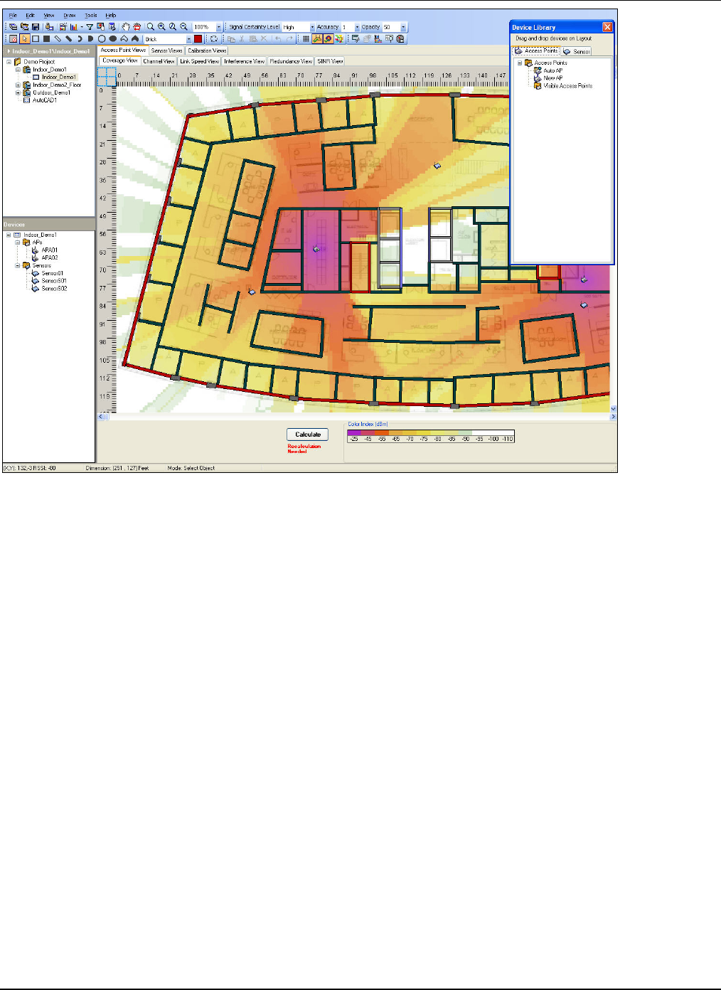
7.1.1 RF View Area........................................................................................................................................................66
7.1.2 Status and Control Pane.......................................................................................................................................67
7.2 PLANNING DEVICE PLACEMENT: VIEWS FOR INDOOR AND OUTDOOR LAYOUT ............................................................67
7.2.1 AP Coverage View................................................................................................................................................67
7.2.2 AP Channel View..................................................................................................................................................69
7.2.3 AP Link Speed View..............................................................................................................................................71
7.2.4 AP Interference View............................................................................................................................................72

TableofContents
3Com®AirProtectPlannerUserGuide
vii
7.2.5 AP Redundancy View............................................................................................................................................74
7.2.6 AP SINR View.......................................................................................................................................................76
7.2.7 Sensor Coverage View..........................................................................................................................................77
7.2.8 Sensor Threat View...............................................................................................................................................79
7.2.9 Sensor Redundancy View......................................................................................................................................80
7.2.10 Calibration View...............................................................................................................................................82
7.3 PLANNING DEVICE PLACEMENT: STATUS AND CONTROL .............................................................................................83
7.3.1 Signal Certainty Level..........................................................................................................................................83
7.3.2 Accuracy...............................................................................................................................................................84
7.3.3 Opacity.................................................................................................................................................................84
7.3.4 Show Grid.............................................................................................................................................................84
7.3.5 View Layout Model...............................................................................................................................................84
7.3.6 Show RF Signal....................................................................................................................................................84
7.3.7 Show Spillage View ..............................................................................................................................................84
7.3.8 Selecting Protocols...............................................................................................................................................85
7.3.9 Calculate/Calibrate Button ..................................................................................................................................86
7.3.10 Color Palette.....................................................................................................................................................86
7.4 STATUS BAR .................................................................................................................................................................87
7.4.1 Cursor Location (X, Y) .........................................................................................................................................87
7.4.2 RSSI Display.........................................................................................................................................................87
7.4.3 Layout Dimensions...............................................................................................................................................87
7.4.4 Current Mode .......................................................................................................................................................87
7.4.5 Interference ..........................................................................................................................................................87
7.4.6 SINR .....................................................................................................................................................................87
7.5 DEVICE LIBRARY..........................................................................................................................................................88
7.6 DEVICE PROPERTIES.....................................................................................................................................................89
7.6.1 Access Point Properties........................................................................................................................................89
7.6.2 Sensor Properties .................................................................................................................................................91
7.7 VIEWING SIGNAL STRENGTH........................................................................................................................................92
7.8 STATISTICS ...................................................................................................................................................................92
7.9 SAVING THE FILE..........................................................................................................................................................95
7.10 SAVING THE PROJECT FILE........................................................................................................................................95
CHAPTER 8 SETTINGS...................................................................................................................................................97
8.1 SETTINGS: INVOKING FROM TOOLS MENU ...................................................................................................................97
8.2 SETTINGS: PREFERENCES .............................................................................................................................................97
8.2.1 Preferences: Layout Designer ..............................................................................................................................97
8.2.2 Preferences: AP Views..........................................................................................................................................98
8.2.3 Preferences: Sensor Views....................................................................................................................................98
8.2.4 Preferences: Color Palettes..................................................................................................................................99
8.2.5 Preferences: Calibration ......................................................................................................................................99
8.3 SETTINGS: AP DEFAULTS............................................................................................................................................100
8.4 SETTINGS: SENSOR DEFAULTS....................................................................................................................................102
CHAPTER 9 GENERATING OUTPUT FROM PLANNER.......................................................................................104
9.1 WLAN PLANNING REPORT ........................................................................................................................................104
APPENDIX A: PLANNING SENSORS...............................................................................................................................107
PLACEMENT OF SENSORS ......................................................................................................................................................107
APPENDIX B: INTEGRATION OF 3COM ® AIRPROTECT PLANNER AND 3COM ® AIRPROTECT
ENTERPRISE........................................................................................................................................................................108
EXPORTING THE PROJECT FROM PLANNER ............................................................................................................................108
APPENDIX C: FILE LEVEL AND APPLICATION LEVEL PARAMETERS...............................................................110
APPENDIX D: GLOSSARY OF TERMS ........................................................................................................................... 111

GettingStarted
3Com®AirProtectPlannerUserGuide
1
Chapter1 GettingStarted
1.1 BeforeYouBegin
Thankyouforpurchasing3Com®AirProtectPlanner(Planner),astateoftheartWirelessLocalAreaNetwork(WLAN)
securityandnetworkplanningtooldevelopedby3ComCorporation.
1.2 Howtogetmoreinformation
Toreceiveimportantnewsonproductupdates,pleasevisitourwebsiteatwww.3com.com.
1.3 ContactInformation
3ComCorporation
350CampusDrive,Marlborough,MA01752
508‐323‐5000(Tel)
508‐323‐1111(Fax)
Fortechnicalsupport,sendanemailto:esupport@3com.com

IntroductiontoWLANPlanningandPlanner
3Com®AirProtectPlannerUserGuide
2
Chapter2 IntroductiontoWLANPlanningandPlanner
WirelessLocalAreaNetworks(WLANs)connectyouinstantlyevenwhileyouaremoving.Theyprovideconvenientand
increasinglyflexibleproductivityintoday’scorporateandindustrialenvironment.However,WLANsneedtobeproperly
plannedforadequatecoverageandsecuritytogetthesebenefits.Thischapterdiscussesthedisadvantagesofpoorlyplanned
WLANsandpresentsPlannerasthesolutiontosuchproblems.
Plannerplanstheentirenetworkwiththehelpofvariousoutdoorobjectsnamely,buildings,trees,waterbodies,indoor
buildingobjectsnamely,walls,windows,doors,elevatorshafts,furniture,concretecolumns,andmetalobjects;anddevices
suchasAccessPoints(APs)andSensors.TheinitialinputtoPlannerisalayoutimageinanygraphicalformat.Asanoutput,
itgeneratesvariousRFviewsandthenassemblestheseviewsintoacomprehensiveRFplanningreport.
2.1 WhatisWi‐Fi?
Wi‐FiisanothernameforIEEE802.11basedWLANs.Thesenetworksoperateatanduse802.11a,5GHz,802.11b/g,2.4GHz
andtheemerging802.11n,2.4and5GHz.Wi‐FiispromulgatedbytheWi‐FiAlliance.ProductscertifiedasWi‐Ficompatible
byWi‐FiAllianceareinteroperablewitheachothereveniftheyarefromdifferentmanufacturers.Youcanuseanybrandof
APwithanyotherbrandofClienthardwarethatisbuilttotheWi‐Fistandard.Wi‐Fihasgainingacceptanceinhomes,offices,
andpublicplaceslikecoffeeshops,hotels,andairports.
2.2 DisadvantagesofPoorlyPlannedWLANs
PoorlyplannedWLANshavethefollowingrisks:
• LowPerformance:Lackofcoverage,capacity,andthroughputplanningresultsinpoorconnectivityspeedsincertain
areas.Thiscouldresultinlowperformanceofthenetwork.
• HighSecurityRisk:RFsignalsspillduetotheverynatureofthewirelessnetworkenvironment.Forexample,
hackerscouldtapintotheWLANfromtheparkinglotorthestreet.Thiscanleadtoserioussecuritybreaches.
• BadUserExperience:Lowperformance,throughput,orcoverageleadtobaduserexperience.
• HighOperationalExpenses(OPEX):Networkadministratorshavetospendalotoftimeandeffortin
troubleshootingissues,qualityofservice,andsecurityexposureafterthedeploymentofnetworks.Thisleadsto
higheroperationalexpenses.
• LowerReturnonInvestment(RoI):ApoorlyplannednetworkresultsinalowerRoIastheproductivitygainsare
notashighaspredicted.
Thecurrentstate‐of‐the‐artistocarryoutasitesurvey(alsocalledradiosurvey),usebestpracticesforAPplacement,oreven
performdeploymentonadhocbasis.Thesemethodshavethefollowinglimitations:
• Sitesurveysaretimeconsuming,expensive,andpronetoerrors.
• Adhocdeploymentsposedifficultyinvisualizingnetworkcoverage,leadtosecurityexposure,andcausechannel
interference.
• ‘What‐If’scenariosarenotpossibleinsitesurveyoradhocdeploymentmethods.
ThereisnoestablishedpracticeforplanningWLANsecuritynetworks,anessentialpartofITsecurityintoday’snetwork
environment.
Pre‐deploymentenablessuccessfulWLANdeploymentsby:
• Maximizingnetworkcoverageandthroughput
• Minimizingchannelinterference
• MinimizingsecurityexposurebyensuringminimumsignalspillageoutsidethedesignatedareaofWLANoperation
• Providing‘What‐If’scenariosfortrade‐offbetweensecurityexposureduetosignalspillageandnetworkcoverage
• MaximizingthedetectionandpreventionrangeofWLANsecuritySensors
• PlanningSensorstoensurereliablelocationtrackingofunauthorizeddevices
• EnsuringthateventheweakesttransmitterisdetectedandpreventedbytheSensors
• Planningtoenablelive24x7RFmonitoring
• Troubleshootingremotely
• Restructuringthewholeplanespeciallywhileextendingtheexistingofficespaceordeployingnewequipments

IntroductiontoWLANPlanningandPlanner
3Com®AirProtectPlannerUserGuide
3
2.3 Planner:ACompleteWLANPlanningSolution
PlannermakesthetaskofWLANplanningsimple.Itseasy‐to‐useinterfaceprovidesrichvisibilityintosecurityexposure,RF
coverage,channelallocation,andavailablelinkspeedinWLANs.Thisensuressecurity,highreliability,andoptimal
configurationofWLANs.
Plannerprovidesthefollowing:
• AdvancedpredictionmodelforSensorandAPplacement
• DevicedatabasewithpresetoptionsforcommonAPmodels,Sensorsmodels.
• AbilitytoaddnewAPmodelsandantennae
• Buildingmaterialdatabase
• CrossFloorcoverage
• LiveAPcalibration
Onceyoumodelthelayoutofthefacility,youcanplaceAPs(RefertoAppendixD:GlossaryofTerms)usingasimpledrag
anddropoperationtogenerateRFmapsandacomprehensivesetofdeliverablesasdescribedinthefollowingsection.
2.4 DeliverablesfromPlanner
• SiteModelforfutureRFplanning
• BillofMaterial(BoM)for3Com®AirProtectEnterpriseSensors(Sensors)
• BoMforAPsandantennae
¾ NumberandlocationofSensors
¾ Number,location,andconfigurationofAPs
¾ Antennatypesandlocation
• RFMaps
¾ SecurityView:CoverageinsidethePerimeter,CoveragebeyondthePerimeter,Redundancy
¾ AccessPoints:Coverage,Spillage,ChannelAllocation,Interference,andRedundancy
• Consolidatedplanningreport
¾ BoMforSensorsandAPs
¾ RFmapsforsecurity(Sensors)coverage
¾ RFmapsfornetwork(AP)coverage
¾ With/outCustomerInput
¾ WLANbasics
• Files
¾ .spm
¾ .prj(project)
¾ .zip(compressedprojectfilein.zipformat)
2.5 Planner:Benefits
PlannerprovidesvisibilityintotheWLANallowingthenetworkadministratorto:
• Eliminatesecurityrisksbyminimizingsignalspillagetoprotectthenetwork.
• PlanforsecurityusingSensorstomaximizedetectionandpreventionofthreats.
• ReducetheOperatingExpenditure(OPEX)byestimatingthenetworkperformanceandminimizingnetwork
problemsandon‐goingnetworkmaintenancethroughproperplanning.
• ReduceCapitalExpenditure(CAPEX)byinvestingonlyintherequiredequipmentsandeliminatingexpensivesite
surveys.
• Increasevisibilityforsecurityexposureanalysisandeffectivemaintenancebyunderstandingtheimpactof
upgrades.
• Satisfyuserneedsbyreducingnetworkdowntimeandmaximizingcoverage,networkcapacity,andthroughput.
• Provide‘What‐If’scenarioswhenthereisachangeinthelayoutorintheplacementoffurniture,oranyadditionor
deletionofWLANequipments.
• ‘What‐If’analysistomigrateto802.11ndevicesfromtheexistinglegacysystems.
• WLANPlanningWizard
¾ CapacityPlanning
¾ CoveragePlanning
IntroductiontoWLANPlanningandPlanner
3Com®AirProtectPlannerUserGuide
4
¾ AutoDevicePlacement
¾ AutoChannelAllocation
• CapacityEstimation
• SupportofAutoCADfilesforsitemodeling.
2.6 WorkingofPlanner
PerformthefollowingstepsforWLANPlanningusingPlanner:
1 Installing
2 Launching
3 DesigningaLayout
4 PlanningWLANforsecurity,coverage,andspeed
5 Settingvariousprotocols,filters,andadvancedparametersforaccurateRFviews
6 GeneratingaBoMandreports
2.7 Planner:Workflow
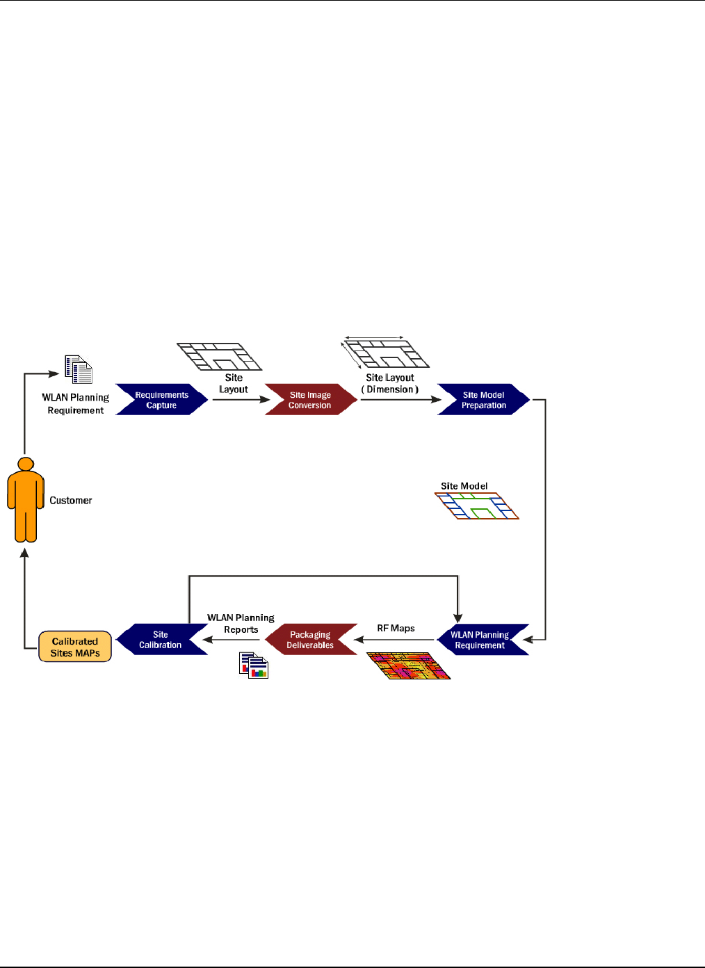
PlannerhelpsyouplantheentireWLANwithminimalinputfromthecustomer.TheinputtoPlannerisalayoutimageinany
graphicalformatoravalidAutoCADfile.Youcancreateamodelofthedeploymentspacebyplacingobjectssuchaswalls,
windows,doors,furniture,andopenspacesontothelayoutasdepictedbelow.
Figure 1. Planner Workflow

LaunchingPlanner
3Com®AirProtectPlannerUserGuide
5
Chapter3 LaunchingPlanner
ThischaptershowsyouhowtolaunchPlannerandusethenewPlannerfile.
3.1 GlobalFunctions
Plannercontainsseveralcommonfunctionsthatapplythroughouttheapplication.Theyareasfollows:
3.1.1 Dialogs
ThefollowingfunctionsapplytoalldialogboxesinPlanner.Dependingonoptionsavailableinaparticulardialogbox,you
can:
• Click<OK>toacceptanactionorsaveallthechangesandclosethedialogbox.
• Click<Save>tosaveallthechangesmadeandclosethedialogbox.
• Click<Cancel>todiscardtheactionorthechangesandclosethedialogbox.
• Click<Apply>tosaveallchangeswhilekeepingthedialogboxopen.
• Click<Delete>toremoveaselecteditem.
• Click<Close>toclosethedialogbox.
• Click<RestoretoDefaults>toresettofactorydefaults.
• Click<ResettoInstallationDefaults>torestoretodefaultinstallationvalues.
• Click<Yes>toaccepttheactioninthedialogbox.
• Click<No>todenyordeclinetheactioninthedialogbox.
3.1.2 Messages
ThefollowingfunctionsapplytoallmessageboxesinPlanner.
• Click<OK>forYes.
• Click<Cancel>forNo.
• Ifyouexceedtheallowedrangeforanyparameter,Plannerpopsupanalertmentioningthevalue/dataisinvalid,
andthatyouhavetobewithinthepermittedrange.
3.1.3 Trees
ThefollowingfunctionsapplytoalltreesinPlanner.Inanytree,youcanperformthefollowing:
• Clicktoexpandthesubnodes.
• Clicktocollapsethesubnodes.
• Double‐clickthenodetexttoeitherexpandorcollapsesubnodes.
3.1.4 OtherFunctions
ThefollowingfunctionsapplytoalltherepositoriesandmessageboxesinPlanner:
• Click intherelevantsectiontoviewmoreinformationabouttherespectivesection.
• Onthevariousrepositoryscreens,clickthecolumnheaderofthetablestosortthelistofitemsinthetable.
3.2 OpeningPlanner
WhenyoulaunchPlanner,theOpenWi‐FiProjectdialogboxappears.Youcandooneofthefollowing:
1 CreateanewWi‐FiProject
2 SelectfromoneoftherecentlyusedWi‐FiProjects
3 OpenanexistingWi‐FiProject

LaunchingPlanner
3Com®AirProtectPlannerUserGuide
6
Figure 2. New Project
• Click<CreateNew>tostartaNewProjectFiletocreateanewWi‐Fiproject.
• SelectafilefromtheRecentFilessectiontoviewarecentlyusedproject.
• Click<Browse>toselectanexistingproject(.spm,.prjor.zip).
• Click<Open>toinvoketheselectedWi‐Fiproject.
3.2.1 NewProjectFile
YoucanstartanewprojectinPlannerbydoingoneofthefollowing:
• FromtheFilemenu,selectNewProject.
• Click<CreateNew>ontheOpenWi‐FiProjectdialogbox.
• Click fromtheToolbar.
ThisopenstheNewProjectFiledialogbox.
Figure 3. New Project File
EnterthefollowingdetailsintheNewProjectFiledialogbox.
• Name:Enterthedesirednameoftheproject.
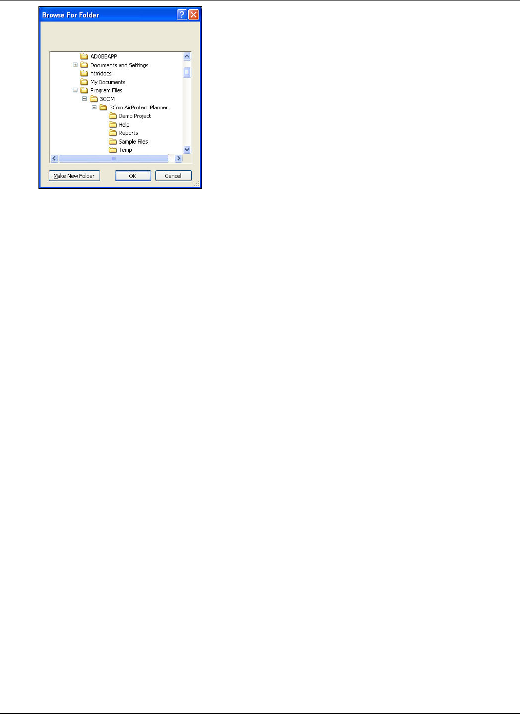
• Location:Enterthedesiredlocationfortheprojectorclick<Browse>tonavigatetothelocation.IntheBrowseFor
Folderdialogbox,selectalocationfromthefoldertreeorclick<MakeNewFolder>toaddanewlocationtothe
foldertree.
LaunchingPlanner
3Com®AirProtectPlannerUserGuide
7
Figure 4. Browsing for Folder
• DirectoryName:Displaysthepathandtheprojectfiledirectoryname.
• LocationMap:Enterthelocationofthedesiredlocationmapimageorclick<Browse>tonavigatetothefolder
containingthedesiredimage.
Ifyouenterinvaliddataorselectaninvalidfile,Plannerdisplaysanalert.
ThePlanneroutputsare:
• ProjectfilecreatedandsavedasanXMLfilewithanextension‘.prj’.
• PlannerfilecreatedandsavedasanXMLfilewithanextension‘.spm’.
Ifatalaterpoint,youmodifyandsavethisXMLoutputfile,byeditingitinatextpad,thefilebecomescorrupt.Afterthat,
youwillnotbeabletoopenthisfileinPlanner.
A.spmfileisboundtoa.prjfile.Youcannotcreatea.spmfileonly.Whenyoutrytoopena.spmfileseparatelyandnot
throughtheProject,Plannercreatesadefaultproject,createsanodeforthat.spmfileunderthe‘Root’locationfolder,and
displaysthe.spmfile.
Theprojectlayoutappearsasfollows.
LaunchingPlanner
3Com®AirProtectPlannerUserGuide
8
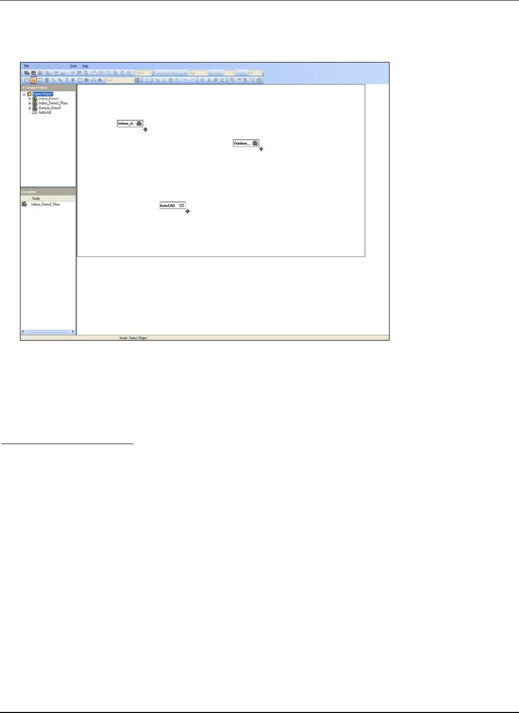
Figure 5. Project Layout
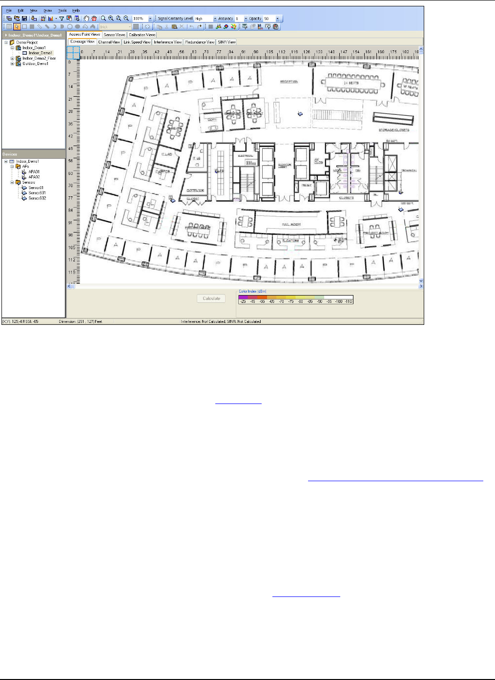
ThenewPlannerprojectlayoutscreenisdividedintothreepanesasfollows:
1 MenuandToolbarsatthetop:
TheMenubarprovidesPlanneroperations.TheToolbarprovidesbuttonsforquickoperations.Theoperationsenableyou
todesignandviewthelayout.RefertothesectionMenuItemsformoredetails.
2 LeftpaneconsistsoftheLocationstreeatthetopandtheDeviceslistbelow:
TheLocationstreecontainslocationfoldersandlocationnodes.Onlaunchinganewproject,PlannercreatestheLocations
treewiththe<ProjectName>astherootlocation.
TheDeviceslistcontainsalistofdevicesplacedonthefloormap.YoucanseethisdevicelistonlyiftheLocationNodeis
loaded.
TheLocationstreeandtheDeviceslistarediscussedfurtherinthesectionWorkingwithLocationTreeandDevicesList.
3 RightpaneconsistsofthePlannerLayoutModelforthelocation.
ThePlannerLayoutModelistheviewablelayoutareaforthelocationselectedintheLocationstree.
3.3 SupportforAutoCAD
PlannersupportsAutoCADfiles.AnAutoCADfilecontainsthedimensionsofthelayoutandalsoalistoflayersinthelayout.
WhenimportedintoPlanner,PlannerautomaticallypopulatestheDimensionsfield.Youcaneditthedimensions.Oncethese
dimensionsareaccepted,theManageLayersscreenappearswhereyoucanselecttherequiredlayers.Plannerselectsthe
layersthatareturnedonintheAutoCADfile,bydefault,andbasedonthat,importsandmodelsalltheobjectsfromthese
layers.Youdonothavetore‐modeltheseobjects.RefertothesectionManagingLayerstoknowmoreaboutmanaginglayers
ofanAutoCADfile.
PlannersupportsthefollowingversionsofAutoCADfiles:
• AutodeskDXFRelease10,11,12,13,14,2000,2002,2004/2005/2006
• AutodeskDWGRelease9,10,11,12,13,14,2000,2002,2004/2005/2006

LaunchingPlanner
3Com®AirProtectPlannerUserGuide
9
PlannerallowsimportingofthefollowinginformationfromanAutoCADfile.
• LayoutDimensions
• LayerInformation
Plannersupportsthefollowingshapesofobjects.Alltheseshapesmustbe2D.
• Lines
• Rectangles
• Polygons
• Circles
• Arcs
However,Plannerdoesnotsupportthefollowingshapes:
• Doughnut
• HollowArcs
• CurvedPolygons
• Spline
• 3Dobjects
WorkingwiththeLocationsTreeandtheDevicesList
3Com®AirProtectPlannerUserGuide
10
Chapter4 WorkingwiththeLocationsTreeandtheDevicesList
Plannerenablesyoutomodeltheenterpriseacrosslocations.Italsoenablesyoutoplacedevicesonalocationtoensure
optimumcoverage.TheLocationstreeandtheDeviceslistfeaturesappearontheleftpaneoftheprojectlayoutscreen.
4.1 LocationsTree
TheLocationstreeenablesyoutoorganizethenetworkintoalistoflocationsandviewlive802.11RFcoveragemapsforeach
locationnode.Thetreealsohelpsyoueasilynavigatethroughthelocationsandswitchbetweendifferentfloors.
TheLocationstreecomprisesoflocationfoldersandlocationnodes.
• Locationfoldersrepresentorganizationalcomponentssuchasbuildings,cities,orcountries.
¾ RootLocation:Thisistherootlocation.PlannerassignstheProjectNameyouselect,asthenamefortheRoot
Location.Youcanrenamethislocation.However,youcannotdeleteormovethislocation.
• Locationnodesrepresentcomponentdetailssuchasafloorinabuilding.Forexample,HawaiiConferenceRoom,
Bldg15–CubicleG2,orExecutiveArea.
Youcanperformvariousfunctionslikeadding,deleting,renaming,movingalocation,andsoonfromtheLocationstree.
4.1.1 AddinganewLocationFolder
IntheLocationstree,right‐clickthelocationfolderunderwhichyouwishtoaddanewlocation,andselectAddLocation
Folder.TheNewLocationFolderdialogboxappears.
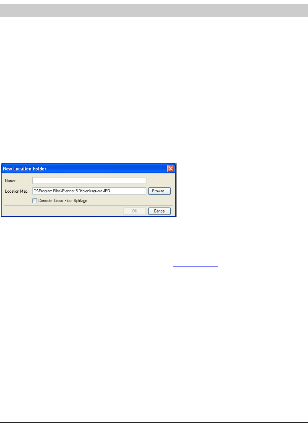
Figure 6. Adding a New Location Folder
• Name:Enterthedesirednameforthenewlocationfolder.
• LocationMap:SpecifythelocationoftheLocationMap.Alternately,click<Browse>tonavigatetothegraphical
locationmapthatyouwishtoimportintothelocationfolder.
• ConsiderCrossFloorSpillage:Selectthischeckboxtoenablecrossfloorspillage.Plannerpopsupanalerttowarn
youthatthisactionisirreversibleonceCrossFloorfolderiscreated.Youcannotde‐selectorchangethisoptionata
laterpoint.
4.1.2 AddinganewLocationNode
IntheLocationstree,right‐clickthelocationfolderunderwhichyouwishtoaddanewlocationnode,andselectAdd
LocationNode.TheNewLocationNodedialogboxappears.
WorkingwiththeLocationsTreeandtheDevicesList
3Com®AirProtectPlannerUserGuide
11
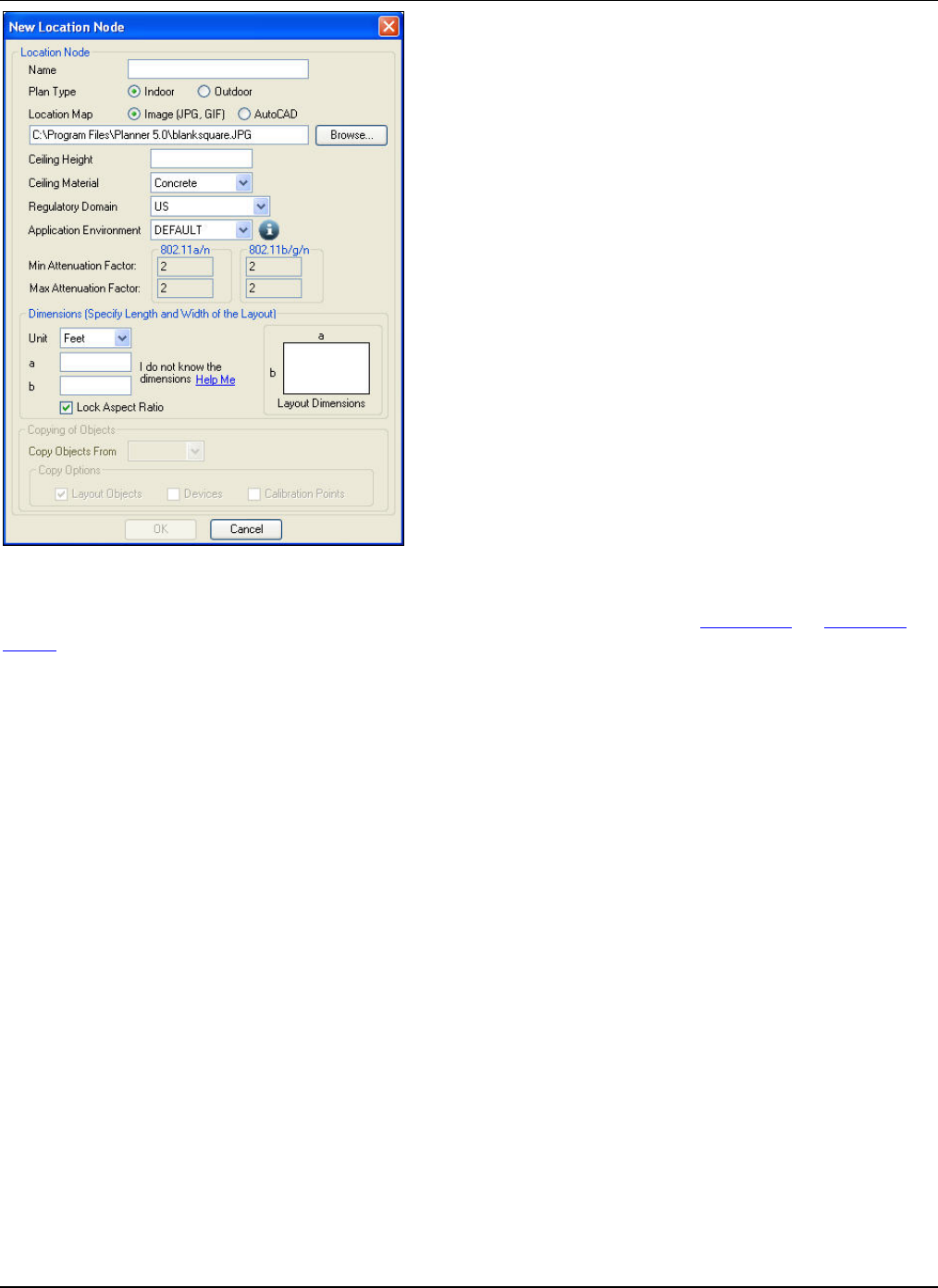
Figure 7. Adding a New Location Node
TheNewLocationNodedialogboxconstitutesdetailsoftheLocationNodeandtwosections:DimensionsandCopyingof
Objects.
SpecifythefollowingdetailsoftheLocationNode:
• Name:Enterthedesirednameforthenewlocationnode.
• PlanType:SpecifyiftheplantypeisanIndoororOutdoorlayout.
• LocationMap:SpecifyiftheLocationMapisa.jpgor.gifImage,oranAutoCADfile.Click<Browse>tonavigateto
thegraphicallocationmapthatyouwishtoimportintothelocationnode.
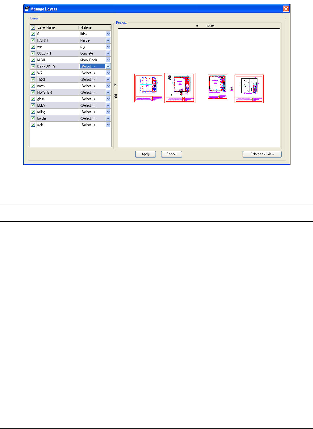
OnceyouselectandimportanAutoCADfileforalocationnode,theManageLayersdialogboxappears.
WorkingwiththeLocationsTreeandtheDevicesList
3Com®AirProtectPlannerUserGuide
12
Figure 8. Managing Layers of an AutoCAD file
• CeilingHeight:Enterthedesiredceilingheightforthelayout.
• CeilingMaterial:Selectthedesiredceilingmaterialforthelayoutfromthedrop‐downlist.
Note:LocationMap–AutoCADoption,CeilingHeight,andCeilingMaterialareavailableonlyifyouselectIndoorLayoutasthe
PlanType.TheyarenotavailableforanOutdoorLayout.
• RegulatoryDomain:Differentcountrieshaveregulatoryagenciespermittingaselectnumberofchannelsfor
protocols.Selecttherelevantcountryfromthedrop‐downlistforwhichyouaredoingWLANplanning.
• ApplicationEnvironment:Selectthedesiredapplicationenvironmentfromthedrop‐downlist.
• MinAttenuationFactor:Specifiestheminimumattenuationfactorsfor802.11a/nand802.11b/g/nprotocols,
dependingontheapplicationenvironmentselected.
• MaxAttenuationFactor:Specifiesthemaximumattenuationfactorsfor802.11a/nand802.11b/g/nprotocols,
dependingontheapplicationenvironmentselected.
Dimensions
• Unit:Selecttheunitofmeasurementyouwanttouseforthelayoutfromthedrop‐downlist.
• a:Specifythelengthofthelayout.
• b:Specifythewidthofthelayout.
• LockAspectRatio:AllowsyoutomaintaintheratioofthelengthandwidthofthelayouttothatoftheLayoutimage
selectedearlier.Toachievethis:
1. SelectLockAspectRatiobeforeenteringthedimensionsofthelayout.
2. Enteranyoneofthetwodimensionsofthelayout.Thevalueoftheotherdimensionisautomaticallyenteredas
perthedefaultaspectratio.
• LayoutDimensions:Displaysapreviewofthelayoutmap.
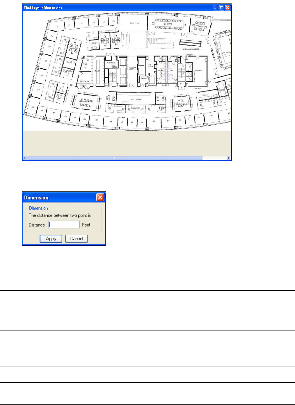
Incaseyoudonotknowthedimensionsofthelayout,click<HelpMe>.TheFindLayoutDimensionsscreenappears.
WorkingwiththeLocationsTreeandtheDevicesList
3Com®AirProtectPlannerUserGuide
13
Figure 9. Finding Layout Dimensions
Clickonepoint,thendragthemouseandclickanotherpoint.TheDimensiondialogboxappears.
Figure 10. Dimensions
• Distance:Specifythedistancebetweenthetwoselectedpointsonthismap.Theunitofmeasurementistheone
mentionedintheNewLocationNodedialogbox.Plannerusesthisinformationtoscalethedimensionsofthelayout,
anddisplaysthesameinthecorrespondingfieldsintheNewLocationNodedialogbox.
Note:EnsurethatthedistanceyouspecifyintheDimensiondialogboxisaccurate.Otherwise,therewillbedrasticdifferenceinthe
actualdimensionsandthedimensionscalculatedbyPlanner.
IfyouimportanAutoCADfile,PlannerextractsthedimensionsfromtheAutoCADfile.Itissometimesobservedthatthedimensions
derivedfromtheAutoCADfilearenotcorrectasitshowsthecompletecanvassize.Hence,ensurethatyouentertheexactdimensionsof
thelayout.
CopyingofObjects:
• CopyObjectsFrom:Allowsyoutocopyallobjectsfromthepreviouslycreatedlayouts.Selectthelayoutfromwhich
youwanttocopyobjectsfromthedrop‐downlist.
• CopyOptions:Selecttheitemsyouwishtocopy:LayoutObjects,Devices,andCalibrationPoints.
Note:PlannerenablesCopyingofObjectsonlyifthereismorethanonenodeunderalocationfolderandthatfolderhasConsiderCross
FloorSpillageactivated.
WorkingwiththeLocationsTreeandtheDevicesList
3Com®AirProtectPlannerUserGuide
14
Onceyouaredoneandclick<OK>,aConfirmdialogboxtoopenthecreatedlocationappears.Alternately,click<Cancel>to
discardaction.
CrossFloorLocationfolder
WhenyoucreatealocationfolderwiththeConsiderCrossFloorSpillagecheckboxenabled,theninformationofallthenodes
isbundledandstoredinonesingle.spmfile.Bydefault,thenameofthe.spmfileisthenameofthefirstnodethatyoucreate.
ItispossibletoaddalocationnodeunderaCrossFloorlocationfolder.However,youcannotaddalocationfolderundera
CrossFloorlocationfolder.
ThedimensionsofallthenodesinaCrossFloorfolderarethesame.Forexample,whiledefiningNode‐1,youspecifya=500
andb=600.Then,Plannerusesthesamedimensionsforallthenodescreatedthereafterinthatfolder.SincePlannerextracts
thedimensionsautomaticallyincaseofanAutoCADfile,theseextracteddimensionsmustmatchthedimensionsofthefirst
nodethatwascreated.Otherwise,PlannerdoesnotallowtheimportoftheAutoCADfile.
Additionally,whenyoucreatethesecondnodeundertheCrossFloorlocationfolder,youcannotchangetheregulatory
domain.
Note:TomodifythedimensionsofanodeunderaCrossFloorLocationfolder,right‐clickanodeandselectLoadLocationNode.Planner
automaticallyappliesthesedimensionstorestofthenodesunderthisfolder.
TheCrossFloorlocationfolderisrepresentedbythe icon.
Non‐CrossFloorLocationfolder
WhenyoucreatealocationfolderwithouttheConsiderCrossFloorSpillagecheckboxenabled,informationofeachnodeis
storedinseparate.spmfiles.YoucanaddaCrossFloorlocationfolderunderaNon‐CrossFloorlocationfolder.
TheNon‐CrossFloorlocationfolderisrepresentedbytheicon.
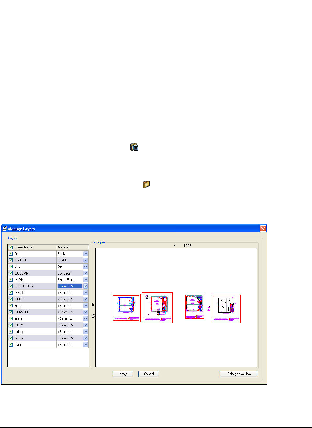
4.1.3 ManagingLayers
TheManageLayersdialogboxdisplaysdetailsoflayersinanAutoCADfile.WhenyouselectandimportanAutoCADfile
foralocationnode,theManageLayersdialogboxappears.
Figure 11. Managing Layers of an AutoCAD file

WorkingwiththeLocationsTreeandtheDevicesList
3Com®AirProtectPlannerUserGuide
15
IntheManageLayersdialogbox,someorallthelayersareselectedbydefault.ThisisbecauseeveryAutoCADfilestoresthe
statusofthelayersthatareturnedonoroffbasedontheselectedcheckboxesoflayers.
• LayerName:Selectthecheckboxagainstthelayersyouwant.Youcanoverridetheexistingstatusofeachlayerby
manuallyselectingthembasedonyourrequirement.
• MaterialType:Selectthematerialtypefromthedrop‐downlist,aspopulatedfromthematerialrepository.Planner
usesallthisinformationtomodeltheobjectsonthefloormap.
• Preview:Reflectsthechangeswiththeselectionoflayers.
• Enlargethisview:Clicktoviewtheenlargedview.
• RestoretonormalView:Clicktorestoretheenlargedviewtonormalview.
Click<Apply>toexecutethechangesmade.
OntheManageLayersscreen,ifyouclick<Cancel>,theAutoCADfileisnotimportedandyouwillseeablankimageonthe
layoutmodel.
CHECKSUM:
WhenyouloadanodewithanAutoCADfile,PlannervalidatestheattachedAutoCADfile.PlannercheckstheCHECKSUM
valueofthatAutoCADfileandverifiesitwiththeCHECKSUMvaluestoredinthe.spmfileforthatAutoCADfile.Thisisthe
valuestoredwhentheAutoCADfilewasfirstimported.Ifthereisanymismatchinthisvalue,Plannerstillloadsthenodebut
doesnotallowyoutousetheManageLayersoption.Plannerpopsupanalerttoinformyouaboutthis.
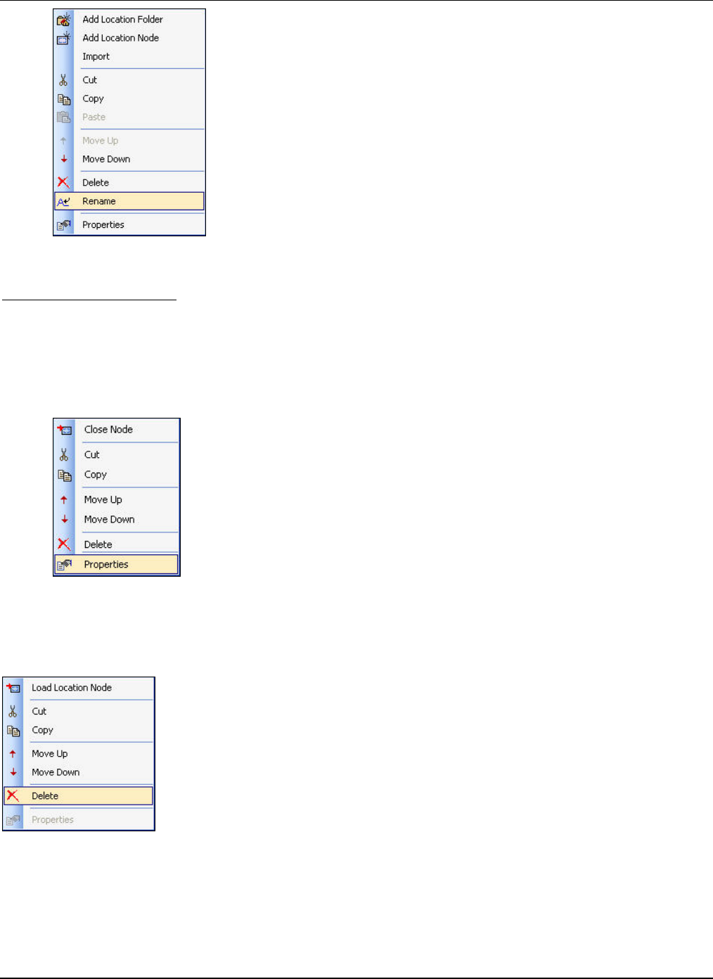
4.1.4 Viewing/LoadingaLocation
Loadingthelocationnodemeansopeningthe.spmfileassociatedwiththenode.Youcanopenonlyonenodeatatime.You
cannotviewalocationlayoutunlessyouloadit.
Toview/loadalocation,right‐clickalocationnodefromtheLocationstreeandselectLoadLocationNode.Plannerlaunches
thelayoutonthelayoutmodelpane.Thetitlebarofthescreenreflectsthepathoftheselectedlocation.
Note:A.spmfilecreatedwiththepreviousversionsofPlannerdoesnothaveanyapplicationenvironmentassignedtothatfile.Whenyou
importthatfileandtrytoloadthenode,thenPlannerpopsupanalertaskingifyouwanttoassignthedefaultapplicationenvironment.
WorkingwiththeLocationsTreeandtheDevicesList
3Com®AirProtectPlannerUserGuide
16
Figure 12. Loading a Location Node
WhenyouloadalocationattachedtoanAutoCADfile,thebackgroundhasablankimageandyoucandrawalltheobjectson
that,unlikeincaseofanimagewherethelayouthasthe.jpgor.gifasthebackgroundimage.
Whenyouclickalocationnodeattachedtoanimage,Plannerdisplaystheimageonthelayoutmodelpane.
4.1.5 ClosingaLocationNode
YoucanclosealocationnodeinPlanner.Plannerunloadsthelocationnodeleavingonlythelayoutonthelayoutmodelpane.
Toclosealocationnodethatyouhaveloaded,right‐clickalocationnodefromtheLocationstreeandselectCloseNode.
Additionally,ifyouclickanyothernodefromthelocationstree,Plannerclosesthecurrentnode.
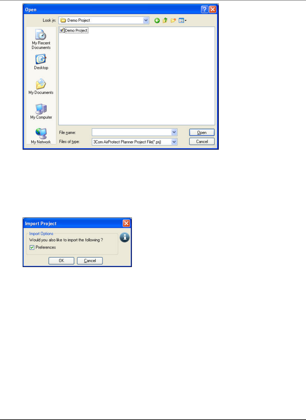
4.1.6 ImportingaLocation
PlannerenablesimportofPlannerProjectfiles(.prj),Plannerfiles(.spm),andcompressedPlannerProjectfiles(.zip)intoa
location.Useeitherofthefollowingstepstoimportafile:
• GotoFileÆOpen.
• Right‐clickalocationfolderfromtheLocationstreeandselectImport.
TheOpendialogboxappears.
WorkingwiththeLocationsTreeandtheDevicesList
3Com®AirProtectPlannerUserGuide
1
7
Figure 13. Importing a Location
Specifythepathofthefileornavigatetothefileyouwishtoimportintothelocationfolder.SelectthefiletypefromtheFiles
oftypedrop‐downlist.
• Onimportinga.prjfile,theentirelocationhierarchyofthatprojectisimportedundertheselectedfolder.
• Onimportinga.spmfile,Plannercreatesanodeunderwhichthe.spmfileisimported.
• Onimportinga.zipfile,Plannerunzipsthefileatatemporarylocationandthenimportsthe.prjfile.TheImport
ProjectdialogboxappearswherePlannerasksyouifyouwouldalsoliketoimporttheprojectpreferencesoptions.
Figure 14. Import Options
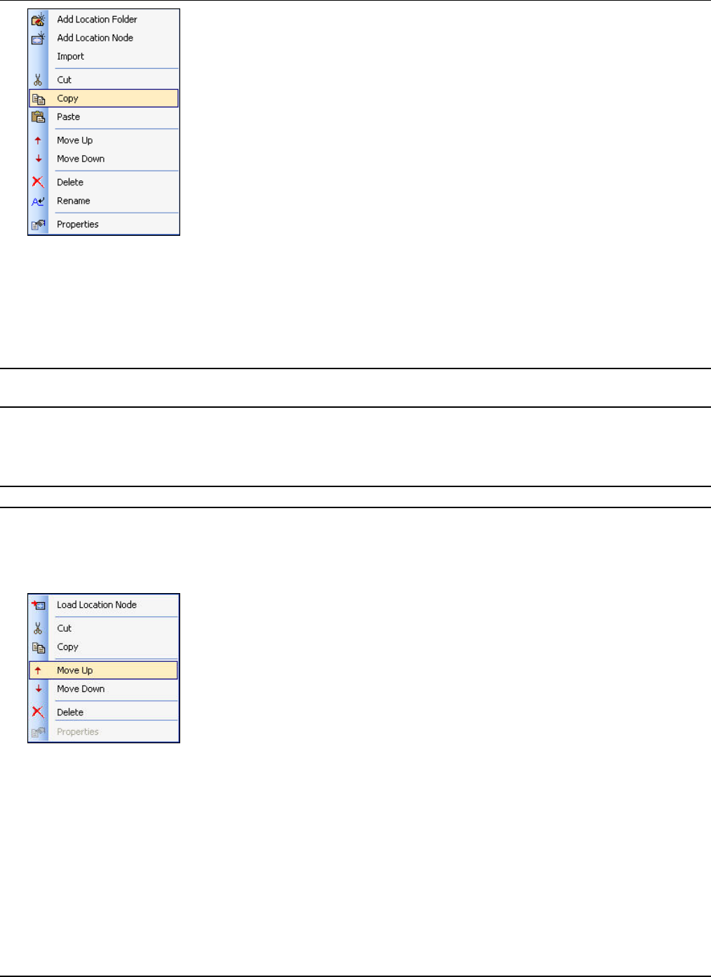
4.1.7 Cut/Copy/PasteaLocation
Youcancut/copylocationfoldersandnodes,andpastethemontootherlocations.
1 Right‐clickalocationfolderornodethatyouwanttocut/copy,fromtheLocationstree.SelectCutorCopy.
WorkingwiththeLocationsTreeandtheDevicesList
3Com®AirProtectPlannerUserGuide
18
Figure 15. Copying a location
2 Right‐clickthedestinationlocationfolderontowhichyouwanttopastethelocationselectedintheabovestep.Select
Paste.
Ifthelocationwhereyouarepastingthelocationfolderornodealreadyhasafolderornodewiththesamename,Planner
renamesthecopiedobjectsincrementallywithasuffix‘01’,‘02’,andsoon.
Note:IfanodebelongstoaCrossFloorlocationfolder,youcannotCut/CopyandPastethatnodeintoanotherfolder.Ifyouwanttocopy
thatnode,youmustcopytheentireCrossFloorlocationfolder.
4.1.8 MovingaLocation
Youcanmovelocationfoldersandnodeswithinalocationfolder.Thischangesthelocationhierarchyofthatfolderinthe
project.
Note:You cannotmovealocationifthelocationisnotunderthesameparentlocationfolder.
Usethefollowingstepstomovealocation:
1 Right‐clickalocationfolderornodefromtheLocationstree.
2 SelectMoveUporMoveDown.
3 Repeattheabovestepsuntilyoureachthedestinationfolderunderwhichyouwanttomovetheselectedlocation.
Figure 16. Moving a location
4.1.9 PlacingLocationsonaLocationFolderwithanattachedimage
Plannerenablesyoutoplacelocationsonalocationfolderthathasanattachedimage.Thishelpsyouidentifythephysical
positionofeachofthelocations.Thelocationsplacedontheattachedimageareindicatedbygreencoloredcircles.Usethe
followingstepstoplacelocationsontheattachedimageandviewtheirdetails:
1 IntheLocationstree,selectalocationfolder.
2 ThebottomleftpanecalledLocationsshowsallthenodesandfoldersavailableundertheselectedlocationfolder.Drag
anddroptherequiredlocationsontheattachedimage,intherightpane.
3 Toviewdetailsaboutthelocation,holdthemousecursoroverthegreencoloredbullets.
WorkingwiththeLocationsTreeandtheDevicesList
3Com®AirProtectPlannerUserGuide
19
4 Togotoaparticularlocationplacedontheimage,dooneofthefollowing:
• Clickthegreencoloredbulletrepresentingthelocation.
• Right‐clickagreencoloredbulletrepresentingthelocation,andselectLocateLocation.
• Double‐clickthegreencoloredbullet.
Figure 17. Placing Locations on a Location Folder
Youcanalsoremovealocationplacedbyright‐clickingagreencoloredbulletrepresentingthelocationandselectingDelete.
4.1.10 RenamingaLocation
Youcanrenamealocation.
RenamingaLocationFolder
Usethefollowingstepstorenamealocationfolder:
1 SelectalocationfolderfromtheLocationstree.
2 Dooneofthefollowing:
• Clickthelocation.
• Right‐clickandselectRename.
Thefieldnowbecomeseditable.Enterthenewnameofthelocationfolder.
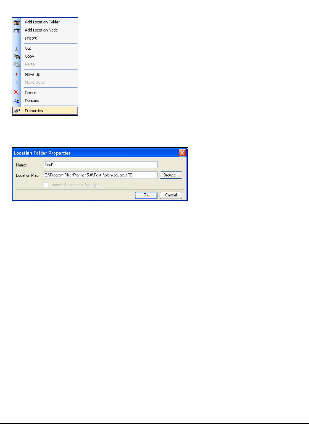
• Right‐clickthelocationfolderandselectProperties.TheLocationFolderPropertiesdialogboxappearswhichallows
youtoeditthenameofthelocationfolder.
WorkingwiththeLocationsTreeandtheDevicesList
3Com®AirProtectPlannerUserGuide
20
Figure 18. Renaming a Location Folder
RenamingaLocationNode
Usethefollowingstepstorenamealocationnode:
1 SelectalocationnodefromtheLocationstree.
2 Dooneofthefollowing:
• Clickthelocation.Thefieldbecomeseditable.Enterthenewnameofthelocationnode.
• Right‐clickthelocationnodeandselectProperties.TheLocationNodePropertiesdialogboxappearswhichallows
youtoeditthenameofthelocationnode.
Figure 19. Renaming a Location Node
4.1.11 DeletingaLocation
Youcandeletealocationfolderornodebyright‐clickingthelocationandselectingDelete.
Figure 20. Deleting a location
4.1.12 ModifyingLocationProperties
Youcanmodifythepropertiesofalocationfolderornode.Usethefollowingstepstodoso:
1 Right‐clickalocationfolderornodefromtheLocationstreeandselectProperties.
WorkingwiththeLocationsTreeandtheDevicesList
3Com®AirProtectPlannerUserGuide
21
Note:Incaseofalocationnode,youwillfirsthavetoLoadthenode.Otherwise,thePropertiesoptionisdisabled.
Figure 21. Viewing Location Properties
2 TheLocationFolderPropertiesorLocationNodePropertiesdialogboxappears.Editthedesiredlocationproperties.
Figure 22. Viewing Location Folder Properties
WorkingwiththeLocationsTreeandtheDevicesList
3Com®AirProtectPlannerUserGuide
22
Figure 23. Viewing Location Node Properties
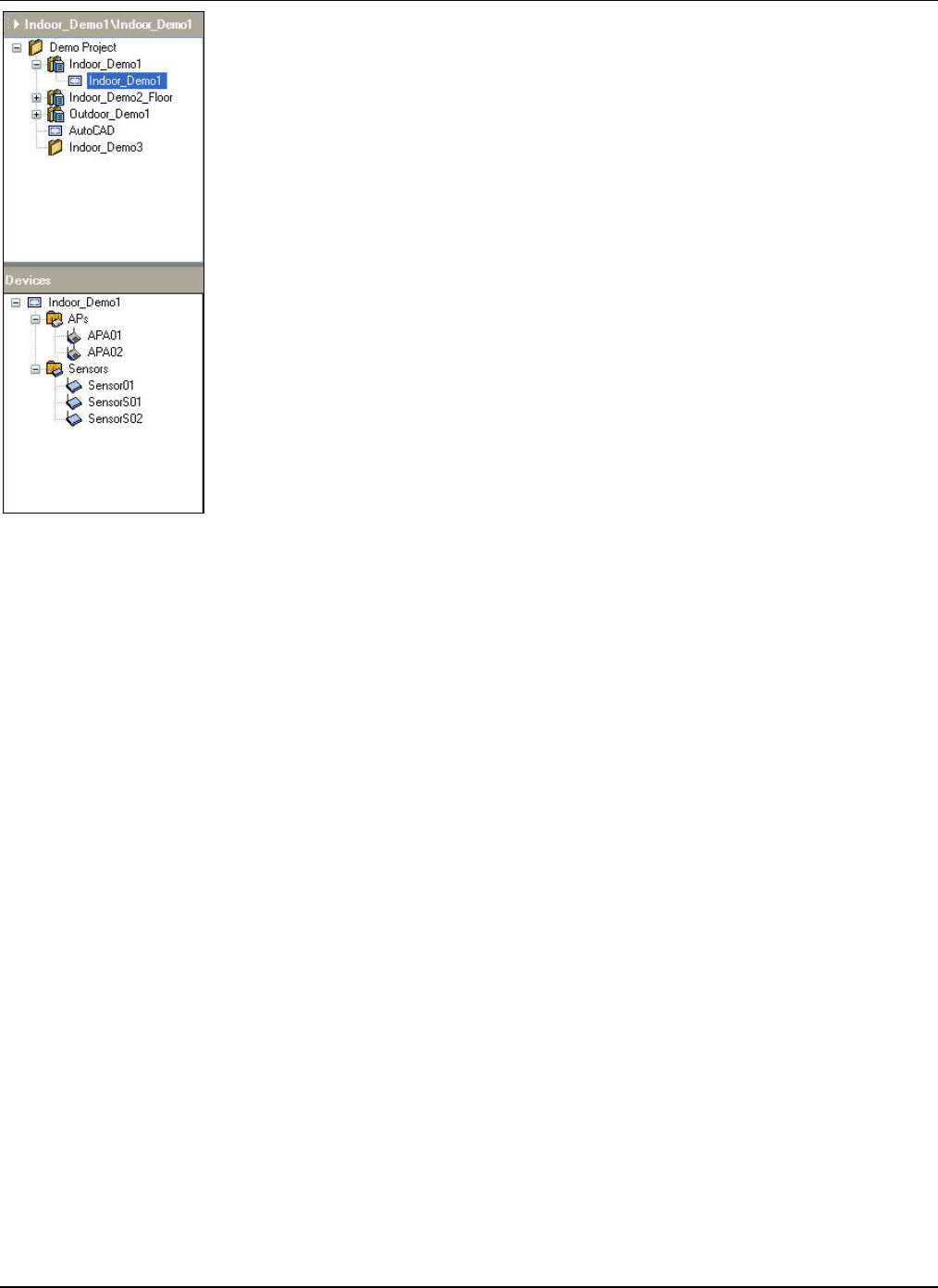
4.2 DevicesList
TheDeviceslistenablesyoutoviewallthedevicesthatareplacedonaparticularlocationnode.Thislistispopulatedonly
whenthenodeisloaded.Thedevicesaredividedbasedontheirtype.Youcanmodifythedevicepropertiesbyright‐clicking
ordouble‐clickingthedevice.
Note:RefertothesectionDeviceLibrarytoperformdevicesrelatedoperations.
WorkingwiththeLocationsTreeandtheDevicesList
3Com®AirProtectPlannerUserGuide
23
Figure 24. Devices List
MenuandToolbarOptions
3Com®AirProtectPlannerUserGuide
24
Chapter5 MenuandToolbarOptions
ThissectiondescribesindetailvariousmenusandToolbaroptionsinPlanner,toenableyoutocreateacompletelayout
model.YoucandesignthelayoutusingvariousobjectsavailableinPlanner.
5.1.1 MenuItems
Thissectiongivesacompletedescriptionoftheavailablemenuoptions.
Note:AdvanceduserscanskipthemenussectionanddirectlyrefertoLayoutIcons.
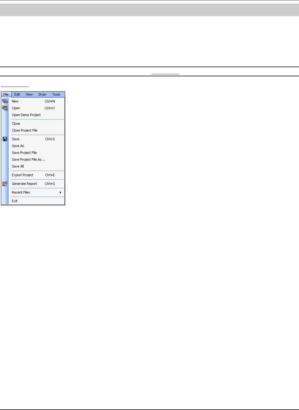
FileMenu
Figure 25. File Menu
MenuandToolbarOptions
3Com®AirProtectPlannerUserGuide
25
Menu Item Name Description Keyboard Shortcut Toolbar Button
New Invokes the new Planner project file Ctrl+N
Open Opens a dialog box to browse and select an
existing project or .zip file Ctrl+O
Open Demo Project Opens the demo project
Close Closes the currently loaded node
Close Project File Closes the current Planner project
Save Saves the current plan Ctrl+S
Save As Invokes a dialog box to save the current
project with a new name
Save Project File Saves the current project
Save Project File
As… Invokes a dialog box to save the current
project with a new name
Save All Saves both the node and project
Export Project Bundles the project into a .zip file so that you
can later import the whole project into a
different system at a different location Ctrl+E
Generate Report
Generates a report for the currently loaded
node. If the node is part of a Cross Floor
location folder, you can generate a report for
all the floors.
Ctrl+G
Recent Files Lists the last four opened projects
Exit Closes the Planner application
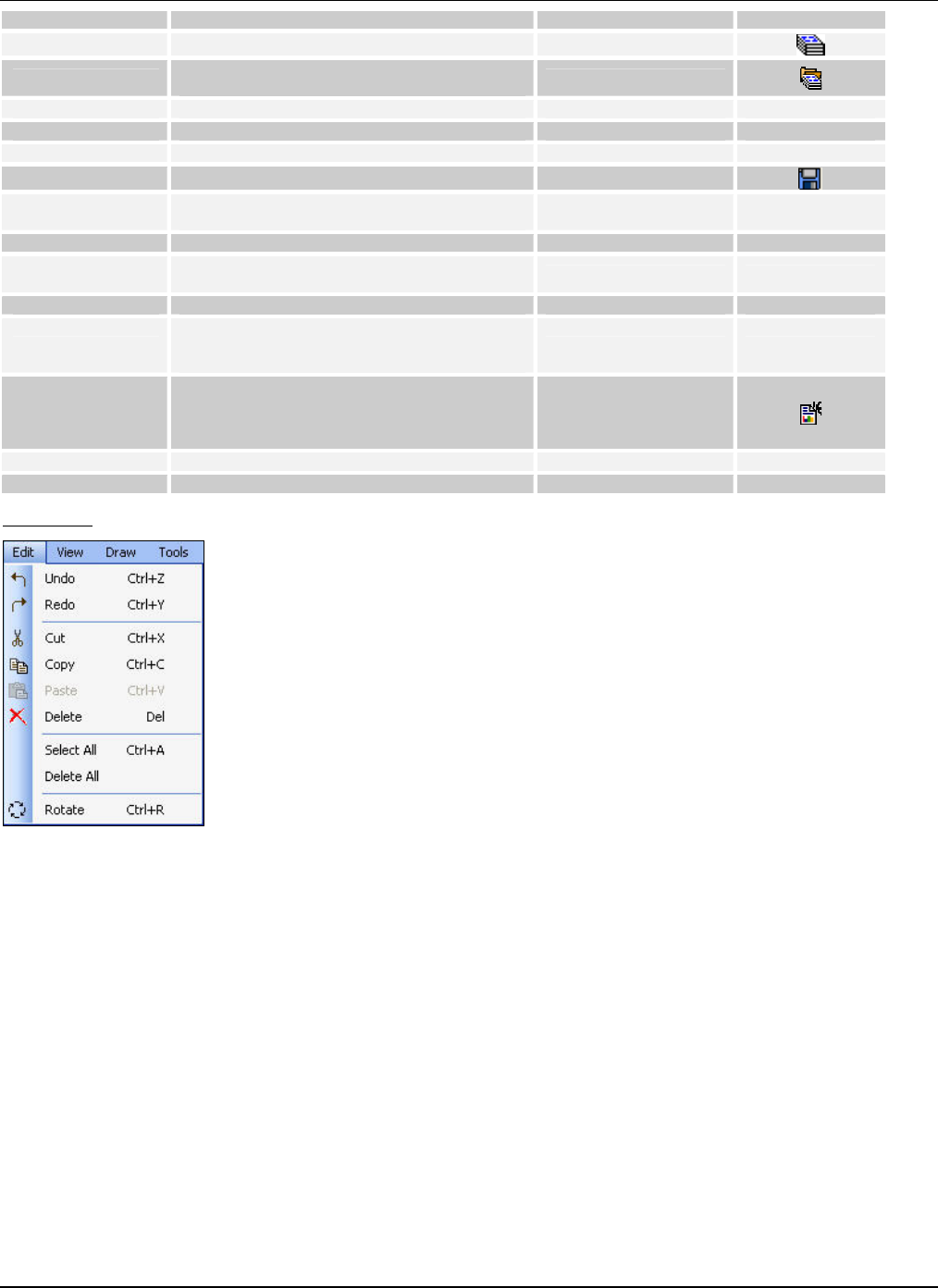
EditMenu
Figure 26. Edit Menu
MenuandToolbarOptions
3Com®AirProtectPlannerUserGuide
26
Menu Item Name Description Keyboard Shortcut Toolbar Button
Undo Reverses the last performed action Ctrl+Z
Redo Reverses the ‘Undo’ command and re-
performs the action Ctrl+Y
Cut Removes the selected object from the layout
to be pasted elsewhere Ctrl+X
Copy Creates a copy of the selected object from the
layout; selected objects remain on the layout Ctrl+C
Paste Pastes the last cut or copied object at the
designated location on the layout Ctrl+V
Delete Removes the selected object from the layout
permanently Del
Select All Selects all the objects on the layout map Ctrl+A
Delete All Deletes all the objects on the layout map
Rotate Rotates an object using the mouse by
selecting any of the control points of the
object Ctrl+R
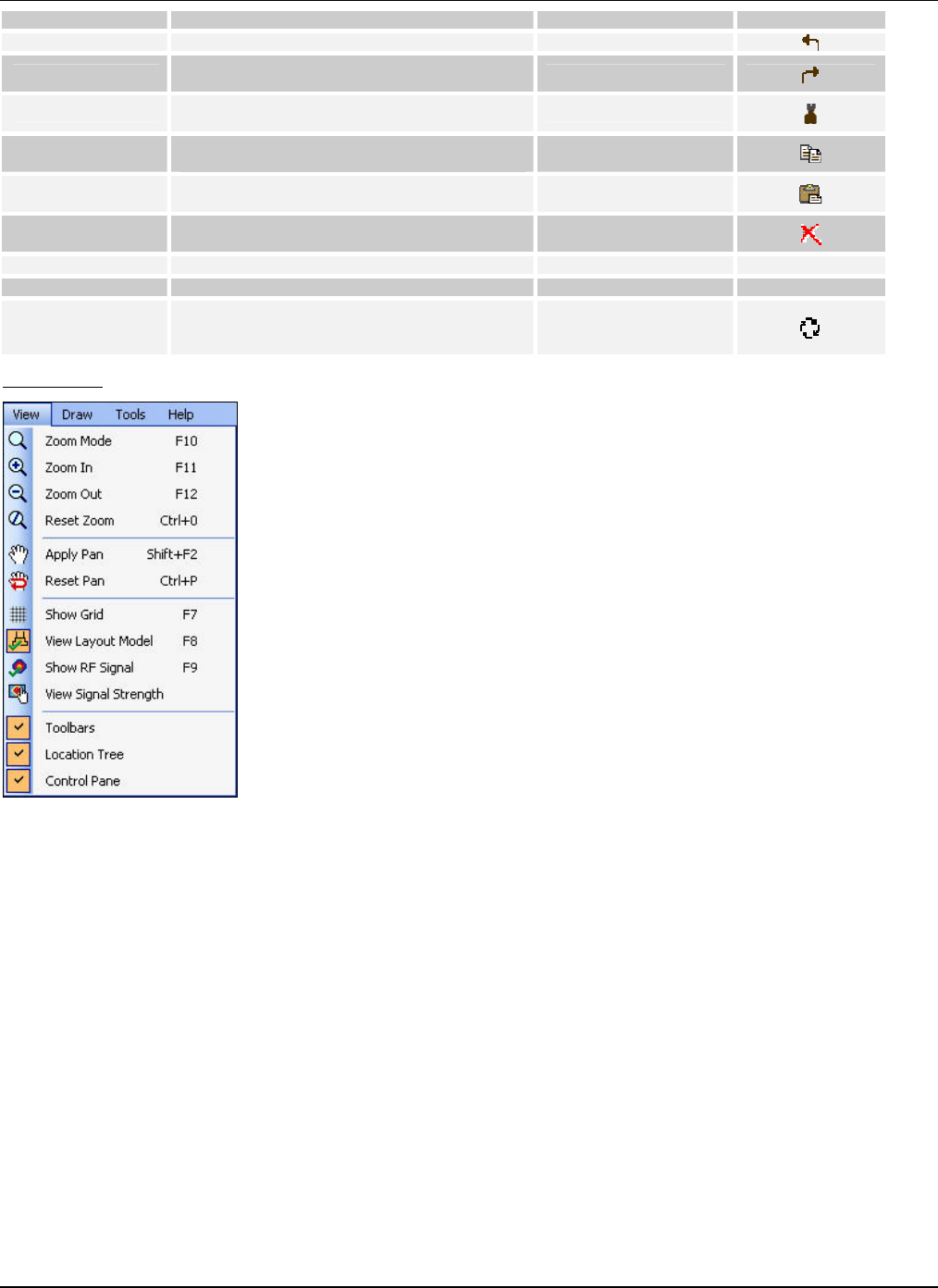
ViewMenu
Figure 27. View Menu
MenuandToolbarOptions
3Com®AirProtectPlannerUserGuide
27
Menu Item Name Description Keyboard Shortcut Toolbar Button
Zoom Mode Activates the zoom mode enabling you to
zoom-in or zoom-out using the mouse scroll F10
Zoom In Zooms in by 10% at each step F11
Zoom Out Zooms out by 10% at each step F12
Reset Zoom Resets the zoom and displays the layout in
the actual size (100%) Ctrl+0
Apply Pan Functions as a snap tool to move around in
the layout Shift+F2
Reset Pan Resets the snap tool Ctrl+P
Show Grid Shows the grid in the layout F7
View Layout Model Shows all the objects in the layout model F8
Show RF Signal Shows the RF signal on the layout F9
View Signal
Strength
Shows the signal strength of all the APs
placed on the layout at a particular location
on the layout
Toolbars Select to view the Toolbar
Location Tree Select to view the Location Tree
Control Pane Select to view the Control Pane
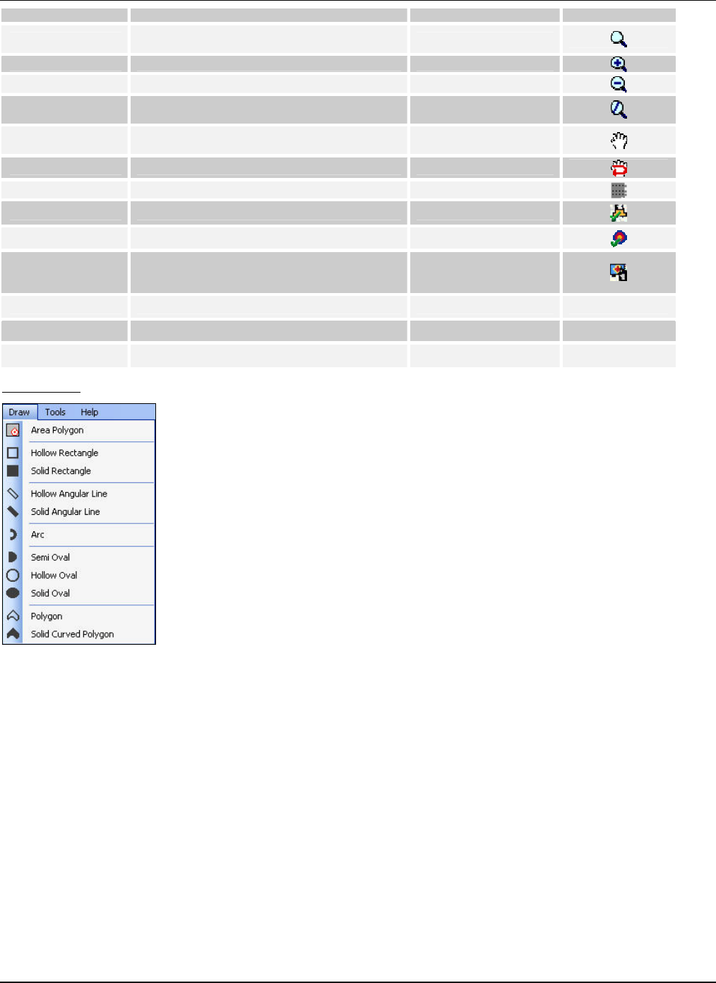
DrawMenu
Figure 28. Draw Menu
MenuandToolbarOptions
3Com®AirProtectPlannerUserGuide
28
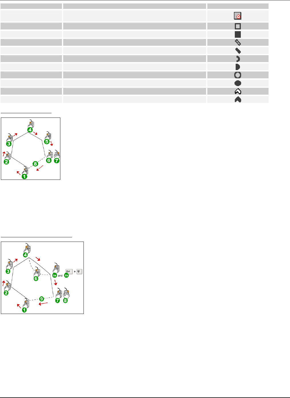
Menu Item Name Description Toolbar Button
Area Polygon Selects disjoint areas in a layout for showing RF maps; this
is helpful in showing statistics of selected regions only
Hollow Rectangle Draws a hollow rectangle
Solid Rectangle Draws a solid rectangle
Hollow Angular Line Draws a hollow angular line
Solid Angular Line Draws a solid angular line
Arc Draws an arc
Semi Oval Draws a semi oval
Hollow Oval Draws a hollow oval
Solid Oval Draws a solid oval
Polygon Draws a hollow curved polygon
Solid Curved Polygon Draws a solid curved polygon
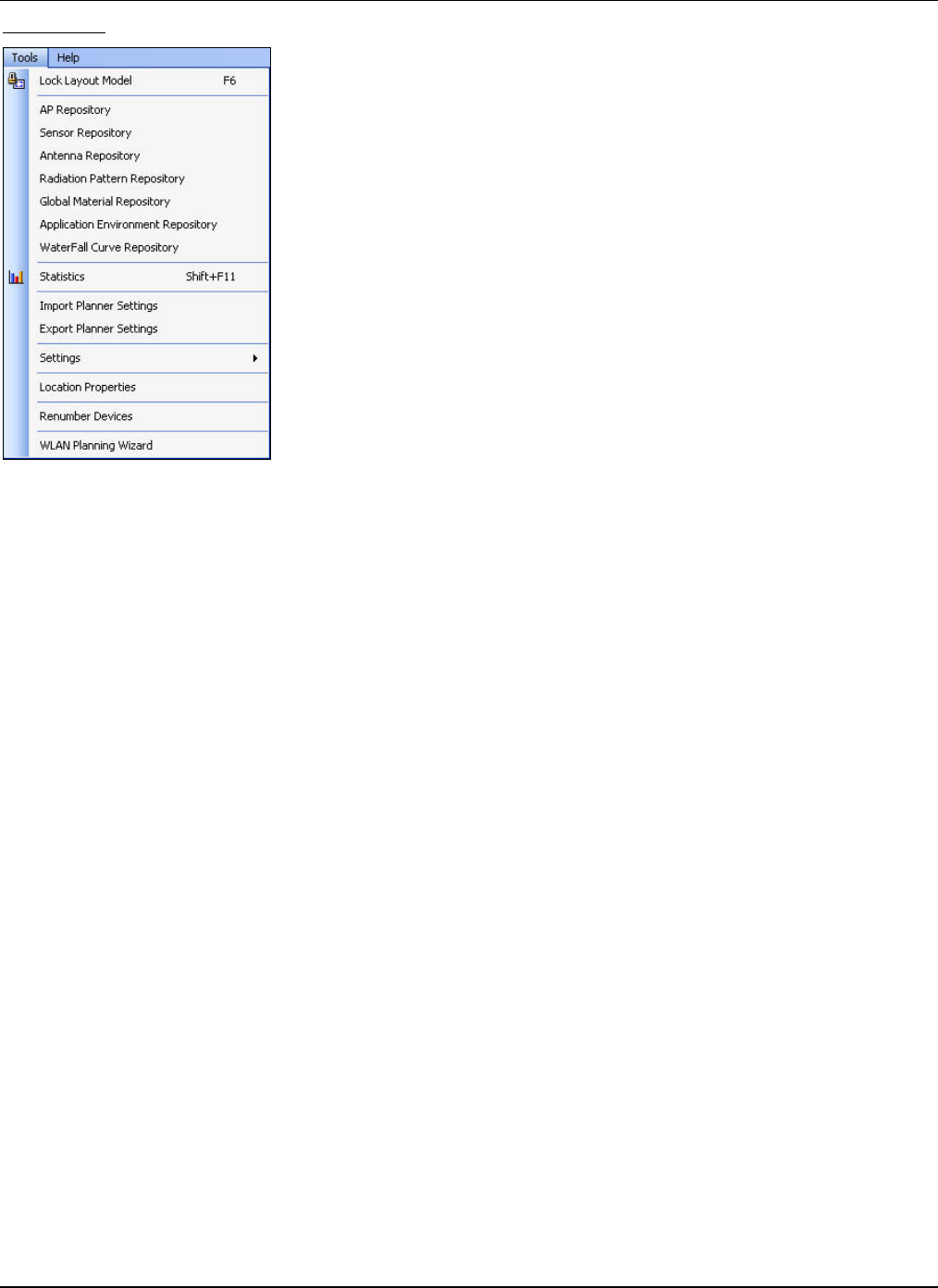
DrawingaPolygon
Figure 29. Drawing a Polygon
1 Left‐clickthestartingpoint(#1)
2 Left‐clickthenextpointthroughallpointsuntilyouareatthelastpoint(#6)
3 Left‐clickthelastpoint(#6)
4 Right‐clicktocompletethepolygon
DrawingaCurvedPolygon
Figure 30. Drawing a Curved Polygon
1 Left‐clickthestartingpoint(#1)
2 Left‐clickthenextpointthroughallpointsuntilyouareatapointwhereyouneedtodrawthecurve(#5a)
3 Todrawacurve(between#4and#5a)inthecurvedpolygon,press<Ctrl+U>toenterthe‘curve’mode(#5b).Movethe
mousetogetthedesiredcurve(#6)
4 Left‐clickthelastpoint(#7)
5 Right‐clicktocompletethecurvedpolygon
MenuandToolbarOptions
3Com®AirProtectPlannerUserGuide
29
ToolsMenu
Figure 31. Tools Menu
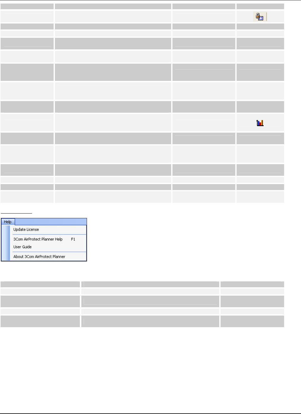
MenuandToolbarOptions
3Com®AirProtectPlannerUserGuide
30
Menu Item Name Description Keyboard Shortcut Toolbar Button
Lock Layout Model Locks all the objects on the layout model to
avoid accidental movement of layout objects F6
AP Repository Helps Add/View/Modify/Delete AP models
Sensor Repository Helps Add/View/Modify/Delete Sensor models
Antenna Repository Helps Add/View/Modify/Delete antenna
models
Radiation Pattern
Repository Helps Add/View/Modify/Delete radiation
patterns
Global Material
Repository
Helps Add/View/Modify/Delete materials in
the repository; helps import a material from
the Local Repository to the Global Repository
Application
Environment
Repository
Helps Add/View/Modify/Delete application
environments
Water Fall Curve
Repository Helps Add/View/Modify/Delete water fall
curves
Statistics Provides statistical data on the RF maps such
as % coverage for network, Sensor ranges,
and redundancy Shift+F11
Import Planner
Settings Imports the preferences and settings from a
specific file
Export Planner
Settings
Exports the preferences and settings to 3Com
® AirProtect Enterprise or any other system
running the Planner application.
Settings Sets the Preferences, AP defaults, and Sensor
defaults
Location Properties Changes location dimensions and calculations
Renumber Devices Helps sequential numbering of devices
WLAN Planning
Wizard Launches the WLAN planning wizard
HelpMenu
Figure 32. Help Menu
Menu Name Description Keyboard Shortcut
Update License Updates the License
3Com ® AirProtect Planner
Help Displays the Planner Help file F1
User Guide Displays the Planner User Guide in .PDF format
About 3Com ® AirProtect
Planner Displays information about Planner
5.1.2 UpdatingtheLicense
GotoHelpÆUpdateLicensetoupdatethelicensekey.
MenuandToolbarOptions
3Com®AirProtectPlannerUserGuide
31
Figure 33. Planner: Activating/Updating License
Usethefollowingstepstoactivate/updatethelicense:
1 EnteryourFirstName,LastName,andEmailId.
2 Click<Browse>tonavigatetolocationofthelicensekeyprovidedby3ComCorporation.
3 Click<ConfirmKey>toconfirmthelicensekey.Alternately,click<Cancel>todiscardtheconfirmationofthelicensekey
andclosethedialogbox.
5.2 Layout:Icons
ThefollowingiconsavailabletoyoufromthePlannerToolbar.SomeofthesearenotcoveredintheMenuList.
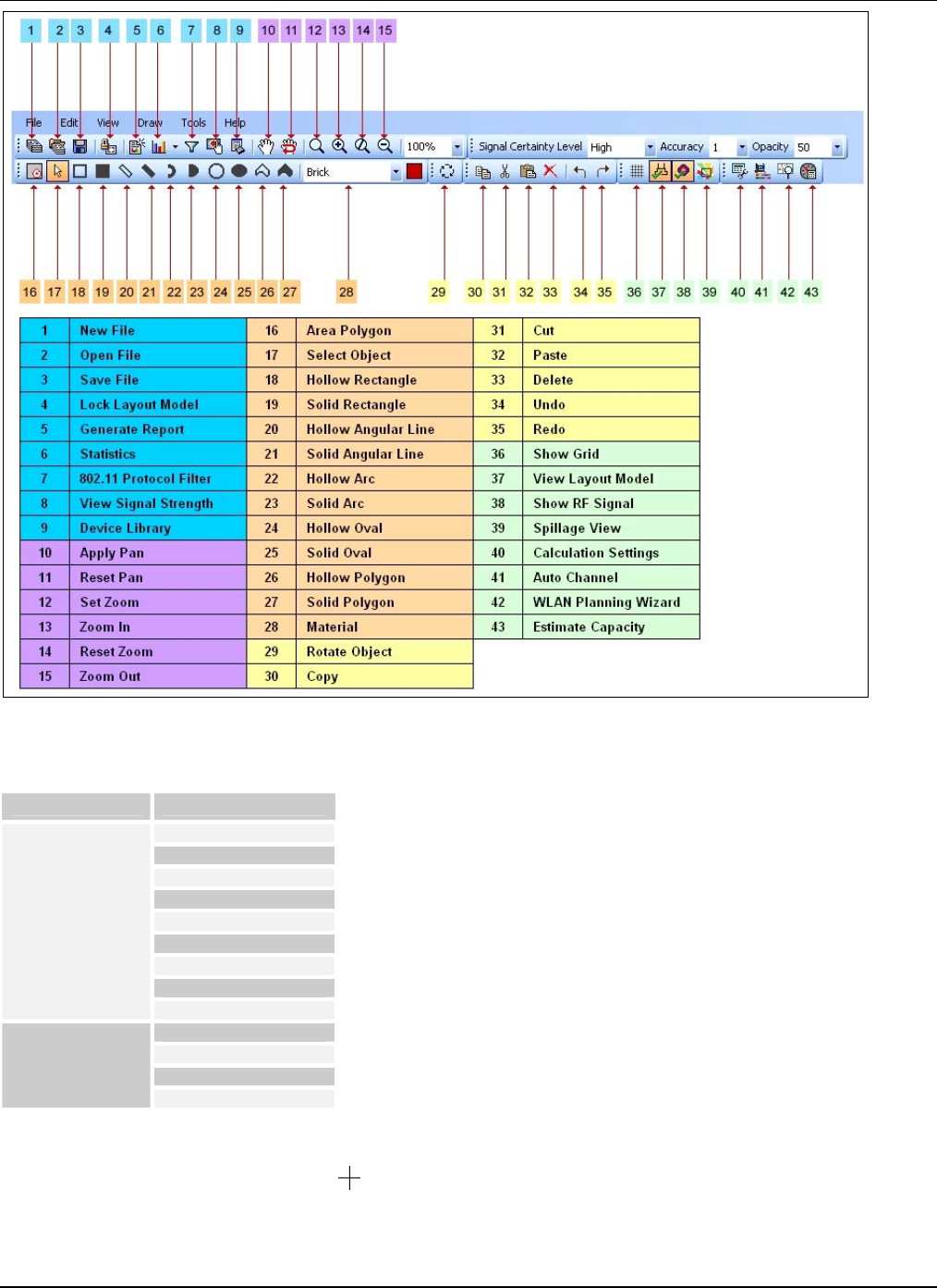
MenuandToolbarOptions
3Com®AirProtectPlannerUserGuide
32
Figure 34. Indoor Objects
Thefollowinglistdescribesthelayouttypeandmaterialsavailable.
Layout Type Materials
Brick
Dry
Concrete
Marble
Sheet Rock
Concrete Column
Wooden
Glass
Indoor
Metal
Building
Tree
Hill
Outdoor
Water Body
Afterselectingthelayouttype,usethefollowingstepstodrawobjectsonthelayout:
1 SelectanObjectTypeandmaterialtypefromthedrop‐downlistfromtheToolbar.
2 Thecursorchangestothecrosshairicon.Now,clickthelocationwhereyouwanttodrawtheobjectandwithout
releasingthebutton,dragthemouseonthelayouttowhereyouwanttheobjectplaced.Youwillseetheoutlineofthe
objectyouaredrawing.
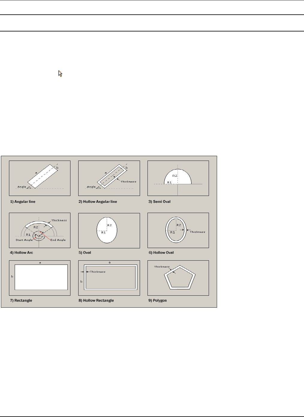
MenuandToolbarOptions
3Com®AirProtectPlannerUserGuide
33
3 Repeattheabovetwostepstoplaceanynumberofobjectsonthelayout.
Recommended:PlacetheobjectsinsuchawaythatthephysicallayoutiswellrepresentedintheLayoutwithminimumnumberof
objects.
5.3 ManagingObjectswithintheLayout
YoucanmanageobjectsandtheirpropertiesonthelayoutinPlanner.
5.3.1 SelectingObjects
Toselectanobject,click ontheToolbar.
Toselectmorethanoneobject,dooneofthefollowing:
• UsetheControlkey.
• Dragthemouseoverthetargetareatoenclosetheobjectswithinadottedoutline.Thisselectsalltheobjectswithinor
touchingthedottedoutline.
5.3.2 MovinganObject
Tomoveanobject,selectanddragittothedesiredposition.
5.3.3 ChangingthePropertiesofanObject
Plannerprovidesobjectsofdifferentshapesandthickness.
Figure 35. Layout Object Properties
Tochangethepropertiesofanobject,double‐clickorright‐clicktheobjectandselectProperties.
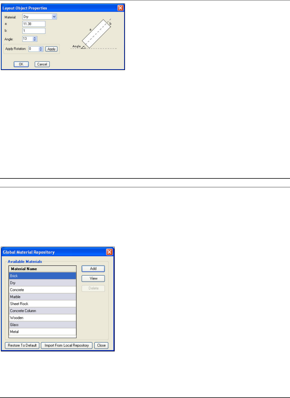
MenuandToolbarOptions
3Com®AirProtectPlannerUserGuide
34
Figure 36. Viewing Layout object properties
Youcanchangethefollowingparameters:
• Material:Selectthematerialtypefromthedrop‐downlist.
• a:Specifythelengthoftheobject.
• b:Specifythewidthoftheobject.
• Angle:Specifytheangleatwhichyouwanttheobjecttobeinclined.
• ApplyRotation:Specifytherotationoftheobject.Click<Apply>toapplytherotationincrementallytotheobject.
5.4 ManagingMaterialRepositories
Plannerprovidesasetofmaterialsintherepositoryusingwhichyoumodelthelayout.Youcanperformseveralfunctionslike
viewingpropertiesofadefaultmaterial,addinganewmaterial,modifying,anddeletingtheuser‐definedmaterials.Theseare
storedintwotypesofrepositories:GlobalMaterialRepositoryandLocalMaterialRepository.Planneralsoallowsyouto
importorexportmaterialtypesfromonerepositorytotheother.
Note:Alltheuser‐definedmaterialsareavailableintheindoorlayoutonly.
Whilemodelingthelayout,youcanalsoselectthematerialtypefromthedrop‐downlistontheToolbar.Theiconofthe
materialinuseappearsadjacenttothisdrop‐downlist,representedbythecolorandpatternassignedtothematerial.
5.4.1 GlobalMaterialRepository
GlobalMaterialRepositoryisamaterialobjectlibraryofPlannerwhichlistsandprovidesmaterialobjectsglobally,acrossall
Plannerprojects.ItisagloballyavailablefilesavedasObjectproperties.xml.
ToviewtheGlobalMaterialRepository,gotoToolsÆGlobalMaterialRepository.
Figure 37. Global Material Repository
YoucanperformthefollowingfunctionsfromtheGlobalMaterialRepositorydialogbox:
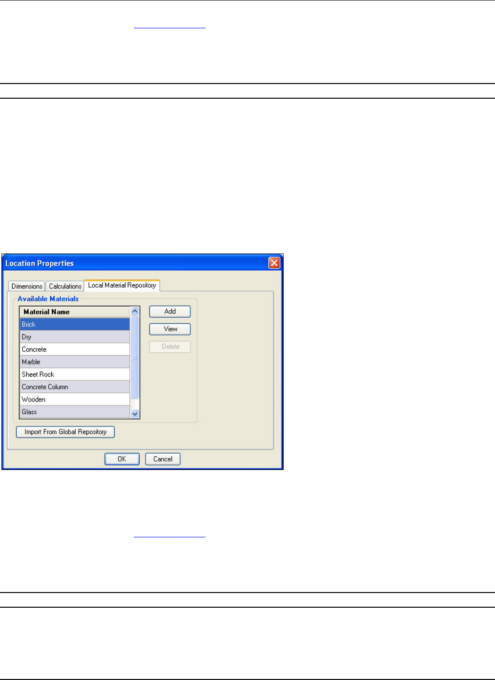
MenuandToolbarOptions
3Com®AirProtectPlannerUserGuide
35
• Add:ClicktoaddanewmaterialtothelistofmaterialsintheGlobalRepository.TheMaterialPropertiesdialogbox
appears.RefertosectionAddingaMaterialformoreinformation.
• View:Clicktoviewmaterialpropertiesofamaterialinthefactorydefaultlist.TheMaterialPropertiesdialogbox
appears.However,thefieldsinthisdialogboxaredisabled,andread‐only.
• Modify:Clicktomodifymaterialpropertiesofamaterialthatyouhavedefined.TheMaterialPropertiesdialogbox
appearswhereyoucanmakethedesiredchanges.
Note:<View>isreplacedby<Modify>whenyouselectauser‐definedmaterial.
• Delete:Clicktodeleteauser‐definedmaterial.Aconfirmationmessageappearsaskingifyouwanttodeletethe
material.
• RestoreToDefault:Clicktorestorethelisttofactorydefaults.Thisactionremovesalltheuser‐definedmaterialsand
retainsonlythedefaultmaterials.
• ImportfromLocalRepository:ClicktoimportmaterialsfromtheLocalMaterialRepository.
• Close:Clicktoclosethisdialogbox.
5.4.2 LocalMaterialRepository
TheLocalMaterialRepositoryisamaterialobjectlibraryofPlanner,whichgivesalistofAvailableMaterialsintheLocal
Repositoryofthat.spmfile.Allthelocalmaterialsarestoredinthe.spmfileandvisibleonlyinthat.spmfile.
TheLocalMaterialRepositoryfeatureisavailableonlyforanIndoorlayoutandnotforanoutdoorlayout.
ToviewtheLocalMaterialRepository,gotoToolsÆLocationPropertiesÆLocalMaterialRepository.
Figure 38. Local Material Repository Tab
YoucanperformthefollowingfunctionsfromtheLocalMaterialRepositorydialogbox:
• Add:ClicktoaddanewmaterialtothelistofmaterialsintheLocalRepository.TheMaterialPropertiesdialogbox
appears.RefertosectionAddingaMaterialformoreinformation.
• View:Clicktoviewmaterialpropertiesofamaterialinthefactorydefaultlist.TheMaterialPropertiesdialogbox
appears.However,thefieldsinthisdialogboxaredisabled,andread‐only.
• Modify:Clicktomodifymaterialpropertiesofamaterialthatyouhavedefined.TheMaterialPropertiesdialogbox
appearswhereyoucanmakethedesiredchanges.
Note:<View>isreplacedby<Modify>whenyouselectauser‐definedmaterial.
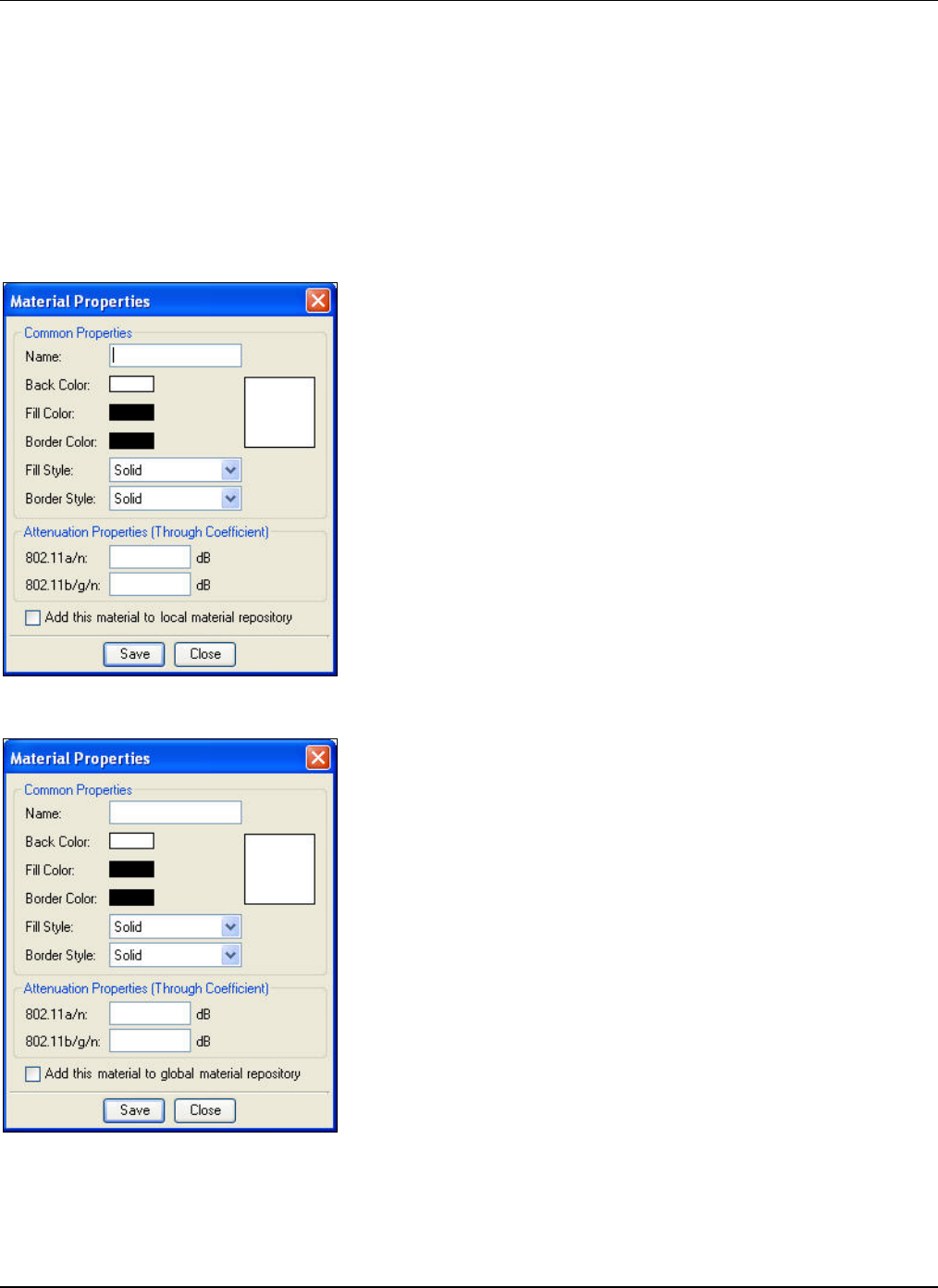
MenuandToolbarOptions
3Com®AirProtectPlannerUserGuide
36
• Delete:Clicktodeleteauser‐definedmaterial.Plannerchecksifyouhaveusedthematerialonthecurrentlayout.If
youhaveusedthematerial,Plannerpromptsyoutodeletethoseobjectsfromthelayoutandthencontinuewiththe
deletionofthematerialfromtherepository.Aconfirmationmessageappearsaskingifyouwanttodeletethe
material.
• ImportfromGlobalRepository:ClicktoimportmaterialsfromtheGlobalMaterialRepository.
Click<OK>tosaveandclosethedialogbox.Alternatelyclick<Cancel>;thiswillclosethedialogboxwithoutapplying
changesmade.
5.4.3 AddingaMaterial
YoucanaddanewmaterialtotheexistinglistofmaterialsintheLocalandGlobalMaterialRepositories.Click<Add>onthe
respectiverepositorydialogboxes.TheMaterialPropertiesdialogboxappears.
Figure 39. Global Material Repository: Adding a New Material
Figure 40. Local Material Repository: Adding a New Material
CommonProperties:
• Name:Nameofthenewmaterial.
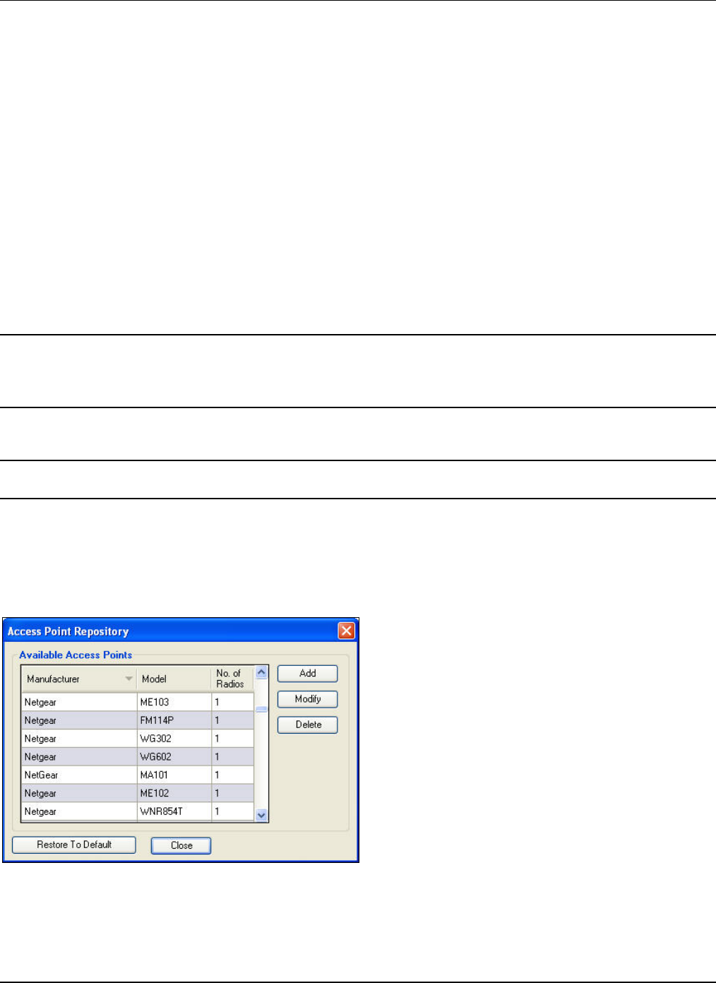
MenuandToolbarOptions
3Com®AirProtectPlannerUserGuide
3
7
• BackColor:Backgroundcolorforthenewmaterial.ClickthecolortochoosethedesiredcolorfromtheColordialog
box.
• FillColor:Fillcolorforthematerial.ClickthecolortochoosethedesiredcolorfromtheColordialogbox.
• BorderColor:Bordercolorforthematerial.ClickthecolortochoosethedesiredcolorfromtheColordialogbox.
• FillStyle:Selectthefilltypepatternfromthedrop‐downlist.
• BorderStyle:Selectthepatternfortheborderfromthedrop‐downlist.
• Thepreviewwindowontherightreflectsthepropertiesyouselectforthematerial.
AttenuationProperties(ThroughCoefficient):
• 802.11a/n:Specifytheattenuationfactorforthe802.11a/nprotocol.Thisvalueisapplicabletoboth802.11aand
802.11a/n.
• 802.11b/g/n:Specifytheattenuationfactorforthe802.11b/g/nprotocol.Thisvalueisapplicabletoboth802.11b/gand
802.11b/g/n.
• AddthenewMaterialtotheotherrepository:
¾ IfyouaddanewmaterialfromtheGlobalMaterialRepositorydialogbox,selecttheAddthismaterialtolocal
materialrepositorycheckboxtoincludethismaterialintheLocalMaterialRepository.Thismaterialwillthenbe
availableintheMaterialdrop‐downlistontheToolbar.
¾ IfyouaddanewmaterialfromtheLocalMaterialRepositorydialogbox,selecttheAddthismaterialtoglobal
materialrepositorycheckboxtoincludethismaterialintheGlobalMaterialRepository.
Note:IfyouaddamaterialintotheLocalMaterialRepositoryandyoulatercreateanew.spmfile,thismaterialdoesnotappearinthe
materiallist.ThisisbecausethematerialwasaddedlocallyandnottotheGlobalMaterialRepository.Similarly,ifyouaddamaterialonly
totheGlobalMaterialRepositorybutdonotcopyittotheLocalRepository,youwillnotfindthematerialinthelistofthecurrentlyloaded
.spmfile.However,whenyoucreateanew.spmfile,youwillseethenewmaterialinthemateriallist.
Click<Save>tosaveandaddthenewmaterialtotherepository.
Click<Close>toclosethewindow.
Note:PlannerdisplaysanalertmessageanddoesnotallowyoutosavethematerialunlessyoufillallthefieldsintheMaterial
Propertiesdialogbox.
5.5 Layout:UsingtheToolsoptions
ThefollowingoperationscanbeperformedusingtheToolsmenu.
5.5.1 APRepository
SelectAPRepositoryfromtheToolsmenu.
Figure 41. Tool Menu – AP Repository
TheAccessPointRepositorydialogboxdisplaysalistofavailableAPs,theirmanufacturer,model,andnumberofradios.
Youcandothefollowing:

MenuandToolbarOptions
3Com®AirProtectPlannerUserGuide
38
• AddanAP
• ModifyanAP
• DeleteanAP
AddAP
Click<Add>toaddanAPandspecifytheAPproperties.TheAddAccessPointdialogboxallowsyoutoselectanddefine
radioproperties.
Figure 42. AP Repository – Adding an AP
Add AP Properties Description
Manufacturer Enter the name of the manufacturer.
Model Enter the AP model.
Available Radio Select the radio from the drop-down list of available radios.
Add Radio Click to add a new radio to the AP. This takes you to the Radio Properties
section in the dialog box.
Delete Radio Click to delete a radio.
Antenna Select the antenna type from the drop-down list.
More Click to select or add a new antenna. For details, refer to the Antenna
Repository section.
Antenna Detachable Select the checkbox, depending upon the type of antenna required.
Protocols Select any or all the protocols (802.11a, 802.11b, 802.11g, 802.11a/n,
802.11b/g/n).
Waterfall Curve Select the waterfall curve for the protocols from the drop-down list. For
details, refer to the Waterfall Curve Repository section.
Power Specify the desired power range for each protocol. Enter a comma-separated
list with values in the range (1 to 100 mW).
Advanced Parameters Click to define advanced 802.11n parameters. The IEEE 802.11n advance
parameters dialog box appears.
IEEE802.11nAdvanceParameters
Youcandescribeadvanceparametersfor802.11n.
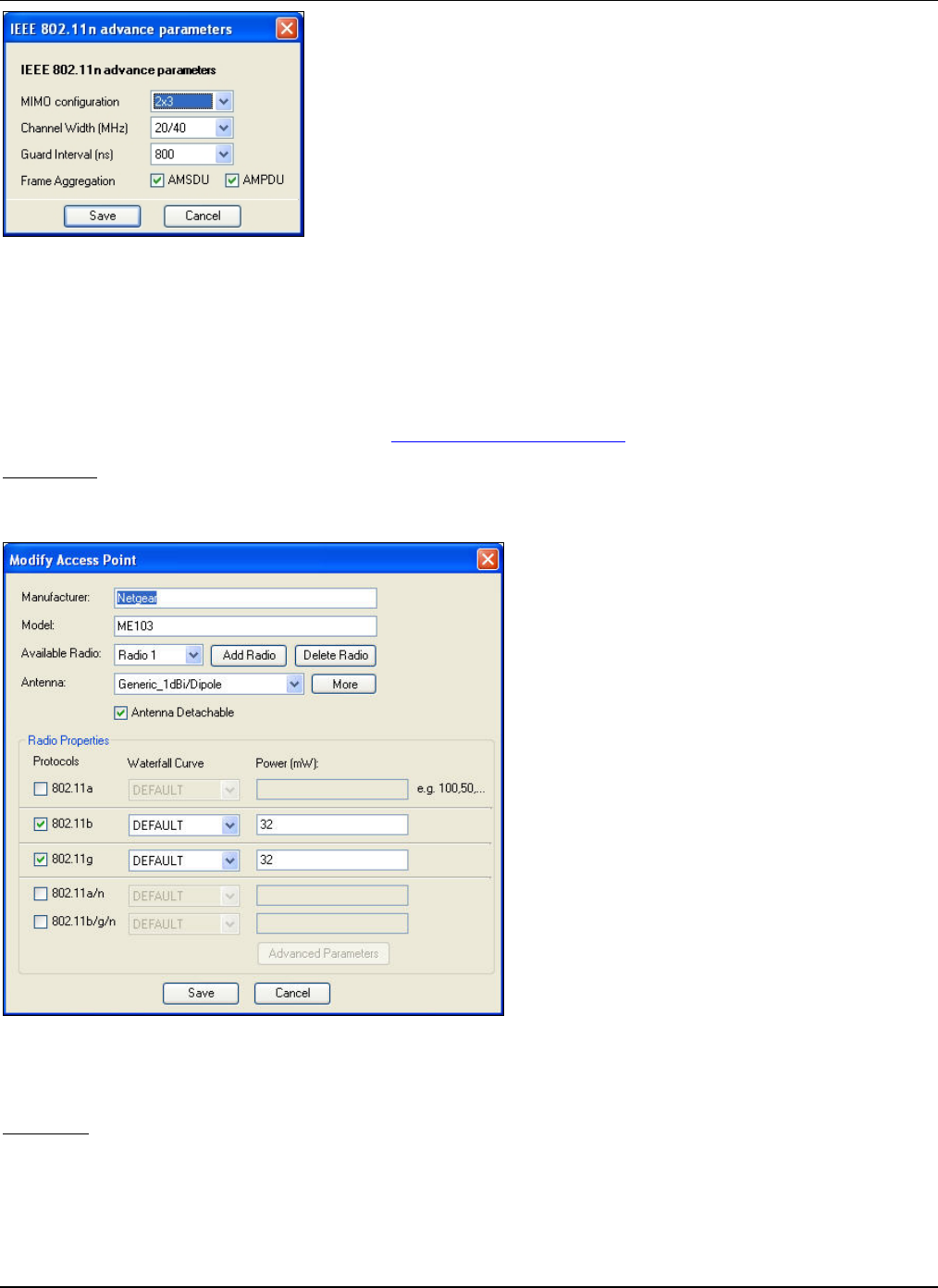
MenuandToolbarOptions
3Com®AirProtectPlannerUserGuide
39
Figure 43. Adding an AP – 802.11n Advance Parameters
Definethedesired802.11nadvanceparameters.
• MIMOconfiguration:SelecttheMIMOconfigurationfromthedrop‐downlist
• Channelwidth(MHz):SelecttheChannelwidthfromthedrop‐downlist
• Guardinterval(ns):SelecttheGuardintervalfromthedrop‐downlist
• FrameAggregation:SelecteitherAMSDUorAMPDU,orbothcheckboxesforframeaggregation.
Formoredetailsontheadvanceparameters,refertoAppendixD:GlossaryofTerms.
ModifyAP
Click<Modify>ontheAccessPointRepositorydialogboxtomodifyanexistingAP.TheModifyAccessPointdialogbox
appears.
Figure 44. AP Repository – Modifying an AP
TheModifyAccessPointdialogboxissimilartotheAddAccessPointdialogbox.
DeleteAP
Click<Delete>andconfirmthedeletionofanAP.
5.5.2 SensorRepository
SelectSensorRepositoryfromtheToolsmenu.
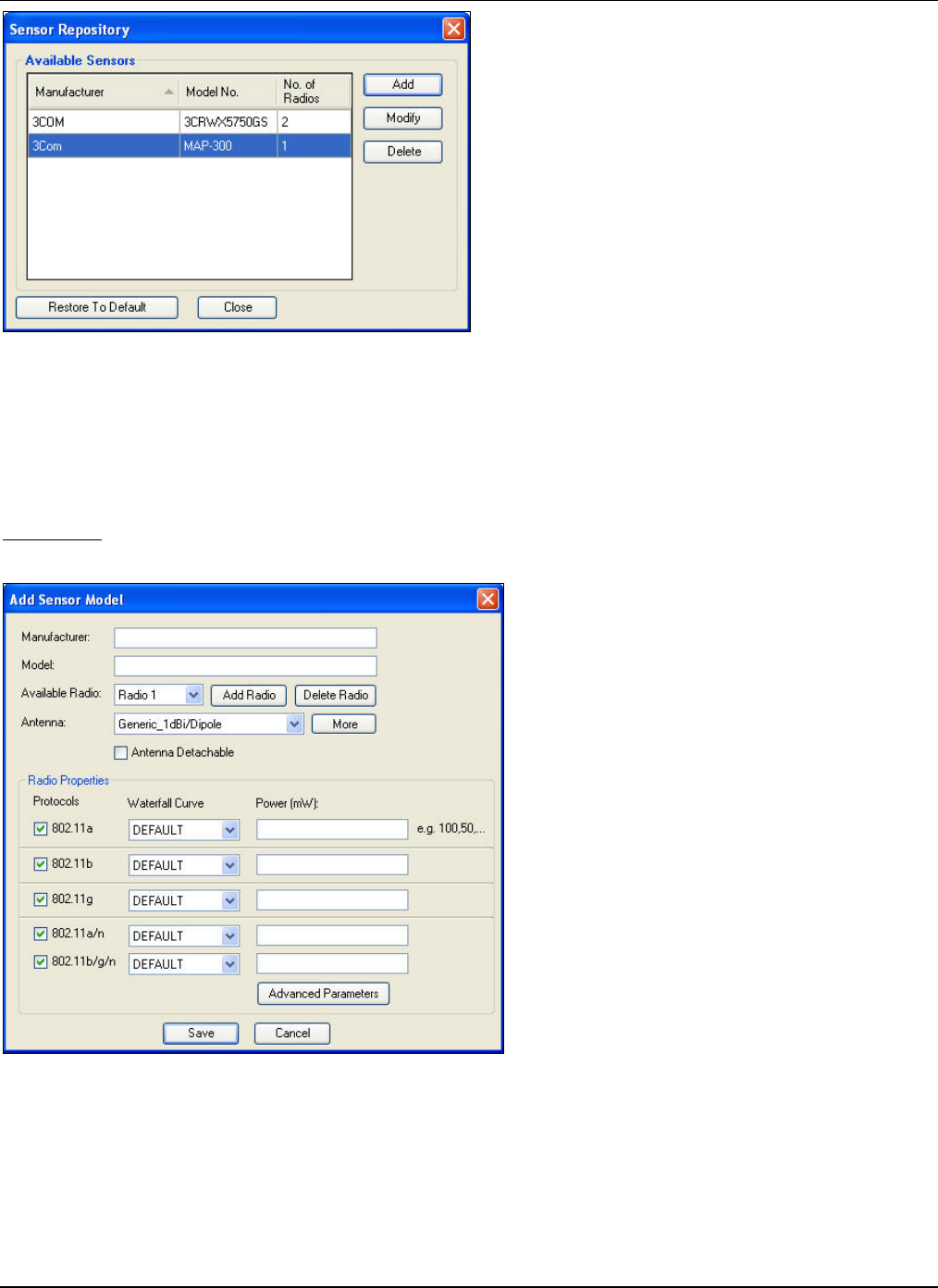
MenuandToolbarOptions
3Com®AirProtectPlannerUserGuide
40
Figure 45. Tool Menu – Sensor Repository
TheSensorRepositorydialogboxdisplaysalistofavailableSensors,theirmanufacturer,model,andnumberofradios.
Youcandothefollowing:
• AddaSensor
• ModifyaSensor
• DeleteaSensor
AddSensor
Click<Add>toaddaSensorandspecifytheSensorproperties.
Figure 46. Sensor Repository – Adding a Sensor
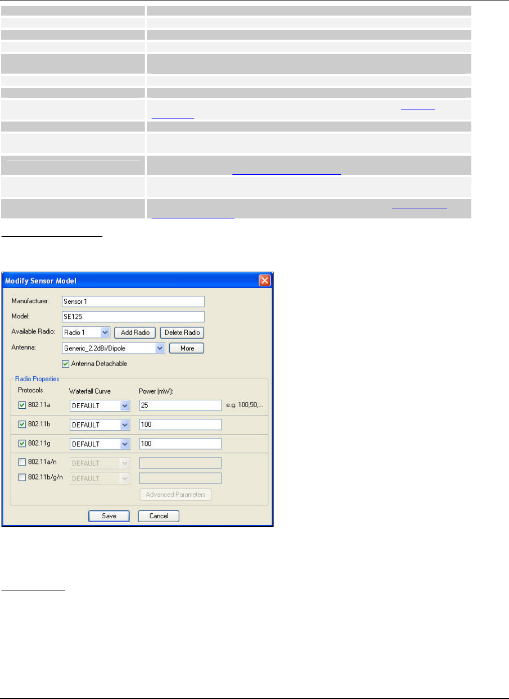
MenuandToolbarOptions
3Com®AirProtectPlannerUserGuide
41
Add Sensor Properties Description
Manufacturer Enter the name of the manufacturer.
Model Enter the Sensor model.
Available Radio Select the radio from the drop-down list of available radios.
Add Radio Click to add a new radio to the Sensor. This takes you to the Radio
Properties section.
Delete Radio Click to delete a radio.
Antenna Select the antenna type from the drop-down list.
More Click to select or add a new antenna. For details, refer to the Antenna
Repository section.
Antenna Detachable Select the checkbox, depending upon the type of antenna required.
Protocols Select any or all the protocols (802.11a, 802.11b, 802.11g, 802.11a/n,
802.11b/g/n).
Waterfall Curve Select the waterfall curve for the protocols from the drop-down list. For
details, refer to the Waterfall Curve Repository section.
Power Specify the desired power range for each protocol. Enter a comma-separated
list with values in the range (1 to 100 mW).
Advanced Parameters Click to define advanced 802.11n parameters. Refer to the IEEE 802.11n
Advance Parameters for more details.
ModifySensorModel
Click<Modify>ontheSensorRepositorydialogboxtomodifyanexistingSensormodel.TheModifySensorModeldialog
boxappears.
Figure 47. Sensor Repository – Modifying a Sensor
TheModifySensorModeldialogboxissimilartotheAddSensorModeldialogbox.
DeleteSensor
Click<Delete>andconfirmthedeletionofaSensor.
5.5.3 AntennaRepository
AntennaRepositorycontainsalistofpredefinedantennae.Youcanaddanewantenna,deleteanantenna,ordefinenew
radiationpatternsforanantenna.
SelectAntennaRepositoryfromtheToolsmenu.
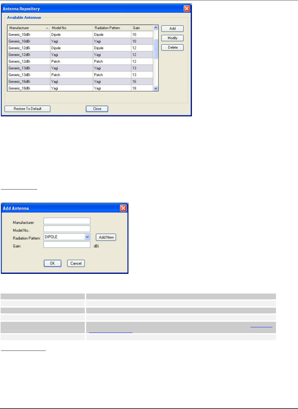
MenuandToolbarOptions
3Com®AirProtectPlannerUserGuide
42
Figure 48. Tools Menu – Antenna Repository
TheAntennaRepositorydialogboxdisplaysalistofavailableantennae,theirmanufacturer,model,radiationpatternand
gain.
Youcandothefollowing:
• Addanantenna
• Modifyanantenna
• Deleteanantenna
AddAntenna
Click<Add>toaddanantennaandspecifytheantennaproperties.
Figure 49. Antenna Repository – Adding an Antenna
Add Antenna Properties Description
Manufacturer Enter the name of the manufacturer.
Model No. Enter the antenna model.
Radiation Pattern Select the radiation pattern from the drop-down list.
Add New Click to add a new radiation pattern. For details, please refer to the Radiation
Pattern Repository section.
Gain Enter the Gain (1 to 99 dBi).
ModifyAntenna
Click<Modify>ontheAntennaRepositorydialogboxtomodifyanexistingantenna.TheModifyAntennadialogbox
appears.
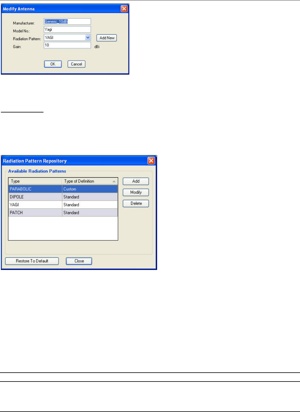
MenuandToolbarOptions
3Com®AirProtectPlannerUserGuide
43
Figure 50. Antenna Repository – Modifying an Antenna
TheModifyAntennadialogboxissimilartotheAddAntennadialogbox.
DeleteAntenna
Click<Delete>andconfirmthedeletionoftheantenna.
5.5.4 RadiationPatternRepository
Youcancreatecustomdefinedradiationpatternswhereyoucandefinethegainateachanglestartingfrom0°to359°.
SelectRadiationPatternRepositoryfromtheToolsmenu.
Figure 51. Tools Menu – Radiation Pattern Repository
TheRadiationPatternRepositorydialogboxdisplaysalistofavailableradiationpatterns,theirtype,maxgain,andtypeof
definition.
Youcandothefollowing:
• IncaseofaCustomRadiationPatterns:
¾ AddaRadiationPattern
¾ Modify/ViewaRadiationPattern
¾ DeleteaRadiationPattern
• IncaseofaStandardRadiationPattern:
¾ AddaRadiationPattern
¾ ViewaRadiationPattern
Note:TheDeleteoptionisdisabledincaseofStandardRadiationPatterns.
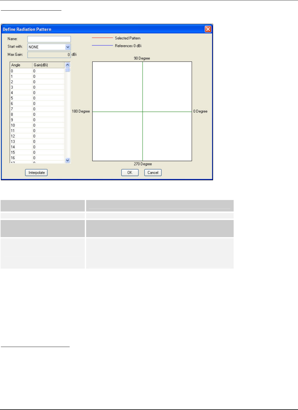
MenuandToolbarOptions
3Com®AirProtectPlannerUserGuide
44
AddRadiationPattern
Click<Add>toaddaRadiationPatternandspecifytheantennaproperties.
Figure 52. Radiation Pattern Repository – Adding a Radiation Pattern
Add Radiation Pattern
Properties Description
Name Enter the name of the radiation pattern.
Start with Select the type of antenna to start with from the drop-
down list. You can choose from None, Dipole, Yagi, Patch,
or Parabolic.
Max Gain
The maximum gain controls pattern behavior. The Max
Gain value will be the maximum value of the gain values at
each angle or higher. Positive gain adds power to the
transmitting power while negative gain reduces the
transmitting power.
ThetableintheDefineRadiationPatterndialogboxshowsgainvaluesateachanglerangingfrom0°to359°.Thesevaluesin
thetablechangedependingontheantennatypeselectedinStartWith.Tocreatecustomradiationpatterns,youcanmodify
thegainvaluestogettherequiredradiationpattern.Thegainvalueshouldbebetween‐99and99dBi.
Forexample,tomodifyastandarddipolepattern,startwithdipoleandmodifythegainvaluesfortheangleswhereyouwant
customization.
Click<Interpolate>ifyouhavedefinedthegainattwodifferentangles,andwantPlannertoautomaticallyinterpolatethe
gainfortheintermediateangles.Foreffectiveinterpolation,ensurethatthegainvalueforalltheanglesbetweenthetwo
anglesis0°.
ModifyRadiationPattern
Click<Modify>ontheRadiationPatternRepositorydialogboxtomodifyacustomradiationpattern.TheModifyRadiation
Patterndialogboxappears.
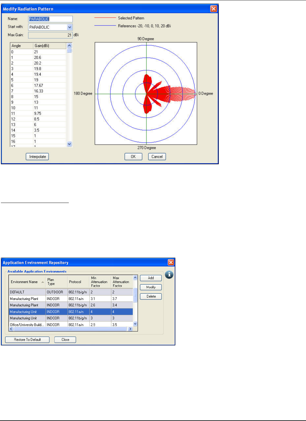
MenuandToolbarOptions
3Com®AirProtectPlannerUserGuide
45
Figure 53. Radiation Pattern Repository – Modifying a Radiation Pattern
TheModifyRadiationPatterndialogboxissimilartotheAddRadiationPatterndialogbox.
DeleteRadiationPattern
Click<Delete>andconfirmthedeletionofaRadiationPattern.
5.5.5 ApplicationEnvironmentRepository
Plannerprovidesalistofapplicationenvironments,whichlistsenvironmentsettings.Youcanusetheseenvironmentsto
designthelayout.Youcanalsocreatecustomdefinedapplicationenvironments.
SelectApplicationEnvironmentRepositoryfromtheToolsmenu.
Figure 54. Tools Menu – Application Environment Repository
TheApplicationEnvironmentRepositorydialogboxdisplaysalistofapplicationenvironments,theplantype,their
protocols,minimumandmaximumattenuationfactors.
Youcandothefollowing:
• IncaseofaDefaultApplicationEnvironment:
¾ AddanApplicationEnvironment
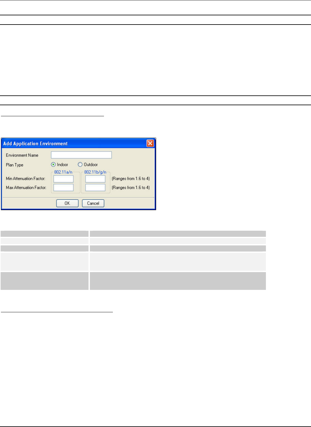
MenuandToolbarOptions
3Com®AirProtectPlannerUserGuide
46
¾ ViewanApplicationEnvironment
Note:TheModifyandDeleteoptionsaredisabledincaseoftheDefaultApplicationEnvironment.
• Incaseofasystemoruser‐definedapplicationenvironment:
¾ AddanApplicationEnvironment
¾ ModifyanApplicationEnvironment
¾ DeleteanApplicationEnvironment
WhenyouusetheDefaultapplicationenvironment,youhavetomodelthelayoutbydrawingobjectsonthelayout.However,
whenyouusesomeotherapplicationenvironment,youmustnotmodelthelayoutasPlannerderivestheattenuationvalues
forthoseenvironmentsettingsassumingasifthereareobjectsplacedonthefloormap.Despitethis,ifyoustillmodelthe
layoutthentheBoMoftheDeviceswillincreasesubstantially.
Recommended:Usetheapplicationenvironmentsasisanddonotmodifythevaluesunlessyouaresureofthosevalues.
AddinganApplicationEnvironment
Click<Add>toaddanapplicationenvironmentandspecifytheenvironmentproperties.TheAddApplicationEnvironment
dialogboxappears.
Figure 55. Application Environment Repository – Adding an Application Environment
Add Application Environment Description
Environment Name Enter the name of the application environment.
Plan Type Select between indoor and outdoor plan types.
Min Attenuation Factor Refers to the minimum loss of signal when passing through a
material, depending on object type and density in the layout. Enter
the minimum attenuation values for 802.11a/n and 802.11b/g/n.
Max Attenuation Factor Refers to the maximum loss of signal when passing through a
material, depending on object type and density in the layout. Enter
the maximum attenuation values for 802.11a/n and 802.11b/g/n.
Attenuationvaluesfor802.11a/naregreaterthan802.11b/g/n.
ModifyinganApplicationEnvironment
Click<Modify>ontheApplicationEnvironmentRepositorydialogboxtomodifyanexistingapplicationenvironment.The
ModifyApplicationEnvironmentdialogboxappears.
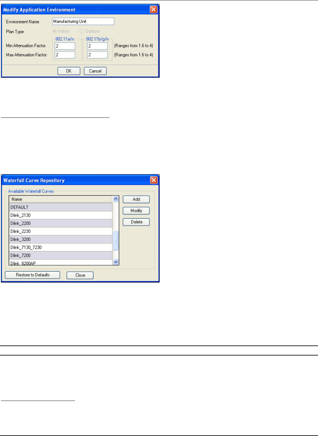
MenuandToolbarOptions
3Com®AirProtectPlannerUserGuide
47
Figure 56. Application Environment Repository – Modifying an Application Environment
TheModifyApplicationEnvironmentdialogboxissimilartotheAddApplicationEnvironmentdialogbox.
DeletinganApplicationEnvironment
Click<Delete>andconfirmthedeletionoftheapplicationenvironment.
5.5.6 WaterfallCurveRepository
Plannerprovidesalistofwaterfallcurves.Youcanusethemtodesignthelayout.Youcanalsocreatecustomdefined
waterfallcurves.
SelectWaterfallCurveRepositoryfromtheToolsmenu.
Figure 57. Tools Menu – Waterfall Curve Repository
TheWaterfallCurveRepositorydialogboxdisplaysalistofWaterfallCurves.
Youcandothefollowing:
• IncaseofaDefaultWaterfallCurve:
¾ AddaWaterfallCurve
¾ ViewaWaterfallCurve
Note:TheModifyandDeleteoptionsaredisabledforDefaultWaterfallCurve.
• Incaseofasystemoruser‐definedwaterfallcurve:
¾ AddaWaterfallCurve
¾ ModifyaWaterfallCurve
¾ DeleteaWaterfallCurve
AddingaWaterfallCurve
Click<Add>toaddawaterfallcurveandspecifythewaterfallcurvesettings.TheAddWaterfallCurvedialogboxappears.
ThedialogboxprovidesalistofthelinkspeedofanAPmappedtothesignalstrengthintheascendingorder.TheAdd
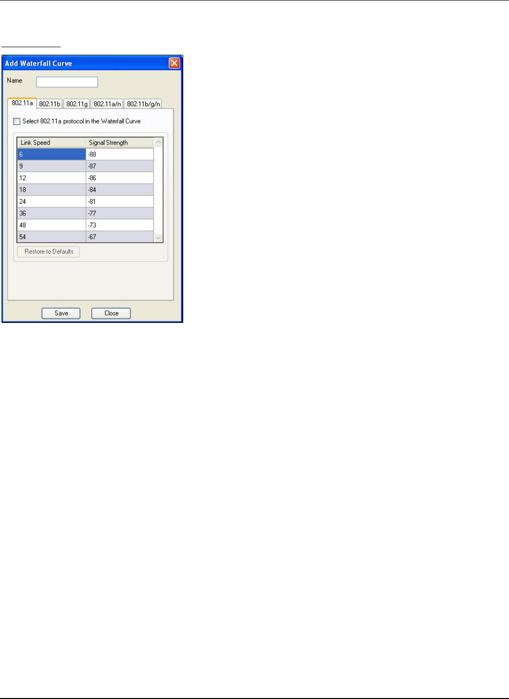
MenuandToolbarOptions
3Com®AirProtectPlannerUserGuide
48
WaterfallCurvedialogboxfor802.11a,802.11b,and802.11gprotocolsisdifferentfromthe802.11a/nand802.11b/g/n
protocols.
802.11(a,b,g):
Figure 58. Waterfall Curve Repository – Adding a Waterfall Curve: 802.11 (a, b, g)
• Name:Enterthenameofthewaterfallcurve.
• Select802.11aprotocolintheWaterfallCurve:Selectthecheckboxtoselectandenableeditaccesstovaluesinthe
listforthe802.11a,802.11b,or802.11gprotocols(fromtherespectivetabs)intheWaterfallCurve.
Thedialogboxliststhelinkspeedmappedtothesignalstrengthfor802.11a,802.11b,or802.11gprotocolsintheascending
orderbasedonwhichtabyouare.
• LinkSpeed:ListsthelinkspeedoftheAPfortherespectiveprotocol.
• SignalStrength:Liststhesignalstrengthcorrespondingtothelinkspeed.Selectavalueandclicktoeditthevalue.
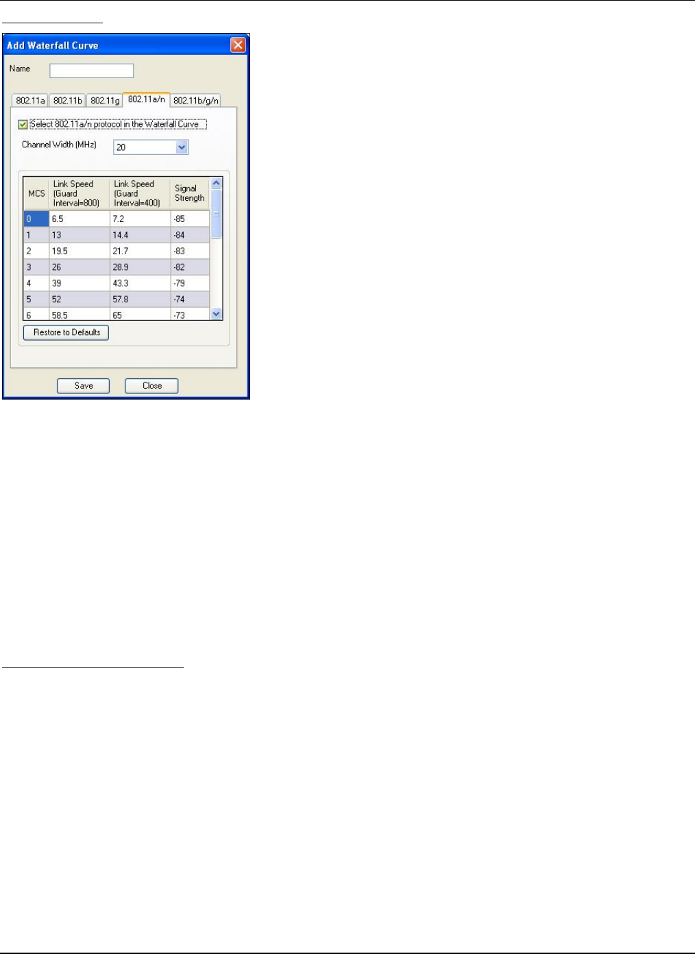
MenuandToolbarOptions
3Com®AirProtectPlannerUserGuide
49
802.11(a/n,b/g/n):
Figure 59. Waterfall Curve Repository – Adding a Waterfall Curve: 802.11 (a/n, b/g/n)
• Name:Enterthenameofthewaterfallcurve.
• Select802.11a/nprotocolintheWaterfallCurve:Selectthecheckboxtoselectandenableeditaccesstovaluesinthe
listforthe802.11a/nor802.11b/g/nprotocols(fromtherespectivetabs)intheWaterfallCurve.
• ChannelWidth(MHz):Selectthechannelwidthfromthedrop‐downlist.Thelinkspeedvaluesdependonthe
channelwidth.Thepossiblevaluesare20MHzor20/40MHz.
Thedialogboxliststhelinkspeedmappedtothesignalstrengthfor802.11a/nor802.11b/g/nprotocolsintheascendingorder
basedonselectedchannelwidth.
• MCS:Specifiesthedataratesupportedby802.11n.
• LinkSpeed(GuardInterval=800):ListsthelinkspeedoftheAPfortherespectiveprotocolataguardintervalof800.
• LinkSpeed(GuardInterval=400):ListsthelinkspeedoftheAPfortherespectiveprotocolataguardintervalof400.
• SignalStrength:Liststhesignalstrengthcorrespondingtothelinkspeed.Selectavalueandclicktoeditthevalue.
ModifyingaWaterfallCurve
Click<Modify>ontheWaterfallCurveRepositorydialogboxtomodifyanexistingwaterfallcurve.TheModifyWaterfall
Curvedialogboxappears.
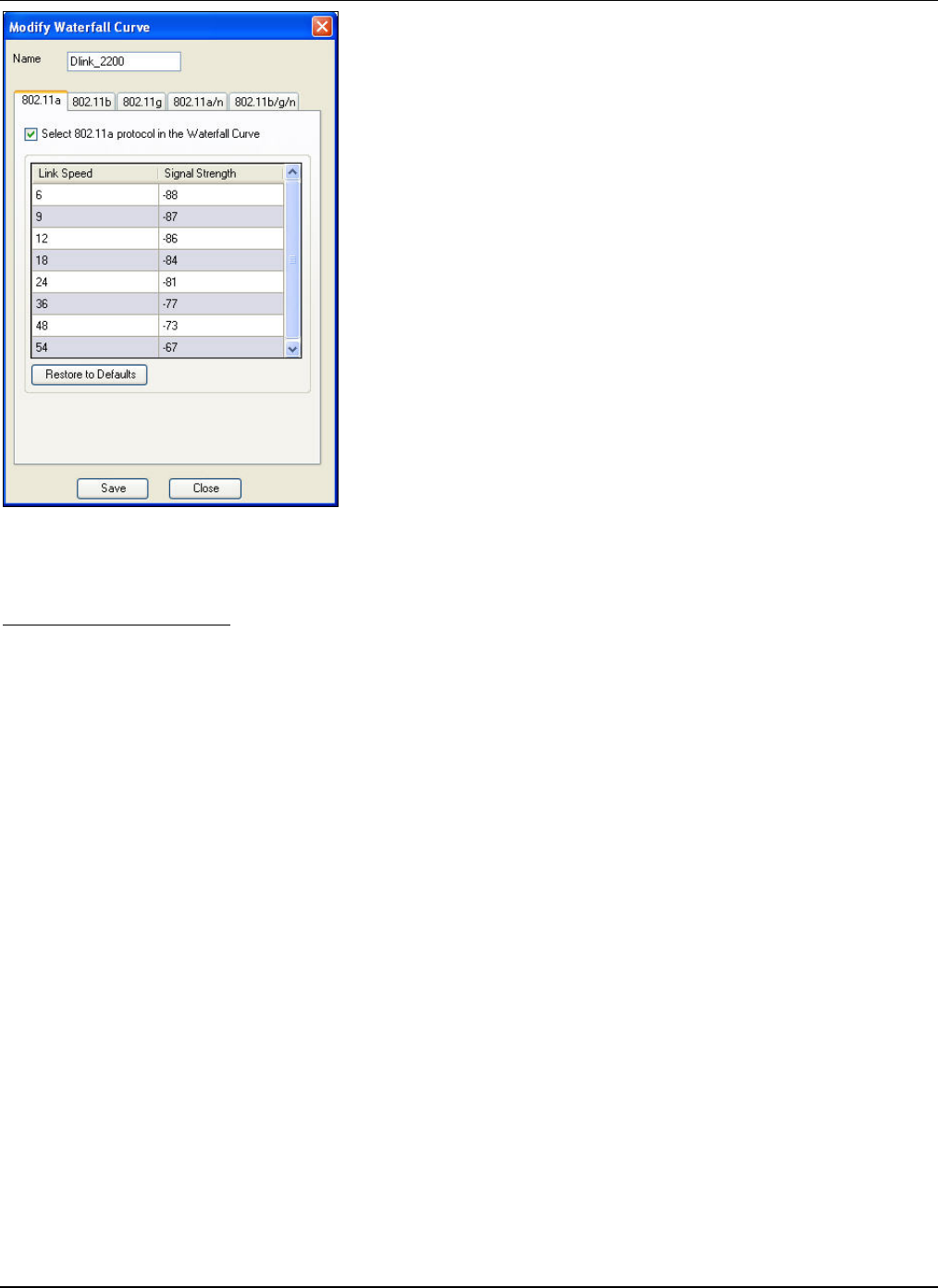
MenuandToolbarOptions
3Com®AirProtectPlannerUserGuide
50
Figure 60. Waterfall Curve Repository – Modifying a Waterfall Curve
TheModifyWaterfallCurvedialogboxissimilartotheAddWaterfallCurvedialogbox.
DeletingaWaterfallCurve
Click<Delete>andconfirmthedeletionofthewaterfallcurve.
5.5.7 ImportPlannerSettings
TheImportoptionallowsyoutoimportsettingsandpreferencessothatallworkstationshavethesamesetofenvironments
andalltheplanningteammemberscanworkinsynchronization.Youcanchoosetoimportanyoftheparameters.
SelectImportPlannerSettingsfromtheToolsmenu.TheImportPlannerSettingsdialogboxappears.
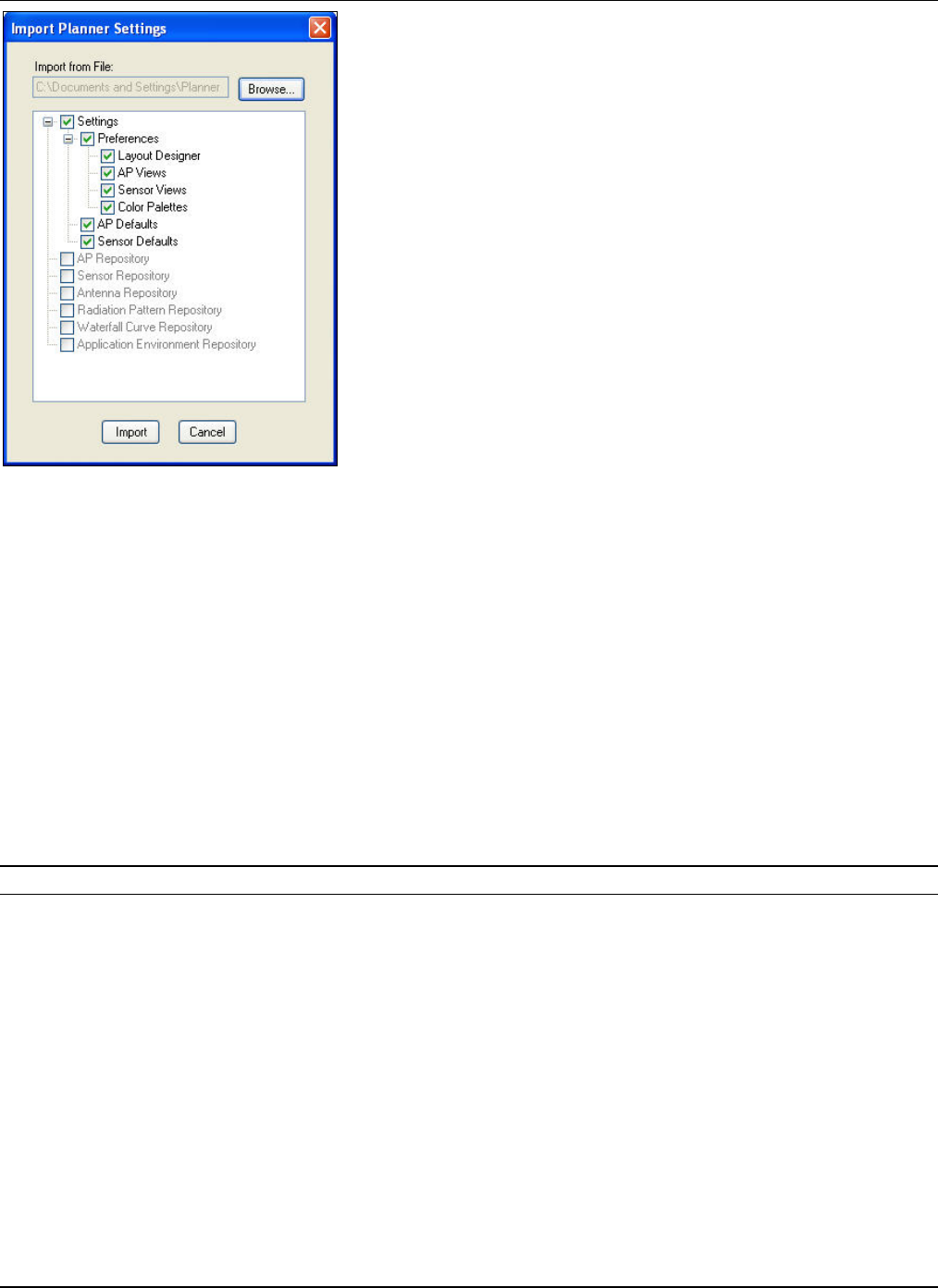
MenuandToolbarOptions
3Com®AirProtectPlannerUserGuide
51
Figure 61. Tools Menu – Import Planner Settings
YoucandothefollowingontheImportPlannerSettingsscreen:
• Click<Browse>tonavigatetothefileyouwanttoimport.Followingisthebasiclistofparametersthatyoucan
import.Selecttheappropriatefields.
¾ Settings
Preferences:LayoutDesigner,APViews,SensorViews,andColorPalettes
APDefaults
SensorDefaults
¾ APRepository
¾ SensorRepository
¾ AntennaRepository
¾ RadiationPatternRepository
¾ WaterfallCurveRepository
¾ ApplicationEnvironmentRepository
Click<Import>toimportselectedoptions.
Note:Importingasectionoverridestheexistingsettings.You cannotundothisaction.
5.5.8 ExportPlannerSettings
TheExportoptionallowsyoutoexportalltheapplicationlevelconfigurationsinafile.Thisexportedfilecanbeimportedby
Plannerrunningonadifferentcomputer.Thiswayalltheteammemberscanworkinsynchronizationwithallthe
configurations.
SelectExportPlannerSettingsfromtheToolsmenu.TheExportPlannerSettingsdialogboxappears.
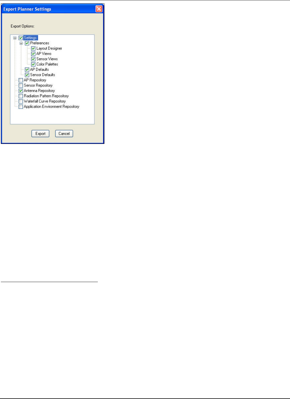
MenuandToolbarOptions
3Com®AirProtectPlannerUserGuide
52
Figure 62. Tools Menu – Export Planner Settings
Followingisthebasiclistofparametersthatyoucanexport.Selecttheappropriatefields.
• Settings
¾ Preferences:LayoutDesigner,APViews,SensorViews,andColorPalettes
¾ APDefaults
¾ SensorDefaults
• APRepository
• SensorRepository
• AntennaRepository
• RadiationPatternRepository
• WaterfallCurveRepository
• ApplicationEnvironmentRepository
Click<Export>toexportselectedoptions.
5.5.9 LocationProperties
YoucanchangetheLocationPropertiesfromtheToolsmenu.
LocationProperties:DimensionsTab
TheDimensionstaballowsyoutochangethedimensionsofthelayout.

MenuandToolbarOptions
3Com®AirProtectPlannerUserGuide
53
Figure 63. Changing Location Properties – Dimensions Tab
Specifythefollowingdimensionsandproperties:
• Unit:Selecttheunitofmeasurementfromthedrop‐downlist.
• Lengthin‘a’direction:Specifythelengthtobeusedforalllayoutsintheplan.
• Lengthin‘b’direction:Specifythewidthtobeusedforalllayoutsintheplan.
• LockAspectRatio:SelecttheLockAspectRatiocheckbox,ifyouwanttomaintaintheratioofthedimensionsofthe
layouttothatofthelayoutimage.
• RFCalculationCellSize:SpecifytheRFcalculationcellsizetodeterminethesizeofthesmallestunitonthelayout.
Plannerperformscalculationsforeachcellonthelayout.
• ResetCellSize:Clicktogetoptimalcellsizenumberforthelayoutdimensionsentered.
• CeilingLoss:Specifythelossoccurringforthecrossfloorradiationduetotheceiling.Therangeis‐50to0.
• Region:Selecttheregionfromthedrop‐downlist.
Note:Changingthelengthandwidthoftheplanresizestheentiresetofobjectsinthelayoutmodel.Plannerresizestheobjectsinthesame
proportioninwhichthesizeoftheplanischanged.Changingtheseunitswillaffectthedimensionvaluesandcoverage.
Duringresize,ifthereareanyobjectslikePolygonsorAreaPolygonsplacedonthefloormap,Plannerdeletestheseobjects,asitcannot
resizethem.
Thesechangesaffectallthelayoutsintheplan.Incaseyouwanttoplanmultiplefloorswithdifferentdimensions,enterthelargestfloor
dimensionsandthenplanforsmallerareasforeachfloor.
LocationProperties:CalculationsTab
TheCalculationstaballowsyoucanspecifythecalculations’settingsandpathlossmodelsettings.Youcanalsoinvokethis
screenbyclickingfromtheToolbar.
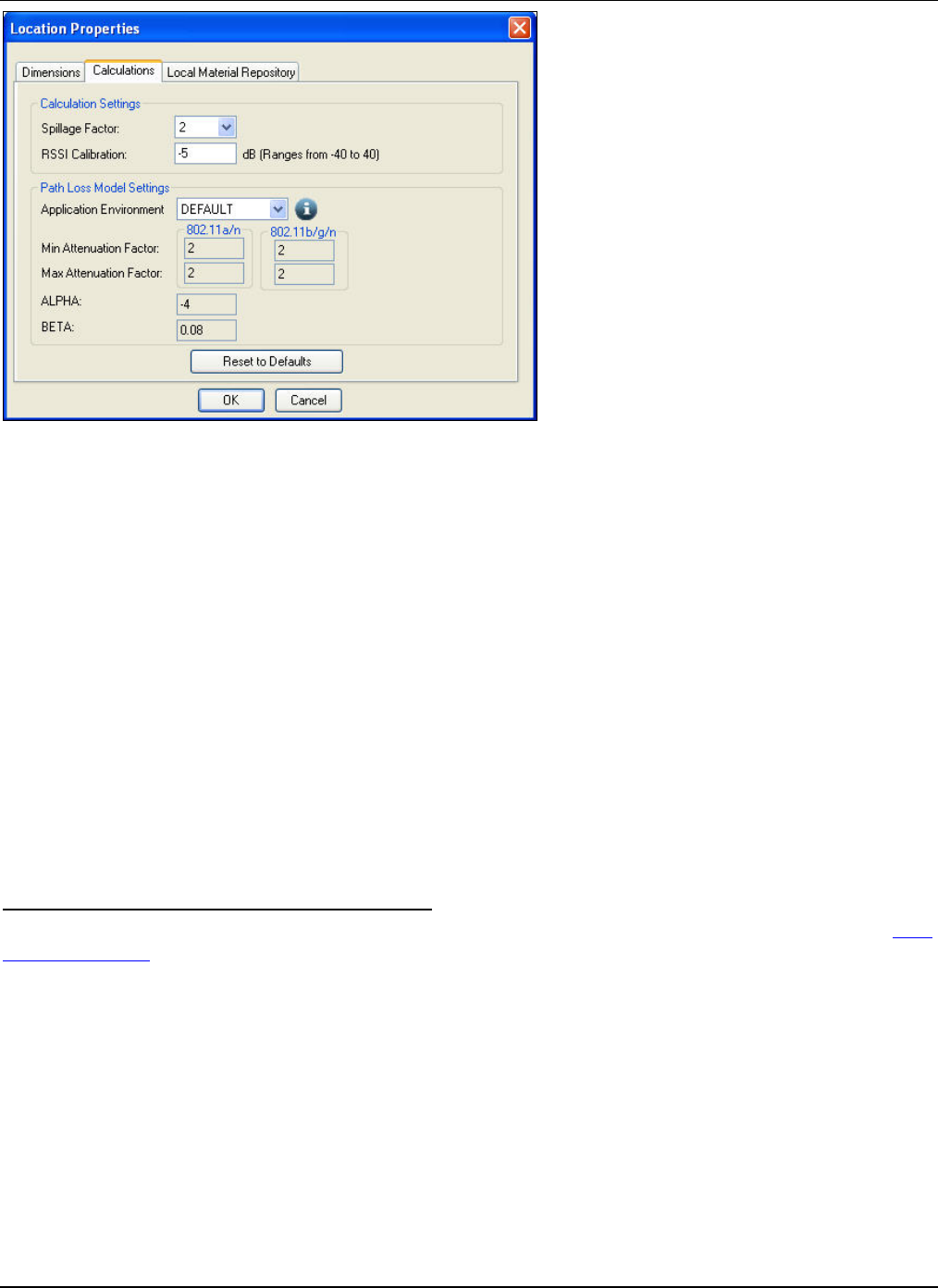
MenuandToolbarOptions
3Com®AirProtectPlannerUserGuide
54
Figure 64. Changing Location Properties – Calculations Tab
CalculationSettings:
• SpillageFactor:SpecifiesthesizeoftheareaasamultiplieroftheactuallayoutareaoverwhichPlannerwillassess
theWLANsignalspillage.Forexample,ifyousetthespillagefactorto2,thesystemwillassessthesignalstrength
over2timesalongeachdimensionofthelayout.Thesystemmaintainsthecenterofthelayoutsothatyoucan
observethespillagesymmetricallyinalldirections.
• RSSICalibration:PlannercalculatestheReceivedSignalStrengthIndicator(RSSI)ateachcellinthelayoutbasedon
idealconditions.ItappliesthisRSSIcalibrationfactortoaccountforun‐modeledobjectslikefurniture,humansand
soon,antenna/feederlosses,RFpropertiesofClientcards,andlayoutinaccuracies.PlannerappliestheCalibration
factorsymmetricallytoallthecells.TherangeforRSSICalibrationis‐40dBto40dB.ThedefaultforRSSIcalibration
factoris‐10dB.
PathLossModelSettings:
• ApplicationEnvironment:Selecttheapplicationenvironmentfromthedrop‐downlist.
• MinAttenuationFactor:Displaystheminimumattenuationfactorsfor802.11a/nand802.11b/g/ndependingonthe
applicationenvironmentselected.
• MaxAttenuationFactor:Displaysthemaximumattenuationfactorsfor802.11a/nand802.11b/g/ndependingonthe
applicationenvironmentselected.
• ALPHAandBETA:Displaystheadvancedcalculationparameters.
LocationProperties:LocalMaterialRepositoryTab
TheLocalMaterialRepositorytabgivesalistofavailablematerialsintheLocalRepositoryofthat.spmfile.RefertotheLocal
MaterialRepositorysectiontoseethevariousfunctionsyoucanperformfromthistab.
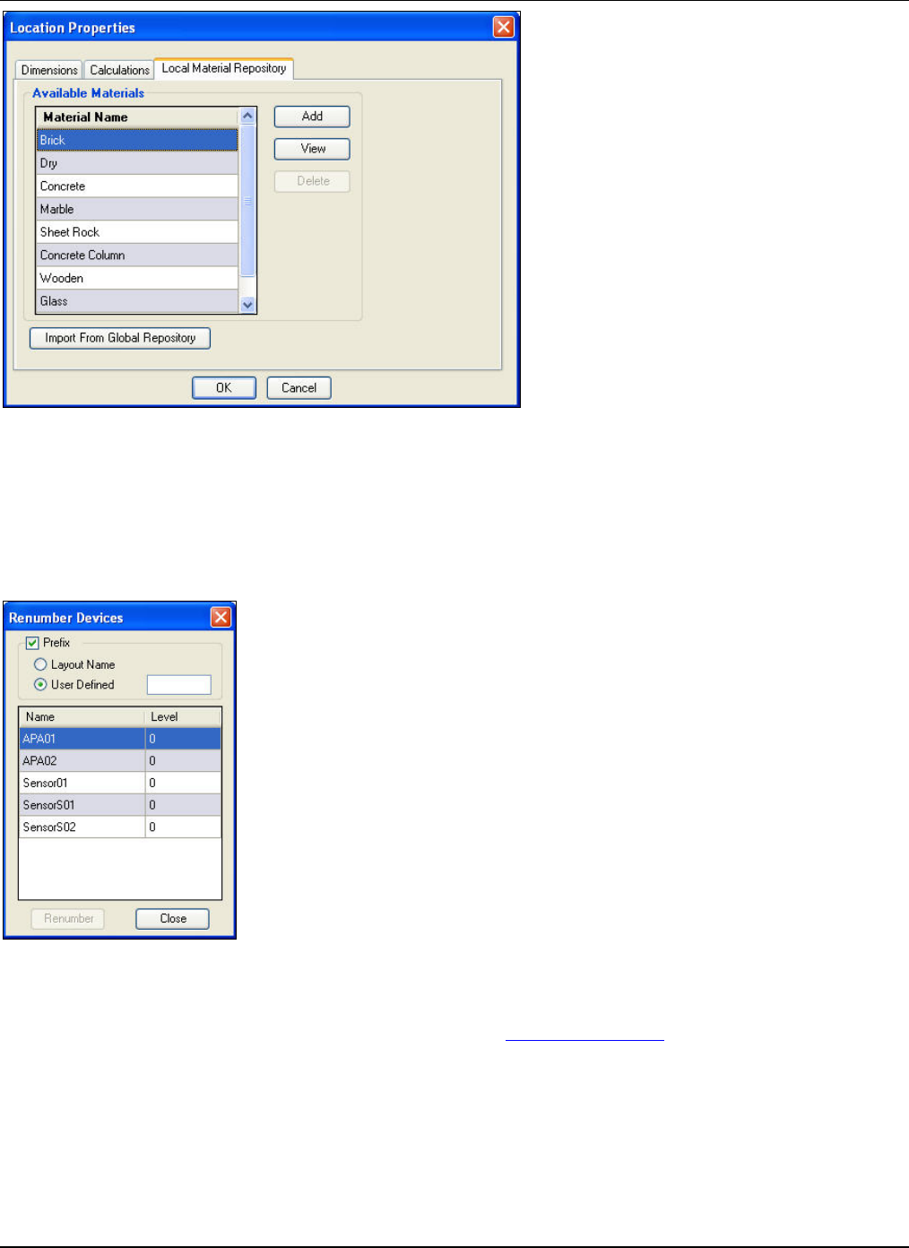
MenuandToolbarOptions
3Com®AirProtectPlannerUserGuide
55
Figure 65. Changing Location Properties – Local Material Repository Tab
5.5.10 RenumberDevices
Plannercreatesadefaultnumberinglabel,namely01,02…forthedevices.Forexample,APsasAP01,AP02…,whileSensors
asSensor01,Sensor02….IfyoudeleteaparticularAPorSensor,itcancreateadiscontinuity.Youcanrestoresequential
numberingusingtheRenumberDevicesoption.
SelectRenumberDevicesfromtheToolsmenu.
Figure 66. Tools Menu – Renumber Devices
Youcandothefollowing:
• SelectPrefixtorenameobjectswithaprefixasdefinedintheSettingsÆAPDefaultssection.
• SelectLayoutName,orselectUserDefinedtoenterauser‐definednameintheUserDefinedfieldtorename
devicesaccordingly.
• Click<Renumber>torenumberthedevices.
Forexample,ifyouchoosetheoptionBuildingName,andthebuildingnameis‘MyBuilding’,thenPlannerwillnumberthe
APsasMyBuildingA01,MyBuildingA02,andSensorswillbenumberedasMyBuildingS01,MyBuildingS02,andsoon.
ThesystemwillbehavesimilarlywithLayoutNameandUserdefinednames.
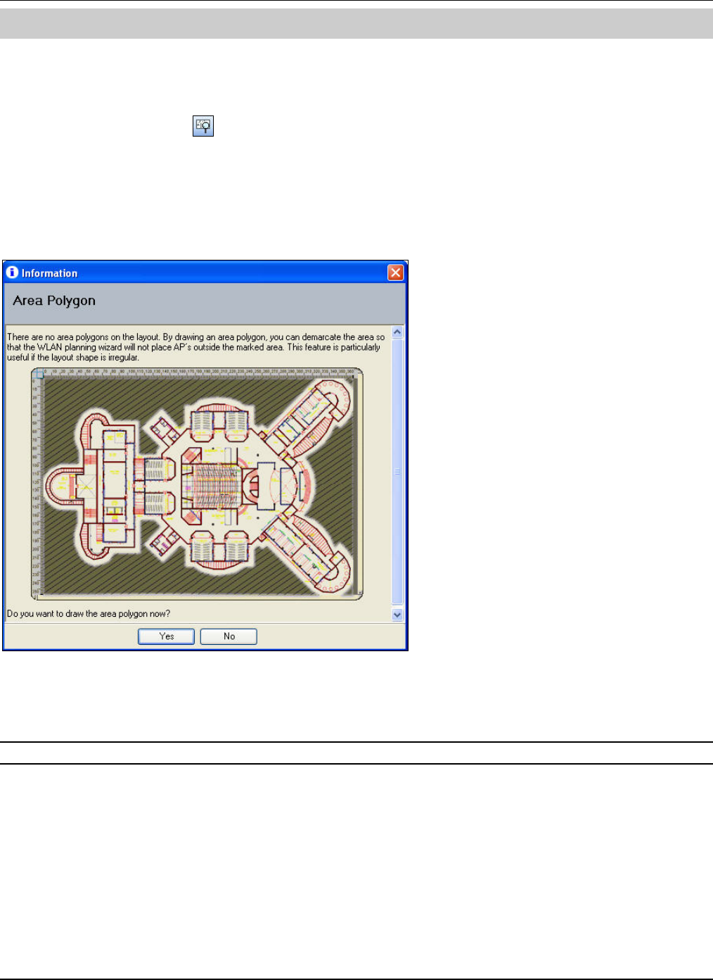
WLANPlanningWizard
3Com®AirProtectPlannerUserGuide
56
Chapter6 WLANPlanningWizard
WLANPlanningWizardisafeatureinPlannerthathelpsyouplanthelayoutasperyourrequirements.Thewizardhelps
youdefineobjectivesbyseekingyourinputsonWi‐Finetworkparameters.Plannerusesthesegivenparameterstomake
availablenumberofAPsrequiredonafloor,assigningchannelstothem,andplacingthesameonthefloormap.Goto
ToolsÆWLANPlanning,orclickontheToolbartoopenthewizard.Plannerverifiesandvalidatesdetailslikedeviceson
thefloormapanddefinedareapolygonsbeforelaunchingthewizard.
Ifthelayouthasmanuallyplaceddevices,thenPlannerasksifyouwishtodeletethedevicesfromthelayout.Ifyouselect
<No>,Plannerdoesnotdeletethedevices.However,theWLANPlanningWizarddoesnotconsiderthesedevicesforany
calculation.Italsopromptsyoutodefineareapolygonsbeforecontinuingwiththewizard.Thisisnotamandatorystep.
Planneralsodisplaysaninformationpop‐upaboutthesignificanceofdefiningareapolygons.Thepop‐upasksifyouwishto
drawtheareapolygon.
Figure 67. Defining Area Polygon: I-Pop-up
Definingtheareapolygonhelpsconfirmthatyouplaceallthedeviceswithintheareapolygonandnotoutsideit.Click<Yes>
todrawtheareapolygon.Alternately,click<No>todiscardtheaction.
Recommended:Defineareapolygonsifyouhaveanirregularlyshapedlayout,asAPplacementsinsuchlayoutsmightnotbeasexpected.
Then,thewelcomescreenappears.
6.1 StepsinWLANPlanning
1 TheWelcometoWLANPlanningWorkflowscreenshowsthestepsintheWLANPlanningworkflow.
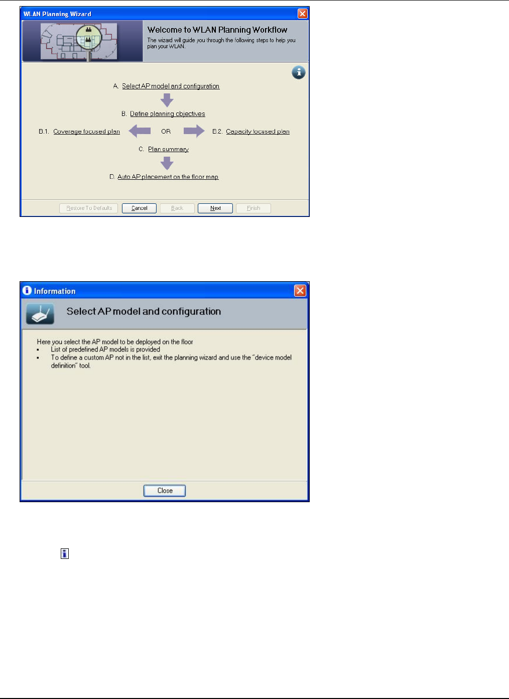
WLANPlanningWizard
3Com®AirProtectPlannerUserGuide
5
7
Figure 68. WLAN Planning – Welcome Screen
Clickeachstepintheworkflowtoviewtheinformationpop‐upforthatstep.Forexample,ifyouclickSelectAPModel
andconfiguration,aninformationpop‐upforselectingAPmodelsandtheirconfigurationappears.
Figure 69. Select AP Model and Configuration – I-Pop-up
OntheWLANPlanningWizardscreens:
• Click toviewmoreinformationaboutthecurrentstepofthewizard.
• Click<RestoreToDefaults>torestorethewizardparameterstofactorydefaults.
• Click<Cancel>tocanceltheactionandclosethewizard.
• Click<Back>toreverttothepreviousstepinthewizard.
• Click<Next>togotothenextstepinthewizard.
• Click<Finish>tofinalizeandsaveinformationenteredinthewizard,andenablePlannertoexecutePlanningasper
yourspecifications.
2 TheWLANPlanningWizard:DeviceSelectionscreenhelpsyouselectthedesiredAPmodelandsetAPpropertiesvital
toWLANperformance.
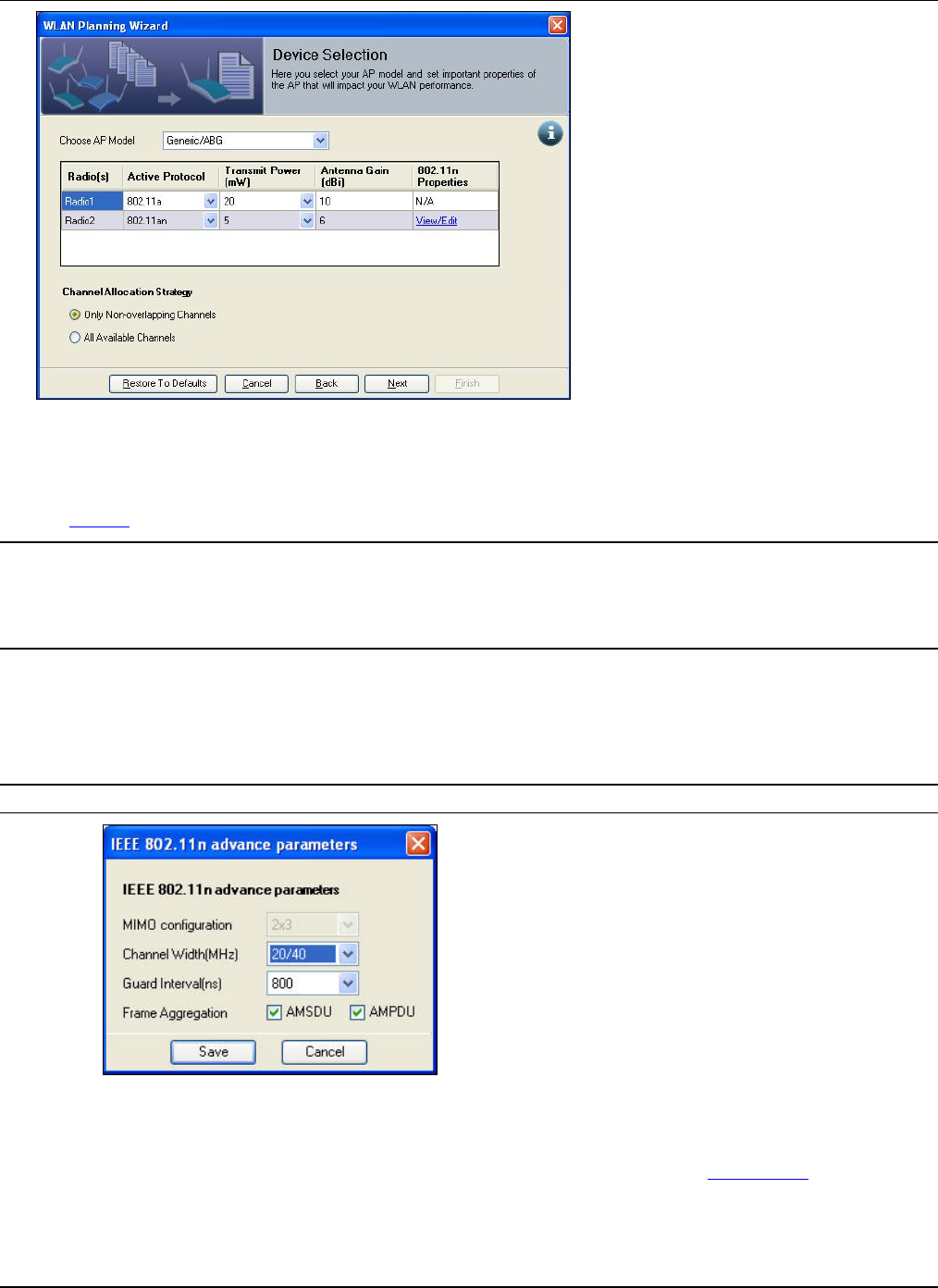
WLANPlanningWizard
3Com®AirProtectPlannerUserGuide
58
Figure 70. WLAN Planning – Device Selection
• ChooseAPModel:SelecttheAPmodelfromthedrop‐downlist.IfthedesiredAPmodeldoesnotexistinthedevice
repository,click<Cancel>toexitthewizardandaddthecustomAPtothedevicerepositorybyfollowingstepsinthe
AddAPsection.
Recommended:Chooseadevicewithomnidirectionalantenna,inordertogetresultsthataremoreaccurateforcapacitycalculations.
Capacitycalculationresultsmaybeincorrectwhenyouusedirectionalantennae.
Ifthepowervaluesfortheradiosareinvalidintheregionforwhichyouareplanning,theplanningwizardpromptsyoutoselectanother
radioordevice.
• TheAPPropertiestabledisplayspre‐definedAPdetailslikeRadio(s),ActiveProtocol,TransmitPower(mW)and
AntennaGain(dBi).Enterthefollowingdetails:
¾ Radio:Selectthedesiredactiveprotocol(s)oftheAPyouwanttouseonthecurrentfloor.
¾ 802.11nProperties:Click<View/Edit>.TheIEEE802.11nAdvanceParametersdialogboxappears.Youcould
eithervieworchangetheadvanced802.11nparametersforthatradio.
Note:Ifyoudonotselectthe802.11nprotocolintheRadiofield,the802.11nPropertiesfieldisnotapplicable.
Figure 71. 802.11n Advance Parameters
SettheIEEE802.11nAdvanceparameters:
MIMOconfiguration:DisplaystheMIMOconfigurationyouspecifiedwhileaddinganAP.Thisfieldis
disabledandcannotbemodified.YoumustgototheAPpropertiesscreentomodifythesame.
ChannelWidth(MHz):Specifythedesiredchannelwidth.
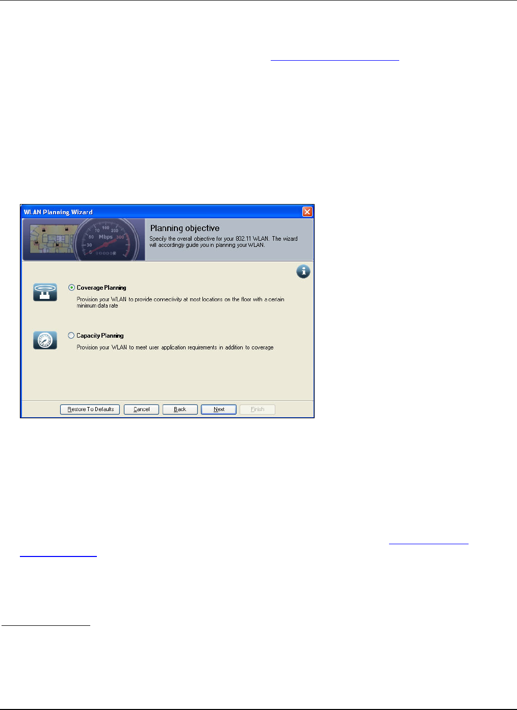
WLANPlanningWizard
3Com®AirProtectPlannerUserGuide
59
GuardInterval(ns):Specifythedesiredguardinterval.
FrameAggregation:SelecteitherAMSDUorAMPDU,orbothcheckboxesforthedesiredframe
aggregation.
Formoredetailsontheadvanceparameters,refertoAppendixD:GlossaryofTerms.
• ChannelAllocationStrategy:Duetolimitedavailablefrequencyspectrumfor802.11WLANs,denseAPdeployment
oftenrequiresspatialreuseoffrequencies.Thestrategyyouchosedeterminesthesetofavailablechannels.Planner
assignschannelstominimizeinterference.Duringon‐siteplanning,interferencefromtheexistingAPsisconsidered.
Selecteitheroftheoptionsforchannelallocationstrategy.
¾ Onlynonoverlappingchannels:Thesearechannelsthatdonotinterferewitheachother.Forexample,inthe
US,2.4GHzbandoffersthreenon‐overlappingchannels–1,6,and11.
¾ Allavailablechannels:Allchannelsareconsidered.Forexample,intheUS2.4GHzbandoffers11channels.
Usingpartiallyoverlappingchannels(say1,4,7,11)canimproveoverallWLANcapacity.
3 TheWLANPlanningWizard:PlanningObjectivescreenhelpsyouspecifytheplanningobjectiveforthe802.11WLAN,
whilealsoguidingyouinplanning.
Figure 72. WLAN Planning – Planning Objective
PlannerallowsyoutochoosethefocusofWLANplanning.Basedonthefocus,Plannerconsidersdifferentfactorsfor
populatingthenumberofAPsrequiredandtheirplacement.
Selectoneofthefollowingoptions:
• CoveragePlanning:SelecttoplantheWLANtoenableusersatmostlocationsonthefloortoconnectwitha
specifiedminimumdatarate.
• CapacityPlanning:SelecttoplantheWLANtoensureconnectivitywithfocusonuserandapplicationrequirements.
4 Dependingontheplanningfocusthatyouchoseinthepreviousstep,PlannerdisplaystheCoveragePlanningor
CapacityPlanningscreenofthewizard.
5 OnceyouaredonewiththeWLANplanning,theWLANPlanningWizard:Summaryscreenappearsdependingonthe
typeoffocus.
6 Ifyouwishtochangethesettings,click<Back>.Click<Finish>toexitthewizard.Plannerwillauto‐placetheAPsonthe
floormap,andassignchannelstothem.
CoveragePlanning
IfyouhaveselectedCoveragePlanninginthepreviousstepofthewizard,theWLANPlanningWizard:CoveragePlanning
screenappears.ThemaximumdataratesupportedbyanAPdependsonthequalityofthesignalreceivedfromthatAP.Due
toRFpathloss,thesignalqualitydegradesasyoumoveawayfromanAP,inturnleadingtoconnectivityatlowerdatarates.
Inacoverage‐focusedplan,youdefineaminimumdatarateforthefloor.YouplanaWLANsuchthatusersatmostlocations
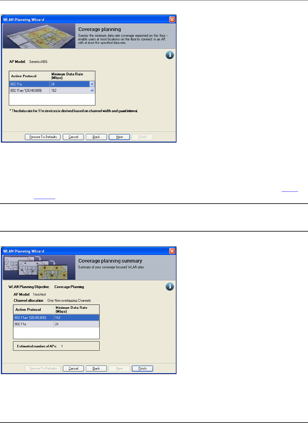
WLANPlanningWizard
3Com®AirProtectPlannerUserGuide
60
onthefloorcanconnectwithatleastthespecifieddatarate.
Figure 73. WLAN Planning – Coverage Planning
• APModel:DisplaystheAPModel.
• TheAPPropertiestabledisplaystheActiveProtocol.Enterthefollowingdetails:
¾ MinimumDataRate(Mbps):Selecttheminimumdatarateforthecurrentactiveprotocolsfromthedrop‐down
list.ThelistcontainsavailableandapplicabledataratesfortheactiveprotocolsetforeachradiointheDevice
Selectionstep.
Note:IfyouhaveselectedthesameactiveprotocolformorethanoneradiointheDeviceSelectionscreen,Plannerdisplaysonlyone
commonrowinthetableintheabovescreen.
Plannerderivesthedataratefor802.11ndevicesfromthechannelwidthandguardintervalvalues.
TheWLANPlanningWizard:CoveragePlanningSummaryscreenappears.
Figure 74. Coverage Planning Summary
TheCoveragePlanningSummaryscreengivesyouasummaryofthecoverage‐focusedplanasperyourrequirementsand
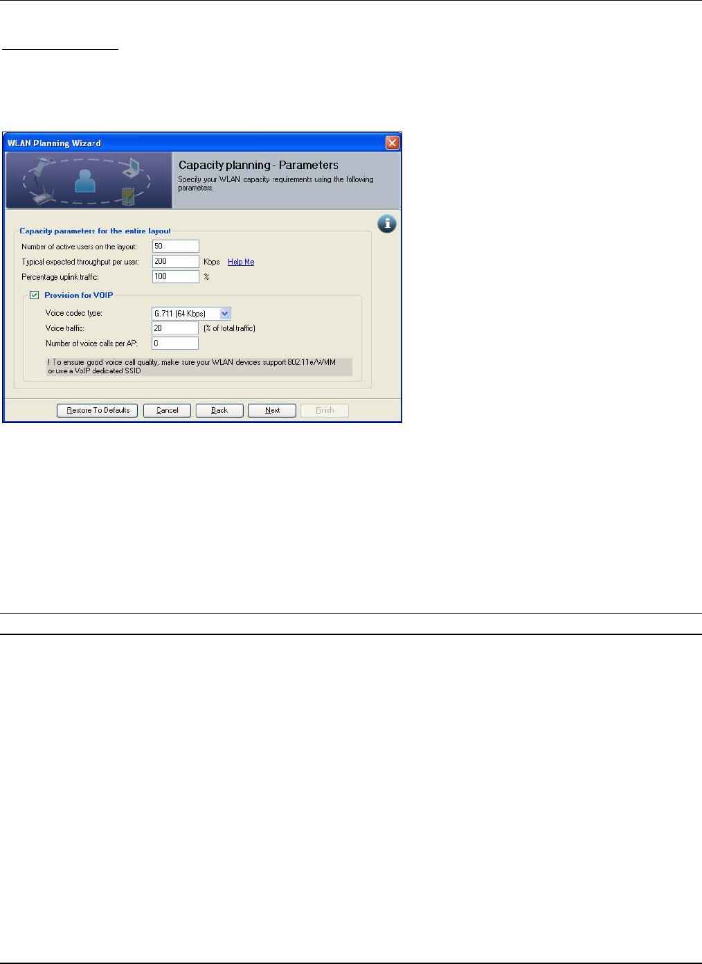
WLANPlanningWizard
3Com®AirProtectPlannerUserGuide
61
specifications.ItalsogivesyouthenumberofAPs,asestimatedbyPlannertosuityourrequirementsofcoverage.
CapacityPlanning
IfyouhaveselectedCapacityPlanninginthepreviousstepofthewizard,theWLANPlanningWizard:CapacityPlanning–
Parametersscreenappears.CapacityofanAPreferstothemaximumachievablethroughputofthatAP.Severalfactorssuchas
numberofactiveusers,typeofapplications,RFinterferenceandsoonaffectthecapacityofanAP.Toprovideenough
bandwidthperuser,youmustplanaWLANbyconsideringthesefactorsinadditiontocoverage.
Figure 75. WLAN Planning – Capacity Planning
SpecifytheparametersforCapacityPlanning:
• Numberofactiveusersonthelayout:TheexpectednumberofuserssimultaneouslyaccessingtheWLANonthe
currentfloor.
• Typicalexpectedthroughputperuser:Specifythebandwidthtypicallyrequiredperuser.ThetotalexpectedWLAN
capacityisaproductofthenumberofactiveusersandbandwidthrequiredperuser.Click<HelpMe>toviewthe
typicalperuserthroughputforvariousapplicationtypes.
• Percentageuplinktraffic:Specifythepercentageflowofuplinktraffic.Uplinktrafficreferstotheflowoftraffictoan
APinaWLAN.Theamountofuplinktrafficindicatestheconflictamongusersformediumaccess.
Note:AhighpercentageofuplinktrafficwithalargenumberofactiveuserswilldegradeanAP’sbandwidthduetohighcontention.
• ProvisionforVoIP :SelecttoenablePlannertoprovideforVoIP.VoIPhasamajorimpactoncapacityplanningandis
determinedby:
¾ Voic ecodectype:Selectthevoicecodectypefromthedrop‐downlist.
¾ Voic etraffic:Specifythepercentagevoicetraffic.
¾ NumberofvoicecallsperAP:SpecifythemaximumnumberofVoIPcallsthatanAPcansimultaneously
support.
TheWLANPlanningWizard:CapacityPlanning–AdvanceParametersscreenappears.
WLANPlanningWizard
3Com®AirProtectPlannerUserGuide
62
Figure 76. Capacity Planning – Advance Parameters
SpecifythefactorsyouwouldliketoconsiderforWLANcapacityplanning.Theseare‘What‐If’scenarios.
• SelecttheeffectsonAPcapacity:
¾ 802.11mediumaccessanomaly:Selecttoconsidertheproportionofactiveusersatvariousdatarates.
¾ 802.11mediumaccesscontention:Selecttoconsiderbandwidthcontentiondeterminedbythetotalnumberof
activeusersperAPandtheamountofuplinktraffic.
¾ 802.11bandwidthefficiency:Selecttoconsidertheimpactofoverheadonbandwidthefficiency.
• SelecteitherofthetypeofperAPcapacityestimate(basedontheselectedfactors)toplantheWLAN:
¾ Conservative:UsestheworstcaseperAPcapacitytoestimatethenumberofAPsrequired.Thisoptionusually
estimatesmorenumberofAPs.
¾ Optimistic:MightoverestimateperAPcapacitythanobservedinpractice.Thisusuallyrequireslessnumberof
APscomparedtotheConservativeestimate.
¾ Average:ModeratelyestimatesperAPcapacityandisabalancebetweentheConservativeandOptimistic
options.Thisisthedefaultselected.
• AccountingfortheeffectofWi‐Fiinterferencegivesamoreaccurateestimateofcapacity.Forinstance,inascenario
withdenselypackedAPs,theinter‐APinterferencemayconsiderablydegradethecapacity.Insomecases,the
capacityrequirementmaynotbefeasibleduetohighinterference.SpecifyifyouwanttoconsidertheeffectofWi‐Fi
Interference.
¾ Yes
¾ No
TheWLANPlanningWizard:CapacityPlanningSummaryscreenappears.
WLANPlanningWizard
3Com®AirProtectPlannerUserGuide
63
Figure 77. Capacity Planning Summary
TheCapacityPlanningSummaryscreengivesyouasummaryofthecapacity‐focusedplanasperyourrequirementsand
specifications,resultsofthe‘What‐IfScenarioAnalysis’,andthenumberofAPs,asestimatedbyPlannertosuittheuserand
applicationrequirementsofcapacity.Planneralsogivesyouitsanalysisoffeasibilityofcapacityplanningas‘Passed!’or
‘Failed!’,withthegivensettings.Itestimatesiftheplannedcapacityisachievablewiththecurrentconfiguration;andifitis
not,thenitgivesthepotentialreasonforfailure.
• IftheCapacityFeasibilityCheckis‘Passed!’(Green),itimpliesthattheplannedcapacityisachieved.
Figure 78. Capacity Planning Summary – Passed! (Green)
• IftheCapacityFeasibilityCheckis‘Passed?’(Orange),itimpliesthattheplannedcapacityisachieved.However,
therearesomeextraAPs,whichPlannercannotplaceusingAutoAPplacementonthelayout.Thisscreenalso
displaysa‘?’linkforEstimatedmaxcapacity(withWi‐Fiinterference)inthe‘What‐IfScenarioAnalysis’section.
ThisimpliesthatPlannerisunabletocalculatetheestimatedmaximumcapacitywithWi‐Fiinterferenceasallthe
estimateddevicesarenotplacedonthelayout.Clicking<Passed?>or<?>tellsyouthattheautoAPplacementisnot
abletoplacealltheAPsfortheselectedlayout.Hence,youmustmanuallyplacetheremainingAPsatthedesired
locationsafteryouexitthewizard.ItalsoasksyoutouseAutoChannelAllocationtominimizeinterference.
WLANPlanningWizard
3Com®AirProtectPlannerUserGuide
64
Figure 79. Capacity Planning Summary – Passed? (Orange)
• IftheCapacityFeasibilityCheckis‘Failed!’,Planneralsogivesthepotentialreasonforthefailure.
Figure 80. Capacity Planning Summary – Failed!
Click<Failed>toviewthereasonforfailure.The‘What‐IfScenarioAnalysis’isusefultounderstandthereasonfor
failure.
Conditionsforfailure:
¾ IftheexpectedcapacityyouspecifiedisgreaterthantheestimatedcapacitywithoutWi‐Fiinterference,the
plannedcapacityisnotfeasible.
¾ IftheexpectedcapacityyouspecifiedisgreaterthantheestimatedcapacitywithWi‐Fiinterference,theplanned
capacityisnotfeasible.
Onceyouclick<Finish>ineitheroftheabovesummaryscreens,PlannerstartsAutoDevicePlacementexplainedindetailin
thenextsection.
6.2 AutoDevicePlacement
PlannerconsidersthefollowingfactorsduringAutoDevicePlacement.
WLANPlanningWizard
3Com®AirProtectPlannerUserGuide
65
• WhetherthereareanyAreaPolygonsdefined.
¾ IfanAreaPolygonisdefined,PlannertriestoplacethecalculatednumberofdeviceswithintheAreaPolygon.
¾ IftherearenoAreaPolygonsdefined,Plannerplacesthedevicesonthelayoutatthecalculatedlocations.
Aftereitheroftheabovesteps,ifstillmoredevicesareleft,thenPlannerdisplaysamessagethattheremaining
devicescannotbeplacedautomaticallyandhenceyoucanmanuallyplacethesameatanydesiredlocationonthe
floormap.PlannershowsalistofthesedevicesintheDevicesLibrarydialogboxunderAutoAPsection.Youcan
draganddropthesedevicesonthefloormap.ThedeviceisofthesametypeaswasselectedduringDeviceSelection
intheWLANplanningwizard.
6.3 AutoChannelAllocation
Duetolimitedavailablefrequencyspectrumfor802.11WLANs,denseAPdeploymentoftenrequiresspatialreuseof
frequencies.Thestrategyyouchosedeterminesthesetofavailablechannels.Channelsareassignedtominimizeinterference.
Ifyouhadplacedsomedevicesmanually,orhadselectedcrossfloordevicesusingtheFilteroption;Plannerconsiders
interferencefromthesedevicesduringAutoChannelallocationtodeterminethebestavailablechannelforadevice.
Selecteitheroftheoptionsforchannelallocationstrategy.PlannerenablesyoutoautomaticallyallocatechannelsoncetheAPs
areplacedonthefloormap.
ClickfromtheToolbartoinvokechannelallocationstrategy.TheChannelAllocationStrategydialogboxappears.
Figure 81. Channel Allocation Strategy
Specifythechannelsyouwanttoassigntothedevices.
• Nonoverlappingchannels:Thesearechannelsthatdonotinterferewitheachother.Forexample,intheUS,2.4GHz
bandoffersthreenon‐overlappingchannels–1,6,and11.
• Allavailablechannels:Allchannelsareconsidered.Forexample,intheUS2.4GHzbandoffers11channels.Using
partiallyoverlappingchannels(forexample,1,4,7,11)canimproveoverallWLANcapacity.
6.4 EstimatingtheCapacity
Atanygivenpoint,ifyouwanttoestimatethecapacity,click ontheToolbar.Plannerdisplaysadialogboxmentioningthe
estimatedcapacityforthelayout.
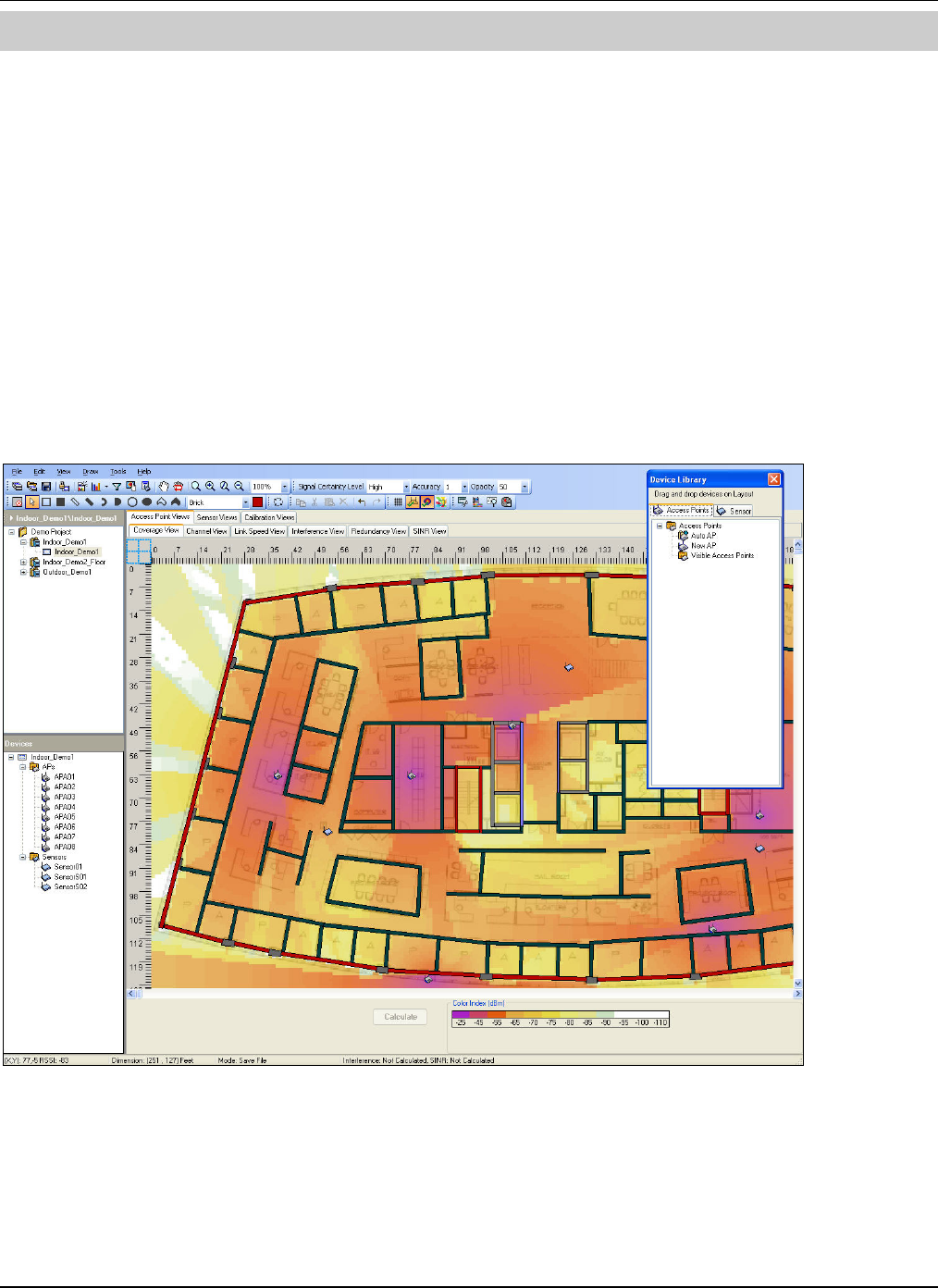
DevicePlacementontheLayoutModel
3Com®AirProtectPlannerUserGuide
66
Chapter7 DevicePlacementontheLayoutModel
Deviceplacementenablesyouto:
• PlanthelocationofSensorsandAPsonthelayoutmodel
• Create‘What‐If’scenarios
• GenerateRFviewstogetvisibilityintothesecurityexposureandRFcoverage
• Usevariousfilterstogetmostrelevantviews
7.1 PlanningDevicePlacement
PlanningDevicePlacementisdividedinto:
• RFViewArea
• StatusandControlPane
7.1.1 RFViewArea
TheRFViewAreahelpsplandeviceplacementforbetternetworkandcoverageforthelayout.Plannerallowsyoutoviewthe
RFViewAreainthe‘FullScreen’mode.Todoso,clickCtrl+F11.IntheFullscreenmode,theToolbar,StatusandControl
Pane,andtheLocationstreearerenderedinvisible,thusallowingyoutousethecompletescreentoviewtheRFmaps.Usethe
samecommandtoreturntothenormalmodeagain.
Figure 82. Planning Device Placement: RF View Area
RFviews(alsocalledRFmaps)areclassifiedintothreegroupsasshowninthefollowingtable.
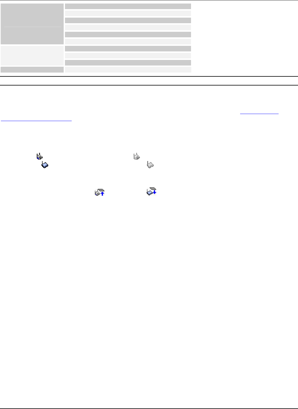
DevicePlacementontheLayoutModel
3Com®AirProtectPlannerUserGuide
6
7
Coverage View
Channel View
Link Speed View
Interference View
Redundancy View
Access Point Views
SINR View
Coverage View
Threat View
Sensor Views Redundancy View
Calibration View Calibration
Note:WheneveryoushiftfromonetaboftheRFviewtoanother,PlannerdisplaysanInformationmessagedescribingthattab.
7.1.2 StatusandControlPane
TheStatusandControlpaneisdividedintotwo.OnepartappearsonetheToolbaratthetopofthescreen,whilethesecond
partappearsonthelowerpaneatthebottomofthescreen.ThesearedescribedindetailinthesectionPlanningDevice
Placement:StatusandControl.
7.2 PlanningDevicePlacement:ViewsforIndoorandOutdoorLayout
PlacementofdeviceslikeAPsandSensorsresultinIndoorandOutdoorviews.YoucandisableanAPbyright‐clickingthe
APandselectingDisableAP.Similarly,youcanenableanAPbyright‐clickingandselectingEnableAP.AnenabledAPis
representedaswhileadisabledAPisrepresentedas.Likewise,youcanenable/disableaSensortoo.AnenabledSensor
isrepresentedaswhileadisabledSensorisrepresentedas.Thisisjustaviewingoptionfor‘What‐If’scenarios.
YoucanalsoviewthecoverageofadeviceondifferentfloorsusingtheFilteroptioninalltheviewsexcepttheCalibration
View.Incaseofcross‐floor,ifanAPorSensorisvisibleonalayoutbutbelongstoaflooraboveorbelow,thenthatAPor
SensorisrepresentedwithanUParrow orDOWNarrow.
7.2.1 APCoverageView
Thisviewdisplayscolor‐codedRSSIdistributionoverthecurrentlayout.Ithelpsyouplanforavailablesignalstrengthata
specificlocationandchecktheavailabilityofRFsignalatdifferentlocationsontheplan.Thishelpsyouensurethatallthe
regionsintheplanhavecoveragefromatleastoneAP.IncasethereismorethanoneAPcoveringanareaonthelayout,you
canseethestrongestsignalstrengthinthisview.
ClickingatapointonthelayoutdisplaysthepredictedRSSIatthatpointintheStatusbar.
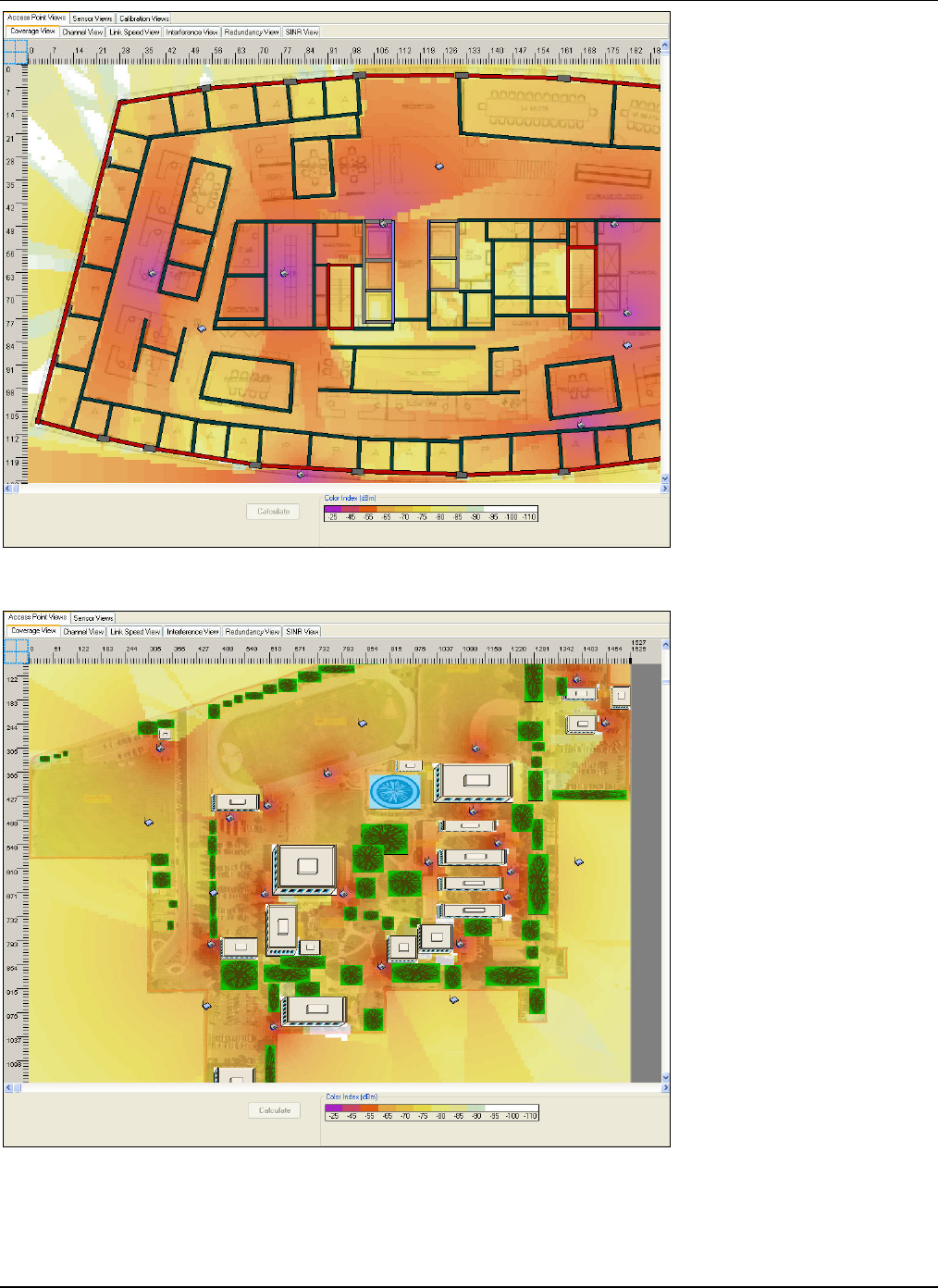
DevicePlacementontheLayoutModel
3Com®AirProtectPlannerUserGuide
68
Figure 83. AP Coverage View: Indoor Layout
Figure 84. AP Coverage View: Outdoor Layout
DevicePlacementontheLayoutModel
3Com®AirProtectPlannerUserGuide
69
ColorPaletteCustomization:Double‐clicktheColorIndexintheStatusbar.ThisopenstheColordialogboxwhereyoucan
customizethecolors.
Note:You cancustomizetheColorPaletteinalltheotherviewstoo.
Figure 85. Planning Device Placement: Customize Color Dialog Box
7.2.2 APChannelView
Thisviewdisplaysthechanneldistributionoverthecurrentlayout.TheoperatingchanneloftheAPthatprovidesmaximum
linkspeedatalocationdecidesthechannelvalueatthatlocation.Thisviewhelpsyoudecidethechannelthatshouldbeused
atalocationforthebestperformance.
Thisviewdisplaysthecolor‐codedchanneloftheAPshowingthemaximumdownlinkdatarateateachpointonthelayout.
PlannerhelpspredicttheAPtowhichaClientshouldassociateforbettersignalstrengthandlinkspeed.Visualdisplayof
channeldistributionalsohelpsyouresolvechanneloverlapconditions.IfyousettheAPtoaparticularchannel,youcansee
thecolorofthecoverageareachangedtothecorrespondingchannelcolor.Youcanselectoneoranycombinationorallthree
protocolstoviewthechannelcoverageforthoseprotocolsonthelayout.
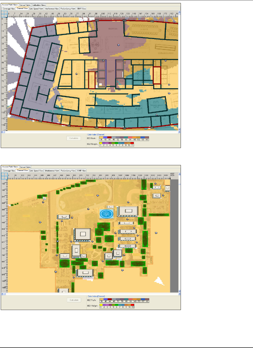
DevicePlacementontheLayoutModel
3Com®AirProtectPlannerUserGuide
70
Figure 86. AP Channel View: Indoor Layout
Figure 87. AP Channel View: Outdoor Layout
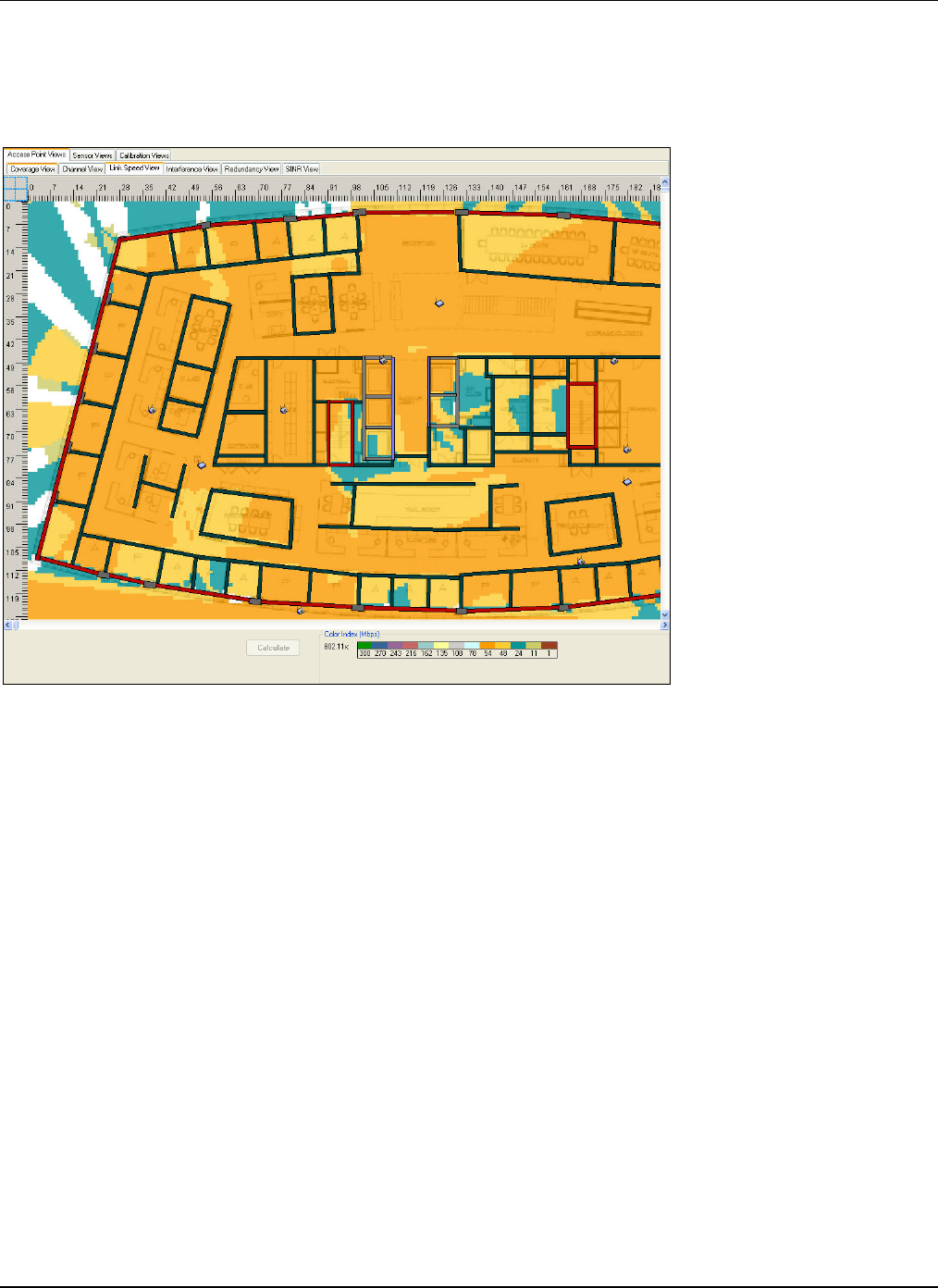
DevicePlacementontheLayoutModel
3Com®AirProtectPlannerUserGuide
71
7.2.3 APLinkSpeedView
ThisviewhelpsyouplanforavailabledownlinkconnectivityspeedsandthechoiceofwirelessClientsthatshouldbeusedat
variouslocationsonthelayout.ItdisplaysthemaximumdownlinkdataratethatawirelessClientcanexpectfroma
connection.Itshowsthe802.11downlinkconnectionspeedavailableateachpointonthelayout.Thisviewalsohelpsyou
planforminimumlinkspeedatalllocationsonthecurrentlayout.
Figure 88. AP Link Speed View: Indoor Layout
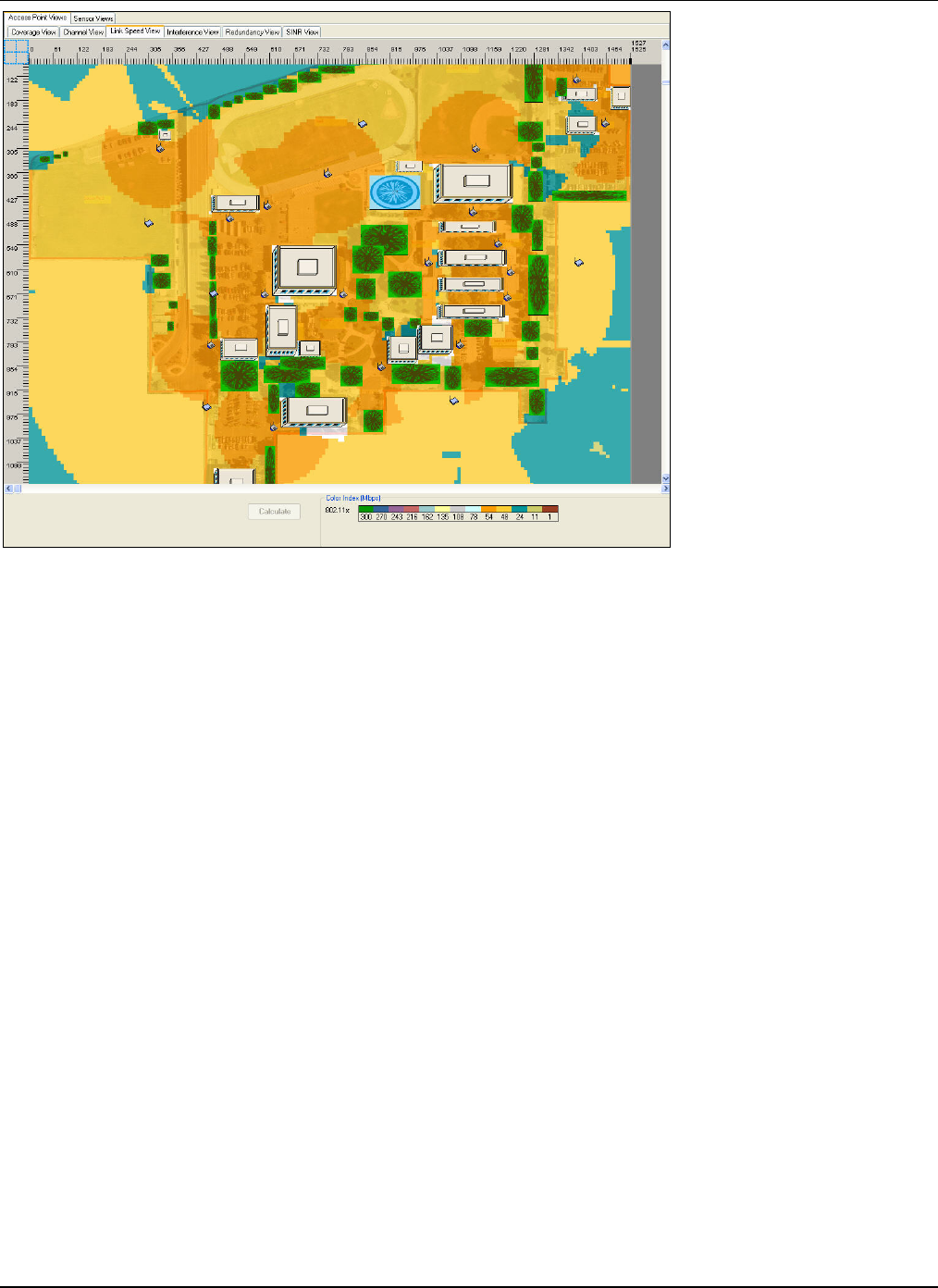
DevicePlacementontheLayoutModel
3Com®AirProtectPlannerUserGuide
72
Figure 89. AP Link Speed View: Outdoor Layout
7.2.4 APInterferenceView
Thisviewdisplaysthelevelof802.11channelinterferenceatvariouslocationsontheplan.Theinterferenceisbasedonthe
signalstrengthofdifferentAPs,operatingonthesamechannel,atthatlocation.Thisviewhelpsyouplanforminimum
interferencetoprovidebetternetworkconnectivityandbetterthroughputforhigherendusersatisfaction.
ThereareInterferenceViewcheckboxesatthebottomoftheAPInterferenceViewscreen.
• CoChannel:Selecttoshowinterferenceduetochannelswiththesamefrequency
• AdjacentChannel:Selecttoshowinterferenceduetoadjacentchannels
• SelectboththecheckboxestoviewthetotalchannelinterferenceduetobothCo‐ChannelandAdjacentChannel
channels.
Thecolorpalettedisplayssixlevelsofinterference:Negligible,Very Low,Low,Moderate,High,andVery High.
TheNetworkUtilizationdrop‐downlistatthebottomrightcornerofthescreenallowsyoutochooseLow,Medium,orHigh
levelofnetworkutilizationwithwhichchannelinterferenceistobecomputed.NetworkUtilizationisameasureofthe
amountof802.11activitythatisthetrafficgeneratedduetocommunicationbetween802.11devicesinthenetwork.Italso
dependsuponthechannelofthecommunicatingdevices.Communicationonachanneladdsloadtoitselfandtoadjacent
channels(incaseof802.11band802.11g)duetooverlapinfrequencyspectrumofadjacentchannels.
Click<SelectChannels>atthebottomrightcornertoviewthepanelofchannelsoperatingonvariousprotocols.Youcan
selectthechannelsinthispanel.Allthechannelsthatarenotselected,donotcontributetotheinterference.Forexample,if
youdonotselectchannel6andthereisadeviceonthelayoutoperatingonchannel6,Plannerdoesnotconsiderthisdevice
forcalculatinginterference.
YoucanalsoviewthechannelinterferenceforcertainchannelsbygoingtoToolsÆSettingsÆPreferencesÆAPViews.
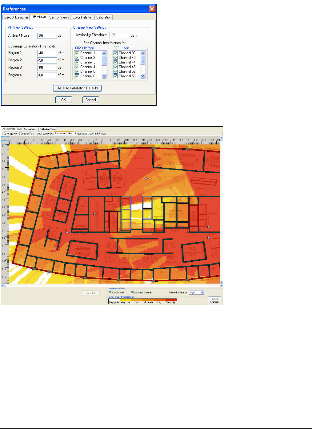
DevicePlacementontheLayoutModel
3Com®AirProtectPlannerUserGuide
73
Figure 90. Interference View: Selecting Channels
Figure 91. AP Interference View: Indoor Layout
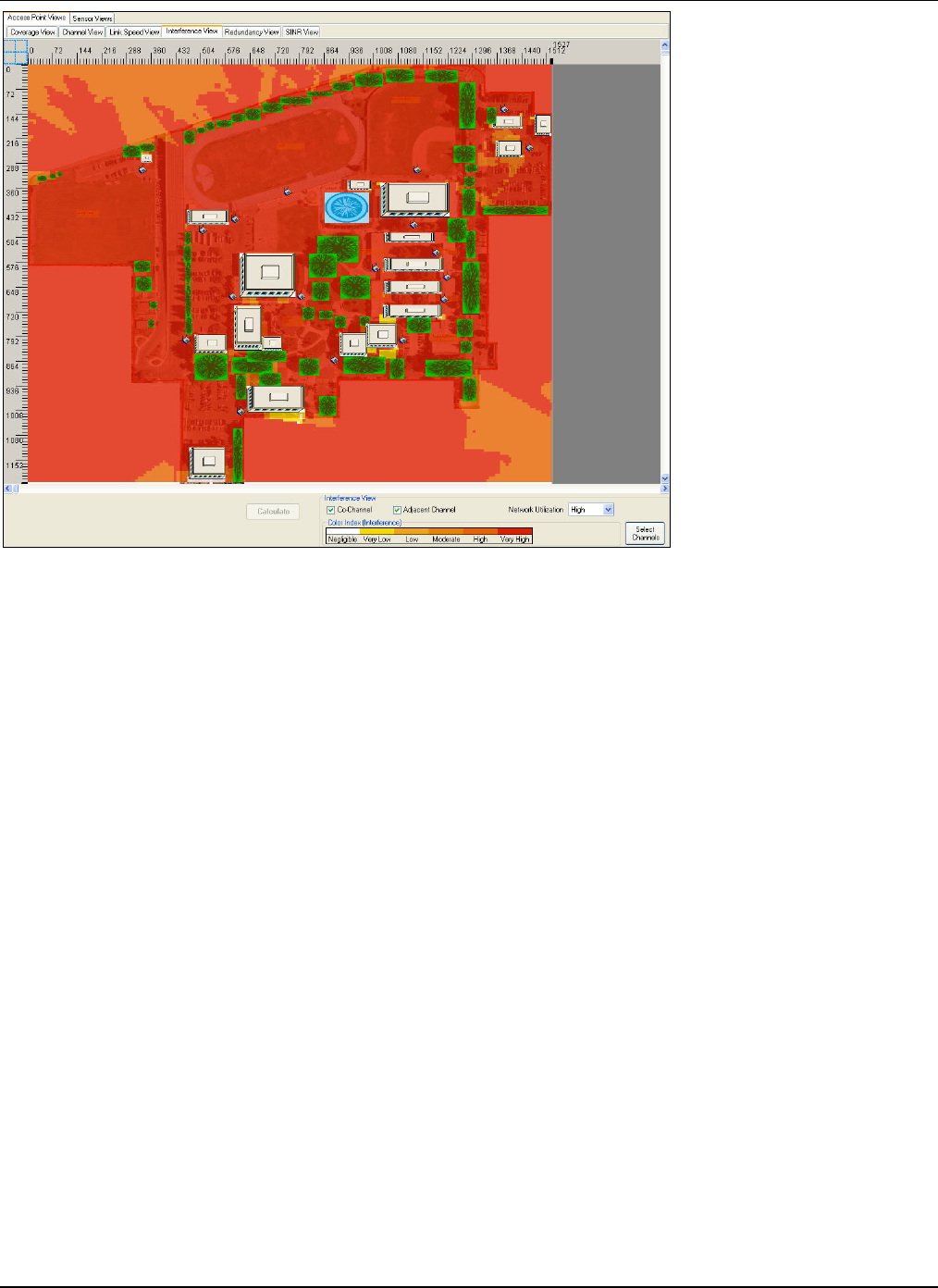
DevicePlacementontheLayoutModel
3Com®AirProtectPlannerUserGuide
74
Figure 92. AP Interference View: Outdoor Layout
7.2.5 APRedundancyView
ThisviewdisplaystheareaonthelayoutcoveredbyasetofAPradios.Itisusefulinplanningforimprovednetwork
availabilityincaseofdevicebreakdown,APmalfunction,capacityplanning,andplannedoutages.EachAPRedundancy
valueismappedtoacolorcode.YoucansetthevaluesusingthecolorpalettegivenatthebottomoftheAPRedundancy
View.
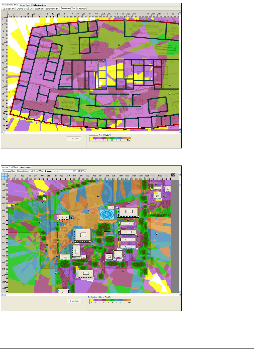
DevicePlacementontheLayoutModel
3Com®AirProtectPlannerUserGuide
75
Figure 93. AP Redundancy View: Indoor Layout
Figure 94. AP Redundancy View: Outdoor Layout
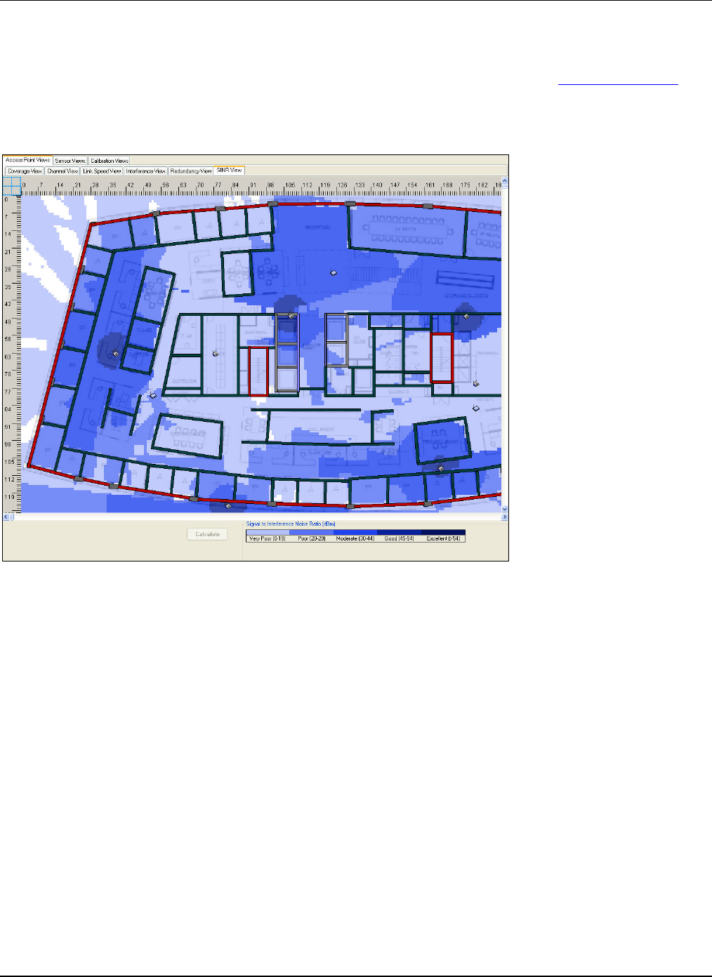
DevicePlacementontheLayoutModel
3Com®AirProtectPlannerUserGuide
76
7.2.6 APSINRView
Thisviewdisplaysthesignal‐to‐interference‐and‐noiseratio(SINR)valuesatdifferentareasonthelayout.SINRistheratioof
thereceivedsignaltotheamountofinterferenceandambientnoiseatagivenlocationonthelayout.SINRdeterminesthe
maximumdaterateorthelinkspeedfeasibleatagivenpointonthelayout.IfSINRispoor,seetheAPInterferenceViewto
determineiftheamountofinterferenceisthelimitingfactor.
TheSINRlevelsarecolor‐coded.ThecolorpaletteshowsfivelevelsofSINRvalues:Ver y Poor,Poor,Moderate,Good,and
Excellent.
Figure 95. AP SINR View: Indoor Layout
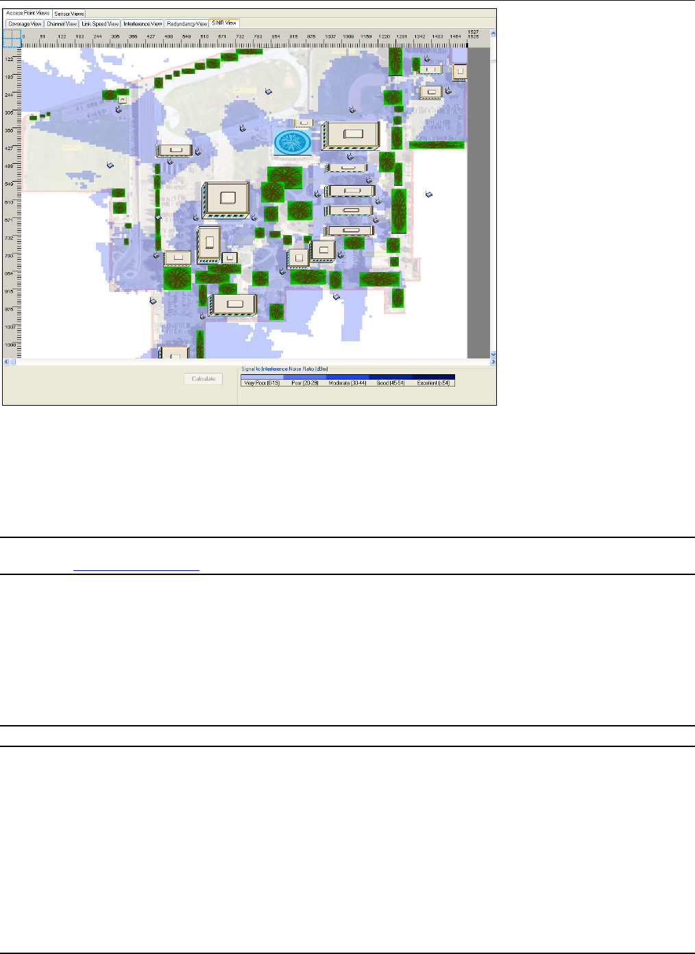
DevicePlacementontheLayoutModel
3Com®AirProtectPlannerUserGuide
7
7
Figure 96. AP SINR View: Outdoor Layout
7.2.7 SensorCoverageView
ThisviewhelpsplantheplacementofSensors.ItdisplaysthezoneofvisibilityforeachSensor.Sensorscancover802.11a,
802.11b,802.11g,802.11a/n,and802.11b/g/nprotocols.SensorsareplacedonthelayoutsuchthattheycandetectWLAN
activityateachpointonthelayoutanditsperimeterandcanpreventunauthorizedactivity.
Recommended:PlanSensorplacementsuchthateachpointonthelayoutanditsperimeterisvisibletotwoorthreeSensors.Youcando
thisusingtheSensorRedundancyView.
TherearetworangesforSensors’RFvisibility:DetectionandPrevention.YoucanvieweitherthePreventionrange,orthe
Detectionrange,orbothusingthetwocheckboxes:ShowPreventionandShowDetectionprovidedatthebottomofthe
screen.
• DetectionRange:AreafromwhichSensorscanreliablydetectanywirelessactivity.Detectionisbasedondatarate
(linkspeed)ofprotocols.SpecifythedatarateorusetheDeviceTransmitPower(dBm)slidertocontrolthedatarate
forwhichyouwanttoseedetection.Sensorscandetectallthedevices(withtransmitpowersetgreaterthanthatin
thesliderbar)locatedwithinitsdetectionrange.Forfurtherspecificresults,selectcertainprotocolsandthenspecify
thedataratesforeach.
Note:Ifyoudisableaprotocol,theviewwillchangeaccordinglyandshowpreventionanddetectiononlyfortheactiveprotocols.
• PreventionRange:AreaoverwhichSensorscanreliablypreventanyunauthorizedwirelessactivityandblock
unwantedWLANdevices.YoucanalsousethePreventionReliabilityslidertocontrolthepreventionrange.Asthe
preventionreliabilityincreases,thepreventionrangereduces.
¾ LowPreventionReliabilityindicatestheoptimisticestimatesofthepreventionrangeofSensors.Theactual
preventionrangeislikelytobelessthanthepredictedpreventionrange.
¾ MediumPreventionReliabilityindicatesthemostlikelypreventionrangeofSensors.Theactualprevention
rangeislikelytobecomparablewiththepredictedpreventionrange.
¾ HighPreventionReliabilityindicatesconservativeestimatesofthepreventionrangeofSensors.Theactual
preventionrangeislikelytobegreaterthanthepredictedpreventionrange.
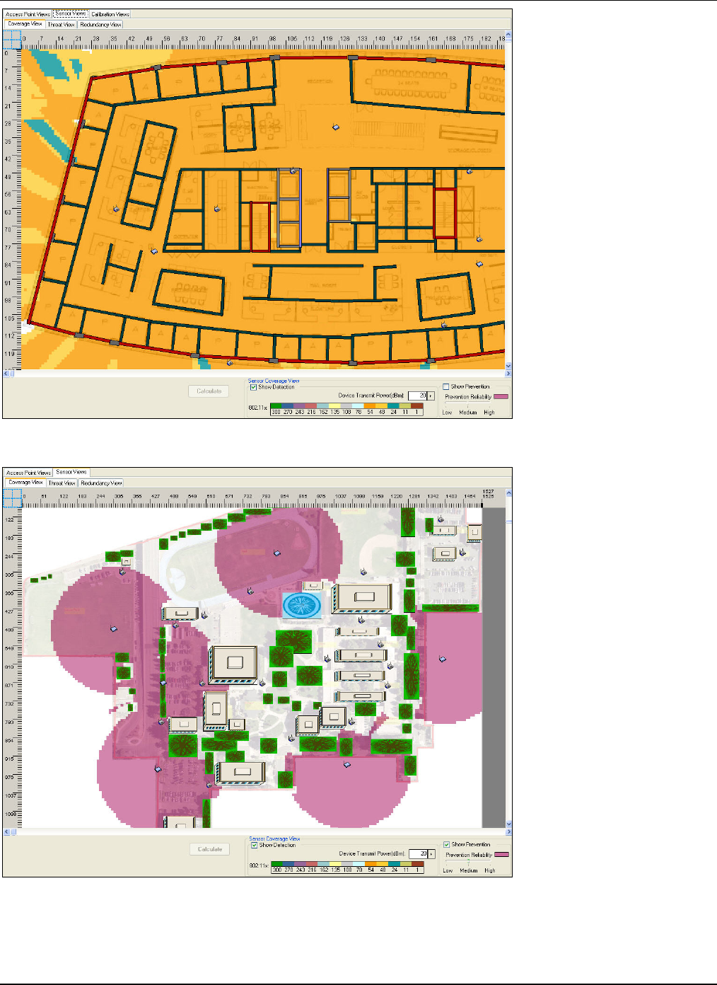
DevicePlacementontheLayoutModel
3Com®AirProtectPlannerUserGuide
78
Figure 97. Sensor Coverage View: Indoor Layout
Figure 98. Sensor Coverage View: Outdoor Layout
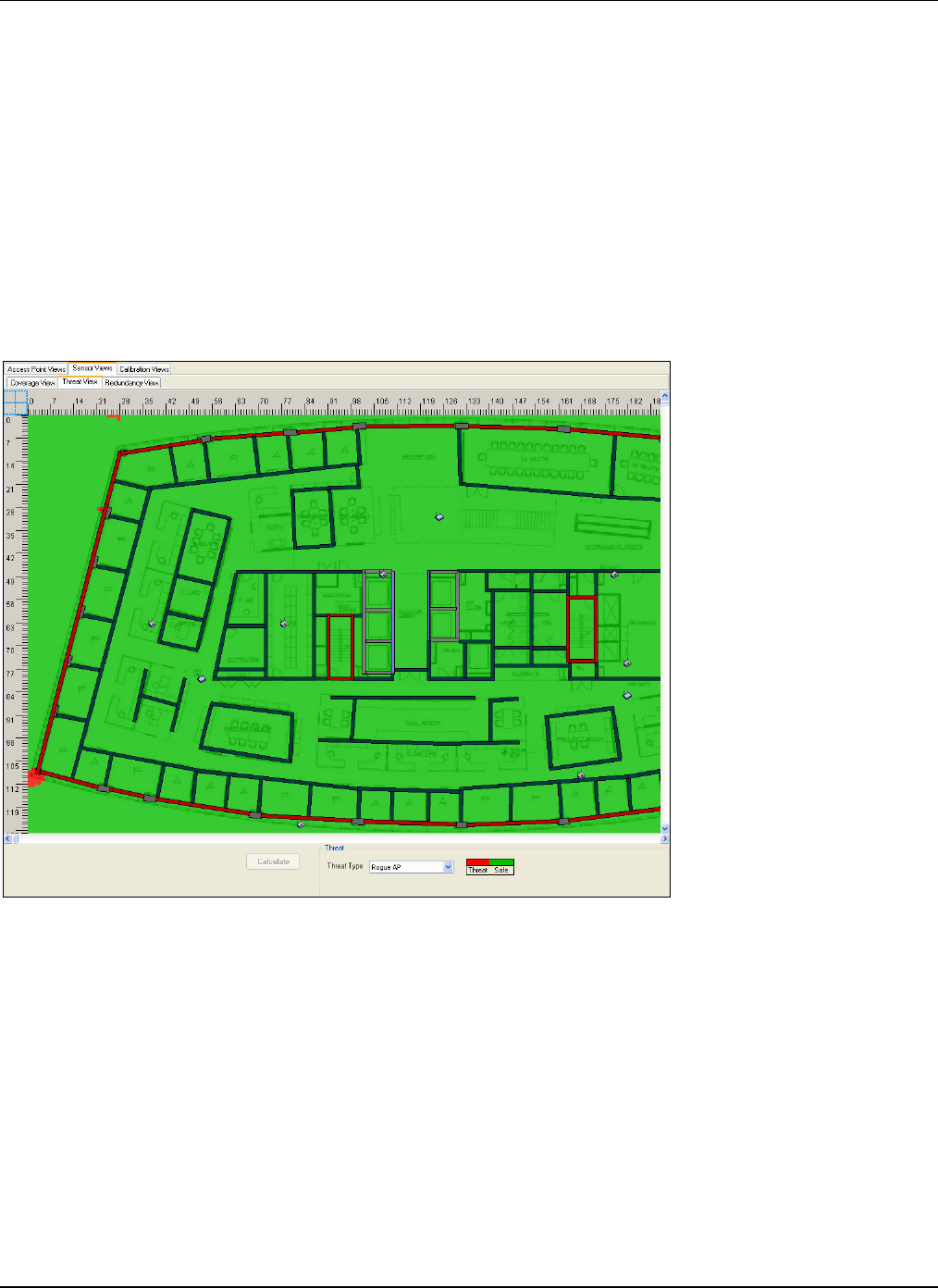
DevicePlacementontheLayoutModel
3Com®AirProtectPlannerUserGuide
79
7.2.8 SensorThreatView
ThisviewdisplaystheareabeyondthedetectionandpreventionrangesoftheSensors.Itshowstheareaswithsecuritylapses,
whichmaybesubjectedtodifferentkindsofthreatsandattacks.Thisviewenablesyoutoidentifythetypeofthreat
dependingonthetypeofdevice:AP,Sensor,andClient.Therisk/safetylevelsarecolor‐coded.Ithelpsyouidentifythe
numberofSensorsneededtoadequatelycoverthelayoutagainstthreats.
Plannersupportsthefollowingtypesofthreats:
• RogueAP
• HoneypotAP
• Adhocconnection
• DoSAttack
• MACSpoofing
• ClientMisassociation
• MisconfiguredAP
• UnauthorizedAssociation
Figure 99. Sensor Threat View: Indoor Layout
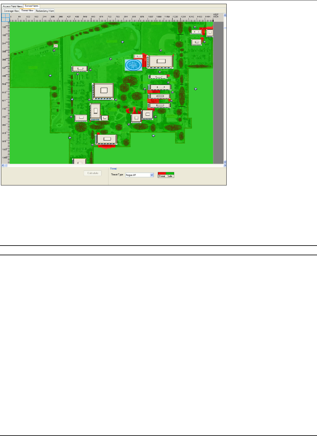
DevicePlacementontheLayoutModel
3Com®AirProtectPlannerUserGuide
80
Figure 100. Sensor Threat View: Outdoor Layout
7.2.9 SensorRedundancyView
ThisviewdisplaystheareacoveredbyasetofSensors.ItisusefulinplanningforimprovedsecuritycoverincaseofSensor
breakdown,malfunction,plannedoutages,andforlocationtrackingby3Com®AirProtectEnterprise.Youcansetthe
Redundancyvalueusingthesliderbaratthebottomofthescreen.
Recommended:UseaSensorredundancyofthreeforlocationtracking.
Allthelocationsonthelayoutshouldappeartobecolored;anyregionwhichiswhiteindicatesthattheregionisnotsecured
duetoabsenceofsignalfromaSensor.
DevicePlacementontheLayoutModel
3Com®AirProtectPlannerUserGuide
81
Figure 101. Sensor Redundancy View: Indoor Layout
Figure 102. Sensor Redundancy View: Outdoor Layout
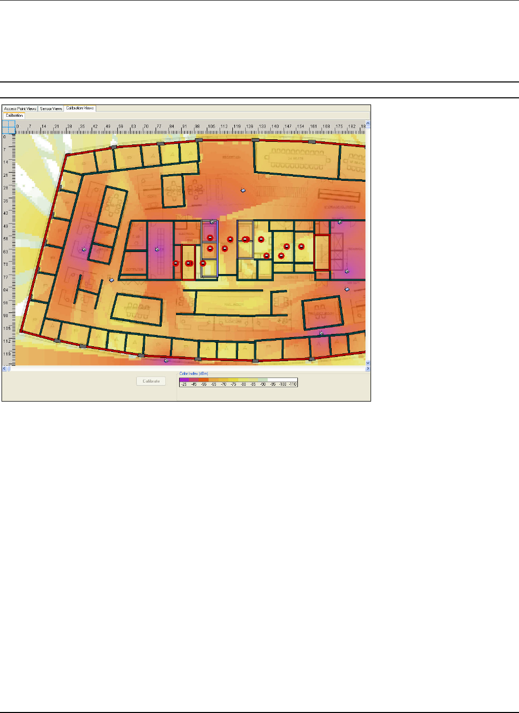
DevicePlacementontheLayoutModel
3Com®AirProtectPlannerUserGuide
82
7.2.10 CalibrationView
Thisviewdisplaysapredefinedsetofpointswhereyouneedtocollectsignalstrength.Thesepredefinedsetofpointsare
calledsystemgeneratedpointsandtheplacementofthesepointsdependsonvariousfactorslikelocationoffloorobjects,their
materialtype,andsoon.Thisviewhelpsyoufinetunethecurrentpredictionsclosertoreallifevalues.Forthis,Plannerneeds
tocollectsignalstrengthvaluesatvariousplaces.
Note:CalibrationViewisnotavailableforoutdoorplanning.
Figure 103. Calibration View: Indoor Layout
Totakereadings,movetoalocationontheflooranddouble‐clickthelocationpoint.Plannerwillautomaticallycollectthe
signalstrengthandaverageitoveraperiodforstablereadings.Youcanalsotakereadingsatanylocationbyright‐clicking
thatpointandselecting<TakeReading>.
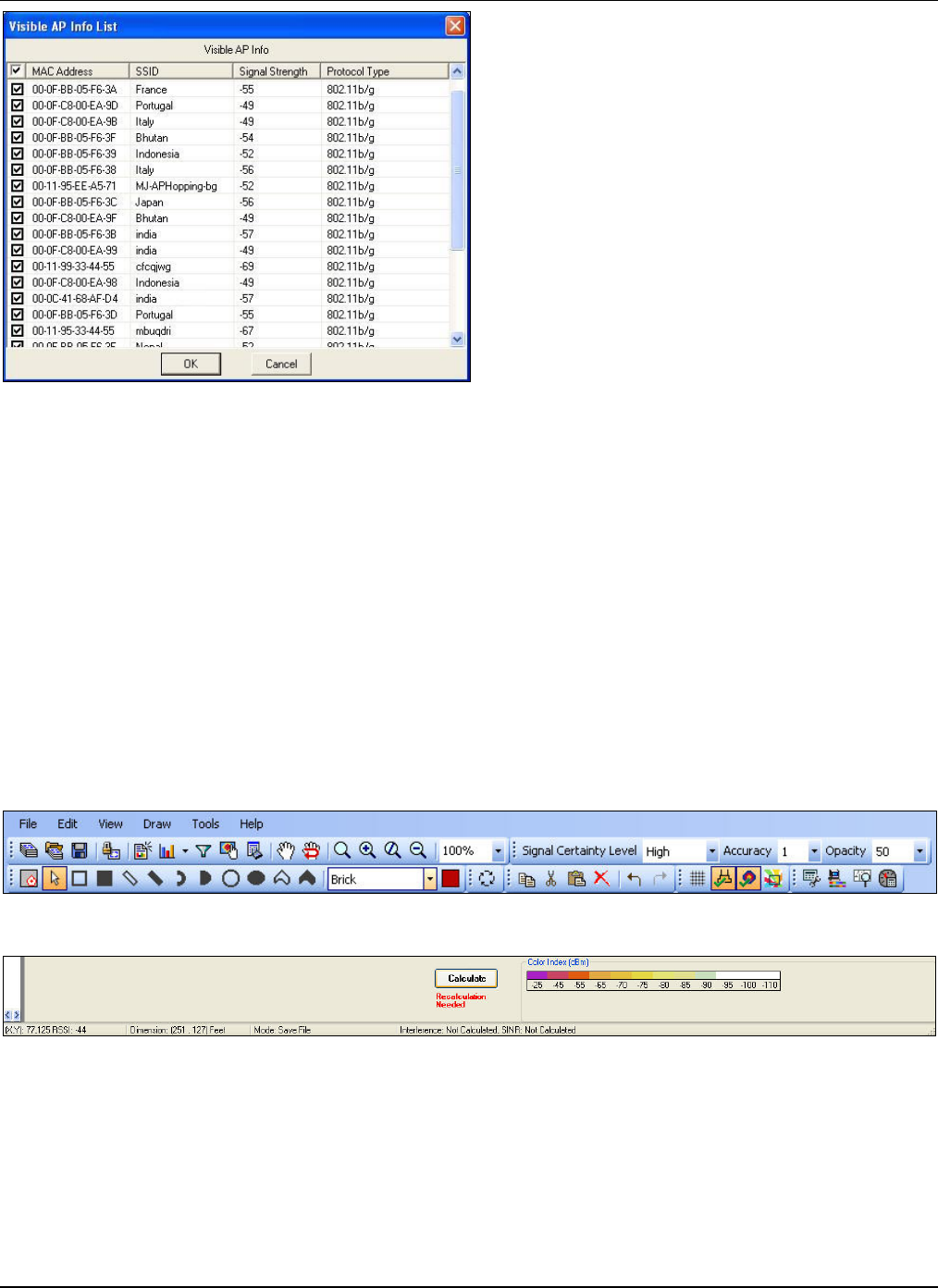
DevicePlacementontheLayoutModel
3Com®AirProtectPlannerUserGuide
83
Figure 104. Visible AP Info List
SelectthedesiredAP’ssignalstrengthandclick<OK>.Thiscreatesauser‐definedpoint.
Aftertakingreadingsatallpoints,click<Calibrate>.Plannerwillcalculatethesignallossduetoobjectsandotherfactors
basedonthemeasuredsignalstrength.
ThisprocesscompletestheloopofstartingwithRFpredictionandusingtheactualmeasuredsignalstrengthtofinetunethe
RFprediction.
ThefollowingoptionsaredisabledinCalibrationView:
• Layouteditoptionslikedrawing,rotate,cut,copy,paste,andsoon
• SpillageView
• GenerateReport
• Statistics
7.3 PlanningDevicePlacement:StatusandControl
Plannerprovidesseveraloptionsforsettingthestatusandcontrols,andgeneratingRFviews.Youcandefinesettingsfromthe
Toolbaratthetopofthescreenandthelowerpaneatthebottomofthescreendisplayingthecolorpalette.
Figure 105. Status and Control Pane – Toolbar
Figure 106. Status and Control Pane – Lower Pane
7.3.1 SignalCertaintyLevel
TheSignalCertaintyLeveltabontheToolbarenablesyoutochoosethereliabilitylevelofthepredictedRFsignalvalues.
ChoosefromLow,Medium,orHighsignalcertaintyvaluesfromthedrop‐downlist.
ClickingtheSignalCertaintyLeveltabdisplaysaninformationpop‐up.
DevicePlacementontheLayoutModel
3Com®AirProtectPlannerUserGuide
84
Figure 107. Status and Control Pane: Signal Certainty Level I-Pop-up
7.3.2 Accuracy
TheAccuracytabontheToolbarallowsyoutosetfourlevelsofaccuracyforRFcomputationswith1beingthelowest
(default)and4beingthehighest.ComputationtimeforcreatingRFmapsincreaseswiththeaccuracylevel.
7.3.3 Opacity
TheOpacityoptionhelpsyouviewthefloormodelandcoveragetogether.SelecttheOpacityvaluefromthedrop‐downlist.
Opacityvalueof0%makesthecoveragecolorstransparentwhileavalueof100%makesthecoveragecolorsopaque.
7.3.4 ShowGrid
Click fromtheToolbartoviewthegridonthelayout.Thishelpsviewthecelldistance.
7.3.5 ViewLayoutModel
Click fromtheToolbartoviewthelayoutmodel.Thishelpsyouverifythelocationsofthedevicesplacedonthelayout
alongwiththeoriginal.gifor.jpgimage.
7.3.6 ShowRFSignal
Click.fromtheToolbartoviewtheRFsignalsofthelayout.Thishelpsyouviewthecolor‐codedsignalcoverageofthe
devicesonthelayout,acrossdifferentviews.
7.3.7 ShowSpillageView
Click fromtheToolbartoinvoketheSpillageView.Thisviewdisplayscolor‐codedRSSIdistributionoverandaroundthe
perimeterofthecurrentlayout.Ithelpsyouanalyzethesecurityexposureduetospillageofthesignalsoutsidetheperimeter
ofthecurrentlayout.Youcanminimizethesecuritythreatsfromwardriversandeavesdroppersbasedontheresultsofthe
SpillageView.PlannerassumestheareaoutsidethelayouttobefreespaceforRFprediction.
HigherSensorcoverageoutsidetheperimeterofthelayoutindicatesabettercoverageforsecurityexposure.Withlarger
coverage,adevicethatisfarawayfromthelayoutperimetercanalsobedetectedbytheSensorandthetransmissioncanbe
prevented,iffoundmalicious.
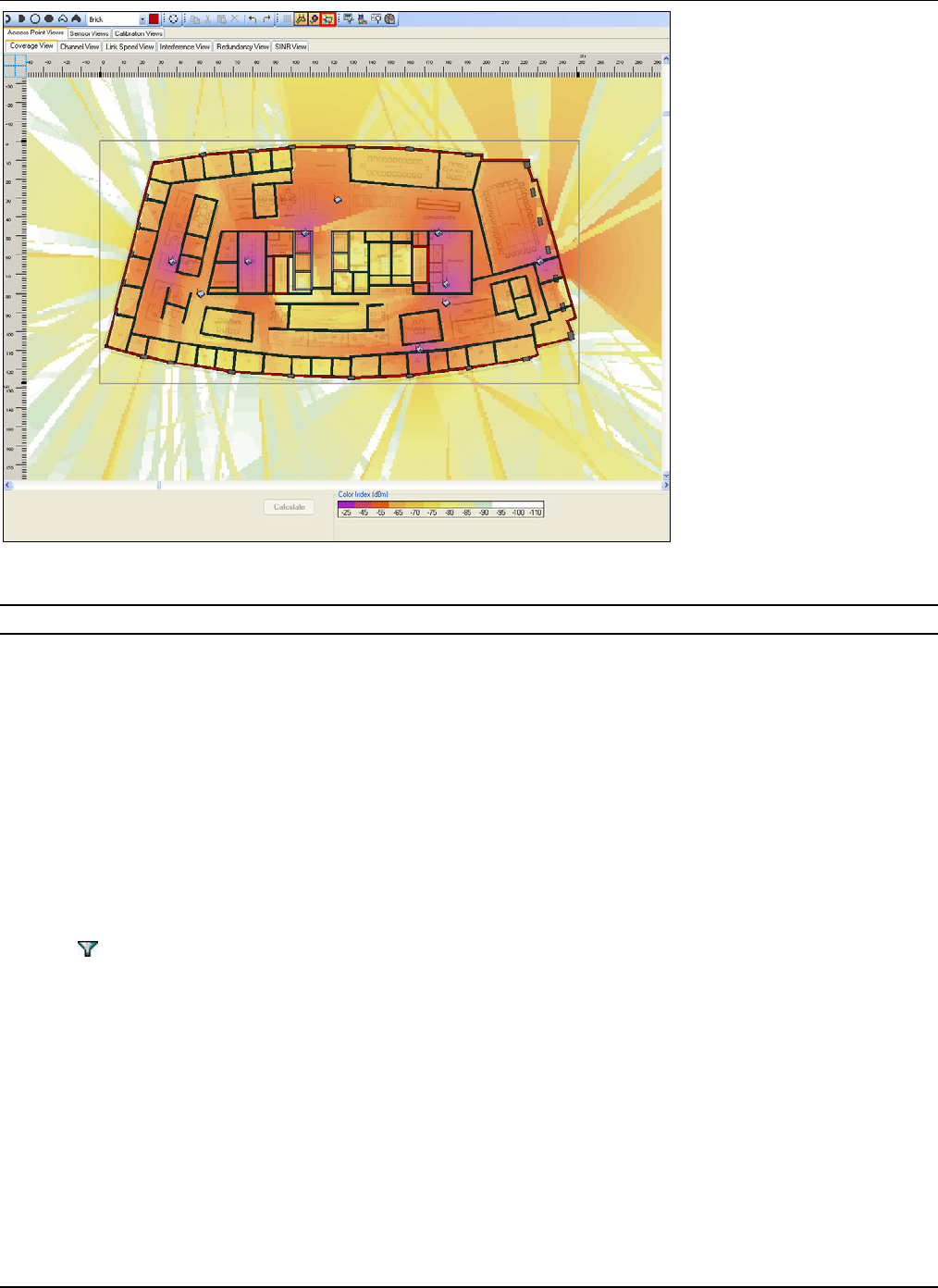
DevicePlacementontheLayoutModel
3Com®AirProtectPlannerUserGuide
85
Figure 108. Spillage View
Note:TheSpillageViewoptionisavailableonlyintheAPCoverageView,SensorCoverageView,andSensorThreatView.
7.3.8 SelectingProtocols
Plannerallowsyoutoselectprotocols.Youcantryvarious‘What‐If’scenariosusingcombinationsofprotocolsandWLAN
devices.Youcanselectthefollowing:
• 802.11a,802.11b,802.11g,802.11a/n,or802.11b/g/nprotocols
• AnisolatedviewoftheselectedWLANdevices
Theviewchangesaccordingtotheselectedprotocol.Ifyouselectmorethanoneprotocol,Plannershowsallthoseprotocols
simultaneously.Selectingmorethanoneprotocolcansometimesleadtomissingdetailsforaspecificprotocolbecauseof
overlap.
UsingtheFilterdialogbox,youcanviewthecoverageofadeviceaboveandbelowthecurrentfloor.Thedialogboxalso
displaysdetailslikethenameofthedevice,thenameofthelayoutwherethedeviceislocated,andthelevel.
Usethefollowingstepstoselecttheprotocols.
1 ClickfromtheToolbar.
2 SelectthedesiredprotocolanddeviceintheFiltersdialogbox.
3 Click<Apply>.
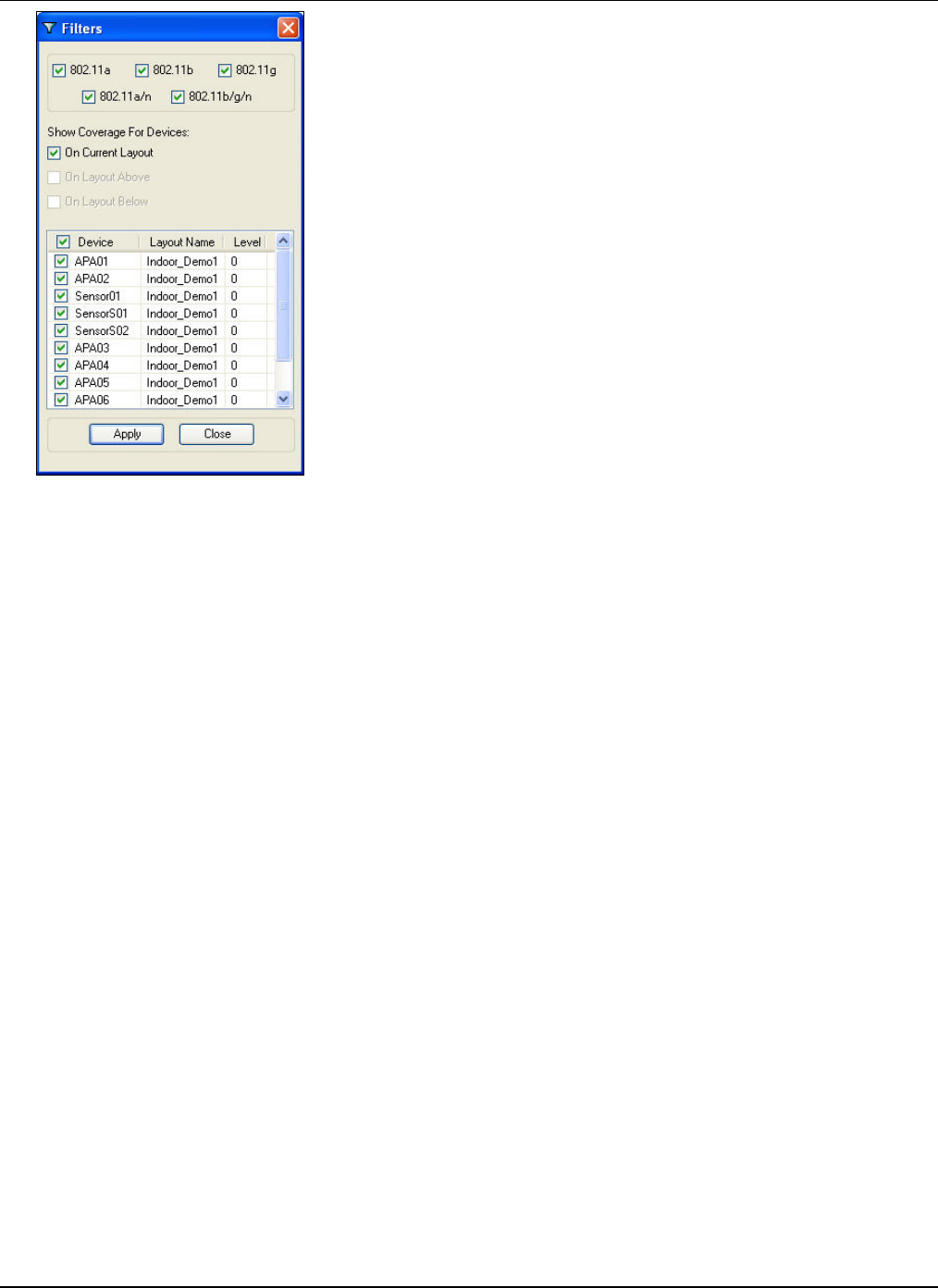
DevicePlacementontheLayoutModel
3Com®AirProtectPlannerUserGuide
86
Figure 109. Filters
Intheabovefigure,ShowCoverageForDeviceshasthefollowingoptions:
• OnCurrentLayout
1. Showsdevicesplacedonthecurrentlayout
2. Displayscoverageonlyforthosedevicesplacedonthecurrentlayout
• OnLayoutAbove
1. Showsdevicesplacedonthelayoutabovethecurrentlayout
2. Displayscoverageonlyforthosedevicesplacedonthelayoutabovethecurrentlayout
• OnLayoutBelow
1. Showsdevicesplacedonthelayoutbelowthecurrentlayout
2. Displayscoverageonlyforthosedevicesplacedonthelayoutbelowthecurrentlayout
7.3.9 Calculate/CalibrateButton
RFcomputationisrequiredwheneveryou:
• Add,move,orchangethepropertiesofanAPoraSensor
• Changealayoutoritsproperties
• Changethespillagefactor,attenuationfactor,ortheaccuracylevel
Click<Calculate>toperformRFcomputations.IfRFcomputationispending,acommentinred‘RecalculationNeeded’
appearsbelowtheCalculatebutton.
The<Calibrate>buttonreplacesthe<Calculate>buttonwhenyouareontheCalibrationtab.Click<Calibrate>totake
readingsandcollectsignalstrengthsatvariouspointsonthelayout.
7.3.10 ColorPalette
ThissectionshowsthecolorpaletteusedintheplanningofDevicePlacementviews.Double‐clicktheColorIndextoopenthe
Colordialogboxwhereyoucancustomizethecolors.
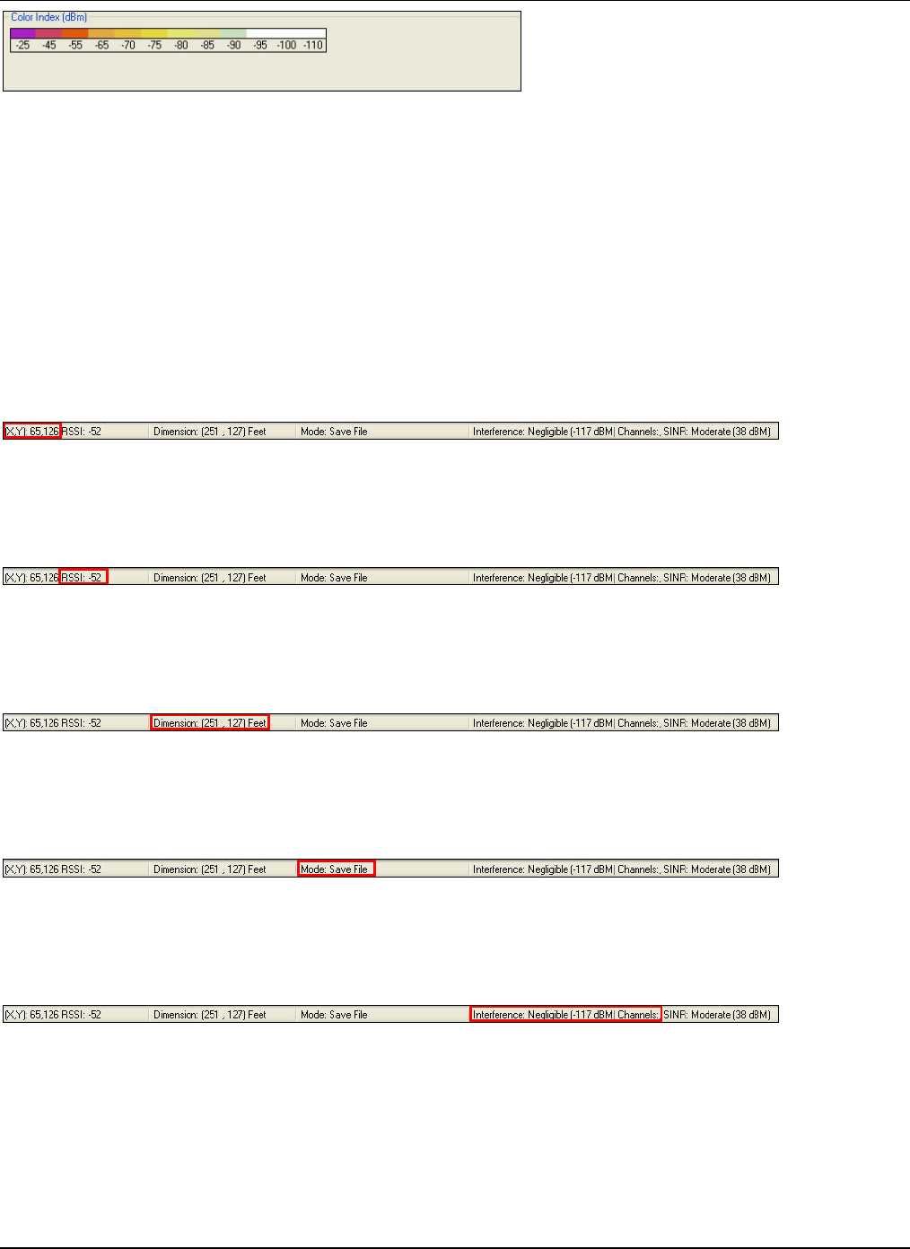
DevicePlacementontheLayoutModel
3Com®AirProtectPlannerUserGuide
8
7
Figure 110. Status and Control Pane: Color Palette
7.4 StatusBar
TheStatusBarappearsattheextremebottomofthescreen.TheStatusBarisdividedintofivesections.
• CursorLocation
• RSSIDisplay
• LayoutDimensions
• CurrentMode
• Interference
• SINR
7.4.1 CursorLocation(X,Y)
CursorLocationdisplaysthelocationcoordinateswithrespecttothetopleftcornerofthelayout.
Figure 111. Status and Control Pane: Cursor Location
7.4.2 RSSIDisplay
Plannerpredictsthesignalstrengthatthepointwherethecursorpoints.
Figure 112. Status and Control Pane: RSSI Display
7.4.3 LayoutDimensions
Thestatusbardisplaysthedimensionsofthelayout.
Figure 113. Status and Control Pane: Layout Dimensions
7.4.4 CurrentMode
Thestatusbardisplaysthenameoftheicononwhichthecursorpoints.
Figure 114. Status and Control Pane: Current Mode
7.4.5 Interference
Thestatusbardisplaysthechannelsthatexperiencehighinterference.
Figure 115. Status and Control Pane: Interference
7.4.6 SINR
ThestatusbardisplaystheSINRlevelataparticularlocationonthelayout.
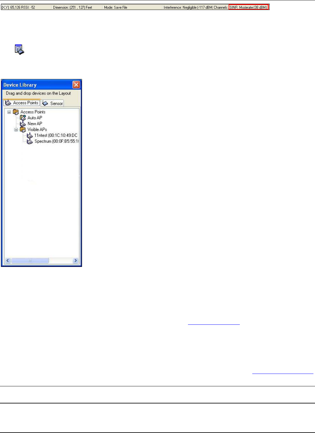
DevicePlacementontheLayoutModel
3Com®AirProtectPlannerUserGuide
88
Figure 116. Status and Control Pane: SINR
7.5 DeviceLibrary
Click ontheToolbartoinvoketheDeviceLibrarydialogbox.
TheDeviceLibrarydialogboxdisplaystheavailableAPsandSensors.Ithastwotabs:AccessPointsandSensors.Youcan
directlydraganddropthedevicesfromthislistatanappropriateplaceonthefloormap.
Figure 117. Device Library
TheAccessPointstreeontheAccessPointstabconsistsof:
• AutoAP:ListsdevicesthatwerecalculatedduringWLANPlanning,butcouldnotbeplacedonthelayout.
• NewAP:DisplaysthedefaultAPsetinthePlannerapplication.ClicktheAP,anddraganddropitonthefloormap.
PlannercreatesaninstanceofthatAP.TochangethedefaultAPproperties,right‐clicktheAPandselectProperties.
TheDefaultAPPropertiesdialogboxappearsasexplainedintheSettings:APDefaultssection.
• VisibleAPs:ListsallthevisibleAPsseenbytheClientintheair.Thesedevicesarepre‐configuredwiththe
propertiesthattheClientseesintheair.
TheSensorstreeontheSensorstabconsistsof:
• NewSensor:DisplaysthedefaultSensorsetinthePlannerapplication.ClicktheSensor,anddraganddropitonthe
floormap.PlannercreatesaninstanceofthatSensor.TochangethedefaultSensorproperties,right‐clicktheSensor
andselectProperties.TheDefaultSensorPropertiesdialogboxappearsasexplainedintheSettings:SensorDefaults
section.
Note:Plannershowsthefreespacereachofadeviceintheformofconcentricsphereswhenyoudragadeviceontothelayout.These
spheresserveasusefulguidelineswhiledecidingtheplacementofdevices.
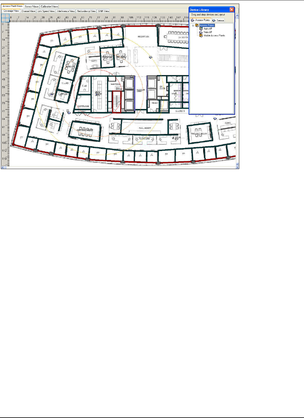
DevicePlacementontheLayoutModel
3Com®AirProtectPlannerUserGuide
89
Figure 118. Device Library: Display Coverage Area of the Device
Onceyouplacethedevicesonthelayout,theydonotappearinthelist.ThesedevicesappearintheDevicesTreeontheleft
paneofthescreen.Youcanchangethelocationofadevicebydraggingthedevicetothenewlocation.
7.6 DeviceProperties
YoucanchangethedevicepropertiesofAPsandSensorsusedtoplanthelayout.
7.6.1 AccessPointProperties
TomodifythepropertiesofanAPplacedonthelayout,doeitherofthefollowing:
• Right‐clicktheAPandselectProperties
• Right‐clickordouble‐clicktheAPintheDeviceListandselectProperties
• Double‐clicktheAP
TheAccessPointPropertiesdialogboxappears.
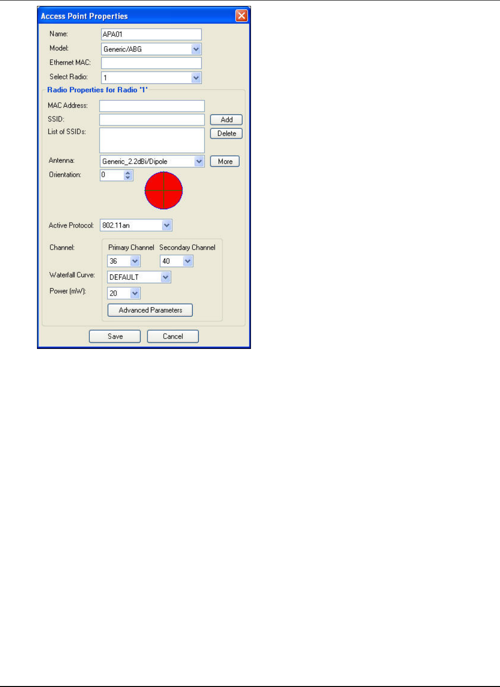
DevicePlacementontheLayoutModel
3Com®AirProtectPlannerUserGuide
90
Figure 119. Access Point Properties
YoucansetthefollowingAPparameters.
• Name:EnterauniquenamebywhichtheAPisidentified.
• Model:SelectanAPModelfromthedrop‐downlistofcommerciallyavailableAPmodels.Plannerenables,disables,
orchangestheotherpropertiesinthisdialogboxbasedontheselectedAPmodel.
• EthernetMAC:EntertheEthernetMACAddressoftheAP.
• SelectRadio:Selecttheradiofromthedrop‐downlist.
• RadioProperties
¾ MACAddress:EntertheMACAddressoftheradio.
¾ SSID:EntertheSSIDoftheAP’sradio.
Click<Add>toaddtheSSIDtotheListofSSIDs.
¾ ListofSSIDs:DisplaysthelistofSSIDsoftheAP’sradio.
Click<Delete>todeleteanSSIDselectedfromtheListofSSIDs.
¾ Antenna:Selectanantennafromthedrop‐downlist.
Click<More>toviewadditionaldetailsoftheantenna.TheSelectAntennadialogboxappearswhichhelps
youaddorselecttheantennainabettermanner,fromthelistofavailableantennae.
¾ Orientation:Selectadirectioninwhichtheantennawouldradiateitspower.
Thepreviewreflectstheantennaradiationbasedontheantennaselected.
¾ ActiveProtocol:Selectanactiveprotocolfromthedrop‐downlist.Eachradiocanoperateonanyoneofthe
protocols.
¾ Channel:Selectanoperatingchannelfortheselectedprotocol.Selectprimaryandsecondarychannelsfromthe
drop‐downlist.Thedifferencebetweentheprimaryandsecondarychannelvaluesisfourunits.
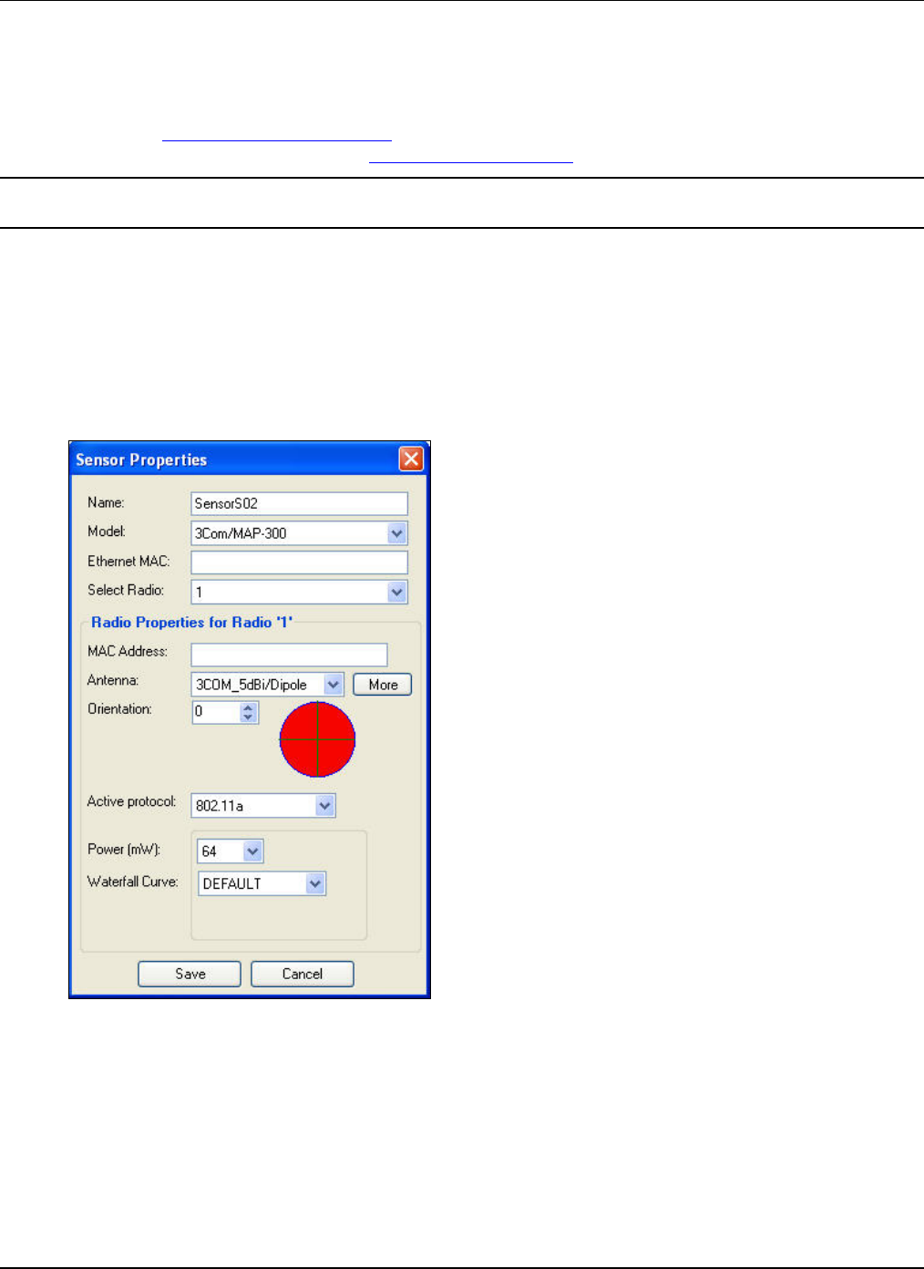
DevicePlacementontheLayoutModel
3Com®AirProtectPlannerUserGuide
91
¾ WaterfallCurve:Selectawaterfallcurvefromthedrop‐downlistofavailablewaterfallcurvesfortheselected
protocol.
¾ Power(mW):SelectapowerlevelfromthesupportedpowervaluesatwhichtheAPwilloperateforeach
selectedprotocol.Youmustkeepthedefaultvalues,whicharebasedonthemaximumtransmitpowerforthe
protocolaspermittedbytheregulatoryagenciesinthecountriesforwhichyouaredoingtheWLANplanning.
RefertoAppendixD:GlossaryofTermsformoredetailsonregulatorydomaincompliance.
¾ Click<AdvancedParameters>tosetadvance802.11nparameters.
Note:Thereisonlyonechannelincaseof802.11a,802.11b,and802.11gprotocols.AdvancedParametersisavailableonlyforthe
802.11nprotocol.
Click<Save>tosavethechanges.Alternately,click<Cancel>todiscardthechanges.
7.6.2 SensorProperties
TomodifythepropertiesofaSensorplacedonthelayout,doeitherofthefollowing:
• Right‐clicktheSensorandselectProperties
• Right‐clickordouble‐clicktheSensorintheDeviceListandselectProperties
• Double‐clicktheSensor
TheSensorPropertiesdialogboxappears.
Figure 120. Sensor Properties
Youcansetthefollowing:
• Name:EnterauniquenamebywhichtheSensorisidentified.
• Model:SelectaSensorModelfromthedrop‐downlistofcommerciallyavailableSensormodels.Plannerenables,
disables,orchangestheotherpropertiesinthisdialogboxbasedontheselectedSensormodel.
• EthernetMAC:EntertheEthernetMACAddressoftheSensor.
• SelectRadio:Selecttheradiofromthedrop‐downlist.
• RadioProperties
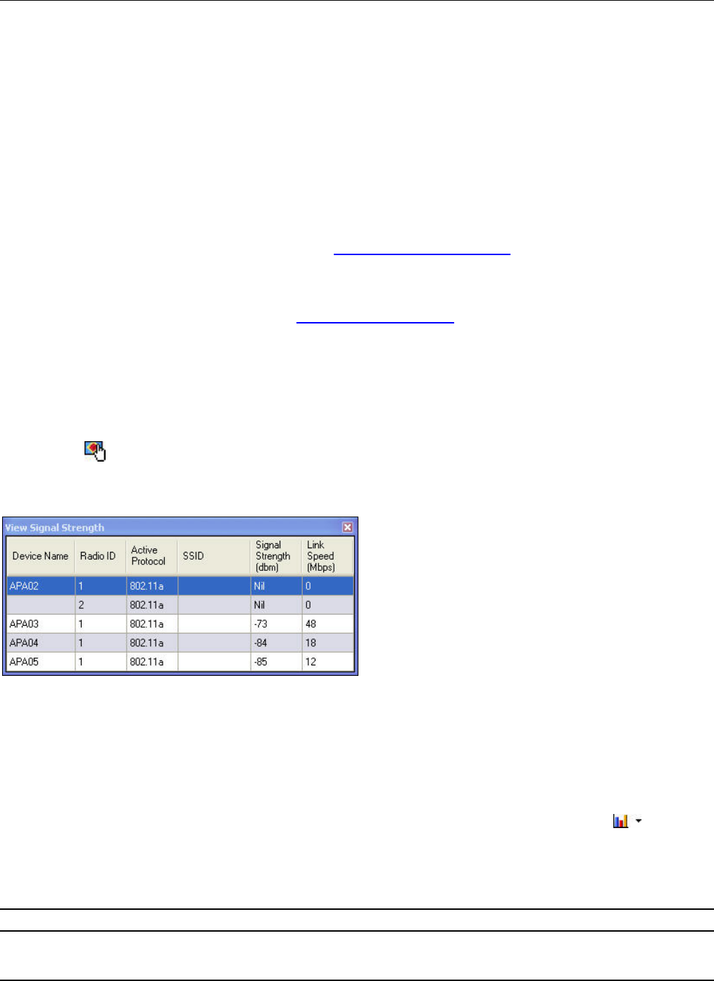
DevicePlacementontheLayoutModel
3Com®AirProtectPlannerUserGuide
92
¾ MACAddress:EntertheMACAddressoftheRadio.
¾ Antenna:Selectanantennafromthedrop‐downlist.
Click<More>toviewadditionaldetailsoftheantenna.TheSelectAntennadialogboxappearswhichhelps
youaddorselecttheantennainabettermanner,fromthelistofavailableantennae.Itisagoodpracticeto
keeptheSensorantennaetobedipoleoromni‐directional,whichenablestheSensortodetectandprevent
attacksfromanydirection.
¾ Orientation:Selectadirectionfromwheretheantennawouldreceiveitspower.
Thepreviewreflectstheantennaradiationbasedontheselectedantenna.
¾ ActiveProtocol:Selectanactiveprotocolfromthedrop‐downlist.Eachradiocanoperateonanyoneofthe
protocols.
¾ Power(mW):SelectapowerlevelfromthesupportedpowervaluesatwhichtheSensoroperatesforeach
selectedprotocol.Youmustkeepthedefaultvalues,whicharebasedonthemaximumtransmitpowerforthe
protocolaspermittedbytheregulatoryagenciesinthecountriesforwhichyouaredoingtheWLANplanning.
(Example:FCCintheUnitedStates).RefertoAppendixD:GlossaryofTermsformoredetailsonregulatory
domaincompliance.
¾ WaterfallCurve:Selectawaterfallcurvefromthedrop‐downlistofavailablewaterfallcurvesfortheselected
protocol.
¾ AdvancedParameters:Clicktosettheadvance802.11nparameters.Thisisavailableonlyifyouhaveselected
the802.11nprotocol.
Click<Save>tosavethechanges.Alternately,click<Cancel>todiscardthechanges.
7.7 ViewingSignalStrength
Plannerenablesyoutoviewthesignalstrengthofallthedevicesplacedonthefloormapacrossalayout.Useeitherofthe
followingtoviewthesignalstrength:
• ClickfromtheToolbar
• Right‐clickanywhereonthefloormapandselectViewsignalStrength
TheViewSignalStrengthscreenappears.
Figure 121. Viewing Signal Strength
ThescreendisplaysthesignalstrengthvaluesanddevicedetailssuchastheDeviceName,RadioID,ActiveProtocol,SSID,
SignalStrength,andLinkSpeedofthedevicesonthefloormap.TheSignalStrengthandLinkSpeedvalueschangeasyou
movethecursoracrossthefloormap.
7.8 Statistics
Statisticsgivesthepercentage(%)areaunderspecificRFcoverageascomparedtothetotallayoutarea.Click onthe
ToolbartoinvokeStatistics.
RFcoverageforstatisticalanalysisincludes:
• AccessPointViews:Coverage,LinkSpeed,andChannelInterference
• SensorViews:SensorDetectionOnly,SensorPreventionOnly,andSensorRedundancy
Note:ToviewtheStatisticsfortheSensorViews,switchtotheSensorViewgroupandclicktheStatisticsicon.
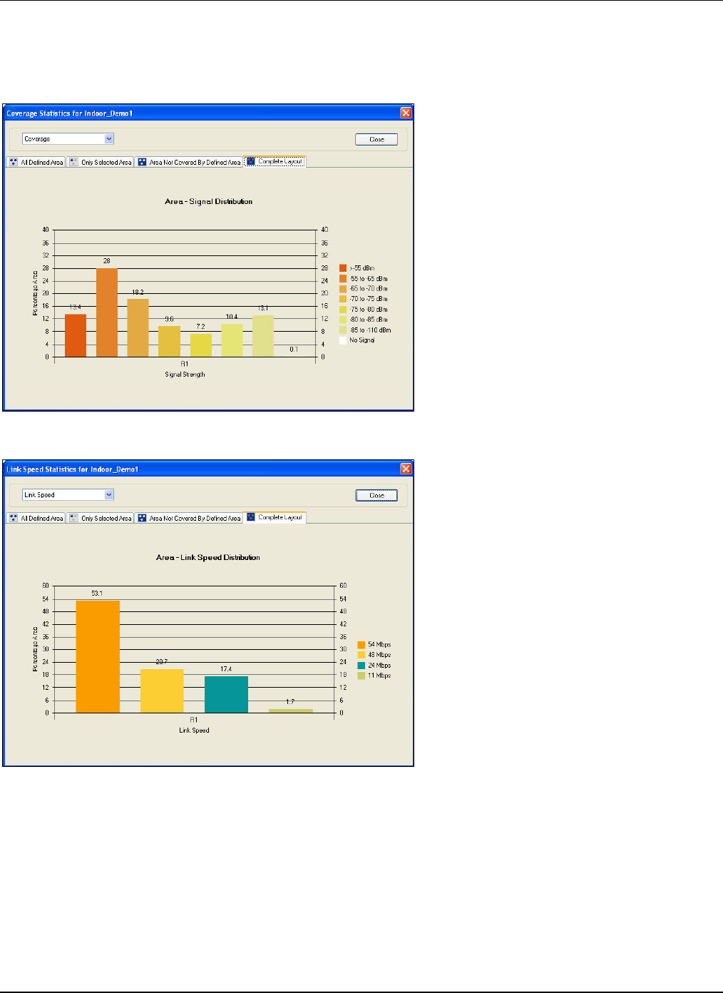
DevicePlacementontheLayoutModel
3Com®AirProtectPlannerUserGuide
93
IfyouchooseaspecificareawiththeAreaPolygonoption,youcanviewstatisticsfordifferentregionssuchas:
• AllDefinedArea
• OnlySelectedArea
• AreaNotCoveredByDefinedArea
• CompleteLayout
Figure 122. Statistics: Area – Signal Distribution
Figure 123. Statistics: Area - Link Speed Distribution
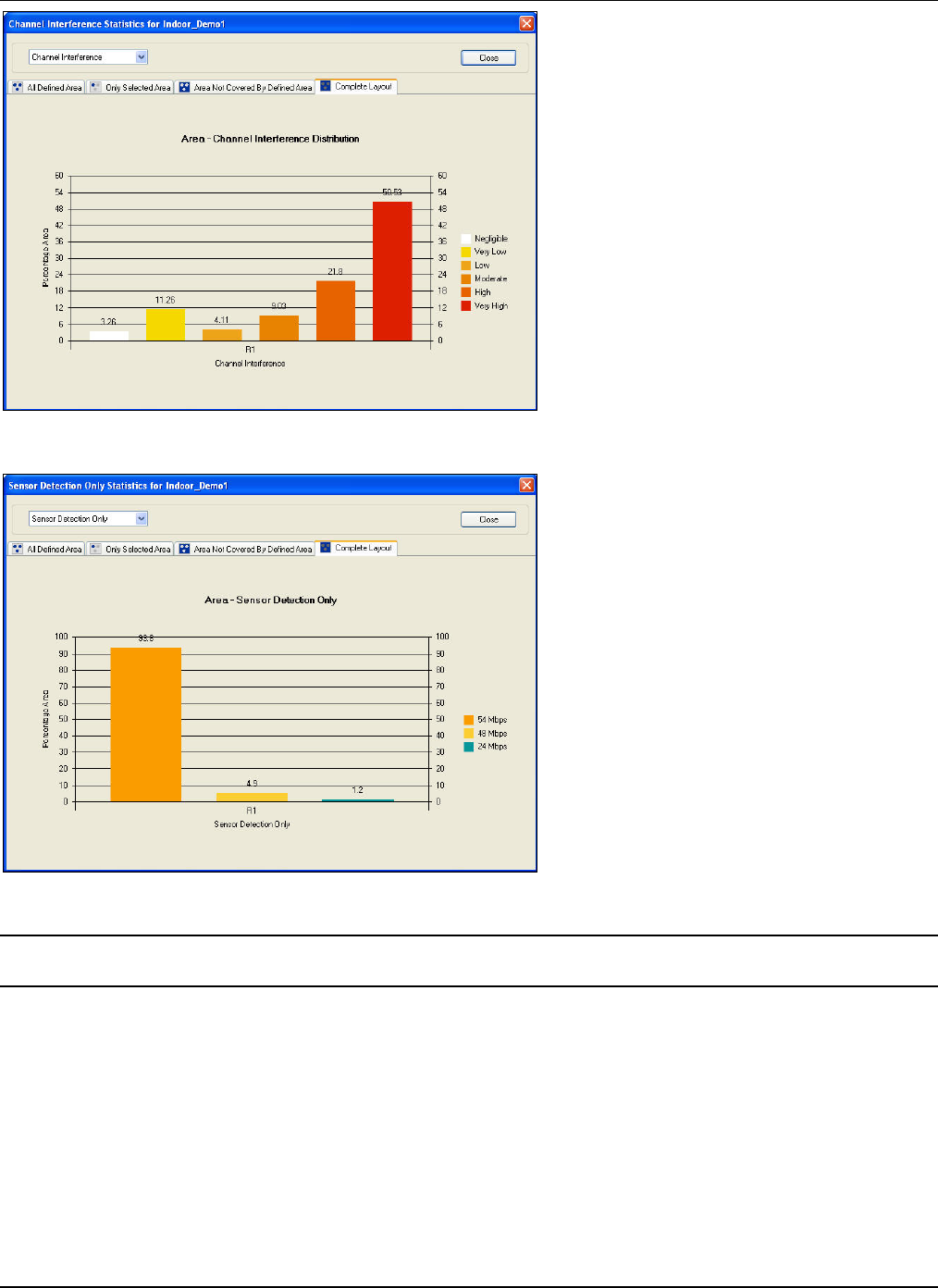
DevicePlacementontheLayoutModel
3Com®AirProtectPlannerUserGuide
94
Figure 124. Statistics: Area – Channel Interference Distribution
Figure 125. Statistics: Area - Sensor Detection
Note:ToviewtheStatisticsforSensorPrevention,ensurethatyouhaveselectedtheShowPreventioncheckboxintheSensorCoverage
View.
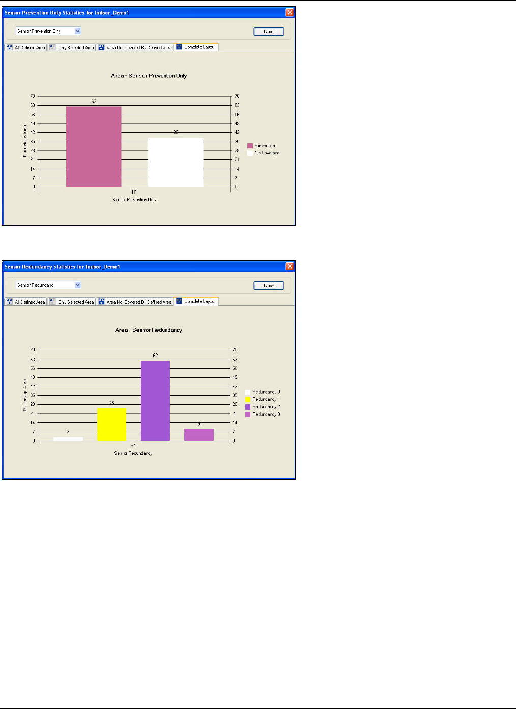
DevicePlacementontheLayoutModel
3Com®AirProtectPlannerUserGuide
95
Figure 126. Statistics: Area - Sensor Prevention
Figure 127. Statistics: Area - Sensor Redundancy
7.9 SavingtheFile
Afteryouhaveplannedtheentirenetwork,youmustsavethefile.Ifyouhavenotsavedthefile,Plannerpromptsyoutosave
thefile,underthefollowingcircumstances:
• Openanotherfile.
• Createanewfile.
• Saveasadifferentfile.
• GenerateaReport.
• ExitPlanner.
7.10 SavingtheProjectFile
Afteryouhaveplannedallthelayoutsunderaproject,youmustsavetheproject.Ifyouhavenotsavedtheproject,Planner
promptsyoutosavetheproject,underthefollowingcircumstances:

DevicePlacementontheLayoutModel
3Com®AirProtectPlannerUserGuide
96
• Openanotherproject.
• Createanewproject.
• Saveasadifferentproject.
• Exportthewholeprojectforimportinto3Com®AirProtectEnterpriseoranyothersystemrunningPlanner.
• ExitPlanner.
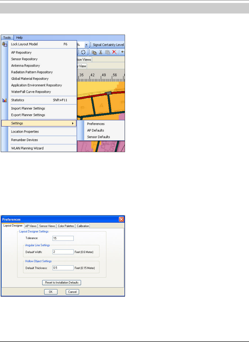
Settings
3Com®AirProtectPlannerUserGuide
9
7
Chapter8 Settings
8.1 Settings:InvokingfromToolsMenu
Figure 128. Settings: Invoking from Tools Menu
TheSettingswindowcontainsthefollowing:
• Preferences
• APDefaults
• SensorDefaults
8.2 Settings:Preferences
GotoSettingsÆPreferences,thePreferencesscreenopensintheLayoutDesignertab.
Figure 129. Preferences – Layout Designer
8.2.1 Preferences:LayoutDesigner
TheLayoutDesignerallowsyoutoperformthefollowingfunctionsontheLayoutDesigner.
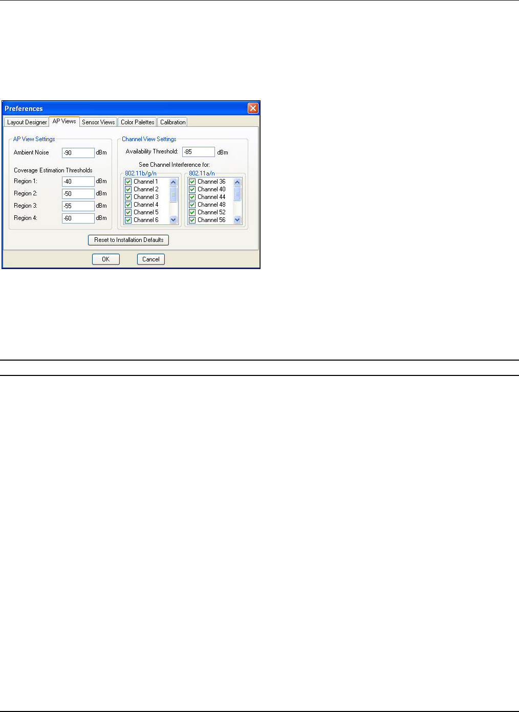
Settings
3Com®AirProtectPlannerUserGuide
98
• Tolerance:Specifythetoleranceintherangeof1to20.Forexample,ifyouclickthemouse20pixelsawayfromthe
declaredtolerancevalue,thecursorwillselectthedevice.
• AngularLineSettings:DefaultWidth:Specifythedesiredwidthtodrawallangularlines.
• HollowObjectSettings:DefaultThickness:Specifythedesiredthicknesstodrawallhollowobjects.
8.2.2 Preferences:APViews
GotoSettingsÆPreferencesÆAPViews,theAPViewstabappears.
Figure 130. Preferences – AP Views
ThescreenallowsyoutodefineAPandChannelviewssettings:
• APViewSettings
¾ AmbientNoise:SpecifyavaluetocalculatetheSINRvaluewithrespecttothetotalchannelinterferenceacross
thelayout.
Recommended:DonotchangetheAmbientNoisevaluesunlessyouareverysureoftheenvironmentproperties.
¾ CoverageEstimationThresholds:SpecifythethresholdforthecoverageoutlinesshownforAPswhiledragging
thoseonthelayout.Enterthevaluesintherange‐100to‐10dBm.Plannershowstheareascoveredintheformof
concentricspheres,dependinguponthevaluesspecifiedfortheregions.Youcanhaveamaximumoffour
separateregions.PlannerassumesanOmni‐directionalantennainthiscase.
• ChannelViewSettings
¾ AvailabilityThreshold:DefineathresholdvaluefortheChannelView.Plannerdoesnotconsiderasignalbelow
thisvalue,whilecalculatingthechannelatalocation.Thevalueshouldbeintherange‐150to‐20.
¾ SeeChannelInterferencefor:Allowsyoutoviewchannelinterferencefortheselectedchannels.
8.2.3 Preferences:SensorViews
GotoSettingsÆPreferencesÆSensorViews,theSensorViewstabappears.
Settings
3Com®AirProtectPlannerUserGuide
99
Figure 131. Preferences – Sensor Views
Thepreventionanddetectionthresholdsaredifferentfordifferentprotocols.Theabovescreenenablesyoutosetthe
preventionanddetectionthresholdvaluesfortheseprotocols.
• SensorViewSettings
¾ Protocol:Selectaprotocolfromthedrop‐downlist.
¾ Therightpaneofthescreendisplaysthedetectionandpreventionfieldsfortheselectedprotocol.
DetectionThreshold:SpecifythelowestsignalstrengthbelowwhichtheSensormustnotconsiderany
signalforcomputingthedetectionrangeinthe802.11(a,b/g,a/n,b/g/n)protocol.Ifyouaredoinga
conservativeSensorplacement,specifyahighercut‐offvalue.
PreventionThreshold:SpecifythevaluesforLowReliability,MedReliability,andHighReliability.The
ReliabilityslidertakesfromthesevaluesinthePreventionViewfortherespectiveprotocol.Forexample,if
yousettheReliabilityslidertoLow,Plannerusesthelowreliabilitythresholdvalue.
(Minimum:‐90dBm;Maximum:0dBm;Default:‐85dBm)
8.2.4 Preferences:ColorPalettes
GotoSettingsÆPreferencesÆColorPalettes,theColorPalettestabappears.
Figure 132. Preferences – Color Palettes
• SelectColorPalettefor:SelectanRFviewfromthedrop‐downlist,forwhichyouwanttosetthecolorpalette.
• ColorIndex(dBm):Double‐clickthecolorindextochangethecolorpalettesettings.
8.2.5 Preferences:Calibration
GotoSettingsÆPreferencesÆCalibration,theCalibrationtabappears.
Settings
3Com®AirProtectPlannerUserGuide
100
Figure 133. Preferences – Calibration
• CreateSystemDefinedCalibrationPoints:Selectthecheckboxtocreatesystemdefinedcalibrationpoints.This
enablesyoutospecifythepairsofpointsforcalibration.Plannercreatesthesepointsaroundamaterialwhenyouare
intheCalibrationView.Thesepointsarerepresentedbytheicon.
• SpecifyNumberofPairs:Specifythenumberofpairsofcalibrationpoints.Thedefaultvalueis4pairs.
8.3 Settings:APDefaults
YoucaninvoketheSettingsdialogboxintwoways:
• SelectSettingsfromtheToolsmenu.
• Right‐clicktheAPintheAPtreeintheDeviceLibrarywindowandselectProperties.
TheDefaultAPPropertiesdialogboxappears.
Settings
3Com®AirProtectPlannerUserGuide
101
Figure 134. Settings – AP Defaults
DefinesettingsforthefollowingAPparameters.
• APPrefix:SpecifythetexttoprefixtoanAPwhenAPsarenumbered.
• Model:SelectanAPmodelfromthedrop‐downlistofcommerciallyavailableAPmodels.Plannerenables,disables,
orchangestheotherpropertiesinthisdialogboxbasedontheselectedAPmodel.
• SelectRadio:Selecttheradiofromthedrop‐downlist.
• RadioProperties
¾ SSID:EntertheSSIDoftheAP’sradio.
Click<Add>toaddanSSIDintheListofSSIDs.
¾ ListofSSIDs:DisplaysthelistofSSIDsoftheAP’sradio.
Click<Delete>todeleteanSSIDselectedfromtheListofSSIDs.
¾ Antenna:Selectanantennafromthedrop‐downlist.
Click<More>toviewadditionaldetailsoftheantenna.TheSelectAntennadialogboxappearswhichhelps
youaddorselecttheantennainabettermanner,fromthelistofavailableantennae.
¾ Orientation:Selectadirectioninwhichtheantennawouldradiateitspower.
Thepreviewreflectstheantennaradiationbasedontheantennaselected.
¾ ActiveProtocol:Selectanactiveprotocolfromthedrop‐downlist.Eachradiocanoperateonanyoneofthe
protocols.
¾ Channel:Selectanoperatingchannelfortheselectedprotocol.Selecttheprimaryandsecondarychannelsfrom
thedrop‐downlist.Thedifferencebetweentheprimaryandsecondarychannelvaluesisfourunits.
¾ WaterfallCurve:Selectawaterfallcurvefromthedrop‐downlistofavailablewaterfallcurvesfortheselected
protocol.
Settings
3Com®AirProtectPlannerUserGuide
102
¾ Power(mW):SelectapowerlevelfromthesupportedpowervaluesatwhichtheAPwilloperateforeach
selectedprotocol.Youmustkeepthedefaultvalues,whicharebasedonthemaximumtransmitpowerforthe
protocolaspermittedbytheregulatoryagenciesinthecountriesforwhichyouaredoingtheWLANplanning.
RefertoAppendixD:GlossaryofTermsformoredetailsonregulatorydomaincompliance.
¾ Click<AdvancedParameters>tosetadvance802.11nparameters.
Note:Thereisonlyonechannelincaseof802.11a,802.11b,and802.11gprotocols.AdvancedParametersisavailableonlyforthe
802.11nprotocol.
Click<Save>tosavethechanges.Alternately,click<Cancel>todiscardthechanges.
8.4 Settings:SensorDefaults
YoucaninvokeSettingsforSensorDefaultsintwoways:
• SelectSettingsfromtheToolsmenu.
• Right‐clicktheSensorintheSensortreeintheDeviceLibrarywindowandselectProperties.
TheDefaultAPPropertiesdialogboxappears.
Figure 135. Settings – Sensor Defaults
DefinesettingsforthefollowingSensorproperties:
• SensorPrefix:SpecifythetexttoprefixtoaSensorwhenSensorsarenumbered.
• Model:SelectaSensormodelfromthedrop‐downlistofcommerciallyavailableSensormodels.Plannerenables,
disables,orchangestheotherpropertiesinthisdialogboxbasedontheselectedSensormodel.
• SelectRadio:Selecttheradiofromthedrop‐downlist.
• RadioProperties
¾ Antenna:Selectanantennafromthedrop‐downlist.
Click<More>toviewadditionaldetailsoftheantenna.TheSelectAntennadialogboxappearswhichhelps
youaddorselecttheantennainabettermanner,fromthelistofavailableantennae.Itisagoodpracticeto
keepSensorantennaetobedipoleoromni‐directional,whichenablestheSensortodetectandprevent
attacksfromanydirection.
¾ Orientation:Selectadirectionfromwheretheantennawouldreceiveitspower.
Thepreviewreflectstheantennaradiationbasedontheantennaselected.
¾ ActiveProtocol:Selectanactiveprotocolfromthedrop‐downlist.Eachradiocanoperateonanyoneofthe
protocols.

Settings
3Com®AirProtectPlannerUserGuide
103
¾ Power(mW):SelectapowerlevelfromthesupportedpowervaluesatwhichtheSensoroperatesforeach
selectedprotocol.Youmustkeepthedefaultvalues,whicharebasedonthemaximumtransmitpowerforthe
protocolaspermittedbytheregulatoryagenciesinthecountriesforwhichyouaredoingtheWLANplanning
(Example:FCCintheUnitedStates).RefertoAppendixD:GlossaryofTermsformoredetailsonregulatory
domaincompliance.
¾ WaterfallCurve:Selectawaterfallcurvefromthedrop‐downlistofavailablewaterfallcurvesfortheselected
protocol.
¾ AdvancedParameters:Clicktosetadvance802.11nparameters.Thisisavailableonlyifyouhaveselected
802.11nprotocol.
Click<Save>tosavethechanges.Alternately,click<Cancel>todiscardthechanges.
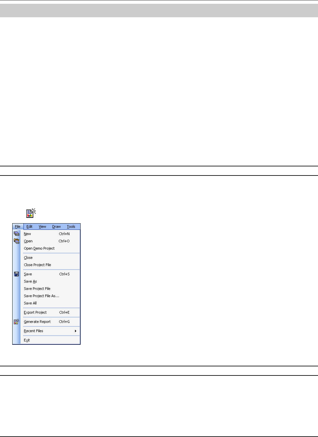
GeneratingOutputfromPlanner
3Com®AirProtectPlannerUserGuide
104
Chapter9 GeneratingOutputfromPlanner
Plannergeneratesacomprehensivereportgivingthearchitect’sdrawings,BoMforWLANdevices,informationaboutAPs’
andSensors’configuration,originallayouts,andallthesecurityexposureandnetworkcoverageRFviewsgeneratedduring
planning.Italsoreplayscustomerinputasareadyreference.Thereportisconfigurablewherebyyoucanselectanyofthe
aboveforinclusioninthereport.Forexample,youmaywanttorestrictthereporttoonlyBoMorsecurityanalysis(leaving
outnetworkdetails).ThereportisgeneratedinMSWORD.ThecompliancereportisgeneratedintheXMLformat.
Contentsofthegeneratedreportsare:
• BoM(BillofMaterial):ContainsatabulatedlistofAPsandSensorsplacedonthelayoutalongwiththelocationon
thefloormap.Thisreportisusefultounderstandtheequipmentrequirementandplacement.
• IntroductionReport:Explainstheentireprocessfromthecustomerinputtothe3ComCorporationoutput.Italso
describesthePlanningMethodologyandObjectives,thegeneralassumptionsmadeformodelingaWLAN,andthe
observationsthatyoucanmakebasedontheRFplan.
• ComplianceReport:ContainstheconfigurationdetailsofAPsandSensorsplacedonthelayout.Youcanimportthis
reportintoaWLANController,sothatyoudonothavetoreconfigurethecontrollersforAPsandSensors.Thereis
nospecificindustryformatforthiskindofreportandhence3ComCorporationhasdecidedthisformat.
• LayoutReport:ContainsdetailsoftheWorkOrder,WLANCoverageMap,SecurityExposureMap,APCoverage
RedundancyMap,LinkSpeedMap,ChannelAllocationMap,SensorCoverageMap,SensorExternalMap,and
SensorRedundancyMap.
Note:You cannotgenerateanyreportwithoutcompletingthecalculationsforalltheRFviews.
9.1 WLANPlanningReport
YoucangenerateaWLANplanningreportintwoways:
1 GotoFileÆGenerateReport.
2 ClickontheToolbar.
Figure 136. Generate Report: Invoking from File Menu
Note:Ifyouhavenotsavedtheprojectfileforwhichyouaretogenerateareport,Plannerpromptsyoutodoso.
ThisdisplaystheGenerateReportdialogbox.
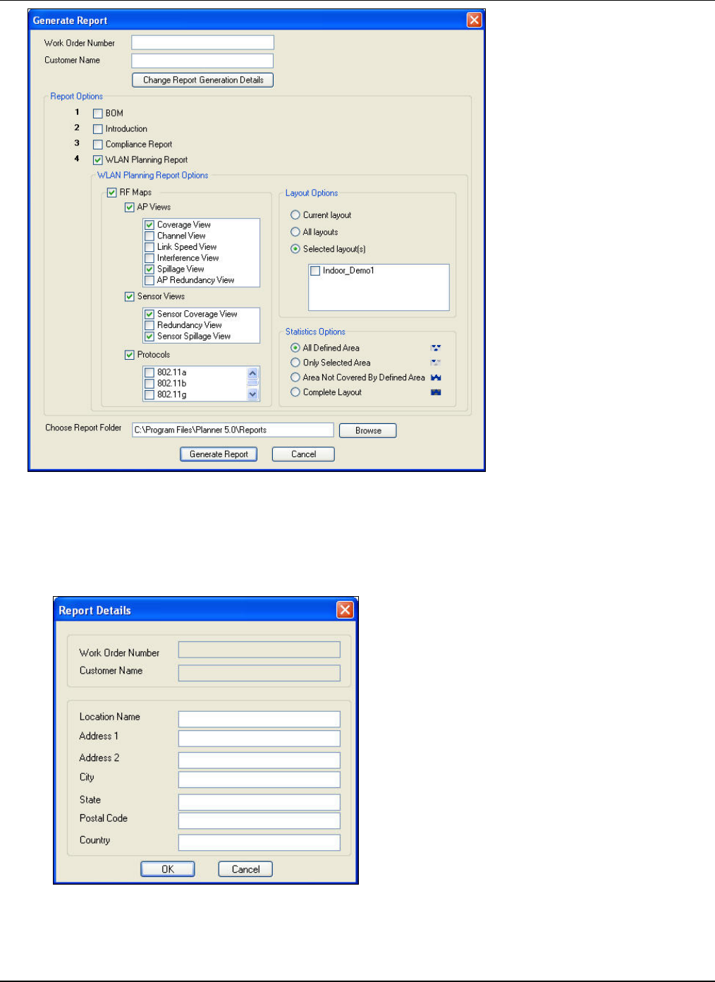
GeneratingOutputfromPlanner
3Com®AirProtectPlannerUserGuide
105
Figure 137. Generating a Report
Enterthedetailstogeneratethereport.
• WorkOrderNumber:Entertheworkordernumber.
• CustomerName:Enterthenameofthecustomerforwhomyouaregeneratingthereport.
• Click<ChangeReportGenerationDetails>tochangethereportdetails.TheReportDetailsdialogboxappears.
Figure 138. Report Details
GeneratingOutputfromPlanner
3Com®AirProtectPlannerUserGuide
106
YoucannotedittheWorkOrderNumberandCustomerNamefieldsfromthisscreen.However,youcaneditthe
followingdetailsofthereport:
¾ LocationName:Specifythedesirednameofthebuilding
¾ Address1,Address2:Specifythedesiredaddressofthelayout
¾ City:Specifythecitywherethelayoutislocated
¾ State:Specifythestatewherethelayoutislocated
¾ PostalCode:Specifythepostalcodeoftheplacewherethelayoutislocated
¾ Country:Specifythecountrywherethelayoutislocated
Click<OK>tosavethechanges.Alternately,click<Cancel>todiscardthechanges.
• ReportOptions:SelecttheoptionsthatyouwantPlannertoincludeintheReport.
¾ BoM:SelecttoincludetheBillofMaterial.
¾ Introduction:SelecttoaddanintroductiononWLANtotheoverallreport.
¾ ComplianceReport:Selecttogenerateacompliancereportfordevices,mentioningdevices’configuration.
¾ WLANPlanningReports:SelecttoincludeacompletesetofRFmaps.Thisenablesyoutoselectthefollowing
WLANPlanningoptionsinthereport.
RFMaps:Youcanselectoneormoreoftheavailableviewsforthefollowing:
APViews
SensorViews
Protocols
LayoutOptions:Plannergeneratesareportforoneofthebelowspecifiedlayouts:
CurrentLayout
AllLayouts
SelectedLayout(s):Selectthecheckboxofthedesiredlayout.
StatisticsOption:Selecttoviewthestatisticsforthefollowingoptions:
AllDefinedArea
OnlySelectedArea
AreanotCoveredbyDefinedArea
CompleteLayout
• ChooseReportFolder:Specifythepathtothefolder,orclick<Browse>tonavigatetothefolderwhereyouwantto
placethereportoutput.TheBrowseforFolderdialogboxappearswhereyoucannavigatetothedesiredfolder.
Figure 139. Browsing for Folder
Click<GenerateReport>togeneratethereport.Alternately,click<Cancel>todiscardtheaction.

AppendixA:PlanningSensors
3Com®AirProtectPlannerUserGuide
10
7
AppendixA:PlanningSensors
InadditiontoPlanner,3ComCorporationalsohasacomplementaryproductcalled3Com®AirProtectEnterprise.3Com®
AirProtectEnterprisemonitorsandprotectsthecorporatenetworkthatincludesbothwiredandwirelessdevices.3Com®
AirProtectEnterpriseconsistsoftwomaincomponents—3Com®AirProtectEnterpriseServerand3Com®AirProtect
EnterpriseSensors(Sensors).The3Com®AirProtectEnterpriseServeractsasadatabaseandthecoordinationcenterfor
variousSensors.SensorsareRFsniffingdevicesconnectedthroughoutthecorporatenetwork.3Com®AirProtectEnterprise
collectsinformationfrommultipleSensors.Ithastheintelligencetoaggregate,correlate,andanalyzeinformationfromthe
SensorsbeforepresentingitonaWebbrowser.
Inordertoobtaincompletemonitoringandprotectioncoveragethroughoutthecorporatenetwork,theentireairspacemustbe
coveredbySensors.PlannerprovidestheabilitytoplantheplacementofSensorsandimportthesecurityplansinto3Com®
AirProtectEnterprise.
PlacementofSensors
YoucanplaceSensorsontheLayoutwhenyouareinanyofthefollowingviews:
• APViews:CoverageView,ChannelView,LinkSpeedView,InterferenceView,RedundancyView,SINRView
• SensorViews:CoverageView,ThreatView,RedundancyView
• CalibrationView
UsethefollowingstepstoplaceaSensoronthelayout:
1 GotoDeviceLibraryÆSensors.
2 DragaSensorfromtheSensornodeandplaceitonthelayout.
3 RecalculatethecoverageafteryouhaveplacedtheSensoronthelayout.
Note:IfyouhaveplacedonlySensorsonthelayout,youcanperformthecalculationsonlyintheSensorviewsandnotintheAPviews.
HoweverifyouhaveplacedbothAPsandSensors,thenyoucanperformthecalculationsinanyoftheviews,andviewtherespective
devicecoverageintherespectiveview.
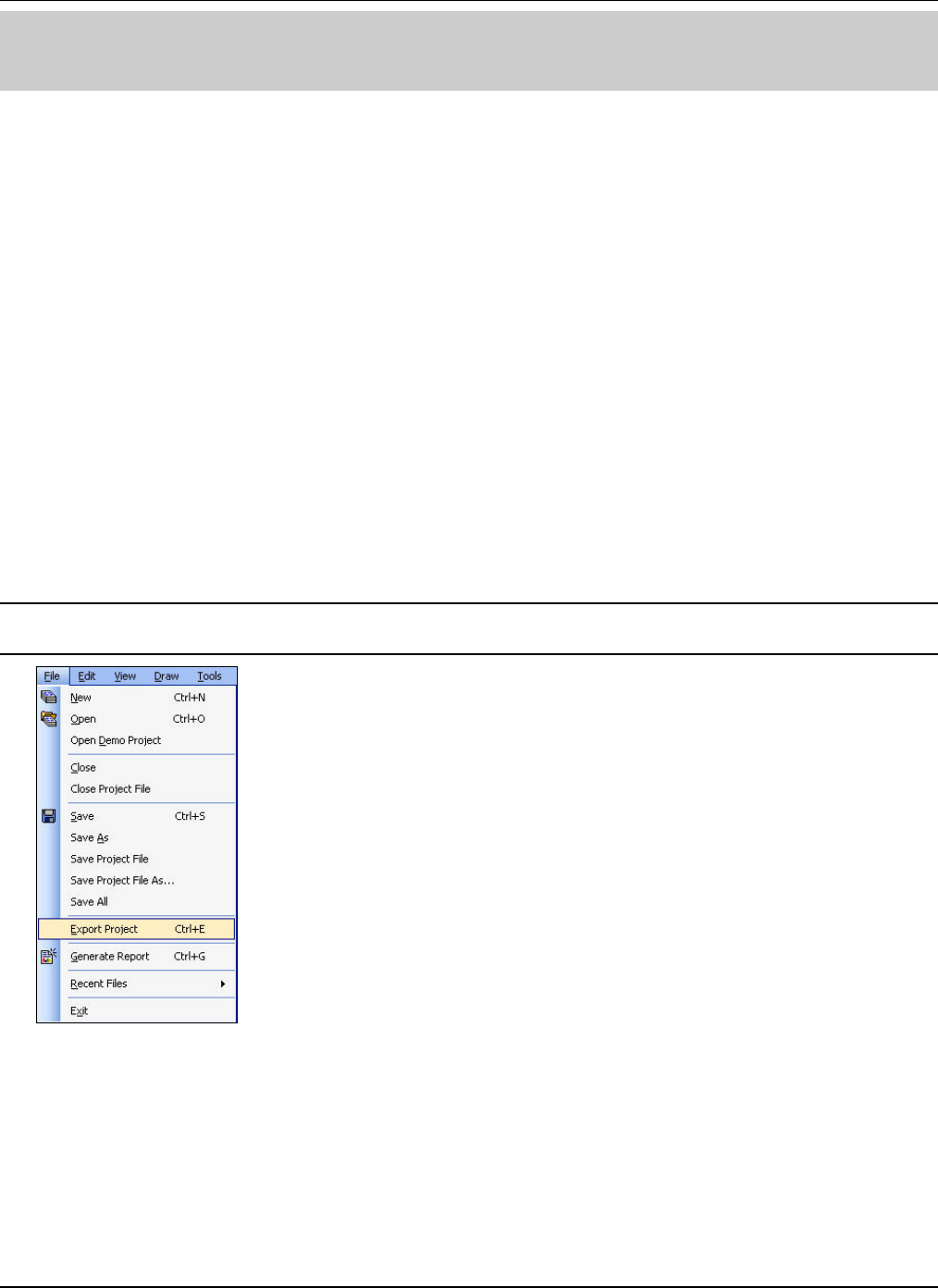
AppendixB:Integrationof3Com®AirProtectPlannerand3Com®AirProtectEnterprise
3Com®AirProtectPlannerUserGuide
108
AppendixB:Integrationof3Com®AirProtectPlannerand3Com®
AirProtectEnterprise
3Com®AirProtectEnterprisemonitorsandprotectsthecorporatenetworkthatincludesbothwiredandwirelessdevicesona
24x7basis.Twokeyfeaturesof3Com®AirProtectEnterpriseare:
• LiveRFViews:EnablesyoutotakeliveRSSIreadingsfromtheSensorstoshowliveRFcoveragemapsforany
layout.
• Locationtrackingonalayout:Enablesyoutotrackthelocationofanydeviceonalayout.
Toenhanceaccuracyofthesefeaturesin3Com®AirProtectEnterprise,youcanoptionallyexportalayoutcreatedinPlanner.
ExportingtheProjectfromPlanner
TheExportProjectfeatureenablesyoutopackagethecurrentprojectintoa.zipfile.Youmightwanttoexportaprojectforthe
followingreasons:
• Toimporttheprojectinto3Com®AirProtectEnterprise
• ToimporttheprojectintosomeothersystemwherePlannerisrunning
Whileexportingtheprojectyouhaveanoptiontoexportthepreferencesofyoursystemaswell.Whenyouopentheexported
projectinanothersystemwithPlannerinstalled,thisoptionhelpsyoutooverridethepreferencesintheothersystemtoget
thesameenvironmentthatyouusedwhileplanningtheproject.
Whileexporting,thefollowingfiles:.spm,images,andpreferences(ifselected)arepackagedintoasinglefile.
Usethefollowingstepstoexporttheproject:
1 GototheLayoutDesignerscreenofPlanner.
2 GotoFileÆExportProject.
Note:You canonlyexportthecurrentlayout.YoucannotexportthelayoutfromtheAPSpillage,SensorSpillage,andCalibrationViews
intheNetworkPlanner.
Figure 140. Exporting the Planner Project
TheExportdialogboxappears.
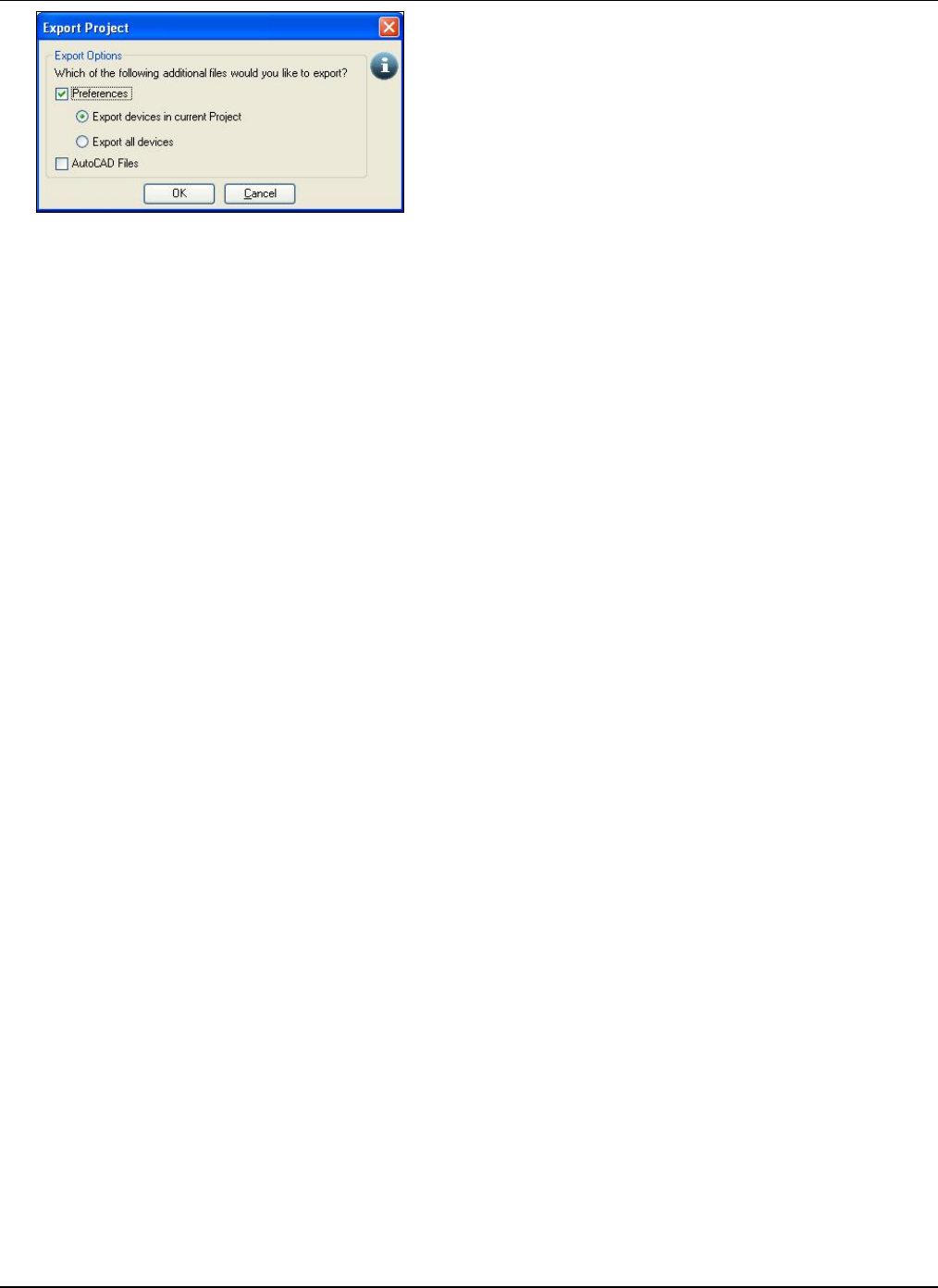
AppendixB:Integrationof3Com®AirProtectPlannerand3Com®AirProtectEnterprise
3Com®AirProtectPlannerUserGuide
109
Figure 141. Export Options
TheExportdialogboxcontainstheExportOptions.Thisenablesyoutoselectthefilesandpreferencesyouwishtoexport.
• Preferences:Selectthecheckboxtoexporttheprojectwithallthepreferences.
Selecteitheroftheexportoptions:
¾ ExportdevicesincurrentProject:ExportsdevicesinthecurrentProjectfile
¾ Exportalldevices:Exportsallthedevices
• AutoCADFiles:SelectthecheckboxtoexporttheAutoCADfiles.
Click<Ok>toexportandsavetheproject.Alternately,click<Cancel>todiscardtheExportaction.
TheProjectZipExportSummaryViewerscreenappears.
AppendixC:FileLevelandApplicationLevelParameters
3Com®AirProtectPlannerUserGuide
110
AppendixC:FileLevelandApplicationLevelParameters
ThefollowingsectionpresentsanoverviewoftheFilelevelandtheApplicationlevelparameters.
Table 1 File Level Parameters
File Level Parameters Data Type Default Value Minimum Maximum
Accuracy Integer 1 1 4
RSSI Calibration Integer -10 dB -40 dB 40 dB
Spillage Factor Positive Integer 2 2 3
Min Attenuation Factor Real 2 1.6 4
Max Attenuation Factor Real 2 1.6 4
Alpha Real -4 Not applicable Not applicable
Beta Real 0.08 Not applicable Not applicable
Table 2 Application Level Parameters
Application Level
Parameters Data Type Default Value Minimum Maximum
Coverage Estimation
Thresholds Integer -40, -50, -55, -60
dBm -100 dBm -10 dBm
Sensor Detection
Threshold Integer -85 dBm -150 dBm -20 dBm
Sensor Redundancy Integer 1 1 10
Sensor Prevention
Thresholds Integer -65, -60, -55 dBm
(low<medium<high) -150 dBm -20 dBm
Device Transmit Power Integer 13 0 20
Channel View Threshold Integer -85 dBm -150 dBm -20 dBm
AP Redundancy Integer 1 1 10
Inadditiontotheseparameters,Planneralsohasthefollowingapplicationlevelparameters:
1 RegionSettingsinToolsÆSettingsÆPreferencesÆAPViews
2 DefaultAccessPointSettings
3 AutoChannelSelect
4 ‘Donotshowthiswindowagain’messages
5 ColorPalettes
6 ReportBaseFolder
Note:ThedefaultinstallationvaluesareselectedwhenyouinstallanewversionofPlanner.

AppendixD:GlossaryofTerms
3Com®AirProtectPlannerUserGuide
111
AppendixD:GlossaryofTerms
ThissectionprovidesaquickreferencetowirelessnetworkingandPlannerrelatedtermsandabbreviationsusedinthisguide.
Table 3 Glossary of Terms
Term Definition Description
802.11 802 Series LANs The IEEE 802.11 is a standard for WLANs. This
standard is continuously developed to provide
better and higher transmission rates.
AP Access Point An AP is an interface between wireless and wired
networks. It connects wireless Clients with an
Ethernet to extend their range.
BoM Bill of Material
Bill of Material is a detailed report that contains
network inventory along with the placement of
APs and Sensors throughout the site. It displays a
list of APs and Sensors on each layout, their
configuration, the Vendor/Model Number, the
protocol used and its distance from the North-
West corner.
Channel Interference
Channels are important to understand because
they affect the overall capacity of the Wireless
LAN. A channel represents a narrow band of radio
frequency. A radio frequency modulates within a
band of frequencies; as a result of which there is a
limited amount of bandwidth within any given
range to carry data. It is important that the
frequencies do not overlap or else the throughput
would be significantly lowered as the network
sorts and reassembles the data packets sent over
the air.
The 802.11b specification operates at radio
frequencies in the 2.4 to 2.497 GHz range and
supports overlapping channels of 22 MHz each.
The frequency ranges and channels vary based on
the regulatory standards adopted by a country.
For instance, in the US, the FCC standard allows
up to 11 channels whereas in Europe the ETSI
standard allows up to 13 channels.
When there are more than one source
transmitting on a radio frequency simultaneously,
the receiver sees more than its partner source.
The receiver will have difficulties distinguishing
one from the other and the data will be lost. This
is interference. Channels you chose for the Clients
and APs are susceptible to interference. Therefore,
it is important to ensure you are on the correct
frequency by selecting appropriate channels for
the APs.
Layout Model
The model of the
Layout with all the
object placements
defined
After you import the layout image into Planner,
the Layout Designer helps designing the Layout
Model. The Layout Model is a ready layout of the
entire layout for which you are performing WLAN
planning. The Layout Model contains all the
objects, locations of walls, windows, and doors
with the details of the materials used in it.
Layout Image A .jpg, .gif image file of
the Layout
In the context of Planner, a Layout Image serves
as the primary input to the entire planning
process.
RF Calculation Cell Size Granularity of the RF
computations of the
WLAN signal strength
When you create a new plan, Planner determines
the granularity of the RF computations of the
WLAN signal strength distribution throughout the
plan. It divides the plan into small units and then
calculates the RF characteristics for each unit. The

AppendixD:GlossaryofTerms
3Com®AirProtectPlannerUserGuide
112
size of a unit determines the granularity of the RF
computations and computational time. Smaller the
size of the unit, higher is the granularity.
However, this requires more time for WLAN signal
computations. Higher granularity also increases
the amount of data generated. The dimension of
each unit is called ‘Factor’. A Factor of four means
that the plan is divided into 4x4 feet or 4x4
meters as per the measurement unit in use.
Planner has an in-built intelligent algorithm to
decide the granularity based on the size of the
plan.
LAN Local Area Network A LAN usually resides in a single building or
campus, and links the computing resources
together, typically by a cable.
Network Planner A tool for planning the
WLAN in Planner
Network Planner helps you design the entire
layout with the specifications of the locations of
the objects on the layout. It also helps you plan
the entire network after the placement of objects
on the layout is fixed. It allows you to drag and
drop the devices such as APs and Sensors on the
layout model. This helps you try various ‘What-If’
scenarios. You can also generate various RF
views.
RF Radio Frequency This is a name given to invisible electromagnetic
waves.
RSSI Received Signal
Strength Indicator This is an indicator of the value of the signal
strength at a wireless receiver.
3Com ® AirProtect
Enterprise
A proprietary product of 3Com Corporation that
functions as a comprehensive Wi-Fi Intrusion
Prevention System and Performance Management
Solution.
3Com ® AirProtect
Enterprise Sensors Sensors are devices that work with the 3Com ®
AirProtect Enterprise Server to provide 802.11
Intrusion Detection and Prevention.
Spillage Propagation of signal
outside a stipulated
area
In Planner, spillage refers to the propagation of RF
signal outside the authorized area of deployment.
Such spillage exposes the authorized area to the
risk of attacks from hackers using Wi-Fi.
.spm file Planner File This is the proprietary Planner file format, which
holds information about RF signal values,
placement of devices, and device settings.
.prj file Planner Project File This is the propriety Planner project file, which
contains a bundle of .spm, image, and AutoCAD
files.
WAN Wide Area Network It is a public and private network serving a large
geographical area. For example, the Internet.
Wi-Fi Wireless Fidelity
Wi-Fi is a commonly used name to refer to
802.11. It is a trade term promulgated by the
Wireless Ethernet Compatibility Alliance (WECA).
"Wi-Fi" is used in place of 802.11b in the same
way that "Ethernet" is used in place of IEEE
802.3. Products certified as Wi-Fi by WECA are
interoperable with each other even if they are
from different manufacturers. A user with a Wi-Fi
product can use any brand of AP with any other
brand of Client hardware that is built to the Wi-Fi
standard.
802.11a Wireless Protocol
When 802.11b was developed, IEEE created a
second extension to the original 802.11 standard
called 802.11a. 802.11a works in the ~5 GHz
frequency band and provides wireless connectivity
speeds of up to 54 Mbps.
802.11b Wireless Protocol IEEE expanded on the original 802.11 standard in
July 1999, creating the 802.11b specification.

AppendixD:GlossaryofTerms
3Com®AirProtectPlannerUserGuide
113
802.11b supports bandwidth up to 11 Mbps.
802.11b uses the same radio signaling frequency
– 2.4 GHz, as the original 802.11 standard. Being
an unregulated frequency, 802.11b gear can incur
interference from microwave ovens, cordless
phones, and other appliances using the same 2.4
GHz range. However, you can easily avoid
interference by installing 802.11b gear at a
reasonable distance from other appliances.
Vendors often prefer using unregulated
frequencies to lower their production costs.
802.11g Wireless Protocol
In 2002 and 2003, WLAN products supporting a
new standard called 802.11g began to appear on
the scene. 802.11g attempts to combine the best
of both 802.11a and 802.11b. 802.11g supports
bandwidth up to 54 Mbps, and it uses the 2.4 GHz
frequency for greater range. 802.11g is
backwards compatible with 802.11b, which means
that 802.11g APs will work with 802.11b Wireless
Network Adapters and vice versa.
802.11n Wireless Protocol
This is an emerging standard for wireless local
area networks that promises higher data rates and
longer range as compared to its predecessors
802.11a, b, and g. 802.11n brings many new
features at the medium access control and
physical layers (for example, multiple-input-
multiple-output (MIMO), wider 40 MHz channels,
frame aggregation).
MIMO configuration Multiple-Input-Multiple-
Output configuration
Multiple-Input-Multiple-Output (MIMO) stands for
multiple radio chains at the transmitter and
receiver, often depicted as n x m, where n is the
number of transmitting radios and m is the
number of receiving radios. MIMO can be
leveraged in many ways for increasing the range
of a WLAN using spatial diversity and for
increasing the data transmission rate using spatial
multiplexing. Spatial diversity is achieved by
transmitting or receiving copies of the same signal
over multiple radios. Spatial multiplexing is
achieved by transmitting and receiving unique
data streams over multiple radios. The maximum
number of spatial streams is limited by min (n,
m), that is, the minimum among the number of
radio chains at the transmitter and receiver. IEEE
802.11n draft 2.0 makes it mandatory for APs to
support a minimum of two spatial streams and
support for up to four streams optionally.
Channel width
Legacy 802.11 protocols operate on 20 MHz
channels. IEEE 802.11n allows bonding of two 20
MHz channels so that a net channel width of 40
MHz can be used. In 40 MHz mode, one channel is
assigned as the “primary” channel and the other is
assigned as the “secondary” channel. The
secondary channel is identified as “upper” or
“lower” with respect to the primary channel. For
example, in 2.4 GHz, if channel 6 is the primary
channel then channel 10 could be assigned as the
upper secondary and channel 2 as the lower
secondary channel.
Guard Interval (GI)
The guard interval is the spacing between
consecutive symbol transmissions. IEEE 802.11n
draft 2.0 prescribes a mandatory long Guard
Interval of 800 ns and an optional short Guard
Interval of 400 ns.

AppendixD:GlossaryofTerms
3Com®AirProtectPlannerUserGuide
114
MCS Modulation and Coding
Schemes
IEEE 802.11n draft 2.0 defines 77 MCS based on
the modulation technique, coding rate, number of
spatial streams, channel width, and guard
interval. The mandatory settings of 20 MHz
channel width, 800 ns guard interval, and up to
two spatial streams gives a total of 16 mandatory
schemes (MCS 0 to 15).
Frame aggregation
Frame aggregation is introduced in IEEE 802.11n
for improving the protocol efficiency. Aggregation
is defined at two levels: Medium Access Control
(MAC) and physical (PHY) layers. At the MAC
layer, Multiple MAC Service Data Units (MSDUs) or
subframes are aggregated and an aggregated
MSDU (A-MSDU) is delivered to the PHY layer for
transmission. The maximum A-MSDU size can be
set to 4KB or 8KB; the maximum MSDU size
carried in each subframe is limited to 2304 bytes.
At the PHY layer, Multiple Protocol Data Units
(MPDUs) or subframes can be aggregated into an
aggregated MPDU (A-MPDU). The maximum size
of an A-MPDU is 64 KB or 64 subframes,
whichever limit is reached first. The maximum
MPDU size carried in each subframe of an A-MPDU
is limited to 4065 bytes.
Regulatory Domain
Compliance
Different countries have regulatory agencies
permitting a select number of channels for device
protocols. Hence, the power values of the devices
placed on the floor map will operate only on those
power values that match that of the respective
country where you are planning.
While specifying the desired power range for each
protocol, ensure that the values are complaint
with the regulatory domain for a particular
country for which you are performing planning.
If you create a .spm file in one location and forget
to send the device information along with the
.spm to another location, then the Client at the
second location will not be able to view the device
information of the previous location. In such a
case, Planner assigns the default device, as
defined by you, in the .spm. If this device has
power values conflicting with the regulatory
domain compliance of the region, then Planner
assigns the factory default device, which is
regulatory domain complaint for any region.
