Hp Blackbird 002 01A Gaming System Upgrade And Service Guide Ma7usgbook_blkbird
2015-01-05
: Hp Hp-Blackbird-002-01A-Gaming-System-Upgrade-And-Service-Guide-167926 hp-blackbird-002-01a-gaming-system-upgrade-and-service-guide-167926 hp pdf
Open the PDF directly: View PDF ![]() .
.
Page Count: 58
- Table of Contents
- Upgrading and Servicing Guide

Upgrading and Servicing Guide
The only warranties for Hewlett-Packard products and services are set forth in the express
statements accompanying such products and services. Nothing herein should be construed as
constituting an additional warranty. HP shall not be liable for technical or editorial errors or
omissions contained herein.
HP assumes no responsibility for the use or reliability of its software on equipment that is not
furnished by HP.
This document contains proprietary information that is protected by copyright. No part of this
document may be photocopied, reproduced, or translated to another language without the prior
written consent of HP.
Hewlett-Packard Company
P.O. Box 4010
Cupertino, CA 95015-4010
USA
Copyright © 2007 Hewlett-Packard Development Company, L.P.
This product incorporates copyright protection technology that is protected by U.S. patents and
other intellectual property rights. Use of this copyright protection technology must be authorized by
Macrovision, and is intended for home and other limited pay-per-view viewing uses only unless
otherwise authorized by Macrovision. Reverse engineering or disassembly is prohibited.
Microsoft and Windows Vista are U.S. registered trademarks of Microsoft Corporation.
The Windows logo and Windows Vista are trademarks or registered trademarks of Microsoft
Corporation in the United States and/or other countries/regions.
HP supports lawful use of technology and does not endorse or encourage the use of our products
for purposes other than those permitted by copyright law.
The information in this document is subject to change without notice.
Table of Contents iii
Table of Contents
Upgrading and Servicing Guide ...............................................................1
Safety Information ..................................................................................................1
Opening and Closing the Computer .........................................................................1
Preparing the computer ......................................................................................2
Before opening the computer ..............................................................................2
After closing the computer ..................................................................................3
Accessing the chassis through the access door (left side).........................................3
Replacing the access door ..................................................................................8
Removing the internal covers.............................................................................11
Replacing the internal covers.............................................................................13
Accessing the chassis through the right side ........................................................14
Replacing the right side access..........................................................................18
Locating Components Inside the Computer...............................................................22
Removing and Replacing Drives .............................................................................23
Removing an optical drive ................................................................................23
Adding or replacing an optical drive .................................................................28
Removing the hard disk drive ............................................................................33
Adding or replacing a hard disk drive ...............................................................34
Adding Memory...................................................................................................35
Removing a memory module.............................................................................36
Installing a memory module ..............................................................................37
Removing and Installing an Add-in Card .................................................................39
Removing an add-in card .................................................................................39
Installing an add-in card...................................................................................42
Removing and Replacing the Power Supply .............................................................45
Removing the power supply ..............................................................................45
Replacing the power supply..............................................................................47
Removing and Replacing the SATA Backplane .........................................................49
Removing the SATA backplane..........................................................................49
Replacing the SATA backplane .........................................................................52
Replacing the Battery ............................................................................................54
iv Table of Contents
Upgrading and Servicing Guide 1
Upgrading and Servicing Guide
Safety Information
This product has not been evaluated for connection to an “IT” power system (an AC
distribution system with no direct connection to the earth, according to IEC 60950).
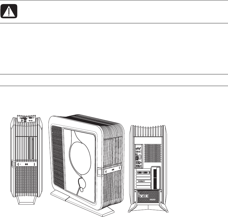
This Upgrading and Servicing Guide provides instructions for removing and replacing
hardware components of your computer.
Illustrations show either the air-cooled chassis or the liquid-cooled chassis. The specifics of
the chassis in the illustrations may vary from your computer model. Items located inside the
chassis may vary depending on your specific model computer.
Opening and Closing the Computer
WARNING: Please read “Safety Information” in the Limited Warranty and
Support Guide before installing and connecting your computer to the electrical
power system.
IMPORTANT: To upgrade your computer to liquid-cooled, contact HP Support.

2Upgrading and Servicing Guide
Preparing the computer
Before you can upgrade any component in your computer, you must prepare the computer
so that you can safely handle it and its components.
Read the following items before attempting to upgrade or service the computer:
1These procedures assume familiarity with the general terminology associated with
personal computers, and with the safety practices and regulatory compliance required
for using and modifying electronic equipment.
2Write down and save the computer model and serial numbers, all installed options,
and other information about the computer. It is easier to consult this information than
to open and examine the computer.
3It is recommended that you use an antistatic wrist strap and a conductive foam pad
when working on the computer.
Before opening the computer
To avoid injury and equipment damage, always perform the following steps, in the order
in which they are listed, before opening the computer:
1Remove any memory card or optical disc (CD or DVD) from the computer.
2Shut down the computer.
3Turn off the computer power supply by using the rocker switch on the back of the
chassis.
4Disconnect the power cord from the electrical outlet and then from the computer.
5Disconnect all other attached cables (such as the keyboard, mouse, and monitor
cables).
6Disconnect all external devices.
WARNING: Always disconnect the computer from the power source before
opening the computer or removing panels. Failure to do so before you open
the computer or do any procedures can result in personal injury or equipment
damage.
CAUTION: To reduce the risk of personal injury from electrical shock or hot
surfaces, disconnect the power cord from the wall electrical outlet, and allow
the internal computer components to cool before touching them.
CAUTION: Static electricity can damage the electronic components of the
computer or optional equipment. Ensure that you are discharged of static
electricity by briefly touching a grounded metal object.

Upgrading and Servicing Guide 3
After closing the computer
To avoid injury and equipment damage, always complete the following steps, in the order
in which they are listed, after closing the computer:
1Reconnect the power cord.
2Reconnect all the cables (such as the keyboard, mouse, and monitor cables).
3Reconnect the external devices.
4Turn on the computer power supply by using the rocker switch on the back of the
chassis.
5Turn on the computer by using the On button on the front of the chassis, and then turn
on all peripherals, such as the monitor.
6If you installed an add-in card, install any software drivers supplied by the card
manufacturer.
Accessing the chassis through the access door
(left side)
To upgrade or service the majority of components in the computer, you must access the
chassis through the access door (left side). Complete the following steps to open the left
access door, remove the door exterior inlay (when replacing it), or lift the access door off
its hinges:
1See “Before opening the computer” on page 2.
WARNING: To reduce the risk of electrical shock, fire, or damage to the
equipment, do not plug telecommunications or telephone cables into the
network interface card (NIC) (labeled as an Ethernet or LAN connector).
CAUTION: Avoid damage, when you remove the access door or the inlay,
protect the inlay by placing it onto a smooth surface covered by a soft cloth.
4Upgrading and Servicing Guide
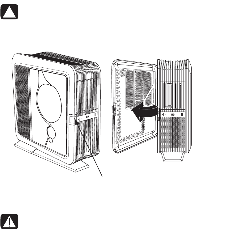
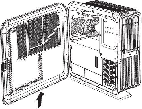
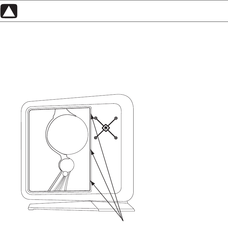
2To open the access door, lift the front edge of the door latch (A), and then swing
the door open.
The door opens until it is about 85 degrees to the chassis. Do not force the door to open
more than 85 degrees.
CAUTION: To avoid damage, do not open the access door more than
85 degrees.
WARNING: Beware of sharp edges inside the chassis.
A
Upgrading and Servicing Guide 5
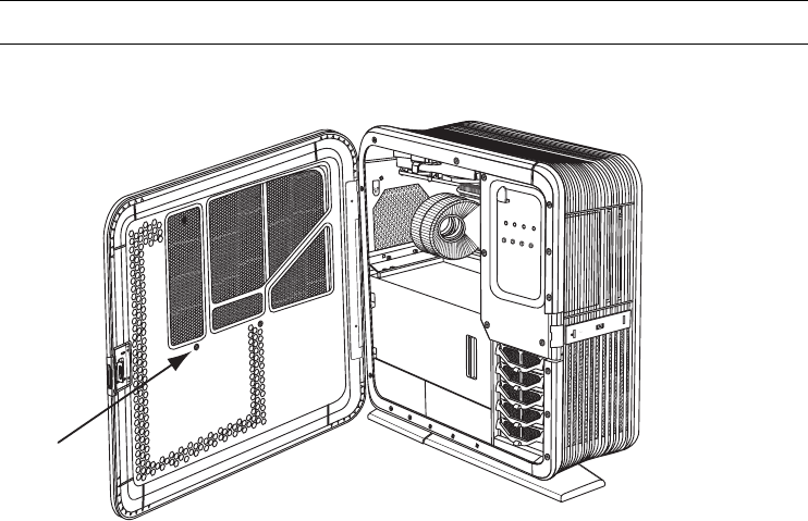
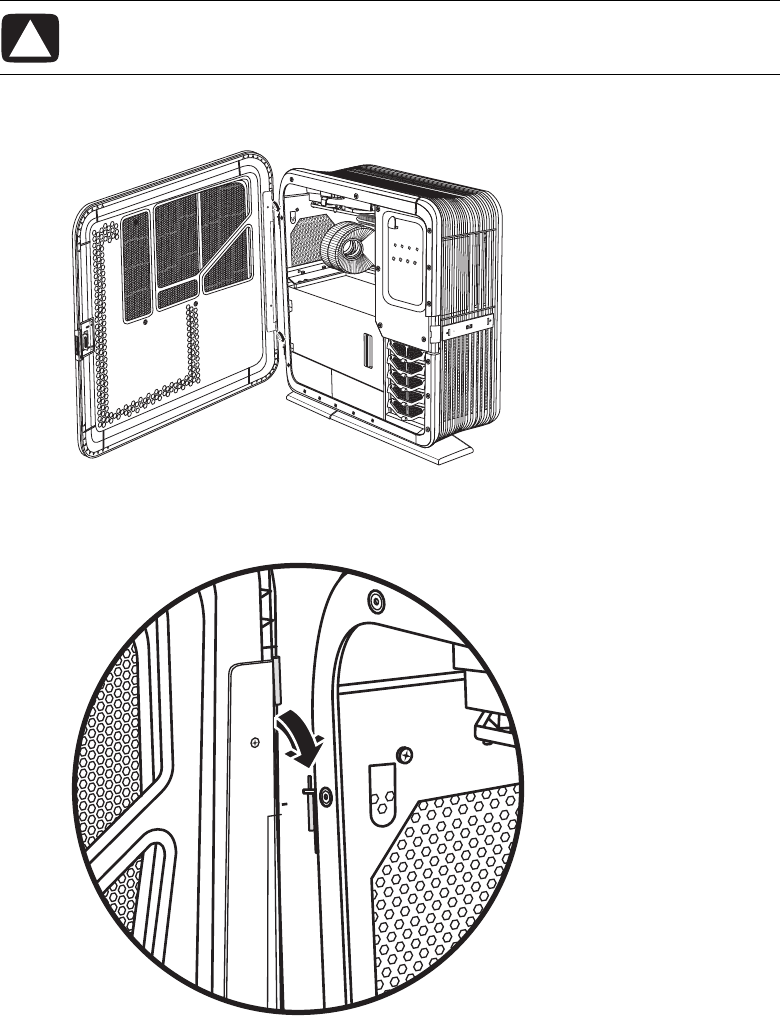
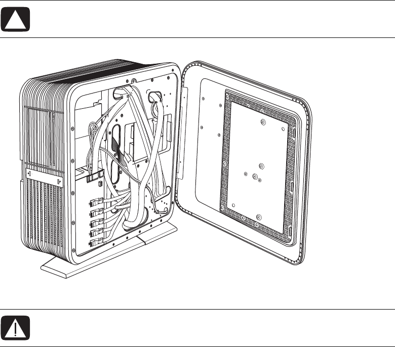
3To remove the exterior door inlay when replacing it:
aRemove the inlay screw (B) from the inside of the door.
b Close the door.
NOTE: Do not remove the access door from the chassis hinges during these steps.
B
6Upgrading and Servicing Guide
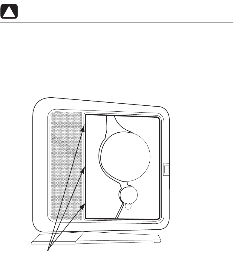
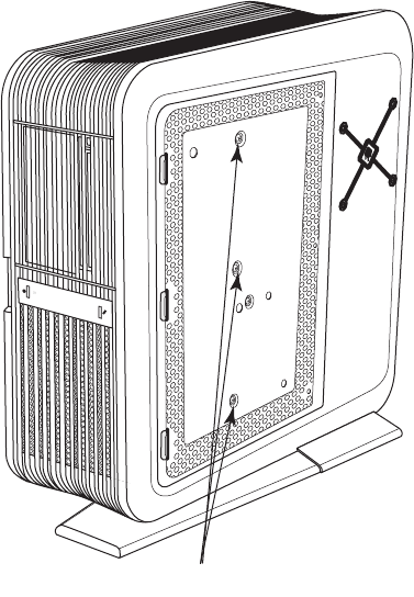
cOn the outside of the door, do the following:
aSlowly pull out the square-cornered edge of the inlay (C, near the rear of the
chassis) to free the three snaps along the left side of the inlay.
bContinue to slowly pull out the edge of the inlay to free the two columns of
three snaps located on each side of the middle of the inlay.
cHolding the inlay near to the door, slide it toward the back of the chassis to
free it.
dSet the inlay aside.
To install the inlay, see “Replacing the access door” on page 8.
CAUTION: To avoid damaging the inlay, do not pull out the inlay more than
2.54 cm (1 inch) away from the door.
C
Upgrading and Servicing Guide 7
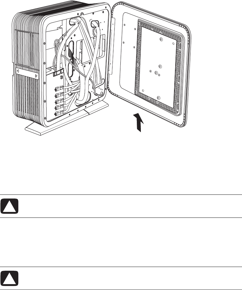
4To remove the door from the chassis hinges:
aOpen the door fully so that it is at 85 degrees to the chassis.
bLift up the door about 2.54 cm (1 inch) until the hinges clear the hinge pins.
cSet the door aside.
8Upgrading and Servicing Guide
Replacing the access door
Complete the following steps to place the left access door on its hinges, install an exterior
inlay, or close the door:
1To place the door on its hinges:
aPosition the door completely open at 85 degrees to the chassis.
bInsert the back edge of the door into the chassis, with the hinges over the
hinge pins.
CAUTION: To avoid damage, do not open the access door more than
85 degrees.
Upgrading and Servicing Guide 9
cLower the door onto the hinges.
2To install an inlay:
aIf necessary, place the door on its hinges as described in step 1.
bClose the door.
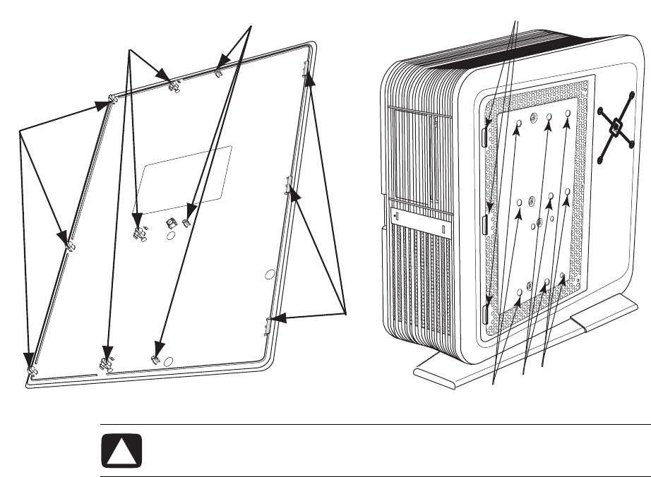
cOn the outside of the door:
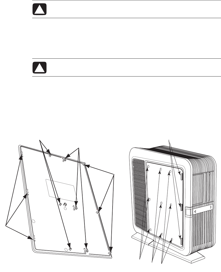
aTo vertically position the inlay with the door, align the top row of snap
studs (F) on the inlay with the top row of holes (G) in the door.
bLower the inlay onto the door just to the left of the slots (E), while maintaining
the vertical alignment.
cSlide the inlay toward the front of the chassis, inserting the three tabs (D) on
the inlay into the slots (E) in the door.
CAUTION: To avoid damaging the door, check that both of the door hinges are
properly seated onto the hinge pins.
CAUTION: To avoid damaging the inlay, do not hold or pull out the inlay more
than 2.54 cm (1 inch) away from the door.
E
GGG
D
F
F
F
10 Upgrading and Servicing Guide
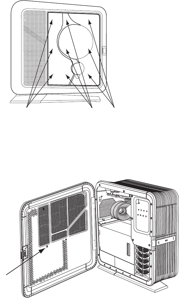
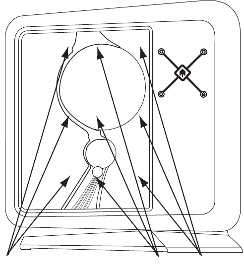
dWith the inlay near to the door, check that the snap studs (F) on the inlay align
with the holes (G) in the door; adjust the inlay position up or down as needed.
eSlowly press the inlay from top to bottom just to the left of the edge of the
inlay (H) to engage the first column of snap studs.
fMove toward the middle of the inlay, and press the inlay from top to bottom
again, to engage the second column of snap studs (I).
gMove near the left edge of the inlay, and press the inlay from top to bottom
again, to engage the last column of snap studs (J).
dOpen the door.
eInsert the inlay screw (B) on the inside of the door.
JH
I
B
Upgrading and Servicing Guide 11
3To close the door, check that the internal covers are in place (see “Replacing the
internal covers” on page 13), and then swing the door toward the front of the chassis
until the latch locks.
4See “After closing the computer” on page 3.
Removing the internal covers
Complete the following steps to access the components inside the chassis by removing the
internal covers (PCI door, thermal divider, and power supply baffle):
1Open the access door. See “Accessing the chassis through the access door (left side)”
on page 3.
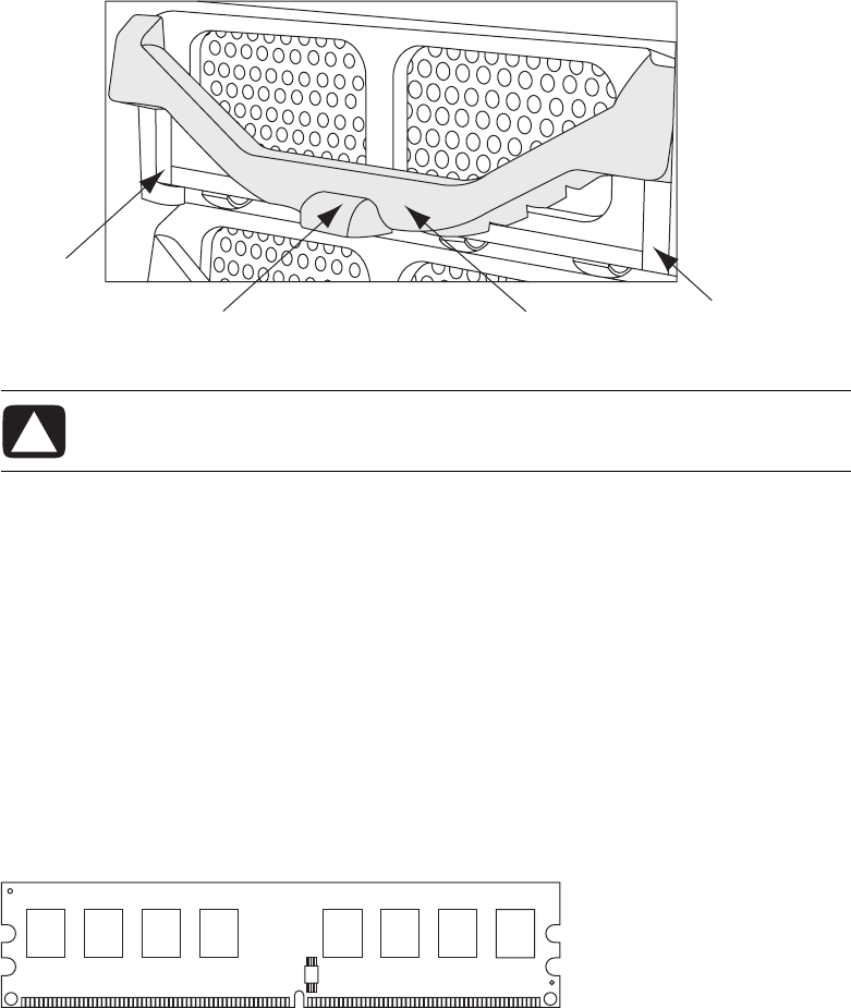
2Open the PCI door by moving the latch (K) to the left, and then swinging the door
open. If necessary, lift up the door to remove it from the hinges.
M
L
K
12 Upgrading and Servicing Guide
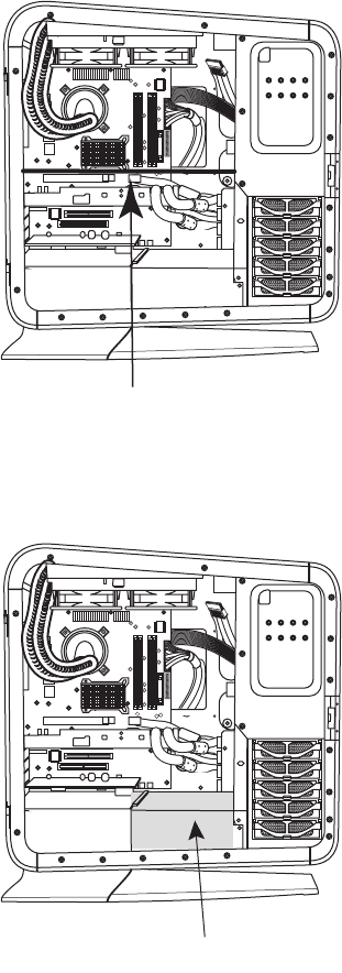
3Remove the thermal divider (L) by pulling it straight out of the chassis.
4Remove the power supply baffle by pulling the baffle (M) straight out of the
chassis.
L
M
Upgrading and Servicing Guide 13
Replacing the internal covers
1Replace the power supply baffle by positioning the baffle onto the guide rails
(M1), and then sliding the baffle straight into the chassis.
2Replace the thermal divider by positioning the divider onto the guide rails (L1),
and then sliding the divider straight into the chassis.
3Replace the PCI door:
aHold the door perpendicular (at 90 degrees) to the chassis, with the hinges over
the hinge pins, and then lower the door onto the pins.
bSwing the door closed.
CAUTION: To avoid damaging the PCI door, check that both of the door hinges
are properly seated onto the hinge pins before closing the door.
L1
M1
14 Upgrading and Servicing Guide
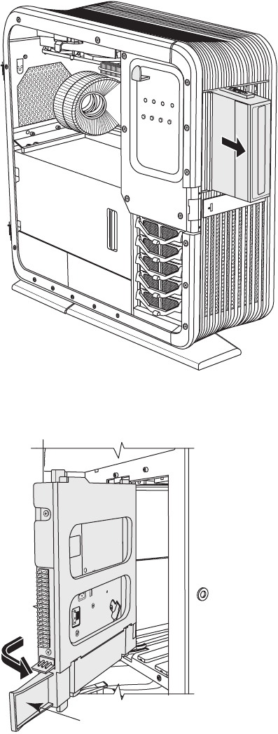
Accessing the chassis through the right side
Complete the following steps to access the right side of the chassis to replace the inlay or
the SATA backplane. You must remove the inlay to access the SATA backplane.
1Loosen the inlay screw (N) from the inside of the chassis.
CAUTION: To avoid damage, when you remove the inlay, protect the inlay by
placing it onto a smooth surface covered by a soft cloth.
NOTE: The inlay screw (N) is a captive screw. Do not remove it from the chassis.
N
Upgrading and Servicing Guide 15
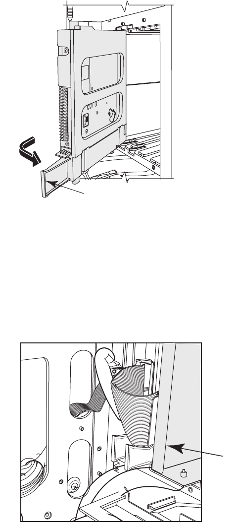
2On the right side of the chassis, do the following:
aSlowly pull out the square-cornered edge of the inlay (O, near the rear of the
chassis) to free the three snaps along the right side of the inlay.
bContinue to slowly pull out the edge of the inlay to free the two columns of three
snaps located on each side of the middle of the inlay.
cHolding the inlay near to the panel, slide the inlay toward the back of the chassis
to free it.
dSet the inlay aside.
This completes the steps to remove the inlay. Continue with step 3 to access the SATA
backplane.
To install the inlay, see “Replacing the right side access” on page 18.
CAUTION: To avoid damaging the inlay, do not pull out the inlay more than
2.54 cm (1 inch) away from the panel.
O

16 Upgrading and Servicing Guide
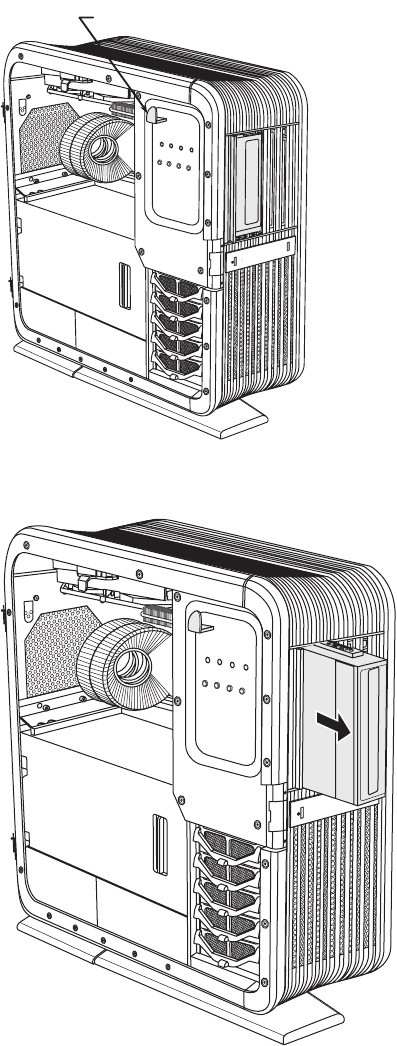
3To open the right access panel:
aRemove the three screws (P) that secure the panel.
bSwing open the panel.
P
Upgrading and Servicing Guide 17
The access panel opens until it is about 85 degrees to the chassis. Do not force the
panel to open more than 85 degrees.
CAUTION: To avoid damage, do not open the panel more than 85 degrees.
WARNING: Beware of sharp edges inside the chassis.
18 Upgrading and Servicing Guide
cIf necessary, lift the panel off the hinges.
Replacing the right side access
Complete the following steps to replace the panel and the inlay on the right side of the
chassis. If you remove the inlay only, skip to step 4.
1To place the panel on its hinges:
aPosition the panel at 85 degrees to the chassis.
bInsert the back edge of the panel into the chassis with the hinges over the
hinge pins.
cLower the panel onto the hinges.
2Close the panel.
CAUTION: To avoid damage, do not open the access panel more than
85 degrees.
CAUTION: To avoid damaging the panel, check that both of the panel hinges
are properly seated onto the hinge pins before closing the panel.
Upgrading and Servicing Guide 19
3Insert three screws (P) to secure the panel.
P
20 Upgrading and Servicing Guide
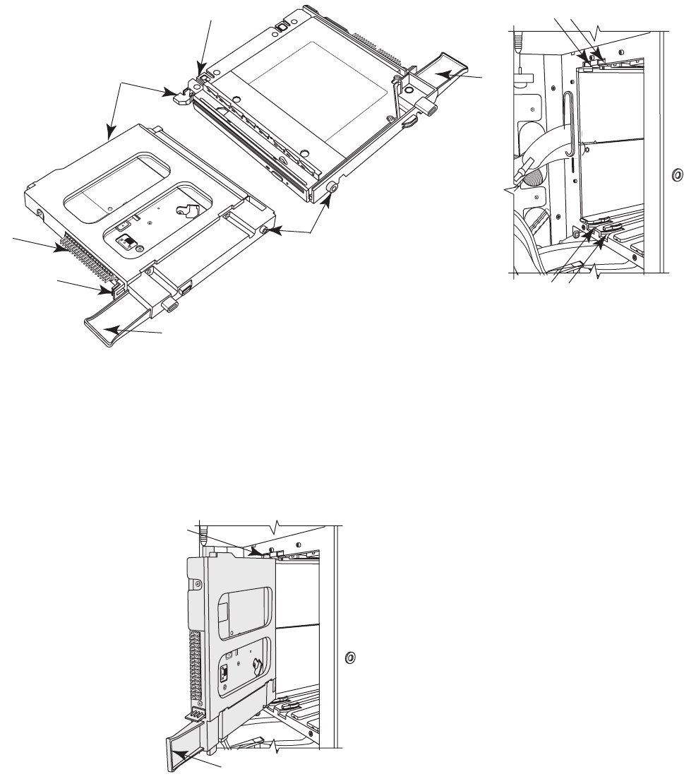
4To install an inlay:
aTo vertically position the inlay with the panel, align the top row of snap studs (Q)
on the inlay with the top row of holes (R) in the panel.
bLower the inlay onto the panel just to the right of the slots (T), while maintaining
the vertical position.
cSlide the inlay toward the front of the chassis inserting the three tabs (S) on the
inlay into the slots (T) in the panel.
T
RRR
S
Q
Q
Q
CAUTION: To avoid damaging the inlay, do not hold or pull out the inlay more
than 2.54 cm (1 inch) away from the panel.
Upgrading and Servicing Guide 21
dWith the inlay near to the panel, check that the snap studs (Q) on the inlay align
with the holes (R) in the panel; adjust the inlay position up or down as needed.
eSlowly press the inlay from top to bottom just to the right of the edge of the
inlay (U), to engage the first column of snap studs.
fMove toward the middle of the inlay, and press the inlay from top to bottom again
to engage the second column of snap studs (V).
gMove near the right edge of the inlay and press the inlay from top to bottom again
to engage the last column of snap studs (W).
UWV
22 Upgrading and Servicing Guide
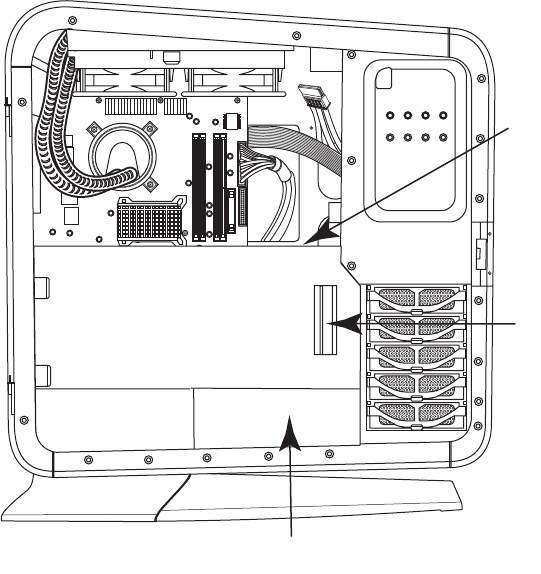
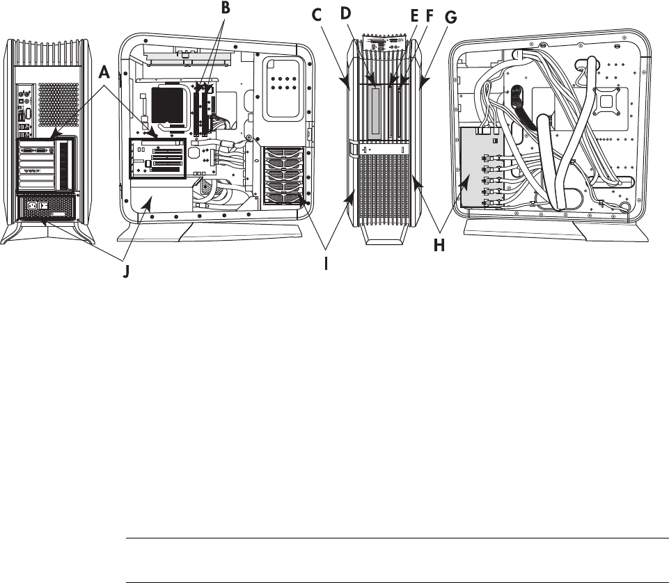
Locating Components Inside the Computer
AAdd-in cards: PCI and PCI-E slots
BMemory
CAccess door (left side) with inlay
D5.25-inch bay for an optional full-size optical disc drive or other 5.25-inch device
ESlim optical disc drive (optional drive)
FSlim optical disc drive
GAccess panel (right side) with inlay
HSATA backplane (including the LED switch settings)
IHard disk drive (in lower bay), with four additional bays for optional hard disk drives
JPower supply
NOTE: The connectors and components of your chassis model may vary from the
illustration.

Upgrading and Servicing Guide 23
Removing and Replacing Drives
Your computer has several drives that you can replace or upgrade. See “Locating
Components Inside the Computer” on page 22 for drive locations.
The primary hard disk drive, as well as each of the optional hard disk drives, is a Serial
ATA (advanced technology attachment) drive. The chassis has bays for up to four
additional optional hard disk drives.
You can add an optical drive to the optional slim optical drive bay or to the 5.25-inch
full-size bay. Each bay comes with an empty slot filler.
Removing an optical drive
Complete the steps for either the slim optical disc drive or the full-size drive.
Removing a slim optical disc drive
1Prepare the computer to be opened, and then open the left access door. See
“Opening and Closing the Computer” on page 1.
CAUTION: Before removing the hard disk drive, back up your personal files
that are on the drive to an external storage device, such as a CD or DVD.
Failure to do so may result in data loss. After replacing the primary hard disk
drive, you use the recovery discs to load the factory-installed files onto the
drive. For details about the recovery procedure, see the user documentation
that came with your computer.
IMPORTANT: Before adding a new optical drive, ensure that it is compatible with the
computer. Also, ensure that you have the correct software for the drive to work with the
operating system.
IMPORTANT: You must remove the optional slim optical disc drive before removing
the primary slim optical disc drive.
24 Upgrading and Servicing Guide
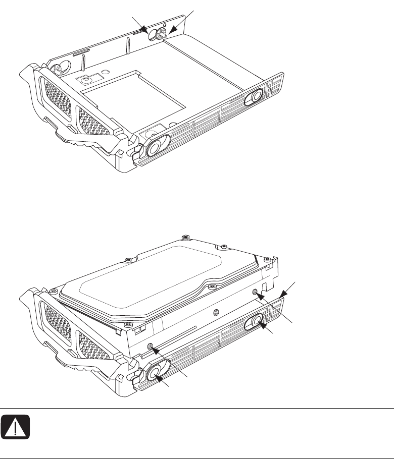
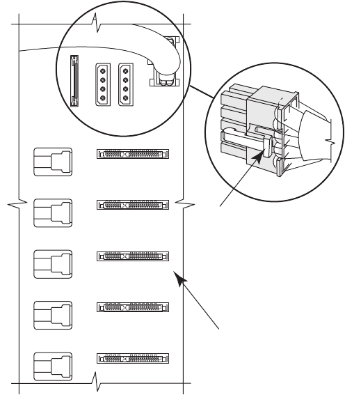
2Use a gentle rocking motion to remove the data cable plug and the power cable plug
from the back of the slim optical disc drives: (C) is the tab for the primary slim disc
drive (on the right when facing the front of the chassis), and (B) is the tab for the
optional slim disc drive (between the primary slim drive and the full-size drive when
facing the front of the chassis), which may be a drive or a filler.
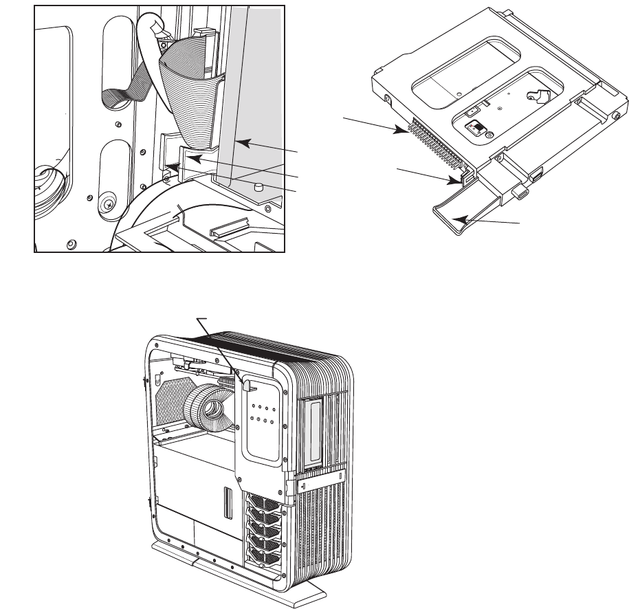
The following figure on the right shows the slim drive assembly, including the pins of
the data connector (D) and the power connector (E).
3Release the drives by pulling out the optical drive latch (H).
B
C
A
B/C
D
E
H
Upgrading and Servicing Guide 25
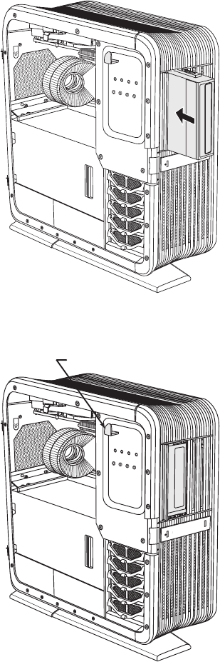
4Push the full-size drive (or filler) partway out through the front of the chassis.
5Remove the optional slim optical disc drive by pulling the drive tab (B) toward the
inside of the chassis, and then rotating it toward you and out of the chassis.
B
26 Upgrading and Servicing Guide
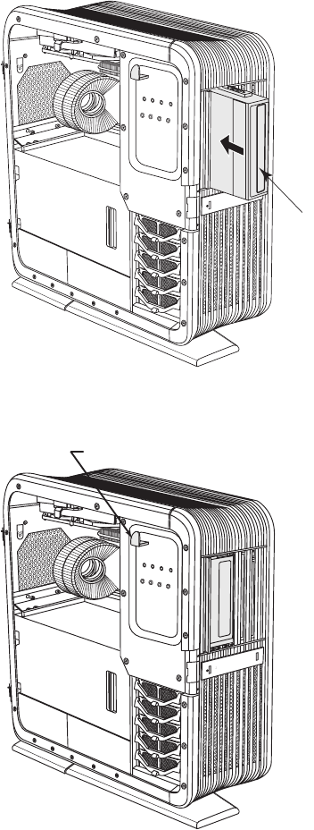
6Remove the primary slim optical disc drive by pulling the drive tab (C) toward the
inside of the chassis, and then rotating it toward you and out of the chassis.
Removing a full-size optical disc drive
1Prepare the computer to be opened, and then open the left access door. See
“Opening and Closing the Computer” on page 1.
2Remove the data cable plug and the power cable plug from the back of the optional
full-size optical disc drive. Use a gentle rocking motion to free the power plug; press
the latch on the data plug, and then pull it from the connector.
The following figure shows the location of the back of the full-size optical disc drive
filler (A), which has rails that attach to an optional full-size drive.
C
A
Upgrading and Servicing Guide 27
3Release the drive by pulling out the optical drive latch (H).
4Remove the drive by pushing it out through the front of the chassis.
H

28 Upgrading and Servicing Guide
Adding or replacing an optical drive
Complete the steps for either the slim optical disc drive or the full-size drive.
Adding or replacing a slim optical disc drive
1If necessary, remove the existing drive or filler. See “Removing an optical drive” on
page 23.
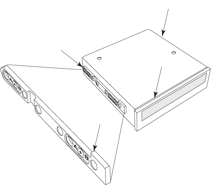
2Insert each slim optical disc drive:
aHold the drive assembly by the tab (B) at the bottom. The light bar (A) is at
the top.
bInsert the knobs (C) of the drive assembly into the slot (F1 or F2), and then rotate
the assembly away from you and into the slot. Push it toward the front of the
chassis until the assembly is completely seated. The light bar (A) should extend out
of the front of the chassis.
IMPORTANT: Be sure that the slim optical disc drive is in an adapter. Get your
replacement slim drive assembly (drive in the adapter) from HP.
IMPORTANT: You must insert the primary slim optical disc drive before inserting the
optional slim optical disc drive.
Upgrading and Servicing Guide 29
ALight bar at the top of the slim optical disc drive assembly
BTab on the primary or the optional slim optical disc drive
CAlignment knobs
DPower connector (pins)
EData connector (pins)
FSlots for slim optical disc drives: (F1) is primary drive slot, (F2) is optional drive slot
B
B
A
E
D
C
C
F2F1
F2
F1
B
C
30 Upgrading and Servicing Guide
3From the front, push the full-size drive (or the filler) all the way into the chassis.
4Secure the drives by pushing in the optical drive latch (H).
5Connect the data cable plug and the power cable plug to the connectors on the back
of the slim optical disk drives.
6Close the access door and the computer. See “Opening and Closing the Computer”
on page 1.
H
Upgrading and Servicing Guide 31
Adding or replacing a full-size optical disc drive
1Remove the rails from the full-size drive filler, or the existing drive, and install the rails
on the replacement drive. Complete the following steps:
aPosition the filler or the existing drive with the top of the unit (A) facing up.
bRemove the two screws and the rail (B) on the left side of the unit.
cPosition the replacement drive with the top of the drive (the disc tray) facing up.
Place the rail, with the notch (D) facing up, on the left side of the replacement
drive. Align the two holes in the rail labeled B with the top row of holes on the
drive, and then insert the screws through the B holes in the rail.
dRemove the two screws and the rail (C) on the right side of the unit.
ePlace the rail, with the notch (D) facing down, on the right side of the replacement
drive. Align the holes in the rail labeled B with the top row of holes on the drive,
and then insert the screws through the B holes in the rail.
B
A
C
D
32 Upgrading and Servicing Guide
2Hold the drive with the top facing toward the right. Specifically, the disc tray (E) faces
toward the right. Slowly insert the drive into the chassis through the front.
If the drive starts to bind or becomes stuck, stop inserting it. Remove the drive and
check that the rails are correctly installed and that the top of the drive is facing toward
the right.
3Secure the drive by pushing in the optical drive latch (H).
E
H
Upgrading and Servicing Guide 33
4Connect the data cable plug and the power cable plug into the connectors of the
replacement full-size optical disc drive. If you are adding a drive, route the cables and
connect them at the motherboard and the power supply.
5Close the access door and the computer. See “Opening and Closing the Computer”
on page 1.
Removing the hard disk drive
1Prepare the computer to be opened, and then open the left access door. See
“Opening and Closing the Computer” on page 1.
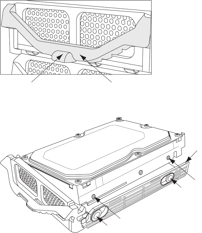
2Press the hard disk drive drawer latch (A), lift the handle (B), and pull the drawer from
the chassis.
3Pull out the flexible right side of the drawer (C), and lift the drive (D) off the pins (E)
and out of the drawer.
AB
C
D
D
E
E
34 Upgrading and Servicing Guide
Adding or replacing a hard disk drive
1If necessary, remove the existing drive. See “Removing the hard disk drive” on
page 33.
2Tip the left side of the drive into the drawer, and insert the pins (B) into the drive. If
necessary, adjust the position of the pins on the left side (A) to match the drive.
3Pull out the flexible right side of the drawer (C), and lower the drive into the drawer,
inserting the pins (E) on the right side into the drive (D). If necessary, adjust the
position of the pins on the right side to match the drive.
WARNING: The lowest of the five hard disk drive drawer slots contains the
operating system. If you install the primary hard disk drive in another slot, or
if you install a data disk in the lowest slot, the computer may not operate
properly.
AB
C
D
D
E
E
Upgrading and Servicing Guide 35
4With the handle (G) released (up), align the drawer with the chassis slot, slide the
drawer into the chassis, and then press the face of the drawer (F) to fully seat it into
the power and SATA data connectors at the back.
5Press the handle (G) down to lock the latch (H).
6Close the access door and the computer. See “Opening and Closing the Computer”
on page 1.
Adding Memory
Your computer comes with random access memory (RAM), which temporarily stores data
and instructions on your computer. The computer has one or more memory modules, but
you may be able to replace the existing memory module(s) with higher-capacity ones.
The motherboard contains sockets for DDR-type (double data rate) DIMMs (dual in-line
memory modules). The exact number of sockets and the type of DDR memory modules may
vary by computer model.
Memory DIMM
CAUTION: The computer may not recognize the drive if the drawer is not fully
seated.
HG
F
F
36 Upgrading and Servicing Guide
To determine which type and speed of memory module your computer uses, and for
specific memory module information and specifications, go to the Web site listed in your
Limited Warranty and Support Guide, and click the Support link.
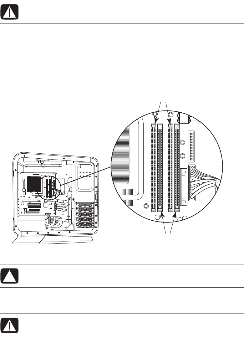
Removing a memory module
1Prepare the computer to be opened, open the left access door, open and remove the
PCI door, and remove the thermal divider. See “Opening and Closing the Computer”
on page 1.
2Locate the memory sockets (A and B) on the motherboard.
3If necessary for clearance, remove the top card from the add-in card slot. See
“Removing and Installing an Add-in Card” on page 39.
WARNING: Using the wrong type of memory module could damage the
computer.
CAUTION: When handling a memory module, be careful not to touch any of
the contacts. Doing so may damage the module.
WARNING: If the memory module has extended heatsink fins, do not grip the
module by the fins.
A
B
Upgrading and Servicing Guide 37
4Push down the retaining clip on each end of the memory socket until the memory
module pops out of the socket.
5Lift the memory module out of the memory socket.
Installing a memory module
Upgrade the memory in your computer with memory modules of the same type and speed
as the memory modules originally installed in your computer.
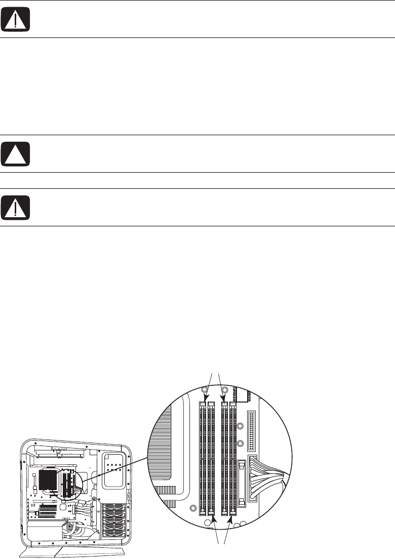
1Open both retaining clips of the memory module socket:
If you are replacing an existing memory module, install the new memory module in the
same memory slot from which you removed one.
Or
If you are adding a memory module, note that for this dual-channel configuration, the
total capacity (size) of the memory modules in the (A) channel slots must match the
capacity of the modules in the (B) channel slots. Install the new modules so that the
two channels match.
WARNING: Do not pull the memory module out of the memory socket. Use the
retaining clips to remove the module.
CAUTION: When handling a memory module, be careful not to touch any of
the contacts. Doing so may damage the module.
WARNING: If the module has extended heatsink fins, do not grip the module
by the fins.
A
B

38 Upgrading and Servicing Guide
2Press the module into place, and ensure that the retaining clips close by pressing them
toward the module.
3If necessary, replace the card you removed from the top add-in card slot. See
“Removing and Installing an Add-in Card” on page 39.
4Replace the thermal divider, replace and close the PCI door, close the left access door
and the computer. See “Opening and Closing the Computer” on page 1.
NOTE: If a blank screen displays after you replace or add a memory module, the memory
module is installed incorrectly, or it is of the wrong type. Remove and reinstall the memory
module.
Upgrading and Servicing Guide 39
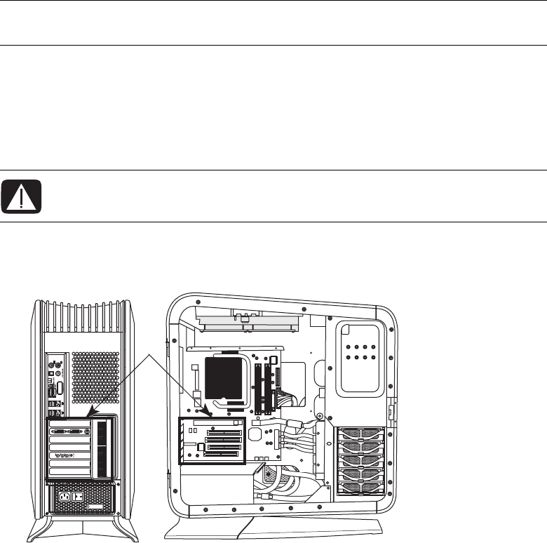
Removing and Installing an Add-in Card
An add-in card is a circuit board, such as a PCI or a PCI-E card, that fits into a computer
add-in card slot. Your computer contains several add-in card slots that can be used to add
components to your computer. The computer component configurations vary by model;
refer to the documentation that came with the computer.
Removing an add-in card
1Prepare the computer to be opened, and then open the left access door, open and
remove the PCI door, and remove the thermal divider. See “Opening and Closing the
Computer” on page 1.
2Locate the add-in card slots (A) on the outside of the chassis, and inside on the
motherboard.
3Disconnect any cables connected to the add-in card.
IMPORTANT: Removal and installation of liquid-cooled graphics cards is not documented
here. To service or upgrade liquid-cooled graphics cards, contact HP Support.
WARNING: Beware of the sharp edges in the chassis and on the add-in card
slot cover.
A
40 Upgrading and Servicing Guide
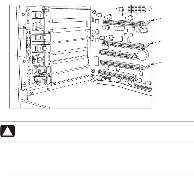
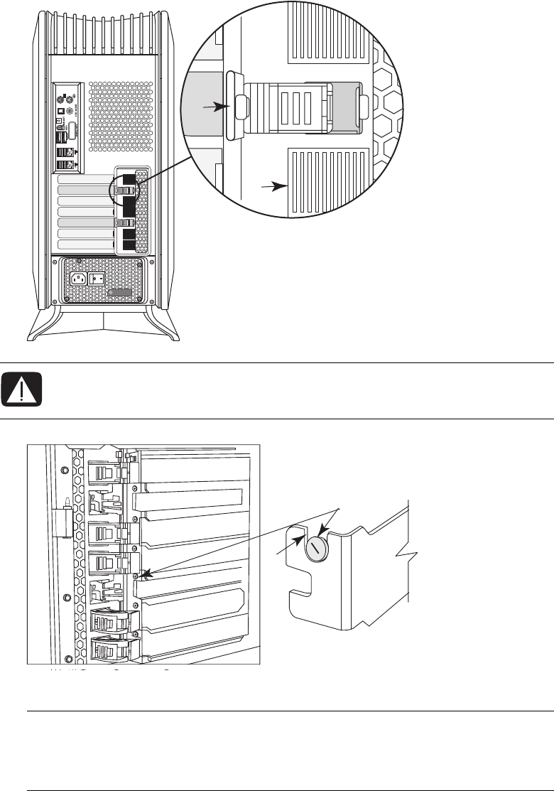
4Inside the chassis, press the latch (B) to release the add-in card you want to remove.
The following figure shows a depressed latch (C).
5If you are adding an add-in card, remove the slot cover.
6To remove the add-in card: Pull up the latch (D), if it is present, hold the card at each
end, and carefully pull it from the chassis, gently rocking the card back and forth to
free it from the socket. Be sure not to scrape the card against the other components.
CAUTION: Your computer may have a latch similar to (D) on the add-in
connector. Pull up the latch (D) to release the card from the connector when
removing the card.
NOTE: Some long add-in cards sit in the slot guides toward the right (front) of the
chassis; these should not be rocked.
B
C
D
D
D
Upgrading and Servicing Guide 41
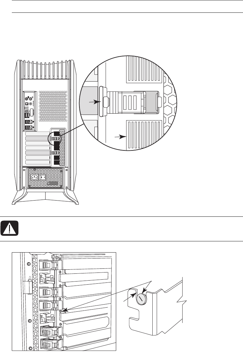
7If you are not replacing the old add-in card, insert the metal slot cover into the open
slot. From the outside of the chassis, press the slot latch (E) to lock the slot cover in
place. (See the Warning that follows.) The following figure shows a locked slot
latch at (F).
IMPORTANT: Use only a slot cover that came with your computer.
WARNING: Do not force the slot latch to close. Check inside the chassis that the
end of the slot cover or card (G) fits against and around the alignment pin (H).
Do not close the latch unless the card or slot cover is properly seated.
F
E
H
G
42 Upgrading and Servicing Guide
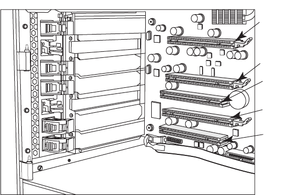
Installing an add-in card
1If necessary, remove the add-in card slot cover or the existing add-in card. See
“Removing an add-in card” on page 39.
2Locate the card slot on the motherboard inside the chassis. In the following figure,
(A) is a PCI-E (Express) x 16 connector, and (B) is a PCI connector. Your computer
may vary.
3Inside the chassis, position the add-in card over the add-in card connector. For some
add-in cards, tip the end of the card into the exterior slot opening, and then position
the card over the add-in card connector. For some long add-in cards, insert the right
side of the card into the slot guides toward the right (front) of the chassis.
4Gently but firmly press the card straight into the add-in card slot so that the whole
connector seats properly.
B
A
A
B
A
Upgrading and Servicing Guide 43
5From the outside of the chassis, press the slot latch (E) to lock the card in place. (See
the Warning that follows.) The following figure shows a locked slot latch at (F).
6Connect cables to the card as needed.
WARNING: Do not force the slot latch to close. Check inside the chassis that the
card (G) fits against and around the alignment pin (H). Do not close the latch
unless the card is properly seated.
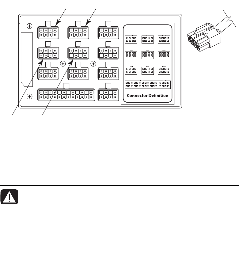
IMPORTANT: Some graphics cards require two power cable plugs. These two
power cables must connect to power supply connectors that are in the same row of the
power supply. Do NOT connect the two power cables from one graphics card to
connectors on different rows of the power supply.
F
E
H
G
44 Upgrading and Servicing Guide
When connecting to the power supply, match the power supply connector color to the
plug, and check the power supply label for connector usage. Your power supply may
vary from the figure. For more power supply information, see “Removing and
Replacing the Power Supply” on page 45.
A12V6 (PCI-E), blue connector on top row
B12V6 (PCI-E), blue connector on top row
C12V5 (PCI-E), blue connector on second row
D12V5 (PCI-E), blue connector on second row
7Replace the thermal divider, replace and close the PCI door, close the left access door
and the computer. See “Opening and Closing the Computer” on page 1.
WARNING: If you disconnect the power connector for the liquid cooling system,
ensure that it is reconnected prior to connecting power and turning on the
computer. Failure to do so may result in damage to the cooling system and to
the computer.
NOTE: If the new add-in card or device does not work, read the manufacturer’s
installation instructions and recheck all connections, including those to the card, power
supply, keyboard, and monitor.
AB
DC
Upgrading and Servicing Guide 45
Removing and Replacing the Power Supply
Removing the power supply
1Prepare the computer to be opened, and then open the left access door, open and
remove the PCI door, remove the thermal divider, and remove the power supply
baffle. See “Opening and Closing the Computer” on page 1.
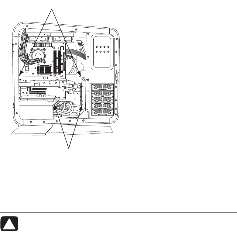
2Inside the chassis, note the location of each plug connected to the power supply and
label the cable. Press the latch (A) on each plug, and then pull the plug from the
connector.
WARNING: Remove the power cord from the computer. Failure to do so before
removing the power supply can result in personal injury or equipment
damage.
A
A
WARNING: If you disconnect the power connector for the liquid cooling system,
ensure that it is reconnected prior to connecting power and turning on the
computer. Failure to do so may result in damage to the cooling system and to
the computer.
46 Upgrading and Servicing Guide
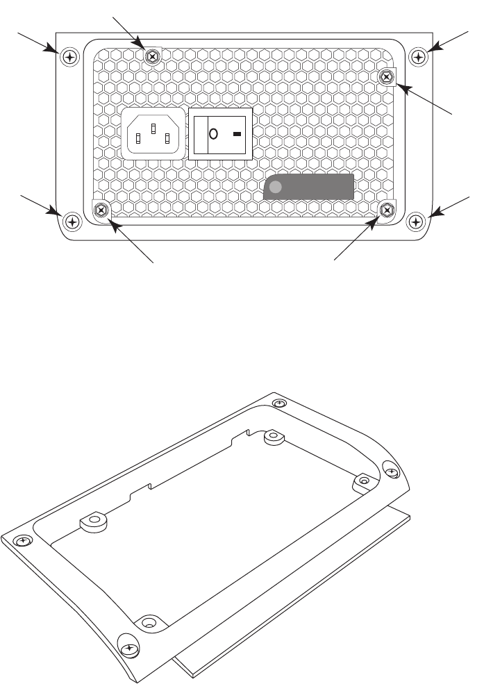
3On the back of the chassis, loosen the four screws (B) that secure the power supply
assembly in the chassis.
4From inside the chassis, push out the power supply assembly through the back of the
chassis.
5Remove the four screws (C) that secure the power supply bracket to the power supply,
and then remove the bracket.
C
BB
B
B
C
CC

Upgrading and Servicing Guide 47
Replacing the power supply
1Align the four (inner) screw holes in the power supply bracket (C) with the screw holes
on the face of the power supply.
2Insert four screws (C) to secure the bracket to the power supply.
3From the back of the chassis, insert the power supply assembly into the opening (D).
4Tighten the four screws (B) in the bracket to secure the power supply assembly in the
chassis.
C
BB
B
B
C
CC
D
48 Upgrading and Servicing Guide
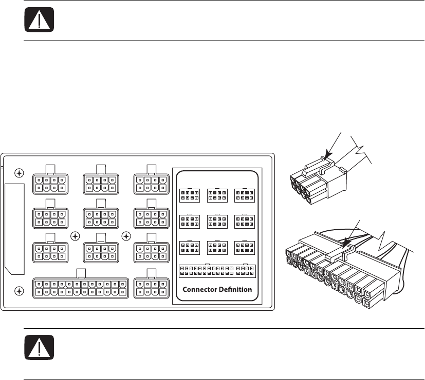
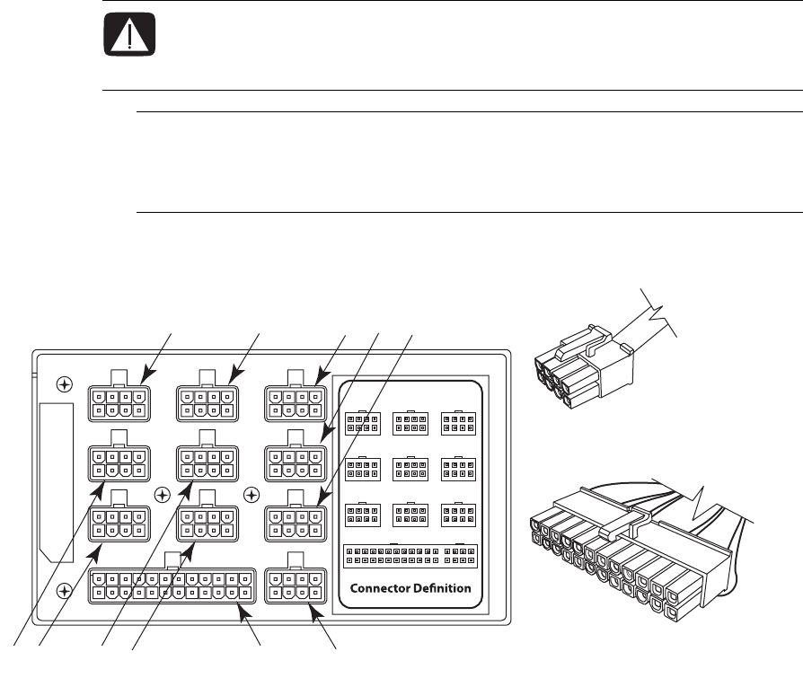
5Inside the chassis, connect the plugs previously removed from the power supply.
Match the power supply connector color to the plug, and check the power supply
label for connector usage.
A12V6 (PCI-E), blue connector
B12V6 (PCI-E), blue connector
C12V4 (SATA/IDE), black connector
D12V4 (SATA/IDE), black connector
E12V3 (SATA/IDE), black connector
F12V3 (SATA/IDE), black connector
G12V1, black connector
H12V2 (CPU), turquoise connector
I12V5 (PCI-E), black connector
WARNING: If you disconnect the power connector for the liquid cooling system,
ensure that it is reconnected prior to connecting power and turning on the
computer. Failure to do so may result in damage to the cooling system and to
the computer.
IMPORTANT: Some graphics cards require two power cable plugs. These two
power cables must connect to power supply connectors that are in the same row of the
power supply. Do NOT connect the two power cables from one graphics card to
connectors on different rows of the power supply.
CADBE
H
KGI F
J

Upgrading and Servicing Guide 49
J12V2 (CPU), turquoise connector
K12V5 (PCI-E), blue connector
6Replace the power supply baffle and the thermal divider, replace and close the PCI
door, close the left access door and close the computer. See “Opening and Closing
the Computer” on page 1.
Removing and Replacing the SATA Backplane
The replacement instructions include setting the LED switch on the SATA backplane.
Removing the SATA backplane
1Prepare the computer to be opened, and then open the left access door, open the PCI
door, remove the thermal divider, and access the chassis through the right side (also,
opening the right access panel). See “Opening and Closing the Computer” on
page 1.
2On the left side of the computer, remove all the hard disk drives or the drive drawers
from the chassis. See “Removing the hard disk drive” on page 33.
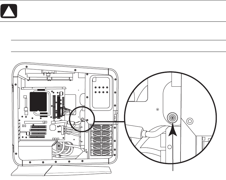
3Inside the drive drawer bay, press the latch on the power plug (A) and then remove it
from the SATA backplane (B).
A
B
50 Upgrading and Servicing Guide
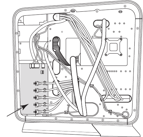
4Locate the SATA backplane (B) on the right side of the chassis.
B
Upgrading and Servicing Guide 51
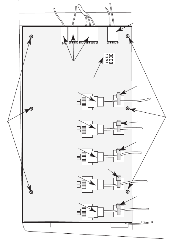
5Carefully cut the five tie-wraps (C) securing the five SATA data cables. Do not damage
the cables. Remove the tie wraps from the anchors.
6Label the five SATA data cable plugs (D1–D5), and then disconnect them.
7Disconnect the plugs (F) at the top of the card.
8Remove the six screws (G) that secure the card to the chassis, and then lift the card
from the chassis.
C
C
C
C
C
D5
D3
D1
D2
D4
E
G
F
F
G
52 Upgrading and Servicing Guide
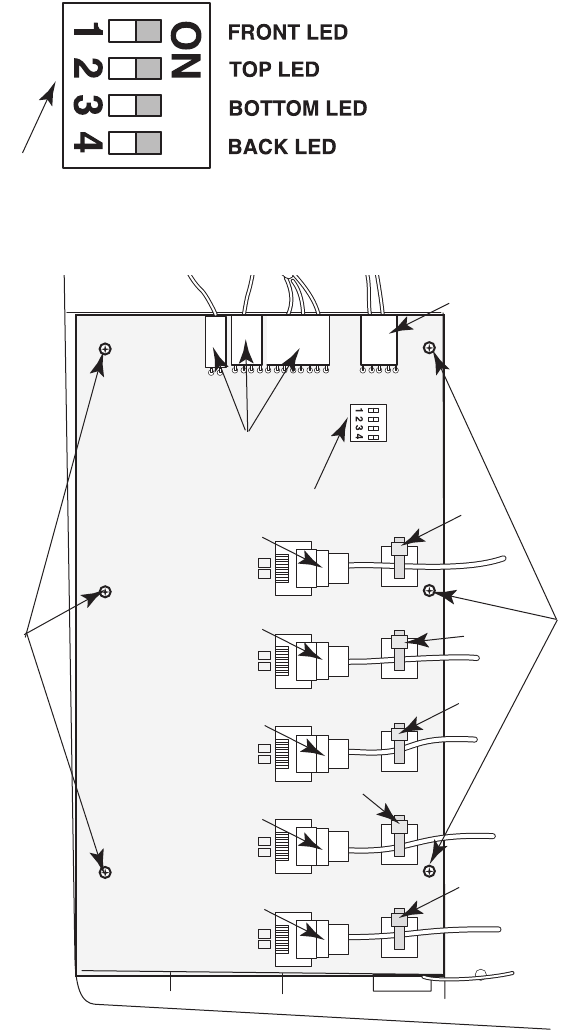
Replacing the SATA backplane
1Set the LED switch (E) settings on the replacement SATA backplane to match the switch
settings on the old backplane.
2Align the replacement SATA backplane over the posts and screw holes, and place the
card onto the chassis. Insert the six screws (G) that secure the card to the chassis.
E
C
C
C
C
C
D5
D3
D1
D2
D4
E
G
F
F
G
Upgrading and Servicing Guide 53
3Reconnect the plugs (F) at the top of the card.
4Reconnect the five SATA data cable plugs (D1–D5).
5Insert new tie-wraps (C) through the anchors and around the SATA data cables, and
then tighten the tie-wraps to secure the cables.
6On the left side of the computer inside the hard disk drive drawer bay, reconnect the
the power plug (A) to the SATA backplane (B).
7Replace all the hard disk drives or the drive drawers into the chassis. See “Adding or
replacing a hard disk drive” on page 34.
8Close and replace the right access, replace the thermal divider, replace and close the
PCI door, close the left access door and the computer. See “Opening and Closing the
Computer” on page 1.
A
B

54 Upgrading and Servicing Guide
Replacing the Battery
A lithium battery on the motherboard provides backup power for the computer
timekeeping capability. The battery has an estimated life expectancy of seven years.
When the battery starts to weaken, the date and time may become incorrect. If the battery
fails, replace it with a CR2032 lithium battery (3 volt, 220mAH rating) or an equivalent
battery.
1Prepare the computer to be opened, and then open the left access door, open and
remove the PCI door, and remove the thermal divider. See “Opening and Closing the
Computer” on page 1.
2Remove any cables or add-in cards as needed so that you can reach the battery. See
“Removing and Installing an Add-in Card” on page 39.
3To remove the battery, push the latch away from the battery, and lift it out of the
socket.
4Install the new CR2032 battery in the socket, with the positive (+) side facing the
latch.
5Replace the add-in cards or any cables you removed.
6Replace the thermal divider, replace and close the PCI door, close the left access door
and the computer. See “Opening and Closing the Computer” on page 1.
Part number: 5992-1557
WARNING: There is danger of explosion if the battery is incorrectly replaced.
Replace it only with a battery of the same, or an equivalent, type. Discard
used batteries according to the manufacturer’s instructions.
