Hp Cn1000E Users Manual Emulex Converged Network Adapter Installation Guide
CN1100E to the manual 531a41ac-ac68-4f6b-8698-18f363af56b7
2015-02-09
: Hp Hp-Cn1000E-Users-Manual-547351 hp-cn1000e-users-manual-547351 hp pdf
Open the PDF directly: View PDF ![]() .
.
Page Count: 29
- HP Emulex Converged Network Adapter Installation Guide
- Contents
- 1 Installing the Emulex CNA
- 2 Installing drivers and software
- Order of the installation
- Downloading software and drivers
- Installing drivers and software
- Installing the Windows device driver using the HP Smart Component kit
- Installing the Windows utility using the HP Smart Component kit
- Installing firmware on Windows systems
- Installing multipathing software on Windows
- Installing the CNA Linux drivers
- Installing the Linux utility
- Installing firmware on Linux systems
- Installing and configuring multipathing software on Linux
- 3 Troubleshooting
- 4 Support and other resources
- A Emulex CNA specifications
- B Regulatory compliance and safety
- Glossary
- Index

HP Emulex Converged Network Adapter
Installation Guide
Abstract
This document provides information about installing, configuring, and troubleshooting the HP Emulex Converged Network
Adapters (CNAs). In this document, CNA refers to HP models CN1000E and CN1100E.
HP Part Number: AA-RWQAC-TE
Published: August 2011
Edition: 3

© Copyright 2010, 2011 Hewlett-Packard Development Company, L.P.
Confidential computer software. Valid license from HP required for possession, use or copying. Consistent with FAR 12.211 and 12.212, Commercial
Computer Software, Computer Software Documentation, and Technical Data for Commercial Items are licensed to the U.S. Government under
vendor's standard commercial license.
The information contained herein is subject to change without notice. The only warranties for HP products and services are set forth in the express
warranty statements accompanying such products and services. Nothing herein should be construed as constituting an additional warranty. HP shall
not be liable for technical or editorial errors or omissions contained herein.
Acknowledgments
Intel, Itanium, Pentium, Intel Inside, and the Intel Inside logo are trademarks or registered trademarks of Intel Corporation or its subsidiaries in the
United States and other countries.
Microsoft, Windows, Windows XP, and Windows NT are U.S. registered trademarks of Microsoft Corporation.
Adobe and Acrobat are trademarks of Adobe Systems Incorporated.
Java is a registered trademark of Oracle and/or its affiliates.
UNIX is a registered trademark of The Open Group.
Warranty
WARRANTY STATEMENT: To obtain a copy of the warranty for this product, see the warranty information website:
http://www.hp.com/go/storagewarranty

Contents
1 Installing the Emulex CNA...........................................................................5
Installation prerequisites............................................................................................................5
Recording reference numbers.................................................................................................5
Installing the Emulex CNA.........................................................................................................6
Electrostatic discharge...............................................................................................................9
Grounding methods..................................................................................................................9
2 Installing drivers and software....................................................................10
Order of the installation...........................................................................................................10
Downloading software and drivers............................................................................................10
Downloading the Windows Windows driver kit (Smart Component) or Linux driver kit.................10
Downloading the OneCommand Manager application kit.......................................................10
Downloading firmware.......................................................................................................11
Downloading multipathing software.....................................................................................11
Installing drivers and software..................................................................................................11
Installing the Windows device driver using the HP Smart Component kit....................................11
Installing the Windows utility using the HP Smart Component kit..............................................11
Installing firmware on Windows systems................................................................................12
Installing multipathing software on Windows.........................................................................12
Installing the CNA Linux drivers...........................................................................................12
Installing the Linux utility.....................................................................................................12
Installing firmware on Linux systems......................................................................................12
Installing and configuring multipathing software on Linux........................................................13
3 Troubleshooting........................................................................................14
Isolating CNA problems..........................................................................................................14
Observe and collect data....................................................................................................14
Isolate the problem to the component...................................................................................14
CNA problem isolation.......................................................................................................14
Verify server and CNA startup BIOS messages..................................................................14
Verify the CNA link.......................................................................................................14
Verify Fibre Channel switch zoning for FC storage.............................................................15
Verify Fibre Channel storage device discovery...................................................................15
CNA LED states......................................................................................................................16
CNA startup BIOS message.....................................................................................................17
4 Support and other resources......................................................................20
Contacting HP........................................................................................................................20
Subscription service............................................................................................................20
New and changed information in this edition.............................................................................20
Related information.................................................................................................................20
HP websites......................................................................................................................20
Typographic conventions.........................................................................................................21
Customer self repair................................................................................................................21
A Emulex CNA specifications........................................................................22
Environmental specifications.....................................................................................................22
Physical specifications.............................................................................................................22
Emulex CNA media specifications............................................................................................23
B Regulatory compliance and safety..............................................................24
Laser device...........................................................................................................................24
Laser safety warning...............................................................................................................24
Certification and classification information.................................................................................24
Contents 3
Laser product label.................................................................................................................24
Notice for North America (FCC & IC)........................................................................................24
FCC Compliance Information Statement................................................................................24
International notices and statements..........................................................................................25
Canadian notice (avis Canadien).............................................................................................25
Class A equipment.............................................................................................................25
European Union regulatory notice.............................................................................................25
Japanese notice......................................................................................................................26
Korean notice.........................................................................................................................26
Glossary....................................................................................................27
Index.........................................................................................................28
4 Contents
1 Installing the Emulex CNA
This chapter describes the following topics for installing the CNA:
•“Installation prerequisites” (page 5)
•“Installing the Emulex CNA” (page 6)
See the server documentation for additional information about installing the CNA.
WARNING! Disconnect the host from the power source before installing the CNA. To reduce the
risk of personal injury from hot surfaces, allow the internal server or workstation components to
cool before touching.
Installation prerequisites
Before you begin, make sure you have the following items available:
•An optical multimode cable with an LC-style duplex connector and approved SFP+ module or
copper cable
•A server with an empty x8 PCIe bus slot
Recording reference numbers
Each CNA is shipped with the following two numbers clearly marked on the board:
•IEEE address (Port 1 MAC address)
•Serial number
The MAC address is a unique 48-bit identifier used when configuring the system. The Fibre Channel
industry uses the World Wide Name (WWN) derived from the MAC address for Fibre Channel
connectivity. The adapter has two ports. Therefore, it has two MAC addresses and two WWNs,
one for each port. Use the serial number when communicating with HP.
NOTE: The factory default MAC addresses are permanent identifiers that cannot be changed.
The MAC address for Port 1 is listed on the CNA. The MAC address for Port 2 and the WWNs
are calculated based on the Port 1 address as follows:
ExampleCalculationMAC address/WWN
F4-CE-46-FD-9C-68Assigned at the factory and printed
on the CNA IEEE address label
Port 1 MAC address
10:00:F4:CE:46-FD-9C-6810:00:[Port 1 MAC address]Port 1 WWN
F4-CE-46-FD-9C-6CPort 1 MAC address + 4Port 2 MAC address
10:00:F4:CE:46-FD-9C-6C10:00:[Port 1 MAC address + 4]Port 2 WWN
Record the serial number and MAC addresses and WWNs for your CNA before installation.
Serial number (on CNA): ________________________________
Port 1 MAC address: ____________________________________
Port 1 WWN: __________________________________________
Port 2 MAC address: ____________________________________
Port 2 WWN: __________________________________________
Installation prerequisites 5
Installing the Emulex CNA
The CNA uses removable optical transceivers or copper interface cables.
CAUTION:
Electrostatic discharge (ESD) can damage electronic components. Be sure you are properly grounded
before beginning this procedure, as described in “Electrostatic discharge” (page 9).
IMPORTANT: The CNA is only supported in PCI Express 8 lane and larger PCIe slots. This may
require optional PCIe riser cards or cages. For instructions on installing the riser card or cage, see
the server documentation.
To install the CNA into a server:
1. Be sure the server is powered off.
2. Remove the access panel.
3. Wearing an anti-static wrist strap, remove the blank panel from an empty x8 or larger PCIe
bus slot.
NOTE: The CNA comes with a standard PCIe bracket installed. A low-profile bracket is
included in the box with the CNA. The low-profile mounting bracket is shorter than the standard
bracket: approximately 7.90 cm (3.11 inches) compared to 12.06 cm (4.75 inches) long.
4. If you require a different mounting bracket, change the bracket as follows. Otherwise, go to
Step 5.
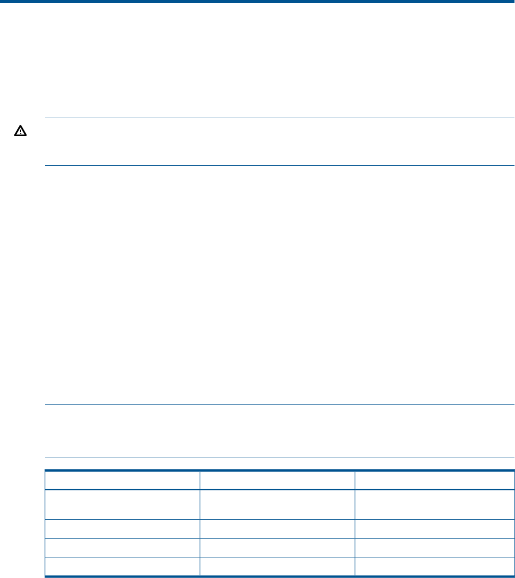
a. Remove any transceivers or cables from the CNA transceiver cage assembly by pulling
the bail (handle) out and down to release the latch, and then gently pull the transceiver
out. Do not force it. After the latch is released, the transceiver/cable slides out easily.
Figure 1 A typical optical transceiver
Figure 2 Removing a transceiver
b. Observing ESD precautions, store the transceiver in an ESD-safe place.
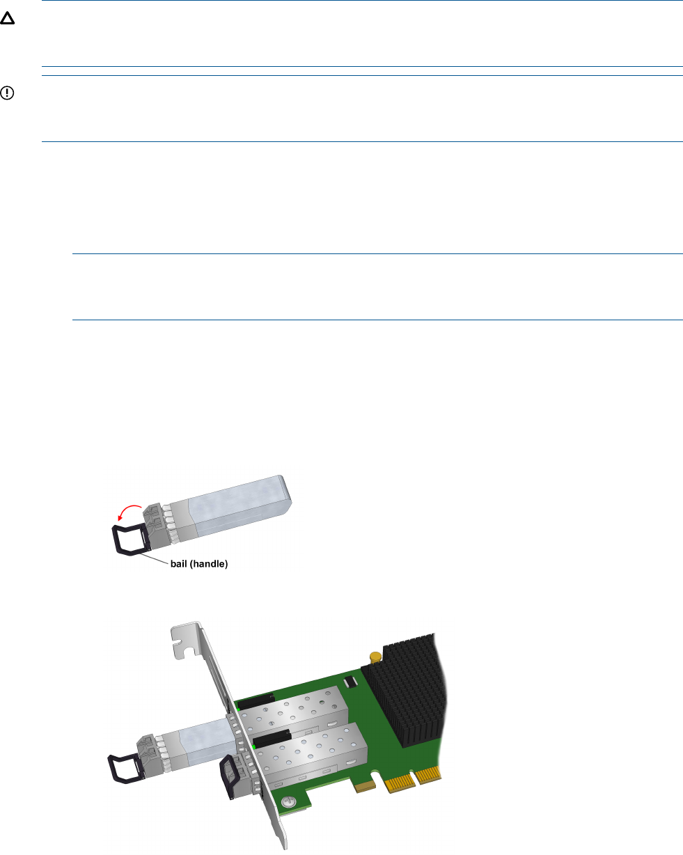
c. Remove the mounting bracket screws from the top of the CNA.
6 Installing the Emulex CNA
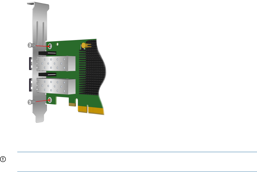
Figure 3 Removing the bracket
d. Remove the bracket and store it for future use.
e. Align the new mounting bracket tabs with the holes in the CNA.
IMPORTANT: Be careful not to push the bracket past the grounding tabs on the
transceiver housing. Make sure the LEDs are properly aligned with the holes in the bracket.
f. Install the screws that attach the CNA to the bracket.
g. Slide the transceiver into the housing. When the latch engages, it clicks.
h. Push the bail back into place.
5. Insert the CNA into the empty PCIe slot. Press firmly until the CNA is seated.
6. Secure the CNA mounting bracket to the case with the panel clip.
7. Replace the server case, and then tighten the screws on the case.
The CNA is now installed in the server and ready for media attachment.
Installing the Emulex CNA 7
8. Attach the media:
a. For fiber optic cable connections:
1. Insert the SFP transceiver module into the cage.
2. Connect one end of the fiber optic cable to the LC connector on the CNA.
3. Connect the other end of the cable to the Converged Network switch.
Figure 4 Emulex CNA with optical transceivers
Figure 5 Connecting fiber optic cable
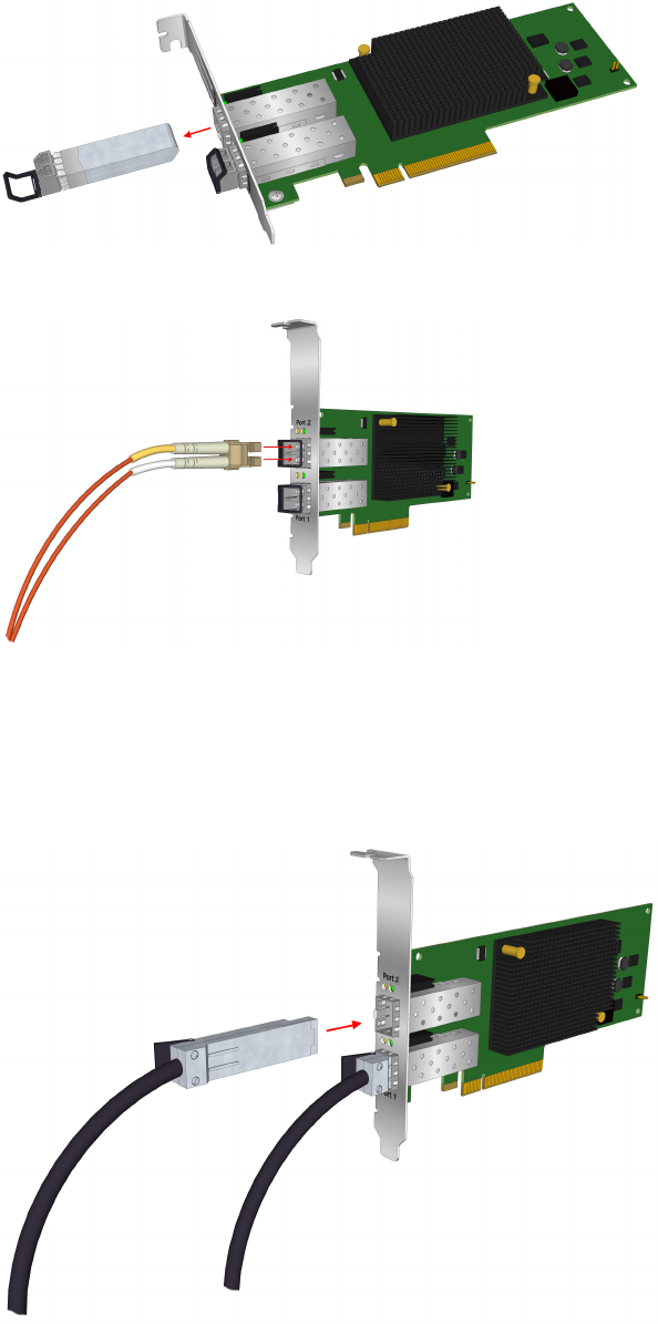
b. For copper cable connections:
1. Connect one end of the copper cable to the CNA.
2. Connect the other end of the cable to the Converged Network switch.
Figure 6 Connecting the direct attach copper cable
8 Installing the Emulex CNA
9. Apply the power:
a. Verify that the CNA is installed securely in the server.
b. Verify that the correct media is attached.
c. Plug in and power on the server.
d. Observe the Link and Activity LEDs to be sure the CNA connects to the switch.
For more information about the meaning of the LED indicators, see “CNA LED states”
(page 16).
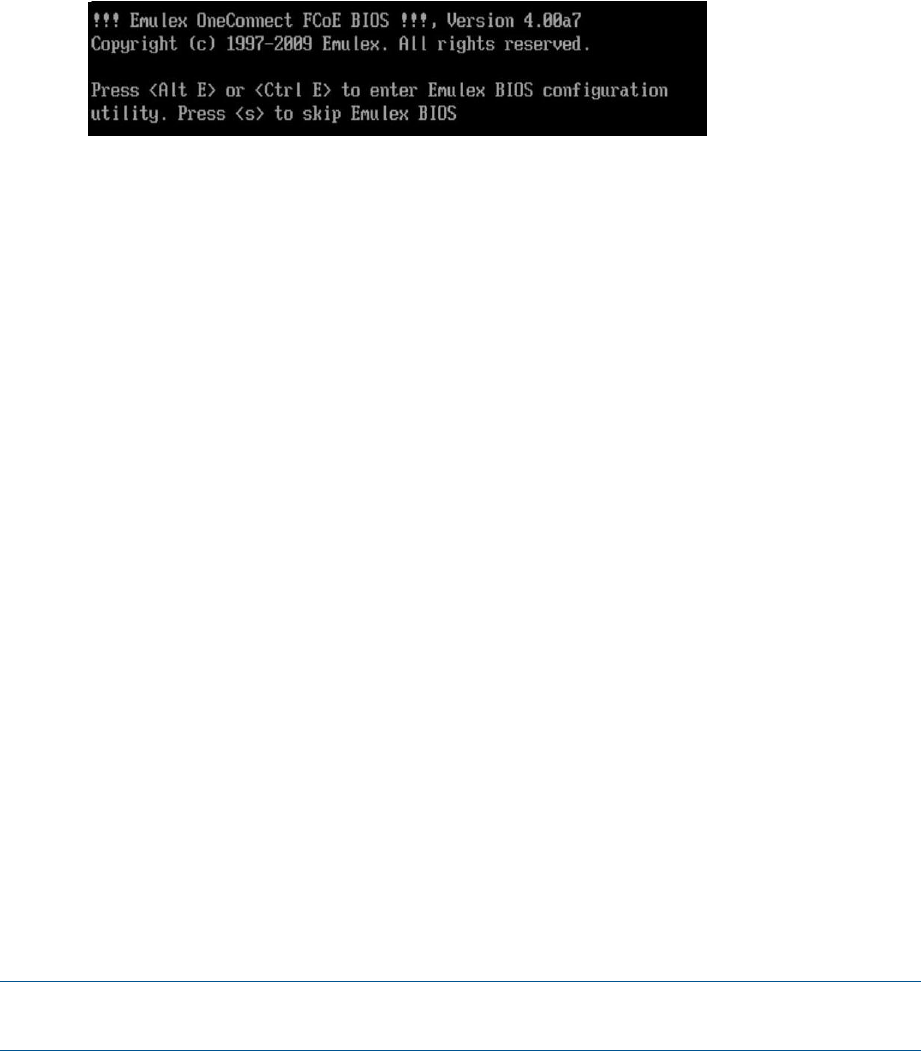
e. Watch the server console for any POST error messages and the CNA BIOS startup
message similar to the one in Figure 7 (page 9)
Figure 7 CNA BIOS example startup message
Electrostatic discharge
To prevent damage to the system, be aware of the precautions you need to follow when setting
up the system or handling parts. A discharge of static electricity from a finger or other conductor
may damage system boards or other static-sensitive devices. This type of damage may reduce the
life expectancy of the device.
To prevent electrostatic damage, observe the following precautions:
•Avoid hand contact by transporting and storing products in static-safe containers.
•Keep electrostatic-sensitive parts in their containers until they arrive at static-free workstations.
•Place parts on a grounded surface before removing them from their containers.
•Avoid touching pins, leads, or circuitry.
•Always be properly grounded when touching a static-sensitive component or assembly (see
“Grounding methods” (page 9)).
Grounding methods
There are several methods for grounding. Use one or more of the following methods when handling
or installing electrostatic-sensitive parts:
•Use a wrist strap connected by a ground cord to a grounded workstation or computer chassis.
Wrist straps are flexible straps with a minimum of 1 megohm (±10 percent) resistance in the
ground cords. To provide proper ground, wear the strap snug against the skin.
•Use heel straps, toe straps, or boot straps at standing workstations. Wear the straps on both
feet when standing on conductive floors or dissipating floor mats.
•Use conductive field service tools.
•Use a portable field service kit with a folding static-dissipating work mat.
If you do not have any of the suggested equipment for proper grounding, have an HP-authorized
reseller install the part.
NOTE: For more information on static electricity, or assistance with product installation, contact
your HP-authorized reseller.
Electrostatic discharge 9

2 Installing drivers and software
For the latest information about storage array support, see the HP SPOCK website at http://
www.hp.com/storage/spock. You must sign up for an HP Passport to enable access.
Some CNA download kits include a readme.txt file that may contain additional information
about installing firmware and drivers, plus enhancements and fixes in the current release. Information
in the readme.txt file supersedes this and other HP Emulex documents.
The Emulex OneCommand Manager application is available for the CNA. See the Emulex
OneCommand Manager Application User Manual:
1. Go to http://www.hp.com/support/manuals.
2. Under storage, click Storage Networking.
3. Click HP Converged Network Adapters .
4. Select Manuals.
Order of the installation
The order of installation is important. It must be done as follows:
1. Install the network driver.
2. Install the FCoE driver.
3. Install the OneCommand Manager utility.
4. Update the CNA firmware and BIOS (if required).
5. Install multipathing software (if required).
Downloading software and drivers
This section describes how to locate and download drivers and software.
Downloading the Windows Windows driver kit (Smart Component) or Linux driver
kit
To download the driver kit:
1. Go to http://www.hp.com/go/support.
2. Click Drivers & Software.
3. Using the HP model number as your guide, enter the CNA model number, and then click
Search.
4. Select your operating system.
5. Select the Windows driver kit (Smart Component) or Linux driver kit and download it to your
server.
NOTE: Install the network driver kit before you install the storage Fibre Channel driver.
Downloading the OneCommand Manager application kit
To download the OneCommand Manager application kit:
1. Go to http://www.hp.com/go/support.
2. Click Drivers & Software.
3. Using the HP model number as your guide, enter the CNA model number, and then click
Search.
4. Select your operating system.
5. Select the OneCommand Manager Application Kit and download it to your server.
10 Installing drivers and software

Downloading firmware
To download firmware:
1. Go to http://www.hp.com/go/support.
2. Click Drivers & Software.
3. Using the HP model number as your guide, enter the CNA model number, and then click
Search.
4. Click Cross operating system (BIOS, Firmware, Diagnostics, etc.).
5. Select the Firmware image and download it to your server.
Downloading multipathing software
To download Windows MPIO DSM software:
1. Go to http://www.hp.com/go/support.
2. Click Drivers & Software.
3. Enter MPIO DSM, and then click Search.
4. Select the MPIO DSM software for your arrays and download it to your server.
To download the Linux HP Device Mapper kit:
1. Go to http://www.hp.com/go/devicemapper.
2. Select your operating system.
3. Select the Device Mapper Multipath Enablement Kit and download it to your server.
Installing drivers and software
This section describes how to install drivers and software.
Installing the Windows device driver using the HP Smart Component kit
To install the Windows drivers:
1. Obtain the latest Smart Component for your configuration and copy it to your Windows server.
2. Unzip the driver Smart Component.
3. Double-click the FCoE Smart Component executable to begin the installation, and then click
Install.
The Smart Component automatically installs the FCoE driver without user intervention.
4. Click Reboot to complete the installation.
Installing the Windows utility using the HP Smart Component kit
To Install the CNA Windows OneCommand Manager utility:
1. Obtain the latest Smart Component for your configuration and copy it to your Windows server.
2. Unzip the Smart Component.
3. Double-click the network Smart Component executable to begin the installation, and then click
Install.
The Smart Component automatically installc the OneCommand Manager software without
any user intervention. When the installation is finished, click Finish to complete the installation.
NOTE: The NIC driver must be installed and the NIC ports enabled for the OneCommand
Manager to operate properly.
Installing drivers and software 11

Installing firmware on Windows systems
Use the OneCommand Manager utility to install the CNA firmware/BIOS:
1. Before you begin, make sure you have the following installed:
•Network driver
•FCoE driver
•OneCommand Manager utility
2. Download the firmware image to your Windows server
3. Follow the procedure in the Updating Adapter Firmware chapter of the OneCommand Manager
Application User Guide.
Installing multipathing software on Windows
If you require multiple-path redundancy, after installing the operating system, you must install the
HP-supplied MPIO DSM kits specific to your storage arrays:
1. Download the MPIO software. See “Downloading multipathing software” (page 11).
2. Double-click the executable file and follow the on-screen instructions.
http://h18006.www1.hp.com/products/sanworks/multipathoptions/index.html
Installing the CNA Linux drivers
NOTE: If performing a Boot from SAN (BFS) installation, do not install the uldk kit. You must
install the FCoE and NIC drivers before installing the OneCommand Manager utility.
Download the Linux driver kit as described in “Downloading the Windows Windows driver kit
(Smart Component) or Linux driver kit” (page 10).
To install the Linux drivers, follow the instructions in the readme.txt file that is included in the
kit.
Installing the Linux utility
To install the Linux OneCommand Manager application kit:
1. Download the appropriate utility kit for your distribution. See “Downloading the OneCommand
Manager application kit” (page 10).
2. Uncompress the file.
3. Change to the elxocm-<operating system>-<version> directory.
4. Execute the install command:
# ./install.sh
NOTE: The NIC driver must be installed and the NIC ports enabled for the OneCommand
Manager to operate properly.
Installing firmware on Linux systems
To install the CNA firmware/BIOS image using the OneCommand Manager utility:
1. Before you begin, make sure you have the following installed:
•Network driver
•FCoE driver
•OneCommand Manager utility
2. Download the firmware image.
3. Follow the instructions in the Updating Adapter Firmware chapter of the OneCommand
Manager Application User Guide.
12 Installing drivers and software

Installing and configuring multipathing software on Linux
If you require multiple-path redundancy, see the Native Linux Multipath Disk Arrays Device-Mapper
for HP StorageWorks Reference Guide or download the HPDMmultipath-4.4.1 Enablement Kit.
Both are available on the HP SPOCK website at http://www.hp.com/storage/spock. You must
sign up for an HP Passport to enable access.
After you log in, under Application Notes on the left of the screen, click Solutions: Linux.
Installing drivers and software 13

3 Troubleshooting
This chapter contains the following topics for information to help resolve potential CNA problems:
•“Isolating CNA problems” (page 14)
•“CNA LED states” (page 16)
•“CNA startup BIOS message” (page 17)
Isolating CNA problems
This section describes how to resolve typical problems with the CNA.
Observe and collect data
The first step in troubleshooting any CNA problem is to observe and collect information about the
problem so the problem can be isolated. Consider the following:
•If the CNA has been working, what has changed? For example, changes to switch or storage
system firmware could affect the CNA.
•Identify the expected and observed results.
•List as many of the observed symptoms as possible.
•Collect relevant information including, but not limited to:
CNA firmware, BIOS, and utilities revision information◦
◦Applicable switch and storage subsystems revision information
◦Operating system driver and path management revision information and log files
◦CNA LED and startup BIOS message
Isolate the problem to the component
After collecting the data, use the data to isolate the problem to a particular component. The typical
components in a CNA solution are a server with a CNA, cables, Converged Network (CN) switch,
storage subsystem, and Fibre Channel switches. Because the focus on this chapter is the CNA, this
section describes typical CNA problem isolation.
CNA problem isolation
Most of the common problems with the CNA are either link connectivity issues, which affect both
Ethernet and Fibre Channel access, or Fibre Channel storage discovery issues.
Verify server and CNA startup BIOS messages
1. Look for server POST errors.
2. Verify that the CNA is detected and has the appropriate firmware. See “CNA startup BIOS
message” (page 17).
If either of these steps reveals errors, the most likely cause is a faulty CNA or the CNA is
incompatible with the server model.
Verify the CNA link
1. Verify that the CNA link is active by observing the CNA LEDs. See “CNA LED states” (page
16).
2. Verify connectivity at the CN switch port. Use the appropriate switch management utility to
display the port information and verify the CNA port WWN. See Figure 8 (page 15) and
Figure 9 (page 15) for an example of displaying the CN switch link status.
14 Troubleshooting
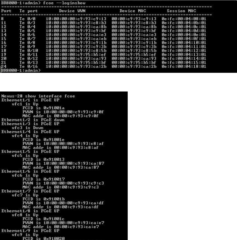
Figure 8 Example of B-series loginshow output
Figure 9 Example of C-series show interface output
3. Observe the CN switch and CNA link error counters.
If any of these steps detect errors, the most likely causes are incompatible or faulty cables, SFPs,
or CN switch ports. Cable or SFP problems can cause a wide range of symptoms from solid to
intermittent and even performance issues. The FCoE switch port and CNA port error counters are
good indications of potential intermittent and performance problems.
Verify Fibre Channel switch zoning for FC storage
Verify that the Fibre Channel zoning and the CNA port WWNs match those displayed by the
CNA.
Verify Fibre Channel storage device discovery
After verifying startup BIOS message, link, and zoning, verify that the CNA can discover the
configured Fibre Channel storage devices.
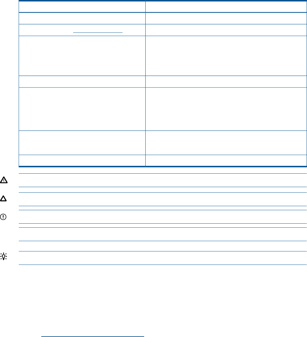
•The first level of CNA Fibre Channel storage device discovery is performed at the BIOS level
using the OneConnect FCoE BIOS utility. Use this utility (see “CNA startup BIOS message”
Isolating CNA problems 15
(page 17)) at system startup to discover and display the storage devices in the attached FC
fabric.
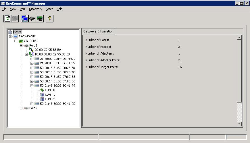
•When the server boots, the operating system performs the next level of discovery. Using the
OneCommand Manager utility (see Figure 10 (page 16)), you can view all Fibre Channel
storage devices known to the server.
Figure 10 OneCommand Manager
If the storage controller cannot be seen, then the most likely causes are Fibre Channel zoning or
SAN connectivity between the CNA and the storage controller.
If the storage controller can be seen, but not any of its LUNs, then the most likely cause of not
seeing discrete LUNs is a LUN mapping problem.
CNA LED states
You can observe green and amber LEDs through openings in the CNA mounting bracket. See
Figure 11 (page 17).Table 1 (page 17) describes the CNA LED link states.
16 Troubleshooting
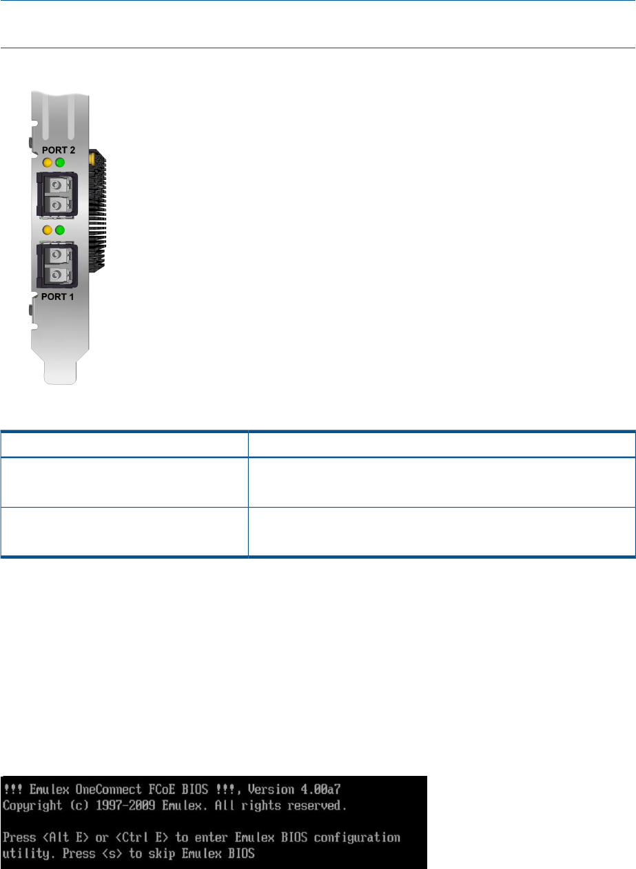
NOTE: When power is applied to the CNA, both LEDs on both ports light for approximately 10
seconds.
Figure 11 CNA LED indicators
Table 1 CNA LED descriptions
MeaningLED
Flash = activityLink activity (Green)
Off = no activity
On = link upLink state (Amber)
Off = link down
CNA startup BIOS message
The CNA BIOS that is typically used to configure Boot from SAN (BFS) can also aid in
troubleshooting CNA installation, SAN link, and zoning configuration issues. During the system
startup the CNA startup BIOS message displays on the system console. This message provides
minimal information, such as the BIOS revision and if a CNA is configured for BFS. It also displays
the LUN path information to the boot device.
During startup, you have the option to enter the BIOS configuration utility by pressing Ctrl+E on
the system console (see Figure 12 (page 17)).
Figure 12 CNA BIOS
Figure 13 (page 18) shows the first screen that displays the CNA ports and their respective Port
WWNs. Use the arrow keys to select a CNA port.
CNA startup BIOS message 17
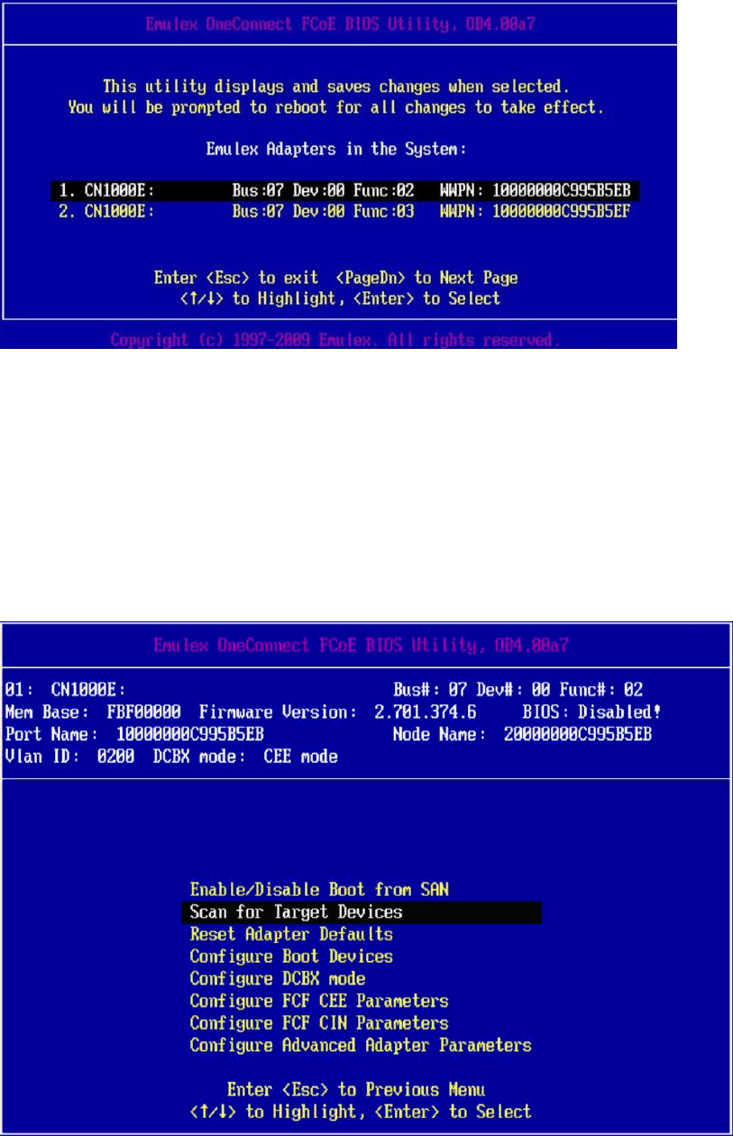
Figure 13 CNA select screen
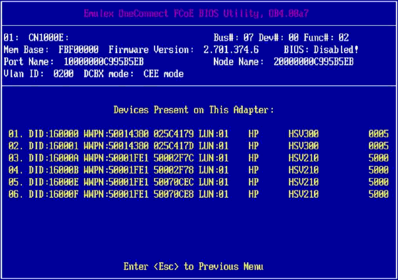
Figure 14 (page 18) shows the CNA BIOS main menu. On this screen, the CNA firmware and
BIOS versions display along with the CNA Port WWN, BIOS enablement state, VLAN, and DCBX
mode. Take note of the code revisions and compare them to the latest supported version for your
server. This menu is typically used for configuring BFS. In addition to the revision configuration
information display, Scan for Target Devices is also a useful troubleshooting tool for zoning issues.
This display is limited and only displays the first LUN for each storage device detected.
Many parameters and options are available with this utility, but do not change any parameters
unless instructed by technical support.
Figure 14 CNA BIOS main menu
18 Troubleshooting

4 Support and other resources
Contacting HP
For worldwide technical support information, see the HP support website:
http://www.hp.com/support
Before contacting HP, collect the following information:
•Product model names and numbers
•Technical support registration number (if applicable)
•Product serial numbers
•Error messages
•Operating system type and revision level
•Detailed questions
Subscription service
HP recommends that you register your product at the Subscriber's Choice for Business website:
http://www.hp.com/go/e-updates
After registering, you will receive e-mail notification of product enhancements, new driver versions,
firmware updates, and other product resources.
New and changed information in this edition
The following additions and changes have been made for this edition:
•Added support for CN1100E.
•Updated download links and procedures.
Related information
The following documents [and websites] provide related information:
•http://www.hp.com/go/san
You can find these documents from the Manuals page of the HP Business Support Center website:
http://www.hp.com/support/manuals
In the Storage section, click Storage Networking and then select your product.
HP websites
For additional information, see the following HP websites:
•http://www.hp.com
•http://www.hp.com/go/storage
•http://www.hp.com/service_locator
•http://www.hp.com/support/manuals
•http://www.hp.com/support/downloads
•http://www.hp.com/storage/whitepapers
20 Support and other resources
Typographic conventions
Table 2 Document conventions
ElementConvention
Cross-reference links and e-mail addressesBlue text: Table 2 (page 21)
Website addressesBlue, underlined text: http://www.hp.com
Bold text •Keys that are pressed
•Text typed into a GUI element, such as a box
•GUI elements that are clicked or selected, such as menu and
list items, buttons, tabs, and check boxes
Text emphasisItalic text
Monospace text •File and directory names
•System output
•Code
•Commands, their arguments, and argument values
Monospace, italic text •Code variables
•Command variables
Emphasized monospace textMonospace, bold text
WARNING! Indicates that failure to follow directions could result in bodily harm or death.
CAUTION: Indicates that failure to follow directions could result in damage to equipment or data.
IMPORTANT: Provides clarifying information or specific instructions.
NOTE: Provides additional information.
TIP: Provides helpful hints and shortcuts.
Customer self repair
HP customer self repair (CSR) programs allow you to repair your HP storage product. If a CSR part
needs replacing, HP ships the part directly to you so that you can install it at your convenience.
Some parts do not qualify for CSR. Your HP-authorized service provider will determine whether a
repair can be accomplished by CSR.
For more information about CSR, contact your local service provider, or see the CSR website:
http://www.hp.com/go/selfrepair
This product has no customer replaceable components.
Typographic conventions 21
A Emulex CNA specifications
This chapter contains the following CNA specifications:
•“Environmental specifications” (page 22)
•“Physical specifications” (page 22)
•“Emulex CNA media specifications” (page 23)
Environmental specifications
Table 3 (page 22) lists the CNA environmental specifications.
Table 3 Environmental specifications
MaximumMinimumEnvironment
55°C (131°F)0°C (32°F)Operating temperature
70°C (158°F)–40°C (–40°F)Storage temperature
85%5%Relative humidity (non-condensing)
N/A150 lf/min (minimum)Airflow
Physical specifications
Table 4 (page 22) lists the physical specifications.
Table 4 Physical specifications
RangeParameter
Minimum eight-lane PCI Express slotPICe slot requirements
Low-profile form factor, 6.60 inches by 2.71 inches, and accommodates both the
full-height and low-profile bracket
Physical dimension
14.5 Watts typicalPower requirements
Agency approvals •Class 1 Laser Product per DHHS 21CFR (J) & EN60825-1
•UL recognized to UL60950-1 2nd Edition
•CUR recognized to CSA 22.2, No. 60950-1-07
•TUV certified by to EN60950-1
•FCC Rules, Part 15, Class A
•Industry Canada, ICES-003, Class A
•EMC Directives 2004/108/EEC (CE Mark)
EN55022, Class A
EN55024
•Australian EMC Framework (C-Tick Mark)
AS/NZS CISPR22:2006 Class A
•Japan VCCI, Class A
•Taiwan BSMI, Class A
•Korea KCC, Class A
•RoHS Compliant (Directive 2002/95/EC)
•China RoHS compliant
22 Emulex CNA specifications
Emulex CNA media specifications
The CNA does not ship with cable media. Select either the fiber optic or copper cabling option,
and purchase the parts separately (see Table 5 (page 23)).
Table 5 Fiber optic and copper cabling parts
Supported mediaMedia type
•HP BLc 10Gb SR SFP+ (part number 455883-B21)
Supported SFP+ optical
media
Supported copper media for
connection to B-series
switches
•HP 1m B-series Active Copper SFP+ Cable (part number AP818A)
•HP 3m B-series Active Copper SFP+ Cable (part number AP819A)
•HP 5m B-series Active Copper SFP+ Cable (part number AP820A)
Supported copper media for
connection to C-series
switches
•HP 3m C-series Passive Copper SFP+ Cable (part number AP784A)
•HP 5m C-series Passive Copper SFP+ Cable (part number AP785A)
•HP 7m C-series Active Copper SFP+ Cable (part number QK701A)
•HP 10m C-series Active Copper SFP+ Cable (part number QK702A)
Supported copper media for
connection to HP
•HP X240 SFP+ SFP+ 0.65 m Direct Attach Cable (part number JD095B)
•HP X240 SFP+ SFP+ 1.2 m Direct Attach Cable (part number JD096B)
A5820X-14XG-SFP+
switches •HP X240 SFP+ SFP+ 3 m Direct Attach Cable (part number JD097B)
CAUTION: Take care not to plug optical cables into cages without transceivers in them.
NOTE: A CNA does not allow data transmission on either 10 Gb optical or copper link unless
it is connected to a compatible optical or copper interface connection (that is, multimode to
multimode). See the appropriate CN switch QuickSpec for the appropriate media supported by
your switch.
Emulex CNA media specifications 23
B Regulatory compliance and safety
Laser device
All HP systems equipped with a laser device comply with safety standards, including International
Electrotechnical Commission (IEC) 825. With specific regard to the laser, the equipment complies
with laser product performance standards set by government agencies as a Class 1 laser product.
The product does not emit hazardous light.
Laser safety warning
WARNING! To reduce the risk of exposure to hazardous radiation:
•Do not try to open the laser device enclosure. There are no user-serviceable components inside.
•Do not operate controls, make adjustments, or perform procedures to the laser device other
than those specified in this document.
•Allow only HP-authorized service technicians to repair the laser device.
Certification and classification information
This product contains a laser internal to the fiber optic (FO) transceiver for connection to the Fibre
Channel communications port.
In the USA, the FO transceiver is certified as a Class 1 laser product conforming to the requirements
contained in 21 CFR 1040.10 and 1040.11 except for deviations pursuant to Laser Notice No.
50, dated June 24, 2007.
Outside the USA, the FO transceiver is certified as a Class 1 laser product conforming to the
requirements contained in IEC 825-1:1993 and EN 60825-1:1994, including Amendment 11:1996
and Amendment 2:2001.
Laser product label
The optional label in Figure 16 (page 24) or equivalent may be located on the surface of the
HP-supplied laser device.
Figure 16 Class 1 laser product label
This optional label indicates that the product is classified as a CLASS 1 LASER PRODUCT. This
label may appear on the laser device installed in your product.
Notice for North America (FCC & IC)
FCC Compliance Information Statement
This device complies with Part 15 of the FCC Rules. Operation is subject to the following two
conditions: (1) This device may not cause harmful interference, and (2) this device must accept
any interference received, including interference that may cause undesired operation.
24 Regulatory compliance and safety
NOTE: This equipment has been tested and found to comply with the limits for a Class A digital
device, pursuant to part 15 of the FCC Rules. These limits are designed to provide reasonable
protection against harmful interference when the equipment is operated in a commercial
environment. This equipment generates, uses, and can radiate radio frequency energy and, if not
installed and used in accordance with the instruction manual, may cause harmful interference to
radio communications. Operation of this equipment in a residential area is likely to cause harmful
interference in which case the user will be required to correct the interference at his own expense.
Shielded cables must be used between this equipment and attached peripheral devices. The reader
is cautioned that changes or modifications made to the equipment not expressly approved by
Emulex could void the user’s authority to operate this equipment. The above statement applies to
products marketed in the USA.
International notices and statements
Canadian notice (avis Canadien)
Class A equipment
This class A digital apparatus meets all requirements of the Industry Canada (IC) Interference -
Causing Equipment Standard (ICES- 003).
Cet appareil numérique de la classe A respecte toutes les exigences du Règlement sur le matériel
brouilleur du Canada. This statement applies to products marketed in Canada.
European Union regulatory notice
Products bearing the CE marking comply with the following EU Directives:
•Low Voltage Directive 2006/95/EC
•EMC Directive 2004/108/EC
•Ecodesign Directive 2009/125/EC, where applicable
CE compliance of this product is valid if powered with the correct CE-marked AC adapter provided
by HP.
Compliance with these directives implies conformity to applicable harmonized European standards
(European Norms) that are listed in the EU Declaration of Conformity issued by HP for this product
or product family and available (in English only) either within the product documentation or at the
following website: http://www.hp.eu/certificates (enter the product number in the search field).
The compliance is indicated by one of the following conformity markings placed on the product:
For non-telecommunications products and for EU harmonized
telecommunications products, such as Bluetooth® within
power class below 10mW.
For EU non-harmonized telecommunications products (If
applicable, a 4-digit notified body number is inserted between
CE and !).
Please refer to the regulatory label provided on the product. The point of contact for regulatory
matters is:
Hewlett-Packard GmbH, Dept./MS: HQ-TRE, Herrenberger Strasse 140, 71034 Boeblingen,
Germany.
International notices and statements 25
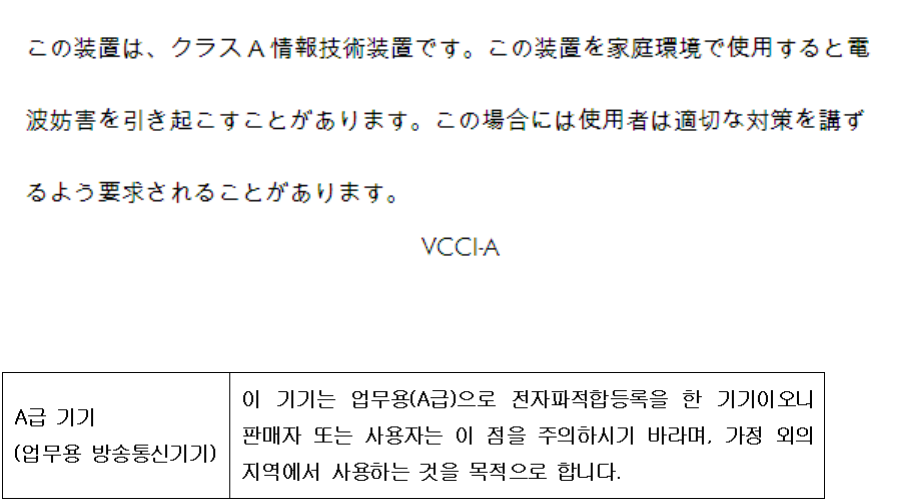
Japanese notice
Korean notice
26 Regulatory compliance and safety

Glossary
This glossary defines acronyms and terms used in this guide and is not a comprehensive
glossary of computer terms.
B
BFS Boot from SAN.
C
CN Converged Network.
CNA Converged Network Adapter.
D
DSM Device Specific Module.
E
ESD Electrostatic discharge.
F
FC Fibre Channel. A comprehensive set of standards for concurrent communication among servers,
storage systems, and peripheral devices.
FCoE Fibre Channel over Ethernet protocol.
Fibre Channel A serial data transport infrastructure and protocol used to implement SANs. See also http://
www.fibrechannel.org/ and http://www.t11.org/.
L
LC Lucent connector. An industry-standard connector for fiber optic cable connections.
M
MPIO Multipath I/O (Microsoft software).
S
SFP Small form-factor pluggable transceiver.
W
WWN World Wide Name. A unique identifier assigned to a Fibre Channel device.
27

Index
B
BIOS
startup message, 17
C
calculations
MAC address and WWN, 5
certification and classification information, laser, 24
Class A equipment, Canadian compliance statement, 25
CNA
installing, 5, 6
isolating problems, 14
LED states, 16
media specifications, 23
observe and collect data, 14
specifications, 22
startup BIOS message, 17
CNA Linux drivers
installing, 12
collecting data
CNA problems, 14
contacting HP, 20
conventions
document, 21
text symbols, 21
copper cable option, 23
copper cables, 23
customer self repair, 21
D
Device Mapper, 11
document
conventions, 21
related information, 20
documentation
HP website, 20
downloading
firmware, 11
Linux driver kit, 10
multipathing software, 11
OneCommand Manager application kit, 10
Windows Smart Component, 10
drivers
installing, 10
E
electrostatic discharge, 6, 9
environmental
specifications, 22
European Union, regulatory compliancex09 notice, 25
F
FCC compliance, 24
fiber optic cable option, 23
fiber optic cables, 23
firmware
downloading, 11
installing on Windows, 12
G
grounding methods, 9
H
help
obtaining, 20
HP
technical support, 20
I
IEC EMC, worldwide regulatory compliance notice, 25
installation
prerequisites, 5
installing
CNA, 5, 6
CNA drivers on Linux, 12
drivers, 10
firmware on Linux, 12
Linux driver kit, 10
multipathing software on Linux, 13
multipathing software on Windows, 12
OneCommand Manager utility, 11
Windows device driver, 11
Windows Smart Component, 10
international notices, 25
isolating
CNA problems, 14
J
Japan, regulatory compliance notice, 26
K
Korean, regulatory compliance notice, 26
L
label, laser, 24
laser
international certification and classification information,
24
product label, 24
radiation, warning, 24
laser device, 24
LED states, 16
Linux
installing firmware, 12
installing the OneCommand Manager application kit,
12
Linux driver kit
downloading, 10
installing, 10
28 Index
M
MAC address
calculations, 5
MAC addresses
recording, 5
MPIO DSM, 11
multipathing software
downloading, 11
installing on Linux, 13
installing on Windows, 12
O
OneCommand Manager application kit
downloading, 10
installing on Linux, 12
OneCommand Manager utility
installing, 11
P
physical
specifications, 22
prerequisites
installation, 5
problems
isolating, 14
R
reference numbers
MAC address, 5
recording, 5
regulatory compliance, 24
notices
European Union, 25
IEC EMC statement, worldwide, 25
Japan, 26
Korean, 26
related documentation, 20
S
safety, 24
Smart Component kit
using, 11
specifications
CNA, 22
CNA media, 23
environmental, 22
physical, 22
Subscriber's Choice, HP, 20
symbols in text, 21
T
technical support
HP, 20
service locator website, 20
text symbols, 21
troubleshooting, 14
typographic conventions, 21
W
warnings, lasers, radiation, 24
websites
customer self repair, 21
HP , 20
HP Subscriber's Choice for Business, 20
product manuals, 20
Windows device driver
installing, 11
Windows firmware
installing, 12
Windows Smart Component
downloading, 10
installing, 10
WWN
calculations, 5
recording, 5
29
