Hp Compaq 4000 Pro Small Form Factor Pc Service And Maintain Tiguan SFF IPSM
2015-01-05
: Hp Hp-Compaq-4000-Pro-Small-Form-Factor-Pc-Service-And-Maintain-141362 hp-compaq-4000-pro-small-form-factor-pc-service-and-maintain-141362 hp pdf
Open the PDF directly: View PDF ![]() .
.
Page Count: 4
HP Compaq 4000 Pro, SFF Chassis 640048-001 page 1
Illustrated Parts & Service Map
HP Compaq 4000 Pro
Small Form Factor Business PC
© 2011 Hewlett-Packard Development Company, L.P. The information contained
herein is subject to change without notice. HP shall not be liable for technical or edito-
rial errors or omissions contained herein. Intel, Pentium, Intel Inside, and the Intel
logo are trademarks or registered trademarks of the Intel Corporation and its subsid-
iaries in the U. S. and other countries.
Document Number 640048-001. 1st Edition January 2011.
Key Specifications
Spare Parts
Processor Type Intel® Pentium Dual-Core, Core 2, Core2 Duo, Core2 Quad
RAM Type DDR3-SDRAM DIMMs, PC3-10600 (1333 MHz) non-ECC
Maximum RAM Supported 8 GB
Expansion Slots • (1) PCIe-x16
• (1) PCIe-x1
• (2) PCI
Chipset Intel B43 Express
Graphics Adapter Integrated Intel GMA 4500 graphics
Bays • (1) external 5.25-inch for optical drive
• (1) external 3.5-inch for media card reader
• (1) internal 3.5-inch or hard drive
I/O Interfaces Front: (4) USB, microphone, headphone
Rear: (4) USB, PS/2 keyboard and mouse, line in, line out,
VGA, DVI-D, RJ-45, serial
Operating Systems • Windows® Vista
• Windows 7
• RedFlag Linux
• FreeDos
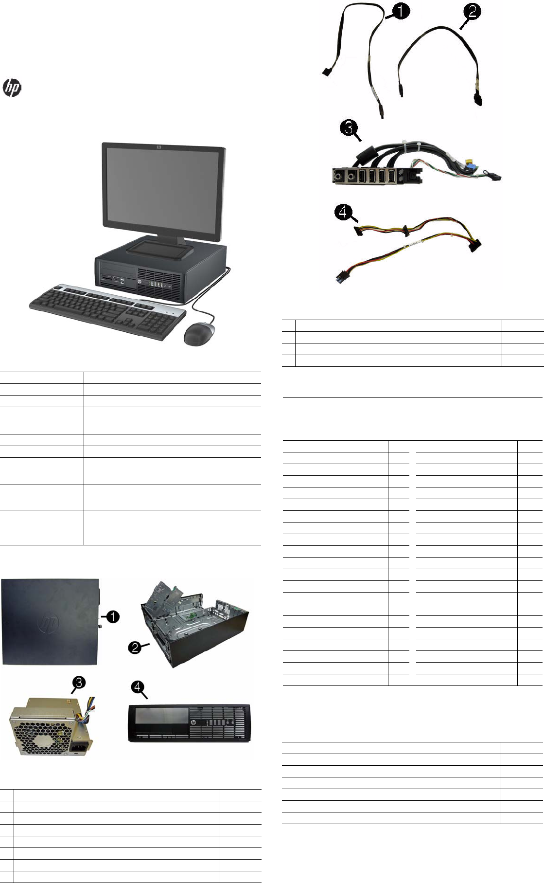
System Unit
1 Access panel 636924-001
2 Chassis Not spared
3 Power supply, 240W 613763-001
* Power supply, 240W, 85% efficient 613663-001
* Power supply, 240W, High Voltage protection 613664-001
4 Front bezel 636920-001
* Bezel blank, 3.5-inch 583653-001
* Bezel blank, 5.25-inch 570838-001
* Not shown
Cables
1 SATA ODD cable, 25 inch, 1 straight, 1 angled end 638814-001
2 19-inch SATA cable, 2 straight ends 638813-001
3 Front I/O cable and power assembly 636926-001
4 SATA power cable 636923-001
Keyboards (not illustrated)
PS/2, Basic
USB, Basic
USB SmartCard
USB Mini[b]
Washable[b]
537745-xx1
537746-xx1
631411-xx4
535873-xx1
577495-xx1
Arabic -17x Kazakstanian -DFx
Belgian -18x LA Spanish -16x
BHCSY -B4x Netherlands -33x
BHCSY -BLx Norwegian -09x
Brazilian Portuguese -20x People’s Republic of China
-AAx
Bulgarian[c] -26x Polish
-24x
Czech -22x Portuguese -13x
Danish -08x Romanian[a] -27x
Estonian -CAx Russian -25x
Finnish[c] -35x Saudi Arabian -DEx
French -05x Slovakian -23x
French Canadian -12x South Korean -KDx
German -04x Spanish -07x
Greek -15x Swedish -10x
Hebrew -BBx Swiss -11x
Hong Kong[d][e] -ACx Taiwanese -ABx
Hungarian -21x Thai -28x
Icelandic
-DDx
Turkish -14x
International[e] -B3x Turkish F -54x
International English -L3x U.S. -00x
Italian -06x U.K. -03x
[a] only for 631411-xx4
[b] only for -001 and -021
[c] only for 631411 and 537745
[d] use -AC2 for 537746
[e] only for 537745 and 537746
Mass Storage Devices (not illustrated)
16X SATA DVD±RW drive with LightScribe 615646-001
16X SATA DVD-ROM drive 581599-001
6X BD-Writer and DVD+/-RW SuperMulti DL Drive 581601-001
1 TB SATA hard drive 636930-001
500 GB SATA hard drive 636929-001
320 GB SATA hard drive 636928-001
250 GB SATA hard drive 636927-001
HP Compaq 4000 Pro, SFF Chassis 640048-001 page 2
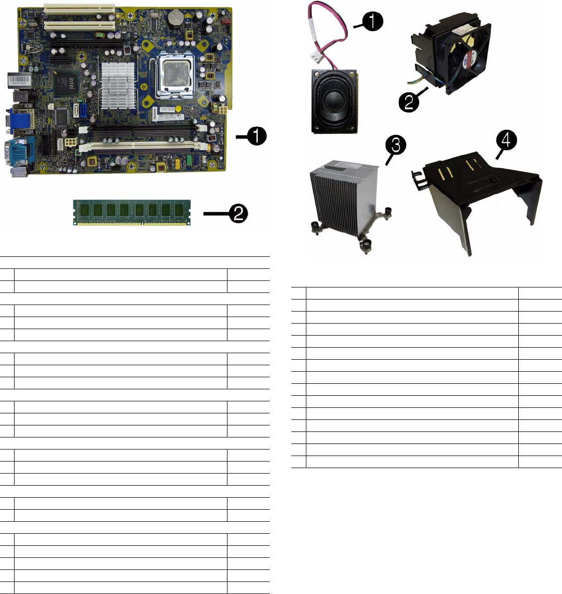
Standard and Optional Boards
System boards with thermal material
1 System board 608748-001
* System board, Netclone (China only) 640126-001
Memory modules (PC3-10600, CL9)
1 GB 635802-001
22 GB 635803-001
*4 GB 585157-001
Other boards
* nVidia Quadro NVS300 PCIe x1 graphics card 632827-001
* nVidia Quadro NVS300 PCIe x16 graphics card 632486-001
* ATI Radeon HD6350 PCIe x16 graphics card, 512 MB 637995-001
Intel Pentium Dual Core Processors (include thermal material)
* E6800, 3.33 GHz, 2-MB L2 cache 631758-001
* E6700, 3.20 GHz, 2-MB L2 cache, 1066-MHz FSB 617840-001
* E5800, 3.20 GHz, 2-MB L2 cache, 800-MHz FSB 646376-001
Intel Celeron Processors (include thermal material)
* E3500, 2.7 GHz, 1-MB L2 cache 633219-001
* E3400, 2.6 GHz, 1-MB L2 cache 602071-001
* E3300, 2.5 GHz, 1-MB L2 cache 585886-001
Intel Core 2 Quad Processors (include thermal material)
* Q9550S, 2.83 GHz, 12-MB L2 cache 593228-001
* Q9505S, 2.83 GHz, 6-MB L2 cache (65W) 593229-001
Intel Core 2 Duo Processors (include thermal material)
* E8600, 3.33 GHz, 6-MB L2 cache 497732-001
* E8500, 3.16 GHz, 6-MB L2 cache 466170-001
* E8400, 3.00 GHz, 6-MB L2 cache 509554-001
* E7600, 3.06 GHz, 3-MB L2 cache 573954-001
* E7500, 2.93 GHz, 3-MB L2 cache 583006-001
* Not shown
Miscellaneous Parts
1 Internal speaker 636925-001
2 Chassis fan assembly 636922-001
3 Heat sink (includes thermal material) 636919-001
4 Baffle 636921-001
* Rubber feet kit 583654-001
* Chassis stand 587451-001
* 2nd serial port 638815-001
* Card reader, 22-in-1 636166-001
* Hood sensor 638816-001
* USB powered speakers 609249-001
* Mouse, PS2, optical, jack black 537748-001
* Mouse, optical, jack black 537749-001
* Mouse, laser, jack black 570580-001
* Mouse, washable 619580-001
* Printer port kit 638817-001
*Not shown
LP = Low profile
HP Compaq 4000 Pro, SFF Chassis 640048-001 page 3
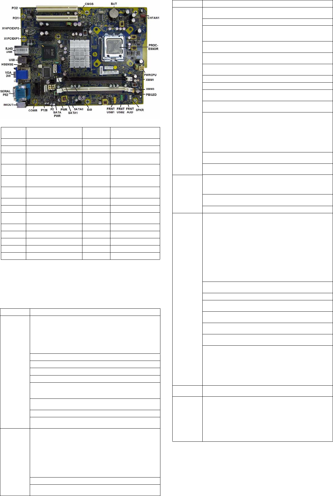
System Board
System Setup and Boot
Basic system information regarding system information, setup, power management, hardware,
and passwords is maintained in the Setup Utility held in the system ROM. The Setup Utility is
accessed by pressing the F10 key when prompted (on screen) to do so during the boot sequence.
If the screen prompt opportunity is missed, a restart will be necessary. For more information
about Setup Utilities refer to the Service Reference Guide.
System Board Connectors and Jumpers (component location may vary)
CMOS CMOS header SATA PWR SATA drive power connec-
tor
BAT Battery socket P2 Power connector
CHFAN System fan connector P126 Parallel port connector
PROCES-
SOR
Processor socket COMB Serial port connector
PWRCPU CPU power connector IN/OUT Double stack audio con-
nector
XMM1& 3 Memory sockets SERIAL PS2 Stacked serial port/PS2
connector
PB/LED Power switch connector VGA/DVI Stacked VGA/DVI connec-
tor
SPKR Speaker connector HSENSE Hood sensor connector
FRNT AUD Front panel connector USB USB connector
FRNT_USB
2
2nd USB connector RJ45/USB Stacked RJ-45/USB con-
nectors
FRNT_USB 1st USB connector X1PCIEXP1 PCIe X1 slot
E49 X16PCIEXP2 PCIe X16, slot 2
SATA1 Primary SATA hard drive PWR Main power connector
SATA2 1st SATA optical drive PCI1 PCI slot 1
PWR Main power connector PCI2 PCI slot 2
Computer Setup Menu
Heading Option/Description
File System Information - Lists the following main system specifications:
• Product name
• SKU number (some models)
• Processor type/speed/stepping
• Cache size (L1/L2)
• Installed memory size/speed/
channels
• Integrated MAC Address
• System BIOS
• Chassis serial number
• Asset tracking number
About - Displays copyright notice.
Set Time and Date - Allows you to set system time and date.
Flash System ROM - Allows you to select a drive containing a new BIOS.
Replicated Setup - Save to Rmv Media and Restore from Rmv Media
Default Setup
• Save Current Settings as Default
• Restore Factory Settings as Default
Apply Defaults and Exit - Applies the selected default settings and clears
any established passwords.
Ignore Changes and Exit - Exits Computer setup without saving changes.
Save Changes and Exit - Saves changes to system configuration or default
settings and exits Computer Setup.
Storage Device Configuration - Lists all installed BIOS-controlled storage devices.
The following options are available:
•Hard Disk
•CD-ROM
• Default Values
• SATA Defaults
• Translation Mode
• Removable Media Boot
• Max SATA Speed
• SATA Emulation
DPS Self-Test - Allows you to execute self-tests on ATA hard drives.
Boot Order - Allows you to specify boot order.
• Shortcut to Temporarily Override Boot Order
Computer Setup Menu (Continued)
Heading Option / Description
Security Setup Password - Allows you to set and enable the setup (Administrator)
password.
Power-On Password - Allows you to set and enable power-on password.
Password Options - When any password exists allows you to lock legacy
resources, enable/disable network server mode, specify password require-
ment for warm boot, and allows you to enable/disable Setup Browse Mode.
Smart Cover (some models) - Allows you to lock/unlock cover lock and set
status of cover removal sensor.
Device Security (some models) - Enables/disables all I/O ports, audio, net-
work controllers, SATA ports, and embedded security devices.
USB Security - Allows you to set Device Available/Device Hidden for front
USB ports 3-6, rear USB ports 9-12, internal USB ports 1-2.
Slot Security - Allows you to disable any PCI or PCI Express slot.
Network Service Boot - Enables/disables boot from OS on a server.
System IDs - Allows you to set Asset tag, Ownership tag, Chassis serial
number or UUID, and keyboard locale setting.
DriveLock Security - Allows you to assign/modify a hard drive password for
added security.
System Security (some models) - Allows you to enable/disable:
• Data Execution Prevention
• PAVP (Protect Audio Video Path) (some models)
• Virtualization Technology
• Virtualization Technology Directed I/O (some models)
• Trusted Execution Technology (some models)
• Embedded Security Device Support (some models)
• OS management of Embedded Security Device through OS (some models)
Master Boot Record Security - Protects the master boot record from viruses
or other corruption. Saves of copy of the current master boot record.
Setup Security Level - Provides method to allow users limited access to
change specified setup options without knowing Setup password.
Power OS Power Management - Allows you to enable/disable Runtime Power
Management, Idle Power Savings, ACPI S3 Hard Disk Reset, ACPI S3 PS2
Mouse Wakeup, USB Wake on Device Insertion (some models), Unique
Sleep State Blink Rates.
Hardware Power Management - Allows you to enable/disable SATA bus
power management and S5 maximum power savings.
Thermal - Allows you to control minimum permitted fan idle speed.
Advanced Power-On Options - Allows you to set:
• POST mode - QuickBoot, FullBoot, Clear Memory, FullBoot every x
days
• POST messages - Enable/disable
• F9 prompt - Hidden/displayed
• F10 prompt - Hidden/displayed
• F11 prompt - Hidden/displayed
• F12 prompt - Hidden/displayed
• Factory Recovery Boot Support - Enable/disable
• Option ROM prompt - Enable/disable
• Remote wakeup boot source - Remote server/local hard drive
• After Power Loss - Off/on/previous state
• POST delay - None, 5, 10, 15, or 20 seconds
• Bypass F1 Prompt on Configuration Changes - Enable/disable
Execute Memory Test (some models) -Restarts computer and executes
POST memory test.
BIOS Power-On - Allows you to set the computer to turn on at a preset time.
Onboard Devices - Allows you to set resources or disable onboard system
devices.
PCI Devices - Lists installed PCI devices with their IRQ settings and allows
you to reconfigure IRQ or disable devices.
PCI VGA Configuration - Allows you to specify which VGA controller will
be used when multiple video adapters are available.
Bus Options (some models) - Allows you to enable/disable PCI SERR#
Generation and PCI VGA palette snooping.
Device Options - Allows you to set:
• Printer Mode - Bi-Directional, EPP & ECP, Output Only
• Num Lock state at power-on - off/on
• S5 Wake on LAN - enable/disable
• Multi-Processor - enable/disable
• Internal speaker - enable/disable
• Monitor Tracking - enable/disable
• NIC Option ROM Download - enable/disable
Management Devices - Only displayed in Advanced menu when BIOS
detects multiple management options.
Management Operations - Allows you to set:
• MEBx Setup Prompt - enable/disable
• Intel Remote PC Assist Prompt - enable/disable
• Intel PC Assist Timeout - 5, 10, 15, 20, 30, 40, 50, 60, 120, 180, 240 sec-
onds
• SOL Character Echo - enable/disable
• SOL Terminal Emulation Mode - enable/disable
• SOL Keyboard - enable/disable
• Unprovision AMT on next boot

HP Compaq 4000 Pro, SFF Chassis 640048-001 page 4
Password Security
Establishing a Setup or Power-On password:
1. Turn on or restart the computer. If you are in Windows, click Start > Shut Down >Restart.
2. As soon as the computer is turned on, press F10 when the monitor light turns green to enter
Computer Setup. Press Enter to bypass the title screen, if necessary. If you do not press F10
when prompted, a restart will be necessary.
3. To establish a Setup password, select Security > Setup Password and follow the instructions
on the screen.
- or -
To establish a Power-On password, select Security > Power-On Password and follow the
instructions on the screen
4. Before exiting, click File > Save Changes and Exit.
Changing a Setup or Power-On password:
1. Turn on or restart the computer. If you are in Windows, click Start > Shut Down > Restart.
To change the Setup password, go to step 2.
To change the Power-on password, go to step 3.
2. To change the Setup password, as soon as the computer is turned on, press F10 when the
monitor light turns green to enter Computer Setup. Press Enter to bypass the title screen, if
necessary.
3. When the key icon appears, type your current password, a slash (/) or alternate delimiter
character, your new password, another slash (/) or alternate delimiter character, and your new
password again as shown:
current password/new password/new password.
NOTE: Type the new password carefully since the characters do not appear on the screen.
4. Press Enter.
The new password will take effect the next time the computer is restarted.
Deleting a Power-On or Setup password
1. Turn on or restart the computer. If you are in Windows, click Start > Shut Down > Restart.
To delete the Setup password, go to step 2.
To delete the Power-On password, go to step 3.
2. To change the Setup password, as soon as the computer is turned on, press F10 when the
monitor light turns green to enter Computer Setup. Press Enter to bypass the title screen, if
necessary.
3. When the key icon appears, type your current password followed by a slash (/) or alternate
delimiter character as shown. Example: currentpassword/
4. Press Enter.
Hewlett-Packard Vision Diagnostics
The Hewlett-Packard Vision Diagnostics utility allows you to view information about the hard-
ware configuration of the computer and perform hardware diagnostic tests on the subsystems of
the computer. The utility simplifies the process of effectively identifying, diagnosing, and iso-
lating hardware issues.
Use HP Vision Diagnostics to determine if all the devices installed on the computer are recog-
nized by the system and functioning properly. Running tests is optional but recommended after
installing or connecting a new device.
To access HP Vision Diagnostics, you must create a Recovery Disc Set then boot to the CD con-
taining the utility. It can also be downloaded from http://www.hp.com and either burned to CD
or installed to a USB flash drive.
1. In Windows Explorer, go to C:\SWSetup\ISOs and burn the file Vision Diagnostics.ISO to a
CD or copy it to a USB flash drive.
2. While the computer is on, insert the CD in the Optical Drive or USB flash drive in a USB port
on the computer.
3. Shut down the operating system and turn off the computer.
4. Turn on the computer. The system will boot into HP Vision Diagnostics.
NOTE: If the system does not boot to the CD in the optical drive or to the USB flash drive,
you may need to change the boot order in the Computer Setup (F10) utility.
5. At the boot menu, select either the HP Vision Diagnostics utility to test the various hardware
components in the computer or the HP Memory Test utility to test memory only.
NOTE: The HP Memory Test is a comprehensive memory diagnostic utility that is run as a
stand-alone application, outside of HP Vision Diagnostics.
6. If running HP Vision Diagnostics, select the appropriate language and click Continue.
7. In the End User License Agreement page, select Agree if you agree with the terms. The HP
Vision Diagnostics utility launches with the Survey tab displayed.
Clearing CMOS
1. Turn off the computer and any external devices, and disconnect the power cord from the
power outlet.
2. Remove the chassis access panel.
3. On the system board, press and hold the CMOS button for 5 seconds.
4. Replace the chassis access panel and reconnect the power cord.
5. Turn on the computer and allow it to start.
Diagnostic LEDs
LED Color LED Activity State/Message
Power Green On Computer on
Power Green 1 blink every 2 seconds Normal Suspend Mode
Power Red 1 blink every second followed
by a 2 second pause
CPU thermal shutdown
Power Red 3 blinks, 1 blink every second
followed by a 2 second pause
Processor not installed
Power Red 4 blinks, 1 blink every second
followed by a 2 second pause
Power failure (power supply overload)
Power Red 5 blinks, 1 blink every second
followed by a 2 second pause
Pre-video memory error
Power Red 6 blinks, 1 blink every second
followed by a 2 second pause
Pre-video graphics error
Power Red 7 blinks, 1 blink every second
followed by a 2 second pause
System board failure (ROM
Power Red 8 blinks, 1 blink every second
followed by a 2 second pause
Invalid ROM based on Checksum
Power Red 9 blinks, 1 blink every second
followed by a 2 second pause
System powers on but is unable to boot
Power Red 10 blinks, 1 blink every second
followed by a 2 second pause
Bad option card
Power Red 11 blinks, 1 blink every second
followed by a 2 second pause
The current processor does not support
a feature previously enabled on this
system.
none none System does not power on and
LEDs are not flashing
System unable to power on
Common POST Error Messages
Screen Message Probable Cause Recommended Action
101-Option ROM Error 1. System ROM checksum
error.
2. Expansion board option
ROM checksum
1. Verify ROM, reflash if required
2. Remove suspected card, reboot
3. Clear CMOS memory, reboot
4. Replace system board
103-System Board
Failure
DMA, timers 1. Clear CMOS memory.
2. Remove expansion boards.
3. Replace system board.
104-ECC Network Con-
troller has been enabled
Enable network controller For this setting to take effect,
remove power from the system for
15 seconds.
164-Memory Size Error
and
201-Memory Error
Incorrect memory configu-
ration
1. Run Setup (F10).
2. Check DIMMs for proper
seating, type, and HP
compatibility.
3. Remove DIMMs singularly and
reboot to isolate faulty DIMM.
4. Replace system board.
213-Incompatible Mem-
ory Module in Memory
Socket(s) X, X,
Memory module missing
SPD information or incom-
patible with chipset
1. Verify memory module type.
2. Try another memory socket.
3. Replace with module
conforming to SPD standard.
214-DIMM Configura-
tion Warning
Populated DIMM configura-
tion is not optimized
Rearrange the DIMMs so that
each channel has the same amount
of memory.
301-, 304-Keyboard error Keyboard failure Check keyboard connection or
keys. Check connector for bent of
missing pins. Replace keyboard. If
304, possible system board prob-
lem.
501-Display Adapter
Failure
Graphics display controller 1. Reseat graphics card.
2. Clear CMOS.
3. Check monitor connection.
4. Replace graphics card.
510-Flash Screen Image
Corrupted
Flash screen image has
errors
Reflash the system ROM with the
latest BIOS image.
513-Front Chassis fan not
detected
515-Power Supply fan not
detected
Fan not connected or mal-
functioning
1. Reseat fan.
2. Reseat fan cable.
3. Replace fan.
660-Display cache is
detected unreliable
Integrated graphics control-
ler display cache not work-
ing properly and disabled
Replace system board if minimal
graphics degrading is an issue.
1720-SMART Hard Drive
Detects Imminent Failure
Hard drive is about to fail 1. Determine if hard drive is
giving correct error message.
Enter Computer Setup and run
the Drive Protection System
test under Storage > DPS Self-
test.
2. Apply hard drive firmware
patch if applicable.
3. Back up contents and replace
hard drive.
1796-SATA Cabling Error One or more SATA devices
are improperly attached. For
optimal performance, the
SATA 0 and SATA 1 con-
nectors must be used before
SATA 2 and SATA 3
Ensure SATA connectors are used
in ascending order. For one
device, use SATA 0. For two
devices, use SATA 0 and SATA 1.
For three devices, use SATA 0,
SATA1, and SATA 2.
1801-Microcode Patch
Error
Processor not supported by
ROM BIOS
1. Upgrade BIOS to proper
version.
2. Change the processor.
