Hp Compaq 6000 Pro Small Form Factor Pc Service And Maintain
2015-01-05
: Hp Hp-Compaq-6000-Pro-Small-Form-Factor-Pc-Service-And-Maintain-141389 hp-compaq-6000-pro-small-form-factor-pc-service-and-maintain-141389 hp pdf
Open the PDF directly: View PDF ![]() .
.
Page Count: 4
HP Compaq 6000 Pro, SFF Chassis 581652-001 page 1
Illustrated Parts & Service Map
HP Compaq 6000 Pro Small Form Factor
Business PC
© 2009 Hewlett-Packard Development Company, L.P. The information con-
tained herein is subject to change without notice. HP shall not be liable for
technical or editorial errors or omissions contained herein. Intel, Pentium,
Intel Inside, and the Intel logo are trademarks or registered trademarks of the
Intel Corporation and its subsidiaries in the U. S. and other countries.
Document Number 581652-001. 1st Edition September 2009.
Key Specifications
Spare Parts
Processor Type Intel Celeron, Core2 Duo, Core2 Quad
RAM Type DDR3-SDRAM DIMMs, PC2-10600 (1333 MHz) non-ECC
Maximum RAM Supported 16 GB
Expansion Slots • 1 PCIe-x16 (SDVO/ADD2)
•2 PCIe-x1
•1 PCI
Graphics Adapter Integrated Intel GMA 4500 graphics
Chipset Intel Q43 Express
Drive Support • (1) 3.5-inch external bay for optional HP 22-in-1 media
card reader, pocket media drive, or other 3.5-inch device
• (1) 5.25-inch external bay for optional optical drive
• (1) 3.5-inch internal bay for primary hard drive
I/O Interfaces USB 2.0 (10, 4 front, 6 rear), DisplayPort, parallel (optional),
serial (optional), RJ-45, front and rear audio jacks (2 each), PS/
2 ports (2), VGA connector, dual color diagnostic LEDs
Operating Systems • Windows 7
• Windows Vista
• Windows XP
System Unit
1 Chassis Not spared
2 Power supply, 240W 508151-001
2 Power supply, 240W, 89% efficient 508152-001
3 Front bezel 581353-001
4 Access panel 581356-001
* Bezel blank 583653-001
* Not shown
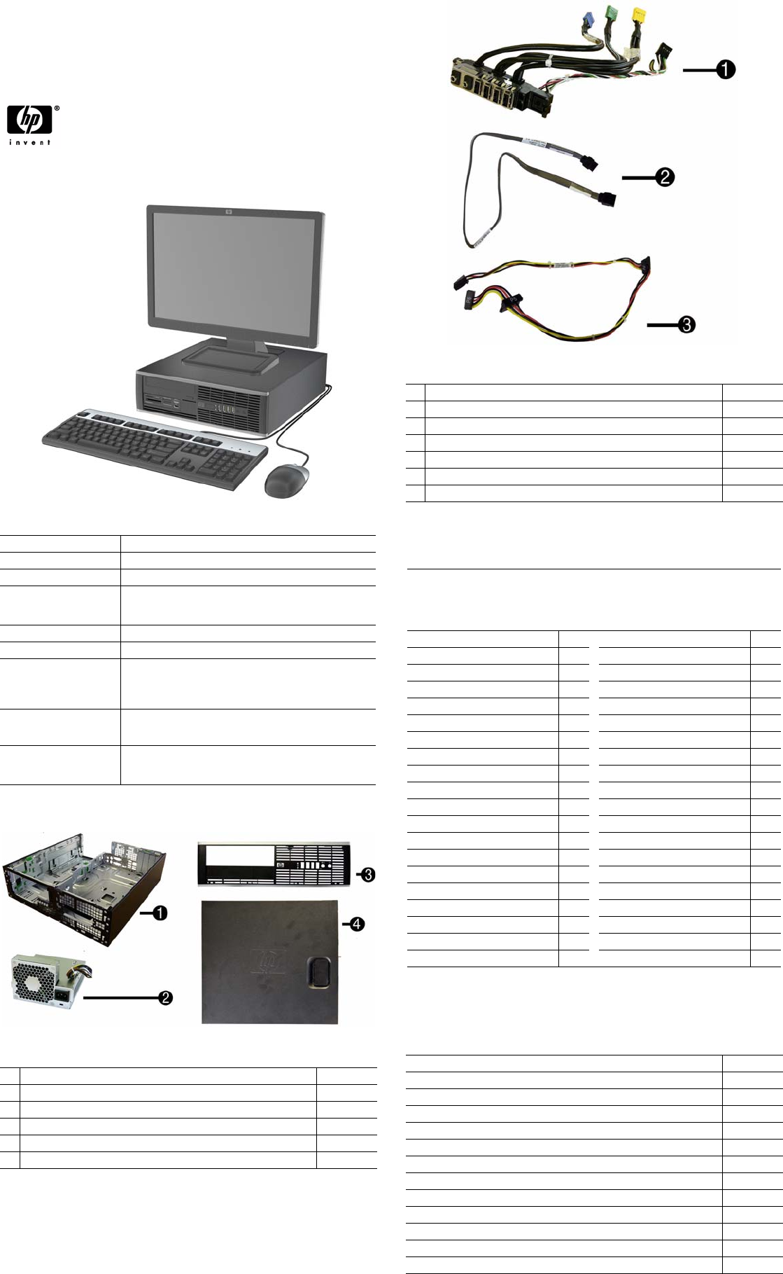
Cables
1 Front I/O cable assembly 581351-001
2 19-inch SATA cable 391739-001
3 SATA power cable 581355-001
* SATA ODD cable, 25 inch, 1 straight, 1 angled end 461535-001
* eSATA port assembly 497726-001
* Adapter, Display Port (DP) to DVI 484156-001
* Adapter, Display Port (DP) to VGA 484155-001
*Not shown
Keyboards (not illustrated)
PS/2, Basic
USB, Standard
USB SmartCard
USB, Mini[a]
Washable[b]
537745-xxx
537746-xxx
537747-xxx
535873-xxx
577495-xxx
Arabic -171 Korean (Hangul)[a]
-KD1
Belgian -181 LA Spanish -161
BHCSY* -B41 Netherlands -331
Brazilian Portuguese -201 Norwegian[b] -091
Bulgarian -261 Polish -241
Czech -221 PRC[a][b]
-AA1
Danish -081 Portuguese -131
Finnish -351 Romanian -271
French[b] -051 Russian -251
French Arabic -DE1 Slovakian -231
French Canadian[a][b] -121 Spanish[b] -071
German -041 Swedish[b] -101
Greek -151 Swiss -111
Hebrew -BB1 Taiwanese[a] -AB1
Hungarian -211 Thai[b] -281
Iceland
-DD1
Turkish -141
International -B31 Turkish F -541
Italian[b] -061 U.S.[a][b] -001
Japanese[a] -291 U.K.[b] -031
Kazakhstan -DF1
*Not for 537747-xxx
[a] only countries marked with [a] are valid for 535873-xxx
[b] only countries marked with [b] are valid for 577495-xxx
Mass Storage Devices (not illustrated)
22-in-1 media card reader, 3.5-inch 480032-001
Blu-ray ROM DVD+/-RW SuperMulti DL Drive 581601-001
16X DVD±RW SuperMulti drive with LightScribe 581600-001
16X DVD-ROM drive 581599-001
500 GB SATA hard drive 504339-001
500-GB hard drive, 2.5-inch 449980-001
320 GB SATA hard drive 504338-001
250 GB, 7200-RPM SATA hard drive 504337-001
160 GB, 10000-RPM SATA hard drive, 2.5-inch with adapter 508312-001
160 GB, hard drive, 3.5-inch 504336-001
80 GB Solid-State Drive (SSD), 2.5-inch with adapter 508311-001
64 GB Solid-State Drive 581057-001
250-GB portable USB hard drive 500019-001
HP Compaq 6000 Pro, SFF Chassis 581652-001 page 2
System Board
Standard and Optional Boards
System boards with thermal grease, alcohol pad, and CPU socket cover
1 System board 531965-001
1 System board, excludes ES 581350-001
Memory modules
2 4 GB, PC3-10600 585157-001
2 2 GB, PC3-10600 576110-001
2 1 GB, PC3-10600 576109-001
Other boards
* Broadcom NetXtreme GbE PCIe NIC 488293-001
* HP Wireless 802.11b/g/n WLAN card 538048-001
* Antenna for use with 538048-001 583345-001
* LSI 56K modem, PCIe 490689-001
* ATI HD3470 (RV620) 256-MB graphics card, one DP 1.1a connector, one
dual-link DVI connector, includes bracket
516913-001
* ATI Radeon HD4550 (RV710) PCIe x16 graphics card, 512 MB 538051-001
* ATI Radeon HD4650 (RV730) PCIe x16 graphics card, 1 GB 538052-001
* Nvidia Quadro NVS290 256-MB PCIe graphics card 460815-001
* Nvidia Quadro NVS295 256-MB PCIe graphics card 578226-001
* Intel Gigabit NIC, includes bracket 490367-001
* HP FireWire IEEE 1394 PCI card, FH 515182-001
* Video card, SDVO, ADD2, DVI-D, includes bracket 398333-001
Intel Celeron Processors with alcohol pad and thermal grease:
E3300, 1-MB cache, 2.50 GHz 585886-001
E3200, 1-MB cache, 2.40 GHz 585885-001
450, 512-KB cache, 2.20 GHz 508256-001
Intel Core2 Quad Processors with alcohol pad and thermal grease:
Q9650, 12-MB cache, 3.00 GHz 497734-001
Q9550, 12-MB cache, 2.83 GHz 465758-001
Q9400, 6-MB cache, 2.66 GHz 497733-001
Q8400, 4-MB cache, 2.66 GHz 573955-001
Intel Core2 Duo Processors with alcohol pad and thermal grease:
E8600, 6-MB cache, 3.33 GHz 497732-001
E8500, 6-MB cache, 3.16 GHz 466170-001
E8400, 6-MB cache, 3.00 GHz 509554-001
E7600, 3-MB cache, 3.06 GHz 573954-001
E7500, 3-MB cache, 2.93 GHz 583006-001
E6300, 2-MB cache, 2.80 GHz 580748-001
E5400, 2-MB cache, 2.70 GHz 531989-001
E5300, 2-MB cache, 2.60 GHz 516900-001
* Not shown
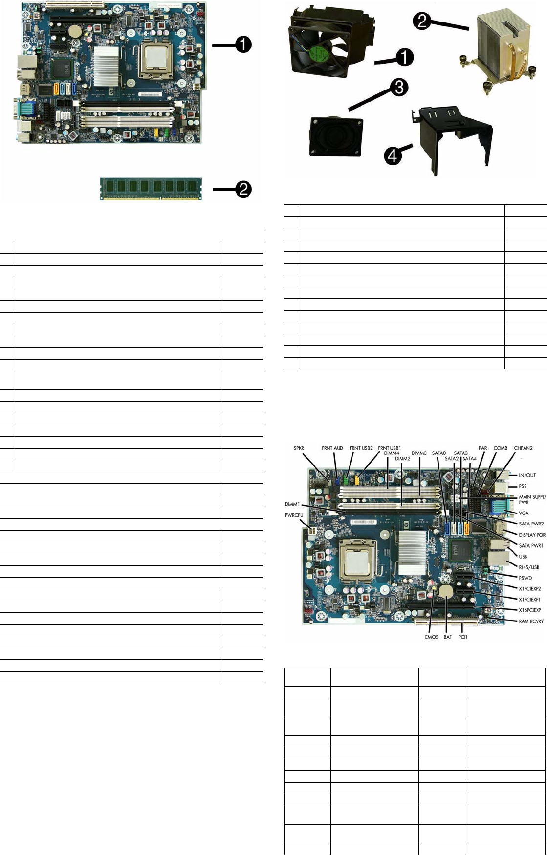
Miscellaneous Parts
1 Chassis fan assembly 581352-001
2 Heatsink with alcohol pad and factory-applied thermal grease 581354-001
3 Internal speaker 394779-001
4 Fan baffle 583652-001
* Rubber feet kit 583654-001
* Second serial port, LP 392414-001
* Solenoid lock assembly 586752-001
* Printer port 497727-001
* Mouse, PS2, optical 537748-001
* Mouse, optical, jack black 537749-001
* Mouse, USB laser 570580-001
* Powered USB speakers 466618-001
* HP Business PC Security Lock Kit 508987-001
* Hard drive conversion kit, 2.5-inch to 3.5-inch 397117-001
*Not shown
LP = Low profile
System Board Connectors and Jumpers (position of some untitled
components may vary in location)
SPKR Speaker connector SATA PWR2 Hard drive power connec-
tor
FRNT AUD Front audio connector USB Stacked USB ports
FRNT USB2 Front USB connector SATA PWR1 Optical drive power con-
nector
FRNT USB1 Front USB connector RJ45/USB Stacked network/USB
connector
DIMM1-4 Memory slots PSWD Password header
SATA0-3 Drive connectors X1PCIEXP2 PCIe x1 slot
PAR Parallel port connector X1PCIEXP1 PCIe x1 slot
COMB Serial port connector X16PCIEXP PCIe x16 slot
CHFAN2 Rear fan connector RAM RCVRY RAM header
IN/OUT Double stack audio connector PCI1 PCI slot
PS2 PS/2 mouse and keyboard
connectors
BAT RTC battery
MAIN SUP-
PLY PWR
Main power CMOS CMOS reset button
VGA Monitor connector PWRCPU CPU power connector

HP Compaq 6000 Pro, SFF Chassis 581652-001 page 3
Setup Utility
Basic system information is in the Setup Utility held in the system ROM, accessed by pressing
F10 when prompted (on screen) during the boot sequence.
Recovering the Configuration Settings
This method of recovery requires that you first perform the Save to Removable Media
command with the Computer Setup (F10) Utility before Restore is needed.
NOTE: It is recommended that you save any modified computer configuration settings to a USB
flash media device or a diskette-like device (a storage device set to emulate a diskette drive) and
save the device for possible future use.
To restore the configuration, insert a USB flash media device or other storage media emulating a
diskette with the saved configuration and perform the Restore from Removable Media command
with the Computer Setup (F10) Utility.
Drive Protection System
The Drive Protection System (DPS) is a diagnostic tool built into the hard drives installed in
some computers. DPS is designed to help diagnose problems that might result in unwarranted
hard drive replacement.
Running DPS will not affect any programs or data stored on the hard drive. The test resides in
the hard drive firmware and can be executed even if the computer will not boot to an operating
system. The time required to execute the test depends on the manufacturer and size of the hard
drive; in most cases, the test will take approximately two minutes per gigabyte.
Use DPS when you suspect a hard drive problem. If the computer reports a SMART Hard Drive
Detect Imminent Failure message, there is no need to run DPS; instead, back up the information
on the hard drive and contact a service provider for a replacement hard drive.
Accessing DPS through Computer Setup
1. Turn on or restart the computer.
2. When the F10 Setup message appears in the lower-right corner of the screen, press the F10.
3. Select Storage > DPS Self-Test.
4. Select the hard drive to be tested and follow the screen prompts to complete the testing
process.
Password Security
This computer supports security password features, which can be established through the
Computer Setup Utilities menu.
This computer supports two security password features that are established through the
Computer Setup Utilities menu: setup password and power-on password. When you establish
only a setup password, any user can access all the information on the computer except Computer
Setup. When you establish only a power-on password, the power-on password is required to
access Computer Setup and any other information on the computer. When you establish both
passwords, only the setup password will give you access to Computer Setup.
When both passwords are set, the setup password can also be used in place of the power-on
password as an override to log in to the computer. This is a useful feature for a network
administrator.
If you forget the password for the computer, you can clear that password so you can gain access
to the information on the computer by resetting the password jumper.
CAUTION: Pushing the CMOS button will reset CMOS values to factory defaults.
Resetting the password jumper
1. Shut down the computer.
2. With the power cord disconnected, press the power button again to drain the system of any
residual power.
3. Remove the access panel.
4. Locate the header and jumper.
5. Remove the jumper from pins 1 and 2. Place the jumper on either pin 1 or 2, but not both.
6. Replace the access panel.
7. Plug in and turn on power. Allow the operating system to start. This clears the current
passwords and disables the password features.
8. To establish new passwords, repeat steps 1 - 4, replace the password jumper on pins 1 and 2,
then repeat steps 6 - 8. Establish new passwords in Computer Setup.
Clearing and Resetting the CMOS
The CMOS button resets CMOS but does not clear the power-on and setup passwords.
Clearing CMOS will clear the Active Management Technology (AMT) settings in the Manage-
ment Engine BIOS Extension (MEBx), including the password. The password will default to
“admin” and will need to be reset. The AMT settings will also need to be reset. To access the
MEBx, press Ctrl+P during POST.
1. Turn off the computer and any external devices, and disconnect power.
2. Remove the access panel.
3. On the system board, press and hold the CMOS button for 5 seconds.
4. Replace the access panel, external devices, and reconnect the power cord.
5. Turn on the computer.
You will receive POST error messages after clearing CMOS and rebooting advising you that
configuration changes have occurred. Use Computer Setup to reset any special system setups
along with the date and time.
HP Vision Field Diagnostics
The Hewlett-Packard Vision Field Diagnostics utility allows you to view information about the
hardware configuration of the computer and perform hardware diagnostic tests on the sub-
systems of the computer. The utility simplifies the process of effectively identifying, diagnos-
ing, and isolating hardware issues.
The Survey tab is displayed when you invoke HP Vision Field Diagnostics. This tab shows the
current configuration of the computer. From the Survey tab, there is access to several categories
of information about the computer. Other tabs provide additional information, including diag-
nostic test options and test results. The information in each screen of the utility can be saved as
an html file and stored on a diskette or USB flash drive.
Use HP Vision Field Diagnostics to determine if all the devices installed on the computer are
recognized by the system and functioning properly. Running tests is optional but recommended
after installing or connecting a new device.
Vision Field Diagnostics may be found on the CD that shipped with some computer models.
The tool may also be downloaded from the HP Web site using the following procedure:
1. Go to www.hp.com
2. Click the Software & Download driver link.
3. Select Download drivers and software (and firmware).
4. Enter the product number in the text box and press Enter.
5. Select the specific product.
6. Select the OS.
7. Click the Diagnostic link.
8. Click Hewlett-Packard Vision Field Diagnostics.
9. Click Download.
NOTE: The download includes instructions on how to create a bootable CD or USB flash drive.
Computer Setup Menu
Heading Option/Description
File System Information - Lists the following main system specifications:
• Product name
• SKU number (some models)
• Processor type/speed/stepping
• Cache Size (L1/L2)
• Memory size/speed/ no. channels
• Integrated MAC Address
• System BIOS
• Chassis serial number
• Asset tracking number
• ME firmware version
• Management mode
About - Displays copyright notice.
Set Time and Date - Allows you to set system time and date.
Flash System ROM - Allows you to select a drive containing a new BIOS.
Replicated Setup-Save to Removable Media & Restore from Removable Media
Default Setup
• Save Current Settings as Default
• Restore Factory Settings as Default
Apply Defaults and Exit - Applies the selected default settings and clears any
established passwords.
Ignore Changes and Exit - Exits setup without applying or saving any changes.
Save Changes and Exit - Saves changes to system configuration or default set-
tings and exits Computer Setup.
Storage Device Configuration - Lists all installed BIOS-controlled storage devices.
• Drive Emulation
• Emulation Type - ATAPI Zip or LS-120 drive, hard disk, CD-ROM drive
• Translation Mode
• Translation Parameters
• SATA Default Values
Storage Options: Removable Media Boot, eSATA Port, Max eSATA Speed,
SATA Emulation
DPS Self-Test - Allows you to execute self-tests on ATA hard drives.
Boot Order - Allows you to specify boot order.
• Shortcut to Temporarily Override Boot Order
Security Setup Password - Allows you to set and enable setup (Administrator) password.
Power-On Password - Allows you to set and enable power-on password.
Password Options - When any password exists allows you to lock legacy
resources, enable/disable network server mode, specify password requirement
for warm boot, and allows you to enable/disable Setup Browse Mode, enable/
disable Stringent Password.
Device Security (some models) - Enables/disables all I/O ports, audio, network
controllers, embedded security devices., SATA0-4.
USB Security - Allows you to set Device Available/Device Hidden for:
Front USB Ports 1-6, Rear USB Ports 1-12.
Slot Security - Allows you to disable PCIe/PCI slots and associated cards.
Network Service Boot - Enables/disables boot from OS on a server.
System IDs - Allows you to set Asset tag, ownership tag, chassis serial number/
UUID, and keyboard locale setting.
DriveLock Security-Lets you assign/modify hard drive p/w for added security.
System Security (some models) - Allows you to enable/disable:
• Data Execution Prevention
• Protected Audio Video Path (PAVP) (some models)
• Virtualization Technology(some models)
• Virtualization Technology Directed I/O (some models)
• Trusted Execution Technology I/O
• Embedded Security Device Support
• OS management of Embedded Security Device (some models)
Master Boot Record Security - Allows you to save or restore master boot record.
Setup Security Level - Provides method to allow users limited access to change
specified setup options without knowing Setup password.
Power OS Power Management - Lets you enable/disable Runtime Power Management,
Idle Power Savings, ACPI S3 Hard Disk Reset, ACPI S3 PS2 Mouse Wakeup,
USB Wake on Device Insertion, Unique Sleep State Blink Rates.
Hardware Power Management-Lets you enable/disable SATA bus power mgmt.
Thermal - Allows you to control minimum permitted fan idle speed.
Advanced Power-On Options - Allows you to set:
• POST mode-QuickBoot, FullBoot, Clear Memory, FullBoot every x days
• POST messages - Enable/disable
• F9 prompt - Enable/disable
• F10 prompt - Enable/disable
• F12 prompt - Enable/disable
• Factory Recovery Boot Support - Enable/disable
• Option ROM prompt - Enable/disable
• WOL After Power Loss - Enable/disable
• Remote wakeup boot source - Remote server/local hard drive
• After Power Loss - Off/on/previous state
• POST delay - None, 5, 10, 15, or 20 seconds
• Limit CPUID Value to 3
• Bypass F1 prompt
Execute Memory Test -Restarts computer and executes POST memory test.
BIOS Power-On - Allows you to set the computer to turn on at a preset time.
Onboard Devices - Lets you set resources or disable onboard system devices.
PCI Devices - Lists installed PCI devices with their IRQ settings and allows you
to reconfigure IRQ or disable devices.
PCI VGA Configuration - Allows you to specify which VGA controller will be
used when multiple video adapters are available.
Bus Options (some models) - Allows you to enable/disable PCI SERR# Genera-
tion and PCI VGA palette snooping.
Device Options - Allows you to set:
• Printer Mode - Bi-Directional, EPP & ECP, Output Only
• Num Lock state at power-on - off/on
• S5 Wake on LAN - enable/disable
• Processor cache - enable/disable
• Integrated video - enable/disable
• Multi-Processor - enable/disable
• Internal speaker - enable/disable
• Monitor Tracking - enable/disable
• NIC PXE Option ROM Download - enable/disable

HP Compaq 6000 Pro, SFF Chassis 581652-001 page 4
Common POST Error Messages
Screen Message Description Recommended Action
101-Option ROM Error 1. System ROM checksum.
2. Expansion board option
ROM checksum.
1. Verify ROM, reflash if required
2. If expansion board recently added,
remove to see if problem remains.
3. Clear CMOS.
4. If message disappears, may be
problem with expansion card.
5. Replace system board.
103-System Board
Failure
DMA or timers 1. Clear CMOS.
2. Remove expansion boards.
3. Replace the system board.
162-System Options
Not Set
Configuration incorrect.
RTC battery may need to be
replaced.
Run Computer Setup and check con-
figuration in Advanced > Onboard
Devices. Reset date and time in Con-
trol Panel. If problem persists,
replace RTC battery.
163-Time & Date Not
Set
Invalid time or date in con-
figuration memory.
RTC battery may need to be
replaced.
- or -
CMOS jumper may not be
properly installed.
Reset the date and time under Con-
trol Panel (Computer Setup can also
be used). If the problem persists,
replace the RTC battery.
- or -
Check for proper placement of the
CMOS jumper.
164-Memory Size
Error
Memory amount has
changed since the last
boot (memory added or
removed).
- or -
Incorrect memory configu-
ration.
Press F1 to save memory changes.
-or-
1. Run Setup (F10).
2. Make sure the memory module(s)
are installed properly.
3. If 3rd party memory added, test
using HP-only memory.
4. Verify proper memory type.
201-Memory Error RAM failure. 1. Ensure memory modules are
correctly installed.
2. Verify proper memory type.
3. Remove and replace the identified
faulty memory module(s).
4. If the error persists after replacing
modules, replace system board.
213-Incompatible
Memory Module in
Memory Socket(s) X,
X, ...
A memory module in mem-
ory socket identified in error
message missing critical
SPD information, or incom-
patible with the chipset.
1. Verify proper memory type.
2. Try another memory socket.
3. Replace DIMM with a module
conforming to the SPD standard.
214-DIMM Configura-
tion Warning
Populated DIMM configura-
tion is not optimized.
Rearrange DIMMs so each channel
has the same amount of memory.
215-DIMM Configura-
tion Warning
Populated DIMM configura-
tion is not optimized.
Remove power from the system and
reinstall memory modules. On AMD
systems, populate modules starting
with slot XMM4, then XMM3,
XMM2, XMM1. On Intel systems,
populate modules starting with slot
DIMM1, then DIMM3, DIMM2,
DIMM4.
219-ECC Memory
Module Detected ECC
Modules not supported
on this Platform
Recently added memory
module(s) support ECC
memory error correction.
1. If additional memory was recently
added, remove it to see if the
problem remains.
2. Check product documentation for
memory support information.
301, 304-Keyboard
error
Keyboard failure or System
Unit Error
1. Reconnect keyboard with
computer turned off.
2. Check connector for bent or
missing pins.
3. Ensure no keys are depressed.
4. Replace keyboard.
5. If 304 possible system board issue
501-Display Adapter
Failure
Graphics display controller. 1. Reseat graphics card.
2. Clear CMOS.
3. Check monitor connection.
4. Replace graphics card if possible
510-Flash Screen
Image Corrupted
Flash Screen image has
errors.
Reflash the system ROM with the
latest BIOS image.
511-CPU Fan not
Detected
CPU fan is not connected or
may have malfunctioned.
1. Reseat CPU fan.
2. Reseat fan cable.
3. Replace CPU fan.
512-Rear Chassis Fan
not Detected
Rear chassis fan is not con-
nected or may have mal-
functioned.
1. Reseat rear chassis fan.
2. Reseat fan cable.
3. Replace rear chassis fan.
605-Diskette Drive
Type Error
Mismatch in drive type. 1. Disconnect any other diskette
controller devices (tape drives).
2. Clear CMOS.
917-Front Audio Not
Connected
Front audio harness has
been detached or unseated
from motherboard.
Reconnect or replace front audio
harness.
921-Device in PCI
Express slot failed to
initialize
There is an incompatibility/
problem with this device and
the system or PCI Express
Link could not be retrained
to an x1.
Try rebooting the system. If the error
reoccurs, the device may not work
with this system
Common POST Error Messages (continued)
Screen Message Description Recommended Action
1720-SMART Hard
Drive Detects Immi-
nent Failure
Hard drive is about to fail.
(Some hard drives have a
hard drive firmware patch
that will fix an erroneous
error message.)
1. Determine if hard drive is giving
correct error message. Enter
Computer Setup and run the Drive
Protection System test under
Storage > DPS Self-test.
2. Apply hard drive firmware patch
if applicable.
3. Back up contents and replace hard
drive.
1796-SATA Cabling
Error
One or more SATA devices
are improperly attached. For
optimal performance, the
SATA 0 and SATA 1 con-
nectors must be used before
SATA 2 and SATA 3.
Ensure SATA connectors are used in
ascending order. For one device, use
SATA 0. For two devices, use SATA
0 and SATA 1. For three devices, use
SATA 0, SATA1, and SATA 4.
1797-SATA Drivelock
is not supported in
RAID mode.
Drivelock is enabled on one
or more SATA hard drives,
and they cannot be accessed
while the system is config-
ured for RAID mode.
Either remove the Drivelocked
SATA device or disable the Drive-
lock feature. To disable the Drive-
lock feature, enter Computer Setup,
change Storage > Storage Options
> SATA Emulation to IDE, and
select File > Save Changes and
Exit. Re-enter Computer Setup and
select Security > Drivelock Secu-
rity. For each listed Drivelock-capa-
ble SATA device, ensure Drivelock
is Disabled. Lastly, change Storage
> Storage Options > SATA Emula-
tion back to RAID and select File >
Save Changes and Exit.
1801-Microcode Patch
Error
Processor not supported by
ROM BIOS.
1. Upgrade BIOS to proper version.
2. Change the processor.
2200-PMM Allocation
Error during MEBx
Download
Memory error during POST
execution of the Manage-
ment Engine (ME) BIOS
Extensions option ROM.
1. Reboot the computer.
2. Unplug power cord, reseat
memory, reboot computer.
3. If memory configuration recently
changed, unplug computer, restore
original memory configuration,
and reboot computer.
4. If the error persists, replace the
system board.
2201-MEBx Module
did not checksum cor-
rectly
Memory error during POST
execution of the Manage-
ment Engine (ME) BIOS
Extensions option ROM.
1. Reboot the computer.
2. Unplug power cord, reseat
memory, reboot computer.
3. If memory configuration recently
changed, unplug computer, restore
original memory configuration,
and reboot computer.
4. If the error persists, replace the
system board.
2202-PMM Dealloca-
tion Error during
MEBx cleanup
Memory error during POST
execution of the Manage-
ment Engine (ME) BIOS
Extensions option ROM.
1. Reboot the computer.
2. Unplug power cord, reseat
memory, reboot computer.
3. If memory configuration recently
changed, unplug computer, restore
original memory configuration,
and reboot computer.
4. If the error persists, replace the
system board.
2203-Setup error dur-
ing MEBx execution
MEBx selection or exit
resulted in a setup failure.
1. Reboot the computer.
2. Unplug power cord, reseat
memory, reboot computer.
3. If memory configuration recently
changed, unplug computer, restore
original memory configuration,
and reboot computer.
4. If the error persists, replace the
system board.
2204-Inventory error
during MEBx execu-
tion
BIOS information passed to
the MEBx resulted in a fail-
ure.
1. Reboot the computer.
2. If error persists, update to latest
BIOS version.
3. If the error still persists, replace
the system board.
2205-Interface error
during MEBx execu-
tion
MEBx operation experi-
enced a hardware error dur-
ing communication with
ME.
1. Reboot the computer.
2. If error persists, update to latest
BIOS version.
3. If the error still persists, replace
the system board.
2211-Memory not con-
figured correctly for
proper MEBx execu-
tion.
DIMM1 is not installed. Make sure there is a memory module
in the black DIMM1 socket and that
it is properly seated.
Invalid Electronic
Serial Number
Electronic serial number is
missing.
Enter the correct serial number in
Computer Setup.
Memory Parity Error Parity RAM failure.
Third-party graphics card
may be causing a problem.
Run Computer Setup and Diagnostic
utilities. Remove 3rd party graphics
card to see if the problem goes away.
Network Server Mode
Active and No Key-
board Attached
Keyboard failure while Net-
work Server Mode enabled.
1. Reconnect keyboard with
computer turned off.
2. Check connector for bent or
missing pins.
3. Ensure that no keys are depressed.
4. Replace keyboard.
Parity Check 2 Parity RAM failure.
Third-party graphics card
may be causing a problem.
Run Computer Setup and Diagnostic
utilities. Remove 3rd party graphics
card to see if problem goes away.
