Hp D3600 Enclosure Users Manual D3600/D3700 Disk User Guide
2015-01-05
: Hp Hp-D3600-Enclosure-Users-Manual-156539 hp-d3600-enclosure-users-manual-156539 hp pdf
Open the PDF directly: View PDF ![]() .
.
Page Count: 69
- HP D3600/D3700 Disk Enclosure User Guide
- Contents
- 1 Hardware
- 2 Technical specifications
- 3 Deployment types
- 4 Installation
- Installation overview
- Required items
- Preliminary tasks
- Determining who will install and configure the disk enclosure
- Confirming support for your hardware and software components
- Signing up to automatically receive advisories, notices, and other messages
- Confirming warranty support and finding out about related services
- Gathering and recording information
- Planning the storage configuration
- Preparing the site
- Racking the disk enclosure
- Installing disk drives in the enclosure
- Installing SAS controllers or controller enclosures
- Preparing the server
- Connecting SAS cables and power cords
- Powering on the disk enclosure
- Verifying the operating status of the disk enclosures
- 5 Configuration
- 6 Operation and management
- 7 Cabling examples
- 8 Troubleshooting
- 9 Replacement procedures
- 10 Support and other resources
- 11 Regulatory compliance notices
- Index

HP D3600/D3700 Disk Enclosure User
Guide
Abstract
This guide describes the D3600/D3700 12Gb SAS disk enclosure. Installation, cabling, configuration, and troubleshooting
procedures are included.
HP Part Number: 734753-001
Published: March 2014
Edition: First

© Copyright 2014 Hewlett-Packard Development Company, L.P.
The information contained herein is subject to change without notice. The only warranties for HP products and services are set forth in the express
warranty statements accompanying such products and services. Nothing herein should be construed as constituting an additional warranty. HP shall
not be liable for technical or editorial errors or omissions contained herein.
WARRANTY STATEMENT: To obtain a copy of the warranty for this product, see the warranty information website:
http://www.hp.com/go/storagewarranty
Revision History
DescriptionDateEdition
Initial release. Described server connect environments.March 2014First

Contents
1 Hardware..................................................................................................7
Overview................................................................................................................................7
D3600 Large Form Factor disk enclosure chassis...........................................................................7
LFF Front view......................................................................................................................8
Drive bay numbering.......................................................................................................8
Rear view...........................................................................................................................8
D3700 Small Form Factor disk enclosure chassis...........................................................................9
SFF Front view.....................................................................................................................9
Drive bay numbering.....................................................................................................10
Rear view.........................................................................................................................10
Disk drives.............................................................................................................................11
Disk drive LEDs..................................................................................................................11
Disk drive blanks...............................................................................................................11
Front status and UID module....................................................................................................12
Front UID module LEDs.......................................................................................................12
Unit identification (UID) button........................................................................................13
Power supply module..............................................................................................................13
Power supply module LED...................................................................................................13
Fan module...........................................................................................................................14
Fan module LEDs...............................................................................................................14
I/O module...........................................................................................................................15
I/O module LEDs...............................................................................................................15
Rear power and UID module....................................................................................................16
Unit identification (UID) button.............................................................................................16
Powering on......................................................................................................................16
Cables..................................................................................................................................16
Cables to connect HP D3600/D3700 to any HP 6Gb SAS initiator..........................................16
Cables to connect HP D3600/D3700 with any HP Smart Array 12Gb SAS initiator....................16
2 Technical specifications.............................................................................17
Physical specifications.............................................................................................................17
Power and environmental specifications.....................................................................................17
Acoustic noise levels...............................................................................................................17
3 Deployment types.....................................................................................18
4 Installation...............................................................................................19
Installation overview................................................................................................................19
Required items.......................................................................................................................19
Preliminary tasks....................................................................................................................20
Determining who will install and configure the disk enclosure...................................................20
Confirming support for your hardware and software components.............................................20
Signing up to automatically receive advisories, notices, and other messages..............................21
Confirming warranty support and finding out about related services.........................................21
Gathering and recording information...................................................................................21
Planning the storage configuration.......................................................................................21
System and performance expectations..............................................................................22
Striping methods...........................................................................................................22
RAID levels...................................................................................................................22
Disk drive sizes and types..............................................................................................23
Spare disks..................................................................................................................23
Array sizing.................................................................................................................24
Preparing the site...................................................................................................................25
Contents 3
Racking the disk enclosure.......................................................................................................26
Rack installation best practices.............................................................................................26
Rack Installation procedures................................................................................................26
Installing disk drives in the enclosure.........................................................................................29
Disk drive options..............................................................................................................29
Disk drive guidelines..........................................................................................................29
Installing a disk drive..........................................................................................................29
Installing SAS controllers or controller enclosures.........................................................................31
Preparing the server................................................................................................................31
Connecting SAS cables and power cords..................................................................................32
Overview..........................................................................................................................32
Cabling best practices........................................................................................................32
Connecting SAS cables to the server or controller enclosure.....................................................33
Connecting SAS cables to cascaded disk enclosures...............................................................34
Connecting power cords.....................................................................................................35
Powering on the disk enclosure.................................................................................................36
Power on best practices......................................................................................................36
Power on procedures..........................................................................................................36
Verifying the operating status of the disk enclosures.....................................................................37
5 Configuration...........................................................................................38
Configuration overview............................................................................................................38
Supported software tools.........................................................................................................38
6 Operation and management......................................................................39
Powering on disk enclosures.....................................................................................................39
Power on procedures..........................................................................................................39
Powering off disk enclosures.....................................................................................................39
Updating disk enclosure firmware.............................................................................................39
7 Cabling examples....................................................................................41
Single-domain example...........................................................................................................42
Dual domain example.............................................................................................................43
8 Troubleshooting........................................................................................44
If the enclosure does not initialize.............................................................................................44
Diagnostic steps.....................................................................................................................44
Is the enclosure front fault LED amber?..................................................................................44
Is the enclosure rear fault LED amber?...................................................................................45
Is the System Health LED amber?..........................................................................................45
Is the power supply LED amber?..........................................................................................45
Is the I/O module fault LED amber?......................................................................................45
Is the fan LED amber?.........................................................................................................46
Recognizing disk drive failure...................................................................................................47
Effects of a disk drive failure................................................................................................47
Compromised fault tolerance...............................................................................................47
Factors to consider before replacing disk drives.....................................................................47
Automatic data recovery (rebuild)........................................................................................48
Time required for a rebuild.............................................................................................48
Failure of another drive during rebuild.............................................................................49
Handling disk drive failures............................................................................................49
9 Replacement procedures...........................................................................50
Customer self repair (CSR).......................................................................................................50
Parts-only warranty service..................................................................................................50
Best practices for replacing hardware components......................................................................50
Verifying component failure.................................................................................................50
4 Contents
Identifying the spare part....................................................................................................50
Replaceable parts...................................................................................................................50
Replacing the failed component................................................................................................51
Replacement instructions..........................................................................................................51
Hardware components............................................................................................................52
10 Support and other resources.....................................................................54
Contacting HP........................................................................................................................54
Before you contact HP........................................................................................................54
HP contact information.......................................................................................................54
Subscription service............................................................................................................54
Documentation feedback....................................................................................................54
Related information.................................................................................................................55
Websites..........................................................................................................................55
Document conventions and symbols..........................................................................................55
Customer self repair................................................................................................................55
Rack stability..........................................................................................................................56
11 Regulatory compliance notices..................................................................57
Regulatory compliance identification numbers............................................................................57
Federal Communications Commission notice..............................................................................57
FCC rating label................................................................................................................57
Class A equipment........................................................................................................57
Modifications....................................................................................................................57
Cables.............................................................................................................................57
Battery replacement notices.....................................................................................................58
RoHS material content declarations...........................................................................................60
China RoHS material content declaration..............................................................................60
India RoHS material content declaration................................................................................60
Turkey RoHS material content declaration..............................................................................60
Ukraine RoHS material content declaration............................................................................60
Regulatory notices..................................................................................................................60
Canadian notice (Avis Canadien)........................................................................................60
Class A equipment........................................................................................................60
European Union notice.......................................................................................................60
Japanese notices................................................................................................................61
VCCI-A notice...............................................................................................................61
Japanese power cord statement......................................................................................61
Korean notices...................................................................................................................61
Class A equipment........................................................................................................61
Taiwanese notices..............................................................................................................61
BSMI Class A notice......................................................................................................61
Chinese notice..............................................................................................................61
Recycling notices....................................................................................................................62
English notice....................................................................................................................62
Bulgarian notice................................................................................................................62
Czech notice.....................................................................................................................62
Danish notice....................................................................................................................62
Dutch notice......................................................................................................................62
Estonian notice..................................................................................................................63
Finnish notice....................................................................................................................63
French notice.....................................................................................................................63
German notice..................................................................................................................63
Greek notice.....................................................................................................................63
Hungarian notice...............................................................................................................64
Italian notice.....................................................................................................................64
Contents 5
Latvian notice....................................................................................................................64
Lithuanian notice................................................................................................................64
Polish notice......................................................................................................................64
Portuguese notice...............................................................................................................65
Romanian notice................................................................................................................65
Slovak notice.....................................................................................................................65
Spanish notice...................................................................................................................65
Swedish notice..................................................................................................................65
Turkish notice....................................................................................................................66
Index.........................................................................................................67
6 Contents
1 Hardware
Overview
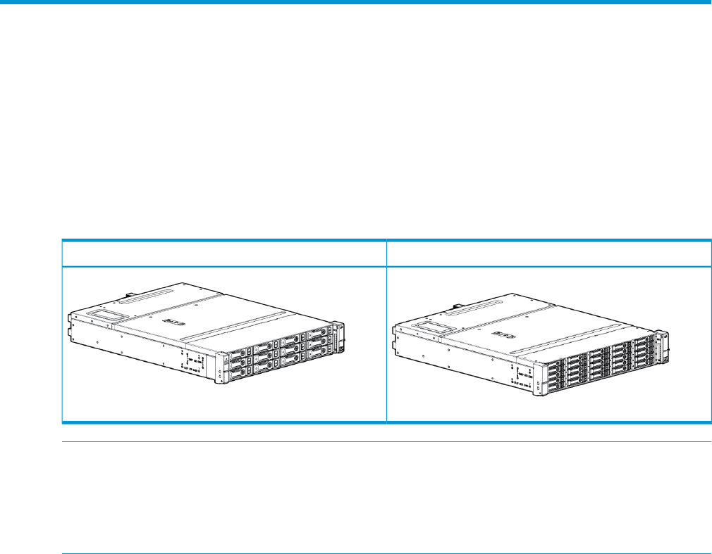
The HP 12Gb SAS disk enclosures are available in two models:
•D3600: supports up to 12 Large Form Factor (LFF) SAS drives for a maximum capacity of 7.2
TB with 600 GB SAS drives, 48 TB with 4 TB SAS MDL, or 4 TB SATA MDL drives.
•D3700: supports up to 25 Small Form Factor (SFF) SAS drives for a maximum capacity of 30
TB with 1.2 TB SAS drives, 25 TB with 1 TB SAS MDL, or 1 TB SATA MDL drives.
The D3700 also supports 12G SAS and SATA Solid State Drives (SSD).
D3700 SFF EnclosureD3600 LFF Enclosure
NOTE: Each enclosure is shipped with an optional digital rain bezel which customers can install
as needed. The graphics in this guide are portrayed without the bezel for clarity.
NOTE: Depending on your disk enclosure model and controller installation environment, one or
more disk enclosures can be cascaded from the disk enclosure that is connected to the controller.
For more information, see the QuickSpecs for the disk enclosure, available on the D3000 website.
The enclosure and its components are detailed in the following sections:
•“D3700 Small Form Factor disk enclosure chassis” Page 9
•“D3600 Large Form Factor disk enclosure chassis” Page 7
•“Disk drives” Page 11
•“Front status and UID module” Page 12
•“Power supply module” Page 13
•“Fan module” Page 14
•“I/O module” Page 15
•“Rear power and UID module” Page 16
•“Cables” Page 16
D3600 Large Form Factor disk enclosure chassis
Each HP D3600 enclosure includes the following standard components:
•D3600 base enclosure with redundant power supplies and fan modules
•Two integrated 12Gb SAS I/O Modules
•Rack mounting hardware kit
•Two 0.5m SAS-HD cables
•Optional digital rain bezel
Overview 7
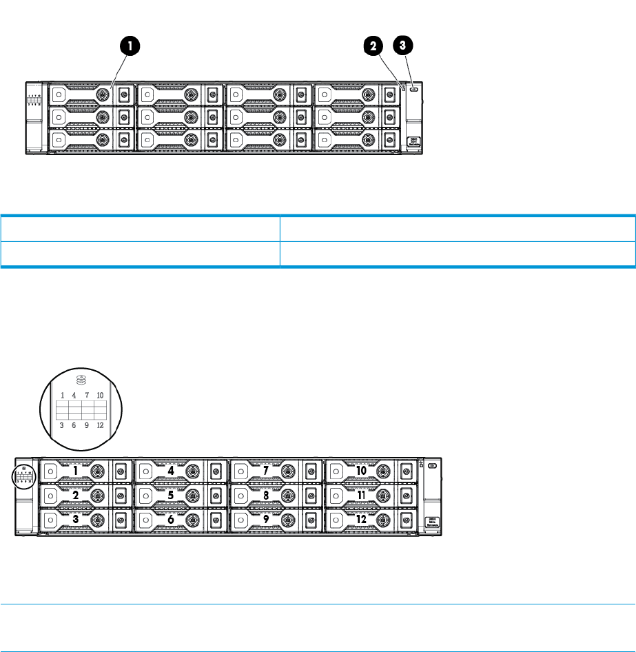
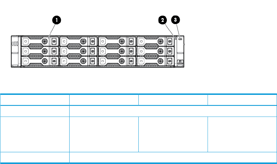
LFF Front view
3. UID push button1. Disk drive in bay 1
2. System Health LED
Drive bay numbering
Disk drives mount in bays on the front of the enclosure. Bays are numbered sequentially from top
to bottom and left to right. A drive-bay legend is included on the left bezel.
Rear view
NOTE: The I/O modules for both the HP D3600 LFF and HP D3700 SFF enclosures share the
same layout.
8 Hardware
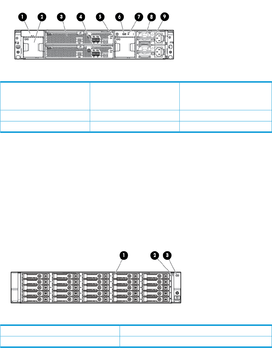
7. Rear system health LED4. I/O module B1. Metal cover with fan module ID
NOTE: A pull tab is provided for
label placement.
8. Power supply5. Fan2. Fan
9. Power supply6. Rear UID button3. I/O module A
D3700 Small Form Factor disk enclosure chassis
Each HP D3700 enclosure includes the following standard components:
•D3700 base enclosure with redundant power supplies and fan modules
•Two integrated 12Gb SAS I/O Modules
•Rack mounting hardware kit
•Two 0.5m SAS-HD cables
•Optional digital rain bezel
SFF Front view
3. UID push button1. Disk drive in bay 16
2. System Health LED
D3700 Small Form Factor disk enclosure chassis 9
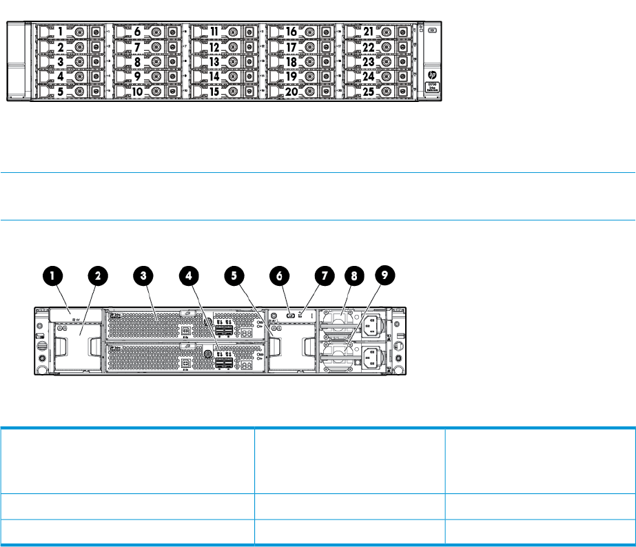
Drive bay numbering
Disk drives mount in bays on the front of the enclosure. Bays are numbered sequentially from top
to bottom and left to right.
Rear view
NOTE: The I/O modules for both the HP D3600 LFF and HP D3700 SFF enclosures share the
same layout.
7. Rear system health LED4. I/O module B1. Metal cover with fan module ID
NOTE: A pull tab is provided for label
placement.
8. Power supply5. Fan2. Fan
9. Power supply6. Rear UID button3. I/O module A
10 Hardware
Disk drives
A variety of disk drive models are supported for use, including dual-ported and single-ported
models. For more information, see the QuickSpecs for the disk enclosure, available on the D3000
website.
Disk drives are hot-pluggable.
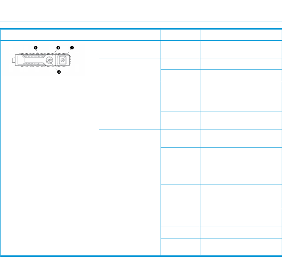
Disk drive LEDs
Two LEDs indicate drive status.
NOTE: Both the HP D3600 LFF and D3700 SFF drive carrier system use I2C communication for
drive authentication, failure and configuration info, activity animation and enhanced LEDs.
DefinitionStatusIndicatorLocation
The drive is being identified by a
host application.
Solid blue1 Locate
Drive activityRotating green2. Activity ring
No drive activityOff
Do not remove the drive.
Removing the drive causes one
Solid white3. Do not remove
or more of the logical drives to
fail.
Drive is safe to remove. Will not
cause a logical drive to fail.
Off
The drive is a member of one or
more logical drives.
Solid green4. Drive status
The drive is rebuilding or
performing a RAID migration,
Flashing green
stripe size migration, capacity
expansion, or logical drive
extension, or is erasing
The drive is a member of one or
more logical drives and predicts
the drive will fail.
Flashing
amber/green
The drive is not configured and
predicts the drive will fail.
Flashing amber
The drive has failed.Solid amber
The drive is not configured by a
RAID controller.
Off
Disk drive blanks
To maintain the proper enclosure air flow, a disk drive or a disk drive blank must be installed in
each drive bay. The disk drive blank maintains proper airflow within the disk enclosure.
Disk drives 11
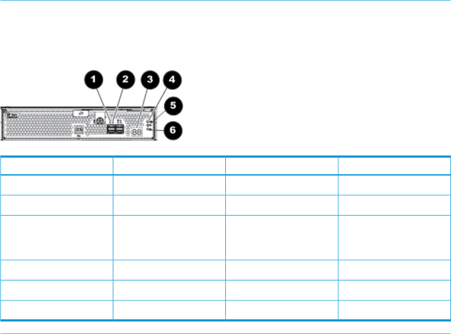
Front status and UID module
The front status and UID module includes status LEDs and a unit identification (UID) button.
Front UID module LEDs
Fault conditionsOperating conditionStartup conditionIndicator
N/A1. HDD in Bay 1
Solid greenSolid green2. System Health LED •Flashing amber:
non-critical error.
•Solid amber: critical
failure.
The UID is a locator LED activated by pressing the rear or the front UID buttons.3. UID
12 Hardware
Unit identification (UID) button
The unit identification (UID) button helps locate an enclosure and its components. When the UID
button is activated, the UID indicators on the front and rear of the enclosure are illuminated. There
is a UID button in the front panel, and another in the rear panel of the enclosure.
NOTE: A remote session from the management utility can also illuminate the UID.
•To turn on the UID light, press the UID button. The UID light on the front and the rear of the
enclosure will illuminate solid blue.
•To turn off an illuminated UID light, press the UID button. The UID light on the front and the
rear of the enclosure will turn off.
Power supply module
Two power supplies provide the necessary operating voltages to all controller enclosure components.
If one power supply fails, the remaining power supply is capable of operating the enclosure.
(Replace any failed component as soon as possible.)
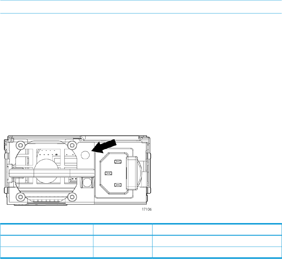
Power supply module LED
One LED provides module status information.
DescriptionLED statusLED color
No powerOffOff
Normal, no fault conditionsSolidGreen
Power supply module 13
Fan module
Fan modules provide cooling necessary to maintain proper operating temperature within the
controller enclosure.
If one fan fails, the system still runs, but HP recommends replacing the module. If two fans fail
(either one complete module, or one fan per module) the system shuts down.
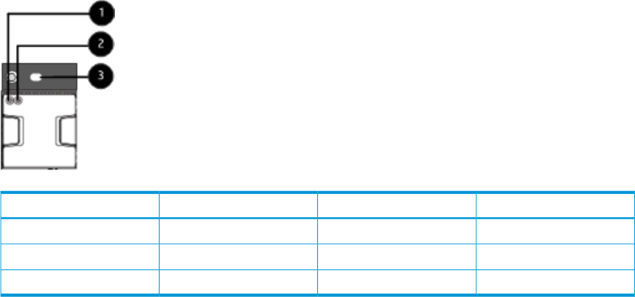
Fan module LEDs
Fault conditionsOperating conditionStartup conditionIndicator
OffOffBlue1. Fan UID
Solid amberSolid greenSolid green2. Health/Status
OffOffBlue3. System UID
One bi-color LED provides module status information.
14 Hardware
I/O module
The I/O module provides the interface between the disk enclosure and the host.
Each I/O module has two ports that can transmit and receive data for bidirectional operation.
I/O module LEDs
LEDs on the I/O module provide status information about each I/O port and the entire module.
NOTE: The following image illustrates LEDs on the I/O module.
The rear power and UID module includes status LEDs, a 7–segment display for status codes, and
a unit identification (UID) button.
Fault conditionsOperating conditionStartup conditionIndicator
OffBlinking or solid green1. Port Link
Solid amberOff2. Port Error
OffA number, representing the
box number, or an
error/warning code.
3. 7–segment display
OffOffBlue4. UID
OffSolid greenBlinking green5. Health
Blinking or solid amberOff6. Fault
I/O module 15

Rear power and UID module
Unit identification (UID) button
The unit identification (UID) button helps locate an enclosure and its components. When the UID
button is activated, the UID on the front and rear of the enclosure are illuminated.
NOTE: A remote session from the management utility can also illuminate the UID.
•To turn on the UID light, press the UID button. The UID light on the front and the rear of the
enclosure will illuminate solid blue. (The UID on cascaded storage enclosures are not
illuminated.)
•To turn off an illuminated UID light, press the UID button. The UID light on the front and the
rear of the enclosure will turn off.
Powering on
Power is applied to the enclosure chassis upon plugging the unit into a live power source. There
is no power on/standby button.
Cables
These disk enclosures use cables with mini-SAS connectors for connections to the host and to
additional cascaded disk enclosures.
Use supported SAS cables with mini-SAS connectors. A variety of SAS cables and cable lengths
are supported for use with this disk enclosure. For more information, see the QuickSpecs for the
disk enclosure, available on the D3000 website.
Cables to connect HP D3600/D3700 to any HP 6Gb SAS initiator
Part numberName
691971-B21HP 0.5m External Mini SAS HD to Mini SAS
Cable
716189-B21HP 1.0m External Mini SAS HD to Mini SAS
Cable
716191-B21HP 2.0m External Mini SAS HD to Mini SAS
Cable
716193-B21HP 4.0m External Mini SAS HD to Mini SAS
Cable
NOTE: This includes the following devices
•HP P421 and P822 controllers
•HP Smart Array H221 and H222 host bus adaptors
•HP Smart Array P721m (for Blade-attach)
•HP 6Gb SAS Switch
Cables to connect HP D3600/D3700 with any HP Smart Array 12Gb SAS initiator
Part numberName
716195-B21HP 1.0m External SAS-HD Cable
716197-B21HP 2.0m External SAS-HD Cable
716199-B21HP 4.0m External SAS-HD Cable
16 Hardware
2 Technical specifications
Physical specifications
HP D3600 LFF: 3.44 x 17.64 x 23.54 in (8.7 x 44.8 x 59.8 cm)Height/Width/Depth
HP D3700 SFF: 3.44 x 17.64 x 21.48 in (8.7 x 44.8 x 54.6 cm)
No disk drives: 38 lb (17.2 kg)Weight
HP D3700 fully populated with SFF disk drives: 54.90 lb (24.9 kg)
HP D3600 fully populated with LFF disk drives: 60 lb (27.2 kg)
Power and environmental specifications
50° to 104° F (10° to 40° C)OperatingTemperature range (Temperature ratings shown
are for sea level. An altitude rating of 1°C per -22° to 149° F (-30° to 65° C)
NOTE: Rated 1°C per 1000 feet of elevation
to 10,000 ft.
Shipping
300 m (1.8°F per 1,000 ft) to 3048 m
(10,000 ft) is applicable. The upper limit might
be limited by the type and number of options
installed.)
10% to 90% relative humidity (Rh)OperatingRelative humidity (Non-operating maximum
humidity of 95% is based on a temperature of 0% to 95% relative humidity (Rh)Non-operating
45°C (113°F). Altitude maximum for storage
corresponds to a pressure minimum of 70 KPa.)
82.4° F (28° C)Long-term storage
(operating)
Maximum wet bulb temperature
101.6° F (38.7° C)Short-term storage
(non-operating)
3048 m (10,000 ft) This value might be limited
by the type and number of options installed.
OperatingAltitude (Maximum allowable altitude change
rate is 457 m/min (1500 ft/min))
9144 m (30,000 ft)Non-operating
100 to 240 VAC (Common- slot Power Supply)Input voltageInput power (Input Power and Heat Dissipation
specifications are maximum values and apply 50 to 60 Hz (Common-slot Power Supply)Input frequency
to worst-case conditions at full rated power
supply load. The power/heat dissipation for 120V power source: 6ARated input current
your installation will vary depending on the
equipment configuration.) 240V power source: 3A
526WInput power (max)
Acoustic noise levels
Listed are the declared A-Weighted sound power levels (LWAd) and declared average bystander
position A-Weighted sound pressure levels (LpAm) when the product is operating in a 23°C ambient
environment. Noise emissions were measured in accordance with ISO 7779 (ECMA 74) and
declared in accordance with ISO 9296 (ECMA 109). The listed sound levels apply to standard
shipping configurations. Additional options may result in increased sound levels.
LWAd= 7.0 BIdle Acoustic Noise (sound power)
LpAm - 53 dBAIdle Acoustic Noise (sound pressure)
LWAd= 7.0 BOperating Acoustic Noise (sound power)
LpAm - 53 dBAOperating Acoustic Noise (sound pressure)
Physical specifications 17

3 Deployment types
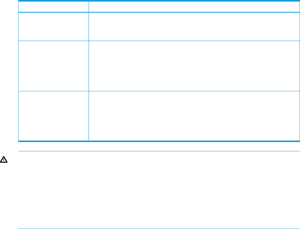
The following types of deployments are supported:
•Single domain
In a single domain deployment, one path exists from the disk enclosure to the host. In a single
domain deployment, only one I/O module in the disk enclosure is used
•Dual domain
In a dual domain deployment, two paths exist from the disk enclosure to the host. In a dual
domain deployment, both I/O modules in the disk enclosure are used. Because dual domain
deployments provide two paths to the storage, access is ensured, even in the event of device,
cable, or power failure. In dual domain environments, dual-port disk drives are required.
•Server attached (single or dual domain)
In a server attached deployment, the disk enclosure is connected to a controller card installed
in a server. Several models of controller cards are supported for use with this disk enclosure.
For more information, see the QuickSpecs for the disk enclosure.
•Controller enclosure attached (single or dual domain)
In a controller enclosure attached deployment, the disk enclosure is connected to a rack-mounted
array controller enclosure. The controller enclosure is then connected to the server or network.
Several models of array controller enclosures are supported for use with this disk enclosure.
For more information, see the QuickSpecs for the disk enclosure.
NOTE: Cabling illustrations are provided elsewhere in this guide, showing a variety of example
deployments. See (page 41).
18 Deployment types

4 Installation
Installation overview
Installation steps include:
1. Locating “Required items” Page 19
2. Completing “Preliminary tasks” Page 20
3. “Preparing the site” Page 25
4. “Racking the disk enclosure” Page 26
5. “Installing disk drives in the enclosure” Page 29
6. “Connecting SAS cables and power cords” Page 32
7. “Powering on the disk enclosure” Page 36
Required items
Items required for installation include the following, some of which ship with the disk enclosure:
•Rack mounting kit
•Disk enclosure
•Disk drives and drive blanks
•SAS controller or controller enclosure
•SAS cables
•Power cables
•Access to a workstation on the server
•Access to the Internet
NOTE: A variety of disk drives, SAS controllers, controller enclosures, and SAS cables are
supported for use with this disk enclosure. For more information, see the QuickSpecs for the disk
enclosure, available on the D3000 website.
Installation overview 19

Preliminary tasks
Planning tasks include:
•“Determining who will install and configure the disk enclosure” Page 20
•“Confirming support for your hardware and software components” Page 20
•“Signing up to automatically receive advisories, notices, and other messages” Page 21
•“Confirming warranty support and finding out about related services” Page 21
•“Gathering and recording information” Page 21
•“Planning the storage configuration” Page 21
Determining who will install and configure the disk enclosure
Storage management experience is required to successfully install and configure this product. If
you are not familiar with installing and configuring storage array systems, HP can install this product
for you. For more information, see the Business & IT Services website: http://www.hp.com/go/
services.
Different levels of assistance are available. For example, the following services might be included:
•Site inspection
•Verification of operating system patch levels
•Customized virtual disk design
•Array hardware installation and activation of optional software
•Array initialization
•Verification that the implemented solution meets your specifications
•Availability of an HP Services Storage Specialist to answer questions during the deployment
process
•Verification testing to confirm product functionality and adherence to HP installation quality
standards
•On-site orientation, including highlights of basic operation and a review of documentation
Confirming support for your hardware and software components
Specific versions of hardware, firmware, software, drivers, and other components are designed
to work together.
The QuickSpecs for your disk enclosure model provide an up-to-date list of supported servers,
operating systems, controllers, switches, and software tools. Download and review the QuickSpecs
for your disk enclosure model to confirm that the components you plan to use are supported for
use with the disk enclosure.
Check the QuickSpecs before initially installing the disk enclosure and before making any changes
to an existing installation. QuickSpecs are available on the D3000 disk enclosures website.
20 Installation

Signing up to automatically receive advisories, notices, and other messages
The Subscriber's Choice website includes options to register for and automatically receive, by
e-mail, personalized product tips, update information, driver- and support-related advisories, and
other notices for this and other HP devices. Although optional, HP recommends registering all of
your HP products with Subscriber's Choice. For more information, see the Subscriber's Choice
website: http://www.hp.com/go/e-updates.
To register for and automatically receive product tips, update information, driver- and support-related
advisories, see the Subscriber's Choice website: http://www.hp.com/go/e-updates. Click Subscribe
and follow the onscreen instructions to select all of the HP products for which you want to receive
notices. While subscribing, indicate your delivery preference (HTML, text, or RSS) and frequency
of delivery (as they become available, weekly, or monthly).
Confirming warranty support and finding out about related services
The standard warranty protects against product defects and some causes of downtime. You can
extend your warranty with HP Care Pack Services. This portfolio of predefined packages is flexible,
allowing you to extend coverage to the exact level of support required. You choose the support
level that meets your business requirement, from basic to mission-critical.
Recommended service levels and appropriate related services for your particular disk enclosure
model are listed on the QuickSpecs. For more information, see the Storage Services website:
http://www8.hp.com/us/en/business-services/it-services.html?compURI=1078604.
Gathering and recording information
A brief worksheet is included on the getting started instructions that is shipped with the disk
enclosure. As you gather and identify the hardware and software components for your environment,
use the worksheet to record information about your components and your configuration. Some
information is easily obtained before installing the disk enclosure, while some of the information
is created during the configuration process.
A basic worksheet is included on the poster, but HP recommends creating and keeping more
detailed records.
Information recorded on the worksheet is used during the initial system setup and configuration,
and is helpful for future configuration changes and troubleshooting purposes.
NOTE: If a supplier is installing or configuring your disk enclosure, provide them with the poster,
and verify that they complete the worksheet and record other important configuration and set up
information.
Planning the storage configuration
Proper planning of the system storage and its subsequent performance is critical to a successful
deployment of the disk enclosure. Improper planning or implementation can result in wasted storage
space, degraded performance, or inability to expand the system to meet growing storage needs.
Preliminary tasks 21

Storage planning considerations include:
•System and performance expectations
•Striping methods
•RAID levels
•Disk drive sizes and types
•Spare drives
•Array sizing (capacity)
NOTE: For the minimum supported configuration, and other configuration information, see the
QuickSpecs for the disk enclosure.
System and performance expectations
To help determine the best way to configure your storage, rank the following three storage
characteristics in order of importance:
•Fault tolerance (high availability)
•I/O performance
•Storage efficiency
With priorities established, you can determine which striping method and RAID level to use; some
configuration methods offer greater fault tolerance, while other configuration methods offer better
I/O performance or storage efficiency.
Striping methods
There are two methods for configuring the physical layout of the disk arrays:
•Vertical striping—the RAID array uses one physical drive from each disk enclosure.
•Horizontal striping—the RAID array uses multiple drives contained within one or more disk
enclosures.
RAID levels
Controllers use RAID technology to group multiple disk drives together in larger logical units (LUNs).
Key RAID methods include the use of data striping, data mirroring, and parity error checking. Data
striping improves speed by performing virtual disk I/O with an entire group of physical disks at
the same time. Mirroring provides data redundancy by storing data and a copy of the data. Parity
error checking provides automatic detection and correction if corruption of a physical disk occurs.
Depending on the host environment, the following RAID levels are supported with this disk enclosure:
RAID0, RAID1, RAID5 and RAID6 with ADG. Each level uses a different combination of RAID
methods that impact data redundancy, the amount of physical disk space used, and I/O speed.
After you create a LUN, you cannot change the RAID level.
The following table compares the different RAID levels.
RAID methodData redundancyBest practicesSummary
StripingNoneIMPORTANT: Do not use RAID0 for
LUNs if fault tolerance is required.
RAID0 is optimized for I/O
speed and efficient use of
RAID0
Consider RAID0 only for noncriticalphysical disk capacity, but
provides no data redundancy. storage. RAID0 LUNs provide the
best performance for applications
that use random I/O.
MirroringHighIn general, RAID1 virtual disks
provide better performance
RAID1 is optimized for data
redundancy and I/O speed,
RAID1
22 Installation

RAID methodData redundancyBest practicesSummary
characteristics over a wider range of
application workloads than RAID5.
but uses the most physical disk
space. IMPORTANT: RAID1
uses about 100% more
physical disk space than
RAID0 and 70% more than
RAID5.
Striping and
parity
MediumRAID 50 tolerates one drive failure
in each spanned array without loss
RAID5 protects against failure
of one drive (and failure of
RAID5
of data. RAID 50 requires lessparticular multiple drives).
rebuild time than single RAID 5RAID 50 is a nested RAID
arrays RAID 50 requires a minimum
of six drives.
method that uses RAID 0
striping across RAID 5 arrays.
Striping and
parity
HighRAID6 is most useful when data loss
is unacceptable but cost is also an
RAID6+0 allows administrators
to split the RAID 6 storage
RAID6
important factor. The probability thatacross multiple external boxes.
data loss will occur when an arrayRAID 60 requires a minimum
is configured with RAID6 is less thanof eight drives. RAID 60 is a
it would be if it was configured withnested RAID method that uses
RAID5. However, write performanceRAID 0 block-level striping
is lower than RAID5 because of the
two sets of parity data.
across multiple RAID 6 arrays
with dual distributed parity.
With the inclusion of dual
parity, RAID 60 will tolerate
the failure of two disks in each
spanned array without loss of
data.
Striping and
parity
HighOrganizations implementing a large
drive array should consider RAID 6
Allocates the equivalent of two
parity drives across multiple
RAID6
with
because it can tolerate up to twodrives and allows simultaneousAdvance
simultaneous drive failures without
downtime or data loss.
write operations Distributed
Data Guarding (RAID 5):
Data
Guarding
(ADG) Allocates parity data across
multiple drives and allows
simultaneous write operations.
Drive Mirroring (RAID 1 and
1+0 Striped Mirroring):
Allocates half of the drive array
to data and the other half to
mirrored data, providing two
copies of every file
Disk drive sizes and types
RAID arrays should be composed of disk drives of the same size and performance capability.
When drives are mixed within a disk enclosure, the usable capacity and the processing ability of
the entire storage subsystem is affected. For example, when a RAID array is composed of different
sized drives, the RAID array defaults to the smallest individual drive size, and capacity in the larger
drives goes unused.
Spare disks
Spares are disks that are not active members of any particular array, but have been configured
to be used when a disk in one of the arrays fails. If a spare is present, it will immediately be used
to begin rebuilding the information that was on the failed disk, using parity information from the
other member disks. During the rebuilding process, the array is operating in a reduced state and,
unless it is a RAID6 or RAID1+0 array, it cannot tolerate another disk failure in the same array. If
another disk fails at this time, the array becomes inaccessible and information stored there must
be restored from backup.
Preliminary tasks 23
After the rebuild of the data onto the spare is completed, when a replacement drive is inserted to
replace the failed drive, the system will automatically transfer the data from the spare onto the
replacement drive and return the spare to an available-spare state. It is important to note that the
process of rebuilding the spare or the replacement drive must not be interrupted or the process will
be aborted.
Some administrators have multiple spare disks, so that multiple arrays can experience failure and
successfully recover, before administrative intervention would be required to replace the spare or
failed disk. When assigning a spare to an array, the administrator chooses which arrays and how
many arrays are protected by that spare.
Array sizing
As a general rule, the greater the number of drives that are included in an array, the greater the
performance level that can be achieved. However, performance considerations are offset by fault
tolerance considerations. The greater the number of drives in an array, the higher the probability
of one or more disk failures in that array. The administrator must strike a balance between
performance and fault tolerance.
24 Installation

Preparing the site
Preparing your site includes:
•Providing adequate structural support
Calculate the total weight of your equipment and verify that your site can support the weight.
For HP ProLiant server environments, consider using Rack Builder, a software tool that provides
a simplified method to planning and configuring racks and rack-mountable products. Rack
Builder is available on the Options tab of the ProLiant Home page of the HP servers website:
http://www.hp.com/country/us/eng/prodserv/servers.html.
•Providing adequate clearance space and ventilation
Be sure to provide adequate clearance around the front and back of the racks. Provide at
least 63.5 cm (25 in) in the front of the rack to allow the doors to open fully and provide at
least 76.2 cm (30 in) in the rear of the rack to allow for servicing and airflow.
If there are unused spaces in your rack, attach blanking panels across those empty spaces to
force the airflow through the components instead of through the open spaces.
•Providing adequate and redundant sources of power
Make sure that you have two high-line power feeds installed near your computer. These two
power sources usually come from the same external power grid, but occasionally might
originate from different grids or even entirely different sources.
For protection against a power-source failure, obtain and include two uninterruptible power
supplies (UPS) in your installation. See the following URL for a list of available UPS:http://
www8.hp.com/us/en/products/ups/
For power consumption specifications, see the QuickSpecs for your disk enclosure model.
To ensure continuous, safe, and reliable operation of your equipment, place your system in an
approved environment.
Consider using the HP Enterprise Configurator (eCO) to help plan and configure racks and
rack-mountable devices. The eCO is available on the HP website: http://h30099.www3.hp.com/
configurator.
Preparing the site 25

Racking the disk enclosure
The disk enclosure can be installed into most standard server racks. To verify that your rack is
supported for use with the disk enclosure, see the QuickSpecs for the disk enclosure, available on
the D3000 website.
CAUTION: Install disk drives in the enclosures only after mounting the enclosures in the rack.
•A disk enclosure populated with disk drives is too heavy to lift safely.
•Movement of a disk enclosure during installation might damage the internal storage media
of installed disk drives.
Rack installation best practices
In addition to industry-standard recommendations, consider the following:
•Locate the heaviest items, such as uninterruptible power supplies (UPS) and additional disk
enclosures near the bottom of the rack.
•To make cabling easy, install the disk enclosures below the server.
•Install similar components next to each other in the rack. Because disk enclosures, switches,
and servers are of differing depths, if you have more than one of a device, mount those devices
adjacent to one another to accommodate working behind the rack.
WARNING! To reduce the risk of personal injury or damage to the equipment, be sure that:
•At least two people lift the storage system during removal or installation if the weight exceeds
22.7 kg (50 lb). If the system is being loaded into the rack above chest level, a third person
MUST assist with aligning the system with the rails while the other two people support the
weight of the system.
•The leveling jacks on the rack are extended to the floor.
•The full weight of the rack rests on the leveling jacks.
•The stabilizing feet are attached to the rack if it is a single-rack installation.
•The racks are coupled together in multiple-rack installations.
•Only one component in a rack is extended at a time. A rack might become unstable if more
than one component is extended.
•To prevent damage and to ease insertion of the device into the rack, support the weight of
the device and keep it level when sliding it into the rack.
Rack Installation procedures
1. Position left and right rack rails at the desired 'U' position in the rack, adjusting the rails to fit
the rack, as needed.
Front and Rear bottom edge of the rails must align with the bottom of EIA boundary in the
lowermost 'U'
NOTE: Rails are marked Land Rwith an arrow indicating the direction in which the rail
should be installed.
2. Use guide pins to align the shelf mount kit to the RETMA column holes.
The bottom of the rail must align with the bottom of the U.
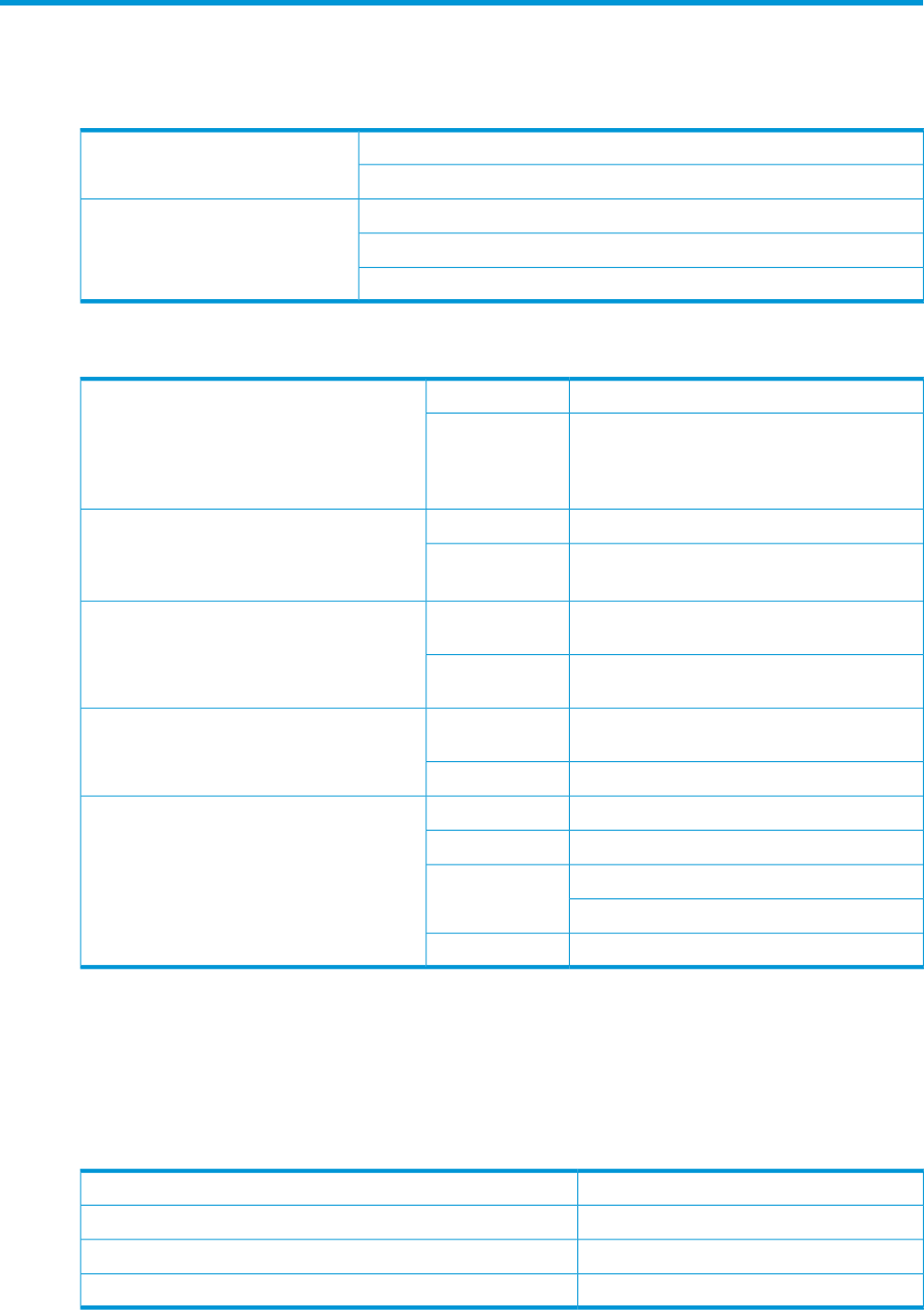
3. To engage the rear, push the rail toward the back of the rack until the spring hook (1) snaps
into place.
26 Installation
4. To engage the front, pull the rail towards the front of the rack to engage the spring hook with
the RETMA column in the same manner as the rear spring hook.
NOTE: Make sure that the respective guide pins for the square or round hole rack align
properly into RETMA column hole spacing.
5. Secure rear of rack rail to the RETMA column with either the square- or round-hole shoulder
screws, provided in the plastic accessory bag.
6. Secure front of rail to the front RETMA column using the provided flat securing screw/guide
pin in the bottom screw position of the rail.
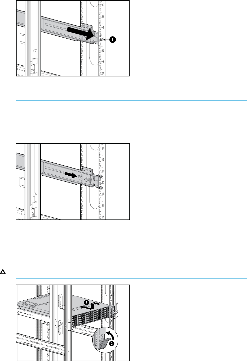
7. Slide the enclosure into position on the rails (1). Secure the chassis into the rack by tightening
the captive CTO screw behind the latch on the front left and right bezel ears of the chassis
(2).
CAUTION: The front CTO screw must be attached at all times when racked.
Racking the disk enclosure 27
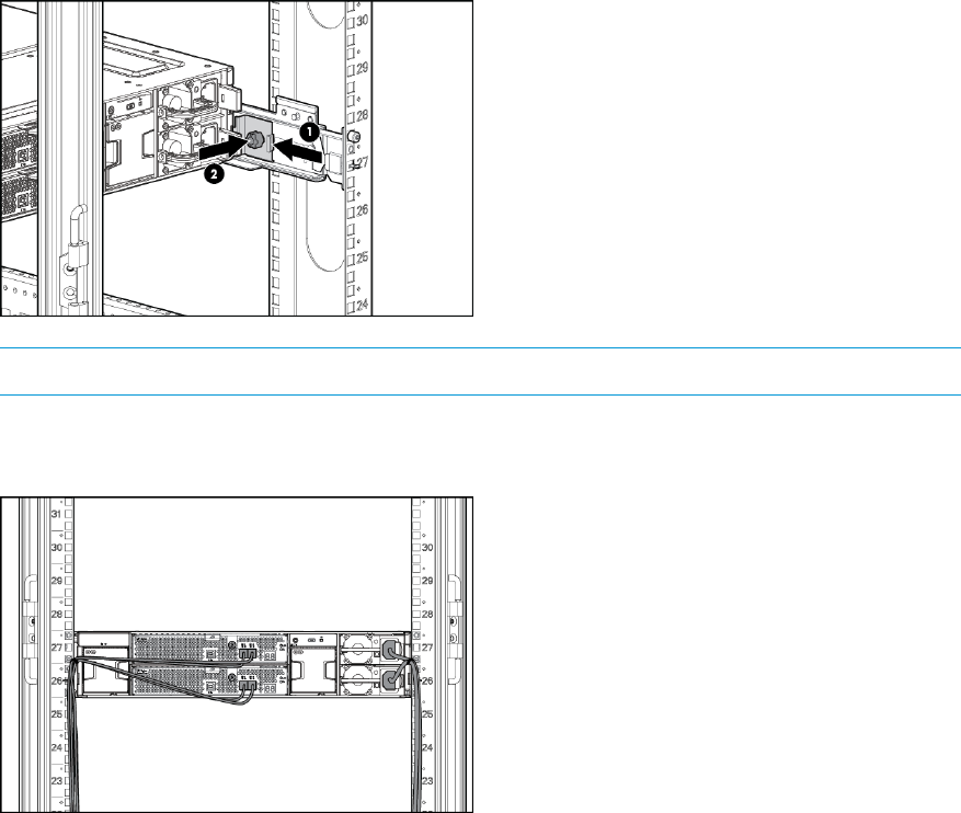
8. The rear ends of the rails have a CTO bracket that must engage with the enclosure in order
to secure it to the rails.
Align the CTO bracket to the corresponding rear slot into the chassis. The movable bracket
can be slid forward or back to correct position. The provided screw will secure the bracket
and chassis to the rail.
NOTE: The provided screw must be secured tightly. HP recommends using a T25 driver.
9. When cabling the device, use holes provided in the rear rack rails, install tie wraps, and route
external cable(s) as required.
28 Installation
Installing disk drives in the enclosure
Disk drive options
Depending on the enclosure model, 12 or 25 disk drives can be installed in the enclosure.
A variety of disk drive models are supported for use, including dual-ported and single-ported
models. For more information about supported disk drives, see the QuickSpecs for the disk enclosure,
available on the D3000 website.
Disk drive guidelines
CAUTION:
•Follow industry-standard practices when handling disk drives. Internal storage media can be
damaged when drives are shaken, dropped, or roughly placed on a work surface.
•When installing a disk drive, press firmly to make sure the drive is fully seated in the drive
bay and then close the latch handle.
•When removing a disk drive, press the release button and pull the drive only slightly out of
the enclosure. Then, to allow time for the internal disk to stop rotating, wait approximately 10
seconds before completely removing the drive from the enclosure.
•Always populate hard drive bays starting with the lowest bay number. If only one hard drive
is used, install it in the bay with the lowest device number.
•Disk drives are hot-pluggable.
•SAS and SATA disk drives may be installed in the same enclosure, but can not be included
in the same RAID logical volume.
Installing a disk drive
CAUTION: To prevent improper cooling and thermal damage, operate the enclosure only when
all bays are populated with either a component or a blank.
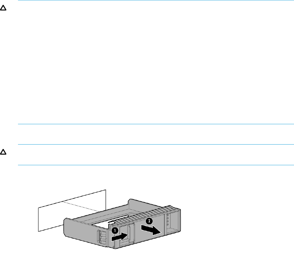
1. Remove the drive blank.
2. Unlatch and swing out the latch handle on the drive. Then, slide the drive into the bay (1),
pressing firmly on the drive to seat it. Close the latch handle (2), pressing firmly until it locks
in place.
Installing disk drives in the enclosure 29
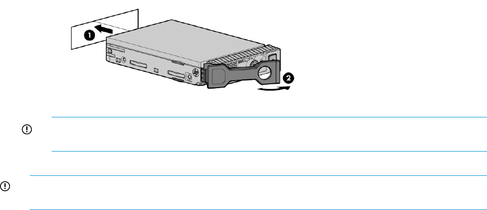
IMPORTANT: When a drive is inserted in an operational enclosure, the drive LEDs flash to
indicate that the drive is seated properly and receiving power.
3. Determine the status of the hard drive.
IMPORTANT: For proper airflow and cooling, a drive blank must remain installed in all unused
drive bays.
30 Installation

Installing SAS controllers or controller enclosures
When installing controllers or controller enclosures, be sure to do the following.
•Record information about the controller or controller enclosure that will connect to the disk
enclosure.
•Depending on your deployment, do one of the following:
For server connect deployments, install one or more Smart Array controllers in the server
that will access the disk enclosure.
◦
◦For controller enclosure connect deployments, install or locate the controller enclosure to
which the disk enclosure will connect.
NOTE: For detailed installation and configuration information about controller cards or controller
enclosures, see the documentation provided with the controller card or controller enclosure.
Preparing the server
When preparing servers for the disk enclosure, be sure to do the following.
•Record information about the server and environment (server connect or controller enclosure
connect) that will connect to the disk enclosure.
•Verify that the servers, controllers, operating system version, and service packs are supported
for use with the disk enclosure. For more information, see the QuickSpecs for the disk enclosure,
available on the D3000 website.
•Install all operating-system-specific service packs, patch kits, or other required tools.
•Install HP system management and monitoring tools, such as HP Systems Insight Manager
(HP-SIM) and the Array Configuration Utility (ACU).
NOTE: For detailed installation and configuration information about the server or the software
tools, see the documentation provided with the server or software.
Installing SAS controllers or controller enclosures 31

Connecting SAS cables and power cords
Overview
Connecting cables includes the following steps:
1. Reading the “Cabling best practices” Page 32.
2. “Connecting SAS cables to the server or controller enclosure” Page 33.
3. “Connecting SAS cables to cascaded disk enclosures” Page 34.
4. “Connecting power cords” Page 35.
IMPORTANT: The following illustrations demonstrate connecting a disk enclosure to a server with
an installed controller. In your environment, the disk enclosure might connect to a controller
enclosure, which then connects to the host or network. Cabling restrictions may exist for the different
installation environments. For more information, see the user documents for your controller or
controller enclosure.
NOTE: For additional examples of cabling scenarios, see (page 41).
Cabling best practices
•Use supported SAS cables and power cords. A variety of cables and cable lengths are
supported for use with this disk enclosure. For more information, see the QuickSpecs for the
disk enclosure, available on the D3000 website.
•Use the shortest possible cable between devices. Shorter cables reduce the possibility of signal
degradation that might occur over longer distances. In addition, shorter cables are easier to
manage and route along the back of the rack.
•Gather cables in the rear of the disk enclosure to ensure that the cabling in the back of the
rack system does not interfere with system operation or maintenance. Bind cables loosely with
cable ties and route the cables out of the way, along the side of the rack. When the cables
are tied together and routed down the side of the rack, system components and indicators
are easily visible and accessible.
•Bind and support cables in a manner that eliminates stress on connectors and tight bends of
the cables. This prevents damage to the connector and cable, and ensures that the connector
remains fully seated in the port.
•Attach a label near both ends of each cable to identify the device connected to that cable.
Include the device, device name, port, or other useful information.
•Use colored markers to color code both ends of each cable, to help visually identify a particular
cable without having to read or locate the label.
•In multipath configurations, you might want to loosely bind the matching pair of cables
connecting devices.
32 Installation
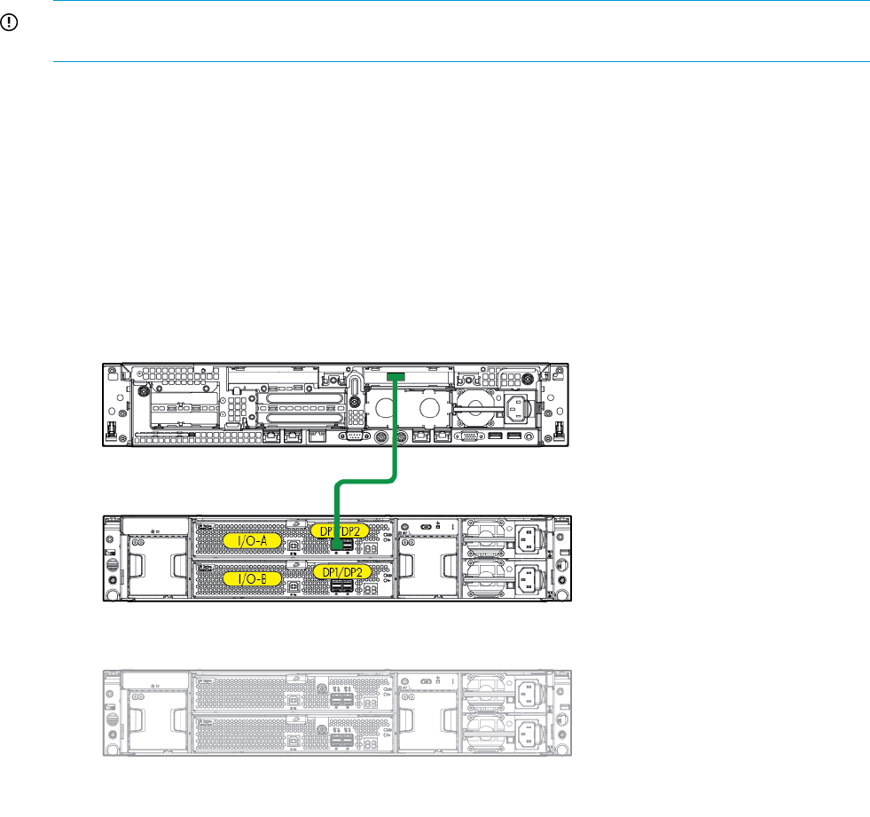
Connecting SAS cables to the server or controller enclosure
To connect the first disk enclosure to the server or controller enclosure, use a standard mini-SAS
cable.
IMPORTANT: When connecting this disk enclosure in a single-domain environment, only the top
I/O module (I/O module A) in the disk enclosure is supported for use.
Observe the following guidelines:
•Only use supported SAS cables with mini-SAS connectors.
•Ensure that the servers or controller enclosures are powered down and power cords are
disconnected before connecting SAS cables to the disk enclosure.
The following illustration demonstrates connecting a disk enclosure to a server with an installed
controller. In your environment, the disk enclosure might connect to a controller enclosure, which
then connects to the host or network. Regardless of environment, cabling principles from the disk
enclosure to the host are the same.
Note the following when connecting cables:
•DP1 on the disk enclosure I/O module is treated as the SAS “in” port.
•DP2 on the disk enclosure I/O module is treated as the SAS “out” port.
•In single-domain configurations, one cable path is created between the host, the primary disk
enclosure, and additional cascaded disk enclosures. (Shown)
•In dual-domain configurations, two cable paths are created between the host, the primary
disk enclosure, and additional cascaded disk enclosures.
Connecting SAS cables and power cords 33
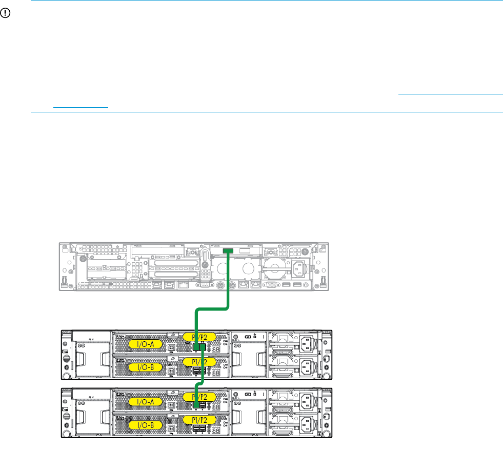
Connecting SAS cables to cascaded disk enclosures
To cascade additional disk enclosures from the disk enclosure that is connected to the server or
controller enclosure, use standard mini-SAS cables.
As additional disk enclosures are connected to the first disk enclosure, they are assigned a box
number. The assigned box number is displayed on the 7-segment display on the rear of the disk
enclosure.
IMPORTANT:
•When connecting this disk enclosure in a single-domain environment, only the top I/O module
(I/O module A) in the disk enclosure is supported for use.
•The number of supported cascaded disk enclosures varies per disk enclosure model and
installation environment. For more information, see the QuickSpecs for the disk enclosure,
controller, or controller enclosure, available on the HP storage website: http://www.hp.com/
go/storage.
Observe the following guidelines:
•Only use supported SAS cables with mini-SAS connectors.
•Use provided color clues on the disk enclosure when cabling cascaded disk enclosures; for
example, connect “green” ports to “green” ports (connect I/O module A on one disk enclosure
to I/O module A on the additional disk enclosure).
Note the following when connecting cables:
•DP1 on the disk enclosure I/O module is treated as the SAS “in” port.
•DP2 on the disk enclosure I/O module is treated as the SAS “out” port.
•In single-domain configurations, one cable path is created between the host, the primary disk
enclosure, and additional cascaded disk enclosures. (Shown)
•In dual-domain configurations, two cable paths are created between the host, the primary
disk enclosure, and additional cascaded disk enclosures.
34 Installation
Connecting power cords
When connecting power cords, use the cords shipped with the disk enclosure.
The power cord should be approved for use in your country. The power cord must be rated for the
product and for the voltage and current marked on the electrical ratings label of the product. The
voltage and current rating for the cord should be greater than the voltage and current rating marked
on the product. In addition, the diameter of the wire must be a minimum of 1.00 mm2or 18 AWG,
your maximum length may be up to 3.66 m (12 ft).
After power is supplied to the disk enclosure, the power supply automatically senses the input
voltage and the power supply LED illuminates as solid green.
To protect the system from power-failure-related downtime, each disk enclosure ships standard with
a redundant power supply. Depending how you connect the power supplies to the power source,
you can eliminate downtime caused by power-related failures.
Level of ProtectionConnection Method
Protects you from downtime when one of the disk enclosure power supplies fails.Connected to:
•One power source The remaining power supply/fan module can operate the disk enclosure until you install
a replacement module.
Protects you from downtime when one of the disk enclosure power supplies fails.Connected to:
•Two separate power
sources
Protects you from data loss when one of your power sources fails, due to a pulled cable
or tripped breaker.
The remaining power source can power the disk enclosure until the failed power source
is restored or relocated. Depending on the cause and duration of the power outage, you
can use this time to properly shut down your storage subsystem.
Protects you from downtime when one of the disk enclosure power supplies fails.Connected to:
Protects you from data loss when one or both of your power sources fails, due to a pulled
cable, tripped breaker, or local power outage.
•Two UPS
•Two separate power
sources The remaining power source or the UPS will power the disk enclosure until power is
restored to the source. Depending on the cause and duration of the power outage, you
can use this time to properly shut down your storage subsystem.
WARNING! To reduce the risk of electric shock or damage to the equipment:
•Do not disable the power cord grounding plug. The grounding plug is an important safety
feature.
•Plug the power cord into a grounded (earthed) electrical outlet that is easily accessible at all
times.
•Route the power cord so that it is not likely to be walked on or pinched by items placed against
it. Pay particular attention to the plug, electrical outlet, and the point where the cord is attached
to the disk enclosure.
Connecting SAS cables and power cords 35

Powering on the disk enclosure
After disk enclosures are physically installed and cabled, apply power to the enclosure by connecting
it to a live power source. Verify that they are operating properly.
Power on best practices
Observe the following best practices before powering on the enclosure for the first time:
•Complete the server, controller, or controller enclosure installation. For more information, see
the server, controller, or controller enclosure user documents.
•Install the disk enclosures.
•Install disk drives in the disk enclosures so that the connected host controller can identify and
configure them at power on.
•Connect the SAS cables and power cords to the enclosure.
Power on procedures
1. Apply power to each UPS, or plug the enclosure in to a live power source. The system power
LED illuminates solid green.
2. Wait a few minutes for the disk enclosures to complete their startup routines.
CAUTION: If power is applied to the server before the disk enclosures complete their startup
routine, the server might not properly discover the storage.
3. Apply power to the controller enclosure (if included in the configuration).
4. Power on (or restart) the server with access to the disk enclosures, start the operating system,
and log on as administrator.
CAUTION: When you power on the server, the monitor might display a “New Hardware
Found” message. Cancel out of this window to prevent the installation of unsupported software.
5. Verify that each component is operating properly.
36 Installation
Verifying the operating status of the disk enclosures
To verify that the disk enclosures and disk drives are operating properly, view the enclosure and
disk drive LEDs and compare them with the patterns described in the following sections. If LED
patterns are not as expected, check cable connections between the devices, check the availability
of your power source, review the installation procedures, and remove and reinsert the module.
•“LFF Front view” (page 8)
•“SFF Front view” (page 9)
•“Fan module LEDs” (page 14)
•“Rear view” (page 10)
•“Power supply module LED” (page 13)
Verifying the operating status of the disk enclosures 37

5 Configuration
Configuration overview
Regardless of the installation environment, operating system, or software tool used to configure
the disk enclosure, the following tasks must be completed:
•Updating controller or controller enclosure firmware or drivers. Instructions are included with
the controller or controller enclosure.
•Updating disk enclosure firmware. Instructions are included with the firmware. For more
information, see “Updating disk enclosure firmware” Page 39.
•Configuring the disk enclosure and its storage.
Creating the logical storage units (LUNs).◦
◦Entering global controller settings, such as setting the read/write cache ratio, setting the
rebuild/expand priority, and setting the redundancy level.
◦Identifying the operating system type (also called Host Mode or Profile) of the host that
will access the disk enclosure. This ensures that the disk enclosure will communicate
properly with that host.
◦Verifying that the configured storage is visible to the host.
Supported software tools
A variety of configuration, management, and diagnostic tools are supported for use with these
disk enclosures. Which tools are supported for your installation environment is determined by the
controller or controller enclosure to which the disk enclosure is connected.
For support information, see the QuickSpecs and user documents for the controller or controller
enclosure.
38 Configuration

6 Operation and management
Included topics:
•“Powering on disk enclosures” Page 39
•“Powering off disk enclosures” Page 39
•“Updating disk enclosure firmware” Page 39
Powering on disk enclosures
IMPORTANT: Always power on disk enclosures before controller enclosures and servers. This
ensures that servers, during the discovery process, identify the enclosures and installed disk drives
as operational devices.
Power on procedures
1. Apply power to each power supply module.
2. Once power is applied to the power supplies, the enclosure starts running.
The power on LED turns solid green.
3. Wait a few minutes for the disk enclosures to complete their startup routines.
CAUTION: If power is applied to the server before the disk enclosures complete their startup
routine, the server might not properly discover the storage.
4. Apply power to the controller enclosure (if included in the configuration).
5. Power on (or restart) the server with access to the disk enclosures, start the operating system,
and log on as administrator.
CAUTION: When you power on the server, the monitor might display a “New Hardware
Found” message. Cancel out of this window to prevent the installation of unsupported software.
6. Verify that each component is operating properly.
Powering off disk enclosures
IMPORTANT: Always power off disk enclosures after controller enclosures and servers.
IMPORTANT: When installing a hot-pluggable component, such as a disk drive, it is not necessary
to power down the enclosure.
To power off a disk enclosure:
1. Power off any attached servers. For more information, see the server documentation.
2. Power off the controller enclosure (if included in the configuration.) For more information, see
the controller enclosure documentation.
3. Power off the disk enclosures.
4. Disconnect power cords.
The system is now without power.
Updating disk enclosure firmware
After initial installation and periodically after that, verify that all devices in the configuration have
the latest available firmware installed.
Powering on disk enclosures 39

To determine currently-installed firmware and software versions on system components, use
management software utilities such as the HP System Management Home page, HP Systems Insight
Manager (HP SIM), Storage Management Utility (SMU), or Command Line Interface (CLI).
To obtain the latest-available firmware and software, see the HP website: http://www.hp.com/
support.
To perform the update, follow the procedures for your environment:
•For server connect environments, execute the downloaded Smart Component using the Firmware
Maintenance CD.
•For controller enclosure connect environments, install the firmware download using the Storage
Management Utility (SMU) or Command Line Interface (CLI).
NOTE: You can receive proactive support alerts, such as Customer Advisories, as well as updates
on drivers, software, firmware, and customer replaceable components, via e-mail through HP
Subscriber's Choice. Sign up for Subscriber's Choice at the following HP website: http://
www.hp.com/go/myadvisory and select the appropriate product.
40 Operation and management

7 Cabling examples
The following basic cabling examples are included:
•“ Single-domain example” (page 42)
•“Dual domain example” (page 43)
IMPORTANT: The following illustrations demonstrate connecting disk enclosures to a generic
host. Cabling restrictions may exist for server connect and controller enclosure connect environments.
For more information, see the user documents for your controller or controller enclosure.
41
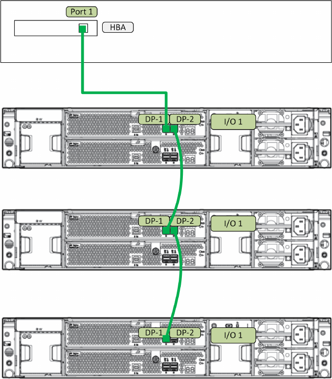
Single-domain example
This example illustrates cabling for a single-domain configuration. In this configuration, note the
following:
•DP1 on the disk enclosure I/O module is treated as the SAS “in” port.
•DP2 on the disk enclosure I/O module is treated as the SAS “out” port.
•In single-domain configurations, one cable path is created between the host, the primary disk
enclosure, and additional cascaded disk enclosures. (Shown)
•In dual-domain configurations, two cable paths are created between the host, the primary
disk enclosure, and additional cascaded disk enclosures.
42 Cabling examples
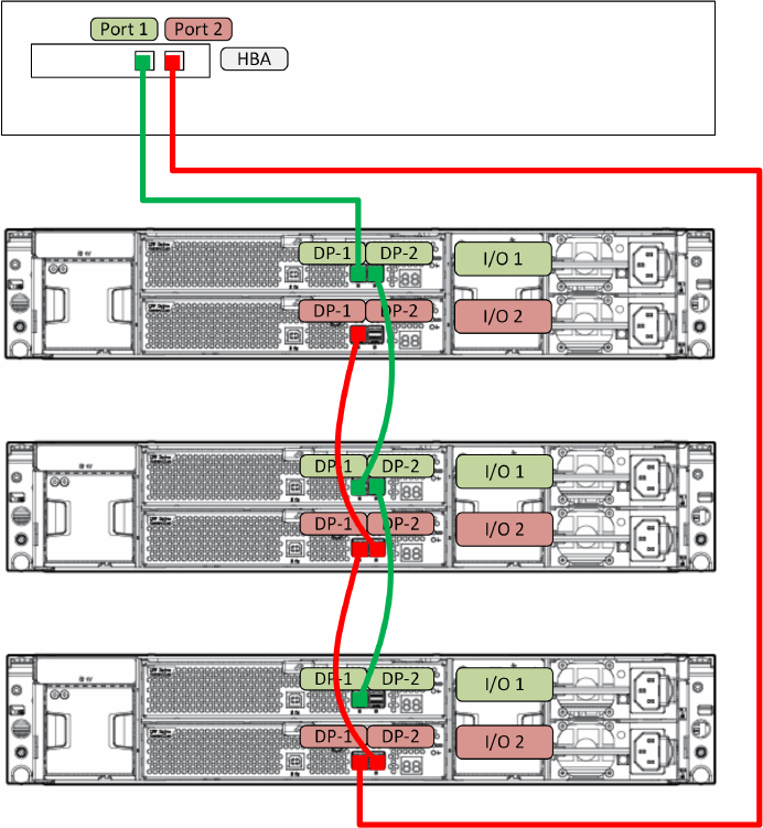
Dual domain example
This example illustrates cabling for a dual-domain configuration in a pattern that offers best possible
fault tolerance. In this configuration, note the following:
•A multi-port, dual-domain controller in the host and dual-port disk drives in the disk enclosure
are required for dual-domain deployments.
•Cables from each I/O module in the disk enclosure to the server or controller enclosure and
to additional cascaded disk enclosures provide dual-domain connectivity.
•The reversing of the cable paths ensures access to the storage, even if the controller, cable,
enclosure I/O module, or enclosure power supply fails.
•This example illustrates using a disk enclosure with one additional cascaded disk enclosure.
More than one additional disk enclosure can be cascaded. For more information, see the
QuickSpecs for the enclosure.
Dual domain example 43

8 Troubleshooting
If the enclosure does not initialize
IMPORTANT: After a power failure, the system automatically returns to the On state when A/C
power is restored, except in the following cases:
•If both power supplies are damaged.
•If there is a single power supply in the system, and it is damaged.
1. Ensure that power has been applied to the enclosure.
2. Verify that the power LED is green.
3. Verify that the power source is working:
a. Verify that the power supplies are working by viewing the power supply LEDs. If necessary,
remove and reinstall the power supplies to verify that they are seated properly.
b. Remove and inspect AC power cords from both power supplies and reconnect them.
Diagnostic steps
Is the enclosure front fault LED amber?
ActionsPossible ReasonsAnswer
No action required.System functioning properly.No
Yes •Be sure that the Front Status and UID
module is undamaged and is fully
seated.
•Front Status and UID module might
not be inserted properly, might
have a damaged connector, or
might have failed. •Check rear fault LEDs to isolate
failed component.•Possible error condition exists.
•Contact an authorized service
provider for assistance.
44 Troubleshooting

Is the enclosure rear fault LED amber?
ActionsPossible ReasonsAnswers
No action requiredFunctioning properly.No
Rear power and UID module might not
be inserted properly, might have a
Yes •Be sure that the rear power and UID
module is undamaged and is fully
seated.
damaged connector, or might have
failed. •Contact an authorized service
provider for assistance.
Is the System Health LED amber?
Possible SolutionsPossible ReasonsAnswer
No action required.System functioning properly.No
Yes •Be sure that all components are fully
seated.
•The system might have experienced
a short. Controller firmware might
be corrupted. •Update controller firmware.
•The system midplane might need
replacement. •Contact an authorized service
provider for assistance.
Is the power supply LED amber?
ActionsPossible ReasonsAnswers
No •Remove and inspect the AC power
cords from both power supplies and
reconnect them.
•Power cords not connected or AC
power is unavailable.
•Power supply functioning properly.
•No action required.
•Power supply might not be inserted
properly, might have a damaged
connector, or might have failed.
Yes •Be sure that the power supply is
undamaged and is fully seated.
•Be sure that all pins on connectors
and components are straight.
•Contact an authorized service
provider for assistance.
Is the I/O module fault LED amber?
Possible SolutionsPossible ReasonsAnswer
No action required.Functioning properly.No
Yes •Make sure that the I/O module is
seated properly by pressing the I/O
•The I/O module is locked.
•The I/O module has failed. module firmly into its bay after the
handle has clicked in place.
•Other fault condition exists.
CAUTION: Never remove an I/O
module from the chassis while the
status LED is green. Removing an
active I/O module can result in data
loss.
•Contact an authorized service
provider for assistance.
Diagnostic steps 45

Is the fan LED amber?
ActionsPossible ReasonsAnswers
No action requiredFunctioning properly.No
Fan might not be inserted properly,
might have a damaged connector, or
might have failed.
Yes •Be sure that the fan is undamaged
and is fully seated.
•Contact an authorized service
provider for assistance.
46 Troubleshooting
Recognizing disk drive failure
In an HP enclosure, a steadily glowing fault LED indicates that a disk drive has failed. Other
indications of failed disk drives are as follows:
•ACU represents failed drives with a distinctive icon.
•HP SIM can detect failed drives remotely across a network. (For more information about HP
SIM, see the documentation on the Management CD.)
•ADU lists all failed drives.
•Operating System log files
For additional information about diagnosing disk drive problems, see the HP ProLiant Servers
Troubleshooting Guide.
Effects of a disk drive failure
When a disk drive fails, all logical drives that are in the same array are affected. Each logical
drive in an array might be using a different fault-tolerance method, so each logical drive can be
affected differently.
•RAID0 configurations cannot tolerate drive failure. If any physical drive in the array fails, all
non-fault-tolerant (RAID0) logical drives in the same array also fail.
•RAID1+0 configurations can tolerate multiple drive failures as long as no failed drives are
mirrored to one another (with no spares assigned).
•RAID5 configurations can tolerate one drive failure (with no spares assigned).
•RAID6 with ADG configurations can tolerate simultaneous failure of two drives (with no spares
assigned).
Compromised fault tolerance
If more disk drives fail than the fault-tolerance method allows, fault tolerance is compromised, and
the logical drive fails.
Factors to consider before replacing disk drives
Before replacing a degraded drive:
•Open HP SIM and inspect the Error Counter window for each physical drive in the same array
to confirm that no other drives have any errors. For details, see the HP SIM documentation on
the Management CD.
•Be sure that the array has a current, valid backup.
•Use replacement drives that have a capacity at least as great as that of the smallest drive in
the array. The controller immediately fails drives that have insufficient capacity.
Recognizing disk drive failure 47

To minimize the likelihood of fatal system errors, take these precautions when removing failed
drives:
•Do not remove a degraded drive if any other drive in the array is offline (the online LED is
off). In this situation, no other drive in the array can be removed without data loss.
•Exceptions:
When RAID1+0 is used, drives are mirrored in pairs. Several drives can be in a failed
condition simultaneously (and they can all be replaced simultaneously) without data loss,
as long as no two failed drives belong to the same mirrored pair.
◦
◦When RAID6 with ADG is used, two drives can fail simultaneously (and be replaced
simultaneously) without data loss.
◦If the offline drive is a spare, the degraded drive can be replaced.
•Do not remove a second drive from an array until the first failed or missing drive has been
replaced and the rebuild process is complete. (The rebuild is complete when the Online LED
on the front of the drive stops blinking.)
Exceptions:
◦In RAID6 with ADG configurations, any two drives in the array can be replaced
simultaneously.
◦In RAID1+0 configurations, any drives that are not mirrored to other removed or failed
drives can be simultaneously replaced offline without data loss.
Automatic data recovery (rebuild)
When you replace a disk drive in an array, the controller uses the fault-tolerance information on
the remaining drives in the array to reconstruct the missing data (the data that was originally on
the replaced drive) and write it to the replacement drive. This process is called automatic data
recovery, or rebuild. If fault tolerance is compromised, this data cannot be reconstructed and is
likely to be permanently lost.
Time required for a rebuild
•The time required for a rebuild varies considerably, depending on several factors:
•The priority that the rebuild is given over normal I/O operations (you can change the priority
setting by using ACU)
•The amount of I/O activity during the rebuild operation
•The rotational speed of the disk drives
•The availability of drive cache
•The model and age of the drives
•The amount of unused capacity on the drives
•The number of drives in the array (for RAID5 and RAID6 with ADG)
Allow approximately 5 minutes per gigabyte without any I/O activity during the rebuild process.
This figure is conservative, and newer drive models usually require less time to rebuild.
System performance is affected during the rebuild, and the system is unprotected against further
drive failure until the rebuild has finished. Therefore, replace drives during periods of low activity
when possible.
CAUTION: If the Online LED of the replacement drive stops blinking and the amber fault LED
glows, or if other drive LEDs in the array go out, the replacement drive has failed and is producing
unrecoverable disk errors. Remove and replace the failed replacement drive.
48 Troubleshooting
When automatic data recovery has finished, the online LED of the replacement drive stops blinking
and begins to glow steadily.
Failure of another drive during rebuild
If a non-correctable read error occurs on another physical drive in the array during the rebuild
process, the Online LED of the replacement drive stops blinking and the rebuild abnormally
terminates. If this situation occurs, restart the server. The system might temporarily become
operational long enough to allow recovery of unsaved data. In any case, locate the faulty drive,
replace it, and restore data from backup.
Handling disk drive failures
If the controller was configured with hardware fault tolerance, complete the following steps after
a disk drive failure:
1. Determine which physical drive failed. On hot-plug drives, an amber drive failure LED
illuminates.
2. If the unit containing the failed drive does not support hot-plug drives, perform a normal
shutdown.
3. Remove the failed drive and replace it with a drive that is of the same capacity. For hot-plug
drives, after you secure the drive in the bay, the LEDs on the drive each flash once in an
alternating pattern to indicate a successful connection. The online LED flashes, indicating that
the controller recognized the drive replacement and began the recovery process.
4. Power on the server, if applicable.
5. The controller reconstructs the information on the new drive, based on information from the
remaining physical drives in the logical drive. While reconstructing the data on hot-plug drives,
the online LED flashes. When the drive rebuild is complete, the online LED is illuminated.
Recognizing disk drive failure 49

9 Replacement procedures
Customer self repair (CSR)
Information in (page 52) identifies hardware components that are customer replaceable. Using
WEBES, ISEE or other diagnostic tools, a support specialist will work with you to diagnose and
assess whether a replacement component is required to address a system problem. The specialist
will also help you determine whether you can perform the replacement.
Parts-only warranty service
Your HP Limited Warranty might include a parts-only warranty service. Under the terms of parts-only
warranty service, HP will provide replacement parts free of charge.
For parts-only warranty service, CSR part replacement is mandatory. If you request HP to replace
these parts, you will be charged for travel and labor costs.
Best practices for replacing hardware components
The following information will help you replace the hardware components on your storage system
successfully.
CAUTION: Removing a component significantly changes the air flow within the enclosure.
Components or a blanking panel must be installed for the enclosure to cool properly. If a component
fails, leave it in place in the enclosure until a new component is available to install.
Verifying component failure
•Consult HP technical support to verify that the hardware component has failed and that you
are authorized to replace it yourself.
•Additional hardware failures can complicate component replacement. Check your management
utilities to detect any additional hardware problems:
◦When you have confirmed that a component replacement is required, you might want to
clear the failure message from the display. This makes it easier to identify additional
hardware problems that might occur while waiting for the replacement part.
◦Before installing the replacement part, check the management utility for new hardware
problems. If additional hardware problems have occurred, contact HP support before
replacing the component.
Identifying the spare part
Parts have a nine-character spare part number on their label. For some spare parts, the part number
might be available in the management software utility. Alternatively, the HP call center will assist
in identifying the correct spare part number.
Replaceable parts
This product contains the replaceable parts illustrated in (page 52).
50 Replacement procedures

Parts that are available for customer self repair (CSR) are indicated as follows:
•Mandatory CSR where geography permits. Order the part directly from HP and repair the
product yourself. On-site or return-to-depot repair is not provided under warranty.
•Optional CSR. You can order the part directly from HP and repair the product yourself, or
you can request that HP repair the product. If you request repair from HP, you might be charged
for the repair depending on the product warranty.
•No CSR. The replaceable part is not available for self repair. For assistance, contact an
HP-authorized service provider
For more information about CSR, contact your local service provider or see the CSR website: http://
www.hp.com/go/selfrepair
To determine the warranty service provided for this product, see the warranty information website:
http://www.hp.com/go/storagewarranty
To order a replacement part, contact an HP-authorized service provider or see the HP Parts Store
online: http://www.hp.com/buy/parts
Replacing the failed component
CAUTION: Components can be damaged by electrostatic discharge (ESD). Use proper anti-static
protection.
•Always transport and store components in an ESD protective enclosure.
•Do not remove the components from the ESD protective enclosure until you are ready to install
it.
•Always use ESD precautions, such as a wrist strap, heel straps on conductive flooring, and
an ESD protective smock when handling ESD sensitive equipment.
•Avoid touching the components connector pins, leads, or circuitry.
•Do not place ESD generating material such as paper or non anti-static (pink) plastic in an ESD
protective enclosure with ESD sensitive equipment.
•HP recommends waiting until periods of low storage system activity to replace a component.
•When replacing components at the rear of the rack, cabling might obstruct access to the
component. Carefully move any cables out of the way to avoid loosening any connections.
In particular, avoid cable damage that might be caused by:
◦Kinking or bending.
◦Disconnecting cables without capping. If uncapped, cable performance might be impaired
by contact with dust, metal or other surfaces.
◦Placing removed cables on the floor or other surfaces, where they might be walked on
or otherwise compressed.
Replacement instructions
Printed instructions are shipped with the replacement part. Instructions for all replaceable components
are also posted to the HP website: http://www.hp.com/support/manuals.
Replacing the failed component 51
Hardware components
52 Replacement procedures

CSR statusDescription
Not a CSR part (part of drive
cage)
1. Chassis Bezel Ear
Not a CSR part (part of drive
cage)
2. Chassis Bezel Ear
Not a CSR part3. Drive Cage
Mandatory4. Backplane
Mandatory5. Fan module interconnect board
Mandatory6. Voltage Regulator Module (VRM) or power module
Mandatory7. Power supply
Not a CSR part8. Enclosure
Mandatory9. I/O module
Mandatory10. Fan module
Mandatory11. Rear Unit ID
Mandatory12. Disk drive
To order a replacement part, contact an HP-authorized service provider or see the HP Parts Store
online: http://www.hp.com/buy/parts
Hardware components 53

10 Support and other resources
Contacting HP
Before you contact HP
Be sure to have the following information available before you call or contact HP:
•Technical support registration number (if applicable)
•Product serial number
•Product model name and number
•Product identification number
•Applicable error message
•Add-on boards or hardware
•Third-party hardware or software
•Operating system type and revision level
HP contact information
For the name of the nearest HP authorized reseller:
•See the Contact HP worldwide (in English) website:
nl
http://welcome.hp.com/country/us/en/wwcontact.html.
For HP technical support:
•In the United States, for contact options see the Contact HP United States website:
nl
http://welcome.hp.com/country/us/en/contact_us.html. To contact HP by phone:
◦Call 1-800-HP-INVENT (1-800-474-6836). This service is available 24 hours a day, 7
days a week. For continuous quality improvement, calls might be recorded or monitored.
◦If you have purchased a Care Pack (service upgrade), call 1-800-633-3600. For more
information about Care Packs, see the HP website:
nl
http://www.hp.com/hps.
•In other locations, see the Contact HP worldwide (in English) website:
nl
http://www8.hp.com/us/en/contact-hp/ww-contact-us.html.
Subscription service
HP recommends that you register your product at the Subscriber's Choice for Business website:
nl
http://www.hp.com/go/e-updates.
After registering, you will receive email notification of product enhancements, new driver versions,
firmware updates, and other product resources.
Documentation feedback
HP welcomes your feedback.
To make comments and suggestions about product documentation, please send a message to
storagedocsFeedback@hp.com. All submissions become the property of HP.
54 Support and other resources
Related information
Websites
•HP: http://www.hp.com
•HP storage: http://www.hp.com/go/storage
•HP support: http://www.hp.com/support
•HP manuals: http://www.hp.com/support/manuals
•HP downloads: http://www.hp.com/support/downloads
Document conventions and symbols
ElementConvention
Cross-reference links and e-mail addressesBlue text: Document conventions and symbols
Website addressesBlue, underlined text: http://www.hp.com
Bold text •Keys that are pressed
•Text typed into a GUI element, such as a box
•GUI elements that are clicked or selected, such as menu
and list items, buttons, tabs, and check boxes
Text emphasisItalic text
Monospace text •File and directory names
•System output
•Code
•Commands, their arguments, and argument values
Monospace, italic text •Code variables
•Command variables
Emphasized monospace textMonospace, bold text
WARNING! Indicates that failure to follow directions could result in bodily harm or death.
CAUTION: Indicates that failure to follow directions could result in damage to equipment or data.
IMPORTANT: Provides clarifying information or specific instructions.
NOTE: Provides additional information.
TIP: Provides helpful hints and shortcuts.
Customer self repair
HP customer self repair (CSR) programs allow you to repair your HP product. If a CSR part needs
replacing, HP ships the part directly to you so that you can install it at your convenience. Some
parts do not qualify for CSR. Your HP-authorized service provider will determine whether a repair
can be accomplished by CSR.
Related information 55

For more information about CSR, contact your local service provider or see the CSR website:
nl
http://www.hp.com/go/selfrepair.
Rack stability
Rack stability protects personnel and equipment.
WARNING! To reduce the risk of personal injury or damage to equipment:
•Extend leveling jacks to the floor.
•Ensure that the full weight of the rack rests on the leveling jacks.
•Install stabilizing feet on the rack.
•In multiple-rack installations, fasten racks together securely.
•Extend only one rack component at a time. Racks can become unstable if more than one
component is extended.
56 Support and other resources

11 Regulatory compliance notices
This section contains regulatory notices for the HP D3600/3700 12Gb SAS disk enclosures.
Regulatory compliance identification numbers
For the purpose of regulatory compliance certifications and identification, this product has been
assigned a unique regulatory model number. The regulatory model number can be found on the
product nameplate label, along with all required approval markings and information. When
requesting compliance information for this product, always refer to this regulatory model number.
The regulatory model number is not the marketing name or model number of the product.
Federal Communications Commission notice
Part 15 of the Federal Communications Commission (FCC) Rules and Regulations has established
Radio Frequency (RF) emission limits to provide an interference-free radio frequency spectrum.
Many electronic devices, including computers, generate RF energy incidental to their intended
function and are, therefore, covered by these rules. These rules place computers and related
peripheral devices into two classes, A and B, depending upon their intended installation. Class A
devices are those that might reasonably be expected to be installed in a business or commercial
environment. Class B devices are those that might reasonably be expected to be installed in a
residential environment (for example, personal computers). The FCC requires devices in both classes
to bear a label indicating the interference potential of the device as well as additional operating
instructions for the user.
This is a class A device.
FCC rating label
The FCC rating label on the device shows the classification (A or B) of the equipment.
Class A equipment
This equipment has been tested and found to comply with the limits for a Class A digital device,
pursuant to Part 15 of the FCC rules. These limits are designed to provide reasonable protection
against harmful interference when the equipment is operated in a commercial environment. This
equipment generates, uses, and can radiate radio frequency energy and, if not installed and used
in accordance with the instructions, might cause harmful interference to radio communications.
Operation of this equipment in a residential area is likely to cause harmful interference, in which
case the user will be required to correct the interference at personal expense.
Modifications
The FCC requires the user to be notified that any changes or modifications made to this device
that are not expressly approved by Hewlett-Packard Company might void the user's authority to
operate the equipment.
Cables
When provided, connections to this device must be made with shielded cables with metallic RFI/EMI
connector hoods in order to maintain compliance with FCC Rules and Regulations.
Regulatory compliance identification numbers 57
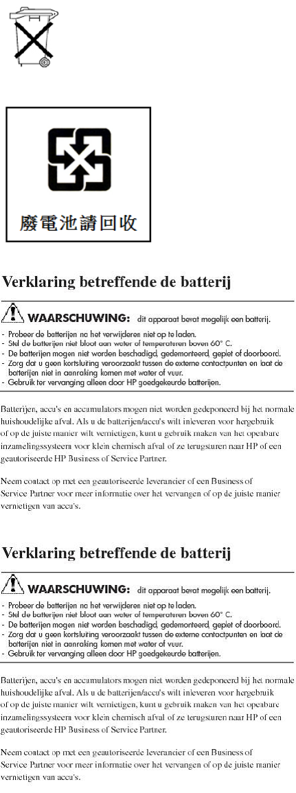
Battery replacement notices
Batteries, battery packs, and accumulators should not be disposed of together with the
general household waste. To forward them to recycling or proper disposal, use the public
collection system or return them to HP, an authorized HP Partner, or their agents.
For more information about battery replacement or proper disposal, contact an authorized
reseller or an authorized service provider.
58 Regulatory compliance notices
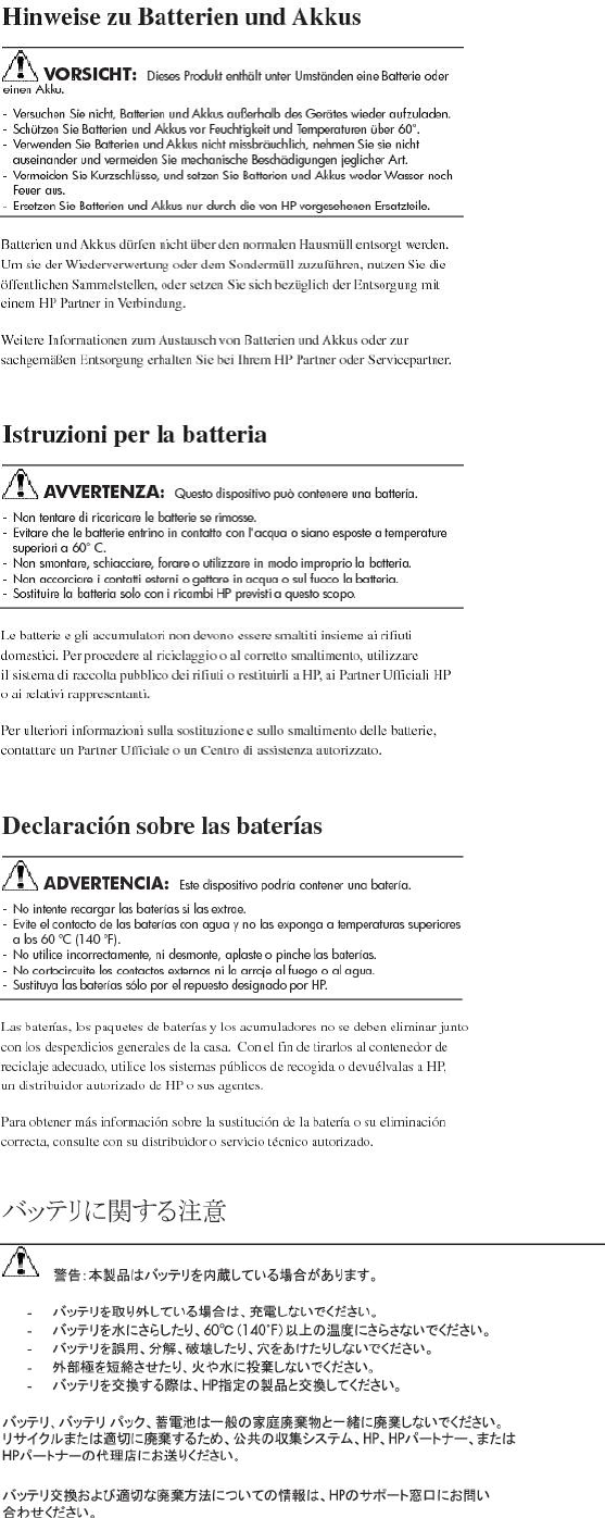
Battery replacement notices 59

RoHS material content declarations
China RoHS material content declaration
Chinese version:http://www8.hp.com/us/en/hp-information/environment/chinarohs.html
English version:http://www8.hp.com/us/en/hp-information/environment/chinarohs-english.html
India RoHS material content declaration
This product complies with the "India E-waste (Management and Handling) Rule 2011" and
prohibits use of lead, mercury, hexavalent chromium, polybrominated biphenyls or polybrominated
diphenyl ethers in concentrations exceeding 0.1 weight % and 0.01 weight % for cadmium, except
for the exemptions set in Schedule 2 of the Rule.
Turkey RoHS material content declaration
Türkiye Cumhuriyeti: EEE Yönetmeliðine Uygundur
Ukraine RoHS material content declaration
Perchlorate material - special handling may apply. See http://www.dtsc.ca.gov/hazardouswaste/
perchlorate
This product’s real-time clock battery or coin cell battery may contain perchlorate and may require
special handling when recycled or disposed of in California.
Regulatory notices
Canadian notice (Avis Canadien)
Class A equipment
This class A digital apparatus meets all requirements of the Canadian Interference-Causing
Equipment Regulations.
Cet appareil numérique de la class A respecte toutes les exigences du Règlement sur le matériel
brouilleur du Canada.
European Union notice
This product complies with the following EU directives:
•Low Voltage Directive 2006/95/EC
•EMC Directive 2004/108/EC
Compliance with these directives implies conformity to applicable harmonized European standards
(European Norms) which are listed on the EU Declaration of Conformity issued by Hewlett-Packard
for this product or product family. This compliance is indicated by the following conformity marking
placed on the product:
Certificates can be obtained from http://www.hp.com/go/certificates.
Hewlett-Packard GmbH, HQ-TRE, Herrenberger Strasse 140, 71034 Boeblingen, German
60 Regulatory compliance notices
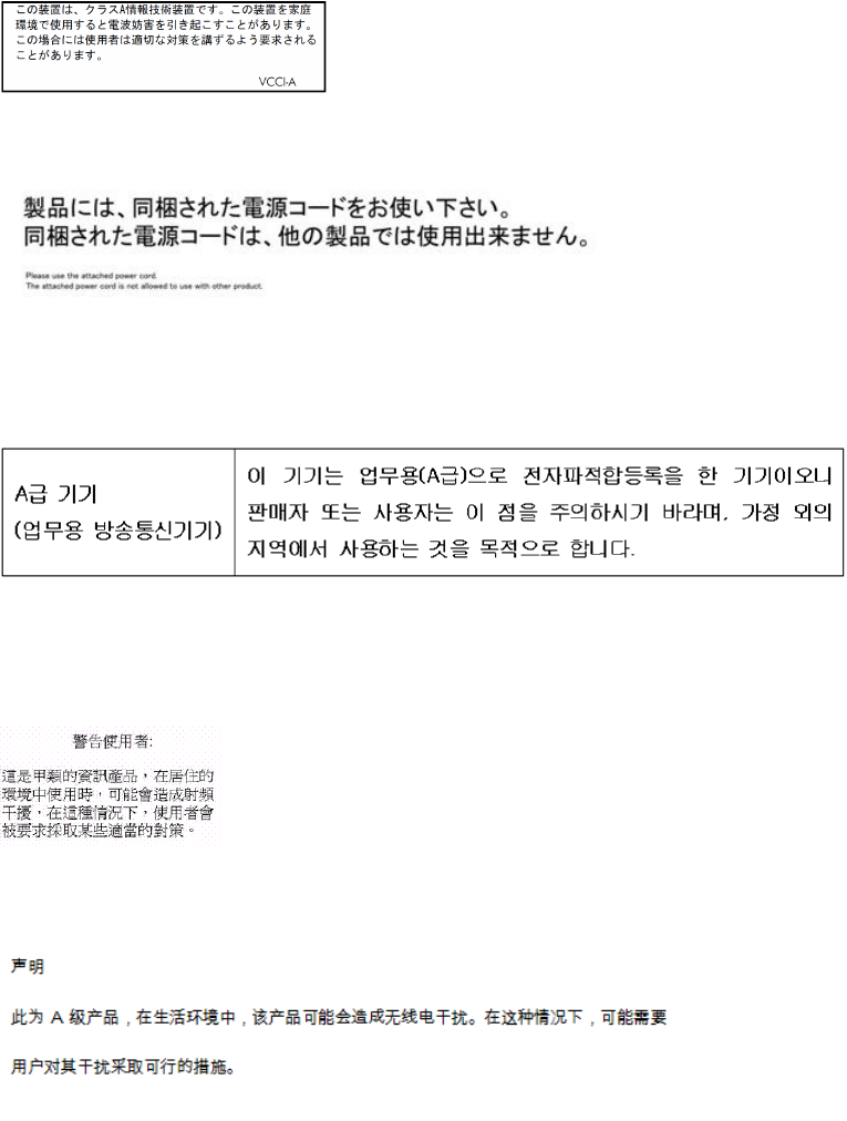
Japanese notices
VCCI-A notice
Japanese power cord statement
Korean notices
Class A equipment
Taiwanese notices
BSMI Class A notice
Chinese notice
Regulatory notices 61
Recycling notices
English notice
Bulgarian notice
Czech notice
Danish notice
Dutch notice
62 Regulatory compliance notices
Estonian notice
Finnish notice
French notice
German notice
Greek notice
Recycling notices 63
Hungarian notice
Italian notice
Latvian notice
Lithuanian notice
Polish notice
64 Regulatory compliance notices
Portuguese notice
Romanian notice
Slovak notice
Spanish notice
Swedish notice
Recycling notices 65
Turkish notice
Türkiye Cumhuriyeti: EEE Yönetmeliğine Uygundur
66 Regulatory compliance notices

Index
B
best practices
cabling, 32
power sources, 35
powering on, 36
racking, 26
C
cables
best practices, 32
cable management considerations, 32
connecting cascaded enclosures, 34
connecting power cords, 35
connecting to the controller, 33
SAS, 16, 32
cabling example
dual-domain, 43
single-domain, 42
cabling guidelines, 33, 34
Canadian notice, 60
cascaded disk enclosures, 34
Chinese notices, 61
clearance space, 25
components, 7
disk drive blanks, 11
disk drives, 11
fan, 14
front status and UID, 12
I/O module, 15
power supply, 13
rear power and UID, 16
SAS cables, 16
supported disk drives, 29
configuration
initial tasks, 38
supported software tools, 38
connecting cables to cascaded enclosures, 34
connecting cables to the controller, 33
connecting power cords, 35
controller
preparing for use with disk enclosure, 31
conventions
documentation, 55
text symbols, 55
Customer Self Repair (CSR)
defined, 50, 55
parts list, 50
website, 55
D
diagnostic steps, 44
if the enclosure does not initialize, 44
if the enclosure front fault LED is amber, 44
if the enclosure rear fault LED is amber, 45
if the fan LED is amber, 46
if the I/O module fault LED is amber, 45
if the power on/standby LED is amber, 45
if the power supply LED is amber, 45
recognizing disk drive failure, 47
diagnostic tools, 38
disk drives
caution, 26
defined, 11
LEDs, 11
recognizing disk drive failure, 47
supported, 29
disk enclosure
available models, 7
example cabling
dual-domain, 43
single-domain, 42
exploded view, 52
illustrated, 7
LFF
component callout, 8
drive bay numbering, 8
front view, 8
rear view, 8
SFF
component callout, 9, 10
drive bay numbering, 10
front view, 9
rear view, 10
document
revision history, 2
documentation
conventions, 55
providing feedback, 54
dual domain
example cabling, 43
E
environmental requirements, 25
European Union notice, 60
F
fan failure, 14
fan module
defined, 14
LEDs, 14
Federal Communications Commission notice, 57
front status and UID module
defined, 12
LEDs, 12
G
guidelines
cabling, 33, 34
H
hard drive
67
options, 29
help
obtaining, 20, 54
HP
Subscriber's Choice for Business, 21
technical support, 54
I
I/O module
defined, 15
LEDs, 15
installation
assistance, HP, 20
J
Japanese notices, 61
K
Korean notices, 61
L
LEDs
disk drives, 11
fan module, 14
front status and UID module, 12
I/O module, 15
power supply module, 13
M
models, compared, 7
P
parts
replaceable, 50
physical requirements, 25
planning
confirming support for components, 20
confirming warranty support, 21
identifying system components, 21
installation, 20
preparing the site, 25
recording information, 21
signing up for email alerts, 21
the storage configuration, 22
using the overview poster, 21
power
applying to the disk enclosure, 36
connecting power cords, 35
protection against failure, table, 35
providing redundant sources, 25
removing from the disk enclosure, 39
shutdown sequence, 39
startup sequence, 36
power cord
AC, 35
power on/standby button
defined, 16
location, 16
operation, 16
power requirements, 25
power supply module
defined, 13
LEDs, 13
powering off, 39
powering on
best practices, 36
troubleshooting, 44
preparing the controller
for disk enclosure, 31
preparing the server
for disk enclosure, 31
R
Rack Builder
website, 25
rack stability
warning, 56
racking
best practices, 26
rear power and UID module
defined, 16
redundant
power cables, 35
regulatory compliance
Canadian notice, 60
Chinese notices, 61
European Union notice, 60
identification numbers, 57
Japanese notices, 61
Korean notices, 61
Taiwanese notices, 61
revision table, 2
S
SAS cables, connecting, 32
server
preparing for use with disk enclosure, 31
shutdown
sequence, 39
single domain
example cabling, 42
software utilities, supported, 38
specifications
environmental, 17
general, 17
power, 17
startup
sequence, 36
status
disk drives, 11
fan module, 14
front status and UID module, 12
I/O module, 15
power supply module, 13
structural support, 25
Subscriber's Choice, HP, 54
website, 21
symbols in text, 55
68 Index
T
Taiwanese notices, 61
technical support
HP, 54
service locator website, 55
text symbols, 55
troubleshooting
powering on, 44
U
UID button
front, 13
rear, 16
utilities, supported, 38
V
ventilation requirements, 25
W
warnings
personal injury, equipment damage, 26
power related, 35
rack stability, 56
websites
customer self repair, 55
HP , 55
HP Subscriber's Choice for Business, 54
weight considerations, 25
69
