Hp D640 Users Manual
2015-02-09
: Hp Hp-D640-Users-Manual-548694 hp-d640-users-manual-548694 hp pdf
Open the PDF directly: View PDF ![]() .
.
Page Count: 293 [warning: Documents this large are best viewed by clicking the View PDF Link!]
- Contents
- Ch 1: About Your Printer
- Standard Features of the D640 Printer
- Accessories For the D640 Printer
- Full 600 x 600 Resolution
- Rugged Construction for Long Life
- Consumable Replacement and Tracking
- Duplex Printing With No Performance Degradation
- Toner Recycling and Economy Mode Printing
- High Capacity Paper Handling
- Custom Paper Size Support
- Backlit LCD Display
- Multiple Interfaces
- PostScript Level 2
- Compatibility with LaserJet 4Si/5Si Printer
- PCL Level 5e
- Integral Hard Disk
- Energy Star Compliance
- Getting to Know the Printer
- Powering On the Printer
- Ch 2: Control Panel
- Ch 3: Printer Tasks
- Introduction
- Removing and Installing the Paper Trays
- Adjusting Standard Tray Paper Guides
- Setting Standard Paper Sizes
- Adjusting Custom Tray Paper Guides
- Setting Custom Paper Sizes
- Configuring Custom Tray Menu Settings
- Loading Paper Into Trays and HCI
- Locking Paper Trays
- Stopping or Interrupting Print Jobs
- Clearing a Paper Jam
- Clearing Paper Input Jams
- Clearing Paper Path Jams
- Clearing Paper Output Jams
- Handling Error Messages and Troubleshooting
- Ch 4: Ordering and Replacing Consumables
- Ch 5: Maintenance
- Ch 6: Advanced Topics
- Ap A: Printer Messages
- Ap B: Host Serial and Parallel Interface Configuration
- Ap C: Specifications and Regulatory Information
- Introduction
- Printer Specifications
- D640 Optional Accessories
- High Capacity Input (HCI) Specifications
- High Capacity Output (HCO) Specifications
- Printer Custom Paper Tray Specifications
- PostScript Upgrade
- Safety and Regulatory Information
- Safety Standards and General Considerations
- Laser Safety Standards
- HP Declaration of Conformity
- Ap D: Using Paper
- Ap E: Printing Reports
- Ap F: Warranty and Support
- Index
User Manual
Model D640
(Printer and Accessories)
HP 5000
Cut Sheet
Printers

HP 5000
D640 Cut Sheet Printer
User Manual
(Printer and Accessories)
Hewlett-Packard Company
C5620-90024
E0397

ii
Notice
Hewlett-Packard makes no warranty of any kind with regard to this material, including, but not
limited to, the implied warranties of merchantability and fitness for a particular purpose.
Hewlett-Packard shall not be liable for errors contained herein or for incidental or consequen-
tial damages in connection with the furnishing, performance, or use of this material.
Hewlett-Packard assumes no responsibility for the use or reliability of its software on equip-
ment that is not furnished by Hewlett-Packard.
This document contains proprietary information which is protected by copyright. All rights are
reserved. No part of this document may be photocopied, reproduced, or translated to another
language without the prior written consent of Hewlett-Packard Company. The information
contained in this document is subject to change without notice.
Printing History
The dates on the title page change only when a new edition is published.
Edition 2.0. . . . . . . . . . . . . . .March 1997
Copyright ©1997 Hewlett-Packard Company
All rights reserved.
March 1997
Please address any comments or questions to:
Publications Manager
System Peripherals Operation
HP5000 Printers - MS 44MC
Hewlett-Packard Company
19111 Pruneridge Avenue
Cupertino, CA 95014

iii
Copyrights and Trademark Credits
Adobe™, PostScript™, PostScript II and the PostScript Logo™ are trademarks of Adobe Sys-
tems Incorporated which may be registered in certain jurisdictions.
Arial, Times New Roman, and Monotype are registered trademarks of the Monotype Corpora-
tion.
Bi-Tronics™, PCL5™, and REt™ are trademarks of Hewlett-Packard Company.
Helvetica and Univers are trademarks of Linotype AG and/or its subsidiaries in the U.S. or
other countries.
Macintosh computer is a product of Apple Computer, Inc.
Microsoft® is a U.S. registered trademark of Microsoft Corporation; Windows™ and LAN
Manager™ are trademarks of Microsoft Corporation.
Novell™ is a trademark of Novell, Incorporated.
TrueType™ is a trademark of Apple Computer, Inc.
WordPerfect is a registered trademark of WordPerfect Corporation.
ITC Zapf Dingbats is a U.S. registered trademark of International Typeface Corporation.
Albertus, Antique Olive, Arial, CG Omega, CG Times, Clarendon Condensed, Coronet, Cou-
rier, Garamond, Letter Gothic, Marigold, Symbol, Times New Roman, Univers, Univers Con-
densed, Wingdings are trademarks of Agfa Division of Miles Inc.
CG Times, a product of Agfa Corporation, is based on Times New Roman, a registered trade-
mark of Monotype Corporation PLC.
Centronics is a trademark of Centronics Data Computer Corp.
Intellifont is a trademark of Miles Inc.
Portions of the software in the PostScript upgrade are Copyright© 1990-1997 Pipeline Associ-
ates, Inc.
Other product names mentioned in this manual may also be trademarks and are used here for
identification only.
iv
Caution and Warnings
A Caution denotes a hazard. It calls attention to a procedure which, if done incorrectly or inat-
tentively, could damage or destroy part or all of the product. Do not proceed beyond a Caution
until the indicated conditions are fully understood and met.
A WARNING denotes a hazard. It calls attention to a procedure or practice, which, if not done
correctly or adhered to, could result in personal injury. Do not proceed beyond a WARNING
sign until the indicated conditions are fully understood and met.
Manual Conventions
The following conventions are used in this manual:
Note Notes contain important information set off from the text.
Caution Caution messages indicate procedures which, if not observed, could result in
damage to equipment.
WARNING! Warning messages call attention to situations that could result in personal
injury.
Printer Warning Symbols
In addition, the following Warning symbols appear on the printer:
WARNING! This symbol indicates high voltage is present. Do not remove or open any
panel marked with this symbol.
WARNING HOT! This symbol indicates high temperatures may be present that could result
in burns or other high-temperature hazards.

v
WARNING! Disconnect the printer from its power source whenever performing any
maintenance or installation procedure.
The printer is equipped with safety interlock switches on most of its covers. The switches dis-
able parts of the printer when the covers are opened. These areas present the risk of electric
shock, burns, and injury from mechanical hazards.
Any unauthorized removal of safety covers, manipulation of safety switches, and interference
with the safety system is strictly prohibited. Such actions can cause personal injury and can
damage the system. Also make sure that the operating and maintenance areas are not
obstructed in any way.
With any drive mechanism, loosely hanging items of clothing and jewelry, such as ties, belt
ends, necklaces, bracelets, and rings, and unprotected hair can cause injury if caught in the
mechanism.

vi
Preface
The User Manual contains all the information needed to operate the printer.
This information is directed toward printer operators who are familiar with basic printer opera-
tions and comfortable with replacing printer consumables such as the toner.
We suggest you take the time to look through and familiarize yourself with the various chap-
ters of the D640 User Manual.
Chapter 1, "About Your Printer", provides an overview of the printer’s features.
Chapter 2, "Control Panel", is a detailed reference to all of the printer’s options.
Chapter 3, "Printer Tasks", explains how to set up printing options.
Chapter 4, "Ordering and Replacing Consumables", guides you through replacing printer con-
sumables, such as toner and developer, and explains how to order more consumables.
Chapter 5, "Maintenance", guides you through cleaning and other maintenance procedures that
keep print quality at its best.
Chapter 6, "Advanced Topics", explains additional topics about the printer that may be of
interest to you. Topics include how to obtain optimal print quality, manage consumables,
adjust paper path alignment, and so on.
Appendix A, "Printer Messages" is a complete list of printer messages, which tell you when to
replace consumables or notify you of problems, and provides samples of simulated poor print
quality to help you diagnose print quality problems.
Appendix B, "Host Serial and Parallel Interface Configuration" describes the serial and parallel
connection options between the printer and its host, and tells you how to configure them.
Appendix C, "Specifications and Regulatory Information", provides specifications for the
printer, HCI, and HCO, and all applicable safety and regulatory compliance statements.
Appendix D, "Using Paper", provides information about paper and other media used with the
printer.
Appendix E, "Printing Reports", tells you how to print informational reports about printer set-
tings and installed options.
Appendix F, "Warranty and Support", tells you how to obtain assistance in setting up the D640
printer and repairing it.
Please feel free to send us your comments, complaints, or suggestions by filling out the reader
response card at the end of this manual.

vii
Other Manuals
The HP 5000 D640 Installation Manual, C5620-90015 (English version) guides you through
unpacking, setup, testing, and configuration of your printer.
The HP 5000 D640 Technical Reference Manual, C5620-90000, is a guide to using fonts and
the PCL and PJL emulations on the D640. It also documents additional aspects of printer usage
in detail.
The HP 5000 D640 Service Manual, C5620-90013, is a comprehensive technical reference to
all mechanical and electronic components in the printer. The Service Manual helps you per-
form fault diagnosis and isolation, then guides you through replacement of subassemblies.
The PCL/PJL Technical Library, 5021-0330, which contains:
The PCL Comparison Guide, 5010-3998
The PJL Technical Reference Manual, 5010-3999
The PCL5 Printer Language Technical Reference Manual, 5961-0509

ix
1 About Your Printer
Standard Features of the D640 Printer . . . . . . . . . . . . . . . . . . . . . . . . . . . . . . . 1-1
Accessories For the D640 Printer . . . . . . . . . . . . . . . . . . . . . . . . . . . . . . . . . . . 1-2
Full 600 x 600 Resolution . . . . . . . . . . . . . . . . . . . . . . . . . . . . . . . . . . . . . . 1-2
Rugged Construction for Long Life . . . . . . . . . . . . . . . . . . . . . . . . . . . . . . . 1-2
Consumable Replacement and Tracking . . . . . . . . . . . . . . . . . . . . . . . . . . . 1-2
Duplex Printing With No Performance Degradation . . . . . . . . . . . . . . . . . . 1-2
Toner Recycling and Economy Mode Printing . . . . . . . . . . . . . . . . . . . . . . 1-3
High Capacity Paper Handling . . . . . . . . . . . . . . . . . . . . . . . . . . . . . . . . . . 1-3
Custom Paper Size Support . . . . . . . . . . . . . . . . . . . . . . . . . . . . . . . . . . . . . 1-3
Backlit LCD Display . . . . . . . . . . . . . . . . . . . . . . . . . . . . . . . . . . . . . . . . . . 1-3
Multiple Interfaces . . . . . . . . . . . . . . . . . . . . . . . . . . . . . . . . . . . . . . . . . . . . 1-3
PostScript Level 2 . . . . . . . . . . . . . . . . . . . . . . . . . . . . . . . . . . . . . . . . . . . . 1-3
Compatibility with LaserJet 4Si/5Si Printer . . . . . . . . . . . . . . . . . . . . . . . . 1-4
PCL Level 5e . . . . . . . . . . . . . . . . . . . . . . . . . . . . . . . . . . . . . . . . . . . . . . . . 1-4
Integral Hard Disk . . . . . . . . . . . . . . . . . . . . . . . . . . . . . . . . . . . . . . . . . . . . 1-4
Energy Star Compliance . . . . . . . . . . . . . . . . . . . . . . . . . . . . . . . . . . . . . . . 1-4
Getting to Know the Printer . . . . . . . . . . . . . . . . . . . . . . . . . . . . . . . . . . . . . . . 1-5
Orientation . . . . . . . . . . . . . . . . . . . . . . . . . . . . . . . . . . . . . . . . . . . . . . . . . . 1-5
The D640 Printer . . . . . . . . . . . . . . . . . . . . . . . . . . . . . . . . . . . . . . . . . . . . . 1-6
Front and Right Side of the Printer . . . . . . . . . . . . . . . . . . . . . . . . . . . . . . . 1-7
Behind the Front Cover . . . . . . . . . . . . . . . . . . . . . . . . . . . . . . . . . . . . . . . . 1-9
Behind the Front Door . . . . . . . . . . . . . . . . . . . . . . . . . . . . . . . . . . . . . . . . 1-11
Behind the Upper Right Cover . . . . . . . . . . . . . . . . . . . . . . . . . . . . . . . . . 1-13
Rear and Left Side of the Printer . . . . . . . . . . . . . . . . . . . . . . . . . . . . . . . . 1-15
High Capacity Input Accessory . . . . . . . . . . . . . . . . . . . . . . . . . . . . . . . . . 1-16
High Capacity Output Accessory . . . . . . . . . . . . . . . . . . . . . . . . . . . . . . . . 1-17
Powering On the Printer . . . . . . . . . . . . . . . . . . . . . . . . . . . . . . . . . . . . . . . . . 1-18
Table of Contents

x
2 Control Panel
Introduction . . . . . . . . . . . . . . . . . . . . . . . . . . . . . . . . . . . . . . . . . . . . . . . . . . . 2-1
Getting to Know the Control Panel . . . . . . . . . . . . . . . . . . . . . . . . . . . . . . . . . 2-2
Control Panel Features and Functions . . . . . . . . . . . . . . . . . . . . . . . . . . . . . 2-2
Checking Printer Status . . . . . . . . . . . . . . . . . . . . . . . . . . . . . . . . . . . . . . . . . . 2-3
Normal Printer Status (No Error Condition Displayed) . . . . . . . . . . . . . . . 2-3
Abnormal Printer Status . . . . . . . . . . . . . . . . . . . . . . . . . . . . . . . . . . . . . . . 2-4
Checking Paper. . . . . . . . . . . . . . . . . . . . . . . . . . . . . . . . . . . . . . . . . . . . . . . . . 2-5
Function Buttons . . . . . . . . . . . . . . . . . . . . . . . . . . . . . . . . . . . . . . . . . . . . . . . 2-6
Navigating Through the Control Panel . . . . . . . . . . . . . . . . . . . . . . . . . . . . 2-7
Custom Menu Settings . . . . . . . . . . . . . . . . . . . . . . . . . . . . . . . . . . . . . . . . . . . 2-9
Printing Menu Settings. . . . . . . . . . . . . . . . . . . . . . . . . . . . . . . . . . . . . . . . . . 2-11
Configuration Menu Settings . . . . . . . . . . . . . . . . . . . . . . . . . . . . . . . . . . . . . 2-14
PCL Menu Settings. . . . . . . . . . . . . . . . . . . . . . . . . . . . . . . . . . . . . . . . . . . . . 2-19
Comms Menu Settings . . . . . . . . . . . . . . . . . . . . . . . . . . . . . . . . . . . . . . . . . . 2-21
Serial Interface Configuration Example . . . . . . . . . . . . . . . . . . . . . . . . . . 2-23
Maintenance Menu Settings . . . . . . . . . . . . . . . . . . . . . . . . . . . . . . . . . . . . . . 2-24
PapSize Menu Settings. . . . . . . . . . . . . . . . . . . . . . . . . . . . . . . . . . . . . . . . . . 2-26
Test Menu Settings. . . . . . . . . . . . . . . . . . . . . . . . . . . . . . . . . . . . . . . . . . . . . 2-28
3 Printer Tasks
Introduction . . . . . . . . . . . . . . . . . . . . . . . . . . . . . . . . . . . . . . . . . . . . . . . . . . . 3-1
Removing and Installing the Paper Trays . . . . . . . . . . . . . . . . . . . . . . . . . . . . 3-2
Adjusting Standard Tray Paper Guides . . . . . . . . . . . . . . . . . . . . . . . . . . . . . . 3-3
Setting Standard Paper Sizes . . . . . . . . . . . . . . . . . . . . . . . . . . . . . . . . . . . . . . 3-7
Adjusting Custom Tray Paper Guides . . . . . . . . . . . . . . . . . . . . . . . . . . . . . . . 3-8
Setting Custom Paper Sizes . . . . . . . . . . . . . . . . . . . . . . . . . . . . . . . . . . . . . . 3-10
Configuring Custom Tray Menu Settings . . . . . . . . . . . . . . . . . . . . . . . . . . . 3-11
Loading Paper Into Trays and HCI . . . . . . . . . . . . . . . . . . . . . . . . . . . . . . . . 3-16
Opening Paper . . . . . . . . . . . . . . . . . . . . . . . . . . . . . . . . . . . . . . . . . . . . . . 3-16
Locking Paper Trays. . . . . . . . . . . . . . . . . . . . . . . . . . . . . . . . . . . . . . . . . . . . 3-18
Stopping or Interrupting Print Jobs . . . . . . . . . . . . . . . . . . . . . . . . . . . . . . . . 3-21
Clearing a Paper Jam . . . . . . . . . . . . . . . . . . . . . . . . . . . . . . . . . . . . . . . . . . . 3-22

xi
Clearing Paper Input Jams. . . . . . . . . . . . . . . . . . . . . . . . . . . . . . . . . . . . . . . . 3-24
Clearing a Tray Pick Error Jam . . . . . . . . . . . . . . . . . . . . . . . . . . . . . . . . . 3-24
Clearing a Feed Path Paper Jam . . . . . . . . . . . . . . . . . . . . . . . . . . . . . . . . . 3-26
Clearing HCI Jams . . . . . . . . . . . . . . . . . . . . . . . . . . . . . . . . . . . . . . . . . . . 3-32
Clearing HCI Jam 1 . . . . . . . . . . . . . . . . . . . . . . . . . . . . . . . . . . . . . . . . . . 3-32
Clearing HCI Jam 2 . . . . . . . . . . . . . . . . . . . . . . . . . . . . . . . . . . . . . . . . . . 3-34
Clearing Paper Path Jams . . . . . . . . . . . . . . . . . . . . . . . . . . . . . . . . . . . . . . . . 3-35
Clearing a Fuser Unit Jam . . . . . . . . . . . . . . . . . . . . . . . . . . . . . . . . . . . . . 3-36
Clearing a Duplex Unit Jam . . . . . . . . . . . . . . . . . . . . . . . . . . . . . . . . . . . . 3-38
Clearing a Reversing Unit Area Jam . . . . . . . . . . . . . . . . . . . . . . . . . . . . . 3-40
Clearing Paper Output Jams . . . . . . . . . . . . . . . . . . . . . . . . . . . . . . . . . . . . . . 3-43
Clearing an Ejection Unit Jam . . . . . . . . . . . . . . . . . . . . . . . . . . . . . . . . . . 3-43
Clearing an HCO Jam . . . . . . . . . . . . . . . . . . . . . . . . . . . . . . . . . . . . . . . . 3-45
Handling Error Messages and Troubleshooting . . . . . . . . . . . . . . . . . . . . . . . 3-49
Error Reporting/Action Response . . . . . . . . . . . . . . . . . . . . . . . . . . . . . . . 3-50
4 Ordering and Replacing Consumables
Introduction. . . . . . . . . . . . . . . . . . . . . . . . . . . . . . . . . . . . . . . . . . . . . . . . . . . . 4-1
Overview of Consumable Supplies. . . . . . . . . . . . . . . . . . . . . . . . . . . . . . . . . . 4-1
Ordering D640 Printer Consumables . . . . . . . . . . . . . . . . . . . . . . . . . . . . . . . . 4-2
Replacing Toner . . . . . . . . . . . . . . . . . . . . . . . . . . . . . . . . . . . . . . . . . . . . . . . . 4-4
Replacing the Toner Collector Bottle . . . . . . . . . . . . . . . . . . . . . . . . . . . . . 4-7
Replacing the Cleaning Roller (When Indicated on Control Panel) . . . . . . 4-7
Replacing Developer. . . . . . . . . . . . . . . . . . . . . . . . . . . . . . . . . . . . . . . . . . . . . 4-9
Discharging Developer . . . . . . . . . . . . . . . . . . . . . . . . . . . . . . . . . . . . . . . . 4-9
Adding New Developer . . . . . . . . . . . . . . . . . . . . . . . . . . . . . . . . . . . . . . . 4-12
Installing Developer Collector Bottle . . . . . . . . . . . . . . . . . . . . . . . . . . . . 4-16
Replacing the Ozone Filter . . . . . . . . . . . . . . . . . . . . . . . . . . . . . . . . . . . . 4-17
Drum Kit - Replacing Drum and Transfer Assembly . . . . . . . . . . . . . . . . . . . 4-18
Setting Up the Printer for Drum Kit Replacement . . . . . . . . . . . . . . . . . . . 4-18
Removing the Transfer Assembly . . . . . . . . . . . . . . . . . . . . . . . . . . . . . . . 4-19
Removing the Drum . . . . . . . . . . . . . . . . . . . . . . . . . . . . . . . . . . . . . . . . . . 4-21
Unpacking the New Drum . . . . . . . . . . . . . . . . . . . . . . . . . . . . . . . . . . . . . 4-23
Installing the Drum . . . . . . . . . . . . . . . . . . . . . . . . . . . . . . . . . . . . . . . . . . 4-24
Installing the New Transfer Assembly . . . . . . . . . . . . . . . . . . . . . . . . . . . 4-27

xii
Fuser Kit - Replacing the Fuser . . . . . . . . . . . . . . . . . . . . . . . . . . . . . . . . . . . 4-29
Removing the Fuser . . . . . . . . . . . . . . . . . . . . . . . . . . . . . . . . . . . . . . . . . 4-30
Installing the Fuser . . . . . . . . . . . . . . . . . . . . . . . . . . . . . . . . . . . . . . . . . . 4-31
Printer Pick Roller Kit - Replacing the Tray Pick Rollers . . . . . . . . . . . . . . . 4-33
At the Control Panel . . . . . . . . . . . . . . . . . . . . . . . . . . . . . . . . . . . . . . . . . 4-33
Removing the Printer Pick Rollers (Upper and Lower) . . . . . . . . . . . . . . 4-33
New Printer Pick Roller Kit . . . . . . . . . . . . . . . . . . . . . . . . . . . . . . . . . . . 4-37
Installing the Printer Lower Pick Rollers . . . . . . . . . . . . . . . . . . . . . . . . . 4-37
Installing the Printer Upper Pick Rollers . . . . . . . . . . . . . . . . . . . . . . . . . 4-39
Installing the Covers and Trays . . . . . . . . . . . . . . . . . . . . . . . . . . . . . . . . . 4-41
HCI Pick Roller Kit - Replacing the HCI Pick Rollers . . . . . . . . . . . . . . . . . 4-42
At the Control Panel . . . . . . . . . . . . . . . . . . . . . . . . . . . . . . . . . . . . . . . . . 4-42
Removing the HCI Pick Rollers (Upper and Lower) . . . . . . . . . . . . . . . . 4-42
New HCI Pick Roller Kit . . . . . . . . . . . . . . . . . . . . . . . . . . . . . . . . . . . . . 4-46
Installing the HCI Lower Pick Rollers . . . . . . . . . . . . . . . . . . . . . . . . . . . 4-49
5 Maintenance
Introduction . . . . . . . . . . . . . . . . . . . . . . . . . . . . . . . . . . . . . . . . . . . . . . . . . . . 5-1
Weekly Cleaning . . . . . . . . . . . . . . . . . . . . . . . . . . . . . . . . . . . . . . . . . . . . . . . 5-1
Removing Stray Toner . . . . . . . . . . . . . . . . . . . . . . . . . . . . . . . . . . . . . . . . 5-2
Precharger Area . . . . . . . . . . . . . . . . . . . . . . . . . . . . . . . . . . . . . . . . . . . . . . 5-3
Paper Feed Area . . . . . . . . . . . . . . . . . . . . . . . . . . . . . . . . . . . . . . . . . . . . . 5-4
Paper Input Trays . . . . . . . . . . . . . . . . . . . . . . . . . . . . . . . . . . . . . . . . . . . . 5-4
Printer Exterior . . . . . . . . . . . . . . . . . . . . . . . . . . . . . . . . . . . . . . . . . . . . . . 5-5
Periodic Cleaning (When Replacing Drum). . . . . . . . . . . . . . . . . . . . . . . . . . . 5-5
Reversing Unit Area . . . . . . . . . . . . . . . . . . . . . . . . . . . . . . . . . . . . . . . . . . 5-5
Duplex Area . . . . . . . . . . . . . . . . . . . . . . . . . . . . . . . . . . . . . . . . . . . . . . . . 5-6
Transfer Assembly - Transfer LED Areas . . . . . . . . . . . . . . . . . . . . . . . . . 5-6
Transfer Assembly Guide . . . . . . . . . . . . . . . . . . . . . . . . . . . . . . . . . . . . . . 5-9
LED Array Area . . . . . . . . . . . . . . . . . . . . . . . . . . . . . . . . . . . . . . . . . . . . 5-10
Reinstalling the Transfer Assembly . . . . . . . . . . . . . . . . . . . . . . . . . . . . . 5-11

xiii
6 Advanced Topics
Maintaining Print Quality . . . . . . . . . . . . . . . . . . . . . . . . . . . . . . . . . . . . . . . . . 6-1
Print Quality Troubleshooting . . . . . . . . . . . . . . . . . . . . . . . . . . . . . . . . . . . 6-1
Print Quality Problems . . . . . . . . . . . . . . . . . . . . . . . . . . . . . . . . . . . . . . . . . 6-2
Good Quality Print Sample . . . . . . . . . . . . . . . . . . . . . . . . . . . . . . . . . . . . . 6-3
Specific Print Quality Problems . . . . . . . . . . . . . . . . . . . . . . . . . . . . . . . . . . 6-4
Managing Consumables . . . . . . . . . . . . . . . . . . . . . . . . . . . . . . . . . . . . . . . . . . 6-6
Toner . . . . . . . . . . . . . . . . . . . . . . . . . . . . . . . . . . . . . . . . . . . . . . . . . . . . . . 6-7
Drum and Developer . . . . . . . . . . . . . . . . . . . . . . . . . . . . . . . . . . . . . . . . . . 6-9
Fuser . . . . . . . . . . . . . . . . . . . . . . . . . . . . . . . . . . . . . . . . . . . . . . . . . . . . . . 6-10
Ozone Filter . . . . . . . . . . . . . . . . . . . . . . . . . . . . . . . . . . . . . . . . . . . . . . . . 6-11
Transfer Unit . . . . . . . . . . . . . . . . . . . . . . . . . . . . . . . . . . . . . . . . . . . . . . . 6-11
Pushing Consumable Life Beyond Estimated Yields . . . . . . . . . . . . . . . . 6-11
Adjusting Paper Path Alignment. . . . . . . . . . . . . . . . . . . . . . . . . . . . . . . . . . . 6-11
Printing Alignment Sheets . . . . . . . . . . . . . . . . . . . . . . . . . . . . . . . . . . . . . 6-12
Measuring Alignment . . . . . . . . . . . . . . . . . . . . . . . . . . . . . . . . . . . . . . . . 6-15
Setting Alignment Values . . . . . . . . . . . . . . . . . . . . . . . . . . . . . . . . . . . . . 6-20
Setting Up Edge-to-Edge Printing. . . . . . . . . . . . . . . . . . . . . . . . . . . . . . . . . . 6-23
Configuring for LaserJet IIIsi and 4si Compatibility . . . . . . . . . . . . . . . . . . . 6-24
Paper Input . . . . . . . . . . . . . . . . . . . . . . . . . . . . . . . . . . . . . . . . . . . . . . . . . 6-24
Example Configuration . . . . . . . . . . . . . . . . . . . . . . . . . . . . . . . . . . . . . . . 6-24
Using the LaserJet 5Si Driver . . . . . . . . . . . . . . . . . . . . . . . . . . . . . . . . . . 6-25
Using Virtual Font Cartridges. . . . . . . . . . . . . . . . . . . . . . . . . . . . . . . . . . . . . 6-26
A Printer Messages
Printer Initialization Failure . . . . . . . . . . . . . . . . . . . . . . . . . . . . . . . . . . . . . . .A-1
Printer Reset . . . . . . . . . . . . . . . . . . . . . . . . . . . . . . . . . . . . . . . . . . . . . . . . . . .A-1
Printer Messages . . . . . . . . . . . . . . . . . . . . . . . . . . . . . . . . . . . . . . . . . . . . . . . .A-2
Status Messages. . . . . . . . . . . . . . . . . . . . . . . . . . . . . . . . . . . . . . . . . . . . . . . . .A-3
Warning Messages . . . . . . . . . . . . . . . . . . . . . . . . . . . . . . . . . . . . . . . . . . . . . .A-4
Paper Jam Messages . . . . . . . . . . . . . . . . . . . . . . . . . . . . . . . . . . . . . . . . . . . . .A-5
Error Messages . . . . . . . . . . . . . . . . . . . . . . . . . . . . . . . . . . . . . . . . . . . . . . . . .A-7
Call Engineer Error Messages and Codes. . . . . . . . . . . . . . . . . . . . . . . . . . . . .A-8

xiv
B Host Serial and Parallel Interface Configuration
Introduction . . . . . . . . . . . . . . . . . . . . . . . . . . . . . . . . . . . . . . . . . . . . . . . . . . . B-1
Using the Serial Interface. . . . . . . . . . . . . . . . . . . . . . . . . . . . . . . . . . . . . . . . . B-2
Using the Parallel Interface . . . . . . . . . . . . . . . . . . . . . . . . . . . . . . . . . . . . . . . B-4
C Specifications and Regulatory Information
Introduction . . . . . . . . . . . . . . . . . . . . . . . . . . . . . . . . . . . . . . . . . . . . . . . . . . . C-1
Printer Specifications . . . . . . . . . . . . . . . . . . . . . . . . . . . . . . . . . . . . . . . . . . . . C-2
Best Printing Area Specifications . . . . . . . . . . . . . . . . . . . . . . . . . . . . . . . . C-6
D640 Optional Accessories . . . . . . . . . . . . . . . . . . . . . . . . . . . . . . . . . . . . . . . C-7
High Capacity Input (HCI) Specifications . . . . . . . . . . . . . . . . . . . . . . . . . . . . C-7
HCI Electrical Specifications . . . . . . . . . . . . . . . . . . . . . . . . . . . . . . . . . . . C-9
High Capacity Output (HCO) Specifications. . . . . . . . . . . . . . . . . . . . . . . . . C-10
HCO Paper Handling Specifications . . . . . . . . . . . . . . . . . . . . . . . . . . . . . C-10
HCO Physical Specifications . . . . . . . . . . . . . . . . . . . . . . . . . . . . . . . . . . C-11
HCO Electrical Specifications . . . . . . . . . . . . . . . . . . . . . . . . . . . . . . . . . C-11
HCO Environmental Specifications . . . . . . . . . . . . . . . . . . . . . . . . . . . . . C-12
Printer Custom Paper Tray Specifications . . . . . . . . . . . . . . . . . . . . . . . . . . . C-12
PostScript Upgrade. . . . . . . . . . . . . . . . . . . . . . . . . . . . . . . . . . . . . . . . . . . . . C-12
Safety and Regulatory Information . . . . . . . . . . . . . . . . . . . . . . . . . . . . . . . . C-13
FCC Statement (USA only) . . . . . . . . . . . . . . . . . . . . . . . . . . . . . . . . . . . C-13
DOC Statement (Canada only) . . . . . . . . . . . . . . . . . . . . . . . . . . . . . . . . . C-13
Europe RFI Statement . . . . . . . . . . . . . . . . . . . . . . . . . . . . . . . . . . . . . . . . C-13
Acoustics Emissions . . . . . . . . . . . . . . . . . . . . . . . . . . . . . . . . . . . . . . . . . C-14
Data Communications (United Kingdom only) . . . . . . . . . . . . . . . . . . . . C-14
Material Safety Data Sheets . . . . . . . . . . . . . . . . . . . . . . . . . . . . . . . . . . . C-14
EPA Energy Star Computer Compliance . . . . . . . . . . . . . . . . . . . . . . . . . C-15
Safety Standards and General Considerations . . . . . . . . . . . . . . . . . . . . . . . . C-15
Laser Safety Standards . . . . . . . . . . . . . . . . . . . . . . . . . . . . . . . . . . . . . . . . . . C-16
Printer Laser Equipment Compliance Label . . . . . . . . . . . . . . . . . . . . . . . C-16
Laser Safety Statement (USA Only) . . . . . . . . . . . . . . . . . . . . . . . . . . . . . C-16
Laser Safety Statement (Finland Only) . . . . . . . . . . . . . . . . . . . . . . . . . . . C-17
HP Declaration of Conformity . . . . . . . . . . . . . . . . . . . . . . . . . . . . . . . . . . . . C-18

xv
D Using Paper
Supported Print Media Types . . . . . . . . . . . . . . . . . . . . . . . . . . . . . . . . . . . . . .D-1
Alternate Sources of Information . . . . . . . . . . . . . . . . . . . . . . . . . . . . . . . . .D-1
Paper Manufacturing. . . . . . . . . . . . . . . . . . . . . . . . . . . . . . . . . . . . . . . . . . . . .D-2
Sources of Paper . . . . . . . . . . . . . . . . . . . . . . . . . . . . . . . . . . . . . . . . . . . . .D-2
Packaging . . . . . . . . . . . . . . . . . . . . . . . . . . . . . . . . . . . . . . . . . . . . . . . . . . .D-3
Media Selection Specifications and Guidelines . . . . . . . . . . . . . . . . . . . . . . . .D-3
Recommendations to the Customer . . . . . . . . . . . . . . . . . . . . . . . . . . . . . . .D-4
Potential Problems . . . . . . . . . . . . . . . . . . . . . . . . . . . . . . . . . . . . . . . . . . . .D-7
Fusing Compatibility . . . . . . . . . . . . . . . . . . . . . . . . . . . . . . . . . . . . . . . . . .D-8
Understanding Paper Ream Labels . . . . . . . . . . . . . . . . . . . . . . . . . . . . . . . . . .D-9
General Guidelines . . . . . . . . . . . . . . . . . . . . . . . . . . . . . . . . . . . . . . . . . . . . . .D-9
Recommended Paper Specification Summary . . . . . . . . . . . . . . . . . . . . . .D-10
Pre-printed Forms and Letterhead . . . . . . . . . . . . . . . . . . . . . . . . . . . . . . .D-11
Adhesive Labels . . . . . . . . . . . . . . . . . . . . . . . . . . . . . . . . . . . . . . . . . . . . .D-12
Other Special Media . . . . . . . . . . . . . . . . . . . . . . . . . . . . . . . . . . . . . . . . .D-16
Things to Avoid . . . . . . . . . . . . . . . . . . . . . . . . . . . . . . . . . . . . . . . . . . . . .D-16
Purchasing, Handling, and Storing . . . . . . . . . . . . . . . . . . . . . . . . . . . . . . . . .D-16
Purchasing Information . . . . . . . . . . . . . . . . . . . . . . . . . . . . . . . . . . . . . . .D-17
Shipping . . . . . . . . . . . . . . . . . . . . . . . . . . . . . . . . . . . . . . . . . . . . . . . . . . .D-17
Storing . . . . . . . . . . . . . . . . . . . . . . . . . . . . . . . . . . . . . . . . . . . . . . . . . . . .D-18
Environmental Considerations . . . . . . . . . . . . . . . . . . . . . . . . . . . . . . . . . .D-18
Printer Normal Operating Environment . . . . . . . . . . . . . . . . . . . . . . . . . . .D-19
Troubleshooting . . . . . . . . . . . . . . . . . . . . . . . . . . . . . . . . . . . . . . . . . . . . . . .D-20
Evaluate Environmental Conditions . . . . . . . . . . . . . . . . . . . . . . . . . . . . .D-23
E Printing Reports
The Printer Setup Report. . . . . . . . . . . . . . . . . . . . . . . . . . . . . . . . . . . . . . . . . .E-1
Setup Report, Page 1 Key . . . . . . . . . . . . . . . . . . . . . . . . . . . . . . . . . . . . . . . . .E-3
Setup Report, Page 2 Key . . . . . . . . . . . . . . . . . . . . . . . . . . . . . . . . . . . . . . . . .E-5
The Maintenance Report . . . . . . . . . . . . . . . . . . . . . . . . . . . . . . . . . . . . . . . . . .E-6
Maintenance Report Key. . . . . . . . . . . . . . . . . . . . . . . . . . . . . . . . . . . . . . . . . .E-6
The Typeface Report. . . . . . . . . . . . . . . . . . . . . . . . . . . . . . . . . . . . . . . . . . . . .E-8
Typeface Report Key . . . . . . . . . . . . . . . . . . . . . . . . . . . . . . . . . . . . . . . . . . . .E-8
The Symbol Set Table Report. . . . . . . . . . . . . . . . . . . . . . . . . . . . . . . . . . . . .E-10
Symbol Set Table Report Key. . . . . . . . . . . . . . . . . . . . . . . . . . . . . . . . . . . . .E-10

xvi
The Printer Menu Settings Report . . . . . . . . . . . . . . . . . . . . . . . . . . . . . . . . . E-12
Printer Menu Settings Report Key . . . . . . . . . . . . . . . . . . . . . . . . . . . . . . . . . E-12
The Ripple Test Print . . . . . . . . . . . . . . . . . . . . . . . . . . . . . . . . . . . . . . . . . . . E-16
Troubleshooting with the Ripple Test Pattern . . . . . . . . . . . . . . . . . . . . . E-16
F Warranty and Support
Where To Call For Help. . . . . . . . . . . . . . . . . . . . . . . . . . . . . . . . . . . . . . . . . . F-1
For installation and general printer questions, call: . . . . . . . . . . . . . . . . . . F-1
For hardware problems, call: . . . . . . . . . . . . . . . . . . . . . . . . . . . . . . . . . . . . F-2
Warranty. . . . . . . . . . . . . . . . . . . . . . . . . . . . . . . . . . . . . . . . . . . . . . . . . . . . . . F-6
HP Maintenance Agreements . . . . . . . . . . . . . . . . . . . . . . . . . . . . . . . . . . . F-6
HP5000 Model D640 Warranty . . . . . . . . . . . . . . . . . . . . . . . . . . . . . . . . . F-6
About Your Printer 1-1
About Your
Printer
1
About Your Printer
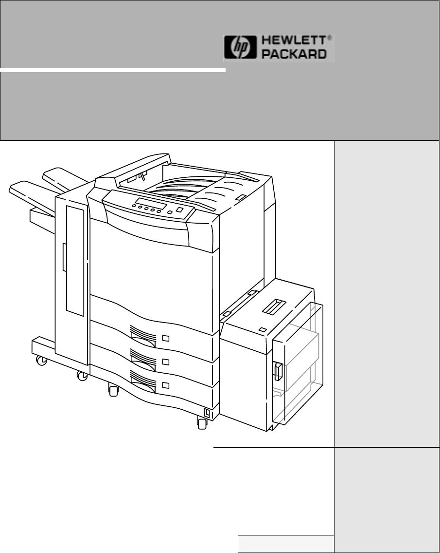
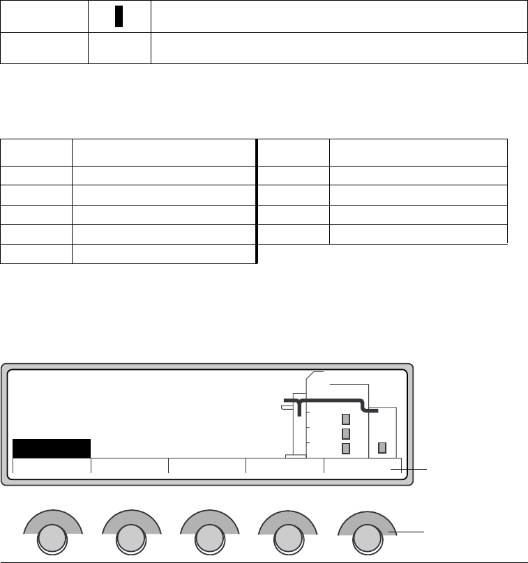
Figure 1-1 D640 with High Capacity Input and High Capacity Output installed
Standard Features of the D640 Printer
• 600 x 600 dpi resolution
• 40 page per minute printing (simplex)
• Duplex printing from A5 to Ledger size paper, plus custom sizes
• Prints forms, pre-punched, labels, and transparency media
• Standard paper input capacity of 1500 sheets (three paper trays)
• 16 MB of memory, expandable to 64 MB
• Hewlett-Packard LaserJet printer compatibility
• EconoMode for reducing toner expense
• Microfine toner
Accessories For the D640 Printer
1-2 About Your Printer
• Toner recycling
• Virtual Font Cartridges resident on internal hard disk
• Operator-replaceable consumables (toner, developer powder, drum, fuser, and paper pick
rollers)
• Bitronics parallel and serial interfaces with automatic switching
• PCL 5e, PJL, and HP-GL/2 language support built in
• IEEE 1284C support for 10 meter parallel cables
• Energy Star compliance
Accessories For the D640 Printer
• High-Capacity Input (HCI) holds 3000 sheets
• High Capacity Output (HCO) holds 2000 sheets
• Custom-size paper trays
• PostScriptTM Level 2
• 16 MB memory upgrade
Full 600 x 600 Resolution
The D640 provides full 600 X 600 dpi (dots per inch) laser resolution, and microfine toner,
ensures output with a professional and crisp look.
Rugged Construction for Long Life
The HP 5000 D640 is ruggedly constructed for years of printing at the rated monthly duty
cycle and for continuous operation without danger of damage to the print engine, a capability
especially important for peak printing periods such as month-end processing.
Consumable Replacement and Tracking
D640 toner and developer are easily replenished from bottles, and all consumable printing
components (photoconductor drum, fuser, and paper pick roller) are replaceable without tools.
To further simplify operation and management, the D640 tracks toner, developer,
photoconductor drum, fuser, and paper pick roller usage and displays operator messages
advising replacement as needed.
Duplex Printing With No Performance Degradation
The D640 performs duplex printing (letter and A4 paper sizes) at 40 page sides per minute.

Accessories For the D640 Printer
About Your Printer 1-3
About Your
Printer
Toner Recycling and Economy Mode Printing
The D640 supports both toner recycling and economy printing mode for greater toner yields.
Toner recycling can increase toner yield by up to 20%. In economy mode, toner usage is
reduced by up to 30% with minimal impact on text print quality.
High Capacity Paper Handling
The D640 features a maximum standard input capacity of 1500 sheets in three 500-sheet paper
trays. Maximum standard output capacity is 400 sheets. Addition of the High Capacity Input
(HCI) accessory increases the total input capacity to 4500 sheets. The High Capacity Output
(HCO) accessory handles up to 2000 sheets and supports output jogging for job separation.
Custom Paper Size Support
The D640 supports non-standard paper sizes with a custom paper tray. Paper sizes as small as
4.75 inches by 7.2 inches (120 mm x 182 mm) or as large as 11.7 inches by 17 inches (297 mm
x 431.8 mm) can be accommodated. The custom paper tray can be used as tray1, tray2, or
tray3. When using more than one custom paper tray, each tray must contain the same size of
paper.
Backlit LCD Display
The D640 features a backlit, menu-oriented, Liquid Crystal Display for ease of configuration
and printer management. Five different languages are supported (English, German, French,
Spanish, and Italian).
Multiple Interfaces
The D640 features integrated Bitronics (parallel) and serial interfaces and supports automatic
switching between these two interfaces. HP JetDirect EX external network interfaces
(purchased separately) provide Ethernet/IEEE 802.3 or Token Ring IEEE 802.5 LAN
interfaces. The same network management software used with HP LaserJet printers and HP
JetDirect cards can be used with the D640 and HP JetDirect EX products, allowing networked
HP printers to be administered and managed with a common set of software tools.
PostScript Level 2
PostScript is available for the D640 as an add-on product and includes an additional 16
megabytes of memory. The printer can be configured to automatically switch between
PostScript and PCL print jobs.

Accessories For the D640 Printer
1-4 About Your Printer
Compatibility with LaserJet 4Si/5Si Printer
The HP 5000 D640 is compatible with the HP LaserJet 4Si printer driver. However, because
the D640 provides more functionality than the HP LaserJet 4Si, not all D640 features can be
accessed with the 4Si printer driver. You can use third party products or additional
programming to access additional D640 features.
The HP 5000 D640 is also compatible with the HP LaserJet 5Si printer driver. However, there
are a few limitations when using the LaserJet 5Si printer driver. Please refer to Chapter 6,
"Advanced Topics", for a discussion of LaserJet compatibility.
PCL Level 5e
The D640 printer supports PCL, the print language of HP LaserJet printers and the most
widely installed print language in the world. Support for PCL Level 5e provides powerful
formatting capabilities and compatibility with a wide range of software solutions.
Integral Hard Disk
The D640 features an internal hard disk drive(850 MB or more) factory preloaded with
thousands of fonts and symbol sets. The hard disk can also be used for storing additional fonts,
electronic forms as PCL macros, and company logos.
Energy Star Compliance
To help minimize power consumption, the D640 complies with the Energy Star Program of the
U.S. Environmental Protection Agency.
Note If you have not done so, please refer to the Installation Manual and complete the
installation procedures. These procedures ensure the safe operation of the printer and the best
print quality.
The printer requires regular maintenance, as described later in this manual. Although
maintenance takes only a few minutes weekly, it is very important to the quality of the
printouts and the life of the printer.
Caution Hewlett-Packard recommends the use of Hewlett-Packard labelled consumable
supplies. Hewlett-Packard is not responsible for any failures or print quality issues arising
from the use of other than Hewlett-Packard supplies. Such failures are not covered under
warranty or by any Hewlett-Packard service agreement.
Getting to Know the Printer
About Your Printer 1-5
About Your
Printer
Getting to Know the Printer
Orientation
Unless otherwise noted, all instructions in this manual assume you are facing the front of the
printer, with the paper trays on the bottom and the paper output on the top.
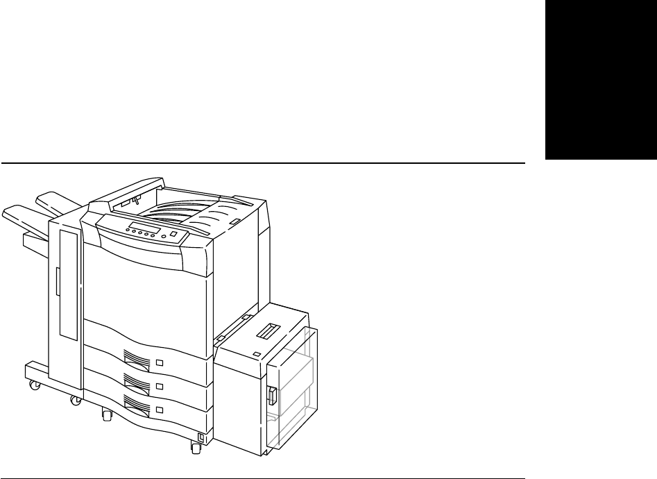
Figure 1-2 D640 with High Capacity Input and High Capacity Output
LTR
LTR
LTR
HCO D640 HCI
Printer
Getting to Know the Printer
1-6 About Your Printer
The D640 Printer
Your printer may or may not be installed with the optional high capacity input (HCI) and high
capacity output (HCO) accessories. Figure 1-2 shows the printer, the HCI, and the HCO
installed together. If you want to know more about these optional accessories, refer to “High
Capacity Input Accessory” on page 1-16 for the HCI, or “High Capacity Output Accessory”
on page 1-17 for the HCO.
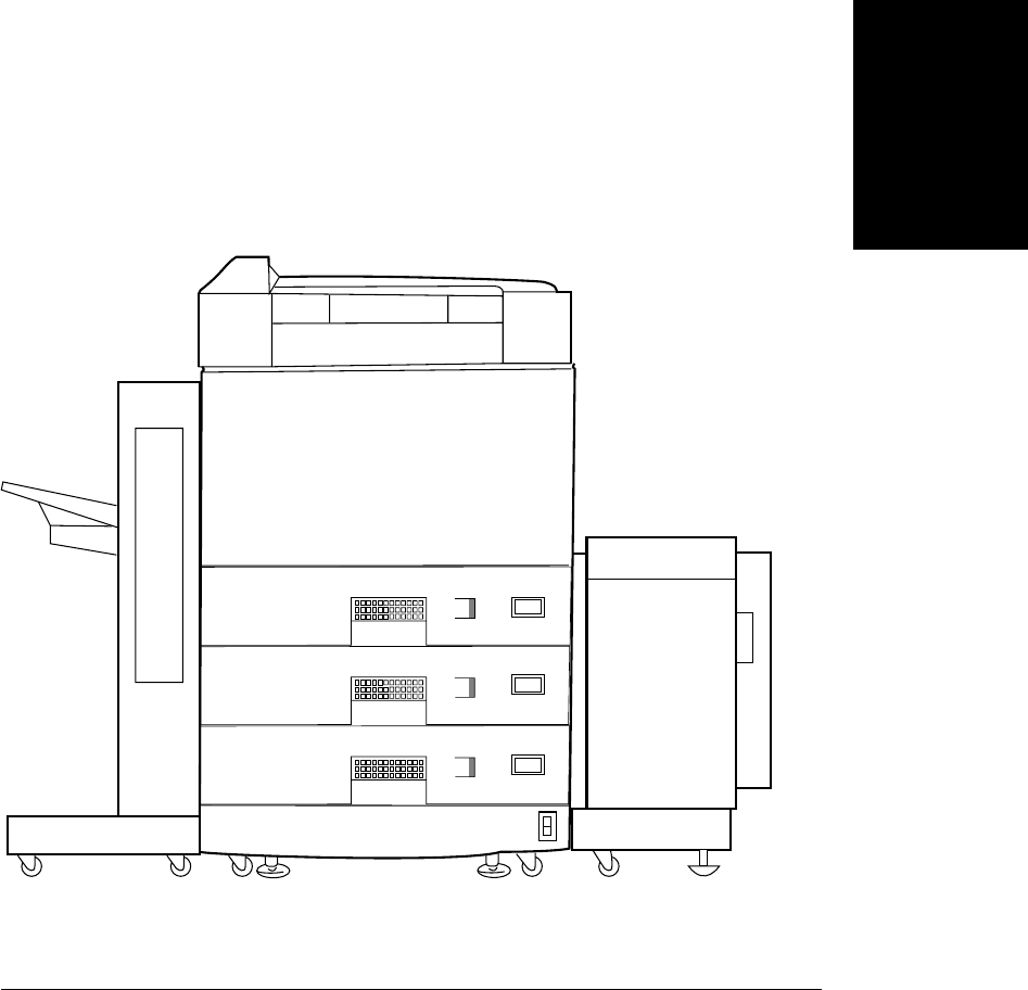
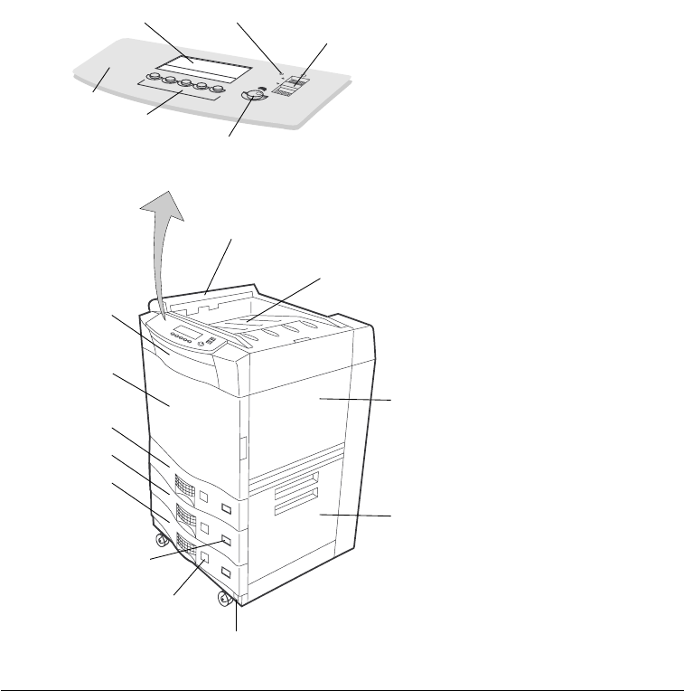
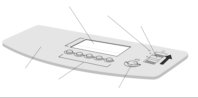
Figure 1-3 shows the front and right sides of the printer and an overview of the Control Panel.
Figure 1-3 Front and right side of the printer
.
.
.
.
.
.
.
.
.
..
.
.
.
.
...
Paper output tray
Ejection unit
Upper right cover
Lower right cover
Main power switch
Paper level indicators
Paper size indicators
Front cover
Front door
Tray1
Tray2
Tray3
..
.
.
....
.
.
.
.
......
Power Save Mode Indicator
Screen contrast control
Function buttons
LCD Panel
*Speaker
ON
* Not used
Standby switch
Control panel

Getting to Know the Printer
About Your Printer 1-7
About Your
Printer
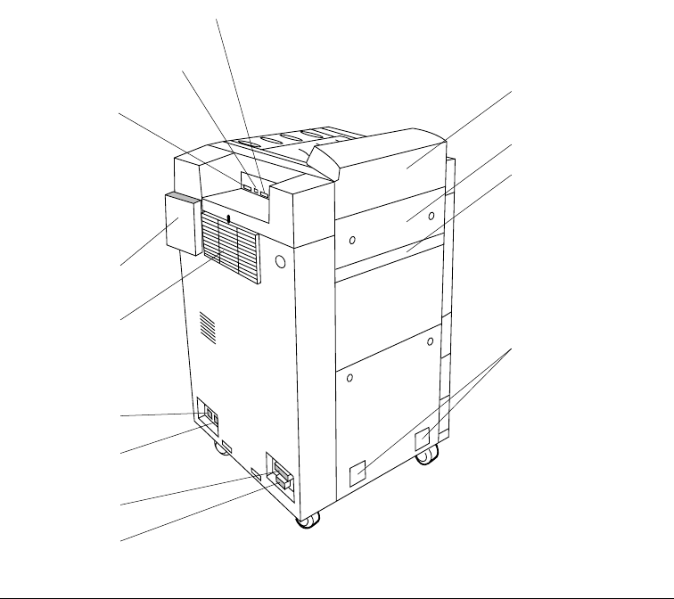
Front and Right Side of the Printer
In Figure 1-3, starting at the Control Panel at the top left and reading clockwise, refer to the
following points of interest.
•Control Panel: Consists of function buttons and a liquid crystal display (also referred to
as the LCD panel) that presents messages about printer activity.
•Screen contrast control: Allows you to adjust the contrast of the display.
•Ejection unit: Deposits paper to the output tray.
•Standby switch: Powers the printer on and off.
•Output tray: Holds printed pages.
•Upper right cover: Provides access to add toner and developer.
•Lower right cover: Provides access to the paper path (for jam clearing) from the paper
trays.
•Paper indicators: Provide a visual gauge for the size and relative amount of paper in each
tray.
•Main power switch: Applies line voltage to the printer.
•Trays 1, 2, and 3: These are the input paper trays for standard size media. You can also
obtain and install optional adjustable custom trays that hold custom (or standard) sizes of
paper.
•Front door: Provides access to the printer’s interior.
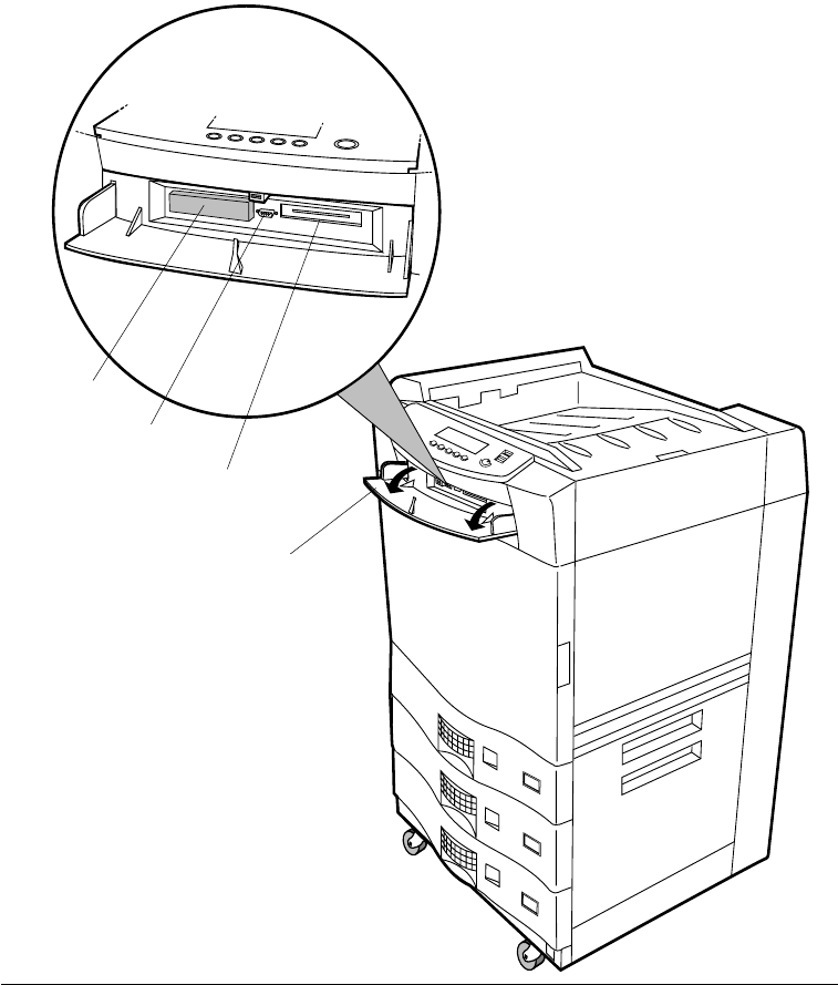
•Front cover: Provides access to the printer’s floppy disk drive for installing PostScript
and PCL code updates.
Getting to Know the Printer
1-8 About Your Printer
Figure 1-4 Behind the front cover
..
.
.
....
.
..
.
.
.....
Floppy disk drive
Front cover
Serial diagnostic port *
PC card slot *
LTR
LTR
LTR
* For support use only.

Getting to Know the Printer
About Your Printer 1-9
About Your
Printer
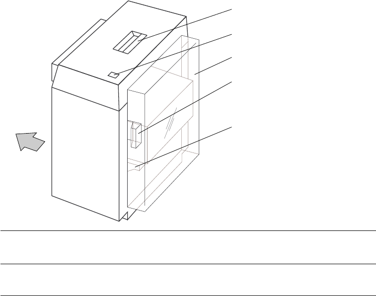
Behind the Front Cover
The front cover is located below the Control Panel, as shown in Figure 1-4. When you open it,
you find the following:
•PC card slot: Used only for support testing, and covered with a rubber protective cap.
•Serial diagnostic port: Used only for testing.
•Floppy disk drive: Used for updating printer functions and installing the PostScript
upgrade.
Getting to Know the Printer
1-10 About Your Printer
Figure 1-5 Behind the front door
Transfer assembly guide
Lever 6
Handle 3
Fuser unit
Decurler lever
Lever 4
Duplex unit
Drum unit locking knob
Drum unit
Precharger cleaner
Lever b1
Knob 1
Knob 2
..
.
.
....
.
..
.
.
.
....
Cleaning roller
LTR
Fuser locking knob
Lever 5
Duplex roller knob
Decurler roller
knob

Getting to Know the Printer
About Your Printer 1-11
About Your
Printer
Behind the Front Door
When you open the front door of the printer, you see the printer’s internal components, shown
in Figure 1-5 and described below.
•Fuser: Applies heat and pressure, which melts the toner and adheres it to the paper.
•Drum unit: Contains the precharger, photoconductor drum, and cleaner.
•Transfer guide: Contains the transfer unit, which moves the print image from the drum to
the paper.
•Fuser Locking knob: Secures the fuser in the printer chassis.
•Cleaning roller: Applies silicone oil and cleans the fuser roller.
•Drum unit locking knob: Secures the drum.
•Precharger Cleaner: Helps keep the drum surface free of stray toner.
•Decurler roller knob: Used to clear paper jams in the immediate area.
•Duplex roller knob: Used to clear paper jams in the duplex paper path (during double-
sided printing).
•Knob 1: Used to clear paper jams as the paper exits the paper trays and enters the drum
area.
•Knob 2: Used to clear paper jams as the paper exits the paper trays and enters the drum
area.
•Handle 3: Lowers the transfer guide to clear paper jams in the drum area.
•Decurler lever: Provides access to paper in the decurler area to clear paper jams.
•Lever b1: Secures the internal printing components in the paper path.
•Lever 4: Releases tension on paper in the fuser area to clear paper jams.
•Lever 5: Provides access to paper in the reverser area to clear paper jams.
•Lever 6: Provides access to paper in the duplexer area to clear paper jams.
Getting to Know the Printer
1-12 About Your Printer
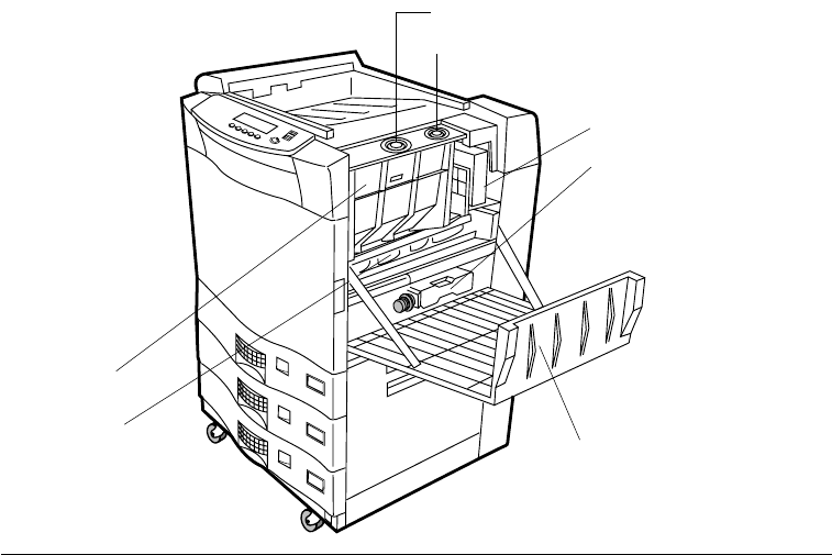
Figure 1-6 Behind the upper right cover
Toner collector bottle
Toner hopper
Developer unit
Developer collector bottle
Upper right cover
..
..
....
.
..
.
.
.....
Install toner here
Install developer here

Getting to Know the Printer
About Your Printer 1-13
About Your
Printer
Behind the Upper Right Cover
By opening the upper right cover, you gain access to the printer’s consumables, as shown in
Figure 1-6 and described below.
•Toner hopper: A reservoir that holds toner. The Control Panel displays messages to
indicate toner low and toner empty status. Never add toner before the printer indicates that
toner is needed.
•Developer unit: holds the developer mixture that prepares toner for transfer to the
photoconductor drum.
•Developer collector bottle: Collects used developer for disposal.
•Toner collector bottle: Collects waste toner for disposal.
Note Never pour waste toner into the toner hopper. If you do not want to discard waste
toner, use the toner recycling feature described in “Toner Recycling Switch” on page 6-8.
Caution Never re-use developer. Severe print quality problems and physical damage may
occur if you do so.
Getting to Know the Printer
1-14 About Your Printer
Figure 1-7 Rear and left side of the printer
Upper left cover
Paper side exit
(under cover)
HCO connector
AC input
power connector
HCI connector
Ozone filter
User documentation
holder
Serial port (RS232/422)
Switches used for support only
Parallel port
(IEEE 1284C)
HCO attachment
points (under covers)
Ejection unit
Lower connector
not used

Getting to Know the Printer
About Your Printer 1-15
About Your
Printer
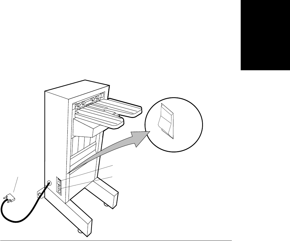
Rear and Left Side of the Printer
The rear of the printer has the features shown in Figure 1-7 and described below.
•Ozone filter: Absorbs and reduces the printer’s ozone emissions.
•Documentation holder: Provides a convenient location to store the printer manuals.
•Parallel port: Supports IEEE 1284C bidirectional host interconnections.
•Serial port: Supports RS232/422 host interconnections.
•Ejection unit: Provides access to clear paper jams in this area.
•Paper Side Exit (under cover): Provides access to the external paper path opening.
•HCO connector: Used to control the optional HCO stacker.
•Lower connector: Reserved for future accessories.
•AC input power connector: Accepts either 120-127 or 200-240 VAC input power (fuser
must be matched to the input voltage).
•HCI connector: Used to control the optional HCI feeder.
Getting to Know the Printer
1-16 About Your Printer
High Capacity Input Accessory
An optional High Capacity Input (HCI) accessory (shown in Figure 1-8) is available to provide
an additional input capacity of 3000 sheets. The HCI sits on rails attached to the printer and is
electrically connected to the printer by a cable, and obtains its power from the printer. The HCI
highlights are:
•HCI release handle: When squeezed, detaches the HCI from the printer.
•Paper table lowering button: When pressed, lowers the table for paper replenishment.
The printer must be powered on with all covers closed, or the table will not lower.
•HCI door: Allows visual inspection of the paper supply.
•Door handle: Provides easy access to the paper supply.
•Elevator-type movable table: Supports the paper supply.
Figure 1-8 High Capacity Input accessory
Note The HCI is pre-set for either A4 or Letter paper sizes. (Adjusting between the two
sizes should be performed only by a trained service technician.)
HCI release handle
Paper table lowering button
HCI door
Door handle
Paper table
(inside door)
Printer
Getting to Know the Printer
About Your Printer 1-17
About Your
Printer
High Capacity Output Accessory
The D640 can stack paper onto the optional High-Capacity Output (HCO) accessory (shown in
Figure 1-9), which holds up to 2000 sheets. The HCO uses a standard power cord that may be
plugged into any standard 120VAC or 240VAC (depending on the HCO version) wall outlet.
The HCO is mechanically and electrically connected to the printer. Power is controlled by the
Main Power switch and is normally left in the ON position.
Figure 1-9 High Capacity Output accessory
Main Power Switch
Input power cord connector
HCO Interface
control cable
ON
OFF
Powering On the Printer
1-18 About Your Printer
Powering On the Printer
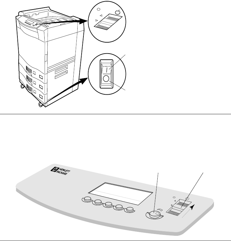
1. Locate the main power switch and standby switch as shown in Figure 1-10.
Figure 1-10 Standby switch and Main power switch
2. Turn on the Main power switch by pressing in at the top of the switch.
3. Turn on the Standby switch, as shown in Figure 1-11, by holding the switch in the up
position momentarily.
Figure 1-11 Turning on the standby switch
4. If you do not see anything on the display after 5 to 10 seconds, turn the screen contrast
control to the 2:00 o’clock (1400) position, as shown in Figure 1-11. You can then adjust
the control to an appropriate level.
ON
ON
OFF
Main power switch
Standby switch
.
.
.
.
..
.
.
.
..
.
.
.
....
..
..
....
.
.
.
.
.
.....
Standby switch
MODEL D640
5000
ON
Screen contrast control

Control Panel 2-1
Control Panel
2
Control Panel
Introduction
The D640 printer performs many kinds of printing tasks. Through the Control Panel menus,
you can select options and features.
If your print job contains commands that change the Control Panel settings, the print job
commands will be effective for that job only.
This chapter is a detailed reference for all of the D640’s menu settings:
If you want to Go to:
• Understand Control Panel functions page 2-2
• Check the printer’s status page 2-3
• Check the printer’s paper page 2-5
• Select Custom menu settings page 2-9
• Select Printer menu settings page 2-11
• Select Configurations menu settings page 2-14
• Select PCL menu settings page 2-19
• Select Comms menu settings page 2-21
• Select Maintenance menu settings page 2-24
• Select PapSize menu settings page 2-26
• Select Test menu settings page 2-28
Getting to Know the Control Panel
2-2 Control Panel
Getting to Know the Control Panel
Figure 2-1 Control Panel
Control Panel Features and Functions
The Control Panel is one of the means to control and configure the printer. Through the
Control Panel, the printer displays information about aspects of normal operation, paper jams,
consumable status, and error conditions. Use the function buttons on the Control Panel to
change printer settings.
Control Panel features include:
• The Standby switch turns the printer on and off:
- When you move the Standby switch momentarily to the ON (or up) position, the printer
powers on. There will be up to a 2 minute delay before you can print while the printer
performs an initialization sequence and warms the fuser to operating temperature.
- When you move the Standby switch momentarily to the OFF (or down) position, the
printer is powered off and placed in Standby mode. There may be a delay in the printer
powering off; any pages currently moving through the paper path are printed before the
printer powers off.
• The Screen contrast control adjusts the contrast of the LCD panel.
• The Function buttons are located below the LCD panel. These five buttons perform
different functions during printer operations, such as when the printer is printing, or when
you are changing settings. Figure 2-6 shows these function buttons.
..
..
....
.
.
.
.
.
.....
PowerSave indicator
Screen contrast control
Function buttons
LCD panel
Standby switch
Speaker
(not used)
ON
Checking Printer Status
Control Panel 2-3
Control Panel
At any given time, you can only perform the action shown on the Control Panel for a
particular button. If a button is undefined, it performs no function.
• The Speaker is not currently activated.
• The Liquid crystal display (LCD) panel displays printer status and operating information.
Figure 2-6 shows the basic menu screen, called the Main Screen. Messages on the Main
Screen:
- Show information about printer status, progress of the print job, and the current paper
path.
- Display the paper size configured for each input source.
- Show any paper jams in the paper path line.
•The PowerSave indicator, when on, indicates that the printer is in PowerSave mode. The
backlight of the LCD panel also turns off in PowerSave mode.
Checking Printer Status
You may want to check the D640’s status for many reasons:
• To verify that it is ready for printing.
• To verify that it is either Online or Offline.
• To check that the correct date, time, and printing protocol are set.
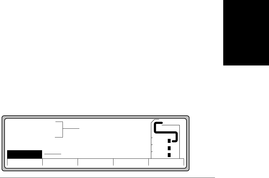
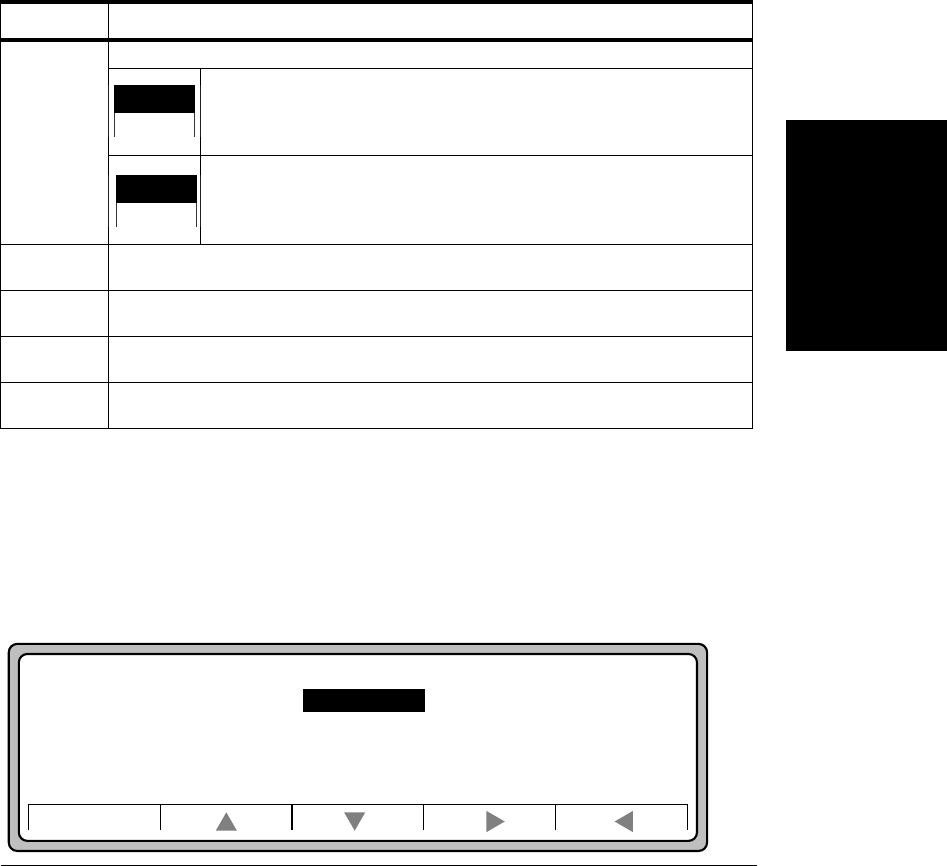
Normal Printer Status (No Error Condition Displayed)
The message field of the display shown in Figure 2-2 reports the D640’s status.
Figure 2-2 Printer status
The message field information indicates:
• Ready -- free
The printer is ready to print.
• JUN 18 05:32.23
Displays the current date (JUN 18) and time (05:32.23).
Ready - - free
JUN 18 05:32.23
PCL
Offline
Offline
Custom Menu Test PapSize
600dpi
LTR
LTR
LTR
Online
Message field
Printer is offline
Checking Printer Status
2-4 Control Panel
•PCL
Indicates that the printer is using PCL (Printer Control Language) emulation.
•Online
The printer is ready to print.
Abnormal Printer Status
The message field (the first and second line) of the Control Panel reports the printer’s
conditions, such as low toner, paper jam, or door open. In these cases, the Control Panel also
describes what action is needed to remedy the situation. Serious conditions may require a
service call. Error messages are listed in Appendix A.
The printer constantly monitors the state of consumables such as developer and toner. When a
consumable runs low, or has reached its end-of-life, a message notifying you to replace the
consumable appears on the Control Panel. An example of such a report is shown in Figure 2-3.
Figure 2-3 Toner empty indication
The printer detects when a cover is open and stops printing to protect you from electrical and
mechanical hazards. If a cover is open, the printer reports the condition, like the screen shown
in Figure 2-4.
Note Do not open a cover while the printer is printing; this will cause a paper jam.
Figure 2-4 Problem status report
Clear
Offline
Menu Test PapSize
LTR
LTR
LTR
Offline
Toner empty
Add New Toner
PCL
Clear
Offline
Menu Test PapSize
LTR
LTR
LTR
Ejection unit cover open
Close ejection unit cover
PCL
Custom
Online
Checking Paper
Control Panel 2-5
Control Panel
Checking Paper
Check the Control Panel to make sure that paper is loaded properly and to observe the progress
of printing. You can:
• Verify that the paper trays contain paper.
• Verify that correct paper sizes are in the paper trays.
• Check on paper travel through the paper path when printing.
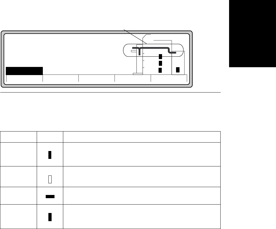
Figure 2-5 shows the paper supply and path information.
Figure 2-5 Paper supply and path information
The Main Screen display (Figure 2-5) shows the path the paper takes from the selected paper
tray to the selected output area. The display also shows the installed paper trays and associated
paper sizes, as listed in Table 2-1.
Paper Size Symbol Description
Letter
(LTR)
LTR indicates that the tray contains letter size paper. The symbol indicates
the long edge is leading into the paper path and the filled-in symbol
indicates the tray has paper. Note: paper size determines whether the long
or short edge leads into the paper path.
A4
A4 indicates that the tray is set to contain A4 size paper. The empty
symbol indicates the tray has no paper.
Legal
(LGL)
LGL indicates legal size paper installed. The symbol indicates the short
edge is leading into the paper path and that the paper tray has paper.
Custom
(CUS)
CUS indicates that custom paper is installed in the custom tray. This
particular custom tray paper configuration has the long edge leading into
the paper path.
Ready - - free
JUN 18 05:32.23
PCL
Offline
Offline
Custom Menu Test PapSize
600dpi
LTR LTR
LTR
LTR
Current paper path
Online
Function Buttons
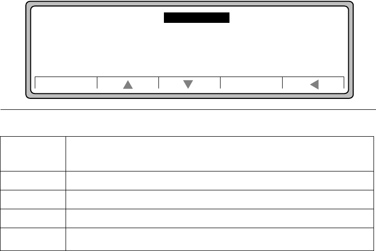
2-6 Control Panel
Table 2-1 lists all available standard paper categories and their respective sizes.
Table 2-1 Standard paper sizes
Function Buttons
The following illustration shows the function buttons assigned to the Main Screen. Table 2-2
describes how each function button is used with the Main Screen.
Figure 2-6 Main Screen Function Buttons
HCI HCI indicates that the HCI is installed and contains paper. Paper size can
only be LTR or A4 (depending on the model of the HCI).
A3 A3 indicates that A3 size paper is the specified paper size, but the missing
symbol indicates that the tray is open.
Category Dimensions Category Dimensions
Letter 8.5 x 11 in (216 x 279 mm) A4 8.26 x 11.69 in (210 x 297 mm)
Legal 8.5 x 14 in (216 x 356 mm) A5 5.84 x 8.26 in (149 x 210 mm)
Ledger 11 x 17 in (280 x 432 mm) B4 (JIS) 10.11 x 14.32 in (257 x 364 mm)
Executive 7.25 x 10.5 in (184 x 267 mm) B5 (JIS) 7.16 x 10.11 in (182 x 257 mm)
A3 11.69 x 16.53 in (297 x 420 mm)
Ready - - free
JUN 18 05:32.23
PCL
Offline
Offline
Custom Menu Test PapSize Commands
for each
button
LTR LTR
LTR
LTR
Online
Function
buttons
600 dpi
Function Buttons
Control Panel 2-7
Control Panel
Table 2-2 Control Panel Main Screen Function Buttons
Navigating Through the Control Panel
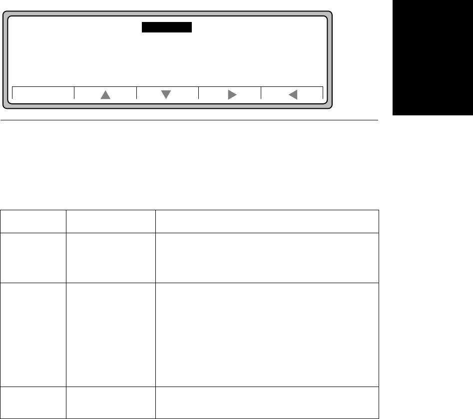
Submenu Arrow Buttons
Figure 2-7 shows the appearance of the Control Panel when you are ready to make selections
from the Control Panel menus. When you want to expand the menu selections (that is, examine
and select settings from submenus providing more options), use the arrow buttons (M, N, P,
and O) and the Select button. Table 2-3 describes how to use each arrow button.
Figure 2-7 Arrow Buttons
Button Function
Online/
Offline
Online/Offline toggles the printer from Offline to Online.
When Online, the printer is ready to print.
When Offline, the printer does not accept print requests. The printer goes
Offline automatically when a paper jam or other detected problems occur.
Custom Custom settings store and recall saved configuration settings.
You can store up to three different custom configuration settings.
Menu Menu provides access to five submenus: Printing, Configuration, PCL, Comms, and
Maintenance.
Test Test prints various maintenance and user reports. Test also provides access to files
stored on a floppy diskette or on the internal hard disk.
PapSize PapSize (paper size) provides a configuration menu for setting the paper size for each
paper source.
Offline
Online
Offline
Online
Online
Menu
Online
Printing
Configuration
PCL
Comms
Maintenance
Function Buttons
2-8 Control Panel
Table 2-3 Control Panel Submenu Function Buttons
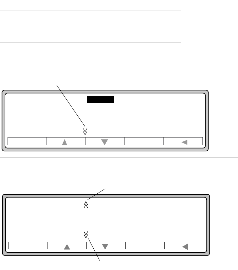
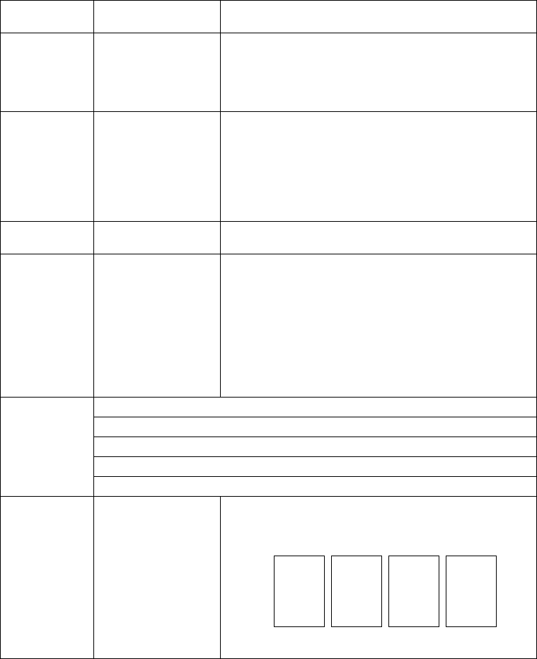
Figure 2-8 shows continuation arrows to indicate there are additional items on a submenu.
Press N display the additional items. Figure 2-9 shows the menu choices after you press N.
Figure 2-8 Continuation arrows
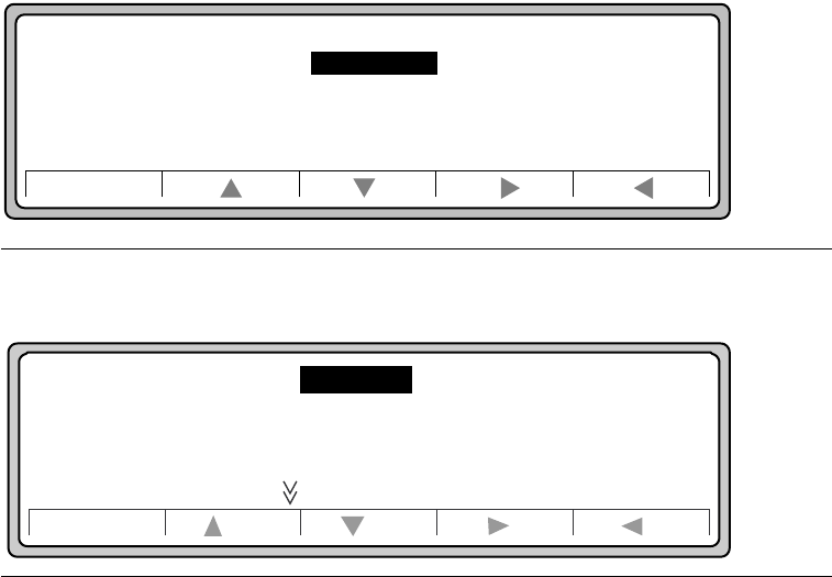
Figure 2-9 Up and down continuation arrows
MPress to scroll up the list of items on the submenu.
NPress to scroll down the list of items on the submenu.
PIf an additional submenu is available, press this arrow to open the
submenu.
OPress to close a submenu and return to the previous menu level.
Select Press to select the setting highlighted on the submenu.
Online
tray1size =
Online
LEGAL
LEDGER
EXECUTIVE
A4
A5
LETTER
Select
Contination arrows
Online
Printing.copies
Online Select
7
8
9
10
11
12
Additional selection above
Additional selections below
Custom Menu Settings
Control Panel 2-9
Control Panel
Once you have highlighted the submenu selection (Figure 2-8), press the Select function
button to activate your selection and return to the previous level. The Online function button
will change to Save. You can make further changes to the settings, or press Save to store your
new settings and return the printer to a Ready -- free state.
Note Changes to menu settings can only be made in the Ready -- free state. If you try to
make a change and see the message "menus locked", it means that the printer is processing a
print job and changes cannot be made
Changes to settings are not permanently saved unless you press the Save button after making
all configuration changes. When you press Save, your new settings are stored in the power-on
configuration. If you do not Save, the new settings are only active until you change them again,
cycle power, or print a job that contains a reset command.
Custom Menu Settings
The printer provides a means to maintain three different Control Panel custom configurations.
This allows you to pre-program configurations for later use. Configuration items available
under the Printing, Configuration, PCL, Comms, and some of the Maintenance submenus are
saved as part of the custom settings.
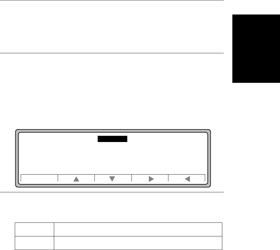
1. On the Main Screen, press Custom to display Figure 2-10:
Figure 2-10 Custom Menu
2. Use M or N to highlight your selection:
Restore Restore is used to recall the printer’s power-on configuration, factory default
configuration, or one of the three custom configurations.
Save Save is used to store a new configuration as the power-on configuration or one
of the three custom settings. All configurations are stored in the printer.
Online
Custom
Online
Restore
Save
Custom Menu Settings
2-10 Control Panel
3. Use M or N to highlight the Save or Restore (Figure 2-10).
4. Use P to obtain more settings options (Figure 2-11).
5. Use M or N to highlight the option you want.
6. Press Select.
Figure 2-11 Custom restore and save menu settings
PwrOnConfig This location stores settings used at power-on or from a job reset.
Note: Whenever you change a configuration value, the Online button changes to
Save. If you press Save, the values are changed in the PwrOnConfig location.
CUSTOM2 This location stores one of three custom configurations.
CUSTOM3 This location stores one of three custom configurations.
CUSTOM4 This location stores one of three custom configurations.
FACTORY This location holds the factory default configuration. Highlight FACTORY and press
Select to restore the printer configuration to the factory default.
Online
Restore
Online Select
PwrOnConfig
CUSTOM2
CUSTOM3
CUSTOM4
FACTORY
Printing Menu Settings
Control Panel 2-11
Control Panel
Printing Menu Settings
The Printing menu provides access to configuration choices that directly affect how your
documents are printed. Figure 2-12 shows some of these.
If your software specifies different values than those programmed in the Control Panel, the
printer uses the values supplied with the printing job.
Figure 2-12 Printing Menu
When you see pointers on the screen pointing up or down, that indicates there are additional
selections available by using M or N to access them.
In the table below, * indicates that a setting is present only if required option is installed (HCI,
HCO, PostScript). The equals sign (=) indicates the factory default value.
Copies =1 (minimum)
32767 (maximum) Sets the number of copies to be printed for each page.
Intray
=TRAY1
TRAY2
TRAY3
=HCI* (Default if HCI
is present
Sets the default media input source.
Paper
=auto
LETTER
LEGAL
LEDGER
EXECUTIVE
A4
A5
A3
JISB4
JISB5
CUSTOM
Sets the default image the page will be formatted for.
Auto uses the page size of the selected intray.
*Outbin =UPPER
HCO-FACEDOWN
HCO-FACEUP
Sets the media output destination.
Online
Menu
Online
Printing
Configuration
PCL
Comms
Maintenance
Printing Menu Settings
2-12 Control Panel
Duplex =OFF
ON Turns double-sided printing on or off.
Binding
=LONGEDGE
SHORTEDGE Sets the duplex binding options.
LONGEDGE (book) binding is the conventional side-to-side
binding used in books.
SHORTEDGE (tablet) binding is the traditional top to bottom
layout used with calendars.
Jobseparate
=none
TRAY1
TRAY2
TRAY3
Lets you dedicate an input tray to be used for job separation
sheets. "none" indicates that the job separation feature is not
enabled. Job separation sheets are usually colored paper.
When your print job contains a job separation command, the
printer will pick a sheet of paper from the designated tray and
insert it into the print job. No text is printed on the job
separation page. This feature can be used with the joboffset
feature if an HCO is connected.
*Joboffset =OFF
ON Enables the HCO offset (jogging) feature, which staggers
finished jobs for easy separation.
*HCI-Alias
TRAY1
TRAY2
TRAY3
=HCI
This setting redirects the HCI to act like tray1, tray2, tray3, or
like itself. It is provided primarily to make the D640 HCI act
just like an HP LaserJet IIIsi or 4si with an HCI, so jobs
configured for a LaserJet print correctly on the D640 without
modification.
To match a IIIsi or a 4si, change HCI-Alias to tray2. This will
cause all print job commands for tray2 (or lower tray) to pick
paper from the D640 HCI.
For more information, see “Configuring for LaserJet IIIsi and
4si Compatibility” on page 6-24.
Emulation
Allows you to select the printer emulation protocol. The selections are:
Auto - automatically selects PCL or PostScript* based on the print job data.
HEX - prints a "hexadecimal dump" of the print (used for troubleshooting).
PCL - is the standard PCL5e (4si) emulation protocol.
PS - is the optional PostScript* Level 2 emulation protocol.
Orientation
=PORTRAIT
LANDSCAPE
REVPORTRAIT
REVLANDSCAPE
Selects the print orientation. The figure below shows print
orientation.
Portrait
ABC
Landscape
ABC
Reverse
Portrait Reverse
Landscape
ABC
ABC

Printing Menu Settings
Control Panel 2-13
Control Panel
Lpi 0.01 (minimum)
= 6.00
100.00 (maximum)
Sets the number of lines per inch to print.
Error-Report
=none
ERRORS
WARNINGS
The printer is capable of printing errors found while
processing a job. This works for PCL or PS jobs and is
typically used to help troubleshoot a file which does not print
correctly. The options are:
none - turns error reporting off.
ERRORS - prints all fatal errors that prevent the job from
printing correctly.
WARNINGS - prints all fatal and nonfatal errors. Non-fatal
errors indicate minor processing problems. For example,
when the printer can’t process a command because of bad
syntax.
Configuration Menu Settings
2-14 Control Panel
Configuration Menu Settings
The Configuration menu (Figure 2-13) provides access to choices that affect general printer
operation. Figure 2-14 shows an example of Configuration menu selections.
Figure 2-13 Configuration Menu
Figure 2-14 Configuration Menu selections
When you see pointers on the screen pointing up or down, that indicates there are additional
selections available by using M or N to access them.
Online
Menu
Online
Printing
Configuration
PCL
Comms
Maintenance
Online
Configuration
Online
traylock
sizes
imageshift
customsize
units
newline =CR+LF
=Confirm
=1/720"

Configuration Menu Settings
Control Panel 2-15
Control Panel
In the table below, * indicates that a setting is present only if required option is installed (HCI,
HCO, PostScript). The equals sign (=) indicates the factory default value.
Newline
=CR + LF
CR
LF
CR or LF
Sets the method of newline interpretation. Some files may
contain carriage returns without line feeds, or line feeds
without carriage returns. Use this setting to print such files
properly.
Traylock.tray
1, 2, 3, and
HCI
tray1
=UNLOCKED
LOCKED
tray2
=UNLOCKED
LOCKED
tray3
=UNLOCKED
LOCKED
*hci
=UNLOCKED
LOCKED
Trays can be locked out of the automatic paper selection
process. Lock out paper trays if you don’t want the tray to be
available unless a job delivers a direct command to pick from
that tray. As an example, if you have a tray with letterhead in it,
you may want to lock out this tray so that if the other two trays
ran out of paper, the letterhead would not automatically be
used. Locked trays are only selected if the print job contains
the command to select the locked tray.
Sizes
= CONFIRM
CONTINUE
US
ISO
This setting specifies how the printer behaves when it receives
a request for a size of media not currently configured in the
printer.
CONFIRM - the printer stops and waits for the operator to
intervene. In this case, the following message appears on the
Control Panel.
PAPER-SIZE MISMATCH
LOAD XX PAPER
CONTINUE - the printer uses the next larger size of paper and
prints without any message.
US - the printer uses Letter paper in place of A4 paper, Ledger
paper in place of A3 paper, and Executive paper in place of A5
paper.
ISO - the printer uses A4 paper in place of Letter paper, A3
paper in place of Ledger paper, and A5 paper in place of
Executive paper.
Note The printer does not automatically resize the
print image for the new paper size. As a result, some
print data may not appear on the printed page.
Configuration Menu Settings
2-16 Control Panel
Imageshift.top
-720(min)
= 0
720(max)
This setting allows you to incrementally adjust the top position
of the image on paper in units, an incremental adjustment. The
factory default unit scale is 1/720", but you can reset the unit
size with the unit setting (see “Unit” on page 2-17). A typical
situation is alignment of text to a pre-printed form. You can
adjust within a range of 1 inch positive and 1 inch negative, in
1/720" increments, as listed below.
Imageshift.left
-720(min)
= 0
720(max)
This setting allows you to incrementally adjust the left position
of the image on paper in units, an incremental adjustment. The
factory default unit scale is 1/720", but you can reset the unit
size with the unit setting (see “Unit” on page 2-17). A typical
situation is alignment of text to a pre-printed form. You can
adjust within a range of 1 inch positive and 1 inch negative, in
1/720" increments, as listed below.
inch milli
meter
Unit Size Setting Range
1/100" 1/200" 1/300" 1/600" 1/720" mm
Minimum -1 -25.4 -100 -200 -300 -600 -720 -25
Maximum +1 +25.4 +100 +200 +300 +600 +720 +25
Customsize.width
2837(min)
=8417
8417(max)
This setting configures the media size of nonstandard media. It
is only used when you have a custom paper tray and one of the
PapSize values is set to Cus(custom). The table below lists the
minimum and maximum custom paper widths in units, an
incremental adjustment. The factory default unit scale is 1/720",
but you can reset the unit size with the unit setting (see “Unit” on
page 2-17).
customsize.width inch milli
meter
Unit Size Setting Range
1/100" 1/200" 1/300" 1/600" 1/720" mm
Minimum 4.72 120 394 788 1182 2364 2837 120
Maximum 11.69 297 1169 2338 3507 7014 8417 297
Configuration Menu Settings
Control Panel 2-17
Control Panel
Tip To make configuring the Imageshift and Customsize settings easier, set the units to
"MM" and make a coarse setting. Then, use a finer unit setting to fine tune the adjustment.
Customsize.height
5155 (min)
= 12240
12240(max)
This setting specifies the width dimensions of custom paper.
The table below lists the minimum and maximum custom paper
height in units, an incremental adjustment. The factory default
unit scale is 1/720", but you can reset the unit size with the unit
setting (see “Unit” on page 2-17).
customsize.height inch milli
meter
Unit Size Setting
1/100" 1/200" 1/300" 1/600" 1/720" MM
Minimum 7.17 182 716 1432 2148 4296 5155 182
Maximum 17.0 431.8 1700 3400 5100 10,200 12,240 432
Unit
1/100"
1/200"
1/300"
1/600"
1/720"
MM
Sets the unit values used in customsize and imageshift.
Dpi 200 dpi
300 dpi
=600 dpi
Sets the print resolution for graphic images in dots per inch (dpi).
Clip
OFF
=ON The D640 is able to print an image across the entire surface of the
physical paper. The image is clipped to prevent an image from
printing within 1/6th inch of any paper edge. This ensures optimum
print quality for the printed image.
If you don’t want this automatic clipping, you can set the printer to
Clip = OFF.
Even with Clip = OFF, the image will only print to the edge of the
paper if your print job contains the appropriate commands. See
“Setting Up Edge-to-Edge Printing” on page 6-23 for more
information.
Jamrecovery
=ON
OFF When a paper jam occurs, the printer reprints all pages that did not
completely exit the printer’s paper path. If you do not want pages to
automatically reprint after a paper jam is cleared, set Jamrecovery =
OFF.
Economode
=OFF
ON This setting specifies economy mode. When it is used for printing
drafts, you can save up to 30 percent of your toner consumption. In
economy mode solid black areas are filled in with a hatched pattern.
When economode is ON, the economode mark (e) appears in the
Control Panel, as shown in Figure 2-15.
Configuration Menu Settings
2-18 Control Panel
Figure 2-15 Economode
Powersave
off
15 MIN
30 MIN
=1 HR
2 HRS
3 HRS
This setting specifies the amount of time after the last print job
before the printer enters PowerSave. When the printer enters
PowerSave, it switches off the Control Panel backlight and lights
the green PowerSave indicator. Any activity on the printer serial or
parallel interface or Control Panel buttons restores full power.
Language
=ENGLISH
FRANCAIS
DEUTSCH
ESPANOL
ITALIANO
This setting specifies the language of text displayed on the Control
Panel and in reports under the test menu.
Ready - - free
JUN 18 05:32.23
PCL
Offline
Offline
Custom Menu Test PapSize
600dpi
LTR
LTR
LTR
Online
e
Economode
PCL Menu Settings
Control Panel 2-19
Control Panel
PCL Menu Settings
The PCL menu (Figure 2-16) lets you set the printer’s default font and symbol set. You can
also use the PCL menu to configure up to two active font cartridges. The selections are shown
in Figure 2-17.
When you see pointers on the screen pointing up or down, that indicates there are additional
selections available by using M or N to access them.
Figure 2-16 PCL Menu
Figure 2-17 PCL Menu selections
Online
Menu
Online
Printing
Configuration
PCL
Comms
Maintenance
Online
PCL
Online
=Courier
symbolset =ROMAN8 8U
pitch =10.00
pointsize =12.00
vcartridge1 =none
vcartridge2 =none
font

PCL Menu Settings
2-20 Control Panel
Font Sets the default character font.
Symbolset Sets the default symbol set (character set) of the font specified in the font setting. A
symbol set is a collection of letters, numbers, and symbols designed for specific
applications such as scientific equations and international language.
Pitch
Sets the default pitch size for the fixed-pitched font. Pitch is the number of characters that
can be printed in one horizontal inch. For example, a font with a pitch of 10 will print 10
characters for every horizontal inch of text. If a proportionally-spaced font is selected in
the font menu, pitch will not appear on the PCL menu.
Pointsize This setting specifies the point size for the scalable font. Pointsize is the height of the font
measured in point (1/72 of an inch).
Virtual
Font
Cartridges
The D640 printer is designed to be compatible with the HP LaserJet 4si. The 4si has two
slots available for font cartridges. HP sells over 50 different font cartridges for 4si and
compatible printers.
The D640 has no slots to hold these cartridges. Instead, we provide the same
functionality with virtual font cartridges. All of the font sets from all of the LaserJet 4si font
cartridges sold by Hewlett-Packard are stored on the D640’s internal hard disk drive. You
select the virtual font cartridge by vcartridge1 and vcartridge2. The font names are
comparable to the actual physical cartridge. For a complete list of the fonts available,
refer to “Using Virtual Font Cartridges” on page 6-26.
Note: Fonts located inside a font cartridge cannot be the printer default font.
Vcartridge1
= None
.
.
.
Printer16
Sets the font cartridge used in virtual font cartridge 1. A cartridge is
a set of fonts. Specified fonts appear at the bottom of the items in
the Font menu. Using vcartridge1 and vcartridge2 together, you
can choose two font sets.
Vcartridge2
= None
.
.
.
Printer16
Sets the font cartridge used in virtual font cartridge 2.
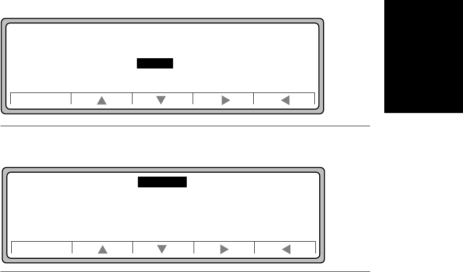
Comms Menu Settings
Control Panel 2-21
Control Panel
Comms Menu Settings
The Comms menu (Figure 2-18) contains options for configuring the printer’s parallel and
serial interface ports. The selections are shown in Figure 2-19.
When you see pointers on the screen pointing up or down, that indicates there are additional
selections available by using M or N to access them.
Figure 2-18 Comms Menu
Figure 2-19 Comms Menu selections
Online
Menu
Online
Printing
Configuration
PCL
Comms
Maintenance
Online
Comms
Online
timeout =15
databuffer =32
parallel
serial
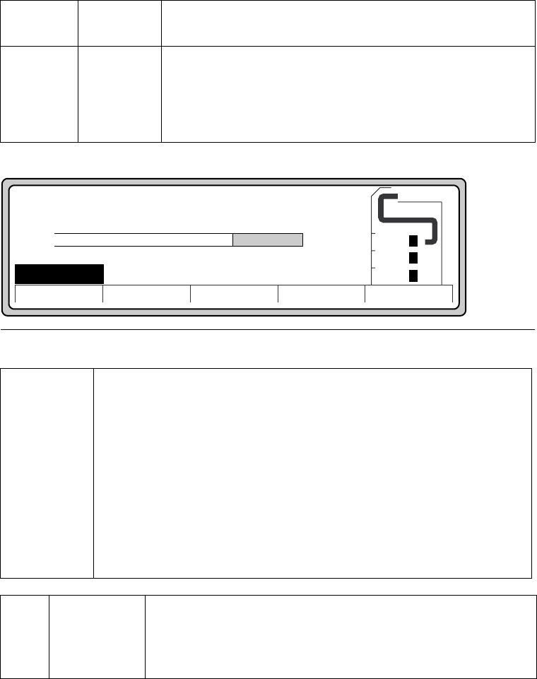
Comms Menu Settings
2-22 Control Panel
Figure 2-20 Incoming data processing bar
Timeout none
=15
300 (max)
Sets the time limit (in seconds) that the printer waits before ending an
incomplete job or switching data ports (serial or parallel). When set to
none, the printer waits for you to manually intervene.
Databuffer
1 (min)
=32
1000(max)
(in Kb)
Sets the size of printer memory allocated for incoming data. Increasing
the data buffer size helps the host transfer data more quickly, but the
printer has less memory to store pages for printing. Decreasing the data
buffer size limits how quickly the host transfers data, but the printer has
more memory for processing and storing pages.The amount of data in
the buffer, relative to its overall size, is displayed as an expanding and
contracting horizontal bar (Figure 2-20) during the processing cycle.
Parallel
This setting specifies Busy signal timing for the Centronics parallel interface.
speed = SLOW Slow setting provides compatibility with older parallel
interfaces on personal computers and should only be
selected if you see characters missing in your printout.
speed = FAST Fast setting provides optimal performance and is the
preferred setting.
mode = COMPATIBLE This setting operates only in uni-directional mode for
downwards compatibility.
mode = ADVANCED This setting enables the use of IEEE-1284 bi-directional
communication (nibble-mode).
Serial
=baud
stopbits
parity
flow
dtr
levels
This setting specifies the serial interface communication options. See below
for an example of how these options are used together.
Printer initializing
Please Wait
PCL
Offline
Offline
Custom Menu Test PapSize
600dpi
LTR
LTR
LTR
Online
Cen

Comms Menu Settings
Control Panel 2-23
Control Panel
Serial Interface Configuration Example
The following is an example of how to configure the serial interface.
1. On Comms menu, use N to highlight Serial. At Serial, use P to display selections.
2. Use P to display baud rates.
3. Use N to scroll to display selections (19200 selected).
4. Continue selecting the following parameters:
• Select stopbits and set the number of stopbits.
• Select parity and set the parity check condition.
• Select flow and set the flow control type of the serial interface:
NOFLOW Disable flow control.
XON/XOFF Enable XON/XOFF flow control.
ROBUST Enable ROBUST flow control (a combination of software and hardware
flow control).
• Select dtr and set the method of handling the serial interface Data Terminal Ready
(DTR) signal.
HI/LO DTR polarity high for ready and low for not ready
LO/HI DTR polarity low for ready and high for not ready
HI/HI DTR polarity permanently high
LO/LO DTR polarity permanently low
• Select levels and set the type of serial interface.
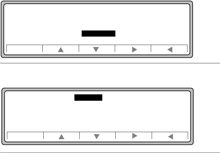
Maintenance Menu Settings
2-24 Control Panel
Maintenance Menu Settings
The Maintenance Menu (Figure 2-21) contains options that help you maintain the D640 for
optimum print quality. The selections are shown in Figure 2-22.
When you see pointers on the screen pointing up or down, that indicates there are additional
selections available by using M or N to access them.
Figure 2-21 Maintenance Menu
Figure 2-22 Maintenance selections
Online
Menu
Online
Printing
Configuration
PCL
Comms
Maintenance
Online
Maintenance
Online
replace
alignment
density = 10
testpages = 30
monitor = OFF
date-time

Maintenance Menu Settings
Control Panel 2-25
Control Panel
Replace
The Replace selection initiates the replacement procedure
for the consumable items you are removing and replacing.
Follow the instructions in “Overview of Consumable
Supplies” on page 4-1 for replacing consumables.
Alignment.tray1,
tray2, tray3, hci,
duplex, and
duplexv
Sets the alignment correction values. See “Using Virtual Font Cartridges” on
page 6-26 for the paper path alignment procedure.
Density
1 (min)
= 10
15 (max)
This setting specifies the relative darkness of the print on a
scale of 1 to 15, with 15 being the darkest setting. Gray scale
patterns show the most visible effect. The effect of changing
Density can be seen immediately.
Note: The higher the density number, the quicker toner is
used. To conserve toner, use a lower setting.
Testpages
cont1 (min)
=30
30000 (max)
Sets the number of pages printed when you print the
testpage in the Test menu. The cont selection causes printing
to continue until you press End and select ABANDON.
Monitor = OFF
ON Turns on a special area on the Control Panel which displays
printer registers. This should only be set to ON when directed
by your service provider for troubleshooting.
Date-Time
minute =0-59
hour = 0-23
date = 1-31
month = JAN-DEC
year = (last 2 digits
of year)
Sets the current date and time. The date and time is
displayed on the Control Panel and printed on all test reports.
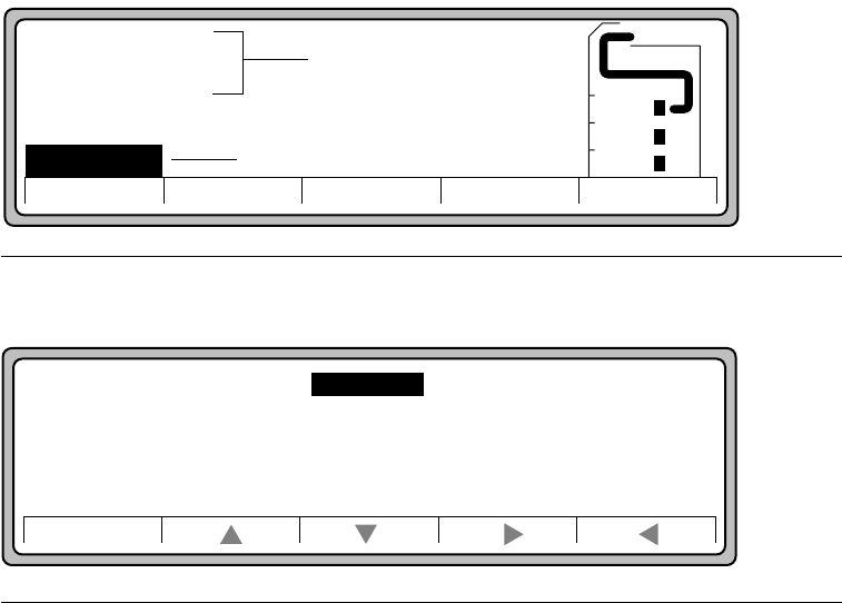
PapSize Menu Settings
2-26 Control Panel
PapSize Menu Settings
PapSize provides access to configure the paper size in the input trays and the HCI.
When you see pointers on the screen pointing up or down, that indicates there are additional
selections available by using M or N to access them.
In the table below, * indicates that a setting is present only if required option is installed (HCI,
HCO, PostScript). The equals sign (=) indicates the factory default value.
Figure 2-23 PapSize Button
Figure 2-24 PapSize selections
Ready - - free
JUN 18 05:32.23
PCL
Offline
Offline
Custom Menu Test PapSize
600dpi
LTR
LTR
LTR
Online
Message field
Printer is offline
Online
PapSize
Online
tray1size =LETTER
tray2size =LETTER
tray3size =LETTER

PapSize Menu Settings
Control Panel 2-27
Control Panel
Note The printer does not automatically sense the size of the paper installed in the trays.
You must set the size into the menu settings. If you change the size of the paper, change the
associated menu setting.
Tray1size
Tray2size
Tray3size
*HCIsize
=LETTER
LEGAL
LEDGER
EXECUTIVE
A4
A5
A3
JISB4
JISB5
CUSTOM
Sets the paper size for tray1, tray2, tray3 and the HCI (if installed).
The HCIsize setting only indicates letter or A4 as these are the only
sizes supported by the HCI.
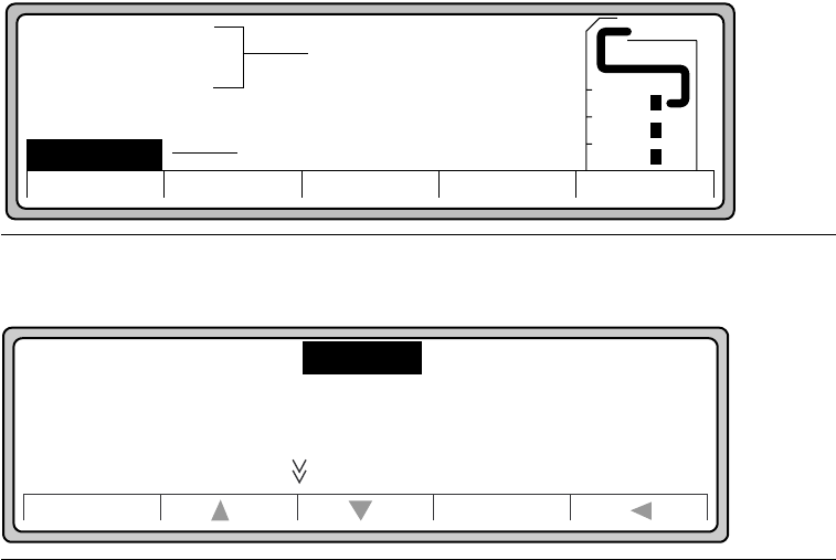
Test Menu Settings
2-28 Control Panel
Test Menu Settings
The Test menu provides access to various print reports and file operations. Use the Test
functions to print out Setup, Maintenance, and Configuration reports, and also to access files
on the D640’s floppy drive and internal hard disk.
The Test functions are shown in Figure 2-25 and Figure 2-26.
“Printing Reports” on page E-1 provides the procedure for printing out the Setups,
Maintenance, Fonts, Table, Menus, and Testprint reports.
Figure 2-25 Test Function Button
Figure 2-26 Test selections
Ready - - free
JUN 18 05:32.23
PCL
Offline
Offline
Custom Menu Test PapSize
600dpi
LTR
LTR
LTR
Online
Message field
Printer is offline
Online
Test
Online Select
MAINT
FONTS
TABLE
MENUS
TESTPRINT
SETUPS

Test Menu Settings
Control Panel 2-29
Control Panel
Report Name Report Contents
SETUPS
Report
• Printing Menu lists the current print job requirements.
• Configuration Menu lists the printer’s image processing requirements.
• PCL Menu lists font characteristics.
• Comms Menu lists printer interface communication requirements.
• Maintenance Menu lists printer alignment characteristics that affect images.
• PapSize Menu lists current paper sizes in each tray.
• Printer Information lists the printer’s buffer information for maintenance purposes.
• Drive A floppy diskette; (3.5 inch floppy drive) shows floppy status (installed/not
installed).
• Drive C (hard drive) lists the hard drive characteristics.
MAINT
• Engine Status lists maintenance information.
• Maintenance Counters list the consumables usage by based on drum revolutions
and duty cycle. The numbers are based on life expectancy of these consumables.
You are responsible for maintenance of these consumables on a schedule
presented in “Maintenance” on page 5-1.
• Event Log lists all printer-captured events (such as paper jams and errors) and
the time and date consumables are replaced.
FONTS Typeface Report lists all available typefaces currently installed in the D640’s virtual
cartridges.
TABLE Table provides images and programming codes for each available typeface.
MENUS Menus provides all current menu settings.
TESTPRINT Testprint provides a ripple test pattern.
filesA filesA is the printer’s 3.5 inch floppy disk drive (FDD) A-drive for inputting information.
filesC filesC is the printer’s C-drive (hard disk drive or HDD) list of directories and files.

Printer Tasks 3-1
Printer Tasks
3
Printer Tasks
Introduction
This chapter guides you through common tasks associated with frequent use of the printer.
If you want to: Go to:
• Remove and install the paper trays page 3-2
• Adjust the standard tray paper guides page 3-3
• Set standard paper sizes in the menu settings page 3-7
• Adjust the custom tray paper guides page 3-8
• Set custom paper sizes in the menu settings page 3-10
• Lock out a paper tray page 3-18
• Stop or interrupt a printing job page 3-21
• Diagnose and fix paper jams page 3-22
• Check error messages and troubleshooting page 3-49
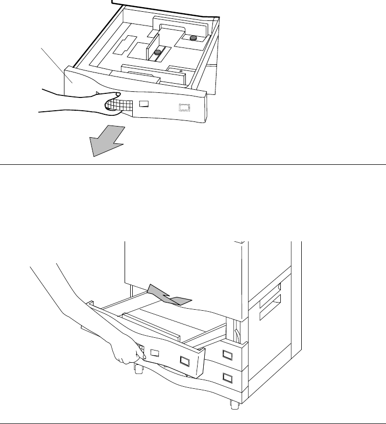
Removing and Installing the Paper Trays
3-2 Printer Tasks
Removing and Installing the Paper Trays
1. Pull out the standard tray as shown in Figure 3-1.
Figure 3-1 Pulling out Standard Tray
2. Install the standard tray by sliding it back in.
3. Pull out the custom tray as shown in Figure 3-3. Angle the tray up slightly until it
disengages the tray guides on either side of the printer, then remove the tray as if it were
a standard tray.
Figure 3-2 Pulling out Custom Tray
Tray
LTR
LTR
LTR
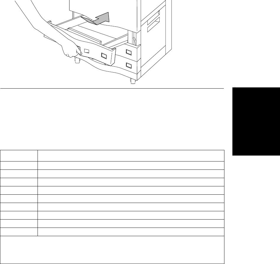
Adjusting Standard Tray Paper Guides
Printer Tasks 3-3
Printer Tasks
4. Install the custom tray as shown in Figure 3-3. Angle the tray down slightly until it
engages the tray guides on either side of the printer, then push the tray in as if it were a
standard tray.
Figure 3-3 Installing Custom Tray
Adjusting Standard Tray Paper Guides
The printer’s standard tray accepts all the standard paper formats listed in and illustrated in
Figure 3-4. A set of moveable paper positioning guides lock into place in the paper trays, with
the paper size visible through a cutout on the guide.
Table 3-1 Paper size settings in Standard Tray
Category Dimensions
Letter 8.5 x 11 in (216 x 279 mm)
Legal 8.5 x 14 in (216 x 356 mm)
Ledger 11 x 17 in (280 x 432 mm)
Executive 7.25 x 10.5 in (184 x 267 mm)
A3 11.69 x 16.53 in (297 x 420 mm)
A4 8.26 x 11.69 in (210 x 297 mm)
A5 5.84 x 8.26 in (149 x 210 mm)
B4 (JIS) 10.11 x 14.32 in (257 x 364 mm)
B5 (JIS) 7.16 x 10.11 in (182 x 257 mm)
* LGR note: Ledger paper extends across the entire tray bottom. When you install ledger paper, lift and
remove the left guide and store it in the molded pocket (located on front panel) labeled LGR.
JIS: Japan Industrial Standards Committee
LTR
LTR
Adjusting Standard Tray Paper Guides
3-4 Printer Tasks
Figure 3-4 Paper Sizes quick reference
5.84 7.25 8.5 11
11.6910.118.267.16
8.26
10.11
10.5
11
11.7
14
14.32
16.53
17
(149 x 210mm)
(182 x 257mm)
(184 x 267mm) — 7.25 x 10.5 in.
(216 x 280mm) — 8.5 x 11 in.
(210 x 297mm)
(216 x 356mm) — 8.5 x 14 in.
(257 x 364mm)
(297 x 420mm)
280 x 432mm) — 11 x 17 in.
A5
JISB5
Executive
A4
Legal JISB4
A3
Ledger ("B" size)
Letter
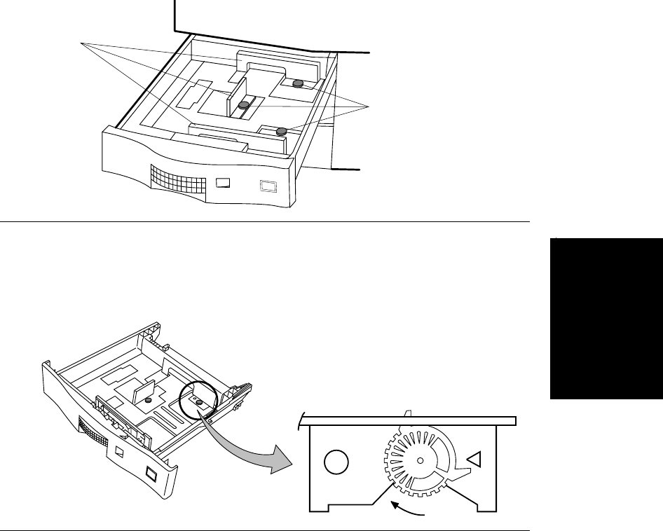
Adjusting Standard Tray Paper Guides
Printer Tasks 3-5
Printer Tasks
1. Each paper guide has a blue locking thumbwheel, as shown in Figure 3-5.
Figure 3-5 Paper guides
2. Turn the blue locking thumbwheels on each paper guide counterclockwise to the OPEN
position (Figure 3-6).
Figure 3-6 Locking device
Lift paper guides out of their current locations and place them in the new paper size locations.
The paper size indicators on the tray are visible through the round circle cutout on the paper
guide, as shown in Figure 3-7.
Guides
(3) Locking devices
LTR
LTR
LGR
C
L
O
S
E
O
P
E
N
LTR
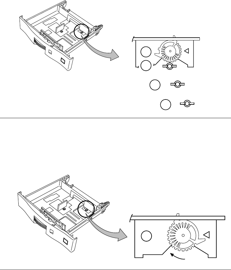
Adjusting Standard Tray Paper Guides
3-6 Printer Tasks
Figure 3-7 Paper guide size selection
3. Adjust both paper guides for the same paper size.
4. Turn the blue locking thumbwheels on each paper guide clockwise to the CLOSE
position to secure it. (Figure 3-8).
Figure 3-8 Securing the paper guide
O
P
E
N
B4
LGL
B5
LTR
LGR
C
L
O
S
E
LTR
LTR
LGR
C
L
O
S
E
O
P
E
N
LTR
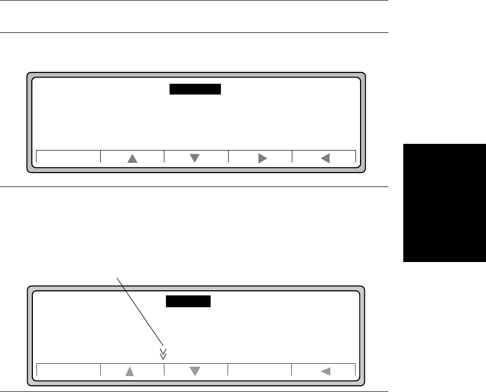
Setting Standard Paper Sizes
Printer Tasks 3-7
Printer Tasks
Setting Standard Paper Sizes
Use the PapSize setting to configure the printer for the size of paper installed in each paper
source.
Note The D640 does not detect paper size. You must visually check each drawer to verify
that it contains the correct paper.
1. At the Main Screen, press PapSize. Figure 3-9 appears.
Figure 3-9 PapSize
2. Verify that all trays have the correct paper size loaded.
3. Select the drawer using N. The selection is highlighted (for example, tray1size).
4. Press P and a list of sizes appears on the Control Panel (Figure 3-10).
Figure 3-10 Paper Size Selection
Online
PapSize
Online
tray1size =LETTER
tray2size =LETTER
tray3size =LETTER
Online
tray1size =
Online
LEGAL
LEDGER
EXECUTIVE
A4
A5
LETTER
Select
Contination arrows
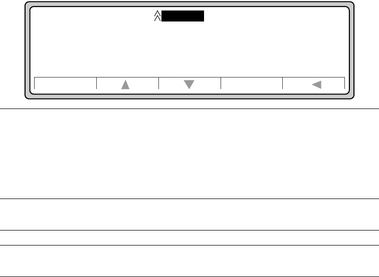
Adjusting Custom Tray Paper Guides
3-8 Printer Tasks
5. Use M or N to move to the correct paper size (Figure 3-11).
Figure 3-11 Paper size selection continuation
6. Press Select to choose the desired size and then press Online to save your choice and
return to a Ready -- Free state.
Adjusting Custom Tray Paper Guides
Note The D640 printer does not support printing on envelopes. Do not use the custom paper
tray to feed envelopes or paper jams will result.
Note You can use standard paper sizes in the custom trays. Set the Control Panel settings to
the standard paper size, not the custom size.
The custom paper tray (product number C5634A) holds paper that has minimum dimensions of
4.75 x 7.2 in (120 x 182 mm) up to 11.7 x 17 in (297 x 431.8 mm). For additional information
regarding paper stock, see “Using Paper” on page D-1.
tray1size
Online Select
JISB4
JISB5
CUSTOM
A3
Adjusting Custom Tray Paper Guides
Printer Tasks 3-9
Printer Tasks
1. Adjust the guides to the size of your paper. Figure 3-12 shows the adjustment guide
travel directions.
Figure 3-12 Custom Paper Tray guide adjustments
2. Load the paper in the tray as described in “Loading Paper Into Trays and HCI” on
page 3-16.
3. Do not stack the paper above the "paper full" mark, as this may cause paper jams or
skewed print.
Note Never mix the types of paper loaded in a tray. Intermixing paper can result in paper
handling problems.
4. Adjust the guides to fit closely, but not too tightly. A tight fit binds the paper and can
cause misfeeds.
Squeeze lever to release
front and rear guides
Thumbscrews to adjust
left guide (finger tighten)
Setting Custom Paper Sizes
3-10 Printer Tasks
Setting Custom Paper Sizes
The custom paper tray can accommodate a wide range of paper sizes, using continuously
adjustable paper guides.
The custom paper tray can accommodate paper stock as small as 4.75 x 7.2 inches (120 x 182
mm) or as large as 11.7 x 17 inches (297 x 431.8 mm). You can install one or more custom
trays in the printer, but they must all be set to the same size.
There are two tasks in setting up custom paper sizes in the custom tray:
• Define the custom tray.
• Set the paper size in the printer menu settings. (Save the dimensions and menu numbers in
case you must refill the tray at some other time.)
1. To specify a tray as the custom tray, press PapSize on the Main Screen (Figure 3-13) to
display the screen shown in Figure 3-14. This display identifies the paper size in each
tray.
Figure 3-13 Main Screen
2. Press M or N to highlight the tray to define as a CUSTOM tray.
Figure 3-14 Paper tray selections
Ready - - free
JUN 18 05:32.23
PCL
Offline
Offline
Custom Menu Test PapSize
600dpi
LTR
LTR
LTR
Online
Message field
Printer is offline
Online
PapSize
Online
tray1size =LETTER
tray2size =LETTER
tray3size =LETTER
Configuring Custom Tray Menu Settings
Printer Tasks 3-11
Printer Tasks
3. Press P to get a list of paper sizes for this tray, as shown in Figure 3-15.
Figure 3-15 Paper size selections
4. Press N to move to CUSTOM.
5. Press Select to define this CUSTOM paper size selection (Figure 3-16).
Figure 3-16 Paper size (continuation of selections)
6. Press Online to return to the Main Screen.
Configuring Custom Tray Menu Settings
You must first interpret your paper dimensions into settings the printer can understand.
Basically, you must accurately measure your paper’s width and height (also called length)
using standard inches (inches) or millimeters (mm), and converting the numbers into printer
units.
For example, using a 5 x 8 inch card:
1. The card is printed with the short side (5 in) as the leading edge. The menu setting for
the leading edge is width.You could also select the long side as the width.
2. The 8 inch side is height. You could also select the short side as the height.
Online
tray1size =
Online
LEGAL
LEDGER
EXECUTIVE
A4
A5
LETTER
Select
Contination arrows
Online
tray1size
Online
JISB4
JISB5
Select
A3
CUSTOM
Configuring Custom Tray Menu Settings
3-12 Printer Tasks
3. The printer has many printer unit options. (A unit is simply a measure of size used to
give you fine control over image placement on the page.)
For most jobs sized in inches, use 1/100" as the unit size.
4. Multiply your paper height (length) by the number of units per inch (in our example, 100
x 8 = 800).
If you use a unit size of 1/200", the number would be 1600; if the unit size was 1/720",
the number would be 5760, and so on. If you are using the mm unit setting, no multipli-
cation is necessary.
5. Multiply your paper width by the number of units per inch (in our example,
100x5=500).
6. Press Menu on the Main Screen to display the Menu options, shown in Figure 3-17.
Figure 3-17 Menu options
7. Press N to highlight Configuration.
8. Press P to get Configuration options (Figure 3-18).
9. Press N to select units. (Figure 3-18).
Figure 3-18 Configuration options
Online
Menu
Online
Printing
Configuration
PCL
Comms
Maintenance
Online
Configuration
Online
newline
traylock
sizes
imageshift
customsize
units
= CR+LF
= CONFIRM
= 1/720"
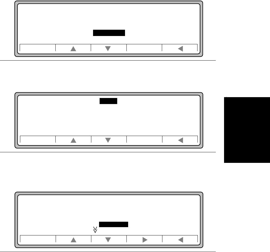
Configuring Custom Tray Menu Settings
Printer Tasks 3-13
Printer Tasks
10. Press M or N to select your unit size selections (Figure 3-19).
Figure 3-19 Unit size selections
11. In our example, 1/100" is highlighted (Figure 3-20).
Figure 3-20 Highlighting 1/100"
12. Press Select. Figure 3-20 is displayed.
13. Press M to highlight customsize (Figure 3-21).
Figure 3-21 Customsize selection
Online
Configuration.units
Online Select
1/100"
1/200"
1/300"
1/600"
1/720"
MM
=
Online
Configuration.units
Online Select
1/100"
1/200"
1/300"
1/600"
1/720"
MM
Online
Configuration
Online
newline = CR+LF
traylock
sizes = CONFIRM
imageshift
customsize
units = 1/100"
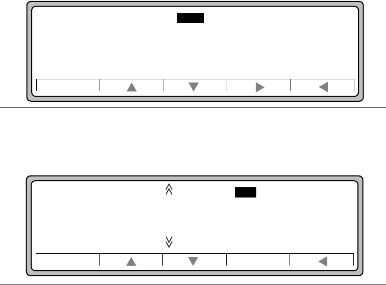
Configuring Custom Tray Menu Settings
3-14 Printer Tasks
14. Press P to highlight width.
Figure 3-22 Customsize width and height selections
15. Press M or N until your number is highlighted (our example is 500, as shown in
Figure 3-23).
Figure 3-23 Width selection for custom paper size
16. Press Select.
17. Press N to highlight height.
Online
Configuration.customsize
Online
width = 8416
height = 12240
Online
Configuration.customsize
Online Select
width = 500
501
502
503
504
505
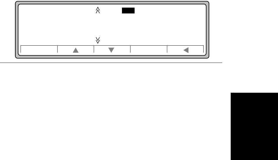
Configuring Custom Tray Menu Settings
Printer Tasks 3-15
Printer Tasks
18. Press M or N until your number is highlighted (our example is 800, as shown in
Figure 3-24).
Figure 3-24 Height selection for Custom Paper Tray
19. Press Select.
20. Press Save.
Online
Configuration.customsize
Save Select
height = 800
801
802
803
804
805
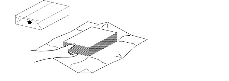
Loading Paper Into Trays and HCI
3-16 Printer Tasks
Loading Paper Into Trays and HCI
This section explains the proper paper loading process, which depends on the type of paper
used and the print job requirements.
Follow these basic guidelines to select and use paper and other media (transparencies, labels,
etc.) for the D640:
• Use only paper labeled specifically for non-impact or laser printing, xerographic copying,
or duplicating. Refer to “Media Selection Specifications and Guidelines” on page D-3 for
complete media specifications.
• Use only one kind of paper in a tray at a time; mixing types of paper can cause jams.
• Do not overfill the paper trays or HCI (note the maximum fill line).
• The HCI is supported for use with paper media only.
Opening Paper
1. Remove the paper from the package, with the package seam side up, as shown in
Figure 3-25. Read the manufacturer’s packaging end-label and note the direction of the
arrow. The arrow points to the side that should be printed first, also referred to as the
face side.
Figure 3-25 Removing paper from the package
2. Inspect the paper for indented or interlocked edges, bent corners, wrinkled sheets, and
excess glue from the wrapper. Discard any damaged sheets.
3. Load the paper into the printer tray or HCI as recommended in the paper loading
illustrations provided in Table 3-2.
PRINT THIS SIDE FIRST
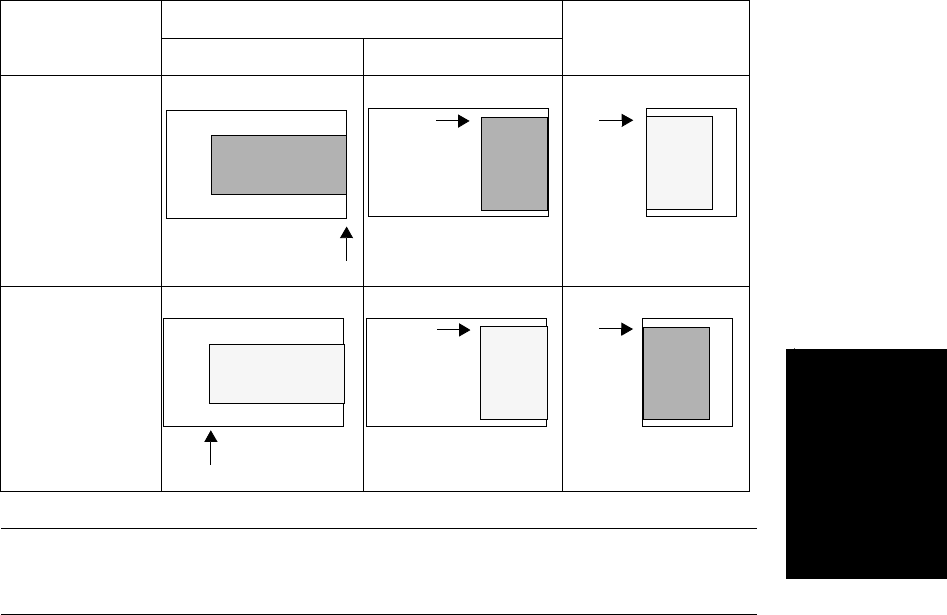
Loading Paper Into Trays and HCI
Printer Tasks 3-17
Printer Tasks
Table 3-2 Paper orientation in trays and HCI
Tip Use the arrow on the paper package as a guideline for loading paper. For the HCI, load
paper so that the arrow on the package is pointing upward. For trays, load paper so that the
arrow on the package is pointing downward.
Input Tray HCI
Short edge leading Long edge leading
Single-sided
printing to
output tray
or
Double-sided
printing to HCO
Double-sided
printing to
output tray
TOF = Top Of
Form
TO
F
Face down
TOF
Face down
TOF
Face up
Face up
TOF
Face up
TOF
Face down
TOF
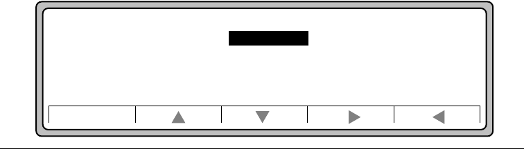
Locking Paper Trays
3-18 Printer Tasks
Locking Paper Trays
All paper sources with the same size of media are automatically linked together. This means
that the printer will automatically switch to the next tray when the current tray runs out of
paper. This could cause problems when all of the paper trays are set to the same size of paper,
but contain different types of paper, such as plain paper and letterhead.
In order to eliminate the linking of trays, you must "lock" the trays you don’t want selected
unless the job gives a direct command to use paper from that source.
For example, if you have a tray with letterhead paper in it, you may want to lock out this tray
so that if the other trays run out of paper, the letterhead paper tray would not be used.
The printer does not detect the paper size loaded in a particular tray.
Follow this procedure to lock a paper tray:
1. On the Main Screen, press Menu.
2. Press N to move to Configuration (Figure 3-26).
Figure 3-26 Configuration Menu
3. Press P to select Configuration.
Online
Menu
Online
Printing
Configuration
PCL
Comms
Maintenance
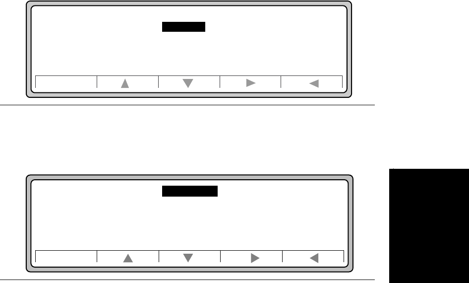
Locking Paper Trays
Printer Tasks 3-19
Printer Tasks
4. Press N to move to traylock (Figure 3-26).
Figure 3-27 traylock
5. Press P to select traylock.
6. Press M or N to move to the tray to lock (Figure 3-28).
Figure 3-28 Configuration.traylock
Online
Configuration =
Online
sizes = CONFIRM
imageshift
customsize
units = 1/720"
newline = CR + LF
traylock
Online
Configuration.traylock
Online
tray1 =UNLOCKED
tray2 =UNLOCKED
tray3 =UNLOCKED
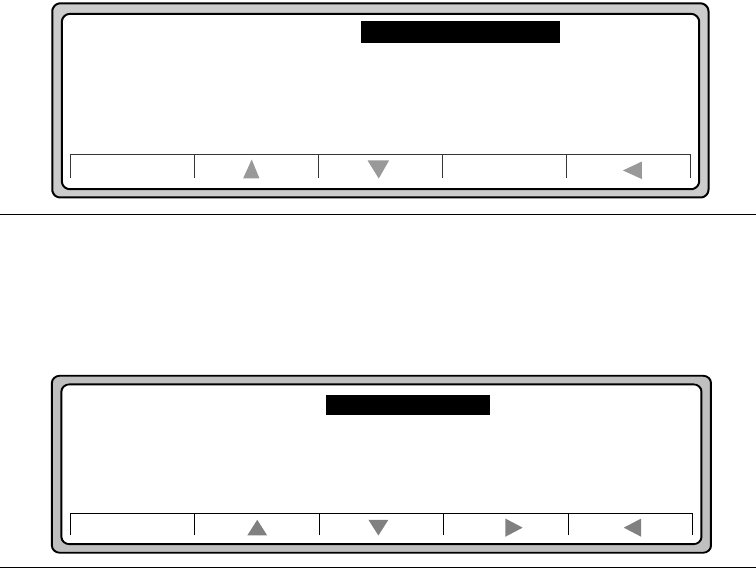
Locking Paper Trays
3-20 Printer Tasks
7. For example, if you want to lock tray1, press P to select tray1. (See the screen in
Figure 3-29.)
Figure 3-29 Configuration.traylock.tray1
8. Press N to move to locked.
9. Press Select. You return to the Configuration.traylock screen with tray1 locked
(Figure 3-30).
Figure 3-30 Tray 1 locked
10. Press Save to save the changes in PwrOnConfig.
Online
Configuration.traylock.tray1 =
Online
LOCKED
tray1 = UNLOCKED
Select
Online
Configuration.traylock
Save
tray1= LOCKED
tray2 = UNLOCKED
tray3 = UNLOCKED
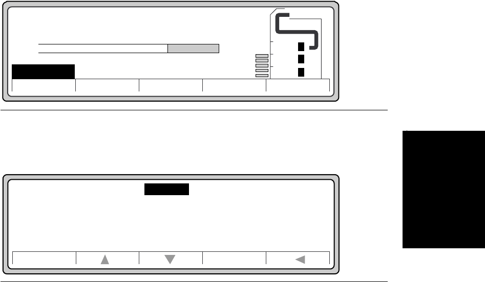
Stopping or Interrupting Print Jobs
Printer Tasks 3-21
Printer Tasks
Stopping or Interrupting Print Jobs
The printer works in three basic states: processing incoming data, imaging the data, and
printing the data. When the printer is in one of these states, the Main Screen changes to reflect
the new state, as shown in Figure 3-31, and the Test button changes to the End button.
Figure 3-31 End Button
If you want to stop or interrupt the print job in progress, press the End button. When you press
End, you will see the End submenu, as shown in Figure 3-32.
Figure 3-32 End Submenu
Ready - - printing
JUN 18 05:32.23
PCL
Offline
Offline
Menu End
600dpi
LTR
LTR
LTR
Cen
Online
Online
End =
Online
ENDDOC
SUPPRESS
ABANDON
PAUSE
Select

Clearing a Paper Jam
3-22 Printer Tasks
The choices available are:
Clearing a Paper Jam
When you start a print job, the printer selects paper, a page at a time, from one of the internal
trays or from the external HCI. Paper jams may occur if the paper is wrinkled, folded, skewed,
or out of specification. The printer goes Offline until the paper jam is cleared.
When a jam occurs, refer to the Control Panel for a visual and written description of the jam
location. For a visual indication refer to the picture on the right side of the Control Panel. The
area in the paper path where the jam occurred will be blinking.
More than one sheet of paper may be located in the paper path; all sheets must be removed
before the printer will resume printing.
In this case, the paper path diagram may continue blinking in the same or another location, and
the printer displays messages about the location of remaining sheets until all jams are cleared.
Note The printer is forced Offline until the problem is fixed.
Table 3-3 lists each paper jam that displays on the Control Panel and how to clear the jam.
More detailed information on clearing paper jams appears on the pages listed. You can also
refer to the illustrated jam clearing pictures located on the inside of the printer’s front door.
PAUSE Temporarily stops the job. Use this to pause the printer, such as when adding or
removing paper or adding toner.
ENDDOC
Any incomplete or partial pages are printed (like a form feed or page eject). The job
ends normally and the printer is ready for another job. This is typically used when the
print job has no end-of-job command, and the Control Panel displays Ready -- wait
for a long time.
SUPPRESS
Continues to process the current job, but the resulting pages are not printed. Printing
resumes with the next job. Select SUPPRESS when you no longer want to print the
current job, but you want to retain data, such as downloaded fonts and macros,
needed for future jobs. SUPPRESS is the recommended way to end routine print
jobs.
ABANDON
Ends processing of the current job and clears all data in the input buffer. This is the
most direct, quickest, and potentially risky way of stopping a current job. Use
ABANDON only when you are certain that the data in the print job is not required by
future print jobs.

Clearing a Paper Jam
Printer Tasks 3-23
Printer Tasks
Table 3-3 Paper jams and remedies
Paper Jam Messages Remedy Refer to
page
Paper Input Jams
TRAY1 Pick error
TRAY2 Pick error
TRAY3 Pick error
Remove tray (1, 2, or 3), remove paper jam from paper entry
area and/or within tray. 3-24
Feed jam 1 Open the front door, lower transfer assembly, rotate knob 1
counterclockwise and knob 2 clockwise to free paper,
remove jammed paper.
3-26
Feed jam 2 Open the side door, remove jammed paper. 3-26
HCI jam 1 Open HCI, lower paper, remove jammed paper. 3-32
HCI jam 2 Pull HCI away from printer, remove jammed paper. 3-34
HCI jam 3 Pull HCI away from printer, remove jammed paper. 3-34
HCI jam 4 Open the front door, lower transfer assembly, rotate knob 1
counterclockwise and knob 2 clockwise to free paper,
remove jammed paper.
3-26
Paper Path Jams
Fuser unit jam 1
Fuser unit jam 2 Open the front door, lower transfer assembly, open lever 4,
push decurler lever down, remove jammed paper to the
right.
3-36
Duplex path jam 1
Duplex path jam 2 Open the front door, raise lever 6, and remove jammed
paper. You may need to turn duplex roller knob to release
the paper.
3-38
Print unit path jam (Reversing unit area jam)
Open the front door, open lever 4, hold lever 5 away from
the fuser, and remove jammed paper. You may need to turn
duplex roller knob to release the paper.
3-40
Paper Output Jams
Ejection unit jam 1
Ejection unit jam 2 Raise the paper ejection cover and remove jammed paper. 3-43
HCO jam 1
HCO jam 2 Open the HCO door, rotate roller knob 1 to free paper, then
lift levers to remove paper. 3-45
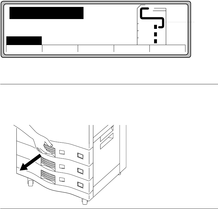
Clearing Paper Input Jams
3-24 Printer Tasks
Clearing Paper Input Jams
Clearing a Tray Pick Error Jam
When the printer tries to load a sheet of paper from one the paper trays and encounters a
picking problem, the Control Panel shows a blinking section at the output of the problem tray
as shown in Figure 3-33.
Figure 3-33 Pick error jam indication
To clear the tray pick error:
1. Open the indicated paper tray, as shown in Figure 3-34.
Figure 3-34 Opening paper tray
Clear
Offline
Menu End
600dpi
LTR
LTR
LTR
Offline
Blinking
****
**** Pick error
Remove paper & Press Clear
PCL
TRAY1
TRAY2
TRAY3
LTR
LTR
LTR
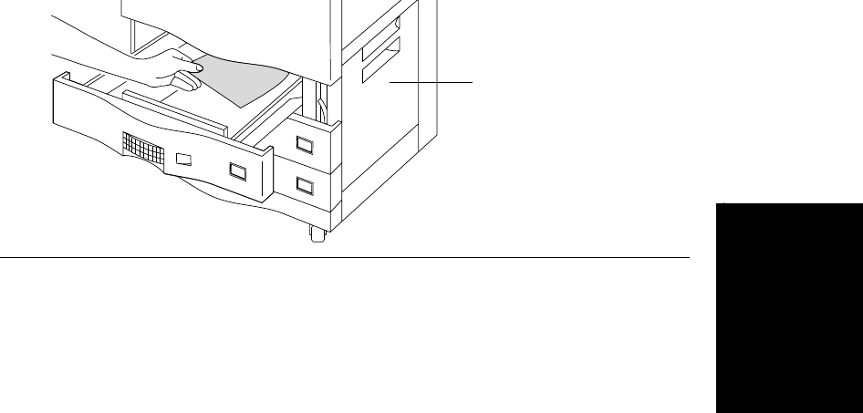
Clearing Paper Input Jams
Printer Tasks 3-25
Printer Tasks
2. Examine the right side of the tray area, particularly the extreme upper right, where the
paper leaves the tray and is pulled into the paper path. There may be one or more pieces
of paper jammed in it. If there is no obvious jam, reach up into the upper right corner of
the tray, feel for paper stuck there, and remove any jammed paper. Pull gently, as the
paper could tear. Refer to Figure 3-35.
3. If you do not find any jammed paper, open the lower right cover and check for paper.
Figure 3-35 Removing paper jam from tray area
4. Press Clear. If no other paper jam indications appear on the Control Panel, you are ready
to resume printing. If the Control Panel still shows a jam, search the area again, or the
area indicated on the Control Panel.
LTR
LTR LTR
Lower right cover
Clearing Paper Input Jams
3-26 Printer Tasks
Clearing a Feed Path Paper Jam
The feed path paper jam paper path is the path between the paper feed unit (pulls paper from
the trays or HCI) and the drum unit. A jam in this area will display feed path jam 1, jam 2 or
jam 4 depending on where the jam physically occurs.
Figure 3-36 shows the location of the Feed path paper jam indication on the Control Panel.
Figure 3-36 Feed path paper jam indication
1. Lower the right-side lower cover (Figure 3-37). If you have an HCI installed, unlatch
the HCI and slide it away from the printer (Figure 3-38).
2. Look for paper caught in the paper feed path at the top of the lower right cover opening.
Only a small area of the paper may be visible. If you see paper, remove it.
Clear Menu Test PapSize
LTR
LTR
LTR
PCL Blinking
Feed path jam 1
Feed path jam 2
Feed path
j
am 4
*****:
Offline
Remove paper & Press Clear
.............
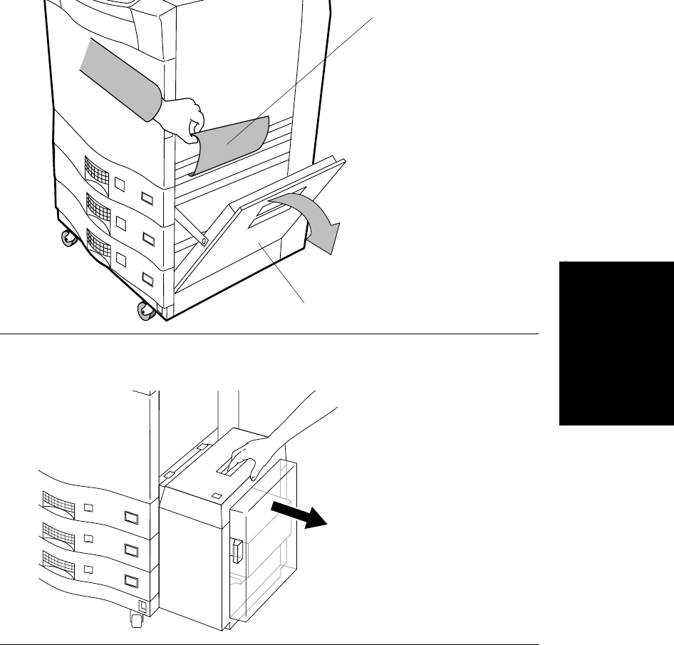
Clearing Paper Input Jams
Printer Tasks 3-27
Printer Tasks
Figure 3-37 Removing paper from side door opening
Figure 3-38 Unlatching the HCI
Lower right door
Paper
LTR
LTR
LTR
LTR
LTR
LTR
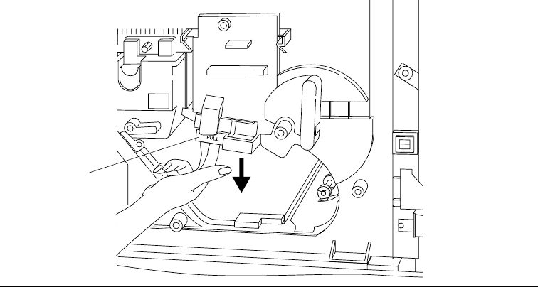
Clearing Paper Input Jams
3-28 Printer Tasks
3. If there is no paper there, close the door and if applicable, push the HCI inward to relatch
it.
4. Open the front door. Note that the inside of the front door has a set of labels showing
various paper jam remedy procedures. Use these as a guide to clearing paper jams.
5. Refer to Figure 3-39. Pull out gently on Handle 3 to unlatch and release the Transfer
Guide. Gently lower the Transfer Guide and let it rest on the bottom of the printer’s
interior.
Figure 3-39 Lowering Transfer Assembly
Handle 3
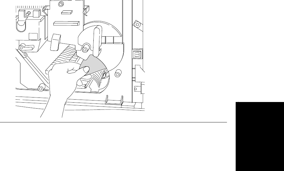
Clearing Paper Input Jams
Printer Tasks 3-29
Printer Tasks
6. If you can see the paper jam, reach up and remove it, as shown in Figure 3-40.
Figure 3-40 Paper removed from under Drum Unit
7. If the paper is not visible, reach into the area indicated in Figure 3-40 and feel for it.
8. Turn knob 1 counterclockwise and knob 2 clockwise to move paper into position for
removal, as shown in Figure 3-41.
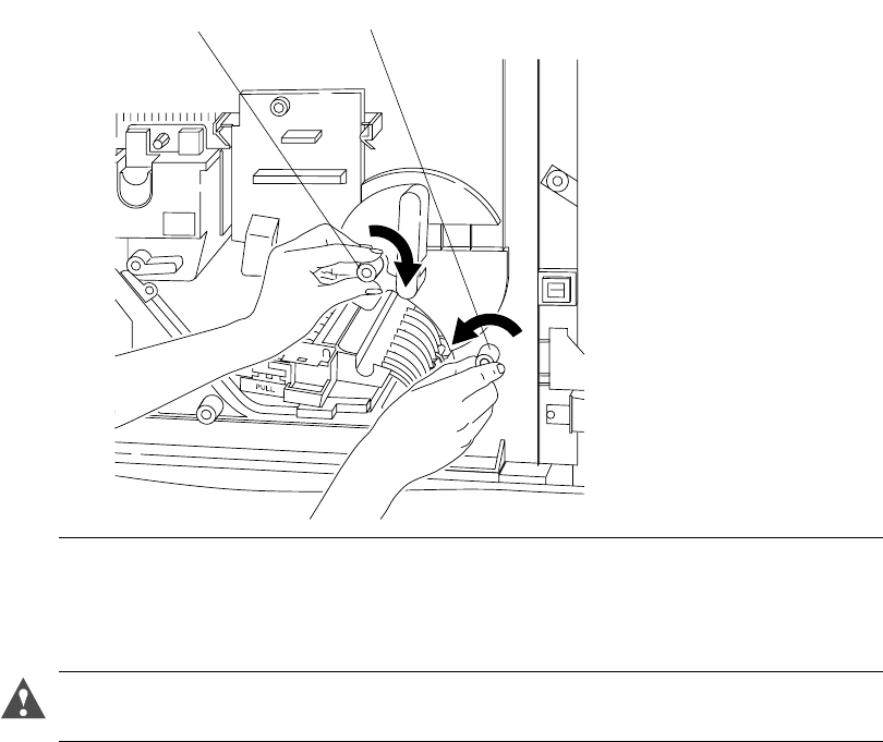
Clearing Paper Input Jams
3-30 Printer Tasks
Figure 3-41 Turning Knobs 1 and 2
9. If paper is visible, reach in and remove it. If it is not visible, you may need to reach in
and search by hand.
Caution Remove any jewelry on your hand or wrist before reaching into the printer. Be
careful not to scratch the drum as you feel for the paper.
Knob 2 Knob 1
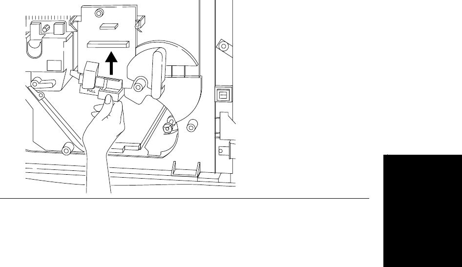
Clearing Paper Input Jams
Printer Tasks 3-31
Printer Tasks
10. Raise the Transfer Guide until it latches into position, as shown in Figure 3-42, and
close the door.
Figure 3-42 Replacing Transfer Assembly
11. If no other paper jam indications appear on the Control Panel, you are ready to resume
printing. If the Control Panel still shows a jam, search the area again, or the area
indicated on the Control Panel.
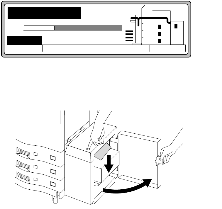
Clearing Paper Input Jams
3-32 Printer Tasks
Clearing HCI Jams
When the printer tries to obtain a sheet of paper from the HCI and the paper fails to load
properly, this is an HCI paper jam. This is indicated on the Control Panel by the blinking paper
path shown in Figure 3-43.
• HCI jam 1(pick error), a jam where the paper did not leave the HCI correctly.
• HCI jam 2 (jam), a jam where the paper did not enter the printer correctly.
• HCI jam 3 (jam), a jam where the paper is between the printer and the HCI.
Figure 3-43 HCI paper path jam indication
Clearing HCI Jam 1
1. If the Control Panel indicates an HCI jam 1 (a pick error), open the HCI door as shown
in Figure 3-44. Press the button on top of the HCI to lower the paper stack.
Figure 3-44 Opening the HCI door
Offline
Offline
Menu End
600dpi
LTR LTR
LTR
LTR
Offline
Blinking
HCI jam 2
Remove paper & Press Clear
PCL
Cen
LTR
LTR
LTR
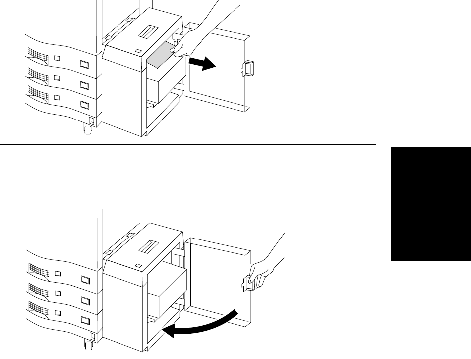
Clearing Paper Input Jams
Printer Tasks 3-33
Printer Tasks
2. Inspect the top of the HCI paper stack for jammed paper and remove any sheets that are
stuck in the paper ejection area or which look crumpled or otherwise defective, as shown
in Figure 3-45.
Figure 3-45 Removing paper from HCI
3. Close the HCI door as shown in Figure 3-46. The paper rises up to the operating
position automatically.
Figure 3-46 Closing the HCI door
4. Press Clear. If there is no paper jam indication, you are ready to resume printing. If the
Control Panel still shows a jam, search the area again, or the area indicated on the
Control Panel.
LTR
LTR
LTR
LTR
LTR
LTR
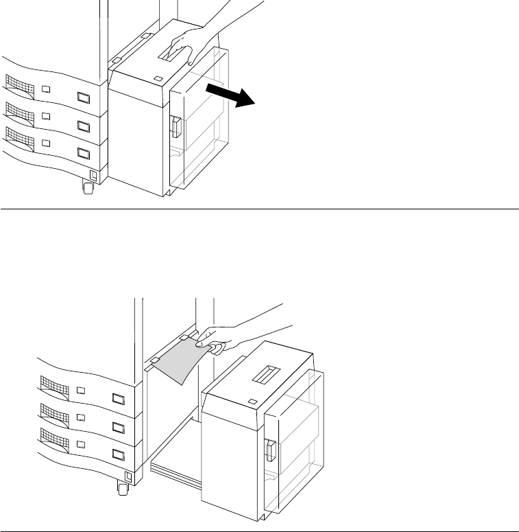
Clearing Paper Input Jams
3-34 Printer Tasks
Clearing HCI Jam 2
If the Control Panel shows an HCI jam 2, there may be paper jammed between the HCI and the
printer.
Squeeze the HCI top handle to release the HCI from the printer and then pull it away as shown
in Figure 3-47.
Figure 3-47 Releasing the HCI from the printer
5. If there is paper hanging out of the printer or the HCI, remove it, as shown in
Figure 3-48:
Figure 3-48 Removing paper between the HCI and the printer
LTR
LTR
LTR
LTR
LTR
LTR
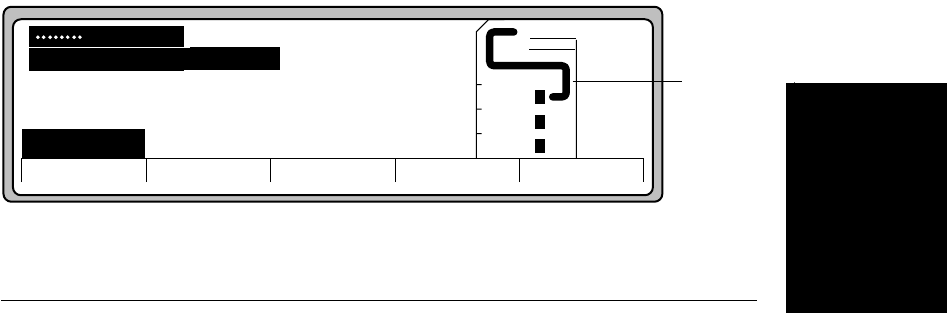
Clearing Paper Path Jams
Printer Tasks 3-35
Printer Tasks
6. Push the HCI towards the printer until it latches and check the Control Panel.
7. Press Clear. If there is no paper jam indication, you are ready to resume printing. If the
Control Panel still shows a jam, search the area again, or the area indicated on the
Control Panel.
Clearing Paper Path Jams
Once the paper has cleared the feed mechanisms, which carry the paper up to the drum unit,
there are places where jams can occur between the drum unit and the area just before the
ejection unit. These areas are: at the fuser, in the duplex path, and the print unit path around the
reversing unit. This is indicated on the Control Panel by the blinking paper path shown in
Figure 3-49.
Figure 3-49 Paper path jams indication
Clear
Offline
Menu Test PapSize
LTR
LTR
LTR
*Offline*
Blinking
Fuser unit jam
Duplex path jam
Print unit path jam
*****:
PCL
Remove paper & Press Clear 600 dpi
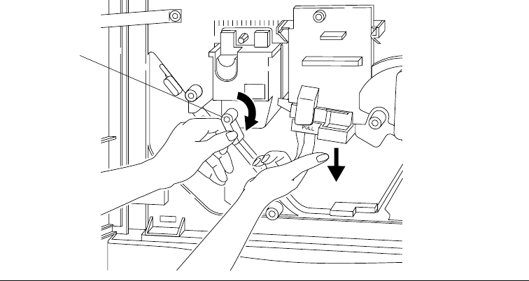
Clearing Paper Path Jams
3-36 Printer Tasks
Clearing a Fuser Unit Jam
The fuser unit jam is located after the drum.
1. Open the front door and lower the Transfer Assembly, as shown in Figure 3-50.
Figure 3-50 Lowering Transfer Assembly
2. Turn Lever 4 fully clockwise (straight down) until stopped to relieve tension on the
paper, as shown in Figure 3-50.
3. Look for a sheet or sheets of jammed paper on the right side of the fuser unit. While
pressing the decurler lever with your left hand, reach in and remove any jammed paper
with your right hand, as shown in Figure 3-51.
Lever 4
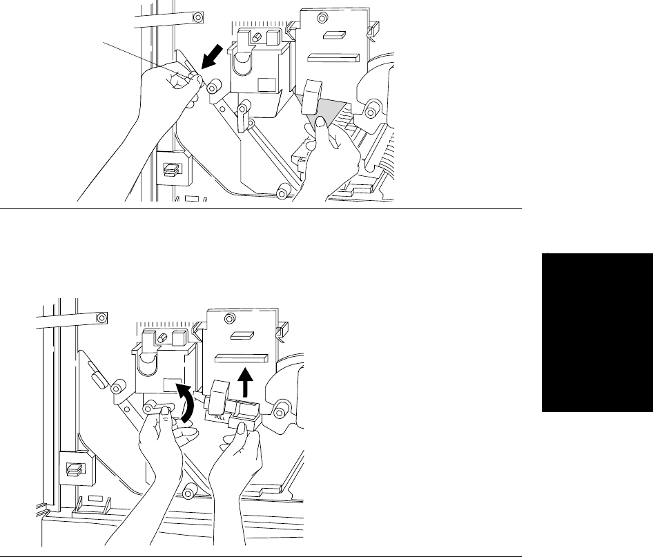
Clearing Paper Path Jams
Printer Tasks 3-37
Printer Tasks
Figure 3-51 Removing Fuser Unit paper jam using Decurler Lever
4. After you have removed the paper, raise the Transfer Guide, return Lever 4 to the
horizontal (closed) position (as shown in Figure 3-52), and close the door.
Figure 3-52 Closing Lever 4 and securing the Transfer Assembly
5. If no other paper jam indications appear on the Control Panel, you are ready to resume
printing. If the Control Panel still shows a jam, search the area again, or the area
indicated on the Control Panel.
Thumb on
decurler lever
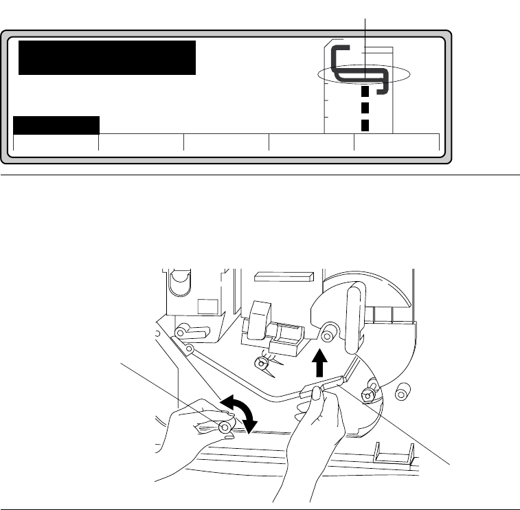
Clearing Paper Path Jams
3-38 Printer Tasks
Clearing a Duplex Unit Jam
The duplex unit jam is indicated on the Control Panel as shown in Figure 3-53.
Figure 3-53 Duplex Unit Paper Jam
1. Open the door and locate lever 6 as shown in Figure 3-54.
2. Lift lever 6 and turn the duplex roller knob to move any paper into view.
Figure 3-54 Freeing Duplex Jam
Clear
Offline
Menu End
600dpi
LTR
LTR
LTR
Blinking
PCL
Duplex path jam 2
Remove paper & Press Clear
Offline
Duplex roller knob
Lever 6
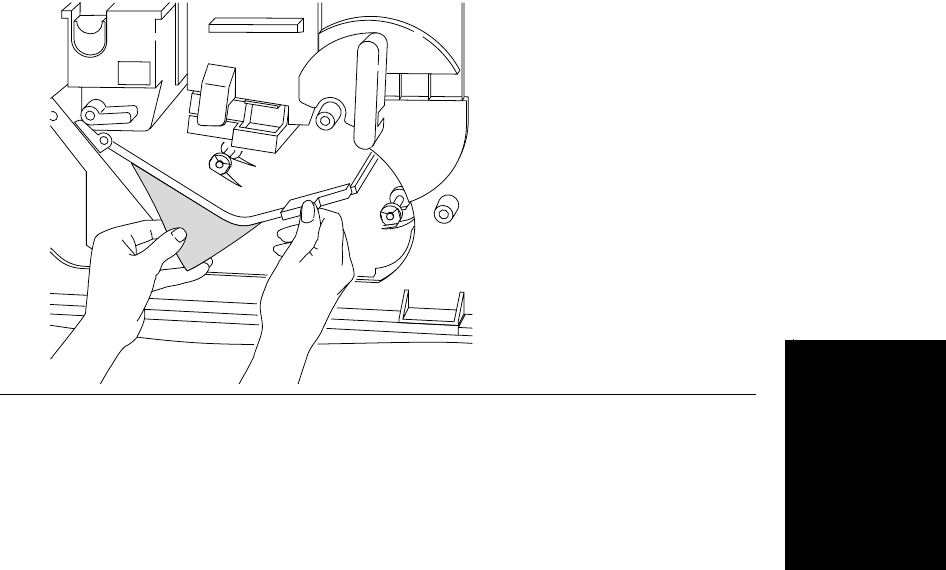
Clearing Paper Path Jams
Printer Tasks 3-39
Printer Tasks
3. Remove paper as shown in Figure 3-55 and close the door.
Figure 3-55 Removing paper jam from duplex path
4. Press Clear. If no other paper jam indications appear on the Control Panel, you are ready
to resume printing. If the Control Panel still shows a jam, search the area again, or the
area indicated on the Control Panel.
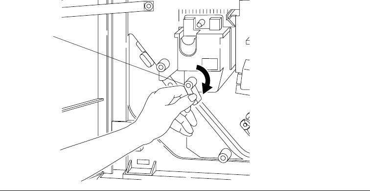
Clearing Paper Path Jams
3-40 Printer Tasks
Clearing a Reversing Unit Area Jam
The reversing unit area paper path jam is located to the left of the duplex unit.
1. Open the front door and turn Lever 4 fully clockwise, shown in Figure 3-56. This
removes pressure on paper leaving the fuser unit area.
Figure 3-56 Opening Lever 4
2. Locate Lever 5 and push it downward and away from the fuser unit area, as shown in
Figure 3-57.
Lever 4
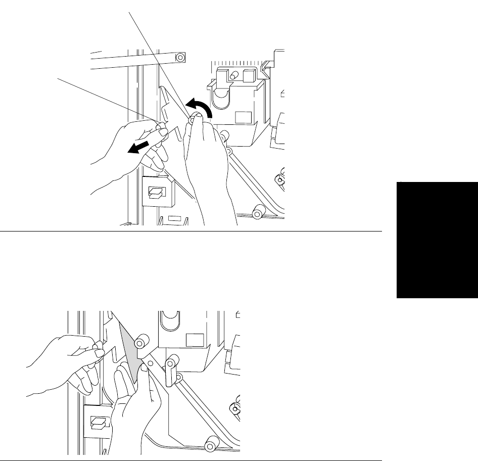
Clearing Paper Path Jams
Printer Tasks 3-41
Printer Tasks
Figure 3-57 Freeing paper in Reversing Unit jam
3. If paper is not visible, turn decurler roller knob counterclockwise to move any paper into
view, or reach up into this area carefully.
4. Remove jammed paper, as shown in Figure 3-58.
Figure 3-58 Removing paper jam from reversing area
Lever 5
Decurler roller knob
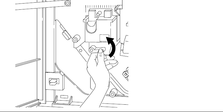
Clearing Paper Path Jams
3-42 Printer Tasks
5. Turn Lever 4 fully counterclockwise back into the closed position, as shown in
Figure 3-59, and close the door.
Figure 3-59 Closing Lever 4
6. If no other paper jam indications appear on the Control Panel, you are ready to resume
printing. If the Control Panel still shows a jam, search the area again, or the area
indicated on the Control Panel.
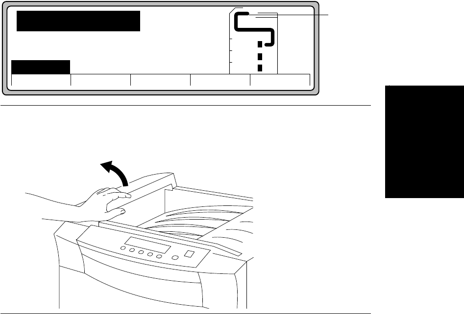
Clearing Paper Output Jams
Printer Tasks 3-43
Printer Tasks
Clearing Paper Output Jams
Once the printed page is made, it is delivered to you outside of the machine. There are several
places in the ejection paper path where jams can occur. They are in the ejection unit and the
HCO.
Clearing an Ejection Unit Jam
Figure 3-60 shows the ejection unit jam indication on the Control Panel.
Figure 3-60 Ejection Unit jam
1. Swing open the ejection unit cover as shown in Figure 3-61.
Figure 3-61 Opening the Ejection Cover
Clear
Offline
Menu End
600dpi
LTR
LTR
LTR
Offline
Blinking
Ejection unit jam 2
Remove paper & Press Clear
PCL
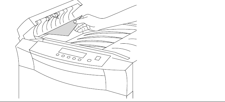
Clearing Paper Output Jams
3-44 Printer Tasks
2. Remove any jammed paper in the ejection unit cover area (Figure 3-62) and close the
cover.
Figure 3-62 Removing jammed paper from Ejection Cover area
3. If no other paper jam indications appear on the Control Panel, you are ready to resume
printing. If the Control Panel still shows a jam, search the area again, or the area
indicated on the Control Panel.
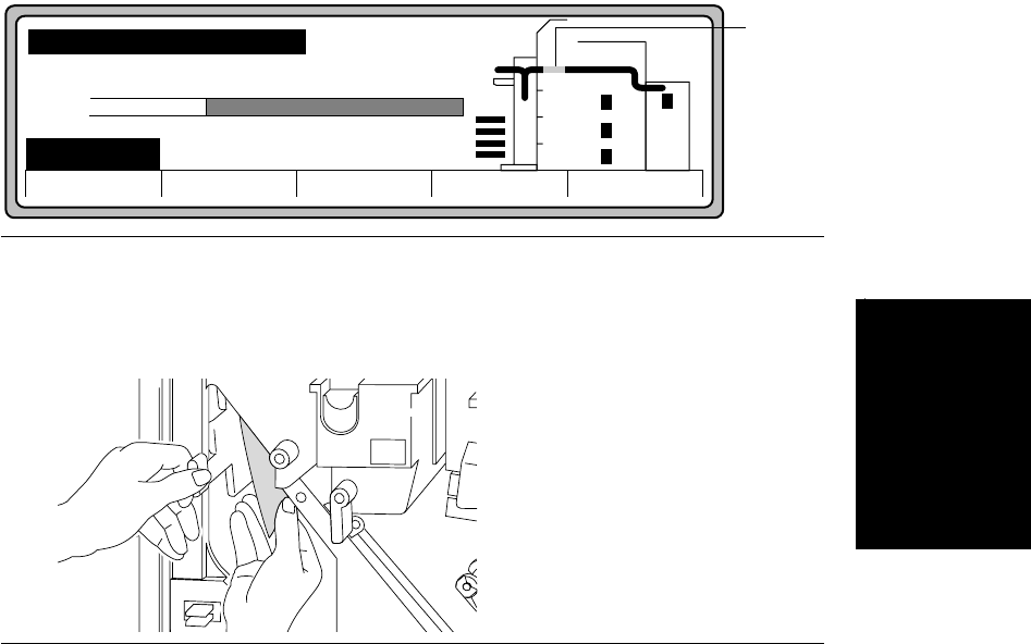
Clearing Paper Output Jams
Printer Tasks 3-45
Printer Tasks
Clearing an HCO Jam
Jams can occur at the input to the HCO. Figure 3-63 shows the HCO jam error indication on
the Control Panel.
Figure 3-63 HCO paper jam indication
1. Open the front door and remove any jammed paper in the reversing area, as shown in
Figure 3-58.
Figure 3-64 Removing paper jam from reversing area
Offline
Offline
Menu End
600dpi
LTR
LTR
LTR
Offline
Blinking
HCO jam 1
PCL
Cen
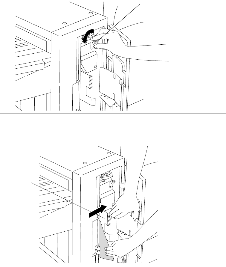
Clearing Paper Output Jams
3-46 Printer Tasks
2. Open the HCO door. Locate and turn knob 1 counterclockwise to move paper from the
input area to the lower section as shown in Figure 3-65.
Figure 3-65 HCO Knob 1 Paper Input Roller
3. Pull lever 2 back (Figure 3-66) and remove any paper.
Figure 3-66 Clearing HCO lower section paper jam using Lever 2
HCO Knob 1
HCO
Lever 2
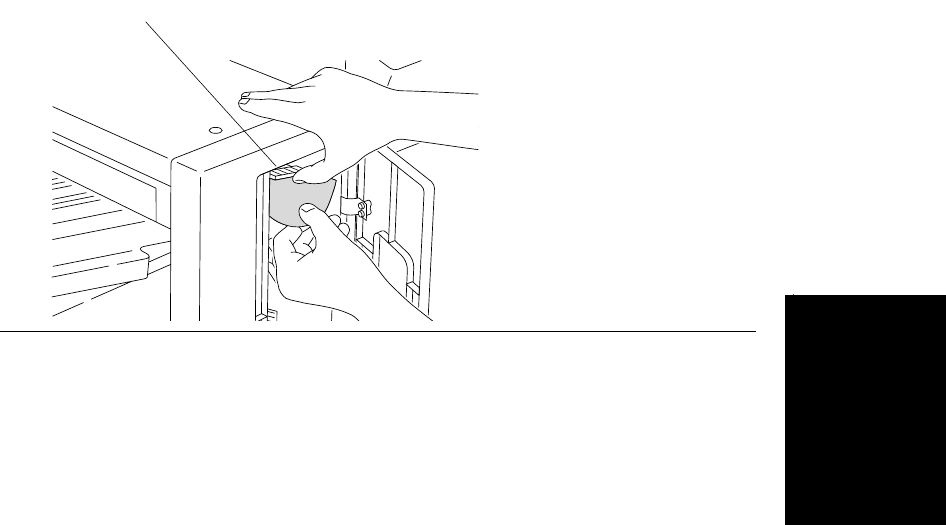
Clearing Paper Output Jams
Printer Tasks 3-47
Printer Tasks
4. If jammed paper is not visible, lift lever 1 to see if there is paper jammed there. Rotate
knob 1 counterclockwise to move any paper into view. Remove any paper found as
shown in Figure 3-67.
Figure 3-67 Clearing HCO upper section paper jam using Lever 1
5. Close the HCO door.
6. If jammed paper is not visible, there may be paper jammed between the HCO and the
printer.
You’ll need to separate the HCO from the printer and check for jams. See the following
section for more information.
HCO Lever 1
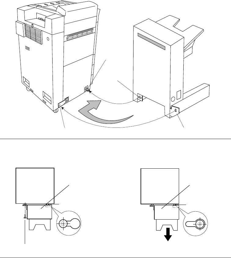
Clearing Paper Output Jams
3-48 Printer Tasks
Separating the HCO and Printer
To separate the HCO from the printer:
1. The printer physically connects to the HCO with a connecting pin, which fits into the
corresponding positioning hole on the HCO. See Figure 3-68.
Figure 3-68 Separating HCO and printer
2. Figure 3-69 shows detailed look at the connecting pin and the positioning hole.
Figure 3-69 Printer connecting pin and HCO positioning hole configuration
Connecting
Pin
Bracket B Bracket A
Positioning
Hole
Printer HCO
Pin
Printer Push HCO
left to disengage
Unscrew Bracket A
Pin
Pull HCO away from printer
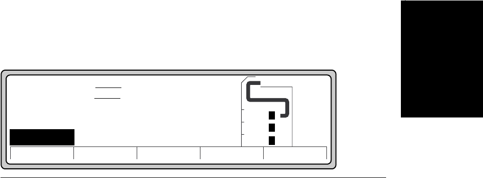
Handling Error Messages and Troubleshooting
Printer Tasks 3-49
Printer Tasks
3. Unscrew bracket A, which connects the HCO to the printer.
4. Push the HCO to the left to disengage the connecting pin from the positioning hole.
5. Pull the HCO away from the printer. It is still connected by a cable, but you should only
need to move it far enough to see if there is paper jammed in the interval between the
machines. If you find paper there, remove it.
6. Push the HCO and the printer together and reseat the connecting pin in the positioning
hole.
7. Replace bracket A.
If no other paper jam indications appear on the Control Panel, you are ready to resume
printing. If the Control Panel still shows a jam, search the area again, or the area
indicated on the Control Panel.
Handling Error Messages and Troubleshooting
An error message can be caused by mechanical problems, such as jams, or by incorrect
settings, such as specifying the wrong paper size from the wrong paper tray. These are typical
printer problems than can be easily cleared by the user.
Printer errors that are caused by mechanical or electrical problems are also reported by specific
error codes. These problems require a service call to your service representative.
An error message is always accompanied by an action message, as shown in Figure 3-70.
Figure 3-70 Error reporting
Error message
Action message
PCL 12.145
Cen
Clear Custom
Offline
Menu Test PapSize
600dpi
LTR
LTR
LTR
Online
Close front door
Front door open
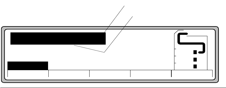
Handling Error Messages and Troubleshooting
3-50 Printer Tasks
Error Reporting/Action Response
Refer to “Error Messages” on page A-7, for how to interpret error messages.
In the unlikely event that the printer has a major error, follow these steps:
1. The printer may self-diagnose the problem and possibly display the message as shown in
Figure 3-71.
2. Write down the error code and message that appears on the Control Panel.
3. Refer to “Call Engineer Error Messages and Codes” on page A-8 to determine the
meaning of the error code.
4. If the error code calls attention to a specific physical component or location on the
printer, check the area specified and correct the problem.
5. If you cannot resolve the problem, call your service representative. Be prepared to give
the service representative the error code and any messages that appear on the Control
Panel to assist in troubleshooting.
Figure 3-71 Call Engineer (Service Representative)
Clear
Offline
Menu End
LTR
LTR
LTR
Offline
High-voltage power supply alarm
Call Engineer (SVC 6F)
PCL
Blinking
Error code

Ordering and Replacing Consumables 4-1
Consumables
4
Ordering and Replacing Consumables
Introduction
This chapter provides user maintenance procedures to maintain the printer’s consumables.
If you want: Go to:
• An overview of the D640 printer supplies page 4-1
• To order additional consumables page 4-2
• To replace toner or recycle toner after replacement page 4-4
• To replace developer and ozone filter page 4-9
• To replace the drum and transfer assembly page 4-18
• To replace the fuser page 4-29
• To replace the printer pick rollers page 4-33
• To replace the HCI pick rollers page 4-42
Overview of Consumable Supplies
You can replace all of the consumable supplies. This chapter presents step-by-step instructions
for removal and replacement of these supplies and explains how to set the printer to produce
lighter or darker prints.
• Each time you replace a consumable, the action is automatically recorded in the printer’s
online maintenance log.
Caution Damage to the photoconductor can cause excessively light or dark printing or
missing text.
Caution Hewlett-Packard recommends the use of Hewlett-Packard labelled consumable
supplies. Hewlett-Packard is not responsible for any failures or print quality issues arising
from the use of other than Hewlett-Packard supplies in the cut sheet printer. Such failures are
not covered under warranty or under the Hewlett-Packard service agreement.
Ordering D640 Printer Consumables
4-2 Ordering and Replacing Consumables
Ordering D640 Printer Consumables
You can order consumables directly from Hewlett-Packard by calling 1-800-538-8787 in the
United States and Canada. Customers outside the United States and Canada should contact
their local Hewlett-Packard sales office.
Please plan for a two to five day delivery in the United States, possibly longer outside the
United States. If your printer was purchased from a Hewlett-Packard reseller, you may be able
to purchase consumables directly from them.
Table 4-1 lists the D640 printer consumables, ordering numbers, kit content descriptions and
quantities, along with the length of time you can expect them to last under optimum operating
conditions.
Use the replacement cycle estimates in Table 4-1 to plan your initial consumable purchases.
Because yields may vary widely from the estimates, you should track your actual usage to
establish proper replacement schedules for each printer installation.
Actual yields depend upon:
• Media (paper type, weight, chemical composition, perforations, paper dust, and quality).
• Media storage factors such as care and handling, room temperature, and humidity.
• Exposure to light (photoconductor drum).
• Frequency of cleaning the printer.
• Average print job size, daily print volume, and patterns of printing.
• Ambient environmental conditions, such as temperature, humidity, and static electricity.
• Power-on hours.
“Managing Consumables” on page 6-6 describes some of the considerations in using and
replacing consumables.
Ordering D640 Printer Consumables
Ordering and Replacing Consumables 4-3
Consumables
Table 4-1 Consumables, product part numbers, and replacement cycles
Note A new printer will report toner low and need to be refilled the first time after printing
about 6,000 images. This is normal and is due to the toner hopper being completely empty in a
new printer.
The estimated yields listed are not a warranty or guarantee of minimum life and are provided to
assist in initial supplies planning. Yields may vary widely based on applications and operating
conditions.
Yield estimate are based on, but not limited to, ideal environmental and operating conditions,
print jobs averaging 4% toner coverage per page, and an average job of 25 pages.
Item Product
Number Contents Qty Replacement Cycle
(Estimated) Shelf
Life
Toner Kit C5626A Toner bottles 8 each Up to 180,000 page sides
Note: Yield based on 4%
toner coverage
18 months
Collector bottles 8 each
Cleaning rollers 4 each
Developer Kit C5632A Developer bottles 2 each Up to 250,000 page sides 18 months
Ozone filter 1 each
Drum Kit C5629A Photoconductor
drum 1 each Up to 195,000 page sides 18 months
Transfer unit 1 each
Cleaning wipes 1 pkg
Fuser Kit C5627A Fuser, 120-127 VAC 1 each Up to 300,000 page sides 18 months
Fuser Kit C5628A Fuser, 200-240 VAC 1 each Up to 300,000 page sides
Printer Pick
Roller Kit C5633A Printer pick rollers 1 set Up to 500,000 pages Inf.
HCI Pick
Roller Kit C5636A HCI pick rollers 1 set Up to 500,000 pages
Note: Replacement cycles based on letter or A4 sized media. Larger sized media require more frequent
replacement.
Replacing Toner
4-4 Ordering and Replacing Consumables
Replacing Toner
The toner comes in a kit that contains bottles of toner, empty toner collector bottles, and fuser
cleaning rollers. The toner collector bottle is replaced with every bottle of toner. The fuser
cleaning roller is replaced after every two bottles of toner.
Note Replace the cleaning roller every other toner replacement.
Caution Only add toner when the printer displays a toner low or toner empty message.
Never try to add toner before the printer requires it. Never add more than one bottle of toner.
Overfilling causes toner spills.
When the toner starts to get low, the Control Panel displays:
Toner Low
Add New Toner
A Toner Low condition does not stop the printer. Toner can be added between jobs or during a
job by pressing Offline:
1. Press Offline.
2. Open the upper right cover (Figure 4-1) to access the toner hopper and toner collector
bottle.
Figure 4-1 Opening Upper Right Cover
Toner collector bottle
Toner hopper
Upper right cover open
..
..
....
.
..
.
.
.....
Replacing Toner
Ordering and Replacing Consumables 4-5
Consumables
When the printer is in a toner low or toner empty condition, opening the upper right
cover displays the following text on the Control Panel:
Toner Replacement
Add new toner
and replace toner collector
then close right cover
3. Locate the toner kit.
4. Remove a toner bottle.
5. Open the toner fill flap (front flap), as shown in Figure 4-2.
Figure 4-2 Opening the Toner Fill Flap and shaking the Toner Bottle
6. Check the top of the toner bottle to make sure it is closed. Shake the contents of the toner
bottle to loosen any toner that has settled and packed during shipment.
7. Line up the guide pins on the bottle with the guide pin openings on the toner fill
opening. Insert and turn the toner bottle clockwise 180° to start filling, as shown in
Figure 4-3.
Toner fill flap
Replacing Toner
4-6 Ordering and Replacing Consumables
Figure 4-3 Filling the toner and removing the Toner Bottle
Note It will take about 30 seconds for the toner to empty into the toner hopper. Because the
toner bottle is translucent, you should be able to see the toner empty out of the bottle.
8. When empty, turn the toner bottle counterclockwise 180° and remove, as shown in
Figure 4-3.
9. Close the toner fill flap, as shown in Figure 4-4.
Figure 4-4 Closing the Toner Fill Flap
10. Discard the toner bottle. The toner bottle is made of recyclable materials. Dispose of it
according to local regulations.
Handle
Guide pin
Toner bottle
Empty toner bottle
Toner fill flap
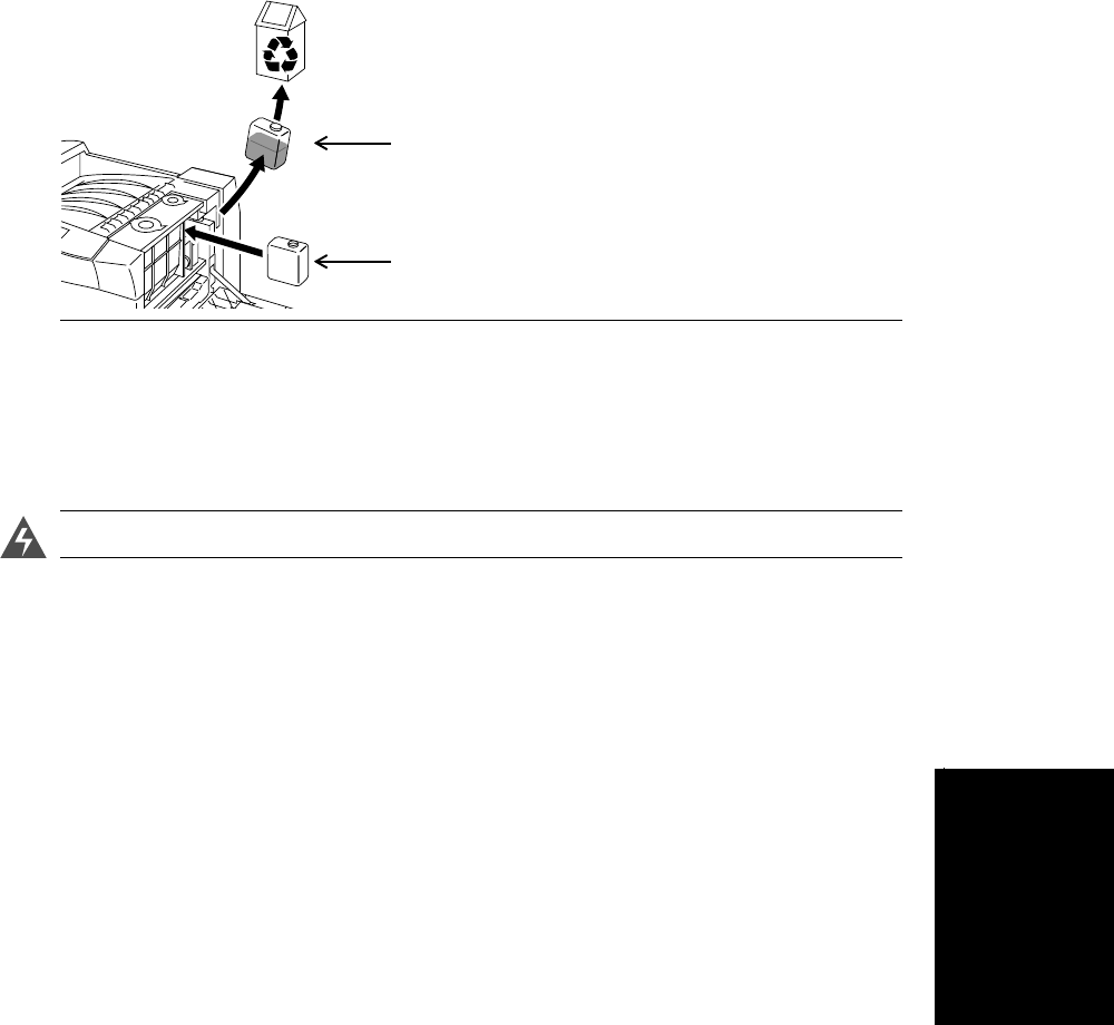
Replacing Toner
Ordering and Replacing Consumables 4-7
Consumables
Replacing the Toner Collector Bottle
If you have toner recycling turned on, you can skip this step. For information about toner
recycling, refer to “Managing Consumables” on page 6-6.
When you replace the toner, remove the old toner collector bottle and replace it with a new,
empty one. Refer to Figure 4-5 for an illustration of the toner collector bottle location.
Figure 4-5 Toner Collector Bottle Replacement
Dispose of the old toner collector bottle in accordance with local regulations. Close the upper
right cover.
Replacing the Cleaning Roller (When Indicated on Control Panel)
WARNING! Handle the old cleaning roller carefully, as it may be hot.
Replace the cleaning roller during every other toner replacement, as directed on the Control
Panel.
1. Open the front door.
2. Pull out the old cleaning roller, as shown in Figure 4-6.
Pull out old bottle
Insert new bottle
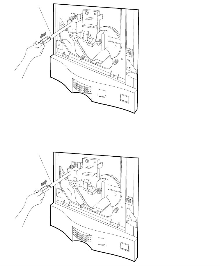
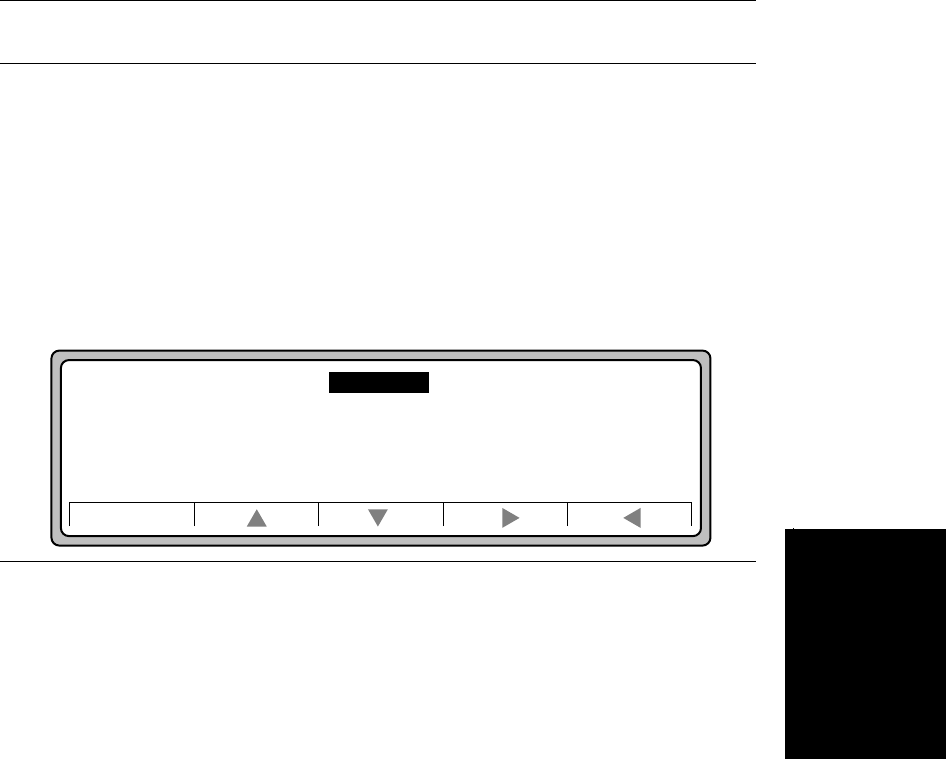
Replacing Developer
Ordering and Replacing Consumables 4-9
Consumables
4. Close the front door.
5. Press Done to return the printer Online.
Replacing Developer
Change the developer when it has either reached end-of-life, or diagnostic procedures have
identified it as a source of problems.
When the developer has reached end-of-life, the Control Panel will display:
Developer at end of life
replace developer
The printer does not stop, but it continues to display the message until you replace the
developer.
Note To avoid possible damage, the printer will stop printing about 40,000 pages after the
"Developer at end life" message first appears.
Replace the ozone filter during every other developer replacement.
Follow these steps for the developer replacement procedure:
1. Discharge old developer.
2. Add new developer. (“Adding New Developer” on page 4-12).
3. Replace the ozone filter (“Replacing the Ozone Filter” on page 4-17).
Discharging Developer
1. Press Menu on the Main Screen. Figure 4-8 is displayed.
Figure 4-8 Menu
Online
Menu
Online
Printing
Configuration
PCL
Comms
Maintenance
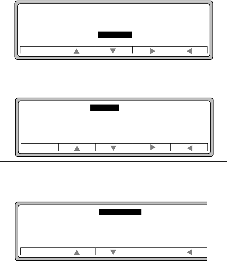
Replacing Developer
4-10 Ordering and Replacing Consumables
2. Use N to highlight Maintenance, as shown in Figure 4-9.
Figure 4-9 Maintenance
3. Use P to display Maintenance selections as shown in Figure 4-10.
Figure 4-10 Maintenance selections
4. Use P to display replace selections, as shown in Figure 4-11. Developer is shown
selected.
Figure 4-11 Replace selections
Online
Menu
Online
Printing
Configuration
PCL
Comms
Maintenance
Online
Maintenance
Online
replace
alignment
density = 10
testpages = 30
monitor = OFF
date-time
Online
Maintenance.replace
Online Select
DEVELOPER
DRUM UNIT
FUSER UNIT
TRAY1ROLLERS
TRAY2ROLLERS
TRAY3ROLLERS
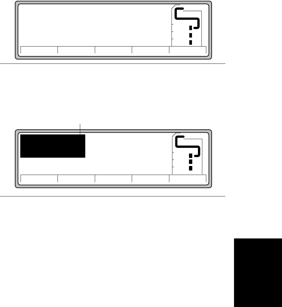
Replacing Developer
Ordering and Replacing Consumables 4-11
Consumables
5. Press Select to display Developer instructions, as shown in Figure 4-12.
Figure 4-12 Discharge Developer
6. Press Start, as shown in Figure 4-12.
7. The old developer is cycled into the empty developer bottle. The process takes about 45
seconds. Do not open any covers or cycle power during this period. Follow the
instructions on the Control Panel.
Figure 4-13 Developer discharging
Start Exit
LTR
LTR
LTR
Developer Replacement
Prepare new developer
and press Start
to discharge old developer
Online
Developer discharge
Developer discharging
Please Wait
Blinking
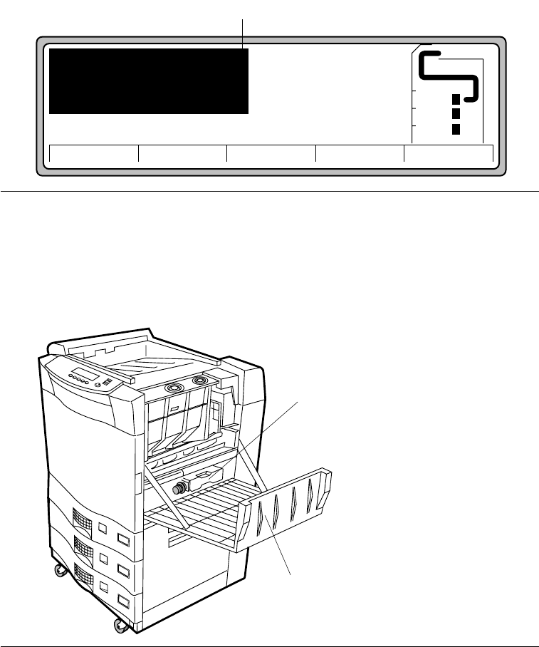
Replacing Developer
4-12 Ordering and Replacing Consumables
8. After 45 seconds, you see the display shown in Figure 4-14.
Figure 4-14 Developer discharge complete
9. Press Done.
Adding New Developer
1. Open the upper right cover and locate the developer bottle as shown in Figure 4-15.
Figure 4-15 Developer and Developer Collector Bottle
Online
Blinking
Done
Developer discharge completed
Prepare new developer bottle
Open upper right cover
Press Done
Developer collector bottle
Upper right cover
..
..
....
.
..
.
.
.....
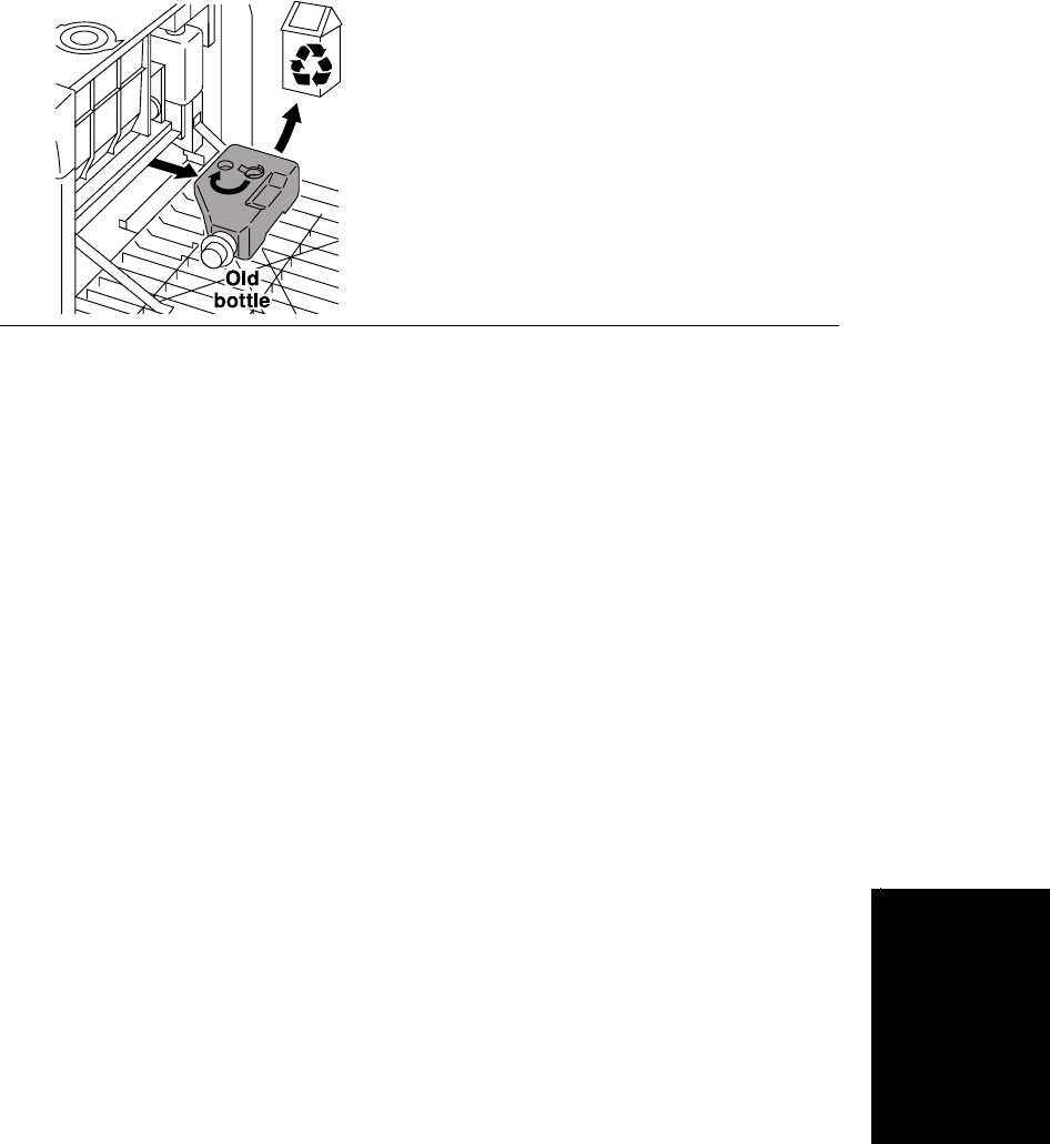
Replacing Developer
Ordering and Replacing Consumables 4-13
Consumables
2. Remove the developer collector bottle, as shown in Figure 4-16.
Figure 4-16 Removing Developer Collector Bottle
3. Move the bottle cap from the storage position onto the collection hole to close the bottle,
as shown in Figure 4-16.
4. Discard the developer collector bottle. The developer collector bottle is made of
recyclable materials; dispose of it in accordance with local regulations.
5. The following text appears on the Control Panel:
Developer injection
Open rear flap
Insert New Developer bottle
Press Done when bottle empty
6. Locate a new bottle of developer.
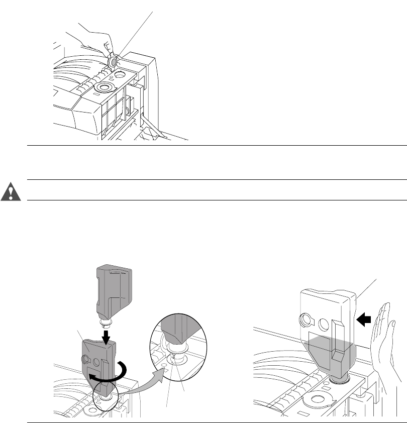
Replacing Developer
4-14 Ordering and Replacing Consumables
7. Open the developer fill flap, as shown in Figure 4-17.
Figure 4-17 Opening the Developer Fill Flap
Caution Never reinstall used developer. Doing so may result in poor print quality.
8. Line up the guide pins on the new developer bottle with the guide pin openings on the
developer fill. Insert and turn the developer bottle clockwise 180° to start filling, as
shown in Figure 4-18.
Figure 4-18 Filling the Developer and tapping the Developer Bottle
Developer fill flap
Developer bottle
Guide pin
Guide pin slot
Developer bottle
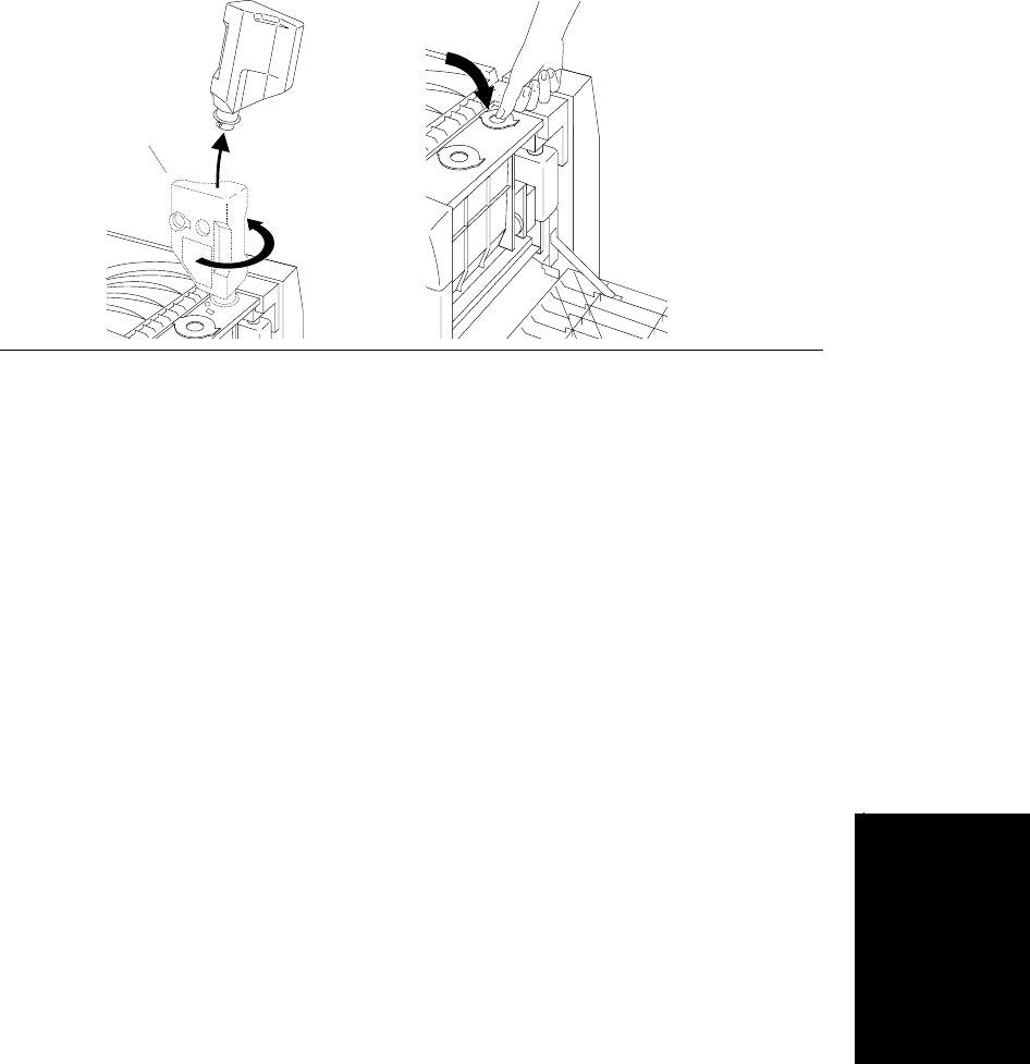
Replacing Developer
Ordering and Replacing Consumables 4-15
Consumables
9. Gently tap the developer bottle to dislodge any remaining developer, as shown in
Figure 4-18.
10. Turn the developer bottle counterclockwise 180° and remove, as shown in Figure 4-19.
Figure 4-19 Removing the Developer Bottle and closing the Fill Flap
11. Close the developer fill flap, as shown in Figure 4-19.
12. Press Done. The Control Panel displays:
Developer injection complete
Remove and Cap Old Bottle
Install Empty New Bottle
Close Cover and Press Done
Empty developer bottle
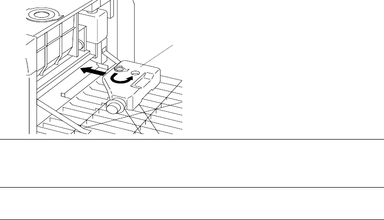
Replacing Developer
4-16 Ordering and Replacing Consumables
Installing Developer Collector Bottle
1. Remove small cap on the side of the developer collector bottle.
2. Turn cap around and place in the storage location, as shown in Figure 4-20.
Figure 4-20 Installing Developer Purge Bottle
3. Insert developer collector bottle into storage position.
Note The developer collector bottle will not fit if you forget to move the small cap to its
storage location.
4. Close upper-right cover.
5. Press Done on the Control panel.
Empty bottle
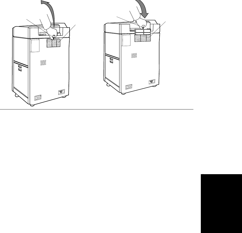
Replacing Developer
Ordering and Replacing Consumables 4-17
Consumables
Replacing the Ozone Filter
Replace the ozone filter after every other developer replacement.
1. Locate the ozone filter packaged in the Developer Kit.
2. Remove the used filter from the filter holder and install the new one, as shown in
Figure 4-21.
Figure 4-21 Replacing the Ozone Filter
3. Discard the used filter. The filter is not made of recyclable materials; dispose of it in
accordance with local regulations.
Ozone filter
Handle
Ozone filter holder
Handle
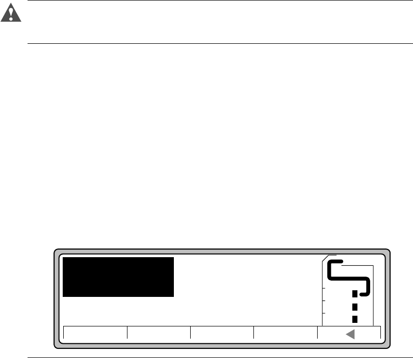
Drum Kit - Replacing Drum and Transfer Assembly
4-18 Ordering and Replacing Consumables
Drum Kit - Replacing Drum and Transfer Assembly
The drum and transfer charger are always replaced together. The drum is replaced when the
Control Panel indicates:
Drum at end life
Replace drum
Caution The drum surface is easily damaged. Avoid contact with the drum surface and
don’t expose the drum to light for extended periods of time. Scratches will appear as dark lines
or marks on the printed page. A scratched drum should be replaced.
This section provides maintenance procedures for:
• Removing the old transfer assembly and installing the new transfer assembly (See
“Removing the Transfer Assembly” on page 4-19).
• Removing the old drum and installing the new drum (See “Installing the Drum” on
page 4-24).
Setting Up the Printer for Drum Kit Replacement
1. Press the Menu button on the Main Screen.
2. Press N to highlight Maintenance.
3. Press P to display Maintenance selections.
4. Press P to enter the Replace submenu.
5. Press N to highlight DRUM UNIT.
6. Press P to display drum instructions as shown in Figure 4-22.
Figure 4-22 Replace Drum
Online
Drum Replacement
Replace Drum unit
and Press Done
Done
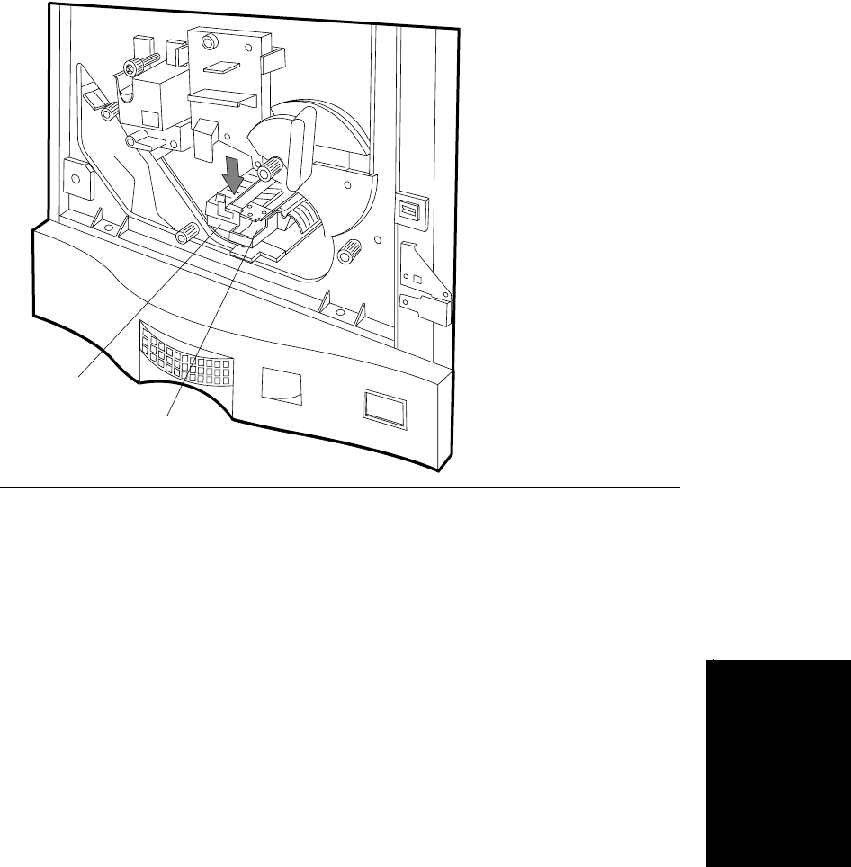
Drum Kit - Replacing Drum and Transfer Assembly
Ordering and Replacing Consumables 4-19
Consumables
Removing the Transfer Assembly
1. Open the front door, if it is not already open.
2. While pulling Handle 3, carefully lower the transfer guide as shown in Figure 4-23.
Figure 4-23 Handle 3 and Transfer Assembly Guide
Transfer assembly
guide
Handle 3
LTR
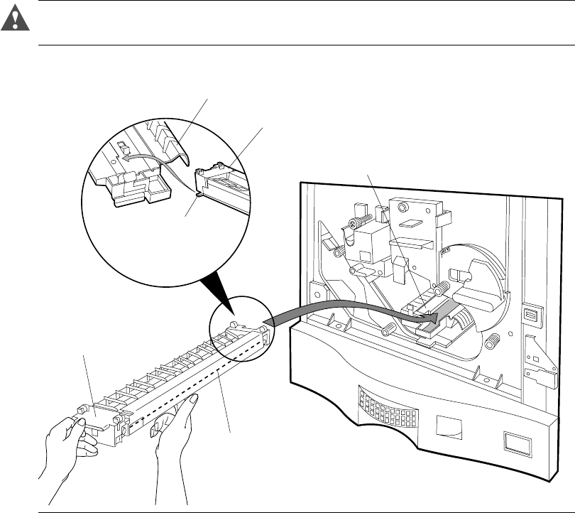
Drum Kit - Replacing Drum and Transfer Assembly
4-20 Ordering and Replacing Consumables
3. Push in and pull up on the transfer assembly to free it from the guide assembly as shown
in Figure 4-24. Lift the transfer assembly out of the guide assembly.
Caution As you handle the transfer assembly, take care not to touch or damage the
transfer wire.
Figure 4-24 Removing the Transfer Assembly
4. Discard the transfer unit.
Transfer assembly
Wire
Transfer assembly guide
LTR
Transfer assembly
Transfer assembly guide
Pin

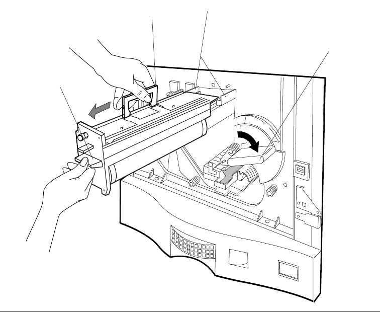
Drum Kit - Replacing Drum and Transfer Assembly
4-22 Ordering and Replacing Consumables
2. Rotate Lever b1 clockwise, as shown in Figure 4-26.
3. Use the drum handles on the top and front to pull it out, as shown in Figure 4-26.
Figure 4-26 Removing the Drum
4. Discard the used drum. The drum is an aluminum cylinder coated with non-hazardous
organic material. Dispose of it according to local ordinances.
Top handle Guide rails
Front handle
Lever b1
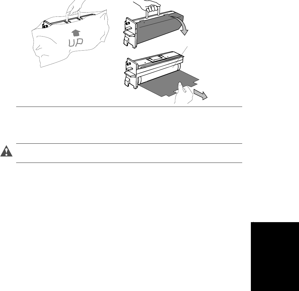
Drum Kit - Replacing Drum and Transfer Assembly
Ordering and Replacing Consumables 4-23
Consumables
Unpacking the New Drum
1. Open the vacuum sealed bag containing the drum and remove it, as shown in
Figure 4-27.
Figure 4-27 Unpacking Drum and removing the Protective Cover
2. Hold the drum by the top handle, set it on a solid surface, and carefully remove the
protective cover, as shown in Figure 4-27.
Caution Do not touch the surface of the drum. Finger prints and scratches on the surface of
the drum may adversely affect print quality.
Drum
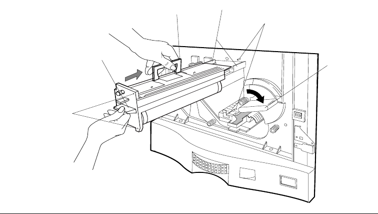
Drum Kit - Replacing Drum and Transfer Assembly
4-24 Ordering and Replacing Consumables
Installing the Drum
1. Make sure Lever b1 is in the OPEN position.
Use the drum handles on the top and front to insert the drum along the guide rails until it
stops, as shown in Figure 4-28. Push forward gently until the drum meets the positioning
pins.
Figure 4-28 Inserting the Drum
Top handle Guide rails
Drum alignment
pins
Front handle
Alignment
pin holes
Lever b1
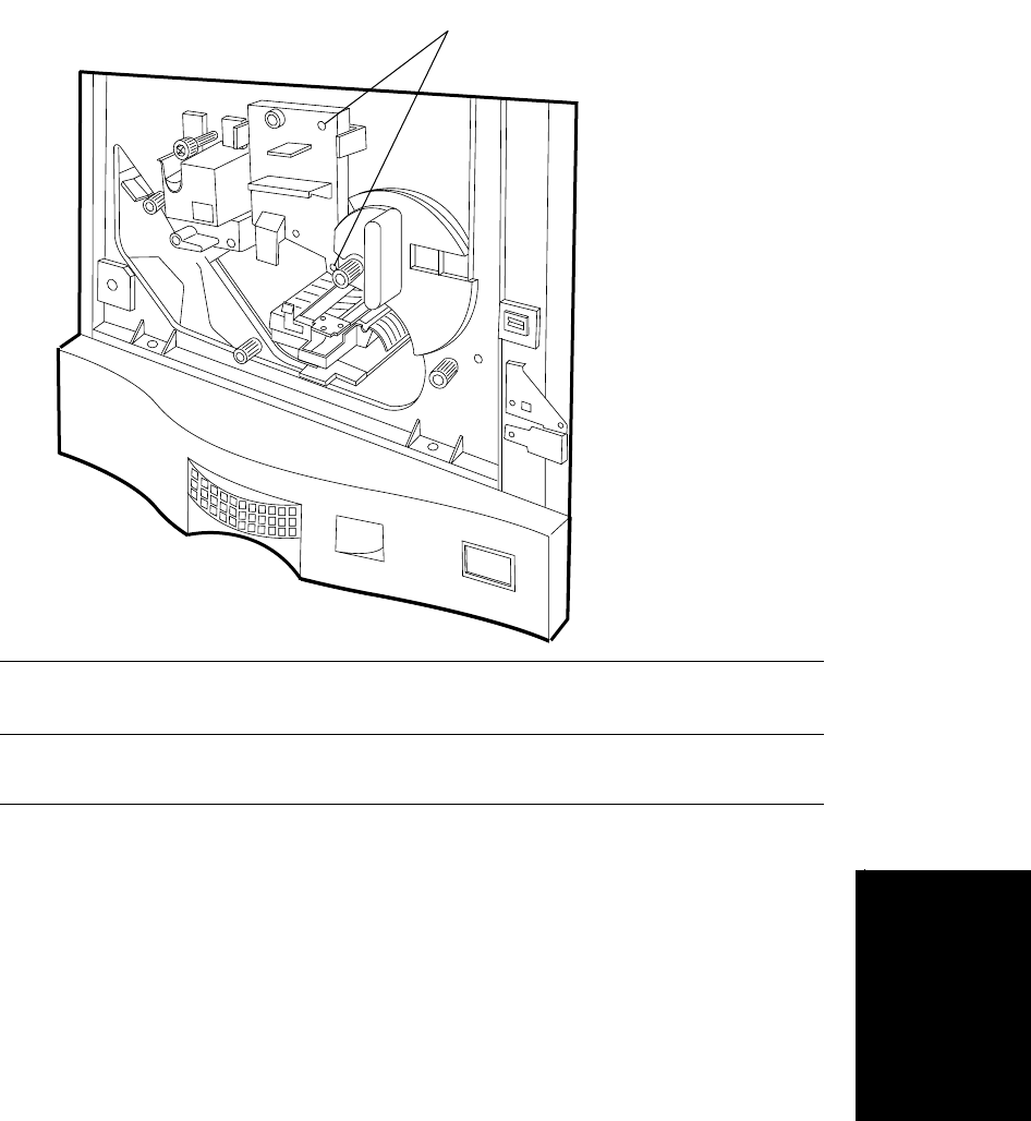
Drum Kit - Replacing Drum and Transfer Assembly
Ordering and Replacing Consumables 4-25
Consumables
2. Gently push the drum onto the positioning pins (Figure 4-29).
Figure 4-29 Drum Alignment Pin locations
Note Make sure the alignment pins on the printer line up with the alignment-pin holes on the
drum.
(2) Drum Alignment Pins
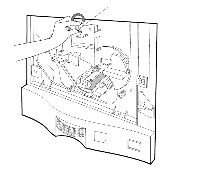
Drum Kit - Replacing Drum and Transfer Assembly
4-26 Ordering and Replacing Consumables
3. Maintain pressure on the drum and finger-tighten the drum locking knob clockwise to
engage the frame and secure the drum as shown in Figure 4-30.
Figure 4-30 Securing the Drum
4. Rotate Lever b1 counterclockwise to lock the drum in place.
Drum locking knob
LTR
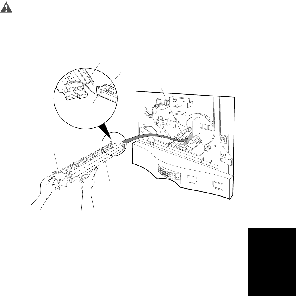
Drum Kit - Replacing Drum and Transfer Assembly
Ordering and Replacing Consumables 4-27
Consumables
Installing the New Transfer Assembly
1. Remove the transfer assembly from its packaging.
Caution As you handle the transfer assembly, take care not to touch or damage the
transfer wire.
2. Using the alignment pin located on the end of the transfer assembly, insert the alignment
pin of the transfer assembly into the left rail of the transfer assembly guide and push in
to the end of the guide as shown in Figure 4-31.
Figure 4-31 Inserting the Transfer Assembly into the Guide
Transfer assembly
Wire
Transfer assembly guide
LTR
Transfer assembly
Transfer assembly guide
Pin
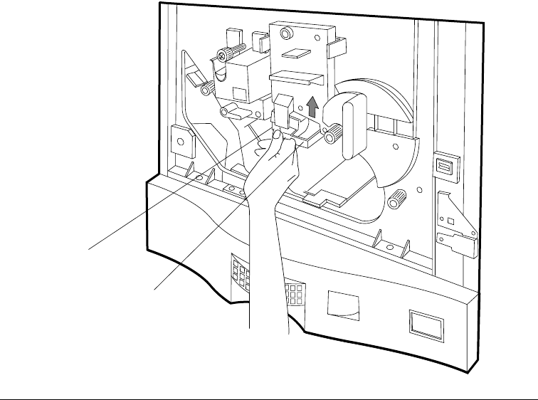
Drum Kit - Replacing Drum and Transfer Assembly
4-28 Ordering and Replacing Consumables
3. Secure the transfer assembly guide by lifting Handle 3 until it snaps into place as shown
in Figure 4-32.
Figure 4-32 Securing the Transfer Assembly
4. Close the front door.
5. Use the drum kit packing materials to repack for disposal.
Handle 3
Transfer assembly
guide
LTR
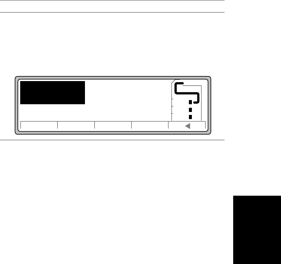
Fuser Kit - Replacing the Fuser
Ordering and Replacing Consumables 4-29
Consumables
Fuser Kit - Replacing the Fuser
The fuser is replaced when the Control Panel indicates:
Fuser At End Life
Replace Fuser
This section provides maintenance procedures for removing the old fuser and installing the
new one.
Note This procedure is applicable to both 120-127 VAC and 200-240 VAC fusers.
1. Press the Menu button on Main Screen.
2. Press N to highlight Maintenance.
3. Press P to display Maintenance selections.
4. Press P to display replace selections
5. Press N to select fuser.
6. Press Select to display fuser instructions, as shown in Figure 4-33.
Figure 4-33 Fuser instructions
Online
Fuser unit Replacement
Replace Fuser unit and
Press Done
Done
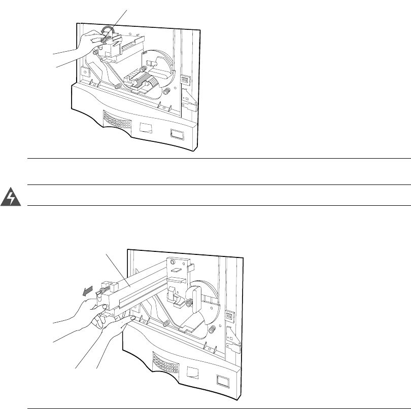
Fuser Kit - Replacing the Fuser
4-30 Ordering and Replacing Consumables
Removing the Fuser
To remove the fuser:
1. Open the front door.
2. Turn the fuser locking knob counterclockwise several times to release the fuser, as
shown in Figure 4-34.
Figure 4-34 Releasing the Fuser Locking Knob
WARNING! The fuser may be hot. Avoid touching the fuser surfaces labeled as hot.
3. Pull the fuser out, supporting it with your hand, as shown in Figure 4-35.
Figure 4-35 Pulling the Fuser out
LTR
Fuser locking knob
Fuser
LTR
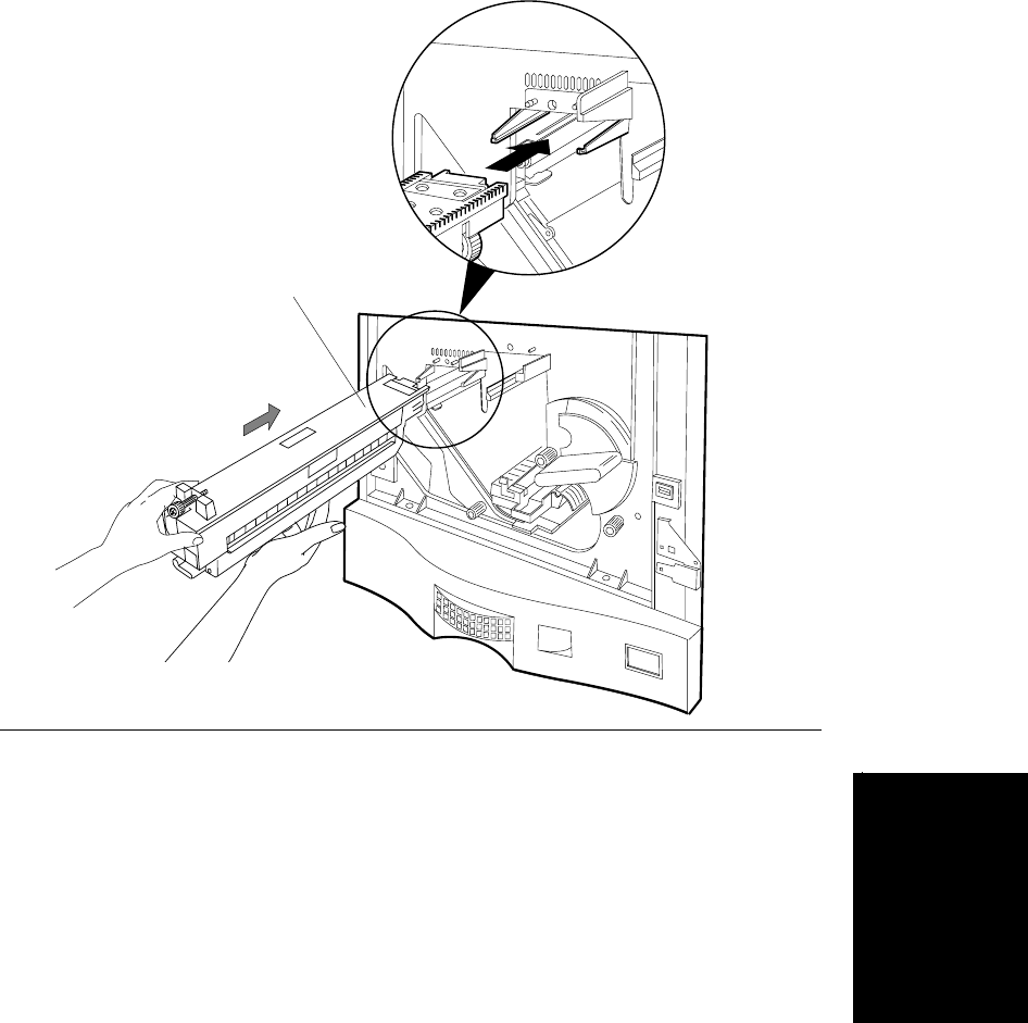
Fuser Kit - Replacing the Fuser
Ordering and Replacing Consumables 4-31
Consumables
Installing the Fuser
1. Locate and remove the new fuser from its packaging.
2. Place the fuser’s leading edge into the guides, then push the fuser into the printer until it
stops, as shown in Figure 4-36.
Figure 4-36 Installing the Fuser
Fuser
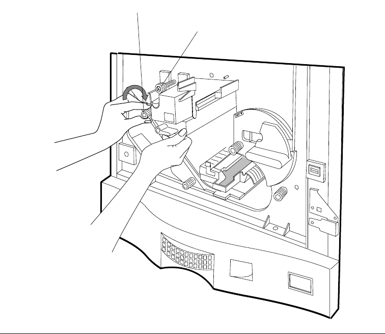
Fuser Kit - Replacing the Fuser
4-32 Ordering and Replacing Consumables
3. Maintain pressure on the fuser and finger-tighten the fuser locking knob clockwise to
engage the frame and secure the fuser into position as shown in Figure 4-37.
If the fuser does not seat properly, do not force it. Instead, refer to Figure 4-37 while
following the next two steps:
a) Hold the fuser up against the printer using light pressure.
b) Carefully rotate the decurler roller knob clockwise until you feel the gears turn
easily and the fuser seats flush against the printer. Tighten the fuser locking
knob.
Figure 4-37 Fuser Locking Knob and Decurler Roller Knob
4. Verify all locks and levers are secure and then close the front door.
5. Press Done.
Decurler roller knob
Fuser locking knob
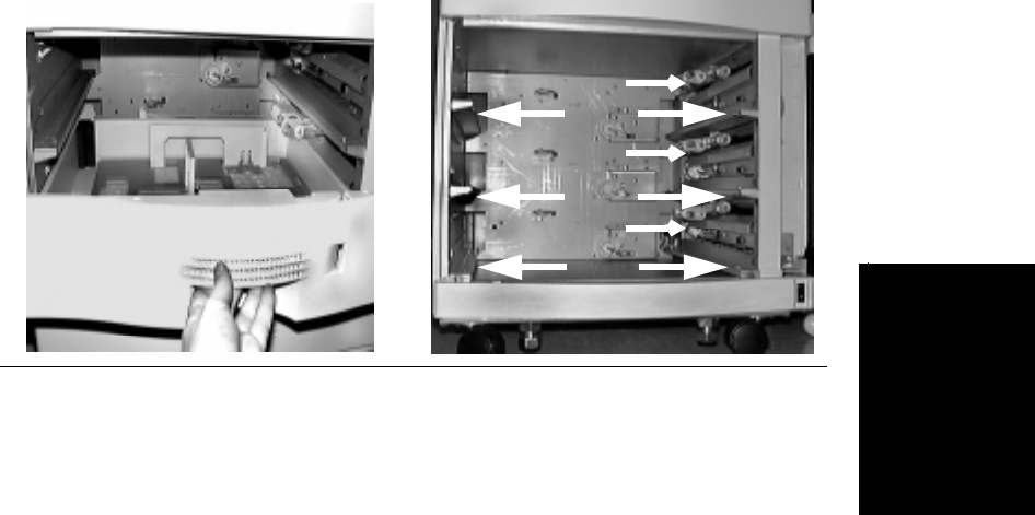
Printer Pick Roller Kit - Replacing the Tray Pick Rollers
Ordering and Replacing Consumables 4-33
Consumables
Printer Pick Roller Kit - Replacing the Tray Pick Rollers
Replace the pick rollers whenever the Control Panel indicates:
Pick Roller At End Life
Replace Pick Roller
or when you get excessive pick errors.
Each tray and the HCI contain pick rollers. The Control Panel will indicate which one requires
replacement. This procedure is applicable to all three printer trays (tray1, tray2, and tray3). For
the HCI replacement procedures, see “HCI Pick Roller Kit - Replacing the HCI Pick Rollers”
on page 4-42.
At the Control Panel
1. Press the Menu button on the Main Screen.
2. Press N to select Maintenance.
3. Press P to select Maintenance options.replace should be highlighted.
4. Press Select to enter the replace submenu.
5. Press N to select the set of tray rollers to be replaced.
6. Press Select.
Removing the Printer Pick Rollers (Upper and Lower)
1. To reach the tray pick rollers more easily, remove all three trays from the printer and set
them aside, as shown in Figure 4-38 below.
Figure 4-38 Removing Paper Trays - all trays removed
Tray3
Tray1
Tray2
Pick rollers
Pick rollers
Pick rollers
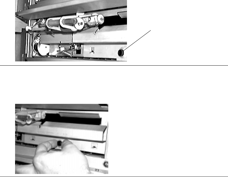
Printer Pick Roller Kit - Replacing the Tray Pick Rollers
4-34 Ordering and Replacing Consumables
2. Locate the thumb screw holding the steel plate over the lower tray roller assembly, as
shown in Figure 4-39.
Figure 4-39 Locating Thumbscrew
3. Unscrew the thumb screw holding the steel plate by rotating counterclockwise several
turns. Place this plate aside for later assembly. See Figure 4-40.
Figure 4-40 Unscrewing Plate
Thumbscrew
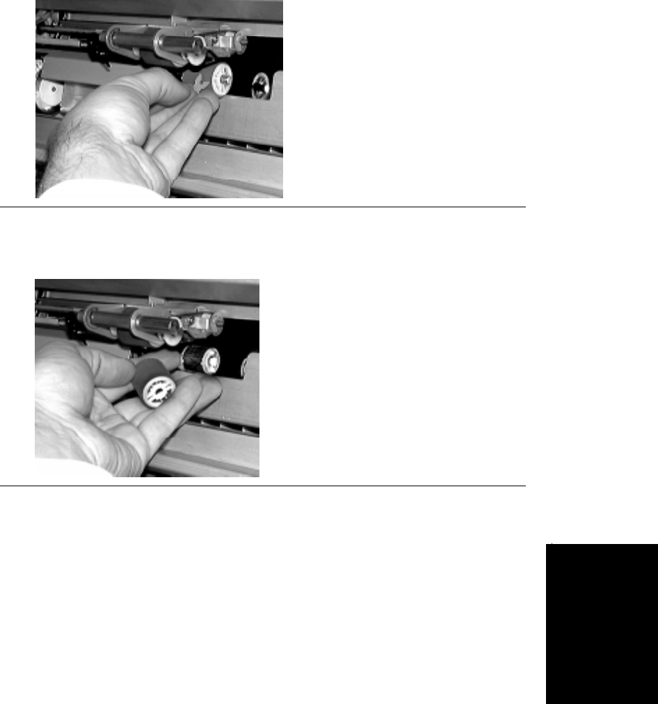
Printer Pick Roller Kit - Replacing the Tray Pick Rollers
Ordering and Replacing Consumables 4-35
Consumables
4. Locate the blue plastic clip holding the lower rollers in place. Pull this clip off and set it
aside. See Figure 4-41.
Figure 4-41 Removing Lower Roller Clip
5. Pull the two lower rollers off of the lower shaft now. See Figure 4-42.
Figure 4-42 Removing Lower Rollers from Shaft
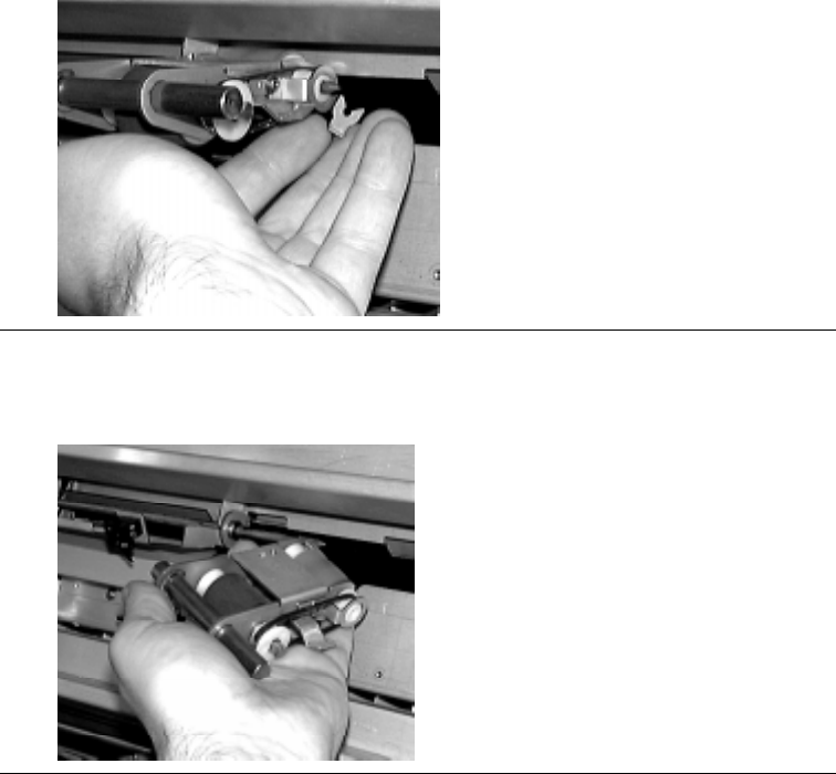
Printer Pick Roller Kit - Replacing the Tray Pick Rollers
4-36 Ordering and Replacing Consumables
6. Locate the blue plastic clip holding the upper rollers in place. Pull this clip off and set it
aside. See Figure 4-43.
Figure 4-43 Removing Upper Roller Clip
7. Pull the upper roller assembly off of the upper shaft, as shown in Figure 4-44.
Figure 4-44 Removing Upper Roller Assembly
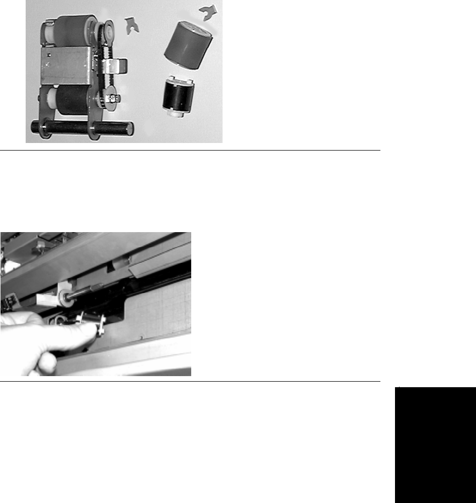
Printer Pick Roller Kit - Replacing the Tray Pick Rollers
Ordering and Replacing Consumables 4-37
Consumables
New Printer Pick Roller Kit
1. Unpack the new printer pick roller kit (Product Number: C5633A). See Figure 4-45.
Figure 4-45 Printer Pick Roller Kit
Installing the Printer Lower Pick Rollers
During installation of the lower rollers the torque limiter roller (a smaller lower roller with a
black color outside) must go on the lower shaft first, as shown in Figure 4-46.
Figure 4-46 Installing Torque Limiter
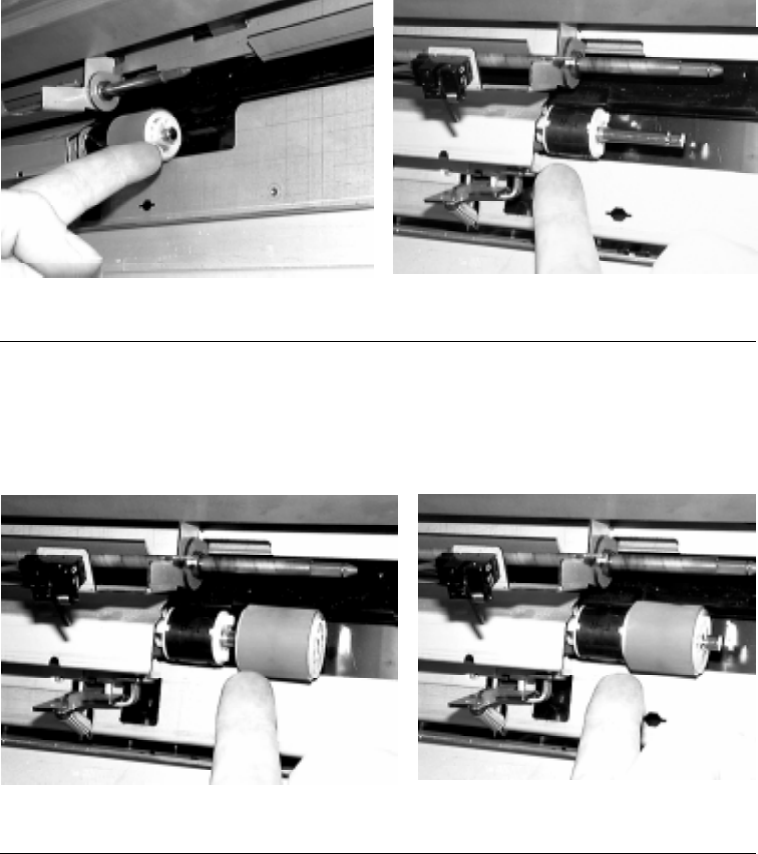
Printer Pick Roller Kit - Replacing the Tray Pick Rollers
4-38 Ordering and Replacing Consumables
1. Install the smaller lower roller (torque limiter roller) so that the notch in the roller’s
plastic fits over the metal pegs on the shaft. When this roller is correctly in all the way,
the roller is locked and will not rotate. See Figure 4-47.
Figure 4-47 Correct Torque Limiter placement
2. Install the larger lower roller on the same shaft. The larger roller (when correctly
positioned) fits onto two small plastic pegs on the smaller lower roller. You may need to
rotate the larger roller against the smaller roller until it snaps into place. See Figure 4-48.
Figure 4-48 Correct Larger Lower Roller placement
Notch correctly positioned to go
over metal peg Roller correctly installed all the way,
with notch over the metal peg
Larger lower roller positioned on the
same shaft as the smaller roller
Larger lower roller rotated to
engage plastic pegs on smaller
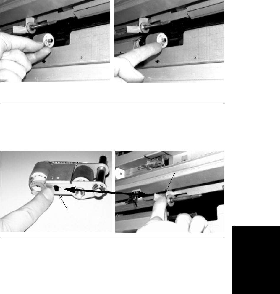
Printer Pick Roller Kit - Replacing the Tray Pick Rollers
Ordering and Replacing Consumables 4-39
Consumables
3. Snap the blue plastic clip into place. It fits over a groove on the end of the shaft to secure
the lower rollers. See Figure 4-49. If you don’t see this groove, the rollers may not be
completely seated all the way onto the shaft.
Figure 4-49 Blue Clip snapped into place
Installing the Printer Upper Pick Rollers
When you install the printer’s upper pick rollers, the slot on the pick roller assembly must mate
with the corresponding mounting tooth on the printer bracket. See Figure 4-50.
Figure 4-50 Upper Pick Roller Assembly Slot and Mounting Tooth on printer
Blue clip placed on lower
roller shaft Blue clip snapped into place on
lower roller shaft groove
Slot
Metal tooth
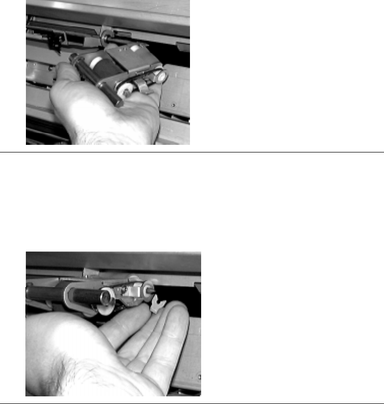
Printer Pick Roller Kit - Replacing the Tray Pick Rollers
4-40 Ordering and Replacing Consumables
4. Install the new upper pick roller assembly over the shaft. See Figure 4-51.
Figure 4-51 Installing Upper Roller Assembly
5. Push the upper roller assembly all the way onto the shaft. You may have to jiggle the
assembly a little as you push it to seat it correctly.
6. Snap the blue plastic clip into place. It fits over a groove on the end of the shaft to secure
the upper roller assembly. If you don’t see this groove, the assembly may not be
completely seated all the way onto the shaft. See Figure 4-52.
Figure 4-52 Installing Upper Roller Clip
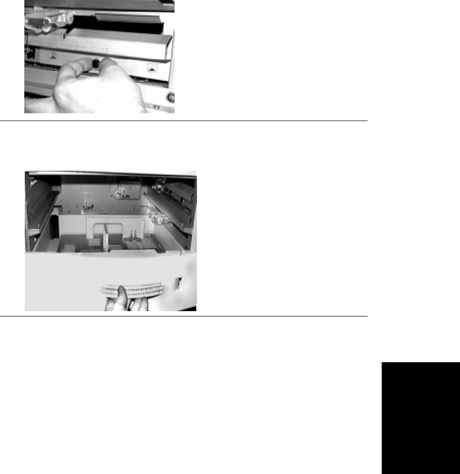
Printer Pick Roller Kit - Replacing the Tray Pick Rollers
Ordering and Replacing Consumables 4-41
Consumables
Installing the Covers and Trays
1. Attach the metal plate to the printer frame with the thumbscrew. Turn the thumbscrew
clockwise several turns until it is snug. Do not overtighten. See Figure 4-53.
Figure 4-53 Attaching Plate
2. Replace the three paper trays back into the printer, as shown in Figure 4-54.
Figure 4-54 Installing Paper Trays
3. Press Done on the Control Panel.
4. Perform the Paper Path Alignment procedure described in “Adjusting Paper Path
Alignment” on page 6-11.
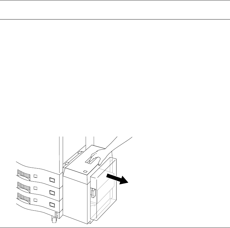
HCI Pick Roller Kit - Replacing the HCI Pick Rollers
4-42 Ordering and Replacing Consumables
HCI Pick Roller Kit - Replacing the HCI Pick Rollers
This section provides the procedures to remove and replace the HCI pick rollers. When the
HCI pick rollers need to be replaced the Control Panel indicates:
HCI Pick Roller At End of Life
Replace HCI Pick Roller
or when you get excessive feed errors from the HCI.
Note We recommend that you use a small flashlight to help you see the inside of the HCI
while working in it.
At the Control Panel
1. Press the Menu button on the Main Screen.
2. Press N to select Maintenance.
3. Press P to select Maintenance options. replace should be highlighted.
4. Press Select to enter the replace submenu.
5. Press N to select the HCI tray rollers. The HCI option only appears if the HCI is
installed.
6. Press Select.
Removing the HCI Pick Rollers (Upper and Lower)
1. Release the HCI from the printer and slide the HCI back on its rails, as shown in
Figure 4-55.
Figure 4-55 Sliding HCI away from printer
LTR
LTR
LTR
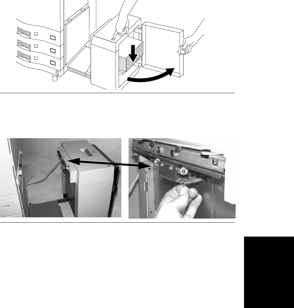
HCI Pick Roller Kit - Replacing the HCI Pick Rollers
Ordering and Replacing Consumables 4-43
Consumables
2. Open the HCI door, press the HCI top button to lower the shelf, and then remove any
paper as shown in Figure 4-56. The printer must be powered on and the HCI must be
connected to the printer for the HCI top button to lower the shelf.
Figure 4-56 Opening the HCI
3. Locate the back of the HCI and carefully remove the retaining springs providing tension
to the lower roller assembly, as shown in Figure 4-57. Notice how these springs are
attached to the lower roller assembly.
Figure 4-57 HCI Rear and Lower Roller Assembly Springs
LTR
LTR
LTR
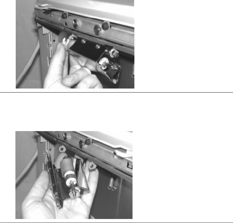
HCI Pick Roller Kit - Replacing the HCI Pick Rollers
4-44 Ordering and Replacing Consumables
4. Locate the white plastic clip securing the lower roller shaft at the far end, shown in
Figure 4-58. Remove this plastic clip.
Figure 4-58 Removing Clip From Lower Roller Assembly
5. Grasp the lower roller assembly and slide the shaft to the side away from the retaining
clip. Once free, lower the assembly and set it aside.
Figure 4-59 Remove Lower Roller Assembly
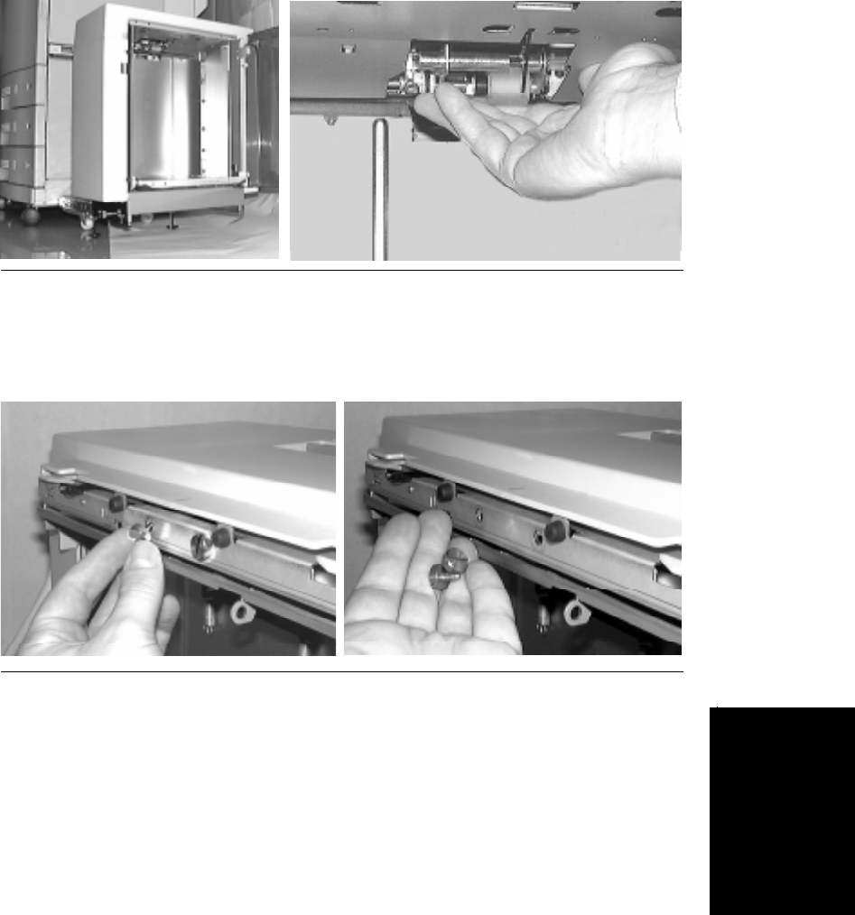
HCI Pick Roller Kit - Replacing the HCI Pick Rollers
Ordering and Replacing Consumables 4-45
Consumables
6. Move to the front of the HCI. Locate the upper roller assembly on the top underside of
the HCI, as shown in Figure 4-60. Hold this assembly up with your hand.
Figure 4-60 HCI interior and Upper Roller Assembly location
7. With your other hand, locate the two thumb screws on the back side of the HCI, as
shown in Figure 4-61. Remove these two screws (turn counterclockwise) and set them
aside.
Figure 4-61 Unscrew Thumbscrews and remove
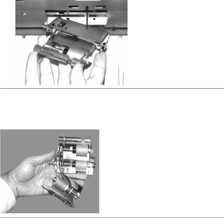
HCI Pick Roller Kit - Replacing the HCI Pick Rollers
4-46 Ordering and Replacing Consumables
8. From the front of the HCI, gently pull out the upper roller assembly, as shown in Figure
4-62. Slide the assembly a little to the right before bringing it out of the HCI.
Figure 4-62 Remove Upper Roller Assembly
New HCI Pick Roller Kit
Unpack the new HCI pick roller kit, shown in Figure 4-63.
Figure 4-63 HCI Roller Kit
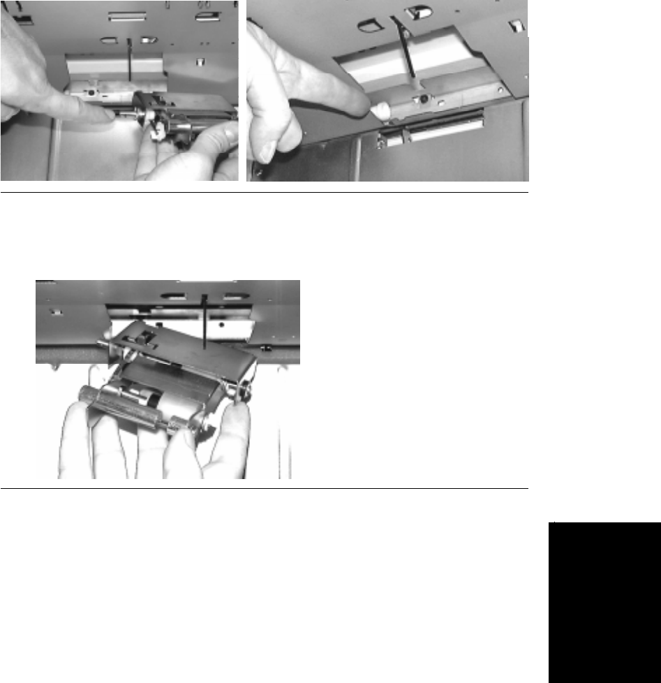
HCI Pick Roller Kit - Replacing the HCI Pick Rollers
Ordering and Replacing Consumables 4-47
Consumables
Installing the HCI Upper Pick Rollers
When you install a new HCI pick roller kit, the shaft on the upper roller assembly (left side)
goes into the hole. See Figure 4-64.
Figure 4-64 Shaft and hole location for HCI Upper Pick Roller Assembly
1. From the front of the HCI, gently guide the upper roller assembly into place, as shown in
Figure 4-65.
Figure 4-65 Installing Upper Roller Assembly
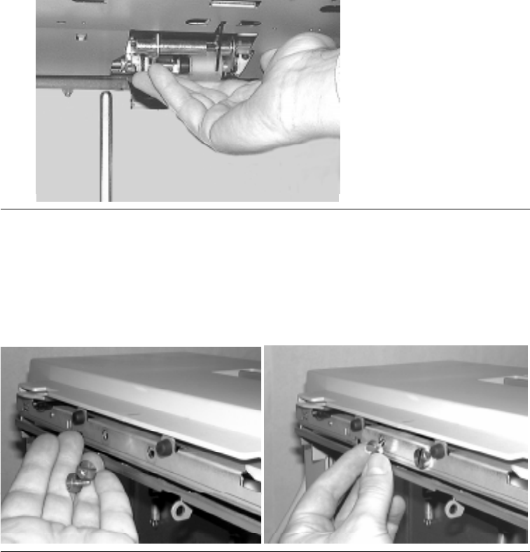
HCI Pick Roller Kit - Replacing the HCI Pick Rollers
4-48 Ordering and Replacing Consumables
2. Once the upper roller assembly is in place, gently hold it up and push it slightly to the
left (to help the screws engage). See Figure 4-66.
Figure 4-66 Holding Upper Roller Assembly in place
3. With your other hand, place the thumbscrews removed previously into the holes on the
back side of the HCI (shown in Figure 4-67). To get the proper screw engagement, you
may need to push the upper roller assembly slightly to the left. If necessary, look
through the screw holes to judge if the hole is aligned correctly. Tighten the
thumbscrews clockwise until they are snug.
Figure 4-67 Installing Thumbscrews
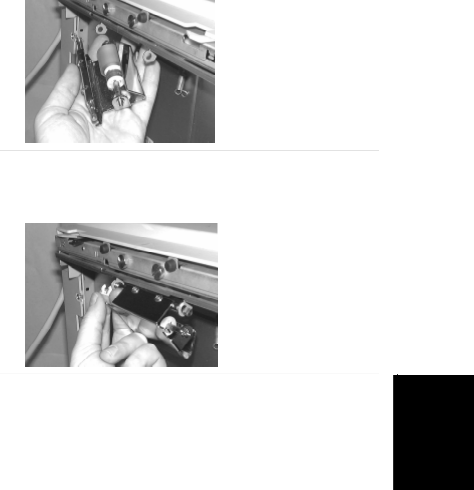
HCI Pick Roller Kit - Replacing the HCI Pick Rollers
Ordering and Replacing Consumables 4-49
Consumables
Installing the HCI Lower Pick Rollers
1. Hold the lower roller assembly and slide the front (closest) shaft into the front metal
retaining clip. Slide the back shaft into the back retaining clip. See Figure 4-68.
Figure 4-68 Installing Lower Roller Assembly
2. Snap the white plastic clip into place. It fits over a groove on the back end of the shaft to
secure the lower rollers (See Figure 4-69.) If you don’t see this groove, the rollers may
not be completely seated all the way onto the shaft.
Figure 4-69 Installing Clip onto Lower Roller Assembly
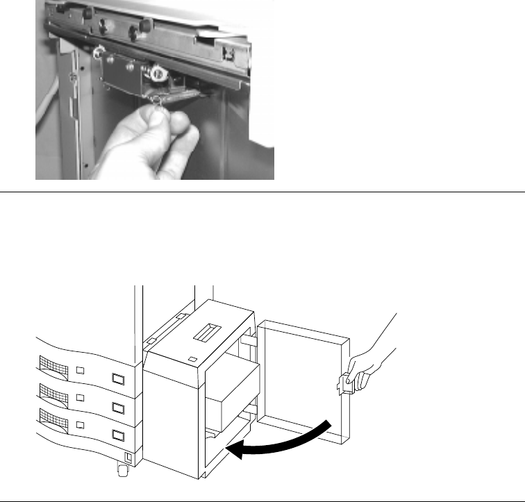
HCI Pick Roller Kit - Replacing the HCI Pick Rollers
4-50 Ordering and Replacing Consumables
3. On the back of the HCI, carefully extend and install each retaining spring to the lower
roller assembly. The retaining springs have a "holder" to pull on while extending the
spring. See Figure 4-70.
Figure 4-70 Installing Retaining Springs
4. Push the HCI against the printer to lock it into place. Add paper to the HCI and close the
HCI door, as shown in Figure 4-71.
Figure 4-71 Closing the HCI Door
5. Press Done on the Control Panel.
6. Perform the Paper Path Alignment procedure described in “Adjusting Paper Path
Alignment” on page 6-11.
LTR
LTR
LTR

Maintenance 5-1
Maintenance
5
Maintenance
Introduction
Cleaning the D640 is an important factor in assuring optimum print quality. There are two
cleaning routines to follow:
• a short weekly cleaning routine that removes paper dust and stray toner particles from the
exterior of the printer.
• a more thorough internal cleaning procedure that should be performed when you replace
the drum.
Weekly Cleaning
Investing just a few minutes on your D640’s maintenance each week ensures minimum
downtime and maintains high print quality. Make sure someone is responsible for printer
maintenance. Perform the maintenance tasks at the recommended intervals.
Use these tools for cleaning:
• Cleaning cloths (supplied with the D640 printer)
•Rags
• Vacuum cleaner specially designed for picking up toner
• Blower brush (supplied with the D640 printer)
Note Turn the main power switch OFF before performing the weekly cleaning.
Caution Make sure that the toner vacuum is properly grounded before using it in the printer,
or the printer may sustain electrical damage. Refer to the vacuum’s operating manual.
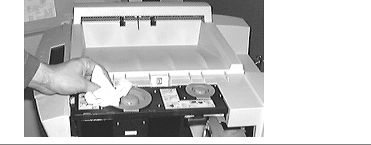
Weekly Cleaning
5-2 Maintenance
Removing Stray Toner
During removal or replacement of various consumable parts, toner occasionally spills onto the
printer interior or exterior.
• Do not attempt to clean up spilled toner with water or any other fluid, as this can harm the
developer, toner, and printer mechanism.
• Use a vacuum cleaner especially designed for trapping toner particles. Regular vacuum
cleaners cannot trap the fine toner particles and will exhaust them back into the air. If you
are unsure which vacuum cleaner to use, consult your service representative.
Toner Hopper Area
To clean the toner hopper area, follow these steps:
1. Turn off the main power switch, and open the upper right cover.
2. Use the toner vacuum to remove any toner on the upper surface of the toner hopper. Use
the supplied cleaning cloths to wipe up any toner or dust off the outside of the toner
hopper area. Clean all the way across the toner hopper area, paying careful attention to
the area in and around the toner hopper. Figure 5-1 illustrates the cleaning procedure.
Figure 5-1 Cleaning Toner Hopper area
3. Close the upper right cover.
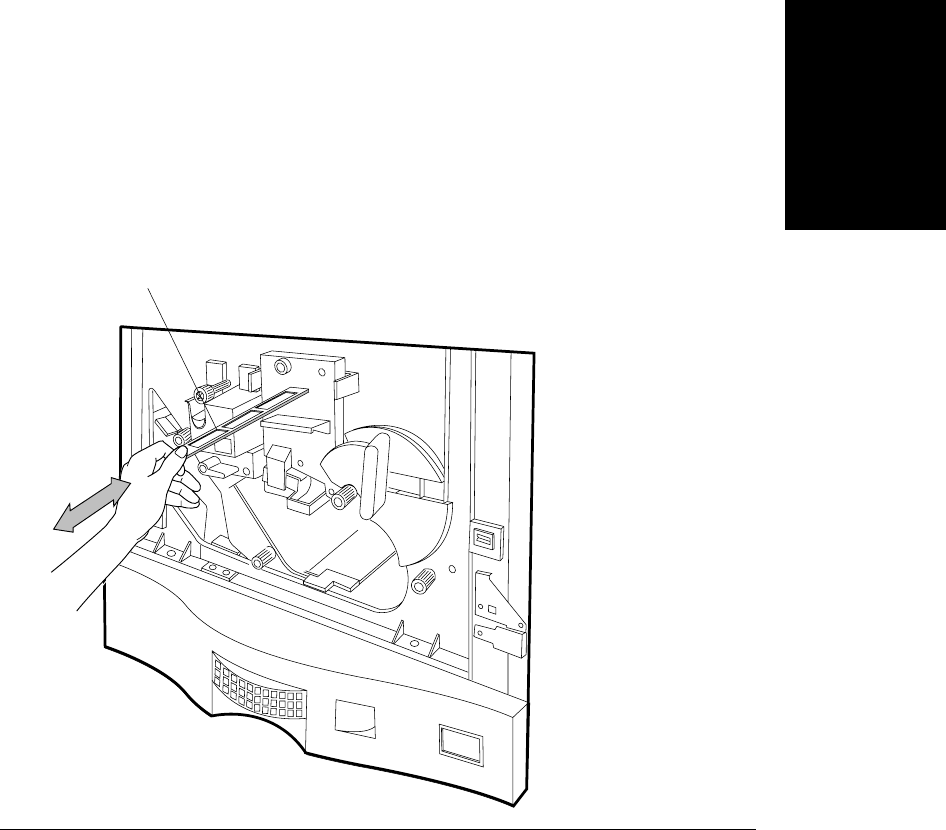
Weekly Cleaning
Maintenance 5-3
Maintenance
Precharger Area
The precharger is a wire located inside the drum. The drum contains a built-in cleaning rod to
remove toner that might build up on the precharger wire.
To clean the precharger, follow these steps:
1. Pull out the precharger cleaner handle (Figure 5-2), then push it back into its original
location. Repeat this "out-in" process 4 or 5 times.
Figure 5-2 Cleaning the Precharger
2. Push the precharger cleaner in completely.
Precharger cleaner
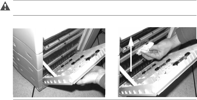
Weekly Cleaning
5-4 Maintenance
Paper Feed Area
To clean the paper feed area, follow these steps:
1. Open the lower right cover.
2. Use the supplied cleaning cloths to wipe up any toner or dust off the paper feed
mechanisms in this area, on the inside area and on the cover area. Clean all the way
down to the base of the printer to ensure a thorough cleaning. See Figure 5-3.
Caution To avoid damage to the paper sensors in the paper feed area, wipe the area from
bottom to top.
Figure 5-3 Cleaning Paper Feed Area
3. Close the lower right cover.
Paper Input Trays
To clean the inside of the paper input trays, follow these steps:
1. Remove tray3 from the printer, then remove any paper in it.
2. Use the vacuum cleaner to remove any paper dust or chips from the tray.
3. Reinstall the paper in the tray, and the tray in the printer.
4. Repeat steps 1 - 3 for the other two trays.
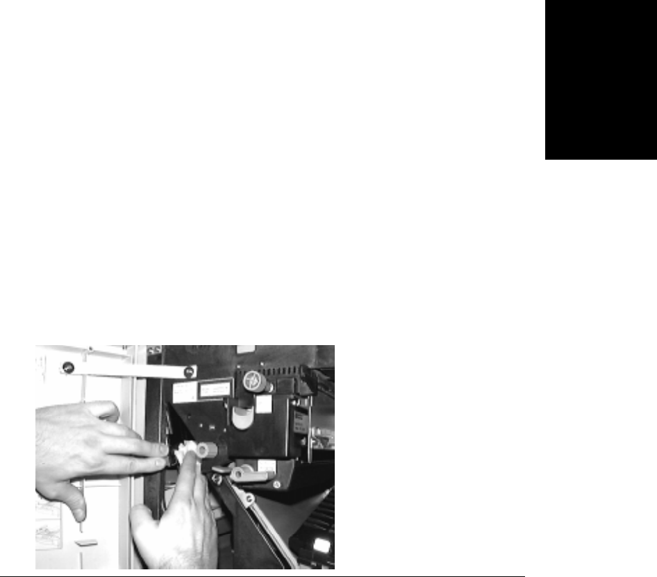
Periodic Cleaning (When Replacing Drum)
Maintenance 5-5
Maintenance
Printer Exterior
1. Check the paper output tray on top of the printer and use the vacuum to remove any
paper dust or dirt.
2. Vacuum the area around the ventilation slots on the rear of the printer to remove any
dust accumulation.
Periodic Cleaning (When Replacing Drum)
Perform the following cleaning routine when you replace the drum assembly.
Reversing Unit Area
1. Turn the main power switch off, and open the front door.
2. Hold lever 5 to the left to open the reversing unit area. See Figure 5-4.
3. Use the supplied cleaning cloths to wipe up any toner or dust off the reversing unit.
Clean all the accessible areas, working toward the back of the printer, to ensure a
thorough cleaning.
Figure 5-4 Cleaning Reversing area
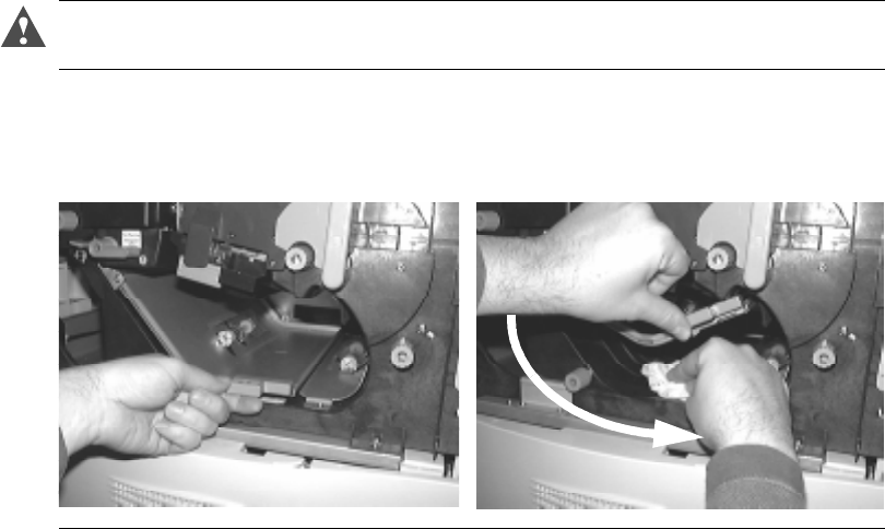
Periodic Cleaning (When Replacing Drum)
5-6 Maintenance
Duplex Area
Caution As you clean the duplex unit, avoid wiping the paper sensor from right to left or
perpendicular to the paper feeding direction. Wipe the area from left to right.
1. Raise lever 6 and use the supplied cleaning cloths to wipe up any toner or dust off the
duplex area in this area, wiping from left to right. Wipe all of the accessible area to
ensure a thorough cleaning. See Figure 5-5.
Figure 5-5 Cleaning Duplex Area
2. Lower lever 6 to close the duplex unit.
3. Wipe away any paper dust or toner on the upper surface of the duplex unit.
Transfer Assembly - Transfer LED Areas
To clean the transfer assembly:
1. Use the supplied cleaning cloths or the vacuum cleaner to wipe any toner or dust off the
outside of the transfer guide and paper guides.
As you handle the transfer assembly, take care not to touch or damage the transfer wire.
2. Pull out gently on Handle 3 to unlatch and release the transfer guide. Gently lower the
transfer guide and let it rest on the bottom of the printer’s interior. See Figure 5-6.
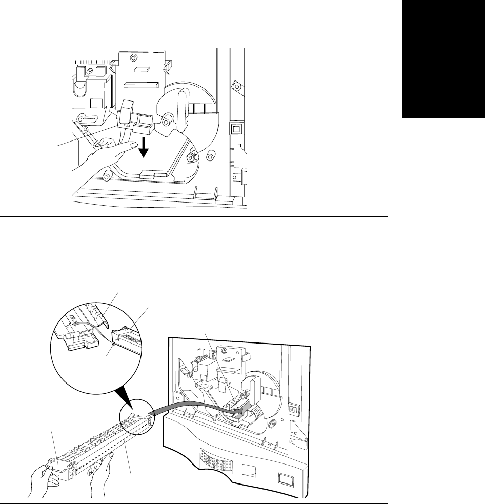
Periodic Cleaning (When Replacing Drum)
Maintenance 5-7
Maintenance
Figure 5-6 Handle 3 and Transfer Assembly Guide
3. Push in and pull up on the transfer assembly to free it from the guide assembly, as shown
in Figure 5-7.
Figure 5-7 Removing the Transfer Assembly
Handle 3
Transfer assembly
Wire
Transfer assembly guide
LTR
Transfer assembly
Transfer assembly guide
Pin
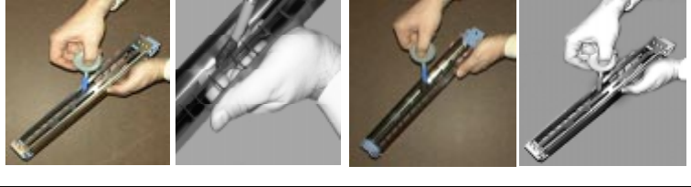
Periodic Cleaning (When Replacing Drum)
5-8 Maintenance
4. Use the supplied blower brush, stored in a pocket inside the front door, to clean the
transfer assembly wire (see Figure 5-8.) Move the brush back and forth across the wires
while quickly squeezing the rubber handle. This blows air to help remove toner and
paper dust. Turn the transfer assembly over so the opposite side can be cleaned in the
same way, and do so. Set the transfer assembly aside in a safe location.
Figure 5-8 Cleaning the Transfer Assembly
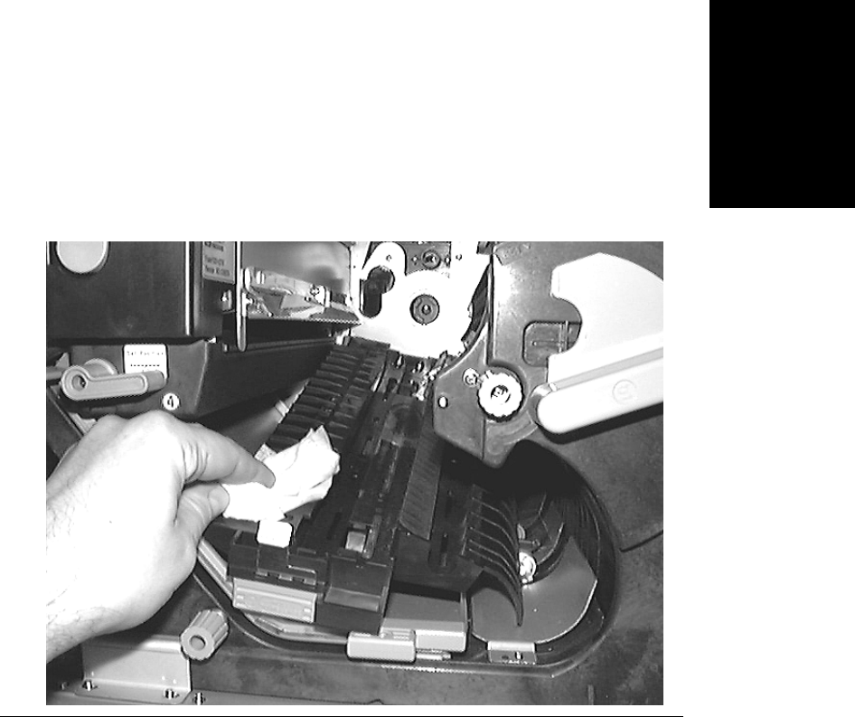
Periodic Cleaning (When Replacing Drum)
Maintenance 5-9
Maintenance
Transfer Assembly Guide
To clean the Transfer Assembly Guide:
1. Take out the drum unit (refer to “Removing the Drum” on page 4-21.)
2. Use the supplied cleaning cloths or vacuum cleaner to wipe up any toner or dust off the
outside of the transfer assembly guide. Clean all the way to the back of this guide. See
Figure 5-9.
Figure 5-9 Cleaning Transfer Assembly Guide
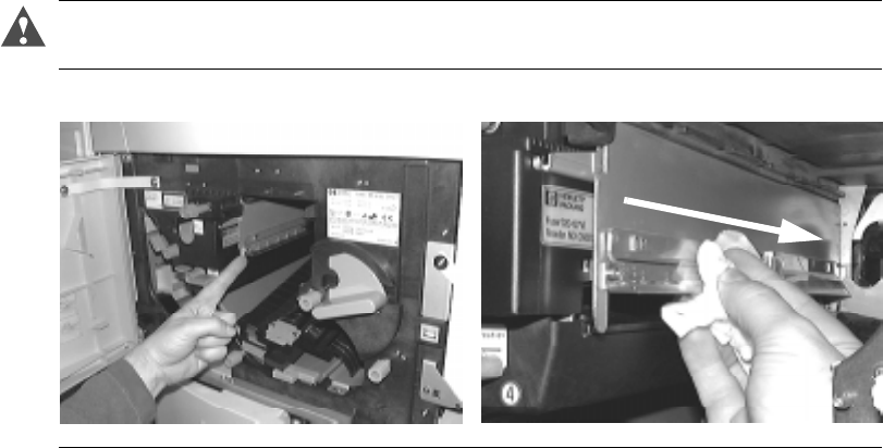
Periodic Cleaning (When Replacing Drum)
5-10 Maintenance
LED Array Area
To clean the LED Array:
1. Use the supplied cleaning cloths to wipe up any toner or dust off the outside of the LED
array. Clean all the way across the LED array. Figure 5-10 shows the LED array and
illustrates the cleaning procedure.
Caution Be careful to avoid contacting the developer unit roller on the right side of the area,
as this could damage the developer.
Figure 5-10 Cleaning LED Array
2. Install the new drum assembly, as described in “Drum Kit - Replacing Drum and
Transfer Assembly” on page 4-18.
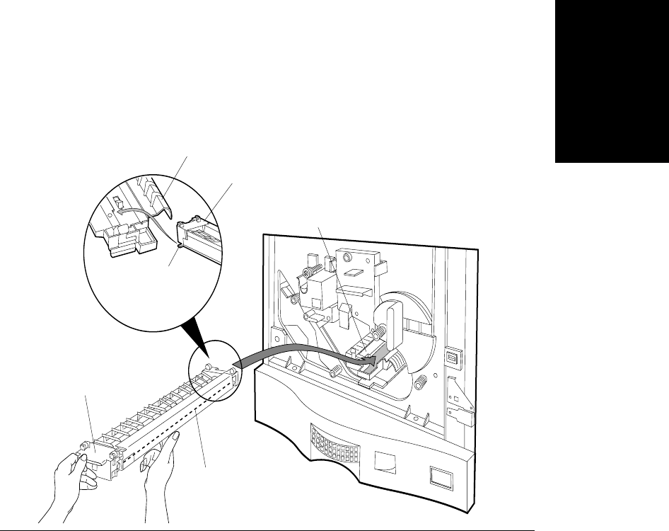
Periodic Cleaning (When Replacing Drum)
Maintenance 5-11
Maintenance
Reinstalling the Transfer Assembly
1. Using the alignment pin located on the end of the cleaned transfer assembly, insert the
alignment pin of the transfer assembly into the left rail of the transfer assembly guide
and push in to the end of the guide. See Figure 5-11.
Figure 5-11 Inserting the Transfer Assembly into the guide
Transfer assembly
Wire
Transfer assembly guide
LTR
Transfer assembly
Transfer assembly guide
Pin
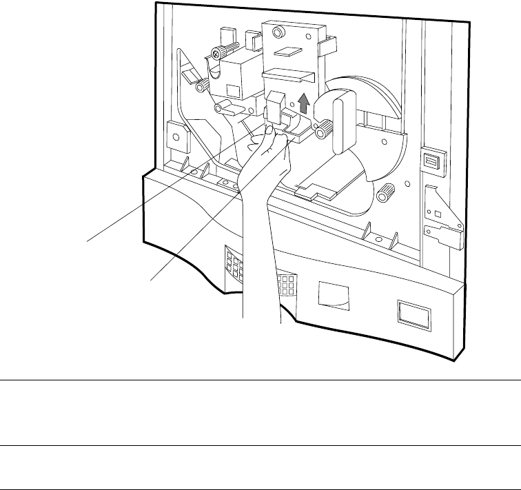
Periodic Cleaning (When Replacing Drum)
5-12 Maintenance
2. Secure the transfer assembly by lifting Handle 3, as shown in Figure 5-12.
Figure 5-12 Securing the Transfer Assembly
3. Close the front door.
Note If you have problems reinstalling the transfer assembly, check to see that the drum is
installed correctly.
Handle 3
Transfer assembly
guide
LTR

Advanced Topics 6-1
Advanced Topics
6
Advanced Topics
This chapter presents information about:
• Maintaining print quality
• Managing consumables
• Adjusting paper path alignment
• Setting up edge-to-edge printing
• Configuring for LaserJet compatibility
• Using virtual font cartridges
The topics in this chapter help you find new uses for the printer, manage your consumable
supplies, and maintain optimum print quality.
Maintaining Print Quality
In some situations, print quality can be very subjective, and in other situations, the problem is
very obvious. This section provides guidelines for making correct diagnosis of the problem to
minimize incorrect and needless repairs.
Visual print quality analysis assumes you have maintained the printer according to the required
maintenance procedures and schedule. Chapter 5 provides the printer maintenance schedule
and procedures.
This section provides print samples, starting with a good quality print. The rest of the print
samples are flawed. The consumables that may be responsible for the flaws are included with
each sample, along with recommended corrective actions.
Print Quality Troubleshooting
If you are dissatisfied with the quality of your prints:
1. Complete all of the weekly maintenance tasks (see “Weekly Cleaning” on page 5-1).
2. Clean your printer thoroughly (see “Periodic Cleaning (When Replacing Drum)” on
page 5-5).
3. Check the quality of your prints.
Maintaining Print Quality
6-2 Advanced Topics
If you are still dissatisfied with your print quality:
1. Print several test pages of your typical work output and compare the print quality to the
samples.
The print samples provided here are generic, that is, they show specific problems. Your
own print samples are typical of your printout problems and so you must compare prob-
lem effects and not the actual print pattern.
2. Generate test prints to compare with the quality samples. (See Appendix E for more
information.)
3. Identify a print quality sample included in this section that has the same flaws as your
print test.
4. Review and complete the actions listed under the print sample in the order in which they
are listed, generating a print after you complete each action.
5. Check the print’s quality; if the flaw or flaws are still present, continue to the next action
in the list. If the flaws are repaired, you do not have to complete the remaining actions.
If you complete all the recommended actions, including changing consumables, and the print
quality doesn’t improve, you may need to call your service representative to resolve the
problem. Refer to “Where To Call For Help” on page F-1 for the telephone number of your
nearest Hewlett-Packard service representative. Be prepared to give the service representative
the error code and any messages that appear on the Control Panel to assist in troubleshooting.
Print Quality Problems
When you have any print quality problems, check the following items before starting your
troubleshooting:
1. Check the Control Panel for any messages about consumables. If there is a “Consumable
at end life” message, replace the consumable and retest for print quality.
2. Check whether the paper being used meets Hewlett-Packard standards. (Refer to “Using
Paper” on page D-1.)
3. Check whether the paper is handled correctly (especially for creases or wrinkles).
4. Check whether the environment for the printer and the paper meets Hewlett-Packard
standards - especially for humidity. Refer to Table C-5, “Printer environmental
specifications”.
5. Check whether the rollers and the paper guides are clean (especially for scattered toner
or developer, accumulated paper powder and paper pieces).
6. Check the Economode setting; be sure it is OFF. (See “Economode” on page 2-17.)
7. Adjust the print density. (See “Density” on page 2-25.)
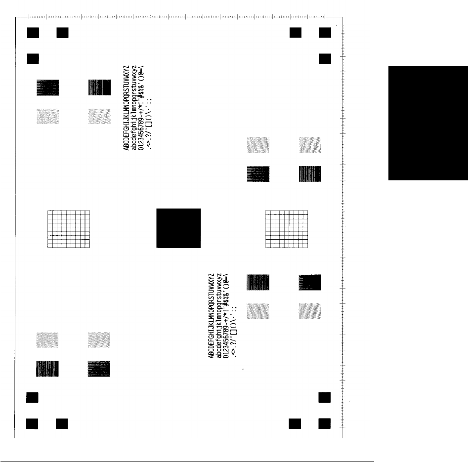
Maintaining Print Quality
Advanced Topics 6-3
Advanced Topics
Good Quality Print Sample
Figure 6-1 Good quality print sample
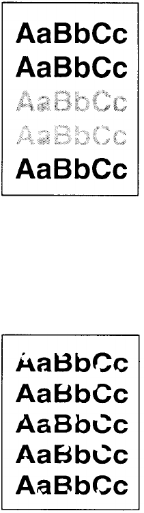
Maintaining Print Quality
6-4 Advanced Topics
Specific Print Quality Problems
All sample pages are shown in Letter size and portrait orientation. Similar problems may show
up on different paper edges, depending on the paper feed
Fading
If a white streak or a faded area appears on the page (in the
direction the paper passes through the printer):
• Check the Economode setting; be sure it is OFF. (See “Econo-
mode” on page 2-17.)
• The moisture content of the paper may be uneven, or there may
be moist spots on the paper. Print several dozen test pages with
paper from a newly-opened ream.
• The print density setting may be too light. Adjust the print den-
sity. (See “Density” on page 2-25.)
• Toner may be on the transfer charger or pre-charger corona
wires. Clean the printer’s transfer assembly unit and pre-
charger. (See “Transfer Assembly Guide” on page 5-9.)
• Replace the developer in the printer with new developer. (See
“Replacing Developer” on page 4-9.)
• Replace the drum unit with a new one. (See “Drum Kit -
Replacing Drum and Transfer Assembly” on page 4-18.)
• If you still have this print quality problem, contact your autho-
rized HP service representative.
Dropouts
If faded areas, generally rounded, occur randomly on the page:
• The moisture content of the paper may be uneven, or there may
be moist spots on the paper. Print several dozen test pages with
paper from a newly-opened ream.
• The paper lot is bad. The manufacturing process can cause
some areas to reject toner. Try paper from a different source.
• Clean the paper feed path and LED array as described in
“Weekly Cleaning” on page 5-1 and “Periodic Cleaning
(When Replacing Drum)” on page 5-5.
• Replace the developer unit with a new one. (See “Replacing
Developer” on page 4-9.)
• If you still have this print quality problem, contact your autho-
rized HP service representative.
Maintaining Print Quality
Advanced Topics 6-5
Advanced Topics
Lines
If sharp or smeared black streaks appear on the page (in the
direction the paper passes through the printer):
• Toner may be on the transfer charger or pre-charger corona
wires. Clean the printer’s transfer assembly unit and pre-
charger. (See “Transfer Assembly Guide” on page 5-9.)
• Replace the drum unit with a new one. (See “Drum Kit -
Replacing Drum and Transfer Assembly” on page 4-18.)
• If you still have this print quality problem, contact your autho-
rized HP service representative.
Toner Smear
If toner smears appear on the leading edge (as is passes through
the printer) of the paper:
• Toner may be loose inside the printer’s paper path. Clean the
printer by following the instructions in “Periodic Cleaning
(When Replacing Drum)” on page 5-5.
• Replace the drum unit with a new one. (See “Drum Kit -
Replacing Drum and Transfer Assembly” on page 4-18.)
• If you still have this print quality problem, contact your autho-
rized HP service representative.
Background Gray Toner Shading
If the amount of background toner shading becomes unacceptable:
• The print density setting may be too high. Adjust the print den-
sity (See “Density” on page 2-25.)
• Toner may be on the transfer charger or pre-charger corona
wires. Clean the printer’s transfer assembly unit and pre-
charger. (See “Transfer Assembly - Transfer LED Areas” on
page 5-6.)
• Change the paper to a lighter basis weight.
• Check the printer’s environment; very humid conditions can
increase the amount of background shading.
• Replace old developer with fresh developer. (See “Replacing
Developer” on page 4-9.)
• Replace the drum unit with a new one. (See “Drum Kit -
Replacing Drum and Transfer Assembly” on page 4-18.)
• If you still have this print quality problem, contact your autho-
rized HP service representative.
Managing Consumables
6-6 Advanced Topics
Repetitive Defects
Repetitive marks appear repeatedly on the printed side of the
page.
• Replace the drum unit in the printer with a new drum unit. (See
“Drum Kit - Replacing Drum and Transfer Assembly” on
page 4-18.)
• Replace the fuser unit in the printer with a new fuser unit. (See
“Fuser Kit - Replacing the Fuser” on page 4-29.)
• If you are still having this print quality problem, contact your
authorized HP service representative.
Managing Consumables
Use the following checklist to identify actions you can take to maximize consumable yields.
Further detailed information is provided later in this section.
1. Keep the printer clean. Follow all the maintenance procedures listed in Chapter 5.
Accumulations of toner and paper dust affect the yields of all consumables.
2. Use high-quality media. Factors such as paper chemicals or scratches from unsupported
media can damage the drum and fuser. See Appendix A for a description of supported
media.
3. Handle all consumables and print media with care. Protect the drum from light and
abrasion. Avoid dropping or rough handling of consumables after they are removed
from their cartons. Store the consumables and media in a clean, stable environment,
preferably at the same location or under the same environmental conditions as the
printer.
4. Use the toner management features discussed on page 6-7. The D640 printer supports
several features that maximize toner usage.
5. Monitor and, if possible, manage print job sizes. Single-page print jobs are the least
efficient for consumable usage. Longer, multiple-page jobs are more efficient.
6. Monitor and, if possible, manage the complexity of printed images. Images which are
too complex to print at rated speed (for example, a large, complex PostScript image)
reduce the life of the drum and developer. Also, printing repetitive images can wear the
fuser rollers unevenly.
7. Avoid frequent lapses into power save mode or frequent power cycling. The start-up
process uses some of the life of the drum and developer.
8. Avoid prolonged periods of inactivity with the power switched on. Hewlett-Packard
recommends you switch off printers that are inactive overnight if the power save feature
isn’t used.

Managing Consumables
Advanced Topics 6-7
Advanced Topics
Note The factory yield estimates for consumables are determined under operating
conditions which are intended to model a large sample of customer installations. However, it is
impossible to model every operating environment, and as result some installations may
experience lower consumable yields than expected. Keep a log of actual consumable usage for
each printer. This provides the most accurate data to plan consumable purchases.
Toner
Toner yields are primarily driven by the quantity of toner applied to each page. Large black
areas, graphic images, gray backgrounds and forms outlines use more toner. If you print
mostly or only a small amount of text, you will probably reach or exceed the estimated yield.
Toner yield estimates are based on 4% toner coverage. This is a standard value used by the
printer industry, which is based on the assumption that the "typical" A4 or letter-size business
letter is 4% covered by black area.
The D640 offers a number of features that, with some trade-offs, can extend toner yield.
Density
The density value is factory set to 10, approximately in the middle of its range. The density
value can be set as low as 1 to reduce toner consumption. To the naked eye, solid area patterns
will not appear any lighter under lower settings. Reducing the density will have the largest
visual effect on gray scale patterns or the small text characters.
Experiment to see if a lower density value can satisfy your print quality requirements. Actual
toner savings will vary based on the types of images printed. The density setting can be found
under the Maintenance Menu, described in “Density” on page 2-25.
Economode
Most printers simply print a lighter pattern when an economode setting is used. However, the
D640 does not lighten the entire image. Instead, dots are turned off in strategic areas to reduce
toner use while maintaining readability. When printing text in economode, the character
outline is perfectly formed, while the inside uses fewer dots. The effects are nearly invisible to
the naked eye at a 10 point character size, but may be more readily seen on large characters.
Experiment to see if economode can be used for some, if not all of your printing. Large text-
only reports may be able to use economode with no perceptible reduction in print quality.
Economode can reduce toner consumption as much as 50%, depending on the printing pattern.
The Economode setting can be found under the Configuration Menu, described in
“Economode” on page 2-17.
Managing Consumables
6-8 Advanced Topics
Recycling
Printers that user powdered toner generally only transfer about 70 to 80% of the toner used for
a page image to the paper. The remaining 20 to 30% is known as waste toner because in most
printers it is thrown away. In a printer that uses a toner cartridge, the waste toner is never seen
because it is moved to a waste area inside the print cartridge.
The D640 printer is unique in the industry, providing the choice of recycling the waste toner or
throwing it away. As the printer ships from the factory, the toner recycling mode is disabled
and waste toner collects in a bottle. You remove and throw out this bottle each time you add a
new bottle of toner. With toner recycling enabled, the waste toner is funneled back into the
toner hopper and gradually mixed with new toner.
The disadvantage to recycling toner is a possible slight reduction in print quality. Print may
appear lighter and small voids may be visible in dark images. In most text applications, you
will probably not notice any reduced print quality with recycling on. If your application
requires the best possible print quality, do not use toner recycling.
Unlike Density and Economode, the effects of toner recycling are not immediately noticeable
when you stop recycling. The waste toner must be completely flushed from the toner path.
Depending on how long the recycling feature was used, it might take up to five bottles of new
toner before the waste toner is completely flushed from the system.
Toner Recycling Switch
Toner recycling is enabled or disabled by moving the plastic slide switch located directly over
the toner collector bottle. When it is pushed to the right, toner is recycled. When it is pushed to
the left, waste toner collects in the toner collector bottle for disposal. Figure 6-2 shows the
bottle and switch location.
Managing Consumables
Advanced Topics 6-9
Advanced Topics
Figure 6-2 Toner Recycling Slide Switch
Drum and Developer
The drum and developer are grouped together because their yields depend on drum rotations.
There is physical wear on the drum and developer mixture with every rotation of the drum.
The drum is often rotating even when the printer is not printing. Factory yield estimates for the
drum and developer, listed on the data sheet and in this manual, can never be accurate because
there is not a one-to-one correspondence between drum rotations and printed pages. However,
the internal counters in the printer do count drum rotations for both the drum and developer.
The drum life is estimated at 250,000 drum rotations and the developer life is estimated at
160,000 drum rotations.
The drum rotates during power up, at the start and end of each job, and while printing each
image. Knowing what factors drive drum rotations helps you understand what determines the
lives of your drum and developer.
Frequent power cycling or lapses into power save mode add wear to the drum and developer.
During power-up or coming out of power save mode, the drum rotates for up to two minutes.
This can produce as many as 80 drum rotations even though no pages are printed.
Toner Recycle Slide
Managing Consumables
6-10 Advanced Topics
The average number of pages in print jobs has a large effect on drum and developer life. Extra
drum rotations occur at the start and end of each job. There are four rotations at the beginning
and four rotations at the end. If the D640 primarily prints very small jobs (less than 25 pages),
you get lower than rated yields on the drum and developer. If you primarily print jobs larger
than 25 pages, you get higher than expected yields.
There is also a negative effect on drum rotations if you print complex images that slow the
printer down. If the printer controller cannot process the incoming data fast enough to keep the
printer running at 40 pages per minute, extra drum rotations occur for the print job.
The estimated yields for the drum and developer assume a job size of 25 page sides per job. It
is not important if you occasionally print small jobs or complex images; it’s important how
your print environment averages usage over a long period of time.
The drum surface is easily damaged by scratches, long exposure to fluorescent light (30
minutes), or exposure to direct sunlight (which may cause gray background shading). The
estimated yields do not account for replacement due to these factors.
Scratches can occur from unsupported media and may be significant enough to require the
drum to be replaced prior to the printer indicating the drum has reached its end of life.
Paper which emits certain chemicals or large amounts of paper dust can cause excessive drum
wear. If you this problem, contact your service representative or the paper manufacturer.
Fuser
The fuser yield is controlled by the number of times a letter or A4 sheet of paper passes
through it. The printer maintains a counter which increments based on the size of paper used.
Factors which may reduce fuser life can be related to printing repetitious images, media
problems or not replacing the cleaning roller when necessary.
Hewlett-Packard recommends mixing up the types and positions of print images printed
among print jobs. Fuser rollers can wear unevenly when a dark image, such as a company logo
or a thick dark line, is printed repeatedly in the same position on every page of every print job.
Media can also have an effect on fuser life. Paper which emits certain chemicals or large
amounts of paper dust can cause excessive wear. If you suspect problems of this sort, contact
your service representative or the paper manufacturer.
For optimum fuser life, replace the cleaning roller after every other bottle of toner, and follow
the recommended cleaning procedures in “Duplex Area” on page 5-6. The cleaning roller
deposits silicon oil onto the fuser roller surface to prevent toner from sticking. It also cleans
away small amounts of toner that adhere to the fuser roller surface. Failure to replace the
cleaning roller at the specified times can greatly reduce fuser yields.

Adjusting Paper Path Alignment
Advanced Topics 6-11
Advanced Topics
Ozone Filter
The ozone filter is replaced after every two bottles of developer. If replaced as specified, you
should always receive the specified yield.
Transfer Unit
The transfer unit is replaced whenever the drum is replaced. Care must be taken to prevent
accidental breakage of the delicate wires located inside the transfer unit. Unless physically
damaged, you will always receive the specified yield.
Pushing Consumable Life Beyond Estimated Yields
The printer maintains counters to track all consumable use and provides an alert message to
inform you when a consumable item needs to be replaced. The printer will not stop, except
for lack of toner or developer, but the message remains until you replace the specified
consumable. There is a built-in "grace period", so the message to replace a consumable
should occur long before you see any print quality or paper jam problems.
When you get a "Toner Low" or "Developer end-life" message, it is best to add toner or
developer as soon as possible. If toner runs out completely, or the developer reaches its end-
life, the printer stops printing to prevent damage to the print engine.
Toner and developer are the only consumables for which the printer physically stops. If you
have a carefully monitored environment, you can watch the print quality and change the
consumables (other than toner and developer) only when absolutely necessary. This tactic may
further extend the replacement cycles of your consumables at your own risk.
Adjusting Paper Path Alignment
Over time, the paper path alignment may change slightly from the factory-set position. The
following paper path alignment procedure will set the printing alignment for each tray to
ensure correct print position. This procedure looks complicated, but after you have performed
it a once or twice, it should only take a few minutes to complete. It may need to be repeated
periodically to ensure proper alignment, but if you only print on blank paper, alignment is
usually not critical.
This procedure sets alignment for both simplex and duplex pages. If you have an HCI installed,
you can also set alignment for it.
Before proceeding, make sure that there is adequate (20 - 30 sheets) paper in each tray and the
HCI (if installed). This amount is necessary for accurate feeding.
Note Please read through the entire procedure before performing any of the
steps.
Adjusting Paper Path Alignment
6-12 Advanced Topics
This procedure includes the following tasks:
• Printing alignment sheets. When you run the alignment program from the printer’s hard
drive, the printer produces a set of alignment pages.
• Measuring alignment. By measuring the current alignment for each tray against a
reference standard, you simply add two numbers to determine new alignment values.
• Setting alignment values. Once you have determined new values, enter them in the
Control Panel and recheck the alignment.
Printing Alignment Sheets
1. Verify that all three paper trays and the HCI (if installed) have Letter (or A4) size paper.
2. Press the Test button on the Main Screen, shown in Figure 6-3.
Figure 6-3 Main Screen
3. Use N to scroll down and highlight filesC, as shown in Figure 6-4, and press Select.
Figure 6-4 Test Submenu
Ready - - free
JUN 18 05:32.23
PCL
Offline
Offline
Custom Menu Test PapSize
LTR LTR
LTR
LTR
Online
600dpi
Online
Test
Online Select
filesA
filesC
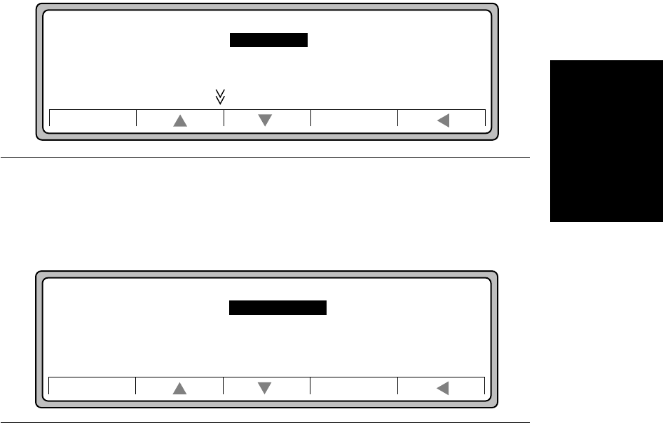
Adjusting Paper Path Alignment
Advanced Topics 6-13
Advanced Topics
4. From the filesC submenu shown in Figure 6-5, use N to highlight USER_ADJ, then
press Select.
Figure 6-5 FilesC submenu
5. Use N to highlight ALIGNSET.*, then press Select.
The last two numbers refer to the program version number, which may be different from
the version number shown in these illustrations. See Figure 6-6.
Figure 6-6 ALIGNSET.12
Online
C:\
Online Select
dir
USER_ADJ\
PCLS\
PS\
MAINT\
FONTS\
Online
C:\USER_ADJ\
Online Select
dir
ALIGNSET.12
Adjusting Paper Path Alignment
6-14 Advanced Topics
6. The number 1 will appear in front of the ALIGNSET.* message, as shown in
Figure 6-7.
Figure 6-7 1 ALIGNSET.*
7. Press Online.
Note After pressing Online, there will be a few seconds delay as the printer loads the
program.
The printer then produces six sheets:
•a Simplex feed alignment ruler sheet. See Figure 6-8.
• a set of alignment sheets, one from each tray (and the HCI if it is installed.)
See Figure 6-9.
•a Duplex unit alignment ruler sheet, which measures the duplex sideways and lengthwise
alignment values (duplexv means "duplex vertical") See Figure 6-12.
The Simplex feed alignment ruler sheet contains:
• instructions for the alignment procedure
• a reference scale to measure the alignment sheets
• a workspace to calculate alignment values and adjustments
When the printer has finished printing these pages, you are ready to begin measuring the
alignment pages.
Online
C:\USER_ADJ\
Online Select
dir
1 ALIGNSET.12
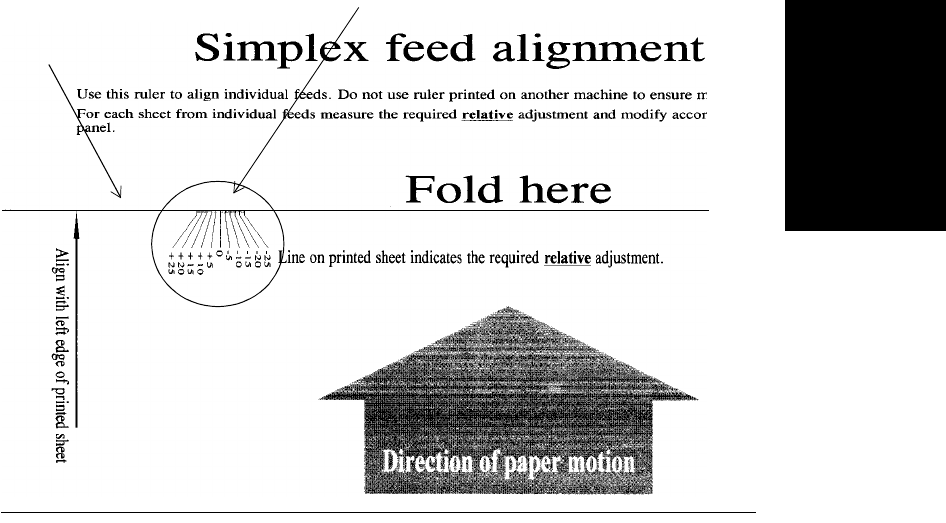
Adjusting Paper Path Alignment
Advanced Topics 6-15
Advanced Topics
Measuring Alignment
You will now read the adjustment values.
1. Carefully and accurately, fold the top part of the Simplex feed alignment ruler sheet,
shown in Figure 6-8.
Figure 6-8 Simplex Feed Alignment Ruler Sheet
Adjustment scale
Fold line
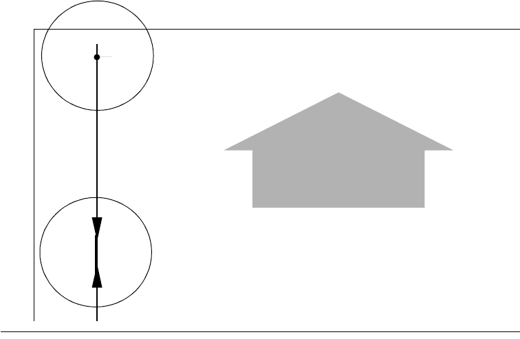
Adjusting Paper Path Alignment
6-16 Advanced Topics
2. On the alignment sheet for tray 1, shown in Figure 6-9, locate the Feed 1 alignment
indicator line.
3. Place the simplex feed alignment ruler sheet adjustment scale between the ends of the
arrows (at "measure between these two arrows", shown in Figure 6-9).
Figure 6-9 Sample Alignment Sheet for Tray1
Measure between these two arrows
Feed alignment indicator line
Direction of paper motion
Feed 1: Upper tray
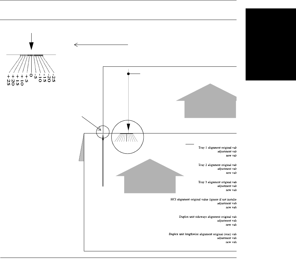
Adjusting Paper Path Alignment
Advanced Topics 6-17
Advanced Topics
4. Position the line labeled "Align with left edge of printed sheet" against the left edge of
the alignment sheet for tray 1. Figure 6-10 shows how the two sheets should look when
properly positioned.
5. The arrow printed on the alignment sheet for tray 1 will intersect the simplex feed
alignment ruler sheet scale at some value, as shown in the illustration.
Note Make sure that the tip of the arrow is on the exact edge of the paper. If it is not, your
measurement may be inaccurate.
Figure 6-10 Measuring alignment with alignment scale
Feed alignment indicator line
Measure between these two arrows
0
+5
+10
+15
+20
+25
-5
-10
-15
-20
-25
Line on printed sheet indicates the required relative adjustment.
Align with left edge of printed sheet
Direction of paper motion
Feed 1: Upper tray
Direction of paper motion
Place edge here
Read measurement here
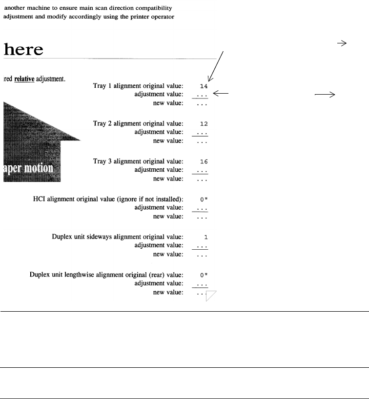
Adjusting Paper Path Alignment
6-18 Advanced Topics
6. Record this value in the adjustment value area for tray 1 on the simplex feed alignment
ruler sheet. See Figure 6-11.
Figure 6-11 Original alignment value and adjustment value
7. Repeat steps 2 through 4 with the alignment sheets for trays 2, 3, and the HCI (if
installed).
Note The printer still prints a sheet for the HCI even if no HCI is present. Simply ignore this
page if you don’t have an HCI connected and paper installed in it.
8. Now read the values for duplex pages as directed in the next section.
Write in adjustment
value from line
measurement
Original alignment value
currently in printer
-5
Example
14
-5
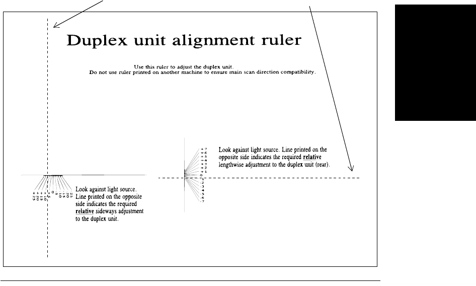
Adjusting Paper Path Alignment
Advanced Topics 6-19
Advanced Topics
Duplex (Double-Sided) Printing Alignment
Figure 6-12 illustrates the Duplex unit alignment ruler sheet, which provides a way to measure
the alignment between the printed image on the front and back sides of a double-sided page.
Figure 6-12 Duplex Unit Alignment Ruler Sheet
1. On the duplex unit alignment ruler sheet, review each side of the paper. View through
the paper: hold the paper up to a bright light with the side with the alignment scale
facing towards you.
2. The sideways indicator line runs up and down the back of the page on the left. Look for
the indicator line and note where it crosses the scale on the left. Record this value on
sheet 1 at Duplex unit sideways alignment adjustment value.
3. The lengthwise indicator line runs across the back of the page. Look for the indicator
line and note where it crosses the scale in the middle of the page. Record this value on
sheet 1 at Duplex unit lengthwise alignment adjustment value.
Lines printed on back side of sheet
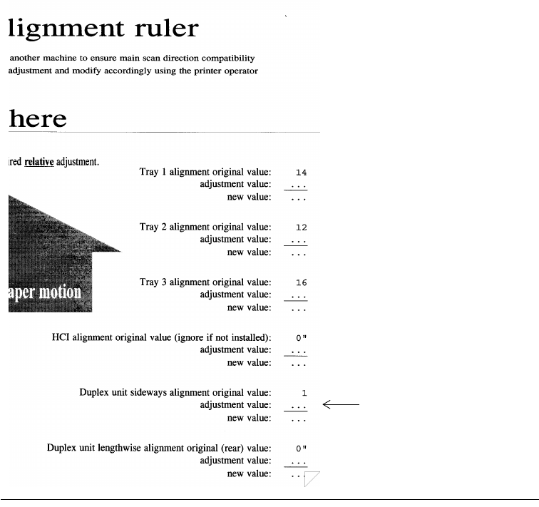
Adjusting Paper Path Alignment
6-20 Advanced Topics
Setting Alignment Values
You will now calculate and enter the new alignment values into the Control Panel.
1. Calculate the new values.
2. For each adjustment value, add the two numbers and write the new value, as shown in
Figure 6-13. If the adjustment value you read off the sheet was 0, no new setting is
required for that tray.
Figure 6-13 Adjustment values entered into work sheet
-6
+3
-2
-2
0No adjustment necessary
+1
-2
+7
+7
+14
+8
+15
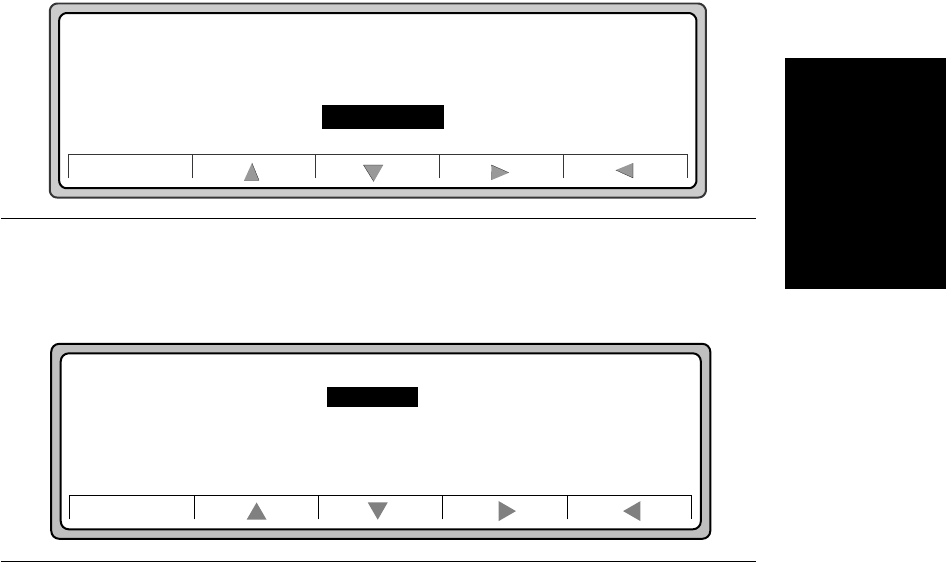
Adjusting Paper Path Alignment
Advanced Topics 6-21
Advanced Topics
Once you calculate the new value, enter it in the Control Panel as follows:
3. Press Menu on the Main Screen (see Figure 6-3).
4. Use N to highlight Maintenance, as shown in Figure 6-14, and press P.
Figure 6-14 Menu
5. From the Maintenance submenu shown in Figure 6-15, use N to highlight alignment and
press P.
Figure 6-15 Maintenance submenu
Online
Menu
Online
Printing
Configuration
PCL
Comms
Maintenance
Online
Maintenance
Online
replace
alignment
density
testpages
monitor
date-time
= 10
= 30
= OFF
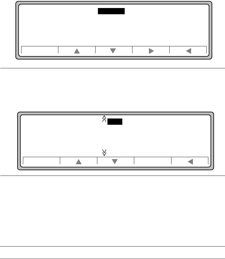
Adjusting Paper Path Alignment
6-22 Advanced Topics
6. Select tray1 and press P. This is the Maintenance.alignment screen, shown in
Figure 6-16.
Figure 6-16 Maintenance.alignment Tray1 setting
7. Press either M or N to highlight the tray1 new value calculated on the Simplex feed
alignment ruler sheet. The selection range is from -25 to +25, (except for duplex
lengthwise, which is +7 to -7). See Figure 6-17.
Figure 6-17 Tray1 values
8. Press Select to save the new value and to return to the Maintenance.alignment submenu.
9. Repeat steps 1 through 4 for trays 2, 3, HCI, duplex (duplex sideways), and duplexv
(duplex lengthwise).
10. Verify your alignment by repeating the procedure in “Printing Alignment Sheets” on
page 6-12. If the alignment is still off (plus or minus 3 to 4 increments or more), note
the adjustment values as you did in the previous alignment procedure, and set the new
adjustment values in the Control Panel.
Note A 1 or 2 increment variation may remain after alignment; this is normal.
Online
Maintenance.alignment
Online
tray1
tray2
tray3
duplex
duplexv
= 5
= 6
= 5
= -6
= -7
Online
Maintenance.alignment.tray1 =
Online Select
5
6
7
8
9
10
Setting Up Edge-to-Edge Printing
Advanced Topics 6-23
Advanced Topics
Setting Up Edge-to-Edge Printing
The D640 printer ordinarily enforces a 1/6" unprintable area around the edge of any page. This
is the factory default and produces the best looking output. There may be some cases where
you don’t want this border. The D640 supports edge-to-edge printing, which allows you to
extend printing to the edge of the physical page.
Note The print quality is not consistent within 1/6" of any edge. This is especially true for
the trailing edge of the second side in duplex printing. For this reason, Hewlett-Packard cannot
guarantee print quality within this 1/6" area. Your Hewlett-Packard warranty and service
contract does not cover service calls related to printing within this 1/6" area.
The quality and squareness of the paper determine print quality when printing close to the
physical paper edge. In general, you may experience degraded print quality within .25 inches
of any paper edge. When printing in duplex you may need to compensate for shrinkage and
curl that may occur when the first side is printed. Lighter weight and recycled papers tend to
shrink more then heavier weight papers.
If you define text to start printing at location 0,0 it will print outside the logical page. This may
or may not be on the physical page. Figure 6-18 describes the physical and logical page
formats.
Figure 6-18 Physical and Logical Page formats
Configuring for LaserJet IIIsi and 4si Compatibility
6-24 Advanced Topics
Configuring for LaserJet IIIsi and 4si Compatibility
The D640 printer is unique and different from the Hewlett-Packard LaserJet family of printers
in general, and from the LaserJet "si" series in particular. While these two printer families
share the same printer language (PCL and PJL), there are a number of physical differences to
their hardware.
We have included features in the D640 printer to make it behave like a LaserJet 4si, so your
print jobs turn out like you expect. In many instances these features also provide compatibility
with the LaserJet IIIsi and/or 5si.
This section covers the compatibility features associated with PCL commands.
Paper Input
The D640 has three paper input trays, while the LaserJet 4si has two. The LaserJet5si has
three.
HCI selection compatibility is provided through the HCI-Alias Control Panel setting. HCI-
Alias enables paper selection compatibility between a LaserJet IIIsi or 4si with an HCI and a
D640 with an HCI. You can also set HCI-Alias = HCI to pick paper from tray1, tray2, tray3, or
the HCI in response to the PCL commands shown in Table -6-1, “Paper tray map for HCI-
Alias = HCI”.
Example Configuration
LaserJet IIIsi / 4si
• UPPER TRAY contains paper for job separation.
• HCI TRAY contains white paper.
- This configuration provides 500 sheets in the upper tray and 1500 sheets in the HCI
tray. To match this configuration on the D640, set up the D640 as follows:
• TRAY1 contains paper for job separation.
• HCI contains white paper.
• Set HCI-Alias = tray2.
- This configuration provides 500 sheets in tray1 and 3000 sheets in the HCI. You could
also load paper for job separation in tray2 and tray3 to increase capacity to 1500 sheets.

Configuring for LaserJet IIIsi and 4si Compatibility
Advanced Topics 6-25
Advanced Topics
If HCI-Alias is set to HCI, the values shown below in Table -6-1, “Paper tray map for HCI-
Alias = HCI” are correct. If HCI-Alias is set to tray2, then you can send a job to either a 4si or
a D640.
Table 6-1 Paper tray map for HCI-Alias = HCI
You can also set the default paper tray (used if there is no paper size or paper source command
embedded in the print job) from the Control Panel. Use the intray setting in the Printing Menu.
Using the LaserJet 5Si Driver
The D640 printer can be used with a LaserJet 5Si printer driver, but there are many differences.
For example:
• The input tray selection is different. See Table 6-1 above.
• The D640 printer does not support media type selection.
• The LaserJet 5Si does not support font cartridges.
IIIsi, 4si D640 5si
upper tray upper tray (tray1) upper drawer (tray2)
lower tray middle tray (tray2) lower drawer (tray3)
n/a High Capacity Input High Capacity Input
n/a lower drawer (tray3) fold out tray (tray1)

Using Virtual Font Cartridges
6-26 Advanced Topics
Using Virtual Font Cartridges
Each of the D640 internal fonts is almost identical to those used in the LaserJet 4si. Some
typefaces, treatments, and symbol sets are slightly different, due to advances in font
technology since the development of the 4si. For example, if you print a very large question
mark on each machine, you may notice differences in the shape.
All of the font sets from all of the 4si font cartridges sold by Hewlett-Packard are stored on the
D640’s internal hard disk drive as virtual font cartridges. You select the virtual font cartridge
by the Control Panel vcartridge1 and vcartridge2 settings (see “Virtual Font Cartridges” on
page 2-20). The font names are comparable to the actual physical cartridge.
Table 6-2 Virtual Font Cartridges
Typeface and Treatment IIISi 4si C40D D640
Line Printer Med. bitmap bitmap bitmap bitmap
Courier Med., Italic, Bold, Bold Italic bitmap Intellifont Intellifont Intellifont
Letter Gothic Med., Italic, Bold nr Intellifont Intellifont Intellifont
Arial Med., Italic, Bold, Bold Italic nr TrueType TrueType TrueType
Symbol Med. nr TrueType TrueType TrueType
Times New Roman Med., Italic, Bold, Bold Italic nr TrueType TrueType TrueType
Wingdings Med. nr TrueType TrueType TrueType
Albertus ExtraBold nr Intellifont Intellifont Intellifont
Albertus Med. nr Intellifont Intellifont Intellifont
Antique Olive Med., Italic, Bold nr Intellifont Intellifont Intellifont
CG Omega Med., Italic, Bold, Bold Italic nr Intellifont Intellifont Intellifont
CG Times Med., Italic, Bold, Bold Italic Intellifont Intellifont Intellifont Intellifont
Clarendon Condensed Bold nr Intellifont Intellifont Intellifont
Coronet nr Intellifont Intellifont Intellifont
Garamond Antiqua nr Intellifont Intellifont Intellifont
Garamond Halbfett nr Intellifont Intellifont Intellifont
Garamond Kursiv nr Intellifont Intellifont Intellifont
Garamond Kursiv Halbfett nr Intellifont Intellifont Intellifont
Marigold. nr Intellifont Intellifont Intellifont
Univers Condensed Med., Italic, Bold, Bold Italic Intellifont Intellifont Intellifont Intellifont
Univers Med., Italic, Bold, Bold Italic Intellifont Intellifont Intellifont Intellifont
ITC Zapf Dingbats Intellifont nr nr nr1
1. ITC Zapf Dingbats are available on the D640 Decorative Words I built-in cartridge.

Printer Messages A-1
Print Messages
A
Printer Messages
Printer Initialization Failure
In the unlikely event that the printer does not start correctly, follow these steps:
1. The printer may self-diagnose the problem and display the message as shown in Figure
A-2, on page A-2.
2. Write down the error code and message that appears on the Control Panel.
3. Refer to “Call Engineer error messages and codes” on page A-9 to determine the mean-
ing of the error code.
4. If the error code calls attention to a specific physical component or location on the
printer, check the area specified and correct the problem. If you can, print a test pattern,
described in “Maintaining Print Quality” on page 6-1.
5. If you cannot resolve the problem, call your service representative, or refer to “Where
To Call For Help” on page F-1 for the telephone number of your nearest
Hewlett-Packard service representative. Be prepared to give the service representative
the error code and any messages that appear on the Control Panel to assist in trouble-
shooting.
Printer Reset
You can reset the printer without powering it off and on. This may be necessary if the printer is
stopped and the Control Panel does not respond.

Printer Messages
A-2 Printer Messages
To perform a printer reset, press function buttons 1, 3, and 5 (shown in Figure A-1 below) at
the same time and release them. If the display goes blank and then returns in a few seconds, the
reset worked. If the display does not go blank, then power off the printer by moving the main
power switch to the OFF position. Wait 20 seconds and power the printer on. See “Powering
On the Printer” on page 1-18 and Figure 1-10.
Figure A-1 Press buttons to reset
Printer Messages
This appendix provides information about messages displayed on the printer’s Control Panel.
There are several types of messages:
•Status messages are reports about what the printer is doing and do not require any action.
Table A-1 lists these messages.
•Warning messages notify you when the life of a consumable is nearly over. Replace the
consumable when convenient. Table A-2 lists these messages and directs you to the
replacement procedure in this manual.
•Paper jam messages occur when paper jams while moving along the printer’s paper path.
Table A-3 lists these messages and directs you to the paper jam removal section in this
manual.
•Error messages indicate conditions that stop or prevent printing until the error is
corrected. Table A-4 lists these messages and directs you to the replacement procedure in
this manual.
•Call Engineer error messages indicate conditions that may require a service representative
to resolve. In some cases, you may be able to resolve these problems yourself, so refer to
Table A-5 to interpret these error messages. This table includes corrective actions for each
message.
135

Status Messages
Printer Messages A-3
Print Messages
Status Messages
The following is a list of normal status messages that will appear from time to time as you use
the D640. These messages provide status only and do not require any action by the operator.
The intention of these messages is to provide current printer status.
Table A-1 Status messages
Message Explanation
Printer Initializing The printer is performing self-diagnostics.
Printer warming up The printer is heating the fuser unit for operation.
Ready -- free The printer is powered on and ready to use. No data has been received
by the printer yet.
Ready -- printing The printer is currently feeding paper and physically imprinting the
image on the paper.
Ready -- waiting The printer has received partial data and is waiting for the host send
additional data.
Ready -- imaging The printer has received data and is building the page image.
Ready -- processing The printer is receiving data from the host.
Error mask on The printer is operating with an error condition disabled. This can only
be set or reset by your service representative.
Menu Locked The menu has either been locked from a print job or the printer is
processing a job and menu changes cannot be made.
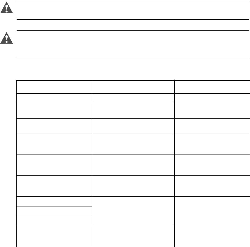
Warning Messages
A-4 Printer Messages
Warning Messages
The following warning messages indicate conditions that require operator intervention, such as
when the output tray fills up with paper, or when a particular consumable has reached the end
of its life. The "end life" message remains until you replace the consumable. Always replace
the consumable as soon as possible to maintain the best print quality.
Caution If you ignore the "Toner low" message, eventually the printer will shut down with
the "Toner empty" message to prevent mechanical damage.
Caution If you ignore the "Developer end-life" message, eventually the printer will shut
down with the "Developer end-life/Change developer at once" message to prevent mechanical
damage.
Table A-2 Warning messages
Message Explanation Action
Output tray full The printer’s output tray is full. Remove paper from tray.
Paper-size mismatch The requested paper size is not
available. Load correct paper size.
Toner low The supply of toner in the toner
hopper is low. Add toner. See “Replacing
Developer” on page 4-9.
Developer end-life The developer has reached the end
of its useful life and needs
replacement.
Replace developer. See
“Discharging Developer” on
page 4-9.
Drum end-life
(drum area blinks) The drum has reached the end of
its useful life and needs
replacement.
See “Drum Kit - Replacing Drum
and Transfer Assembly” on
page 4-18.
Fuser end-life
(fuser area blinks) The fuser has reached the end of
its useful life and needs
replacement.
See “Removing the Fuser” on
page 4-30.
Tray 1 rollers end-life The indicated pick roller has
reached the end of its useful life
and needs replacement.
See “Printer Pick Roller Kit -
Replacing the Tray Pick Rollers”
on page 4-33.
Tray 2 rollers end-life
Tray 3 rollers end-life
HCI rollers end-life The HCI pick rollers have reached
the end of its useful life and need
replacement.
See “HCI Pick Roller Kit -
Replacing the HCI Pick Rollers”
on page 4-42.
Paper Jam Messages
Printer Messages A-5
Print Messages
Paper Jam Messages
Paper jam messages appear when there is a problem moving paper through the printer. One or
more sheets of paper may be jammed. Refer to the Control Panel’s indication of the jam
location and check Table A-3 below. If the jam message does not go away after removing the
jammed paper, check the area again for stray paper fragments, and check the Control Panel.
There may be more paper jammed at other locations in the paper path.
WARNING! When you remove jammed paper, avoid contact with the paper sensors in the
paper feed path. These small black plastic actuator levers are easily damaged.
Table A-3 Paper jams and their remedies
Paper Jam Messages Remedy Refer to
page
Loading Jams
TRAY1 pick error
TRAY2 pick error
TRAY3 pick error
Remove tray (1, 2, or 3), remove paper jam from paper entry
area and/or within the tray. page 3-24
Feed path jam 1 Open the front door, lower transfer assembly, rotate knob 1
counterclockwise and knob 2 clockwise to free paper,
remove jammed paper.
page 3-26
Feed path jam 2 Open the lower right cover, remove jammed paper. page 3-26
HCI jam 1 Open HCI, lower paper, remove jammed paper. page 3-32
HCI jam 2 Pull HCI away from printer, remove jammed paper. page 3-34
HCI jam 3 Pull HCI away from printer, remove jammed paper. page 3-34
HCI jam 4 Open the front door, lower transfer assembly, rotate knob 1
counterclockwise and knob 2 clockwise to free paper,
remove jammed paper.
page 3-26
Paper Path Jams
Fusing unit jam 1
Fusing unit jam 2 Open the front door, lower transfer assembly, open lever 4,
push decurler lever down, remove jammed paper to right. page 3-36
Duplex path jam 1
Duplex path jam 2 Open the front door, raise lever 6, and remove jammed
paper. You may need to turn duplex roller knob to release
the paper.
page 3-38
Print unit path jam (Reversing unit area jam)
Open the front door, open lever 4, hold lever 5 away from
the fuser, and remove jammed paper. You may need to turn
duplex roller knob to release the paper.
page 3-40

Paper Jam Messages
A-6 Printer Messages
Paper Ejection Jams
Ejection unit jam 1
Ejection unit jam 2 Raise the paper ejection cover and remove jammed paper. page 3-43
HCO jam 1
HCO jam 2 Open the HCO door, rotate roller knob 1 to free paper, then
lift levers to remove paper. page 3-45
Paper Jam Messages Remedy Refer to
page

Error Messages
Printer Messages A-7
Print Messages
Error Messages
When any of the following error messages appear on the first line of the display screen, the
printer suspends printing until the error is corrected.
Table A-4 Error messages
Message Explanation Action
Ejection unit cover open The ejection unit cover (on top
of the printer) is open or not
completely closed.
Close the ejection cover until it
clicks shut.
Front Door open The front door is open or not
completely closed. Close the front door until it latches.
Upper right cover open The upper right cover is open or
not completely closed. Close the upper right cover until it
latches.
Lower right cover open The lower right cover is open or
not completely closed. Close the lower right cover until it
latches.
HCI cover open The HCI door is open or not
completely closed. Close the HCI door until it latches.
Fuser interlock The fuser is not seated
properly. Remove and reinsert the fuser into
the printer. See “Removing the
Fuser” on page 4-30.
Drum unit interlock The drum is not seated
properly. Remove and reinsert the drum into
the printer. See “Removing the
Drum” on page 4-21.
Developer collector not in
(During developer replacement
only)
The developer collector bottle is
not seated properly or is
missing.
Remove and reinsert the developer
collector bottle into the printer. See
“Installing Developer Collector
Bottle” on page 4-16.
Toner empty The toner hopper is out of
toner. Refer to “Replacing Toner” on page
4-4 and install toner.
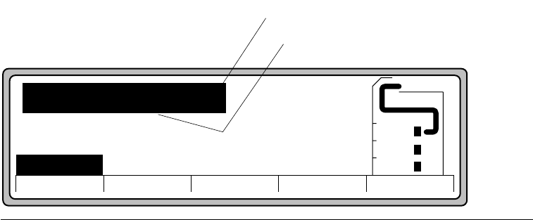
Call Engineer Error Messages and Codes
A-8 Printer Messages
Call Engineer Error Messages and Codes
Call Engineer error messages stop the printer and take it Offline. Some of these errors can be
corrected by the user, but most require a visit from your service representative.
Figure A-2 Call Engineer (Service Representative)
Before calling the service representative, follow these steps:
1. Try clearing the error by pressing Clear.
2. If the error condition persists, look up the error in “Call Engineer error messages and
codes” on page A-9 and follow the instructions.
3. If the error condition persists, power the printer off and on to clear the error.
4. If the error condition persists, call your local service representative.
Clear
Offline
Menu End
LTR
LTR
LTR
Offline
High-voltage power supply alarm
Call Engineer (SVC 6F)
PCL
Blinking
Error code

Call Engineer Error Messages and Codes
Printer Messages A-9
Print Messages
Table A-5 Call Engineer error messages and codes
Error
Message Code Description Action
Pick motor 1
alarm SVC 08 The upper tray’s pick motor
(tray 1) did not work correctly
and may need to be
replaced.
Try clearing the error by pressing Clear. If
the error condition persists, call your local
service representative.
Pick motor 2
alarm SVC 09 The middle tray’s pick motor
(tray 2) did not work correctly
and may need to be
replaced.
Try clearing the error by pressing Clear. If
the error condition persists, call your local
service representative
Pick motor 3
alarm SVC 0A The lower tray’s pick motor
(tray 3) did not work correctly
and may need to be
replaced.
Try clearing the error by pressing Clear. If
the error condition persists, call your local
service representative.
Switch-back
motor alarm SVC 0B The switch-back motor (just
left of the fuser) did not work
correctly and may need to be
replaced.
Try clearing the error by pressing Clear. If
the error condition persists, call your local
service representative.
Feed motor
alarm SVC 0D The feed motor (located on
the bottom) did not work
correctly and may need to be
replaced.
Try clearing the error by pressing Clear. If
the error condition persists, call your local
service representative.
Stacker select
alarm SVC 0E The solenoid switch in the
printer which controls paper
output going to the HCO did
not work correctly and may
need to be replaced.
Try clearing the error by pressing Clear. If
the error condition persists, call your local
service representative.
Duplex motor
alarm SVC 0F The duplex motor did not
work correctly and may need
to be replaced.
Try clearing the error by pressing Clear. If
the error condition persists, call your local
service representative.
Fuser alarm
(time-out) SVC 27 The fuser unit did not heat-up
to the normal fuser
temperature within the
allotted warm up time.
Confirm that the voltage rating on the fuser
matches the voltage rating of the printer.
Verify that the fuser unit is correctly
installed and that all printer doors and
covers are closed, then press Clear. If the
error message persists, refer to “Removing
the Fuser” on page 4-30 and replace the
fuser. If this error code returns, call your
service representative.
Fuser
temperature
high alarm
SVC 28 The fuser unit temperature is
above a normal level. Verify that the fuser unit is correctly
installed and that all printer doors and
covers are closed, then press Clear. If the
error message persists, refer to “Removing
the Fuser” on page 4-30 and replace the
fuser. If this error code returns, call your
service representative.

Call Engineer Error Messages and Codes
A-10 Printer Messages
Fuser
temperature
low alarm
SVC 29 The fuser unit temperature is
below a normal level. Verify that the fuser unit is correctly
installed and that all printer doors and
covers are closed. Press returns, call from
the front panel. If the error message
persists, refer to “Removing the Fuser” on
page 4-30 and replace the fuser. If this error
code returns, call your service
representative.
Toner motor
alarm SVC 50 The motor which drops toner
into the printer is not working
correctly and may need to be
replaced.
Open the upper right cover and check that
the connector at the right side of the toner
hopper is connected. If it is connected
properly, call your service representative.
Toner screw
rotation alarm SVC 51 The waste toner auger is not
working correctly and may
need to be replaced.
To fix this error call your service
representative.
Developer
discharge
alarm
SVC52 During the developer
replacement procedure the
old developer might not be
evacuated properly. The
problem could be mechanical
or electrical.
To fix this error, call your service
representative.
Developer
shutter alarm SVC54 During the developer
replacement procedure, the
shutter releasing the old
developer did not open
correctly. The problem could
be mechanical or electrical.
To fix this error, call your service
representative.
Toner auto-
adjustment
alarm
SVC 56 After the developer was
replaced, the automatic toner
calibration could not be done
correctly. The problem could
be mechanical or electrical.
Purge developer and try again with a new
bottle. If this error code persists, call your
service representative.
Toner density
high alarm SVC 57 The concentration of toner in
the developer unit is above
the normal range.
Purge developer and try again with a new
bottle. If this error code persists, call your
service representative.
Toner density
low alarm SVC 58 The concentration of toner in
the developer unit is below
the normal range.
Purge developer and try again with a new
bottle. If this error code persists, call your
service representative.
Toner density
voltage high
alarm
SVC 59 The reference voltage used
to measure the toner
concentration in the
developer unit is above the
normal range.
Purge developer and try again with a new
bottle. If this error code persists, call your
service representative.
Error
Message Code Description Action

Call Engineer Error Messages and Codes
Printer Messages A-11
Print Messages
Toner density
voltage low
alarm
SVC 5A The reference voltage used
to measure the toner
concentration in the
developer unit is below the
normal range.
Purge developer and try again with a new
bottle. If this error code persists, call your
service representative.
Toner hopper
alarm SVC 5B The hopper which holds the
toner is not working correctly,
or there is no toner in the
hopper. This error will occur
if you continue to clear a
Toner Empty condition.
Confirm that the plastic protective cover on
the right side of the toner hopper was
removed (see page 2-47 of the
D640
Installation Manual
)
.
If you have recently
added toner, call your service
representative. If you have not recently
added toner, try adding toner. If the toner
hopper is full, call your service
representative. If the toner hopper was
empty, cycle power after adding toner.
Main motor
alarm SVC 69 The main motor did not reach
normal rotation speed. Verify that the drum and fuser unit is
correctly installed and that all printer doors
and covers are closed, then press Clear. If
this error code returns, call your service
representative.
High-voltage
power supply
alarm
SVC 6F The high voltage power
supply is not working
correctly.
Clean the transfer assembly charger (see
“Transfer Assembly Guide” on page 5-9)
and try to print again. If the error persists,
try replacing the transfer unit (see
“Removing the Transfer Assembly” on page
4-19). If the error still persists, try replacing
the drum unit (see “Drum Kit - Replacing
Drum and Transfer Assembly” on page 4-
18). If the error persists after replacing the
drum unit, call your service representative.
Spindle motor
alarm SVC 79 The motor inside the optical
unit did not reach the normal
rotation speed.
Turn the printer off for at least 30 seconds,
and turn the printer on again. If this error
code returns, call your service
representative.
BD1 alarm SVC 7A The BD (beam detection)
signal number 1, inside the
optical unit is not working
correctly.
Turn the printer off for at least 30 seconds,
and turn the printer on again. If this error
code returns, call your service
representative.
BD2 alarm SVC 7B The BD (beam detection)
signal number 2, inside the
optical unit is not working
correctly.
Turn the printer off for at least 30 seconds,
and turn the printer on again. If this error
code returns, call your service
representative.
BD speed high
alarm SVC 7C The BD (beam detection)
cycle, inside the optical unit
is above normal speed.
Turn the printer off for at least 30 seconds,
and turn the printer on again. If this error
code returns, call your service
representative.
Error
Message Code Description Action

Call Engineer Error Messages and Codes
A-12 Printer Messages
BD speed low
alarm SVC 7D The BD (beam detection)
cycle, inside the optical unit
is below normal speed.
Turn the printer off for at least 30 seconds,
and turn the printer on again. If this error
code returns, call your service
representative.
LD alarm SVC 7E The LD (laser diode), inside
the optical unit is not working
correctly.
Turn the printer off for at least 30 seconds,
and turn the printer on again. If this error
code returns, call your service
representative.
In-frame fan
alarm 1 SVC A0 Fan number 1 (inside the
optical unit) did not rotate
correctly.
Turn the printer off for at least 30 seconds,
and turn the printer on again. If this error
code returns, call your service
representative.
In-frame fan
alarm 2 SVC A1 Fan number 2 (upper left rear
side) did not rotate correctly. Turn the printer off for at least 30 seconds,
and turn the printer on again. If this error
code returns, call your service
representative.
In-frame fan
alarm 6 SVC A3 Fan number 6 (fan for
cooling the main controller
board) did not rotate
correctly.
Turn the printer off for at least 30 seconds,
and turn the printer on again. If this error
code returns, call your service
representative.
In-frame fan
alarm 7 SVC A4 Fan number 7 (lower left rear
side) did not rotate correctly. Turn the printer off for at least 30 seconds,
and turn the printer on again. If this error
code returns, call your service
representative.
Watchdog
timer alarm
(master)
SVC B0 The timer on the mechanism
controller board was not
reset by the “Master CPU”.
Turn the printer off for at
least 30 seconds, and turn
the printer on again. If this
error code returns, call your
service representative.
Turn the printer off for at least 30 seconds,
and turn the printer on again. If this error
code returns, call your service
representative.
Watchdog
timer alarm
(slave)
SVC B1 The timer on the mechanism
controller board was not
reset by the “Slave CPU”.
Turn the printer off for at
least 30 seconds, and turn
the printer on again. If this
error code returns, call your
service representative.
Turn the printer off for at least 30 seconds,
and turn the printer on again. If this error
code returns, call your service
representative.
Communicatio
n alarm SVC B3 The communication
between the two processors
on the mechanism controller
board was disabled.
Turn the printer off for at least 30 seconds,
and turn the printer on again. This error is
not related to the serial or parallel ports. If
this error code returns, call your service
representative.
Error
Message Code Description Action

Call Engineer Error Messages and Codes
Printer Messages A-13
Print Messages
EEPROM
alarm SVC B4 The mechanism controller
detected a problem with the
NVRAM (EEPROM).
Turn the printer off for at least 30 seconds,
and turn the printer on again. If this error
code returns, call your service
representative.
VS alarm SVC B5 A return signal from the main
controller was not received
by the mechanism controller
during the normal response
time.
Turn the printer off for at least 30 seconds,
and turn the printer on again. If this error
code returns, call your service
representative.
Prepick alarm SVC B6 A return signal from the main
controller was not received
by the mechanism controller
during the normal response
time.
Turn the printer off for at least 30 seconds,
and turn the printer on again. If this error
code returns, call your service
representative.
VR alarm
(time-out) SVC B7 A return signal from the
mechanism controller was
not received during the
normal response time.
Turn the printer off for at least 30 seconds,
and turn the printer on again. If this error
code returns, call your service
representative.
HCI table
decent alarm SVC C4 The HCI encountered an
error when the HCI’s table
was being lowered.
Refer to “Clearing HCI Jams” on page 3-32
to locate and remove any paper that may be
jammed inside the HCI. Look for any paper
stuck at the lower left side as you open the
HCI’s door. Reattach the HCI to the printer
and close the HCI’s door. Press Clear. If
this error code returns, call your service
representative.
HCI table
ascent alarm SVC C5 The HCI encountered an
error when the HCI’s table
was being raised.
Refer to “Clearing HCI Jams” on page 3-32
to locate and remove any paper that may be
jammed inside the HCI, in particular look for
any paper stuck at the lower left side as you
open the HCI’s door. Reattach the HCI to
the printer and close the HCI’s door. Press
Clear. If this error code returns, call your
service representative.
HCO stacker
alarm SVC D8 This code indicates an error
with the HCO. Verify the following:
(1) the HCO interface cable is connected to
the printer, (2) the HCO’s power cable is
plugged into an working AC outlet, and (3)
the HCO’s power switch is turned on. (Refer
to the
D640 Installation Manual
for this
information). Press Clear. If this error code
returns, call your service representative.
Disconnect the HCO interface cable and
power the printer off and on to continue
using the printer without the HCO.
Error
Message Code Description Action
Host Serial and Parallel Interface Configuration B-1
Interface
Configuration
B
Host Serial and Parallel Interface Configuration
Introduction
The D640 printer is equipped with two standard communication interfaces used to connect to a
host computer:
•Bitronics (Parallel) interface
•RS-232C serial interface
With the addition of an HP JetDirect EX interface, purchased separately, you can use the
printer on a local area network (LAN). The JetDirect EX interface connects the network to the
Bitronics interface of the printer. (If you purchased the HP JetDirect EX interface, you’ll find
detailed directions included in the JetDirect EX Configuration Guide.)
Figure B-1 Standard Signal Interface Connectors
The standard parallel (IEEE 1284C) and serial (RS-232C) communication interface connectors
are located on the back of the printer, as shown in Figure B-1. The IEEE 1284C connector is at
the upper back of the printer; this connector is smaller than the usual (Centronics) parallel
Serial connector
Parallel connector

Using the Serial Interface
B-2 Host Serial and Parallel Interface Configuration
connector. This is a “C” type Bitronics connection. Hewlett-Packard has included an “A-to-C”
parallel printer cable with the printer. The RS-232C connector is the standard DB25 pin
connector, located near the top center of the printer.
You can get more information about HP’s compliance with the IEEE 1284 Standard from the
HP FIRST fax retrieval service at 1-800-333-1917 in the USA and Canada. Ask for document
number 1951. The same document is also available by ftp from:
ftp://ftp-boi.external.hp.com/pub/printers/laserjet/doc/bp02455.asc
Using the Serial Interface
Use the serial interface when you need to locate the printer at some distance (up to 50 feet (15
meters)) from the host computer. You can use either an RS-232C or an RS-422A cable.
Table B-1 lists RS-232C and RS-422A pin assignments and signal descriptions. Those pins not
listed in the table are not used.
Table B-1 Pin assignments for a serial cable
Pin
Number Description RS-232 RS-422 I/O
1 Protective ground. * * -
2 Transmitted data (data from printer). * n/a Output
3 Received data (received by printer). * n/a Input
3 (RS-422) Received data inverted (RDA) (received by printer). n/a * Input
4 Request to send. This signal is HIGH when the
printer is on. * n/a Output
7 Signal ground. * *
9 (RS-422) Send data inverted (SDA). n/a * Output
10 (RS-422) Send data non-inverted (SDB). n/a * Output
14 Must be connected to ground (7) to select RS-422
mode (SDB). n/a * Input
18 (RS-422) Receive data non-inverted (RDB). n/a * Input
20 Data terminal ready * n/a Output
* = valid signal
n/a = unimplemented
Using the Serial Interface
Host Serial and Parallel Interface Configuration B-3
Interface
Configuration
The serial interface is accessible through a 25-pin female connector (Figure B-2) at the back of
the printer.
The interface can be configured to operate in an RS-232 or RS-422 configuration. Use the
control panel to set the configuration.
If you are set up for RS-232 operation, you can convert to RS-422 operation by shorting pin 14
of the interface to ground (pin 7).
Figure B-2 RS-232 and RS-422 Host Interface Connectors pin diagram
1
2
3
4
5
6
7
8
9
10
11
12
13
14
15
16
17
18
19
20
21
22
23
24
25
1
2
3
4
5
6
7
8
9
10
11
12
13
14
15
16
17
18
19
20
21
22
23
24
25
FGround
TxD
RxD
RTS
Ground
*422Sel
DTR
FGround
RxDA
Ground
TxDA
TxDB
*422Sel
RxDB
(RS-232 interface) (RS-422 interface)

Using the Parallel Interface
B-4 Host Serial and Parallel Interface Configuration
Using the Parallel Interface
The parallel interface uses a 36-pin connector (Figure B-3) at the back of the printer. It is an
IEEE 1284 Type C parallel connection.
Signal names on the following connector pin assignment diagram relate to Centronics
operating mode.
Figure B-3 Parallel Host Interface Connector pin diagram
1
2
3
4
5
6
7
8
9
10
11
12
13
14
15
16
17
18
19
20
21
22
23
24
25
26
27
28
29
30
31
32
33
34
35
36
Ground
Ground
Ground
Ground
Ground
Ground
Ground
Ground
Ground
Ground
Ground
Ground
Ground
Ground
Ground
Ground
Ground
Peripheral logic hi
Busy
Select
Ack
Fault
P error
Data 1
Data 2
Data 3
Data 4
Data 5
Data 6
Data 7
Data 8
Init
Strobe
Select in
Auto Feed
NC

Specifications and Regulatory Information C-1
Specifications
C
Specifications and Regulatory Information
Introduction
This chapter provides specifications, safety compliance, options, and printing paper for the
HP5000 family D640 cut sheet printer and accessories.
If you want to: Go to:
•Printer specifications page C-2
•Printable area specifications page C-6
•Summary of printer options specifications page C-7
•HCI specifications page C-7
•HCO specifications page C-10
•Custom tray specifications page C-12
•Postscript upgrade page C-12
•Safety information page C-13
•Regulatory information page C-13
•Safety standards page C-15
•General considerations page C-15

Printer Specifications
C-2 Specifications and Regulatory Information
Printer Specifications
This section provides general, print speed, physical, electrical, and environmental
specifications as well as safety standards.
Table C-1 lists general specifications for your D640 printer.
Table C-1 Printer general specifications
Item Specifications
Printing
technology
Laser diode, electro-photographic
Printing speed 40 ppm (Letter and A4 landscape)
Paper
Size Letter, Legal, Ledger. Executive, A3, A4, A5, B4 (JIS), B5 (JIS)
Type Plain Paper, Label paper, Recycle paper, Transparency paper, Bond
paper, Pre-punched paper
Resolution 600 × 600 dpi
Paper capacity
• 3 trays × 500 sheets (64 g/m2) standard
• 1 tray x 500 sheets (64 g/m2) optional custom tray
• 3,000 sheets (A4, Letter size only) optional High Capacity Input
(HCI)
Stacker capacity • 500 sheets (64 g/m2) face down tray
• 2,000 sheets optional High-Capacity Output
Emulation PCL, HEX, optional PostScript (PS)
Interface 2 ports (Serial RS232C/422A and Parallel IEEE 1284C)
Warm-up time Less than 150 seconds
First print time Less than 18 seconds
R e s i d e n t R A M 16 MB (Expandable to 64 MB)
Resident font Bitmap font: 1, Outline fonts: 45
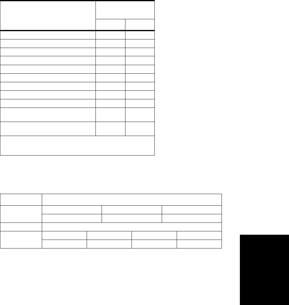
Printer Specifications
Specifications and Regulatory Information C-3
Specifications
Table C-2 lists D640 printer print speeds for various paper sizes.
Table C-2 Printer print speed specifications
Table C-3 lists the printer’s physical specifications.
Table C-3 Printer physical specifications
Paper Size
From Tray 1, 2, 3
or HCI
Simplex Duplex
Letter 40 40
Legal 25 15
Ledger 21 15
Executive 40 40
A3 21 15
A4 40 40
A5 40 40
B4 (JIS) 24 24
B5 (JIS) 30 30
Custom (width = 120mm to 297mm,
length = 182mm to 215.9mm) 40 40
Custom (width = 120mm to 297mm,
length = 215.9mm to 431.8mm) 21 15
Notes:
1. Unit of measure: Images Per Minute (IPM)
2. In Simplex and Duplex Modes, all the speeds have ±5% tolerance.
Item Specification
Dimensions Width Depth Height
570 mm (22.5 in) 630 mm (24.8 in) 1,030 mm (40.6 in)
Weight Approximately 130 kg
Service area Front Back Left Right
650 mm (25.6 in) 850 mm (33.5 in) 850 mm (33.5 in) 850 mm (33.5 in)
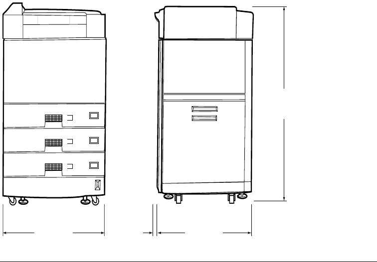
Printer Specifications
C-4 Specifications and Regulatory Information
Figure C-1 illustrates the physical specifications and Figure C-2 illustrates the required printer
service area dimensions.
Figure C-1 D640 Printer Physical Dimensions
23.0 in.
(585 mm) 25.2 in.
(640 mm)
1.38 in
(35 mm)
40.5 in.
(1030 mm)
LTR
LTR
LTR
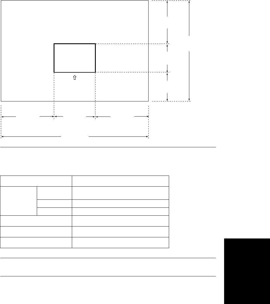
Printer Specifications
Specifications and Regulatory Information C-5
Specifications
Figure C-2 D640 Printer required service area dimensions
Table C-4 Printer electrical specifications
Note If the printer is connected to a line conditioner, make sure the line conditioner can
support the in-rush current requirement for the printer.
Item Specifications
Input power
Voltage 120 to 127 VAC ± 10%, 12A
200 to 240 VAC ± 10% 7A
Phase Single-phase
Frequency 50/60Hz ± 5%
Power consumption 1,300 VA or less than during operating
Heat production 894 kcal per hour (3550 Btu per hour)
In-rush current Up to 100 amps
Printer
Operating
Side
23.0 in.
(585 mm)
33.5 in.
(850 mm) 33.5 in.
(850 mm)
25.6 in.
(650 mm)
33.5 in.
(850 mm)
25.2 in.
(640 mm)
84.3 in.
(2140 mm)
90.0 in.
(2285 mm)
Printer Specifications
C-6 Specifications and Regulatory Information
Table C-5 Printer environmental specifications
Best Printing Area Specifications
Place your printed image in an area within a 1/6 inch (4.23 mm) border. Printing outside of this
boundary may be of lower quality.
Figure C-3 shows the best printing area.
Figure C-3 Best printing area
If data is printed outside the best printing area, you may obtain poor print quality.
Item Specification
Ambient Conditions Operating Non-operating
Temperature 15 to 35°C0 to 35
°
C
Humidity 20 to 80% RH
(no condensation)
40 to 60% RH optimal
20 to 80% RH
(no condensation)
40 to 60% RH optimal
Maximum wetbulb temperature 29°C (no condensation)
Temperature and humidity gradients 15 °C per hour or less and 30% RH per day or
less (no condensation)
Acoustic noise See Table C-15 for details.
Dust 0.15 mg./m3 (stearic acid)
Ozone emission 0.1 PPM or less
Best area
Margin
D640 Optional Accessories
Specifications and Regulatory Information C-7
Specifications
D640 Optional Accessories
Table C-6 lists printer options and their associated specifications.
Table C-6 D640 printer options and specifications summary
High Capacity Input (HCI) Specifications
The C5621A and C5622A are user-installable high capacity input (HCI) paper hoppers.
C5621A uses Letter size paper only and the C5622A uses A4 size paper only.
Figure C-4 illustrates the C5621A/C5622A high capacity input hopper.
Figure C-4 High Capacity Input physical dimensions
Item Specification Part Number
High-Capacity Input (HCI) 3,000 sheets (20 lbs; 64 g/m2) C5621A (Letter)
C5622A (A4)
High-Capacity Output (HCO) 2,000 sheets (20 lbs; 64 g/m2) C5623A (120 V)
C5624A (200 - 240)
Custom paper tray 500 sheets (at 75g/m2) C5634A
Standard paper tray 500 sheets (at 75g/m2 C5625A
PostScript upgrade PostScript Level 2
(includes 16 MB memory) C5630A
16 MB Memory Kit 16 MB SIMM (maximum 3 SIMMs) C5635A
Printer
11.3 in.
(287 mm)
22.2 in.
(562 mm)
17.6 in.
(446 mm)
High Capacity Input (HCI) Specifications
C-8 Specifications and Regulatory Information
Table C-7 lists the HCI paper related specifications.
Table C-7 HCI paper handling specifications
Table C-8 lists the HCI physical dimensions, unit weight, and required service area dimensions
and Figure C-4 illustrates these dimensions. Figure C-5 illustrates the HCI service area
requirements.
Table C-8 HCI physical specifications
Item Specifications
Processing speed 40 ppm (C5621A: Letter landscape, C5622A: A4 landscape)
Paper Size C5621A: Letter / C5622A: A4
Type Plain paper, Label paper, Bond paper, Pre-punched paper, 64 to 90g/m2
Paper capacity 3,000 sheets (75g/ m2)
Item Specification
Dimensions
Width 11.3 in (287 mm)
Depth 17.6 in (446 mm)
Height 22.2 in (562 mm)
Weight About 38 lbs (17 kg)
Service area
Front 25.6 in (650 mm)
Back 33.5 in (850 mm)
Right 33.5 in (850 mm)
High Capacity Input (HCI) Specifications
Specifications and Regulatory Information C-9
Specifications
Figure C-5 HCO (left), D640 Printer (center), and HCI (right) required service area
dimensions
HCI Electrical Specifications
Table C-9 lists the HCI electrical specifications.
Table C-9 HCI electrical specifications
Item Specification
Input power 24VDC, supplied from D640 printer
Power consumption 30VA or less during operating
Printer HCIHCO
Operating
Side
23.0 in.
(585 mm)
33.5 in.
(850 mm) 21.25 in.
(540 mm)
33.5 in.
(850 mm)
11.38 in.
(289 mm)
25.6 in.
(650 mm)
33.5 in.
(850 mm)
25.2 in.
(640 mm)
84.3 in.
(2140 mm)
122.6 in.
(3114 mm)
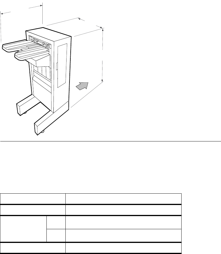
High Capacity Output (HCO) Specifications
C-10 Specifications and Regulatory Information
High Capacity Output (HCO) Specifications
Figure C-6 shows the user-installable high capacity output (HCO). Model number C5623A is
the 120VAC version, and model number C5624A is the 240VAC version. The HCO can stack
up to 2000 sheets of paper.
Figure C-6 High Capacity Output physical dimensions
HCO Paper Handling Specifications
Table C-10 lists the HCO paper handling specifications.
Table C-10 HCO paper handling specifications
Item Specifications
Processing speed 40 ppm
Paper
Size Letter, Legal, Ledger, Executive, A3, A4, A5, B4(JIS),
B5(ISO)
Type Plain paper, Label paper, Transparency, Bond paper,
Pre-punched paper, 64 to 90g/m2
Paper capacity 2,000 sheets (75g/ m2)
Printer
16.1 in.
(408 mm)
36.0 in.
(913 mm)
17.4 in.
(442 mm)
High Capacity Output (HCO) Specifications
Specifications and Regulatory Information C-11
Specifications
HCO Physical Specifications
Table C-11 lists the HCO physical dimensions, unit weight, and also provides the required
service access area dimensions.
Figure C-6 illustrates these specifications.
Table C-11 HCO physical specifications
HCO Electrical Specifications
Table C-12 lists the HCO electrical specifications.
Table C-12 HCO electrical specifications
Item Specification
Dimensions
Width 16.1 in, 408 mm
Depth 17.4 in (446 mm)
Height 36.0 in, 913 mm
Weight About 70 lbs (32 kg)
Service area
Front 25.6 in (650 mm)
Back 33.5 in (850 mm)
Right 33.5 in (850 mm)
Item Specifications
Input power
Voltage 100 to 120 VAC ± 10%,
200 to 240 VAC ± 10%
Phase Single-phase
Frequency 50/60Hz
Power consumption 120 VA or less than during operating
Heat production 83 kcal per hour
Printer Custom Paper Tray Specifications
C-12 Specifications and Regulatory Information
HCO Environmental Specifications
Table C-13 lists the HCO environmental specifications.
Table C-13 HCO environmental specifications
Printer Custom Paper Tray Specifications
The C5634A custom paper tray is a user-installable, optional paper tray compatible and
switchable with any of the standard printer paper trays. The custom paper tray can hold up to
500 sheets of paper, as listed in the Table C-14 specifications.
Table C-14 Custom paper tray physical specifications
The paper guides in the custom paper tray are adjustable, and it also supports the following
standard media sizes: Letter, Legal, Ledger, Executive, A3, A4, A5, B4 and B5.
PostScript Upgrade
The C5630A PostScript upgrade is a user-installable optional upgrade for PostScript Level 2
emulation.
You can add PostScript to your D640 printer with the C5630A PostScript upgrade. If you add
PostScript, you must also install another 16 MB of printer memory (included with the C5630A
PostScript upgrade kit).
Ambient Condition Operating Non-operating
Temperature 15 to 35 °C 0 to 35 °C
Humidity 20 to 80% RH
(no condensation)
40 to 60% RH optimal
20 to 80% RH
(no condensation)
40 to 60% RH optimal
Temperature and
humidity gradients 15 °C per hour or less and 30% RH per day or less (no
condensation)
Minimum Maximum
Width 120 mm 297mm
Length 182 mm 431.8 mm

Safety and Regulatory Information
Specifications and Regulatory Information C-13
Specifications
Safety and Regulatory Information
This product was tested for conformance to various national and international regulations and
standards. The scope of this regulatory testing includes electrical and mechanical safety,
electromagnetic emissions, immunity, acoustics and hazardous materials.
When required, approvals are obtained from third party test agencies. Approval marks appear
on the product label. In addition, various regulatory bodies require some information under the
headings noted below.
FCC Statement (USA only)
This equipment has been tested and found to comply with the limits of a Class A digital device
pursuant to part 15 of FCC Rules. These limits are designed to provide reasonable protection
against harmful interference when the equipment is operated in a commercial environment.
This equipment generates, uses, and can radiate radio frequency energy, and if not installed
and used in accordance with the instruction manual, may cause harmful interference to radio
communications. Operation of this equipment in a residential area is likely to cause harmful
interference, in which case the user will be required to correct the interference at his own
expense.
Any changes or modifications not expressly approved by Hewlett-Packard could void the
user’s authority to operate this equipment.
Use of a shielded interface cable is required to comply within the Class A limits in part 15 of
the FCC rules.
DOC Statement (Canada only)
This Class A digital apparatus meets all the requirements of the Canadian Interference-Causing
Equipment Regulations.
Cet appareil numérique de la classe A respecte toutes les exigences du Règlement sur le
matériel brouilleur du Canada.
Europe RFI Statement
This is a Class A product. In a domestic environment, this product may cause radio
interference, in which case the user may be required to take adequate measures.

Safety and Regulatory Information
C-14 Specifications and Regulatory Information
Acoustics Emissions
Data Communications (United Kingdom only)
Pursuant to Section 22 of Telecommunications Act of 1984, this product is approved for
indirect connection to Public Telecommunications systems within the United Kingdom under
the General Approval number NS/G/1234/J/100003.
Material Safety Data Sheets
Hewlett-Packard has Material Safety Data Sheets (MSDS) available for all chemicals
associated with the printing process implemented by all HP products. Should your site require
a Material Safety Data Sheet for an HP-supplied chemical in use at your site, please contact HP
at 1-800-752-0900 in the US (or 613-820-6483 in Canada) or your local HP service office, and
provide the following information:
•HP part or product number
•Chemical substance description
•Your name
•Company name
•Company address
•Telephone number
•FAX number, if the request if for a FAX copy
Table C-15 Acoustic noise levels per ISO 9296, with HCI and HCO
Operation Printer Only With HCO
and HCI Power Save
Mode
Bystander (while printing) 56 dB(A) 58 dB(A) -
Bystander (in standby mode) 52 dB(A) 52 dB(A) 33 dB(A)
Sound Power (while printing) 7.4 bels(A) 7.7 bels(A) -
Sound Power (in standby mode) 6.6 bels(A) 6.6 bels(A) 4.5 bels(A)

Safety Standards and General Considerations
Specifications and Regulatory Information C-15
Specifications
EPA Energy Star Computer Compliance
Your D640 printer is designed to conserve electricity by dropping from 165W while printing to
under 45W when in the PowerSave mode. For maximum energy conservation, Hewlett-
Packard recommends that the printer be turned off when it will not be used for more than a few
days. With this new, power-saving design, your D640 printer qualifies for the U.S.
Environmental Protection Agency’s Energy Star Computer compliance.
Safety Standards and General Considerations
This printer has been designed to conform to recognized technical standards, including the
following national and international product safety standards and norms:
•CSA C22.2 No. 950
•EN 60950 (IEC 950)
•EN 60825 (IEC 825)
•UL 1950
•U.S. CDRH 21CFR Ch.1 Subch J
Any unauthorized removal of safety covers, manipulation of safety switches, and interference
with the safety system is strictly prohibited. Such actions can cause personal injury and can
damage the system. Also make sure that the operating and maintenance areas are not
obstructed in any way.
As an Energy Star partner,
Hewlett-Packard Company
has determined that this
product meets Energy Star
Guidelines for energy
efficiency.

Laser Safety Standards
C-16 Specifications and Regulatory Information
Laser Safety Standards
Printer Laser Equipment Compliance Label
This product is a Class I laser product.
The laser safety label is located on the top of the optical unit.
Laser Safety Statement (USA Only)
The Center for Devices and Radiological Health (CDRH) of the U.S. Food and Drug
Administration has implemented regulations for laser products manufactured since August 1,
1976. Compliance is mandatory for products marketed in the United States. This printer is
certified as a “Class 1” laser product under the U.S. Department of Health and Human Services
(DHHS) Radiation Performance Standard according to the Radiation Control for Health and
Safety Act of 1968. Since radiation emitted inside this printer is completely confined within
protective housings and external covers, the laser beam cannot escape during any phase of
normal user operation.
Caution Use of controls or adjustments or performance of procedures other than those
specified herein may result in hazardous radiation exposure.
DANGER INVISIBLE LASER RADIATION WHEN OPEN AND INTERLOCK
FAILED OR DEFEATED.
AVOID DIRECT EXPOSURE TO BEAM
ATTENTION EXPOSITION AU LASER INVISIBLE SI OUVERT OU SI LE
VERROUILLADE EST DEFECTUEUX EVITER L’EXPOSITION DIRECTE
AU RAYON DE LASER.
VORSICHT UNSICHTBARE LASERSTRAHLUNG. WENN ABDECKUNG
GEOFFNET UND SICHERHEITSVERRIEGELUNG UBERBRuCKT NICHT
DEM STRAHL AUSSETZEN.
FARA Risk för stråining av osynilgt laserljus om såkerhetsorytare är ur funktion
då tuckan öppnas.

Laser Safety Standards
Specifications and Regulatory Information C-17
Specifications
Laser Safety Statement (Finland Only)
LASERTURVALLISUUS
LUOKAN 1 LASERLAITE
KLASS 1 LASER APPARAT
HP5000 D640 laserkirjoitin on käyttäjän kannalta turvallinen luokan 1 laserlaite. Normaalissa
käytössä kirjoittimen suojakotelointi estää lasersäteen pääsyn laitteen ulkopuolelle. Laitten
turvallisuusluokka on määritetty standardin EN 60825 (1991) mukaisesti.
VAROITUS !
Laitteen käyttäminen muulla kuin käyttöohjeessa mainitulla tavalla saattaa altistaa käyttäjän
turvallisuusluokan 1 ylittävälle näkymättömälle lasersäteilylle.
VARNING !
Om apparaten används på annat sätt an i bruksanvisning specificerats, kan användaren utsättas
för osynlig laserstrålning, som överskrider gränsen för laserklass 1.
HUOLTO
HP 5000 D640 kirjoittimen sisällä ei ole käyttäjän huollettavissa olevia kohteita. Laitteen saa
avata ja huoltaa ainoastaan sen huoltamiseen koulutettu henkilö. Tällaiseksi
huoltotoimenpiteeksi ei katsota värianekasetin vaihtamista, paperiradan puhdistusta tai muita
käyttäjän käsikirjassa lueteltuja, käyttäjän tehäväksi tarkoitettuja ylläpitotoimia, jotka voidaan
suoritta ilman erikoistyökaluja.
VARO !
Mikäli kirjoittimen suojakotelo avataan, olet alttina näkymättömälle lasersäteilylle laitteen
ollessa toiminnassa. Älä katso säteeseen.
VARNING !
Om laserprinterns skyddshölje öppnas då apparaten är i funktion, utsättas användaren för
osynlig laserstrålning. Betrakta ej stralen.
Tiedot laitteessa käytettävän laserdiodin säteilyominaisuuksista:
Aallonpituus 780 nm
Teho 5 mW
Luokan 3B laser
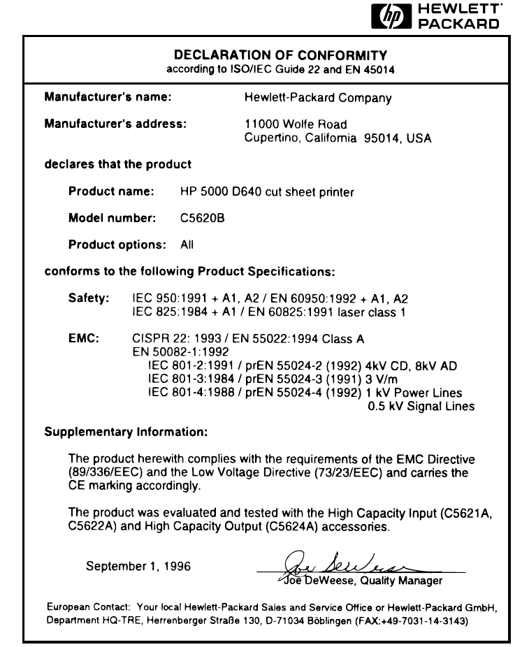
HP Declaration of Conformity
C-18 Specifications and Regulatory Information
HP Declaration of Conformity

Using Paper D-1
Using Paper
D
Using Paper
The D640 prints on a variety of print media, including paper, labels, and overhead
transparencies, at up to 600 x 600 dots per inch (dpi).
Note The D640 does not accept envelopes as print media.
The D640 printer uses laser electrophotographic technologies. In this process, a laser writes an
electrostatic image onto the photosensitive drum. As this image passes the developing station,
a dry, powdery toner is attracted to the imaged areas. This developed image then advances to
the transfer station, where the belt contacts the media and the toner image is electrostatically
transferred onto the paper. After transfer, the media passes through the fuser; heat and pressure
are applied and the toner fuses (melts) onto the media. The media is then deposited in the
output tray, ready for use.
To create the printed image all print media must be transported through the printer,
electrostatically charged, and heated. This is why media properties such as electrical
resistivity, caliper, smoothness, and stiffness can affect the print quality and media handling
performance of your D640 printer.
Supported Print Media Types
Your D640 printer will print on a variety of media, including paper, labels, and overhead
transparencies. “Media Selection Specifications and Guidelines” on page D-3 provides
suggestions for these different media.
Hewlett-Packard neither warrants nor recommends the use of a particular print media. Media
properties are subject to change by manufacturers and Hewlett-Packard has no control over
such changes. The customer assumes all responsibility for the quality and performance of
media. Although testing media helps to characterize their performance, long-term satisfaction
requires process quality control by the manufacturer and proper handling until use.
Alternate Sources of Information
The manufacturer and the vendor of the media that you select should be able to provide
information about the suitability of its use in a D640 printer. Your vendor should be your
contact when selecting media for your individual application needs. If you have tried all of the
suggestions outlined in this document, and still need assistance, HP provides support through
the world-wide network of Hewlett-Packard Sales and Service Offices. Refer to “Warranty and
Support” on page F-1.
Paper Manufacturing
D-2 Using Paper
In the United States, Hewlett-Packard also offers support through a local support
representative. A customer support technician will be happy to offer advice to help solve your
printer operation problems.
Paper Manufacturing
Laser printers require paper types and specifications that were uncommon just a decade ago.
Until then, no distinction was made between writing paper and xerographic paper. The
manufacture of paper is complex. Several different mills may offer the same type of paper (for
example, 25% cotton bond, writing stock) but each manufacturer will vary the texture, color,
fiber, lignin, coating, and other elements which make their product unique. In the paper
industry, there are no equivalent papers between manufacturers, only substitutes.
Sources of Paper
Paper is primarily made from cellulose fiber, the major component of the cell walls of wood
fibers and other plants. Sources of this fiber include:
•Raw Wood
•Recycled or waste wood
•Cotton
Pulping methods are based, in part, on the fiber length of the raw wood. Hardwoods, such as
cottonwood, contain short fibers, from one to two millimeters in length. Softwood fibers,
including pine, spruce, and other conifers range in length from three to six millimeters. In each
case, the thickness is less than that of a human hair.
These differences often mean variability among paper manufacturers, even within the same
company. To ensure quality and consistency, a certain percentage of this material must come
from raw wood. Timber may be harvested from national forests and private land as well as tree
farms or plantations.
Surface Coatings
A thin layer of coating may be applied to the paper which could change its physical
characteristics. These surface coatings or “sizings” are added to make the sheets more resistant
to ink or water penetration and to increase durability. Coatings may also be added to create a
neutral pH in paper used for archival storage (such as legal documents). Surface coatings are
usually liquid starches and are applied either by spraying, immersion, or mixing into the
furnish.
Heavy coatings of clay or talc should be avoided because they become hard and brittle, causing
the fibers to break like a piece of chalk and come off during printer operation. Surface coatings
also affect the surface electrical resistivity, which is a important factor in the performance of
your D640 printers.
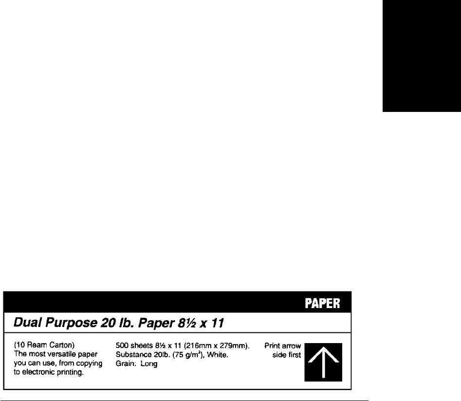
Media Selection Specifications and Guidelines
Using Paper D-3
Using Paper
Cast Surfaces
When a very smooth surface is required, a clay and water solution is applied to the paper, and
is then “cast” under high temperatures. Cast surface paper is mainly used for offset color
presses and making original typeset master sheets used in publication printing. This type of
paper is not recommended for D640 printers because clay is very abrasive to components in
the paper path.
Packaging
Packaging is an important step in the paper-making process. Much of the paper used for
computing printing applications is packaged in reams: wrapped bundles containing 500 sheets.
Because paper is hygroscopic, or capable of absorbing or losing moisture from the air, it
should be protected by moisture-proof polylaminated wrapping and moisture barriers. A ream
of finished paper usually contains about 4% moisture. The paper ream remains stable if
properly stored and opened only when ready to be used.
Paper Ream Label
A ream label is placed on the outside of the paper wrapping. The ream label usually indicates
paper: basis weight, size, number of sheets, grain direction and grade. The printing surface of
the paper may be indicated by an arrow on the ream label. Paper should be loaded into the
printer so that surface indicated by the arrow will be the printing surface. The printing surface
may be up or down, depending on the printer model and the paper feeding source.
Figure D-1 Ream Label
Media Selection Specifications and Guidelines
Hewlett-Packard neither warrants nor recommends the use of a particular print media. Media
properties are subject to change by manufacturers and Hewlett-Packard has no control over
such changes. The customer assumes all responsibility for the quality and performance of
media. Although testing media helps to characterize their performance, long-term satisfaction
requires process quality control by the manufacturer and proper handling until use.

Media Selection Specifications and Guidelines
D-4 Using Paper
Recommendations to the Customer
Hewlett-Packard D640 printers are designed to be as flexible as possible in the types of print
media they can use. Since there are many varieties of media and variations in the
manufacturing process, you should test a particular medium in your environment to determine
if it performs acceptably.
Buy Media that Meets Specifications
To get the best performance from your D640 printer, select high quality print media that meet
the guidelines and specifications in this document.
Test Small Amounts of Media
The next step in choosing media, particularly if you are planning a large purchase, is to print a
small quantity in your environment. Subject it to the temperature, humidity, and printing
application in which it will be operating. DO NOT purchase large quantities without first
testing the media! Hewlett-Packard recommends that you ask your media vendor for a
guarantee that their media will perform satisfactorily in your D640 printer, and that you ask the
vendor to assume responsibility for the replacement of any media that will not print
acceptably.
Use High Quality Media
Hewlett-Packard printers will work best with high quality media. Quality media for D640
printers are characterized by uniform physical properties, freedom from dust and lint, accurate
cutting to size, and packaging that protects it from moisture and physical damage. Curled or
bent edges, spots, dust or lint, wrinkling, and inaccurate cutting to size are common media
problems that should be avoided. These problems can cause misfeeding, jamming, premature
wear, or unsatisfactory print quality.
Size
Table D-1, “Paper sizes” shows paper sizes that can be used with D640 printers. Shown also is
the numeric code displayed on the operator panel for each paper size. All paper sizes can be
used in either simplex or duplex printing modes. Use only paper that is within the dimensions
shown in Table D-1, “Paper sizes”.
Note Although the D640 printer can print over the entire sheet, we do not guarantee quality
for print in the outer 5mm of the page periphery. This border will vary slightly with the quality
of the paper used.
Table D-1 Paper sizes
Size Dimensions
A3 11.69 X 16.53 in. 297 X 420 mm
A4 8.26 X 11.69 in. 210 X 297 mm
Media Selection Specifications and Guidelines
Using Paper D-5
Using Paper
Basis Weight
Basis weight is an important characteristic to consider because, paper that is too light or too
heavy may cause misfeeds, mis-stacking, paper jams, or excessive mechanical wear.
The printer is specifically designed to perform at maximum efficiency when 20 pound bond
(75g/m2) paper is used. Optimum print quality and paper path reliability are achieved when
high quality electrophotographic (EP) paper is used. EP papers have specific characteristics
that distinguish them from bond papers. The range of paper weight that the printer and HCI can
process is 17 to 24 pound (64 to 90 g/m 2). The printer can handle paper weights up to 36
pound (135 g/m2), but 17 to 24 is optimum.
Specifications for basis weight depend upon the paper source the paper is fed. In general, the
straighter the paper path, the heavier the basis weight may be. For more complex paper paths,
as in feeding from the HCI, a lighter weight may be required, in range of 18 to 24 pound.
Furnish (Composition)
Furnish is the fiber and chemical composition of paper. Fiber composition of the paper used in
D640 printers should be manufactured from 100 percent chemical wood pulp and/or cotton
fiber. To ensure that paper of a special fiber composition will work properly, always test it
before purchasing large quantities. Other allowable components of paper are sizing, fillers,
buffers and pigments.
Note DO NOT use coated paper or paper containing materials that melt, vaporize, offset,
discolor or release hazardous emissions when exposed to 392°F (200°C).
A5 5.84 X 8.26 in. 149 X 210 mm
JIS B4 10.11 X 14.32 in. 257 x 364 mm
JIS B5 7.16 X 10.11 in. 182 X 257 mm
Letter 8.5 X 11 in. 216 X 280 mm
Legal 8.5 X 14 in. 216 X 356 mm
Ledger 11 X 17 in. 280 X 432 mm
Executive 7.25 X 10.5 in. 184 X 267 mm
Table D-1 Paper sizes
Size Dimensions
Media Selection Specifications and Guidelines
D-6 Using Paper
Curl
Curl is curvature in a sheet of paper. Curl is typically measured by laying the sheet of paper on
a flat surface, with the corners up, and measuring the height of the corners. In-ream curl is the
amount of curl a sheet of paper has before printing. (In-ream curl may result from the paper
manufacturing process or from exposure to the environment). Post-image curl is the amount of
curl a sheet of paper has after printing (from exposure to the fusing process and paper path in
the printer). Paper with excessive in-ream curl may lead to feeding and print quality problems.
In addition paper with excessive post-image curl may be difficult to handle or use in
automatic-feed photocopiers.
The curl side of the paper can be identified by a slight concave bowing from the outside edges
of the paper stack towards the center of the top sheet. This curled side is always the side that
should face away from the printer’s photoconductor. Having the curl side face away from the
photoconductor helps the paper separate from the photoconductor surface during the printing
process.
Paper curl becomes more obvious after fusing of a print. If the curl of a printed page appears
too excessive, it is likely that paper handling problems may occur during duplex printing. If
this is the situation, open the paper tray and turn the paper over. Try printing again. If the
problem is still not resolved, select a different paper for duplex printing, and reserve the
“problem” paper for single-sided printing.
Besides paper handling problems, excessive curl may also result in blurred print and similar
print quality problems. The HP standard for in-ream paper curl is no more than 0.2 inches
(5 mm) on any part of the paper, with 0.1 inches (3 mm) the optimal value.
Finish (Texture)
Finish, or texture, is the degree to which the surface is free of irregularities (or the smoothness
or roughness of the paper). Using paper that meets HP specifications for surface texture is
critical to the operation of D640 printers. The degree of surface texture is determined by the
fiber composition of the paper, fillers which may have been added to the paper mixture, and
the number of passes through the calendar stacks. Common paper textures included
cockleshell, linen and laid.

Media Selection Specifications and Guidelines
Using Paper D-7
Using Paper
Potential Problems
Some textures improve paper feeding while others hinder the feed operation. Too smooth or
too rough paper can cause a variety of problems in D640 printers.
Felt Side vs.Wire Side
The way paper is manufactured results in two-sided paper properties. This, along with other
process variations, may make one side of the paper the preferred side to print on. The “top”
side of the paper sheet as it is formed is known as the felt side, and the “bottom” is known as
the wire side. Most manufacturers indicate the preferred printing side on the package.
Moisture Content
Note Moisture content is the most critical factor in paper performance in D640 printers. The
moisture content of most paper at the time of manufacture is about 4-6% of volume by weight.
This percentage can be altered as a result of environmental conditions during converting
processes, shipping, storage, and printing.
Storage, especially over long periods, can greatly influence moisture content. Because of the
hygroscopic properties of paper, unless proper humidity and temperature are maintained, the
paper will lose or gain moisture.
Table D-2 Finish (texture) potential problems
Problems Too Smooth Too Rough
Feeding •misfeeds •misfeeds
•multi-feeds
Print
Quality
•poor toner adhesion
•washout will show up (loose
toner particles from a previ-
ously printed page)
•background toner scatter
•poor toner adhesion
•light and dark transitions (toner
migrates to the valleys of the paper
surface, but not the peaks)
•printed characters may have broken
edges
Premature
Wear
none •registration roller
•paper path rollers
•fuser
•paper path guides

Media Selection Specifications and Guidelines
D-8 Using Paper
The environmental conditions required to maintain the proper moisture content is 68°F to
75°F (20°C to 24°C) with a relative humidity of 45% to 55%.
The HP standard for moisture content is 4.7% ± 1% by weight. Although a paper may have the
proper moisture content at the time of manufacture, exposure to temperature and humidity
extremes may alter the percentage.
Fusing Compatibility
Media that does not meet HP specifications may:
• Discolor
• Melt
• Scorch
• Offset
• Release hazardous emissions
• Have poor toner adhesion
• Break down in other ways
• Possibly damage the printer
All media used in D640 printers must have the ability to withstand the fusing temperature of
392°C/200°C for 0.1 second, without experiencing any problems.
Inspect the rollers for colored ink build-up from pre-printed logos or letterhead and for toner
buildup or spots. Inspect printed output for repetitive defects and smearing. If necessary,
contact your forms vendor to ensure paper’s fusing compatibility with D640 printers.
Table D-3 Moisture content potential problems
Too Moist •Paper shrinks unevenly during fusing, causing print quality problems
•Overall paper curl increases (increases post-image curl, causes poor toner
adhesion, feed and print quality problems)
Too Dry •Excess static (causes multi-feeds and paper jams)
•Surface electrical resistivity (causes streaking and smudging of loose toner
particles)
Understanding Paper Ream Labels
Using Paper D-9
Using Paper
Understanding Paper Ream Labels
Figure D-2, shown below, is an example of a typical label from a ream of paper. It includes
much of the information about paper use and paper specifications.
Figure D-2 Paper Ream Label details
General Guidelines
Some general guidelines to follow when selecting media are summarized on the following
pages.
Use conventional white xerographic paper for most printing. The paper should be of high
quality, free of cuts, tears, grease spots, loose particles, dust, wrinkles, voids, and curled or
bent edges. Xerographic papers, also called photocopy or xerocopy papers, are usually made
from chemical wood pulp and are characterized by a smooth surface, controlled electrical
properties, heat stability, and cleanliness. These characteristics ensure good image transfer,
fusing without excessive curl, and reliable printer operation.
Some applications may require a paper having a more prestigious look or feel. Bond papers
generally have a watermark and often use cotton fiber. These papers tend to have a rougher
surface and their properties may not be controlled like xerographic papers. However, your
D640 printer will print satisfactorily on many of these bond papers. Also, some paper
manufacturers are now making laser grade bond papers which have properties compatible with
laser quality printing.
One of the most important things you can do to ensure the best possible performance from your
D640 printer is to select a quality paper. Table D-4, “Recommended paper specifications”,
summarizes the specifications of a paper that will give you the best performance.

General Guidelines
D-10 Using Paper
Note It is possible that paper could meet all of the general specifications listed in this table
and still not print satisfactorily because of the printing environment or other variables over
which Hewlett-Packard has no control.
Recommended Paper Specification Summary
Table D-4 Recommended paper specifications
Parameter Specification
Paper Weight 17 to 24 pound (64 to 90 g/m2) for printer and HCI; printer supports up
to 36 pound (135 g/m2)
Paper Grade No. 1 or No. 4 electrophotographic
Paper Direction Long grain (parallel to the long dimension)
Short grain (ideal for letter/A4 size paper)
Furnish Fiber composition: 100% chemical wool pulp and /or cotton fiber
Ash Content Not to exceed 10%
Moisture Content 4.7 ± 1% by weight
Smoothness 100 to 200 Sheffield units
Front side: 30 ± 12 Sec
Back side: 23 ± 10 Sec
Friction Coefficient 0.45 to 0.65
0.55 to 0.15 (dynamic)
0.60 ± 0.15 static
Surface Resistivity 1010 to 1012 Ohms
Caliper 97± 3 em
Finishing Cut sheet to within ±0.03 in (±0.8mm) of nominal, ±0.2° square
Cut Edge Conditions Rotary precision cut
Packaging Polylaminated moisture-proof ream wrap

General Guidelines
Using Paper D-11
Using Paper
Pre-printed Forms and Letterhead
To avoid multiple feeding and jamming problems when using pre-printed forms, embossed
paper, and letterhead, observe the following guidelines:
•Do not use low-temperature inks (the kind used with some types of thermography).
•Use forms and letterhead printed by offset lithography or engraving.
•Forms must be printed with heat-resistant inks that will not melt, vaporize, or release
hazardous emissions when heated to 392°F (200°C) for 0.1 second. Typically, oxidation-
set or oil-based inks meet this requirement.
•If oxidation-cured inks are used, the use of oxidation retardants should be minimized.
•When the form is pre-printed, be careful not to change the moisture content of the paper,
or use materials that change the paper’s electrical or handling properties. Forms should be
sealed in moisture-proof wrap to prevent moisture changes during storage.
•Pre-printed forms should not be processed with a finish or coated at the end of their
production.
•Do not use heavily embossed or raised letterhead papers.
•Avoid papers with heavily textured surfaces.
•Avoid using a band of ink on the leading edge of the paper.
•Water additives must not be used, as they change the conductivity of the paper. The effect
of the electrical charge applied to the paper during the printing process may be altered.
•Following offset printing, the printed pages should be allowed to dry for one to two weeks
in an atmosphere of 60°F to 80°F (16°C to 27°C) with a relative humidity of 35% to 50%.
Stiffness
(Clark Method)
Printing direction: 90 ± 25
Cross direction: 40 ±15
Fusing Compatibility Must not scorch, melt, offset, or release hazardous emissions when
heated to 392° F (200°C)
Opacity 84% ± 3%
Wax Pick 12 minimum (Dennison)
Grain Letter / A4 is best with
short grain
For all other sizes, use
long grain
Table D-4 Recommended paper specifications
Parameter Specification
General Guidelines
D-12 Using Paper
Adhesive Labels
For the purposes of this specification, a label is defined as paper with a pressure-sensitive
adhesive backing. Label stock includes the top or face sheet, the adhesive, and the liner or
carrier sheet, also referred to as the backing.
Note the following points about label stock:
•Top or face sheets: The top sheet, which is the printing surface, is usually composed of
xerographic paper. Label top sheets must provide good toner adhesion.
•Carrier sheets: The carrier sheet must be compatible with the temperatures and pressure of
the fusing process, and must be coated for easy release of the top sheet.
•Adhesives: The adhesive must be stable at the 392°F (200°C) temperatures encountered in
the printer's fusing process, and must not produce emissions that exceed exposure levels or
threshold limits established by OSHA and other safety agencies. Adhesives must not come
in direct contact with any part of the printer. No adhesive should be pressed out of the
edges or between die-cuts (the cuts between individual labels).
• Label arrangement: Labels should be arranged on the carrier sheet so that any exposed
spaces run lengthwise down the sheet (See Table D-5, “Label specifications”.) Using label
stock with spaces between the horizontal rows of labels can often result in labels peeling
off during printing, causing serious jamming and possible printer damage.
Labels may be specially manufactured to leave a margin around the outside edges that
correspond to the outer margins of the printable area. If this special arrangement is to be used,
DO NOT REMOVE the excess top sheet material from the carrier sheet.
Figure D-3 Adhesive Label arrangements

General Guidelines
Using Paper D-13
Using Paper
Note It is possible that labels could meet all of the general specifications listed in "Adhesive
Label arrangements" and still not print satisfactorily because of the printing environment or
other variables over which Hewlett-Packard has no control.
Note The following actions can cause labels to peel off, possibly damaging the inside of
your printer: printing on labels while the printer is in duplex mode or removing individual
labels from the carrier sheet, then printing on the remaining labels.
Note Hewlett-Packard does not recommend removing any labels from the carrier sheet and
then printing on the remaining labels. If labels must be removed, remove them from the bottom
of the carrier sheet, continuing toward the top.
Note Overhead transparencies used in D640 printers must be able to withstand the 392°F
(200°C) temperature encountered in the printer's fusing process.
Specifications for overhead transparencies are summarized in Table D-6, “Overhead
transparency specifications summary”.
Table D-5 Label specifications
Adhesive
Must not be on any external surfaces of the label before, during or after
printing.
Label construction and die-cutting must not allow labels to peel off during
transport, printing, or fusing.
Basis Weight 32 to 34 pounds (120 to 128 g/m2).
Curl In-ream: flat within 0.2 in. (5 mm).
Finishing Cut sheet within 0.031 in. (0.79 mm) of nominal and within 0.2° of
square.
Fusing
Compatibility
All adhesives, carrier sheets, top sheets, and other materials used in
label construction must be compatible with the heat and pressure of the
fusing process. Materials must not discolor, melt, offset, or release
hazardous emissions when heated to 392°F (200°C).
Packaging Moisture proof wrap to preserve properties.
Shelf Life One year, minimum, stored at 72°F (22°C) and 50% R.H.
Refer to
Purchasing
in the next section for ordering HP labels.

General Guidelines
D-14 Using Paper
Refer to Purchasing in the next section for ordering HP transparencies.
Recycled Paper
Recycled paper is a combination of waste paper, pre-consumer waste, and post-consumer
waste. Printed waste paper is usually washed to remove most of the inks and other
contaminants. A recycled sheet of paper may contain dark specks or appear gray or dirty. You
should choose a recycled paper that meets the same specifications (except perhaps brightness)
as standard paper, and has an appearance suitable for your needs. Hewlett-Packard
recommends that the recycled paper contain no more than 5% groundwood.
Note Depending on the quality of recycled paper, you may experience a higher jam rate and
reduced consumable life compared to equivalent quality non-recycled paper.
Archival Paper
Paper used for archiving must meet the same specifications as standard paper, however, the pH
should be no less than 7.0. Some archival demands are more stringent than others, requiring
the degree of alkalinity and chemical stability to be specified.
Toner is chemically stable and should last as long as the paper does. Toner can be degraded by
petroleum based solvents or plasticizers, such as those found in vinyl folders. Avoid folding
archival documents across printed areas or handling them roughly. Discuss archival
requirements with your paper supplier.
Colored Paper
Colored paper can be used in D640 printers as long as the standard paper specifications are
met.
Table D-6 Overhead transparency specifications summary
Basis Weight 45 to 60 pound (170 to 225 g/m2)
Cutting Angle 90°plus or minus 0.2°
Finishing Plus or minus 0.03 in. (plus or minus 0.8 mm)
Fusing
Compatibility
All materials of the overhead transparency must be compatible with the heat and
pressure of the fusing process. Materials must not discolor, melt, offset material,
or release hazardous emissions when heated to 392°F (200°C).

General Guidelines
Using Paper D-15
Using Paper
Paper with Cutouts or Perforations
Hewlett-Packard does not recommend using paper with cutouts or perforations because they
often cause paper handling problems and may cause printer damage.
A cutout is defined as any portion of the paper that has been removed, including binder holes,
notches, square cuts, etc.
Paper with internal perforations may cause misfeeds and paper jams.
If you must use papers with internal perforations or cutouts, take care to conform to the
following:
•Cutouts and perforations should be punched from the side to be printed on, so that edge
trimmings will not scratch the photosensitive belt.
•Do not print at a cutout location, or closer than 1/8 inch (3.5 mm) to the edge of a cutout,
to prevent toner from contaminating the inside of the printer.
•Cutouts and perforations should be cut clean (without burrs), to avoid multiple feed,
contamination problems, or paper jams.
•Avoid perforations that run perpendicular to the paper path. When the printer transfers
paper from one set of rollers to the next, a perforation can cause the page to bend
downward and miss the pickup point on the next roller.
Chemically Treated Paper
Coatings such as lacquers, polymers, laminations or other chemicals protect the paper but can
cause problems in the fuser and transfer areas of D640 printers. The surface resistivity and
moisture content can be greatly altered, resulting in print quality problems. Hard surfaces
coatings increase wear on the rollers and paper guides. All chemically treated paper must meet
HP specifications for fusing compatibility.
Synthetic Paper
Synthetic papers (those manufactured from man-made fibers) do not perform as well as bond
papers in any printer, especially D640 printers. Each type has its own problems which result in
poor feed and print quality performances. All synthetic papers must follow HP specifications,
especially for caliper and fusing compatibility. Be cautious about heat-generated fumes which
may be dangerous to breathe.
Coated Paper
Do not use papers where a coating has been added after the paper is produced. Most coated
paper does not meet specifications for fusing compatibility, as well as all other specifications
for D640 printers.
Purchasing, Handling, and Storing
D-16 Using Paper
Other Special Media
Odd sizes
Check minimum and maximum supported sizes in Figure 3-4, Paper Sizes quick refer-
ence, on page 3-4.
Carbonless Paper
Carbonless paper (NCR) is not supported by D640 printer.
Recycled Paper
Choose recycled paper that meets HP specifications (except perhaps brightness) and that has
an appearance suitable for your needs. HP recommends that recycled paper contained no more
than 5% groundwood.
Things to Avoid
DO NOT attempt to print on any of the following:
•Extremely shiny or glossy paper.
•Very rough, textured, or embossed media.
•Multipart forms or carbonless papers.
•Media, media coatings, dyes, or inks that produce hazardous emissions or melt when
exposed to a fusing temperature of 392°F (200°C).
•Media that offsets or discolors.
•Media with folds, staples, paper clips, etc.
•Damaged, curled, wrinkled, or irregularly shaped media.
•Letterhead paper produced using low temperature dyes or thermography.
•Paper containing large amounts of clay or talc.
•Media that have already been printed with a photo copier or a D640 printer.
•Low quality recycled paper.
Purchasing, Handling, and Storing
The performance of D640 printers is dependent on the condition of the print media used. This
section contains recommendations for purchasing, shipping, handling and storing media.
Acceptable paper can be purchased from your local supply house. Ask your vendor to verify
that the paper will work acceptably with a D640 printer.
In the United States, overhead transparencies are supplied by Hewlett-Packard through HP
SafetyNet (to order transparencies in Europe, contact your local HP sales office). To order
from HP SafetyNet, call (800) 538-8787 and ask for the HP part number listed below. Each
box contains 50 overhead transparencies.
Purchasing, Handling, and Storing
Using Paper D-17
Using Paper
Purchasing Information
In the United States, Hewlett-Packard supplies labels through HP SafetyNet (to ordering labels
in Europe, contact your local HP sales office). To order from HP SafetyNet, call (800) 538-
8787 and ask for the HP part number listed in Table D-7, “Hewlett - Packard laser printer label
media”. Each box contains 100 sheets, 81/2 x 11 inch (216 x 280 mm), except where otherwise
noted.
*Contains 75 sheets, 8 1/2 x 11 in. (216 x 280 mm).
Shipping
When print media are shipped through different environments, the entire stack of cartons on
the shipping pallet should be plastic wrapped. When shipped across bodies of water, individual
cartons should be wrapped, as well. Media should never be shipped in such a manner that they
are damaged or bent along the edges.
Transparency Size HP Part Number
Letter - 8.5 x 11 in. (216 x 279 mm) 92296T
A4 - 210 x 297 mm (8.26 x 11.69 in.) 92296U
Table D-7 Hewlett - Packard laser printer label media
Label Size
(Height and Weight) Number per
sheet HP Part Number
1 x 2 5/8 in (25 1/2 x 51 mm) 30 92296A
1 1/3 in x 4 (25 1/2 x 102 mm) 14 92296B
1 x 4 in (25 1/2 x 102 mm) 20 92296C
2 x 4 in (51 x 102 mm) 10 92296D
3 1/3 in x 4 85 x 102 mm) 6 92296E
1/2 in x 1 3/4 (13 x 45 mm) 80 92296F
2/3 in x 3 7/16 (18 x 88 mm) 30 92296G
2 3/4 in x 2 3/4 (70 x 70 mm) 9 92296H*
1 1/2 in x 4 (39 x 102 mm) 12 92296J*
8 1/2 x 11 in (215 x 280 mm) 1 92296K
Purchasing, Handling, and Storing
D-18 Using Paper
Storing
Adhere to the following guidelines when stacking and storing print media:
•DO NOT store cartons of reams directly on the floor; cartons should be placed on a pallet
or on shelves.
•DO NOT store individual reams in such a manner that they will curl or warp along the
edges.
•Rewrap partially used reams of paper before storing.
•DO NOT stack more than six cartons high.
•Stack each carton squarely on top of the one underneath.
•Stack each carton upright.
•DO NOT place anything on top of paper, regardless of whether the paper is packaged or
not.
•Store envelopes in a protective box so the edges will not be damaged.
•Keep stored media away from extremes in temperature and humidity.
•DO NOT store printed documents in vinyl folders (which may contain plasticizers), or
expose the documents to petroleum based solvents.
Environmental Considerations
Media should be protected from temperature and humidity extremes. D640 printers are
designed to operate in a wide range of environmental conditions, but for best performance,
media should be stored and used at 59°F to 95°F (15°C - 35°C), with a relative humidity of
40% to 60%.
When media are used in an environment outside the ranges of temperature and humidity shown
above, follow these guidelines:
•DO NOT leave the media exposed to humidity or temperature extremes. Any extreme
changes in the environment will cause the media to take on unwanted characteristics if left
unwrapped or in the input tray of the printer.
•Where humidity extremes occur, store paper in an airtight container, or seal it in plastic.
•If there is a significant temperature difference between the media storage area and the
printer’s operating environment, allow the media to adjust to the temperature in the
printer’s operating environment before unwrapping. The greater the temperature
difference and the greater the amount of media to equilibriate, the longer this time period
should be. Allow one day for every 20°F (10°C) difference in temperature between
storage environment and printing environment.
Paper is affected by temperature and humidity variations during transport, storage, and use.
When the atmosphere is moist, paper tends to have wavy edges; conversely, when the
atmosphere is dry, paper tends to have wavy centers.
Purchasing, Handling, and Storing
Using Paper D-19
Using Paper
Acclimatizing paper to the “best performance conditions” described above minimizes these
adverse affects, but exposure to temperature and humidity extremes will eventually make
acclimatization impossible. In extreme conditions, the paper may become unfit for use. For
optimum results, keep paper supplies in moisture-proof packaging and load only the amount
that will be used soon.
Printer Normal Operating Environment
The specifications for the printer's operating environment are defined below. Observing these
environmental guidelines helps ensure trouble-free printer operation.The temperature and
humidity of the paper used with the printer should be in balance with the printer's environment.
•Temperature 59°F to 95°F (15°C to 35°C)
•Relative Humidity 20% to 80%
•Altitude 0 to 7000 feet (0 to 2150 m)
Total Operating Environment
Figure D-4 is a map of the operating range of the printer, showing recommended maxima and
minima for temperature and humidity. Operating the printer in the A,C, D, and E areas of
Figure D-4 may result in lower-quality prints.
Figure D-4 Total operating environment
D
B
E
C
A
95°F (35°C)
85°F (30°C)
65°F (18°C)
59°F (15°C)
Temperature
20% 80%Humidity

Troubleshooting
D-20 Using Paper
Troubleshooting
Paper problems are somewhat difficult to detect. A series of steps will help isolate paper-
induced problems. The steps to follow are:
•Is it a paper or a printer problem?
•Isolate a paper path
•Isolate a paper brand
•Isolate a paper type
•Evaluate user’s paper practices
•Evaluate environmental conditions
Is it a Paper or Printer Problem?
When determining a printer failure, a distinction must be made between problems relating to
the printer itself and those involving paper. Often a problem which first appears to be related to
the printer is actually a matter of poor paper selection or handling. To determine is a problem is
printer or paper-induced a few simple steps can be helpful:
•Turn paper over in the tray to print on the reverse side.
•Rotate sheets 180° (end to end) to feed with a different leading edge.
If the symptoms cease, or change in some way, it can be assumed that the problems are paper
induced.
Isolate a Paper Path
The physical properties and composition of a particular paper influence its motion along a
printer’s main paper path. As a general rule, the straighter a paper path, the more forgiving it is
of the paper’s physical characteristics.
Try Using the Straightest Paper Path
Some problems can be avoided by using the straightest paper path. Feed paper from tray1. This
path is recommended for transparencies and heavy basis weight media.
Figure D-5 D640 paper paths
Ltr
Ltr
Ltr

Troubleshooting
Using Paper D-21
Using Paper
Determine if the Problem is Due to Duplexing
The duplexing feature may have both paper feed problems and print quality problems as a
result of printing on paper that has just made a pass through the printer (resulting in increased
paper curl). This paper curl increases image dropout, and pickup and stacking problems. The
second pass is made with paper which may no longer meet the specifications for moisture and
curl. Dry paper may not hold static charges which affect print quality and stacking. Image mis-
alignment front-to-back on a duplexed page may be caused by paper shrinkage.
Isolate the Source From Which the Printer Jams
Where was the paper being fed from? Possible sources include:
•Tray1, Tray2, Tray3
(500 20 pound paper sheets each)
•High Capacity Input Unit
(3000 20 pound paper sheets)
Where Does the Jam Occur?
Check where paper stops when a jam occurs. Types of jams that can occur include:
•Input paper jams
•Internal paper path jams
•Output jams
Is the Printer is Experiencing Multi-feed Jams?
The following are some possible causes in multi-feeds.
•Paper may be too light or too thin. Check the basis weight and caliper.
•Paper may be too smooth or too rough. Check the finish.
•Paper may have too much curl. Measure paper curl and check moisture content.
•Paper may have bad edge cuts or edge welds. Observe the cut edge condition.
•The customer may be attempting to print embossed paper, pre-printed forms, or perforated
paper which does not meet HP specifications. (See the following section,"Isolate a Paper
Type", for details about the difficulties of embossed paper.)
•Paper may be loaded incorrectly. Turn over the sheets in the paper tray to determine if in-
ream curl is the cause of misfeeds.
•Customer may be fanning paper before loading it into the paper tray.
•Customer may be adding paper in small amounts. Do not add small amounts of paper or
mix types of paper in the tray.
•The printer or paper storage environment may be too humid or too dry. (As a result, paper
may be too moist or too dry). Determine if this is the case and advise the customer.
Troubleshooting
D-22 Using Paper
Is the Printer Experiencing Misfeeds?
The following are some possible causes in misfeeds.
•Paper may be too stiff. Check basis weight and measure caliper.
•Paper may be too smooth or too rough. Check the finish.
•Paper may be too heavy or too light. Check the basis weight.
•The customer may be attempting to print embossed paper, pre-printed forms, or perforated
paper which does not meet HP specifications. (See the following section, "Isolate a Paper
Type", for details about the difficulties of embossed paper.)
•Paper may be loaded incorrectly. Turn over the sheets in the paper tray to determine if in-
ream curl is the cause of misfeeds.
•Customer may be fanning paper before loading it into the paper tray.
•The printer or paper storage environment may be too humid or too dry. (As a result, paper
may be too moist or too dry). Determine if this is the case and advise the customer.
Isolate Paper Brand
If the printer jams with only one brand of paper:
•If the paper ream being used appears to be old, open a fresh ream of the same paper and
load it properly into the printer. If the problem is remedied, investigate storage and
handling conditions.
•Do not purchase more paper than you can use in a short time (3 months). Paper stored for
longer periods may experience heat and moisture extremes which can damage it. Planning
helps prevent damage to your paper supply.
•If the problem persists, try switching paper brands.
Isolate a Paper Type
When paper jams and other problems occur frequently, it is often because special paper is
causing the difficulty. Use only paper that conforms to all HP specifications, and always test
paper before purchasing large quantities. If future problems occur, the cause may be easily
isolated to storage or handling conditions.
Some types of media that may cause problems are:
•Pre-printed forms and special letterhead
•Embossed paper
•Perforated paper
•Adhesive labels
•Envelopes
•Transparencies
•Chemically treated paper

Troubleshooting
Using Paper D-23
Using Paper
•Synthetic paper
•Coated paper
•Other special media
Refer to Table D-4, “Recommended paper specifications,” on page D-10 for a table of
recommended media specifications.
Printer Maintenance
General cleanliness of the printer is the most important part of printer maintenance. Good
maintenance improves the performance of any printer. Papers which create a lot of dust and
debris in the printer require a more aggressive maintenance schedule.
Areas which builds up paper dust heavily are:
•pick-up rollers
•paper guides
Taking extra time to clean and inspect the paper path results in fewer paper jams and cleaner
print. If problems continue after cleaning, inspect for wear or damage.
Paper Stacking
Consider the following guidelines when advising the customer about stacking paper:
•Do not store cartons of reams directly on the floor; cartons should be placed on a pallet or
on shelves.
•Do not stack more than six cartons high.
•Stack each carton squarely on top of the other.
•Stack each carton upright.
•Do not store individual reams in such a manner that they will curl or warp along the edges.
•Do not place anything on top of paper, whether it is packaged or unpackaged.
•Do not place paper close to heating or air conditioning vents or open windows.
Evaluate Environmental Conditions
Printing Environment
Ideally, the printing environment should be at or near room temperature, and not too dry or too
humid. Remember, paper is hygroscopic; it absorbs and loses moisture rapidly.
Heat works with humidity to damage paper. Heat causes the moisture in paper to evaporate,
while cold causes it to condense on the sheets. Heating systems and air conditioners remove
most of the humidity from the room. As paper is opened and used, it loses moisture, causing
streaks and smudging. Humid weather or water coolers can cause the humidity to increase in a
room. As paper storage is opened and used it absorbs any excess moisture, causing light print
and dropouts.
Troubleshooting
D-24 Using Paper
Paper Storage Environment
Paper storage and handling is as important as the paper-making process itself. Paper storage
environment conditions directly affect the feed operation.
Do not purchase more media than you can use in a short time (3 months). Paper stored for long
periods may experience damage from heat and moisture extremes. Planning is important to
prevent damage to a large supply of paper.
Unconverted paper in sealed reams can remain stable for several months before use. Converted
papers have more potential for environmental damage, especially if they are not wrapped in a
moisture-proof barrier.
Maintain paper in a storage environment of 59° to 95°F (15° to 35°C), with a relative humidity
of 40% to 60%.
•Paper should be stored at or near room temperature.
•The air should not be too dry or too humid (due to hygroscopic properties of paper).
•The best way to store an opened ream of paper is to re-wrap it tightly in its moisture-proof
wrapping. If the printer environment is subject to extremes, unwrap only the amount of
paper to be used during the day’s operation.

Printing Reports E-1
Printing Reports
E
Printing Reports
The D640 printer has built-in reports that can be printed as offline test prints. This appendix
describes how to print these reports and gives a sample of each type of report.
The Printer Setup Report
The printer stores all configuration settings. The setup report show the printer’s current
configuration options as well as page counts and code revision values.
To print the Setup report:
1. At the Main Screen, press Test.
SETUPS is highlighted.
2. Press Select.
A two-page report is printed:
Figure E-1 (1 of 2) lists all menu settings.
Figure E-2 (2 of 2) lists information about the floppy and hard disk drives.
The Printer Setup Report
E-2 Printing Reports
Figure E-1 Printer Setup Report Sample (1 of 2)
1
2345
678
9
2

Setup Report, Page 1 Key
Printing Reports E-3
Printing Reports
Setup Report, Page 1 Key
a This is the serial number for your printer.
b This is the time of day the Setup Report was printed, shown in the upper left corner as a
clock face, and in the lower right corner as text.
c This section lists all of the current values for the Printing Menu settings. If you have
installed an HCO, you will also see the outbin, joboffset, and HCI-alias settings.
d This section lists all of the current values for the Configuration Menu settings.
e This section lists all of the current values for the PCL Menu settings.
f This section lists all of the current values for the Comms (Communications) Menu
settings.
g This section lists all of the current values for the Maintenance Menu settings.
h This section lists all of the current values for the PapSize Menu settings.
i This section lists information about the current state of the printer and some statistics about
its operation.
The Total page count is the number of pages printed since the last report was printed.
Paper Height and Width are the physical dimensions of the paper in the current INTRAY. Print
Width and Height are the dimensions of the image printed on the paper.
Total RAM size is the amount of memory in the printer.
Page RAM size is the amount of memory available to compose images. This space is used for
fonts, graphics, and other information.
Free RAM size is the amount of memory left over after page RAM is reserved.
The last four lines of this section contain version numbers for printer hardware and software.
In the event of problems, your service representative may ask for these version numbers to
help troubleshoot the printer.
Setup Report, Page 1 Key
E-4 Printing Reports
Figure E-2 Printer Setup Report Sample (2 of 2)
12 3
1

Setup Report, Page 2 Key
Printing Reports E-5
Printing Reports
Setup Report, Page 2 Key
a This is the time of day the Setup Report was printed, shown in the upper left corner as a
clock face, and in the lower right corner as text.
b This area shows the contents of any diskette inserted in the internal 3.5" disk drive
(filesA).
c This area shows the contents and details of the internal hard drive (filesC).
The Maintenance Report
E-6 Printing Reports
The Maintenance Report
The Maintenance report will show all the important maintenance events (such as jams, alarms,
and errors) as well as consumable status.
To print the Maintenance report:
1. At the Main Screen, press Test.
SETUPS is highlighted.
2. Press N to highlight MAINT.
3. Press Select.
Figure E-3 shows the Engine Status, Maintenance Counters, and the Event Log.
The engine status is used only by a service representative.
Maintenance Report Key
a This is the serial number for your printer.
b This is the time of day the Maintenance Report was printed, shown in the upper left corner
as a clock face. It is also printed in the lower right corner as text (not visible in this
illustration).
c This section lists all of the current values for the printer engine.
d This section lists all of the current values of the counters tracking consumable lifetimes.
CURRENT indicates the cumulative use for each consumable since it was replaced.
MAXIMUM indicates the recommended maximum usage for each consumable.
REPLACE indicates the point at which the consumable should be replaced. The Control Panel
indicates when a particular consumable has reached this point.
USAGE indicates the percentage of use for each consumable (except toner). When this value
reaches 100%, the printer displays an end-of-life message to indicate the consumable should
be changed.
e This section lists errors that have occurred in the D640 since the last Maintenance report
was printed.
Maintenance Report Key
Printing Reports E-7
Printing Reports
Figure E-3 Printer Maintenance Report Sample
1
2
3
4
5
The Typeface Report
E-8 Printing Reports
The Typeface Report
The D640 comes with a number of fonts (typefaces). The typefaces available are very close to
those found on an HP LaserJet 4si.
To get a list of these typefaces, follow this procedure:
1. At the Main Screen, press Test.
SETUPS is highlighted.
2. Press N to highlight FONTS.
3. Press Select.
Figure E-4 provides examples of the installed typefaces resident in the printer.
If you have selected a virtual font cartridge, you will see the message "not installed" instead of
a font sample. This is because the font image is "not installed" in memory until it is selected by
your print job. Once it has been selected, you can reprint this report and see a sample of the
font.
Typeface Report Key
a This is the time of day the Typeface Report was printed, shown in the upper left corner as
a clock face. It is also printed in the lower right corner as text.
b This section lists all of the installed typefaces.
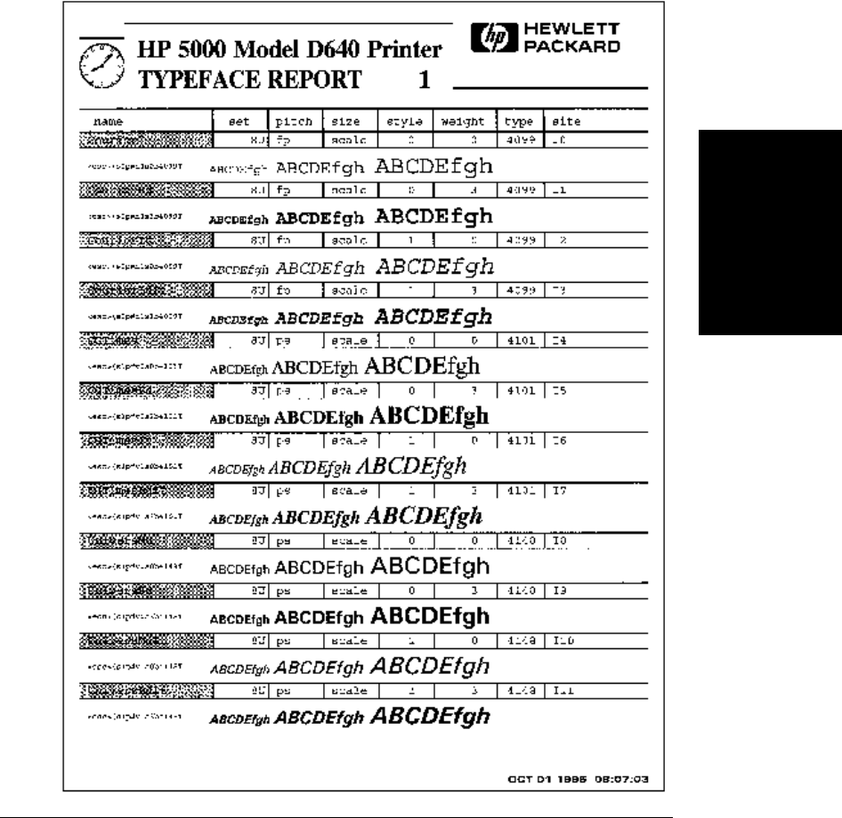
Typeface Report Key
Printing Reports E-9
Printing Reports
Figure E-4 Typeface Report Sample
1
2
The Symbol Set Table Report
E-10 Printing Reports
The Symbol Set Table Report
The printer has individual symbol sets for each typeface. This report shows the symbol set and
codes for the symbol set specified in the PCL menu setting. The printer prints a page for each
font in the printer.
To print the Symbol Set Table report:
1. At the Main Screen, press Test.
SETUPS is highlighted.
2. Press N to highlight TABLE.
3. Press Select.
A one page report is printed:
Figure E-5 lists the font name, code for the font, pitch, weight, and type code.
Symbol Set Table Report Key
a This is the time of day the Symbol Set Table Report was printed, shown in the upper left
corner as a clock face. It is also printed in the lower right corner as text.
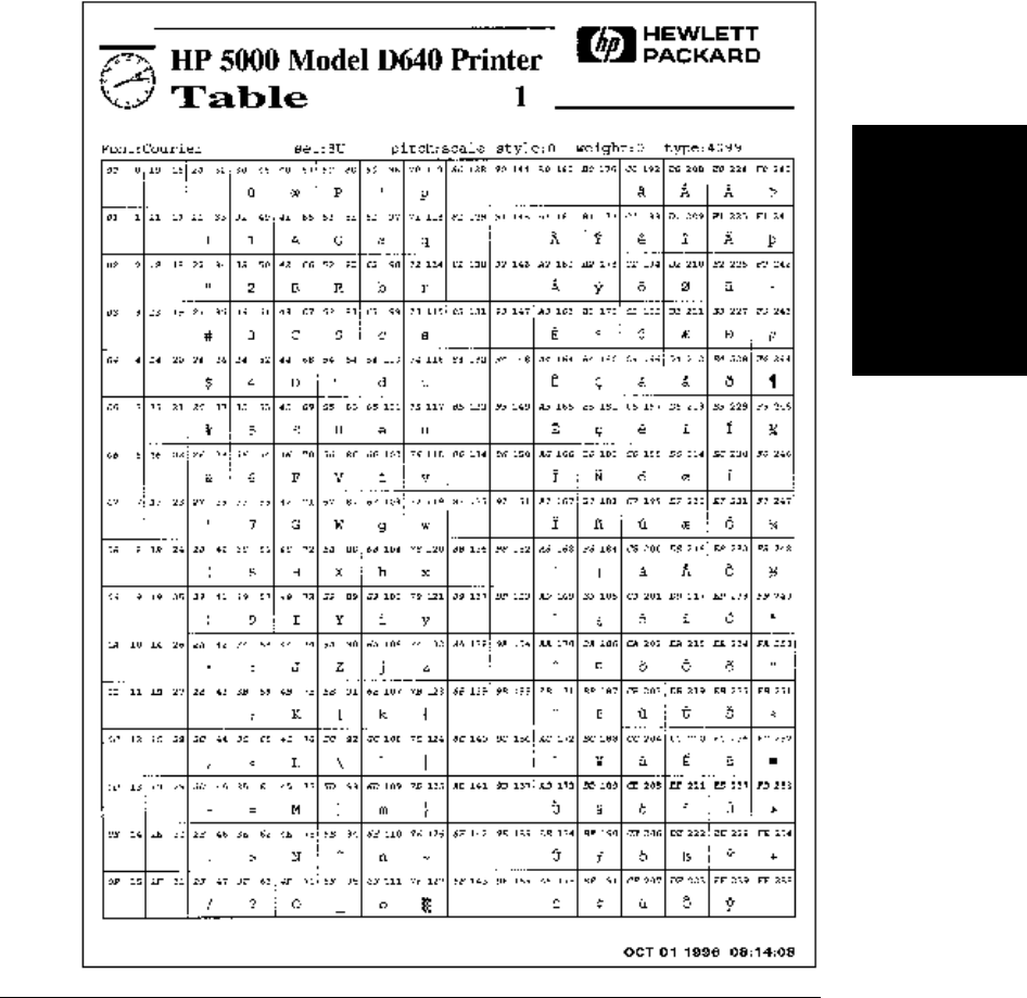
Symbol Set Table Report Key
Printing Reports E-11
Printing Reports
Figure E-5 Symbol Set Table Report Sample
1
The Printer Menu Settings Report
E-12 Printing Reports
The Printer Menu Settings Report
The printer can print a report showing the complete menu tree.
To print the Menu Settings report:
1. At the Main Screen, press Test.
SETUPS is highlighted.
2. Press N to highlight MENUS.
3. Press Select.
Figure E-6 identifies all Printing Menu, Configuration Menu, PCL Menu, Communications
Menu, Maintenance Menu, and Paper Size Menu settings.
In these examples of the Printer Menu Setting Report Pages, the default factory setting is
indicated by the "=" sign in front of the setting option.
Printer Menu Settings Report Key
a This is the time of day the Printer Menu Setting Report was printed, shown in the upper
left corner as a clock face. It is also printed in the lower right corner as text.
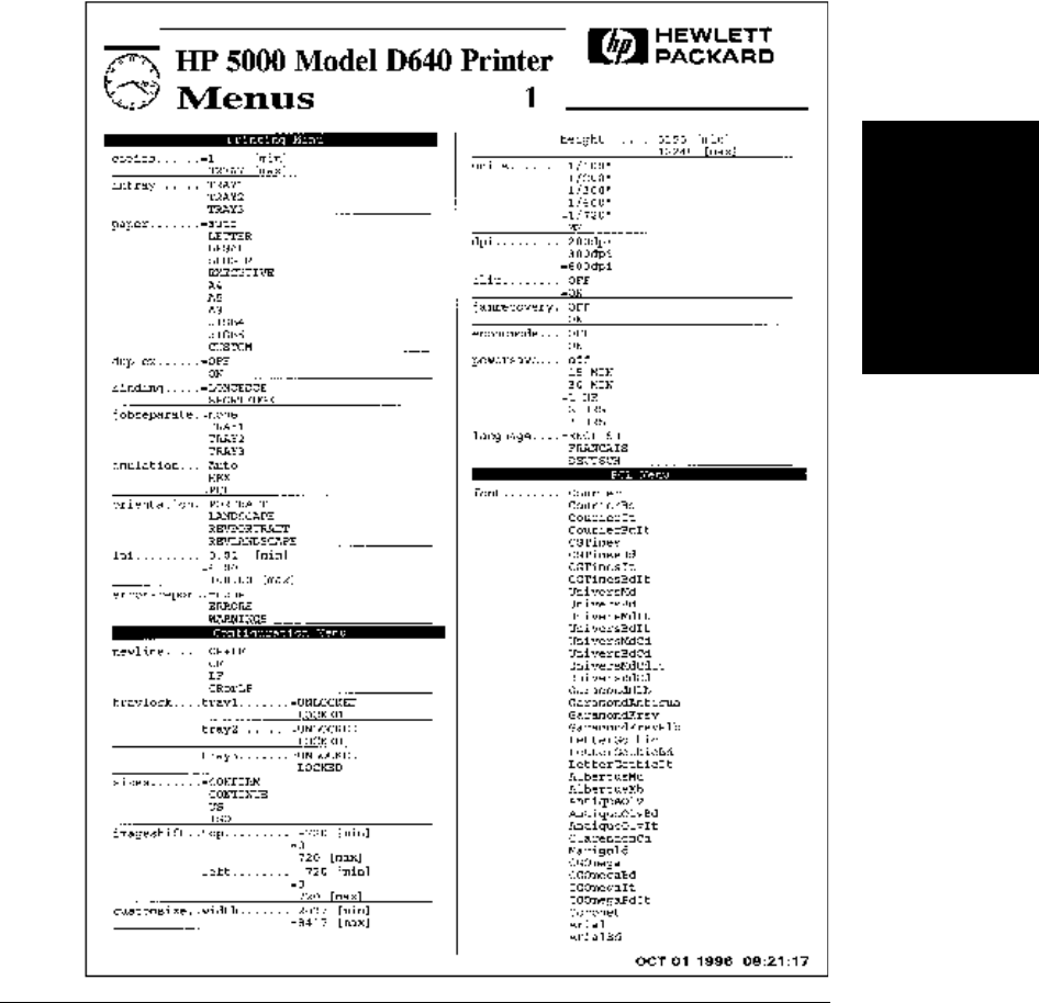
Printer Menu Settings Report Key
Printing Reports E-13
Printing Reports
Figure E-6 Printer Menus Report Sample (Sheet 1 of 3)
1
1
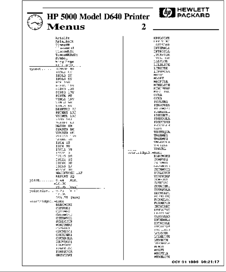
Printer Menu Settings Report Key
E-14 Printing Reports
Figure E-7 Printer Menus Report Sample (Sheet 2 of 3)
1
1
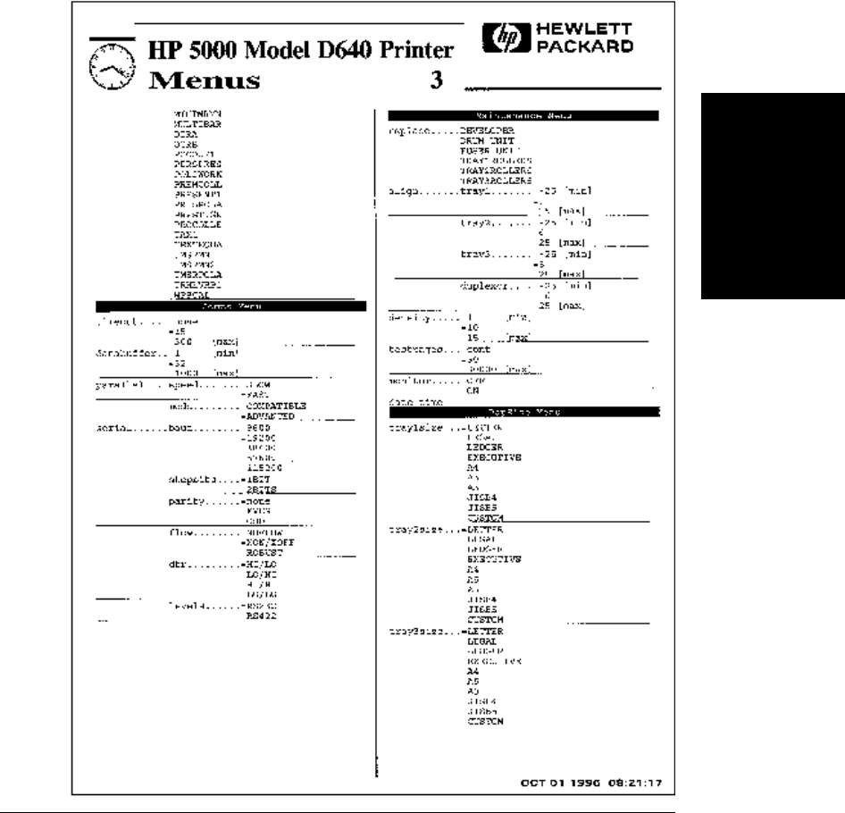
Printer Menu Settings Report Key
Printing Reports E-15
Printing Reports
Figure E-8 Printer Menus Report Sample (Sheet 3 of 3)
1
1

The Ripple Test Print
E-16 Printing Reports
The Ripple Test Print
The printer provides a test print ripple pattern that is useful in checking print quality and paper
feeding. The test print pattern uses the font and point size specified in the PCL menu.
To print a test print ripple pattern:
1. At the Main Screen, press Test.
SETUPS is highlighted.
2. Press N to TESTPRINT.
TESTPRINT is highlighted.
3. Press Select.
Note TESTPRINT will print several pages. You can change the number of pages printed by
altering the testpages configuration in the Maintenance menu (See “Maintenance Menu
Settings” on page 2-24).
Figure E-9 shows the ripple test pattern. The pattern allows visual observations of print quality.
Troubleshooting with the Ripple Test Pattern
The ripple test pattern can help determine if the printer is operating at optimum performance or
if it needs maintenance.
1. Look at the test pattern and other print jobs that indicate print quality problems.
2. Go to “Maintaining Print Quality” on page 6-1 and follow the instructions for comparing
your observations to the supplied problem samples.
3. Identify the problem with the sample and perform the maintenance as described.
The Ripple Test Print
Printing Reports E-17
Printing Reports
Figure E-9 Printer Ripple Test Pattern Sample

Warranty and Support F-1
Warranty and
Support
F
Warranty and Support
Where To Call For Help
We have established phone numbers for you to call and receive help should any questions or
problems arise during the installation of the D640 printer or any of its accessories. The
numbers listed are available during normal business hours of 8:00 AM to 5:00 PM. This phone
assistance is available free of charge (except phone tolls) during the first year after shipment of
your printer. You may call as often as necessary for assistance with the following items:
•Installation
•Configuration
•Daily use, such as clearing paper jams or installing consumables
•Questions about the manuals
Prior to calling you should have your printer’s serial number available. This can be found on a
label located on the upper right corner of the printer when the printers front door is open. It will
look like "JP20000149". In addition, have your question ready and be near the printer if
necessary.
After the first year you may continue to use this service for a per-call fee, which will be
specified when you call.
Note Please call your local HP Support Organization for all service related issues and for all
locations that are not directly listed. Refer to the next page for a list of regional Support
Organization telephone numbers.
For installation and general printer questions, call:
•The toll-free number in the US and Canada is:
1-888-223-6774
•The alternate number for the US, Canada, and for English speaking callers is:
1-208-422-9102
•In Europe, use the numbers in Table F-1, “European installation support” to reach HP’s
European support center in Amsterdam.

Where To Call For Help
F-2 Warranty and Support
For hardware problems, call:
•In the US and Canada:
1-800-633-3600
•In Europe:
•31-20-682-26-28 (English)
•31-20-681-78-10 (German)
•31-20-681-77-50 (French)
For the rest of the world, use the numbers in Table F-2, “International hardware support”.
Table F-1 European installation support
Austria 0660 6386 Netherlands 020 6068751
Belgium (Dutch) 02 626 8806 Norway 22 11 6299
Belgium (French) 02 626 8807 Portugal 01 441 7199
Finland 0203 47288 Spain 902 321 123
France 04 50 43 9853 Sweden 08 619 2170
Germany 0180 5 25 81 43 Switzerland 0848 80 11 11
Ireland 01 662 5525 UK 0171 512 5202
Italy 02 26410350

Where To Call For Help
Warranty and Support F-3
Warranty and
Support
Table F-2 International hardware support
Area Address Telephone
Canada
Hewlett-Packard Ltd. 5150 Spectrum Way, Mississauga, Ontario, L4W 5GI 905-206-4725
Hewlett-Packard Ltd. 101, 17971-106A Avenue, Edmonton, Alberta T5S 1V8 403-425-4725
Hewlett-Packard Ltd. 17500 Trans Canada Highway, South Service Road,
Kirkland, Quebec H9J 2X8 514-697-4232
Latin America
Hewlett-Packard
de Mexico Prolongacion Reforma 700, Lomas de Santa Fe, 01210
Mexico, D.F. 525-258-4077
Hewlett-Packard
Argentina S.A. Montaneses 2140/50/60, 1428 Buenos Aires, Argentina 54-1-787-7100
Edisa
Hewlett-Packard S.A. R. Aruana, 125-Tambore, 06460-010-Barueri-Sao
Paulo, Brazil 55-11-726-4700
Australia and New Zealand
Hewlett-Packard Ltd. 31-41 Joseph Street, Blackburn, Victoria 3130, Australia 61-3-272-2895
Hewlett-Packard
(NZ) Ltd. 186-190 Willis Street, P.O. Box 9443, Wellington, New
Zealand 64-4-802-6800
Japan
Hewlett-Packard
Japan, Ltd. 9-1 Takakura-cho, Hachioji-shi, Tokyo 192 81-426-60-2111
Hewlett-Packard
Japan, Ltd. Forum honjo 2F, 2-4-1 Honjo, Matsumoto-shi,
Nagano 390 81-263-39-2454
Hewlett-Packard
Japan, Ltd. 6-6 Hosojima-cho, Hamamatsu-shi, Shizuoka 435 81-53-466-6231

Where To Call For Help
F-4 Warranty and Support
Europe
Hewlett-Packard GmbH Lieblgasse 1, A-1200 Vienna, Austria 43-1-25000-555
Hewlett-Packard A/S Kongevejen 25, DK-3460 Birkeroed, Denmark 45-99-10-00
Hewlett-Packard Oy, Tekniset palvelut, Piispankalliontie 17, 02200 Espoo,
Finland 358-9-88721
Hewlett-Packard GmbH Kunden-Informations-Zentrum, Berliner Strasse 111,
D-40880 Ratingen, Germany 0180-5-32-62-
99
Hewlett-Packard
Italiana, S.p.A. Via G.di Vittorio, 9, 1-20063 Cernusco S/N (MI), Italy 39-2-92124341
Hewlett-Packard B.V. Startbaan 16, 1180 AR Amstelveen, The Netherlands 31-20-5476432
Hewlett-Packard
Norge AS Postboks 60, Skoeyen, 0212 Oslo, Norway 47-22-73-59-05
Hewlett-Packard
Polska sp.z 0.0. A1. Jerozolimskie 181, 02-222 Warszawa, Polska 48-22-608-7700
Hewlett-Packard
Portugal, S.A. Edificio Escritorios Parque Oceano, 5 Pisco-F,
Sto Amaro de Oeiras, 2780 Oeiras, Lisboa, Spain 351-1-482-85-
00
Hewlett-Packard
Espanola, S.A. Ctra. N-VI, KM. 16,5000, 28230 Las Rozas, Madrid,
Spain 34-1-631-16-00
Hewlett-Packard Avda. Diagonal, 605, 08028 Barcelona, Spain 34-3-401-91-00
Hewlett-Packard
(Schweiz) AG In der Luberzen 29, 8902 Urdorf/Zurich, Switzerland 01-735-71-11
Hewlett Packard
(Suisse) S.A. 39, Rue de Veyrot, 1217 Meyrin 1, Switzerland 022-780-44-46
Hewlett-Packard Amen Corner, Cain Road, Bracknell, Berks RG12 1HN,
England 1344-360000
Table F-2 International hardware support
Area Address Telephone

Where To Call For Help
Warranty and Support F-5
Warranty and
Support
India and Far East Area
China
Hewlett-Packard Co.,
Ltd.
5-6/F, West Wing Office, China World Trade Centre,
No. 1 Jian Guo Men Wai Avenue, Beijing, 100004,
People’s Republic of China
86-10-
65053888
Hewlett-Packard 17-21/F Shell Tower, Time Square, 1 Matheson Street,
Causeway Bay, Hong Kong 852-2599-7090
Hewlett-Packard India,
Ltd. Paharpur Business Center, 21 Nehru Place, New Delhi
110 019, India 91-11-6472311-
2328-2329-
2330
P.T. Hewlett-Packard Servisindo Gedung Berca, Jalan Abdul Muis 62, Jakarta
10160, Indonesia 62-21-351-8788
Hewlett-Packard Korea 25-12, Yoido-dong, Youngdeungpo-gu, Seoul 150-010,
Korea 82-2-769-0114
Hewlett-Packard Ground Floor Wisma Cyclecarri, 288 Jalan Raja Laut,
50350 Kuala Lumpur, Malaysia 02-03-298-6555
Phillipines
Corporation 9th Floor, Rufine Pacific Towers, 6784 Ayala Avenue,
Makati City, Metro Manila 1229, Phillipines 632-894-1451
Hewlett-Packard
Singapore Pte Ltd. 450 Alexandra Road, Singapore 119960 65-275-3888
Hewlett-Packard
Taiwan Ltd. 8th Floor, HP Building, 337 Fu Hsing North Road,
Taipei, Taiwan 886-2-712-0404
Hewlett-Packard Ltd. 23-25/F Vibulthani Tower II, 3199 Rama IV Road,
Klongtan, Klong Toey, Bangkok 10110, Thailand 662-661-3900-
34
Hewlett-Packard
Vietnam Tecasin Business Centre, 243-243B Hoang Van Thu,
Unit G10-12, Tan Binh District, Vietnam 84-8-844-3441
Table F-2 International hardware support
Area Address Telephone
Warranty
F-6 Warranty and Support
Warranty
HP Maintenance Agreements
Hewlett-Packard has several types of maintenance agreements that meets a wide range of
support needs.
On-Site Service Agreements
To provide you with the support level best suited to your system usage and support budget, HP
has on-site service agreements with two response times:
Priority On-Site Service is designed for production-critical applications, giving you four-hour
service response to your site for calls made during normal HP business hours.
Next Day On-Site Service provides on-site support by the next working day following your
service request. Extended coverage hours and extended travel beyond HP designated service
zones are available for additional charges on most on-site service agreements.
HP5000 Model D640 Warranty
This warranty entitles you to standard warranty services for your HP5000 Model D640 printer
and is available from HP worldwide. However, there may be local variations in the level of
warranty service. You should contact the local HP Service Center to check for the applicable
local warranty in your country or province.
90 Day On-Site Limited Warranty
Hewlett-Packard warrants the HP5000 Model D640 printer and accessories against defects in
materials and workmanship for a period of 90 days from purchase by the end user. During the
warranty period, HP will, at its option, either repair or replace products which prove to be
defective. The warranty period begins on either the date of delivery, or, where the
purchase price includes installation by Hewlett-Packard, on the date of installation.
To have your HP5000 Model D640 printer serviced by HP, contact the closest HP Service
Center.
Exclusions
The warranty on your HP5000 Model D640 printer and accessories shall not apply to defects
resulting from:
•Improper or inadequate maintenance by customer.
•Customer supplied software or interfacing.
•Unauthorized modification or misuse.
•Operation outside of the environmental specifications for the product.
•Operation of non-supported printing media.
•Duty cycle abuse (see note below)

Warranty
Warranty and Support F-7
Warranty and
Support
•Operating the printer from a mechanical switch box without a designated surge protector.
•Improper site preparation and maintenance.
•Failure to perform key operator maintenance, as specified in the D640 User Manual.
•Use of non-HP consumables (see note below), memory boards, interface boards, or
adapters.
Note The use of non-HP consumable supplies alone does not affect either your warranty or
any maintenance contract you may have purchased. However, if an HP 5000 D640 printer
failure or damage is found to be to be attributable directly to the use of a non-HP consumable,
HP will not repair the printer free-of-charge. In this case, standard time and materials charges
will be applied to service your printer for that particular failure or damage
Operation of the printer beyond the limit of its duty cycle (printing greater than the equivalent
of 300,000 single-sided pages per month) shall be deemed printer abuse and all repairs thereaf-
ter will be billed on a time and materials basis.
If you are using a mechanical switchbox, ensure that it is equipped with a surge protector.
Damage to your printer could occur from the use of unprotected mechanical switch boxes.
Limitations
The warranty set forth above is exclusive and no other warrants, whether written or oral, is
expressed or implied. Hewlett-Packard specifically disclaims the implied warranties of
merchantability and fitness for a particular purpose.
Service During The Warranty Period
If your hardware should fail during the warranty period, contact an authorized HP dealer or
your local Customer Service Center.
Service After The Warranty Period
If your hardware should fail after the warranty period, contact an authorized HP dealer or your
local Customer Service Center. If you have an HP Maintenance Agreement, request service
under your agreement.

Index-1
A
AC input power connector 1-15
accessories, printer 1-2, C-7
adding, developer 4-12
adjusting
paper guides 3-3, 3-4, 3-8
paper path alignment 6-11 to 6-22
alignment
duplex 6-19
measuring 6-15
paper path 6-11
printing alignment sheets 6-12
setting values 6-20
arrows, continuation 2-8
C
call engineer, messages A-8
caution messages iv
checking
paper 2-5
printer status 2-3
cleaning
duplex area 5-6
LED array area 5-10
paper feed area 5-4
paper input trays 5-4
periodic 5-5 to 5-12
precharger area 5-3
printer exterior 5-5
required tools 5-1
reversing unit area 5-5
toner hopper area 5-2
transfer assembly 5-6
transfer assembly guide 5-9
weekly 5-1 to 5-5
cleaning roller 1-11
replacing 4-7
clearing, paper jams 3-22 to 3-49
See also paper jams 5-4
Comms menu 2-21
compatibility
LaserJet 1-1, 1-4, 6-24
Configuration menu 2-14
configuring
for LaserJet compatibility 6-24
paper size 2-26
parallel interface B-4
serial interface 2-23, B-1 to B-3
connector
HCI 1-15
HCO 1-15
parallel interface B-1
serial interface B-1
consumables
developer 4-9
drum kit 4-18
fuser kit 4-29
HCI pick roller kit 4-42
introduction to 4-1
list of 4-3
managing 6-6
ordering 4-2
overview 4-2
pick roller kit 4-33
replacement cycle 4-2
replacing 1-2
toner 4-4
tracking 1-2
continuation arrows 2-8
control panel 1-7
display brightness 2-2
features 2-2
function buttons 2-2
introduction 2-1
navigating 2-7
Custom menu 2-9
custom paper 1-3, 2-27, 3-10
custom paper tray 3-8 to 3-15
specifications C-12
D
decurler lever 1-11
developer 1-13, 6-9
adding 4-12
replacing 4-9
developer collector bottle 1-13
installing 4-16
developer fill lid 4-14
developer kit 4-3
Index
Index-2
developer purge bottle 4-16
display brightness 1-18, 2-2
documentation holder 1-15
drum 1-11, 6-9
installing 4-24
removing 4-21
unpacking 4-23
drum kit 4-3, 4-18
replacing 4-18
duplex
alignment 6-19
jams 3-38
printing 1-1, 1-2
printing edge-to-edge 6-23
duplex area, cleaning 5-6
E
economode 2-17, 6-7
edge-to-edge printing 6-23
ejection unit 1-7, 1-15, 3-43
Energy Star compliance 1-4, C-15
error messages 3-49, A-7
F
floppy disk drive 1-9
font cartridges. See virtual font cartridges
fonts, 4si compatibility 6-26
forms, printing 1-1, D-11
function buttons 2-2, 2-6
fuser 1-11, 6-10, D-1
installing 4-31
paper jams 3-36
removing 4-30
fuser kit 4-3
replacing 4-29
fuser locking knob 1-11
H
hard disk 1-4
HCI 1-3, 1-16
capacity 1-16
connector 1-15
dimensions chart C-8, C-11
door 1-16
electrical specifications C-9
loading 3-16
paper jams 3-32
paper shelf lowering button 1-16
release handle 1-16
service area C-8
service area requirements C-11
specifications C-7
weight C-8, C-11
HCO 1-17, C-11
acoustics C-14
capacity 1-17
connector 1-15
electrical C-11
heat production C-11
operating humidity C-12
operating temperature C-12
paper capacity C-10
paper handling C-10
paper jams 3-45
paper sizes C-10
power consumption C-11
processing speed C-10
separating from printer 3-48
specifications C-10
high-capacity input. See HCI
high-capacity output. See HCO
Index-3
I
input capacity 1-1, C-7
installing
developer collector bottle 4-16
drum 4-24
fuser 4-31
paper trays 3-2
pick rollers 4-47
transfer assembly 4-27
interrupting, printing 3-21
J
jams. See paper jams
L
labels
adhesive D-12
arrangement D-12
carrier sheet D-12
die-cuts D-12
printing in duplex mode D-13
size D-17
specifications D-13
laser standards C-16
LaserJet
compatibility 1-1, 1-4, 6-24
LCD display 1-3
See also control panel
LED array area, cleaning 5-10
loading, paper 3-16
locking, paper trays 3-18
M
Main Screen 2-3, 3-10, 3-12
maintenance
agreement F-6
introduction 5-1
periodic cleaning 5-5
print quality 6-1
weekly cleaning 5-1
Maintenance menu 2-24
Maintenance report E-6
managing, consumables 6-6
measuring, alignment 6-15
media, selection D-3
memory, printer 1-1, C-2, C-7
menus
Comms 2-21
Configuration 2-14
Custom 2-9
Maintenance 2-24
PapSize 2-26
PCL 2-19
Printing 2-11
Test 2-28
messages
call engineer A-8
caution iv
error A-7
paper jams A-5
status A-3
warning iv, A-4
misfeeds, causes of D-5
O
optional accessories, specifications C-7
ordering
consumables 4-2
output tray 1-7
ozone filter 1-15, 6-11
replacing 4-17
P
paper
checking 2-5
guidelines for use 3-16
HCO capacity C-10
loading 3-16
orientation in trays 3-17
selection D-3
size C-2
sizes 2-5, 2-6
specifications D-1 to D-24
stacker capacity C-2
tray capacity C-2
Index-4
paper feed area
cleaning 5-4
paper guides
adjusting 3-3, 3-4, 3-8
custom 3-8
paper indicators 1-7
paper input trays, cleaning 5-4
paper jams
clearing 3-22 to 3-49
in duplex unit 3-38
in feed path 3-26
in fuser unit 3-36
in HCI 3-32
in HCO 3-45
in reversing unit 3-40
messages A-5
paper path 2-5
adjusting alignment 6-11 to 6-22
paper side exit 1-15
paper size
configuring 2-26
setting custom 3-10
setting standard 3-7
table 2-6
paper trays 6-24
adjusting guides 3-3
default 6-25
installing 3-2
locking 3-18
removing 3-2
paper, custom 1-3
PapSize menu 2-26
parallel interface
configuring B-4
connector B-1
parallel port 1-15
PC card slot 1-9
PCL 1-4
PCL menu 2-19
pick rollers
HCI 4-3
installing 4-47
printer 4-3, 4-33
replacing 4-33, 4-42
PostScript 1-3, C-12
power cord 1-17
power source, disconnecting v
power switch, main 1-7, 1-18
powering on, printer 1-18
Powersave indicator 2-3
precharger area, cleaning 5-3
print media D-1
print quality 6-23
degraded 6-23
maintaining 6-1
problems 6-2
troubleshooting 6-1, 6-4
printer
accessories 1-2
dimensions C-3, C-4
fonts 6-26, C-2
hard disk 1-4
heat production C-5
interfaces C-2
memory 1-1, C-2, C-7
orientation 1-5
physical dimensions C-4
pick rollers 4-3, 4-33
power consumption C-5
powering on 1-18
resetting A-1
resolution 1-1, 1-2
service area dimensions C-5
specifications C-2 to C-6
standard features 1-1
status 2-3
support F-1
warranty F-6
weight C-3
Index-5
printer control language. See PCL
printer exterior, cleaning 5-5
Printer Menu Settings report E-12
Printer Setup report E-1
printing
alignment sheets 6-12
duplex 1-1, 1-2
edge-to-edge 6-23
forms 1-1, D-11
input capacity 1-1
reports 2-28
resolution C-2
speed C-2
stopping or interrupting 3-21
Printing menu 2-11
R
recycling
toner 1-3, 6-8
removing
drum 4-21
fuser 4-30
paper trays 3-2
replacing
cleaning roller 4-7
consumables 1-2
developer 4-9
drum kit 4-18
fuser kit 4-29
ozone filter 4-17
pick rollers 4-42
toner 4-4
toner collector bottle 4-7
transfer assembly 4-19
reports
Maintenance E-6
Printer Menu Settings E-12
Printer Setup E-1
printing 2-28, E-1 to E-16
Ripple Test Print E-16
Symbol Set Table E-10
Typeface E-8
resetting, printer A-1
resolution, printer 1-1, 1-2
reversing unit area, cleaning 5-5
Ripple Test Print report E-16
S
screen contrast control 1-7
serial interface
configuring 2-23, B-1 to B-3
connector 1-9, 1-15, B-1
specifications
best print area C-6
custom paper tray C-12
HCI C-7
HCO C-10
introduction C-1
optional accessories C-7
printer C-2 to C-6
transparencies D-14
standby switch 1-7, 2-2
status
checking 2-3
messages A-3
printer 2-3
stopping, printing 3-21
support F-1
switch
main power 1-7, 1-18
standby 1-7, 2-2
Symbol Set Table report E-10
T
temperature hazards iv
Test menu 2-28
toner 4-5, 6-7
recycling 1-3, 6-8
removing stray 5-2
replacing 4-4
toner collector bottle 1-13
replacing 4-7
toner fill lid 4-5
toner hopper 1-13
toner hopper area, cleaning 5-2
toner kit 4-3

READER COMMENT SHEET
System Peripherals Operation
D640 Cut Sheet Printer User Manual
Manual Part Number C5620-90024
March 1997
A reader comment sheet helps us improve the accuracy and readability of this User Manual. It also
gives you a way to make suggestions and recommend improvements to the product.
Serious errors, such as technical inaccuracies that may render a program or mechanical device inopera-
tive, should be reported immediately to your Hewlett Packard Response Center or directly to a Support
Engineer. This ensures that such problems are addressed as quickly as possible.
Editorial suggestions (please include page, table, and figure numbers):
Recommendations (attach additional information, if needed):
Name: Date:
Job Title: Telephone:
Company:
Address:
Hewlett-Packard has the right to use submitted suggestions without obligation, with all such ideas
becoming the property of Hewlett-Packard.

Manual Part No.
C5620-90024
Copyright © 1997
Hewlett-Packard
E0397
Printed in USA
