Hp Eva3000 Disk Array Users Manual StorageWorks 3000/5000 Enterprise Virtual User Guide (VCS 4.xxx)
2015-01-05
: Hp Hp-Eva3000-Disk-Array-Users-Manual-156638 hp-eva3000-disk-array-users-manual-156638 hp pdf
Open the PDF directly: View PDF ![]() .
.
Page Count: 165 [warning: Documents this large are best viewed by clicking the View PDF Link!]

HP StorageWorks 3000/5000 Enterprise
Virtual Array user guide (VCS 4.xxx)
Part number: 5697-7026
Twelfth edition: October 2007
Legal and notice information
© Copyright 2003-2007 Hewlett-Packard Development Company, L.P.
The information contained herein is subject to change without notice. The only warranties for HP products and services are set forth
in the express warranty statements accompanying such products and services. Nothing herein should be construed as constituting
an additional warranty. HP shall not be liable for technical or editorial errors or omissions contained herein.
Windows, Windows NT, and Windows XP are U.S. registered trademarks of Microsoft Corporation.
Java is a US trademark of Sun Microsystems, Inc.

Contents
Aboutthisguide .......................... 13
Intendedaudience..................................... 13
Relateddocumentation................................... 13
Documentconventionsandsymbols ............................. 13
Rackstability ....................................... 14
HPtechnicalsupport.................................... 14
Customerselfrepair .................................... 15
Productwarranties..................................... 15
Subscriptionservice .................................... 15
HPwebsites........................................ 15
Documentationfeedback .................................. 15
1EnterpriseVirtualArraydescription.................. 17
IntroductiontotheEnterpriseVirtualArray........................... 17
Featuresandenhancements................................. 17
Easeofmanagement.................................. 17
Dataavailability.................................... 17
Performance ..................................... 18
Scalability ...................................... 18
Operatingsystemsupport................................ 18
Faultmanagementanddiagnostics............................ 19
EVAremotesupporttools................................ 19
Storagesystemcomponents................................. 19
HPCommandViewEVA ................................ 19
Controllersoftware................................... 20
VCSfeaturesandfunctionality............................ 20
Softwarelicensing................................. 20
Hardware ...................................... 20
Physicallayoutofthestoragesystem ......................... 21
FibreChanneldriveenclosure............................ 21
FibreChannelloopswitches............................. 22
HSV110andHSV100controllers........................... 22
Racks ...................................... 22
2EnterpriseVirtualArraystartup .................. 25
EVA5000storagesystemconnections............................. 25
EVA3000storagesystemconnections............................. 26
Proceduresforgettingstarted ................................ 27
Gatheringinformation ................................. 27
Hostinformation.................................. 28
SettingupacontrollerpairusingtheOCP......................... 28
EnteringtheWWN ................................ 29
EnteringtheWWNchecksum............................ 29
Enteringthestoragesystempassword......................... 30
InstallingHPCommandViewEVA ............................ 30
InstallingoptionalEVAsoftwarelicenses ......................... 31
3EnterpriseVirtualArrayoperation ................. 33
Bestpractices....................................... 33
HP StorageWorks 3000/5000 Enterprise Virtual Array user guide (VCS 4.xxx) 3
Operatingtipsandinformation ............................... 33
Reservingadequatefreespace ............................. 33
UsingFATAdiskdrives................................... 33
FailbackpreferencesettingforHSVcontrollers......................... 33
Changingvirtualdiskfailover/failbacksetting....................... 36
Storagesystemshutdownandpowerup............................ 37
Shuttingdownthestoragesystem ............................ 37
Poweringupthestoragesystem ............................. 37
Saving storage system configurationdata ........................... 38
Addingdiskdrivestothestoragesystem ........................... 39
Guidelinesforaddingdiskdrives ............................ 39
Creatingdiskgroups.................................. 40
Addingadiskdrive .................................. 41
Removingthedriveblank.............................. 41
ChangingtheDeviceAdditionPolicy......................... 42
Installingthediskdrive............................... 42
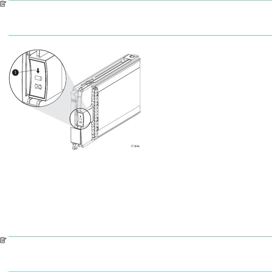
Checkingstatusindicators.............................. 42
Addingthedisktoadiskgroup ........................... 95
Handling fiberopticcables................................. 43
4EnterpriseVirtualArrayhardwarecomponents............ 45
FibreChanneldriveenclosures................................ 45
Enclosurelayout.................................... 45
I/Omodules ..................................... 46
I/Omodulestatusindicators ............................ 47
FibreOpticFibreChannelcables ............................ 49
CopperFibreChannelcables .............................. 49
FibreChanneldiskdrives................................ 49
Diskdrivestatusindicators ............................. 50
Diskdrivestatusdisplays .............................. 50
Diskdriveblank.................................. 51
Powersuppliesandblowers............................... 51
Powersupplies .................................. 52
Blowers ..................................... 52
DriveenclosureEMU.................................. 53
Controlsanddisplays ............................... 53
EMUfunctions................................... 54
EMUmonitoringfunctions.............................. 55
EMUdisplays................................... 55
EMUindicatordisplays............................... 56
Usingthealphanumericdisplay ........................... 56
EMUpushbuttonstatusindicators .......................... 57
Audiblealarmoperations.............................. 57
Enablingtheaudiblealarm............................. 58
Mutingorunmutingtheaudiblealarm ........................ 59
Disablingtheaudiblealarm............................. 59
Enclosurenumberfeature.............................. 60
ErrorConditionReporting.............................. 62
Reportinggroupfeature............................... 65
FibreChannelloopswitches................................. 66
Power-onselftest(POST) ................................ 67
Readingtheswitchindicators .............................. 67
Problemisolation ................................... 68
HSVcontrollers ...................................... 69
Highavailabilityfeatures................................ 70
Operatorcontrolpanel................................. 70
Statusindicators.................................. 71
Navigationbuttons................................. 72
Alphanumericdisplay ............................... 72
DisplayingtheOCPmenutree............................ 72
4
Displayingsysteminformation............................ 73
Displayingversionssysteminformation ........................ 73
Shuttingdownthesystem.............................. 74
Shuttingthecontrollerdown............................. 74
Restartingthesystem................................ 75
Uninitializingthesystem .............................. 75
Passwordoptions ................................. 75
Changingapassword ............................... 75
Clearingapassword................................ 76
SettingupacontrollerpairusingtheOCP....................... 76
Powersupply/blowerassembly ............................. 76
Cachebattery..................................... 77
HSVcontrollercabling ................................. 77
Racks .......................................... 77
Rack configurations .................................. 77
Powerdistribution ................................... 77
PDUs ...................................... 78
PDMs ...................................... 79
RackACpowerdistribution............................. 80
RackSystem/Epowerdistributioncomponents..................... 81
Movingandstabilizingarack.............................. 82
5Customerreplaceableunits.................... 85
Customerselfrepair(CSR) ................................. 85
Partsonlywarrantyservice ............................... 85
Bestpracticesforreplacinghardwarecomponents ....................... 85
Verifyingcomponentfailure............................... 85
Procuringthesparepart ................................ 85
Replaceableparts................................... 86
Replacingthefailedcomponent ............................. 88
Returningthedefectivepart............................... 88
Beforeyoubegin ..................................... 88
Diskreplacementvideo................................. 88
Typesofdiskfailures.................................... 89
Checkingsystemredundancy ................................ 89
Verifyingcomponentfailure................................. 90
Removingadisk...................................... 93
ChangingtheDeviceAdditionPolicy............................. 93
Installingadisk...................................... 94
Verifyingproperoperation ................................. 94
Addingthedisktoadiskgroup ............................... 95
Returningthefailedcomponent ............................... 95
Replacingthediskenclosurepowersupply/blower....................... 95
Beforeyoubegin ................................... 96
Verifyingcomponentfailure............................... 96
Removingablower .................................. 97
Installingablower................................... 97
Removingapowersupply................................ 98
Installingapowersupply................................ 98
Verifyingproperoperation ............................... 99
Returningthefailedcomponent ............................. 99
A Regulatory notices and specifications................ 101
Regulatorynotices..................................... 101
FederalCommunicationsCommission(FCC)notice..................... 101
FCC Class A certification.............................. 101
ClassAequipment................................. 101
ClassBequipment................................. 102
Declaration of conformity for products marked with the FCC logo, United States only . . . . . 102
HP StorageWorks 3000/5000 Enterprise Virtual Array user guide (VCS 4.xxx) 5
Modifications................................... 102
Cables...................................... 102
Laserdevice ..................................... 102
Lasersafetywarnings................................ 102
CompliancewithCDRHregulations ......................... 103
Certification and classificationinformation......................... 103
Canadiennotice(avisCanadien) ............................ 103
ClassAequipment................................. 103
ClassBequipment................................. 103
Europeanunionnotice ................................. 103
NoticeforFrance ................................... 104
WEEERecyclingNotices ................................ 104
Englishnotice................................... 104
Dutchnotice ................................... 104
Czechoslovakiannotice............................... 104
Estoniannotice .................................. 105
Finnishnotice................................... 105
Frenchnotice ................................... 105
Germannotice .................................. 105
Greeknotice ................................... 106
Hungariannotice ................................. 106
Italiannotice ................................... 106
Latviannotice................................... 106
Lithuaniannotice ................................. 107
Polishnotice ................................... 107
Portuguesenotice ................................. 107
Slovakiannotice.................................. 107
Sloveniannotice.................................. 108
Spanishnotice .................................. 108
Swedishnotice .................................. 108
Germanynoisedeclaration ............................... 108
Japanesenotice.................................... 109
Harmonicsconformance(Japan)........................... 109
Taiwanesenotice ................................... 109
Japanesepowercordnotice............................... 109
Country-specific certifications .............................. 109
Fibre Channel drive enclosure specifications.......................... 110
Physical specifications ................................. 110
Environmental specifications............................... 110
Power specifications .................................. 111
Fibre Channel switch specifications.............................. 113
Controller specifications .................................. 113
Physical specifications ................................. 113
Power specifications .................................. 113
Environmental specifications............................... 114
Rack specifications..................................... 114
Physical specifications ................................. 114
Environmental specifications............................... 116
Power specifications .................................. 116
BEMU-generatedconditionreports ................. 119
Conditionreportformat................................... 119
Correctingerrors ..................................... 120
Driveconditions.................................... 120
0.1.en.01 CRITICAL condition—Drive configurationordrivelinkrate............ 120
0.1.en.02INFORMATIONcondition—Drivemissing................... 121
0.1.en.03INFORMATIONcondition—Drivesoftwarelockactive ............. 121
0.1.en.04CRITICALcondition—Loopadrivelinkrateincorrect .............. 122
0.1.en.05CRITICALcondition—Loopbdrivelinkrateincorrect .............. 122
Powersupplyconditions ................................ 122
6
0.2.en.01NONCRITICALCondition—PowersupplyACinputmissing........... 123
0.2.en.02UNRECOVERABLEcondition—Powersupplymissing.............. 123
0.2.en.03CRITICALcondition—Powersupplyloadunbalanced.............. 123
Blowerconditions ................................... 124
0.3.en.01NONCRITICALcondition—Blowerspeed................... 124
0.3.en.02CRITICALcondition—Blowerspeed ..................... 124
0.3.en.03UNRECOVERABLEcondition—Blowerfailure................. 125
0.3.en.04UNRECOVERABLEcondition—Blowerinternal ................ 125
0.3.en.05NONCRITICALcondition—Blowermissing.................. 125
0.3.en.06UNRECOVERABLEcondition—Noblowersinstalled.............. 125
Temperatureconditions................................. 125
0.4.en.01NONCRITICALcondition—Hightemperature................. 126
0.4.en.02CRITICALcondition—Hightemperature ................... 126
0.4.en.03NONCRITICALcondition—Lowtemperature ................. 127
0.4.en.04CRITICALcondition—Lowtemperature.................... 127
0.4.en.05UNRECOVERABLEcondition—Hightemperature ............... 127
EMUconditions.................................... 128
ResettingtheEMU................................. 128
07.01.01CRITICALcondition—EMUinternalclock ................... 128
07.01.02UNRECOVERABLEcondition—EMUinterrupted ................ 128
0.7.01.03UNRECOVERABLECondition—Powersupplyshutdown............. 129
0.7.01.04INFORMATIONcondition—EMUinternaldata ................ 129
0.7.01.05UNRECOVERABLEcondition—BackplaneNVRAM............... 129
0.7.01.10NONCRITICALcondition—NVRAMinvalidreaddata ............. 129
0.7.01.11NONCRITICALcondition—EMUNVRAMwritefailure.............. 129
0.7.01.12NONCRITICALcondition—EMUcannotreadNVRAMdata........... 130
0.7.01.13UNRECOVERABLEcondition—EMUloadfailure................ 130
0.7.01.14NONCRITICALcondition—EMUenclosureaddress............... 130
0.7.01.15UNRECOVERABLEcondition—EMUhardwarefailure.............. 131
0.7.01.16INFORMATIONcondition—EMUinternalESIdatacorrupted........... 131
0.7.01.17UNRECOVERABLEcondition—Powershutdownfailure ............. 131
0.7.01.18UNRECOVERABLEcondition—EMUhardwarefailure.............. 131
0.7.01.19UNRECOVERABLEcondition—EMUESIdriverfailure.............. 132
Transceiverconditions ................................. 132
0.F.en.01CRITICALcondition—Transceiverincompatibility................ 132
0.F.en.02CRITICALcondition—Transceiverdatasignallost ............... 132
0.F.en.03 CRITICAL condition—Transceiver fibrechanneldriveenclosurebusfault...... 133
0.F.en.04CRITICALcondition—Transceiverremoved .................. 133
0.F.en.05 CRITICAL condition—Invalid fibrechannelcharacter.............. 133
Voltagesensorandcurrentsensorconditions........................ 133
1.2.en.01NONCRITICALcondition—Highvoltage ................... 134
1.2.en.02CRITICALcondition—Highvoltage...................... 134
1.2.en.03NONCRITICALcondition—Lowvoltage ................... 134
1.2.en.04CRITICALcondition—Lowvoltage...................... 134
1.3.en.01NONCRITICALcondition—Highcurrent ................... 134
1.3.en.02CRITICALcondition—Highcurrent...................... 134
Backplaneconditions.................................. 135
8.2.01.10NONCRITICALcondition—BackplaneNVRAMread.............. 135
8.2.01.11NONCRITICALcondition—BackplaneNVRAMwritefailure ........... 135
8.2.01.12NONCRITICALcondition—BackplaneNVRAMreadfailure ........... 135
8.2.01.13NONCRITICALcondition—BackplaneWWNisblank ............. 135
I/OModuleconditions................................. 135
8.7.en.01CRITICALcondition—I/Omoduleunsupported ................ 136
8.7.en.02CRITICALcondition—I/Omodulecommunication ............... 136
8.7.en.10NONCRITICALcondition—I/OmoduleNVRAMread ............. 136
8.7.en.11NONCRITICALcondition—I/OmoduleNVRAMwrite ............. 136
8.7.en.12NONCRITICALcondition—I/OModuleNVRAMreadfailure .......... 137
8.7.en.13NONCRITICALcondition—I/Omoduleremoved................ 137
Hostconditions .................................... 137
HP StorageWorks 3000/5000 Enterprise Virtual Array user guide (VCS 4.xxx) 7
CControllerfaultmanagement ................... 139
UsingHPCommandViewEVA ............................... 139
GUIterminationeventdisplay................................ 139
GUIeventdisplay ................................... 140
Faultmanagementdisplays ............................... 140
DisplayingLastFaultInformation........................... 140
DisplayingDetailedInformation ........................... 141
Interpretingfaultmanagementinformation....................... 141
Glossary............................. 143
Index .............................. 159
8

Figures
1..EVA5000Storagesystemhardwarecomponents.................. 21
2..EVA5000 configuration............................. 26
3..EVA3000 configuration............................. 27
4..LocationoftheWorldWideNamelabels..................... 29
5..Diskdriveactivityindicator ........................... 40
6..Sequentialbuildingofverticaldiskgroups..................... 41
7..Removingthedriveblank............................ 41
8..Installingthediskdrive............................. 94
9..Diskdrivestatusindicators ........................... 43
10 ..FCdriveenclosure—frontandrearviews ..................... 46
11 ..I/O module.................................. 47
12 ..Inputandoutputports ............................. 47
13 ..FibreOpticFibreChannelcable......................... 49
14 ..CopperFibreChannelcable .......................... 49
15 ..Diskdrivestatusindicators ........................... 50
16 ..Powersupplyandblowerassemblycomponents .................. 51
17 ..EMUcontrolsanddisplays ........................... 54
18 ..EnclosurenumberingwithenclosureIDexpansioncables .............. 61
19 ..Enclosure address bus components with enclosure ID expansion cables . . . . . . . . 62
20 ..Displayingerrorconditionvalues......................... 65
21 ..FCloopswitch ................................ 67
22 ..HSVcontroller................................. 70
23 ..ControllerOCP ................................ 71
24 ..60–Hzand50–Hzwallreceptacles ....................... 78
25 ..DualPDUassembly .............................. 79
26 ..RackPDM .................................. 80
27 ..RackACpowerdistribution ........................... 81
28 ..Single rack configuration floorspacerequirements ................. 82
29 ..Raisingalevelerfoot.............................. 83
30 ..Typicalproductlabel.............................. 86
31 ..Diskdrivelabel ................................ 86
32 ..Selectingastoragesystem ........................... 90
33 ..Checkingredundancy ............................. 90
34 ..Diskstatusindicators.............................. 92
35 ..CheckingNodeWorldWideName ....................... 92
36 ..Monitoringungroupprogress .......................... 92
37 ..Checkingdiskgroupstatus ........................... 93
38 ..Removingadisk................................ 93
HP StorageWorks 3000/5000 Enterprise Virtual Array user guide (VCS 4.xxx) 9
39 ..Installingadisk ................................ 94
40 ..Checking model number and firmwareversion................... 95
41 ..Power supply/blowerstatusindicator....................... 97
42 ..Removingablower............................... 97
43 ..Installingablower............................... 98
44 ..Removingapowersupply............................ 98
45 ..Installing apowersupply............................ 99
46 ..Typical enclosure certificationlabel........................ 110
47 ..Powersupplyelementnumbering......................... 123
48 ..Blowerelementnumbering ........................... 124
49 ..DisconnectingACpower ............................ 131
50 ..Transceiverelementnumbering.......................... 132
51 ..I/Omoduleelementnumbering ......................... 136
52 ..GUIterminationeventdisplay.......................... 139
53 ..Typical HPCommandViewEVAEventdisplay ................... 140
10

Tables
1..Documentconventions ............................. 13
2..WWNpushbuttonfunctions .......................... 28
3..Systempasswordpushbuttonfunctions ...................... 30
4..Failbackpreferencesettings........................... 34
5..Failbacksettingsbyoperatingsystem....................... 36
6..Impact on virtual disk presentation when changing failover/failback setting . . . . . . . 36
7..OperationalI/Omodulestatusindicators..................... 48
8..Non-operationalI/Omodulestatusindicators ................... 48
9..Diskdrivestatusindicatordescriptions ...................... 50
10 ..Operationaldiskdrivestatusindications...................... 51
11 ..Non-operationaldiskdrivestatusindications.................... 51
12 ..Powersupply/blowerstatusindicators....................... 53
13 ..EMUmonitoringfunctions............................ 55
14 ..EMUstatusdisplays .............................. 55
15 ..EMU statusindications ............................. 56
16 ..EMUdisplaygroups .............................. 57
17 ..Audiblealarmsoundpatterns .......................... 58
18 ..Errorconditionreportingcharacteristics...................... 63
19 ..FibreChannelswitchsystemindicators ...................... 68
20 ..FibreChannelswitchportindicators ....................... 68
21 ..FibreChannelswitchbasictroubleshooting .................... 69
22 ..Controllerstatusindicators ........................... 71
23 ..Controllerportstatusindicators ......................... 71
24 ..Navigationbuttonfunctions........................... 72
25 ..MenuoptionswithintheOCPdisplay....................... 73
26 ..Shutdownmethods............................... 74
27 ..HardwarecomponentCSRsupport........................ 87
28 ..Drive enclosure physical specifications ...................... 110
29 ..Environmental operating specifications ...................... 111
30 ..Environmental shipping or short-term storage specifications.............. 111
31 ..EnterprisestoragesystemACinputlinevoltages .................. 111
32 ..ACinputcurrentandwattage .......................... 112
33 ..Output voltage and current specifications ..................... 112
34 ..Power specifications .............................. 112
35 ..Fibre Channel switch specifications........................ 113
36 ..Controller enclosure physical specifications .................... 113
37 ..ControllerpowersupplyACpowerrequirements .................. 113
HP StorageWorks 3000/5000 Enterprise Virtual Array user guide (VCS 4.xxx) 11
38 ..Controller power supply output specifications.................... 114
39 ..ACinputcurrentandwattage .......................... 114
40 ..9000-SeriesEnterprise42URackPhysicalDimensions................ 115
41 ..9000-SeriesEnterprise42URackShippingDimensions ............... 115
42 ..9000-SeriesEnterprise41URackPhysicalDimensions................ 115
43 ..9000-SeriesEnterprise41URackShippingDimensions ............... 115
44 ..10000-SeriesEnterprise42URackPhysicalDimensions ............... 115
45 ..10000-SeriesEnterprise42URackShippingDimensions............... 116
46 ..Environmental operating specifications ...................... 116
47 ..Environmental shipping or short term storage specifications.............. 116
48 ..Enterprise Virtual Array AC power specifications .................. 117
49 ..Assignedelementtypecodes .......................... 120
50 ..Temperaturesensorelementnumbering...................... 126
51 ..Voltageandcurrentsensorlocations ....................... 133
52 ..Controller event text description file........................ 142
12
About this guide
This user guide provides information about:
•Description of the HP StorageWorks Enterprise Virtual Array family and its components.
•Starting your storage system.
•Operating your storage system.
•Regulations and specifications.
•EMU-generated error condition reports.
•HSV fault management concepts.
•Installing customer replaceable units.
Intended audience
This book is intended for use by Enterprise Virtual Array customers involved in the installation, operation,
and management of EVA3000/5000 storage systems and who are experienced with the following:
•SANs and storage systems.
•Networking and virtual storage concepts.
•Enterprise Virtual Array products.
Related documentation
Additional product documentation is available from the following HP website:
http://www.hp.com/support/manuals
Click Disk Storage Systems under Storage, and then select the appropriate product under EVA Disk Arrays.
Document conventions and symbols
Table 1 Document conventions
Convention Element
Blue text: Table 1 Cross-reference links and e-mail addresses
Blue, underlined text: http://www.hp.com website addresses
Bold text •Keys that are pressed
•Text typed into a GUI element, such as a box
•GUI elements that are clicked or selected, such as
menu and list items, buttons, tabs, and check boxes
Italic text Text emphasis
Monospace text •File and directory names
•System output
•Code
•Commands, their arguments, and argument values
Monospace, italic text •Code variables
•Command variables
Monospace, bold text Emphasized monospace text
HP StorageWorks 3000/5000 Enterprise Virtual Array user guide (VCS 4.xxx) 13

WARNING!
Indicates that failure to follow directions could result in bodily harm or death.
CAUTION:
Indicates that failure to follow directions could result in damage to equipment or data.
IMPORTANT:
Provides clarifying information or specific instructions.
NOTE:
Provides additional information.
TIP:
Provides helpful hints and shortcuts.
Rack stability
WARNING!
To reduce the risk of personal injury or damage to equipment:
•Extend leveling jacks to the floor.
•Ensure that the full weight of the rack rests on the leveling jacks.
•Install stabilizing feet on the rack.
•In multiple-rack installations, secure racks together.
•Extend only one rack component at a time. Racks may become unstable if more than one component
is extended.
HP technical support
For worldwide technical support information, see the HP support website:
http://www.hp.com/support
Before contacting HP, collect the following information:
•Product model names and numbers
•Technical support registration number (if applicable)
•Product serial numbers
•Error messages
•Operating system type and revision level
•Detailed questions
14 About this guide

Customer self repair
HP customer self repair (CSR) programs allow you to repair your StorageWorks product. If a CSR part
needs replacing, HP ships the part directly to you so that you can install it at your convenience. Some
parts do not qualify for CSR. Your HP-authorized service provider will determine whether a repair can be
accomplished by CSR.
For more information about CSR, contact your local service provider. For North America, see the CSR
website:
http://www.hp.com/go/selfrepair
This product has no customer replaceable components.
Product warranties
For information about HP StorageWorks product warranties, see the warranty information website:
http://www.hp.com/go/storagewarranty
Subscription service
HP recommends that you register your product at the Subscriber’s Choice for Business website:
http://www.hp.com/go/e-updates
After registering, you will receive e-mail notification of product enhancements, new driver versions,
firmware updates, and other product resources.
HP websites
For additional information, see the following HP websites:
•h
ttp://www.hp.com
•http://www.hp.com/go/storage
•http://www.hp.com/service_locator
•http://www.hp.com/support/manuals
•http://www.hp.com/support/downloads
Documentation feedback
HP welcomes your feedback.
To make comments and suggestions about product documentation, please send a message to
StorageDocsFeedback@hp.com. All submissions become the property of HP.
HP StorageWorks 3000/5000 Enterprise Virtual Array user guide (VCS 4.xxx) 15
16 About this guide

1 Enterprise Virtual Array
description
This chapter provides an overview of Enterprise Virtual Array and its components.
Introduction to the Enterprise Virtual Array
The HP StorageWorks Enterprise Virtual Array family is a high performance, scaled capacity, on demand,
"virtual" RAID storage system.
This storage system is designed for environments where improved storage use and scalability is critical. It
meets application-specific demands for consistently high transaction I/O (input/output) and MB data
rate performance, and provides seamless capacity expansion, instantaneous replication, and simplified
storage administration.
The Enterprise Virtual Array (EVA) is available in multiple configurations—each optimized for
general-purpose commercial environments and high-performance technical computing environments. The
solutions include support for multivendor operating system platforms and stringent data center availability
enhancements, such as multipathing and clustering.
This guide includes information for two Enterprise Virtual Array products: EVA5000 and EVA3000.
•EVA5000—available in multiple configurations ranging from the single-rack 2C2D configuration
to the multi-rack 2C18D. The EVA5000 includes two HSV110 controllers and four FC loop switches.
•EVA3000—available in configurations ranging from the 2C2D configuration to the 2C4D
configuration. The EVA3000 includes two HSV100 controllers and no loop switches. Multiple
EVA3000s can be installed in a single rack.
Seer the HP StorageWorks Enterprise Virtual Array 3000/5000 hardware configuration guide for more
information about configurations. See “Related documentation” on page 13 for links to this document.
Features and enhancements
The Enterprise Virtual Array provides many features and enhancements which are detailed in the sections
that follow.
Ease of management
Easy-to-use storage management tools:
•Software tools that allow you to manage larger SAN configurations with more servers and more
storage solutions
•HP-supplied disk drives conform to the enclosure-initiated Enclosure Services Interface (ESI)
•State-of-the-art controller software
•Completely integrated configurations with a single part number, plus disk drives and storage
system software
Data availability
•Redundant hardware design and value—added software eliminate single points of failure from
server to storage in clustered or single server configurations with multipathing.
•Full support for local and remote data replication using optional HP StorageWorks Business Copy
EVA and HP StorageWorks Continuous Access EVA applications.
HP StorageWorks 3000/5000 Enterprise Virtual Array user guide (VCS 4.xxx) 17
•Dual– and multi–node cluster support provided for host–level fault tolerance and high system
availability.
•Support for active-active failover, allowing the use of industry popular multipathing solutions and
native host bus adapters.
Performance
Outstanding self-tuning performance includes:
•Virtualization technology—Vraid, enables data to be distributed from 8 to 240 disks to increase
disk spindle count far beyond traditional RAID sets. This virtualization method also optimizes
storage for the best performance of a specificconfiguration and application. Enterprise Virtual
Array eliminates tedious management functions to provide the best performance possible.
•Both online high-performance disk drives and FATA (Fibre Attached Technology Adapted) disk
drives.
•State-of-the-art controller software that improves performance, increases capacity, and allows for
easy dynamicstorageexpansion.
Scalability
The EVA5000 provides:
•Up to 32 TB of usable capacity. Total maximum raw capacity will vary based upon the
redundancy (Vraid) selected.
•Amaximumof240diskdrives
•Support for 1024 virtual disks
The EVA3000 provides:
•Up to 22.4 TB of raw capacity (2C4D configuration using 400 GB FATA disks).
•A maximum of 56 disk drives
•Support for 1024 virtual disks
All models support the following disk capacities:
•300 GB FC disk drives
•250 GB, 400 GB, and 500 GB FATA disk drives
•146 G B F C d i s k d rives
•72 GB FC disk drives
•36 GB FC disk drives
For the most current information on supported disk drives, see the HP StorageWorks Enterprise
Virtual Array 3000/5000 release notes.See“Related documentation” on page 13 for links to
this document.
Operating system support
•HP–UX
•Microsoft Windows 2003
•Microsoft Windows 2000
•HP OpenVMS
•Tru64
•Sun Solaris
•IBM AIX
•Linux
•VMware
•Novell NetWare
18 Enterprise Virtual Array description

For the most current information on supported operating systems, see the appropriate connectivity
documents. See “Related documentation” on page 13 for links to these documents.
Fault management and diagnostics
WEBES must be installed to ensure proper customer alerts for their EVA products.
WEBES can be used as part of the HP ISEE remote service offering. Or, for those customers who
do not wish to have remote support, it can be configuredtosendalocalnotification (e-mail) to a
customer-identified account only. The e-mail option is also available to the customer when ISEE is used.
WEBES is a powerful service tool that provides real-time diagnosis of hardware events ranging from
single errors (or faults) to multiple event correlation and complex analysis. It is designed to send a
notification only when an event or series of events has occurred that requires a service action.
AServiceToolsCDisincludedwiththeHPCommandViewEVApackage. However,itisalwaysbest
to check the HP website for the latest updates.
ThelatestW
EBES kit can be downloaded from this URL: http://h18000.www1.hp.com/support/svctools
EVA remote support tools
As a no-charge option, HP will install ISEE remote service tool for any Enterprise Virtual Array under
warranty or service support. This tool enables EVA self-monitoring and diagnosis. ISEE can significantly
reduce the time required to isolate and correct problems. If desired, the tool can be configured to
transmit status information directly to an HP service center for proactive problem resolution. Contact your
local HP Services department for details.
Storage system components
The Enterprise Virtual Array comprises three main components:
•Hardware—the physical components, such as disk drives, enclosures, controllers, and Fibre
Channel switches. These pieces are installed in a rack and connected to the SAN.
•HP StorageWorks Controller Software—manages operation of the storage system hardware and
provides the communication link to HP Command View EVA.
•HP Command View EVA—management software that communicates with the controllers.
Together, HP Command View EVA and the controllers control and monitor Enterprise Virtual
Array storage systems.
These components work together to create an entire storage system solution. Management is
accomplished by accessing HP Command View EVA through your browser.
HP Command View EVA
HP Command View EVA is the software suite through which you configure, manage, and monitor the
Enterprise Virtual Array (EVA). The software suite includes:
•HP Command View EVA — Use the graphical user interface for simple or initial configuration
tasks, and for real time status monitoring of the array.
•HP StorageWorks Storage System Scripting Utility — Use the command line interface to script
and run repetitious and complex configuration tasks. See HP StorageWorks Storage Scripting
Utility reference for more information.
•HP Command View EVAPerf — Use this tool to monitor array performance.
HP Command View EVA enables you to:
•Initialize the array.
•Create, modify, and monitor disk groups, virtual disks, logical unit numbers (LUNs), snapshots,
snapclones, mirrorclones, and DR groups.
•Restore a virtual disk from a snapshot or mirrorclone.
HP StorageWorks 3000/5000 Enterprise Virtual Array user guide (VCS 4.xxx) 19

•Configure and monitor physical subsystem components such as controllers, physical disks, power
supplies, blowers, and network connections.
•Configure and view controller logs and events.
Controller software
HP StorageWorks Virtual Controller Software (VCS) manages all aspects of storage system operation.
VCS provides scalable capacity on-demand, improves performance, increases disk utilization efficiency,
and allows for easy dynamic storage expansion. VCS is installed on the storage system and is also
included in the VCS for HSV Controller software kit.
VCS features and functionality
•Support for up to 240 disk drives per controller pair on the EVA5000.
•Support for up to 56 disk drives per controller pair on the EVA3000.
•Management of up to 1024 virtual disks, ranging in size from 1 GB to 2 TB per virtual disk, per
disk pool
•Dynamic capacity expansion (if supported by your operating system)
•Virtualdiskdataloadleveling
•Distributed sparing of disk capacity
•Virtually capacity-free snapshot (Vsnap)
•Virtually Instantaneous Snapclone (VIS) and 3–phase Snapclones
•Dual redundant controller operation for increased fault tolerance
•Multi-path failover support
•Battery backup for cache memory
•Asynchronous disk swap (Hot Swap)
•Clustered server support
•Mirrored write-back cache support
•Read-ahead and adaptive read caching support
•Virtual RAID level selectable (Vraid0, Vraid1, Vraid5)
•Non-disruptive software upgrade capability
•Supports connection of up to 256 hosts
•Multivendor platform support
•Controller password protection for configuration control
•Selective storage presentation
•SAN-based data zoning
Software licensing
HP Command View EVA, HP Business Copy EVA and HP StorageWorks Continuous Access EVA require
asepa
rate license for each controller pair. Instructions for obtaining licenses are included with the
software documentation.
Additional information about HP Business Copy EVA and HP Continuous Access EVA can be found online
at http://h18006.www1.hp.com/storage/software.html.
Hardware
The Enterprise Virtual Array includes the following hardware components:
•Fibre Channel drive enclosure—Contains disk drives, power supplies, blowers, I/O modules,
and an Environmental Monitoring Unit (EMU).
•Fibre Channel loop switch—Provides twelve-port central interconnect for Fibre Channel drive
enclosure FC Arbitrated Loops. Fibre Channel loop switches are used only on the EVA5000.
20 Enterprise Virtual Array description
•HSV controller—Manages all aspects of storage system operation, including communications
between host systems and other devices. A pair of HSV controllers is included in Enterprise
Virtual Array.
•Rack—A variety of free-standing racks are available.
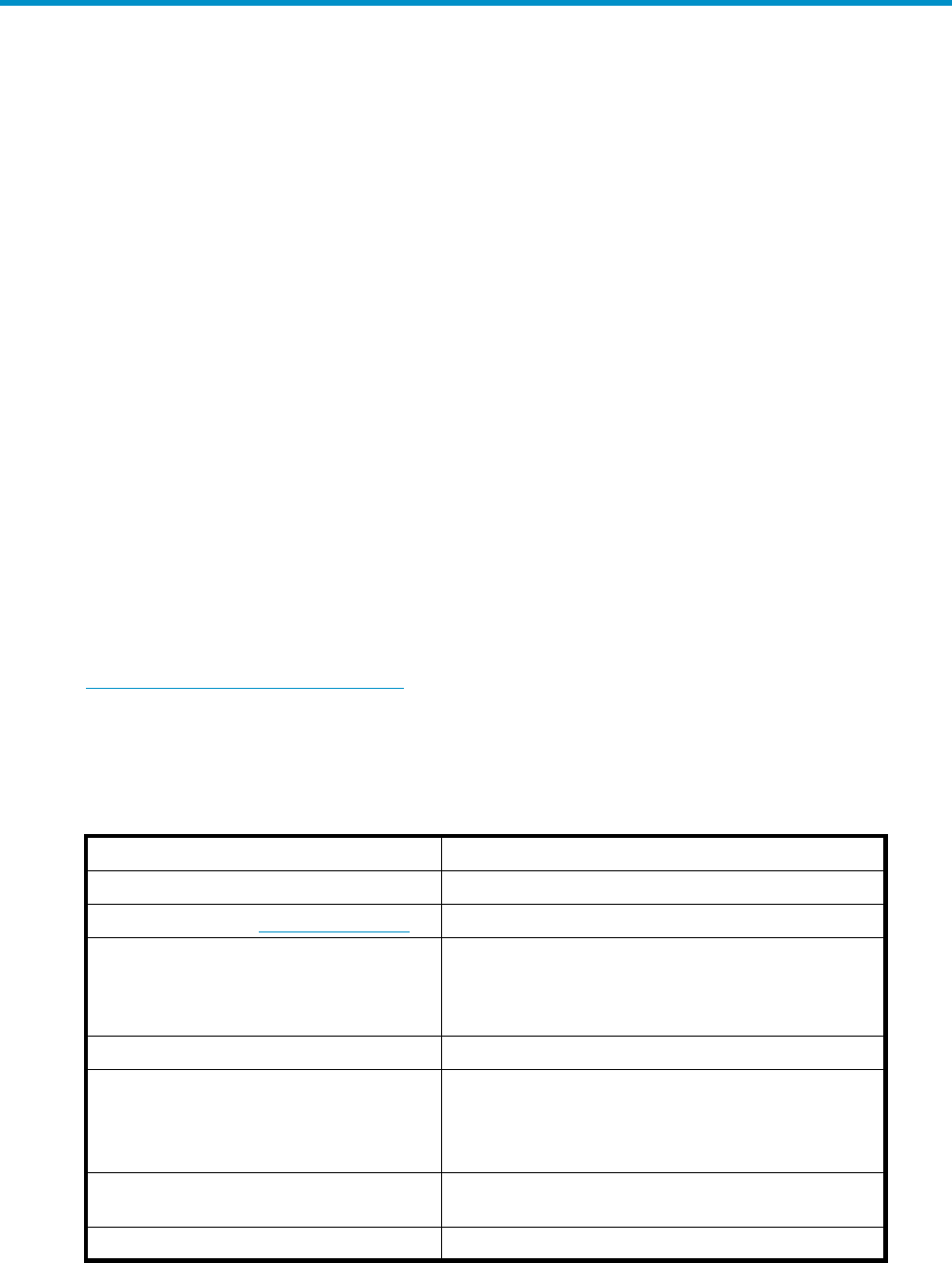
Physical layout of the storage system
The basic physical components are shown in Figure 1. The disk drives are installed in the disk enclosures,
which connect to Fibre Channel (FC) loop switches. The controller pair also connects to the FC loop
switches.
1
3
3
2
CXO7941
A
Figure 1 EVA5000 Storage system hardware components
1. Drive enclosures 2. FC device loop switches
3. HSV110 controllers
The hardware components shown in Figure 1 are discussed in the following sections and in Storage
System Hardware Components.
Fibre Channel drive enclosure
Each Fibre Channel drive enclosure includes the following features. For additional information, see
Fibre Channel drive enclosures.
•3U enclosure
•Dual-redundant, active-to-active, 2–Gbps FC loops
•Fourteen bays for 1–inch FC disks
•Environmental Monitoring Unit (EMU)
•Dual 2–Gbps FC I/O modules—A and B loops
•Dual redundant 500W power supplies and blowers
•Dual redundant blowers
For ease of management, the disk drives are referred to by their physical location, the drive bay number.
HP StorageWorks 3000/5000 Enterprise Virtual Array user guide (VCS 4.xxx) 21

Fibre Channel loop switches
The Fibre Channel loop switch acts as a central point of interconnection and establishes a fault-tolerant
physical loop topology between the controllers and the disk enclosures. The EVA5000 uses four loop
switches to connect the drive enclosures to the controller pair.
The FC loop switches provide the following features. For detailed information on Fibre Channel loop
switches, see Fibre Channel loop switches.
•2.125–Gbps operating speed
•Twelve ports
•Half-width, 1U size
•System and port status indicators
•Universal power supply that operates between 100 to 250 VAC and 50 to 60 Hz
NOTE:
Each bezel covers two FC loop switches in a space of 1U.
HSV110 and HSV100 controllers
Two controllers are contained in each rack. Each controller is contained in a separate enclosure and
provides the features listed below. For detailed information, see HSV controllers.
•High-performance microprocessor
•An Operator Control Panel (OCP)
•Two 2–Gbps Fibre Channel-Switched fabric host ports
•Four2–GbpsFibreChanneldriveenclosuredeviceports(twodeviceportsinHSV100controller)
• Arranged in redundant pairs
• Data load/performance balanced across a pair
• Support for up to 240 disks with HSV110 and 56 with HSV100
•1.25 GB cache per controller, mirrored, with battery backup
•2–GBpsFCcachemirroringportswithdeviceportbackups
•Dual power supplies
In addition to managing the operation of the storage system, the HSV controllers serve as the interface
between the storage system hardware and the SAN. All host I/Os and all HP Command View EVA
management commands are processed by the controllers. Up to 18 drive enclosures are supported
by one controller pair.
NOTE:
To avoid impacting Secure Path operation, the internal identification of the controllers has been changed
for VCS v4.001. For VCS v4.001 and later firmware, the EVA3000 controller is now identified as HSV101
and the EVA5000 controller is identified as HSV111.
Racks
The rack provides the capability for mounting standard 483 mm (19 in) wide controller and drive
enclosures. For additional information, see Racks.
The following racks are available:
•22U Rack
•25U Rack
•33U Rack
22 Enterprise Virtual Array description

•36U Rack
•41U Rack
•42U Rack
•Universal Rack
NOTE:
Racks and rack-mountable components are typically described using “U” measurements. “U”
measurements are used to designate panel or enclosure heights.
The racks provide the following:
•Unique frame and rail design—Allows fast assembly, easy mounting, and outstanding structural
integrity.
•Thermal integrity—Front-to-back natural convection cooling is greatly enhanced by the innovative
multi-angled design of the front door.
•Security provisions—The front and rear door are lockable, which prevents unauthorized entry.
•Flexibility—Provides easy access to hardware components for operation monitoring.
•Custom expandability—Several options allow for quick and easy expansion of the racks to
create a custom solution.
HP StorageWorks 3000/5000 Enterprise Virtual Array user guide (VCS 4.xxx) 23
24 Enterprise Virtual Array description

2 Enterprise Virtual Array startup
This chapter describes the procedures necessary to complete the installation and configuration of the
Enterprise Virtual Array. When these procedures are complete, you can begin using your storage system.
NOTE:
InstallationoftheEnterpriseVirtualArrayshouldbedoneonlybyanHPauthorizedservice
representative. The information in this chapter provides an overview of the steps involved in the
installation and configuration of the storage system.
This chapter consists of:
•Storage system connections
•Procedures for getting started
• Gathering information
• Setting up the storage system hardware
• Entering data using the Operator Control Panel (OCP)
• Installing HP Command View EVA
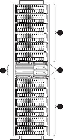
EVA5000 storage system connections
Figure 2 shows a typical EVA5000 SAN topology:
•The HSV110 controllers connect via two host ports (FP1 and FP2) to the Fibre Channel fabrics. The
hosts that will access the storage system are connected to the same fabrics.
•The HP Command View EVA management server also connects to the fabric.
•The controllers connect through two loop pairs to the drive enclosures. Each loop pair consists of
two independent loops, each capable of managing all the disks should one loop fail. Four FC
loop switches are used to connect the controllers to the disk enclosures.
HP StorageWorks 3000/5000 Enterprise Virtual Array user guide (VCS 4.xxx) 25
Browser
Host X
FCA
Management
Server
Command
View EVA
CXO7947
B
Controller
A
FCA FCA FCA
Host Z
Browser
Non-Host
FP1 FP2
Loop
Pair 1 Loop
Pair 1
Loop
Pair 2 Loop
Pair 2
Controller
B
FP1 FP2
Network Interconnection
FC Loop Switches
FC Loop Switches
Drive Enclosures
Fabric 2Fabric 1
F
P = Fibre (Host) Port
F
CA = Fibre Channel Adapter
Cache
Mirror Port
A
A
B
B
Figure 2 EVA5000 configuration
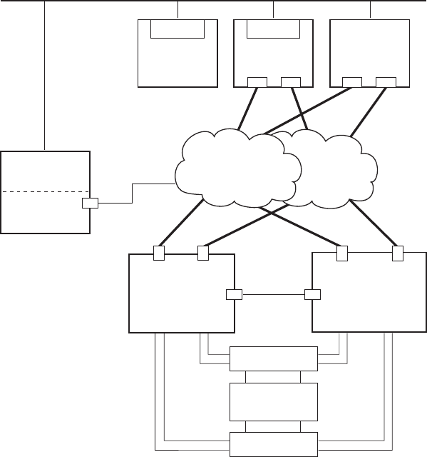
EVA3000 storage system connections
Figure 3 shows a typical EVA3000 SAN topology:
•The HSV100 controllers connect via two host ports (FP1 and FP2) to the Fibre Channel fabrics.
The hosts that will access the storage system are connected to the same fabrics.
•The HP Command View EVA management server also connects to the fabric.
•The controllers connect through one loop pair to the drive enclosures. The loop pair consists
of two independent loops, each capable of managing all the disks should one loop fail. The
controllers connect directly to the disk enclosures.
26 Enterprise Virtual Array startup
Browser
Host X
FCA
Management
Server
Command
View EVA
25060
a
Controller
A
FCA FCA FCA
Host Z
Browser
Non-Host
FP1 FP2
Loop
Pair 1 Loop
Pair 1
Controller
B
FP1 FP2
Network Interconnection
Drive Enclosures
F
P = Fibre (Host) Port
F
CA = Fibre Channel Adapter
Cache
Mirror Port
B
A
B
A
Fabric 1
Fabric 2
Figure 3 EVA3000 configuration
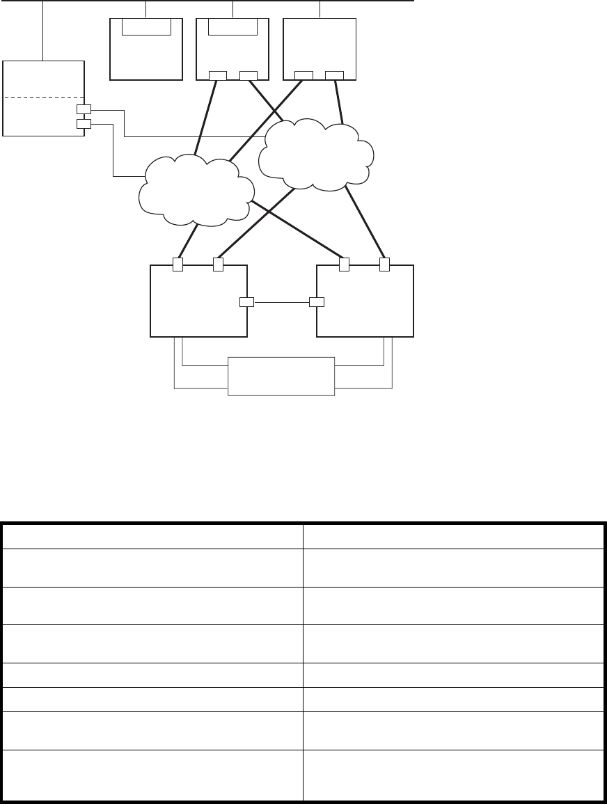
Procedures for getting started
Step Responsibility
1. Gather information and identify all related storage
documentation. Customer
2. Contact an authorized service representative for
hardware configuration information. Customer
3. Enter the World Wide Name (WWN) into the
OCP. HP Service Engineer
4. Configure HP Command View EVA. HP Service Engineer
5. Prepare the hosts. Customer
6. Configure the system through HP Command View
EVA. HP Service Engineer
7. Make virtual disks available to their hosts. Refer to
the storage system software documentation for each
host’s operating system.
HP Service Engineer
Gathering information
The following items should be available when installing and configuring an Enterprise Virtual Array. They
provide information necessary to set up the storage system successfully.
•HP StorageWorks Enterprise Virtual Array 3000/5000 release notes.
HP StorageWorks 3000/5000 Enterprise Virtual Array user guide (VCS 4.xxx) 27
•HP StorageWorks Enterprise Virtual Array 3000/5000 read me first.
•HP StorageWorks Enterprise Virtual Array 3000/5000 World Wide Name label,whichis
shipped with the storage system
•The latest HP OpenView Storage Management Server Update, which consists of the management
server update CD and its associated documentation, or the latest Windows Server Update
• You can determine the latest update version available by checking the release notes or
contacting your authorized service representative to find out how to receive the latest
information.
• Additional documentation is available from the following HP website:
•http://www.hp.com/support/manuals
Click Disk Storage Systems under Storage, and then select the appropriate product
under EVA Disk Arrays.
Locate these items and keep them handy. You will need them for the procedures in this manual.
Host information
Make a list of information for each host computer that will be accessing the storage system. You will need
the following information for each host:
•The LAN name of the host
•A list of World Wide Names of the FC adapters, also called host bus adapters, through which the
host will connect to the fabric or fabrics that provide access to the storage system
•Operating system type
•AvailableLUNnumbers
Setting up a controller pair using the OCP
NOTE:
ThisprocedureshouldbeperformedbyanHPauthorizedservicerepresentative.
Two pieces of data must be entered during initial setup using the controller OCP:
•World Wide Name (WWN)—Required to complete setup. This procedure should be performed
by an HP authorized service representative.
•Storage system password—Optional. A password provides security allowing only specific
instances of HP Command View EVA to access the storage system.
The OCP on either controller can be used to input the WWN and password data. For more information
about the OCP, see “Operator Control Panel”onpage70.
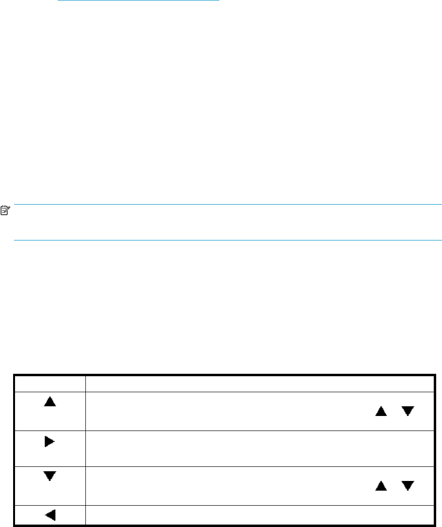
Table 2 lists the push button functions when entering the WWN, WWN checksum, and password data.
Table 2 WWN push button functions
Button Function
Selects a WWN or checksum character by scrolling up through the character list one
character at a time. If you select an incorrect character, you can use either or to
select the correct character.
Accepts the current character and selects the next character. If you accept an incorrect
character, you can move through all 16 characters, one character at a time, until you
display the incorrect character. You can then change the character.
Selects a WWN or checksum character by scrolling down through the character list one
character at a time. If you select an incorrect character, you can use either or to
the select correct character.
Accepts all the WWN or checksum characters.
28 Enterprise Virtual Array startup
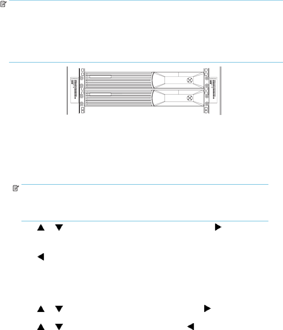
Entering the WWN
Fibre Channel protocol requires that each controller pair have a unique WWN. This 16-character
alphanumeric name identifies the controller pair on the storage system. Two WWN labels attached to the
rack identify the storage system WWN and checksum. See Figure 4.
NOTE:
•TheWWNisuniquetoacontrollerpairandcannotbeusedforanyothercontrollerpairordevice
anywhere on the network.
•This is the only WWN applicable to any controller installed in a specific physical location, even a
replacement controller.
•Once a WWN is assigned to a controller, you cannot change the WWN while the controller is part
ofthesamestoragesystem.
CXO7601
C
Figure 4 Location of the World Wide Name labels
Complete the following procedure to assign the WWN to each pair of controllers.
1. Turn the power switches on both controllers off.
2. Apply power to the rack.
3. Turn the power switch on both controllers on.
NOTE:
Notifications of the startup test steps that have been executed are displayed while the
controllerisbooting. Itmaytakeuptotwominutesforthestepstodisplay. Thedefault
WWNentrydisplayhasa0ineachofthe16positions.
4. Press or until the first character of the WWN is displayed. Press to accept this character
and select the next.
5. Repeat the preceding step to enter the remaining characters.
6. Press to accept the WWN and select the checksum entry mode.
Entering the WWN checksum
The second part of the WWN entry procedure is to enter the two-character checksum, as follows.
1. Verify that the initial WWN checksum displays 0 in both positions.
2. Press or until the first checksum character is displayed. Press to accept this character and
select the second character.
3. Press or until the second character is displayed. Press to accept the checksum and exit.
4. Verify that the default display is automatically selected. This indicates that the checksum is valid.
HP StorageWorks 3000/5000 Enterprise Virtual Array user guide (VCS 4.xxx) 29
NOTE:
If you enter an incorrect WWN or checksum, the system will reject the data and you must repeat the
procedure.
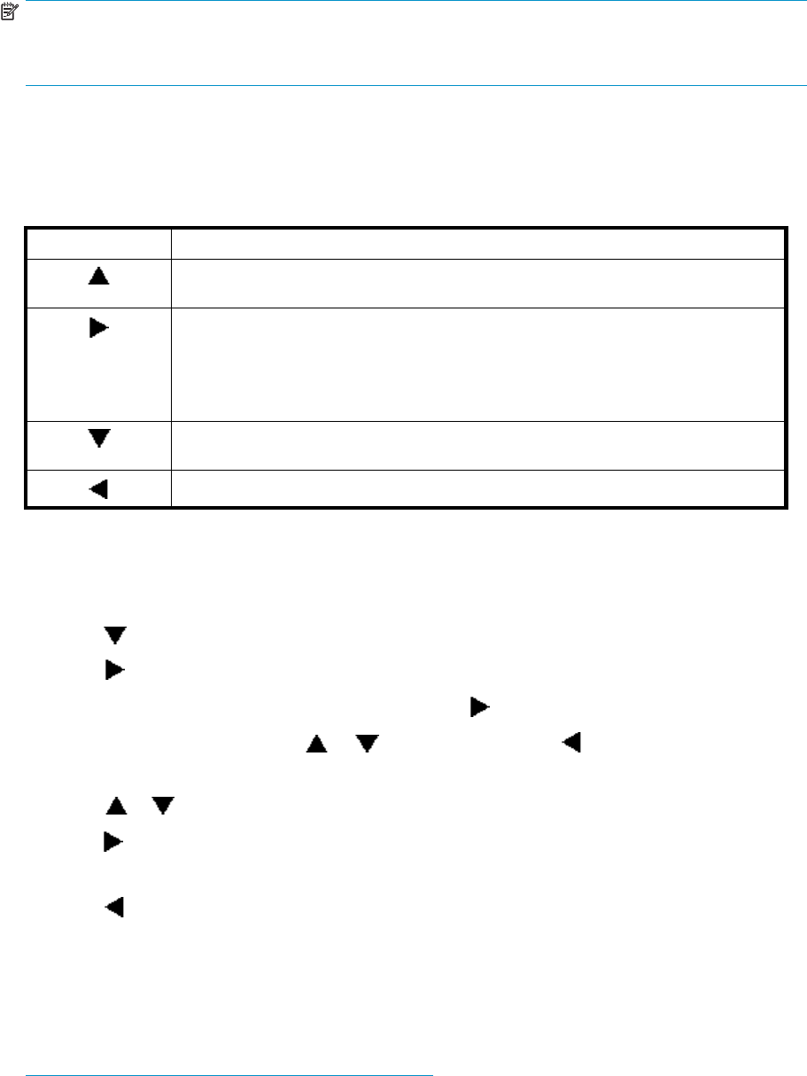
Entering the storage system password
The eight-character storage system password feature enables you to restrict management access to the
storage system. Table 3 describes the push button functions when using the password feature.
Table 3 System password push button functions
Button Function
Selects a password character by scrolling up through the character list one character
at a time.
•Moves from the default display to the system menu tree.
•Moves from the system password display to the password entry display.
•Accepts the current character and selects the next character.
If you accept an incorrect character, you can loop through the display, one position at
time, to select the character to be changed.
Selects a password character by scrolling down through the character list one character
at a time.
Accepts all the password characters.
Complete the following procedure to set the password:
1. Select a unique eight-character password using uppercase or lowercase letters A through Z.
2. From the default menu, press any push button to select the menu tree.
3. Press to cycle through the displays until System Password is displayed.
4. Press to select the system password function.
5. When the System Password function is flashing, press to select the change password function.
6. To change the password, press or to show Yes and press .
The default Enter Password function displays the default password, AAAAAAAA.
7. Press or until the first character of the password is displayed.
8. Press to accept this character and select the next character.
9. Repeat the process to enter the remaining password characters.
10. Press to enter the password and return to the default menu display.
The controller pair setup is complete.
Installing HP Command View EVA
HP Command View EVA is installed on a management server. Installation may be skipped if the
latest version of HP Command View EVA is running. Verify the latest version at the HP website:
http://h18006.www1.hp.com/storage/software.html.
See the HP StorageWorks Command View EVA installation guide for information on installing the software.
30 Enterprise Virtual Array startup
Installing optional EVA software licenses
If you purchased optional EVA software, it will be necessary to install the license. Optional software
available for the Enterprise Virtual Array includes HP Business Copy EVA and HP Continuous Access EVA.
Installation instructions are included with the license.
HP StorageWorks 3000/5000 Enterprise Virtual Array user guide (VCS 4.xxx) 31
32 Enterprise Virtual Array startup

3 Enterprise Virtual Array
operation
This chapter presents the tasks that you might need to perform during normal operation of the storage
system.
Best practices
For useful information on managing and configuring your storage system, See the HP
StorageWorks Enterprise Virtual Array configuration best practices white paper available from
http://h71028.www7.hp.com/ERC/downloads/5982-9140EN.pdf.
Operating tips and information
Reservingadequatefreespace
To ensure efficient storage system operation, a certain amount of unallocated capacity, or free space,
should be reserved in each disk group. The recommended amount of free space is influenced by your
system configuration. For guidance on how much free space to reserve, See the HP StorageWorks
Enterprise Virtual Array configuration best practices white paper. See Best practices.
Using FATA disk drives
FATA drives are designed for lower duty cycle applications such as near on-line data replication for
back-up. These drives should not be used as a replacement for EVA’s high performance, standard
duty cycle, Fibre Channel drives. Doing so could shorten the life of the drive. Download the following
document for more information on FATA drives, their uses and benefits:
http://h71028.www7.hp.com/ERC/downloads/5982-7353EN.pdf
Failback preference setting for HSV controllers
Table 4 describes the failback settings supported with HSV controllers and HP Command View EVA.
These settings apply to all supported operating systems.
Table 5 describes the failback default behavior and settings allowed for each operating system. The table
indicates when Secure Path is used in conjunction with the operating system
HP StorageWorks 3000/5000 Enterprise Virtual Array user guide (VCS 4.xxx) 33

Table 4 Failback preference settings
Setting Point in time Behavior
At initial presentation Theunitsareal
ternately brought online
to Controller A or to Controller B.
On dual boot or controller resynch IfcachedataforaLUNexistsona
particular controller, the unit will be
brought online there. Otherwise, the
units are alternately brought online to
Controller A or to Controller B.
On controller failover All LUNs are brought online to the
surviving controller.
No preference
On controller failback All LUNs remain on the surviving
controller. There is no failback except
if a host moves the LUN using SCSI
commands.
At initial presentation The units are brought online to Controller
A.
On dual boot or controller resynch IfcachedataforaLUNexistsona
particular controller, the unit will be
brought online there. Otherwise, the
units are brought online to Controller A.
On controller failover All LUNs are brought online to the
surviving controller.
Path A - Failover
Only
On controller failback All LUNs remain on the surviving
controller. There is no failback except
if a host moves the LUN using SCSI
commands.
At initial presentation The units are brought online to Controller
B.
On dual boot or controller resynch If cache data for a LUN exists on a
particular controller, the unit will be
brought online there. Otherwise, the
units are brought online to Controller B.
On controller failover All LUNs are brought online to the
surviving controller.
Path B - Failover Only
On controller failback All LUNs remain on the surviving
controller. There is no failback except
if a host moves the LUN using SCSI
commands.
34 Enterprise Virtual Array operation

Setting Point in time Behavior
At initial presentation The units are brought online to Controller
A.
On dual boot or controller resynch If cache data foraLUNexistsona
particular controller, the unit will be
brought onlinethere. Otherwise,the
units are brought online to Controller A.
On controller failover All LUNs are brought online to the
surviving controller.
Path A - Failover/
Failback
On controller failback All LUNs remain on the surviving
controller. After controller restoration,
the units that are online to Controller
B and set to Path A are brought online
to Controller A. This is a one time
occurrence. If the host then moves the
LUN using SCSI commands, the LUN will
remain where moved.
At initialpresentation The units are brought online to Controller
B.
On dual boot or controller resynch If cache data for a LUN exists on a
particular controller, the unit will be
brought online there. Otherwise, the
units are brought online to Controller B.
On controller failover All LUNs are brought online to the
surviving controller.
Path B - Failover/
Failback
On controller failback All LUNs remain on the surviving
controller. After controller restoration,
the units that are online to Controller
A and set to Path B are brought online
toControllerB.Thisisaonetime
occurrence. If the host then moves the
LUN using SCSI commands, the LUN will
remain where moved.
HP StorageWorks 3000/5000 Enterprise Virtual Array user guide (VCS 4.xxx) 35
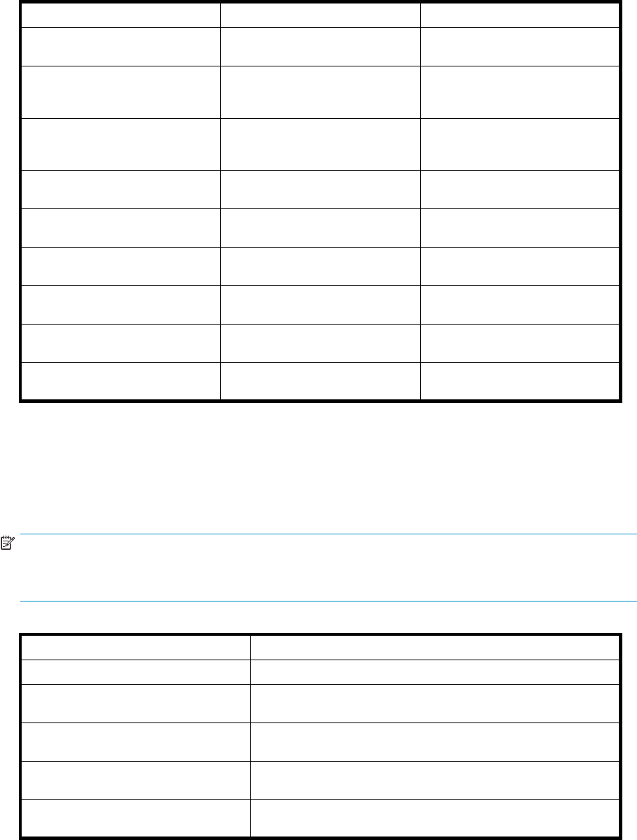
Table 5 Failback settings by operating system
Operating system Default behavior Settings supported
HP-UX Autoback done by the host No Preference, Path A/B - Failover
Only.
Tru64 UNIX Host follows the unit All settings allowed.
Recommended setting: Path
A/B - Failover/Failback.
OpenVMS (7.3-2orlaterr) Host follows the unit All settings allowed.
Recommended setting: Path
A/B - Failover/Failback.
Windows Auto failback done by the host No Preference, Path A/B - Failover
Only.
Sun Solaris Auto failback done by the host No Preference, Path A/B - Failover
Only.
IBM AIX Auto failback done by the host No Preference, Path A/B - Failover
Only.
Linux Auto failback done by the host No PreferencePath A/B - Failover
Only
Novell NetWare Auto failback done by the host No PreferencePath A/B - Failover
Only
VMware Auto failback done by the host No PreferencePath A/B - Failover
Only
Changing virtual disk failover/failback setting
Changing the failover/failback setting of a virtual disk may impact which controller presents the disk.
Table 6 identifies the presentation behavior that results when the failover/failback setting for a virtual
disk is changed.
NOTE:
If the new setting causes the presentation of the virtual disk to move to a new controller, any snapshots
or snapclones associated with the virtual disk will also be moved.
Table 6 Impact on virtual disk presentation when changing failover/failback setting
New setting Impact on virtual disk presentation
No Preference None. The disk maintains its original presentation
Path A Failover If the disk is currently presented on controller B, it is moved to
controller A. If the disk is on controller A, it remains there.
Path B Failover If the disk is currently presented on controller A, it is moved to
controller B. If the disk is on controller B, it remains there.
Path A Failover/Failback If the disk is currently presented on controller B, it is moved to
controller A. If the disk is on controller A, it remains there.
Path B Failover/Failback If the disk is currently presented on controller A, it is moved to
controller B. If the disk is on controller B, it remains there.
36 Enterprise Virtual Array operation

Storage system shutdown and powerup
The storage system is shut down using HP Command View EVA. The shutdown process performs the
following functions in the indicated order:
1. Flushes cache
2. Removes power from the controllers
3. Disables cache battery power
4. Removes power from the drive enclosures
5. Disconnects the system from HP Command View EVA
NOTE:
The storage system may take a long time to complete the necessary cache flush during controller
shutdown when snapshots are being used. The delay may be particularly long if multiple child snapshots
are used, or if there has been a large amount of write activity to the snapshot source Vdisk.
Shutting down the storage system
To shut the storage system down, perform the following steps:
1. Start HP Command View EVA.
2. Select the appropriate storage system in the Navigation pane.
The Initialized Storage System Properties window for the selected storage system opens.
3. Click Shut down.
The Shutdown Options window opens.
4. Under System Shutdown click Power Down. If you want to delay the initiation of the shutdown, enter
the number of minutes in the Shutdown delay field.
The controllers complete an orderly shutdown and then power off. The disk enclosures then power
off. Wait for the shutdown to complete.
5. Turn off the power switch on the rear of each HSV controller.
6. Turn off the circuit breakers on both of the EVA rack Power Distribution Units (PDU).
7. If your management server is an SMA and you are not using it to manage other storage arrays, shut
down the SMA. From the SMA user interface, click Settings > Maintenance > Shutdown.
Powering up the storage system
To power up a storage system, perform the following steps:
1. Verify that each fabric Fibre Channel switch to which the HSV controllers are connected is powered
up and fully booted. The power indicator on each switch should be on.
If you must power up the SAN switches, wait for them to complete their power-on boot process
before proceeding. This may take several minutes.
2. If the management server you shut down is an SMA, power it on and wait for it to completely boot.
Verify the SMA is running by logging into it using the web interface.
NOTE:
Before applying power to the rack, ensure that the power switch on each HSV controller
is off.
HP StorageWorks 3000/5000 Enterprise Virtual Array user guide (VCS 4.xxx) 37

3. Power on the circuit breakers on both EVA rack PDUs. Verify that all drive enclosures are operating
properly. The status indicator and the power indicator should be on (green).
4. Wait three minutes and then verify that all disk drives are ready. The drive ready indicator and
the drive online indicator should be on (green).
5. Powerontheuppercontroller. Ittakestherollofmastercontroller.
6. Wait 10 seconds and then power on the lower controller. It takes the roll of slave controller.
7. Verify that the (Operator Control Panel) OCP display on each controller displays the storage system
name and the EVA WWN.
8. Start HP Command View EVA and verify connection to the storage system. If the storage system is
not visible, click HSV Storage Network in the Navigation pane then click Discover in the Content
pane to discover the array.
NOTE:
If the storage system is still not visible, reboot the management server to re-establish the
communication link.
9. Check the storage system status using HP Command View EVA to ensure everything is operating
properly. If any status indicator is not normal, check the log files or contact your HP—authorized
service provider for assistance.
Saving storage system configuration data
As part of an overall data protection strategy, storage system configurationdatashouldsavedduring
initial installation, and whenever major configuration changes are made to the storage system. This
includes adding or removing disk drives, creating or deleting disk groups, and adding or deleting
virtual disks. The saved configuration data can save substantial time should it ever become necessary to
re-initializethestoragesystem.Theconfiguration data is saved to a series of files which should be stored
in a location other than on the storage system.
This procedure can be performed from the SMA or management server where the HP Command View
EVA is installed, or any host that can run the Storage System Scripting Utility (SSSU) to communicate
with the management server.
NOTE:
For more information on using SSSU, see the HP StorageWorks Storage System Scripting Utility reference.
See “Related documentation” on page 13.
1. Double-click on the SSSU desktop icon to run the application. When prompted, enter Manager
(management server name or IP address), User name, and Password.
2. Enter LS SYSTEM to display the EVA storage systems managed by the management server.
3. Enter SELECT SYSTEM system name,wheresystem name isthenameofthestoragesystem.
The storage system name is case sensitive. If there are spaces between the letters in the name, quotes
must enclose the name: for example, SELECT SYSTEM “Large EVA”.
4. Enter CAPTURE CONFIGURATION, specifying the full path and filename of the output files for
the configuration data.
The configuration data is stored in a series of from one to five files, which are SSSU scripts. The file
names begin with the name you select, with the restore step appended. For example, if you specify a
file name of LargeEVA.txt,theresultingconfiguration files would be LargeEVA_Step1A.txt,
LargeEVA_Step1B,etc.
The contents of the configuration files can be viewed with a text editor.
38 Enterprise Virtual Array operation

NOTE:
If the storage system contains disk drives of different capacities, the SSSU procedures used do not
guarantee that disk drives of the same capacity will be exclusively added to the same disk group. If you
need to restore an array configuration that contains disks of different sizes and types, you must manually
recreate these disk groups. The controller software and the utility’s CAPTURE CONFIGURATION
command are not designed to automatically restore this type of configuration. For more information,
see the HP StorageWorks Storage System Scripting Utility reference.
The following examples illustrate how to save and restore the storage system configuration data using
SSSU on a Windows host.
Example 1. Saving configuration data using SSSU on a Windows Host
1. Double-click on the SSSU desktop icon to run the application. When prompted, enter Manager
(management server name or IP address), User name, and Password.
2. Enter LS SYSTEM to display the EVA storage systems managed by the management server.
3. Enter SELECT SYSTEM system name,wheresystem name isthenameofthestoragesystem.
4. Enter CAPTURE CONFIGURATION pathname\filename,wherepathname identifies the location
where the configuration files will be saved, and filename isthenameusedastheprefixforthe
configurations files: for example, CAPTURE CONFIGURATION c:\EVAConfig\LargeEVA.
5. Enter EXIT to close the command window.
Example 2. Restoring configuration data using SSSU on a Windows Host
If it is necessary to restore the storage system configuration, it can be done using the following procedure:
1. Double-click on the SSSU desktop icon to run the application.
2. Enter FILE pathname\filename,wherepathname identifies the location where the configuration
files are be saved, and filename is the name of the first configuration file: for example, FILE
c:\EVAConfig\LargeEVA_Step1A.txt.
3. Repeat the preceding step for each configuration file.
Adding disk drives to the storage system
As your storage requirements grow, you may be adding disk drives to your storage system. Adding new
disk drives is the easiest way to increase the storage capacity of the storage system. Disk drives can be
added online without impacting storage system operation.
CAUTION:
When adding disks to an expansion cabinet on an EVA5000, do not install a disk in bays 12, 13, or 14
in enclosures 17, 20, or 24. These bays in enclosures 17, 20, and 24 do not receive a hard assigned
AL-PA. Installing a disk in any of these slots may impact the operation of the storage system.
Guidelines for adding disk drives
When adding new disk drives to the storage system, you should ensure that the disk drives are installed
in the correct positions to maintain availability. The disk drives should be distributed across the disk
enclosures to protect against the failure of a single disk enclosure.
Use the following guidelines when adding disk drives to your storage system:
•Install high performance and FATA disk drives in separate groups. These different drive types must
be in separate disk groups. You may also want to consider separating different drive capacities
and spindle speeds into different groups.
HP StorageWorks 3000/5000 Enterprise Virtual Array user guide (VCS 4.xxx) 39
•The disk drives should be distributed evenly across the disk enclosures. The number of disks of
a given type in each enclosure should not differ by more than one. For example, no enclosure
should have seven disks until all the other enclosures have at least six. A minimum of four disks
are required to be populated in every disk enclosure.
•Disk drives should be installed in vertical columns within the disk enclosures. Add drives vertically
in multiples of eight, completely filling columns if possible. Disk groups are more robust if filled
with the same number of disk drives in each enclosure. See Figure 6 for an example.
NOTE:
When adding multiple disk drives, add a disk and wait for its activity indicator (1) to stop flashing
(up to 90 seconds) before installing the next disk (see Figure 5). This procedure must be followed to
avoidunexpectedEVAsystembehavior.
Figure 5 Disk drive activity indicator
Creating disk groups
The new disks you add will typically be used to create new disk groups. Although you cannot select
which disks will be part of a disk group, you can control this by building the disk groups sequentially.
Add the disk drives required for the first disk group, and then create a disk group using these disk drives.
Now add the disk drives for the second disk group, and then create that disk group. This process gives
you control over which disk drives are included in each disk group. Figure 6 shows the sequential
building of vertical disk groups.
NOTE:
Standard and FATA disk drives must be in separate disk groups. Disk drives of different capacities and
spindle speeds can be included in the same disk group, but you may want to consider separating
them into separate disk groups.
40 Enterprise Virtual Array operation
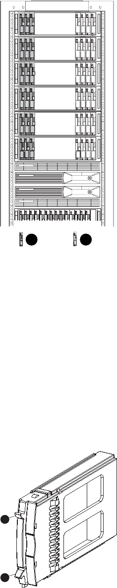
CX8167-ST
21
Figure 6 Sequential building of vertical disk groups
1. Disks installed in first group
2. Disks installed in second group
Adding a disk drive
This section describes the procedure for adding a Fibre Channel disk drive.
Removingthedriveblank
1. Grasp the drive blank by the two mounting tabs (see Figure 7).
2. Lift up on the lower mounting tab and pull the blank out of the enclosure.
CXO7359B
˚
1
2
Figure 7 Removing the drive blank
1. Upper mounting tab 2. Lower mounting tab
HP StorageWorks 3000/5000 Enterprise Virtual Array user guide (VCS 4.xxx) 41
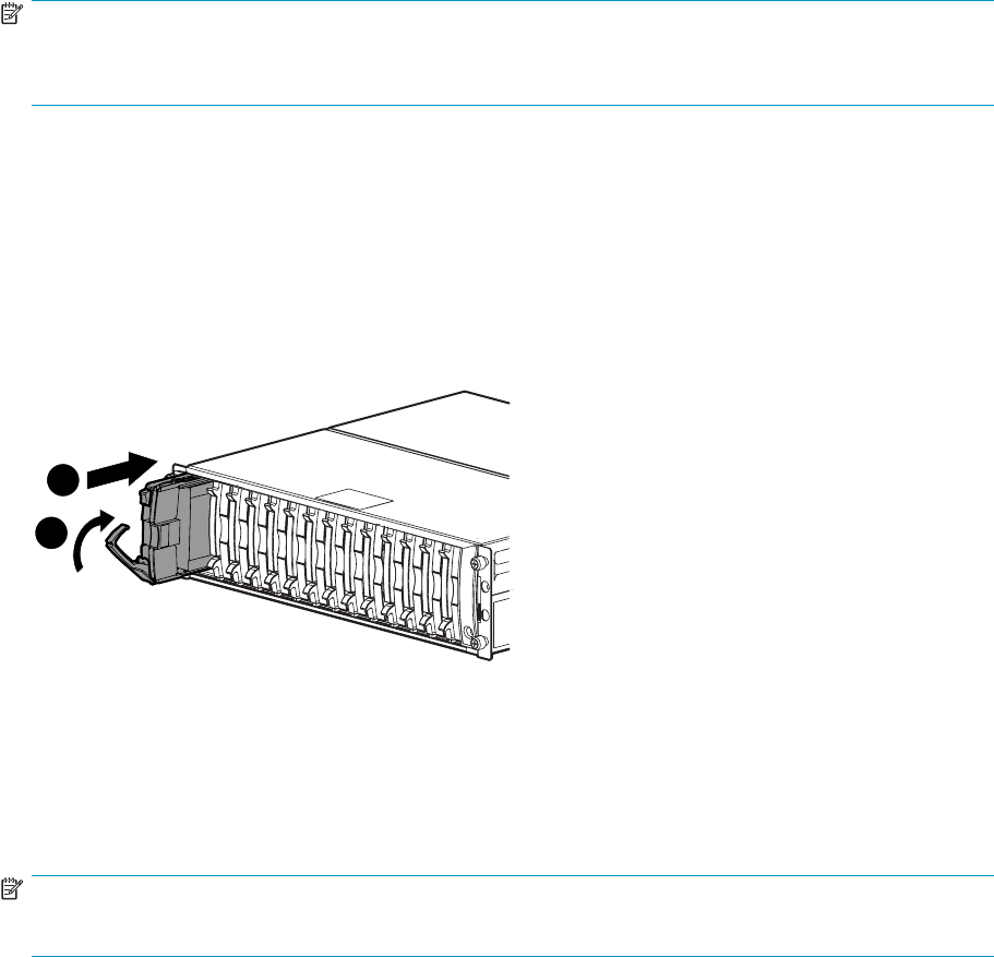
Changing the Device Addition Policy
To prevent the storage system from automatically grouping a new disk drive that may have the incorrect
firmware on it, the Device Addition Policy must be checked and set to manual if necessary:
1. Open Command View VA and in the Navigation pane select the storage system.
The Initialized Storage System Properties window opens.
2. Click System Options.
3. Select Set system operational policies.
4. IftheDeviceAdditionPolicyissettoAutomatic, change it to Manual.
5. Click Save changes.
NOTE:
If you want to return the Device Addition Policy to automatic, use the above procedure to do so after
verifying the disk drive has the correct firmware version.
Installing the disk drive
1. Push in the ejector button on the disk drive and pull the release lever down to the full open position.
2. Insertthedriveintotheenclosureasfarasitwillgo(1,Figure 8).
3. Close the release lever until it engages the ejector button, and the disk drive seats in the backplane
(2, Figure 8).
4. Press in firmly on the disk drive to ensure it is seated properly.
1
1
2
0116a
Figure 8 Installing the disk drive
Checking status indicators
After replacing the disk drive, check the following to verify that the disk drive is operating normally:
NOTE:
It may take up to 10 minutes for the component to display good status.
•Check the disk drive status indicators. See Figure 9.
•Activityindicator(1)shouldbeonorflashing
• Online indicator (2) should be on or flashing
• Fault indicator (3) should be off
•Check the following using HP Command View EVA.
42 Enterprise Virtual Array operation
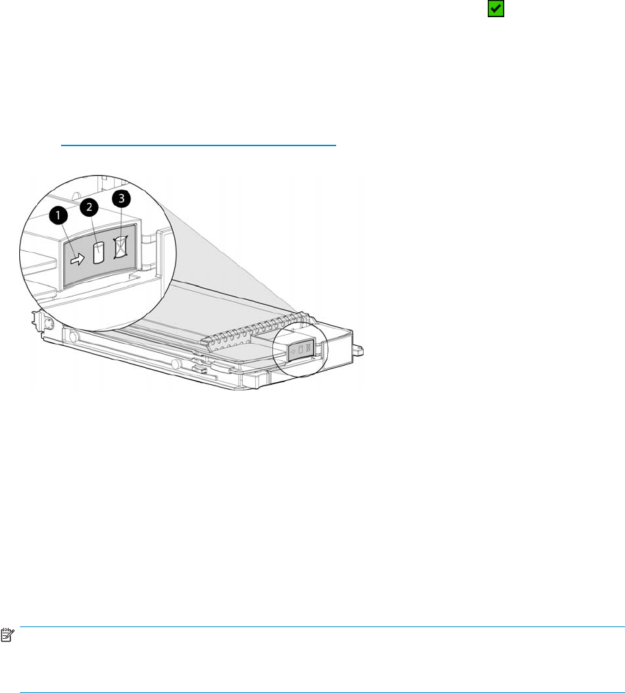
• Navigate to the disk drive and check the operational state. It should be .
•RecordtheModel number and the Firmware version.Checkthefirmware version against the
supported disk firmware in the HP StorageWorks 3000/5000 Enterprise Virtual Array release
notes.See“Related documentation” on page 13 for a link to this document.
If the disk drive is using an unsupported version of firmware, download the correct firmware
from the following website and install it using the instructions included with the firmware file.
Use the disk drive model number to locate the correct firmware file. Do not add the disk drive
to a disk group if it using an unsupported firmware version.
http://www.hp.com/support/evadiskfirmware
Figure 9 Disk drive status indicators
1. A ct ivi t y 2. Online
3. Fault
Adding the disk to a disk group
After replacing the disk, it should be added to a disk group.
1. In the Navigation pane, select Storage system > Hardware > Rack > Disk enclosure > Bay.
2. In the Content pane, select the Disk Drive tab.
3. Click Group to initiate the process for adding the disk to a disk group.
NOTE:
If the Device Addition Policy is set to automatic, the disk will automatically be added to a disk group. In
this case the Group option will not be available.
Handling fiber optic cables
This section provides protection and cleaning methods for fiber optic connectors.
Contamination of the fiberopticconnectorsoneitheratransceiveroracableconnectorcanimpede
the transmission of data. Therefore, protecting the connector tips against contamination or damage
is imperative. The tips can be contaminated by touching them, by dust, or by debris. They can be
damaged when dropped. To protect the connectors against contamination or damage, use the dust
covers or dust caps provided by the manufacturer. These covers are removed during installation, and
are installed whenever the transceivers or cables are disconnected. Cleaning the connectors should
remove contamination.
The transceiver dust caps protect the transceivers from contamination. Donotdiscardthedustcovers.
HP StorageWorks 3000/5000 Enterprise Virtual Array user guide (VCS 4.xxx) 43

CAUTION:
To avoid damage to the connectors, always install the dust covers or dust caps whenever a transceiver
or a fiber cable is disconnected. Remove the dust covers or dust caps from transceivers or fiber cable
connectors only when they are connected. Do not discard the dust covers.
To minimize the risk of contamination or damage, do the following:
•Dust covers—Remove and set aside the dust covers and dust caps when installing an I/O module,
a transceiver or a cable. Install the dust covers when disconnecting a transceiver or cable.
•When to clean—If a connector may be contaminated, or if a connector has not been protected by
a dust cover for an extended period of time, clean it.
•How to clean:
1. Wipe the connector with a lint–free tissue soaked with 100% isopropyl alcohol.
2. Wipe the connector with a dry, lint–free tissue.
3. Dry the connector with moisture-free compressed air.
One of the many sources for cleaning equipment specifically designed for fiber optic connectors is:
AlcoaFujikuraLtd.
1-888-385-4587 (North America)
011-1-770-956-7200 (International)
44 Enterprise Virtual Array operation

4 Enterprise Virtual Array
hardware components
This chapter describes the Enterprise Virtual Array hardware components.
Fibre Channel drive enclosures
Thedriveencl
osure contains the disk drives used for data storage. A storage system includes multiple
drive enclosures. The major components of the enclosure are:
•2.125–Gb, dual loop, 14–drive enclosure
•Dual-loop, Fibre Channel drive enclosure I/O modules
•Copper Fibre Channel cables
•Fibre Channel disk drives and drive blanks
•Power supplies
•Blowers
•Cache batteries
•EMU
Enclosure layout
Thediskdrivesmountinbays in the front of the enclosure. The bays are numbered sequentially from left
to right. A drive is referred to by its bay number. Enclosure status indicators are located in the lower-right,
front corner. Figure 10 shows the front and rear views of the FC drive enclosure.
HP StorageWorks 3000/5000 Enterprise Virtual Array user guide (VCS 4.xxx) 45
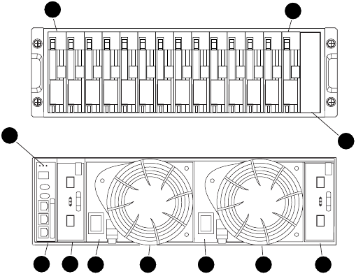
0112a
Front
Rear
12
3456 78 9
10
10
Figure 10 FC drive enclosure—front and rear views
1. D r iv e b a y 1 2. D r iv e b a y 14
3. EMU 4. I/O module B
5. Blower 1 6. Power supply 1
7. Blower 2 8. Power supply 2
9. I/O module A 10. Statusindicators(EMU,enclosurepower,
enclosure fault)
I/O modules
Two I/O modules provide the interface between the drive enclosure and the host controllers. See
Figure 11. They route data to and from the disk drives using Loop A and Loop B, the dual-loop
configuration. For redundancy, only dual-controller, dual-loop operation is supported. Each controller is
connected to both I/O modules in the drive enclosure.
46 Enterprise Virtual Array hardware components
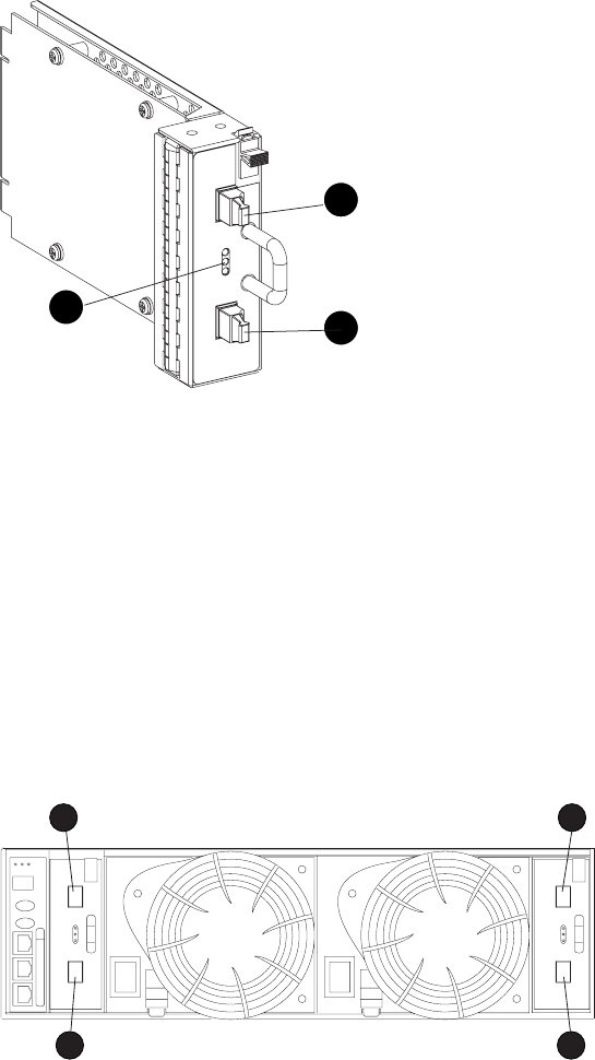
0107a
1
2
3
Figure 11 I/O module
1. Status indicators (Upper port, Power, and Lower port)
2. Upper port
3. Lower port
TheI/Omodulesarefunctionallyidentical,butarenotinterchangeable.ModuleAcanonlybeinstalled
at the right end of the enclosure, and module B can only be installed at the left end of the enclosure. See
Figure 10.
Each I/O module has two ports that can both transmit and receive data for bidirectional operation.
Activating a port requires connecting a FC cable to the port. The port function depends upon the
loop. See Figure 12.
CXO7954
A
3 1
4 2
Figure 12 Input and output ports
1. Lo o p A l ow er p o r t 2. Loop A upper port
3. Loop B lower port 4. Loop B upper port
I/O module status indicators
There are three status indicators on the I/O module. See Figure 11. The status indicator states for
an operational I/O module are shown in Table 7.Table 8 shows the status indicator states for a
non-operational I/O module.
HP StorageWorks 3000/5000 Enterprise Virtual Array user guide (VCS 4.xxx) 47

Table 7 Operational I/O module status indicators
Upper Power Lower Descriptions
Off On Off •I/O Module is operational
On Flashing, then On On •Top port—Fibre Channel drive enclosure signal detected.
•Power—Flashes for about 90 seconds after initial power application,
then remains constant.
•Bottom port—Fibre Channel drive enclosure signal detected.
On On On •Top port—Fibre Channel drive enclosure signal detected.
•Power—Present.
•Bottom port—Fibre Channel drive enclosure signal detected.
Flashing Flashing Flashing •When the locate function is active, all three indicators flash
simultaneously. The Locate function overrides all other indicator
functions. Therefore, an error could be detected while the Locate
functionisactiveandnotbeindicateduntiltheLocateaction
terminates.
Table 8 Non-operational I/O module status indicators
Upper Power Lower Descriptions
On On Off •Top port—Fibre Channel drive enclosure signal detected.
•Power—Present.
•Bottom port—No Fibre Channel drive enclosure signal detected.
Check transceiver and fiber cable connections.
NOTE:
This status applies to configurations with and without FC loop
switches.
Off On On •Top port—No Fibre Channel drive enclosure signal detected. Check
transceiver and fiber cable connections.
•Power—Present.
•Bottom port—Fibre Channel drive enclosure signal detected .
Flashing On On •Top port—EMU detected possible transceiver problem. Check
transceiver and fiber cable connections.
•Power—Present.
•Bottom port—Fibre Channel drive enclosure signal detected .
On On Flashing •Top port—Fibre Channel drive enclosure signal detected.
•Power—Present.
•Bottom port—EMU detected possible transceiver problem. Check
transceiver and fiber cable connections.
NOTE:
The EMU will not flash the lower indicator on its own. It will flash
only in response to a locate command. You can flash each of the
lights independently during a locate action.
Off Off Off •No I/O module power.
•I/O module is nonoperational.
•Check power supplies. If power supplies are operational, replace
I/O module.
48 Enterprise Virtual Array hardware components
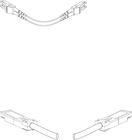
Fibre Optic Fibre Channel cables
The Enterprise Virtual Array uses orange, 50-µm, multi-mode, fiber optic cables for connection to the
SAN. The fiber optic cable assembly consists of two, 2–m fiber optic strands and small form-factor
connectors on each end. See Figure 13.
To ensure optimum operation, the fiber optic cable components require protection from contamination
and mechanical hazards. Failure to provide this protection can cause degraded operation. Observe the
following precautions when using fiber optic cables.
•To avoid breaking the fiber within the cable:
•Donotkinkth
ecable
• Do not use a cable bend-radius of less than 30 mm (1.18 in)
•To avoid deforming, or possibly breaking the fiber within the cable, do not place heavy objects
on the cable.
•To avoid contaminating the optical connectors:
• Do not touch the connectors
•Neverleave
the connectors exposed to the air
• Install a dust cover on each transceiver and fiber cable connector when they are disconnected
If an open connector is exposed to dust, or there is any doubt about the cleanliness of the connector,
clean the connector as described in Handling fiber optic cables.
CXO7972
A
Figure 13 Fibre Optic Fibre Channel cable
Copper Fibre Channel cables
The Enterprise Virtual Array Fibre Channel 10000-Series implementation uses copper Fibre Channel
cables to connect the drive enclosures to each other, or to the loop switches and to the HSV controllers.
The cables are available in 0.6–meter and 2.0–meter lengths. Copper cables provide performance
comparable to fiber optic cables. Copper cable connectors differ from fiber optic small form-factor
connectors (see Figure 14).
8164A-ST
Figure 14 Copper Fibre Channel cable
Fibre Channel disk drives
The Fibre Channel disk drives are hot-pluggable and include the following features:
•Dual-ported 2–Gbps Fibre Channel drive enclosure interface that allows up to 120 disk drives to
be supported per Fibre Channel drive enclosure pair.
•Compact, direct-connect design for maximum storage density and increased reliability and
signal integrity.
HP StorageWorks 3000/5000 Enterprise Virtual Array user guide (VCS 4.xxx) 49
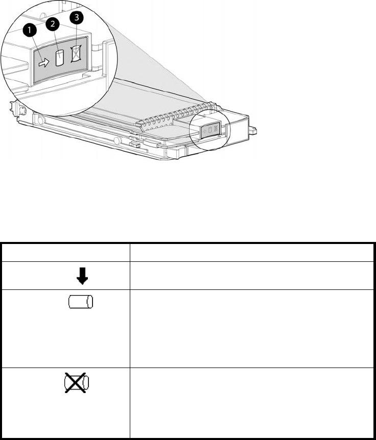
•Both online high-performance disk drives and FATA disk drives in a variety of capacities and
spindle speeds.
•Better vibration damping for improved performance.
Up to 14 disk drives can be installed in a drive enclosure.
Disk drive status indicators
Three status indicators display the drive operational status. Figure 15 shows the disk drive status
indicators. Table 9 provides a description of each status indicator.
Figure 15 Disk drive status indicators
1. A c t i vi t y 2. Online
3. Fault
Table 9 Disk drive status indicator descriptions
Status indicator Description
Activity This green status indicator flashes when the disk drive is
being accessed. It is on when the drive is idle.
Online The green status indicator is on when the disk drive is
online and operating normally. This indicator will be off
in the following situations:
•There is no controller on the bus.
•+5.1 VDC is not available.
•The drive is not properly installed in the enclosure.
Fault
This amber status indicator is on when there is a disk drive
failure. Depending on the host controller, this indicator may
flash when the controller detects an error condition.
The amber status indicator flashes in synchronization with
the other two status indicators in response to the EMU
locate command.
Disk drive status displays
The disk drive status indicators can assume three states: on, off, or flashing. The status indicators states
for operational drive status are shown in Table 10.SeeTable 11 for the non-operational drive status
indicator states.
50 Enterprise Virtual Array hardware components
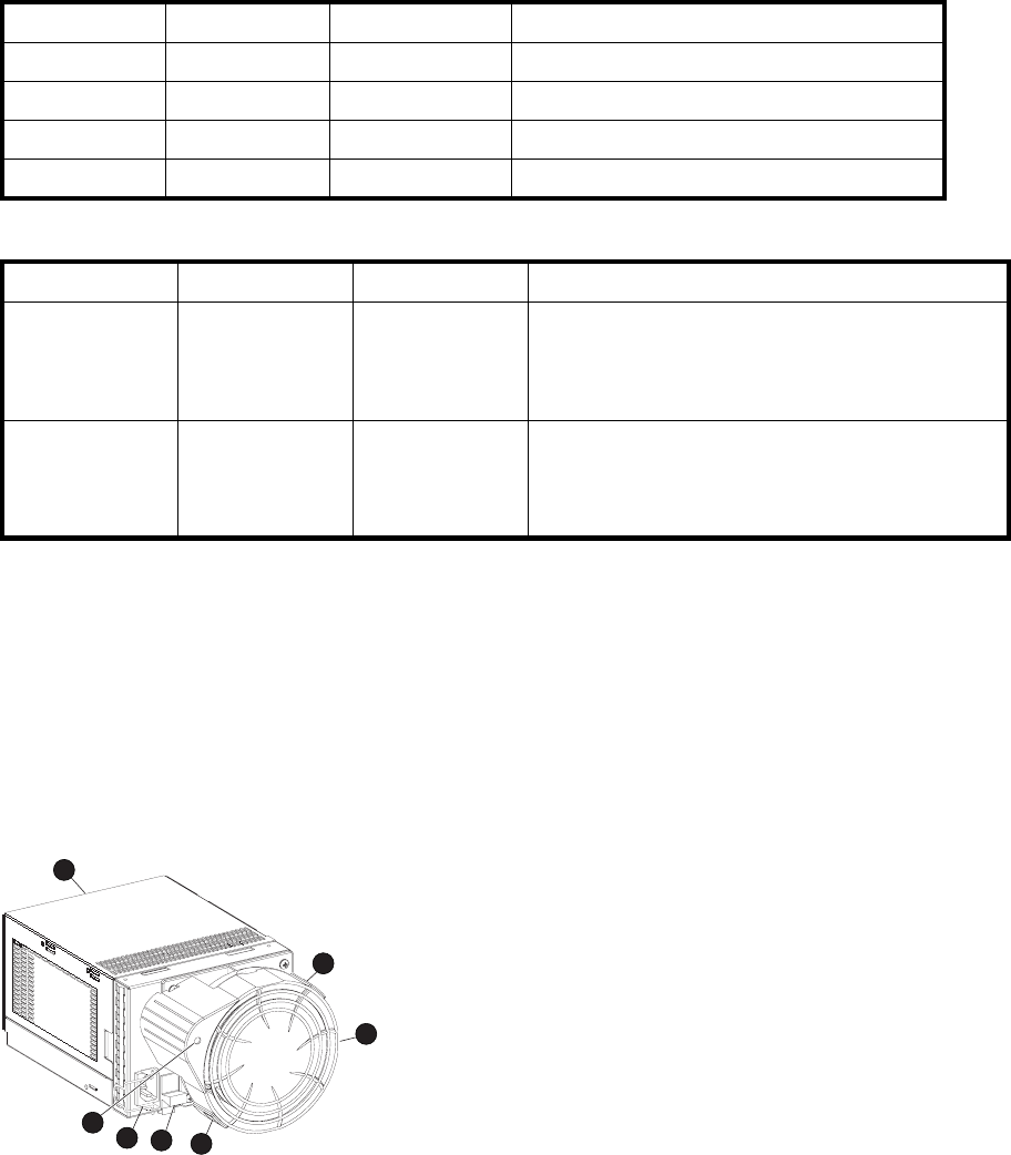
Table 10 Operational disk drive status indications
Activity Online Fault Description
Flashing On Off Initial startup.
On On Off The drive is online but is not being accessed.
Flashing Flashing Flashing The drive is being located.
Flashing On Off The drive is operational and active.
Table 11 Non-operational disk drive status indications
Activity Online Fault Description
On On On Indicates no connection or the controllers are offline.
Recommended corrective actions:
1. Check power supplies for proper operation.
2. If defective, replace disk drive.
On Off Flashing Indicates disk drive error/not active. Recommended
corrective actions:
1. Verify FC loop continuity.
2. Replace disk drive.
Disk drive blank
To maintain the proper enclosure air flow, a disk drive or a disk drive blank must be installed in each
drive bay. The disk drive blank maintains proper airflow within the disk enclosure.
Power supplies and blowers
This section describes the function and operation of the disk enclosure power supplies and blowers.
Figure 16 illustrates the major power supply and cooling components.
CXO7489
A
1
34
5
5
6
2
Figure 16 Power supply and blower assembly components
1. Po we r s u p p ly
2. Status indicator
3. AC Input connector with bail
4. Module latch (wine-colored)
5. Blower tabs (wine-colored)
6. Blower
HP StorageWorks 3000/5000 Enterprise Virtual Array user guide (VCS 4.xxx) 51

Power supplies
The two power supplies mount in the rear of the enclosure. See Figure 16. The supplies are autoranging
and operate on acountry-specificACinputvoltageof202to240VAC±10%,50to60Hz,±5%,(188
to264VAC,47to63Hz).
The DC outputs of this power supply are:
•+5.1 VDC for theEMU,I/Omodule,backplane, and disk drives
•+12.1 VDC for the disk drives
•+12.5 VDC for the disk drives
The output of each power supply is 499W, with a peak output of 681W. A single power supply can
support an enclosure with a full complement of disks.
The power supply circuitry provides protection against:
•Overloads
•Short circuits
•Overheating
Power supply status and diagnostic information is reported to the EMU with voltage, current, and
temperature signals.
See Regulatory Notices and Specifications for the enclosure power specifications.
The power supply temperature sensor provides a temperature range signal to the EMU, which uses this
signal to set the blower speed.
The power supply internal temperature can also control the speed of the blower. The higher the power
supply temperature, the faster the speed of the blower. If the power supply temperature exceeds a preset
value, the power supply automatically shuts down.
Blowers
The power supply–mounted blowers cool the enclosure by circulating air through the enclosure. The
blowers, under the control of the EMU or the associated power supply, can operate at multiple speeds.
This ensures that when the enclosure temperature changes the blowers can automatically adjust the
air flow.
If a blower is operating too slowly or has stopped (a “blower failure”), internal circuitry automatically
operates the remaining blower at a higher speed. Simultaneously, the error condition is reported in
several ways, including the power supply indicator, the audible alarm, the enclosure fault indicators,
and the EMU alphanumeric display.
Should both blowers fail, the power supplies automatically shut down.
NOTE:
The blowers are field-replaceable units and can be replaced, individually, while the system is running.
The blowers are also interchangeable. The failure of a power supply +12.5 VDC circuit disables
the associated blower.
The status indicator on the blower displays the status of both the power supply and the blower. See
Figure 16.SeeTable 12 for definitions of the indicator displays.
52 Enterprise Virtual Array hardware components

Table 12 Power supply/blower status indicators
Blower status
indicator Description
On Both the power supply and the blower are operational.
Flashing The power supply or the blower locate function is active.
Off The power supply or the blower is non–operational. When
there is a blower problem, the other blower runs at a higher
speed. Recommended corrective actions:
•Check blower for proper operation. Replace if defective.
•Check power supplies for proper operation. Replace if
defective.
Drive enclosure EMU
The EMU provides increased protection against catastrophic failures. The EMU detects conditions such
as failed power supplies, failed blowers, elevated temperatures, and external air sense faults and
communicates these conditions to the storage system controllers.
The EMU for Fibre Channel-Arbitrated Loop (FC–AL) drive enclosures is fully compliant with SCSI-3
Enclosure Services (SES), and mounts in the left rear bay of a drive enclosure. See Figure 10.
Controls and displays
Figure 17 illustrates the location and function of the EMU displays, controls, and connectors.
HP StorageWorks 3000/5000 Enterprise Virtual Array user guide (VCS 4.xxx) 53
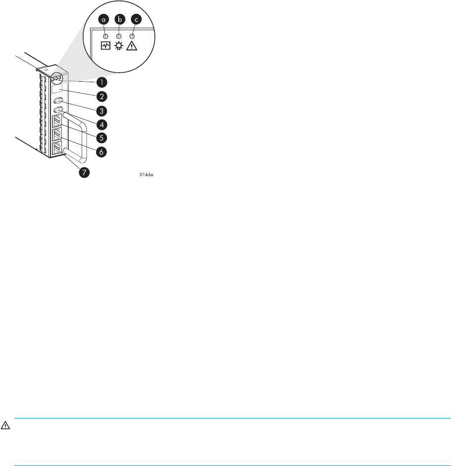
Figure 17 EMU controls and displays
1. Status indicators:
a. EMU—This flashing green is the heartbeat for an operational EMU.
b. Enclosure power—When both the +5 VDC and +12 VDC are correct, this green indicator is on.
c. Enclosure fault—This amber indicator is normally off. The indicator is lit when an enclosure error
condition exists.
2. Alphanumeric display—A two-character, seven–segment alphanumeric display of the enclosure functions
and status.
3. Function select button—The primary function of this button is to select a display group function. The
indicatorisonwhenanerrorconditionexists.
4. Display group select button—This button is used to view display groups and control the audible alarm. The
indicator is on when the audible alarm is muted or disabled.
5. RS232 – for use by HP-authorized service representatives
6. LCD ONLY–unused
7. CAB ONLY–enclosure address bus connector
WARNING!
To reduce the risk of electrical shock, fire, or damage to the equipment, do not plug telephone or
telecommunications connectors into the “RS232 ONLY” receptacle.
EMU functions
The primary functions of the EMU include:
•Using the Enclosure Services Processor (ESP) to control the Enclosure Services Interface (ESI) and
communicate with the controllers.
•Assigning the Enclosure Number (En), based upon the cabinet address bus feature.
•Displaying the bay 1 loop ID.
•Monitoring enclosure operation.
•Detecting, reporting, recording, and displaying conditions.
•Displaying EMU, enclosure, and element status.
•Implementing automatic corrective actions for some conditions.
•Providing enclosure status data to the controllers.
•Reporting the WWN and the logical address of all disk drives.
54 Enterprise Virtual Array hardware components

NOTE:
Although the EMU can determine the logical address of a drive, the EMU can neither display nor
change this information. HP Command View EVA can display the addresses from the EMU-supplied
status information.
EMU monitoring functions
The internal EMU circuitry monitors the enclosure and component functions listed in Table 13.
Table 13 EMU monitoring functions
Component Monitored Functions
Blowers •Installation
•Removal
•Type
•Speed (rpm)
Disk drives •Installation
•Removal
•Bypass status
•Loop ID
•Temperature
•Drive fault
EMU •Temperature
•Operation
•Type
•Revision level
Enclosure •Enclosure power
•Enclosure fault
•Backplane type
•Backplane revision level
I/O module •Installation
•Removal
•Status
•Type
•Revision level
Power supplies •Installation
•Removal
•Status
•Type
•Revision level
•+5 VDC voltage and current
•+12 VDC voltage and current
•Total power
•Temperature
Transceiver •Type •Link status
EMU displays
The EMU uses a combination of status indicators, alphanumeric display, and an audible alarm to indicate
the operational status of the enclosure and its components. See Table 14.
Table 14 EMU status displays
Display Function
Audible alarm (For information on the audible alarm, see
“Audible Alarm Operations” on page 57.) Any EMU–detected condition causes this
alarm to sound.
Status indicators (For a description of the status
indicators, see “EMU LED Displays”onpage56.) Display enclosure and EMU status.
Alphanumeric display (For a description of the alphanumeric
display, see “Using the alphanumeric display”onpage56.) The two-character, seven-segment display
displays alphanumeric characters.
HP StorageWorks 3000/5000 Enterprise Virtual Array user guide (VCS 4.xxx) 55

EMU indicator displays
The EMU status indicators are located above the alphanumeric display. See Figure 17.Theseindicators
present the same information as those on the front, lower right corner of the enclosure.
You can determine the EMU and enclosure status using the information in EMU LED displays table.
Table 15 EMU status indications
EMU indicator
(green) Power indicator
(green) Fault indicator
(amber) Status and recommended actions
Flashing Flashing Flashing The EMU Locate function is active. This
display has precedence over all others.
Fault conditions cannot be displayed when
the Locate function is active.
Flashing On Off The EMU is operational. The enclosure
power(both+5VDCand+12VDC)is
present and correct. There are no enclosure
faults.
Flashing On On The EMU is operational. There is an
enclosure fault. Check the alphanumeric
display error code for information about
the problem.
Flashing Off Off The EMU is operational. This display may
be present when power is initially applied
to the enclosure. Note: When the +5 VDC
is incorrect, all the indicators are off.
On On Off There is an EMU fault. There is no enclosure
fault.
Off On Off There is an EMU fault. There is no enclosure
fault.
Off Off Off There is an enclosure fault. Either +5 VDC
is incorrect, or both +5 VDC and +12 VDC
are incorrect. Other error conditions may
exist.
Using the alphanumeric display
The two-character alphanumeric display is located at the top of the EMU (see Figure 17). This
seven-segment display provides information about multiple enclosure functions. The push buttons control
the data displayed or entered.
Alphanumeric display description
The top-level, two-character alphanumeric display (En, Li, rG, Au, and Er), is the display group. The
function of the other displays is display-group dependent. The default display is the enclosure number, a
decimal number in the range 00 through 14. The push buttons allow you to select the alphanumeric
display or to enter data.
•The bottom push button sequentially moves between groups and selects a display group .
See EMU display groups for a description of these display groups.
•The top push button moves between the levels within a display group (see 2, Figure 17).
Display groups
When you press and release the bottom push button, the alphanumeric display selects a different display
group. EMU display groups describes the display groups.
56 Enterprise Virtual Array hardware components
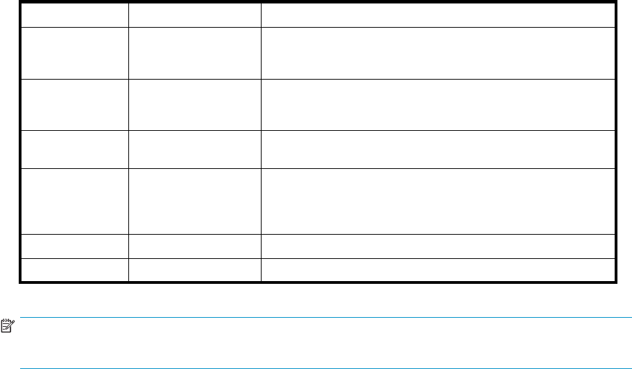
Table 16 EMU display groups
Display Display group Description
En Enclosure Number The enclosure number is the default display and is a decimal
number in the range 00 through 14. See Using the Enclosure
Number Featurefor detailed information.
Li Bay 1 Loop ID This display group has a single sublevel display that defines
the enclosure bay 1 loop ID. Valid loop IDs are in the range
00 through 7F.
rG Reporting Group This display group has two, two-digit displays that define the
reporting group number in the range 0000 through 4095.
Au Audible Alarm This display group provides control over the audible alarm or
horn. The sublevel displays are audible alarm enabled (on) or
audible alarm disabled (oF). See Audible Alarm Operations
for detailed information.
Fr Firmware Revision This display group defines the EMU code firmware version.
Er Error Condition This display group reads Er when there is an error condition.
NOTE:
Any time you press and release the bottom push button the display will change to En, Li, rG, Au, or Er.
Aflashing alphanumeric display indicates that you can edit an address, state, or view a condition report.
EMU push button status indicators
The push button status indicators display error conditions and the state of the audible alarm.
•When an error condition exists, the top push button status indicator is On.
• For a single error condition, the status indicator is On until the error condition is viewed.
• For multiple errors, the status indicator is On until the last error condition is viewed.
•The bottom push button indicator is On only when the alarm is muted or disabled.
Audible alarm operations
Whenever an error condition exists, the audible alarm automatically sounds until all errors are corrected.
You have the option of either muting or disabling the alarm.
•Disabling the audible alarm prevents it from sounding for any error condition.
•Muting the alarm silences it for the existing condition, but any new condition causes the alarm
to sound.
Audible alarm patterns
The audible alarm sound pattern differs depending on the type of error condition. See Table 17 for the
duration and the approximate relationship of these alarms. The most severe, active error condition
controls the alarm pattern.
HP StorageWorks 3000/5000 Enterprise Virtual Array user guide (VCS 4.xxx) 57
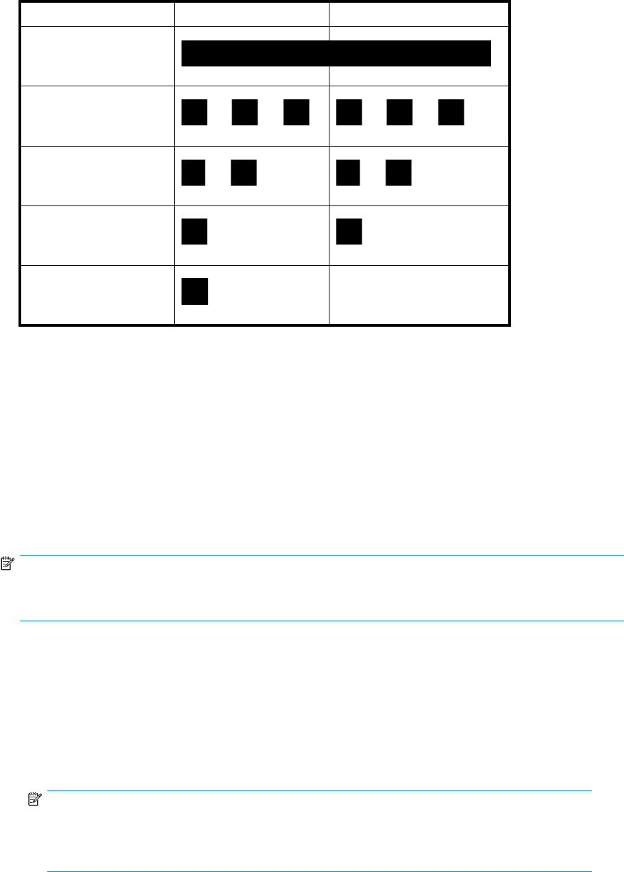
Table 17 Audible alarm sound patterns
Condition type Cycle 1 Cycle 2
UNRECOVERABLE
CRITICAL
NONCRITICAL
INFORMATION
Legend
Alarm On Alarm Off
Controlling the audible alarm
You can control the alarm with the push buttons. This process includes muting, enabling, and disabling.
When an error condition exists, the alphanumeric display reads Er, the alarm sounds, and you can:
•Correct all errors, thereby silencing the alarm until a new error occurs.
•Mute, or temporarily disable, the alarm by pressing and holding the bottom push button. The
alarm remains off until another error occurs, or until you enable (unmute) the alarm. When a new
error occurs, the alarm sounds and the push button indicator is off.
Using the mute feature ensures that you are aware of the more severe errors and provides you
with the capability of correcting them promptly.
•Disable the alarm to prevent any error condition from sounding the alarm.
NOTE:
Disabling the alarm does not prevent the EMU alphanumeric display from displaying Er. Nor does it
prevent HP Command View EVA from displaying the error condition report.
When the alarm is enabled (on), the bottom push button status indicator is off.
Enabling the audible alarm
To enable the alarm:
1. Press and release the bottom push button until the alphanumeric display is Au.
2. Press and hold the top push button until the alphanumeric display is a Flashing oF (Audible Alarm
Off).
NOTE:
When the alarm display is flashing, press and hold the top push button to cause the display
to toggle between On and oF. Press and release the top push button to cause the display to
select the next state.
3. Press and release the top push button to change the display to a flashing On (Audible Alarm On).
58 Enterprise Virtual Array hardware components

4. Press and release the bottom push button to accept the change and to display Au. The bottom push
button indicator is now off.
Muting or unmuting the audible alarm
You may want to mute the alarm in the following situations:
•The error does not require immediate corrective action.
•You cannot correct the error at this time. For example, the error may require a replacement part.
To mute the audible alarm:
NOTE:
Er isdisplayedinthealphanumericdisplaywhenanerrorconditionispresent.
1. Press and hold the bottom push button until the status indicator is On.
A muted alarm will remain off until a new condition report exists.
2. To unmute the alarm, press and hold the bottom push button until the status indicator is Off.Whena
new error condition occurs, the alarm will sound.
Disabling the audible alarm
CAUTION:
Disabling the audible alarm increases the potential of damage to equipment from a reported but
unobserved fault. HP does not recommend disabling the audible alarm.
Disabling the audible alarm affects only one enclosure. This action does not affect condition report
displays on the EMU alphanumeric display or errors reported by HP Command View EVA.
To disable the alarm:
1. Press and release the bottom push button until the alphanumeric display is Au.
2. Press and holdthetoppushbuttonuntilthealphanumericdisplayisaFlashingon (Audible Alarm
On).
NOTE:
When the alarm display is flashing, pressing and holding the top push button causes
the display to rapidly change between on and oF and also causes the display to select
the next state.
3. Press and release the top push button to change the display to a Flashing oF (Audible Alarm Off).
4. Press and release the bottom push button to accept the change and display Au. The bottom push
button indicator is now on.
NOTE:
Adisabledaudible alarm (the bottom push button indicator is on) cannot sound for
any error condition. To ensure that you are immediately alerted to error conditions, it is
recommended that the alarm mute function be used rather than the alarm disable function.
If you must use the disable function, remember to enable the audible alarm as soon as
possible to ensure that you are alerted to errors.
HP StorageWorks 3000/5000 Enterprise Virtual Array user guide (VCS 4.xxx) 59

Enclosure number feature
This section provides a description of the purpose, function, and operation of the EMU enclosure number
(En) feature.
En description
In a single rack configuration, the En is a decimal number in the range 00 through 14, which is
automatically assigned by the enclosure address bus.
NOTE:
Your storage system may use an enclosure address bus higher than 14 if your configuration includes an
optional expansion cabinet. The enclosure address bus connection determines the En. For a single rack,
the display is a decimal number in the range 01 th rough 14. For a multiple (t wo ) rack configuration, the
display is decimal number in the range 01 through 24.
By default, the two-character alphanumeric display shows this number. Pressing the bottom push button
changes the display to En,theEndisplaymode.
When the display is En, pressing and releasing the top push button displays the enclosure number.
A display of 00 indicates that the enclosure is not connected to the enclosure address bus. When this
condition exists, there is no EMU-to-EMU communication over the enclosure address bus.
A display of 01 through 14 indicates that the enclosure is connected to the enclosure address bus and can
exchange information with other enclosures on the enclosure address bus. The decimal number indicates
the physical position of the enclosure in relation to the bottom of the rack.
•01 is the address of the enclosure connected to the lower connector in the first (lower) enclosure
ID expansion cable.
•14 is the address of the enclosure closest to end of the bus, the upper connector in the last
(upper) ID expansion cable.
Unless there is an error condition, the display automatically returns to the enclosure number (01 through
14) one minute after a push button was last pressed.
Enclosure address bus
The enclosure address bus provides a means for managing and reporting environmental conditions within
the rack. It is composed of enclosure ID expansion cables that interconnect the drive enclosures and
controller enclosures. Two drive enclosures connect to each enclosure ID expansion cable.
The drive enclosure numbers are always assigned by the enclosure address bus. Connecting the EMU
CAB connector to an enclosure address bus enclosure ID expansion cable automatically establishes an
enclosure number of 01 through 14. Any drive enclosure not connected to the enclosure address bus
has the enclosure number 00.
NOTE:
The enclosure number is automatically assigned. You cannot manually assign an enclosure number.
The enclosures are numbered as shown in Figure 18.
60 Enterprise Virtual Array hardware components
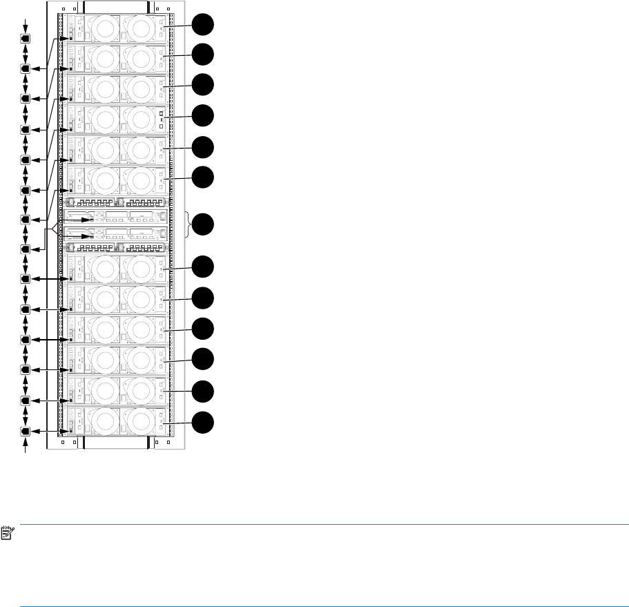
0046a-2
13
13
1
2
3
4
5
6
7
8
9
10
11
12
13
Figure 18 Enclosure numbering with enclosure ID expansion cables
NOTE:
If an expansion rack is used, the enclosure numbering shown above may change or contain additional
numbering. Refer to the HP StorageWorks Enterprise Virtual Array hardware configuration guide for
more information.
For more information about the reporting group number, see ViewingtheReportingGroupFeature.
Enclosure address bus connections
Connecting the enclosures to the enclosure ID expansion cables establishes the enclosure address bus.
The enclosures are automatically numbered based on the enclosure ID expansion cable to which they are
connected. Figure 19 shows the typical configuration of a 42U cabinet with 14 enclosures.
HP StorageWorks 3000/5000 Enterprise Virtual Array user guide (VCS 4.xxx) 61
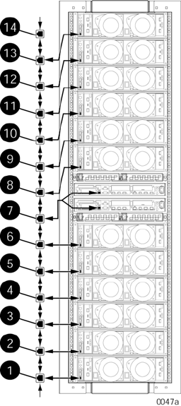
Figure 19 Enclosure address bus components with enclosure ID expansion cables
1. Shelf ID expansion cable port 1—Disk enclosure 1
2. Shelf ID expansion cable port 2—Disk enclosure 2
3. Shelf ID expansion cable port 3—Disk enclosure 3
4. Shelf ID expansion cable port 4—Disk enclosure 4
5. Shelf ID expansion cable port 5—Disk enclosure 5
6. Shelf ID expansion cable port 6—Disk enclosure 6
7. Shelf ID expansion cable port 7—Controller enclosures
8. Shelf ID expansion cable port 8—Disk enclosure 8
9. Shelf ID expansion cable port 9—Disk enclosure 9
10. Shelf ID expansion cable port 10—Disk enclosure 10
11. Shelf ID expansion cable port 11—Disk enclosure 11
12. Shelf ID expansion cable port 12—Disk enclosure 12
13. Shelf ID expansion cable port 13—Disk enclosure 13
Error Condition Reporting
The EMU constantly monitors enclosure operation and notifies you of conditions that could affect
operation. When an error condition is detected, the following action is taken:
•The EMU alphanumeric display is changed to Er. A condition report has precedence over all
other displays.
•The audible alarm sounds (if it is not disabled).
•The error is stored in the error queue.
•The error is passed to the controllers for processing and display by Command View EVA.
62 Enterprise Virtual Array hardware components
NOTE:
An error always generates a condition report. Not all condition reports are generated by errors.
Error condition categories
Each error condition is assigned to a category based on its impact on disk enclosure operation. The
following four error categories are used:
•Unrecoverable—themostsevereerrorcondition,itoccurswhenoneormoreenclosure
components have failed and have disabled some enclosure functions. The enclosure may be
incapable of correcting, or bypassing the failure, and requires repairs to correct the error.
NOTE:
To maintain data integrity, corrective action should be implemented immediately for an
UNRECOVERABLE condition.
•Critical—occurs when one or more enclosure components have failed or are operating outside
of their specifications. The failures impact the normal operation of some components in the
enclosure. Other components within the enclosure may be able to continue normal operations.
Prompt corrective action should be taken to prevent system degradation.
•Noncritical—occurs when one or more components inside the enclosure have failed or are
operating outside of their specifications. The failure of these components does not impact
continued normal operation of the enclosure. All components in the enclosure continue to
operate according to their specifications. The ability of the components to operate correctly
may be reduced should other errors occur. Prompt corrective action should be taken to prevent
system degradation.
•Information—the least severe condition indicates a condition exists that does not reduce the
capability of a component. However, the condition can become an error and require corrective
action. An INFORMATION condition provides an early warning, which enables you to prepare
to implement corrective action before a component fails. Correction of the reported problem
may be delayed.
The error conditions are prioritized by severity—from most severe to least. The most severe condition
takes precedence and is reported first when multiple errors are detected. The reporting characteristics
for each error condition are listed in Table 18.
Table 18 Error condition reporting characteristics
Error condition Takes precedence over Audible alarm pattern1
UNRECOVERABLE All other conditions On continuously
CRITICAL NONCRITICAL and
INFORMATION Sounds three times per alarm cycle
NONCRITICAL INFORMATION Sounds two times per alarm cycle
INFORMATION No other conditions Sounds once per alarm cycle
1The pattern occurs when the condition is the most severe active condition
Error queue
The EMU maintains an internal error queue for storing error conditions. Each error condition remains in
the error queue until the problem is corrected, or for at least 15 seconds after the error is reported. This
ensures that when there are multiple errors or a recurring error, each can be displayed. Each entry in the
error queue can be displayed using a combination of the top and bottom buttons. Each error entry in the
queue contains the element type, the element number, and the error code.
HP StorageWorks 3000/5000 Enterprise Virtual Array user guide (VCS 4.xxx) 63

Correcting the error removes the associated condition from the error queue. Replacing the EMU will
also clear the error conditions. The order in which the EMU displays the error queue information is
based on two factors:
•The severity of the error
•Thetimetheerroroccurred
Themostsevereerrorinthequeuealwayshasprecedence,regardlessofhowlonglesssevereerrorshave
been in the queue. This ensures that the most severe errors are displayed immediately.
NOTE:
Whenviewinganerror,theoccurrenceofamoresevereerrortakesprecedenceandthedisplaychanges
to the most severe error.
The earliest reported condition within an error type has precedence over errors reported later. For
example, if errors at all levels have occurred, the EMU displays them in the following order:
1. UNRECOVERABLE errors in the sequence they occurred.
2. CRITICAL errors in the sequence they occurred.
3. NONCRITICAL errors in the sequence they occurred.
4. INFORMATION conditions in the sequence they occurred.
Error condition report format
Each EMU detected condition generates a condition report containing three pieces of information.
•Element type The first two-digit hexadecimal display defines the element type reporting the
problem. The format for this display is e.t. with a period after each character. Valid element
types are 0.1. through F.F.
•Element number The second display is a two-digit decimal number that defines the specificelement
reporting the problem. The format for this display is en. with a period after the second character.
•Error code The third display is a two-digit decimal number that defines the specificerrorcode.
The format for this display is ec without any periods.
For detailed information about each condition report, including recommended corrective actions.
Navigating the error condition display
When an error condition occurs, the alphanumeric display changes to Er and the error menu is active.
Thebuttonsareusedtodisplaytheerrorconditionvalues.
Perform the following procedure to display error conditions. Figure 20 illustrates the sequence for
displaying error conditions.
1. With Er in the display, press and hold the top push button until the first element type is displayed.
Themostsevereerrorinthequeuewillbedisplayed.
2. Release the top push button when the element type is displayed. The element type has both decimal
points lit.
3. Press and release the top push button to display the element number. This display has only the
right decimal point lit.
4. Press and release the top push button again to display the error code. This display has no decimal
points lit. Repeated press/release operations will cycle through these three values.
5. Press and hold the top push button from any of the three display states to move to the element
type for the next error condition in the queue.
6. Usethetoppushbuttontodisplaythevaluesfortheerrorcondition.
7. When all error conditions have been displayed, press and release the bottom push button to return
to the Er display.
64 Enterprise Virtual Array hardware components
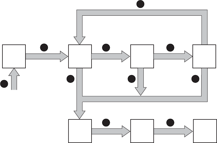
Er en. ec
e.t.
en. ec
e.t.
CXO8233
A
3 3 3
1
4
2
2 2
2 2
1Press & hold top push button to view first error in queue.
2Press & release top push button.
3Press & hold top push button to view next error.
4Press and release the bottom push button at any time to return to the Er display.
e.t. =elementtype,en. =elementnumber,ec =errorcode
Figure 20 Displaying error condition values
Analyzing condition reports
Analyzing each error condition report involves three steps:
1. Identifying the element.
2. Determining the major problem.
3. Defining additional problem information.
Reporting group feature
Another function of the enclosure address bus is to provide communications within a reporting group.
A Reporting Group (rG) is an HSV controller pair and the associated drive enclosures. The controller
pair automatically assigns a unique (decimal) four-digit Reporting Group Number (RGN) to each EMU
on a Fibre Channel drive enclosure.
Each of the drive enclosures on a loop pair are in one reporting group:
•All of the drive enclosures on loop pair 1, both loop 1A and loop 1B, share a unique reporting
group number.
•All of the drive enclosures on loop pair 2, both loop 2A and loop 2B, share a unique reporting
group number.
Each EMU collects environmental information from the associated enclosure and broadcasts the
information to reporting group members using the enclosure address bus. Information from enclosures
in other reporting groups is ignored.
HP StorageWorks 3000/5000 Enterprise Virtual Array user guide (VCS 4.xxx) 65
Reporting group numbers
The reporting group number (RGN) range is 0000 through 4099, decimal.
•0000 is reserved for enclosures that are not part of any reporting group.
•0001 through 0015 are RGNs reserved for use by the EMU.
•0016 through 4095 are valid RGNs.
•4096 through 4099 are invalid RGNs.
The reporting group numbers are displayed on the EMU alphanumeric display as a pair of two-digit
displays. These two displays are identified as rH and rL.
•Valid rH displays are in the range 00 through 40, and represent the high-order (most significant)
two digits of the RGN.
•Valid rL displays are in the range 00 through 99, and represent the low-order (least significant)
two digits of the RGN.
To view a reporting group number:
1. Press and release the bottom push button until the alphanumeric display is rG.
2. To display the two most significant digits of the Reporting Group Number, press and hold the
top push button unit the display is rH.
3. Press and release the top push button to display the first two digits of the RGN.
4. Press and release the top push button until the alphanumeric display is rH.
5. Press and hold the top push button until the alphanumeric display is rL.
6. Press and release the top push button to display the last two digits of the Reporting Group Number.
7. To exit the display, press and release the bottom push button until the alphanumeric display is rG.
Fibre Channel loop switches
The Fibre Channel loop switch acts as a central point of interconnection and establishes a fault-tolerant
physical loop topology between the controllers and the disk enclosures.
66 Enterprise Virtual Array hardware components
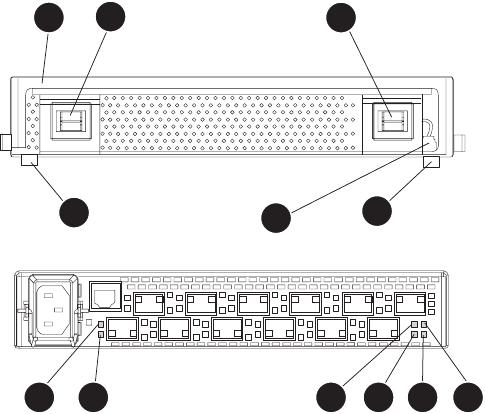
3
4
4
4
2
4
2
3
1
65 7 8 9 1
0
Figure 21 FC loop switch
1. Handle 2. Bezel snaps
3. Alignment tabs 4. Walk-up RS232 port
5. SFP status indicator 6. Port Bypassed indicator
7. P OS T f a u l t i n d i c a t o r 8. Over Temp indicator
9. Power indicator 10. Loop operational indicator
Power-on self test (POST)
When you power on the Fibre Channel switch, it performs a Power–on Self Test (POST) to verify that the
switch is functioning properly. During a POST, all of the indicators turn on for approximately two seconds.
Then, turn off all of the indicators, except the power indicator.
If the Port Bypass indicators are blinking at a constant rate and the POST Fault indicator is on, the
switch detected a fault during the POST. In this case, you need to contact your HP authorized service
representative.
Reading the switch indicators
The Fibre Channel switch contains both system indicators and port indicators. The system indicators
indicate the status of the switch, and the port indicators provide status of a specificport.Figure 21 shows
the Fibre Channel switch with the system and port indicators.
Table 19 lists and describes the system indicators.
HP StorageWorks 3000/5000 Enterprise Virtual Array user guide (VCS 4.xxx) 67

Table 19 Fibre Channel switch system indicators
System indicator Description
Power Agreenindicat
or. When lit, this indicates that the switch is plugged in and the
internal power is functional.
Loop operational A green indicator. When lit, this indicates that the Fibre Channel loop has
completed initialization and is now operational.
POST fault An amber indicator. When lit, this indicates that the internal hardware self-test
failed and the switch will not function.
OvertTemp An amber indicator. When lit, this indicates that the ambient temperature has
exceeded 40° C. The switch is still functional; however you should correct the
problem immediately. The Over temp indicator turns off when the problem is
corrected.
Table 20 describes the port indicators.
Table 20 Fibre Channel switch port indicators
SFP status
indicator
(Green)
Port bypass
indicator (Amber) Description
Off Off Indicates that the port does not have an SFP installed and is
bypassed by the loop.
On Off Indicates that the port is operating normally. The port and device
are fully operational.
On On Indicates the that port is in a bypassed state. The port is
non-operational due to loss of signal, poor signal integrity, or
the Loop Initialization Procedure (LIP).Note: This condition is
also normal when the SFP is present but not attached to a Fibre
Channel drive enclosure node or when the SFP is present and
attached to only a cable assembly. Attaching the SFP to a device
and plugging it into the port should initiate the LIP by the attached
device.
Off On Indicates a Tx fault. The port is non-operational due to an SFP
transmitter fault, improperly-seated SFP, or another failed device.
Problem isolation
Table 21 lists several basic problems and their solutions.
68 Enterprise Virtual Array hardware components

Table 21 Fibre Channel switch basic troubleshooting
Problem Recommended action
SFPs are installed in ports but no
indicators arelit. 1. Verify that the power cord is firmly seated in the switch and is
connected to the power outlet.
2. Check the power indicator to verify that the switch is on.
SFP is installed, but the Port Bypassed
indicator is lit. Re-seat the SFP. If the same condition occurs, the SFP is probably
faulty and should be replaced.
SFP is installed, but the SFP status
indicator and the Port Bypassed indicator
are lit.
This condition indicates that the switch is not receiving a valid
Fibre Channel signal or that the switch is receiving an LIP.
1. Ensure that the switch is powered on.
2. Contact your HP authorized service representative for further
assistance.
SFP is installed and the SFP status
indicator is lit, but the devices are not
communicating.
This condition indicates that the switch is receiving a valid Fibre
Channel signal, but there are no upper level protocols active.
1. Verify that you are running the correct firmware on all storage
system hardware.
2. Check the Loop Operational indicator.
a. If the Loop Operational indicator is lit, the devices have
completed initialization.
b. If the Loop Operational indicator is off, the devices were
not initialized. Disconnect the devices from the switch.
Reconnect the devices one at a time. This allows you to
isolate the device that is responsible for the loop failure.
3. Contact your authorized service representative for further
assistance.
HSV controllers
This section describes the major feature and functions of the HSV110 and HSV100 controllers. Each
Enterprise Virtual Array includes a pair of controllers. Figure 22 shows the HSV controller.
HP StorageWorks 3000/5000 Enterprise Virtual Array user guide (VCS 4.xxx) 69
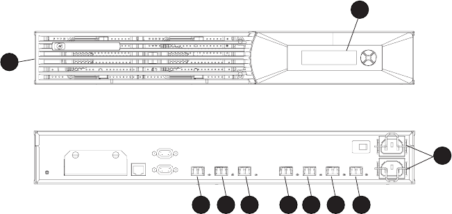
CXO8040
A
Front
Rear
1
2
9
1
0
876 5 43
Figure 22 HSV controller
1. B e z e l 2. OCP
3. Host port FP1 4. Host port FP2
5. Mirror port 6. Device port 1B
7. D e v ic e p o r t 2 B ( H S V 110 o n l y ) 8. Device port 1A
9. Device port 2A (HSV110 only) 10. AC input connectors
High availability features
Two interconnected controllers ensure that the failure of a controller component does not disable the
system. A single controller can fully support an entire system until the defective controller, or controller
component, is repaired. For EVA5000 configurations, the complete data redundancy configuration
includes two Loop A and two Loop B data paths. For EVA3000 configurations, data redundancy is
accomplished with two Loop A data paths.
Each controller has two lead-acid cache batteries that provide power to the cache memory. When the
batteries are fully charged, they can provide power to the cache for up to 96 hours.
Operator control panel
The operator control panel (OCP) provides a direct interface to each controller. From the OCP you
can display storage system status and configuration information, shut down the storage system, and
manage the password.
The OCP includes a 40-character LCD alphanumeric display, four push buttons, and four status indicators
See Figure 23.
HP Command View EVA is the tool you will typically use to display storage system status and configuration
information or perform the tasks available from the OCP. However, if HP Command View EVA is not
available, the OCP can be used to perform these tasks.
70 Enterprise Virtual Array hardware components
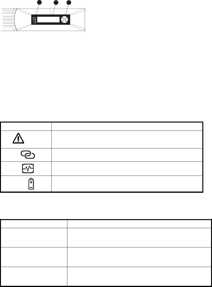
CXO7638
A
12 3
Figure 23 Controller OCP
1. St a t us i n d i c a t o rs ( s e e Table 22)
2. 40–character alphanumeric display
3. Left, right, top, and bottom push buttons
Status indicators
The status indicators display the operational status of the controller. The function of each indicator is
described in Table 22. During initial setup, the status indicators might not be fully operational.
The following sections define the alphanumeric displays modes, including the possible displays, the valid
status indicator displays, and the push button functions.
Table 22 Controller status indicators
Indicator Description
Fault
When this indicator is on there is a controller problem. Check either HP
Command View EVA or the LCD Fault Management displays for a definition of
the problem and recommended corrective action.
Host Link Whenthisindicatorisgreen,thereisa link between the storage system and a
host. When red, there is no link between the storage system and a host.
Controller
When this indicator is flashing slowly, a heartbeat, the controller is operating
normally. When this indicator is not flashing, there is a problem.
Cache Battery
When this indicator is off, the battery assembly is charged. When this indicator
is on, the battery assembly is discharged.
Each port on the rear of the controller has an associated status indicator located directly above it.
Table 23 lists the port and its status description.
Table 23 Controller port status indicators
Port Description
Fibre Channel host ports •Green—Normal operation
•Amber—Nosignaldetected
•Off—No SFP1detected
Fibre Channel device ports •Green—Normal operation
•Amber—No signal detected or the controller has failed the port
•Off—No SFP1detected
Fibre Channel cache mirror ports •Green—Normal operation
•Amber—No signal detected or the controller has failed the port
•Off—No SFP1detected
1On copper Fibre Channel cables, the SFP is integrated into the cable connector.
HP StorageWorks 3000/5000 Enterprise Virtual Array user guide (VCS 4.xxx) 71
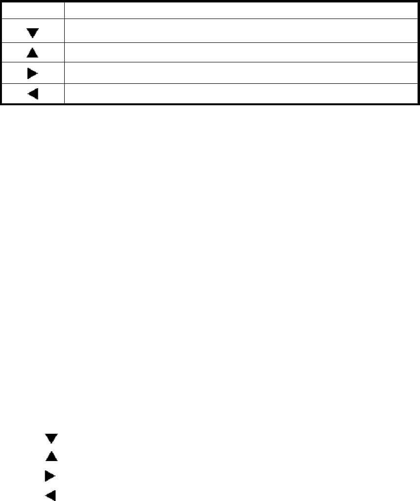
Navigation buttons
The operation of the navigation buttons is determined by the current display and location in the menu
structure. Table 24 defines the basic push button functions when navigating the menus and options.
To simplify presentation and to avoid confusion, the push button reference names, regardless of labels,
are left, right, top, and bottom.
Table 24 Navigation button functions
Button Function
Movesdownthroughtheavailablemenusandoptions
Moves up through the available menus and options
Selects the displayed menu or option.
Returns to the previous menu.
Alphanumeric display
The alphanumeric display uses two LCD rows, each capable of displaying up to 20 alphanumeric
characters. By default, the alphanumeric display alternates between displaying the Storage System Name
andtheWorldWideName.Anactive(flashing) display, an error condition message, or a user entry
(pressing a push button) overrides the default display. When none of these conditions exist, the default
display returns after approximately 10 seconds.
Displaying the OCP menu tree
The Storage System Menu Tree lets you select information to be displayed, configuration settings to
change, or procedures to implement. To enter the menu tree, press any navigation push button when
the default display is active.
The menu treeisorganizedintothefollowingmajormenus:
•System Info—displays information and configuration settings.
•Fault Management—displays fault information. Information about the Fault Management menu
is included in Controller fault management.
•Shutdown Options—initiates the procedure for shutting down the system in a logical, sequential
manner. Using the shutdown procedures maintains data integrity and avoids the possibility of
losing or corrupting data.
•System Password—create a system password to ensure that only authorized personnel can
manage the storage system using HP Command View EVA.
To enter and navigate the storage system menu tree:
1. Press any push button while the default display is in view. System Information becomes the active
display.
2. Press to sequence down through the menus.
Press to sequence up through the menus.
Pressto select the displayed menu.
Press to return to the previous menu.
72 Enterprise Virtual Array hardware components
NOTE:
To exit any menu, press Esc or wait ten seconds for the OCP display to return to the default display.
Table 25 identifies the menu options available within the OCP display.
CAUTION:
Some of the configuration settings available through the OCP impact the operating characteristics of
the storage system. You should not change any setting unless you understand how it will impact system
operation. For more information on the OCP settings, contact your HP-authorized service representative.
Table 25 Menu options within the OCP display
Information Fault Management Shutdown Options System Password
Port ConfigLast Fault Restart Change Password
UUID Unique Half Detail View Power Off Clear Password
Controller Versions System Uninitialize Current Password
Debug Flags
Unbypass Loops
Print Flags
Displaying system information
NOTE:
The purpose of this information is to assist the HP-authorized service representative when servicing
your system.
The system information displays show the system configuration including the VCS version, the OCP
firmware and application programming interface (API) versions, and the enclosure address bus
programmable integrated circuit (PIC) configuration. You can only view, not change, this information.
Displaying versions system information
When you press , the active display is Versions. From the Versions display you can determine the:
•OCP firmware version
•Controller version
•VCS version
NOTE:
The terms PPC, Sprite, Glue, SDC, CBIC, and Atlantis are for development purposes and have no
significance for normal operation.
NOTE:
When viewing the software or firmware version information, pressing displays the Versions Menu tree.
To display System Information
HP StorageWorks 3000/5000 Enterprise Virtual Array user guide (VCS 4.xxx) 73
1. The default display alternates between the Storage System Name display and the World Wide
Name display.
Press any push button to display the Storage System Menu Tree.
2. Press until the desired Versions Menu option appears, and then press or to move to
sub–menu items.
Shutting down the system
CAUTION:
To power off the system for more than 96 hours, use HP Command View EVA.
You can use the Shutdown System function to implement the shutdown methods listed below. These
shutdown methods are explained in Table 26.
•Shutting down the controller (see Shutting the controller down).
•Restarting the system (see Restarting the System).
•Uninitializing the system (see Uninitializing the System).
To ensure that you do not mistakenly activate a shutdown procedure, the default state is always NO,
indicating do not implement this procedure. As a safeguard, implementing any shutdown method
requires you to complete at least two actions.
Table 26 Shutdown methods
LCD prompt Description
Restart System? Implementing this procedure establishes communications between the storage
system and HP Command View EVA. This procedure is used to restore
the controller to an operational state where it can communicate with HP
Command View EVA.
Power off system? Implementing this procedure initiates the sequential removal of controller
power. This ensures no data is lost. The reasons for implementing this
procedure include replacing a drive enclosure.
Uninitialize? Implementing this procedure will cause the loss of all data. For a detailed
discussion of this procedure, see Uninitializing the System.
Shutting the controller down
Use the following procedure to access the Shutdown System display and execute a shutdown procedure.
NOTE:
HP Command View EVA is the preferred method for shutting down the controller. Shut down the
controller from the OCP only if HP Command View EVA cannot communicate with the controller.
Shutting down the controller from the OCP removes power from the controller on which the procedure is
performedonly. Torestorepower,togglethecontroller’spowerswitch.
CAUTION:
If you decide NOT to power off while working in the Power Off menu, Power Off System NO must be
displayed before you press Esc. This reduces the risk of accidentally powering down.
1. Press three times to scroll to the Shutdown Options menu.
2. Press to display Restart.
74 Enterprise Virtual Array hardware components

3. Press to scroll to Power Off.
4. Press to select Power Off.
5. Power off system is displayed. Press Enter to power off the system.
Restarting the system
Torestorethecontrollertoanoperationalstate,usethefollowingproceduretorestartthesystem.
1. Press three times to scroll to the Shutdown Options menu.
2. Press to select Restart.
3. Press to display Restart system?.
4. Press Enter to go to Startup.
No user input is required. The system will automatically initiate the startup procedure and proceed to
load the Storage System Name and World Wide Name information from the operational controller.
Uninitializing the system
Uninitializing the system is another way to shut down the system. This action causes the loss of all storage
systemdata. BecauseHPCommandViewEVAcannotcommunicatewiththediskdriveenclosures,
the stored data cannot be accessed.
CAUTION:
Uninitializing the system destroys all user data. The WWN will remain in the controller unless both
controllers are powered off. The password will be lost. If the controllers remain powered on until you
create another storage system (initialize via GUI), you will not have to re-enter the WWN.
Use the following procedure to uninitialize the system.
1. Press three times to scroll to the Shutdown Options menu.
2. Press to display Restart.
3. Press twice to display Uninitialize System.
4. Press to display Uninitialize?
5. Select Yes and press Enter. The system is now uninitialized.
Password options
The password entry options are:
•Entering a password during storage system initialization (see Setting up an HSV210-series
controllerpairusingtheOCP).
•Showing the current password.
•Changing a password (see Changing a password).
•Removing password protection (see Clearing a password).
Changing a password
For security reasons, you may need to change a storage system password. Your password must contain
eight characters consisting of any combination of the uppercase letters A through Z and the lowercase
letters a through z.
Use the following procedure to change the password.
HP StorageWorks 3000/5000 Enterprise Virtual Array user guide (VCS 4.xxx) 75
NOTE:
Changing a system password on the controller requires changing the password on any HP Command
View EVA with access to the storage system.
1. Select a unique, eight-character password.
2. From the default menus (Storage System Name or World Wide Name) displayed, press three
times to display System Password.
3. Press to display Change Password?
4. Press Enter for yes.
The default password, AAAAAAAA,isdisplayed.
5. Press or to select the first character.
6. Press to accept this character and select the next character.
7. Repeat the process to enter the remaining password characters.
8. Press Enter to enter the password and return to the default display.
Clearing a password
Use the following procedure to remove storage system password protection.
NOTE:
Changing a system password on the controller requires changing the password on any HP Command
View EVA with access to the storage system.
1. Press fourtimestoscrolltotheSystemPasswordmenu.
2. Press to display Change Password?.
3. Press to scroll to Clear Password.
4. Press to display Clear Password.
5. Press Enter to clear the password.
The Password cleared messagewillbedisplayed.
Setting up a controller pair using the OCP
For information about how to set up a controller pair during initial installation see Setting Up a Controller
Pair Using the OCP.
Power supply/blower assembly
Two power supply/blower assemblies provide the necessary operating voltages and cooling to all
controller enclosure components. If one power supply/blower assembly fails, the remaining is capable
of operating the enclosure.
Each power supply/blower includes an amber status indicator which will be on if either of the fallowing
conditions occur:
•The blower is operating at a slow speed or has failed and requires replacement.
•The power supply has failed and requires replacement.
76 Enterprise Virtual Array hardware components

Cache battery
Two cache batteries provide backup power to maintain the contents of the controller cache when AC
power is lost and the storage system has not been shutdown properly. When fully charged the batteries
can sustain the cache contents for to 96 hours. The batteries are located behind the OCP.
Each battery includes an amber status indicator which will be on if the battery fails. If the status indicator
is on, the battery should be replaced as soon as possible.
HSV controller cabling
All data cables and power cables attach to the rear of the controller. Adjacent to each data connector is
a two-colored link status indicator. Table 23 identifies the status conditions presented by these indicators.
NOTE:
These indicators do not indicate whether there is communication on the link, only whether the link
can transmit and receive data.
The data connections are the interfaces to the disk drive enclosures or loop switches (depending on your
configuration), the other controller, and the fabric. Fiber optic cables link the controllers to the fabric,
and, if an expansion cabinet is part of the configuration, link the expansion cabinet drive enclosures to
the loop switches in the main cabinet. Copper cables are used between the controllers (mirror port) and
between the controllers and the drive enclosures or loop switches.
Racks
All storage system components are mounted in a rack. Each configuration includes two controller
enclosures (the controller pair), drive enclosures, FC loop switches (if required), and an expansion
bulkhead. Each controller pair and all the associated drive enclosures form a single storage system.
Rack configurations
Each system configuration depends on the number of disk enclosures included in the storage system. For
more information about racks and configurations, including expansion and interconnection, refer to the
HP StorageWorks Enterprise Virtual Array hardware configuration guide.
Power distribution
AC power is distributed to the rack through a dual Power Distribution Unit (PDU) assembly mounted at the
bottom rear of the rack. The characteristics of the fully-redundant rack power configuration are as follows:
•Each PDU is connected to a separate circuit breaker-protected, 30–A AC site power source
(220–240 VAC ±10%, 50 or 60–Hz, ±5%). Figure 24 illustratesthecompatible60–Hzand
50–Hz wall receptacles.
HP StorageWorks 3000/5000 Enterprise Virtual Array user guide (VCS 4.xxx) 77

CXO7549
A
NEMA L6-30R receptacle, 3-wire, 30-A, 60-Hz
CXO5409
B
IEC 309 receptacle, 3–wire, 30–A, 50–Hz
Figure 24 60–Hz and 50–Hz wall receptacles
•The standard power configuration for any Enterprise Virtual Array rack is the fully redundant
configuration. Implementing this configuration requires:
• Two separate circuit breaker-protected, 30–A site power sources with a compatible wall
receptacle (see Figure 24).
• One dual PDU assembly. Each PDU connects to a different wall receptacle.
• Six Power Distribution Modules (PDM) per rack. Three PDMs mount vertically on each side
of the rack. Each set of PDMs connects to a different PDU.
• The drive enclosure power supplies on the left (PS 1) connect to the PDMs on the left with a
gray, 66 cm (26 in) power cord.
• The drive enclosure power supplies on the right (PS 2) connect to the PDMs on the right with a
black, 66 cm (26 in) power cord.
• The upper controller connects to a PDM on the left with a gray, 152 cm (60 in) power cord.
• The lower controller connects to a PDM on the right with a black, 66 cm (26 in) power cord.
NOTE:
Drive enclosures, when purchased separately, include one 50 cm black cable and one 50 cm gray cable.
The configuration provides complete power redundancy and eliminates all single points of failure for
both the AC and DC power distribution.
PDUs
Each Enterprise Virtual Array rack has either a 50– or 60–Hz, dual PDU mounted at the bottom rear
of the rack. The 228481–002/228481–003 PDU placement is back-to-back, plugs facing down, with
switches on top.
•The standard 50–Hz PDU cable has an IEC 309, 3–wire, 30–A, 50–Hz connector.
•The standard 60–Hz PDU cable has a NEMA L6–30P, 3–wire, 30–A, 60–Hz connector.
If these connectors are not compatible with the site power distribution, you must replace the PDU power
cord cable connector.
Each of the two PDU power cables has an AC power source specific connector. The circuit
breaker-controlled PDU outputs are routed to a group of four AC receptacles (see Figure 25). The voltages
are then routed to PDMs, sometimes referred to as AC power strips, mounted on the two vertical rails
in the rear of the rack.
78 Enterprise Virtual Array hardware components
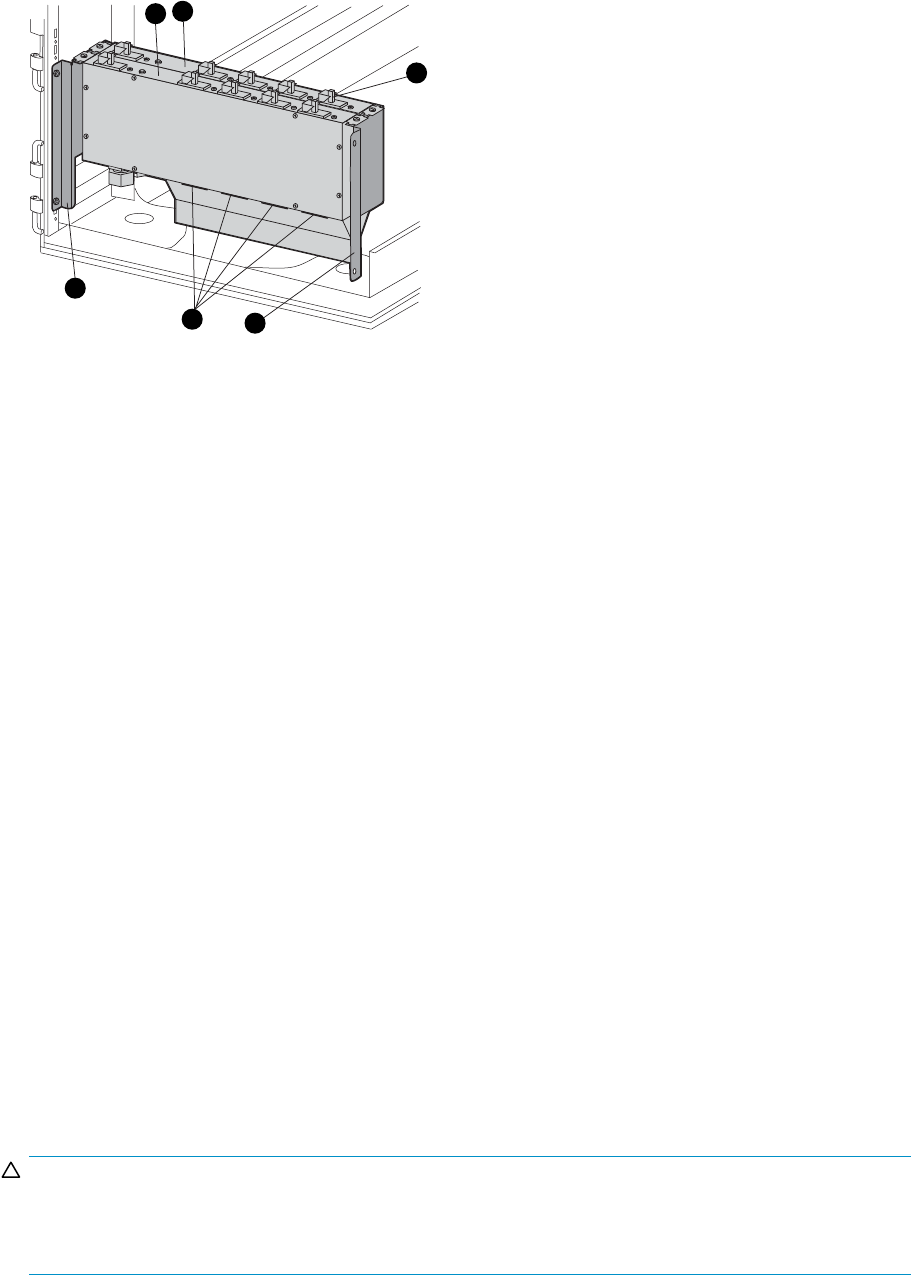
1
0130a
2
3
5
45
Figure 25 Dual PDU assembly
1. P D U 1 2. PDU 2
3. Circuit breakers 4. AC receptacles
5. Mounting hardware
PDU 1
PDU 1 connects to AC power distribution source 1. A PDU 1 failure:
•Disables the power distribution circuit.
•Removes powerfromPDMs1,2,and3.
•Disables PS 1 in the drive enclosures.
•Disables the upper controller power supply.
PDU 2
PDU 2 connects to AC power distribution source 2. A PDU 2 failure:
•Disables the power distribution circuit.
•Removes power from PDMs 4, 5, and 6.
•Disables PS 2 in the drive enclosures.
•Disables the lower controller power supply.
PDMs
There are six PDMs mounted in the rear of each rack:
•Three mounted on the left vertical rail connect to PDU 1.
•Three mounted on the right vertical rail connected to PDU 2.
Each PDM has eight AC receptacles and one thermal circuit breaker. The PDMs distribute the AC power
from the PDUs to the enclosures. Two power sources exist for each controller pair and drive enclosure. If
aPDUfa
ils, the system will remain operational.
CAUTION:
TheACpowerdistributionwithinarackensuresabalancedloadtoeachPDUandreducesthepossibility
of an overload condition. Changing the cabling to or from a PDM could cause an overload condition.
HP supports only the AC power distributions defined in this user guide.
HP StorageWorks 3000/5000 Enterprise Virtual Array user guide (VCS 4.xxx) 79
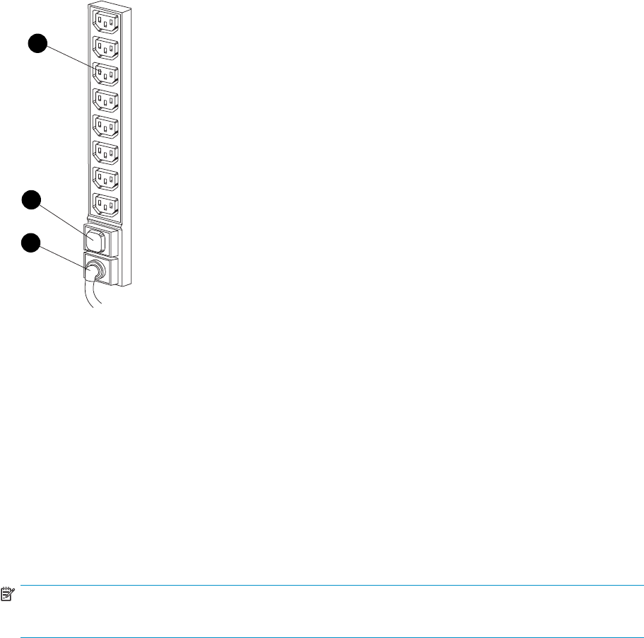
0131
a
1
2
3
Figure 26 Rack PDM
1. Power receptacles 2. Thermal circuit breakers
3. AC power connector
Rack AC power distribution
The power distribution in an Enterprise Virtual Array rack is the same for all variants. The site AC input
voltage is routed to the dual PDU assembly mounted in the rack lower rear. Each PDU distributes AC to a
maximum of four PDMs mounted on the left and right vertical rails (see Figure 27).
•PDMs 1 through 3 connect to receptacles A through D on PDU 1. Power cords connect these
PDMs to the number 1 drive enclosure power supplies and to the upper controller enclosure.
•PDMs 4 through 6 connect to receptacles A through D on PDU 2. Power cords connect these
PDMs to the number 2 drive enclosure power supplies and to the lower controller enclosure.
NOTE:
The locationsofthePDUsandthePDMsarethesameinallracks.
80 Enterprise Virtual Array hardware components
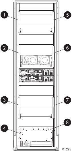
Figure 27 Rack AC power distribution
1. PDM1 2. PDM2
3. PDM 3 4. PDU 1
5. PDM 4 6. PDM 5
7. P D M 6 8. PDU 2
Rack System/E power distribution components
AC power is distributed to the Rack System/E rack through Power Distribution Units (PDU) mounted on the
two vertical rails in the rear of the rack. Up to four PDUs can be mounted in the rack—two mounted
ontherightsideofthecabinetandtwomountedontheleftside.
Each of the PDU power cables has an AC power source specific connector. The circuit breaker-controlled
PDU outputs are routed to a group of ten AC receptacles. The storage system components plug directly
into the PDUs.
Rack AC power distribution
The power distribution configuration in a Rack System/E rack depends on the number of storage systems
installed in the rack. If one storage system is installed, only two PDUs are required. If multiple storage
systems are installed, four PDUs are required.
The site AC input voltage is routed to each PDU mounted in the rack. Each PDU distributes AC through
ten receptacles directly to the storage system components.
•PDUs 1 and 3 (optional) are mounted on the left side of the cabinet. Power cords connect these
PDUs to the number 1 drive enclosure power supplies and to the controller enclosures.
•PDUs 2 and 4 (optional) are mounted on the right side of the cabinet. Power cords connect these
PDUs to the number 2 drive enclosure power supplies and to the controller enclosures.
HP StorageWorks 3000/5000 Enterprise Virtual Array user guide (VCS 4.xxx) 81
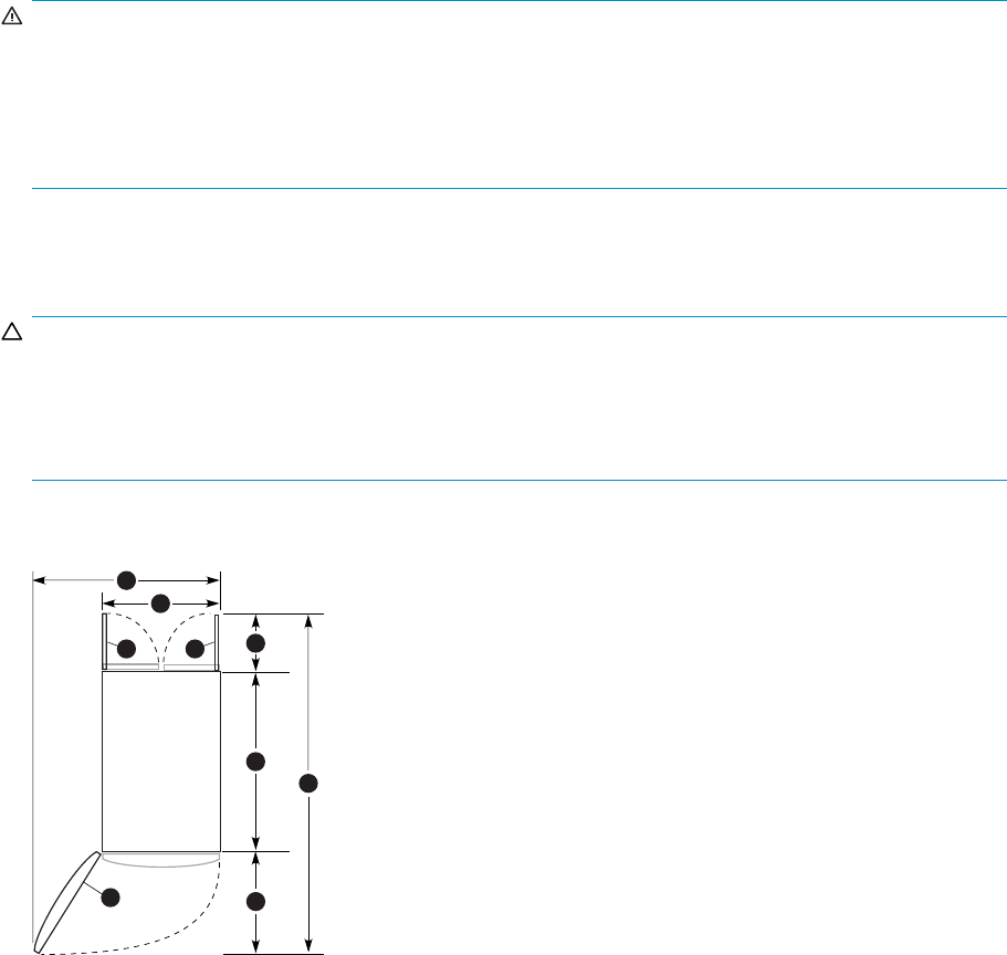
Moving and stabilizing a rack
WARNING!
The physical size and weight of the rack requires a minimum of two people to move. If one person tries
to move the rack, injury may occur.
To ensure stability of the rack, always push on the lower half of the rack. Be especially careful when
moving the rack over any bump (e.g., door sills, ramp edges, carpet edges, or elevator openings). When
the rack is moved over a bump, there is a potential for it to tip over.
Moving the rack requires a clear, uncarpeted pathway that is at least 80 cm (31.5 in) wide for the
60.3 cm (23.7 in) wide, 42U rack. A vertical clearance of 203.2 cm (80 in) should ensure sufficient
clearance for the 200 cm (78.7 in) high, 42U rack.
CAUTION:
Ensurethatnoverticalorhorizontalrestrictionsexistthatwouldpreventrackmovementwithout
damaging the rack.
Make sure that all four leveler feet are in the fully raised position. This process will ensure that the casters
support the rack weight and the feet do no impede movement.
Each rack requires an area 600 mm (23.62 in) wide and 1000 mm (39.37 in) deep (see Figure 28).
CXO8238
A
1
3
2
4
5
6
7
8
2
Figure 28 Single rack configuration floor space requirements
1. Front door 2. Rear door
3. Rack width 600 mm 4. Service area width 813 mm
5. Rear service area depth 300 mm 6. Rack depth 1000 mm
7. Front service area depth 406 mm 8. Total rack depth 1706 mm
Ifthefeetarenotfullyraised,completethefollowingprocedure:
1. Raiseonefootbyturningthelevelerfoothexnutcounterclockwiseuntiltheweightoftherackis
fully on the caster (see Figure 29).
2. Repeat Step 1 for the other feet.
82 Enterprise Virtual Array hardware components

1
2
CXO7589
A
Figure 29 Raising a leveler foot
1. H e x n u t 2. Leveler foot
3. Carefully move the rack to the installation area and position it to provide the necessary service
areas (see Figure 28).
Tostabilizetherackwhenitisinthefinal installation location:
1. Use a wrench to lower the foot by turning the leveler foot hex nut clockwise until the caster does
not touch the floor. Repeat for the other feet.
2. After lowering the feet, check the rack to ensure it is stable and level.
3. Adjust the feet as necessary to ensure the rack is stable and level.
HP StorageWorks 3000/5000 Enterprise Virtual Array user guide (VCS 4.xxx) 83
84 Enterprise Virtual Array hardware components

5 Customer replaceable units
This chapter describes the procedures for replacing CRUs. Information about initial enclosure installation,
ESD protection, and common replacement procedures is also presented.
Customer self repair (CSR)
Table 27 identifies which hardware components are customer replaceable. Using WEBES, ISEE or other
diagnostic tools, a support specialist will work with you to diagnose and assess whether a replacement
component is required to address a system problem. The specialist will also help you determine whether
you can perform the replacement.
Partsonlywarrantyservice
Your HP Limited Warranty may include a parts only warranty service. Under the terms of parts only
warranty service, HP will provide replacement parts free of charge.
For parts only warranty service, CSR part replacement is mandatory. If you request HP to replace these
parts, you will be charged for the travel and labor costs of this service.
Best practices for replacing hardware components
The following information will help you replace the hardware components on your storage system
successfully. Follow these tips any time you must replace a component.
CAUTION:
Removing a component significantly changes the air flow within the enclosure. All components must be
installed for the enclosure to cool properly. If a component fails, leave it in place in the enclosure until a
new component is available to install.
Verifying component failure
•Consult HP technical support to verify that the hardware component has failed and that you
are authorized to replace it yourself.
•Additional hardware failures can complicate component replacement. Check HP StorageWorks
Command View EVA and/or the WEBES System Event Analyzer as follows to detect any
additional hardware problems:
• When you have confirmed that a component replacement is required, you may want to clear
the Real Time Monitoring view. This makes it easier to identify additional hardware problems
that may occur while waiting for the replacement part.
• Before installing the replacement part, check the Real Time Monitoring view for any new
hardware problems. If additional hardware problems have occurred, contact HP support
before replacing the component.
• See the System Event Analyzer online help for additional information.
Procuring the spare part
Parts have a nine–character spare component number on their label (Figure 30). The first six characters
(123479) identify the element; the last three characters (002) define the revision level. The replacement
HP StorageWorks 3000/5000 Enterprise Virtual Array user guide (VCS 4.xxx) 85
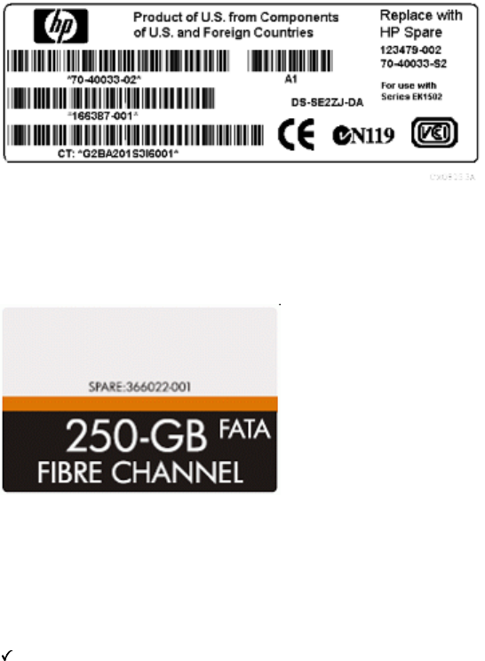
component revision level must be the same as, or greater than, the number on the element being
replaced. The higher the revision level, the later the revision.
Figure 30 Typical product label
The spare part number for each disk drive is listed on the capacity label attached to each drive. See
Figure 31.
Figure 31 Disk drive label
Replaceable parts
This product contains the replaceable parts listed in Table 27. Parts that are available for customer self
repair (CSR) are indicated as follows:
Mandatory: CSR. Parts for which customer self repair is mandatory. If you request HP to replace these
parts, you will be charged for the travel and labor costs of this service.
•Optiona
l CSR: Parts for which customer self repair is optional. These parts are also designed for
customer self repair. If, however, you require that HP replace them for you, this may be done at no
additional charge under the type of warranty service designated for your product.
-- No CSR: Parts for which customer self repair is not available. These parts are not designed for customer
self repair. In order to satisfy the customer warranty, HP requires that an authorized service provider
replace the part.
86 Customer replaceable units

Table 27 Hardware component CSR support
Part description Assembly
part number Spare
part number
CSR
=Mandatory
•=Optional
-- = N/A
Disk enclosure blower 70-40085-01 123482-001
(70-40085–S1) •1
Disk enclosure power supply 30-50872-XXXX=01,
02, 03, 12, 13 212398-001
(30-50872-S1 or
-S2) •1
Disk drive – 300 GB 10K 365608-001 366023-001 •
Disk drive – 250GBFATA 365606-001 366022-001 •
Disk drive – 146 GB 10K 293557-001 300590-001 •
Disk drive – 146 GB 15K 365610-001 366024-001 •
Disk drive – 72 GB 10K 238926-001 244448-001 •
Disk drive – 72 GB 15K 293569-001 300588-001 •
Operator control panel 70-41143-01 390859-001
(70-41143-S1) --
EMU 70-40145-02 375393-001
(70-40145-S2) --
FC I/O module A 70-40616-03 364549-001
(70-40616-S4) --
FC I/O module B 70-40615-03 364548-001
(70-40615-S4) --
2GB SFP Transceiver 212192-002 229204-001 --
Controller EVA5000 (SPS) 70-40464-02 233858-001
(70-40464-S2) --
Controller EVA5000 (DPS) 70-40927-01
(252556-001) 293632-001
(70-40927-S1) --
Controller EVA3000 70-40927-02
(313337-001) 313338-001
(70-40927-S2) --
Front panel bezel EVA3000 70-40475-02 313588-001
(70-40475-S2) •
Front panel bezel EVA5000 70-40475-01 246438-001
(70-40475-S1) •
1Always use caution to avoid damage to cabling when replacing this component.
For more information about CSR, contact your local service provider. For North America, see the CSR
website:
http://www.hp.com/go/selfrepair
To determine the warranty service provided for this product, see the warranty information website:
http://www.hp.com/go/storagewarranty
To order a replacement part, contact an HP-authorized service provider or see the HP Parts Store online:
http://www.hp.com/buy/parts
HP StorageWorks 3000/5000 Enterprise Virtual Array user guide (VCS 4.xxx) 87

Replacing the failed component
CAUTION:
Components can be damaged by electrostatic discharge. Observe the following proper anti-static
protection:
•Always transport and store CRUs in an ESD protective enclosure.
•Do not remove theCRUfromtheESDprotectiveenclosureuntilyouarereadytoinstallit.
•Always use ESD precautions, such as a wrist strap, heel straps on conductive flooring, and an ESD
protective smock when handling ESD sensitive equipment.
•Avoid touching the CRU connector pins, leads, or circuitry.
•Do not place ESD generating material such as paper or non anti-static (pink) plastic in an ESD
protective enclosure with ESD sensitive equipment.
•HP recommends waiting until periods of low storage system activity to replace a component.
•When replacing components at the rear of the rack, cabling may obstruct access to the
component. Carefully move any cables out of the way to avoid loosening any connections. In
particular, avoid cable damage that may be caused by:
• Kinking or bending.
• Disconnecting cables without capping. If uncapped, cable performance may be impaired by
contact with dust, metal or other surfaces.
• Placing removed cables on the floororothersurfaces,wheretheymaybewalkedonor
otherwise compressed.
•Replacement procedures are provided with each component. You can also download the
replacement instructions from the Manuals page of the Business Support Center website. see
“Related documentation” on page 13 for more information.
Returning the defective part
HP specifies, in the materials shipped with a replacement CSR part, whether the defective component
must be returned to HP. Where required, you must ship the defective component back to HP within a
defined period of time, normally five (5) business days. The defective component must be returned with
the associated documentation provided in the shipping material. Failure to return the defective component
may result in HP billing you for the replacement. With a customer self repair, HP will pay all shipping and
component return costs and determine the courier/carrier to be used.
Before you begin
Observe the following precautions when replacing the disk:
•Ensure you have a replacement part available before removing the failed component. Removing
a component impacts cooling within the enclosure.
•Donotremovemorethanonediskatatimefromtheenclosure.Doingsowillimpactcoolingof
the enclosure and may cause data loss.
•Parts can be damaged by electrostatic discharge. Use proper anti-static protection.
•Have a copy of the product user guide available for reference. You can download a copy of the
user guide from the product support page on the HP website.
Disk replacement video
To assist you in replacing the disk, a replacement video is available. You can view the video at the
following website. The same procedure is used for EVA3000/5000 and EVA4x00/6x00/8x00 products.
http://www.thesml.com/csr.htm?prodSeriesId=470490
88 Customer replaceable units

Types of disk failures
There are two types of disk failures:
•Hard failure:T
he disk is no longer functioning properly and has been assigned a failed status.
This type of failure is indicated by an operational state of Failed in HP Command View EVA.
The amber fault status indicator on the disk is typically on.
•Impending failure: Although the disk is still functioning, errors have been detected that indicate
an impending failure. This type of failure is not accompanied by a failed status.
CAUTION:
A disk with an impending failure will appear to be operating normally in HP Command View
EVA, and the fault light on the disk will not be on. Therefore, it is important that you positively
identify the disk before performing the replacement. Work with the HP Solution Center to ensure
you identify the correct disk for replacement.
Checking system redundancy
Before replacing a disk, check the redundancy status of the entire storage system to ensure a disk can
be removed without impacting data availability.
CAUTION:
Do not proceed with the disk replacement until you are certain the storage system is redundant.
1. Open HP Command View EVA and click the icon of the storage system you want to check (Figure 32).
2. On the Initialized Storage System Properties window, click Check Redundancy (Figure 33).
3. If the system is redundant, continue with Verifying component failure.
If the system is not redundant, information is displayed indicating the cause of the lack of redundancy.
See the HP Command View EVA online help to interpret the information that is displayed. In this
situation, work with your HP call center agent to determine how to proceed.
HP StorageWorks 3000/5000 Enterprise Virtual Array user guide (VCS 4.xxx) 89
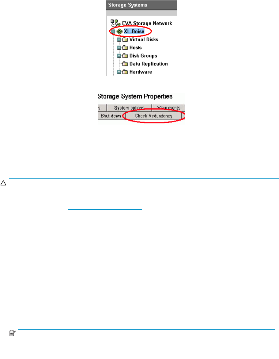
Figure 32 Selecting a storage system
Figure 33 Checking redundancy
Verifying component failure
Before replacing a disk, use the following methods to verify component failure:
CAUTION:
If HP Command View EVA does not present a status consistent with the disk status indicators, or if HP
Command View EVA or your system monitoring tool indicates multiple hardware failures, contact HP
support for assistance (http://www.hp.com/support).
•Analyze any failure messages received. Error messages identify each disk by its rack, enclosure,
bay, and UUID (World Wide Name). Record this information to assist you in identifying the
correct disk before replacing it.
The following is a sample of the disk identification information:
FRU List:
Storage System Name: EVA_1
Storage System World Wide ID: 5000-1FE1-0015-42A0
Disk Drive UUID: 2000-0000-871D-FE60
Drive Location ---
Enclosure ID: 8
Bay ID: 1
Rack Number: 0
NOTE:
The Disk Drive UUID corresponds to the disk Node World Wide Name displayed in HP Command
View EVA.
•Check the disk status indicators (Figure 34). If a hard failure has occurred, the fault indicator
should be On.
•Check the disk status using HP Command View EVA:
1. In the Navigation pane, select Storage system > Hardware > Rack > Disk enclosure > Bay.Use
the information from the error message to guide you to the correct disk.
2. In the Content pane, select the Disk Drive tab.
90 Customer replaceable units

3. Check the disk Node World Wide Name against the error message UUID information recorded
earlier to ensure you have selected the correct disk (Figure 35).
4. Check the disk operational state. If a hard failure has occurred, the operational state should be
Failed. A disk with an impending failure indicates Good status until the condition of the disk
degrades enough to become a hard failure.
5. Verify that the Requested usage and Actual usage fields display Ungrouped (Figure 37).
CAUTION:
Both fields must display Ungrouped before you remove the disk.
If fields display Ungrouped, continue with Step 7. If you must ungroup the disk, continue with the
following step.
NOTE:
If the fields do not display Ungrouped after you attempt to ungroup the disk, contact
your HP-authorized service representative for assistance.
6. For an impending failure, you must ungroup the disk before you remove it:
NOTE:
You should only ungroup one disk at a time. Before you ungroup a disk, verify that
leveling is not in progress and that sufficientfreespaceisavailable.Afteryouungroup
the disk, verify the status of the disk group before continuing. For more information
about leveling and free space, see the HP StorageWorks Enterprise Virtual Array best
practicesdocument.
a. Click Ungroup.
b. Click Ungroup in background.
CAUTION:
When selecting Ungroup in background, a dialog box is displayed indicating the
Operation succeeded. This indicates that the ungroup operation has been initiated.
You can monitor the progress of the ungroup on the Disk Drive Properties window.
c. Click the Disk Drive tab and monitor the ungroup progress. When the ungroup is complete,
continue with the next step.
• If you are running XCS 6.000 or later, monitor the Migration progress field
(Figure 36).
• If you are running an earlier version of XCS or any version of VCS, monitor the
Requested usage field and the Actual usage field. Both fields will display Ungrouped
when the process is complete.
NOTE:
The ungrouping process may take up to several hours to complete. The time
depends on the capacity of the disk and the level of storage system activity.
7. Click Remove to prepare the disk for removal. The status indicators on the disk will begin flashing
to help you locate the disk. You can now remove the disk as described in Removing a disk.
HP StorageWorks 3000/5000 Enterprise Virtual Array user guide (VCS 4.xxx) 91
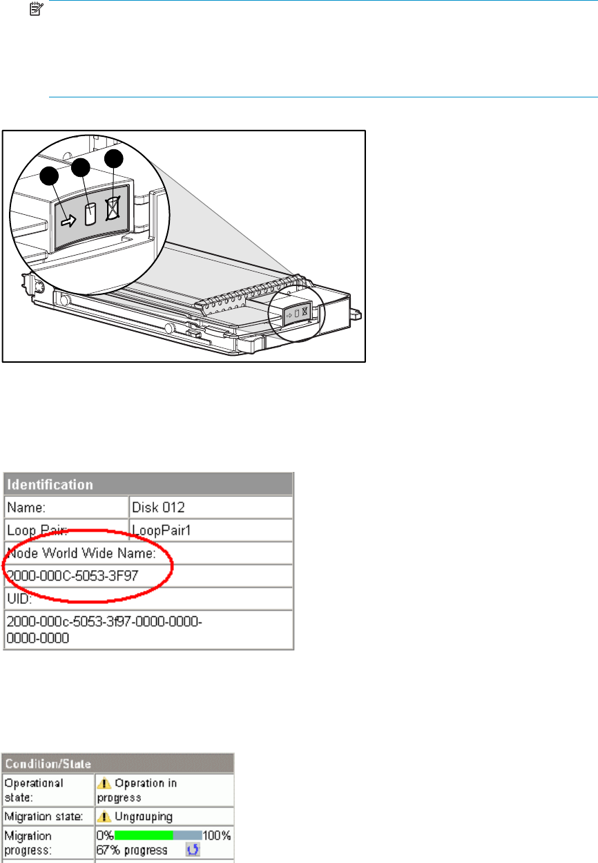
NOTE:
Certain hard disk failures result in a status of Drive unmated. If you are running XCS
5.xxx or earlier and HP Command View EVA 5.x or earlier, the Drive unmated status
disables the Remove button. In this situation, you can remove the disk immediately from
the enclosure. The fault indicator will be on to help locate the failed disk.
123
Figure 34 Disk status indicators
1. A c t iv i t y 2. Online 3. Fault
Figure 35 Checking Node World Wide Name
Figure 36 Monitoring ungroup progress
92 Customer replaceable units
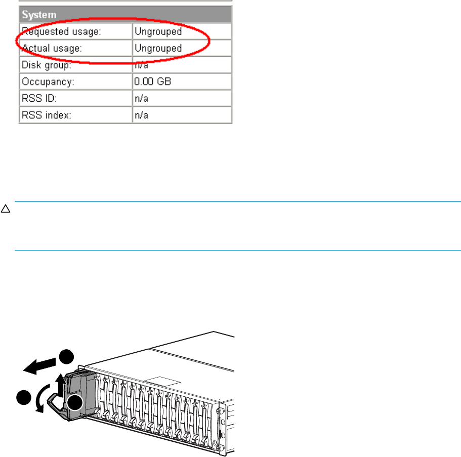
Figure 37 Checking disk group status
Removing a disk
CAUTION:
Rotating media can make the disk difficult to handle. To avoid dropping and damaging the disk, wait
approximately 30 seconds for the media to stop rotating before removing the disk from the enclosure.
1. Push in the wine-colored ejector button (1) and pull the release lever (2) down to the full open
position.
2. Pull the disk part way out of the enclosure (3) and wait for the media to stop spinning.
3. When the media has stopped spinning, remove the disk from the enclosure.
1
1
0115a
2
3
Figure 38 Removing a disk
Changing the Device Addition Policy
To prevent the storage system from automatically grouping a new disk that may have the incorrect
firmware on it, check the Device Addition Policy and set it to manual if necessary:
1. In the HP Command View EVA Navigation pane, select the storage system.
The Initialized Storage System Properties window opens.
2. Click System Options.
3. Select Set system operational policies.
4. If the Device Addition Policy is set to Automatic, change it to Manual.
5. Click Save changes.
HP StorageWorks 3000/5000 Enterprise Virtual Array user guide (VCS 4.xxx) 93
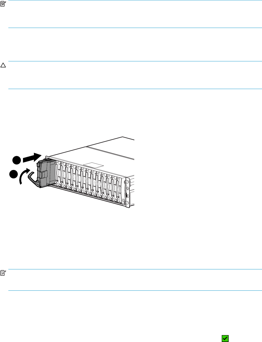
NOTE:
To return the Device Addition Policy to automatic, repeat this procedure after you verify that the disk has
the correct firmware version.
Installing a disk
CAUTION:
You should only replace one disk at a time. After installing the new disk, complete the remaining
procedures in this document for this disk before you attempt to replace another disk.
1. Push in the ejector button on the disk and pull the release lever down to the full open position.
2. Insert the disk into the enclosure as far as it will go (1).
3. Close the release lever until it engages the ejector button, and the disk seats in the backplane (2).
4. Press in firmly on the disk to ensure it is seated properly.
1
1
2
0116a
Figure 39 Installing a disk
Verifying proper operation
After replacing the disk, check the following to verify that the disk is operating normally:
NOTE:
It may take up to 10 minutes for the component to display good status.
•Check the disk status indicators (Figure 34).
•Activityindicator(1)shouldbeonorflashing
• Online indicator (2) should be on or flashing
• Fault indicator (3) should be off
•Check the following using HP Command View EVA:
• Navigate back to the component and check the operational state. It should be .
• Ensure the disk is running the correct firmware. Record the Model number and the Firmware
version of the disk (Figure 40). Check the firmware version against the supported disk firmware
in the HP StorageWorks Enterprise Virtual Array release notes.SeetheHP StorageWorks
Enterprise Virtual Array upgrading disk drive firmware read me first for installation instructions.
You can download these documents from the following website:
94 Customer replaceable units
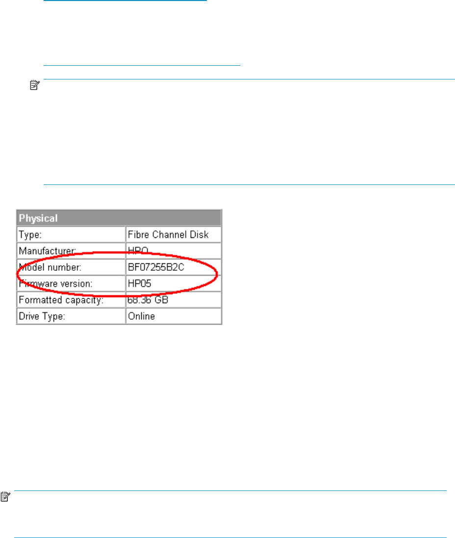
http://www.hp.com/support/manuals
Click Disk Storage Systems under Storage, and then select the appropriate product under
EVA Disk Arrays.
If the disk is running an unsupported version of firmware, download the correct firmware from
the following website and install it using the instructions included with the firmware file. Do not
add the disk to a disk group if it is running an unsupported firmware version.
http://www.hp.com/support/evadiskfirmware
NOTE:
When downloading the firmware, use the disk model number to locate the correct firmware
file. If you have difficulty locating the correct firmware, contact your HP-authorized service
representative for assistance.
If you are running XCS 6.000, verify that leveling is not in progress before upgrading the disk drive
firmware. In HP Command View EVA, go to the General tab of the Disk Group Properties window
and verify that the Leveling field displays Inactive. If it displays Active, wait for leveling to complete
before performing the upgrade. This does not apply if you are running XCS 6.100 or later.
Figure 40 Checking model number and firmware version
Adding the disk to a disk group
After replacing the disk, add it to a disk group. The disk is typically added back into its original disk
group.
1. In the Navigation pane, select Storage system >Hardware >Rack >Disk enclosure >Bay.
2. In the Content pane, select the Disk Drive tab.
3. Click Group to initiate the process for adding the disk to a disk group.
Operation Successful is displayed indicating the disk is now grouped and leveling has
been initiated. The storage system begins immediately using the disk.
NOTE:
If the Device Addition Policy is set to automatic, the disk is automatically added to a disk group. In
this case the Group option will not be available.
Returning the failed component
Follow the return instructions provided with the new component.
Replacing the disk enclosure power supply/blower
This section describes the procedure for replacing the power supply/blower assembly.
HP StorageWorks 3000/5000 Enterprise Virtual Array user guide (VCS 4.xxx) 95

NOTE:
Because this component is used in several products, the drawings may reflect a different enclosure than
theoneyouhave.Theremovalandreplacementprocedureisthesameforeachproduct.
Before you begin
Observe the following precautions when replacing the power supply/blower.
CAUTION:
You have only seven minutes to perform the replacement procedure! Both power supplies must be
installed for the enclosure to cool properly. If a power supply fails, leave it in place in the enclosure until
a new power supply is available to install. The enclosure could shut down due to overheating unless the
power supply is replaced within seven minutes of removal of the failed/failing power supply.
If cabling is obstructing access to the power supply/blower, carefully move the cables out of the way
to avoid loosening any connections.
Parts can be damaged by electrostatic discharge. Use proper anti-static protection. Refer to the
documentation that shipped with your system for additional information.
Have a copy of the product User Guide available for reference. You can download a copy of the User
Guide from the product support page on the HP website.
Verifying component failure
CAUTION:
If HP Command View EVA does not present a status consistent with the power supply/blower status
indicator, or if HP Command View or your system monitoring tool indicates multiple hardware failures,
contact HP support for assistance (http://www.hp.com/support).
The power supply and blower are separately replaceable components. Before replacing a power supply
or blower, use the following methods to verify the component failure:
•Analyzeanyfailuremessagesyoumayhavereceivedfromsystemmonitoring(SystemEvent
Analyzer).
•Check status using HP Command View EVA:
1. In the Navigation pane, select Storage system > Hardware > Rack > Disk enclosure.
2. In the Content pane, select the Power tab or the Cooling tab then the appropriate component (1
or 2). The Operational state should be Failed.
3. To help identify the correct enclosure, click Locate > Locate On to flash the status indicators
on the front of the disk enclosure.
•Check the power supply/blower status indicator. See Figure 41.Itshouldbeoff.
96 Customer replaceable units
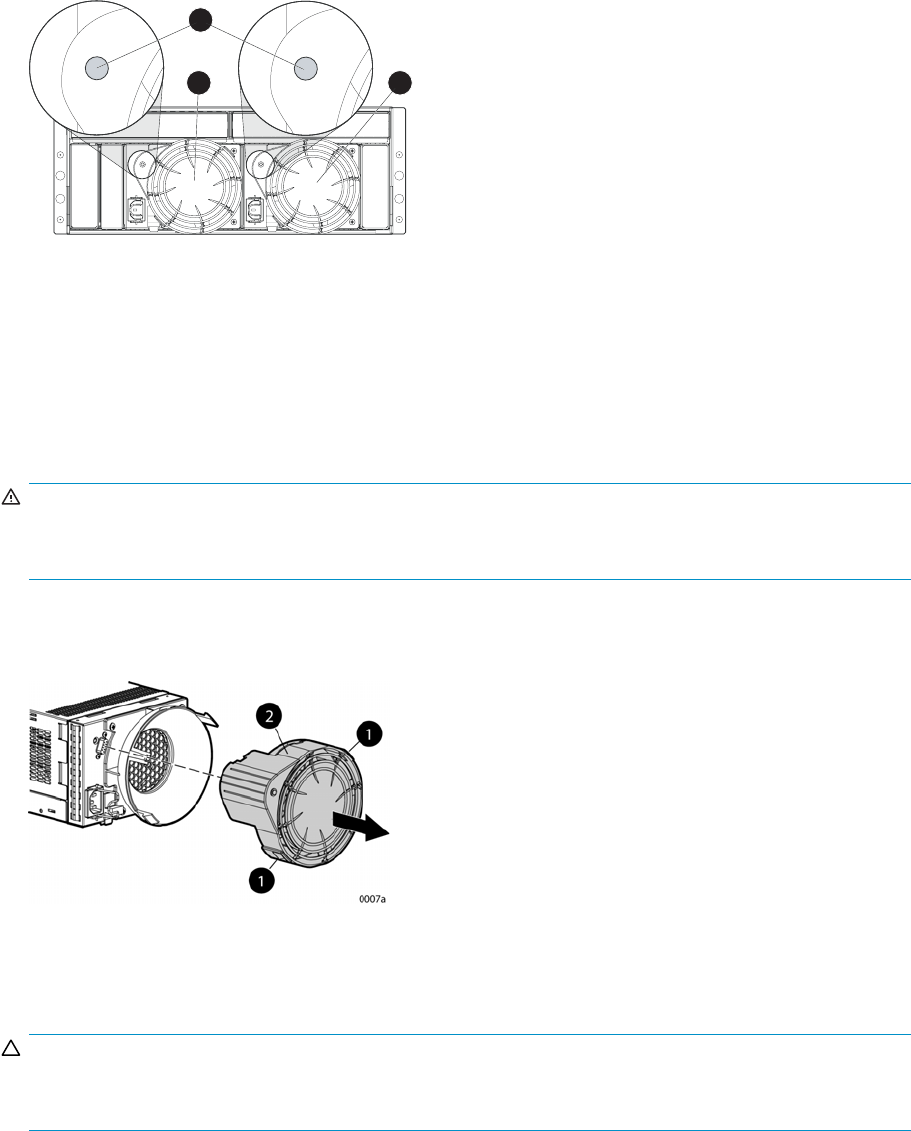
1
2
3
Figure 41 Power supply/blower status indicator
1. S t a tu s i n d icator 2. Power supply/blower 1
3. Power supply/blower 2
Removing a blower
It is not necessary to remove the power supply to replace a failed blower.
WARNING!
The blower motor does not stop immediately when the blower is removed. Keep your fingers away from
the blower blades until the motor stops.
•While pushing in on the two wine-colored mounting tabs (1, Figure 42), pull the blower (2)
away from the power supply.
Figure 42 Removing a blower
Installing a blower
CAUTION:
Pressing on the center section of the blower can damage the blades or the housing. Only press on
the outer edge of the blower when installing it.
1. Align the blower guide post (2, Figure 43) with the mounting hole next to the power supply
connector (1).
2. Slide the blower onto the power supply (4) until the mounting tabs (3) snap into place.
HP StorageWorks 3000/5000 Enterprise Virtual Array user guide (VCS 4.xxx) 97
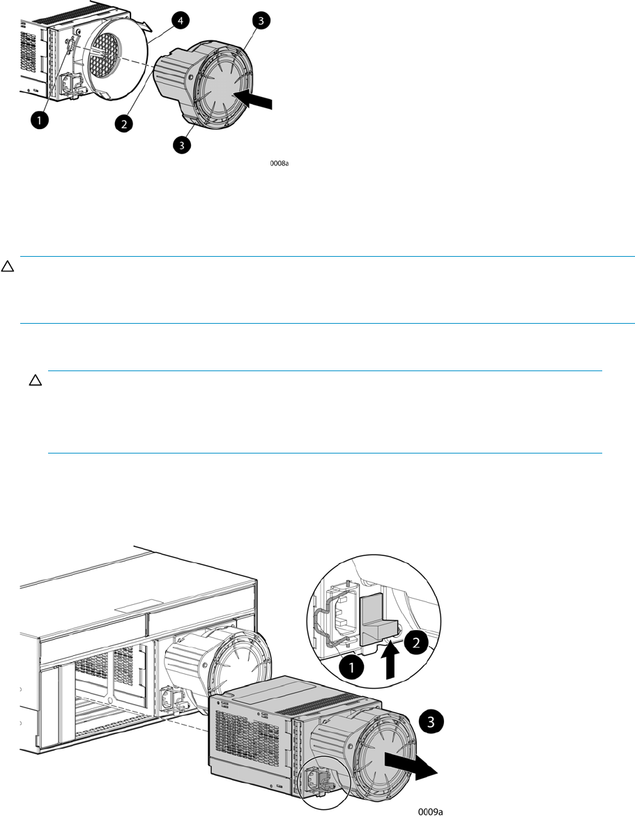
Figure 43 Installing a blower
Removing a power supply
CAUTION:
When a power supply is removed, the enclosure could shut down within seven minutes due to overheating
unless the power supply is replaced.
1. Disengage the power cord lock (1, Figure 44) and disconnect the power cord from the power supply.
CAUTION:
When removing the left power supply, ensure the cord lock on the right power supply is
engaged. This will avoid inadvertently disconnecting the right power supply. Also take care
to avoid disrupting the cables on the I/O module to left of the power supply.
2. Lift up on the wine-colored mounting latch (2), then grasp the blower (3) and pull the power supply
out of the enclosure.
3. Remove the blower from the defective power supply and install it on the replacement power supply.
Figure 44 Removing a power supply
Installing a power supply
1. Lift up on the module latch (1, Figure 45) and slide the power supply into the enclosure until it is
fully seated.
98 Customer replaceable units
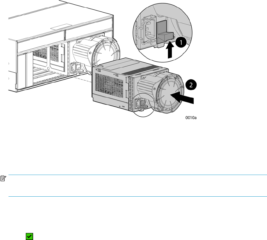
2. Connect the power cord to the power supply and engage the cord lock.
Figure 45 Installing a power supply
Verifying proper operation
After replacing the power supply or blower, check the following to verify that the component is operating
properly:
NOTE:
It may take up to 10 minutes for the component to display good status.
•Make sure the blower begins operating immediately.
•The status indicator should be on.
•From HP Command View EVA:
• Navigate back to the component and check the status. It should be
.
• TurnoffthelocatefunctionbyclickingLocate > Locate Off.
Returning the failed component
Follow the return instructions provided with the new component.
HP StorageWorks 3000/5000 Enterprise Virtual Array user guide (VCS 4.xxx) 99
100 Customer replaceable units

A Regulatory notices and
specifications
This appendix includes regulatory notices and product specifications for the HP StorageWorks Enterprise
Virtual Array family.
Regulatory notices
Federal Communications Commission (FCC) notice
Part 15 of the Federal Communications Commission (FCC) Rules and Regulations has established Radio
Frequency (RF) emission limits to provide an interference-free radio frequency spectrum. Many electronic
devices, including computers, generate RF energy incidental to their intended function and are, therefore,
covered by these rules. These rules place computers and related peripheral devices into two classes, A
and B, depending upon their intended installation. Class A devices are those that may reasonably be
expected to be installed in a business or commercial environment. Class B devices are those that may
reasonably be expected to be installed in a residential environment (for example, personal computers).
The FCC requires devices in both classes to bear a label indicating the interference potential of the device
as well as additional operating instructions for the user.
The rating label on the device shows the classification (A or B) of the equipment. Class B devices have an
FCC logo or FCC ID on the label. Class A devices do not have an FCC logo or FCC ID on the label.
After the class of the device is determined, refer to the corresponding statement in the following sections.
FCC Class A certification
This equipment generates, uses, and may emit radio frequency energy. The equipment has been type
tested and found to comply with the limits for a Class A digital device pursuant to Part 15 of the FCC
rules, which are designed to provide reasonable protection against such radio frequency interference.
Operation of this equipment in a residential area may cause interference, in which case the user at the
user’s own expense will be required to take whatever measures may be required to correct the interference.
Any modifications to this device—unless approved by the manufacturer—can void the user’s authority to
operate this equipment under Part 15 of the FCC rules.
NOTE:
Additional information on the need to interconnect the device with shielded (data) cables or the need for
special devices, such as ferrite beads on cables, is required if such means of interference suppression
was usedinthequalification test for the device. This information will vary from device to device and
needs to be obtained from the HP EMC group.
Class A equipment
This equipment has been tested and found to comply with the limits for a Class A digital device, pursuant
toPart15oftheFCCRules.Theselimitsaredesignedtoprovidereasonableprotectionagainstharmful
interference when the equipment is operated in a commercial environment. This equipment generates,
uses, and can radiate radio frequency energy and, if not installed and used in accordance with the
instructions, may cause harmful interference to radio communications. Operation of this equipment in a
residential area is likely to cause harmful interference, in which case the user will be required to correct
the interference at personal expense.
HP StorageWorks 3000/5000 Enterprise Virtual Array user guide (VCS 4.xxx) 101

Class B equipment
This equipment has been tested and found to comply with the limits for a Class B digital device, pursuant
to Part 15 of the FCC Rules. These limits are designed to provide reasonable protection against harmful
interference in a residential installation. This equipment generates, uses, and can radiate radio frequency
energy and, if not installed and used in accordance with the instructions, may cause harmful interference
to radio communications. However, there is no guarantee that interference will not occur in a particular
installation. If this equipment does cause harmful interference to radio or television reception, which
can be determined by turning the equipment off and on, the user is encouraged to try to correct the
interference by one or more of the following measures:
•Reorient or relocate the receiving antenna.
•Increase the separation between the equipment and receiver.
•Connect the equipment into an outlet on a circuit that is different from that to which the receiver is
connected.
•Consult the dealer or an experienced radio or television technician for help.
Declaration of conformity for products marked with the FCC logo, United States only
This device complies with Part 15 of the FCC Rules. Operation is subject to the following two conditions:
(1) this device may not cause harmful interference, and (2) this device must accept any interference
received, including interference that may cause undesired operation.
Forquestionsregardingyourproduct,refertohttp://thenew.hp.com.
For questions regarding this FCC declaration, contact:
•Hewlett-Packard CompanyProduct Regulations Manager3000 Hanover St.Palo Alto, CA 94304
•Or call 1-650-857-1501
To identify this product, refer to the part, series, or model number found on the product.
Modifications
TheFCCrequirestheusertobenotified that any changes or modifications made to this device that are not
expressly approved by Hewlett-Packard Company may void the user’s authority to operate the equipment.
Cables
Connections to this device must be made with shielded cables with metallic RFI/EMI connector hoods
in order to maintain compliance with FCC Rules and Regulations.
Laser device
All Hewlett-Packard systems equipped with a laser device comply with safety standards, including
International Electrotechnical Commission (IEC) 825. With specificregardtothelaser,theequipment
complies with laser product performance standards set by government agencies as a Class 1 laser
product. The product does not emit hazardous light; the beam is totally enclosed during all modes of
customer operation and maintenance.
Laser safety warnings
Heed the following warning:
102 Regulatory notices and specifications

WARNING!
WARNING: To reduce the risk of exposure to hazardous radiation:
• Do not try to open the laser device enclosure. There are no user-serviceable components inside.
• Do not operate controls, make adjustments, or perform procedures to the laser device other than
those specified herein.
• Allow only HP authorized service technicians to repair the laser device.
Compliance with CDRH regulations
The Center for Devices and Radiological Health (CDRH) of the U.S. Food and Drug Administration
implemented regulations for laser products on August 2, 1976. These regulations apply to laser products
manufactured from August 1, 1976. Compliance is mandatory for products marketed in the United States.
Certification and classification information
This product contains a laser internal to the Optical Link Module (OLM) for connection to the Fibre
communications port.
In the USA, the OLM is certified as a Class 1 laser product conforming to the requirements contained in
the Department of Health and Human Services (DHHS) regulation 21 CFR, Subchapter J. The certification
is indicated by a label on the plastic OLM housing.
Outside the USA, the OLM is certified as a Class 1 laser product conforming to the requirements
contained in IEC 825-1:1993 and EN 60825-1:1994, including Amendment 11:1996.
The OLM includes the following certifications:
•UL Recognized Component (USA)
•CSA Certified Component (Canada)
•TUV Certified Component (European Union)
•CB Certificate (Worldwide)
Canadien notice (avis Canadien)
Class A equipment
This Class A digital apparatus meets all requirements of the Canadian Interference-Causing Equipment
Regulations.
Cet appareil numérique de la classe A respecte toutes les exigences du Règlement sur le matériel
brouilleur du Canada.
Class B equipment
This Class B digital apparatus meets all requirements of the Canadian Interference-Causing Equipment
Regulations.
Cet appareil numérique de la classe B respecte toutes les exigences du Règlement sur le matériel
brouilleur du Canada.
European union notice
Products with the CE Marking comply with both the EMC Directive (89/336/EEC) and the Low Voltage
Directive (73/23/EEC) issued by the Commission of the European Community.
Compliance with these directives implies conformity to the following European Norms (the equivalent
international standards are in parenthesis):
HP StorageWorks 3000/5000 Enterprise Virtual Array user guide (VCS 4.xxx) 103

•EN55022 (CISPR 22) - Electromagnetic Interference
•EN55024(IEC61000-4-2,3,4,5,6,8,11)-ElectromagneticImmunity
•EN61000-3-2 (IEC61000-3-2) - Power Line Harmonics
•EN61000-3-3 (IEC61000-3-3) - Power Line Flicker
•EN60950 (IEC950) - Product Safety
Notice for France
DECLARATIOND’INSTALLATIONETDEMISEENEXPLOITATIONd’unmatérieldetraitementde
l’information (ATI), classé A en fonction des niveaux de perturbations radioélectriques émis, définis dans
la norme européenne EN 55022 concernant la Compatibilité Electromagnétique.
WEEE Recycling Notices
English notice
Disposal of waste equipment by users in private household in the European Union
This symbol on the product or on its packaging indicates that this product must not be disposed of
with your other household waste. Instead, it is your responsibility to dispose of your waste equipment
by handing it over to a designated collection point for recycling of waste electrical and electronic
equipment. The separate collection and recycling of your waste equipment at the time of disposal will
help to conserve natural resources and ensure that it is recycled in a manner that protects human health
and the environment. For more information about where you can drop off your waste equipment for
recycling, please contact your local city office, your household waste disposal service, or the shop where
you purchased the product.
Dutch notice
Verwijdering van afgedankte apparatuur door privé-gebruikers in de Europese Unie
Dit symbool op het product of de verpakking geeft aan dat dit product niet mag worden
gedeponeerd bij het normale huishoudelijke afval. U bent zelf verantwoordelijk voor het inleveren van uw
afgedankte apparatuur bij een inzamelingspunt voor het recyclen van oude elektrische en elektronische
apparatuur. Door uw oude apparatuur apart aan te bieden en te recyclen, kunnen natuurlijke bronnen
worden behouden en kan het materiaal worden hergebruikt op een manier waarmee de volksgezondheid
en het milieu worden beschermd. Neem contact op met uw gemeente, het afvalinzamelingsbedrijf of
de winkel waar u het product hebt gekocht voor meer informatie over inzamelingspunten waar u oude
apparatuur kunt aanbieden voor recycling.
Czechoslovakian notice
Likvidace zařízení soukromými domácími uživateli v Evropské unii
Tento symbol na produktu nebo balení označuje výrobek, který nesmí být vyhozen spolu s ostatním
domácím odpadem. Povinností uživatele je předat takto označený odpad na předem určené sběrné
místo pro recyklaci elektrických a elektronických zařízení. Okamžité třídění a recyklace odpadu pomůže
uchovat přírodní prostředíazajistítakovýzpůsob recyklace, který ochrání zdraví a životní prostředí
člověka. Další informace o možnostech odevzdání odpadu k recyklaci získáte na příslušném obecním
nebo městském úřadě,odfirmy zabývající se sběrem a svozem odpadu nebo v obchodě,kdejste
produkt zakoupili.
104 Regulatory notices and specifications

Estonian notice
Seadmete jäätmete kõrvaldamine eramajapidamistes Euroopa Liidus
See tootel või selle pakendil olev sümbol näitab, et kõnealust toodet ei tohi koos teiste
majapidamisjäätmetega kõrvaldada. Teie kohus on oma seadmete jäätmed kõrvaldada, viies need
elektri- ja elektroonikaseadmete jäätmete ringlussevõtmiseks selleks ettenähtud kogumispunkti. Seadmete
jäätmete eraldi kogumine ja ringlussevõtmine kõrvaldamise ajal aitab kaitsta loodusvarasid ning tagada,
et ringlussevõtmine toimub viisil, mis kaitseb inimeste tervist ning keskkonda. Lisateabe saamiseks
selle kohta, kuhu oma seadmete jäätmed ringlussevõtmiseks viia, võtke palun ühendust oma kohaliku
linnakantselei, majapidamisjäätmete kõrvaldamise teenistuse või kauplusega, kust Te toote ostsite.
Finnish notice
Laitteiden hävittäminen kotitalouksissa Euroopan unionin alueella
Jos tuotteessa tai sen pakkauksessa on tämä merkki, tuotetta ei saa hävittää kotitalousjätteiden
mukana. Tällöin hävitettävä laite on toimitettava sähkölaitteiden ja elektronisten laitteiden
kierrätyspisteeseen. Hävitettävien laitteiden erillinen käsittely ja kierrätys auttavat säästämään
luonnonvaroja ja varmistamaan, että laite kierrätetään tavalla, joka estää terveyshaitat ja suojelee
luontoa. Lisätietoja paikoista, joihin hävitettävät laitteet voi toimittaa kierrätettäväksi, saa ottamalla
yhteyttä jätehuoltoon tai liikkeeseen, josta tuote on ostettu.
French notice
Élimination des appareils mis au rebut par les ménages dans l’Union européenne
Le symbole apposé sur ce produit ou sur son emballage indique que ce produit ne doit pas être
jeté avec les déchets ménagers ordinaires. Il est de votre responsabilité de mettre au rebut vos appareils
en les déposant dans les centres de collecte publique désignés pour le recyclage des équipements
électriques et électroniques. La collecte et le recyclage de vos appareils mis au rebut indépendamment du
reste des déchets contribue à la préservation des ressources naturelles et garantit que ces appareils seront
recyclés dans le respect de la santé humaine et de l’environnement. Pour obtenir plus d’informations
sur les centres de collecte et de recyclage des appareils mis au rebut, veuillez contacter les autorités
locales de votre région, les services de collecte des ordures ménagères ou le magasin dans lequel
vous avez acheté ce produit.
German notice
Entsorgung von Altgeräten aus privaten Haushalten in der EU
Das Symbol auf dem Produkt oder seiner Verpackung weist darauf hin, dass das Produkt
nicht über den normalen Hausmüll entsorgt werden darf. Benutzer sind verpflichtet, die Altgeräte
an einer Rücknahmestelle für Elektro- und Elektronik-Altgeräte abzugeben. Die getrennte Sammlung
und ordnungsgemäße Entsorgung Ihrer Altgeräte trägt zur Erhaltung der natürlichen Ressourcen
bei und garantiert eine Wiederverwertung, die die Gesundheit des Menschen und die Umwelt
schützt. Informationen dazu, wo Sie Rücknahmestellen für Ihre Altgeräte finden, erhalten Sie bei Ihrer
Stadtverwaltung, den örtlichen Müllentsorgungsbetrieben oder im Geschäft, in dem Sie das Gerät
erworben haben.
HP StorageWorks 3000/5000 Enterprise Virtual Array user guide (VCS 4.xxx) 105

Greek notice
Απόρριψη άχρηστου εξοπλισµού από χρήστες σε ιδιωτικά νοικοκυριά στην Ευρωπαϊκή Ένωση
Το σύµβολο αυτό στο προϊόν ή τη συσκευασία του υποδεικνύει ότι το συγκεκριµένο προϊόν δεν
πρέπει να διατίθεται µαζί µε τα άλλα οικιακά σας απορρίµµατα.Αντίθετα,είναι δική σας ευθύνη να
απορρίψετε τον άχρηστο εξοπλισµό σας παραδίδοντάς τον σε καθορισµένο σηµείο συλλογής για την
ανακύκλωση άχρηστου ηλεκτρικού και ηλεκτρονικού εξοπλισµού.Η ξεχωριστή συλλογή και ανακύκλωση
του άχρηστου εξοπλισµού σας κατά την απόρριψη θα συµβάλει στη διατήρηση των φυσικών πόρων και θα
διασφαλίσει ότι η ανακύκλωση γίνεται µε τρόπο που προστατεύει την ανθρώπινη υγεία και το περιβάλλον.
Για περισσότερες πληροφορίες σχετικά µετοπούµπορείτεναπαραδώσετετονάχρηστοεξοπλισµόσας
για ανακύκλωση,επικοινωνήστε µετοαρµόδιο τοπικό γραφείο,την τοπική υπηρεσία διάθεσης οικιακών
απορριµµάτων ή το κατάστηµα όπου αγοράσατε το προϊόν.
Hungarian notice
Készülékek magánháztartásban történőselejtezése az Európai Unió területén
A készüléken, illetve a készülék csomagolásán látható azonos szimbólum annak jelzésére szolgál,
hogy a készülék a selejtezés során az egyéb háztartási hulladéktól eltérőmódon kezelendő.Avásárló
a hulladékká vált készüléket köteles a kijelölt gyűjtőhelyre szállítani az elektromos és elektronikai
készülékek újrahasznosítása céljából. A hulladékká vált készülékek selejtezéskori begyűjtése és
újrahasznosítása hozzájárul a természeti erőforrások megőrzéséhez, valamint biztosítja a selejtezett
termékek környezetre és emberi egészségre nézve biztonságos feldolgozását. A begyűjtés pontos
helyérőlbővebb tájékoztatást a lakhelye szerint illetékes önkormányzattól, az illetékes szemételtakarító
vállalattól, illetve a terméket elárusító helyen kaphat.
Italian notice
Smaltimento delle apparecchiature da parte di privati nel territorio dell’Unione Europea
Questo simbolo presente sul prodotto o sulla sua confezione indica che il prodotto non può
essere smaltito insieme ai rifiuti domestici. È responsabilità dell’utente smaltire le apparecchiature
consegnandole presso un punto di raccolta designato al riciclo e allo smaltimento di apparecchiature
elettriche ed elettroniche. La raccolta differenziata e il corretto riciclo delle apparecchiature da smaltire
permette di proteggere la salute degli individui e l’ecosistema. Per ulteriori informazioni relative ai
punti di raccolta delle apparecchiature, contattare l’ente locale per lo smaltimento dei rifiuti, oppure il
negozio presso il quale è stato acquistato il prodotto.
Latvian notice
Nolietotu iekārtu iznīcināšanas noteikumi lietotājiem Eiropas Savienības privātajāsmājsaimniecībās
Šāds simbols uz izstrādājuma vai uz tāiesaiņojuma norāda, ka šo izstrādājumu nedrīkst izmest
kopāar citiem sadzīves atkritumiem. Jūs atbildat par to, lai nolietotāsiekārtas tiktu nodotas speciāli
iekārtotos punktos, kas paredzētiizmantotoelektriskounelektroniskoiekārtu savākšanai otrreizējai
pārstrādei. Atsevišķa nolietoto iekārtu savākšana un otrreizējāpārstrāde palīdzēssaglabāt dabas
resursus un garantēs, ka šīsiekārtas tiks otrreizēji pārstrādātas tādāveidā, lai pasargātu vidi un cilvēku
veselību. Lai uzzinātu, kur nolietotāsiekārtas var izmest otrreizējai pārstrādei, jāvēršas savas dzīves
vietas pašvaldībā, sadzīves atkritumu savākšanas dienestāvai veikalā,kurāizstrādājums tika nopirkts.
106 Regulatory notices and specifications

Lithuanian notice
Vartotojųiš privačiųnamųūkiųįrangos atliekųšalinimas Europos Sąjungoje
Šissimbolisantgaminioarbajopakuotės rodo, kad šio gaminio šalinti kartu su kitomis namų
ūkio atliekomis negalima. Šalintinas įrangos atliekas privalote pristatyti įspecialiąsurinkimo vietą
elektros ir elektroninėsįrangos atliekoms perdirbti. Atskirai surenkamos ir perdirbamos šalintinos įrangos
atliekos padės saugoti gamtinius išteklius ir užtikrinti, kad jos bus perdirbtos tokiu būdu, kuris nekenkia
žmoniųsveikatai ir aplinkai. Jeigu norite sužinoti daugiau apie tai, kur galima pristatyti perdirbtinas
įrangos atliekas, kreipkitėsįsavo seniūniją,namųūkio atliekųšalinimo tarnybąarba parduotuvę,kurioje
įsigijote gaminį.
Polish notice
Pozbywanie sięzużytego sprzętu przez użytkownikówwprywatnychgospodarstwachdomowychw
Unii Europejskiej
Ten symbol na produkcie lub jego opakowaniu oznacza, żeproduktuniewolnowyrzucać
do zwykłych pojemników na śmieci. Obowiązkiem użytkownika jest przekazanie zużytego sprzętu
do wyznaczonego punktu zbiórki w celu recyklingu odpadów powstałych ze sprzętu elektrycznego
i elektronicznego. Osobna zbiórka oraz recykling zużytego sprzętu pomogąw ochronie zasobów
naturalnych i zapewniąponowne wprowadzenie go do obiegu w sposób chroniący zdrowie człowieka i
środowisko. Aby uzyskaćwięcejinformacjiotym,gdziemożna przekazaćzużyty sprzętdorecyklingu,
należysięskontaktowaćzurzędem miasta, zakładem gospodarki odpadami lub sklepem, w którym
zakupiono produkt.
Portuguese notice
Descarte de Lixo Elétrico na Comunidade Européia
Este símbolo encontrado no produto ou na embalagem indica que o produto não deve ser
descartado no lixo doméstico comum. É responsabilidade do cliente descartar o material usado (lixo
elétrico), encaminhando-o para um ponto de coleta para reciclagem. A coleta e a reciclagem seletivas
desse tipo de lixo ajudarão a conservar as reservas naturais; sendo assim, a reciclagem será feita de
uma forma segura, protegendo o ambiente e a saúde das pessoas. Para obter mais informações sobre
locais que reciclam esse tipo de material, entre em contato com o escritório da HP em sua cidade, com o
serviçodecoletadelixooucomalojaemqueoprodutofoiadquirido.
Slovakian notice
Likvidácia vyradených zariadení v domácnostiach v Európskej únii
Symbol na výrobku alebo jeho balení označuje, že daný výrobok sa nesmie likvidovaťsdomovým
odpadom. Povinnosťou spotrebiteľa je odovzdaťvyradené zariadenie v zbernom mieste, ktoré je určené
na recykláciu vyradených elektrických a elektronických zariadení. Separovaný zber a recyklácia
vyradených zariadení prispieva k ochrane prírodných zdrojov a zabezpečuje, že recyklácia sa vykonáva
spôsobom chrániacim ľudské zdravie a životné prostredie. Informácie o zberných miestach na recykláciu
vyradených zariadení vám poskytne miestne zastupiteľstvo, spoločnosťzabezpečujúca odvoz domového
odpadu alebo obchod, v ktorom ste si výrobok zakúpili.
HP StorageWorks 3000/5000 Enterprise Virtual Array user guide (VCS 4.xxx) 107

Slovenian notice
Odstranjevanje odslužene opreme uporabnikov v zasebnih gospodinjstvih v Evropski uniji
Ta znak na izdelku ali njegovi embalaži pomeni, da izdelka ne smete odvreči med gospodinjske
odpadke. Nasprotno, odsluženo opremo morate predati na zbirališče, pooblaščeno za recikliranje
odslužene električne in elektronske opreme. Ločeno zbiranje in recikliranje odslužene opreme prispeva k
ohranjanju naravnih virov in zagotavlja recikliranje te opreme na zdravju in okolju neškodljiv način. Za
podrobnejše informacije o tem, kam lahko odpeljete odsluženo opremo na recikliranje, se obrnite na
pristojni organ, komunalno službo ali trgovino, kjer ste izdelek kupili.
Spanish notice
Eliminación de residuos de equipos eléctricos y electrónicos por parte de usuarios particulares en la
Unión Europea
Este símbolo en el producto o en su envase indica que no debe eliminarse junto con los
desperdicios generales de la casa. Es responsabilidad del usuario eliminar los residuos de este tipo
depositándolos en un "punto limpio" para el reciclado de residuos eléctricos y electrónicos. La recogida
y el reciclado selectivos de los residuos de aparatos eléctricos en el momento de su eliminación
contribuirá a conservar los recursos naturales y a garantizar el reciclado de estos residuos de forma que
se proteja el medio ambiente y la salud. Para obtener más información sobre los puntos de recogida
de residuos eléctricos y electrónicos para reciclado, póngase en contacto con su ayuntamiento, con el
servicio de eliminación de residuos domésticos o con el establecimiento en el que adquirió el producto.
Swedish notice
Bortskaffande av avfallsprodukter från användare i privathushåll inom Europeiska Unionen
Om den här symbolen visas på produkten eller förpackningen betyder det att produkten inte får
slängas på samma ställe som hushållssopor. I stället är det ditt ansvar att bortskaffa avfallet genom att
överlämna det till ett uppsamlingsställe avsett för återvinning av avfall från elektriska och elektroniska
produkter. Separat insamling och återvinning av avfallet hjälper till att spara på våra naturresurser och
gör att avfallet återvinns på ett sätt som skyddar människors hälsa och miljön. Kontakta ditt lokala
kommunkontor, din närmsta återvinningsstation för hushållsavfall eller affären där du köpte produkten för
att få mer information om var du kan lämna ditt avfall för återvinning.
Germany noise declaration
Schalldruckpegel Lp = 70 dB(A)
Am Arbeitsplatz (operator position)
Normaler Betrieb (normal operation)
Nach ISO 7779:1999 (Typprüfung)
108 Regulatory notices and specifications
Japanese notice
Harmonics conformance (Japan)
Taiwanese notice
Japanese power cord notice
Country-specificcertifications
HP tests electronic products for compliance with country-specific regulatory requirements, as an individual
item or as part of an assembly. The product label (see Figure 46)specifies the regulations with which
the product complies.
NOTE:
Components without an individual product certification label are qualified as part of the next higher
assembly (for example, enclosure, rack, or tower).
HP StorageWorks 3000/5000 Enterprise Virtual Array user guide (VCS 4.xxx) 109
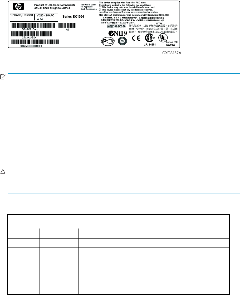
Figure 46 Typical enclosure certification label
NOTE:
The certification symbols on the label depend upon the certification level. For example, the FCC Class A
certificationsymbolisnotthesameastheFCCClassBcertification symbol.
Fibre Channel drive enclosure specifications
This appendix defines the physical, environmental, and power specifications of the Fibre Channel drive
enclosure and the elements.
Physical specifications
This section describes the physical specifications of the drive enclosure and elements.
WARNING!
An assembled enclosure (all elements installed) weighs more than 29.5 kg (65 lb) and requires a
minimum of two individuals to move.
Table 28 defines the dimensions and weights of the enclosure.
Table28Driveenclosurephysicalspecifications
NOTE: Metric dimensions are expressed in whole numbers. For example, 10.795 cm is expressed as 108
mm. Millimeter dimensions are always expressed in whole numbers.
Shipping
Empty Installed Carton Carton and pallet
Height 131 m m ( 5.16 i n ) 131 m m ( 5.16 i n ) 641mm(25.25in) 768mm(30.25in)
Width 505 mm (19.875
in) 505 mm (19.875 in) 318 m m (12.5 in) 610 m m (24 i n )
Depth 448 mm (17.625
in) 448 mm (17.625 in) 597 mm (23.5 in) 1016 mm (40 in)
Weight 10.9 kg (24 lb) 30.9 kg (68 lb) 43.6 kg (96 lb) 49 kg (108 lb)
Environmental specifications
To ensure optimum product operation, you must maintain the operational environmental specifications
listed in Table 29. The ambient temperature (the enclosure air intake or room temperature) is especially
critical.
110 Regulatory notices and specifications
Table 29 Environmental operating specifications
Ambient temperature:+10°Cto+35°C(+50°Fto+95°F)withanaveragerateofchangeof1°C/hour
maximum and a step change of 3 °C or less. Maintaining the optimum ambient temperature within the
specified range ensures that the internal operating temperatures support the drive manufacturer’s MTBF
specifications.
Relative humidity: 40% to 60% (noncondensing) with a step change of 10% or less (noncondensing)
Air quality: Not to exceed a maximum of 500,000 particles, 0.5 micron or larger, per cubic foot of air.
Heat dissipation:1600BTUsperhour
When shipping, or placing this product in short term storage, HP recommends maintaining the
environmental conditions listed in Table 30.
Table 30 Environmental shipping or short-term storage specifications
Ambient temperature:–40°Cto+66°C(–40°Fto+151°F)
Relative humidity: 10% to 80% (noncondensing)
Altitude: 15,240 m (50,000 ft)
Power specifications
The input voltage to the drive enclosure power supplies is a function of the country-specificinputvoltage
to Enterprise storage system rack power distribution units (PDUs). Enterprise storage system AC input line
voltages defines the AC input power available to the drive enclosure power supplies.
CAUTION:
The AC power distribution within a rack ensures a balanced to each PDA and reduces the possibility of
an overload condition. Changing the cabling to or from a PDM could cause an overload condition.
Table 31 Enterprise storage system AC input line voltages
Specification Minimal Nominal Maximum
60 Hz service
AC Line Voltage 57 Hz 60 Hz 63 Hz
AC Line Voltage—Japan 180 VAC 202 VAC 220 VAC
AC Line Voltage–North America 180 VAC 208 VAC 220 VAC
AC Line Voltage–Europe 208VAC 240VAC 254VAC
50 Hz service
AC Line Frequency 47 Hz 50 Hz 53 Hz
AC Line Voltage–Japan 180 VAC 202 VAC 220 VAC
AC Line Voltage–North America 190 VAC 220 VAC 235 VAC
AC Line Voltage–North America 200 VAC 230 VAC 244 VAC
AC Line Voltage–Europe 208VAC 240VAC 254VAC
Table 32 defines the AC input current and wattage to the drive enclosure power supplies.
HP StorageWorks 3000/5000 Enterprise Virtual Array user guide (VCS 4.xxx) 111

Table 32 AC input current and wattage
Nominal Maximum
Input voltage Amps Watts Amps Watts
60–Hz input
100 VAC–JBOD 4.35 436 6.41 641
208 VAC–North America 2.03 419 2.94 609
50–Hz Input
120 VAC–J BOD 3.59 419 5.27 633
220 VAC–North America 1. 92 418 2.78 608
230 VAC–NorthAmerica 1. 9 2 418 2.78 608
240 VAC–Europe 1. 76 416 2.55 607
Table 33 Output voltage and current specifications
Range
Specification Minimum Nominal Maximum
+5.1 VDC
Initial Voltage, Steady
state current +5.13 VDC, 1.0 A +5.18 VDC N/A +5.23 VDC, 26.0 A
+12.2 VDC (Disk Drive Voltage)
Initial Voltage, Steady
state current +12.13 V D C , 1.0 A +12.25 VDC N/A +12.37 VDC, 26.0 A
+12.5 VDC (Disk Drive Voltage)
Initial Voltage, Steady
state current +12.25 VDC,
0.0 0A +12.50 VDC N/A +12.75 VDC, 2.0 A
Table 34 Power specifications
Voltage Current (A) Power (W)
>Maximum continuous current
+5.1 VDC (with a minimum +12.2
VDC load of 0A) 26.0 A 132 W
+12.2 VDC (with a minimum +5
VDC load of 4A) 28.0 A 342.0 W
+12.5 VDC 2.0 A 25.0 W
Total 499.0 W
Maximum peak current (simultaneous seek activity)
+5.1 VDC 26.0 A 132.0 W
+12.2 VDC 43.0 A 524.0 W
+12.5 VDC 2.0 A 25.0 W
Total 681.0 W
112 Regulatory notices and specifications
Fibre Channel switch specifications
The Fibre Channel Switch requires a clean, dry environment for normal operation. Table 35 lists the
specifications for the Fibre Channel Switch.
Table 35 Fibre Channel switch specifications
Specification Description
Weight Approximately 7.0 lbs.
Dimensions 8.50 x 1.57 x 16.00 inches (W x H x D) NOTE: The switch with extender
is 21.66 in (depth).
Operating Temperature 0°Cto40°Cfornormal operation (ambient air temperature)
Storage Temperature -40°Cto80°Cnoncondensing
Power 50 or 60 Hz 100–250 VAC 0.6–0.4 A
Controller specifications
This section defines the physical, power, and environmental specifications of the controller enclosure.
Physical specifications
Table 36 defines the dimensions of the controller.
Table 36 Controller enclosure physical specifications
Specification Installed Shipping
Height 62 mm (2.45 in) 267 mm (10.5 in)
Width 502mm(19.56in) 762mm(30in)
Depth 444 mm (17.49 in) 762 mm (30 in)
Weight 10.4 kg (23 lb) 12.7 kg (28 lb)
Power specifications
Table 37 and Table 38 define the controller power supply input power requirements and output power
specifications.
Table 37 Controller power supply AC power requirements
AC Input Voltage Frequency
Minimum Nominal Maximum Maximum Minimum
180VAC 202VAC 220VAC 47Hz 50 Hz
208 VAC 57 Hz 60 Hz
208 VAC 240 VAC 254 VAC
HP StorageWorks 3000/5000 Enterprise Virtual Array user guide (VCS 4.xxx) 113
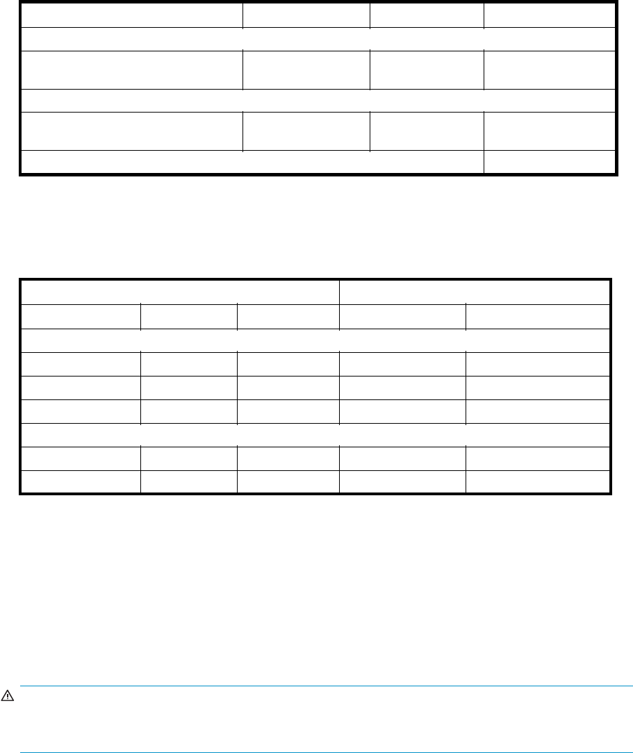
Table 38 Controller power supply output specifications
Voltage Specification Minimum Nominal Maximum
+3.3 VDC
Output Voltage Steady state current
Power 3.23 VDC 3.30 VDC 3.36 VDC 18 A
59.4W
+5.1 VDC
Output Voltage Steady state current
Power 4.80 VDC 5.00 VDC 5.25 VDC 5.0 A
25.5 W
Total Current Total Power 24 A 105.6 W
1. +3.3 VDC steady state current requires a minimum 5.0-V load of 1 A.
2. Total power includes 14.0 watts for the internal blower.
Table 39 defines the AC input current and wattage to the controller power supplies.
Table 39 AC input current and wattage
Nominal Maximum
Input Voltage Amps Watts Amps Watts
60-Hz input
100 VAC 0.928 94 1.53 150
120 VAC 0.788 94 1. 25 148
208 VAC 0.576 97 0.73 146
50–Hz Input
220 VAC 0.616 102 0.69 146
240 VAC 0.573 100 0.64 147
Environmental specifications
There are no controller environmental specifications. See Environmental specifications for this information.
Rack specifications
Physical specifications
WARNING!
The weight of the drive enclosure with the elements installed always requires at least two individuals to
move. HP recommends using a fork lift or a hand truck to move an enclosure in the shipping container.
Table 40 through Table 45 define the dimensions and weights of the 9000-Series and 10000-Series
Enterprise Virtual Array racks.
114 Regulatory notices and specifications

Table 40 9000-Series Enterprise 42U Rack Physical Dimensions
Configuration Height in / mm Width in / mm Depth in / mm Max Wt lbs / kg
Enterprise 2C6D 78.75 / 2000.0 23.7 / 602 35.8 / 909 918 / 416
Enterprise 2C12D 78.75 / 2000.0 23.7 / 602 35.8 / 909 1350 / 612
Enterprise 0C6D 78.75 / 2000.0 23.7 / 602 35.8 / 909 818 / 371
Enterprise 0C12D 78.75 / 2000.0 23.7 / 602 35.8 / 909 1250 / 567
Table 41 9000-Series Enterprise 42U Rack Shipping Dimensions
Configuration Height in / mm Width in / mm Depth in / mm Max Wt
(packaging)
lbs / kg
Enterprise 2C6D 8 5 . 3 8 / 216 9 3 6 . 0 / 914 4 8 . 0 / 12 2 0 1111 / 5 0 4
Enterprise 2C12D 85.38 / 2169 36.0 / 914 48.0 / 1220 1543 / 700
Enterprise 0C6D 85.38 / 2169 36.0 / 914 48.0 / 1220 1011 / 459
Enterprise 0C12D 85.38 / 2169 36.0 / 914 48.0 / 1220 1443 / 654
Table 42 9000-Series Enterprise 41U Rack Physical Dimensions
Configuration Height in / mm Width in / mm Depth in / mm Max Wt lbs / kg
Enterprise 2C6D 78 . 75 / 2000.0 23.7 / 602 39.1 / 993 917 / 416
Enterprise 2C12D 78.75 / 2000.0 23.7 / 602 39.1 / 993 1349 / 612
Enterprise 0C6D 78.75/2000.0 23.7/602 39.1/993 817/371
Enterprise 0C12D 78.75 / 2000.0 23.7 / 602 39.1 / 993 1249 / 567
Table 43 9000-Series Enterprise 41U Rack Shipping Dimensions
Configuration Height in / mm Width in / mm Depth in / mm Max Wt
(packaging)
lbs / kg
Enterprise 2C6D 85.38 / 2169 36.0 / 914 48.0 / 1220 1110 / 503
Enterprise 2C12D 85.38 / 2169 36.0 / 914 48.0 / 1220 1542 / 699
Enterprise 0C6D 85.38 / 2169 36.0 / 914 48.0 / 1220 1010 / 458
Enterprise 0C12D 85.38 / 2169 36.0 / 914 48.0 / 1220 1442 / 654
Table 44 10000-Series Enterprise 42U Rack Physical Dimensions
Configuration Height in / mm Width in / mm Depth in / mm Max Wt lbs / kg
Enterprise 2C6D 78.75 / 2000.0 23.7 / 600 39.3 / 1000 918 / 416
Enterprise 2C12D 78.75 / 2000.0 23.7 / 600 39.3 / 1000 1350 / 612
Enterprise 0C6D 78.75 / 2000.0 23.7 / 600 39.3 / 1000 818 / 371
Enterprise 0C12D 78.75 / 2000.0 23.7 / 600 39.3 / 1000 1250 / 567
HP StorageWorks 3000/5000 Enterprise Virtual Array user guide (VCS 4.xxx) 115
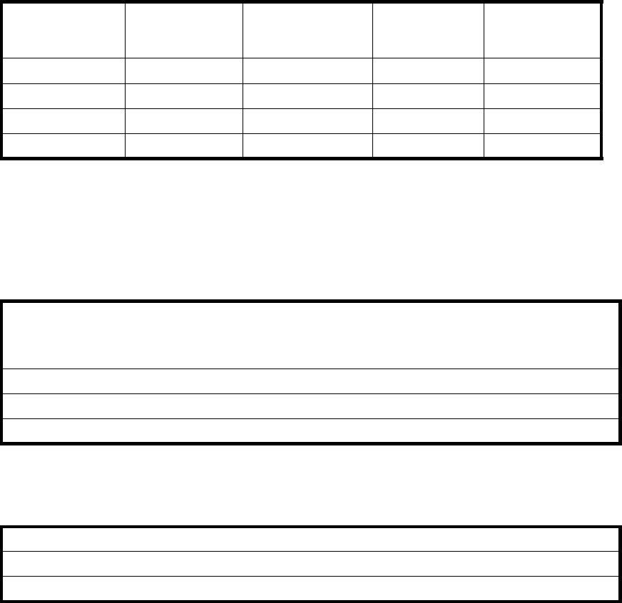
Table 45 10000-Series Enterprise 42U Rack Shipping Dimensions
Configurations Height in / mm Width in / mm Depth in / mm Max Wt
(packaging)
lbs / kg
Enterprise 2C6D8 6 . 2 2 / 219 0 3 2 . 0 / 813 4 8 . 0 / 12 2 0 1111 / 5 0 4
Enterprise 2C12D 86.22 / 2190 32.0 / 813 48.0 / 1220 1543 / 700
Enterprise 0C6D 86.22 / 2190 32.0 / 813 48.0 / 1220 1011 / 459
Enterprise 0C12D 86.22 / 2190 32.0 / 813 48.0 / 1220 1443 / 654
Environmental specifications
To ensure optimum product operation, you must maintain the operational environmental specifications
listed in Table 46. The ambient temperature (the enclosure air intake or room temperature) is especially
critical.
Table 46 Environmental operating specifications
Ambient temperature:+10°Cto+35°C(+50°Fto+95°F)withanaveragerateofchangeof1°C/hour
maximum and a step change of 3 °C or less. Maintaining the optimum ambient temperature within the
specified range ensures that the internal operating temperatures support the drive manufacturer’s MTBF
specifications.
Relative humidity: 40% to 60% (noncondensing) with a step change of 10% or less (noncondensing).
Air quality: Not to exceed a maximum of 500,000 particles, 0.5 micron or larger, per cubic foot of air.
Heat dissipation: 12,708 BT U s per h o ur.
When shipping, or placing this product in short term storage, HP recommends maintaining the
environmental conditions listed in Table 47.
Table 47 Environmental shipping or short term storage specifications
Ambient temperature:–40°Cto+66°C(–40°Fto+151°F)
Relative humidity: 10% to 80% (noncondensing)
Altitude: below 15,240 m (50,000 ft)
Power specifications
Table 48 defines the AC power specifications for the Enterprise Virtual Array PDUs, PDMs, drive enclosure
power supplies, and controller enclosure power supplies.
116 Regulatory notices and specifications

Table 48 Enterprise Virtual Array AC power specifications
Nominal input voltage Specifications
60-Hz Service
202 VAC Voltage Range Power
Receptacle Japan 180-220VAC,57-63Hz,32A,SinglePhase3-wire,2-pole,
IEC 309
208 VAC Voltage Range Power
Receptacle North America 180-220 VAC, 57-63Hz, 32 A, Single Phase
3-wire, 2-pole, NEMA L6-30
240 VAC Voltage Range Power
Receptacle Europe 208-254 VAC, 57-63 Hz, 32 A, Single Phase 3-wire,
2-pole, IEC 309
50-Hz Service
202 VAC Voltage Range Power
Receptacle Japan 180-220 VAC, 47-63Hz, 32 A, Single Phase 3-wire, 2-pole,
IEC 309
220 VAC Voltage Range Power
Receptacle North America 190-235 VAC, 47-63Hz, 32 A, Single Phase
3-wire, 2-pole, NEMA L6-30
230 VAC Voltage Range Power
Receptacle North America 200-244 VAC, 47-63Hz, 32 A, Single Phase
3-wire, 2-pole, NEMA L6-30
240 VAC Voltage Range Power
Receptacle Europe 208-254 VAC, 57-63 Hz, 32 A, Single Phase 3-wire,
2-pole, IEC 309
The power consumptionofanEnterpriseVirtualArrayis3,724W.
HP StorageWorks 3000/5000 Enterprise Virtual Array user guide (VCS 4.xxx) 117
118 Regulatory notices and specifications

B EMU-generated condition reports
This section provides a description of the EMU generated condition reports that contain the following
information:
•Element type (et), a hexadecimal number in the range 01 through FF.
•Element number (en), a decimal number in the range 00 through 99 that defines a specific
problem.
•Error code (ec), a decimal number in the range 00 through 99.
•The recommended corrective action.
NOTE:
The conventions used to differentiate between the elements of the condition report are:
• Element type—period after each character
• Element number—period after the second character
• Error code—no periods
The EMU can send error messages to the controller for transmission to HP Command View EVA. The
messages displayed are specific to HP Command View EVA and are not within the scope of this
publication.
The I/O modules have the built-in intelligence to:
•Observe fibre channel events
•Bypass drive ports based on events
•Perform drive port testing and monitoring to prevent poor-performing drives from participating
in the loop
•Communicate fibre channel events to the controllers
This appendix explains the condition report format, correcting problems, and how to identify element
types. The error codes are arranged in element type sequence (that is, 0.1., 0.2., 0.3., etc.).
Condition report format
When the EMU alphanumeric display is Er, three additional displays identify the possible cause of the
problem: the element type, the specificelement,andtheerrorcode,whichdefines the possible cause
of the problem.
•The first-level display identifies the type of element affected with two alphanumeric characters
separated by periods such as 0.1., 0.2., 1.3., F.F., and so forth. A disk drive problem would
display an element type number of 0.1.
•The second-level display identifies the element affected with a two-digit, decimal number followed
by a period. For example, when a bay 6 drive error occurs, the element number display is 06.; a
display of 14 . indicates a bay 14 p r o b l e m.
•The third-level display identifies a specific problem, the error code with a two-digit, decimal
number. For example, should the problem be either the installation of an incorrectly configured
drive or one that cannot operate at the loop link rate, the display is 01.
HP StorageWorks 3000/5000 Enterprise Virtual Array user guide (VCS 4.xxx) 119

Correcting errors
Correcting an error may require you to perform a specific set of actions. In some cases, the only available
corrective action is to replace the element.
Table 49 lists the element type codes assigned to the drive enclosure elements.
Table 49 Assigned element type codes
Code Element
0.1. Disk Drives
0.2. Power Supplies
0.3. Blowers
0.4. Temperature Sensors
0.6 Audible Alarm 1
0.7. EMU
0.C. Controller OCP LCD1
0.F. Transceivers
1. 0 . Language1
1.1. Communication Port1
1. 2. Voltage Sensors
1. Current Sensors
8.0 Drive Enclosure1
8.2. Drive Enclosure Backplane
8.7. I/O Modules
1Does not generate a condition report. However, for any error, you should record the error code. Then, implement the
recommended corrective action.
Drive conditions
The format of a disk drive condition report is 0.1.en.ec,where:
•0.1. is the disk drive element type number
•en. is the two-character disk drive element
•ec is the error code
A direct correlation exists between the disk drive element number and the bay number. However, no
direct correlation exists between the disk drive bay number and the device Fibre Channel drive enclosure
physical address. The Fibre Channel drive enclosure physical address is assigned by negotiation
during system initialization.
The following sections define the disk drive error codes.
0.1.en.01CRITICALcondition—Driveconfiguration or drive link rate
As each drive spins up and comes on-line, the EMU determines if the drive is Fibre Channel compatible
and can operate at the link rate (1 Gbps or 2 Gbps) established by the I/O module. If either of these
conditions are not met, the EMU issues the condition report 0.1.en.01.
The corrective actions for these conditions are:
•When the drive is not Fibre Channel-compatible you must install a Fibre Channel compatible
driveoradriveblank.
120 EMU-generated condition reports
•When the drive is Fibre Channel-compatible, the EMU compares the drive link rate with the I/O
module link rate, the loop link rate.
If the EMU cannot determine the drive link rate, the EMU activates the drive bypass function for one
minute. During this time the EMU continually checks the drive to determine the link rate.
•If the EMU determines the drive cannot operate at the Fibre Channel link rate set by the I/O
module, the drive bypass function ends and the drive is placed on the loop. This does not
generate a condition report.
•TheEMUissuestheconditionreport0.1.en.01 when the drive link rate is incompatible with
Fibre Channel link rate.
•WhentheEMUcannotdeterminethedrivelinkrateduringtheone-minutedrivebypasstime,the
EMU places the drive on the loop. This process allows the drive to negotiate for an address.
• If negotiation indicates the link rates are compatible, the EMU rechecks the drive link rate to
verify compatibility.
• If negotiation indicates the link rates are incompatible, an error condition exists and drive
loop data transfers stop.
This condition report remains active until the problem is corrected. The problem affects disk drive en.
Therefore, correction to prevent the possible failure of other elements is not required.
Complete the following procedure to correct this problem:
1. Record all six characters of the condition report.
2. Replace the defective drive with:
• A Fibre Channel-compatible drive.
• A Fibre Channel drive capable of operating at a link rate supported by I/O modules and
transceivers.
3. Observe the EMU to ensure the error is corrected.
4. If unable to correct the problem, contact your authorized service representative.
0.1.en.02 INFORMATION condition—Drive missing
The drive is improperly installed or missing. Either option could affect the enclosure air flow and cause an
overtemperature condition for another element.
•This error remains active for one minute, or until the problem is corrected, whichever occurs first.
•Immediate correction is not required. However, correction cannot be delayed indefinitely.
Complete the following procedure to correct this problem.
1. Record all six characters of the condition report.
2. Remove and install the drive to ensure that it is properly installed.
3. Observe the EMU to ensure the error is corrected.
4. If removing and installing the drive did not correct the problem, install a replacement drive or a
drive blank.
5. Observe the EMU to ensure the error is corrected.
6. If unable to correct the problem, contact your authorized service representative.
0.1.en.03 INFORMATION condition—Drive software lock active
Some enclosures have a software-activated lock that prevents physically removing a drive while this feature
is active. This feature can be activated even when an enclosure does not have a physical lock. Removing
a drive when this feature is active generates a condition report. This error remains active for 15 seconds.
No action is required to correct this condition.
HP StorageWorks 3000/5000 Enterprise Virtual Array user guide (VCS 4.xxx) 121
0.1.en.04 CRITICAL condition—Loop a drive link rate incorrect
The drive is capable of operating at the loop link rate but is running at a different rate. For example, the
drive is operating at 1 Gbps, and the loop is operating at 2 Gbps. Only when the drive is operating at
the Fibre Channel link rate established by the I/O module can this drive transfer data.
This error remains active until the problem is corrected.
Complete the following procedure to correct this problem:
1. Record all six characters of the condition report.
2. Remove and replace the drive in the enclosure.
3. Observe the drive status indicators to ensure the drive is operational.
4. Observe the EMU to ensure the error is corrected.
5. If removing and replacing the drive did not correct the problem, replace the drive.
6. Observe the drive status indicators to ensure the drive is operational.
7. Observe the EMU to ensure the error is corrected.
8. If unable to correct the problem, contact your authorized service representative.
0.1.en.05 CRITICAL condition—Loop b drive link rate incorrect
The drive is capable of operating at the loop link rate but is running at a different rate. For example, the
drive is operating at 1 Gbps, and the loop is operating at 2 Gbps. Only when the drive is operating at
theFibreChannellinkrateestablishedbytheI/Omodulecanthisdrivetransferdata.
This error remains active until the problem is corrected.
Complete the following procedure to correct this problem:
1. Record all six characters of the condition report.
2. Remove and replace the drive in the enclosure.
3. Observe the drive status indicators to ensure the drive is operational.
4. Observe the EMU to ensure the error is corrected.
5. If removing and replacing the drive did not correct the problem, replace the drive.
6. Observe the drive status indicators to ensure the drive is operational.
7. Observe the EMU to ensure the error is corrected.
8. If unable to correct the problem, contact your authorized service representative.
Power supply conditions
The format of a power supply condition report is 0.2.en.ec,where:
•0.2. is the power supply element type number
•en. is the two-character power supply element number
•ec is the error code
Figure 47 shows the location of power supply 1 and power supply 2.
122 EMU-generated condition reports
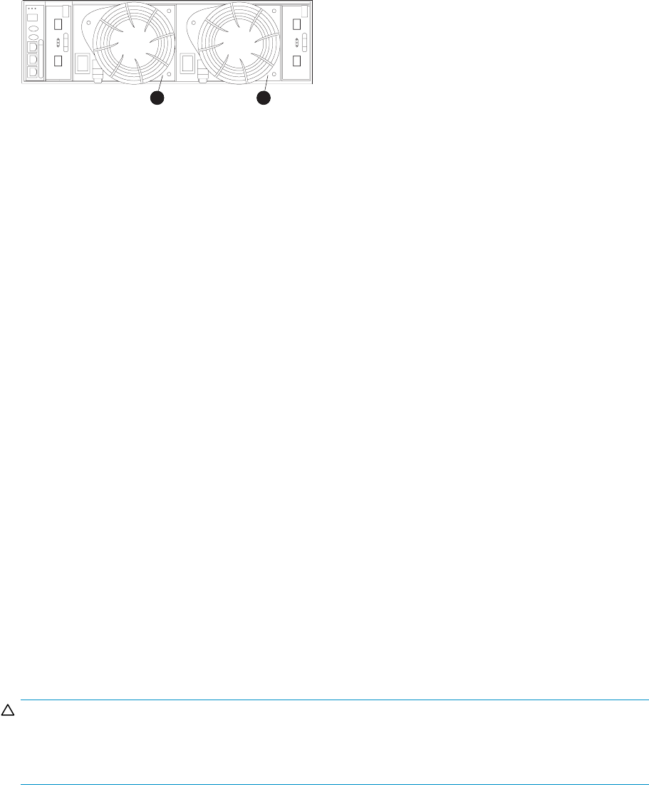
CXO7952
A
21
Figure 47 Power supply element numbering
The following sections define the power supply condition reports.
0.2.en.01NONCRITICALCondition—PowersupplyACinputmissing
The loss of the AC input to a power supply makes the remaining power supply a single point of failure.
This condition report remains active until AC power is applied to the power supply.
Complete the following procedure to correct this problem:
1. Record all six characters of the condition report.
2. Ensure that there is AC power to the rack PDU, and from the PDU to the PDMs and that the PDU and
PDM circuit breakers are not reset.
If there is no AC power to the PDU, contact building facilities management.
Verify that the power supply AC power cord is properly connected.
3. If AC is present, and the rack power distribution circuitry is functioning properly, the power supply
indicator should be on.
4. Observe the EMU to ensure the error is corrected.
5. Contact your authorized service representative.
0.2.en.02 UNRECOVERABLE condition—Power supply missing
This condition report indicates a power supply is not installed or installed incorrectly. Both of these
conditions affect air flow within the enclosure and can cause an overtemperature condition. Enclosure
shutdown is imminent.
The operational power supply will automatically shut down after seven minutes, thereby disabling the
enclosure. This condition report remains active until either the problem is corrected, or the operational
power supply shuts down, whichever occurs first.
To correct this problem, record all six characters of the condition report, then contact your authorized
service representative.
CAUTION:
Removing power from an enclosure may cause the loss or corruption of data. To avoid this condition, shut
down the system using HP Command View EVA. An automatic shutdown and possible data corruption
may result if the power supply is removed before a replacement is available.
0.2.en.03CRITICALcondition—Power supply load unbalanced
This condition report indicates that a component within a power supply may have failed. This can make
the remaining power supply a single point of failure.
This condition report remains active until corrected.
Complete the following procedure to correct this problem:
1. Record all six characters of the condition report.
HP StorageWorks 3000/5000 Enterprise Virtual Array user guide (VCS 4.xxx) 123
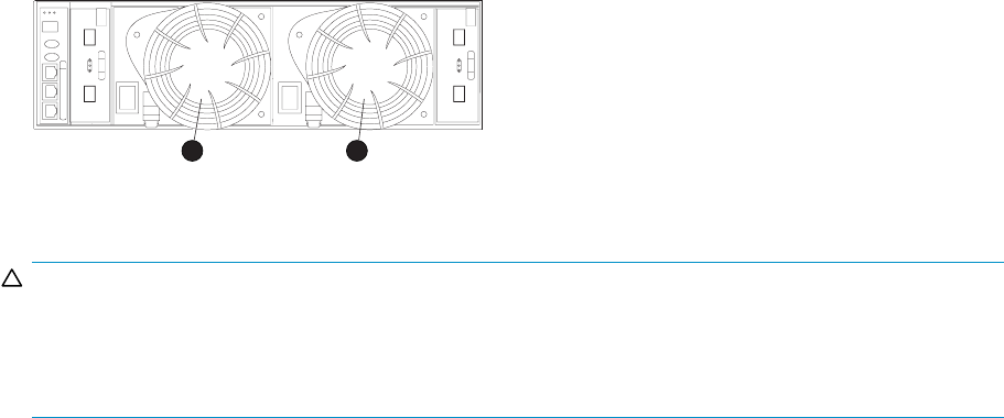
2. Ensure that the blower on the power supply is functioning properly. If not, correct the blower
condition and wait one minute.
3. Contact your authorized service representative.
Blower conditions
The format of a blower condition report is 0.3.en.ec,where:
•0.3.istheblower element type number
•en. is the two-character blower element number
•ec is the error code
As shown in Figure 48,blower 1isinlocation1andblower2isinlocation2.
CXO7953
A
21
Figure 48 Blower element numbering
CAUTION:
Asingleblower operatingathighspeedcanprovidesufficient air flow to cool an enclosure and the
elements for up to 100 hours. However, operating an enclosure at temperatures approaching an
overheating threshold can damage elements and may reduce the MTBF of a specific element. Immediate
replacement of the defective blower is required.
The following sections define the power supply condition reports.
0.3.en.01 NONCRITICAL condition—Blower speed
Ablower is operating at a speed outside of the EMU specified range, possibly because of a bearing
problem. This can affect enclosure cooling and cause an element to fail. This condition report remains
active until the problem is corrected.
This error does not normally require immediate correction. However, an error of this type could contribute
to an element overheating.
HP recommends replacing the blower as soon as possible.
To correct this problem, record all six characters of the condition report, then contact your HP authorized
service representative.
0.3.en.02CRITICALcondition—Blowerspeed
Ablower is operating at a speed that is significantly outside the EMU specified range, possibly because
of a bearing problem. This can cause the loss of cooling and cause an element to fail. The error remains
active until the problem is corrected.
HP recommends replacing the blower as soon as possible.
To correct this problem, record all six characters of the condition report, then contact your authorized
service representative.
124 EMU-generated condition reports

0.3.en.03 UNRECOVERABLE condition—Blower failure
Ablower has stopped. The operational blower now operates at high speed and is a single point of
failure. This condition report remains active until the problem is corrected.
To correct this problem, record all six characters of the condition report, then contact your authorized
service representative.
0.3.en.04 UNRECOVERABLE condition—Blower internal
A power supply reported an internal blower error that could affect enclosure cooling and cause an
element to fail. HP recommends correcting the problem before the blower fails. This condition report
remains active until the problem is corrected.
To correct this problem, record all six characters of the condition report, then contact your HP authorized
service representative.
0.3.en.05 NONCRITICAL condition—Blower missing
Ablower has been removed or is improperly installed. Even though the blower flaps close to maintain
the proper air flow, the reduced cooling capability can cause overheating, causing an element to fail.
This condition report remains active until the problem is corrected.
To correct this problem, record all six characters of the condition report, then contact your HP authorized
service representative.
0.3.en.06 UNRECOVERABLE condition—No blowers installed
NOTE:
IMPORTANT
When this condition exists there will be two error messages.
The first message will be 0.3.en.05 and will identify the first blower.
The second message will be 0.3.en.06 and will identify the second blower.
TheEMUcannotdetectanyinstalledblowers.Shutdown is imminent! The EMU will shut down the
enclosure in seven minutes unless you correct the problem. This condition report remains active until you
correct the problem or the EMU shuts down the power supplies, whichever occurs first.
Complete the following procedure to correct this problem.
1. Record all six characters of the condition report.
2. Use the controller shutdown procedure to shut down the controllers.
3. Contact your authorized service representative.
CAUTION:
An automatic shutdown and possible data corruption may result if the blower is removed before
a replacement is available.
Temperature conditions
The format of a temperature condition report is 0.4.en.ec,where:
•0.4. is temperature sensor element type
•en. is the two-character temperature sensor element
•ec is the error code
HP StorageWorks 3000/5000 Enterprise Virtual Array user guide (VCS 4.xxx) 125

Refer to Table 50 to determine the location of each temperature sensor.
Table 50 Temperature sensor element numbering
Sensor Sensor location Sensor Sensor location
01. Power Supply 1 Exhaust 10. Drive Bay 7
02. Power Supply 2 Exhaust 11. Drive Bay 8
03. EMU 12. D rive B ay 9
04. Drive Bay 1 13. D ri ve B ay 10
05. Drive Bay 2 14 . Drive Bay 11
06. Drive Bay 3 15. Drive Bay 12
07. Drive Bay 4 16. Drive Bay 13
08. Drive Bay 5 17. Drive Bay 14
09. Drive Bay 6
The following sections list the temperature condition reports and the default temperature thresholds. Use HP
Command View EVA to view the temperature sensor ranges for the disk drives, EMU, and power supplies.
0.4.en.01 NONCRITICAL condition—High temperature
This condition report indicates that an element temperature is approaching, but has not reached, the high
temperature CRITICAL threshold. Continued operation under these conditions may result in a CRITICAL
condition. This condition report remains active until the problem is corrected.
Complete the following procedure to correct this problem.
1. Record all six characters of the condition report.
2. Ensure that all elements are properly installed to maintain proper air flow.
3. Ensure that nothing is obstructing the air flow at either the front of the enclosure or the rear of
the blower.
4. Ensure that both blowers are operating properly (the indicators are on) and neither blower is
operatingathighspeed.
5. Verify that the ambient temperature range is +10 °C to +35 °C (+50 °F to +95 °F). Correct the
ambient conditions.
6. Observe the EMU to ensure the error is corrected.
7. If unable to correct the problem, contact your authorized service representative.
0.4.en.02CRITICALcondition—Hightemperature
This condition report indicates that an element temperature is above the high temperature CRITICAL
threshold. Continued operation under these conditions may result in element failure and may reduce an
element MTBF. This condition report remains active until the problem is corrected.
Complete the following procedure to correct this problem.
1. Record all six characters of the condition report.
2. Ensure that all elements are properly installed to maintain proper air flow.
3. Ensure that nothing is obstructing the air flow at either the front of the enclosure or the rear of
the blower.
4. Ensure that both blowers are operating properly (the indicators are on) and neither blower is
operating at high speed.
126 EMU-generated condition reports

5. Verify that the ambient temperature range is +10 °C to +35 °C (+50 °F to +95 °F). Adjust as
necessary.
6. Observe the EMU to ensure the error is corrected.
7. If unable to correct the problem, contact your authorized service representative.
0.4.en.03 NONCRITICAL condition—Low temperature
This condition report indicates that an element temperature is approaching, but has not reached, the low
temperature CRITICAL threshold. Continued operation under these conditions may result in a CRITICAL
condition. This condition report remains active until the problem is corrected.
Complete the following procedure to correct this problem.
1. Record all six characters of the condition report.
2. Verify that the ambient temperature range is +10 °C to +35 °C (+50 °F to +95 °F). Adjust as
necessary.
3. Observe the EMU to ensure the error is corrected.
4. If the ambient temperature is correct and the problem persists, contact your Authorized Service
Representative.
0.4.en.04 CRITICAL condition—Low temperature
This condition report indicates that an element temperature has reached the low temperature CRITICAL
threshold. HP recommends correcting this error to prevent affecting other elements. This condition
report remains active until the problem is corrected.
Complete the following procedure to correct this problem.
1. Record all six characters of the condition report.
2. Verify that the ambient temperature range is +10 °C to +35 °C (+50 °F to +95 °F). Adjust as
necessary.
3. Observe the EMU to ensure the error is corrected.
4. If the ambient temperature is correct and the problem persists, contact your authorized service
representative.
0.4.en.05 UNRECOVERABLE condition—High temperature
This condition report indicates that the EMU has evaluated the temperature of the three temperature
groups (EMU, disk drives, and power supplies), and determined that the average temperature of two
of the three groups exceeds the critical level (use HP Command View EVA to view the temperature
thresholds). Under these conditions the EMU starts a timer that will automatically shut down the enclosure
in seven minutes unless you correct the problem. Enclosure shutdown is imminent!
CAUTION:
An automatic shutdown and possible data corruption may result if the procedure below is not performed
immediately.
Complete the following procedure to correct this problem.
1. Ensure that all disk drives, I/O modules, and power supply elements are fully seated.
2. Ensure that all blowers are operating properly.
3. Verify that the ambient temperature range is +10 °C to +35 °C (+50 °F to +95 °F). Adjust as
necessary.
HP StorageWorks 3000/5000 Enterprise Virtual Array user guide (VCS 4.xxx) 127

4. If steps 1, 2 or 3 did not reveal a problem, use HP Command View EVA to request the HSV210
controller to shut down the drive enclosure. Completing this action will halt the drive enclosure
data transfers.
5. Contact your authorized service representative and request assistance.
EMU conditions
TheformatofanEMUconditionreportis0.7.01.ec,where:
•0.7.istheEMU
element type number
•01. is the two-character EMU element number
•ec is the error code
NOTE:
There is only one EMU in a drive enclosure. Therefore, the element number is always 01.
Resetting the EMU
In some cases, the only corrective action for an EMU error is to replace the EMU. Call your authorized
service representative if this action is required. Another option is to reset the EMU using the following
procedure.
1. Firmly grasp the EMU mounting handle and pull the EMU partially out of the enclosure.
NOTE:
You do not need to remove the EMU from the enclosure or disconnect the cables. You must
avoid putting any strain on the cables or connectors.
2. Wait 30 seconds, and then push the EMU in and fully seat the element in the backplane.TheEMU
should display any enclosure condition report within two minutes.
07.01.01 CRITICAL condition—EMU internal clock
There is an internal EMU clock error that will remain active until the problem is corrected.
Complete the following procedure to correct this problem.
1. Record all six characters of the condition report.
2. Reset the EMU.
3. If resetting the EMU did not correct the problem, replace the EMU.
4. Observe the EMU to ensure the error is corrected.
5. If unable to correct the problem, contact your HP authorized service representative.
07.01.02 UNRECOVERABLE condition—EMU interrupted
The Inter-IC(I2C)busisnotprocessingdataandtheEMUisunabletomonitororreportthestatusofthe
elements or enclosures. IMMEDIATE corrective action is required to ensure proper enclosure operation.
This condition report remains active until the problem is corrected.
Complete the following procedure NOW to correct this problem.
1. Record all six characters of the condition report.
2. Reset the EMU.
3. Observe the EMU to ensure the error is corrected.
128 EMU-generated condition reports

4. If resetting the EMU did not correct the problem, replace the EMU.
5. If unable to correct the problem, contact your HP authorized service representative.
0.7.01.03 UNRECOVERABLE Condition—Power supply shutdown
This message only appears in HP Command View EVA to report a power supply has already shut
down. This message can be the result of the controller shutdown command or an EMU or power supply
initiated power shutdown.
This message cannot be displayed until after restoration of power. Therefore, there is no corrective
action required.
0.7.01.04 INFORMATION condition—EMU internal data
The EMU is unable to collect data for the SCSI-3 Engineering Services (SES) page. This condition report
remains active for 15 seconds. The condition report affects only internal EMU operations. There is no
degradation of enclosure operations.
The EMU initiates automatic recovery procedures.
If the problem is not automatically corrected after one minute, contact your HP authorized service
representative.
0.7.01.05 UNRECOVERABLE condition—Backplane NVRAM
NOTE:
IMPORTANT
Backplane NVRAM errors usually occur during manufacture. At this time they are identified and
corrected. They rarely occur during normal operation.
When a backplane NVRAM is not programmed or cannot be read by the EMU, there is no
communication with the disk drives. This condition report remains active until the problem is corrected.
Complete the following procedure to correct this problem.
1. Record all six characters of the condition report.
2. Reset the EMU.
3. Observe the EMU to ensure the error is corrected.
4. If resetting the EMU did not correct the problem, contact your HP authorized service representative.
0.7.01.10 NONCRITICAL condition—NVRAM invalid read data
The data read from the EMU NVRAM is invalid. This error initiates an automatic recovery process. This
condition report remains active until the problem is corrected.
If the automatic recovery process does not correct the problem, complete the following procedure.
1. Record all six characters of the condition report.
2. Reset the EMU.
3. Observe the EMU to ensure the error is corrected.
4. If resetting the enclosure did not correct the problem, contact your HP authorized service
representative.
0.7.01.11 NONCRITICAL condition—EMU NVRAM write failure
The EMU cannot write data to the NVRAM. This condition report remains active until the problem is
corrected.
HP StorageWorks 3000/5000 Enterprise Virtual Array user guide (VCS 4.xxx) 129

Complete the following procedure to correct this problem:
1. Record all six characters of the condition report.
2. Reset the EMU.
3. Observe the EMU to ensure the error is corrected.
4. If resetting the enclosure did not correct the problem, contact your HP authorized service
representative.
0.7.01.12 NONCRITICAL condition—EMU cannot read NVRAM data
The EMU is unable to read data from the NVRAM. This condition report remains active until the problem
is corrected.
Complete the following procedure to correct this problem:
1. Record all six characters of the condition report.
2. Reset the EMU.
3. Observe the EMU to ensure the error is corrected.
4. If resetting the enclosure did not correct the problem, contact your HP authorized service
representative.
0.7.01.13 UNRECOVERABLE condition—EMU load failure
The EMU Field Programmable Gate Array (FPGA) that controls the ESI bus failed to load information
required for EMU operation. This condition report remains active until the problem is corrected.
Complete the following procedure to correct this problem:
1. Record all six characters of the condition report.
2. Reset the EMU.
3. Observe the EMU to ensure the error is corrected.
4. If resetting the enclosure did not correct the problem, contact your HP authorized service
representative.
0.7.01.14 NONCRITICAL condition—EMU enclosure address
Either the enclosure address is incorrect or the enclosure has no address. Possible causes include a
defective enclosure address bus cable, an incorrectly connected cable, or a defective enclosure address
bus enclosure ID expansion cable. This condition report remains active until the problem is corrected.
Complete the following procedure to correct this problem:
1. Record all six characters of the condition report.
2. Remove and reconnect the cable between the address bus enclosure ID expansion cable and the
EMU.
NOTE:
The EMU display may not display a change in condition for up to 30 seconds.
3. Observe the EMU to ensure the error is corrected.
4. If the problem is not corrected, remove and reinstall the lower and upper terminators, and all the
enclosure ID expansion cable-to-enclosure ID expansion cables.
5. Observe the EMU to ensure the error is corrected.
6. Reset the EMU, then observe the EMU to ensure the error is corrected.
7. If resetting the EMU did not correct the problem, contact your HP authorized service representative.
130 EMU-generated condition reports
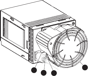
0.7.01.15 UNRECOVERABLE condition—EMU hardware failure
The EMU has detected an internal hardware problem. This condition report remains active until the
problem is corrected.
Complete the following procedure to correct this problem:
1. Record all six characters of the condition report.
2. Reset the EMU.
3. Observe the EMU to ensure the error does not recur within the first minute.
4. If the error does recur, contact your HP authorized service representative. The EMU is inoperative
andmustbereplacedassoonaspossible.
0.7.01.16 INFORMATION condition—EMU internal ESI data corrupted
The EMU ESI data is corrupted. This condition does not affect any other element and no action is required.
0.7.01.17 UNRECOVERABLE condition—Power shutdown failure
The power supply did not respond to a controller, EMU, or power supply shut down command. Shutting
down the supply is required to prevent overheating.
Complete the following procedure to correct the problem:
1. Record all six characters of the condition report.
2. Move the power cord bail lock 1, Figure 49,totheleft.
3. Disconnect the AC power cord 2 from the supply.
CXO7490
A
23
14
Figure 49 Disconnecting AC power
0.7.01.
18 UNRECOVERABLE condition—EMU hardware failure
The EMU has detected an internal hardware problem. This condition report remains active until the
problem is corrected.
Complete the following procedure to correct this problem:
1. Record all six characters of the condition report.
2. Reset the EMU.
3. Observe the EMU to ensure the error does not recur within the first minute.
4. If the error does recur, contact your HP authorized service representative. The EMU is inoperative
andmustbereplacedassoonaspossible.
HP StorageWorks 3000/5000 Enterprise Virtual Array user guide (VCS 4.xxx) 131
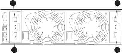
0.7.01.19 UNRECOVERABLE condition—EMU ESI driver failure
The EMU has detected an internal hardware problem. This condition report remains active until the
problem is corrected.
Complete the following procedure to correct this problem:
1. Record all six characters of the condition report.
2. Reset the EMU.
3. Observe the EMU to ensure the error does not recur within the first minute.
4. If the error does recur, contact your HP authorized service representative. The EMU is inoperative
and must be replaced as soon as possible.
Transceiver conditions
The format of a transceiver condition report is 0.F.en.ec,where:
•0.F. is the transceiver element type number
•en. is the two-character transceiver element number (see Figure 50)
•ec is the error code
CXO7954
A
3 1
4 2
Figure 50 Transceiver element numbering
1. Tr a n s c e ive r 01 2. Tra n s c e i ve r 0 2
3. Transceiver 03 4. Transceiver 04
0.F.en.01CRITICALcondition—Transceiverincompatibility
The transceivers on this link are not the same type or they are incompatible with the I/O module. This
error prevents the controller from establishing a link with the enclosure disk drives and eliminates the
enclosuredual-loopcapability.Thiserrorremainsactiveuntiltheproblemiscorrected.
To correct this problem, record all six characters of the condition report, then contact your HP authorized
service representative.
0.F.en.02 CRITICAL condition—Transceiver data signal lost
This symptom can occur when a controller has been powered off or a cable has been removed from
the transceiver. The transceiver can no longer detect a data signal. This error prevents the controller
from transferring data on a loop and eliminates the enclosure dual-loop capability. This error remains
active until the problem is fixed.
To correct this problem, record all six characters of the condition report, then contact your HP authorized
service representative.
132 EMU-generated condition reports

0.F.en.03CRITICALcondition—Transceiverfibre channel drive enclosure bus fault
The system has detected a Fibre Channel drive enclosure bus fault involving a transceiver. This error
prevents the controller from transferring data on a loop and eliminates the enclosure dual-loop capability.
Complete the following procedure to correct this problem:
1. Record all six characters of the condition report.
2. Check all the transceivers and cables to ensure they are properly connected.
3. Check all the transceivers on the loop to ensure they are compatible with the I/O module.
4. If the problem persists, contact your HP authorized service representative.
0.F.en.04 CRITICAL condition—Transceiver removed
The EMU detects that a transceiver has been removed. This error remains active until the problem is fixed.
Theerrorcanbeclearedbydoingoneofthefollowing:
1. Install a new transceiver,
or
Reconfigure the system by switching from a loop topology to one with Vixel switches, then the
transceiver is not necessary.
2. Clear the error by resetting the EMU or by removing and then re-installing the I/O module.
0.F.en.05 CRITICAL condition—Invalid fibre channel character
This symptom can occur under the following conditions:
•The incoming data stream is corrupted.
•Acableisno
t completely connected.
•The signal is degraded.
This error prevents the controller from transferring data on a loop and eliminates the enclosure dual-loop
capability. This error remains active until the problem is fixed.
To correct this problem, record all six characters of the condition report, then contact your HP authorized
service representative.
Voltage sensor and current sensor conditions
The format of these sensor condition reports is 1. 2. e n .e c for a voltage sensor, and 1. 3. e n . e c for a
current sensor, where:
•1. 2. is the voltage sensor element type
•1.3. is the current sensor element type number
•en. is the sensor element number
•ec is the error code
Table 51 lists the location of the power supply voltage and current sensors.
Table 51 Voltage and current sensor locations
Sensor Sensor Element Location
01. Power Supply 1 +5 VDC
02. Power Supply 1 +12 VDC
03. Power Supply 2 +5 VDC
04. Power Supply 2 +12 VDC
HP StorageWorks 3000/5000 Enterprise Virtual Array user guide (VCS 4.xxx) 133
Use HP Command View EVA to view the voltage and current error thresholds for both +5 VDC and +12
VDC power supplies.
1. 2. e n .01 N O N C R I TI C A L c o n d i t i o n — H i g h v o l t a g e
This condition report indicates that an element voltage is approaching, but has not reached, the high
voltage CRITICAL threshold. Continued operation under these conditions may result in a CRITICAL
condition. This condition report remains active until the problem is corrected.
To correct this problem, record all six characters of the condition report, then contact your HP authorized
service representative.
1.2.en.02CRITICALcondition—Highvoltage
This condition report indicates that an element voltage has reached the high voltage CRITICAL threshold.
This report remains active until the problem is corrected.
To correct this problem, record all six characters of the condition report, then contact your HP authorized
service representative.
1. 2. e n .0 3 N O N C R I TI C A L c o n d i t i o n — L ow vo l t a g e
This condition report indicates that an element voltage is approaching, but has not reached, the low
voltage CRITICAL threshold. Continued operation under these conditions may result in a CRITICAL
condition. This condition report remains active until the problem is corrected.
To correct this problem, record all six characters of the condition report, then contact your HP authorized
service representative.
1.2.en.04 CRITICAL condition—Low voltage
This condition report indicates that an element voltage has reached the low voltage CRITICAL threshold.
This condition report remains active until the problem is corrected.
To correct this problem, record all six characters of the condition report, then contact your HP authorized
service representative.
1.3. e n. 01 NONCRITICAL condition—High current
This condition report indicates that an element current is approaching, but has not reached, the high
current CRITICAL threshold. Continued operation under these conditions may result in a CRITICAL
condition. This condition report remains active until the problem is corrected.
To correct this problem, record all six characters of the condition report, then contact your HP authorized
service representative.
1.3.en.02CRITICALcondition—Highcurrent
This condition report indicates that an element current has reached the high current CRITICAL threshold.
This condition report remains active until the problem is corrected.
To correct this problem, record all six characters of the condition report, then contact your HP authorized
service representative.
134 EMU-generated condition reports

Backplane conditions
IMPORTANT:
Backplane NVRAM errors usually occur during manufacture. At this time they are identified and
corrected. They rarely occur during normal operation.
Theformatofabackplane condition report is 8.2.01.ec,where:
•8.2. is the backplane element type number
•01. is the two-character backplane element number
•ec is the error code
Theonlycorrectiveactionavailableforthiserroristoreplacethedriveenclosure.
8.2.01.10 NONCRITICAL condition—Backplane NVRAM read
An invalid NVRAM read occurred and an automatic recovery process has begun. This condition report is
active for 15 seconds.
If the automatic recovery process does not correct the problem, record all six characters of the condition
report, then contact your HP authorized service representative.
8.2.01.11 NONCRITICAL condition—Backplane NVRAM write failure
The system is unable to write data to the NVRAM. This problem prevents communication between
elements in the enclosure. This condition report is active for 15 seconds.
To correct this problem, record all six characters of the condition report, then contact your HP authorized
service representative.
8.2.01.12 NONCRITICAL condition—Backplane NVRAM read failure
The system is unable to read data from the NVRAM. This problem prevents communication between
elements in the enclosure. This condition report is active for 15 seconds.
To correct this problem, record all six characters of the condition report, then contact your HP authorized
service representative.
8.2.01.13 NONCRITICAL condition—Backplane WWN is blank
The system is unable to read valid data from the NVRAM. This report is active until corrected. This
condition can result in incorrect device location data being displayed.
To correct this problem, record all six characters of the condition report, then contact your HP authorized
service representative.
I/O Module conditions
The format of an I/O module condition report is 8.7.en.ec,where:
•8.7. is the I/O module element type number
•en. is the two-character I/O module element number (see Figure 51)
•ec is the error code
HP StorageWorks 3000/5000 Enterprise Virtual Array user guide (VCS 4.xxx) 135
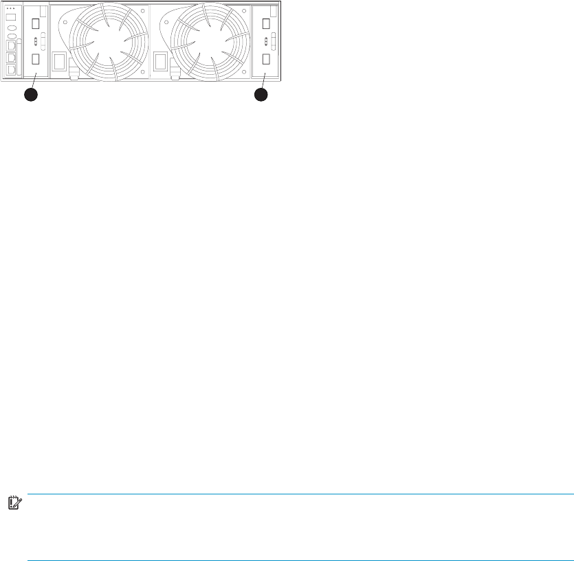
CXO7951
A
12
Figure 51 I/O module element numbering
1. I/O Module A (01) 2. I/O Module B (02)
Correction of an I/O module problem normally requires replacing the module. The following sections
define the I/O module problem by I/O module location.
8.7.en.01 CRITICAL condition—I/O module unsupported
The I/O module Fibre Channel link speed is not supported by the backplane. This error prevents the
controller from establishing a link with enclosure drives and eliminates the enclosure dual-loop capability.
This condition report remains active until the problem is corrected.
To correct this problem, record all six characters of the condition report, then contact your HP authorized
service representative.
8.7.en.02 CRITICAL condition—I/O module communication
TheI/OmoduleisunabletocommunicatewiththeEMU.
Complete the following procedure to correct this problem:
1. Record all six characters of the condition report.
2. Contact your HP authorized service representative.
IMPORTANT:
MultipleerroneouserrormessagesindicatingI2Cbuserrors,suchasNVRAMerrors,
blowers missing, and so forth, could indicate an EMU problem.
8.7.en.10 NONCRITICAL condition—I/O module NVRAM read
An invalid NVRAM read occurred and automatic recovery was initiated.
Complete the following procedure to correct this problem:
1. Record all six characters of the condition report.
2. Observe the I/O module status indicators for an operational display.
3. Contact your HP authorized service representative.
8.7.en.11 NONCRITICAL condition—I/O module NVRAM write
The system is unable to write data to the I/O module NVRAM.
Complete the following procedure to correct this problem:
1. Record all six characters of the condition report.
2. Observe the I/O module status indicators for an operational display.
3. Contact your HP authorized service representative.
136 EMU-generated condition reports
8.7.en.12 NONCRITICAL condition—I/O Module NVRAM read failure
The system is unable to read data from the I/O module NVRAM.
Complete the following procedure to correct this problem:
1. Record all six characters of the condition report.
2. Contact your HP authorized service representative.
8.7.en.13 NONCRITICAL condition—I/O module removed
The system detects that an I/O module has been removed.
To correct the problem, install an I/O module.
Host conditions
The EMU has the capability of displaying host controller defined condition reports on the EMU
alphanumeric display.
TheformatofahostconditionreportisF. F.en.ec,where:
•F.F.isthehos
t element type number
•en. is the two-character host element number
•ec is the error code
Thehostcont
roller can display host controller defined error codes on the EMU alphanumeric display
HP StorageWorks 3000/5000 Enterprise Virtual Array user guide (VCS 4.xxx) 137
138 EMU-generated condition reports
C Controller fault management
This appendix describes how the controller displays events and termination event information. Termination
event information is displayed on the LCD. HP Command View EVA enables you to view controller events.
This appendix also discusses how to identify and correct problems.
Once you create a storage system, an error condition message has priority over other controller displays.
HP Command View EVA provides detailed descriptions of the storage system error conditions, or faults.
The Fault Management displays provide similar information on the LCD, but not in as much detail.
Whenever possible, refer to HP Command View EVA for fault information.
Using HP Command View EVA
HP Command View EVA provides detailed information about each event affecting system operation in
either a Termination Event display or an Event display. These displays are similar, but not identical.
GUI termination event display
A problem that generates the Termination Event display prevents the system from performing a specific
function or process. You can use the information in this display (see GUI Termination Event Display)
to diagnose and correct the problem.
NOTE:
The major differences between the Termination Event display and the Event display are:
• The Termination Event display includes a Code Flag field; it does not include the EIP Type field.
• The Event display includes an EIP type field; it does not include a Code Flag field.
• The Event display includes a Corrective Action Code field.
Date Time SWCID Evt No Code Flag Descrip-
tion
Figure 52 GUI termination event display
The fields in the Termination Event display include:
•Date—The date the event occurred.
•Time—The time the event occurred.
•SWCID—Software Identification Code. A hexadecimal number in the range 0–FF that identifies
the controller software component reporting the event.
•Evt No—Event Number. A hexadecimal number in the range 0–FF that is the software component
identification number.
•Code Flag—An internal code that includes a combination of other flags.
•Description—The condition that generated the event. This field may contain information about an
individual field’s content and validity.
HP StorageWorks 3000/5000 Enterprise Virtual Array user guide (VCS 4.xxx) 139

GUI event display
A problem that generates the Event display reduces the system capabilities. You can use the information
in this display (see Figure 53)todiagnoseandcorrectproblems.
NOTE:
The major differences between the Event Display and the Termination Event display are:
•TheEventdispl
ay includes an EIP type field; it does not include a Code Flag field.
• The Event display includes a Corrective Action Code (CAC) field.
• The Termination Event display includes a Code Flag field; it does not include the EIP Type field.
Date Time SWCID Evt No CAC EIP Type Descrip-
tion
Figure 53 Typical HP Command View EVA Event display
The Event display provides the following information:
•Date—The date the event occurred.
•Time—The time the even occurred.
•SWCID—Software Identification Code. A number in the range 1–256 that identifies the internal
firmware module affected.
•EvtNo—EventNumber.Ahexadecimalnumberintherange0–FFthatisthesoftwarecomponent
identification number.
•CAC—Corrective Action Code. A specific action to correct the problem.
•EIP Type—Event Information Packet Type. A hexadecimal character that defines the event
information format.
•Description—The problem that generated the event.
Fault management displays
When you do not have access to the GUI, you can display and analyze termination codes (TCs) on the
OCP LCD display. You can then use the event text code document, as described in the section titled
“Interpreting Fault Management Information” to determine and implement corrective action. You can
also provide this information to the authorized service representative should you require additional
support. This lets the service representative identify the tools and components required to correct the
conditionintheshortestpossibletime.
When the fault management display is active, you can either display the last fault or display detailed
information about the last 32 faults reported.
Displaying Last Fault Information
Complete the following procedure to display Last Fault information
1. When the Fault Management display is active, press to select the Last Fault menu.
2. Press to display the last fault information.
The first line of the TC display contains the eight-character TC error code and the two-character IDX
(index) code. The IDX is a reference to the location in the TC array that contains this error. The
second line of the TC display identifies the affected parameter with a two-character parameter
number (0–30), the eight-character parameter code affected, and the parameter code number.
3. Press to return to the Last Fault menu.
140 Controller fault management

Displaying Detailed Information
The Detail View menu lets you examine detailed fault information stored in the Last Termination Event
Array (LTEA). This array stores information for the last 32 termination events.
Complete the following procedure to display the LTEA information about any of the last 32 termination
events:
1. When the Fault Management display is active (flashing), press to select the Detail View menu.
The LTEA selection menu is active (LTEA 0 is displayed).
2. Press or to increment to a specificerror.
3. Press to observe data about the selected error.
Interpreting fault management information
Each version of HP Command View EVA includes an ASCII text file that defines all the codes that the
authorized service representative can view either on the GUI or on the OCP.
IMPORTANT:
Thisinformationisfortheexclusiveuseoftheauthorizedservicerepresentative.
The file name identifies the file type and the revision date. For example, the file name
hsv110_event_w010605 _t100.txt provides the following information:
•hsv110_—The EVA controller model number
•event_—The type of information in the file
•w010605_—the base level build string (the file creation date).
•01—creation year
•06—creation month
•05—creation date
•t100—the NSC software version number string.
Table 52 describes types of information available in this file.
HP StorageWorks 3000/5000 Enterprise Virtual Array user guide (VCS 4.xxx) 141

Table 52 Controller event text description file
Information type Description
Event Code This hexadecimal code identifies the reported event type.
Termination Code (TC) The hexadecimal code specifies the condition that generated the
termination code. It might also define either a system or user initiated
corrective action.
Coupled Crash Control Codes This single digit, decimal character defines the requirement for the other
controller to initiate a coupled crash control.0. Other controller SHOULD
NOT complete a coupled crash.1. Other controller SHOULD complete a
coupled crash.
Dump/Restart Control Codes This single decimal character (0, 1, 3) defines the requirement to:0.
Perform a crash dump and then restart the controller.1. DO NOT perform
a crash dump; just restart the controller.3. DO NOT perform a crash
dump; DO NOT restart the controller
Corrective Action Codes (CAC) These hexadecimal codes supplement the Termination Code information
to identify the faulty element and the recommended corrective action.
Software Component ID Codes
(SWCID) These decimal codes identify software associated with the event.
Event Information Packets (EIP) These codes specify the packet organization for specifictypeevents.
142 Controller fault management

Glossary
This glossary defines terms used in this guide or related to this product and is not a comprehensive
glossary of computer terms.
µmA symbol for micrometer; one millionth of a meter. For example, 50 µmis
equivalent to 0.000050 m.
3U Aunitofme
asurement representing three “U” spaces. “U” spacing is used to
designate panel or enclosure heights. Three “U” spaces is equivalent to 5.25
inches (133 mm).
See also rack-mounting unit.
active member
of a virtual disk
family
An active member of a virtual disk family is a simulated disk drive created
by the controllers as storage for one or more hosts. An active member of a
virtual disk family is accessible by one or more hosts for normal storage. An
active virtual disk member and its snapshot, if one exists, constitute a virtual disk
family. An active member of a virtual disk family is the only necessary member
of a virtual disk family.
See also virtual disk,virtual disk copy,virtual disk family,and snapshot.
adapter See controller.
AL_PA Arbitrated Loop Physical Address. A 1-byte value the arbitrated loop topology
uses to identify the loop ports. This value becomes the last byte of the address
identifierforeachpublicportontheloop.
allocation policy Storage system rules that govern how virtual disks are created. Allocate
Completely and Allocate on Demand are the two rules used in creating virtual
disks.
•Allocate Completely—The space a virtual disk requires on the physical disks
is reserved, even if the virtual disk is not currently using the space.
•Allocate on Demand—The space a virtual disk requires on the physical
disksisnotreserveduntilneeded.
ambient tempera-
ture The air temperature in the area where a system is installed. Also called intake
temperature or room temperature.
ANSI American National Standards Institute. A non-governmental organization that
develops standards (such as SCSI I/O interface standards and Fibre Channel
interface standards) used voluntarily by many manufacturers within the United
States.
arbitrated loop A Fibre Channel topology that links multiple ports (up to 126) together on a
single shared simplex media. Transmissions can only occur between a single
pair of nodes at any given time. Arbitration is the scheme that determines which
node has control of the loop at any given moment
arbitrated loop
physical address See AL_PA.
arbitrated loop
topology See arbitrated loop.
array All the physical disk drives in a storage system that are known to and under
the control of a controller pair.
HP StorageWorks 3000/5000 Enterprise Virtual Array user guide (VCS 4.xxx) 143
array controller See controller.
asynchronous Events scheduled as the result of a signal requesting the event or that which is
without any specified time relation.
audible alarm The Environmental Monitoring Unit (EMU) alarm that sounds when there is a
drive enclosure element condition report. The audible alarm can be muted
or disabled.
backplane An electronic printed circuit board that distributes data, control, power, and
other signals to element connectors.
bad block A data block that contains a physical defect.
bad block replace-
ment A replacement routine that substitutes defect-free disk blocks for those found to
have defects. This process takes place in the controller and is transparent to
the host.
bail lock Part of the power supply AC receptacle that engages the AC power cord
connector to ensure that the cord cannot be accidentally disconnected.
baud The maximum rate of signal state changes per second on a communication
circuit. If each signal state change corresponds to a code bit, then the baud
rate and the bit rate are the same. It is also possible for signal state changes
to correspond to more than one code bit so the baud rate may be lower than
thecodebitrate.
bay The physical location of an element, such as a drive, I/O module, EMU or
power supply in a drive enclosure. Each bay is numbered to define its location.
bidirectional Also called Bi-Di. The movement of optical signals in opposite directions through
a common fiber cable such as the data flow path typically on a parallel printer
port. A parallel port can provide two-way data flow for disk drives, scanning
devices, FAX operations and even parallel modems.
block Also called a sector. The smallest collection of consecutive bytes addressable on
a disk drive. In integrated storage elements, a block contains 512 bytes of data,
error codes, flags, and the block address header.
blower A variable speed airflow device that pulls air into an enclosure or element. It
usually pulls air in from the front and exhausts the heated air out the rear.
cabinet Analternatetermusedforarack.
cable assembly Afiber optic cable that has connectors installed on one or both ends. General
use of these cable assemblies includes the interconnection of multimode fiber
optic cable assemblies with either LC or SC type connectors.
•When there is a connector on only one end of the cable, the cable assembly
is referred to as a pigtail.
•When there is a connector on each end of the cable, the cable assembly
is referred to as a jumper.
CAC Corrective Action Code. An HP Command View EVA graphical user interface
(GUI) display component that defines the action required to correct a problem.
See also read cache,write cache,andmirrored cache.
cache High-speed memory that sets aside data as an intermediate data buffer between
ahostandthestoragemedia.Thepurposeofcacheistoimproveperformance.
cache battery A rechargeable unit mounted within a controller enclosure that supplies back-up
power to the cache module in case of primary power shortage.
144 Glossary
cache battery in-
dicator 1. An orange light emitting diode (indicator) that illuminates on the controller
operator control panel (OCP) to define the status of the HSV Controller
cache batteries.
2. An amber status indicator that illuminates on a cache battery. When
illuminated, it indicates that one or more cache battery cells have failed
and the battery must be replaced with a new battery.
carrier A drive-enclosure-compatible assembly containing a disk drive or other storage
devices.
client A software program that uses the services of another software program. The HP
Command View EVA client is a standard internet browser.
clone See Virtual Disk Copy.
communication
logical unit num-
ber (LUN)
See console LUN.
condition report A three-element code generated by the EMU in the form where e.t. is the
element type (a hexadecimal number), en. is the element number (a decimal
number), and ec is the condition code (a decimal number).
console LUN A SCSI-3 virtual object that makes a controller pair accessible by the host before
any virtual disks are created. Also called a communication LUN.
console LUN ID The ID that can be assigned when a host operating system requires a unique ID.
The console LUN ID is assigned by the user, usually when the storage system
is initialized.
See also console LUN.
controller Ahardware/firmware device that manages communications between host
systems and other devices. Controllers typically differ by the type of interface to
the host and provide functions beyond those the devices support.
controller enclo-
sure A unit that holds one or more controllers, power supplies, blowers, cache
batteries, transceivers, and connectors.
controller event Asignificant occurrence involving any storage system hardware or software
component reported by the controller to HP Command View EVA.
controller fault
indicator An amber fault indicator that illuminates on the controller OCP to indicate when
there is an HSV Controller fault.
controller pair Two interconnected controller modules which together control the disk enclosures
in the storage system.
corrective action
code See CAC.
CRITICAL Condi-
tion A drive enclosure EMU condition that occurs when one or more drive enclosure
elements have failed or are operating outside of their specifications. The failure
of the element makes continued normal operation of at least some elements in
the enclosure impossible. Some enclosure elements may be able to continue
normal operations. Only an UNRECOVERABLE condition has precedence.
This condition has precedence over NONCRITICAL errors and INFORMATION
condition.
CRU Customer Replaceable Unit. A storage system element that a user can replace
without using special tools or techniques, or special training.
customer replace-
able unit See CRU.
HP StorageWorks 3000/5000 Enterprise Virtual Array user guide (VCS 4.xxx) 145
data entry mode The state in which controller information can be displayed or controller
configuration data can be entered. On the Enterprise Storage System, the
controller mode is active when the LCD on the HSV Controller OCP is Flashing.
default disk group The first disk group created at the time the system in initialized. The default
disk group can contain the entire set of physical disks in the array or just a
few of the disks.
See also disk group.
Detailed Fault
View An HSV Controller OCP display that permits a user to view detailed information
about a controller fault.
device channel A channel used to connect storage devices to a host I/O bus adapter or
intelligent controller.
device ports Controller pair device ports connected to the storage system’s physical disk drive
array through the Fibre Channel drive enclosure. Also called a device-side port.
device-side ports See device ports.
DIMM Dual Inline Memory Module. A small circuit board holding memory chips.
dirty data The write-back cached data that has not been written to storage media even
though the host operation processing the data has completed.
disk drive A carrier-mounted storage device supporting random access to fixed size blocks
of data.
disk drive blank A carrier that replaces a disk drive to control airflow within a drive enclosure
whenever there is less than a full complement of storage devices.
drive enclosure A unit that holds storage system devices such as disk drives, power supplies,
blowers, I/O modules, transceivers, or EMUs.
drive enclosure
event Asignificant operational occurrence involving a hardware or software
component in the drive enclosure. The drive enclosure EMU reports these events
to the controller for processing.
disk failure pro-
tection A method by which a controller pair reserves drive capacity to take over the
functionality of a failed or failing physical disk. For each disk group, the
controllers reserve space in the physical disk pool equivalent to the selected
number of physical disk drives.
disk group A physical disk drive set or pool in which a virtual disk is created. A disk group
may contain all the physical disk drives in a controller pair array or a subset
of the array.
disk migration
state A physical disk drive operating state. A physical disk drive can be in a stable
or migration state:
•Stable—The state in which the physical disk drive has no failure nor is a
failure predicted.
•Migration—The state in which the disk drive is failing, or failure is predicted
to be imminent. Data is then moved off the disk onto other disk drives in
thesamediskgroup.
disk replacement
delay The time that elapses between a drive failure and when the controller starts
searching for spare disk space. Drive replacement seldom starts immediately in
case the “failure” was a glitch or temporary condition.
drive blank See disk drive blank.
drive enclosure See drive enclosure.
dual-loop Aconfiguration where each drive is connected to a pair of controllers through
two loops. These two Fibre Channel loops constitute a loop pair.
146 Glossary
dual power supply
configuration See redundant power configuration.
dynamic capacity
expansion A storage system feature that provides the ability to increase the size of an
existing virtual disk. Before using this feature, you must ensure that your
operating system supports capacity expansion of a virtual disk (or LUN).
EIA Electronic Industries Alliance. A standards organization specializing in the
electrical and functional characteristics of interface equipment.
EIP Event Information Packet. The event information packet is an HSV element
hexadecimal character display that defines how an event was detected. Also
called the EIP type.
electromagnetic
interference See EMI.
electrostatic dis-
charge See ESD.
element 1. Inadriveenclosure,adevicesuchasanEMU,powersupply,disk,blower,
or I/O module. The object can be controlled, interrogated, or described
by the enclosure services process.
2. In the Open SAN Manager, a controllable object, such as the Enterprise
storage system.
Command View
EVA GUI The graphical user interface (GUI) through which a user can control and monitor
a storage system. HP Command View EVA can be installed on more than one
storage management server in a fabric. Each installation is a management
agent. The client for the agent is a standard browser.
EMI Electromagnetic Interference. The impairment of a signal by an electromagnetic
disturbance.
EMU Environmental Monitoring Unit. An element which monitors the status of an
enclosure, including the power, air temperature, and blower status. The EMU
detects problems and displays and reports these conditions to a user and the
controller. In some cases, the EMU implements corrective action.
enclosure A unit used to hold various storage system devices such as disk drives,
controllers, power supplies, blowers, an EMU, I/O modules, or blowers.
enclosure address
bus An Enterprise storage system bus that interconnects and identifies controller
enclosures and disk drive enclosures by their physical location. Enclosures
within a reporting group can exchange environmental data. This bus uses
enclosure ID expansion cables to assign enclosure numbers to each enclosure.
Communications over this bus do not involve the Fibre Channel drive enclosure
bus and are, therefore, classified as out-of-band communications.
enclosure number
(En) One of the vertical rack-mounting positions where the enclosure is located.
The positions are numbered sequentially in decimal numbers starting from the
bottom of the cabinet. Each disk enclosure has its own enclosure number. A
controller pair shares an enclosure number. If the system has an expansion rack,
the enclosures in the expansion rack are numbered from 15 to 24, starting
at the bottom.
enclosure services Those services that establish the mechanical environmental, electrical
environmental, and external indicators and controls for the proper operation
and maintenance of devices with an enclosure as described in the SES SCSI-3
Enclosure Services Command Set (SES), Rev 8b, American National Standard
for Information Services.
HP StorageWorks 3000/5000 Enterprise Virtual Array user guide (VCS 4.xxx) 147
Enclosure Services
Interface See ESI.
Enclosure Services
Processor See ESP.
Enterprise Virtual
Array The Enterprise Virtual Array is a product that consists of one or more storage
systems. Each storage system consists of a pair of HSV controllers and the disk
drives they manage. A storage system within the Enterprise Virtual Array can be
formally referred to as an Enterprise storage system, or generically referred to
as the storage system.
Enterprise Virtual
Array rack A unit that holds controller enclosures, disk drive enclosures, power distribution
supplies, and enclosure address buses that, combined, comprise an Enterprise
storage system solution. Also called the Enterprise storage system rack.
See also rack.
environmental
monitoring unit See EMU.
error code The portion of an EMU condition report that defines a problem.
ESD Electrostatic Discharge. The emission of a potentially harmful static electric
voltage as a result of improper grounding.
ESI Enclosure Services Interface. The SCSI-3 engineering services interface
implementation developed for StorageWorks products. A bus that connects
the EMU to the disk drives.
ESP Enclosure Services Processor. An EMU that implements an enclosure’s services
process.
event Any significant change in the state of the Enterprise storage system hardware or
software component reported by the controller to HP Command View EVA.
See also controller event,drive enclosure event,management agent event,and
termination event.
Event Information
Packet See EIP.
Event Number See Evt No.
Evt No. Event Number. A sequential number assigned to each Software Code
Identification (SWCID) event. It is a decimal number in the range 0-255.
exabyte A unit of storage capacity that is the equivalent of 260 bytes or
1,152,921,504,606,846,976 bytes. One exabyte is equivalent to 1,024
petabytes.
fabric A Fibre Channel fabric switch or two or more interconnected Fibre Channel
switches allowing data transmission.
fabric port Aportwhichiscapableofsupportinganatt
achedarbitratedloop.Thisporton
a loop will have the AL_PA hexadecimal address 00 (loop ID 7E), giving the
fabricthehighestpriorityaccesstotheloop.Aloopportisthegatewaytothe
fabric for the node ports on a loop.
failover The process that takes place when one controller assumes the workload of
a failed companion controller. Failover continues until the failed controller is
operational.
fan The variable speed airflow device that cools an enclosure or element by forcing
ambient air into an enclosure or element and forcing heated air out the other
side.
See also blower.
148 Glossary
Fault Manage-
ment Code See FMC.
Fibre Channel
drive enclosure Fibre Channel Arbitrated Loop. The American National Standards Institute’s
(ANSI) document that specifies arbitrated loop topology operation.
FC HBA Fibre Channel Host Bus Adapter. An interchangeable term for Fibre Channel
adapter.
See also FCA.
FCA Fibre Channel Adapter. An adapter used to connect the host server to the
fabric. Also called a Host Bus Adapter (HBA) or a Fibre Channel Host Bus
Adapter (FC HBA).
See also FC HBA.
FCC Federal Communications Commission. The federal agency responsible for
establishing standards and approving electronic devices within the United States.
FCP Fibre Channel Protocol. The mapping of SCSI-3 operations to Fibre Channel.
fiber The optical media used to implement Fibre Channel.
fiber optics The technology where light is transmitted through glass or plastic (optical)
threads (fibers) for data communication or signaling purposes.
fiber optic cable A transmission medium designed to transmit digital signals in the form of pulses
of light. Fiber optic cable is noted for its properties of electrical isolation and
resistance to electrostatic contamination.
fibre The international spelling that refers to the Fibre Channel standards for optical
media.
Fibre Channel A data transfer architecture designed for mass storage devices and other
peripheral devices that require very high bandwidth.
Fibre Channel
adapter See FCA.
Fibre Channel
Loop Switch An enclosure that provides twelve-port central interconnect for Fibre Channel
Arbitrated Loops following the ANSI Fibre Channel drive enclosure standard.
field replaceable
unit See FRU.
flush The act of writing dirty data from cache to a storage media
FMC Fault Management Code. The HP Command View EVA display of the Enterprise
Storage System error condition information.
form factor A storage industry dimensional standard for 3.5inch (89 mm) and 5.25inch (133
mm)highstoragedevices.Deviceheightsarespecified as low-profile (1inch or
25.4 mm), half-height (1.6inch or 41 mm), and full-height (5.25inch or 133 mm).
FPGA Field Programmable Gate Array. A programmable device with an internal array
of logic blocks surrounded by a ring of programmable I/O blocks connected
together through a programmable interconnect.
frequency The number of cycles that occur in one second expressed in Hertz (Hz). Thus, 1
Hz is equivalent to one cycle per second.
FRU Field Replaceable Unit. A hardware element that can be replaced in the field.
This type of replacement can require special training, tools, or techniques.
Therefore, FRU procedures are usually performed only by an Authorized Service
Representative.
HP StorageWorks 3000/5000 Enterprise Virtual Array user guide (VCS 4.xxx) 149
Gb Gigabit. A measurement of the rate at which the transfer of bits of data
occurs. Sometimes referred to as Gbps. Nominally, a Gb is a transfer rate of
1,000,000,000 (109)bitspersecond.
For Fibre Channel transceivers or FC loops the Gb transfer rates are:
•1 Gb is a transmission rate of 1,062,500,000 bits per second.
•2 Gb is a transmission rate of 2,125,000,000 bits per second.
GB Gigabyte. A unit of measurement defining either:
•Adatatransferrate.
•A storage or memory capacity of 1,073,741,824 (230)bytes.
See also GBps.
Gbps Gigabits per second. A measurement of the rate at which the transfer of bits
of data occurs. Nominally, a Gb is a transfer rate of 1,000,000,000 (109)
bits per second.
See also Gb.
GBps Gigabytespersecond. Ameasurementoftherateatwhichthetransferof
bytes of data occurs. A GBps is a transfer rate of 1,000,000,000 (109) bytes
per second.
See also GB.
Giga (G) The notation to represent 109or 1 billion (1,000,000,000).
gigabaud An encoded bit transmission rate of one billion (109)bitspersecond.
gigabit See Gb.
gigabit per second See Gbps.
graphical user
interface See GUI.
GUI Graphical User Interface. Software that displays the status of a storage system
and allows its user to control the storage system.
HBA Host Bus Adapter.
See also FCA.
host A computer that runs user applications and uses (or can potentially use) one or
more virtual disks created and presented by the controller pair.
Host Bus Adapter See FCA.
host computer See host.
host link indicator The HSV Controller display that indicates the status of the storage system Fibre
Channel links.
host ports A connection point to one or more hosts through a Fibre Channel fabric. A
host is a computer that runs user applications and that uses (or can potentially
use) one or more of the virtual disks that are created and presented by the
controller pair.
host-side ports See host ports.
hot-pluggable A method of element replacement whereby the complete system remains
operational during element removal or insertion. Replacement does not interrupt
data transfers to other elements.
hub A communications infrastructure device to which nodes on a multi-point bus
orlooparephysicallyconnected.Itisusedtoimprovethemanageabilityof
physical cables.
150 Glossary
I/O module Input/Output module. The enclosure element that is the Fibre Channel drive
enclosure interface to the host or controller. I/O modules are bus speed specific,
either 1 Gb or 2 Gb.
IDX A 2-digit decimal number portion of the HSV controller termination code display
that defines one of 32 locations in the Termination Code array that contains
information about a specificevent.
See also param and TC.
in-band communi-
cation The method of communication between the EMU and controller that utilizes
the Fibre Channel drive enclosure bus.
INFORMATION
condition A drive enclosure EMU condition report that may require action. This condition
is for information only and does not indicate the failure of an element. All
condition reports have precedence over an INFORMATION condition.
initialization A process that prepares a storage system for use. Specifically, the system
binds controllers together as an operational pair and establishes preliminary
data structures on the disk array. Initialization also sets up the first disk group,
called the default disk group.
input/output mod-
ule See I/O module.
intake tempera-
ture See ambient temperature
interface A set of protocols used between components such as cables, connectors, and
signal levels.
JBOD Just a Bunch of Disks. A number of disks connected to one or more controllers.
KKilo. A scientific notation denoting a multiplier of one thousand (1,000).
KB Kilobyte. A unit of measurement defining either storage or memory capacity.
1. For storage, a KB is a capacity of 1,000 (103) bytes of data.
2. For memory, a KB is a capacity of 1,024 (210) bytes of data.
LAN Local area network. A group of computers and associated devices that share
a common communications line and typically share the resources of a single
processor or server within a small geographic area.
laser Adevicethatamplifies light waves and concentrates them in a narrow, very
intense beam.
Last Fault View An HSV Controller display defining the last reported fault condition.
Last Termination
Error Array See LTEA.
LCD Liquid Crystal Display. The indicator on a panel that is associated with an
element. The LCD is usually located on the front of an element.
indicator Light Emitting Diode. A semiconductor diode, used in an electronic display, that
emits light when a voltage is applied to it.
License Key A WWN-encoded sequence that is obtained from the license key fulfillment
Website.
light emitting
diode See indicator.
link A connection between ports on Fibre Channel devices. The link is a full duplex
connection to a fabric or a simplex connection between loop devices.
HP StorageWorks 3000/5000 Enterprise Virtual Array user guide (VCS 4.xxx) 151
logon Also called login, it is a procedure whereby a user or network connection is
identified as being an authorized network user or participant.
loop See arbitrated loop.
loop ID Seven-bit values numbered contiguously from 0 to 126 decimal and represent
the 127 valid AL_PA values on a loop (not all 256 hexadecimal values are
allowed as AL_PA values per Fibre Channel).
loop pair A Fibre Channel attachment between a controller and physical disk drives.
Physical disk drives connect to controllers through paired Fibre Channel
arbitrated loops. There are two loop pairs, designated loop pair 1 and loop
pair 2. Each loop pair consists of two loops (called loop A and loop B) that
operate independently during normal operation, but provide mutual backup
in case one loop fails.
LTEA Last Termination Event Array. A two-digit HSV Controller number that identifies a
specific event that terminated an operation. Valid numbers range from 00 to 31.
LUN Logical Unit Number. A SCSI convention used to identify elements. The host
sees a virtual disk as a LUN. The LUN address a user assigns to a virtual disk for
a particular host will be the LUN at which that host will see the virtual disk.
management
agent The HP Command View EVA software that controls and monitors the Enterprise
storagesystem.Thesoftwarecanexistonmorethanonemanagementserverin
a fabric. Each installation is a management agent.
management
agent event Significant occurrence to or within the management agent software, or an
initialized storage cell controlled or monitored by the management agent.
Mb Megabit. A term defining a data transfer rate.
See also Mbps.
MB Megabtye. A term defining either:
•Adatatransfer rate.
•A measure of either storage or memory capacity of 1,048,576 (220) bytes.
See also MBps.
Mbps Megabits per second. A measure of bandwidth or data transfers occurring at a
rate of 1,000,000 (106)bitspersecond.
MBps Megabytes per second. A measure of bandwidth or data transfers occurring at
a rate of 1,000,000 (106) bytes per second.
mean time be-
tween failures See MTBF.
Mega A notation denoting a multiplier of 1 million (1,000,000).
metadata Information that a controller pair writes on the disk array. This information is
used to control and monitor the array and is not readable by the host.
micro meter See µm.
mirrored caching A process in which half of each controller’s write cache mirrors the companion
controller’s write cache. The total memory available for cached write data is
reduced by half, but the level of protection is greater.
mirroring The act of creating an exact copy or image of data.
MTBF Mean Time Between Failures. The average time from start of use to first failure in
a large population of identical systems, components, or devices.
152 Glossary
multi-mode fiber Afiber optic cable with a diameter large enough (50 microns or more) to allow
multiple streams of light to travel different paths from the transmitter to the
receiver. This transmission mode enables bidirectional transmissions.
Network Storage
Controller See NSC.
NONCRITICAL
Condition A drive enclosure EMU condition report that occurs when one or more elements
inside the enclosure have failed or are operating outside of their specifications.
The failure does not affect continued normal operation of the enclosure. All
devices in the enclosure continue to operate according to their specifications.
The ability of the devices to operate correctly may be reduced if additional
failures occur. UNRECOVERABLE and CRITICAL errors have precedence over
this condition. This condition has precedence over INFORMATION condition.
Early correction can prevent the loss of data.
node port A device port that can operate on the arbitrated loop topology.
non-OFC (Open
Fibre Control) A laser transceiver whose lower-intensity output does not require special open
Fibre Channel mechanisms for eye protection. The Enterprise storage system
transceivers are non-OFC compatible.
NSC Network Storage Controller. The HSV Controllers used by the Enterprise storage
system.
NVRAM Nonvolatile Random Access Memory. Memory whose contents are not lost when
asystemisturnedOfforifthereisapowerfailure. Thisisachievedthrough
the use of UPS batteries or implementation technology such as flash memory.
NVRAM is commonly used to store important configuration parameters.
occupancy alarm
level A percentage of the total disk group capacity in blocks. When the number of
blocks in the disk group that contain user data reaches this level, an event code
is generated. The alarm level is specified by the user.
OCP Operator Control Panel. The element that displays the controller’s status using
indicators and an LCD. Information selection and data entry is controlled by
the OCP push buttons.
online/nearonline An online drive is a normal, high-perfomance drive, while a near-online drive
is a lower-performance drive.
operator control
panel See OCP.
OpenView Stor-
age Management
Server
A centralized, appliance-based monitoring and management interface that
supports multiple applications, operating systems, hardware platforms, storage
systems, tape libraries and SAN-related interconnect devices. It is included and
resides on the SANWorks Management Server, a single aggregation point
for data management.
param That portion of the HSV controller termination code display that defines:
•The 2-character parameter identifier that is a decimal number in the 0
through 30 range.
•The 8-character parameter code that is a hexadecimal number.
See also IDX and TC.
password A security interlock where the purpose is to allow:
•A management agent to control only certain storage systems
•Only certain management agents to control a storage system
PDM Power Distribution Module. A thermal circuit breaker-equipped power strip that
distributes power from a PDU to Enterprise Storage System elements.
HP StorageWorks 3000/5000 Enterprise Virtual Array user guide (VCS 4.xxx) 153
PDU Power Distribution Unit. The rack device that distributes conditioned AC or DC
power within a rack.
petabyte A unit of storage capacity that is the equivalent of 250, 1,125,899,906,842,624
bytes or 1,024 terabytes.
physical disk A disk drive mounted in a drive enclosure that communicates with a controller
pair through the device-side Fibre Channel loops. A physical disk is hardware
with embedded software, as opposed to a virtual disk, which is constructed by
the controllers. Only the controllers can communicate directly with the physical
disks.
The physical disks, in aggregate, are called the array and constitute the storage
pool from which the controllers create virtual disks.
physical disk ar-
ray See array.
port A Fibre Channel connector on a Fibre Channel device.
port_name A64-bituniqueidentifier assigned to each Fibre Channel port. The port_name
is communicated during the login and port discovery processes.
port-wine colored A convention of applying the color of port wine to a CRU tab, lever, or handle
to identify the unit as hot-pluggable.
power distribution
module See PDM.
power distribution
unit See PDU.
power supply An element that develops DC voltages for operating the storage system elements
from either an AC or DC source.
preferred address AnAL_PAwhichanodeportattemptstoacquireduringloopinitialization.
preferred path A preference for which controller of the controller pair manages the virtual disk.
This preference is set by the user when creating the virtual disk. A host can
change the preferred path of a virtual disk at any time. The primary purpose of
preferring a path is load balancing.
protocol The conventions or rules for the format and timing of messages sent and received.
push button A switch that is engaged or disengaged when it is pressed.
quiesce The act of rendering bus activity inactive or dormant. For example, “quiesce the
SCSI bus operations during a device warm-swap.”
rack Afloorstanding structure primarily designed for, and capable of, holding and
supporting storage system equipment. All racks provide for the mounting of
panels per Electronic Industries Alliance (EIA) Standard RS310C.
rack-mounting
unit A measurement for rack heights based upon a repeating hole pattern. It is
expressed as “U” spacing or panel heights. Repeating hole patterns are spaced
every 1.75 inches (44.45 mm) and based on EIA’s Standard RS310C.For
example, a 3U unit is 5.25inches (133.35 mm) high, and a 4U unit is 7.0inches
(177.79 mm) high.
read caching A cache method used to decrease subsystem response times to a read request
by allowing the controller to satisfy the request from the cache memory rather
than from the disk drives. Reading data from cache memory is faster than
reading data from a disk. The read cache is specified as either On or Off for
each virtual disk. The default state is on.
154 Glossary
read ahead
caching A cache management method used to decrease the subsystem response time to
a read request by allowing the controller to satisfy the request from the cache
memory rather than from the disk drives.
reconstruction The process of regenerating the contents of a failed member data. The
reconstruction process writes the data to a spare set disk and incorporates the
spare set disk into the mirrorset, striped mirrorset or RAID set from which the
failed member came.
redundancy 1. ElementRedundancy—Thedegreetowhichlogicalorphysicalelements
are protected by having another element that can take over in case of
failure. For example, each loop of a device-side loop pair normally works
independently but can take over for the other in case of failure.
2. Data Redundancy—The level to which user data is protected. Redundancy
is directly proportional to cost in terms of storage usage; the greater the
levelofdataprotection,themorestoragespaceisrequired.
redundant power
configuration A capability of the Enterprise storage system racks and enclosures to allow
continuous system operation by preventing single points of power failure.
•For a rack, two AC power sources and two power conditioning units
distribute primary and redundant AC power to enclosure power supplies.
•For a controller or drive enclosure, two power supplies ensure that the DC
power is available even when there is a failure of one supply, one AC
source, or one power conditioning unit. Implementing the redundant power
configuration provides protection against the loss or corruption of data.
reporting group An Enterprise Storage System controller pair and the associated disk drive
enclosures. The Enterprise Storage System controller assigns a unique decimal
reporting group number to each EMU on its loops. Each EMU collects disk
drive environmental information from its own sub-enclosure and broadcasts the
data over the enclosure address bus to all members of the reporting group.
Information from enclosures in other reporting groups is ignored.
room temperature See ambient temperature
SCSI 1. Small Computer System Interface. An American National Standards Institute
(ANSI) interface which defines the physical and electrical parameters of
a parallel I/O bus used to connect computers and a maximum of 16 bus
elements.
2. The communication protocol used between a controller pair and the hosts.
Specifically, the protocol is Fibre Channel drive enclosure or SCSI on Fibre
Channel. SCSI is the higher command-level protocol and Fibre Channel
is the low-level transmission protocol. The controllers have full support for
SCSI-2; additionally, they support some elements of SCSI-3.
SCSI-3 The ANSI standard that defines the operation and function of Fibre Channel
systems.
SCSI-3 Enclosure
Services See SES.
selective presenta-
tion The process whereby a controller presents a virtual disk only to the host
computer which is authorized access.
serial transmission A method of transmission in which each bit of information is sent sequentially on
a single channel rather than simultaneously as in parallel transmission.
SES SCSI-3 Enclosures Services. Those services that establish the mechanical
environment, electrical environment, and external indicators and controls for the
proper operation and maintenance of devices within an enclosure.
HP StorageWorks 3000/5000 Enterprise Virtual Array user guide (VCS 4.xxx) 155
small computer
system interface See SCSI.
Snapclone A virtual disk that can be manipulated while the data is being copied. Only an
Active member of a virtual disk family can be snapcloned.
The Snapclone, like a snapshot, reflects the contents of the source virtual disk at
a particular point in time. Unlike the snapshot, the Snapclone is an actual clone
of the source virtual disk and immediately becomes an independent Active
member of its own virtual disk family.
snapshot A temporary virtual disk (Vdisk) that reflects the contents of another virtual disk
at a particular point in time. A snapshot operation is only done on an active
virtual disk. Up to seven snapshots of an active virtual disk can exist at any
point. The active disk and its snapshot constitute a virtual family.
See also active virtual disk,virtual disk copy,andvirtual disk family.
SSN Storage System Name. An HP Command View EVA-assigned, unique
20-character name that identifies a specific storage system.
storage carrier See carrier.
storage pool The aggregated blocks of available storage in the total physical disk array.
storage system The controllers, storage devices, enclosures, cables, and power supplies and
their software.
Storage System
Name See SSN.
switch An electro-mechanical device that initiates an action or completes a circuit.
TB Terabyte. A term defining either:
•Adatatransferrate.
•A measure of either storage or memory capacity of 1,099,5111,627,776
(240)bytes.
See also TBps.
TBps Terabytes per second. A data transfer rate of 1,000,000,000,000 (1012)bytes
per second.
TC Termination Code. An Enterprise Storage System controller 8-character
hexadecimal display that defines a problem causing controller operations to halt.
See also IDX and param.
Termination Code See TC.
termination event Occurrences that cause the storage system to cease operation.
terminator Interconnected elements that form the ends of the transmission lines in the
enclosure address bus.
topology An interconnection scheme that allows multiple Fibre Channel ports to
communicate. Point-to-point, arbitrated loop, and switched fabric are all Fibre
Channel topologies.
transceiver The device that converts electrical signals to optical signals at the point where the
fiber cables connect to the FC elements such as hubs, controllers, or adapters.
uninitialized sys-
tem A state in which the storage system is not ready for use.
See also initialization.
UNRECOVERABLE
Condition A drive enclosure EMU condition report that occurs when one or more elements
inside the enclosure have failed andhavedisabledtheenclosure.Theenclosure
156 Glossary
may be incapable of recovering or bypassing the failure and will require repairs
to correct the condition.
This is the highest level condition and has precedence over all other errors and
requires immediate corrective action.
unwritten cached
data Also called unflushed data.
See also dirty data.
UPS Uninterruptible Power Supply. A battery-operated power supply guaranteed to
provide power to an electrical device in the event of an unexpected interruption
to the primary power supply. Uninterruptible power supplies are usually rated
by the amount of voltage supplied and the length of time the voltage is supplied.
Vdisk Virtual Disk. A simulated disk drive created by the controllers as storage
for one or more hosts. The virtual disk characteristics, chosen by the storage
administrator, provide a specific combination of capacity, availability,
performance, and accessibility. A controller pair simulates the characteristics
of the virtual disk by deploying the disk group from which the virtual disk was
created.
The host computer sees the virtual disk as “real,” with the characteristics of an
identical physical disk.
See also active virtual disk,virtual disk copy,virtual disk family,andvirtual
disk snapshot.
virtual disk See Vdisk.
virtual disk copy A clone or exact replica of another virtual disk at a particular point in time.
Only an active virtual disk can be copied. A copy immediately becomes the
active disk of its own virtual disk family.
See also active virtual disk,virtual disk family,andvirtual disk snapshot
virtual disk family A virtual disk and its snapshot, if a snapshot exists, constitute a family. The
original virtual disk is called the active disk. When you firstcreateavirtualdisk
family, the only member is the active disk.
See also active virtual disk,virtual disk copy,andvirtual disk snapshot.
virtual disk snap-
shot See snapshot.
Vraid0 A virtualization technique that provides no data protection. Data host is broken
down into chunks and distributed on the disks comprising the disk group from
which the virtual disk was created. Reading and writing to a Vraid0 virtual disk
is very fast and makes the fullest use of the available storage, but there is no
data protection (redundancy) unless there is parity.
Vraid1 A virtualization technique that provides the highest level of data protection.
All data blocks are mirrored or written twice on separate physical disks. For
read requests, the block can be read from either disk, which can increase
performance. Mirroring takes the most storage space because twice the storage
capacity must be allocated for a given amount of data.
Vraid5 A virtualization technique that uses parity striping to provide moderate data
protection. Parity is a data protection mechanism for a striped virtual disk. A
striped virtual disk is one where the data to and from the host is broken down
into chunks and distributed on the physical disks comprising the disk group in
which the virtual disk was created. If the striped virtual disk has parity, another
chunk (a parity chunk) is calculated from the set of data chunks and written to
the physical disks. If one of the data chunks becomes corrupted, the data can
be reconstructed from the parity chunk and the remaining data chunks.
World Wide
Name See WWN.
HP StorageWorks 3000/5000 Enterprise Virtual Array user guide (VCS 4.xxx) 157
write back
caching A controller process that notifiesthehostthatthewriteoperationiscomplete
when the data is written to the cache. This occurs before transferring the data to
the disk. Write back caching improves response time since the write operation
completesassoonasthedatareachesthecache. Assoonaspossibleafter
caching the data, the controller then writes the data to the disk drives.
write caching A process when the host sends a write request to the controller, and the
controller places the data in the controller cache module. As soon as possible,
the controller transfers the data to the physical disk drives.
WWN World Wide Name. A unique Fibre Channel identifier consisting of a
16-character hexadecimal number. A WWN is required for each Fibre Channel
communication port.
158 Glossary

Index
Symbols
+5.1 VDC,52
A
AC input missing,123
AC power
distributing,77
frequency,52
specifications,114
voltage,52
AC power specifications,112
air flow
affecting temperature,52
adjusting automatically,52
air quality
environmental specifications, 111
air quality:
operating specifications,116
alarm code cycles,57
alphanumeric display
controlling,56
description,55,56
altitude
shipping, 111 , 116
short-term storage,111
ambient temperature
environmental specifications, 111
shipping,111
short-term storage,111
API versions,73
ASCII, error codes definitions,141
asynchronous disk swap,20
audible alarm
unmuting,59
disabling,59
enabling,58
muting,59
selecting display group,56
sound patterns,57
automatically correcting errors,54
B
backplane
NONCRITICAL conditions, 135, 135, 135
NVRAM conditions,129,135
bays
locating,45
numbering,45
benefits,17
bidirectional operation,47
blowers
cooling enclosures,52
UNRECOVERABLE conditions,125
CRITICAL conditions,124
failure,125
missing,125,125
monitored functions,55
NONCRITICAL conditions,124,125
speed,124
status indicators,52
UNRECOVERABLE conditions,125
browser interface,19
BTU specifications, 111 , 116
C
cables
FCC compliance statement,102
cabling controller,77
CAC,139,142
cache battery,77
cache battery assembly indicator,71
CAUTIONs
initializing the system,75
CDRH, compliance regulations,103
Center for Devices and Radiological Health
See CDRH
certification product labels,109
changing passwords,75
checksum,29
Class A equipment, Canadian compliance
statement,103
Class B equipment, Canadian compliance
statement,103
cleaning fiber optic connectors,44
clearing passwords,76
clustering,17
code flag,139
Command View EVA
defined,19,19
location of,25
Command View GUI
displaying events,140
displaying termination events,139
commercial environments, use in,17
components, storage system,19
HP StorageWorks 3000/5000 Enterprise Virtual Array user guide (VCS 4.xxx) 159
condition reporting
backplane,135
current sensors,133
drives,120
element types,120
EMU,128
hosts,137
I/O modules,135
power supplies,122
transceivers,132
voltage sensor,133
condition reporting
temperature,125
conditions, EMU detection of,54
configuration
physical layout,21
connectors
power IEC 309 receptacle,78
power NEMA L6-30R,78
protecting,43
controller
cabling,77
connectors,77
defined,20,22
initial setup,28
status indicators,71
controller enclosure
cache battery,77
power supply/blower assembly,76
controllers
physical dimensions,113
power requirements,113
controls,53
conventions
document,13
text symbols,14
cooling
enclosures,52
blowers,51
power supplies,52
Corrective Action Code
See CAC
Corrective Action Codes
See CAC
country-specific certifications,109
coupled crash control codes,142
CRITICAL conditions
I/O modules communication,136
audible alarm,58
blowers speed,124
drive link rate,120,122,122
drives configuration,120
EMU internal clock,128
high current,134
high temperature,126
high voltage,134
I/O modules unsupported,136
low temperature,127
low voltage,134
transceivers,132,133
current sensors,133
customer self repair,15
parts list,86
D
data center, use in,17
DC power
+5.1 VDC,52
DC power specifications,112,114
detail view,141
detail view menu,141
diagnostic information,52
disabling the audible alarm,59
disk drives
defined,49
hot swapping,20
MTBF specifications,116
power usage,52
reporting status,50
disk drives, MTBF specifications, 111
display groups
error code, Er,56
audible alarm, Au,56
enclosure number, En,56
loop ID, Li,56
reporting group, rG,56
displaying errors,54
displays
audible alarm,55,57
EMU status,55
enclosure status,55
document
conventions,13
prerequisites,13
documentation
providing feedback,15
drive enclosures
defined,20
front view,45
drives
detecting configuration error,120
detecting drive link error,122,122
detecting link rate error,120
missing,121
monitoring functions,55
reporting conditions,120
dump/restart control codes,142
dust covers, using,44
dynamic capacity expansion,20
E
EIP,140,142
element condition reporting;,120
160
EMU
controls,53
alphanumeric display,55
conditions,128
CRITICAL conditions,128
displaying status,53
INFORMATION conditions,129,131
locating,21
NONCRITICAL conditions,129,129,130,
130
resetting,128
status indicators,55
UNRECOVERABLE conditions,128,130,131
EMU indicator displays,56
EMU monitoring functions ,55
En description,60
enabling the audible alarm,58
enclosure address bus
defined,60
detecting errors with,130
enclosure certification label,110
enclosure functions,55
enclosure number description,60
enclosure number display group,56
Enclosure Services Interface
See ESI
Enclosure Services Interface
See ESI
Enclosure Services Processor
See ESP
enclosures
cooling,52
adjusting temperature,52
bays,45
managing air flow,52
sensing temperature,52
enclosures, physical specifications,110
Enterprise rack
physical layout,21
environmental specifications
heat dissipation,116
relative humidity,116
environmental specifications
air quality, 111 , 116
altitude,111
controllers,114
drive enclosure,110
Fibre Channel loop switches,113
relative humidity,111,116
shipping, 111 , 116
short term storage,116
error code
selecting display group,56
error codes, defined,141
error messages,54
errors
displaying,54
correcting automatically,54
ESI,17,54
ESP,54
event code, defined,142
event GUI display,140
Event Information Packet
See EIP
Event Information Packets
See EIP
event number,139
F
failure,135
fan redundancy,21
FATA drives, using,33
fault management
details,141
display,72
displays,140
fault tolerance,20
FC loop switches
environmental specifications,113
FC loops,25,47
FCC
Class A Equipment, compliance notice,101
Class B Equipment, compliance notice,102
Declaration of Conformity,102
modifications,102
FCC Class A certification, 101
features
defined,17
VCS,20
Federal Communications Commission (FCC)
notice, 101
fiber optics
cleaning cable connectors,44
protecting cable connectors,43
Fibre Channel Drive Enclosure
defined,20,21
disk capacity,21
Fibre Channel drive enclosures,53
Fibre Channel Loop Switches,66
connecting to,21
defined,20,22
reading indicators,68
testing,67
file name, error code definitions,141
firmware version display,73
functions monitoring,55
H
hardware components,20
harmonics conformance
Japan,109
help
obtaining,14
high availability
HSV Controllers,70
high current conditions,134,134
high temperature conditions, 126, 126, 127
high voltage conditions,134,134
HP StorageWorks 3000/5000 Enterprise Virtual Array user guide (VCS 4.xxx) 161
host bus adapters,28
hot swap,20
HPtechnical support,14
HSV Controllers
defined,20,22
initial setup,28
HSV controllers
HSV101/111,22
HSV101/111,22
HSV110 controller
OCP
shutting down the controller,74
shutdown,74
I
I/O modules
bidirectional,47
CRITICAL conditions,136
monitored functions,55
NONCRITICAL conditions, 136, 136, 137
I/O modules
CRITICAL conditions,136
element numbering,136
IDX code display,140
indicators
battery status,71
EMU displays,56
push buttons,57,72
INFORMATION conditions
audible alarm,58
drive missing,121
EMU, 129 , 131
INITIALIZE LCD,74
initializing the system
defined,74
internal clock,128
L
labels
enclosure certification,110
product certification,109
laser device
regulatory compliance notice,102
lasers
radiation, warning,102
last fault information,140
Last Termination Event Array
See LTEA
LCD
default display,72
Li display group,56
Loop ID
display group,56
loop switches
defined,20
loop switches, environmental specifications for,
113
low temperature
CRITICAL conditions,127
NONCRITICAL conditions,127
low voltage
CRITICAL conditions,134
NONCRITICAL conditions,134
LTEA,141
LUN numbers,28
M
Management Server,30
Management Server, Command View EVA,25
missing
AC input,123
power supplies,123,123
Modular Array family,17
monitored functions
blowers,55
I/O module,55
power supply,55
MTBF, 111 , 116
multipathing,17
N
NONCRITICAL conditions
audible alarm,58
blowers
missing,125
EMU
NVRAM write failure,129
enclosure address,130
backplane,135
NVRAM conditions,135
blowers
speed,124
EMU
cannot read NVRAM data,130
enclosure address,130
NVRAM invalid read data,129
high current,134
high temperature,126
high voltage,134
I/O modules,136
low temperature,127
low voltage,134
NVRAM,129
NVRAM read,135
NVRAM write failure,129
power supplies,123
NONCRITICAL conditions
NVRAM read failure,135
not installed
power supplies,123
NVRAM read failure,137
NVRAM write failure,129
162
O
OCP
fault management displays,140
using,28
OCP
push button icons,76
OpenView Storage Management Server,19,
30
P
parameter code,140
parameter code number,140
parts
replaceable,86
password
clearing,76
entering,75
changing,75,75
clearing,75
entering,30
removing,75
PDUs,77
physical configuration,21
physical specifications
enclosures,110
PIC,73
port indicators,67
POST,67
power connectors
IEC 309 receptacle,78
NEMA L6-30R,78
POWER OFF LCD,74
power specifications
AC,112,114
controller,113
DC,112,114
drive enclosure, 111
power supplies,52
sensing temperature,52
AC frequency,52
AC input missing,123
AC voltage,52
cooling,52
DC outputs,52
missing,123,123
NONCRITICAL conditions,123
not installed,123
overload,52
protection,52
status indicators,52
thermal protection,52
UNRECOVERABLE conditions,129,131
power supplies
monitored functions,55
power supply redundancy,21
power supply/blower assembly,76
Power-On Self Test
See POST
powering off the system
defined,74
prerequisites,13
product certification,109
protecting
power supplies,52
protecting fiber optic connectors
cleaning supplies,44
dust covers,44
how to clean,44
push buttons
indicators,72
definition,72
EMU,57
navigating with,72
push buttons
icons,76
R
rack
defined,22
environmental specifications,116
physical layout,21
power specifications,116
rack configurations,77
regulatory compliance notices
cables,102
Class A, 101
Class B,102
European Union,103
Japan,109
laser devices,102
modifications,102
Taiwan,109
WEEE recycling notices,104
regulatory notices, 101
relative,111
relative humidity
drive enclosure, 111
operating,116
shipping,116
short term storage,116
short-term storage,111
resetting EMU,128
RESTART LCD,74
restarting the system,74,75
restarting the system
defined,74
rH displays,66
rL displays,66
room temperature
See ambient temperature
S
sensing
power supply temperature,52
SES compliance,53
setting password,30
HP StorageWorks 3000/5000 Enterprise Virtual Array user guide (VCS 4.xxx) 163
SFP,69
shipping specifications,111,116
relative humidity,116
short circuit,52
shutdown
controllers,74
shutdown failure, 131
shutdown system,72
shutting down the system,74
restarting,75
signals, diagnostic,52
slots
See enclosures, bays
Software Component ID Codes
See SWCID
Software Identification Code
See SWCID
software version display,73,73
specifications
disk drive, MTBF, 111 , 116
enclosure,113
heat dissipation, 111
physical,110,113
power,111,113
speed conditions, blower,124,124,125
status indicators
power supplies,52
status, disk drives,50
storage system
restarting,75
initializing,75
shutting down,74
storage system components,19
storage system menu tree
fault management,72
system information,72
Storage System Name,72
storage system racks, defined;,22
Subscriber’s Choice, HP,15
SWCID,139,140,142
symbols in text,14
system information
firmware version,73
software version,73
versions,73
system information
display,72
system menu tree
shut down system,72
system password,72
system password,72
system rack configurations,77
T
TC,142
TC display,140
TC error code,140
technical support
HP,14
service locator website,15
temperature
condition reports,125
effect of air flow,52
sensing,52
Termination Code
See TC
termination event GUI display,139
text symbols,14
transceivers
CRITICAL conditions,132,132,133
monitored functions,55
turning off power,74
U
Uninitializing,75
uninitializing the system,75
universal disk drives,49
UNRECOVERABLE conditions
blowers
no blowers installed,125
audible alarm,58
backplane NVRAM,129
blowers
failure,125
EMU
load failure,130
communications interrupted,128
hardware failure,131
high temperature,127
power supplies
missing,123
shutdown,129
missing,123
shutdown failure,131
shutdown,129
user interface,19,19
using the OCP,28
V
VCS
defined,20
features,20
VCS version,73
verifying operation,53
version information
displaying,73
software,73
Controller,73
firmware,73
OCP,73
software,73
VCS,73
version information: firmware,73
virtual RAID,17
See also vRAID
164
