Hp Eva6400 Array Users Manual 6400/8400 Enterprise Virtual User Guide
2015-01-05
: Hp Hp-Eva6400-Array-Users-Manual-156643 hp-eva6400-array-users-manual-156643 hp pdf
Open the PDF directly: View PDF ![]() .
.
Page Count: 150 [warning: Documents this large are best viewed by clicking the View PDF Link!]
- HP 6400/8400 Enterprise Virtual Array User Guide
- Contents
- 1 EVA6400/8400 hardware
- 2 Enterprise Virtual Array startup
- 3 EVA6400/8400 operation
- Best practices
- Operating tips and information
- Reserving adequate free space
- Using FATA disk drives
- Using solid state disk drives
- QLogic HBA speed setting
- EVA6400/8400 host port negotiates to incorrect speed
- Creating 16 TB or greater virtual disks in Windows 2008
- Importing Windows dynamic disk volumes
- Losing a path to a dynamic disk
- Microsoft Windows 2003 MSCS cluster installation
- Managing unused ports
- Changing the host port connectivity
- Failback preference setting for HSV controllers
- Storage system shutdown and startup
- Saving storage system configuration data
- Adding disk drives to the storage system
- Handling fiber optic cables
- Using the OCP
- 4 Configuring application servers
- Overview
- Clustering
- Multipathing
- Installing Fibre Channel adapters
- Testing connections to the EVA
- Adding hosts
- Creating and presenting virtual disks
- Verifying virtual disk access from the host
- Configuring virtual disks from the host
- HP-UX
- IBM AIX
- Linux
- OpenVMS
- Oracle Solaris
- VMware
- Configuring the EVA6400/8400 with VMware host servers
- Configuring an ESX server
- Verifying virtual disks from the host
- Verifying virtual disks from the host
- HP EVA P6000 Software Plug-in for VMware VAAI
- Windows
- 5 Customer replaceable units
- 6 Support and other resources
- A Regulatory compliance notices
- Regulatory compliance identification numbers
- Federal Communications Commission notice
- Canadian notice (Avis Canadien)
- European Union notice
- Japanese notices
- Korean notices
- Taiwanese notices
- Turkish recycling notice
- Vietnamese Information Technology and Communications compliance marking
- Laser compliance notices
- Recycling notices
- English recycling notice
- Bulgarian recycling notice
- Czech recycling notice
- Danish recycling notice
- Dutch recycling notice
- Estonian recycling notice
- Finnish recycling notice
- French recycling notice
- German recycling notice
- Greek recycling notice
- Hungarian recycling notice
- Italian recycling notice
- Latvian recycling notice
- Lithuanian recycling notice
- Polish recycling notice
- Portuguese recycling notice
- Romanian recycling notice
- Slovak recycling notice
- Spanish recycling notice
- Swedish recycling notice
- Battery replacement notices
- B Error messages
- C Controller fault management
- D Non-standard rack specifications
- E Single Path Implementation
- High-level solution overview
- Benefits at a glance
- Installation requirements
- Recommended mitigations
- Supported configurations
- General configuration components
- Connecting a single path HBA server to a switch in a fabric zone
- HP-UX configuration
- Windows Server (32-bit) configuration
- Windows Server (64-bit) configuration
- Oracle Solaris configuration
- Tru64 UNIX configuration
- OpenVMS configuration
- Linux (32-bit) configuration
- Linux (64-bit) configuration
- IBM AIX configuration
- VMware configuration
- Failure scenarios
- Glossary
- Index

HP 6400/8400 Enterprise Virtual Array
User Guide
Abstract
This document describes the components and operation of the HP 6400/8400 Enterprise Virtual Array.
HP Part Number: 5697-2479
Published: September 2013
Edition: 9

© Copyright 2009, 2013 Hewlett-Packard Development Company, L.P.
The information contained herein is subject to change without notice. The only warranties for HP products and services are set forth in the express
warranty statements accompanying such products and services. Nothing herein should be construed as constituting an additional warranty. HP shall
not be liable for technical or editorial errors or omissions contained herein.
Warranty
WARRANTY STATEMENT: To obtain a copy of the warranty for this product, see the warranty information website:
http://www.hp.com/go/storagewarranty
Acknowledgements
Microsoft® and Windows® are U.S. registered trademarks of Microsoft Corporation.
Java® and Oracle® are registered U.S. trademark of Oracle Corporation or its affiliates.
UNIX® is a registered trademark of The Open Group.

Contents
1 EVA6400/8400 hardware..........................................................................9
M6412A disk enclosures............................................................................................................9
Enclosure layout...................................................................................................................9
I/O modules.....................................................................................................................10
I/O module status indicators..........................................................................................10
Fiber optic Fibre Channel cables..........................................................................................11
Copper Fibre Channel cables..............................................................................................12
Fibre Channel disk drives....................................................................................................12
Disk drive status indicators..............................................................................................12
Disk drive blank............................................................................................................13
Controller enclosures...............................................................................................................13
Operator control panel.......................................................................................................14
Status indicators............................................................................................................15
Navigation buttons........................................................................................................16
Alphanumeric display....................................................................................................16
Power supplies.......................................................................................................................16
Blower module.......................................................................................................................17
Battery module.......................................................................................................................17
HSV controller cabling............................................................................................................18
Storage system racks...............................................................................................................19
Rack configurations............................................................................................................19
Power distribution–Modular PDUs.............................................................................................20
PDUs................................................................................................................................21
PDU A.........................................................................................................................22
PDU B.........................................................................................................................22
PDMs...............................................................................................................................22
Rack AC power distribution.................................................................................................23
Rack System/E power distribution components.......................................................................24
Rack AC power distribution............................................................................................24
Moving and stabilizing a rack..................................................................................................25
2 Enterprise Virtual Array startup ..................................................................27
EVA8400 storage system connections........................................................................................27
EVA6400 storage system connections.......................................................................................28
Direct connect........................................................................................................................28
iSCSI connection configurations................................................................................................29
Fabric connect iSCSI..........................................................................................................29
Direct connect iSCSI...........................................................................................................29
Procedures for getting started...................................................................................................30
Gathering information........................................................................................................30
Host information...........................................................................................................30
Setting up a controller pair using the OCP............................................................................30
Entering the WWN.......................................................................................................31
Entering the WWN checksum.........................................................................................32
Entering the storage system password..............................................................................32
Installing HP P6000 Command View....................................................................................32
Installing optional EVA software licenses...............................................................................33
3 EVA6400/8400 operation........................................................................34
Best practices.........................................................................................................................34
Operating tips and information................................................................................................34
Reserving adequate free space............................................................................................34
Contents 3
Using FATA disk drives........................................................................................................34
Using solid state disk drives.................................................................................................34
QLogic HBA speed setting..................................................................................................34
EVA6400/8400 host port negotiates to incorrect speed.........................................................34
Creating 16 TB or greater virtual disks in Windows 2008.......................................................35
Importing Windows dynamic disk volumes............................................................................35
Losing a path to a dynamic disk..........................................................................................35
Microsoft Windows 2003 MSCS cluster installation................................................................35
Managing unused ports......................................................................................................35
Changing the host port connectivity......................................................................................35
Failback preference setting for HSV controllers............................................................................37
Changing virtual disk failover/failback setting.......................................................................39
Implicit LUN transition.........................................................................................................39
Storage system shutdown and startup........................................................................................39
Shutting down the storage system.........................................................................................40
Starting the storage system..................................................................................................40
Saving storage system configuration data...................................................................................40
Adding disk drives to the storage system....................................................................................42
Creating disk groups..........................................................................................................42
Handling fiber optic cables......................................................................................................43
Using the OCP.......................................................................................................................43
Displaying the OCP menu tree.............................................................................................43
Displaying system information..............................................................................................44
Displaying versions system information..................................................................................45
Shutting down the system....................................................................................................45
Shutting the controller down................................................................................................46
Restarting the system..........................................................................................................46
Uninitializing the system......................................................................................................46
Password options...............................................................................................................47
Changing a password........................................................................................................47
Clearing a password..........................................................................................................47
4 Configuring application servers..................................................................48
Overview..............................................................................................................................48
Clustering..............................................................................................................................48
Multipathing..........................................................................................................................48
Installing Fibre Channel adapters..............................................................................................48
Testing connections to the EVA.................................................................................................49
Adding hosts..........................................................................................................................49
Creating and presenting virtual disks.........................................................................................49
Verifying virtual disk access from the host...................................................................................50
Configuring virtual disks from the host.......................................................................................50
HP-UX...................................................................................................................................50
Scanning the bus...............................................................................................................50
Creating volume groups on a virtual disk using vgcreate.........................................................51
IBM AIX................................................................................................................................51
Accessing IBM AIX utilities..................................................................................................51
Adding hosts.....................................................................................................................52
Creating and presenting virtual disks....................................................................................52
Verifying virtual disks from the host.......................................................................................52
Linux.....................................................................................................................................52
HBA drivers.......................................................................................................................52
Verifying virtual disks from the host.......................................................................................53
OpenVMS.............................................................................................................................53
4 Contents
Updating the AlphaServer console code, Integrity Server console code, and Fibre Channel FCA
firmware...........................................................................................................................53
Verifying the Fibre Channel adapter software installation........................................................53
Console LUN ID and OS unit ID...........................................................................................53
Adding OpenVMS hosts.....................................................................................................54
Scanning the bus...............................................................................................................55
Configuring virtual disks from the OpenVMS host...................................................................56
Setting preferred paths.......................................................................................................56
Oracle Solaris........................................................................................................................56
Loading the operating system and software...........................................................................56
Configuring FCAs with the Oracle SAN driver stack...............................................................56
Configuring Emulex FCAs with the lpfc driver....................................................................57
Configuring QLogic FCAs with the qla2300 driver.............................................................58
Fabric setup and zoning.....................................................................................................60
Oracle StorEdge Traffic Manager (MPxIO)/Oracle Storage Multipathing..................................60
Configuring with Veritas Volume Manager............................................................................60
Configuring virtual disks from the host...................................................................................61
Verifying virtual disks from the host..................................................................................63
Labeling and partitioning the devices...............................................................................63
VMware................................................................................................................................64
Configuring the EVA6400/8400 with VMware host servers....................................................64
Configuring an ESX server ..................................................................................................64
Loading the FCA NVRAM..............................................................................................64
Setting the multipathing policy........................................................................................65
Specifying DiskMaxLUN.................................................................................................66
Verifying connectivity.....................................................................................................66
Verifying virtual disks from the host.......................................................................................66
Verifying virtual disks from the host.......................................................................................66
HP EVA P6000 Software Plug-in for VMware VAAI.................................................................67
System prerequisites......................................................................................................67
Enabling vSphere Storage API for Array Integration (VAAI).................................................67
Installing the VAAI Plug-in...............................................................................................68
Installation overview.................................................................................................68
Installing the HP EVA VAAI Plug-in using ESX host console utilities...................................69
Installing the HP VAAI Plug-in using vCLI/vMA.............................................................70
Installing the VAAI Plug-in using VUM.........................................................................72
Uninstalling the VAAI Plug-in...........................................................................................74
Uninstalling VAAI Plug-in using the automated script (hpeva.pl).......................................74
Uninstalling VAAI Plug-in using vCLI/vMA (vihostupdate)...............................................74
Uninstalling VAAI Plug-in using VMware native tools (esxupdate)....................................74
Windows..............................................................................................................................75
Verifying virtual disk access from the host..............................................................................75
Setting the Pending Timeout value for large cluster configurations.............................................75
5 Customer replaceable units........................................................................76
Customer self repair (CSR).......................................................................................................76
Parts only warranty service..................................................................................................76
Best practices for replacing hardware components......................................................................76
Component replacement videos...........................................................................................76
Verifying component failure.................................................................................................76
Identifying the spare part....................................................................................................76
Replaceable parts...................................................................................................................77
Replacing the failed component................................................................................................79
Replacement instructions..........................................................................................................79
Contents 5
6 Support and other resources......................................................................80
Contacting HP........................................................................................................................80
Subscription service............................................................................................................80
Documentation feedback....................................................................................................80
Related information.................................................................................................................80
Documents........................................................................................................................80
HP websites......................................................................................................................80
Typographic conventions.........................................................................................................81
Rack stability..........................................................................................................................82
Customer self repair................................................................................................................82
A Regulatory compliance notices...................................................................83
Regulatory compliance identification numbers............................................................................83
Federal Communications Commission notice..............................................................................83
FCC rating label................................................................................................................83
Class A equipment........................................................................................................83
Class B equipment........................................................................................................83
Declaration of Conformity for products marked with the FCC logo, United States only.................84
Modification.....................................................................................................................84
Cables.............................................................................................................................84
Canadian notice (Avis Canadien).............................................................................................84
Class A equipment.............................................................................................................84
Class B equipment.............................................................................................................84
European Union notice............................................................................................................84
Japanese notices....................................................................................................................85
Japanese VCCI-A notice......................................................................................................85
Japanese VCCI-B notice......................................................................................................85
Japanese VCCI marking.....................................................................................................85
Japanese power cord statement...........................................................................................85
Korean notices.......................................................................................................................85
Class A equipment.............................................................................................................85
Class B equipment.............................................................................................................86
Taiwanese notices...................................................................................................................86
BSMI Class A notice...........................................................................................................86
Taiwan battery recycle statement..........................................................................................86
Turkish recycling notice............................................................................................................86
Vietnamese Information Technology and Communications compliance marking...............................86
Laser compliance notices.........................................................................................................87
English laser notice............................................................................................................87
Dutch laser notice..............................................................................................................87
French laser notice.............................................................................................................87
German laser notice...........................................................................................................88
Italian laser notice..............................................................................................................88
Japanese laser notice.........................................................................................................88
Spanish laser notice...........................................................................................................89
Recycling notices....................................................................................................................89
English recycling notice......................................................................................................89
Bulgarian recycling notice...................................................................................................90
Czech recycling notice........................................................................................................90
Danish recycling notice.......................................................................................................90
Dutch recycling notice.........................................................................................................90
Estonian recycling notice.....................................................................................................91
Finnish recycling notice.......................................................................................................91
French recycling notice.......................................................................................................91
German recycling notice.....................................................................................................91
6 Contents
Greek recycling notice........................................................................................................92
Hungarian recycling notice.................................................................................................92
Italian recycling notice........................................................................................................92
Latvian recycling notice.......................................................................................................92
Lithuanian recycling notice..................................................................................................93
Polish recycling notice.........................................................................................................93
Portuguese recycling notice.................................................................................................93
Romanian recycling notice..................................................................................................93
Slovak recycling notice.......................................................................................................94
Spanish recycling notice.....................................................................................................94
Swedish recycling notice.....................................................................................................94
Battery replacement notices.....................................................................................................94
Dutch battery notice...........................................................................................................94
French battery notice..........................................................................................................95
German battery notice........................................................................................................95
Italian battery notice..........................................................................................................96
Japanese battery notice......................................................................................................96
Spanish battery notice........................................................................................................97
B Error messages.........................................................................................98
C Controller fault management....................................................................107
Using HP P6000 Command View...........................................................................................107
GUI termination event display................................................................................................107
GUI event display............................................................................................................107
Fault management displays...............................................................................................108
Displaying Last Fault Information...................................................................................108
Displaying Detailed Information....................................................................................108
Interpreting fault management information......................................................................109
D Non-standard rack specifications..............................................................110
Rack specifications................................................................................................................110
Internal component envelope.............................................................................................110
EIA310-D standards..........................................................................................................110
EVA cabinet measures and tolerances.................................................................................110
Weights, dimensions and component CG measurements.......................................................110
Airflow and Recirculation..................................................................................................111
Component Airflow Requirements..................................................................................111
Rack Airflow Requirements...........................................................................................111
Configuration Standards...................................................................................................111
Environmental and operating specifications..............................................................................111
UPS Selection..................................................................................................................111
Shock and vibration specifications......................................................................................113
E Single Path Implementation......................................................................115
High-level solution overview...................................................................................................115
Benefits at a glance..............................................................................................................115
Installation requirements........................................................................................................116
Recommended mitigations.....................................................................................................116
Supported configurations.......................................................................................................116
General configuration components.....................................................................................116
Connecting a single path HBA server to a switch in a fabric zone..........................................116
HP-UX configuration.........................................................................................................118
Requirements..............................................................................................................118
HBA configuration.......................................................................................................118
Risks..........................................................................................................................119
Limitations..................................................................................................................119
Contents 7
Windows Server (32-bit) configuration................................................................................119
Requirements..............................................................................................................119
HBA configuration.......................................................................................................120
Risks..........................................................................................................................120
Limitations..................................................................................................................120
Windows Server (64-bit) configuration................................................................................121
Requirements..............................................................................................................121
HBA configuration.......................................................................................................121
Risks..........................................................................................................................121
Limitations..................................................................................................................121
Oracle Solaris configuration..............................................................................................122
Requirements..............................................................................................................122
HBA configuration.......................................................................................................122
Risks..........................................................................................................................123
Limitations..................................................................................................................123
Tru64 UNIX configuration.................................................................................................123
Requirements..............................................................................................................123
HBA configuration.......................................................................................................124
Risks..........................................................................................................................124
OpenVMS configuration...................................................................................................125
Requirements..............................................................................................................125
HBA configuration.......................................................................................................125
Risks..........................................................................................................................125
Limitations..................................................................................................................126
Linux (32-bit) configuration................................................................................................126
Requirements..............................................................................................................126
HBA configuration.......................................................................................................126
Risks..........................................................................................................................127
Limitations..................................................................................................................127
Linux (64-bit) configuration................................................................................................127
Requirements..............................................................................................................127
HBA configuration.......................................................................................................128
Risks..........................................................................................................................128
Limitations..................................................................................................................128
IBM AIX configuration......................................................................................................129
Requirements..............................................................................................................129
HBA configuration.......................................................................................................129
Risks..........................................................................................................................129
Limitations..................................................................................................................129
VMware configuration......................................................................................................130
Requirements..............................................................................................................130
HBA configuration.......................................................................................................130
Risks..........................................................................................................................130
Limitations..................................................................................................................131
Failure scenarios...................................................................................................................131
HP-UX.............................................................................................................................131
Windows Server .............................................................................................................132
Oracle Solaris.................................................................................................................132
OpenVMS and Tru64 UNIX..............................................................................................133
Linux..............................................................................................................................133
IBM AIX..........................................................................................................................134
VMware.........................................................................................................................134
Glossary..................................................................................................136
Index.......................................................................................................147
8 Contents
1 EVA6400/8400 hardware
The EVA6400/8400 contains the following hardware components:
•HSV controllers—Contains power supplies, cache batteries, fans, and an operator control
panel (OCP)
•Fibre Channel disk enclosure—Contains disk drives, power supplies, fans, midplane, and I/O
modules
•Fibre Channel Arbitrated Loop cables—Provides connectivity to the HSV controllers and the
Fibre Channel disk enclosures
•Rack—Several free standing racks are available
M6412A disk enclosures
The M6412A disk enclosure contains the disk drives used for data storage; a storage system
contains multiple disk enclosures. The major components of the enclosure are:
•12-bay enclosure
•Dual-loop, Fibre Channel drive enclosure I/O modules
•Copper Fibre Channel cables
•Fibre Channel disk drives and drive blanks
•Power supplies
•Fan modules
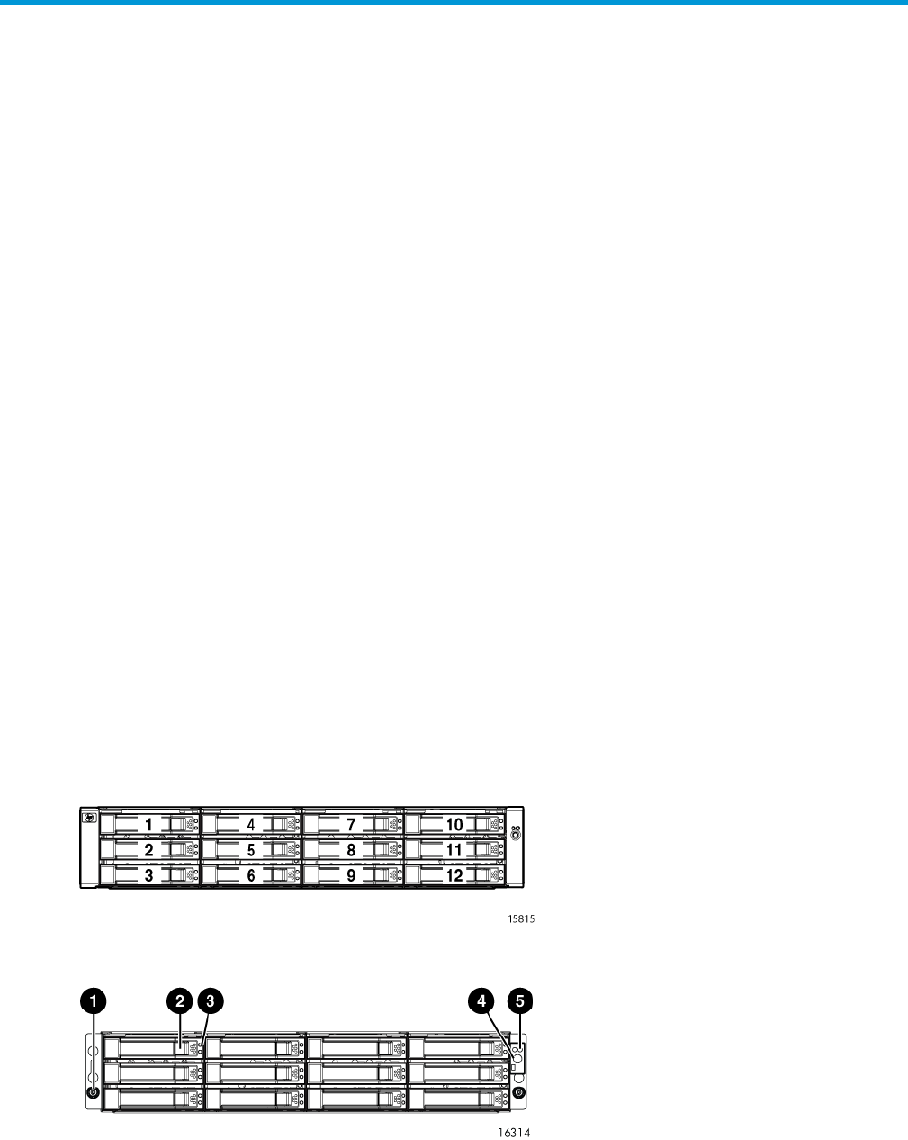
Enclosure layout
The disk drives mount in bays in the front of the enclosure. The bays are numbered sequentially
from top to bottom and left to right. A drive is referred to by its bay number (see Figure 1 (page
9)). Enclosure status indicators are located at the right of each disk. Figure 2 (page 9) shows
the front and Figure 3 (page 10) shows the rear view of the disk enclosure.
Figure 1 Disk drive bay numbering
Figure 2 Disk enclosure front view without bezel ears
4. UID push button1. Rack-mounting thumbscrew
5. Enclosure status LEDs2. Disk drive release
3. Drive LEDs
M6412A disk enclosures 9
Figure 3 Disk enclosure rear view
7. I/O module B1. Power supply 1
8. Rear UID push button2. Power supply 1 status LED
9. Enclosure status LEDs3. Fan 1
10. Fan 24. Enclosure product number and serial number
11. Power push button5. Fan 1 status LED
12. Power supply 26. I/O module A
I/O modules
Two I/O modules provide the interface between the disk enclosure and the host controllers,
(Figure 4 (page 10)). For redundancy, only dual-controller, dual-loop operation is supported. Each
controller is connected to both I/O modules in the disk enclosure.
Each I/O module has two ports that can transmit and receive data for bidirectional operation.
Activating a port requires connecting a Fibre Channel cable to the port. The port function depends
upon the loop.
Figure 4 I/O module detail
4. Manufacturing diagnostic port1. Double 7–segment display: enclosure ID
5. I/O module status LEDs2. 4 Gb I/O ports
3. Port 1 (P1), Port 2 (P2) status LEDs
I/O module status indicators
There are five status indicators on the I/O module. See Figure 4 (page 10). The status indicator
states for an operational I/O module are shown in Table 1 (page 11).Table 2 (page 11) shows
the status indicator states for a non-operational I/O module.
10 EVA6400/8400 hardware

Table 1 Port status LEDs
DescriptionStatus LED
Green (left) •Solid green— Active link
•Flashing green—Locate, remotely asserted by application client
Amber (right) •Solid amber—Module fault, no synchronization
•Flashing amber—Module fault
Table 2 I/O module status LEDs
DescriptionStatus LED
•Locate
•Flashing blue—Remotely asserted by application client
•Module health indicator
•Flashing green—I/O module powering up.
•Solid green—Normal operation
•Green off—Firmware malfunction
•Fault indicator
•Flashing amber—Warning condition (not visible when solid
amber showing)
•Solid amber—Replace FRU
•Amber off—Normal operation
Fiber optic Fibre Channel cables
The Enterprise Virtual Array uses orange, 50-µm, multi-mode, fiber optic cables for connection to
the SAN or the host, where there is a direct connection to the host. The fiber optic cable assembly
consists of two 2-m fiber optic strands and small form-factor connectors on each end. See
Figure 5 (page 12).
To ensure optimum operation, the fiber optic cable components require protection from
contamination and mechanical hazards. Failure to provide this protection can cause degraded
operation. Observe the following precautions when using fiber optic cables.
•To avoid breaking the fiber within the cable:
Do not kink the cable◦
◦Do not use a cable bend-radius of less than 30 mm (1.18 inch)
•To avoid deforming, or possibly breaking the fiber within the cable, do not place heavy objects
on the cable.
•To avoid contaminating the optical connectors:
Do not touch the connectors◦
◦Never leave the connectors exposed to the air
◦Install a dust cover on each transceiver and fiber cable connector when they are
disconnected
If an open connector is exposed to dust, or if there is any doubt about the cleanliness of the
connector, clean the connector as described in “Handling fiber optic cables” (page 43).
M6412A disk enclosures 11
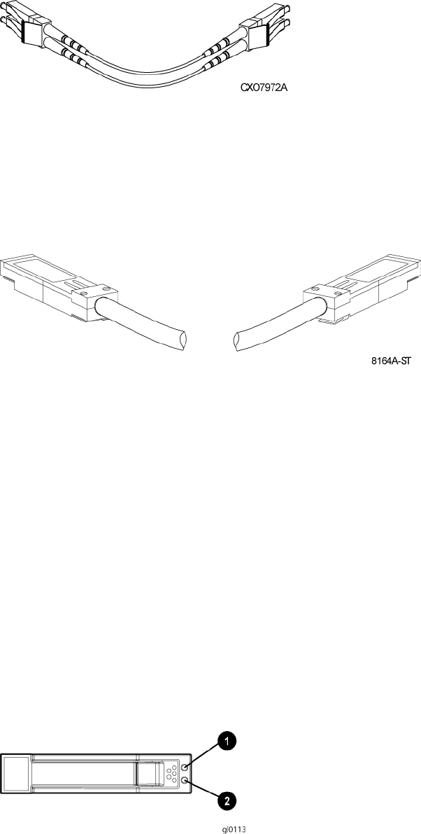
Figure 5 Fiber Optic Fibre Channel cable
Copper Fibre Channel cables
The Enterprise Virtual Array uses copper Fibre Channel cables to interconnect disk shelves. The
cables are available in 0.6-meter (1.97 ft.) and 2.0-meter (6.56 ft.) lengths. Copper cables provide
performance comparable to fiber optic cables. Copper cable connectors differ from fiber optic
small form-factor connectors (see Figure 6 (page 12)).
Figure 6 Copper Fibre Channel cable
Fibre Channel disk drives
The Fibre Channel disk drives are hot-pluggable and include the following features:
•Dual-ported 4 Gbps Fibre Channel controller interface that allows up to 96 disk drives to be
supported per array controller enclosure
•Compact, direct-connect design for maximum storage density and increased reliability and
signal integrity
•Both online high-performance disk drives and FATA disk drives supported in a variety of
capacities and spindle speeds
•Better vibration damping for improved performance
Up to 12 disk drives can be installed in a drive enclosure.
Disk drive status indicators
Two status indicators display drive operational status. Figure 7 (page 12) identifies the disk drive
status indicators. Table 3 (page 13) describes them.
Figure 7 Disk status indicators
2. Green1. Bi-color (amber/blue)
12 EVA6400/8400 hardware
Table 3 Disk status indicator LED descriptions
DescriptionDrive LED
Bi-color (top) •Slow flashing blue (0.5 Hz)—Used to locate drive.
•Solid amber—Drive fault.
Green (bottom) •Flashing—Drive is spinning up or down and is not ready.
•Solid—Drive is ready to perform I/O operations.
•Flickering—Indicates drive activity.
Disk drive blank
To maintain the proper enclosure air flow, a disk drive or a disk drive blank must be installed in
each drive bay. The disk drive blank maintains proper airflow within the disk enclosure.
Controller enclosures
This section describes the major features, purpose, and function of the HSV400 and HSV450
controllers. Each Enterprise Virtual Array has a pair of these controllers. Figure 8 (page 13) shows
the HSV400 controller rear view and Figure 9 (page 14) shows the HSV450 controller rear view.
The front of the HSV400 and HSV450 is shown in Figure 10 (page 14).
NOTE: Some controller enclosure modules have a cache battery located behind the OCP.
Figure 8 HSV400 controller rear view
6. DPI ports1. Serial port
7. Mirror ports2. Unit ID
8. Fiber ports3. Controller health
9. Power supply 14. Fault indicator
10. Power supply 25. Power
Controller enclosures 13
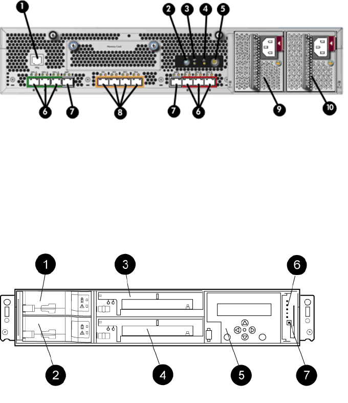
Figure 9 HSV450 controller rear view
6. DPI ports1. Serial port
7. Mirror ports2. Unit ID
8. Fiber ports3. Controller health
9. Power supply 14. Fault indicator
10. Power supply 25. Power
Figure 10 Controller front view
5. Operator Control Panel (OCP)1. Battery 1
6. Status indicators2. Battery 2
7. Unit ID3. Blower 1
4. Blower 2
Operator control panel
The operator control panel (OCP) provides a direct interface to each controller. From the OCP you
can display storage system status and configuration information, shut down the storage system,
and manage the password.
The OCP includes a 40-character LCD alphanumeric display, six push-buttons, and five status
indicators. See Figure 11 (page 15).
HP P6000 Command View is the tool you will typically use to display storage system status and
configuration information or perform the tasks available from the OCP. However, if HP P6000
Command View is not available, the OCP can be used to perform these tasks.
14 EVA6400/8400 hardware
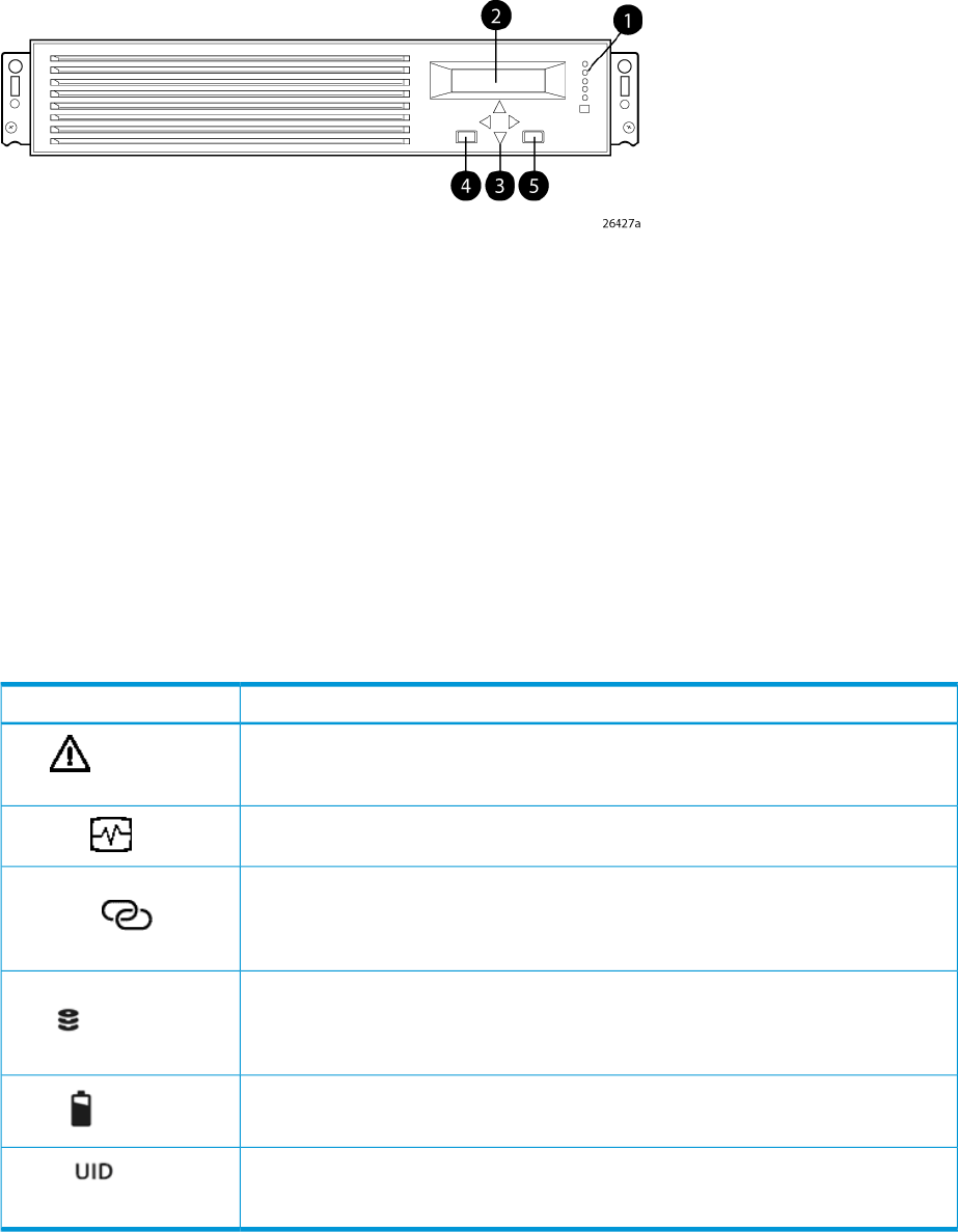
Figure 11 Controller OCP
1. Status indicators (see Table 4 (page 15)) and UID button
2. 40-character alphanumeric display
3. Left, right, top, and bottom push-buttons
4. Esc
5. Enter
Status indicators
The status indicators display the operational status of the controller. The function of each indicator
is described in Table 4 (page 15). During initial setup, the status indicators might not be fully
operational.
The following sections define the alphanumeric display modes, including the possible displays,
the valid status indicator displays, and the pushbutton functions.
Table 4 Controller status indicators
DescriptionIndicator
When the indicator is a solid amber, it means there was a boot failure. When it flashes,
the controller is inoperative. Check either HP P6000 Command View or the LCD Fault
Management displays for a definition of the problem and recommended corrective action.
Fault
When the indicator is flashing green slowly, the controller is booting up. When the
indicator turns to solid green, boot is successful and the controller is operating normally.
Controller
When this indicator is green, there is at least one physical link between the storage
system and hosts that is active and functioning normally. When this indicator is amber,
Physical link to hosts
established there are no links between the storage system and hosts that are active and functioning
normally.
When this indicator is green, all virtual disks that are presented to hosts are healthy and
functioning normally. When this indicator is amber, at least one virtual disk is not
Virtual disks presented to
hosts functioning normally. When this indicator is off, there are no virtual disks presented to
hosts and this indicates a problem with the virtual disk on the array.
When this indicator is green, the battery is working properly. When this indicator is
amber, there is a battery failure.
Battery
Press to turn on (solid blue); press again to turn it off. This LED mimics the function of the
UID on the back of the controller.This indicator comes on in response to a Locate command
issued by HP P6000 Command View.
Unit ID
Each port on the rear of the controller has an associated status indicator located directly above it.
Table 5 (page 16) lists the port and its status description.
Controller enclosures 15

Table 5 Controller port status indicators
Status indicator descriptionPort
Fibre Channel host ports •Green—Normal operation
•Amber—No signal detected
•Off—No SFP1detected or the Direct Connect OCP setting is incorrect
Fibre Channel device ports •Green—Normal operation
•Amber—No signal detected or the controller has failed the port
•Off—No SFP1detected
Fibre Channel cache mirror ports •Green—Normal operation
•Amber—No signal detected or the controller has failed the port
•Off—No SFP1detected
1On copper Fibre Channel cables, the SFP is integrated into the cable connector.
Navigation buttons
The operation of the navigation buttons is determined by the current display and location in the
menu structure. Table 6 (page 16) defines the basic push button functions when navigating the
menus and options.
To simplify presentation and to avoid confusion, the pushbutton reference names, regardless of
labels, are left, right, top, and bottom.
Table 6 Navigation button functions
FunctionButton
Moves down through the available menus and options
Moves up through the available menus and options
Selects the displayed menu or option.
Returns to the previous menu.
Used for “No” selections and to return to the default display.Esc
Used for “Yes” selections and to progress through menu items.Enter
Alphanumeric display
The alphanumeric display uses two LCD rows, each capable of displaying up to 20 alphanumeric
characters. By default, the alphanumeric display alternates between displaying the Storage System
Name and the World Wide Name. An active (flashing) display, an error condition message, or
a user entry (pressing a push-button) overrides the default display. When none of these conditions
exist, the default display returns after approximately 10 seconds.
Power supplies
Two power supplies provide the necessary operating voltages to all controller enclosure components.
If one power supply fails, the remaining supply is capable of operating the enclosure.
16 EVA6400/8400 hardware
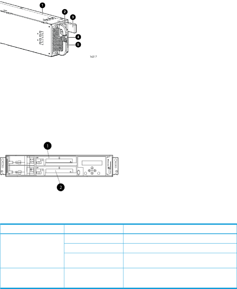
Figure 12 Power supply
4. Status indicator (solid green on—normal operation; solid
amber—failure or no power)
1. Power supply
5. Handle2. AC input connector
3. Latch
Blower module
Fan modules provide the cooling necessary to maintain the proper operating temperature within
the controller enclosure. If one fan fails, the remaining fan is capable of cooling the enclosure.
Figure 13 Blower module pulled out
2. Blower 21. Blower 1
Table 7 Fan status indicators
DescriptionFault indicatorStatus indicator
Normal operation.Solid greenGreen
Maintenance in progress.Blinking
Amber is on or blinking, or the enclosure is powered
down.
Off
Fan failure. Green will be off. (Green and amber are
not on simultaneously except for a few seconds after
power-up.)
OnAmber
Battery module
Batteries provide backup power to maintain the contents of the controller cache when AC power
is lost and the storage system has not been shutdown properly. When fully charged the batteries
can sustain the cache contents for to 96 hours. Three batteries are used on the EVA8400 and two
batteries are used on the EVA6400. Figure 14 (page 18) illustrates the location of the cache
batteries and the battery status indicators. See Table 8 (page 18) for additional information on
the status indicators.
Blower module 17
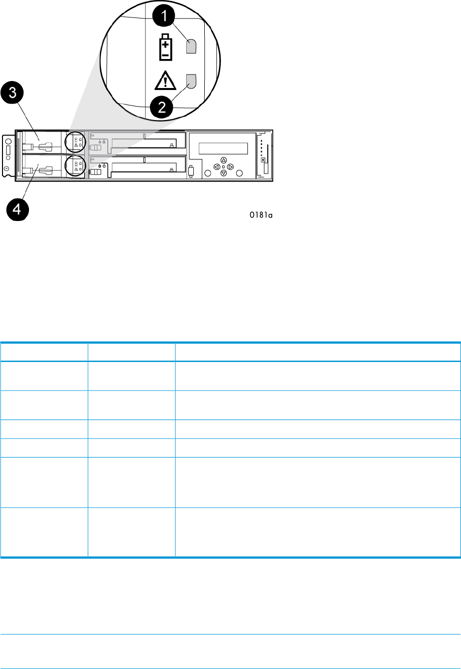
Figure 14 Battery module
3. Battery 01. Status indicator
4. Battery 12. Fault indicator
The table below describes the battery status indicators. When a battery is first installed, the fault
indicator goes on (solid) for approximately 30 seconds while the system discovers the new battery.
Then, the battery status indicators display the battery status as described in the table below.
Table 8 Battery status indicators
DescriptionFault indicatorStatus indicator
Normal operation. A maintenance charge process keeps the battery fully
charged.
OffOn
Battery is undergoing a full charging process. This is the indication you
typically see after installing a new battery.
OffFlashing
Battery fault. The battery has failed and should be replaced.OnOff
The battery has experienced an over temperature fault.FlashingOff
Battery code is being updated. When a new battery is installed, it may
be necessary for the controllers to update the code on the battery to the
Flashing (fast)Flashing (fast)
correct version. Both indicators flash rapidly for approximately 30
seconds.
Battery is undergoing a scheduled battery load test, during which the
battery is discharged and then recharged to ensure it is working properly.
FlashingFlashing
During the discharge cycle, you will see this display. The load test occurs
infrequently and takes several hours.
HSV controller cabling
All data cables and power cables attach to the rear of the controller. Adjacent to each data
connector is a two-colored link status indicator. Table 5 (page 16) identifies the status conditions
presented by these indicators.
NOTE: These indicators do not indicate whether there is communication on the link, only whether
the link can transmit and receive data.
18 EVA6400/8400 hardware
The data connections are the interfaces to the disk drive enclosures or loop switches (depending
on your configuration), the other controller, and the fabric. Fiber optic cables link the controllers
to the fabric, and, if an expansion cabinet is part of the configuration, link the expansion cabinet
drive enclosures to the loop is in the main cabinet. Copper cables are used between the controllers
(mirror port) and between the controllers and the drive enclosures or loop switches.
Storage system racks
All storage system components are mounted in a rack. Each configuration includes one enclosure
holding both controllers (the controller pair), FC cables the controller and the disk enclosures. Each
controller pair and all the associated drive enclosures form a single storage system.
The rack provides the capability for mounting 483 mm (19 inch) wide controller and drive
enclosures.
NOTE: Racks and rack-mountable components are typically described using “U” measurements.
“U” measurements are used to designate panel or enclosure heights. The “U” measurement is a
standard of 41 mm (1.6 inch).
The racks provide the following:
•Unique frame and rail design—Allows fast assembly, easy mounting, and outstanding structural
integrity.
•Thermal integrity—Front-to-back natural convection cooling is greatly enhanced by the innovative
multi-angled design of the front door.
•Security provisions—The front and rear door are lockable, which prevents unauthorized entry.
•Flexibility—Provides easy access to hardware components for operation monitoring.
•Custom expandability—Several options allow for quick and easy expansion of the racks to
create a custom solution.
Rack configurations
Each system configuration contains several disk enclosures included in the storage system. See
Figure 15 (page 19) for a typical EVA6400/8400 rack configuration. The standard rack is the
42U HP 10000 Intelligent Series rack. The EVA6400/8400 is also supported with 22U, 36U,
42U 5642, and 47U racks. The 42U 5643 is a field-installed option and the 47U rack must be
assembled onsite because the cabinet height creates shipping difficulties.
For more information on HP rack offerings for the EVA6400/8400, see:
http://h18004.www1.hp.com/products/servers/proliantstorage/racks/index.html
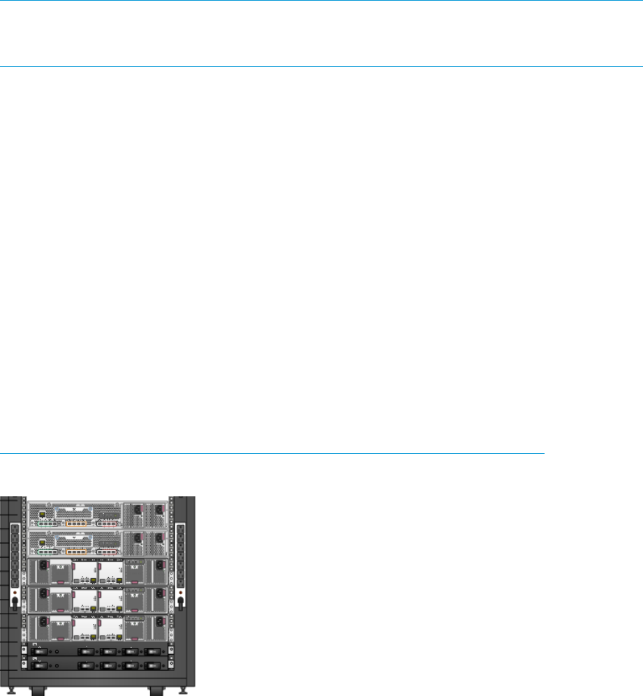
Figure 15 Storage system hardware components – back view
Storage system racks 19

Power distribution–Modular PDUs
NOTE: This section describes the most common power distribution system for EVA6400/8400s.
For information about other options, see the HP power distribution units website:
http://h18004.www1.hp.com/products/servers/proliantstorage/power-protection/pdu.html
AC power is distributed to the rack through a dual Power Distribution Unit (PDU) assembly mounted
at the bottom rear of the rack. The characteristics of the fully-redundant rack power configuration
are as follows:
•Each PDU is connected to a separate circuit breaker-protected, 30-A AC site power source
(100–127 VAC or 220–240 VAC ±10%, 50 or 60-Hz, ±5%). The following figures illustrate
the most common compatible 60-Hz and 50-Hz wall receptacles.
NEMA L5-30R receptacle, 3-wire, 30-A, 60-Hz
NEMA L6-30R receptacle, 3-wire, 30-A, 60-Hz
IEC 309 receptacle, 3-wire, 30-A, 50-Hz
•The standard power configuration for any Enterprise Virtual Array rack is the fully redundant
configuration. Implementing this configuration requires:
◦Two separate circuit breaker-protected, 30-A site power sources with a compatible wall
receptacle.
◦One dual PDU assembly. Each PDU connects to a different wall receptacle.
◦Four to eight (depending on the rack) Power Distribution Modules (PDM) per rack. PDMs
are split evenly on both sides of the rack. Each set of PDMs connects to a different PDU.
–Eight PDMs for 42U, 47U, and 42U 5642 racks
–Six PDMs for 36U racks
–Four PDMs for 22U racks
◦The drive enclosure power supplies on the left (PS 1) connect to the PDMs on the left with
a gray, 66 cm (26 inch) power cord.
◦The drive enclosure power supplies on the right (PS 2) connect to the PDMs on the right
with a black, 66 cm (26 inch) power cord.
◦Each controller has a left and right power supply. The left power supplies of each should
be connected to the left PDMs and the right power supplies should be connected to the
right PDMs.
NOTE: Drive enclosures, when purchased separately, include one 50 cm black cable and one
50 cm gray cable.
20 EVA6400/8400 hardware
The configuration provides complete power redundancy and eliminates all single points of failure
for both the AC and DC power distribution.
CAUTION: Operating the array with a single PDU will result in the following conditions:
•No redundancy
•Louder controllers and disk enclosures due to increased fan speed
•HP P6000 Command View will continuously display a warning condition, making issue
monitoring a labor-intensive task
Although the array is capable of doing so, HP strongly recommends that an array operating with
a single PDU should not:
•Be put into production
•Remain in this state for more than 24 hours
PDUs
Each Enterprise Virtual Array rack has either a 50- or 60-Hz, dual PDU mounted at the bottom rear
of the rack. The PDU placement is back-to-back, plugs facing toward the front (Figure 16 (page
21)), with circuit breaker switches facing the back (Figure 17 (page 22)).
•The standard 50-Hz PDU cable has an IEC 309, 3-wire, 30-A, 50-Hz connector.
•The standard 60-Hz PDU cable has a NEMA L6-30P, 3-wire, 30-A, 60-Hz connector.
If these connectors are not compatible with the site power distribution, you must replace the PDU
power cord cable connector. One option is the NEMA L5-30R receptacle, 3-wire, 30-A, 60-Hz
connector.
Each of the two PDU power cables has an AC power source specific connector. The circuit
breaker-controlled PDU outputs are routed to a group of four AC receptacles. The voltages are
then routed to PDMs, sometimes called AC power strips, mounted on the two vertical rails in the
rear of the rack.
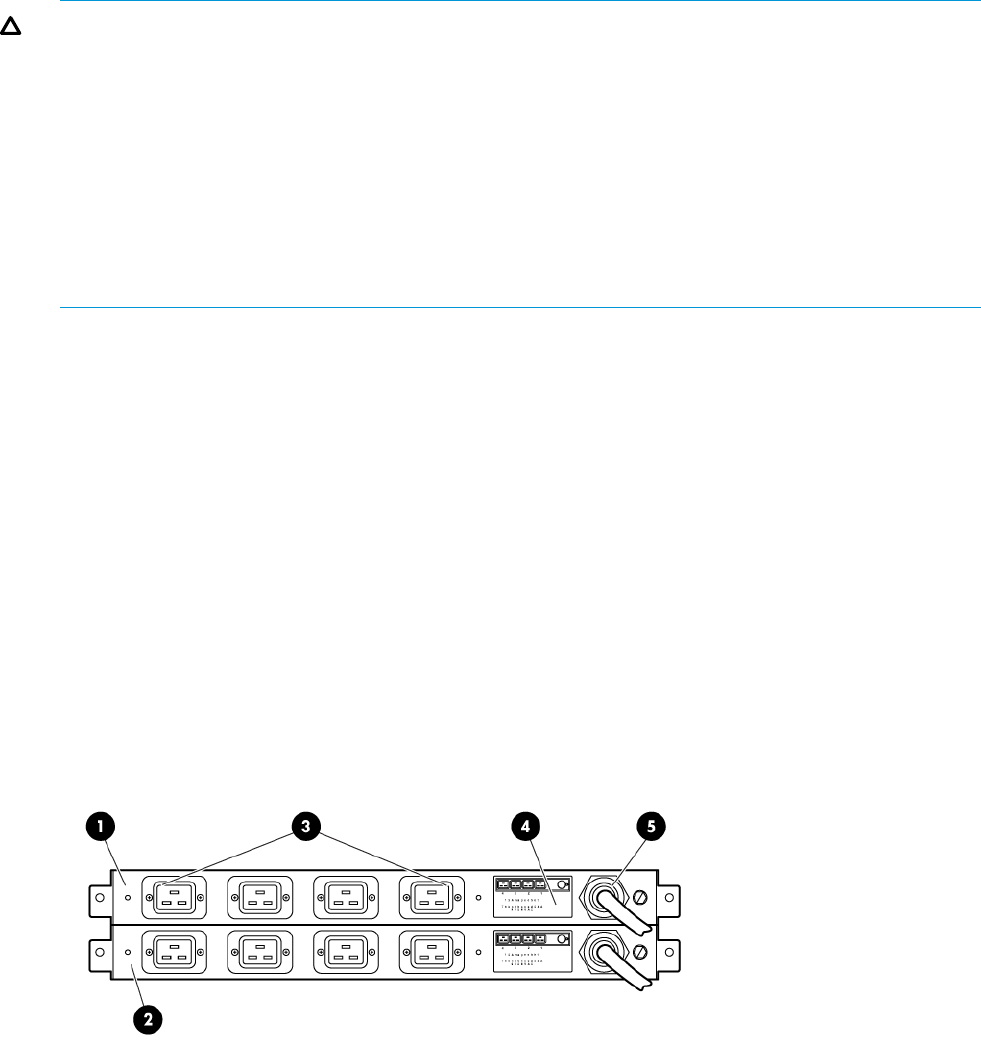
Figure 16 Dual PDU—front view
4. Power receptacle schematic1. PDU B
5. Power cord2. PDU A
3. AC receptacles
Power distribution–Modular PDUs 21
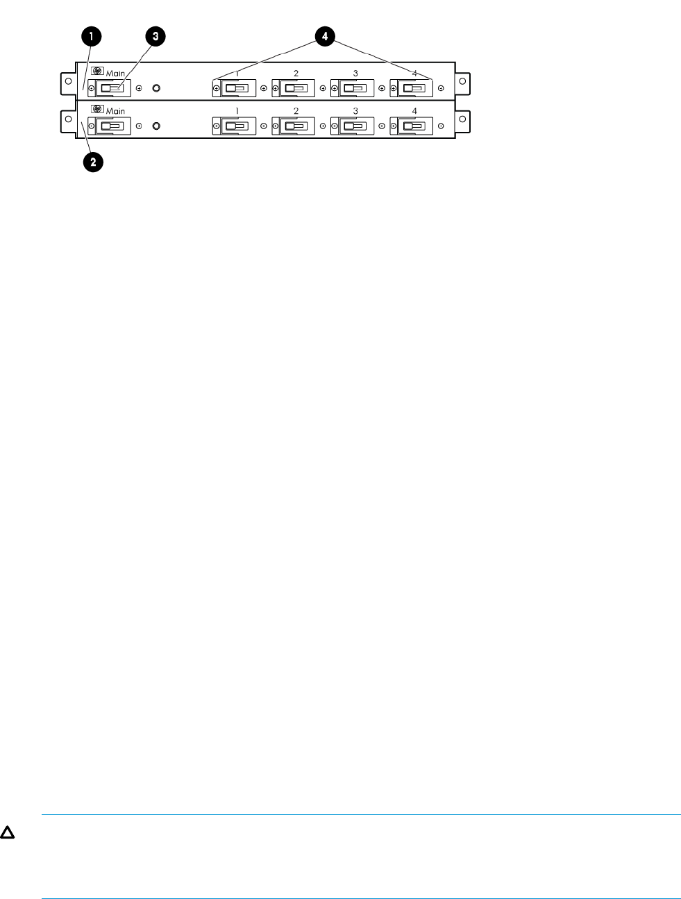
Figure 17 Dual PDU—rear view
3. Main circuit breaker1. PDU B
4. Circuit breakers2. PDU A
PDU A
PDU A connects to AC PDM A1–A4.
A PDU A failure:
•Disables the power distribution circuit
•Removes power from from the left side of the rack
•Disables disk enclosure PS 1
•Disables the left power supplies in the controllers
PDU B
PDU B connects to AC PDM B1–B4.
A PDU B failure:
•Disables the power distribution circuit
•Removes power from the right side of the rack
•Disables disk enclosure PS 2
•Disables the right power supplies in the controllers
PDMs
Depending on the rack, there can be up to eight PDMs mounted in the rear of the rack:
•The PDMs on the left vertical rail connect to PDU A
•The PDMs on the right vertical rail connect to PDU B
Each PDM has seven AC receptacles. The PDMs distribute the AC power from the PDUs to the
enclosures. Two power sources exist for each controller pair and disk enclosure. If a PDU fails, the
system will remain operational.
CAUTION: The AC power distribution within a rack ensures a balanced load to each PDU and
reduces the possibility of an overload condition. Changing the cabling to or from a PDM could
cause an overload condition. HP supports only the AC power distributions defined in this user
guide.
22 EVA6400/8400 hardware
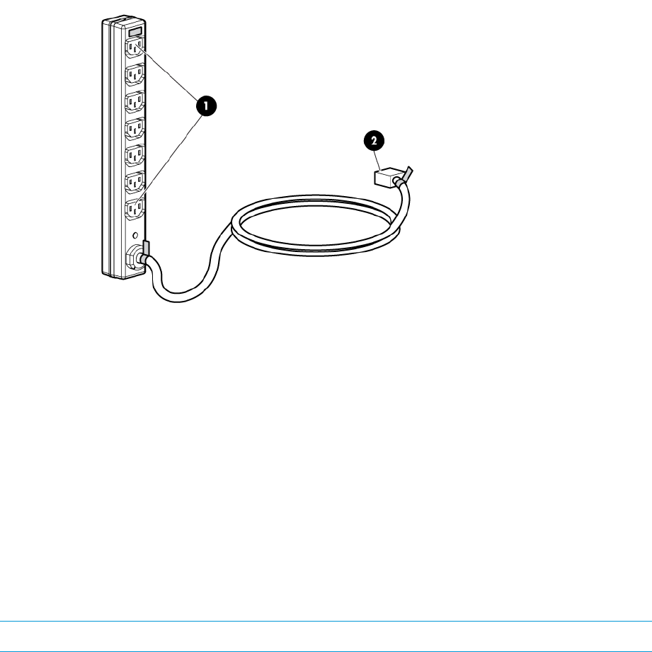
Figure 18 Rack PDM
1. Power receptacles
2. AC power connector
Rack AC power distribution
The power distribution in an Enterprise Virtual Array rack is the same for all variants. The site AC
input voltage is routed to the dual PDU assembly mounted in the rack lower rear. Each PDU
distributes AC to a maximum of four PDMs mounted on the left and right vertical rails (see
Figure 19 (page 24)).
•PDMs A1 through A4 connect to receptacles A through D on PDU A. Power cords connect
these PDMs to the left power supplies on the disk enclosures and to the left power supplies on
the controllers.
•PDMs B1 through B4 connect to receptacles A through D on PDU B. Power cords connect
these PDMs to the right power supplies on the disk enclosures and to the right power supplies
on the controllers.
NOTE: The locations of the PDUs and the PDMs are the same in all racks.
Power distribution–Modular PDUs 23
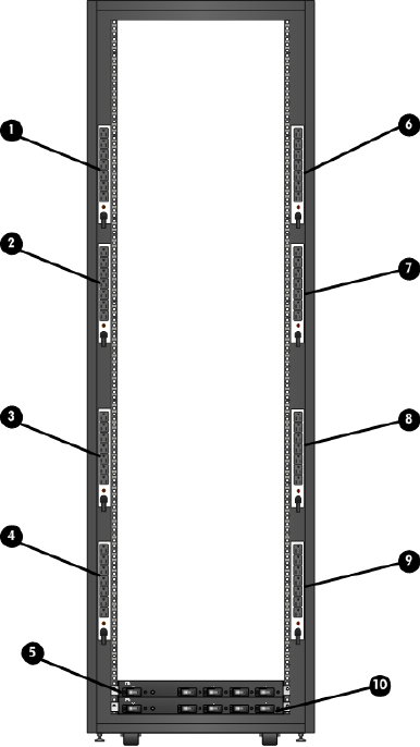
Figure 19 Rack AC power distribution
6. PDM 51. PDM 1
7. PDM 62. PDM 2
8. PDM 73. PDM 3
9. PDM 84. PDM 4
10. PDU 25. PDU 1
Rack System/E power distribution components
AC power is distributed to the Rack System/E rack through Power Distribution Units (PDU) mounted
on the two vertical rails in the rear of the rack. Up to four PDUs can be mounted in the rack—two
mounted on the right side of the cabinet and two mounted on the left side.
Each of the PDU power cables has an AC power source specific connector. The circuit
breaker-controlled PDU outputs are routed to a group of ten AC receptacles. The storage system
components plug directly into the PDUs.
Rack AC power distribution
The power distribution configuration in a Rack System/E rack depends on the number of storage
systems installed in the rack. If one storage system is installed, only two PDUs are required. If
multiple storage systems are installed, four PDUs are required.
24 EVA6400/8400 hardware
The site AC input voltage is routed to each PDU mounted in the rack. Each PDU distributes AC
through ten receptacles directly to the storage system components.
•PDUs 1 and 3 (optional) are mounted on the left side of the cabinet. Power cords connect
these PDUs to the number 1 disk enclosure power supplies and to the controllers.
•PDUs 2 and 4 (optional) are mounted on the right side of the cabinet. Power cords connect
these PDUs to the number 2 disk enclosure power supplies and to the controllers.
For additional information on power distribution support, see the following website:
http://h18004.www1.hp.com/products/servers/proliantstorage/power-protection/pdu.html
Moving and stabilizing a rack
WARNING! The physical size and weight of the rack requires a minimum of two people to move.
If one person tries to move the rack, injury may occur.
To ensure stability of the rack, always push on the lower half of the rack. Be especially careful
when moving the rack over any bump (such as door sills, ramp edges, carpet edges, or elevator
openings). When the rack is moved over a bump, there is a potential for it to tip over.
Moving the rack requires a clear, uncarpeted pathway that is at least 80 cm (31.5 inch) wide for
the 60.3 cm (23.7 inch) wide, 42U rack. A vertical clearance of 203.2 cm (80 inch) should ensure
sufficient clearance for the 200 cm (78.7 inch) high, 42U rack.
CAUTION: Ensure that no vertical or horizontal restrictions exist that would prevent rack movement
without damaging the rack.
Make sure that all four leveler feet are in the fully raised position. This process will ensure that the
casters support the rack weight and the feet do not impede movement.
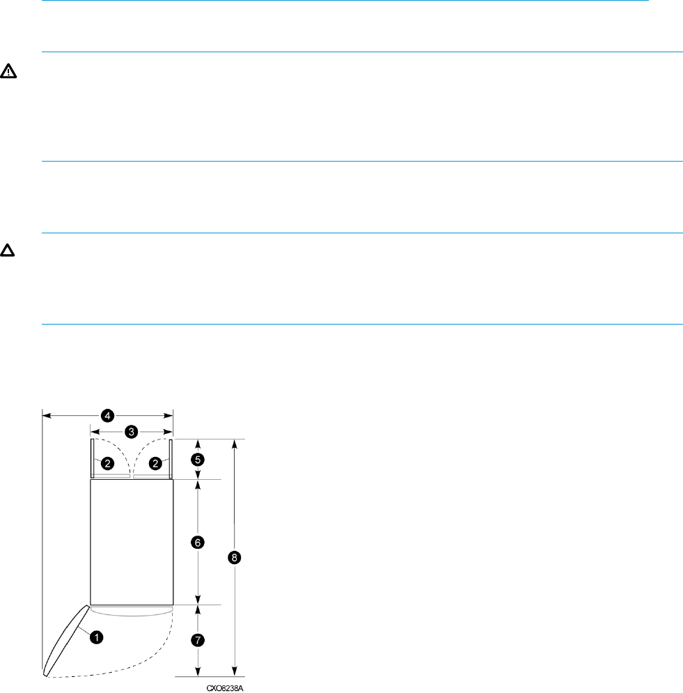
Each rack requires an area 600 mm (23.62 inch) wide and 1000 mm (39.37 inch) deep (see
Figure 20 (page 25)).
Figure 20 Single rack configuration floor space requirements
5. Rear service area depth 300 mm1. Front door
6. Rack depth 1000 mm2. Rear door
7. Front service area depth 406 mm3. Rack width 600 mm
8. Total rack depth 1706 mm4. Service area width 813 mm
Moving and stabilizing a rack 25
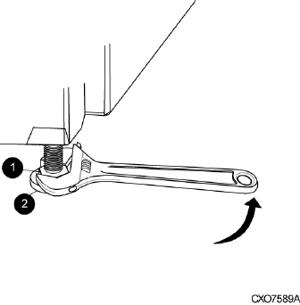
If the feet are not fully raised, complete the following procedure:
1. Raise one foot by turning the leveler foot hex nut counterclockwise until the weight of the rack
is fully on the caster (see Figure 21 (page 26)).
2. Repeat Step 1 for the other feet.
Figure 21 Raising a leveler foot
2. Leveler foot1. Hex nut
3. Carefully move the rack to the installation area and position it to provide the necessary service
areas (see Figure 20 (page 25)).
To stabilize the rack when it is in the final installation location:
1. Use a wrench to lower the foot by turning the leveler foot hex nut clockwise until the caster
does not touch the floor. Repeat for the other feet.
2. After lowering the feet, check the rack to ensure it is stable and level.
3. Adjust the feet as necessary to ensure the rack is stable and level.
26 EVA6400/8400 hardware
2 Enterprise Virtual Array startup
This chapter describes the procedures to install and configure the Enterprise Virtual Array. When
these procedures are complete, you can begin using your storage system.
NOTE: Installation of the Enterprise Virtual Array should be done only by an HP authorized
service representative. The information in this chapter provides an overview of the steps involved
in the installation and configuration of the storage system.
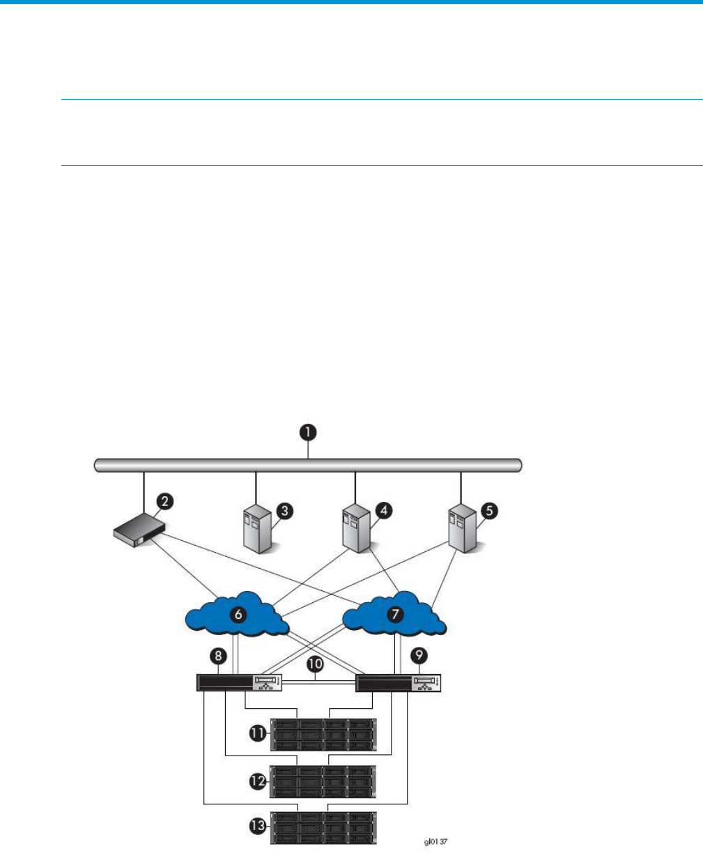
EVA8400 storage system connections
Figure 22 (page 27) shows how the storage system is connected to other components of the storage
solution.
•The HSV450 controllers connect via four host ports (FP1, FP2, FP3, and FP4) to the Fibre
Channel fabrics. The hosts that will access the storage system are connected to the same
fabrics.
•The HP P6000 Command View management server also connects to the fabric.
•The controllers connect through two loop pairs to the drive enclosures. Each loop pair consists
of two independent loops, each capable of managing all the disks should one loop fail.
Figure 22 EVA8400 configuration
11. Drive enclosure 16. Fabric 11. Network interconnection
12. Drive enclosure 27. Fabric 22. Management server
13. Drive enclosure 38. Controller A3. Non-host
9. Controller B4. Host A
10. Cache mirror ports5. Host B
EVA8400 storage system connections 27
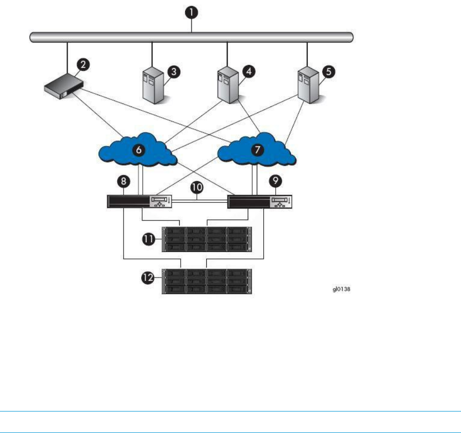
EVA6400 storage system connections
Figure 23 (page 28) shows a typical EVA6400 SAN topology:
•The HSV400 controllers connect via four host ports (FP1, FP2, FP3, and FP4) to the Fibre
Channel fabrics. The hosts that will access the storage system are connected to the same
fabrics.
•The HP P6000 Command View management server also connects to both fabrics.
•The controllers connect through one loop pair to the drive enclosures. The loop pair consists
of two independent loops, each capable of managing all the disks should one loop fail.
Figure 23 EVA6400 configuration
9. Controller B5. Host B1. Network interconnection
10. Cache mirror ports6. Fabric 12. Management server
11. Drive enclosure 17. Fabric 23. Non-host
12. Drive enclosure 28. Controller A4. Host A
Direct connect
NOTE: Direct connect is supported on Microsoft Windows only.
Direct connect provides a lower cost solution for smaller configurations. When using direct connect,
the storage system controllers are connected directly to the hosts, not to SAN Fibre Channel switches.
Make sure the following requirements are met when configuring your environment for direct connect:
•A management server running HP P6000 Command View must be connected to one port on
each EVA controller. The management host must use dual HBAs for redundancy.
•To provide redundancy, it is recommended that dual HBAs be used for each additional host
connected to the storage system. Using this configuration, up to four hosts (including the
management host) can be connected to an EVA6400/8400.
28 Enterprise Virtual Array startup

•The Host Port Configuration must be set to Direct Connect using the OCP.
•HP P6000 Continuous Access cannot be used with direct connect configurations.
•The HSV controller firmware cannot differentiate between an empty host port and a failed
host port in a direct connect configuration. As a result, the Connection state dialog box on
the Controller Properties window displays Connection failed for an empty host
port. To fix this problem, insert an optical loop-back connector into the empty host port; the
Connection state will display Connected. For more information about optical loop-back
connectors, contact your HP-authorized service provider.
iSCSI connection configurations
The EVA6400/8400 support iSCSI attach configurations using the HP MPX100. Both fabric connect
and direct connect are supported for iSCSI configurations. For complete information on iSCSI
configurations, go to the following website:
http://h18006.www1.hp.com/products/storageworks/evaiscsiconnect/index.html
NOTE: An iSCSI connection configuration supports mixed direct connect and fabric connect.
Fabric connect iSCSI
Fabric connect provides an iSCSI solution for EVA Fibre Channel configurations that want to
continue to use all EVA ports on FC or if the EVA is also used for HP P6000 Continuous Access.
Make sure the following requirements are met when configuring your MPX100 environment for
fabric connect:
•A maximum of two MPX100s per storage system are supported
•Each storage system port can connect to a maximum of two MPX100 FC ports.
•Each MPX100 FC port can connect to a maximum of one storage system port.
•In a single MPX100 configuration, if both MPX100 FC ports are used, each port must be
connected to one storage system controller.
•In a dual MPX100 configuration, at least one FC port from each MPX100 must be connected
to one storage system controller.
•The Host Port Configuration must be set to Fabric Connect using the OCP.
•HP P6000 Continuous Access is supported on the same storage system connected in MPX100
fabric connect configurations.
Direct connect iSCSI
Direct connect provides a lower cost solution for configurations that want to dedicate controller
ports to iSCSI I/O. When using direct connect, the storage system controllers are connected directly
to the MPX100s, not to SAN Fibre Channel switches.
Make sure the following requirements are met when configuring your MPX100 environment for
direct connect:
•A maximum two MPX100s per storage system are supported.
•In a single MPX100 configuration, if both MPX100 FC ports are used each port must be
connected to one storage system controller.
•In a dual MPX100 configuration, at least one FC port from each MPX100 must be connected
to one storage system controller.
•The Host Port Configuration must be set to Direct Connect using the OCP.
iSCSI connection configurations 29

•HP P6000 Continuous Access cannot be used with direct connect configurations.
•EVAs cannot be directly connected to each other to create HP P6000 Continuous Access
configuration. However, hosts can be direct connected to the EVA in a HP P6000 Continuous
Access configuration. At least one port from each array in an HP P6000 Continuous Access
configuration must be connected to a Fabric connection for remote array connectivity.
Procedures for getting started
ResponsibilityStep
Customer1. Gather information and identify all related storage documentation.
Customer2. Contact an authorized service representative for hardware configuration
information.
HP Service Engineer3. Enter the World Wide Name (WWN) into the OCP.
HP Service Engineer4. Configure HP P6000 Command View.
Customer5. Prepare the hosts.
HP Service Engineer6. Configure the system through HP P6000 Command View.
HP Service Engineer7. Make virtual disks available to their hosts. See the storage system software
documentation for each host's operating system.
Gathering information
The following items should be available when installing and configuring an Enterprise Virtual Array.
They provide information necessary to set up the storage system successfully.
•HP 6400/8400 Enterprise Virtual Array World Wide Name label, (shipped with the storage
system)
•HP Enterprise Virtual Array Release Notes
Locate these items and keep them handy. You will need them for the procedures in this manual.
Host information
Make a list of information for each host computer that will be accessing the storage system. You
will need the following information for each host:
•The LAN name of the host
•A list of World Wide Names of the FC adapters, also called host bus adapters, through which
the host will connect to the fabric that provides access to the storage system, or to the storage
system directly if using direct connect.
•Operating system type
•Available LUN numbers
Setting up a controller pair using the OCP
NOTE: This procedure should be performed by an HP authorized service representative.
Two pieces of data must be entered during initial setup using the controller OCP:
•World Wide Name (WWN) — Required to complete setup. This procedure should be
performed by an HP authorized service representative.
•Storage system password — Optional. A password provides security allowing only specific
instances of HP P6000 Command View to access the storage system.
30 Enterprise Virtual Array startup
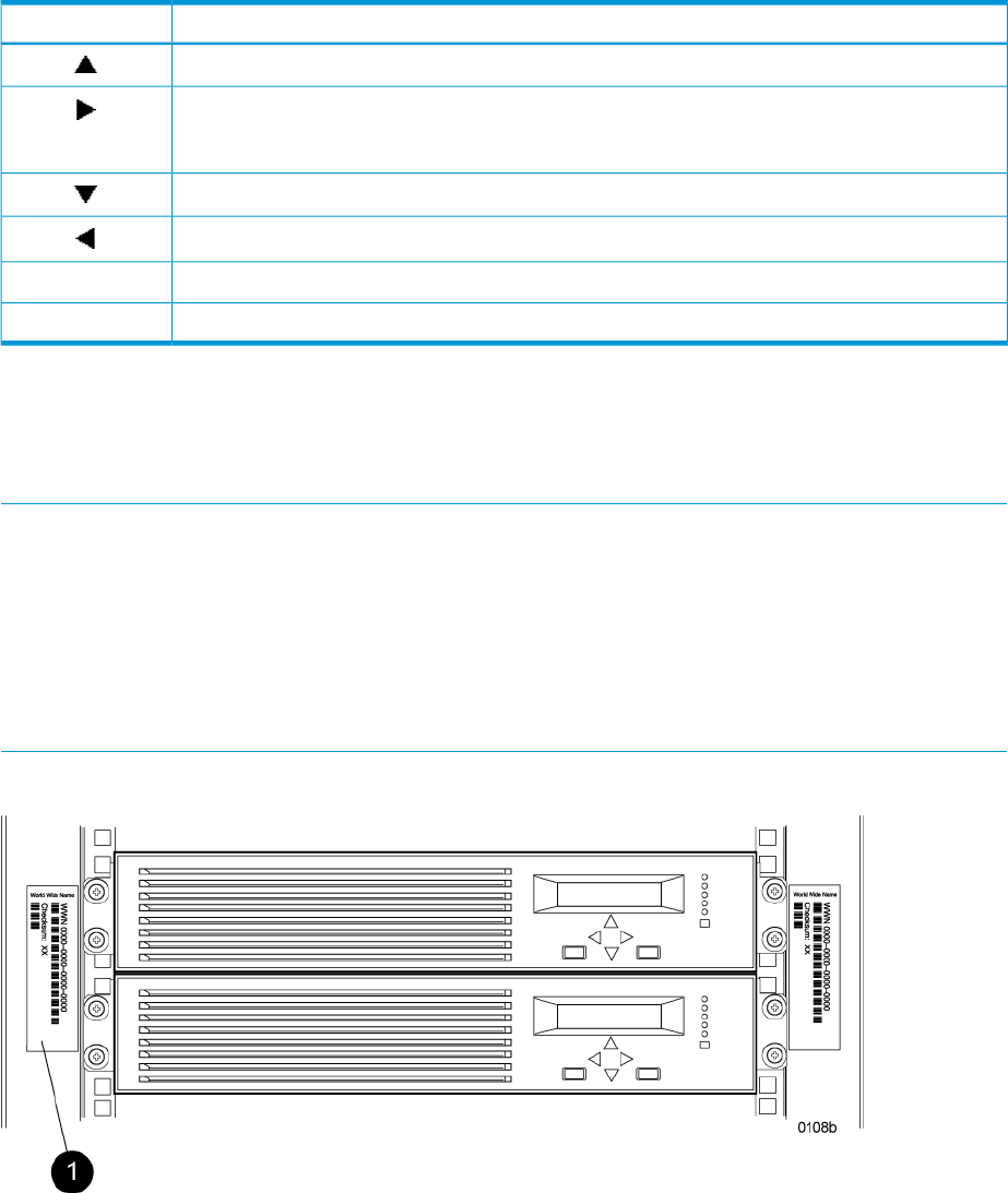
The OCP on either controller can be used to input the WWN and password data. For more
information about the OCP, see “Operator Control Panel” (page 14).
Table 9 (page 31) lists the push-button functions when entering the WWN, WWN checksum, and
password data.
Table 9 Push button functions
FunctionButton
Selects a character by scrolling up through the character list one character at a time.
Moves forward one character. If you accept an incorrect character, you can move through all 16
characters, one character at a time, until you display the incorrect character. You can then change
the character.
Selects a character by scrolling down through the character list one character at a time.
Moves backward one character.
Returns to the default display.ESC
Accepts all the characters entered.ENTER
Entering the WWN
Fibre Channel protocol requires that each controller pair have a unique WWN. This 16-character
alphanumeric name identifies the controller pair on the storage system. Two WWN labels attached
to the rack identify the storage system WWN and checksum. See Figure 24 (page 31).
NOTE:
•The WWN is unique to a controller pair and cannot be used for any other controller pair or
device anywhere on the network.
•This is the only WWN applicable to any controller installed in a specific physical location,
even a replacement controller.
•Once a WWN is assigned to a controller, you cannot change the WWN while the controller
is part of the same storage system.
Figure 24 Location of the World Wide Name labels
1. World Wide Name labels
Complete the following procedure to assign the WWN to each pair of controllers.
1. Turn the power switches on both controllers off.
2. Apply power to the rack.
Procedures for getting started 31
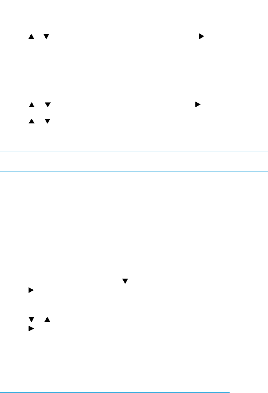
3. Turn the power switch on both controllers on.
NOTE: Notifications of the startup test steps that have been executed are displayed while
the controller is booting. It may take up to two minutes for the steps to display. The default
WWN entry display has a 0 in each of the 16 positions.
4. Press or until the first character of the WWN is displayed. Press to accept this character
and select the next.
5. Repeat Step 4 to enter the remaining characters.
6. Press Enter to accept the WWN and select the checksum entry mode.
Entering the WWN checksum
The second part of the WWN entry procedure is to enter the two-character checksum, as follows.
1. Verify that the initial WWN checksum displays 0 in both positions.
2. Press or until the first checksum character is displayed. Press to accept this character
and select the second character.
3. Press or until the second character is displayed. Press Enter to accept the checksum and
exit.
4. Verify that the default display is automatically selected. This indicates that the checksum is
valid.
NOTE: If you enter an incorrect WWN or checksum, the system will reject the data and you must
repeat the procedure.
Entering the storage system password
The storage system password feature enables you to restrict management access to the storage
system. The password must meet the following requirements:
•8 to 16 characters in length
•Can include upper or lower case letters
•Can include numbers 0 - 9
•Can include the following characters: ! “ # $ % & ‘ ( ) * + , - . / : ; < = > ? @ [ ] ^ _ ` { | }
•Cannot include the following characters: space ~ \
Complete the following procedure to enter the password:
1. Select a unique password of 8 to 16 characters.
2. With the default menu displayed, press three times to display System Password.
3. Press to display Change Password?
4. Press Enter for yes.
The default password, AAAAAAAA~~~~~~~~, is displayed.
5. Press or to select the desired character.
6. Press to accept this character and select the next character.
7. Repeat the process to enter the remaining password characters.
8. Press Enter to enter the password and return to the default display.
Installing HP P6000 Command View
HP P6000 Command View is installed on a management server. Installation can be skipped if the
latest version of HP P6000 Command View is running. Verify the latest version at the HP website:
http://h18006.www1.hp.com/products/storage/software/cmdvieweva/index.html
See the HP P6000 Command View Installation Guide for more information.
32 Enterprise Virtual Array startup
Installing optional EVA software licenses
If you purchased optional EVA software, you must install the license. Optional software available
for the Enterprise Virtual Array includes HP P6000 Business Copy and HP P6000 Continuous
Access. Installation instructions are included with the license.
Procedures for getting started 33

3 EVA6400/8400 operation
Best practices
For useful information on managing and configuring your storage system, see the HP 4400 and
6400/8400 Enterprise Virtual Array configuration best practices white paper available at:
http://h18006.www1.hp.com/storage/arraywhitepapers.html
Operating tips and information
Reserving adequate free space
To ensure efficient storage system operation, a certain amount of unallocated capacity, or free
space, should be reserved in each disk group. The recommended amount of free space is influenced
by your system configuration. For guidance on how much free space to reserve, see the HP 4400
and 6400/8400 Enterprise Virtual Array configuration best practices white paper. See “Best
practices” (page 34).
Using FATA disk drives
FATA drives are designed for lower duty cycle applications such as near online data replication
for backup. These drives should not be used as a replacement for EVA's high performance, standard
duty cycle, Fibre Channel drives. Doing so could shorten the life of the drive.
For useful information on managing and configuring your storage system, see the HP 4400 and
6400/8400 Enterprise Virtual Array configuration best practices white paper. See “Best practices”
(page 34).
Using solid state disk drives
The following requirements apply to solid state disk (SSD) drives:
•Supported in the EVA4400 and EVA6400/8400 only, running a minimum controller software
version of 09500000 for the 72 GB drive and 09534000 for the 200 GB and 400 GB drives
•SSD drives must be in a separate disk group
•The SSD disk group supports a minimum of 6 and a maximum of 8 drives per array
•SSD drives can only be configured with Vraid5 or Vraid1 (Vraid1 requires controller software
version 09534000 or later)
•Supported with HP P6000 Business Copy
•Not supported with HP P6000 Continuous Access
•Dynamic Capacity Management extend and shrink features are not supported
Use of these devices in unsupported configurations can lead to unpredictable results, including
unstable array operation or data loss.
QLogic HBA speed setting
In a Linux direct connect environment with QLogic 4 Gb/s HBAs, auto speed negotiation is not
supported. The QLogic HBA speed setting must be set to 4 Gb/s.
EVA6400/8400 host port negotiates to incorrect speed
The EVA6400/8400 might not correctly negotiate to 4 Gb/s when connected to an HP M-Series
4400, 4700, or 6140 switch with ports set to autonegotiate. The workaround is to set the switch
port to 4 Gb/s.
34 EVA6400/8400 operation

Creating 16 TB or greater virtual disks in Windows 2008
When creating a virtual disk that is 16 TB or greater in Windows 2008, ensure that the Allocation
unit size field is set to something other than Default in the Windows New Simple Volume wizard.
The recommended setting is 16K. If this field is set to Default, you will receive the following error
message:
The format operation did not complete because the cluster count is
higher than expected.
Importing Windows dynamic disk volumes
If you create a snapshot, snapclone, or mirrorclone with a Windows 2003 RAID-spanned dynamic
volume on the source virtual disk, and then try to import the copy to a Windows 2003 x64 (64-bit)
system, it will import with Dynamic Foreign status. The following message displays in the DiskPart
utility:
The disk management services could not complete the operation.
This error occurs because the 64-bit version of DiskPart fails to import dynamic RAID sets on a new
server.
To avoid this issue, use the 32-bit version of DiskPart instead of the 64-bit version. Copy DiskPart
from a 32-bit x86 Windows system, located in C:\WINDOWS\system32. Place the DiskPart utility
in a temporary folder on the 64-bit x64 Windows system.
Losing a path to a dynamic disk
If you are using Windows 2003 with dynamic disks and a path to the EVA virtual disk is temporarily
lost, the Logical Disk Manager (LDM) will erroneously show a failed dynamic volume. For more
information, see the following issue on the Microsoft knowledge base website:
http://support.microsoft.com/kb/816307
To resolve the issue, reboot the Windows 2003 server to restore the dynamic volume.
Microsoft Windows 2003 MSCS cluster installation
The MSCS cluster installation wizard on Windows 2003 can fail to find the shared quorum device
and disk resources might not be auto-created by the cluster setup wizard. This is a known Windows
Cluster Setup issue that has existed since Windows 2003 was released.
There are two possible workarounds for this problem:
•Follow the workaround recommendation described in the Microsoft support article entitled
Shared disks are missing or are marked as "Failed" when you create a server cluster in
Windows Server 2003 (ID 886807), available for download on the Microsoft website:
http://support.microsoft.com/default.aspx?scid=KB;EN-US;886807
•Use the MPIO DSM CLI to set the load balancing policy for each LUN to NLB.
Microsoft is currently working on a resolution to address this issue.
Managing unused ports
When you have unused ports on an EVA, perform the following steps:
1. Place a loopback plug on all unused ports.
2. Change the mode on unused ports from fabric to direct connect.
Changing the host port connectivity
To change the host port connectivity:
Operating tips and information 35

1. Disconnect any connected cable.
NOTE: Failing to disconnect the cable prior to making the change will require a controller
restart to clear the condition.
2. Use the OCP and navigate to the host port to be changed.
3. Select fabric for an FC switch connection or direct for direct attachment to an HBA.
4. Reconnect cables.
36 EVA6400/8400 operation

Failback preference setting for HSV controllers
Table 10 (page 37) describes the failback preference behavior for the controllers.
Table 10 Failback preference behavior
BehaviorPoint in timeSetting
The units are alternately brought online to
Controller A or to Controller B.
At initial presentationNo preference
If cache data for a LUN exists on a particular
controller, the unit will be brought online there.
On dual boot or controller resynch
Otherwise, the units are alternately brought
online to Controller A or to Controller B.
All LUNs are brought online to the surviving
controller.
On controller failover
All LUNs remain on the surviving controller.
There is no failback except if a host moves the
LUN using SCSI commands.
On controller failback
The units are brought online to Controller A.At initial presentationPath A - Failover Only
If cache data for a LUN exists on a particular
controller, the unit will be brought online there.
On dual boot or controller resynch
Otherwise, the units are brought online to
Controller A.
All LUNs are brought online to the surviving
controller.
On controller failover
All LUNs remain on the surviving controller.
There is no failback except if a host moves the
LUN using SCSI commands.
On controller failback
The units are brought online to Controller B.At initial presentationPath B - Failover Only
If cache data for a LUN exists on a particular
controller, the unit will be brought online there.
On dual boot or controller resynch
Otherwise, the units are brought online to
Controller B.
All LUNs are brought online to the surviving
controller.
On controller failover
All LUNs remain on the surviving controller.
There is no failback except if a host moves the
LUN using SCSI commands.
On controller failback
The units are brought online to Controller A.At initial presentationPath A -
Failover/Failback If cache data for a LUN exists on a particular
controller, the unit will be brought online there.
On dual boot or controller resynch
Otherwise, the units are brought online to
Controller A.
All LUNs are brought online to the surviving
controller.
On controller failover
All LUNs remain on the surviving controller.
After controller restoration, the units that are
On controller failback
online to Controller B and set to Path A are
brought online to Controller A. This is a one
time occurrence. If the host then moves the LUN
using SCSI commands, the LUN will remain
where moved.
The units are brought online to Controller B.At initial presentationPath B -
Failover/Failback
Failback preference setting for HSV controllers 37

Table 10 Failback preference behavior (continued)
BehaviorPoint in timeSetting
If cache data for a LUN exists on a particular
controller, the unit will be brought online there.
On dual boot or controller resynch
Otherwise, the units are brought online to
Controller B.
All LUNs are brought online to the surviving
controller.
On controller failover
All LUNs remain on the surviving controller.
After controller restoration, the units that are
On controller failback
online to Controller A and set to Path B are
brought online to Controller B. This is a one
time occurrence. If the host then moves the LUN
using SCSI commands, the LUN will remain
where moved.
Table 11 (page 38) describes the failback default behavior and supported settings when
ALUA-compliant multipath software is running with each operating system. Recommended settings
may vary depending on your configuration or environment.
Table 11 Failback settings by operating system
Supported settingsDefault behaviorOperating system
No Preference
Path A/B – Failover Only
Host follows the unit1
HP-UX
Path A/B – Failover/Failback
No Preference
Path A/B – Failover Only
Host follows the unit1
IBM AIX
Path A/B – Failover/Failback
No Preference
Path A/B – Failover Only
Host follows the unit 1
Linux
Path A/B – Failover/Failback
No PreferenceHost follows the unitOpenVMS
Path A/B – Failover Only
Path A/B – Failover/Failback
(recommended)
No PreferenceHost follows the unit1
Sun Solaris
Path A/B – Failover Only
Path A/B – Failover/Failback
No PreferenceHost follows the unitTru64 UNIX
Path A/B – Failover Only
Path A/B – Failover/Failback
(recommended)
No Preference
Path A/B – Failover Only
Host follows the unit1
VMware
Path A/B – Failover/Failback
No PreferenceFailback performed on the hostWindows
Path A/B – Failover Only
Path A/B – Failover/Failback
38 EVA6400/8400 operation

1If preference has been configured to ensure a more balanced controller configuration, the Path A/B – Failover/Failback
setting is required to maintain the configuration after a single controller reboot.
Changing virtual disk failover/failback setting
Changing the failover/failback setting of a virtual disk may impact which controller presents the
disk. Table 12 (page 39) identifies the presentation behavior that results when the failover/failback
setting for a virtual disk is changed.
NOTE: If the new setting causes the presentation of the virtual disk to move to a new controller,
any snapshots or snapclones associated with the virtual disk will also be moved.
Table 12 Impact on virtual disk presentation when changing failover/failback setting
Impact on virtual disk presentationNew setting
None. The disk maintains its original presentation.No Preference
If the disk is currently presented on controller B, it is moved to controller A.
If the disk is on controller A, it remains there.
Path A Failover
If the disk is currently presented on controller A, it is moved to controller B.
If the disk is on controller B, it remains there.
Path B Failover
If the disk is currently presented on controller B, it is moved to controller A.
If the disk is on controller A, it remains there.
Path A Failover/Failback
If the disk is currently presented on controller A, it is moved to controller B.
If the disk is on controller B, it remains there.
Path B Failover/Failback
Implicit LUN transition
Implicit LUN transition automatically transfers management of a virtual disk to the array controller
that receives the most read requests for that virtual disk. This improves performance by reducing
the overhead incurred when servicing read I/Os on the non-managing controller. Implicit LUN
transition is enabled in XCS.
When creating a virtual disk, one controller is selected to manage the virtual disk. Only this
managing controller can issue I/Os to a virtual disk in response to a host read or write request. If
a read I/O request arrives on the non-managing controller, the read request must be transferred
to the managing controller for servicing. The managing controller issues the I/O request, caches
the read data, and mirrors that data to the cache on the non-managing controller, which then
transfers the read data to the host. Because this type of transaction, called a proxy read, requires
additional overhead, it provides less than optimal performance. (There is little impact on a write
request because all writes are mirrored in both controllers’ caches for fault protection.)
With implicit LUN transition, when the array detects that a majority of read requests for a virtual
disk are proxy reads, the array transitions management of the virtual disk to the non-managing
controller. This improves performance because the controller receiving most of the read requests
becomes the managing controller, reducing proxy read overhead for subsequent I/Os.
Implicit LUN transition is disabled for all members of an HP P6000 Continuous Access DR group.
Because HP P6000 Continuous Access requires that all members of a DR group be managed by
the same controller, it would be necessary to move all members of the DR group if excessive proxy
reads were detected on any virtual disk in the group. This would impact performance and create
a proxy read situation for the other virtual disks in the DR group. Not implementing implicit LUN
transition on a DR group may cause a virtual disk in the DR group to have excessive proxy reads.
Storage system shutdown and startup
The storage system is shut down using HP P6000 Command View. The shutdown process performs
the following functions in the indicated order:
Storage system shutdown and startup 39

1. Flushes cache
2. Removes power from the controllers
3. Disables cache battery power
4. Removes power from the drive enclosures
5. Disconnects the system from HP P6000 Command View
NOTE: The storage system may take a long time to complete the necessary cache flush during
controller shutdown when snapshots are being used. The delay may be particularly long if multiple
child snapshots are used, or if there has been a large amount of write activity to the snapshot
source virtual disk.
Shutting down the storage system
To shut the storage system down, perform the following steps:
1. Start HP P6000 Command View.
2. Select the appropriate storage system in the Navigation pane.
The Initialized Storage System Properties window for the selected storage system opens.
3. Click Shut down.
The Shutdown Options window opens.
4. Under System Shutdown click Power Down. If you want to delay the initiation of the shutdown,
enter the number of minutes in the Shutdown delay field.
The controllers complete an orderly shutdown and then power off. The disk enclosures then
power off. Wait for the shutdown to complete.
Starting the storage system
To start a storage system, perform the following steps:
1. Verify that each fabric Fibre Channel switch to which the HSV controllers are connected is
powered up and fully booted. The power indicator on each switch should be on.
If you must power up the SAN switches, wait for them to complete their power-on boot process
before proceeding. This may take several minutes.
2. Power on the circuit breakers on both EVA rack PDUs, which powers on the controller enclosures
and disk enclosures. Verify that all enclosures are operating properly. The status indicator and
the power indicator should be on (green).
3. Wait three minutes and then verify that all disk drives are ready. The drive ready indicator
and the drive online indicator should be on (green).
4. Verify that the Operator Control Panel (OCP) display on each controller displays the storage
system name and the EVA WWN.
5. Start HP P6000 Command View and verify connection to the storage system. If the storage
system is not visible, click HSV Storage Network in the navigation pane, and then click Discover
in the Content pane to discover the array.
NOTE: If the storage system is still not visible, reboot the management server to re-establish
the communication link.
6. Check the storage system status using HP P6000 Command View to ensure everything is
operating properly. If any status indicator is not normal, check the log files or contact your
HP-authorized service provider for assistance.
Saving storage system configuration data
As part of an overall data protection strategy, storage system configuration data should be saved
during initial installation, and whenever major configuration changes are made to the storage
40 EVA6400/8400 operation

system. This includes adding or removing disk drives, creating or deleting disk groups, and adding
or deleting virtual disks. The saved configuration data can save substantial time should it ever
become necessary to re-initialize the storage system. The configuration data is saved to a series
of files stored in a location other than on the storage system.
This procedure can be performed from the management server where HP P6000 Command View
is installed, or any host that can run HP Storage System Scripting Utility (SSSU) to communicate
with HP P6000 Command View.
NOTE: For more information about using HP SSSU, see the HP Storage System Scripting Utility
Reference. See “Documents” (page 80).
1. Double-click the HP SSSU desktop icon to run the application. When prompted, enter Manager
(management server name or IP address), User name, and Password.
2. Enter LS SYSTEM to display the EVA storage systems managed by the management server.
3. Enter SELECT SYSTEM system name, where system name is the name of the storage
system.
The storage system name is case sensitive. If there are spaces between the letters in the name,
quotes must enclose the name: for example, SELECT SYSTEM “Large EVA”.
4. Enter CAPTURE CONFIGURATION, specifying the full path and filename of the output files
for the configuration data.
The configuration data is stored in a series of from one to five files, which are SSSU scripts.
The file names begin with the name you select, with the restore step appended. For example,
if you specify a file name of LargeEVA.txt, the resulting configuration files would be
LargeEVA_Step1A.txt, LargeEVA_Step1B, and so on.
The contents of the configuration files can be viewed with a text editor.
NOTE: If the storage system contains disk drives of different capacities, the HP SSSU procedures
used do not guarantee that disk drives of the same capacity will be exclusively added to the same
disk group. If you need to restore an array configuration that contains disks of different sizes and
types, you must manually recreate these disk groups. The controller software and the CAPTURE
CONFIGURATION command are not designed to automatically restore this type of configuration.
For more information, see the HP Storage System Scripting Utility Reference.
Saving storage system configuration data 41

Example 1 Saving configuration data using HP SSSU on a Windows host
To save the storage system configuration:
1. Double-click the HP SSSU desktop icon to run the application. When prompted, enter Manager
(management server name or IP address), User name, and Password.
2. Enter LS SYSTEM to display the EVA storage systems managed by the management server.
3. Enter SELECT SYSTEM system name, where system name is the name of the storage
system.
4. Enter CAPTURE CONFIGURATION pathname\filename, where pathname identifies the
location where the configuration files will be saved, and filename is the name used as the
prefix for the configurations files: for example, CAPTURE CONFIGURATION
c:\EVAConfig\LargeEVA
5. Enter EXIT to close the command window.
Example 2 Restoring configuration data using HP SSSU on a Windows host
To restore the storage system configuration:
1. Double-click the HP SSSU desktop icon to run the application.
2. Enter FILE pathname\filename, where pathname identifies the location where the
configuration files are to be saved and filename is the name of the first configuration file: for
example, FILE c:\EVAConfig\LargeEVA_Step1A.txt
3. Repeat the preceding step for each configuration file.
Adding disk drives to the storage system
As your storage requirements grow, you may be adding disk drives to your storage system. Adding
new disk drives is the easiest way to increase the storage capacity of the storage system. Disk
drives can be added online without impacting storage system operation.
Consider the following best practices to improve availability when adding disks to an array:
•Set the add disk option to manual.
•Add disks one at a time, waiting a minimum of 60 seconds between disks.
•Distribute disks vertically and as evenly as possible to all disk enclosures.
•Unless otherwise indicated, use the SET DISK_GROUP command in the HP Storage System
Scripting Utility to add new disks to existing disk groups.
•Add disks in groups of eight.
•For growing existing applications, if the operating system supports virtual disk growth, increase
virtual disk size. Otherwise, use a software volume manager to add new virtual disks to
applications.
See the disk drive replacement instructions for the steps to add a disk drive. See “Replacement
instructions” (page 79) for a link to this document.
Creating disk groups
The new disks you add will typically be used to create new disk groups. Although you cannot
select which disks will be part of a disk group, you can control this by building the disk groups
sequentially.
Add the disk drives required for the first disk group, and then create a disk group using these disk
drives. Now add the disk drives for the second disk group, and then create that disk group. This
process gives you control over which disk drives are included in each disk group.
42 EVA6400/8400 operation

NOTE: Standard and FATA disk drives must be in separate disk groups. Disk drives of different
capacities and spindle speeds can be included in the same disk group, but you may want to
consider separating them into separate disk groups.
Handling fiber optic cables
This section provides protection and cleaning methods for fiber optic connectors.
Contamination of the fiber optic connectors on either a transceiver or a cable connector can impede
the transmission of data. Therefore, protecting the connector tips against contamination or damage
is imperative. The tips can be contaminated by touching them, by dust, or by debris. They can be
damaged when dropped. To protect the connectors against contamination or damage, use the
dust covers or dust caps provided by the manufacturer. These covers are removed during installation,
and are installed whenever the transceivers or cables are disconnected. Cleaning the connectors
should remove contamination.
The transceiver dust caps protect the transceivers from contamination. Do not discard the dust
covers.
CAUTION: To avoid damage to the connectors, always install the dust covers or dust caps
whenever a transceiver or a fiber cable is disconnected. Remove the dust covers or dust caps from
transceivers or fiber cable connectors only when they are connected. Do not discard the dust covers.
To minimize the risk of contamination or damage, do the following:
•Dust covers — Remove and set aside the dust covers and dust caps when installing an I/O
module, a transceiver or a cable. Install the dust covers when disconnecting a transceiver or
cable.
•When to clean — If a connector may be contaminated, or if a connector has not been protected
by a dust cover for an extended period of time, clean it.
•How to clean:
1. Wipe the connector with a lint-free tissue soaked with 100% isopropyl alcohol.
2. Wipe the connector with a dry, lint-free tissue.
3. Dry the connector with moisture-free compressed air.
One of the many sources for cleaning equipment specifically designed for fiber optic connectors
is:
Alcoa Fujikura Ltd.
1-888-385-4587 (North America)
011-1-770-956-7200 (International)
Using the OCP
Displaying the OCP menu tree
The Storage System Menu Tree lets you select information to be displayed, configuration settings
to change, or procedures to implement. To enter the menu tree, press any navigation push-button
when the default display is active.
The menu tree is organized into the following major menus:
•System Info—displays information and configuration settings.
•Fault Management—displays fault information. Information about the Fault Management menu
is included in “Controller fault management” (page 107).
Handling fiber optic cables 43

•Shutdown Options—initiates the procedure for shutting down the system in a logical, sequential
manner. Using the shutdown procedures maintains data integrity and avoids the possibility
of losing or corrupting data.
•System Password—create a system password to ensure that only authorized personnel can
manage the storage system using HP P6000 Command View.
To enter and navigate the storage system menu tree:
1. Press any push-button while the default display is in view. System Information becomes the
active display.
2. Press to sequence down through the menus.
Press to sequence up through the menus.
Press to select the displayed menu.
Press to return to the previous menu.
NOTE: To exit any menu, press Esc or wait ten seconds for the OCP display to return to the default
display.
Table 13 (page 44) identifies all the menu options available within the OCP display.
CAUTION: Many of the configuration settings available through the OCP impact the operating
characteristics of the storage system. You should not change any setting unless you understand
how it will impact system operation. For more information on the OCP settings, contact your
HP-authorized service representative.
Table 13 Menu options within the OCP display
System PasswordShutdown OptionsFault ManagementSystem Information
Change PasswordRestartLast FaultVersions
Clear PasswordPower OffDetail ViewHost Port Config
(Sets Fabric or Direct
Connect)
Current Password
(Set or not)
Uninitialize SystemDevice Port Config
(Enables/disables device
ports)
I/O Module Config
(Enables/disables
auto-bypass)
Loop Recovery Config
(Enables/disables recoveries)
Unbypass Devices
UUID Unique Half
Debug Flags
Print Flags
Mastership Status (Displays
controller role — master or
slave)
Displaying system information
NOTE: The purpose of this information is to assist the HP-authorized service representative when
servicing your system.
44 EVA6400/8400 operation

The system information displays show the system configuration, including the XCS version, the OCP
firmware and application programming interface (API) versions, and the enclosure address bus
programmable integrated circuit (PIC) configuration. You can only view, not change, this information.
Displaying versions system information
When you press , the active display is Versions. From the Versions display you can determine
the:
•OCP firmware version
•Controller version
•XCS version
NOTE: The terms PPC, Sprite, Glue, SDC, CBIC, and Atlantis are for development purposes and
have no significance for normal operation.
NOTE: When viewing the software or firmware version information, pressing displays the
Versions Menu tree.
To display System Information:
1. The default display alternates between the Storage System Name display and the World Wide
Name display.
Press any push-button to display the Storage System Menu Tree.
2. Press until the desired Versions Menu option appears, and then press or to move to
submenu items.
Shutting down the system
CAUTION: To power off the system for more than 96 hours, use HP P6000 Command View.
You can use the Shutdown System function to implement the shutdown methods listed below. These
shutdown methods are explained in Table 14 (page 45).
•Shutting down the controller (see “Shutting the controller down” (page 46)).
•Restarting the system (see “Restarting the system” (page 46)).
•Uninitializing the system (see “Uninitializing the system” (page 46)).
To ensure that you do not mistakenly activate a shutdown procedure, the default state is always
NO, indicating do not implement this procedure. As a safeguard, implementing any shutdown
method requires you to complete at least two actions.
Table 14 Shutdown methods
DescriptionLCD prompt
Implementing this procedure establishes communications between the storage system
and HP P6000 Command View. This procedure is used to restore the controller to
an operational state where it can communicate with HP P6000 Command View.
Restart System?
Implementing this procedure initiates the sequential removal of controller power.
This ensures no data is lost. The reasons for implementing this procedure include
replacing a drive enclosure.
Power off system?
Implementing this procedure will cause the loss of all data. For a detailed discussion
of this procedure, see “Uninitializing the system” (page 46).
Uninitialize?
Using the OCP 45
Shutting the controller down
Use the following procedure to access the Shutdown System display and execute a shutdown
procedure.
CAUTION: If you decide NOT to power off while working in the Power Off menu, Power Off
System NO must be displayed before you press Esc. This reduces the risk of accidentally powering
down.
NOTE: HP P6000 Command View is the preferred method for shutting down the controller. Shut
down the controller from the OCP only if HP P6000 Command View cannot communicate with the
controller.
Shutting down the controller from the OCP removes power from the controller on which the procedure
is performed only. To restore power, toggle the controller’s power.
1. Press three times to scroll to the Shutdown Options menu.
2. Press to display Restart.
3. Press to scroll to Power Off.
4. Press to select Power Off.
5. Power off system is displayed. Press Enter to power off the system.
Restarting the system
To restore the controller to an operational state, use the following procedure to restart the system.
1. Press three times to scroll to the Shutdown Options menu.
2. Press to select Restart.
3. Press to display Restart system?
4. Press Enter to go to Startup.
No user input is required. The system will automatically initiate the startup procedure and
proceed to load the Storage System Name and World Wide Name information from the
operational controller.
Uninitializing the system
Uninitializing the system is another way to shut down the system. This action causes the loss of all
storage system data. Because HP P6000 Command View cannot communicate with the disk drive
enclosures, the stored data cannot be accessed.
CAUTION: Uninitializing the system destroys all user data. The WWN will remain in the controller
unless both controllers are powered off. The password will be lost. If the controllers remain powered
on until you create another storage system (initialize via GUI), you will not have to re-enter the
WWN.
Use the following procedure to uninitialize the system.
1. Press three times to scroll to the Shutdown Options menu.
2. Press to display Restart.
3. Press twice to display Uninitialize System.
4. Press to display Uninitialize?
5. Select Yes and press Enter.
The system displays Delete all data? Enter DELETE:_______
46 EVA6400/8400 operation

6. Press the arrow keys to navigate to the open field and type DELETE and then press ENTER.
The system uninitializes.
NOTE: If you do not enter the word DELETE or if you press ESC, the system does not
uninitialize. The bottom OCP line displays Uninit cancelled.
Password options
The password entry options are:
•Entering a password during storage system initialization (see “Entering the storage system
password” (page 32)).
•Displaying the current password.
•Changing a password (see “Changing a password” (page 47)).
•Removing password protection (see “Clearing a password” (page 47)).
Changing a password
For security reasons, you may need to change a storage system password. The password must
contain eight to 16 characters consisting of any combination of alpha, numeric, or special. See
“Entering the storage system password” (page 32) for more information on valid password
characters.
Use the following procedure to change the password.
NOTE: Changing a system password on the controller requires changing the password on any
HP P6000 Command View with access to the storage system.
1. Select a unique password of 8 to 16 characters.
2. With the default menu displayed, press three times to display System Password.
3. Press to display Change Password?
4. Press Enter for yes.
The default password, AAAAAAAA~~~~~~~~, is displayed.
5. Press or to select the desired character.
6. Press to accept this character and select the next character.
7. Repeat the process to enter the remaining password characters.
8. Press Enter to enter the password and return to the default display.
Clearing a password
Use the following procedure to remove storage system password protection.
NOTE: Changing a system password on the controller requires changing the password on any
HP P6000 Command View with access to the storage system.
1. Press four times to scroll to the System Password menu.
2. Press to display Change Password?
3. Press to scroll to Clear Password.
4. Press to display Clear Password.
5. Press Enter to clear the password.
The Password cleared message will be displayed.
Using the OCP 47

4 Configuring application servers
Overview
This chapter provides general connectivity information for all supported operating systems. Where
applicable, an OS-specific section is included to provide more information.
Clustering
Clustering is connecting two or more computers together so that they behave like a single computer.
Clustering may also be used for parallel processing, load balancing, and fault tolerance.
See the Single Point of Connectivity Knowledge (SPOCK) website (http://www.hp.com/storage/
spock) for the clustering software supported on each operating system.
NOTE: For OpenVMS, you must make the Console LUN ID and OS unit IDs unique throughout
the entire SAN, not just the controller subsystem.
Multipathing
Multipathing software provides a multiple-path environment for your operating system. See the
following website for more information:
http://h18006.www1.hp.com/products/sanworks/multipathoptions/index.html
See the Single Point of Connectivity Knowledge (SPOCK) website (http://www.hp.com/storage/
spock) for the multipathing software supported on each operating system.
Installing Fibre Channel adapters
For all operating systems, supported Fibre Channel adapters (FCAs) must be installed in the host
server in order to communicate with the EVA.
NOTE: Traditionally, the adapter that connects the host server to the fabric is called a host bus
adapter (HBA). The server HBA used with the EVA6400/8400 is called a Fibre Channel adapter
(FCA). You might also see the adapter called a Fibre Channel host bus adapter (Fibre Channel
HBA) in other related documents.
Follow the hardware installation rules and conventions for your server type. The FCA is shipped
with its own documentation for installation. See that documentation for complete instructions. You
need the following items to begin:
•FCA boards and the manufacturer’s installation instructions
•Server hardware manual for instructions on installing adapters
•Tools to service your server
The FCA board plugs into a compatible I/O slot (PCI, PCI-X, PCI-E) in the host system. For instructions
on plugging in boards, see the hardware manual.
You can download the latest FCA firmware from the following website http://www.hp.com/
support/downloads. Enter HBA in the Search Products box and then select your product. For
supported FCAs by operating system, see the SPOCK website http://www.hp.com/storage/spock.
48 Configuring application servers

Testing connections to the EVA
After installing the FCAs, you can create and test connections between the host server and the
EVA. For all operating systems, you must:
•Add hosts
•Create and present virtual disks
•Verify virtual disks from the hosts
The following sections provide information that applies to all operating systems. For OS-specific
details, see the applicable operating system section.
Adding hosts
To add hosts using HP P6000 Command View:
1. Retrieve and note the worldwide names (WWNs) for each FCA on your host.
You need this information to select the host FCAs in HP P6000 Command View.
2. Use HP P6000 Command View to add the host and each FCA installed in the host system.
NOTE: To add hosts using HP P6000 Command View, you must add each FCA installed in
the host. Select Add Host to add the first adapter. To add subsequent adapters, select Add
Port. Ensure that you add a port for each active FCA.
3. Select the applicable operating system for the host mode.
Table 15 Select the host mode for the applicable operating system
Host mode selectionOperating System
HP-UXHP-UX
IBM AIXIBM AIX
LinuxLinux
LinuxMac OS X
OVMSOpenVMS
Sun SolarisOracle Solaris
VMwareVMware
Microsoft WindowsWindows
Microsoft Windows 2008
Microsoft Windows 2012
LinuxCitrix Xen Server
4. Check the Host folder in the navigation pane of HP P6000 Command View to verify that the
host FCAs are added.
NOTE: More information about HP P6000 Command View is available at http://
www.hp.com/support/manuals. Click Storage Software under Storage, and then select HP
P6000 Command View software under Storage Device Management Software.
Creating and presenting virtual disks
To create and present virtual disks to the host server:
Testing connections to the EVA 49

1. From HP P6000 Command View, create a virtual disk on the EVA6400/8400.
2. Specify values for the following parameters:
•Virtual disk name
•Vraid level
•Size
3. Present the virtual disk to the host you added.
4. If applicable (OpenVMS), select a LUN number if you chose a specific LUN on the Virtual
Disk Properties window.
Verifying virtual disk access from the host
To verify that the host can access the newly presented virtual disks, restart the host or scan the bus.
If you are unable to access the virtual disk:
•Verify that all cabling to the switch, EVA, and host is properly connected.
•Verify all firmware levels. For more information, see the Enterprise Virtual Array QuickSpecs
and associated release notes.
•Ensure that you are running a supported version of the host operating system. For more
information, see the HP P6000 Enterprise Virtual Array Compatibility Reference.
•Ensure that the correct host is selected as the operating system for the virtual disk in HP P6000
Command View.
•Ensure that the host WWN number is set correctly (to the host you selected).
•Verify the FCA switch settings.
•Verify that the virtual disk is presented to the host.
•Verify zoning.
Configuring virtual disks from the host
After you create the virtual disks on the EVA6400/8400 and rescan or restart the host, follow the
host-specific conventions for configuring these new disk resources. For instructions, see the
documentation included with your server.
HP-UX
Scanning the bus
To scan the FCA bus and display information about the EVA6400/8400 devices:
1. Enter the # ioscan -fnCdisk command to start the rescan.
All new virtual disks become visible to the host.
2. Assign device special files to the new virtual disks using the insf command.
# insf -e
NOTE: Uppercase Ereassigns device special files to all devices. Lowercase eassigns device
special files only to the new devices—in this case, the virtual disks.
The following is a sample output from an ioscan command:
# ioscan -fnCdisk
# ioscan -fnCdisk
Class I H/W Patch Driver S/W H/W Type Description
State
========================================================================================
ba 3 0/6 lba CLAIMED BUS_NEXUS Local PCI Bus
50 Configuring application servers

Adapter (782)
fc 2 0/6/0/0 td CLAIMED INTERFACE HP Tachyon XL@ 2 FC
Mass Stor Adap /dev/td2
fcp 0 0/6/0/0.39 fcp CLAIMED INTERFACE FCP Domain
ext_bus 4 0/6/00.39.13.0.0 fcparray CLAIMED INTERFACE FCP Array Interface
target 5 0/6/0/0.39.13.0.0.0 tgt CLAIMED DEVICE
ctl 4 0/6/0/0.39.13.0.0.0.0 sctl CLAIMED DEVICE HP HSV400 /dev/rscsi/c4t0d0
disk 22 0/6/0/0.39.13.0.0.0.1 sdisk CLAIMED DEVICE HP HSV400 /dev/dsk/c4t0d1
/dev/rdsk/c4t0d
ext_bus 5 0/6/0/0.39.13.255.0 fcpdev CLAIMED INTERFACE FCP Device Interface
target 8 0/6/0/0.39.13.255.0.0 tgt CLAIMED DEVICE
ctl 20 0/6/0/0.39.13.255.0.0.0 sctl CLAIMED DEVICE HP HSV400 /dev/rscsi/c5t0d0
ext_bus 10 0/6/0/0.39.28.0.0 fcparray CLAIMED INTERFACE FCP Array Interface
target 9 0/6/0/0.39.28.0.0.0 tgt CLAIMED DEVICE
ctl 40 0/6/0/0.39.28.0.0.0.0 sctl CLAIMED DEVICE HP HSV400 /dev/rscsi/c10t0d0
disk 46 0/6/0/0.39.28.0.0.0.2 sdisk CLAIMED DEVICE HP HSV400 /dev/dsk/c10t0d2
/dev/rdsk/c10t0d2
disk 47 0/6/0/0.39.28.0.0.0.3 sdisk CLAIMED DEVICE HP HSV400 /dev/dsk/c10t0d3
/dev/rdsk/c10t0d3
disk 48 0/6/0/0.39.28.0.0.0.4 sdisk CLAIMED DEVICE HP HSV400 /dev/dsk/c10t0d4
/dev/rdsk/c10t0d4
disk 49 0/6/0/0.39.28.0.0.0.5 sdisk CLAIMED DEVICE HP HSV400 /dev/dsk/c10t0d5
/dev/rdsk/c10t0d5
disk 50 0/6/0/0.39.28.0.0.0.6 sdisk CLAIMED DEVICE HP HSV400 /dev/dsk/c10t0d
/dev/rdsk/c10t0d6
disk 51 0/6/0/0.39.28.0.0.0.7 sdisk CLAIMED DEVICE HP HSV400 /dev/dsk/c10t0d7
/dev/rdsk/c10t0d7
Creating volume groups on a virtual disk using vgcreate
You can create a volume group on a virtual disk by issuing a vgcreate command. This builds
the virtual group block data, allowing HP-UX to access the virtual disk. See the pvcreate,
vgcreate, and lvcreate man pages for more information about creating disks and file systems.
Use the following procedure to create a volume group on a virtual disk:
NOTE: Italicized text is for example only.
1. To create the physical volume on a virtual disk, enter a command similar to the following:
# pvcreate -f /dev/rdsk/c32t0d1
2. To create the volume group directory for a virtual disk, enter a command similar to the following:
# mkdir /dev/vg01
3. To create the volume group node for a virtual disk, enter a command similar to the following:
# mknod /dev/vg01/group c 64 0x010000
The designation 64 is the major number that equates to the 64-bit mode. The 0x01 is the
minor number in hex, which must be unique for each volume group.
4. To create the volume group for a virtual disk, enter a command similar to the following:
# vgcreate –f /dev/vg01 /dev/dsk/c32t0d1
5. To create the logical volume for a virtual disk, enter a command similar to the following:
# lvcreate -L1000 /dev/vg01/lvol1
In this example, a 1-Gb logical volume (lvol1) is created.
6. Create a file system for the new logical volume by creating a file system directory name and
inserting a mount tap entry into /etc/fstab.
7. Run the mkfs command on the new logical volume. The new file system is ready to mount.
IBM AIX
Accessing IBM AIX utilities
You can access IBM AIX utilities such as the Object Data Manager (ODM), on the following website:
http://www.hp.com/support/downloads
IBM AIX 51
In the Search products box, enter MPIO, and then click AIX MPIO PCMA for HP Arrays. Select IBM
AIX, and then select your software storage product.
Adding hosts
To determine the active FCAs on the IBM AIX host, enter:
# lsdev -Cc adapter |grep fcs
Output similar to the following appears:
fcs0 Available 1H-08 FC Adapter
fcs1 Available 1V-08 FC Adapter
# lscfg -vl
fcs0 fcs0 U0.1-P1-I5/Q1 FC Adapter
Part Number.................80P4543
EC Level....................A
Serial Number...............1F4280A419
Manufacturer................001F
Feature Code/Marketing ID...280B
FRU Number.................. 80P4544
Device Specific.(ZM)........3
Network Address.............10000000C940F529
ROS Level and ID............02881914
Device Specific.(Z0)........1001206D
Device Specific.(Z1)........00000000
Device Specific.(Z2)........00000000
Device Specific.(Z3)........03000909
Device Specific.(Z4)........FF801315
Device Specific.(Z5)........02881914
Device Specific.(Z6)........06831914
Device Specific.(Z7)........07831914
Device Specific.(Z8)........20000000C940F529
Device Specific.(Z9)........TS1.90A4
Device Specific.(ZA)........T1D1.90A4
Device Specific.(ZB)........T2D1.90A4
Device Specific.(YL)........U0.1-P1-I5/Q1b.
Creating and presenting virtual disks
When creating and presenting virtual disks to an IBM AIX host, be sure to:
1. Set the OS unit ID to 0.
2. Set Preferred path/mode to No Preference.
3. Select a LUN number if you chose a specific LUN on the Virtual Disk Properties window.
Verifying virtual disks from the host
To scan the IBM AIX bus, enter: cfgmgr -v
The -v switch (verbose output) requests a full output.
To list all EVA devices, enter:
Output similar to the following is displayed:
hdisk1 Available 1V-08-01 HP HSV400 Enterprise Virtual Array
hdisk2 Available 1V-08-01 HP HSV400 Enterprise Virtual Array
hdisk3 Available 1V-08-01 HP HSV400 Enterprise Virtual Array
Linux
HBA drivers
For most configurations and the latest version of Linux distributions, native HBA drivers are the
supported drivers. Native driver means the driver that is included with the OS distribution.
52 Configuring application servers

NOTE: The term inbox driver is also sometimes used and means the same as native driver.
However, in some configurations, it may require the use of an out-of-box driver, which typically
requires a driver package be downloaded and installed on the host. In those cases, follow the
documentation of the driver package for instruction. Driver support information can be found on
the Single Point of Connectivity Knowledge (SPOCK) website:
http://www.hp.com/storage/spock
NOTE: Registration is required to access SPOCK.
Verifying virtual disks from the host
To ensure that the LUN is recognized after a virtual disk is presented to the host, do one of the
following:
•Reboot the host.
•Enter the following command (where X is the SCSI host enumerator of the HBA):
echo “- – –” /sys/class/scsi_host/host[X]/scan
To verify that the host can access the virtual disks, enter the # more /proc/scsi/scsi command.
The output lists all SCSI devices detected by the server. An EVA6400/8400 LUN entry looks similar
to the following:
Host: scsi3 Channel: 00 ID: 00 Lun: 01
Vendor: HP Model: HSV400 Rev:
Type: Direct-Access ANSI SCSI revision: 02
OpenVMS
Updating the AlphaServer console code, Integrity Server console code, and Fibre
Channel FCA firmware
The firmware update procedure varies for the different server types. To update firmware, follow
the procedure described in the Installation instructions that accompany the firmware images.
Verifying the Fibre Channel adapter software installation
A supported FCA should already be installed in the host server. The procedure to verify that the
console recognizes the installed FCA varies for the different server types. Follow the procedure
described in the Installation instructions that accompany the firmware images.
Console LUN ID and OS unit ID
HP P6000 Command View software contains a box for the Console LUN ID on the Initialized
Storage System Properties window.
It is important that you set the Console LUN ID to a number other than zero. If the Console LUN ID
is not set or is set to zero, the OpenVMS host will not recognize the controller pair. The Console
LUN ID for a controller pair must be unique within the SAN. Table 16 (page 54) shows an example
of the Console LUN ID.
You can set the OS unit ID on the Virtual Disk Properties window. The default setting is 0, which
disables the ID field. To enable the ID field, you must specify a value between 1 and 32767,
OpenVMS 53

ensuring that the number you enter is unique within the SAN. An OS Unit ID greater than 9999
is not capable of being served by MSCP.
CAUTION: It is possible to enter a duplicate Console LUN ID or OS unit ID number. You must
ensure that you enter a Console LUN ID and OS Unit ID that is not already in use. A duplicate
Console LUN ID or OS Unit ID can allow the OpenVMS host to corrupt data due to confusion about
LUN identity. It can also prevent the host from recognizing the controllers.
Table 16 Comparing console LUN to OS unit ID
System DisplayID type
$1$GGA100:Console LUN ID set to 100
$1$DGA50:OS unit ID set to 50
Adding OpenVMS hosts
To obtain WWNs on AlphaServers, do one of the following:
•Enter the show device fg/full OVMS command.
•Use the WWIDMGR -SHOW PORT command at the SRM console.
To obtain WWNs on Integrity servers, do one of the following:
•Enter the show device fg/full OVMS command.
•Use the following procedure from the server console:
1. From the EFI boot Manager, select EFI Shell.
2. In the EFI Shell, enter “Shell> drivers”.
A list of EFI drivers loaded in the system is displayed.
3. In the listing, find the line for the FCA for which you want to get the WWN information.
For a Qlogic HBA, look for HP 4 Gb Fibre Channel Driver or HP 2 Gb Fibre
Channel Driver as the driver name. For example:
T D
D Y C I
R P F A
V VERSION E G G #D #C DRIVER NAME IMAGE NAME
== ======== = = = == == =================================== ===================
22 00000105 B X X 1 1 HP 4 Gb Fibre Channel Driver PciROM:0F:01:01:002
4. Note the driver handle in the first column (22 in the example).
5. Using the driver handle, enter the drvdfg driver_handle command to find the Device
Handle (Ctrl). For example:
Shell> drvcfg 22
Configurable Components
Drv[22] Ctrl[25] Lang[eng]
6. Using the driver and device handle, enter the drvdfg —sdriver_handle
device_handle command to invoke the EFI Driver configuration utility. For example:
Shell> drvcfg -s 22 25
7. From the Fibre Channel Driver Configuration Utility list, select item 8
(Info) to find the WWN for that particular port.
Output similar to the following appears:
Adapter Path: Acpi(PNP0002,0300)/Pci(01|01)
Adapter WWPN: 50060B00003B478A
Adapter WWNN: 50060B00003B478B
Adapter S/N: 3B478A
54 Configuring application servers

Scanning the bus
Enter the following command to scan the bus for the OpenVMS virtual disk:
$ MC SYSMAN IO AUTO/LOG
A listing of LUNs detected by the scan process is displayed. Verify that the new LUNs appear on
the list.
NOTE: The EVA6400/8400 console LUN can be seen without any virtual disks presented. The
LUN appears as $1$GGAx (where xrepresents the console LUN ID on the controller).
After the system scans the fabric for devices, you can verify the devices with the SHOW DEVICE
command:
$ SHOW DEVICE NAME-OF-VIRTUAL-DISK/FULL
For example, to display device information on a virtual disk named $1$DGA50, enter $ SHOW
DEVICE $1$DGA50:/FULL.
The following output is displayed:
Disk $1$DGA50: (BRCK18), device type HSV210, is online, file-oriented device,
shareable, device has multiple I/O paths, served to cluster via MSCP Server,
error logging is enabled.
Error count 2 Operations completed 4107
Owner process "" Owner UIC [SYSTEM]
Owner process ID 00000000 Dev Prot S:RWPL,O:RWPL,G:R,W
Reference count 0 Default buffer size 512
Current preferred CPU Id 0 Fastpath 1
WWID 01000010:6005-08B4-0010-70C7-0001-2000-2E3E-0000
Host name "BRCK18" Host type, avail AlphaServer DS10 466 MHz, yes
Alternate host name "VMS24" Alt. type, avail HP rx3600 (1.59GHz/9.0MB), yes
Allocation class 1
I/O paths to device 9
Path PGA0.5000-1FE1-0027-0A38 (BRCK18), primary path.
Error count 0 Operations completed 145
Path PGA0.5000-1FE1-0027-0A3A (BRCK18).
Error count 0 Operations completed 338
Path PGA0.5000-1FE1-0027-0A3E (BRCK18).
Error count 0 Operations completed 276
Path PGA0.5000-1FE1-0027-0A3C (BRCK18).
Error count 0 Operations completed 282
Path PGB0.5000-1FE1-0027-0A39 (BRCK18).
Error count 0 Operations completed 683
Path PGB0.5000-1FE1-0027-0A3B (BRCK18).
Error count 0 Operations completed 704
Path PGB0.5000-1FE1-0027-0A3D (BRCK18).
Error count 0 Operations completed 853
Path PGB0.5000-1FE1-0027-0A3F (BRCK18), current path.
Error count 2 Operations completed 826
Path MSCP (VMS24).
Error count 0 Operations completed 0
You can also use the SHOW DEVICE DG command to display a list of all Fibre Channel disks
presented to the OpenVMS host.
NOTE: Restarting the host system shows any newly presented virtual disks because a hardware
scan is performed as part of the startup.
If you are unable to access the virtual disk, do the following:
•Check the switch zoning database.
•Use HP P6000 Command View to verify the host presentations.
•Check the SRM console firmware on AlphaServers.
•Ensure that the correct host is selected for this virtual disk and that a unique OS Unit ID is used
in HP P6000 Command View.
OpenVMS 55

Configuring virtual disks from the OpenVMS host
To set up disk resources under OpenVMS, initialize and mount the virtual disk resource as follows:
1. Enter the following command to initialize the virtual disk:
$ INITIALIZE name-of-virtual-disk volume-label
2. Enter the following command to mount the disk:
MOUNT/SYSTEM name-of-virtual-disk volume-label
NOTE: The /SYSTEM switch is used for a single stand-alone system, or in clusters if you
want to mount the disk only to select nodes. You can use the /CLUSTER switch for OpenVMS
clusters. However, if you encounter problems in a large cluster environment, HP recommends
that you enter a MOUNT/SYSTEM command on each cluster node.
3. View the virtual disk’s information with the SHOW DEVICE command. For example, enter the
following command sequence to configure a virtual disk named data1 in a stand-alone
environment:
$ INIT $1$DGA1: data1
$ MOUNT/SYSTEM $1$DGA1: data1
$ SHOW DEV $1$DGA1: /FULL
Setting preferred paths
You can set or change the preferred path used for a virtual disk by using the SET DEVICE /PATH
command. For example:
$ SET DEVICE $1$DGA83: /PATH=PGA0.5000-1FE1-0007-9772/SWITCH
This allows you to control which path each virtual disk uses.
You can use the SHOW DEV/FULL command to display the path identifiers.
For additional information on using OpenVMS commands, see the OpenVMS help file:
$ HELP TOPIC
For example, the following command displays help information for the MOUNT command:
$ HELP MOUNT
Oracle Solaris
NOTE: The information in this section applies to both SPARC and x86 versions of the Oracle
Solaris operating system.
Loading the operating system and software
Follow the manufacturer’s instructions for loading the operating system (OS) and software onto the
host. Load all OS patches and configuration utilities supported by HP and the FCA manufacturer.
Configuring FCAs with the Oracle SAN driver stack
Sun-branded FCAs are supported only with the Oracle SAN driver stack. The Oracle SAN driver
stack is also compatible with current Emulex FCAs and QLogic FCAs. Support information is
available on the Oracle website: http://www.oracle.com/technetwork/server-storage/solaris/
overview/index-136292.html
To determine which non-Orcle branded FCAs HP supports with the Oracle SAN driver stack, see
the latest MPxIO application notes or contact your HP representative.
56 Configuring application servers

Update instructions depend on the version of your OS:
•For Solaris 9, install the latest Oracle StorEdge SAN software with associated patches. To
locate the software, log in to My Oracle Support:
https://support.oracle.com/CSP/ui/flash.html
1. Select the Patches & Updates tab and then search for StorEdge SAN Foundation Software
4.4 (formerly called StorageTek SAN 4.4).
2. Reboot the host after the required software/patches have been installed. No further activity
is required after adding any new LUNs once the array ports have been configured with
the cfgadm –ccommand for Solaris 9.
Examples for two FCAs:
cfgadm -c configure c3
cfgadm -c configure c4
3. Increase retry counts and reduce I/O time by adding the following entries to the
/etc/system file:
set ssd:ssd_retry_count=0xa
set ssd:ssd_io_time=0x1e
4. Reboot the system to load the newly added parameters.
•For Solaris 10, go the Oracle Software Downloads website (http://www.oracle.com/
technetwork/indexes/downloads/index.html) to install the latest patches. Under Servers and
Storage Systems, select Solaris 10. Reboot the host once the required software/patches have
been installed. No further activity is required after adding new LUNs, as the controller and
LUN recognition are automatic for Solaris 10.
1. For Solaris 10 x86/64, ensure patch 138889-03 or later is installed. For SPARC, ensure
patch 138888-03 or later is installed.
2. Increase the retry counts by adding the following line to the /kernel/drv/sd.conf
file:
sd-config-list="HP HSV","retries-timeout:10";
3. Reduce the I/O timeout value to 30 seconds by adding the following line to the
/etc/system file:
set sd:sd_io_time=0x1e
4. Reboot the system to load the newly added parameters.
Configuring Emulex FCAs with the lpfc driver
To configure Emulex FCAs with the lpfc driver:
1. Ensure that you have the latest supported version of the lpfc driver (see http://www.hp.com/
storage/spock).
You must sign up for an HP Passport to enable access. For more information on how to use
SPOCK, see the Getting Started Guide (http://h20272.www2.hp.com/Pages/spock_overview/
introduction.html).
2. Edit the following parameters in the /kernel/drv/lpfc.conf driver configuration file to
set up the FCAs for a SAN infrastructure:
topology=2;
scan-down=0;
nodev-tmo=60;
linkdown-tmo=60;
Oracle Solaris 57

3. If using a single FCA and no multipathing, edit the following parameter to reduce the risk of
data loss in case of a controller reboot:
nodev-tmo=120;
4. If using Veritas Volume Manager (VxVM) DMP for multipathing (single or multiple FCAs), edit
the following parameter to ensure proper VxVM behavior:
no-device-delay=0;
5. In a fabric topology, use persistent bindings to bind a SCSI target ID to the world wide port
name (WWPN) of an array port. This ensures that the SCSI target IDs remain the same when
the system reboots. Set persistent bindings by editing the configuration file or by using the
HBA management software.
NOTE: HP recommends that you assign target IDs in sequence, and that the EVA has the
same target ID on each host in the SAN.
The following example for an EVA6400/8400 illustrates the binding of targets 20 and 21
(lpfc instance 2) to WWPNs 50001fe100270938 and 50001fe100270939, and the binding
of targets 30 and 31 (lpfc instance 0) to WWPNs 50001fe10027093a and
50001fe10027093b:
fcp-bind-WWPN="50001fe100270938:lpfc2t20",
"50001fe100270939:lpfc2t21",
"50001fe10027093a:lpfc0t30",
"50001fe10027093b:lpfc0t31";
NOTE: Replace the WWPNs in the example with the WWPNs of your array ports.
6. For each LUN that will be accessed, add an entry to the /kernel/drv/sd.conf file. For
example, if you want to access LUNs 1 and 2 through all four paths, add the following entries
to the end of the file:
name="sd" parent="lpfc" target=20 lun=1;
name="sd" parent="lpfc" target=21 lun=1;
name="sd" parent="lpfc" target=30 lun=1;
name="sd" parent="lpfc" target=31 lun=1;
name="sd" parent="lpfc" target=20 lun=2;
name="sd" parent="lpfc" target=21 lun=2;
name="sd" parent="lpfc" target=30 lun=2;
name="sd" parent="lpfc" target=31 lun=2;
7. Reboot the server to implement the changes to the configuration files.
8. If LUNs have been preconfigured in the /kernel/drv/sd.conf file, use the devfsadm
command to perform LUN rediscovery after configuring the file.
NOTE: The lpfc driver is not supported for Oracle StorEdge Traffic Manager/Sun Storage
Multipathing. To configure an Emulex FCA using the Oracle SAN driver stack, see “Configuring
FCAs with the Oracle SAN driver stack” (page 56).
Configuring QLogic FCAs with the qla2300 driver
See the latest Enterprise Virtual Array release notes or contact your HP representative to determine
which QLogic FCAs and which driver version HP supports with the qla2300 driver. To configure
QLogic FCAs with the qla2300 driver:
1. Ensure that you have the latest supported version of the qla2300 driver (see http://
www.qlogic.com).
58 Configuring application servers

2. You must sign up for an HP Passport to enable access. For more information on how to use
SPOCK, see the Getting Started Guide (http://www.qlogic.com).
3. Edit the following parameters in the /kernel/drv/qla2300.conf driver configuration file
to set up the FCAs for a SAN infrastructure (HBA0 is used in the example, but the parameter
edits apply to all HBAs):
NOTE: If you are using a Sun-branded QLogic FCA, the configuration file is
\kernal\drv\qlc.conf.
hba0-connection-options=1;
hba0-link-down-timeout=60;
hba0-persistent-binding-configuration=1;
NOTE: If you are using Solaris 10, editing the persistent binding parameter is not required.
4. If using a single FCA and no multipathing, edit the following parameters to reduce the risk of
data loss in case of a controller reboot:
hba0-login-retry-count=60;
hba0-port-down-retry-count=60;
hba0-port-down-retry-delay=2;
The hba0-port-down-retry-delay parameter is not supported with the 4.13.01 driver;
the time between retries is fixed at approximately 2 seconds.
5. In a fabric topology, use persistent bindings to bind a SCSI target ID to the world wide port
name (WWPN) of an array port. This ensures that the SCSI target IDs remain the same when
the system reboots. Set persistent bindings by editing the configuration file or by using the
SANsurfer utility.
NOTE: Persistent binding is not required for QLogic FCAs if you are using Solaris 10.
The following example for an EVA6400/8400 illustrates the binding of targets 20 and 21
(hba instance 0) to WWPNs 50001fe100270938 and 50001fe100270939, and the binding
of targets 30 and 31 (hba instance 1) to WWPNs 50001fe10027093a and
50001fe10027093b:
hba0-SCSI-target-id-20-fibre-channel-port-name="50001fe100270938";
hba0-SCSI-target-id-21-fibre-channel-port-name="50001fe10027093a";
hba1-SCSI-target-id-30-fibre-channel-port-name="50001fe100270939";
hba1-SCSI-target-id-31-fibre-channel-port-name="50001fe10027093b";
NOTE: Replace the WWPNs in the example with the WWPNs of your array ports.
6. If the qla2300 driver is version 4.13.01 or earlier, for each LUN that users will access add
an entry to the /kernel/drv/sd.conf file:
name="sd" class="scsi" target=20 lun=1;
name="sd" class="scsi" target=21 lun=1;
name="sd" class="scsi" target=30 lun=1;
name="sd" class="scsi" target=31 lun=1;
If LUNs are preconfigured in the/kernel/drv/sd.conf file, after changing the configuration
file. use the devfsadm command to perform LUN rediscovery.
7. If the qla2300 driver is version 4.15 or later, verify that the following or a similar entry is
present in the /kernel/drv/sd.conf file:
name="sd" parent="qla2300" target=2048;
Oracle Solaris 59

To perform LUN rediscovery after configuring the LUNs, use the following command:
/opt/QLogic_Corporation/drvutil/qla2300/qlreconfig –d qla2300 -s
8. Reboot the server to implement the changes to the configuration files.
NOTE: The qla2300 driver is not supported for Oracle StorEdge Traffic Manager/Sun Storage
Multipathing. To configure a QLogic FCA using the Oracle SAN driver stack, see “Configuring
FCAs with the Oracle SAN driver stack” (page 56).
Fabric setup and zoning
To set up the fabric and zoning:
1. Verify that the Fibre Channel cable is connected and firmly inserted at the array ports, host
ports, and SAN switch.
2. Through the Telnet connection to the switch or Switch utilities, verify that the WWN of the
EVA ports and FCAs are present and online.
3. Create a zone consisting of the WWNs of the EVA ports and FCAs, and then add the zone
to the active switch configuration.
4. Enable and then save the new active switch configuration.
NOTE: There are variations in the steps required to configure the switch between different
vendors. For more information, see the HP SAN Design Reference Guide, available for downloading
on the HP website: http://www.hp.com/go/sandesign.
Oracle StorEdge Traffic Manager (MPxIO)/Oracle Storage Multipathing
Oracle StorEdge Traffic Manager (MPxIO)/Sun Storage Multipathing can be used for FCAs
configured with the Oracle SAN driver depending on the operating system version, architecture
(SPARC/x86), and patch level installed. For configuration details, see the HP MPxIO application
notes, available on the HP support website: http://www.hp.com/support/manuals.
NOTE: MPxIO is included in the SPARC and x86 Oracle SAN driver. A separate installation of
MPxIO is not required.
In the Search products box, enter MPxIO, and then click the search symbol. Select the
application notes from the search results.
Configuring with Veritas Volume Manager
The Dynamic Multipathing (DMP) feature of Veritas Volume Manager (VxVM) can be used for all
FCAs and all drivers. EVA disk arrays are certified for VxVM support. When you install FCAs,
ensure that the driver parameters are set correctly. Failure to do so can result in a loss of path
failover in DMP. For information about setting FCA parameters, see “Configuring FCAs with the
Oracle SAN driver stack” (page 56) and the FCA manufacturer’s instructions.
The DMP feature requires an Array Support Library (ASL) and an Array Policy Module (APM). The
ASL/APM enables Asymmetric Logical Unit Access (ALUA). LUNs are accessed through the primary
controller. After enablement, use the vxdisk list <device> command to determine the
primary and secondary paths. For VxVM 4.1 (MP1 or later), you must download the ASL/APM
from the Symantec/Veritas support site for installation on the host. This download and installation
is not required for VxVM 5.0 or later.
To download and install the ASL/APM from the Symantec/Veritas support website:
1. Go to http://support.veritas.com.
2. Enter Storage Foundation for UNIX/Linux in the Product Lookup box.
3. Enter EVA in the Enter key words or phrase box, and then click the search symbol.
4. To further narrow the search, select Solaris in the Platform box.
5. Read TechNotes and follow the instructions to download and install the ASL/APM.
60 Configuring application servers

6. Run vxdctl enable to notify VxVM of the changes.
7. Verify the configuration of VxVM as shown in Example 3 “Verifying the VxVM configuration”
(the output may be slightly different depending on your VxVM version and the array
configuration).
Example 3 Verifying the VxVM configuration
# vxddladm listsupport all | grep HP
libvxhpevale.so HP HSV300, HSV400, HSV450
# vxddladm listsupport libname=libvxhpevale.so
ATTR_NAME ATTR_VALUE
=======================================================================
LIBNAME libvxhpevale.so
VID HP
PID HSV300, HSV400, HSV450
ARRAY_TYPE A/A-A-HP
ARRAY_NAME EVA4400, EVA6400, EVA8400
# vxdmpadm listapm all | grep HP
dmphpalua dmphpalua 1 A/A-A-HP Active
# vxdmpadm listapm dmphpalua
Filename: dmphpalua
APM name: dmphpalua
APM version: 1
Feature: VxVM
VxVM version: 41
Array Types Supported: A/A-A-HP
Depending Array Types: A/A-A
State: Active
# vxdmpadm listenclosure all
ENCLR_NAME ENCLR_TYPE ENCLR_SNO STATUS ARRAY_TYPE
============================================================================
Disk Disk DISKS CONNECTED Disk
EVA84000 EVA8400 50001FE1002709E0 CONNECTED A/A-A-HP
By default, the EVA I/O policy is set to Round-Robin. For VxVM 4.1 MP1, only one path is used
for the I/Os with this policy. Therefore, HP recommends that you change the I/O policy to
Adaptive in order to use all paths to the LUN on the primary controller. Example 4 “Setting the
I/O policy” shows the commands you can use to check and change the I/O policy.
Example 4 Setting the I/O policy
# vxdmpadm getattr arrayname EVA8400 iopolicy
ENCLR_NAME DEFAULT CURRENT
============================================
EVA84000 Round-Robin Round-Robin
# vxdmpadm setattr arrayname EVA8400 iopolicy=adaptive
# vxdmpadm getattr arrayname EVA8400 iopolicy
ENCLR_NAME DEFAULT CURRENT
============================================
EVA84000 Round-Robin Adaptive
Configuring virtual disks from the host
The procedure used to configure the LUN path to the array depends on the FCA driver. For more
information, see “Installing Fibre Channel adapters” (page 48).
Oracle Solaris 61
To identify the WWLUN ID assigned to the virtual disk and/or the LUN assigned by the storage
administrator:
•Oracle SAN driver, with MPxIO enabled:
You can use the luxadm probe command to display the array/node WWN and
associated array for the devices.
◦
◦The WWLUN ID is part of the device file name. For example:
/dev/rdsk/c5t600508B4001030E40000500000B20000d0s2
◦If you use luxadm display, the LUN is displayed after the device address. For
example:
50001fe1002709e9,5
•Oracle SAN driver, without MPxIO:
The EVA WWPN is part of the file name (which helps you to identify the controller). For
example:
/dev/rdsk/c3t50001FE1002709E8d5s2
/dev/rdsk/c3t50001FE1002709ECd5s2
◦
/dev/rdsk/c4t50001FE1002709E9d5s2
/dev/rdsk/c4t50001FE1002709EDd5s2
If you use luxadm probe, the array/node WWN and the associated device files are
displayed.
◦You can retrieve the WWLUN ID as part of the format -e (scsi, inquiry) output; however,
it is cumbersome and hard to read. For example:
09 e8 20 04 00 00 00 00 00 00 35 30 30 30 31 46 .........50001F
45 31 30 30 32 37 30 39 45 30 35 30 30 30 31 46 E1002709E050001F
45 31 30 30 32 37 30 39 45 38 36 30 30 35 30 38 E1002709E8600508
42 34 30 30 31 30 33 30 45 34 30 30 30 30 35 30 B4001030E4000050
30 30 30 30 42 32 30 30 30 30 00 00 00 00 00 00 0000B20000
◦The assigned LUN is part of the device file name. For example:
/dev/rdsk/c3t50001FE1002709E8d5s2
You can also retrieve the LUN with luxadm display. The LUN is displayed after the
device address. For example:
50001fe1002709e9,5
•Emulex (lpfc)/QLogic (qla2300) drivers:
You can retrieve the WWPN by checking the assignment in the driver configuration file
(the easiest method, because you then know the assigned target) or by using HBA
management software.
◦
◦You can retrieve the WWLUN ID by using HBA management software.
You can also retrieve the WWLUN ID as part of the format -e (scsi, inquiry) output;
however, it is cumbersome and difficult to read. For example:
09 e8 20 04 00 00 00 00 00 00 35 30 30 30 31 46 .........50001F
45 31 30 30 32 37 30 39 45 30 35 30 30 30 31 46 E1002709E050001F
45 31 30 30 32 37 30 39 45 38 36 30 30 35 30 38 E1002709E8600508
42 34 30 30 31 30 33 30 45 34 30 30 30 30 35 30 B4001030E4000050
30 30 30 30 42 32 30 30 30 30 00 00 00 00 00 00 0000B20000
◦The assigned LUN is part of the device file name. For example:
/dev/dsk/c4t20d5s2
62 Configuring application servers

Verifying virtual disks from the host
Verify that the host can access virtual disks by using the format command. See Example 5 “Format
command”.
Example 5 Format command
# format
Searching for disks...done
c2t50001FE1002709F8d1: configured with capacity of 1008.00MB
c2t50001FE1002709F8d2: configured with capacity of 1008.00MB
c2t50001FE1002709FCd1: configured with capacity of 1008.00MB
c2t50001FE1002709FCd2: configured with capacity of 1008.00MB
c3t50001FE1002709F9d1: configured with capacity of 1008.00MB
c3t50001FE1002709F9d2: configured with capacity of 1008.00MB
c3t50001FE1002709FDd1: configured with capacity of 1008.00MB
c3t50001FE1002709FDd2: configured with capacity of 1008.00MB
AVAILABLE DISK SELECTIONS:
0. c0t0d0 <SUN18G cyl 7506 alt 2 hd 19 sec 248> /pci@1f,4000/scsi@3/sd@0,0
1. c2t50001FE1002709F8d1 <HP-HSV400-0952 cyl 126 alt 2 hd 128 sec 128>
/pci@1f,4000/QLGC,qla@4/fp@0,0/ssd@w50001fe1002709f8,1
2. c2t50001FE1002709F8d2 <HP-HSV400-0952 cyl 126 alt 2 hd 128 sec 128>
/pci@1f,4000/QLGC,qla@4/fp@0,0/ssd@w50001fe1002709f8,2
3. c2t50001FE1002709FCd1 <HP-HSV400-0952 cyl 126 alt 2 hd 128 sec 128>
/pci@1f,4000/QLGC,qla@4/fp@0,0/ssd@w50001fe1002709fc,1
4. c2t50001FE1002709FCd2 <HP-HSV400-0952 cyl 126 alt 2 hd 128 sec 128>
/pci@1f,4000/QLGC,qla@4/fp@0,0/ssd@w50001fe1002709fc,2
5. c3t50001FE1002709F9d1 <HP-HSV400-0952 cyl 126 alt 2 hd 128 sec 128>
/pci@1f,4000/lpfc@5/fp@0,0/ssd@w50001fe1002709f9,1
6. c3t50001FE1002709F9d2 <HP-HSV400-0952 cyl 126 alt 2 hd 128 sec 128>
/pci@1f,4000/lpfc@5/fp@0,0/ssd@w50001fe1002709f9,2
7. c3t50001FE1002709FDd1 <HP-HSV400-0952 cyl 126 alt 2 hd 128 sec 128>
/pci@1f,4000/lpfc@5/fp@0,0/ssd@w50001fe1002709fd,1
8. c3t50001FE1002709FDd2 <HP-HSV400-0952 cyl 126 alt 2 hd 128 sec 128>
/pci@1f,4000/lpfc@5/fp@0,0/ssd@w50001fe1002709fd,2
Specify disk (enter its number):
If you cannot access the virtual disks:
•Verify the zoning.
•For Oracle Solaris, verify that the correct WWPNs for the EVA (lpfc, qla2300 driver) have
been configured and the target assignment is matched in /kernel/drv/sd.conf (lpfc and
qla2300 4.13.01).
Labeling and partitioning the devices
Label and partition the new devices using the Oracle format utility:
CAUTION: When selecting disk devices, be careful to select the correct disk because using the
label/partition commands on disks that have data can cause data loss.
1. Enter the format command at the root prompt to start the utility.
2. Verify that all new devices are displayed. If not, enter quit or press Ctrl+D to exit the format
utility and verify that the configuration is correct (see “Configuring virtual disks from the host”
(page 61)).
3. Record the character-type device file names (for example, c1t2d0) for all new disks.
You will use this data to create the file systems or to use the file system with the Solaris or
Veritas Volume Manager.
4. When prompted to specify the disk, enter the number of the device to be labeled.
Oracle Solaris 63

5. When prompted to label the disk, enter Y.
6. Because the virtual geometry of the presented volume varies with size, select autoconfigure
as the disk type.
7. If you are not using Veritas Volume Manager, use the partition command to create or
adjust the partitions.
8. For each new device, use the disk command to select another disk, and then repeat Step 1
through Step 5.
9. When you finish labeling the disks, enter quit or press Ctrl+D to exit the format utility.
For more information, see the System Administration Guide: Devices and File Systems for your
operating system, available on the Oracle website:
http://www.oracle/com/technetwork/indexes/documentation/index.html
NOTE: Some format commands are not applicable to the EVA storage systems.
VMware
Configuring the EVA6400/8400 with VMware host servers
To configure an EVA6400/8400 on a VMware ESX server:
1. Using HP P6000 Command View, configure a host for one ESX server.
2. Verify that the Fibre Channel Adapters (FCAs) are populated in the world wide port name
(WWPN) list. Edit the WWPN, if necessary.
3. Set the connection type to VMware.
4. To configure additional ports for the ESX server:
a. Select a host (defined in Step 1).
b. Select the Ports tab in the Host Properties window.
c. Add additional ports for the ESX server.
5. Perform one of the following tasks to locate the WWPN:
•From the service console, enter the wwpn.pl command.
Output similar to the following is displayed:
[root@gnome7 root]# wwpn.plvmhba0: 210000e08b09402b (QLogic)
6:1:0vmhba1:
210000e08b0ace2d (QLogic) 6:2:0[root@gnome7 root]#
•Check the SCSI device information section of /proc/scsi/qla2300/Xdirectory, where
X is a bus instance number.
Output similar to the following is displayed:
SCSI Device Information:
scsi-qla0-adapter-node=200000e08b0b0638;
scsi-qla0-adapter-port=210000e08b0b0638;
6. Repeat this procedure for each ESX server.
Configuring an ESX server
This section provides information about configuring the ESX server.
Loading the FCA NVRAM
The FCA stores configuration information in the non-volatile RAM (NVRAM) cache. You must
download the configuration for HP Storage products.
64 Configuring application servers

Perform one of the following procedures to load the NVRAM:
•If you have a HP ProLiant blade server:
Download the supported FCA BIOS update, available on http://www.hp.com/support/
downloads, to a virtual floppy.
For instructions on creating and using a virtual floppy, see the HP Integrated Lights-Out
user guide.
1.
2. Unzip the file.
3. Follow the instructions in the readme file to load the NVRAM configuration onto each
FCA.
•If you have a blade server other than a ProLiant blade server:
Download the supported FCA BIOS update, available on http://www.hp.com/support/
downloads.
1.
2. Unzip the file.
3. Follow the instructions in the readme file to load the NVRAM configuration onto each
FCA.
Setting the multipathing policy
You can set the multipathing policy for each LUN or logical drive on the SAN to one of the following:
•Most recently used (MRU)
•Fixed
•Preferred
•Round robin (applicable only for ESX4.x and ESXi5.x)
ESX 3.x commands
•The # esxcfg-mpath --policy=mru --lun=vmhba0:0:1 command sets vmhba0:0:1
with an MRU multipathing policy.
•The # esxcfg-mpath --policy=fixed --lun=vmhba0:0:1 command sets
vmhba1:0:1 with a Fixed multipathing policy.
•The # esxcfg-mpath --preferred --path=vmhba2:0:1 --lun=vmhba2:0:1
command sets vmhba2:0:1 with a Preferred multipathing policy.
ESX 4.x commands
•The # esxcli nmp device setpolicy --device
naa.6001438002a56f220001100000710000 --psp VMW_PSP_MRU command sets
device naa.6001438002a56f220001100000710000 with an MRU multipathing policy.
•The # esxcli nmp device setpolicy --device
naa.6001438002a56f220001100000710000 --psp VMW_PSP_FIXED command sets
device naa.6001438002a56f220001100000710000 with a Fixed multipathing policy.
•The # esxcli nmp device setpolicy --device
naa.6001438002a56f220001100000710000 --psp VMW_PSP_RR command sets
device naa.6001438002a56f220001100000710000 with a RoundRobin multipathing
policy.
NOTE: Each LUN can be accessed through both EVA storage controllers at the same time;
however, each LUN path is optimized through one controller. To optimize performance, if the LUN
multipathing policy is Fixed, all servers must use a path to the same controller.
VMware 65
ESXi 5.x
•The # esxcli storage nmp device set --device
naa.6001438002a56f220001100000710000 --psp VMW_PSP_MRU command sets
device naa.6001438002a56f220001100000710000 with an MRU multipathing policy.
•The # esxcli storage nmp device set --device
naa.6001438002a56f220001100000710000 --psp VMW_PSP_FIXED command sets
device naa.6001438002a56f220001100000710000 with a Fixed multipathing policy.
•The # esxcli storage nmp device set --device
naa.6001438002a56f220001100000710000 --psp VMW_PSP_RR command sets
device naa.6001438002a56f220001100000710000 with a RoundRobin multipathing
policy.
Specifying DiskMaxLUN
The DiskMaxLUN setting specifies the highest-numbered LUN that can be scanned by the ESX
server.
•For ESX 2.5.x, the default value is 8. If more than eight LUNs are presented, you must change
the setting to an appropriate value. To set DiskMaxLUN, select Options> Advanced Settings
in the MUI, and then enter the highest-numbered LUN.
•For ESX 3.x or ESX 4.x, the default value is set to the Max set value of 256. To set
DiskMaxLun to a different value, in Virtual Infrastructure Client, select Configuration> Advance
Settings> Disk> Disk.MaxLun, and then enter the new value.
Verifying connectivity
To verify proper configuration and connectivity to the SAN:
•For ESX 2.5.x, enter the # vmkmultipath -q command.
•For ESX 3.x, enter the # esxcfg-mpath -l command.
•For ESX 4.x or ESXi 5.x, enter the # esxcfg-mpath -b command.
For each LUN, verify that the multipathing policy is set correctly and that each path is marked on.
If any paths are marked dead or are not listed, check the cable connections and perform a rescan
on the appropriate FCA. For example:
•For ESX 2.5.x, enter the # cos-rescan.sh vmhba0 command.
•For ESX 3.x, ESX 4.x, or ESXi 5.x, enter the # esxcfg-rescan vmhba0 command.
If paths or LUNs are still missing, see the VMware or HP Storage documentation for troubleshooting
information.
Verifying virtual disks from the host
To verify that the host can access the virtual disks, enter the # more /proc/scsi/scsi command.
The output lists all SCSI devices detected by the server. An EVA6400/8400 LUN entry looks similar
to the following:
Host: scsi3 Channel: 00 ID: 00 Lun: 01
Vendor: HP Model: HS400 Rev:
Type: Direct-Access ANSI SCSI revision: 02
Verifying virtual disks from the host
Use the VMware vCenter management GUI to check all devices (see Figure 25 (page 67)).
66 Configuring application servers
Figure 25 Verifying virtual disks
HP EVA P6000 Software Plug-in for VMware VAAI
The vSphere Storage API for Array Integration (VAAI) is included in VMware vSphere solutions.
VAAI can be used to offload certain functions from the target VMware host to the storage array.
With the tasks being performed more efficiently by the array instead of the target VMware host,
performance can be greatly enhanced.
The HP EVA P6000 Software Plug-in for VMware VAAI (VAAI Plug-in) enables the offloading of
the following functions (primitives) to the EVA:
•Full copy—Enables the array to make full copies of data within the array, without the ESX
server having to read and write the data.
•Block zeroing—Enables the array to zero out a large number of blocks to speed up provisioning
of virtual machines.
•Hardware assisted locking—Provides an alternative means to protect the metadata for VMFS
cluster file systems, thereby improving the scalability of large ESX server farms sharing a
datastore.
System prerequisites
ESX/ESXi 4.1or laterVMware operating system:
VMware vCenter 4.1VMware management station:
ESX/ESXi 4.1 environments: vCLI 4.1 (Windows or Linux)VMware administration tools:
XCS 10100000 or laterHP P6000 controller software:
Enabling vSphere Storage API for Array Integration (VAAI)
To enable the VAAI primitives, do the following:
NOTE: By default, the three VAAI primitives are enabled.
NOTE: The EVA VAAI Plug-In is required with vSphere 4.1 in order to permit discovery of the
EVA VAAI capability. This is not required for vSphere 5.
1. Install the XCS 10100000 controller software.
VMware 67

2. Enable the primitives from the ESX server.
Enable and disable these primitives through the following advanced settings:
•DataMover.HardwareAcceleratedMove (full copy)
•DataMover.HardwareAcceleratedInit (block zeroing)
•VMFS3.HarwareAccelerated Locking (hardware assisted locking)
For more information about the vSphere Storage API for Array Integration (VAAI), see the
VMware documentation.
3. Install the HP EVA VAAI Plug-in.
For information about installing the VAAI Plug-in, see “Installing the VAAI Plug-in” (page 68).
Installing the VAAI Plug-in
Depending on user preference and environment, choose one of the following three methods to
install the HP EVA VAAI Plug-in:
•Using ESX host console utilities
•vCLI/vMA
•Using VUM
The following table compares the three VAAI Plug-in installation methods:
Table 17 Comparison of installation methods
Scriptable
VMware
commands used
Client operating
system
Host
Operating
System
Required
deployment tools
Installation
method
Yes
(eva-vaaip.sh)
esxupdate
esxcli
N/AESX 4.1N/AESX host console
utilities—Local
console
Any computer running
SSH
SSH tool, such as
PuTTy
ESX host console
utilities—Remote
console
Yes
(eva-vaaip.pl)
vicfg-hostops.pl
vihostupdate.pl
Windows XPWindows
VistaWindows
7Windows Server
ESX 4.1, ESXi
4.1
VMware vSphere
CLI
VMware CLI
(vCLI)
2003Windows Server
2008 Linux x86Linux
x64
N/AN/AVM Appliance
(vMA)
NoVUM graphical
user interface
Windows Server
2003, Windows
Server 2008
ESX 4.1, ESXi
4.1
VMware vSphere
ServerVMware
Update Manager
VMware Update
Manager (VUM)
Installation overview
Regardless of installation method, key installation tasks include:
1. Obtaining the HP VAAI Plug-in software bundle from the HP website.
2. Extracting files from HP VAAI Plug-in software bundle to a temporary location on the server.
3. Placing the target VMware host in maintenance mode.
4. Invoking the software tool to install the HP VAAI Plug-in.
Automated installation steps include:
a. Installing the HP VAAI plug-in driver (hp_vaaip_p6000) on the target VMware host.
b. Adding VIB details to the target VMware host.
68 Configuring application servers

c. Creating VAAI claim rules.
d. Loading and executing VAAI claim rules.
5. Restarting the target VMware host.
6. Taking the target VMware host out of maintenance mode.
After installing the HP VAAI Plug-in, the operating system will execute all VAAI claim rules and
scan every five minutes to check for any array volumes that may have been added to the target
VMware host. If new volumes are detected, they will become VAAI enabled.
Installing the HP EVA VAAI Plug-in using ESX host console utilities
NOTE: This installation method is supported for use only with VAAI Plug-in version 1.00, in
ESX/ESXi 4.1 environments. This is required for ESX 4.1, but not for ESX 5i.
1. Obtain the VAAI Plug-in software package and save to a local folder on the target VMware
host:
a. Go to the HP Support Downloads website at http://www.hp.com/support/downloads.
b. Navigate through the display to locate and then download the HP EVA P6000 Software
Plug-in for VMware VAAI to a temporary folder on the server. (Example folder location:
/root/vaaip)
2. Install the VAAI Plug-in.
From the ESX service console, enter a command using the following syntax:
esxupdate --bundle hp_vaaip_p6000-xxx.zip --maintenancemode update
(where hp_vaaip_p6000-xxx.zip represents the filename of the VAAI Plug-in.)
3. Restart the target VMware host.
VMware 69

4. Verify the installation:
a. Check for new HP P6000 claim rules.
Using the service console, enter:
esxcli corestorage claimrule list -c VAAI
The return display will be similar to the following:
Rule Class Rule Class Type Plugin Matches
VAAI 5001 runtime vendor hp_vaaip_p6000 vendor=HP model=HSV
VAAI 5001 file vendor hp_vaaip_p6000 vendor=HP model=HSV
b. Check for claimed storage devices.
Using the service console, enter:
esxcli vaai device list
The return display will be similar to the following:
aa.600c0ff00010e1cbc7523f4d01000000
Device Display Name: HP iSCSI Disk (naa.600c0ff00010e1cbc7523f4d01000000)
VAAI Plugin Name: hp_vaaip_P6000
naa.600c0ff000da030b521bb64b01000000
Device Display Name: HP Fibre Channel Disk (naa.600c0ff000da030b521bb64b01000000)
VAAI Plugin Name: hp_vaaip_P6000
c. Check the VAAI status on the storage devices.
Using the service console, enter:
esxcfg-scsidevs -l | egrep "Display Name:|VAAI Status:"
The return display will be similar to the following:
Display Name: Local TEAC CD-ROM (mpx.vmhba5:C0:T0:L0)
VAAI Status: unknown
Display Name: HP Serial Attached SCSI Disk (naa.600508b1001052395659314e39440200)
VAAI Status: unknown
Display Name: HP Serial Attached SCSI Disk (naa.600c0ff0001087439023704d01000000)
VAAI Status: supported
Display Name: HP Serial Attached SCSI Disk (naa.600c0ff0001087d28323704d01000000)
VAAI Status: supported
Display Name: HP Fibre Channel Disk (naa.600c0ff000f00186a622b24b01000000)
VAAI Status: unknown
Table 18 VAAI device status values
DescriptionValue
The array volume is hosted by a non-supported VAAI array.Unknown
The array volume is hosted by a supported VAAI array, and all three VAAI commands
completed successfully.
Supported
The array volume is hosted by a supported VAAI array, but all three VAAI commands
did not complete successfully.
Not supported
NOTE: VAAI device status will be "Unknown" until all VAAI primitives are attempted by ESX on
the device and completed successfully. Upon completion, VAAI device status will be “Supported."
Installing the HP VAAI Plug-in using vCLI/vMA
NOTE: This installation method is supported for use only with VAAI Plug-in version 1.00, in
ESX/ESXi 4.1 environments.
70 Configuring application servers

1. Obtain the VAAI Plug-in software package and save to a local folder on the target VMware
host:
a. Go to the HP Support Downloads website at http://www.hp.com/support/downloads.
b. Navigate through the display to locate and then download the HP EVA P6000 Software
Plug-in for VMware VAAI to a temporary folder on the server. (Example folder location:
/root/vaaip)
2. Enter maintenance mode.
Enter a command using the following syntax:
vicfg-hostops.pl --server Host_IP_Address --username
User_Name--password Account_Password -o enter
3. Install the VAAI Plug-in using vihostupdate.
Enter a command using the following syntax:
vihostupdate.pl --server Host_IP_Address --username User_Name
--password Account_Password --bundle
hp_vaaip_p6000_offline-bundle-xyz --install
4. Restart the target VMware host.
Enter a command using the following syntax:
vicfg-hostops.pl --server Host_IP_Address --username
User_Name--password Account_Password -o reboot -f
5. Exit maintenance mode.
Enter a command using the following syntax:
vicfg-hostops.pl --server Host_IP_Address --username
User_Name--password Account_Password -o exit
6. Verify the claimed VAAI device.
a. Check for new HP P6000 claim rules.
Enter a command using the following syntax:
esxcli --server Host_IP_Address --username User_Name --password
Account_Password corestorage claimrule list –c VAAI
The return display will be similar to the following:
Rule Class Rule Class Type Plugin Matches
VAAI 5001 runtime vendor hp_vaaip_p6000 vendor=HP model=HSV
VAAI 5001 file vendor hp_vaaip_p6000 vendor=HP model=HSV
b. Check for claimed storage devices.
List all devices claimed by the VAAI Plug-in.
Enter a command using the following syntax:
esxcli --server Host_IP_Address --username User_Name --password
Account_Password vaai device list
The return display will be similar to the following:
naa.600c0ff00010e1cbc7523f4d01000000
Device Display Name: HP iSCSI Disk (naa.600c0ff00010e1cbc7523f4d01000000)
VAAI Plugin Name: hp_vaaip_p6000
naa.600c0ff000da030b521bb64b01000000
Device Display Name: HP Fibre Channel Disk (naa.600c0ff000da030b521bb64b01000000)
VAAI Plugin Name: hp_vaaip_p6000
c. Check the VAAI status on the storage devices. Use the vCenter Management Station as
listed in the following section.
See also Table 18 (page 70).
VMware 71

Installing the VAAI Plug-in using VUM
NOTE:
•This installation method is supported for use with VAAI Plug-in versions 1.00 and 2.00, in
ESX/ESXi 4.1 environments.
•Installing the plug-in using VMware Update Manager is the recommended method.
Installing the VAAI Plug-in using VUM consists of two steps:
1. “Importing the VAAI Plug-in to the vCenter Server” (page 72)
2. “Installing the VAAI Plug-in on each ESX/ESXi host” (page 73)
Importing the VAAI Plug-in to the vCenter Server
1. Obtain the VAAI Plug-in software package and save it on the system that has VMware vSphere
client installed:
a. Go to the HP Support Downloads website at http://www.hp.com/support/downloads.
b. Locate the HP EVA P6000 Software Plug-in for VMware VAAI and then download it to
a temporary folder on the server.
c. Expand the contents of the downloaded .zip file into the temporary folder and locate
the HP EVA VAAI offline bundle file. The filename will be in one of the following formats:
hp_vaaip_p6000_offline-bundle_xyz.zip
(where xyz represents the VAAI Plug-in version.)
2. Open VUM:
a. Double-click the VMware vSphere Client icon on your desktop, and then log in to the
vCenter Server using administrator privileges.
b. Click the Home icon in the navigation bar.
c. In the Solutions and Applications pane, click the Update Manager icon to start VUM.
NOTE: If the Solutions and Applications pane is missing, the VUM Plug-in is not installed
on your vCenter Client system. Use the vCenter Plug-ins menu to install VUM.
3. Import the Plug-in:
a. Select the Patch Repository tab.
b. Click Import Patches in the upper right corner. The Import Patches dialog window will
appear.
c. Browse to the extracted HP EVA VAAI offline bundle file. The filename will be in the follow
format:
hp_vaaip_p6000_offline-bundle_xyz.zip
(where xyz represents the VAAI Plug-in version.)
d. Wait for the import process to complete.
e. Click Finish.
72 Configuring application servers
4. Create a new Baseline set for this offline plug-in:
a. Select the Baselines and Groups tab.
b. Above the left pane, click Create.
c. In the New Baseline window:
•Enter a name and a description. (Example: HP P6000 Baseline and VAAI Plug-in for
HP EVA)
•Select Host Extension.
•Click Next to proceed to the Extensions window.
d. In the Extensions window:
•Select HP EVA VAAI Plug-in for VMware vSphere x.x, where x.x represents the
plug-in version.
•Click the down arrow to add the plug-in in the Extensions to Add panel at the bottom
of the display.
•Click Next to proceed.
•Click Finish to complete the task and return to the Baselines and Groups tab.
The HP P6000 Baseline should now be listed in the left pane.
Importing the VAAI Plug-in is complete. To install the plug-in, see “Installing the VAAI Plug-in on
each ESX/ESXi host” (page 73).
Installing the VAAI Plug-in on each ESX/ESXi host
1. From the vCenter Server, click the Home icon in the navigation bar.
2. Click the Hosts and Clusters icon in the Inventory pane.
3. Click the DataCenter that has the ESX/ESXi hosts that you want to stage.
4. Click the Update Manager tab. VUM automatically evaluates the software recipe compliance
for all ESX/ESXi Hosts.
5. Above the right pane, click Attach to open the Attach Baseline or Group dialog window.
Select the HP P6000 Baseline entry, and then click Attach.
6. To ensure that the patch and extensions compliance content is synchronized, again click the
DataCenter that has the ESX/ESXi hosts that you want to stage. Then, in the left panel, right-click
the DataCenter icon and select Scan for Updates. When prompted, ensure that Patches and
Extensions is selected, and then click Scan.
7. Stage the installation:
a. Click Stage to open the Stage Wizard.
b. Select the target VMware hosts for the extension that you want to install, and then click
Next.
c. Click Finish.
8. Complete the installation:
a. Click Remediate to open the Remediation Wizard.
b. Select the target VMware host that you want to remediate, and then click Next.
c. Make sure that the HP EVA VAAI extension is selected, and then click Next.
d. Fill in the related information, and then click Next.
e. Click Finish.
Installing the VAAI Plug in is complete. View the display for a summary of which ESX/ESXi hosts
are compliant with the vCenter patch repository.
VMware 73

NOTE:
•In the Tasks & Events section, the following tasks should have a Completed status: Remediate
entry, Install, and Check.
•If any of the above tasks has an error, click the task to view the detail events information.
Verifying VAAI status
1. From the vCenter Server, click the Home Navigation bar, and then click Hosts and Clusters.
2. Select the target VMware host from the list, and then click the Configuration tab.
3. Click the Storage Link under Hardware.
See also Table 18 (page 70).
Uninstalling the VAAI Plug-in
Procedures vary, depending on user preference and environment:
Uninstalling VAAI Plug-in using the automated script (hpeva.pl)
1. Enter maintenance mode.
2. Query the installed VAAI Plug-in to determine the name of the bulletin to uninstall.
Enter a command using the following syntax:
c:\>hpeva.pl --server Host_IP_Address --username User_Name --password
Account_Password --query
3. Uninstall the VAAI Plug-in.
Enter a command using the following syntax:
c:\>hpeva.pl --server Host_IP_Address --username User_Name --password
Account_Password --bulletin Bulletin_Name --remove
4. Restart the host.
5. Exit maintenance mode.
Uninstalling VAAI Plug-in using vCLI/vMA (vihostupdate)
1. Enter maintenance mode.
2. Query the installed VAAI Plug-in to determine the name of the VAAI Plug-in bulletin to uninstall.
Enter a command using the following syntax:
c:\>vihostupdate.pl --server Host_IP_Address --username User_Name
--password Account_Password --query
3. Uninstall the VAAI Plug-in.
Enter a command using the following syntax:
c:\>vihostupdate.pl --server Host_IP_Address --username User_Name
--password Account_Password --bulletin
0-HPQ-ESX-4.1.0-hp-vaaip-p6000-1.0.10 --remove
4. Restart the host.
5. Exit maintenance mode.
Uninstalling VAAI Plug-in using VMware native tools (esxupdate)
1. Enter maintenance mode.
2. Query the installed VAAI Plug-in to determine the name of the VAAI Plug-in bulletin to uninstall.
Enter a command using the following syntax:
$host# esxupdate --vib-view query | grep hp-vaaip-p6000
74 Configuring application servers
3. Uninstall the VAAI Plug-in.
Enter a command using the following syntax:
$host# esxupdate remove -b VAAI_Plug_In_Bulletin_Name
--maintenancemode
4. Restart the host.
5. Exit maintenance mode.
Windows
Verifying virtual disk access from the host
With Windows, you must rescan for new virtual disks to be accessible. After you rescan, you must
select the disk type, and then initialize (assign disk signature), partition, format, and assign drive
letters or mount points according to standard Windows conventions.
Setting the Pending Timeout value for large cluster configurations
For clusters, if disk resource counts are greater than 8, HP recommends that you increase the
Pending Timeout value for each disk resource from 180 second to 360 seconds. Changing the
Pending Timeout value ensures continuous operation of disk resources across the SAN.
To set the Pending Timeout value:
1. Open Microsoft Cluster Administrator.
2. Select a Disk Group resource in the left pane.
3. Right-click a Disk Resource in the right pane and select Properties.
4. Click the Advanced tab.
5. Change the Pending Timeout value to 360.
6. Click OK.
7. Repeat steps 3-6 for each disk resource.
Windows 75

5 Customer replaceable units
Customer self repair (CSR)
Table 13 (page 77) and Table 20 (page 77) identifies which hardware components are customer
replaceable. Using HP Insight Remote Support or other diagnostic tools, a support specialist will
work with you to diagnose and assess whether a replacement component is required to address
a system problem. The specialist will also help you determine whether you can perform the
replacement.
Parts only warranty service
Your HP Limited Warranty may include a parts only warranty service. Under the terms of parts
only warranty service, HP will provide replacement parts free of charge.
For parts only warranty service, CSR part replacement is mandatory. If you request HP to replace
these parts, you will be charged for travel and labor costs.
Best practices for replacing hardware components
The following information will help you replace the hardware components on your storage system
successfully.
CAUTION: Removing a component significantly changes the air flow within the enclosure. All
components must be installed for the enclosure to cool properly. If a component fails, leave it in
place in the enclosure until a new component is available to install.
Component replacement videos
To assist you in replacing the components, videos have been produced of the procedures. To view
the videos, go to the following website and navigate to your product:
http://www.hp.com/go/sml
Verifying component failure
•Consult HP technical support to verify that the hardware component has failed and that you
are authorized to replace it yourself.
•Additional hardware failures can complicate component replacement. Check HP P6000
Command View and/or HP Insight Remote Support as follows to detect any additional hardware
problems:
◦When you have confirmed that a component replacement is required, you may want to
clear the Real Time Monitoring view. This makes it easier to identify additional hardware
problems that may occur while waiting for the replacement part.
◦Before installing the replacement part, check the Real Time Monitoring view for any new
hardware problems. If additional hardware problems have occurred, contact HP support
before replacing the component.
◦See the HP Insight Remote Support documentation for additional information.
Identifying the spare part
Parts have a nine-character spare component number on their label (Figure 26 (page 77)). For
some spare parts, the part number will be available in HP P6000 Command View. Alternatively,
the HP call center will assist in identifying the correct spare part number.
76 Customer replaceable units
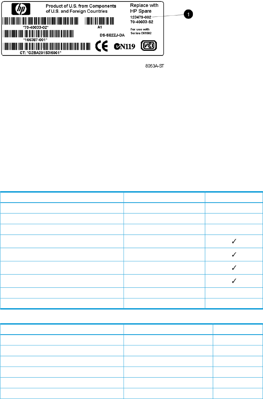
Figure 26 Typical product label
1. Spare part number
Replaceable parts
This product contains the replaceable parts listed in Table 13 (page 77) and Table 20 (page 77).
Parts that are available for customer self repair (CSR) are indicated as follows:
✓ Mandatory CSR where geography permits. Order the part directly from HP and repair the
product yourself. On-site or return-to-depot repair is not provided under warranty.
• Optional CSR. You can order the part directly from HP and repair the product yourself, or you
can request that HP repair the product. If you request repair from HP, you may be charged for the
repair depending on the product warranty.
-- No CSR. The replaceable part is not available for self repair. For assistance, contact an
HP-authorized service provider.
Table 13 Controller enclosure replacement parts
CSR statusSpare part numberDescription
•512730–00110 port controller, 4GB total cache (HSV400)
•512731–00112 port controller, 7GB Total Cache (HSV450)
•512732–00112 port t controller, 11GB Total Cache (HSV450)
512735-001Array battery
489883–001Array power supply
483017–001Array fan module
508563–001OCP module
--512733–001Memory board: cache line flush 10 port
--512734–001Memory board: cache line flush 12 port
Table 20 M6412-A disk enclosure replaceable parts
CSR statusSpare part numberDescription
•461492–0054 Gb FC disk shelf midplane
•461493–0054 Gb FC disk shelf backplane
•399053–001SPS-BD Front UID
•399054–001SPS-BD Power UID with cable
•399055–001SPS-BD Front UID Interconnect PCA with cable
•461494–0054 Gb FC disk shelf I/O module
Replaceable parts 77

Table 20 M6412-A disk enclosure replaceable parts (continued)
CSR statusSpare part numberDescription
468715–001FC disk shelf fan module
405914–001FC disk shelf power supply
537582-001Disk drive 300 GB, 10K, EVA M6412–A Enclosure,
Fibre Channel
518734-001Disk drive 450 GB, 10K, EVA M6412–A Enclosure,
Fibre Channel
518735-001Disk drive 600 GB, 10K, EVA M6412–A Enclosure,
Fibre Channel
454410–001Disk drive 146 GB, 15K, EVA M6412–A Enclosure,
Fibre Channel
454411–001Disk drive 300 GB, 15K, EVA M6412–A Enclosure,
Fibre Channel
466277–001Disk drive 400 GB, 15K, EVA M6412–A Enclosure,
Fibre Channel
454412–001Disk drive 450 GB, 15K, EVA M6412–A Enclosure,
Fibre Channel
495808-001Disk drive 600 GB, 15K, EVA M6412–A Enclosure,
Fibre Channel
454414–001Disk drive 1 TB, 7.2K, EVA M6412-A Enclosure, FATA
515189–001Disk drive 72 GB, EVA M6412–A Enclosure, SSD
595336-001Disk drive 200 GB, EVA M6412–A Enclosure, SSD
595337-001Disk drive 400 GB, EVA M6412–A Enclosure, SSD
•432374-001SPS-CABLE ASSY, 4Gb COPPER, FC, 2.0m
•432375-001SPS-CABLE ASSY, 4Gb COPPER, FC, 0.6m
•496917-001SPS-CABLE ASSY, 4Gb COPPER, FC, 0.41m
For more information about CSR, contact your local service provider. For North America, see the
CSR website:
http://www.hp.com/go/selfrepair
To determine the warranty service provided for this product, see the warranty information website:
http://www.hp.com/go/storagewarranty
To order a replacement part, contact an HP-authorized service provider or see the HP Parts Store
online:
http://www.hp.com/buy/parts
78 Customer replaceable units

Replacing the failed component
CAUTION: Components can be damaged by electrostatic discharge. Use proper anti-static
protection.
•Always transport and store CRUs in an ESD protective enclosure.
•Do not remove the CRU from the ESD protective enclosure until you are ready to install it.
•Always use ESD precautions, such as a wrist strap, heel straps on conductive flooring, and
an ESD protective smock when handling ESD sensitive equipment.
•Avoid touching the CRU connector pins, leads, or circuitry.
•Do not place ESD generating material such as paper or non anti-static (pink) plastic in an ESD
protective enclosure with ESD sensitive equipment.
•HP recommends waiting until periods of low storage system activity to replace a component.
•When replacing components at the rear of the rack, cabling may obstruct access to the
component. Carefully move any cables out of the way to avoid loosening any connections.
In particular, avoid cable damage that may be caused by:
◦Kinking or bending.
◦Disconnecting cables without capping. If uncapped, cable performance may be impaired
by contact with dust, metal or other surfaces.
◦Placing removed cables on the floor or other surfaces, where they may be walked on or
otherwise compressed.
Replacement instructions
Printed instructions are shipped with the replacement part. Instructions for all replaceable components
are also included on the documentation CD that ships with the EVA6400/8400 and posted on
the web. For the latest information, HP recommends that you obtain the instructions from the web.
Go to the following website: http://www.hp.com/support/manuals. Under Storage, select Disk
Storage Systems, then select HP 6400/8400 Enterprise Virtual Arrays under P6000/EVA Disk
Arrays. The manuals page for the EVA6400/8400 appears. Scroll to the Service and maintenance
information section where the replacement instructions are posted.
•HP controller enclosure replacement instructions
•HP cache battery replacement instructions
•HP controller blower replacement instructions
•HP power supply replacement instructions
•HP operator control panel replacement instructions
•HP disk enclosure backplane replacement instructions
•HP disk enclosure fan module replacement instructions
•HP disk enclosure front UID interconnect board (with cable) replacement instructions
•HP disk enclosure front UID replacement instructions
•HP disk enclosure I/O module replacement instructions
•HP disk enclosure midplane replacement instructions
•HP disk enclosure power supply replacement instructions
Replacing the failed component 79

6 Support and other resources
Contacting HP
For worldwide technical support information, see the HP support website:
http://www.hp.com/support
Before contacting HP, collect the following information:
•Product model names and numbers
•Technical support registration number (if applicable)
•Product serial numbers
•Error messages
•Operating system type and revision level
•Detailed questions
Subscription service
HP recommends that you register your product at the Subscriber's Choice for Business website:
http://www.hp.com/go/e-updates
After registering, you will receive e-mail notification of product enhancements, new driver versions,
firmware updates, and other product resources.
Documentation feedback
HP welcomes your feedback.
To make comments and suggestions about product documentation, please send a message to
storagedocsFeedback@hp.com. All submissions become the property of HP.
Related information
Documents
TYou can find the documents referenced in this guide on the Manuals page of the Business Support
Center website:
http://www.hp.com/support/manuals
In the Storage section, click Disk Storage Systems or Storage Software and then select your product.
HP websites
For additional information, see the following HP websites:
•HP:
http://www.hp.com
•HP Storage:
http://www.hp.com/go/storage
•HP Partner Locator:
http://www.hp.com/service_locator
•HP Software Downloads:
http://www.hp.com/support/downloads
80 Support and other resources

•HP Software Depot:
http://www.software.hp.com
•HP Single Point of Connectivity Knowledge (SPOCK):
http://www.hp.com/storage/spock
•HP SAN manuals:
http://www.hp.com/go/sdgmanuals
Typographic conventions
Table 21 Document conventions
ElementConvention
Cross-reference linksBlue text: Table 21 (page 81)
Website addressesBlue, underlined text: http://www.hp.com
Bold text •Keys that are pressed
•Text typed into a GUI element, such as a box
•GUI elements that are clicked or selected, such as menu
and list items, buttons, tabs, and check boxes
Text emphasisItalic text
Monospace text •File and directory names
•System output
•Code
•Commands, their arguments, and argument values
Monospace, italic text •Code variables
•Command variables
Emphasized monospace textMonospace, bold text
Indication that the example continues.
.
.
An alert that calls attention to important information that if
not understood or followed can result in personal injury.
WARNING!
An alert that calls attention to important information that if
not understood or followed can result in data loss, data
corruption, or damage to hardware or software.
CAUTION:
An alert that calls attention to essential information.
IMPORTANT:
An alert that calls attention to additional or supplementary
information.
NOTE:
An alert that calls attention to helpful hints and shortcuts.
TIP:
Typographic conventions 81

Rack stability
Rack stability protects personnel and equipment.
WARNING! To reduce the risk of personal injury or damage to equipment:
•Extend leveling jacks to the floor.
•Ensure that the full weight of the rack rests on the leveling jacks.
•Install stabilizing feet on the rack.
•In multiple-rack installations, fasten racks together securely.
•Extend only one rack component at a time. Racks can become unstable if more than one
component is extended.
Customer self repair
HP customer self repair (CSR) programs allow you to repair your product. If a CSR part needs
replacing, HP ships the part directly to you so that you can install it at your convenience. Some
parts do not qualify for CSR. Your HP-authorized service provider will determine whether a repair
can be accomplished by CSR.
For more information about CSR, contact your local service provider, or see the CSR website:
http://www.hp.com/go/selfrepair
82 Support and other resources

A Regulatory compliance notices
Regulatory compliance identification numbers
For the purpose of regulatory compliance certifications and identification, this product has been
assigned a unique regulatory model number. The regulatory model number can be found on the
product nameplate label, along with all required approval markings and information. When
requesting compliance information for this product, always refer to this regulatory model number.
The regulatory model number is not the marketing name or model number of the product.
Product specific information:
HP ________________
Regulatory model number: _____________
FCC and CISPR classification: _____________
These products contain laser components. See Class 1 laser statement in the “Laser compliance
notices” (page 87) section.
Federal Communications Commission notice
Part 15 of the Federal Communications Commission (FCC) Rules and Regulations has established
Radio Frequency (RF) emission limits to provide an interference-free radio frequency spectrum.
Many electronic devices, including computers, generate RF energy incidental to their intended
function and are, therefore, covered by these rules. These rules place computers and related
peripheral devices into two classes, A and B, depending upon their intended installation. Class A
devices are those that may reasonably be expected to be installed in a business or commercial
environment. Class B devices are those that may reasonably be expected to be installed in a
residential environment (for example, personal computers). The FCC requires devices in both classes
to bear a label indicating the interference potential of the device as well as additional operating
instructions for the user.
FCC rating label
The FCC rating label on the device shows the classification (A or B) of the equipment. Class B
devices have an FCC logo or ID on the label. Class A devices do not have an FCC logo or ID on
the label. After you determine the class of the device, refer to the corresponding statement.
Class A equipment
This equipment has been tested and found to comply with the limits for a Class A digital device,
pursuant to Part 15 of the FCC rules. These limits are designed to provide reasonable protection
against harmful interference when the equipment is operated in a commercial environment. This
equipment generates, uses, and can radiate radio frequency energy and, if not installed and used
in accordance with the instructions, may cause harmful interference to radio communications.
Operation of this equipment in a residential area is likely to cause harmful interference, in which
case the user will be required to correct the interference at personal expense.
Class B equipment
This equipment has been tested and found to comply with the limits for a Class B digital device,
pursuant to Part 15 of the FCC Rules. These limits are designed to provide reasonable protection
against harmful interference in a residential installation. This equipment generates, uses, and can
radiate radio frequency energy and, if not installed and used in accordance with the instructions,
may cause harmful interference to radio communications. However, there is no guarantee that
interference will not occur in a particular installation. If this equipment does cause harmful
interference to radio or television reception, which can be determined by turning the equipment
Regulatory compliance identification numbers 83
off and on, the user is encouraged to try to correct the interference by one or more of the following
measures:
•Reorient or relocate the receiving antenna.
•Increase the separation between the equipment and receiver.
•Connect the equipment into an outlet on a circuit that is different from that to which the receiver
is connected.
•Consult the dealer or an experienced radio or television technician for help.
Declaration of Conformity for products marked with the FCC logo, United States only
This device complies with Part 15 of the FCC Rules. Operation is subject to the following two
conditions: (1) this device may not cause harmful interference, and (2) this device must accept any
interference received, including interference that may cause undesired operation.
For questions regarding this FCC declaration, contact us by mail or telephone:
•Hewlett-Packard Company P.O. Box 692000, Mail Stop 510101 Houston, Texas 77269-2000
•Or call 1-281-514-3333
Modification
The FCC requires the user to be notified that any changes or modifications made to this device
that are not expressly approved by Hewlett-Packard Company may void the user's authority to
operate the equipment.
Cables
When provided, connections to this device must be made with shielded cables with metallic RFI/EMI
connector hoods in order to maintain compliance with FCC Rules and Regulations.
Canadian notice (Avis Canadien)
Class A equipment
This Class A digital apparatus meets all requirements of the Canadian Interference-Causing
Equipment Regulations.
Cet appareil numérique de la class A respecte toutes les exigences du Règlement sur le matériel
brouilleur du Canada.
Class B equipment
This Class B digital apparatus meets all requirements of the Canadian Interference-Causing
Equipment Regulations.
Cet appareil numérique de la class B respecte toutes les exigences du Règlement sur le matériel
brouilleur du Canada.
European Union notice
This product complies with the following EU directives:
•Low Voltage Directive 2006/95/EC
•EMC Directive 2004/108/EC
Compliance with these directives implies conformity to applicable harmonized European standards
(European Norms) which are listed on the EU Declaration of Conformity issued by Hewlett-Packard
for this product or product family.
84 Regulatory compliance notices
This compliance is indicated by the following conformity marking placed on the product:
This marking is valid for non-Telecom products and EU
harmonized Telecom products (e.g., Bluetooth).
Certificates can be obtained from http://www.hp.com/go/certificates.
Hewlett-Packard GmbH, HQ-TRE, Herrenberger Strasse 140, 71034 Boeblingen, Germany
Japanese notices
Japanese VCCI-A notice
Japanese VCCI-B notice
Japanese VCCI marking
Japanese power cord statement
Korean notices
Class A equipment
Japanese notices 85
Class B equipment
Taiwanese notices
BSMI Class A notice
Taiwan battery recycle statement
Turkish recycling notice
Türkiye Cumhuriyeti: EEE Yönetmeliğine Uygundur
Vietnamese Information Technology and Communications compliance
marking
86 Regulatory compliance notices
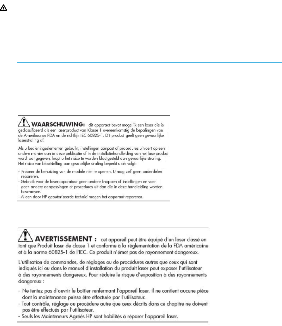
Laser compliance notices
English laser notice
This device may contain a laser that is classified as a Class 1 Laser Product in accordance with
U.S. FDA regulations and the IEC 60825-1. The product does not emit hazardous laser radiation.
WARNING! Use of controls or adjustments or performance of procedures other than those
specified herein or in the laser product's installation guide may result in hazardous radiation
exposure. To reduce the risk of exposure to hazardous radiation:
•Do not try to open the module enclosure. There are no user-serviceable components inside.
•Do not operate controls, make adjustments, or perform procedures to the laser device other
than those specified herein.
•Allow only HP Authorized Service technicians to repair the unit.
The Center for Devices and Radiological Health (CDRH) of the U.S. Food and Drug Administration
implemented regulations for laser products on August 2, 1976. These regulations apply to laser
products manufactured from August 1, 1976. Compliance is mandatory for products marketed in
the United States.
Dutch laser notice
French laser notice
Laser compliance notices 87
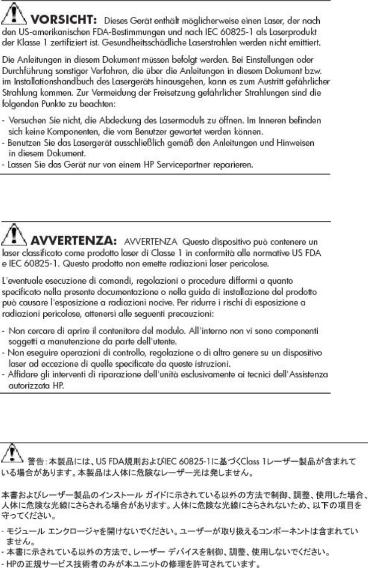
German laser notice
Italian laser notice
Japanese laser notice
88 Regulatory compliance notices
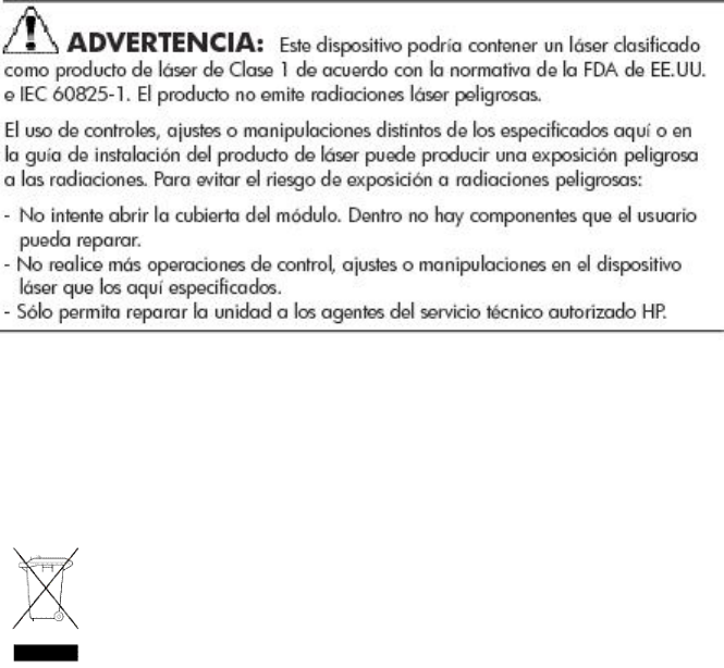
Spanish laser notice
Recycling notices
English recycling notice
Disposal of waste equipment by users in private household in the European Union
This symbol means do not dispose of your product with your other household waste. Instead, you should
protect human health and the environment by handing over your waste equipment to a designated
collection point for the recycling of waste electrical and electronic equipment. For more information,
please contact your household waste disposal service
Recycling notices 89

Bulgarian recycling notice
Изхвърляне на отпадъчно оборудване от потребители в частни домакинства в Европейския
съюз
Този символ върху продукта или опаковката му показва, че продуктът не трябва да се изхвърля заедно
с другите битови отпадъци. Вместо това, трябва да предпазите човешкото здраве и околната среда,
като предадете отпадъчното оборудване в предназначен за събирането му пункт за рециклиране на
неизползваемо електрическо и електронно борудване. За допълнителна информация се свържете с
фирмата по чистота, чиито услуги използвате.
Czech recycling notice
Likvidace zařízení v domácnostech v Evropské unii
Tento symbol znamená, že nesmíte tento produkt likvidovat spolu s jiným domovním odpadem. Místo
toho byste měli chránit lidské zdraví a životní prostředí tím, že jej předáte na k tomu určené sběrné
pracoviště, kde se zabývají recyklací elektrického a elektronického vybavení. Pro více informací kontaktujte
společnost zabývající se sběrem a svozem domovního odpadu.
Danish recycling notice
Bortskaffelse af brugt udstyr hos brugere i private hjem i EU
Dette symbol betyder, at produktet ikke må bortskaffes sammen med andet husholdningsaffald. Du skal
i stedet den menneskelige sundhed og miljøet ved at afl evere dit brugte udstyr på et dertil beregnet
indsamlingssted for af brugt, elektrisk og elektronisk udstyr. Kontakt nærmeste renovationsafdeling for
yderligere oplysninger.
Dutch recycling notice
Inzameling van afgedankte apparatuur van particuliere huishoudens in de Europese Unie
Dit symbool betekent dat het product niet mag worden gedeponeerd bij het overige huishoudelijke afval.
Bescherm de gezondheid en het milieu door afgedankte apparatuur in te leveren bij een hiervoor bestemd
inzamelpunt voor recycling van afgedankte elektrische en elektronische apparatuur. Neem voor meer
informatie contact op met uw gemeentereinigingsdienst.
90 Regulatory compliance notices

Estonian recycling notice
Äravisatavate seadmete likvideerimine Euroopa Liidu eramajapidamistes
See märk näitab, et seadet ei tohi visata olmeprügi hulka. Inimeste tervise ja keskkonna säästmise nimel
tuleb äravisatav toode tuua elektriliste ja elektrooniliste seadmete käitlemisega egelevasse kogumispunkti.
Küsimuste korral pöörduge kohaliku prügikäitlusettevõtte poole.
Finnish recycling notice
Kotitalousjätteiden hävittäminen Euroopan unionin alueella
Tämä symboli merkitsee, että laitetta ei saa hävittää muiden kotitalousjätteiden mukana. Sen sijaan sinun
on suojattava ihmisten terveyttä ja ympäristöä toimittamalla käytöstä poistettu laite sähkö- tai
elektroniikkajätteen kierrätyspisteeseen. Lisätietoja saat jätehuoltoyhtiöltä.
French recycling notice
Mise au rebut d'équipement par les utilisateurs privés dans l'Union Européenne
Ce symbole indique que vous ne devez pas jeter votre produit avec les ordures ménagères. Il est de
votre responsabilité de protéger la santé et l'environnement et de vous débarrasser de votre équipement
en le remettant à une déchetterie effectuant le recyclage des équipements électriques et électroniques.
Pour de plus amples informations, prenez contact avec votre service d'élimination des ordures ménagères.
German recycling notice
Entsorgung von Altgeräten von Benutzern in privaten Haushalten in der EU
Dieses Symbol besagt, dass dieses Produkt nicht mit dem Haushaltsmüll entsorgt werden darf. Zum
Schutze der Gesundheit und der Umwelt sollten Sie stattdessen Ihre Altgeräte zur Entsorgung einer dafür
vorgesehenen Recyclingstelle für elektrische und elektronische Geräte übergeben. Weitere Informationen
erhalten Sie von Ihrem Entsorgungsunternehmen für Hausmüll.
Recycling notices 91

Greek recycling notice
Απόρριψη άχρηοτου εξοπλισμού από ιδιώτες χρήστες στην Ευρωπαϊκή Ένωση
Αυτό το σύμβολο σημαίνει ότι δεν πρέπει να απορρίψετε το προϊόν με τα λοιπά οικιακά απορρίμματα.
Αντίθετα, πρέπει να προστατέψετε την ανθρώπινη υγεία και το περιβάλλον παραδίδοντας τον άχρηστο
εξοπλισμό σας σε εξουσιοδοτημένο σημείο συλλογής για την ανακύκλωση άχρηστου ηλεκτρικού και
ηλεκτρονικού εξοπλισμού. Για περισσότερες πληροφορίες, επικοινωνήστε με την υπηρεσία απόρριψης
απορριμμάτων της περιοχής σας.
Hungarian recycling notice
A hulladék anyagok megsemmisítése az Európai Unió háztartásaiban
Ez a szimbólum azt jelzi, hogy a készüléket nem szabad a háztartási hulladékkal együtt kidobni. Ehelyett
a leselejtezett berendezéseknek az elektromos vagy elektronikus hulladék átvételére kijelölt helyen történő
beszolgáltatásával megóvja az emberi egészséget és a környezetet.További információt a helyi
köztisztasági vállalattól kaphat.
Italian recycling notice
Smaltimento di apparecchiature usate da parte di utenti privati nell'Unione Europea
Questo simbolo avvisa di non smaltire il prodotto con i normali rifi uti domestici. Rispettare la salute
umana e l'ambiente conferendo l'apparecchiatura dismessa a un centro di raccolta designato per il
riciclo di apparecchiature elettroniche ed elettriche. Per ulteriori informazioni, rivolgersi al servizio per
lo smaltimento dei rifi uti domestici.
Latvian recycling notice
Europos Sąjungos namų ūkio vartotojų įrangos atliekų šalinimas
Šis simbolis nurodo, kad gaminio negalima išmesti kartu su kitomis buitinėmis atliekomis. Kad
apsaugotumėte žmonių sveikatą ir aplinką, pasenusią nenaudojamą įrangą turite nuvežti į elektrinių ir
elektroninių atliekų surinkimo punktą. Daugiau informacijos teiraukitės buitinių atliekų surinkimo tarnybos.
92 Regulatory compliance notices

Lithuanian recycling notice
Nolietotu iekārtu iznīcināšanas noteikumi lietotājiem Eiropas Savienības privātajās mājsaimniecībās
Šis simbols norāda, ka ierīci nedrīkst utilizēt kopā ar citiem mājsaimniecības atkritumiem. Jums jārūpējas
par cilvēku veselības un vides aizsardzību, nododot lietoto aprīkojumu otrreizējai pārstrādei īpašā lietotu
elektrisko un elektronisko ierīču savākšanas punktā. Lai iegūtu plašāku informāciju, lūdzu, sazinieties ar
savu mājsaimniecības atkritumu likvidēšanas dienestu.
Polish recycling notice
Utylizacja zużytego sprzętu przez użytkowników w prywatnych gospodarstwach domowych w
krajach Unii Europejskiej
Ten symbol oznacza, że nie wolno wyrzucać produktu wraz z innymi domowymi odpadkami.
Obowiązkiem użytkownika jest ochrona zdrowa ludzkiego i środowiska przez przekazanie zużytego
sprzętu do wyznaczonego punktu zajmującego się recyklingiem odpadów powstałych ze sprzętu
elektrycznego i elektronicznego. Więcej informacji można uzyskać od lokalnej firmy zajmującej wywozem
nieczystości.
Portuguese recycling notice
Descarte de equipamentos usados por utilizadores domésticos na União Europeia
Este símbolo indica que não deve descartar o seu produto juntamente com os outros lixos domiciliares.
Ao invés disso, deve proteger a saúde humana e o meio ambiente levando o seu equipamento para
descarte em um ponto de recolha destinado à reciclagem de resíduos de equipamentos eléctricos e
electrónicos. Para obter mais informações, contacte o seu serviço de tratamento de resíduos domésticos.
Romanian recycling notice
Casarea echipamentului uzat de către utilizatorii casnici din Uniunea Europeană
Acest simbol înseamnă să nu se arunce produsul cu alte deşeuri menajere. În schimb, trebuie să protejaţi
sănătatea umană şi mediul predând echipamentul uzat la un punct de colectare desemnat pentru reciclarea
echipamentelor electrice şi electronice uzate. Pentru informaţii suplimentare, vă rugăm să contactaţi
serviciul de eliminare a deşeurilor menajere local.
Recycling notices 93

Slovak recycling notice
Likvidácia vyradených zariadení používateľmi v domácnostiach v Európskej únii
Tento symbol znamená, že tento produkt sa nemá likvidovať s ostatným domovým odpadom. Namiesto
toho by ste mali chrániť ľudské zdravie a životné prostredie odovzdaním odpadového zariadenia na
zbernom mieste, ktoré je určené na recykláciu odpadových elektrických a elektronických zariadení.
Ďalšie informácie získate od spoločnosti zaoberajúcej sa likvidáciou domového odpadu.
Spanish recycling notice
Eliminación de los equipos que ya no se utilizan en entornos domésticos de la Unión Europea
Este símbolo indica que este producto no debe eliminarse con los residuos domésticos. En lugar de ello,
debe evitar causar daños a la salud de las personas y al medio ambiente llevando los equipos que no
utilice a un punto de recogida designado para el reciclaje de equipos eléctricos y electrónicos que ya
no se utilizan. Para obtener más información, póngase en contacto con el servicio de recogida de
residuos domésticos.
Swedish recycling notice
Hantering av elektroniskt avfall för hemanvändare inom EU
Den här symbolen innebär att du inte ska kasta din produkt i hushållsavfallet. Värna i stället om natur
och miljö genom att lämna in uttjänt utrustning på anvisad insamlingsplats. Allt elektriskt och elektroniskt
avfall går sedan vidare till återvinning. Kontakta ditt återvinningsföretag för mer information.
Battery replacement notices
Dutch battery notice
94 Regulatory compliance notices
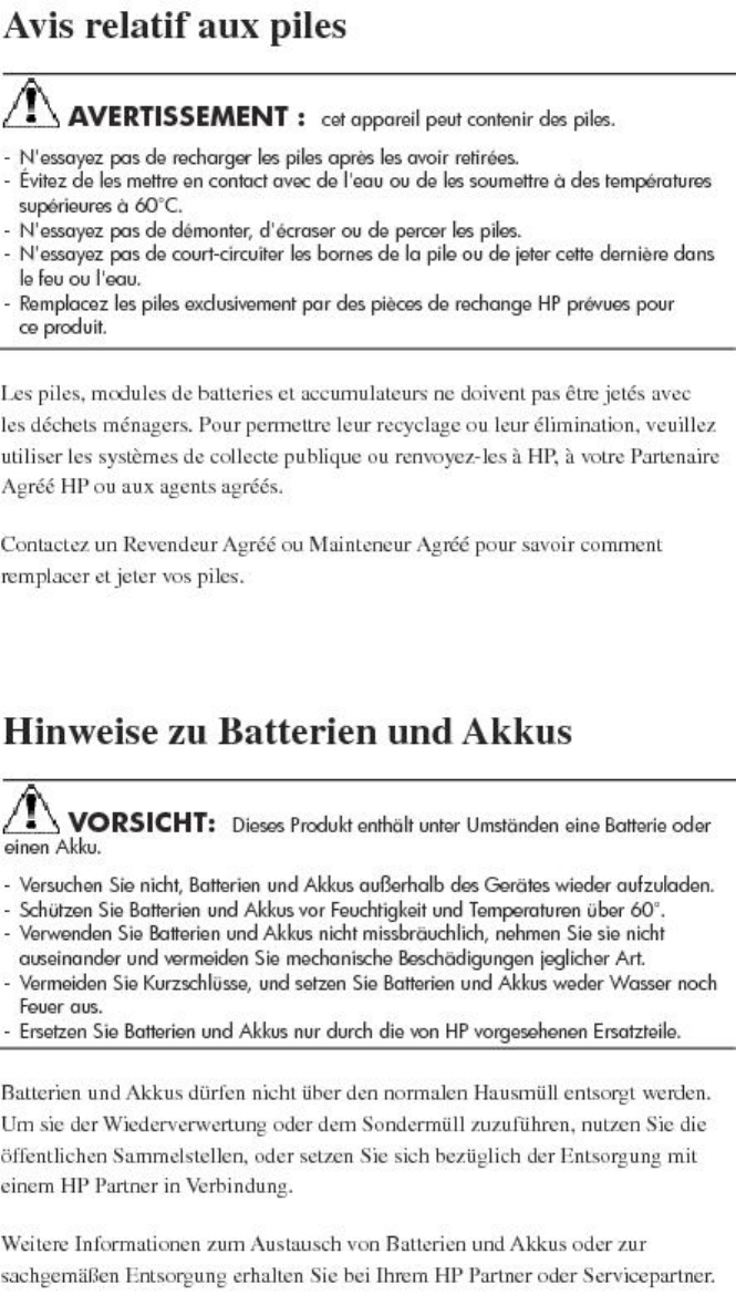
French battery notice
German battery notice
Battery replacement notices 95
Italian battery notice
Japanese battery notice
96 Regulatory compliance notices

Spanish battery notice
Battery replacement notices 97

B Error messages
This list of error messages is in order by status code value, 0 to xxx.
Table 22 Error Messages
How to CorrectMeaningStatus Code Value
No corrective action required.The SCMI command completed successfully.0
Successful Status
Delete the associated object and try
the operation again. Several situations
can cause this message:
Presenting a LUN to a host:
•Delete the current association or
specify a different LUN number.
Storage cell initialize:
•Remove or erase disk volumes
before the storage cell can be
successfully created.
Adding a port WWN to a host:
•Specify a different port WWN.
Adding a disk to a disk group:
•Delete the specified disk volume
before creating a new disk volume.
The object or relationship already exists.1
Object Already Exists
Report the error to product support.The command or response buffer is not large
enough to hold the specified number of
2
Supplied Buffer Too Small items. This can be caused by a user or
program error.
Report the error to product support.The handle is already assigned to an
existing object. This can be caused by a user
or program error.
3
Object Already Assigned
Reclaim some logical space or add
physical hardware.
There is insufficient storage available to
perform the request.
4
Insufficient Available Data
Storage
Report the error to product support.An unexpected condition was encountered
while processing a request.
5
Internal Error
Report the error to product support.This error is no longer supported.6
Invalid status for logical disk
Report the error to product support.The supplied class code is of an unknown
type. This can be caused by a user or
program error.
7
Invalid Class
Report the error to product support.The function code specified with the class
code is of an unknown type.
8
Invalid Function
Report the error to product support.The specified command supplied
unrecognized values. This can indicate a
user or program error.
9
Invalid Logical Disk Block State
Verify the hardware configuration and
retry the request.
The specified request supplied an invalid
loop configuration.
10
Invalid Loop Configuration
Report the error to product support.There are insufficient resources to fulfill the
request, the requested value is not
11
Invalid parameter supported, or the parameters supplied are
invalid. This can indicate a user or program
error.
98 Error messages

Table 22 Error Messages (continued)
How to CorrectMeaningStatus Code Value
In the following cases, the message
can occur because the operation is
The supplied handle is invalid. This can
indicate a user error, program error, or a
storage cell in an uninitialized state.
In the following cases, the storage cell is in
an uninitialized state, but no action is
required:
12
Invalid Parameter handle not allowed when the storage cell is
in an uninitialized state. If you see
these messages, initialize the storage
cell and retry the operation.
Storage cell set device addition policy
Storage cell discard (informational
message): Storage cell set name
Storage cell look up object count
(informational message): Storage cell set time
Storage cell set volume replacement
delayStorage cell look up object (informational
message): Storage cell free command lock
Storage cell set console lun id
Report the error to product support.The supplied identifier is invalid. This can
indicate a user or program error.
13
Invalid Parameter Id
Report the error to product support.Quorum disks from multiple storage systems
are present.
14
Invalid Quorum Configuration
Case 1: Report the error to product
support.
Case 2: To add additional capacity
to the disk group, use the management
The supplied target handle is invalid. This
can indicate a user or program error (Case
1),
or
15
Invalid Target Handle
software to add disks by count or
capacity.
Volume set requested usage (Case 2):
The operation could not be completed
because the disk has never belonged to a
disk group and therefore cannot be added
to a disk group.
Report the error to product support.The supplied target identifier is invalid. This
can indicate a user or program error.
16
Invalid Target Id
Report the error to product support.The time value specified is invalid. This can
indicate a user or program error.
17
Invalid Time
Report the error to product support.The operation could not be completed
because one or more of the disk media was
inaccessible.
18
Media is Inaccessible
Report the error to product support.The Fibre Channel port specified is not valid.
This can indicate a user or program error.
19
No Fibre Channel Port
Report the error to product support.There is no firmware image stored for the
specified image number.
20
No Image
The disk device must be in either
maintenance mode or in a reserved
The disk device is not in a state to allow the
specified operation.
21
No Permission state for the specified operation to
proceed.
Create a storage cell and retry the
operation.
The operation requires a storage cell to exist.22
Storage system not initialized
Report the error to product support.The Fibre Channel port specified is either
not a loop port or is invalid. This can
indicate a user or program error.
23
Not a Loop Port
Verify that the controller is a
participating member of the storage
cell.
The controller must be participating in the
storage cell to perform the operation.
24
Not a Participating Controller
99

Table 22 Error Messages (continued)
How to CorrectMeaningStatus Code Value
Case 1: Either delete the associated
object or resolve the in progress state.
Case 2: . Report the error to product
support.
Several states can cause this message:
Case 1: The operation cannot be performed
because an association exists a related
object, or the object is in a progress state.
25
Objects in your system are in use,
and their state prevents the
operation you wish to perform.
Case 3: Unpresent the LUNs before
deleting this virtual disk.
Derived unit create: Case 2: The supplied
virtual disk handle is already an attribute of
another derived unit. This may indicate a
programming error Case 4: Resolve the delay before
performing the operation.
Derived unit discard: Case 3: One or more
LUNs are presented to EVA hosts that are
based on this virtual disk.
Case 5: Delete any remaining virtual
disks or wait for the used capacity to
reach zero before the disk group can
Case 4: Logical disk clear data lost: The
virtual disk is in the non-mirrored delay
window.
be deleted. If this is the last remaining
disk group, uninitialize the storage cell
to remove it.
Case 5: LDAD discard: The operation cannot
be performed because one or more virtual Case 6: Report the error to product
support.
disks still exist, the disk group still may be Case 7: The disk must be in a reserved
state before it can be erased.
recovering its capacity, or this is the last disk
group that exists. Case 8: Delete the virtual disks or LUN
presentations before uninitializing the
storage cell.
Case 6: LDAD resolve condition: The disk
group contains a disk volume that is in a
data-lost state. This condition cannot be
resolved. Case 9: Delete the LUN presentations
before deleting the EVA host.
Case 7: Physical Store erase volume: The
disk is a part of a disk group and cannot be
erased.
Case 10: Report the error to product
support.
Case 11: Resolve the situation before
attempting the operation again.
Case 8: Storage cell discard: The storage
cell contains one or more virtual disks or
LUN presentations. Case 12: Resolve the situation before
attempting the operation again.
Case 9: Storage cell client discard: = The
EVA host contains one or more LUN
presentations. Case 13: This may indicate a
programming error. Report the error
to product support.
Case 10: SCVD discard: The virtual disk
contains one or more derived units and Case 14: Select another disk or
remove the disk from the disk group
cannot be discarded. This may indicate a
programming error. before making it a member of a
different disk group.
Case 11: SCVD set capacity: The capacity
cannot be modified because the virtual disk Case 15: Remove the virtual disks from
the group and retry the operation.
has a dependency on either a snapshot or
snapclone.
Case 12: SCVD set disk cache policy: The
virtual disk cache policy cannot be modified
while the virtual disk is presented and
enabled.
Case 13: SCVD set logical disk: The logical
disk attribute is already set, or the supplied
logical disk is already a member of another
virtual disk.
Case 14: VOLUME set requested usage: The
disk volume is already a member of a disk
group or is in the state of being removed
from a disk group.
Case 15: GROUP discard: The Continuous
Access group cannot be discarded as one
or more virtual disk members exist.
100 Error messages

Table 22 Error Messages (continued)
How to CorrectMeaningStatus Code Value
Report the error to product support.The operation cannot be performed because
the object does not exist. This can indicate
a user or program error.
VOLUME set requested usage: The disk
volume set requested usage cannot be
26
Parameter Object Does Not Exist
performed because the disk group does not
exist. This can indicate a user or program
error.
Case 1: Report the error to product
support.
Case 2: Retry the request at a later
time.
Case 1: The operation cannot be performed
because the object does not exist. This can
indicate a user or program error.
Case 2: DERIVED UNIT discard: The
operation cannot be performed because the
27
Target Object Does Not Exist
Case 3: Report the error to product
support.
virtual disk, snapshot, or snapclone does not
exist or is still being created. Case 4: Report the error to product
support.
Case 3: VOLUME set requested usage: The
operation cannot be performed because the
target disk volume does not exist. This can
indicate a user or program error.
Case 4: GROUP get name: The operation
cannot be performed because the
Continuous Access group does not exist. This
can indicate a user or program error.
Verify the hardware connections and
that communication to the device is
successful.
A timeout has occurred in processing the
request.
28
Timeout
Report the error to product support.The supplied storage cell identifier is invalid.
This can indicate a user or program error.
29
Unknown Id
Report the error to product support.The supplied parameter handle is unknown.
This can indicate a user or program error.
30
Unknown Parameter Handle
Report the error to product support.The operation could not be completed
because one or more of the disk media had
an unrecoverable error.
31
Unrecoverable Media Error
Report the error to product support.This error is no longer supported.32
Invalid State
Verify the hardware connections,
communication to the device, and that
A SCMI transport error has occurred.33
Transport Error the management software is operating
successfully.
Resolve the condition and retry the
request. Report the error to product
support.
The operation could not be completed
because the drive volume is in a missing
state.
34
Volume is Missing
Report the error to product support.The supplied cursor or sequence number is
invalid. This may indicate a user or program
error.
35
Invalid Cursor
Report the error to product support.The specified target logical disk already has
an existing data sharing relationship. This
can indicate a user or program error.
36
Invalid Target for the Operation
No action required.There are no more events to retrieve. (This
message is informational only.)
37
No More Events
Retry the request at a later time.The command lock is busy and being held
by another process.
38
Lock Busy
101

Table 22 Error Messages (continued)
How to CorrectMeaningStatus Code Value
Report the error to product support.The storage system time is not set. The
storage system time is set automatically by
the management software.
39
Time Not Set
Report the error to product support.The requested operation is not supported by
this firmware version. This can indicate a
user or program error.
40
Not a Supported Version
Report the error to product support.The specified SCVD does not have a logical
disk associated with it. This can indicate a
user or program error.
41
No Logical Disk for Vdisk
Delete the associated presentation(s)
and retry the request.
The virtual disk specified is already
presented to the client and the requested
operation is not allowed.
42
Logical disk Presented
Report the error to product support.The request is not allowed on the slave
controller. This can indicate a user or
program error.
43
Operation Denied On Slave
Report the error to product support.This error is no longer supported.44
Not licensed for data replication
Configure the virtual disk to be a
member of a Continuous Access group
and retry the request.
The operation cannot be performed because
the virtual disk is not a member of a
Continuous Access group.
45
Not DR group member
Configure the Continuous Access
group correctly and retry the request.
The operation cannot be performed because
the Continuous Access group is not in the
required mode.
46
Invalid DR mode
Wait for the copying state to complete
and retry the request.
The operation cannot be performed because
at least one of the virtual disk members is in
a copying state.
47
The target DR member is in full
copy, operation rejected
Use the management software to save
the password specified so
communication can proceed.
The management software is unable to log
in to the storage system. The storage system
password has been configured.
48
Security credentials needed.
Please update your system's ID
and password in the Storage
System Access menu.
Use the management software to set
the password to match the device so
communication can proceed.
The management software is unable to login
to the device. The storage system password
may have been re-configured or removed.
49
Security credentials supplied
were invalid. Please update your
system's ID and password in the
Storage System Access menu.
No action required.The management software is already logged
in to the device. (This message is
informational only.)
50
Security credentials supplied
were invalid. Please update your
system's ID and password in the
Storage System Access menu.
Verify that devices are powered on
and that device hardware connections
are functioning correctly.
The Continuous Access group is not
functioning.
.
51
Storage system connection down
Add one or more virtual disks as
members and retry the request.
No virtual disks are members of the
Continuous Access group.
52
DR group empty
Retry the request with valid attributes
for the operation.
The request cannot be performed because
one or more of the attributes specified is
incompatible.
53
Incompatible attribute
Remove the virtual disk as a member
of a data replication group and retry
the request.
The requested operation cannot be
performed on a virtual disk that is already
a member of a data replication group.
54
Vdisk is a DR group member
102 Error messages

Table 22 Error Messages (continued)
How to CorrectMeaningStatus Code Value
No action required.The requested operation cannot be
performed on a virtual disk that is a log unit.
55
Vdisk is a DR log unit
Report the error to product support.The battery system is missing or discharged.56
Cache batteries failed or missing.
The virtual disk member must be
presented to a client before this
operation can be performed.
The virtual disk member is not presented to
a client.
57
Vdisk is not presented
Report the error to product support.Invalid status for logical disk. This error is
no longer supported.
58
Other controller failed
Case 1: If this operation is still desired,
delete one or more of the items and
retry the operation.
Case 2: If this operation is still desired,
delete one or more of the EVA hosts
and retry the operation.
Case 1: The maximum number of items
allowed has been reached.
Case 2: The maximum number of EVA hosts
has been reached.
Case 3: The maximum number of port
WWNs has been reached.
59
Maximum Number of Objects
Exceeded.
Case 3: If this operation is still desired,
delete one or more of the port WWNs
and retry the operation.
Case 1: If this operation is still desired,
delete one or more of the items on the
Case 1: The maximum number of items
already exist on the destination storage cell.
Case 2: The size specified exceeds the
maximum size allowed.
60
Max size exceeded destination storage cell and retry the
operation.
Case 2: Use a smaller size and retry
the operation.
Case 3: The presented user space exceeds
the maximum size allowed. Case 3: No action required.
Case 4: The presented user space exceeds
the maximum size allowed. Case 4: No action required.
Case 5: The size specified exceeds the
maximum size allowed.
Case 6: The maximum number of EVA hosts
already exist on the destination storage cell.
Case 5: Use a smaller size and try this
operation again.
Case 6: If this operation is still desired,
delete one or more of the EVA hosts
and retry the operation.
Case 7: The maximum number of EVA hosts
already exist on the destination storage cell. Case 7: If this operation is still desired,
delete one or more of the virtual disks
Case 8: The maximum number of Continuous
Access groups already exist. on the destination storage cell and
retry the operation.
Case 8: If this operation is still desired,
delete one or more of the groups and
retry the operation.
Reconfigure one of the storage system
controller passwords, then use the
The login password entered on the
controllers does not match.
61
Password mismatch. Please
update your system's password management software to set the
in the Storage System Access password to match the device so
communication can proceed.menu. Continued attempts to
access this storage system with
an incorrect password will
disable management of this
storage system.
Wait for the merge operation to
complete and retry the request.
The operation cannot be performed because
the Continuous Access connection is
currently merging.
62
DR group is merging
Wait for the logging operation to
complete and retry the request.
The operation cannot be performed because
the Continuous Access connection is
currently logging.
63
DR group is logging
103

Table 22 Error Messages (continued)
How to CorrectMeaningStatus Code Value
Resolve the suspended mode and retry
the request.
The operation cannot be performed because
the Continuous Access connection is
currently suspended
64
Connection is suspended
Retrieve a valid firmware image file
and retry the request.
The firmware image file has a header
checksum error.
65
Bad image header
Retrieve a valid firmware image file
and retry the request.
The firmware image file has a checksum
error.
66
Bad image
Retrieve a valid firmware image file
and retry the request.
Invalid status for logical disk. This error is
no longer supported.
67 The firmware image file is too
large.
Image too large
Retrieve a valid firmware image file
and retry the request
The firmware image file is incompatible with
the current firmware.
70
Image incompatible with system
configuration. Version conflict in
upgrade or downgrade not
allowed.
Verify that the firmware image is not
corrupted and retry the firmware
download process.
The firmware image download process has
failed because of a corrupted image
segment.
71
Bad image segment
No action required.The firmware version already exists on the
device.
72
Image already loaded
Verify that the firmware image is not
corrupted and retry the firmware
download process.
The firmware image download process has
failed because of a failed write operation.
73
Image Write Error
Case 1: No action required.
Case 2: No action required.
Case 1: The operation cannot be performed
because the virtual disk or snapshot is part
of a snapshot group.
Case 2: The operation may be prevented
because a snapclone or snapshot operation
74
Logical Disk Sharing
Case 3: If a snapclone operation is in
progress, wait until the snapclone
operation has completed and retry the
is in progress. If a snapclone operation is in operation. Otherwise, the operation
progress, the parent virtual disk should be cannot be performed on this virtual
disk.
discarded automatically after the operation
completes. If the parent virtual disk has Case 4: No action required.
snapshots, then you must delete the
snapshots before the parent virtual disk can
be deleted. Case 5: No action required.
Case 3: The operation cannot be performed
because either the previous snapclone
operation is still in progress, or the virtual
disk is already part of a snapshot group.
Case 4: A capacity change is not allowed
on a virtual disk or snapshot that is a part
of a snapshot group.
Case 5: The operation cannot be performed
because the virtual disk or snapshot is a part
of a snapshot group.
Retrieve a valid firmware image file
and retry the request.
The firmware image file is not the correct
size.
75
Bad Image Size
Retry the request once the firmware
download process is complete.
The controller is currently processing a
firmware download. Retry the request once
the firmware download process is complete.
76
The controller is temporarily busy
and it cannot process the request.
Retry the request later.
Report the error to product support.The disk volume specified is in a predictive
failed state.
77
Volume Failure Predicted
104 Error messages

Table 22 Error Messages (continued)
How to CorrectMeaningStatus Code Value
Resolve the condition and retry the
request.
The current condition or state is preventing
the request from completing successfully.
78
Invalid object condition for this
command.
Wait for the operation to complete
and retry the request.
The current condition of the snapshot,
snapclone or parent virtual disk is preventing
the request from completing successfully.
79
Snapshot (or snapclone) deletion
in progress. The requested
operation is currently not
allowed. Please try again later.
Resolve the condition by setting the
usage to a reserved state and 80 retry
the request. Invalid Volume Usage
Case 1: The disk volume is already a part
of a disk group.
80
Invalid Volume Usage
Report the error to product support.Case 2: The disk volume usage cannot be
modified, as the minimum number of disks
exist in the disk group.
Resolve the condition by adding
additional disks and retry the request.
The disk volume usage cannot be modified,
as the minimum number of disks exist in the
disk group.
81
Minimum Volumes In Disk Group
No action required.The controller is currently shutting down.82
Shutdown In Progress
Retry the request at a later time.The device is not ready to process the
request.
83
Controller API Not Ready, Try
Again Later
No action required.This is a snapshot virtual disk and cannot be
a member of a Continuous Access group.
84
Is Snapshot
Modify the mirror policy and retry the
request.
An incompatible mirror policy of the virtual
disk is preventing it from becoming a
member of a Continuous Access group.
85
Cannot add or remove DR group
member. Mirror cache must be
active for this Vdisk. Check
controller cache condition.
Report the error to product support.Case 1: A virtual disk is in an inoperative
state and the request cannot be processed.
86
Command View EVA has
detected this array as Case 2: The snapclone cannot be associated
with a virtual disk that is in an inoperative
inoperative. Contact HP Service
for assistance. state. 86 Command View EVA has detected
this array as inoperative. Contact HP Service
for assistance.
Case 3: The snapshot cannot be associated
with a virtual disk that is in an inoperative
state. Report the error to product support.
Report the error to product support.The disk group is in an inoperative state and
cannot process the request.
87
Disk group inoperative or disks
in group less than minimum.
Report the error to product support.The storage system is inoperative and cannot
process the request.
88
Storage system inoperative
Resolve the condition and retry the
request.
The request cannot be performed because
the Continuous Access group is in a failsafe
locked state.
89
Failsafe Locked
Retry the request later.The disk cache data need to be flushed
before the condition can be resolved.
90
Data Flush Incomplete
105

Table 22 Error Messages (continued)
How to CorrectMeaningStatus Code Value
Report the error to product support.The disk group is in a redundancy mirrored
inoperative state and the request cannot be
completed.
91
Redundancy Mirrored Inoperative
Select another LUN number and retry
the request.
The LUN number is already in use by
another client of the storage system.
92
Duplicate LUN
Resolve the condition and retry the
request. Report the error to product
support.
While the request was being performed, the
remote storage system controller failed.
93
Other remote controller failed
Correctly select the remote storage
system and retry the request.
The remote storage system specified does
not exist.
94
Unknown remote Vdisk
Correctly select the remote Continuous
Access group retry the request.
The remote Continuous Access group
specified does not exist.
95
Unknown remote DR group
Resolve the condition and retry the
request. Report the error to product
support.
The disk metadata was unable to be
updated.
96
PLDMC failed
Retry the request later.Another process has already taken the SCMI
lock on the storage system.
97
Storage system could not be
locked. System busy. Try
command again.
'Resolve the condition and retry the
request
While the request was being performed, an
error occurred on the remote storage system.
98
Error on remote storage system.
Resolve the condition and retry the
request.
The request failed because the operation
cannot be performed on a Continuous
Access connection that is up.
99
The DR operation can only be
completed when the
source-destination connection is
down. If you are doing a
destination DR deletion, make
sure the connection link to the
source DR system is down or do
a failover operation to make this
system the source.
The storage system password may
have been re-configured or removed.
The management software is unable to log
into the device as the password has
changed.
100
Login required - password
changed. The management software must be
used to set the password up to match
the device so communication can
proceed.
106 Error messages

C Controller fault management
This appendix describes how the controller displays events and termination event information.
Termination event information is displayed on the LCD. HP P6000 Command View enables you
to view controller events. This appendix also discusses how to identify and correct problems.
Once you create a storage system, an error condition message has priority over other controller
displays.
HP P6000 Command View provides detailed descriptions of the storage system error conditions,
or faults. The Fault Management displays provide similar information on the LCD, but not in as
much detail. Whenever possible, see HP P6000 Command View for fault information.
Using HP P6000 Command View
HP P6000 Command View provides detailed information about each event affecting system
operation in either a Termination Event display or an Event display. These displays are similar, but
not identical.
GUI termination event display
A problem that generates the Termination Event display prevents the system from performing a
specific function or process. You can use the information in this display (see “GUI termination event
display” (page 107)) to diagnose and correct the problem.
NOTE: The major differences between the Termination Event display and the Event display are:
• The Termination Event display includes a Code Flag field; it does not include the EIP Type field.
• The Event display includes an EIP type field; it does not include a Code Flag field.
• The Event display includes a Corrective Action Code field.
Figure 27 GUI termination event display
DescriptionCode FlagEvt NoSWCIDTimeDate
The fields in the Termination Event display include:
•Date—The date the event occurred.
•Time—The time the event occurred.
•SWCID—Software Identification Code. A hexadecimal number in the range 0–FF that identifies
the controller software component reporting the event.
•Evt No—Event Number. A hexadecimal number in the range 0–FF that is the software
component identification number.
•Code Flag—An internal code that includes a combination of other flags.
•Description—The condition that generated the event. This field may contain information about
an individual field’s content and validity.
GUI event display
A problem that generates the Event display reduces the system capabilities. You can use the
information in this display (see Figure 28 (page 108)) to diagnose and correct problems.
NOTE: The major differences between the Event Display and the Termination Event display are:
• The Event display includes an EIP type field; it does not include a Code Flag field.
• The Event display includes a Corrective Action Code (CAC) field.
• The Termination Event display includes a Code Flag field; it does not include the EIP Type field.
Using HP P6000 Command View 107

Figure 28 Typical HP P6000 Command View Event display
DescriptionEIP TypeCACEvt NoSWCIDTimeDate
The Event display provides the following information:
•Date—The date the event occurred.
•Time—The time the even occurred.
•SWCID—Software Identification Code. A number in the range 1–256 that identifies the internal
firmware module affected.
•Evt No—Event Number. A hexadecimal number in the range 0–FF that is the software
component identification number.
•CAC—Corrective Action Code. A specific action to correct the problem.
•EIP Type—Event Information Packet Type. A hexadecimal character that defines the event
information format.
•Description—The problem that generated the event.
Fault management displays
When you do not have access to the GUI, you can display and analyze termination codes (TCs)
on the OCP LCD display. You can then use the event text code document, as described in the
section titled “Interpreting Fault Management Information” to determine and implement corrective
action. You can also provide this information to the authorized service representative should you
require additional support. This lets the service representative identify the tools and components
required to correct the condition in the shortest possible time.
When the fault management display is active, you can either display the last fault or display
detailed information about the last 32 faults reported.
Displaying Last Fault Information
Complete the following procedure to display Last Fault information
1. When the Fault Management display is active, press to select the Last Fault menu.
2. Press to display the last fault information.
The first line of the TC display contains the eight-character TC error code and the two-character
IDX (index) code. The IDX is a reference to the location in the TC array that contains this error.
The second line of the TC display identifies the affected parameter with a two-character
parameter number (0–30), the eight-character parameter code affected, and the parameter
code number.
3. Press to return to the Last Fault menu.
Displaying Detailed Information
The Detail View menu lets you examine detailed fault information stored in the Last Termination
Event Array (LTEA). This array stores information for the last 32 termination events.
Complete the following procedure to display the LTEA information about any of the last 32
termination events:
1. When the Fault Management display is active (flashing), press to select the Detail View
menu.
The LTEA selection menu is active (LTEA 0 is displayed).
2. Press or to increment to a specific error.
3. Press to observe data about the selected error.
108 Controller fault management

Interpreting fault management information
Each version of HP P6000 Command View includes an ASCII text file that defines all the codes
that the authorized service representative can view either on the GUI or on the OCP.
IMPORTANT: This information is for the exclusive use of the authorized service representative.
The file name identifies the controller model, file type, XCS baselevel id, and XCS version. For
example, the file name hsv210_event_cr08d3_5020.txt provides the following information:
•hsv210_—The EVA controller model number
•event_—The type of information in the file
•w010605_—The base level build string (the file creation date).
01—The creation year◦
◦06—The creation month
◦05—The creation date
•5020—The XCS version
Table 22 (page 109) describes types of information available in this file.
Table 23 Controller event text description file
DescriptionInformation type
This hexadecimal code identifies the reported event type.Event Code
This hexadecimal code specifies the condition that generated the termination
code. It might also define either a system or user initiated corrective action.
Termination Code (TC)
This single digit, decimal character defines the requirement for the other controller
to initiate a coupled crash control.0. Other controller SHOULD NOT complete
a coupled crash.1. Other controller SHOULD complete a coupled crash.
Coupled Crash Control Codes
This single decimal character (0, 1, 3) defines the requirement to:0. Perform a
crash dump and then restart the controller.1. DO NOT perform a crash dump;
Dump/Restart Control Codes
just restart the controller.3. DO NOT perform a crash dump; DO NOT restart
the controller.
These hexadecimal codes supplement the Termination Code information to
identify the faulty element and the recommended corrective action.
Corrective Action Codes (CAC)
These decimal codes identify software associated with the event.Software Component ID Codes
(SWCID)
These codes specify the packet organization for specific type events.Event Information Packets (EIP)
GUI termination event display 109

D Non-standard rack specifications
The appendix provides information on the requirements when installing the 6400/8400 in a
non-standard rack. All the requirements must be met to ensure proper operation of the storage
system.
Rack specifications
Internal component envelope
EVA component mounting brackets require space to be mounted behind the vertical mounting rails.
Room for the mounting of the brackets includes the width of the mounting rails and needed room
for any mounting hardware, such as screws, clip nuts, etc. Figure 29 (page 110) shows the
dimensions required for the mounting space for the EVA product line. It does not show required
space for additional HP components such as servers.
Figure 29 Mounting space dimensions
EIA310-D standards
The rack must meet the Electronic Industries Association, (EIA), Standard 310-D, Cabinets, Racks
and Associated Equipment. The standard defines rack mount spacing and component dimensions
specified in U units.
Copies of the standard are available for purchase at http://www.eia.org/.
EVA cabinet measures and tolerances
EVA component rack mount brackets are designed to fit cabinets with mounting rails set at depths
from 28.25 inches to 29.6 inches, inside rails to inside rails.
Weights, dimensions and component CG measurements
Cabinet CG dimensions are reported as measured from the inside bottom of the cabinet (Z), the
leading edge of the vertical mounting rails (Y), and the centerline of the cabinet mounting space
(X). Component CG measurements are measured from the bottom of the U space the component
is to occupy (Z), the mounting surface of the mounting flanges (Y), and the centerline of the
component (X). Table 24 (page 111) lists the CG dimensions for the EVA components.
Determining the CG of a configuration may be necessary for safety considerations. CG
considerations for CG calculations do not include cables, PDU’s and other peripheral components.
Some consideration should be made to allow for some margin of safety when estimating
configuration CG.
110 Non-standard rack specifications

Estimating the configuration CG requires measuring the CG of the cabinet the product will be
installed in. Use the following formula:
ΣdcomponentW = dsystem cgW
where dcomponent= the distance of interest and W = Weight
The distance of a component is its CG’s distance from the inside base of the cabinet. For example,
if a loaded disk enclosure is to be installed into the cabinet with its bottom at 10U, the distance
for the enclosure would be (10*1.75)+2.7 inches.
Table 24 Component data
Component Data
Z (in)Y (in)X (in)Weight (Lb)U height1
14.2125.75-0.108233HP 10K cabinet CG
02.62501.43Filler panel, 3U
7.952.7-0.288743Fully loaded drive enclosure
00.87500.471Filler panel, 1U
10.642.53-0.0941204Controller pair
11U = 1.75 inches
Airflow and Recirculation
Component Airflow Requirements
Component airflow must be directed from the front of the cabinet to the rear. Components vented
to discharge airflow from the sides must discharge to the rear of the cabinet.
Rack Airflow Requirements
The following requirements must be met to ensure adequate airflow and to prevent damage to the
equipment:
•If the rack includes closing front and rear doors, allow 830 square inches (5,350 sq cm) of
hole evenly distributed from top to bottom to permit adequate airflow (equivalent to the required
64 percent open area for ventilation).
•For side vented components, the clearance between the installed rack component and the
side panels of the rack must be a minimum of 2.75 inches (7 cm).
•Always use blanking panels to fill all empty front panel U-spaces in the rack. This ensures
proper airflow. Using a rack without blanking panels results in improper cooling that can lead
to thermal damage.
Configuration Standards
EVA configurations are designed considering cable length, configuration CG, serviceability and
accessibility, and to allow for easy expansion of the system. If at all possible, it is best to configure
non HP cabinets in a like manner.
Environmental and operating specifications
This section identifies the product environmental and operating specifications.
NOTE: Further testing is required to update the information in Tables 45-47. Once testing is
complete, these tables will be updated in a future release.
UPS Selection
This section provides information that can be used when selecting a UPS for use with the EVA. The
four HP UPS products listed in Table 25 (page 112) are available for use with the EVA and are
Environmental and operating specifications 111

included in this comparison. Table 26 (page 112) identifies the amount of time each UPS can sustain
power under varying loads and with various UPS ERM (Extended Runtime Module) options.
The load imposed on the UPS for different disk enclosure configurations are listed in Table 27 (page
113) and Table 28 (page 113).
NOTE: The specified power requirements reflect fully loaded enclosures (14 disks) .
Table 25 HP UPS models and capacities
Capacity (in watts)UPS Model
1340R1500
2700R3000
4500R5500
12000R12000
Table 26 UPS operating time limits
Minutes of operation
Load (percent) With 2 ERMsWith 1 ERMWith standby battery
R1500
49235100
6332680
161571350
2901463420
R3000
205100
306.580
451250
1204020
R5500
46247100
6031980
106611950
3031695920
R12000
18115100
2415780
41281450
101694320
112 Non-standard rack specifications

Table 27 EVA8400 UPS loading
% of UPS capacity
WattsEnclosures R12000R5500
41.0492012
36.898.1441411
33.689.7403710
30.581.336609
27.473.032848
24.264.629077
21.156.225306
17.947.921535
14.839.517774
11.731.114003
8.522.710232
5.414.46471
Table 28 EVA6400 UPS loading
% of UPS capacity
WattsEnclosures R12000R5500R3000
26.871.432148
23.663.028377
20.554.691.124606
17.346.277.220835
14.237.963.217074
11.129.549.313303
7.921.235.39532
4.812.821.45771
Shock and vibration specifications
Table 29 (page 113) lists the product operating shock and vibration specifications. This information
applies to products weighing 45 Kg (100 lbs) or less.
NOTE: HP EVA P6000 products are designed and tested to withstand the operational shock and
vibration limits specified in Table 29 (page 113). Transmission of site vibrations through non-HP
racks exceeding these limits could cause operational failures of the system components.
Table 29 Operating Shock/Vibration
Shock test with half sine pulses of 10 G magnitude and 10 ms duration applied in all three axes (both positive and
negative directions).
Sine sweep vibration from 5 Hz to 500 Hz to 5 Hz at 0.1 G peak, with 0.020” displacement limitation below 10
Hz. Sweep rate of 1 octave/minute. Test performed in all three axes.
Environmental and operating specifications 113

Table 29 Operating Shock/Vibration (continued)
Random vibration at 0.25 G rms level with uniform spectrum in the frequency range of 10 to 500 Hz. Test performed
for two minutes each in all three axes.
Drives and other items exercised and monitored running appropriate exerciser (UIOX, P-Suite, etc.) with appropriate
operating system and hardware.
114 Non-standard rack specifications

E Single Path Implementation
This appendix provides guidance for connecting servers with a single path host bus adapter (HBA)
to the Enterprise Virtual Array (EVA) storage system with no multi-path software installed. A single
path HBA is defined as an HBA that has a single path to its LUNs. These LUNs are not shared by
any other HBA in the server or in the SAN.
The failure scenarios demonstrate behavior when recommended configurations are employed, as
well as expected failover behavior if guidelines are not met. To implement single adapter servers
into a multi-path EVA environment, configurations should follow these recommendations.
NOTE: The purpose of single HBA configurations for non-mission critical storage access is to
control costs. This appendix describes the configurations, limitations, and failover characteristics
of single HBA servers under different operating systems. Much of the description herein are based
upon a single HBA configuration resulting in a single path to the device, but such is not the case
with OpenVMS and Tru64 UNIX.
HP OpenVMS and Tru64 UNIX have native multi-path features by default.
With OpenVMS and Tru64 UNIX, a single HBA configuration will result in two paths to the device
by virtue of having connections to both EVA controllers. Single HBA configurations are not single
path configurations with these operating systems.
In addition, cluster configurations of both OpenVMS and Tru64 UNIX provide enhanced availability
and security. To achieve availability within cluster configurations, each member should be configured
with its own HBA(s) and connectivity to shared LUNs. Cluster configuration will not be discussed
further within this appendix as the enhanced availability requires both additional server hardware
and HBAs which is contrary to controlling configuration costs for non-mission critical applications.
For further information on cluster configurations and attributes, see the appropriate operating
system guides and the SAN design guide.
NOTE: HP continually makes additions to its storage solution product line. For more information
about the HP Fibre Channel product line, the latest drivers, and technical tips, and to view other
documentation, see the HP website at
http://www.hp.com/country/us/eng/prodserv/storage.html
High-level solution overview
EVA was designed for highly dynamic enterprise environments requiring high data availability,
fault tolerance, and high performance; thus, the EVA controller runs only in multi-path failover
mode. Multi-path failover mode ensures the proper level of fault tolerance for the enterprise with
mission-critical application environments. However, this appendix addresses the need for
non-mission-critical applications to gain access to the EVA system running mission-critical production
applications.
The non-mission-critical applications gain access to the EVA from a single path HBA server without
running a multi-path driver. When a single path HBA server uses the supported configurations, a
fault in the single path HBA server does not result in a fault in the other servers.
Benefits at a glance
The EVA is a high-performance array controller utilizing the benefits of virtualization. Virtualization
within the storage system is ideal for environments needing high performance, high data availability,
fault tolerance, efficient storage management, data replication, and cluster support. However,
enterprise-level data centers incorporate non-mission-critical applications as well as applications
that require high availability.
Single-path capability adds flexibility to budget allocation. There is a per-path savings as the
additional cost of HBAs and multi-path software is removed from non-mission−critical application
requirements. These servers can still gain access to the EVA by using single path HBAs without
multi-path software. This reduces the costs at the server and infrastructure level.
High-level solution overview 115

Installation requirements
•The host must be placed in a zone with any EVA worldwide IDs (WWIDs) that access storage
devices presented by the hierarchical storage virtualization (HSV) controllers to the single path
HBA host. The preferred method is to use HBA and HSV WWIDs in the zone configurations.
•On HP-UX, Solaris, Microsoft Windows Server, Linux, and IBM AIX operating systems, the
zones consist of the single path HBA systems and one HSV controller port.
•On OpenVMS and Tru64 UNIX operating systems, the zones consist of the single HBA systems
and two HSV controller ports. This will result in a configuration where there are two paths per
device, or multiple paths.
Recommended mitigations
EVA is designed for the mission-critical enterprise environment. When used with multi-path software,
high data availability and fault tolerance are achieved. In single path HBA server configurations,
neither multi-path software nor redundant I/O paths are present. Server-based operating systems
are not designed to inherently recover from unexpected failure events in the I/O path (for example,
loss of connectivity between the server and the data storage). It is expected that most operating
systems will experience undesirable behavior when configured in non-high-availability configurations.
Because of the risks of using servers with a single path HBA, HP recommends the following actions:
•Use servers with a single path HBA that are not mission-critical or highly available.
•Perform frequent backups of the single path server and its storage.
Supported configurations
All examples detail a small homogeneous Storage Area Network (SAN) for ease of explanation.
Mixing of dual and single path HBA systems in a heterogeneous SAN is supported. In addition to
this document, reference and adhere to the SAN Design Reference Guide for heterogeneous SANs,
located at:
http://h18006.www1.hp.com/products/storageworks/san/documentation.html
General configuration components
All configurations require the following components:
•Enterprise XCS software
•HBAs
•Fibre Channel switches
Connecting a single path HBA server to a switch in a fabric zone
Each host must attach to one switch (fabric) using standard Fibre Channel cables. Each host has
its single path HBA connected through switches on a SAN to one port of an EVA.
Because a single path HBA server has no software to manage the connection and ensure that only
one controller port is visible to the HBA, the fabric containing the single path HBA server, SAN
switch, and EVA controller must be zoned. Configuring the single path by switch zoning and the
LUNs by Selective Storage Presentation (SSP) allows for multiple single path HBAs to reside in the
same server. A single path HBA server with OpenVMS or Tru64 UNIX operating system should
be zoned with two EVA controllers. See the HP SAN Design Reference Guide at the following HP
website for additional information about zoning:
http://h18006.www1.hp.com/products/storageworks/san/documentation.html
To connect a single path HBA server to a SAN switch:
1. Plug one end of the Fibre Channel cable into the HBA on the server.
2. Plug the other end of the cable into the switch.
Figure 30 (page 117) and Figure 31 (page 118) represent configurations containing both single path
HBA server and dual HBA server, as well as a SAN appliance, connected to redundant SAN
116 Single Path Implementation

switches and EVA controllers. Whereas the dual HBA server has multi-path software that manages
the two HBAs and their connections to the switch (with the exception of OpenVMS and Tru64 UNIX
servers), the single path HBA has no software to perform this function. The dashed line in the figure
represents the fabric zone that must be established for the single path HBA server. Note that in
Figure 31 (page 118), servers with OpenVMS or Tru64 UNIX operating system should be zoned
with two controllers.
Figure 30 Single path HBA server without OpenVMS or Tru64 UNIX
6 SAN switch 21 Network interconnection
7 Fabric zone2 Single HBA server
8 Controller A3 Dual HBA server
9 Controller B4 Management server
5 SAN switch 1
Supported configurations 117
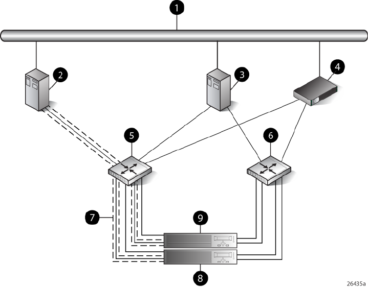
Figure 31 Single path HBA server with OpenVMS or Tru64 UNIX
6 SAN switch 21 Network interconnection
7 Fabric zone2 Single HBA server
8 Controller A3 Dual HBA server
9 Controller B4 Management server
5 SAN switch 1
HP-UX configuration
Requirements
•Proper switch zoning must be used to ensure each single path HBA has an exclusive path to
its LUNs.
•Single path HBA server can be in the same fabric as servers with multiple HBAs.
•Single path HBA server cannot share LUNs with any other HBAs.
•In the use of snapshots and snapclones, the source virtual disk and all associated snapshots
and snapclones must be presented to the single path hosts that are zoned with the same
controller. In the case of snapclones, after the cloning process has completed and the clone
becomes an ordinary virtual disk, you may present that virtual disk as you would any other
ordinary virtual disk.
HBA configuration
•Host 1 is a single path HBA host.
•Host 2 is a multiple HBA host with multi-pathing software.
See Figure 32 (page 119).
118 Single Path Implementation

Risks
•Disabled jobs hang and cannot umount disks.
•Path or controller failure may results in loss of data accessibility and loss of host data that has
not been written to storage.
NOTE: For additional risks, see “HP-UX failure scenarios” (page 131).
Limitations
•HP P6000 Continuous Access is not supported with single-path configurations.
•Single path HBA server is not part of a cluster.
•Booting from the SAN is not supported.
Figure 32 HP-UX configuration
5 SAN switch 11 Network interconnection
6 SAN switch 22 Host 1
7 Controller A3 Host 2
8 Controller B4 Management server
Windows Server (32-bit) configuration
Requirements
•Switch zoning or controller level SSP must be used to ensure each single path HBA has an
exclusive path to its LUNs.
•Single path HBA server can be in the same fabric as servers with multiple HBAs.
•Single path HBA server cannot share LUNs with any other HBAs.
•In the use of snapshots and snapclones, the source virtual disk and all associated snapshots
and snapclones must be presented to the single path hosts that are zoned with the same
controller. In the case of snapclones, after the cloning process has completed and the clone
Supported configurations 119

becomes an ordinary virtual disk, you may present that virtual disk as you would any other
ordinary virtual disk.
HBA configuration
•Host 1 is a single path HBA host.
•Host 2 is a multiple HBA host with multi-pathing software.
See Figure 33 (page 120).
Risks
•Single path failure will result in loss of connection with the storage system.
•Single path failure may cause the server to reboot.
•Controller shutdown puts controller in a failed state that results in loss of data accessibility
and loss of host data that has not been written to storage.
NOTE: For additional risks, see “Windows Server failure scenarios” (page 132).
Limitations
•HP P6000 Continuous Access is not supported with single path configurations.
•Single path HBA server is not part of a cluster.
•Booting from the SAN is not supported on single path HBA servers.
Figure 33 Windows Server (32-bit) configuration
5 SAN switch 11 Network interconnection
6 SAN switch 22 Host 1
7 Controller A3 Host 2
8 Controller B4 Management server
120 Single Path Implementation

Windows Server (64-bit) configuration
Requirements
•Switch zoning or controller level SSP must be used to ensure each single path HBA has an
exclusive path to its LUNs.
•Single path HBA server can be in the same fabric as servers with multiple HBAs.
•Single path HBA server cannot share LUNs with any other HBAs.
HBA configuration
•Hosts 1 and 2 are single path HBA hosts.
•Host 3 is a multiple HBA host with multi-pathing software.
See Figure 34 (page 122).
NOTE: Single path HBA servers running the Windows Server 2003 (x64) operating system will
support multiple single path HBAs in the same server. This is accomplished through a combination
of switch zoning and controller level SSP. Any single path HBA server will support up to four single
path HBAs.
Risks
•Single path failure will result in loss of connection with the storage system.
•Single path failure may cause the server to reboot.
•Controller shutdown puts controller in a failed state that results in loss of data accessibility
and loss of host data that has not been written to storage.
NOTE: For additional risks, see “Windows Server failure scenarios” (page 132).
Limitations
•HP P6000 Continuous Access is not supported with single path configurations.
•Single path HBA server is not part of a cluster.
•Booting from the SAN is not supported on single path HBA servers.
Supported configurations 121
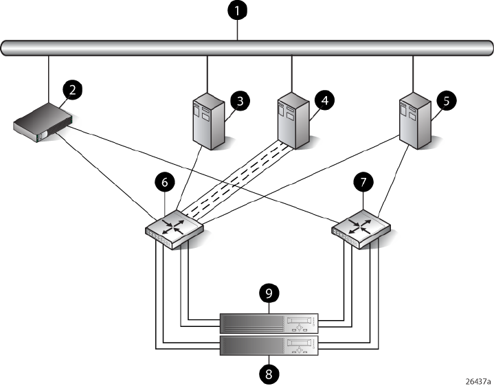
Figure 34 Windows Server (64-bit) configuration
6 SAN switch 11 Network interconnection
7 SAN switch 22 Management server
8 Controller A3 Host 1
9 Controller B4 Host 2
5 Host 3
Oracle Solaris configuration
Requirements
•Switch zoning or controller level SSP must be used to ensure each single path HBA has an
exclusive path to its LUNs.
•Single path HBA server can be in the same fabric as servers with multiple HBAs.
•Single path HBA server cannot share LUNs with any other HBAs.
•In the use of snapshots and snapclones, the source virtual disk and all associated snapshots
and snapclones must be presented to the single path hosts that are zoned with the same
controller. In the case of snapclones, after the cloning process has completed and the clone
becomes an ordinary virtual disk, you may present that virtual disk as you would any other
ordinary virtual disk.
HBA configuration
•Host 1 is a single path HBA host.
•Host 2 is a multiple HBA host with multi-pathing software.
See Figure 35 (page 123).
122 Single Path Implementation

Risks
•Single path failure may result in loss of data accessibility and loss of host data that has not
been written to storage.
•Controller shutdown results in loss of data accessibility and loss of host data that has not been
written to storage.
NOTE: For additional risks, see “Oracle Solaris failure scenarios” (page 132).
Limitations
•HP P6000 Continuous Access is not supported with single path configurations.
•Single path HBA server is not part of a cluster.
•Booting from the SAN is not supported.
Figure 35 Oracle Solaris configuration
5 SAN switch 11 Network interconnection
6 SAN switch 22 Host 1
7 Controller A3 Host 2
8 Controller B4 Management server
Tru64 UNIX configuration
Requirements
•Switch zoning or controller level SSP must be used to ensure each HBA has exclusive access
to its LUNs.
•All nodes with direct connection to a disk must have the same access paths available to them.
•Single HBA server can be in the same fabric as servers with multiple HBAs.
•In the use of snapshots and snapclones, the source virtual disk and all associated snapshots
and snapclones must be presented to the single host that are zoned with the same controller.
Supported configurations 123
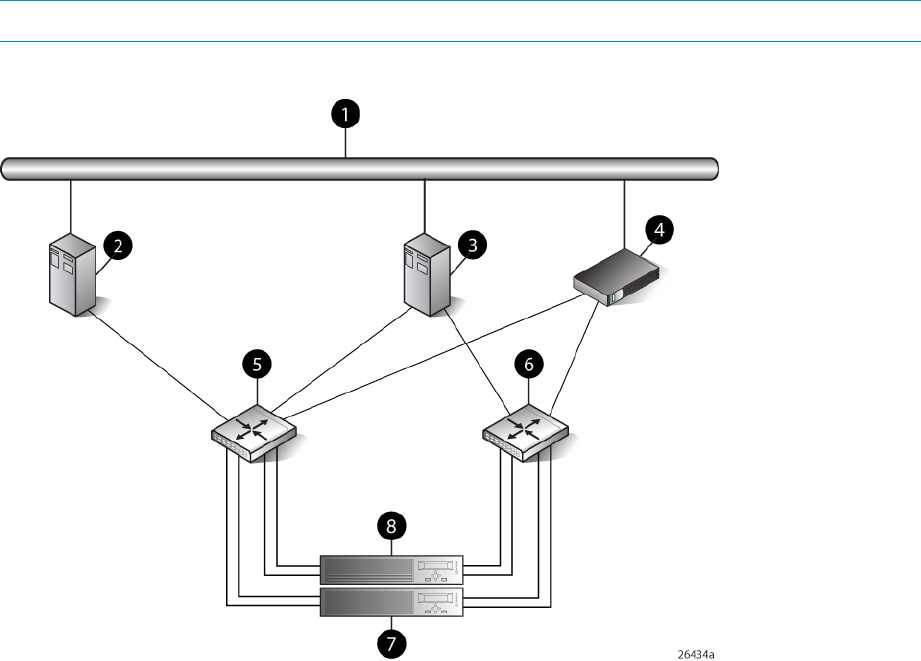
In the case of snapclones, after the cloning process has completed and the clone becomes an
ordinary virtual disk, you may present that virtual disk as you would any other ordinary virtual
disk.
HBA configuration
•Host 1 is single HBA host with Tru64.
•Host 2 is a dual HBA host.
See Figure 36 (page 124).
Risks
•For nonclustered nodes with a single HBA, a path failure from the HBA to the SAN switch will
result in a loss of connection with storage devices.
•If a host crashes or experiences a power failure, or if the path is interrupted, data will be lost.
Upon re-establishment of the path, a retransmit can be performed to recover whatever data
may have been lost during the outage. The option to retransmit data after interruption is
application-dependent.
NOTE: For additional risks, see “OpenVMS and Tru64 UNIX failure scenarios” (page 133).
Figure 36 Tru64 UNIX configuration
5 SAN switch 11 Network interconnection
6 SAN switch 22 Host 1
7 Controller A3 Host 2
8 Controller B4 Management server
124 Single Path Implementation

OpenVMS configuration
Requirements
•Switch zoning or controller level SSP must be used to ensure each single path HBA has an
exclusive path to its LUNs.
•All nodes with direct connection to a disk must have the same access paths available to them.
•Single path HBA server can be in the same fabric as servers with multiple HBAs.
•In the use of snapshots and snapclones, the source virtual disk and all associated snapshots
and snapclones must be presented to the single path hosts that are zoned with the same
controller. In the case of snapclones, after the cloning process has completed and the clone
becomes an ordinary virtual disk, you may present that virtual disk as you would any other
ordinary virtual disk.
HBA configuration
•Host 1 is a single path HBA host.
•Host 2 is a dual HBA host.
See Figure 37 (page 126).
Risks
•For nonclustered nodes with a single path HBA, a path failure from the HBA to the SAN switch
will result in a loss of connection with storage devices.
NOTE: For additional risks, see “OpenVMS and Tru64 UNIX failure scenarios” (page 133).
Supported configurations 125
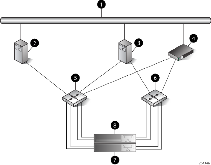
Limitations
•HP P6000 Continuous Access is not supported with single path configurations.
Figure 37 OpenVMS configuration
5 SAN switch 11 Network interconnection
6 SAN switch 22 Host 1
7 Controller A3 Host 2
8 Controller B4 Management server
Linux (32-bit) configuration
Requirements
•Switch zoning or controller level SSP must be used to ensure each single path HBA has an
exclusive path to its LUNs.
•All nodes with direct connection to a disk must have the same access paths available to them.
•Single path HBA server can be in the same fabric as servers with multiple HBAs.
•In the use of snapshots and snapclones, the source virtual disk and all associated snapshots
and snapclones must be presented to the single path hosts that are zoned with the same
controller. In the case of snapclones, after the cloning process has completed and the clone
becomes an ordinary virtual disk, you may present that virtual disk as you would any other
ordinary virtual disk.
HBA configuration
•Host 1 is a single path HBA.
•Host 2 is a dual HBA host with multi-pathing software.
See Figure 38 (page 127).
126 Single Path Implementation
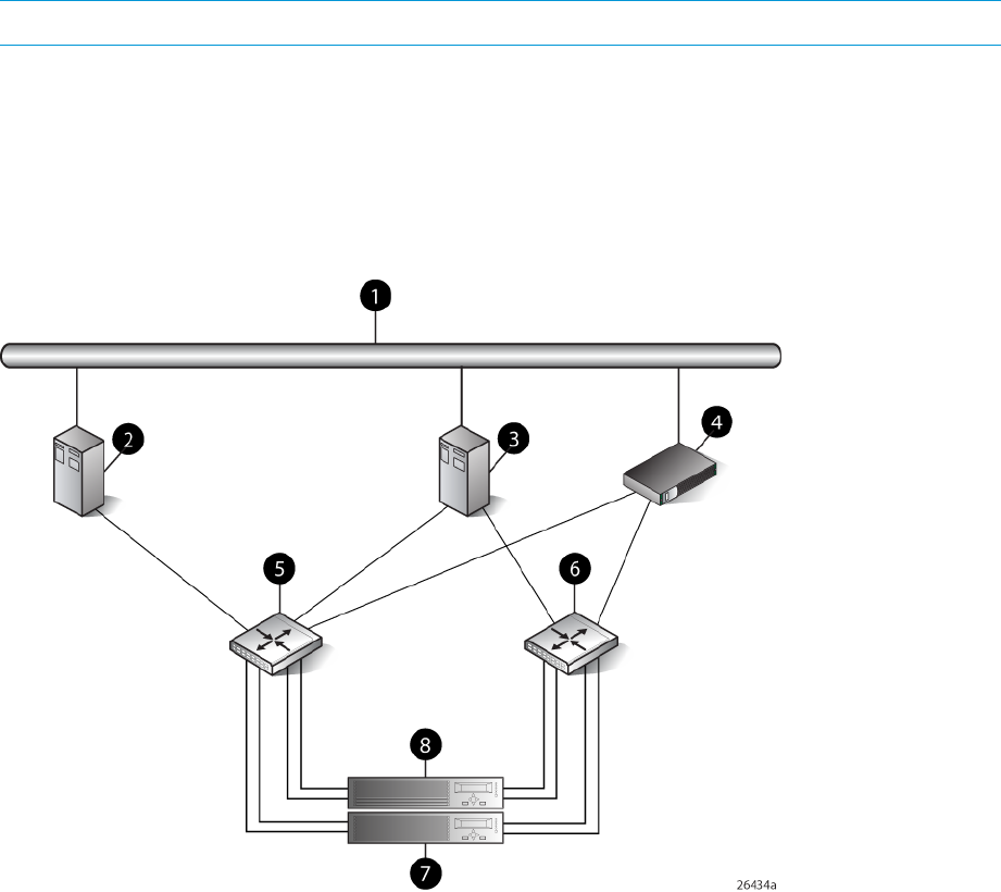
Risks
•Single path failure may result in data loss or disk corruption.
NOTE: For additional risks, see “Linux failure scenarios” (page 133).
Limitations
•HP P6000 Continuous Access is not supported with single path configurations.
•Single path HBA server is not part of a cluster.
•Booting from the SAN is supported on single path HBA servers.
Figure 38 Linux (32-bit) configuration
5 SAN switch 11 Network interconnection
6 SAN switch 22 Host 1
7 Controller A3 Host 2
8 Controller4 Management server
Linux (64-bit) configuration
Requirements
•Switch zoning or controller level SSP must be used to ensure each single path HBA has an
exclusive path to its LUNs.
•All nodes with direct connection to a disk must have the same access paths available to them.
•Single path HBA server can be in the same fabric as servers with multiple HBAs.
•In the use of snapshots and snapclones, the source virtual disk and all associated snapshots
and snapclones must be presented to the single path hosts that are zoned with the same
controller. In the case of snapclones, after the cloning process has completed and the clone
Supported configurations 127
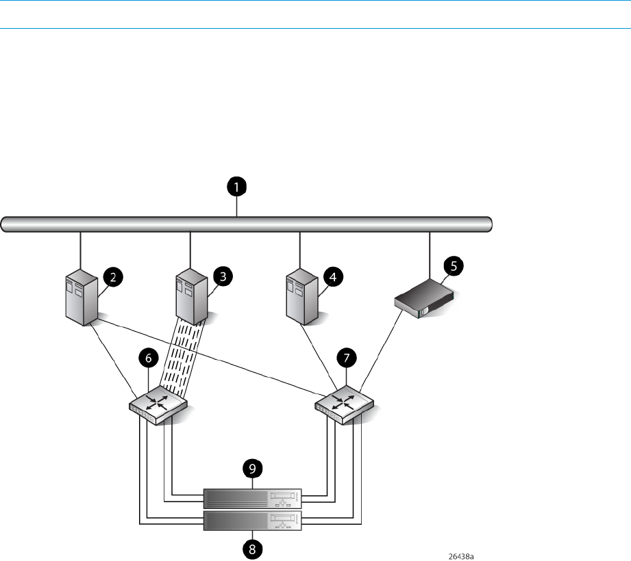
becomes an ordinary virtual disk, you may present that virtual disk as you would any other
ordinary virtual disk.
•Linux 64-bit servers can support up to14 single or dual path HBAs per server. Switch zoning
and SSP are required to isolate the LUNs presented to each HBA from each other.
HBA configuration
•Host 1 and 2 are single path HBA hosts.
•Host 3 is a dual HBA host with multi-pathing software.
See Figure 39 (page 128).
Risks
•Single path failure may result in data loss or disk corruption.
NOTE: For additional risks, see “Linux failure scenarios” (page 133).
Limitations
•HP P6000 Continuous Access is not supported with single path configurations.
•Single path HBA server is not part of a cluster.
•Booting from the SAN is supported on single path HBA servers.
Figure 39 Linux (64-bit) configuration
6 SAN switch 11 Network interconnection
7 SAN switch 22 Host 3
8 Controller A3 Host 2
9 Controller B4 Host 1
5 Management server
128 Single Path Implementation

IBM AIX configuration
Requirements
•Switch zoning or controller level SSP must be used to ensure each single path HBA has an
exclusive path to its LUNs.
•Single path HBA server can be in the same fabric as servers with multiple HBAs.
•Single path HBA server cannot share LUNs with any other HBAs.
•In the use of snapshots and snapclones, the source virtual disk and all associated snapshots
and snapclones must be presented to the single path hosts that are zoned with the same
controller. In the case of snapclones, after the cloning process has completed and the clone
becomes an ordinary virtual disk, you may present that virtual disk as you would any other
ordinary virtual disk.
HBA configuration
•Host 1 is a single path HBA host.
•Host 2 is a dual HBA host with multi-pathing software.
See Figure 40 (page 130).
Risks
•Single path failure may result in loss of data accessibility and loss of host data that has not
been written to storage.
•Controller shutdown results in loss of data accessibility and loss of host data that has not been
written to storage.
NOTE: For additional risks, see “IBM AIX failure scenarios” (page 134).
Limitations
•HP P6000 Continuous Access is not supported with single path configurations.
•Single path HBA server is not part of a cluster.
•Booting from the SAN is not supported.
Supported configurations 129
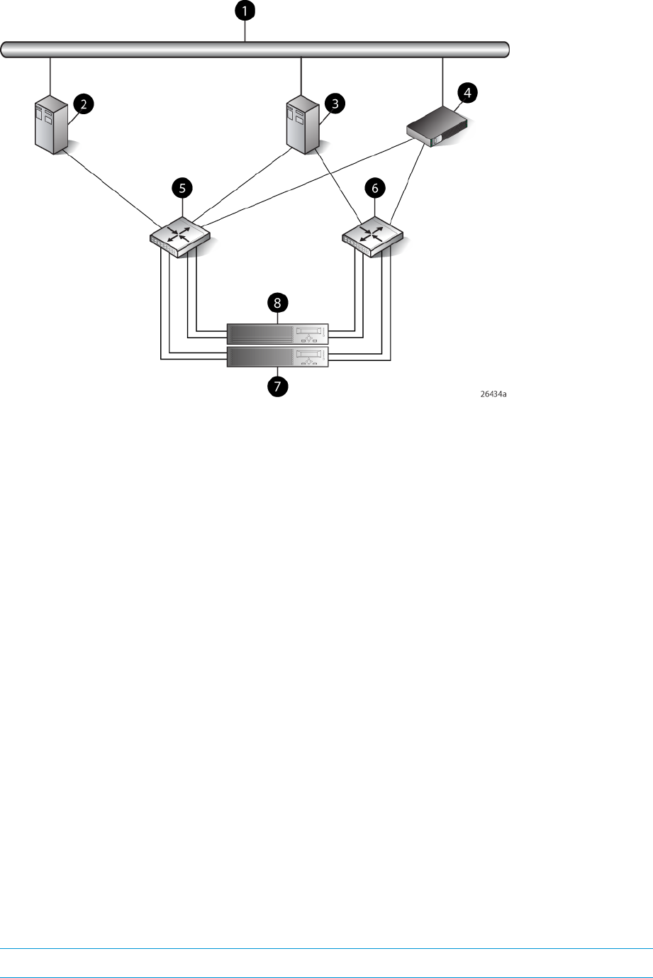
Figure 40 IBM AIX Configuration
5 SAN switch 11 Network interconnection
6 SAN switch 22 Single HBA server
7 Controller A3 Dual HBA server
8 Controller B4 Management server
VMware configuration
Requirements
•Switch zoning or controller level SSP must be used to ensure each single path HBA has an
exclusive path to its LUNs.
•All nodes with direct connection to a disk must have the same access paths available to them.
•Single path HBA server can be in the same fabric as servers with multiple HBAs.
•In the use of snapshots and snapclones, the source virtual disk and all associated snapshots
and snapclones must be presented to the single path hosts that are zoned with the same
controller. In the case of snapclones, after the cloning process has completed and the clone
becomes an ordinary virtual disk, you may present that virtual disk as you would any other
ordinary virtual disk.
HBA configuration
•Host 1 is a single path HBA.
•Host 2 is a dual HBA host with multi-pathing software.
See Figure 41 (page 131).
Risks
•Single path failure may result in data loss or disk corruption.
NOTE: For additional risks, see “VMware failure scenarios” (page 134).
130 Single Path Implementation
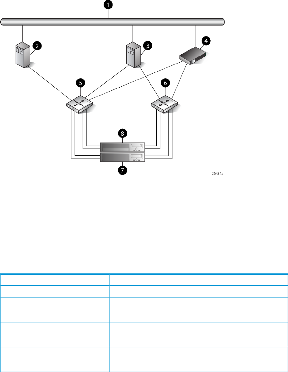
Limitations
•HP P6000 Continuous Access is not supported with single path configurations.
•Single path HBA server is not part of a cluster.
•Booting from the SAN is supported on single path HBA servers.
Figure 41 VMware configuration
5 SAN switch 11 Network interconnection
6 SAN switch 22 Single HBA server
7 Controller A3 Dual HBA server
8 Controller B4 Management server
Failure scenarios
HP-UX
Table 30 HP-UX failure scenarios
Failure effectFault stimulus
Extremely critical event on UNIX. Can cause loss of system disk.Server failure (host power-cycled)
Short term: Data transfer stops. Possible I/O errors.
Long term: Job hangs, cannot umount disk, fsck failed, disk corrupted,
need mkfs disk.
Switch failure (SAN switch disabled)
Short term: Data transfer stops. Possible I/O errors.
Long term: Job hangs, cannot umount disk, fsck failed, disk corrupted,
need mkfs disk.
Controller failure
Short term: Data transfer stops. Possible I/O errors.
Long term: Job hangs, cannot umount disk, fsck failed, disk corrupted,
need mkfs disk.
Controller restart
Failure scenarios 131

Table 30 HP-UX failure scenarios (continued)
Failure effectFault stimulus
Short term: Data transfer stops. Possible I/O errors.
Long term: Job hangs, cannot umount disk, fsck failed, disk corrupted,
need mkfs disk.
Server path failure
Short term: Data transfer stops. Possible I/O errors.
Long term: Job hangs, replace cable, I/O continues. Without cable
replacement job must be aborted; disk seems error free.
Storage path failure
Windows Server
Table 31 Windows Server failure scenarios
Failure effectFault stimulus
OS runs a command called chkdsk when rebooting. Data lost, data that
finished copying survived.
Server failure (host power-cycled)
Write delay, server hangs until I/O is cancelled or cold reboot.Switch failure (SAN switch disabled)
Write delay, server hangs or reboots. One controller failed, other
controller and shelves critical, shelves offline. Volume not accessible.
Server cold reboot, data lost. Check disk when rebooting.
Controller failure
Controller momentarily in failed state, server keeps copying. All data
copied, no interruption. Event error warning error detected during paging
operation.
Controller restart
Write delay, volume inaccessible. Host hangs and restarts.Server path failure
Write delay, volume disappears, server still running. When cables
plugged back in, controller recovers, server finds volume, data loss.
Storage path failure
Oracle Solaris
Table 32 Oracle Solaris failure scenarios
Failure effectFault stimulus
Check disk when rebooting. Data loss, data that finished copying survived.Server failure (host power-cycled)
Short term: Data transfer stops. Possible I/O errors.
Long term: Repeated error messages on console, no access to CDE.
System reboot causes loss of data on disk. Must newfs disk.
Switch failure (SAN switch disabled)
Short term: Data transfer stops. Possible I/O errors.
Long term: Repeated error messages on console, no access to CDE.
System reboot causes loss of data on disk. Must newfs disk.
Controller failure
Short term: Data transfer stops. Possible I/O errors.
Long term: Repeated error messages on console, no access to CDE.
System reboot causes loss of data on disk. Must newfs disk.
Controller restart
Short term: Data transfer stops. Possible I/O errors.
Long term: Repeated error messages on console, no access to CDE.
System reboot causes loss of data on disk. Must newfs disk.
Server path failure
Short term: Job hung, data lost.
Long term: Repeated error messages on console, no access to CDE.
System reboot causes loss of data on disk. Must newfs disk.
Storage path failure
132 Single Path Implementation

OpenVMS and Tru64 UNIX
Table 33 OpenVMS and Tru64 UNIX failure scenarios
Failure effectFault stimulus
All I/O operations halted. Possible data loss from unfinished or unflushed
writes. File system check may be needed upon reboot.
Server failure (host power-cycled)
OpenVMS—OS will report the volume in a Mount Verify state until the
MVTIMEOUT limit is exceeded, when it then marks the volume as Mount
Verify Timeout. No data is lost or corrupted.
Switch failure (SAN switch disabled)
Tru64 UNIX—All I/O operations halted. I/O errors are returned back to
the applications. An I/O failure to the system disk can cause the system
to panic. Possible data loss from unfinished or unflushed writes. File system
check may be needed upon reboot.
I/O fails over to the surviving path. No data is lost or corrupted.Controller failure
OpenVMS—OS will report the volume in a Mount Verify state until the
MVTIMEOUT limit is exceeded, when it then marks the volume as Mount
Verify Timeout. No data is lost of corrupted.
Controller restart
Tru64 UNIX—I/O retried until controller back online. If maximum retries
exceeded, I/O fails over to the surviving path. No data is lost or
corrupted.
OpenVMS—OS will report the volume in a Mount Verify state until the
MVTIMEOUT limit is exceeded, when it then marks the volume as Mount
Verify Timeout. No data is lost or corrupted.
Server path failure
Tru64 UNIX—All I/O operations halted. I/O errors are returned back to
the applications. An I/O failure to the system disk can cause the system
to panic. Possible data loss from unfinished or unflushed writes. File system
check may be needed upon reboot.
OpenVMS—OS will report the volume in a Mount Verify state until the
MVTIMEOUT limit is exceeded, when it then marks the volume as Mount
Verify Timeout. No data is lost or corrupted.
Storage path failure
Tru64 UNIX—I/O fails over to the surviving path. No data is lost or
corrupted.
Linux
Table 34 Linux failure scenarios
Failure effectFault stimulus
OS reboots, automatically checks disks. HSV disks must be manually
checked unless auto mounted by the system.
Server failure (host power-cycled)
Short: I/O suspended, possible data loss.
Long: I/O halts with I/O errors, data loss. HBA driver must be reloaded
before failed drives can be recovered, fsck should be run on any failed
drives before remounting.
Switch failure (SAN switch disabled)
Short term: I/O suspended, possible data loss.
Long term: I/O halts with I/O errors, data loss. Cannot reload driver,
need to reboot system, fsck should be run on any failed disks before
remounting.
Controller failure
Short term: I/O suspended, possible data loss.
Long term: I/O halts with I/O errors, data loss. Cannot reload driver,
need to reboot system, fsck should be run on any failed disks before
remounting.
Controller restart
Failure scenarios 133

Table 34 Linux failure scenarios (continued)
Failure effectFault stimulus
Short: I/O suspended, possible data loss.
Long: I/O halts with I/O errors, data loss. HBA driver must be reloaded
before failed drives can be recovered, fsck should be run on any failed
drives before remounting.
Server path failure
Short: I/O suspended, possible data loss.
Long: I/O halts with I/O errors, data loss. HBA driver must be reloaded
before failed drives can be recovered, fsck should be run on any failed
drives before remounting.
Storage path failure
IBM AIX
Table 35 IBM AIX failure scenarios
Failure effectFault stimulus
Check disk when rebooting. Data loss, data that finished copying survivedServer failure (host power-cycled)
Short term: Data transfer stops. Possible I/O errors.
Long term: Repeated error messages in errpt output. System reboot causes
loss of data on disk. Must crfs disk.
Switch failure (SAN switch disabled)
Short term: Data transfer stops. Possible I/O errors.
Long term: Repeated error messages in errpt output. System reboot causes
loss of data on disk. Must crfs disk.
Controller failure
Short term: Data transfer stops. Possible I/O errors.
Long term: Repeated error messages in errpt output. System reboot causes
loss of data on disk. Must crfs disk.
Controller restart
Short term: Data transfer stops. Possible I/O errors.
Long term: Repeated error messages in errpt output. System reboot causes
loss of data on disk. Must crfs disk.
Server path failure
Short term: Data transfer stops. Possible I/O errors.
Long term: Repeated error messages in errpt output. System reboot causes
loss of data on disk. Must crfs disk.
Storage path failure
VMware
Table 36 VMware failure scenarios
Failure effectFault stimulus
OS reboots, automatically checks disks. HSV disks must be manually
checked unless auto mounted by the system.
Server failure (host power-cycled)
Short: I/O suspended, possible data loss.
Long: I/O halts with I/O errors, data loss. HBA driver must be reloaded
before failed drives can be recovered, fsck should be run on any failed
drives before remounting.
Switch failure (SAN switch disabled)
Short term: I/O suspended, possible data loss.
Long term: I/O halts with I/O errors, data loss. Cannot reload driver,
need to reboot system, fsck should be run on any failed disks before
remounting.
Controller failure
Short term: I/O suspended, possible data loss.
Long term: I/O halts with I/O errors, data loss. Cannot reload driver,
need to reboot system, fsck should be run on any failed disks before
remounting.
Controller restart
134 Single Path Implementation

Table 36 VMware failure scenarios (continued)
Failure effectFault stimulus
Short: I/O suspended, possible data loss.
Long: I/O halts with I/O errors, data loss. HBA driver must be reloaded
before failed drives can be recovered, fsck should be run on any failed
drives before remounting.
Server path failure
Short: I/O suspended, possible data loss.
Long: I/O halts with I/O errors, data loss. HBA driver must be reloaded
before failed drives can be recovered, fsck should be run on any failed
drives before remounting.
Storage path failure
Failure scenarios 135

Glossary
This glossary defines terms used in this guide or related to this product and is not a
comprehensive glossary of computer terms.
Symbols and numbers
3U A unit of measurement representing three “U” spaces. “U” spacing is used to designate panel or
enclosure heights. Three “U” spaces is equivalent to 133 mm (5.25 inches).
See also rack-mounting unit.
µm A symbol for micrometer; one millionth of a meter. For example, 50 µm is equivalent to 0.000050
m.
A
active member of
a virtual disk
family
A simulated disk drive created by the controllers as storage for one or more hosts. An active
member of a virtual disk family is accessible by one or more hosts for normal storage. An active
virtual disk member and its snapshot, if one exists, constitute a virtual disk family. An active
member of a virtual disk family is the only necessary member of a virtual disk family.
See also virtual disk,virtual disk copy,virtual disk family, and snapshot .
adapter See controller.
AL_PA Arbitrated loop physical address. A 1-byte value the arbitrated loop topology uses to identify the
loop ports. This value becomes the last byte of the address identifier for each public port on the
loop.
allocation policy The storage system rules that govern how virtual disks are created. There are two rules:
•Allocate Completely—The space a virtual disk requires on the physical disks is reserved,
even if the virtual disk is not currently using the space.
•Allocate on Demand—The space a virtual disk requires on the physical disks is not reserved
until needed.
ALUA Asymmetric logical unit access. Operating systems that support asymmetric logical unit access
work with the array’s active/active functionality to enable any virtual disk to be accessed through
either of the array’s two controllers.
ambient
temperature The air temperature in the area where a system is installed. Also called intake temperature or
room temperature.
ANSI American National Standards Institute. A non-governmental organization that develops standards
(such as SCSI I/O interface standards and Fibre Channel interface standards) used voluntarily
by many manufacturers within the United States.
arbitrated loop A Fibre Channel topology that links multiple ports (up to 126) together on a single shared simplex
medium. Transmissions can only occur between a single pair of nodes at any given time.
Arbitration is the scheme that determines which node has control of the loop at any given moment
arbitrated loop
physical address See AL_PA.
arbitrated loop
topology See arbitrated loop.
array synonym of storage array, storage system, and virtual array. A group of disks in one or more
disk enclosures combined with controller software that presents disk storage capacity as one or
more virtual disks.
array controller See controller.
array controller
failover The process that takes place when one controller assumes the workload of a failed companion
controller.
asynchronous Events scheduled as the result of a signal requesting the event or that which is without any specified
time relation.
136 Glossary
B
backplane An electronic printed circuit board that distributes data, control, power, and other signals among
components in an enclosure.
bad block A data block that contains a physical defect.
bad block
replacement A replacement routine that substitutes defect-free disk blocks for those found to have defects. This
process takes place in the controller and is transparent to the host.
bail lock The part of the power supply AC receptacle that engages the AC power cord connector to ensure
that the cord cannot be accidentally disconnected.
battery A rechargeable unit mounted within a controller enclosure that supplies backup power to the
cache module in case of primary power shortage.
baud The maximum rate of signal state changes per second on a communication circuit. If each signal
state change corresponds to a code bit, then the baud rate and the bit rate are the same. It is
also possible for signal state changes to correspond to more than one code bit so the baud rate
may be lower than the code bit rate.
bay The physical location of an element, such as a drive, I/O module, EMU or power supply in a
drive enclosure. Each bay is numbered to define its location.
bidirectional Also called Bi-Di. The movement of optical signals in opposite directions through a common fiber
cable such as the data flow path typically on a parallel printer port. A parallel port can provide
two-way data flow for disk drives, scanning devices, FAX operations and even parallel modems.
block Also called a sector. The smallest collection of consecutive bytes addressable on a disk drive. In
integrated storage elements, a block contains 512 bytes of data, error codes, flags, and the
block address header.
blower See fan.
C
cabinet An alternate term used for a rack.
cable assembly A fiber optic cable that has connectors installed on one or both ends. General use of these cable
assemblies includes the interconnection of multimode fiber optic cable assemblies with either LC
or SC type connectors.
•When there is a connector on only one end of the cable, the cable assembly is referred to
as a pigtail.
•When there is a connector on each end of the cable, the cable assembly is referred to as
a jumper.
CAC Corrective Action Code. An HP P6000 Command View graphical user interface (GUI) display
component that defines the action required to correct a problem.
cache High-speed memory that sets aside data as an intermediate data buffer between a host and the
storage media. The purpose of cache is to improve performance.
cache battery See battery.
carrier A drive enclosure-compatible assembly containing a disk drive or other storage devices.
client An intelligent device that requests services from other intelligent devices. In the context of HP
P6000 Command View, a client is a computer that is used to access the software remotely using
a supported browser.
clone A full copy of a volume usable by an application.
communication
LUN See console LUN.
condition report A three-element code generated by the EMU in the form where e.t. is the element type (a
hexadecimal number), en. is the element number (a decimal number), and ec is the condition
code (a decimal number).
console LUN A SCSI-3 virtual object that makes a controller pair accessible by the host before any virtual disks
are created. Also called a communication LUN.
137
console LUN ID The ID that can be assigned when a host operating system requires a unique ID. The console
LUN ID is assigned by the user, usually when the storage system is initialized.
controller A hardware/firmware device that manages communications between host systems and other
devices. Controllers typically differ by the type of interface to the host and provide functions
beyond those the devices support.
controller
enclosure A unit that holds one or more controllers, power supplies, blowers or fans, cache batteries,
transceivers, and connectors.
controller event A significant occurrence involving any storage system hardware or software component reported
by the controller to HP P6000 Command View.
controller pair Two connected controller modules that control a disk array.
corrective action
code See CAC.
CRITICAL Condition A drive enclosure EMU condition that occurs when one or more drive enclosure elements have
failed or are operating outside of their specifications. The failure of the element makes continued
normal operation of at least some elements in the enclosure impossible. Some enclosure elements
may be able to continue normal operations. Only an UNRECOVERABLE condition has precedence.
This condition has precedence over NONCRITICAL errors and INFORMATION condition.
CRU Customer replaceable unit. A storage system element that a user can replace without using special
tools or techniques, or special training.
customer
replaceable unit See CRU.
D
data entry mode The state in which controller information can be displayed or controller configuration data can
be entered. On the Enterprise Storage System, the controller mode is active when the LCD on the
HSV Controller OCP is Flashing.
default disk group The disk group that is created when the array is initialized. The minimum number of disks the
group can contain is eight. The maximum is the number of installed disks.
Detailed Fault
View An HSV Controller OCP display that permits a user to view detailed information about a controller
fault.
device channel A channel used to connect storage devices to a host I/O bus adapter or intelligent controller.
device ports The controller pair device ports connected to the storage system’s physical disk drive array through
the Fibre Channel drive enclosure. Also called a device-side port.
device-side ports See device ports.
DIMM Dual inline memory module. A small circuit board holding memory chips.
dirty data The write-back cached data that has not been written to storage media even though the host
operation processing the data has completed.
disk drive A carrier-mounted storage device supporting random access to fixed size blocks of data.
disk drive blank A carrier that replaces a disk drive to control airflow within a drive enclosure whenever there is
less than a full complement of storage devices.
disk drive
enclosure A unit that holds storage system devices such as disk drives, power supplies, fans, I/O modules,
and transceivers.
disk failure
protection A method by which a controller pair reserves drive capacity to take over the functionality of a
failed or failing physical disk. For each disk group, the controllers reserve space in the physical
disk pool equivalent to the selected number of physical disk drives.
disk group A named group of disks selected from all the available disks in a disk array. One or more virtual
disks can be created from a disk group. Also refers to the physical disk locations associated with
a parity group.
138 Glossary
disk migration
state A physical disk drive operating state. A physical disk drive can be in a stable or migration state:
Stable—The state in which the physical disk drive has no failure nor is a failure predicted.•
•Migration—The state in which the disk drive is failing, or failure is predicted to be imminent.
Data is then moved off the disk onto other disk drives in the same disk group.
disk replacement
delay The time that elapses between a drive failure and when the controller starts searching for spare
disk space. Drive replacement seldom starts immediately in case the “failure” was a glitch or
temporary condition.
DR group failover An operation that reverses data replication direction so that the destination becomes the source
and the source becomes the destination. Failovers can be planned or unplanned and can occur
between DR groups or managed sets (which are sets of DR groups).
drive enclosure
event A significant operational occurrence involving a hardware or software component in the drive
enclosure. The drive enclosure EMU reports these events to the controller for processing.
dual fabric Two independent fabrics providing multipath connections between Fibre Channel end devices.
dual power supply
configuration See redundant power configuration.
dual-loop A configuration where each drive is connected to a pair of controllers through two loops. These
two Fibre Channel loops constitute a loop pair.
dynamic capacity
expansion A storage system feature that provides the ability to increase the size of an existing virtual disk.
Before using this feature, you must ensure that your operating system supports capacity expansion
of a virtual disk (or LUN).
E
EIA Electronic Industries Alliance. A standards organization specializing in the electrical and functional
characteristics of interface equipment.
EIP Event Information Packet. The event information packet is an HSV element hexadecimal character
display that defines how an event was detected. Also called the EIP type.
electromagnetic
interference See EMI.
electrostatic
discharge See ESD.
element In a disk enclosure, a device such as a, power supply, disk, fan/blower, or I/O module. The
object can be controllled, interrogated, or described by the enclosure services process.
EMI Electromagnetic Interference. The impairment of a signal by an electromagnetic disturbance.
EMU Environmental Monitoring Unit. An element which monitors the status of an enclosure, including
the power, air temperature, and blower status. The EMU detects problems and displays and
reports these conditions to a user and the controller. In some cases, the EMU implements corrective
action.
enclosure A unit used to hold various storage system devices such as disk drives, controllers, power supplies,
I/O modules, or fans/blowers.
enclosure address
bus An Enterprise storage system bus that interconnects and identifies controller enclosures and disk
drive enclosures by their physical location. Enclosures within a reporting group can exchange
environmental data. This bus uses enclosure ID expansion cables to assign enclosure numbers to
each enclosure. Communications over this bus do not involve the Fibre Channel drive enclosure
bus and are, therefore, classified as out-of-band communications.
enclosure number
(En) One of the vertical rack-mounting positions where the enclosure is located. The positions are
numbered sequentially in decimal numbers starting from the bottom of the cabinet. Each disk
enclosure has its own enclosure number. A controller pair shares an enclosure number. If the
system has an expansion rack, the enclosures in the expansion rack are numbered from 15 to
24, starting at the bottom.
enclosure services Those services that establish the mechanical environmental, electrical environmental, and external
indicators and controls for the proper operation and maintenance of devices with an enclosure
139
as described in the SES SCSI-3 Enclosure Services Command Set (SES), Rev 8b, American National
Standard for Information Services.
Enclosure Services
Interface See ESI.
Enclosure Services
Processor See ESP.
environmental
monitoring unit See EMU.
error code The portion of an EMU condition report that defines a problem.
ESD Electrostatic Discharge. The emission of a potentially harmful static electric voltage as a result of
improper grounding.
ESI Enclosure Services Interface. The SCSI-3 engineering services interface implementation developed
for storage products. A bus that connects the EMU to the disk drives.
ESP Enclosure Services Processor. An EMU that implements an enclosure’s services process.
event Any significant change in the state of the Enterprise storage system hardware or software
component reported by the controller to HP P6000 Command View.
See also controller event, drive enclosure event, management agent event, and termination event.
Event Information
Packet See EIP.
Event Number A sequential number assigned to each Software Code Identification (SWCID) event. It is a decimal
number in the range 0-255.
Evt No. See Event Number.
exabyte A unit of storage capacity that is the equivalent of 260 bytes or 1,152,921,504,606,846,976
bytes. One exabyte is equivalent to 1,024 petabytes.
F
fabric A network of Fibre Channel switches or hubs and other devices.
fabric port A port which is capable of supporting an attached arbitrated loop. This port on a loop will have
the AL_PA hexadecimal address 00 (loop ID 7E), giving the fabric the highest priority access to
the loop. A loop port is the gateway to the fabric for the node ports on a loop.
failover See array controller failover or DR group failover.
failsafe A safe state that devices automatically enter after a malfunction. Failsafe DR groups stop accepting
host input and stop logging write history if a group member becomes unavailable.
fan The variable speed airflow device that cools an enclosure or component by forcing ambient air
into an enclosure or component and forcing heated air out the other side.
FATA Fibre Attached Technology Adapted disk drive.
Fault Management
Code See FMC.
FC HBA Fibre Channel Host Bus Adapter.
See also FCA.
FCA Fibre Channel Adapter.
See also FC HBA.
FCC Federal Communications Commission. The federal agency responsible for establishing standards
and approving electronic devices within the United States.
FCP Fibre Channel Protocol.
fiber The optical media used to implement Fibre Channel.
fiber optic cable A transmission medium designed to transmit digital signals in the form of pulses of light. Fiber
optic cable is noted for its properties of electrical isolation and resistance to electrostatic
contamination.
140 Glossary
fiber optics The technology where light is transmitted through glass or plastic (optical) threads (fibers) for data
communication or signaling purposes.
Fibre Channel A data transfer architecture designed for mass storage devices and other peripheral devices that
require high bandwidth.
Fibre Channel
adapter See FCA.
Fibre Channel
drive enclosure An enclosure that provides 12-port central interconnect for Fibre Channel arbitrated loops following
the ANSI Fibre Channel disk enclosure standard.
Fibre Channel Loop Fibre Channel Arbitrated Loop. The American National Standards Institute’s (ANSI) document
that specifies arbitrated loop topology operation.
field replaceable
unit See FRU.
flush The act of writing dirty data from cache to a storage media.
FMC Fault Management Code. The HP P6000 Command View display of the Enterprise Storage System
error condition information.
form factor A storage industry dimensional standard for 89 mm (3.5 inch) and 133 mm (5.25 inch) high
storage devices. Device heights are specified as low-profile (25.4 mm), half-height (41 mm), and
full-height (133 mm).
FPGA Field Programmable Gate Array. A programmable device with an internal array of logic blocks
surrounded by a ring of programmable I/O blocks connected together through a programmable
interconnect.
frequency The number of cycles that occur in one second expressed in Hertz (Hz). Thus, 1 Hz is equivalent
to one cycle per second.
FRU Field replaceable unit. An assembly component that is designed to be replaced on site, without
the system having to be returned to the manufacturer for repair.
G
Giga (G) The notation to represent 109or 1 billion (1,000,000,000).
gigabaud An encoded bit transmission rate of one billion (109) bits per second.
H
HBA Host Bus Adapter.
host A computer that runs user applications and uses the information stored on an array.
Host Bus Adapter Host bus adapter.
host computer See host.
host link indicator The HSV Controller display that indicates the status of the storage system Fibre Channel links.
host ports A connection point to one or more hosts through a Fibre Channel fabric.
host-side ports See host ports.
hot-pluggable The ability to add and remove elements or devices to a system or appliance while the appliance
is running and have the operating system automatically recognize the change.
hub A communications infrastructure device to which nodes on a multi-point bus or loop are physically
connected. It is used to improve the manageability of physical cables.
I
I/O module Input/Output module. The enclosure element that is the Fibre Channel drive enclosure interface
to the host or controller.
IDX A 2-digit decimal number portion of the HSV controller termination code display that defines one
of 32 locations in the Termination Code array that contains information about a specific event.
in-band
communication The communication that uses the same communications channel as the operational data.
141
INFORMATION
condition A drive enclosure EMU condition that may require action. This condition is for information purposes
only and does not indicate the failure of an element.
initialization A configuration step that binds the controllers together and establishes preliminary data structures
on the array. Initialization also sets up the first disk group, called the default disk group, and
makes the array ready for use.
input/output
module See I/O module.
intake temperature See ambient temperature.
interface A set of protocols used between components such as cables, connectors, and signal levels.
J
JBOD Just a Bunch of Disks.
L
laser A device that amplifies light waves and concentrates them in a narrow, very intense beam.
Last Fault View An HSV Controller display defining the last reported fault condition.
Last Termination
Error Array See LTEA.
license key A WWN-encoded sequence that is obtained from the license key fulfillment website.
link A connection of ports on Fibre Channel devices.1.
2. A full duplex connection to a fabric or a simplex connection of loop devices.
logon A procedure whereby a user or network connection is identified as being an authorized network
user or participant.
loop See arbitrated loop.
loop ID Seven-bit values numbered contiguous from 0 to 126 decimal that represent the 127 valid AL-PA
values on a loop. (With Fibre Channel, not all 256 hexadecimal values are allowed as AL-PA
values.)
loop pair A Fibre Channel attachment between a controller and physical disk drives. Physical disk drives
connect to controllers through paired Fibre Channel arbitrated loops. There are two loop pairs,
designated loop pair 1 and loop pair 2. Each loop pair consists of two loops (called loop A and
loop B) that operate independently during normal operation, but provide mutual backup in case
one loop fails.
LTEA Last termination event array. A two-digit HSV Controller number that identifies a specific event
that terminated an operation. Valid numbers range from 00 to 31.
LUN Logical unit number. A LUN results from mapping a SCSI logical unit number, port ID, and LDEV
ID to a RAID group. The size of the LUN is determined by the emulation mode of the LDEV and
the number of LDEVs associated with the LUN. For example, a LUN associated with two OPEN-3
LDEVs has a size of 4,693 MB.
M
management
agent The HP P6000 Command View software that controls and monitors the HP Enterprise storage
system. The software can exist on more than one management server in a fabric. Each installation
is a management agent.
management
agent event A significant occurrence to or within the management agent software, or an initialized storage
cell controlled or monitored by the management agent.
mean time
between failures See MTBF.
Mega A notation denoting a multiplier of 1 million (1,000,000).
metadata The data in the first sectors of a disk drive that the system uses to identify virtual disk members.
micro meter See µm.
142 Glossary
mirrored caching A process in which half of each controller’s write cache mirrors the companion controller’s write
cache. The total memory available for cached write data is reduced by half, but the level of
protection is greater.
mirroring The act of creating an exact copy or image of data.
MTBF Mean time between failures. The average time from start of use to first failure in a large population
of identical systems, components, or devices.
multi-mode fiber A fiber optic cable with a diameter large enough (50 microns or more) to allow multiple streams
of light to travel different paths from the transmitter to the receiver. This transmission mode enables
bidirectional transmissions.
N
near-online
storage On-site storage of data on media that takes slightly longer to access than online storage kept on
high-speed disk drives.
Network Storage
Controller See NSC.
node port A device port that can operate on the arbitrated loop topology.
non-OFC (Open
Fibre Control) A laser transceiver whose lower-intensity output does not require special open Fibre Channel
mechanisms for eye protection. The HP Enterprise Storage System transceivers are non-OFC
compatible.
NONCRITICAL
Condition An EMU condition that occurs when one or more elements in the drive enclosure fail or are
operating outside specifications. The failure does not affect operation of the enclosure; all devices
in the enclosure continue to operate according to specifications. If there are additional failures,
however, the devices may not operate properly. UNRECOVERABLE and CRITICAL errors take
precedence over this condition. This condition takes precedence over the INFORMATION
condition. Early correction can prevent the loss of data.
NSC Network storage controller. The HSV controllers used by the HP Enterprise Storage System.
NVRAM Nonvolatile Random Access Memory. Memory whose contents are not lost when a system is
turned Off or if there is a power failure. This is achieved through the use of UPS batteries or
implementation technology such as flash memory. NVRAM is commonly used to store important
configuration parameters.
O
occupancy alarm
level A percentage of the total disk group capacity in blocks. When the number of blocks in the disk
group that contain user data reaches this level, an event code is generated. The alarm level is
specified by the user.
OCP Operator Control Panel. The element that displays the controller’s status using indicators and an
LCD. Information selection and data entry is controlled by the OCP pushbutton.
online storage An allotment of storage space that is available for immediate use, such as a peripheral device
that is turned on and connected to a server.
operator control
panel See OCP.
P
param That portion of the HP HSV controller termination code display that defines:
•The two-character parameter identifier that is a decimal number in the 0 through 31 range.
•The eight-character parameter code that is a hexadecimal number.
password A security interlock where the purpose is to allow:
•A management agent to control only certain storage systems
•Only certain management agents to control a storage system
143
PDM Power distribution module. A thermal circuit breaker-equipped power strip that distributes power
from a PDU to HP Enterprise Storage System elements.
PDU Power distribution unit. The rack device that distributes conditioned AC or DC power within a
rack.
petabyte A unit of storage capacity that is the equivalent of 250, 1,125,899,906,842,624 bytes or 1,024
terabytes.
physical disk A disk drive mounted in a drive enclosure that communicates with a controller pair through the
device-side Fibre Channel loops. A physical disk is hardware with embedded software, as opposed
to a virtual disk, which is constructed by the controllers. Only the controllers can communicate
directly with the physical disks.
The physical disks, in aggregate, are called the array and constitute the storage pool from which
the controllers create virtual disks.
physical disk array See array.
port A physical connection that allows data to pass between a host and a disk array.
port-colored Pertaining to the application of the color of port or red wine to a CRU tab, lever, or handle to
identify the unit as hot-pluggable.
port_name A 64-bit unique identifier assigned to each Fibre Channel port. The port_name is communicated
during the login and port discovery processes.
power distribution
module See PDM.
power distribution
unit See PDU.
power supply An element that develops DC voltages for operating the storage system elements from either an
AC or DC source.
preferred address An AL_PA which a node port attempts to acquire during loop initialization.
preferred path A preference for which controller of the controller pair manages the virtual disk. This preference
is set by the user when creating the virtual disk. A host can change the preferred path of a virtual
disk at any time. The primary purpose of preferring a path is load balancing.
protocol The conventions or rules for the format and timing of messages sent and received.
Q
quiesce The act of rendering bus activity inactive or dormant. For example, “quiesce the SCSI bus
operations during a device warm-swap.”
R
rack A floorstanding structure primarily designed for, and capable of, holding and supporting storage
system equipment. All racks provide for the mounting of panels per Electronic Industries Alliance
(EIA) Standard RS310C.
rack-mounting unit A measurement for rack heights based upon a repeating hole pattern. It is expressed as “U”
spacing or panel heights. Repeating hole patterns are spaced every 44.45 mm (1.75 inches)
and based on EIA’s Standard RS310C. For example, a 3U unit is 133.35 mm (5.25 inches)
high, and a 4U unit is 177.79 mm (7.0 inches) high.
read ahead
caching A cache management method used to decrease the subsystem response time to a read request
by allowing the controller to satisfy the request from the cache memory rather than from the disk
drives.
read caching A cache method used to decrease subsystem response times to a read request by allowing the
controller to satisfy the request from the cache memory rather than from the disk drives. Reading
data from cache memory is faster than reading data from a disk. The read cache is specified as
either On or Off for each virtual disk. The default state is on.
reconstruction The process of regenerating the contents of a failed member data. The reconstruction process
writes the data to a spare set disk and incorporates the spare set disk into the mirrorset, striped
mirrorset or RAID set from which the failed member came.
144 Glossary
redundancy Element Redundancy—The degree to which logical or physical elements are protected by
having another element that can take over in case of failure. For example, each loop of a
1.
device-side loop pair normally works independently but can take over for the other in case
of failure.
2. Data Redundancy—The level to which user data is protected. Redundancy is directly
proportional to cost in terms of storage usage; the greater the level of data protection, the
more storage space is required.
redundant power
configuration A capability of the HP Enterprise Storage System racks and enclosures to allow continuous system
operation by preventing single points of power failure.
reporting group An Enterprise Storage System controller pair and the associated disk drive enclosures. The
Enterprise Storage System controller assigns a unique decimal reporting group number to each
EMU on its loops. Each EMU collects disk drive environmental information from its own
sub-enclosure and broadcasts the data over the enclosure address bus to all members of the
reporting group. Information from enclosures in other reporting groups is ignored.
RoHS Reduction of Hazardous Substances.
room temperature See ambient temperature.
RPO Recovery point objective. The maximum age of the data you want the ability to restore in the
event of a disaster. For example, if your RPO is six hours, you want to be able to restore systems
back to the state they were in as of no longer than six hours ago. To achieve this objective, you
need to make backups or other data copies at least every six hours.
S
SCSI-3 The ANSI standard that defines the operation and function of Fibre Channel systems.
SCSI-3 Enclosure
Services See SES.
selective
presentation The process whereby a controller presents a virtual disk only to the host computer which is
authorized access.
serial transmission A method of transmission where each bit of information is sent sequentially on a single channel,
not simultaneously on all channels as occurs in parallel transmission.
SES SCSI-3 Enclosures Services. Those services that establish the mechanical environment, electrical
environment, and external indicators and controls for the proper operation and maintenance of
devices within an enclosure.
SFP Small form-factor pluggable transceiver.
solid state disk
(SSD) A high-performance storage device that contains no moving parts. SSD components include either
DRAM or EEPROM memory boards, a memory bus board, a CPU, and a battery card.
SSN Storage system name. A unique 20-character name, assigned by HP P6000 Command View,
that identifies a storage system.
storage carrier See carrier.
storage pool The aggregated blocks of available storage in the total physical disk array.
storage system See array.
Storage System
Name See SSN.
switch An electro-mechanical device that initiates an action or completes a circuit.
T
TC Termination Code. An eight-character hexadecimal display that identifies why controller operations
have halted.
Termination Code See TC.
termination event The occurrences that cause the storage system to cease operation.
terminator Interconnected elements that form the ends of the transmission lines in the enclosure address bus.
145
topology An interconnection scheme that allows multiple Fibre Channel ports to communicate. Point-to-point,
arbitrated loop, and ed fabric are all Fibre Channel topologies.
transceiver The device that converts electrical signals to optical signals at the point where the fiber cables
connect to the Fibre Channel elements such as hubs, controllers, or adapters.
U
UID Unit identification.
uninitialized
system A state in which the storage system is not ready for use.
UNRECOVERABLE
Condition An EMU condition that occurs when one or more elements in the drive enclosure have failed and
have disabled the enclosure. The enclosure may not be able to recover or bypass the failure; this
will require repairs to correct the condition. This is the highest-level condition. It takes precedence
over all other errors and requires immediate corrective action.
unwritten cached
data Also known as unflushed data.
See also dirty data.
UPS Uninterruptible power supply. A battery-operated power supply guaranteed to provide power to
an electrical device in the event of an unexpected interruption to the primary power supply.
Uninterruptible power supplies are usually rated by the amount of voltage supplied and the length
of time the voltage is supplied.
UUID Unique universal identifier. A unique 128-bit identifier for each component of an array. UUIDs
are internal system values that users cannot modify.
V
virtual disk Variable disk capacity that is defined and managed by the array controller and presentable to
hosts as a disk.
virtual disk family A virtual disk and its snapshot, if a snapshot exists, constitute a family. The original virtual disk
is called the active disk. When you first create a virtual disk family, the only member is the active
disk.
Vraid0 Optimized for I/O speed and efficient use of physical disk space, but provides no data
redundancy.
Vraid1 Optimized for data redundancy and I/O speed, but uses the most physical disk space.
Vraid5 Provides a balance of data redundancy, I/O speed, and efficient use of physical disk space.
Vraid6 Offers the features of Vraid5 while providing more protection for an additional drive failure, but
uses additional physical disk space.
W
World Wide Name See WWN.
write back caching A controller process that notifies the host that the write operation is complete when the data is
written to the cache. This occurs before transferring the data to the disk. Write back caching
improves response time since the write operation completes as soon as the data reaches the
cache. As soon as possible after caching the data, the controller then writes the data to the disk
drives.
write caching A process when the host sends a write request to the controller, and the controller places the data
in the controller cache module. As soon as possible, the controller transfers the data to the physical
disk drives.
WWN World Wide Name. A unique identifier assigned to a Fibre Channel device.
146 Glossary

Index
A
AC power, 20
adding
IBM AIX hosts, 52
OpenVMS hosts, 54
adding hosts, 49
API versions, 45
ASCII error codes definitions, 109
B
bad image header, 104
bad image segment, 104
bad image size, 104
battery replacement notices, 94
bays
locating, 9
numbering, 9
bidirectional operation of I/O modules, 10
C
cabling controller, 18
CAC, 107, 109
Cache batteries failed or missing, 103
cache battery assembly indicator, 15
Canadian notice, 84
changing passwords, 47
checksum, 32
cleaning fiber optic connectors, 43
clearing passwords, 47
code flag, 107
configuring EVA, 64
configuring the ESX server, 64
connection suspended, 104
connectivity
verifying, 66
connectors
power IEC 309 receptacle, 20
power NEMA L5-30R, 20
power NEMA L6-30R, 20
protecting, 43
contacting HP, 80
controller
cabling, 18
connectors, 18
initial setup, 30
status indicators, 15
conventions
document, 81
text symbols, 81
Corrective Action Code see CAC
coupled crash control codes, 109
creating virtual disks, 49
creating volume groups, 51
customer self repair, 76, 82
parts list, 77
D
Declaration of Conformity, 84
detail view, 108
detail view menu, 108
disk drives
defined, 12
reporting status, 12
disk enclosures
bays, 9
front view, 9
rear view, 9
DiskMaxLUN, 66
disks
labeling, 63
partinioning, 63
Disposal of waste equipment, European Union, 89
DMP, 60
document
conventions, 81
related information, 80
DR group empty, 102
DR group logging, 103
DR group merging, 103
dump/restart control codes, 109
dust covers, using, 43
E
EIP, 108, 109
error codes, defined, 109
error messages, 98
European Union notice, 84
event code, defined, 109
event GUI display, 107
Event Information Packet see EIP
event number, 107
F
fabric setup, 60
FATA drives, 34
fault management
details, 108
display, 43
displays, 108
FC loops, 10, 27
FCA
configuring, 56
configuring QLogic, 58
configuring, Emulex, 57
Federal Communications Commission notice, 83
fiber optics
cleaning cable connectors, 43
protecting cable connectors, 43
file name for error code definitions, 109
firmware version display, 44
147
H
help
obtaining, 80
host bus adapters, 30
hosts
adding IBM AIX hosts, 52
adding OpenVMS hosts, 54
HPtechnical support, 80
HP P6000 Command View
adding hosts with, 49
creating virtual disk with, 49
displaying events, 107
displaying termination events, 107
location of, 27
using, 49
HSV controller
initial setup, 30
shutdown, 46
I
I/O modules
bidirectional, 10
IDX code display, 108
image already loaded, 104
image incompatible with configuration, 104
image too large, 104
image write error, 104
implicit LUN transition, 39
incompatible attribute, 102
indicators
battery status, 15
push buttons, 16
INITIALIZE LCD, 45
initializing the system
defined, 45
invalid
parameter ID, 99
quorum configuration, 99
target handle, 99
target id, 99
time, 99
invalid cursor, 101
invalid state, 101
invalid status, 104
invalid target, 101
iopolicy
setting, 61
iSCSI configurations, 29
J
Japanese notices, 85
K
Korean notices, 85
L
laser compliance notices, 87
last fault information, 108
Last Termination Event Array see LTEA
LCD
default display, 16
lock busy, 101
logical disk presented, 102
logical disk sharing, 104
lpfc driver, 57
LTEA, 108
LUN numbers, 30
M
management server, 27, 32
maximum number of objects exceeded, 103
maximum size exceeded, 103
media inaccessible, 99
multipathing, 48
policy, 65
N
no FC port, 99
no image, 99
no logical disk for Vdisk, 102
no more events, 101
no permission, 99
non-standard rack, specifications, 110
not a loop port, 99
not participating controller, 99
O
object does not exist, 101
objects in use, 100
OCP
fault management displays, 108
using, 30
operation rejected, 102
Oracle SAN driver stack, 56
Oracle StorEdge, 56
Traffic Manager, 60
other controller failed, 103
P
parameter code, 108
parameter code number, 108
parts
replaceable, 77
password
changing, 47
clearing, 47
entering, 32, 47
removing, 47
password mismatch, 103
PDUs, 20
PIC, 45
power connectors
IEC 309 receptacle, 20
NEMA L5-30R, 20
NEMA L6-30R, 20
POWER OFF LCD, 45
powering off the system
148 Index
defined, 45
presenting virtual disks, 49
protecting fiber optic connectors
cleaning supplies, 43
dust covers, 43
how to clean, 43
proxy reads, 39
push buttons
indicators, 16
navigating with, 16
push-buttons
definition, 16
Q
qla2300 driver, 58
R
rack
non-standard specifications, 110
rack configurations, 19
rack stability
warning, 82
recycling notices, 89
regulatory compliance
Canadian notice, 84
European Union notice, 84
identification numbers, 83
Japanese notices, 85
Korean notices, 85
laser, 87
recycling notices, 89
Taiwanese notices, 86
related documentation, 80
RESTART LCD, 45
restarting the system, 45, 46
defined, 45
S
Secure Path, 48
security credentials invalid, 102
Security credentials needed, 102
setting password, 32
shutdown
controllers, 46
restarting, 46
shutdown system, 44
shutting down the system, 45
slots see disk enclosures, bays
Software Component ID Codes see SWCID
Software Identification Code see SWCID
software version display, 44, 45
status, disk drives, 12
storage connection down, 102
storage not initialized, 99
storage system
initializing, 46
restarting, 46
shutting down, 45
storage system menu tree
fault management, 43
shut down system, 44
system information, 43
system password, 44
Storage System Name, 16
Subscriber's Choice, HP, 80
SWCID, 107, 108, 109
symbols in text, 81
system information
display, 43
firmware version, 44
software version, 44
versions, 45
system password, 44
system rack configurations, 19
T
Taiwanese notices, 86
TC, 109
TC display, 108
TC error code, 108
technical support
HP, 80
service locator website, 80
Termination Code see TC
termination event GUI display, 107
text symbols, 81
time not set, 102
timeout, 101
transport error, 101
turning off power, 45
typographic conventions, 81
U
Uninitializing, 46
uninitializing the system, 46
universal disk drives, 12
unknown id, 101
unknown parameter handle, 101
unrecoverable media error, 101
UPS, selecting, 111
using the OCP, 30
V
Vdisk DR group member, 102
Vdisk DR log unit, 103
Vdisk not presented, 103
verifying virtual disks, 61
Veritas Volume Manager, 60
version information
controller, 45
displaying, 44
firmware, 44, 45
OCP, 45
software, 44, 45
XCS, 45
version not supported, 102
vgcreate, 51
virtual disks
149
configuring, 50, 56, 61
presenting, 49
verifying, 53, 61, 62, 66
VMware
VAAI Plug-in, 67
volume groups, 51
volume is missing, 101
W
warning
rack stability, 82
website
Oracle documentation, 64
Symantec/Veritas, 60
websites
customer self repair, 82
HP, 80
HP Subscriber's Choice for Business, 80
WWLUN ID
identitying, 62
WWN labels, 31
X
XCS version, 45
Z
zoning, 60
150 Index
