Hp Eva P6350 450Gb 10K Sas Field Starter Kit Users Manual P63x0/P65x0 Enterprise Virtual Array User Guide
2015-01-05
: Hp Hp-Eva-P6350-450Gb-10K-Sas-Field-Starter-Kit-Users-Manual-156616 hp-eva-p6350-450gb-10k-sas-field-starter-kit-users-manual-156616 hp pdf
Open the PDF directly: View PDF ![]() .
.
Page Count: 316 [warning: Documents this large are best viewed by clicking the View PDF Link!]
- HP P63x0/P65x0 Enterprise Virtual Array User Guide
- Contents
- 1 P63x0/P65x0 EVA hardware
- SAS disk enclosures
- Controller enclosure
- HSV controller cabling
- Storage system racks
- Power distribution units
- Moving and stabilizing a rack
- 2 P63x0/P65x0 EVA operation
- 3 Configuring application servers
- Overview
- Clustering
- Multipathing
- Installing Fibre Channel adapters
- Testing connections to the array
- Adding hosts
- Creating and presenting virtual disks
- Verifying virtual disk access from the host
- Configuring virtual disks from the host
- HP-UX
- IBM AIX
- Linux
- OpenVMS
- Oracle Solaris
- VMware
- 4 Replacing array components
- 5 iSCSI or iSCSI/FCoE configuration rules and guidelines
- iSCSI or iSCSI/FCoE module rules and supported maximums
- HP P6000 Command View and iSCSI or iSCSI/FCoE module management rules and guidelines
- HP P63x0/P65x0 EVA storage system software
- Fibre Channel over Ethernet switch and fabric support
- Operating system and multipath software support
- iSCSI initiator rules, guidelines, and support
- Supported IP network adapters
- IP network requirements
- Set up the iSCSI Initiator
- Windows
- Multipathing
- Installing the MPIO feature for Windows Server 2012
- Installing the MPIO feature for Windows Server 2008
- Installing the MPIO feature for Windows Server 2003
- About Microsoft Windows Server 2003 scalable networking pack
- iSCSI Initiator version 3.10 setup for Apple Mac OS X (single-path)
- iSCSI Initiator setup for Linux
- Setting up the iSCSI Initiator for VMware
- Configuring multipath with the Solaris 10 iSCSI Initiator
- Configuring Microsoft MPIO iSCSI devices
- Load balancing features of Microsoft MPIO for iSCSI
- Microsoft MPIO with QLogic iSCSI HBA
- Microsoft Windows Cluster support
- Setting up authentication
- CHAP restrictions
- Microsoft Initiator CHAP secret restrictions
- Linux version
- ATTO Macintosh Chap restrictions
- Recommended CHAP policies
- iSCSI session types
- The iSCSI or iSCSI/FCoE controller CHAP modes
- Enabling single–direction CHAP during discovery and normal session
- Enabling CHAP for the iSCSI or iSCSI/FCoE module-discovered iSCSI initiator entry
- Enable CHAP for the Microsoft iSCSI Initiator
- Enable CHAP for the open-iscsi iSCSI Initiator
- Enabling single–direction CHAP during discovery and bi-directional CHAP during normal session
- Enabling bi-directional CHAP during discovery and single–direction CHAP during normal session
- Enabling bi-directional CHAP during discovery and bi-directional CHAP during normal session
- Enable CHAP for the open-iscsi iSCSI Initiator
- iSCSI and FCoE thin provision handling
- 6 Single path implementation
- Installation requirements
- Recommended mitigations
- Supported configurations
- HP-UX configuration
- Windows Server 2003 (32-bit) ,Windows Server 2008 (32–bit) , and Windows Server 2012 (32–bit) configurations
- Windows Server 2003 (64-bit) and Windows Server 2008 (64–bit) configurations
- Oracle Solaris configuration
- OpenVMS configuration
- Xen configuration
- Linux (32-bit) configuration
- Linux (Itanium) configuration
- IBM AIX configuration
- VMware configuration
- Mac OS configuration
- Failure scenarios
- 7 Troubleshooting
- If the disk enclosure does not initialize
- Diagnostic steps
- Effects of a disk drive failure
- Factors to consider before replacing disk drives
- Automatic data recovery (rebuild)
- iSCSI module diagnostics and troubleshooting
- iSCSI and iSCSI/FCoE diagnostics
- Issues and solutions
- Issue: HP P6000 Command View does not discover the iSCSI or iSCSI/FCoE modules
- Issue: Initiator cannot login to iSCSI or iSCSI/FCoE module target
- Issue: Initiator logs in to iSCSI or iSCSI/FCoE controller target but EVA assigned LUNs are not appearing on the initiator
- Issue: EVA presented virtual disk is not seen by the initiator
- Issue: Windows initiators may display Reconnecting if NIC MTU changes after connection has logged in.
- Issue: When communication between HP P6000 Command View and iSCSI or iSCSI/FCoE module is down, use following options:
- HP P6000 Command View issues and solutions
- 8 Error messages
- 9 Support and other resources
- A Regulatory compliance notices
- Regulatory compliance identification numbers
- Federal Communications Commission notice
- Canadian notice (Avis Canadien)
- European Union notice
- Japanese notices
- Korean notices
- Taiwanese notices
- Turkish recycling notice
- Vietnamese Information Technology and Communications compliance marking
- Laser compliance notices
- Recycling notices
- English recycling notice
- Bulgarian recycling notice
- Czech recycling notice
- Danish recycling notice
- Dutch recycling notice
- Estonian recycling notice
- Finnish recycling notice
- French recycling notice
- German recycling notice
- Greek recycling notice
- Hungarian recycling notice
- Italian recycling notice
- Latvian recycling notice
- Lithuanian recycling notice
- Polish recycling notice
- Portuguese recycling notice
- Romanian recycling notice
- Slovak recycling notice
- Spanish recycling notice
- Swedish recycling notice
- Battery replacement notices
- B Non-standard rack specifications
- C Command reference
- Command syntax
- Commands
- Admin
- Beacon
- Clear
- Date
- Exit
- FRU
- Help
- History
- Image
- Initiator
- Logout
- Lunmask
- Passwd
- Ping
- Quit
- Reboot
- Reset
- Save
- Set
- Set alias
- Set CHAP
- Set FC
- Set features
- Set iSCSI
- Set iSNS
- Set Mgmt
- Set NTP
- Set properties
- Set SNMP
- Set system
- Set VPGroups
- Show
- Show CHAP
- Show FC
- Show features
- Show initiators
- Show initiators LUN mask
- Show iSCSI
- Show iSNS
- Show logs
- Show LUNinfo
- Show LUNs
- Show lunmask
- Show memory
- Show mgmt
- Show NTP
- Show perf
- Show presented targets
- Show properties
- Show SNMP
- Show stats
- Show system
- Show targets
- Show VPGroups
- Shutdown
- Target
- Traceroute
- D Using the iSCSI CLI
- E Simple Network Management Protocol
- F iSCSI and iSCSI/FCoE module log messages
- Glossary
- Index

HP P63x0/P65x0 Enterprise Virtual Array
User Guide
Abstract
This document describes the hardware and general operation of the P63x0/P65x0 EVA.
HP Part Number: 5697-2486
Published: September 2013
Edition: 5

© Copyright 2011, 2013 Hewlett-Packard Development Company, L.P.
The information contained herein is subject to change without notice. The only warranties for HP products and services are set forth in the express
warranty statements accompanying such products and services. Nothing herein should be construed as constituting an additional warranty. HP shall
not be liable for technical or editorial errors or omissions contained herein.
Warranty
To obtain a copy of the warranty for this product, see the warranty information website:
http://www.hp.com/go/storagewarranty
Acknowledgments
Microsoft® and Windows® are U.S. registered trademarks of Microsoft Corporation.
Java® and Oracle® are registered U.S. trademark of Oracle Corporation or its affiliates.
Intel® and Itanium® are registered trademarks of Intel Corporation or its subsidiaries in the United States and other countries.

Contents
1 P63x0/P65x0 EVA hardware....................................................................13
SAS disk enclosures................................................................................................................13
Small Form Factor disk enclosure chassis...............................................................................13
Front view....................................................................................................................13
Rear view.....................................................................................................................14
Drive bay numbering.....................................................................................................14
Large Form Factor disk enclosure chassis...............................................................................14
Front view....................................................................................................................14
Rear view.....................................................................................................................15
Drive bay numbering.....................................................................................................15
Disk drives........................................................................................................................15
Disk drive LEDs.............................................................................................................15
Disk drive blanks...........................................................................................................16
Front status and UID module................................................................................................16
Front UID module LEDs...................................................................................................16
Unit identification (UID) button........................................................................................17
Power supply module..........................................................................................................17
Power supply LED..........................................................................................................17
Fan module.......................................................................................................................17
Fan module LED............................................................................................................18
I/O module......................................................................................................................18
I/O module LEDs..........................................................................................................19
Rear power and UID module...............................................................................................19
Rear power and UID module LEDs...................................................................................20
Unit identification (UID) button........................................................................................21
Power on/standby button...............................................................................................21
SAS cables.......................................................................................................................21
Controller enclosure................................................................................................................21
Controller status indicators..................................................................................................24
Controller status LEDs.....................................................................................................25
Power supply module..........................................................................................................26
Battery module..................................................................................................................27
Fan module.......................................................................................................................27
Management module.........................................................................................................28
iSCSI and iSCSI/FCoE recessed maintenance button..............................................................28
Reset the iSCSI or iSCSI/FCoE module and boot the primary image....................................29
Reset iSCSI or iSCSI/FCoE MGMT port IP address.............................................................29
Enable iSCSI or iSCSI/FCoE MGMT port DHCP address....................................................29
Reset the iSCSI or iSCSI/FCoE module to factory defaults...................................................29
HSV controller cabling............................................................................................................29
Storage system racks ..............................................................................................................30
Rack configurations............................................................................................................30
Power distribution units............................................................................................................31
PDU 1..............................................................................................................................31
PDU 2..............................................................................................................................31
PDMs...............................................................................................................................32
Rack AC power distribution.................................................................................................33
Moving and stabilizing a rack..................................................................................................33
2 P63x0/P65x0 EVA operation....................................................................36
Best practices.........................................................................................................................36
Operating tips and information................................................................................................36
Contents 3
Reserving adequate free space............................................................................................36
Using SAS-midline disk drives..............................................................................................36
Failback preference setting for HSV controllers.......................................................................36
Changing virtual disk failover/failback setting..................................................................38
Implicit LUN transition.........................................................................................................38
Recovery CD.....................................................................................................................39
Adding disk drives to the storage system...............................................................................39
Handling fiber optic cables.................................................................................................39
Storage system shutdown and startup........................................................................................40
Powering on disk enclosures................................................................................................40
Powering off disk enclosures................................................................................................41
Shutting down the storage system from HP P6000 Command View...........................................41
Shutting down the storage system from the array controller......................................................41
Starting the storage system..................................................................................................41
Restarting the iSCSI or iSCSI/FCoE module ..........................................................................42
Using the management module................................................................................................43
Connecting to the management module................................................................................43
Connecting through a public network...............................................................................44
Connecting through a private network..............................................................................45
Accessing HP P6000 Command View on the management module..........................................45
Changing the host port default operating mode.....................................................................45
Saving storage system configuration data...................................................................................46
Saving or restoring the iSCSI or iSCSI/FCoE module configuration...........................................48
3 Configuring application servers..................................................................50
Overview..............................................................................................................................50
Clustering..............................................................................................................................50
Multipathing..........................................................................................................................50
Installing Fibre Channel adapters..............................................................................................50
Testing connections to the array................................................................................................51
Adding hosts..........................................................................................................................51
Creating and presenting virtual disks.........................................................................................52
Verifying virtual disk access from the host...................................................................................52
Configuring virtual disks from the host.......................................................................................52
HP-UX...................................................................................................................................52
Scanning the bus...............................................................................................................52
Creating volume groups on a virtual disk using vgcreate.........................................................53
IBM AIX................................................................................................................................54
Accessing IBM AIX utilities..................................................................................................54
Adding hosts.....................................................................................................................54
Creating and presenting virtual disks....................................................................................54
Verifying virtual disks from the host.......................................................................................54
Linux.....................................................................................................................................55
Driver failover mode...........................................................................................................55
Installing a QLogic driver....................................................................................................55
Upgrading Linux components..............................................................................................56
Upgrading qla2x00 RPMs..............................................................................................56
Detecting third-party storage...........................................................................................56
Compiling the driver for multiple kernels...........................................................................57
Uninstalling the Linux components........................................................................................57
Using the source RPM.........................................................................................................57
HBA drivers.......................................................................................................................58
Verifying virtual disks from the host.......................................................................................58
OpenVMS.............................................................................................................................58
4 Contents
Updating the AlphaServer console code, Integrity Server console code, and Fibre Channel FCA
firmware...........................................................................................................................58
Verifying the Fibre Channel adapter software installation........................................................58
Console LUN ID and OS unit ID...........................................................................................59
Adding OpenVMS hosts.....................................................................................................59
Scanning the bus...............................................................................................................60
Configuring virtual disks from the OpenVMS host...................................................................61
Setting preferred paths.......................................................................................................61
Oracle Solaris........................................................................................................................61
Loading the operating system and software...........................................................................62
Configuring FCAs with the Oracle SAN driver stack...............................................................62
Configuring Emulex FCAs with the lpfc driver....................................................................62
Configuring QLogic FCAs with the qla2300 driver.............................................................64
Fabric setup and zoning.....................................................................................................65
Oracle StorEdge Traffic Manager (MPxIO)/Oracle Storage Multipathing..................................65
Configuring with Veritas Volume Manager............................................................................66
Configuring virtual disks from the host...................................................................................67
Verifying virtual disks from the host..................................................................................68
Labeling and partitioning the devices...............................................................................69
VMware................................................................................................................................70
Configuring the EVA with VMware host servers......................................................................70
Configuring an ESX server ..................................................................................................70
Setting the multipathing policy........................................................................................71
Verifying virtual disks from the host.......................................................................................73
HP P6000 EVA Software Plug-in for VMware VAAI.................................................................73
System prerequisites......................................................................................................73
Enabling vSphere Storage API for Array Integration (VAAI).................................................73
Installing the VAAI Plug-in...............................................................................................74
Installation overview.................................................................................................74
Installing the HP EVA VAAI Plug-in using ESX host console utilities...................................75
Installing the HP VAAI Plug-in using vCLI/vMA.............................................................76
Installing the VAAI Plug-in using VUM.........................................................................78
Uninstalling the VAAI Plug-in...........................................................................................80
Uninstalling VAAI Plug-in using the automated script (hpeva.pl).......................................80
Uninstalling VAAI Plug-in using vCLI/vMA (vihostupdate)...............................................80
Uninstalling VAAI Plug-in using VMware native tools (esxupdate)....................................81
4 Replacing array components......................................................................82
Customer self repair (CSR).......................................................................................................82
Parts-only warranty service..................................................................................................82
Best practices for replacing hardware components......................................................................82
Component replacement videos...........................................................................................82
Verifying component failure.................................................................................................82
Identifying the spare part....................................................................................................82
Replaceable parts...................................................................................................................83
Replacing the failed component................................................................................................85
Replacement instructions..........................................................................................................85
5 iSCSI or iSCSI/FCoE configuration rules and guidelines................................87
iSCSI or iSCSI/FCoE module rules and supported maximums ......................................................87
HP P6000 Command View and iSCSI or iSCSI/FCoE module management rules and guidelines......87
HP P63x0/P65x0 EVA storage system software..........................................................................87
Fibre Channel over Ethernet switch and fabric support.................................................................87
Operating system and multipath software support.......................................................................90
iSCSI initiator rules, guidelines, and support ..............................................................................91
General iSCSI initiator rules and guidelines ..........................................................................91
Contents 5
Apple Mac OS X iSCSI initiator rules and guidelines..............................................................91
Microsoft Windows iSCSI Initiator rules and guidelines...........................................................91
Linux iSCSI Initiator rules and guidelines ..............................................................................92
Solaris iSCSI Initiator rules and guidelines.............................................................................92
VMware iSCSI Initiator rules and guidelines..........................................................................93
Supported IP network adapters ................................................................................................93
IP network requirements ..........................................................................................................93
Set up the iSCSI Initiator..........................................................................................................94
Windows..........................................................................................................................94
Multipathing.....................................................................................................................99
Installing the MPIO feature for Windows Server 2012...........................................................100
Installing the MPIO feature for Windows Server 2008..........................................................103
Installing the MPIO feature for Windows Server 2003..........................................................104
About Microsoft Windows Server 2003 scalable networking pack.........................................105
SNP setup with HP NC 3xxx GbE multifunction adapter...................................................105
iSCSI Initiator version 3.10 setup for Apple Mac OS X (single-path)........................................105
Set up the iSCSI Initiator for Apple Mac OS X.................................................................106
Storage setup for Apple Mac OS X................................................................................109
iSCSI Initiator setup for Linux.............................................................................................109
Installing and configuring the SUSE Linux Enterprise 10 iSCSI driver...................................109
Installing and configuring for Red Hat 5....................................................................111
Installing and configuring for Red Hat 4 and SUSE 9..................................................112
Installing the initiator for Red Hat 3 and SUSE 8.........................................................112
Assigning device names...............................................................................................112
Target bindings...........................................................................................................113
Mounting file systems...................................................................................................114
Unmounting file systems...............................................................................................114
Presenting EVA storage for Linux....................................................................................115
Setting up the iSCSI Initiator for VMware............................................................................115
Configuring multipath with the Solaris 10 iSCSI Initiator........................................................117
MPxIO overview.........................................................................................................118
Preparing the host system........................................................................................118
Enabling MPxIO for HP P63x0/P65x0 EVA...............................................................118
Enable iSCSI target discovery...................................................................................120
Modify target parameter MaxRecvDataSegLen...........................................................121
Monitor Multipath devices.......................................................................................122
Managing and Troubleshooting Solaris iSCSI Multipath devices...................................123
Configuring Microsoft MPIO iSCSI devices..........................................................................123
Load balancing features of Microsoft MPIO for iSCSI............................................................124
Microsoft MPIO with QLogic iSCSI HBA..............................................................................125
Installing the QLogic iSCSI HBA....................................................................................125
Installing the Microsoft iSCSI Initiator services and MPIO..................................................125
Configuring the QLogic iSCSI HBA................................................................................125
Adding targets to QLogic iSCSI Initiator.........................................................................126
Presenting LUNs to the QLogic iSCSI Initiator..................................................................127
Installing the HP MPIO Full Featured DSM for EVA...........................................................128
Microsoft Windows Cluster support....................................................................................129
Microsoft Cluster Server for Windows 2003...................................................................129
Requirements..............................................................................................................129
Setting the Persistent Reservation registry key...................................................................129
Microsoft Cluster Server for Windows 2008...................................................................130
Requirements.........................................................................................................130
Setting up authentication ..................................................................................................131
CHAP restrictions ............................................................................................................131
Microsoft Initiator CHAP secret restrictions ..........................................................................131
6 Contents
Linux version...................................................................................................................132
ATTO Macintosh Chap restrictions .....................................................................................132
Recommended CHAP policies ...........................................................................................132
iSCSI session types ..........................................................................................................132
The iSCSI or iSCSI/FCoE controller CHAP modes ................................................................132
Enabling single–direction CHAP during discovery and normal session....................................132
Enabling CHAP for the iSCSI or iSCSI/FCoE module-discovered iSCSI initiator entry ................134
Enable CHAP for the Microsoft iSCSI Initiator.......................................................................135
Enable CHAP for the open-iscsi iSCSI Initiator .....................................................................135
Enabling single–direction CHAP during discovery and bi-directional CHAP during normal session
.....................................................................................................................................136
Enabling bi-directional CHAP during discovery and single–direction CHAP during normal
session...........................................................................................................................138
Enabling bi-directional CHAP during discovery and bi-directional CHAP during normal session...140
Enable CHAP for the open-iscsi iSCSI Initiator......................................................................142
iSCSI and FCoE thin provision handling..............................................................................144
6 Single path implementation.....................................................................149
Installation requirements........................................................................................................149
Recommended mitigations.....................................................................................................149
Supported configurations.......................................................................................................150
General configuration components.....................................................................................150
Connecting a single path HBA server to a switch in a fabric zone..........................................150
HP-UX configuration..............................................................................................................152
Requirements...................................................................................................................152
HBA configuration............................................................................................................152
Risks..............................................................................................................................152
Limitations.......................................................................................................................152
Windows Server 2003 (32-bit) ,Windows Server 2008 (32–bit) , and Windows Server 2012 (32–bit)
configurations......................................................................................................................153
Requirements...................................................................................................................153
HBA configuration............................................................................................................153
Risks..............................................................................................................................153
Limitations.......................................................................................................................154
Windows Server 2003 (64-bit) and Windows Server 2008 (64–bit) configurations.......................154
Requirements...................................................................................................................154
HBA configuration............................................................................................................154
Risks..............................................................................................................................155
Limitations.......................................................................................................................155
Oracle Solaris configuration...................................................................................................155
Requirements...................................................................................................................155
HBA configuration............................................................................................................156
Risks..............................................................................................................................156
Limitations.......................................................................................................................156
OpenVMS configuration........................................................................................................157
Requirements...................................................................................................................157
HBA configuration............................................................................................................157
Risks..............................................................................................................................157
Limitations.......................................................................................................................158
Xen configuration.................................................................................................................158
Requirements...................................................................................................................158
HBA configuration............................................................................................................158
Risks..............................................................................................................................159
Limitations.......................................................................................................................159
Linux (32-bit) configuration.....................................................................................................159
Contents 7
Requirements...................................................................................................................159
HBA configuration............................................................................................................160
Risks..............................................................................................................................160
Limitations.......................................................................................................................160
Linux (Itanium) configuration...................................................................................................160
Requirements...................................................................................................................160
HBA configuration............................................................................................................161
Risks..............................................................................................................................161
Limitations.......................................................................................................................161
IBM AIX configuration...........................................................................................................162
Requirements...................................................................................................................162
HBA configuration............................................................................................................162
Risks..............................................................................................................................162
Limitations.......................................................................................................................162
VMware configuration...........................................................................................................163
Requirements...................................................................................................................163
HBA configuration............................................................................................................163
Risks..............................................................................................................................163
Limitations.......................................................................................................................164
Mac OS configuration...........................................................................................................164
Failure scenarios...................................................................................................................164
HP-UX.............................................................................................................................164
Windows Servers.............................................................................................................165
Oracle Solaris.................................................................................................................165
OpenVMS......................................................................................................................165
Linux..............................................................................................................................166
IBM AIX..........................................................................................................................167
VMware.........................................................................................................................167
Mac OS.........................................................................................................................168
7 Troubleshooting......................................................................................169
If the disk enclosure does not initialize.....................................................................................169
Diagnostic steps...................................................................................................................169
Is the enclosure front fault LED amber?................................................................................169
Is the enclosure rear fault LED amber?.................................................................................169
Is the power on/standby button LED amber?.......................................................................170
Is the power supply LED amber?........................................................................................170
Is the I/O module fault LED amber?....................................................................................170
Is the fan LED amber?.......................................................................................................171
Effects of a disk drive failure...................................................................................................171
Compromised fault tolerance.............................................................................................171
Factors to consider before replacing disk drives........................................................................171
Automatic data recovery (rebuild)...........................................................................................172
Time required for a rebuild................................................................................................172
Failure of another drive during rebuild................................................................................173
Handling disk drive failures...............................................................................................173
iSCSI module diagnostics and troubleshooting..........................................................................173
iSCSI and iSCSI/FCoE diagnostics.....................................................................................173
Locate the iSCSI or iSCSI/FCoE module.........................................................................174
iSCSI or iSCSI/FCoE module's log data.........................................................................175
iSCSI or iSCSI/FCoE module statistics............................................................................175
Troubleshoot using HP P6000 Command View................................................................175
Issues and solutions..........................................................................................................175
Issue: HP P6000 Command View does not discover the iSCSI or iSCSI/FCoE modules.........175
Issue: Initiator cannot login to iSCSI or iSCSI/FCoE module target.....................................176
8 Contents
Issue: Initiator logs in to iSCSI or iSCSI/FCoE controller target but EVA assigned LUNs are not
appearing on the initiator............................................................................................176
Issue: EVA presented virtual disk is not seen by the initiator...............................................176
Issue: Windows initiators may display Reconnecting if NIC MTU changes after connection has
logged in...................................................................................................................177
Issue: When communication between HP P6000 Command View and iSCSI or iSCSI/FCoE
module is down, use following options:..........................................................................177
HP P6000 Command View issues and solutions...................................................................178
8 Error messages.......................................................................................180
9 Support and other resources....................................................................197
Contacting HP......................................................................................................................197
HP technical support........................................................................................................197
Subscription service..........................................................................................................197
Documentation feedback..................................................................................................197
Related documentation..........................................................................................................197
Documents......................................................................................................................197
Websites........................................................................................................................197
Typographic conventions.......................................................................................................198
Customer self repair..............................................................................................................198
Rack stability........................................................................................................................199
A Regulatory compliance notices.................................................................200
Regulatory compliance identification numbers..........................................................................200
Federal Communications Commission notice............................................................................200
FCC rating label..............................................................................................................200
Class A equipment......................................................................................................200
Class B equipment......................................................................................................200
Declaration of Conformity for products marked with the FCC logo, United States only...............201
Modification...................................................................................................................201
Cables...........................................................................................................................201
Canadian notice (Avis Canadien)...........................................................................................201
Class A equipment...........................................................................................................201
Class B equipment...........................................................................................................201
European Union notice..........................................................................................................201
Japanese notices..................................................................................................................202
Japanese VCCI-A notice....................................................................................................202
Japanese VCCI-B notice....................................................................................................202
Japanese VCCI marking...................................................................................................202
Japanese power cord statement.........................................................................................202
Korean notices.....................................................................................................................202
Class A equipment...........................................................................................................202
Class B equipment...........................................................................................................203
Taiwanese notices.................................................................................................................203
BSMI Class A notice.........................................................................................................203
Taiwan battery recycle statement........................................................................................203
Turkish recycling notice..........................................................................................................203
Vietnamese Information Technology and Communications compliance marking.............................203
Laser compliance notices.......................................................................................................204
English laser notice..........................................................................................................204
Dutch laser notice............................................................................................................204
French laser notice...........................................................................................................204
German laser notice.........................................................................................................205
Italian laser notice............................................................................................................205
Japanese laser notice.......................................................................................................205
Contents 9
Spanish laser notice.........................................................................................................206
Recycling notices..................................................................................................................206
English recycling notice....................................................................................................206
Bulgarian recycling notice.................................................................................................206
Czech recycling notice......................................................................................................206
Danish recycling notice.....................................................................................................206
Dutch recycling notice.......................................................................................................207
Estonian recycling notice...................................................................................................207
Finnish recycling notice.....................................................................................................207
French recycling notice.....................................................................................................207
German recycling notice...................................................................................................207
Greek recycling notice......................................................................................................207
Hungarian recycling notice...............................................................................................208
Italian recycling notice......................................................................................................208
Latvian recycling notice.....................................................................................................208
Lithuanian recycling notice................................................................................................208
Polish recycling notice.......................................................................................................208
Portuguese recycling notice...............................................................................................209
Romanian recycling notice................................................................................................209
Slovak recycling notice.....................................................................................................209
Spanish recycling notice...................................................................................................209
Swedish recycling notice...................................................................................................209
Battery replacement notices...................................................................................................210
Dutch battery notice.........................................................................................................210
French battery notice........................................................................................................210
German battery notice......................................................................................................211
Italian battery notice........................................................................................................211
Japanese battery notice....................................................................................................212
Spanish battery notice......................................................................................................212
B Non-standard rack specifications..............................................................213
Internal component envelope..................................................................................................213
EIA310-D standards..............................................................................................................213
EVA cabinet measures and tolerances.....................................................................................213
Weights, dimensions and component CG measurements...........................................................214
Airflow and Recirculation.......................................................................................................214
Component Airflow Requirements.......................................................................................214
Rack Airflow Requirements................................................................................................214
Configuration Standards........................................................................................................214
UPS Selection.......................................................................................................................214
Shock and vibration specifications..........................................................................................215
C Command reference...............................................................................217
Command syntax..................................................................................................................217
Command line completion................................................................................................217
Authority requirements......................................................................................................217
Commands..........................................................................................................................217
Admin............................................................................................................................218
Beacon...........................................................................................................................218
Clear.............................................................................................................................218
Date..............................................................................................................................219
Exit................................................................................................................................219
FRU................................................................................................................................220
Help..............................................................................................................................220
History...........................................................................................................................222
Image............................................................................................................................222
10 Contents
Initiator...........................................................................................................................223
Logout............................................................................................................................225
Lunmask.........................................................................................................................225
Passwd...........................................................................................................................228
Ping...............................................................................................................................229
Quit...............................................................................................................................230
Reboot...........................................................................................................................230
Reset..............................................................................................................................230
Save..............................................................................................................................231
Set.................................................................................................................................231
Set alias.........................................................................................................................232
Set CHAP.......................................................................................................................233
Set FC............................................................................................................................233
Set features.....................................................................................................................234
Set iSCSI........................................................................................................................235
Set iSNS.........................................................................................................................236
Set Mgmt........................................................................................................................236
Set NTP..........................................................................................................................237
Set properties..................................................................................................................237
Set SNMP.......................................................................................................................238
Set system.......................................................................................................................239
Set VPGroups..................................................................................................................239
Show.............................................................................................................................240
Show CHAP....................................................................................................................242
Show FC........................................................................................................................242
Show features..................................................................................................................244
Show initiators.................................................................................................................244
Show initiators LUN mask.................................................................................................246
Show iSCSI.....................................................................................................................247
Show iSNS.....................................................................................................................249
Show logs.......................................................................................................................249
Show LUNinfo.................................................................................................................250
Show LUNs.....................................................................................................................251
Show lunmask.................................................................................................................252
Show memory.................................................................................................................252
Show mgmt.....................................................................................................................253
Show NTP......................................................................................................................253
Show perf.......................................................................................................................254
Show presented targets.....................................................................................................255
Show properties..............................................................................................................258
Show SNMP...................................................................................................................259
Show stats......................................................................................................................259
Show system...................................................................................................................261
Show targets...................................................................................................................262
Show VPGroups...............................................................................................................262
Shutdown.......................................................................................................................263
Target............................................................................................................................263
Traceroute.......................................................................................................................264
D Using the iSCSI CLI.................................................................................265
Logging on to an iSCSI or iSCSI/FCoE module.........................................................................265
Understanding the guest account............................................................................................265
Working with iSCSI or iSCSI/FCoE module configurations.........................................................266
Modifying a configuration.................................................................................................267
Saving and restoring iSCSI or iSCSI/FCoE controller configurations........................................267
Contents 11
Restoring iSCSI or iSCSI/FCoE module configuration and persistent data................................267
E Simple Network Management Protocol......................................................269
SNMP parameters................................................................................................................269
SNMP trap configuration parameters.......................................................................................269
Management Information Base ..............................................................................................270
Network port table...........................................................................................................270
FC port table...................................................................................................................272
Initiator object table.........................................................................................................273
LUN table.......................................................................................................................275
VP group table................................................................................................................277
Sensor table....................................................................................................................278
Notifications........................................................................................................................279
System information objects................................................................................................280
Notification objects..........................................................................................................280
Agent startup notification..................................................................................................281
Agent shutdown notification..............................................................................................281
Network port down notification..........................................................................................281
FC port down notification..................................................................................................281
Target device discovery....................................................................................................282
Target presentation (mapping)...........................................................................................282
VP group notification........................................................................................................282
Sensor notification...........................................................................................................283
Generic notification..........................................................................................................283
F iSCSI and iSCSI/FCoE module log messages.............................................284
Glossary..................................................................................................298
Index.......................................................................................................311
12 Contents
1 P63x0/P65x0 EVA hardware
The P63x0/P65x0 EVA contains the following components:
•EVA controller enclosure — Contains HSV controllers, power supplies, cache batteries, and
fans. Available in FC and iSCSI options
NOTE: Compared to older models, the HP P6350 and P6550 employ newer batteries and
a performance enhanced management module. They require XCS Version 11000000 or later
on the P6350 and P6550 and HP P6000 Command View Version 10.1 or later on the
management module. The P6300 and P6350 use the HSV340 controller while the P6500
and P6550 use the HSV360 controller.
•SAS disk enclosure — Contains disk drives, power supplies, fans, midplane, and I/O modules.
•Y-cables — Provides dual-port connectivity to the EVA controller.
•Rack — Several free standing racks are available.
SAS disk enclosures
6 Gb SAS disk enclosures are available in two models:
•Small Form Factor (SFF): Supports 25 SFF (2.5 inch) disk drives
•Large Form Factor (LFF): Supports 12 LFF (3.5 inch) disk drives
•The SFF model is M6625; the LFF model is M6612.
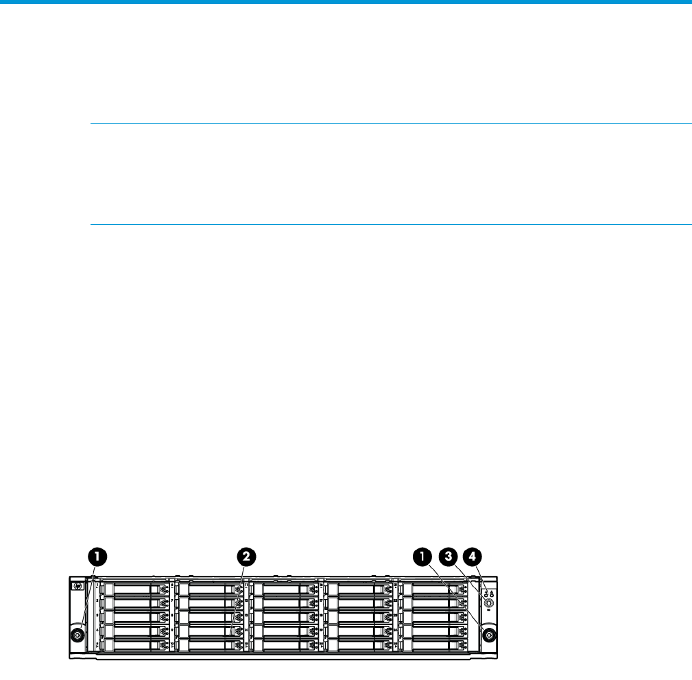
Small Form Factor disk enclosure chassis
Front view
3. UID push button and LED1. Rack-mounting thumbscrew
4. Enclosure status LEDs2. Disk drive in bay 9
SAS disk enclosures 13
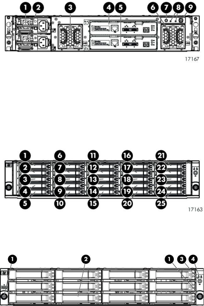
Rear view
7. UID push button and LED4. I/O module A1. Power supply 1
8. Enclosure status LEDs5. I/O module B2. Power supply 2
9. Power push button and LED6. Fan 23. Fan 1
Drive bay numbering
Disk drives mount in bays on the front of the enclosure. Bays are numbered sequentially from top
to bottom and left to right. Bay numbers are indicated on the left side of each drive bay.
Large Form Factor disk enclosure chassis
Front view
3. UID push button and LED1. Rack-mounting thumbscrew
4. Enclosure status LEDs2. Disk drive in bay 6
14 P63x0/P65x0 EVA hardware
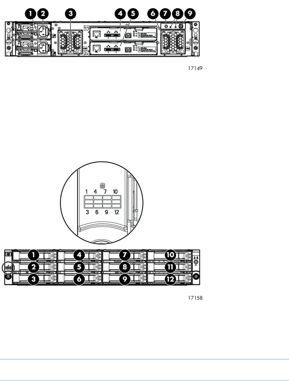
Rear view
7. UID push button and LED4. I/O module A1. Power supply 1
8. Enclosure status LEDs5. I/O module B2. Power supply 2
9. Power push button and LED6. Fan 23. Fan 1
Drive bay numbering
Disk drives mount in bays on the front of the enclosure. Bays are numbered sequentially from top
to bottom and left to right. A drive-bay legend is included on the left bezel.
Disk drives
Disk drives are hot-pluggable. A variety of disk drive models are supported for use.
Disk drive LEDs
Two LEDs indicate drive status.
NOTE: The following image shows a Small Form Factor (SFF) disk drive. LED patterns are the
same for SFF and LFF disk drives.
SAS disk enclosures 15
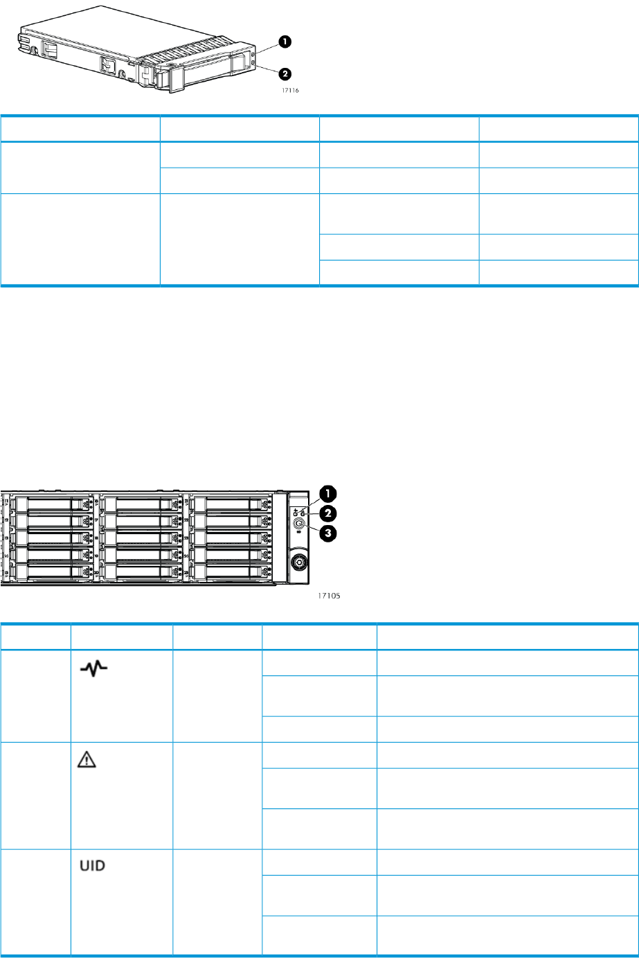
DescriptionLED statusLED colorLED
Locate driveSlow blinking (0.5 Hz)Blue1. Locate/Fault
Drive faultSolidAmber
Drive is spinning up or down
and is not ready
Blinking (1 Hz)Green2. Status
Drive activityFast blinking (4 Hz)
Ready for activitySolid
Disk drive blanks
To maintain the proper enclosure air flow, a disk drive or a disk drive blank must be installed in
each drive bay. The disk drive blank maintains proper airflow within the disk enclosure.
Front status and UID module
The front status and UID module includes status LEDs and a unit identification (UID) button.
Front UID module LEDs
DescriptionLED statusLED colorLED iconLED
No powerOffGreen1. Health
Enclosure is starting up and not ready,
performing POST
Blinking
Normal, power is onSolid
Normal, no fault conditionsOffAmber2. Fault
A fault of lesser importance was detected in the
enclosure chassis or modules
Blinking
A fault of greater importance was detected in
the enclosure chassis or modules
Solid
Not being identified or power is offOffBlue3. UID
Unit is being identified from the management
utility
Blinking
Unit is being identified from the UID button
being pushed
Solid
16 P63x0/P65x0 EVA hardware
Unit identification (UID) button
The unit identification (UID) button helps locate an enclosure and its components. When the UID
button is activated, the UID on the front and rear of the enclosure are illuminated.
NOTE: A remote session from the management utility can also illuminate the UID.
•To turn on the UID light, press the UID button. The UID light on the front and the rear of the
enclosure will illuminate solid blue. (The UID on cascaded storage enclosures are not
illuminated.)
•To turn off an illuminated UID light, press the UID button. The UID light on the front and the
rear of the enclosure will turn off.
Power supply module
Two power supplies provide the necessary operating voltages to all controller enclosure components.
If one power supply fails, the remaining power supply is capable of operating the enclosure.
(Replace any failed component as soon as possible.)
NOTE: If one of the two power supply modules fails, it can be hot-replaced.
Power supply LED
One LED provides module status information.
DescriptionLED status
No powerOff
Normal, no fault conditionsOn
Fan module
Fan modules provide cooling necessary to maintain proper operating temperature within the disk
enclosure. If one fan fails, the remaining fan is capable of cooling the enclosure. (Replace any
failed component as soon as possible.)
NOTE: If one of the two fan modules fail, it can be hot-replaced.
SAS disk enclosures 17
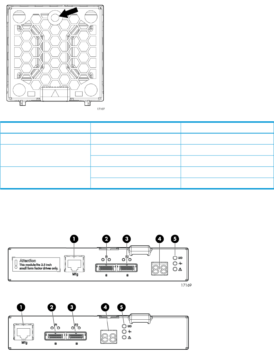
Fan module LED
One bi-color LED provides module status information.
DescriptionLED statusLED color
No powerOffOff
The module is being identifiedBlinkingGreen
Normal, no fault conditionsSolid
Fault conditions detectedBlinkingAmber
Problems detecting the moduleSolid
I/O module
The I/O module provides the interface between the disk enclosure and the host.
Each I/O module has two ports that can transmit and receive data for bidirectional operation.
4. Double 7–segment display1. Manufacturing diagnostic port
5. I/O module LEDs2. SAS Port 1
3. SAS Port 2
18 P63x0/P65x0 EVA hardware
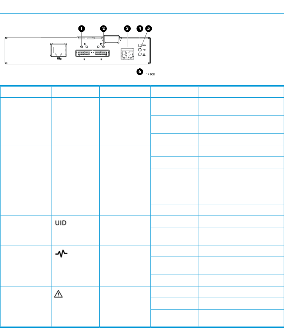
I/O module LEDs
LEDs on the I/O module provide status information about each I/O port and the entire module.
NOTE: The following image illustrates LEDs on the Small Form Factor I/O module.
DescriptionLED statusLED colorLED iconLED
No cable, no power, or port not
connected
OffGreenn/a1. SAS Port Link
The port is being identified by an
application client
Blinking
Healthy, active linkSolid
Normal, no errors detectedOffAmbern/a2. SAS Port Error
Error detected by application clientBlinking
Error, fault conditions detected on
the port by the I/O module
Solid
No cable, no power, enclosure not
detected
Offn/an/a3. 7–segment
display
The enclosure box numberNumber
Not being identified or no powerOffBlue4. UID
Module is being identified, from
the management utility
Solid
No power or firmware malfunctionOffGreen5. Health
Enclosure is starting up and not
ready, performing POST
Blinking
Normal, power is onSolid
Normal, no fault conditionsOffAmber6. Fault
A fault of lesser importanceBlinking
A fault of greater importance, I/O
failed to start
Solid
Rear power and UID module
The rear power and UID module includes status LEDs, a unit identification (UID) button, and the
power on/standby button.
SAS disk enclosures 19
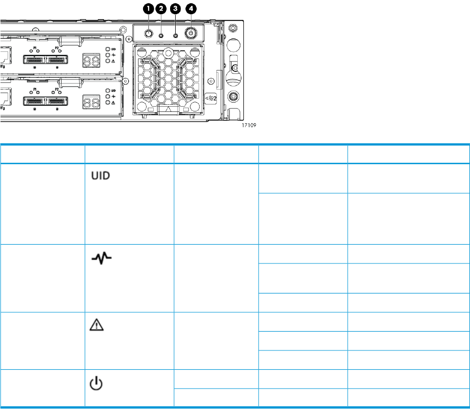
Rear power and UID module LEDs
DescriptionStatusLED colorLED iconLED
Not being identified or no
power
OffBlue1. UID
Unit is being identified, either
from the UID button being
On
pushed or from the
management utility
No powerOffGreen2. Health
Enclosure is starting up and
not ready, performing POST
Blinking
Normal, power is onSolid
Normal, no fault conditionsOffAmber3. Fault
A fault of lesser importanceBlinking
A fault of greater importanceSolid
Power is onSolidGreen4. On/Standby
Standby powerSolidAmber
20 P63x0/P65x0 EVA hardware
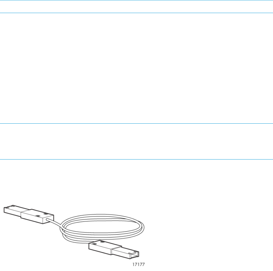
Unit identification (UID) button
The unit identification (UID) button helps locate an enclosure and its components. When the UID
button is activated, the UID on the front and rear of the enclosure are illuminated.
NOTE: A remote session from the management utility can also illuminate the UID.
•To turn on the UID light, press the UID button. The UID light on the front and the rear of the
enclosure will illuminate solid blue. (The UID on cascaded storage enclosures are not
illuminated.)
•To turn off an illuminated UID light, press the UID button. The UID light on the front and the
rear of the enclosure will turn off.
Power on/standby button
The power on/standby button applies either full or partial power to the enclosure chassis.
•To initially power on the enclosure, press and hold the on/standby button for a few seconds,
until the LEDs begin to illuminate.
•To place an enclosure in standby, press and hold the on standby button for a few seconds,
until the on/standby LED changes to amber.
NOTE: System power to the disk enclosure does not completely shut off with the power on/standby
button. The standby position removes power from most of the electronics and components, but
portions of the power supply and some internal circuitry remain active. To completely remove
power from the system, disconnect all power cords from the device.
SAS cables
These disk enclosures use cables with mini-SAS connectors for connections to the controller and
cascaded disk enclosures.
Controller enclosure
For both the P63x0 EVA and P65x0 EVA, a single enclosure contains a management module and
two controllers. Two interconnected controllers ensure that the failure of a controller component
does not disable the system. One controller can fully support an entire system until the defective
controller, or controller component, is repaired. The controllers have an 8 Gb host port capability.
The P63x0 and P65x0 EVA controllers are available in FC, FC-iSCSI, and iSCSI/FCoE versions.
The controller models are HSV340 (for the P63x0) and HSV360 (for the P65x0).
Figure 1 (page 22) shows the bezel of the controller enclosure. Figure 2 (page 22) shows the front
of the controller enclosure with the bezel removed.
Controller enclosure 21
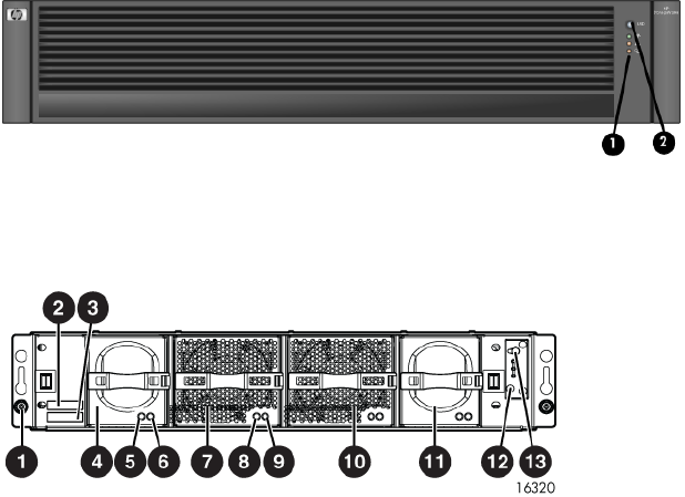
Figure 1 Controller enclosure (front bezel)
2. Front UID push button1. Enclosure status LEDs
Figure 2 Controller enclosure (front view with bezel removed)
8. Fan 1 normal operation LED1. Rack-mounting thumbscrew
9. Fan 1 fault LED2. Enclosure product number (PN) and serial number
10. Fan 23. World Wide Number (WWN)
11. Battery 24. Battery 1
12. Enclosure status LEDs5. Battery normal operation LED
13. Front UID push button6. Battery fault LED
7. Fan 1
Each P63x0 controller contains two SAS data ports. Each P65x0 controller contains four SAS data
ports (made possible using Y-cables—one cable with two outputs). For both the P63x0 and P65x0
EVA, the FC controller adds four 8 Gb FC ports (Figure 3 (page 23)); the FC-iSCSI controller adds
two 8 Gb FC ports and four 1 GbE iSCSI ports (Figure 4 (page 23)); and the iSCSI/FCoE controller
adds two 8 Gb FC ports and two10 GbE iSCSI/FCoE ports (Figure 5 (page 24)).
22 P63x0/P65x0 EVA hardware
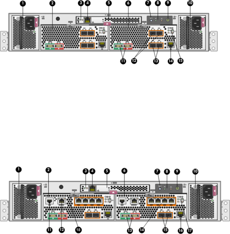
Figure 3 P6000 EVA FC controller enclosure (rear view)
9. Enclosure power push button1. Power supply 1
10. Power supply 22. Controller 1
11. DP-A and DP-B, connection to back end (storage)3. Management module status LEDs
12. FP1 and FP2, connection to front end (host or SAN)4. Ethernet port
13. FP3 and FP4, connection to front end (host or SAN)5. Management module
14. Manufacturing diagnostic port6. Controller 2
15. Controller status and fault LEDs7. Rear UID push button
8. Enclosure status LEDs
Figure 4 P6000 EVA FC-iSCSI controller enclosure (rear view)
10. Power supply 21. Power supply 1
11. Serial port2. Controller 1
12. SW Management port3. Management module status LEDs
13. DP-A and DP-B, connection to back-end (storage)4. Ethernet port
14. 1GbE ports 1–45. Management module
15. FP3 and FP4, connection to front end (host or SAN)6. Controller 2
16. Manufacturing diagnostic port7. Rear UID push button
17. Controller status and fault LEDs8. Enclosure status LEDs
18. iSCSI module recessed maintenance button9. Enclosure power push button
Controller enclosure 23
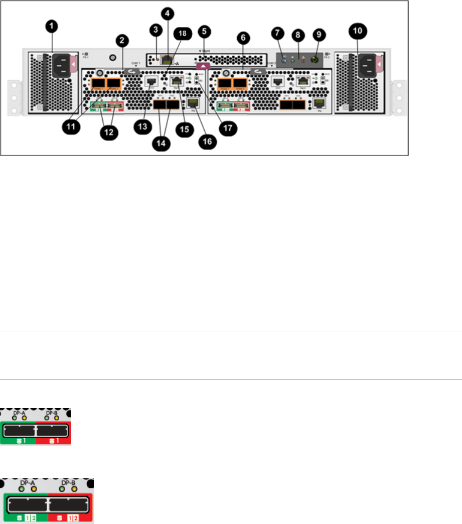
Figure 5 P6000 EVA iSCSI/FCoE controller enclosure (rear view)
10. Power supply 21. Power supply 1
11. 10GbE ports 1–22. Controller 1
12. DP-A and DP-B, connection to back-end (storage)3. Management module status LEDs
13. Serial port4. Ethernet port
14. FP3 and FP4, connection to front end (host or SAN)5. Management module
15. SW Management port6. Controller 2
16. Manufacturing diagnostic port7. Rear UID push button
17. Controller status and fault LEDs8. Enclosure status LEDs
18. iSCSI/FCoE recessed maintenance button9. Enclosure power push button
NOTE: The only difference between the P63x0 and P65x0 controllers is the number indicated
below the SAS data ports (DP-A and DP-B). On the P63x0, 1is displayed (Figure 6 (page 24)).
On the P65x0, 1 | 2is displayed (Figure 7 (page 24)).
Figure 6 P63x0 data port numbering
Figure 7 P65x0 data port numbering
Controller status indicators
The status indicators display the operational status of the controller. The function of each indicator
is described in Table 3 (page 25). During initial setup, the status indicators might not be fully
operational.
Each port on the rear of the controller has an associated status indicator located directly above it.
Table 1 (page 25) lists the port and its status description for the HSV340. Table 2 (page 25) lists
the port and its status descriptions for the HSV340 FC-iSCSI.
24 P63x0/P65x0 EVA hardware
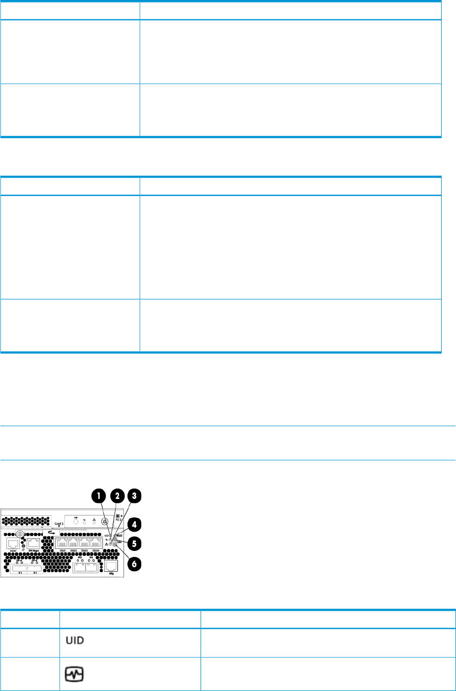
Table 1 HSV340/360 controller port status indicators
DescriptionPort
Fibre Channel host ports •Green — Normal operation
•Amber — No signal detected
•Off — No SFP1detected or the Direct Connect HP P6000 Control Panel
setting is incorrect
Fibre Channel device ports •Green — Normal operation
•Amber — No signal detected or the controller has failed the port
•Off — No SFP1detected
1On copper Fibre Channel cables, the SFP is integrated into the cable connector.
Table 2 HSV340/360 FC-iSCSI controller port status indicators
DescriptionPort
Fibre Channel switch ports •Green on — Normal operation or loopback port
•Green flashing — Normal online I/O activity
•Amber on — Faulted port, disabled due to diagnostics or Portdisable
command
•Amber flashing — Port with no synchronization, receiving light but not yet
online or segmented port
•Off — No SFP1, no cable, no license detected.
Fibre Channel device ports •Green — Normal operation
•Amber — No signal detected or the controller has failed the port
•Off — No SFP1detected
1On copper Fibre Channel cables, the SFP is integrated into the cable connector.
Controller status LEDs
Figure 8 (page 25) shows the location of the controller status LEDs; Table 3 (page 25) describes
them.
NOTE: Figure 8 (page 25) shows an FC-iSCSI controller, however the LEDs for the FC, FC-iSCSI,
and iSCSI/FCoE controllers are identical, unless specifically noted.
Figure 8 Controller status LEDs
Table 3 Controller status LEDs
IndicationLEDItem
Blue LED identifies a specific controller within the enclosure or
identifies the FC-iSCSI or iSCSI/FCoE module within the controller.
1
Green LED indicates controller health. LED flashes green during
boot and becomes solid green after boot.
2
Controller enclosure 25
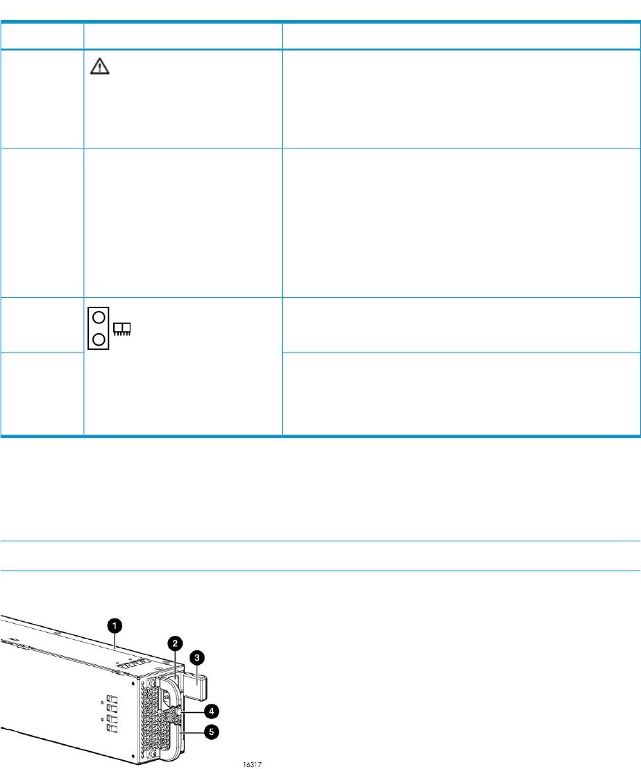
Table 3 Controller status LEDs (continued)
IndicationLEDItem
Flashing amber indicates a controller termination, or the system
is inoperative and attention is required. Solid amber indicates that
3
the controller cannot reboot, and that the controller should be
replaced. If both the solid amber and solid blue LEDs are lit, the
controller has completed a warm removal procedure, and can be
safely swapped.
Only used on the FC-iSCSI and iSCSI/FCoE controllers (not on
the FC controller).
MEZZ4
Amber LED indicates the FC-iSCSI or iSCSI/FCoE module status
that is communicated to the array controller.
Slow flashing amber LED indicates an IP address conflict on the
management port.
Solid amber indicates an FC-iSCSI or iSCSI/FCoE module critical
error, or shutdown.
Green LED indicates write-back cache status. Slow flashing green
LED indicates standby power. Solid green LED indicates cache is
good with normal AC power applied.
5
Amber LED indicates DIMM status. The LED is off when DIMM
status is good. Slow flashing amber indicates DIMMs are being
6
powered by battery (during AC power loss). Flashing amber with
the chassis powered up indicates a degraded battery. Solid amber
with the chassis powered up indicates a failed battery.
Power supply module
Two power supplies provide the necessary operating voltages to all controller enclosure components.
If one power supply fails, the remaining power supply is capable of operating the enclosure.
(Replace any failed component as soon as possible.)
NOTE: If one of the two power supply modules fails, it can be hot-replaced.
Figure 9 Power supply
4. Status indicator (dual-color: amber and green)1. Power supply
5. Handle2. AC input connector
3. Latch
26 P63x0/P65x0 EVA hardware
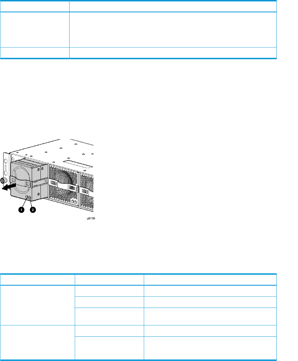
Table 4 Power supply LED status
DescriptionLED color
Amber •The power supply is powered up but not providing output power.
•The power supply is plugged into a running chassis, but is not receiving AC input
power (the fan and LED on the supply receive power from the other power supply in
this situation).
Normal, no fault conditionsGreen
Battery module
Battery modules provide power to the controllers in the enclosure.
Figure 10 Battery module pulled out
2. Amber—Fault LED1. Green—Normal operation LED
Each battery module provides power to the controller directly across from it in the enclosure.
Table 5 Battery status indicators
DescriptionFault indicatorStatus indicator
Normal operation.Solid greenOn left—Green
Maintenance in progress.Blinking
Amber is on or blinking, or the enclosure is powered
down.
Off
Battery failure; no cache hold-up. Green will be off.Solid amberOn right—Amber
Battery degraded; replace soon. Green will be off.
(Green and amber are not on simultaneously except for
a few seconds after power-up.)
Blinking amber
Fan module
Fan modules provide the cooling necessary to maintain the proper operating temperature within
the controller enclosure. If one fan fails, the remaining fan is capable of cooling the enclosure.
Controller enclosure 27
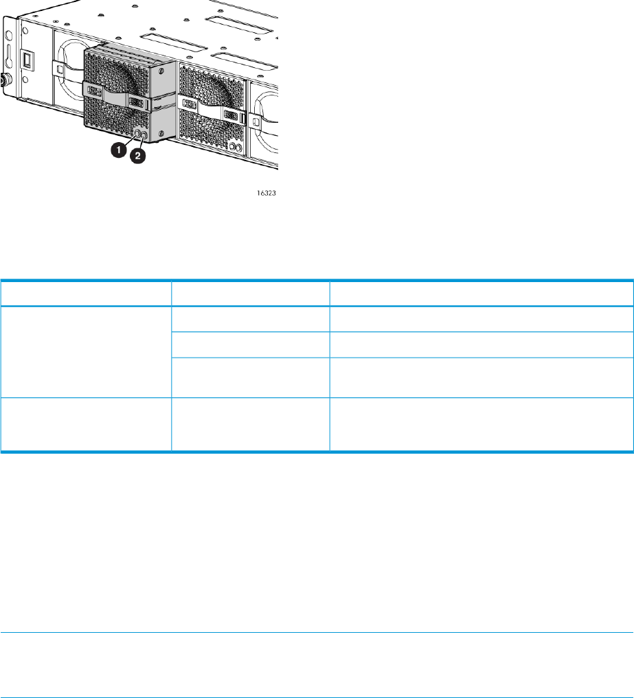
Figure 11 Fan module pulled out
2. Amber—Fan fault LED1. Green—Fan normal operation LED
Table 6 Fan status indicators
DescriptionFault indicatorStatus indicator
Normal operation.Solid greenOn left—Green
Maintenance in progress.Blinking
Amber is on or blinking, or the enclosure is powered
down.
Off
Fan failure. Green will be off. (Green and amber are
not on simultaneously except for a few seconds after
power-up.)
OnOn right—Amber
Management module
The HP P6000 Control Panel provides a direct interface to the management module within each
controller. From the HP P6000 Control Panel you can display storage system status and configuration
information, shut down the storage system, and manage the password. For tasks to perform with
the HP P6000 Control Panel, see the HP P6000 Control Panel online help.
The HP P6000 Control Panel provides two levels of administrator access and an interface for
software updates to the management module. For additional details about the HP P6000 Control
Panel, see the HP P6000 Control Panel online help.
NOTE: The HP P6350 and P6550 employ a performance-enhanced management module as
well as new batteries. This requires HP P6000 Command View 10.1 or later on the management
module and XCS 11000000 or later on the P6350 and P6550.
iSCSI and iSCSI/FCoE recessed maintenance button
The iSCSI and iSCSI/FCoE recessed maintenance button is the only manual user-accessible control
for the module. It is used to reset or to recover a module. This maintenance button is a multifunction
momentary switch and provides the following functions, each of which causes a reboot that
completes in less than one minute:
•Reset the iSCSI or iSCSI/FCoE module and boot the primary image
•Reset the iSCSI or iSCSI/FCoE MGMT port IP address
•Enable iSCSI or iSCSI/FCoE MGMT port DHCP address
•Reset the iSCSI or iSCSI/FCoE module to factory defaults
28 P63x0/P65x0 EVA hardware

Reset the iSCSI or iSCSI/FCoE module and boot the primary image
Use a pointed nonmetallic tool to briefly press the maintenance button for a duration of two seconds
and release it. The iSCSI or iSCSI/FCoE module responds as follows:
1. The amber MEZZ status LED illuminates once.
NOTE: Holding the maintenance button for more than two seconds but less than six seconds
or until the MEZZ status LED illuminates twice, boots a secondary image, and is not
recommended for field use.
2. After approximately two seconds, the power-on self-test begins, and the MEZZ status LED is
turned off.
3. When the power-on self test is complete, the MEZZ status LED illuminates and flashes once
per second.
Reset iSCSI or iSCSI/FCoE MGMT port IP address
Reset and restore the MGMT port IP address to the default of 192.168.0.76 or 192.168.0.82
depending on the controller 1 or 2 position.
NOTE: Setting the IP address by this method is not persistent. To make the change persistent,
use the command line interface (CLI).
1. Use a pointed nonmetallic tool to briefly press the maintenance button. Release the button
after six seconds and observe six extended flashes of the MEZZ status LED.
2. The iSCSI or iSCSI/FCoE module boots and sets the MGMT port to IP address 192.168.0.76
or 192.168.0.82 depending on the controller 1 or 2 position.
Enable iSCSI or iSCSI/FCoE MGMT port DHCP address
Resets the iSCSI or iSCSI/FCoE module and configure the MGMT port to use DHCP to access its
IP address. Enabling DHCP by this method is not persistent. To make the change persistent, use
the CLI .
1. Use a pointed nonmetallic tool to briefly press the maintenance button. Release the button
after seven seconds and observe seven extended flashes of the MEZZ status LED.
2. The iSCSI or iSCSI/FCoE module boots and configures the MGMT port for DHCP.
Reset the iSCSI or iSCSI/FCoE module to factory defaults
This resets the iSCSI or iSCSI/FCoE module and restores it to the factory default configuration,
with reset passwords, MGMT port IP address set to either 192.168.0.76 or 192.168.0.82
depending on the controller 1 or 2 position, Disables iSCSI ports with no IP address, erases
presentations, and erases discovered initiators and targets).
1. Use a pointed nonmetallic tool to press the maintenance button. Release the button after twenty
seconds and observe twenty extended flashes of the MEZZ status LED.
2. The iSCSI or iSCSI/FCoE module boots and is restored to factory defaults.
HSV controller cabling
All data cables and power cables attach to the rear of the controller. Adjacent to each data
connector is a two-colored link status indicator. Table 1 (page 25) identifies the status conditions
presented by these indicators.
NOTE: These indicators do not indicate whether there is communication on the link, only whether
the link can transmit and receive data.
The data connections are the interfaces to the disk drive enclosures, the other controller, and the
fabric. Fiber optic cables link the controllers to the fabric, and, if an expansion cabinet is part of
the configuration, link the expansion cabinet drive enclosures to the loops in the main cabinet.
HSV controller cabling 29
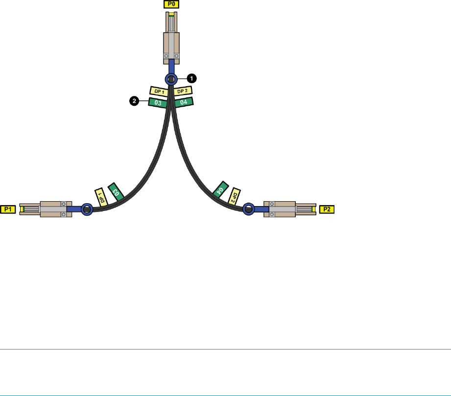
Y-cables (Figure 12 (page 30)) are used to connect the P6500 EVA and enable each controller
data port to act as two ports.
Figure 12 P6500 Y-cable
2. Port number label1. Pull tab (may also be a release bar)
Storage system racks
All storage system components are mounted in a rack. Each configuration includes one controller
enclosure holding both controllers (the controller pair) and the disk enclosures. Each controller pair
and all associated disk enclosures form a single storage system.
The rack provides the capability for mounting standard 483 mm (19 in) wide controller and disk
enclosures.
NOTE: Racks and rack-mountable components are typically described using “U” measurements.
“U” measurements are used to designate panel or enclosure heights. The “U” measurement is a
standard of 41mm (1.6 in).
The racks provide the following:
•Unique frame and rail design—Allows fast assembly, easy mounting, and outstanding structural
integrity.
•Thermal integrity—Front-to-back natural convection cooling is greatly enhanced by the innovative
multi-angled design of the front door.
•Security provisions—The front and rear door are lockable, which prevents unauthorized entry.
•Flexibility—Provides easy access to hardware components for operation monitoring.
•Custom expandability—Several options allow for quick and easy expansion of the racks to
create a custom solution.
Rack configurations
The standard rack for the P63x0/P65x0 EVA is the 42U HP 10000 Intelligent Series rack. The
P63x0/P65x0 EVA is also supported with 22U, 36U, 42U 5642, and 47U racks. The 42U 5642
is a field-installed option. The 47U rack must be assembled on site because the cabinet height
creates shipping difficulties.
For more information on HP rack offerings for the P63x0/P65x0 EVA see:
30 P63x0/P65x0 EVA hardware

http://h18004.www1.hp.com/products/servers/proliantstorage/racks/index.html
Power distribution units
AC power is distributed to the rack through a dual Power Distribution Unit (PDU) assembly mounted
at the bottom rear of the rack (modular PDU) or on the rack (monitored PDU). The modular PDU
may be mounted back-to-back either vertically (AC receptacles facing down and circuit breaker
switches facing up) or horizontally (AC receptacles facing front and circuit breaker switches facing
rear). For information about PDU support with the P63x0/P65x0 EVA, see the HP P6300/P6500
Enterprise Virtual Arrays QuickSpecs. For details and specifications about specific PDU models,
see the HP Power Distribution Units website:
http://h18004.www1.hp.com/products/servers/proliantstorage/power-protection/pdu.html
The standard power configuration for any HP Enterprise Virtual Array rack is the fully redundant
configuration. Implementing this configuration requires:
•Two separate circuit breaker-protected, 30-A site power sources with a compatible wall
receptacle.
•One dual PDU assembly. Each PDU connects to a different wall receptacle.
•Four to eight (depending on the rack) Power Distribution Modules (PDMs) per rack. All PDMs
are located (side by side in pairs) on the left side of the rack. Each set of PDMs connects to
a different PDU.
◦Eight PDMs for 42U, 47 U, and 42U 5642 racks
◦Six PDMs for 36U racks
◦Four PDMs for 22U racks
•Each controller enclosure has two power supplies:
Controller PS 1 connects to the left PDM in a PDM pair with a black, 66 cm (26 inch)
power cord.
◦
◦Controller PS 2 connects to the right PDM in a PDM pair with a gray, 152 cm (60 inch)
power cord.
NOTE: Drive enclosures, when purchased separately, include one 50 cm black cable and one
50 cm gray cable.
The configuration provides complete power redundancy and eliminates all single points of failure
for both the AC and DC power distribution.
PDU 1
PDU 1connects to AC PDM 1–1 to 1–4.
A PDU 1failure:
•Disables the power distribution circuit
•Removes power from the left side of the PDM pairs
•Disables drive enclosures PS 1
•Disables the controller PS 1
PDU 2
PDU 2connects to AC PDM 2-1 to 2–4.
Power distribution units 31
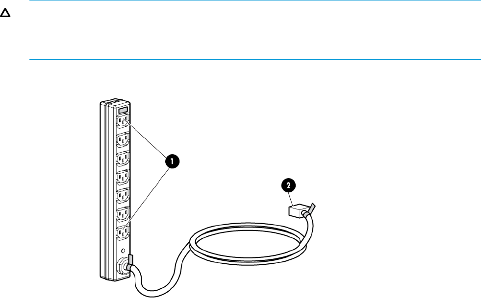
A PDU 2 failure:
•Disables the power distribution circuit
•Removes power from the right side of the PDM pairs
•Disables drive enclosures PS 2
•Disables the controller PS 2
PDMs
Depending on the rack, there can be up to eight PDMs mounted in the rear of the rack:
•The PDMs on the left side of the PDM pairs connect to PDU 1.
•The PDMs on the right side of the PDM pairs connect to PDU 2.
Each PDM has seven AC receptacles. The PDMs distribute the AC power from the PDUs to the
enclosures. Two power sources exist for each controller pair and disk enclosure. If a PDU fails, the
system will remain operational.
CAUTION: The AC power distribution within a rack ensures a balanced load to each PDU and
reduces the possibility of an overload condition. Changing the cabling to or from a PDM could
cause an overload condition. HP supports only the AC power distributions defined in this user
guide.
Figure 13 Rack PDM
1. Power receptacles
2. AC power connector
32 P63x0/P65x0 EVA hardware
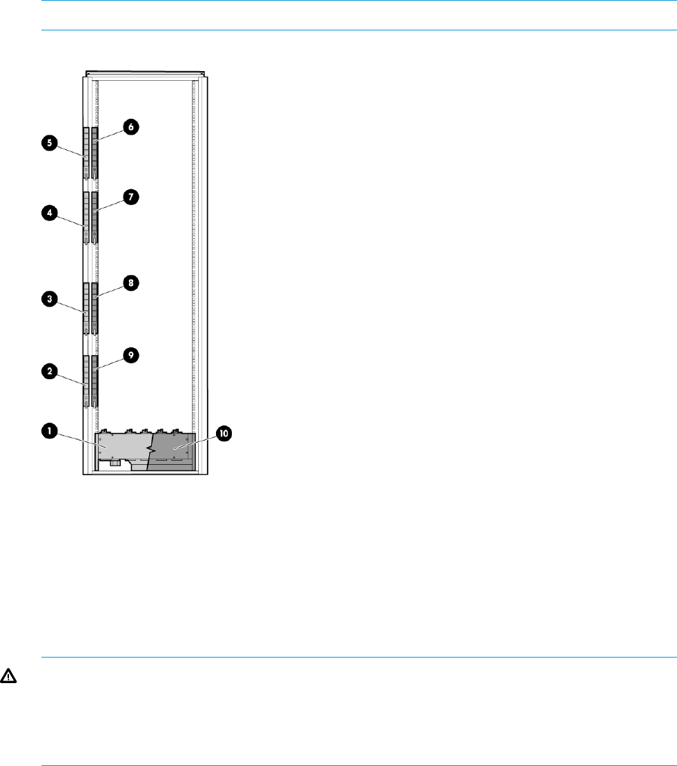
Rack AC power distribution
The power distribution in a rack is the same for all variants. The site AC input voltage is routed to
the dual PDU assembly mounted in the bottom rear of the rack. Each PDU distributes AC to a
maximum of four PDMs mounted in pairs on the left vertical rail (see Figure 14 (page 33)).
•PDMs 1–1 through 1–4 connect to receptacles A through D on PDU A. Power cords connect
these PDMs to the left power supplies on the disk enclosures (disk PS 1) and to the left power
supply on the controller enclosure (controller PS 1).
•PDMs 2–1 through 2–4 connect to receptacles A through D on PDU B. Power cords connect
these PDMs to the right power supplies on the disk enclosures (disk PS 2) and to the right
power supply on the controller enclosure (controller PS 2).
NOTE: The locations of the PDUs and the PDMs are the same in all racks.
Figure 14 Rack AC power distribution
6. PDM 2–11. PDU 1
7. PDM 2–22. PDM 1–1
8. PDM 2–33. PDM 1–2
9. PDM 2–44. PDM 1–3
10. PDU 25. PDM 1–4
Moving and stabilizing a rack
WARNING! The physical size and weight of the rack requires a minimum of two people to move.
If one person tries to move the rack, injury may occur.
To ensure stability of the rack, always push on the lower half of the rack. Be especially careful
when moving the rack over any bump (e.g., door sills, ramp edges, carpet edges, or elevator
openings). When the rack is moved over a bump, there is a potential for it to tip over.
Moving and stabilizing a rack 33
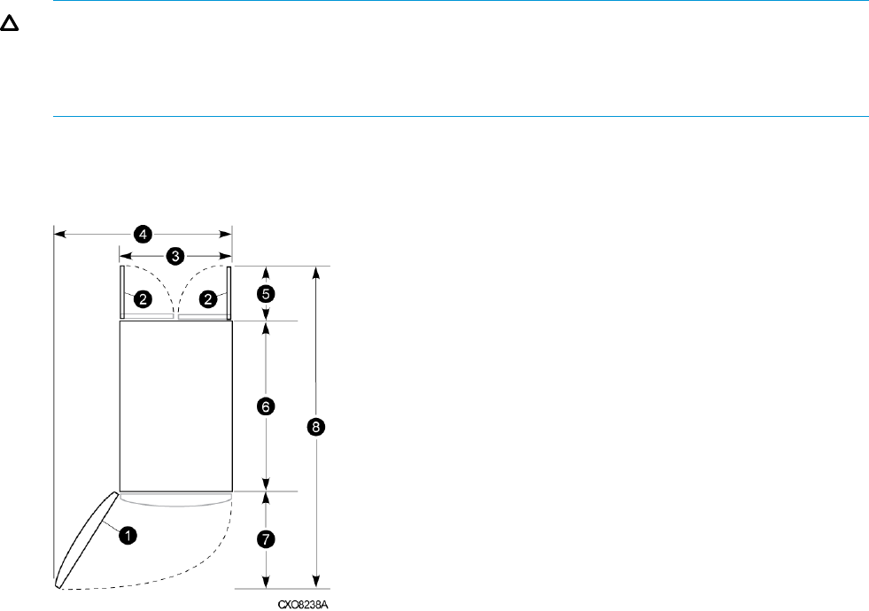
Moving the rack requires a clear, uncarpeted pathway that is at least 80 cm (31.5 in) wide for
the 60.3 cm (23.7 in) wide, 42U rack. A vertical clearance of 203.2 cm (80 in) should ensure
sufficient clearance for the 200 cm (78.7 in) high, 42U rack.
CAUTION: Ensure that no vertical or horizontal restrictions exist that would prevent rack movement
without damaging the rack.
Make sure that all four leveler feet are in the fully raised position. This process will ensure that the
casters support the rack weight and the feet do not impede movement.
Each rack requires an area 600 mm (23.62 in) wide and 1000 mm (39.37 in) deep (see
Figure 15 (page 34)).
Figure 15 Single rack configuration floor space requirements
5. Rear service area depth 300 mm1. Front door
6. Rack depth 1000 mm2. Rear door
7. Front service area depth 406 mm3. Rack width 600 mm
8. Total rack depth 1706 mm4. Service area width 813 mm
If the feet are not fully raised, complete the following procedure:
1. Raise one foot by turning the leveler foot hex nut counterclockwise until the weight of the rack
is fully on the caster (see Figure 16 (page 35)).
2. Repeat Step 1 for the other feet.
34 P63x0/P65x0 EVA hardware
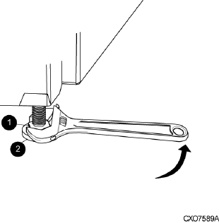
Figure 16 Raising a leveler foot
1. Hex nut
2. Leveler foot
3. Carefully move the rack to the installation area and position it to provide the necessary service
areas (see Figure 15 (page 34)).
To stabilize the rack when it is in the final installation location:
1. Use a wrench to lower the foot by turning the leveler foot hex nut clockwise until the caster
does not touch the floor. Repeat for the other feet.
2. After lowering the feet, check the rack to ensure it is stable and level.
3. Adjust the feet as necessary to ensure the rack is stable and level.
Moving and stabilizing a rack 35

2 P63x0/P65x0 EVA operation
Best practices
For useful information on managing and configuring your storage system, see the HP P6300/P6500
Enterprise Virtual Array configuration best practices white paper available at:
http://h18006.www1.hp.com/storage/arraywhitepapers.html
Operating tips and information
Reserving adequate free space
To ensure efficient storage system operation, reserve some unallocated capacity, or free space, in
each disk group. The recommended amount of free space is influenced by your system configuration.
For guidance on how much free space to reserve, see the HP P6300/P6500 Enterprise Virtual
Array configuration best practices white paper.
Using SAS-midline disk drives
SAS-midline drives are designed for lower duty cycle applications such as near online data
replication for backup. Do not use these drives as a replacement for EVA's high performance,
standard duty cycle, Fibre Channel drives. This practice could shorten the life of the drive.
Failback preference setting for HSV controllers
Table 7 (page 36) describes the failback preference setting for the controllers.
Table 7 Failback preference settings
BehaviorPoint in timeSetting
The units are alternately brought online to
Controller 1 or to Controller 2.
At initial presentationNo preference
If cache data for a LUN exists on a particular
controller, the unit will be brought online there.
On dual boot or controller resynch
Otherwise, the units are alternately brought
online to Controller 1 or to Controller 2.
All LUNs are brought online to the surviving
controller.
On controller failover
All LUNs remain on the surviving controller.
There is no failback except if a host moves the
LUN using SCSI commands.
On controller failback
The units are brought online to Controller 1.At initial presentationPath A - Failover Only
If cache data for a LUN exists on a particular
controller, the unit will be brought online there.
On dual boot or controller resynch
Otherwise, the units are brought online to
Controller 1.
All LUNs are brought online to the surviving
controller.
On controller failover
All LUNs remain on the surviving controller.
There is no failback except if a host moves the
LUN using SCSI commands.
On controller failback
The units are brought online to Controller 2.At initial presentationPath B - Failover Only
If cache data for a LUN exists on a particular
controller, the unit will be brought online there.
On dual boot or controller resynch
36 P63x0/P65x0 EVA operation

Table 7 Failback preference settings (continued)
BehaviorPoint in timeSetting
Otherwise, the units are brought online to
Controller 2.
All LUNs are brought online to the surviving
controller.
On controller failover
All LUNs remain on the surviving controller.
There is no failback except if a host moves the
LUN using SCSI commands.
On controller failback
The units are brought online to Controller 1.At initial presentationPath A -
Failover/Failback If cache data for a LUN exists on a particular
controller, the unit will be brought online there.
On dual boot or controller resynch
Otherwise, the units are brought online to
Controller 1.
All LUNs are brought online to the surviving
controller.
On controller failover
All LUNs remain on the surviving controller.
After controller restoration, the units that are
On controller failback
online to Controller 2 and set to Path A are
brought online to Controller 1. This is a
one-time occurrence. If the host then moves the
LUN using SCSI commands, the LUN will
remain where moved.
The units are brought online to Controller 2.At initial presentationPath B -
Failover/Failback If cache data for a LUN exists on a particular
controller, the unit will be brought online there.
On dual boot or controller resynch
Otherwise, the units are brought online to
Controller 2.
All LUNs are brought online to the surviving
controller.
On controller failover
All LUNs remain on the surviving controller.
After controller restoration, the units that are
On controller failback
online to Controller 1 and set to Path B are
brought online to Controller 2. This is a
one-time occurrence. If the host then moves the
LUN using SCSI commands, the LUN will
remain where moved.
Table 8 (page 37) describes the failback default behavior and supported settings when
ALUA-compliant multipath software is running with each operating system. Recommended settings
may vary depending on your configuration or environment.
Table 8 Failback settings by operating system
Supported settingsDefault behaviorOperating system
No preferenceHost follows the unit1
HP-UX
Path A/B – Failover only
Path A/B – Failover/Failback
No preferenceAuto failback done by the hostIBM AIX
Path A/B – Failover only
Path A/B – Failover/Failback
No preferenceAuto failback done by the hostLinux
Operating tips and information 37

Table 8 Failback settings by operating system (continued)
Supported settingsDefault behaviorOperating system
Path A/B – Failover only
Path A/B – Failover/Failback
No preferenceHost follows the unit1
OpenVMS
Path A/B – Failover only
Path A/B – Failover/Failback
(recommended)
No preferenceHost follows the unit1
Oracle Solaris
Path A/B – Failover only
Path A/B – Failover/Failback
No preferenceHost follows the unit1
VMware
Path A/B – Failover only
Path A/B – Failover/Failback
No preferenceFailback performed on the hostWindows
Path A/B – Failover only
Path A/B – Failover/Failback
1If preference has been configured to ensure a more balanced controller configuration, the Path A/B –Failover/Failback
setting is required to maintain the configuration after a single controller reboot.
Changing virtual disk failover/failback setting
Changing the failover/failback setting of a virtual disk may impact which controller presents the
disk. Table 9 (page 38) identifies the presentation behavior that results when the failover/failback
setting for a virtual disk is changed.
NOTE: If the new setting moves the presentation of the virtual disk to a new controller, any
snapshots or snapclones associated with the virtual disk are also moved.
Table 9 Impact on virtual disk presentation when changing failover/failback setting
Impact on virtual disk presentationNew setting
None. The disk maintains its original presentation.No Preference
If the disk is currently presented on Controller 2, it is moved to Controller 1.Path A Failover
If the disk is on Controller 1, it remains there.
If the disk is currently presented on Controller 1, it is moved to Controller 2.Path B Failover
If the disk is on Controller 2, it remains there.
If the disk is currently presented on Controller 2, it is moved to Controller 1.Path A Failover/Failback
If the disk is on Controller 1, it remains there.
If the disk is currently presented on Controller 1, it is moved to Controller 2.Path B Failover/Failback
If the disk is on Controller 2, it remains there.
Implicit LUN transition
Implicit LUN transition automatically transfers management of a virtual disk to the array controller
that receives the most read requests for that virtual disk. This improves performance by reducing
the overhead incurred when servicing read I/Os on the non-managing controller. Implicit LUN
transition is enabled in all versions of XCS.
38 P63x0/P65x0 EVA operation

When creating a virtual disk, one controller is selected to manage the virtual disk. Only this
managing controller can issue I/Os to a virtual disk in response to a host read or write request. If
a read I/O request arrives on the non-managing controller, the read request must be transferred
to the managing controller for servicing. The managing controller issues the I/O request, caches
the read data, and mirrors that data to the cache on the non-managing controller, which then
transfers the read data to the host. Because this type of transaction, called a proxy read, requires
additional overhead, it provides less than optimal performance. (There is little impact on a write
request because all writes are mirrored in both controllers’ caches for fault protection.)
With implicit LUN transition, when the array detects that a majority of read requests for a virtual
disk are proxy reads, the array transitions management of the virtual disk to the non-managing
controller. This improves performance because the controller receiving most of the read requests
becomes the managing controller, reducing proxy read overhead for subsequent I/Os.
Implicit LUN transition is disabled for all members of an HP P6000 Continuous Access DR group.
Because HP P6000 Continuous Access requires that all members of a DR group be managed by
the same controller, it would be necessary to move all members of the DR group if excessive proxy
reads were detected on any virtual disk in the group. This would impact performance and create
a proxy read situation for the other virtual disks in the DR group. Not implementing implicit LUN
transition on a DR group may cause a virtual disk in the DR group to have excessive proxy reads.
Recovery CD
HP does not ship the recovery CD with the HP P6350/P6550 EVA. You can download the image
from the HP Software Depot at the following URL and burn a CD, if needed:
http://www.software.hp.com
Adding disk drives to the storage system
As your storage requirements grow, you may be adding disk drives to your storage system. Adding
new disk drives is the easiest way to increase the storage capacity of the storage system. Disk
drives can be added online without impacting storage system operation.
Consider the following best practices to improve availability when adding disks to an array:
•Set the add disk option to manual.
•Add disks one at a time, waiting a minimum of 60 seconds between disks.
•Distribute disks vertically and as evenly as possible to all the disk enclosures.
•Unless otherwise indicated, use the SET DISK_GROUP command in the HP Storage System
Scripting Utility to add new disks to existing disk groups.
•Add disks in groups of eight.
•For growing existing applications, if the operating system supports virtual disk growth, increase
virtual disk size. Otherwise, use a software volume manager to add new virtual disks to
applications.
See the HP Disk Drive Replacement Instructions for the steps to add a disk drive. See “Replacement
instructions” (page 85) for a link to this document.
Handling fiber optic cables
This section provides protection methods for fiber optic connectors.
Contamination of the fiber optic connectors on either a transceiver or a cable connector can impede
the transmission of data. Therefore, protecting the connector tips against contamination or damage
is imperative. The tips can be contaminated by touching them, by dust, or by debris. They can be
damaged when dropped. To protect the connectors against contamination or damage, use the
dust covers or dust caps provided by the manufacturer. These covers are removed during installation,
and should be installed whenever the transceivers or cables are disconnected.
Operating tips and information 39

The transceiver dust caps protect the transceivers from contamination. Do not discard the dust
covers.
CAUTION: To avoid damage to the connectors, always install the dust covers or dust caps
whenever a transceiver or a fiber cable is disconnected. Remove the dust covers or dust caps from
transceivers or fiber cable connectors only when they are connected. Do not discard the dust covers.
To minimize the risk of contamination or damage, do the following:
•Dust covers—Remove and set aside the dust covers and dust caps when installing an I/O
module, a transceiver or a cable. Install the dust covers when disconnecting a transceiver or
cable.
One of the many sources for cleaning equipment specifically designed for fiber optic connectors
is:
Alcoa Fujikura Ltd.
1-888-385-4587 (North America)
011-1-770-956-7200 (International)
Storage system shutdown and startup
You can shut down the array from HP P6000 Command View or from the array controller.
The shutdown process performs the following functions in the indicated order:
1. Flushes cache
2. Removes power from the controllers
3. Disables cache battery power
4. Removes power from the drive enclosures
5. Disconnects the system from HP P6000 Command View
NOTE: The storage system may take several minutes (up to 15) to complete the necessary cache
flush during controller shutdown when snapshots are being used. The delay may be particularly
long if multiple child snapshots are used, or if there has been a large amount of write activity to
the snapshot source virtual disk.
Powering on disk enclosures
IMPORTANT: Always power up disk enclosures before controllers and servers. This ensures that
the servers, during their discovery, see the enclosure as an operational device. If you do not power
up the disk enclosures before powering up the controllers and servers, you will need to power
down the servers, ensure that the disk enclosures are powered up, and then power back up the
servers.
1. Apply power to each UPS.
2. Apply power to the disk enclosures by pressing and holding the power on/standby button on
the rear of the disk enclosures until the system power LED illuminates solid green.
The LED on the power on/standby button changes from amber to solid green, indicating that
the disk enclosure has transitioned from a standby state to fully powered.
3. Wait a few minutes for the disk enclosures to complete their startup routines.
CAUTION: If power is applied to the controller before the disk enclosures complete their
startup routine, the array might not start properly.
4. Power on (or restart) the controller and allow the array to complete startup.
5. Using P6000 Command View, verify that each component is operating properly.
40 P63x0/P65x0 EVA operation

Powering off disk enclosures
CAUTION: Be sure that the server controller is the first unit to be powered down and the last to
be powered back up. Taking this precaution ensures that the system does not erroneously mark
the disk drives as failed when the server is later restarted. It is recommended to perform this action
with P6000 Command View (see below).
IMPORTANT: If installing a hot-plug device, it is not necessary to power down the enclosure.
To power off a disk enclosure:
1. Power down any attached servers. See the server documentation.
2. Perform an orderly shutdown of the array controllers.
3. Allow all components to enter standby power mode. Note that not all indicators may be off.
4. Disconnect the power cords
The system is now powered down.
Shutting down the storage system from HP P6000 Command View
1. Start HP P6000 Command View.
2. Select the appropriate storage system in the Navigation pane.
The Initialized Storage System Properties window for the selected storage system opens.
3. Click Shut down.
The Shutdown Options window opens.
4. Under System Shutdown click Power Down. If you want to delay the initiation of the shutdown,
enter the number of minutes in the Shutdown delay field.
The controllers complete an orderly shutdown and then power off. The disk enclosures then
power off. Wait for the shutdown to complete.
5. Turn off the power to the rack power distribution units. Even though the disk enclosures are
powered off in Step 4, unless the power on the rack distribution units are turned off, the I/O
modules remain powered on in a standby state.
Shutting down the storage system from the array controller
CAUTION: Use this power off method for emergency shutdown only. This is not an orderly
shutdown and cached data could be lost.
1. Push and hold the power switch button on the back panel of the P63x0/P65x0 EVA (see
callout 9 in Figure 3 (page 23)).
2. Wait 4 seconds. The power button and the green LED start to blink.
NOTE: Use this power off method for emergency shutdown only. This is not an orderly
shutdown and cached data could be lost.
3. After 10 seconds, the power shuts down.
Starting the storage system
To start a storage system, perform the following steps:
1. Turn on the SAN switches and wait for all switches to complete the power-on boot process.
It may be necessary to wait several minutes for this to complete.
NOTE: Before applying power to the rack PDUs, ensure that the power switch on the controller
enclosure is off.
Storage system shutdown and startup 41

2. Ensure all power cords are connected to the controller enclosure and disk enclosures. Apply
power to the rack PDUs.
3. Apply power to the controller enclosure (rear panel on the enclosure). The disk enclosures will
power on automatically. Wait for a solid green status LED on the controller enclosure and disk
enclosures (approximately five minutes).
4. Wait (up to five minutes) for the array to complete its startup routine.
5. Apply power to the servers in the SAN with access to the array, start the operating system,
and log in as administrator.
CAUTION:
•If power is applied to a server and it attempts to boot off of an array that has not been
powered on properly, the server will not start.
•If a New Hardware Found message appears when you power on a server, cancel the
message and ensure that supported drivers are installed on the server.
6. Start HP P6000 Command View and verify connection to the storage system. If the storage
system is not visible, click EVA Storage Network in the navigation pane, and then click Discover
in the content pane to discover the array.
NOTE: If the storage system is still not visible, reboot the management server or management
module to re-establish the communication link.
7. Check the storage system status using HP P6000 Command View to ensure everything is
operating properly. If any status indicator is not normal, check the log files or contact your
HP-authorized service provider for assistance.
There is a feature in the HP P6000 Control Panel that enables the controllers to boot automatically
when power is applied after a full shutdown. See the HP P6000 Control Panel online help or user
guide for details about setting this feature. To further clarify the use of this feature:
•If this feature is disabled and you turn on power to the array from the rack power distribution
unit (PDU), only the disk enclosures boot up. With this feature enabled, the controllers will
also boot up, making the entire array ready for use.
•If, after setting this feature, you remove the management module from its slot and reinsert it
to reset power or you restart the management module from the HP P6000 Control Panel, only
the controllers will automatically boot up after a full shutdown. In this scenario, you must ensure
that the disk enclosures are powered up first; otherwise, the controller boot up process may
be interrupted.
•After setting this HP P6000 Control Panel feature, if you have to shut down the array, perform
the following steps:
1. Use HP P6000 Command View to shut down the controllers and disk enclosures.
2. Turn off power from the rack power distribution unit (PDU).
3. Turn on power from the rack PDU.
After startup of the management module, the controllers will automatically start.
Restarting the iSCSI or iSCSI/FCoE module
If you determine that the iSCSI or iSCSI/FCoE modules must be rebooted, you can use HP P6000
Command View to restart the modules. Shutting down the iSCSI or iSCSI/FCoE modules through
HP P6000 Command View is not supported. You must use the CLI to shut down the modules and
then power cycle the array to power on the modules after the shutdown.
To restart a module:
1. Select the iSCSI controller in the navigation pane.
2. Select Shutdown on the iSCSI Controller Properties window.
42 P63x0/P65x0 EVA operation
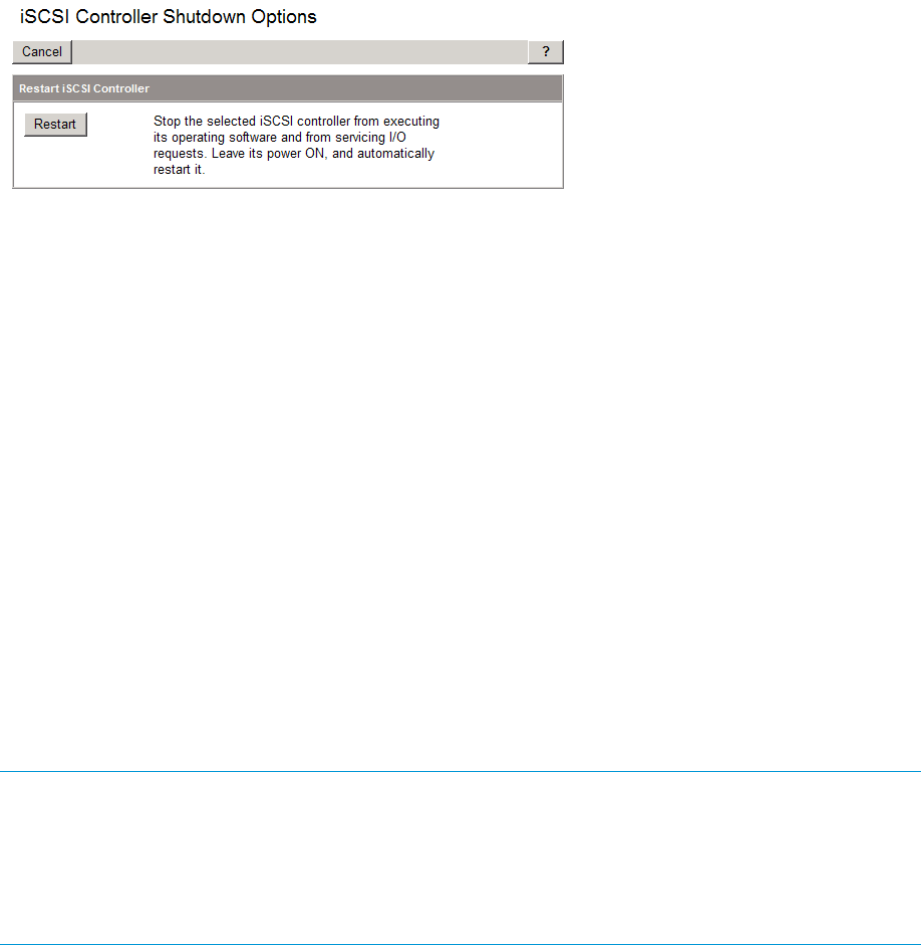
3. Select Restart on the iSCSI Controller Shutdown Options window (Figure 17 (page 46)).
Figure 17 iSCSI Controller Shutdown Options
The following is an example of the shutdown procedure using the CLI:
MEZ75 login: guest
Password:********
Welcome to MEZ75
**********************************************
* *
* HP StorageWorks MEZ75 *
* *
**********************************************
MEZ75 #> admin start -p config
MEZ75 (admin) #> shutdown
Are you sure you want to shutdown the System (y/n): y
Using the management module
Connecting to the management module
You can connect to the management module through a public or a private network.
NOTE: If you are using HP P6000 Command View on the management server to manage the
P63x0/P65x0 EVAs, HP recommends that when accessing HP P6000 Command View on either
the management server (server-based management) or the management module (array-based
management), you use the same network. This is recommended until a multi-homed solution is
available, which would allow the management module access to be configured on a separate
network (private or different).
If you use a laptop to connect to the management module, configure the laptop to have an address
in the same IP range as the management module (for example, 192.168.0.2 with a subnet mask
of 255.255.255.0).
The management module has an MDI-X port that supports straight-through or crossover Ethernet
cables. Use a Cat5e or greater cable to connect the management module from its Ethernet jack
(2, Figure 18 (page 44)) to the management server.
Using the management module 43
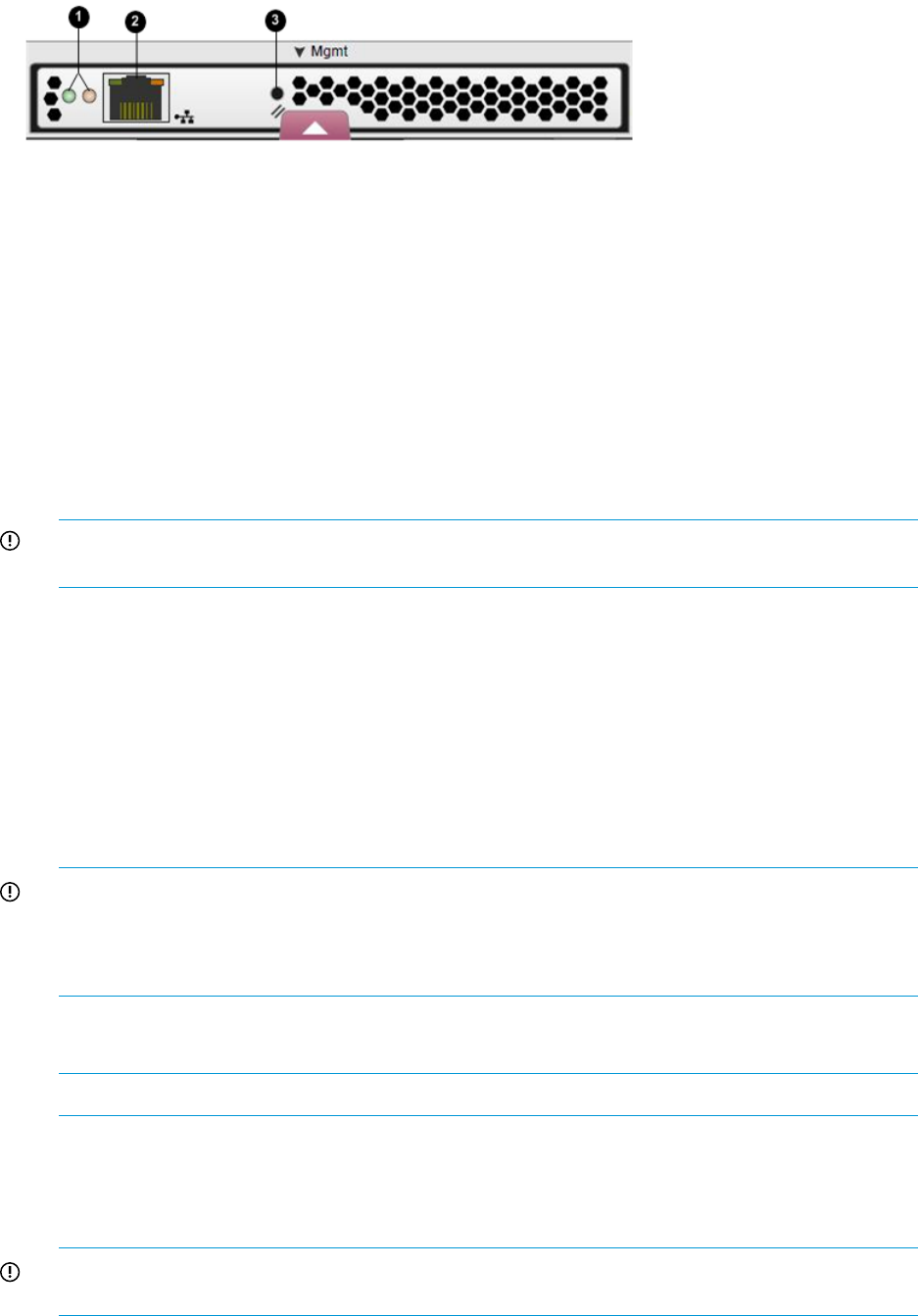
Figure 18 Management module
3. Reset button1. Status LEDs
2. Ethernet jack
Connecting through a public network
1. Initialize the P63x0 EVA or P65x0 EVA storage system using HP P6000 Command View.
2. If it is currently connected, disconnect the public network LAN cable from the back of the
management module in the controller enclosure.
3. Press and hold the recessed Reset button (3, Figure 18 (page 44)) for 4 to 5 seconds. The
green LED on the management module (1, Figure 18 (page 44)) blinks to indicate the
configuration reset has started. The reset may take up to 2 minutes to complete. When the
reset is completed, the green LED turns solid. This sets IP addresses of 192.168.0.1/24 (IPv4)
and fd50:f2eb:a8a::7/48 (IPv6).
IMPORTANT: At initial setup, you cannot browse to the HP P6000 Control Panel until you
perform this step.
4. Do one of the following:
•Temporarily connect a LAN cable from a private network to the management module.
•Temporarily connect a laptop computer directly to the management module using a LAN
patch cable.
5. Browse to https://192.168.0.1:2373/ or https://[fd50:f2eb:a8a::7]:2373/
and log in as an HP EVA administrator. HP recommends that you either change or delete the
default IPv4 and IPv6 addresses to avoid duplicate address detection issues on your network.
The default user name is admin. No password is required during the initial setup. The HP
P6000 Control Panel GUI appears.
IMPORTANT: If you change the password for the administrator or user account for the HP
P6000 Control Panel, be sure to record the new passwords since they cannot be cleared
without resetting the management module.
HP recommends that you change the default passwords.
6. Select Administrator Options > Configure Network Options.
7. Enter an IP address and other network settings that apply.
NOTE: The reserved internal IP addresses are 10.253.251.230 through 10.253.251.249.
8. Click Save Changes. The IP address changes immediately, causing you to lose connectivity to
the HP P6000 Control Panel.
The new IP address is stored and remains in effect, even when the storage system is later shut
down or restarted.
IMPORTANT: The new IP address will be lost if the storage system is later uninitialized or
the management module is reset.
44 P63x0/P65x0 EVA operation

9. Remove the LAN cable to the private network or laptop and reconnect the cable to the public
network.
10. From a computer on the public network, browse to https://new IP:2373 and log in. The
HP P6000 Control Panel GUI appears.
Connecting through a private network
1. Press and hold the recessed Reset button (3, Figure 18 (page 44)) for 4 to 5 seconds. The
green LED on the management module (1, Figure 18 (page 44)) blinks to indicate the
configuration reset has started. The reset may take up to 2 minutes to complete. When the
reset is completed, the green LED turns solid. This sets IP addresses of 192.168.0.1/24 (IPv4)
and fd50:f2eb:a8a::7/48 (IPv6).
2. Browse to https://192.168.0.1:2373/ or https://[fd50:f2eb:a8a::7]:2373/
and log in as an HP EVA administrator. HP recommends that you either change or delete the
default IPv4 and IPv6 addresses to avoid duplicate address detection issues on your network.
The default user name is admin. No password is required during the initial setup. The HP
P6000 Control Panel GUI appears.
IMPORTANT: At initial setup, you cannot browse to the HP P6000 Control Panel until you
perform this step.
3. Select Administrator Options > Configure Network Options.
4. Enter an IP address and other network settings that apply.
NOTE: The reserved internal IP addresses are 10.253.251.230 through 10.253.251.249.
5. Click Save Changes. The IP address changes immediately, causing you to lose connectivity to
the HP P6000 Control Panel.
The new IP address is stored and remains in effect, even when the storage system is shut down
or restarted.
IMPORTANT: The new IP address will be lost if the storage system is later uninitialized or
the management module is reset.
6. From a computer on the private network, browse to https://newly configured ip
address:2373 and log in. The HP P6000 Control Panel GUI appears.
Accessing HP P6000 Command View on the management module
To access HP P6000 Command View on the management module:
1. Login to P6000 Control Panel
2. From the left pane, select Launch HP P6000 Command View from the User Options
3. Click Launch HP P6000 Command View
Changing the host port default operating mode
NOTE: Fibre Channel host ports must be connected or have an optical loopback plug installed.
When using the loopback plug, the host port must be configured for direct connect.
By default, a storage system is shipped to operate in a Fibre Channel switch environment and is
configured in fabric mode. If you choose to connect the storage system directly to a server, you
must change the host port operating mode to direct mode. If you do not change this mode, the
storage system will be unable to communicate with your server. Use the HP P6000 Control Panel
to change the default operating mode.
Using the management module 45
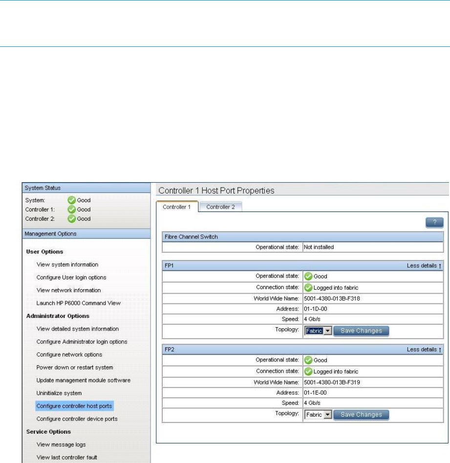
NOTE: Change your browser settings for the HP P6000 Control Panel as described in the HP
P6000 Command View Installation Guide. You must have administrator privilege to change the
settings in the HP P6000 Control Panel.
To change the default operating mode:
1. Connect to the management module using one of the methods described in “Connecting
through a public network” (page 44) or “Connecting through a private network” (page 45).
2. Log into the HP P6000 Control Panel as an HP P6000 administrator. The HP P6000 Control
Panel is displayed.
3. Select Administrator Options > Configure Controller Host Ports (Figure 17 (page 46)).
4. Select the controller.
Figure 19 iSCSI Controller Shutdown Options
5. In the Topology box, select Direct from the drop-down menu.
6. Click Save Changes.
7. Repeat steps through 6for other ports where direct connect is desired.
8. Close the HP P6000 Control Panel and remove the Ethernet cable from the server, however,
you may want to retain access to the ABM to initialize the storage cell, for example.
Saving storage system configuration data
As part of an overall data protection strategy, storage system configuration data should be saved
during initial installation, and whenever major configuration changes are made to the storage
system. This includes adding or removing disk drives, creating or deleting disk groups, and adding
or deleting virtual disks. The saved configuration data can save substantial time if re-initializing
the storage system becomes necessary. The configuration data is saved to a series of files, which
should be stored in a location other than on the storage system.
You can perform this procedure from the management server where HP P6000 Command View
is installed from any host running HP Storage System Scripting Utility (called the utility) and connected
to the management server.
46 P63x0/P65x0 EVA operation

NOTE: For more information on using the utility, see the HP Storage System Scripting Utility
Reference. See “Related documentation” (page 197).
1. Double-click the SSSU desktop icon to run the application. When prompted, enter Manager
(management server name or IP address), User name, and Password.
2. Enter LS SYSTEM to display the storage systems managed by the management server.
3. Enter SELECT SYSTEM system name, where system name is the name of the storage
system.
The storage system name is case sensitive. If there are spaces the letters in the name, quotes
must enclose the name: for example, SELECT SYSTEM “Large EVA”.
4. Enter CAPTURE CONFIGURATION, specifying the full path and filename of the output files
for the configuration data.
The configuration data is stored in a series of from one to five files, which are SSSU scripts.
The file names begin with the name you select, with the restore step appended. For example,
if you specify a file name of LargeEVA.txt, the resulting configuration files would be
LargeEVA_Step1A.txt, LargeEVA_Step1B, etc.
The contents of the configuration files can be viewed with a text editor.
NOTE: If the storage system contains disk drives of different capacities, the SSSU procedures
used do not guarantee that disk drives of the same capacity will be exclusively added to the same
disk group. If you need to restore an array configuration that contains disks of different sizes and
types, you must manually recreate these disk groups. The controller software and the utility’s
CAPTURE CONFIGURATION command are not designed to automatically restore this type of
configuration. For more information, see the HP Storage System Scripting Utility Reference.
The following examples illustrate how to save and restore the storage system configuration data
using SSSU on a Windows host.
Saving storage system configuration data 47

Example 1 Saving configuration data on a Windows host
1. Double-click on the SSSU desktop icon to run the application. When prompted, enter Manager
(management server name or IP address), User name, and Password.
2. Enter LS SYSTEM to display the storage systems managed by the management server.
3. Enter SELECT SYSTEM system name, where system name is the name of the storage
system.
4. Enter CAPTURE CONFIGURATION pathname\filename, where pathname identifies the
location where the configuration files will be saved, and filename is the name used as the
prefix for the configurations files: for example, CAPTURE CONFIGURATION
c:\EVAConfig\LargeEVA
5. Enter EXIT to close the SSSU command window.
Example 2 Restoring configuration data on a Windows host
If it is necessary to restore the storage system configuration, it can be done using the following
procedure.
1. Double-click on the SSSU desktop icon to run the application.
2. Enter FILE pathname\filename, where pathname identifies the location where the
configuration files are be saved and filename is the name of the first configuration file: for
example, FILE c:\EVAConfig\LargeEVA_Step1A.txt
3. Repeat the preceding step for each configuration file. Use files in sequential order. For example,
use Step1A before Step1B, and so on. Files that are not needed for configuration data are
not created, so there is no need to restore them.
Saving or restoring the iSCSI or iSCSI/FCoE module configuration
After the initial setup of the iSCSI or iSCSI/FCoE modules, save the configuration for each module,
in case a service action is required. The Save Configuration function (Figure 20 (page 49)) enables
you to save the configuration from a selected module to a file on the management server. You can
use this file as a restoration point. The Full Configuration Restore function enables the restoration
of the configuration to the point when the configuration was last saved (such as during the LUN
presentation to new initiators). If a new controller is installed, the full configuration can be restored
and no reconfiguration is required. When using HP P6000 Command View to uninitialize a P6300
or P6500 array, the iSCSI or iSCSI/FCoE modules are issued reset mappings and are rebooted,
to avoid stale persistent data, without clearing configured IP addresses.
To save or restore the configuration:
1. Select the iSCSI controller in the Navigation pane.
2. Select Set Options.
3. Select Save/Restore configuration.
4. Select the configuration method.
48 P63x0/P65x0 EVA operation
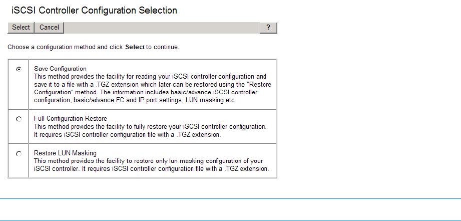
Figure 20 iSCSI Controller Configuration Selection window
NOTE: ARestore action will reboot the module.
Saving storage system configuration data 49

3 Configuring application servers
Overview
This chapter provides general connectivity information for all the supported operating systems.
Where applicable, an OS-specific section is included to provide more information.
Clustering
Clustering is connecting two or more computers together so that they behave like a single computer.
Clustering is used for parallel processing, load balancing, and fault tolerance.
See the HP P6000 Enterprise Virtual Array Compatibility Reference for the clustering software
supported on each operating system. See“Related documentation” (page 197) for the location of
this document. Clustering is not supported on Linux or VMware.
NOTE: For OpenVMS, you must make the Console LUN ID and OS unit IDs unique throughout
the entire SAN, not just the controller subsystem.
Multipathing
Multipathing software provides a multiple-path environment for your operating system. See the
following website for more information:
http://h18006.www1.hp.com/products/sanworks/multipathoptions/index.html
See the HP P6000 Enterprise Virtual Array Compatibility Reference for the multipathing software
supported on each operating system. See “Related documentation” (page 197) for the location of
this document.
Installing Fibre Channel adapters
For all operating systems, supported Fibre Channel adapters (FCAs) must be installed in the host
server in order to communicate with the EVA.
NOTE: Traditionally, the adapter that connects the host server to the fabric is called a host bus
adapter (HBA). The server HBA used with the storage systems is called a Fibre Channel adapter
(FCA). You might also see the adapter called a Fibre Channel host bus adapter (Fibre Channel
HBA) in other related documents.
Follow the hardware installation rules and conventions for your server type. The FCA is shipped
with its own documentation for installation. See that documentation for complete instructions. You
need the following items to begin:
•FCA boards and the manufacturer’s installation instructions
•Server hardware manual for instructions on installing adapters
•Tools to service your server
The FCA board plugs into a compatible I/O slot (PCI, PCI-X, PCI-E) in the host system. For instructions
on plugging in boards, see the hardware manual.
You can download the latest FCA firmware from the following website: http://www.hp.com/
support/downloads. Enter HBA in the Search Products box and then select your product. For
supported FCAs by operating system, go to the Single Point of Connectivity Knowledge website
(http://www.hp.com/storage/spock). You must sign up for an HP Passport to enable access.
50 Configuring application servers

Testing connections to the array
After installing the FCAs, you can create and test connections between the host server and the
array. For all operating systems, you must:
•Add hosts
•Create and present virtual disks
•Verify virtual disks from the hosts
The following sections provide information that applies to all operating systems. For OS-specific
details, see the applicable operating system section.
Adding hosts
To add hosts using HP P6000 Command View:
1. Retrieve the worldwide names (WWNs) for each FCA on your host. You need this information
to select the host FCAs in HP P6000 Command View.
2. Use HP P6000 Command View to add the host and each FCA installed in the host system.
NOTE: To add hosts using HP P6000 Command View, you must add each FCA installed in
the host. Select Add Host to add the first adapter. To add subsequent adapters, select Add
Port. Ensure that you add a port for each active FCA.
3. Select the applicable operating system for the host mode.
Table 10 Operating system and host mode selection
Host mode selection in HP P6000 Command ViewOperating System
HP-UXHP-UX
IBM AIXIBM AIX
LinuxLinux
LinuxMac OS X
Microsoft WindowsMicrosoft Windows
Microsoft Windows 2008
Microsoft Windows 2012
OVMSOpenVMS
Sun SolarisOracle Solaris
VMwareVMware
LinuxCitrix XenServer
4. Check the Host folder in the Navigation pane of HP P6000 Command View to verify that the
host FCAs are added.
NOTE: More information about HP P6000 Command View is available at http://
www.hp.com/support/manuals. Click Storage Software under Storage, and then select HP
P6000 Command View Software under Storage Device Management Software.
Testing connections to the array 51

Creating and presenting virtual disks
To create and present virtual disks to the host server:
1. From HP P6000 Command View, create a virtual disk on the storage system.
2. Specify values for the following parameters:
•Virtual disk name
•Vraid level
•Size
3. Present the virtual disk to the host you added.
4. If applicable (AIX or OpenVMS) select a LUN number if you chose a specific LUN on the
Virtual Disk Properties window.
Verifying virtual disk access from the host
To verify that the host can access the newly presented virtual disks, restart the host or scan the bus.
If you are unable to access the virtual disk:
•Verify that all cabling is connected to the switch, EVA, and host.
•Verify that all firmware levels are appropriate for your configuration. For more information,
refer to the Enterprise Virtual Array QuickSpecs and associated release notes. See “Related
documentation” (page 197) for the location of these documents.
•Ensure that you are running a supported version of the host operating system. For more
information, see the HP P6000 Enterprise Virtual Array Compatibility Reference.
•Ensure that the correct host is selected as the operating system for the virtual disk in HP P6000
Command View.
•Ensure that the host WWN number is set correctly (to the host you selected).
•Verify that the FCA switch settings are correct.
•Verify that the virtual disk is presented to the host.
•Verify that the zoning is correct for your configuration.
Configuring virtual disks from the host
After you create the virtual disks and rescan or restart the host, follow the host-specific conventions
for configuring these new disk resources. For instructions, see the documentation included with
your server.
HP-UX
To create virtual disks for HP-UX, scan the bus and then create volume groups on a virtual disk.
Scanning the bus
To scan the FCA bus and display information about the devices:
1. Enter the command # ioscan -fnCdisk to start the rescan.
All new virtual disks become visible to the host.
2. Assign device special files to the new virtual disks using the insf command:
# insf -e
NOTE: Lowercase eassigns device special files only to the new devices—in this case, the
virtual disks. Uppercase Ereassigns device special files to all devices.
The following is a sample output from an ioscan command:
52 Configuring application servers

# ioscan -fnCdisk
# ioscan -fnCdisk
Class I H/W Patch Driver S/W H/W Type Description
State
========================================================================================
ba 3 0/6 lba CLAIMED BUS_NEXUS Local PCI Bus
Adapter (782)
fc 2 0/6/0/0 td CLAIMED INTERFACE HP Tachyon XL@ 2 FC
Mass Stor Adap /dev/td2
fcp 0 0/6/0/0.39 fcp CLAIMED INTERFACE FCP Domain
ext_bus 4 0/6/00.39.13.0.0 fcparray CLAIMED INTERFACE FCP Array Interface
target 5 0/6/0/0.39.13.0.0.0 tgt CLAIMED DEVICE
ctl 4 0/6/0/0.39.13.0.0.0.0 sctl CLAIMED DEVICE HP HSV340 /dev/rscsi/c4t0d0
disk 22 0/6/0/0.39.13.0.0.0.1 sdisk CLAIMED DEVICE HP HSV340 /dev/dsk/c4t0d1
/dev/rdsk/c4t0d
ext_bus 5 0/6/0/0.39.13.255.0 fcpdev CLAIMED INTERFACE FCP Device Interface
target 8 0/6/0/0.39.13.255.0.0 tgt CLAIMED DEVICE
ctl 20 0/6/0/0.39.13.255.0.0.0 sctl CLAIMED DEVICE HP HSV340 /dev/rscsi/c5t0d0
ext_bus 10 0/6/0/0.39.28.0.0 fcparray CLAIMED INTERFACE FCP Array Interface
target 9 0/6/0/0.39.28.0.0.0 tgt CLAIMED DEVICE
ctl 40 0/6/0/0.39.28.0.0.0.0 sctl CLAIMED DEVICE HP HSV340 /dev/rscsi/c10t0d0
disk 46 0/6/0/0.39.28.0.0.0.2 sdisk CLAIMED DEVICE HP HSV340 /dev/dsk/c10t0d2
/dev/rdsk/c10t0d2
disk 47 0/6/0/0.39.28.0.0.0.3 sdisk CLAIMED DEVICE HP HSV340 /dev/dsk/c10t0d3
/dev/rdsk/c10t0d3
disk 48 0/6/0/0.39.28.0.0.0.4 sdisk CLAIMED DEVICE HP HSV340 /dev/dsk/c10t0d4
/dev/rdsk/c10t0d4
disk 49 0/6/0/0.39.28.0.0.0.5 sdisk CLAIMED DEVICE HP HSV340 /dev/dsk/c10t0d5
/dev/rdsk/c10t0d5
disk 50 0/6/0/0.39.28.0.0.0.6 sdisk CLAIMED DEVICE HP HSV340 /dev/dsk/c10t0d
/dev/rdsk/c10t0d6
disk 51 0/6/0/0.39.28.0.0.0.7 sdisk CLAIMED DEVICE HP HSV340 /dev/dsk/c10t0d7
/dev/rdsk/c10t0d7
Creating volume groups on a virtual disk using vgcreate
You can create a volume group on a virtual disk by issuing a vgcreate command. This builds
the virtual group block data, allowing HP-UX to access the virtual disk. See the pvcreate,
vgcreate, and lvcreate man pages for more information about creating disks and file systems.
Use the following procedure to create a volume group on a virtual disk:
NOTE: Italicized text is for example only.
1. To create the physical volume on a virtual disk, enter the following command:
# pvcreate -f /dev/rdsk/c32t0d1
2. To create the volume group directory for a virtual disk, enter the command:
# mkdir /dev/vg01
3. To create the volume group node for a virtual disk, enter the command:
# mknod /dev/vg01/group c 64 0x010000
The designation 64 is the major number that equates to the 64-bit mode. The 0x01 is the
minor number in hex, which must be unique for each volume group.
4. To create the volume group for a virtual disk, enter the command:
# vgcreate –f /dev/vg01 /dev/dsk/c32t0d1
5. To create the logical volume for a virtual disk, enter the command:
# lvcreate -L1000 /dev/vg01/lvol1
In this example, a 1-Gb logical volume (lvol1) is created.
6. Create a file system for the new logical volume by creating a file system directory name and
inserting a mount tab entry into /etc/fstab.
7. Run the command mkfs on the new logical volume. The new file system is ready to mount.
HP-UX 53

IBM AIX
Accessing IBM AIX utilities
You can access IBM AIX utilities such as the Object Data Manager (ODM), on the following website:
http://www.hp.com/support/downloads
In the Search products box, enter MPIO, and then click AIX MPIO PCMA for HP Arrays. Select IBM
AIX, and then select your software storage product.
Adding hosts
To determine the active FCAs on the IBM AIX host, enter:
# lsdev -Cc adapter |grep fcs
Output similar to the following appears:
fcs0 Available 1H-08 FC Adapter
fcs1 Available 1V-08 FC Adapter
# lscfg -vl
fcs0 fcs0 U0.1-P1-I5/Q1 FC Adapter
Part Number.................80P4543
EC Level....................A
Serial Number...............1F4280A419
Manufacturer................001F
Feature Code/Marketing ID...280B
FRU Number.................. 80P4544
Device Specific.(ZM)........3
Network Address.............10000000C940F529
ROS Level and ID............02881914
Device Specific.(Z0)........1001206D
Device Specific.(Z1)........00000000
Device Specific.(Z2)........00000000
Device Specific.(Z3)........03000909
Device Specific.(Z4)........FF801315
Device Specific.(Z5)........02881914
Device Specific.(Z6)........06831914
Device Specific.(Z7)........07831914
Device Specific.(Z8)........20000000C940F529
Device Specific.(Z9)........TS1.90A4
Device Specific.(ZA)........T1D1.90A4
Device Specific.(ZB)........T2D1.90A4
Device Specific.(YL)........U0.1-P1-I5/Q1b.
Creating and presenting virtual disks
When creating and presenting virtual disks to an IBM AIX host, be sure to:
1. Set the OS unit ID to 0.
2. Set Preferred path/mode to No Preference.
3. Select a LUN number if you chose a specific LUN on the Virtual Disk Properties window.
Verifying virtual disks from the host
To scan the IBM AIX bus and list all EVA devices, enter: cfgmgr -v
The -v switch (verbose output) requests a full output.
Output similar to the following is displayed:
hdisk1 Available 1V-08-01 HP HSV340 Enterprise Virtual Array
hdisk2 Available 1V-08-01 HP HSV340 Enterprise Virtual Array
hdisk3 Available 1V-08-01 HP HSV340 Enterprise Virtual Array
54 Configuring application servers

Linux
Driver failover mode
If you use the INSTALL command without command options, the driver’s failover mode depends
on whether a QLogic driver is already loaded in memory (listed in the output of the lsmod
command). Possible driver failover mode scenarios include:
•If an hp_qla2x00src driver RPM is already installed, the new driver RPM uses the failover of
the previous driver package.
•If there is no QLogic driver module (qla2xxx module) loaded, the driver defaults to failover
mode. This is also true if an inbox driver is loaded that does not list output in the
/proc/scsi/qla2xxx directory.
•If there is a driver loaded in memory that lists the driver version in /proc/scsi/qla2xxx
but no driver RPM has been installed, then the driver RPM loads the driver in the failover mode
that the driver in memory currently uses.
Installing a QLogic driver
NOTE: The HP Emulex driver kit performs in a similar manner; use ./INSTALL -h to list all
supported arguments.
1. Download the appropriate driver kit for your distribution. The driver kit file is in the format
hp_qla2x00-yyyy-mm-dd.tar.gz.
2. Copy the driver kit to the target system.
3. Uncompress and untar the driver kit using the following command:
# tar zxvf hp_qla2x00-yyyy-mm-dd.tar.gz
4. Change directory to the hp_qla2x00-yyyy-mm-dd directory.
5. Execute the INSTALL command.
The INSTALL command syntax varies depending on your conguration.
If a previous driver kit is installed, you can invoke the INSTALL command without any
arguments. To use the currently loaded conguration:
# ./INSTALL
To force the installation to failover mode, use the -f ag:
# ./INSTALL -f
To force the installation to single-path mode, use the -s ag:
# ./INSTALL -s
To list all supported arguments, use the -h flag:
# ./INSTALL -h
The INSTALL script installs the appropriate driver RPM for your conguration, as well as the
appropriate fibreutils RPM.
6. Once the INSTALL script is finished, you will either have to reload the QLogic driver modules
(qla2xxx, qla2300, qla2400, qla2xxx_conf) or reboot your server.
To reload the driver use one or more of the following commands, as applicable:
# /opt/hp/src/hp_qla2x00src/unload.sh
# modprobe qla2xxx_conf
# modprobe qla2xxx
# modprobe qla2300
Linux 55

# modprobe qla2400
To reboot the server, enter the reboot command.
CAUTION: If the boot device is attached to the SAN, you must reboot the host.
7. To verify which RPM versions are installed, use the rpm command with the -q option. For
example:
# rpm -q hp_qla2x00src
# rpm –q fibreutils
Upgrading Linux components
If you have any installed components from a previous solution kit or driver kit, such as the qla2x00
RPM, invoke the INSTALL script with no arguments, as shown in the following example:
# ./INSTALL
To manually upgrade the components, select one of the following kernel distributions:
•For 2.4 kernel based distributions, use version 7.xx.
•For 2.6 kernel based distributions, use version 8.xx.
Depending on the kernel version you are running, upgrade the driver RPM as follows:
•For the hp_qla2x00src RPM:
# rpm -Uvh hp_qla2x00src- version-revision.linux.rpm
•For fibreutils RPM, you have two options:
To upgrade the driver:
# rpm -Uvh fibreutils-version-revision.linux.architecture.rpm
◦
◦To remove the existing driver, and install a new driver:
# rpm -e fibreutils
# rpm -ivh fibreutils-version-revision.linux.architecture.rpm
Upgrading qla2x00 RPMs
If you have a qla2x00 RPM from HP installed on your system, use the INSTALL script to upgrade
from qla2x00 RPMs. The INSTALL script removes the old qla2x00 RPM and installs the new
hp_qla2x00src while keeping the driver settings from the previous installation. The script takes
no arguments. Use the following command to run the INSTALL script:
# ./INSTALL
NOTE: IF you are going to use the failover functionality of the QLA driver, uninstall Secure Path
and reboot before you attempt to upgrade the driver. Failing to do so can cause a kernel panic.
Detecting third-party storage
The preinstallation portion of the RPM contains code to check for non-HP storage. The reason for
doing this is to prevent the RPM from overwriting any settings that another vendor may be using.
You can skip the detection process by setting the environmental variable HPQLAX00FORCE to y
by issuing the following commands:
# HPQLA2X00FORCE=y
# export HPQLA2X00FORCE
You can also use the -F option of the INSTALL script by entering the following command:
56 Configuring application servers

# ./INSTALL -F
Compiling the driver for multiple kernels
If your system has multiple kernels installed on it, you can compile the driver for all the installed
kernels by setting the INSTALLALLKERNELS environmental variable to y and exporting it by
issuing the following commands:
# INSTALLALLKERNELS=y
# export INSTALLALLKERNELS
You can also use the -a option of the INSTALL script as follows:
# ./INSTALL -a
Uninstalling the Linux components
To uninstall the components, use the INSTALL script with the -u option as shown in the following
example:
# ./INSTALL -u
To manually uninstall all components, or to uninstall just one of the components, use one or all of
the following commands:
# rpm -e fibreutils
# rpm -e hp_qla2x00
# rpm -e hp_qla2x00src
Using the source RPM
In some cases, you may have to build a binary hp_qla2x00 RPM from the source RPM and use
that manual binary build in place of the scripted hp_qla2x00src RPM. You need to do this if
your production servers do not have the kernel sources and gcc installed.
If you need to build a binary RPM to install, you will need a development machine with the same
kernel as your targeted production servers. You can install the binary RPM-produced RPM methods
on your production servers.
NOTE: The binary RPM that you build works only for the kernel and configuration that you build
on (and possibly some errata kernels). Ensure that you use the 7.xx version of the hp_qla2x00
source RPM for 2.4 kernel-based distributions and the 8.xx version of the hp_qla2x00 source
RPM for 2.6 kernel-based distributions.
Use the following procedure to create the binary RPM from the source RPM:
1. Select one of the following options:
•Enter the #./INSTALL -S command. The binary RPM creation is complete. You do not
have to perform 2through 4.
•Install the source RPM by issuing the # rpm -ivh
hp_qla2x00-version-revision.src.rpm command. Continue with 2.
2. Select one of the following directories:
•For Red Hat distributions, use the /usr/src/redhat/SPECS directory.
•For SUSE distributions, use the /usr/src/packages/SPECS directory.
3. Build the RPM by using the # rpmbuild -bb hp_qla2x00.spec command.
NOTE: In some of the older Linux distributions, the RPM command contains the RPM build
functionality.
At the end of the command output, the following message appears:
Linux 57

"Wrote: ...rpm".
This line identifies the location of the binary RPM.
4. Copy the binary RPM to the production servers and install it using the following command:
# rpm -ivh hp_qla2x00-version-revision.architecture.rpm
HBA drivers
For most configurations and latest version of linux distributions, native HBA drivers are the supported
drivers. Native driver means the driver that is included with the OS distribution.
NOTE: The term inbox driveris also sometimes used and means the same as native driver.
However in some configurations, it may require use of an out-of-box driver, which typically requires
a driver package be downloaded and installed on the host. In those cases, follow the documentation
of the driver package for instruction. Driver support information can be found on the Single Point
of Connectivity Knowledge (SPOCK) website:
http://www.hp.com/storage/spock
NOTE: Registration is required to access SPOCK
Verifying virtual disks from the host
To verify the virtual disks, first verify that the LUN is recognized and then verify that the host can
access the virtual disks.
•To ensure that the LUN is recognized after a virtual disk is presented to the host, do one of
the following:
◦Reboot the host.
◦Execute the following command (where Xis the SCSI host enumerator of the HBA):
echo “- - -“ > /sys/class/scsi_host/host[X]/scan
•To verify that the host can access the virtual disks, enter the # more /proc/scsi/scsi
command.
The output lists all SCSI devices detected by the server. An P63x0/P65x0 EVAs LUN entry
looks similar to the following:
Host: scsi3 Channel: 00 ID: 00 Lun: 01
Vendor: HP Model: HSV340 Rev:
Type: Direct-Access ANSI SCSI revision: 02
OpenVMS
Updating the AlphaServer console code, Integrity Server console code, and Fibre
Channel FCA firmware
The firmware update procedure varies for the different server types. To update firmware, follow
the procedure described in the Installation instructions that accompany the firmware images.
Verifying the Fibre Channel adapter software installation
A supported FCA should already be installed in the host server. The procedure to verify that the
console recognizes the installed FCA varies for the different server types. Follow the procedure
described in the Installation instructions that accompany the firmware images.
58 Configuring application servers

Console LUN ID and OS unit ID
HP P6000 Command View software contains a box for the Console LUN ID on the Initialized
Storage System Properties window.
It is important that you set the Console LUN ID to a number other than zero (0). If the Console LUN
ID is not set or is set to zero (0), the OpenVMS host will not recognize the controller pair. The
Console LUN ID for a controller pair must be unique within the SAN. Table 11 (page 59) shows
an example of the Console LUN ID.
You can set the OS unit ID on the Virtual Disk Properties window. The default setting is 0, which
disables the ID field. To enable the ID field, you must specify a value between 1 and 32767,
ensuring that the number you enter is unique within the SAN. An OS Unit ID greater than 9999
is not capable of being served by MSCP.
CAUTION: It is possible to enter a duplicate Console LUN ID or OS unit ID number. You must
ensure that you enter a Console LUN ID and OS Unit ID that is not already in use. A duplicate
Console LUN ID or OS Unit ID can allow the OpenVMS host to corrupt data due to confusion about
LUN identity. It can also prevent the host from recognizing the controllers.
Table 11 Comparing console LUN to OS unit ID
System DisplayID type
$1$GGA100:Console LUN ID set to 100
$1$DGA50:OS unit ID set to 50
Adding OpenVMS hosts
To obtain WWNs on AlphaServers, do one of the following:
•Enter the show device fg/full OVMS command.
•Use the WWIDMGR -SHOW PORT command at the SRM console.
To obtain WWNs on Integrity servers, do one of the following:
1. Enter the show device fg/full OVMS command.
2. Use the following procedure from the server console:
a. From the EFI boot Manager, select EFI Shell.
b. In the EFI Shell, enter “Shell> drivers”.
A list of EFI drivers loaded in the system is displayed.
3. In the listing, find the line for the FCA for which you want to get the WWN information.
For a Qlogic HBA, look for HP 4 Gb Fibre Channel Driver or HP 2 Gb Fibre
Channel Driver as the driver name. For example:
T D
D Y C I
R P F A
V VERSION E G G #D #C DRIVER NAME IMAGE NAME
== ======== = = = == == =================================== ===================
22 00000105 B X X 1 1 HP 4 Gb Fibre Channel Driver PciROM:0F:01:01:002
4. Note the driver handle in the first column (22 in the example).
5. Using the driver handle, enter the drvdfg driver_handle command to find the Device
Handle (Ctrl). For example:
Shell> drvcfg 22
Configurable Components
Drv[22] Ctrl[25] Lang[eng]
OpenVMS 59

6. Using the driver and device handle, enter the drvdfg —sdriver_handle device_handle
command to invoke the EFI Driver configuration utility. For example:
Shell> drvcfg -s 22 25
7. From the Fibre Channel Driver Configuration Utility list, select item 8 (Info)
to find the WWN for that particular port.
Output similar to the following appears:
Adapter Path: Acpi(PNP0002,0300)/Pci(01|01)
Adapter WWPN: 50060B00003B478A
Adapter WWNN: 50060B00003B478B
Adapter S/N: 3B478A
Scanning the bus
Enter the following command to scan the bus for the OpenVMS virtual disk:
$ MC SYSMAN IO AUTO/LOG
A listing of LUNs detected by the scan process is displayed. Verify that the new LUNs appear on
the list.
NOTE: The console LUN can be seen without any virtual disks presented. The LUN appears as
$1$GGAx(where xrepresents the console LUN ID on the controller).
After the system scans the fabric for devices, you can verify the devices with the SHOW DEVICE
command:
$ SHOW DEVICE NAME-OF-VIRTUAL-DISK/FULL
For example, to display device information on a virtual disk named $1$DGA50, enter $ SHOW
DEVICE $1$DGA50:/FULL.
The following output is displayed:
Disk $1$DGA50: (BRCK18), device type HSV210, is online, file-oriented device,
shareable, device has multiple I/O paths, served to cluster via MSCP Server,
error logging is enabled.
Error count 2 Operations completed 4107
Owner process "" Owner UIC [SYSTEM]
Owner process ID 00000000 Dev Prot S:RWPL,O:RWPL,G:R,W
Reference count 0 Default buffer size 512
Current preferred CPU Id 0 Fastpath 1
WWID 01000010:6005-08B4-0010-70C7-0001-2000-2E3E-0000
Host name "BRCK18" Host type, avail AlphaServer DS10 466 MHz, yes
Alternate host name "VMS24" Alt. type, avail HP rx3600 (1.59GHz/9.0MB), yes
Allocation class 1
I/O paths to device 9
Path PGA0.5000-1FE1-0027-0A38 (BRCK18), primary path.
Error count 0 Operations completed 145
Path PGA0.5000-1FE1-0027-0A3A (BRCK18).
Error count 0 Operations completed 338
Path PGA0.5000-1FE1-0027-0A3E (BRCK18).
Error count 0 Operations completed 276
Path PGA0.5000-1FE1-0027-0A3C (BRCK18).
Error count 0 Operations completed 282
Path PGB0.5000-1FE1-0027-0A39 (BRCK18).
Error count 0 Operations completed 683
Path PGB0.5000-1FE1-0027-0A3B (BRCK18).
Error count 0 Operations completed 704
Path PGB0.5000-1FE1-0027-0A3D (BRCK18).
Error count 0 Operations completed 853
Path PGB0.5000-1FE1-0027-0A3F (BRCK18), current path.
Error count 2 Operations completed 826
Path MSCP (VMS24).
Error count 0 Operations completed 0
You can also use the SHOW DEVICE DG command to display a list of all Fibre Channel disks
presented to the OpenVMS host.
60 Configuring application servers

NOTE: Restarting the host system shows any newly presented virtual disks because a hardware
scan is performed as part of the startup.
If you are unable to access the virtual disk, do the following:
•Check the switch zoning database.
•Use HP P6000 Command View to verify the host presentations.
•Check the SRM console firmware on AlphaServers.
•Ensure that the correct host is selected for this virtual disk and that a unique OS Unit ID is used
in HP P6000 Command View.
Configuring virtual disks from the OpenVMS host
To set up disk resources under OpenVMS, initialize and mount the virtual disk resource as follows:
1. Enter the following command to initialize the virtual disk:
$ INITIALIZE name-of-virtual-disk volume-label
2. Enter the following command to mount the disk:
MOUNT/SYSTEM name-of-virtual-disk volume-label
NOTE: The /SYSTEM switch is used for a single stand-alone system, or in clusters if you
want to mount the disk only to select nodes. You can use the /CLUSTER switch for OpenVMS
clusters. However, if you encounter problems in a large cluster environment, HP recommends
that you enter a MOUNT/SYSTEM command on each cluster node.
3. View the virtual disk’s information with the SHOW DEVICE command. For example, enter the
following command sequence to configure a virtual disk named data1 in a stand-alone
environment:
$ INIT $1$DGA1: data1
$ MOUNT/SYSTEM $1$DGA1: data1
$ SHOW DEV $1$DGA1: /FULL
Setting preferred paths
You can use one of the following options for setting, changing, or displaying preferred paths:
•To set or change the preferred path, use the following command:
$ SET DEVICE $1$DGA83: /PATH=PGA0.5000-1FE1-0007-9772/SWITCH
This allows you to control which path each virtual disk uses.
•To display the path identifiers, use the SHOW DEV/FULL command.
•For additional information on using OpenVMS commands, see the OpenVMS help file:
$ HELP TOPIC
For example, the following command displays help information for the MOUNT command:
$ HELP MOUNT
Oracle Solaris
NOTE: The information in this section applies to both SPARC and x86 versions of the Oracle
Solaris operating system.
Oracle Solaris 61

Loading the operating system and software
Follow the manufacturer’s instructions for loading the operating system (OS) and software onto the
host. Load all OS patches and configuration utilities supported by HP and the FCA manufacturer.
Configuring FCAs with the Oracle SAN driver stack
Oracle-branded FCAs are supported only with the Oracle SAN driver stack. The Oracle SAN
driver stack is also compatible with current Emulex FCAs and QLogic FCAs. Support information
is available on the Oracle website:
http://www.oracle.com/technetwork/server-storage/solaris/overview/index-136292.html
To determine which non-Oracle branded FCAs HP supports with the Oracle SAN driver stack, see
the latest MPxIO application notes or contact your HP representative.
Update instructions depend on the version of your OS:
•For Solaris 9, install the latest Oracle StorEdge SAN software with associated patches. To
locate the software, log into My Oracle Support:
https://support.oracle.com/CSP/ui/flash.html
1. Select the Patches & Updates tab and then search for StorEdge SAN Foundation Software
4.4 (formerly called StorageTek SAN 4.4).
2. Reboot the host after the required software/patches have been installed. No further activity
is required after adding any new LUNs once the array ports have been configured with
the cfgadm –ccommand for Solaris 9.
Examples for two FCAs:
cfgadm -c configure c3
cfgadm -c configure c4
3. Increase retry counts and reduce I/O time by adding the following entries to the /etc/
system file:
set ssd:ssd_retry_count=0xa
set ssd:ssd_io_time=0x1e
4. Reboot the system to load the newly added parameters.
•For Solaris 10, go to the Oracle Software Downloads website (http://www.oracle.com/
technetwork/indexes/downloads/index.html) to install the latest patches. Under Servers and
Storage Systems, select Solaris 10. Reboot the host once the required software/patches have
been installed. No further activity is required after adding any new LUNs, as the controller
and LUN recognition are automatic for Solaris 10.
1. For Solaris 10 x86/64, ensure patch 138889-03 or later is installed. For SPARC, ensure
patch 138888-03 or later is installed.
2. Increase the retry counts by adding the following line to the /kernel/drv/sd.conf file:
sd-config-list="HP HSV","retries-timeout:10";
3. Reduce the I/O timeout value to 30 seconds by adding the following line to the /etc/system
file:
set sd:sd_io_time=0x1e
4. Reboot the system to load the newly added parameters.
Configuring Emulex FCAs with the lpfc driver
To configure Emulex FCAs with the lpfc driver:
62 Configuring application servers

1. Ensure that you have the latest supported version of the lpfc driver (see http://www.hp.com/
storage/spock).
You must sign up for an HP Passport to enable access. For more information on how to use
SPOCK, see the Getting Started Guide (http://h20272.www2.hp.com/Pages/spock_overview/
introduction.html).
2. Edit the following parameters in the /kernel/drv/lpfc.conf driver configuration file to
set up the FCAs for a SAN infrastructure:
topology=2;
scan-down=0;
nodev-tmo=60;
linkdown-tmo=60;
3. If using a single FCA and no multipathing, edit the following parameter to reduce the risk of
data loss in case of a controller reboot:
nodev-tmo=120;
4. If using Veritas Volume Manager (VxVM) DMP for multipathing (single or multiple FCAs), edit
the following parameter to ensure proper VxVM behavior:
no-device-delay=0;
5. In a fabric topology, use persistent bindings to bind a SCSI target ID to the world wide port
name (WWPN) of an array port. This ensures that the SCSI target IDs remain the same when
the system reboots. Set persistent bindings by editing the configuration file or by using the
lputil utility.
NOTE: HP recommends that you assign target IDs in sequence, and that the EVA has the
same target ID on each host in the SAN.
The following example for an P63x0/P65x0 EVAs illustrates the binding of targets 20 and
21 (lpfc instance 2) to WWPNs 50001fe100270938 and 50001fe100270939, and the
binding of targets 30 and 31 (lpfc instance 0) to WWPNs 50001fe10027093a and
50001fe10027093b:
fcp-bind-WWPN="50001fe100270938:lpfc2t20",
"50001fe100270939:lpfc2t21",
"50001fe10027093a:lpfc0t30",
"50001fe10027093b:lpfc0t31";
NOTE: Replace the WWPNs in the example with the WWPNs of your array ports.
6. For each LUN that will be accessed, add an entry to the /kernel/drv/sd.conf file. For
example, if you want to access LUNs 1 and 2 through all four paths, add the following entries
to the end of the file:
name="sd" parent="lpfc" target=20 lun=1;
name="sd" parent="lpfc" target=21 lun=1;
name="sd" parent="lpfc" target=30 lun=1;
name="sd" parent="lpfc" target=31 lun=1;
name="sd" parent="lpfc" target=20 lun=2;
name="sd" parent="lpfc" target=21 lun=2;
name="sd" parent="lpfc" target=30 lun=2;
name="sd" parent="lpfc" target=31 lun=2;
Oracle Solaris 63

7. Reboot the server to implement the changes to the configuration files.
8. If LUNs have been preconfigured in the /kernel/drv/sd.conf file, use the devfsadm
command to perform LUN rediscovery after configuring the file.
NOTE: The lpfc driver is not supported for Oracle StorEdge Traffic Manager/Oracle Storage
Multipathing. To configure an Emulex FCA using the Oracle SAN driver stack, see “Configuring
FCAs with the Oracle SAN driver stack” (page 62).
Configuring QLogic FCAs with the qla2300 driver
See the latest Enterprise Virtual Array release notes or contact your HP representative to determine
which QLogic FCAs and which driver version HP supports with the qla2300 driver. To configure
QLogic FCAs with the qla2300 driver:
1. Ensure that you have the latest supported version of the qla2300 driver (see http://
www.hp.com/storage/spock).
2. You must sign up for an HP Passport to enable access. For more information on how to use
SPOCK, see the Getting Started Guide (http://h20272.www2.hp.com/Pages/spock_overview/
introduction.html).
3. Edit the following parameters in the /kernel/drv/qla2300.conf driver configuration file
to set up the FCAs for a SAN infrastructure (HBA0 is used in the example but the parameter
edits apply to all HBAs):
NOTE: If you are using a Oracle-branded QLogic FCA, the configuration file is
\kernel\dri\qlc.conf.
hba0-connection-options=1;
hba0-link-down-timeout=60;
hba0-persistent-binding-configuration=1;
NOTE: If you are using Solaris 10, editing the persistent binding parameter is not required.
4. If using a single FCA and no multipathing, edit the following parameters to reduce the risk of
data loss in case of a controller reboot:
hba0-login-retry-count=60;
hba0-port-down-retry-count=60;
hba0-port-down-retry-delay=2;
The hba0-port-down-retry-delay parameter is not supported with the 4.13.01 driver;
the time between retries is fixed at approximately 2 seconds.
5. In a fabric topology, use persistent bindings to bind a SCSI target ID to the world wide port
name (WWPN) of an array port. This ensures that the SCSI target IDs remain the same when
the system reboots. Set persistent bindings by editing the configuration file or by using the
SANsurfer utility.
NOTE: Persistent binding is not required for QLogic FCAs if you are using Solaris10.
The following example for a P63x0/P65x0 EVA illustrates the binding of targets 20 and 21
(hba instance 0) to WWPNs 50001fe100270938 and 50001fe100270939, and the binding
of targets 30 and 31 (hba instance 1) to WWPNs 50001fe10027093a and
50001fe10027093b:
hba0-SCSI-target-id-20-fibre-channel-port-name="50001fe100270938";
hba0-SCSI-target-id-21-fibre-channel-port-name="50001fe10027093a";
hba1-SCSI-target-id-30-fibre-channel-port-name="50001fe100270939";
64 Configuring application servers

hba1-SCSI-target-id-31-fibre-channel-port-name="50001fe10027093b";
NOTE: Replace the WWPNs in the example with the WWPNs of your array ports.
6. If the qla2300 driver is version 4.13.01 or earlier, for each LUN that users will access, add
an entry to the /kernel/drv/sd.conf file:
name="sd" class="scsi" target=20 lun=1;
name="sd" class="scsi" target=21 lun=1;
name="sd" class="scsi" target=30 lun=1;
name="sd" class="scsi" target=31 lun=1;
If LUNs are preconfigured in the/kernel/drv/sd.conf file, after changing the configuration
file, use the devfsadm command to perform LUN rediscovery.
7. If the qla2300 driver is version 4.15 or later, verify that the following or a similar entry is
present in the /kernel/drv/sd.conf file:
name="sd" parent="qla2300" target=2048;
To perform LUN rediscovery after configuring the LUNs, use the following command:
/opt/QLogic_Corporation/drvutil/qla2300/qlreconfig –d qla2300 -s
8. Reboot the server to implement the changes to the configuration files.
NOTE: The qla2300 driver is not supported for Oracle StorEdge Traffic Manager/Oracle Storage
Multipathing. To configure a QLogic FCA using the Oracle SAN driver stack, see “Configuring
FCAs with the Oracle SAN driver stack” (page 62).
Fabric setup and zoning
To set up the fabric and zoning:
1. Verify that the Fibre Channel cable is connected and firmly inserted at the array ports, host
ports, and SAN switch.
2. Through the Telnet connection to the switch or Switch utilities, verify that the WWN of the
EVA ports and FCAs are present and online.
3. Create a zone consisting of the WWNs of the EVA ports and FCAs, and then add the zone
to the active switch configuration.
4. Enable and then save the new active switch configuration.
NOTE: There are variations in the steps required to configure the switch between different
vendors. For more information, see the HP SAN Design Reference Guide, available for downloading
on the HP website: http://www.hp.com/go/sandesign.
Oracle StorEdge Traffic Manager (MPxIO)/Oracle Storage Multipathing
Oracle StorEdge Traffic Manager (MPxIO)/Oracle Storage Multipathing can be used for FCAs
configured with the Oracle SAN driver and depending on the operating system version, architecture
(SPARC/x86), and patch level installed. For configuration details, see the HP StorageWorks MPxIO
application notes, available on the HP support website: http://www.hp.com/support/manuals.
NOTE: MPxIO is included in the SPARC and x86 Oracle SAN driver. A separate installation of
MPxIO is not required.
In the Search products box, enter MPxIO, and then click the search symbol. Select the
application notes from the search results.
Oracle Solaris 65

Configuring with Veritas Volume Manager
The Dynamic Multipathing (DMP) feature of Veritas Volume Manager (VxVM) can be used for all
FCAs and all drivers. EVA disk arrays are certified for VxVM support. When you install FCAs,
ensure that the driver parameters are set correctly. Failure to do so can result in a loss of path
failover in DMP. For information about setting FCA parameters, see “Configuring FCAs with the
Oracle SAN driver stack” (page 62) and the FCA manufacturer’s instructions.
The DMP feature requires an Array Support Library (ASL) and an Array Policy Module (APM). The
ASL/APM enables Asymmetric Logical Unit Access (ALUA). LUNs are accessed through the primary
controller. After enablement, use the vxdisk list <device> command to determine the
primary and secondary paths. For VxVM 4.1 (MP1 or later), you must download the ASL/APM
from the Symantec/Veritas support site for installation on the host. This download and installation
is not required for VxVM 5.0 or later.
To download and install the ASL/APM from the Symantec/Veritas support website:
1. Go to http://support.veritas.com.
2. Enter Storage Foundation for UNIX/Linux in the Product Lookup box.
3. Enter EVA in the Enter keywords or phrase box, and then click the search symbol.
4. To further narrow the search, select Solaris in the Platform box and search again.
5. Read TechNotes and follow the instructions to download and install the ASL/APM.
6. Run vxdctl enable to notify VxVM of the changes.
7. Verify the configuration of VxVM as shown in Example 3 “Verifying the VxVM configuration”
(the output may be slightly different depending on your VxVM version and the array
configuration).
Example 3 Verifying the VxVM configuration
# vxddladm listsupport all | grep HP
libvxhpevale.so HP HSV200, HSV210
# vxddladm listsupport libname=libvxhpevale.so
ATTR_NAME ATTR_VALUE
=======================================================================
LIBNAME libvxhpevale.so
VID HP
PID HSV200, HSV210
ARRAY_TYPE A/A-A-HP
ARRAY_NAME EVA4K6K, EVA8000
# vxdmpadm listapm all | grep HP
dmphpalua dmphpalua 1 A/A-A-HP Active
# vxdmpadm listapm dmphpalua
Filename: dmphpalua
APM name: dmphpalua
APM version: 1
Feature: VxVM
VxVM version: 41
Array Types Supported: A/A-A-HP
Depending Array Types: A/A-A
State: Active
# vxdmpadm listenclosure all
ENCLR_NAME ENCLR_TYPE ENCLR_SNO STATUS ARRAY_TYPE
============================================================================
Disk Disk DISKS CONNECTED Disk
EVA81000 EVA8100 50001FE1002709E0 CONNECTED A/A-A-HP
By default, the EVA I/O policy is set to Round-Robin. For VxVM 4.1 MP1, only one path is used
for the I/Os with this policy. Therefore, HP recommends that you change the I/O policy to
Adaptive in order to use all paths to the LUN on the primary controller. Example 4 “Setting the
I/O policy” shows the commands you can use to check and change the I/O policy.
66 Configuring application servers

Example 4 Setting the I/O policy
# vxdmpadm getattr arrayname EVA8100 iopolicy
ENCLR_NAME DEFAULT CURRENT
============================================
EVA81000 Round-Robin Round-Robin
# vxdmpadm setattr arrayname EVA81000 iopolicy=adaptive
# vxdmpadm getattr arrayname EVA8100 iopolicy
ENCLR_NAME DEFAULT CURRENT
============================================
EVA81000 Round-Robin Adaptive
Configuring virtual disks from the host
The procedure used to configure the LUN path to the array depends on the FCA driver. For more
information, see “Installing Fibre Channel adapters” (page 50).
To identify the WWLUN ID assigned to the virtual disk and/or the LUN assigned by the storage
administrator:
•Oracle SAN driver, with MPxIO enabled:
You can use the luxadm probe command to display the array/node WWN and
associated array for the devices.
◦
◦The WWLUN ID is part of the device file name. For example:
/dev/rdsk/c5t600508B4001030E40000500000B20000d0s2
◦If you use luxadm display, the LUN is displayed after the device address. For example:
50001fe1002709e9,5
•Oracle SAN driver, without MPxIO:
The EVA WWPN is part of the file name (which helps you to identify the controller). For
example:
/dev/rdsk/c3t50001FE1002709E8d5s2
/dev/rdsk/c3t50001FE1002709ECd5s2
◦
/dev/rdsk/c4t50001FE1002709E9d5s2
/dev/rdsk/c4t50001FE1002709EDd5s2
If you use luxadm probe, the array/node WWN and the associated device files are
displayed.
◦You can retrieve the WWLUN ID as part of the format -e (scsi, inquiry) output; however,
it is cumbersome and hard to read. For example:
09 e8 20 04 00 00 00 00 00 00 35 30 30 30 31 46 .........50001F
45 31 30 30 32 37 30 39 45 30 35 30 30 30 31 46 E1002709E050001F
45 31 30 30 32 37 30 39 45 38 36 30 30 35 30 38 E1002709E8600508
42 34 30 30 31 30 33 30 45 34 30 30 30 30 35 30 B4001030E4000050
30 30 30 30 42 32 30 30 30 30 00 00 00 00 00 00 0000B20000
◦The assigned LUN is part of the device file name. For example:
/dev/rdsk/c3t50001FE1002709E8d5s2
You can also retrieve the LUN with luxadm display. The LUN is displayed after the
device address. For example:
Oracle Solaris 67
50001fe1002709e9,5
•Emulex (lpfc)/QLogic (qla2300) drivers:
You can retrieve the WWPN by checking the assignment in the driver configuration file
(the easiest method, because you then know the assigned target) or by using
HBAnyware/SANSurfer.
◦
◦You can retrieve the WWLUN ID by using HBAnyware/SANSurfer.
You can also retrieve the WWLUN ID as part of the format -e (scsi, inquiry) output;
however, it is cumbersome and difficult to read. For example:
09 e8 20 04 00 00 00 00 00 00 35 30 30 30 31 46 .........50001F
45 31 30 30 32 37 30 39 45 30 35 30 30 30 31 46 E1002709E050001F
45 31 30 30 32 37 30 39 45 38 36 30 30 35 30 38 E1002709E8600508
42 34 30 30 31 30 33 30 45 34 30 30 30 30 35 30 B4001030E4000050
30 30 30 30 42 32 30 30 30 30 00 00 00 00 00 00 0000B20000
◦The assigned LUN is part of the device file name. For example:
/dev/dsk/c4t20d5s2
Verifying virtual disks from the host
Verify that the host can access virtual disks by using the format command. See Example 5 “Format
command”.
68 Configuring application servers

Example 5 Format command
# format
Searching for disks...done
c2t50001FE1002709F8d1: configured with capacity of 1008.00MB
c2t50001FE1002709F8d2: configured with capacity of 1008.00MB
c2t50001FE1002709FCd1: configured with capacity of 1008.00MB
c2t50001FE1002709FCd2: configured with capacity of 1008.00MB
c3t50001FE1002709F9d1: configured with capacity of 1008.00MB
c3t50001FE1002709F9d2: configured with capacity of 1008.00MB
c3t50001FE1002709FDd1: configured with capacity of 1008.00MB
c3t50001FE1002709FDd2: configured with capacity of 1008.00MB
AVAILABLE DISK SELECTIONS:
0. c0t0d0 <SUN18G cyl 7506 alt 2 hd 19 sec 248> /pci@1f,4000/scsi@3/sd@0,0
1. c2t50001FE1002709F8d1 <HP-HSV210-5100 cyl 126 alt 2 hd 128 sec 128>
/pci@1f,4000/QLGC,qla@4/fp@0,0/ssd@w50001fe1002709f8,1
2. c2t50001FE1002709F8d2 <HP-HSV210-5100 cyl 126 alt 2 hd 128 sec 128>
/pci@1f,4000/QLGC,qla@4/fp@0,0/ssd@w50001fe1002709f8,2
3. c2t50001FE1002709FCd1 <HP-HSV210-5100 cyl 126 alt 2 hd 128 sec 128>
/pci@1f,4000/QLGC,qla@4/fp@0,0/ssd@w50001fe1002709fc,1
4. c2t50001FE1002709FCd2 <HP-HSV210-5100 cyl 126 alt 2 hd 128 sec 128>
/pci@1f,4000/QLGC,qla@4/fp@0,0/ssd@w50001fe1002709fc,2
5. c3t50001FE1002709F9d1 <HP-HSV210-5100 cyl 126 alt 2 hd 128 sec 128>
/pci@1f,4000/lpfc@5/fp@0,0/ssd@w50001fe1002709f9,1
6. c3t50001FE1002709F9d2 <HP-HSV210-5100 cyl 126 alt 2 hd 128 sec 128>
/pci@1f,4000/lpfc@5/fp@0,0/ssd@w50001fe1002709f9,2
7. c3t50001FE1002709FDd1 <HP-HSV210-5100 cyl 126 alt 2 hd 128 sec 128>
/pci@1f,4000/lpfc@5/fp@0,0/ssd@w50001fe1002709fd,1
8. c3t50001FE1002709FDd2 <HP-HSV210-5100 cyl 126 alt 2 hd 128 sec 128>
/pci@1f,4000/lpfc@5/fp@0,0/ssd@w50001fe1002709fd,2
Specify disk (enter its number):
If you cannot access the virtual disks:
•Verify the zoning.
•For Oracle Solaris, verify that the correct WWPNs for the EVA (lpfc,qla2300 driver) have
been configured and the target assignment is matched in /kernel/drv/sd.conf (lpfc
and qla2300 4.13.01).
Labeling and partitioning the devices
Label and partition the new devices using the Oracle format utility:
CAUTION: When selecting disk devices, be careful to select the correct disk because using the
label/partition commands on disks that have data can cause data loss.
1. Enter the format command at the root prompt to start the utility.
2. Verify that all new devices are displayed. If not, enter quit or press Ctrl+D to exit the format
utility, and then verify that the configuration is correct (see “Configuring virtual disks from the
host” (page 67)).
3. Record the character-type device file names (for example, c1t2d0) for all new disks.
You will use this data to create the file systems or to use the file systems with the Solaris or
Veritas Volume Manager.
4. When prompted to specify the disk, enter the number of the device to be labeled.
5. When prompted to label the disk, enter Y.
6. Because the virtual geometry of the presented volume varies with size, select autoconfigure
as the disk type.
Oracle Solaris 69
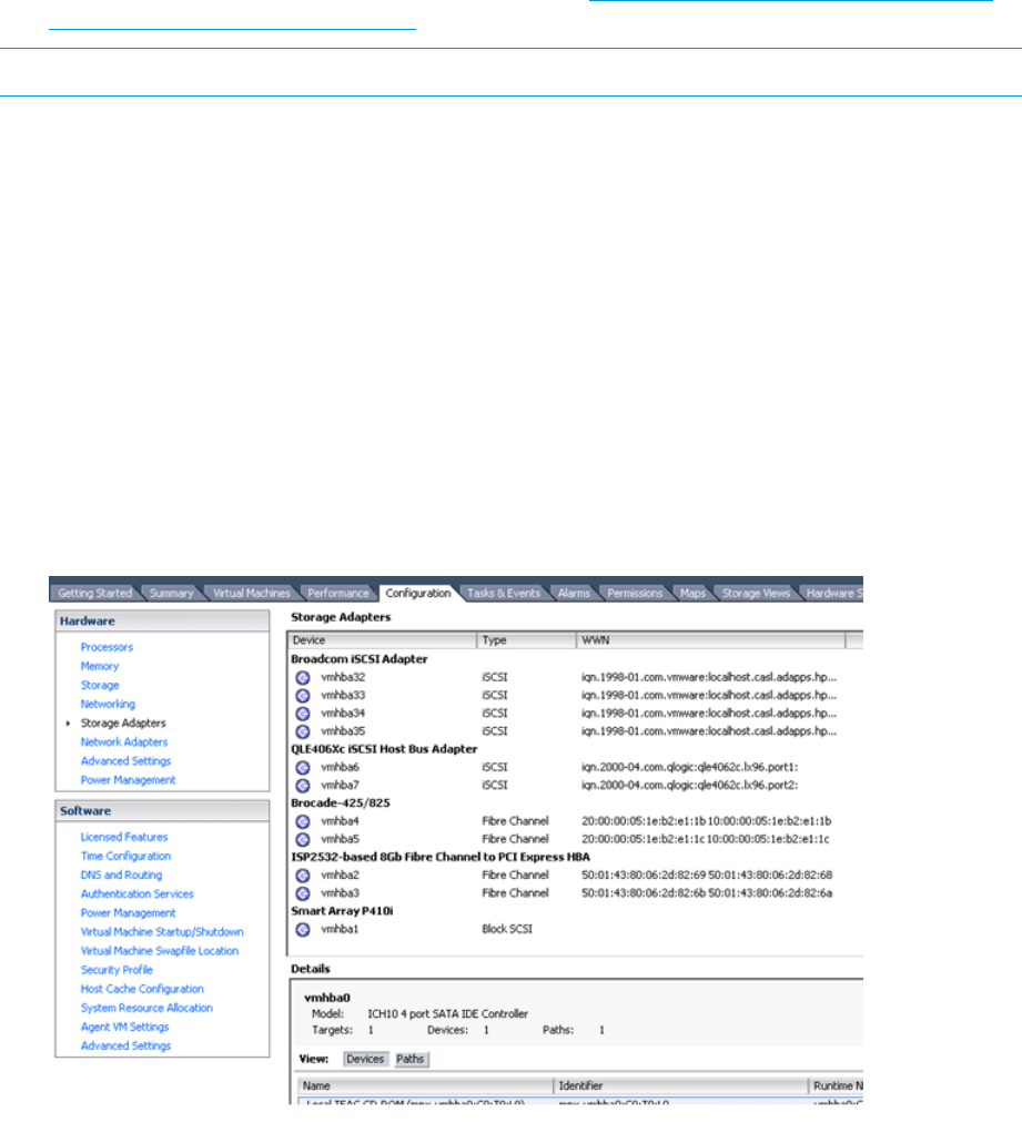
7. For each new device, use the disk command to select another disk, and then repeat 1through
6.
8. Repeat this labeling procedure for each new device. (Use the disk command to select another
disk.)
9. When you finish labeling the disks, enter quit or press Ctrl+D to exit the format utility.
For more information, see the System Administration Guide: Devices and File Systems for your
operating system, available on the Oracle website: http://www.oracle.com/technetwork/
indexes/documentation/index.html.
NOTE: Some format commands are not applicable to the EVA storage systems.
VMware
Configuring the EVA with VMware host servers
To configure an EVA with a VMware ESX server:
1. Using HP P6000 Command View, configure a host for one ESX server.
2. Verify that the Fibre Channel Adapters (FCAs) are populated in the world wide port name
(WWPN) list. Edit the WWPN, if necessary.
3. Set the connection type to VMware.
4. Add a port to the host defined in 1. Do not add host entries for servers with more than one
FCA.
5. Check the VMware vCenter management GUI to find out the WWPN of your server (see
diagram below).
Figure 21 VMware vCenter management GUI
6. Repeat this procedure for each ESX server.
Configuring an ESX server
This section provides information about configuring the ESX server.
70 Configuring application servers
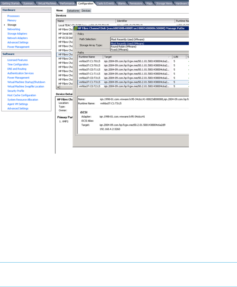
Setting the multipathing policy
You can set the multipathing policy for each LUN or logical drive on the SAN to one of the following:
•Most recently used (MRU)
•Fixed
•Round robin
To change multipathing policy, use the VMware vSphere GUI interface under the Configuration
tab and select Storage. Then select Devices.
Figure 22 Setting multipathing policy
Use the GUI to change policies, or you can use the following commands from the CLI:
ESX 4.x commands
•The # esxcli nmp device setpolicy --device
naa.6001438002a56f220001100000710000 --psp VMW_PSP_MRU command sets
device naa.6001438002a56f220001100000710000 with an MRU multipathing policy.
•The # esxcli nmp device setpolicy --device
naa.6001438002a56f220001100000710000 --psp VMW_PSP_FIXED command sets
device naa.6001438002a56f220001100000710000 with a Fixed multipathing policy.
•The # esxcli nmp device setpolicy --device
naa.6001438002a56f220001100000710000 --psp VMW_PSP_RR command sets
device naa.6001438002a56f220001100000710000 with a RoundRobin multipathing
policy.
NOTE: Each LUN can be accessed through both EVA storage controllers at the same time;
however, each LUN path is optimized through one controller. To optimize performance, if the LUN
multipathing policy is Fixed, all servers must use a path to the same controller.
VMware 71
You can also set the multipathing policy from the VMware Management User Interface (MUI) by
clicking the Failover Paths tab in the Storage Management section and then selecting Edit… link
for each LUN whose policy you want to modify.
ESXi 5.x commands
•The # esxcli storage nmp device set --device
naa.6001438002a56f220001100000710000 --psp VMW_PSP_MRU command sets
device naa.6001438002a56f220001100000710000 with an MRU multipathing policy.
•The # esxcli storage nmp device set --device
naa.6001438002a56f220001100000710000 --psp VMW_PSP_FIXED command sets
device naa.6001438002a56f220001100000710000 with an Fixed multipathing policy.
•The # esxcli storage nmp device set --device
naa.6001438002a56f220001100000710000 --psp VMW_PSP_RR command sets
device naa.6001438002a56f220001100000710000 with a RoundRobin multipathing
policy.
72 Configuring application servers
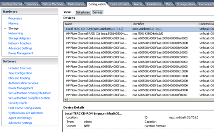
Verifying virtual disks from the host
Use the VMware vCenter management GUI to check all devices (see figure below).
HP P6000 EVA Software Plug-in for VMware VAAI
The vSphere Storage API for Array Integration (VAAI) is included in VMware vSphere solutions.
VAAI can be used to offload certain functions from the target VMware host to the storage array.
With the tasks being performed more efficiently by the array instead of the target VMware host,
performance can be greatly enhanced.
The HP P6000 EVA Software Plug-in for VMware VAAI (VAAI Plug-in) enables the offloading of
the following functions (primitives) to the EVA:
•Full copy—Enables the array to make full copies of data within the array, without the ESX
server having to read and write the data.
•Block zeroing—Enables the array to zero out a large number of blocks to speed up provisioning
of virtual machines.
•Hardware assisted locking—Provides an alternative means to protect the metadata for VMFS
cluster file systems, thereby improving the scalability of large ESX server farms sharing a
datastore.
•Block Space Reclamation—Enables the array to reclaim storage block space on thin provisioned
volumes upon receiving command from ESX server 5.1x or later.
System prerequisites
ESX/ESXi 4.1VMware operating system:
VMware vCenter 4.1VMware management station:
ESX/ESXi 4.1 environments: vCLI 4.1 (Windows or Linux)VMware administration tools:
ESX 5.0
ESX 5.1
XCS 11001000 or laterHP P6000 controller software:
Enabling vSphere Storage API for Array Integration (VAAI)
To enable the VAAI primitives, do the following:
VMware 73

NOTE: By default, the four VAAI primitives are enabled.
NOTE: The EVA VAAI Plug-In is required with vSphere 4.1 in order to permit discovery of the
EVA VAAI capability. This is not required for vSphere 5 or later.
1. Install the XCS controller software.
2. Enable the primitives from the ESX server.
Enable and disable these primitives through the following advanced settings:
•DataMover.HardwareAcceleratedMove (full copy)
•DataMover.HardwareAcceleratedInit (block zeroing)
•VMFS3.HarwareAccelerated Locking (hardware assisted locking)
For more information about the vSphere Storage API for Array Integration (VAAI), see the ESX
Server Configuration Guide.
3. Install the HP EVA VAAI Plug-in.
For information about installing the VAAI Plug-in, see “Installing the VAAI Plug-in” (page 74).
Installing the VAAI Plug-in
Depending on user preference and environment, choose one of the following three methods to
install the HP EVA VAAI Plug-in:
•Using ESX host console utilities
•vCLI/vMA
•Using VUM
The following table compares the three VAAI Plug-in installation methods:
Table 12 Comparison of installation methods
Scriptable
VMware
commands used
Client operating
system
Host
Operating
System
Required
deployment tools
Installation
method
Yes
(eva-vaaip.sh)
esxupdate
esxcli
N/AESX 4.1N/AESX host console
utilities—Local
console
Any computer running
SSH
SSH tool, such as
PuTTy
ESX host console
utilities—Remote
console
Yes
(eva-vaaip.pl)
vicfg-hostops.pl
vihostupdate.pl
Windows XPWindows
VistaWindows
7Windows Server
ESX 4.1, ESXi
4.1
VMware vSphere
CLI
VMware CLI
(vCLI)
2003Windows Server
2008 Linux x86Linux
x64
N/AN/AVM Appliance
(vMA)
NoVUM graphical
user interface
Windows Server
2003, Windows
Server 2008
ESX 4.1, ESXi
4.1
VMware vSphere
ServerVMware
Update Manager
VMware Update
Manager (VUM)
Installation overview
Regardless of installation method, key installation tasks include:
1. Obtaining the HP VAAI Plug-in software bundle from the HP website.
2. Extracting files from HP VAAI Plug-in software bundle to a temporary location on the server.
74 Configuring application servers

3. Placing the target VMware host in maintenance mode.
4. Invoking the software tool to install the HP VAAI Plug-in.
Automated installation steps include:
a. Installing the HP VAAI plug-in driver (hp_vaaip_p6000) on the target VMware host.
b. Adding VIB details to the target VMware host.
c. Creating VAAI claim rules.
d. Loading and executing VAAI claim rules.
5. Restarting the target VMware host.
6. Taking the target VMware host out of maintenance mode.
After installing the HP VAAI Plug-in, the operating system will execute all VAAI claim rules and
scan every five minutes to check for any array volumes that may have been added to the target
VMware host. If new volumes are detected, they will become VAAI enabled.
Installing the HP EVA VAAI Plug-in using ESX host console utilities
NOTE: This installation method is supported for use only with VAAI Plug-in version 1.00, in
ESX/ESXi 4.1 environments. This is required for ESX 4.1, but not for ESX 5i.
1. Obtain the VAAI Plug-in software package and save to a local folder on the target VMware
host:
a. Go to the HP Support Downloads website at http://www.hp.com/support/downloads.
b. Navigate through the display to locate and then download the HP P6000 EVA Software
Plug-in for VMware VAAI to a temporary folder on the server. (Example folder location:
/root/vaaip)
2. Install the VAAI Plug-in.
From the ESX service console, enter a command using the following syntax:
esxupdate --bundle hp_vaaip_p6000-xxx.zip --maintenance mode update
(where hp_vaaip_p6000-xxx.zip represents the filename of the VAAI Plug-in.)
3. Restart the target VMware host.
VMware 75

4. Verify the installation:
a. Check for new HP P6000 claim rules.
Using the service console, enter:
esxcli corestorage claimrule list -c VAAI
The return display will be similar to the following:
Rule Class Rule Class Type Plugin Matches
VAAI 5001 runtime vendor hp_vaaip_p6000 vendor=HP model=HSV
VAAI 5001 file vendor hp_vaaip_p6000 vendor=HP model=HSV
b. Check for claimed storage devices.
Using the service console, enter:
esxcli vaai device list
The return display will be similar to the following:
aa.600c0ff00010e1cbc7523f4d01000000
Device Display Name: HP iSCSI Disk (naa.600c0ff00010e1cbc7523f4d01000000)
VAAI Plugin Name: hp_vaaip_P6000
naa.600c0ff000da030b521bb64b01000000
Device Display Name: HP Fibre Channel Disk (naa.600c0ff000da030b521bb64b01000000)
VAAI Plugin Name: hp_vaaip_P6000
c. Check the VAAI status on the storage devices.
Using the service console, enter:
esxcfg-scsidevs -l | egrep "Display Name:|VAAI Status:"
The return display will be similar to the following:
Display Name: Local TEAC CD-ROM (mpx.vmhba5:C0:T0:L0)
VAAI Status: unknown
Display Name: HP Serial Attached SCSI Disk (naa.600508b1001052395659314e39440200)
VAAI Status: unknown
Display Name: HP Serial Attached SCSI Disk (naa.600c0ff0001087439023704d01000000)
VAAI Status: supported
Display Name: HP Serial Attached SCSI Disk (naa.600c0ff0001087d28323704d01000000)
VAAI Status: supported
Display Name: HP Fibre Channel Disk (naa.600c0ff000f00186a622b24b01000000)
VAAI Status: unknown
Table 13 Possible VAAI device status values
DescriptionValue
The array volume is hosted by a non-supported VAAI array.Unknown
The volume is hosted by a supported VAAI array (such as the HP P6000 EVA) and all
three VAAI commands completed successfully.
Supported
The volume is hosted by a supported VAAI array (such as the HP P6000 EVA), but all
three VAAI commands did not complete successfully.
Not supported
NOTE: VAAI device status will be "Unknown" until all VAAI primitives are attempted by ESX on
the device and completed successfully. Upon completion, VAAI device status will be “Supported."
Installing the HP VAAI Plug-in using vCLI/vMA
NOTE: This installation method is supported for use only with VAAI Plug-in version 1.00, in
ESX/ESXi 4.1 environments.
1. Obtain the VAAI Plug-in software package and save to a local folder on the target VMware
host:
a. Go to the HP Support Downloads website at http://www.hp.com/support/downloads.
b. Locate the HP P6000 Software Plug-in for VMware VAAI and then download it to a
temporary folder on the server.
76 Configuring application servers

2. Enter maintenance mode.
Enter a command using the following syntax:
vicfg-hostops.pl --server Host_IP_Address --username
User_Name--password Account_Password -o enter
3. Install the VAAI Plug-in using vihostupdate.
Enter a command using the following syntax:
vihostupdate.pl --server Host_IP_Address --username User_Name
--password Account_Password --bundle
hp_vaaip_p6000_offline-bundle-xyz --install
4. Restart the target VMware host.
Enter a command using the following syntax:
vicfg-hostops.pl --server Host_IP_Address --username
User_Name--password Account_Password -o reboot -f
5. Exit maintenance mode.
Enter a command using the following syntax:
vicfg-hostops.pl --server Host_IP_Address --username
User_Name--password Account_Password -o exit
6. Verify the claimed VAAI device.
a. Check for new HP P6000 claim rules.
Enter a command using the following syntax:
esxcli --server Host_IP_Address --username User_Name --password
Account_Password corestorage claimrule list –c VAAI
The return display will be similar to the following:
Rule Class Rule Class Type Plugin Matches
VAAI 5001 runtime vendor hp_vaaip_p6000 vendor=HP model=HSV
VAAI 5001 file vendor hp_vaaip_p6000 vendor=HP model=HSV
b. Check for claimed storage devices.
List all devices claimed by the VAAI Plug-in.
Enter a command using the following syntax:
esxcli --server Host_IP_Address --username User_Name --password
Account_Password vaai device list
The return display will be similar to the following:
naa.600c0ff00010e1cbc7523f4d01000000
Device Display Name: HP iSCSI Disk (naa.600c0ff00010e1cbc7523f4d01000000)
VAAI Plugin Name: hp_vaaip_p6000
naa.600c0ff000da030b521bb64b01000000
Device Display Name: HP Fibre Channel Disk (naa.600c0ff000da030b521bb64b01000000)
VAAI Plugin Name: hp_vaaip_p6000
c. Check the VAAI status on the storage devices. Use the vCenter Management Station as
listed in the following section.
Table 14 Possible VAAI device status values
DescriptionValue
The array volume is hosted by a non-supported VAAI array.Unknown
The array volume is hosted by a supported VAAI array and all three VAAI commands
completed successfully.
Supported
The array volume is hosted by a supported VAAI array, but all three VAAI commands
did not complete successfully.
Not supported
VMware 77

NOTE: VAAI device status will be "Unknown" until all VAAI primitives are attempted by ESX on
the device and completed successfully. Upon completion, VAAI device status will be “Supported."
Installing the VAAI Plug-in using VUM
NOTE:
•This installation method is supported for use with VAAI Plug-in versions 1.00 and 2.00, in
ESX/ESXi 4.1 environments.
•Installing the plug-in using VMware Update Manager is the recommended method.
Installing the VAAI Plug-in using VUM consists of two steps:
1. “Importing the VAAI Plug-in to the vCenter Server” (page 78)
2. “Installing the VAAI Plug-in on each ESX/ESXi host” (page 79)
Importing the VAAI Plug-in to the vCenter Server
1. Obtain the VAAI Plug-in software package and save it on the system that has VMware vSphere
client installed:
a. Go to the HP Support Downloads website at http://www.hp.com/support/downloads.
b. Locate the HP P6000 EVA Software Plug-in for VMware VAAI and then download it to
a temporary folder on the server.
c. Expand the contents of the downloaded .zip file into the temporary folder and locate
the HP EVA VAAI offline bundle file. The filename will be in one of the following formats:
hp_vaaip_p6000_offline-bundle_xyz.zip
(where xyz represents the VAAI Plug-in version.)
2. Open VUM:
a. Double-click the VMware vSphere Client icon on your desktop, and then log in to the
vCenter Server using administrator privileges.
b. Click the Home icon in the navigation bar.
c. In the Solutions and Applications pane, click the Update Manager icon to start VUM.
NOTE: If the Solutions and Applications pane is missing, the VUM Plug-in is not installed
on your vCenter Client system. Use the vCenter Plug-ins menu to install VUM.
3. Import the Plug-in:
a. Select the Patch Repository tab.
b. Click Import Patches in the upper right corner. The Import Patches dialog window will
appear.
c. Browse to the extracted HP P6000 VAAI offline bundle file. The filename will be in the
following format: hp_vaaip_p6000-xyz.zip or
hp_vaaip_p6000_offline-bundle-xyz.zip, where xyz will vary, depending on
the VAAI Plug-in version. Select the file and then click Next.
d. Wait for the import process to complete.
e. Click Finish.
78 Configuring application servers
4. Create a new Baseline set for this offline plug-in:
a. Select the Baselines and Groups tab.
b. Above the left pane, click Create.
c. In the New Baseline window:
•Enter a name and a description. (Example: HP P6000 Baseline and VAAI Plug-in for
HP EVA)
•Select Host Extension.
•Click Next to proceed to the Extensions window.
d. In the Extensions window:
•Select HP EVA VAAI Plug-in for VMware vSphere x.x, where x.x represents the plug-in
version.
•Click the down arrow to add the plug-in in the Extensions to Add panel at the bottom
of the display.
•Click Next to proceed.
•Click Finish to complete the task and return to the Baselines and Groups tab.
The HP P6000 Baseline should now be listed in the left pane.
Importing the VAAI Plug-in is complete. To install the plug-in, see “Installing the VAAI Plug-in on
each ESX/ESXi host” (page 79).
Installing the VAAI Plug-in on each ESX/ESXi host
1. From the vCenter Server, click the Home icon in the navigation bar.
2. Click the Hosts and Clusters icon in the Inventory pane.
3. Click the DataCenter that has the ESX/ESXi hosts that you want to stage.
4. Click the Update Manager tab. VUM automatically evaluates the software recipe compliance
for all ESX/ESXi Hosts.
5. Above the right pane, click Attach to open the Attach Baseline or Group dialog window.
Select the HP P6000 Baseline entry, and then click Attach.
6. To ensure that the patch and extensions compliance content is synchronized, again click the
DataCenter that has the ESX/ESXi hosts that you want to stage. Then, in the left panel, right-click
the DataCenter icon and select Scan for Updates. When prompted, ensure that Patches and
Extensions is selected, and then click Scan.
7. Stage the installation:
a. Click Stage to open the Stage Wizard.
b. Select the target VMware hosts for the extension that you want to install, and then click
Next.
c. Click Finish.
8. Complete the installation:
a. Click Remediate to open the Remediation Wizard.
b. Select the target VMware host that you want to remediate, and then click Next.
c. Make sure that the HP EVA VAAI extension is selected, and then click Next.
d. Fill in the related information, and then click Next.
e. Click Finish.
Installing the VAAI Plug in is complete. View the display for a summary of which ESX/ESXi hosts
are compliant with the vCenter patch repository.
VMware 79

NOTE:
•In the Tasks & Events section, the following tasks should have a Completed status: Remediate
entry, Install, and Check.
•If any of the above tasks has an error, click the task to view the detail events information.
Verifying VAAI status
1. From the vCenter Server, click the Home Navigation bar and then click Hosts and Clusters.
2. Select the target VMware host from the list and then click the Configuration tab.
3. Click the Storage Link under Hardware.
Table 15 Possible VAAI device status values
DescriptionValue
The array volume is hosted by a non-supported VAAI array.Unknown
The array volume is hosted by a supported VAAI array (such as the HP P6000) and all
three VAAI commands completed successfully.
Supported
The array volume is hosted by a supported VAAI array (such as the HP P6000), but all
three VAAI commands did not complete successfully.
Not supported
Uninstalling the VAAI Plug-in
Procedures vary, depending on user preference and environment:
Uninstalling VAAI Plug-in using the automated script (hpeva.pl)
1. Enter maintenance mode.
2. Query the installed VAAI Plug-in to determine the name of the bulletin to uninstall.
Enter a command using the following syntax:
c:\>hpeva.pl --server Host_IP_Address --username User_Name --password
Account_Password --query
3. Uninstall the VAAI Plug-in.
Enter a command using the following syntax:
c:\>hpeva.pl --server Host_IP_Address --username User_Name --password
Account_Password --bulletin Bulletin_Name --remove
4. Restart the host.
5. Exit maintenance mode.
Uninstalling VAAI Plug-in using vCLI/vMA (vihostupdate)
1. Enter maintenance mode.
2. Query the installed VAAI Plug-in to determine the name of the VAAI Plug-in bulletin to uninstall.
Enter a command using the following syntax:
c:\>vihostupdate.pl --server Host_IP_Address --username User_Name
--password Account_Password --query
3. Uninstall the VAAI Plug-in.
Enter a command using the following syntax:
c:\>vihostupdate.pl --server Host_IP_Address --username User_Name
--password Account_Password --bulletin
0-HPQ-ESX-4.1.0-hp-vaaip-p6000-1.0.10 --remove
4. Restart the host.
5. Exit maintenance mode.
80 Configuring application servers
Uninstalling VAAI Plug-in using VMware native tools (esxupdate)
1. Enter maintenance mode.
2. Query the installed VAAI Plug-in to determine the name of the VAAI Plug-in bulletin to uninstall.
Enter a command using the following syntax:
$host# esxupdate --vib-view query | grep hp-vaaip-p6000
3. Uninstall the VAAI Plug-in.
Enter a command using the following syntax:
$host# esxupdate remove -b VAAI_Plug_In_Bulletin_Name
--maintenancemode
4. Restart the host.
5. Exit maintenance mode.
VMware 81

4 Replacing array components
Customer self repair (CSR)
Table 16 (page 83) and Table 17 (page 84) identify hardware components that are customer
replaceable. Using HP Insight Remote Support software or other diagnostic tools, a support specialist
will work with you to diagnose and assess whether a replacement component is required to address
a system problem. The specialist will also help you determine whether you can perform the
replacement.
Parts-only warranty service
Your HP Limited Warranty may include a parts-only warranty service. Under the terms of parts-only
warranty service, HP will provide replacement parts free of charge.
For parts-only warranty service, CSR part replacement is mandatory. If you request HP to replace
these parts, you will be charged for travel and labor costs.
Best practices for replacing hardware components
The following information will help you replace the hardware components on your storage system
successfully.
CAUTION: Removing a component significantly changes the air flow within the enclosure.
Components or a blanking panel must be installed for the enclosure to cool properly. If a component
fails, leave it in place in the enclosure until a new component is available to install.
Component replacement videos
To assist you in replacing components, videos of the procedures have been produced. To view
the videos, go to the following website and navigate to your product:
http://www.hp.com/go/sml
Verifying component failure
•Consult HP technical support to verify that the hardware component has failed and that you
are authorized to replace it yourself.
•Additional hardware failures can complicate component replacement. Check your management
utilities to detect any additional hardware problems:
◦When you have confirmed that a component replacement is required, you may want to
clear the failure message from the display. This makes it easier to identify additional
hardware problems that may occur while waiting for the replacement part.
◦Before installing the replacement part, check the management utility for new hardware
problems. If additional hardware problems have occurred, contact HP support before
replacing the component.
◦See the System Event Analyzer online help for additional information.
Identifying the spare part
Parts have a nine-character spare part number on their label (Figure 23 (page 83)). For some spare
parts, the part number will be available in HP P6000 Command View. Alternatively, the HP call
center will assist in identifying the correct spare part number.
82 Replacing array components

Figure 23 Example of typical product label
1. Spare component number
Replaceable parts
This product contains the replaceable parts listed in “Controller enclosure replacement parts ”
(page 83) and “Disk enclosure replaceable parts ” (page 84). Parts that are available for customer
self repair (CSR) are indicated as follows:
✓ Mandatory CSR where geography permits. Order the part directly from HP and repair the
product yourself. On-site or return-to-depot repair is not provided under warranty.
• Optional CSR. You can order the part directly from HP and repair the product yourself, or you
can request that HP repair the product. If you request repair from HP, you may be charged for the
repair depending on the product warranty.
– No CSR. The replaceable part is not available for self repair. For assistance, contact an
HP-authorized service provider
Table 16 Controller enclosure replacement parts
CSR statusSpare part numberDescription
•537151–0014 Gb P63x0 array controller (HSV340)
•537152–0014 Gb P63x0 array controller (HSV340) with iSCSI
(MEZ50–1GbE)
•613468–0014 Gb P63x0 array controller (HSV340) with iSCSI
(MEZ75–10GbE)
•537153–0014 Gb P65x0 array controller (HSV360)
•537154–0014 Gb P65x0 array controller (HSV360) with iSCSI/FCoE
(MEZ50–10GbE)
•613469–0014 Gb P65x0 array controller (HSV360) with iSCSI/FCoE
(MEZ75)
•587246–0011 GB cache DIMM for P63x0 controller
•583721–0012 GB cache DIMM for P63x0/P65x0 controller
•681646-0014 GB cache DIMM for P65x0 controller
✓671987-001Array battery for P63x0/P65x0 controller (8 CELL)
✓671988-001Array battery for P63x0/P65x0 controller (6 CELL)
✓460581–001Array battery
✓519842–001Array power supply
✓460583–001Array fan module
✓460584–005Array management module
•461489–001Array LED membrane display
•461490–005Array midplane
Replaceable parts 83

Table 16 Controller enclosure replacement parts (continued)
CSR statusSpare part numberDescription
•461491–005Array riser assembly
•466264–001Array power UID
✓583395–001P6300 bezel assembly
✓583396–001P6500 bezel assembly
✓676972-001P63x0 bezel assembly
✓676973-001P65x0 bezel assembly
•583399–001Y-cable, 2 m
•408767-001SAS cable, SPS-CA, EXT Mini SAS, 2M
Table 17 Disk enclosure replaceable parts
CSR statusSpare part numberDescription
✓583711–001Disk drive, 300 GB, 10K, SFF, 6G, M6625, SAS
✓613921–001Disk drive, 450 GB, 10K, SFF, 6G, M6625, SAS
✓613922–001Disk drive, 600 GB, 10K, SFF, 6G, M6625, SAS
✓583713–001Disk drive, 146 GB, 15K, SFF, 6G, M6625, SAS
✓660676-001Disk drive, 200 GB, 15K, LFF, 6G, M6612,SAS
✓583716–001Disk drive, 300 GB, 15K, LFF, 6G, M6612,SAS
✓660677-001Disk drive, 400 GB, 15K, LFF, 6G, M6612,SAS
✓583717–001Disk drive, 450 GB, 15K, LFF, 6G, M6612, SAS
✓583718–001Disk drive, 600 GB, 15K, LFF, 6G, M6612, SAS
✓583714–001Disk drive, 500 GB, 7.2K, SFF, 6G, M6625, SAS-MDL
✓665749-001Disk drive, 900 GB, 7.2K, SFF, 6G, M6625, SAS-MDL
✓660678-001Disk drive, 1000 GB, 7.2K, LFF, 6G, M6612, SAS-MDL
✓602119–001Disk drive, 2 TB, 7.2K, LFF, 6G, M6612, SAS-MDL
✓687045-001Disk drive, 3 TB, 7.2K, LFF, 6G, M6612, SAS-MDL
•519316–001I/O board, SAS, 2600
•519320–001I/O board, SAS, 2700
•519324-001Voltage Regulator Module (VRM)
•519322-001Front Unit ID
✓511777-001Power supply, 460W
•519317-001Backplane, 12 slot, SAS, 2600
•519321-001Backplane, 25 slot, SAS, 2700
✓519325-001Fan module
•519323-001Fan module interconnect board
–581330-001Bezel kit
•519319-001Rear power UID
84 Replacing array components

Table 17 Disk enclosure replaceable parts (continued)
CSR statusSpare part numberDescription
•408765-001External mini-SAS Cable, 0.5m
•519318-001Rackmount kit, 1U/2U
For more information about CSR, contact your local service provider or see the CSR website:
http://www.hp.com/go/selfrepair
To determine the warranty service provided for this product, see the warranty information website:
http://www.hp.com/go/storagewarranty
To order a replacement part, contact an HP-authorized service provider or see the HP Parts Store
online:
http://www.hp.com/buy/parts
Replacing the failed component
CAUTION: Components can be damaged by electrostatic discharge (ESD). Use proper anti-static
protection.
•Always transport and store CRUs in an ESD protective enclosure.
•Do not remove the CRU from the ESD protective enclosure until you are ready to install it.
•Always use ESD precautions, such as a wrist strap, heel straps on conductive flooring, and
an ESD protective smock when handling ESD sensitive equipment.
•Avoid touching the CRU connector pins, leads, or circuitry.
•Do not place ESD generating material such as paper or non anti-static (pink) plastic in an ESD
protective enclosure with ESD sensitive equipment.
•HP recommends waiting until periods of low storage system activity to replace a component.
•When replacing components at the rear of the rack, cabling may obstruct access to the
component. Carefully move any cables out of the way to avoid loosening any connections.
In particular, avoid cable damage that may be caused by:
◦Kinking or bending.
◦Disconnecting cables without capping. If uncapped, cable performance may be impaired
by contact with dust, metal or other surfaces.
◦Placing removed cables on the floor or other surfaces, where they may be walked on or
otherwise compressed.
Replacement instructions
Printed instructions are shipped with the replacement part. Instructions for all replaceable components
are also included on the documentation CD that ships with the P63x0/P65x0 EVA and posted on
the web. For the latest information, HP recommends that you obtain the instructions from the web.
Go to the following web site: http://www.hp.com/support/manuals. Under Storage, select Disk
Storage Systems, then select HP P6300/P6500 Enterprise Virtual Array Systems under P6000/EVA
Disk Arrays. The manuals page for the P63x0/P65x0 EVA appears. Scroll to the Service and
maintenance information section where the following replacement instructions are posted:
•HP P6300/P6500 EVA FC Controller Enclosure Replacement Instructions
•HP P6300/P6500 EVA FC-iSCSI Controller Enclosure Replacement Instructions
Replacing the failed component 85
•HP Controller Enclosure Battery Replacement Instructions
•HP Controller Enclosure Cache DIMM Replacement Instructions
•HP Controller Enclosure Fan Module Replacement Instructions
•HP Controller Enclosure LED Display Replacement Instructions
•HP Controller Enclosure Management Module Replacement Instructions
•HP Controller Enclosure Midplane Replacement Instructions
•HP Controller Enclosure Power Supply Replacement Instructions
•HP Controller Enclosure Riser Assembly Replacement Instructions
•HP Large Form Factor Disk Enclosure Backplane Replacement Instructions
•HP Small Form Factor Disk Enclosure Backplane Replacement Instructions
•HP Disk Enclosure Fan Module Replacement Instructions
•HP Disk Enclosure Fan Interconnect Board Replacement Instructions
•HP Disk Enclosure Front Power UID interconnect board Replacement Instructions
•HP Disk Enclosure I/O Module Replacement Instructions
•HP Disk Enclosure VRM Replacement Instructions
•HP Disk Enclosure Rear Power UID Interconnect Board Replacement Instructions
•HP Power UID Replacement Instructions
•HP Disk Drive Replacement Instructions
86 Replacing array components

5 iSCSI or iSCSI/FCoE configuration rules and guidelines
This chapter describes the iSCSI configuration rules and guidelines for the HP P6000 iSCSI and
iSCSI/FCoE modules.
iSCSI or iSCSI/FCoE module rules and supported maximums
The iSCSI or iSCSI/FCoE modules are configured in a dual-controller configuration in the HP
P6000. Dual-controller configurations provide for high availability with failover between iSCSI or
iSCSI/FCoE modules. All configurations are supported as redundant pairs only. iSCSI connected
servers can be configured for access to one or both controllers.
HP P6000 Command View and iSCSI or iSCSI/FCoE module management
rules and guidelines
The HP P6000 Command View implementation provides the equivalent functionality for both iSCSI,
iSCSI/FCoE, and Fibre Channel connected servers. Management functions are integrated in HP
P6000 Command View.
The following are the HP P6000 Command View rules and guidelines for the iSCSI or iSCSI/FCoE
modules:
•Requires HP P6000 Command View for array-based and server-based management
•HP P6000 Command View manages the iSCSI or iSCSI/FCoE modules out of band (IP) through
the iSCSI or iSCSI/FCoE controller management IP ports. The HP P6000 Command View
application server must be on the same IP network and in the same subnet with the iSCSI or
iSCSI/FCoE module's management IP port.
•The iSCSI or iSCSI/FCoE module iSCSI and FCoE Initiators or iSCSI LUN masking information
does not reside in the HP P6000 Command View database. All iSCSI Initiator and LUN
presentation information resides in the iSCSI and iSCSI/FCoE modules.
•The default iSCSI Initiator EVA host mode setting is Microsoft Windows. The iSCSI initiator
for Apple Mac OS X, Linux, Oracle Solaris, VMware, Windows 2008, and Windows 2012
host mode setting is configured with HP P6000 Command View.
NOTE: Communication between HP P6000 Command View and the iSCSI modules is not secured
by the communication protocol. If this unsecured communication is a concern, HP recommends a
confined or secured IP network within a data center for this purpose.
HP P63x0/P65x0 EVA storage system software
The iSCSI and iSCSI/FCoE modules are not supported with HP P6000 Continuous Access.
Fibre Channel over Ethernet switch and fabric support
The iSCSI/FCoE modules provide FCoE target functionality. This enables server side FCoE
connectivity from Converged Network Adapters (CNAs) over 10 GbE lossless links and converged
network switches to the HP P6000 to realize end-to-end FCoE configurations. A simplified example
is illustrated in Figure 25 (page 88). HP P6000 Command View supports the iSCSI/FCoE module’s
FCoE LUN presentations while simultaneously servicing Fibre Channel and iSCSI hosts. The
iSCSI/FCoE modules support simultaneous operation of iSCSI and FCoE on each port.
The iSCSI/FCoE modules are supported with HP B-series and C-series product line converged
network switch models.
iSCSI or iSCSI/FCoE module rules and supported maximums 87
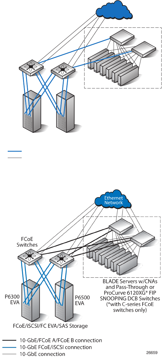
Figure 24 Mixed FC and FCoE storage configuration using FC and FCoE storage targets
26659b
FCoE/iSCSI/FC EVA/SAS storage
P6500
EVA
P6300
EVA
BLADE servers w/CNAs
and Pass-Thru modules or
ProCurve 6120XG* FIP
SNOOPING DCB switches
(*with C-series FCoE
switches only)
10-GbE FCoE/iSCSI connection
10-GbE connection
Ethernet
network
B-series or
C-series CN
switches
Figure 25 FCoE support
88 iSCSI or iSCSI/FCoE configuration rules and guidelines
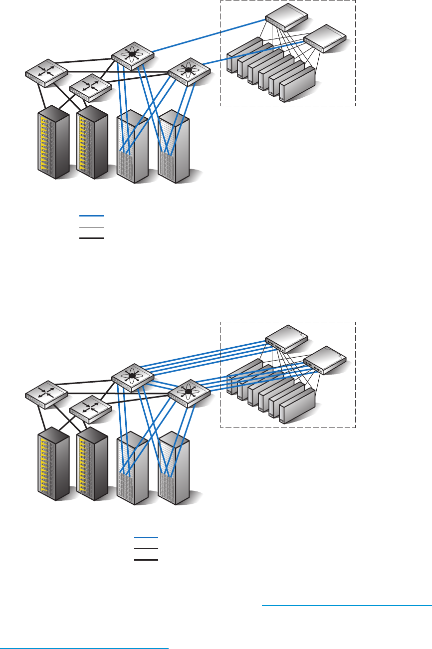
The following is an example of a Mixed FC and FCoE storage configuration:
Figure 26 Mixed FC and FCoE storage configuration
26660a
P6300 EVA P6500 EVA
FCoE switches
FC switches
FCoE/iSCSI/FC EVA/SAS storage
BLADE Servers w/CNAs and Pass-Thru modules or
ProCurve 6120XG* FIP SNOOPING DCB switches
(*with C-series FCoE switches only)
10-GbE FCoE/iSCSI connection
10-GbE connection
Fibre Channel
3PAR
F-Class or T-Class
The following is an example of an FC and FCoE storage with Cisco Fabic Extender for HP
BladeSystem configurations:
Figure 27 FC and FCoE storage with Cisco Fabic Extender for HP BladeSystem configuration
26663a
P6300 EVA P6500 EVA
C-series FCoE switches
FC switches
FCoE/iSCSI/FC EVA/SAS storage
BLADE Servers w/CNAs and
Cisco Fabric Extender* for HP BladeSystem
(*with C-series FCoE switches only)
10-GbE FCoE/iSCSI connection
10-GbE connection
Fibre Channel
3PAR
F-Class or T-Class
For the latest information on Fibre Channel over Ethernet switch model and firmware support, see
the Single Point of Connectivity Knowledge (SPOCK) at http://www.hp.com/storage/spock. You
must sign up for an HP Passport to enable access. Also, for information on FCoE configuration and
attributes, see the HP SAN Design Reference Guide at:
http://www.hp.com/go/sandesign
Fibre Channel over Ethernet switch and fabric support 89

NOTE: HP recommends that at least one zone be created for the FCoE WWNs from each port
of the HP P6000 with the iSCSI/FCoE modules. The zone should also contain CNA WWNs.
Zoning should include member WWNs from each one of the iSCSI/FCoE modules to ensure
configuration of multipath redundancy.
Operating system and multipath software support
This section describes the iSCSI or iSCSI/FCoE module's operating system, multipath, and cluster
support.
For the latest information on operating system and mulitpath software support, see the Single Point
of Connectivity Knowledge (SPOCK) at http://www.hp.com/storage/spock. You must sign up for
an HP Passport to enable access.
Table 18 (page 91) provides the operating system and multipath software support.
90 iSCSI or iSCSI/FCoE configuration rules and guidelines

Table 18 Operating system and multipath software support
EVA storage systemConnectivityClustersMultipath softwareOperating system
EVA4400/4400 with the embedded
switch
iSCSINoneNoneApple Mac OS X
iSCSI, FCoEMSCSMPIO with HP DSMMicrosoft Windows
Server 2008, 2003,
Hyper-V, and 2012
EVA4000/4100/6000/6100/8000/8100
EVA6400/8400
MPIO with Microsoft
DSM P6300/P6500
iSCSI, FCoENoneDevice MapperRed Hat Linux, SUSE
Linux P6350/P6550
iSCSINoneSolaris MPxIOSolaris
iSCSI, FCoENoneVMware MPxIOVMware
iSCSI initiator rules, guidelines, and support
This section describes the following iSCSI Initiator rules and guidelines.
General iSCSI initiator rules and guidelines
The following are the iSCSI Initiator rules and guidelines.
•iSCSI Initiators and iSCSI or iSCSI/FCoE ports can reside in different IP subnets. This requires
setting the iSCSI or iSCSI/FCoE module's gateway feature. See “set mgmt command” (page 236)
for more information.
•Both single path and multipath initiators are supported on the same iSCSI or iSCSI/FCoE
modules.
•Fibre Channel, iSCSI, and FCoE presented LUNs must be uniquely presented to initiators
running only one protocol type. Presenting a common LUN to initiators simultaneously running
different protocols is unsupported.
Apple Mac OS X iSCSI initiator rules and guidelines
The Apple Mac OS X iSCSI initiator supports the following:
•Power PC and Intel Power Mac G5, Xserve, Mac Pro
•ATTO Technology Mac driver
•iSNS
•CHAP
iSCSI Initiator operating system considerations:
•Host mode setting – Apple Mac OS X
•Multipathing is not supported
Microsoft Windows iSCSI Initiator rules and guidelines
The Microsoft Windows iSCSI Initiator supports the following:
•Microsoft iSCSI Initiator versions 2.08, 2.07
•Microsoft iSCSI Initiator for Windows 2012, Windows 2008, Vista, and Windows 7
•Multipath on iSCSI or iSCSI/FCoE module single or dual controller configurations
iSCSI initiator rules, guidelines, and support 91

iSCSI Initiator operating system considerations:
•Host mode setting – Microsoft Windows 2012, Windows 2008 or Windows 2003
•TCPIP parameter Tcp1323Opts must be entered in the registry with a value of DWord=2
under the registry setting#
HKEY_LOCAL_MACHINE\SYSTEM\CurrentControlSet\Ser¬vices\Tcpip\Parameters.
•The TimeOutValue parameter should be entered in the registry with a value of DWord=120
under the registry setting #HKEY_LOCAL_MACHINE\SYSTEM\CurrentControlSet\
Services\Disk.
•TCPIP parameter Tcp1323Opts must be entered in the registry with a value of DWord=2
under the registry setting # HKEY_LOCAL_MACHINE\SYSTEM\CurrentControlSet\
Services\Tcpip\Parameters
•The TimeOutValue parameter should be entered in the registry with a value of DWord=120
under the registry setting #HKEY_LOCAL_MACHINE\SYSTEM\CurrentControlSet\
Services\Disk.
CAUTION: Using the Registry Editor incorrectly can cause serious problems that may require
reinstallation of the operating system. Backup the registry before making any changes. Use Registry
Editor at your own risk.
NOTE: These parameters are automatically set by the HP iSCSI or iSCSI/FCoE module kit. This
kit also includes a null device driver for the P6000, and is available at: http://
h18006.www1.hp.com/products/storageworks/evaiscsiconnect/index.html
Linux iSCSI Initiator rules and guidelines
The Linux iSCSI Initiator supports the following:
•Red Hat Linux and SUSE Linux
•Multipath using HP Device Mapper
iSCSI Initiator operating system considerations:
•Host mode setting – Linux
•NIC bonding is not supported
Solaris iSCSI Initiator rules and guidelines
The Solaris iSCSI Initiator supports the following:
•Solaris iSCSI initiator only
•Multipath using MPxIO
•MPxIO Symmetric option only
•MPxIO round-robin
•MPxIO auto-failback
iSCSI Initiator operating system considerations:
•Host mode setting – Oracle Solaris
•Does not support TOE NICs or iSCSI HBA
•Does not support LUN 0
92 iSCSI or iSCSI/FCoE configuration rules and guidelines

VMware iSCSI Initiator rules and guidelines
The VMware iSCSI Initiator supports the following:
•Native iSCSI software initiator in VMware ESX 4.0/3.5
•Guest OS SCSI Controller, LSI Logic and/or BUS Logic (BUS Logic with SUSE Linux only)
•ESX server's native multipath solution, based on NIC teaming on the server
•Guest OS boot from an iSCSI or an iSCSI/FCoE presented target device
•Virtual Machine File System (VMFS) data stores and raw device mapping for guest OS virtual
machines
•Multi-initiator access to the same LUN via VMFS
•VMware ESX server 4.0/3.5 native multipath solution based on NIC teaming
iSCSI Initiator operating system considerations:
•Host mode setting VMware
•Does not support hardware iSCSI initiator (iSCSI HBA)
Supported IP network adapters
For the latest information on network adapter support, see the product release notes or the Single
Point of Connectivity Knowledge (SPOCK) at http://www.hp.com/storage/spock. You must sign
up for an HP Passport to enable access.
Table 19 (page 93) lists the IP network adapters supported by the iSCSI and iSCSI/FCoE controller.
Table 19 Operating system and multipath software support
Network interconnectOperating system
All standard GbE NICs/ASICs supported by AppleApple Mac OS X
All standard 1 GbE or 10 GbE NICs/ASICs and TOE NICs supported by HP
for Windows 2012, 2008, and 2003
Microsoft Windows Server 2012,
2008, 2003, Hyper-V
QLogic iSCSI HBAs
All standard 1 GbE or 10 GbE NICs/ASICs supported by HP for LinuxRed Hat Linux, SUSE Linux
QLogic iSCSI HBAs
All standard GbE NICs/ASICs supported by OracleSolaris
All standard 1GbE or 10 GbE NICs/ASICs supported by HP for VMwareVMware
QLogic iSCSI HBAs
IP network requirements
HP recommends the following:
•Network protocol: TCP/IP IPv6, IPv4, Ethernet 1000 Mb/s or 10 GbE
•IP data: LAN/VLAN support with less than 10 ms latency; maximum of 2 VLANs per port, 1
VLAN per protocol
•IP management—LAN/WAN support
•Dedicated IP network for iSCSI data
•Jumbo frames
NOTE: If you configure IPv6 on any iSCSI or iSCSI/FCoE module's ISCSI data port, you must
also configure IPv6 on the HP P6000 Command View management server.
Supported IP network adapters 93

Set up the iSCSI Initiator
Windows
For Windows Server 2012 and Windows Server 2008, the iSCSI initiator is included with the
operating system. For Windows Server 2003, you must download and install the iSCSI initiator
(version 2.08 recommended).
HP recommends the following Windows HKEY_LOCAL_MACHINE Registry settings:
Tcp1323opts = "2"
TimeOutvalue = "120"
NOTE: Increasing the TimeOutvalue from the default of 60 to 120 will avoid initiator I/O timeouts
during controller code loads and synchronizations. These settings are included in the HP P6000
iSCSI/FCoE and MPX200 Multifunction Router kit.
94 iSCSI or iSCSI/FCoE configuration rules and guidelines
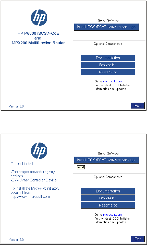
1. Install the HP P6000 iSCSI/FCoE and MPX200 Multifunction Router kit.
a. Start the installer by running Launch.exe; if you are using a CD-ROM, the installer
should start automatically.
b. Click Install iSCSI/FCoE software package (see Figure 28 (page 95) and Figure 29
(page 95)).
Figure 28 Windows Server 2003 kit
Figure 29 Windows registry and controller device installation
For Windows Server 2003, the Microsoft iSCSI initiator installation presents an option
for installing MPIO using the Microsoft generic DSM (Microsoft MPIO Multipathing Support
for iSCSI check box). For Windows Server 2008, MPIO is installed separately. See
Figure 30 (page 96).
Set up the iSCSI Initiator 95
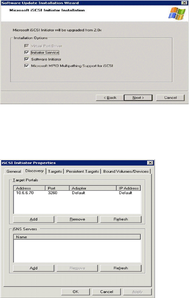
Figure 30 iSCSI Initiator Installation
c. Click the Microsoft iSCSI Initiator icon to open the Control Panel applet.
The iSCSI Initiator Properties window opens.
d. Click the Discovery tab (see Figure 31 (page 96)).
Figure 31 iSCSI Initiator Properties—Discovery tab
e. In the Target Portals section, click Add.
A dialog box opens to enter the iSCSI port IP Address.
f. Click OK.
The Discovery is now complete.
2. Set up the iSCSI Host and virtual disks on HP P6000 Command View:
96 iSCSI or iSCSI/FCoE configuration rules and guidelines
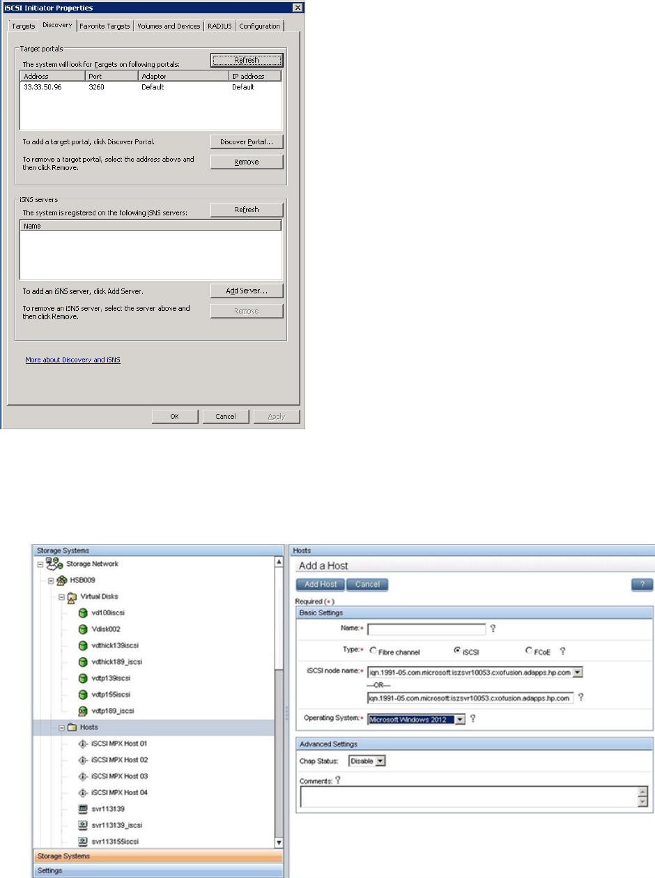
Figure 32 iSCSI Initiator Properties—Discovery tab (Windows 2008)
a. From HP P6000 Command View, click the EVA storage system icon to start the iSCSI
storage presentation. In adding a host, the iSCSI or iSCSI/FCoE modules are the target
EVA storage system.
Figure 33 Add a host
b. b. Select the Hosts folder.
Set up the iSCSI Initiator 97
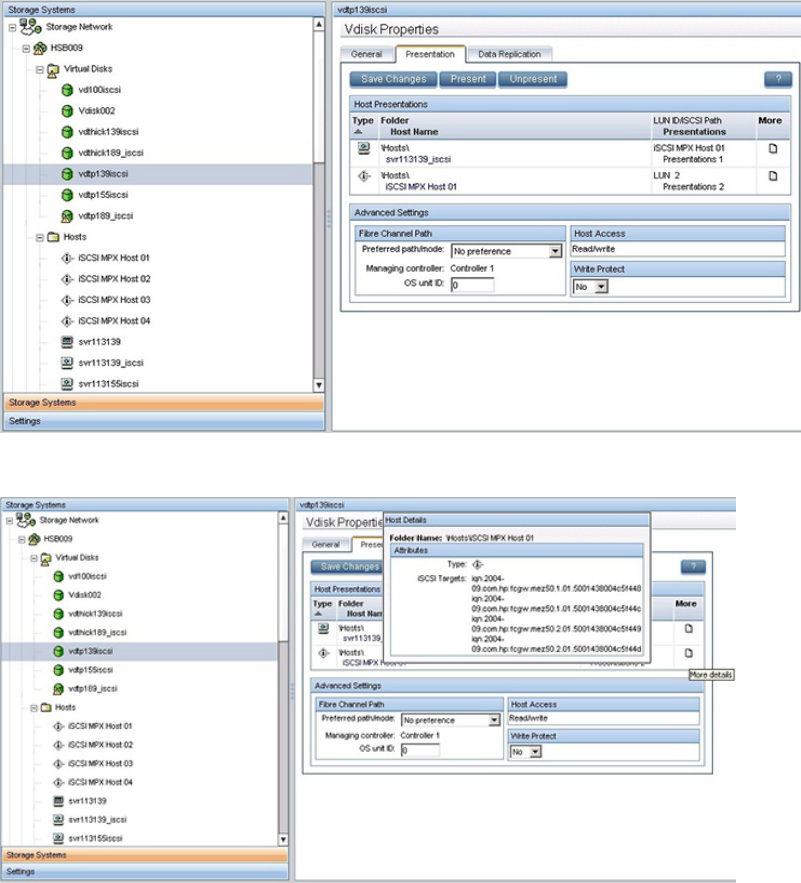
c. c. To create iSCSI Initiator host, click Add host.
A dialog box opens.
•Enter a name for the initiator host in the Name box.
•Select iSCSI as the Type.
•Select the initiator iSCSI qualified name (IQN) from the iSCSI node name list. Or,
you can enter a port WWN
•Select an OS from the Operating System list.
d. Create a virtual disk and present it to the host you created in Step 2.c. Note the numbers
in the target IQN; these target WWNs will be referenced during Initiator login. See
Figure 34 (page 98) and Figure 35 (page 98).
Figure 34 Virtual disk properties
Figure 35 Host details
98 iSCSI or iSCSI/FCoE configuration rules and guidelines
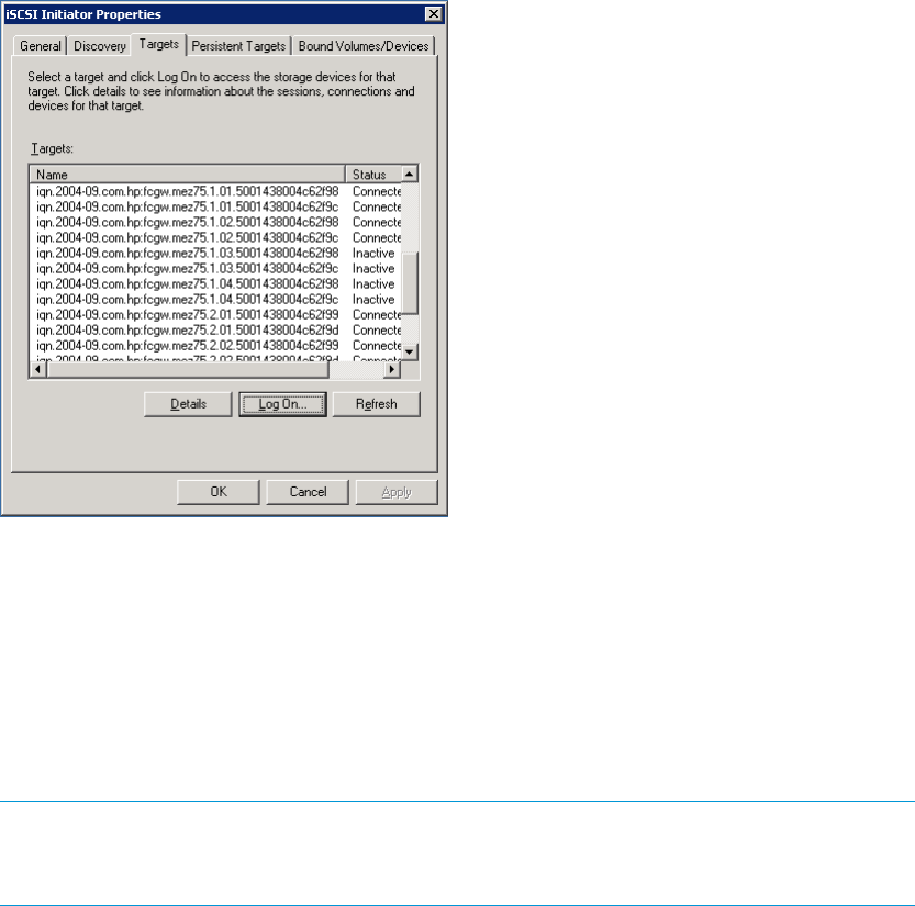
3. Set up the iSCSI disk on the iSCSI Initiator:
a. Open the iSCSI Initiator Control Panel applet.
b. Click the Targets tab and then the Refresh button to see the available targets
(Figure 36 (page 99)). The status should be Inactive.
Figure 36 iSCSI Initiator Properties—Targets tab
c. Select the target IQN, keying off the module 1 or 2 field and the WWN field, noted in
Step 2.d, and click Log On.
A dialog box opens.
d. Configure the target IQN:
•Select the Automatically box to restore this connection when the system boots.
•Select the Multipathing box to enable MPIO. The target status is Connected when
logged in.
NOTE: HP recommends using the Advanced button to selectively choose the Local
Adapter, Source IP, and Target Portal. The Target Portal IP Address is the iSCSI port to
which this initiator connection path is defined.
e. Depending on the operating system, open Server Manager or Computer Management.
f. Select Disk Management.
g. Select Action > Rescan Disks. Verify that the newly assigned disk is listed. If not, a reboot
may be required.
h. Prepare the disk for use by formatting and partitioning.
Multipathing
Microsoft MPIO includes support for the establishment of redundant paths to send I/O from the
initiator to the target. For Windows Server 2008 and Microsoft Windows 2012, MPIO is a separate
feature that has to be installed separately. Microsoft iSCSI Software Initiator Version 2.x includes
MPIO and has to be selected for installation. Setting up redundant paths properly is important to
ensure high availability of the target disk. Ideally, the system would have the paths use separate
NIC cards and separate network infrastructure (cables, switches, iSCSI or iSCSI/FCoE modules).
HP recommends separate target ports.
Set up the iSCSI Initiator 99

Microsoft MPIO support allows the initiator to log in to multiple sessions to the same target and
aggregate the duplicate devices into a single device exposed to Windows. Each session to the
target can be established using different NICs, network infrastructure, and target ports. If one
session fails, another session can continue processing I/O without interruption to the application.
The iSCSI target must support multiple sessions to the same target. The Microsoft iSCSI MPIO DSM
supports a set of load balance policies that determine how I/O is allocated among the different
sessions. With Microsoft MPIO, the load balance policies apply to each LUN individually.
The Microsoft iSCSI DSM v2.x assumes that all targets are active/active and can handle I/O on
any path at any time. There is no mechanism within the iSCSI protocol to determine whether a
target is active/active or active/passive; therefore, the iSCSI or iSCSI/FCoE modules support only
multipath configurations with the EVA with active/active support. More information can be found
at:
http://www.microsoft.com/WindowsServer2003/technologies/storage/mpio/default.mspx
http://www.microsoft.com/WindowsServer2003/technologies/storage/mpio/faq.mspx
http://download.microsoft.com/download/3/0/4/304083f1-11e7-44d9-92b9-2f3cdbf01048/
mpio.doc
Table 20 (page 100) details the differences between Windows Server 2008 and Windows Server
2003.
Table 20 Windows server differences
Windows Server 2003Windows Server 2008 and 2012
Separate installationIncluded with operating systemiSCSI Initiator
Included with iSCSI initiatorFeature has to be installedMPIO
Table 21 (page 100) shows the supported MPIO options for the iSCSI or iSCSI/FCoE controller.
Table 21 Supported MPIO options for iSCSI or iSCSI/FCoE modules
Windows Server 2003Windows Server 2008 and 2012
SupportedSupportedHP MPIO Full Featured
DSM for EVA*
SupportedSupportedMicrosoft generic DSM
*Preferred
Installing the MPIO feature for Windows Server 2012
NOTE: Microsoft Windows 2012 includes a separate MIOP feature that requires installation for
use. Microsoft Windows Server 2012 also includes the iSCSI Initiator. Download or installation is
not required.
Installing the MPIO feature for Windows Server 2012:
100 iSCSI or iSCSI/FCoE configuration rules and guidelines
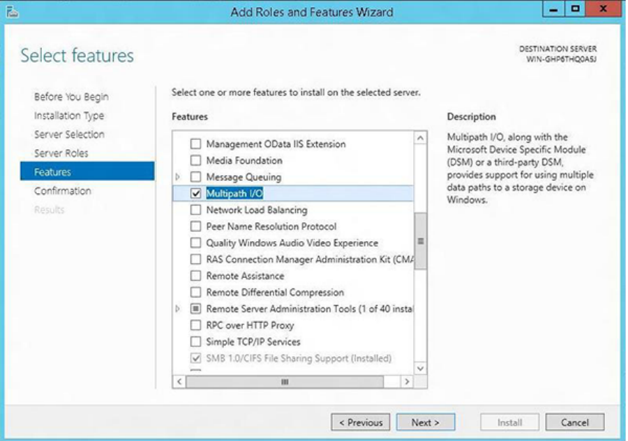
1. Check the box for Multipath I/O in the Add Features page.
Figure 37 Add Features page
2. Click Next and then click Install.
3. After the server reboots, add support for iSCSI Devices using the MPIO applet.
Set up the iSCSI Initiator 101
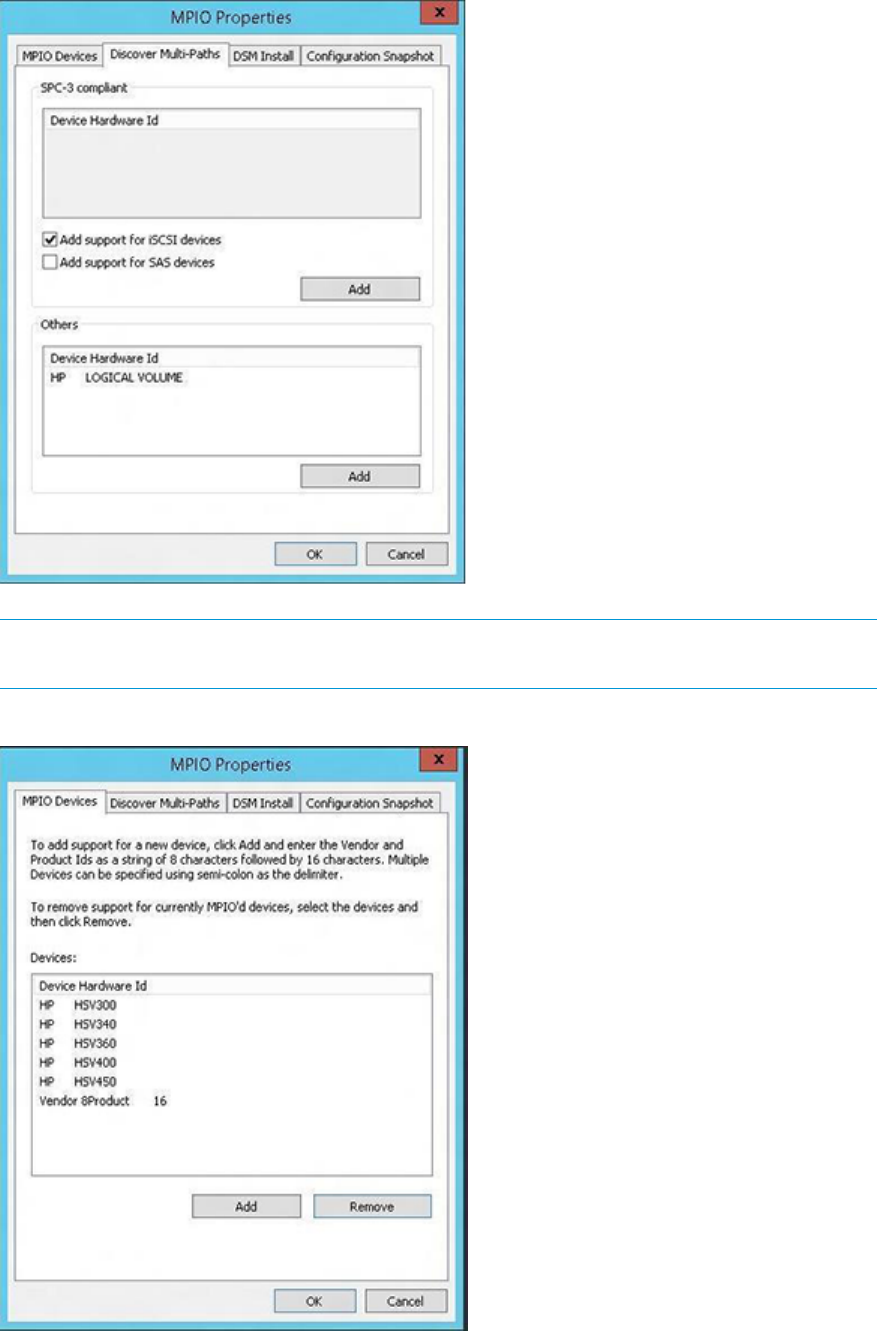
Figure 38 MPIO Properties page before reboot
NOTE: You must present a virtual disk to the initiator to enable the Add support for iSCSI
devices checkbox.
Figure 39 MPIO Properties page after reboot
4. A final reboot is required to get the devices MPIO-ed.
102 iSCSI or iSCSI/FCoE configuration rules and guidelines
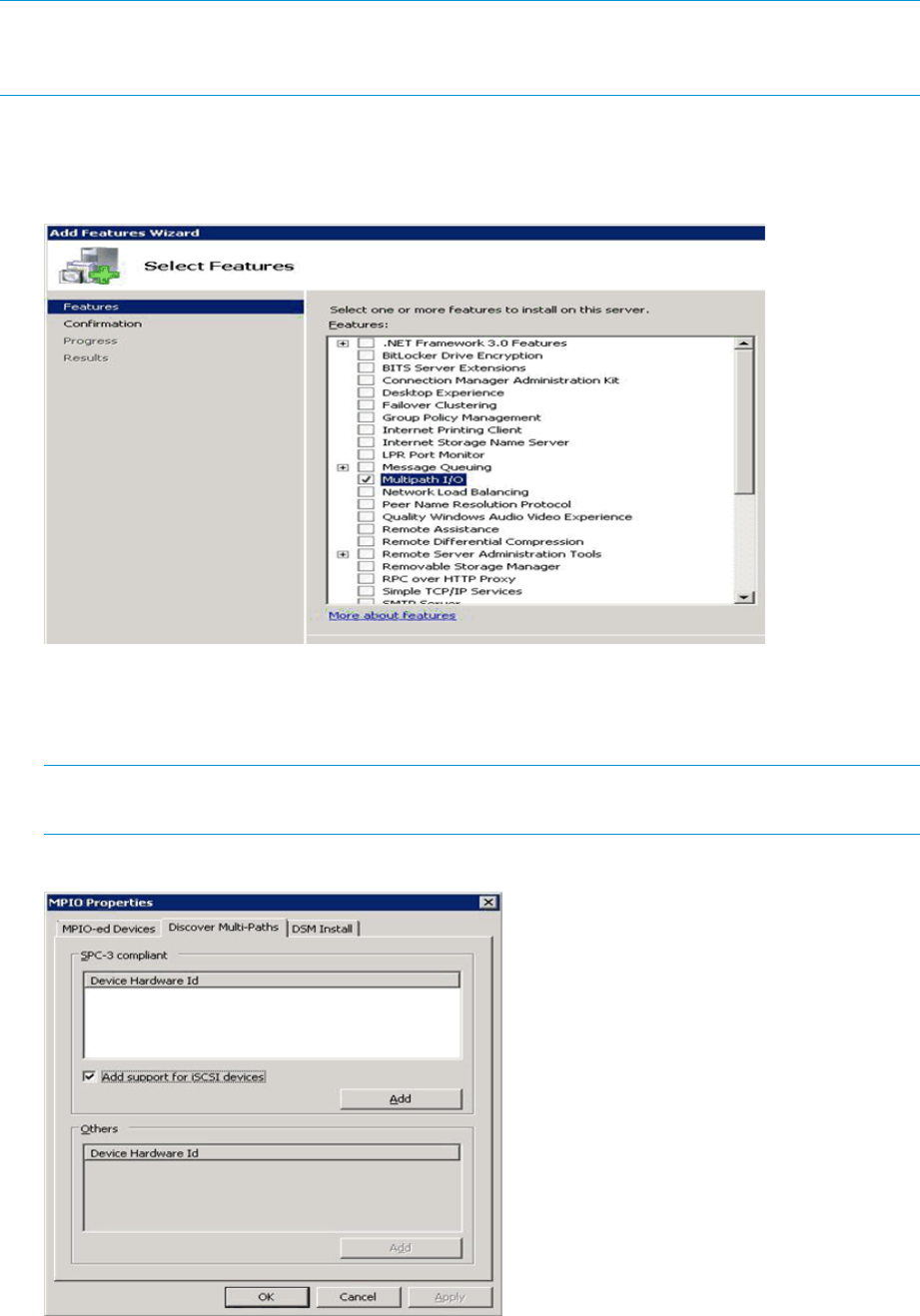
Installing the MPIO feature for Windows Server 2008
NOTE: Microsoft Windows 2008 includes a separate MPIO feature that requires installation for
use. Microsoft Windows Server 2008 also includes the iSCSI Initiator. Download or installation is
not required.
Installing the MPIO feature for Windows Server 2008:
1. Check the box for Multipath I/O in the Add Features page (Figure 37 (page 103)).
Figure 40 Add Features page
2. Click Next and then click Install.
3. After the server reboots, add support for iSCSI Devices using the MPIO applet (see
Figure 41 (page 103) and Figure 42 (page 104)).
NOTE: You must present a virtual disk to the initiator to enable the Add support for iSCSI
devices checkbox.
Figure 41 MPIO Properties page before reboot
Set up the iSCSI Initiator 103
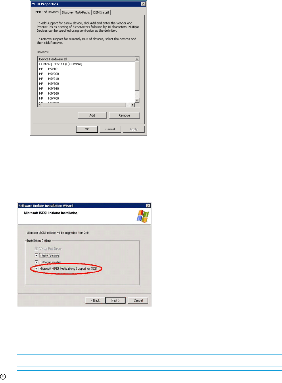
Figure 42 MPIO Properties page after reboot
4. A final reboot is required to get the devices MPIO-ed.
Installing the MPIO feature for Windows Server 2003
For Windows Server 2003, if you are installing the initiator for the first time, check all the installation
option checkboxes and then click Next to continue (Figure 43 (page 104)).
Figure 43 Software update installation wizard
To add or remove specific MS iSCSI software Initiator components after the initial install, run the
setup package executable and select the check box to add MPIO. The application automatically
checks the boxes for components that are already installed. For example, if you want to add the
MS MPIO component, leave the other check boxes unchecked; check only the MS MPIO check
box.
NOTE: The installation requires a reboot.
IMPORTANT: Windows XP Professional is not supported by Microsoft's MPIO.
104 iSCSI or iSCSI/FCoE configuration rules and guidelines

About Microsoft Windows Server 2003 scalable networking pack
The Microsoft Windows Server 2003 Scalable Networking Pack (SNP) contains functionality for
offloading TCP network processing to hardware. TCP Chimney is a feature that allows TCP/IP
processing to be offloaded to hardware. Receive Side Scaling allows receive packet processing
to scale across multiple CPUs.
HP’s NC3xxx Multifunction Gigabit server adapters support TCP offload functionality using
Microsoft’s Scalable Networking Pack (SNP).
For more support details, read the latest HP adapter information for more support details.
To download the SNP package and for more details see: http://support.microsoft.com/kb/912222.
NOTE: Windows Server 2003 SP2 includes SNP functionality.
SNP setup with HP NC 3xxx GbE multifunction adapter
Microsoft’s Scalable Networking Pack works in conjunction with HP’s NC3xxxx Multifunction
Gigabit server adapters for Windows 2003 only.
To set up SNP on a Windows 2003 server:
1. Install the hardware and necessary software for the NC3xxx Multifunction Gigabit server
adapter, following the manufacturer’s installation procedures.
2. Download the SNP package from the Microsoft website: http://support.microsoft.com/kb/
912222.
a. To start the installation immediately click Run, or
b. To copy the download to your computer for installation at a later time, click Save.
A reboot is required after successful installation.
3. After reboot, verify TCP offload settings by opening a Command Prompt window and issuing
the command:
C:\>netsh interface ip show offload
The following is displayed:
Offload Options for interface "33-IP Storage Subnet" with index:
10003:
TCP Transmit Checksum
IP Transmit Checksum
TCP Receive Checksum
IP Receive Checksum
TCP Large Send TCP Chimney Offload.
4. To modify TOE Chimney settings, use the commands:
>netsh int ip set chimney enabled
>netsh int ip set chimney disabled
For more information, go to:
http://support.microsoft.com/kb/912222
iSCSI Initiator version 3.10 setup for Apple Mac OS X (single-path)
The EVA4400 and EVA connectivity option supports the Macintosh Xtend iSCSI Initiator provided
by ATTO Technologies. For more details please visit http://www.attotech.com.
Set up the iSCSI Initiator 105
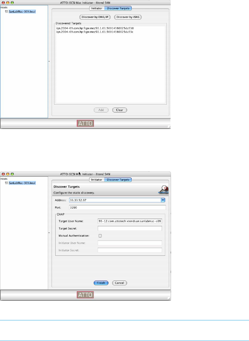
Set up the iSCSI Initiator for Apple Mac OS X
1. Install the ATTO iSCSI Macintosh Initiator v3.10 following the install instructions provided by
the vendor.
2. Run the Xtend SAN application to discover and configure the EVA iSCSI targets. The Xtend
SAN iSCSI Initiator can discover targets either by static address or iSNS.
For static address discovery:
a. Select Discover Targets and then select Discover by DNS/IP (Figure 44 (page 106)).
Figure 44 Discover targets
b. Add the static IP address of the iSCSI or iSCSI/FCoE module's port in the Address field
and then select Finish (Figure 45 (page 106)).
Figure 45 Add static IP address
c. Select a target from the Discovered Target list and then click Add (Figure 44 (page 106)).
NOTE: The iSCSI or iSCSI/FCoE module's port may present several iSCSI targets to
the Xtend SAN iSCSI Initiator. Select only one target from the list.
106 iSCSI or iSCSI/FCoE configuration rules and guidelines
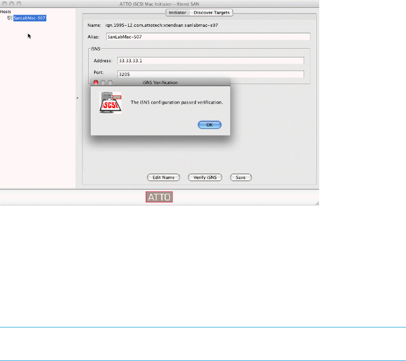
3. For iSNS discovery:
a. Select Initiator and then enter the iSNS name or IP address in the iSNS Address field
(Figure 46 (page 107)).
Figure 46 iSNS discovery and verification
b. Test the connection from the initiator to the iSNS server by selecting Verify iSNS. If
successful, select Save.
If necessary, working on the iSNS server, make the appropriate edits to add the Xtend
SAN iSCSI Initiator to any iSNS discovery domains that include iSCSI module targets.
c. Select Discover Targets.
d. Select Discover by iSNS.
A list of module targets appears under Discovered Targets (Figure 44 (page 106)).
NOTE: The module's port may present several iSCSI targets to the Xtend SAN iSCSI
Initiator. Select only one target from the list.
e. Select the newly-added target under Host name in the left frame.
f. Check the Visible box (Figure 47 (page 107)). This allows the initiator to display the target
status.
g. Check the Auto Login box. This configures the iSCSI Initiator to automatically log in to
the iSCSI target at system startup.
h. Click Save.
Figure 47 Selecting newly added target
Set up the iSCSI Initiator 107
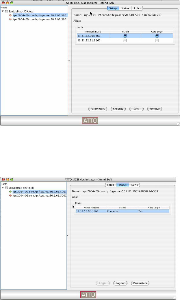
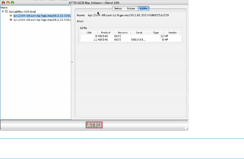
Storage setup for Apple Mac OS X
1. Present LUNs using HP P6000 Command View.
2. Verify that the EVA LUNs are presented to the Macintosh iSCSI Initiator:
a. Open the Xtend SAN iSCSI application.
b. Select the iSCSI or iSCSI/FCoE module target entry under the host name.
c. Click the LUNs button.
A list of presented EVA LUNs is displayed (Figure 49 (page 109)).
Figure 49 Presented EVA LUNs
NOTE: If no LUNs appear in the list, log out and then log in again to the target, or a
system reboot may be required.
3. Set up the iSCSI drive on the iSCSI Initiator:
a. Open Disk Utilities from the Apple Mac OS X Finder Applications list.
b. Format and partition the EVA LUN as needed.
iSCSI Initiator setup for Linux
Installing and configuring the SUSE Linux Enterprise 10 iSCSI driver
Configure the initiator using the built-in GUI-based tool or the open-iscsi administration utility using
the iscsiadm command. See the iscsiadm (8) man pages for detailed command information.
1. Modify the Initiator Name by issuing the following command:
# vi /etc/initiatorname.iscsi
2. To configure the Initiator and Targets, start the iSCSI Initiator applet by finding it in the YaST
Control Center under Network Services, and then set the service to start at boot time
(Figure 50 (page 110)).
Set up the iSCSI Initiator 109
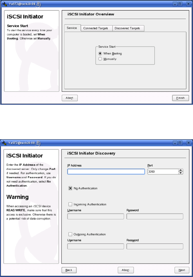
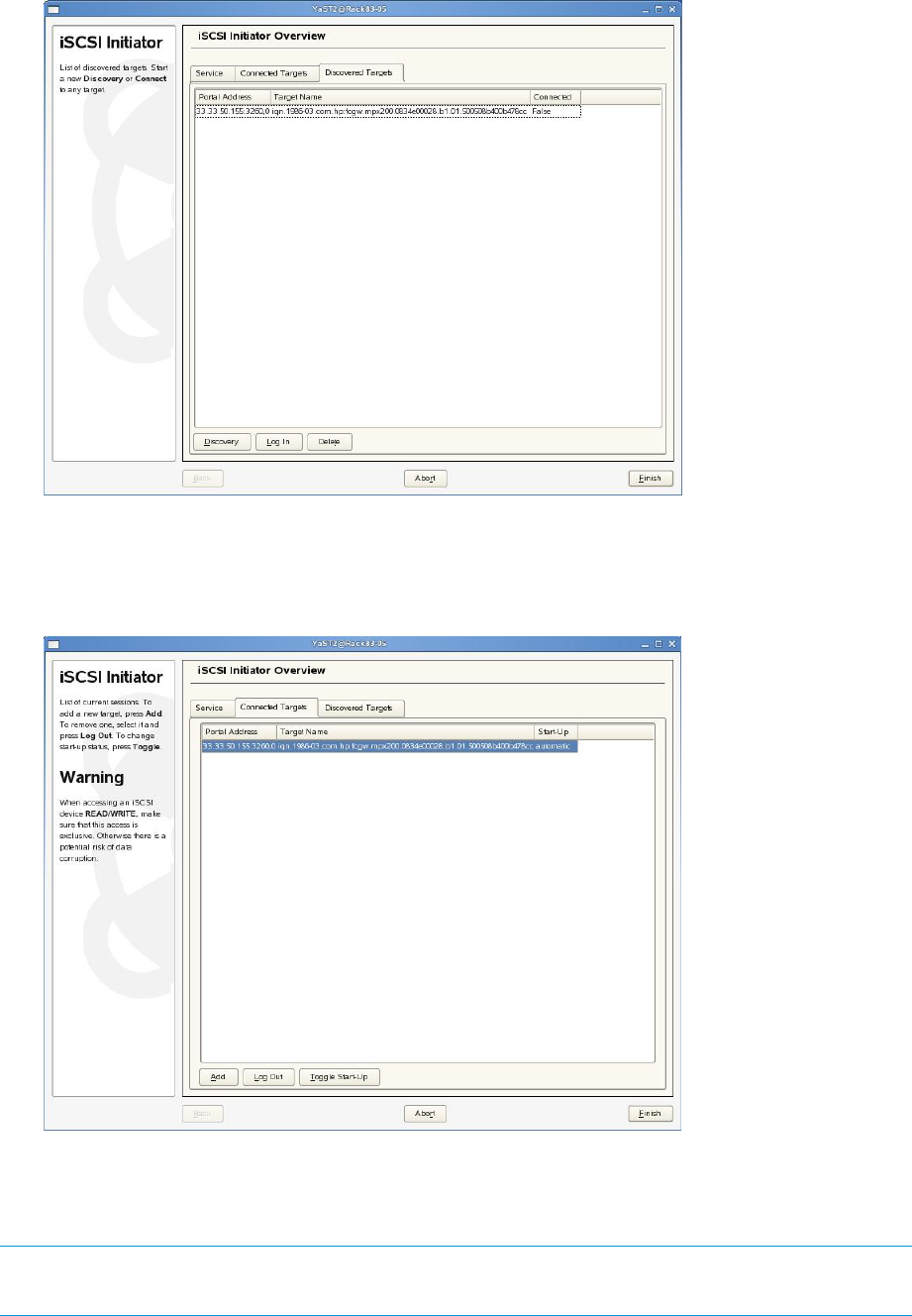
Figure 52 Target login
5. Click the Connected Targets tab, and then click the Toggle Start-Up button on each target
listed so the targets start automatically (Figure 53 (page 111)).
Figure 53 Connected Targets tab
Installing and configuring for Red Hat 5
To install and configure for Red Hat 5:
NOTE: The iSCSI driver package is included but is not installed by default. Install the package
iscsi—initiator—utils during or after operating system installation.
Set up the iSCSI Initiator 111

1. Use the iscsiadm command to control discovery and connectivity:
# iscsiadm –m discovery –t st –p 10.6.0.33:3260
2. Edit the initiator name:
# vi /etc/iscsi/initiatorname.iscsi
3. To start the iSCSI service use the service command:
# service iscsi start
4. Verify that the iSCSI service autostarts:
#chkconfig iscsi on
NOTE: For more detail, see the man pages regarding the iscsiadm open-iscsi administration
utility.
Installing and configuring for Red Hat 4 and SUSE 9
To install and configure for Red Hat 4 and for SUSE 9:
NOTE: The iSCSI driver is included with the Red Hat 4 and SUSE 9 distributions and is installed
by default. Configuration is the same for Red Hat 3, 4, SUSE 8 and 9.
1. Update /etc/iscsi.conf to include the IP address of your iSCSI target. A sample
configuration file might include entries like this:
DiscoveryAddress=33.33.33.101
For a more detailed description of the configuration file format, enter:
man iscsi.conf
2. Enter the following command to manually start iSCSI services to test your configuration:
/etc/init.d/iscsi start
3. Modify the /etc/initiatorname.iscsi file to reflect a meaningful name for the initiator.
For example:
InitiatorName=iqn.1987–05.com.cisco:servername.yourcompany.com
NOTE: In most cases, the only part of the file requiring modification is after the colon.
If there are problems starting the iscsi daemon, they are usually caused by an incorrect IP Address
or an ill-formatted initiator name.
Installing the initiator for Red Hat 3 and SUSE 8
If you are upgrading from a previous installation of an iSCSI driver, HP recommends that you
remove the /etc/initiatorname.iscsi file before installing the new driver. See the following
website for the latest version of the Linux driver for EVA iSCSI connectivity:
http://sourceforge.net/projects/linux-iscsi
NOTE: The Linux driver supports both Red Hat 3 and SUSE 8. See the Readme file in the tar ball
for more information on how to configure the Linux iSCSI Initiator.
Assigning device names
Because Linux assigns SCSI device nodes dynamically whenever a SCSI logical unit is detected,
the mapping from device nodes such as /dev/sda or /dev/sdb to iSCSI targets and logical
units may vary.
Variations in process scheduling and network delay can result in iSCSI targets being mapped to
different SCSI device nodes every time the driver is started. Because of this variability, configuring
112 iSCSI or iSCSI/FCoE configuration rules and guidelines

applications or operating system utilities to use the standard SCSI device nodes to access iSCSI
devices can result in sending SCSI commands to the wrong target or logical unit.
To provide consistent naming, the iSCSI driver scans the system to determine the mapping from
SCSI device nodes to iSCSI targets. The iSCSI driver creates a tree of directories and symbolic
links under /dev/iscsi to make it easier to use a particular iSCSI target's logical unit.
The directory tree under /dev/iscsi contains subdirectories for each iSCSI bus number, each
target id number on the bus, and each logical unit number for each target. For example, the whole
disk device for bus 0,target ID 0, and LUN 0 would be
/dev/iscsi/bus0/target0/LUN0/disk.
In each logical unit directory there is a symbolic link for each SCSI device node that can be
connected to that particular logical unit. These symbolic links are modeled after the Linux devfs
naming convention:
•The symbolic link disk maps to the whole-disk SCSI device node such as /dev/sda or
/dev/sdb.
•The symbolic links part1 through part15 maps to each partition of that SCSI disk. For
example, a symbolic link can map to partitions /dev/sda1,dev/sda15, or to as many
partitions as necessary.
NOTE: These symbolic links exist regardless of the number of disk partitions. Opening the
partition devices results in an error if the partition does not actually exist on the disk.
•The symbolic link mt maps to the auto-rewind SCSI tape device node for the LUN /dev/st0,
for example. Additional links for mtl,mtm, and mta map to the other auto-rewind devices
/dev/st0l, /dev/st0m, /dev/st0a, regardless of whether these device nodes actually
exist or could be opened.
•The symbolic link mtn maps to the no-rewind SCSI tape device node, if any. For example,
this LUN maps to /dev/nst0. Additional links formtln,mtmn, and mtan map to the other
no-rewind devices such as /dev/nst0l, /dev/nst0m, /dev/nst0a, regardless of
whether those device nodes actually exist or could be opened.
•The symbolic link cd maps to the SCSI CD-ROM device node, if any, for the LUN /dev/scd0
for example.
•The symbolic link generic maps to the SCSI generic device node, if any, for the LUN
/dev/sg0.
Because the symlink creation process must open all of the SCSI device nodes in /dev in order to
determine which nodes map to iSCSI devices, you may see many modprobe messages logged
to syslog indicating that modprobe could not find a driver for a particular combination of major
and minor numbers. This message can be ignored. The messages occur when Linux is unable to
find a driver to associate with a SCSI device node that the iSCSI daemon is opening as part of its
symlink creation process. To prevent these messages from occurring, remove the SCSI device
nodes that do not contain an associated high-level SCSI driver.
Target bindings
The iSCSI driver automatically maintains a bindings file, /var/iscsi/bindings. This file
contains persistent bindings to ensure that the same iSCSI bus and target ID number are used for
every iSCSI session with a particular iSCSI TargetName, even when the driver is repeatedly
restarted.
This feature ensures that the SCSI number in the device symlinks (described in “Assigning device
names” (page 112)) always map to the same iSCSI target.
Set up the iSCSI Initiator 113

NOTE: Because of the way Linux dynamically allocates SCSI device nodes as SCSI devices are
found, the driver does not and cannot ensure that any particular SCSI device node /dev/sda,
for example, always maps to the same iSCSI TargetName. The symlinks described in
“Assigning device names” (page 112) are intended to provide application and fstab file persistent
device mapping and must be used instead of direct references to particular SCSI device nodes.
If the bindings file grows too large, lines for targets that no longer exist may be manually removed
by editing the file. Manual editing should not be needed, however, since the driver can maintain
up to 65,535 different bindings.
Mounting file systems
Because the Linux boot process normally mounts file systems listed in /etc/fstab before the
network is configured, adding mount entries in iSCSI devices to /etc/fstab will not work. The
iscsi-mountall script manages the checking and mounting of devices listed in the file
/etc/fstab.iscsi, which has the same format as /etc/fstab. This script is automatically
invoked by the iSCSI startup script.
NOTE: If iSCSI sessions are unable to log in immediately due to network or authentication
problems, the iscsi-mountall script can time out and fail to mount the file systems.
Mapping inconsistencies can occur between SCSI device nodes and iSCSI targets, such as mounting
the wrong device due to device name changes resulting from iSCSI target configuration changes
or network delays. Instead of directly mounting SCSI devices, HP recommends one of the following
options:
•Mount the /dev/iscsi tree symlinks.
•Mount file system UUIDs or labels (see man pages for mke2fs,mount, and fstab).
•Use logical volume management (see Linux LVM).
Unmounting file systems
It is very important to unmount all file systems on iSCSI devices before the iSCSI driver stops. If
the iSCSI driver stops while iSCSI devices are mounted, buffered writes may not be committed to
disk, and file system corruption can occur.
Since Linux will not unmount file systems that are being used by a running process, any processes
using those devices must be stopped (see fuser(1)) before iSCSI devices can be unmounted.
To avoid file system corruption, the iSCSI shutdown script automatically stops all processes using
devices in /etc/fstab.iscsi, first by sending them SIGTERM, and then by sending any
remaining processes SIGKILL. The iSCSI shutdown script unmounts all iSCSI file systems and stops
the iSCSI daemon, terminating all connections to iSCSI devices.
CAUTION: File systems not listed in /etc/fstab.iscsi cannot be automatically unmounted.
114 iSCSI or iSCSI/FCoE configuration rules and guidelines
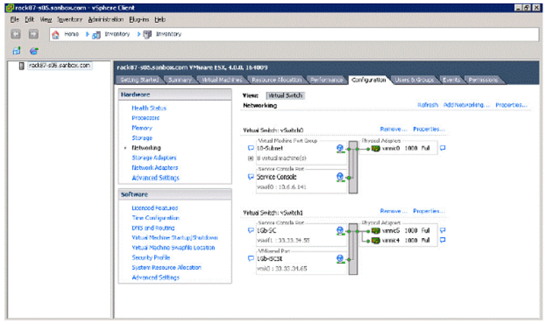
Presenting EVA storage for Linux
To set up LUNs using HP P6000 Command View:
1. Set up LUNs using HP P6000 Command View. For procedure steps, see Step 2.
2. Set up the iSCSI drive on the iSCSI Initiator:
a. Restart the iSCSI services:
/etc/rc.d/initd/iscsi restart
b. Verify that the iSCSI LUNs are presented to the operating system by entering the following
command:
fdisk -l
Setting up the iSCSI Initiator for VMware
The software iSCSI Initiator is built into the ESX server VMkernel and uses standard 10 GigE/GigE
NICs to connect to the iSCSI or iSCSI/FCoE modules.
To set up software-based iSCSI storage connectivity:
1. Install the appropriate license from VMware to enable the iSCSI software driver using the
VMware instructions.
2. Configure the VMKernel TCP/IP networking stack for iSCSI support. Configure the VMkernel
service console with dedicated virtual switch using a dedicated NIC for iSCSI data traffic.
Follow the instructions from VMware. Figure 54 (page 115) shows an example of a
configuration.
Figure 54 Configuration tab
3. Open a firewall port by enabling the iSCSI software client service:
a. Using the VMware VI client, select the server.
b. Click the Configuration tab, and then click Security Profile.
c. Click the Properties link.
The Firewall Properties dialog box is displayed (see Figure 55 (page 116)).
Set up the iSCSI Initiator 115

Figure 55 Firewall Properties dialog box
d. Select the Software iSCSI check box for to enable iSCSI traffic.
e. Click OK.
4. Enable the iSCSI software initiators:
a. In the VMware VI client, select the server from the inventory panel.
b. Click the Configuration tab, and then click Storage Adapters under Hardware.
c. Under iSCSI Software Adapter, choose the available software initiator.
d. Click the Properties link of the software adapter.
The iSCSI Initiator Properties dialog box is displayed.
e. Click Configure.
The General Properties dialog box is displayed (see Figure 56 (page 116)).
Figure 56 General Properties dialog box
f. Select the Enabled check box.
g. Click OK.
5. Set up Discovery Addressing for the software initiator:
a. Repeat Step 4 to open the iSCSI initiator Properties dialog box.
b. Click the Dynamic Discovery tab
c. Click Add to add a new iSCSI target.
The Add Send Target Server dialog box is displayed (see Figure 57 (page 117)).
116 iSCSI or iSCSI/FCoE configuration rules and guidelines
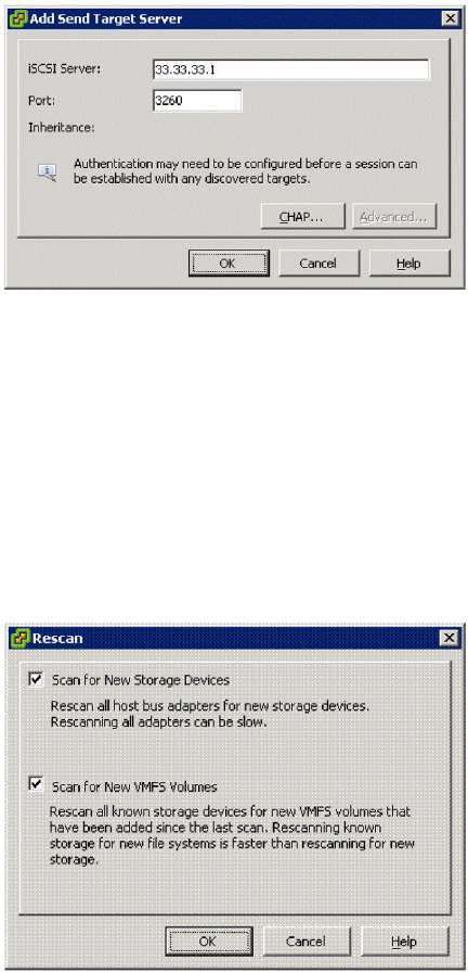
Figure 57 Add Send Target Server dialog box
d. Enter the iSCSI IP address of the iSCSI or iSCSI/FCoE module.
e. Click OK.
6. To verify that the LUNs are presented to the VMware host, rescan for new iSCSI LUNs:
a. In VMware’s VI client, select a server and click the Configuration tab.
b. Choose Storage Adapters in the hardware panel and click Rescan above the Storage
Adapters panel.
The Rescan dialog box is displayed (see Figure 58 (page 117)).
Figure 58 Rescan dialog box
c. Select the Scan for New Storage Devices and the Scan for New VMFS Volumes check
boxes.
d. Click OK.
The LUNs are now available for the ESX server.
When presenting iSCSI storage to Virtual Machines, you must do the following:
•Create Virtual Machines using LSI Logic emulation.
•Present iSCSI storage to a Virtual Machine either as a data store created on an iSCSI device
or raw device mapping.
Configuring multipath with the Solaris 10 iSCSI Initiator
This section contains information about configuring multipath with the Solaris 10 iSCSI Initiator to
the iSCSI or iSCSI/FCoE modules.
Set up the iSCSI Initiator 117

MPxIO overview
The Oracle multipathing software (MPxIO) provides basic failover and load-balancing capability
to HP P6000, and EVA4x00/6x00/8x00 storage systems. MPxIO allows the merging of multiple
SCSI layer paths, such as an iSCSI device exposing the same LUN via several different iSCSI target
names. Because MPxIO is independent of transport, it can multipath a target that is visible on both
iSCSI and FC ports. This section describes only the iSCSI implementation of MPxIO with the iSCSI
or iSCSI/FCoE modules.
For more information about MPxIO, see the Solaris Fibre Channel and Storage Multipathing
Administration Guide at: http://docs.sun.com/source/819-0139.
Preparing the host system
To verify that MPxIO is enabled:
1. Enter the following command to verify that the MPIO setting is no:
cat kernel/drv/iscsi.conf
2. 2. Verify mpxio-disable=”no”
If setting is yes change to no, and reboot:
Reboot -- -r
Example: MPxIO on all iSCSI port settings in /kernel/dev/iscsi.conf.
# Copyright 2006 Sun Microsystems, Inc. All rights reserved.
# Use is subject to license terms.
#
#ident "@(#)iscsi.conf 1.2 06/06/12 SMI"
name="iscsi" parent="/" instance=0;
ddi-forceattach=1;
#
# I/O multipathing feature (MPxIO) can be enabled or disabled using
# mpxio-disable property. Setting mpxio-disable="no" will activate
# I/O multipathing; setting mpxio-disable="yes" disables the feature.
#
# Global mpxio-disable property:
#
# To globally enable MPxIO on all iscsi ports set:
# mpxio-disable="no";#
# To globally disable MPxIO on all iscsi ports set:
# mpxio-disable="yes";
#
mpxio-disable="no";
#
Enabling MPxIO for HP P63x0/P65x0 EVA
This section describes the steps necessary to configure a Solaris server to recognize an HP storage
array in an iSCSI multipath environment with the iSCSI or iSCSI/FCoE modules.
Edit the scsi_vhci.conf file
HP EVA storage arrays are supported with MPxIO:
•As symmetric devices only
•With no load balancing
•With no failback
To configure MPxIO for HP storage devices, the appropriate information needs to be added in the
/kernel/drv/scsi_vhci.conf file. To enable MPxIO for HP storage:
1. Use a text editor to change the configuration file. For example:
# vi /kernel/drv/scsi_vhci.conf
118 iSCSI or iSCSI/FCoE configuration rules and guidelines

2. Modify load balancing to none:
load-balance="none";
3. Modify auto-failback to disable:
auto-failback="disable";
4. Add the following lines to cover the 4x00/6x00/8x00/P6000 HP arrays:
device-type-scsi-options-list =
“HP HSV“, “symmetric-option“;
symmetric-option = 0x1000000;
NOTE: You must enter six spaces between HP and HSV, as shown.
Example: HP storage array settings in /kernel/drv/scsi_vhci.conf:
#
# Copyright 2004 Sun Microsystems, Inc. All rights reserved.
# Use is subject to license terms.
#
#pragma ident "@(#)scsi_vhci.conf 1.9 04/08/26 SMI"
#
name="scsi_vhci" class="root";
#
# Load balancing global configuration: setting load-balance="none" will cause
# all I/O to a given device (which supports multipath I/O) to occur via one
# path. Setting load-balance="round-robin" will cause each path to the device
# to be used in turn.
#
load-balance="none";
#
# Automatic failback configuration
# possible values are auto-failback="enable" or auto-failback="disable"
auto-failback="disable";
#
# For enabling MPxIO support for 3rd party symmetric device need an
# entry similar to following in this file. Just replace the "SUN SENA"
# part with the Vendor ID/Product ID for the device, exactly as reported by
# Inquiry cmd.
#
# device-type-scsi-options-list =
# "SUN SENA", "symmetric-option";
#
# symmetric-option = 0x1000000;
#
device-type-scsi-options-list =
"HP HSV","symmetric-option";
symmetric-option = 0x1000000;
5. Activate the changes, by a reconfiguration reboot:
# reboot -- -r
Edit the sgen.conf file
To ensure that the HP storage arrays are recognized by Solaris as scsi controllers, the appropriate
information needs to be added in the /kernel/drv/sgen.conf file.
1. Use a text editor to change the configuration file. For example:
# vi /kernel/drv/scsi_vhci.conf
2. Add array_ctrl to device-type-config-list:
device-type-config-list="array_ctrl";
3. Uncomment all target/lun pair entries.
Example: HP storage array settings in /kernel/drv/sgen.conf.
Set up the iSCSI Initiator 119

.
.
.
# devices on your system. Please refer to sgen(7d) for details.
#
# sgen may be configured to bind to SCSI devices exporting a particular device
# type, using the device-type-config-list, which is a ',' delimited list of
# strings.
#
device-type-config-list="array_ctrl";
.
.
.
# After configuring the device-type-config-list and/or the inquiry-config-list,
# the administrator must uncomment those target/lun pairs at which there are
# devices for sgen to control. If it is expected that devices controlled by
# sgen will be hotplugged or added into the system later, it is recommended
# that all of the following lines be uncommented.
name="sgen" class="scsi" target=0 lun=0;
name="sgen" class="scsi" target=1 lun=0;
name="sgen" class="scsi" target=2 lun=0;
name="sgen" class="scsi" target=3 lun=0;
name="sgen" class="scsi" target=4 lun=0;
name="sgen" class="scsi" target=5 lun=0;
name="sgen" class="scsi" target=6 lun=0;
name="sgen" class="scsi" target=7 lun=0;
name="sgen" class="scsi" target=8 lun=0;
name="sgen" class="scsi" target=9 lun=0;
name="sgen" class="scsi" target=10 lun=0;
name="sgen" class="scsi" target=11 lun=0;
name="sgen" class="scsi" target=12 lun=0;
name="sgen" class="scsi" target=13 lun=0;
name="sgen" class="scsi" target=14 lun=0;
name="sgen" class="scsi" target=15 lun=0;
Create an sgen driver alias
The HP storage array is a self identifying scsi device and must be bound to the sgen driver using
an alias.
1. Enter the following command to update the sgen driver.
# update_drv –a –I “scsiclass,0c” sgen
NOTE: Lowercase cis mandatory.
2. Verify sgen alias setting:
#egrep sgen /etc/driver_aliases
Example:
# rep sgen /etc/driver_aliases
sgen "scsa,08.bfcp"
sgen "scsa,08.bvhci"
sgen "scsiclass,0c"
Enable iSCSI target discovery
Solaris supports three iSCSI target discovery methods:
•SendTargets
•Static
•iSNS
This section describes SendTargets discovery only. For further information on Static and iSNS
discovery please see: http://docs.sun.com/app/docs/doc/817-5093/fqnlk?l=en&=view
120 iSCSI or iSCSI/FCoE configuration rules and guidelines

To enable iSCSI target discovery:
1. Enable Sendtargets discovery:
# iscsiadm modify discovery –t enable
2. Verify SendTargets setting is enabled:
# iscsiadm list discovery
3. The iSCSI or iSCSI/FCoE module has multiple iSCSI ports available to the Solaris iSCSI initiator.
To discover the targets available, enter the following command for each iSCSI port IP address
that the iSCSI initiator will access:
#iscsiadm add discovery-address ‘iscsi port IP address’
4. Verify discovery address entries:
#iscsiadm list discovery-address
5. Once discovery addresses are entered, the Solaris initiator polls each address for all targets
available. To list the discovered targets available to the initiator, enter the following command:
#iscsiadm list target
Example:
#iscsiadm list target
Target: iqn.2004-09.com.hp.fcgw.mez50.2.01.50014380025da539
Alias: -
TPGT: 0
ISID: 4000002a0000
Connections: 1
Target: iqn.2004-09.com.hp.fcgw.mez50.1.01.50014380025da538
Alias: -
TPGT: 0
ISID: 4000002a0000
Connections: 1
NOTE: The iSCSI Initiator must discover all targets presented by each iSCSI or iSCSI/FCoE
module's iSCSI port that will be used in a multipath configuration.
6. Create the iSCSI device links for the local system:
# devfsadm -i iscsi
Modify target parameter MaxRecvDataSegLen
Oracle recommends setting the Maximum Receive Data Segment Length to 655536 bytes for each
iSCSI discovered target. Refer to the following URL for more information: http://wikis.sun.com/
display/StorageDev/iSCSI+Features+Related+to+RFC+3720+Parameters.
To modify target parameter MaxRecvDataSegLen:
1. List all iSCSI targets:
#iscsiadm list target-param
2. Modify maxrecvdataseglen to 65536 for each target:
#iscsiadm modify target-param -p maxrecvdataseglen=65536 ‘target
iqn’
3. Verify target setting using the example below.
Example:
# iscsiadm list target-param
Target: iqn.2004-09.com.hp.fcgw.mez50.1.01.50014380025da538
#iscsiadm modify target-param –p maxrecvdataseglen=65536 iqn.2004-09.com.hp.fcgw.mez50.
1.01.50014380025da538
# iscsiadm list target-param -v iqn.2004-09.com.hp.fcgw.mez50.1.01.50014380025da538
Set up the iSCSI Initiator 121
Target: iqn.2004-09.com.hp.fcgw.mez50.1.01.50014380025da538
Alias: -
Bi-directional Authentication: disabled
Authentication Type: NONE
Login Parameters (Default/Configured):
Data Sequence In Order: yes/-
Data PDU In Order: yes/-
Default Time To Retain: 20/-
Default Time To Wait: 2/-
Error Recovery Level: 0/-
First Burst Length: 65536/-
Immediate Data: yes/-
Initial Ready To Transfer (R2T): yes/-
Max Burst Length: 262144/-
Max Outstanding R2T: 1/-
Max Receive Data Segment Length: 8192/65536
Max Connections: 1/-
Header Digest: NONE/-
Data Digest: NONE/-
Configured Sessions: 1
Monitor Multipath devices
Once virtual disks are presented by HP P6000 Command View to the Solaris host, the following
commands should be used to monitor the configuration:
1. iscsiadm list target -S
This command lists targets with their presented LUNs. In a multipath environment, the same
LUN number should appear under different EVA port targets from the same controller.
Example:
iscsiadm list target -S
Target: iqn.2004-09.com.hp.fcgw.mez50.2.01.50014380025da539
Alias: -
TPGT: 0
ISID: 4000002a0000
Connections: 1
LUN: 120
Vendor: HP
Product: HSV340
OS Device Name: /dev/rdsk/c5t600508B4000B15A200005000038E0000d0s2
Target: iqn.2004-09.com.hp.fcgw.mez50.1.01.50014380025da538
Alias: -
TPGT: 0
ISID: 4000002a0000
Connections: 1
LUN: 120
Vendor: HP
Product: HSV340
OS Device Name: /dev/rdsk/c5t600508B4000B15A200005000038E0000d0s2
2. mpathadm list lu
This command lists the total and operational path count for each logical unit. Both controller
and device path counts are displayed.
Example:
#mpathadm list lu
/scsi_vhci/array-controller@g50014380025c4170
Total Path Count: 2
Operational Path Count: 2
/dev/rdsk/c5t600508B4000B15A200005000038E0000d0s2
Total Path Count: 2
122 iSCSI or iSCSI/FCoE configuration rules and guidelines

3. mpathadm show lu ‘logical-unit’
This command lists details regarding a specific logical unit. This command can help verify
symmetric mode, load balancing, and autofailback settings, as well as path and target
port information.
Example:
#mpathadm show lu /dev/rdsk/c5t600508B4000B15A200005000038E0000d0s2
Logical Unit: /dev/rdsk/c5t600508B4000B15A200005000038E0000d0s2
mpath-support: libmpscsi_vhci.so
Vendor: HP
Product: HSV340
Revision: 0005
Name Type: unknown type
Name: 600508b4000b15a200005000038e0000
Asymmetric: no
Current Load Balance: none
Logical Unit Group ID: NA
Auto Failback: off
Auto Probing: NA
Paths:
Initiator Port Name: iqn.1986-03.com.sun:01:sansun-s04,4000002a00ff
Target Port Name: 4000002a0000,iqn.2004-09.com.hp.fcgw.mez50.2.01.
50014380025da539
Override Path: NA
Path State: OK
Disabled: no
Initiator Port Name: iqn.1986-03.com.sun:01:sansun-s04,4000002a00ff
Target Port Name: 4000002a0000,iqn.2004-09.com.hp.fcgw.mez50.1.01.
50014380025da538d
Override Path: NA
Path State: OK
Disabled: no
Target Ports:
Name: 4000002a0000,iqn.1986-03.com.hp:fcgw.MEZ50.0834e00028.
b2.01.50014380025c4179
Relative ID: 0
Name: 4000002a0000,iqn.2004-09.com.hp.fcgw.mez50.1.01.
50014380025da538
Relative ID: 0
Managing and Troubleshooting Solaris iSCSI Multipath devices
For further details on managing and troubleshooting a Solaris iSCSI multipath environment, see
Chapter 14 of the Solaris System Administration Guide: Devices and File Systems at http://
dlc.sun.com/pdf/817-5093/817-5093.pdf.
Configuring Microsoft MPIO iSCSI devices
For Microsoft MPIO, the load balance policies apply to each LUN individually. To display and
modify the LUN load balance policy (see Figure 59 (page 124)):
1. Start the MS iSCSI control panel applet.
2. Select the Target tab.
3. Click Details.
4. Click Devices.
5. Highlight a LUN device name and click Advanced.
6. Select the MPIO check box.
Set up the iSCSI Initiator 123
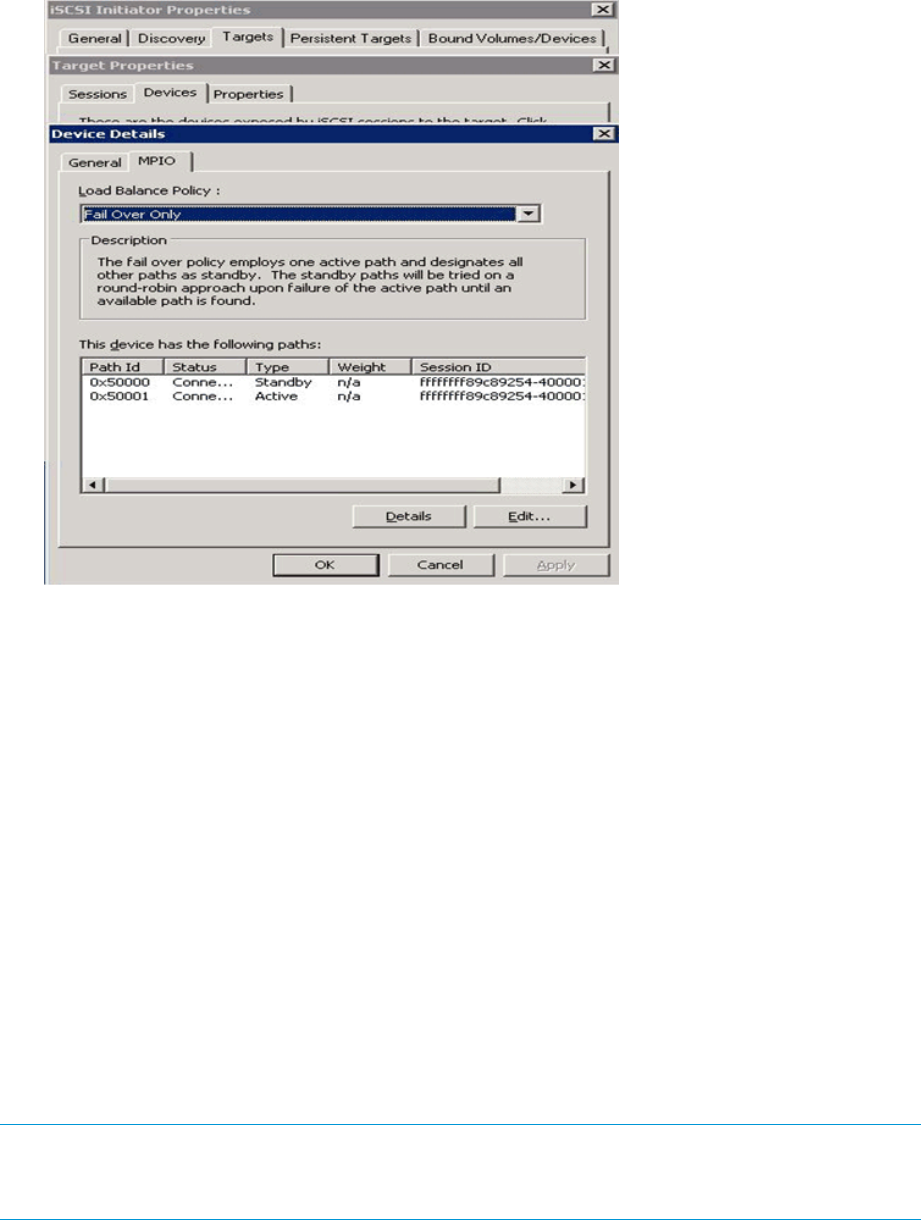
7. Select the desired options on the Load Balance Policy menu to set the policy.
Figure 59 iSCSI Initiator MPIO properties
Load balancing features of Microsoft MPIO for iSCSI
The features of Microsoft MPIO for iSCSI include the following:
•Failover Only. No load balancing is performed. There is a single active path and the rest of
the paths are standby paths. The active path is used for sending all I/O. If the active path
fails, one of the standby paths is used. When the formerly active path is reconnected, it
becomes active and the activated standby path returns to standby.
•Round Robin. All paths are active paths; they are used for sending I/O in a round robin
fashion.
•Round Robin with a subset of paths. A set of paths is configured as active and a set of paths
is configured as standby. I/O is sent in a round robin fashion over the active paths. If all of
the active paths fail, one of the standby paths is used. If any of the formerly active paths
become available again, the formerly active paths are used. The activated standby path
becomes a standby path again.
•Weighted Path. Each path is assigned a weight and I/O is sent on the path with the lowest
weight. If the path with the lowest weight fails, the path with the next lowest weight is used.
•Least Queue Depth. This is not supported by MPIO.
NOTE: For raw disk access, MPIO load balance policy must be set to Failover Only. For
file system disk access, all MPIO load balance policies are supported. Failover policies are set on
a LUN-by-LUN basis. MPIO support does not have global failover settings.
124 iSCSI or iSCSI/FCoE configuration rules and guidelines
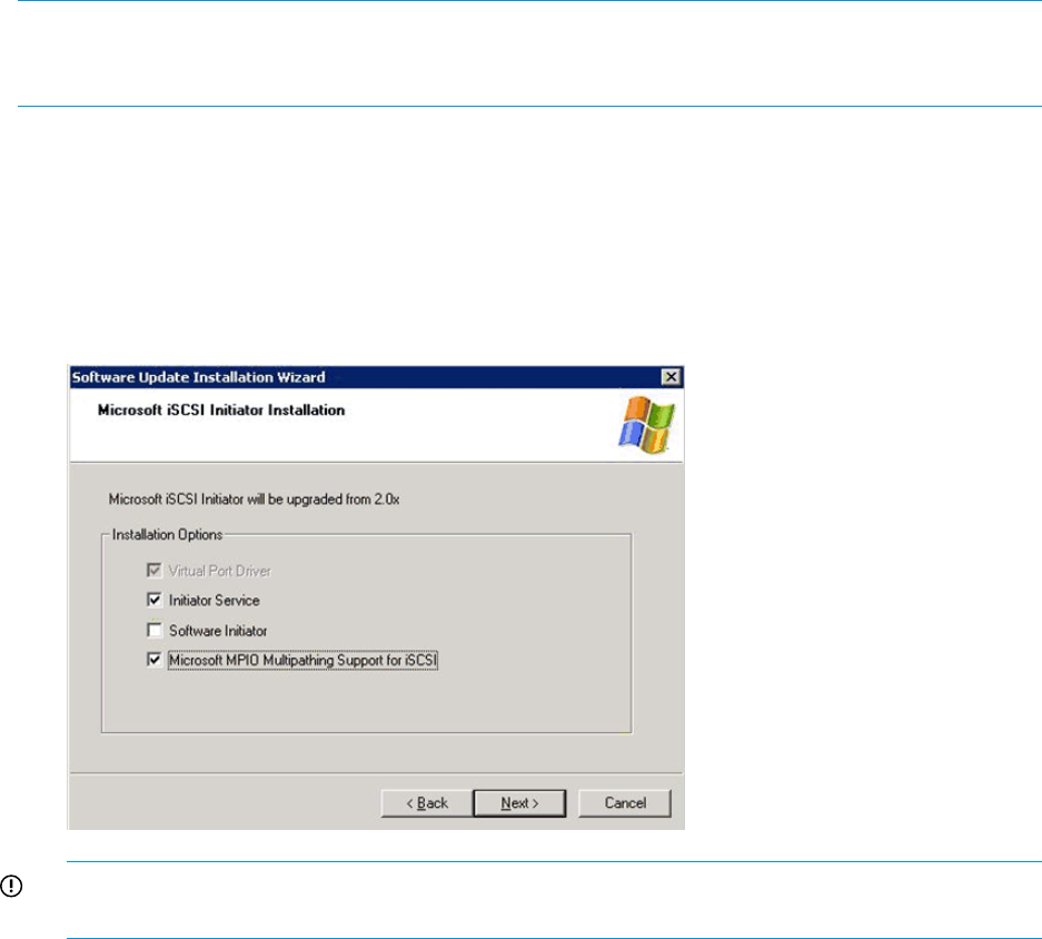
Microsoft MPIO with QLogic iSCSI HBA
The QLogic iSCSI HBA is supported in a multipath Windows configuration that is used in conjunction
with Microsoft iSCSI Initiator Services and Microsoft MPIO. Because the iSCSI driver resides on
board the QLogic iSCSI HBA, it is not necessary to install the Microsoft iSCSI Initiator.
Installing the QLogic iSCSI HBA
Install the QLogic iSCSI HBA hardware and software following the instructions in the QLogic
installation manual. The QLogic iSCSI HBA is managed by QLogic’s SANsurfer Management Suite
(SMS).
NOTE: Once the QLogic iSCSI HBA is installed, the configuration settings for the QLogic iSCSI
Initiator must now be set through SMS. The QLogic iSCSI HBA will not appear in Microsoft’s
Network Connection device list.
Installing the Microsoft iSCSI Initiator services and MPIO
To install the Microsoft iSCSI Initiator:
1. Access the Microsoft iSCSI Initiation Installation page of the Software Update Installation
Wizard (Figure 60 (page 125))
2. Reboot your system.
Figure 60 Microsoft iSCSI Initiator services screen
IMPORTANT: Do not check Microsoft Software Initiator; the QLogic initiator resides on the
iSCSI HBA.
Configuring the QLogic iSCSI HBA
To configure the QLogic iSCSI HBA:
1. Start QLogic SMS either from the desktop icon or through Start/Programs and connect to
localhost (see Figure 61 (page 126)).
Set up the iSCSI Initiator 125
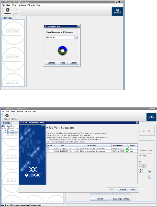
2. Click Yes to start the general configuration wizard (see Figure 62 (page 126)). Use the Wizard
to:
•Choose iSCSI HBA port to configure the QLogic iSCSI HBA.
•Configure HBA Port network settings.
•Configure HBA Port DNS settings (optional).
•Configure SLP Target Discovery settings (optional).
•Configure iSNS Target Discovery settings (optional).
Figure 61 Connect to host screen
Figure 62 Start general configuration wizard
Adding targets to QLogic iSCSI Initiator
To add the HBA Port iSCSI targets:
1. Click the green plus sign (see Figure 63 (page 127)).
2. Enter the first iSCSI or iSCSI/FCoE module's target port IP address.
126 iSCSI or iSCSI/FCoE configuration rules and guidelines
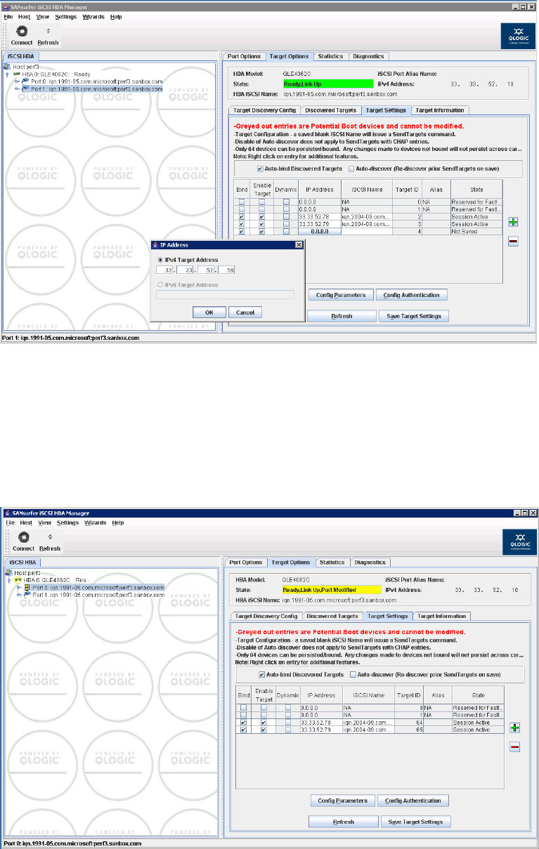
Figure 63 HBA Port Target Configuration
3. Repeat Steps 1 and 2 to add each additional iSCSI or iSCSI/FCoE target iSCSI port.
4. Click Next.
5. To enable the changes, enter the SMS password: config.
6. Select the Target Settings tab. Verify that the HBA state is Ready, Link Up and each target
entry’s state is Session Active (Figure 64 (page 127)).
Figure 64 Target Settings tab
Presenting LUNs to the QLogic iSCSI Initiator
To present LUNs to the QLogic iSCSI Initiator:
Set up the iSCSI Initiator 127
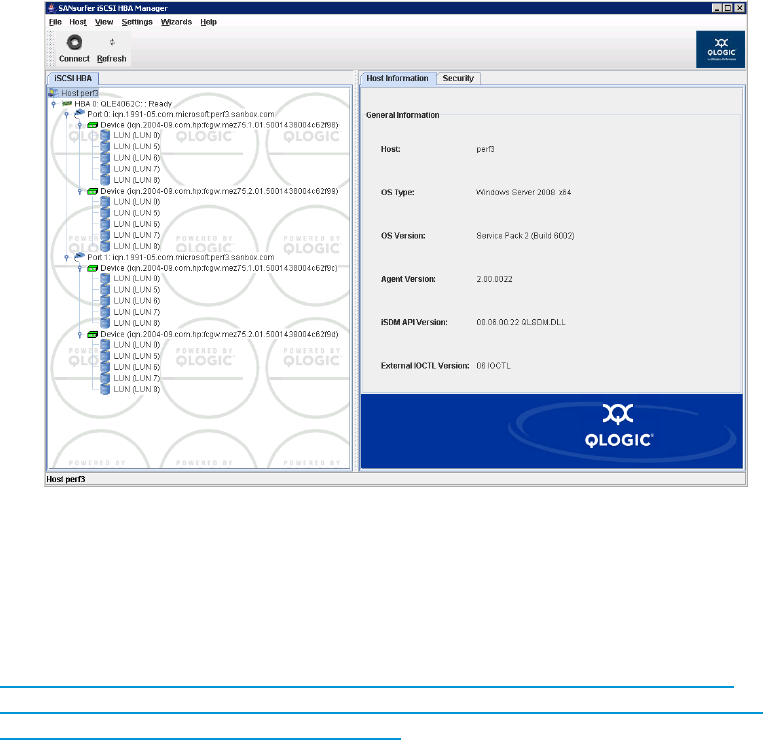
1. Follow procedures in Step 2 to:
•Create an iSCSI host.
•Present LUNs to the iSCSI host.
2. On the iSCSI HBA tab (Figure 65 (page 128) verify that the QLogic iSCSI HBA is connected to
the iSCSI LUNs in SMS under the HBA iSCSI port.
Figure 65 HBA iSCSI port connections
Use Microsoft’s iSCSI services to manage the iSCSI target login and LUN load balancing
policies.
Installing the HP MPIO Full Featured DSM for EVA
Follow the steps in the Installation and Reference Guide located at:
http://h20000.www2.hp.com/bizsupport/TechSupport/DocumentIndex.jsp?
contentType=SupportManual&lang=en&cc=us&docIndexId=64179&taskId=101&
prodTypeId=18964&prodSeriesId=421492
Following the installation of the HP MPIO Full Featured DSM for EVA, open Computer Management
to view and control the iSCSI LUNs (see Figure 66 (page 129)).
128 iSCSI or iSCSI/FCoE configuration rules and guidelines

Figure 66 Example: HP MPIO DSM Manager with iSCSI devices
Microsoft Windows Cluster support
Microsoft Cluster Server for Windows 2003
iSCSI failover clustering is supported by the iSCSI or iSCSI/FCoE modules. For more information,
see:
http://www.microsoft.com/windowsserver2003/technologies/storage/ iscsi/iscsicluster.mspx
Requirements
•Operating system: Windows Server 2003 Enterprise, SP2, R2, x86/x64
•Firmware: minimum version—3.1.0.0, released November 2009
•Initiator:
Persistent Reservation registry key—for Microsoft Generic DSM◦
◦Multiple NIC/iSCSI HBA ports—four recommended:
one public–
–one private
–two storage, for higher availability and performance
◦MPIO—use HP DSM or the Microsoft Generic DSM. HP recommends using the latest
available DSM.
•Connectivity: Dual blade configuration for redundancy
Setting the Persistent Reservation registry key
The iSCSI Persistent Reservation Setup utility assists you in creating the proper registry settings for
use with the Microsoft Generic DSM and Microsoft Cluster Server. This must be run on every node
of the cluster.
1. Run PRset.hta to start the application.
This automatically adds the registry key and values seen.
2. Click Modify to make changes (see Figure 67 (page 130)).
Set up the iSCSI Initiator 129
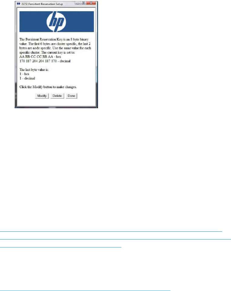
Figure 67 iSCSI Persistent Reservation Setup window
3. Click Done to finish.
Each cluster is required to have its own value, and each node of a single cluster must have its own
value. For example, Cluster A could have the default setting of AABBCCCCBBAA. Possible node
settings:
1Node 1
2Node 2
3Node 3
4Node 4
When the HP Full Featured DSM for EVA is installed, it sets up Persistent Reservation in the registry
by default. For more information on the HP DSM, see:
http://h20000.www2.hp.com/bizsupport/TechSupport/DocumentIndex.jsp?
contentType=SupportManual&lang=en&cc=us&docIndexId=64179&taskId=101&
prodTypeId=18964&prodSeriesId=421492
Microsoft Cluster Server for Windows 2008
iSCSI Failover clustering is supported on the HP StorageWorks MPX200 Multifunction Router. For
more information, see:
http://technet.microsoft.com/en-us/library/cc754482.aspx
Requirements
•Operating system: Windows Server 2008 Enterprise, SP2, R2, x86/x64
•Firmware: Minimum version—3.1.0.0, released November 2009
•Initiator:
Multiple NIC/iSCSI HBA ports—four recommended◦
–one public
–one private
–two storage, for higher availability and performance
◦MPIO—use HP DSM or the Microsoft Generic DSM. HP recommends using the latest
available DSM.
•Connectivity: Dual blade configuration for redundancy
130 iSCSI or iSCSI/FCoE configuration rules and guidelines

Setting up authentication
Challenge Handshake Authentication Protocol (CHAP) is an authentication protocol used for secure
logon between the iSCSI Initiator and iSCSI target. CHAP uses a challenge-response security
mechanism for verifying the identity of an initiator without revealing a secret password that is
shared by the two entities. It is also referred to as a three-way handshake. An important concept
of CHAP is that the initiator must prove to the target that it knows a shared secret without actually
revealing the secret. (Sending the secret across the wire could reveal it to an eavesdropper.) CHAP
provides a mechanism for doing this.
NOTE: Setting up authentication for your iSCSI devices is optional. If you require authentication,
HP recommends that you configure it after you have properly verified installation and operation
of the iSCSI implementation without authentication.
In a secure environment, authentication may not be required, access to the targets is limited only
to trusted initiators.
In a less secure environment, the target cannot determine if a connection request is truly from a
given host. In that case, the target can use CHAP to authenticate an initiator.
When an initiator contacts a target that uses CHAP, the target (called the authenticator) responds
by sending the initiator a challenge. The challenge is a piece of information that is unique for this
authentication session. The initiator then encrypts this information, using a previously-issued password
that is shared by both initiator and target. The encrypted information is then returned to the target.
The target has the same password and uses it as a key to encrypt the information it originally sent
to the initiator. It compares its results with the encrypted results sent by the initiator. If they are the
same, the initiator is assumed to be authentic
These schemes are often called proof of possession protocols. The challenge requires that an entity
prove possession of a shared key or one of the key pairs in a public key scheme.
This procedure is repeated throughout the session to verify that the correct initiator is still connected.
Repeating these steps prevents someone from stealing the initiator’s session by replaying information
that was intercepted on the line.
There are sever alInternet RFCs that cover CHAP in more detail:
•RFC 1994 (PPP Challenge Handshake Authentication Protocol, August 1996
•RFC 2433 (Microsoft PPP CHAP Extensions, October 1998)
•RFC 2759 (Microsoft PPP CHAP Extensions version 2, January 2000)
CHAP restrictions
The CHAP restrictions are as follows:
•Maximum length of 100 characters
•Minimum length of 1 character
•No restriction on the type of characters that can be entered
•Entering an IQN using the HP P6000 Command View add host tab requires the iSCSI initiator
to have been registered by the iSCSI or iSCSI/FCoE module's initiator database. Implying
that the initiator's target discovery has completed.
Microsoft Initiator CHAP secret restrictions
•Maximum length of 16 characters
•Minimum length of 12 characters
•No restriction on the type of characters that can be entered
•When an initiator uses iSNS for target discovery, only normal session CHAP applies
Set up the iSCSI Initiator 131
Linux version
•CHAP is supported with Linux open-iscsi Initiator and the iSCSI or iSCSI/FCoE modules.
•CHAP setup with Linux iSCSI Initiator is not supported with the iSCSI or iSCSI/FCoE modules.
ATTO Macintosh Chap restrictions
The ATTO Macintosh iSCSI Initiator does not support CHAP at this time.
Recommended CHAP policies
•The same CHAP secret should not be configured for authentication of multiple initiators or
multiple targets.
•Any CHAP secret used for initiator authentication must not be configured for the authentication
of any target; and any CHAP secret used for target authentication must not be configured for
authentication of any initiator.
•CHAP should be configured after the initial iSCSI Initiator/target login to validate initiator/target
connectivity. The first initiator/target login also creates a discovered iSCSI Initiator entry on
the iSCSI or iSCSI/FCoE modules that will be used in the CHAP setup.
iSCSI session types
iSCSI defines two types of sessions:
•Discovery. SCSI discovery allows an initiator to find the targets to which it has access.
•Normal operational session. A normal operational session is unrestricted.
CHAP is enforced on both the discovery and normal operational session.
The iSCSI or iSCSI/FCoE controller CHAP modes
The iSCSI or iSCSI/FCoE modules support two CHAP modes:
•Single-direction. The target authenticates the identity of the initiator with the user-provided
CHAP secret. To enable single-direction CHAP, you need to enable CHAP for a specific initiator
record on the iSCSI or iSCSI/FCoE modules and input a corresponding CHAP secret from the
iSCSI host.
•Bi-directional. The initiator and target authenticate identity of each other with the user-provided
CHAP secrets. To enable bi-directional CHAP for a discovery session, you need to provide a
CHAP secret for the initiator and for the iSCSI port for which you are performing discovery.
To enable bi-directional CHAP for a normal session, you will need to provide a CHAP secret
for the initiator and for the iSCSI-presented target that you are trying to log in to.
•Once CHAP is enabled, it is enforced for both the normal and discovery sessions. You only
have the choice of what type (single or bi-directional) of CHAP to perform:
◦Single-direction CHAP during discovery and during normal session
◦Single-direction CHAP during discovery and bi-directional CHAP during normal session
◦Bi-directional CHAP during discovery and single–direction CHAP during normal session
◦Bi-directional CHAP during discovery and during normal session
Enabling single–direction CHAP during discovery and normal session
Table 22 (page 133) lists the parameters you use to enable single-direction CHAP.
132 iSCSI or iSCSI/FCoE configuration rules and guidelines

Table 22 iSCSI or iSCSI/FCoE module secret settings
MS Initiator secret settingsiSCSI or iSCSI/FCoE module secret settings
Setting (example)ActionSetting (example)Source
N/AGeneral Tab SecretN/AiSCSI Port
CHAPsecret01Add Target PortalCHAPsecret01Discovered iSCSI Initiator
CHAPsecret01Log on to TargetN/AiSCSI Presented Target
NOTE: These are examples of secret settings. Configure CHAP with settings that apply to your specific network
environment.
1. Enable CHAP for the iSCSI or iSCSI/FCoE modules discovered iSCSI Initiator entry. CHAP
can be enabled via CLI only. To enable CHAP for the iSCSI or iSCSI/FCoE modules discovered
iSCSI Initiator entry using the iSCSI or iSCSI/FCoE module's CLI:
a. If the iSCSI Initiator is not listed under set chap command:
•HP Command View Option: add the initiator iqn name string via HP Command
View’s add host tab.
• Go to the HP P6000 Command View and select Hosts then select Add Host tab
and enter the iqn name string.
•CLI Option: Enter the initiator add command and add the iSCSI Initiator that is about
to do discovery.
b. If the iSCSI Initiator is listed under set chap command, then enable CHAP secret. For
example: CHAPsecret01:
•Select the index of the iSCSI Initiator.
•To Enable CHAP, select 0, then type the CHAP secret.
Set up the iSCSI Initiator 133
2. Enable CHAP for the Microsoft iSCSI Initiator:
a. Click Discovery.
•For manually discovering iSCSI target portals:
a. Click Add under Target Portals.
b. Enter the IP address of the iSCSI port of the iSCSI or iSCSI/FCoE module.
c. Click Advanced.
d. Select the CHAP Login Information check box.
e. Enter the CHAP secret for the iSCSI or iSCSI/FCoE modules discovered iSCSI
Initiator in the Target Secret box. For example:
CHAPsecret01
f. Click OK and the initiator completes Target discovery.
•Using iSNS for target discovery:
a. Click Add under iSNS Servers.
b. Enter the IP address of the iSNS server.
c. Click OK.
b. Click Targets.
c. Select the appropriate target for login.
d. Click Log On.
e. Click Advanced.
f. Select the CHAP Login Information check box.
g. Enter the CHAP secret for the iSCSI or iSCSI/FCoE modules discovered iSCSI Initiator in
the Target Secret box.
h. Click OK.
i. Click OK and the initiator completes normal login.
Enabling CHAP for the iSCSI or iSCSI/FCoE module-discovered iSCSI initiator entry
CHAP can be enabled via CLI only. To enable CHAP for the iSCSI or iSCSI/FCoE modules
discovered iSCSI Initiator entry using the iSCSI or iSCSI/FCoE module's CLI:
1. If the iSCSI Initiator is not listed under set chap command:
a. HP Command View Option: add the initiator iqn name string via HP Command View’s
Add Host tab.
•Go to HP Command View and select Hosts then select the Add Host tab and enter
the iqn name string.
b. CLI Option: Enter the initiator add command and add the iSCSI Initiator that is about to
do discovery.
2. If the iSCSI Initiator is listed under the set chap command, enable CHAP secret. For example:
CHAPsecret01.
a. Select the index of the iSCSI Initiator.
b. To Enable CHAP, select 0, then enter the CHAP secret.
134 iSCSI or iSCSI/FCoE configuration rules and guidelines
Enable CHAP for the Microsoft iSCSI Initiator
1. Click Discovery. For manually discovering iSCSI target portals:
a. Click Add under Target Portals.
b. Enter the IP address of the iSCSI port of the iSCSI or iSCSI/FCoE module.
c. Click Advanced.
d. Select the CHAP Login Information checkbox.
e. Enter the CHAP secret for the iSCSI or iSCSI/FCoE module's-discovered iSCSI Initiator in
the Target Secret box, for example, CHAPsecret01.
f. Click OK and the initiator completes Target discovery. Using iSNS for target discovery:
•Click Add under iSNS Servers.
•Enter the IP address of the iSNS server.
•Click OK.
2. Click Targets and select the appropriate target for login.
3. Click Log On and then click Advanced.
4. Select the CHAP Login Information checkbox.
5. Enter the CHAP secret for the iSCSI or iSCSI/FCoE module's-discovered iSCSI Initiator in the
Target Secret box.
6. Click OK.
7. Click OK again.
Enable CHAP for the open-iscsi iSCSI Initiator
To enable CHAP in open-iscsi, you need to edit /etc/iscsi/iscsid.conf file:
1. Enable CHAP for both Discovery and Normal Session by:
node.session.auth.authmethod = CHAP
node.session.auth.authmethod = CHAP
2. Setup Username and Password for Initiator for Normal Session. For Example:
# To set a CHAP username and password for initiator
# authentication by the target(s), uncomment the following lines:
#node.session.auth.username = username
#node.session.auth.password = password
node.session.auth.username = iqn.1994-05.com.redhat:fc813cac13.
sanergy33
node.session.auth.password = CHAPSecret01
3. Setup Username and Password for Initiator for Discovery Session. For example:
# To set a discovery session CHAP username and password for the initiator
# authentication by the target(s), uncomment the following lines:
#discovery.sendtargets.auth.username = username
#discovery.sendtargets.auth.password = password
discovery.sendtargets.auth.username = iqn.1994-05.com.redhat:fc813cac13.
sanergy33
discovery.sendtargets.auth.password = CHAPSecret01
4. Save the file and start or restart iscsi:
[root@sanergy33 iscsi]# /etc/init.d/iscsi start or /etc/init.d/iscsi
restart
5. Using the iscsiadm do a discovery. For example:
[root@sanergy33 iscsi]# iscsiadm -m discovery -t sendtargets -p
10.10.1.23
Set up the iSCSI Initiator 135

6. Using the iscsiadm do a login into the iSCSI Target. For example:
[root@sanergy33 iscsi]# iscsiadm --mode node --targetname
iqn.2004-09.com.hp.fcgw.mez50.1.01.50014380025da538 --login
The following is a sample iscsid.conf file for CHAP:
# *************
# CHAP Settings
# *************
# To enable CHAP authentication set node.session.auth.authmethod
# to CHAP. The default is None.
#node.session.auth.authmethod = CHAP
node.session.auth.authmethod = CHAP
# To set a CHAP username and password for initiator
# authentication by the target(s), uncomment the following lines:
#node.session.auth.username = username
node.session.auth.username = iqn.1994-05.com.redhat:fc813cac13.sanergy33
#node.session.auth.password = password
node.session.auth.password = CHAPSecret01
# To set a CHAP username and password for target(s)
# authentication by the initiator, uncomment the following lines:
#node.session.auth.username_in = username_in
#node.session.auth.password_in = password_in
# To enable CHAP authentication for a discovery session to the target
# set discovery.sendtargets.auth.authmethod to CHAP. The default is None.
#discovery.sendtargets.auth.authmethod = CHAP
node.session.auth.authmethod = CHAP
# To set a discovery session CHAP username and password for the initiator
# authentication by the target(s), uncomment the following lines:
#discovery.sendtargets.auth.username = username
discovery.sendtargets.auth.username = iqn.1994-05.com.redhat:fc813cac13.sanergy3
3
#discovery.sendtargets.auth.password = password
discovery.sendtargets.auth.password = CHAPSecret01
# To set a discovery session CHAP username and password for target(s)
# authentication by the initiator, uncomment the following lines:
#discovery.sendtargets.auth.username_in = username_in
#discovery.sendtargets.auth.password_in = password_in
Enabling single–direction CHAP during discovery and bi-directional CHAP during
normal session
Table 23 (page 136) lists the parameters you need to enable single-direction CHAP during discovery.
Table 23 Parameters enabling single-direction CHAP
MS Initiator secret settings
hpstorageworksGeneral Tab SecretN/AiSCSI Port
CHAPsecret0Add Target PortalCHAPsecret01Discovered iSCSI
Initiator
CHAPsecret01Log on to TargethpstorageworksiSCSI Presented
Target
Note: These are examples of secret settings. You must configure CHAP with settings that apply to your specific network
environment.
136 iSCSI or iSCSI/FCoE configuration rules and guidelines
1. Enable CHAP for the iSCSI or iSCSI/FCoE controller-discovered iSCSI Initiator entry. CHAP
can be enabled via CLI only.
To enable CHAP for the iSCSI or iSCSI/FCoE controller-discovered iSCSI Initiator entry using
the iSCSI or iSCSI/FCoE controller CLI:
a. If the iSCSI Initiator is not listed under the set chap command:
•HP Command View Option: add the initiator iqn name string via HP Command
View’s Add Host tab.
• Go to HP Command View and select Hosts then select Tab Add Host and enter
the iqn name string.
•CLI Option: Enter the initiator add command and add the iSCSI Initiator that is about
to do discovery.
b. If the iSCSI Initiator is listed under set chap command, then enable CHAP secret. For
example: CHAPsecret01.
•Select the index of the iSCSI Initiator.
•To Enable CHAP, select 0, then enter the CHAP secret.
2. Enable CHAP for the iSCSI or iSCSI/FCoE controller iSCSI presented target:
• To enable CHAP for the iSCSI or iSCSI/FCoE controller Discovered iSCSI Initiator entry
using the iSCSI or iSCSI/FCoE controller CLI:
•Enter the set CHAP command.
•Select the Presented Target the initiator will log in to.
•Enable CHAP and enter a CHAP secret. For example: hpstorageworks
Set up the iSCSI Initiator 137

3. Enable CHAP for the Microsoft iSCSI Initiator.
a. Click the General tab.
b. Click Secret in the middle of the screen.
c. Click Reset.
d. Enter the iSCSI or iSCSI/FCoE controller iSCSI Presented Target CHAP secret. For example:
hpstorageworks.
e. Click Discovery.
•For manually discovering iSCSI target portals:
a. Click Add under Target Portals.
b. Enter the IP address of the iSCSI port of the iSCSI or iSCSI/FCoE controller.
c. Click Advanced.
d. Select the CHAP Login Information check box.
e. Enter the CHAP secret for the iSCSI or iSCSI/FCoE controller discovered iSCSI
Initiator in the Target Secret box. For example: CHAPsecret01.
f. Click OK and the initiator completes target discovery.
•Using iSNS for target discovery:
a. Click Add under iSNS Servers.
b. Enter the IP address of the iSNS server.
c. Click OK.
f. Click Targets.
g. Select the appropriate target for login.
h. Click Log On.
i. Click Advanced.
j. Select the CHAP Login Information check box.
k. Enter the CHAP secret for the iSCSI or iSCSI/FCoE controller discovered iSCSI Initiator
in the Target Secret box. For example: CHAPsecret01.
l. Select the Mutual Authentication check box.
m. Click OK.
n. Click OK and the initiator completes normal login.
Enabling bi-directional CHAP during discovery and single–direction CHAP during
normal session
Table 24 (page 138) lists the parameters you need to enable bi-direction CHAP during discovery
and bi-directional CHAP during normal session.
Table 24 Parameters enabling bi-direction CHAP
MS Initiator secret settings
hpstorageworksGeneral Tab SecrethpstorageworksiSCSI Port
CHAPsecret0Add Target PortalCHAPsecret01Discovered iSCSI
Initiator
CHAPsecret01Log on to TargetN/AiSCSI Presented
Target
Note: These secret settings are for example only. Please configure CHAP with settings that apply to your specific
network environment.
138 iSCSI or iSCSI/FCoE configuration rules and guidelines
1. Enable CHAP for the iSCSI or iSCSI/FCoE controller discovered iSCSI Initiator entry. CHAP
can be enabled via CLI only.
To enable CHAP for the iSCSI or iSCSI/FCoE controller discovered iSCSI Initiator entry using
the iSCSI or iSCSI/FCoE controller CLI:
a. If the iSCSI Initiator is not listed under the set chap command:
•HP Command View Option: add the initiator iqn name string via the HP Command
View Add Host tab.
Go to HP Command View and select Hosts then select the Add Host tab and enter
the iqn name string.
•CLI Option: Enter the initiator add command and add the iSCSI Initiator that
is about to do discovery.
b. If the iSCSI Initiator is listed under the set chap command, then enable CHAP secret.
For example: CHAPsecret01.
•Select the index of the iSCSI Initiator.
•To Enable CHAP, select 0, then enter the CHAP secret.
2. Enable CHAP for the iSCSI or iSCSI/FCoE controller iSCSI port:
a. To enable CHAP for the iSCSI or iSCSI/FCoE controller iSCSI port using HP P6000
Command View:
•Select the appropriate iSCSI Controller, then select the IP Ports tab, then select the
appropriate IP Port.
•Under Security, select Enabled in CHAP Status, then enter the CHAP Secret. For
example, hpstorageworks
•Click the Save Changes tab to save the changes.
b. To enable CHAP for the iSCSI or iSCSI/FCoE controller iSCSI port using the iSCSI or
iSCSI/FCoE controller CLI:
•Enter the set chap command.
•Select the appropriate Portal iqn name index that the initiator will log in to.
•Select 0 to enable CHAP.
•Enter a CHAP secret. For example: hpstorageworks.
Set up the iSCSI Initiator 139

3. Enable CHAP for the Microsoft iSCSI Initiator.
a. Click the General tab.
b. Click Secret in the middle of the screen.
c. Click Reset.
d. Enter the iSCSI or iSCSI/FCoE controller iSCSI Presented Target CHAP secret. For example:
hpstorageworks.
e. Click OK.
f. Click Discovery.
•For manually discovering iSCSI target portals:
a. Click Add under Target Portals.
b. Enter the IP address of the iSCSI port of the iSCSI or iSCSI/FCoE controller.
c. Click Advanced.
d. Select the CHAP Login Information check box.
e. Enter the CHAP secret for the iSCSI or iSCSI/FCoE controller discovered iSCSI
Initiator in the Target Secret box. For example: CHAPsecret01.
f. Select the Mutual Authentication check box.
g. Click OK.
h. Click OK and the initiator completes Target discovery.
•Using iSNS for Target discovery:
a. Click Add under iSNS Servers.
b. Enter the IP address of the iSNS server.
c. Click OK.
g. Click Targets.
h. Select the appropriate target for login.
i. Click Log On.
j. Click Advanced.
k. Select the CHAP Login Information check box.
l. Enter the CHAP secret for the iSCSI or iSCSI/FCoE controller discovered iSCSI Initiator
in the Target Secret box. For example: CHAPsecret01.
m. Select the Mutual Authentication check box.
n. Click OK.
o. Click OK and the initiator completes normal login.
Enabling bi-directional CHAP during discovery and bi-directional CHAP during normal
session
Table 25 (page 140) lists the parameters you need to enable bi–directional CHAP during discovery
and bi-directional CHAP during normal session.
Table 25 Parameters enabling bi-direction CHAP
MS Initiator secret settings
hpstorageworksGeneral Tab SecrethpstorageworksiSCSI Port
CHAPsecret0Add Target PortalCHAPsecret01Discovered iSCSI
Initiator
CHAPsecret01Log on to TargethpstorageworksiSCSI Presented
Target
Note: These are examples of secret settings. You must configure CHAP with settings that apply to your specific network
environment.
140 iSCSI or iSCSI/FCoE configuration rules and guidelines
1. Enable CHAP for the iSCSI or iSCSI/FCoE controller discovered iSCSI Initiator entry. CHAP
can be enabled via CLI only. To enable CHAP for the iSCSI or iSCSI/FCoE controller discovered
iSCSI Initiator entry using the iSCSI or iSCSI/FCoE controller CLI:
a. If the iSCSI Initiator is not listed under set chap command:
•HP Command View Option: add the initiator iqn name string via Command View’s
Add Host tab.
• Go to HP P6000 Command View and select Hosts then select Tab Add Host
and enter the iqn name string.
•CLI Option: Enter the initiator add command and add the iSCSI Initiator that
is about to do discovery.
b. If the iSCSI Initiator is listed under set chap command, then enable CHAP secret. For
example: CHAPsecret01.
a. Select the index of the iSCSI Initiator.
b. To Enable CHAP, select 0, then type the CHAP secret.
2. Enable CHAP for the iSCSI or iSCSI/FCoE controller iSCSI port:
a. To enable CHAP for the iSCSI or iSCSI/FCoE controller iSCSI port using HP P6000
Command View:
•Select the appropriate iSCSI Controller, then select the IP Ports tab, then select the
appropriate IP Port.
•Under Security, select Enabled in CHAP Status, then enter the CHAP Secret. For
example: hpstorageworks.
•Click the Save Changes tab to save the changes.
b. To enable CHAP for the iSCSI or iSCSI/FCoE controller iSCSI port using the iSCSI or
iSCSI/FCoE controller CLI:
•Enter the set chap command.
•Select the appropriate Portal iqn name index that the initiator will log in to.
•Select 0 to enable CHAP.
•Enter a CHAP secret. For example: hpstorageworks.
3. Enable CHAP for the iSCSI or iSCSI/FCoE controller iSCSI presented target:
• To enable CHAP for the iSCSI or iSCSI/FCoE controller Discovered iSCSI Initiator entry
using the iSCSI or iSCSI/FCoE controller CLI:
•Enter the set CHAP command.
•Select the Presented Target the initiator will log in to.
•Enable CHAP and enter a CHAP secret. For example: hpstorageworks.
Set up the iSCSI Initiator 141
4. Enable CHAP for the Microsoft iSCSI Initiator.
a. Click the General tab.
b. Click Secret in the middle of the screen.
c. Click Reset.
d. Enter the iSCSI or iSCSI/FCoE controller iSCSI Presented Target CHAP secret. For example:
hpstorageworks.
e. Click OK.
f. Click Discovery.
•For manually discovering iSCSI target portals:
a. Click Add under Target Portals.
b. Enter the IP address of the iSCSI port of the iSCSI or iSCSI/FCoE controller.
c. Click Advanced.
d. Select the CHAP Login Information check box.
e. Enter the CHAP secret for the iSCSI or iSCSI/FCoE controller discovered iSCSI
Initiator in the Target Secret box. For example: CHAPsecret01.
f. Select the Mutual Authentication check box.
g. Click OK.
h. Click OK and the initiator completes target discovery.
•Using iSNS for target discovery:
a. Click Add under iSNS Servers.
b. Enter the IP address of the iSNS server.
c. Click OK.
g. Click Targets.
h. Select the appropriate target for login.
i. Click Log On.
j. Click Advanced.
k. Select the CHAP Login Information check box.
l. Enter the CHAP secret for the iSCSI or iSCSI/FCoE controller discovered iSCSI Initiator
in the Target Secret box. For example: CHAPsecret01.
m. Select the Mutual Authentication check box.
n. Click OK.
o. Click OK and the initiator completes normal login.
Enable CHAP for the open-iscsi iSCSI Initiator
To enable CHAP in open-iscsi, you need to edit the /etc/iscsi/iscsid.conf file.
1. Enable CHAP for both Discovery and Normal Session by:
node.session.auth.authmethod = CHAP
node.session.auth.authmethod = CHAP
2. Setup Username and Password for Initiator and Target for Normal Session. For Example:
# To set a CHAP username and password for initiator
# authentication by the target(s), uncomment the following lines:
#node.session.auth.username = username
#node.session.auth.password = password
node.session.auth.username = iqn.1994-05.com.redhat:fc813cac13.sanergy33
node.session.auth.password = CHAPSecret01
# To set a CHAP username and password for target(s)
# authentication by the initiator, uncomment the following lines:
#node.session.auth.username_in = username_in
node.session.auth.username_in = iqn.2004-09.com.hp.fcgw.mez50.1.01.50014380025da538
#node.session.auth.password_in = password_in
node.session.auth.password_in = hpstorageworks
142 iSCSI or iSCSI/FCoE configuration rules and guidelines
3. Setup Username and Password for Initiator and Portal for Discovery Session. For example:
# To set a discovery session CHAP username and password for the initiator
# authentication by the target(s), uncomment the following lines:
#discovery.sendtargets.auth.username = username
#discovery.sendtargets.auth.password = password
discovery.sendtargets.auth.username = iqn.1994-05.com.redhat:fc813cac13.sanergy33
#discovery.sendtargets.auth.password = CHAPSecret01
# To set a discovery session CHAP username and password for target(s)
# authentication by the initiator, uncomment the following lines:
#discovery.sendtargets.auth.username_in = username_in
discovery.sendtargets.auth.username_in = iqn.2004-09.com.hp.fcgw.mez50.1.01.50014380025da538
#discovery.sendtargets.auth.password_in = password_in
discovery.sendtargets.auth.password_in = hpstorageworks
4. Save the file and start or restart iscsi:
[root@sanergy33 iscsi]# /etc/init.d/iscsi start or /etc/init.d/iscsi
restart
5. Using the iscsiadm do a discovery. For example:
[root@sanergy33 iscsi]# iscsiadm -m discovery -t sendtargets -p
10.10.1.23
6. Using the iscsiadm do a login into the iSCSI Target. For example:
[root@sanergy33 iscsi]# iscsiadm --mode node --targetname
iqn.2004-09.com.hp.fcgw.mez50.1.01.50014380025da538 –login
The following is a sample iscsid.conf file for CHAP:
# *************
# CHAP Settings
# *************
# To enable CHAP authentication set node.session.auth.authmethod
# to CHAP. The default is None.
#node.session.auth.authmethod = CHAP
node.session.auth.authmethod = CHAP
# To set a CHAP username and password for initiator
# authentication by the target(s), uncomment the following lines:
#node.session.auth.username = username
node.session.auth.username =
iqn.1994-05.com.redhat:fc813cac13.sanergy33
#node.session.auth.password = password
node.session.auth.password = CHAPSecret01
# To set a CHAP username and password for target(s)
# authentication by the initiator, uncomment the following lines:
#node.session.auth.username_in = username_in
node.session.auth.username_in =
iqn.2004-09.com.hp.fcgw.mez50.1.01.50014380025da538
#node.session.auth.password_in = password_in
node.session.auth.password_in = hpstorageworks
# To enable CHAP authentication for a discovery session to the target
# set discovery.sendtargets.auth.authmethod to CHAP. The default is None.
#discovery.sendtargets.auth.authmethod = CHAP
discovery.sendtargets.auth.authmethod = CHAP
# To set a discovery session CHAP username and password for the initiator
# authentication by the target(s), uncomment the following lines:
#discovery.sendtargets.auth.username = username
discovery.sendtargets.auth.username =
iqn.1994-05.com.redhat:fc813cac13.sanergy33
#discovery.sendtargets.auth.password = password
discovery.sendtargets.auth.password = CHAPSecret01
# To set a discovery session CHAP username and password for target(s)
# authentication by the initiator, uncomment the following lines:
#discovery.sendtargets.auth.username_in = username_in
discovery.sendtargets.auth.username_in =
iqn.2004-09.com.hp.fcgw.mez50.1.01.50014380025da538
#discovery.sendtargets.auth.password_in = password_in
discovery.sendtargets.auth.password_in = hpstorageworks
Set up the iSCSI Initiator 143
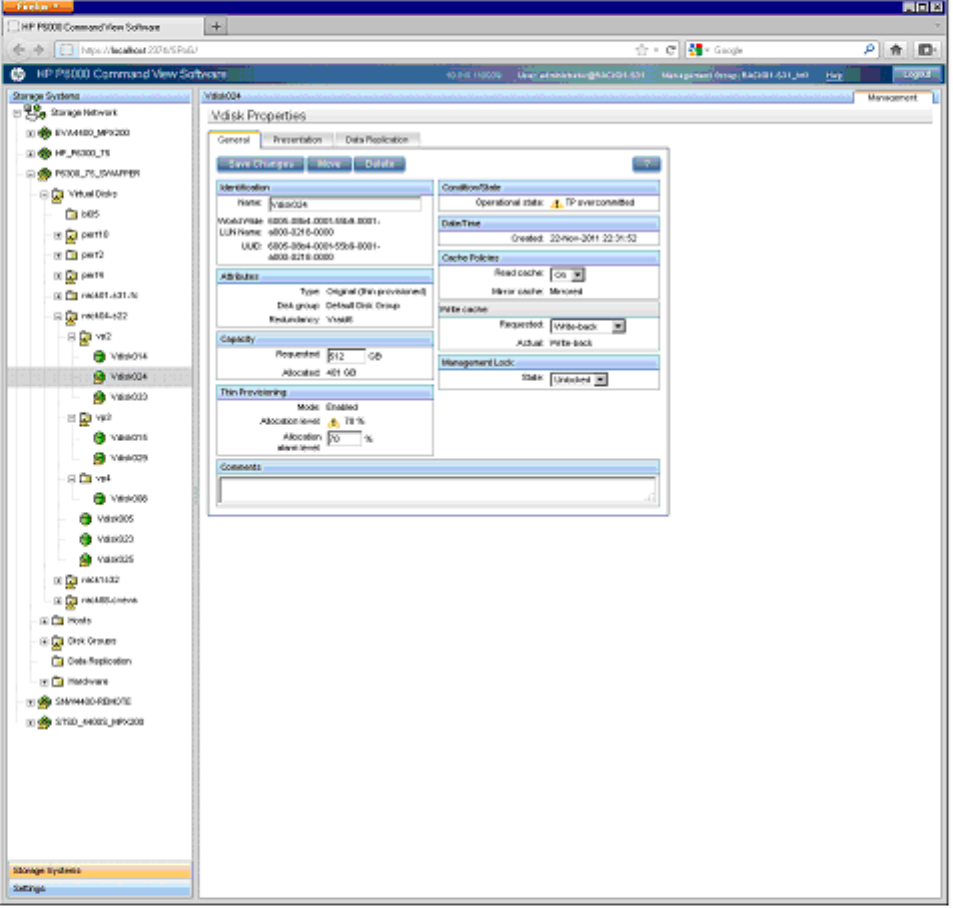
iSCSI and FCoE thin provision handling
iSCSI and FCoE presented LUNs which experience the thin provision (TP) Overcommitted state, as
detected by P6000 Command View and illustrated in Figure 68 (page 144) will generally be
write-protected until the Overcommitted state is cleared. However, there is a special case for
Windows and Windows 2008 FCoE or iSCSI initiators, the TP Overcommitted LUNs are masked
and manual intervention through P6000 Command View is required to remove the mask by
re-presenting the LUN(s) to the iSCSI or FCoE initiator(s).
Note that the TP Overcommitted mask state, only for the iSCSI and FCoE presented LUNs, is cleared
by a restart of both of the iSCSI controllers.
Figure 68 FCoE presented LUN reported as TP Overcommitted
The masking is visible by navigating to the LUN’s presentation tab as illustrated in Figure 69 (page
145), where it can be seen that the LUN is presented to the P6000 iSCSI Host port, but no longer
to a iSCSI or FCoE initiator. A user may walk through the Virtual Disks tabs and note each TP
Overcommited LUN and then present after the TP Overcommited state is cleared. Or a user may
first clear the TP Overcommitted state and then walk through the Virtual Disks presentation tabs
and re-present each LUN listed in the iSCSI HOST 01,02,03,04 lists which are found to no longer
be presented to iSCSI or FCoE initiators.
144 iSCSI or iSCSI/FCoE configuration rules and guidelines
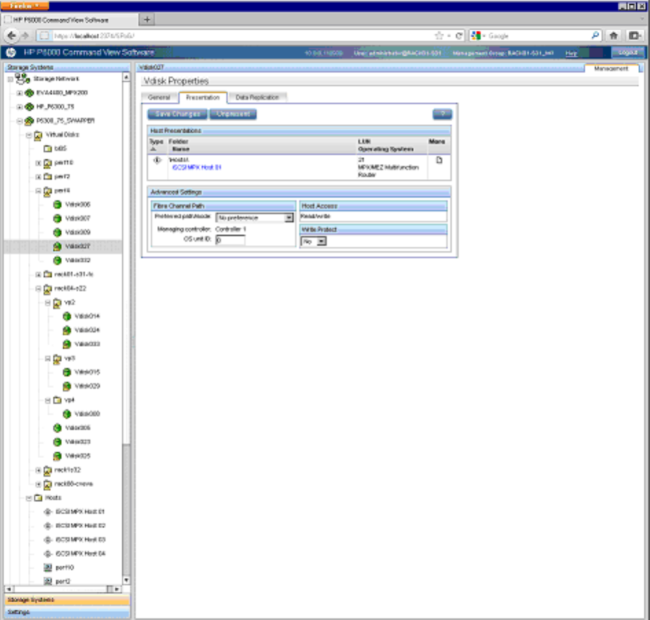
Figure 69 or Windows 2008 initiator iSCSIpresented LUN reported as TP Overcommitted
Lists of all presented LUNs, per Virtual Port Group, are always available by navigating to the
HOSTs tab and then to the one of four iSCSI HOSTs VPgroups, as illustrated in Figure 70 (page
146).
Set up the iSCSI Initiator 145
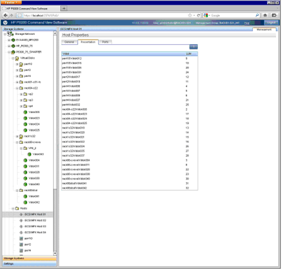
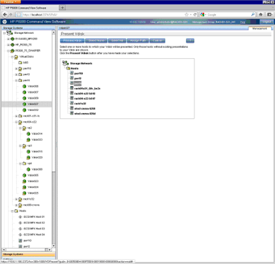
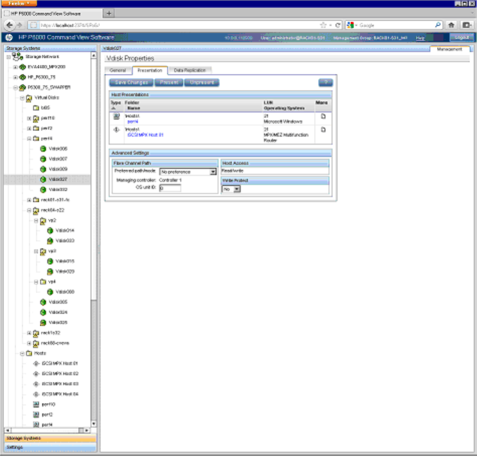
Figure 72 Normal view of iSCSI LUN presented to iSCSI initiator
148 iSCSI or iSCSI/FCoE configuration rules and guidelines

6 Single path implementation
This chapter provides guidance for connecting servers with a single path host bus adapter (HBA)
to the Enterprise Virtual Array (EVA) storage system with no multipath software installed. A single
path HBA is defined as:
•A single HBA port to a switch with no multipathing software installed
•A single HBA port to a switch with multipathing software installed
HBA LUNs are not shared by any other HBA in the server or in the SAN. Failover action is different
depending on which single path method is employed.
The failure scenarios demonstrate behavior when recommended configurations are employed, as
well as expected failover behavior if guidelines are not met. To implement single adapter servers
into a multipath EVA environment, configurations should follow these recommendations.
The purpose of single HBA configurations for non-mission critical storage access is to control costs.
This chapter describes the configurations, limitations, and failover characteristics of single HBA
servers under different operating systems. Several of the descriptions are based on a single HBA
configuration resulting in a single path to the device, but OpenVMS has native multipath features
by default.
NOTE: Tru64 and NetWare are not supported with the P63x0/P65x0 EVA.
With OpenVMS, a single HBA configuration will result in two paths to the device by having
connections to both EVA controllers. Single HBA configurations are not single path configurations
with these operating systems.
In addition, cluster configurations for OpenVMS provide enhanced availability and security. To
achieve availability within cluster configurations, configure each member with its own HBAs and
connectivity to shared LUNs. For further information on cluster configurations and attributes, see
the appropriate operating system guide and the HP SAN Design Reference Guide.
NOTE: HP continually makes additions to its storage solution product line. For more information
about the HP Fibre Channel product line, the latest drivers, and technical tips, and to view other
documentation, see the HP website at:
http://www.hp.com/country/us/eng/prodserv/storage.html
Installation requirements
•The host must be placed in a zone with any EVA worldwide IDs (WWIDs) that access storage
devices presented by the hierarchical storage virtualization (HSV) controllers to the single path
HBA host. The preferred method is to use HBA and HSV WWIDs in the zone configurations.
•On HP-UX, Solaris, Microsoft Windows Server 2012, Microsoft Windows Server 2008,
Microsoft Windows Server 2003 (32-bit), Windows 2000, Linux and IBM AIX operating
systems, the zones consist of the single path HBA systems and one HSV controller port.
•On OpenVMS, the zones consist of the single HBA systems and two HSV controller ports. This
results in a configuration where there are two paths per device, or multiple paths.
Recommended mitigations
EVA is designed for the mission-critical enterprise environment. When used with multipath software,
high data availability and fault tolerance are achieved. In single path HBA server configurations,
neither multipath software nor redundant I/O paths are present. Server-based operating systems
are not designed to inherently recover from unexpected failure events in the I/O path (for example,
loss of connectivity between the server and the data storage). It is expected that most operating
systems will experience undesirable behavior when configured in non-high-availability configurations.
Installation requirements 149

Because of the risks of using servers with a single path HBA, HP recommends the following actions:
•Use servers with a single path HBA that are not mission-critical or highly available.
•Perform frequent backups of the single path server and its storage.
Supported configurations
All examples detail a small homogeneous Storage Area Network (SAN) for ease of explanation.
Mixing of dual and single path HBA systems in a heterogeneous SAN is supported. In addition to
this document, reference and adhere to the HP SAN Design Reference Guide for heterogeneous
SANs, located at:
http://www.hp.com/go/sandesign
General configuration components
All configurations require the following components:
•XCS controller software
•HBAs
•Fibre Channel switches
Connecting a single path HBA server to a switch in a fabric zone
Each host must attach to one switch (fabric) using standard Fibre Channel cables. Each host has
its single path HBA connected through switches on a SAN to one port of an EVA.
Because a single path HBA server has no software to manage the connection and ensure that only
one controller port is visible to the HBA, the fabric containing the single path HBA server, SAN
switch, and EVA controller must be zoned. Configuring the single path by switch zoning and the
LUNs by Selective Storage Presentation (SSP) allows for multiple single path HBAs to reside in the
same server. A single path HBA server with the OpenVMS operating system should be zoned with
two EVA controllers. See the HP SAN Design Reference Guide at the following HP website for
additional information about zoning:
http://h18006.www1.hp.com/products/storageworks/ san/documentation.html
To connect a single path HBA server to a SAN switch:
1. Plug one end of the Fibre Channel cable into the HBA on the server.
2. Plug the other end of the cable into the switch.
Figure 73 (page 151) and Figure 74 (page 151) represent configurations containing both single path
HBA server and dual HBA server, as well as a SAN appliance, connected to redundant SAN
switches and EVA controllers. Whereas the dual HBA server has multipath software that manages
the two HBAs and their connections to the switch, the single path HBA has no software to perform
this function. The dashed line in the figure represents the fabric zone that must be established for
the single path HBA server. Note that in Figure 74 (page 151), servers with OpenVMS can be
zoned with two controllers.
150 Single path implementation
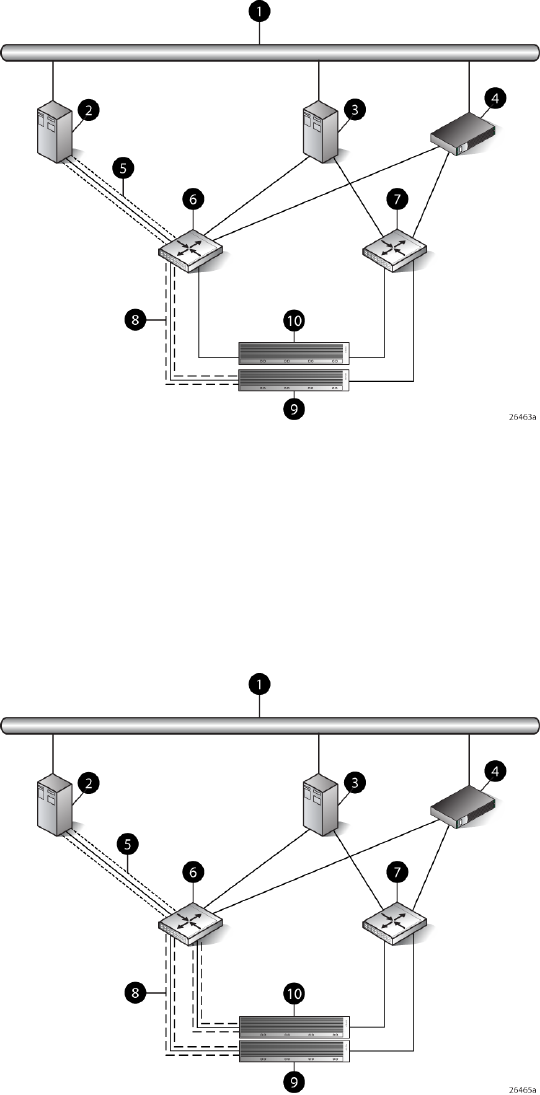
Figure 73 Single path HBA server without OpenVMS
6. SAN switch 11. Network interconnection
7. SAN switch 22. Single HBA server (Host 1)
8. Fabric zone3. Dual HBA server (Host 2)
9. Controller A4. Management server
10. Controller B5. Multiple single HBA paths
Figure 74 Single path HBA server with OpenVMS
6. SAN switch 11. Network interconnection
7. SAN switch 22. Single HBA server (Host 1)
8. Fabric zone3. Dual HBA server (Host 2)
9. Controller A4. Management server
10. Controller B5. Multiple single HBA paths
Supported configurations 151

HP-UX configuration
Requirements
•Proper switch zoning must be used to ensure each single path HBA has an exclusive path to
its LUNs.
•Single path HBA server can be in the same fabric as servers with multiple HBAs.
•Single path HBA server cannot share LUNs with any other HBAs.
•In the use of snapshots and snapclones, the source virtual disk and all associated snapshots
and snapclones must be presented to the single path hosts that are zoned with the same
controller. In the case of snapclones, after the cloning process has completed and the clone
becomes an ordinary virtual disk, you may present that virtual disk as you would any other
ordinary virtual disk.
HBA configuration
•Host 1 is a single path HBA host.
•Host 2 is a multiple HBA host with multipathing software.
See Figure 75 (page 153).
Risks
•Disabled jobs hang and cannot umount disks.
•Path or controller failure may results in loss of data accessibility and loss of host data that has
not been written to storage.
NOTE: For additional risks, see “HP-UX” (page 164).
Limitations
•HP P6000 Continuous Access is not supported with single-path configurations.
•Single path HBA server is not part of a cluster.
•Booting from the SAN is not supported.
152 Single path implementation

Figure 75 HP-UX configuration
5. SAN switch 11. Network interconnection
6. SAN switch 22. Single HBA server (Host 1)
7. Controller A3. Dual HBA server (Host 2)
8. Controller B4. Management server
Windows Server 2003 (32-bit) ,Windows Server 2008 (32–bit) , and
Windows Server 2012 (32–bit) configurations
Requirements
•Switch zoning or controller level SSP must be used to ensure each single path HBA has an
exclusive path to its LUNs.
•Single path HBA server can be in the same fabric as servers with multiple HBAs.
•Single path HBA server cannot share LUNs with any other HBAs.
•In the use of snapshots and snapclones, the source virtual disk and all associated snapshots
and snapclones must be presented to the single path hosts that are zoned with the same
controller. In the case of snapclones, after the cloning process has completed and the clone
becomes an ordinary virtual disk, you may present that virtual disk as you would any other
ordinary virtual disk.
HBA configuration
•Host 1 is a single path HBA host.
•Host 2 is a multiple HBA host with multipathing software.
See Figure 76 (page 154).
Risks
•Single path failure will result in loss of connection with the storage system.
•Single path failure may cause the server to reboot.
•Controller shutdown puts controller in a failed state that results in loss of data accessibility
and loss of host data that has not been written to storage.
Windows Server 2003 (32-bit) ,Windows Server 2008 (32–bit) , and Windows Server 2012 (32–bit) configurations 153
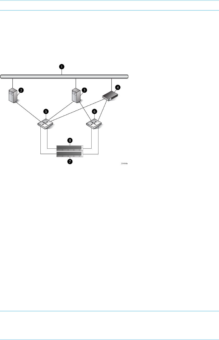
NOTE: For additional risks, see “Windows Servers” (page 165).
Limitations
•HP P6000 Continuous Access is not supported with single path configurations.
•Single path HBA server is not part of a cluster.
•Booting from the SAN is not supported on single path HBA servers.
Figure 76 Windows Server 2003 (32-bit) and Windows 2008 (32–bit) configuration
5. SAN switch 11. Network interconnection
6. SAN switch 22. Single HBA server (Host 1)
7. Controller A3. Dual HBA server (Host 2)
8. Controller B4. Management server
Windows Server 2003 (64-bit) and Windows Server 2008 (64–bit)
configurations
Requirements
•Switch zoning or controller level SSP must be used to ensure each single path HBA has an
exclusive path to its LUNs.
•Single path HBA server can be in the same fabric as servers with multiple HBAs.
•Single path HBA server cannot share LUNs with any other HBAs.
HBA configuration
•Hosts 1 and 2 are single path HBA hosts.
•Host 3 is a multiple HBA host with multipathing software.
See Figure 77 (page 155).
NOTE: Single path HBA servers running the Windows Server 2003 (x64) or Windows Server
2008 (x64) operating system will support multiple single path HBAs in the same server. This is
accomplished through a combination of switch zoning and controller level SSP. Any single path
HBA server will support up to four single path HBAs.
154 Single path implementation
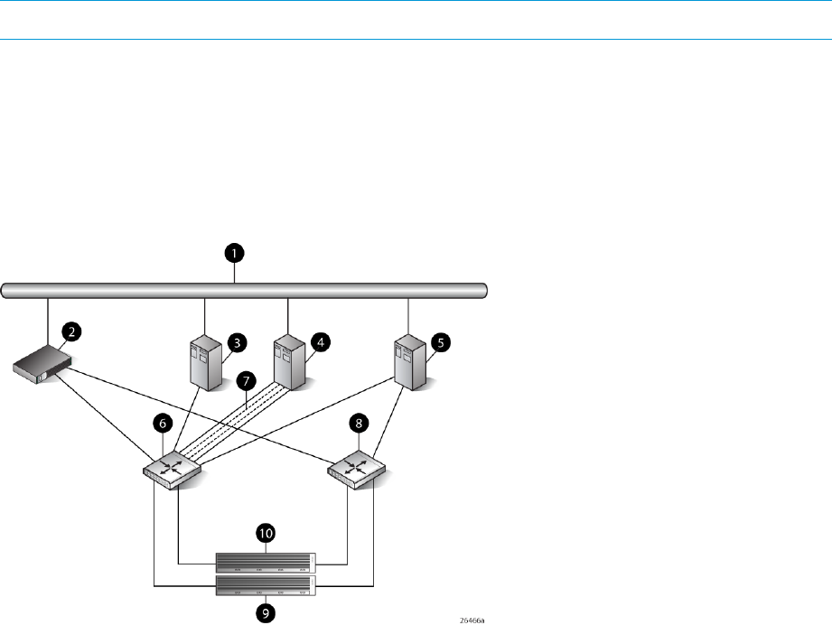
Risks
•Single path failure will result in loss of connection with the storage system.
•Single path failure may cause the server to reboot.
•Controller shutdown puts controller in a failed state that results in loss of data accessibility
and loss of host data that has not been written to storage.
NOTE: For additional risks, see “Windows Servers” (page 165).
Limitations
•HP P6000 Continuous Access is not supported with single path configurations.
•Single path HBA server is not part of a cluster.
•Booting from the SAN is not supported on single path HBA servers.
Figure 77 Windows Server 2003 (64-bit) and Windows Server 2008 (64–bit) configurations
6. SAN switch 11. Network interconnection
7. Multiple single HBA paths2. Management server
8. SAN switch 23. Host 1
9. Controller A4. Host 2
10. Controller B5. Host 3
Oracle Solaris configuration
Requirements
•Switch zoning or controller level SSP must be used to ensure each single path HBA has an
exclusive path to its LUNs.
•Single path HBA server can be in the same fabric as servers with multiple HBAs.
•Single path HBA server cannot share LUNs with any other HBAs.
•In the use of snapshots and snapclones, the source virtual disk and all associated snapshots
and snapclones must be presented to the single path hosts that are zoned with the same
controller. In the case of snapclones, after the cloning process has completed and the clone
Oracle Solaris configuration 155
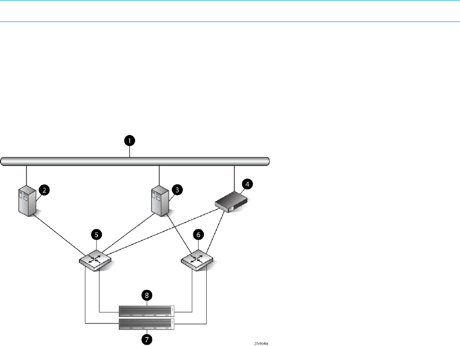
becomes an ordinary virtual disk, you may present that virtual disk as you would any other
ordinary virtual disk.
•HBA must be properly configured to work in a single HBA server configuration. The user is
required to:
◦Download and extract the contents of the TAR file.
HBA configuration
•Host 1 is a single path HBA host.
•Host 2 is a multiple HBA host with multipathing software.
See Figure 78 (page 156).
Risks
•Single path failure may result in loss of data accessibility and loss of host data that has not
been written to storage.
•Controller shutdown results in loss of data accessibility and loss of host data that has not been
written to storage.
NOTE: For additional risks, see “Oracle Solaris” (page 165).
Limitations
•HP P6000 Continuous Access is not supported with single path configurations.
•Single path HBA server is not part of a cluster.
•Booting from the SAN is not supported.
Figure 78 Oracle Solaris configuration
5. SAN switch 11. Network interconnection
6. SAN switch 22. Single HBA server (Host 1)
7. Controller A3. Dual HBA server (Host 2)
8. Controller B4. Management server
156 Single path implementation

OpenVMS configuration
Requirements
•Switch zoning or controller level SSP must be used to ensure each single path HBA has an
exclusive path to its LUNs.
•All nodes with direct connection to a disk must have the same access paths available to them.
•Single path HBA server can be in the same fabric as servers with multiple HBAs.
•In the use of snapshots and snapclones, the source virtual disk and all associated snapshots
and snapclones must be presented to the single path hosts that are zoned with the same
controller. In the case of snapclones, after the cloning process has completed and the clone
becomes an ordinary virtual disk, you may present that virtual disk as you would any other
ordinary virtual disk.
HBA configuration
•Host 1 is a single path HBA host.
•Host 2 is a dual HBA host.
See Figure 79 (page 158).
Risks
•For nonclustered nodes with a single path HBA, a path failure from the HBA to the SAN switch
will result in a loss of connection with storage devices.
NOTE: For additional risks, see “OpenVMS” (page 165).
OpenVMS configuration 157
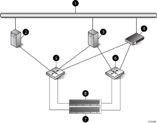
Limitations
•HP P6000 Continuous Access is not supported with single path configurations.
Figure 79 OpenVMS configuration
5. SAN switch 11. Network interconnection
6. SAN switch 22. Single HBA server (Host 1)
7. Controller A3. Dual HBA server (Host 2)
8. Controller B4. Management server
Xen configuration
Requirements
•Switch zoning or controller level SSP must be used to ensure each single path HBA has an
exclusive path to its LUNs.
•All nodes with direct connection to a disk must have the same access paths available to them.
•Single path HBA server can be in the same fabric as servers with multiple HBAs.
•In the use of snapshots and snapclones, the source virtual disk and all associated snapshots
and snapclones must be presented to the single path hosts that are zoned with the same
controller. In the case of snapclones, after the cloning process has completed and the clone
becomes an ordinary virtual disk, you may present that virtual disk as you would any other
ordinary virtual disk.
HBA configuration
•Host 1 is a single path HBA.
•Host 2 is a dual HBA host with multipathing software.
See Figure 80 (page 159).
158 Single path implementation

Risks
•Single path failure may result in data loss or disk corruption.
Limitations
•HP P6000 Continuous Access is not supported with single path configurations.
•Single path HBA server is not part of a cluster.
•Booting from the SAN is not supported.
Figure 80 Xen configuration
5. SAN switch 11. Network interconnection
6. SAN switch 22. Single HBA server (Host 1)
7. Controller A3. Dual HBA server (Host 2)
8. Controller B4. Management server
Linux (32-bit) configuration
Requirements
•Switch zoning or controller level SSP must be used to ensure each single path HBA has an
exclusive path to its LUNs.
•All nodes with direct connection to a disk must have the same access paths available to them.
•Single path HBA server can be in the same fabric as servers with multiple HBAs.
•In the use of snapshots and snapclones, the source virtual disk and all associated snapshots
and snapclones must be presented to the single path hosts that are zoned with the same
controller. In the case of snapclones, after the cloning process has completed and the clone
becomes an ordinary virtual disk, you may present that virtual disk as you would any other
ordinary virtual disk.
•Single HBA path to the host with MPIO driver enabled to provide recovery from controller on
controller link failures.
Linux (32-bit) configuration 159

HBA configuration
•Host 1 is a single path HBA.
•Host 2 is a dual HBA host with multipathing software.
See Figure 81 (page 160).
Risks
•Single path failure may result in data loss or disk corruption.
NOTE: For additional risks, see “Linux” (page 166).
Limitations
•HP P6000 Continuous Access is not supported with single path configurations.
•Single HBA path at the host server is not part of a cluster, unless in a Linux High Availability
Cluster.
•Booting from the SAN is supported on single path HBA servers.
Figure 81 Linux (32-bit) configuration
5. SAN switch 11. Network interconnection
6. SAN switch 22. Single HBA server (Host 1)
7. Controller A3. Dual HBA server (Host 2)
8. Controller B4. Management server
Linux (Itanium) configuration
Requirements
•Switch zoning or controller level SSP must be used to ensure each single path HBA has an
exclusive path to its LUNs.
•All nodes with direct connection to a disk must have the same access paths available to them.
•Single path HBA server can be in the same fabric as servers with multiple HBAs.
•In the use of snapshots and snapclones, the source virtual disk and all associated snapshots
and snapclones must be presented to the single path hosts that are zoned with the same
160 Single path implementation

controller. In the case of snapclones, after the cloning process has completed and the clone
becomes an ordinary virtual disk, you may present that virtual disk as you would any other
ordinary virtual disk.
•Linux 64-bit servers can support up to 14 single or dual path HBAs per server. Switch zoning
and SSP are required to isolate the LUNs presented to each HBA from each other.
HBA configuration
•Host 1 is a single path HBA.
•Host 2 is a dual HBA host with multipathing software.
See Figure 82 (page 161).
Risks
•Single path failure may result in data loss or disk corruption.
NOTE: For additional risks, see “Linux” (page 166).
Limitations
•HP P6000 Continuous Access is not supported with single path configurations.
•Single path HBA server is not part of a cluster.
•Booting from the SAN is supported on single path HBA servers.
Figure 82 Linux (Itanium) configuration
5. SAN switch 11. Network interconnection
6. SAN switch 22. Single HBA server (Host 1)
7. Controller A3. Dual HBA server (Host 2)
8. Controller B4. Management server
Linux (Itanium) configuration 161

IBM AIX configuration
Requirements
•Switch zoning or controller level SSP must be used to ensure each single path HBA has an
exclusive path to its LUNs.
•Single path HBA server can be in the same fabric as servers with multiple HBAs.
•Single path HBA server cannot share LUNs with any other HBAs.
•In the use of snapshots and snapclones, the source virtual disk and all associated snapshots
and snapclones must be presented to the single path hosts that are zoned with the same
controller. In the case of snapclones, after the cloning process has completed and the clone
becomes an ordinary virtual disk, you may present that virtual disk as you would any other
ordinary virtual disk.
HBA configuration
•Host 1 is a single path HBA host.
•Host 2 is a dual HBA host with multipathing software.
See Figure 83 (page 163).
Risks
•Single path failure may result in loss of data accessibility and loss of host data that has not
been written to storage.
•Controller shutdown results in loss of data accessibility and loss of host data that has not been
written to storage.
NOTE: For additional risks, see “IBM AIX” (page 167).
Limitations
•HP P6000 Continuous Access is not supported with single path configurations.
•Single path HBA server is not part of a cluster.
•Booting from the SAN is not supported.
162 Single path implementation
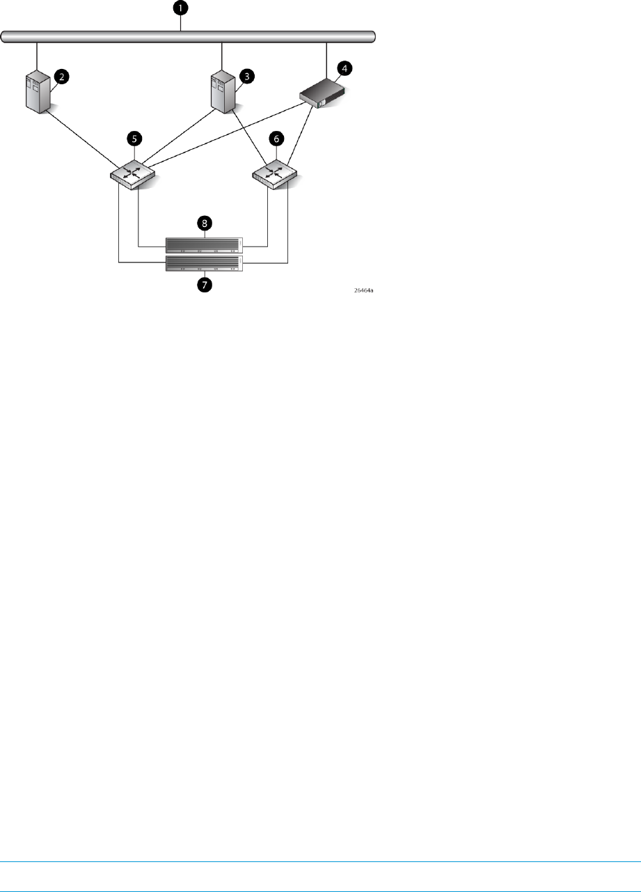
Figure 83 IBM AIX Configuration
5. SAN switch 11. Network interconnection
6. SAN switch 22. Single HBA server (Host 1)
7. Controller A3. Dual HBA server (Host 2)
8. Controller B4. Management server
VMware configuration
Requirements
•Switch zoning or controller level SSP must be used to ensure each single path HBA has an
exclusive path to its LUNs.
•All nodes with direct connection to a disk must have the same access paths available to them.
•Single path HBA server can be in the same fabric as servers with multiple HBAs.
•In the use of snapshots and snapclones, the source virtual disk and all associated snapshots
and snapclones must be presented to the single path hosts that are zoned with the same
controller. In the case of snapclones, after the cloning process has completed and the clone
becomes an ordinary virtual disk, you may present that virtual disk as you would any other
ordinary virtual disk.
HBA configuration
•Host 1 is a single path HBA.
•Host 2 is a dual HBA host with multipathing software.
See Figure 84 (page 164).
Risks
•Single path failure may result in data loss or disk corruption.
NOTE: For additional risks, see “VMware” (page 167).
VMware configuration 163
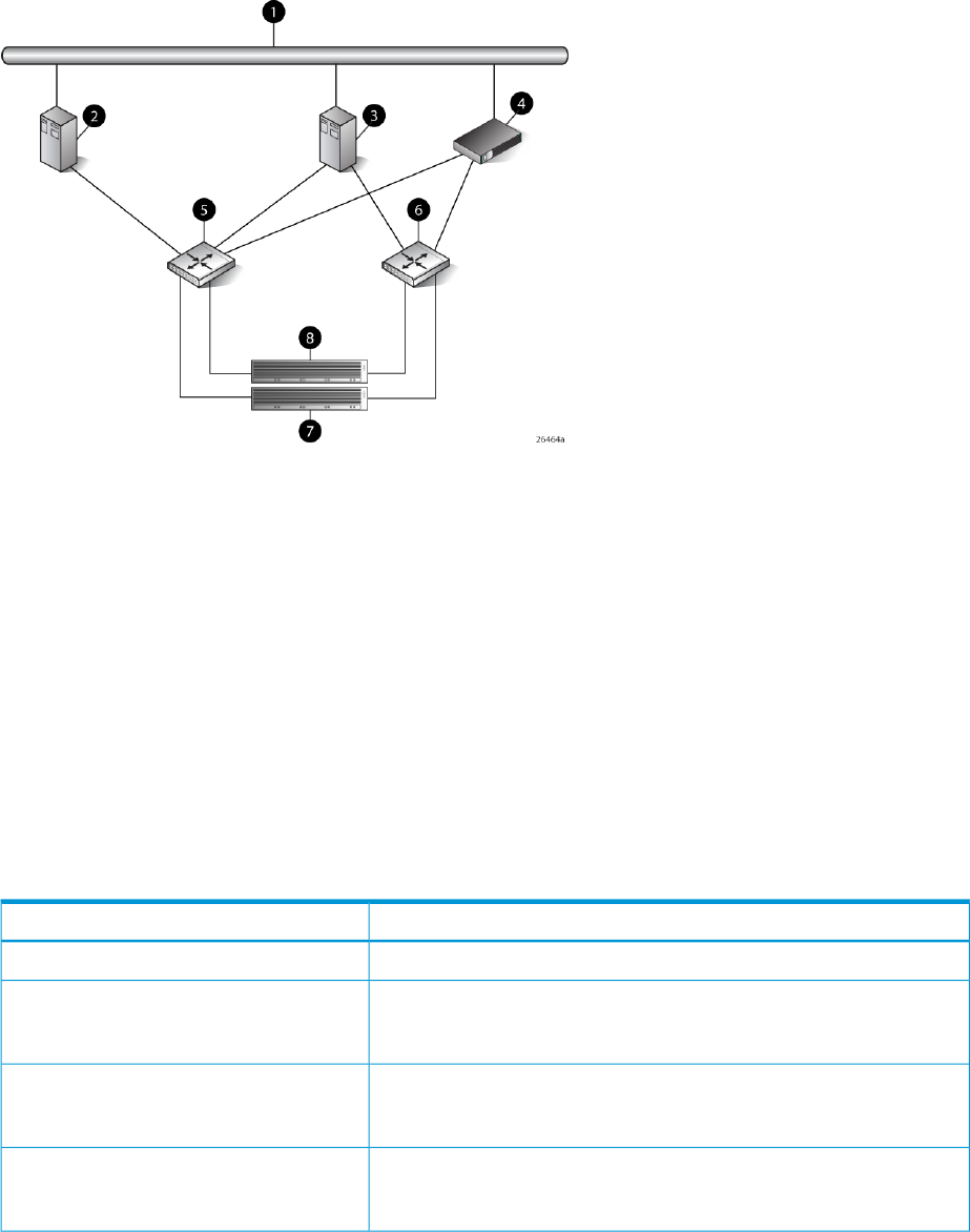
Limitations
•HP P6000 Continuous Access is not supported with single path configurations.
•Single HBA path at the host server is not part of a cluster, unless in a VMware High Availability
Cluster.
•Booting from the SAN is supported on single path HBA servers.
Figure 84 VMware configuration
5. SAN switch 11. Network interconnection
6. SAN switch 22. Single HBA server (Host 1)
7. Controller A3. Dual HBA server (Host 2)
8. Controller B4. Management server
Mac OS configuration
For information about Mac OS connectivity, see Mac OS X Fibre Channel connectivity to the HP
StorageWorks Enterprise Virtual Array Storage System Configuration Guide (to download, see
“Related documentation” (page 197)).
Failure scenarios
HP-UX
Failure effectFault stimulus
Extremely critical event on UNIX. Can cause loss of system disk.Server failure (host power-cycled)
Short term: Data transfer stops. Possible I/O errors.
Long term: Job hangs, cannot umount disk, fsck failed, disk corrupted,
need mkfs disk.
Switch failure (SAN switch disabled)
Short term: Data transfer stops. Possible I/O errors.
Long term: Job hangs, cannot umount disk, fsck failed, disk corrupted,
need mkfs disk.
Controller failure
Short term: Data transfer stops. Possible I/O errors.
Long term: Job hangs, cannot umount disk, fsck failed, disk corrupted,
need mkfs disk.
Controller restart
164 Single path implementation

Failure effectFault stimulus
Short term: Data transfer stops. Possible I/O errors.
Long term: Job hangs, cannot umount disk, fsck failed, disk corrupted,
need mkfs disk.
Server path failure
Short term: Data transfer stops. Possible I/O errors.
Long term: Job hangs, replace cable, I/O continues. Without cable
replacement job must be aborted; disk seems error free.
Storage path failure
Windows Servers
Failure effectFault stimulus
OS runs a command called chkdsk when rebooting. Data lost, data that
finished copying survived.
Server failure (host power-cycled)
Write delay, server hangs until I/O is cancelled or cold reboot.Switch failure (SAN switch disabled)
Write delay, server hangs or reboots. One controller failed, other
controller and shelves critical, shelves offline. Volume not accessible.
Server cold reboot, data lost. Check disk when rebooting.
Controller failure
Controller momentarily in failed state, server keeps copying. All data
copied, no interruption. Event error warning error detected during paging
operation.
Controller restart
Write delay, volume inaccessible. Host hangs and restarts.Server path failure
Write delay, volume disappears, server still running. When cables
plugged back in, controller recovers, server finds volume, data loss.
Storage path failure
Oracle Solaris
Failure effectFault stimulus
Check disk when rebooting. Data loss, data that finished copying survived.Server failure (host power-cycled)
Short term: Data transfer stops. Possible I/O errors.
Long term: Repeated error messages on console, no access to CDE.
System reboot causes loss of data on disk. Must newfs disk.
Switch failure (SAN switch disabled)
Short term: Data transfer stops. Possible I/O errors.
Long term: Repeated error messages on console, no access to CDE.
System reboot causes loss of data on disk. Must newfs disk.
Controller failure
Short term: Data transfer stops. Possible I/O errors.
Long term: Repeated error messages on console, no access to CDE.
System reboot causes loss of data on disk. Must newfs disk.
Controller restart
Short term: Data transfer stops. Possible I/O errors.
Long term: Repeated error messages on console, no access to CDE.
System reboot causes loss of data on disk. Must newfs disk.
Server path failure
Short term: Job hung, data lost.
Long term: Repeated error messages on console, no access to CDE.
System reboot causes loss of data on disk. Must newfs disk.
Storage path failure
OpenVMS
Failure effectFault stimulus
Nonclustered-Processes fail.
Clustered—Other nodes running processes that used
devices served from the single-path HBA failed over access
Server failure (host power-cycled)
Failure scenarios 165

Failure effectFault stimulus
to a different served path. When the single-path node
crashes, only the processes executing on that node fail.
In either case, no data is lost or corrupted.
I/O is suspended or process is terminated across this HBA
until switch is back online. No data is lost or corrupted.
The operating system will report the volume in a Mount
Verify state until the MVTIMEOUT limit is exceeded, when
Switch failure (SAN switch disabled)
it then marks the volume as Mount Verify Timeout. No data
is lost or corrupted.
I/O fails over to the surviving controller. No data is lost or
corrupted.
Controller failure
I/O is suspended or process is terminated across this HBA
until EVA is back online. No data is lost or corrupted.
The operating system will report the volume in a Mount
Verify state until the MVTIMEOUT limit is exceeded, when
it then marks the volume as Mount Verify Timeout.
Controller restart
If the LUN is not shared, I/O is suspended or process is
terminated across this HBA until path is restored.
If running OpenVMS 7.3-1 and the LUN is shared, another
cluster node having direct access will take over serving the
device, resulting in no loss of service.
Server path failure
In either case, no data is lost or corrupted.
The operating system will report the volume in a Mount
Verify state until the MVTIMEOUT limit is exceeded, when
it then marks the volume as Mount Verify Timeout.
I/O is suspended or process is terminated across this HBA
until path is restored. No data is lost or corrupted.
The operating system will report the volume in a Mount
Verify state until the MVTIMEOUT limit is exceeded, when
it then marks the volume as Mount Verify Timeout.
Storage path failure
Linux
Failure effectFault stimulus
OS reboots, automatically checks disks. HSV disks must be manually
checked unless auto mounted by the system.
Server failure (host power-cycled)
Short: I/O suspended, possible data loss.
Long: I/O halts with I/O errors, data loss. HBA driver must be reloaded
before failed drives can be recovered, fsck should be run on any failed
drives before remounting.
Switch failure (SAN switch disabled)
Short term: I/O suspended, possible data loss.
Long term: I/O halts with I/O errors, data loss. Cannot reload driver,
need to reboot system, fsck should be run on any failed disks before
remounting.
Controller failure
Short term: I/O suspended, possible data loss.
Long term: I/O halts with I/O errors, data loss. Cannot reload driver,
need to reboot system, fsck should be run on any failed disks before
remounting.
Controller restart
166 Single path implementation

Failure effectFault stimulus
Short: I/O suspended, possible data loss.
Long: I/O halts with I/O errors, data loss. HBA driver must be reloaded
before failed drives can be recovered, fsck should be run on any failed
drives before remounting.
Server path failure
Short: I/O suspended, possible data loss.
Long: I/O halts with I/O errors, data loss. HBA driver must be reloaded
before failed drives can be recovered, fsck should be run on any failed
drives before remounting.
Storage path failure
IBM AIX
Failure effectFault stimulus
Check disk when rebooting. Data loss, data that finished copying survivedServer failure (host power-cycled)
Short term: Data transfer stops. Possible I/O errors.
Long term: Repeated error messages in errpt output. System reboot causes
loss of data on disk. Must crfs disk.
Switch failure (SAN switch disabled)
Short term: Data transfer stops. Possible I/O errors.
Long term: Repeated error messages in errpt output. System reboot causes
loss of data on disk. Must crfs disk.
Controller failure
Short term: Data transfer stops. Possible I/O errors.
Long term: Repeated error messages in errpt output. System reboot causes
loss of data on disk. Must crfs disk.
Controller restart
Short term: Data transfer stops. Possible I/O errors.
Long term: Repeated error messages in errpt output. System reboot causes
loss of data on disk. Must crfs disk.
Server path failure
Short term: Data transfer stops. Possible I/O errors.
Long term: Repeated error messages in errpt output. System reboot causes
loss of data on disk. Must crfs disk.
Storage path failure
VMware
Failure effectFault stimulus
OS reboots, automatically checks disks. HSV disks must be manually
checked unless auto mounted by the system.
Server failure (host power-cycled)
Short: I/O suspended, possible data loss.
Long: I/O halts with I/O errors, data loss. HBA driver must be reloaded
before failed drives can be recovered, fsck should be run on any failed
drives before remounting.
Switch failure (SAN switch disabled)
Short term: I/O suspended, possible data loss.
Long term: I/O halts with I/O errors, data loss. Cannot reload driver,
need to reboot system, fsck should be run on any failed disks before
remounting.
Controller failure
Short term: I/O suspended, possible data loss.
Long term: I/O halts with I/O errors, data loss. Cannot reload driver,
need to reboot system, fsck should be run on any failed disks before
remounting.
Controller restart
Failure scenarios 167

Failure effectFault stimulus
Short: I/O suspended, possible data loss.
Long: I/O halts with I/O errors, data loss. HBA driver must be reloaded
before failed drives can be recovered, fsck should be run on any failed
drives before remounting.
Server path failure
Short: I/O suspended, possible data loss.
Long: I/O halts with I/O errors, data loss. HBA driver must be reloaded
before failed drives can be recovered, fsck should be run on any failed
drives before remounting.
Storage path failure
Mac OS
Failure effectFault stimulus
OS reboots. Both HFS and StorNext replay journal on filesystem. Disk
auto mounted by OS.
Server failure (host power-cycled)
Short term: I/O suspended, possible data loss.
Long term: I/O halts with I/O errors.
Switch failure
Short term: I/O suspended, possible data loss.
Long term: I/O fails over to alternate storage controller if visible (by
zoning). Otherwise, I/O halts with I/O errors, data loss.
Controller failure
Can require a server reboot for full recovery.
Short term: I/O suspended, possible data loss.
Long term: I/O fails over to alternate storage controller if visible (by
zoning). Otherwise, I/O halts with I/O errors, data loss.
Controller restart
Can require a server reboot for full recovery.
Short term: I/O suspended, possible data loss.
Long term: I/O halts with I/O errors, data loss.
Server path failure
Can require a server reboot for full recovery.
Short term: I/O suspended, possible data loss.
Long term: I/O fails over to alternate storage controller if available.
Otherwise, I/O halts with I/O errors.
Storage path failure
Can require a server reboot for full recovery.
168 Single path implementation

7 Troubleshooting
If the disk enclosure does not initialize
IMPORTANT: After a power failure, the system automatically returns to the last-powered state
(On or Off) when A/C power is restored.
1. Ensure that the power on/standby button was pressed firmly and held for approximately three
seconds.
2. Verify that the power on/standby button LED is green.
3. Verify that the power source is working:
a. Verify that the power supplies are working by viewing the power supply LEDs. If necessary,
remove and reinstall the power supplies to verify that they are seated properly.
b. Remove and inspect AC power cords from both power supplies and reconnect them.
Diagnostic steps
Is the enclosure front fault LED amber?
ActionsPossible ReasonsAnswer
No action required.System functioning properly.No
Yes •Be sure that the Front Status and UID
module is undamaged and is fully
seated.
•Front Status and UID module might
not be inserted properly, might
have a damaged connector, or
might have failed. •Check rear fault LEDs to isolate
failed component.•Possible error condition exists.
•Contact an authorized service
provider for assistance.
Is the enclosure rear fault LED amber?
ActionsPossible ReasonsAnswers
No action requiredFunctioning properly.No
Rear power and UID module might not
be inserted properly, might have a
Yes •Be sure that the rear power and UID
module is undamaged and is fully
seated.
damaged connector, or might have
failed. •Contact an authorized service
provider for assistance.
If the disk enclosure does not initialize 169

Is the power on/standby button LED amber?
Possible SolutionsPossible ReasonsAnswer
No action required.System functioning properly.No
Yes •Firmly press the power on/standby
button and hold for approximately
three seconds.
•The power on/standby button has
not been pressed firmly or held
long enough.
• • Be sure that all components are fully
seated.
The system midplane and/or
power button/LED assembly might
need to be replaced. •Contact an authorized service
provider for assistance.
Is the power supply LED amber?
ActionsPossible ReasonsAnswers
No •Remove and inspect the AC power
cords from both power supplies and
reconnect them.
•Both power cords not connected or
AC power is unavailable.
•Power supply functioning properly.
•No action required.
Yes •Verify AC input power.•This supply is not receiving AC
power, but the other supply is
receiving AC power. •Be sure that the power supply is
undamaged and is fully seated.
NOTE: It is possible for one
power supply to show a green
status and the other supply to show
an amber status.
•Be sure that all pins on connectors
and components are straight.
•Contact an authorized service
provider for assistance.
•Power supply might not be inserted
properly, might have a damaged
connector, or might have failed.
Is the I/O module fault LED amber?
Possible SolutionsPossible ReasonsAnswer
No action required.Functioning properly.No
Yes •Make sure that the I/O module is
seated properly by pressing the I/O
•The I/O module is locked.
•The I/O module has failed. module firmly into its bay after the
handle has clicked in place.
•Other fault condition exists.
CAUTION: Never remove an I/O
module from the chassis while the
status LED is green. Removing an
active I/O module can result in data
loss.
•Contact an authorized service
provider for assistance.
170 Troubleshooting

Is the fan LED amber?
ActionsPossible ReasonsAnswers
No action requiredFunctioning properly.No
Fan might not be inserted properly,
might have a damaged connector, or
might have failed.
Yes •Be sure that the fan is undamaged
and is fully seated.
•Contact an authorized service
provider for assistance.
Effects of a disk drive failure
When a disk drive fails, all virtual disks that are in the same array are affected. Each virtual disk
in an array might be using a different fault-tolerance method, so each can be affected differently.
•RAID0 configurations cannot tolerate drive failure. If any physical drive in the array fails, all
non-fault-tolerant (RAID0) logical drives in the same disk group also fail.
•RAID1+0 configurations can tolerate multiple drive failures as long as no failed drives are
mirrored to one another (with no spares assigned).
•RAID5 configurations can tolerate one drive failure (with no spares assigned).
•RAID6 configurations can tolerate simultaneous failure of two drives (with no spares assigned).
Compromised fault tolerance
If more disk drives fail than the fault-tolerance method allows, fault tolerance is compromised, and
the virtual disk fails.
Factors to consider before replacing disk drives
Before replacing a degraded drive:
•Be sure that the array has a current, valid backup.
•Use replacement drives that have a capacity at least as great as that of the smallest drive in
the array. The controller immediately fails drives that have insufficient capacity.
Effects of a disk drive failure 171

To minimize the likelihood of fatal system errors, take these precautions when removing failed
drives:
•Do not remove a degraded drive if any other drive in the array is offline (the online LED is
off). In this situation, no other drive in the array can be removed without data loss.
•Exceptions:
When RAID1+0 is used, drives are mirrored in pairs. Several drives can be in a failed
condition simultaneously (and they can all be replaced simultaneously) without data loss,
as long as no two failed drives belong to the same mirrored pair.
◦
◦When RAID6 is used, two drives can fail simultaneously (and be replaced simultaneously)
without data loss.
◦If the offline drive is a spare, the degraded drive can be replaced.
•Do not remove a second drive from an array until the first failed or missing drive has been
replaced and the rebuild process is complete. (The rebuild is complete when the Online LED
on the front of the drive stops blinking.)
Exceptions:
◦In RAID6 configurations, any two drives in the array can be replaced simultaneously.
◦In RAID1+0 configurations, any drives that are not mirrored to other removed or failed
drives can be simultaneously replaced offline without data loss.
Automatic data recovery (rebuild)
When you replace a disk drive in an array, the controller uses the fault-tolerance information on
the remaining drives in the array to reconstruct the missing data (the data that was originally on
the replaced drive) and write it to the replacement drive. This process is called automatic data
recovery, or rebuild. If fault tolerance is compromised, this data cannot be reconstructed and is
likely to be permanently lost.
Time required for a rebuild
The time required for a rebuild varies considerably, depending on several factors:
•The priority that the rebuild is given over normal I/O operations
•The amount of I/O activity during the rebuild operation
•The rotational speed of the disk drives
•The availability of drive cache
•The model and age of the drives
•The amount of unused capacity on the drives
•The number of drives in the array (for RAID5 and RAID6 )
Allow approximately 5 minutes per gigabyte without any I/O activity during the rebuild process.
This figure is conservative, and newer drive models usually require less time to rebuild.
System performance is affected during the rebuild, and the system is unprotected against further
drive failure until the rebuild has finished. Therefore, replace drives during periods of low activity
when possible.
CAUTION: If the Online LED of the replacement drive stops blinking and the amber fault LED
glows, or if other drive LEDs in the array go out, the replacement drive has failed and is producing
unrecoverable disk errors. Remove and replace the failed replacement drive.
172 Troubleshooting
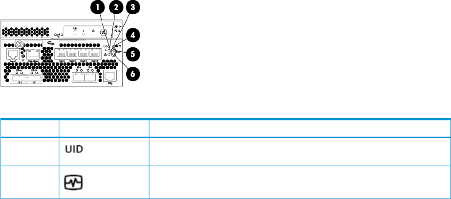
When automatic data recovery has finished, the online LED of the replacement drive stops blinking
and begins to glow steadily.
Failure of another drive during rebuild
If a non-correctable read error occurs on another physical drive in the array during the rebuild
process, the Online LED of the replacement drive stops blinking and the rebuild abnormally
terminates. If this situation occurs, restart the server. The system might temporarily become
operational long enough to allow recovery of unsaved data. In any case, locate the faulty drive,
replace it, and restore data from backup.
Handling disk drive failures
If the controller was configured with hardware fault tolerance, complete the following steps after
a disk drive failure:
1. Determine which physical drive failed. On hot-plug drives, an amber drive failure LED
illuminates.
2. If the unit containing the failed drive does not support hot-plug drives, perform a normal
shutdown.
3. Remove the failed drive and replace it with a drive that is of the same capacity. For hot-plug
drives, after you secure the drive in the bay, the LEDs on the drive each flash once in an
alternating pattern to indicate a successful connection. The online LED flashes, indicating that
the controller recognized the drive replacement and began the recovery process.
4. Power up the server, if applicable.
5. The controller reconstructs the information on the new drive, based on information from the
remaining physical drives in the logical drive. While reconstructing the data on hot-plug drives,
the online LED flashes. When the drive rebuild is complete, the online LED is illuminated.
iSCSI module diagnostics and troubleshooting
Diagnostic information is also available through HP P6000 Command View and the CLI event logs
and error displays. This section describes diagnostics.
iSCSI and iSCSI/FCoE diagnostics
The iSCSI and iSCSI/FCoE self test status and operational status are indicated by the MEZZ LED
as shown in Figure 85 (page 173) and Table 26 (page 173).
Figure 85 Controller status LEDs
Table 26 Controller status LEDs
IndicationLEDItem
Blue LED identifies a specific controller within the enclosure and the iSCSI or
iSCSI/FCoE module within the controller.
1
Green LED indicates controller health. LED flashes green during boot and
becomes solid green after boot.
2
iSCSI module diagnostics and troubleshooting 173
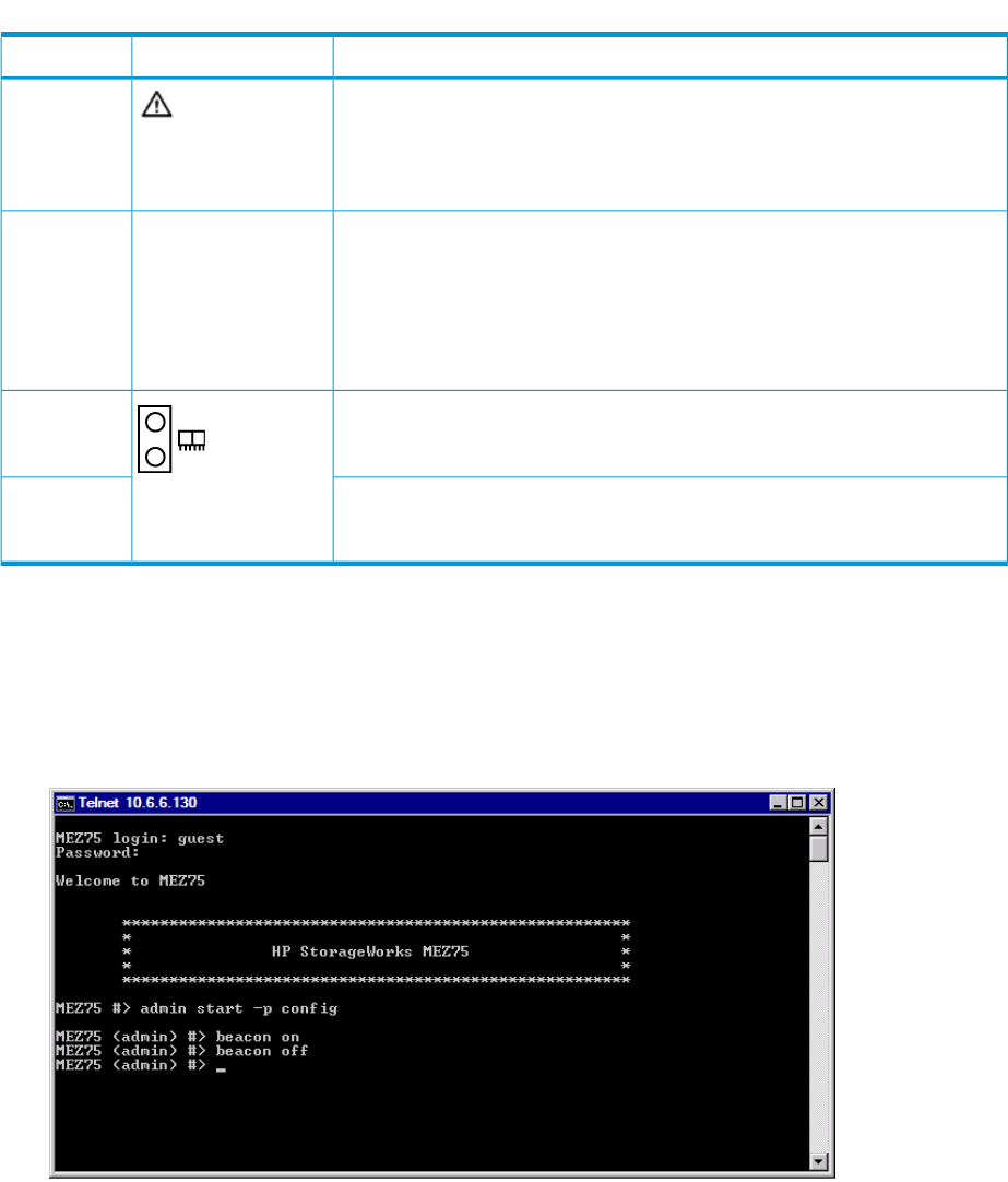
Table 26 Controller status LEDs (continued)
IndicationLEDItem
Flashing amber indicates a controller termination, or the system is inoperative
and attention is required. Solid amber indicates that the controller cannot reboot,
3
and that the controller should be replaced. If both the solid amber and solid
blue LEDs are lit, the controller has completed a warm removal procedure, and
can be safely swapped.
Amber LED indicates the iSCSI or iSCSI/FCoE module status that is
communicated to the array controller.
MEZZ4
Slow flashing amber LED indicates an IP address conflict on the management
port.
Solid amber indicates an iSCSI or iSCSI/FCoE module critical error, or
shutdown.
Green LED indicates write-back cache status. Slow flashing green LED indicates
standby power. Solid green LED indicates cache is good with normal AC power
applied.
5
Amber LED indicates DIMM status. The LED is off when DIMM status is good.
Slow flashing amber indicates DIMMs are being powered by battery (during
AC power loss). Solid amber indicates a DIMM failure.
6
Locate the iSCSI or iSCSI/FCoE module
A flashing UID beacon (blue LED) indicates the identification beacon is ON. There are two ways
to identify the location of an iSCSI or iSCSI/FCoE module.
1. Enter the CLI command beacon on (see Figure 86 (page 174)).
Figure 86 Beacon on command
174 Troubleshooting
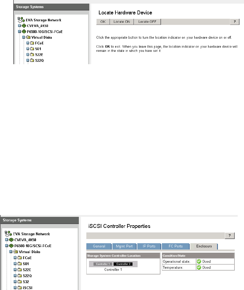
2. 2. In HP P6000 Command View, click the General tab and then click the Locate button. Use
the Locate ON and Locate OFF buttons to control the blue LED (see Figure 87 (page 175)).
Figure 87 Locate Hardware Device
iSCSI or iSCSI/FCoE module's log data
The iSCSI or iSCSI/FCoE modules maintain logs that can be displayed or collected through the
CLI. The log is persistent through reboots or power cycles. To view the log use the CLI command
show logs.
See “iSCSI or iSCSI/FCoE module log messages” (page 284) for log data descriptions.
iSCSI or iSCSI/FCoE module statistics
Statistics are available via the iSCSI or iSCSI/FCoE module CLI for the iSCSI and Fibre Channel
ports. To view the statistics us the CLI command show stats.
Troubleshoot using HP P6000 Command View
HP P6000 Command View can display the properties for each iSCSI module. At a glance, you
can check each module’s software revision, serial number, temperature, and power/cooling status
(see Figure 88 (page 175)).
Figure 88 iSCSI and iSCSI/FCoE module properties
Issues and solutions
Issue: HP P6000 Command View does not discover the iSCSI or iSCSI/FCoE modules
Solution 1: Ensure that a DHCP server is available.
Solution 2: Set a static IP address on each iSCSI and iSCSI/FCoE module through the CLI.
Solution 3: Ensure the HP P6000 Command View station is on the same subnet of the management
ports.
Solution 4: Enter the known IP address of the management port of the iSCSI modules in the HP
P6000 Command View discovery screen.
iSCSI module diagnostics and troubleshooting 175
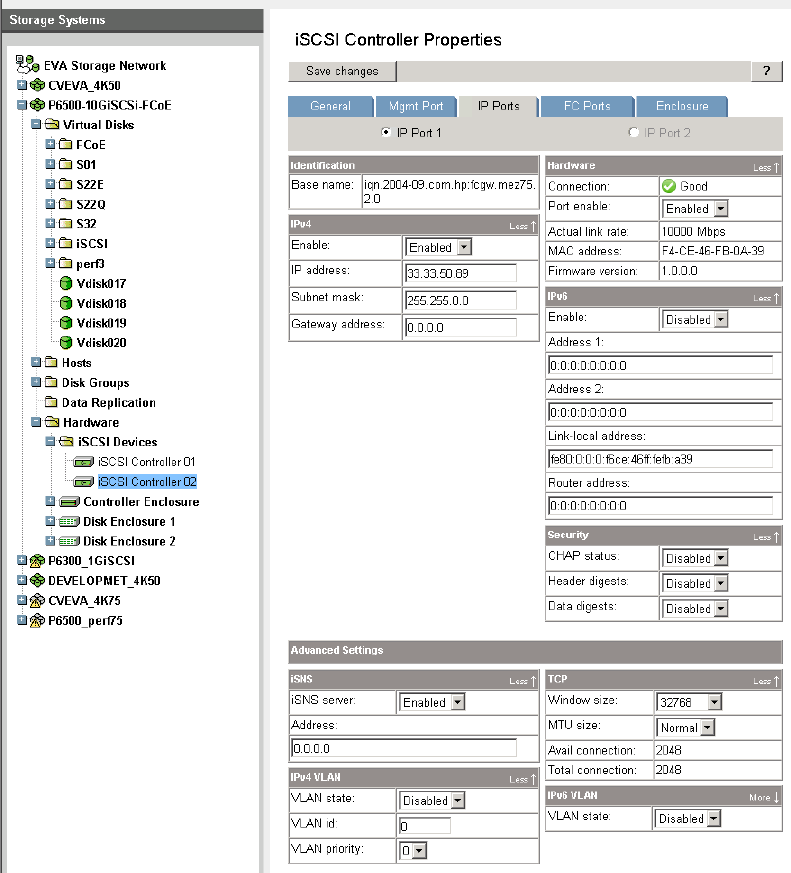
Issue: Initiator cannot login to iSCSI or iSCSI/FCoE module target
Solution 1: Ensure the correct iSCSI port IP address is used
Solution 2: In HP P6000 Command View, for each iSCSI controller 01 and 02, click the IP ports
tab, then expand the TCP properties under the Advanced Settings. There should be available
connections; if not, choose another IP port to log in to or reduce the connections from other initiators
by logging out from unused connections (see Figure 89 (page 176)).
Figure 89 IP Ports tab
Issue: Initiator logs in to iSCSI or iSCSI/FCoE controller target but EVA assigned LUNs are not
appearing on the initiator
Solution 1. The initiator needs to log in to the target where the EVA LUN was assigned.
Solution 2. The EVA LUN was assigned to a different iSCSI Host then was expected.
Issue: EVA presented virtual disk is not seen by the initiator
Solution 1. The initiator has to login to the proper iSCSI target. Match the virtual disk presentation
properties as in Figure 90 (page 177) and Figure 91 (page 177) to the initiator’s target login.
176 Troubleshooting
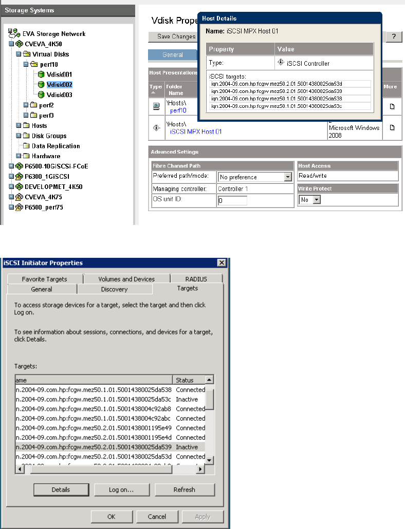
Figure 90 Host details
Figure 91 Target tab
Issue: Windows initiators may display Reconnecting if NIC MTU changes after connection has
logged in.
Solution. Log out of those sessions and Log On again to re-establish the Connected state.
Issue: When communication between HP P6000 Command View and iSCSI or iSCSI/FCoE module
is down, use following options:
Solution 1. Refresh using Hardware > iSCSI Devices > iSCSI Controller 01 or 02 > Refresh button.
Solution 2. If the IPv4 management port IP address is set:
1. Discover the controller. This option is exposed through iSCSI controller —> Set options
—> Discover controller
iSCSI module diagnostics and troubleshooting 177

2. Enter a valid IPv4 mgmt Ip address under Mgmt Port and click the Save changes button. If
only IPv6 mgmt port IP address is set, enter a valid lPv6 management IP address under Mgmt
Port and click the Save changes button.
NOTE: If you configure IPv6 on any iSCSI or iSCSI/FCoE module’s iSCSI port, you must
also configure IPv6 on the HP P6000 Command View EVA management server.
HP P6000 Command View issues and solutions
SolutionIssue
Click the Refresh button on the iSCSI Controller properties
page.
Discovered iSCSI Controller not found with selected EVA.
Check management port connection.
Check the iSCSI Controller Properties Condition/State of
the FC ports.
Only iSCSI or iSCSI/FCoE modules that are in the same
controller chassis are supported for connectivity.
Not a supported configuration. Both HP Storage Works
iSCSI or iSCSI/FCoE modules should belong to same
chassis/enclosure.
Check FCoE zoning/connectivity to the EVA.Not a supported configuration. HP iSCSI/FCoE module
cannot be discovered with this EVA.
Check all iSCSI or iSCSI/FCoE module FC Ports
Condition/State. Check that the iSCSI or iSCSI/FCoE
The virtual disk operation has failed. Please make sure that
FC target connections are online. module and HP P6000 Command View are in a consistent
state, each with the same hosts and presented LUNs. You
may have to use the iSCSI or iSCSI/FCoE module's CLI to
reset factory or reset mappings, and remove all
presentations and hosts from HP P6000 Command View.
Enable port.IP port of iSCSI controller 01 and 02 should be enabled
to change the corresponding port attributes.
Check software version. Code load latest revision if
necessary.
Command not supported with this version of HP iSCSI.
Check the status of the P6000 controller health and the
MEZZ status for failed conditions. Ensure that the P6000
FC ports are up.
Unable to process command at this time. Check all
connections as iSCSI or iSCSI/FCoE module's Fibre
Channel ports are unavailable.
Ensure the correct file is being used to restore configuration.Invalid iSCSI Controller configuration file extension.
File may be invalid or corrupt.Operation failed; iSCSI controller code load file cannot
open/read. Retrieve another copy of firmware file.
Process may have been interrupted during code load, try
again.
iSCSI Controller code load process have been failed.
Ensure the correct file is being used.Invalid iSCSI controller code load file extension.
A result of HP P6000 Command View and the iSCSI or
iSCSI/FCoE LUN mask being inconsistent while trying to
iSCSI or iSCSI/FCoE LUN presentation:
Operation Failed! The virtual disk operation has failed.
Please make sure that the FC target connections are online. map a LUN that is already mapped or is offline. This can
result from misuse of the CLI or making LUN masking
changes while a module or controller is down. Use the CLI
to reset mappings/reboot or reset factory/reboot, then
unmap all presented LUNs, deleting the iSCSI HOSTs and
also removing both iSCSI controllers. The CLI show luns,
show luninfo, and show initiators_lunmask
commands can provide information on which LUNs are
causing the inconsistency.
178 Troubleshooting

There can be a mismatch on the Vdisk allocated size in
comparison with the host volume size shown by optimizer
(slab count and volume information).
Volume information mismatch across cveva and Optimize
ReTrim used space
Based on the controller load, the efficiency of space
reclamation might vary and the reclamation not start
Space reclaim is very minimal for iSCSI LUN during the
file deletion. immediately. Reclaim of the specified space (or majority
of the specified space) may complete over a period of time
and may not be instantly.
The system event log when the threshold limit of the vdisk
is reached, When the system event log reaches the
Thin Provisioning Threshold and Resource Exhaustion Test
(LOGO) Failed threshold limit on the vdisk, the user can see an event on
the LUN utilization capacity and pool availability capacity
for LUN is restricted by either size of LUN or available
capacity in pool.
iSCSI module diagnostics and troubleshooting 179

8 Error messages
This list of error messages is in order by status code value, 0 to 243.
Table 27 Error Messages
How to correctMeaningStatus code value
No corrective action required.The SCMI command completed successfully.0
Successful Status
Delete the associated object and try
the operation again. Several situations
can cause this message:
Presenting a LUN to a host:
•Delete the current association or
specify a different LUN number.
Storage cell initialize:
•Remove or erase disk volumes
before the storage cell can be
successfully created.
Adding a port WWN to a host:
•Specify a different port WWN.
Adding a disk to a disk group:
•Delete the specified disk volume
before creating a new disk volume.
The object or relationship already exists.1
Object Already Exists
Report the error to product support.The command or response buffer is not large
enough to hold the specified number of
2
Supplied Buffer Too Small items. This can be caused by a user or
program error.
Report the error to product support.This error is no longer supported.3
Object Already Assigned
Reclaim some logical space or add
physical hardware.
There is insufficient storage available to
perform the request.
4
Insufficient Available Data
Storage
Report the error to product support.An unexpected condition was encountered
while processing a request.
5
Internal Error
Report the error to product support.This error is no longer supported.6
Invalid status for virtual disk
Report the error to product support.The supplied class code is of an unknown
type. This can be caused by a user or
program error.
7
Invalid Class
Report the error to product support.The function code specified with the class
code is of an unknown type.
8
Invalid Function
Report the error to product support.This error is no longer supported.9
Invalid Logical Disk Block State
Report the error to product support.This error is no longer supported.10
Invalid Loop Configuration
Report the error to product support.There are insufficient resources to fulfill the
request, the requested value is not
11
Invalid parameter supported, or the parameters supplied are
invalid. This can indicate a user or program
error.
180 Error messages

Table 27 Error Messages (continued)
How to correctMeaningStatus code value
In the following cases, the message
can occur because the operation is
The supplied handle is invalid. This can
indicate a user error, program error, or a
storage cell in an uninitialized state.
In the following cases, the storage cell is in
an uninitialized state, but no action is
required:
12
Invalid Parameter handle not allowed when the storage cell is
in an uninitialized state. If you see
these messages, initialize the storage
cell and retry the operation.
Storage cell set device addition policy
Storage cell discard (informational
message): Storage cell set name
Storage cell look up object count
(informational message): Storage cell set time
Storage cell set volume replacement
delayStorage cell look up object (informational
message): Storage cell free command lock
Storage cell set console lun id
Report the error to product support.The supplied identifier is invalid. This can
indicate a user or program error.
13
Invalid Parameter Id
Report the error to product support.This error is no longer supported.14
Invalid Quorum Configuration
Case 1: Report the error to product
support.
The supplied target handle is invalid. This
can indicate a user or program error (Case
1),
15
Invalid Target Handle
Case 2: To add additional capacity
to the disk group, use the managementor software to add disks by count or
capacity.
Volume set requested usage (Case 2):
The operation could not be completed
because the disk has never belonged to a
disk group and therefore cannot be added
to a disk group.
Report the error to product support.The supplied target identifier is invalid. This
can indicate a user or program error.
16
Invalid Target Id
Report the error to product support.This error is no longer supported.17
Invalid Time
Report the error to product support.The operation could not be completed
because one or more of the disk media was
inaccessible.
18
Media is Inaccessible
Report the error to product support.The Fibre Channel port specified is not valid.
This can indicate a user or program error.
19
No Fibre Channel Port
Report the error to product support.There is no firmware image stored for the
specified image number.
20
No Image
The disk device must be in either
maintenance mode or in a reserved
The disk device is not in a state to allow the
specified operation.
21
No Permission state for the specified operation to
proceed.
Create a storage cell and retry the
operation.
The operation requires a storage cell to exist.22
Storage system not initialized
Report the error to product support.The Fibre Channel port specified is either
not a loop port or is invalid. This can
indicate a user or program error.
23
Not a Loop Port
Report the error to product support.This error is no longer supported.24
Not a Participating Controller
181

Table 27 Error Messages (continued)
How to correctMeaningStatus code value
Case 1: Either delete the associated
object or resolve the in progress state.
Several states can cause this message:
Case 1: The operation cannot be performed
because an association exists a related
object, or the object is in a progress state.
25
Objects in your system are in use,
and their state prevents the
operation you wish to perform. Case 2: Report the error to product
support.
Case 2: The supplied virtual disk handle is
already an attribute of another derived unit.
This may indicate a programming error.
Case 3: Unpresent the LUNs before
deleting this virtual disk.
Case 4: Resolve the delay before
performing the operation.
Case 3: One or more LUNs are presented
to EVA hosts that are based on this virtual
disk. Case 5: Delete any remaining virtual
disks or wait for the used capacity to
Case 4: Virtual disk clear data lost: The
virtual disk is in the non-mirrored delay
window.
reach zero before the disk group can
be deleted. If this is the last remaining
disk group, uninitialize the storage cell
to remove it.Case 5: LDAD discard: The operation cannot
be performed because one or more virtual Case 6: Report the error to product
support.
disks still exist, the disk group still may be
recovering its capacity, or this is the last disk
group that exists. Case 7: The disk must be in a reserved
state before it can be erased.
Case 6: LDAD resolve condition: The disk
group contains a disk volume that is in a Case 8: Delete the virtual disks or LUN
presentations before uninitializing the
storage cell.
data-lost state. This condition cannot be
resolved.
Case 9: Delete the LUN presentations
before deleting the EVA host.
Case 7: Physical store erase volume: The
disk is a part of a disk group and cannot be
erased. Case 10: Report the error to product
support.
Case 8: Storage cell discard: The storage
cell contains one or more virtual disks or
LUN presentations. Case 11: Resolve the situation before
attempting the operation again.
Case 9: Storage cell client discard: = The
EVA host contains one or more LUN
presentations.
Case 12: Resolve the situation before
attempting the operation again.
Case 13: Select another disk or
remove the disk from the disk group
Case 10: Virtual disk discard: The virtual
disk is in use and cannot be discarded. This
may indicate a programming error. before making it a member of a
different disk group.
Case 11: Virtual disk set capacity: The
capacity cannot be modified because the Case 14: Remove the virtual disks from
the group and retry the operation.
virtual disk has a dependency on either a
snapshot or snapclone.
Case 12: Virtual disk set disk cache policy:
The virtual disk cache policy cannot be
modified while the virtual disk is presented
and enabled.
Case 13: VOLUME set requested usage: The
disk volume is already a member of a disk
group or is in the state of being removed
from a disk group.
Case 14: GROUP discard: The Continuous
Access group cannot be discarded as one
or more virtual disk members exist.
Report the error to product support.The operation cannot be performed because
the object does not exist. This can indicate
a user or program error.
VOLUME set requested usage: The disk
volume set requested usage cannot be
26
Parameter Object Does Not Exist
performed because the disk group does not
exist. This can indicate a user or program
error.
182 Error messages

Table 27 Error Messages (continued)
How to correctMeaningStatus code value
Report the error to product support.The operation cannot be performed because
the object does not exist. This can indicate
a user or program error.
27
Target Object Does Not Exist
Verify the hardware connections and
that communication to the device is
successful.
A timeout has occurred in processing the
request.
28
Timeout
Report the error to product support.This error is no longer supported.29
Unknown Id
Report the error to product support.This error is no longer supported.30
Unknown Parameter Handle
Report the error to product support.The operation could not be completed
because one or more of the disk media had
an unrecoverable error.
31
Unrecoverable Media Error
Report the error to product support.This error is no longer supported.32
Invalid State
Verify the hardware connections,
communication to the device, and that
A SCMI transport error has occurred.33
Transport Error the management software is operating
successfully.
Resolve the condition and retry the
request. Report the error to product
support.
The operation could not be completed
because the drive volume is in a missing
state.
34
Volume is Missing
Report the error to product support.The supplied cursor or sequence number is
invalid. This may indicate a user or program
error.
35
Invalid Cursor
Report the error to product support.The specified target virtual disk already has
an existing data sharing relationship. This
can indicate a user or program error.
36
Invalid Target for the Operation
No action required.There are no more events to retrieve. (This
message is informational only.)
37
No More Events
Retry the request at a later time.The command lock is busy and being held
by another process.
38
Lock Busy
Report the error to product support.The storage system time is not set. The
storage system time is set automatically by
the management software.
39
Time Not Set
Report the error to product support.The requested operation is not supported by
this firmware version. This can indicate a
user or program error.
40
Not a Supported Version
Report the error to product support.This is an internal error.41
No Logical Disk for Vdisk
Delete the associated presentation(s)
and retry the request.
The virtual disk specified is already
presented to the client and the requested
operation is not allowed.
42
Virtual disk Presented
Report the error to product support.The request is not allowed on the slave
controller. This can indicate a user or
program error.
43
Operation Denied On Slave
Report the error to product support.This error is no longer supported.44
Not licensed for data replication
183

Table 27 Error Messages (continued)
How to correctMeaningStatus code value
Configure the virtual disk to be a
member of a Continuous Access group
and retry the request.
The operation cannot be performed because
the virtual disk is not a member of a
Continuous Access group.
45
Not DR group member
Configure the Continuous Access
group correctly and retry the request.
The operation cannot be performed because
the Continuous Access group is not in the
required mode.
46
Invalid DR mode
Wait for the copying state to complete
and retry the request.
The operation cannot be performed because
at least one of the virtual disk members is in
a copying state.
47
The target DR member is in full
copy, operation rejected
Use the management software to save
the password specified so
communication can proceed.
The management software is unable to log
in to the storage system. The storage system
password has been configured.
48
Security credentials needed.
Please update your system's ID
and password in the Storage
System Access menu.
Use the management software to set
the password to match the device so
communication can proceed.
The management software is unable to login
to the device. The storage system password
may have been re-configured or removed.
49
Security credentials supplied
were invalid. Please update your
system's ID and password in the
Storage System Access menu.
No action required.The management software is already logged
in to the device. (This message is
informational only.)
50
Security credentials supplied
were invalid. Please update your
system's ID and password in the
Storage System Access menu.
Verify that devices are powered on
and that device hardware connections
The Continuous Access group is unable
communicate to the remote site.
51
Storage system connection down are functioning correctly. In particular,
validate that the inter-site link is
functioning correctly.
Add one or more virtual disks as
members and retry the request.
No virtual disks are members of the
Continuous Access group.
52
DR group empty
Retry the request with valid attributes
for the operation. Currently, this error
The request cannot be performed because
one or more of the attributes specified is
incompatible.
53
Incompatible attribute code is only used for mirror clone
operations, and is returned when a
fracture or invert is requested and all
operations are not alike.
Remove the virtual disk as a member
of a data replication group and retry
the request.
The requested operation cannot be
performed on a virtual disk that is already
a member of a data replication group.
54
Vdisk is a DR group member
No action required.The requested operation cannot be
performed on a virtual disk that is a log unit.
55
Vdisk is a DR log unit
Report the error to product support.The battery system is missing or discharged.56
Cache batteries failed or missing.
The virtual disk member must be
presented to a client before this
operation can be performed.
The virtual disk member is not presented to
a client.
57
Vdisk is not presented
Retry the operation once controller
failout is complete.
The other controller failed during the
execution of this operation.
58
Other controller failed
184 Error messages

Table 27 Error Messages (continued)
How to correctMeaningStatus code value
Case 1: If this operation is still desired,
delete one or more of the items and
retry the operation.
Case 2: If this operation is still desired,
delete one or more of the EVA hosts
and retry the operation.
Case 1: The maximum number of items
allowed has been reached.
Case 2: The maximum number of EVA hosts
has been reached.
Case 3: The maximum number of port
WWNs has been reached.
59
Maximum Number of Objects
Exceeded.
Case 3: If this operation is still desired,
delete one or more of the port WWNs
and retry the operation.
Case 1: If this operation is still desired,
delete one or more of the items on the
Case 1: The maximum number of items
already exist on the destination storage cell.
60
Max size exceeded destination storage cell and retry the
operation.
Case 2: The size specified exceeds the
maximum size allowed. Case 2: Use a smaller size and retry
the operation.
Case 3: The presented user space exceeds
the maximum size allowed. Case 3: No action required.
Case 4: The presented user space exceeds
the maximum size allowed. Case 4: No action required.
Case 5: The size specified exceeds the
maximum size allowed. Case 5: Use a smaller size and try this
operation again.
Case 6: The maximum number of EVA hosts
already exist on the destination storage cell. Case 6: If this operation is still desired,
delete one or more of the EVA hosts
and retry the operation.
Case 7: The maximum number of EVA hosts
already exist on the destination storage cell. Case 7: If this operation is still desired,
delete one or more of the virtual disks
Case 8: The maximum number of Continuous
Access groups already exist. on the destination storage cell and
retry the operation.
Case 8: If this operation is still desired,
delete one or more of the groups and
retry the operation.
Reconfigure one of the storage system
controller passwords, then use the
The login password entered on the
controllers does not match.
61
Password mismatch. Please
update your system's password management software to set the
in the Storage System Access password to match the device so
communication can proceed.menu. Continued attempts to
access this storage system with
an incorrect password will
disable management of this
storage system.
Wait for the merge operation to
complete and retry the request.
The operation cannot be performed because
the Continuous Access connection is
currently merging.
62
DR group is merging
Wait for the logging operation to
complete and retry the request.
The operation cannot be performed because
the Continuous Access connection is
currently logging.
63
DR group is logging
Resolve the suspended mode and retry
the request.
The operation cannot be performed because
the Continuous Access connection is
currently suspended
64
Connection is suspended
Retrieve a valid firmware image file
and retry the request.
The firmware image file has a header
checksum error.
65
Bad image header
Retrieve a valid firmware image file
and retry the request.
The firmware image file has a checksum
error.
66
Bad image
Report the error to product support.This error is no longer supported.67
Obsolete
185

Table 27 Error Messages (continued)
How to correctMeaningStatus code value
Report the error to product support.This error is no longer supported.68
Obsolete
Report the error to product support.This error is no longer supported.69
Obsolete
Retrieve a valid firmware image file
and retry the request
The firmware image file is incompatible with
the current system configuration. Version
70
Image incompatible conflict in upgrade or downgrade not
allowed.
Verify that the firmware image is not
corrupted and retry the firmware
download process.
The firmware image download process has
failed because of a corrupted image
segment.
71
Bad image segment
No action required.The firmware version already exists on the
device.
72
Image already loaded
Verify that the firmware image is not
corrupted and retry the firmware
download process.
The firmware image download process has
failed because of a failed write operation.
73
Image Write Error
Case 1: No action required.
Case 2: No action required.
Case 1: The operation cannot be performed
because the virtual disk or snapshot is part
of a snapshot group.
74
Virtual Disk Sharing
Case 3: If a snapclone operation is in
progress, wait until the snapcloneCase 2: The operation may be prevented
because a snapclone or snapshot operation operation has completed and retry the
is in progress. If a snapclone operation is in operation. Otherwise, the operation
progress, the parent virtual disk should be cannot be performed on this virtual
disk.discarded automatically after the operation
completes. If the parent virtual disk has Case 4: No action required.
snapshots, then you must delete the Case 5: No action required.
snapshots before the parent virtual disk can
be deleted.
Case 3: The operation cannot be performed
because either the previous snapclone
operation is still in progress, or the virtual
disk is already part of a snapshot group.
Case 4: A capacity change is not allowed
on a virtual disk or snapshot that is a part
of a snapshot group.
Case 5: The operation cannot be performed
because the virtual disk or snapshot is a part
of a snapshot group.
Retrieve a valid firmware image file
and retry the request.
The firmware image file is not the correct
size.
75
Bad Image Size
Retry the request once the firmware
download process is complete.
The controller is currently processing a
firmware download. Retry the request once
the firmware download process is complete.
76
Image Busy
Report the error to product support.The disk volume specified is in a predictive
failed state.
77
Volume Failure Predicted
Resolve the condition and retry the
request.
The current condition or state is preventing
the request from completing successfully.
78
Invalid object condition for this
command.
Wait for the operation to complete
and retry the request.
The current condition of the snapshot,
snapclone, or parent virtual disk is
79
Snapshot (or snapclone) deletion
in progress. The requested preventing the request from completing
successfully.operation is currently not
allowed. Please try again later.
186 Error messages

Table 27 Error Messages (continued)
How to correctMeaningStatus code value
Resolve the condition by setting the
usage to a reserved state, wait for the
The disk volume is already a part of a disk
group.
80
Invalid Volume Usage usage to change to this state, and retry
the request.
Resolve the condition by adding
additional disks and retry the request.
The disk volume usage cannot be modified,
as the minimum number of disks exist in the
disk group.
81
Minimum Volumes In Disk Group
No action required.The controller is currently shutting down.82
Shutdown In Progress
Retry the request at a later time.The device is not ready to process the
request.
83
Controller API Not Ready, Try
Again Later
No action required.This is a snapshot virtual disk and cannot be
a member of a Continuous Access group.
84
Is Snapshot
Modify the mirror policy and retry the
request.
An incompatible mirror policy of the virtual
disk is preventing it from becoming a
member of a Continuous Access group.
85
Cannot add or remove DR group
member. Mirror cache must be
active for this Vdisk. Check
controller cache condition.
Report the error to product support.Case 1: A virtual disk is in an inoperative
state and the request cannot be processed.
86
HP P6000 Command View has
detected this array as This is due to a loss of cache data from
power/controller loss or disk drive failure.inoperative. Contact HP Service
for assistance. Case 2: The snapclone cannot be associated
with a virtual disk that is in an inoperative
state. HP P6000 Command View has
detected this array as inoperative. Contact
HP Services for assistance.
Case 3: The snapshot cannot be associated
with a virtual disk that is in an inoperative
state. This is due to a loss of cache data from
power/controller loss or disk drive failure.
Report the error to product support.The disk group is in an inoperative state and
cannot process the request.
87
Disk group inoperative
Report the error to product support.The storage system is inoperative and cannot
process the request because all disk groups
88
Storage system inoperative have lost sufficient drives such that no data
is available.
Resolve the condition and retry the
request.
The request cannot be performed because
the Continuous Access group is in a failsafe
locked state.
89
Failsafe Locked
Retry the request later.The disk cache data need to be flushed
before the condition can be resolved.
90
Data Flush Incomplete
Report the error to product support.This error is no longer supported.91
Redundancy Mirrored Inoperative
Select another LUN number and retry
the request.
The LUN number is already in use by
another client of the storage system.
92
Duplicate LUN
Retry the request once remote
controller failout is complete.
While the request was being performed, the
remote storage system controller terminated.
93
Other remote controller failed
Correctly select the remote storage
system and retry the request.
The remote storage system specified does
not exist.
94
Unknown remote Vdisk
187

Table 27 Error Messages (continued)
How to correctMeaningStatus code value
Correctly select the remote Continuous
Access group retry the request.
The remote Continuous Access group
specified does not exist.
95
Unknown remote DR group
Report the error to product support.This error is no longer supported.96
PLDMC failed
Retry the request later.Another process has already taken the SCMI
lock on the storage system.
97
Storage system could not be
locked. System busy. Try
command again.
Resolve the condition and retry the
request
While the request was being performed, an
error occurred on the remote storage system.
98
Error on remote storage system.
Resolve the condition and retry the
request.
The request failed because the operation
cannot be performed on a Continuous
Access connection that is up.
99
The DR operation can only be
completed when the
source-destination connection is
down. If you are doing a
destination DR deletion, make
sure the connection link to the
source DR system is down or do
a failover operation to make this
system the source.
The storage system password may
have been re-configured or removed.
The management software is unable to log
into the device as the password has
changed.
100
Login required - password
changed. The management software must be
used to set the password up to match
the device so communication can
proceed.
Log out of a management agent
session before attempting a new login.
The maximum number of login sessions
allowed to the storage system has been
reached.
101
Maximum logins
Retry the operation later. If the error
persists, report the error to product
support.
The command cookie sent in the attempted
command is invalid.
102
Invalid Cookie
Log in again.The login session is no longer valid due to
timeout.
103
Login Timed Out
Remove a snapshot before attempting
this command again.
The virtual disk has reached the maximum
number of allowed snapshots.
104
Maximum Snapshot Depth
Case 1: Specify a valid capacity
value.
Case 1: Creation of the virtual disk failed
due to an invalid capacity value.
105
Attribute Mismatch
Case 2: Choose a valid mirror policy
value.
Case 2: Virtual disk mirror policy does not
match other snapshots.
Set a password before logging in.
Without a password no login is
required.
Management agent was not able to log in
because password is not set.
106
Password Not Set
Check if the port number refers to a
valid host port and try again.
Invalid port when trying to get host port
information.
107
Not Host Port
Unpresent the already presented
virtual disk or change the WWID of
this virtual disk.
A virtual disk with this WWID is already
presented.
108
Duplicate LUN WWID
Report the error to product support.This error is no longer supported.109
System Inoperative
Report the error to product support.This is an internal error.110
188 Error messages

Table 27 Error Messages (continued)
How to correctMeaningStatus code value
Snapclone Active
Wait several minutes for the drive
enclosure code load to finish, then
retry the operation.
The operation cannot be completed while
the drive enclosures are undergoing code
load.
111
EMU Load Busy
Change the user name for the new
Continuous Access group or delete the
An existing Continuous Access group
already has this user name.
112
Duplicate User Name existing Continuous Access group with
the same name.
Allow the drive to finish code load.The operation is not allowed because the
drive is in a migrate code load state.
113
Drive Reserved For Code Load
Report the error to product support.This error is no longer supported.114
Already Presented
Report the error to product support.This error is no longer supported.115
Invalid Remote Storage Cell
Retry the operation later. If the error
persists, report the error to product
support.
The SCMI lock context in StorageCell is
empty where the lock is expected to be taken
by the management agent.
116
No Management Interface Lock
Use another Continuous Access group
or remove members from the existing
Continuous Access group.
The specified Continuous Access group
already has the maximum number of
members.
117
Maximum Members
Use an existing destination or stop
using a destination.
The specified Continuous Access group is
attempting to use a new destination past the
maximum number.
118
Maximum Destinations
Populate the user name field.The user name field for the specified
Continuous Access group is empty.
119
Empty User Name
Use the command form designed to
be used when no storage sell exists
yet.
The command is not valid when a
StorageCell is already formed and the NSC
is operating normally as a member of the
storage cell.
120
Storage Cell Exists
Close the requested session before
attempting this command again.
The requested session is already open on
this NSC. It cannot be opened for multiple
session operation.
121
Already Open
Open the requested session before
attempting this command again.
The requested session was not established
by opening the session.
122
Session Not Open
Case 1: Resolve the RAID inoperative
condition in the disk group.
Case 1: The specified Continuous Access
group cannot complete the operation until
123
Not Marked Inoperative
Case 2: Command is unnecessary on
a non thin provisioned overcommit
virtual disk.
the disk group is marked permanently data
lost.
Case 2: The specified virtual disk is not in
the thin provisioned overcommit state.
Retry the operation later. If the error
persists, report the error to product
support.
Drive activity prevents the operation from
being completed at this time.
124
Media Not Available
Resolve degraded battery situation.The batteries do not allow the warm plug of
a controller.
125
Battery System Failed
Resolve the cache data lost situation
on the virtual disk.
The virtual disk is cache data lost.126
Member is Cache Data Lost
Retry the operation later. If the error
persists, report the error to product
support.
The resource needed to execute the request
is in use by internal DRM process. The
operation can be retried later.
127
Internal Lock Collision
189

Table 27 Error Messages (continued)
How to correctMeaningStatus code value
Ensure other OCP is on and try again.
If the problem persists, report the error
to product support.
EVA 6400/8400 only. A generic error was
detected with the OCP interface.
128
OCP Error
Ensure other controller is operative.The virtual disk is not mirrored to the other
controller.
129
Mirror Temporarily Offline
Disable Failsafe mode on Group.Cannot perform operation because FAILSAFE
is enabled on Group.
130
Failsafe Mode Enabled
Migrate RAID0 data to another disk
group or a more protective
The drive firmware cannot be downloaded
to the drive because it is being used for
131
Drive FW Load Abort Due to
VRaid0 Vdisk redundancy before retrying the drive
update.
RAID0 data. One or more RAID0 virtual
disks would be inoperable if the drive were
to be loaded.
Report the error to product support.There is a diagnostic problem with the
indicated port.
132
FC Ports Unavailable
Need to reconfigure configuration to
only have two remote destinations.
Only two remote relationships are allowed.133
Only Two Remote Relations Are
Allowed
Report the error to product support.The existing drive configuration does not
support the requested SRC mode.
134
The Requested SRC Mode is Not
Possible
Report the error to product support.This error is no longer supported.135
Source Group Discarded, but the
Destination Group NOT
Discarded
Report the error to product support.This error is no longer supported.136
Invalid DRM Group Tunnel
Specified
Report the error to product support.This error is no longer supported.137
Specified DRM Log Size Too
Small
Retry command using an appropriate
disk group identifier.
The disk group requested for the attempted
command is not valid.
138
Invalid Disk Group Specified
Disable read-only mode in group.Data replication group is already read-only.139
DRM Group is Already
Read-Only
Disable active-active mode in group.Data replication group is already
active-active.
140
DRM Group is Already
Active-Active
Retry command after DILX is complete.The requested operation cannot be
completed while Disk In Line Exerciser is in
progress.
141
DILX Is Already Running
No corrective action required.Disk In Line Exerciser cannot be stopped
because it is not running.
142
DILX Is Not Running
Reissue operation with a valid log sizeInvalid user defined log size.143
Invalid User Defined Log Size
Retry the command with an existing
data replication group.
Invalid data replication group identifier
specified.
144
Invalid Second Handle Paramed
Unsuspend group and reissue
operation.
Data replication group already auto
suspended.
145
DRM Group Already Auto
Suspended
190 Error messages

Table 27 Error Messages (continued)
How to correctMeaningStatus code value
Code load the EVA firmware with a
supported method.
An unsupported code load attempt was
made.
146
Specified Option Iis Not Yet
Implemented
Disable active-active or read-only and
retry operation.
Data replication group is already
present_only.
147
DRM Group Is Already “Present
Only”
Report the error to product support.This error is no longer supported.148
The Presented Unit Identifier Is
Invalid
Report the error to product support.This is an internal error.149
Internal SCS Error
Report the error to product support.This is an internal error.150
Invalid SCS Function Code
Report the error to product support.The command is not supported.151
Unsupported SCS Function Code
Replace the failed drive and retry the
command.
The requested command cannot be
completed because a physical drive is failed.
152
Init PS Failed
Verify that the parameters of the
command are correct and retry.
The object identifier included with the
command is invalid. This can indicate a user
or program error.
153
Target Bad Identifier
Report the error to product support.This error is no longer supported.154
Physcial Store Is Volume
Verify that the parameters of the
command are correct and retry.
The requested "usage" of the volume is not
a valid value. This can indicate a user or
program error.
155
Bad Volume Usage
Verify that the parameters of the
command are correct and retry.
The requested "usage" of the volume is not
a consistent with the disk group indicated.
This can indicate a user or program error.
156
Bad LDAD Usage
Verify that the parameters of the
command are correct and retry.
The disk group requested for the attempted
command is not valid.
157
No LDAD Handle
Report the error to product support.This error is no longer supported.158
Bad Quorum Flag
Verify that the parameters of the
command are correct and retry.
The command parameters do not correlate
to an object in the system. This can indicate
a user or program error.
159
Internal Tag Invalid
Verify that the parameters of the
command are correct and retry.
The command parameters do not correlate
to an object in the system. This can indicate
a user or program error.
160
Internal Tag Bad UUID
Ensure that a supported number of
drives are used to initialize the storage
When attempting to initialize the storage
cell, either the command is attempted with
161
Too Many Physical Store Tags cell, and that the drives are each
included only once.
too many drives, or the drive list has
duplicate entries.
Report the error to product support.This error indicates that a product support
command is invalid or no longer supported.
162
Bad Routine
Verify that the parameters of the
command are correct and retry.
The identifier supplied with the command
does not correspond to an object in the
system.
163
No Tag For Identifier
Report the error to product support.This error only applies to product support
commands.
164
Bad Loop Number
191

Table 27 Error Messages (continued)
How to correctMeaningStatus code value
Remove an adapter connection before
attempting the command again.
The system has reached the limit of client
adapters, so the command attempted cannot
add another.
165
Too Many Port WWNs
Retry the command with an accurate
port WWN.
The port WWN supplied with the command
is not correct.
166
Port WWN Not Found
Retry the command with an accurate
virtual disk identifier.
The virtual disk identifier supplied with the
command is not correct.
167
No Virtual Disk For Presented
Unit
Retry the command with an accurate
client identifier.
The client identifier supplied with the
command is not correct.
168
No Client For Presented Unit
Either the data replication destination
is a different version that does not
The command is not supported.169
Unsupported support the command, or the
command is only executable by
product support.
Report the error to product support.This is an internal error.170
SCS Operation Failed
Remove members from group and retry
operation.
Operation cannot be completed because it's
group has members.
171
Has Members
Report the error to product support.This error is no longer supported.172
Incompatible Preferred Mask
Retry operation with more available
drives.
Not enough volumes have been selected for
creation of a disk group or addition to a
disk group.
173
Too Few Volume Tags
Report the error to product support.This error relates to the ILF product support
feature.
174
ILF Debug Flag Not Set
Report the error to product support.The drive is not valid for the specified
command.
175
Invalid Physical Object Identifier
Add more disks to the array and retry.There are not enough available drives to
create the requested storage cell.
176
Too Few Drives
Add more disks to the tag list and
retry.
Supplied tag list contains fewer than the
minimum required number of drives.
177
Too Few Physical Store Tags
Report the error to product support.This is an internal error.178
Unexpected SCS Error
Case 1: Remove the unsupported drive
and retry operation.
Case 1: A physical disk whose capacity is
larger than the maximum supported physical
disk capacity was detected.
179
Unsupported Capacity
Case 2: Retry the shrink operation,
leaving the minimum supported virtual
disk space in the virtual disk.
Case 2: A shrink operation on an existing
virtual disk would shrink the virtual disk
beneath the minimum supported virtual disk
capacity. Case 3: Retry the operation using a
smaller, supported capacity.
Case 3: An expand operation on an existing
virtual disk or the creation of a new virtual
disk results in a virtual disk larger than the
maximum supported virtual disk capacity.
Report the error to product support.This error is no longer supported.180
Insufficient Memory
Add more drives of the requested type
or change the requested drive type.
There were not enough available drives of
the requested type to complete the
operation.
181
Insufficient Drive Type
192 Error messages

Table 27 Error Messages (continued)
How to correctMeaningStatus code value
Correct the list such that only one type
of drive is used.
The supplied list of drives contained multiple
drive types.
182
Mixed Drive Types
No corrective action required.An attempt to enable the OCP Locate LED
failed because the LED is already enabled.
183
Already On
No corrective action required.An attempt to disable the OCP Locate LED
failed because the LED is already disabled.
184
Already Off
Report the error to product support.This error is no longer supported.185
Virtual Disk Info Failed
Report the error to product support.This error is no longer supported.186
No Derived Unit for Virtual Disk
Upgrade the source and/or
destination arrays to bring the mix into
compliance.
A data replication configuration is using an
unsupported mix of firmware versions on the
source and destination side.
187
Invalid on DRM Mixed
Configurations
Correct the port parameter and retry
command.
The supplied port number is invalid.188
Invalid Port Specified
Check the data replication group
parameter and retry.
Specified data replication group not found.189
Unknown Group
Heal the inoperative condition and
then retry the attach operation.
The empty container being converted to a
snapshot or snapclone is inoperative.
190
Target Object Is Inoperative
Report the error to product support.A reserved opcode was passed via SCMI
command.
191
Invalid Read16 Operand
Report the error to product support.A SCMI command was passed with an
invalid destination controller.
192
Invalid Controller
Report the error to product support.An invalid page code was requested via
SCMI command.
193
Invalid Read16 Special Page
Change asynchronous mode and retry
operation.
Cannot set Failsafe mode while the group
is in asynchronous mode.
194
Cannot Set Failsafe
Case 1: Retry operation using an
empty container.
Case 1: An attach operation was attempted
using a non-empty container.
195
Invalid Logical Disk
Case 2: Retry operation using a mirror
clone.
Case 2: A mirror clone operation was
attempted using a virtual disk that was not
a mirror clone.
Retry the attach, using an empty
container in the same disk group as
the target virtual disk.
An attach operation attempted to attach an
empty container from one disk group to the
target virtual disk from a different disk
group.
196
LDAD Mismatch
Retry with an non-empty virtual disk.An operation was attempted on an empty
container.
197
Empty Container
Select a different caching policy.A non-mirrored caching policy was
requested in Active-Active mode.
198
Unsupported for Active-Active
Mode
Retry operation using a RAID type less
than or equal to the RAID type of the
original virtual disk.
A snapshot or snapclone was requested with
a RAID type greater than the original virtual
disk.
199
Incompatible Redundancy
Retry operation using the same RAID
type as the existing snapshots or
snapclones.
A snapshot or snapclone was requested with
a different RAID type different from the
existing snapshots or snapclones.
200
Unsupported Snap Tree
193

Table 27 Error Messages (continued)
How to correctMeaningStatus code value
Verify/re-establish communication to
the remote site.
Attempt to create a data replication group
failed because of a loss of communication
with the remote site.
201
No Path To DR Destination
Report the error to product support.This error is no longer supported.202
Nonexistent Group
Report the error to product support.This error is no longer supported.203
Invalid Asynch Log Size
Report the error to product support.Failed to reserve additional space for data
replication log disk capacity.
204
Reserve Asynch Log Capacity
Change data replication group
asynchronous mode and retry
operation.
Data replication operation attempted while
in asynchronous mode.
205
Not In Synchronous Mode
Retry request later (after instant restore
has completed).
An instant restore operation is in progress
on this virtual disk (or another related virtual
disk).
206
Instant Restore In Progress
No action required.Cannot perform this operation on a mirror
clone device.
207
Mirror Clone
No action required.Cannot perform operation while mirror clone
is resynchronizing.
208
Mirror Clone Synchronizing
No action required.Cannot perform operation because device
or associated device is a mirror clone.
209
Has Mirror Clone
Report the error to product support.This error is no longer supported.210
Invalid Remote Node
No action required.Cannot perform Instant Restore operation
because device or associated device is a
mirror clone.
211
Incompatible Instant Restore
Node
Suspend data replication group and
retry operation.
Cannot perform an Instant Restore operation
because data replication group is NOT
suspended.
212
The DR Group Is Not Suspended
Report the error to product support.Cannot start an Instant Restore operation
because the virtual disks are not in a
Business Copy sharing relationship.
213
Snap Tree Mismatch
Report the error to product support.Cannot start an Instant Restore operation on
the original virtual disk.
214
Original Logical Disk
Retry the request later.The drive is in the process of regenerating ,
reverting, or missing.
215
LDAD Downgraded
Report the error to product support.Not enough quorum disks for redundancy
to do drive code load.
216
Insufficient Quorums
No action required.The requested operation has already been
completed.
217
Already Complete
Take drive out of maintenance mode
and retry command.
A drive is in maintenance mode.218
Maintenance Mode
Retry the request later.A drive or associated drive in the tree which
is a snapshot is being deleted.
219
Deleting Invalid Snapshots
Retry the request later.A data replication device is transitioning
from async/sync or sync/async.
220
Temporary Sync Set
Wait for an Instant Restore to finish
then retry the request.
Maximum Instant Restores in progress. Need
to wait for one to finish.
221
Max Instant Restores
194 Error messages

Table 27 Error Messages (continued)
How to correctMeaningStatus code value
Retry the operation later. If the error
persists, report the error to product
support.
Storage Cell Not Locked. The requestor must
have a valid command lock before
attempting this command.
222
Fail Not Locked
Retry the operation later. If the error
persists, report the error to product
support.
Storage Cell Lock Busy. The requestor does
not have the command lock to perform this
command.
223
Fail Lock Busy
Take data replication group out of
DEFER COPY mode and retry
command.
Command not allowed while data
replication group is set to DEFER COPY
mode.
224
”Is Defer Copy” Set
Report the error to product support.This operation failed because of another
operation error occurring on the user
supplied command list.
225
Related Operation Failed
Retry the request later.A log disk shrink is in progress.226
Log Shrink In Progress
Retry the request later.A log disk deallocation is in progress.227
Log Deallocation In Progress
Report the error to product support.A host adapter could not be added.228
Reserved WWN
Change the disk group to the proper
redundancy and retry the command.
The disk group is of improper redundancy
type.
229
Incompatible LDAD Type
Perform a resynchronization or restart
of the controllers.
The system needs to resynchronize in order
to clear multiple inoperable conditions.
230
Cannot Clear Multiple
Inoperatives
Wait until the operation is done then
retry.
The data replication group is performing a
add, remove, or shrink operation.
231
DR Group Async Operation
Report the error to product support.This error is no longer supported.232
Remove Log Full
Delete the data replication group and
retry.
The operation cannot proceed because an
active data replication group exists.
233
DR Groups Exist
Report the error to product support.This error is no longer supported.234
Cannot Resolve a Raid6
Inoperative
Ensure both sides of the data
replication system are the same
firmware and retry.
Data replication destination does not support
the source requested RAID type.
235
Invalid DR Destination
Redundancy Type
The virtual disk must be smaller than
2 TB to proceed.
This operation is not supported on large
virtual disks.
236
Unsupported Large Virtual Disk
The operation is not supported on this
firmware.
This operation is not supported on thin
provision virtual disks.
237
Unsupported Thin Provisioning
Ensure the EVA is in a good state and
retry.
The operation caused a check condition.238
SCSI Sensebyte Check Condition
Add more disks and retry.The EVA ran out of space and a thin
provision virtual disk needs to expand.
239
Virtual Disk Thin Provision
Overcommit
Review the supported process of online
LUN migration and retry.
The virtual disks have the same disk group
and raid redundancy.
240
Same Disk Group and
Redundancy
Ensure the EVA is in a good state and
retry.
Some disk drives are in exception processing
or the back-end is unstable.
241
Unstable Device Configuration
195

Table 27 Error Messages (continued)
How to correctMeaningStatus code value
Report the error to product support.The event was not found.242
Event Not Found
Replace the unsupported drives with
supported drives and retry.
There were not enough drives to complete
the operation and some unsupported drives
were detected.
243
Unsupported Drive
196 Error messages

9 Support and other resources
Contacting HP
HP technical support
For worldwide technical support information, see the HP support website:
http://www.hp.com/support
Before contacting HP, collect the following information:
•Product model names and numbers
•Technical support registration number (if applicable)
•Product serial numbers
•Error messages
•Operating system type and revision level
•Detailed questions
Subscription service
HP recommends that you register your product at the Subscriber's Choice for Business website:
http://www.hp.com/go/e-updates
After registering, you will receive e-mail notification of product enhancements, new driver versions,
firmware updates, and other product resources.
Documentation feedback
HP welcomes your feedback.
To make comments and suggestions about product documentation, please send a message to
storagedocsFeedback@hp.com. All submissions become the property of HP.
Related documentation
Documents
For documents referenced in this guide, see the Manuals page on the Business Support Center
website:
http://www.hp.com/support/manuals
In the Storage section, click Disk Storage Systems and then select HP P6300/P6500 Enterprise
Virtual Array Systems under P6000/EVA Disk Arrays.
Websites
•HP:
http://www.hp.com
•HP Storage:
http://www.hp.com/go/storage
•HP Partner Locator:
http://www.hp.com/service_locator
Contacting HP 197

•HP Software Downloads:
http://www.hp.com/support/manuals
•HP Software Depot:
http://www.software.hp.com
•HP Single Point of Connectivity Knowledge (SPOCK):
http://www.hp.com/storage/spock
•HP SAN manuals:
http://www.hp.com/go/sdgmanuals
Typographic conventions
Table 28 Document conventions
ElementConvention
Cross-reference links and e-mail addressesBlue text: Table 28 (page 198)
Website addressesBlue, underlined text: http://www.hp.com
Bold text •Keys that are pressed
•Text typed into a GUI element, such as a box
•GUI elements that are clicked or selected, such as menu
and list items, buttons, tabs, and check boxes
Text emphasisItalic text
Monospace text •File and directory names
•System output
•Code
•Commands, their arguments, and argument values
Monospace, italic text •Code variables
•Command variables
Emphasized monospace textMonospace, bold text
Indication that the example continues..
.
.
An alert that calls attention to important information that if
not understood or followed can result in personal injury.
WARNING!
An alert that calls attention to important information that if
not understood or followed can result in data loss, data
corruption, or damage to hardware or software.
CAUTION:
An alert that calls attention to additional or supplementary
information.
IMPORTANT:
An alert that calls attention to helpful hints and shortcuts.
TIP:
Customer self repair
HP customer self repair (CSR) programs allow you to repair your EVA product. If a CSR part needs
replacing, HP ships the part directly to you so that you can install it at your convenience. Some
198 Support and other resources

parts do not qualify for CSR. Your HP-authorized service provider will determine whether a repair
can be accomplished by CSR.
For more information about CSR, contact your local service provider, or see the CSR website:
http://www.hp.com/go/selfrepair
Rack stability
Rack stability protects personnel and equipment.
WARNING! To reduce the risk of personal injury or damage to equipment:
•Extend leveling jacks to the floor.
•Ensure that the full weight of the rack rests on the leveling jacks.
•Install stabilizing feet on the rack.
•In multiple-rack installations, fasten racks together securely.
•Extend only one rack component at a time. Racks can become unstable if more than one
component is extended.
Rack stability 199

A Regulatory compliance notices
Regulatory compliance identification numbers
For the purpose of regulatory compliance certifications and identification, this product has been
assigned a unique regulatory model number. The regulatory model number can be found on the
product nameplate label, along with all required approval markings and information. When
requesting compliance information for this product, always refer to this regulatory model number.
The regulatory model number is not the marketing name or model number of the product.
Product specific information:
HP ________________
Regulatory model number: _____________
FCC and CISPR classification: _____________
These products contain laser components. See Class 1 laser statement in the “Laser compliance
notices” (page 204) section.
Federal Communications Commission notice
Part 15 of the Federal Communications Commission (FCC) Rules and Regulations has established
Radio Frequency (RF) emission limits to provide an interference-free radio frequency spectrum.
Many electronic devices, including computers, generate RF energy incidental to their intended
function and are, therefore, covered by these rules. These rules place computers and related
peripheral devices into two classes, A and B, depending upon their intended installation. Class A
devices are those that may reasonably be expected to be installed in a business or commercial
environment. Class B devices are those that may reasonably be expected to be installed in a
residential environment (for example, personal computers). The FCC requires devices in both classes
to bear a label indicating the interference potential of the device as well as additional operating
instructions for the user.
FCC rating label
The FCC rating label on the device shows the classification (A or B) of the equipment. Class B
devices have an FCC logo or ID on the label. Class A devices do not have an FCC logo or ID on
the label. After you determine the class of the device, refer to the corresponding statement.
Class A equipment
This equipment has been tested and found to comply with the limits for a Class A digital device,
pursuant to Part 15 of the FCC rules. These limits are designed to provide reasonable protection
against harmful interference when the equipment is operated in a commercial environment. This
equipment generates, uses, and can radiate radio frequency energy and, if not installed and used
in accordance with the instructions, may cause harmful interference to radio communications.
Operation of this equipment in a residential area is likely to cause harmful interference, in which
case the user will be required to correct the interference at personal expense.
Class B equipment
This equipment has been tested and found to comply with the limits for a Class B digital device,
pursuant to Part 15 of the FCC Rules. These limits are designed to provide reasonable protection
against harmful interference in a residential installation. This equipment generates, uses, and can
radiate radio frequency energy and, if not installed and used in accordance with the instructions,
may cause harmful interference to radio communications. However, there is no guarantee that
interference will not occur in a particular installation. If this equipment does cause harmful
interference to radio or television reception, which can be determined by turning the equipment
200 Regulatory compliance notices
off and on, the user is encouraged to try to correct the interference by one or more of the following
measures:
•Reorient or relocate the receiving antenna.
•Increase the separation between the equipment and receiver.
•Connect the equipment into an outlet on a circuit that is different from that to which the receiver
is connected.
•Consult the dealer or an experienced radio or television technician for help.
Declaration of Conformity for products marked with the FCC logo, United States only
This device complies with Part 15 of the FCC Rules. Operation is subject to the following two
conditions: (1) this device may not cause harmful interference, and (2) this device must accept any
interference received, including interference that may cause undesired operation.
For questions regarding this FCC declaration, contact us by mail or telephone:
•Hewlett-Packard Company P.O. Box 692000, Mail Stop 510101 Houston, Texas 77269-2000
•Or call 1-281-514-3333
Modification
The FCC requires the user to be notified that any changes or modifications made to this device
that are not expressly approved by Hewlett-Packard Company may void the user's authority to
operate the equipment.
Cables
When provided, connections to this device must be made with shielded cables with metallic RFI/EMI
connector hoods in order to maintain compliance with FCC Rules and Regulations.
Canadian notice (Avis Canadien)
Class A equipment
This Class A digital apparatus meets all requirements of the Canadian Interference-Causing
Equipment Regulations.
Cet appareil numérique de la class A respecte toutes les exigences du Règlement sur le matériel
brouilleur du Canada.
Class B equipment
This Class B digital apparatus meets all requirements of the Canadian Interference-Causing
Equipment Regulations.
Cet appareil numérique de la class B respecte toutes les exigences du Règlement sur le matériel
brouilleur du Canada.
European Union notice
This product complies with the following EU directives:
•Low Voltage Directive 2006/95/EC
•EMC Directive 2004/108/EC
Compliance with these directives implies conformity to applicable harmonized European standards
(European Norms) which are listed on the EU Declaration of Conformity issued by Hewlett-Packard
for this product or product family.
Canadian notice (Avis Canadien) 201
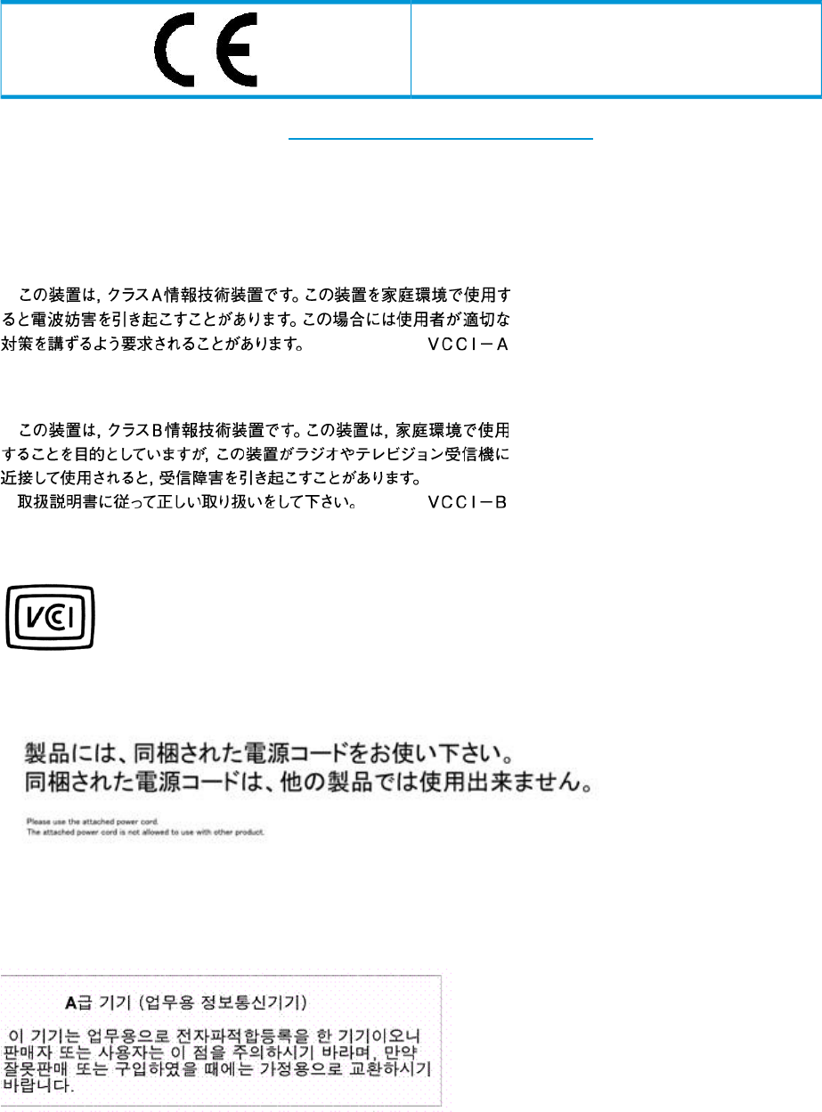
This compliance is indicated by the following conformity marking placed on the product:
This marking is valid for non-Telecom products and EU
harmonized Telecom products (e.g., Bluetooth).
Certificates can be obtained from http://www.hp.com/go/certificates.
Hewlett-Packard GmbH, HQ-TRE, Herrenberger Strasse 140, 71034 Boeblingen, Germany
Japanese notices
Japanese VCCI-A notice
Japanese VCCI-B notice
Japanese VCCI marking
Japanese power cord statement
Korean notices
Class A equipment
202 Regulatory compliance notices
Class B equipment
Taiwanese notices
BSMI Class A notice
Taiwan battery recycle statement
Turkish recycling notice
Türkiye Cumhuriyeti: EEE Yönetmeliğine Uygundur
Vietnamese Information Technology and Communications compliance
marking
Taiwanese notices 203
Laser compliance notices
English laser notice
This device may contain a laser that is classified as a Class 1 Laser Product in accordance with
U.S. FDA regulations and the IEC 60825-1. The product does not emit hazardous laser radiation.
WARNING! Use of controls or adjustments or performance of procedures other than those
specified herein or in the laser product's installation guide may result in hazardous radiation
exposure. To reduce the risk of exposure to hazardous radiation:
•Do not try to open the module enclosure. There are no user-serviceable components inside.
•Do not operate controls, make adjustments, or perform procedures to the laser device other
than those specified herein.
•Allow only HP Authorized Service technicians to repair the unit.
The Center for Devices and Radiological Health (CDRH) of the U.S. Food and Drug Administration
implemented regulations for laser products on August 2, 1976. These regulations apply to laser
products manufactured from August 1, 1976. Compliance is mandatory for products marketed in
the United States.
Dutch laser notice
French laser notice
204 Regulatory compliance notices
German laser notice
Italian laser notice
Japanese laser notice
Laser compliance notices 205

Spanish laser notice
Recycling notices
English recycling notice
Disposal of waste equipment by users in private household in the European Union
This symbol means do not dispose of your product with your other household waste. Instead, you should
protect human health and the environment by handing over your waste equipment to a designated
collection point for the recycling of waste electrical and electronic equipment. For more information,
please contact your household waste disposal service
Bulgarian recycling notice
Изхвърляне на отпадъчно оборудване от потребители в частни домакинства в Европейския
съюз
Този символ върху продукта или опаковката му показва, че продуктът не трябва да се изхвърля заедно
с другите битови отпадъци. Вместо това, трябва да предпазите човешкото здраве и околната среда,
като предадете отпадъчното оборудване в предназначен за събирането му пункт за рециклиране на
неизползваемо електрическо и електронно борудване. За допълнителна информация се свържете с
фирмата по чистота, чиито услуги използвате.
Czech recycling notice
Likvidace zařízení v domácnostech v Evropské unii
Tento symbol znamená, že nesmíte tento produkt likvidovat spolu s jiným domovním odpadem. Místo
toho byste měli chránit lidské zdraví a životní prostředí tím, že jej předáte na k tomu určené sběrné
pracoviště, kde se zabývají recyklací elektrického a elektronického vybavení. Pro více informací kontaktujte
společnost zabývající se sběrem a svozem domovního odpadu.
Danish recycling notice
Bortskaffelse af brugt udstyr hos brugere i private hjem i EU
Dette symbol betyder, at produktet ikke må bortskaffes sammen med andet husholdningsaffald. Du skal
i stedet den menneskelige sundhed og miljøet ved at afl evere dit brugte udstyr på et dertil beregnet
indsamlingssted for af brugt, elektrisk og elektronisk udstyr. Kontakt nærmeste renovationsafdeling for
yderligere oplysninger.
206 Regulatory compliance notices

Dutch recycling notice
Inzameling van afgedankte apparatuur van particuliere huishoudens in de Europese Unie
Dit symbool betekent dat het product niet mag worden gedeponeerd bij het overige huishoudelijke afval.
Bescherm de gezondheid en het milieu door afgedankte apparatuur in te leveren bij een hiervoor bestemd
inzamelpunt voor recycling van afgedankte elektrische en elektronische apparatuur. Neem voor meer
informatie contact op met uw gemeentereinigingsdienst.
Estonian recycling notice
Äravisatavate seadmete likvideerimine Euroopa Liidu eramajapidamistes
See märk näitab, et seadet ei tohi visata olmeprügi hulka. Inimeste tervise ja keskkonna säästmise nimel
tuleb äravisatav toode tuua elektriliste ja elektrooniliste seadmete käitlemisega egelevasse kogumispunkti.
Küsimuste korral pöörduge kohaliku prügikäitlusettevõtte poole.
Finnish recycling notice
Kotitalousjätteiden hävittäminen Euroopan unionin alueella
Tämä symboli merkitsee, että laitetta ei saa hävittää muiden kotitalousjätteiden mukana. Sen sijaan sinun
on suojattava ihmisten terveyttä ja ympäristöä toimittamalla käytöstä poistettu laite sähkö- tai
elektroniikkajätteen kierrätyspisteeseen. Lisätietoja saat jätehuoltoyhtiöltä.
French recycling notice
Mise au rebut d'équipement par les utilisateurs privés dans l'Union Européenne
Ce symbole indique que vous ne devez pas jeter votre produit avec les ordures ménagères. Il est de
votre responsabilité de protéger la santé et l'environnement et de vous débarrasser de votre équipement
en le remettant à une déchetterie effectuant le recyclage des équipements électriques et électroniques.
Pour de plus amples informations, prenez contact avec votre service d'élimination des ordures ménagères.
German recycling notice
Entsorgung von Altgeräten von Benutzern in privaten Haushalten in der EU
Dieses Symbol besagt, dass dieses Produkt nicht mit dem Haushaltsmüll entsorgt werden darf. Zum
Schutze der Gesundheit und der Umwelt sollten Sie stattdessen Ihre Altgeräte zur Entsorgung einer dafür
vorgesehenen Recyclingstelle für elektrische und elektronische Geräte übergeben. Weitere Informationen
erhalten Sie von Ihrem Entsorgungsunternehmen für Hausmüll.
Greek recycling notice
Απόρριψη άχρηοτου εξοπλισμού από ιδιώτες χρήστες στην Ευρωπαϊκή Ένωση
Αυτό το σύμβολο σημαίνει ότι δεν πρέπει να απορρίψετε το προϊόν με τα λοιπά οικιακά απορρίμματα.
Αντίθετα, πρέπει να προστατέψετε την ανθρώπινη υγεία και το περιβάλλον παραδίδοντας τον άχρηστο
εξοπλισμό σας σε εξουσιοδοτημένο σημείο συλλογής για την ανακύκλωση άχρηστου ηλεκτρικού και
ηλεκτρονικού εξοπλισμού. Για περισσότερες πληροφορίες, επικοινωνήστε με την υπηρεσία απόρριψης
απορριμμάτων της περιοχής σας.
Recycling notices 207

Hungarian recycling notice
A hulladék anyagok megsemmisítése az Európai Unió háztartásaiban
Ez a szimbólum azt jelzi, hogy a készüléket nem szabad a háztartási hulladékkal együtt kidobni. Ehelyett
a leselejtezett berendezéseknek az elektromos vagy elektronikus hulladék átvételére kijelölt helyen történő
beszolgáltatásával megóvja az emberi egészséget és a környezetet.További információt a helyi
köztisztasági vállalattól kaphat.
Italian recycling notice
Smaltimento di apparecchiature usate da parte di utenti privati nell'Unione Europea
Questo simbolo avvisa di non smaltire il prodotto con i normali rifi uti domestici. Rispettare la salute
umana e l'ambiente conferendo l'apparecchiatura dismessa a un centro di raccolta designato per il
riciclo di apparecchiature elettroniche ed elettriche. Per ulteriori informazioni, rivolgersi al servizio per
lo smaltimento dei rifi uti domestici.
Latvian recycling notice
Europos Sąjungos namų ūkio vartotojų įrangos atliekų šalinimas
Šis simbolis nurodo, kad gaminio negalima išmesti kartu su kitomis buitinėmis atliekomis. Kad
apsaugotumėte žmonių sveikatą ir aplinką, pasenusią nenaudojamą įrangą turite nuvežti į elektrinių ir
elektroninių atliekų surinkimo punktą. Daugiau informacijos teiraukitės buitinių atliekų surinkimo tarnybos.
Lithuanian recycling notice
Nolietotu iekārtu iznīcināšanas noteikumi lietotājiem Eiropas Savienības privātajās mājsaimniecībās
Šis simbols norāda, ka ierīci nedrīkst utilizēt kopā ar citiem mājsaimniecības atkritumiem. Jums jārūpējas
par cilvēku veselības un vides aizsardzību, nododot lietoto aprīkojumu otrreizējai pārstrādei īpašā lietotu
elektrisko un elektronisko ierīču savākšanas punktā. Lai iegūtu plašāku informāciju, lūdzu, sazinieties ar
savu mājsaimniecības atkritumu likvidēšanas dienestu.
Polish recycling notice
Utylizacja zużytego sprzętu przez użytkowników w prywatnych gospodarstwach domowych w
krajach Unii Europejskiej
Ten symbol oznacza, że nie wolno wyrzucać produktu wraz z innymi domowymi odpadkami.
Obowiązkiem użytkownika jest ochrona zdrowa ludzkiego i środowiska przez przekazanie zużytego
sprzętu do wyznaczonego punktu zajmującego się recyklingiem odpadów powstałych ze sprzętu
elektrycznego i elektronicznego. Więcej informacji można uzyskać od lokalnej firmy zajmującej wywozem
nieczystości.
208 Regulatory compliance notices

Portuguese recycling notice
Descarte de equipamentos usados por utilizadores domésticos na União Europeia
Este símbolo indica que não deve descartar o seu produto juntamente com os outros lixos domiciliares.
Ao invés disso, deve proteger a saúde humana e o meio ambiente levando o seu equipamento para
descarte em um ponto de recolha destinado à reciclagem de resíduos de equipamentos eléctricos e
electrónicos. Para obter mais informações, contacte o seu serviço de tratamento de resíduos domésticos.
Romanian recycling notice
Casarea echipamentului uzat de către utilizatorii casnici din Uniunea Europeană
Acest simbol înseamnă să nu se arunce produsul cu alte deşeuri menajere. În schimb, trebuie să protejaţi
sănătatea umană şi mediul predând echipamentul uzat la un punct de colectare desemnat pentru reciclarea
echipamentelor electrice şi electronice uzate. Pentru informaţii suplimentare, vă rugăm să contactaţi
serviciul de eliminare a deşeurilor menajere local.
Slovak recycling notice
Likvidácia vyradených zariadení používateľmi v domácnostiach v Európskej únii
Tento symbol znamená, že tento produkt sa nemá likvidovať s ostatným domovým odpadom. Namiesto
toho by ste mali chrániť ľudské zdravie a životné prostredie odovzdaním odpadového zariadenia na
zbernom mieste, ktoré je určené na recykláciu odpadových elektrických a elektronických zariadení.
Ďalšie informácie získate od spoločnosti zaoberajúcej sa likvidáciou domového odpadu.
Spanish recycling notice
Eliminación de los equipos que ya no se utilizan en entornos domésticos de la Unión Europea
Este símbolo indica que este producto no debe eliminarse con los residuos domésticos. En lugar de ello,
debe evitar causar daños a la salud de las personas y al medio ambiente llevando los equipos que no
utilice a un punto de recogida designado para el reciclaje de equipos eléctricos y electrónicos que ya
no se utilizan. Para obtener más información, póngase en contacto con el servicio de recogida de
residuos domésticos.
Swedish recycling notice
Hantering av elektroniskt avfall för hemanvändare inom EU
Den här symbolen innebär att du inte ska kasta din produkt i hushållsavfallet. Värna i stället om natur
och miljö genom att lämna in uttjänt utrustning på anvisad insamlingsplats. Allt elektriskt och elektroniskt
avfall går sedan vidare till återvinning. Kontakta ditt återvinningsföretag för mer information.
Recycling notices 209
Battery replacement notices
Dutch battery notice
French battery notice
210 Regulatory compliance notices
German battery notice
Italian battery notice
Battery replacement notices 211
Japanese battery notice
Spanish battery notice
212 Regulatory compliance notices
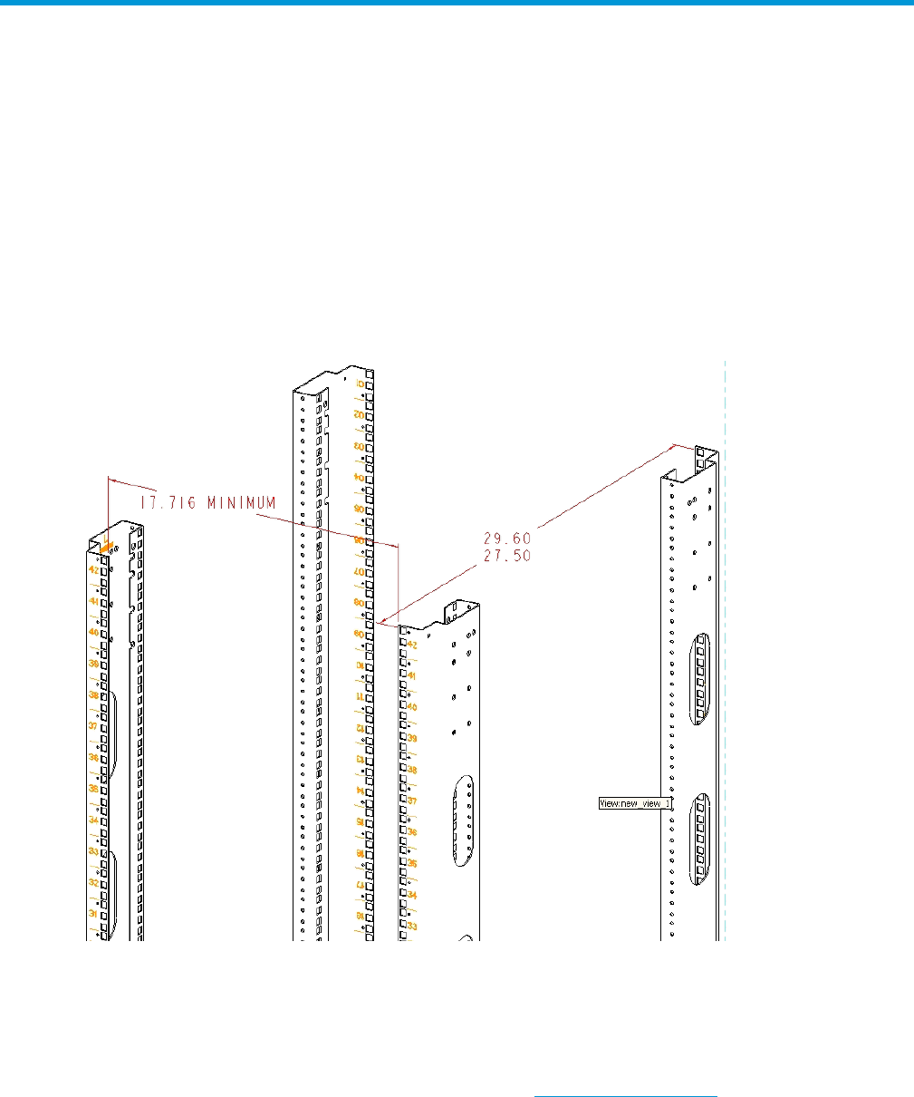
B Non-standard rack specifications
The appendix provides information on the requirements when installing the P63x0/P65x0 EVA in
a non-standard rack. All the requirements must be met to ensure proper operation of the storage
system.
Internal component envelope
EVA component mounting brackets require space to be mounted behind the vertical mounting rails.
Room for the mounting of the brackets includes the width of the mounting rails and needed room
for any mounting hardware, such as screws, clip nuts, etc. Figure 92 (page 213) shows the
dimensions required for the mounting space for the EVA product line. It does not show required
space for additional HP components such as servers.
Figure 92 Mounting space dimensions
EIA310-D standards
The rack must meet the Electronic Industries Association, (EIA), Standard 310-D, Cabinets, Racks
and Associated Equipment. The standard defines rack mount spacing and component dimensions
specified in U units.
Copies of the standard are available for purchase at http://www.eia.org/.
EVA cabinet measures and tolerances
EVA component rack mount brackets are designed to fit cabinets with mounting rails set at depths
from 27.5 inches to 29.6 inches, inside rails to inside rails.
Internal component envelope 213

Weights, dimensions and component CG measurements
Cabinet CG dimensions are reported as measured from the inside bottom of the cabinet (Z), the
leading edge of the vertical mounting rails (Y), and the centerline of the cabinet mounting space
(X). Component CG measurements are measured from the bottom of the U space the component
is to occupy (Z), the mounting surface of the mounting flanges (Y), and the centerline of the
component (X).
Determining the CG of a configuration may be necessary for safety considerations. CG
considerations for CG calculations do not include cables, PDU’s and other peripheral components.
Some consideration should be made to allow for some margin of safety when estimating
configuration CG.
Estimating the configuration CG requires measuring the CG of the cabinet the product will be
installed in. Use the following formula:
ΣdcomponentW = dsystem cgW
where dcomponent= the distance of interest and W = Weight
The distance of a component is its CG’s distance from the inside base of the cabinet. For example,
if a loaded disk enclosure is to be installed into the cabinet with its bottom at 10U, the distance
for the enclosure would be (10*1.75)+2.7 inches.
Airflow and Recirculation
Component Airflow Requirements
Component airflow must be directed from the front of the cabinet to the rear. Components vented
to discharge airflow from the sides must discharge to the rear of the cabinet.
Rack Airflow Requirements
The following requirements must be met to ensure adequate airflow and to prevent damage to the
equipment:
•If the rack includes closing front and rear doors, allow 830 square inches (5,350 sq cm) of
hole evenly distributed from top to bottom to permit adequate airflow (equivalent to the required
64 percent open area for ventilation).
•For side vented components, the clearance between the installed rack component and the
side panels of the rack must be a minimum of 2.75 inches (7 cm).
•Always use blanking panels to fill all empty front panel U-spaces in the rack. This ensures
proper airflow. Using a rack without blanking panels results in improper cooling that can lead
to thermal damage.
Configuration Standards
EVA configurations are designed considering cable length, configuration CG, serviceability and
accessibility, and to allow for easy expansion of the system. If at all possible, it is best to configure
non HP cabinets in a like manner.
UPS Selection
This section provides information that can be used when selecting a UPS for use with the EVA. The
four HP UPS products listed in Table 29 (page 215) are available for use with the EVA and are
included in this comparison. Table 30 (page 215) identifies the amount of time each UPS can sustain
power under varying loads and with various UPS ERM (Extended Runtime Module) options.
NOTE: The specified power requirements reflect fully loaded enclosures (14 disks).
214 Non-standard rack specifications

Table 29 HP UPS models and capacities
Capacity (in watts)UPS Model
1340R1500
2700R3000
4500R5500
12000R12000
Table 30 UPS operating time limits
Minutes of operation
Load (percent) With 2 ERMsWith 1 ERMWith standby battery
R1500
49235100
6332680
161571350
2901463420
R3000
205100
306.580
451250
1204020
R5500
46247100
6031980
106611950
3031695920
R12000
18115100
2415780
41281450
101694320
Shock and vibration specifications
Table 31 (page 216) lists the product operating shock and vibration specifications. This information
applies to products weighing 45 Kg (100 lbs) or less.
NOTE: HP EVA products are designed and tested to withstand the operational shock and vibration
limits specified in Table 31 (page 216). Transmission of site vibrations through non-HP racks
exceeding these limits could cause operational failures of the system components.
Shock and vibration specifications 215

Table 31 Operating Shock/Vibration
Shock test with half sine pulses of 10 G magnitude and 10 ms duration applied in all three axes (both positive and
negative directions).
Sine sweep vibration from 5 Hz to 500 Hz to 5 Hz at 0.1 G peak, with 0.020” displacement limitation below 10
Hz. Sweep rate of 1 octave/minute. Test performed in all three axes.
Random vibration at 0.25 G rms level with uniform spectrum in the frequency range of 10 to 500 Hz. Test performed
for two minutes each in all three axes.
Drives and other items exercised and monitored running appropriate exerciser (UIOX, P-Suite, etc.) with appropriate
operating system and hardware.
216 Non-standard rack specifications

C Command reference
This chapter lists and describes the P6000 iSCSI and iSCSI/FCoE module's CLI commands in
alphabetical order. Each command description includes its syntax, keywords, notes, and examples.
Command syntax
The HP P6000 iSCSI or iSCSI/FCoE module's CLI command syntax uses the following format:
keywordCommand
keyword [value]
keyword [value1] [value2]
The command is followed by one or more keywords. Consider the following rules and conventions:
•Commands and keywords are case insensitive.
•Required keyword values appear in standard font within brackets; for example, [value].
•Optional keyword values appear in italics within brackets; for example, [value].
•In command prompts, <1> or <2> indicates which module, 01 or 02, is being managed.
Command line completion
The command line completion feature makes entering and repeating commands easier.
Table 32 (page 217) describes the command line completion keystrokes.
Table 32 Command line completion keystrokes
DescriptionKeystroke
Completes the command line. Enter at least one character and press the TAB key to complete
the command line. If more than one possibility exists, press the TAB key again to display
all possibilities.
TAB
Scrolls backward through the list of previously entered commands.UP ARROW
Scrolls forward through the list of previously entered commands.DOWN ARROW
Moves the cursor to the beginning of the command line.CTRL+A
Moves the cursor to the end of the command line.CTRL+B
Authority requirements
The various set commands perform tasks that may require you to be in an administrator session.
Note that:
•Commands related to monitoring tasks are available to all account names.
•Commands related to configuration tasks are available only within an Admin session. An
account must have admin authority to enter the admin start command, which opens an admin
session (see admin command).
Commands
This section lists and describes the HP P6000 iSCSI and iSCSI/FCoE module's CLI commands in
alphabetical order. Each command description includes its syntax, keywords, notes, and examples.
Command syntax 217

Admin
Opens and closes an administrator (admin) session. Any command that changes the iSCSI or
iSCSI/FCoE module's configuration must be entered in an Admin session. An inactive Admin
session times out after 15 minutes.
Admin sessionAuthority
start (or begin)
end (or stop)
cancel
adminSyntax
Opens the Admin session.start (or begin)Keywords
Closes the Admin session. The logout, shutdown, and reset
commands also end an Admin session.
end (or stop)
Terminates an Admin session opened by another user. Use this
keyword with care because it terminates the Admin session without
warning the other user and without saving pending changes.
cancel
NOTE: Closing a Telnet window during an Admin session does not release the session. When
using Telnet, you must either wait for the Admin session to time out, or use the admin cancel
command.
Example: The following example shows how to open and close an Admin session:
MEZ50 <1>#> admin start
Password : config
MEZ50 <1> (admin) #>
.
.
.
MEZ50 <1> (admin) #> admin end
MEZ50 <1> #>
Beacon
Enables or disables the flashing of the blue UID beacon LED.
NoneAuthority
on
off
beaconSyntax
Turns on the flashing of the controller blue UID beacon.onKeywords
Turns off the flashing of the controller blue UID beacon.off
Example: The following example turns the controller blue UID beacon on and then off.
MEZ50 <1>#> beacon on
MEZ50 <1#> beacon off
Clear
Removes all entries (events) from the iSCSI or iSCSI/FCoE module's log file or resets the FC and
iSCSI statistic counters.
Admin sessionAuthority
logs
stats
clearSyntax
218 Command reference

Clears all entries from the module's log file.logsKeywords
Resets the statistic counters.stats
Examples: The following examples show the clear commands:
MEZ50 <1>(admin) #> clear logs
MEZ50 <1>(admin) #> clear stats
Date
Displays or sets the date and time. To set the date and time, you must enter the information in the
format MMDDhhmmCCYY (numeric representation of month-date-hour-minute-century-year). The new
date and time takes effect immediately. Each module has its own independent date set. Properly
setting the date ensures that event log entries are dated correctly. The date must be set prior to
applying any feature keys or licenses.
Admin session required to set the date and time. No authority is required to display the
current date and time.
Authority
[MMDDhhmmCCYY]
dateSyntax
Specifies the date, which requires an Admin session. If you omit
[MMDDhhmmCCYY], the command displays the current date,
which does not require an Admin session.
[MMDDhhmmCCYY]Keywords
NOTE: Always set the time using Greenwich Mean Time (GMT) and Universal Transverse Mercator
(UTM). You must disable the network time protocol (NTP) to set the time with the date command.
Examples: The following examples show the setting and then the display of the date:
MEZ50_02 (admin) #> date
Tue May 24 18:33:41 UTC 2011
MEZ50_02 (admin) #> date ?
Please enter time in Universal (UTC) timezone.
Note that Universal (UTC) time may not be the same as your local time.
Usage: date [<MMDDhhmmCCYY>]
MEZ50_02 (admin) #> date 052513272011
Wed May 25 13:27:00 UTC 2011
MEZ50_02 (admin) #>
Exit
Exits the command line interface and returns you to the login prompt (same as the quit command).
NoneAuthority
exitSyntax
Example 1: The exit command logs the session out. The following example shows the exit
command:
MEZ50 #>exit
Connection to host lost.
Commands 219

FRU
Saves and restores the module’s configuration.
Admin session to restoreAuthority
restore
save
FRUSyntax
The fru restore command requires that you first FTP the tar
file containing the configuration to the module. When you issue
restoreKeywords
this command, the system prompts you to enter the restore level.
You can fully restore the module’s configuration (all configuration
parameters and LUN mappings) or restore only the LUN mappings.
The restored configuration does not take effect until the module is
rebooted.
Creates a tar file containing the module’s persistent data,
configuration, and LUN mappings. The file is stored in the module’s
/var/ftp directory. You must then FTP the tar file from the module.
save
Example1: The following is an example of the fru restore command:
MEZ50 <1>(admin) #> fru restore
A list of attributes with formatting and current values will
follow. Enter a new value or simply press the ENTER key to accept
the current value. If you wish to terminate this process before
reaching the end of the list press 'q' or 'Q' and the ENTER key to
do so.
Type of restore (0=full, 1=mappings only) [full]
FRU restore completed.
Please reboot the system for configuration to take affect.
Example 2: The following is an example of the fru save command:
MEZ50 <1>(admin) #> fru save
FRU save completed. Configuration File is HP_StorageWorks_MEZnn_FRU.bin
Please use FTP to extract the file out from the System.
Help
Displays a list of the commands and their syntax using the basic help command for iSCSI and
iSCSI/FCoE modules:
MEZ50 <1>#> help
iSCSI/FCoE module CLI command qualifieriSCSI module CLI command qualifierCLI command
[ begin | end | start | stop |
cancel ]
[ begin | end | start | stop |
cancel ]
admin
[ on | off ][ on | off ]
beacon
<MMDDhhmmCCYY><MMDDhhmmCCYY>
date
[ logs | stats ][ logs | stats ]
clear
exit
[ restore | save ][ restore | save ]
fru
help
history
[ cleanup | list | unpack ]
image cleanup
[ cleanup | list | unpack ]
image cleanup
image
220 Command reference

iSCSI/FCoE module CLI command qualifieriSCSI module CLI command qualifierCLI command
image list
image unpack [ ]
image list
image unpack [ ]
[ add | mod | rm ][ add | mod | rm ]
initiator
logout
[ add | rm ][ add | rm ]
lunmask
passwd
ping
quit
reboot
[ factory | mappings ][ factory | mappings ]
reset
[ capture | logs | traces ][ capture | logs | traces ]
save
[ alias | chap | chassis | fc |
features | iscsi | isns | mgmt | ntp
[ alias | chap | fc |
features | iscsi | isns | mgmt
set
| properties | snmp | system|
| ntp | vpgroups ]
properties | snmp | system ] set alias
set alias set chap
set chap set fc [ <PORT_NUM> ]
set fc [ <PORT_NUM> ] set isns
set isns set mgmt
set mgmt set ntp
set properties
set ntp set snmp [trap_destinations [
set properties <DEST_NUM> ]]
set snmp [trap_destinations set system
set vpgroups [vpgroup index]
[
<DEST_NUM> ]]
set system
[ chap | chassi | fc | features|
feature_keys | initiators | iostats |
[ chap | fc | features |
initiators | initiators_lunmask | iscsi | isns
show
iscsi | isns | logs | luninfo | luns| | logs | luninfo | luns | lunmask |
memory | mgmt | ntp | perf |memory | mgmt | ntp | perf |
presented_initiators | presented_targets | presented_targets |
properties | snmp|properties | snmp | stats | system |
stats | system | targets | vpgroups ]targets ]
show chap show chap
show fc [ <PORT_NUM> ] show fc [ <PORT_NUM> ]
show features show features
show feature_keys show initiators [ fc | iscsi ]
show initiators [ fc | iscsi ] show initiators_lunmask
show iscsi [ <PORT_NUM > show iscsi [ <PORT_NUM> ]
show isns show isns
show logs [ <ENTRIES> ] show logs [ <ENTRIES>
show luninfo show luninfo
show luns show luns
show memory show lunmask
show mgmt show memory
show ntp show mgmt
show perf [ byte | init_rbyte | init_wbyte | show ntp
tgt_rbyte | tgt_wbyte ] show perf [ byte | init_rbyte | init_wbyte
show presented_initiators [ fc | iscsi ]| tgt_rbyte | tgt_wbyte ]
show presented_targets [ fc | iscsi ] show presented_targets [ fc | iscsi ]
show properties show properties
show rpcinfo show snmp
show snmp show stats
show stats show system
show targets [ fc | iscsi ] show system
show targets [ fc | iscsi ]
show vpgroups [vpgroup index]
shutdown
[rm ][rm ]
target
[ add | rm ][ add | rm ]
targetmap
Commands 221

iSCSI/FCoE module CLI command qualifieriSCSI module CLI command qualifierCLI command
traceroute
iSCSI Server Connectivity Command
Set:
========================================
lunmask [ add | rm ]
show [initiators_lunmask | lunmask
]
show initiators_lunmask
show lunmask
History
Displays a numbered list of the previously entered commands.
NoneAuthority
historySyntax
Example: :
MEZ50_02 (admin) #> history
1: save capture
2: admin start
3: admin start
4: save logs
5: save fru
6: fru save
7: save traces
8: save capture
9: image list
10: show system
11: show mgmt
12: history
13: history
MEZ50_02 (admin) #>
Image
Updates the iSCSI or iSCSI/FCoE module's firmware image and cleans up (removes) the image
files in the module’s /var/ftp directory.
Admin sessionAuthority
cleanup
list [file]
unpack [file]
imageSyntax
Removes all firmware image files in the module’s /var/ftp
directory. These are files transferred by the user when updating the
module’s firmware image.
cleanupKeywords
Displays a list of the firmware image files in the module’s /var/
ftp directory.
list [file]
Unpacks the firmware image file specified in the [file] parameter
and installs the firmware image on the module. Before using this
upack [file]
command, you must first transfer the firmware image file to the
module’s /var/ftp directory using FTP. To activate the new
firmware, you must reboot the module.
222 Command reference
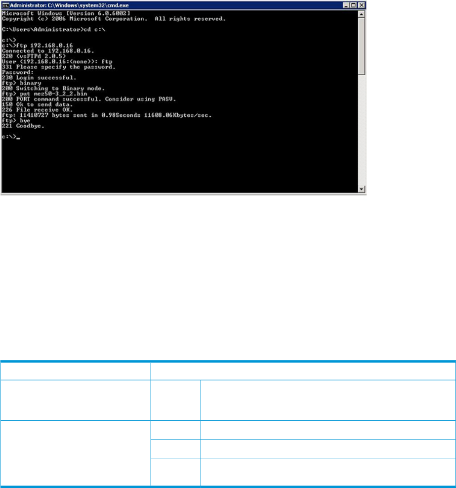
Example 1:
MEZ50_02 (admin) #> image cleanup
MEZ50_02 (admin) #> image list
No images found in system.
Example 2:
MEZ50_02 (admin) #> image list
mez50-3_0_4_1.bin
Only the file name is displayed as a response to this command.
The software image file is placed using ftp to the iSCSI or iSCSI/FCoE module as shown in Figure 93
(page 223).
Figure 93 FTP to iSCSI or iSCSI/FCoE module
Example 3:
MEZ50_02 (admin) #> image unpack
Usage: image unpack [ <file> ]
MEZ50_02 (admin) #> image unpack mez50-3_0_4_1.bin
Unpack Completed. A reboot is required for the FW to take affect.
Do you wish to reboot the System at the current time (y/n): y
System will now be rebooted...
MEZ50_02 #>
Initiator
Adds, modifies, and removes an initiator in the module’s database.
Admin sessionAuthority
add
mod
remove
initiatorSyntax
Adds an initiator to the module’s database.addKeywords
Modifies the settings of an initiator.mod
Removes a logged out initiator. You cannot remove an initiator
that is currently logged in.
remove
Example 1:
MEZ50 (admin) #> initiator add
A list of attributes with formatting and current values will follow.
Enter a new value or simply press the ENTER key to accept the current value.
If you wish to terminate this process before reaching the end of the list press 'q' or 'Q' and the ENTER key
Commands 223
to do so.
Only valid iSCSI name characters will be accepted. Valid characters include lower-case alphabetical (a-z),
numerical (0-9), colon, hyphen, and period.
iSCSI Initiator Name (Max = 223 characters) [ ]iqn.1995.com.microsoft:server1
OS Type (0=Windows, 1=Linux, 2=Solaris,
3=OpenVMS, 4=VMWare, 5=Mac OS X,
6=Windows2008, 7=Windows2012, 8=Other) [Windows ] 6
All attribute values that have been changed will now be saved.
Example 2:
MEZ50 (admin) #> initiator mod
Index (WWNN,WWPN/iSCSI Name)
----- ----------------------
0 iqn.1991-05.com.microsoft:perf2.sanbox.com
1 iqn.1991-05.com.microsoft:perf3.sanbox.com
2 iqn.1991-05.com.microsoft:perf10.sanbox.com
3 iqn.1995.com.microsoft:server1
Please select an Initiator from the list above ('q' to quit): 3
A list of attributes with formatting and current values will follow.
Enter a new value or simply press the ENTER key to accept the current value.
If you wish to terminate this process before reaching the end of the list
press 'q' or 'Q' and the ENTER key to do so.
OS Type (0=Windows, 1=Linux, 2=Solaris,
3=OpenVMS, 4=VMWare, 5=Mac OS X,
6=Windows2008, 7=Windows2012,8=Other) [Windows2008 ] 6
All attribute values that have been changed will now be saved.
Example 3:
MEZ50 (admin) #> initiator rm
Warning: This command will cause the removal of all mappings and maskings
associated with the initiator that is selected. All connections
involving the selected initiator will be dropped.
Index Status (WWNN,WWPN/iSCSI Name)
----- ------ ----------------------
0 LoggedIn iqn.1991-05.com.microsoft:perf2.sanbox.com
1 LoggedIn iqn.1991-05.com.microsoft:perf3.sanbox.com
2 LoggedIn iqn.1991-05.com.microsoft:perf10.sanbox.com
3 LoggedOut iqn.1995.com.microsoft:server1
Please select a 'LoggedOut' Initiator from the list above ('q' to quit): 3
All attribute values that have been changed will now be saved.
Example 4:
MEZ75 (admin) #> initiator mod
Index Type (WWNN,WWPN/iSCSI Name)
----- ----- ----------------------
0 FCOE 20:00:00:c0:dd:10:f7:0d,21:00:00:c0:dd:10:f7:0d
1 FCOE 20:00:00:c0:dd:10:f7:0f,21:00:00:c0:dd:10:f7:0f
2 FCOE 20:00:00:c0:dd:18:dc:53,21:00:00:c0:dd:18:dc:53
3 FCOE 20:00:00:c0:dd:18:dc:54,21:00:00:c0:dd:18:dc:54
4 FCOE 20:00:00:c0:dd:18:dc:5d,21:00:00:c0:dd:18:dc:5d
5 FCOE 20:00:00:c0:dd:18:dc:5e,21:00:00:c0:dd:18:dc:5e
6 FCOE 20:00:00:00:c9:95:b5:77,10:00:00:00:c9:95:b5:77
7 FCOE 20:00:00:00:c9:95:b5:73,10:00:00:00:c9:95:b5:73
8 FCOE 20:00:f4:ce:46:fb:0a:4b,21:00:f4:ce:46:fb:0a:4b
9 FCOE 20:00:f4:ce:46:fe:62:69,10:00:f4:ce:46:fe:62:69
10 FCOE 20:00:f4:ce:46:fe:62:6d,10:00:f4:ce:46:fe:62:6d
11 FCOE 20:00:f4:ce:46:fb:0a:4c,21:00:f4:ce:46:fb:0a:4c
12 FCOE 20:01:00:00:ab:cd:20:88,20:01:00:00:12:3a:45:68
13 FCOE 20:01:00:00:2a:8f:2a:50,20:01:00:00:a5:a5:ff:f8
14 ISCSI iqn.1995.com.microsoft:server1
Please select an Initiator from the list above ('q' to quit): 14
A list of attributes with formatting and current values will follow.
Enter a new value or simply press the ENTER key to accept the current value.
If you wish to terminate this process before reaching the end of the list
press 'q' or 'Q' and the ENTER key to do so.
OS Type (0=Windows, 1=Linux, 2=Solaris,
3=OpenVMS, 4=VMWare, 5=Mac OS X,
6=Windows2008, 7=Windows2012 8=HP-UX, 9=AIX,
10=Other) [Windows2008 ] 6
All attribute values that have been changed will now be saved.
224 Command reference

Logout
Exits the command line interface and returns you to the login prompt.
NoneAuthority
logoutSyntax
Example:
MEZ50 <1>(admin) #> logout
(none) login:
Lunmask
Maps a target LUN to an initiator, and also removes mappings. The CLI prompts you to select from
a list of virtual port groups, targets, LUNs, and initiators.
Admin sessionAuthority
add
remove
lunmaskSyntax
Maps a LUN to an initiator. After you enter the command, the CLI
displays a series of prompts from which you choose the initiator,
target, and LUN from lists of existing devices.
addKeywords
Removes the mapping of a LUN from an initiator. After you enter
the command, the CLI displays a series of prompts from which
remove
you choose the initiator, target, and LUN from lists of existing
devices.
Example 1: The following example shows the lunmask add command.
MEZ50 (admin) #> lunmask add
Index Mapped (WWNN,WWPN/iSCSI Name)
----- ------ ----------------------
0 Yes iqn.1991-05.com.microsoft:perf2.sanbox.com
1 Yes iqn.1991-05.com.microsoft:perf3.sanbox.com
2 Yes iqn.1991-05.com.microsoft:perf10.sanbox.com
Please select an Initiator from the list above ('q' to quit): 1
Index (WWNN,WWPN/iSCSI Name)
----- ----------------------
0 50:01:43:80:02:5d:a5:30,50:01:43:80:02:5d:a5:38
1 50:01:43:80:02:5d:a5:30,50:01:43:80:02:5d:a5:3c
Please select a Target from the list above ('q' to quit): 0
LUN
----
0
1
2
3
4
5
6
7
8
9
10
11
Commands 225
12
13
Please select a LUN to present to the initiator ('q' to quit): 12
All attribute values that have been changed will now be saved.
MEZ50 (admin) #> lunmask rm
Index (WWNN,WWPN/iSCSI Name)
----- ----------------------
0 50:01:43:80:02:5d:a5:30,50:01:43:80:02:5d:a5:38
1 50:01:43:80:02:5d:a5:30,50:01:43:80:02:5d:a5:3c
Please select a Target from the list above ('q' to quit): 0
LUN
----
0
1
2
3
4
5
6
7
8
9
10
11
12
13
Please select a LUN presented to the initiator ('q' to quit): 12
Index Initiator
----- -----------------
0 iqn.1991-05.com.microsoft:perf3.sanbox.com
Please select an Initiator to remove ('a' to remove all, 'q' to quit): 0
All attribute values that have been changed will now be saved.
Example 2: The following shows an example of the lunmask add command with virtual port
groups.
MEZ75 (admin) #> lunmask add
Index Type Mapped (WWNN,WWPN/iSCSI Name)
----- ---- ------ ----------------------
0 FCOE Yes 20:00:00:c0:dd:10:f7:0d,21:00:00:c0:dd:10:f7:0d
1 FCOE Yes 20:00:00:c0:dd:10:f7:0f,21:00:00:c0:dd:10:f7:0f
2 FCOE No 20:00:00:c0:dd:18:dc:53,21:00:00:c0:dd:18:dc:53
3 FCOE No 20:00:00:c0:dd:18:dc:54,21:00:00:c0:dd:18:dc:54
4 FCOE No 20:00:00:c0:dd:18:dc:5d,21:00:00:c0:dd:18:dc:5d
5 FCOE No 20:00:00:c0:dd:18:dc:5e,21:00:00:c0:dd:18:dc:5e
6 FCOE Yes 20:00:00:00:c9:95:b5:77,10:00:00:00:c9:95:b5:77
7 FCOE Yes 20:00:00:00:c9:95:b5:73,10:00:00:00:c9:95:b5:73
8 FCOE No 20:00:f4:ce:46:fb:0a:4b,21:00:f4:ce:46:fb:0a:4b
9 FCOE Yes 20:00:f4:ce:46:fe:62:69,10:00:f4:ce:46:fe:62:69
10 FCOE Yes 20:00:f4:ce:46:fe:62:6d,10:00:f4:ce:46:fe:62:6d
11 FCOE No 20:00:f4:ce:46:fb:0a:4c,21:00:f4:ce:46:fb:0a:4c
Please select an Initiator from the list above ('q' to quit): 10
Index (VpGroup Name)
----- --------------
1 VPGROUP_1
2 VPGROUP_2
226 Command reference
3 VPGROUP_3
4 VPGROUP_4
Multiple VpGroups are currently 'ENABLED'.
Please select a VpGroup from the list above ('q' to quit): 1
Index (WWNN,WWPN/iSCSI Name)
----- ----------------------
0 50:01:43:80:04:c6:89:60,50:01:43:80:04:c6:89:68
1 50:01:43:80:04:c6:89:60,50:01:43:80:04:c6:89:6c
Please select a Target from the list above ('q' to quit): 0
Index (LUN/VpGroup)
----- -------------
0 0/VPGROUP_1
1 1/VPGROUP_1
2 2/VPGROUP_1
3 3/VPGROUP_1
4 4/VPGROUP_1
5 5/VPGROUP_1
6 6/VPGROUP_1
7 7/VPGROUP_1
8 8/VPGROUP_1
9 9/VPGROUP_1
10 10/VPGROUP_1
11 11/VPGROUP_1
12 12/VPGROUP_1
Please select a LUN to present to the initiator ('q' to quit): 12
Index (IP/WWNN) (MAC/WWPN)
----- ----------- ------------
0 20:00:f4:ce:46:fb:0a:43 21:00:f4:ce:46:fb:0a:43
1 20:00:f4:ce:46:fb:0a:44 21:00:f4:ce:46:fb:0a:44
Please select a portal to map the target from the list above ('q' to quit): 0
FC presented target WWPN [50:01:43:80:04:c6:89:68 ] :
Target Device is already mapped on selected portal.
Example 3: The following example shows the lunmask rm (remove) command.
MEZ50 (admin) #> lunmask rm
Index (WWNN,WWPN/iSCSI Name)
----- ----------------------
0 50:01:43:80:02:5d:a5:30,50:01:43:80:02:5d:a5:38
1 50:01:43:80:02:5d:a5:30,50:01:43:80:02:5d:a5:3c
Please select a Target from the list above ('q' to quit): 1
LUN
----
0
1
2
3
4
5
6
7
8
9
10
11
12
13
Please select a LUN presented to the initiator ('q' to quit): 12
Commands 227

Index Initiator
----- -----------------
0 iqn.1991-05.com.microsoft:perf3.sanbox.com
Please select an Initiator to remove ('a' to remove all, 'q' to quit): 0
All attribute values that have been changed will now be saved.
Example 4: The following shows an example of the lunmask rm command with virtual port
groups.
MEZ75 (admin) #> lunmask rm
Index (WWNN,WWPN/iSCSI Name)
----- ----------------------
0 50:01:43:80:04:c6:89:60,50:01:43:80:04:c6:89:68
1 50:01:43:80:04:c6:89:60,50:01:43:80:04:c6:89:6c
Please select a Target from the list above ('q' to quit): 0
Index (VpGroup Name)
----- --------------
1 VPGROUP_1
2 VPGROUP_2
3 VPGROUP_3
4 VPGROUP_4
Multiple VpGroups are currently 'ENABLED'.
Please select a VpGroup from the list above ('q' to quit): 1
Index (LUN/VpGroup)
----- -------------
0 0/VPGROUP_1
1 1/VPGROUP_1
2 2/VPGROUP_1
3 3/VPGROUP_1
4 4/VPGROUP_1
5 5/VPGROUP_1
6 6/VPGROUP_1
7 7/VPGROUP_1
8 8/VPGROUP_1
9 9/VPGROUP_1
10 10/VPGROUP_1
11 11/VPGROUP_1
12 12/VPGROUP_1
Please select a LUN presented to the initiator ('q' to quit): 12
Index Type Initiator
----- ---- -----------------
0 FC 20:00:00:c0:dd:10:f7:0d
1 FC 20:00:00:c0:dd:10:f7:0f
2 FCOE 20:00:f4:ce:46:fe:62:6d
Please select an Initiator to remove ('a' to remove all, 'q' to quit): 2
All attribute values that have been changed will now be saved.
Passwd
Changes the guest and administrator passwords.
Admin sessionAuthority
passwdSyntax
228 Command reference

Example:
MEZ50 <1>(admin) #> passwd
Press 'q' and the ENTER key to abort this command.
Select password to change (0=guest, 1=admin) : 1
account OLD password : ******
account NEW password (6-128 chars) : ******
please confirm account NEW password : ******
Password has been changed.
Ping
Verifies the connectivity of management and GE ports. This command works with both IPv4 and
IPv6.
Admin sessionAuthority
pingSyntax
Example 1: Ping through an iSCSI data port to another iSCSI data port.
MEZ50_02 (admin) #> ping
A list of attributes with formatting and current values will follow.
Enter a new value or simply press the ENTER key to accept the current value.
If you wish to terminate this process before reaching the end of the list
press 'q' or 'Q' and the ENTER key to do so.
IP Address (IPv4 or IPv6) [0.0.0.0] 33.33.52,91
Invalid IP Address.
IP Address (IPv4 or IPv6) [0.0.0.0] 33.33.52.91
Iteration Count (0=Continuously) [0 ] 8
Outbound Port (0=Mgmt, 1=GE1, 2=GE2, ...) [Mgmt ] 1
Size Of Packet (Min=1, Max=1472 Bytes) [56 ]
Pinging 33.33.52.91 with 56 bytes of data:
Reply from 33.33.52.91: bytes=64 time=0.1ms
Reply from 33.33.52.91: bytes=64 time=<0.1ms
Reply from 33.33.52.91: bytes=64 time=<0.1ms
Reply from 33.33.52.91: bytes=64 time=<0.1ms
Reply from 33.33.52.91: bytes=64 time=<0.1ms
Reply from 33.33.52.91: bytes=64 time=<0.1ms
Reply from 33.33.52.91: bytes=64 time=<0.1ms
Reply from 33.33.52.91: bytes=64 time=<0.1ms
Ping Statistics for 33.33.52.91:
Packets: Sent = 8, Received = 8, Lost = 0
Approximate round trip times in milli-seconds:
Minimum = 0.0ms, Maximum = 0.1ms, Average = 0.0ms
Example 2: Ping through the mgmt port to another mgmt port.
MEZ75 (admin) #> ping
A list of attributes with formatting and current values will follow.
Enter a new value or simply press the ENTER key to accept the current value.
If you wish to terminate this process before reaching the end of the list
press 'q' or 'Q' and the ENTER key to do so.
IP Address (IPv4 or IPv6) [0.0.0.0] 10.6.0.194
Iteration Count (0=Continuously) [0 ] 8
Outbound Port (0=Mgmt, 1=GE1, 2=GE2, ...) [Mgmt ] 0
Size Of Packet (Min=1, Max=1472 Bytes) [56 ]
Pinging 10.6.0.194 with 56 bytes of data:
Reply from 10.6.0.194: bytes=56 time=1.3ms
Reply from 10.6.0.194: bytes=56 time=0.1ms
Reply from 10.6.0.194: bytes=56 time=0.1ms
Commands 229

Reply from 10.6.0.194: bytes=56 time=0.1ms
Reply from 10.6.0.194: bytes=56 time=0.1ms
Reply from 10.6.0.194: bytes=56 time=0.1ms
Reply from 10.6.0.194: bytes=56 time=0.1ms
Reply from 10.6.0.194: bytes=56 time=0.1ms
Ping Statistics for 10.6.0.194:
Packets: Sent = 8, Received = 8, Lost = 0
Approximate round trip times in milli-seconds:
Minimum = 0.1ms, Maximum = 1.3ms, Average = 0.2ms
Quit
Exits the command line interface and returns you to the login prompt (same as the exit command).
NoneAuthority
quitSyntax
Example 1:The following example shows the quit command for the iSCSI or iSCSI/FCoE module:
MEZ50 <1>(admin) #> quit
MEZ50 login:
Reboot
Restarts the module firmware.
Admin sessionAuthority
rebootSyntax
Example:
MEZ50 <1>(admin) #> reboot
Are you sure you want to reboot the System (y/n): y
System will now be rebooted...
Reset
Restores the module configuration parameters to the factory default values. The reset factory
command deletes all LUN mappings, as well as all persistent data regarding targets, LUNs, initiators,
virtual port group settings, log files, iSCSI and MGMT IP addresses, FC and Ethernet port statistics,
and passwords. This command also restores the factory default IP addresses. The reset mappings
command clears only the LUN mappings.
Admin sessionAuthority
factory
mappings
resetSyntax
factoryKeywords
mappings
Example 1:
MEZ50 <1>(admin) #> reset factory
Are you sure you want to restore to factory default settings (y/n): y
Please reboot the System for the settings to take affect
Example 2:
MEZ50 <1>(admin) #> reset mappings
Are you sure you want to reset the mappings in the system (y/n): y
Please reboot the System for the settings to take affect.
230 Command reference

Save
Saves logs and traces.
Admin sessionAuthority
capture
logs
traces
saveSyntax
The save capture command creates a debug file that captures
all debug dump data. After the command completes, you must FTP
the debug capture file from the module.
captureKeywords
The save logs command creates a tar file that contains the
module’s log data, storing the file in the module’s /var/ftp
logs
directory. After the command completes, you must FTP the log’s tar
file from the module.
The save traces command creates a tar file that contains the
module’s dump data, storing the tar file in the module’s /var/ftp
traces
directory. After the command completes, you must FTP the trace’s
tar file from the module. After executing this command, the system
notifies you if the module does not have any dump data. Each time
it generates dump data, the system adds an event log entry.
Example 1:
MEZ50 <1>(admin) #> save capture
Debug capture completed. Package is System_Capture.tar.gz
Please use FTP to extract the file out from the System.
Example 2:
MEZ50 <1>(admin) #> save logs
Save Event Logs completed. Package is System_Evl.tar.gz
Please use FTP to extract the file out from the System.
Example 3: Save traces is not supported by the iSCSI or iSCSI/FCoE modules.
MEZ50 (admin) #> save traces
Save ASIC Traces failed.
Set
Configures general iSCSI or iSCSI/FCoE parameters, as well as parameters that are specific to
the FC, iSCSI, and management ports.
iSCSI/FCoE moduleiSCSI moduleCommand
alias
chap
alias
chap
Set
chassisfc [<PORT_NUM>]
fc [<PORT_NUM>]features
featuresiscsi [<PORT_NUM>]
iscsi [<PORT_NUM>]isns
isnsmgmt
mgmtntp
ntpproperties
propertiessnmp [trap_destinations [<DEST_NUM>]]
system snmp [trap_destinations [<DEST_NUM>]]
system
vpgroups [vpgroup index]
Commands 231

Assigns alias name to a presented iSCSI target. See
the “set alias command” (page 232)
aliasKeywords
Sets the CHAP secrets. See the “set CHAP
command” (page 233)
chap
Sets the FC port parameters. “set FC
command” (page 233)
fc [<PORT_NUM>]
Applies license keys to the module. See the “set features
command” (page 234)
features
Sets the iSCSI port parameters. See the “set iSCSI
command” (page 235)
iscsi [<PORT_NUM>]
Sets the Internet simple name service (iSNS) parameters.
See the “set iSNS command” (page 236)
isns
Sets the management port parameters. See the “set
mgmt command” (page 236)
mgmt
Sets the network time protocol (NTP) parameters. See
the “set NTP command” (page 237)
ntp
Configures CLI properties for the module. See the “set
properties command” (page 237)
properties
Sets the simple network management protocol (SNMP)
parameters. Sets system parameters such as symbolic
snmp [trap_destinations
[<DEST_NUM>]] name and log level. See the “set SNMP
command” (page 238)
Sets system parameters such as symbolic name and log
level. See the “set system command” (page 239)
system
Sets virtual port groups (VPGs) on the module. See the
“set VPGroups command” (page 239)
vpgroups [vpgroup index]
Set alias
Allows an alias name to be assigned to a presented iSCSI target.
Admin sessionAuthority
set aliasSyntax
Example:
MEZ50 <2> (admin) #> set alias
A list of attributes with formatting and current values will follow.
Enter a new value or simply press the ENTER key to accept the current value.
If you wish to terminate this process before reaching the end of the list
press 'q' or 'Q' and the ENTER key to do so.
Index (WWNN,WWPN/iSCSI Name)
----- ----------------------
0 iqn.1986-03.com.hp:fcgw.MEZ50.0834e00025.b1.01.50001fe150070ce9
1 iqn.1986-03.com.hp:fcgw.MEZ50.0834e00025.b1.02.50001fe150070ce9
2 iqn.1986-03.com.hp:fcgw.MEZ50.0834e00025.b1.03.50001fe150070ce9
3 iqn.1986-03.com.hp:fcgw.MEZ50.0834e00025.b1.04.50001fe150070ce9
4 iqn.1986-03.com.hp:fcgw.MEZ50.0834e00025.b1.01.50001fe150070cec
5 iqn.1986-03.com.hp:fcgw.MEZ50.0834e00025.b1.02.50001fe150070cec
6 iqn.1986-03.com.hp:fcgw.MEZ50.0834e00025.b1.03.50001fe150070cec
7 iqn.1986-03.com.hp:fcgw.MEZ50.0834e00025.b1.04.50001fe150070cec
Please select a iSCSI node from the list above ('q' to quit): 0
A list of attributes with formatting and current values will follow.
Enter a new value or simply press the ENTER key to accept the current value.
If you wish to terminate this process before reaching the end of the list
press 'q' or 'Q' and the ENTER key to do so.
232 Command reference

Set CHAP
Provides for the configuration of the challenge handshake authentication protocol (CHAP).
Admin sessionAuthority
set chapSyntax
Example:
MEZ50 <1>(admin) #> set chap
A list of attributes with formatting and current values will follow. Enter a
new value or simply press the ENTER key to accept the current value. If you
wish to terminate this process before reaching the end of the list press 'q' or
'Q' and the ENTER key to do so.
Index iSCSI Name
----- ----------
0 iqn.1986-03.com.hp:fcgw.MEZ50.0834e00025.b1.0
1 iqn.1986-03.com.hp:fcgw.MEZ50.0834e00025.b1.1
2 iqn.1986-03.com.hp:fcgw.MEZ50.0834e00025.b1.01.50001fe150070ce9
3 iqn.1986-03.com.hp:fcgw.MEZ50.0834e00025.b1.02.50001fe150070ce9
4 iqn.1986-03.com.hp:fcgw.MEZ50.0834e00025.b1.03.50001fe150070ce9
5 iqn.1986-03.com.hp:fcgw.MEZ50.0834e00025.b1.04.50001fe150070ce9
6 iqn.1986-03.com.hp:fcgw.MEZ50.0834e00025.b1.01.50001fe150070cec
7 iqn.1986-03.com.hp:fcgw.MEZ50.0834e00025.b1.02.50001fe150070cec
8 iqn.1986-03.com.hp:fcgw.MEZ50.0834e00025.b1.03.50001fe150070cec
9 iqn.1986-03.com.hp:fcgw.MEZ50.0834e00025.b1.04.50001fe150070cec
Please select a presented target from the list above ('q' to quit): 2
A list of attributes with formatting and current values will follow.
Enter a new value or simply press the ENTER key to accept the current value. If
you wish to terminate this process before reaching the end of the list press
'q' or 'Q' and the ENTER key to do so.
CHAP (0=Enable, 1=Disable) [Disabled] 0
CHAP Secret (Max = 100 characters) [ ] ****
All attribute values for that have been changed will now be saved.
Set FC
Configures an FC port.
Admin sessionAuthority
[<PORT_NUM>]set fcSyntax
The number of the FC port to be configured.[<PORT_NUM>]Keywords
Example 1:
MEZ50 (admin) #> set fc
A list of attributes with formatting and current values will follow.
Enter a new value or simply press the ENTER key to accept the current value.
If you wish to terminate this process before reaching the end of the list
press 'q' or 'Q' and the ENTER key to do so.
WARNING:
The following command might cause a loss of connections to both ports.
Configuring FC Port: 1
-------------------------
Port Status (0=Enable, 1=Disable) [Enabled ]
Link Rate (0=Auto, 1=1Gb, 2=2Gb, 4=4Gb, 8=8GB) [Auto ]
Frame Size (0=512B, 1=1024B, 2=2048B) [2048 ]
Execution Throttle (Min=16, Max=65535) [256 ]
All attribute values for Port 1 that have been changed will now be saved.
Configuring FC Port: 2
-------------------------
Port Status (0=Enable, 1=Disable) [Enabled ]
Commands 233

Link Rate (0=Auto, 1=1Gb, 2=2Gb, 4=4Gb, 8=8GB) [Auto ]
Frame Size (0=512B, 1=1024B, 2=2048B) [2048 ]
Execution Throttle (Min=16, Max=65535) [256 ]
All attribute values for Port 2 that have been changed will now be saved.
Example 2:
MEZ75 (admin) #> set fc
A list of attributes with formatting and current values will follow.
Enter a new value or simply press the ENTER key to accept the current value.
If you wish to terminate this process before reaching the end of the list
press 'q' or 'Q' and the ENTER key to do so.
WARNING:
The following command might cause a loss of connections to both ports.
Configuring FC Port: 1
-------------------------
Port Status (0=Enable, 1=Disable) [Enabled ]
Link Rate (0=Auto, 1=1Gb, 2=2Gb, 4=4Gb, 8=8GB) [Auto ]
Frame Size (0=512B, 1=1024B, 2=2048B) [2048 ]
Execution Throttle (Min=16, Max=65535) [256 ]
All attribute values for Port 1 that have been changed will now be saved.
Configuring FC Port: 2
-------------------------
Port Status (0=Enable, 1=Disable) [Enabled ]
Link Rate (0=Auto, 1=1Gb, 2=2Gb, 4=4Gb, 8=8GB) [Auto ]
Frame Size (0=512B, 1=1024B, 2=2048B) [2048 ]
Execution Throttle (Min=16, Max=65535) [256 ]
All attribute values for Port 2 that have been changed will now be saved.
Configuring FC Port: 3
-------------------------
Port Status (0=Enable, 1=Disable) [Enabled ]
Frame Size (0=512B, 1=1024B, 2=2048B) [2048 ]
Execution Throttle (Min=16, Max=65535) [256 ]
All attribute values for Port 3 that have been changed will now be saved.
Configuring FC Port: 4
-------------------------
Port Status (0=Enable, 1=Disable) [Enabled ]
Frame Size (0=512B, 1=1024B, 2=2048B) [2048 ]
Execution Throttle (Min=16, Max=65535) [256 ]
All attribute values for Port 4 that have been changed will now be saved.
Set features
Applies license keys to the module. The date and time must be set on the module prior to applying
a new feature key. (This option is not currently supported. It will be supported in a future release.)
Admin sessionAuthority
set featuresSyntax
Example:
MEZ75 (admin) #> set features
A list of attributes with formatting and current values will follow.
Enter a new value or simply press the ENTER key to accept the current value.
If you wish to terminate this process before reaching the end of the list
press 'q' or 'Q' and the ENTER key to do so.
234 Command reference

Enter feature key to be saved/activated:
Set iSCSI
Configures an iSCSI port.
Admin sessionAuthority
[<PORT_NUM>]set iscsiSyntax
The iSCSI port to be configured. If not entered, all ports are
selected as shown in the example.
[<PORT_NUM>]Keywords
Example:
MEZ50 (admin) #> set iscsi
A list of attributes with formatting and current values will follow.
Enter a new value or simply press the ENTER key to accept the current value.
If you wish to terminate this process before reaching the end of the list
press 'q' or 'Q' and the ENTER key to do so.
WARNING:
The following command might cause a loss of connections to both ports.
Configuring iSCSI Port: 1
---------------------------
Port Status (0=Enable, 1=Disable) [Enabled ]
Port Speed (0=Auto, 1=100Mb, 2=1Gb) [Auto ]
MTU Size (0=Normal, 1=Jumbo, 2=Other) [Normal ]
Window Size (Min=8192B, Max=1048576B) [32768 ]
IPv4 Address [33.33.52.96 ]
IPv4 Subnet Mask [255.255.0.0 ]
IPv4 Gateway Address [0.0.0.0 ]
IPv4 TCP Port No. (Min=1024, Max=65535) [3260 ]
IPv4 VLAN (0=Enable, 1=Disable) [Disabled ]
IPv6 Address 1 [:: ]
IPv6 Address 2 [:: ]
IPv6 Default Router [:: ]
IPv6 TCP Port No. (Min=1024, Max=65535) [3260 ]
IPv6 VLAN (0=Enable, 1=Disable) [Disabled ]
iSCSI Header Digests (0=Enable, 1=Disable) [Disabled ]
iSCSI Data Digests (0=Enable, 1=Disable) [Disabled ]
All attribute values for Port 1 that have been changed will now be saved.
Configuring iSCSI Port: 2
---------------------------
Port Status (0=Enable, 1=Disable) [Enabled ]
Port Speed (0=Auto, 1=100Mb, 2=1Gb) [Auto ]
MTU Size (0=Normal, 1=Jumbo, 2=Other) [Normal ]
Window Size (Min=8192B, Max=1048576B) [32768 ]
IPv4 Address [33.33.52.97 ]
IPv4 Subnet Mask [255.255.0.0 ]
IPv4 Gateway Address [0.0.0.0 ]
IPv4 TCP Port No. (Min=1024, Max=65535) [3260 ]
IPv4 VLAN (0=Enable, 1=Disable) [Disabled ]
IPv6 Address 1 [:: ]
IPv6 Address 2 [:: ]
IPv6 Default Router [:: ]
IPv6 TCP Port No. (Min=1024, Max=65535) [3260 ]
IPv6 VLAN (0=Enable, 1=Disable) [Disabled ]
iSCSI Header Digests (0=Enable, 1=Disable) [Disabled ]
iSCSI Data Digests (0=Enable, 1=Disable) [Disabled ]
All attribute values for Port 2 that have been changed will now be saved.
Configuring iSCSI Port: 3
---------------------------
Commands 235

Port Status (0=Enable, 1=Disable) [Enabled ]
Port Speed (0=Auto, 1=100Mb, 2=1Gb) [Auto ]
MTU Size (0=Normal, 1=Jumbo, 2=Other) [Normal ]
Window Size (Min=8192B, Max=1048576B) [32768 ]
IPv4 Address [0.0.0.0 ]
IPv4 Subnet Mask [0.0.0.0 ]
IPv4 Gateway Address [0.0.0.0 ]
IPv4 TCP Port No. (Min=1024, Max=65535) [3260 ]
IPv4 VLAN (0=Enable, 1=Disable) [Disabled ]
IPv6 Address 1 [:: ]
IPv6 Address 2 [:: ]
IPv6 Default Router [:: ]
IPv6 TCP Port No. (Min=1024, Max=65535) [3260 ]
IPv6 VLAN (0=Enable, 1=Disable) [Disabled ]
iSCSI Header Digests (0=Enable, 1=Disable) [Disabled ]
iSCSI Data Digests (0=Enable, 1=Disable) [Disabled ]
All attribute values for Port 3 that have been changed will now be saved.
Configuring iSCSI Port: 4
---------------------------
Port Status (0=Enable, 1=Disable) [Enabled ]
Port Speed (0=Auto, 1=100Mb, 2=1Gb) [Auto ]
MTU Size (0=Normal, 1=Jumbo, 2=Other) [Normal ]
Window Size (Min=8192B, Max=1048576B) [32768 ]
IPv4 Address [0.0.0.0 ]
IPv4 Subnet Mask [0.0.0.0 ]
IPv4 Gateway Address [0.0.0.0 ]
IPv4 TCP Port No. (Min=1024, Max=65535) [3260 ]
IPv4 VLAN (0=Enable, 1=Disable) [Disabled ]
IPv6 Address 1 [:: ]
IPv6 Address 2 [:: ]
IPv6 Default Router [:: ]
IPv6 TCP Port No. (Min=1024, Max=65535) [3260 ]
IPv6 VLAN (0=Enable, 1=Disable) [Disabled ]
iSCSI Header Digests (0=Enable, 1=Disab
Set iSNS
Configures iSNS parameters for a module.
Admin sessionAuthority
set isnsSyntax
Example:
MEZ50 <2> (admin) #> set isns
A list of attributes with formatting and current values will follow.
Enter a new value or simply press the ENTER key to accept the current value.
If you wish to terminate this process before reaching the end of the list
press 'q' or 'Q' and the ENTER key to do so.
iSNS (0=Enable, 1=Disable) [Disabled ] 0
iSNS Address (IPv4 or IPv6) [0.0.0.0 ] 10.3.6.33
TCP Port No. [3205 ]
All attribute values that have been changed will now be saved.
Set Mgmt
Configures the module’s management port (10/100).
Admin sessionAuthority
set mgmtSyntax
Example 1:
236 Command reference

MEZ50 <1>(admin) #> set mgmt
A list of attributes with formatting and current values will
follow. Enter a new value or simply press the ENTER key to accept
the current value. If you wish to terminate this process before
reaching the end of the list press 'q' or 'Q' and the ENTER key to
do so.
WARNING:
The following command might cause a loss of connections to the MGMT
port.
IPv4 Interface (0=Enable, 1=Disable) [Enabled]
IPv4 Mode (0=Static, 1=DHCP, 2=Bootp, 3=Rarp) [Dhcp ]
IPv6 Interface (0=Enable, 1=Disable) [Enabled]
IPv6 Mode (0=Manual, 1=AutoConfigure) [Manual ] 1
All attribute values that have been changed will now be saved.
Example 2: The following example shows how to use the set mgmt command to set a static
address.
MEZ50 <1>(admin) #> set mgmt
A list of attributes with formatting and current values will follow.
Enter a new value or simply press the ENTER key to accept the current value.
If you wish to terminate this process before reaching the end of the list
press 'q' or 'Q' and the ENTER key to do so.
WARNING:
The following command might cause a loss of connections to the MGMT port.
IPv4 Interface (0=Enable, 1=Disable) [Enabled ]
IPv4 Mode (0=Static, 1=DHCP, 2=Bootp, 3=Rarp) [Static ]
IPv4 Address [172.17.136.86 ]
IPv4 Subnet Mask [255.255.255.0 ]
IPv4 Gateway [172.17.136.1 ]
IPv6 Interface (0=Enable, 1=Disable) [Disabled ]
All attribute values that have been changed will now be saved.
Set NTP
Configures the NTP parameters.
Admin sessionAuthority
set ntpSyntax
Example:
MEZ50 <1>(admin) #> set ntp
A list of attributes with formatting and current values will follow.
Enter a new value or simply press the ENTER key to accept the current value.
If you wish to terminate this process before reaching the end of the list
press 'q' or 'Q' and the ENTER key to do so.
NTP (0=Enable, 1=Disable) [Disabled ] 0
TimeZone Offset from GMT (Min=-12:00,Max=12:00) [00:00 ] -8:0
IP Address [1] (IPv4 or IPv6) [0.0.0.0 ] 207.126.97.57
IP Address [2] (IPv4 or IPv6) [0.0.0.0 ]
IP Address [3] (IPv4 or IPv6) [0.0.0.0 ]
All attribute values that have been changed will now be saved.
Set properties
Configures CLI properties for the module.
Admin sessionAuthority
set propertiesSyntax
Example:
Commands 237

MEZ50 (admin) #> set properties
A list of attributes with formatting and current values will follow.
Enter a new value or simply press the ENTER key to accept the current value.
If you wish to terminate this process before reaching the end of the list
press 'q' or 'Q' and the ENTER key to do so.
CLI Inactivty Timer (0=Disable, 1=15min, 2=60min) [Disabled] 0
CLI Prompt (Max=32 Characters) [MEZ50 ]
All attribute values that have been changed will now be saved.
Set SNMP
Configures the general simple network management protocol (SNMP) properties, as well as
configuring eight trap destinations.
Admin sessionAuthority
[trap_destinations]<DEST_NUM>]]set snmpSyntax
Specifies the setting of the trap destinations.[trap_destinations]Keywords
Example: The following example shows the set snmp command for setting the general properties.
MEZ50 <1>(admin) #> set snmp
A list of attributes with formatting and current values will follow.
Enter a new value or simply press the ENTER key to accept the current value.
If you wish to terminate this process before reaching the end of the list
press 'q' or 'Q' and the ENTER key to do so.
Configuring SNMP :
-----------------
Read Community [ ] Public
Trap Community [ ] Private
System Location [ ]
System Contact [ ]
Authentication Traps (0=Enable, 1=Disable) [Disabled ]
All attribute values that have been changed will now be saved.
The following example shows configuring an SNMP trap destination:
MEZ50 <1>(admin) #> set snmp trap_destinations
A list of attributes with formatting and current values will follow.
Enter a new value or simply press the ENTER key to accept the current value.
If you wish to terminate this process before reaching the end of the list
press 'q' or 'Q' and the ENTER key to do so.
Configuring SNMP Trap Destination 1 :
-------------------------------------
Destination enabled (0=Enable, 1=Disable) [Disabled ] 0
IP Address [0.0.0.0 ] 10.0.0.5
Destination Port [0 ] 1024
Trap Version [0 ] 2
Configuring SNMP Trap Destination 2 :
-------------------------------------
Destination enabled (0=Enable, 1=Disable) [Disabled ]
Configuring SNMP Trap Destination 3 :
-------------------------------------
Destination enabled (0=Enable, 1=Disable) [Disabled ]
Configuring SNMP Trap Destination 4 :
-------------------------------------
Destination enabled (0=Enable, 1=Disable) [Disabled ]
Configuring SNMP Trap Destination 5 :
-------------------------------------
Destination enabled (0=Enable, 1=Disable) [Disabled ]
Configuring SNMP Trap Destination 6 :
-------------------------------------
Destination enabled (0=Enable, 1=Disable) [Disabled ]
Configuring SNMP Trap Destination 7 :
238 Command reference

-------------------------------------
Destination enabled (0=Enable, 1=Disable) [Disabled ]
Configuring SNMP Trap Destination 8 :
-------------------------------------
Destination enabled (0=Enable, 1=Disable) [Disabled ]
All attribute values that have been changed will now be saved.
Set system
Configures the module's system-wide parameters.
Admin sessionAuthority
set systemSyntax
Example 1:
MEZ50 (admin) #> set system
A list of attributes with formatting and current values will follow.
Enter a new value or simply press the ENTER key to accept the current value.
If you wish to terminate this process before reaching the end of the list
press 'q' or 'Q' and the ENTER key to do so.
System Symbolic Name (Max = 64 characters) [MEZ50-1 ]
Controller Lun AutoMap (0=Enable, 1=Disable) [Enabled ]
Target Access Control (0=Enable, 1=Disable) [Disabled ]
Telnet (0=Enable, 1=Disable) [Enabled ]
SSH (0=Enable, 1=Disable) [Enabled ]
All attribute values that have been changed will now be saved.
Example 2:
MEZ75 (admin) #> set system
A list of attributes with formatting and current values will follow.
Enter a new value or simply press the ENTER key to accept the current value.
If you wish to terminate this process before reaching the end of the list
press 'q' or 'Q' and the ENTER key to do so.
System Symbolic Name (Max = 64 characters) [MEZ75-1 ]
Target Presentation Mode (0=Auto, 1=Manual) [Auto ]
Controller Lun AutoMap (0=Enable, 1=Disable) [Enabled ]
Target Access Control (0=Enable, 1=Disable) [Disabled ]
Telnet (0=Enable, 1=Disable) [Enabled ]
SSH (0=Enable, 1=Disable) [Enabled ]
FTP (0=Enable, 1=Disable) [Enabled ]
System Log Level (Default,Min=0, Max=2) [0 ]
All attribute values that have been changed will now be saved.
Set VPGroups
Sets virtual port groups (VPGs) on the module. Allows you to enable and disable VPGs, and to
modify the VPG name.
Admin sessionAuthority
set vpgroups [vpgroup index]Syntax
Example 1: The following example enables virtual port groups 2 and 3.
MEZ75 (admin) #> set vpgroups
The following wizard will query for attributes before persisting
and activating the updated mapping in the system configuration.
If you wish to terminate this wizard before reaching the end of the list
press 'q' or 'Q' and the ENTER key to do so.
Configuring VpGroup: 1
Commands 239

-------------------------
Status (0=Enable, 1=Disable) [Enabled ]
VpGroup Name (Max = 64 characters) [VPGROUP_1 ]
All attribute values for VpGroup 1 that have been changed will now be saved.
Configuring VpGroup: 2
-------------------------
Status (0=Enable, 1=Disable) [Disabled ] 0
VpGroup Name (Max = 64 characters) [VPGROUP_2 ]
All attribute values for VpGroup 2 that have been changed will now be saved.
Configuring VpGroup: 3
-------------------------
Status (0=Enable, 1=Disable) [Disabled ] 0
VpGroup Name (Max = 64 characters) [VPGROUP_3 ]
All attribute values for VpGroup 3 that have been changed will now be saved.
Configuring VpGroup: 4
-------------------------
Status (0=Enable, 1=Disable) [Disabled ]
All attribute values for VpGroup 4 that have been changed will now be saved.
Example 2: The set vpgroups command is not presently supported by the iSCSI module
MEZ50_02 (admin) #> set vpgroups
Usage: set [ alias | chap | fc | features |
iscsi | isns | mgmt | ntp |
properties | snmp | system ]
Show
Displays module operational information
NoneAuthority
chap
chassis
showSyntax
features
fc [port_num]
initiators [fc or iscsi]
initiator_lunmask
memory
iscsi [port_num]
isns [port_num]
logs [entries]
luninfo
luns
lunmask
mgmt
ntp
perf [ byte | init_rbyte
| init_wbyte
| tgt_rbyte
| tgt_wbyte ]
presented_targets [fc or iscsi]
properties
snmp
stats
targets [fc or iscsi]
system
vpgroups [vpgroup index]
Displays configured CHAP iSCSI nodes. See the “show
CHAP command” (page 242)
chapKeywords
Displays FC port information. See the “show FC
command” (page 242)
fc [port_num]
Displays licensed features. See the “show features
command” (page 244)
features
240 Command reference

Displays SCSI initiator information: iSCSI or FC. See
the “show initiators command” (page 244)
initiators [fc or iscsi]
Displays initiators and the LUNs to which they are
mapped. See the “show initiators LUN mask
command” (page 246)
initiators_lunmask
Displays iSCSI port information and configuration. See
the “show iSCSI command” (page 247)
iscsi [port_num]
Displays the module’s iSCSI name server (iSNS)
configuration. “show iSNS command” (page 249)
isns [port_num]
Displays the module’s logging information. See the
“show logs command” (page 249)
logs
Displays complete LUN information for a specified
target and LUN. See the “show LUNinfo
command” (page 250)
luninfo
Displays LUN information and their targets. See the
“show LUNs command” (page 251)
luns
Sets system parameters such as symbolic name and log
level. See the “show system command” (page 261)
system
Displays LUN mappings. See the “show lunmask
command” (page 252)
lunmask
Displays memory usage. See the “show memory
command” (page 252)
memory
Displays the module’s management port (10/100)
configuration. See the “show mgmt
command” (page 253)
mgmt
Displays the module’s network time protocol (NTP)
configuration. See the “show NTP command” (page 253)
ntp
Displays module's performance. See the “show perf
command” (page 254)
perf [ byte | init_rbyte |
init_wbyte | tgt_rbyte | tgt_wbyte
]
Displays targets presented by the module: FC, iSCSI,
or both. See the “show presented targets
command” (page 255)
presented_targets [fc or iscsi]
Displays module properties. See the “show properties
command” (page 258)
properties
Displays the module’s simple network management
protocol (SNMP) properties and trap configurations.
See the “show SNMP command” (page 259)
snmp
Displays the module statistics, both FC and iSCSI. See
the “show stats command” (page 259)
stats
Displays module product information including serial
number, software version, hardware version,
system
configuration, and temperature. See the “show system
command” (page 261)
Displays targets discovered by the module: FC, iSCSI,
or both. See the “show targets command” (page 262)
targets [fc or iscsi]
Displays virtual port groups. See the “show VPGroups
command” (page 262)
vpgroups [vpgroup index]
Commands 241

Show CHAP
Displays CHAP configuration for iSCSI nodes.
NoneAuthority
show chapSyntax
Example:
MEZ50 <1>(admin) #> show chap
The following is a list of iSCSI nodes that have been configured
with CHAP 'ENABLED':
Type iSCSI Node
-------- ------------
Init iqn.1991-05.com.microsoft:server1
Show FC
Displays FC port information for the specified port. If you do not specify a port, this command
displays all ports.
NoneAuthority
[port_num]show fcSyntax
Identifies the FC or FCoE port to display.[port_num]Keywords
Example 1:
MEZ75 (admin) #> show fc
FC Port Information
---------------------
FC Port FC1
Port Status Enabled
Port Mode FCP
Link Status Up
Current Link Rate 4Gb
Programmed Link Rate Auto
WWNN 20:00:00:c0:dd:00:00:75 (VPGROUP_1)
WWPN 21:00:00:c0:dd:00:00:75 (VPGROUP_1)
Port ID 00-00-ef (VPGROUP_1)
WWNN 20:01:00:c0:dd:00:00:75 (VPGROUP_2)
WWPN 21:01:00:c0:dd:00:00:75 (VPGROUP_2)
Port ID 00-00-e8 (VPGROUP_2)
WWNN 20:02:00:c0:dd:00:00:75 (VPGROUP_3)
WWPN 21:02:00:c0:dd:00:00:75 (VPGROUP_3)
Port ID 00-00-e4 (VPGROUP_3)
WWNN 20:03:00:c0:dd:00:00:75 (VPGROUP_4)
WWPN 21:03:00:c0:dd:00:00:75 (VPGROUP_4)
Port ID 00-00-e2 (VPGROUP_4)
Firmware Revision No. 5.01.03
Frame Size 2048
Execution Throttle 256
Connection Mode Loop
FC Port FC2
Port Status Enabled
Port Mode FCP
Link Status Up
Current Link Rate 4Gb
Programmed Link Rate Auto
WWNN 20:00:00:c0:dd:00:00:76 (VPGROUP_1)
WWPN 21:00:00:c0:dd:00:00:76 (VPGROUP_1)
242 Command reference
Port ID 00-00-ef (VPGROUP_1)
WWNN 20:01:00:c0:dd:00:00:76 (VPGROUP_2)
WWPN 21:01:00:c0:dd:00:00:76 (VPGROUP_2)
Port ID 00-00-e8 (VPGROUP_2)
WWNN 20:02:00:c0:dd:00:00:76 (VPGROUP_3)
WWPN 21:02:00:c0:dd:00:00:76 (VPGROUP_3)
Port ID 00-00-e4 (VPGROUP_3)
WWNN 20:03:00:c0:dd:00:00:76 (VPGROUP_4)
WWPN 21:03:00:c0:dd:00:00:76 (VPGROUP_4)
Port ID 00-00-e2 (VPGROUP_4)
Firmware Revision No. 5.01.03
Frame Size 2048
Execution Throttle 256
Connection Mode Loop
FC Port FCOE1
Port Status Enabled
Port Mode FCP
Link Status Up
Current Link Rate 10Gb
Programmed Link Rate Auto
WWNN 20:00:f4:ce:46:fb:0a:43
WWPN 21:00:f4:ce:46:fb:0a:43
Port ID ef-0d-01
Firmware Revision No. 5.02.03
Frame Size 2048
Execution Throttle 256
Connection Mode Point-to-Point
SFP Type 10Gb
Enode MAC Address f4-ce-46-fb-0a-43
Fabric Provided MAC Address 0e-fc-00-ef-0d-01
VlanId 5
Priority Level 3
Priority GroupId 1
Priority GroupPercentage 60
FC Port FCOE2
Port Status Enabled
Port Mode FCP
Link Status Up
Current Link Rate 10Gb
Programmed Link Rate Auto
WWNN 20:00:f4:ce:46:fb:0a:44
WWPN 21:00:f4:ce:46:fb:0a:44
Port ID ef-09-01
Firmware Revision No. 5.02.03
Frame Size 2048
Execution Throttle 256
Connection Mode Point-to-Point
SFP Type 10Gb
Enode MAC Address f4-ce-46-fb-0a-44
Fabric Provided MAC Address 0e-fc-00-ef-09-01
VlanId 5
Priority Level 3
Priority GroupId 1
Priority GroupPercentage 60
Example 2:
MEZ50_02 (admin) #> show fc
FC Port Information
---------------------
FC Port 1
Port Status Enabled
Link Status Up
Commands 243

Current Link Rate 4Gb
Programmed Link Rate Auto
WWNN 20:00:00:c0:dd:00:01:50
WWPN 21:00:00:c0:dd:00:01:50
Port ID 00-00-ef
Firmware Revision No. 5.01.03
Frame Size 2048
Execution Throttle 256
Connection Mode Loop
FC Port 2
Port Status Enabled
Link Status Up
Current Link Rate 4Gb
Programmed Link Rate Auto
WWNN 20:00:00:c0:dd:00:01:51
WWPN 21:00:00:c0:dd:00:01:51
Port ID 00-00-ef
Firmware Revision No. 5.01.03
Frame Size 2048
Execution Throttle 256
Connection Mode Loop
Show features
Displays any features that have been licensed.
NoneAuthority
show featuresSyntax
Example:
MEZ50 <1>#> show features
No Feature Keys exist in the system.
Show initiators
Displays SCSI initiator information for iSCSI, FC, or both.
NoneAuthority
fc
iscsi
show
features
Syntax
Specifies the display of FC initiators.fcKeywords
Specifies the display of iSCSI initiators.iscsi
Example 1:
MEZ50_02 (admin) #> show initiators
Initiator Information
-----------------------
Initiator Name iqn.1991-05.com.microsoft:perf10.sanbox.com
Alias
IP Address 33.33.52.87, 33.33.52.11
Status Logged In
OS Type Windows
Initiator Name iqn.1991-05.com.microsoft:perf2.sanbox.com
Alias
IP Address 33.33.52.20, 33.33.52.68
Status Logged In
244 Command reference
OS Type Windows
Initiator Name iqn.1991-05.com.microsoft:perf3.sanbox.com
Alias
IP Address 33.33.52.17, 33.33.52.16
Status Logged In
OS Type Windows
Initiator Name iqn.1995-12.com.attotech:xtendsan:sanlabmac-s09
Alias
IP Address 0.0.0.0
Status Logged Out
OS Type Mac OS X
Example 2:
MEZ75 (admin) #> show initiators
Initiator Information
-----------------------
WWNN 20:00:00:c0:dd:10:f7:0d
WWPN 21:00:00:c0:dd:10:f7:0d
Port ID ef-0b-01
Status Logged In
Type FCOE
OS Type Windows2008
WWNN 20:00:00:c0:dd:10:f7:0f
WWPN 21:00:00:c0:dd:10:f7:0f
Port ID ef-0f-01
Status Logged In
Type FCOE
OS Type Windows2008
WWNN 20:00:00:c0:dd:18:dc:53
WWPN 21:00:00:c0:dd:18:dc:53
Port ID ef-12-01
Status Logged In
Type FCOE
OS Type Windows
WWNN 20:00:00:c0:dd:18:dc:54
WWPN 21:00:00:c0:dd:18:dc:54
Port ID ef-13-01
Status Logged In
Type FCOE
OS Type Windows
WWNN 20:00:00:c0:dd:18:dc:5d
WWPN 21:00:00:c0:dd:18:dc:5d
Port ID ef-16-01
Status Logged In
Type FCOE
OS Type Windows
WWNN 20:00:00:c0:dd:18:dc:5e
WWPN 21:00:00:c0:dd:18:dc:5e
Port ID ef-17-01
Status Logged In
Type FCOE
OS Type Windows
WWNN 20:00:00:00:c9:95:b5:77
WWPN 10:00:00:00:c9:95:b5:77
Port ID ef-1a-01
Status Logged In
Commands 245

Type FCOE
OS Type Windows2008
WWNN 20:00:00:00:c9:95:b5:73
WWPN 10:00:00:00:c9:95:b5:73
Port ID ef-1e-01
Status Logged In
Type FCOE
OS Type Windows2008
WWNN 20:00:f4:ce:46:fb:0a:4b
WWPN 21:00:f4:ce:46:fb:0a:4b
Port ID ef-10-01
Status Logged In
Type FCOE
OS Type Windows
WWNN 20:00:f4:ce:46:fe:62:69
WWPN 10:00:f4:ce:46:fe:62:69
Port ID ef-0e-01
Status Logged In
Type FCOE
OS Type Windows2008
WWNN 20:00:f4:ce:46:fe:62:6d
WWPN 10:00:f4:ce:46:fe:62:6d
Port ID ef-0a-01
Status Logged In
Type FCOE
OS Type Other
WWNN 20:00:f4:ce:46:fb:0a:4c
WWPN 21:00:f4:ce:46:fb:0a:4c
Port ID ef-14-01
Status Logged In
Type FCOE
OS Type Windows
Show initiators LUN mask
Displays all LUNs mapped to a user-selected Initiator.
NoneAuthority
show initiators_lunmaskSyntax
Example 1:
MEZ75 (admin) #> show initiators_lunmask
Index Type (WWNN,WWPN/iSCSI Name)
----- ----- ----------------------
0 FCOE 20:00:00:c0:dd:10:f7:0d,21:00:00:c0:dd:10:f7:0d
1 FCOE 20:00:00:c0:dd:10:f7:0f,21:00:00:c0:dd:10:f7:0f
2 FCOE 20:00:00:c0:dd:18:dc:53,21:00:00:c0:dd:18:dc:53
3 FCOE 20:00:00:c0:dd:18:dc:54,21:00:00:c0:dd:18:dc:54
4 FCOE 20:00:00:c0:dd:18:dc:5d,21:00:00:c0:dd:18:dc:5d
5 FCOE 20:00:00:c0:dd:18:dc:5e,21:00:00:c0:dd:18:dc:5e
6 FCOE 20:00:00:00:c9:95:b5:77,10:00:00:00:c9:95:b5:77
7 FCOE 20:00:00:00:c9:95:b5:73,10:00:00:00:c9:95:b5:73
8 FCOE 20:00:f4:ce:46:fb:0a:4b,21:00:f4:ce:46:fb:0a:4b
9 FCOE 20:00:f4:ce:46:fe:62:69,10:00:f4:ce:46:fe:62:69
10 FCOE 20:00:f4:ce:46:fe:62:6d,10:00:f4:ce:46:fe:62:6d
11 FCOE 20:00:f4:ce:46:fb:0a:4c,21:00:f4:ce:46:fb:0a:4c
246 Command reference

Please select an Initiator from the list above ('q' to quit): 0
Target(WWPN) (LUN/VpGroup)
------------ -------------
50:01:43:80:04:c6:89:68 0/VPGROUP_1
50:01:43:80:04:c6:89:68 9/VPGROUP_1
50:01:43:80:04:c6:89:68 10/VPGROUP_1
50:01:43:80:04:c6:89:68 11/VPGROUP_1
50:01:43:80:04:c6:89:68 12/VPGROUP_1
50:01:43:80:04:c6:89:6c 0/VPGROUP_1
50:01:43:80:04:c6:89:6c 9/VPGROUP_1
50:01:43:80:04:c6:89:6c 10/VPGROUP_1
50:01:43:80:04:c6:89:6c 11/VPGROUP_1
50:01:43:80:04:c6:89:6c 12/VPGROUP_1
Example 2:
MEZ50 (admin) #> show initiators_lunmask
Index (WWNN,WWPN/iSCSI Name)
----- ----------------------
0 iqn.1991-05.com.microsoft:perf2.sanbox.com
1 iqn.1991-05.com.microsoft:perf3.sanbox.com
2 iqn.1991-05.com.microsoft:perf10.sanbox.com
Please select an Initiator from the list above ('q' to quit): 1
Target (WWNN,WWPN) LUN Number
------------------ ----------
50:01:43:80:02:5d:a5:30,50:01:43:80:02:5d:a5:38 9
50:01:43:80:02:5d:a5:30,50:01:43:80:02:5d:a5:38 10
50:01:43:80:02:5d:a5:30,50:01:43:80:02:5d:a5:38 11
50:01:43:80:02:5d:a5:30,50:01:43:80:02:5d:a5:38 13
50:01:43:80:02:5d:a5:30,50:01:43:80:02:5d:a5:3c 9
50:01:43:80:02:5d:a5:30,50:01:43:80:02:5d:a5:3c 10
50:01:43:80:02:5d:a5:30,50:01:43:80:02:5d:a5:3c 11
50:01:43:80:02:5d:a5:30,50:01:43:80:02:5d:a5:3c 13
Show iSCSI
Displays iSCSI information for the specified port. If you do not specify the port, this command
displays all ports.
NoneAuthority
[port_num]show
iscsi
Syntax
The number of the iSCSI port to be displayed.[port_num]Keywords
Example:
MEZ50 (admin) #> show iscsi
iSCSI Port Information
------------------------
iSCSI Port GE1
Port Status Enabled
Link Status Up
iSCSI Name iqn.2004-09.com.hp:fcgw.mez50.1.0
Firmware Revision 1.0.0.0
Current Port Speed 1Gb/FDX
Programmed Port Speed Auto
MTU Size Normal
Window Size 32768
MAC Address 00-23-7d-f4-15-a5
Commands 247
IPv4 Address 33.33.52.96
IPv4 Subnet Mask 255.255.0.0
IPv4 Gateway Address 0.0.0.0
IPv4 Target TCP Port No. 3260
IPv4 VLAN Disabled
IPv6 Address 1 ::
IPv6 Address 2 ::
IPv6 Link Local fe80::223:7dff:fef4:15a5
IPv6 Default Router ::
IPv6 Target TCP Port No. 3260
IPv6 VLAN Disabled
iSCSI Max First Burst 65536
iSCSI Max Burst 262144
iSCSI Header Digests Disabled
iSCSI Data Digests Disabled
iSCSI Port GE2
Port Status Enabled
Link Status Up
iSCSI Name iqn.2004-09.com.hp:fcgw.mez50.1.1
Firmware Revision 1.0.0.0
Current Port Speed 1Gb/FDX
Programmed Port Speed Auto
MTU Size Normal
Window Size 32768
MAC Address 00-23-7d-f4-15-a6
IPv4 Address 33.33.52.97
IPv4 Subnet Mask 255.255.0.0
IPv4 Gateway Address 0.0.0.0
IPv4 Target TCP Port No. 3260
IPv4 VLAN Disabled
IPv6 Address 1 ::
IPv6 Address 2 ::
IPv6 Link Local fe80::223:7dff:fef4:15a6
IPv6 Default Router ::
IPv6 Target TCP Port No. 3260
IPv6 VLAN Disabled
iSCSI Max First Burst 65536
iSCSI Max Burst 262144
iSCSI Header Digests Disabled
iSCSI Data Digests Disabled
iSCSI Port GE3
Port Status Enabled
Link Status Up
iSCSI Name iqn.2004-09.com.hp:fcgw.mez50.1.2
Firmware Revision 1.0.0.0
Current Port Speed 1Gb/FDX
Programmed Port Speed Auto
MTU Size Normal
Window Size 32768
MAC Address 00-23-7d-f4-15-a7
IPv4 Address 0.0.0.0
IPv4 Subnet Mask 0.0.0.0
IPv4 Gateway Address 0.0.0.0
IPv4 Target TCP Port No. 3260
IPv4 VLAN Disabled
IPv6 Address 1 ::
IPv6 Address 2 ::
IPv6 Link Local fe80::223:7dff:fef4:15a7
IPv6 Default Router ::
IPv6 Target TCP Port No. 3260
IPv6 VLAN Disabled
iSCSI Max First Burst 65536
iSCSI Max Burst 262144
248 Command reference

iSCSI Header Digests Disabled
iSCSI Data Digests Disabled
iSCSI Port GE4
Port Status Enabled
Link Status Up
iSCSI Name iqn.2004-09.com.hp:fcgw.mez50.1.3
Firmware Revision 1.0.0.0
Current Port Speed 1Gb/FDX
Programmed Port Speed Auto
MTU Size Normal
Window Size 32768
MAC Address 00-23-7d-f4-15-a8
IPv4 Address 0.0.0.0
IPv4 Subnet Mask 0.0.0.0
IPv4 Gateway Address 0.0.0.0
IPv4 Target TCP Port No. 3260
IPv4 VLAN Disabled
IPv6 Address 1 ::
IPv6 Address 2 ::
IPv6 Link Local fe80::223:7dff:fef4:15a8
IPv6 Default Router ::
IPv6 Target TCP Port No. 3260
IPv6 VLAN Disabled
iSCSI Max First Burst 65536
iSCSI Max Burst 262144
iSCSI Header Digests Disabled
iSCSI Data Digests Disabled
Show iSNS
Displays Internet simple name service (iSNS) configuration information for the specified iSCSI port.
If you do not specify the port, this command displays the iSNS configuration information for all
iSCSI ports.
NoneAuthority
[port_num]show
isns
Syntax
The iSCSI port number whose iSNS configuration is to be
displayed.
[port_num]Keywords
Example:
MEZ75 (admin) #> show isns
iSNS Information
----------------
iSNS Enabled
IP Address 10.3.6.33
TCP Port No. 3205
Show logs
Displays either all or a portion of the module's event log.
NoneAuthority
[last_x_entries]show logsSyntax
Shows only the last x number of module's log entries. For
example, show logs 10 displays the last ten entries in the
[last_x_entries]Keywords
module event log. The show logs command (not specifying
number of entries) displays the entire module event log.
Commands 249

Example:
MEZ75 (admin) #> show logs
03/11/2011 22:18:42 UserApp 3 User has cleared the logs
03/11/2011 22:29:23 UserApp 3 qapisetpresentedtargetchapinfo_1_svc: Chap Configuration Changed
03/11/2011 22:31:22 UserApp 3 #1: qapisetfcinterfaceparams_1_svc: FC port configuration changed
03/11/2011 22:31:25 UserApp 3 #2: qapisetfcinterfaceparams_1_svc: FC port configuration changed
03/11/2011 22:31:26 UserApp 3 #3: qapisetfcinterfaceparams_1_svc: FC port configuration changed
03/11/2011 22:31:28 UserApp 3 #4: qapisetfcinterfaceparams_1_svc: FC port configuration changed
03/11/2011 22:35:28 UserApp 3 #3206: qapisetisns_1_svc:iSNS configuration changed
03/11/2011 22:35:36 BridgeApp 1 QLIS_HandleTeb: iSNS Connection Failed
03/11/2011 22:35:44 BridgeApp 1 QLIS_HandleTeb: iSNS Connection Failed
03/11/2011 22:35:55 UserApp 3 qapisetmgmintfcparams_1_svc:Management port configuration changed
03/11/2011 22:38:47 UserApp 3 qapisetntpparams_1_svc: NTP configuration changed
03/11/2011 22:39:22 UserApp 3 qapisetcliparams_1_svc: cli settings changed
03/11/2011 22:41:25 UserApp 3 qapisetsnmpparams_1_svc: snmp settings changed
03/11/2011 22:43:34 UserApp 3 qapisetsnmpparams_1_svc: snmp settings changed
03/11/2011 22:43:42 UserApp 3 qapisetsnmpparams_1_svc: snmp settings changed
03/11/2011 22:44:18 UserApp 3 qapisetbridgebasicinfo_1_svc:Bridge configuration changed
Show LUNinfo
Displays complete information for a specified LUN and target.
NoneAuthority
show luninfoSyntax
Example:
MEZ75 (admin) #> show luninfo
Index (WWNN,WWPN/iSCSI Name)
----- ----------------------
0 50:01:43:80:04:c6:89:60,50:01:43:80:04:c6:89:68
1 50:01:43:80:04:c6:89:60,50:01:43:80:04:c6:89:6c
Please select a Target from the list above ('q' to quit): 1
Index (LUN/VpGroup)
----- -------------
0 0/VPGROUP_1
1 1/VPGROUP_1
2 2/VPGROUP_1
3 3/VPGROUP_1
4 4/VPGROUP_1
5 5/VPGROUP_1
6 6/VPGROUP_1
7 7/VPGROUP_1
8 8/VPGROUP_1
9 9/VPGROUP_1
10 10/VPGROUP_1
11 11/VPGROUP_1
12 12/VPGROUP_1
13 0/VPGROUP_2
14 0/VPGROUP_3
15 0/VPGROUP_4
250 Command reference

Please select a LUN from the list above ('q' to quit): 10
LUN Information
-----------------
WWULN 60:05:08:b4:00:0f:1d:4f:00:01:50:00:00:cf:00:00
LUN Number 10
VendorId HP
ProductId HSV340
ProdRevLevel 0005
Portal 0
Lun Size 22528 MB
Lun State Online
LUN Path Information
--------------------
Controller Id WWPN,PortId / IQN,IP Path Status
------------- --------------------------------- -----------
1 50:01:43:80:04:c6:89:68, 00-00-aa Current Optimized
2 50:01:43:80:04:c6:89:6c, 00-00-b1 Active
Show LUNs
Displays LUN information for each target.
NoneAuthority
show lunsSyntax
Example:
MEZ75 (admin) #> show luns
Target(WWPN) VpGroup LUN
------------ ------- ---
50:01:43:80:04:c6:89:68 VPGROUP_1 0
VPGROUP_1 1
VPGROUP_1 2
VPGROUP_1 3
VPGROUP_1 4
VPGROUP_1 5
VPGROUP_1 6
VPGROUP_1 7
VPGROUP_1 8
VPGROUP_1 9
VPGROUP_1 10
VPGROUP_1 11
VPGROUP_1 12
VPGROUP_2 0
VPGROUP_3 0
VPGROUP_4 0
50:01:43:80:04:c6:89:6c VPGROUP_1 0
VPGROUP_1 1
VPGROUP_1 2
VPGROUP_1 3
VPGROUP_1 4
VPGROUP_1 5
VPGROUP_1 6
VPGROUP_1 7
VPGROUP_1 8
VPGROUP_1 9
VPGROUP_1 10
VPGROUP_1 11
VPGROUP_1 12
VPGROUP_2 0
Commands 251

VPGROUP_3 0
VPGROUP_4 0
Show lunmask
Displays all initiators mapped to a user-specified LUN.
NoneAuthority
show lunmaskSyntax
Example:
MEZ75 (admin) #> show lunmask
Index (WWNN,WWPN/iSCSI Name)
----- ----------------------
0 50:01:43:80:04:c6:89:60,50:01:43:80:04:c6:89:68
1 50:01:43:80:04:c6:89:60,50:01:43:80:04:c6:89:6c
Please select a Target from the list above ('q' to quit): 1
Index (LUN/VpGroup)
----- -------------
0 0/VPGROUP_1
1 1/VPGROUP_1
2 2/VPGROUP_1
3 3/VPGROUP_1
4 4/VPGROUP_1
5 5/VPGROUP_1
6 6/VPGROUP_1
7 7/VPGROUP_1
8 8/VPGROUP_1
9 9/VPGROUP_1
10 10/VPGROUP_1
11 11/VPGROUP_1
12 12/VPGROUP_1
13 0/VPGROUP_2
14 0/VPGROUP_3
15 0/VPGROUP_4
Please select a LUN from the list above ('q' to quit): 7
Target 50:01:43:80:04:c6:89:60,50:01:43:80:04:c6:89:6c
LUN Initiator
--- -----------------
7 10:00:00:00:c9:95:b5:73
Show memory
Displays free and total physical system memory and GE port connections. Does not display
information about free space in /var/ftp/.
NoneAuthority
show memorySyntax
Example:
MEZ75 (admin) #> show memory
Memory Units Free/Total
-------------- ----------
Physical 85MB/916MB
252 Command reference

Buffer Pool 9812/9856
Nic Buffer Pool 53427/81920
Process Blocks 8181/8192
Request Blocks 8181/8192
Event Blocks 4096/4096
Control Blocks 1024/1024
1K Buffer Pool 4096/4096
4K Buffer Pool 512/512
Sessions 4096/4096
Connections:
10GE1 2048/2048
10GE2 2048/2048
Show mgmt
Displays the module’s management port (10/100) configuration.
NoneAuthority
show mgmtSyntax
Example:
MEZ75 (admin) #> show mgmt
Management Port Information
-----------------------------
IPv4 Interface Enabled
IPv4 Mode Static
IPv4 IP Address 10.6.6.130
IPv4 Subnet Mask 255.255.240.0
IPv4 Gateway 10.6.4.201
IPv6 Interface Disabled
Link Status Up
MAC Address f4-ce-46-fb-0a-40
Show NTP
Displays the module’s network time protocol (NTP) configuration.
NoneAuthority
show ntpSyntax
Example:
MEZ50_02 (admin) #> show ntp
NTP Information
-----------------
Mode Disabled
Status Offline
TimeZone Offset 00:00
MEZ50_02 (admin) #>
Commands 253

Show perf
Displays the port, read, write, initiator, or target performance in bytes per second.
NoneAuthority
[byte | init_rbyte | init_wbyte | tgt_rbyte | tgt_wbyte
]
show perfSyntax
Displays performance data (bytes per second) for all ports.byteKeywords
Displays initiator mode read performance.init_rbyte
Displays initiator mode write performance.init_wbyte
Displays target mode read performance.tgt_rbyte
Displays target mode write performance.tgt_wbyte
Example 1:
MEZ50 (admin) #> show perf
WARNING: Valid data is only displayed for port(s) that are not
associated with any configured FCIP routes.
Port Bytes/s Bytes/s Bytes/s Bytes/s Bytes/s
Number (init_r) (init_w) (tgt_r) (tgt_w) (total)
------ -------- -------- -------- -------- --------
GE1 0 0 6M 6M 12M
GE2 0 0 5M 5M 11M
GE3 0 0 0 0 0
GE4 0 0 0 0 0
FC1 6M 6M 0 0 12M
FC2 5M 5M 0 0 11M
Example 2:
MEZ50 (admin) #> show perf byte
WARNING: Valid data is only displayed for port(s) that are not
associated with any configured FCIP routes.
Displaying bytes/sec (total)... (Press any key to stop display)
GE1 GE2 GE3 GE4 FC1 FC2
------------------------------------------------
11M 10M 0 0 11M 10M
12M 11M 0 0 12M 11M
12M 12M 0 0 12M 12M
12M 12M 0 0 12M 12M
11M 11M 0 0 11M 11M
12M 12M 0 0 12M 12M
12M 11M 0 0 12M 11M
12M 11M 0 0 12M 11M
11M 10M 0 0 11M 10M
12M 12M 0 0 12M 12M
254 Command reference

Show presented targets
Displays targets presented by the module's FC, FCoE, or iSCSI or for all.
NoneAuthority
fc
iscsi
show presented
targets
Syntax
Specifies the display of FC presented targets.fcKeywords
Specifies the display of iSCSI presented targets.iscsi
Example 1:
MEZ50 (admin) #> show presented_targets
Presented Target Information
------------------------------
iSCSI Presented Targets
-------------------------
Name iqn.2004-09.com.hp:fcgw.mez50.1.01.50014380025da538
Alias
<MAPS TO>
WWNN 50:01:43:80:02:5d:a5:30
WWPN 50:01:43:80:02:5d:a5:38
Name iqn.2004-09.com.hp:fcgw.mez50.1.01.50014380025da53c
Alias eva4k50
<MAPS TO>
WWNN 50:01:43:80:02:5d:a5:30
WWPN 50:01:43:80:02:5d:a5:3c
Example 2:
MEZ75 (admin) #> show presented_targets
Presented Target Information
------------------------------
FC/FCOE Presented Targets
----------------------
WWNN 20:04:f4:ce:46:fb:0a:43
WWPN 21:04:f4:ce:46:fb:0a:43
Port ID ef-0d-02
Port FC3
Type FCOE
<MAPS TO>
WWNN 50:01:43:80:04:c6:89:60
WWPN 50:01:43:80:04:c6:89:68
VPGroup 1
WWNN 20:04:f4:ce:46:fb:0a:44
WWPN 21:04:f4:ce:46:fb:0a:44
Port ID ef-09-02
Port FC4
Type FCOE
<MAPS TO>
WWNN 50:01:43:80:04:c6:89:60
WWPN 50:01:43:80:04:c6:89:68
VPGroup 1
WWNN 20:05:f4:ce:46:fb:0a:43
WWPN 21:05:f4:ce:46:fb:0a:43
Port ID ef-0d-03
Commands 255
Port FC3
Type FCOE
<MAPS TO>
WWNN 50:01:43:80:04:c6:89:60
WWPN 50:01:43:80:04:c6:89:6c
VPGroup 1
WWNN 20:05:f4:ce:46:fb:0a:44
WWPN 21:05:f4:ce:46:fb:0a:44
Port ID ef-09-03
Port FC4
Type FCOE
<MAPS TO>
WWNN 50:01:43:80:04:c6:89:60
WWPN 50:01:43:80:04:c6:89:6c
VPGroup 1
WWNN 20:06:f4:ce:46:fb:0a:43
WWPN 21:06:f4:ce:46:fb:0a:43
Port ID ef-0d-04
Port FC3
Type FCOE
<MAPS TO>
WWNN 50:01:43:80:04:c6:89:60
WWPN 50:01:43:80:04:c6:89:68
VPGroup 2
WWNN 20:06:f4:ce:46:fb:0a:44
WWPN 21:06:f4:ce:46:fb:0a:44
Port ID ef-09-04
Port FC4
Type FCOE
<MAPS TO>
WWNN 50:01:43:80:04:c6:89:60
WWPN 50:01:43:80:04:c6:89:68
VPGroup 2
WWNN 20:09:f4:ce:46:fb:0a:43
WWPN 21:09:f4:ce:46:fb:0a:43
Port ID ef-0d-05
Port FC3
Type FCOE
<MAPS TO>
WWNN 50:01:43:80:04:c6:89:60
WWPN 50:01:43:80:04:c6:89:68
VPGroup 3
WWNN 20:09:f4:ce:46:fb:0a:44
WWPN 21:09:f4:ce:46:fb:0a:44
Port ID ef-09-05
Port FC4
Type FCOE
<MAPS TO>
WWNN 50:01:43:80:04:c6:89:60
WWPN 50:01:43:80:04:c6:89:68
VPGroup 3
WWNN 20:0b:f4:ce:46:fb:0a:43
WWPN 21:0b:f4:ce:46:fb:0a:43
Port ID ef-0d-06
Port FC3
Type FCOE
<MAPS TO>
WWNN 50:01:43:80:04:c6:89:60
WWPN 50:01:43:80:04:c6:89:68
256 Command reference
VPGroup 4
WWNN 20:0b:f4:ce:46:fb:0a:44
WWPN 21:0b:f4:ce:46:fb:0a:44
Port ID ef-09-06
Port FC4
Type FCOE
<MAPS TO>
WWNN 50:01:43:80:04:c6:89:60
WWPN 50:01:43:80:04:c6:89:68
VPGroup 4
WWNN 20:07:f4:ce:46:fb:0a:43
WWPN 21:07:f4:ce:46:fb:0a:43
Port ID ef-0d-07
Port FC3
Type FCOE
<MAPS TO>
WWNN 50:01:43:80:04:c6:89:60
WWPN 50:01:43:80:04:c6:89:6c
VPGroup 2
WWNN 20:07:f4:ce:46:fb:0a:44
WWPN 21:07:f4:ce:46:fb:0a:44
Port ID ef-09-07
Port FC4
Type FCOE
<MAPS TO>
WWNN 50:01:43:80:04:c6:89:60
WWPN 50:01:43:80:04:c6:89:6c
VPGroup 2
WWNN 20:0a:f4:ce:46:fb:0a:43
WWPN 21:0a:f4:ce:46:fb:0a:43
Port ID ef-0d-08
Port FC3
Type FCOE
<MAPS TO>
WWNN 50:01:43:80:04:c6:89:60
WWPN 50:01:43:80:04:c6:89:6c
VPGroup 3
WWNN 20:0a:f4:ce:46:fb:0a:44
WWPN 21:0a:f4:ce:46:fb:0a:44
Port ID ef-09-08
Port FC4
Type FCOE
<MAPS TO>
WWNN 50:01:43:80:04:c6:89:60
WWPN 50:01:43:80:04:c6:89:6c
VPGroup 3
WWNN 20:0c:f4:ce:46:fb:0a:43
WWPN 21:0c:f4:ce:46:fb:0a:43
Port ID ef-0d-09
Port FC3
Type FCOE
<MAPS TO>
WWNN 50:01:43:80:04:c6:89:60
WWPN 50:01:43:80:04:c6:89:6c
VPGroup 4
WWNN 20:0c:f4:ce:46:fb:0a:44
WWPN 21:0c:f4:ce:46:fb:0a:44
Port ID ef-09-09
Commands 257

Port FC4
Type FCOE
<MAPS TO>
WWNN 50:01:43:80:04:c6:89:60
WWPN 50:01:43:80:04:c6:89:6c
VPGroup 4
iSCSI Presented Targets
-------------------------
Name iqn.2004-09.com.hp:fcgw.mez75.1.01.5001438004c68968
Alias
<MAPS TO>
WWNN 50:01:43:80:04:c6:89:60
WWPN 50:01:43:80:04:c6:89:68
VPGroup 1
Name iqn.2004-09.com.hp:fcgw.mez75.1.01.5001438004c6896c
Alias foo2
<MAPS TO>
WWNN 50:01:43:80:04:c6:89:60
WWPN 50:01:43:80:04:c6:89:6c
VPGroup 1
Name iqn.2004-09.com.hp:fcgw.mez75.1.02.5001438004c6896c
Alias
<MAPS TO>
WWNN 50:01:43:80:04:c6:89:60
WWPN 50:01:43:80:04:c6:89:6c
VPGroup 2
Name iqn.2004-09.com.hp:fcgw.mez75.1.03.5001438004c6896c
Alias
<MAPS TO>
WWNN 50:01:43:80:04:c6:89:60
WWPN 50:01:43:80:04:c6:89:6c
VPGroup 3
Name iqn.2004-09.com.hp:fcgw.mez75.1.04.5001438004c6896c
Alias
<MAPS TO>
WWNN 50:01:43:80:04:c6:89:60
WWPN 50:01:43:80:04:c6:89:6c
VPGroup 4
Name iqn.2004-09.com.hp:fcgw.mez75.1.02.5001438004c68968
Alias
<MAPS TO>
WWNN 50:01:43:80:04:c6:89:60
WWPN 50:01:43:80:04:c6:89:68
VPGroup 2
Name iqn.2004-09.com.hp:fcgw.mez75.1.
Show properties
Displays the module's CLI properties.
NoneAuthority
show propertiesSyntax
Example:
258 Command reference

MEZ75 (admin) #> show properties
CLI Properties
----------------
Inactivty Timer Disabled
Prompt String MEZ75
Show SNMP
Displays the module’s simple network management protocol (SNMP) and any configured traps.
NoneAuthority
show snmpSyntax
Example:
MEZ75 (admin) #> show snmp
SNMP Configuration
------------------
Read Community public
Trap Community private
System Location
System Contact
Authentication traps Disabled
System OID 1.3.6.1.4.1.3873.1.20
System Description HP StorageWorks MEZ75
Show stats
Displays the module statistics: FC and iSCSI.
NoneAuthority
show statsSyntax
Example:
MEZ75 (admin) #> show stats
FC Port Statistics
--------------------
FC Port FC1
Interrupt Count 101689711
Target Command Count 0
Initiator Command Count 125680315
Link Failure Count 0
Loss of Sync Count 0
Loss of Signal Count 0
Primitive Sequence Error Count 0
Invalid Transmission Word Count 35
Invalid CRC Error Count 0
FC Port FC2
Interrupt Count 122918453
Target Command Count 0
Initiator Command Count 124846653
Link Failure Count 0
Loss of Sync Count 0
Loss of Signal Count 0
Primitive Sequence Error Count 0
Invalid Transmission Word Count 9
Invalid CRC Error Count 0
Commands 259
FC Port FC3
Interrupt Count 292953354
Target Command Count 129313203
Initiator Command Count 0
Link Failure Count 0
Loss of Sync Count 0
Loss of Signal Count 0
Primitive Sequence Error Count 0
Invalid Transmission Word Count 0
Invalid CRC Error Count 0
FC Port FC4
Interrupt Count 268764874
Target Command Count 121869815
Initiator Command Count 0
Link Failure Count 0
Loss of Sync Count 0
Loss of Signal Count 0
Primitive Sequence Error Count 0
Invalid Transmission Word Count 0
Invalid CRC Error Count 0
iSCSI Port Statistics
-----------------------
iSCSI Port 10GE1
Interrupt Count 0
Target Command Count 0
Initiator Command Count 0
MAC Xmit Frames 10
MAC Xmit Byte Count 780
MAC Xmit Multicast Frames 0
MAC Xmit Broadcast Frames 0
MAC Xmit Pause Frames 0
MAC Xmit Control Frames 0
MAC Xmit Deferrals 0
MAC Xmit Late Collisions 0
MAC Xmit Aborted 0
MAC Xmit Single Collisions 0
MAC Xmit Multiple Collisions 0
MAC Xmit Collisions 0
MAC Xmit Dropped Frames 0
MAC Xmit Jumbo Frames 0
MAC Rcvd Frames 686069
MAC Rcvd Byte Count 74913437
MAC Rcvd Unknown Control Frames 0
MAC Rcvd Pause Frames 0
MAC Rcvd Control Frames 0
MAC Rcvd Dribbles 0
MAC Rcvd Frame Length Errors 0
MAC Rcvd Jabbers 0
MAC Rcvd Carrier Sense Errors 0
MAC Rcvd Dropped Frames 0
MAC Rcvd CRC Errors 0
MAC Rcvd Encoding Errors 0
MAC Rcvd Length Errors Large 0
MAC Rcvd Length Errors Small 0
MAC Rcvd Multicast Frames 0
MAC Rcvd Broadcast Frames 0
PDUs Xmited 0
Data Bytes Xmited 780
PDUs Rcvd 0
Data Bytes Rcvd 74913437
I/O Completed 0
260 Command reference

Unexpected I/O Rcvd 0
iSCSI Format Errors 0
Header Digest Errors 0
Data Digest Errors 0
Sequence Errors 0
IP Xmit Packets 0
IP Xmit Byte Count 0
IP Xmit Fragments 0
IP Rcvd Packets 0
IP Rcvd Byte Count 0
IP Rcvd Fragments 0
IP Datagram Reassembly Count 0
IP Error Packets 0
IP Fragment Rcvd Overlap 0
IP Fragment Rcvd Out of Order 0
IP Datagram Reassembly Timeouts 0
TCP Xmit Segment Count 10
TCP Xmit Byte Count 0
TCP Rcvd Segment Count 686069
TCP Rcvd Byte Count 74913437
TCP Persist Timer Expirations 0
TCP Rxmit Timer Expired 0
TCP Rcvd Duplicate Acks 0
TCP Rcvd Pure Acks 0
TCP Xmit Delayed Acks 0
TCP Xmit Pure Acks 0
TCP Rcvd Segment Errors 0
TCP Rcvd Segment Out of Order 0
TCP Rcvd Window Probes 0
TCP Rcvd Window Updates 0
TCP ECC Error Corections 0
iSCSI Port Statistics
-----------------------
iSCSI Port 10GE2
Interrupt Count 0
Target Command Count 0
Initiator Command Count 0
MAC Xmit Frames 5
MAC Xmit Byte Count 390
MAC Xmit Multicast Frames 0
MAC Xmit Broadcast Frames 0
MAC Xmit Pause Frames 0
MAC Xmit Control Frames 0
MAC Xmit Deferrals 0
MAC Xmit Late Collisions 0
MAC Xmit Aborted 0
MAC Xmit Single Collisions 0
MAC Xmit Multiple Collisions 0
MAC Xmit Collisions 0
MAC Xmit Dropped Fram
Show system
Displays module product information, including the serial number, hardware and software versions,
port quantities, and temperature.
NoneAuthority
show systemSyntax
Example:
MEZ75 (admin) #> show system
Commands 261

System Information
--------------------
Product Name HP StorageWorks MEZ75
Symbolic Name MEZ75-1
Controller Slot Left
Target Presentation Mode Auto
Controller Lun AutoMap Enabled
Target Access Control Disabled
Serial Number PBGXEA1GLYG016
HW Version 01
SW Version 3.2.2.6
Boot Loader Version 10.1.1.3
No. of FC Ports 4
No. of iSCSI Ports 2
Log Level 0
Telnet Enabled
SSH Enabled
FTP Enabled
Temp (C) 41
Uptime 19Days2Hrs19Mins32Secs
Show targets
Displays targets discovered by the module's FC, FCoE, or iSCSI ports or by all ports.
NoneAuthority
fc
iscsi
show targetsSyntax
Specifies the display of FC targets.fcKeywords
Specifies the display of iSCSI targets.iscsi
Example:
MEZ75 (admin) #> show targets
Target Information
--------------------
WWNN 50:01:43:80:04:c6:89:60
WWPN 50:01:43:80:04:c6:89:68
Port ID 00-00-aa
State Online
WWNN 50:01:43:80:04:c6:89:60
WWPN 50:01:43:80:04:c6:89:6c
Port ID 00-00-b1
State Online
Show VPGroups
Displays information about the modules’s configured virtual port groups.
NoneAuthority
[vp index]
show
vpgroups
Syntax
The number (1–4) of the virtual port group to be displayed.vp indexKeywords
Example 1:
MEZ75 (admin) #> show vpgroups
262 Command reference

VpGroup Information
---------------------
Index 1
VpGroup Name VPGROUP_1
Status Enabled
WWPNs 21:00:00:c0:dd:00:00:75
21:00:00:c0:dd:00:00:76
Index 2
VpGroup Name VPGROUP_2
Status Enabled
WWPNs 21:01:00:c0:dd:00:00:75
21:01:00:c0:dd:00:00:76
Index 3
VpGroup Name VPGROUP_3
Status Enabled
WWPNs 21:02:00:c0:dd:00:00:75
21:02:00:c0:dd:00:00:76
Index 4
VpGroup Name VPGROUP_4
Status Enabled
WWPNs 21:03:00:c0:dd:00:00:75
21:03:00:c0:dd:00:00:76
Example 2: The iSCSI module does not presently support VPgroups.
MEZ50 (admin) #> show vpgroups
Usage: show [ chap | fc |
features | initiators |
initiators_lunmask | iscsi |
isns | logs |
luns | luninfo |
lunmask | memory |
mgmt | ntp |
perf | presented_targets |
properties | snmp |
stats | system |
targets ]
Shutdown
Shuts down the module.
Admin sessionAuthority
shutdownSyntax
Example: This operation disables the iSCSI or iSCSI/FCoE module, a controller power cycle is
required to reactivate the iSCSI or iSCSI/FCoE module.
MEZ75 (admin) #> shutdown
Are you sure you want to shutdown the System (y/n):
Target
Removes an offline target from the module’s database. Typically, you will use this command to
remove targets from the database that are no longer connected to the module or to add a target
that was offline. However, these commands are not needed by the iSCSI and iSCSI/FCoE modules
Commands 263

because the targets are auto detected and the show targets displayed information can be a helpful
debug aid.
Admin sessionAuthority
add
rm
targetSyntax
Removes a target from the module’s target database.rmKeywords
Example:
MEZ75 (admin) #> target rm
Warning: This command will cause the removal of all mappings and maskings
associated with the target that is selected.
Index State (WWNN,WWPN/iSCSI Name)
----- ----- ----------------------
0 Online 50:01:43:80:04:c6:89:60,50:01:43:80:04:c6:89:68
1 Online 50:01:43:80:04:c6:89:60,50:01:43:80:04:c6:89:6c
Please select an 'OFFLINE' Target from the list above ('q' to quit):
Traceroute
Prints the route a network packet takes to reach the destination specified by the user.
Admin sessionAuthority
tracerouteSyntax
Example:
MEZ75 (admin) #> traceroute
A list of attributes with formatting and current values will follow.
Enter a new value or simply press the ENTER key to accept the current value.
If you wish to terminate this process before reaching the end of the list
press 'q' or 'Q' and the ENTER key to do so.
IP Address (IPv4 or IPv6) [0.0.0.0] 10.6.6.131
Outbound Port (0=Mgmt, 1=GE1, 2=GE2, ...) [Mgmt ] 0
Tracing route to 10.6.6.131 over a maximum of 30 hops:
1 10.6.6.131 0.1ms 0.1ms 0.1ms
Traceroute completed in 1 hops.
264 Command reference

D Using the iSCSI CLI
The CLI enables you to perform a variety of iSCSI or iSCSI/FCoE module management tasks through
an Ethernet or serial port connection. However, HP P6000 Command View should be the primary
management tool for the iSCSI and ISCSI/FCoE modules. The CLI is a supplemental interface.
Logging on to an iSCSI or iSCSI/FCoE module
You can either use Telnet or Secure SHell (SSH) to log on to a module, or you can log on to the
switch through the serial port. To log on to the module using Telnet:
1. On the workstation, open a command line window.
2. Enter the telnet command followed by the IP address:
= telnet <ip address>
NOTE: This is the management port IP address of either iSCSI controller 01 or 02, and may
be a static IP, a DHCP provided IP, or a default static IP.
A Telnet window opens and prompts you to log in.
3. Enter an account name and password.
To log on to a module using SSH:
NOTE: SSH works in a way similar to Telnet, except it uses ROSA to encode transmissions to
and from your workstation and the HP iSCSI or iSCSI/FCoE module.
1. On the workstation, open a command line window.
2. Enter the ssh command followed by the module mgmt port IP address:
# ssh <ip address>
An SSH window opens and prompts you to log in.
3. Enter an account name and password.
To log on to a switch through the serial port:
1. Configure the workstation port with the following settings, using an RJ45 to DB9 dongle (HP
spares part number 663678–001) and a standard RJ45 Ethernet cable:
•115200 baud
•8-bit character
•1 stop bit
•No parity, and flow control—none
2. When prompted, enter an account name and password (typically, guest and password).
Understanding the guest account
iSCSI and iSCSI/FCoE modules come from the factory with the guest account already defined.
This guest account provides access to the module and its configuration. After planning your
management needs, consider changing the password for this account. For information about
changing passwords, see the “passwd command” (page 228). The guest account is automatically
closed after 15 minutes of inactivity. For example:
login as: guest
guest@172.17.136.86's password: *********
******************************************************
* *
* HP StorageWorks MEZ50 *
* *
******************************************************
MEZ50 (admin) #> show system
Logging on to an iSCSI or iSCSI/FCoE module 265

System Information
--------------------
Product Name HP StorageWorks MEZ50
Symbolic Name MEZ50-1
System Mode iSCSI Server Connectivity
Controller Slot Left
Controller Lun AutoMap Enabled
Target Access Control Disabled
Serial Number 1808ZJ03297
HW Version 01
SW Version 3.0.3.9
Boot Loader Version 1.1.1.9
No. of FC Ports 2
No. of iSCSI Ports 4
Telnet Enabled
SSH Enabled
Temp (C) 36
MEZ50 (admin) #>
Working with iSCSI or iSCSI/FCoE module configurations
Successfully managing iSCSI and iSCSI/FCoE modules with the CLI depends on effective module
configurations. Key module management tasks include modifying configurations, backing up
configurations, and restoring configurations.
Status viewing through the use of the show commands can be quite helpful in collecting information
needed to resolve problems.
•show fc
•show iscsi
•show perf
•show stats
•show luns
•show luninfo
•show initiators
•show initiators_lunmask
•show targets
•show presented_targets
•show system
•show logs nn
NOTE: Mapping and unmapping LUNs through the CLI is likely to result in inconsistencies with
HP P6000 Command View and is not recommended by HP. There may be cases where a CLI reset
mappings is a more effective method of addressing these inconsistencies than using the CLI lunmask
add or lunmask rm commands.
266 Using the iSCSI CLI
Modifying a configuration
The module has the following major areas of configuration:
•Management port configuration requires the use of the following commands:
The “set mgmt command” (page 236)◦
◦The “show mgmt command” (page 253)
•iSCSI port configuration requires using the following commands:
The “set iSCSI command” (page 235)◦
◦The “show iSCSI command” (page 247)
•Virtual port groups configuration requires the following commands:
The “set VPGroups command” (page 239)◦
◦The “show VPGroups command” (page 262)
•LUN mapping requires the use of the “show lunmask command” (page 252).
Saving and restoring iSCSI or iSCSI/FCoE controller configurations
Saving and restoring a configuration helps protect your work. You can also use a saved
configuration as a template for configuring other modules.
Persistent data consists of system settings, virtual port group settings, LUN mappings, discovered
FC targets, and discovered iSCSI initiators. To save a module’s configuration and persistent data:
1. Generate a file (HP_StorageWorks_MEZ50_FRU.bin) containing the saved data (see page
2-12) , by entering the fru save CLI command.
This command stores the file locally on the module in an FTP directory.
2. Transfer the saved data from the iSCSI or iSCSI/FCoE module to a workstation by executing
an FTP utility on a workstation.
The following example shows an FTP transfer to get the saved module configuration data:
c:\> ftp 172.17.137.102
Connected to 172.17.137.102.
220 (none) FTP server (GNU inetutils 1.4.2) ready.
User (172.17.137.102:(none)): ftp
331 Guest login ok, type your name as password.
Password: ftp
230 Guest login ok, access restrictions apply.
ftp> bin
200 Type set to I.
ftp> get HP_StorageWorks_MEZ50_FRU.bin
200 PORT command successful.
150 Opening BINARY mode data connection for 'HP_StorageWorks_MEZ50_FRU.bin'
(6168 bytes).
226 Transfer complete.
ftp: 6168 bytes received in 0.00Seconds 6168000.00Kbytes/sec.
ftp> quit
221 Goodbye.
Restoring iSCSI or iSCSI/FCoE module configuration and persistent data
1. Transfer the saved data from a workstation to the iSCSI or iSCSI/FCoE module by executing
an FTP utility on the workstation.
The following example shows an FTP transfer to put previously saved module configuration
data on the module:
c:\> ftp 172.17.137.102
Connected to 172.17.137.102.
Working with iSCSI or iSCSI/FCoE module configurations 267

220 (none) FTP server (GNU inetutils 1.4.2) ready.
User (172.17.137.102:(none)): ftp
331 Guest login ok, type your name as password.
Password: ftp
230 Guest login ok, access restrictions apply.
ftp> bin
NOTE: Use of the CLI fru save does not capture all required P6000 information and a
fru restore is likely to result in HP P6000 Command View inconsistencies which prevent
normal operations. Use HP P6000 Command View for all normal save and restore operations.
200 Type set to I.
ftp> put HP StorageWorks MEZ50_FRU.bin
200 PORT command successful.
150 Opening BINARY mode data connection for 'HP StorageWorks MEZ50_FRU.bin'.
226 Transfer complete.
ftp: 6168 bytes sent in 0.00Seconds 6168000.00Kbytes/sec.
ftp> quit
221 Goodbye.
2. Update an iSCSI or iSCSI/FCoE module with the saved configuration data (see page 2-12)
by executing the fru restore CLI command. The fru restore command has the following
two options:
•Full restore restores all module configuration parameters, including IP addresses, subnet
masks, gateways, virtual port group settings, LUN mappings, and all other persistent
data.
•Partial restore restores only the LUN mappings and persistent data, such as discovered
FC targets and iSCSI initiators.
268 Using the iSCSI CLI

E Simple Network Management Protocol
Simple network management protocol (SNMP) provides monitoring and trap functions for managing
the module through third-party applications that support SNMP. The module firmware supports
SNMP versions 1 and 2 and a QLogic management information base (MIB) (see “Management
Information Base ” (page 270)). You may format traps using SNMP version 1 or 2.
SNMP parameters
You can set the SNMP parameters using the CLI. (For command details, see the “set SNMP
command” (page 238))
Table 33 (page 269) describes the SNMP parameters.
Table 33 SNMP parameters
DescriptionParameter
A password that authorizes an SNMP management server to read information from the
module. This is a write-only field. The value on the module and the SNMP management
Read community
server must be the same. The read community password can be up to 32 characters,
excluding the number sign (#), semicolon (;), and comma (,). The default is password is
private.
A password that authorizes an SNMP management server to receive traps. This is a write-only
field. The value on the module and the SNMP management server must be the same. The
Trap community
trap community password can be up to 32 characters, excluding the number sign (#),
semicolon (;), and comma (,). The default password is private.
Specifies the name of the module location. The name can be up to 64 characters, excluding
the number sign (#), semicolon (;), and comma (,). The default is undefined.
System location
Specifies the name of the person to be contacted to respond to trap events. The name can
be up to 64 characters, excluding the number sign (#), semicolon (;), and comma (,). The
default is undefined.
System contact
Enables or disables the generation of authentication traps in response to authentication
failures. The default is disabled.
Authentication
traps
SNMP trap configuration parameters
SNMP trap configuration lets you set up to eight trap destinations. Choose from Traps 1–Trap 8
to configure each trap. Table 34 (page 269) describes the parameters for configuring an SNMP
trap.
Table 34 SNMP trap configuration parameters
DescriptionParameter
Enables or disables trap n. If disabled, the trap is not configured.Trap n enabled
Specifies the IP address to which the SNMP traps are sent. A maximum of eight trap addresses
are supported. The default address for traps is 0.0.0.0.
Trap address*
Port number on which the trap is sent. The default is 162. If the trap destination is not enabled,
then this value is 0 (zero). Most SNMP managers and management software listen on this
port for SNMP traps.
Trap port*
Specifies the SNMP version (1 or 2) with which to format traps.Trap version
* Trap address (other than 0.0.0.0.) and trap port combinations must be unique. For example, if trap 1 and trap 2
have the same address, then they must have different port values. Similarly, if trap 1 and trap 2 have the same port
value, they must have different addresses.
SNMP parameters 269

Management Information Base
This section describes the QLogic management information base (MIB).
Network port table
The network port table contains a list of network ports that are operational on the module. The
entries in this table include the management port (labeled MGMT), and the Gigabit Ethernet ports
(labeled GE1 and GE2).
qsrNwPortTable
SEQUENCE OF QsrNwPortEntrySyntax
Not accessibleAccess
Entries in this table include the management port, and the iSCSI ports on the module.Description
qsrNwPortEntry
QsrNwPortEntrySyntax
Not accessibleAccess
Each entry (row) contains information about a specific network port.Description
A network port entry consists of the following sequence of objects:
QsrPortRoleqsrNwPortRole
unsigned32qsrNwPortIndex
INTEGERqsrNwPortAddressMode
InetAddressTypeqsrIPAddressType
InetAddressqsrIPAddress
InetAddressqsrNetMask
InetAddressqsrGateway
MacAddressqsrMacAddress
QsrLinkStatusqsrNwLinkStatus
QsrLinkRateqsrNwLinkRate
qsrNwPortRole
QsrPortRoleSyntax
Not accessibleAccess
Operational role of this port: management port or iSCSI port.Description
qsrNwPortIndex
Unsigned32Syntax
Not accessibleAccess
A positive integer indexing each network port in a given role.Description
270 Simple Network Management Protocol

qsrNwPortAddressMode
INTEGER
1 = Static
Syntax
2 = DHCP
3 = Bootp
4 = RARP
Read-onlyAccess
Method by which the port gets its IP address.Description
qsrIPAddressType
InetAddressType
Syntax
Read-onlyAccess
IP address type: ipv4 or ipv6.Description
qsrIPAddress
InetAddress
Syntax
Read-onlyAccess
IP address of the port.Description
qsrNetMask
InetAddress
Syntax
Read-onlyAccess
Subnet mask for this port.Description
qsrGateway
InetAddress
Syntax
Read-onlyAccess
Gateway for this port.Description
qsrMacAddress
IMacAddress
Syntax
Read-onlyAccess
MAC address for this port.Description
qstNwLinkStatus
QsrLinkStatus
Syntax
Read-onlyAccess
Operational link status for this port.Description
Management Information Base 271

qsrNwLinkRate
QsrLinkRate
Syntax
Read-onlyAccess
Operational link rate for this port.Description
FC port table
This table contains a list of the Fibre Channel (FC) ports on the module. There are as many entries
in this table as there are FC ports on the module.
qsrFcPortTable
SEQUENCE OF QsrFcPortEntry
Syntax
Not accessibleAccess
A list of the FC ports on the module. The table contains as many entries as
there are FC ports on the module.
Description
qsrFcPortEntry
QsrFcPortEntry
Syntax
Not accessibleAccess
Each entry (row) contains information about a specific FC port.Description
An FC port entry consists of the following sequence of objects:
QsrPortRoleqsrFcPortRole
unsigned32qsrFcPortIndex
PhysAddressqsrFcPortNodeWwn
PhysAddressqsrFcPortWwn
PhysAddressqsrFcPortId
Unsigned32qsrFcPortType
QsrLinkStatusqsrFcLinkStatus
QsrLinkRateqsrFcLinkRate
qsrFcPortRole
QsrPortRole
Syntax
Not accessibleAccess
Operational role of this port: FCP mode or frame shuttle mode.Description
qsrFcPortIndex
Unsigned32
Syntax
Not accessibleAccess
A positive integer indexing each FC port in a given role.Description
272 Simple Network Management Protocol

qsrFcPortNodeWwn
PhysAddress
Syntax
Read-onlyAccess
World wide name of the node that contains this port.Description
qsrFcPortWwn
PhysAddress
Syntax
Read-onlyAccess
World wide name for this port.Description
qsrFcPortId
PhysAddress
Syntax
Read-onlyAccess
Interface's 24-bit FC address identifier.Description
qsrFcPortType
Unsigned32
Syntax
Read-onlyAccess
Type of FC port, as indicated by the use of the appropriate value assigned
by IANA. The IANA-maintained registry for FC port types is located here:
www.iana.org/assignments/fc-port-types
Description
qsrFcLinkStatus
QsrLinkStatus
Syntax
Read-onlyAccess
Current link status for this port.Description
qsrFcLinkRate
QsrLinkRate
Syntax
Read-onlyAccess
Current link rate for this port.Description
Initiator object table
The initiator object table is a list of the iSCSI initiators that have been discovered by the module.
There are as many entries in this table as there are iSCSI initiators on the module.
qsrIsInitTable
SEQUENCE OF QsrIsInitEntry
Syntax
Not accessibleAccess
Entries in this table contain Information about initiators.Description
Management Information Base 273

qsrIsInitEntry
QsrIsInitEntry
Syntax
Not accessibleAccess
Each entry (row) contains information about a specific iSCSI initiator.Description
An iSCSI initiator information entry consists of the following sequence of the object:
Unsigned32qsrIsInitIndex
SnmpAdminStringqsrIsInitName
SnmpAdminStringqsrIsInitAlias
InetAddressTypeqsrIsInitAddressType
InetAddressqsrIsInitAddress
INTEGERqsrIsInitStatus
SnmpAdminStringqsrIsInitOsType
INTEGERqsrIsInitChapEnabled
qsrIsInitIndex
Unsigned32
Syntax
Not accessibleAccess
An arbitrary positive integer denoting each iSCSI initiator discovered by the
module.
Description
qsrIsInitName OBJECT-TYPE
SnmpAdminString
Syntax
Not accessibleAccess
iSCSI name of the initiator.Description
qsrIsInitAlias OBJECT-TYPE
SnmpAdminString
Syntax
Read-onlyAccess
Alias for the iSCSI initiator.Description
qsrIsInitAddressType
InetAddressType
Syntax
Read-onlyAccess
Type of iSCSI initiator’s IP address (IPv4 or IPv6).Description
qsrIsInitAddress
InetAddress
Syntax
Read-onlyAccess
IP address of the iSCSI initiator.Description
274 Simple Network Management Protocol

qsrIsInitStatus
Integer:
1 = unknown,
Syntax
2 = loggedIn,
3 = loggedOut,
4 = recovery
Read-onlyAccess
Status of the iSCSI initiator, that is, whether or not it is logged in to the module.Description
qsrIsInitOsType
SnmpAdminString
Syntax
Read-onlyAccess
The type of the iSCSI initiator's operating system.Description
qsrIsInitChapEnabled
Integer: 0= enabled; 2 = disabledSyntax
Read-onlyAccess
A value indicating whether CHAP is enabled or not for this iSCSI initiator.Description
LUN table
These tables contain information about the logical unit number (LUN) list.
qsrLunTable
SEQUENCE OF QsrLunEntry
Syntax
Not accessibleAccess
A list of the LUNs on the FC targets discovered by the module. There are as
many entries in this table as there are FC targets on the module.
Description
qsrLunEntry
QsrLunEntry
Syntax
Not accessibleAccess
Each entry (row) contains information about a specific LUN. This table extends
scsiDscLunTable in QLOGIC-SCSI-MIB. The entries in this table show
other attributes of the LUN.
Description
The QsrLunEntry contains of following sequences of objects.
PhysAddressqsrLunWwuln
SnmpAdminStringqsrLunVendorId
SnmpAdminStringqsrLunProductId
SnmpAdminStringqsrLunProdRevLevel
Unsigned32qsrLunSize
INTEGERqsrLunState
Management Information Base 275

INTEGERqsrLunVPGroupid
SnmpAdminStringqsrLunVPGroupname
qsrLunWwuln
PhysAddress
Syntax
Read-onlyAccess
The worldwide unique LUN name (WWULN) for the LUN.Description
qsrLunVendorId
SnmpAdminString
Syntax
Read-onlyAccess
Vendor ID for the LUN.Description
qsrLunProductId
SnmpAdminString
Syntax
Read-onlyAccess
Product ID for the LUNDescription
qsrLunProdRevLevel
SnmpAdminString
Syntax
Read-onlyAccess
Product revision level for the LUNDescription
qsrLunSize OBJECT-TYPE
Unsigned32
Syntax
Read-onlyAccess
Size of the LUN (in megabytes)Description
qsrLunState
Integer
1 = online,
Syntax
2 = offline,
3 = reserved
Read-onlyAccess
State of the LUN (online or offline)Description
qsrLunVPGroupid
Integer
Syntax
Read-onlyAccess
ID of the VP group to which this LUN belongsDescription
276 Simple Network Management Protocol

qsrLunVPGroupname OBJECT-TYPE
SnmpAdminString
Syntax
Read-onlyAccess
VP group name to which this LUN belongsDescription
VP group table
This table contains a list of virtual port groups (VPGs). There are four entries in this table at any
point of time.
qsrVPGroupTable
SEQUENCE OF QsrVPGroupEntry
Syntax
Not accessibleAccess
Table for the VP groupDescription
qsrVPGroupEntry OBJECT-TYPE
QsrVPGroupEntry
Syntax
Not accessibleAccess
Each entry in the VP group tableDescription
{ qsrVPGroupIndex } ::= { qsrVPGroupTable 1 }Index
The QsrVPGroupEntry contains the following sequence of objects:
Unsigned32qsrVPGroupIndex
INTEGERqsrVPGroupId
SnmpAdminStringqsrVPGroupName
VpGroupWwnnAndWwpnqsrVPGroupWWNN
VpGroupWwnnAndWwpnqsrVPGroupWWPN
INTEGERqsrVPGroupStatus
qsrVPGroupIndex OBJECT-TYPE
Unsigned32
Syntax
Read-onlyAccess
VP group index.Description
qsrVPGroupId OBJECT-TYPE
Integer
Syntax
Read-onlyAccess
VP group ID.Description
qsrVPGroupName
SnmpAdminString
Syntax
Management Information Base 277

Read-onlyAccess
VP group name or host group name.Description
qsrVPGroupWWNN
VpGroupWwnnAndWwpn
Syntax
Read-onlyAccess
Worldwide port number (WWPN)Description
qsrVPGroupStatus OBJECT-TYPE
Integer: 0 = enabled; 1= disabledSyntax
Read-onlyAccess
Maintain the status of the VP group (enabled/disabled)Description
Sensor table
The sensor table lists all the sensors on the module. Each table row specifies a single sensor.
qsrSensorTable
SEQUENCE OF QsrSensorEntry
Syntax
Not accessibleAccess
List of all the sensors on the module. The table contains as many entries (rows)
as there are sensors.
Description
qsrSensorEntry
QsrSensorEntry
Syntax
Not accessibleAccess
Each entry (row) corresponds to a single sensor.Description
A sensor entry consists of the following sequence of objects:
INTEGERqsrSensorType
Unsigned32qsrSensorIndex
INTEGERqsrSensorUnits
Integer32qsrSensorValue
Integer32qsrUpperThreshold
Integer32qsrLowerThreshold
INTEGERqsrSensorState
qsrSensorType
INTEGER
Temperature = 1
Syntax
Not accessibleAccess
Type of data being measured by this sensor.Description
278 Simple Network Management Protocol

qsrSensorIndex
Unsigned32
Syntax
Not accessibleAccess
A positive integer identifying each sensor of a given type.Description
qsrSensorUnits
INTEGER
Celsius = 1
Syntax
Read-onlyAccess
Unit of measurement for the sensor.Description
qsrSensorValue
Integer32
Syntax
Read-onlyAccess
Current value of the sensor.Description
qsrUpperThreshold
Integer32
Syntax
Read-onlyAccess
Upper-level threshold for this sensor.Description
qsrLowerThreshold
Integer32
Syntax
Read-onlyAccess
Lower-level threshold for this sensor.Description
qsrSensorState
INTEGER
Syntax
Read-onlyAccess
State of this sensor, indicating the health of the system: Unknown = The sensor
value/thresholds cannot be determined. Normal = The sensor value is within
Description
normal operational limits. Warning = The sensor value is approaching a
threshold. Critical = The sensor value has crossed a threshold.
Notifications
The module provides the notification types described in this section.
NOTE: Every notification uses qsrBladeSlot as one of the objects. This determines the originator
module for the same notification.
Notifications 279

System information objects
System information objects provide the system serial number, version numbers
(hardware/software/agent), and number of ports (FC/GE).
qsrSerialNumber
SnmpAdminString
Syntax
Read-onlyAccess
System serial number.Description
qsrHwVersion
SnmpAdminString
Syntax
Read-onlyAccess
System hardware version number.Description
qsrSwVersion
SnmpAdminString
Syntax
Read-onlyAccess
System software (firmware) version number.Description
qsrNoOfFcPorts
Unsigned32
Syntax
Read-onlyAccess
Quantity of FC ports on the system.Description
qsrNoOfGbEPorts
Unsigned32
Syntax
Read-onlyAccess
Quantity of gigabit Ethernet ports on the system.Description
qsrAgentVersion
SnmpAdminString
Syntax
Read-onlyAccess
Version number of the agent software on the system.Description
Notification objects
This section defines the objects used in notifications.
qsrEventSeverity
INTEGER
Syntax
280 Simple Network Management Protocol

Accessible for notifyAccess
Indicates the severity of the event. The value clear specifies that a condition
that caused an earlier trap is no longer present.
Description
qsrEventDescription
SnmpAdminString
Syntax
Accessible for notifyAccess
A textual description of the event that occurred.Description
qsrEventTimeStamp
DateAndTime
Syntax
Accessible for notifyAccess
Indicates when the event occurred.Description
Agent startup notification
The agent startup notification indicates that the agent on the module has started running.
qsrAgentStartup uses the qsrEventTimeStamp object.
Agent shutdown notification
The agent shutdown notification indicates that the agent on the module is shutting down.
qsrAgentShutdown uses the qsrEventTimeStamp object.
Network port down notification
The network port down notification indicates that the specified network port is down. The next time
the port comes up, this event is sent with the qsrEventSeverity object set to clear.
qsrNwPortDown uses the following objects:
•qsrNwLinkStatus
•qsrEventTimeStamp
•qsrEventSeverity
Network notifications are sent for the following events:
•Management port: down or up
•iSCSI port: down or up
•Port number (1–4)
FC port down notification
The FC port down notification indicates that the specified FC port is down. The next time the port
comes up, this event is sent with the qsrEventSeverity object set to clear.
qsrFcPortDown uses the following objects:
•qsrFcLinkStatus
•qsrEventTimeStamp
•qsrEventSeverity
Notifications 281
FC notifications are sent for the following events:
•Fibre Channel port: down or up
•down or up Port number (1–4)
Target device discovery
The Fibre Channel target device discovery notification indicates that the specified Fibre Channel
target is online or offline.
qsrDscTgtStatusChanged uses the following objects:
•qsrBladeSlot
•qsrEventTimeStamp
•qsrFcTgtState
•qsrEventSeverity
FC target device discovery notifications are sent for the following event:
•FC Target
◦State: Discovered, went offline, or went online
◦Target WWPN
Target presentation (mapping)
The target presentation notification indicates that the specified target has been presented (mapped)
or unpresented (unmapped).
qsrPresTgtMapped uses the following objects:
•qsrBladeSlot
•qsrEventTimeStamp
•qsrPresTgtMapped
•qsrPresTgtUnmapped
•qsrEventSeverity
Target presentation notifications are sent for the following event:
•Target Presentation
◦State: Presented (mapped) or unpresented (unmapped)
◦Target name
VP group notification
The VP group notification indicates that the specified VP group is enabled or disabled. It also
represents change in the name of the VP group.
qsrVPGroupStatusChanged uses the following objects:
•qsrBladeSlot
•qsrVPGroupIndex
•qsrVPGroupStatus
•qsrEventTimeStamp
•qsrEventSeverity
282 Simple Network Management Protocol
VP group notifications are sent for the following events:
•Change in name of a VP group
•Enabling and disabling a VP group
Sensor notification
The sensor notification indicates that the state for the specified sensor is not normal. When the
sensor returns to the normal state, this event is sent with the qsrEventSeverity object set to
clear.
qsrSensorNotification uses the following objects:
•qsrSensorValue
•qsrSensorState
•qsrEventTimeStamp
•qsrEventSeverity
Sensor notifications are sent for the following events:
•Over Temperature; sensor number (1 of 1)
•Temperature returned to normal; sensor number (1 of 1)
◦
Generic notification
The generic notification reports events other than the defined event types. It provides a description
object that identifies the event in clear text.
qsrGenericEvent uses the following objects:
•qsrEventTimeStamp
•qsrEventSeverity
•qsrEventDescription
Generic notifications are sent for the following events:
•FC port configuration change; port number (1 of 4)
•iSCSI port configuration change; port number (1 of 4)
•iSNS configuration change
•NTP configuration change
•Module configuration change
•Management port configuration change
•Firmware upgrade complete
•Reboot module
Notifications 283

F iSCSI and iSCSI/FCoE module log messages
This appendix provides details about messages logged to a file. The message log is persistent
because it is maintained across module power cycles and reboots. Information in Table 35 (page
284) is organized as follows:
•The ID column specifies the message identification numbers in ascending order.
•The Log Message column indicates the message text displayed in the iSCSI or iSCSI/FCoE
module's CLI. Note that:
◦Log messages for the iSCSI driver module are common to both iSCSI ports. Log messages
beginning with #0 denote iSCSI port 1 (GE1) and log messages beginning with #1 denote
iSCSI port 2 (GE2).
◦Log messages for the FC driver module are common to both FC ports. Log messages
beginning with #0 denote FC port 1 (FC1) and log messages beginning with #1 denote
FC port 2 (FC2).
•The Module Type column specifies the message reporting module, where:
App = Application module◦
◦FC = FC driver
◦iSCSI = iSCSI driver
◦System = System module
◦TOE = TCP/IP offload engine module
◦User = User module
•The Msg. Type column specifies the log message type, where:
Error = Error log message◦
◦Fatal = Fatal log message
◦Info = Informational log message
•The Description column provides additional information about the log message.
Table 35 iSCSI or iSCSI/FCoE module log messages
DescriptionMsg
Type
Module
Type
Log messageID
NULL doorbell routine for unloaded drivers. When
a driver is unloaded, the doorbell routine is
redirected to this NULL routine.
ErrorAppQLBA_NullDoorbell: driver
unloaded, port disabled
40967
Processing unsupported ordered tag task
management command.
ErrorAppQLBA_ProcessTrb: Processing
unsupported ordered tag
command
40996
Processing unsupported head-of-queue task
management command.
ErrorAppQLBA_ProcessTrb: Processing
unsupported head of queue
tag command
41004
Unable to create an object for the target device;
exceeded the maximum number of target devices.
ErrorAppQLBA_CreateTargetDeviceObject:
Too many devices
41058
Unable to create an object for the target node;
exceeded the maximum number of target devices.
ErrorAppQLBA_CreateTargetNodeObject:
Too many devices
41060
284 iSCSI and iSCSI/FCoE module log messages

Table 35 iSCSI or iSCSI/FCoE module log messages (continued)
Memory unavailable for LUN object.ErrorAppQLBA_CreateLunObject:
LunObject memory unavailable
41067
Unable to create an object for initiator object;
exceeded the maximum number of initiators.
ErrorAppQLBA_CreateInitiatorObject:
Too many initiators
41077
Process control block status indicates that a
peripheral component interface/interconnect (PCI)
error occurred during a target operation.
ErrorAppQLBA_DisplayTargetOperationStatus:
PCI Error, Status 0x%.2x
41096
Process control block status indicates that a direct
memory access (DMA) error occurred during an
initiator operation.
ErrorAppQLBA_DisplayInitiatorOperationStatus:
DMA Error, Status 0x%.2x
41106
Process control block status indicates that a transport
error (protocol) occurred during an initiator
operation.
ErrorAppQLBA_DisplayInitiatorOperationStatus:
Transport Error, Status
0x%.2x
41107
Process control block status indicates that a data
overrun error occurred during an initiator operation.
ErrorAppQLBA_DisplayInitiatorOperationStatus:
Data Overrun, Status 0x%.2x
41111
iSCSI login failed between receipt of protocol data
unit (PDU) and request for the data segment.
ErrorAppQLIS_LoginPduContinue:
Operation failed. Initiator
0x%x, TPB status 0x%x
41234
iSCSI login failed due to unsupported version
number in received login PDU.
ErrorAppQLKV_ValidateLoginTransitCsgNsgVersion
failed (status 0x%x)
41238
iSCSI login PDU contains invalid initiator name. The
format and character set used to form the initiator
name is invalid.
ErrorAppQLIS_LoginPduContinue:
Invalid initiator name.
Initiator:
41257
iSCSI target login was attempted to a portal (iSCSI1
or iSCSI2) on which the target is not presented.
ErrorAppQLIS_LoginPduContinue:
Target not configured for
Portal
41265
iSCSI login PDU received for a target with a target
name unknown to the module.
ErrorAppQLIS_LoginPduContinue:
Target not found. Target
name:
41267
iSCSI login PDU received without a target name for
a normal session.
ErrorAppQLIS_LoginPduContinue:
Missing target name
41268
iSCSI login PDU received without an initiator name
key/value.
ErrorAppQLIS_LoginPduContinue: TSIH
is 0 but InitiatorName
key/value not provided
41270
iSCSI login PDU received with an incorrect initiator
task tag for a session which is partially logged in.
ErrorAppQLIS_LoginPduContinue:
CONN_STATE_IN_LOGIN, Unknown
InitTaskTag
41272
This would occur if a login PDU other than the initial
login PDU used an initiator task tag which was
different than the initiator task tag provided in the
initial login PDU.
iSCSI login PDU was received with a target session
identifying handle (TSIH) out of range. This would
ErrorAppQLIS_LoginPduContinue: TSIH
0x%x out of range
41283
occur if the iSCSI initiator attempting the login failed
to used the TSIH value provided in the Target Login
Response PDU (module is target) in subsequent login
PDUs.
iSCSI login PDU was received with an invalid TSIH
value. The TSIH is invalid because there is no
ErrorAppQLIS_LoginPduContinue:
Session does not exist,
invalid TSIH 0x%x
41284
session with that TSIH value. This would occur if the
iSCSI initiator attempting the login failed to used
the TSIH value provided in the target login response
PDU (module is target) in subsequent login PDUs.
285

Table 35 iSCSI or iSCSI/FCoE module log messages (continued)
iSCSI login rejected due to a CHAP authentication
error.
ErrorAppQLIS_LoginPduContinue:
Session does not exist,
invalid TSIH 0x%x
41353
iSCSI login rejected due to a CHAP key error.ErrorAppQLIS_LoginPduContinue:
Unexpected CHAP key detected
41354
Failed to allocate an object for Set Port Info IOCTL
processing: PortType: 0 = FC, 1 = iSCSIPortId: 0 =
FC1 or iSCSI1(GE1), 1 = FC2 or iSCSI2 (GE2)
ErrorAppQLBI_SetPortInfo:
QLUT_AllocatePortalObject
failed (PortType 0x%x,
PortId 0x%x)
41508
Inquiry command failed. The Inquiry command was
issued by the module as part of its discovery
process.
ErrorAppQLBI_GetLunInfo: INQUIRY
failed, TPB status 0x%x
41626
Pass-Through command for Inquiry command for
page 83 failed. The Inquiry command was issued
by the module as part of its discovery process.
ErrorAppQLBI_GetLunInfo: INQUIRY
failed, TPB status 0x%x
41629
Pass-Through command for Read Capacity
command failed. The Read Capacity command was
ErrorAppQLBI_Passthru: Invalid data
length %d bytes
41635
issued by the module as part of its discovery
process.
Read Capacity command failed. The Read Capacity
command was issued by the module as part of its
discovery process.
ErrorAppQLBI_GetLunInfo: INQUIRY
failed, TPB status 0x%x
41636
Pass-Through command issued by management
application (such as GUI) was aborted.
ErrorAppQLBI_GetLunInfo: INQUIRY
failed, TPB status 0x%x
41696
Pass-Through command issued by management
application (such as GUI) failed due to invalid
command descriptor block (CDB) length.
ErrorAppQLBI_Passthru: Invalid CDB
length %d bytes
41700
Pass-Through command issued by management
application (such as GUI) failed due to invalid data
length.
ErrorAppQLBI_Passthru: Invalid data
length %d bytes
41701
Pass-Through command issued by management
application (such as GUI) was interrupted or timed
out.
ErrorAppQLBI_Passthru: Invalid data
length %d bytes
41717
IOCTL operation unsupported. Operation code
provided in log message.
ErrorAppQLBI_Ioctl: ERROR: Operation
(0x%x) not supported in this
mode
41750
Report LUNs command failed. The Report LUNs
command was issued by the module as part of its
discovery process.
ErrorAppQLBI_GetLunList: REPORT LUNS
command failed
41768
Report LUNs command failed with check condition
status. The Report LUNs command was issued by
the module as part of its discovery process.
ErrorAppQLBI_GetLunList: REPORT LUNS
command failed with CHECK
CONDITION, SCSI STATUS
0x%02X
41769
Failed to allocate LUN object; out of resources.ErrorAppQLBI_GetLunList: Lun
allocation failed for LunId
%d
41771
Login attempted using FC virtual port (VP) index that
is out-of-range (range = 0–31). Index reported in
log message.
ErrorAppQLFC_Login: VpIndex (%d) out
of range
41994
Login attempted using FC VP index that has not
been configured. Operation attempted on an
unconfigured VP.
ErrorAppQLFC_Login: VP Index 0x%x
not configured
41995
286 iSCSI and iSCSI/FCoE module log messages

Table 35 iSCSI or iSCSI/FCoE module log messages (continued)
Attempting login but FC connection cannot be
opened.
ErrorAppQLFC_Login: Can't open
connection
42002
Attempting logout of device for which there is no
active path (WWPN not found).
ErrorAppQLFC_Logout: No active path
to device. WWPN:
%.2X%.2X%.2X%.2X%.2X%.2X%.2X%.2X
42024
Logout attempted using FC VP index that has not
been configured. Operation attempted on an
unconfigured VP.
ErrorAppQLFC_Logout: VP Index 0x%x
not configured
42027
Event notification; FC processor encountered a
system error (unrecoverable firmware error).
ErrorAppQLFC_HandleTeb: System Error42068
Event notification; FC driver encountered a fatal
error.
ErrorAppQLFC_HandleTeb: Driver Fatal
Error
42069
Event notification; FC port logged out.ErrorAppQLFC_HandleTeb: Driver Fatal
Error
42072
Failed to allocate object for iSCSI session; out of
session resources.
ErrorAppQLIS_AllocateSessionObject:
Out of session resources
42242
Received iSCSI PDU with duplicate command
sequence number (CmdSN). Command PDU will be
dropped.
ErrorAppQLIS_EnqueueiScsiPdu:
Duplicate PDU, CmdSN %d
(0x%x), dropping it
42252
Unable to allocate iSCSI initiator object while
instantiating session.
ErrorAppQLIS_InstantiateSession:
Can't add Initiator to the
database
42258
iSCSI session login rejected because the maximum
number of allowed hosts are already logged in.
ErrorAppQLIS_InstantiateSession:
Maximum number (%d) of
42259
allowed hosts already logged
in
Failed to execute iSCSI Command PDU because its
CmdSN is out-of-range. Log message contains the
ErrorAppQLIS_InstantiateSession:
Maximum number (%d) of
42404
incorrect CmdSN, the valid CmdSN range, the first
byte of the CDB, and the data length.
allowed hosts already logged
in
Event notification; iSCSI driver encountered a fatal
error.
ErrorAppQLIS_HandleTeb: Driver Fatal
Error
42648
Event notification; an IOCTL request was received
to unload the iSCSI driver.
ErrorAppQLIS_HandleTeb: Unload
Driver
42649
Event notification; attempt to connect to the iSNS
server failed.
ErrorAppQLIS_HandleTeb: iSNS
Connection Failed
42654
Failed to allocate memory for TPB extension.ErrorAppQLUT_AllocateTpbExtension:
TPB allocation failed
43265
Failed to allocate data segment descriptor (DSD)
(buffer length %d).
ErrorAppQLUT_AllocateTpbExtension:
Alloc of DSD failed for
buffer len %d
43267
Failed to allocate data buffer (length %d).ErrorAppQLUT_AllocateTpbExtension:
Data buffer allocation
failed (length %d)
43268
Module is booting up.InfoAppSystem Booting Up.53254
Decompression failed. Disabling compression
temporarily.
InfoAppQLBA_ProcessTpb:
De-compression failed.
53357
Disabling compression
temporarily
287

Table 35 iSCSI or iSCSI/FCoE module log messages (continued)
iSCSI session full feature login.InfoAppQLIS_LoginPduContinue:
[0x%x] SES_STATE_LOGGED_IN
NORMAL
53584
iSCSI session discovery login.InfoAppQLIS_LoginPduContinue:
[0x%x] SES_STATE_LOGGED_IN
DISCOVERY
53585
iSCSI login of Initiator: %s.InfoAppQLIS_LoginPduContinue:
Initiator: %s
53586
iSCSI login of Target: %s.InfoAppQLIS_LoginPduContinue:
Target: %s
53587
FC login occurred, origin xx (1 = adapter, 2 =
target, 3 = initiator), VP (virtual port) xx, ID (loop
ID) xx.
InfoAppQLFC_Login: Origin 0x%x, VP
Index 0x%x, Id 0x%x
54274
FC login occurred with port ID xx.xx.xx.InfoAppQLFC_Login: Port ID
%.2x%.2x%.2x
54275
FC login occurred with WWNN
xx.xx.xx.xx.xx.xx.xx.xx.
InfoAppQLFC_Login: Node Name
%.2x%.2x%.2x%.2x%.2x%.2x%.2x%.2x
54276
FC login occurred with WWPN
xx.xx.xx.xx.xx.xx.xx.xx.
InfoAppQLFC_Login: Port Name
%.2x%.2x%.2x%.2x%.2x%.2x%.2x%.2x
54277
QLFC_Logout: Origin 0x%x, VP Index 0x%x, Id
0x%x
InfoAppQLFC_Logout: Origin 0x%x,
VP Index 0x%x, Id 0x%x
54306
FC Logout: Port ID %.2x%.2x%.2x.InfoAppQLFC_Logout: Port ID
%.2x%.2x%.2x
54307
FC Logout: Node Name xx xx xx xx xx xx xx xx.InfoAppQLFC_Logout: Node Name
%.2x%.2x%.2x%.2x%.2x%.2x%.2x%.2x
54308
FC Logout: Port Name xx xx xx xx xx xx xx xx.InfoAppQLFC_Logout: Port Name
%.2x%.2x%.2x%.2x%.2x%.2x%.2x%.2x
54309
FC login event notification, VP (virtual port) xx.InfoAppQLFC_Logout: Port Name
%.2x%.2x%.2x%.2x%.2x%.2x%.2x%.2x
54359
iSCSI target connection opened for port %d, data
description block (DDB) %d.
InfoAppQLIS_OpenConnectionNotification:
Target connection opened
(Port %d, DDB %d)
54683
Event notification; iSCSI open connection request.InfoAppQLIS_OpenConnectionNotification:
Target connection opened
(Port %d, DDB %d)
54938
Event notification; iSCSI close connection request
or connection closed.
InfoAppQLIS_HandleTeb:
UTM_EC_CLOSE_CONNECTION or
UTM_EC_CONNECTION_CLOSED
54939
Event notification; iSCSI connection closed.InfoAppQLIS_HandleTeb:
UTM_EC_CLOSE_CONNECTION or
UTM_EC_CONNECTION_CLOSED
54940
Event notification; connection opened with iSNS
server.
InfoAppQLIS_HandleTeb:iSNS Server
Open Connection succeeded
54941
Event notification; iSNS registered state change
notification (RSCN) received.
InfoAppQLIS_HandleTeb:
UTM_EC_ISNS_SCN
54943
Event notification; iSNS client discovered.InfoAppQLIS_HandleTeb:
UTM_EC_ISNS_CLIENT_DISCOVERED
54945
iSCSI processor SRAM test failed.FataliSCSI#%d: qlutm_init: Diagnostic
failed, invalid SRAM
69652
288 iSCSI and iSCSI/FCoE module log messages

Table 35 iSCSI or iSCSI/FCoE module log messages (continued)
iSCSI processor failed diagnostic reboot.FataliSCSI#%d: qlutm_init: Diagnostic
failed, fail reboot
69653
iSCSI processor failed NVRAM diagnostic.FataliSCSI#%d: qlutm_init: Diagnostic
failed, invalid NVRAM
69654
iSCSI processor failed DRAM diagnostic.FataliSCSI#%d: qlutm_init: Diagnostic
failed, invalid DRAM
69655
iSCSI processor failed to return diagnostic results.FataliSCSI#%d: qlutm_init: Failed to
return diagnostic result to
Bridge
69656
Response queue entry contains an invalid handle.FataliSCSI#%d:
QLUtmProcessResponseQueue:
69941
Invalid handle %x EntryType
%x
Set NVRAM reboot timer failed.FataliSCSI#%d: QLSetNvram:
QLRebootTimer failed AF %x
RS %x Time %d
69951
Port disable reboot timer failed.FataliSCSI#%d: QLDisable:
QLRebootTimer failed AF %x
RS %x Time %d
69964
Port enable reboot timer failed.FataliSCSI#%d: QLEnable: QLRebootTimer
failed AF %x RS %x Time %d
69966
iSNS response contains an invalid handle.FataliSCSI#%d:
QLProcSrblessiSNSResponse:
Invalid handle %x
70224
Start iSCSI processor failed.FataliSCSI#%d: QLInitializeDevice:
QLStartAdapter failed
70400
iSCSI processor firmware initialization failed.FataliSCSI#%d: QLInitializeAdapter:
QLInitializeFW failed
70417
iSCSI processor port fatal error.FataliSCSI#%d:
QLDoInterruptServiceRoutine:
70432
PortFatal interrupt.
PortFatalErrorStatus %08x
CSR %08x AS %x AF %x
Start iSCSI processor reboot timer failed.FataliSCSI#%d: QLStartAdapter:
QLRebootTimer failed AF %x
RS %x Time %d
70448
iSCSI processor fatal system error.FataliSCSI#%d: QLIsrDecodeMailbox:
System Error 8002 MB[1-7]
70489
%04x %04x %04x %04x %04x
%04x %04x
Response queue invalid entry type.FataliSCSI#%d: QLProcessResponseQueue:
Invalid entry type in
response queue %x
70501
Response queue invalid handle for specified entry
type.
FataliSCSI#%d: QLProcessResponseQueue:
Invalid handle %x EntryType
%x
70502
Asynchronous event for unknown event type.FataliSCSI#%d: QLProcessAen: Invalid
event %x
70524
Reboot timer failed.FataliSCSI#%d: QLRebootTimer: Reboot
failed!
70544
289

Table 35 iSCSI or iSCSI/FCoE module log messages (continued)
iSCSI driver missed iSCSI processor heartbeat.
iSCSI processor rebooted.
FataliSCSI#%d: QLRebootTimer: Reboot
failed!
70563
iSCSI processor failed to complete operation before
timeout.
FataliSCSI#%d: QLRebootTimer: Reboot
failed!
70564
iSCSI processor system error restart.FataliSCSI#%d: QLRebootTimer: Reboot
failed!
70609
iSCSI processor reboot failed.FataliSCSI#%d: QLProcessSystemError:
RebootHba failed
70610
iSCSI processor NVRAM invalid (checksum error).FataliSCSI#%d: QLConfigChip: invalid
NVRAM
70784
iSCSI controller Set Flash command failed.FataliSCSI#%d: QLStartFw:
MBOX_CMD_SET_FLASH failed
%x
70835
iSCSI controller failed to load firmware.FataliSCSI#%d: QLStartFw: Invalid Fw
loader state 0x%x
70836
iSCSI controller firmware load operation timed out.FataliSCSI#%d: QLStartFw: Load Fw
loader timeout
70837
iSCSI controller failed to initialize.FataliSCSI#%d: ql_adapter_up: Failed
to initialize adapter
70938
iSCSI controller reported that an SNS response had
an invalid handle.
FataliSCSI#%d:
QLProcSrblessiSNSResponse:
Invalid handle %x
72351
iSCSI processor failed firmware initialization.ErroriSCSI#%d: QLUtmIoctlEnable:
Initialize FW failed
73990
iSCSI processor failed the internal loopback test.ErroriSCSI#%d: QLRunDiag: MBOX Diag
test internal loopback
failed %x %x
74056
iSCSI processor failed the external loopback test.ErroriSCSI#%d: QLRunDiag: MBOX Diag
test external loopback
failed %x %x
74057
iSCSI processor reported an invalid Accept Target
I/O (ATIO) Continuation type x.
ErroriSCSI#%d: QLUtmReceiveScsiCmd:
Invalid ATIO Continuation
type %x
74068
iSCSI processor reported an Immediate data
address (xxxxxxxx:xxxxxxxx) in an unsupported
PDU Type.
ErroriSCSI#%d:
QLUtmProcessResponseQueue:
Immediate data addr
74069
%08x:%08x in unsupported
PduType
iSCSI processor could not connect with the iSCSI
name server (iSNS).
ErroriSCSI#%d: QLiSNSEnableCallback:
iSNS Server TCP Connect
failed
74241
iSCSI processor reported that the iSCSI port NVRAM
contains invalid data (checksum error).
ErroriSCSI#%d: QLIsrDecodeMailbox:
NVRAM invalid
74577
iSCSI processor reported a duplicate IP address
was detected (address xxxx xxxx xxxx xxxx xxxx).
ErroriSCSI#%d: QLIsrDecodeMailbox: AEN
%04x, Duplicate IP address
74580
detected, MB[1-5] %04x %04x
%04x %04x %04x
iSCSI processor reported a link down condition.ErroriSCSI#%d: QLIsrDecodeMailbox:
Link down
74587
290 iSCSI and iSCSI/FCoE module log messages

Table 35 iSCSI or iSCSI/FCoE module log messages (continued)
Driver failed to receive a heartbeat from the iSCSI
processor for the specified number of seconds.
ErroriSCSI#%d: QLReadyTimer: Adapter
missed heartbeat for %d
seconds. Time left %d
74656
iSCSI processor (adapter) failed to provide a
heartbeat for xseconds.
ErroriSCSI#%d: QLReadyTimer: Adapter
missed heartbeat for 0x%x
seconds
74659
iSCSI processor failed to complete an abort request.ErroriSCSI#%d: QLReadyTimer: Abort
pTpb=%p failed, DrvCount
0x%x
74660
Driver timed out an iSCSI processor operation and
is aborting the operation.
ErroriSCSI#%d: QLTimer: Abort pTpb=%p,
Type %x, Timeout 0x%x
DrvCount 0x%x, DdbIndex 0x%x
74661
Driver timed out an iSCSI processor mailbox
command.
ErroriSCSI#%d: QLReadyTimer: MBOX_CMD
%04x %04x %04x %04x %04x
%04x %04x %04x timed out
74663
Driver timed out while attempting to reconnect with
the iSNS.
ErroriSCSI#%d: QLReadyTimer:
QLiSNSReenable failed.
74665
iSCSI processor was restarted.ErroriSCSI#%d: QLProcessSystemError:
Restart RISC
74705
iSCSI processor rejected the firmware initialize
command.
ErroriSCSI#%d: QLInitializeFW:
MBOX_CMD_INITIALIZE_FIRMWARE
74746
failed %04x %04x %04x %04x
%04x %04x
Driver’s initiator database is full. The driver is
capable of storing 1024 iSCSI initiators in its
ErroriSCSI#%d: QLUpdateInitiatorData:
No more room in Initiator
Database.
74784
database. Use the CLI or GUI to remove
unwanted/unused iSCSI initiators.
Driver’s target database is full. Use the CLI or GUI
to remove unwanted/unused iSCSI targets.
ErroriSCSI#%d: QLSetTargetData: No
more room in Target
Database.
74800
TCP retry for a frame failed on the connection
ddbIndex. Tpb contains the frame memory
address.
ErroriSCSI#%d: ql_process_error:
OB_TCP_IOCB_RSP_W returned
DdbInx 0x%x pTpb %p
75008
Restart iSCSI processor (RISC).InfoiSCSI#%d: QLDisable: Restart RISC86347
EEPROM updated, restart iSCSI processor (RISC).InfoiSCSI#%d: QLEnable: Restart RISC
to update EEPROM
86349
Link up reported by iSCSI processor for GE1 or GE
2.
InfoiSCSI#%d: QLIsrDecodeMailbox:
Link up
86874
iSCSI controller reported a link speed/configuration
of 100 Mb full-duplex (FDX).
InfoiSCSI#%d: QLGetFwStateCallback:
link 100Mb FDX
87346
iSCSI controller reported a link speed/configuration
of 1000 Mb FDX.
InfoiSCSI#%d: QLGetFwStateCallback:
link 1000Mb FDX
87348
iSCSI controller reported an invalid link speed.InfoiSCSI#%d: QLGetFwStateCallback:
Invalid link speed 0x%x
87350
FC1 processor SRAM test failed.FatalFC#%d: qlutm_init: Diagnostic
failed, port 1 invalid SRAM
102419
FC1 processor power-on self-test (POST) failed.FatalFC#%d: qlutm_init: Diagnostic
failed, port 1 POST failed
102420
FC2 processor SRAM test failed.FatalFC#%d: qlutm_init: Diagnostic
failed, port 2 invalid SRAM
102421
291

Table 35 iSCSI or iSCSI/FCoE module log messages (continued)
FC2 processor POST failed.FatalFC#%d: qlutm_init: Diagnostic
failed, port 2 POST failed
102422
FC processor failed to return diagnostic results.FatalFC#%d: qlutm_init: Failed to
return diagnostic result to
Bridge
102423
FC processor failed reset.FatalFC#%d: QLInitializeAdapter:
Reset ISP failed
102656
FC processor firmware load failed.FatalFC#%d: QLInitializeAdapter:
Load RISC code failed
102657
FC processor receive sequencer code load failed.FatalFC#%d: QLInitializeAdapter:
Load ISP2322 receive
sequencer code failed
102658
FC processor transmit sequencer code load failed.FatalFC#%d: QLInitializeAdapter:
Load ISP2322 transmit
sequencer code failed
102659
FC processor firmware checksum failed.FatalFC#%d: QLInitializeAdapter:
Verify Checksum command
failed (%x)
102662
FC processor firmware initialization failed.FatalFC#%d: QLInitializeFW: FAILED102680
FC processor paused due to internal parity error.FatalFC#%d:
QLInterruptServiceRoutine:
102688
Risc pause %x with parity
error hccr %x, Disable
adapter
FC processor returned an invalid interrupt status.FatalFC#%d:
QLInterruptServiceRoutine:
102689
Invalid interrupt status:
%x
FC processor system error.FatalFC#%d: QLIsrEventHandler:
System error event (%x),
102716
MB1=%x, MB2=%x, MB3=%x,
MB4=%x, MB5=%x, MB6=%x,
MB7=%x
Response queue entry contains an invalid handle.FatalFC#%d: QLProcessResponseQueue:
Invalid handle %x, type %x
102746
FC processor external SRAM parity error count
exceeded limit; FC port disabled.
FatalFC#%d: QLTimer: Ext Ram parity
error exceed limit cnt 0x%x,
limit 0x%x, Disabled adapter
102752
FC processor heartbeat failed.FatalFC#%d: QLTimer: Heartbeat
failed
102755
FC processor being restarted.`FatalFC#%d: QLRestartRisc: restart
RISC
102800
FC processor received a SCSI command for an
unknown target path or has run out of resources to
execute additional commands.
ErrorFC#%d: QLUtmReceiveIo: Path
invalid/FW No resource count
%x
106583
FC processor was disabled by an IOCTL request to
the driver.
ErrorFC#%d: QLIoctlEnable: Adapter
disabled
106589
FC processor firmware failed initialization. The
request to initialize was received by the driver in
an IOCTL request.
ErrorFC#%d: QLIoctlEnable:
Initialize FW error
106590
292 iSCSI and iSCSI/FCoE module log messages

Table 35 iSCSI or iSCSI/FCoE module log messages (continued)
FC processor failed the external loopback test.ErrorFC#%d: QLIoctlRunDiag:
Diagnostic loopback command
failed %x % %x %x
106592
FC processor failed to re-initialize in response to
an IOCTL disable request.
ErrorFC#%d: QLIoctlDisable:
Re-initialize adapter failed
106593
FC processor reported a link down condition.ErrorFC#%d: QLIsrEventHandler: Link
down (%x)
106803
FC processor reported an unexpected asynchronous
event. The mailbox registers provide status, event
code, and data related to the event.
ErrorFC#%d: QLIsrEventHandler:
Unexpected async event (%x),
MB1=%x, MB2=%x, MB3=%x,
106813
MB4=%x, MB5=%x, MB6=%x,
MB7=%x
FC controller reported an invalid Entry Status %x,
type %x.
ErrorFC#%d: QLProcessResponseQueue:
Invalid EntryStatus %x, type
%x
106847
FC controller failed to provide a heartbeat.ErrorFC#%d: QLTimer: Heartbeat
failed
106851
Driver has determined that the FC link is unreliable
and unusable due to the number of errors
encountered. The link has been taken down.
ErrorFC#%d: QLTimer: Link error
count (0x%x) exceeded, link
down
106853
FC processor was unable to obtain the number of
loop IDs required. This failure occurs only when the
FC processor is running multi-ID firmware.
ErrorFC#%d: QLReserveLoopId: out
of loop Ids
106912
Driver was unable to re-establish connection to the
target within the timeout and retry counts, and is
therefore marking it offline.
ErrorFC#%d: QLMarkDeviceOffline:
Device Id: %x marked
offline, cLinkDownTimeout =
%x, cPortDownRetryCount=%x
106928
FC processor is unable to log into the FC fabric
name server.
ErrorFC#%d: QLSnsGetAllNext: Name
server login FAILED %x
106948
Driver’s host (initiator) database is full.ErrorFC#%d: QLUpdateDeviceData: out
of slots in host database
107029
Driver’s target database is full.ErrorFC#%d: QLUpdateDeviceData: out
of slots in target database
107030
Driver’s host (initiator) database is full. Maximum
host database is 64.
ErrorFC#%d: QLUpdateDeviceDatabase
0x%x: GET_ID failed %x
107041
Drivers host (initiator) database is full.ErrorFC#%d: QLUpdateDeviceDatabase
0x%x: out of slots in host
database
107056
Driver was unable to re-establish connection to the
target within the timeout and retry counts, and is
therefore marking it offline.
ErrorFC#%d: QLUpdatePort 0x%x: out
of slots in host database
107078
FC controller failed a Flash write (address x data
x).
ErrorFC#%d: QLWriteFlashDword:
Write fails at addr 0x%x
data 0x%x
107984
FC controller failed the Get VP Database command
(for virtual port %d).
ErrorFC#%d: QLGetVpDatabase:
MBOX_CMD_GET_VP_DATABASE for
VP %d fatal error
108032
FC controller failed the Get VP Database command
(for virtual port %d) with status x.
ErrorFC#%d: QLGetVpDatabase:
MBOX_CMD_GET_VP_DATABASE for
VP %d failed %x
108033
293

Table 35 iSCSI or iSCSI/FCoE module log messages (continued)
FC controller reported failure status for an Execute
IOCB (input/output control block) command.
ErrorFC#%d: QLVerifyMenloFw:
EXECUTE_COMMAND_IOCB failed
MB0 %x MB1 %x
108049
FC controller reported a fatal error while processing
an Execute IOCB command.
ErrorFC#%d: QLVerifyMenloFw:
EXECUTE_COMMAND_IOCB fatal
error
108050
FC controller reported failure status for a Get
Firmware State command.
ErrorFC#%d: QLGetFwState: Get
Firmware State failed 0-3
%x %x %x %x
108064
Request to reset the FC processor (adapter) received
from IOCTL interface.
InfoFC#%d: QLIoctlDisable: Reset
adapter
118882
FC loop initialization process (LIP) occurred. The LIP
type is reported, as is the contents of the FC
processor’s mailbox 1 register.
InfoFC#%d: QLIsrEventHandler: LIP
occurred (%x): mailbox1 =
%x
119088
FC LIP reset occurred. The LIP reset type is reported,
as is the contents of the FC processor’s mailbox 1
register.
InfoFC#%d: QLIsrEventHandler: LIP
reset occurred (%x):
mailbox1 = %x
119089
FC link up occurred. Event status is reported, as is
the contents of the FC processor’s mailbox 1
register.
InfoFC#%d: QLIsrEventHandler: Link
up (%x) mailbox1 = %x
119090
FC link up occurred. Event status is reported, as is
the RunTimeMode (0 = loop, 1 = point-to-point).
InfoFC#%d: QLIsrEventHandler: Link
mode up (%x): RunTimeMode=%x
119092
An RSCN was received. Event status is reported,
as is the RSCN information.
InfoFC#%d: QLIsrEventHandler: RSCN
update (%x) rscnInfo: %x
119093
FC port update. Event status is reported, as is the
contents of the FC processor’s mailbox 1, 2, and 3
registers.
InfoFC#%d: QLIsrEventHandler: Port
update (%x) mb1-3 %x %x %x
119097
RPC (remote procedure call) server initialization
entry point.
ErrorUserQBRPC_Initialize: Entered139265
Get System API memory allocation failed.ErrorUserQBRPC_Initialize:GetBridge
Mem Allocation error
139266
Get System Advanced API memory allocation failed.ErrorUserQBRPC_Initialize:GetBridgeAdv
Mem Allocation error
139267
Get Management API memory allocation failed.ErrorUserQBRPC_Initialize:GetMgmt Mem
Allocation error
139268
Get iSCSI API memory allocation failed.ErrorUserQBRPC_Initialize:GetIscsi
Mem Allocation error
139269
Get iSCSI advanced API memory allocation failed.ErrorUserQBRPC_Initialize:GetIscsiAdv
Mem Allocation error
139270
Get iSNS API memory allocation failed.ErrorUserQBRPC_Initialize:GetIsns Mem
Allocation error
139271
Get FC Interface API memory allocation failed.ErrorUserQBRPC_Initialize:GetFcIntfc
Mem Allocation error
139272
Get FC Advanced API memory allocation failed.ErrorUserQBRPC_Initialize:GetFcAdv
Mem Allocation error
139273
Failed memory allocation for Get FC SFP API.ErrorUserQBRPC_Initialize:GetFcSfp
Mem Allocation error
139280
Failed memory allocation for Get Log API.ErrorUserQBRPC_Initialize:GetLog Mem
Allocation error
139281
294 iSCSI and iSCSI/FCoE module log messages

Table 35 iSCSI or iSCSI/FCoE module log messages (continued)
Failed memory allocation for Get Statistics API.ErrorUserQBRPC_Initialize:GetStats
Mem Allocation error
139282
Failed memory allocation for Get Initiator List API.ErrorUserQBRPC_Initialize:InitListMem
Allocation error
139283
Failed memory allocation for Get Target List API.ErrorUserQBRPC_Initialize:TargetList
Mem Allocation error
139284
Failed memory allocation for Get LUN List API.ErrorUserQBRPC_Initialize:LunList
MemAllocation error
139285
Failed memory allocation for Get Presented Targets
List API.
ErrorUserQBRPC_Initialize:PresTarget
Mem Allocation error
139286
Failed memory allocation for Get LUN Mask API.ErrorUserQBRPC_Initialize:LunMask Mem
Allocation error
139287
Failed memory allocation for Initiator API.ErrorUserQBRPC_Initialize:Init Mem
Allocation error
139288
Failed memory allocation for Target Device API.ErrorUserQBRPC_Initialize:TgtDevice
Mem Allocation error
139289
Failed memory allocation for FC Target API.ErrorUserQBRPC_Initialize:FcTgt Mem
Allocation error
139296
Failed memory allocation for System Status API.ErrorUserQBRPC_Initialize:BridgeStatus
Mem Allocation error
139297
Failed memory allocation for Diagnostic API.ErrorUserQBRPC_Initialize:Diag Mem
Allocation error
139298
Failed memory allocation for Diagnostic Log API.ErrorUserQBRPC_Initialize:DiagLog Mem
Allocation error
139299
Failed memory allocation for FRU Image API.ErrorUserQBRPC_Initialize:FruImage
Mem Allocation error
139300
Failed memory allocation for OEM Manufacturing
API.
ErrorUserQBRPC_Initialize:OemMfg Mem
Allocation error
139301
Failed memory allocation for Status API.ErrorUserQBRPC_Initialize:Status Mem
Allocation error
139302
Failed memory allocation for TCP/IP Statistics API.ErrorUserQBRPC_Initialize:TcpIpStats
Mem Allocation error
139303
Failed memory allocation for NTP Status API.ErrorUserQBRPC_Initialize:NtpStats
Mem Allocation error
139304
Failed memory allocation for LUN List API.ErrorUserQBRPC_Initialize:LunList
MemAlloc error
139305
RPC free resources entry point.ErrorUserQBRPC_FreeResources:Entered139315
Detected duplicate IP address for management port.ErrorUsercheckDuplicateIp: Detected
Error %08x %08x%04x
139553
A firmware upgrade was performed, the new
version is: d.d.d.d.
InfoUserFW Upgrade performed: new
version is: %d.%d.%d.%d
151842
User issued a REBOOT or SHUTDOWN command.InfoUserREBOOT/SHUTDOWN Command from
user. Code=%d
151843
FC port configuration has changed.InfoUser#%d:
qapisetfcinterfaceparams_1_svc:
151889
FC port configuration
changed
295

Table 35 iSCSI or iSCSI/FCoE module log messages (continued)
iSCSI port configuration has changed.InfoUser#%d:
qapisetiscsiinterfaceparams_1_svc:
151890
iSCSI port configuration
changed
iSNS configuration has changed.InfoUser#%d: qapisetisns_1_svc:iSNS
configuration changed
151891
NTP configuration has changed.InfoUserqapisetntpparams_1_svc: NTP
configuration changed
151892
VLAN configuration has changed.InfoUser#%d:
qapisetvlanparams_1_svc:
VLAN configuration changed
151893
LUN mask was added for LUN %d.InfoUserqapisetlunmask_1_svc:
Lunmask added for LUN %d
151894
LUN mask was removed for LUN %d.InfoUserqapisetlunmask_1_svc:
Lunmask removed for LUN %d
151895
Management port configuration has changed.InfoUserqapisetmgmintfcparams_1_svc:Management
port configuration changed
151896
Module configuration has changed.InfoUserqapisetbridgebasicinfo_1_svc:Bridge
configuration changed
151897
GE port %d was enabled user.InfoUserGE%d: Port status changed
by user to ENABLED.
151908
GE port %d was disabled by user.InfoUserGE%d: Port status changed
by user to DISABLED.
151909
FC port %d was enabled by user.InfoUserFC%d: Port status changed
by user to ENABLED.
151910
FC port %d was disabled by user.InfoUserFC%d: Port status changed
by user to DISABLED.
151911
Target at WWPN: xx.xx.xx.xx.xx.xx.xx.xx has been
mapped to iSCSI portal %d.
InfoUserqapimaptargetdevice_1_svc:
Target WWPN:
151912
%.2x%.2x%.2x%.2x%.2x%.2x%.2x%.2x
mapped to iSCSI portal %d.
Target at WWPN: xx.xx.xx.xx.xx.xx.xx.xx has been
unmapped from iSCSI portal %d.
InfoUserqapimaptargetdevice_1_svc:
Target WWPN:
151913
%.2x%.2x%.2x%.2x%.2x%.2x%.2x%.2x
unmapped from iSCSI portal
%d.
Initiators configuration has changed.InfoUserqapiaddmodifyinitiator_1_svc
: Initiator Configuration
Changed
152082
Initiator has been removed.InfoUserqapiremoveinitiator_1_svc :
Initiator Removed
152083
Left power and cooling module (PCM) is or has
been installed.
InfoUsersysTempMon: Left PCM
Installed
152129
Left PCM is or has been uninstalled.InfoUsersysTempMon: Left PCM
Un-installed
152130
Right PCM is or has been installed.InfoUsersysTempMon: Right PCM
Installed
152131
Right PCM is or has been uninstalled.InfoUsersysTempMon: Right PCM
Un-installed
152132
296 iSCSI and iSCSI/FCoE module log messages

Table 35 iSCSI or iSCSI/FCoE module log messages (continued)
Left PCM is connected AC power.InfoUsersysTempMon: Power for Left
PCM Plugged-in
152133
Left PCM is not connected to AC power
(unplugged).
InfoUsersysTempMon: Power for Left
PCM Un-plugged
152134
Right PCM is connected AC power.InfoUsersysTempMon: Power for Right
PCM Plugged-in
152135
Right PCM is not connected to AC power
(unplugged).
InfoUsersysTempMon: Power for Right
PCM Un-plugged
152136
Left PCM (#1) is reporting a faulty fan.InfoUsersysTempMon: Slot 1 (R1) PCM
Fan%d faulty
152137
Left PCM (#1) is reporting a healthy fan.InfoUsersysTempMon: Slot 2 (R2) PCM
Fan%d faulty
152138
Right PCM (#2) is reporting a faulty fan.InfoUsersysTempMon: Slot 1 (R1) PCM
Fan%d healthy
152139
Right PCM (#2) is reporting a healthy fan.InfoUsersysTempMon: Slot 2 (R2) PCM
Fan%d healthy
152140
Module has detected an over temperature, Front:
%dC Rear: %dC CPU1: %dC CPU2: %dC.
InfoUsersysTempMon: Over Temperature
Front: %dC Rear: %dC CPU1:
%dC CPU2: %dC
152141
Fan(s) speed has been set to high.InfoUsersysTempMon: Setting the fan
speed to high
152142
Fan(s) speed has been set to normal.InfoUsersysTempMon: Setting the fan
speed to normal
152143
Module temperature has returned to normal
operating range, Front: %dC Rear: %dC CPU1: %dC
CPU2: %dC.
InfoUsersysTempMon: Temperature back
to safe value. Front: %dC
Rear: %dC CPU1: %dC CPU2:
%dC
152144
Module has reached a critical temperature ad is
shutting down, Front: %dC Rear: %dC CPU1: %dC
CPU2: %dC.
InfoUsersysTempMon: Critical
Temperature, Shutting Down
Front: %dC Rear: %dC CPU1:
%dC CPU2: %dC
152145
A GE port (eth#%d) has invalid NVRAM
parameters.
FatalTOEQL3022:ql3xxx_probe: Adapter
eth#%d, Invalid NVRAM
parameters
200721
Uncorrectable memory error detected at address
provided in log message.
FatalSystem"memory monitor: Detected
Uncorrectable Ecc %08lx
233473
system is rebooting in 5
secs\n"
Attempt to register the interrupt handler failed.FatalSystem"Failed to register
interrupt handler!\n"
233474
Failed class_simple_create system call from
memory monitor initialization routine.
FatalSystem"%s class_simple_create
failed\n"
233475
Failed to kill system task.ErrorSystem"Failed to kill sys killer
%d\n"
237572
Module temperature has exceeded the high
temperature threshold.
ErrorSystemTemperature over high
threshold %d
237573
Module temperature has returned to the normal
operating range.
InfoSystemTemperature is back to
normal range %d
249862
297

Glossary
This glossary defines terms used in this guide or related to this product and is not a
comprehensive glossary of computer terms.
Symbols and numbers
3U A unit of measurement representing three “U” spaces. “U” spacing is used to designate panel or
enclosure heights. Three “U” spaces is equivalent to 5.25 inches (133 mm).
See also rack-mounting unit.
µm A symbol for micrometer; one millionth of a meter. For example, 50 µm is equivalent to
0.000050 m.
A
active member of
a virtual disk
family
A simulated disk drive created by the controllers as storage for one or more hosts. An active
member of a virtual disk family is accessible by one or more hosts for normal storage. An active
virtual disk member and its snapshot, if one exists, constitute a virtual disk family. An active
member of a virtual disk family is the only necessary member of a virtual disk family.
See also virtual disk ,virtual disk copy,virtual disk family .
adapter See controller.
AL_PA Arbitrated loop physical address. A 1-byte value the arbitrated loop topology uses to identify the
loop ports. This value becomes the last byte of the address identifier for each public port on the
loop.
allocation policy Storage system rules that govern how virtual disks are created. Allocate Completely and Allocate
on Demand are the two rules used in creating virtual disks.
•Allocate Completely—The space a virtual disk requires on the physical disks is reserved,
even if the virtual disk is not currently using the space.
•Allocate on Demand—The space a virtual disk requires on the physical disks is not reserved
until needed.
ALUA Asymmetric logical unit access. Operating systems that support asymmetric logical unit access
work with the EVA’s active/active functionality to enable any virtual disk to be accessed through
either of the array’s two controllers.
ambient
temperature The air temperature in the area where a system is installed. Also called intake temperature or
room temperature.
ANSI American National Standards Institute. A non-governmental organization that develops standards
(such as SCSI I/O interface standards and Fibre Channel interface standards) used voluntarily
by many manufacturers within the United States.
arbitrated loop A Fibre Channel topology that links multiple ports (up to 126) together on a single shared simplex
media. Transmissions can only occur between a single pair of nodes at any given time. Arbitration
is the scheme that determines which node has control of the loop at any given moment.
arbitrated loop
physical address See AL_PA.
arbitrated loop
topology See arbitrated loop.
array A synonym of storage array, storage system, and virtual array. A group of disks in one or more
disk enclosures combined with controller software that presents disk storage capacity as one or
more virtual disks.
array controller See controller.
array controller
failover The process that takes place when one controller assumes the workload of a failed companion
controller.
array-based
management A management structure in which HP P6000 Command View is installed on the management
module within the EVA controller enclosure.
298 Glossary
asynchronous Events scheduled as the result of a signal requesting the event or that which is without any specified
time relation.
B
backplane An electronic printed circuit board that distributes data, control, power, and other signals among
components within an enclosure.
bad block A data block that contains a physical defect.
bad block
replacement A replacement routine that substitutes defect-free disk blocks for those found to have defects. This
process takes place in the controller and is transparent to the host.
bail lock The part of the power supply AC receptacle that engages the AC power cord connector to ensure
that the cord cannot be accidentally disconnected.
battery A rechargeable unit mounted within a controller enclosure that supplies backup power to the
cache module in case of primary power shortage.
baud The maximum rate of signal state changes per second on a communication circuit. If each signal
state change corresponds to a code bit, then the baud rate and the bit rate are the same. It is
also possible for signal state changes to correspond to more than one code bit so the baud rate
may be lower than the code bit rate.
bay The physical location of a component, such as a drive, I/O module, or power supply in a disk
enclosure. Each bay is numbered to define its location.
bidirectional An array that contains both source and destination virtual disks. A bidirectional configuration
allows multidirectional I/O flow among several arrays.
block Also called a sector. The smallest collection of consecutive bytes addressable on a disk drive. In
integrated storage elements, a block contains 512 bytes of data, error codes, flags, and the
block address header.
blower See fan.
C
cabinet An alternate term used for a rack.
cable assembly A fiber optic cable that has connectors installed on one or both ends. General use of these cable
assemblies includes the interconnection of multimode fiber optic cable assemblies with either LC
or SC type connectors.
•When there is a connector on only one end of the cable, the cable assembly is referred to
as a pigtail.
•When there is a connector on each end of the cable, the cable assembly is referred to as
a jumper.
CAC Corrective action code. An HP P6000 Command View graphical user interface (GUI) display
component that defines the action required to correct a problem.
See also read caching,mirrored caching,write caching.
cache High-speed memory that sets aside data as an intermediate data buffer between a host and the
storage media. The purpose of cache is to improve performance.
cache battery See battery.
carrier A drive-enclosure-compatible assembly containing a disk drive or other storage devices.
client An intelligent device that requests the services from other intelligent devices. In the context of HP
P6000 Command View, a client is a computer used to access the software remotely using a
supported browser.
clone A full copy of a volume usable by an application.
communication
LUN See console LUN.
condition report A three-element code generated by the EMU in the form where e.t. is the element type (a
hexadecimal number), en. Is the element number (a decimal number), and ec is the condition
code (a decimal number).
299
console LUN A SCSI-3 virtual object that makes a controller pair accessible by the host before any virtual disks
are created. Also called a communication LUN.
console LUN ID The ID that can be assigned when a host operating system requires a unique ID. The console
LUN ID is assigned by the user, usually when the storage system is initialized.
container Virtual disk space that is preallocated for later use as a snapclone, snapshot, or mirrorclone.
controller A hardware/software device that manages communications host systems and other devices.
Controllers typically differ by the type of interface to the host and provide functions beyond those
the devices support.
controller
enclosure A unit that holds one or more controllers, power supplies, fans, transceivers, and connectors.
controller event A significant occurrence involving any storage system hardware or software component reported
by the controller to HP P6000 Command View.
controller pair Two connected controller modules that control a disk array.
corrective action
code See CAC.
CRITICAL Condition A drive enclosure EMU condition that occurs when one or more drive enclosure elements have
failed or are operating outside of their specifications. The failure of the element makes continued
normal operation of at least some elements in the enclosure impossible. Some enclosure elements
may be able to continue normal operations. Only an UNRECOVERABLE condition has precedence.
This condition has precedence over NONCRITICAL errors and an INFORMATION condition.
CRU Customer replaceable unit. A storage system element that a user can replace without using special
tools or techniques, or special training.
customer
replaceable unit See CRU.
D
data entry mode The state in which controller information can be displayed or controller configuration data can
be entered. On the Enterprise Storage System, the controller mode is active when the LCD on the
HSV Controller OCP is Flashing.
data replication
group failover An operation that reverses data replication direction so that the destination becomes the source
and the source becomes the destination. Failovers can be planned or unplanned and can occur
between DR groups or managed sets (which are sets of DR groups).
default disk group The disk group created when the system is initialized. The disk group must contain a minimum
of eight disks. The maximum is the number of installed disks.
Detailed Fault
View An HSV Controller OCP display that permits a user to view detailed information about a controller
fault.
device channel A channel used to connect storage devices to a host I/O bus adapter or intelligent controller.
device ports The controller pair device ports connected to the storage system’s physical disk drive array through
the Fibre Channel drive enclosure. Also called a device-side port.
device-side ports See device ports.
DIMM Dual Inline Memory Module. A small circuit board holding memory chips.
dirty data The write-back cached data that has not been written to storage media even though the host
operation processing the data has completed.
disk drive A carrier-mounted storage device supporting random access to fixed size blocks of data.
disk drive blank A carrier that replaces a disk drive to control airflow within a drive enclosure whenever there is
less than a full complement of storage devices.
disk drive
enclosure A unit that holds storage system devices such as disk drives, power supplies, fans, I/O modules,
and transceivers.
disk failure
protection A method by which a controller pair reserves drive capacity to take over the functionality of a
failed or failing physical disk. For each disk group, the controllers reserve space in the physical
disk pool equivalent to the selected number of physical disk drives.
300 Glossary
disk group A named group of disks selected from all the available disks in a disk array. One or more virtual
disks can be created from a disk group. Also refers to the physical disk locations associated with
a parity group.
disk migration
state A physical disk drive operating state. A physical disk drive can be in a stable or migration state:
Stable—The state in which the physical disk drive has no failure nor is a failure predicted.•
•Migration—The state in which the disk drive is failing, or failure is predicted to be imminent.
Data is then moved off the disk onto other disk drives in the same disk group.
disk replacement
delay The time that elapses during a drive failure and when the controller starts searching for spare
disk space. Drive replacement seldom starts immediately in case the “failure” was a glitch or
temporary condition.
drive enclosure
event A significant operational occurrence involving a hardware or software component in the drive
enclosure. The drive enclosure EMU reports these events to the controller for processing.
dual power supply
configuration See redundant power configuration.
dual-loop A configuration where each drive is connected to a pair of controllers through two loops. These
two Fibre Channel loops constitute a loop pair.
dynamic capacity
expansion A storage system feature that provides the ability to increase the size of an existing virtual disk.
Before using this feature, you must ensure that your operating system supports capacity expansion
of a virtual disk (or LUN).
E
EIA Electronic Industries Alliance. A standards organization specializing in the electrical and functional
characteristics of interface equipment.
EIP Event Information Packet. The event information packet is an HSV element hexadecimal character
display that defines how an event was detected. Also called the EIP type.
electromagnetic
interference See EMI.
electrostatic
discharge See ESD.
element In a disk enclosure, a device such as a power supply, disk, fan/blower, or I/O module. The
object can be controllled, interrogated, or described by the enclosure services process.
EMI Electromagnetic Interference. The impairment of a signal by an electromagnetic disturbance.
EMU Environmental Monitoring Unit. An element which monitors the status of an enclosure, including
the power, air temperature, and blower status. The EMU detects problems and displays and
reports these conditions to a user and the controller. In some cases, the EMU implements corrective
action.
enclosure A unit used to hold various storage system devices such as disk drives, controllers, power supplies,
I/O modules, or fans/blowers.
enclosure address
bus An Enterprise storage system bus that interconnects and identifies controller enclosures and disk
drive enclosures by their physical location. Enclosures within a reporting group can exchange
environmental data. This bus uses enclosure ID expansion cables to assign enclosure numbers to
each enclosure. Communications over this bus do not involve the Fibre Channel drive enclosure
bus and are, therefore, classified as out-of-band communications.
enclosure number
(En) One of the vertical rack-mounting positions where the enclosure is located. The positions are
numbered sequentially in decimal numbers starting from the bottom of the cabinet. Each disk
enclosure has its own enclosure number. A controller pair shares an enclosure number. If the
system has an expansion rack, the enclosures in the expansion rack are numbered from 15 to
24, starting at the bottom.
enclosure services Those services that establish the mechanical environment, electrical environment, and external
indicators and controls for the proper operation and maintenance of devices with an enclosure
as described in the SES SCSI-3 Enclosure Services Command Set (SES), Rev 8b, American National
Standard for Information Services.
301
Enclosure Services
Interface See ESI.
Enclosure Services
Processor See ESP.
Enterprise Virtual
Array The Enterprise Virtual Array is a product that consists of one or more storage systems. Each storage
system consists of a pair of HSV controllers and the disk drives they manage. A storage system
within the Enterprise Virtual Array can be formally referred to as an Enterprise storage system,
or generically referred to as the storage system.
environmental
monitoring unit See EMU.
error code The portion of an EMU condition report that defines a problem.
ESD Electrostatic Discharge. The emission of a potentially harmful static electric voltage as a result of
improper grounding.
ESI Enclosure Services Interface. The SCSI-3 engineering services interface implementation developed
for HP products. A bus that connects the EMU to the disk drives.
ESP Enclosure Services Processor. An EMU that implements an enclosure’s services process.
event Any significant change in the state of the Enterprise storage system hardware or software
component reported by the controller to HP P6000 Command View.
Event Information
Packet See EIP.
Event Number See Evt No..
Evt No. Event Number. A sequential number assigned to each Software Code Identification (SWCID)
event. It is a decimal number in the range 0-255.
exabyte A unit of storage capacity that is the equivalent of 260 bytes or 1,152,921,504,606,846,976
bytes. One exabyte is equivalent to 1,024 petabytes.
HP P6000
Command View
GUI
The graphical user interface (GUI) through which a user can control and monitor a storage system.
HP P6000 Command View can be installed on more than one storage management server in a
fabric. Each installation is a management agent. The client for the agent is a standard browser.
F
fabric A network of Fibre Channel switches or hubs and other devices.
fabric port A port which is capable of supporting an attached arbitrated loop. This port on a loop will have
the AL_PA hexadecimal address 00 (loop ID 7E), giving the fabric the highest priority access to
the loop. A loop port is the gateway to the fabric for the node ports on a loop.
failover See array controller failover or data replication group failover.
failsafe A safe state that devices automatically enter after a malfunction. Failsafe DR groups stop accepting
host input and stop logging write history if a group member becomes unavailable.
fan The variable speed airflow device that cools an enclosure or component by forcing ambient air
into an enclosure or component and forcing heated air out the other side.
FATA Fibre Attached Technology Adapted disk drive.
Fault Management
Code See FMC.
FC HBA Fibre Channel Host Bus Adapter.
See also FCA.
FCA Fibre Channel Adapter. An adapter used to connect the host server to the fabric. Also called a
Host Bus Adapter (HBA) or a Fibre Channel Host Bus Adapter (FC HBA).
FCC Federal Communications Commission. The federal agency responsible for establishing standards
and approving electronic devices within the United States.
FCoE Fibre Channel over Ethernet.
FCP Fibre Channel Protocol.
302 Glossary
fiber The optical media used to implement Fibre Channel.
fiber optic cable A transmission medium designed to transmit digital signals in the form of pulses of light. Fiber
optic cable is noted for its properties of electrical isolation and resistance to electrostatic
contamination.
fiber optics The technology where light is transmitted through glass or plastic (optical) threads (fibers) for data
communication or signaling purposes.
fibre The international spelling that refers to the Fibre Channel standards for optical media.
Fibre Channel A data transfer architecture designed for mass storage devices and other peripheral devices that
require high bandwidth.
Fibre Channel
adapter See FCA.
Fibre Channel
drive enclosure An enclosure that provides twelve-port central interconnect for Fibre Channel Arbitrated Loops
following the ANSI Fibre Channel disk enclosure standard.
Fibre Channel Loop Fibre Channel Arbitrated Loop. The American National Standards Institute’s (ANSI) document
that specifies arbitrated loop topology operation.
field replaceable
unit See FRU.
flush The act of writing dirty data from cache to a storage media.
FMC Fault Management Code. The HP P6000 Command View display of the Enterprise Storage System
error condition information.
form factor A storage industry dimensional standard for 3.5inch (89 mm) and 5.25inch (133 mm) high
storage devices. Device heights are specified as low-profile (1inch or 25.4 mm), half-height
(1.6inch or 41 mm), and full-height (5.25inch or 133 mm).
FPGA Field Programmable Gate Array. A programmable device with an internal array of logic blocks
surrounded by a ring of programmable I/O blocks connected together through a programmable
interconnect.
frequency The number of cycles that occur in one second expressed in Hertz (Hz). Thus, 1 Hz is equivalent
to one cycle per second.
FRU Field Replaceable Unit. An assembly component that is designed to be replaced on site, without
the system having to be returned to the manufacturer for repair.
G
general purpose
server A server that runs customer applications, such as file and print services.
Giga (G) The notation to represent 109or 1 billion (1,000,000,000).
gigabaud An encoded bit transmission rate of one billion (109) bits per second.
gray-color The convention of applying an alloy or gray color to a CRU tab, lever, or handle to identify the
unit as warm-swappable.
H
HBA Host Bus Adapter.
See also FCA.
host A computer that runs user applications and uses (or can potentially use) one or more virtual disks
created and presented by the controller pair.
Host bus adapter See FCA.
host computer See host.
host link indicator The HSV Controller display that indicates the status of the storage system Fibre Channel links.
host port A connection point to one or more hosts through a Fibre Channel fabric. A host is a computer
that runs user applications and that uses (or can potentially use) one or more of the virtual disks
that are created and presented by the controller pair.
303
host-side ports See host port.
hot-pluggable The ability to add and remove elements or devices to a system or appliance while the appliance
is running and have the operating system automatically recognize the change.
hub A communications infrastructure device to which nodes on a multi-point bus or loop are physically
connected. It is used to improve the manageability of physical cables.
I
I/O module Input/Output module. The enclosure element that is the Fibre Channel drive enclosure interface
to the host or controller.
IDX A 2-digit decimal number portion of the HSV controller termination code display that defines one
of 48 locations in the Termination Code array that contains information about a specific event.
in-band
communication The communication that uses the same communications channel as the operational data.
INFORMATION
condition A drive enclosure EMU condition report that may require action. This condition is for information
only and does not indicate the failure of an element. All condition reports have precedence over
an INFORMATION condition.
initialization A configuration step that binds the controllers together and establishes preliminary data structures
on the array. Initialization also sets up the first disk group, called the default disk group, and
makes the array ready for use.
Input/Output
module See I/O module.
intake temperature See ambient temperature.
interface A set of protocols used between components such as cables, connectors, and signal levels.
J
JBOD Just a Bunch of Disks.
K
KKilo. A scientific notation denoting a multiplier of one thousand (1,000).
KB Kilobyte. A unit of measurement defining either storage or memory capacity.
1. For storage, a KB is a capacity of 1,000 (103) bytes of data.
2. For memory, a KB is a capacity of 1,024 (210) bytes of data.
L
LAN Local area network. A group of computers and associated devices that share a common
communications line and typically share the resources of a single processor or server within a
small geographic area.
laser A device that amplifies light waves and concentrates them in a narrow, very intense beam.
Last Fault View An HSV Controller display defining the last reported fault condition.
Last Termination
Error Array See LTEA.
LED Light Emitting Diode. A semiconductor diode used in an electronic display that emits light when
a voltage is applied to it. A visual indicator.
License Key A WWN-encoded sequence that is obtained from the license key fulfillment website.
light emitting diode See LED.
link A connection of ports on fibre channel devices.1.
2. A full duplex connection to a fabric or a simplex connection of loop devices.
logon A procedure whereby a user or network connection is identified as being an authorized network
user or participant.
304 Glossary
loop See arbitrated loop.
loop ID Seven-bit values numbered contiguous from 0 to 126 decimal that represent the 127 valid AL_PA
values on a loop (not all 256 hexadecimal values are allowed as AL_PA values per Fibre Channel).
loop pair A Fibre Channel attachment a controller and physical disk drives. Physical disk drives connect
to controllers through paired Fibre Channel arbitrated loops. There are two loop pairs, designated
loop pair 1 and loop pair 2. Each loop pair consists of two loops (called loop A and loop B)
that operate independently during normal operation, but provide mutual backup in case one loop
fails.
LTEA Last termination event array. A two-digit HSV Controller number that identifies a specific event
that terminated an operation. The valid numbers range from 00 to 47.
LUN Logical unit number. A LUN results from mapping a SCSI logical unit number, port ID, and LDEV
ID to a RAID group. The size of the LUN is determined by the emulation mode of the LDEV and
the number of LDEVs associated with the LUN. For example, a LUN associated with two OPEN-3
LDEVs has a size of 4,693 MB.
M
management
agent The HP P6000 Command View software that controls and monitors the Enterprise storage system.
The software can exist on more than one management server in a fabric. Each installation is a
management agent.
management
agent event A significant occurrence to or within the management agent software, or an initialized storage
cell controlled or monitored by the management agent.
management
server A server on which management software is installed, such as HP P6000 Command View and
HP Replication Solutions Manager.
MB Megabtye. A term defining either:
•A data transfer rate.
•A measure of either storage or memory capacity of 1,048,576 (220) bytes.
See also MB.
Mb Megabit. A term defining a data transfer rate.
See also Mbps.
MBps Megabytes per second. A measure of bandwidth or data transfers occurring at a rate of
1,000,000 (106) bytes per second.
Mbps Megabits per second. A measure of bandwidth or data transfers occurring at a rate of 1,000,000
(106) bits per second.
mean time
between failures See MTBF.
Mega A notation denoting a multiplier of 1 million (1,000,000).
metadata The data in the first sectors of a disk drive that the system uses to identify virtual disk members.
micro meter See µm.
mirrored caching A process in which half of each controller’s write cache mirrors the companion controller’s write
cache. The total memory available for cached write data is reduced by half, but the level of
protection is greater.
mirroring The act of creating an exact copy or image of data.
MTBF Mean time between failures. The average time from start of use to first failure in a large population
of identical systems, components, or devices.
multi-mode fiber A fiber optic cable with a diameter large enough (50 microns or more) to allow multiple streams
of light to travel different paths from the transmitter to the receiver. This transmission mode enables
bidirectional transmissions.
N
near-online
storage On-site storage of data on media that takes slightly longer to access than online storage kept on
high-speed disk drives.
305
Network Storage
Controller See NSC.
node port A device port that can operate on the arbitrated loop topology.
non-OFC (Open
Fibre Control) A laser transceiver whose lower-intensity output does not require special open Fibre Channel
mechanisms for eye protection. The Enterprise storage system transceivers are non-OFC compatible.
NONCRITICAL
Condition A drive enclosure EMU condition report that occurs when one or more elements inside the enclosure
have failed or are operating outside of their specifications. The failure does not affect continued
normal operation of the enclosure. All devices in the enclosure continue to operate according to
their specifications. The ability of the devices to operate correctly may be reduced if additional
failures occur. UNRECOVERABLE and CRITICAL errors have precedence over this condition. This
condition has precedence over INFORMATION condition. Early correction can prevent the loss
of data.
NSC Network Storage Controller. The HSV Controllers used by the Enterprise storage system.
NVRAM Nonvolatile Random Access Memory. Memory whose contents are not lost when a system is
turned Off or if there is a power failure. This is achieved through the use of UPS batteries or
implementation technology such as flash memory. NVRAM is commonly used to store important
configuration parameters.
O
occupancy alarm
level A percentage of the total disk group capacity in blocks. When the number of blocks in the disk
group that contain user data reaches this level, an event code is generated. The alarm level is
specified by the user.
OCP Operator Control Panel. The element that displays the controller’s status using indicators and an
LCD. Information selection and data entry is controlled by the OCP push-button.
online storage An allotment of storage space that is available for immediate use, such as a peripheral device
that is turned on and connected to a server.
operator control
panel See OCP.
P
param The portion of the HSV controller termination code display that defines:
•The two-character parameter identifier that is a decimal number in the 0 through 31 range.
•The eight-character parameter code that is a hexadecimal number.
See also IDX,TC.
password A security interlock where the purpose is to allow:
•A management agent to control only certain storage systems
•Only certain management agents to control a storage system
PDM Power distribution module. A thermal circuit breaker-equipped power strip that distributes power
from a PDU to Enterprise Storage System elements.
PDU Power distribution unit. The rack device that distributes conditioned AC or DC power within a
rack.
petabyte A unit of storage capacity that is the equivalent of 250, 1,125,899,906,842,624 bytes or 1,024
terabytes.
physical disk A disk drive mounted in a drive enclosure that communicates with a controller pair through the
device-side Fibre Channel loops. A physical disk is hardware with embedded software, as opposed
to a virtual disk, which is constructed by the controllers. Only the controllers can communicate
directly with the physical disks.
The physical disks, in aggregate, are called the array and constitute the storage pool from which
the controllers create virtual disks.
physical disk array See array.
306 Glossary
port A physical connection that allows data to pass between a host and a disk array.
port-colored Pertaining to the application of the color of port or red wine to a CRU tab, lever, or handle to
identify the unit as hot-pluggable.
port_name A 64-bit unique identifier assigned to each Fibre Channel port. The port_name is communicated
during the login and port discovery processes.
power distribution
module See PDM.
power distribution
unit See PDU.
power supply An element that develops DC voltages for operating the storage system elements from either an
AC or DC source.
preferred address An AL_PA which a node port attempts to acquire during loop initialization.
preferred path A preference for which controller of the controller pair manages the virtual disk. This preference
is set by the user when creating the virtual disk. A host can change the preferred path of a virtual
disk at any time. The primary purpose of preferring a path is load balancing.
protocol The conventions or rules for the format and timing of messages sent and received.
pushbutton A button that is engaged or disengaged when it is pressed.
Q
quiesce The act of rendering bus activity inactive or dormant. For example, “quiesce the SCSI bus
operations during a device warm-swap.”
R
rack A floorstanding structure primarily designed for, and capable of, holding and supporting storage
system equipment. All racks provide for the mounting of panels per Electronic Industries Alliance
(EIA) Standard RS310C.
rack-mounting unit A measurement for rack heights based upon a repeating hole pattern. It is expressed as “U”
spacing or panel heights. Repeating hole patterns are spaced every 44.45 mm (1.75 inches)
and based on EIA’s Standard RS310C. For example, a 3U unit is 133.35 mm (5.25 inches)high,
and a 4U unit is 177.79 mm (7.0 inches) high.
read ahead
caching A cache management method used to decrease the subsystem response time to a read request
by allowing the controller to satisfy the request from the cache memory rather than from the disk
drives.
read caching A cache method used to decrease subsystem response times to a read request by allowing the
controller to satisfy the request from the cache memory rather than from the disk drives. Reading
data from cache memory is faster than reading data from a disk. The read cache is specified as
either On or Off for each virtual disk. The default state is on.
reconstruction The process of regenerating the contents of a failed member data. The reconstruction process
writes the data to a spare set disk and incorporates the spare set disk into the mirrorset, striped
mirrorset or RAID set from which the failed member came.
redundancy Element Redundancy—The degree to which logical or physical elements are protected by
having another element that can take over in case of failure. For example, each loop of a
1.
device-side loop pair normally works independently but can take over for the other in case
of failure.
2. Data Redundancy—The level to which user data is protected. Redundancy is directly
proportional to cost in terms of storage usage; the greater the level of data protection, the
more storage space is required.
307
redundant power
configuration A capability of the Enterprise storage system racks and enclosures to allow continuous system
operation by preventing single points of power failure.
•For a rack, two AC power sources and two power conditioning units distribute primary and
redundant AC power to enclosure power supplies.
•For a controller or drive enclosure, two power supplies ensure that the DC power is available
even when there is a failure of one supply, one AC source, or one power conditioning unit.
Implementing the redundant power configuration provides protection against the loss or
corruption of data.
reporting group An Enterprise Storage System controller pair and the associated disk drive enclosures. The
Enterprise Storage System controller assigns a unique decimal reporting group number to each
EMU on its loops. Each EMU collects disk drive environmental information from its own
sub-enclosure and broadcasts the data over the enclosure address bus to all members of the
reporting group. Information from enclosures in other reporting groups is ignored.
RoHS Reduction of Hazardous Substances.
room temperature See ambient temperature.
RPO Recovery point objective. The maximum age of the data you want the ability to restore in the
event of a disaster. For example, if your RPO is six hours, you want to be able to restore systems
back to the state they were in as of no longer than six hours ago. To achieve this objective, you
need to make backups or other data copies at least every six hours.
S
SCSI Small Computer System Interface. An American National Standards Institute (ANSI) interface
which defines the physical and electrical parameters of a parallel I/O bus used to connect
computers and a maximum of 16 bus elements.
1.
2. The communication protocol used a controller pair and the hosts. Specifically, the protocol
is Fibre Channel drive enclosure or SCSI on Fibre Channel. SCSI is the higher command-level
protocol and Fibre Channel is the low-level transmission protocol. The controllers have full
support for SCSI-2; additionally, they support some elements of SCSI-3.
SCSI-3 The ANSI standard that defines the operation and function of Fibre Channel systems.
SCSI-3 Enclosure
Services See SES.
selective
presentation The process whereby a controller presents a virtual disk only to the host computer which is
authorized access.
serial transmission A method of transmission where each bit of information is sent sequentially on a single channel,
not simultaneously on all channels as occurs in parallel transmission.
SES SCSI-3 Enclosures Services. Those services that establish the mechanical environment, electrical
environment, and external indicators and controls for the proper operation and maintenance of
devices within an enclosure.
SFP Small form-factor pluggable transceiver.
solid state disk
(SSD) A high-performance storage device that contains no moving parts. SSD components include either
DRAM or EEPROM memory boards, a memory bus board, a CPU, and a battery card.
SSN Storage System Name. An HP P6000 Command View-assigned, unique 20-character name that
identifies a specific storage system.
storage carrier See carrier.
storage pool The aggregated blocks of available storage in the total physical disk array.
storage system See array.
Storage System
Name See SSN.
switch An electronic component that switches network traffic from one connection to another.
308 Glossary
T
TB Terabyte. A term defining either:
•A data transfer rate.
•A measure of either storage or memory capacity of 1,099,5111,627,776 (240) bytes.
See also TBps.
TBps Terabytes per second. A data transfer rate of 1,000,000,000,000 (1012) bytes per second.
TC Termination Code. An Enterprise Storage System controller 8-character hexadecimal display that
defines a problem causing controller operations to halt.
Termination Code See TC.
termination event The occurrences that cause a storage system to cease operation.
terminator Interconnected elements that form the ends of the transmission lines in the enclosure address bus.
topology An interconnection scheme that allows multiple Fibre Channel ports to communicate. Point-to-point
and arbitrated loop are examples of Fibre Channel topologies.
transceiver The device that converts electrical signals to optical signals where the fiber cables connect to the
Fibre Channel elements such as hubs, controllers, or adapters.
U
UID Unit identification.
uninitialized
system A state in which the storage system is not ready for use.
UNRECOVERABLE
condition A drive enclosure EMU condition report that occurs when one or more elements inside the enclosure
have failed and have disabled the enclosure. The enclosure may be incapable of recovering or
bypassing the failure and will require repairs to correct the condition. This is the highest level
condition and has precedence over all other errors and requires immediate corrective action.
unwritten cached
data Also known as unflushed data.
See also dirty data.
UPS Uninterruptible Power Supply. A battery-operated power supply guaranteed to provide power to
an electrical device in the event of an unexpected interruption to the primary power supply.
Uninterruptible power supplies are usually rated by the amount of voltage supplied and the length
of time the voltage is supplied.
UUID Unique Universal Identifier. A unique 128-bit identifier for each component of an array. UUIDs
are internal system values that users cannot modify.
V
virtual disk Variable disk capacity that is defined and managed by the array controller and presented to
hosts as a disk. Can be called Vdisk in the user interface.
virtual disk copy A clone or exact replica of another virtual disk at a particular point in time. Only an active virtual
disk can be copied. A copy immediately becomes the active disk of its own virtual disk family.
See also active member of a virtual disk family.
virtual disk family A virtual disk and its snapshot, if a snapshot exists, constitute a family. The original virtual disk
is called the active disk. When you first create a virtual disk family, the only member is the active
disk.
See also active member of a virtual disk family,virtual disk copy.
Vraid The level to which user data is protected. Redundancy is directly proportional to cost in terms of
storage usage; the greater the level of data protection, the more storage space is required.
Vraid0 Optimized for I/O speed and efficient use of physical disk space, but provides no data
redundancy.
Vraid1 Optimized for data redundancy and I/O speed, but uses the most physical disk space.
Vraid5 Provides a balance of data redundancy, I/O speed, and efficient use of physical disk space.
309
Vraid6 Offers the features of Vraid5 while providing more protection for an additional drive failure, but
uses additional physical disk space.
W
World Wide Name See WWN.
write back caching A controller process that notifies the host that the write operation is complete when the data is
written to the cache. This occurs before transferring the data to the disk. Write back caching
improves response time since the write operation completes as soon as the data reaches the
cache. As soon as possible after caching the data, the controller then writes the data to the disk
drives.
write caching A process when the host sends a write request to the controller, and the controller places the data
in the controller cache module. As soon as possible, the controller transfers the data to the physical
disk drives.
WWN World Wide Name. A unique identifier assigned to a Fibre Channel device.
310 Glossary

Index
A
AC power
distributing, 31
accessing
multipathing, 50
Secure Path, 50
add features page, 103
adding hosts, 51, 59
admin command, 218
agent shutdown notification, 281
agent startup notification, 281
Apple Mac
iSCSI Initiator, 91, 105
storage setup, 109
authority requirements, 217
B
bad image header, 185
bad image segment, 186
bad image size, 186
battery replacement notices, 210
beacon command, 218
C
cables
data, 29
handling fiber optic, 39
SAS, 21
Y-cable, 13, 22, 30
cabling controller, 29
Cache batteries failed or missing, 184
Canadian notice, 201
Cautions
file systems, 114
CHAP
policies, 132
restrictions, 131
clear command, 218
CLI usage, 265
command reference, 217
command syntax, 217
commands
admin, 218
beacon, 218
clear, 218
date, 219
exot, 219
fru, 220
help, 220
hstory, 222
image, 222
logout, 225
omotoatpr, 223
passwd, 228
ping, 229
quit, 230
reboot, 230
reset, 230
save, 231
set, 231
set fc, 233
set iscsi, 235
set isns, 236
set mgmt, 236
set ntp, 237
set properties, 237
set snmp, 238
set system, 239
set vpgroups, 239
show, 240
show chap, 242
show fc, 242
show features, 244
show initiators lun mask, 246
show initiatorws, 244
show iscsi, 247
show isns, 249
show logs, 249
show luninfo, 250
show lunmask, 252
show luns, 251
show memory, 252
show mgmt, 253
show ntp, 253
show perf, 254
show presented targets, 255
show properties, 258
show snmp, 259
show stats, 259
show system, 261
show targets, 262
show vpgroups, 262
shutdown, 263
target, 263
traceroute, 264
commandslunmask, 225
commandsset alias, 232
commandsset chap, 233
commandsset features, 234
components
disk drive blanks, 16
disk drives, 15
fan, 17
front status and UID, 16
I/O module, 18
power supply, 17, 26
rear power and UID, 19
SAS cables, 21
configuration, modifying, 267
configuring
ESX server, 70
311
EVA, 70
restoring, 267
saving and restoring, 267
Solaris, 66
connected targets tab, 111
connection suspended, 185
connectors
protecting, 39
controller
cabling, 29
connectors, 29
HSV340, 13
conventions
document, 198
creating
virtual disks, 52
volume groups, 53
customer self repair, 198
parts list, 83
D
date command, 219
Declaration of Conformity, 201
device names
Linux Initiator, 112
device names, assigning, 112
diagnostic steps, 169
if the enclosure does not initialize, 169
if the enclosure front fault LED is amber, 169
if the enclosure rear fault LED is amber, 169
if the fan LED is amber, 171
if the I/O module fault LED is amber, 170
if the power on/standby LED is amber, 170
if the power supply LED is amber, 170
diagnostics
iSCSI and iSCSI/FCoE, 173
iSCSI module, 173
discovered targets tab, 110
discovery
target device, 282
disk drives
defined, 15
LEDs, 15
disk enclosure
LFF
component callout, 14, 15
drive bay numbering, 15
front view, 14
rear view, 15
SFF
component callout, 13, 14
drive bay numbering, 14
front view, 13
rear view, 14
disks
labeling, 69
partinioning, 69
Disposal of waste equipment, European Union, 206
document
conventions, 198
related documentation, 197
documentation
HP website, 197
providing feedback, 197
DR group
empty, 184
logging, 185
merging, 185
dust covers, using, 40
E
error messages, 180
European Union notice, 201
exit command, 219
F
fabric setup, 65
fan module
defined, 17
LEDs, 18
FATA drives, using, 36
FC port down notification, 281
FC port table, 272
FCA
configuring QLogic, 64
configuring with Solaris, 62
configuring, Emulex, 62
Federal Communications Commission notice, 200
fiber optics
protecting cable connectors, 39
file systems
mounting, 114
unmounting, 114
unmouting, 114
front status and UID module
defined, 16
LEDs, 16
fru command, 220
G
generic notification, 283
guest account, understanding, 265
H
hardware device, locating, 175
help
obtaining, 197
help command, 220
high availability
HSV Controllers, 21
history command, 222
host system, presenting, 118
hosts
adding, 59
adding to IBM AIX, 54
adding to OpenVMS, 59
HPtechnical support, 197
312 Index
HP P6000 Command View
adding hosts with, 51
creating virtual disk with, 52
troubleshooting, 175
using, 51
HP-UX
create virtual disks, 52
creating volume groups, 53
failure scenarios, 164
single path implementation, 152
I
I/O module
defined, 18
LEDs, 19
IBM AIX
adding hosts, 54
creating virtual disks, 54
failure scenarios, 167
single path implementation, 162
verifying virtual disks, 54
image already loaded, 186
image command, 222
image incompatible, 186
image write error, 186
implicit LUN transition, 38
incompatible attribute, 184
initiator command, 223
initiator object table, 273
initiator setup
Linux, 109
invalid
parameter id, 181
quorum configuration, 181
target handle, 181
target id, 181
time, 181
invalid cursor, 183
invalid state, 183
invalid status, 185
invalid target, 183
iopolicy
setting, 66
IP network adapters, 93
iSCSI
Apple Mac Initiator, 91
Apple Mac initiator, 105
CLI, 265
configuration rules, 87
configuring MPIO devices, 123
enable target discovery, 120
Initiator for VMware, 115
initiator rules and guidelines, 91
initiator setup for Linux, 109
Initiator with Solaris 10, 117
Linux initiator, 92
load balancing MPIO features, 124
Microsoft Windows initiator, 91
Oracle Solaris Initiator, 92
supported maximums, 87
VMware initiator, 93
Windows Server 2003 initiator, 94
iSCSI log messages, 284
iSCSI, locating, 174
iSCSI/FCoE rules, 87
J
Japanese notices, 202
K
Korean notices, 202
L
laser compliance notices, 204
LEDs
disk drives, 15
fan module, 18
front status and UID module, 16
I/O module, 19
power supply module, 17
rear power and UID module, 20
Linux
failure scenarios, 166
installing Red Hat, 111
iSCSI initiator, 92
iSCSI initiator setup for, 109
presenting EVA storage for, 115
QLogic driver, 55
single path implementation (32-bit), 159
single path implementation (Itanium), 160
uninstalling components, 57
verifying virtual disks, 58
Linux Initiator
device names, 112
target bindings, 113
lock busy, 183
log data, 175
logging on, iSCSI module, 265
logical disk presented, 183
logical disk sharing, 186
logout command, 225
LUN table, 275
lunmask command, 225
M
Mac OS
failure scenarios, 168
single path implementation, 164
maximum number of objects exceeded, 185
maximum size exceeded, 185
media inaccessible, 181
Microsoft Windows
iSCSI Initiator, 91
MPIO, 99, 100
installing, 103
installing for Windows Server 2003, 104
options, 100
properties page, 103
313
with QLogic iSCSI HBA, 125
MPxIO
enabling for EVA, 118
multipath devices, monitoring, 122
multipathing, 99
accessing, 50
ESX server, 71
Solaris 10, 117
N
network port down notification, 281
network port table, 270
no FC port, 181
no image, 181
no logical disk for Vdisk, 183
no more events, 183
no permission, 181
non-standard rack, specifications, 213
not a loop port, 181
not participating controller, 181
notifications
agent shutdown, 281
agent startup, 281
FC port down, 281
generic, 283
network port down, 281
sensor, 283
VP group, 282
O
object does not exist, 182, 183
objects in use, 182
OpenVMS
adding hosts, 59
configuring virtual disks, 61
failure scenarios, 165
scanning bus, 60
single path implementation, 157
operation rejected, 184
Oracle San driver stack, 62
Oracle StorEdge, 62
Traffic Manager, 65
other controller failed, 184
P
pages
add features, 103
properties, 103
parts
replaceable, 83
passwd command, 228
password mismatch, 185
ping command, 229
power
applying to the disk enclosure, 40
startup sequence, 40
power on/standby button
defined, 21
location, 19
operation, 21
power supply module
defined, 17, 26
LEDs, 17
powering down, 41
powering up, 40
troubleshooting, 169
presenting virtual disks, 52
protecting fiber optic connectors
cleaning supplies, 40
dust covers, 40
proxy reads, 38
Q
qla2300 driver, 64
QLogic iSCSI HBA
configuring, 125
installing, 125
QLogic iSCSI initiator
adding targets to, 126
presenting LUNs to, 127
quit command, 230
R
rack
defined, 30
non-standard specifications, 213
rack configurations, 30
rack stability
warning, 199
rear power and UID module
defined, 19
LEDs, 20
reboot command, 230
recycling notices, 206
Red Hat Linux
installing and configuring, 111, 112
regulatory compliance
Canadian notice, 201
European Union notice, 201
identification numbers, 200
Japanese notices, 202
Korean notices, 202
laser, 204
recycling notices, 206
Taiwanese notices, 203
related documentation, 197
reset command, 230
S
save command, 231
Secure Path
accessing, 50
security credentials invalid, 184
Security credentials needed, 184
sensor notification, 283
sensor table, 278
set alias command, 232
set chap command, 233
314 Index
set command, 231
set fc command, 233
set features command, 234
set iscsi command, 235
set isns command, 236
set mgmt command, 236
set ntp command, 237
set properties command, 237
set snmp command, 238
set system command, 239
set vpgroups command, 239
show chap command, 242
show command, 240
show fc command, 242
show features command, 244
show initiators command, 244
show initiators lun mask command, 246
show iscsi command, 247
show isns command, 249
show logs command, 249
show luninfo command, 250
show lunmask command, 252
show luns command, 251
show memory command, 252
show mgmt command, 253
show ntp command, 253
show perf command, 254
show presented targets command, 255
show properties command, 258
show snmp command, 259
show stats command, 259
show system command, 261
show targets command, 262
show vpgroups command, 262
shutdown command, 263
single path implementation
failure scenarios, 164
HP-UX, 152
IBM AIX, 162
Linux (Itanium), 160
Linux 32-bit, 159
Mac OS, 164
OpenVMS, 157
Oracle Solaris, 155
VMware, 163
Windows Server 32-bit, 153
Windows Server 64-bit, 154
Xen, 158
SNMP
parameters, 269
trap configuration parameters, 269
SNP
setup, 105
Windows Server 2003, 105
Solaris
configuring FCAs, 62
configuring virtual disks, 67
fabric setup, 65
failure scenarios, 165
iSCSI Initiator, 92, 117
loading OS, 62
single path implementation, 155
startup sequence, 40
statistics, 175
status
disk drives, 15
fan module, 18
front status and UID module, 16
I/O module, 19
power supply module, 17
rear power and UID module, 20
storage connection down, 184
storage not initialized, 181
storage system racks, defined;, 30
Subscriber's Choice, HP, 197
support
FCoE, 87
Fibre Channel switch, 87
operating system, 90
supportmultipath software, 90
SUSE Linux
installing and configuring, 109
system information objects, 280
system rack configurations, 30
T
tabs
connected targets, 111
discovered targets, 110
tabstarget settings, 127
Taiwanese notices, 203
target
login, 111
target bindings, 113
target command, 263
target device discovery, 282
target parameter, modify, 121
target presentation, 282
target settings tab, 127
technical support
HP, 197
service locator website, 197
time not set, 183
timeout, 183
traceroute command, 264
transport error, 183
troubleshooting
powering up, 169
U
UID button
front, 17
rear, 21
unknown id, 183
unknown parameter handle, 183
unrecoverable media error, 183
UPS, selecting, 214
315
V
Vdisk
DR group member, 184
DR log unit, 184
not presented, 184
Veritas Volume Manager, 66
version not supported, 183
vgcreate, 53
virtual disks
configuring, 52, 61, 67
HP-UX, 52
IBM AIX, 54
Linux, 58
OpenVMS, 61
presenting, 52
Solaris, 67
verifying, 67, 68
VMware
configuring servers, 70
failure scenarios, 167
iSCSI Initiator, 93
setting up iSCSI Initiator, 115
single path implementation, 163
VAAI Plug-in, 73
volume groups, 53
volume is missing, 183
VP group
notification, 282
table, 277
W
warning
rack stability, 199
websites
customer self repair, 198
HP , 197
HP Subscriber's Choice for Business, 197
Oracle documentation, 70
product manuals, 197
Symantec/Veritas, 66
Windows Server 2003
failure scenarios, 165
iSCSI initiator, 94
scalable networking pack, 105
single path implementation (32-bit), 153
single path implementation (64-bit), 154
Windows Server 2008
failure scenarios, 165
single path implementation (32-bit), 153
single path implementation (64-bit), 154
WWLUN ID, identifying, 67
X
Xen, single path implementation, 158
Z
zoning, 65
316 Index
