Hp Fish Finder 5345A Users Manual Pdc35
5345A to the manual 2f2ae762-9d5c-4009-8ba0-b8a501d9c036
2015-02-09
: Hp Hp-Fish-Finder-5345A-Users-Manual-546424 hp-fish-finder-5345a-users-manual-546424 hp pdf
Open the PDF directly: View PDF ![]() .
.
Page Count: 14

__________
This bulletin supersedes TB 9-6625-1996-35, dated 13 November 1985.
*TB 9-6625-1996-35
DEPARTMENT OF THE ARMY TECHNICAL BULLETIN
CALIBRATION PROCEDURE FOR
FREQUENCY COUNTER
HEWLETT-PACKARD
MODELS 5345A, 5345A/E28 AND 5345AOPT12
Headquarters, Department of the Army, Washington, DC
25 June 2001
Approved for public release; distribution is unlimited
REPORTING OF ERRORS AND RECOMMENDED IMPROVEMENTS
You can help improve this publication. If you find any mistakes or if you know of a
way to improve the procedure, please let us know. Mail your letter or DA Form 2028
to: Commander, U. S. Army Aviation and Missile Command, ATTN: AMSAM-MMC-
MA-NP, Redstone Arsenal, AL 35898-5230. A reply will be furnished to you. You may
also send in your comments electronically to our e-mail address:
2028@redstone.army.mil or FAX 256-842-6546/DSN 788-6546.
SECTION I. IDENTIFICATION AND DESCRIPTION Paragraph Page
Test instrument identification............................ 1 2
Forms, records, and reports............................... 2 2
Calibration description....................................... 3 2
II. EQUIPMENT IDENTIFICATION
Equipment required........................................... 4 3
Accessories required.......................................... 5 3
III. CALIBRATION PROCESS
Preliminary instructions.................................... 6 4
Equipment setup................................................ 7 4
Time base stability............................................. 8 5
Sensitivity.......................................................... 9 6
A12 Interface I/O................................................ 10 8
Power supply ..................................................... 11 9
Final procedure.................................................. 12 12

TB 9-6625-1996-35
2
SECTION I
IDENTIFICATION AND DESCRIPTION
1. Test Instrument Identification. This bulletin provides instructions for the
calibration of Frequency Counter, Hewlett-Packard, Models 5345A, 5345A/E28 and
5345AOPT12. The manufacturer's manuals were used as the prime data sources in
compiling these instructions. The equipment being calibrated will be referred to as the
TI (test instrument) throughout this bulletin.
a. Model Variations. Differences among models are listed within the text.
b. Time and Technique. The time required for this calibration is approximately 2
hours, using the dc and low frequency technique.
2. Forms, Records, and Reports.
a. Forms, records and reports required for calibration personnel at all levels are
prescribed by TB 750-25.
b. Adjustments to be reported are designated (R) at the end of the sentence in which
they appear. When adjustments are in tables, the (R) follows the designated adjustment.
Report only those adjustments made and designated with (R).
3. Calibration Description. TI parameters and performance applications which
pertain to this calibration are in table 1.
Table 1. Calibration Description
Test instrument parameters Performance specifications
Time base:
Frequency: 10 MHz
Aging rate (after 24 hour warmup): < 5 x 10⁻¹⁰ per day
Line voltage variation
(for 10% variation): <1 x 10⁻¹⁰ 15 minutes after change
Channel A and B sensitivity: Separate inputs:
25 mV rms: dc to 500 MHz (dc coupled)
Common inputs:
50 mV rms: dc to 400 MHz (dc coupled)
A12 interface I/O Range: -2 to +2 V dc
Accuracy: ±0.0005 V dc

TB 9-6625-1996-35
3
SECTION II
EQUIPMENT REQUIREMENTS
4. Equipment Required. Table 2 identifies the specific equipment to be used in this
calibration procedure. This equipment is issued with Secondary Transfer Calibration
Standards Set AN/GSM-287 or AN/GSM-705. Alternate items may be used by the
calibrating activity. The items selected must be verified to perform satisfactorily prior
to use and must bear evidence of current calibration. The equipment must meet or
exceed the minimum use specifications listed in table 2. The accuracies listed in table 2
provide a four-to-one ratio between the standard and TI.
5. Accessories Required. The accessories required for this calibration are common
usage accessories, issued as indicated in paragraph 4 above, and are not listed in this
calibration procedure. The following peculiar accessories are also required for this
calibration: Adapter, SMC jack to BNC plug, Hewlett-Packard Model 1250-0831;
Extender Boards, 10-terminal circuit board extenders (05345-60201 and 05345-60202);
and Extender Cable, Hewlett-Packard Model 05345-60205.
Table 2. Minimum Specifications of Equipment Required
Common name
Minimum use specifications Manufacturer and model
(part number)
AUTOTRANSFORMER Range: 105 to 125 V ac
Accuracy: ±1%
General Radio, Type
W10MT3AS3 (7910809) or
Ridge, Model 9020A (9020A)
or Ridge, Model 9020F (9020F)
FUNCTION GENERATOR Range: 10 Hz to 30 MHz
Amplitude: 0 to 40 mV rms
Accuracy: ±3% (±1.5 dB)
(SG-1288/G)
FREQUENCY DIFFERENCE
METER
Range: 10 MHz
Resolution: 1 part in 10-10 per day
3.7 to 12.4 GHz, Hewlett-
Packard, Model 537A
(7910718-2)
MULTIMETER Range: -2 to +2 Vdc
Accuracy: ±0.000125%
Range: 0 to ± 15 V dc
Accuracy: ±0.03%
Hewlett-Packard, Model
3458A (3458A)
OSCILLOSCOPE Bandwidth: 100 MHz
Sensitivity: 50 mV/div
Sweep rate: 10 ns/div
Accuracy: ±3%
Tektronix, Type 2465BOPT46
(2465BOPT46)
SIGNAL GENERATOR Range: 30 to 500 MHz
Amplitude: 0 to 40 mV rms
Accuracy: ±3% (±1.5 dB)
(SG-1207/U)
TIME/FREQUENCY
WORKSTATION
Frequency: 10 MHz
Accuracy: 1.25 parts in 10-10 per day
Autek Systems Corp. Model
620 (MIS-38946)
TB 9-6625-1996-35
4
SECTION III
CALIBRATION PROCESS
6. Preliminary Instructions
a. The instruction outlined in paragraphs 6 and 7 are preparatory to the calibration
process. Personnel should become familiar with the entire bulletin before beginning the
calibration.
b. Items of equipment used in this procedure are referenced within the text by
common name as listed in table 2.
c. Unless otherwise specified, verify the result of each test and, whenever the test
requirement is not met, take corrective action before continuing with the calibration.
Adjustments required to calibrate the TI are included in this procedure. Additional
maintenance information is contained in the manufacturer's manual for this TI.
d. Unless otherwise specified, all controls and control settings refer to the TI.
7. Equipment Setup
WARNING
HIGH VOLTAGE is used or exposed during the performance
of this calibration. DEATH ON CONTACT may result if
personnel fail to observe safety precautions. REDUCE
OUTPUT(S) to minimum after each step within the
performance check where applicable.
a. Remove protective cover from TI only when necessary to make adjustments.
Replace cover after completing the adjustments.
b. Connect TI rear panel DIGITAL BUS 1.0 LOAD to controller GPIB0 (opt 12
only).
c. Connect TI to autotransformer, connect autotransformer to a 115 V ac source and
adjust for 115 V ac output.
d. Set POWER switch to ON and allow at least 1 hour for stabilization. If TI has
been disconnected from line power for more than 24 hours, allow at least 24 hours for
warmup before beginning calibration.
e. Set TI rear panel INT STD/EXT STD switch to INT STD and INTERNAL/EXT
ARM/EXT GATE switch to INTERNAL (OPT 12 only).
f. Position controls as listed in (1) through (10) below:
(1) FUNCTION switch to FREQ A.
(2) GATE TIME switch to 100 ms.
(3) DISPLAY POSITION switch to AUTO.
TB 9-6625-1996-35
5
(4) SAMPLE RATE control fully ccw.
(5) CHANNEL A and B LEVEL controls to PRESET.
(6) CHANNEL A and B SLOPE switches to + (positive).
(7) CHANNEL A and B input impedance switches to 50 Ω.
(8) CHANNEL A and B ATTEN switches to X1.
(9) CHANNEL A and B AC-DC switches to DC.
(10) CHECK-COM A-SEP switch to SEP.
8. Time Base Stability
a. Performance Check
(1) Connect time/frequency workstation OUTPUT 1 MHz to frequency difference
meter REF INPUT.
(2) Connect TI FREQ STD OUTPUT 10 MHz (rear panel) to frequency
difference meter SIG INPUT.
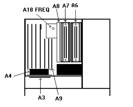
(3) Adjust A18 FREQ ADJ (fig. 1) for minimum difference indication on frequency
difference meter.
Figure 1. Test instrument - top view.
(4) Allow at least 24 hours for stabilization. Frequency difference meter
indication will remain within 5 parts in 10-10.
(5) Adjust autotransformer output to 105 V and allow 15 minutes for
stabilization. Verify that TI oscillator drift is less than 1 part in 10-10.
(6) Adjust autotransformer output to 125 V and allow 15 minutes for
stabilization. Verify that TI oscillator drift is less than 1 part in 10-10 .
(7) Adjust autotransformer output to 115 V.
b. Adjustments. No further adjustments can be made.

TB 9-6625-1996-35
6
9. Sensitivity
a. Performance Check
(1) Set function generator as listed in (a) through (c) below:
(a) Output Type to UnBalanced 600
(b) Function to Sine Wave.
(b) Frequency to 10 Hz.
(c) Amplitude to 1 mV.
(2) Position TI controls as listed in (a) through (f) below:
(a) CHANNEL A LEVEL control to PRESET.
(b) CHANNEL A SLOPE switch to +.
(c) CHANNEL A 50Ω/1MΩ switch to 50Ω.
(d) CHANNEL A ATTEN X1/X10 switch to X1.
(e) CHANNEL A AC/DC switch to DC.
(f) CHECK/COM A/SEP switch to SEP.
(3) Connect TI CHANNEL A input to function generator Function Output
Unbalanced.
(4) Press the function generator Enter key to enable the knob, and slowly rotate
the function generator knob cw until TI display GATE light flashes and indication is
stable at approximately 10 Hz.
(5) Verify that the function generator indicates within limits specified in table 3.
If not perform b below.
(6) Repeat technique of 1 through (5) above for remaining settings listed in table
3.
Table 3. Sensitivity
Test
instrument
input
CHECK-COM
A-SEP switch
setting
Function generator/signal
generator frequency
setting
Function generator/signal
generator indications
(≤)
CHANNEL A SEP 10 Hz 0.071 VPP
CHANNEL A SEP 10 kHz 0.071 VPP
CHANNEL A SEP 100 kHz 0.071 VPP
CHANNEL A SEP 1 MHz 0.071 VPP
CHANNEL A1 SEP 10 MHz 0.025 VRMS
CHANNEL A SEP 100 MHz 0.025 VRMS
CHANNEL A SEP 500 MHz 0.025 VRMS
CHANNEL A2 COM A 10 Hz 0.141 VPP
CHANNEL A COM A 10 kHz 0.141 VPP
CHANNEL A COM A 100 kHz 0.141 VPP
CHANNEL A COM A 1 MHz 0.141 VPP
CHANNEL A1 COM A 10 MHz 0.050 VRMS
CHANNEL A COM A 100 MHz 0.050 VRMS
CHANNEL A COM A 400 MHz 0.050 VRMS
1Substitute the signal generator for the function generator.
Substitute the function generator for the signal generator.
2
TB 9-6625-1996-35
b. Adjustments
(1) Substitute signal generator for function generator.
(2) Connect signal generator RF OUTPUT connector to TI CHANNEL A input.
(3) Connect signal generator EXT REF INPUT connector (rear panel) to TI
FREQ STD OUTPUT 10 MHz connector (rear panel).
(4) Extend front panel display assembly using extender cable 05345-60205.
Disconnect CHAN A P1 caple from A9 J1 CHA (CHAN B P2 cable to A9 J2 CH B for
CHANNEL B) and connect A9 J1 CH A (A9 J2 CH B for CHANNEL B) to oscilloscope
CHANNEL A.
(5) Position TI CHANNEL A and CHANNEL B controls as listed in (a) through
(f) below:
(a) LEVEL control to PRESET.
(b) SLOPE switch to +.
(c) IMPEDANCE switch to 50Ω.
(d) ATTEN switch to X1.
(e) COUPLING switch to DC.
(f) CHECK-COM A-SEP switch to SEP.
(6) Set signal generator frequency to 100 MHz and amplitude to 25 mV.
(7) Position oscilloscope controls as listed in (a) through (f) below:
(a) CH1 VOLTS/DIV switch to .2 V.
(b) SEC/DIV switch to 20 ns.
(c) Pull delayed sweep switch and set to 10 ns.
(d) Set TRIGGER MODE pushbutton to AUTO.
(e) Set TRIGGER SOURCE pushbutton to VERT.
(f) Set TRIGGER COUPLING pushbutton to DC.
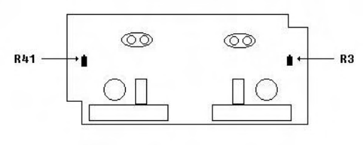
(8) Adjust A3R41 (fig. 2)(A3R3 (fig. 2) for CHANNEL B) for a symmetrical
waveform displayed on oscilloscope (R).
Figure 2. A3 input attenuator (cmponent side).
7
(9) While alternately setting CHANNEL A and CHANNEL B SLOPE switches
to (+) and (-), observe that waveform maintains its symmetrical form.

TB 9-6625-1996-35
8
(10) Repeat (8) and (9) above as required to compensate for interaction.
(11) Disconnect oscilloscope and signal generator from TI, reinstall TI from panel,
and reconnect CHAN A P1 cable to A9 J1 CH A and CHAN B P2 cable to A9 J2 CH B.
(12) Replace TI covers.
10. A12 Interface I/O
a. Performance Check
NOTE
This option can only be calibrated in an automated mode.
The TI must be connected to a controller with a properly
configured GPIB IEEE interface card.
NOTE
If you are running this section with any controller and or
software other than the fielded controller and the ICE
environment, you will have to write the required mnemonics
and take reading as per the software that you are using.
(1) Connect TI and multimeter IEEE connectors to the controller GPIB0.
(2) Assure TI address is set to 2 and multimeter address is set to 12.
(3) Adjust TI CHANNEL A and CHANNEL B LEVEL controls to PRESET.
(4) Remove screws holding TI top cover. Do not remove top cover until
instructed.
(5) Press the RESET key on the multimeter.
(6) Output the following mnemonic string to the TI: I2B500A500I1.
(7) Connect multimeter Input HI and LO to TI rear panel CHAN A
TRIG LEVEL.
(8) Output the following mnemonic string to the TI: B500A000I1.
(9) Retrieve the reading from the multimeter. If the reading is not
within limits listed in table 4, perform the listed adjustment.
(10) Repeat technique of (7) through (9) above for remaining table 4 entries.
Table 4. A12 interface I/O.
Multimeter indication
Output
mnemonic
Connect multimeter to
test instrument
rear panel connector
Min
Max Perform adjust
listed below
B500A000I1 CHAN A TRIG LEVEL -2.0005 -1.9995 b1
TB 9-6625-1996-35
9
A:00I1 CHAN A TRIG LEVEL 1.9995 2.0005 b2
B000I1 CHAN B TRIG LEVEL -2.0005 -1.9995 b3
B:00I1 CHAN B TRIG LEVEL 1.9995 2.0005 b4
b. Adjustments
NOTE
Remove top cover to make adjustments, then replace top
cover before repeating (a) above.
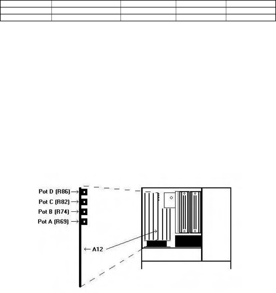
(1) Adjust A12 pot A (R69) (fig. 3) for a –2.0000 ± 0.0005 V dc multimeter
indication (R).
(2) Adjust A12 pot B (R74) (fig. 3) for a 2.0000 ± 0.0005 V dc multimeter indication
(R).
(3) Adjust A12 pot D (R86) (fig. 3) for a –2.0000 ± 0.0005 V dc multimeter
indication (R).
(4) Adjust A12 pot C (R82) (fig. 3) for a –2.0000 ± 0.0005 V dc multimeter
indication (R).
Figure 3. I/O adjustment location.
11. Power Supply
NOTE
Do not perform power supply check if all other parameters
are within tolerance.
TB 9-6625-1996-35
10
a. Performance Check
(1) Mount circuit board A6 (fig. 1) on extender boards.
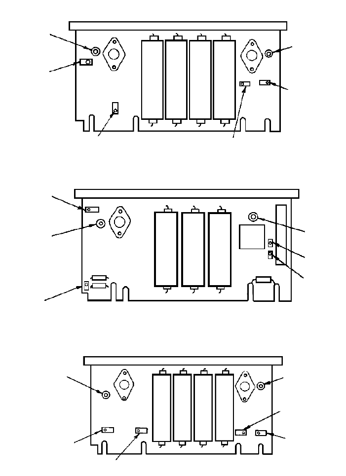
(2) Connect multimeter between A6TP6 and + 5 V RET (fig. 4). If multimeter
does not indicate between 4.98 and 5.02 V dc, perform b(1) below.
(3) Connect multimeter between A6TP3 and - 5.2 V RET (fig. 4). If multimeter
does not indicate between -5.18 and -5.22 V, perform b(2) below.
(4) Replace circuit board A6 in TI and mount circuit board A7 (fig. 1) on extender
boards.
(5) Connect multimeter between A7TP1 (A7TP2; serial prefix 1428A and prior)
and + 15 RET (fig. 4). If multimeter does not indicate between 14.98 and 15.02
V, perform b(3) below.
(6) Connect multimeter between A7TP3 (A7TP7; serial prefix 1428A and prior)
and -15 V RET (fig. 4). If multimeter does not indicate between -14.98 and -
15.02 V, perform b(4) below.
b. Adjustments
(1) Adjust R19 (fig. 4) for 5.00 V indication on multimeter (R).
(2) Adjust R29 (fig. 4) for 5.20 V indication on multimeter (R).
(3) Adjust R16 (fig. 4) (R18 (fig. 4); serial prefix 1428A and prior) for +15.00 V
indication on multimeter (R).
(4) Adjust R17 (fig. 4) (R24 (fig. 4); serial prefix 1428A and prior) for -15.00 V
indication on multimeter (R).
TB 9-6625-1996-35
11
R18
+15V
RET
TP2 -15V RETA7 CIRCUIT BOARD S/N 1428A
R24
TP7
TP3
R29
-5.2 V
RET
TP6
+5V
RET
R19
A6 CIRCUIT BOARD
R16 R17
TP1
+15V RET A7 CIRCUIT BOARD S/N 1808
TP3
-15V
RET
Figure 4. Power supply circuit boards.
TB 9-6625-1996-35
12
12. Final Procedure
a. Deenergize and disconnect all equipment.
b. Annotate and affix DA label/form in accordance with TB 750-25.
TB 9-6625-1996-35
PIN: 046669-000
By Order of the Secretary of the Army:
Distribution:
To be distributed in accordance with IDN 342172, requirements for calibration procedure
TB 9-6625-1996-35.
0116212