Hp 8517B Users Manual
HP 8517B to the manual 816d4cc6-a997-460a-946c-b5dbca8faf33
2015-02-09
: Hp Hp-Hp-8517B-Users-Manual-547588 hp-hp-8517b-users-manual-547588 hp pdf
Open the PDF directly: View PDF ![]() .
.
Page Count: 136 [warning: Documents this large are best viewed by clicking the View PDF Link!]
- Contents
- Index
- What You’ll Find in This Manual…
- Safety and Regulatory Information
- Getting Started
- Installation
- Operating the HP 8517B Test Set
- Specifications
- Troubleshooting the Test Set
- HP 8517B Test Set Replacement Procedures
- Assembly Replacement Procedures
- Initial Precautions
- Switch/Splitter Replacement
- Frequency Converter Replacement
- Regulator Board Replacement
- Filter Capacitor Replacement
- Test Port Connector Replacement
- Fan Assembly Replacement
- Power Transformer Replacement
- O-Ring Replacement
- Front Panel and Interface Board Replacement
- Bias Tees Replacement
- Test Port Coupler Replacement
- Test Port Attenuator Replacement
- Input Amplifier Replacement
- Buffer Amplifier Replacement
- Post Regulator Board Replacement
- Assembly Replacement Procedures
- HP 8517B Replaceable Parts
- Notice
- Warranty
- Service and Support
- Typeface Conventions

HP 8517B
S-Parameter Test Set
Operating and
Service Manual
PrintedinUSA
12 August 1998
HP part number 08517-90054

ii
HP 8517B S-Parameter Test Set Manual
Notice
The information contained in this document is subject to change without
notice.
Hewlett-Packard makes no warranty of any kind with regard to this material,
including, but not limited to, the implied warranties of merchantability and
fitness for a particular purpose. Hewlett-Packard shall not be liable for errors
contained herein or for incidental or consequential damages in connection
with the furnishing, performance, or use of this material.
Hewlett-Packard assumes no responsibility for the use or reliability of its
software on equipment that is not furnished by Hewlett-Packard.
This document contains proprietary information which is protected by
copyright. All rights are reserved. No part of this document may be
photocopied, reproduced, or translated to another language without prior
written consent of Hewlett-Packard Company.
Restricted Rights Legend
Use, duplication, or disclosure by the U.S. Government is subject to
restrictions as set forth in subparagraph (c)(1)(ii) of the Rights in Technical
Data and Computer Software clause at DFARS 252.227-7013 for DOD
agencies, and subparagraphs (c)(1) and (c)(2) of the Commercial Computer
Software Restricted Rights clause at FAR 52.227-19 for other agencies.
Hewlett-Packard Company
Santa Rosa Systems Division
1400 Fountaingrove Parkway
Santa Rosa, CA 95403-1799, U.S.A.
© Copyright Hewlett-Packard Company 1997, 1998

HP 8517B S-Parameter Test Set Manual
iii
What You’ll Find in This Manual…
HP 8517B S-Parameter Test Set
Chapters 1 and 2 •Test set description and installation information
Chapters 3 and 4 •Principles of operation and specifications
Chapters 5, 6, and 7 •Troubleshooting, replacement procedures, and replaceable parts
information

iv
HP 8517B S-Parameter Test Set Manual
Warranty
Certification Hewlett-Packard Company certifies that this product met its published
specifications at the time of shipment from the factory. Hewlett-Packard
further certifies that its calibration measurements are traceable to the
United States National Institute of Standards and Technology (NIST,
formerly NBS), to the extent allowed by the Institute’s calibration facility,
and to the calibration facilities of other International Standards
Organization members.
Warranty This Hewlett-Packard system product is warranted against defects in
materials and workmanship for a period corresponding to the individual
warranty periods of its component products. Instruments are warranted for a
period of one year. During the warranty period, Hewlett-Packard Company
will, at its option, either repair or replace products that prove to be defective.
Warranty service for products installed by HP and certain other products
designated by HP will be performed at Buyer’s facility at no charge within
HP service travel areas. Outside HP service travel areas, warranty service
will be performed at Buyer’s facility only upon HP’s prior agreement and
Buyer shall pay HP’s round trip travel expenses. In all other areas, products
must be returned to a service facility designated by HP.
For products returned to HP for warranty service, Buyer shall prepay
shipping charges to HP and HP shall pay shipping charges to return the
product to Buyer. However, Buyer shall pay all shipping charges, duties, and
taxes for products returned to HP from another country.
HP warrants that its software and firmware designated by HP for use with an
instrument will execute its programming instructions when properly
installed on that instrument. HP does not warrant that the operation of the
instrument, or software, or firmware will be uninterrupted or error free.
LIMITATION OF WARRANTY. The foregoing warranty shall not apply
to defects resulting from improper or inadequate maintenance by Buyer,
Buyer-supplied software or interfacing, unauthorized modification or
misuse, operation outside of the environmental specifications for the
product, or improper site preparation or maintenance.
NO OTHER WARRANTY IS EXPRESSED OR IMPLIED. HP
SPECIFICALLY DISCLAIMS THE IMPLIED WARRANTIES OR
MERCHANTABILITY AND FITNESS FOR A PARTICULAR PURPOSE.
EXCLUSIVE REMEDIES. THE REMEDIES PROVIDED HEREIN ARE
BUYER’S SOLE AND EXCLUSIVE REMEDIES. HP SHALL NOT BE
LIABLE FOR ANY DIRECT, INDIRECT, SPECIAL, INCIDENTAL, OR

HP 8517B S-Parameter Test Set Manual
v
CONSEQUENTIAL DAMAGES, WHETHER BASED ON CONTRACT,
TORT, OR ANY OTHER LEGAL THEORY.
Assistance Product maintenance agreements and other customer assistance agreements
are available for Hewlett-Packard products.
For assistance, call your local Hewlett-Packard Sales and Service Office
(refer to “Service and Support”).

vi
HP 8517B S-Parameter Test Set Manual
Service and Support
Any adjustment, maintenance, or repair of this product must be performed
by qualified personnel. Contact your customer engineer through your local
HP Service Center. You can find a list of HP Service Centers on the web at
http://www.hp.com/go/tmdir.
If you do not have access to the Internet, one of these HP centers can direct
you to your nearest HP representative:
United States: Hewlett-Packard Company
Test and Measurement Call Center
PO Box 4026
Englewood, CO 80155-4026
(800) 452 4844 (toll-free in US)
Canada: Hewlett-Packard Canada Ltd.
5150 Spectrum Way
Mississauga, Ontario L4W 5G1
(905) 206 4725
Europe: Hewlett-Packard European Marketing Centre
Postbox 999
1180 AZ Amstelveen
The Netherlands
(31 20) 547 9900
Japan: Hewlett-Packard Ltd.
Measurement Assistance Center
9-1, Takakura-Cho, Hachioji-Shi
Tokyo 192, Japan
(81) 426 56 7832
(81) 426 56 7840 (FAX)
Latin America: Hewlett-Packard Latin American Region Headquarters
5200 Blue Lagoon Drive, 9th Floor
Miami, Florida 33126, U.S.A.
(305) 267 4245, (305) 267-4220
(305) 267 4288 (FAX)
Australia/New Zealand: Hewlett-Packard Australia Ltd.
31-41 Joseph Street
Blackburn, Victoria 3130
Australia
1 800 629 485 (Australia)
0800 738 378 (New Zealand)
(61 3) 9210 5489 (FAX)
Asia-Pacific: Hewlett-Packard Asia Pacific Ltd.
17-21/F Shell Tower, Times Square
1 Matheson Street, Causeway Bay
Hong Kong
(852) 2599 7777
(852) 2506 9285 (FAX)
HP 8517B S-Parameter Test Set Manual
vii
Safety and Regulatory Information
Review this product and related documentation to familiarize yourself with
safety markings and instructions before you operate the instrument. This
product has been designed and tested in accordance with international
standards.
WARNING
The WARNING notice denotes a hazard. It calls attention to a procedure,
practice, or the like, that, if not correctly performed or adhered to, could result
in personal injury. Do not proceed beyond a WARNING notice until the
indicated conditions are fully understood and met.
CAUTION
The CAUTION notice denotes a hazard. It calls attention to an operating
procedure, practice, or the like, which, if not correctly performed or adhered
to, could result in damage to the product or loss of important data. Do not
proceed beyond a CAUTION notice until the indicated conditions are fully
understood and met.
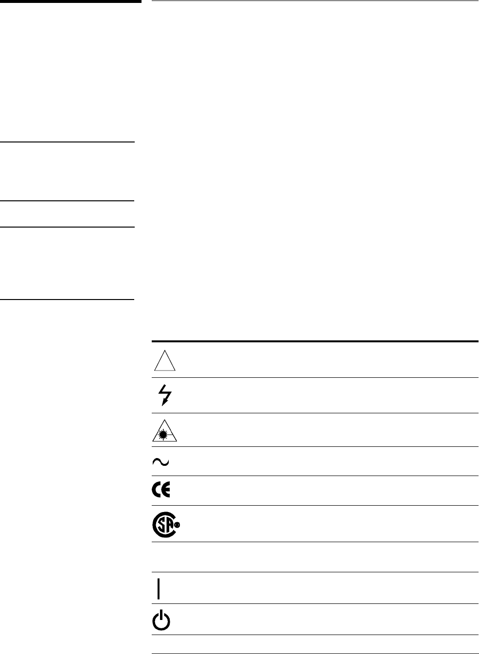
Instrument Markings
When you see this symbol on your instrument, you should refer to the instrument’s
instruction manual for important information.
This symbol indicates hazardous voltages.
The laser radiation symbol is marked on products that have a laser output.
This symbol indicates that the instrument requires alternating current (ac) input.
The CE mark is a registered trademark of the European Community. If it is
accompanied by a year, it indicates the year the design was proven.
The CSA mark is a registered trademark of the Canadian Standards Association.
1SM1-A This text indicates that the instrument is an Industrial Scientific and Medical Group 1
Class A product (CISPER 11, Clause 4).
This symbol indicates that the power line switch is ON.
This symbol indicates that the power line switch is OFF or in STANDBY position.
!

viii
HP 8517B S-Parameter Test Set Manual
Safety Earth
Ground
This is a Safety Class I product (provided with a protective earthing
terminal). An uninterruptible safety earth ground must be provided from the
main power source to the product input wiring terminals, power cord, or
supplied power cord set. Whenever it is likely that the protection has been
impaired, the product must be made inoperative and secured against any
unintended operation.
Before Applying Power Verify that the product is configured to match the available main power
source as described in the input power configuration instructions in this
manual. If this product is to be powered by auto-transformer, make sure the
common terminal is connected to the neutral (grounded) side of the ac power
supply.

HP 8517B S-Parameter Test Set Manual
ix
Typeface Conventions
Not all of the following conventions may appear within this manual,
however, refer to this listing whenever you encounter on of the special font
characters.
Italics •Used to emphasize important information:
Use this software only with the HP 8517B Test Set.
•Used for the title of a publication:
Refer to the HP 8517B S-Parameter Test Set Manual
•Used to indicate a variable:
Type LOAD BIN filename.
Instrument Display •Used to show on-screen prompts and messages that you will see on the
display of an instrument:
The HP 8517B will display the message CAL1 SAVED.
Keycap
•Used for labeled keys on the front panel of an instrument or on a
computer keyboard:
Press
[Return]
.
Softkey
•Used for simulated keys that appear on an instrument display:
Press
{Prior Menu}
.
User Entry •Used to indicate text that you will enter using the computer keyboard;
text shown in this typeface must be typed exactly as printed:
Type LOAD PARMFILE
•Used for examples of programming code:
#endif // ifndef NO_CLASS
Path Name
•Used for a subdirectory name or file path:
Edit the file
usr/local/bin/sample.txt
Computer Display
•Used to show messages, prompts, and window labels that appear on a
computer monitor:
The
Edit Parameters
window will appear on the screen.
•Used for menus, lists, dialog boxes, and button boxes on a computer
monitor from which you make selections using the mouse or keyboard:
Double-click
EXIT
to quit the program.

x
HP 8517B S-Parameter Test Set Manual

Contents
HP 8517B S-Parameter Test Set Manual
Contents-1
Notice ..................................................... ii
RestrictedRightsLegend................................ ii
WhatYou’llFindinThisManual…..............................iii
HP8517BS-ParameterTestSet ..........................iii
Warranty ...................................................iv
Certification .............................................iv
Warranty ................................................iv
Assistance............................................... v
Service and Support . .........................................vi
SafetyandRegulatoryInformation.............................. vii
Safety Earth Ground . . . ...................................viii
BeforeApplyingPower ...................................viii
Typeface Conventions ........................................ix
1. Getting Started
HowtoUseThisManual .....................................1-1
TestSetDescription .........................................1-2
Figure 1-1. Standard HP 8517B Test Set Block Diagram .........1-2
Figure 1-2. Option 004, HP 8517B Test Set Block Diagram .......1-3
Figure 1-3. Option 007, HP 8517B Test Set Block Diagram .......1-3
HP8517BTestSetOptions ...................................1-4
Table 1-1. HP 8517B Options and Descriptions ................1-4
VerifyingTestSetOperation ..................................1-5
Table 1-2. Test Set Operation Verification .....................1-5
CheckingSystemOperation.............................1-5
CheckingSpecifications................................1-5
Troubleshooting the Test Set . . ..........................1-5
MaintainingMeasurementAccuracy ............................1-6
InstrumentsSupportedbyThisManual ..........................1-7
Figure 1-4. Instrument Serial-Number Label Example ...........1-7
InstrumentFirmwareCompatibility .............................1-8
Table 1-3. Source Firmware Revision Compatibility Matrix .......1-8
Service and Support Options Available ..........................1-9
Table 1-4. Service and Support Options ......................1-9
Accessories ...............................................1-10
RecommendedTestEquipment ...............................1-12
Table 1-6. Recommended Test Equipment ....................1-12
OperatingandSafetyPrecautions..............................1-13
Table 1-7. Maximum Input Power Levels ....................1-13
SafetyPrecautions ......................................1-13

Contents-2
HP 8517B S-Parameter Test Set Manual
2. Installation
InitialInspection ........................................... 2-2
OperatingEnvironment................................... 2-2
StoringtheTestSet ...................................... 2-2
AccessoriesSupplied .................................... 2-2
Figure 2-1. Accessories Supplied with the HP 8517B Test Set .... 2-3
Table 2-1. Accessories in Figure 2-1 ........................ 2-3
InstallingtheTestSetIntoaSystemRack ....................... 2-4
InstallingtheTestSetonaBench........................... 2-4
Figure 2-2. Recommended Static-Free Workstation Configuration .2-4
ConfiguringtheTestSetinaSystem ........................... 2-5
Figure 2-3. Configuring an HP 8517B Test Set in a System ...... 2-5
ConnectingtheSystemCables ............................. 2-6
Table 2-2. Connection Instructions and Connector Descriptions .. 2-6
ConnectSystemPower................................ 2-6
andControlCables ................................... 2-6
Signal Path Connections . .............................. 2-6
TestPortConnectors.................................. 2-6
Anti-RotationClamp.................................. 2-6
ReplacingO-RingsinAnti-RotationClamps .................. 2-6
PackagingtheTestSet....................................... 2-7
3. Operating the HP 8517B Test Set
Front-PanelFeatures ........................................ 3-1
Figure 3-1. Front-Panel Features of the HP 8517B Test Set ...... 3-1
Table 3-1. Front-Panel Description ......................... 3-1
Rear-PanelFeatures......................................... 3-2
Figure 3-2. Rear-Panel Features of the HP 8517B Test Set ....... 3-2
Table 3-2. Rear-Panel Descriptions ......................... 3-2
ControllingMultipleTestSets ................................ 3-3
Figure 3-3. RF and IF Switching with Two Test Sets ............ 3-4
Table 3-3. RF and IF Switch Settings in Figure 3-3, Above ....... 3-4
Multiple Test-Set Connections . . .............................. 3-5
InitializationatPower-Up................................. 3-5
SelectingaTestSet ...................................... 3-5
Table 3-4. Selecting a Test Set When Multiple Units are Configured 3-6
TestSetIFSwitching ................................. 3-6
TestSetAddressing................................... 3-6
RFSwitchDriverControl.............................. 3-6
Figure3-4. RFandIFSwitchingwithFourTestSets........ 3-7
Table 3-5. Coaxial Switch Settings for Figure 3-4, Above ........ 3-7
MeasurementCalibration .................................... 3-8
MeasuringHigh-PowerDeviceswithOption004 ................. 3-9
ChangingSignalPathStatesAfterSystemCalibration............. 3-10
ChangingtheTestPortAttenuators ........................ 3-10
StoringTraceMemories ................................. 3-11
ViewingNormalizedParameters........................... 3-11

HP 8517B S-Parameter Test Set Manual
Contents-3
MakingOperationalChecks ..................................3-13
PerformanceVerification ....................................3-14
UsingAnti-RotationClamps .................................3-15
Attachthefirstclamp.................................3-15
Figure 3-5. Using a Torque Wrench Correctly ................3-16
Positioningthethumb-screw ...........................3-16
Figure 3-6. Visually Aligning Clamp and Nut Flats ............3-17
Positioning the connector .............................3-17
Figure 3-7. Mating the Clamp and Nut Flats .................3-17
Aligningthethumb-screw .............................3-18
Figure 3-8. Aligning the Thumbscrew With the Counter-Sink Hole 3-18
Attachingthesecondclamp............................3-18
4. Specifications
MechanicalSpecifications ....................................4-1
SupplementalCharacteristics ..................................4-1
Table 4-1. HP 8510/HP 8517B Mechanical Specifications .......4-1
Table 4-2. HP 8510/HP 8517B Supplemental Characteristics .....4-1
5. Troubleshooting the Test Set
TheoryofOperation .........................................5-2
Figure 5-1. Standard HP 8517B RF Block Diagram ............5-2
TheRFSourcePower.....................................5-2
TheReferenceSignalPath .................................5-3
TheTestSignalPath......................................5-3
The S11 and S21 Measurements .............................5-3
TheSamplerControlSwitching.............................5-3
TheLOSignalControl....................................5-4
Troubleshooting Sequence . ...................................5-5
Figure 5-2. Troubleshooting Flowchart ......................5-5
Equipment Needed But Not Supplied . . ......................5-6
Table 5-1. Equipment Required, But Not Supplied ..............5-6
Troubleshooting Procedures ...................................5-7
Table 5-2. Power Supply Voltages to A15 .....................5-7
Table 5-3. Power Supply Voltages to A27 .....................5-7
Figure 5-3. Power Supply Fuses and Test Points ...............5-8
HP-IBAddressSwitch ....................................5-8
Figure 5-4. Instrument HP-IB Switch Setting ..................5-9
FuseLocation ...........................................5-9
Figure 5-5. Fuse and Voltage Cam Location ...................5-9
Figure 5-6. The ACTIVE LED Location .....................5-10
IftheSelf-TestFailstoRunProperly ....................5-10
Figure 5-7. HP 8518B Test Set, A4 Board Assembly LEDs .......5-11
Table 5-4. Instrument Self-Test Indicator State Definitions ......5-11
Figure 5-8. Service Adapter Connections ....................5-12
UsingtheServiceAdapter.............................5-12
ServiceAdapterConclusions...........................5-13
Table 5-5. Results Observations ...........................5-13

Contents-4
HP 8517B S-Parameter Test Set Manual
UnratioedPowerTest................................ 5-14
Figure 5-9. Diagram of IF Signal Path ..................... 5-14
IsolatingSignalPathProblems ............................ 5-14
TestingSignalPaths1-4.............................. 5-14
TestingPaths5and6 ................................ 5-16
Figure 5-10. RF Path 1 and Path 2, HP 8517B Standard Test Set .5-17
Figure 5-11. RF Path 3 and Path 4, HP 8517B Standard Test Set .5-18
Figure 5-12. RF Path 5 and Path 6, HP 8517B Standard Test Set .5-19
Figure 5-13. RF Path 1 through Path 4,
HP 8517B Option 007 Test Set ......................... 5-20
Figure 5-14. RF Signal for Path 1 through Path 4,
HP 8517B Option 007 ............................... 5-21
Figure 5-15. RF Path 5 and Path 6, HP 8517B Option 007 ...... 5-22
Table 5-6. Test Results for Path 1 through Path 6 ............. 5-23
SampleDiagnostics..................................... 5-23
Table 5-7. Most Probable Failures
(B indicates Bad; — indicates Good) .................... 5-23
6. HP 8517B Test Set Replacement Procedures
Figure 6-1. ESD-Safe Workstation Configuration .............. 6-2
PerformanceTests .......................................... 6-2
Adjustments............................................... 6-2
Equipment Needed But Not Supplied . .......................... 6-3
Table 6-1. Replacement-Procedure Tools Needed .............. 6-3
Figure 6-2. HP 8517B Major Assembly Location Diagram ...... 6-4
AssemblyReplacementProcedures............................. 6-5
InitialPrecautions ....................................... 6-5
Switch/SplitterReplacement............................... 6-5
A18Switch/SplitterAssembly .......................... 6-5
FrequencyConverterReplacement .......................... 6-5
A14,A10toA13FrequencyConverterAssembly .......... 6-5
RegulatorBoardReplacement ............................. 6-6
A15RegulatorBoardAssembly......................... 6-6
FilterCapacitorReplacement .............................. 6-6
C1toC4FilterCapacitors ............................. 6-6
TestPortConnectorReplacement........................... 6-7
2.4mmTestPortConnectors ........................... 6-7
Figure 6-3. Diagram of 2.4 mm Test Port Connector ............ 6-7
FanAssemblyReplacement ............................... 6-8
B1FanAssembly .................................... 6-8
PowerTransformerReplacement ........................... 6-8
T1PowerTransformer ................................ 6-8
Figure 6-4. Wire Connections to FL1 Line Module ............. 6-9
O-RingReplacement.................................... 6-10
Figure 6-5. Positioning the O-Ring Within the Clamp .......... 6-10
FrontPanelandInterfaceBoardReplacement ................ 6-10
A1FrontPanelandInterfaceBoardAssembly ............ 6-10

HP 8517B S-Parameter Test Set Manual
Contents-5
BiasTeesReplacement...................................6-11
A7andA9BiasTees .................................6-11
TestPortCouplerReplacement ............................6-11
A6andA8TestPortCouplers..........................6-11
TestPortAttenuatorReplacement ..........................6-11
A16orA17PortAttenuators...........................6-11
Input Amplifier Replacement ..............................6-12
A22InputAmplifierAssembly .........................6-12
BufferAmplifierReplacement.............................6-12
A23toA26BufferAmplifiers..........................6-12
PostRegulatorBoardReplacement .........................6-13
A27PostRegulatorBoardAssembly ....................6-13
7. HP 8517B Replaceable Parts
Introduction................................................7-1
Rebuilt-ExchangeAssemblies ..............................7-1
ReplaceablePartsList ....................................7-1
OrderingInformation..................................7-2
ToOrderParts....Fast!...............................7-2
Table 7-1. Reference Designation Abbreviations ..............7-2
Table 7-2. Manufacturer Names and Addresses ................7-3
Table 7-3. Standard Abbreviations ..........................7-4
Table 7-4. Multipliers, Abbreviation and Description ...........7-10
Figure 7-1. Power Cable and Plug Part Numbers ..............7-11
Table 7-5. Instrument Fuses ..............................7-12
Figure 7-2. The Low Cost Rebuilt-Exchange Procedure .........7-13
Table 7-6. Major Assembly Reference Designator and Parts Information
7-14
Figure 7-3. Major Assembly Locations in the Standard
HP 8517B Test Set ...................................7-15
Table 7-7. Semi-Rigid Cable Assemblies in the Standard
HP 8517B Test Set ...................................7-16
Table 7-8. Flexible Cable Assemblies in the Standard
HP 8517B Test Set ...................................7-17
Table 7-9. Miscellaneous Parts, Front Panel HP 8517B Test Set ..7-19
Table 7-10. Test Port Connector Assembly Components .........7-20
Table 7-11. Miscellaneous Parts, Rear Panel HP 8517B Test Set ..7-21
Figure 7-4. Detailed Views of Hardware Stack-Ups ............7-23
Table 7-12. Miscellaneous Parts, Top Internal View ............7-24
Table 7-13. Miscellaneous Parts, Motherboard ...............7-25
Table 7-14. Parts Unique to HP 8517B Option 001 Test Set ......7-27
Table 7-15. Parts Unique to HP 8417B Option 002 Test Set ......7-29
Table 7-16. Parts Unique to HP 8517B Option 004 Test Set ......7-30
Table 7-17. Parts Unique to HP 8517B Option 007 Test Set ......7-31
Table 7-18. Parts Unique to Option 002 “plus” Option 007 .....7-33
Table 7-19. Parts Unique to Option 004 “plus” Option 007 .....7-34
Table 7-20. Instrument Chassis Replaceable Parts .............7-35

Contents-6
HP 8517B S-Parameter Test Set Manual

HP 8517B S-Parameter Test Set Manual
1-1
1
Getting Started
This is the operating and service manual for the HP 8517B S-parameter test
set. It is to be used in conjunction with the HP 8510C Network Analyzer
Operating and Service Manual. Together, these manuals provide
information needed to configure the system and make measurements.
How to Use This Manual
Step 1. Review Chapter 1, “Getting Started” and Chapter 2, “Installation” of this manual to
learn about:
• Using this test set
• Using options of the test set
• Preparing the site for operation
• Understanding safety considerations
• Unpacking the instrument and checking it for shipment damages
• Configuring the HP 8517B test set with the HP 8510C Network Analyzer
Step 2. Insert the contents of this manual into the HP 8510C Test Sets and Accessories
binder behind the tab labeled “Test Sets.”
Step 3. Review the
Connector Care Quick Reference Card
(HP part number 08510-90360)
supplied with the HP 8510C manuals set.
Refer to the calibration kit documentation for complete information about care,
cleaning, gaging, and connecting precision devices. Knowledge and application of
proper connector care is essential to achieving good connections and maintaining
maximum performance quality with your precision calibration devices.
Step 4. Read Chapter 3, “Operation,” to learn about test set front- and rear-panel features.
This chapter also has information about controlling multiple test sets, measuring
high power devices, using the anti-rotation clamps on the cables, and connecting
devices to the test set.
Step 5. Refer to Chapters 4 through 7 for reference information about specifications,
troubleshooting, replacement procedures, and replacement parts information.
1-2
HP 8517B S-Parameter Test Set Manual
Getting Started
Test Set Description
Test Set Description
The HP 8517B test set configured with an HP 8510B/C network analyzer
and an HP 8360 series source, creates a system capable of making
S-parameter measurements from 45 MHz to 50 GHz. The system is
particularly suited for making two-port device measurements. You can
measure all four S-parameters without physically reversing the DUT (device
under test).
The system is also designed for making measurements on non-reciprocal
devices or components like transistors, amplifiers or isolators where S12
measurements are required.
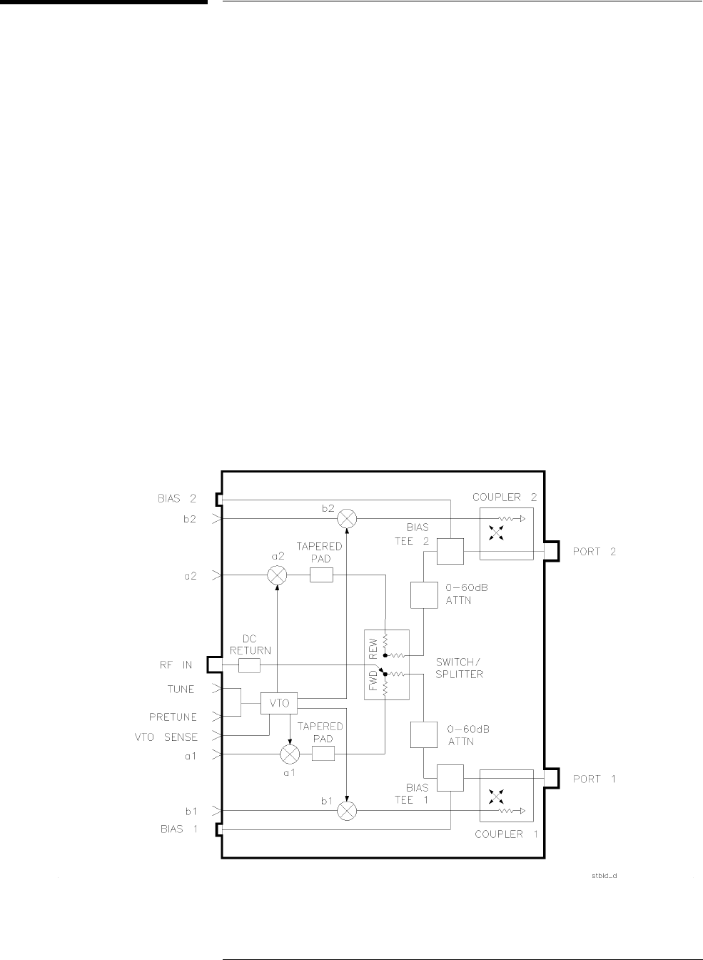
Two directional couplers are used for signal separation. The configuration is
illustrated in the following figures:
•Figure 1-1, “Standard HP 8517B Test Set Block Diagram"
•Figure 1-2, “Option 004, HP 8517B Test Set Block Diagram"
•Figure 1-3, “Option 007, HP 8517B Test Set Block Diagram"
For active-device measurements, two bias tees apply external DC bias to
both test port center conductors.
Figure 1-1 Standard HP 8517B Test Set Block Diagram
HP 8517B S-Parameter Test Set Manual
1-3
Getting Started
Test Set Description
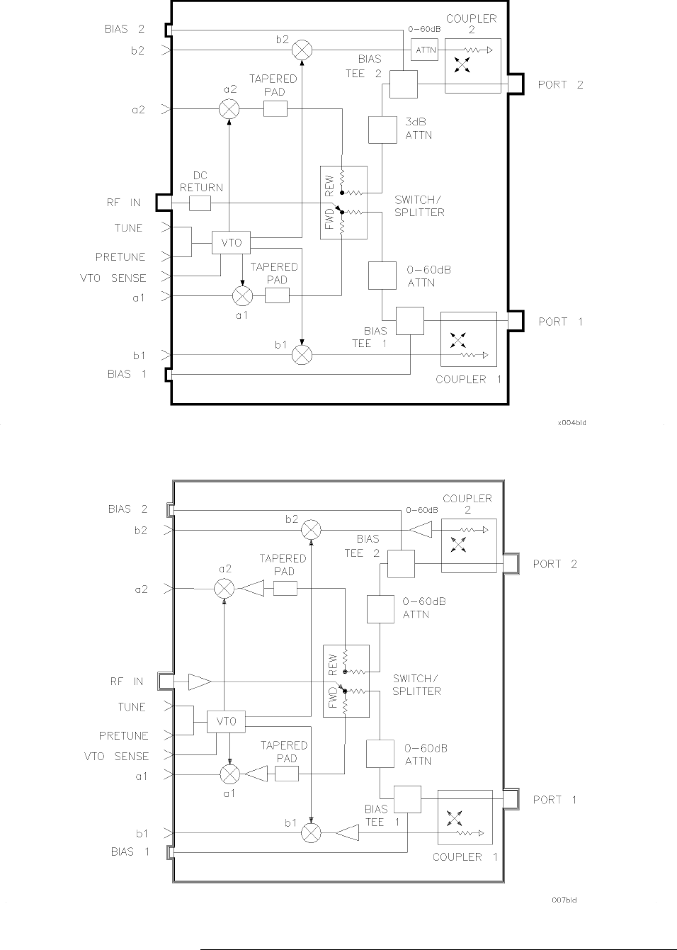
Figure 1-2 Option 004, HP 8517B Test Set Block Diagram
Figure 1-3 Option 007, HP 8517B Test Set Block Diagram

1-4
HP 8517B S-Parameter Test Set Manual
Getting Started
HP 8517B Test Set Options
HP 8517B Test Set Options
Options for the HP 8517B test set are described in Table 1-1, below.
Table 1-1 HP 8517B Options and Descriptions
Options HP 8517B Test Set Option Description
Option 001 Adds IF switching capability for up to four test set connections to the HP 8510C Network
Analyzer.
The test set used is selected from the network analyzer. Refer to “Controlling Multiple Test
Sets” in Chapter 3, “Operation” of this manual for more information.
Option 002 Deletes the programmable attenuators and bias tees.
Note:
If bias is required but attenuation is not, the bias can be applied externally by using an
HP 11612B bias tee.
Option 004 Moves Port 2 attenuator in front of the b2 sampler, allowing devices with output power up to 30
dBm (1 W) to be measured. Adds a 3 dB attenuator which protects the switch splitter from high
power into Port 2.
Option 007 Adds five amplifiers, two 10 dB attenuators, two 6 dB attenuators, and two tapered attenuators.
These components increase the available power and dynamic range of the test set.
Option 908 Supplies the hardware required for rack mounting the test set when its handles are removed.
Refer to Chapter 2, “Installation” for more information.
Option 910 Adds a duplicate copy of this manual to the shipment.
Option 913 Supplies the hardware required for rack mounting the test set with its handles attached. Refer
to Chapter 2, “Installation” for more information.
Option 002 “plus” 007 Removes the bias tee, and retains the high dynamic range capability in the test set.
Option 004 “plus” 007 Adds high-dynamic range and high power measurement capability to Port 2.

HP 8517B S-Parameter Test Set Manual
1-5
Getting Started
Verifying Test Set Operation
Verifying Test Set Operation
The test set is designed to operate with an HP 8510C network analyzer. You
canverifyitsoperationby:
Table 1-2 Test Set Operation Verification
Checking System Operation Perform a system calibration as described in the
HP 8510C Operating and
Programming Manual
. A successful calibration indicates that the system, and
therefore the test set, are operating properly.
Checking Specifications Specifications for the test set, and the system, can be determined by running
the specification and performance verification software described in the
HP
8510C On-Site Service Manual
, Chapter 8, “Specification and Performance
Verification”. Additional mechanical specifications and supplemental
characteristics are in Chapter 4, “Specifications” of this manual.
Troubleshooting the Test Set To troubleshoot the test set, refer to the
HP 8510C On-Site Service Manual
.
Use the information in that manual to determine if the test set is at fault. If the
test set is at fault, refer to Chapter 5, “Troubleshooting the Test Set” in this
manual to isolate the trouble.

1-6
HP 8517B S-Parameter Test Set Manual
Getting Started
Maintaining Measurement Accuracy
Maintaining Measurement Accuracy
Precision measurements rely on a precision calibration of the network
analyzer. As a general rule, the shorter the time lapse between a calibration
and a device measurement, the more precise the measurement results will be
(within the limitations of your system).
Hewlett-Packard recommends calibrating your system every few hours, or at
least re-verifying your system’s calibration this frequently. Doing so helps
retain measurement precision.
The frequency of calibrations is determined by both the location of the
system and the ambient temperature stability in its operating area.
HP 8517B S-Parameter Test Set Manual
1-7
Getting Started
Instruments Supported by This Manual
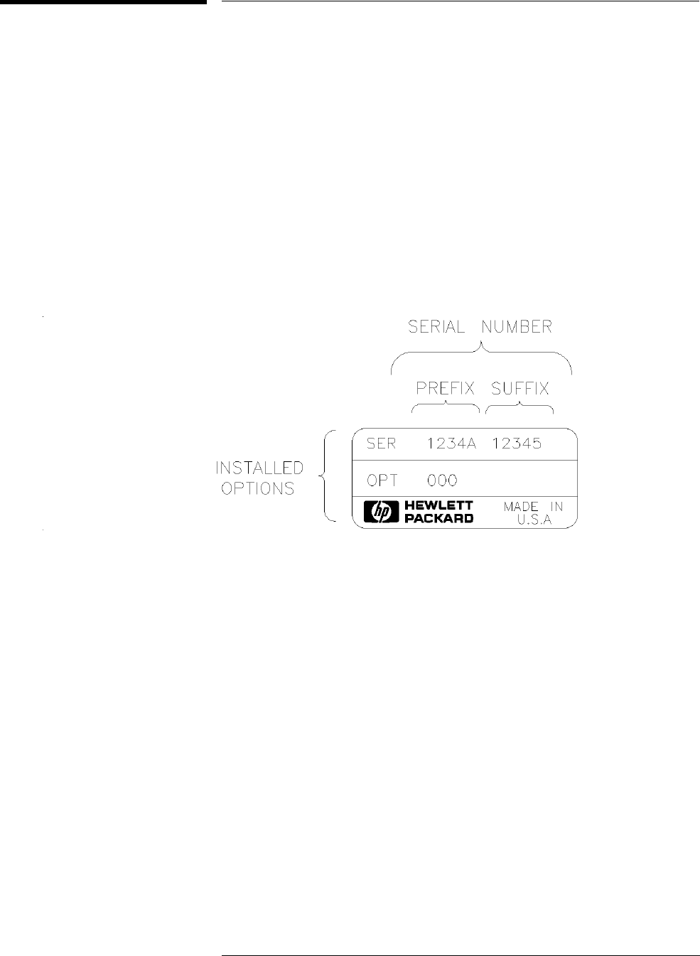
Instruments Supported by This Manual
A serial number label is attached to the rear panel of the test set. There are
two parts to the serial number: a prefix, and a suffix. See Figure 1-4, and
read the following descriptions:
•The prefix includes the first four digits of the serial number, plus the
letter. The contents of this manual apply directly to test sets with the
same serial number prefix as the one(s) on the title page.
•The suffix includes the last five digits of the serial number, which is
sequential and unique to each test set. You will need this part of the
number to report test-set problems to an HP sales and service engineer.
Figure 1-4 Instrument Serial-Number Label Example
serial.tif

1-8
HP 8517B S-Parameter Test Set Manual
Getting Started
Instrument Firmware Compatibility
Instrument Firmware Compatibility
To use the HP 8517B test set at frequencies up to 50 GHz, use an
HP 83650B or HP 83651B source.
If your network analyzer or source do not meet the required frequency
ranges for your measurement needs, you need to upgrade your system.
Please contact an HP Sales and Service representative for information. These
offices are listed in “Service and Support” on page vi at the front of this
manual
Table 1-3 Source Firmware Revision Compatibility Matrix
Instrument Model
Number and Name Compatible With Model: Firmware Revision Compatible With HP
8340 Series
Sources?
Compatible With
HP 8350 Series
Sources?
HP 8517B Test Set HP 8510B Network Analyzer
HP 8510C Network Analyzer
B.06.00 and higher
C.06.00 and higher
Yes, up to the higher
frequency limits.
Yes, up to the higher
frequency limits.
HP 8517B,
Option 007 Test Set
HP 8510C Network Analyzer 7.0 or higher, only Yes, up to the higher
frequency limits.
No, not compatible

HP 8517B S-Parameter Test Set Manual
1-9
Getting Started
Service and Support Options Available
Service and Support Options Available
A variety of service and support products are available for coverage of
repair, calibration, and verification issues. Contact your HP sales and service
engineer for details. Their office addresses and phone numbers are listed in
the front of this document.
The purchase of an HP 8517B includes a one year on-site service warranty.
In the event of failure, Hewlett-Packard provides service for the system.
NOTE
System installation is not included.
Table 1-4 Service and Support Options
Option Number Option Description
Option W30 Adds a three year customer return-repair coverage warranty to the instrument.
Customers may return the instrument to HP within that three year period for repair.
Option W31 Adds a three year on-site repair coverage warranty for next-day on-site repair of the
instrument. Customers may return the instrument to HP within that three year period for
repair and get next-day service on their instrument.
Option 1BN Adds to the instrument a MIL-STD 45662A Certificate of Calibration.
This option must be
ordered when the instrument order is placed
.
Option 1BP Adds to the instrument a MIL-STD 45662A Certificate of Calibration and the
corresponding calibration data.
This option must be ordered when the instrument order is
placed
.
Option UK6 Adds a certificate of calibration (rather than the MIL-STD certificate) and the
corresponding calibration data to the instrument.
This option must be ordered when the
instrument order is placed.

1-10
HP 8517B S-Parameter Test Set Manual
Getting Started
Accessories
Accessories
The accessories supplied with the test set, including part numbers, are listed
in “Accessories Supplied” in this section and in the “Replaceable Parts List”
of this manual.
Accessories Available Table 1-5 describes accessories available for the HP 8517B test set. For
additional HP 8510C system accessories information, refer to the HP 8510C
manual set.
Table 1-5 HP 8517B Test Set Accessories Available
Accessory Type Accessory Model Number Contents or Description
Calibration Kit1HP 85056A 2.4 mm Calibration Kit Contains open and short circuits
Fixed and sliding loads (2)
2.4 mm to 2.4 mm adapters
2.4 mm connector tools and gauges
Verification Kit1HP 85057S 2.4 mm Verification Kit Contains precision airline, mismatched airline,
20 dB and 40 dB attenuators
Cables HP 85133C 2.4 mm Test Port Return
Cable
Used when measuring a 2.4 mm-ported device connected directly to
Port 1 of the test set. The test port return cable is connected
between the device under test and Port 2.
HP 85133D 2.4 mm Test Port Return
Cable Set
Used when measuring a 2.4 mm-ported device connected between
the cable ends.
HP 85133E 2.4 mm Flexible Test Port
Return Cable
Used when measuring a 2.4 mm-ported device connected directly to
Port 1 of the test set. The test port return cable is connected
between the device under test and Port 2.
HP 85133F 2.4 mm Flexible Test Port
Return Cable Set
Used when measuring a 2.4 mm-ported device connected between
the cable ends.
HP 85134D 3.5 mm Test Port Return
Cable Set
Used when measuring a 3.5 mm device under test connected
between the cable ends.
HP 85134E 3.5 mm Flexible Test Port
Return Cable
Used when measuring one end of a 3.5 mm device connected
directly to an HP 85130F adapter at Port 1. The test-port return
cable is connected between the device and Port 2.
HP 85134F 3.5 mm Flexible Test Port
Return Cable Set
Used when measuring a 3.5 mm device connected between the
cable ends.
HP 85135C 7 mm Test Port Return
Cable
Used when measuring one end of a 7 mm device connected
directly to an HP 85130E adapter at Port 1. The test port return
cable is connected between the device and Port 2.
Cables (Continued) HP 85135D 7 mm Test Port Return
Cable Set
Used when measuring a 7 mm device connected between the cable
ends.

HP 8517B S-Parameter Test Set Manual
1-11
Getting Started
Accessories
NOTE
For more information about other 2.4 mm adapters, refer to the “2.4 mm
Adapters and Calibration Accessories,” Operating Note, (HP part number
11900-90003).
HP 85135E 7 mm Flexible Test Port
Return Cable
Used when measuring one end of a 7 mm device connected directly
to an HP 85130E adapter at Port 1. The test port return cable is
connected between the device and Port 2.
HP 85135F 7 mm Flexible Test Port
Return Cable Set
Used when measuring a 7 mm device connected between the cable
ends.
Adapters HP 85130E Special 2.4 mm to 7 mm
Adapter Set
Used to convert special 2.4 mm test set ports into a 7 mm connector
interface (m or f).
HP 85130F Special 2.4 mm to 3.5 mm
Adapter Set
Used to convert special 2.4 mm ports of the test set into a 3.5 mm
connector interface (m or f).
HP 85130G Special 2.4 mm to 2.4 mm
Adapter Set
Used to convert special 2.4 mm ports of the test set into a standard
2.4 mm connector interface (m or f). These adapters function as
“test port savers.”
HP 11904S 2.4 mm to K-2.9 mm2
Adapter Kit
Used to calibrate the test set using 2.4 mm devices, then to change
the test ports to 2.92 mm and perform fully error corrected
measurements. The kit contains (2) 2.4 mm to 2.92 mm (m)
adapters and (2) 2.4 mm to 2.92 (f) adapters.
Test Fixture Kit HP 85041A Transistor Test Fixture Kit
(TTF)
A comprehensive measurement system for testing and
characterizing stripline packaged microwave transistors. Although
the fixture contains 7 mm connectors and its frequency limit is
18 GHz, the kit may be adapted for use with the test set. Use
HP 85135C or HP 85135E cables with the HP 85130E adapter set.
Please consult your HP Sales and Service representative for
recommendations.
1. NIST traceable data and uncertainties are available.
2. The K-connector is developed and manufactured by the Wiltron Company (Morgan Hill, California).
Table 1-5 HP 8517B Test Set Accessories Available (Continued)
Accessory Type Accessory Model Number Contents or Description

1-12
HP 8517B S-Parameter Test Set Manual
Getting Started
Recommended Test Equipment
Recommended Test Equipment
Additional equipment and accessories required for use with the test set are
listed in Table 1-6. The table lists which items are required to verify the
performance of the test set and which are required to operate it. Other
equipment may be substituted if their specifications meet or exceed those
listed in the critical specifications column
O = Operation; P = Performance Test; T = Troubleshooting
Table 1-6 Recommended Test Equipment
Item Critical
Specifications Recommended Model Use
Network Analyzer no substitute HP 8510B or HP 8510C O, P, T
Source no substitute HP 83651B O, P, T
Controller no substitute HP 9000 Series 200 or 300 with 3 Mbyte RAM and
HP BASIC 3.0 or higher or PCC-305 or PC-308
HP BASIC Controller with 3 Mbyte Basic Language
Processor RAM
N/A
Disk Drive is compatible with the
controller
is compatible with the controller P
Multimeter range: 0 to 50 V HP 3456A T
Oscilloscope 50 MHz bandwidth HP 1740A T

HP 8517B S-Parameter Test Set Manual
1-13
Getting Started
Operating and Safety Precautions
Operating and Safety Precautions
CAUTION
ESD Sensitive Assemblies
Test set assemblies are very sensitive to damage from electrostatic discharge.
They may or may not continue to function if subjected to electrostatic
discharge. Their reliability, however, will be impaired. Handle the
instrument devices at static-safe work stations, only.
Operating Precautions Observe the following normal precautions when handling and operating the
test set:
•Do not exceed the input power levels listed below:
•Do not exceed +15 dBm into the test set with the source RF input.
•Never apply a dc voltage to the source RF input of the test set.
•Do not torque any connection at the test port connectors to more than
90 N-cm (8 in-lb). The wrench supplied with your accessory kit is
calibrated for 90 N-cm (8 in-lb) torque.
•Do not torque any connection to more than 90 N-cm (8 in-lb) at the
source RF input or on the back of your test set.
Safety Precautions The voltages inside this test set warrant normal caution for operator safety.
Nevertheless, service should be performed by qualified personnel, only.
Service strategy, troubleshooting procedures, replaceable parts, and other
information about the test set are provided in this manual or the HP 8510C
On-Site Service Manual.
Table 1-7 Maximum Input Power Levels
Power Level Test Port
+17 dBm Port 1
+17 dBm Port 2
+30 dBm1
1. This is the maximum input power allowed with HP 8517B Option 004, or
Option 004 “plus” Option 007, when the attenuator is set to
≤
20 dB. Without
attenuation, the maximum input power allowed is +17 dBm.
Port 2 (Option 004, or Option 004 “plus” 007)

1-14
HP 8517B S-Parameter Test Set Manual
Getting Started
Operating and Safety Precautions

HP 8517B S-Parameter Test Set Manual
2-1
2
Installation
This chapter contains installation information. Topics include initial
inspection, environmental considerations, test set location when using it with
the HP 8510C network analyzer, and making connections to the test set.
Refer to “Installation” in the HP 8510C On-Site Service Manual for
complete system connection and turn-on instructions.
Refer to “Packaging the Test Set” for information about shipping the
instrument.

2-2
HP 8517B S-Parameter Test Set Manual
Installation
Initial Inspection
Initial Inspection
Inspect the shipping container and cushioning materials for damage. If there
is damage, keep the container until you have checked the contents for
completeness.
If shipping materials are damaged, complete the performance tests outlined
in the HP 8510C On-Site Service Manual. If the test set fails the
performance tests, or is damaged or defective, keep the shipping materials.
Notify both the carrier and the nearest Hewlett-Packard Sales and Service
Office (listed in “Service and Support” at the front of this manual).
The office can arrange for repair or replacement of the test set without
waiting for the claim settlement.
Operating
Environment
For the HP 8517B to operate within specifications, the ambient temperature
must remain between 0° Cand+55° C. Keep relative humidity to less than
95% (at 40° C dry bulb temperature, maximum). The instrument can be
operated at altitudes up to 4,500 meters (15,000 feet).
Storing the Test Set Acceptable storage temperatures range from –40° Cto+75° C, with relative
humidity ≤90% at +65° C (maximum dry bulb temperature) and at altitudes
up to 15,240 meters (50,000 feet).
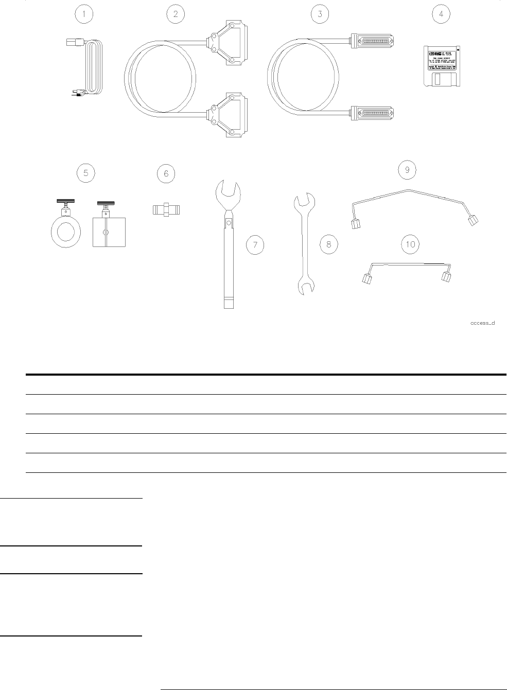
Accessories Supplied Figure 2-1 illustrates accessories supplied with the test set. If you did not
receive one of these accessories with the test set, notify your nearest HP
Sales and Service Office so that the missing parts can be sent to you.
HP 8517B S-Parameter Test Set Manual
2-3
Installation
Initial Inspection
Figure 2-1 Accessories Supplied with the HP 8517B Test Set
CAUTION
Assemblies in the test set are extremely sensitive to damage by static
electricity. They may or may not continue to function if subjected to an
electrostatic discharge. Their reliability, however, will be impaired.
CAUTION
Always use an anti-static wrist strap when calibrating or verifying the test set
or while using the test set to measure devices. Never touch test port center
conductors. Use a wrist strap when connecting the extended center
conductor of a sliding load termination.
Table 2-1 Accessories in Figure 2-1
(1) Power Cord U.S.A. only (6) Female 2.4 mm to Female 2.4 mm Adapter
(2) Test Set Interconnect Cable (7) 20 mm, 98 N-cm (8 in-lb) Torque Wrench
(3) HP-IB Cable (8) 1/2” x 9/16” Open End Wrench
(4) Specification and Performance Verification Software (9) RF Source Cable, Bench-top Configuration
(5) Anti-rotation Clamps (10) RF Source Cable, Rack Configuration
2-4
HP 8517B S-Parameter Test Set Manual
Installation
Installing the Test Set Into a System Rack
Installing the Test Set Into a System Rack
The HP 85043C system rack is the recommended model to use. To
rack-mount the test set into a system configured with the HP 8510C, refer to
the “Installation” chapter of the HP 8510C On-Site Service Manual and to
the HP 85043C System Rack Manual.
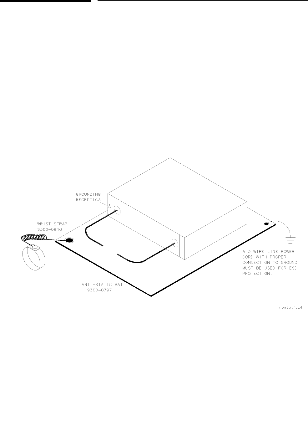
Installing the Test Set
on a Bench
When installing the test set for use on a bench, place it on a grounded
anti-static work surface to reduce the chance of ESD damage. The antistatic
surface should extend far enough in front of the test set to provide effective
protection for the test ports and cable ends. See Figure 2-2.
A grounding receptacle is provided on the test set as an alternate grounding
point for your anti-static wrist-strap.
Figure 2-2 Recommended Static-Free Workstation Configuration
HP 8517B S-Parameter Test Set Manual
2-5
Installation
Configuring the Test Set in a System
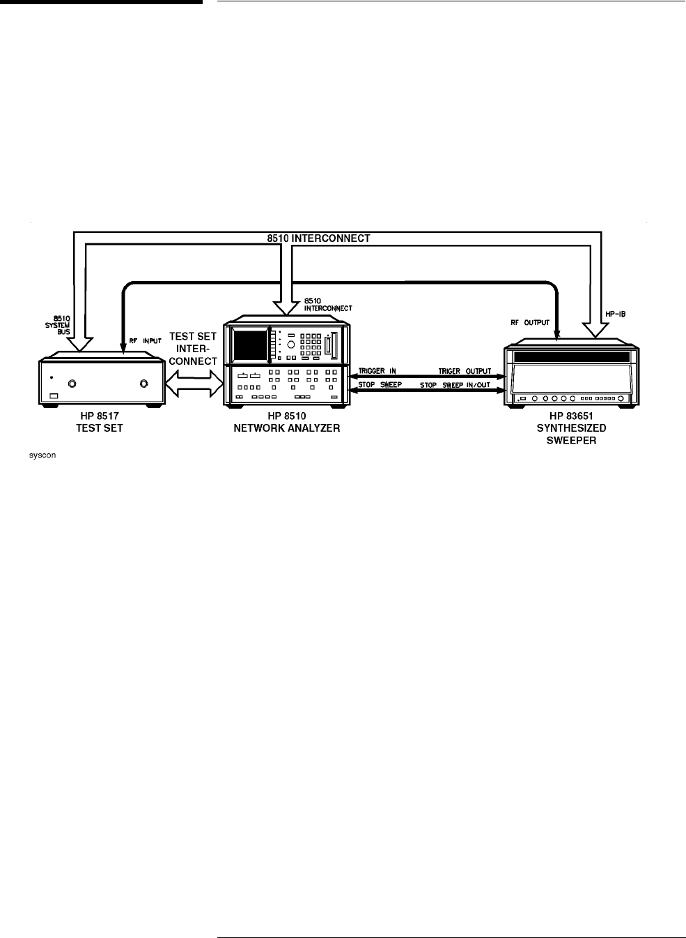
Configuring the Test Set in a System
Figure 2-3 illustrates the cable connections for installing an HP 8517B in a
system. Refer to the information that follows to install the test set.
Figure 2-3 Configuring an HP 8517B Test Set in a System

2-6
HP 8517B S-Parameter Test Set Manual
Installation
Configuring the Test Set in a System
Connecting the System
Cables
Replacing O-Rings in
Anti-Rotation Clamps
The anti-rotation clamp’s internal O-ring is a field-replaceable part. There is
no need to disassemble the anti-rotation clamp.
When the O-ring no longer holds the RF cable securely, replace it by
following the instructions in Chapter 6, “Replacement Procedures.”
Table 2-2 Connection Instructions and Connector Descriptions
Connect System Power
and Control Cables
Check the test-set line module (see item (1) in Chapter 3, Figure 3-2 of this manual). It must be set for
the correct voltage in your region. Refer to Chapter 5, “Troubleshooting” of this manual for information
about changing the voltage selection or replacing the line fuse.
• After setting or confirming the line-voltage module, connect the test set power cord to an electrical
outlet.
• Attach the HP 8517B IF-interconnect cable from J11 TEST SET INTERCONNECT (on the test set’s
rear panel) to J1 TEST SET INTERCONNECT on the rear panel of the HP 85102 IF detector.
• Attach the system bus cable from HP 8517B J12 HP 8510 SYSTEM BUS connector to HP 8510C
INTERCONNECT on the HP 85101 display/processor.
The test set IF interconnect cable and the system bus cable transmit control signals between the test
set and the network analyzer.
Signal Path Connections The IF interconnect cable transmits IF signals from the test set to the HP 85102 IF detector.
• Attach one end of the 2.4 mm RF cable (item 9 or 10, Figure 2-1) to the RF output on the rear panel
of the HP 83651 Synthesized Sweeper.
• Attach the other end of the RF cable to the RF input on the HP 8517B Test Set.
Test Port Connectors Port 1 and Port 2 are male, NMD-2.4 mm connectors, and mate to female 2.4 mm connectors.
Anti-Rotation Clamps Use the anti-rotation clamps (item 5, Figure 2-1) to stabilize the test port or RF cable at the
connection, or to stabilize an adapter at the connection.
• Connect test port cables or adapters to the test ports.
• Torque the connections to 90 N-cm (8 in lb).
• Loosen the anti-rotation clamp thumb screw enough to slip the clamp over the cable and up to the
front panel. The clamp end with the flats should come to rest on the flats of the test port shoulder.
• Finger-tighten the thumb screws to prevent further loosening or tightening of the test port/RF cable
connection. Refer to Chapter 3, “Operation” of this manual for additional information.

HP 8517B S-Parameter Test Set Manual
2-7
Installation
Packaging the Test Set
Packaging the Test Set
To repackage the test set, use its original factory packaging.
Refer to the test set using its complete model and serial numbers in any
correspondence to an HP Sales and Service Office.
Containers and materials identical to those used in the original shipment by
the factory are available through Hewlett-Packard Sales and Service Offices.
However, commercially available, comparable packaging materials may be
used, also.
1. Wrap the test set in heavy paper or anti-static plastic.
2. If you are shipping the test set to an HP Sales or Service office, complete
and attach a service tag (located in the HP 8510C manual set).
3. Use sufficient shock absorbing material on all sides of the test set to
provide a thick, firm cushion and prevent movement.
4. Seal the shipping container securely and mark it “FRAGILE.”

2-8
HP 8517B S-Parameter Test Set Manual
Installation
Packaging the Test Set
HP 8517B S-Parameter Test Set Manual
3-1
3
Operating the HP 8517B Test Set
This chapter contains illustrations and descriptions of the HP 8517B front-
and rear-panel features. Information about operating multiple test sets
(Option 001) is also provided.
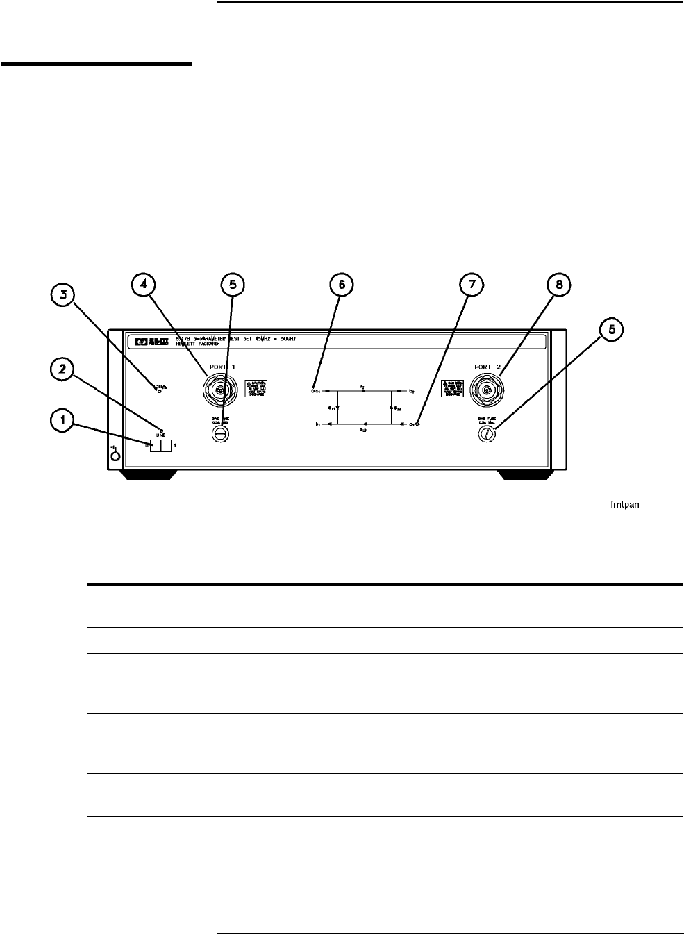
Front-Panel Features
Figure 3-1 Front-Panel Features of the HP 8517B Test Set
Table 3-1 Front-Panel Description
(1) Line Switch This switch turns the test set on or off. When the side of the switch labeled “0” is depressed, the
test set is OFF; when the side labeled “1” is depressed, the test set is ON.
(2) Line LED This LED is lit when the test set line switch is ON and not lit when the test set line switch is OFF.
(3) Active LED This LED lights about two seconds after power is turned on, following the successful conclusion of
the self-test. If the test set is used with other test sets (Option 001) and is not addressed by the HP
8510C, then this light remains off.
(4) Port 1 This test port transmits RF energy from the source to the DUT and receives reflected or transmitted
RF energy from the DUT. The reflected RF energy is coupled to a sampler within the instrument.
Connections made to this input must be torqued to 90 N-cm (8 in-lb), and no more.
(5) Bias Fuse The fuses that limit bias applied to Port 1 and Port 2 are located in these holders (see the
instrument front panel or the replaceable parts list for the fuse values).
HP 8517B S-Parameter Test Set Manual
3-2
Rear-Panel Features
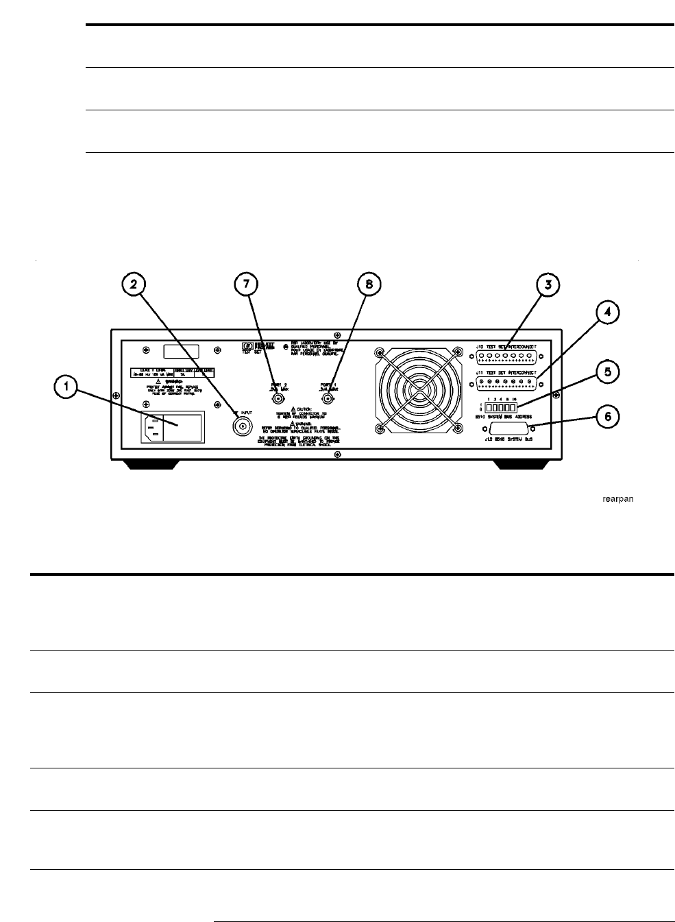
Figure 3-2 Rear-Panel Features of the HP 8517B Test Set
(6) a1 LED This LED indicates that the test set is internally switched to the S11 or S21 mode and source power
is switched to Port 1.
(7) a2 LED This LED indicates that the test set is internally switched to the S22 or S12 mode and source power
is switched to Port 2.
(8) Port 2 This test port transmits RF energy from the source to the DUT and receives reflected or transmitted
RF energy from the DUT.
Table 3-2 Rear-Panel Descriptions
(1) Line Module Houses the line cord connector, line fuse and line voltage selector. Pull out the right side
of the line module cover to replace or change the fuse or to change the voltage selection.
Remove the voltage selector drum to rotate it to a different voltage setting. Recommended
fuse values are printed on the rear panel.
(2) RF Input A 2.4 mm connector that receives RF energy from the source. Connections made to this
input must be torqued no more than 90 N-cm (8 in-lb).
(3) J10 Test Set Interconnect Used only in test sets with Option 001. It allows connecting another test set to the option
001 test set. Up to four test sets can be serially connected to the analyzer. The HP 8510C
system automatically selects the IF output from the chosen test set for processing and
display. Refer to “Controlling Multiple Test Sets” in this chapter for more information.
(4) J11 Test Set Interconnect Transmits the IF signal from the test set to the HP 85102 IF detector. It also transmits
control signals bi-directionally.
(5) HP 8510 System Bus Address Switch A five-pole binary-weighted switch sets the test-set’s system bus address. The binary
weight of each pole is indicated on the rear panel. So are the On and Off positions. The
default setting is decimal twenty (off-off-on-off-on, from left to right).
Table 3-1 Front-Panel Description (Continued)

HP 8517B S-Parameter Test Set Manual
3-3
Controlling Multiple Test Sets
HP 851X Series, Option 001 test sets allow an HP 8510C to alternately
control up to four test sets connected to it. For example:
•While a measurement is underway on test set number 1 (equipped with
Option 001), a test device can be connected to test set number 2 (which
does not need Option 001).
•When the measurement on test set number 1 is complete, the HP 8510C
can then control test set number 2.
In a standard test set, the 20 MHz IF and control signals are applied directly
to J11 TEST SET INTERCONNECT, which is attached to the HP 8510C.
Option 001 adds a set of IF switches, control switches, and the J10 TEST
SET INTERCONNECT attachment. This configuration allows the selection
of the 20 MHz test set IF signal.
As shown in Figure 3-3 on page 3-4, test set number 1 can:
•apply its IF signal to the HP 8510C, or it can
•switch to pass the IF signal from test set number 2, through J10 TEST
SET INTERCONNECT, and into the HP 8510C.
(6) J12 8510 System Bus Connector Used for HP-IB communications with the HP 85101 display/processor.
(7) Port 2 Bias A female BNC connector used to supply bias through the center conductor of Port 2 to
active devices under test.
(8) Port 1 Bias A female BNC connector used to supply bias through the center conductor of Port 1 to
active devices under test.
Table 3-2 Rear-Panel Descriptions (Continued)
HP 8517B S-Parameter Test Set Manual
3-4
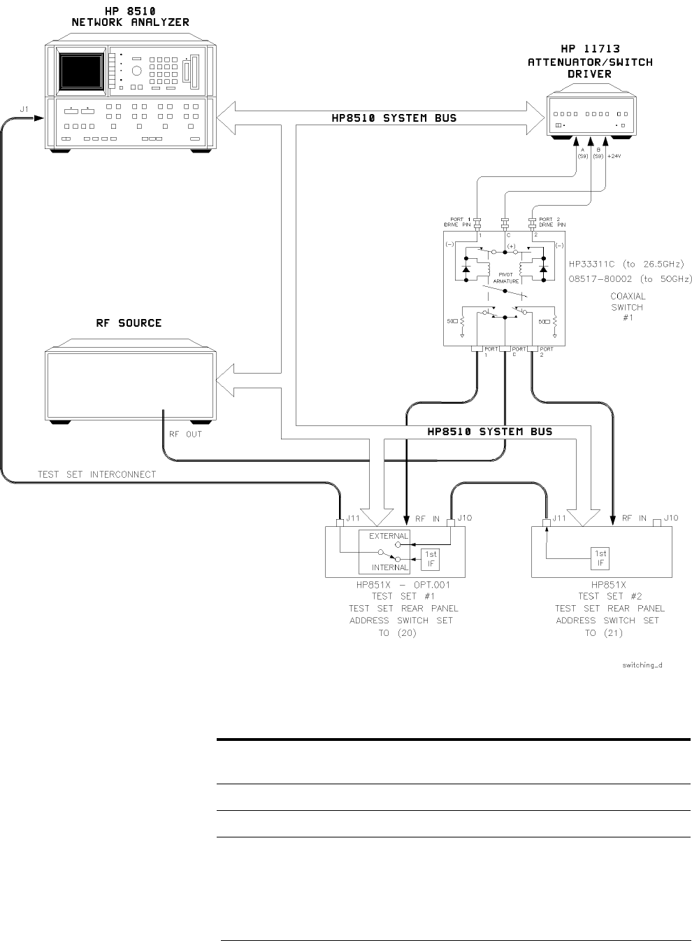
Figure 3-3 RF and IF Switching with Two Test Sets
Table 3-3 RF and IF Switch Settings in Figure 3-3, Above
New ADDRESS of
Test Set
1,
2
1. Not all system connections are illustrated.
2. In dual source configurations, the second source may be multiplexed in a similar manner. If only one
dual source test set is used, the second source may be connected directly to the appropriate test
set.
Test Set Number
Selected Coaxial Switch Port Selected
20 Number 1 Port 1
21 Number 2 Port 2

HP 8517B S-Parameter Test Set Manual
3-5
Multiple Test-Set Connections
For dual test-set configurations, set each rear panel address switch on each
test set to the address shown in Figure 3-3. Refer to Figure 3-4 on page 3-7
for the configuration of two or more test sets.
•Use the supplied test set interconnect cable to attach test set number 1,
J11 to the network analyzer.
•Use the supplied test set interconnect cable to attach test set number 2,
J11 to test set number 1, J10.
You may connect up to four test sets in a series if the total length of all test
set interconnect cables does not exceed 13 meters (about 40 feet). The last
test set connected in the chain does not require Option 001.
If the RF coaxial switch is not incorporated into the system, the RF input to
the test set must be manually switched to the active test set.
Initialization at
Power-Up
At power-up, configure the IF switches so that only one system test set is
active. To verify which test set is active, use the following steps:
1. Verify that all system test set LEDs are lit.
2. View the network analyzer’s test set address by pressing the
INSTRUMENT STATE,
[LOCAL]
key, then press
{TEST SET}
.
The HP-IB
address of the test set is displayed on the screen.
The address displayed must match the address of the test set selected. If
not, enter the correct address using the network analyzer’s key pad.
3. If an unselected test set’s LEDs are lit, deactivate it. Do this by entering
its address, pressing
[x1]
, then entering the address of the test set desired,
followed by
[x1]
.
Selecting a Test Set To select another test set, follow the procedure in Table 3-4 on page 3-6 of
this chapter.

HP 8517B S-Parameter Test Set Manual
3-6
Table 3-4 Selecting a Test Set When Multiple Units are Configured
Test Set IF Switching A test set is selected via the built-in capability of the analyzer to generate an addressed
command to each test set. Each time you change the
{HP-IB ADDRESS}
{TEST SET}
function (refer to LOCAL [MENU] in the
HP 8510C Operation and Service Manual
), the
network analyzer does the following:
• switches the IF signal of the previously addressed test set to external
• switches the IF signal of the newly addressed test set to internal
• sets the test set’s front panel ACTIVE LED to indicate test-set status
• applies the active test set’s IF signals directly to J11 TEST SET INTERCONNECT
• passes the inactive test set’s IF signals at J10 through to J11 and on to the next
test set or to the network analyzer
Test Set Addressing You can change the test set address via program control, or via the network analyzer front
panel keys. You must also change the mechanical switches on the test-set’s rear panel.
Here’s how:
1. Change the test set address via the network analyzer keys;
a. On the analyzer’s front panel, press the INSTRUMENT STATE [LOCAL] key, then
press
{TEST SET}
. The test set’s address appears on the display.
b. Using the key pad, enter the desired address for the test set, then press [x1]. The new
HP-IB address appears on the display.
2. Change the test set address via the HP-IB command:
From the controller, enter the HP-IB ADDRESS; command, followed by the
address value. Refer to the command reference for programming details.
3. Reset the mechanical switches on the test-set’s rear panel. Set the switches to match the
new HP-IB address displayed on the network analyzer screen.
RF Switch Driver Control When the
{HP-IB ADDRESS}
{TEST SET}
function is changed, the network analyzer
generates a code sequence. The code sequence is automatically issued across the
HP 8510C system bus to the device at the ADDRESS of RF SWITCH .
In the recommended configuration, the device is an HP 11713A attenuator/switch driver. The
switch/driver in turn controls one or more coaxial switches. These switches, (shown in a
Figure 3-3, and Figure 3-4) are used to choose which test set receives the RF output from the
network analyzer source.
The exact command issued depends upon the new value of the
{HP-IB ADDRESS}
{TEST SET}
value, also shown in shown in a Figure 3-3 and Figure 3-4.
HP 8517B S-Parameter Test Set Manual
3-7
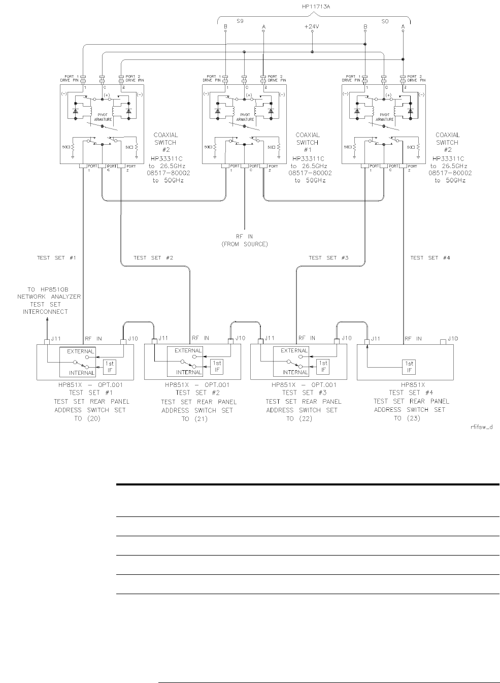
Figure 3-4 RF and IF Switching with Four Test Sets
Table 3-5 Coaxial Switch Settings for Figure 3-4, Above
New ADDRESS
of Test Set
1,
2, 3
1. Not all system connections are shown.
2. In dual source configurations, the second source can be multiplexed in a similar manner.
3. If only one dual source test set is used, the second source can be directly connected to the
appropriate test set.
Test Set Selected
1, 2, 3
Coaxial Port Selected
with Switch #1 Coaxial Port Selected
with Switch #2
20 1 Port 1 Port 1
21 2 Port 1 Port 2
22 3 Port 2 Port 1
23 4 Port 2 Port 2

HP 8517B S-Parameter Test Set Manual
3-8
Measurement Calibration
After selecting the active test set, complete the system calibration procedure
as usual. When you select a different test set, make sure that you recall the
cal set that applies to that test set.
NOTE
Since the cal-set limited instrument state does not include the number of the
active test set, a cal set which does not apply to the current test set can be
turned on without displaying the HP 8510C caution messages. However, this
causes errors in the data displayed because incorrect error coefficients are
applied to the measured data.
For convenience, store a hardware-state file and an instrument-state file for
each combination of test set to cal set. You may also store your hardware
state file on a tape or disk for future use.
To change the configuration, recall the appropriate hardware state file. The
hardware state file:
•sets the address of test set
•issues the RF switch command, then
•recalls the appropriate instrument state file which
•recalls the cal set

HP 8517B S-Parameter Test Set Manual
3-9
Measuring High-Power Devices with Option 004
The HP 8517B, Option 004 test set enables devices with output power up to
30 dBm (1 watt) to be measured at Port 2, without adding external
attenuators. Reverse dynamic range (S12) degrades by approximately 3 dB.
When measuring devices having greater than +17 dBm output power, you
must use the Port 2 step attenuator to decrease the power to ≤+17 dBm.
The step attenuator has to be set during calibration for the value needed
during device measurements. However, this setting may cause inadequate
power level during calibration. Refer to “Changing Signal Path States After
System Calibration” on page 3-10 for additional information.

HP 8517B S-Parameter Test Set Manual
3-10
Changing Signal Path States After System
Calibration
Changing an internal attenuator or any external equipment after completing
the calibration means the measurement results cannot be specified. You must
use your own estimation of the potential error contribution due to the
change.
For example, when the port attenuation is changed with correction ON, the
message CAUTION: CORRECTION MAY BE INVALID displays. You must judge
whether the error is tolerable in the particular application and how to
compensate for the change.
The application question is: “Does increasing the signal level during
calibration improve the calibration enough to risk a possible increase in error
contributions when you change the setup?”
The only reason for changing an internal attenuator or external equipment
between calibrations and measurements is to maximize the signal level
under both conditions, thus minimizing uncertainty due to noise.
Many factors enter into a setup-change decision, for example:
•is it more accurate to calibrate at a low signal level without changing the
setup, or
•is it more accurate to change the setup to optimize levels for both the
calibration and measurement
Changing attenuators at Port 1 or Port 2 does not change the test set
mismatch, directivity, or isolation characteristics severely. It does change the
frequency response magnitude and phase, however. The difference between
frequency response calibration and measurement can be normalized by using
HP 8510C trace memories.
Changing the Test Port
Attenuators
If only the attenuators at Port 1 or Port 2 are changed, use the following
procedure to minimize errors:
1. Connect a short, or a thru, and set Port 1 and Port 2 attenuators for the
best IF signal levels during calibration.
2. Perform the appropriate measurement calibration.
3. Connect the correct calibration standard, set Port 1 and Port 2
attenuators to the value required for operating the test device.

HP 8517B S-Parameter Test Set Manual
3-11
If you view the response of a short circuit, notice that:
•Changing Port 1 attenuator has negligible effect on S11 marker reading
•Changing Port 2 attenuator has negligible effect on S22 marker reading
This is due to the way the attenuators are paired. Both the reference and the
test signal are changed by approximately equal amounts.
When viewing S21 or S12, however, changing Port 1 or Port 2 attenuators
offsets the marker reading by the difference value between Port 1 attenuator
and Port 2 attenuator.
Storing Trace
Memories
To compensate for the main frequency response effects due to changing
the attenuators, use the HP 8510C trace memories and trace mathematics
function, as explained below:
1. Connect the thru used for calibration and set the port attenuators to the
value used for device measurement.
2. Recheck the user parameter levels, then press PARAMETER [
S21
].
3. Press MENUS
[DISPLAY]
,then
{DATA AND MEMORIES}
.
Press DISPLAY:
{DATA-->MEMORY n}
to store the S21 trace in default trace
memory 1. This trace represents the frequency response difference
between the S21 signal path calibration and the measurement.
4. Press PARAMETER
[S12]
, then press the following DISPLAY: menu keys:
{SELECT DEFAULTS}
{DEFAULT to MEMORY: 2}
{DATA-->MEMORY 2}
The S12 trace is now stored in trace memory 2. This trace is the
frequency response difference of the S12 signal path between calibration
and measurement.
Viewing Normalized
Parameters
Use the traces stored in memory 1 and memory 2 to normalize the corrected
data to the new levels after the attenuation is changed. The next example
uses normalization for S21 or S12, only. To view the corrected parameters:
1. Press MENUS
[DISPLAY]
,then
{DATA AND MEMORIES}
2. Press PARAMETER
[S11]
and view the S11 measurement.
3. Press PARAMETER
[S22]
and view the S22 measurement.
4. Press PARAMETER
[S21]
, then the following DISPLAY: menu keys:
{SELECT DEFAULTS}
{DEFAULT to MEMORY: 1}
{MATH ( / ) }

HP 8517B S-Parameter Test Set Manual
3-12
5. View the S21 measurement. If the thru is connected, the transmission
coefficient should be 1 ∠0°.
6. Press PARAMETER
[S12]
, then press the following DISPLAY: menu keys:
{SELECT DEFAULTS}
{DEFAULT to MEMORY: 2}
7. Press PARAMETER
[S12]
to view the S12 measurement. If the thru is
connected, the transmission coefficient should be 1 ∠0°.
Normalization is turned OFF for S11 and S22 measurements. Then the
appropriate memory is selected and normalization is turned on to view S21
and S12.
Since these are accurate, repeatable attenuators, this sequence may be
effective in your application. If other parts of the test must be changed,
especially components connected to the test ports, this procedure may
require additional steps to adequately compensate for the changes.

HP 8517B S-Parameter Test Set Manual
3-13
Making Operational Checks
To check the operation of multiple test-set configurations, do the following:
1. Connect a device with a known response to test set number 1. Press the
following HP 8510C front-panel keys:
INSTRUMENT STATE
[LOCAL]
AUXILIARY MENUS
[SYSTEM]
{HP-IB ADDRESSES}
{TEST SET}
2. When the message TEST SET HP-IB ADDRESS appears, enter
[20]
,the
address of test set number 1, then press
[x1]
. The measurement trace from
test-set number 1 should display.
3. Store the trace in memory by pressing the following keys:
MENU
[DISPLAY]
{DATA AND MEMORIES}
{DATA --> MEMORY n}
DISPLAY
: {DATA and MEMORY]
4. Next, enter the HP-IB address of test set number 2, followed by
[x1]
,then
re-enter the address of test set number 1 followed by
[x1]
.
5. Repeat the above procedure for each of the other test sets in the system.
Observe any difference in the response between the stored trace and the
results trace by switching back and forth between the test sets.
Any differences in data that you suspect are due to the IF switch (Option
001) or to RF switching, must be checked out. Refer to Chapter 5,
“Troubleshooting the Test Set” in this manual.

HP 8517B S-Parameter Test Set Manual
3-14
Performance Verification
Standard system performance verification procedures verify the operation of
an Option 001 test set used as test set number 1.
To verify the performance of a different test set in the configuration, enter its
HP-IB address (as explained in “Making Operational Checks” on page 3-13)
to select it, then continue with this procedure.
Refer to the HP 8510C On-Site Service Manual for its performance
verification procedure.

HP 8517B S-Parameter Test Set Manual
3-15
Using Anti-Rotation Clamps
During the performance verification procedure, use anti-rotation clamps to
secure RF connections at the test ports of each test set. While installed, each
clamp stabilizes the connector on RF cable to the large nut on the test set’s
RF test port. If an adapter is used, the clamp stabilizes the adapter to the
front panel RF port connector.
Without these clamps, the test port connections can loosen when a device
under test is moved. As a result, the loosening can invalidate calibrations and
measurements.
NOTE
These instructions refer to an installation using HP RF cables. However, the
anti-rotation clamps may also be used with front panel adapters. Adapter
installations are similar. There are two anti-rotation clamps included in the
test set accessories box.
Attach the first clamp
Remove one anti-rotation clamp from the accessories box. Loosen its
thumb-screw until it is nearly freed from the counter-sink socket in the
clamp body. The clamp is shown as item (5) in Figure 2-1, “Accessories
Supplied with the HP 8517B Test Set.”
1. Gently push the clamp (round-hole end first) over and past the RF cable
connector to be used.
2. Fit the rubber O-ring in the round end of the clamp over the connector.
NOTE
If the O-ring is not snug or is damaged, refer to the Chapter 6, “Replacement
Procedures” for instructions about replacing the internal O-ring.
3. Wiggle the clamp to ease it over the connector.
4. Attach the cable to the test port and tighten it as specified in the cable
manual.
NOTE
Do not twist the cable as you attach it to the test port.
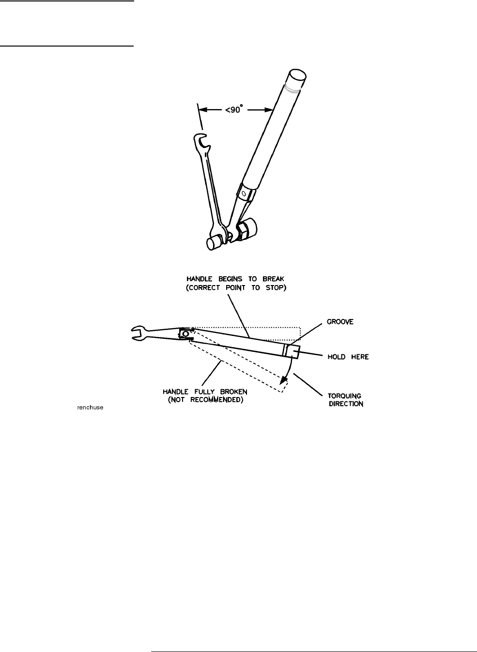
Use the torque wrench supplied with your calibration kit to tighten the cable
to 90 N-cm (8 in-lb). Do not over-torque the connection. See Figure 3-5.
HP 8517B S-Parameter Test Set Manual
3-16
CAUTION
Important! The test set RF connector becomes loosened easily. Hold the RF
cable securely throughout the remainder of this procedure. Do not allow the
cable to rotate.
Figure 3-5 Using a Torque Wrench Correctly
Positioning the thumb-screw
See Figure 3-6. Position the clamp so the thumb-screw is positioned at the
top of the clamp.
•Turn the clamp to visually align the clamp flats with the flats on the test
port connector nut.
•This positioning minimizes rotating the connector in the procedure step.
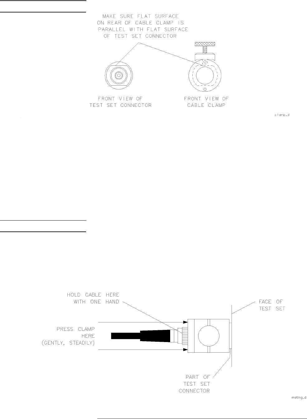
HP 8517B S-Parameter Test Set Manual
3-17
NOTE
The flats may actually be in any orientation, with respect to the front panel.
Figure 3-6 Visually Aligning Clamp and Nut Flats
Positioning the connector
See Figure 3-7. Maneuver the clamp over the RF connector and onto the test
port connector.
1. Hold the test cable with one hand. Use the other hand to press the clamp
gently and steadily, as you wiggle it into position straight over the RF
connector and onto the test port connector nut.
NOTE
Be sure to loosen the clamp when you are slipping it over the connector.
2. Fit the internal flats in the clamp over the flats on the test port connector
nut.
3. Avoid rotating the clamp as you position it so the RF connection remains
tight (remember it loosens easily).
Figure 3-7 Mating the Clamp and Nut Flats
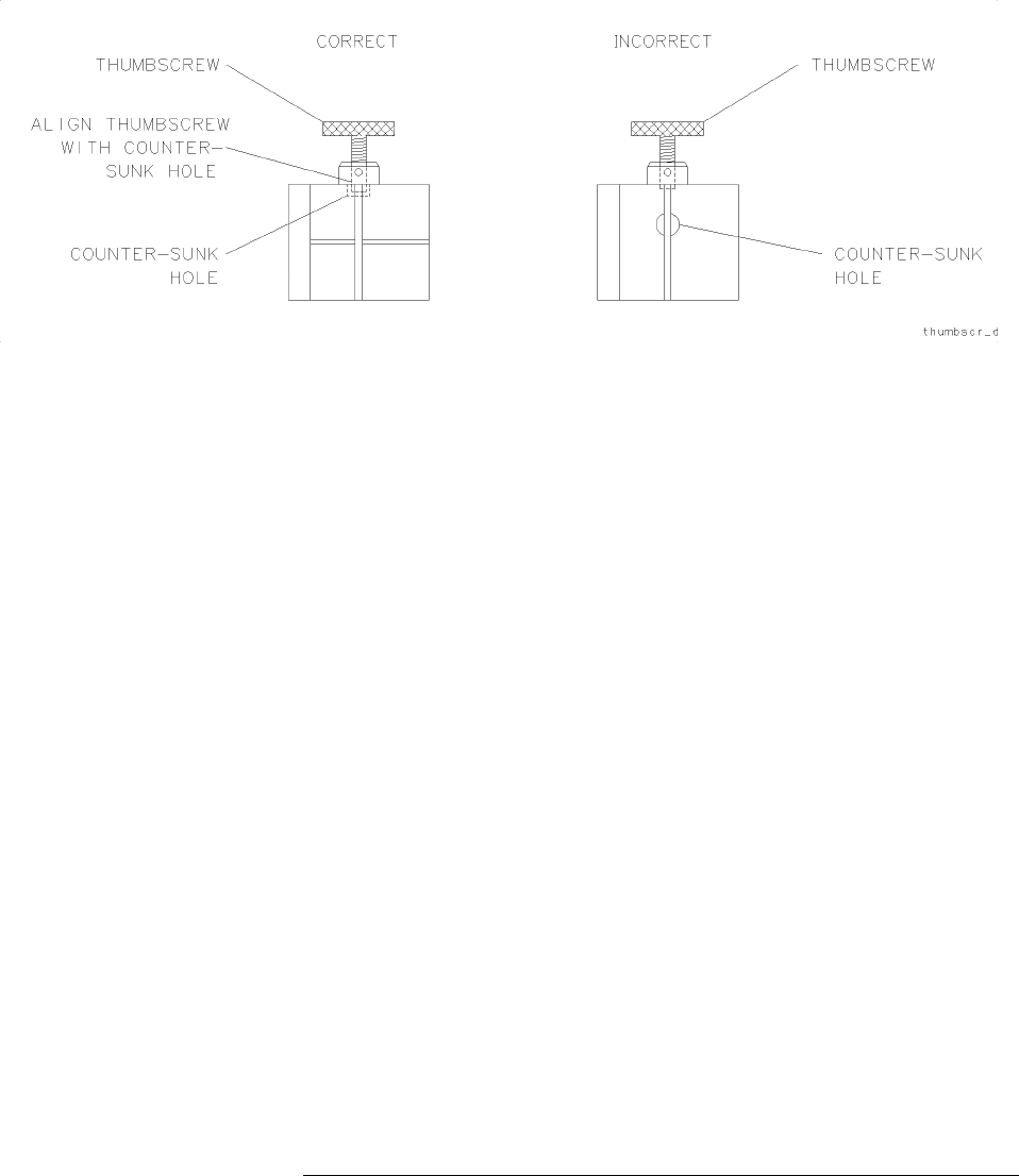
3-18
HP 8517B S-Parameter Test Set Manual
Operating the HP 8517B Test Set
Using Anti-Rotation Clamps
Aligning the thumb-screw
See Figure 3-8. Ensure that the thumb-screw is aligned with the counter-sink
hole on the clamp’s body.
1. Push the clamp toward the test set front panel.
2. Finger-tighten the thumb-screw. The cable cannot be damaged if the
thumb-screw is tightened too tightly.
Figure 3-8 Aligning the Thumbscrew With the Counter-Sink Hole
Attaching the second clamp
To complete the anti-rotation clamp installation, repeat the steps above,
beginning at step 1 to attach the second clamp.

HP 8517B S-Parameter Test Set Manual
-1

HP 8517B S-Parameter Test Set Manual
4-2
Specifications
4
Specifications
Specifications describe the warranted performance of the instrument. The
electrical specifications of the test set when used with an HP 8510 network
analyzer, are defined in the HP 8510C On-Site Service Manual.
Mechanical Specifications
Supplemental Characteristics
Supplemental characteristics listed in Table 4-2 provide useful information
by giving typical, but non-warranted, performance parameters.
Table 4-1 HP 8510/HP 8517B Mechanical Specifications
Test Port Description Specification
Connector Type:
Precision, rugged male test-port connector
2.4 mm1
1. Precision rugged make test-port connector.
Center Pin Recession2
2. Refer to the calibration kit manual to learn about measuring the pin depth.
+0.00254 mm to +0.0178 mm
+0.0001 inches to +0.007 inches
Table 4-2 HP 8510/HP 8517B Supplemental Characteristics
Front Panel Test Ports
Connector type precision 2.4 mm, male
Connector torque 90 N-cm (8 in-lb), maximum
Impedance 50
Ω,
nominal
Damage-input level
At Port 1 and Port 2
: +17 dBm CW, RF
At Port 2 with Option 004:
30 dBm CW (1 watt) CW, RF
DC bias 500 mA, 40 Vdc, maximum
Nominal source operating power level
+
2 dBm to –20 dBm,
with flatness correction off, depending on frequency
Nominal connector-nut size 20 mm

4-3
HP 8517B S-Parameter Test Set Manual
Specifications
Rear Panel RF Connectors
Connector type precision 2.4 mm female
Recommended connection torque 90 N-cm (8 in-lb), maximum for precision-2.4 mm hardware
Damage input level 15 dBm1
Nominal connector-nut size 8 mm
User 1 Power Levels for Reference Channel Phase Lock
Minimum power level –45 dBm
Maximum power level –10 dBm to –20 dBm, depending on frequency
HP 8517B Power Requirements and Physical Characteristics
Operating temperature range 0
°
C to 55
°
C
Input Power (AC) 110, 120, 220, or 240 Vac, ±10%
Line frequency from 47 to 66 Hz
Dimensions 460 mm (High)
×
133 mm (Wide)
×
609 mm (Deep)
(18.1 inches H
×
5.25 inches W
×
24 inches D)
Weight 15 kg (35 lb), net
1. This must be AC coupled.
Table 4-2 HP 8510/HP 8517B Supplemental Characteristics (Continued)

HP 8517B S-Parameter Test Set Manual
4-4
Specifications

HP 8517B S-Parameter Test Set Manual
5-1
5
Troubleshooting the Test Set
The troubleshooting strategy for the HP 8517B S-Parameter test set is a
systematic sequence of procedures. The information may be used after
system-level troubleshooting has identified the test set as the problem
instrument.
Use the troubleshooting flowchart in Figure 5-2 to help isolate the faulty
assembly. Notice procedure numbers within some of the flow diagram
blocks. These are keyed to troubleshooting procedures. Perform the
numbered procedure associated with each block as you progress through the
chart.
Refer to the block diagrams, located at the end of this section, to help you
understand the test set’s operation.
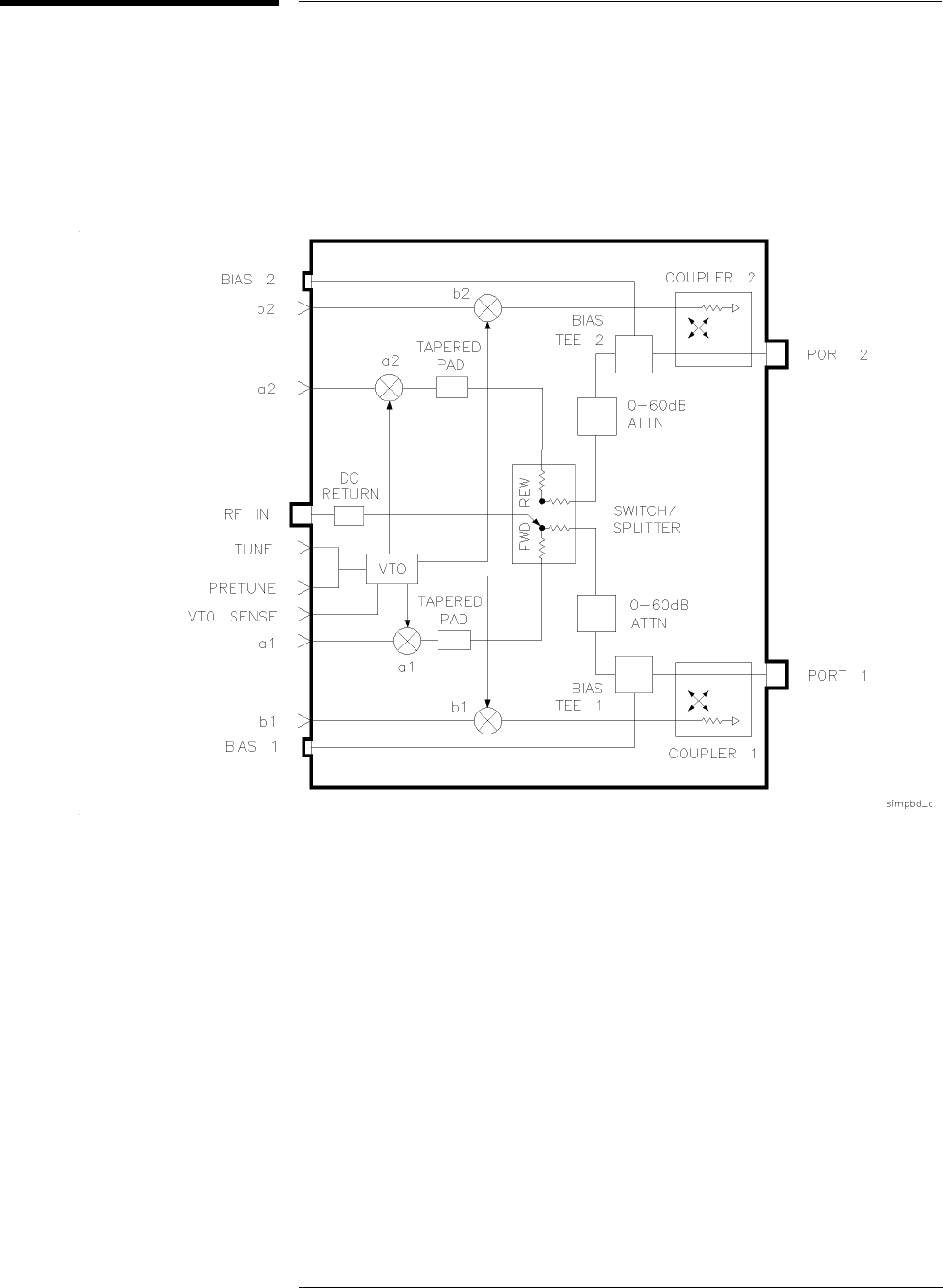
5-2
HP 8517B S-Parameter Test Set Manual
Troubleshooting the Test Set
Theory of Operation
Theory of Operation
RF paths for Port 1 and Port 2 are similar. This section discusses in detail the
source power signal, as it is routed via the RF IN connector, through the test
set, and to Port 1 for S11 and S21 measurements.
Figure 5-1 Standard HP 8517B RF Block Diagram
TheRFSourcePower •RF source power enters the test set through the rear panel. The RF power
is applied to the switch/splitter (A18).
•At the switch/splitter, the power is attenuated by approximately 7 to
14 dB, depending upon frequency.
•The switch/splitter receives its control signals from the attenuator/switch
driver board (A5).
•The switch part of the switch/splitter, which is a combination of two
power splitters and a solid-state switch, selects the power splitter to use
and, therefore, the test port to receive the RF power.
•LEDs on the front panel and on the attenuator/switch driver board (A5)
indicate which test port is active.

HP 8517B S-Parameter Test Set Manual
5-3
Troubleshooting the Test Set
Theory of Operation
The Reference Signal
Path •The reference signal is routed from the switch/splitter through the
20-7 dB tapered pad (AT1) to attenuate any VTO feed-through signals.
•The signal is then applied to A10, the a1 sampler assembly, where it is
down-converted to a 20 MHz IF (intermediate frequency).
•Because the RF power is being routed to Port 1, the a1 IF signal is used
to phase lock the network analyzer. Had the RF power been routed to
Port2,thea2IFsignalwouldhavebeenusedtophaselockthenetwork
analyzer.
The Test Signal Path •The test signal is routed from the switch/splitter (A18) to the 60 dB
programmable attenuator (A16) for Port 1.
•The signal may then be attenuated in 10 dB steps or passed through
without attenuation to Port 1 bias tee (A7).
•A bias supply to provide dc voltage to Port 1 bias tee can be connected
to J8 on the rear panel of the test set, also.
•The RF signal rides this dc level which is used to turn active devices on
(bias ON) so their S-parameters can be measured.
•Beyond the bias tee, the test signal travels to the directional coupler
(A6).
•At the coupler, the incident RF power is applied to the device under test.
The S11 and S21
Measurements •The signal reflected from the DUT is separated from the signal incident
to the DUT by the Port 1 coupler (A6).
•The reflected signal exits the coupler and is applied to b1 sampler (A12),
then is down-converted to a 20 MHz IF signal.
•The S11 measurement is the ratio of the two IF signals from a1 and b1
samplers.
•The incident signal is transmitted through the DUT, through Port 2
coupler, then into b2 sampler (A13).
•The incident signal is down-converted to a 20 MHz IF so S21 can be
measured. S21 is the ratio of the two IF signals from samplers a1 and b2.
The Sampler Control
Switching •The samplers may be turned on and off, depending upon the parameter
being measured.
•Sampler switching is controlled by a microprocessor on the HP-IB board
assembly (A4). The default condition (test set power ON and no HP-IB
commands sent by the network analyzer) is for the test set to be active
with the RF signal applied to Port 1.

5-4
HP 8517B S-Parameter Test Set Manual
Troubleshooting the Test Set
Theory of Operation
•If the test set is equipped with Option 001 (multiple test set capability),
its begin state is inactive. That is, rather than using the test set’s internal
IF, a switch is set in the test set to accept an IF from another test set.
The LO Signal Control The LO, generated by A14 VTO/driver, is phase locked to the source so the
desired VTO harmonic is 20 MHz greater than the source frequency.
The phase-locked loop includes:
•Portions of the test set, such as the VTO summing-amp board (A3), the
VTO/driver (A14), and the a1 sampler assembly (A10), and
•The HP 8510C Network Analyzer
The VTO summing-amp board (A3) provides control voltages to tune the
VTOtothecorrectLOfrequency.
The VTO also has an output LENDRA (Low END of RAnge) which is
routed via the test set interconnect cable, to the HP 85102.
The LENDRA provides an indication to the network analyzer about whether
or not the VTO is operating within its normal frequency range.
If the VTO exceeds its normal frequency range, the network analyzer
displays the running error message VTO OVER RANGE.
CAUTION
Electrostatic Discharge Sensitive (ESD) Assemblies
Assemblies you might handle in these troubleshooting procedures are
extremely sensitive to damage from static electricity. They may or may not
continue to function if they are subjected to electrostatic discharge. Their
reliability, however, will be impaired.
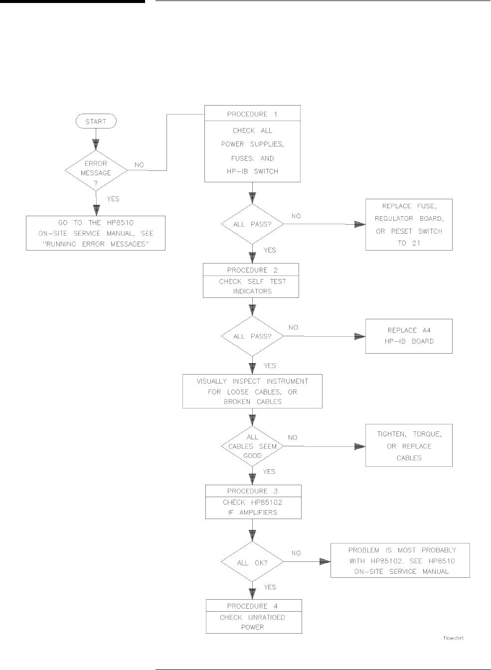
HP 8517B S-Parameter Test Set Manual
5-5
Troubleshooting the Test Set
Troubleshooting Sequence
Troubleshooting Sequence
Use this troubleshooting flowchart, along with the procedures in the
following section, to help isolate faulty assemblies.
Figure 5-2 Troubleshooting Flowchart

5-6
HP 8517B S-Parameter Test Set Manual
Troubleshooting the Test Set
Troubleshooting Sequence
Equipment Needed
But Not Supplied
Gather the equipment listed in Table 5-1 to use for troubleshooting the test
set (these items are not supplied with the instrument at shipment).
Table 5-1 Equipment Required, But Not Supplied
Equipment Type HP Part Number
1-point, Pozidriv screwdriver 8710-0899
2-point, Pozidriv screwdriver 8710-0900
Service adapter 85105-60210
5/16-inch torque wrench 8710-1655
Oscilloscope HP 1740A

HP 8517B S-Parameter Test Set Manual
5-7
Troubleshooting the Test Set
Troubleshooting Procedures
Troubleshooting Procedures
The troubleshooting procedures in this chapter are listed below:
•“A15 Primary Regulator Board Assembly” on page 5-7
•“A27 Post-Regulator Board Assembly” on page 5-7
•“Self-Test Indicators” on page 5-9
•“HP 85102 IF Amplifier Test” on page 5-12
•“Unratioed Power Test” on page 5-14
•“HP 8517B, Option 007 Unratioed Power Test” on page 5-20
•“Finding the Faulty Assembly” on page 5-23
A15 Primary Regulator
Board Assembly Use a digital voltmeter to check the voltages and an oscilloscope to check for
a maximum ripple level as listed in Table 5-2.
A27 Post-Regulator Board
Assembly (Option 007, Only) Use a digital voltmeter to check the voltages and an
oscilloscope to check for a maximum ripple level as listed in Table 5-3.
Table 5-2 Power Supply Voltages to A15
Nominal Voltage Test Point Voltage Range Maximum Ripple
Peak-to-Peak
+5.05 Vdc A15TP1 +4.75 to +5.25 2 mv
–5.20 Vdc A15TP2 –4.90 to –5.50 2 mv
+14.85 Vdc A15TP3 +14.10 to +15.60 2 mv
–14.85 Vdc A15TP6 –14.10 to –15.60 2 mv
Table 5-3 Power Supply Voltages to A27
Nominal Voltage Test Point Voltage Range Maximum Ripple
Peak-to-Peak
+5.0 Vdc A27TP1 +4.75 to +5.25 2 mv
–3.50 Vdc A27TP2 –3.26 to –3.75 2 mv
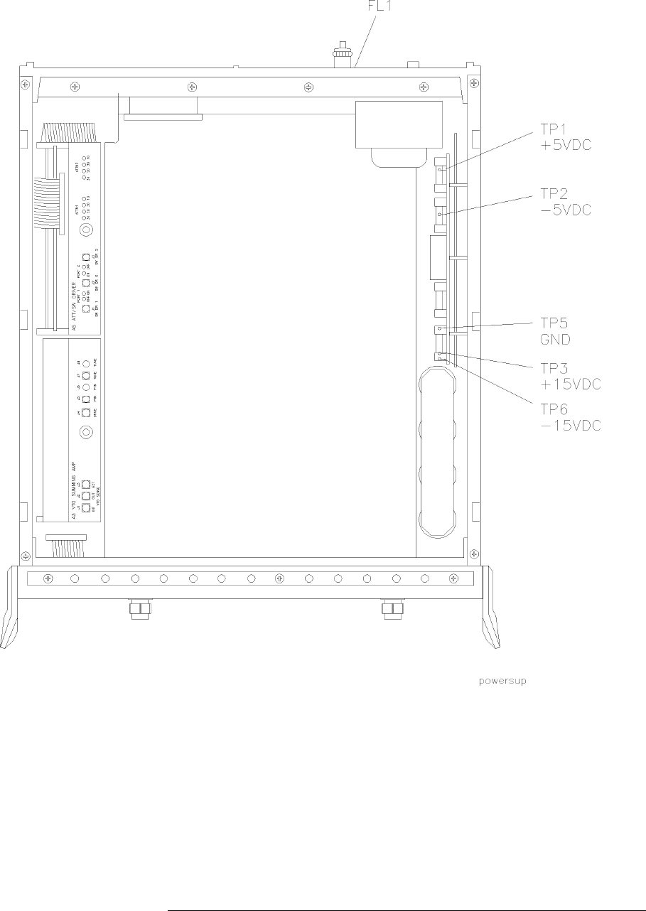
5-8
HP 8517B S-Parameter Test Set Manual
Troubleshooting the Test Set
Troubleshooting Procedures
Figure 5-3 Power Supply Fuses and Test Points
HP-IB Address Switch The HP-IB address switch is located on the rear-panel of the instrument. It is
easy to access, but unnecessary to change unless the error message SYSTEM
BUS ADDRESS ERROR appears on the system display.
To set the HP-IB address switch, position the switches as illustrated in
Figure 5-4 (the LSB is on the left-hand side; the MSB is on the right-hand
side). The default setting is decimal twenty, or binary 10100 as read from
right-to-left (on, off, on, off, off). In the drawing, the dark-side is selected.
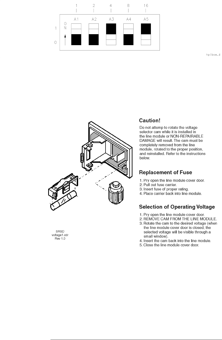
HP 8517B S-Parameter Test Set Manual
5-9
Troubleshooting the Test Set
Troubleshooting Procedures
Figure 5-4 Instrument HP-IB Switch Setting
Fuse Location The fuse is located inside the line module at the rear panel of the test set. The
value rating and part number of the fuse is listed in Chapter 7, “Replaceable
Parts” of this manual. Review the information in Figure 5-5 to replace the
line fuse or to set the voltage selector cam.
Figure 5-5 Fuse and Voltage Cam Location
Self-Test Indicators If the front-panel ACTIVE LED (shown in Figure 5-6) fails to light within
five seconds after turning the power on, or if it lights immediately, the
instrument has failed self-test.
To determine the portion of the self-test that failed, note which LEDs on A4
board assembly are turned on. Figure 5-7 shows the location of the LEDs.
See Table 5-4 for the condition description of the LED status indicators.
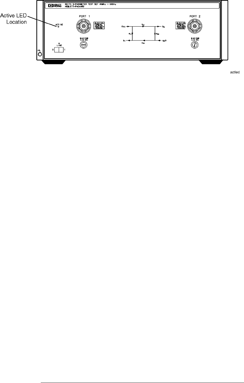
5-10
HP 8517B S-Parameter Test Set Manual
Troubleshooting the Test Set
Troubleshooting Procedures
Figure 5-6 The ACTIVE LED Location
If the Self-Test Fails to Run Properly
If the portion of memory holding the self-test program is faulty, the self-test
will not run properly. If any of the following conditions occur, it indicates
thattheA4HP-IBboardislikelytobefaulty.
•All LEDs flash briefly, then turn off
•All LEDs flash briefly and stay on
•The ACTIVE LED turns on too quickly after power on
•The ACTIVE LED does not turn on at all
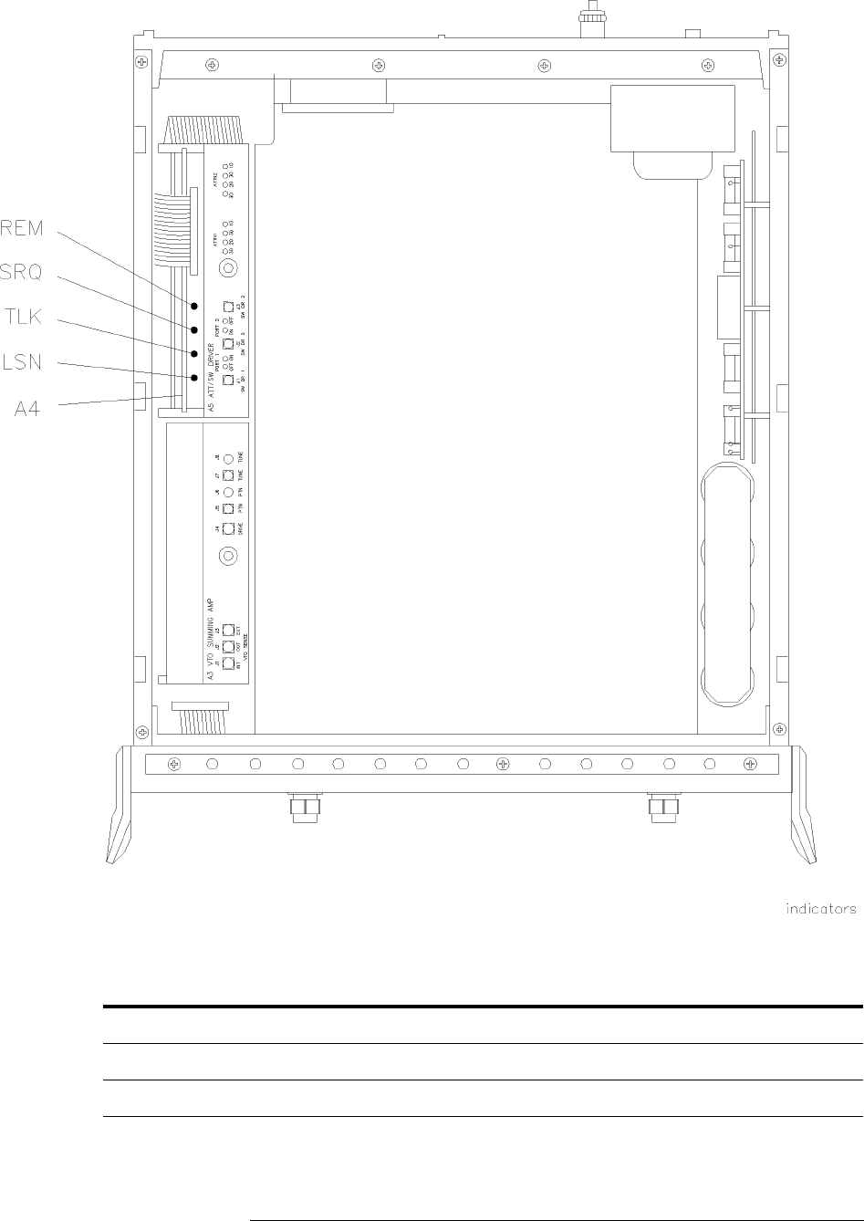
HP 8517B S-Parameter Test Set Manual
5-11
Troubleshooting the Test Set
Troubleshooting Procedures
Figure 5-7 HP 8518B Test Set, A4 Board Assembly LEDs
Table 5-4 Instrument Self-Test Indicator State Definitions
Self-Test Indication LSN TLK SRQ REM Time (Following Power-On)
PWON ON ON ON ON 0 to 0.5 seconds
Start ROM Test OFF ON ON ON on briefly (a flash)
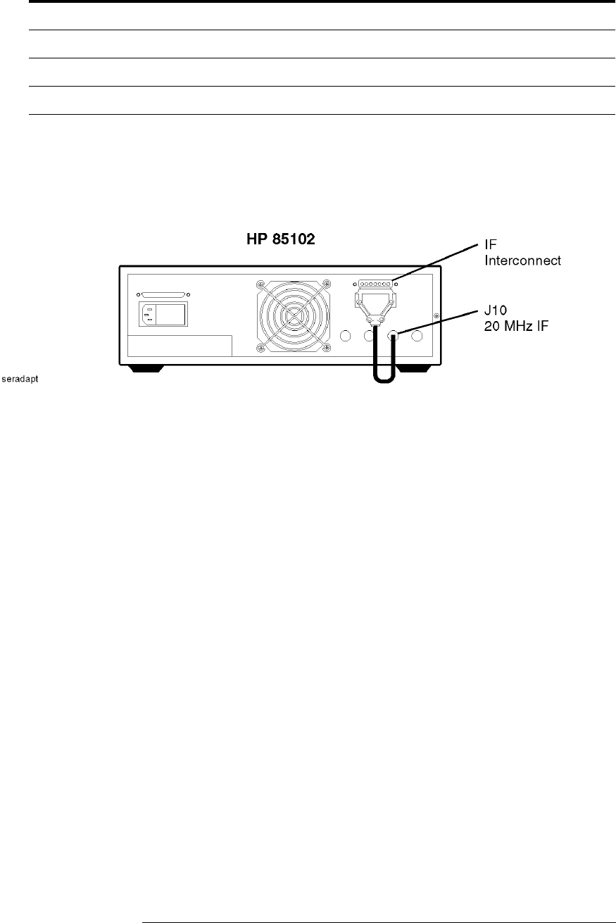
5-12
HP 8517B S-Parameter Test Set Manual
Troubleshooting the Test Set
Troubleshooting Procedures
HP 85102 IF
Amplifier Test The service adapter can substitute as a test set by returning the 20 MHz IF
signal from the HP 85102 to the amplifier on the HP 85102. Doing this
determines whether a fault is in the test set or is in the HP 85102.
Figure 5-8 Service Adapter Connections
Using the Service Adapter
1. Connect the service adapter as shown in Figure 5-8. On the network
analyzer, press:
INSTRUMENT STATE
[PRESET]
MENUS
[MARKER]
STIMULUS
[MENU]
{STEP}
PARAMETER
[MENU]
2. Examine each user parameter by pressing the
{USER 1 a1}
through
{USER 4 b1}
softkeys to observe unratioed power level traces at each
channel.
3. The traces should be flat lines, quite close to one another, as indicated by
the marker value (typically about –28 dB, ±5dB).
Pass ROM Test OFF OFF ON ON 0.5 to 0.2 seconds
Start RAM Test OFF OFF OFF ON N/A
Pass RAM Test OFF OFF OFF OFF after 2 seconds
Table 5-4 Instrument Self-Test Indicator State Definitions
Self-Test Indication LSN TLK SRQ REM Time (Following Power-On)

HP 8517B S-Parameter Test Set Manual
5-13
Troubleshooting the Test Set
Troubleshooting Procedures
Service Adapter Conclusions
Table 5-5 Results Observations
If all channels look good The HP 85102 is working properly. The problem is
most likely in the source or the test set. Refer to
Procedure 4, “Unratioed Power Tests” in this chapter.
If one or more channels look bad The problem is most likely in the HP 85102. Refer to
the HP 8510C On-Site Service Manual for information
about troubleshooting the HP 85102.
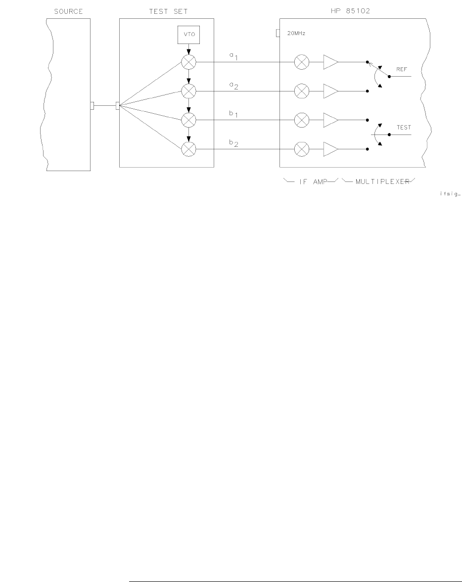
5-14
HP 8517B S-Parameter Test Set Manual
Troubleshooting the Test Set
Troubleshooting Procedures
Unratioed Power Test
We will examine six RF signal paths in the test set by observing their
associated IF signals. Figure 5-10 through Figure 5-15 show the test set
traces (and simplified block diagrams) that are typical for RF paths 1
through 6.
Figure 5-9 Diagram of IF Signal Path
Isolating Signal Path
Problems
Determining the RF component in the test set that is most likely the cause of
a failure can be accomplished within four steps:
1. Run the signal-path tests on paths 1 through 6 using the procedures on
the following pages.
2. Record your test results in Table 5-6 for each path.
3. Compare the results in Table 5-6 with those in Table 5-7.
4. Investigate the most probable cause, based on the information in
Table 5-7.
Testing Signal Paths 1-4
1. Set the network analyzer to its factory default settings by pushing the
front-panel TEST switch.
2. Set the source for step mode. Press the network analyzer keys:
INSTRUMENT STATE
[PRESET]
STIMULUS
[MENU]
{STEP}

HP 8517B S-Parameter Test Set Manual
5-15
Troubleshooting the Test Set
Troubleshooting Procedures
3. To examine each sampler’s IF signal, redefine which port and sampler
the network analyzer uses for the phase lock. Use the following steps:
a. Redefining to Port 2, sampler a2, press:
PARAMETER
[MENU]
{USER 3 a2}
then
{REDEFINE PARAMETER}
{DRIVE}
DRIVE:
{PORT 2}
{PHASE LOCK}
{a2}
{REDEFINE DONE}
Observe the resulting a2 IF trace on the display.
b. Redefining to Port 2, sampler b2, press:
{USER 2 b2}
then
{REDEFINE PARAMETER}
{DRIVE}
DRIVE:
{PORT 2}
{PHASE LOCK}
{a2}
{REDEFINE DONE}
Observe the resulting b2 IF trace on the display.
4. Connect an open (or short) to Port 1 and Port 2. Power is reflected back
to b1 and b2 samplers through the coupler.
To check each sampler trace, press:
{USER 1 a1}
{USER 2 b2}
{USER 3 a2}
{USER 4 b1}
5. Record your results for paths 1 thru 4 (
{USER 1}
to
{USER 4}
)inTable5-6.
NOTE
See Figure 5-10 for an RF signal-path 1 trace example. For Option 007, see
Figure 5-13.

5-16
HP 8517B S-Parameter Test Set Manual
Troubleshooting the Test Set
Troubleshooting Procedures
TestingPaths5and6
1. Connect a cable between Port 1 and Port 2.
2. To observe the b1 power-level trace through path 5, press:
PARAMETER
[MENU]
{USER 4 b1}
then
{REDEFINE PARAMETER}
{DRIVE}
DRIVE:
{PORT 2}
{PHASE LOCK}
{a2}
{REDEFINE DONE}
The b1 path signal is illustrated in Figure 5-12. Typically, each trace
should resemble the examples in Figure 5-12, (±5dB).
3. Record your results in Figure 5-6.
4. To observe the b2 power level trace through path 6, press:
PARAMETER
[MENU]
{USER 2 b2}
then
{REDEFINE PARAMETER}
{DRIVE}
DRIVE:
{PORT 1}
{PHASELOCK}
{a1}
{REDEFINE DONE}
The b2 path signal is illustrated in Figure 5-12. Typically, each trace
should resemble the examples in Figure 5-12, (±5dB).
5. Record your results in Figure 5-6.
NOTE
Be sure that you return the parameters to their original conditions for a1, b1,
a2, and b2. Use the redefine function to achieve this, or push the instrument
TEST switch to restore factory default conditions.
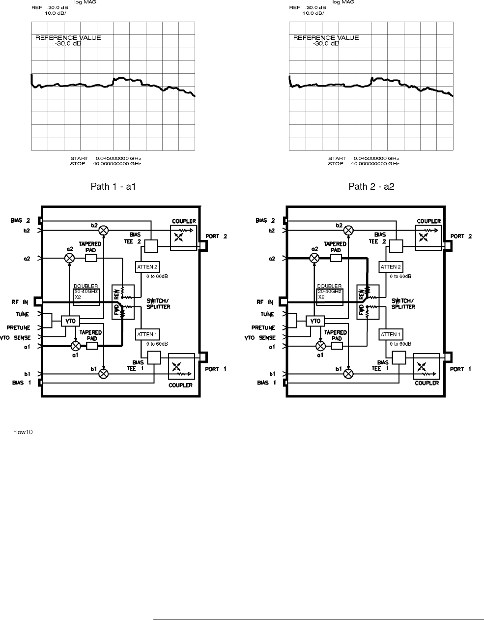
HP 8517B S-Parameter Test Set Manual
5-17
Troubleshooting the Test Set
Troubleshooting Procedures
Figure 5-10 RF Path 1 and Path 2, HP 8517B Standard Test Set
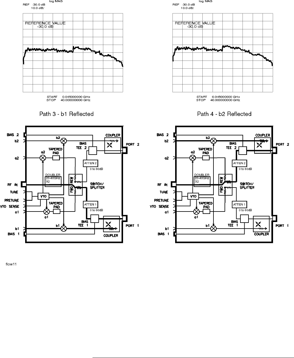
5-18
HP 8517B S-Parameter Test Set Manual
Troubleshooting the Test Set
Troubleshooting Procedures
Figure 5-11 RF Path 3 and Path 4, HP 8517B Standard Test Set
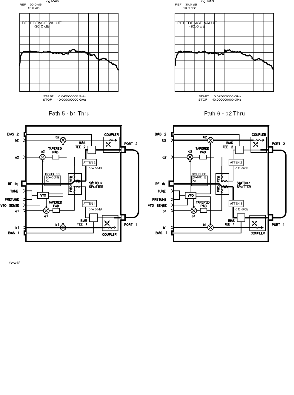
HP 8517B S-Parameter Test Set Manual
5-19
Troubleshooting the Test Set
Troubleshooting Procedures
Figure 5-12 RF Path 5 and Path 6, HP 8517B Standard Test Set
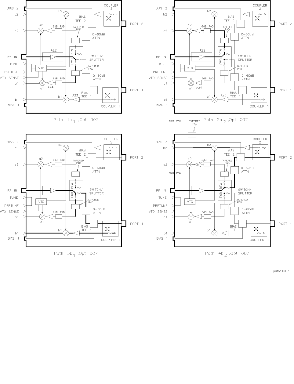
5-20
HP 8517B S-Parameter Test Set Manual
Troubleshooting the Test Set
Troubleshooting Procedures
HP 8517B, Option 007
Unratioed Power Test Figure 5-13 through Figure 5-15 illustrate the signal path and trace display
for the unratioed power tests on HP 8517B, Option 007 model test sets.
Figure 5-13 RF Path 1 through Path 4, HP 8517B Option 007 Test Set
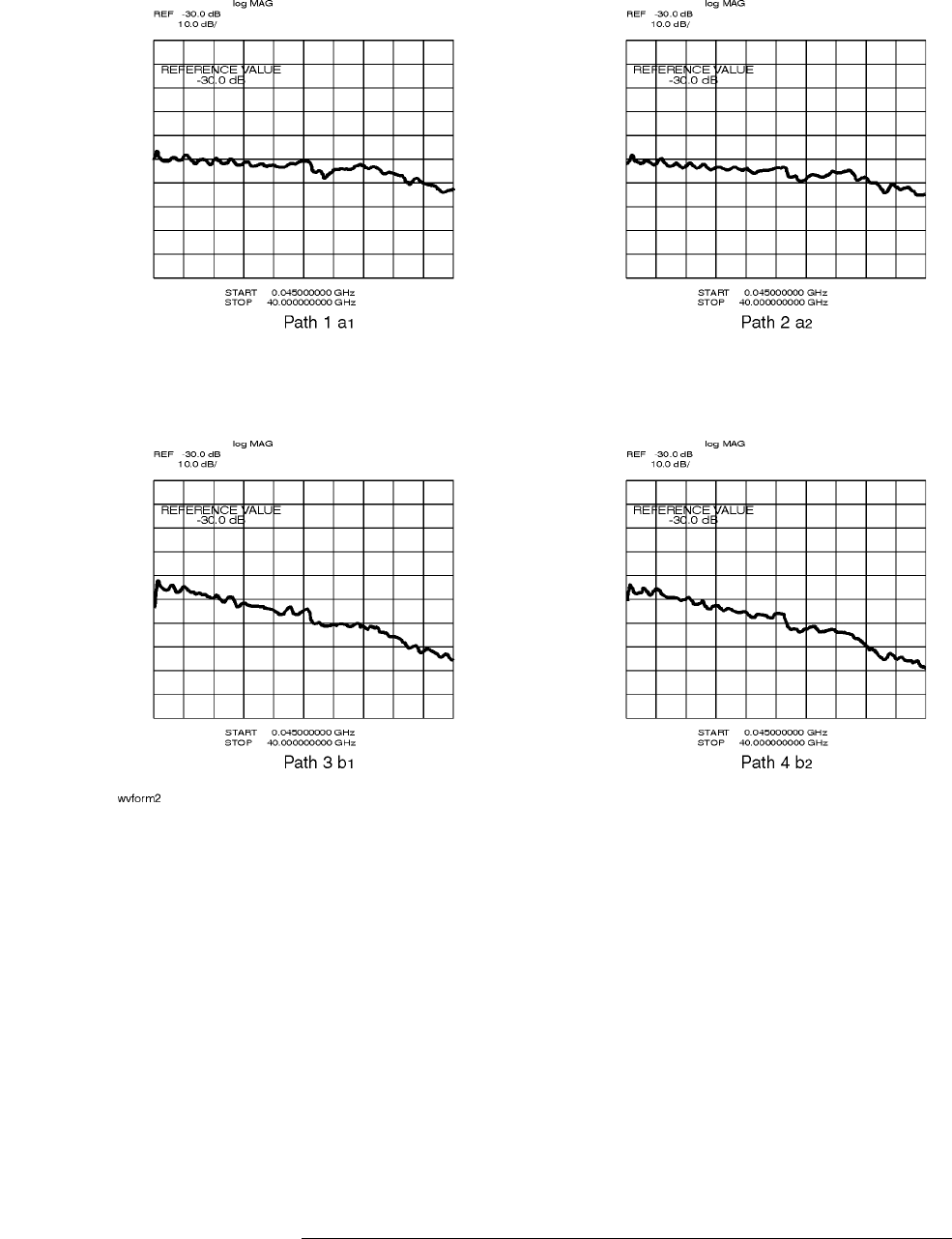
HP 8517B S-Parameter Test Set Manual
5-21
Troubleshooting the Test Set
Troubleshooting Procedures
Figure 5-14 RF Signal for Path 1 through Path 4, HP 8517B Option 007
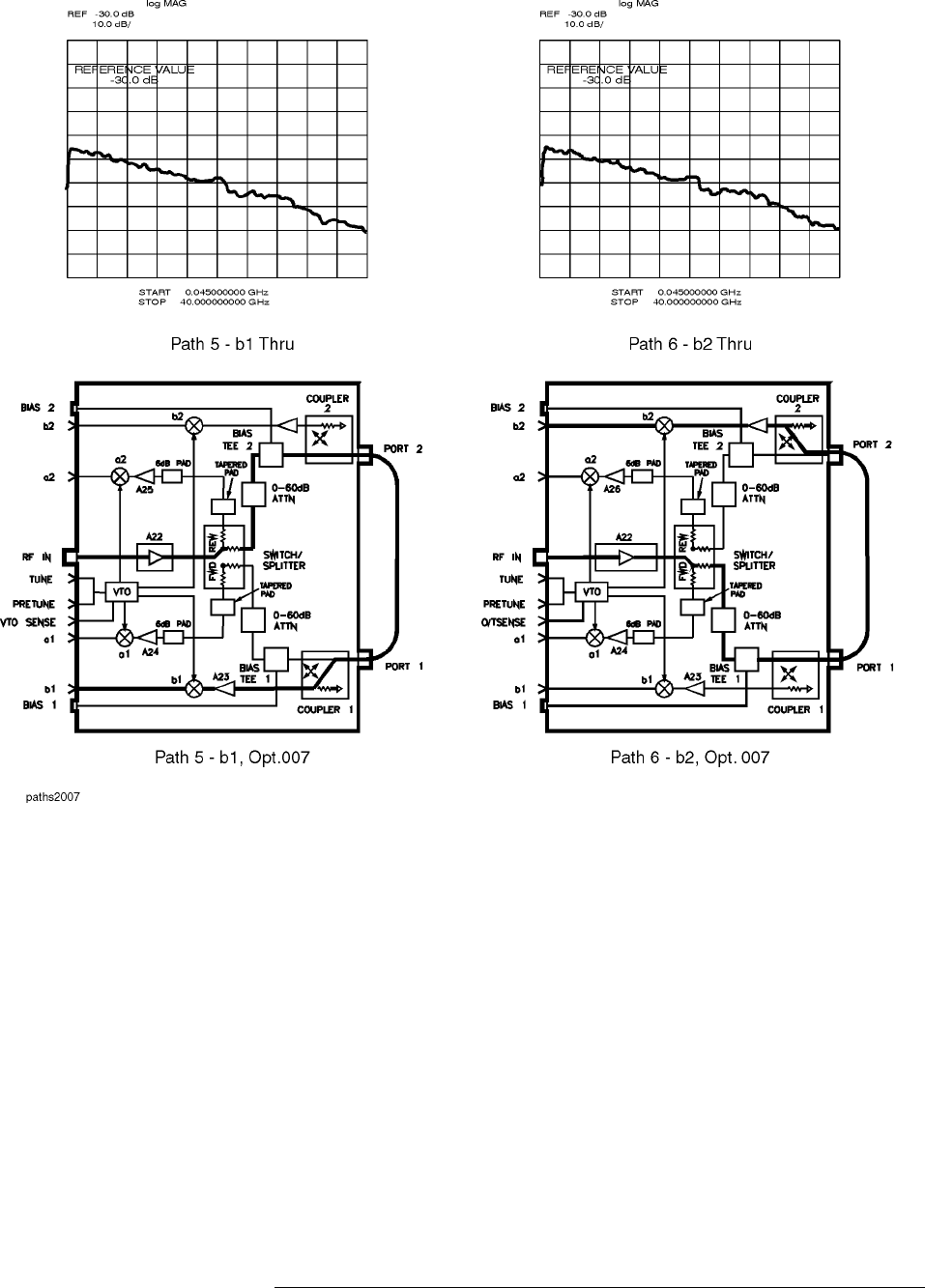
5-22
HP 8517B S-Parameter Test Set Manual
Troubleshooting the Test Set
Troubleshooting Procedures
Figure 5-15 RF Path 5 and Path 6, HP 8517B Option 007

HP 8517B S-Parameter Test Set Manual
5-23
Troubleshooting the Test Set
Troubleshooting Procedures
Finding the Faulty
Assembly Compare the results recorded in Table 5-6 with the matrix in Table 5-7.
There are 32 possible combinations, twelve of which point to probable
failures. These are shown in Table 5-7.
Sample Diagnostics Suppose you have determined that paths 3 and 5 are bad. Paths 1, 2, 4, and 6
are good. Refer to Table 5-7. Notice that the most likely cause for the failure
is the b1 sampler.
Table 5-6 Test Results for Path 1 through Path 6
a1
Path1 a2
Path2 b1
Path 3 b2
Path 4 b1 thru
Path5 b2 thru
Path6
Table 5-7 Most Probable Failures (
B
indicates Bad;
—
indicates Good)
Path Most Probable Failure
a1
Path1
a2
Path2
b1
Path 3
b2
Path 4
b1 thru
Path5
b2 thru
Path6
Assembly, or Description of Condition
——————The HP 8517B test set is not the problem
B B B B B B The source, source cable, VTO, cables from rear
panel to switch splitter
— B — B B — The switch splitter
B—B——BThe switch splitter
——B—B—b1 sampler
B —————a1 sampler
— B ————a2 sampler
——— B — Bb2 sampler
— — B — B B Port 1 connector or directional coupler
—— B — B BA1, T1
——— B B —A2, T2
— — — B B B Port 2 connector or directional coupler

5-24
HP 8517B S-Parameter Test Set Manual
Troubleshooting the Test Set
Troubleshooting Procedures

HP 8517B S-Parameter Test Set Manual
6-1
6
HP 8517B Test Set Replacement Procedures
The replacement procedures in this chapter are listed below:
1“A18 Switch/Splitter Assembly” on page 6-5
2“A14, A10 to A13 Frequency Converter Assembly” on page 6-5
3“A15 Regulator Board Assembly” on page 6-6
4“C1 to C4 Filter Capacitors” on page 6-6
5“2.4 mm Test Port Connectors” on page 6-7
6“Fan Assembly Replacement” on page 6-8
7“T1 Power Transformer” on page 6-8
8“Anti-Rotation Clamp O-Ring Replacement” on page 6-10
9“A1 Front Panel and Interface Board Assembly” on page 6-10
10 “A7andA9BiasTees”onpage6-11
11 “A6 and A8 Test Port Couplers” on page 6-11
12 “A16 or A17 Port Attenuators” on page 6-11
13 “A22 Input Amplifier Assembly” on page 6-12
14 “A23 to A26 Buffer Amplifiers” on page 6-12
15 “A27 Post Regulator Board Assembly” on page 6-13
CAUTION
To prevent electrostatic discharge (ESD) damage, earth ground the work area
and yourself. Some of the assemblies being handled in the following
procedures are very sensitive to damage resulting from static discharges.
Assemblies exposed to ESD may or may not continue to operate properly.
Their reliability, however, will be degraded. Refer to Figure 6-1 for
ESD-safe workstation recommendations.
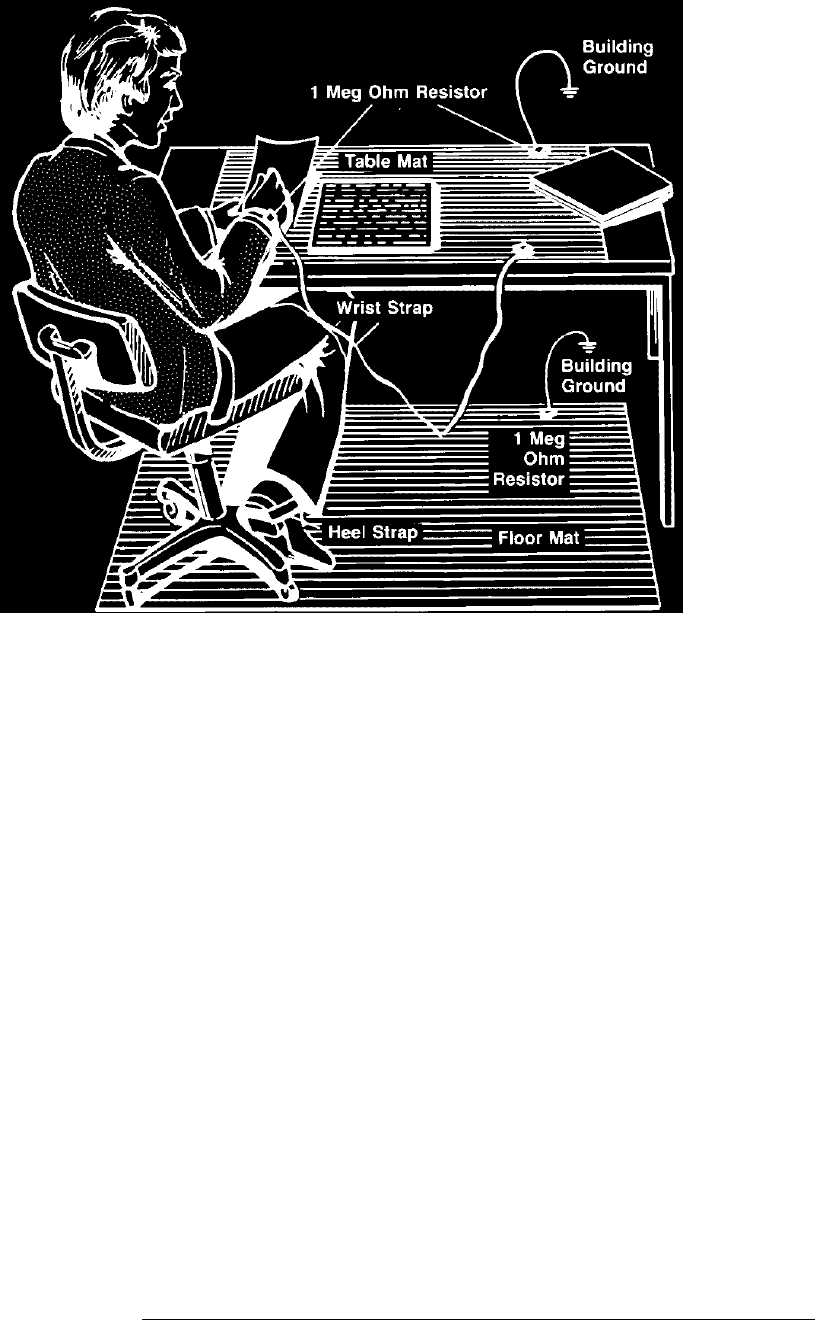
6-2
HP 8517B S-Parameter Test Set Manual
HP 8517B Test Set Replacement Procedures
Figure 6-1 ESD-Safe Workstation Configuration
Performance Tests
Performance test information and procedures are located in Chapter 8 of the
HP 8510C On-Site Service Manual.
Note that the HP 8510C performance test software (shipped with the test set)
is required to test the test set. The results generated during the HP 8517B
performance-test are based on its operation as part of the HP 8510C system.
The HP 8510C includes the test set, cables, calibration kit, and so forth.
Adjustments
The HP 8517B Test Set has no adjustments. Specifically, no attempt should
be made to adjust the samplers.

HP 8517B S-Parameter Test Set Manual
6-3
HP 8517B Test Set Replacement Procedures
Equipment Needed But Not Supplied
Table 6-1 lists the equipment needed to replace the assemblies documented
in the following procedures. See Figure 6-2 to locate the test set assemblies.
Table 6-1 Replacement-Procedure Tools Needed
Tools Used for Procedure: HP Part Number
2 point Pozidriv screwdriver all components 8710-0900
1 point Pozidriv screwdriver all components 8710-0899
5/16 inch torque wrench, 90 N-cm (8 in-lb) all components and 3.5 mm semi-rigid cables, 2.4/1.85
mm cables
8710-1765
5/16 inch torque wrench, 112 N-cm (10 in-lb) HP 8516A 2.4 mm semi-rigid cables 8710-1655
1/2 inch torque wrench, 280 N-cm (25 in-lb) 7 mm, 2.4 mm, 1.85 mm test port connectors 8710-1581
9/16 inch torque wrench, 470 N-cm (42 in-lb) HP 8517B rear panel 2.4 mm connectors 8710-1580
20 mm torque wrench, 90 N-cm (8 in-lb) 2.4 mm and 1.85 mm test port connectors 8710-1764
2.9 mm gage kit port connectors Part of HP 85056A Cal Kit
anti-static mat all components 9300-0797
wrist strap all components 9300-1257
clip lead C1-C4 capacitors any supplier
needle nose pliers couplers any supplier
wire cutters couplers, B1 fan any supplier
T-10 Torx screwdriver all components 8710-1623
T-15 Torx screwdriver all components 8710-1622
9/16 inch 50 in-lb torque wrench test ports 8710-1948
9/16 inch nut driver connector repair 8720-0008
1/2 inch torque wrench, 280 N-cm (25 in-lb) connector repair 8710-1581
100
Ω
, 20 watt resistor C1-C4 capacitor removal 0819-0019
1 inch torque wrench, 800 N-cm (72 in-lb) coupler removal and test port connector flange removal MTB 100 72 lb-in E1
5/16 inch open end wrench fan replacement and test port connector removal any supplier
1/2 inch open-end wrench RF input connector any supplier
1/2 x 9/16 inch thin wrench, fixed Test port connector removal 8710-1770
5/16 inch thin wrench 3.5 mm, 2.4 mm, 1.85 mm semi-rigid connector
removal
8710-2079
1. Order from Mountz Company, 1080 North 11th Street, San Jose, CA 95112, phone (408) 292-2214, or contact Mountz through the
internet at http://www.mountztorque.com/html/home.htm
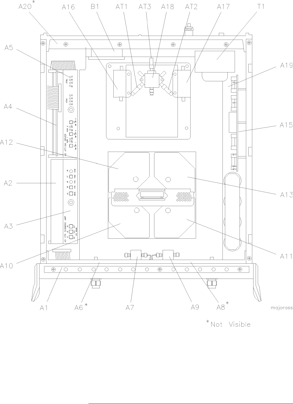
6-4
HP 8517B S-Parameter Test Set Manual
HP 8517B Test Set Replacement Procedures
Figure 6-2 HP 8517B Major Assembly Location Diagram

HP 8517B S-Parameter Test Set Manual
6-5
HP 8517B Test Set Replacement Procedures
Assembly Replacement Procedures
Assembly Replacement Procedures
Initial Precautions Before beginning any of the procedures in this chapter, do the following:
1. Turn off the HP 8517B test set.
2. Disconnect the test set’s power cord.
3. Remove the top- and side-covers, trim strips, and handles.
4. Do not exceed the maximum torque necessary to secure a connector.
Refer to Table 6-1 for torque specifications.
5. Exercise caution with semi-rigid cables; they can be bent very easily.
6. Reverse an assembly’s removal procedure for reinstallation, unless
otherwise instructed.
Switch/Splitter
Replacement
A18 Switch/Splitter Assembly
1. See Table 6-2 for component locations.
2. Remove the five semi-rigid cables and the three flexible cables from the
switch/splitter. (Reposition cables as required to ease removal.)
3. Remove the two fixed attenuators from the switch/splitter (note that
there are three fixed attenuators in Option 007, and in Option 004 “plus”
007).
4. Remove the two screws that attach the switch/splitter to the bracket.
5. Remove the switch/splitter from the test set.
Frequency Converter
Replacement
A14, A10 to A13 Frequency Converter Assembly
The frequency converter consists of the A14 VTO (voltage-tuned oscillator)
assembly and four samplers, A10 through A13. See Figure 6-2 for
component locations.
1. Remove the semi-rigid cable attached to each of the four samplers.
2. Remove the four in-line attenuators from the samplers (only in Options
007, Option 002 “plus” 007, and Option 004 “plus” 007).
3. Remove the six flexible cables from the frequency converter by pulling
gently on the gold connector.
4. Remove the four frequency converter mounting plate screws and the
bracket screw that fastens the frequency converter to the chassis.
5. Unplug the ribbon cable near the front panel.

6-6
HP 8517B S-Parameter Test Set Manual
HP 8517B Test Set Replacement Procedures
Assembly Replacement Procedures
6. Unplug the four harnessed (multi-colored) wire and socket assemblies.
7. Lift the frequency converter out of the test set.
8. Remove the frequency converter bracket by removing the two Pozidriv
screws.
Regulator Board
Replacement
A15 Regulator Board Assembly
1. See Figure 6-2 for component locations.
2. Unplug the transformer socket from the regulator board.
3. Unplug the amplifier socket from the regulator board (only in Options
007, Option 002 “plus” 007, and Option 004 “plus” 007).
4. Remove the three mounting screws from the top edge of the regulator
board.
5. Remove the regulator board. (You may need to partially back out one of
the transformer mounting screws for clearance.)
Filter Capacitor
Replacement
C1 to C4 Filter Capacitors
1. With the test set in an upright position, pull the metal and plastic cover
off the 4 capacitors. See Figure 6-2 for the location of the filter
capacitors.
2. Turn the test set over and remove the bottom cover.
3. To discharge the capacitors, do the following:
a. Attach one end of an insulated clip lead to the chassis of the
instrument.
b. Attach the other end of the clip lead to a 100 ÞΩ20-watt resistor.
c. Use the resistor to discharge each capacitor terminal (the large
Pozidriv screw on the bottom side of the test set). Each capacitor has
two terminals.
d. Discharge all capacitor terminals. It takes approximately six seconds
per capacitor to discharge.
4. To remove a capacitor, remove the corresponding pair of screws and pull
the capacitor out of the test set.
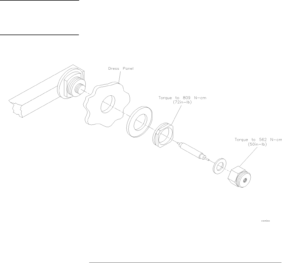
HP 8517B S-Parameter Test Set Manual
6-7
HP 8517B Test Set Replacement Procedures
Assembly Replacement Procedures
Test Port Connector
Replacement
2.4 mm Test Port Connectors
1. Incline the rear of the test set approximately four inches and support it
with a stable, solid object (such as a thick book).
2. Using a 9/16-inch open-end wrench, unscrew the test port connector nut.
3. Pull out the center conductor assembly and replace it with a new
assembly. Do not touch either end of the new assembly. Part numbers for
the test port connector components are located on page 7-16.
4. Replace the test port connector nut and torque it to 562 N-cm (50 in-lb).
5. Measure the pin depth of each port using a 2.4 mm female pin-depth
gage. Refer to the connector care information in the calibration kit
manual for more information about using the gage.
NOTE
If the center pin protrudes, or if the depth is less than 0.0001 inch, remove
the connector assembly and increase or decrease shims to adjust the pin
depth to between 0.0001 and 0.0007 inch. When measuring the pin depth be
sure to include the uncertainty calculation of your gage.
6. If you added or removed shims, regage the test port connector assembly.
Figure 6-3 Diagram of 2.4 mm Test Port Connector

6-8
HP 8517B S-Parameter Test Set Manual
HP 8517B Test Set Replacement Procedures
Assembly Replacement Procedures
Fan Assembly
Replacement
B1 Fan Assembly
Turn off the test set and disconnect the power cord from the ac-power mains.
WARNING
Electrocution can result if ac power remains connected to the test set during
this procedure. Disconnect the ac power cord before starting.
To replace the B1 fan assembly, remove T1 transformer to expose the ends of
the fan wires which must be de-soldered from the line module, FL1. Refer to
Chapter 7, “Replaceable Parts” in this manual for a detailed view of the fan
and transformer hardware.
1. See Figure 6-2 for component locations.
2. Position the test set on its right-hand side.
3. Using a 5/16-inch open-end wrench, remove the hard-line cables
connected between the couplers A7 and A9 and the bulkhead connectors
J2 and J5.
4. Unplug the transformer connector at J2 on the A15 regulator board.
5. Using a large Pozidriv screwdriver, remove the four screws and washers
that hold the transformer onto the rear panel.
6. Using a large Pozidriv screwdriver, remove the screw that holds the
transformer angle bracket to the main deck.
NOTE
The transformer wires soldered to the line module are short, so do not pull
the transformer out too far.
7. Carefully remove the transformer from the test set and place it on the
bench near the test set.
8. Strip the heat shrink tubing off the two fan wires, then de-solder the
wires from the line module. Cut any cable ties restraining the fan wires.
9. Using a small Pozidriv screwdriver, remove the screw and lockwasher
that secure the green/yellow fan ground wire to the top of the rear panel
frame.
10. Using a small Pozidriv screwdriver, remove the four screws that hold the
fan to the rear panel. Remove the fan assembly.
Power Transformer
Replacement
T1 Power Transformer
Turn off the test set and disconnect the power cord from the mains.
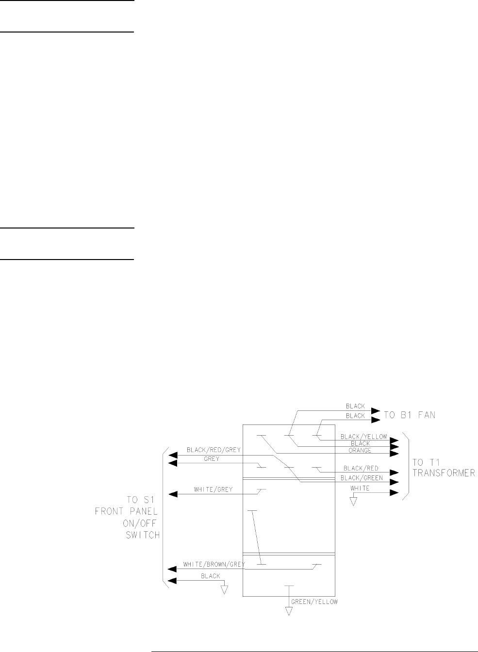
HP 8517B S-Parameter Test Set Manual
6-9
HP 8517B Test Set Replacement Procedures
Assembly Replacement Procedures
WARNING
Electrocution can result if ac power remains connected to the test set during
this procedure. Disconnect the ac power cord before starting.
1. See Figure 6-2 for component locations.
2. Position the test set onto its right-hand side.
3. Using a 5/16-inch open-end wrench, remove the hard-line cables
connected between the coupler A7 and the bulkhead connector J2.
4. Unplug the transformer connector from J2 on the A15 regulator board.
5. Using a large Pozidriv screwdriver, remove the four screws and washers
that hold the transformer onto the rear panel.
6. Using a large Pozidriv screwdriver, remove the screw that holds the
transformer angle bracket to the main deck.
NOTE
The transformer wires soldered to the line module are short, so do not pull
the transformer out too far.
7. Carefully remove the transformer from the test set and place it on the
bench near the test set.
8. Strip the heat shrink tubing off the transformer wires that are soldered to
the line module, and de-solder the wires.
9. De-solder the transformer ground wire connected to the chassis side rail.
10. Remove the transformer. When you replace the transformer, refer to
Figure 6-4 for the location of wires connected to the line module.
Figure 6-4 Wire Connections to FL1 Line Module

6-10
HP 8517B S-Parameter Test Set Manual
HP 8517B Test Set Replacement Procedures
Assembly Replacement Procedures
O-Ring Replacement Anti-Rotation Clamp O-Ring Replacement
1. Pry the O-ring out of the clamp with fine tweezers or a similar tool.
2. To insert the new O-ring (HP part number 0900-0007), engage one side
of the ring in the slot of the phenolic clamp donut (shown in Figure 6-5).
3. Use your fingers to seat the O-ring into the groove within the clamp.
Figure 6-5 Positioning the O-Ring Within the Clamp
Front Panel and
Interface Board
Replacement
A1 Front Panel and Interface Board Assembly
1. See Figure 6-2 for component locations.
2. Remove the four semi-rigid cables that connect to the coupler on the
front panel.
3. Remove the ten screws that secure the front panel assembly to the front
frame.
4. Grasp the test ports and pull the front panel assembly out, tilting the top
of the assembly toward you.
5. Unplug the ribbon cable attached to the board assembly on the front
panel.
6. Grasp the cable attached to the line switch and carefully pull it toward
the front of the instrument. This provides enough cable length for you to
tilt the front panel assembly the rest of the way out of the test set frame.
7. Carefully remove the front panel assembly.
8. Lay the front panel assembly face down on the work surface.

HP 8517B S-Parameter Test Set Manual
6-11
HP 8517B Test Set Replacement Procedures
Assembly Replacement Procedures
Bias Tees Replacement A7 and A9 Bias Tees
1. See Figure 6-2 for component locations.
2. Remove the two semi-rigid cables attached to the bias tee to be replaced.
3. De-solder the wires attached to the bias tee.
4. Remove the two screws that secure the bias tee to the bias-tee bracket.
5. Remove the bias tee.
NOTE
This procedure does not apply to Option 002 or Option 002 “plus” 007.
Test Port Coupler
Replacement
A6 and A8 Test Port Couplers
1. See Figure 6-2 for component locations.
2. Remove the front panel assembly as described in the procedure “A1
Front Panel and Interface Board Assembly”.
3. Remove the test port connector nut with a 1-inch wrench.
4. Remove the test port washer.
5. Remove the coupler from the front panel.
Test Port Attenuator
Replacement
A16 or A17 Port Attenuators
NOTE
This procedure does not apply to Option 002 or Option 002 “plus” 007.
1. See Figure 6-2 for component locations.
2. Remove the two semi-rigid cables attached to the attenuator.
3. Unplug the ribbon cable from the attenuator.
4. Remove the two screws that secure the attenuator bracket to the
amplifier bracket.
5. Remove the attenuator/attenuator bracket from the instrument.
6. Remove the two screws that secure the attenuator to the attenuator
bracket.

6-12
HP 8517B S-Parameter Test Set Manual
HP 8517B Test Set Replacement Procedures
Assembly Replacement Procedures
Input Amplifier
Replacement
A22 Input Amplifier Assembly
NOTE
This procedure is for Option 007, Option 002 “plus” 007, and Option 004
“plus” 007, only.
1. See the figure in Chapter 7, Table 7-17 for the location of the A22
amplifier.
2. Without disconnecting AT1 and AT2 fixed attenuators, remove the other
five semi-rigid cables attached to the A18 switch/splitter.
3. Remove the W45 semi-rigid cable between the A22 input amplifier and
J7 rear-panel RF input connector.
4. Remove the two screws holding the switch/splitter to the amplifier
mount bracket.
5. Remove the switch/splitter from the amplifier mount bracket.
6. Remove the four screws that secure the A22 input amplifier to the
amplifier-mount bracket.
Buffer Amplifier
Replacement
A23 to A26 Buffer Amplifiers
NOTE
This procedure is for Option 007, Option 002 “plus” 007, and Option 004
“plus” 007, only.
1. See the figure in Chapter 7, Table 7-17 for the location of the buffer
amplifiers.
2. Remove the two semi-rigid cables from the buffer amplifier to be
replaced.
3. Remove the four screws securing the buffer amplifier to the amplifier
mount bracket.
4. Remove the buffer amplifier.

HP 8517B S-Parameter Test Set Manual
6-13
HP 8517B Test Set Replacement Procedures
Assembly Replacement Procedures
Post Regulator Board
Replacement
A27 Post Regulator Board Assembly
NOTE
This procedure is for Option 007, Option 002 “plus” 007, and Option 004
“plus” 007, only.
1. See the figure in Chapter 7, Table 7-17 for the location of the A22
amplifier bracket. The A27 board assembly is located beneath the A22
amplifier bracket.
2. Without removing the step attenuator from the bracket (this step is not
applicable to Option 002 “plus” 007), remove the four semi-rigid cables
attached to the attenuators at Port 1 and Port 2.
3. Remove the four buffer amplifiers from the bracket (refer to “A23 to
A26 Buffer Amplifiers”).
4. Remove the A18 switch/splitter assembly (refer to “A18 Switch/Splitter
Assembly”).
5. Remove the A22 input amplifier (refer to “A22 Input Amplifier
Assembly”).
6. Remove the four screws attaching the amplifier bracket to the test set.
7. Flip the amplifier bracket over. Note the A27 board assembly mounted
to the underside of the bracket.
8. De-solder the two pins from the regulator to remove the A27 amplifier
regulator board assembly.
9. Remove the five screws holding the board assembly to the bracket.
10. Remove the two screws holding the voltage regulator to the bracket.
11. Remove the regulator board assembly from the amplifier mount bracket.
NOTE
Do not loosen the grommets (HP part number 3050-0003) located on the
regulator board assembly.
12. For reassembly, install two grommets on the underside of the mount
bracket. There are two cut-outs on the sheet metal for these grommet
insulators.

6-14
HP 8517B S-Parameter Test Set Manual
HP 8517B Test Set Replacement Procedures
Assembly Replacement Procedures

HP 8517B S-Parameter Test Set Manual
7-1
7
HP 8517B Replaceable Parts
Introduction
This section provides information about ordering replacement parts. Parts
that can be replaced include major assemblies and chassis hardware, but not
individual pieces of major assemblies. Table 7-1 lists the major assembly
reference designations and abbreviations used in the parts lists.
Rebuilt-Exchange
Assemblies
Rebuilt-exchange assemblies (R-E assemblies) cost less than new
assemblies. They are available through the rebuilt-exchange program.
Factory rebuilt (repaired and tested) assemblies meet all factory
specifications required of a new assembly. They are available on an
exchange (trade-in) basis only. Defective assemblies must be returned for
credit. Figure 7-2 illustrates the rebuilt-exchange procedure. The rest of the
figures in this chapter provide parts information. If you have any questions,
contact the HP Sales and Service office in your region.
Replaceable Parts List Use the illustrations in this chapter to help locate and identify HP 8517B
replaceable parts. Each illustration is accompanied by a replaceable parts list
that includes the following information:
•Hewlett-Packard part number.
•Part quantity as shown in the corresponding figure. (There may or may
not be more of the same part located elsewhere in the instrument.)
•Part description, using the abbreviations found in Table 7-3.
NOTE
A typical manufacturer of the part is identified by a five-digit code (refer to
the Manufacturers Code list in Table 7-2) and given only if a part is available
from an alternate supplier (other than Hewlett-Packard).
.

7-2
HP 8517B S-Parameter Test Set Manual
HP 8517B Replaceable Parts
Ordering Information
To order parts listed in the replaceable parts table, record the following
information, then address the order to the nearest Hewlett-Packard Sales and
Service Office:
the Hewlett-Packard part number
the quantity required
To order parts not listed in the replaceable parts lists, record the following
information:
the instrument model number
the complete instrument serial number
the description and function of the part, and
the number of parts required
Address the order to the nearest Hewlett-Packard Sales and Service Office.
The office addresses are provided in “Service and Support” of this manual.
ToOrderParts....Fast!
•Telephone 1-(800) 227-8164
•Monday through Friday, 6 am to 5 pm (Pacific Standard Time)
Hewlett-Packard Parts specialists have direct on-line access to replacement
parts inventory corresponding to the replaceable parts list in this manual.
There is a charge for one day delivery service. The standard delivery time is
four days.
For after hours and holidays, phone (415) 968-2347. The fast-service applies
to United States customers, only. Outside the United States, contact your
nearest Hewlett-Packard Sales and Service Office.
Table 7-1 Reference Designation Abbreviations
AAssembly FFuse SSwitch
AT Attenuator, Isolator, Limiter,
Termination
FL Filter T Transformer
B Fan, Motor HY Circulator TB Terminal Block
BT Battery J Electrical Connector
(Stationary Portion),
Jack
TC Thermocouple
C Capacitor K Relay TP Test Point
CP Coupler L Coil, Inductor U Integrated Circuit,
Microcircuit
CR Diode, Diode Thyristor, Step
Recovery Diode, Varactor
M Meter V Electron Tube

HP 8517B S-Parameter Test Set Manual
7-3
HP 8517B Replaceable Parts
DC Directional Coupler MP Miscellaneous
Mechanical Part
VR Breakdown Diode
(Zener), Voltage
Regulator
DL Delay Line P Electrical Connector
(Movable Portion), Plug
W Cable, Wire, Jumper
DS Annunciator, Lamp, Light
Emitting Diode (LED),
Signaling Device (visible)
Q Silicon Controlled
Rectifier (SCR),
Transistor, Triode
Thyristor
XSocket
E Miscellaneous Electrical Part R Resistor Y Crystal Unit
(Piezoelectric, Quartz)
RT Thermistor Z Tuned Cavity, Tuned
Circuit
Table 7-1 Reference Designation Abbreviations (Continued)
Table 7-2 Manufacturer Names and Addresses
Manufacturer
Code
Manufacturer Name Manufacturer Address
00000 Any satisfactory supplier N/A
00853 Sangamo Elec Co. S. Carolina Div Pickens, SC 29671
24546 Corning Glass Works (Bradford) Bradford, PA 16701
28480 Hewlett-Packard Co. Corporate HQ Palo Alto, CA 94304
56289 Sprague Electric Company North Adams, MA 01247

7-4
HP 8517B S-Parameter Test Set Manual
HP 8517B Replaceable Parts
Table 7-3 Standard Abbreviations
A
A Across Flats, Acrylic, Air (Dry Method), Ampere
ADJ Adjust, Adjustment
ANSI American National Standards Institute (formerly USASI-ASA)
ASSY Assembly
AWG American Wire Gage
B
BCD Binary Coded Decimal
BD Board, Bundle
BE-CU Beryllium Copper
BNC Type of Connector
BRG Bearing, Boring
BRS Brass
BSC Basic
BTN Button
C
C Capacitance, Capacitor, Cold, Center Tapped, Cermet, Compression
CCP Carbon Composition Plastic
CD Cadmium, Card, Cord
CER Ceramic
CHAM Chamfer
CHAR Character, Characteristic, Charcoal
CMOS Complementary Metal Oxide Semi-conductor
CNDCT Conducting, Conductive, Conductivity, Conductor
CONT Contact, Continuous, Control, Controller
CONV Converter
CPRSN Compression
CUP-PT Cup point
D
D Deep, Depletion, Depth, Diameter, Direct Current
DA Darlington
DAP-GL Diallyl Phthalate Glass
DBL Double

HP 8517B S-Parameter Test Set Manual
7-5
HP 8517B Replaceable Parts
DCDR Decoder
DEG Degree
D-HOLE D-Shaped hole
DIA Diameter
DIP Dual In-Line Package
DIP-SLDR DIP Solder
DO Package Type Designation
DP Deep, Depth, Diametric Pitch, Dip
D-MODE Depletion Mode
DP3T Double Pole Triple Throw
DPDT Double Pole Double
Throw
DWL Dowel
E
E-R E-Ring
EXT Extended, Extension, External, Extinguish
F
F Fahrenheit, Farad, Female, Fixed, Flange, Frequency, Film (Resistor)
FC Carbon Film/Composition, Edge of Cut-off Frequency, Face
FDTHRU Feed-through
FEM Female
FIL-HD Fillister Head
FL Flash, Flat, Fluid
FLAT-PT Flat Point
FR Front
RFEQ Frequency
FT Current Gain Bandwidth Product (Transition Frequency), Feet, Foot
FXD Fixed
G
GEN General, Generator
GND Ground
GP General Purpose, Group
H
H Henry
Table 7-3 Standard Abbreviations (Continued)

7-6
HP 8517B S-Parameter Test Set Manual
HP 8517B Replaceable Parts
HDW Hardware
HEX Hexadecimal, Hexagon, Hexagonal
HLCL Helical
HP Hewlett-Packard Company, High Pass
I
IIC Collector Current, Integrated Circuit
ID Identification, Inside Diameter
IF Intermediate Frequency, Forward Current
IN Inch
INCL Including
INT Integral, Intensity, Internal
J
J-FET Junction Field Effect Transistor
JFET Junction Field Effect Transistor
K
K Kelvin, Key, Kilo, Potassium
KNRLD Knurled
KVDC Kilovolts Direct Current
L
LED Light Emitting Diode
LG Length, Long
LIN Linear, Linearity
LK Link, Lock
LKG Leakage, Locking
LUM Luminous
M
M Male, Maximum, Mega, Mi, Milli, Mode
MA Milliampere
MACH Machined
MAX Maximum
MC Molded Carbon Composition
MET Metal, Metallized
MHZ Mega Hertz
Table 7-3 Standard Abbreviations (Continued)

HP 8517B S-Parameter Test Set Manual
7-7
HP 8517B Replaceable Parts
MINTR Miniature
MIT Miter
MLD Mold, Molded
MM Magnetized Material, Millimeter
MOM Momentary
MTG Mounting
MTLC Metallic
MW Milliwatt
N
N Nano, None
N_CHAN N-Channel
NH Nano Henry
NM Nanometer, nonmetallic
NO Normally Open, Number
NOM Nominal
NPN Negative Positive Negative (Transistor)
NS Nanosecond, Non-Shorting, Nose
NUM Numeric
NYL Nylon (Polyamide)
O
OA Over-All
OD Outside Diameter
OP AMP Operational Amplifier
Opt Optical, Option, Optional
P
PA Picoampere, Power Amplifier
PAN-HD Pan Head
PAR Parallel, Parity
PB Lead (Metal), Push-button
PC Printed Circuit
PCB Printed Circuit Board
P-CHAN P-Channel
PD Pad, Power Dissipation
Table 7-3 Standard Abbreviations (Continued)

7-8
HP 8517B S-Parameter Test Set Manual
HP 8517B Replaceable Parts
PF Pico Farad, Power Factor
PKG Package
PLSTC Plastic
PNL Panel
PNP Positive Negative Positive (Transistor)
POLYC Polycarbonate
POLYE Polyester
POT Potentiometer
POZI Pozidriv Recess
PREC Precision
PRP Purple, Purpose
PSTN Piston
PT Part, Point, Pulse Time
PW Pulse Width
Q
Q Figure of Merit
R
R Range, Red, Resistance, Resistor, Right, Ring
REF Reference
RES Resistance, Resistor
RF Radio Frequency
RGD Rigid
RND Round
RR Rear
RVT Rivet, Riveted
S
SAWR Surface Acoustic Wave Resonator
SEG Segment
SGL Single
SI Silicon, Square Inch
SL Slide Slow
SLT Slot, Slotted
SMA Subminiature, A-Type (Threaded Connector)
Table 7-3 Standard Abbreviations (Continued)

HP 8517B S-Parameter Test Set Manual
7-9
HP 8517B Replaceable Parts
SMB Subminiature, B-Type (Slip-on Connector)
SMC Subminiature, C-Type (Threaded Connector)
SPCG Spacing
SPDT Single Pole Double Throw
SPST Single Pole SIngle Throw
SQ Square
SST Stainless Steel
STL Steel
SUBMIN Subminiature
SZ Size
T
T Teeth, temperature, Thickness, Time, Timed, Tooth, Typical
TA Ambient Temperature, Tantalum
TC Temperature Coefficient
THD Thread, Threaded
THK Thick
TO Package Type Designation
TPG Tapping
TR-HD Truss Head
TRMR Trimmer
TRN Turn, Turns
TRSN Torsion
U
UCD
(or
µ
CD)
Microcandela
UF
(or
µ
F)
Micro Farad
UH
(or
µ
H)
Micro Henry
UL
(or
µ
CD)
Microliter, Underwriters’ Laboratories, Inc.
UNHDND Unhardened
V
V Variable, Violet, Volt, Voltage
VAC Vacuum, Volt—Alternating Current
Table 7-3 Standard Abbreviations (Continued)

7-10
HP 8517B S-Parameter Test Set Manual
HP 8517B Replaceable Parts
VAR Variable
VDC Volts—Direct Current
W
W Watt, Wattage, White, Wide, Width
W/SW With, Switch
WW Wire Wound
X
X By (as used with dimensions), Reactance
Y
YIG Yttrium-Iron-Garnet
Z
ZNR Zener Diode
Table 7-3 Standard Abbreviations (Continued)
Table 7-4 Multipliers, Abbreviation and Description
Abbreviation Prefix Multiple
Ttera 10
12
Ggiga 10
9
M mega 106
kkilo 10
3
da deka 102
d deci 10-1
c centi 10-2
m milli 10-3
µ
micro 10-6
n nano 10-9
ppico 10
-12
f femto 10-15
a atto 10-18
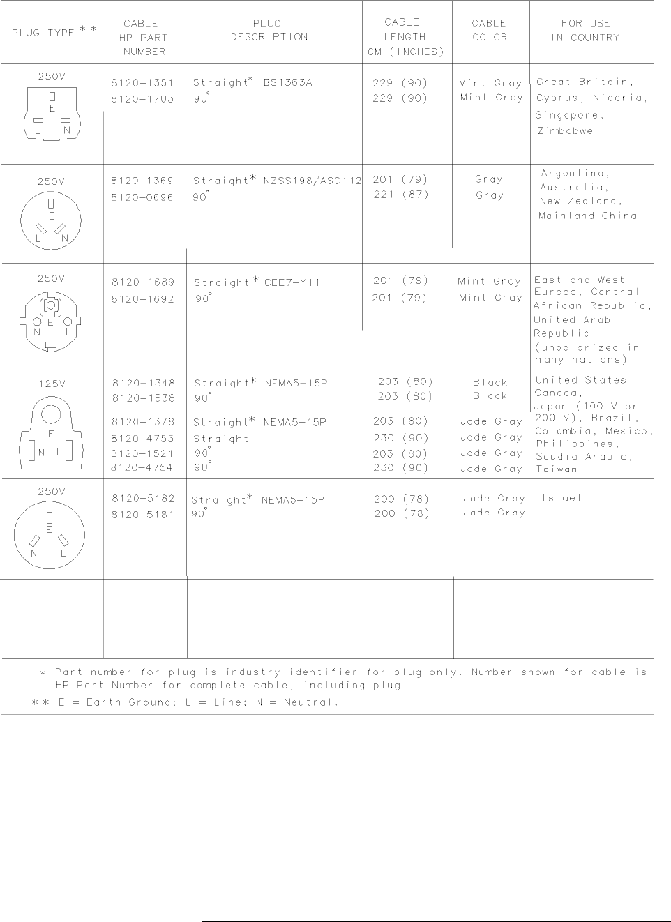
HP 8517B S-Parameter Test Set Manual
7-11
HP 8517B Replaceable Parts
Figure 7-1 Power Cable and Plug Part Numbers

7-12
HP 8517B S-Parameter Test Set Manual
HP 8517B Replaceable Parts
Table 7-5 Instrument Fuses
Fuse Name Location Amps for 100 to 120 Vac
(part number) Amps for 220 to 250 Vac
(part number)
ac Line F1 Rear Panel 2.0 2110-0002 1.0 2110-0001
+5 Vdc F1 Regulator Board 1.5 2110-0043 1.5 2110-0043
- 5 Vdc F2 Regulator Board 1.0 2110-0001 1.0 2110-0001
+15 Vdc F3 Regulator Board 1.5 2110-0043 1.5 2110-0043
- 15 Vdc F4 Regulator Board 1.0 2110-0001 1.0 2110-0001
Bias Bias Fuses Front Panel 0.5 2110-0012 0.5 2110-0012
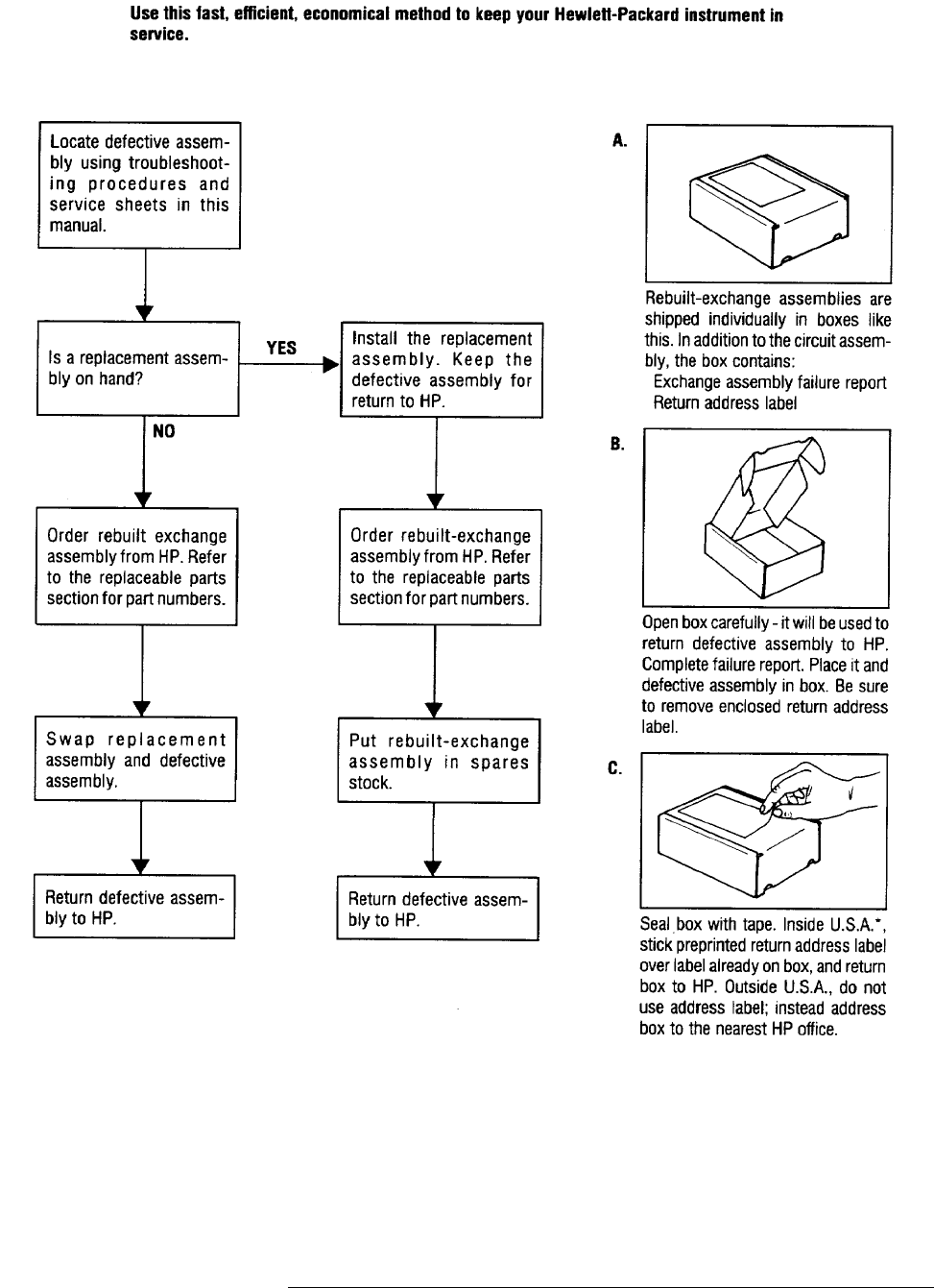
HP 8517B S-Parameter Test Set Manual
7-13
HP 8517B Replaceable Parts
Figure 7-2 The Low Cost Rebuilt-Exchange Procedure
Use this fast, efficient economical
method to keep your Hewlett-
Packard instrument in service.
*Hewlett-Packard pays postage on boxes mailed in the U.S.A.

7-14
HP 8517B S-Parameter Test Set Manual
HP 8517B Replaceable Parts
Table 7-6 Major Assembly Reference Designator and Parts Information
Ref Des HP Part Number QTY Description
A1 08513-60005 1 Front Panel Interface Board Assembly
A6, A8 5086-7518
5086-6518
2 50 GHz Coupler, (NEW)
50 GHz Coupler, (R-E)
A7, A9 5086-7484
5086-6484
2 Bias Tee (NEW)
Bias Tee (R-E)
A16, A17 33325-60004
33325-69004
2 60 dB Step Attenuator (NEW)
60 dB Step Attenuator (R-E)
A18 5086-7570
5086-6570
1 Switch/Splitter (NEW)
Switch/Splitter (R-E)
AT1, AT2 33340-60006 2 20-7 dB Tapered Pad
AT3 5063-0691 1 DC Return
A2 08513-60004
08513-69004
1 IF-MUX Used for Option 001 (NEW) See Table 7-14
IF-MUX Used for Option 001 (R-E)
A3 08517-60002
08517-69002
1 VTO Summing Amplifier Board Assembly (NEW)
VTO Summing Amplifier Board Assembly (R-E)
A4 08517-60003 1 HP-IB Board Assembly (NEW)
A5 08517-60001 1 Attenuator/Switch Driver Board Assembly
A10, A11, A12,
and A13
5086-6501 4 Frequency Converter Assembly
A14 5086-7501
5086-6501
1 Frequency Converter 50 GHz (Samplers and VTO) (NEW)
Frequency Converter 50 GHz (Samplers and VTO) (R-E)
A15 08516-60002 1 Regulator Board Assembly
A19 08513-60001 1 Motherboard Assembly
A20 08513-60006 1 HP-IB Interface Board Assembly
A27 08517-60044 1 Post Regulator Board Assembly
B1 08513-20031 1 Fan-TBAX 34-CFM 115 V 50/60 Hz 1.5kV DIEL
T1 9100-4723 1 Power Transformer
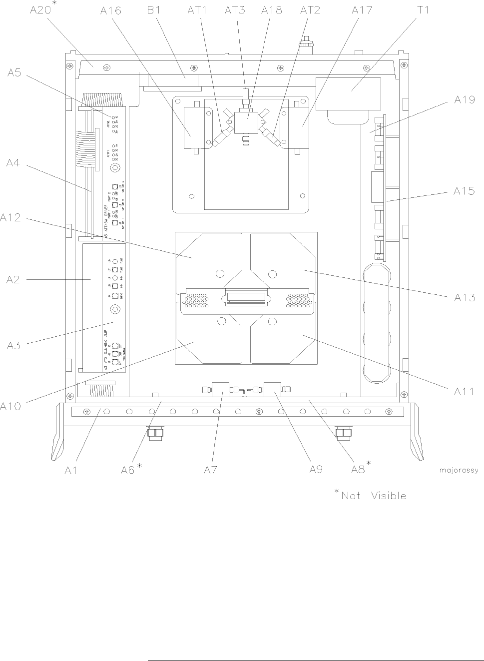
HP 8517B S-Parameter Test Set Manual
7-15
HP 8517B Replaceable Parts
Figure 7-3 Major Assembly Locations in the Standard HP 8517B Test Set
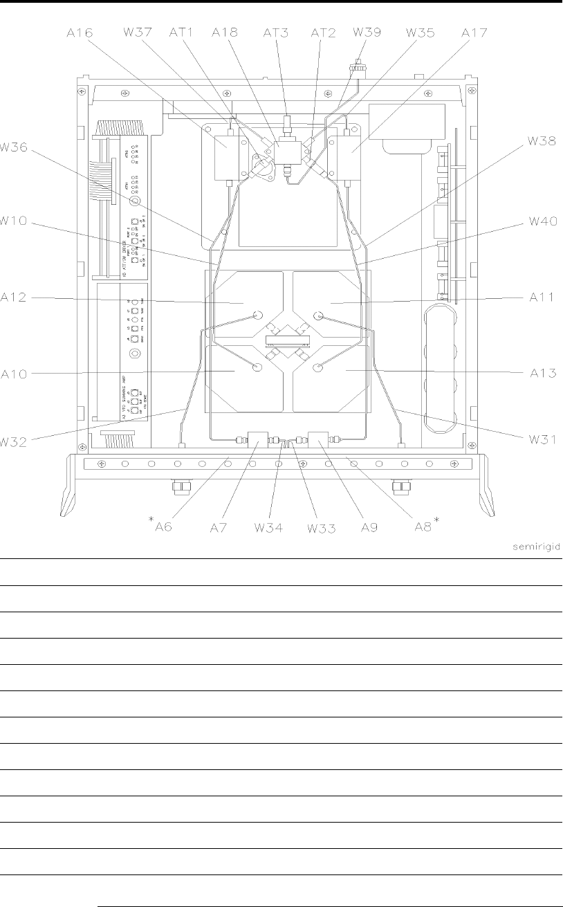
7-16
HP 8517B S-Parameter Test Set Manual
HP 8517B Replaceable Parts
Table 7-7 Semi-Rigid Cable Assemblies in the Standard HP 8517B Test Set
Ref Des HP Part Number Quantity Description
W10 08517-20039 1 Cable Assembly AT1 to A10J2
W31 08517-20042 1 Cable Assembly A8J3 to A11J2
W32 08517-20041 1 Cable Assembly A6J3 to A12J2
W33 08517-20038 1 Cable Assembly A8J2 to A9J2
W34 08517-20038 1 Cable Assembly A6J2 to A7J2
W35 08517-20028 1 Cable Assembly A17J2 to A18J7
W36 08517-20031 1 Cable Assembly A7J1 to A16J1
W37 08517-20027 1 Cable Assembly A16J2 to A18J1
W38 08517-20032 1 Cable Assembly A9J1 to A17J1
W39 08517-20056 1 Cable Assembly AT3 to Rear Panel J7
W40 08517-20040 1 Cable Assembly AT2 to A13J2
*Components not visible
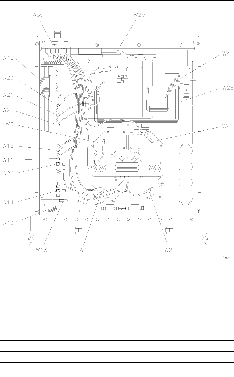
HP 8517B S-Parameter Test Set Manual
7-17
HP 8517B Replaceable Parts
Table 7-8 Flexible Cable Assemblies in the Standard HP 8517B Test Set
Ref Des HP Part Number Quantity Description
W1 08513-60121 1 Cable Assembly A12J3 to A1J11
W2 08513-60122 1 Cable Assembly A13J3 to A4J11
W3 08513-60123 1 Cable Assembly A10J3 to A2J11
W4 08513-60124 1 Cable Assembly A11J3 to A3J11
W13 08513-60133 1 Cable Assembly A3J1 to A14J1
W14 08513-60134 1 Cable Assembly A3J2 to A7J11
W16 08513-60136 1 Cable Assembly A3J5 to A5J11
W18 08513-60138 1 Cable Assembly A3J7 to A6J11

7-18
HP 8517B S-Parameter Test Set Manual
HP 8517B Replaceable Parts
W20 08513-60140 1 Cable Assembly A3J4 to A14J2
W21 08513-60141 1 Cable Assembly A5J2 to A18J4
W22 08513-60142 1 Cable Assembly A5J1 to A18J3
W23 08513-60143 1 Cable Assembly A5J3 to A18J6
W28 08517-60014 1 Ribbon Cable Assembly A16 through A19
W29 85102-60226 1 Cable Assembly Line Switch
W30 08513-60014 1 Cable Assembly J10 to J11
W42 08513-60036 1 Cable Assembly A4 to A20
W43 08513-60013 1 Cable Assembly A1 to A19
W44 08517-60015 1 Cable Assembly A17 through A19
Table 7-8 Flexible Cable Assemblies in the Standard HP 8517B Test Set (Continued)
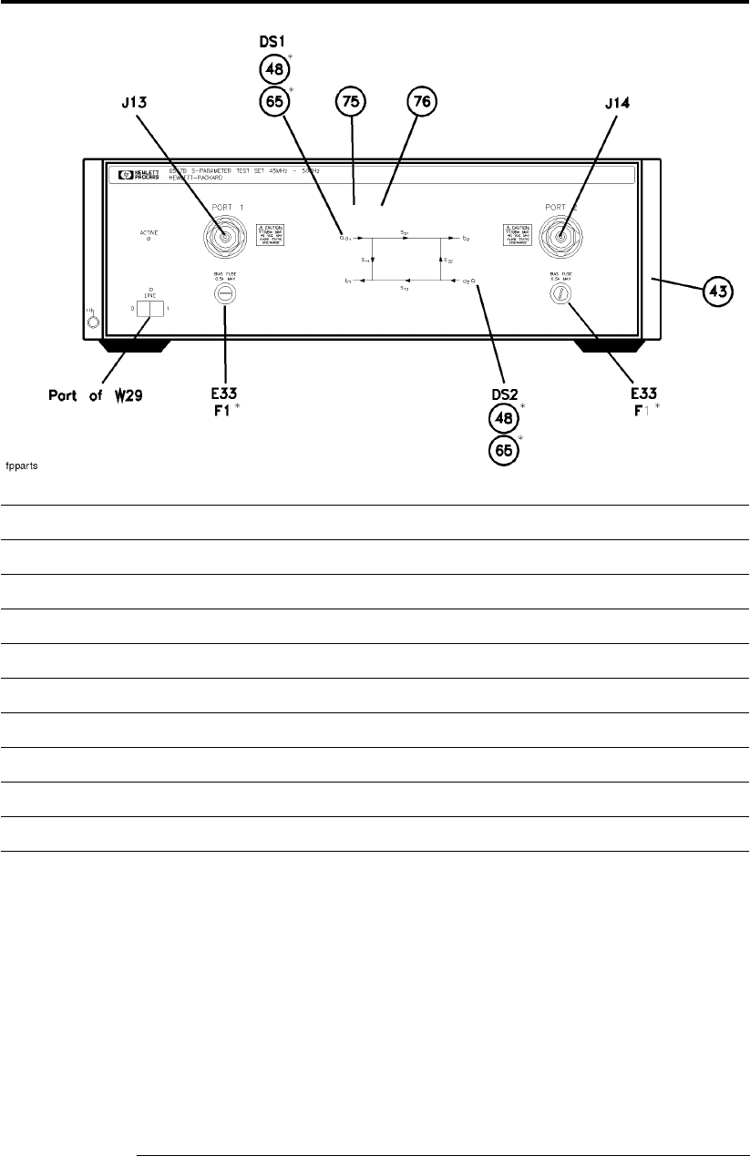
HP 8517B S-Parameter Test Set Manual
7-19
HP 8517B Replaceable Parts
Table 7-9 Miscellaneous Parts, Front Panel HP 8517B Test Set
Ref Des HP Part Number Quantity Description
DS1,DS2 1990-0858 2 LED Lamp 25 MA, Maximum
E33,E34 2110-0797 2 Fuse Holder
F1,F2 2110-0012 2 Fuse 0.5 A 250 V
J13,J141 – 1 ea See Table 7-10
43 5021-8747 1 Front Bezel
48 1450-0615 2 Retainer LED
65 08340-40002 2 Mount LED
75 08517-00002 1 Front Dress Panel
76 08517-00003 1 Front Sub-Panel
1. See Table 7-10 for parts detail.
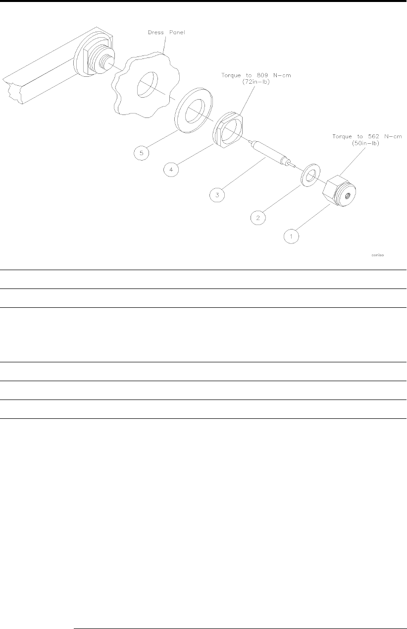
7-20
HP 8517B S-Parameter Test Set Manual
HP 8517B Replaceable Parts
Table 7-10 Test Port Connector Assembly Components
Item HP Part Number Quantity Description
1 5062-7274 1 Test Port Connector
2 5001-3930
5001-3904
5001-3905
5001-3906
.0002 IN SHIM
.0005 IN SHIM
.001 IN SHIM
.002 IN SHIM
3 5062-7276 1 Test Port Center Conductor
4 5021-3428 2 Test Port Connector Nut
5 5021-3427 2 Test Port Washer
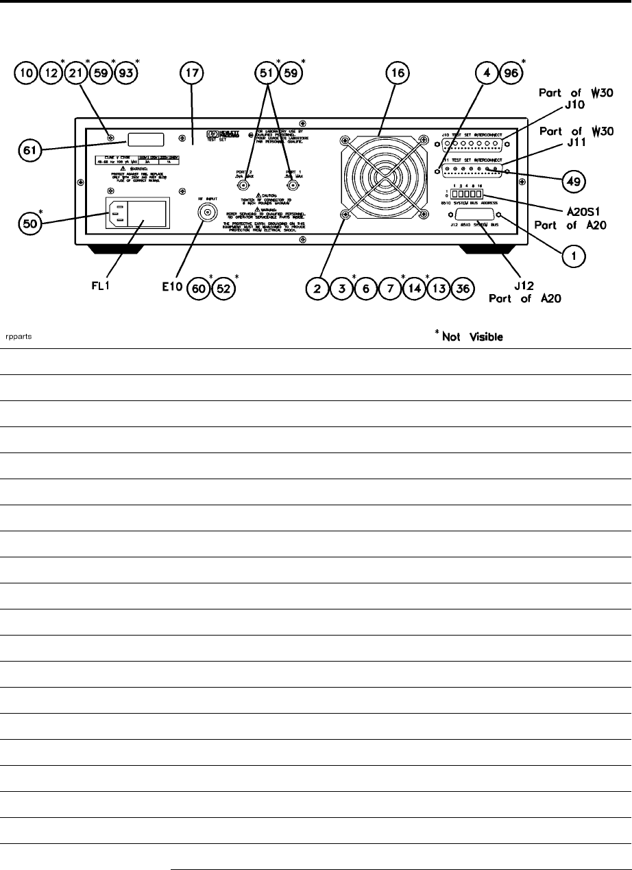
HP 8517B S-Parameter Test Set Manual
7-21
HP 8517B Replaceable Parts
Table 7-11 Miscellaneous Parts, Rear Panel HP 8517B Test Set
Ref Des HP Part Number Quantity Description
E10 5062-7243 1 2.4 mm RF Connector Assembly
FL1 9135-0217 1 Line Module-Filtered
J10 1251-2197 1 Connector R&P 24F (Part of W30)
J11 1251-2204 1 Connector R&P 24M (Part of W30)
1 0380-0643 2 Standoff-Hex 0.255-IN-LG 6-32 THD
210400-0010 4 Grommet-Round 0.188-IN-ID .312-IN-GRV-OD
310380-0926 4 Threaded Insert-STDF 6-32 0.188-IN-LG SST
421251-7812 6 Connector Jackscrew
610380-0002 4 Screw-Mach 6-32 0.625-IN-LG PAN-HD-POZI
712510-0322 4 Nut-HEX-W/LKWR 6-32-THD 0.109-IN-THK
1032510-0270 4 Screw-Mach 8-32 3.25-IN-LG PAN-HD-POZI
1233050-0139 12 Washer-FL MTLC NO.8 0.172-IN-ID
1313050-0152 4 Washer-Shoulder NO.8 0.172-IN-ID .438-IN-OD
1413050-0227 4 Washer-FL MTLC NO.6 0.149-IN-ID
16 3160-0309 1 Finger Guard
17 08517-00001 1 Rear Panel
2132190-0017 4 Washer-LK INTL NO. 10 0.195-IN-ID
36108513-00002 1 Transformer Bracket

7-22
HP 8517B S-Parameter Test Set Manual
HP 8517B Replaceable Parts
49 5021-0906 14 Teflon™ Cable Sleeve
50 5001-3907 2 Line Module Retainer Clips
51 2190-0016 2 Washer-LK INTL T 3/8 IN 0.377-IN-ID
52 2190-0104 1 Washer-LK INTL T 7/16 IN 0.439-IN-ID
5932950-0001 2 Nut-HEX-DBL-CHAM 3/8-32-THD 0.094-IN-THK
60 2950-0132 1 Nut-HEX-DBL-CHAM 7/16-28-THD 0.094-IN-THK
61 7121-2380 1 Serial Number Label
93308513-20032 2 Transformer Support Bracket
9620590-0663 6 Nut-HEX 4/40
1. See Figure 7-4, item 2 for detail.
2. See Figure 7-4, item 3 for detail.
3. See Figure 7-4, item 1 for detail.
Table 7-11 Miscellaneous Parts, Rear Panel HP 8517B Test Set
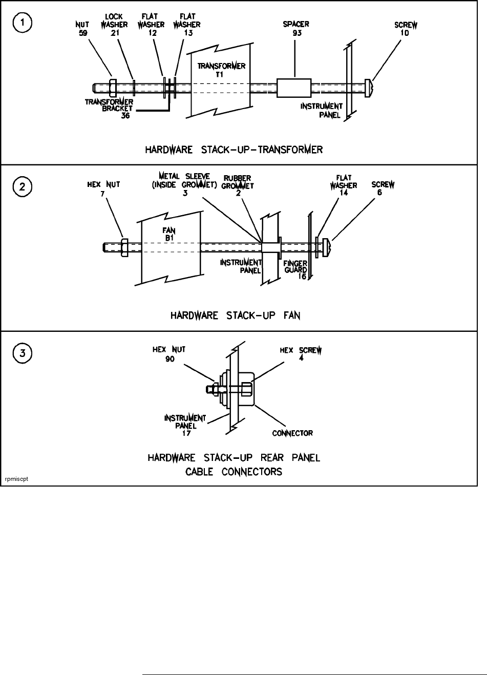
HP 8517B S-Parameter Test Set Manual
7-23
HP 8517B Replaceable Parts
Figure 7-4 Detailed Views of Hardware Stack-Ups
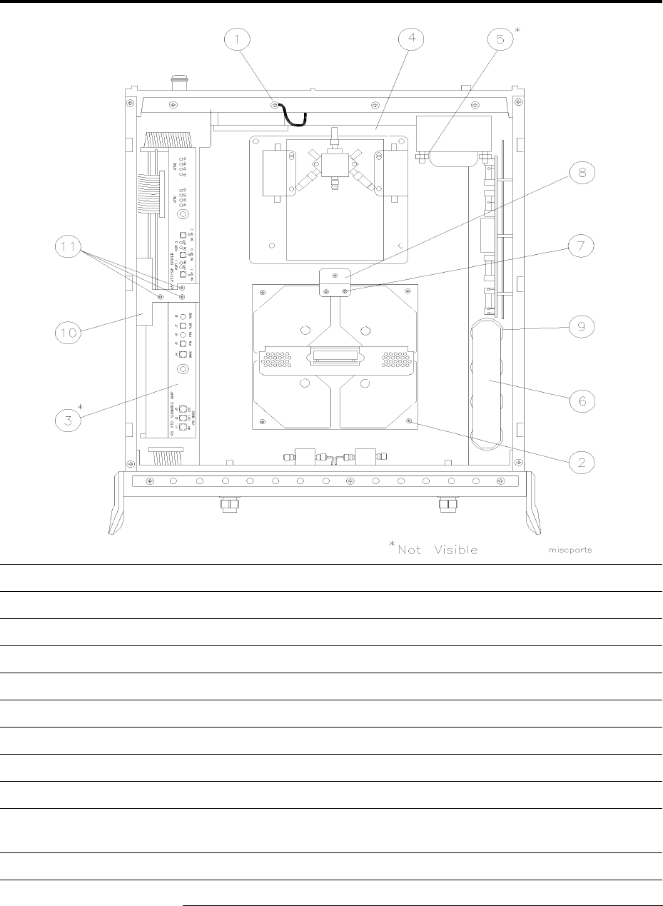
7-24
HP 8517B S-Parameter Test Set Manual
HP 8517B Replaceable Parts
Table 7-12 Miscellaneous Parts, Top Internal View
Item HP Part Number Quantity Description
1 0360-0031 1 Terminal Crimp
2 2360-0115 5 Machine Screw
3 08512-20005 1 RFI Gasket
4 08513-00001 1 Top Deck
5 08513-00002 1 Transformer Bracket
6 08513-00015 1 Capacitor Plate
7 2200-0109 2 Machine Screw
8 08514-00007 1 Mounting Plate
9 See Table 7-13 for all part
numbers and locations
– C1 through C4 and R1 through R4
10 0513-00037 1 Enclosure Bracket
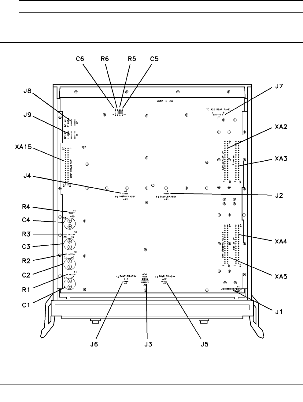
HP 8517B S-Parameter Test Set Manual
7-25
HP 8517B Replaceable Parts
11 2200-0107 3 Machine Screws
Table 7-12 Miscellaneous Parts, Top Internal View
Table 7-13 Miscellaneous Parts, Motherboard
Ref Des HP Part Number Quantity Description Manufacturer
Code
Manufacturer Part
Number
C1 - C4 0180-2671 4 Capacitor-FXD .012F+75-10% 30VDC AL 00853 500123U030AC2A
bottom.pcx

7-26
HP 8517B S-Parameter Test Set Manual
HP 8517B Replaceable Parts
C5 - C6 0160-4834 2 Capacitor-FXD .047
µ
F ±10% 100VDC CER
J1 1251-574 Connector 20-PIN M Post Type
(A19J1) DOES NOT INCLUDE A19MP1 and
A19MP2
Ref Des HP Part Number Quantity Description Manufacturer
Code
Manufacturer Part
Number
J2 1251-6868 4 Connector 5-PIN M Post Type
J3 1251-7939 1 Connector - Post Type 0.100-PIN-SPCG 14-CONT
(A19J3 DOES NOT INCLUDE A19MP3)
J4, J5, and J6 1251-6868 Connector 5-PIN M Post Type
J7 1251-3825 1 Connector 5-PIN M Post Type
J8 and J9 1200-0508 1 ea. Socket - IC 14-CONT DIP-SLDR
R1 and R2 0764-0015 1 ea. Resistor 560
Ω
5% 2W MO TC = 0±200
R3 and R4 0764-0016 1 ea. Resistor 1 k
Ω
5% 2W MO TC = 0±200
R5 and R6 0757-0394 1 ea. Resistor 51.1
Ω
1% 0.125W F TC = 0±100 24546 C4-1/8-T0-51R1-F
XA2, XA3, XA4,
and XA5
1251-7882 1 ea. Connector-PC Edge 2-Rows
XA6 to XA14 Not Assigned
XA15 1251-7882 1 Connector-PC Edge 2-Rows
Table 7-13 Miscellaneous Parts, Motherboard (Continued)
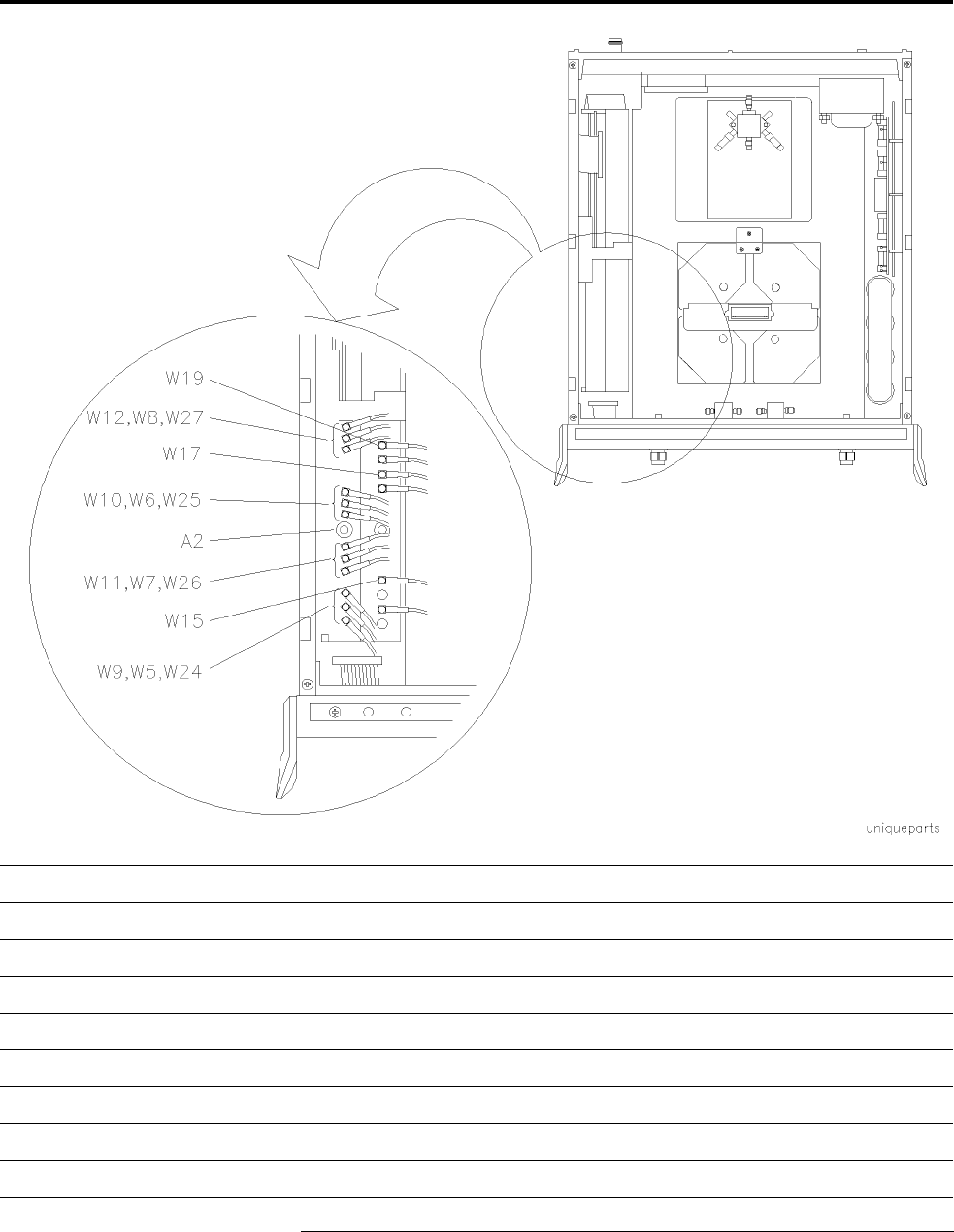
HP 8517B S-Parameter Test Set Manual
7-27
HP 8517B Replaceable Parts
Table 7-14 Parts Unique to HP 8517B Option 001 Test Set
Ref Des HP Part Number Quantity Description
A2 08513-60004 1 Board Assembly, IF Multiplexer (NEW)
08513-69004 Board Assembly, IF Multiplexer (R-E)
Cable Assemblies Unique to Option 001
W5 08513-60125 1 Cable Assembly, A2J2 to J11A1
W6 08513-60126 1 Cable Assembly, A2J8 to J11A4
W7 08513-60127 1 Cable Assembly, A2J5 to J11A2
W8 08513-60128 1 Cable Assembly, A2J11 to J11A3
W9 08513-60129 1 Cable Assembly, A2J3 to J10A1

7-28
HP 8517B S-Parameter Test Set Manual
HP 8517B Replaceable Parts
W10 08513-60130 1 Cable Assembly, A2J9 to J10A4
Ref Des HP Part Number Quantity Description
W11 08513-60131 1 Cable Assembly, A2J6 to J10A2
W12 08513-60132 1 Cable Assembly, A2J12 to J10A3
W15 08513-60135 1 Cable Assembly, A3J3 to J10A7
W17 08513-60137 Cable Assembly, A3J6 to J10A5
W19 08513-60139 1 Cable Assembly, A3J8 to J10A6
W24 08513-60144 1 Cable Assembly, A12J3 to A2J1
W25 08513-60145 1 Cable Assembly, A13J3 to A2J7
W26 08513-60146 1 Cable Assembly, A10J3 to A2J4
W27 08513-60147 1 Cable Assembly, A11J3 to A2J10
W45 08517-20017 1 Cable Assembly, A8 to A18
W46 08517-20018 1 Cable Assembly, A6 to A18
Table 7-14 Parts Unique to HP 8517B Option 001 Test Set
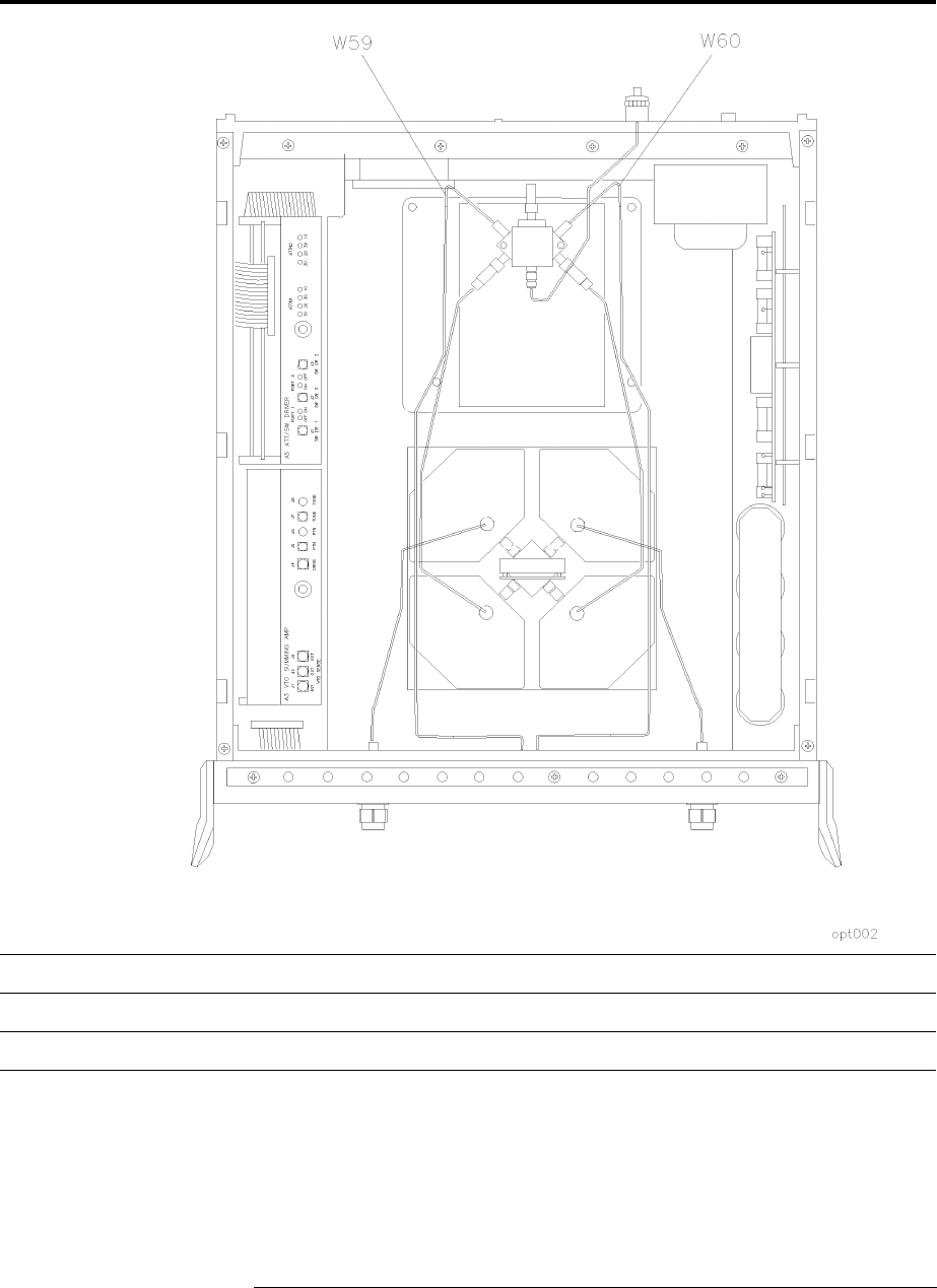
HP 8517B S-Parameter Test Set Manual
7-29
HP 8517B Replaceable Parts
Table 7-15 Parts Unique to HP 8417B Option 002 Test Set
Ref Des HP Part Number Quantity Description
W59 08517-20743 1 Cable Assembly, A12J3 to Port 1 J13
W60 08517-20737 1 Cable Assembly, A13J3 to Port 2J14
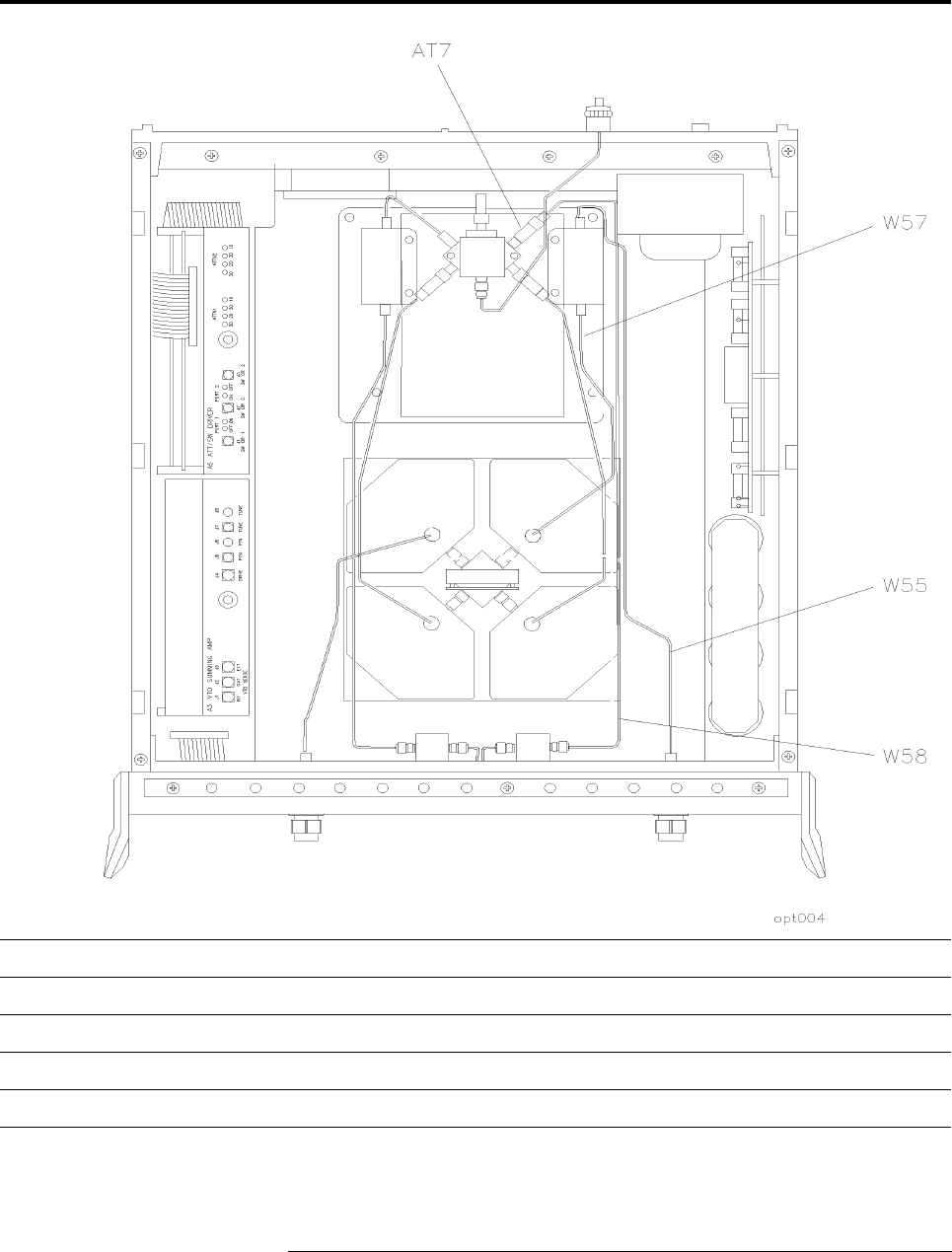
7-30
HP 8517B S-Parameter Test Set Manual
HP 8517B Replaceable Parts
Table 7-16 Parts Unique to HP 8517B Option 004 Test Set
Ref Des HP Part Number Quantity Description
W55 08517-20051 1 Cable Assembly, AT7 to A9J1
W57 08517-20052 1 Cable Assembly, A8J3 to A17J2
W58 08517-20050 1 Cable Assembly, A17J1 to A11J2
AT7 08517-60020 1 3 dB Attenuator
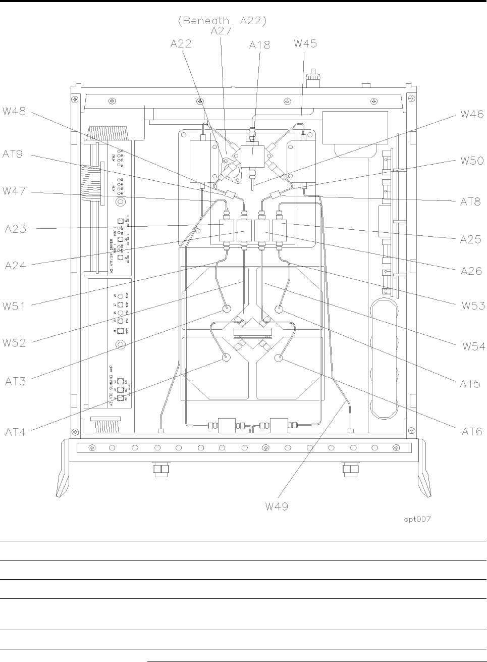
HP 8517B S-Parameter Test Set Manual
7-31
HP 8517B Replaceable Parts
Table 7-17 Parts Unique to HP 8517B Option 007 Test Set
Ref Des HP Part Number Quantity Description
AT8 and AT9 08516-60021 2 3 dB Attenuators
A22 5086-7650 1 Input Amplifier
A23, A24,
A25, and A26
5086-7649 4 Buffer Amplifiers
A27 08517-60045 1 Post Regulator Board Assembly (Beneath A22 Input Amplifier)

7-32
HP 8517B S-Parameter Test Set Manual
HP 8517B Replaceable Parts
Ref Des HP Part Number Quantity Description
Cable Assemblies Unique to Option 007
W45 08517-20023 1 Front Panel J7 to A22 Input Amplifier
W46 08517-20024 1 A22 Input Amplifier to A18J5
W47 08517-2003 1 A6 Coupler to A23
W48 08517-20061 1 AT1 to A24
W49 08517-20036 1 A8 Coupler to A25
W50 08517-20062 1 AT2 to A26
W51 08517-20034 1 A23 to AT3
W52 08517-20029 1 A24 to AT4
W53 08517-20034 1 A25 to AT5
W54 08517-20030 1 AT6 to A26
AT3 33340-60004 1 13 dB to 5 dB Attenuator
AT4 08516-60004 1 10 dB Attenuator
AT5 33340-60004 1 13 dB to 5 dB Attenuator
AT6 08516-60007 1 10 dB Attenuator
Table 7-17 Parts Unique to HP 8517B Option 007 Test Set (Continued)
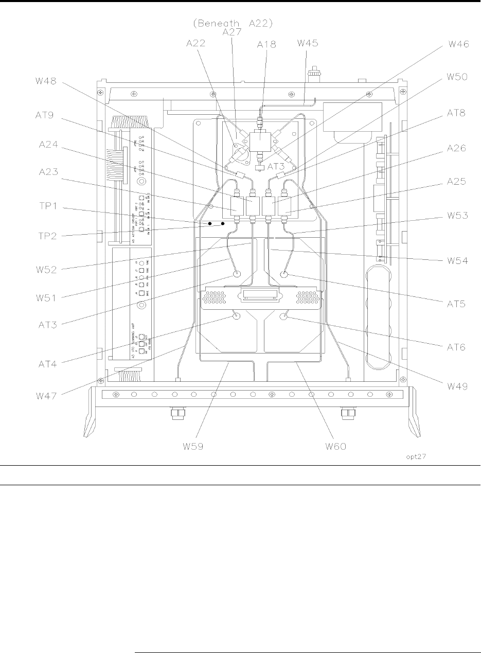
HP 8517B S-Parameter Test Set Manual
7-33
HP 8517B Replaceable Parts
Table 7-18 Parts Unique to Option 002 “plus” Option 007
There are no unique parts to Option 002 “plus” Option 007. All other parts are included in Option 002 or Option 007.
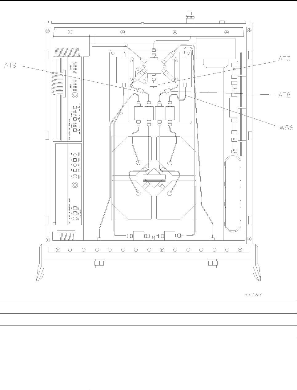
7-34
HP 8517B S-Parameter Test Set Manual
HP 8517B Replaceable Parts
Table 7-19 Parts Unique to Option 004 “plus” Option 007
Ref Des HP Part Number Quantity Description
W56 08517-20049 1 A17J1 to A25
All other parts are included in Option 004 or Option 007.
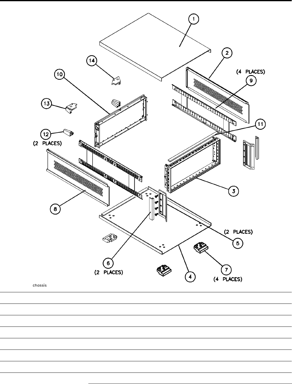
HP 8517B S-Parameter Test Set Manual
7-35
HP 8517B Replaceable Parts
Table 7-20 Instrument Chassis Replaceable Parts
Item Number HP Part Number Quantity Description
1 08513-00040 1 Top Cover
2 08513-00041 1 Side Cover, Perforated
3 5021-8403 1 Front Frame
4 5062-3747 1 Bottom Cover
5 5062-3799 1 Handle Assembly
6 5021-8496 1 Trim, Front Handle

7-36
HP 8517B S-Parameter Test Set Manual
HP 8517B Replaceable Parts
7 5041-8821 4 Bottom Foot
8 5062-3757 1 Side Cover
Item Number HP Part Number Quantity Description
9 5021-5837 1 18-inch Corner Strut
10 5021-5804 1 Rear Frame
11 5041-8802 1 Trim Strip
12 5041-8821 2 Back Panel Foot
13 5021-8538 1 Lock Foot
14 5021-8540 1 Lock Foot
Table 7-20 Instrument Chassis Replaceable Parts (Continued)

Index
HP 8517B S-Parameter Test Set Manual
Index-1
A
abbreviations used in parts descriptions, 7-4
accessories descriptions, 2-3
active LED location, 3-1
adapter part numbers, 1-11
addressing a test set, 3-6
altering signal path conditions, 3-10
attaching anti-rotation clamps, 3-15
B
bias supply connector, 3-3
bias tees replacement, 6-11
bias tees usage, 1-2
block diagram, Option 004 HP 8517B, 1-3
block diagram, Option 007 HP 8517B, 1-3
block diagram, standard HP 8517B, 1-2
buffer amplifier replacement, 6-12
C
cable assemblies, flexible, 7-17
cable assemblies, semi-rigid, 7-16
cable descriptions and part numbers, 1-10
cabling the test set, 2-5
calibration cycle frequency, 1-6
calibration kit part number, 1-10
calibration procedure, 3-8
capacitor (filter capacitor) replacement, 6-6
CAUTION: CORRECTION MAY BE INVALID, 3-10
characteristics, 4-1, 4-2
characteristics of test set, 4-1
checking test set operation, 3-13
checking test-system operation, 1-5
checking test-system specifications, 1-5
choosing a test set from multiple test sets, 3-6
commands, switch driver, 3-6
configuration, 2-5
connection instructions, 2-6
connector-type descriptions, 2-6
D
definitions of prefixes used, 7-10
description of test set, 1-2
E
environmental requirements, 2-2
equipment requirements for replacing components, 6-3
ESD information, 6-1
ESD precaution, 1-13
F
fan assembly replacement, 6-8
features, front panel, 3-1
firmware compatibility matrix, 1-8
fixture kit part number, 1-11
frequency converter replacement, 6-5
front panel boards replacement, 6-10
front panel test ports, 4-1
front-panel parts ID, 7-19
fuse part numbers, 7-12
H
hardware stacking sequence, 7-23
high-power device measurement, 3-9
I
IF switching in the test set, 3-6
initializing a test set, 3-5
input amplifier replacement, 6-12
installing anti-rotation clamps, 3-15
J
J10 and J10 interconnect locations, 3-2
L
LED descriptions, 3-2
line module location, 3-2
M
manufacturer addresses (other than HP), 7-3
measurement accuracy maintenance, 1-6
measurement capabilities, 1-2
mechanical specifications, test set, 4-1
multiple test set configuration, 3-3, 3-7

Index-2
HP 8517B S-Parameter Test Set Manual
N
network analyzer compatibility matrix, 1-8
normalizing parameters, viewing, 3-11
O
operation precautions, 1-13
operation verification, 1-5
option descriptions, 1-4
options for service and support, 1-9
ordering information, 7-2
O-ring replacement, 2-6, 6-10
P
parts ID, front panel, 7-19
parts ID, instrument chassis, 7-35
parts ID, internal top view, 7-24
parts ID, major assemblies, 7-15
parts ID, motherboard, 7-25
parts ID, rear panel, 7-21
parts ID, test port components, 7-20
parts ID, unique to option 002, 7-27
parts ID, unique to option 002 "plus" 007, 7-33
parts ID, unique to option 004, 7-30
parts ID, unique to option 004 "plus" 007, 7-34
parts ID, unique to option 007, 7-31
phase lock, 4-2
phone-ordering parts, 7-2
physical characteristics, 4-2
plug assembly part numbers, 7-11
port attenuators replacement, 6-11
post-regulator board replacement, 6-13
power level input limits, 1-13
power requirements, 4-2
power transformer replacement, 6-9
powering up, 3-5
R
racking the test set, 2-4
R-E (rebuilt exchange assemblies) defined, 7-1
R-E process, 7-13
rear panel RF connector, 4-2
rear-panel parts ID, 7-21
reference channel phase lock power level, 4-2
reference designation, major assemblies, 7-14
reference designator abbreviations, 7-2
regulator board replacement, 6-6
replacement procedure basics, 6-5
revision information, 1-8
RF input damage level, 4-2
S
safety precautions, 1-13
sales and service internet address, vi
sales and service office locations, vi
selecting a test set, 3-5
serial prefix location and description, 1-7
service and support options, 1-9
shipping the test set, 2-7
source compatibility matrix, 1-8
static discharge precautions, 6-1
storage temperature, 2-2
switch/splitter replacement, 6-5
switch-driver control, 3-6
T
temperature and humidity requirements, 2-2
test equipment model requirements, 1-12
test port attenuator modifications, 3-10
test port characteristics, 4-1
test port couplers replacement, 6-11
test set, 4-2
test set accessories identification, 2-3
test set adapters, 1-11
test set connections, for two or more, 3-5
test set options, 1-4
test set specifications, 4-1
test set switching, two test sets, 3-4
test set test-fixture kit, 1-11
test set troubleshooting, 1-5
test-port connector replacement, 6-7
test-port parts ID, 7-20
trace memory storage, 3-11
U
user 1 power levels for reference channel, 4-2
using bias tees, 1-2
using multiple test-set configurations, 3-5
using the test set at a bench, 2-4
V
verification kit part number, 1-10
verifying test set performance, 3-14
viewing S11 to S22 parameters, 3-12
W
what to do with damaged shipments, 2-2
