Hp Laserjet Cp5000 Cp5525Dn Laser Printer Ce708A201 Users Manual Color Enterprise CP5520 Series Service
2015-02-11
: Hp Hp-Hp-Laserjet-Cp5000-Cp5525Dn-Laser-Printer-Ce708A201-Users-Manual-545065 hp-hp-laserjet-cp5000-cp5525dn-laser-printer-ce708a201-users-manual-545065 hp pdf
Open the PDF directly: View PDF ![]() .
.
Page Count: 686 [warning: Documents this large are best viewed by clicking the View PDF Link!]
- Theory of operation
- Basic operation
- Formatter-control system
- Engine-control system
- Image-formation system
- Pickup, feed, and delivery system
- Paper feeder
- Optional 3X500-sheet paper deck
- Removal and replacement
- Introduction
- Removal and replacement strategy
- Electrostatic discharge
- Required tools
- Service approach
- Removal and replacement procedures
- Print cartridges
- Toner-collection unit
- Fuser
- Pickup roller (Tray 1)
- Separation pad (Tray 1)
- Separation roller assembly (Tray 2)
- Pickup roller (Tray 2)
- Pickup roller, separation roller, and feed roller (1 x 500-sheet and 3 x 500-sheet paper feeders)
- Secondary transfer roller
- Intermediate transfer belt (ITB)
- Formatter PCA
- Hard Drive
- Covers
- Main assemblies
- Formatter case
- Laser/scanner assembly
- Paper pickup assembly
- Registration sensor assembly
- Lifter-drive assembly
- ITB front guide assembly
- ITB rear guide assembly
- Residual toner full sensor
- Main drive assembly
- Fuser drive assembly
- Fuser gear assembly
- Paper delivery assembly
- Duplex drive assembly (duplex models)
- Delivery drive assembly (simplex models)
- Residual-toner-feed assembly
- ITB motor (M1)
- Drum motor (M2)
- Developing motor (M3)
- Fuser motor (M4)
- Developing-disengagement motor (M6)
- Power-supply fan (FM1)
- Fuser fan (FM2)
- Formatter fan (FM3) and ICB PCA
- DC controller PCA
- Low-voltage power supply
- Imaging (developing) high-voltage power supply
- First transfer high-voltage power supply
- Second transfer high-voltage power supply
- Driver PCA
- Power switch PCA
- Environmental sensor
- 1 x 500-sheet paper feeder assembly
- 3 x 500-sheet paper feeder (optional accessory)
- 3 x 500 rear cover
- 3 x 500 right and left cassette rails
- 3 x 500 paper deck controller PCAs
- 3 x 500 paper deck lifter-drive assembly
- 3 x 500 paper deck pickup motor
- 3 x 500 front-lower cover
- 3 x 500 left cover
- 3 x 500 right-corner cover
- 3 x 500 front-upper cover
- 3 x 500 right-door assembly
- 3 x 500 right-lower cover 1
- 3 x 500 right-lower cover 2
- 3 x 500 left-lower cover
- 3 x 500 rear-lower cover
- 3 x 500 paper deck pickup assembly
- Solve problems
- Solve problems checklist
- Menu map
- Troubleshooting process
- Tools for troubleshooting
- Component diagnostics
- LED diagnostics
- Engine diagnostics
- Paper-path test
- Manual sensor test
- Tray/Bin manual sensor test
- Tray 1 paper sensor (PS2)
- Tray 2 paper present sensor (PS1)
- Tray 2 paper surface sensor (PS4)
- Tray 2 paper size switches (SW7 and SW8)
- Tray 3 paper sensor (SR3)
- Tray 3 paper surface sensor (SR2)
- Tray 3 paper size sensors (SW2 and SW3)
- Tray 3 feed sensor (SR1)
- Tray 3 door opening/closing sensor (SW1)
- Tray 4 paper sensor (SR3)
- Tray 4 paper surface sensor (SR2)
- Tray 4 paper size sensors (SW2 and SW3)
- Tray 4 feed sensor (SR1)
- Tray 4 door opening/closing door sensor (SW1)
- Tray 5 paper sensor (SR83)
- Tray 5 paper surface sensor (SR82)
- Tray 5 paper size sensors (SW82 and SW83)
- Tray 5 feed sensor (SR81)
- Tray 5 door opening/closing sensor (SW1)
- Tray 6 paper sensor (SR93)
- Tray 6 paper surface sensor (SR92)
- Tray 6 paper size sensors (SW92 and SW93)
- Tray 6 feed sensor (SR91)
- Tray 6 door opening/closing sensor (SW1)
- Output-bin-full sensor (PS10)
- Paper-path sensors test
- Print/stop test
- Component tests
- Diagrams
- Internal print-quality test pages
- Print quality troubleshooting tools
- Control panel menus
- Interpret control-panel messages, status-alert messages, and event code errors
- 10.0X.Y0 Supply memory error
- 10.22.50
- 10.22.51
- 10.22.52
- 10.23.50
- 10.23.51
- 10.23.52
- 10.23.70 Printing past very low
- 10.XX.34 Used supply in use
- 10.XX.40 Genuine HP supplies installed
- 10.XX.41 Unsupported supply in use
- 10.XX.70 Printing past very low
- 10.YY.15 Install <supply>
- 10.YY.25 Wrong cartridge in <color> slot
- 10.YY.35 Incompatible <supply>
- 11.00.YY Internal clock error
- 13.00.00
- 13.A3.FF
- 13.D3.DZ
- 13.WX.EE
- 13.WX.FF
- 13.WX.YZ Fuser area jam
- 13.WX.YZ Fuser wrap jam
- 13.WX.YZ Jam below control panel
- 13.WX.YZ Jam in lower right door
- 13.WX.YZ Jam in middle right door
- 13.WX.YZ Jam in right door
- 13.WX.YZ Jam in Tray 1
- 13.WX.YZ Jam in Tray <X>
- 20.00.00 Insufficient memory To continue, press OK
- 21.00.00 Page too complex
- 32.1C.XX
- 32.21.00
- 40.00.01 USB I/O buffer overflow To continue, press OK
- 40.00.02 Embedded I/O buffer overflow To continue, press OK
- 40.00.03 EIO buffer overflow To continue, press OK
- 40.00.04 Unsupported USB accessory detected To continue, press OK
- 40.00.05 Embedded I/O bad transmission To continue, press OK
- 41.02.00 Error
- 41.03.YZ Unexpected size in tray <X>
- 41.05.YZ Unexpected type in tray <X>
- 41.07.YZ Error To continue, press OK
- 42.XX.YY
- 47.00.XX
- 47.01.XX
- 47.02.XX
- 47.03.XX
- 47.04.XX
- 47.05.00
- 47.06.XX
- 47.WX.YZ Printer calibration error To continue, press OK
- 50.WX.YZ Fuser error To continue, turn off then on
- 51.00.YY Error
- 52.XX.00 Error To continue, turn off then on
- 54.XX.YY Error
- 55.00.YY DC controller error To continue, turn off then on
- 55.0X.YY DC controller error To continue, turn off then on
- 56.00.YY Error To continue, turn off then on
- 57.00.0Y Error To continue, turn off then on
- 59.00.YY Error To continue, turn off then on
- 59.0X.50 Error To continue, turn off then on
- 59.0X.60 Error To continue, turn off then on
- 59.0X.70 Error To continue, turn off then on
- 59.0X.80 Error To continue, turn off then on
- 60.00.0Y Tray <Y> lifting error
- 61.00.01
- 62.00.00 No system To continue, turn off then on
- 70.00.00 Error To continue, turn off then on
- 80.0X.YY Embedded JetDirect error
- 98.00.01 Corrupt data in firmware volume
- 98.00.02 Corrupt data in solutions volume
- 98.00.03 Corrupt data in configuration volume
- 98.00.04 Corrupt data in job data volume
- 99.00.01 Upgrade not performed file is corrupt
- 99.00.02 Upgrade not performed timeout during receive
- 99.00.03 Upgrade not performed error writing to disk
- 99.00.04 Upgrade not performed timeout during receive
- 99.00.05 Upgrade not performed timeout during receive
- 99.00.06 Upgrade not performed error reading upgrade
- 99.00.07 Upgrade not performed error reading upgrade
- 99.00.08 Upgrade not performed error reading upgrade
- 99.00.09 Upgrade canceled by user
- 99.00.10 Upgrade canceled by user
- 99.00.11 Upgrade canceled by user
- 99.00.12 Upgrade not performed the file is invalid
- 99.00.13 Upgrade not performed the file is invalid
- 99.00.14 Upgrade not performed the file is invalid
- 99.00.2X
- 99.09.60 Unsupported disk
- 99.09.61 Unsupported disk
- 99.09.62 Unknown disk
- 99.09.63 Incorrect disk
- 99.09.64 Disk malfunction
- 99.09.65 Disk data error
- 99.09.66 No disk data installed
- 99.09.67 Disk is not bootable please download firmware
- 99.XX.YY
- <Binname> Full Remove all paper from bin
- <Supply> almost full
- <Supply> low OR Supplies low
- <Supply>very low OR Supplies very low
- <Tray X> lifting
- [File System] device failure To clear, press OK
- [File System] file operation failed To clear, press OK
- [File System] file system is full To clear, press OK
- [File System] is not initialized
- [File System] is write protected
- Accept bad signature
- Bad optional tray connection
- Calibration reset pending
- Canceling
- Canceling... <jobname>
- Checking engine
- Checking paper path
- Chosen personality not available To continue, press OK
- Cleaning do not grab paper
- Cleaning...
- Clearing event log
- Clearing paper path
- Close front door
- Close lower right door
- Close middle right door
- Close right door
- Close upper right door For help press ?
- Cooling device
- Creating cleaning page
- Data received To print last page, press OK
- EIO <X> disk initializing
- EIO <X> disk not functional
- EIO <X> disk spinning up
- Event log is empty
- Expected drive missing
- HP Secure Hard Drive disabled
- Incompatible <supply>
- Incompatible supplies
- Initializing...
- Install <supply>
- Install <supply> Close rear door
- Install Fuser Unit
- Install supplies
- Install Transfer Unit
- Internal disk not functional
- Internal disk spinning up
- Load Tray <X>: [Type], [Size]
- Load Tray <X>: [Type], [Size] To use another tray, press OK
- Loading program <XX> Do not power off
- Manually feed output stack Then press OK to print second sides
- Manually feed: [Type], [Size]
- Manually feed: [Type], [Size] To use another tray, press OK
- Moving solenoid
- Moving solenoid and motor
- No job to cancel
- Paused
- Performing Color Band Test...
- Performing Paper Path Test...
- Please wait...
- Printing CMYK samples...
- Printing Color Usage Log...
- Printing Configuration...
- Printing Demo Page...
- Printing Diagnostics Page...
- Printing Engine Test...
- Printing Event Log...
- Printing File Directory...
- Printing Font List...
- Printing Fuser Test Page...
- Printing Help Page...
- Printing Menu Map...
- Printing PQ Troubleshooting...
- Printing Registration Page...
- Printing RGB Samples...
- Printing stopped
- Printing Supplies Status Page...
- Printing Usage Page...
- Processing duplex job Do not grab paper until job completes
- Processing job from tray <X>... Do not grab paper until job completes
- Processing... <filename>
- Processing... copy <X> of <Y>
- Ready
- Ready <IP Address>
- Remove all print cartridges
- Remove at least one print cartridge
- Remove shipping lock from Tray 2
- Replace <supply>
- Replace supplies
- Restore Factory Settings
- Restricted from printing in color
- Rotating <color> motor
- Rotating motor
- Size mismatch in Tray <X>
- Sleep mode on
- Supplies in wrong positions
- Tray <X> empty: [Type], [Size]
- Tray <X> open
- Tray <X> overfilled
- Troubleshooting
- Type mismatch Tray <X>
- Unsupported drive installed To continue, press OK
- Unsupported supply in use OR Unsupported supply installed To continue, press OK
- Unsupported tray configuration
- Unsupported USB accessory detected Remove USB accessory
- USB accessory needs too much power Remove USB and turn off then on
- USB accessory not functional
- Used supply installed To continue, press OK OR Used supply in use
- Wrong cartridge in <color> slot
- Event-log messages
- Component diagnostics
- Clear jams
- Solve paper-handling problems
- Product feeds multiple sheets
- Product feeds incorrect page size
- Product pulls from incorrect tray
- Paper does not feed automatically
- Paper does not feed from Tray 2, 3, 4, 5, or 6
- Transparencies or glossy paper will not feed
- Envelopes jam or will not feed in the product
- Output is curled or wrinkled
- Product will not duplex or duplexes incorrectly
- Use manual print modes
- Solve image-quality problems
- Clean the product
- Solve performance problems
- Solve connectivity problems
- Service mode functions
- Preboot menu options
- Product updates
- Parts and diagrams
- Order parts by authorized service providers
- How to use the parts lists and diagrams
- Assembly locations
- External covers, panels, and doors
- Right door assembly
- Internal components (1 of 9)
- Internal components (2 of 9)
- Internal components (3 of 9)
- Internal components (4 of 9)
- Internal components (5 of 9)
- Internal components (6 of 9)
- Internal components (7 of 9)
- Internal components (8 of 9)
- Internal components (9 of 9)
- 1x250 cassette
- Paper pick-up assembly
- Paper delivery assembly
- Printed circuit assemblies
- 1x500 paper feeder
- 3x500 paper feeder
- Alphabetical parts list
- Numerical parts list
- Service and support
- Hewlett-Packard limited warranty statement
- HP's Premium Protection Warranty: LaserJet print cartridge limited warranty statement
- Color LaserJet Fuser Kit, Transfer Kit, and Toner Collection Unit Limited Warranty Statement
- Data stored on the print cartridge
- End User License Agreement
- Customer self-repair warranty service
- Customer support
- Product specifications
- Regulatory information
- FCC regulations
- Environmental product stewardship program
- Protecting the environment
- Ozone production
- Power consumption
- Paper use
- Plastics
- HP LaserJet print supplies
- Return and recycling instructions
- Paper
- Material restrictions
- Disposal of waste equipment by users in private households in the European Union
- Chemical substances
- Material Safety Data Sheet (MSDS)
- For more information
- Declaration of Conformity
- Certificate of Volatility
- Safety statements
- Laser safety
- Canadian DOC regulations
- VCCI statement (Japan)
- Power cord instructions
- Power cord statement (Japan)
- EMC statement (China)
- EMC statement (Korea)
- EMI statement (Taiwan)
- Laser statement for Finland
- GS statement (Germany)
- Substances Table (China)
- Restriction on Hazardous Substances statement (Turkey)
- Index
HP COLOR LASERJET ENTERPRISE CP5520
PRINTER SERIES
Service Manual

HP Color LaserJet Enterprise CP5520
Printer Series
Service Manual
Copyright and License
© 2010 Copyright Hewlett-Packard
Development Company, L.P.
Reproduction, adaptation, or translation
without prior written permission is
prohibited, except as allowed under the
copyright laws.
The information contained herein is subject
to change without notice.
The only warranties for HP products and
services are set forth in the express warranty
statements accompanying such products and
services. Nothing herein should be
construed as constituting an additional
warranty. HP shall not be liable for technical
or editorial errors or omissions contained
herein.
Part number: CE707-90935
Edition 1, 11/2010
Trademark Credits
Adobe
®
, Acrobat
®
, and PostScript
®
are
trademarks of Adobe Systems Incorporated.
Corel® is a trademark or registered
trademark of Corel Corporation or Corel
Corporation Limited.
Microsoft®, Windows®, Windows® XP,
and Windows Vista® are U.S. registered
trademarks of Microsoft Corporation.
UNIX
®
is a registered trademark of The
Open Group.
ENERGY STAR
®
and the ENERGY STAR
®
mark are registered U.S. marks.

Conventions used in this guide
TIP: Tips provide helpful hints or shortcuts.
NOTE: Notes provide important information to explain a concept or to complete a task.
CAUTION: Cautions indicate procedures that you should follow to avoid losing data or damaging
the product.
WARNING! Warnings alert you to specific procedures that you should follow to avoid personal
injury, catastrophic loss of data, or extensive damage to the product.
ENWW iii
iv Conventions used in this guide ENWW

Table of contents
1 Theory of operation .......................................................................................................... 1
Basic operation ........................................................................................................................ 2
Major product systems ............................................................................................... 2
Product block diagram ............................................................................................... 2
Sequence of operation ............................................................................................... 3
Normal sequence of operation ..................................................................... 3
Formatter-control system ............................................................................................................ 5
Sleep mode .............................................................................................................. 5
Input/output ............................................................................................................. 6
CPU ........................................................................................................................ 6
Memory ................................................................................................................... 6
Firmware ................................................................................................... 6
Nonvolatile memory ................................................................................... 6
PJL overview ............................................................................................................. 6
PML ......................................................................................................................... 7
Control panel ........................................................................................................... 7
Engine-control system ................................................................................................................ 8
DC controller ............................................................................................................ 9
Motors .................................................................................................... 12
Fans ....................................................................................................... 14
Fuser-control circuit ................................................................................... 15
Fuser temperature control ........................................................... 16
Fuser protective function ............................................................. 17
Fuser failure detection ................................................................ 18
Low-voltage power supply ......................................................................... 19
Overcurrent/overvoltage protection ............................................. 21
High-voltage power supply ........................................................................ 22
Laser scanner system ............................................................................................... 24
Laser failure detection ............................................................................... 25
Image-formation system ........................................................................................................... 26
Electrophotographic process ..................................................................................... 26
Image formation process .......................................................................................... 28
ENWW v
Latent-image formation block ..................................................................... 29
Pre-exposure ............................................................................. 29
Primary charging ...................................................................... 29
Laser beam exposure ................................................................. 30
Developing block ..................................................................................... 31
Transfer block .......................................................................................... 32
Primary transfer ......................................................................... 32
Secondary transfer .................................................................... 32
Separation ............................................................................... 33
Fusing block ............................................................................................ 33
ITB cleaning block .................................................................................... 34
Drum cleaning block ................................................................................. 34
Print cartridges ........................................................................................................ 35
Memory tag ............................................................................................ 36
Cartridge presence detection ..................................................................... 36
Toner level detection ................................................................................. 36
Cartridge life detection ............................................................................. 36
Developing unit engagement and disengagement control .............................. 36
ITB unit .................................................................................................................. 38
Primary transfer roller engagement and disengagement control ...................... 39
ITB unit presence detection ........................................................................ 40
ITB cleaning mechanism ............................................................................ 40
Calibration ............................................................................................................. 41
Color-misregistration control ...................................................................... 42
Environment change control ....................................................................... 43
Image stabilization control ........................................................................ 43
Image density control (DMAX) ..................................................... 43
Image halftone control (DHALF) ................................................... 43
Pickup, feed, and delivery system ............................................................................................. 44
Photo sensors .......................................................................................................... 46
Motors and solenoids .............................................................................................. 47
Pickup and feed block ............................................................................................. 47
Tray 2 cassette pickup .............................................................................. 48
Tray 2 cassette multiple-feed prevention ...................................................... 49
Tray 2 cassette media-size detection and Tray 2 cassette-presence detection .. . 50
Tray 2 cassette lift-up operation .................................................................. 51
Cassette media-presence detection ............................................................. 53
Tray 1 (MP tray) paper pickup .................................................................................. 53
Tray 1 (MP tray) last-paper detection ......................................................................... 54
Paper feed ............................................................................................................. 55
Skew-feed prevention ................................................................................ 57
vi ENWW
Media detection ....................................................................................... 58
Feed-speed control ................................................................................... 59
Fusing and delivery block ......................................................................................... 59
Loop control ............................................................................................ 59
Pressure roller pressurization and depressurization control ............................ 61
Output bin full detection ............................................................................ 62
Duplex block (duplex models only) ............................................................................ 63
Duplex reverse and duplex feed control ...................................................... 63
Duplex operation ..................................................................................... 64
Jam detection ......................................................................................................... 66
Paper feeder ......................................................................................................................... 68
Paper-feeder motors ................................................................................................. 69
Paper-feeder paper pickup and feed ......................................................................... 70
Cassette media-size detection and cassette-presence detection ...................................... 70
Paper-feeder cassette lift operation ............................................................................ 71
Paper-feeder jam detection ....................................................................................... 72
Optional 3X500-sheet paper deck ........................................................................................... 73
Motor control .......................................................................................................... 76
Pickup-and-feed operation ........................................................................................ 77
Cassette media-size detection and cassette-presence detection ...................................... 78
Cassette lift-up operation .......................................................................................... 79
Jam detection ......................................................................................................... 81
2 Removal and replacement .............................................................................................. 83
Introduction ........................................................................................................................... 84
Removal and replacement strategy ........................................................................................... 84
Electrostatic discharge ............................................................................................................ 84
Required tools ........................................................................................................................ 85
Service approach ................................................................................................................... 86
Before performing service ........................................................................................ 86
After performing service ........................................................................................... 86
Post-service test ....................................................................................................... 86
Print-quality test ........................................................................................ 86
Removal and replacement procedures ...................................................................................... 87
Print cartridges ........................................................................................................ 87
Toner-collection unit ................................................................................................. 91
Fuser ..................................................................................................................... 93
Reset the New Fuser Kit setting at the control panel ...................................... 93
Pickup roller (Tray 1) ............................................................................................... 94
Separation pad (Tray 1) ........................................................................................... 95
Separation roller assembly (Tray 2) ........................................................................... 97
ENWW vii
Pickup roller (Tray 2) ............................................................................................... 98
Pickup roller, separation roller, and feed roller (1 x 500-sheet and 3 x 500-sheet paper
feeders) ................................................................................................................. 99
Secondary transfer roller ........................................................................................ 101
Intermediate transfer belt (ITB) ................................................................................. 102
Reset the New Transfer Kit setting at the control panel ................................ 104
Formatter PCA ...................................................................................................... 105
Hard Drive ........................................................................................................... 107
Remove the encrypted HDD ..................................................................... 108
Remove the solid-state hard drive ............................................................. 109
Covers ................................................................................................................. 111
Identification and location ....................................................................... 111
Right-front cover and control-panel assembly .............................................. 113
Left cover .............................................................................................. 115
Rear cover ............................................................................................. 116
Remove the rear cover ............................................................. 116
Toner collection unit access door .............................................................. 117
Right-rear cover ...................................................................................... 119
Reinstall the right-rear cover ...................................................... 120
Top cover .............................................................................................. 121
Remove the top cover .............................................................. 121
Front-door assembly ............................................................................... 123
Right-door assembly ............................................................................... 126
Main assemblies ................................................................................................... 130
Formatter case ....................................................................................... 130
Remove the formatter case ........................................................ 130
Laser/scanner assembly .......................................................................... 132
Remove the laser/scanner assembly .......................................... 132
Paper pickup assembly ........................................................................... 135
Remove the paper pickup assembly ........................................... 135
Reinstall the paper pickup assembly .......................................... 138
Registration sensor assembly ................................................................... 142
Remove the registration sensor assembly .................................... 142
Lifter-drive assembly ................................................................................ 145
Remove the lifter-drive assembly ................................................ 145
ITB front guide assembly ......................................................................... 148
ITB rear guide assembly .......................................................................... 151
Residual toner full sensor ......................................................................... 152
Remove the residual toner full sensor ......................................... 152
Main drive assembly .............................................................................. 157
Remove the main drive assembly ............................................... 157
viii ENWW
Install the main drive assembly .................................................. 167
Fuser drive assembly .............................................................................. 172
Remove the fuser drive assembly ............................................... 172
Install a replacement fuser drive assembly .................................. 174
Fuser gear assembly ............................................................................... 176
Remove the fuser gear assembly ................................................ 176
Install a replacement fuser gear assembly ................................... 182
Paper delivery assembly .......................................................................... 184
Remove the delivery assembly ................................................... 184
Reinstall the paper delivery assembly ......................................... 185
Duplex drive assembly (duplex models) ..................................................... 187
Remove the duplex-drive assembly ............................................. 187
Delivery drive assembly (simplex models) .................................................. 189
Remove the delivery drive assembly ........................................... 189
Residual-toner-feed assembly ................................................................... 190
Remove the residual-toner-feed assembly .................................... 190
ITB motor (M1) ....................................................................................... 192
Remove the ITB motor .............................................................. 192
Drum motor (M2) ................................................................................... 194
Remove the drum motor ........................................................... 194
Developing motor (M3) ........................................................................... 195
Remove the developing motor ................................................... 195
Fuser motor (M4) .................................................................................... 196
Remove the fuser motor ............................................................ 196
Developing-disengagement motor (M6) ..................................................... 197
Remove the developing-disengagement motor ............................. 197
Power-supply fan (FM1) .......................................................................... 198
Remove the power-supply fan ................................................... 198
Fuser fan (FM2) ...................................................................................... 201
Remove the fuser fan ............................................................... 201
Formatter fan (FM3) and ICB PCA ............................................................ 204
Remove the formatter fan and ICB PCA ...................................... 204
DC controller PCA .................................................................................. 207
Remove the DC controller PCA .................................................. 207
Low-voltage power supply ....................................................................... 209
Remove the low-voltage power supply ........................................ 209
Imaging (developing) high-voltage power supply ........................................ 213
Remove the imaging (developing) high-voltage power supply ....... 213
First transfer high-voltage power supply ..................................................... 214
Remove the first transfer high-voltage power supply ..................... 214
Second transfer high-voltage power supply ................................................ 216
ENWW ix
Remove the second transfer high-voltage power supply ................ 216
Driver PCA ............................................................................................ 218
Remove the driver PCA ............................................................ 218
Power switch PCA .................................................................................. 220
Remove the power switch PCA .................................................. 220
Environmental sensor .............................................................................. 221
Remove the environmental sensor .............................................. 221
1 x 500-sheet paper feeder assembly ...................................................................... 222
1 x 500 rear cover ................................................................................. 222
1 x 500 left cover .................................................................................. 223
1 x 500 right-front cover ......................................................................... 225
1 x 500 front-upper cover ....................................................................... 226
1 x 500 right door ................................................................................. 227
1 x 500 right-lower cover ........................................................................ 229
1 x 500 pickup assembly ........................................................................ 230
1 x 500 lifter-drive assembly ................................................................... 233
1 x 500 pickup motor ............................................................................. 234
1 x 500 driver PCA ................................................................................ 235
3 x 500-sheet paper feeder (optional accessory) ....................................................... 236
3 x 500 rear cover ................................................................................. 236
3 x 500 right and left cassette rails .......................................................... 237
3 x 500 paper deck controller PCAs ........................................................ 238
3 x 500 paper deck lifter-drive assembly .................................................. 239
3 x 500 paper deck pickup motor ............................................................ 240
3 x 500 front-lower cover ........................................................................ 241
3 x 500 left cover .................................................................................. 242
3 x 500 right-corner cover ...................................................................... 243
3 x 500 front-upper cover ....................................................................... 244
3 x 500 right-door assembly .................................................................... 245
3 x 500 right-lower cover 1 ..................................................................... 247
3 x 500 right-lower cover 2 ..................................................................... 248
3 x 500 left-lower cover .......................................................................... 249
3 x 500 rear-lower cover ........................................................................ 250
Remove the 3 x 500 rear-lower cover ........................................ 250
3 x 500 paper deck pickup assembly ....................................................... 251
Remove the 3 x 500 paper deck pickup assembly ....................... 251
3 Solve problems ............................................................................................................. 253
Solve problems checklist ....................................................................................................... 254
Menu map .......................................................................................................................... 256
Current settings pages ........................................................................................... 256
xENWW
Control panel menus .............................................................................................. 257
Sign In menu ........................................................................................................ 257
Retrieve Job From USB menu .................................................................................. 257
Retrieve Job From Device Memory menu .................................................................. 257
Supplies menu ...................................................................................................... 258
Trays menu ........................................................................................................... 260
Administration menu .............................................................................................. 261
Reports menu ......................................................................................... 261
General Settings menu ............................................................................ 261
Retrieve From USB Settings menu ............................................................. 266
Print Settings menu ................................................................................. 266
Print Options menu ................................................................................. 267
Display Settings menu ............................................................................. 269
Manage Supplies menu .......................................................................... 270
Manage Trays menu ............................................................................... 271
Network Settings menu ........................................................................... 272
Troubleshooting menu ............................................................................................ 275
Device Maintenance menu ..................................................................................... 276
Backup/Restore menu ............................................................................. 276
Calibration/Cleaning menu ..................................................................... 277
USB Firmware Upgrade menu .................................................................. 277
Service menu ......................................................................................... 278
Troubleshooting process ........................................................................................................ 279
Determine the problem source ................................................................................. 279
Pre-troubleshooting checklist .................................................................... 279
Troubleshooting flowchart ....................................................................... 280
Power subsystem ................................................................................................... 282
Power-on checks .................................................................................... 282
Power-on troubleshooting overview ............................................ 282
Tools for troubleshooting ....................................................................................................... 284
Component diagnostics .......................................................................................... 284
LED diagnostics ...................................................................................... 284
Understand lights on the formatter ............................................. 284
Engine diagnostics ................................................................................. 285
Defeating interlocks ................................................................. 286
Disable cartridge check ........................................................... 287
Engine test button .................................................................... 288
Paper-path test ....................................................................................... 288
Manual sensor test ................................................................................. 289
Front-door opening/closing switch (PS14) .................................. 291
Right-door opening/closing sensor (PS15) .................................. 292
ENWW xi
TOP (top-of-page) sensor (PS5) .................................................. 294
Fuser loop sensors 1 and 2 (PS7 and PS8) ................................. 295
Fuser pressure-release sensor (PS9) ............................................ 296
Fuser output sensor (PS6) .......................................................... 297
Developer alienation sensor (PS11) ........................................... 298
ITB alienation switch (SW5) ...................................................... 299
Tray/Bin manual sensor test .................................................................... 300
Tray 1 paper sensor (PS2) ........................................................ 302
Tray 2 paper present sensor (PS1) ............................................. 303
Tray 2 paper surface sensor (PS4) ............................................. 304
Tray 2 paper size switches (SW7 and SW8) .............................. 305
Tray 3 paper sensor (SR3) ........................................................ 306
Tray 3 paper surface sensor (SR2) ............................................. 307
Tray 3 paper size sensors (SW2 and SW3) ............................... 308
Tray 3 feed sensor (SR1) .......................................................... 309
Tray 3 door opening/closing sensor (SW1) ................................ 310
Tray 4 paper sensor (SR3) ........................................................ 311
Tray 4 paper surface sensor (SR2) ............................................. 311
Tray 4 paper size sensors (SW2 and SW3) ............................... 311
Tray 4 feed sensor (SR1) .......................................................... 311
Tray 4 door opening/closing door sensor (SW1) ........................ 311
Tray 5 paper sensor (SR83) ...................................................... 312
Tray 5 paper surface sensor (SR82) ........................................... 312
Tray 5 paper size sensors (SW82 and SW83) ........................... 312
Tray 5 feed sensor (SR81) ........................................................ 312
Tray 5 door opening/closing sensor (SW1) ................................ 312
Tray 6 paper sensor (SR93) ...................................................... 312
Tray 6 paper surface sensor (SR92) ........................................... 312
Tray 6 paper size sensors (SW92 and SW93) ........................... 312
Tray 6 feed sensor (SR91) ........................................................ 312
Tray 6 door opening/closing sensor (SW1) ................................ 312
Output-bin-full sensor (PS10) ..................................................... 313
Paper-path sensors test ............................................................................ 313
Print/stop test ........................................................................................ 314
Component tests ..................................................................................... 314
Component test (special-mode test) ............................................ 314
Additional component tests ....................................................... 317
Diagrams ............................................................................................................. 319
Block diagrams ...................................................................................... 319
Plug/jack locations ................................................................................. 321
Location of connectors ............................................................................ 322
xii ENWW
DC controller connections ......................................................... 322
Product connections ................................................................. 324
Locations of major components ................................................................ 331
General timing charts ............................................................................. 338
General circuit diagram .......................................................................... 340
Internal print-quality test pages ................................................................................ 344
Print-quality-troubleshooting pages ............................................................ 344
Diagnostics page ................................................................................... 347
Clean the paper path ............................................................................. 349
Set up an auto cleaning page ................................................... 349
Configuration page ................................................................................ 350
Configuration page ................................................................. 350
HP embedded Jetdirect page .................................................... 352
Finding important information on the configuration pages ............ 353
Color-band test ...................................................................................... 354
Print quality troubleshooting tools ............................................................................ 355
Repetitive image-defect ruler .................................................................... 355
Calibrate the product .............................................................................. 356
Control panel menus .............................................................................................. 356
Sign In menu ......................................................................................... 357
Retrieve Job From USB menu ................................................................... 358
Retrieve Job From Device Memory menu ................................................... 359
Supplies menu ....................................................................................... 360
Trays menu ............................................................................................ 363
Administration menu ............................................................................... 365
Reports menu .......................................................................... 365
General Settings menu ............................................................. 367
Retrieve From USB Settings menu .............................................. 380
Print Settings menu .................................................................. 380
Print Options menu .................................................................. 382
Display Settings menu .............................................................. 384
Manage Supplies menu ........................................................... 385
Manage Trays menu ................................................................ 388
Network Settings menu ............................................................ 391
Troubleshooting menu ............................................................................. 401
Device Maintenance menu ...................................................................... 406
Backup/Restore menu .............................................................. 406
Calibration/Cleaning menu ...................................................... 407
USB Firmware Upgrade menu ................................................... 408
Service menu .......................................................................... 409
Interpret control-panel messages, status-alert messages, and event code errors .............. 411
ENWW xiii
10.0X.Y0 Supply memory error ............................................................... 411
10.22.50 .............................................................................................. 412
10.22.51 .............................................................................................. 412
10.22.52 .............................................................................................. 412
10.23.50 .............................................................................................. 412
10.23.51 .............................................................................................. 413
10.23.52 .............................................................................................. 413
10.23.70 Printing past very low .............................................................. 413
10.XX.34 Used supply in use ................................................................... 414
10.XX.40 Genuine HP supplies installed ................................................... 414
10.XX.41 Unsupported supply in use ........................................................ 415
10.XX.70 Printing past very low ............................................................... 415
10.YY.15 Install <supply> ....................................................................... 416
10.YY.25 Wrong cartridge in <color> slot ................................................ 416
10.YY.35 Incompatible <supply> ............................................................. 417
11.00.YY Internal clock error .................................................................. 418
13.00.00 .............................................................................................. 418
13.A3.FF .............................................................................................. 418
13.D3.DZ ............................................................................................. 418
13.WX.EE ............................................................................................. 419
13.WX.FF ............................................................................................. 419
13.WX.YZ Fuser area jam ...................................................................... 420
13.WX.YZ Fuser wrap jam ...................................................................... 421
13.WX.YZ Jam below control panel ......................................................... 422
13.WX.YZ Jam in lower right door ........................................................... 422
13.WX.YZ Jam in middle right door ......................................................... 423
13.WX.YZ Jam in right door .................................................................... 423
13.WX.YZ Jam in Tray 1 ........................................................................ 424
13.WX.YZ Jam in Tray <X> ..................................................................... 424
20.00.00 Insufficient memory To continue, press OK .................................. 425
21.00.00 Page too complex ................................................................... 425
32.1C.XX .............................................................................................. 425
32.21.00 .............................................................................................. 430
40.00.01 USB I/O buffer overflow To continue, press OK .......................... 430
40.00.02 Embedded I/O buffer overflow To continue, press OK ................. 430
40.00.03 EIO buffer overflow To continue, press OK ................................. 430
40.00.04 Unsupported USB accessory detected To continue, press OK ........ 430
40.00.05 Embedded I/O bad transmission To continue, press OK .............. 431
41.02.00 Error ...................................................................................... 431
41.03.YZ Unexpected size in tray <X> ..................................................... 431
41.05.YZ Unexpected type in tray <X> .................................................... 432
xiv ENWW
41.07.YZ Error To continue, press OK ...................................................... 434
42.XX.YY .............................................................................................. 436
47.00.XX .............................................................................................. 436
47.01.XX .............................................................................................. 436
47.02.XX .............................................................................................. 436
47.03.XX .............................................................................................. 437
47.04.XX .............................................................................................. 437
47.05.00 .............................................................................................. 437
47.06.XX .............................................................................................. 437
47.WX.YZ Printer calibration error To continue, press OK ........................... 437
50.WX.YZ Fuser error To continue, turn off then on .................................... 439
51.00.YY Error ...................................................................................... 442
52.XX.00 Error To continue, turn off then on .............................................. 442
54.XX.YY Error ...................................................................................... 443
55.00.YY DC controller error To continue, turn off then on .......................... 445
55.0X.YY DC controller error To continue, turn off then on .......................... 446
56.00.YY Error To continue, turn off then on .............................................. 446
57.00.0Y Error To continue, turn off then on ............................................. 446
59.00.YY Error To continue, turn off then on .............................................. 447
59.0X.50 Error To continue, turn off then on .............................................. 448
59.0X.60 Error To continue, turn off then on .............................................. 449
59.0X.70 Error To continue, turn off then on .............................................. 449
59.0X.80 Error To continue, turn off then on .............................................. 449
60.00.0Y Tray <Y> lifting error ............................................................... 450
61.00.01 .............................................................................................. 451
62.00.00 No system To continue, turn off then on ...................................... 452
70.00.00 Error To continue, turn off then on ............................................. 452
80.0X.YY Embedded JetDirect error ......................................................... 452
98.00.01 Corrupt data in firmware volume ............................................... 454
98.00.02 Corrupt data in solutions volume ............................................... 454
98.00.03 Corrupt data in configuration volume ......................................... 454
98.00.04 Corrupt data in job data volume ............................................... 454
99.00.01 Upgrade not performed file is corrupt ........................................ 455
99.00.02 Upgrade not performed timeout during receive ........................... 455
99.00.03 Upgrade not performed error writing to disk ............................... 455
99.00.04 Upgrade not performed timeout during receive ........................... 455
99.00.05 Upgrade not performed timeout during receive ........................... 456
99.00.06 Upgrade not performed error reading upgrade ........................... 456
99.00.07 Upgrade not performed error reading upgrade ........................... 456
99.00.08 Upgrade not performed error reading upgrade ........................... 456
99.00.09 Upgrade canceled by user ....................................................... 457
ENWW xv
99.00.10 Upgrade canceled by user ....................................................... 457
99.00.11 Upgrade canceled by user ....................................................... 457
99.00.12 Upgrade not performed the file is invalid ................................... 457
99.00.13 Upgrade not performed the file is invalid ................................... 458
99.00.14 Upgrade not performed the file is invalid ................................... 458
99.00.2X .............................................................................................. 458
99.09.60 Unsupported disk .................................................................... 459
99.09.61 Unsupported disk .................................................................... 459
99.09.62 Unknown disk ......................................................................... 459
99.09.63 Incorrect disk .......................................................................... 460
99.09.64 Disk malfunction ...................................................................... 460
99.09.65 Disk data error ........................................................................ 460
99.09.66 No disk data installed .............................................................. 460
99.09.67 Disk is not bootable please download firmware .......................... 460
99.XX.YY .............................................................................................. 461
<Binname> Full Remove all paper from bin ............................................... 461
<Supply> almost full ............................................................................... 461
<Supply> low OR Supplies low ................................................................ 461
<Supply>very low OR Supplies very low ................................................... 462
<Tray X> lifting ...................................................................................... 463
[File System] device failure To clear, press OK ........................................... 464
[File System] file operation failed To clear, press OK .................................. 464
[File System] file system is full To clear, press OK ....................................... 464
[File System] is not initialized ................................................................... 464
[File System] is write protected ................................................................. 464
Accept bad signature ............................................................................. 464
Bad optional tray connection ................................................................... 465
Calibration reset pending ........................................................................ 465
Canceling ............................................................................................. 465
Canceling... <jobname> ......................................................................... 465
Checking engine .................................................................................... 466
Checking paper path .............................................................................. 466
Chosen personality not available To continue, press OK ............................. 466
Cleaning do not grab paper .................................................................... 466
Cleaning... ............................................................................................ 466
Clearing event log .................................................................................. 467
Clearing paper path ............................................................................... 467
Close front door ..................................................................................... 467
Close lower right door ............................................................................ 467
Close middle right door .......................................................................... 468
Close right door ..................................................................................... 468
xvi ENWW
Close upper right door For help press ? .................................................... 468
Cooling device ...................................................................................... 468
Creating cleaning page .......................................................................... 469
Data received To print last page, press OK ............................................... 469
EIO <X> disk initializing ......................................................................... 469
EIO <X> disk not functional ..................................................................... 469
EIO <X> disk spinning up ....................................................................... 470
Event log is empty .................................................................................. 470
Expected drive missing ........................................................................... 470
HP Secure Hard Drive disabled ................................................................ 470
Incompatible <supply> ............................................................................ 471
Incompatible supplies ............................................................................. 471
Initializing... .......................................................................................... 471
Install <supply> ...................................................................................... 472
Install <supply> Close rear door .............................................................. 472
Install Fuser Unit ..................................................................................... 472
Install supplies ....................................................................................... 473
Install Transfer Unit ................................................................................. 473
Internal disk not functional ....................................................................... 473
Internal disk spinning up ......................................................................... 474
Load Tray <X>: [Type], [Size] .................................................................. 474
Load Tray <X>: [Type], [Size] To use another tray, press OK ....................... 475
Loading program <XX> Do not power off .................................................. 475
Manually feed output stack Then press OK to print second sides .................. 475
Manually feed: [Type], [Size] ................................................................... 475
Manually feed: [Type], [Size] To use another tray, press OK ....................... 476
Moving solenoid .................................................................................... 476
Moving solenoid and motor ..................................................................... 476
No job to cancel .................................................................................... 476
Paused .................................................................................................. 477
Performing Color Band Test... .................................................................. 477
Performing Paper Path Test... ................................................................... 477
Please wait... ......................................................................................... 477
Printing CMYK samples... ........................................................................ 477
Printing Color Usage Log... ..................................................................... 478
Printing Configuration... .......................................................................... 478
Printing Demo Page... ............................................................................. 478
Printing Diagnostics Page... ..................................................................... 478
Printing Engine Test... ............................................................................. 478
Printing Event Log... ................................................................................ 478
Printing File Directory... ........................................................................... 479
ENWW xvii
Printing Font List... .................................................................................. 479
Printing Fuser Test Page... ....................................................................... 479
Printing Help Page... .............................................................................. 479
Printing Menu Map... ............................................................................. 479
Printing PQ Troubleshooting... ................................................................. 480
Printing Registration Page... ..................................................................... 480
Printing RGB Samples... .......................................................................... 480
Printing stopped ..................................................................................... 480
Printing Supplies Status Page... ................................................................ 480
Printing Usage Page... ............................................................................ 480
Processing duplex job Do not grab paper until job completes ...................... 481
Processing job from tray <X>... Do not grab paper until job completes ......... 481
Processing... <filename> ......................................................................... 481
Processing... copy <X> of <Y> ................................................................ 481
Ready ................................................................................................... 482
Ready <IP Address> ............................................................................... 482
Remove all print cartridges ...................................................................... 482
Remove at least one print cartridge .......................................................... 482
Remove shipping lock from Tray 2 ............................................................ 482
Replace <supply> .................................................................................. 483
Replace supplies .................................................................................... 484
Restore Factory Settings .......................................................................... 484
Restricted from printing in color ................................................................ 485
Rotating <color> motor ........................................................................... 485
Rotating motor ....................................................................................... 485
Size mismatch in Tray <X> ...................................................................... 485
Sleep mode on ...................................................................................... 486
Supplies in wrong positions ..................................................................... 486
Tray <X> empty: [Type], [Size] ................................................................ 486
Tray <X> open ....................................................................................... 487
Tray <X> overfilled ................................................................................. 488
Troubleshooting ..................................................................................... 488
Type mismatch Tray <X> ......................................................................... 488
Unsupported drive installed To continue, press OK ..................................... 489
Unsupported supply in use OR Unsupported supply installed To continue,
press OK ............................................................................................... 489
Unsupported tray configuration ................................................................ 490
Unsupported USB accessory detected Remove USB accessory ...................... 490
USB accessory needs too much power Remove USB and turn off then on ...... 490
USB accessory not functional ................................................................... 490
Used supply installed To continue, press OK OR Used supply in use ............. 491
xviii ENWW
Wrong cartridge in <color> slot ............................................................... 491
Event-log messages ............................................................................................... 492
Print an event log ................................................................................... 493
View an event log .................................................................................. 493
Clear an event log .................................................................................. 494
Clear jams .......................................................................................................................... 495
Common causes of jams ........................................................................................ 495
Jam locations ........................................................................................................ 496
Clear jams in the upper-right door ........................................................................... 501
Clear jams in the lower-right door ........................................................................... 503
Clear jams in Tray 1 .............................................................................................. 504
Clear jams from Tray 2, Tray 3, or an optional tray .................................................. 506
Clear jams in the output bin area ............................................................................ 507
Jam causes and solutions ....................................................................................... 508
Jams in the output bin ............................................................................. 508
Jams in the fuser and transfer area ........................................................... 508
Jams in the duplex area (duplex models only) ............................................ 509
Jams in Tray 1, Tray 2 and internal paper path .......................................... 510
Jams in Tray 3, 4, 5, and 6 ..................................................................... 513
Change jam recovery ............................................................................................ 515
Solve paper-handling problems .............................................................................................. 516
Product feeds multiple sheets .................................................................................. 516
Product feeds incorrect page size ............................................................................ 516
Product pulls from incorrect tray .............................................................................. 517
Paper does not feed automatically ........................................................................... 517
Paper does not feed from Tray 2, 3, 4, 5, or 6 ......................................................... 517
Transparencies or glossy paper will not feed ............................................................ 518
Envelopes jam or will not feed in the product ............................................................ 519
Output is curled or wrinkled ................................................................................... 519
Product will not duplex or duplexes incorrectly .......................................................... 520
Use manual print modes ....................................................................................................... 521
Solve image-quality problems ................................................................................................ 524
Print quality examples ............................................................................................ 524
Clean the product ................................................................................................................ 531
Clean the paper path ............................................................................................ 531
Set up an auto cleaning page .................................................................. 531
Solve performance problems ................................................................................................. 532
Solve connectivity problems ................................................................................................... 533
Solve direct-connect problems ................................................................................. 533
Solve network problems ......................................................................................... 533
Service mode functions ......................................................................................................... 534
ENWW xix
Service menu ........................................................................................................ 534
Product resets ....................................................................................................... 536
Restore factory-set defaults ....................................................................... 536
Clean Disk and Partial Clean functions .................................................................... 537
Active and repository firmware locations ................................................... 537
Partial Clean ......................................................................................... 537
Execute a Partial Clean ............................................................ 538
Clean Disk ............................................................................................ 538
Execute a Clean Disk ............................................................... 539
Preboot menu options ........................................................................................................... 540
Product updates ................................................................................................................... 547
Determine the installed revision of firmware .............................................................. 547
Perform a firmware upgrade ................................................................................... 547
Embedded Web Server ........................................................................... 547
USB storage device (Preboot menu) .......................................................... 548
USB storage device (control-panel menu) ................................................... 549
4 Parts and diagrams ...................................................................................................... 551
Order parts by authorized service providers ............................................................................ 552
Order parts, accessories, and supplies .................................................................... 552
Related documentation and software ....................................................................... 552
Supplies part numbers ........................................................................................... 553
Customer self repair parts ...................................................................................... 553
Service replacement parts ...................................................................................... 555
Accessories part numbers ....................................................................................... 557
How to use the parts lists and diagrams .................................................................................. 558
Assembly locations ............................................................................................................... 559
External covers, panels, and doors ......................................................................................... 560
Right door assembly ............................................................................................................. 562
Internal components (1 of 9) .................................................................................................. 564
Internal components (2 of 9) .................................................................................................. 566
Internal components (3 of 9) .................................................................................................. 568
Internal components (4 of 9) .................................................................................................. 570
Internal components (5 of 9) .................................................................................................. 572
Internal components (6 of 9) .................................................................................................. 574
Internal components (7 of 9) .................................................................................................. 576
Internal components (8 of 9) .................................................................................................. 578
Internal components (9 of 9) .................................................................................................. 580
1x250 cassette .................................................................................................................... 582
Paper pick-up assembly ........................................................................................................ 584
Paper delivery assembly ....................................................................................................... 586
xx ENWW
Printed circuit assemblies ...................................................................................................... 588
1x500 paper feeder ............................................................................................................. 590
1x500PF external components ................................................................................ 590
1x500PF internal components ................................................................................. 592
1x500PF PCA ....................................................................................................... 594
3x500 paper feeder ............................................................................................................. 596
3x500PF external components ................................................................................ 596
3x500PF internal components ................................................................................. 598
3x500PF cassette .................................................................................................. 600
3x500PF PCAs ..................................................................................................... 602
Alphabetical parts list ........................................................................................................... 604
Numerical parts list .............................................................................................................. 617
Appendix A Service and support ..................................................................................... 631
Hewlett-Packard limited warranty statement ............................................................................. 632
HP's Premium Protection Warranty: LaserJet print cartridge limited warranty statement .................. 633
Color LaserJet Fuser Kit, Transfer Kit, and Toner Collection Unit Limited Warranty Statement .......... 634
Data stored on the print cartridge ........................................................................................... 635
End User License Agreement .................................................................................................. 636
Customer self-repair warranty service ..................................................................................... 638
Customer support ................................................................................................................. 639
Appendix B Product specifications ................................................................................... 641
Physical specifications .......................................................................................................... 642
Power consumption, electrical specifications, and acoustic emissions .......................................... 642
Environmental specifications .................................................................................................. 642
Appendix C Regulatory information ................................................................................. 643
FCC regulations ................................................................................................................... 644
Environmental product stewardship program ........................................................................... 645
Protecting the environment ...................................................................................... 645
Ozone production ................................................................................................. 645
Power consumption ............................................................................................... 645
Paper use ............................................................................................................. 645
Plastics ................................................................................................................. 645
HP LaserJet print supplies ....................................................................................... 645
Return and recycling instructions ............................................................................. 646
United States and Puerto Rico .................................................................. 646
Multiple returns (more than one cartridge) .................................. 646
Single returns .......................................................................... 646
ENWW xxi
Shipping ................................................................................ 646
Non-U.S. returns .................................................................................... 646
Paper .................................................................................................................. 647
Material restrictions ............................................................................................... 647
Disposal of waste equipment by users in private households in the European Union ...... 647
Chemical substances ............................................................................................. 648
Material Safety Data Sheet (MSDS) ......................................................................... 648
For more information ............................................................................................. 648
Declaration of Conformity ..................................................................................................... 649
Certificate of Volatility .......................................................................................................... 651
Types of memory ................................................................................................... 651
Volatile memory ..................................................................................... 651
Non-volatile memory .............................................................................. 651
Hard-disk-drive memory .......................................................................... 651
Safety statements ................................................................................................................. 652
Laser safety .......................................................................................................... 652
Canadian DOC regulations .................................................................................... 652
VCCI statement (Japan) .......................................................................................... 652
Power cord instructions .......................................................................................... 652
Power cord statement (Japan) ................................................................................. 652
EMC statement (China) .......................................................................................... 653
EMC statement (Korea) .......................................................................................... 653
EMI statement (Taiwan) .......................................................................................... 653
Laser statement for Finland ..................................................................................... 653
GS statement (Germany) ........................................................................................ 654
Substances Table (China) ....................................................................................... 654
Restriction on Hazardous Substances statement (Turkey) ............................................. 654
Index ............................................................................................................................... 655
xxii ENWW


Basic operation
Major product systems
The product contains the following five systems:
●Engine-control system
●Laser scanner system
●Image-formation system
●Media feed system
●Optional paper feeder system
Product block diagram
Figure 1-1 Product block diagram
MEDIA FEED SYSTEM
LASER SCANNER SYSTEM
ENGINE CONTROL SYSTEM
IMAGE-FORMATION SYSTEM
OPTION
2 Chapter 1 Theory of operation ENWW

Sequence of operation
The DC controller in the engine-control system controls the operational sequences of the product. The
following table describes durations and operations for each period of a print operation from the time
the product is turned on until the motor stops rotating.
Normal sequence of operation
Table 1-1 Sequence of operation
Name Timing Purpose
WAIT From the time the power switch is turned on, the door
is closed, or the product exits Sleep mode, until the
product is ready for a print operation.
Brings the product to printable condition:
●Detects and heats the fuser
●Detects the print cartridge and any cartridge
changes
●Detects the ITB, and moves the ITB and the
developing unit to the home position
●Cleans residual toner from the intermediate
transfer belt (ITB) and the secondary transfer
roller
STBY (standby) From the end of the WAIT or LSTR period until either
a print command is sent or the power switch is
turned off.
Maintains the product in printable condition:
●Enters Sleep mode if the sleep command is
received
●Performs a calibration if the calibration
command is received
INTR (initial
rotation)
From the time the print command is received until the
product picks up a piece of paper.
Prepares for the print job
●Activates the high-voltage power supply
●Activates the laser scanner
●Opens the laser shutter
●Cleans the protective laser glass
●Engages the print cartridges
●Warms the fuser
ENWW Basic operation 3

Table 1-1 Sequence of operation (continued)
Name Timing Purpose
PRINT From the end of the INTR period until the last sheet
completes the fusing operation.
Prints
●Forms the image on the photosensitive drum
●Transfers the toner image to the paper
●Fuses the toner image to the paper
LSTR (last
rotation)
From the end of the PRINT period until the main
motor stops rotating.
Moves the last printed sheet to the output bin.
●Stops the high-voltage power supply
●Stops the laser scanner
●Closes the laser shutter
●Cleans the protective laser glass
●Disengages the print cartridges
●Stops the fuser
The product enters the INTR period as the LSTR
period is completed, if the formatter sends another
print command.
4 Chapter 1 Theory of operation ENWW

Formatter-control system
The formatter is responsible for the following procedures:
●Controlling sleep mode
●Receiving and processing print data from the various product interfaces
●Monitoring control-panel functions and relaying product-status information (through the control
panel and the network or bidirectional interface)
●Developing and coordinating data placement and timing with the DC controller PCA
●Storing font information
●Communicating with the host computer through the network or the bidirectional interface
The formatter receives a print job from the network or bidirectional interface and separates it into
image information and instructions that control the printing process. The DC controller PCA
synchronizes the image-formation system with the paper-input and -output systems, and then signals the
formatter to send the print-image data.
The formatter also provides the electrical interface and mounting locations for an additional DIMM.
Sleep mode
NOTE: In the Display Settings menu (a sub menu of the Administration menu), this item is
termed Sleep Mode.
This feature conserves power after the product has been idle for an adjustable period of time. When
the product is in Sleep Mode, the control-panel backlight is turned off, but the product retains all
settings, downloaded fonts, and macros. The default setting is for Sleep Mode to be enabled, and the
product enters Sleep Mode after a 15-minute idle time.
The product exits Sleep Mode and enters the warm-up cycle when any of the following events occur:
●A print job, valid data, or a PML or PJL command is received
●A control-panel button is pressed
●A cover is opened
●A paper tray is opened
●The engine-test switch is pressed
NOTE: Product error messages override the Sleep message. The product enters Sleep Mode at the
appropriate time, but the error message continues to appear.
ENWW Formatter-control system 5

Input/output
The product has three I/O interfaces:
●USB 2.0 port for connecting directly to a computer
●Internal 10/100Base-T network port
●Walk-up USB port
CPU
The formatter incorporates a 800 MHz Vermillion processor.
Memory
The random access memory (RAM) on the formatter printed circuit assembly (PCA) contains the page,
I/O buffers, and the font storage area. It stores printing and font information received from the host
system, and can also serve to temporarily store a full page of print-image data before the data is sent to
the print engine.
NOTE: If the product encounters a problem when managing available memory, a clearable warning
message appears on the control-panel display.
Firmware
The firmware is contained in the internal solid state drive (SSD) or hard disk (HD). A remote firmware
upgrade process is used to overwrite and upgrade the firmware on the SSD or HD.
Nonvolatile memory
The product uses nonvolatile memory (NVRAM) to store device and user configuration settings. The
contents of NVRAM are retained when the product is turned off or disconnected.
PJL overview
The printer job language (PJL) is an integral part of configuration, in addition to the standard printer
command language (PCL). With standard cabling, the product can use PJL to perform a variety of
functions.
●Two-way communication with the host computer through a network connection or a USB
connection. The product can inform the host about the control-panel settings which can be
changed from the host.
●Dynamic I/O switching. The product uses this switching to be configured with a host on each I/O.
The product can receive data from more than one I/O simultaneously, until the I/O buffer is full.
This can occur even when the product is offline.
6 Chapter 1 Theory of operation ENWW
●Context-sensitive switching. The product can automatically recognize the personality (PS or PCL) of
each job and configure itself to serve that personality.
●Isolation of print environment settings from one print job to the next. For example, if a print job is
sent to the product in landscape mode, the subsequent print jobs print in landscape mode only if
they are formatted for landscape printing.
PML
The printer management language (PML) allows remote configuration and status read-back through the
I/O ports.
Control panel
The formatter sends and receives product status and command data to and from the control-panel PCA.
ENWW Formatter-control system 7
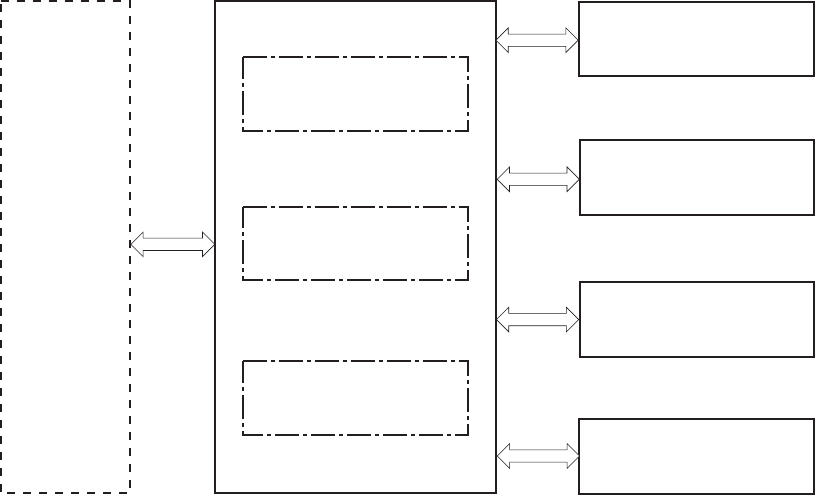
Engine-control system
The engine-control system coordinates all product functions, according to commands that the formatter
sends. The engine-control system drives the laser/scanner system, the image formation system, and the
pickup/feed/delivery system.
The engine control system contains the following major components:
●DC controller
●Low-voltage power supply
●High-voltage power supply
Figure 1-2 Engine-control system
Formatter
DC controller
Low-voltage power supply
High-voltage power supply
LASER SCANNER SYSTEM
IMAGE-FORMATION SYSTEM
MEDIA FEED SYSTEM
ENGINE CONTROL SYSTEM
OPTION
8 Chapter 1 Theory of operation ENWW
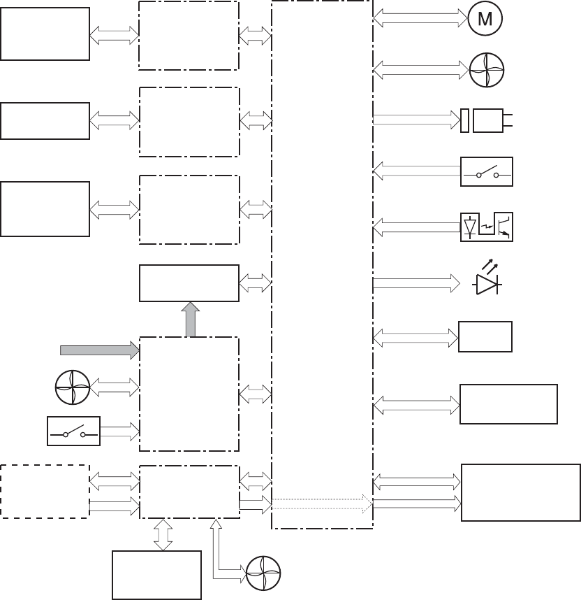
DC controller
The DC controller controls the operational sequence of the product.
Figure 1-3 DC controller diagram
Fan
Control panel
Switch
ITB ass’y
Cartridge
(x4)
Transfer 2 high-
voltage
power supply
T2 roller
Fuser
DC controller
AC input
Low-voltage
power supply
Formatter Laser scanner ass’y
Motor
Solenoid
Photointerrupter
Switch
Fan
Accessor y
Sensor
LED
Transfer 1 high-
voltage
power supply
Developing high-
voltage
power supply
Fan
ICB
The DC controller controls the product's electrical components, listed in the following table.
ENWW Engine-control system 9

Table 1-2 Electrical components
Component type Abbreviation Name
Switch SW1 Power switch
SW2 24V interlock switch
SW3 5V interlock switch 1
SW4 5V interlock switch 2
SW5 Primary transfer disengagement switch
SW6 Toner collection unit switch
SW7 Tray 2 cassette media end guide position switch
SW8 Tray 2 cassette media width guide position switch
Solenoid SL1 Tray 2 cassette pickup solenoid
SL2 Tray 1 pickup solenoid
SL3 Duplex reverse solenoid 1 (duplex models only)
SL5 Primary transfer disengagement solenoid
SL7 Duplex reverse solenoid 2 (duplex models only)
Fan FM1 Power supply fan
FM2 Fuser fan
FM3 Formatter fan
Photointerrupter (sensor) PS1 Tray 2 cassette paper-presence sensor
PS2 Tray 1 paper-presence sensor
PS3 Last-paper sensor
PS4 Tray 2 cassette paper-stack surface sensor
PS5 Top-of-page (TOP) sensor
PS6 Fuser delivery sensor
PS7 Loop sensor 1
PS8 Loop sensor 2
PS9 Fuser pressure-release sensor
PS10 Output bin full sensor
PS11 Developing disengagement sensor
PS12 Black drum home-position sensor
PS13 YMC drum home-position sensor
PS14 Front door sensor
PS15 Right door sensor
10 Chapter 1 Theory of operation ENWW

Table 1-2 Electrical components (continued)
Component type Abbreviation Name
Motor M1 ITB Motor
M2 Drum motor
M3 Developing motor
M4 Fuser motor
M5 Pickup motor
M6 Developing disengagement motor
M7 Duplex reverse motor (duplex model only)
M8 Duplex feed motor (duplex model only)
M9 Tray 2 cassette lifter motor
M10 Scanner motor
ENWW Engine-control system 11
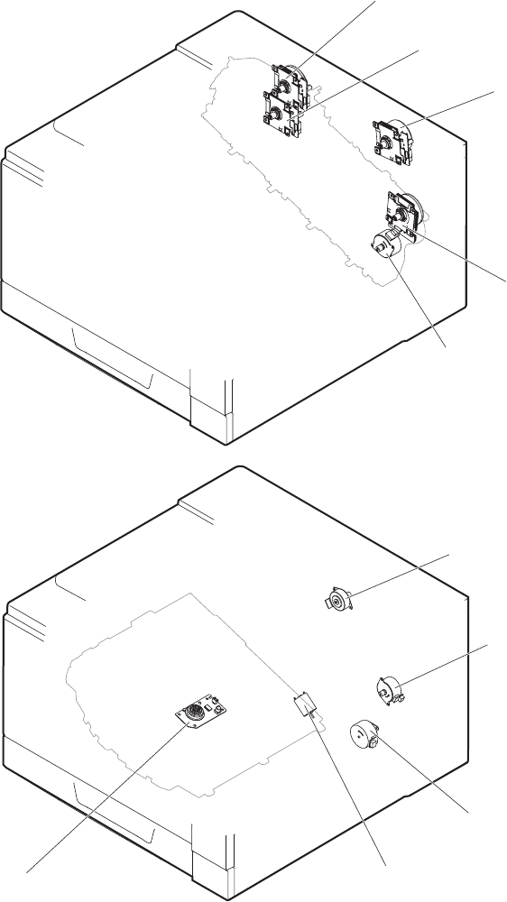
Motors
The product has ten motors for paper feed and image formation. The DC controller determines there is
a motor failure if a motor does not reach a specified speed within a specified period after motor
startup, or if the rotational speed is outside a specified range for a specified period.`
Figure 1-4 Motors
Pickup motor
Cassette lifter motor
Scanner motor
Fuser motor
Developer disengagement motor
ITB motor
Drum motor
Developer motor
Duplex feed motor (duplex models)
Duplex reverse motor (duplex models)
12 Chapter 1 Theory of operation ENWW

Table 1-3 Motors
Description Components driven Failure
detection
ITB motor (M1) ITB
Black photosensitive drum
Black developing roller
Yes
Drum motor (M2) Yellow, magenta, and cyan photosensitive drums Yes
Developing motor (M3) Yellow, magenta, and cyan developing rollers Yes
Fuser motor (M4) Fuser pressure and delivery rollers
Pressurizes and depressurizes the pressure roller
Engages and disengages the primary transfer roller
Yes
Pickup motor (M5) Tray 1 pickup roller
Tray 2 cassette pickup roller
Feed roller
No
Developing
disengagement motor
(M6)
Engages and disengages the developing unit No
Duplex reverse motor
(M7; duplex models
only)
Duplex reverse roller No
Duplex feed motor (M8;
duplex models only)
Duplex feed roller No
Tray 2 cassette lifter
motor (M9)
Lifter for the Tray 2 cassette No
Scanner motor (M10) Scanner mirror No
ENWW Engine-control system 13
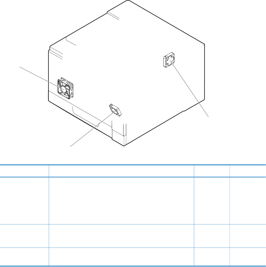
Fans
The product uses three fans to maintain the correct internal temperature. The DC controller determines a
fan failure when a fan locks for a specified period after it starts driving.
Figure 1-5 Fans
Power supply fan
Fuser fan
Formatter fan
Table 1-4 Fans
Description Area cooled Type Speed
Power supply fan
(FM1)
Low-voltage power supply
Output bin
Delivery unit
Laser scanner unit
Intake Full/Half
Fuser (FM2) Duplex feed unit
ITB area
Intake Full
Formatter (FM3) Formatter area Intake Controlled by
the formatter
14 Chapter 1 Theory of operation ENWW
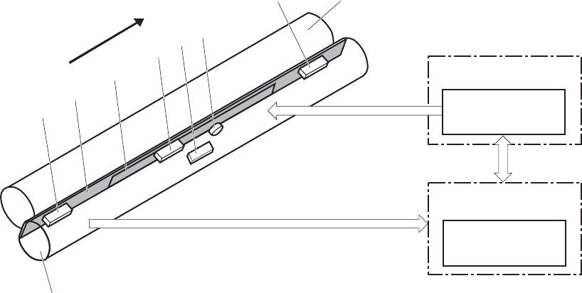
Fuser-control circuit
The fuser-control circuit monitors and controls the temperature in the fuser. The product uses on-demand
fusing. The fuser-control circuit consists of the following major components:
●Fuser main heater (H1): Heats the center of the fuser sleeve
●Fuser sub heater (H2): Heats the ends of the fuser sleeve
●Thermistors; detect the fuser temperature (contact type)
◦Sleeve thermistor (TH1): Detects the temperature at the center of the fuser sleeve
◦Main thermistor (TH2): Detects the temperature at the center of the fuser heater
◦Sub thermistor 1 (TH3): Detects the temperature at the end of the fuser heater nearest the front
of the product
◦Sub thermistor 2 (TH4): Detects the temperature at the end of the fuser heater nearest the rear
of the product
●Thermal fuse (FU1): Prevents abnormal temperature rise in the fuser heater (non-contact type)
Figure 1-6 Fuser-control circuit
H1
FUSER TEMPERATURE signal
Pressure roller
FUSER HEATER
CONTROL signal
TH4
TH2
FU1
TH3
Fuser sleeve
Fuser heater
control circuit
Fuser heater
safety circuit
Low-voltage power supply
DC controller
H2
TH1
Front of engine
ENWW Engine-control system 15
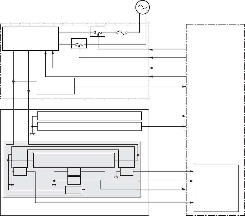
Fuser temperature control
The fuser temperature control maintains the fuser heater at its targeted temperature.
The fuser main heater and sub heater control the temperature of the fuser sleeve.
The DC controller monitors the main thermistor and the sleeve thermistor. The DC controller controls the
FUSER MAIN HEATER CONTROL (FSRD1) and the FUSER SUB-HEATER CONTROL (FSRD2) signals
according to the detected temperature. The fuser-heater control circuit controls the fuser heater
depending on the signal so that the heater remains at the targeted temperature.
Figure 1-7 Fuser-heater control circuit
Noise filter
DC controller
Fuser presence circuit
FU1
TH1
TH2
TH3 TH4
Fuser sleeve
Fuser heater
safety circuit
RLD1
RLD2
FSRD1
FSRD2
ZEROX
FUSEROPEN
FUHL
THERM1
THERM2
THERM4
THERM3
FU102
Improper fuser installation prevention circuit
AC input
H1
H2
RL102
RL103
Low-voltage power supply
Fuser heater
control circuit
Zerocross
circuit
Fuser
16 Chapter 1 Theory of operation ENWW
Fuser protective function
The protective function detects an abnormal temperature rise of the fuser unit and interrupts power
supply to the fuser heater.
The following three protective components prevent an abnormal temperature rise of the fuser heater:
●DC controller
◦The DC controller interrupts power supply to the fuser heater when it detects an abnormal
temperature of the fuser heater.
●Fuser-heater safety circuit
◦The fuser heater safety circuit interrupts power supply to the fuser heater when the detected
temperature of the main and sub thermistors is abnormal.
●Thermal fuse
◦The thermal fuse is broken to interrupt power supply to the fuser heater when the
thermoswitch detects an abnormal temperature of the fuser heater.
◦The current detection circuit detects the current value flowing in the fuser heater control
circuit. The DC controller deactivates the FUSER HEATER CONTROL signal and releases the
relay to interrupt power supply to the fuser heater when it detects a specified current value or
higher by the CURRENT DETECTION (FUR_CURRMS) signal.
ENWW Engine-control system 17
Fuser failure detection
The DC controller determines a fuser unit failure, deactivates the FUSER HEATER CONTROL signal,
releases the relay to interrupt power supply to the fuser heater, and then notifies the formatter of a
failure state when it encounters the following conditions:
●Abnormal temperature rise: The sleeve thermistor does not rise at a specified temperature within a
specified period after the fuser heater control starts.
●Abnormally low temperature: The thermistors are at a specified temperature or lower during a
print operation or other fuser heating cycle.
●Abnormally high temperature: The thermistors are at a specified temperature or higher, regardless
of the fuser control status.
●Drive circuit abnormality: The frequency in the zerocross circuit is out of a specified range when
the product is turned on or is in the standby period.
18 Chapter 1 Theory of operation ENWW
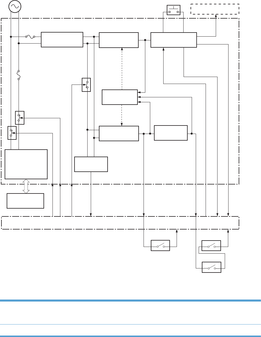
Low-voltage power supply
The low-voltage power supply (LVPS) converts AC input voltage to DC voltage.
Figure 1-8 Low-voltage power supply
FU102
FU101
Formatter
+3.3V generation
circuit
Power switch
Remote switch
control circuit
+3.3V
SWON/OFF
PWRON
+24V generation
circuit
+5V generation
circuit
+24V
Interlock switch
DC controller
ZEROX
REMOTEON
RLD1
RLD2
+3.3V
Protection
circuit
Fuser
Fuser heater
control circuit
Noise filter
Noise filter
Rectifying circuit
Zerocross
circuit
+24V
+5V
+24R
+5R
Low-voltage power supply
RL101
RL102
RL103
SW1
SW2
SW3
SW4
+5V
Interlock switch
The product uses three DC voltages: 24V, 5V, and 3.3V. The voltages are subdivided as follows:
+24V Supplied constantly
Stopped during Sleep mode
+24R Interrupted when the front or right door is opened
ENWW Engine-control system 19

+5V Supplied constantly
Stopped during Sleep mode
+5R Interrupted when the front or right door is opened
+3.3V Supplied constantly
20 Chapter 1 Theory of operation ENWW

Overcurrent/overvoltage protection
The low-voltage power supply has a protective circuit against overcurrent and overvoltage to prevent
failures in the power supply circuit. The low-voltage power supply automatically stops supplying the DC
voltage whenever excessive current flows or voltage abnormally increases.
If the dc voltage is not being supplied from the low-voltage power supply, the protective function may
be running. In this case, turn off the power switch and unplug the power cord. Do not turn the power
switch on until the root cause is found.
The LVPS has two fuses on the PCA. The LVPS 24V output is interrupted to the fuser and the high-voltage
power supply if the either of the interlock switches (SW3 and SW4) is in the off position (door open).
WARNING! The product power switch only interrupts dc voltage from the LVPS. The AC voltage is
present in the product when the power cord is plugged into a power receptacle and the power switch
is in the off position. You must unplug the product power cord before servicing the product.
WARNING! If you believe the overcurrent or overvoltage protection circuits have been activated, do
not plug in the product power cord or turn on the product power until the cause of the failure is found
and corrected.
In addition, fuses in the low-voltage power supply protect against overcurrent. If overcurrent flows into
the AC line, the fuses melt and cut off the power distribution.
ENWW Engine-control system 21
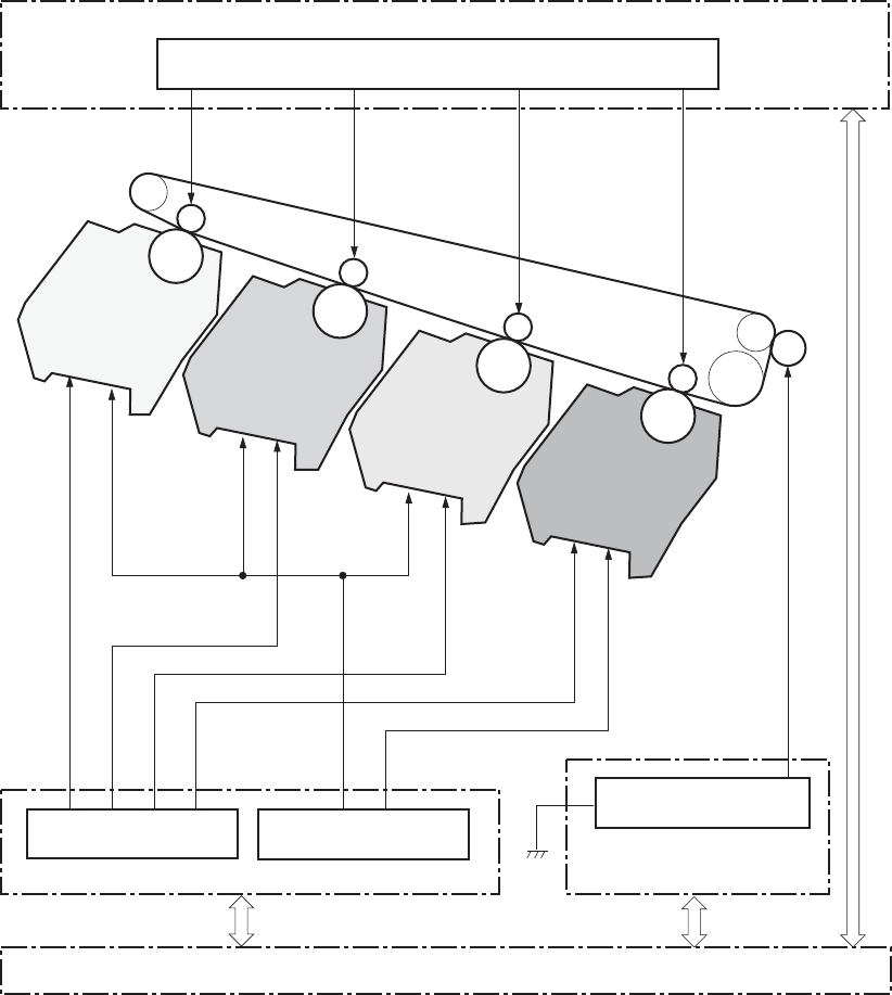
High-voltage power supply
The DC controller controls the high-voltage power supply to generate biases.
Figure 1-9 High-voltage power supply
Secondary transfer bias circuit
TRS2
TRI-1
Primary charging bias circuit
DEV high-voltage power supply
DEV-4
DEV-3
DEV-2
DEV-1
PRI-4
DC controller
TR2 high-voltage power supply
Primary transfer bias circuit
TR1 high-voltage power supply
TRI-2
TRI-3
TRI-4
PRI-3
PRI-2
PRI-1
FG
Developing bias circuit
The high-voltage power supply (HVPS) applies biases to the following components:
●Primary charging roller: The primary charging bias is applied to the surface of the photosensitive
drum to charge it uniformly negative as a preparation for the image formation.
●Developing roller: The developing bias is used to adhere toner to an electrostatic latent image
formed on the photosensitive drum.
22 Chapter 1 Theory of operation ENWW
●Primary transfer roller: The primary transfer bias is used to transfer the toner from each
photosensitive drum onto the ITB.
●Secondary transfer roller: The secondary transfer bias is used to transfer the toner image from the
ITB onto the paper. The reversed bias is applied to transfer residual toner on the secondary
transfer roller back to the ITB. The residual toner on the ITB is deposited in the toner collection unit.
ENWW Engine-control system 23
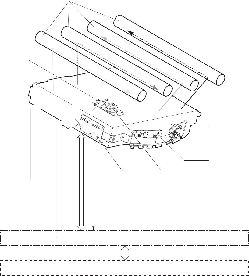
Laser scanner system
The laser scanner system forms latent images on the photosensitive drums according to the VIDEO
signals sent from the formatter.
The main components of the laser/scanner are the laser unit and the scanner motor unit. The DC
controller sends signals to the laser/scanner to control the functions of these components.
Figure 1-10 Laser/scanner system
DC controller
Formatter
Scanner mirror
Scanner motor unit
SCANNER MOTOR CONTROL signal
VIDEO signal
LASER CONTROL signal
BDI signal
Laser unit (Y/M)
Laser unit (C/Bk)
Connecting board
Photosensitive drum
24 Chapter 1 Theory of operation ENWW
Laser failure detection
The DC controller determines an optical unit failure and notifies the formatter, if the laser/scanner
encounters the following conditions:
●The scanner motor does not reach a specified rotation frequency within a specified period of the
scanner motor start up.
●The beam detect (BD) interval is out of a specified value during a print operation.
ENWW Engine-control system 25
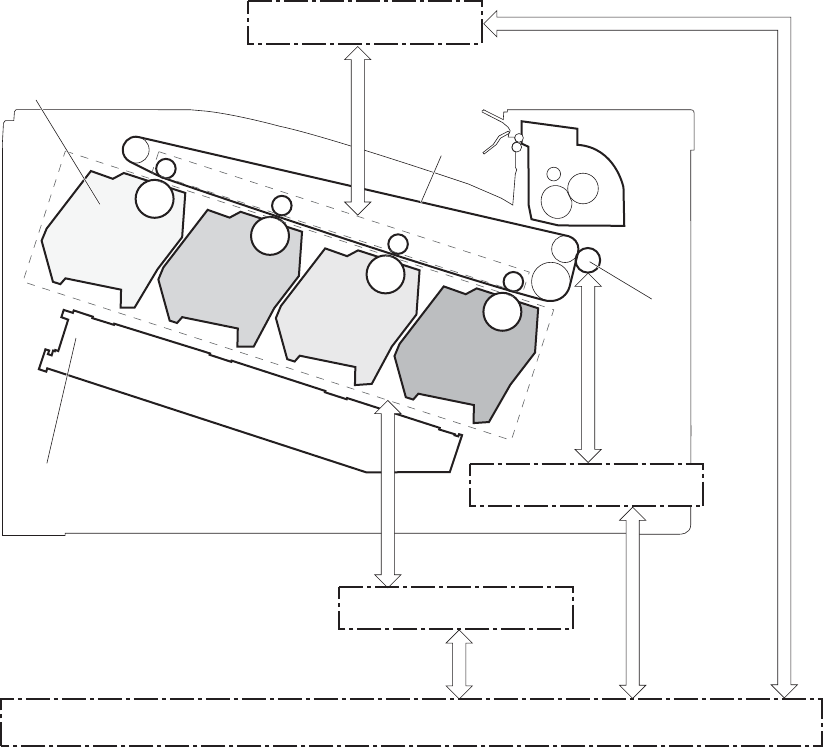
Image-formation system
Electrophotographic process
The electrophotographic process forms an image on the paper. Following are the major components
used in the process:
●Print cartridges
●Intermediate transfer belt (ITB)
●Secondary transfer roller
●Fuser
●Laser scanner
The DC controller uses the laser scanner and HVPS to form the toner image on the photosensitive drum.
The image is transferred to the print media and then fused onto the paper.
Figure 1-11 Electrophotographic process block diagram
ITB Fuser
Secondary transfer
roller
Cartridge
Laser scanner
DC controller
DEV high-voltage
power supply
TR2 high-voltage
power supply
TR1 high-voltage
power supply
26 Chapter 1 Theory of operation ENWW
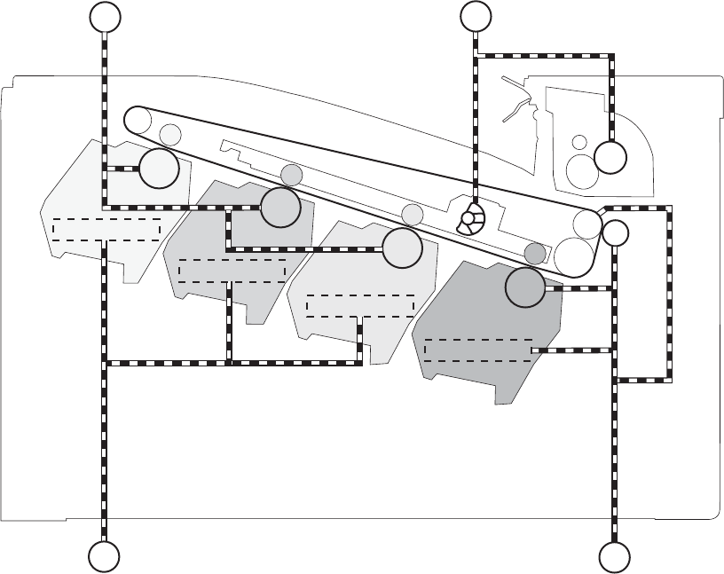
Figure 1-12 Electrophotographic process drive system
Developing roller
Developing roller
Developing roller
Developing roller
Fuser motor
ITB motor
Drum motor
Developing motor
M2
M3 M1
M4
ENWW Image-formation system 27
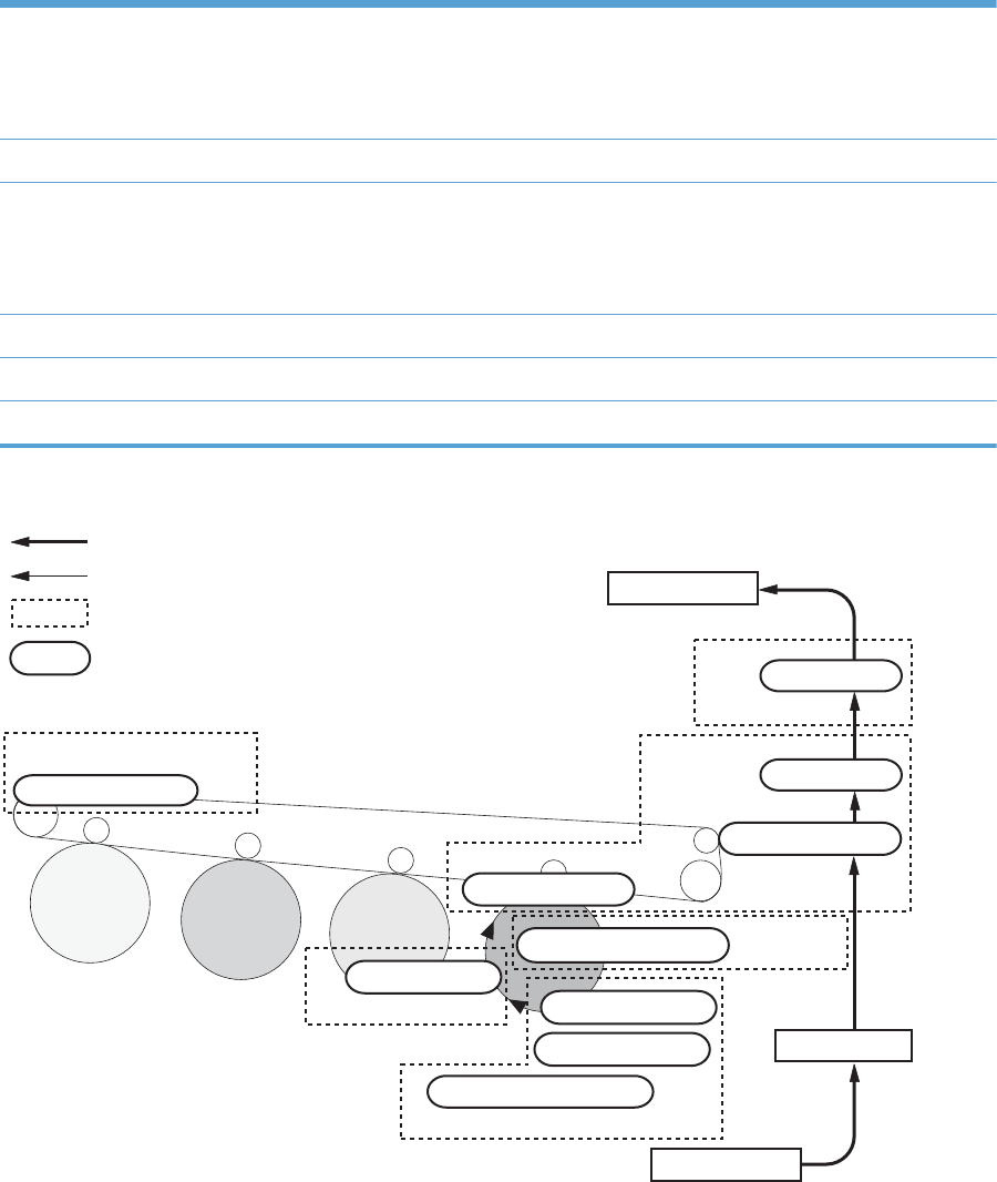
Image formation process
Each of the following processes functions independently and must be coordinated with the other
product processes. Image formation consists of the following processes:
Latent-image formation block Step 1: pre-exposure
Step 2: primary charging
Step 3: laser-beam exposure
Developing block Step 4: developing
Transfer block Step 5: primary transfer
Step 6: secondary transfer
Step 7: separation
Fusing block Step 8: fusing
ITB cleaning block Step 9: ITB cleaning
Drum cleaning block Step 10: Drum cleaning
Figure 1-13 Image formation process
: Step
: Block
: Direction of drum rotation
: Media path
ITB cleaning
9. ITB cleaning
Developing
4. Developing
5. Primary transfer
10. Drum cleaning Drum cleaning
Latent image formation
1. Pre-exposure
2. Primary charging
3. Laser beam exposure
Pickup
Registration
Fuser
8. Fuser
Transfer
7. Separation
6. Secondary transfer
Delivery
28 Chapter 1 Theory of operation ENWW
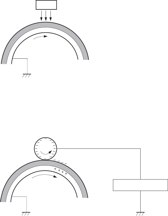
Latent-image formation block
During the latent-image formation stage, the laser scanner forms invisible images on the photosensitive
drums in the print cartridges.
Pre-exposure
Step 1: Light from the pre-exposure LED strikes the photosensitive drum surface. This eliminates the
residual electrical charges on the drum surface.
Figure 1-14 Pre-exposure
Photosensitive drum
LED
Primary charging
Step 2: DC and AC biases are applied to the primary charging roller, which transfers a uniform
negative potential to the photosensitive drum.
Figure 1-15 Primary charging
Primary charging roller
Primary charging bias
Photosensitive drum
ENWW Image-formation system 29
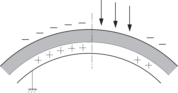
Laser beam exposure
Step 3: The laser beam scans the photosensitive drum to neutralize negative charges on parts of the
drum surface. An electrostatic latent image is formed on the drum where negative charges were
neutralized.
Figure 1-16 Laser beam exposure
Laser beam
30 Chapter 1 Theory of operation ENWW
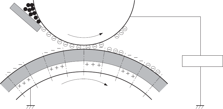
Developing block
Step 4: In the print cartridge, toner acquires a negative charge from the friction that occurs when the
developing roller rotates against the developing blade. The developing bias is applied to the
developing roller to create a difference in the electric potential of the drum. When the negatively
charged toner comes in contact with the photosensitive drum, it adheres to the latent image because the
drum surface has a higher potential.
Figure 1-17 Developing
Developing bias
Photosensitive drum
Developing roller
Developing blade
ENWW Image-formation system 31
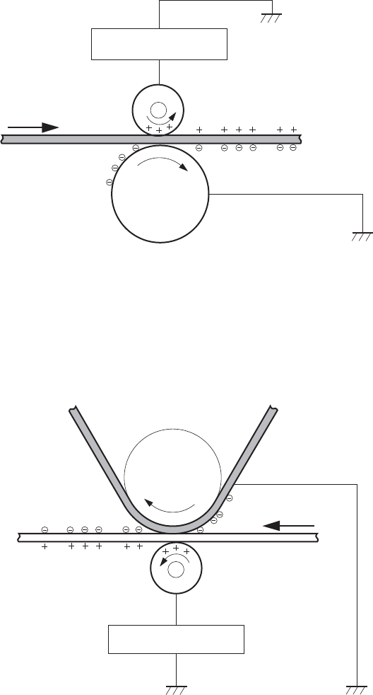
Transfer block
Primary transfer
Step 5: The toner on the photosensitive drum is transferred to the intermediate transfer belt (ITB). The
ITB is given a positive charge by the bias of the primary transfer roller. The negatively charged toner on
the drum surface is transferred onto the ITB. All four color planes are transferred onto the ITB in this
step.
Figure 1-18 Primary transfer
ITB
Primary transfer bias
Primary transfer roller
Photosensitive
drum
Secondary transfer
Step 6: The toner image on the ITB is transferred to the paper. The secondary transfer bias is applied
to the secondary transfer roller to charge the paper positive. As the paper passes between the
secondary transfer roller and the ITB, the complete toner image on the ITB is transferred onto the paper.
Figure 1-19 Secondary transfer
ITB
Secondary transfer bias
Secondary transfer roller
Paper
Secondary transfer
opposed roller
32 Chapter 1 Theory of operation ENWW
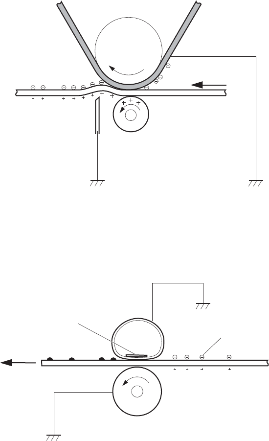
Separation
Step 7: The elasticity of the paper and the curvature of the secondary transfer opposed roller cause the
paper to separate from the ITB. The static charge eliminator reduces back side static charge of the
paper and controls excess discharge after the transfer process for stable media feed and image quality.
Figure 1-20 Separation
ITB
Secondary transfer roller
Paper
Secondary transfer
opposed roller
Static charge eliminator
Fusing block
Step 8: The product uses an on-demand fuser. The toner image is permanently affixed to the printing
paper by heat and pressure.
Figure 1-21 Fusing
Paper
Pressure roller
Fuser sleeve
Fuser heater
Toner
ENWW Image-formation system 33
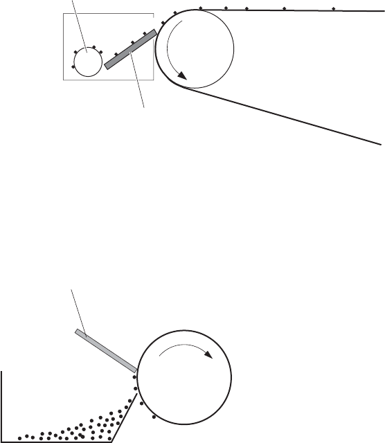
ITB cleaning block
Step 9: The cleaning blade scrapes the residual toner off the surface of the ITB. The residual toner feed
screw deposits residual toner in the toner collection unit.
Figure 1-22 ITB cleaning
ITB
Cleaning blade
Residual toner feed screw
Drum cleaning block
Step 10: The cleaning blade scrapes the residual toner off the surface of the photosensitive drum, and
toner is deposited in the waste section inside the print cartridge.
Figure 1-23 Drum cleaning
Cleaning blade
Photosensitive
drum
Toner waste
34 Chapter 1 Theory of operation ENWW
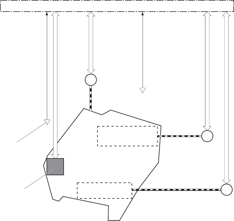
Print cartridges
The product has four print cartridges, one for each color: yellow, magenta, cyan, and black. Each of
them has the same structure. The cartridges are filled with toner and consist of the following
components:
●Photosensitive drum
●Developing unit
●Primary charging roller
The DC controller rotates the motors to drive the photosensitive drum, developing unit, and primary
charging roller.
Figure 1-24 Print cartridge block diagram
M6
M2
M3
DC controller
Developing unit
Memory tag
Developing
disengagement
motor
PS11:
Developing disengagement
sensor
Drum motor
Developing motor
Photosensitive drum
Primary charging roller
PS13:
YMC drum home
position sensor
ENWW Image-formation system 35
Memory tag
The memory tag is a non-volatile memory chip in the cartridge that stores information about usage for
the cartridge. The product reads and writes the data in the memory tag. The DC controller determines a
memory tag error and notifies the formatter when it fails to either read from or write to the memory tag.
Cartridge presence detection
The DC controller detects the presence of the cartridges by monitoring the cartridge e-label and ground
circuit. When the DC controller determines a cartridge absence, it notifies the formatter.
Toner level detection
The DC controller detects the remaining toner level in a cartridge by the optical detection method. The
DC controller notifies the formatter of the remaining toner level.
Cartridge life detection
The DC controller detects the cartridge life by monitoring the total operational wear limit or remaining
toner level of the cartridge. The DC controller determines a cartridge end of life and notifies the
formatter when the operational wear limit of the cartridge reaches a specified amount or the cartridge
runs out of toner.
Developing unit engagement and disengagement control
The developing unit engagement and disengagement control engages the developing unit with the
photosensitive drum or disengages the developing unit from the drum depending on the print mode: full-
color mode or black-only mode. The developing unit is engaged only when required, preventing a
deterioration of the drums and maximizing their life.
The developing disengagement motor rotates the developing disengagement cam. As the cam rotates,
the developing unit engages with or separates from the photosensitive drum.
When the product is turned on and when each print job is completed, all four of the developing units
disengage from the photosensitive drums. When the print mode is in full-color mode, all of the
developing units engage with the drums. When the print mode is in black-only mode, only black
developing unit engages with the drum.
36 Chapter 1 Theory of operation ENWW
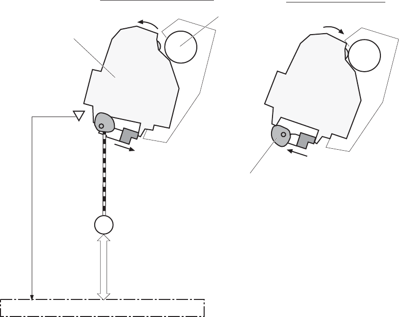
The DC controller determines a developing disengagement motor abnormality and notifies the formatter
when it does not detect a specified signal from the developing disengagement sensor during the
developing roller engagement and disengagement operation.
Figure 1-25 Developing unit engagement and disengagement control
M6
DC controller
Developing disengagement motor
Developing unit
Developing disengagement cam
Photosensitive drum
PS11:
Developing
disengagement
sensor
Developing unit is engaged
Developing unit is disengaged
ENWW Image-formation system 37
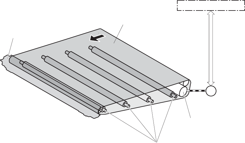
ITB unit
The ITB unit receives the toner image from the photosensitive drums and transfers the complete toner
image to the print media. The ITB unit consists of the following components:
●ITB
●ITB drive roller
●Primary transfer rollers
●ITB cleaner
The ITB motor drives the ITB drive roller which rotates the ITB. The rotation of the ITB causes the primary
transfer rollers to rotate. The ITB cleaner cleans the ITB surface.
Figure 1-26 ITB unit block diagram
ITB
M1 ITB motor
ITB cleaner
Primary transfer roller
ITB drive roller
DC controller
38 Chapter 1 Theory of operation ENWW
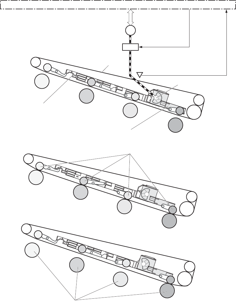
Primary transfer roller engagement and disengagement control
Figure 1-27 Primary transfer roller engagement and disengagement control
ITB
SL5
SW5
M4
DC controller
Fuser motor
Primary transfer
disengagement solenoid
Primary transfer
disengagement switch
Primary transfer
disengagement cam
Bk slide plate
YMC slide plate
<Only black is engaged>
<All colors are engaged>
<All colors are disengaged>
Primary transfer roller
Photosensitive drum
ENWW Image-formation system 39
The primary transfer roller engagement and disengagement control engages the ITB with the
photosensitive drum, or disengages the ITB from the drum, depending on the requirements of the print
job.
●All rollers disengaged: The ITB disengages from all four photosensitive drums. This is the state
during a standby period, and also is the home position for the primary transfer rollers.
●All rollers engaged: The ITB engages with all the four photosensitive drums. This is the state for
full-color jobs.
●Only black roller engaged: The ITB engages with only the black photosensitive drum. This is
the state for the black-only print jobs.
The operational sequence of the primary transfer roller engagement and disengagement control is as
follows:
1. The fuser motor drives the primary transfer disengagement solenoid to rotate the primary transfer
disengagement cam.
2. As the cam rotates, the YMC slide plate or the Bk slide plate moves to right or left. This causes the
primary transfer roller to move up or down.
3. The ITB engages with or disengages from the photosensitive drum depending on the movement of
the primary transfer rollers.
The DC controller determines that an abnormal primary transfer roller disengagement error has occured
and notifies the formatter. This error happens when the DC controller does not detect a specified signal
from the primary transfer disengagement switch, even though the primary transfer disengagement
solenoid is driven.
ITB unit presence detection
The DC controller detects the ITB unit presence by monitoring the primary transfer disengagement
switch. The DC controller drives the primary transfer disengagement solenoid for specified times during
the initial rotation period of the following:
●The product is turned on
●The product exits Sleep mode
●The door is closed
The DC controller determines an ITB unit absence and notifies the formatter when it does not detect a
specified signal from the primary transfer disengagement switch.
ITB cleaning mechanism
The cleaning blade in the ITB cleaner scrapes the residual toner off the ITB surface. The ITB motor drives
the residual toner feed screw and the screw deposits the residual toner in the toner collection unit.
The DC controller detects whether the toner collection unit is full by monitoring the ITB residual toner full
sensor. When the DC controller determines the toner collection unit is full, it notifies the formatter. The
40 Chapter 1 Theory of operation ENWW
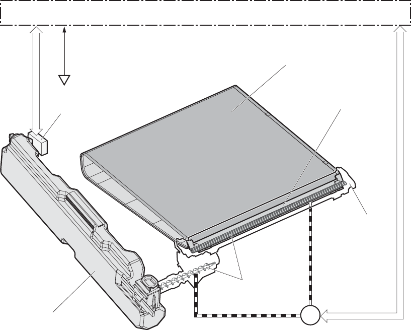
DC controller also detects the presence of the toner collection unit by monitoring the toner collection unit
switch.
Figure 1-28 ITB cleaning mechanism
SW6 ITB
M1
DC controller
Toner collection unit switch
ITB residual toner full sensor Cleaning blade
ITB cleaner
ITB motor
Residual toner feed screw
Toner collection unit
Calibration
The product calibrates itself to print a high-quality image. The calibration corrects a color-misregistration
and color-density variation caused by environment changes or variation inherent in the product. The
product performs the following calibrations:
●Color-misregistration control
●Environment change control
●Image stabilization control
ENWW Image-formation system 41
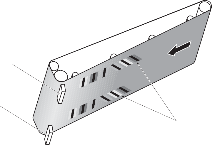
Color-misregistration control
The color-misregistration control corrects the misaligned color planes caused by the variation inherent in
the laser scanner units or cartridges. The color-misregistration control corrects the following:
●Horizontal scanning start position
●Horizontal scanning magnification
●Vertical scanning start position
The DC controller forms a pattern of toner on the surface of the ITB, and measures a misaligned length
with the registration density sensor and the registration density belt-perimeter sensor. Accordingly, the
formatter calibrates the color-misregistration.
Figure 1-29 Color-misregistration control
ITB
Pattern of toner
Regisration density sensor
Registration density
belt-perimeter sensor
The DC controller commands the formatter to perform the color-misregistration control whenever one of
the following occurs:
●The product is turned on or the door is closed, after replacing any one of the cartridges
●The product is turned on or the door is closed, after replacing the ITB unit or the laser scanner unit
●A specified number of pages have been printed
●Continuous printing for a specified period of time
●Cold starting of the fuser when the product is turned on
If data from the registration density or registration density belt-perimeter sensor is out of a specified
range during the cartridge-presence detection or when starting the color-misregistration control, the DC
controller determines an abnormal sensor and notifies the formatter.
42 Chapter 1 Theory of operation ENWW
Environment change control
The environment change control calibrates each high-voltage bias to obtain an appropriate image
according to the environment changes. The DC controller determines the environment, where the
product is installed, based on the surrounding temperature and humidity data from the environment
sensor. It adjusts the high-voltage biases to accommodate environmental changes.
The DC controller determines an environment sensor abnormality and notifies the formatter when it
detects out of specified range data from the environment sensor.
Image stabilization control
The image stabilization control reduces the fluctuations in image density caused by environmental
changes or deterioration of the photosensitive drums or toner. The two kinds of image stabilization
controls are image density control (DMAX) and image halftone control (DHALF).
Image density control (DMAX)
The image density control calibrates each high-voltage bias to stabilize the image density variation
caused by the deterioration of the photosensitive drum or toner. The DC controller commands the
formatter to control the image density under the following conditions:
●The detected temperature of the fuser is a specified degree or lower when the product is turned on
●The product is turned on, or the door is closed, and also whenever a specified number of pages
have been printed after replacing any one of the cartridges
●The product is turned, on or the door is closed, after replacing the ITB unit or the laser scanner unit
●A specified number of pages have been printed
●After a specified period of time from the previous image density control
●The environment is changed for a specified condition after the previous image density control
Image halftone control (DHALF)
The image halftone control is performed by the formatter to calibrate the halftone. The DC controller
measures the halftone pattern according to a command from the formatter. Accordingly, the formatter
calibrates the halftone. The DC controller controls the image halftone under the following conditions:
●The image density control is completed
●The formatter sends a command
ENWW Image-formation system 43
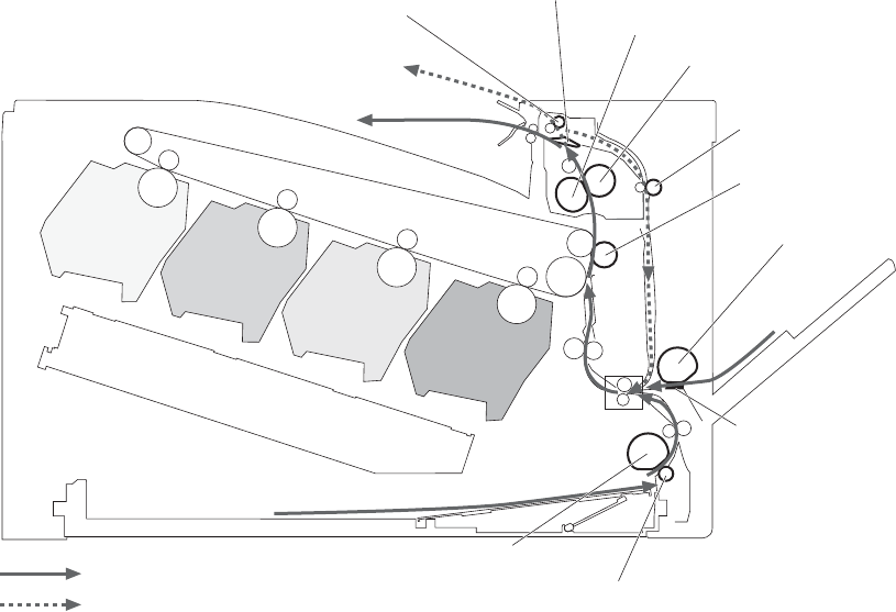
Pickup, feed, and delivery system
The pickup/feed/delivery system consists of several types of feed rollers and sensors. The duplex model
has a mechanism that reverses and refeeds the print media to print two sides automatically.
Figure 1-30 Pickup, feed, and delivery system
Fuser sleeve
Pressure roller
Duplex feed roller
(duplex model only)
T2 roller
MP tray pickup roller
MP tray separation pad
Cassette separation roller
Cassette pickup roller
Simplex paper path
Duplex paper path (duplex model)
Duplex reverse roller
(for duplex model)
Duplex flapper
(for duplex model)
The pickup/feed/delivery system can be divided into the following three blocks:
●Pickup-and-feed block: From each input source to the fuser inlet
●Fuser-and-delivery block: From the fuser to the output bin
●Duplex block: From the duplex reverse unit to the duplex re-pickup unit (duplex models only)
44 Chapter 1 Theory of operation ENWW
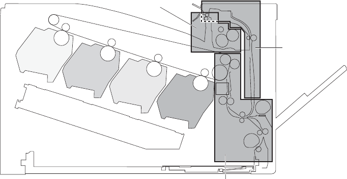
Figure 1-31 Pickup, feed, and delivery system blocks
Duplex block
Pickup-and-feed block
Fuser-and-delivery block
ENWW Pickup, feed, and delivery system 45
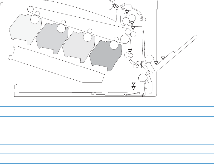
Photo sensors
Figure 1-32 Photo sensors (paper path)
PS3
PS2
PS1
PS4
PS10
PS6
PS7
PS8
PS5
MS
Table 1-5 Photo sensors and switches (product)
Item Description Item Description
PS1 Tray 2 cassette paper-presence sensor PS6 Fuser delivery sensor
PS2 Tray 1 (MP tray) paper-presence sensor PS7 Loop sensor 1
PS3 Last-paper sensor PS8 Loop sensor 1
PS4 Tray 2 cassette paper-stack surface sensor PS10 Output bin media-full sensor
PS5 Top-of-Page (TOP) sensor
46 Chapter 1 Theory of operation ENWW
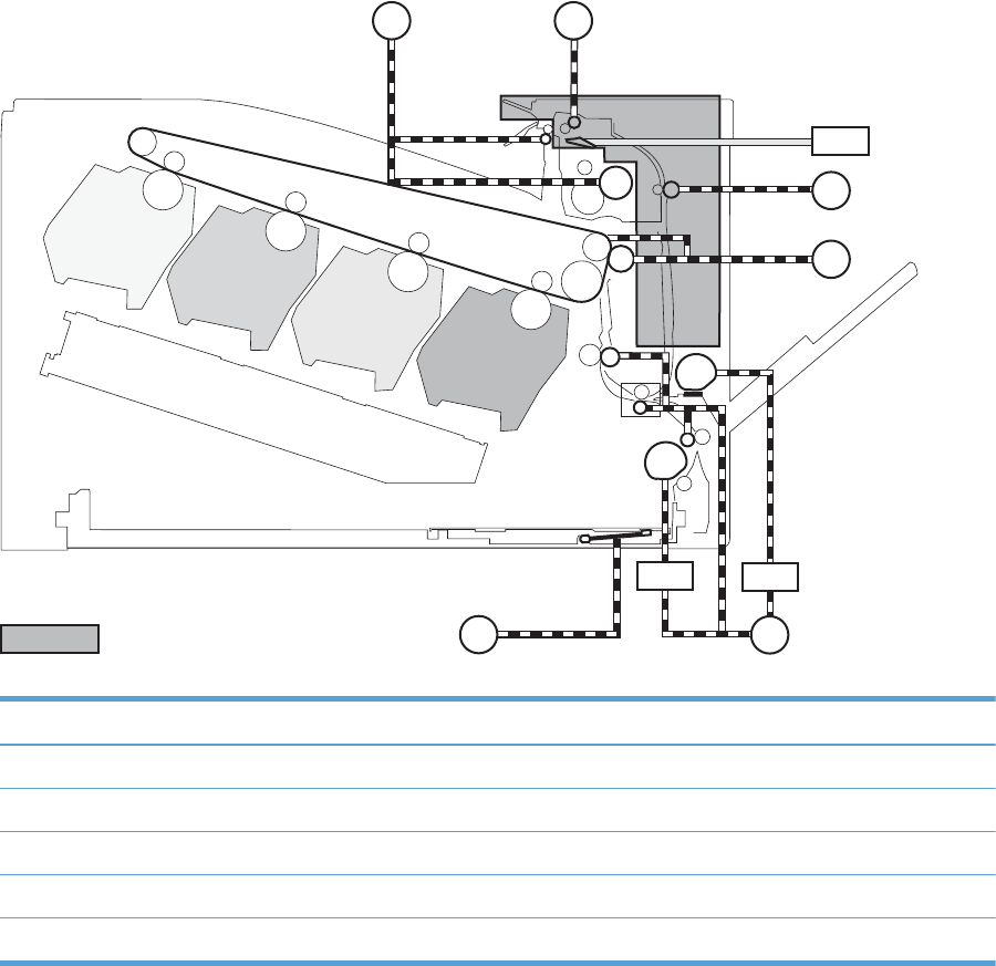
Motors and solenoids
Figure 1-33 Motors and solenoids (paper path)
M4
SL3
M1
M9 M5
SL2
SL1
M7
M8
For duplex model only
Table 1-6 Motors and solenoids (paper path)
Item Description Item Description
M1 ITB motor M9 Tray 2 cassette lifter motor
M4 Fuser motor SL1 Tray 2 cassette pickup solenoid
M5 Pickup motor SL2 Tray 1 (MP tray) pickup solenoid
M7 Duplex reverse motor (duplex models only) SL3 Duplex reverse solenoid 1 (duplex models only)
M8 Duplex feed motor (duplex models only)
Pickup and feed block
The pickup-and-feed block picks one sheet of paper from the Tray 2 cassette or the MP tray and feeds it
into the fuser.
ENWW Pickup, feed, and delivery system 47
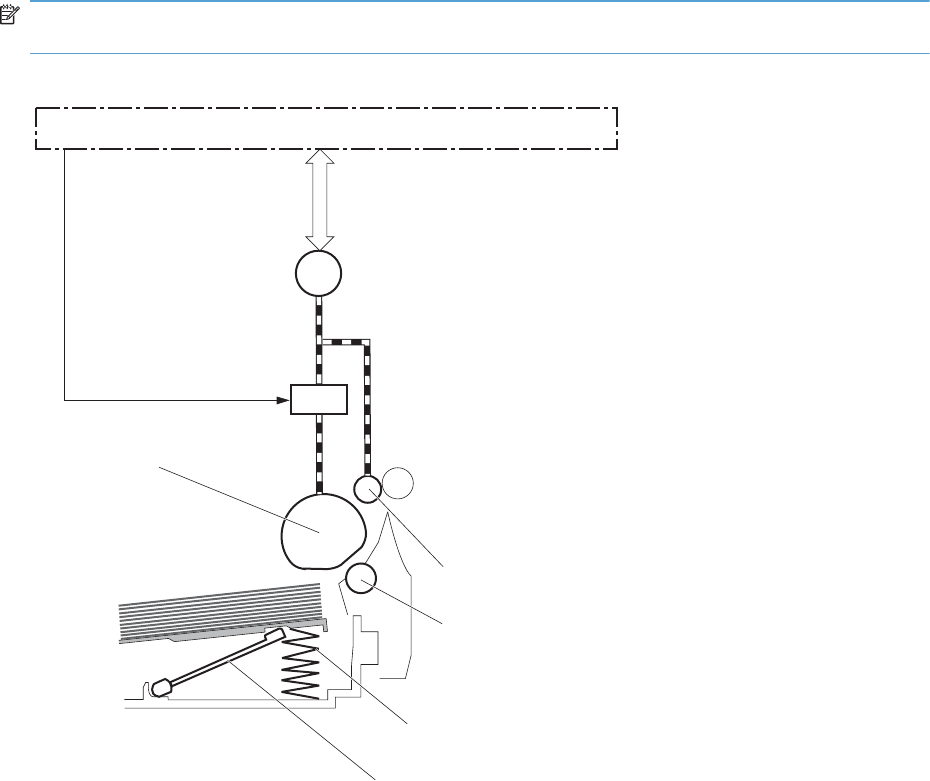
Tray 2 cassette pickup
The operational sequence of the Tray 2 cassette pickup is as follows:
1. The product is turned on or the Tray 2 cassette is inserted.
2. The lift-up operation and the lifting plate spring move up the lifting plate to the position where the
paper can be picked up.
3. The DC controller rotates the pickup motor when it receives a print command from the formatter.
4. The Tray 2 cassette (CST) feed roller rotates.
5. The Tray 2 cassette (CST) pickup solenoid is driven at a specified timing.
6. The Tray 2 cassette (CST) pickup roller rotates and picks up the paper.
7. The Tray 2 cassette (CST) separation roller removes any multiple-fed sheets.
8. One sheet of paper is fed into the product.
NOTE: The lift-up operation pushes up the lifting plate to keep the stack surface of paper at the
pickup position.
Figure 1-34 Tray 2 cassette pickup operation
SL1
M5
DC controller
Pickup motor
CST pickup solenoid
CST pickup roller
CST feed roller
CST separation roller
Lifter
Lifting plate spring
48 Chapter 1 Theory of operation ENWW
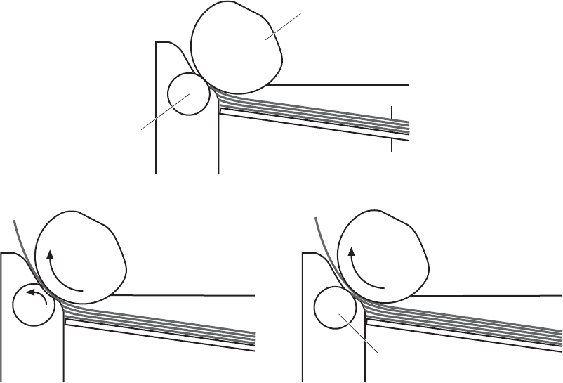
Tray 2 cassette multiple-feed prevention
The product uses a separation roller method to prevent multiple sheets of print media from entering the
paper path. The Tray 2 cassette separation roller does not have its own driving force. Therefore the
Tray 2 cassette separation roller follows the rotation of the Tray 2 cassette pickup roller.
During normal feed, when the product picks up one piece of paper, the Tray 2 cassette separation
roller is driven by the Tray 2 cassette pickup roller through one sheet of paper. Thus the separation
roller rotates in the paper feed direction.
During multiple-feed, when the product picks up more than one piece of paper, the low friction force
between the sheets weakens the driving force from the Tray 2 cassette pickup roller. In addition, some
braking force is always applied to the Tray 2 cassette separation roller, so the weak rotational force of
the pickup roller is not enough to rotate the separation roller. Therefore, the separation roller holds
back any multiple-fed sheets, and one sheet of paper is fed into the product.
Figure 1-35 Tray 2 cassette multiple-feed prevention
CST Pickup roller
Print media
Lifting plate
<Normal-feed> <Multiple-feed>
The separation roller does not rotate
CST separation roller
ENWW Pickup, feed, and delivery system 49

Tray 2 cassette media-size detection and Tray 2 cassette-presence detection
The DC controller detects the size of paper loaded in the Tray 2 cassette by using the Tray 2 cassette-
media-end switch and Tary 2 cassette media width switch.
The DC controller also detects the presence of the cassette by using the Tray 2 cassette media end
switch. The DC controller notifies the formatter if the Tray 2 cassette is absent.
Table 1-7 Tray 2 cassette media-size detection and Tray 2 cassette-presence detection (product
base)
Paper size Cassette media width sensor Cassette media end switch
Top switch Center switch Bottom switch Top switch
1
Center switch Bottom switch
A4 On On On See footnote Off Off
Letter On On Off Off Off
B5 On Off Off Off Off
Executive Off Off Off Off Off
A5-R Off On On Off Off
B5-R Off Off On Off Off
Letter-R On Off On Off Off
A4-R On Off On Off On
A3 On On On On On
11 X 17 On On Off On On
B4 On Off Off On On
Legal On Off On On On
1
The top Tray 2 cassette-media-end switch detects the presence of the Tray 2 cassette. It turns off when the Tray 2 cassette is
present and turns on when the Tray 2 cassette is absent.
50 Chapter 1 Theory of operation ENWW
Tray 2 cassette lift-up operation
The cassette lift-up operation keeps the surface of the paper stack surface at the correct pickup position
whenever the following conditions occur:
●Product power is turned on
●Tray 2 cassette is installed
The list below describes the sequence of the Tray 2 cassette lift-up operation.
●The Tray 2 cassette lifter motor rotates to move the lifter rack toward the Tray 2 cassette-media-
stack surface sensor.
●As the lifter rack moves, the lifter moves up.
●The Tray 2 cassette lifter motor stops when the Tray 2 cassette-media-stack surface sensor detects
the lifter rack.
ENWW Pickup, feed, and delivery system 51
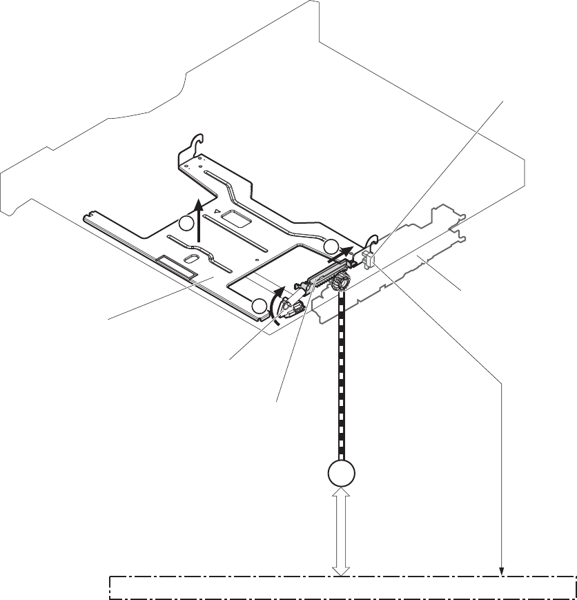
The DC controller determines a Tray 2 cassette lifter motor failure and notifies the formatter if the Tray 2
cassette-media-stack surface sensor does not detect the lifter rack within a specified period after the
Tray 2 cassette lifter motor starts rotating.
Figure 1-36 Tary 2 cassette lift-up operation
M9
1
2
3
DC controller
Cassette lifter motor
Lifter
Lifting plate
Lifter rack
Lifter drive ass’y
Cassette
PS4:
Cassette media stack surface sensor
52 Chapter 1 Theory of operation ENWW
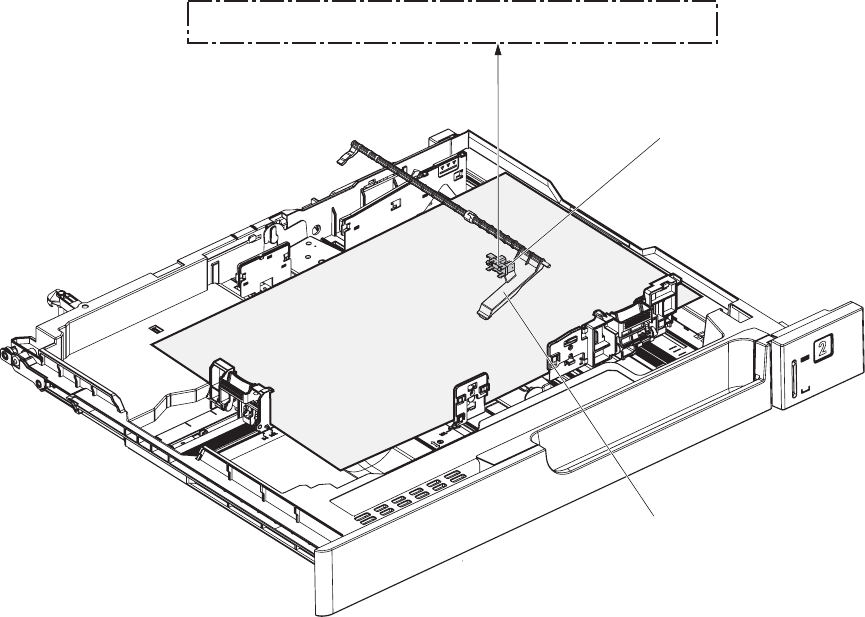
Cassette media-presence detection
The Tray 2 cassette-media-out sensor detects the presence of paper in the Tray 2 cassette.
The DC controller notifies the formatter when the Tray 2 cassette-media-out sensor detects the media is
absent.
Figure 1-37 Tray 2 cassette media-presence detection
PS1
Cassette media out sensor
Cassette media out sensor flag
DC controller
Tray 1 (MP tray) paper pickup
The operational sequence of the MP tray pickup is as follows:
1. The DC controller rotates the pickup motor when it receives a print command from the formatter.
2. As the MP tray pickup solenoid is driven, the MP tray pickup roller rotates and the lifting plate
moves up.
3. The MP tray pickup roller picks up the paper.
4. The MP tray separation pad removes any multiple-fed sheets and one sheet of paper is fed into the
product.
ENWW Pickup, feed, and delivery system 53
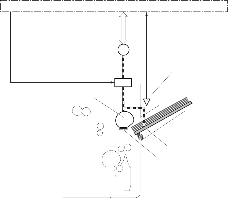
The MP tray media presence sensor detects the presence of print media on the MP tray.
Figure 1-38 Tray 1 (MP tray) paper pickup
MP tray pickup roller
MP tray separation pad
SL2
M5
PS2:
MP tray media presence sensor
Pickup motor
MP tray pickup solenoid
Lifting plate
DC controller
Tray 1 (MP tray) last-paper detection
The product detects whether the print media on the MP tray is the last sheet during continuous printing
to prevent toner contamination on the photosensitive drums and the ITB.
The product attempts to form the next image before the DC controller detects a media absence because
the paper path between the MP tray media-presence sensor and the registration roller is short. To
prevent the photosensitive drums and the ITB from being contaminated with toner, the last-paper sensor
detects the last-paper. The MP tray last-paper detection roller rotates when the last-paper is picked up.
54 Chapter 1 Theory of operation ENWW
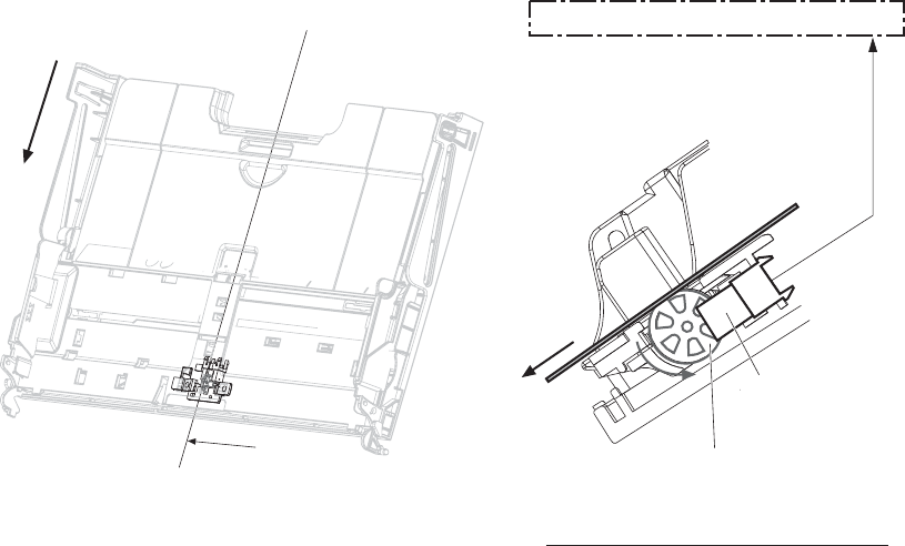
The DC controller notifies the formatter of a media absence when it detects the last-paper by the last-
paper sensor.
Figure 1-39 Tray 1 (MP tray) last-paper detection
A
DC controller
PS3:
Last-paper sensor
Last-paper
MP tray last-paper detection roller
Cross sectional view from A direction
Feed direction
Paper feed
After the paper pickup operation, the paper picked up from either the Tray 2 cassette or MP tray is then
fed to the fixing-and-delivery block.
1. The registration shutter corrects the skew-feeding of the paper that is picked up from the Tray 2
cassette or MP tray.
2. When the TOP sensor detects the leading edge of paper, the DC controller controls the rotational
speed of the pickup motor to align with the leading edge of toner image on the ITB.
3. The toner image on the ITB is transferred onto the paper, and the paper is fed to the fusing-and-
delivery block.
ENWW Pickup, feed, and delivery system 55
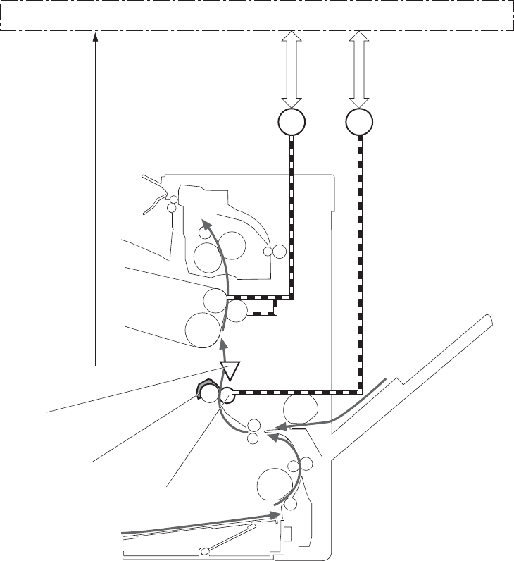
The DC controller notifies the formatter of a paper size mismatch error when the paper length detected
by the TOP sensor does not match the paper size specified by the formatter.
Figure 1-40 Paper feed
TOP sensor
M1 M5
Registration shutter
Registration roller
Pickup motor
ITB motor
DC controller
PS5
56 Chapter 1 Theory of operation ENWW
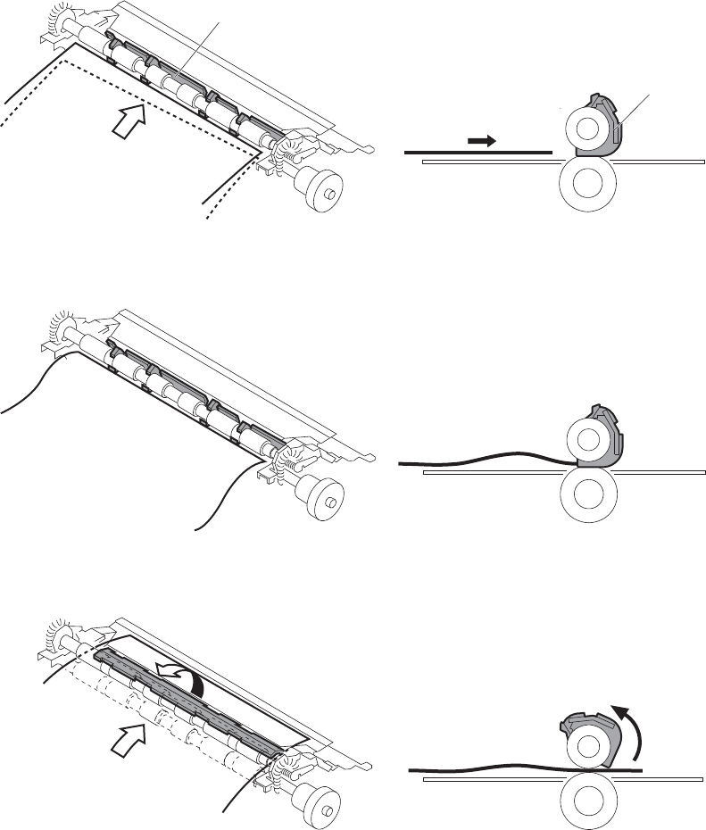
Skew-feed prevention
The printer corrects the skew feed without decreasing the throughput.
1. The leading edge of paper strikes the registration shutter and aligns.
2. As the feed rollers keep pushing the paper, the paper gets warped against the registration shutter.
3. The stiffness of paper pushes up the registration shutter and the realigned paper passes through
straightened.
Figure 1-41 Skew-feed prevention
Paper
Paper
Registration shutter
Registration shutter
ENWW Pickup, feed, and delivery system 57

Media detection
The product automatically selects an optimal print mode for a print-media by monitoring the media
sensors on the paper path.
Media detection sensor types
●Reflected light type (detects the glossiness of paper)
●Transmitted light type (detects the thickness of paper)
The DC controller detects the type of print-media by the reflected light and the transmitted light, and
switches the print modes accordingly. The DC controller identifies the following paper type:
●Plain paper
●Light paper
●Heavy paper
●Glossy paper
●Glossy film
●Overhead transparency (OHT)
The DC controller determines a media mismatch error and notifies the formatter under the following
conditions:
●Simplex printing
◦The specified print mode is OHT, but the media sensor detects media other than an overhead
transparency.
◦The specified print mode is something other than OHT, but the media sensor detects an
overhead transparency.
●Duplex printing
◦The specified print mode is for duplex-printable-print mode, but the media sensor detects an
overhead transparency. For more information about duplex-printable mode, see Duplex block
(duplex models only) on page 63.
The DC controller flashes the media sensor during the initial rotation period under the following
conditions:
●Product power is turned on
●The door is closed
The DC controller determines a media sensor abnormality and notifies the formatter when the light
intensity is out of a specified range.
58 Chapter 1 Theory of operation ENWW

Feed-speed control
The product adjusts the feed speed to obtain the best print quality depending on the type of print
media. The product prints at the speed corresponding to the print mode specified by the formatter.
Auto Sense mode Print mode Print
speed
Media
sensor
detection
Normal mode Normal 1/1 Yes
Light mode Light media 1 1/1 Yes
Heavy Mode Heavy media 1 2/3 Yes
Cardstock Mode Heavy media 3 1/3 No
Transparency Mode OHT 1/3 Yes
Transparency2 Mode OHT + higher fuser temp 1/3 Yes
Envelope Mode Envelope 2/3 No
Label Mode Label 1/3 No
Tough Mode Glossy film 1/3 Yes
Extra Heavy Mode Heavy media 2 1/3 Yes
Heavy Glossy Mode Glossy media 1 2/3 Yes
X-hvyglossymode Glossy media 2 1/3 Yes
Rough Mode Rough 2/3 No
Card Glossy Mode Glossy media 3 1/3 Yes
4mm trns Mode OHT + lower fuser temp 1/3 Yes
Light Rough Mode Light media 1 + fuser temp adjustments 1/1 Yes
Fusing and delivery block
The fusing-and-delivery block fuses the toner image onto the print media and delivers the printed page
to the output bin.
Loop control
The product controls the loop (slackness) of print media to prevent the defects of print quality and media
feed.
●If the fuser sleeve rotates slower than the ITB, the paper loop increases and an image defect or
paper crease occurs.
●If the fuser sleeve rotates faster than the ITB, the paper loop decreases and an image is stretched
because the toner image is not transferred to the paper correctly
ENWW Pickup, feed, and delivery system 59
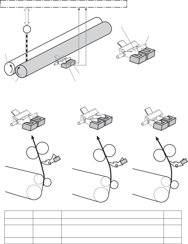
Two loop sensors located between the fuser sleeve and the ITB detect the paper loop. Accordingly the
DC controller controls the rotational speed of the fuser motor to keep the loop amount properly.
●Loop sensor 1: Detects the paper loop for heavy media
●Loop sensor 2: Detects the paper loop for plain media other than heavy media
Figure 1-42 Loop control
Pressure roller
DC controller
M5
Loop sensor1
Loop sensor2
Sensor flag for heavy paper
Sensor flag for other than heavy paper
Fuser motor
Speed of fuser motor
OFF
ON
ON
OFF
OFF
ON
Speed down
Heavy media: Speed up
Other media: Speed down
Speed up
A
B
C
Pressure roller
ITB
<A> <B> <C>
PS7
PS8
Small-loop Large-loop
(heavy media)
Large-loop
(other than heavy media)
Loop sensor1 Loop sensor2 Illus.
Fuser sleeve
Fuser sleeve
60 Chapter 1 Theory of operation ENWW
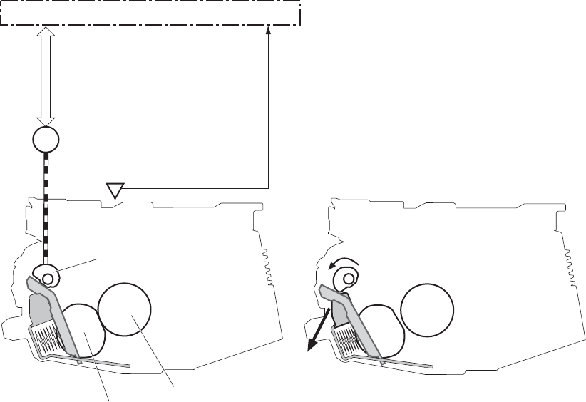
Pressure roller pressurization and depressurization control
The product releases the pressure roller from the fuser sleeve, except during printing, to prevent
deforming the fuser sleeve and the pressure roller and to facilitate the jam-clearing procedure.
1. The DC controller reverses the fuser motor to rotate the fuser pressure release cam.
2. The pressure roller is pressurized or depressurized depending on the position of the cam.
The DC controller determines a fuser pressure-release mechanism abnormality and notifies the formatter
when it does not sense the fuser pressure-release sensor for a specified period from when it reverses the
fuser motor.
Figure 1-43 Pressure roller pressurization and depressurization control
M4
DC controller
Fuser motor
PS9:
Fuser pressure release sensor
Fuser sleeve
Pressure roller
Fuser pressure release cam
<Pressurized> <Depressurized>
ENWW Pickup, feed, and delivery system 61
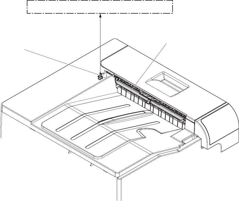
Output bin full detection
The output bin media-full sensor detects whether the output bin is full of printed pages. The DC
controller determines the output bin is full and notifies the formatter when it senses the output bin media-
full sensor is on for a specified period during standby or printing.
Figure 1-44 Output bin full detection
Output bin media full sensor flag
Output bin media full sensor
DC controller
PS10
62 Chapter 1 Theory of operation ENWW
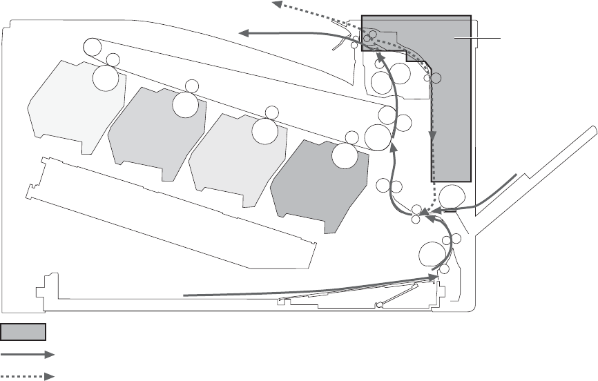
Duplex block (duplex models only)
The duplex block reverses and feeds the paper.
Figure 1-45 Duplex block
Duplex block
Simplex paper path
Duplex paper path (duplex model)
Only for the duplex model
Duplex reverse and duplex feed control
The duplex reverse control reverses the paper after the first side is printed. The duplex feed control
feeds the paper to the duplex block to print the second side of the page.
The operational sequence of the duplex reverse and duplex feed control is as follows:
1. The DC controller rotates the duplex reverse motor and drives the duplex reverse solenoid at a
specified timing after the first side of page is printed.
2. The duplex flapper moves and the paper is fed by the duplex reverse roller.
3. The duplex reverse motor is reversed.
4. The duplex reverse roller is reversed accordingly the paper is switched back.
ENWW Pickup, feed, and delivery system 63
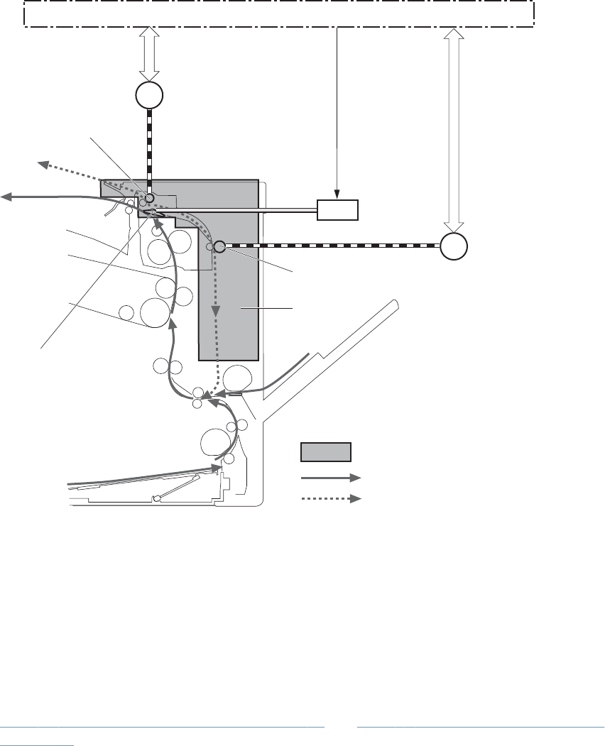
5. The duplex feed motor rotates.
6. The duplex feed roller feeds the paper.
Figure 1-46 Duplex operation
DC controller
Duplex reverse solenoid
Duplex feed roller
Duplex ass’y
Simplex paper path
Duplex paper path (duplex model)
Duplex reverse roller
Duplex flapper
Only for the duplex model
SL3
M7
M8 Duplex feed motor
Duplex reverse motor
Duplex operation
The product prints two sides of paper with the following operation depending on the paper size.
●One-sheet operation: Feeds one sheet of two-sided page in a duplex print operation
●Two-sheet operation: Feeds two sheets of two-sided page in a duplex print operation
The duplex print operation is specified by the formatter.
The duplex print is performed only with the duplex printable paper size and specified print mode. See
Table 1-8 Paper sizes, duplex operation on page 65 and Table 1-9 Print modes, duplex operation
on page 65.
64 Chapter 1 Theory of operation ENWW

Table 1-8 Paper sizes, duplex operation
Paper size Duplexing media feed mode
A4-R One-sheet operation
A3
Letter-R
B4
B5-R
Ledger
Legal
A4 One-sheet operation
Two-sheet operation
B5
Letter
A5-R
Executive
Table 1-9 Print modes, duplex operation
Print mode Duplex print
1
Print mode Duplex print
1
AUTO Yes X-hvyglossy Yes
Normal Yes Card glossy No
Light Yes Rough Yes
Light rough Yes Transparency No
Heavy Yes 4mm transparency No
Extra heavy No Tough Yes
Cardstock No Label No
heavy glossy Yes Envelop No
1
This table shows whether the automatic duplex operation is available for each print mode, but it does not mean that the print-
quality of the automatic duplex print operation will be acceptable.
ENWW Pickup, feed, and delivery system 65
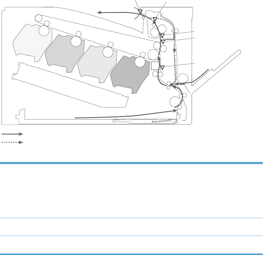
Jam detection
The product uses the following sensors to detect the presence of print-media and to check whether the
print-media is being fed correctly or has jammed:
●TOP sensor (PS5)
●Fuser delivery sensor (PS6)
●Loop sensor 1 (PS7)
●Loop sensor 2 (PS8)
●Output bin media full sensor (PS10)
Figure 1-47 Sensors for jam detection
PS6
PS7
PS8
PS5
Simplex media path
Duplex media path (duplex model)
PS10
The product detects the following jams:
Pickup delay jam Tray 1 (MP tray): The TOP sensor does not detect the leading edge of paper within a
specified period, including a retry, after the MP tray pickup solenoid is turned on.
Tray 2 cassette: The TOP sensor does not detect the leading edge of paper within a
specified period, including a retry, after the Tray 2 cassette pickup solenoid is turned on.
Paper feeder: The TOP sensor does not detect the leading edge of paper within a specified
period after the paper-feeder (PF) feed sensor detects the leading edge.
Pickup stationary jam The TOP sensor does not detect the trailing edge of paper within a specified period after the
leading edge of paper reaches the secondary transfer roller unit.
Fuser delivery delay jam The fuser delivery sensor does not detect the leading edge of paper within a specified period
after the leading edge of paper reaches the secondary transfer roller unit.
66 Chapter 1 Theory of operation ENWW

Fuser delivery stationary jam The fuser delivery sensor does not detect the trailing edge of paper within a specified period
after the TOP sensor detects the trailing edge.
The output bin media full sensor does not detect the leading edge of paper within a specified
period after the fuser delivery sensor detects the leading edge.
Wrapping jam The fuser delivery sensor detects a paper absence yet it does not detect the trailing edge of
paper after it detects the leading edge.
Residual paper jam One of the following sensors detects a presence of paper when the printer is turned on or
when the door is closed.
●TOP sensor
●Fuser delivery sensor
●Loop sensor 1
●Loop sensor 2
NOTE: The product automatically clears all paper from the paper path if the TOP sensor
detects residual paper when the product is turned on or a door is closed.
Door open jam The door open is detected during a paper feed operation.
Duplex re-pickup jam (duplex
model only)
The TOP sensor does not detect the leading edge of paper within a specified period after the
paper is reversed during a duplex print operation.
ENWW Pickup, feed, and delivery system 67
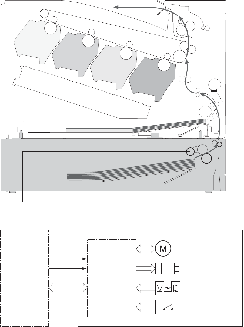
Paper feeder
This product supports a 500-sheet tray (Tray 3). The operational sequence of the paper feeder is
controlled by the paper feeder controller PCA.
Figure 1-48 Paper-feeder paper path
PF pickup roller
PF feed roller
PF separation roller
Figure 1-49 Paper-feeder block diagram
+24V
DC controller
+3.3V
Paper feeder
Paper feeder
controller
Motor
Solenoid
Photointerrupter
Switch
68 Chapter 1 Theory of operation ENWW
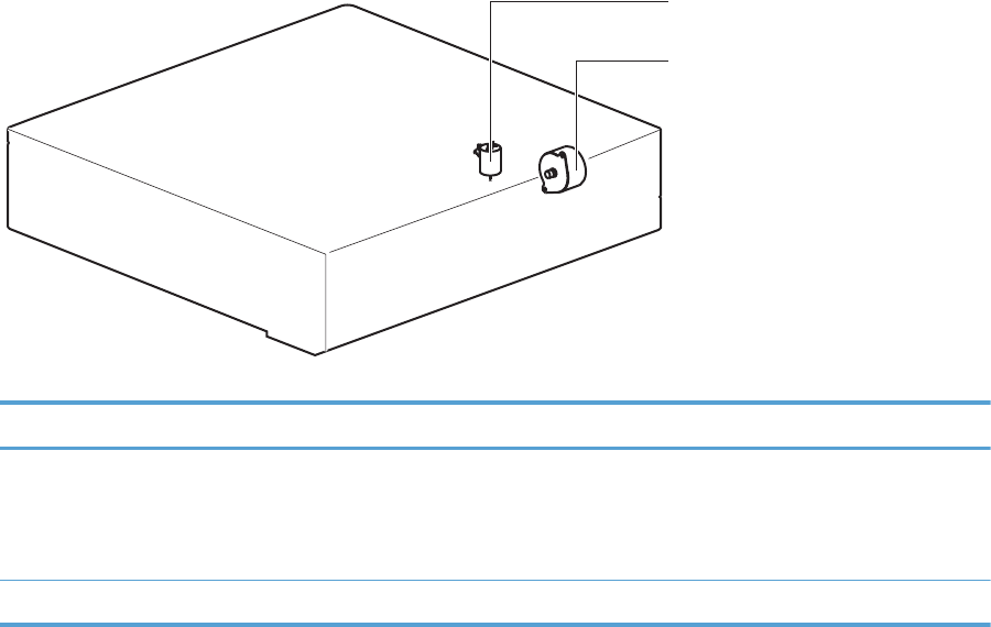
Paper-feeder motors
The paper feeder has two motors for paper feed and cassette lift-up operation.
Figure 1-50 Paper-feeder motors
PF lifter motor (M2)
PF pickup motor (M1)
Table 1-10 Paper-feeder motors
Motor Driving part Failure detection
PF pickup motor (M1) PF pickup roller
PF separation roller
PF feed roller
No
PF lifter motor (M2) Lifter for the PF cassette No
ENWW Paper feeder 69
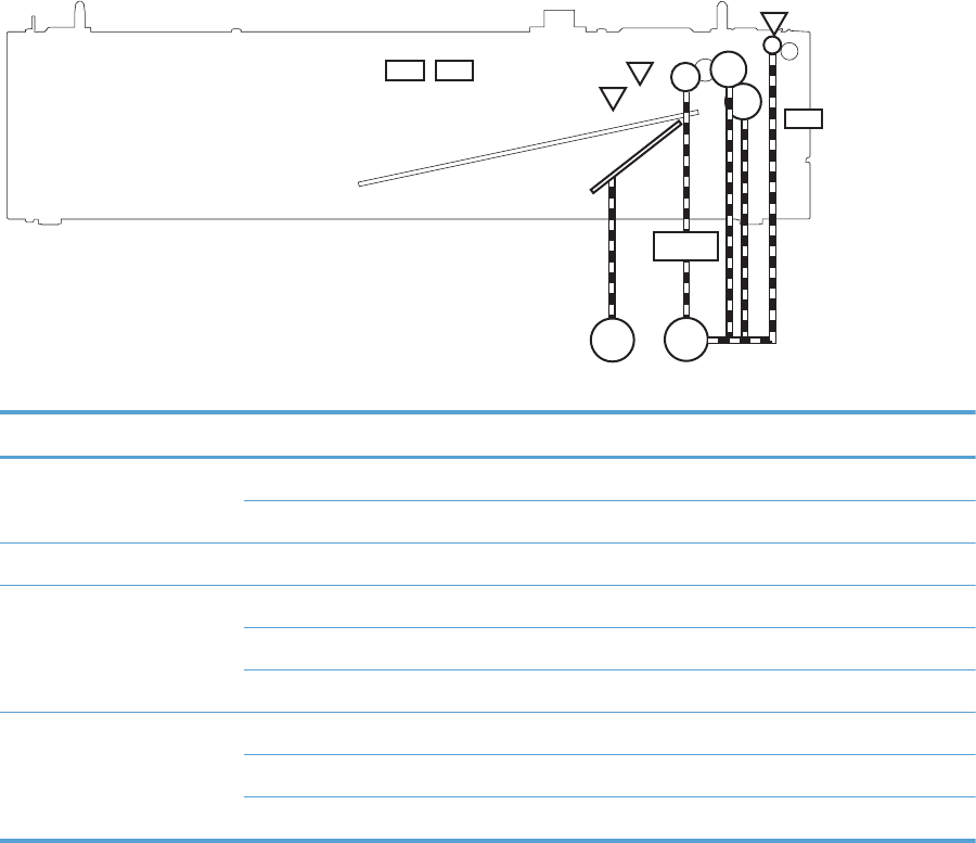
Paper-feeder paper pickup and feed
The pickup-and-feed operation picks up one sheet of print media in the paper-feeder cassette and feeds
it to the product.
Figure 1-51 Paper-feeder electrical components
M1
M2
SL1
SR1
SR2
SR3
SW1
SW2SW3
Table 1-11 Paper-feeder electrical components
Component type Abbreviation Description
Motor M1 PF pickup motor
M2 PF lifter motor
Solenoid SL01 PF pickup solenoid
Photointerruptor (sensor) SR1 PF paper-feed sensor
SR2 PF paper-stack surface sensor
SR3 PF cassette paper-presence sensor
Switch SW1 PF door-open switch
SW2 PF cassette paper end-plate position switch
SW3 PF cassette paper-width switch
Cassette media-size detection and cassette-presence detection
The paper feeder detects the size of the paper loaded in the paper feeder cassette by monitoring the
paper feeder cassette media end switch and the paper feeder cassette media width switch. It also
detects the presence of cassette by monitoring the switches. The paper feeder controller notifies the
formatter through the DC controller when it determines a cassette is absent.
70 Chapter 1 Theory of operation ENWW

Table 1-12 Cassette media-size detection and cassette-presence detection (Tray 3)
Paper size Paper feeder
Cassette media-width sensor
Paper feeder
Cassette media-end switch
Top switch Center switch Bottom switch Top switch Center switch Bottom switch
Executive Off On On On On On
Letter Off Off On On On On
A5 On On Off On On On
B5 Off On Off On On On
A4OffOffOffOnOnOn
Ledger Off Off On Off Off On
LegalOnOnOffOffOffOn
B4 Off On Off Off Off On
A3 Off Off Off Off Off On
A4-R NOTE: The product cannot detect the paper size of A4-R and Letter-R. If A4-R or Letter-R sized paper is
loaded to the cassette, A5 size is notified to the formatter.
Letter-R
UniversalOnOnOffOffOnOn
Cassette absent Off Off Off Off Off Off
Paper-feeder cassette lift operation
The cassette lift-up operation keeps the surface of the paper stack at the pickup position whenever the
following occurs:
●Product power is turned on
●Cassette is installed
●Stack surface in the cassette lowers
The operational sequence of the cassette lift-up is as follows:
1. The PF lifter motor rotates to raise the lifter.
2. When the PF paper-stack surface sensor detects the surface of the paper stack, the PF lifter motor
stops.
3. The lifter motor rotates again when the PF paper-stack surface detects that the paper surface is
lowered during a print operation.
ENWW Paper feeder 71
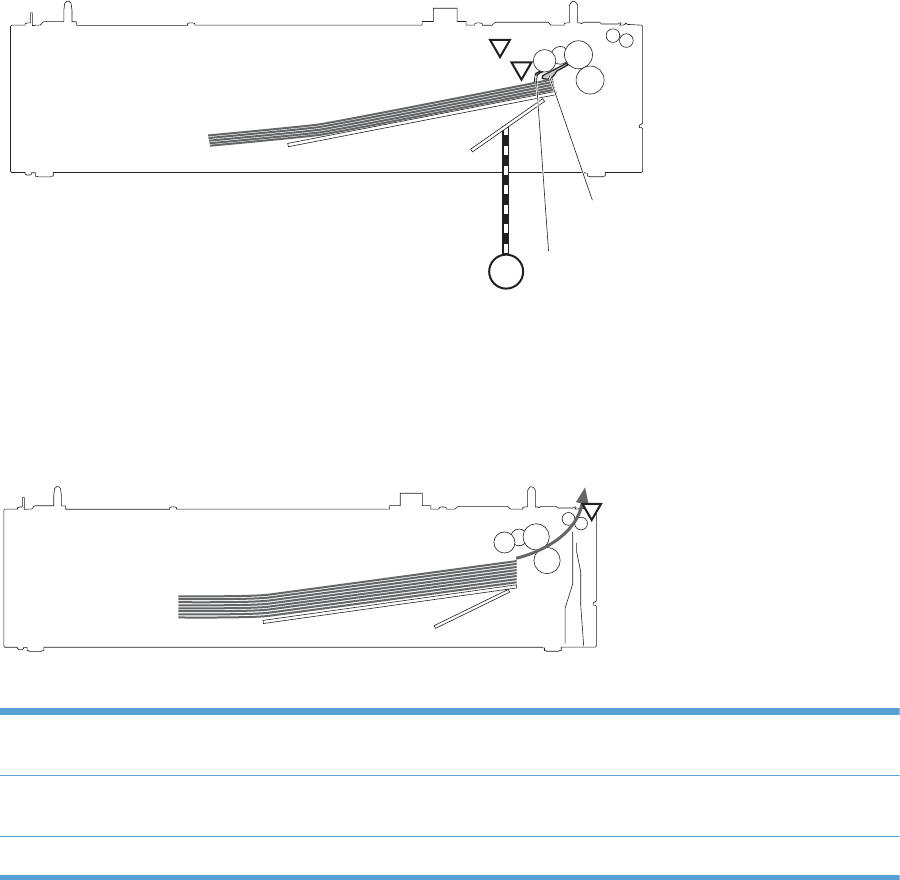
The paper feeder controller PCA determines a PF lifter motor failure and notifies the formatter through
the DC controller when the PF paper-stack surface sensor does not detect the stack surface within a
specified period after the PF lifter motor starts rotating.
Figure 1-52 Paper-feeder cassette lift operation
M2
SR2
SR3
Lifter
Lifting plate
PF lifter motor PF media stack surface flag
PF cassette media presence sensor flag
PF media stack surface sensor
PF cassette media presence sensor
Paper-feeder jam detection
The paper feeder uses the PF paper-feed sensor (SR1) to detect the presence of print-media and to
check whether print-media is being fed correctly or has jammed.
Figure 1-53 Paper-feeder jam detection
SR1
Paper feeder 1
The paper feeder detects the following jams:
PF pickup delay jam The PF paper-feed sensor does not detect the leading edge of paper within a specified period,
including a retry, after the PF pickup solenoid is turned on.
PF residual paper jam The PF paper-feed sensor detects a presence of paper when the printer is turned on, when the
door is closed or when the automatic delivery is performed.
PF door open jam A door open is detected during paper-feed operation.
72 Chapter 1 Theory of operation ENWW
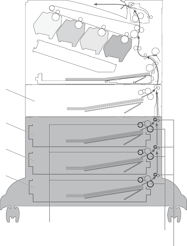
Optional 3X500-sheet paper deck
The 3x500-sheet paper deck is installed at bottom of the product. It picks up the paper and feeds it to
the printer. The paper deck controller controls the operational sequence of the paper deck.
Figure 1-54 3X500-sheet paper deck
Paper deck cassette 1
Paper deck cassette 2
Paper deck cassette 3
Paper feeder
Paper deck cassette pickup roller
Paper deck cassette feed roller
Paper deck cassette separation roller
The signal flow of the paper deck controller is shown below.
ENWW Optional 3X500-sheet paper deck 73
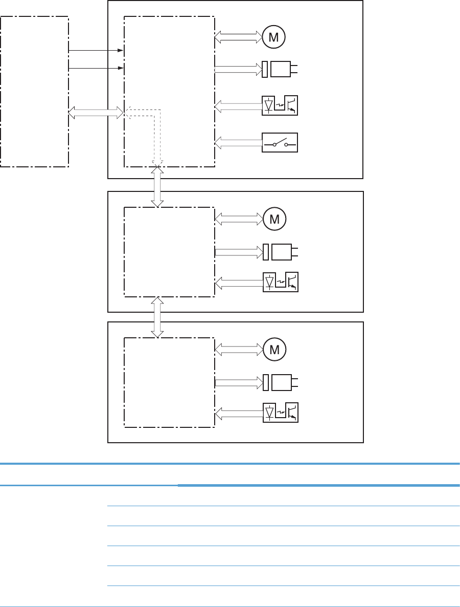
Figure 1-55 3X500-sheet paper deck block diagram
DC controller Paper deck
controller 1
Motor
Solenoid
Photointerrupter
Switch
Paper deck cassette 1
+24V
+3.3V
Paper deck
controller 2
Paper deck
controller 3
Paper deck cassette 2
Paper deck cassette 3
Motor
Solenoid
Photointerrupter
Motor
Solenoid
Photointerrupter
Table 1-13 3X500-sheet paper deck
Component Description
Motor M1 Paper deck cassette 1 pickup motor
M2 Paper deck cassette 1 lifter motor
M81 Paper deck cassette 2 pickup motor
M82 Paper deck cassette 2 lifter motor
M91 Paper deck cassette 3 pickup motor
M92 Paper deck cassette 3 lifter motor
74 Chapter 1 Theory of operation ENWW

Table 1-13 3X500-sheet paper deck (continued)
Component Description
Solenoid SL1 Paper deck cassette 1 pickup solenoid
SL82 Paper deck cassette 2 pickup solenoid
SL92 Paper deck cassette 3 pickup solenoid
Photointerrupter SR1 Paper deck cassette 1 media feed sensor
SR2 Paper deck cassette 1 stack surface sensor
SR3 Paper deck cassette 1 cassette media out sensor
SR81 Paper deck cassette 2 media feed sensor
SR82 Paper deck cassette 2 stack surface sensor
SR83 Paper deck cassette 2 cassette media out sensor
SR91 Paper deck cassette 3 media feed sensor
SR92 Paper deck cassette 3 stack surface sensor
SR93 Paper deck cassette 3 cassette media out sensor
Switch SW1 Paper deck door-open-detection switch
SW2 Paper deck cassette 1 cassette media end switch
SW3 Paper deck cassette 1 cassette media width switch
SW82 Paper deck cassette 2 cassette media end switch
SW83 Paper deck cassette 2 cassette media width switch
SW92 Paper deck cassette 3 cassette media end switch
SW93 Paper deck cassette 3 cassette media width switch
ENWW Optional 3X500-sheet paper deck 75
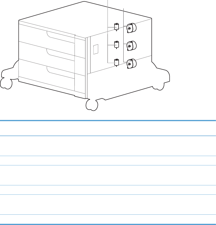
Motor control
Each of the paper deck cassettes uses two motors for paper-feed and cassette lift-up operation.
Figure 1-56 Paper deck motors
Paper deck cassette lifter motor
Paper deck cassette pickup motor
Table 1-14 Paper deck motors
Component Component driven Failure
detection
Paper deck cassette 1 pickup motor M1 Paper deck cassette 1 pickup roller, paper
deck cassette 1 separation roller, and paper
deck cassette 1 feed roller
No
Paper deck cassette 1 lifter motor M2 Lifter for the paper deck cassette 1 No
Paper deck cassette 2 pickup motor M81 Paper deck cassette 2 pickup roller, paper
deck cassette 2 separation roller, and paper
deck cassette 2 feed roller
No
Paper deck cassette 2 lifter motor M82 Lifter for the paper deck cassette 2 No
Paper deck cassette 3 pickup motor M91 Paper deck cassette 3 pickup roller, paper
deck cassette 3 separation roller, and paper
deck cassette 3 feed roller
No
Paper deck cassette 3 lifter motor M92 Lifter for the paper deck cassette 3 No
76 Chapter 1 Theory of operation ENWW
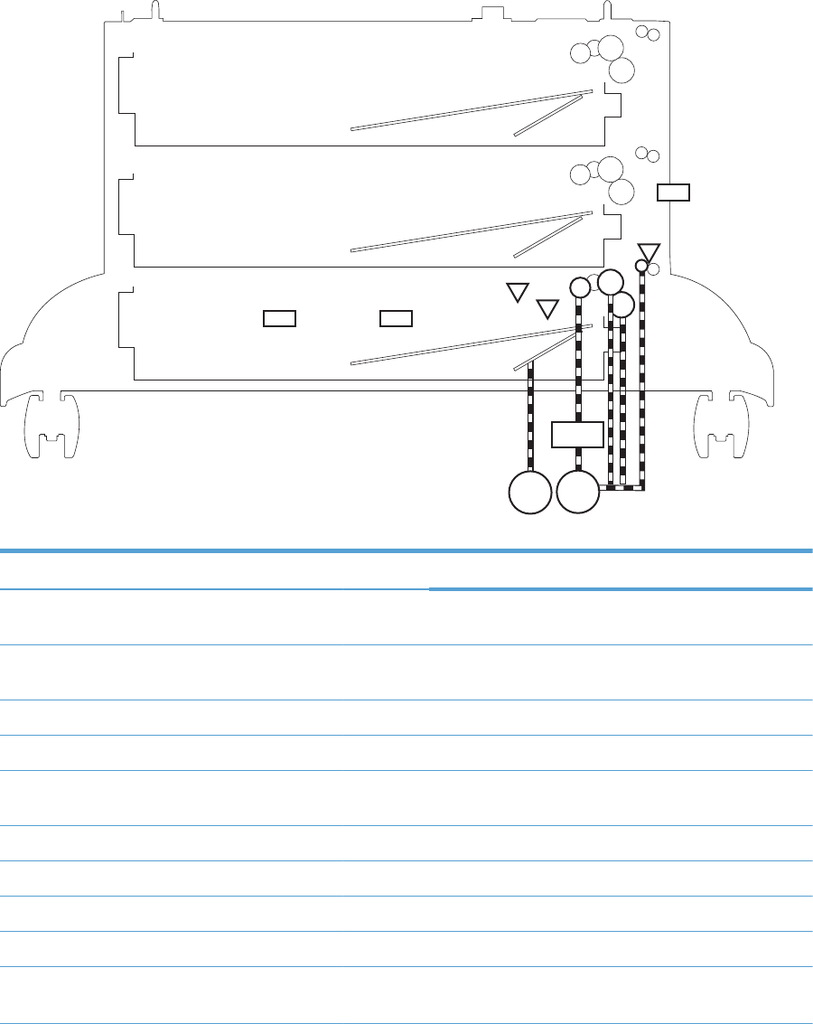
Pickup-and-feed operation
The pickup-and-feed operation picks up one sheet of paper in the paper deck cassette and feeds it to
the product. The paper deck has three cassettes but each cassette performs the same operation. Paper
deck cassette 3 is used to describe the pickup-and-feed operation in this section.
Figure 1-57 Pickup-and-feed operation
M91
M92
SL91
SR1
SW1
SR92
SR93
Paper deck cassette 1
Paper deck cassette 2
Paper deck cassette 3
SW92 SW93
Table 1-15 Pickup-and-feed operation
Component Signal
Paper deck cassette 1 pickup motor M1 PAPER DECK CASSETTE 1 PICKUP MOTOR CONTROL
signal
Paper deck cassette 1 lifter motor M2 PAPER DECK CASSETTE 1 LIFTER MOTOR CONTROL
signal
Paper deck cassette 1 pickup solenoid SL01 PAPER DECK CASSETTE 1 SOLENOID signal
Paper deck cassette 1 media feed sensor SR1 PAPER DECK CASSETTE 1 MEDIA FEED signal
Paper deck cassette 1 media stack surface sensor SR2 PAPER DECK CASSETTE 1 MEDIA STACK SURFACE
signal
Paper deck cassette 1 media out sensor SR3 PAPER DECK CASSETTE 1 MEDIA OUT signal
Paper deck door-open-detection switch SW1 PAPER DECK DOOR OPEN DETECTION signal
Paper deck cassette 1 media end switch SW2 PAPER DECK CASSETTE 1 MEDIA END signal
Paper deck cassette 1 media width switch SW3 PAPER DECK CASSETTE 1 MEDIA WIDTH signal
Paper deck cassette 2 pickup motor M81 PAPER DECK CASSETTE 2 PICKUP MOTOR CONTROL
signal
ENWW Optional 3X500-sheet paper deck 77

Table 1-15 Pickup-and-feed operation (continued)
Component Signal
Paper deck cassette 2 lifter motor M82 PAPER DECK CASSETTE 2 LIFTER MOTOR CONTROL
signal
Paper deck cassette 2 pickup solenoid SL82 PAPER DECK CASSETTE 2 SOLENOID signal
Paper deck cassette 2 media feed sensor SR81 PAPER DECK CASSETTE 2 MEDIA FEED signal
Paper deck cassette 2 media stack surface sensor SR82 PAPER DECK CASSETTE 2 MEDIA STACK SURFACE
signal
Paper deck cassette 2 media out sensor SR83 PAPER DECK CASSETTE 2 MEDIA OUT signal
Paper deck cassette 2 media end switch SW82 PAPER DECK CASSETTE 2 MEDIA END signal
Paper deck cassette 2 media width switch SW83 PAPER DECK CASSETTE 2 MEDIA WIDTH signal
Paper deck cassette 3 pickup motor M91 PAPER DECK CASSETTE 3 PICKUP MOTOR CONTROL
signal
Paper deck cassette 3 lifter motor M92 PAPER DECK CASSETTE 3 LIFTER MOTOR CONTROL
signal
Paper deck cassette 3 pickup solenoid SL91 PAPER DECK CASSETTE 3 SOLENOID signal
Paper deck cassette 3 media feed sensor SR91 PAPER DECK CASSETTE 3 MEDIA FEED signal
Paper deck cassette 3 media stack surface sensor SR92 PAPER DECK CASSETTE 3 MEDIA STACK SURFACE
signal
Paper deck cassette 3 media out sensor SR93 PAPER DECK CASSETTE 3 MEDIA 0UT signal
Paper deck cassette 3 media end switch SW92 PAPER DECK CASSETTE 3 MEDIA END signal
Paper deck cassette 3 media width switch SW93 PAPER DECK CASSETTE 3 MEDIA WIDTH signal
Cassette media-size detection and cassette-presence detection
The paper deck detects the size of the paper loaded in the paper deck cassette by monitoring the
paper deck cassette media end switch and the paper deck cassette media width switch. It also detects
the presence of cassette by monitoring the switches. The paper deck controller notifies the formatter
through the DC controller when it determines a cassette is absent.
Table 1-16 Cassette media-size detection and cassette-presence detection (3X500-sheet paper
deck)
Paper size 3X500-sheet paper deck
Cassette media width sensor
3X500-sheet paper deck
Cassette media end switch
Top switch Center switch Bottom switch Top switch Center switch Bottom switch
Executive Off On On On On On
Letter Off Off On On On On
A5 On On Off On On On
78 Chapter 1 Theory of operation ENWW

Table 1-16 Cassette media-size detection and cassette-presence detection (3X500-sheet paper
deck) (continued)
B5 Off On Off On On On
A4 OffOffOff OnOnOn
Ledger Off Off On Off Off On
Legal On On Off Off Off On
B4 Off On Off Off Off On
A3 Off Off Off Off Off On
A4-R NOTE: The product cannot detect the paper size of A4-R and Letter-R. If A4-R or Letter-R sized paper is
loaded to the cassette, A5 size is notified to the formatter.
Letter-R
Universal On On Off Off On On
Cassette absent Off Off Off Off Off Off
Cassette lift-up operation
The cassette lift-up operation keeps the surface of the paper stack at the pickup position whenever the
following occurs:
●Product power is turned on
●Cassette is installed
●Stack surface in the cassette lowers
ENWW Optional 3X500-sheet paper deck 79
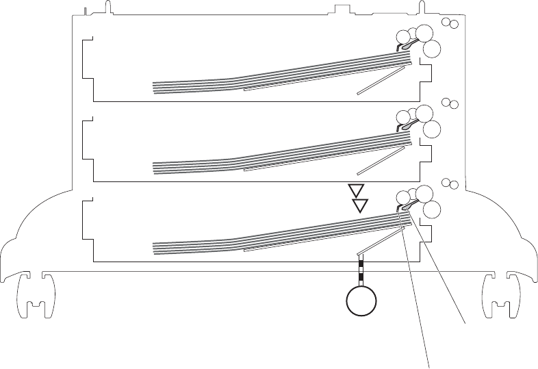
The paper deck cassette media-out sensor detects the presence of paper in the paper deck cassette.
Paper deck cassette 3 is used to describe the Cassette lift-up operation in this section.
Figure 1-58 Cassette lift-up operation
M92
SR92
SR93
Lifter
Lifting plate
Paper deck cassette 3 lifter motor
Paper deck cassette 3 media stack surface sensor flag
Paper deck cassette 3 media out
sensor flag
Paper deck cassette 3 media stack surface sensor
Paper deck cassette 3 media out sensor
Paper deck cassette 1
Paper deck cassette 2
Paper deck cassette 3
80 Chapter 1 Theory of operation ENWW
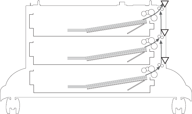
Jam detection
The paper deck uses the following sensors to detect the presence of paper and to check whether paper
is being fed correctly or has jammed.
●Paper deck cassette 1 media feed sensor (SR1)
●Paper deck cassette 2 media feed sensor (SR81)
●Paper deck cassette 3 media feed sensor (SR91)
Figure 1-59 Jam detection
SR1
SR81
SR91
The paper deck detects the following jams.
●Paper deck no pick jam 1
The paper deck cassette 1 media feed sensor does not detect the leading edge of paper within a
specified period after the paper deck cassette 2 media feed sensor detects the leading edge. The
paper deck cassette 2 media feed sensor does not detect the leading edge of paper within a
specified period after the paper deck cassette 3 media feed sensor detects the leading edge.
●Paper deck no pick jam 2
The paper deck cassette 1 media feed sensor does not detect the leading edge of paper within a
specified period, including a retry, after the paper deck cassette 1 pickup solenoid has turned on.
The paper deck cassette 2 media feed sensor does not detect the leading edge of paper within a
specified period, including a retry, after the paper deck cassette 2 pickup solenoid has turned on.
The paper deck cassette 3 media feed sensor does not detect the leading edge of paper within a
specified period, including a retry, after the paper deck cassette 3 pickup solenoid has turned on.
●Paper deck residual paper jam
ENWW Optional 3X500-sheet paper deck 81
Any one of the following sensors detects a presence of paper after the automatic delivery is
performed when the printer is turned on or when the door is closed.
◦Paper deck cassette 1 media feed sensor
◦Paper deck cassette 2 media feed sensor
◦Paper deck cassette 3 media feed sensor
●Paper deck door open jam
A paper deck door open is detected during a paper-feed operation.
●Automatic Delivery
The paper deck automatically clears the paper if any one of the following sensors detects the
residual paper during the initial sequence after the printer is turned on or after the door is closed.
◦Paper deck cassette 1 media feed sensor
◦Paper deck cassette 2 media feed sensor
◦Paper deck cassette 3 media feed sensor
82 Chapter 1 Theory of operation ENWW


Introduction
This chapter describes the removal and replacement of field-replaceable units (FRUs) only.
Replacing FRUs is generally the reverse of removal. Occasionally, notes and tips are included to
provide directions for difficult or critical replacement procedures.
HP does not support repairing individual subassemblies or troubleshooting to the component level.
Note the length, diameter, color, type, and location of each screw. Be sure to return each screw to its
original location during reassembly.
Incorrectly routed or loose wire harnesses can interfere with other internal components and can become
damaged or broken. Frayed or pinched harness wires can be difficult to find. When replacing wire
harnesses, always use the provided wire loops, lance points, or wire-harness guides and retainers.
Removal and replacement strategy
WARNING! Turn the product off, wait 5 seconds, and then remove the power cord before
attempting to service the product. If this warning is not followed, severe injury can result, in addition to
damage to the product. The power must be on for certain functional checks during troubleshooting.
However, disconnect the power supply during parts removal.
Never operate or service the product with the protective cover removed from the laser/scanner
assembly. The reflected beam, although invisible, can damage your eyes.
The sheet-metal parts can have sharp edges. Be careful when handling sheet-metal parts.
CAUTION: Do not bend or fold the flat flexible cables (FFCs) during removal or installation. Also, do
not straighten pre-folds in the FFCs. You must fully seat all FFCs in their connectors. Failure to fully seat
an FFC into a connector can cause a short circuit in a PCA.
NOTE: To install a self-tapping screw, first turn it counterclockwise to align it with the existing thread
pattern, and then carefully turn it clockwise to tighten. Do not overtighten. If a self-tapping screw-hole
becomes stripped, repair the screw-hole or replace the affected assembly.
TIP: For clarity, some photos in this chapter show components removed that would not be removed to
service the product. If necessary, remove the components listed at the beginning of a procedure before
proceeding to service the product.
Electrostatic discharge
CAUTION: Some parts are sensitive to electrostatic discharge (ESD). Look for the ESD reminder
when removing product parts. Always perform service work at an ESD-protected workstation or mat, or
use an ESD strap. If an ESD workstation, mat, or strap is not available, ground yourself by touching the
sheet-metal chassis before touching an ESD-sensitive part.
Protect the ESD-sensitive parts by placing them in ESD pouches when they are out of the product.
84 Chapter 2 Removal and replacement ENWW
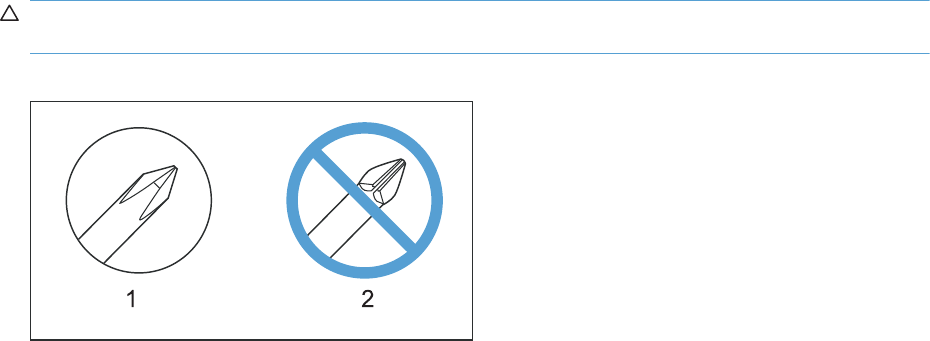
Required tools
●#2 Phillips screwdriver with a magnetic tip and a 152-mm (6-inch) shaft length
●Small flat blade screwdriver
●Needle-nose pliers
●ESD mat or ESD strap (if one is available)
●Portable USB storage device (USB thumbdrive); for firmware upgrade
●Penlight (optional)
CAUTION: Always use a Phillips screwdriver (callout 1). Do not use a pozidrive screwdriver
(callout 2) or any motorized screwdriver. These can damage screws or screw threads.
Figure 2-1 Phillips and pozidrive screwdriver comparison
ENWW Required tools 85

Service approach
Before performing service
●Remove all media from the product.
●Turn off the power using the power switch.
●Unplug the power cable and interface cable or cables.
●Place the product on an ESD workstation or mat, or use an ESD strap (if one is available). If an
ESD workstation, mat, or strap is not available, ground yourself by touching the sheet-metal
chassis before touching an ESD-sensitive part.
●Remove the print cartridges. See Print cartridges on page 87.
●Remove the tray cassette or cassettes.
After performing service
●Plug in the power cable.
●Reinstall the print cartridges.
●Reinstall the tray cassette or cassettes.
●If the 1 x 500-sheet paper feeder or optional 3 x 500-sheet paper feeder was removed for
service, place the product on the feeder or feeders. Engage the feeder tray locks to secure the
feeder or feeders to the product.
Post-service test
Perform the following test to verify that the repair or replacement was successful.
Print-quality test
1. Verify that you have completed the necessary reassembly steps.
2. Make sure that the tray contains clean, unmarked paper.
3. Attach the power cord and interface cable or interface cables, and then turn on the product.
4. Verify that the expected startup sounds occur.
5. Print a configuration page, and then verify that the expected printing sounds occur.
6. Print a demo page, and then verify that the print quality is as expected.
7. Send a print job from the host computer, and then verify that the output meets expectations.
8. If necessary, restore any customer-specified settings.
9. Clean the outside of the product with a damp cloth.
86 Chapter 2 Removal and replacement ENWW
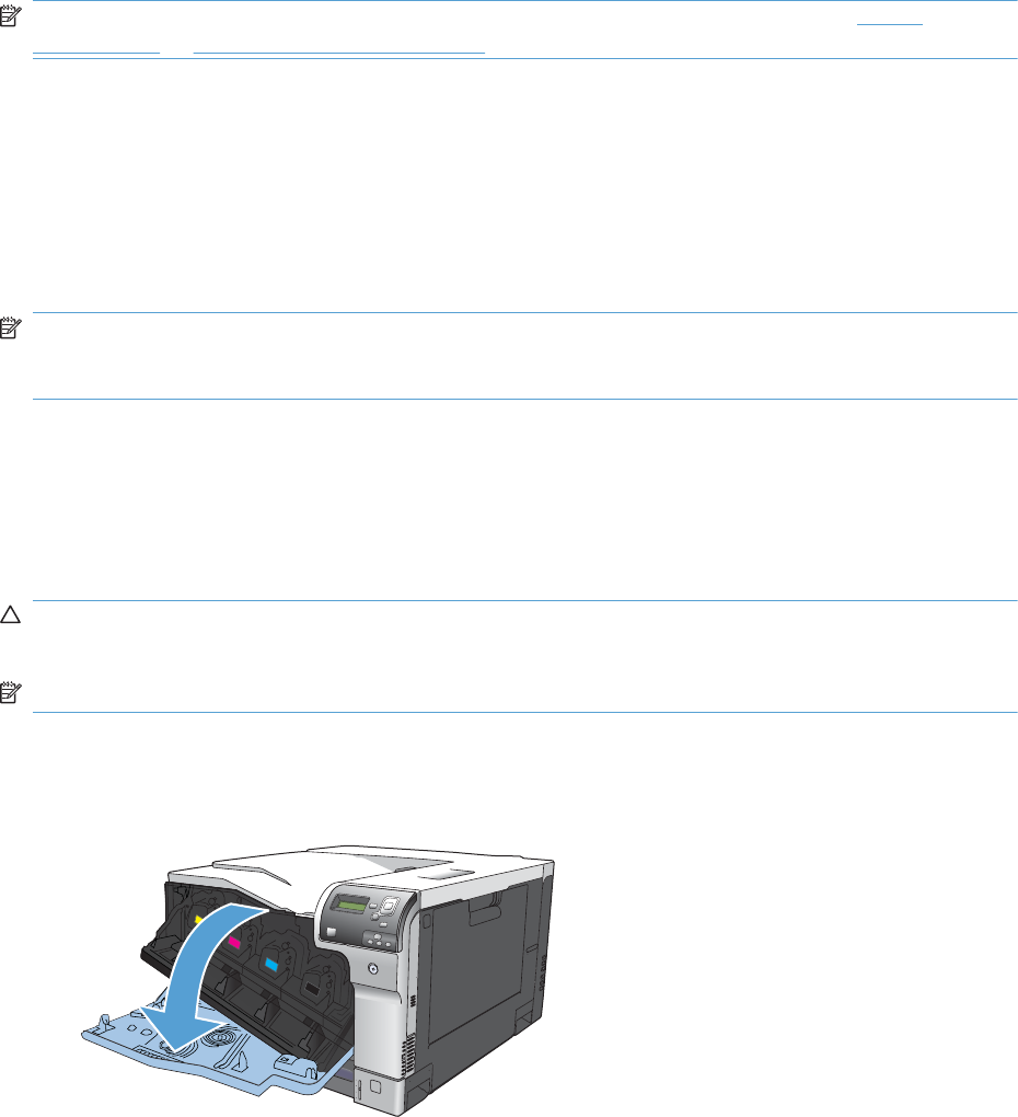
Removal and replacement procedures
NOTE: The following assemblies are Customer Self Repair (CSR) components. Go to Covers
on page 111 or Main assemblies on page 130 for information about removing service assemblies.
Print cartridges
When a print cartridge approaches the end of its estimated useful life, the control panel displays a
message recommending that you order a replacement. The product can continue to print using the
current print cartridge until the control panel displays a message instructing you to replace the
cartridge, unless you have selected the option to override the message by using the Supply Settings
menu.
NOTE: Cartridge life remaining is used to determine if a supply is near or at estimated end of life.
Cartridge life remaining is approximate only, and varies depending on types of documents printed and
other factors.
The product uses four colors and has a different print cartridge for each color: black (K), magenta (M),
cyan (C), and yellow (Y).
You can replace a print cartridge when the print quality is no longer acceptable. The control-panel
message also indicates the color of the cartridge that has reached the end of its estimated useful life.
Replacement instructions are provided on the label on the print cartridge.
CAUTION: If toner gets on clothing, wipe it off with a dry cloth and wash the clothes in cold water.
Hot water sets toner into fabric.
NOTE: Information about recycling used print cartridges is contained in the print-cartridge box.
Replace print cartridges
1. Open the front door. Make sure that the door is completely open.
ENWW Removal and replacement procedures 87
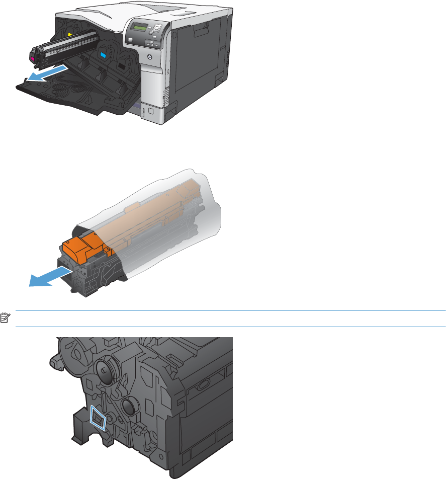
2. Grasp the handle of the used print cartridge and pull out to remove.
3. Remove the new print cartridge from its protective bag.
NOTE: Be careful not to damage the memory tag on the print cartridge.
88 Chapter 2 Removal and replacement ENWW
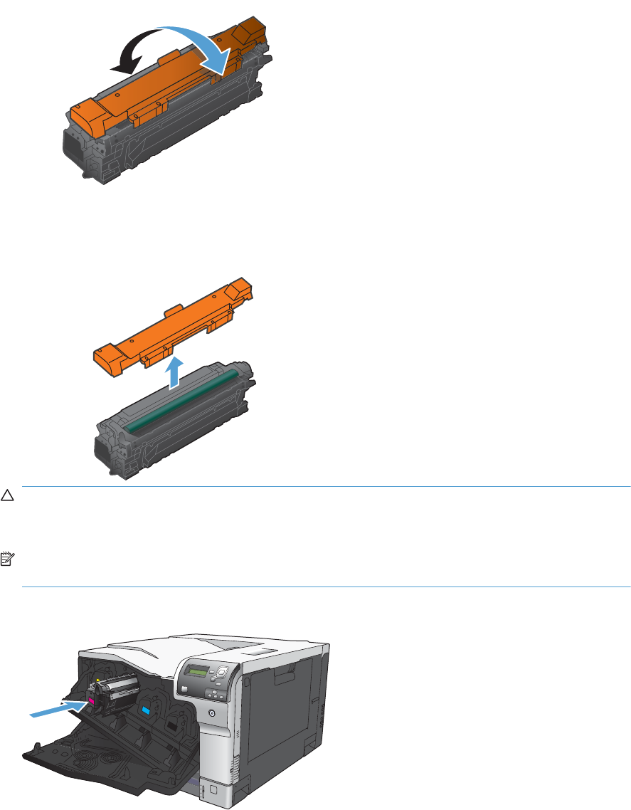
4. Grasp both sides of the print cartridge and distribute the toner by gently rocking the print
cartridge.
5. Remove the orange protective cover from the print cartridge. Place the protective cover on the
used print cartridge to protect it during shipping.
CAUTION: Avoid prolonged exposure to light.
Do not touch the green roller. Doing so can damage the cartridge.
NOTE: Store the used print cartridge in the protective bag removed from the replacement
cartridge. Information about recycling used print cartridges is contained in the print-cartridge box.
6. Align the print cartridge with its slot and insert the print cartridge until it clicks into place.
ENWW Removal and replacement procedures 89
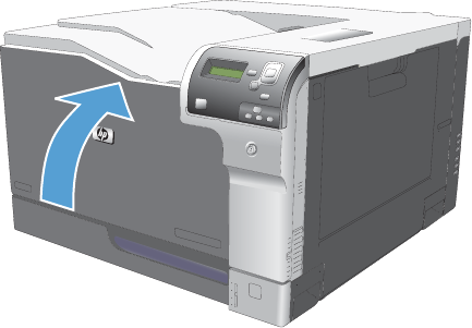
7. Close the front door.
90 Chapter 2 Removal and replacement ENWW
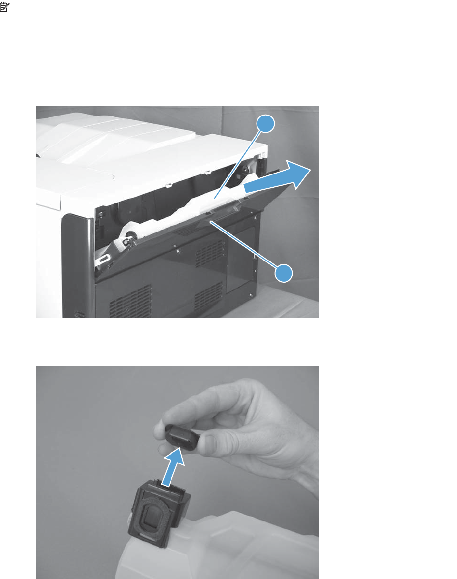
Toner-collection unit
NOTE: The toner-collection unit (TCU) is designed for a single use. Do not try to empty the toner-
collection unit and reuse it. To recycle a discarded toner-collection unit, follow the instructions that come
with a replacment toner-collection unit.
1. Open the TCU access door (callout 1) on the product back side.
2. Grasp the top of the TCU (callout 2), and then remove it from the product.
Figure 2-2 Remove the toner-collection unit (1 of 3)
2
1
3. Remove the plug from the discarded TCU.
Figure 2-3 Remove the toner-collection unit (2 of 3)
ENWW Removal and replacement procedures 91

4. Install the plug onto the discarded TCU before putting it into the box and mailing it for recycling.
Figure 2-4 Remove the toner-collection unit (3 of 3)
92 Chapter 2 Removal and replacement ENWW
Fuser
CAUTION: The fuser might be hot. Allow enough time after turning off the product power for the
fuser to cool.
1. Open the right-door assembly.
2. Grasp the handles and squeeze the blue release levers (callout 1).
Figure 2-5 Remove the fuser
2
1
3. Pull the fuser (callout 2) straight out of the product to remove it.
Reset the New Fuser Kit setting at the control panel
NOTE: Use this procedure to reset the internal page count if a replacement fuser is installed.
1. At the control panel, press the Home button .
2. Open the following menus:
●Administration
●Manage Supplies
●Reset Supplies
●New Fuser Kit
3. Use the Down arrow button to highlight the Yes item, and then press OK to select it.
ENWW Removal and replacement procedures 93
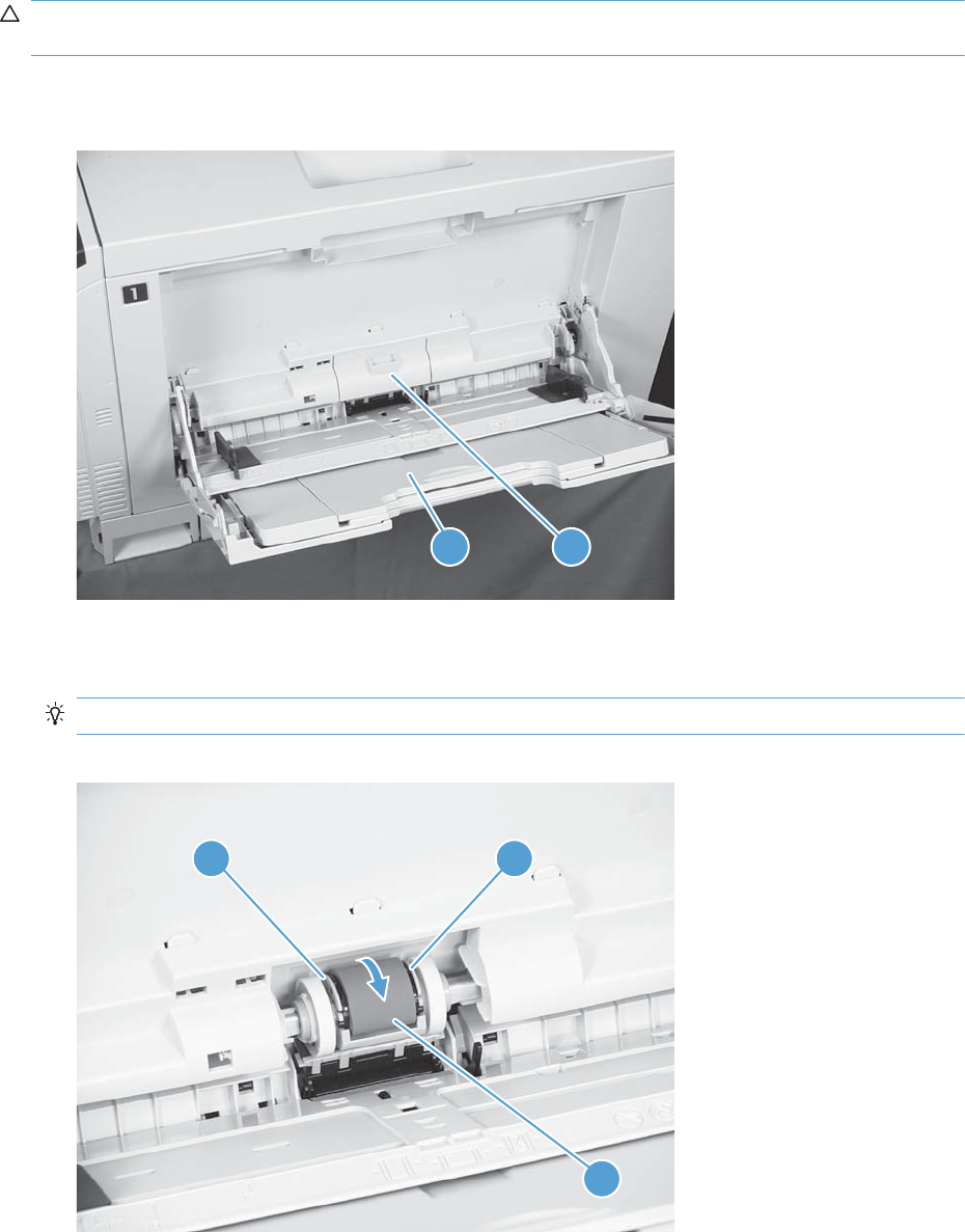
Pickup roller (Tray 1)
CAUTION: Do not touch the spongy roller surface unless you are replacing the roller. Skin oils on the
roller can cause paper pickup problems.
1. Open Tray 1 (callout 1), and then remove the pickup roller cover (callout 2).
Figure 2-6 Remove the pickup roller (Tray 1) (1 of 2)
1 2
2. Spead out the pickup roller retainers (callout 1) until both sides unlatch, and then remove the
pickup roller (callout 2).
Reinstallation tip When you reinstall the roller, make sure that the roller snaps into place
Figure 2-7 Remove the pickup roller (Tray 1) (2 of 2)
2
1 1
94 Chapter 2 Removal and replacement ENWW
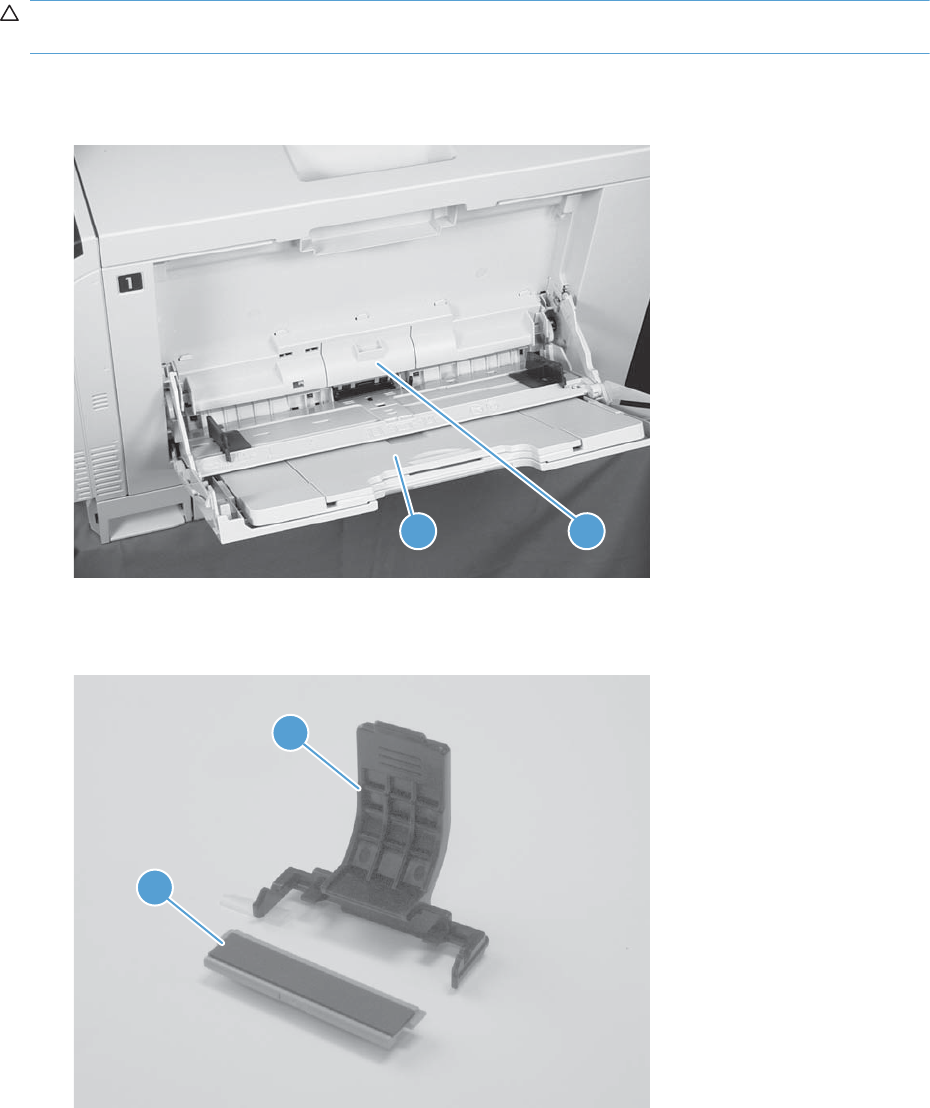
Separation pad (Tray 1)
CAUTION: Do not touch the spongy roller surface unless you are replacing the roller. Skin oils on the
roller can cause paper pickup problems.
1. Open Tray 1 (callout 1), and then remove the pickup roller cover (callout 2).
Figure 2-8 Remove the separation pad (Tray 1) (1 of 4)
1 2
2. Take out the tool (callout 2) supplied with a new separation pad (callout 1).
Figure 2-9 Remove the separation pad (Tray 1) (2 of 4)
1
2
ENWW Removal and replacement procedures 95
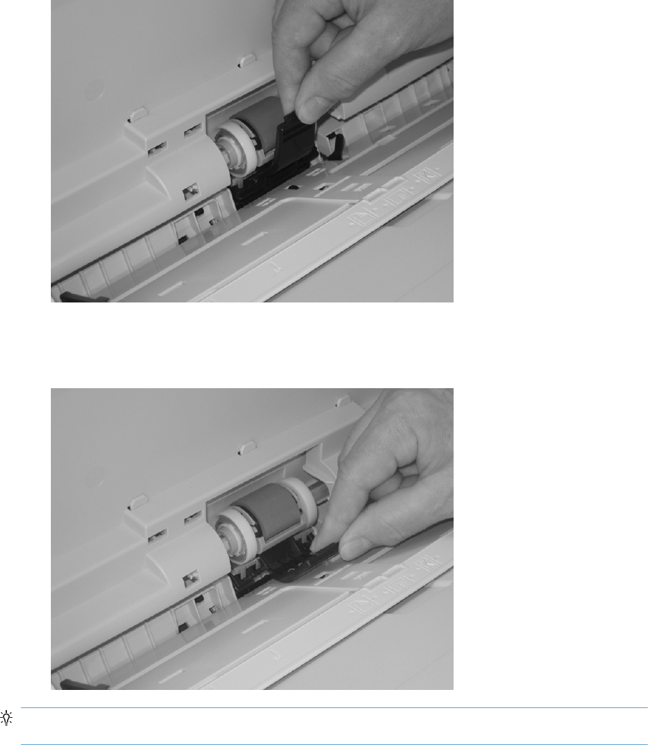
3. Insert the tool under the separation pad.
Figure 2-10 Remove the separation pad (Tray 1) (3 of 4)
4. Rotate the top of the tool away from the product to release the separation pad, and then remove
the tool and the separation pad together.
Figure 2-11 Remove the separation pad (Tray 1) (4 of 4)
Reinstallation tip You do not need to use the tool to install the new separation pad. Press the new
pad with your hand until it snaps into place and engages with the engine.
96 Chapter 2 Removal and replacement ENWW
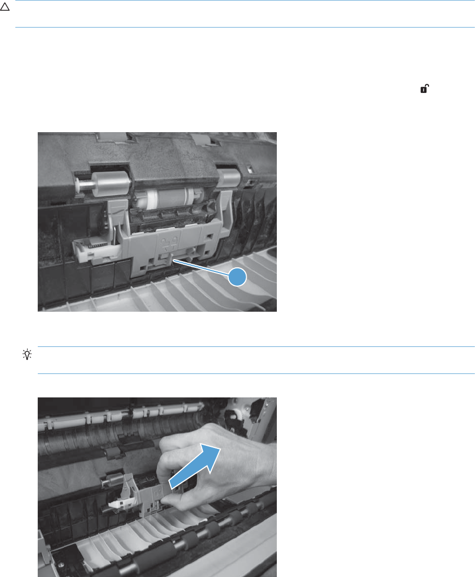
Separation roller assembly (Tray 2)
CAUTION: Do not touch the spongy roller surface unless you are replacing the roller. Skin oils on the
roller can cause paper pickup problems.
1. Remove Tray 2 from the product.
2. Open the right-door assembly.
3. On the separation roller assembly, slide the lever (callout 1) toward the unlocked icon until it
clicks into the unlocked position.
Figure 2-12 Remove the separation roller assembly (Tray 2) (1 of 2)
1
4. Pull the separation roller assembly up and remove it from the product.
Reinstallation tip When you install the separation roller assembly, make sure that it snaps into
the locked postion.
Figure 2-13 Remove the separation roller assembly (Tray 2) (2 of 2)
ENWW Removal and replacement procedures 97
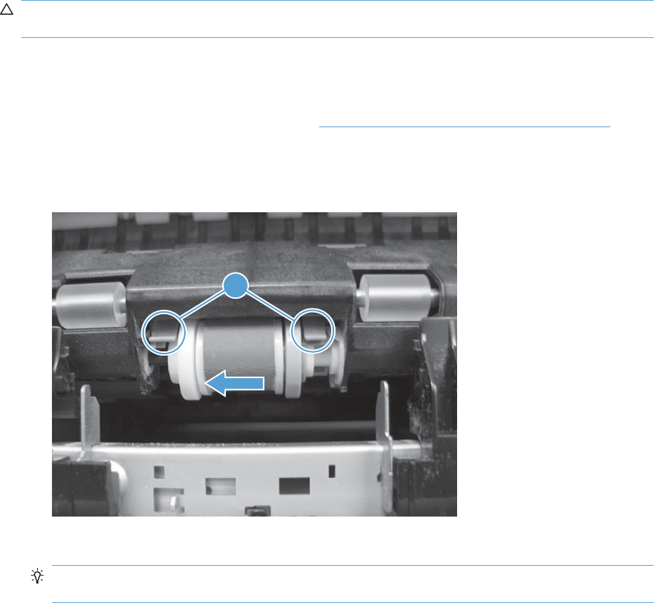
Pickup roller (Tray 2)
CAUTION: Do not touch the spongy roller surface unless you are replacing the roller. Skin oils on the
roller can cause paper pickup problems.
1. Open Tray 2.
2. Open the right-door assembly.
3. Remove the separation roller assembly (see Separation roller assembly (Tray 2) on page 97)
4. Lift one of the two levers (callout 1) on either side of the pickup roller, and then push the right side
of the roller in the direction of the arrow.
Figure 2-14 Remove the pickup roller (Tray 2)
1
5. Remove the pickup roller.
Reinstallation tip Insert the left side of the roller into the product first. Make sure that the
replacement roller snaps into place.
98 Chapter 2 Removal and replacement ENWW
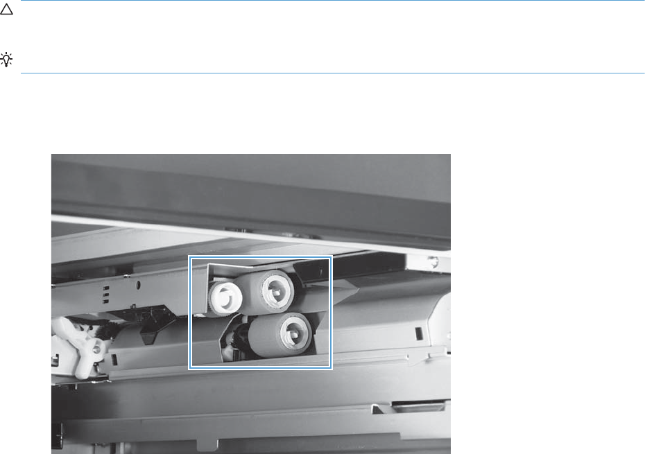
Pickup roller, separation roller, and feed roller (1 x 500-sheet and
3 x 500-sheet paper feeders)
CAUTION: Do not touch the spongy roller surface unless you are replacing the roller. Skin oils on the
roller can cause paper pickup problems.
TIP: You do not have to separate the product from the feeder to remove these rollers.
1. Remove the Tray 3 or Tray 4/5/6 cassette from the product, and then locate the rollers on the
right-hand side of the tray cavity.
Figure 2-15 Remove the 1 x 500 or 3 x 500 rollers (1 of 2)
ENWW Removal and replacement procedures 99
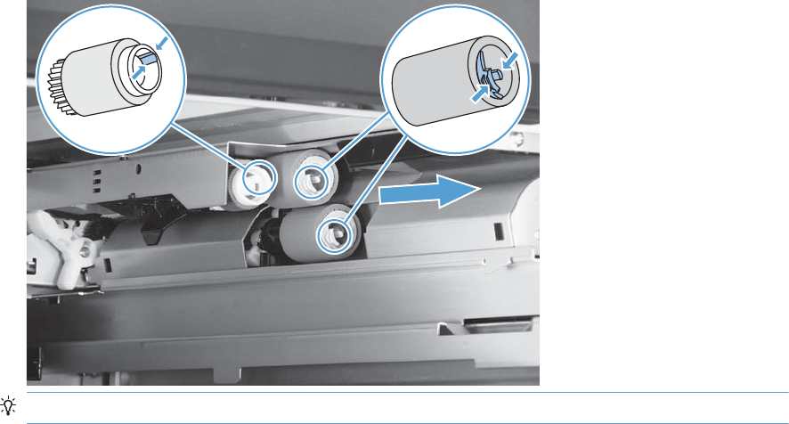
2. Release three tabs, and then pull the rollers in the direction of the arrow.
Figure 2-16 Remove the 1 x 500 or 3 x 500 rollers (2 of 2)
Reinstallation tip When you reinstall the rollers, make sure that the rollers snap into place.
100 Chapter 2 Removal and replacement ENWW
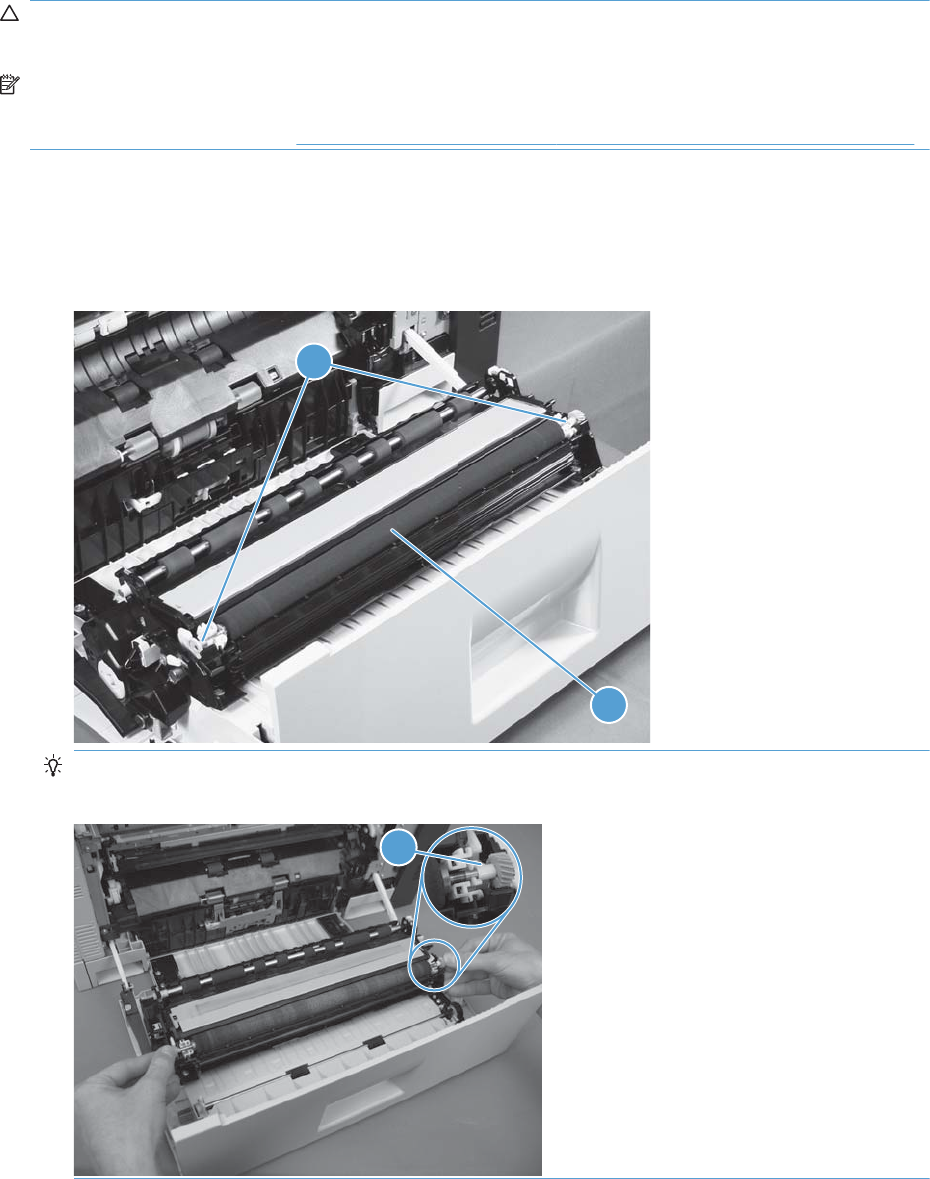
Secondary transfer roller
CAUTION: Do not touch the spongy roller surface unless you are replacing the roller. Skin oils on the
roller can cause image quality problems.
NOTE: If the secondary transfer roller is replaced, HP recommends that the ITB be replaced also. If
both components are replaced at the same time, you must use the control-panel menus to reset the
Transfer Kit menu item. See Reset the New Transfer Kit setting at the control panel on page 104.
1. Open the right-door assembly.
2. Grasp one of the blue round features (callout 1) on either end of the transfer roller, and then lift
the transfer roller (callout 2) off of the product.
Figure 2-17 Remove the transfer roller
2
1
TIP: Place the new roller assembly in place with the roller gear (callout 1) on the right side, and
then press down to ensure that the roller shaft snaps securely in the roller clasps.
1
ENWW Removal and replacement procedures 101
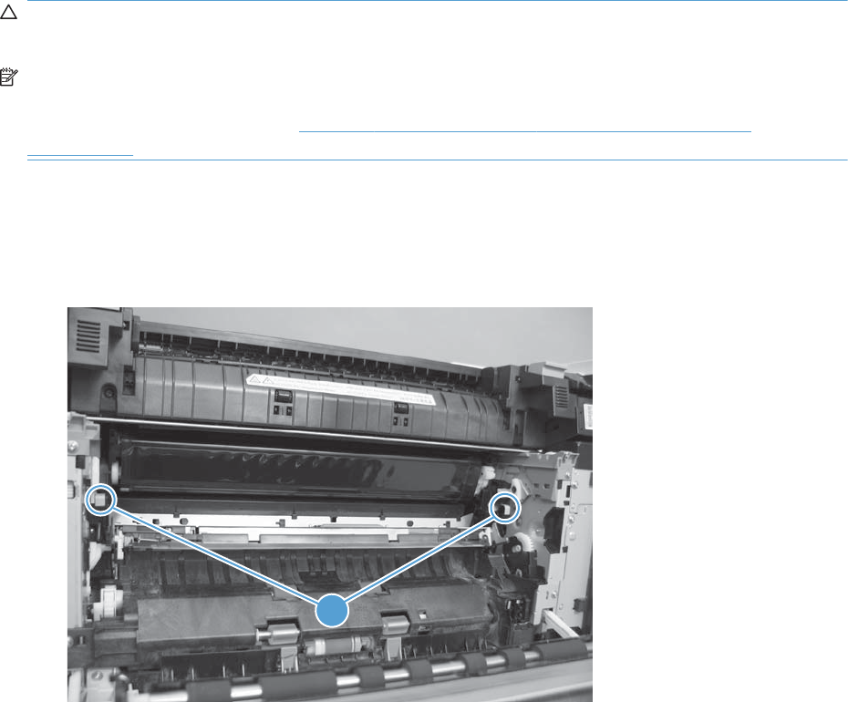
Intermediate transfer belt (ITB)
CAUTION: Do not touch the black-plastic belt. Skin oils and fingerprints on the belt can cause print-
quality problems. Always place the ITB on a flat surface in a safe and protected location.
NOTE: If the ITB assembly is replaced, HP recommends that the secondary transfer roller be replaced
also. If both components are replaced at the same time, you must use the control-panel menus to reset
the Transfer Kit menu item. See Reset the New Transfer Kit setting at the control panel
on page 104.
1. Open the right-door assembly.
2. Use both hands to grasp the blue levers (callout 1), apply slight downward pressure, and pull the
ITB toward you at a downward angle.
Figure 2-18 Remove the intermediate transfer belt (1 of 3)
1
102 Chapter 2 Removal and replacement ENWW
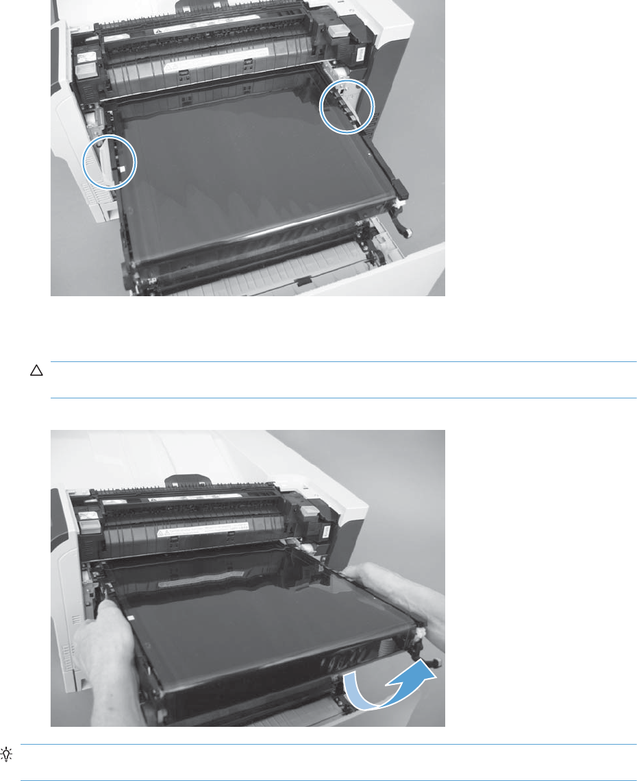
3. Pull the ITB out of the product until two large handles expand along the right and left side of the
ITB.
Figure 2-19 Remove the intermediate transfer belt (2 of 3)
4. Grasp the large handles on the ITB, pull it straight out of the product until it stops, and then pull up
to remove it from the product.
CAUTION: The ITB is a sensitive component. Be careful when handling the ITB so that it is not
damaged. Always place the ITB in a safe and protected location.
Figure 2-20 Remove the intermediate transfer belt (3 of 3)
Reinstallation tip If you are installing a replacement ITB, make sure that you remove all of the
packing tape and the protective cover sheet.
ENWW Removal and replacement procedures 103

Reset the New Transfer Kit setting at the control panel
NOTE: Use this procedure to reset the internal page count if a replacement ITB and secondary
transfer roller are installed.
1. At the control panel, press the Home button .
2. Open the following menus:
●Administration
●Manage Supplies
●Reset Supplies
●New Transfer Kit
3. Use the Down arrow button to highlight the Yes item, and then press OK to select it.
104 Chapter 2 Removal and replacement ENWW
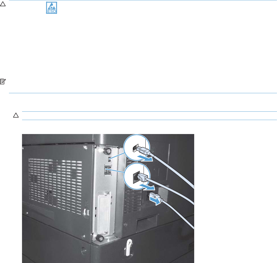
Formatter PCA
CAUTION: ESD sensitive component.
Do not replace the laser scanner and the formatter PCA at the same time. The settings for the laser
scanner are stored in the formatter RAM. When you install a new laser scanner, it reads the settings
from the formatter.
Do not replace the DC controller PCA and the formatter PCA at the same time. The settings for the DC
Controller PCA are stored in the formatter RAM. When you install a new DC Controller PCA, it reads
the settings from the formatter.
NOTE: If possible, print a configuration page before replacing the formatter. You might need to
transfer the serial number and the page count information to the new formatter.
1. Disconnect communication cables (if installed).
CAUTION: Make sure that the product power is off and that the power cord is unplugged.
Figure 2-21 Remove the formatter (1 of 2)
ENWW Removal and replacement procedures 105
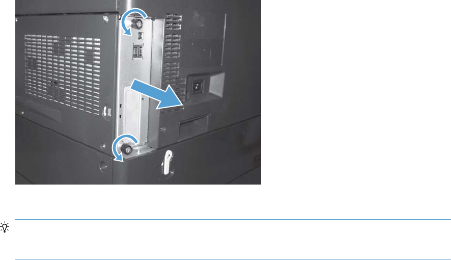
2. Loosen two thumb screws, and then pull the formatter straight out and away from the product to
remove it.
Figure 2-22 Remove the formatter (2 of 2)
3. Firmly pull the formatter from the product. Place the formatter on a clean, flat, grounded surface.
Reinstallation tip If the formatter PCA was replaced, print a configuration page and make
sure that the serial number and page count information were transfered to the formatter PCA. If
they were not, use the Service menu to reset these values.
106 Chapter 2 Removal and replacement ENWW
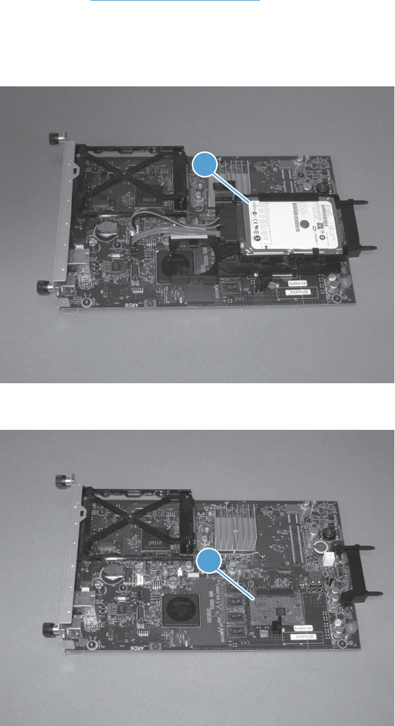
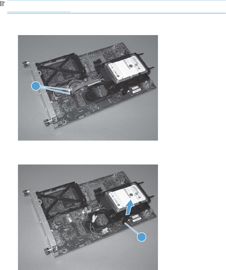
Remove the encrypted HDD
NOTE: If you are installing a replacement hard drive, you must reinstall the product firmware. See
Product updates on page 547.
1. Disconnect two connectors (callout 1).
Figure 2-23 Remove the encrypted HDD (1 of 3)
1
2. Release one tab (callout 1), and then slightly separate the HDD support arm from the PCA.
Figure 2-24 Remove the encrypted HDD (2 of 3)
1
108 Chapter 2 Removal and replacement ENWW
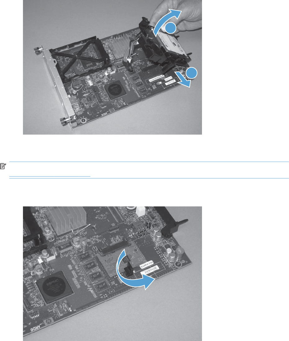
3. Rotate the HDD up and away from the PCA, and then slide it as shown below to remove it.
Figure 2-25 Remove the encrypted HDD (3 of 3)
1
2
Remove the solid-state hard drive
NOTE: If you are installing a replacement hard drive, you must reinstall the product firmware. See
Product updates on page 547.
1. Release the hard drive lock.
Figure 2-26 Remove the solid-state hard drive (1 of 3)
ENWW Removal and replacement procedures 109
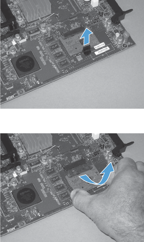
2. Remove the lock from the PCA.
Figure 2-27 Remove the solid-state hard drive (2 of 3)
3. Disconnect the solid-state PCA from the formatter PCA, and then remove it.
Figure 2-28 Remove the solid-state hard drive (3 of 3)
110 Chapter 2 Removal and replacement ENWW
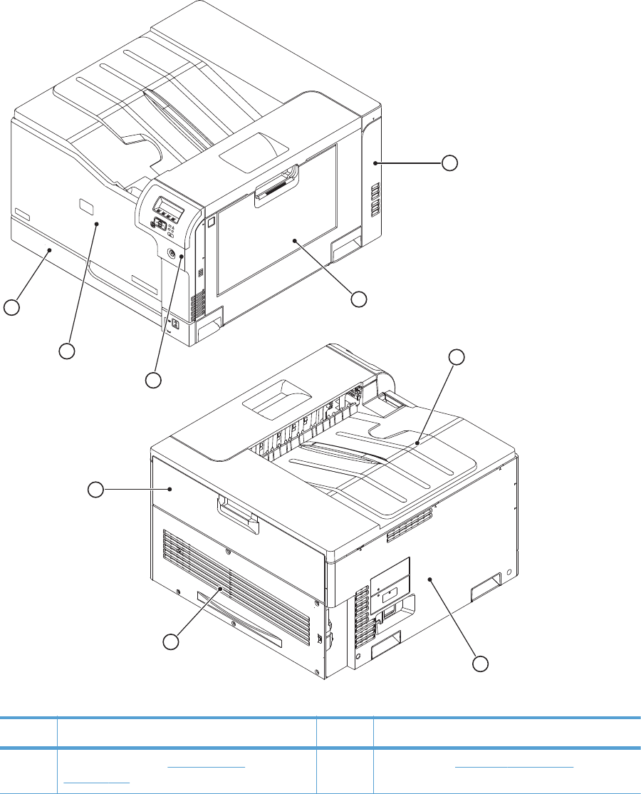

Table 2-1 External panels, covers, and doors (continued)
Item Description Item Description
2 Right-door assembly (see Right-door assembly
on page 126)
7 Left cover (see Left cover on page 115)
3 Right-front cover and control-panel assembly (see
Right-front cover and control-panel assembly
on page 113)
8 Rear cover (see Rear cover on page 116)
4 Front-door assembly (see Front-door assembly
on page 123)
9 Toner collection unit access door (see Toner
collection unit access door on page 117)
5 Tray 2 cassette
112 Chapter 2 Removal and replacement ENWW
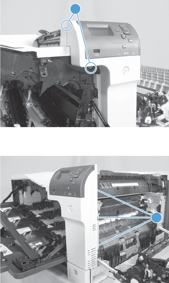
Right-front cover and control-panel assembly
1. Open the front door and the right door.
2. Remove two screws (callout 1).
Figure 2-30 Remove the right-front cover and control-panel assembly (1 of 3)
1
3. Release 3 tabs (callout 1) on the right side of the assembly.
Figure 2-31 Remove the right-front cover and control-panel assembly (2 of 3)
1
ENWW Removal and replacement procedures 113
Release two tabs on the top of
the assembly also.
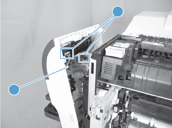
4. Support the assembly, release one cable retainer (callout 1), and then disconnect two connectors
(callout 2). Remove the assembly.
Figure 2-32 Remove the right-front cover and control-panel assembly (3 of 3)
1
2
114 Chapter 2 Removal and replacement ENWW
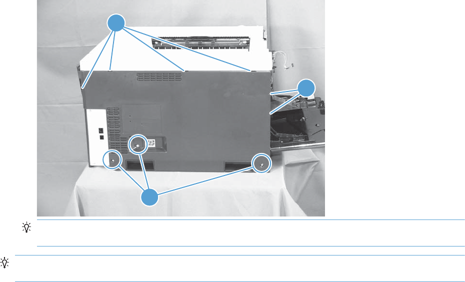
Left cover
1. Remove Tray 2 from the product.
2. Open the front door.
3. Remove three screws (callout 1). Starting from the left side of the cover, release six tabs (callout 2),
and then remove the cover from the product.
Figure 2-33 Remove the left cover
2
1
2
TIP: Opening the toner-collection door might make it easier to release the tabs on the left side of
the cover.
Reinstallation tip If the front door will not close after the left cover has been reinstalled, verify that
the two tabs on the right side of the cover have been aligned correctly with the product chassis.
ENWW Removal and replacement procedures 115
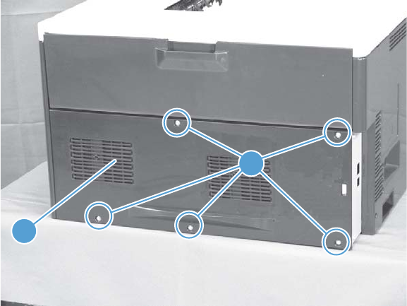
Rear cover
Remove the rear cover
▲Remove five screws (callout 1), and then remove the cover (callout 2) from the product.
Figure 2-34 Remove the rear cover
1
2
116 Chapter 2 Removal and replacement ENWW
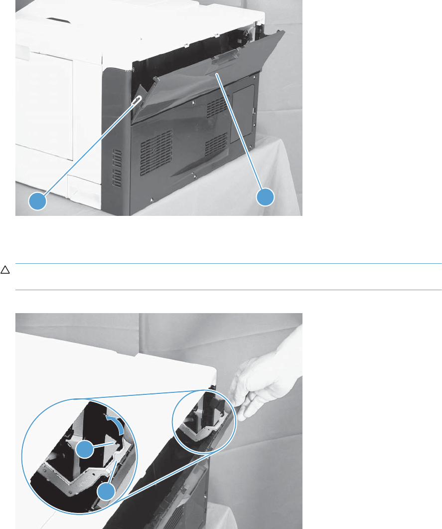
Toner collection unit access door
1. Open the toner collection unit access door (callout 1), remove the toner collection unit, and then
release the link arm (callout 2) on the left side of the door.
Figure 2-35 Remove the toner collection unit access door (1 of 3)
1
2
2. Partially close the door so that the right link arm (callout 1) can clear the stop (callout 2) on the
door, and then disengage the link arm from the door.
CAUTION: Do not disconnect the right-hand link arm when the door is completely open. Doing
so can disconnect the link arm spring.
Figure 2-36 Remove the toner collection unit access door (2 of 3)
1
2
ENWW Removal and replacement procedures 117
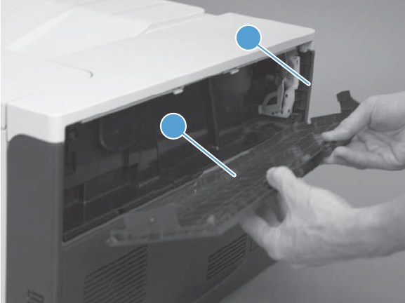
3. Rotate the access door down 90 degrees (callout 1), and then pull on the right side of the door
(callout 2) to remove the access door.
Figure 2-37 Remove the toner collection unit access door (3 of 3)
1
2
118 Chapter 2 Removal and replacement ENWW
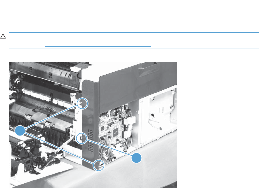
Right-rear cover
1. Remove the rear cover. See Rear cover on page 116.
2. Open the right-door assembly.
3. Remove two screws (callout 1), release one tab (callout 2), and then remove the cover.
CAUTION: The ground spring on the back of the cover can easily be dislodged. Be careful not
to lose it. See Reinstall the right-rear cover on page 120.
Figure 2-38 Remove the right-rear cover
1
2
ENWW Removal and replacement procedures 119
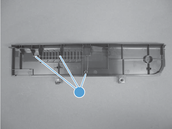
Reinstall the right-rear cover
▲Make sure that the ground spring (callout 1) is correctly installed before you reinstall the right-rear
cover.
Figure 2-39 Right-rear cover ground spring
1
120 Chapter 2 Removal and replacement ENWW
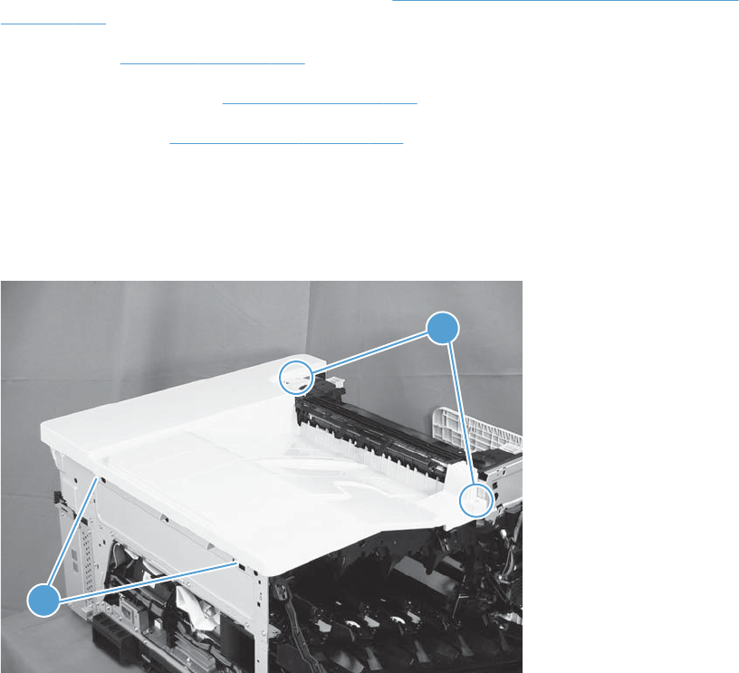
Top cover
Before proceeding, remove the following components:
●Right-front cover and control-panel assembly. See Right-front cover and control-panel assembly
on page 113.
●Left cover. See Left cover on page 115.
●Remove the rear cover. See Rear cover on page 116.
●Right-rear cover. See Right-rear cover on page 119.
Remove the top cover
1. Open the right-door assembly, and then remove four screws (callout 1).
Figure 2-40 Remove the top cover (1 of 2)
1
1
2. Open the toner-collection door.
ENWW Removal and replacement procedures 121
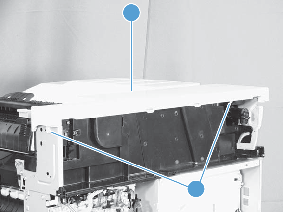
3. Release two tabs (callout 1), and then remove the cover (callout 2).
Figure 2-41 Remove the top cover (2 of 2)
1
2
122 Chapter 2 Removal and replacement ENWW
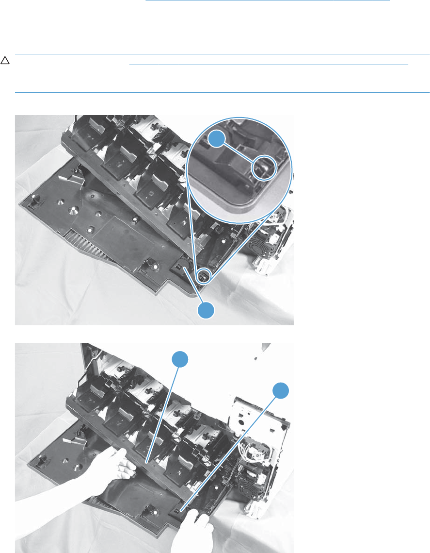
Front-door assembly
1. Remove the control panel. See Right-front cover and control-panel assembly on page 113.
2. Open the front door.
3. Remove one screw (callout 1) and the inner cover rail mount (callout 2).
CAUTION: As shown in Figure 2-43 Remove the front-door assembly (2 of 4) on page 123,
when removing the inner cover rail mount (callout 3), hold down the inner cover (callout 4) with
one hand to prevent it from springing back at the product.
Figure 2-42 Remove the front-door assembly (1 of 4)
1
2
Figure 2-43 Remove the front-door assembly (2 of 4)
3
4
ENWW Removal and replacement procedures 123
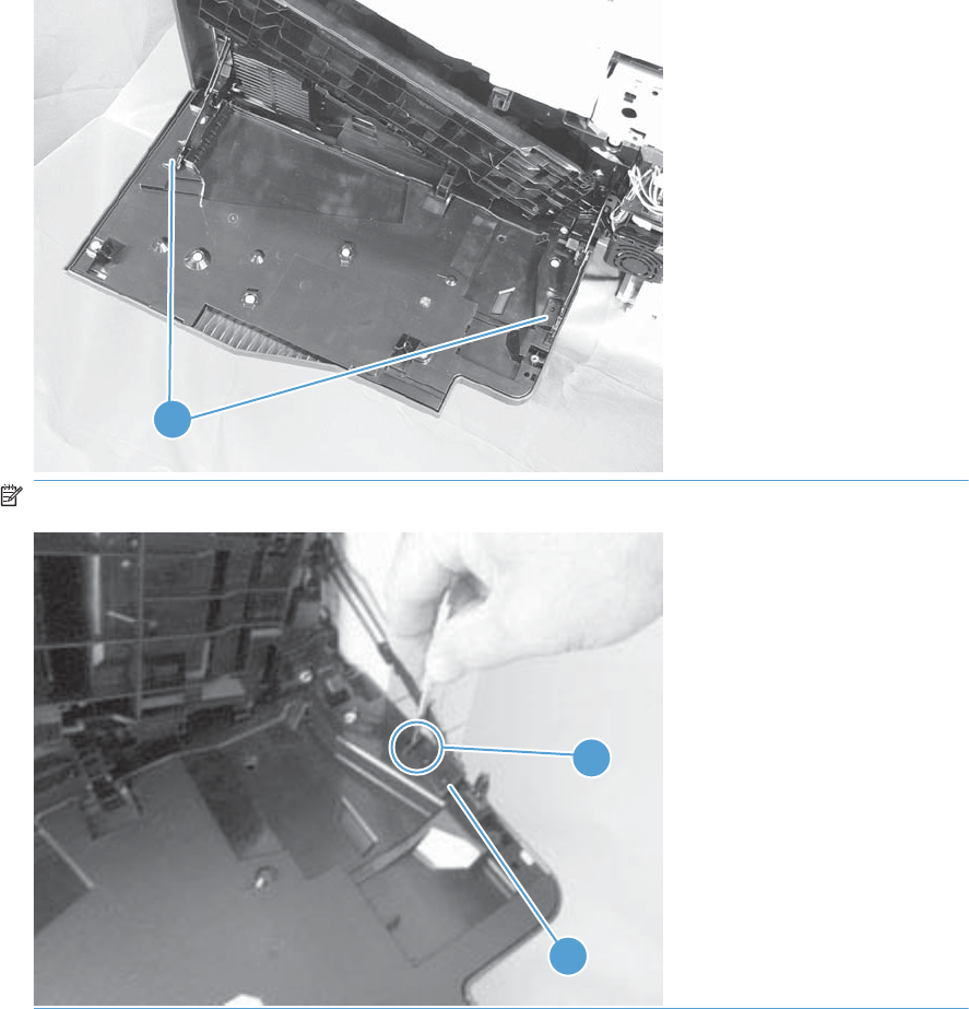
4. Close the inner cover, and then release two tabs on each stopper (callout 1) with a small flat-blade
screwdriver (callout 2).
Figure 2-44 Remove the front-door assembly (3 of 4)
1
NOTE: Each tab is at the end of the stopper that is closest to the product.
1
2
124 Chapter 2 Removal and replacement ENWW
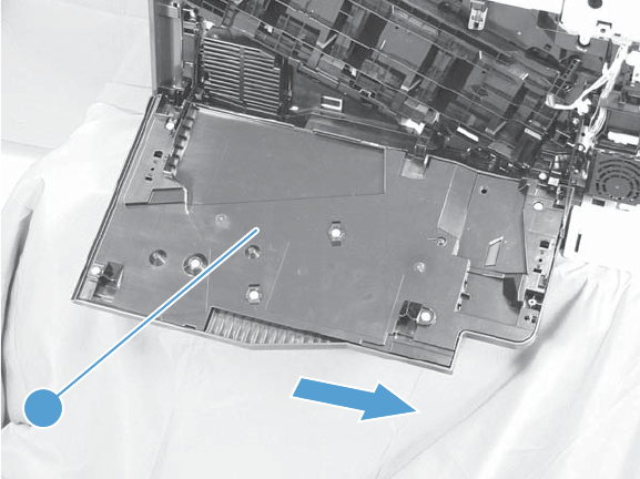
5. Position the door as shown below (callout 1), and then slide the front-door assembly in the
direction that the arrow indicates to remove it from the product.
Figure 2-45 Remove the front-door assembly (4 of 4)
1
ENWW Removal and replacement procedures 125
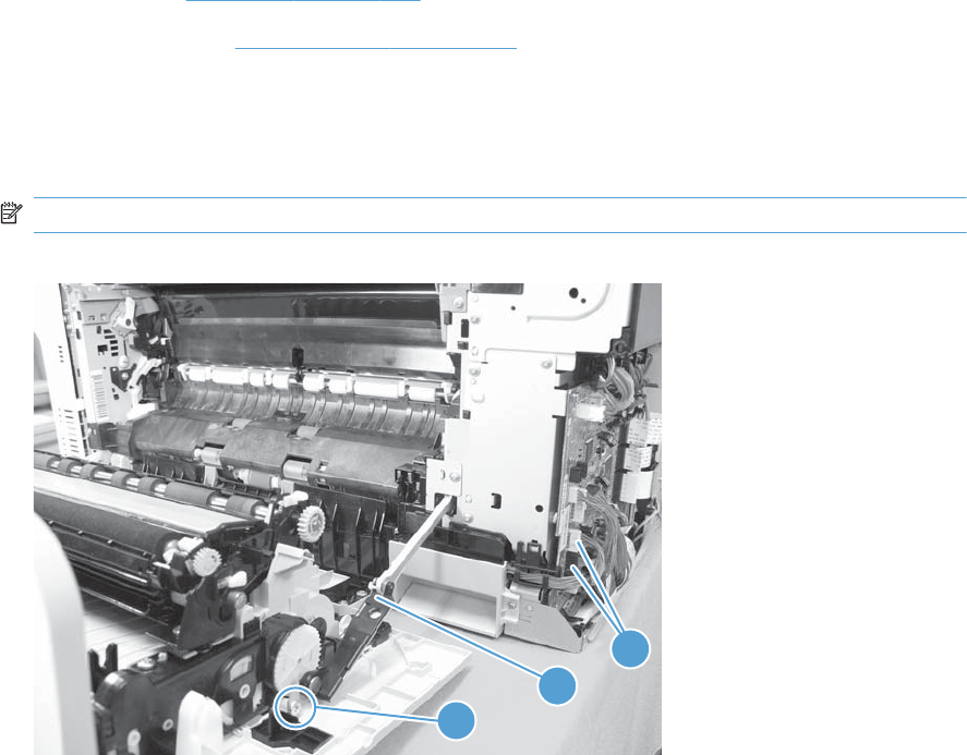
Right-door assembly
Remove the following components:
●Rear cover (see Rear cover on page 116)
●Right rear cover (see Right-rear cover on page 119)
1. Open the right-door assembly
2. Remove one screw (callout 1), release the link arm (callout 2), and then disconnect two connectors
(callout 3).
NOTE: The link arm is spring loaded and retracts into the product.
Figure 2-46 Remove the right-door assembly (1 of 6)
2
1
3
126 Chapter 2 Removal and replacement ENWW
Connectors J152 and J112 on the DC Controller.
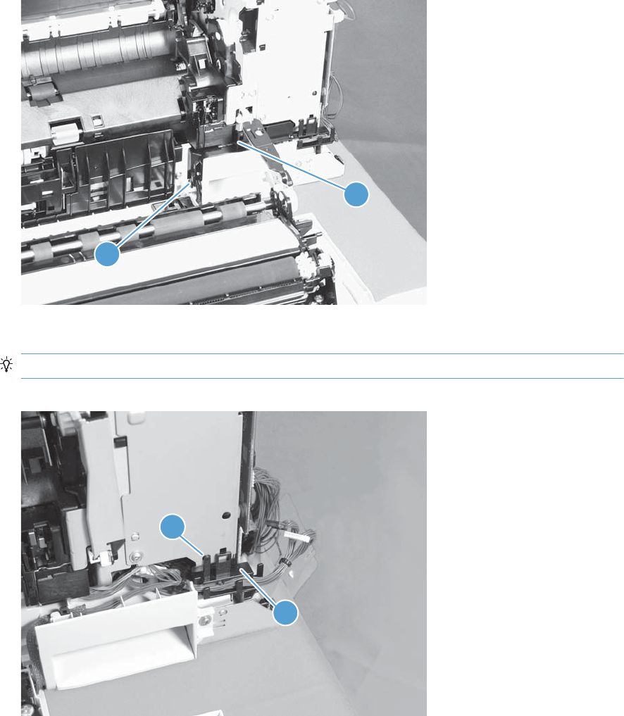
3. Carefully release one tab (callout 1), and then remove the cable cover (callout 2).
Figure 2-47 Remove the right-door assembly (2 of 6)
2
1
4. Release one tab (callout 1), and then remove the guide (callout 2).
TIP: Release the wire harnesses from the guide as you remove it.
Figure 2-48 Remove the right-door assembly (3 of 6)
2
1
ENWW Removal and replacement procedures 127
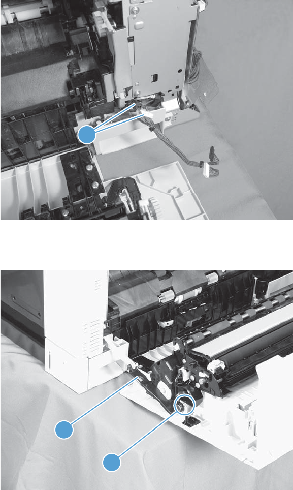
5. Disconnect two connectors (callout 1).
Figure 2-49 Remove the right-door assembly (4 of 6)
1
6. Remove one screw (callout 1), and then release the link arm (callout 2).
Figure 2-50 Remove the right-door assembly (5 of 6)
2
1
128 Chapter 2 Removal and replacement ENWW
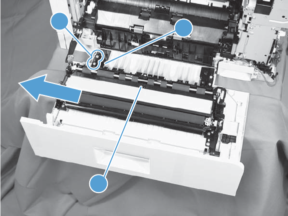
7. Remove two screws (callout 1), remove the hinge (callout 2), and then slide the right-door
assembly (callout 3) to the left to remove it.
Figure 2-51 Remove the right-door assembly (6 of 6)
12
3
ENWW Removal and replacement procedures 129
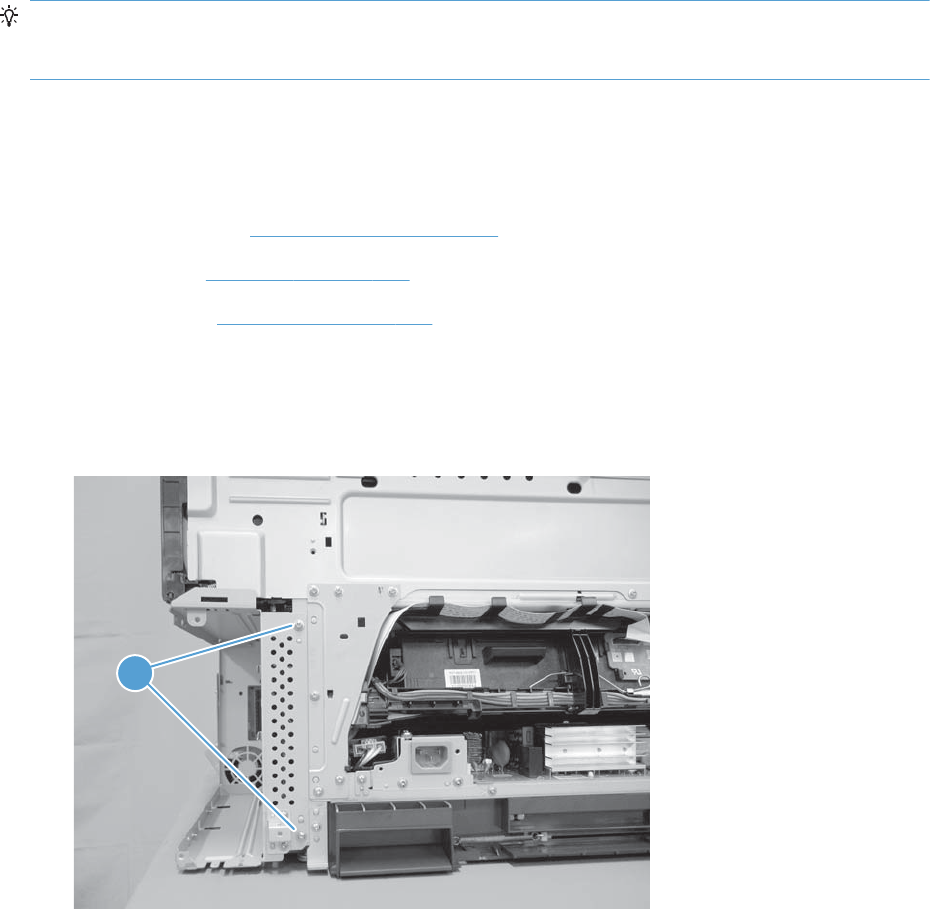
Main assemblies
TIP: For clarity, some photos in this chapter show components removed that would not be removed to
service the product. If necessary, remove the components listed at the beginning of a procedure before
proceeding to service the product.
Formatter case
Before proceeding, remove the following components:
●Formatter PCA. See Formatter PCA on page 105.
●Left cover. See Left cover on page 115.
●Rear cover. See Rear cover on page 116.
Remove the formatter case
1. Remove two screws (callout 1).
Figure 2-52 Remove the formatter case assembly (1 of 2)
1
130 Chapter 2 Removal and replacement ENWW
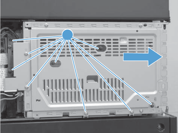
2. Remove nine screws (callout 1), and then slide the formatter case unit (callout 2) away from the
DC controller to remove it.
Figure 2-53 Remove the formatter case assembly (2 of 2)
1
ENWW Removal and replacement procedures 131
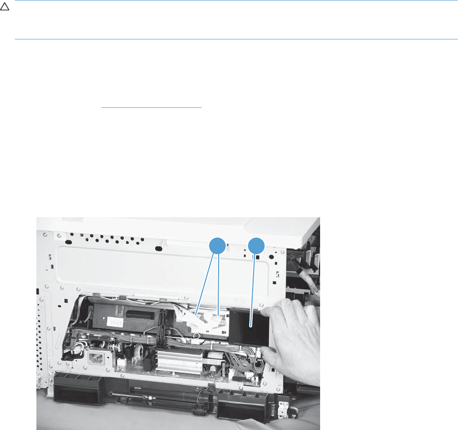
Laser/scanner assembly
CAUTION: Do not replace the laser scanner and the formatter PCA at the same time. The settings for
the laser scanner are stored in the formatter RAM. When you install a new laser scanner, it reads the
settings from the formatter.
Before proceeding, remove the following components:
●Tray 2
●Left cover. See Left cover on page 115.
Remove the laser/scanner assembly
1. Open the front door.
2. On the left side of the product, pinch and remove the fan duct (callout 1), and then disconnect the
two flat cables (callout 2).
Figure 2-54 Remove the laser/scanner assembly (1 of 4)
2 1
132 Chapter 2 Removal and replacement ENWW
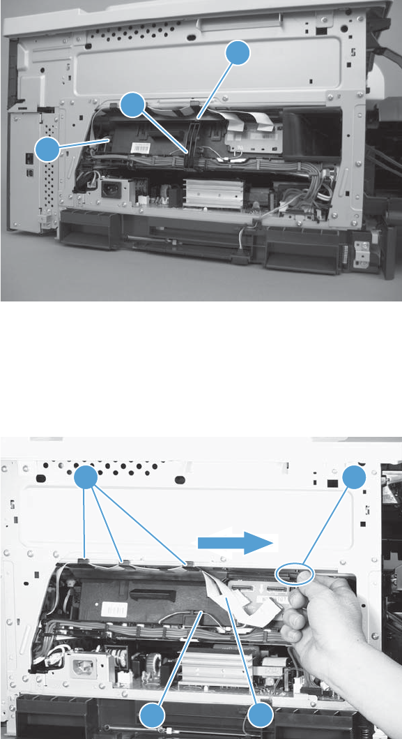
3. Release one tab (callout 1), remove the stopper (callout 2), and then disconnect one connector
(callout 3).
Figure 2-55 Remove the laser/scanner assembly (2 of 4)
1
2
3
4. Release one tab (callout 1), and then slide the cable guide (callout 2) in the direction that the
arrow indicates.
5. Remove the cable guide (callout 2) and the flat cables (callout 3) together, and then remove one
spring (callout 4).
Figure 2-56 Remove the laser/scanner assembly (3 of 4)
43
21
ENWW Removal and replacement procedures 133
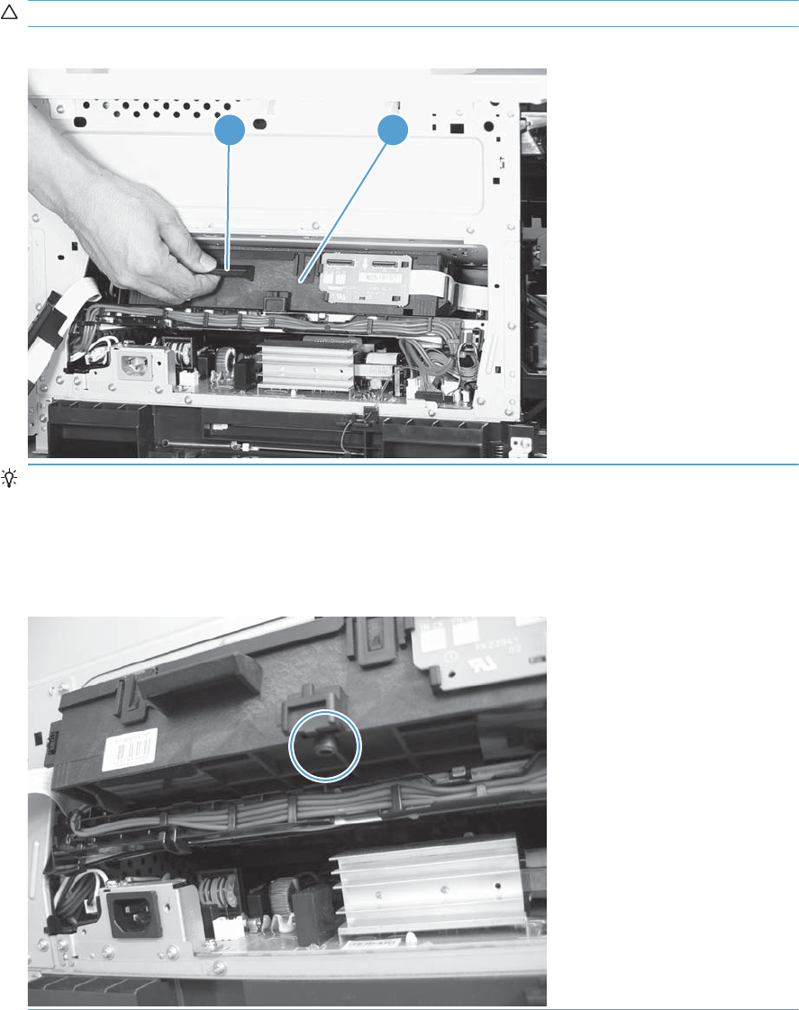
6. While holding up the handle (callout 1), pull the laser/scanner (callout 2) up slightly and then out
of the product.
CAUTION: Do not touch the protective glass strip on top of the assembly.
Figure 2-57 Remove the laser/scanner assembly (4 of 4)
1 2
Reinstallation tip Align the assembly with the guides on the left side of the opening when
reinstalling the assembly.
Align the pin on the bottom of the assembly with the hole in the product when reinstalling the
assembly. After pushing the assembly into the product, you might have to pull the assembly slightly
forward to seat the pin in the hole.
134 Chapter 2 Removal and replacement ENWW
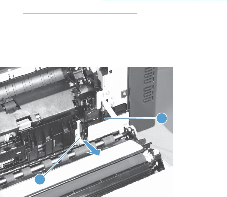
Paper pickup assembly
Before proceeding, remove the following components:
●Tray 2 cassette.
●Tray 2 separation roller assembly. See Separation roller assembly (Tray 2) on page 97.
●ITB. See Intermediate transfer belt (ITB) on page 102.
Remove the paper pickup assembly
1. Open the right door, pull out one tab (callout 1), pull the bottom of the cable cover out, and then
pull up to remove the cable cover (callout 2).
Figure 2-58 Remove the paper pickup assembly (1 of 3)
2
1
ENWW Removal and replacement procedures 135
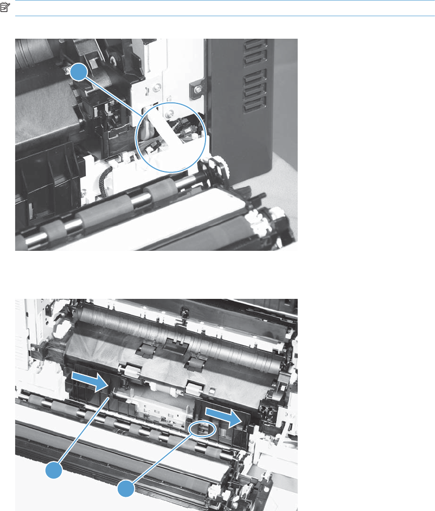
2. Disconnect four connectors (callout 1).
NOTE: The connectors might be hidden behind the assembly.
Figure 2-59 Remove the paper pickup assembly (2 of 3)
1
3. Pull out one tab (callout 1), and then slide the guide (callout 2) to the right to remove it.
Figure 2-60 Remove the paper pickup assembly (3 of 3)
1
2
136 Chapter 2 Removal and replacement ENWW
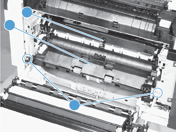
4. Remove two screws (callout 1), move the registration sensor flag (callout 2) to the up position, and
then pull the paper pickup assembly (callout 3) toward you to remove it.
Figure 2-61 Remove the paper pickup assembly (4 of 4)
1
2
3
ENWW Removal and replacement procedures 137
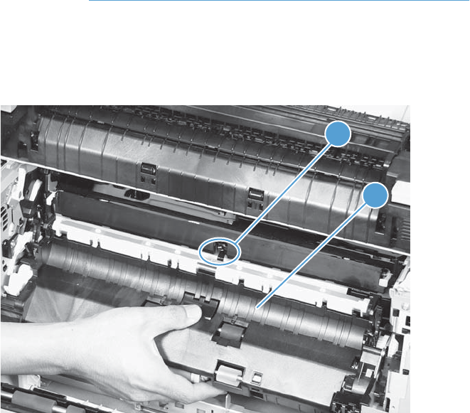
Reinstall the paper pickup assembly
Use the steps below to reinstall the paper pickup assembly. If you are installing a replacement
assembly, also see Installing a replacement paper pickup assembly on page 140 after completing
these steps.
1. When reassembling the paper pickup assembly (callout 1), the sensor flag (callout 2) is in the
way. Be sure to hold up the sensor flag when reassembling.
Figure 2-62 Reinstall the paper pickup assembly
2
1
138 Chapter 2 Removal and replacement ENWW
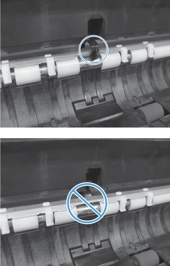
2. Make sure that the sensor flag is correctly installed, and that the flag moves properly after
reassembling the paper pickup assembly.
Figure 2-63 Paper pickup assembly sensor flag correctly installed
Figure 2-64 Paper pickup assembly sensor flag incorrectly installed
ENWW Removal and replacement procedures 139

Installing a replacement paper pickup assembly
▲Use the Service menu to reset the New Registration Roller menu item and enter the Media
Sensor Value from the replacement paper pickup assembly.
Reset the New Registration Roller menu item
a. Press the Home button .
b. Open the following menus:
●Device Maintenance
●Service
●Service Access Code
c. Use the arrow buttons to enter the access code, and then press the OK button.
d. Press the Down arrow button to highlight the New Registration Roller menu, and
then press the OK button.
e. Press the Down arrow button to highlight the Yes item, and then press the OK button.
Reset the Media Sensor Value
a. Press the Home button .
b. Open the following menus:
●Device Maintenance
●Service
●Service Access Code
c. Use the arrow buttons to enter the access code, and then press the OK button.
140 Chapter 2 Removal and replacement ENWW
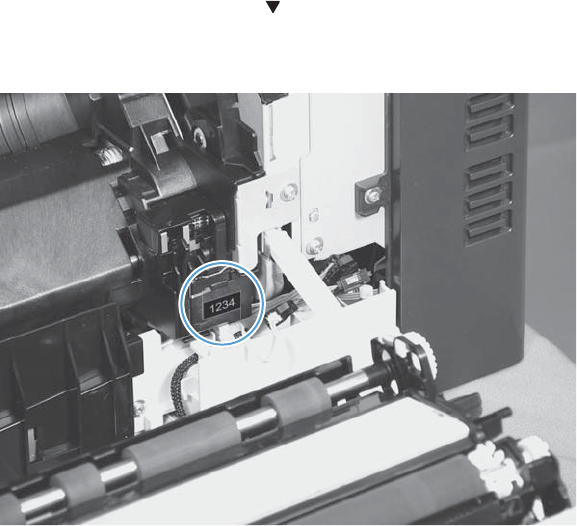
d. Press the Down arrow button to highlight the Media Sensor Value menu, and then
press the OK button.
Figure 2-65 Media sensor value label
e. Use the arrow buttons to enter the media sensor value found on the replacement assembly.
f. Press the OK button to save to save the value.
ENWW Removal and replacement procedures 141
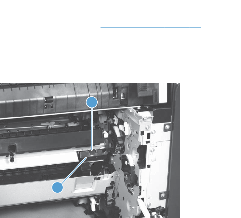
Registration sensor assembly
Before proceeding, remove the following components:
●Tray 2 cassette.
●Cassette separation roller assembly. See Separation roller assembly (Tray 2) on page 97.
●Intermediate transfer belt (ITB). See Intermediate transfer belt (ITB) on page 102.
●Cassette pickup drive assembly. See Paper pickup assembly on page 135.
Remove the registration sensor assembly
1. Push the tab (callout 1) down, and then pull the top of the cover to remove the cover (callout 2).
You might need a small flat-blade screwdriver to press down the tab.
Figure 2-66 Remove the registration sensor assembly (1 of 4)
2
1
142 Chapter 2 Removal and replacement ENWW
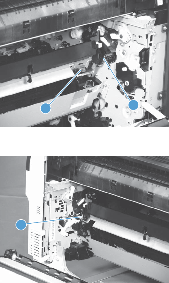
2. Disconnect one connector (callout 1), and then detach the bottom part of the spring (callout 2) at
the right end. If necessary, use a pick or needle-nose pliers to detach the spring.
Figure 2-67 Remove the registration sensor assembly (2 of 4)
2
1
3. Detach the bottom of one spring (callout 1) at the left end.
Figure 2-68 Remove the registration sensor assembly (3 of 4)
1
ENWW Removal and replacement procedures 143
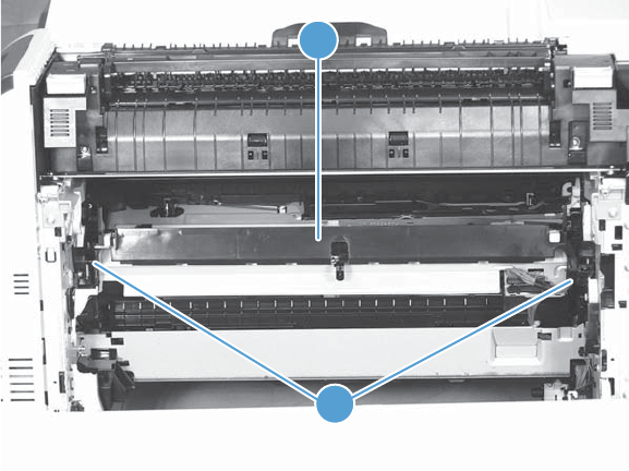
4. Release one of the registration sensor unit pivot hinges from the shafts (callout 1), pull out that end
of the assembly (callout 2), and then repeat the procedure on the other pivot hinge.
Figure 2-69 Remove the registration sensor assembly (4 of 4)
1
2
144 Chapter 2 Removal and replacement ENWW
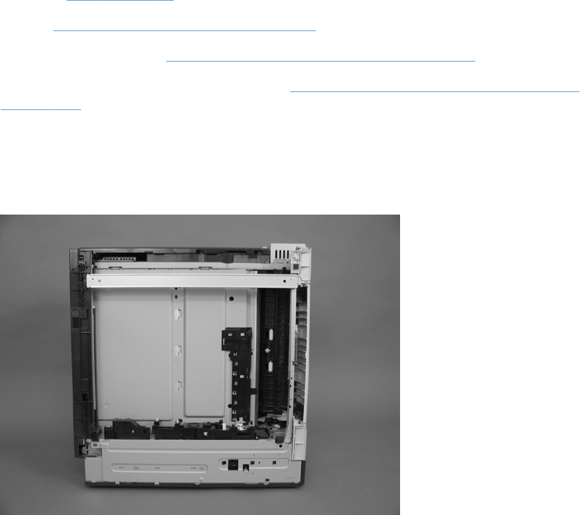
Lifter-drive assembly
Before proceeding, remove the following components:
●Tray 2 cassette.
●Fuser. See Fuser on page 93.
●ITB. See Intermediate transfer belt (ITB) on page 102.
●1 x 500-paper feeder. See 1 x 500-sheet paper feeder assembly on page 222.
●3 x 500-paper feeder (optional accessory). See 3 x 500-sheet paper feeder (optional accessory)
on page 236.
Remove the lifter-drive assembly
1. Verify that the right door is closed, and then turn the product so that the front side faces up.
Figure 2-70 Remove the lifter-drive assembly (1 of 3)
ENWW Removal and replacement procedures 145
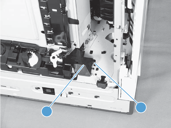
2. Release the tab (callout 1), and then pull up to remove the cover (callout 2).
Figure 2-71 Remove the lifter-drive assembly (2 of 3)
21
146 Chapter 2 Removal and replacement ENWW
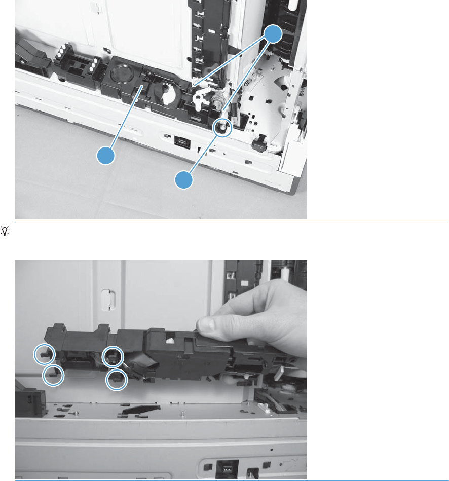
3. Disconnect two connectors (callout 1), remove one screw (callout 2), and then remove the lifter
drive unit (callout 3).
Figure 2-72 Remove the lifter-drive assembly (3 of 3)
1
3
2
Reinstallation tip Make sure that the tabs align correctly when reinstalling the lifter-drive
assembly.
ENWW Removal and replacement procedures 147
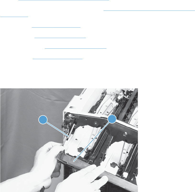
ITB front guide assembly
Before proceeding, remove the following components:
●ITB. See Intermediate transfer belt (ITB) on page 102.
●Right-front cover and control-panel assembly. See Right-front cover and control-panel assembly
on page 113.
●Left cover. See Left cover on page 115.
●Rear cover. See Rear cover on page 116.
●Right-rear cover. See Right-rear cover on page 119.
●Top cover. See Top cover on page 121.
1. Open the front door (callout 1) halfway, and then push up the upper part of the link arm (callout
2) to detach it from the product chassis.
Figure 2-73 Remove the ITB front guide assembly (1 of 4)
21
148 Chapter 2 Removal and replacement ENWW
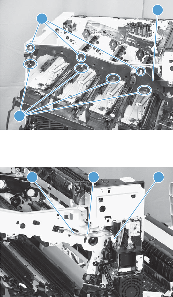
2. Remove three screws (callout 1), release four tabs (callout 2), and then remove the cartridge upper
guide unit (callout 3).
Figure 2-74 Remove the ITB front guide assembly (2 of 4)
3
2
1
3. Disconnect one connector (callout 1), and then release the cables (callout 3) from the cable clamp
(callout 2).
Figure 2-75 Remove the ITB front guide assembly (3 of 4)
123
ENWW Removal and replacement procedures 149
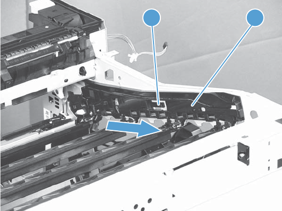
4. Release one tab (callout 1), and then slide the ITB front guide assembly (callout 2) in the direction
that the arrow indicates to remove it.
Figure 2-76 Remove the ITB front guide assembly (4 of 4)
2
1
150 Chapter 2 Removal and replacement ENWW
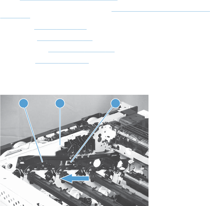
ITB rear guide assembly
Before proceeding, remove the following components:
●ITB. See Intermediate transfer belt (ITB) on page 102.
●Right-front cover and control-panel assembly. See Right-front cover and control-panel assembly
on page 113.
●Left cover. See Left cover on page 115.
●Rear cover. See Rear cover on page 116.
●Right-rear cover. See Right-rear cover on page 119.
●Top cover. See Top cover on page 121.
▲Disconnect one connector (callout 1), release one tab (callout 2), and then slide the ITB rear guide
unit (callout 3) in the direction that the arrow indicates to remove it.
Figure 2-77 Remove the ITB rear guide assembly
31 2
ENWW Removal and replacement procedures 151
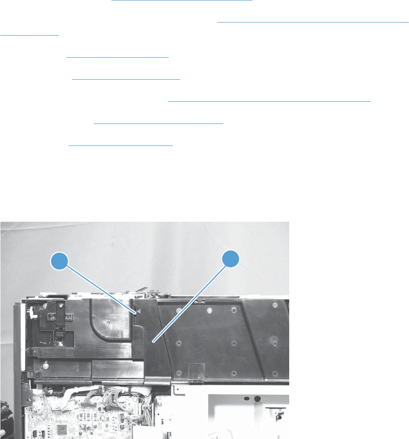
Residual toner full sensor
Before proceeding, remove the following components:
●Toner-collection unit. See Toner-collection unit on page 91.
●Right-front cover and control-panel assembly. See Right-front cover and control-panel assembly
on page 113.
●Left cover. See Left cover on page 115.
●Rear cover. See Rear cover on page 116.
●Toner collection unit access door. See Toner collection unit access door on page 117.
●Right-rear cover. See Right-rear cover on page 119.
●Top cover. See Top cover on page 121.
Remove the residual toner full sensor
1. Release one tab (callout 1), and then remove the cover (callout 2).
Figure 2-78 Remove the residual toner full sensor (1 of 4)
12
152 Chapter 2 Removal and replacement ENWW
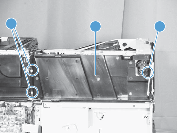
2. Remove two M4-screws (callout 1) and one M3-screw (callout 2). Then remove the toner cover
(callout 3).
Figure 2-79 Remove the residual toner full sensor (2 of 4)
13 2
ENWW Removal and replacement procedures 153
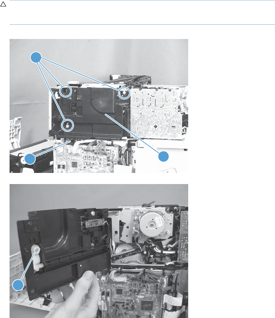
3. Disconnect one connector (callout 1), remove three screws (callout 2), and then remove the
residual toner full sensor assembly (callout 3).
CAUTION: During the removal process, make sure that the white gear (callout 4) does not fall
out of the assembly. The white gear might stay on the product, and not come off with the
assembly.
Figure 2-80 Remove the residual toner full sensor (3 of 4)
11
2
3
Figure 2-81 Remove the residual toner full sensor (4 of 4)
4
154 Chapter 2 Removal and replacement ENWW
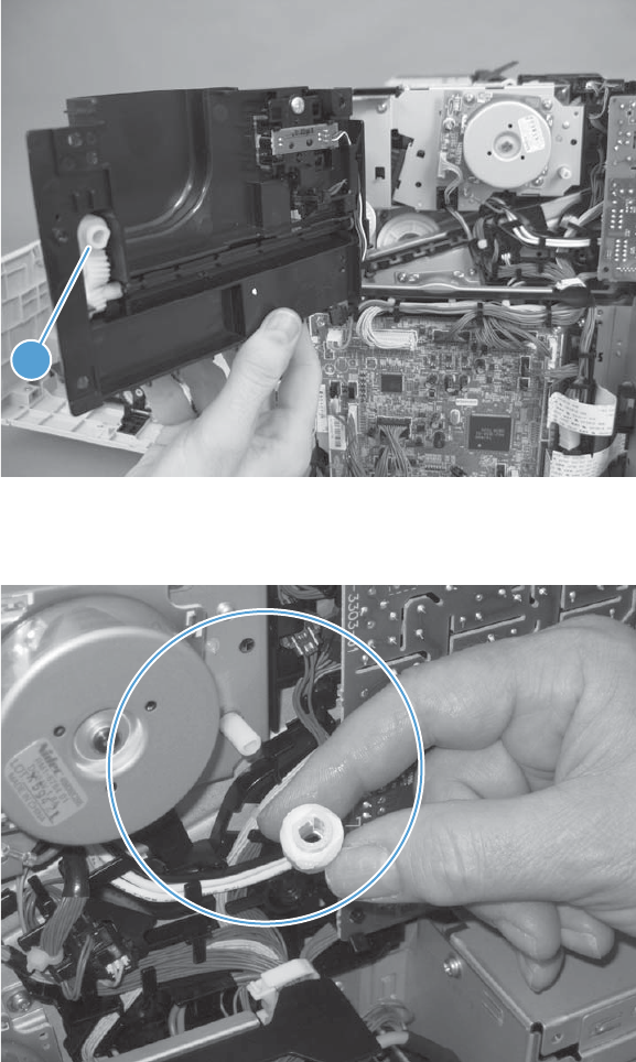
Reinstall the residual toner full sensor
1. If the white gear (callout 1) was removed with the residual toner full sensor assembly, carefully
remove it from the assembly.
Figure 2-82 Reinstall the residual toner full sensor (1 of 3)
1
2. Alight the flat portion of the gear with the corresponding flat portion of the drive shaft.
Figure 2-83 Reinstall the residual toner full sensor (2 of 3)
ENWW Removal and replacement procedures 155
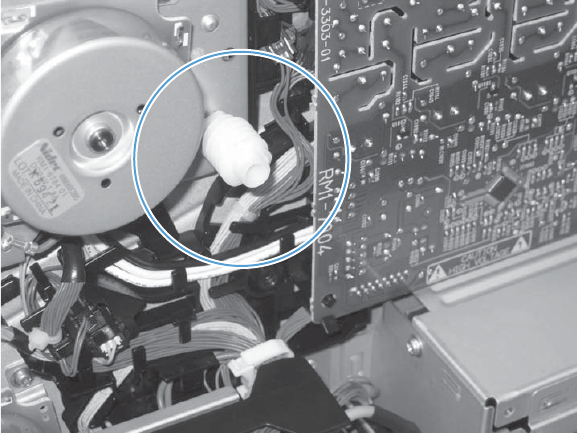
3. Install the gear on the shaft before you install the residual toner full sensor assembly.
Figure 2-84 Reinstall the residual toner full sensor (3 of 3)
156 Chapter 2 Removal and replacement ENWW
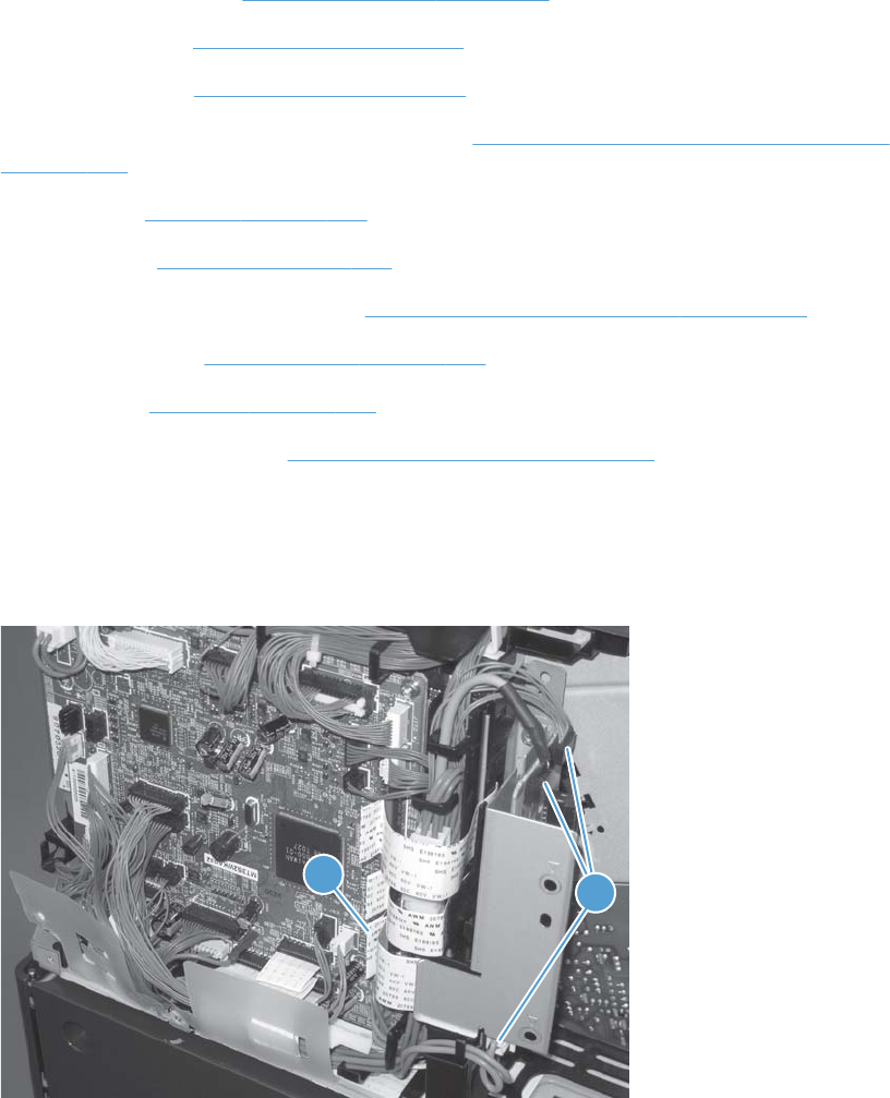
Main drive assembly
Before proceeding, remove the following components:
●Toner-collection unit. See Toner-collection unit on page 91.
●Formatter PCA. See Formatter PCA on page 105.
●Formatter case. See Formatter case on page 130.
●Right-front cover and control-panel assembly. See Right-front cover and control-panel assembly
on page 113.
●Left cover. See Left cover on page 115.
●Rear cover. See Rear cover on page 116.
●Toner collection unit access door. See Toner collection unit access door on page 117.
●Right-rear cover. See Right-rear cover on page 119.
●Top cover. See Top cover on page 121.
●Residual-toner full sensor. See Residual toner full sensor on page 152.
Remove the main drive assembly
1. Disconnect three connectors (callout 1) and one FFC (callout 2).
Figure 2-85 Remove the main drive assembly (1 of 17)
21
ENWW Removal and replacement procedures 157
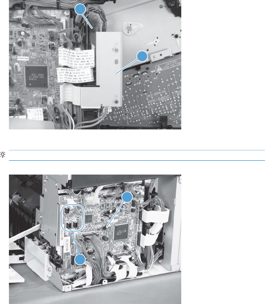
2. Remove one screw (callout 1), and then remove the sheet-metal plate (callout 2).
Figure 2-86 Remove the main drive assembly (2 of 17)
1
2
3. Disconnect twenty-two connectors and six FFCs on the DC controller PCA (callout 1).
TIP: Three connectors (callout 2) should be empty when the DC controller is reinstalled.
Figure 2-87 Remove the main drive assembly (3 of 17)
1
2
158 Chapter 2 Removal and replacement ENWW
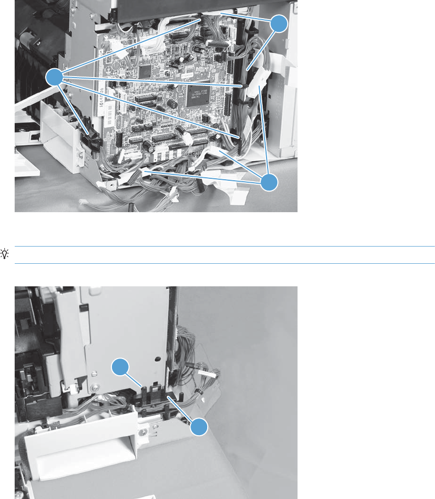
4. Disconnect three intermediate connectors (callout 1), and then release the wire harnesses
(callout 3) from the guides (callout 2).
Figure 2-88 Remove the main drive assembly (4 of 17)
1
3
2
5. Release one tab (callout 1), and then remove the guide (callout 2).
TIP: Release the wire harnesses from the guide as you remove it.
Figure 2-89 Remove the main drive assembly (5 of 17)
2
1
ENWW Removal and replacement procedures 159
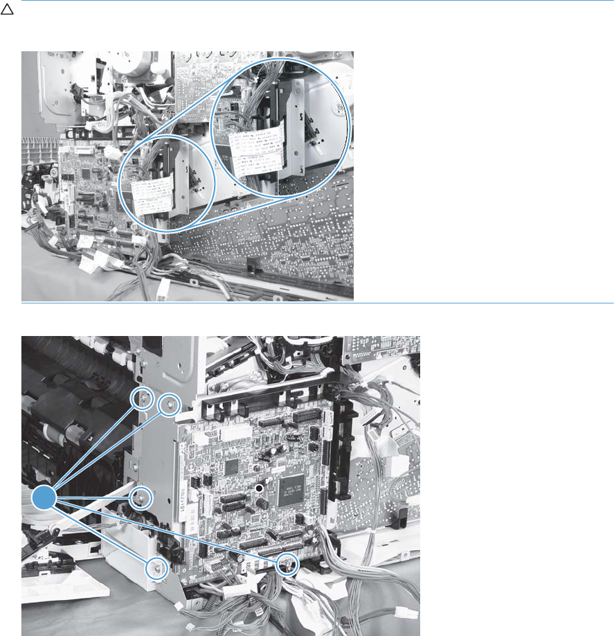
6. Remove five screws (callout 1), and then remove the DC controller and the two sheet-metal support
plates.
CAUTION: Carefully unthread the FFCs from the plate to avoid damaging them when you
remove the DC controller and the two sheet-metal support plates.
Figure 2-90 Remove the main drive assembly (6 of 17)
1
160 Chapter 2 Removal and replacement ENWW
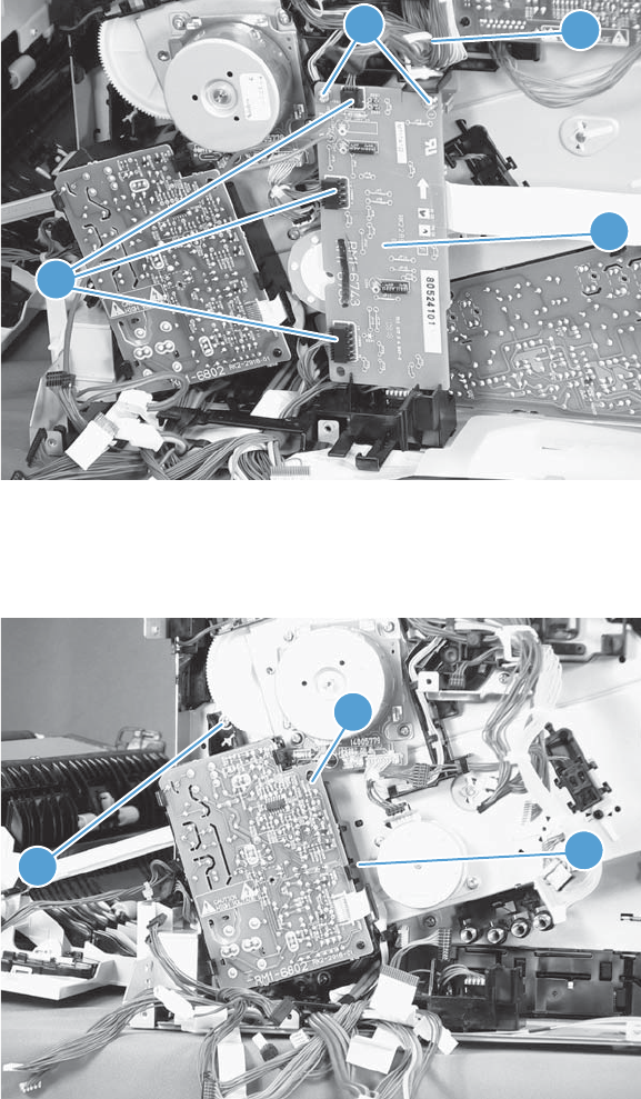
7. Disconnect three connectors (callout 1), remove two screws (callout 2), release one wire retainer
(callout 3), and then remove the driver PCA (callout 4).
Figure 2-91 Remove the main drive assembly (7 of 17)
4
2
1
3
8. Remove one screw (callout 1), and then remove the second transfer high-voltage power supply
(callout 2) and the PCA holder (callout 3) assembly.
Figure 2-92 Remove the main drive assembly (8 of 17)
3
2
1
ENWW Removal and replacement procedures 161
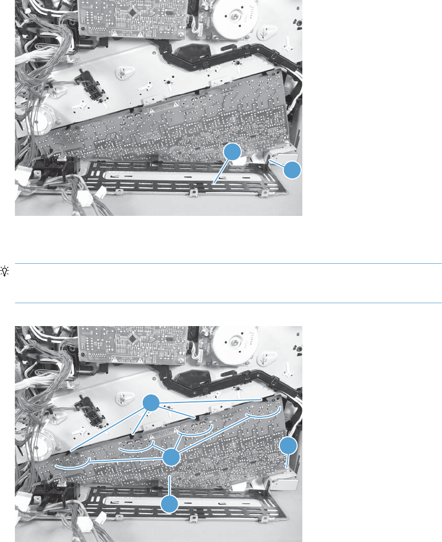
9. Release one tab (callout 1), and then remove the cover (callout 2).
Figure 2-93 Remove the main drive assembly (9 of 17)
2
1
10. Remove one screw (callout 1), release four tabs (callout 2), and then remove the developing high-
voltage power supply (callout 3).
Reinstallation tip When you reinstall the power supply PCA, look through the holes on the
PCA (callout 4) and make sure that the contact springs are correctly positioned against the back
side of the PCA.
Figure 2-94 Remove the main drive assembly (10 of 17)
1
2
3
4
162 Chapter 2 Removal and replacement ENWW
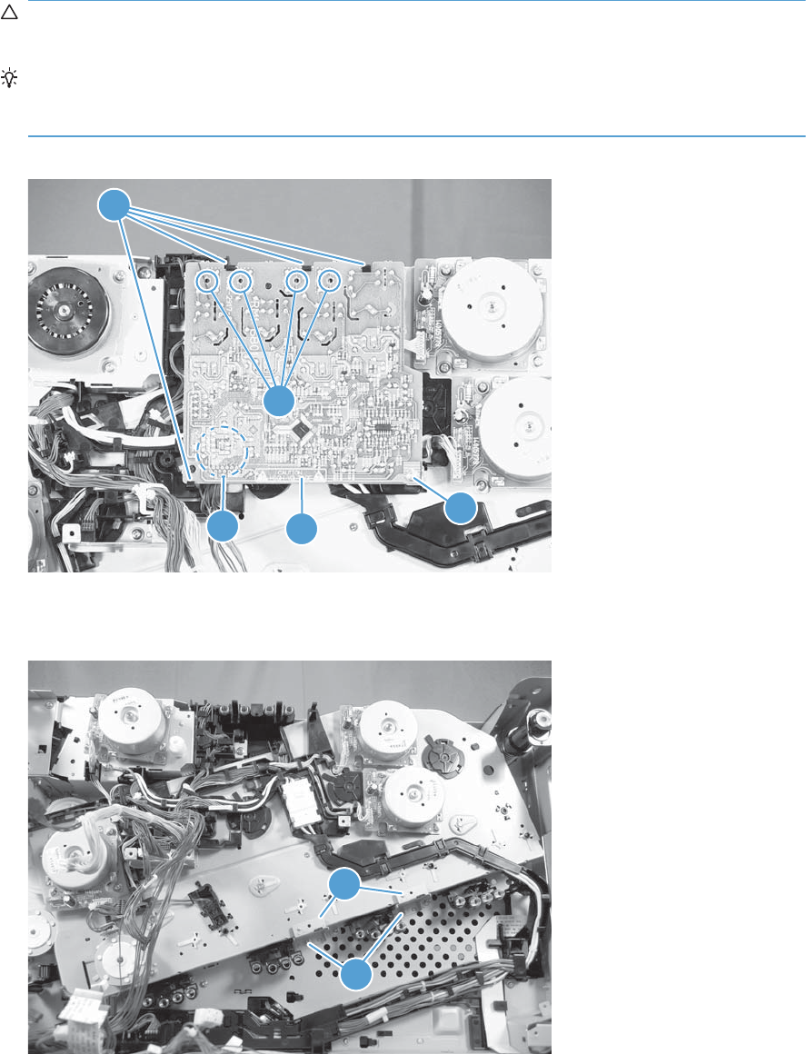
11. Remove one screw (callout 1), release four tabs (callout 2), and then separate the first transfer
high-voltage power supply (callout 3) from the product.
CAUTION: The PCA is still connected to the product. Disconnect one connector (callout 4) on
the back side of the PCA to remove it.
Reinstallation tip When you reinstall the power supply PCA, look through the holes on the
PCA (callout 5) and make sure that the contact springs are correctly positioned against the back
side of the PCA.
Figure 2-95 Remove the main drive assembly (11 of 17)
1
2
3
4
5
12. Remove two screws (callout 1), and then remove the sheet-metal support brackets (callout 2).
Figure 2-96 Remove the main drive assembly (12 of 17)
1
2
ENWW Removal and replacement procedures 163
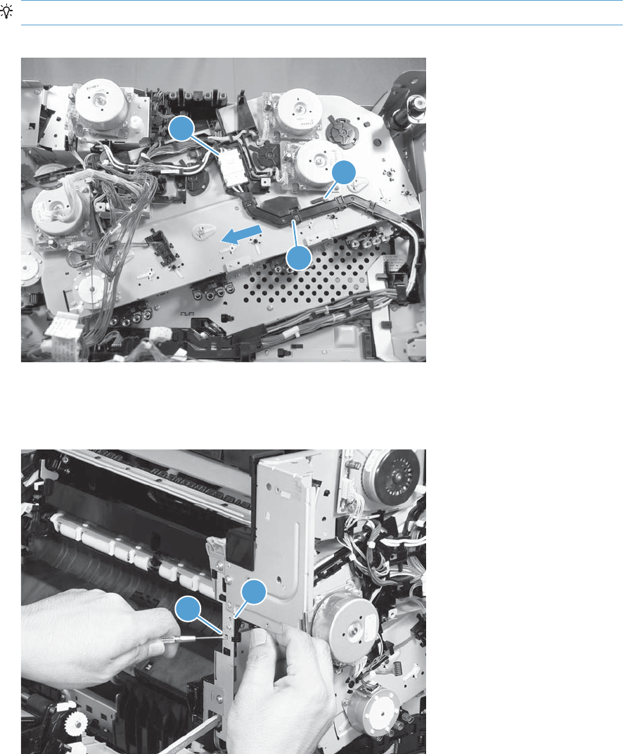
13. Disconnect one connector (callout 1), release one tab (callout 2), slide the cable guide (callout 3)
to the left to release the it, and then move the guide to the side, out of the way.
TIP: It might be easier to disconnect the connector if you release it from the holder.
Figure 2-97 Remove the main drive assembly (13 of 17)
1
2
3
14. Use a small flat blade screwdriver to release one tab (callout 1), and then remove the sensor
holder (callout 2).
Figure 2-98 Remove the main drive assembly (14 of 17)
1
2
164 Chapter 2 Removal and replacement ENWW
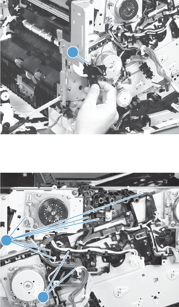
15. Disconnect one connector (callout 1), and then remove the sensor assembly.
Figure 2-99 Remove the main drive assembly (15 of 17)
1
16. Disconnect six connectors (callout 1), and then release the wire harnesses from the guides
(callout 2).
Figure 2-100 Remove the main drive assembly (16 of 17)
1
2
ENWW Removal and replacement procedures 165
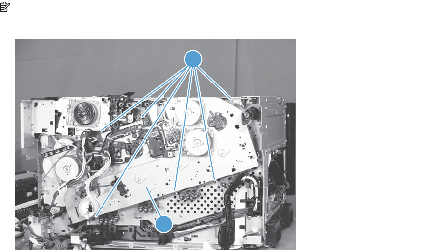
17. Remove six screws (callout 1), and then remove the main drive assembly (callout 2).
NOTE: Make sure that the right door is closed.
Figure 2-101 Remove the main drive assembly (17 of 17)
2
1
166 Chapter 2 Removal and replacement ENWW
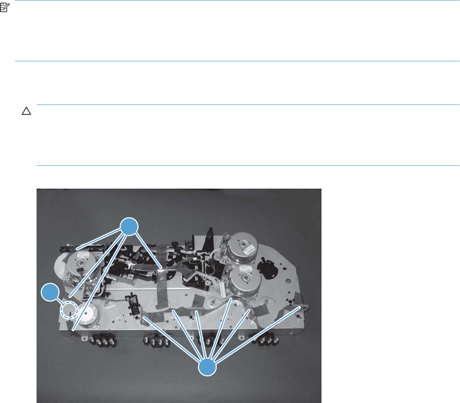
Install the main drive assembly
NOTE: Installing a replacement assembly: follow the instructions in this section.
Reinstalling the original assembly: some of these instructions in this section do not apply (for
example, removing the shipping spacers). Do not rotate the gears when handling the assembly. If the
gears are rotated—and become out of phase—it will be difficult to install the assembly on the product.
1. Do not remove the orange spacers and spacer shipping tape (callout 1) installed on the
replacement main drive assembly. Remove the remaining shipping tape (callout 2).
CAUTION: A gear (callout 3) on the back of the assembly is not captive when the shipping tape
is removed. Do not lose the gear when handling the assembly with the shipping tape removed.
When removing tape, make sure that the entire strip is removed. Check the back of the assembly
to verify that the entire strip of tape is removed.
Figure 2-102 Install the main drive assembly (1 of 8)
3
2
1
ENWW Removal and replacement procedures 167
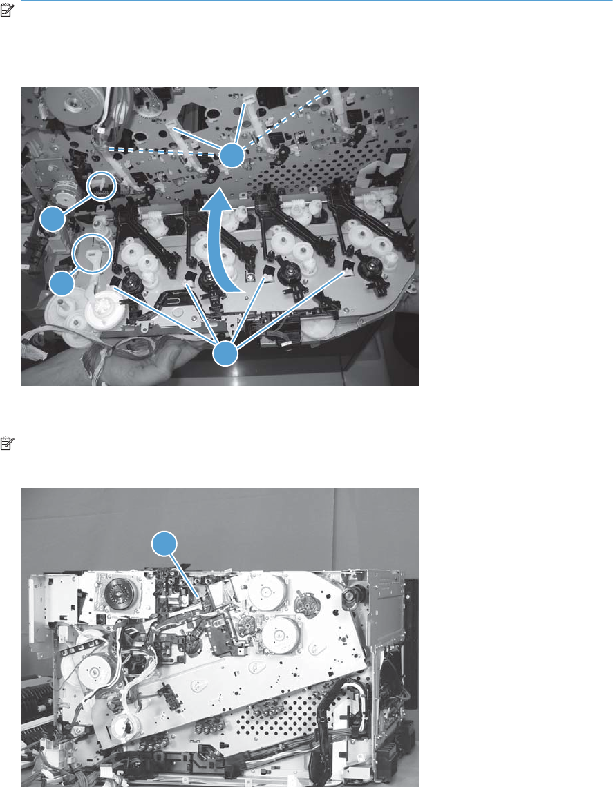
2. With the right door closed, position the drive assembly near the product, and then rotate it up and
onto the chassis.
NOTE: Make sure that the right-door link arm shaft (callout 1) aligns with and is positioned in
the hole (callout 2) on the arm on the drive assembly, and that the pins on the assembly (callout 3)
are positioned in the holes in the link arms on the chassis (callout 4).
Figure 2-103 Install the main drive assembly (2 of 8)
2
1
3
4
3. Install one screw (callout 1).
NOTE: Do not fully tighten this screw.
Figure 2-104 Install the main drive assembly (3 of 8)
1
168 Chapter 2 Removal and replacement ENWW
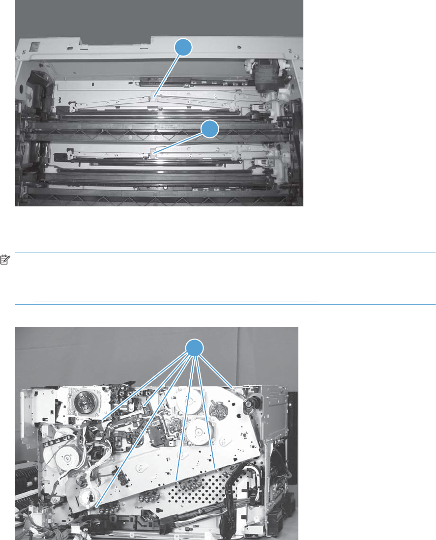
4. From the top of the product, look at each shutter arm. Make sure that they are in the closed
position (callout 1). If they are in the open position (callout 2), carefully push on the shutters to
close them.
Figure 2-105 Install the main drive assembly (4 of 8)
2
1
5. Make sure that the six sheet-metal screw tabs (callout 1) on the drive assembly are flat against the
product chassis.
NOTE: If the tabs are not flat against the chassis, the developer-disengagement drive gears and
cams—on the back side of the drive assembly—are not properly aligned with, and seated in, the
corresponding holes on the product. Remove the drive assembly, realign it, and then reinstall it.
See Figure 2-103 Install the main drive assembly (2 of 8) on page 168.
Figure 2-106 Install the main drive assembly (5 of 8)
1
ENWW Removal and replacement procedures 169
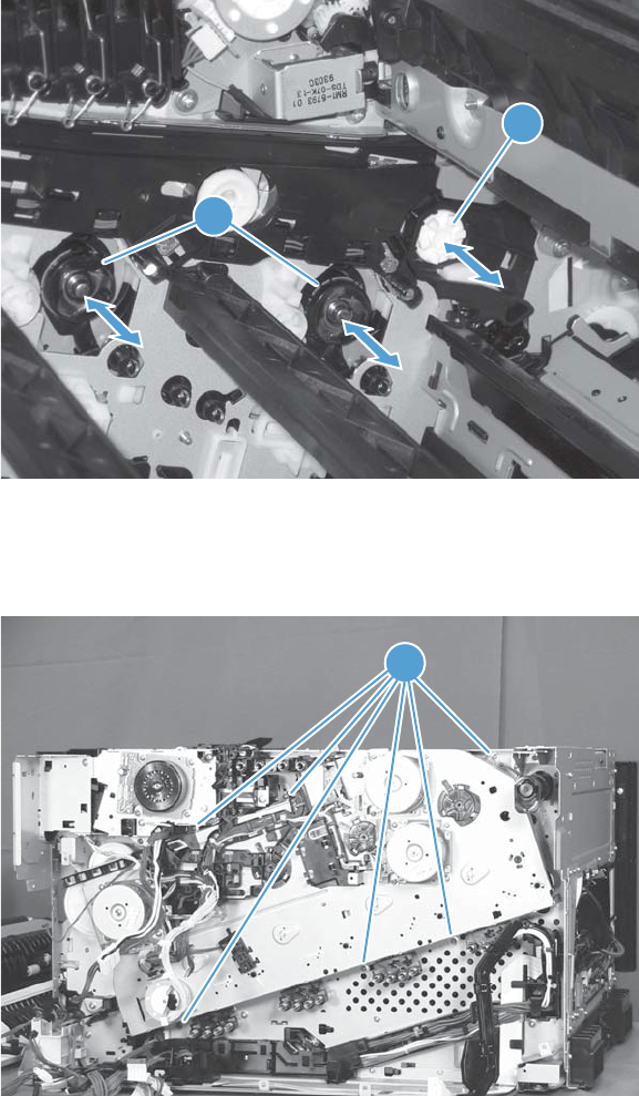
6. With the drive assembly correctly installed, verify the following:
●Open and close the front door. The OPC drum drive gears (callout 1; two shown, four total)
must move in and out when viewed from inside the product.
●Open and close the right door. The ITB drive gear (callout 2) must move in and out when
viewed from inside the product.
Figure 2-107 Install the main drive assembly (6 of 8)
2
1
7. Install the remaining five mounting screws, tighten all six screws (callout 1), and then remove the
orange spacers and spacer shipping tape.
Figure 2-108 Install the main drive assembly (7 of 8)
1
170 Chapter 2 Removal and replacement ENWW
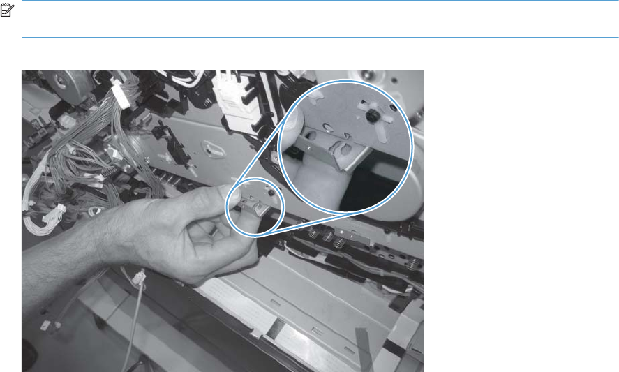
8. Reinstall the two small sheet-metal brackets.
NOTE: The tab on the sheet-metal brackets must be inserted in the hole in the drive assembly
chassis as shown below.
Figure 2-109 Install the main drive assembly (8 of 8)
ENWW Removal and replacement procedures 171
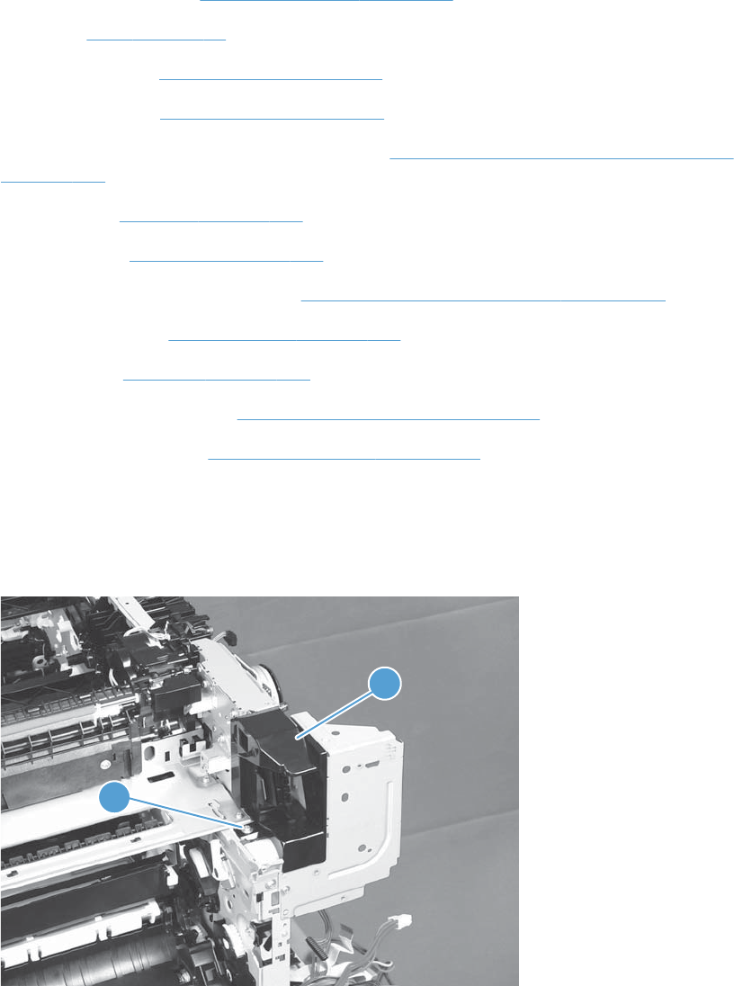
Fuser drive assembly
Before proceeding, remove the following components:
●Toner-collection unit. See Toner-collection unit on page 91.
●Fuser. See Fuser on page 93.
●Formatter PCA. See Formatter PCA on page 105.
●Formatter case. See Formatter case on page 130
●Right-front cover and control-panel assembly. See Right-front cover and control-panel assembly
on page 113.
●Left cover. See Left cover on page 115.
●Rear cover. See Rear cover on page 116.
●Toner collection unit access door. See Toner collection unit access door on page 117.
●Right-rear cover. See Right-rear cover on page 119.
●Top cover. See Top cover on page 121.
●Residual-toner full sensor. See Residual toner full sensor on page 152.
●Main drive assembly. See Main drive assembly on page 157.
Remove the fuser drive assembly
1. Remove one screw (callout 1) and the cover (callout 2).
Figure 2-110 Remove the fuser drive assembly (1 of 3)
1
2
172 Chapter 2 Removal and replacement ENWW
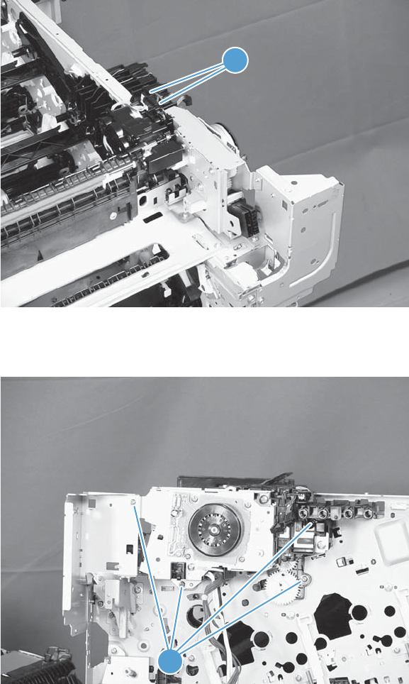
2. Disconnect two connectors (callout 1).
Figure 2-111 Remove the fuser drive assembly (2 of 3)
1
3. Remove four screws (callout 1), and then remove the fuser drive assembly.
Figure 2-112 Remove the fuser drive assembly (3 of 3)
1
ENWW Removal and replacement procedures 173
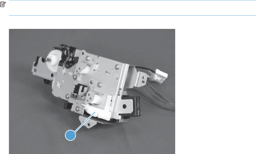
Install a replacement fuser drive assembly
Use the following procedure to install a replacement fuser drive assembly or reinstall the original fuser
drive assembly.
1. Replacement fuser drive assembly: Before beginning, take note of the spacer (callout 1) on
the replacement fuser drive assembly.
Original fuser drive assembly: Proceed to the next step.
NOTE: The fuser drive motor is shown removed in the following figure. However, you do not
need to remove the fuser motor to install the fuser drive assembly.
Figure 2-113 Install a replacement fuser drive assembly (1 of 3)
1
174 Chapter 2 Removal and replacement ENWW
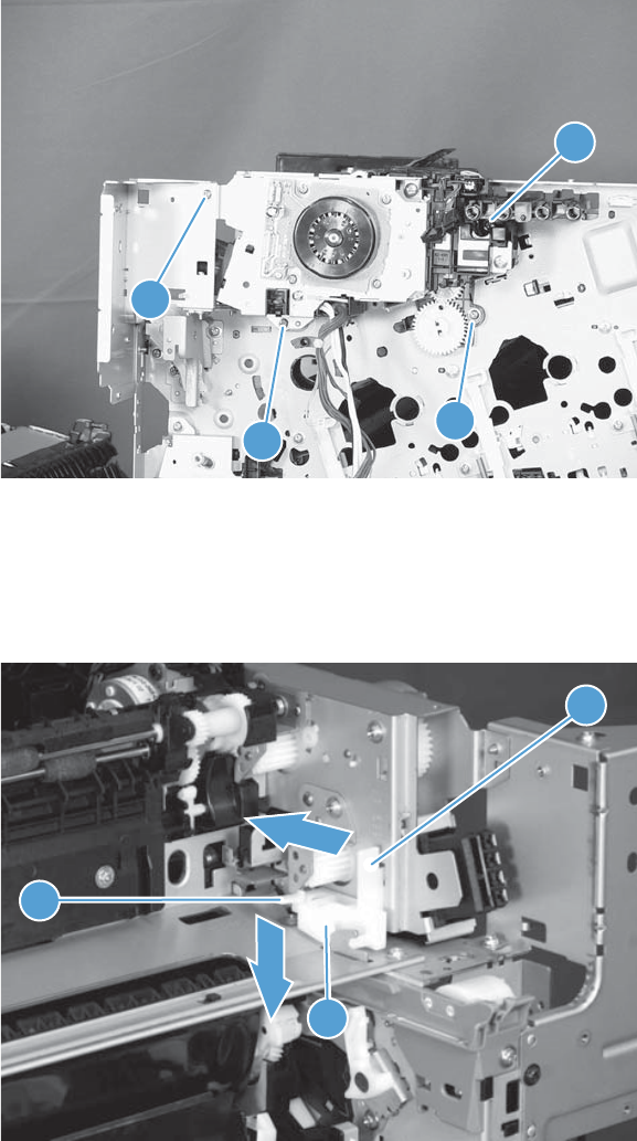
2. Replacement fuser drive assembly: Fasten the replacement fuser gear assembly to the
product with four screws. Install the screws in the order shown below (callouts 1 to 4).
Original fuser drive assembly: Install, but do not fully tighten four screws (callouts 1 to 4).
Carefully push the drive assembly to the left (toward the right-door side of the product) until it
slightly shifts forward. Apply steady pressure to hold the assembly in place, and then tighten the
screws.
Figure 2-114 Install a replacement fuser drive assembly (2 of 3)
1
2
3
4
3. Replacement fuser drive assembly: Release two tabs in the order shown below
(callouts 1 and 2). and then remove the spacer (callout 3).
Original fuser drive assembly: Installation complete—this step is not required.
Figure 2-115 Install a replacement fuser drive assembly (3 of 3)
1
2
3
ENWW Removal and replacement procedures 175
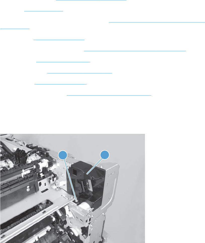
Fuser gear assembly
Before proceeding, remove the following components:
●Toner-collection unit. See Toner-collection unit on page 91.
●Fuser. See Fuser on page 93.
●Right-front cover and control-panel assembly. See Right-front cover and control-panel assembly
on page 113.
●Left cover. See Left cover on page 115.
●Toner collection unit access door. See Toner collection unit access door on page 117.
●Rear cover. See Rear cover on page 116.
●Right-rear cover. See Right-rear cover on page 119.
●Top cover. See Top cover on page 121.
●Residual toner full sensor. See Residual toner full sensor on page 152.
Remove the fuser gear assembly
1. Remove one screw (callout 1) and the cover (callout 2).
Figure 2-116 Remove the fuser gear assembly (1 of 9)
12
176 Chapter 2 Removal and replacement ENWW
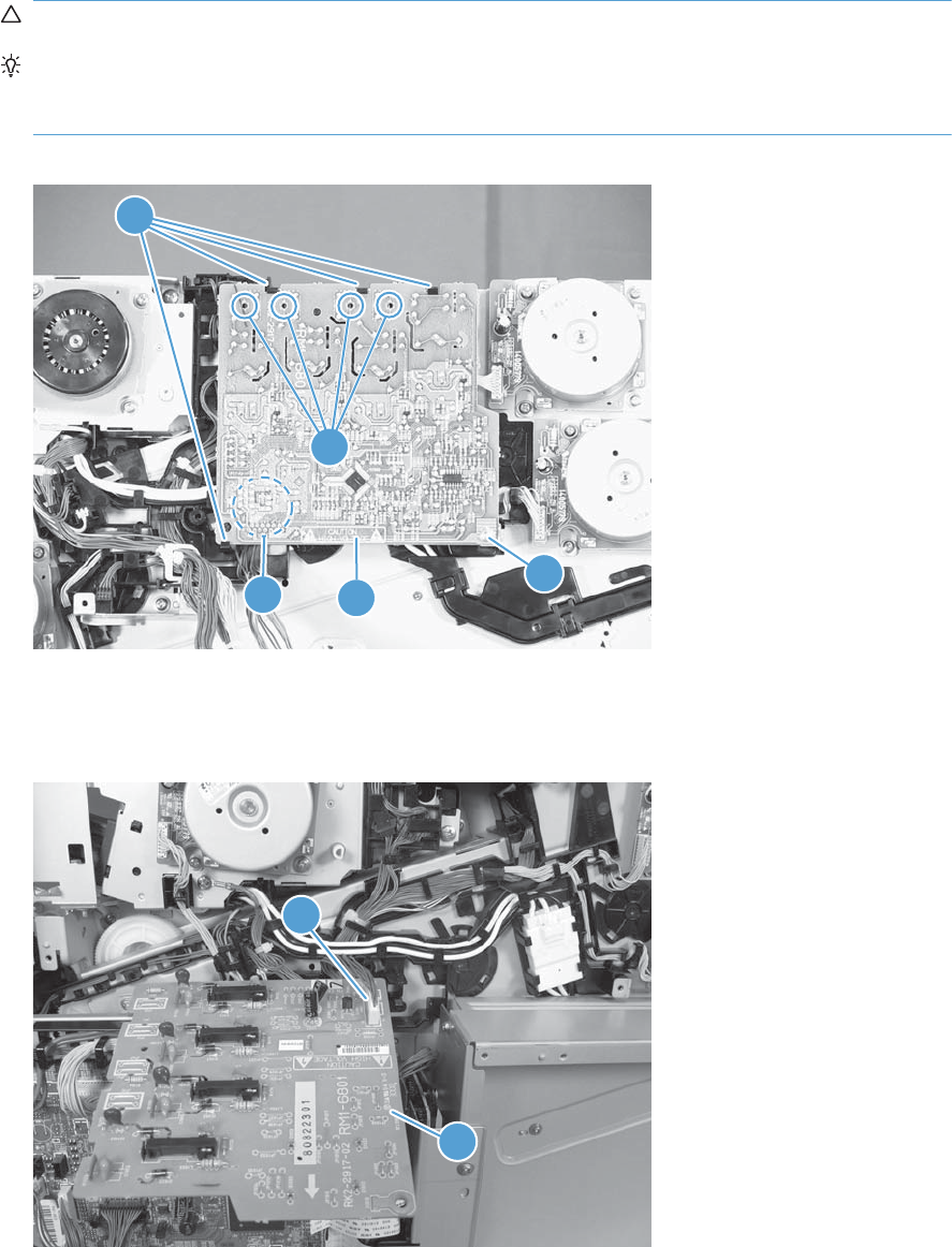
2. Remove one screw (callout 1), release four tabs (callout 2), and then separate the first transfer
high-voltage power supply (callout 3) from the product.
CAUTION: The PCA is still connected to the product.
Reinstallation tip When you reinstall the power supply PCA, look through the holes on the
PCA (callout 5) and make sure that the contact springs are correctly positioned against the back
side of the PCA.
Figure 2-117 Remove the fuser gear assembly (2 of 9)
1
2
3
4
5
3. Disconnect one connector (callout 1) and then remove the first transfer high-voltage power supply
(callout 2).
Figure 2-118 Remove the fuser gear assembly (3 of 9)
1
2
ENWW Removal and replacement procedures 177
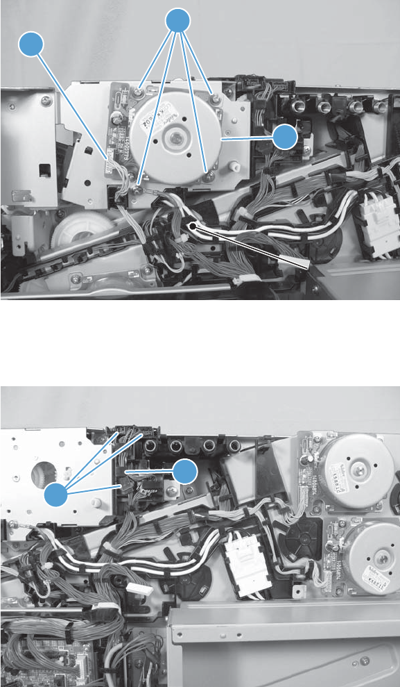
4. Disconnect one connector (callout 1), remove four screws (callout 2), and then remove the fuser
motor (callout 3).
Figure 2-119 Remove the fuser gear assembly (4 of 9)
1
3
2
5. Disconnect three connectors (callout 1), and then release the wire harnesses from the guide
(callout 2).
Figure 2-120 Remove the fuser gear assembly (5 of 9)
1
2
178 Chapter 2 Removal and replacement ENWW
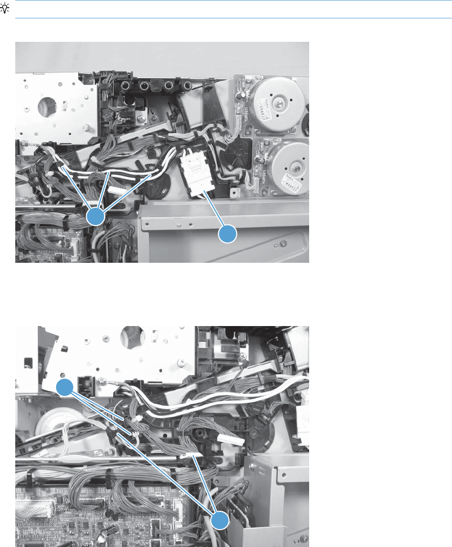
6. Disconnect one connector (callout 1), and then release the wire harness from the guide (callout 2).
TIP: It might be easier to disconnect the connector, if you release it from the black-plastic holder.
Figure 2-121 Remove the fuser gear assembly (6 of 9)
1
2
1
7. Disconnect two connectors (callout 1), and then release the wire harness from the retainer and
guide (callout 2).
Figure 2-122 Remove the fuser gear assembly (7 of 9)
1
2
ENWW Removal and replacement procedures 179
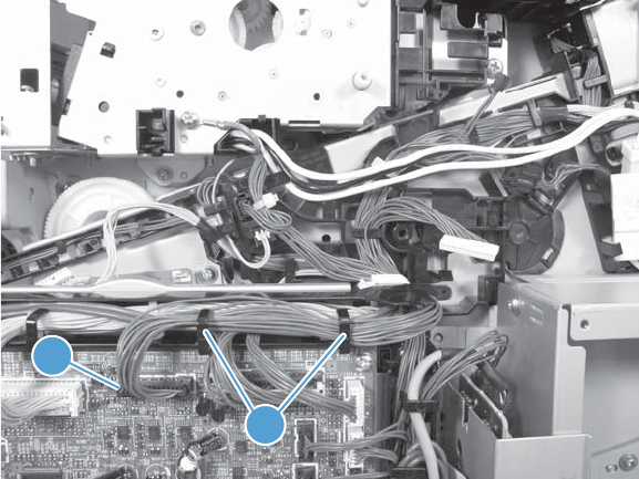
8. Disconnect one connector (callout 1), and then release the wire harness from the guide (callout 2).
Figure 2-123 Remove the fuser gear assembly (8 of 9)
1
2
180 Chapter 2 Removal and replacement ENWW
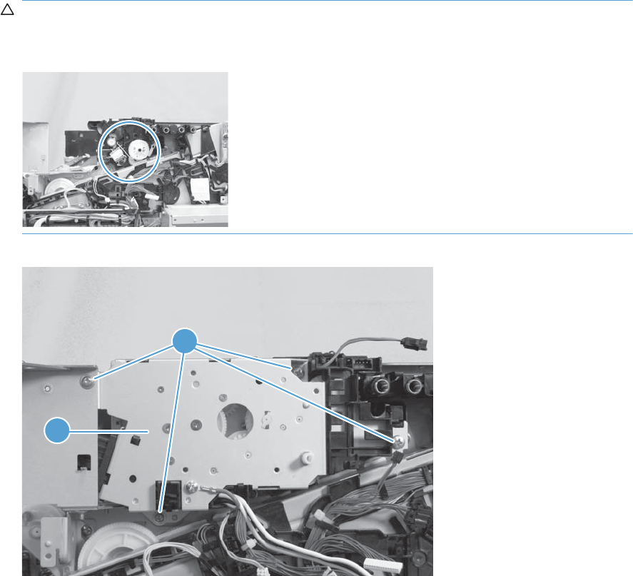
9. Remove four screws (callout 1), and then remove the fuser gear assembly (callout 2).
CAUTION: Do not remove the gear or solenoid located behind the fuser gear assembly. The
gear and solenoid are installed in specific alignment with the other components behind the
assembly. If the gear or solenoid are removed, the product will not properly function.
Figure 2-124 Remove the fuser gear assembly (9 of 9)
1
2
ENWW Removal and replacement procedures 181

Install a replacement fuser gear assembly
Use the following procedure to install a replacement fuser drive assembly or reinstall the original fuser
gear assembly.
1. Replacement fuser gear assembly: Before beginning, take note of the spacer (callout 1) on
the replacement fuser drive assembly.
Original fuser gear assembly: Proceed to the next step.
NOTE: The fuser drive motor is shown removed in the following figure. However, you do not
need to remove the fuser motor to install the fuser gear assembly.
Figure 2-125 Install a replacement fuser gear assembly (1 of 3)
1
182 Chapter 2 Removal and replacement ENWW
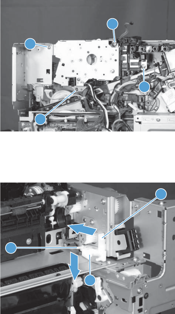
2. Replacement fuser drive assembly: Fasten the replacement fuser gear assembly to the
product with four screws. Install the screws in the order shown below (callouts 1 to 4).
Original fuser drive assembly: Install, but do not fully tighten four screws (callouts 1 to 4).
Carefully push the drive assembly to the left (toward the right-door side of the product) until it
slightly shifts forward. Apply steady pressure to hold the assembly in place, and then tighten the
screws.
Figure 2-126 Install a replacement fuser gear assembly (2 of 3)
1
2
3
4
3. Replacement fuser drive assembly: Release two tabs in the order shown below
(callouts 1 and 2). and then remove the spacer (callout 3).
Original fuser drive assembly: Installation complete—this step is not required.
Figure 2-127 Install a replacement fuser gear assembly (3 of 3)
1
2
3
ENWW Removal and replacement procedures 183
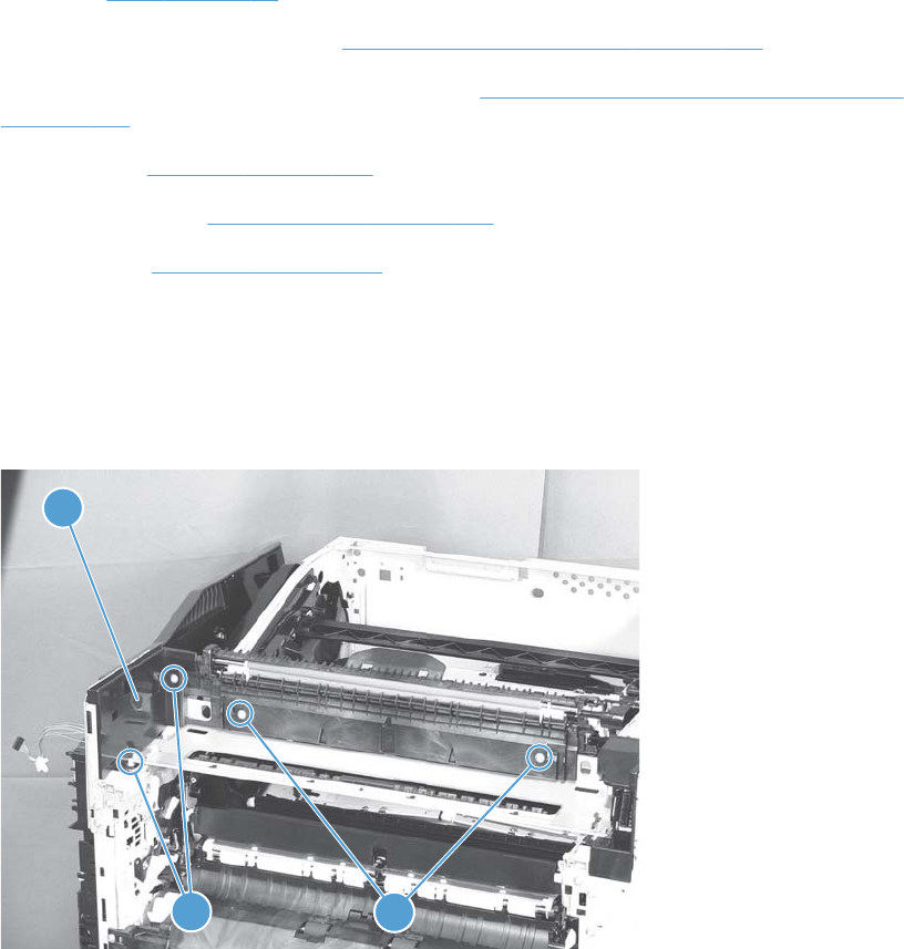
Paper delivery assembly
Before proceeding, remove the following components:
●Fuser. See Fuser on page 93.
●Intermediate transfer belt (ITB). See Intermediate transfer belt (ITB) on page 102.
●Right-front cover and control-panel assembly. See Right-front cover and control-panel assembly
on page 113.
●Left cover. See Left cover on page 115.
●Right-rear cover. See Right-rear cover on page 119.
●Top cover. See Top cover on page 121.
Remove the delivery assembly
1. Remove two screws (callout 1), remove the cover (callout 2), and then remove two screws (callout
3).
Figure 2-128 Remove the paper delivery assembly (1 of 2)
2
13
184 Chapter 2 Removal and replacement ENWW
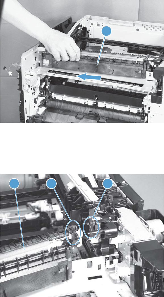
2. Pull the left side of the unit away from the engine, and then slide the delivery unit (callout 1) in the
direction that the arrow indicates to remove it.
Figure 2-129 Remove the paper delivery assembly (2 of 2)
1
Reinstall the paper delivery assembly
1. Make sure that the delivery assembly (callout 1) two mounting holes (callout 2) align with the
shafts (callout 3) on the product.
Figure 2-130 Reinstall the paper delivery assembly (1 of 3)
2
13
ENWW Removal and replacement procedures 185
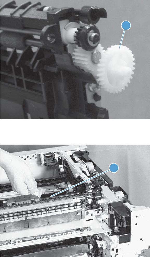
2. During reassembly, the white gear (callout 1) can become dislodged. Make sure that it is correctly
installed on the assembly.
Figure 2-131 Reinstall the paper delivery assembly (2 of 3)
1
3. After reinstalling the delivery assembly, verify that the sensor flag (callout 1) moves smoothly.
Figure 2-132 Reinstall the paper delivery assembly (3 of 3)
1
186 Chapter 2 Removal and replacement ENWW
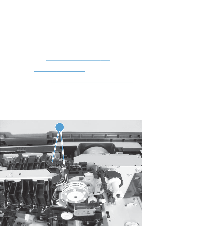
Duplex drive assembly (duplex models)
Before proceeding, remove the following components:
●Fuser. See Fuser on page 93.
●Intermediate transfer belt (ITB). See Intermediate transfer belt (ITB) on page 102.
●Right-front cover and control-panel assembly. See Right-front cover and control-panel assembly
on page 113.
●Left cover. See Left cover on page 115.
●Rear cover. See Rear cover on page 116.
●Right-rear cover. See Right-rear cover on page 119.
●Top cover. See Top cover on page 121.
●Delivery assembly. See Paper delivery assembly on page 184.
Remove the duplex-drive assembly
1. Disconnect two connectors (callout 1).
Figure 2-133 Remove the duplex-drive assembly (1 of 3)
1
ENWW Removal and replacement procedures 187
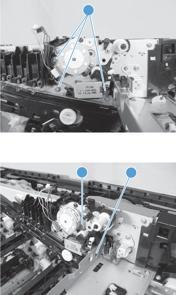
2. Remove three screws (callout 1).
Figure 2-134 Remove the duplex-drive assembly (2 of 3)
1
3. Release one tab (callout 1), and then remove the assembly (callout 2).
Figure 2-135 Remove the duplex-drive assembly (3 of 3)
1
2
188 Chapter 2 Removal and replacement ENWW
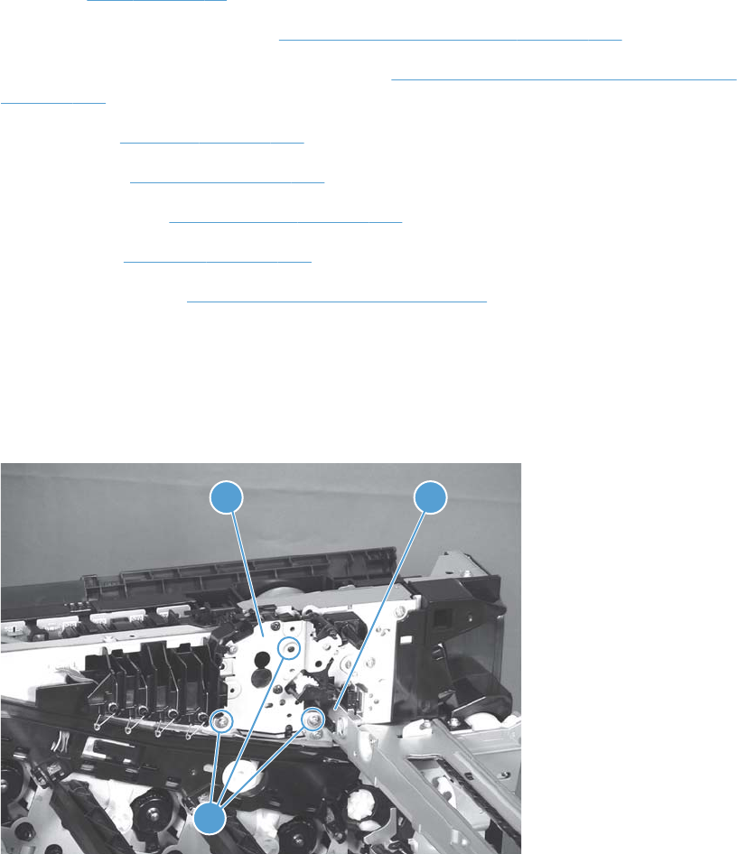
Delivery drive assembly (simplex models)
Before proceeding, remove the following components:
●Fuser. See Fuser on page 93.
●Intermediate transfer belt (ITB). See Intermediate transfer belt (ITB) on page 102.
●Right-front cover and control-panel assembly. See Right-front cover and control-panel assembly
on page 113.
●Left cover. See Left cover on page 115.
●Rear cover. See Rear cover on page 116.
●Right-rear cover. See Right-rear cover on page 119.
●Top cover. See Top cover on page 121.
●Delivery assembly. See Paper delivery assembly on page 184.
Remove the delivery drive assembly
▲Remove three screws (callout 1), release one tab (callout 2), and then remove the delivery drive
assembly (callout 3).
Figure 2-136 Remove the delivery drive assembly
1
23
ENWW Removal and replacement procedures 189
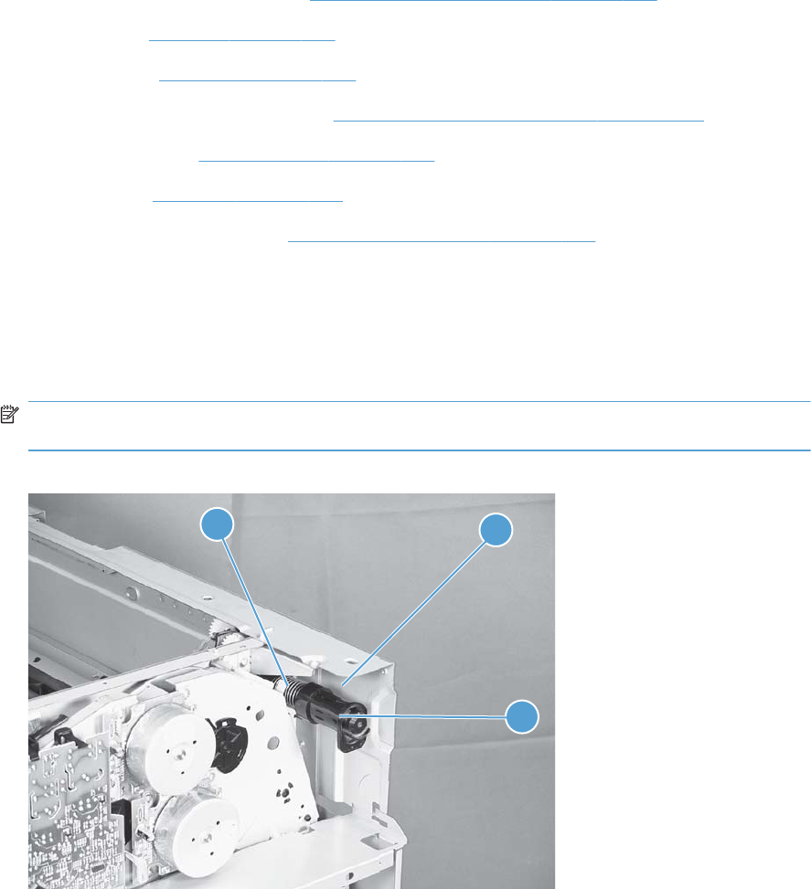
Residual-toner-feed assembly
Before proceeding, remove the following components:
●Intermediate transfer belt (ITB). See Intermediate transfer belt (ITB) on page 102.
●Left cover. See Left cover on page 115.
●Rear cover. See Rear cover on page 116.
●Toner collection unit access door. See Toner collection unit access door on page 117.
●Right-rear cover. See Right-rear cover on page 119.
●Top cover. See Top cover on page 121.
●Toner cover. See the first step of Residual toner full sensor on page 152.
Remove the residual-toner-feed assembly
1. Release one tab (callout 1) by pulling the tab up. If necessary, use a small, flat-blade screwdriver
to pull the tab up. Remove the shutter (callout 2), and then pull the spring (callout 3) off the
assembly.
NOTE: There might be a piece of transparent tape over the tab (callout 1). Remove the tape to
release the tab.
Figure 2-137 Remove the residual-toner-feed assembly (1 of 2)
31
2
190 Chapter 2 Removal and replacement ENWW
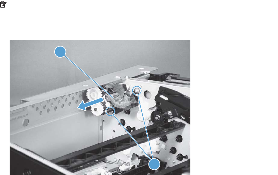
2. Remove two screws (callout 1), and then remove the residual-toner-feed assembly (callout 2).
NOTE: When removing the residual-toner-feed assembly (callout 2), make sure that the assembly
does not separate from the toner auger. This can spill toner in the product. To reduce the risk of
such an incident, pull the assembly in the direction indicated by the arrow.
Figure 2-138 Remove the residual-toner-feed assembly (2 of 2)
1
2
ENWW Removal and replacement procedures 191
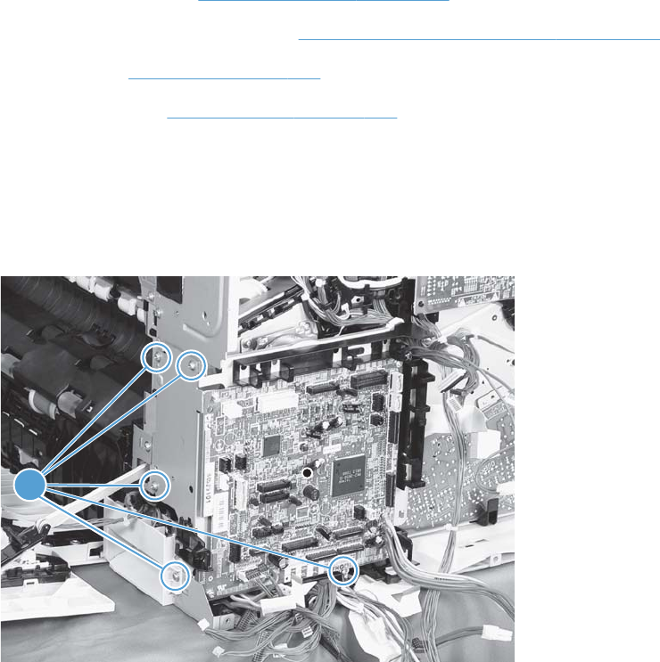
ITB motor (M1)
Before proceeding, remove the following components:
●Toner-collection unit. See Toner-collection unit on page 91.
●Toner collection unit access door. See Toner collection unit access door on page 117.
●Rear cover. See Rear cover on page 116.
●Right-rear cover. See Right-rear cover on page 119.
Remove the ITB motor
1. Disconnect all of the cables and FFCs from the DC controller (release the cables from the guides),
remove six screws (callout 1), and then remove the DC controller and the DC controller support.
Figure 2-139 Remove the ITB motor (1 of 2)
1
192 Chapter 2 Removal and replacement ENWW
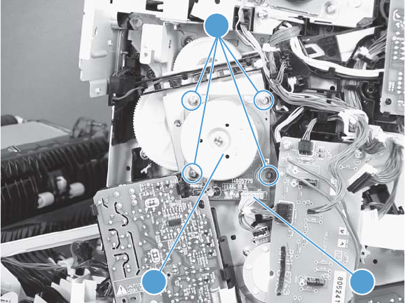
2. Disconnect one connector (callout 1), remove four screws (callout 2), and then remove the motor
(callout 3).
Figure 2-140 Remove the ITB motor (2 of 2)
13
2
ENWW Removal and replacement procedures 193
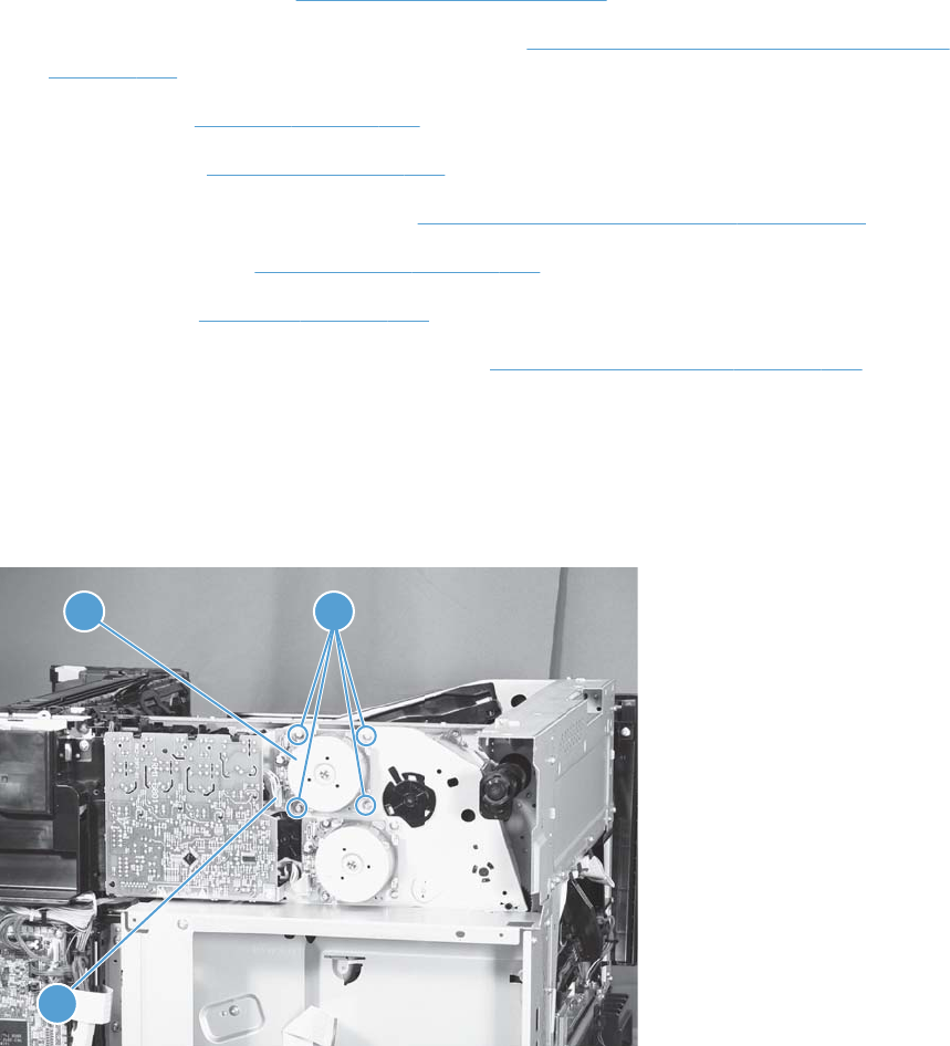
Drum motor (M2)
Before proceeding, remove the following components:
●Toner collection unit. See Toner-collection unit on page 91.
●Right-front cover and control-panel assembly. See Right-front cover and control-panel assembly
on page 113.
●Left cover. See Left cover on page 115.
●Rear cover. See Rear cover on page 116.
●Toner collection unit access door. See Toner collection unit access door on page 117.
●Right-rear cover. See Right-rear cover on page 119.
●Top cover. See Top cover on page 121.
●Toner cover. See the first and second steps of Residual toner full sensor on page 152.
Remove the drum motor
Disconnect one connector (callout 1), remove four screws (callout 2), and then remove the motor
(callout 3).
Figure 2-141 Remove the drum motor
1
32
194 Chapter 2 Removal and replacement ENWW
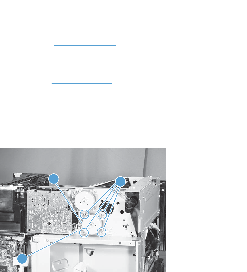
Developing motor (M3)
Before proceeding, remove the following components:
●Toner collection unit. See Toner-collection unit on page 91.
●Right-front cover and control-panel assembly. See Right-front cover and control-panel assembly
on page 113.
●Left cover. See Left cover on page 115.
●Rear cover. See Rear cover on page 116.
●Toner collection unit access door. See Toner collection unit access door on page 117.
●Right-rear cover. See Right-rear cover on page 119.
●Top cover. See Top cover on page 121.
●Toner cover. See the first and second steps of Residual toner full sensor on page 152.
Remove the developing motor
Disconnect one connector (callout 1), remove four screws (callout 2), and then remove the motor
(callout 3).
Figure 2-142 Remove the developing motor
2
3
1
ENWW Removal and replacement procedures 195
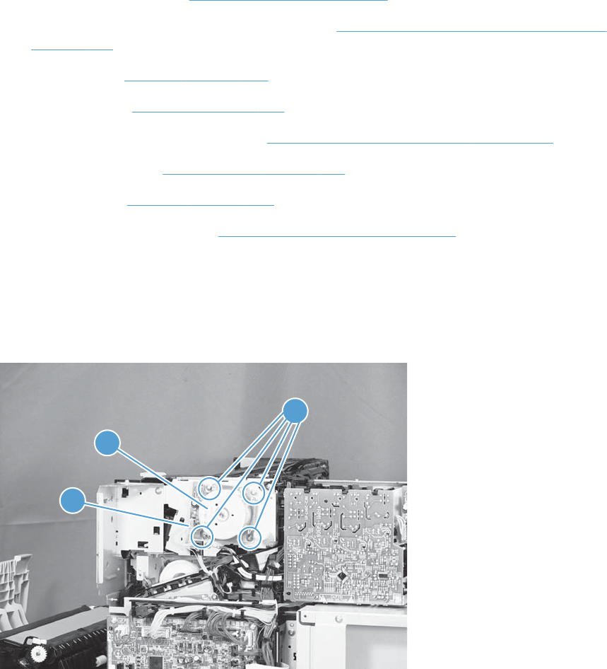
Fuser motor (M4)
Before proceeding, remove the following components:
●Toner collection unit. See Toner-collection unit on page 91.
●Right-front cover and control-panel assembly. See Right-front cover and control-panel assembly
on page 113.
●Left cover. See Left cover on page 115.
●Rear cover. See Rear cover on page 116.
●Toner collection unit access door. See Toner collection unit access door on page 117.
●Right-rear cover. See Right-rear cover on page 119.
●Top cover. See Top cover on page 121.
●Residual toner full sensor. See Residual toner full sensor on page 152.
Remove the fuser motor
Disconnect one connector (callout 1), remove four screws (callout 2), and then remove the motor
(callout 3).
Figure 2-143 Remove the fuser motor
2
3
1
196 Chapter 2 Removal and replacement ENWW
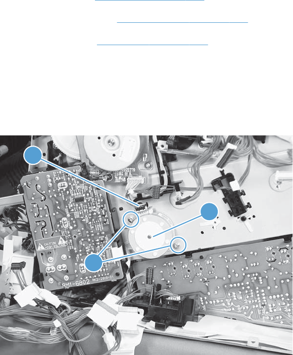
Developing-disengagement motor (M6)
Before proceeding, remove the following components:
●Rear cover. See Rear cover on page 116.
●Right-rear cover. See Right-rear cover on page 119.
●Driver PCA. See Driver PCA on page 218.
Remove the developing-disengagement motor
Disconnect one connector (callout 1), remove two screws (callout 2), and then remove the motor (callout
3).
Figure 2-144 Remove the developing-disengagement motor
1
3
2
ENWW Removal and replacement procedures 197
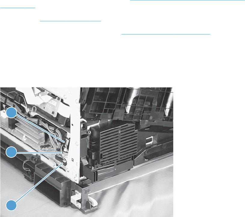
Power-supply fan (FM1)
Before proceeding, remove the following components:
●Right-front cover and control-panel assembly. See Right-front cover and control-panel assembly
on page 113.
●Left cover. See Left cover on page 115.
●Front-door assembly (steps 1 and 2 only). See Front-door assembly on page 123.
Remove the power-supply fan
1. Disconnect one connector (callout 1), and then release the cables (callout 3) from the guide
(callout 2).
Figure 2-145 Remove the power-supply fan (1 of 3)
1
3
2
198 Chapter 2 Removal and replacement ENWW
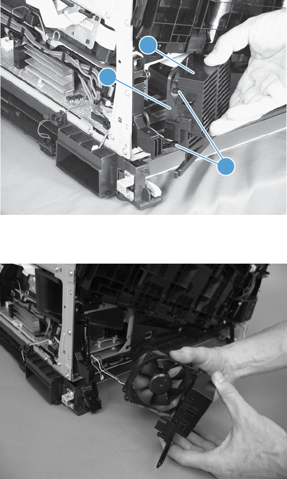
2. Release two tabs (callout 1), and then remove the fan (callout 2) and the fan holder (callout 3)
together.
Figure 2-146 Remove the power-supply fan (2 of 3)
3
1
2
3. Pull on the sides of the fan holder to remove the fan from the holder.
Figure 2-147 Remove the power-supply fan (3 of 3)
ENWW Removal and replacement procedures 199
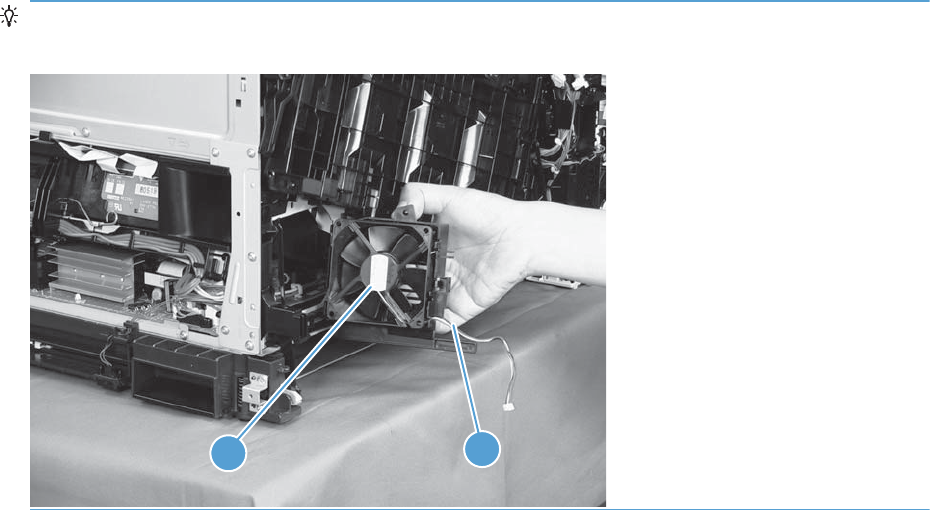
Reinstallation tip When reinstalling the fan, verify that the fan cables (callout 1) are positioned as
shown and that the label (callout 2) on the fan is facing toward the inside of the product.
1
2
200 Chapter 2 Removal and replacement ENWW
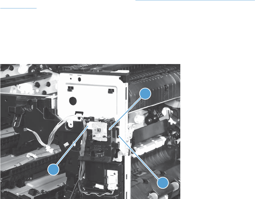
Fuser fan (FM2)
Before proceeding, remove the following components:
●Right-front cover and control-panel assembly. See Right-front cover and control-panel assembly
on page 113.
Remove the fuser fan
1. Disconnect one connector (callout 1), release one tab (callout 2), and then slide the guide
(callout 3) down to remove it.
Figure 2-148 Remove the fuser fan (1 of 4)
3
2
1
ENWW Removal and replacement procedures 201
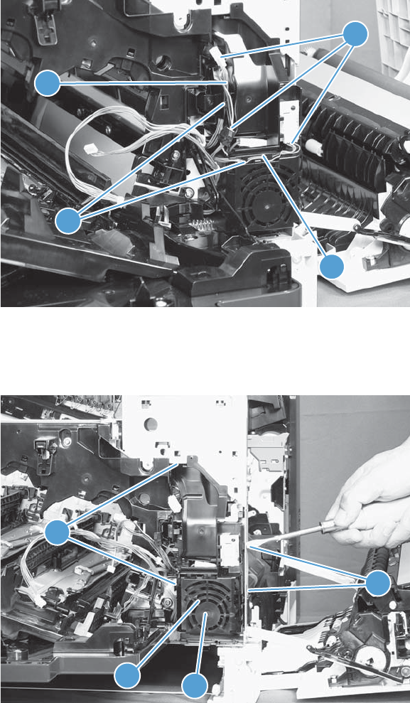
2. Disconnect three connectors (callout 1), and then release the cables (callout 3) from the cable
guides (callout 2).
Figure 2-149 Remove the fuser fan (2 of 4)
2
3
3
1
3. Release four tabs (callout 1), and then remove the fan (callout 2) and the fan holder (callout 3)
together.
Figure 2-150 Remove the fuser fan (3 of 4)
1
23
1
202 Chapter 2 Removal and replacement ENWW
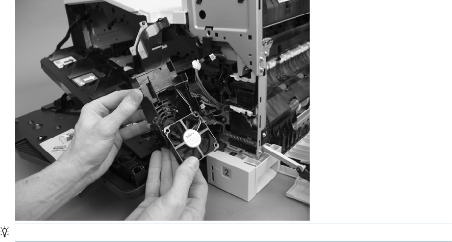
4. Turn the fan holder over, and then pull the fan out of the holder.
Figure 2-151 Remove the fuser fan (4 of 4)
Reinstallation tip Note the wiring path and label orientation for reinstallation.
ENWW Removal and replacement procedures 203
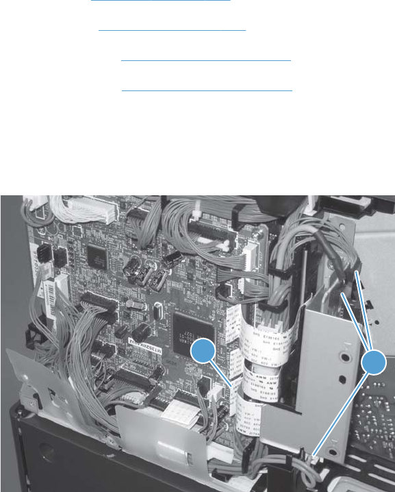
Formatter fan (FM3) and ICB PCA
Before proceeding, remove the following components:
●Left cover. See Left cover on page 115.
●Rear cover. See Rear cover on page 116.
●Formatter PCA. See Formatter PCA on page 105.
●Formatter case. See Formatter case on page 130.
Remove the formatter fan and ICB PCA
1. Disconnect three connectors (callout 1) and one FFC (callout 2).
Figure 2-152 Remove the formatter fan (1 of 5)
21
204 Chapter 2 Removal and replacement ENWW
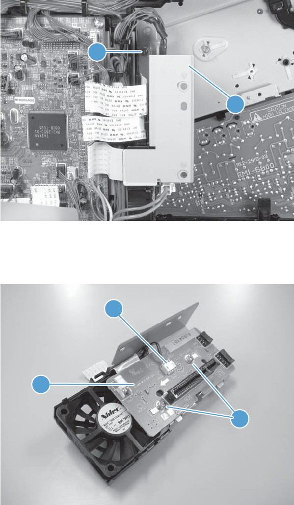
2. Remove one screw (callout 1) and then remove the sheet-metal plate (callout 2).
Figure 2-153 Remove the formatter fan (2 of 5)
2
1
3. Disconnect one connector (callout 1), remove two screws (callout 2), and then remove the inter
connect board (IBC) PCA (callout 3) from the assembly.
Figure 2-154 Remove the formatter fan (3 of 5)
2
1
3
ENWW Removal and replacement procedures 205
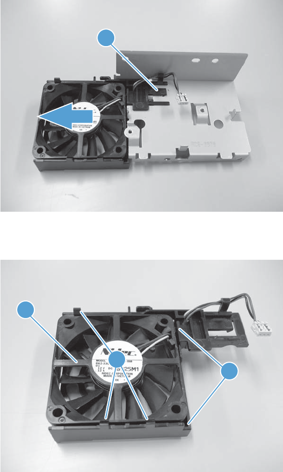
4. Release one tab (callout 1) and slide the formatter fan away form the sheet-metal plate to remove
it.
Figure 2-155 Remove the formatter fan (4 of 5)
1
5. Release three tabs (callout 1) and remove the fan (callout 2) from the holder (callout 3).
Figure 2-156 Remove the formatter fan (5 of 5)
2
3
1
206 Chapter 2 Removal and replacement ENWW
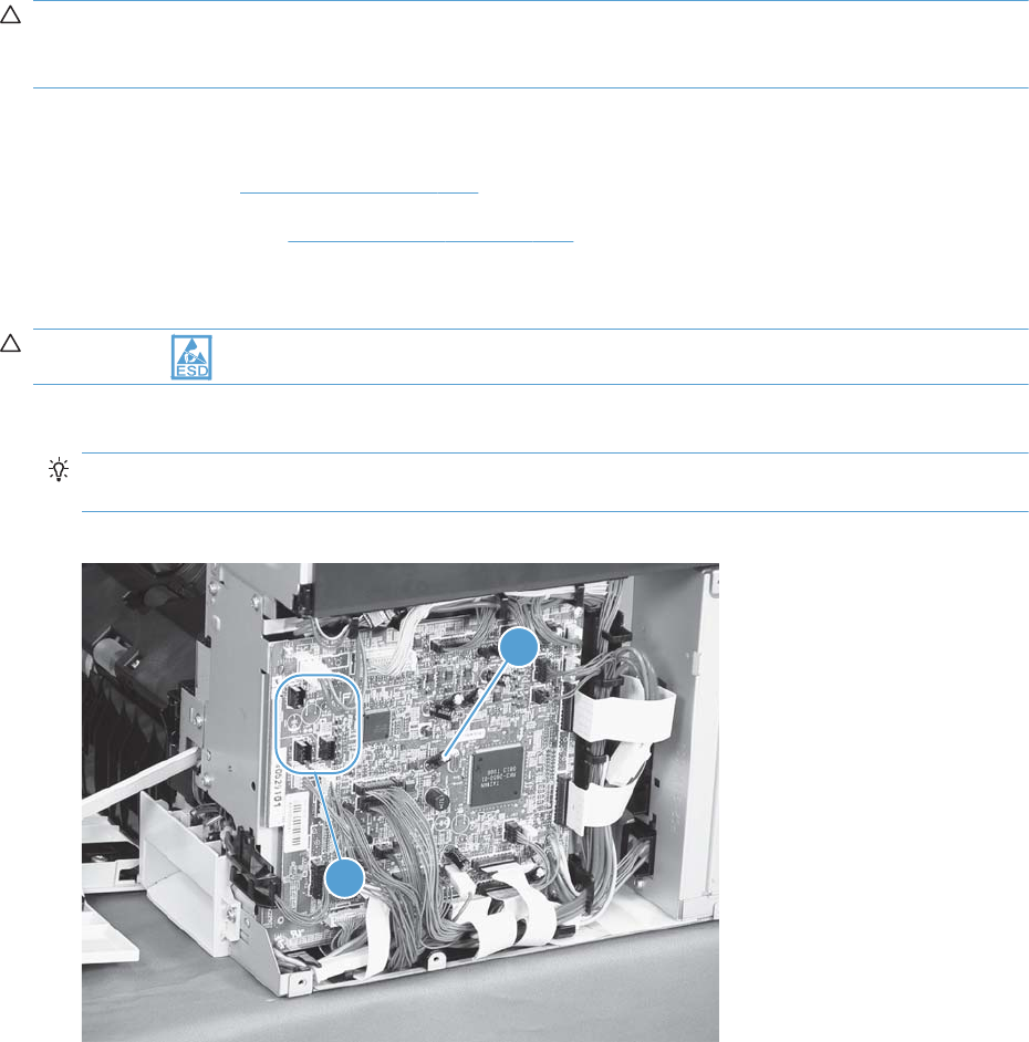
DC controller PCA
CAUTION: Do not replace the DC controller PCA and the formatter PCA at the same time. The
settings for the DC Controller PCA are stored in the formatter RAM. When you install a new DC
Controller PCA, it reads the settings from the formatter.
Before proceeding, remove the following components:
●Rear cover. See Rear cover on page 116.
●Right-rear cover. See Right-rear cover on page 119.
Remove the DC controller PCA
CAUTION: ESD-sensitive part.
1. Disconnect 22 connectors and six flat cables on the DC controller PCA (callout 1).
Reinstallation tip Two connectors (callout 2) should be empty when the DC controller is
reinstalled.
Figure 2-157 Remove the DC controller PCA (1 of 3)
1
2
ENWW Removal and replacement procedures 207
It is typically easier to
connect the flat cables
last - after all other
cables have been
connected.
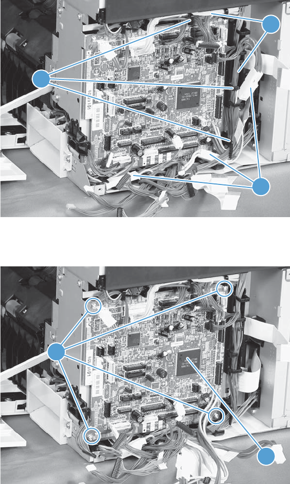
2. Disconnect three intermediate connectors (callout 1), and then release the cables (callout 3) from
the cable guides (callout 2) on the top and right sides of the DC controller PCA.
Figure 2-158 Remove the DC controller PCA (2 of 3)
2
1
3
3. Remove four screws (callout 1), and then remove the DC controller PCA (callout 2).
Figure 2-159 Remove the DC controller PCA (3 of 3)
1
2
208 Chapter 2 Removal and replacement ENWW
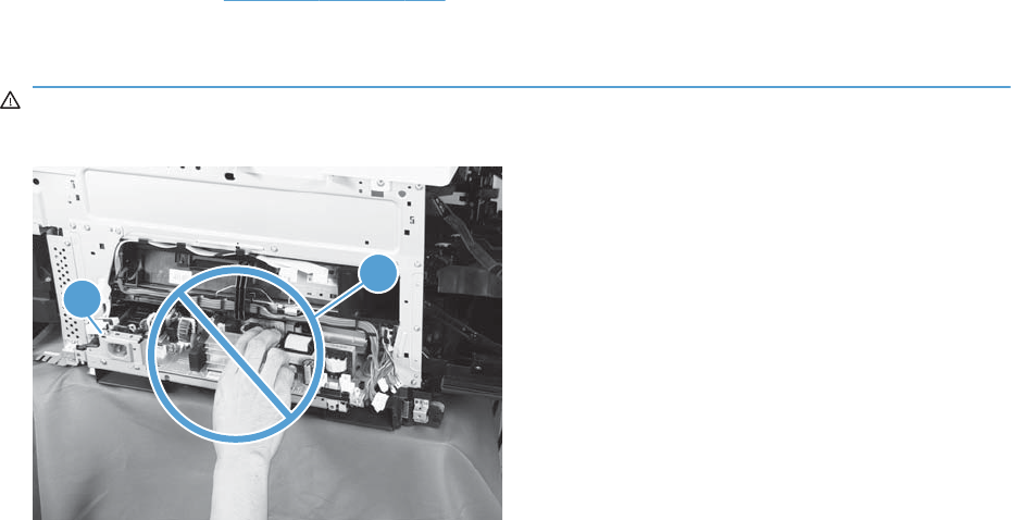
Low-voltage power supply
Before proceeding, remove the following components:
●Tray 2 cassette.
●Left cover. See Left cover on page 115.
Remove the low-voltage power supply
WARNING! When removing the low-voltage power supply unit (callout 1), do not touch the electric
element (callout 2) as shown. Be sure to hold the bottom side of the low-voltage power supply unit.
1
2
ENWW Removal and replacement procedures 209
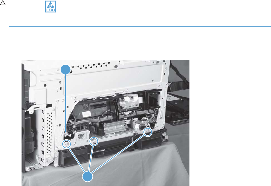
CAUTION: ESD-sensitive part.
Unplug the power cord from the product before proceeding.
1. Open the front door, disconnect two connectors (callout 1), and then remove three screws (callout
2) that have a triangular icon next to them.
Figure 2-160 Remove the low-voltage power supply (1 of 3)
2
1
210 Chapter 2 Removal and replacement ENWW
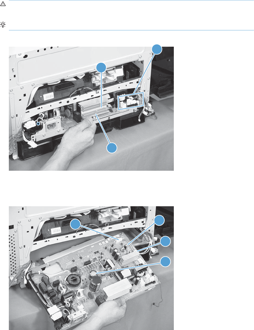
2. Slightly lift up on the low-voltage power supply (callout 1), slide it slightly forward, disconnect
eight connectors (callout 2), and then release the cables from the front cable clamp.
WARNING! Do not use the power supply electric element (callout 3) as a handle to pull out the
power supply.
TIP: One of the connectors (callout 2) is located far back inside the product.
Figure 2-161 Remove the low-voltage power supply (2 of 3)
1
3
2
3. Release the cables (callout 2) from the rear cable clamp (callout 1), disconnect one rear connector
(callout 3), and then remove the low-voltage power supply unit (callout 4).
Figure 2-162 Remove the low-voltage power supply (3 of 3)
32
1
4
ENWW Removal and replacement procedures 211
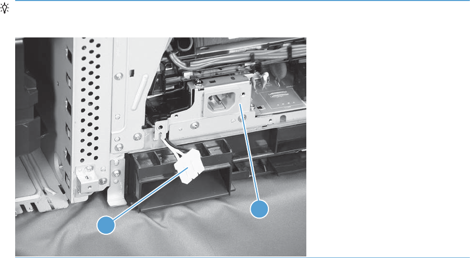
Reinstallation tip When reinstallling the low-voltage power supply unit (callout 1), be careful not to
catch the AC cables (callout 2) in the low-voltage power supply unit.
1
2
212 Chapter 2 Removal and replacement ENWW
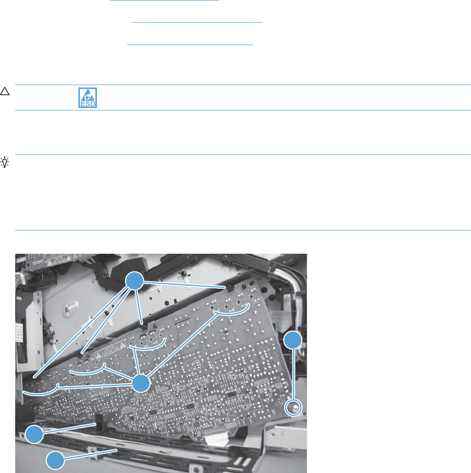
Imaging (developing) high-voltage power supply
Before proceeding, remove the following components:
●Rear cover. See Rear cover on page 116.
●Right-rear cover. See Right-rear cover on page 119.
●Formatter case. See Formatter case on page 130.
Remove the imaging (developing) high-voltage power supply
CAUTION: ESD-sensitive part.
Remove one screw (callout 1), release four tabs (callout 2), remove the cable routing plate (callout 3),
and then remove the imaging (developing) high-voltage power supply PCA.
Reinstallation tip Reinsert the power supply by angling the smaller left end behind the DC
controller and driver PCA. Ensure that the power supply sits behind the black tab (callout 4). Carefully
press the power supply to engage all four tabs.
When you reinstall the power supply PCA, look through the holes on the PCA (callout 5) and make sure
that the contact springs are correctly positioned against the back side of the PCA.
Figure 2-163 Remove the imaging (developing) high-voltage power supply
1
2
3
4
5
ENWW Removal and replacement procedures 213
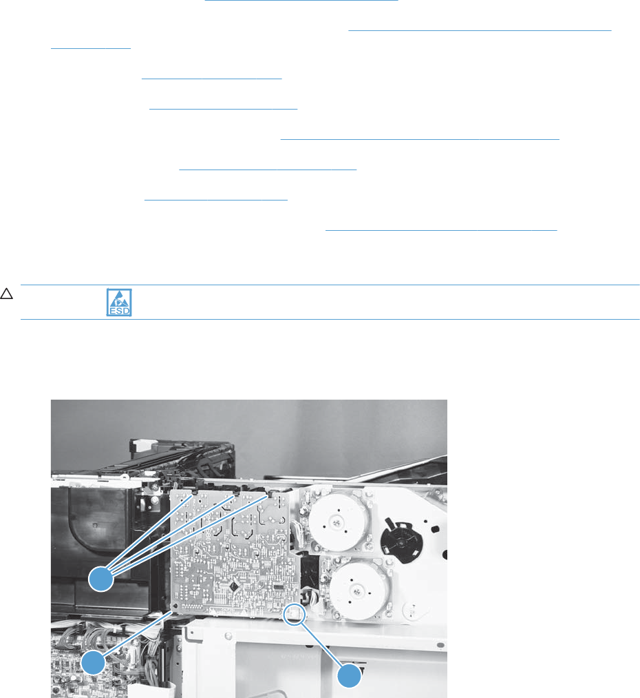
First transfer high-voltage power supply
Before proceeding, remove the following components:
●Toner collection unit. See Toner-collection unit on page 91.
●Right-front cover and control-panel assembly. See Right-front cover and control-panel assembly
on page 113.
●Left cover. See Left cover on page 115.
●Rear cover. See Rear cover on page 116.
●Toner collection unit access door. See Toner collection unit access door on page 117.
●Right-rear cover. See Right-rear cover on page 119.
●Top cover. See Top cover on page 121.
●Toner cover. See the first and second steps of Residual toner full sensor on page 152.
Remove the first transfer high-voltage power supply
CAUTION: ESD-sensitive part.
1. Remove one screw (callout 1), release three tabs (callout 2), and then slide the power supply off
the alignment post (callout 3).
Figure 2-164 Remove the first transfer high-voltage power supply (1 of 2)
1
2
3
214 Chapter 2 Removal and replacement ENWW
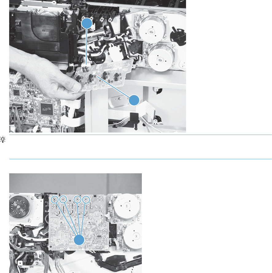
2. Disconnect one connector (callout 2), and then remove the first transfer high-voltage power supply
PCA (callout 1).
Figure 2-165 Remove the first transfer high-voltage power supply (2 of 2)
1
2
Reinstallation tip When you reinstall the power supply PCA, look through the holes on the
PCA (callout 1) and make sure that the contact springs are correctly positioned against the back
side of the PCA.
Figure 2-166 Reinstall the first transfer high-voltage power supply
1
ENWW Removal and replacement procedures 215
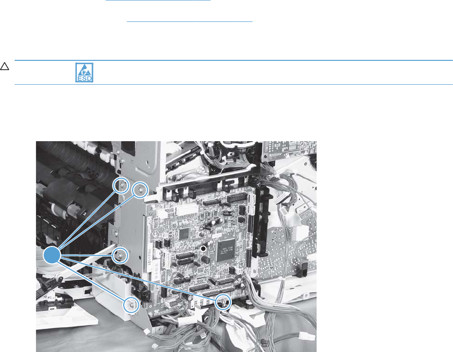
Second transfer high-voltage power supply
Before proceeding, remove the following components:
●Rear cover. See Rear cover on page 116.
●Right-rear cover. See Right-rear cover on page 119.
Remove the second transfer high-voltage power supply
CAUTION: ESD-sensitive part.
1. Disconnect all of the cables and FFCs from the DC controller (release the cables from the guides),
remove five screws (callout 1), and then remove the DC controller and the DC controller support.
Figure 2-167 Remove the second transfer high-voltage power supply (1 of 2)
1
216 Chapter 2 Removal and replacement ENWW
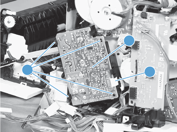
2. Release four tabs (callout 1), and then unroute the cable (callout 2) as you remove the second
transfer high-voltage power supply (callout 3).
Figure 2-168 Remove the second transfer high-voltage power supply (2 of 2)
1
3
2
ENWW Removal and replacement procedures 217

Driver PCA
Before proceeding, remove the following components:
●Rear cover. See Rear cover on page 116.
●Right-rear cover. See Right-rear cover on page 119.
Remove the driver PCA
CAUTION: ESD-sensitive part.
1. Disconnect all of the cables and FFCs from the DC controller (release the cables from the guides),
remove six screws (callout 1), and then remove the DC controller and the DC controller support.
Figure 2-169 Remove the driver PCA (1 of 2)
1
218 Chapter 2 Removal and replacement ENWW
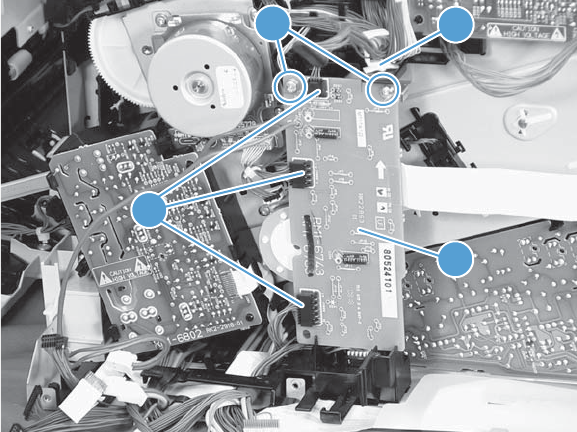
2. Disconnect three connectors (callout 1), remove two screws (callout 2), and then unroute the cable
(callout 3) as you remove the driver PCA (callout 4).
Figure 2-170 Remove the driver PCA (2 of 2)
23
1
4
ENWW Removal and replacement procedures 219
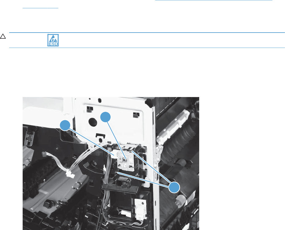
Power switch PCA
Before proceeding, remove the following components:
●Right-front cover and control-panel assembly. See Right-front cover and control-panel assembly
on page 113.
Remove the power switch PCA
CAUTION: ESD-sensitive part.
1. Open the front door and the right door.
2. Disconnect one connector (callout 1), release two tabs (callout 2), and then remove the PCA
(callout 3).
Figure 2-171 Remove the power switch PCA
1
3
2
220 Chapter 2 Removal and replacement ENWW
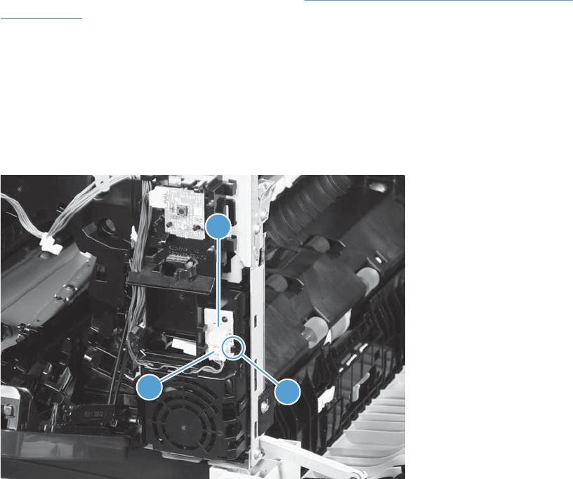
Environmental sensor
Before proceeding, remove the following components:
●Right-front cover and control-panel assembly. See Right-front cover and control-panel assembly
on page 113.
Remove the environmental sensor
1. Open the front door and the right door.
2. Disconnect one connector (callout 1), release one tab (callout 2), and then remove the
environmental sensor (callout 3).
Figure 2-172 Remove the environmental sensor
2
1
3
ENWW Removal and replacement procedures 221
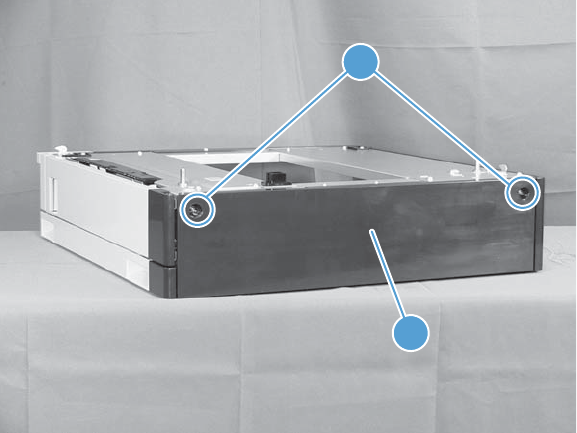
1 x 500-sheet paper feeder assembly
1 x 500 rear cover
Remove two screws (callout 1), and then remove the rear cover (callout 2).
Figure 2-173 Remove the 1 x 500 rear cover
2
1
222 Chapter 2 Removal and replacement ENWW
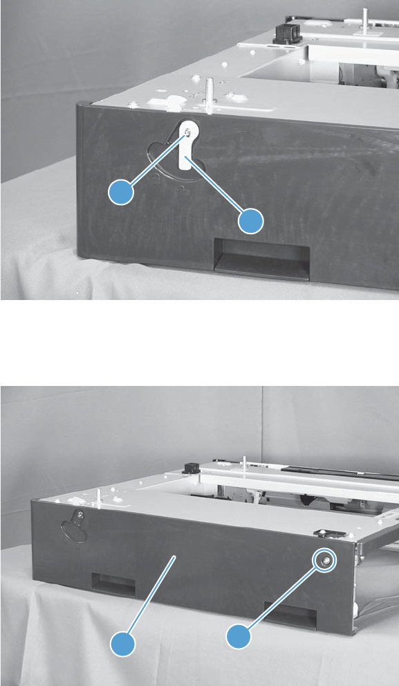
1 x 500 left cover
1. Take the cassette out of the feeder, release one tab (callout 1), and then remove the lever
(callout 2).
Figure 2-174 Remove the 1 x 500 left cover (1 of 2)
1
2
2. Remove one screw (callout 1), release four tabs from the inside (see the tip that follows this step),
and then remove the left cover (callout 2).
Figure 2-175 Remove the 1 x 500 left cover (2 of 2)
1
2
ENWW Removal and replacement procedures 223
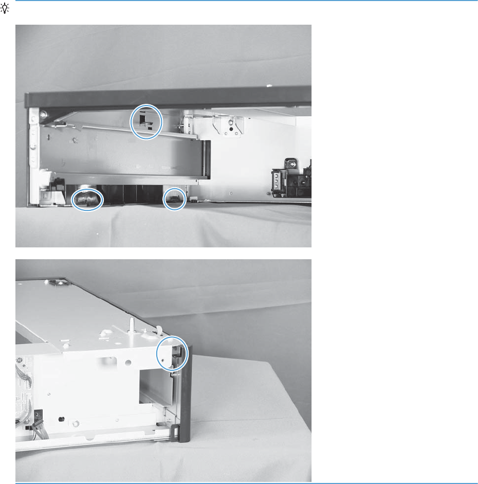
TIP: The following figures show the tabs inside the cover.
224 Chapter 2 Removal and replacement ENWW
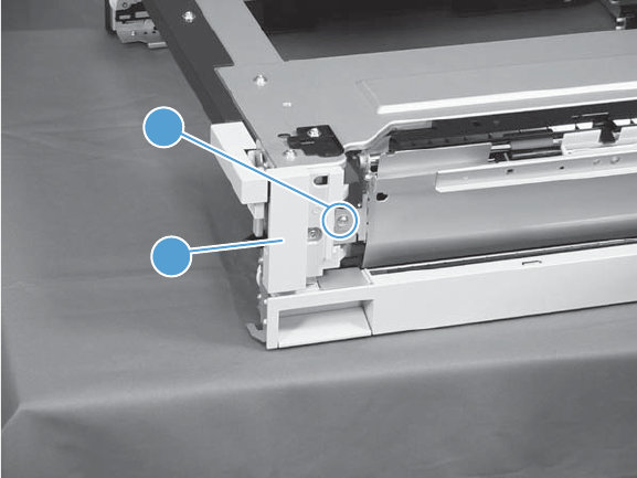
1 x 500 right-front cover
1. Take the cassette out of the feeder, and then open the right door.
2. Remove one screw (callout 1), and then remove the right-front cover (callout 2).
Figure 2-176 Remove the 1 x 500 right-front cover
2
1
ENWW Removal and replacement procedures 225
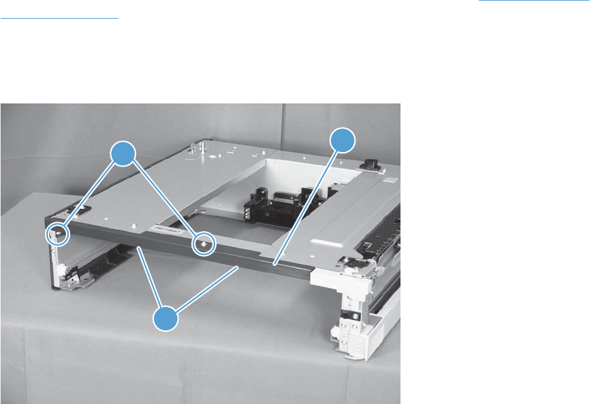
1 x 500 front-upper cover
1. Remove the cassette from the feeder, and then remove the right-front cover (see 1 x 500 right-front
cover on page 225).
2. Remove two screws (callout 1), release two tabs (callout 2), and then remove the front upper cover
unit (callout 3).
Figure 2-177 Remove the 1 x 500 front-upper cover
1
2
3
226 Chapter 2 Removal and replacement ENWW
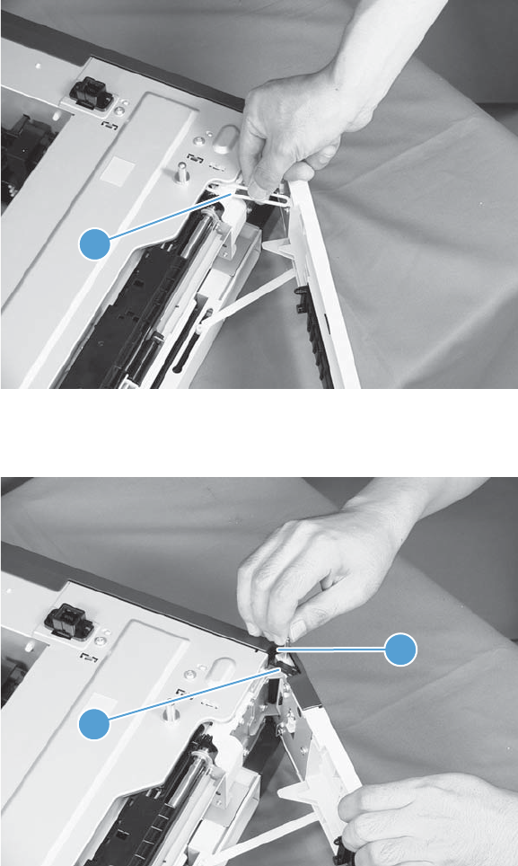
1 x 500 right door
1. Lift the product off the feeder, and then open the tray right door.
2. Release the link arm (callout 1).
Figure 2-178 Remove the 1 x 500 right door (1 of 3)
1
3. Release the stopper (callout 1), and then release the shaft (callout 2).
Figure 2-179 Remove the 1 x 500 right door (2 of 3)
1
2
ENWW Removal and replacement procedures 227
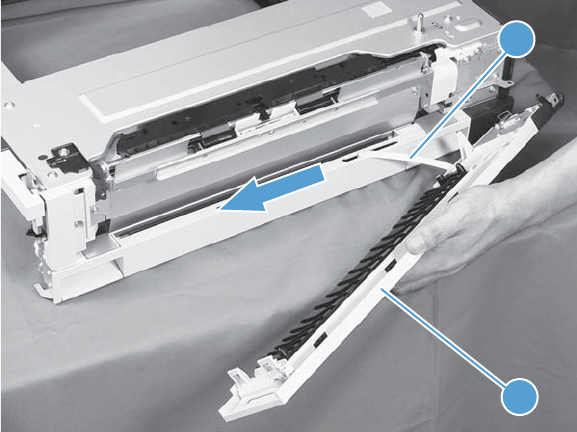
4. Slide the right door (callout 1) and the arm (callout 2) in the direction that the arrow indicates to
remove them together, and then remove the arm from the right door unit.
Figure 2-180 Remove the 1 x 500 right door (3 of 3)
2
1
228 Chapter 2 Removal and replacement ENWW

1 x 500 right-lower cover
1. Remove the cassette from the feeder, and then remove the right door (see 1 x 500 right door
on page 227).
2. Remove one screw (callout 1), and then slide the cover (callout 2) to the right to clear an
alignment pin at the left side of the cover.
Figure 2-181 Remove the 1 x 500 right-lower cover
2
1
ENWW Removal and replacement procedures 229
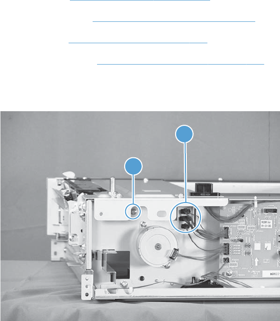
1 x 500 pickup assembly
Before proceeding, remove the following components:
●Rear cover. See 1 x 500 rear cover on page 222.
●Right-front cover. See 1 x 500 right-front cover on page 225.
●Right door. See 1 x 500 right door on page 227.
●Right-lower cover. See 1 x 500 right-lower cover on page 229.
1. Disconnect three connectors (callout 1), and then remove one screw (callout 2).
Figure 2-182 Remove the 1 x 500 pickup assembly (1 of 4)
1
2
230 Chapter 2 Removal and replacement ENWW
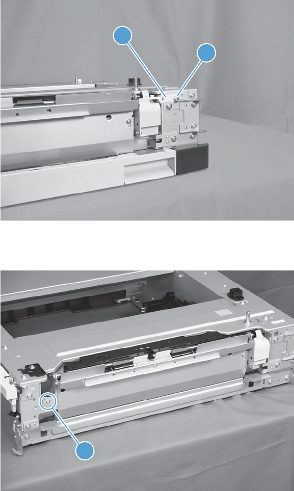
2. Remove one screw (callout 1), and then remove the stopper of the right-door link (callout 2).
Figure 2-183 Remove the 1 x 500 pickup assembly (2 of 4)
1
2
3. Remove one screw (callout 1).
Figure 2-184 Remove the 1 x 500 pickup assembly (3 of 4)
1
ENWW Removal and replacement procedures 231
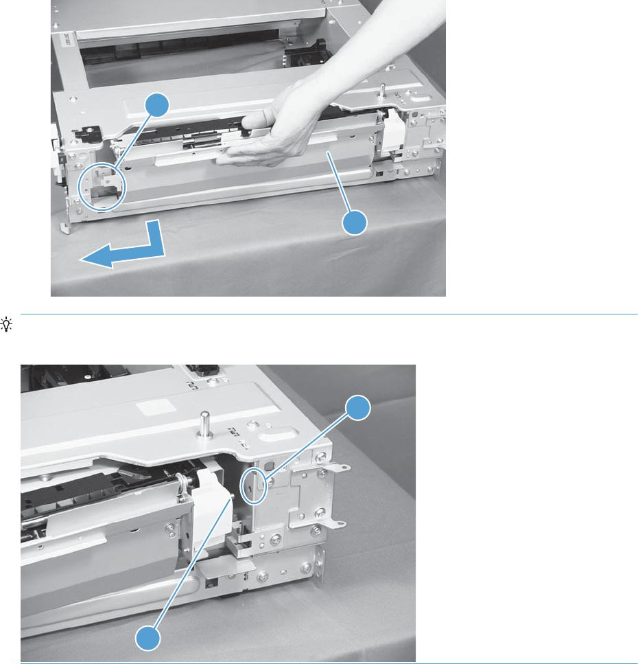
4. Lift the 1 x 500 pickup assembly (callout 1) slightly to clear a tab (callout 2), and then slide it in
the direction that the arrow indicates to remove it.
Figure 2-185 Remove the 1 x 500 pickup assembly (4 of 4)
1
2
Reinstallation tip When reassembling the 1 x 500 pickup assembly, be sure to fit the shaft (callout
1) on the assembly to the hole (callout 2) in the feeder.
2
1
232 Chapter 2 Removal and replacement ENWW
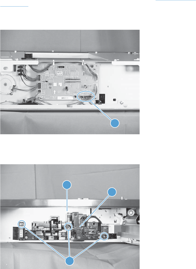
1 x 500 lifter-drive assembly
1. Remove the cassette from the feeder, and then remove the rear cover (see 1 x 500 rear cover
on page 222).
2. Disconnect two connectors (callout 1).
Figure 2-186 Remove the 1 x 500 lifter-drive assembly (1 of 2)
1
3. From the front, inside the tray cavity, remove three screws (callout 1), release one tab (callout 2),
and then remove the 1 x 500 lifter-drive assembly (callout 3).
Figure 2-187 Remove the 1 x 500 lifter-drive assembly (2 of 2)
2
3
1
ENWW Removal and replacement procedures 233
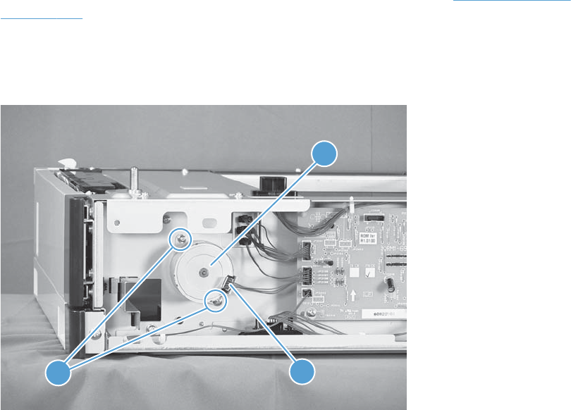
1 x 500 pickup motor
1. Remove the cassette from the feeder, and then remove the rear cover (see 1 x 500 rear cover
on page 222).
2. Disconnect one connector (callout 1), remove two screws (callout 2), and then remove the 1 x 500
pickup motor (callout 3).
Figure 2-188 Remove the 1 x 500 pickup motor
21
3
234 Chapter 2 Removal and replacement ENWW
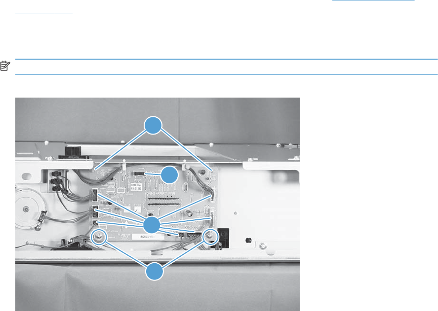
1 x 500 driver PCA
1. Remove the cassette from the feeder, and then remove the rear cover (see 1 x 500 rear cover
on page 222).
2. Disconnect seven connectors (callout 1), remove two screws (callout 2), release two tabs (callout
3), and then remove the 1 x 500 driver PCA.
NOTE: One connector (callout 4) on the 1 x 500 driver PCA remains empty.
Figure 2-189 Remove the 1 x 500 driver PCA
3
2
1
4
ENWW Removal and replacement procedures 235
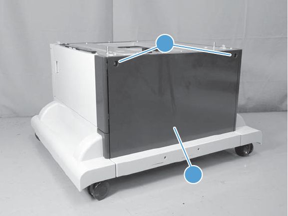
3 x 500-sheet paper feeder (optional accessory)
3 x 500 rear cover
Remove two screws (callout 1), and then remove the 3 x 500 rear cover (callout 2).
Figure 2-190 Remove the 3 x 500 rear cover
1
2
236 Chapter 2 Removal and replacement ENWW
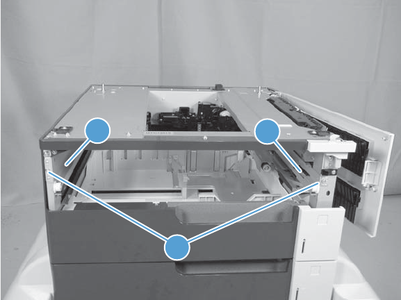
3 x 500 right and left cassette rails
1. Remove a cassette.
2. Remove two screws (callout 1), and then remove the 3 x 500 right (callout 2) and left (callout 3)
cassette rails. Repeat this procedure for the remaining cassette rails.
Figure 2-191 Remove the 3 x 500 right and left cassette rails
1
2
3
ENWW Removal and replacement procedures 237
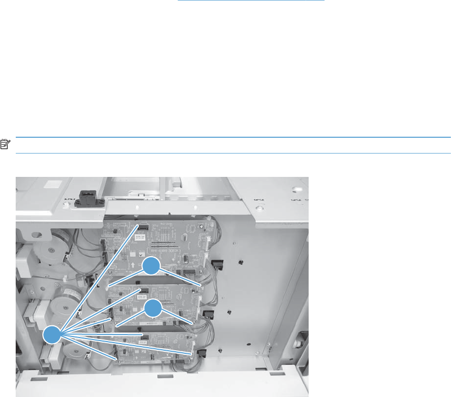
3 x 500 paper deck controller PCAs
1. Remove the 3 x 500 rear cover (see 3 x 500 rear cover on page 236).
2. Disconnect all of the connectors for the desired PCA.
●The top PCA has seven connectors.
●The middle PCA has six connectors.
●The bottom PCA has five connectors.
3. Remove two screws (callout 1), release two tabs (callout 2), and then remove the PCA. Repeat this
procedure for the remaining PCAs.
NOTE: Some connectors (callout 3) on the PCAs are not used.
Figure 2-192 Remove the 3 x 500 paper deck controller PCA
1
2
3
238 Chapter 2 Removal and replacement ENWW
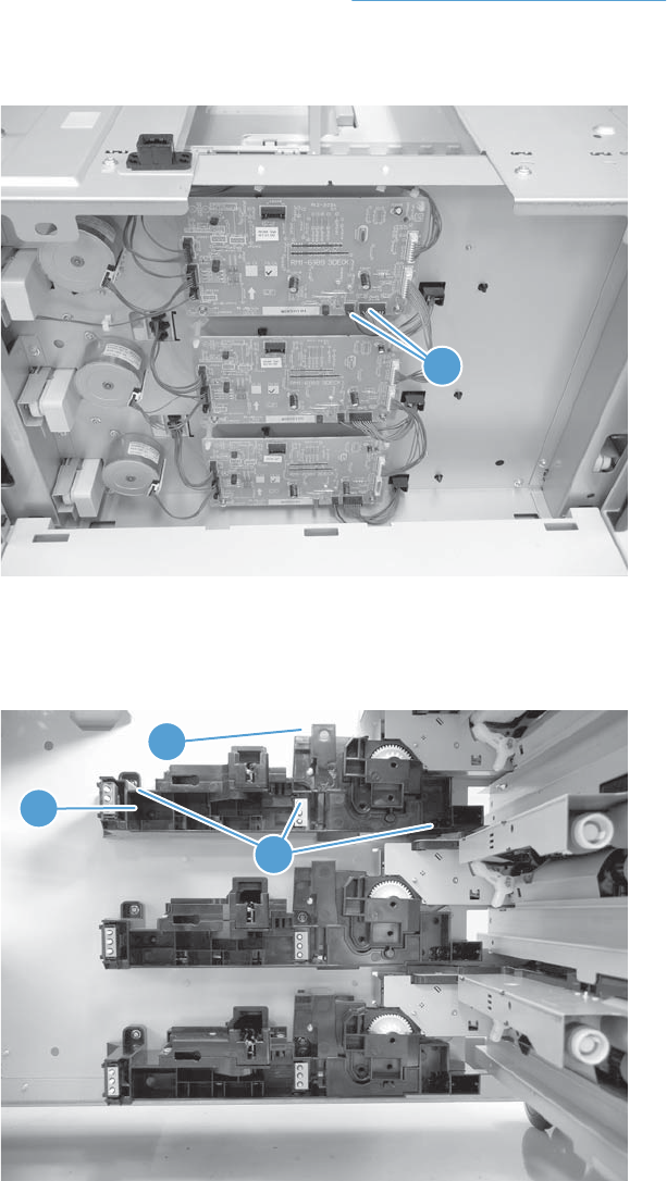
3 x 500 paper deck lifter-drive assembly
This procedure describes removing the paper deck cassette 1 lifter-drive assembly. Use this procedure
for any of the paper deck lifter assemblies.
1. Remove the 3 x 500 rear cover. See 3 x 500 rear cover on page 236.
2. Disconnect two connectors (callout 1).
Figure 2-193 Remove the 3 x 500 paper deck lifter-drive assembly (1 of 2)
1
3. Remove all of the cassettes, remove three screws (callout 1), release one tab (callout 2), and then
remove the cassette lifter assembly (callout 3).
Figure 2-194 Remove the 3 x 500 paper deck lifter-drive assembly (2 of 2)
3
2
1
ENWW Removal and replacement procedures 239
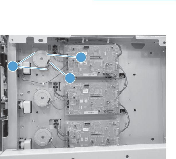
3 x 500 paper deck pickup motor
This procedure describes removing the paper deck cassette 1 pickup motor. Use this procedure for any
of the paper deck pickup motors.
1. Remove the 3 x 500 rear cover. See 3 x 500 rear cover on page 236.
2. Disconnect one connector (callout 1), remove two screws (callout 2), and then remove the cassette
pickup motor (callout 3).
Figure 2-195 Remove the 3 x 500 paper deck pickup motor
1
2
3
240 Chapter 2 Removal and replacement ENWW
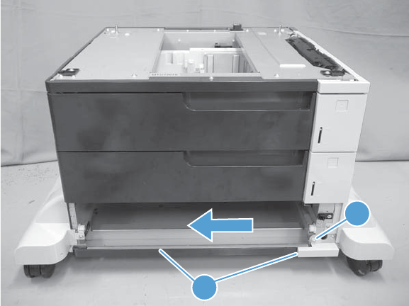
3 x 500 front-lower cover
1. Remove the lowest cassette.
2. Remove one screw (callout 1), and then slide the 3 x 500 front-lower cover (callout 2) toward the
left side of the feeder to remove it.
Figure 2-196 Remove the 3 x 500 front-lower cover
1
2
ENWW Removal and replacement procedures 241
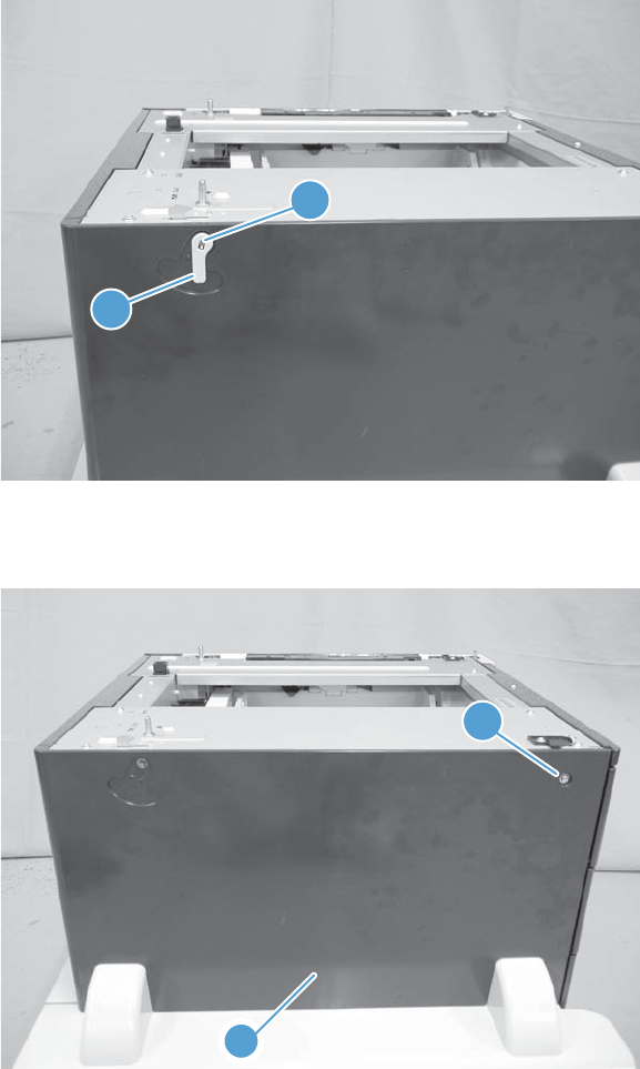
3 x 500 left cover
1. Release one tab (callout 1), and then remove the locking lever (callout 2).
Figure 2-197 Remove the 3 x 500 left cover (1 of 2)
1
2
2. Remove one screw (callout 1), and then remove the left cover (callout 2).
Figure 2-198 Remove the 3 x 500 left cover (2 of 2)
1
2
242 Chapter 2 Removal and replacement ENWW
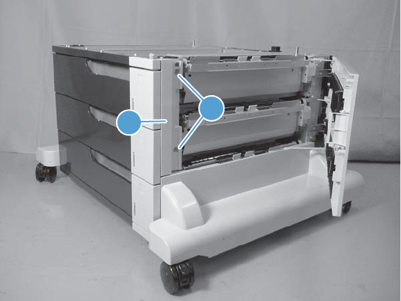
3 x 500 right-corner cover
Open the right door, remove two screws (callout 1), and then remove the 3 x 500 right-corner cover
(callout 2).
Figure 2-199 Remove the 3 x 500 right-corner cover
1
2
ENWW Removal and replacement procedures 243
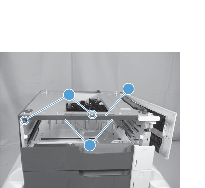
3 x 500 front-upper cover
1. Remove the right-corner cover (see 3 x 500 right-corner cover on page 243).
2. Remove the upper cassette.
3. Remove two screws (callout 1), release two tabs (callout 2), and then remove the front-upper cover
(callout 3).
Figure 2-200 Remove the 3 x 500 front-upper cover
1
2
3
244 Chapter 2 Removal and replacement ENWW
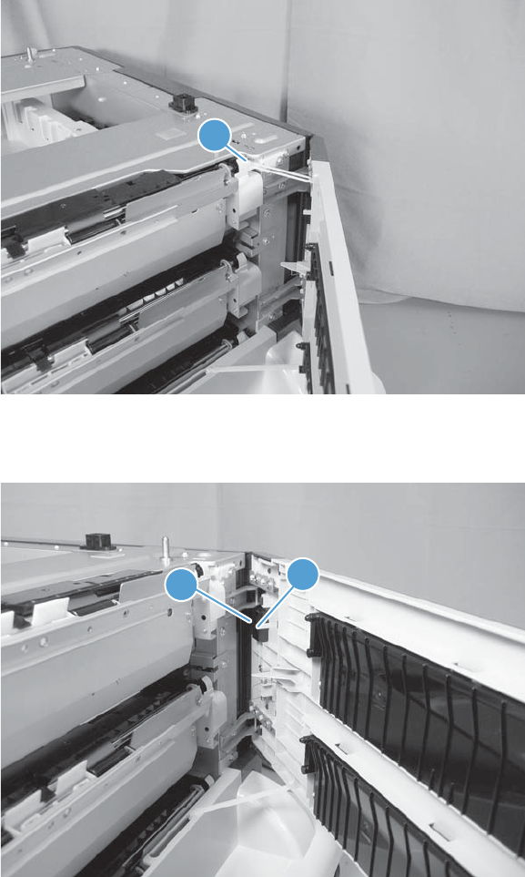
3 x 500 right-door assembly
1. Open the right door, and then release one upper-link arm (callout 1).
Figure 2-201 Remove the 3 x 500 right-door assembly (1 of 3)
1
2. Release one tab (callout 1), and then remove the stopper (callout 2).
Figure 2-202 Remove the 3 x 500 right-door assembly (2 of 3)
1
2
ENWW Removal and replacement procedures 245
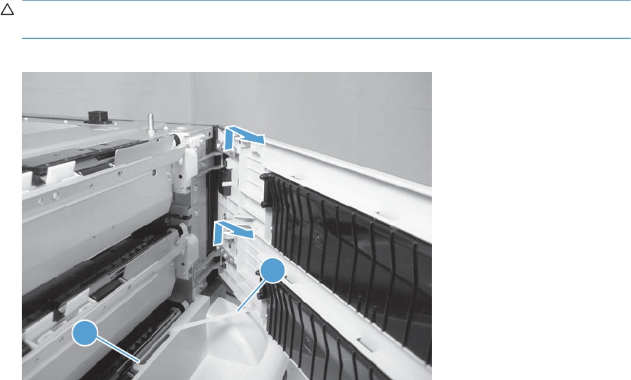
3. Lift up on the door to release it, slide the lower-link arm (callout 1) along the slot in the chassis to
the release point (callout 2), and then remove the 3 x 500 right door.
CAUTION: The door remains attached to the feeder until the link arm is released. Do not
damage the link arm when the door is removed.
Figure 2-203 Remove the 3 x 500 right-door assembly (3 of 3)
1
2
246 Chapter 2 Removal and replacement ENWW
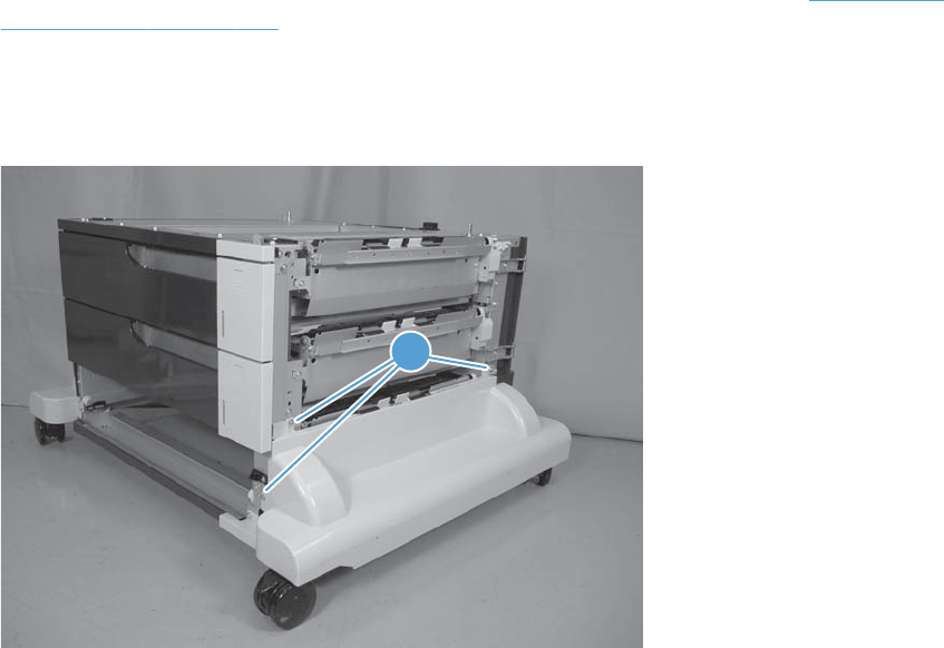
3 x 500 right-lower cover 1
1. Remove the lowest cassette, and then remove the 3 x 500 right door assembly (see 3 x 500 right-
door assembly on page 245).
2. Remove three screws (callout 1), loosen the top portion of the cover, and then remove the 3 x 500
right-lower cover 1.
Figure 2-204 Remove the 3 x 500 right-lower cover 1
1
ENWW Removal and replacement procedures 247
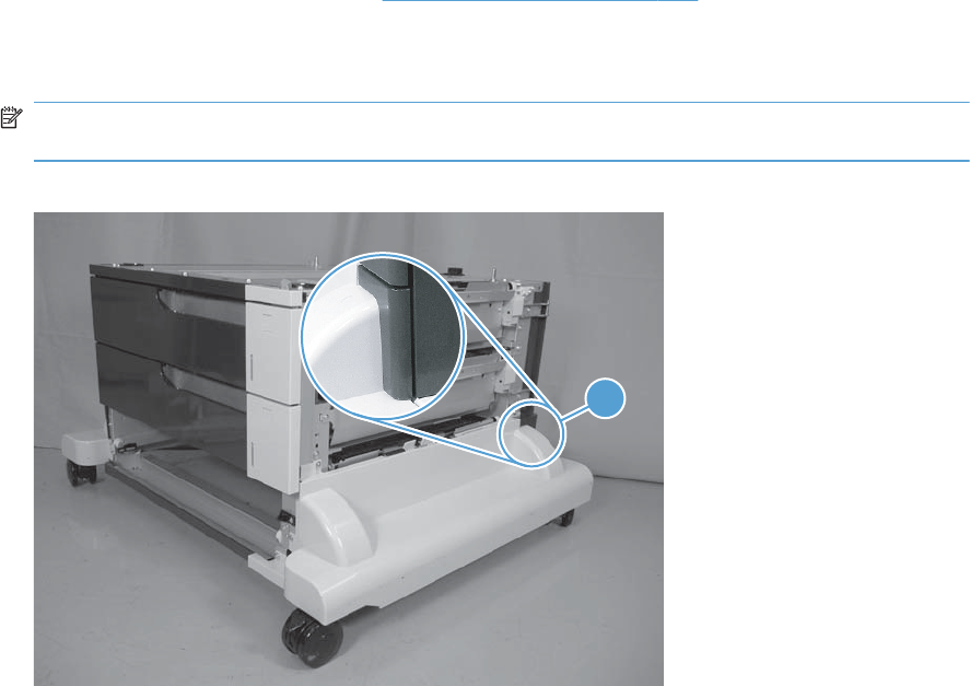
3 x 500 right-lower cover 2
1. Remove the 3 x 500 rear cover (see 3 x 500 rear cover on page 236).
2. Release one tab (not shown), and then slide the 3 x 500 right-lower cover 2 (callout 1) toward the
back of the feeder to remove it.
NOTE: The figure in this step does not show the rear cover removed. Remove the rear cover to
access the tab.
Figure 2-205 Remove the 3 x 500 right-lower cover 2
1
248 Chapter 2 Removal and replacement ENWW
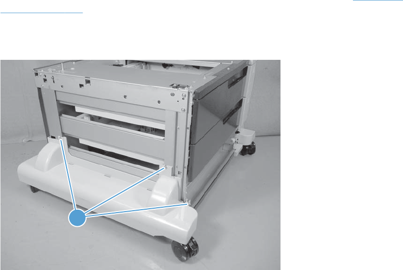
3 x 500 left-lower cover
1. Remove the lowest cassette, and then remove the 3 x 500 right door assembly (see 3 x 500 left
cover on page 242).
2. Remove three screws (callout 1), and then remove the 3 x 500 left-lower cover.
Figure 2-206 Remove the 3 x 500 left-lower cover
1
1
ENWW Removal and replacement procedures 249
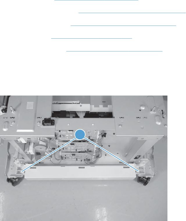
3 x 500 rear-lower cover
Before proceeding, remove the following components:
●Lowest cassette.
●Rear cover. See 3 x 500 rear cover on page 236.
●Right door assembly. See 3 x 500 right-door assembly on page 245.
●Right-lower cover. See 3 x 500 right-lower cover 1 on page 247.
●Left cover. See 3 x 500 left cover on page 242.
●Left-lower cover. See 3 x 500 left-lower cover on page 249.
Remove the 3 x 500 rear-lower cover
Remove two screws (callout 1), and then remove the 3 x 500 rear-lower cover.
Figure 2-207 Remove the 3 x 500 rear-lower cover
1
250 Chapter 2 Removal and replacement ENWW
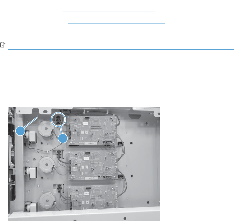
3 x 500 paper deck pickup assembly
Before proceeding, remove the following components:
●3 x 500 rear cover. See 3 x 500 rear cover on page 236.
●Right-corner cover. See 3 x 500 right-corner cover on page 243
●Right door assembly. See 3 x 500 right-door assembly on page 245.
●Right-lower cover. See 3 x 500 rear-lower cover on page 250.
NOTE: Remove this cover onlyif you are removing the paper-feeder cassette 3 pickup assembly.
Remove the 3 x 500 paper deck pickup assembly
This procedure describes removing the paper deck cassette 1 assembly. Use this procedure for any of
the paper deck pickup assemblies.
1. Remove one screw (callout 1), and then disconnect three connectors (callout 2).
Figure 2-208 Remove the 3 x 500 paper deck pickup assembly (1 of 3)
1
2
ENWW Removal and replacement procedures 251
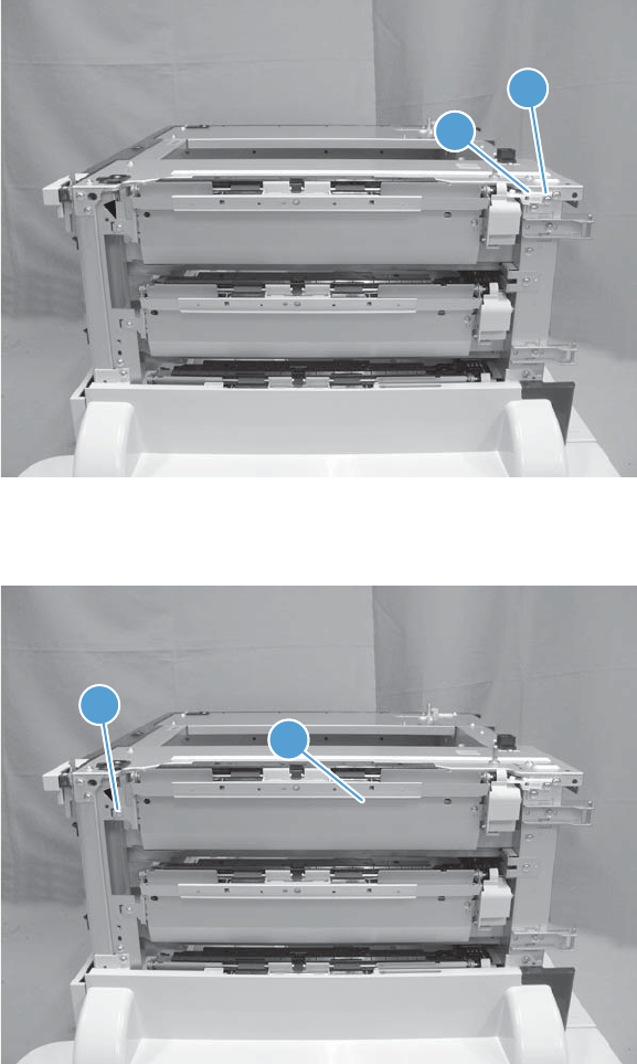
2. Remove the cassette, remove one screw (callout 1), and then remove the right-door link stopper
(callout 2).
Figure 2-209 Remove the 3 x 500 paper deck pickup assembly (2 of 3)
1
22
3. Remove one screw (callout 1), and then remove the paper deck pickup assembly (callout 2).
Figure 2-210 Remove the 3 x 500 paper deck pickup assembly (3 of 3)
1
22
252 Chapter 2 Removal and replacement ENWW

3 Solve problems
To use the information in this chapter, you should have a basic understanding of the HP LaserJet
printing process. Explanations of each mechanical assembly, the printer systems, and the basic theory
of operation are contained in the English-language service manual. Do not perform any of these
troubleshooting processes unless you understand the function of each product component.
●Solve problems checklist
●Menu map
●Troubleshooting process
●Tools for troubleshooting
●Clear jams
●Solve paper-handling problems
●Use manual print modes
●Solve image-quality problems
●Clean the product
●Solve performance problems
●Solve connectivity problems
●Service mode functions
●Preboot menu options
●Product updates
ENWW 253
Solve problems checklist
If the product is not responding correctly, complete the steps in the following checklist, in order. If the
product does not pass a step, follow the corresponding troubleshooting suggestions. If a step resolves
the problem, you can stop without performing the other steps on the checklist.
1. Make sure that the control-panel display shows one of the following messages: Ready, Paused,
or SLEEP MODE ON. If no lights are illuminated or the display does not say Ready, Paused,
or Sleep Mode, use the Power-on checks section in the product service manual to troubleshoot
the problem.
2. Check the cables.
a. Check the cable connection between the product and the computer or network port. Make
sure that the connection is secure.
b. Make sure that the cable itself is not faulty by using a different cable, if possible.
c. Check the network connection.
3. Ensure that the print media that you are using meets specifications.
4. Print a configuration page. If the product is connected to a network, an HP Jetdirect page also
prints.
a. If the pages do not print, check that at least one tray contains print media.
b. If the page jams in the product, see the jams section.
5. If the configuration page prints, check the following items.
a. If the page prints correctly, the product hardware is working. The problem is with the
computer you are using, with the printer driver, or with the program.
b. If the page does not print correctly, the problem is with the product hardware.
6. Does the image quality meet the user's requirements? If yes, see step 7. If no, check the following
items:
●Print the print-quality (PQ) troubleshooting pages.
●Solve the print-quality problems, and then see step 7.
7. At the computer, check to see if the print queue is stopped, paused, or set to print offline.
Windows: Click Start, click Settings, and then click Printers or Printers and Faxes.
Double-click the HP Color LaserJet CP5525n, HP Color LaserJet CP5525dn, or HP
Color LaserJet CP5525xh item depending on the product model installed.
-or-
Mac OS X: Open Printer Setup Utility, and then double-click the line for the HP Color
LaserJet CP5525n, HP Color LaserJet CP5525dn, or HP Color LaserJet CP5525xh
item depending on the product model installed.
254 Chapter 3 Solve problems ENWW
8. Verify that you have installed the HP Color LaserJet Enterprise CP5520 Printer Series printer driver.
Check the program to make sure that you are using the HP Color LaserJet Enterprise CP5520
Printer Series printer driver.
9. Print a short document from a different program that has worked in the past. If this solution works,
the problem is with the program that you are using. If this solution does not work (the document
does not print) complete these steps:
a. Try printing the job from another computer that has the product software installed.
b. If you connected the product to the network, connect the product directly to a computer with
a USB cable. Redirect the product to the correct port, or reinstall the software, and select the
new connection type that you are using.
ENWW Solve problems checklist 255

Menu map
Print the menu maps
1. At the control panel, press the Home button .
2. Open the following menus:
●Administration
●Reports
●Configuration/Status Pages
3. Use the Down arrow button to highlight the Administration Menu Map item, and then
press the OK button to select it.
4. Use the Up arrow button to highlight the Print item, and then press the OK button.
5. Press the Home button or Back button to exit the menus.
Current settings pages
Printing the current settings pages provides a map of the user configurable settings that might be helpful
in the troubleshooting process.
Print the current settings pages
1. At the control panel, press the Home button .
2. Open the following menus:
●Administration
●Reports
●Configuration/Status Pages
3. Use the Down arrow button to highlight the Current Settings Page item, and then press the
OK button to select it.
4. Use the Up arrow button to highlight the Print item, and then press the OK button
5. Press the Home button or Back button to exit the menus.
256 Chapter 3 Solve problems ENWW

Control panel menus
To use all of the capabilities of this product, a firmware upgrade might be required. HP recommends
that you periodically go to www.hp.com/go/ljcp5525series_software to see if a new version of
firmware is available.
NOTE: Print a configuration page to determine the version of firmware currently installed in this
product.
Navigate the control-panel menus
●Press the Home button to access the menus.
●Use the up arrow button and down arrow button to highlight a desired menu item.
●Press the OK button to select the menu item.
Sign In menu
Table 3-1 Sign In menu
First level Second level Values
User Access Code Access Code
Administrator Access Code Access Code
Service Access Code Access Code
Retrieve Job From USB menu
Use the Retrieve Job From USB menu to view listings of jobs stored on an external USB memory
device.
Table 3-2 Retrieve Job From USB menu
First level Second level Values
Retrieve Job From USB OK
Cancel
Select a File or Folder Select from the provided list.
Retrieve Job From Device Memory menu
Use the Retrieve Job From Device Memory menu to view listings of jobs stored on the internal
product memory.
ENWW Menu map 257

Table 3-3 Retrieve Job From Device Memory menu
First level Second level Third level Values
Retrieve Job From Device
Memory
All Jobs (No PIN)
NOTE: Individual job names also
appear.
Print Range: 1 – 9999
Default = 1
Delete Select from the provided list.
Supplies menu
In the following table, asterisks (*) indicate the factory default setting.
Table 3-4 Supplies menu
First level Second level Third level Fourth level Values
Manage Supplies Supplies Status
Supply Settings Black Cartridge Very Low
Settings
Stop
Prompt to
continue*
Continue
Low Threshold
Settings
1-100%
Color Cartridges Very Low
Settings
Stop
Prompt to
continue*
Continue
Low Threshold
Settings
Cyan Cartridge
Magenta
Cartridge
Yellow Cartridge
1-100%
Fuser Very Low
Settings
Stop
Prompt to
continue*
Continue
Low Threshold
Settings
1-100%
Transfer Kit Very Low
Settings
Stop
Prompt to
continue*
Continue
258 Chapter 3 Solve problems ENWW

Table 3-4 Supplies menu (continued)
First level Second level Third level Fourth level Values
Low Threshold
Settings
1-100%
Color/Black Mix Auto*
Mostly Color
Pages
Mostly Black
Pages
Supply Messages Low Message On*
Off
Level Gauge On*
Off
Black Cartridge
OK: - Status
Cyan Cartridge
OK: - Status
Magenta
Cartridge OK: -
Status
Yellow Cartridge
OK: - Status
Toner Collection
Unit OK: - Status
Transfer Kit OK: -
Status
Fuser OK: -
Status
ENWW Menu map 259

Trays menu
In the following table, asterisks (*) indicate the factory default setting.
Table 3-5 Trays menu
First level Second level Values
Manage Trays Use Requested Tray Exclusively*
First
Manually Feed Prompt Always*
Unless loaded
Size/Type Prompt Display*
Do not display
Use another tray Enabled*
Disabled
Alternative Letterhead Mode Disabled*
Enabled
Blank Pages Auto*
Yes
Override A4/Letter Yes*
No
Tray 1 Size Select from a provided list.
Tray 1 Type Select from a provided list.
Tray 2 Size Select from a provided list.
Tray 2 Type Select from a provided list.
Tray 3 Size Select from a provided list.
Tray 3 Type Select from a provided list.
Tray 4 Size Select from a provided list.
Tray 4 Type Select from a provided list.
Tray 5 Size Select from a provided list.
Tray 5 Type Select from a provided list.
Tray 6 Size Select from a provided list.
Tray 6 Type Select from a provided list.
260 Chapter 3 Solve problems ENWW

Administration menu
Reports menu
Table 3-6 Reports menu
First level Second level Third level Values
Configuration/Status Pages Print
Administration Menu Map
Configuration Page
Supplies Status Page
Usage Page
Paper Path Page
File Directory Page
Current Settings Page
Color Usage Job Log
Other Pages Print
Demonstration Page
RGB Samples
CMYK Samples
PCL Font List
PS Font List
General Settings menu
In the following table, asterisks (*) indicate the factory default setting.
Table 3-7 General Settings menu
First level Second level Third level Fourth level Values
Date/Time Settings Date/Time Format Date Format DD/MMM/YYYY
MMM/DD/YYYY*
YYYY/MMM/DD
Time Format 12 hour (AM/PM)*
24 hours
Date/Time Date
Time
Time Zone
ENWW Menu map 261

Table 3-7 General Settings menu (continued)
First level Second level Third level Fourth level Values
Adjust for Daylight
Savings
On
Off*
Energy Settings Sleep Delay 15*
Range: 1 – 120 minutes
Optimum Speed/
Energy Usage
Faster First Page*
Save Energy
Save More Energy
Save Most Energy
Print Quality Adjust Color Highlights Cyan Density
Magenta Density
Yellow Density
Black Density
-5 to 5
Default = 0
Midtones Cyan Density
Magenta Density
Yellow Density
Black Density
-5 to 5
Default = 0
Shadows Cyan Density
Magenta Density
Yellow Density
Black Density
-5 to 5
Default = 0
Restore Color Values
Image Registration Adjust Tray <X> Print Test Page
X1 Shift
Y1 Shift
X2 Shift
Y2 Shift
-5.00 mm to 5.00 mm
Default = 0
Auto Sense Mode Tray 1 Sensing Full sensing
Expanded sensing*
Transparency Only
Tray X Sensing Expanded sensing*
Transparency Only
262 Chapter 3 Solve problems ENWW

Table 3-7 General Settings menu (continued)
First level Second level Third level Fourth level Values
Adjust Paper Types Select from a list of paper
types that the product
supports. The available
options are the same for
each paper type.
Print Mode Select from a list of print
modes.
Default = Auto Sense
Mode
Resistance Mode Normal*
Up
Down
Humidity Mode Normal*
High
Fuser Temp Mode Normal*
Up
Down
Paper Curl Mode Normal*
Reduced
Optimize Normal Paper Standard*
Smooth
Light Media Normal*
Smooth
Heavy Paper Standard*
Smooth
Envelope Control Normal*
Alternate 1
Alternate 2
Environment Normal*
Low Temp
Line Voltage Normal*
Low Voltage
Tray 1 Normal*
Alternate
Cleaning Control Normal*
Alternate
ENWW Menu map 263

Table 3-7 General Settings menu (continued)
First level Second level Third level Fourth level Values
Background Normal*
Alternate 1
Alternate 2
Alternate 3
Media Temp Normal*
Alternate
Uniformity Control Normal*
Alternate 1
Alternate 2
Alternate 3
Pre-Rotation Normal*
Alternate 1
Alternate 2
Alternate 3
Registration Normal*
Alternate
Transfer Control Normal*
Alternate 1
Alternate 2
Alternate 3
Moisture Control Normal*
Alternate
Restore Optimize
Edge Control Off
Light
Normal*
Maximum
Jam Recovery Auto*
Off
On
264 Chapter 3 Solve problems ENWW

Table 3-7 General Settings menu (continued)
First level Second level Third level Fourth level Values
Manage Stored Jobs Quick Copy Job
Storage Limit
1-300
Default = 32
Quick Copy Job Held
Timeout
Off*
1 hour
4 Hours
1 Day
1 Week
Default Folder Name
for Stored Jobs
Select from a list of folder
names.
Public*
Sort Stored Jobs By Job Name*
Date
Restore Factory
Settings
Reset All
Calibration
General
Print
Security
Restrict Color Enable
Disable
Color if Allowed*
ENWW Menu map 265

Retrieve From USB Settings menu
Table 3-8 Retrieve From USB Settings menu
First level Second level Values
Retrieve From USB Settings Access Code Enable*
Disable
Print Settings menu
In the following table, asterisks (*) indicate the factory default setting.
Table 3-9 Print Settings menu
First level Second level Values
Manual Feed Enabled
Disabled*
Courier Font Regular*
Dark
Wide A4 Enabled
Disabled*
Print PS Errors Enabled
Disabled*
Print PDF Errors Enabled
Disabled*
Personality Auto*
PCL
POSTSCRIPT
PDF
PCL Form Length Range: 5 – 128
Default = 60
Orientation Portrait*
Landscape
Font Source Internal*
Soft
USB
266 Chapter 3 Solve problems ENWW

Table 3-9 Print Settings menu (continued)
First level Second level Values
Font Number Range: 0 – 999
Default = 0
Font Pitch Range: 0.44 – 99.99
Default = 10
Font Point Size Range: 4.00 – 999.75
Default = 12.00
Symbol Set Select from a list of symbol sets.
Append CR to LF No*
Yes
Suppress Blank Pages No*
Yes
Media Source Mapping Standard*
Classic
Print Options menu
In the following table, asterisks (*) indicate the factory default setting.
Table 3-10 Print Options menu
First level Second level Values
Number of Copies Default = 1
Default Paper Size Select from a list of sizes that the
product supports.
Default Custom Paper Size Inches X Dimension Range: 2.99 – 12.28
Default = 12.28
Y Dimension Range: 5.00 – 18.50
Default = 18.5
MM X Dimension Range: 76 – 312
Default = 312
Y Dimension Range: 127 – 470
Default = 470
Sides 1-sided*
2-sided
ENWW Menu map 267

Table 3-10 Print Options menu (continued)
First level Second level Values
Two-Sided Format Book-style*
Flip-style
Enable Edge to Edge
Overrides
Enabled
Disabled*
268 Chapter 3 Solve problems ENWW

Display Settings menu
In the following table, asterisks (*) indicate the factory default setting.
Table 3-11 Display Settings menu
First level Second level Values
Display Brightness Range: -10 to 10
Default = 0
Language Select from a list of languages that the
product supports.
Show IP address Display*
Hide
Sleep Mode Disabled
Use sleep delay*
Use sleep schedule
Balance power savings/Wait time
Inactivity Timeout Range: 10 – 300 seconds
Default = 60
Clearable Warnings On
Job*
Continuable Events Auto continue (10 seconds)*
Press OK to continue
ENWW Menu map 269

Manage Supplies menu
In the following table, asterisks (*) indicate the factory default setting.
Table 3-12 Manage Supplies menu
First level Second level Third level Fourth level Values
Supplies Status
Supply Settings Black Cartridge Very Low Settings Stop
Prompt to continue*
Continue
Low Threshold
Settings
1-100%
Color Cartridges Very Low Settings Stop
Prompt to continue*
Continue
Low Threshold
Settings
Cyan Cartridge
Magenta Cartridge
Yellow Cartridge
1-100%
Fuser Very Low Settings Stop
Prompt to continue*
Continue
Low Threshold
Settings
1-100%
Transfer Kit Very Low Settings Stop
Prompt to continue*
Continue
Low Threshold
Settings
1-100%
Color/Black Mix Auto*
Mostly Color Pages
Mostly Black Pages
Supply Messages Low Message On*
Off
Level Gauge On*
Off
270 Chapter 3 Solve problems ENWW

Table 3-12 Manage Supplies menu (continued)
First level Second level Third level Fourth level Values
Reset Supplies New Fuser Kit No
Yes
New Transfer Kit No
Yes
Manage Trays menu
In the following table, asterisks (*) indicate the factory default setting.
Table 3-13 Manage Trays menu
First level Values
Use Requested Tray Exclusively*
First
Manually Feed Prompt Always*
Unless loaded
Size/Type Prompt Display*
Do not display
Use another tray Enabled*
Disabled
Alternative Letterhead Mode Disabled*
Enabled
Blank Pages Auto*
Yes
Override A4/Letter Yes*
No
ENWW Menu map 271

Network Settings menu
In the following table, asterisks (*) indicate the factory default setting.
Table 3-14 Network Settings menu
First level Values
I/O Timeout Range: 5 – 300 sec
Default = 15
Embedded Jetdirect See the table that follows for details. These menus have the same
structure. If an additional HP Jetdirect network card is installed in the
EIO slot, then both menus are available.
Table 3-15 Embedded Jetdirect
First level Second level Third level Fourth level Fifth level Values
Information Print Sec Report Yes
No*
TCP/IP Enable On*
Off
Host Name Use the arrow
buttons to edit the
host name.
NPIXXXXXX*
IPv4 Settings Config Method Bootp*
DHCP
Auto IP
Manual
Default IP Auto IP*
Legacy
DHCP Release Yes
No*
DHCP Renew Yes
No*
Primary DNS Range: 0 – 255
Default =
xxx.xxx.xx.xx
Secondary DNS Range: 0 – 255
Default = 0.0.0.0
272 Chapter 3 Solve problems ENWW

Table 3-15 Embedded Jetdirect (continued)
First level Second level Third level Fourth level Fifth level Values
IPv6 Settings Enable On*
Off
Address Manual Settings Enable On
Off*
Address Select from a
provided list.
DHCPV6 Policy Router Specified
Router
Unavailable*
Always
Primary DNS Select from a
provided list.
Secondary DNS Select from a
provided list.
Proxy Server Select from a
provided list.
Proxy Port Default = 00080
Idle Timeout Default = 0270
Security Secure Web HTTPS Required*
HTTPS Optional
IPSEC Keep
Disable*
802.1x Reset
Keep*
Reset Security Yes
No*
Diagnostics Embedded Test LAN HW Test Yes
No*
HTTP Test Yes
No*
SNMP Test Yes
No*
ENWW Menu map 273

Table 3-15 Embedded Jetdirect (continued)
First level Second level Third level Fourth level Fifth level Values
Data Path Test Yes
No*
Select All Tests Yes
No*
Execution Time Range: 1 – 60 hours
Default = 1
Execute Yes
No*
Ping Test Dest Type IPv4
IPv6
Dest IPv4 Range: 0 – 255
Default =
127.0.0.1
Dest IPv6 Select from a
provided list.
Default = : : 1
Packet Size Default = 64
Timeout Default = 001
Count Default = 004
Print Results Yes
No*
Execute Yes
No*
Ping Results Packets Sent Default = 00000
Packets Received Default = 00000
Percent Lost Default = 000
RTT Min Default = 0000
RTT Max Default = 0000
RTT Average Default = 0000
Ping In Progress Yes
No*
274 Chapter 3 Solve problems ENWW

Table 3-15 Embedded Jetdirect (continued)
First level Second level Third level Fourth level Fifth level Values
Refresh Yes
No*
Link Speed Auto*
10T Half
10T Full
100TX Half
100TX Full
100TX Auto
1000TX Full
Troubleshooting menu
In the following table, asterisks (*) indicate the factory default setting.
Table 3-16 Troubleshooting menu
First level Second level Third level Fourth level Values
Exit Troubleshooting
NOTE: This item only
displays if you are
backing out of the
Troubleshooting menu.
Print Event Log
View Event Log
Print Quality Pages Print PQ
Troubleshooting
Pages
Diagnostics Page
Color Band Test Print Test Page
Copies Range: 1 – 30
Default = 1
Diagnostic Tests Disable Cartridge
Check
Paper Path Sensors Start Test
Paper Path Test Print Test Page Print
Source Select from a list of the
available trays.
ENWW Menu map 275

Table 3-16 Troubleshooting menu (continued)
First level Second level Third level Fourth level Values
Test Duplex Path Off*
On
Number of Copies Range: 1 – 500
Default = 1
Manual Sensor Test Select from a list of the
product sensors.
Tray/Bin Manual
Sensor Test
Select from a list of the
product sensors.
Component Test Select from a list of
available components.
Repeat Off*
On
Print/Stop Test
Retrieve Diagnostic
Data
Export to USB
Diagnostic Files Device Data File
Debug Information
File*
Include Crash Dumps Off
On*
Cleanup Debug Info Off
On*
General Debug Data
Device Maintenance menu
Backup/Restore menu
CAUTION: Data backup and restoration is the responsibility of the customer/administrator of the
product. Service personnel should not back up or restore customer data under any circumstances.
In the following table, asterisks (*) indicate the factory default setting.
276 Chapter 3 Solve problems ENWW

Table 3-17 Backup/Restore menu
First level Second level Third level Values
Backup Data Scheduled Backups Enable Scheduling Disabled*
Enabled
Backup Time Default = current time
Days Between Backups Default = 1
Backup Now
Export Last Backup
Restore Data Insert a USB drive that contains
the backup file.
Calibration/Cleaning menu
In the following table, asterisks (*) indicate the factory default setting.
Table 3-18 Calibration/Cleaning menu
First level Second level Values
Auto Cleaning Off*
On
Cleaning Interval Select from a list of cleaning intervals.
Auto Cleaning Size Letter*
A4
Print Cleaning Page
Clean Laser Glass
Quick Calibration
Full Calibration
Delay Calibration at Wake/Power
On
Yes*
No
USB Firmware Upgrade menu
To display: At the product control panel, select the Device Maintenance menu, and then select the
USB Firmware Upgrade menu.
Insert a USB storage device with a firmware upgrade bundle into the USB port, and follow the on-
screen instructions.
ENWW Menu map 277

Service menu
The personal identification number (PIN; Service Access Code) used to access the Service menu is
11552010.
In the following table, asterisks (*) indicate the factory default setting.
First level Second level Third level Values
User Access Code
Administrator Access
Code
Service Access Code Print Event Log
View Event Log
Clear Event Log
Cycle Counts Mono Cycle Counts 0*
Range: 0 – 9999999
Color Cycle Count 0*
Range: 0 – 9999999
Refurbish Cycle Count 0*
Range: 0 – 9999999
Serial Number
Service ID 20182*
Cold Reset Paper Letter*
A4
New Registration Roller Yes
No*
Media Sensor Value 0*
Range: 0 – 4095
Manual Laser Glass
Cleaning
Test Support Continuous Print from
USB
Automatic Calibrations Disabled
Enabled*
278 Chapter 3 Solve problems ENWW

Troubleshooting process
When the product malfunctions or encounters an unexpected situation, the product control panel alerts
you to the situation. This chapter contains information to help diagnose and solve problems.
●Use the pretroubleshooting checklist to evaluate the source of the problem and to reduce the
number of steps that are required to fix the problem.
●Use the troubleshooting flowchart to pinpoint the root cause of hardware malfunctions. The
flowchart guides you to the section of this chapter that contains steps for correcting the
malfunction.
Before beginning any troubleshooting procedure, check the following issues:
●Are supply items within their rated life?
●Does the configuration page reveal any configuration errors?
NOTE: The customer is responsible for checking supplies and for using supplies that are in good
condition.
Determine the problem source
When the product malfunctions or encounters an unexpected situation, the product control panel alerts
you to the situation. This section contains a pre-troubleshooting checklist to filter out many possible
causes of the problem. A troubleshooting flowchart helps you diagnose the root cause of the problem.
The remainder of this chapter provides steps for correcting problems.
Pre-troubleshooting checklist
The following table includes basic questions to ask the customer to quickly help define the problem.
General topic Questions
Environment ●Is the product installed on a solid, level surface (+/- 1°)?
●Is the power-supply voltage within ± 10 volts of the specified power source?
●Is the power-supply plug inserted in the product and the outlet (not a power
strip)?
●Is the operating environment within the specified parameters?
●Is the product exposed to ammonia gas, such as that produced by diazo
copiers or office cleaning materials?
NOTE: Diazo copiers produce ammonia gas as part of the coping
processes. Ammonia gas (from cleaning supplies or a diazo copier) can have
an adverse affect on some product components (for example, the print-
cartridge OPC).
●Is the product exposed to direct sunlight?
ENWW Troubleshooting process 279

General topic Questions
Media ●Does the customer use only supported media?
●Is the media in good condition (no curls, folds, or distortion)?
●Is the media stored correctly and within environmental limits?
Input trays ●Is the amount of media in the tray within specifications?
●Is the media correctly placed in the tray?
●Are the paper guides aligned with the stack?
●Is the cassette correctly installed in the product?
Print cartridges ●Is each print cartridge installed correctly?
●Are original HP print cartridges installed?
●Are the cartridges damaged?
ITB and fuser ●Are the ITB and fuser correctly installed?
●Is the ITB or fuser damaged?
Doors ●Are the right and front doors closed?
Condensation ●Does condensation occur following a temperature change (particularly in
winter following cold storage)? If so, wipe affected parts dry or leave the
product on for 10 to 20 minutes.
●Was a print cartridge opened soon after being moved from a cold to a warm
room? If so, allow the print cartridge to sit at room temperature for 1 to 2
hours.
Miscellaneous ●Check for and remove any non-HP components (for example, print cartridges
or memory modules) from the product.
●Check to see whether the hardware or software configuration has changed or
the problem is not associated with any specific software.
●Remove the product from the network and ensure that the failure is associated
with the product before beginning troubleshooting.
●For any print-quality issues, calibrate the product. See Calibrate the product
on page 356.
Troubleshooting flowchart
This flowchart highlights the general processes that you can follow to quickly isolate and solve product
hardware problems.
Each row depicts a major troubleshooting step. A “yes” answer to a question allows you to proceed to
the next major step. A “no” answer indicates that more testing is needed. Go to the appropriate section
in this chapter, and follow the instructions there. After completing the instructions, go to the next major
step in this troubleshooting flowchart.
280 Chapter 3 Solve problems ENWW

Table 3-19 Troubleshooting flowchart
1
Power on
Is the product on and does a readable
message display?
Follow the power-on troubleshooting checks. See Power subsystem
on page 282.
After the control panel display is functional, see step 2.
Yes No
2
Control panel
messages
Does the message Ready display on the
control panel?
If an error message displays, see Interpret control-panel messages,
status-alert messages, and event code errors on page 411.
After the errors have been corrected, go to step 3.
Yes No
3
Event log
Open the Troubleshooting menu and print
an event log to see the history of errors with
this product.
Does the event log print?
If the event log does not print, see Print an event log
on page 493.
If paper jams inside the product, see Clear jams on page 495.
If error messages display on the control panel when you try to print
an event log, see Print an event log on page 493.
After successfully printing and evaluating the event log, see step 4.
Yes No
4
Information
pages
Open the Reports menu and print the
configuration pages to verify that all the
accessories are installed.
Are all the accessories installed?
If accessories that are installed are not listed on the configuration
page, remove the accessory and reinstall it.
After evaluating the configuration pages, see step 5.
Yes No
5
Image quality
Does the print quality meet the customer's
requirements?
Compare the images with the sample defects in the image defect
tables. See Print quality examples on page 524.
After the print quality is acceptable, see step 6.
Yes No
6
Interface
Can the customer print successfully from the
host computer?
Verify that all I/O cables are connected correctly and that a valid
IP address is listed on the Jetdirect configuration page.
If error messages display on the control panel, see Print an event
log on page 493.
When the customer can print from the host computer, this is the
end of the troubleshooting process.
Yes. This is the end of
the troubleshooting
process.
No
ENWW Troubleshooting process 281

Power subsystem
Power-on checks
The basic product functions should start up when the product is plugged into an electrical outlet and the
power switch is pushed to the on position. If the product does not start, use the information in this
section to isolate and solve the problem.
Power-on troubleshooting overview
Turn on the product power. If the control panel display remains blank, random patterns display, or
asterisks remain on the control panel display, perform power-on checks to find the cause of the
problem.
During normal operation, the power supply, fuser, and formatter cooling fans begin to spin after the
product power is turned on. Place your hand over the holes in the left-side cover, near the formatter. If
the fan is operating, you will feel air passing out of the product. You can also lean close to the product
and hear the fan operating. You can also place your hand over the hole in the right-front lower corner.
If the fan is operating, you should feel air being drawn into the product. When these fans are
operational, the DC side of the power supply is functioning correctly.
After the fans are operating, the motor turn on and off (unless the right or front cover is open, a jam
condition is sensed, or the paper-path sensors are damaged). You might be able to visually and
audibly determine if the motors turn on and off.
If the fans and motors are operating correctly, the next troubleshooting step is to isolate print engine,
formatter, and control panel problems. Perform an engine test (see Engine test button on page 288). If
the formatter is damaged, it might interfere with the engine test. If the engine-test page does not print,
try removing the formatter and then performing the engine test again. If the engine test is then
successful, the problem is almost certainly with the formatter, the control panel, or the cable that
connects them.
If the control panel is blank when you turn on the product, check the following items.
1. Make sure that the product is plugged directly into an active electrical outlet (not a power strip)
that delivers the correct voltage.
2. Make sure that the power switch is in the on position.
3. Make sure that the fans run briefly, which indicates that the power supply is operational.
4. Make sure that the control panel display wire harness is connected.
5. Make sure that the formatter is seated and operating correctly. Turn off the product and remove
the formatter. Reinstall the formatter, and then verify that the heartbeat LED is flashing.
6. Remove any HP Jetdirect or other EIO cards, and then try to turn the product on again.
NOTE: If the control panel display is blank, but the cooling fans run after the product power is turned
on, try printing an engine-test page to determine whether the problem is with the control-panel display,
formatter, or other product components. See Engine test button on page 288.
282 Chapter 3 Solve problems ENWW

Power-on timing (approximate)
Power-on timing from boot sequence to the Ready state might change as the firmware is upgraded.
●00.00 seconds; power-button LED illuminates and fans rotate at high speed
●00.06 seconds; control panel backlight illuminates and engine noises begin
●00:10 seconds; HP logo appears on the control-panel display, boot sequence count appears on
the control-panel display
Boot sequence
◦1/8 = 10 seconds
◦2/8 = 15 seconds
NOTE: Depending on how the product was shut down, the product might stay at this point
for several minutes while the Disk Check process completes.
◦7/8 = 45 seconds
◦8/8 = 50 seconds
●01:30 seconds; fuser fan noise stops and engine noises stop
●01:50 seconds; product enters the Ready state
ENWW Troubleshooting process 283
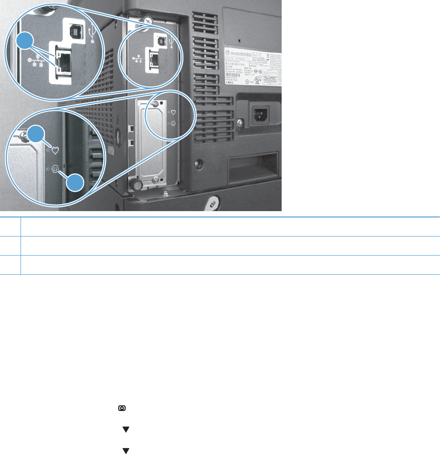
Tools for troubleshooting
Component diagnostics
LED diagnostics
LED, engine, and individual diagnostics can identify and troubleshoot product problems.
Understand lights on the formatter
Three LEDs on the formatter indicate that the product is functioning correctly.
1
3
2
1Formatter connectivity LED (lit when formatter is correctly seated)
2HP Jetdirect LEDs
3Heartbeat LED
HP Jetdirect LEDs
The embedded HP Jetdirect print server has two LEDs. The yellow LED indicates network activity, and
the green LED indicates the link status. A blinking yellow LED indicates network traffic. If the green LED
is off, a link has failed.
For link failures, check all the network cable connections. In addition, you can try to manually configure
the link settings on the embedded print server by using the product control-panel menus.
1. Press the Home button .
2. Press the Down arrow to highlight the Administration menu, and then press the OK button.
3. Press the Down arrow to highlight the Network Settings menu, and then press the OK
button.
284 Chapter 3 Solve problems ENWW

4. Press the Down arrow to highlight the Embedded Jetdirect option, and then press the OK
button.
5. Press the Down arrow to highlight the Link Speed menu, and then press the OK button.
6. Select the appropriate link speed, and then press the OK button.
Heartbeat LED
The heartbeat LED indicates that the formatter is functioning correctly. While the product is initializing
after you turn it on, the LED blinks on/off, on/off, pauses for a short duration, then repeats the
sequence. This sequence continues after the product has finished the initialization sequence.
Engine diagnostics
This section provides an overview of the engine diagnostics that are available in the HP Color LaserJet
Enterprise CP5520 Printer Series product. The product contains extensive internal diagnostics that help
in troubleshooting print quality, paper path, noise, component, and timing issues.
ENWW Tools for troubleshooting 285
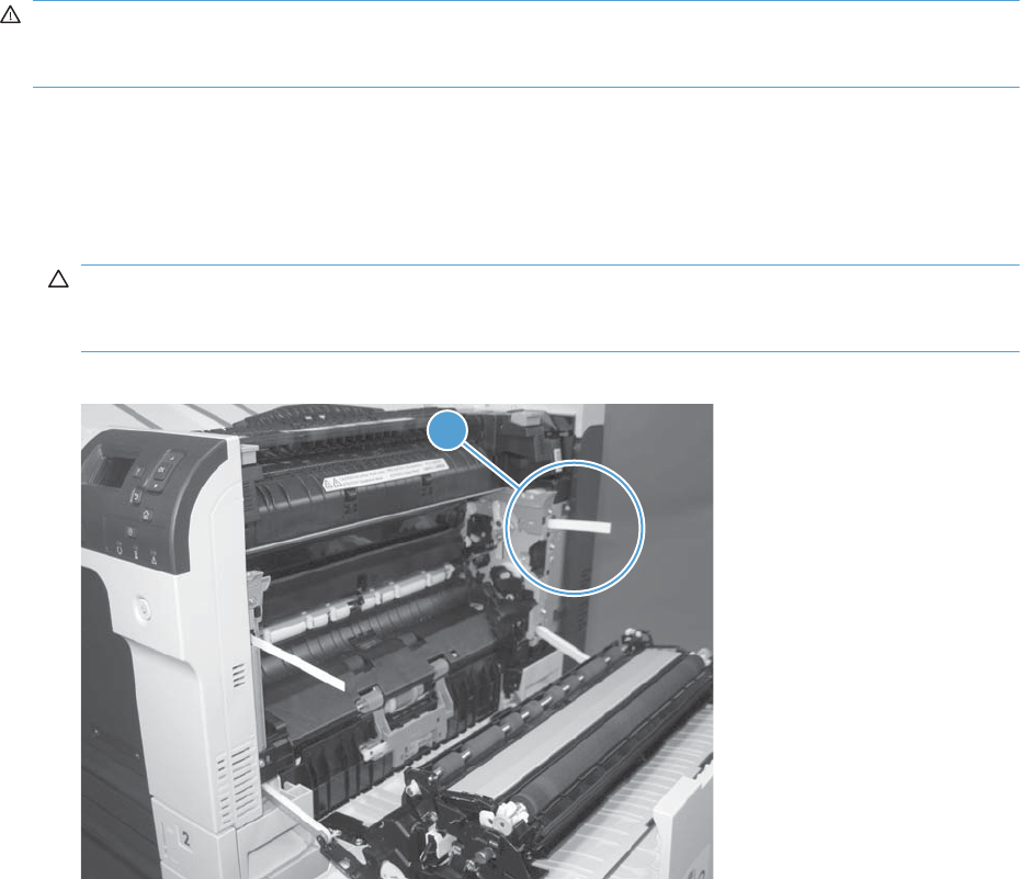
Defeating interlocks
Different tests can be used to isolate different types of issues. For component or noise isolation, you can
run the diagnostic test when the front and right doors are open. To operate the product with the doors
open, the door switch levers must be depressed to simulate a closed-door position.
WARNING! Be careful when performing printer diagnostics to avoid risk of injury. Only trained
service personnel should open the doors and run the diagnostics with the covers removed. Never touch
any of the power supplies when the printer is plugged in or turned on.
Defeat the right-door opening/closing sensor (PS15)
1. Open the right and front doors.
2. Insert a thin piece of paper into the right-door sensor slot (callout 1).
CAUTION: Using too thick of a piece of paper to activate this sensor might dislodge the photo-
interrupter body from its mounting bracket. Make sure you use a thin piece of paper to activate the
sensor.
Figure 3-1 Defeating door interlocks (1 of 2)
1
286 Chapter 3 Solve problems ENWW
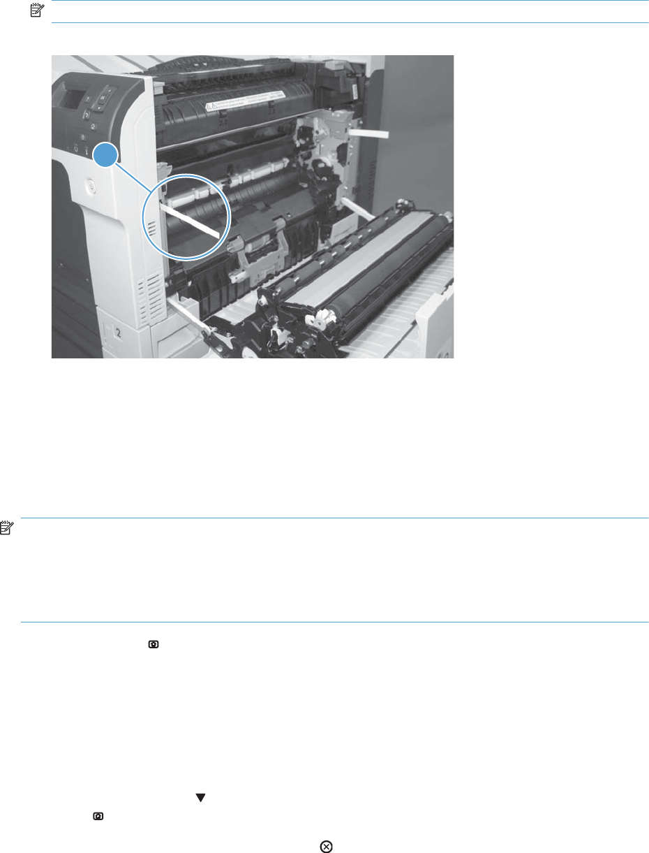
3. Insert a folded piece of paper into the front door switch (callout 2). Wait until the product enters
the Ready state.
NOTE: The paper must be thick enough to depress and hold in place the sensor actuator arm.
Figure 3-2 Defeating door interlocks (2 of 2)
1
Disable cartridge check
Use this diagnostic test to print internal pages or send an external job to the product when one or more
print cartridges are removed or exchanged. Consumable supply errors are ignored while the product is
in this mode. When the product is in this mode, you can navigate the troubleshooting menus and print
internal pages (the print quality pages will be the most useful). This test can be used isolate problems,
such as noise, and to isolate print-quality problems that are related to individual print cartridges.
NOTE: Cartridges are not keyed and can be interchanged. An error will display on the control panel
if a print cartridge is installed in the wrong position. The Supplies Status menu will explain which
print cartridge is misplaced.
NOTE: Do not remove or exchange print cartridges and image drums until after you start the disable
cartridge check diagnostic.
1. Press the Home button.
2. Open the following menus:
●Administration
●Troubleshooting
●Diagnostic Tests
3. Press the Down arrow to highlight DISABLE CARTRIDGE CHECK, and then press the OK
button .
To exit this diagnostic test, press the Stop button and then select EXIT TROUBLESHOOTING.
ENWW Tools for troubleshooting 287
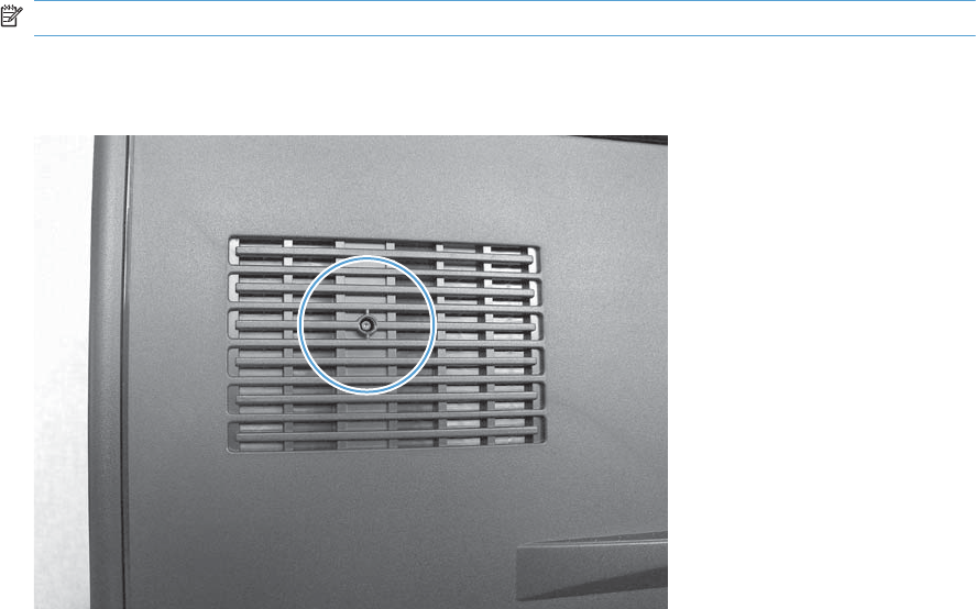
Engine test button
1. Turn the product on.
2. Use a fine-point tool, (for example a precision-slotted screwdriver with a 1 mm (0.04 in) blade
width) to press the engine test button.
NOTE: Access the engine test button through a hole in the rear cover.
3. An engine test page (lines in each of the print cartridge colors) prints.
Figure 3-3 Engine test button location
Paper-path test
This diagnostic test generates one or more test pages that you can use to isolate the cause of jams.
To isolate a problem, specify which input tray to use, specify whether to use the duplex path, and
specify the number of copies to print. Multiple copies can be printed to help isolate intermittent
problems. The following options become available after you start the diagnostic feature:
●Print Test Page. Run the paper-path test from the default settings: Tray 2, no duplex, and one
copy. To specify other settings, scroll down the menu and select the setting, and then scroll back
up and select Print Test Page to start the test.
●Source Tray. Select Tray 1, Tray 2, or the optional tray.
●Test Duplex Path. Enable or disable two-sided printing.
288 Chapter 3 Solve problems ENWW

NOTE: Duplex models only.
●Number of Copies. Set the numbers of copies to be printed; the choices are 1,10, 50, 100, or
500.
1. Press the Home button.
2. Open the following menus:
●Administration
●Troubleshooting
●Diagnostic Tests
3. Press the Down arrow to highlight PAPER PATH TEST, and then press the OK button.
4. Select the paper-path test options for the test you want to run.
Manual sensor test
Use this diagnostic test to manually test the product sensors and switches. Each sensor is represented by
a letter and number on the control panel display.
1. Press the Home button .
2. Open the following menus:
●Administration
●Troubleshooting
●Diagnostic Tests
3. Press the Down arrow to highlight the Manual Sensor Test item, and then press the OK
button.
To exit this diagnostic, press the Stop button , and then select EXIT TROUBLESHOOTING.
Menus cannot be opened during this test, so the OK button serves the same function as the
Stop button .
Table 3-20 Manual sensor diagnostic tests
Sensor or switch name Sensor or switch number
Front door opening/closing switch PS14
Right door opening/closing sensor PS15
A TOP (top of page) sensor PS5
Fuser loop 1 sensor PS7
Fuser loop 2 sensor PS8
Fuser pressure-release sensor PS9
Fuser output sensor PS6
ENWW Tools for troubleshooting 289

Table 3-20 Manual sensor diagnostic tests (continued)
Sensor or switch name Sensor or switch number
Developer alienation sensor PS11
ITB alienation sensor SW5
290 Chapter 3 Solve problems ENWW
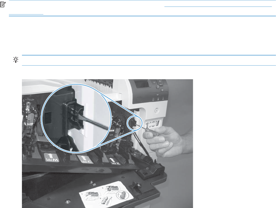
Front-door opening/closing switch (PS14)
NOTE: This switch is also activated by the right door. See Right-door opening/closing sensor (PS15)
on page 292. During this test, the right door must remain closed.
1. Open the front-door assembly to disengage the front-door opening/closing switch.
2. Close the front-door assembly, and then check the control panel on the product for sensor
response.
TIP: You can leave the front door open and use a folded piece of paper to activate the switch.
Figure 3-4 Test the front-door opening/closing switch
3. Check the control-panel display for sensor response.
4. If there is no response, replace the front-door opening/closing microswitch or the cable.
ENWW Tools for troubleshooting 291
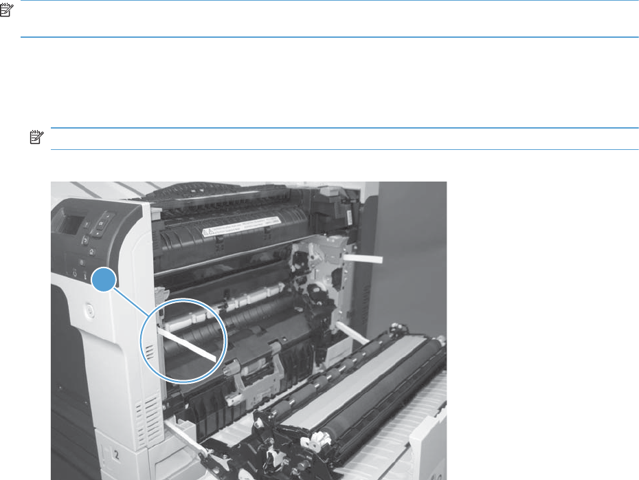
Right-door opening/closing sensor (PS15)
NOTE: The front-door opening/closing switch (PS14) is also activated by the right door. During this
test, the front door must remain closed.
1. Open the right-door assembly to disengage the right-door opening/closing photo-interrupter
sensor.
2. Insert a piece of paper (callout 1) to override the front-door opening/closing switch (PS14).
NOTE: The paper must be thick enough to depress and hold in place the sensor actuator arm.
Figure 3-5 Test the right-door opening/closing switch (1 of 2)
1
292 Chapter 3 Solve problems ENWW
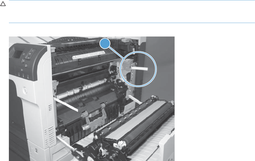
3. Insert a thin piece of paper (callout 1) to activate the right-door opening/closing sensor (PS15).
CAUTION: Using too thick of a piece of paper to activate this sensor might dislodge the photo-
interrupter body from its mounting bracket. Make sure you use a thin piece of paper to activate the
sensor.
Figure 3-6 Test the right-door opening/closing switch (2 of 2)
1
4. If there is no response, replace the right-door sensor.
ENWW Tools for troubleshooting 293
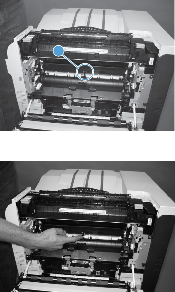
TOP (top-of-page) sensor (PS5)
1. Open the right door, and then locate the sensor flag (callout 1).
Figure 3-7 Test the TOP sensor (1 of 2)
1
2. Activate the TOP sensor.
Figure 3-8 Test the TOP sensor (2 of 2)
3. Check the control-panel display for sensor response.
4. If there is no response, replace the registration assembly.
294 Chapter 3 Solve problems ENWW
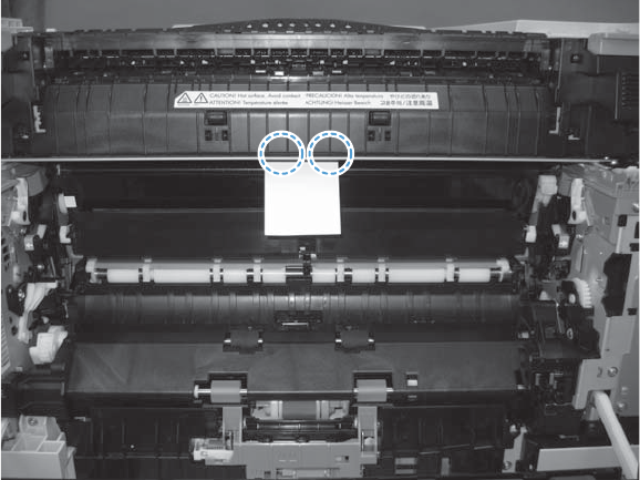
Fuser loop sensors 1 and 2 (PS7 and PS8)
1. Open the right door.
2. Slowly insert a piece of paper at the entrance of the fuser to activate the fuser loop sensors 1 and
2 underneath the fuser.
Figure 3-9 Test the fuser loop sensors
3. Check the control-panel display for a sensor response.
4. If there is no response, replace fuser.
ENWW Tools for troubleshooting 295
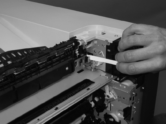
Fuser pressure-release sensor (PS9)
1. Open the right-door assembly.
2. Remove the fuser.
3. Insert a piece of paper as shown to activate the fuser pressure-release sensor.
Figure 3-10 Test the fuser pressure-release sensor
4. Check the control-panel display for sensor response.
5. If there is no response, replace the fuser drive assembly.
296 Chapter 3 Solve problems ENWW
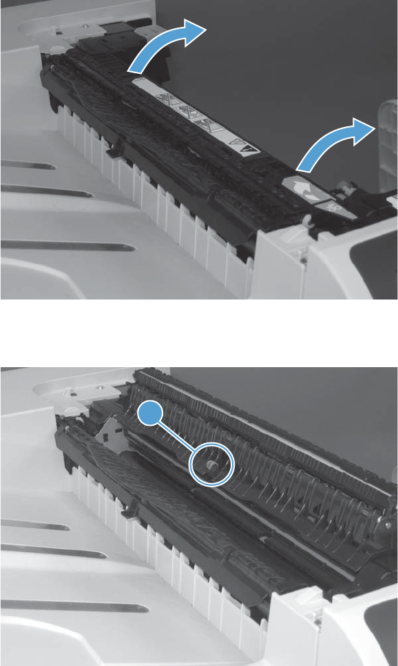
Fuser output sensor (PS6)
1. Open the right-door assembly.
2. Open the fuser jam-access flap.
Figure 3-11 Test the fuser output sensor (1 of 2)
3. Locate the fuser output sensor flag (callout 1), and then activate the sensor flag.
Figure 3-12 Test the fuser output sensor (2 of 2)
1
4. Check the control-panel display for a sensor response.
5. If there is no response, replace the fuser.
ENWW Tools for troubleshooting 297

Developer alienation sensor (PS11)
This sensor is located inside the main-drive assembly and cannot be accessed for direct manual testing.
Use the paper path sensor test to test this sensor.
1. Press the Home button .
2. Open the following menus:
●Administration
●Troubleshooting
●Diagnostic Tests
3. Press the Down arrow to highlight the Paper Path Sensors item, and then press the OK
button.
4. Press the Down arrow to highlight Start, and then check the control-panel display for sensor
response (watch the developer alienation sensor (PS11) in the list).
5. If there is no response, replace the main drive assembly.
298 Chapter 3 Solve problems ENWW
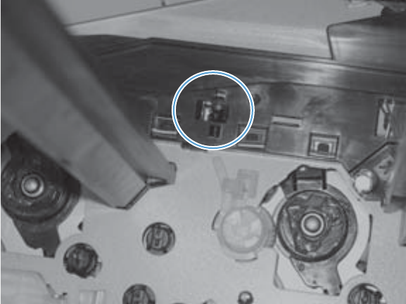
ITB alienation switch (SW5)
1. Remove the toner cartridges and the ITB. Activate the senor by moving the flag located on the rear
ITB guide rail.
Figure 3-13 Test the ITB alienation switch
2. Check the control-panel display for sensor response.
3. If there is no response, replace the main drive assembly.
ENWW Tools for troubleshooting 299

Tray/Bin manual sensor test
Use this test to test the tray and bin sensors and switches manually. The following illustrations and table
show the locations of these sensors.
1. Press the Home button .
2. Open the following menus:
●Administration
●Troubleshooting
●Diagnostic Tests
3. Press the Down arrow to highlight the Tray/Bin Manual Sensor Test item, and then press
the OK button.
Table 3-21 Tray/Bin manual sensor test
Sensor or switch name Sensor or switch number
Tray 1 paper sensor PS2
Tray 2 paper sensor PS1
Tray 2 paper surface sensor PS4
Tray 2 paper size switches SW7 and SW 8
Tray 3 paper sensor SR3
Tray 3 paper surface sensor SR2
Tray 3 paper size switches SW2 and SW3
Tray 3 feed sensor SR1
Tray 3 door opening/closing sensor SW1
Tray 4 paper sensor SR3
Tray 4 paper surface sensor SR2
Tray 4 paper size switches SW2 and SW3
Tray 4 feed sensor SR1
Tray 4 opening/closing sensor
1
SW1
Tray 5 paper sensor SR83
Tray 5 paper surface sensor SR82
Tray 5 paper size switches SW82 and SW83
Tray 5 feed sensor SR81
Tray 5 opening/closing sensor
1
SW1
Tray 6 paper sensor SR93
Tray 6 paper surface sensor SR92
300 Chapter 3 Solve problems ENWW

Table 3-21 Tray/Bin manual sensor test (continued)
Sensor or switch name Sensor or switch number
Tray 6 paper size switches SW92 and SW93
Tray 6 feed sensor SR91
Tray 6 opening/closing sensor
1
SW1
Output bin full sensor PS10
1
Tray 4, Tray 5, and Tray 6 use the same opening/closing sensor (SW1) on the right door of the accessory.
ENWW Tools for troubleshooting 301
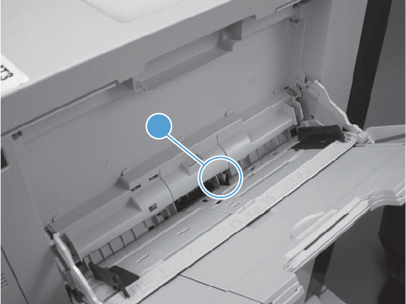
Tray 1 paper sensor (PS2)
1. Open Tray 1.
2. Locate the Tray 1 paper-present sensor flag (callout 1), and then toggle the sensor flag to activate
the sensor.
Figure 3-14 Test the Tray 1 paper present sensor
1
3. Check the control-panel display for sensor response.
4. If there is no response, replace the paper pickup assembly.
302 Chapter 3 Solve problems ENWW
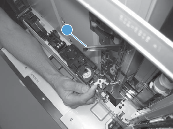
Tray 2 paper present sensor (PS1)
1. Remove the tray.
2. In the tray cavity, release the spring loaded tray-present lever to lower the flag (callout 1), and
then toggle the flag to activate the sensor.
Figure 3-15 Test the tray 2 paper sensor
1
3. Check the control-panel display for sensor response.
4. If there is no response, replace the last paper detect sensor.
ENWW Tools for troubleshooting 303
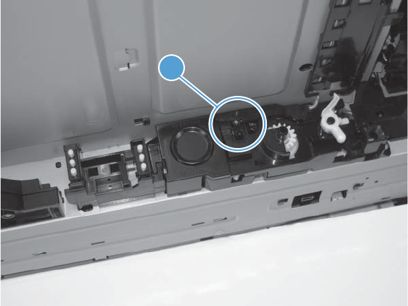
Tray 2 paper surface sensor (PS4)
1. Remove the tray.
2. In the tray cavity, insert a slip of paper in the photo sensor receptor and transmitter (callout 1).
Figure 3-16 Tray 2 paper surface sensor
1
3. Check the control-panel display for sensor response.
4. If there is no response, replace the lifter drive assembly.
304 Chapter 3 Solve problems ENWW
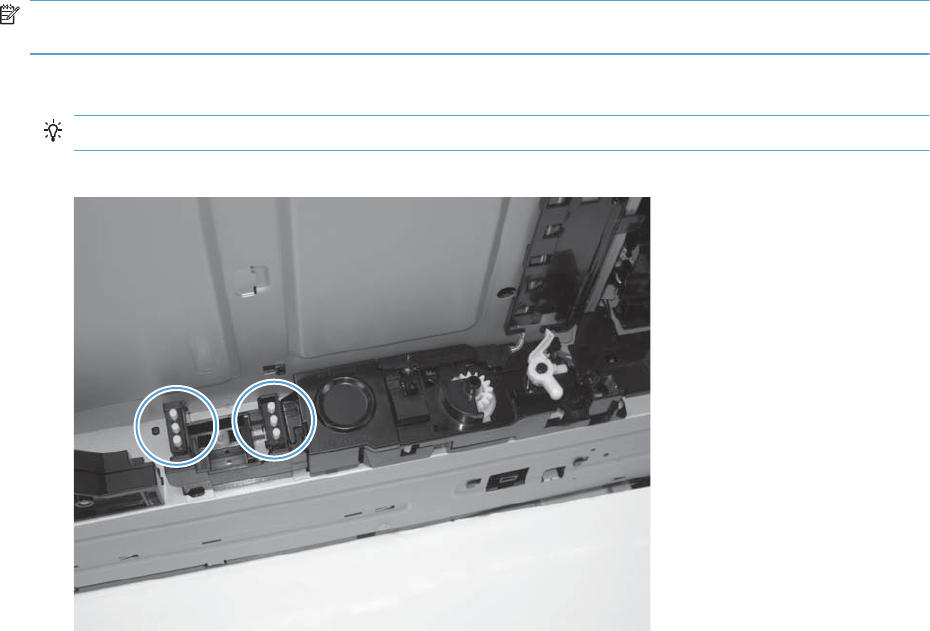
Tray 2 paper size switches (SW7 and SW8)
NOTE: These switches also detect cassette presence. If these switches fail, the message Tray <X>
open could appear on the control-panel display.
1. Remove the tray. From inside the tray cavity, push any of the switch buttons (callout 1).
TIP: You can test these sensors by opening, and then closing the tray.
Figure 3-17 Test the Tray 2 paper size switches
2. Check the control-panel display for sensor response.
3. If there is no response, replace the lifter assembly.
ENWW Tools for troubleshooting 305

Tray 3 paper sensor (SR3)
1. Remove the tray.
2. In the tray cavity, release the spring loaded tray-present lever to lower the flag (callout 1), and
then toggle the flag to activate the sensor.
Figure 3-18 Test Tray 3 paper sensor
1
3. Check the control-panel display for sensor response.
4. If there is no response, replace the paper pickup assembly.
306 Chapter 3 Solve problems ENWW
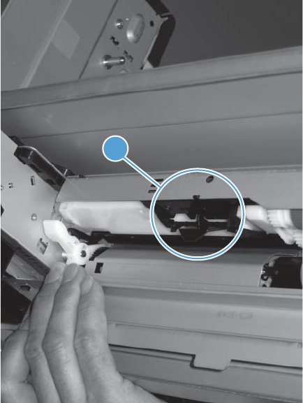
Tray 3 paper surface sensor (SR2)
1. Remove the tray.
2. In the tray cavity, release the spring loaded tray-present lever to lower the flag (callout 1), and
then toggle the flag to activate the sensor.
Figure 3-19 Test Tray 3 paper sensor
1
3. Check the control-panel display for sensor response.
4. If there is no response, replace the paper pickup assembly.
ENWW Tools for troubleshooting 307
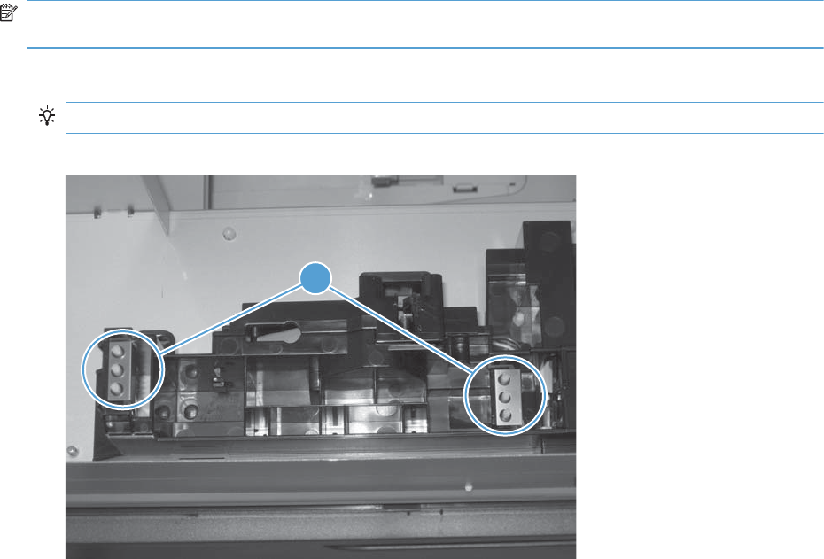
Tray 3 paper size sensors (SW2 and SW3)
NOTE: These switches also detect cassette presence. If these switches fail, the message Tray <X>
open could appear on the control-panel display.
1. Remove the tray. From inside the tray cavity, push any of the switch buttons (callout 1).
TIP: You can test these sensors by opening, and then closing the tray.
Figure 3-20 Test Tray 3 paper size sensors
1
2. Check the control-panel display for sensor response.
3. If no response, replace the lifter drive assembly.
308 Chapter 3 Solve problems ENWW
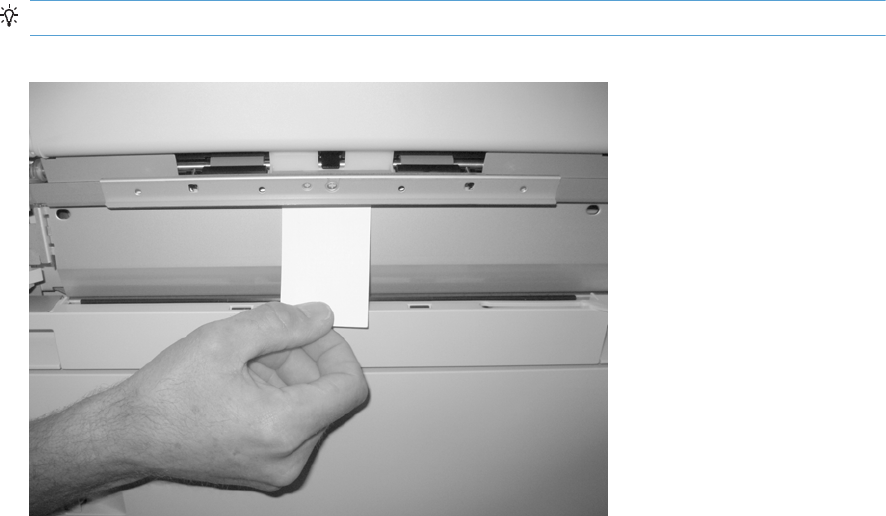
Tray 3 feed sensor (SR1)
1. Open the paper-feeder door.
2. Insert a piece of paper as shown to activate the feed sensor.
TIP: Use stiff paper when performing this test (for example a business card or index card).
Figure 3-21 Test the Tray 3 feed sensor
3. Check the control-panel display for sensor response.
4. If no response, replace the paper pickup assembly.
ENWW Tools for troubleshooting 309
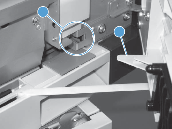
Tray 3 door opening/closing sensor (SW1)
1. Open and then close the paper-feeder door to activate the sensor. The tab on the door (callout 1)
activates the senor (callout 2).
Figure 3-22 Test the Tray 3 door opening/closing sensor
1
2
2. Check the control-panel display for sensor response.
3. If no response, replace the button switch.
310 Chapter 3 Solve problems ENWW
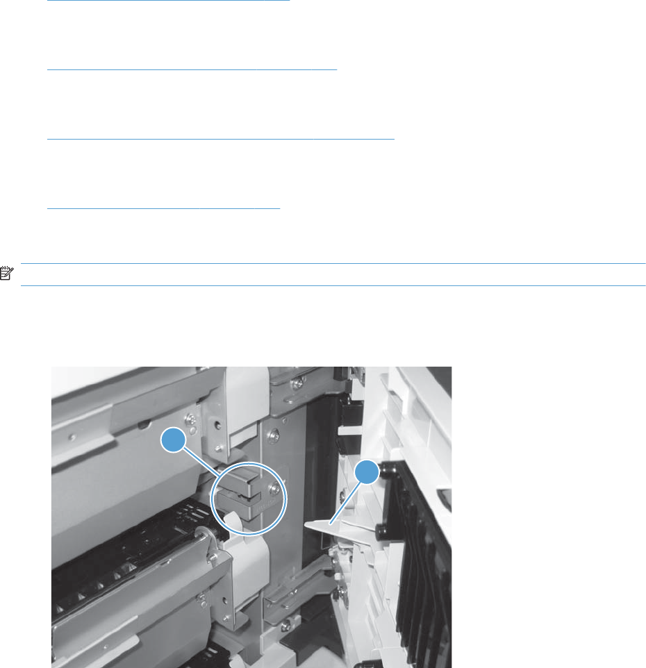
Tray 4 paper sensor (SR3)
See Tray 3 paper sensor (SR3) on page 306.
Tray 4 paper surface sensor (SR2)
See Tray 3 paper surface sensor (SR2) on page 307.
Tray 4 paper size sensors (SW2 and SW3)
See Tray 3 paper size sensors (SW2 and SW3) on page 308.
Tray 4 feed sensor (SR1)
See Tray 3 feed sensor (SR1) on page 309.
Tray 4 door opening/closing door sensor (SW1)
NOTE: Tray 4, Tray 5, and Tray 6 use the same opening/closing door sensor (SW1).
1. Open and then close the paper-feeder door to activate the sensor (the tab on the door (callout 1)
activates the senor (callout 2).
Figure 3-23 Test the Tray 4 door opening/closing sensor
1
2
2. Check the control-panel display for sensor response.
3. If no response, replace the button switch.
ENWW Tools for troubleshooting 311

Tray 5 paper sensor (SR83)
See Tray 3 paper sensor (SR3) on page 306.
Tray 5 paper surface sensor (SR82)
See Tray 3 paper surface sensor (SR2) on page 307.
Tray 5 paper size sensors (SW82 and SW83)
See Tray 3 paper size sensors (SW2 and SW3) on page 308.
Tray 5 feed sensor (SR81)
See Tray 3 feed sensor (SR1) on page 309.
Tray 5 door opening/closing sensor (SW1)
See Tray 4 door opening/closing door sensor (SW1) on page 311.
Tray 6 paper sensor (SR93)
See Tray 2 paper present sensor (PS1) on page 303.
Tray 6 paper surface sensor (SR92)
See Tray 3 paper surface sensor (SR2) on page 307.
Tray 6 paper size sensors (SW92 and SW93)
See Tray 3 paper size sensors (SW2 and SW3) on page 308.
Tray 6 feed sensor (SR91)
See Tray 3 feed sensor (SR1) on page 309.
Tray 6 door opening/closing sensor (SW1)
See Tray 4 door opening/closing door sensor (SW1) on page 311.
312 Chapter 3 Solve problems ENWW
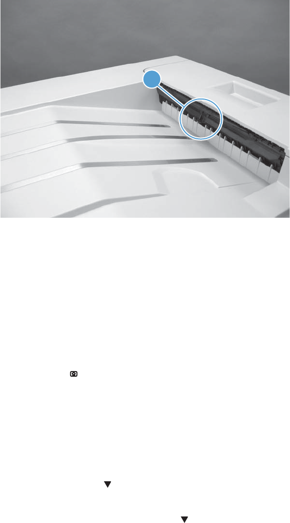
Output-bin-full sensor (PS10)
1. Locate the output-bin-full sensor flag (callout 1), and then activate the sensor flag.
Figure 3-24 Test the output-bin-full sensor
1
2. Check the control-panel display for sensor response.
3. If there is no response, examine the flag at the left end of the output bin full sensor flag. If the flag
is broken, replace the paper delivery assembly. If the flag is not broken, replace the fuser gear
assembly.
Paper-path sensors test
This test displays the status of each paper-path sensor and allows viewing of sensor status while printing
internal pages.
1. Press the Home button.
2. Open the following menus:
●Administration
●Troubleshooting
●Diagnostic Tests
3. Press the Down arrow to highlight the Paper Path Sensors option, and then press the OK
button.
4. Select Start Test. Press the down arrow to see the test results.
ENWW Tools for troubleshooting 313

NOTE: Exiting the Paper-path sensor test menu and then reentering it will clear the test values
from the previous test.
Viewing the sensor status before you activate the test should show that the sensors PS9, PS11 and
SW5 have already been activated. After running the Paper-path sensor test, sensor PS9 does not
show any activation status.
Table 3-22 Paper-path sensors diagnostic tests
Sensor name Sensor number
TOP (top of page) sensor PS5
Fuser loop sensor PS7
Fuser loop sensor PS8
Fuser delivery sensor PS6
Output bin full sensor PS10
Developer alienation PS11
Fuser pressure-release sensor PS9
Primary transfer-roller-disengagement sensor SW5
Print/stop test
Use this diagnostic test to isolate the cause of problems such as image-formation defects and jams
within the engine. During this test you can stop the paper anywhere along the product paper path. The
test can be programmed to stop printing internal pages or an external print job when the paper
reaches a certain position. The test can also be programmed to stop from 0 to 60,000 ms. If the timer
is set to a value that is greater than the job-print time, you can recover the product in one of two ways.
●After the print job is completed press the Stop button to return to the Diagnostic Tests menu
before the timer times out.
●After the timer times out, press the Stop button . Activate the door switch to restart the engine
and return it to a normal state.
When the timer trips, the control panel display shows the message Printing stopped To continue,
press OK. Pressing the Home button will print the previously selected job. If you do not want the
previous job to print, press the Stop button first, and then press the Home button .
NOTE: Do not try to perform a print/stop test while the product is calibrating, because you will be
required to power-cycle the product. If a jam message displays on the control panel during testing,
activate the door switch.
Component tests
Component test (special-mode test)
This test activates individual parts independently to isolate problems.
314 Chapter 3 Solve problems ENWW

Each component test can be performed once or repeatedly. If you select the Repeat option (at the end
of the menu), the test cycles the component on and off. This process continues for two minutes, and then
the test terminates.
NOTE: The front or side door interlocks must be defeated to run the component tests. Some tests may
require that the ITB and print cartridges be removed. The control panel display prompts you to remove
some or all cartridges during certain tests.
1. Press the Home button .
2. Open the following menus:
●Administration
●Troubleshooting
●Diagnostic Tests
3. Press the Down arrow to highlight the Component Test item, and then press the OK button.
4. Select the component test options for the test you want to run.
Table 3-23 Component tests (1 of 2)
Component test Component tested Comments
Transfer Motors M1 (ITB motor)
M2 (drum motor)
Drives the ITB motor and drum
motor together at a specified
speed for 5 seconds.
Belt Only M1 (ITB motor) Drives ITB drive motor at a
specified speed for 5 seconds.
Developer Motors M1 (ITB motor)
M3 (developer motor)
Drives the ITB motor at a
specified speed for 5 seconds.
Drives the developer motor at
a specified speed for 5
seconds (drives 3 times).
Cartridge Motors M1 (ITB motor)
M2 (drum motor)
Drives the ITB motor at a
specified speed for 5 seconds.
Drives the drum motor at a
specified speed for 5 seconds
(drives 3 times).
Fuser Motor M4 Drives the fuser motor at a
specified speed for 5 seconds.
Alienation Motor (cartridge) M6 (developer alienation motor) Drives the developer
disengagement motor and
engages or disengages the
developer (drives the motor
four times). If the home
position of the developer is not
commanded within 5 seconds,
the product brings the
developer to its home position.
ENWW Tools for troubleshooting 315

Table 3-23 Component tests (1 of 2) (continued)
Component test Component tested Comments
ITB Contact/Alienation Motor M4 (fuser motor)
SL5 (disengagement solenoid)
Drives the fuser motor M4
(drives the motor four times)
and the T1 roller
disengagement solenoid SL5,
and brings the T1 roller to
either one of the following
states:
●4 rollers are disengaged
(home position)
●Only K T1 roller is
engaged or 4 rollers are
engaged
If home position of the T1 roller
is not commanded within 10
seconds, the printer moves the
T1 roller to its home position.
Additionally, the printer keeps
the state of 4 rollers
engagement so that the service
technician can access and
manually clean the dust-proof
glass (open the front door and
remove the cartridge).
Fuser Contact/Alienation Drive M4 (fuser motor) Reverses the fuser motor to
rotate the fuser pressure
release cam and pressurize or
depressurize the pressure
roller. If home position of the
pressure roller is not
commanded within 5 seconds,
the printer brings the pressure
roller to its home position.
Tray<X> Pickup Motor M5 (pickup motor)
M1 (Tray 3 pickup motor)
M1 (Tray 4 pickup motor)
M81 (Tray 5 pickup motor)
M91 (Tray 6 pickup motor)
Drives the pickup motor M5,
the 500 sheet paper feeder
pickup motor M1, and each of
the 3x500 paper deck cassette
pickup motors, cassette 1 M1,
cassette 2 M81, and cassette
3 M91 individually at a
specified speed for 5 seconds.
DuplexerPickup Motor M8 (duplex pickup motor) Drives the duplex feed motor
at a specified speed for 5
seconds.
Switchback Motor M7 (duplex reverse motor) Drives the duplex reverse
motor at a specified speed for
5 seconds.
316 Chapter 3 Solve problems ENWW

Table 3-23 Component tests (1 of 2) (continued)
Component test Component tested Comments
Tray<X> Pickup Solenoid SL2 (Tray 1 pickup solenoid)
SL1 (Tray 2 pickup solenoid)
SL1 (Tray 3 pickup solenoid)
SL1 (Tray 4 pickup solenoid)
SL82 (Tray 5 pickup solenoid)
SL92 (Tray 6 pickup solenoid)
Drives the Tray 1 pickup
solenoid SL2, the Tray 2
cassette pickup solenoid SL1,
the 500 sheet feeder pickup
solenoid SL1, and each of the
3x500 paper deck cassette
solenoids, cassette 1 SL1,
cassette 2 SL82, and cassette
3 SL92, individually for 5
seconds.
Switchback Flapper Solenoid SL3 (duplex reverse solenoid) Drives the duplex reverse
solenoid for 10 seconds.
Laser Scanner Motor M10 (laser/scanner motor) Drives the laser/scanner motor
at a specified speed for 10
seconds.
Additional component tests
The following tests are not supported in the firmware. These component tests are accomplished by
manipulating or observing the product during operation or when the power is turned on.
Table 3-24 Component tests (2 of 2)
Component test Component tested Comments
Paper Deck Cassette Lifter Motor M9 (Tray 2 lifter drive assembly)
M2 (Tray 3 lifter drive assembly)
M2 (Tray 4 lifter drive assembly)
M82 (Tray 5 lifter drive assembly)
M92 (Tray 6 lifter drive assembly)
Open and then close a paper tray.
Listen at the back side of the product for
the sound of the lift motor for that tray.
If the lift motor does not make a sound
and the paper surface sensor for that
tray passes a sensor test (see Tray/Bin
manual sensor test on page 300),
replace the lifter drive assembly.
Power Supply Fan FM1 Turn the product power off, and then on.
Listen at the left-front-lower corner area
of the print engine for fan noise while
the product initializes.
Full/half speed intake fan
Cools the following areas:
●low-voltage power supply area
●face-down bin
●delivery bin
●laser scanner area
ENWW Tools for troubleshooting 317

Table 3-24 Component tests (2 of 2) (continued)
Component test Component tested Comments
Fuser Fan FM2 Turn the product power off, and then on.
Listen at the front-right-lower corner of
the print engine for fan noise while the
product initializes.
Full speed intake fan
Cools the following areas:
●duplex feed
●ITB
Formatter Fan FM3 Turn the product power off, and then on.
Listen at the back-lower center area of
the rear cover for fan noise while the
product initializes.
Speed controlled intake
fan
Cools the following areas:
●DC controller
●ICB
●formatter
NOTE: The formatter controls the
speed of this fan depending on product
operations.
318 Chapter 3 Solve problems ENWW
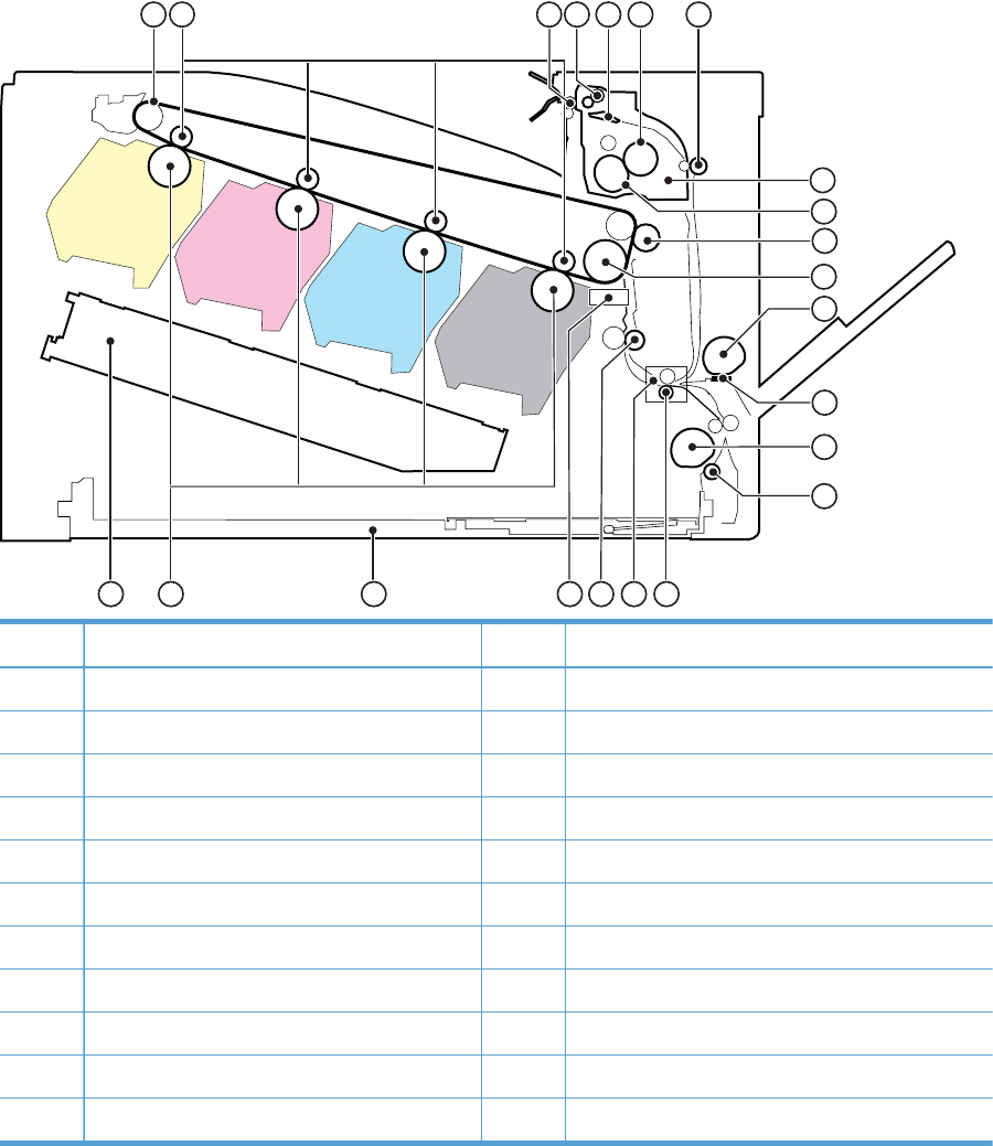
Diagrams
Block diagrams
Figure 3-25 Product cross section
21
15
16
17
18
19
20
12456
11
12
13
14
7
8
9
10
3
22
Item Description Item Description
1 ITB 12 MP tray pickup roller
2 Primary transfer roller 13 MP tray separation pad
3 Delivery roller 14 Cassette pickup roller
4 Duplex reverse roller (duplex models only) 15 Cassette separation roller
5 Duplex flapper (duplex models only 16 Feed roller
6 Pressure roller 17 Media sensor
7 Duplex feed roller (duplex models only) 18 Registration roller
8 IFuser 19 Registration density sensor
9 Fuser sleeve 20 Cassette
10 Secondary transfer roller 21 Photosensitive drum
ITB drive roller Laser/scanner assembly
ENWW Tools for troubleshooting 319
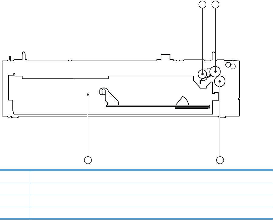
Figure 3-26 Optional paper feeder (Tray 3) cross section
12
3
4
1 Pickup roller
2 Feed roller
3 Separation roller
4 Cassette
320 Chapter 3 Solve problems ENWW
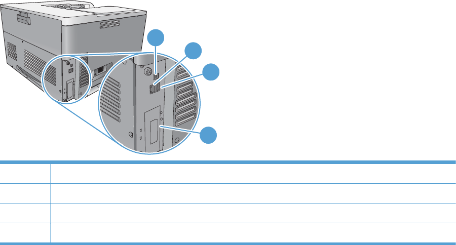
Plug/jack locations
1
2
4
3
1 Hi-Speed USB 2.0 printing port
2 Local area network (LAN) Ethernet (RJ-45) network port
3 USB port for a third-party device
4 EIO interface expansion slot
ENWW Tools for troubleshooting 321
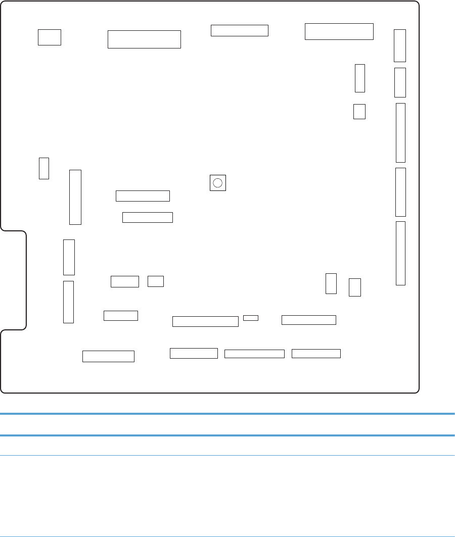
Location of connectors
DC controller connections
Figure 3-27 DC controller connections
SW301
J21
J161
J121 J122
J151
J152
J73
J72 J192 J71
J111 J26
J61
J62
J63 J25
J51
J91
J171
J172
J101
J102
J181
J131
J81
J93
J33
J112
J92
Table 3-25 DC controller connections
Item Description Item Description Item Description
J21 DC controller power J73 Secondary transfer J122 Top of page sensor
J25 Low-voltage power
supply
J81 ITB motor
Fuser motor
Drum motor
Developing motor
J131 Fuser
322 Chapter 3 Solve problems ENWW

Table 3-25 DC controller connections (continued)
Item Description Item Description Item Description
J33 Environment sensor J91 Duplex reverse
solenoid
Cassette pickup
solenoid
Pickup motor
Developing
disengagement motor
J151 Cassette paper size
Cassette paper
presence
Cassette lifter motor
J51 Formatter J92 Duplex feed motor
Duplex reverse motor
J152 MP tray paper
presence
MP tray pickup
solenoid
J61 Laser scanner J93 Driver PCA J161 Cartridge toner level
sensors
J62 Laser scanner J101 Cartridge memory tag
(yellow, magenta,
cyan)
J171 Cartridge pre-exposure
LEDs
J63 Laser scanner motor J102 Cartridge memory tag
(black)
J172 Cartridge pre-exposure
LEDs
J71 Developing high-
voltage PCA
J111 Registration and
density sensor
J181 Cartridge drum home-
position sensors
Right door switch
Primary transfer
disengagement
solenoid
Fuser pressure release
Output bin full sensor
Toner collection unit full
sensor
ITB waste toner full
sensor
J72 Cartridge primary
transfer
J121 Front door switch
Fuser fan
J192 Paper feeder
ENWW Tools for troubleshooting 323
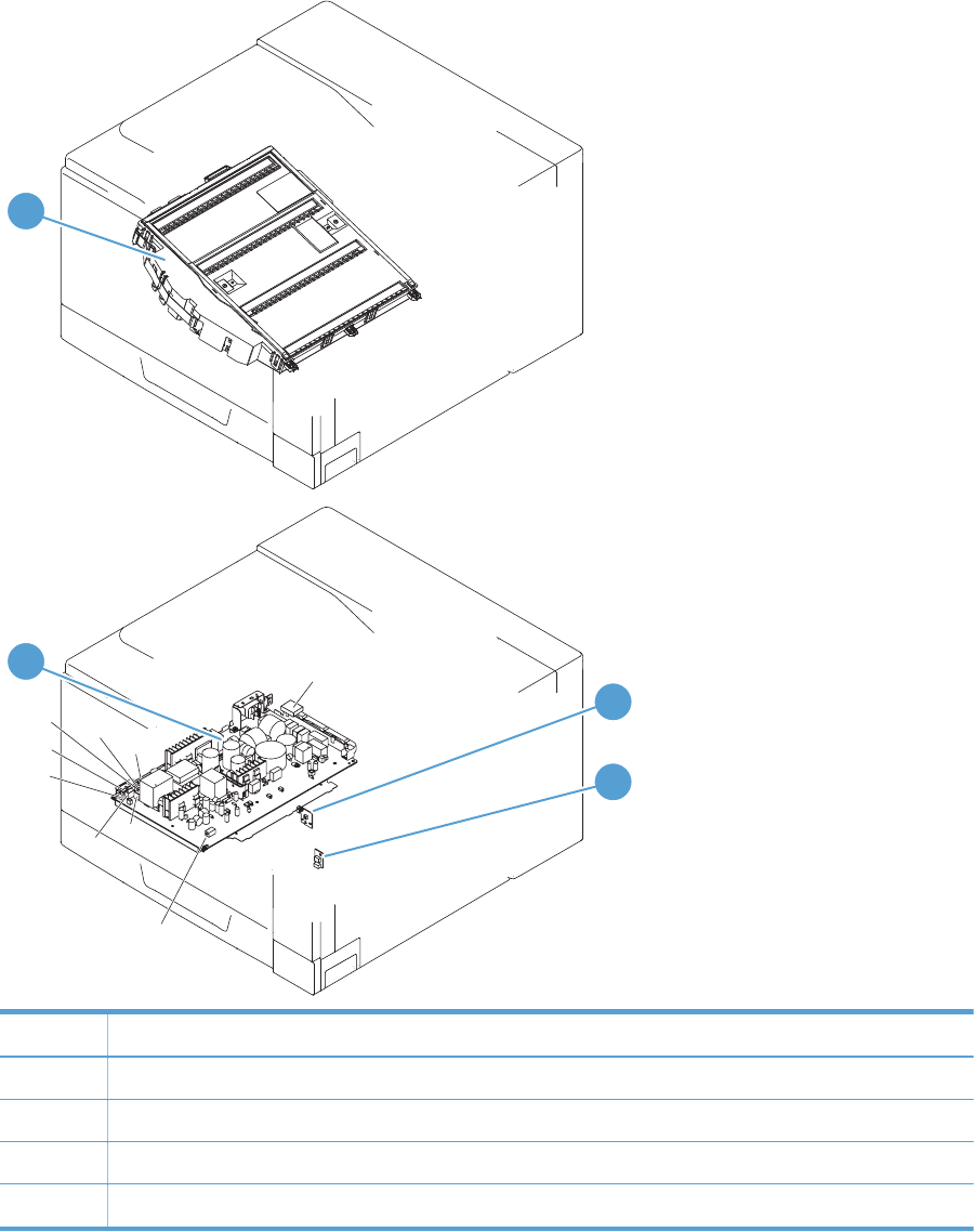
Product connections
Figure 3-28 Product connections (1 of 6)
J831
J832
J1001
J502
J301
J106
J304
J305
J105
J303
J302
J203
J110
1
2
3
4
Item Description
1 Laser scanner unit
2 Low-voltage power supply
3 Power switch PCA
4 Environment sensor
324 Chapter 3 Solve problems ENWW
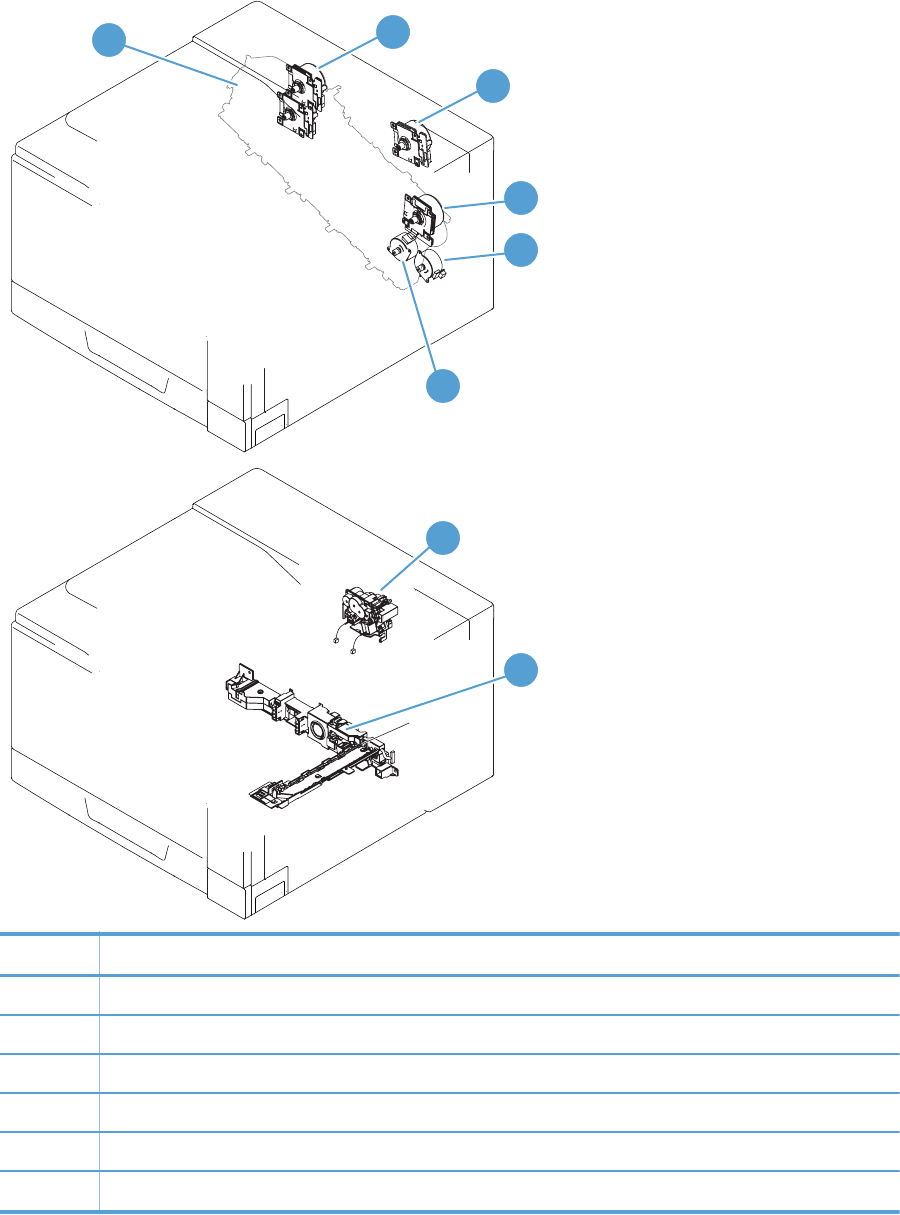
Figure 3-29 Product connections (2 of 6)
J742
J739
J553 J522
J516
J517
J518
J515
J514
J523
1
3
4
5
8
6
2
7
Item Description
1 Developing motor
2 Drum motor
3 Fuser motor
4 ITB motor
5Pickup motor
6 Developing disengagement motor
ENWW Tools for troubleshooting 325
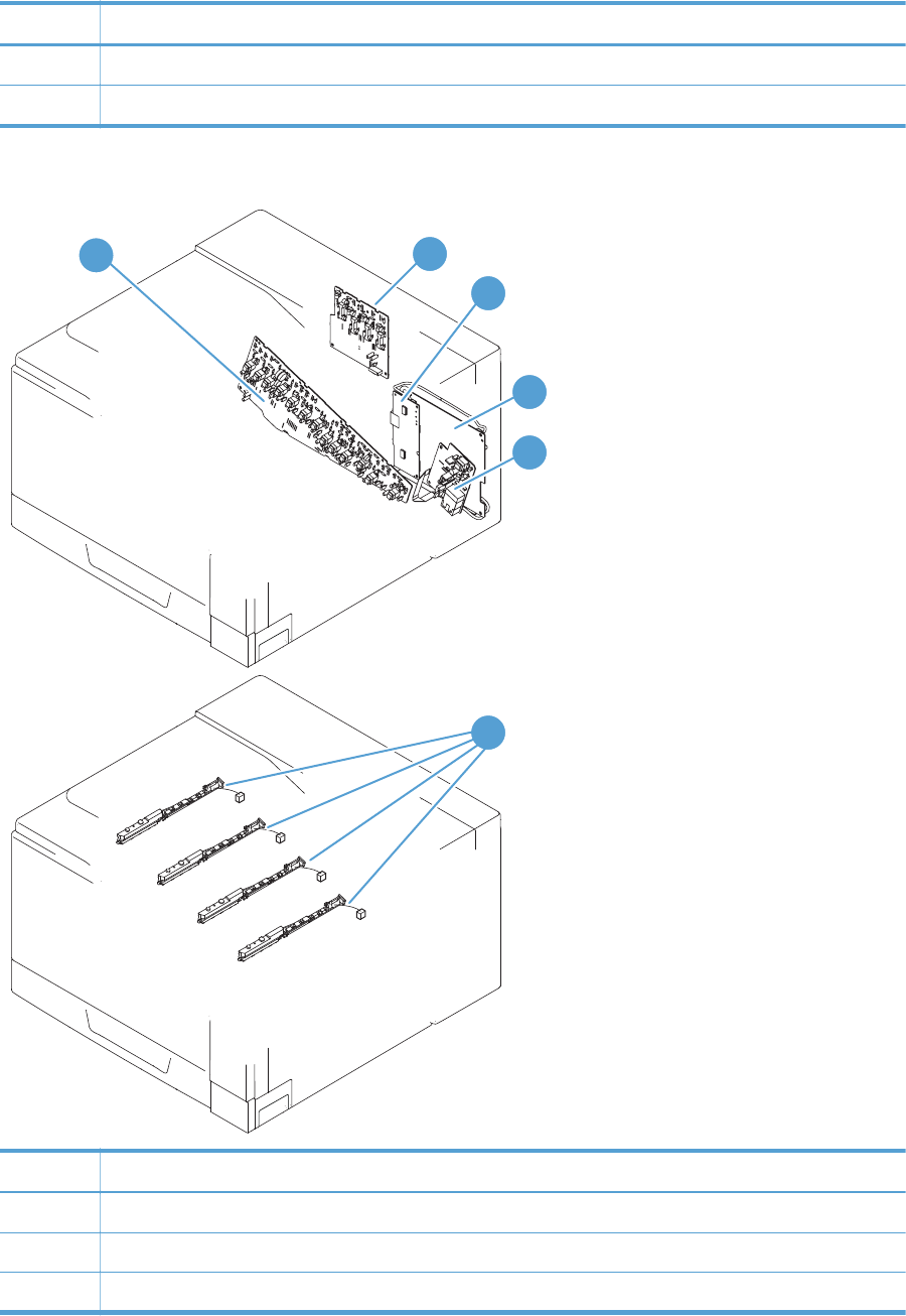
Item Description
7Drive unit
8 Lifter drive unit
Figure 3-30 Product connections (3 of 6)
J1001
J557
J558
J559
J560
12
3
4
5
6
Item Description
1 High-voltage power supply imaging (developing) PCA
2 High-voltage power supply 1st transfer PCA
3 Driver PCA
326 Chapter 3 Solve problems ENWW
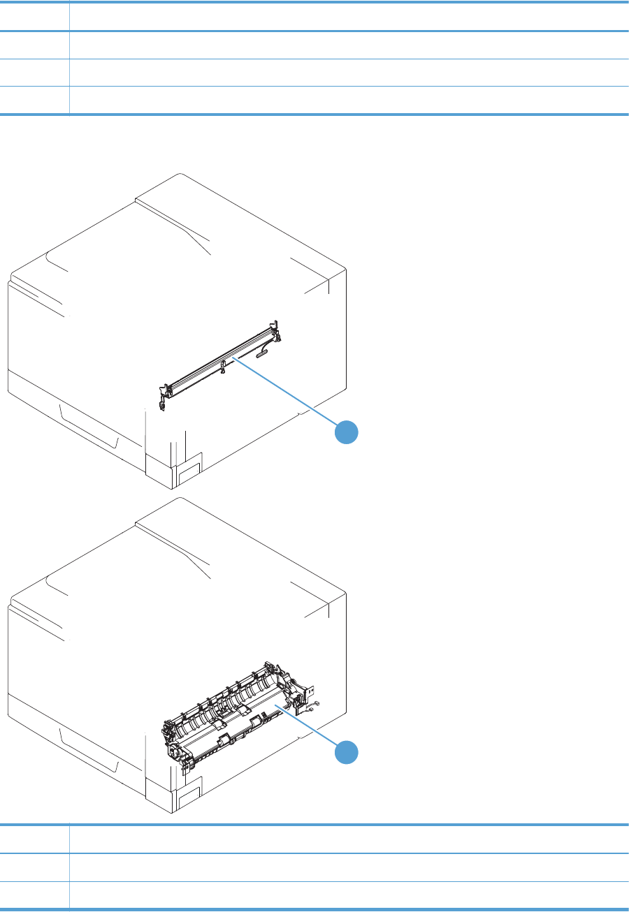
Item Description
4 DC controller PCA
5 High-voltage power supply 2nd transfer PCA
6 Toner remaining detect PCA
Figure 3-31 Product connections (4 of 6)
J554
J535
J538
1
2
Item Description
1 Registration sensor assembly
2 Paper pickup drive unit
ENWW Tools for troubleshooting 327
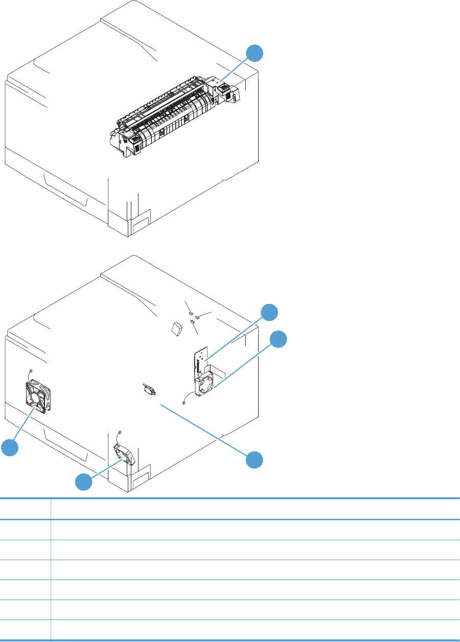
Figure 3-32 Product connections (5 of 6)
J524
J106
J109 J525
J552
J522
J708
J704
J51
J142
1
2
3
4
5
6
Item Description
1 Fuser
2 24V interlock switch
3 Fuser fan
4 Power supply fan
5 ICB PCA
6 Formatter fan
328 Chapter 3 Solve problems ENWW
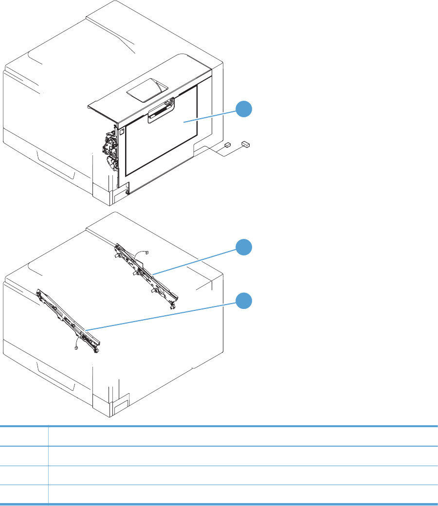
Figure 3-33 Product connections (6 of 6)
J706
J705
J152
J736
1
2
3
Item Description
1 Right door assembly
2ITB rear guide
3 ITB front guide
ENWW Tools for troubleshooting 329
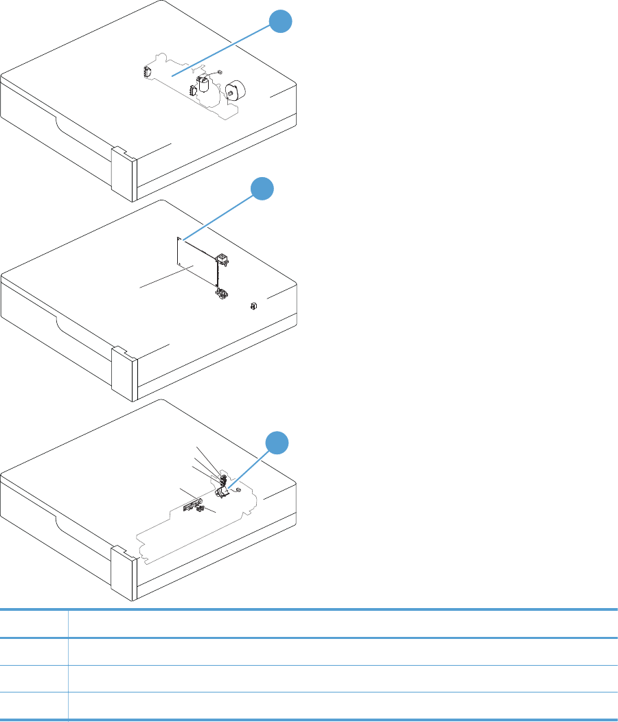
Figure 3-34 Paper feeder connections
J707
J706
J2006
J704
J733
J734 J705
J703
J752
J751
J701
J702
J703
Paper feeder controller PCA
3
2
1
Item Description
1 Paper feeder lifter-drive assembly
2 Paper feeder PCA
3 Paper feeder paper-pickup assembly
330 Chapter 3 Solve problems ENWW
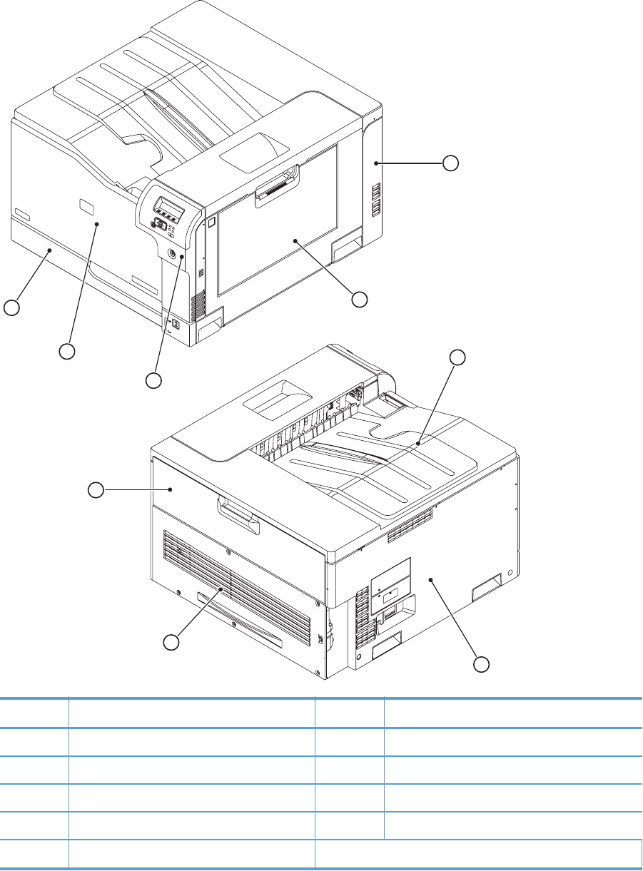
Locations of major components
Figure 3-35 External component locations
1
2
3
4
5
6
7
9
8
Item Description Item Description
1Right-rear cover 6Top cover
2 Right-door assembly 7 Left cover
3 Right-front cover 8 Rear cover
4 Front-door assembly 9 Toner collection unit access-door
5 Cassette (Tray 2)
ENWW Tools for troubleshooting 331
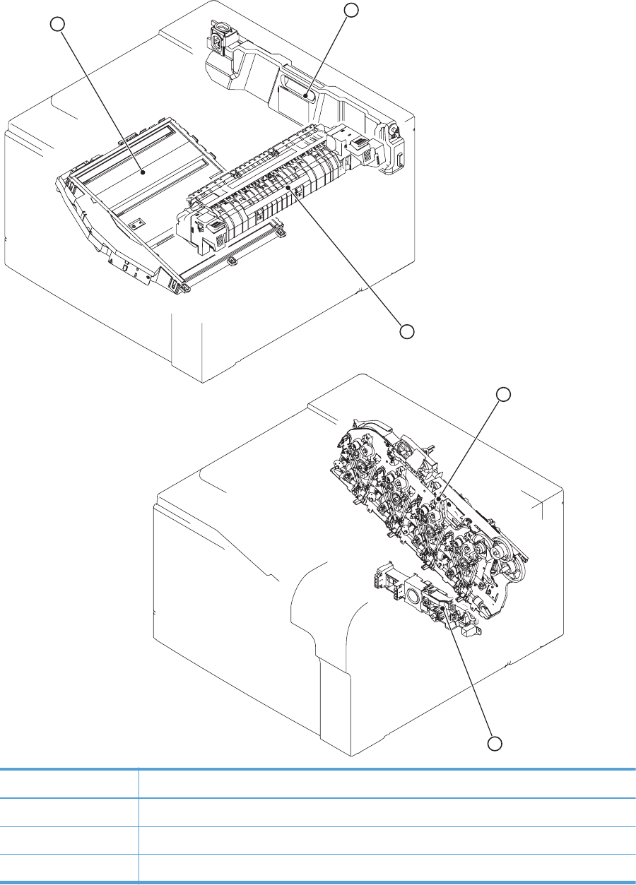
Figure 3-36 Major component locations (1 of 3)
1
2
3
4
5
Item Description
1 Laser scanner unit
2 Toner collection unit
3 Fuser
332 Chapter 3 Solve problems ENWW

Item Description
4 Main drive unit
5 Lifter drive unit
ENWW Tools for troubleshooting 333
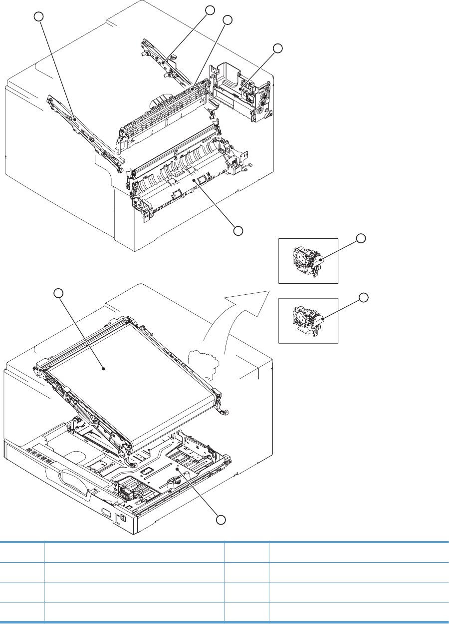
Figure 3-37 Major component locations (2 of 3)
1
2
3
4
5
6
7
8
9
Item Description Item Description
1 ITB front guide unit 6 Duplex drive unit (duplex models only)
2 ITB rear guide unit 7 Delivery drive unit (simplex models only)
3 Delivery unit 8 Cassette (Tray 2)
334 Chapter 3 Solve problems ENWW
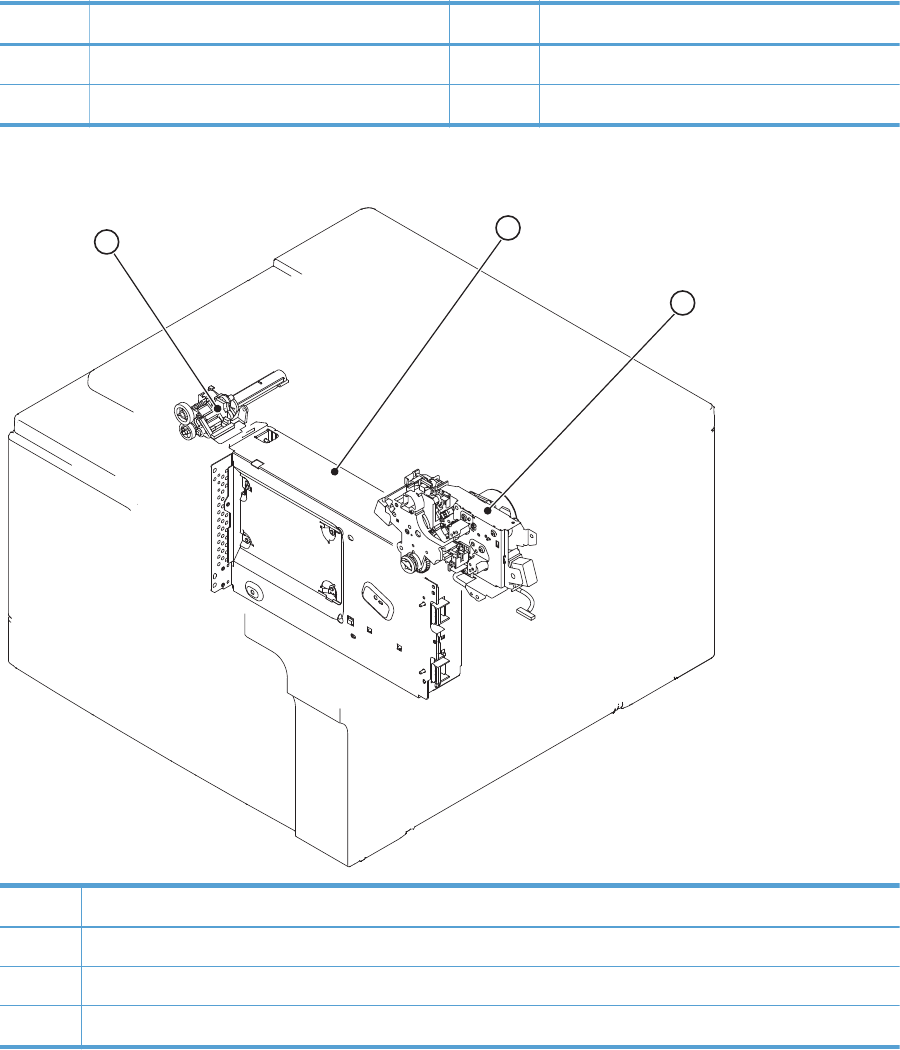
Item Description Item Description
4 Toner collection unit full sensor 9 ITB unit
5 Cassette pickup drive unit
Figure 3-38 Major component locations (3 of 3)
12
3
Item Description
1 Waste toner carrier unit
2 Formatter
3 Fuser drive unit
ENWW Tools for troubleshooting 335
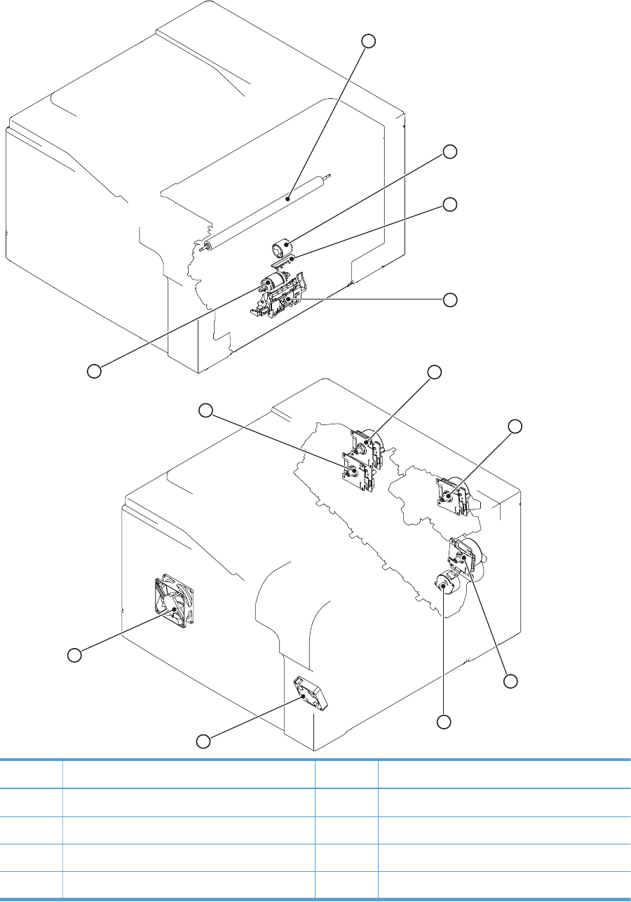
Figure 3-39 Motors, fans, and rollers component locations
1
2
3
4
5
6
7
8
9
10
11
12
Item Description Item Description
1 Secondary transfer roller unit 7 Drum motor
2 MP tray (Tray 1) pickup roller 8 Fuser motor
3 MP tray (Tray 1) separation pad 9 ITB motor
4 Cassette (Tray 2) separation roller unit 10 Developing disengagement motor
336 Chapter 3 Solve problems ENWW
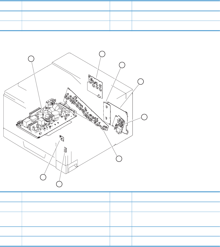
Item Description Item Description
5 Cassette (Tray 2) pickup roller unit 11 Fuser fan
6 Developing motor 12 Power supply fan
Figure 3-40 PCA component locations
1
2
3
4
5
6
7
8
Item Description Item Description
1 Low-voltage power-supply PCA 5 High-voltage power supply 2nd transfer PCA
2 High-voltage power supply 1st transfer PCA 6 High-voltage power supply imaging
(development) PCA
3 Driver PCA 7 Environment sensor PCA
4 DC controller PCA 8 Power switch PCA
ENWW Tools for troubleshooting 337

General timing charts
Figure 3-41 General timing chart (1 of 2)
Two consecutive prints on letter paper
1Print command
2Cassette pickup solenoid
3Top of paper sensor
4Fuser output sensor
5Top of paper signal
6Y video signal
7M video signal
8C video signal
9K video signal
10 Scanner motor
11 Pickup motor
12 ITB motor
13 Fuser motor
14 Drum motor
15 Developer motor
16 Developer disengagement motor
23 K developing bias
20 Y developing bias
21 M developing bias
LSTR STBY
22 C developing bias
PRINT
19 K primary charging bias
WAIT STBY INTR
17 Fuser heater
18 Y/M/C primary charging bias
Power ON
338 Chapter 3 Solve problems ENWW

Figure 3-42 General timing chart (2 of 2)
LSTR STBYPRINTWAIT STBY INTR
Power ON
26 C T1 bias
24 Y T1 bias
25 M T1 bias
K T1 bias
T2 bias
Power fan
Fuser fan
27
28
29
30
ENWW Tools for troubleshooting 339
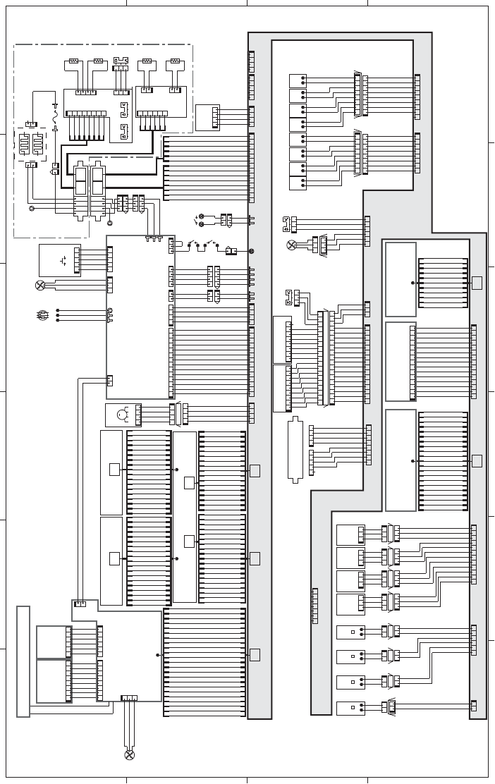
General circuit diagram
Figure 3-43 General circuit diagram (1 of 2)
A
65 4 3
B
C
D
V42+
V
42
+
D
N
G
DNG
X
R
TS
C
X
TTSC
KLCSTSC
V3.3+
J733DH
12345
J733DA
87654321
J192
1234
J733DB
1234567
8
432154321
DNG3MREHT
DNG2MREHT
DNGS
V3.3+
LH
U
F
2
P
OO
L
1POOL
I
H
SI
A
H
DNGMREHT
N
EP
O
R
ES
U
F
)R-BUS(3MREHT
)M-BUS(2MREHT
0NIAGDR
1N
I
A
G
D
R
DNG
V5+
DELBTI
DNG
1NIAGLBDR
0NIAGLBDR
POTBTI
V5+
12345
J302
54321
J1001
4321
J304
YBTSV3.3+
DNG
DNG
R4
2
+
1234
J25
DEL_WSP
SMRRUC_RSF
NOETOMER
EKUMI
H
S
XOREZ
2DLR
1DLR
1DRSF
2DRSF
FFO/NOWS
NORWP
KCOLNAF
REWOPNAF
NO_OTUA
Control panel USB
1234 56
J2J1
87654321
DNG
DNG
+D
-D
SUBV
DNG
OPF
DNG
V
3.
3
_P
F
V5_PF
DNG
S
CP
F/
KLCPF
IPF
J305ICB
J303ICB
123456
12345678
ICB
PSW LED
F
FON
WS O
DNG
V3.3+
R21+
NDG
J304
J301
+12U
12
2
1
FM3
J142
123
Formatter fan
GND
/FAN3LK
FAN3PWM
1234567
J191
J31J32
DC controller PCA
Fuser
Formatter
Low-voltage power
supply ass’y
TB2
TB1 FU1
J5003M J5003F
MT2
J5001F J5002F
H2
H1
12
21
21
21
1
1
21
J704D
J704DA
J704DB
J704L
J704LA
J704LB
4123
3214B8 A6
B8 A6
J110F
J109M
J110M
J109F
MT3
HEATER1
HEATERC
HEATER2
132
231
132
231
4
1
2
3
5
6
7
8
8765
4321
J13
J11A
2
3
41
GND
THERM1
GND
THERM4
HAISHI
GND
+3.3V
Loop sensor 1
Loop sensor 2
PS8PS7
J12
1
2
3
321
J1055
2
1
4HT
12
Sub-S
1HT
Sub-F PS6
THERM2
GND
2HT
THERM3
GND
3HT
2112
Sub-M Sub-R
211
2
J221A J222A
J123
6543
21
4
1
2
3
5
6
J33J131
J502
4321
123414 13 12 11 10 9 8 2345617
PMETVNE
V
3.
3
+
DNG
YTDMUHVNE
6
5
3
2
1
4
8
7
6
5
3
2
1
4
1ST 2ST 3ST 4ST 1ST 2ST 3ST 4ST
11
1
221 112
72DLOS
53DLOS
4
3DLOS
82DLOS
23DLO
S
13DLOS
03D
LOS
33DLOS
92DLO
S
12DLOS
52DLOS
22DLOS
32DLOS
62DLOS
42DLOS
02DLOS
J706D
J705LH J706LH
J706LJ705L
J705D
87654321
1234567887654321
12345678
98 2345617
J172
12345678
J171
.
C
.N
3
P
XE
E
RP
2
PX
E
ER
P
V5
+
V5
+
V5+
V5+
4
P
XE
E
RP
1PXEERP
1PXEERP
4PXEERP
V5+
V5+
V5+
V5+
2
PX
E
ER
P
3
PX
E
ER
P
DNG
V3.3+
SNSROODF
D
N
G
MWP2NAF
KL2NAF/
321
J524L
J524DH
321
J524D
654321
J121
321
J536
J601
982345617
J611PS5
123
J537
J554L
J554D
J554H
18 17 16 15 14 13 12 11 10 9 8 234561719
197165432 8 9101112131415161718
32116 15 14 13 12 11 10 9 8 2345617
J122J111
DNG
U3.3+
SNSPOT
11
NKLCTVH
2SRT
DNG
DNG
PMWP2RT
DNG
NMWP2RT
PKLCTVH
R42+
R
42
+
R5+
J1201
J73
4
1
2
3
5
6
7
8
9
01
11
4
1
2
3
5
6
7
8
9
01
11
D
N
G
11SRT
2
1
SR
T
41SRT
31SRT
D
N
G
ATADS1RT
KCS1RT
D
L
1RT
DNG
R5+
DNG
R42+
R42+
EO1RT/
7165432 8 9 101112131415
J1001A
15 14 13 12 11 10 9 8 2345617
J72
21
4IRPMWP
4SRGHC
2
VEDMWP
2L
B
MW
P
2SRMWP
DNG
DNG
R5+
R42+
R42+
KLCTVH
1LBMWP
1VEDMWP
3SRMWP
3LBMWP
3VEDMWP
1SRGHC
4LBMWP
4V
EDMWP
321IRPMWP
DNG
J2001
J71
4
1
2
3
5
6
7
8
9
01
11
2
1
31
4
1
51
61
71
81
91
02
1
21
2
02
9
1
81
71
61
51
41
31
21
11
0
1
9
8
7
6
5
3
2
1
4
J551J550J549J548
1ST 2ST 3ST 4ST
123321123321
J560LJ557L J559LJ558L
J560DJ559D
J559H
J558D
J560HJ558HJ557H
J557D
321123
321
321123
123123321
12 11 10 9 8 2345617
J161
4SNSTR
3SNSTR
1SNSTR
DELNOT
DELNOT
DELNOT
DNG
DNG
D
N
G
DNG
2SNSTR
DELNOT
J101J102
12345612
2SSV
2NIV
1NIV
1SSV
3
N
IV
3SSV
4NIV
4SSV
J719DH
21
J719D
J717HJ718H J716H
12
J718D
21
J717D
12
J716D
211221
J718L
12
J719L
34DLOS
24DLOS
04DLOS
14DLOS
93DLOS
83DLOS
63D
LOS
73DLOS
J716LJ717L
12 211221
MEM3MEM4 MEM2 MEM1
1ST2ST3ST
4ST
J301
23
J51
4
1
2
3
5
6
7
8
9
01
11
21
31
41
51
61
71
81
91
02
12
2
2
32
32
22
12
02
91
81
71
61
51
41
31
21
11
01
9
8
7
6
5
3
2
1
4
NEODV/
C-NOREWOP
OELC
IELC
POT/
Y
B
T
S
V
3.3+
TSRCV
FFONO
C
D
1YATAD
DNG
DNG
DNG
D
NG
DNG
1YATAD/
1MATAD
1MATAD/
1C
A
TAD/
1CATA
D
1KATAD/
1KATAD
0DB/
DNG
19 18
J631J632
19
J732 J832
17
J731
J831
1719
J62 J61
91
81
71
61
51
41
31
21
1
1
01
9
8
7
6
5
3
2
1
4
4
1
2
3
5
6
7
8
9
0
1
11
21
31
41
51
61
71
81
91
LCS
DNG
DNG
DNG
WOPYDL
0LRTCYDL
1
LR
T
CYDL
0LRTCMDL
1LRTCMDL
DNG
ADS
V5+
DNG
WOPMDL
OYATAD/
OYATAD
IMATAD/
IMATAD
V3.3+
7
71
61
51
41
31
21
11
01
9
8
6
5
3
2
1
4
4
1
2
3
5
6
7
8
9
01
11
21
31
41
51
61
7
1
WOPKDL
0LRTCK
D
L
1LRTCKDL
0LRTCCDL
V5+
DNG
DNG
DNG
1DB/
DNG
1LRTCCDL
WOPCDL
IKATAD/
ICATAD/
ICATAD
DN
G
IKATAD
91
4
1
2
3
5
6
7
8
9
01
11
21
31
41
51
61
71
81
1
91
81
71
61
51
41
31
21
11
01
9
8
7
6
5
3
2
4
LCS
ADS
DNG
V5+
DNG
Y-MWP
Y_ATAD
Y
_
A
TAD
/
DNG
Y_0LTC
Y_1LTC
DNG
M-MWP
M_0LTC
M_1LTC
M_ATAD/
M_ATAD
DNG
V3.
3
+
4
1
2
3
5
6
7
8
9
01
11
21
31
41
5
1
61
71
81
81
71
61
51
41
3
1
21
11
01
9
8
7
6
5
3
2
1
4
D
NG
K_ATAD/
K_ATAD
DNG
C_0LTC
DB/
C_ATAD/
DNG
DNG
C_1LTC
K_1LTC
C-MWP
DNG
V5
+
K-MWP
K_0LTC
C_ATAD
DNG
CED
N
CS
/
CCANCS/
V42
+
DNG
4321
J741D
1234
J63
M
J741H
1234
J741L
4321
J529
M10
14 13 12 11 10 9 8 2345617
J21
7165432 8 9 1011121314
J105
DNG
DNG
DNG
V42+
V42+
V3.3+
J707M
21 2341
21 2341
DNG
V3.3+
DNG
DNG
V42+
V42+
21
J303 J203
2341
LNFG
3
1
2
R
E
W
OP
NAF
KCOLNAF
DNG
FM1
123
J106
21
SW1
V5+
J711F
J711M
2
J710F
J710M
112
.C.N
.C.N
V5+
231
J305
12
SW2
J708M
J708F
V42+
R42+
21
12
3WS4WS
1
1
J707F
FM2
PS14
Paper feeder
Scanner motor
Power switch
Fuser output
sensor
Environment
sensor
24V Interlock
switch
5V Interlock switch
Front door sensor
Fuser fan
Top of paper sensor
Registration density sensorRegistration density
belt-perimeter sensor
Y Toner
level sensor M Toner
level sensor
C Toner
level sensor
K Toner
level sensor
Developing high-voltage
power supply PCA
Transfer 1 high-voltage
power supply PCA
Transfer 2 high-voltage
power supply PCA
J26
Power supply fan
ACH
ACL
GND
THERM1(SUB-S)
THERM4(SUB-F)
RDNS1
RDNS2
RRDLED
FRDLED
FDNS1
FDNS2
21
122
2122
340 Chapter 3 Solve problems ENWW
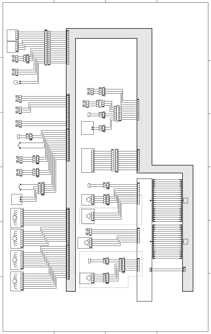
Figure 3-44 General circuit diagram (2 of 2)
A
65 4 3
B
C
D
MM
NPCLK
GND
NPSD_RD
NPSD OUT
+5V
/NPRST
NPSTART
NPSL DATA
NPSL EN
NPLED
71654328910
J541
71654328910
10982345617
J542D
J542L
J542DH
J531D
J531DH
J531L
21
12
+3.3V
NPTRLED
MPFEEDSL
+24V
MPLASTSNS
GND
+3.3U
MPPEMPTYSNS
GND
+3.3V
M
M7
1234
123456
654321
4321
4321
J525D
J552L
J520
J525DH
J522D
J522L
J552D
J552DH
SL
SL3
12
12
12
J525L
J522DH
/PHB RVRS
PHB RVRS
/PHA RVRS
PHA RVRS
/HI SL-ON
+24U
M
M8
4321
J521
/PHB DUPFD
PHB DUPFD
/PHA DUPFD
PHA DUPFD
/PHB FEED
PHB FEED
/PHA FEED
PHA FEED
+24U
/PICK SL ON
J92
17
J1002
4
1
2
3
5
6
7
8
9
01
11
21
31
4
1
51
61
71
GND
FLIPMPHB
FLIPMI0B
FLIPMI1B
FLIPMSTBY
FLIPMI1A
FLIPMI0A
FLIPMPHA
DUPFEEDMPHB
DUPFEEDMI0B
DUPFEEDMI1B
DUPFEEDMSTBY
DUPFEEDMCHI
DUPFEEDMI1A
DUPFEEDMI0A
DUPFEEDMPHA
GND
4
1
2
3
5
6
7
8
9
01
11
21
31
41
51
61
71
Duplex
reverse motor
Duplex reverse solenoid
Duplex feed motor Media sensor Media sensor
10 9 8 2345617
J152
7654321
J114D
J114H
1234567
J114L
10 9 8 2345617
J1003
Duplex model only
123456
J1006
10 9 8 2345617
J112
Duplex model only
J931J932
43211234
16 15 14 13 12 11 10 9 8 2345617
71654328910111213141516
16151413121110982345617
J742D
J742L
J742LH
21
M9 PS4
123
J534
J739L
PS1
J533
123
321
123
J739DH
J739D
J151
PS15
J544
PS13
J506
PS12
J505
123 123 321
J181
J181A
71654328910111213141515 14 13 12 11 10 9 8 2345617
J181B
J511DH
12
J511L
21
J511D
SL
21
SL5
12
SW5
J738L
J738DH
J738D
J510
123
321
321
PS9PS10
321
J743L
J743DH
123
J743D
321
J513
J709L
SW6
21
J709D
J709DH
12345
54321
123
M
12345678
M3
87654321
J514
87654321
M2
12345678
J515
MM
87654321
J516
12345678
M4
12345678
87654321
J517
M1
16 15 14 13 12 11 10 9 8 2345617
J81
J81A
71654328910111213141516
J81B
MPS11
123
M6
1234
J519
J518
1234567
J1005
M
M5
4321
J523
1234
J535L
4321
J535D
J535DHJ538D
J538DH
J538L
SL
21
SL1
21
21
12
J530DH
12
J530D
SL
J530L
12
SL2
123 321
123
321
123
321
J561D
J736D
J736L
J561H
J528
J736DH
J527
PS3
PS2
12
J93
J2 J1
21
J91
J1001
LIFTMON
+24V
LIFTSNS
GND
+3.3R
PEMPTY
GND
+3.3R
CSTSIZE22
CSTSIZE21
GND
CSTSIZE20
CSTSIZE12
CSTSIZE11
GND
CSTSIZE10
RDOORSNS
GND
+3.3V
N.C.
N.C.
N.C.
N.C.
N.C.
N.C.
DRMHPYMC
GND
+3.3A
DRMHPBK
GND
+3.3A
WTSSNS
GND
TONLED5V
TBOXSNS
GND
PFULLSNS
GND
+3.3A
FSRKAIJYO
GND
+3.3A
TRIKANHP
GND
TRIKANSL
+24V
/FSRFG
/FSRDEC
/FSRACC
FSRFR
GND
GND
+24R
+24R
/ITBFG
/ITBDEC
/ITBACC
ITBFR
GND
GND
+24R
+24R
/3DEVFG
/3DEVDEC
/3DEVACC
3DEVFR
GND
GND
+24R
+24R
/3DRUMFG
/3DRUMDEC
/3DRUMACC
3DRUMFR
GND
GND
+24R
+24R
Driver PCA
/PHB_DEV
PHB_DEV
/PHA_DEV
PHA_DEV
DEVDTCH SNS
GND
+5V
+24R
GND
21
4
1
2
3
5
6
7
8
9
01
11
31
41
51
6
1
7
1
81
91
0
2
12
+5V
GND
DEVRIKANHP
DEVMPHB
DEVMI0B
DEVMSTBY
DEVMI0A
DEVMPHA
GND
FEEDMPHB
FEEDMI0B
FEEDMI1B
FEEDMSTBY
FEEDMCHI
FEEDMI1A
FEEDMI0A
FEEDMPHA
CSTSL
HFLAPPER
FLIPSL2
GND
21
4
1
2
3
5
6
7
8
9
01
11
31
4
1
51
61
7
1
8
1
91
02
12
Developer motor
DC controller PCA
Drum motor Fuser motor ITB motor ITB
Residual toner
full sensor
Face-down bin
media full sensor
Fuser pressure
release sensor
T1
alienation switch T1
disengagement solenoid
Right door sensor
Y/M/C drum home-
position sensor
K drum home-
position sensor
Cassette lifter motor
Cassette media stack
surface sensor
Cassette media
out sensor Cassette media
width switch
MP tray media
out sensor
Last-media sensor
MP tray
pickup solenoid
Cassette pickup solenoid
Pickup motor
Developer
disengagement
sensor
Developer
disengagement
motor
SW8 SW7
Cassette media
end switch
Toner collection
box switch
1
2
ENWW Tools for troubleshooting 341
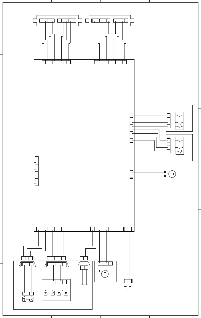
Figure 3-45 Paper feeder general circuit diagram (1 X 500)
A
65 4 3
B
C
D
21
J2001
J733LH
J733LB J733LA
J2002
J734DH
J734DBJ734DA
J2007
L_SIZE1
GND
L_SIZE2
L_SIZE3
W_SIZE1
GND
W_SIZE2
W_SIZE3
J707
J706
SW3
SW2
J2006
M2
LIFT
+24V
J2008
J2003
J2004
J2005
J704
M1
J705
SW1SL1
J752
SR2 SR3
SR1
J751
PF media stack
surface sensor
PF pickup motor
PF cassette media end switch
PF cassette media
width switch
+24U
+24U
GND
GND
STS
CMD
+3.3V
CLK
1
2
3
45
6
7
8
1234234
543214321
+24U
GND
GND
STS
CMD
CLK
+3.3V
+24U
N.C.
9823
4
5
617
21
12
M
1
3
4
2
2
4
3
1
43211234
87654321
12345678
21
DOPEN
GND
12123456
+24V
PICK
BOUT1
BOUT2
AOUT2
AOUT1
87654321
GND
PATHS
+3.3U
PSNS
GND
PLVL
+3.3U
+3.3U
M
4321
J702D
21
J703D
12345123
J701D
J701LH
J701L
321
321
J703H
J703L
J702L
J702LH
LS
12
1
2
12345
54321
Paper feeder controller PCA
PF lifter motor
PF cassette media
out sensor
PF pickup
solenoid
PF door switch
PF media feed sensor
1
2
5
342 Chapter 3 Solve problems ENWW
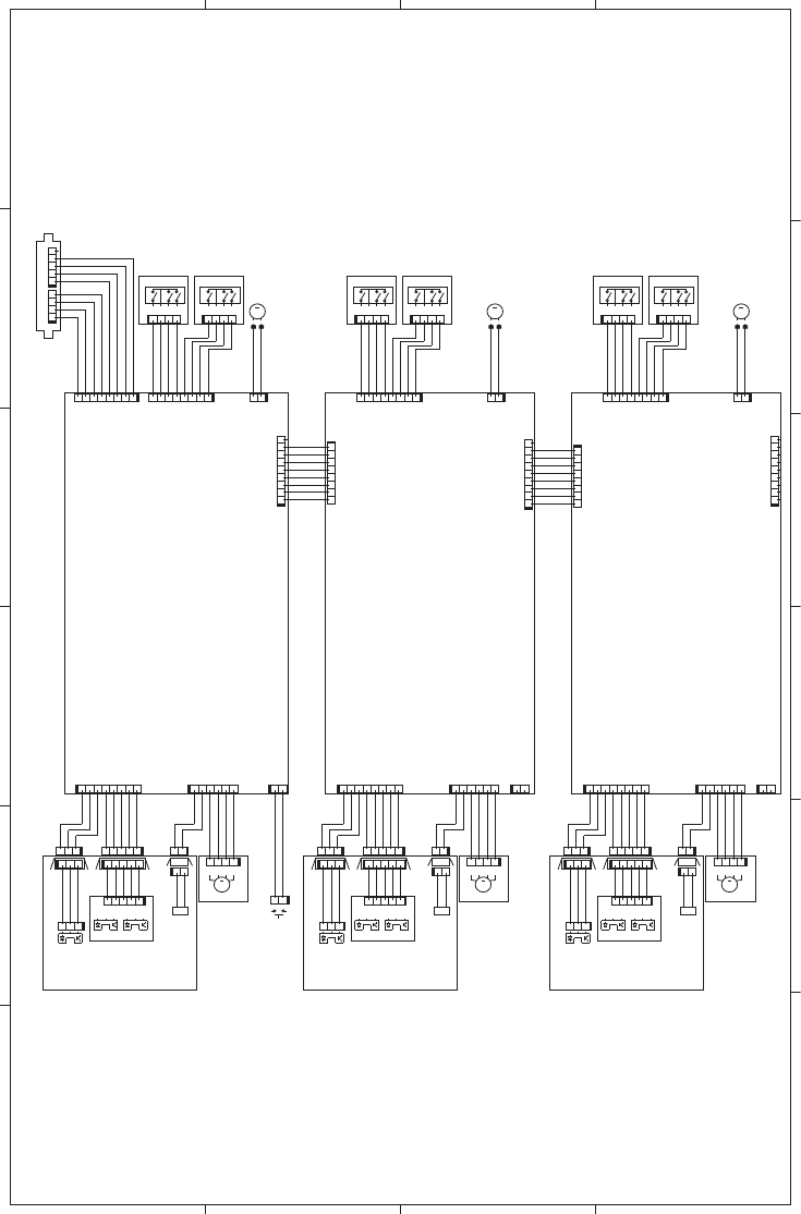
Figure 3-46 Paper deck general circuit diagram (3 X 500)
A
65 4 3
B
C
D
SL
M
MM
M
SL SL
M
M
W_SIZE3
W_SIZE2
GND
W_SIZE1
L_SIZE3
L_SIZE2
L_SIZE1
GND
+24V
LIFT
LIFT
+24V
GND
L_SIZE2
L_SIZE3
W_SIZE1
GND
W_SIZE2
W_SIZE3
CLK
CMD
STS
+3.3V
GND
+24U
+24U
W_SIZE3
W_SIZE2
W_SIZE1
L_SIZE3
L_SIZE2
L_SIZE1
GND
PATHS
+3.3U
PSNS
GND
PLVL
+3.3U
+24V
PICK
BOUT1
BOUT2
AOUT2
AOUT1
GND
DOPEN
GND
PATHS
+3.3U
PSNS
GND
PLVL
+3.3U
PICK
BOUT1
BOUT2
AOUT2
AOUT1
L_SIZE1
+3.3U
GND
+3.3U
+24V
+3.3U
GND
PATHS
+3.3U
GND
PSNS
PLVL
+3.3U
+24V
PICK
BOUT1
BOUT2
AOUT2
AOUT1
STS
GND
GND
+24U
+24U
LIFT
+24V
GND
GND
CLK
CMD
+3.3V
CLK
+3.3V
CMD
STS
GND
GND
+24U
+24U
N.C. N.C.
12345678
J2001C
716543289
J2002B
87654321
J2001B
982345617
J2002
2
4
3
1
SW92
SR92
J733LH
1234
J733LB
12345
J733LA
12345678
J2001
J703H
12345
J702D
123
J701D
J701LH
2
4
3
1
SW2
12
J703L
12345
J752
54321
J702L
J702LH
4321
J707
12
M2
21
J2006
21
SW1
21
J705
M1
12
SL1
21
J703D
SR1
321
J701L
SR2
4321
J704
1234
J706
12
J2005
87654321
J2007
123456
J2004
87654321
J2003
SR3
321
J751
1
3
4
2
SW3
2
4
3
1
SW83
123
J851
SR83
12345678
J2003B
654321
J2004B
1
2
3456
7
8
J2007B
21
J2005B
4321
J806
1234
J804
SR82
123
J801L
SR81
12
J803D
21
SL82
M81
12
J2006B
21
M82
1234
J807
J802LH
12345
J802L
54321
J852
21
J803L
1
3
4
2
SW82
J801LH
321
J801D
54321
J802D
J803H
982345617
J2002C
J903H
12345
J902D
123
J901D
J901LH
12
J903L
12345
J952
54321
J902L
J902LH
4321
J907
12
M92
21
J2006C
M91
12
SL92
21
J903D
SR91
321
J901L
4321
J904
1
2
34
J906
12
J2005C
87654321
J2007C
123456
J2004C
87654321
J2003C
SR93
321
J951
1
3
4
2
SW93
PD CST1 media
end switch PD CST1 media
width switch
PD CST1
pickup motor
PD CST1 media
stack surface sensor
PD CST2 media
stack surface sensor
PD CST2
pickup motor
PD CST3 media
stack surface sensor
PD CST3
pickup motor
PD CST2 media
end switch
PD CST2 media
width switch PD CST3 media
end switch
PD CST3 media
width switch
PD CST1
lifter motor
Paper deck controller PCA 1
Paper deck controller PCA 2
Paper deck controller PCA 3
PD door switch
PD CST1 media
out sensor
PD CST1
pickup
solenoid
PD CST1 media
feed sensor
PD CST2 media
out sensor
PD CST2
pickup
solenoid
PD CST2 media
feed sensor
PD CST3 media
out sensor
PD CST3
pickup
solenoid
PD CST3 media
feed sensor
PD CST2
lifter motor PD CST3
lifter motor
21
ENWW Tools for troubleshooting 343

Internal print-quality test pages
Print-quality-troubleshooting pages
Use the built-in print-quality-troubleshooting pages to help diagnose and solve print-quality problems.
1. Press the Home button.
2. Open the following menus:
●Administration
●Troubleshooting
●Print Quality Pages
3. Press the Down arrow to highlight the Print PQ Troubleshooting Pages item, and then
press the OK button to print the pages.
The product returns to the Ready state after printing the print-quality-troubleshooting pages. Follow the
instructions on the pages that print out.
Figure 3-47 Print-quality troubleshooting procedure
hp color LaserJet CP 5520 Printers
Print Quality Troubleshooting Procedure
1
344 Chapter 3 Solve problems ENWW
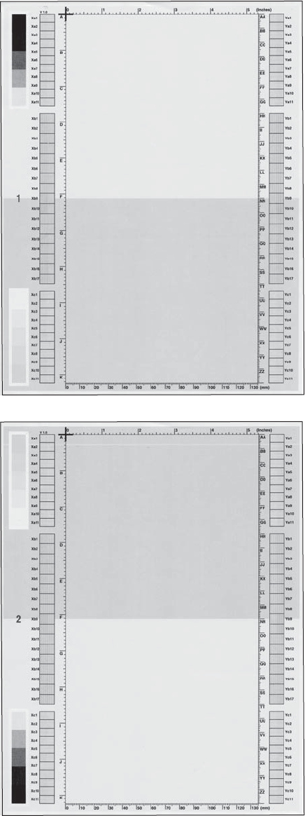
Figure 3-48 Yellow print-quality troubleshooting page
Yellow
Green
Figure 3-49 Yellow comparison page
Green
Yellow
Yellow cannot be easily seen unless combined with cyan, so half of each page is yellow and the other
half is an amplified version of yellow problems (green half). Compare the yellow on page one with the
corresponding green on page two for defects. You can also check the cyan page for defects.
ENWW Tools for troubleshooting 345
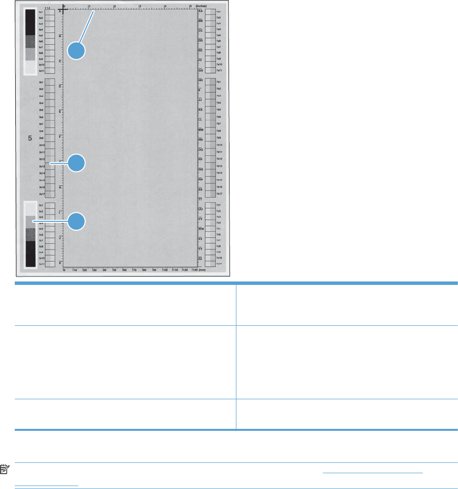
Figure 3-50 Black print-quality troubleshooting page
1
3
2
1. Grids The grids are in inches and millimeters. They are label with
letters and numbers so that defects can be described by
position and by distance between repeats.
2. Color plane registration (CPR) bars After printing, the box with no extra color in each area on
each page shows how far off the CPR of that color is. Each
page has two process direction areas and three scan
direction areas that are labeled x and y and 1–11. The page
should be fed by the long edge. Each square from the center
equals 42 microns.
3. Color ramp patches Used to detect offset for the OPC or developer in the image
drum or offset in the fuser.
NOTE: To get further assistance in print quality troubleshooting, go to www.hp.com/support/
ljcp5520series and select PQ Troubleshooting Tools.
346 Chapter 3 Solve problems ENWW
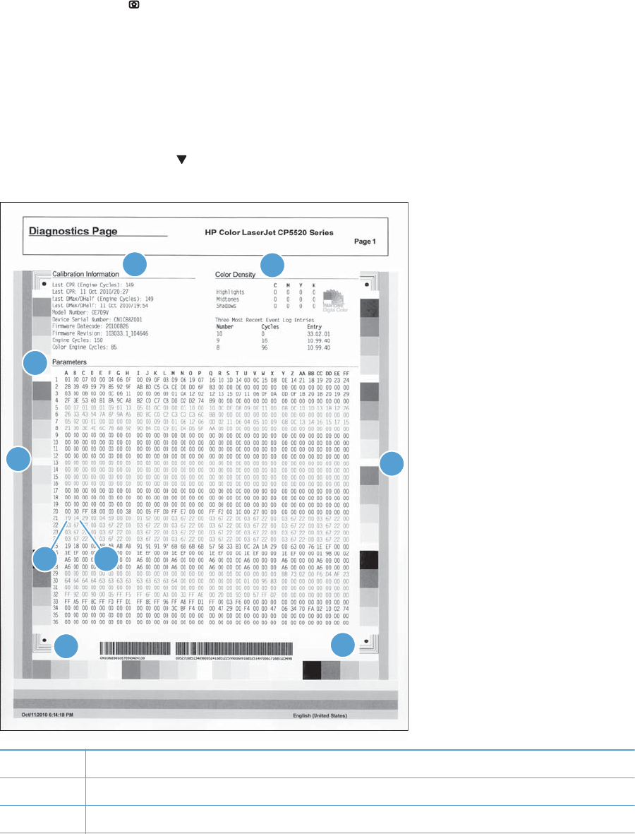
Diagnostics page
Use the diagnostics page to evaluate problems with color plane registration, EP parameters, and print
quality.
1. Press the Home button.
2. Open the following menus:
●Administration
●Troubleshooting
●Print Quality Pages
3. Press the Down arrow to highlight the Diagnostics Page item, and then press the OK button
to print the page.
56
1
2
3
44
8
7
1Calibration information
2Parameters
3Color density
ENWW Tools for troubleshooting 347

4Color plane registration
5Primary colors
6Secondary colors
7Temperature values (21A)
8Humidity values (21B)
348 Chapter 3 Solve problems ENWW

Clean the paper path
Process a cleaning page
1. Press the Home button .
2. Open the following menus:
●Device Maintenance
●Calibration/Cleaning
3. Press the Down arrow to highlight the Print Cleaning Page item, and then press the OK
button.
4. The product prints a cleaning page, and then returns to the main menu. Discard the printed page.
Set up an auto cleaning page
Use the procedure in this section to set up an automatic cleaning page.
1. Press the Home button .
2. Open the following menus:
●Device Maintenance
●Calibration/Cleaning
3. Press the Down arrow to highlight the Auto Cleaning item, and then select the Enabled
item. Press the OK button.
4. Press the Down arrow to highlight the Cleaning Interval item, and then use the arrow
buttons to select an interval. Press the OK button.
TIP: HP recommends processing a cleaning page after every 5000 printed pages.
5. Press the Down arrow to highlight the Auto Cleaning Size item, and then use the arrow
buttons to select the cleaning page size. Press the OK button.
ENWW Tools for troubleshooting 349

Configuration page
Depending on the model, up to three pages print when you print a configuration page. In addition to
the main configuration page, the embedded Jetdirect configuration pages print.
Configuration page
Use the configuration page to view current product settings, to help troubleshoot product problems, or
to verify installation of optional accessories, such as memory (DIMMs), paper trays, and printer
languages.
1. Press the Home button .
2. Open the following menus:
●Administration
●Reports
●Configuration/Status Pages
3. Press the Down arrow to highlight the Configuration Page item, and then press the OK
button.
4. Press the Up arrow to highlight the Print item, and then press the OK button.
The message Submitted to Queue displays on the control panel until the product finishes printing
the configuration page. The product returns to the Ready state after printing the configuration page.
NOTE: If the product is configured with EIO cards (for example, an HP Jetdirect Print Server) or an
optional hard-disk drive, additional pages will print that provide information about those devices.
350 Chapter 3 Solve problems ENWW
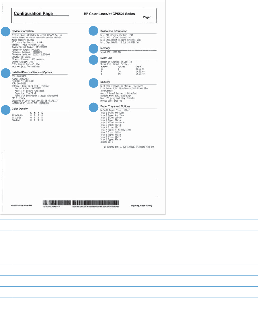
Figure 3-51 Configuration page
5
6
1
2
3
4
8
7
1Printer information
2Installed personalities and options
3Color density
4Calibration information
5Memory
6Event log
7Security
8Paper trays and options
ENWW Tools for troubleshooting 351
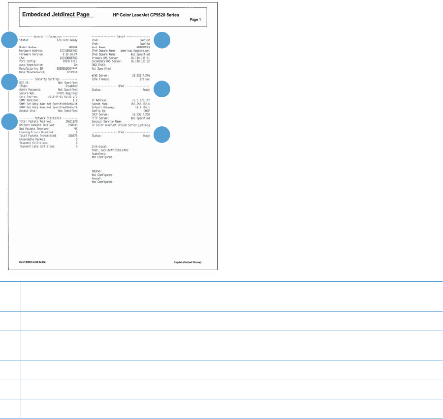
HP embedded Jetdirect page
The second configuration page is the HP embedded Jetdirect page, which contains the following
information:
Figure 3-52 HP embedded Jetdirect page
5
6
1
2
3
4
1HP Jetdirect Configuration indicates the product status, model number, hardware firmware version, port select, port
configuration, auto negotiation, manufacturing identification, and manufactured date.
2Security Settings information
3Network Statistics indicates the total packets received, unicast packets received, bad packets received, framing
errors received, total packets transmitted, unsendable packets, transmit collisions, and transmit late collisions.
4TCP/IP information, including the IP address
5IPv4 information
6IPv6 information
Always make sure the status line under the HP Jetdirect configuration lines indicates "I/O Card Ready".
352 Chapter 3 Solve problems ENWW

Finding important information on the configuration pages
Certain information, such as the firmware date codes, the IP address, and the e-mail gateways, is
especially helpful while servicing the product. This information is on the various configuration pages.
Table 3-26 Important information on the configuration pages
Type of information Specific information Configuration page
Firmware date codes
When you use the remote firmware upgrade
procedure, all of these firmware components
are upgraded.
DC controller Look on the main configuration page,
under “Device Information.”
Firmware datecode Look on the main configuration page,
under “Device Information.”
Embedded Jetdirect firmware version Look on the embedded Jetdirect page,
under “HP Jetdirect Configuration.”
Accessories and internal storage
All optional devices that are installed on the
product should be listed on the main
configuration page.
In addition, separate pages print for the
optional paper handling devices and the fax
accessory. These pages list more-detailed
information for those devices.
External disk (optional) Look on the main configuration page,
under “Installed Personalities and
Options.” Shows model and capacity.
Embedded HP Jetdirect Look on the main configuration page,
under “Installed Personalities and
Options.” Shows model and ID.
Total RAM Look on the main configuration page,
under “Memory.”
Duplex unit Look on the main configuration page,
under “Paper Trays and Options.”
Additional 500-sheet feeders Additional 500-sheet feeders Look on the main configuration page,
under “Paper Trays and Options.”
Engine cycles and event logs
Total page counts and maintenance kit
counts are important for ongoing product
maintenance.
The configuration page lists only the three
most recent errors. To see a list of the 50
most recent errors, print an event log from
the Diagnostics menu.
Engine cycles Look on the main configuration page,
under “Device Information.”
Event-log information Event-log information Look on the main configuration page,
under “Event log.”
ENWW Tools for troubleshooting 353

Color-band test
The color-band test page shows bands of colors that can indicate whether or not the product is
producing colors correctly.
1. Press the Home button .
2. Open the following menus:
●Administration
●Troubleshooting
●Print Quality Pages
3. Press the Down arrow to highlight the Color Band Test item, and then press the OK button.
4. Press the Down arrow to highlight the Print Test Page item, and then press the OK button.
354 Chapter 3 Solve problems ENWW
Print quality troubleshooting tools
Repetitive image-defect ruler
Use a ruler to measure occurrences of repetitive image defects to help solve image quality problems.
Place the ruler next to the first occurrence of the defect on the page. Find the distance between identical
defects and use the figure below to identify the component that is causing the defect.
NOTE: When printing this defect ruler, verify that any scaling options in the printer driver are
disabled.
0 mm
35 mm
42 mm
79 mm
60 mm
94 m m
76 m m
80 mm
50 mm
Distance between defects Product components that cause the defect
35 mm Print cartridge (primary charging roller)
42 mm Print cartridge (developer roller)
50 mm Print engine (primary transfer roller)
60 mm Print engine (secondary transfer roller)
76 mm Fuser (fuser film)
79 mm Fuser (pressure roller)
94 mm Print cartridge (OPC)
ENWW Tools for troubleshooting 355

Calibrate the product
Calibration is a product function that optimizes print quality. If you experience any image-quality
problems, calibrate the product.
1. Press the Home button .
2. Press the Down arrow to highlight the Device Maintenance menu, and then press the OK
button.
3. Press the Down arrow to highlight the Calibration/Cleaning menu, and then press the OK
button.
4. Press the Down arrow to highlight the Full Calibration or Quick Calibration setting, and
then press the OK button.
●Full Calibration: takes about 70 seconds and performs color plane registration,
environment change control, and Dmax and Dhalf adjustments. Use Full Calibration if
colors are misaligned or appear blurry. Full Calibration runs automatically after a
replacement transfer belt (ITB) is installed. Full Calibration must be run manually after a
laser scanner is replaced.
●Quick Calibration: takes about 45 seconds and performs Dmax and Dhalf adjustments.
Use Quick Calibration if colors are wrong, highlights are missing, or if colors are too dark
or too light.
Control panel menus
To use all of the capabilities of this product, a firmware upgrade might be required. HP recommends
that you periodically go to www.hp.com/go/ljcp5525series_software to see if a new version of
firmware is available.
NOTE: Print a configuration page to determine the version of firmware currently installed in this
product.
Navigate the control-panel menus:
●Press the Home button to access the menus.
●Press the Up arrow button and Down arrow button to highlight a desired menu item.
●Press the OK button to select the menu item.
●Press the Back arrow button to navigate backwards in nested menus.
●Press the Home button again, or the Back arrow button repeatedly, to exit the menus.
356 Chapter 3 Solve problems ENWW

Sign In menu
Table 3-27 Sign In menu
First level Second level Values Description
User Access Code Access Code Access the product with a user–level
personal identification number (PIN).
NOTE: Some menus or functions
might not be available.
Administrator Access Code Access Code Access the product with a
administrator–level PIN.
Service Access Code Access Code Access the product with a technician–
level PIN.
ENWW Tools for troubleshooting 357

Retrieve Job From USB menu
Use the Retrieve Job From USB menu to view listings of jobs stored on an external USB memory
device.
NOTE: You must enable this feature by using the control-panel menus or the HP Embedded Web
Server before it can be used.
To enable this feature by using the control-panel menus, access the Administration menu, Retrieve
From USB Settings sub menu, and then select Enable.
Table 3-28 Retrieve Job From USB menu
First level Second level Values Description
Retrieve Job From
USB
OK
Cancel
Use the Retrieve Job From USB item to
view a listing of all jobs stored on a portable
storage device.
Select a File or Folder Select from the provided list.
358 Chapter 3 Solve problems ENWW

Retrieve Job From Device Memory menu
Use the Retrieve Job From Device Memory menu to view listings of jobs stored on the internal
product memory.
Table 3-29 Retrieve Job From Device Memory menu
First level Second level Third level Values Description
Retrieve Job From
Device Memory
All Jobs (No PIN)
NOTE: Individual job
names also appear.
Print Range: 1 – 9999
Default = 1
Use the Retrieve Job From
Device Memory item to view a
listing of all jobs stored in the
product memory.
Delete Select from the provided list.
ENWW Tools for troubleshooting 359

Supplies menu
In the following table, asterisks (*) indicate the factory default setting.
Table 3-30 Supplies menu
First level Second level Third level Fourth level Values Description
Manage
Supplies
Supplies
Status
Supply
Settings
Black
Cartridge
Very Low
Settings
Stop
Prompt to
continue*
Continue
Select what the
product should do
when the print
cartridge is very
near the end of its
estimated life.
Stop: The
product stops until
you replace the
cartridge.
Prompt to
continue: The
product stops until
you clear the
prompt message.
After the prompt
message is
cleared, there will
not be another
message
indicating that the
supply needs to
be replaced.
Continue: The
product provides
an alert message,
but it continues
printing. There
will not be
another message
indicating that the
supply needs to
be replaced.
Low Threshold
Settings
1-100% Use the arrow
buttons to enter
the percentage of
estimated
cartridge life at
which you want
the product to
alert you that the
cartridge is low.
360 Chapter 3 Solve problems ENWW

Table 3-30 Supplies menu (continued)
First level Second level Third level Fourth level Values Description
Color
Cartridges
Very Low
Settings
Stop
Prompt to
continue*
Continue
Select what the
product should do
when the print
cartridge is very
near the end of its
estimated life.
Stop: The
product stops until
you replace the
cartridge.
Prompt to
continue: The
product stops until
you clear the
prompt message.
Continue: The
product provides
an alert message,
but it continues
printing.
Low Threshold
Settings
Cyan Cartridge
Magenta
Cartridge
Yellow
Cartridge
1-100% Use the arrow
buttons to enter
the percentage of
estimated
cartridge life at
which you want
the product to
alert you that the
cartridge is low.
Fuser Very Low
Settings
Stop
Prompt to
continue*
Continue
Stop: The
product stops until
you replace the
fuser kit.
Prompt to
continue: The
product stops until
you clear the
prompt message.
Continue: The
product provides
an alert message,
but it continues
printing.
ENWW Tools for troubleshooting 361

Table 3-30 Supplies menu (continued)
First level Second level Third level Fourth level Values Description
Low Threshold
Settings
1-100% Use the arrow
buttons to enter
the percentage of
estimated supplies
life at which you
want the product
to alert you that
the cartridge is
low.
Transfer Kit Very Low
Settings
Stop
Prompt to
continue*
Continue
Stop: The
product stops until
you replace the
transfer kit.
Prompt to
continue: The
product stops until
you clear the
prompt message.
Continue: The
product provides
an alert message,
but it continues
printing.
Low Threshold
Settings
1-100% Use the arrow
buttons to enter
the percentage of
estimated supplies
life at which you
want the product
to alert you that
the cartridge is
low.
Color/Black
Mix
Auto*
Mostly Color
Pages
Mostly Black
Pages
Use this feature to
instruct the
product when to
switch between
color and
monochrome
printing modes for
the best overall
performance.
Select the setting
depending on the
types of jobs you
typically print.
362 Chapter 3 Solve problems ENWW

Table 3-30 Supplies menu (continued)
First level Second level Third level Fourth level Values Description
Supply
Messages
Low Message On*
Off
Select how the
product displays
the supply
information.
Low Message:
Determines
whether or not a
low supply
message is
displayed on the
control panel.
Level Gauge On*
Off
LEVEL GAUGE:
Determines
whether or not a
supply level
gauge appears
on the control
panel.
Black
Cartridge OK:
- Status
Supply status
message—no
action required.
Cyan
Cartridge OK:
- Status
Supply status
message—no
action required.
Magenta
Cartridge OK:
- Status
Supply status
message—no
action required.
Yellow
Cartridge OK:
- Status
Supply status
message—no
action required.
Toner
Collection Unit
OK: - Status
Supply status
message—no
action required.
Transfer Kit
OK: - Status
Supply status
message—no
action required.
Fuser OK: -
Status
Supply status
message—no
action required.
Trays menu
In the following table, asterisks (*) indicate the factory default setting.
ENWW Tools for troubleshooting 363

Table 3-31 Trays menu
First level Second level Values Description
Manage Trays Use Requested Tray Exclusively*
First
Use this feature to control how
the product handles jobs that
have specified a specific input
tray.
Manually Feed Prompt Always*
Unless loaded
Use this feature to indicate
whether a prompt should appear
when the type or size for a job
does not match the specified tray
and the product pulls from the
multipurpose tray instead.
Size/Type Prompt Display*
Do not display
Use this feature to control
whether the tray configuration
message appears whenever a
tray is closed.
Use another tray Enabled*
Disabled
Use this feature to turn on or off
the control-panel prompt to select
another tray when the specified
tray is empty.
Alternative Letterhead
Mode
Disabled*
Enabled
Use this feature so that you can
load letterhead or preprinted
paper into the tray the same way
for all print jobs, whether you
are printing to one side of the
sheet or to both sides of the
sheet.
Blank Pages Auto*
Yes
Use this feature to control how
the product handles two-sided
jobs (duplexing).
Auto: This option enables Smart
Duplexing, which instructs the
product not to process blank
pages.
Yes: This option disables Smart
Duplexing and forces the
duplexer to flip the sheet of
paper even if it is printed on only
one side.
Override A4/Letter Yes*
No
Use this feature to print on letter-
size paper when an A4 job is
sent but no A4-size paper is
loaded in the product (or to print
on A4 paper when a letter-size
job is sent but no letter-size
paper is loaded).
364 Chapter 3 Solve problems ENWW

Table 3-31 Trays menu (continued)
First level Second level Values Description
Tray 1 Size Select from a provided list. Allows you to configure the
paper size for Tray 1. The
default is Any Size. See the
product user guide for a
complete list of available sizes.
Tray 1 Type Select from a provided list. Allows you to configure the
paper type for Tray 1. The
default is Any Type. See the
product user guide for a
complete list of available types.
Tray 2 Size Select from a provided list. Use this feature to specify the
size of paper loaded in the tray.
Tray 2 Type Select from a provided list. Use this feature to specify the
type of paper loaded in the tray.
Tray 3 Size Select from a provided list. Use this feature to specify the
size of paper loaded in the tray.
Tray 3 Type Select from a provided list. Use this feature to specify the
type of paper loaded in the tray.
Tray 4 Size Select from a provided list. Use this feature to specify the
size of paper loaded in the tray.
Tray 4 Type Select from a provided list. Use this feature to specify the
type of paper loaded in the tray.
Tray 5 Size Select from a provided list. Use this feature to specify the
size of paper loaded in the tray.
Tray 5 Type Select from a provided list. Use this feature to specify the
type of paper loaded in the tray.
Tray 6 Size Select from a provided list. Use this feature to specify the
size of paper loaded in the tray.
Tray 6 Type Select from a provided list. Use this feature to specify the
type of paper loaded in the tray.
Administration menu
Reports menu
NOTE: After selecting items from this menu, select Print to print the report.
Table 3-32 Reports menu
First level Second level Values Description
Configuration/Status
Pages
Print Select a report, and then select Print to print the report.
ENWW Tools for troubleshooting 365

Table 3-32 Reports menu (continued)
First level Second level Values Description
Administration Menu
Map
Prints the control-panel menu map, which shows the layout
of the control-panel menu items.
Configuration Page Shows the printer settings and installed accessories.
Supplies Status Page Shows the approximate remaining life for the supplies;
reports statistics on total number of pages and jobs
processed, serial number, page counts, and maintenance
information.
Usage Page Prints a count of impressions (letter/A4 equivalents that
have passed through the product; lists whether they were
monochrome, or color; and reports the count).
Paper Path Page Prints a count of all paper sizes that have passed through
the product by paper size; lists whether they were
simplex, duplex, blank page, source, destination, paper
type, and print mode usage.
File Directory Page Shows the file name and folder name for files that are
stored in the product memory.
Current Settings Page Shows the products current settings.
Color Usage Job Log Shows information about the number of color and black &
white pages that each user has printed. It also indicates
from which software program each of the jobs was
printed.
Other Pages Print This menu contains several other product-related reports
and pages.
Demonstration Page Print the Demo page for an example of high-quality
printing from the product.
RGB Samples Print the RGB Samples page for a palette of RGB (red,
green, blue) color values. Use this page to match colors.
CMYK Samples Print the CMYK Samples page for a palette of CMYK
(cyan, magenta, yellow, black) color values. Use this
page to match colors.
PCL Font List Use this feature to print a list of printer control language
(PCL) fonts that are currently available to the product.
PS Font List Use this feature to print a list of PostScript (PS) fonts that
are currently available to the product.
366 Chapter 3 Solve problems ENWW

General Settings menu
In the following table, asterisks (*) indicate the factory default setting.
Table 3-33 General Settings menu
First level Second level Third level Fourth level Values Description
Date/Time
Settings
Date/Time
Format
Date Format DD/MMM/YYYY
MMM/DD/YYYY*
YYYY/MMM/DD
Allows you to choose
the order in which
the year, month, and
day appear in the
date.
Time Format 12 hour (AM/
PM)*
24 hours
Time Format
Date/Time Date Allows you to set the
correct date. The
range for the year is
2008 to 2037.
Time Time
Time Zone Allows you to set the
correct time zone.
Adjust for
Daylight Savings
On
Off*
If you are in an area
that observes
daylight saving time,
select On.
Energy Settings Sleep Delay 15*
Range: 1 – 120
minutes
Reduces power
consumption when
the product has been
inactive for the
selected period.
ENWW Tools for troubleshooting 367

Table 3-33 General Settings menu (continued)
First level Second level Third level Fourth level Values Description
Optimum Speed/
Energy Usage
Faster First Page*
Save Energy
Save More
Energy
Save Most
Energy
Controls the fuser
cool down behavior.
Faster First Page:
The fuser maintains
power and the first
page processes
faster for any new
job that is sent to the
product.
Save Energy: The
fuser reduces power
when it is idle.
Save More
Energy: The fuser
reduces more power
than the Save
Energy option.
Save Most
Energy: The fuser is
turned off and it
gradually cools to
room temperature.
The Save Most
Energy option takes
the longest time to
print the first page.
Print Quality Adjust Color Highlights Cyan Density
Magenta Density
Yellow Density
Black Density
-5 to 5
Default = 0
Adjust the darkness
or lightness of
highlights on a
printed page. Lower
values represent
lighter highlights on
a printed page, and
higher values
represent darker
highlights on a
printed page.
Midtones Cyan Density
Magenta Density
Yellow Density
Black Density
-5 to 5
Default = 0
Adjust the darkness
or lightness of
midtones on a
printed page. Lower
values represent
lighter midtones on a
printed page, and
higher values
represent darker
midtones on a
printed page.
368 Chapter 3 Solve problems ENWW

Table 3-33 General Settings menu (continued)
First level Second level Third level Fourth level Values Description
Shadows Cyan Density
Magenta Density
Yellow Density
Black Density
-5 to 5
Default = 0
Shadows
Restore Color
Values
Restore the color
settings by resetting
the density values of
each color.
Image
Registration
Adjust Tray <X> Print Test Page Print Test Page
X1 Shift
Y1 Shift
X2 Shift
Y2 Shift
-5.00 mm to 5.00
mm
Default = 0
The scan direction is
referred to as X. X1
is the scan direction
for a single-sided
page or for the
second side of a two-
sided page. X2 is the
scan direction for the
first side of a two-
sided page.
The feed direction is
referred to as Y. Y1
is the feed direction
for a single-sided
page or for the
second side of a two-
sided page. Y2 is the
feed direction for the
first side of a two-
sided page.
ENWW Tools for troubleshooting 369

Table 3-33 General Settings menu (continued)
First level Second level Third level Fourth level Values Description
Auto Sense Mode Tray 1 Sensing Full sensing
Expanded
sensing*
Transparency
Only
Sets the sensing
option for Tray 1 for
paper types using
AUTO SENSE
mode.
When Full sensing
is selected, the
product senses every
page and switches
modes accordingly.
The product can
distinguish light
paper, plain paper,
heavy paper, glossy
paper, tough paper,
or transparencies.
Using this mode
significantly reduces
print speed. Use it
only when you are
printing on mixed
paper types.
When Expanded
sensing is selected,
the product senses
only the first page
and assumes the rest
of the pages are the
same type. The
product can
distinguish light
paper, plain paper,
heavy paper, glossy
paper, tough paper,
or transparencies.
When
Transparency
Only is selected, the
product senses only
the first page. The
product can
distinguish
transparencies from
other paper types.
370 Chapter 3 Solve problems ENWW

Table 3-33 General Settings menu (continued)
First level Second level Third level Fourth level Values Description
Tray X Sensing Expanded
sensing*
Transparency
Only
Sets the sensing
option for Trays 2-5
for paper types using
AUTO SENSE
mode.
When Expanded
sensing is selected,
the product senses
only the first few
pages and assumes
the rest of the pages
are the same type.
The product can
distinguish light
paper, plain paper,
heavy paper, glossy
paper, tough paper,
or transparencies.
The product senses
the paper type when
you turn it on and
after you open and
close a tray.
When
Transparency
Only is selected, the
product senses only
the first page. The
product can
distinguish
transparencies from
other paper types.
Adjust Paper
Types
Select from a list of
paper types that the
product supports. The
available options are
the same for each
paper type.
Print Mode Select from a list of
print modes.
Default = Auto
Sense Mode
Configure the print
mode that is
associated with each
media type.
ENWW Tools for troubleshooting 371

Table 3-33 General Settings menu (continued)
First level Second level Third level Fourth level Values Description
Resistance Mode Normal*
Up
Down
Use this setting to
correct print quality
problems in low-
humidity
environments and
highly resistive
paper. The default
setting is Normal.
Use the Up setting to
increase the T2 bias
in order to solve print
quality problems that
are related to poor
toner transfer at the
T2 stage. Use the
Down setting to
decrease the T2 bias
in the event that
small, pin-hole
defects occur.
Humidity Mode Normal*
High
Use this setting to
correct print quality
problems in high-
humidity
environments. The
default setting is
Normal. Use the
High setting if you
are in a high-
humidity environment
and you are seeing
problems with low
toner density on the
first page of a job.
372 Chapter 3 Solve problems ENWW

Table 3-33 General Settings menu (continued)
First level Second level Third level Fourth level Values Description
Fuser Temp Mode Normal*
Up
Down
If you are seeing a
faint image of the
page repeated at the
bottom of the page
or on the following
page, you should
first make sure the
Paper Type and Print
Mode settings are
correct for the type of
paper you are using.
If you continue to see
ghost images on
your print jobs, set
this feature to the Up
or Down setting. Try
the Up setting to
improve toner fixing
performance. Try the
Down setting if you
are seeing hot offset
issues. Using this
mode increases wear
on product parts and
might also slow
down the printing
process.
Paper Curl Mode Normal*
Reduced
If excessive curling of
paper occurs in
warm, high-humidity
environments above
23° C (73° F), set
this feature to
Reduced. This setting
reduces the fuser
temperature,
increases the gap
between pages, and
increases the
frequency of
consumable
replacements.
Optimize Normal Paper Standard*
Smooth
Set to SMOOTH
when printing on
smooth paper of
normal weight.
Light Media Normal*
Smooth
Set to SMOOTH
when printing on
smooth paper of light
weight.
ENWW Tools for troubleshooting 373

Table 3-33 General Settings menu (continued)
First level Second level Third level Fourth level Values Description
Heavy Paper Standard*
Smooth
Set to SMOOTH
when printing on
smooth, heavy media
types.
Envelope Control Normal*
Alternate 1
Alternate 2
Set to REDUCED
TEMP if envelopes
are sticking due to
moisture in the
envelop adhesive.
Environment Normal*
Low Temp
Set to LOW TEMP if
the product is
operating in a low-
temperature
environment and you
are having problems
with print quality
such as blisters in the
printed image.
Line Voltage Normal*
Low Voltage
Set to LOW
VOLTAGE if the
product is operating
in a low-voltage
environment and you
are having problems
with print quality
such as blisters in the
printed image.
Tray 1 Normal*
Alternate
Set the mode to
ALTERNATE if you
are seeing marks on
the back side of the
paper when printing
from Tray 1. This sets
the product to initiate
a clean sequence
every time a job
finishes when the
product is set for
Any Size and Any
Type for Tray 1.
Cleaning Control Normal*
Alternate
Generates and
processes a fuser
cleaning page for
the printer.
374 Chapter 3 Solve problems ENWW
Set to Alternate 1 if envelopes
are wrinkling. Set to Alternate 2 if
envelopes are sticking together or
sealing as they are printed.

Table 3-33 General Settings menu (continued)
First level Second level Third level Fourth level Values Description
Background Normal*
Alternate 1
Alternate 2
Alternate 3
Set to
ALTERNATIVE 1
when a background
occurs all over the
page. Set to
ALTERNATIVE 2
when thin vertical
lines appear on the
page. Set to
ALTERNATIVE 3
when the other
alternatives do not
correct the problem.
Media Temp Normal*
Alternate
Set to ALTERNATE
if the product is
operating in a low-
temperature
environment and you
are having problems
with print quality
such as blisters in the
printed image.
Uniformity
Control
Normal*
Alternate 1
Alternate 2
Alternate 3
Set to
ALTERNATIVE 1 to
improve uniformity
on any paper type.
Set to
ALTERNATIVE 2 to
improve uniformity
on normal and light
paper types. Set to
ALTERNATIVE 3
when the other
alternatives do not
correct the problem.
Pre-Rotation Normal*
Alternate 1
Alternate 2
Alternate 3
Turn this feature on if
horizontal streaks
appear on pages.
Using this feature
increases the first-
page-out time by
about 3.5 seconds.
Registration Normal*
Alternate
Set to
ALTERNATIVE
when color
misregistration
occurs.
ENWW Tools for troubleshooting 375
ALTERNATE
ALTERNATE 1, 2, AND 3
ALTERNATE 1, 2 AND 3

Table 3-33 General Settings menu (continued)
First level Second level Third level Fourth level Values Description
Transfer Control Normal*
Alternate 1
Alternate 2
Alternate 3
Set to
ALTERNATIVE 1 to
reduce primary
transfer bias and to
resolve low density
or blotchy images.
Set to
ALTERNATIVE 2 to
resolve ghosting
outlines that look like
a finger or fingers.
Set to
ALTERNATIVE 3
when the other
alternatives do not
correct the problem.
Moisture Control Normal*
Alternate
Use this setting to
correct print quality
problems in high-
humidity
environments. The
default setting is
Normal. Use the
Alternate setting if
you are in a high-
humidity environment
and you are seeing
problems with low
toner density on the
first page of a job.
Restore Optimize Allows you to
optimize various
print modes to
address print quality
issues.
376 Chapter 3 Solve problems ENWW
ALTERNATE 1, 2, AND 3

Table 3-33 General Settings menu (continued)
First level Second level Third level Fourth level Values Description
Edge Control Off
Light
Normal*
Maximum
The Edge Control
setting determines
how edges are
rendered. Edge
control has two
components:
adaptive halftoning
and trapping.
Adaptive halftoning
increases edge
sharpness. Trapping
reduces the effect of
color-plane
misregistration by
overlapping the
edges of adjacent
objects slightly.
Off turns off both
trapping and
adaptive halftoning.
Light sets trapping
at a minimal level,
and adaptive
halftoning is on.
Normal is the
default trapping
setting. Trapping is
at a medium level
and adaptive
halftoning is on.
Maximum is the
most aggressive
trapping setting.
Adaptive halftoning
is on.
Jam Recovery Auto*
Off
On
Sets whether the
product will attempt
to reprint pages after
a jam. If you select
Auto, the product
reprints pages if
enough memory is
available for full-
speed two-sided
printing.
ENWW Tools for troubleshooting 377

Table 3-33 General Settings menu (continued)
First level Second level Third level Fourth level Values Description
Manage Stored
Jobs
Quick Copy Job
Storage Limit
1-300
Default = 32
Allows you to specify
the number of Quick
Copy jobs that can
be stored on the
product. The default
value is 32. The
maximum allowed
value is 300.
Quick Copy Job
Held Timeout
Off*
1 hour
4 Hours
1 Day
1 Week
Allows you to set the
amount of time that
Quick Copy jobs are
kept before being
automatically deleted
from the queue.
Default Folder
Name for Stored
Jobs
Select from a list of
folder names.
Public*
use this item to select
the default folder
name for stored jobs.
Sort Stored Jobs
By
Job Name*
Date
use this item to select
how stored jobs are
listed.
378 Chapter 3 Solve problems ENWW

Table 3-33 General Settings menu (continued)
First level Second level Third level Fourth level Values Description
Restore Factory
Settings
Reset All
Calibration
General
Print
Security
Allows you to clear
the page buffer,
remove all
perishable
personality data,
reset the printing
environment, and
return most settings
to factory defaults.
Restrict Color Enable
Disable
Color if Allowed*
This menu item
controls the
authorization of color
printing.
DISABLE COLOR:
All jobs sent to the
product print only in
monochrome.
ENABLE COLOR:
All color pages sent
to the product print
in color.
Color if Allowed:
A permissions
database is
referenced to verify if
color pages are
printed in color or
monochrome.
ENWW Tools for troubleshooting 379

Retrieve From USB Settings menu
Table 3-34 Retrieve From USB Settings menu
First level Second level Values Description
Retrieve From USB Settings Enable
Disable*
Configure this setting to allow
Walk-up USB printing at the
control panel.
Print Settings menu
In the following table, asterisks (*) indicate the factory default setting.
Table 3-35 Print Settings menu
First level Second level Values Description
Manual Feed Enabled
Disabled*
Setting this option to On makes
Manual Feed the default for
jobs that do not select a tray. The
Autoselect option in the printer
driver overrides this option.
Courier Font Regular*
Dark
Allows you to select a version of
the Courier font.
The Dark setting is an internal
Courier font available on HP
LaserJet Series III printers and
older.
Wide A4 Enabled
Disabled*
Allows you to change the
printable area of A4 paper. If
you select Disabled, the printable
area is seventy-eight 10-pitch
characters on a single line. If you
select Enabled, the printable
area is eighty 10-pitch
characters on a single line.
Print PS Errors Enabled
Disabled*
Allows you to select to print PS
error pages.
Print PDF Errors Enabled
Disabled*
Allows you to select to print PDF
error pages.
Personality Auto*
PCL
POSTSCRIPT
PDF
Sets the default personality to
automatic switching, PCL, PDF,
or POSTSCRIPT modes.
PCL Form Length Range: 5 – 128
Default = 60
Allows you to set the Form
Length
380 Chapter 3 Solve problems ENWW

Table 3-35 Print Settings menu (continued)
First level Second level Values Description
Orientation Portrait*
Landscape
Allows you to set the default
page orientation to portrait or
landscape.
Font Source Internal*
Soft
USB
Selects the font source. The
default is Internal.
Font Number Range: 0 – 999
Default = 0
The product assigns a number to
each font and lists the numbers
on the PCL font list. The default is
0.
Font Pitch Range: 0.44 – 99.99
Default = 10
Selects the font pitch. This item
might not appear, depending on
the font selected. The default is
10.00.
Font Point Size Range: 4.00 – 999.75
Default = 12.00
Selects the font point size. The
default is 12.00.
Symbol Set Select from a list of symbol sets. Selects any one of several
available symbol sets at the
product control panel. A symbol
set is a unique grouping of all
the characters in a font.
Append CR to LF No*
Yes
Select Yes to append a carriage
return to each line-feed that is
encountered in backward-
compatible PCL jobs (pure text,
no job control). Some
environments indicate a new line
by only the line-feed control
code. Use this option to append
the required carriage return to
each line feed.
ENWW Tools for troubleshooting 381

Table 3-35 Print Settings menu (continued)
First level Second level Values Description
Suppress Blank Pages No*
Yes
When generating your own PCL,
extra form feeds are included
that would cause a blank page
to be printed. Select Yes for
form feeds to be ignored if the
page is blank.
Media Source Mapping Standard*
Classic
The Media Source Mapping
command selects an input tray
by a number that maps to the
various available trays and
feeders.
The Standard numbering is
based on newer HP LaserJet
printers with updated changes to
the numbering of trays and
feeders.
The Classic numbering is based
on HP LaserJet 4 printers and
earlier models.
Print Options menu
In the following table, asterisks (*) indicate the factory default setting.
Table 3-36 Print Options menu
First level Second level Values Description
Number of Copies Default = 1Allows you to set the
default number of copies
for print jobs. The default
number is 1.
Default Paper Size Select from a list of sizes
that the product supports.
Allows you to set the
default paper size.
Default Custom Paper
Size
Inches X Dimension Range: 2.99 – 12.28
Default = 12.28
Allows you to set the
default size for any
custom print job that does
not specify the dimensions
(in inches).
Y Dimension Range: 5.00 – 18.50
Default = 18.5
Allows you to set the
default size for any
custom print job that does
not specify the dimensions
(in inches).
382 Chapter 3 Solve problems ENWW

Table 3-36 Print Options menu (continued)
First level Second level Values Description
MM X Dimension Range: 75 – 311.90
Default = 311.90
Allows you to set the
default size for any
custom print job that does
not specify the dimensions
(in millimeters).
Y Dimension Range: 127 – 470
Default = 470
Allows you to set the
default size for any
custom print job that does
not specify the dimensions
(in millimeters).
Sides 1-sided*
2-sided
Use this feature to
indicate whether the
original document is
printed on one or both
sides, and whether the
copies should be printed
on one or both sides.
Two-Sided Format Book-style*
Flip-style
Allows you to change the
binding edge for two-
sided printing.
NOTE: This menu is
available only on models
that have automatic
duplexing.
Enable Edge to Edge
Overrides
Enabled
Disabled*
Use the feature to turn the
edge-to-edge mode on or
off for all print jobs. This
mode can be overridden
inside a print job by an
edge-to-edge PJL variable.
ENWW Tools for troubleshooting 383

Display Settings menu
In the following table, asterisks (*) indicate the factory default setting.
Table 3-37 Display Settings menu
First level Second level Values Description
Display Brightness Range: -10 to 10
Default = 0
Sets the brightness of the control
panel display. The default is 0.
This item also controls the
viewing angle at which the
display is visible.
Language Select from a list of languages
that the product supports.
Sets the language. The default
language is ENGLISH.
Show IP address Display*
Hide
Use this feature to display or
hide the IP address on the
control-panel display.
Sleep Mode Use sleep delay*
Use sleep schedule
Use Both
The sleep delay setting helps
save energy by having the
product enter a low-power mode
after a certain time of inactivity.
The sleep schedule automatically
wakes up the product at the start
of the workday. The sleep
schedule can be configured
using the EWS.
Inactivity Timeout Range: 10 – 300 seconds
Default = 60
Idle Timeout: The time period,
in seconds, after which an idle
TCP print data connection is
closed (default is 60 seconds, 0
disables the timeout).
Clearable Warnings On
Job*
Sets whether a warning is
cleared on the control panel or
when another job is sent.
Job: The warning message
disappears at the end of the job.
On: The warning message
remains until you press the OK
button.
Continuable Events Auto continue (10
seconds)*
Press OK to continue
Determines product behavior
when the system generates an
Auto Continuable error.
On: Allows the product to
continue printing.
Off: Stops the product from
printing until the error is cleared
by the user.
384 Chapter 3 Solve problems ENWW

Manage Supplies menu
In the following table, asterisks (*) indicate the factory default setting.
Table 3-38 Manage Supplies menu
First level Second level Third level Fourth level Values Description
Supplies Status Use the Supplies
Status menu to
configure how the
product reacts when
supplies are reaching
the end of their
estimated life.
Supply Settings Black Cartridge Very Low
Settings
Stop
Prompt to
continue*
Continue
Select what the
product should do
when the print
cartridge is very near
the end of its
estimated life.
Stop: The product
stops until you
replace the
cartridge.
Prompt to
continue: The
product stops until
you clear the prompt
message. After the
prompt message is
cleared, there will
not be another
message indicating
that the supply needs
to be replaced.
Continue: The
product provides an
alert message, but it
continues printing.
There will not be
another message
indicating that the
supply needs to be
replaced.
Low Threshold
Settings
1-100% Set the percentage at
which the product
notifies you when the
supply is very low.
ENWW Tools for troubleshooting 385

Table 3-38 Manage Supplies menu (continued)
First level Second level Third level Fourth level Values Description
Color Cartridges Very Low
Settings
Stop
Prompt to
continue*
Continue
Select what the
product should do
when the print
cartridge is very near
the end of its
estimated life.
Stop: The product
stops until you
replace the
cartridge.
Prompt to
continue: The
product stops until
you clear the prompt
message.
Continue: The
product provides an
alert message, but it
continues printing.
Low Threshold
Settings
Cyan Cartridge
Magenta
Cartridge
Yellow Cartridge
1-100% Set the percentage at
which the product
notifies you when the
supply is very low.
Fuser Very Low
Settings
Stop
Prompt to
continue*
Continue
Stop: The product
stops until you
replace the fuser kit.
Prompt to
continue: The
product stops until
you clear the prompt
message.
Continue: The
product provides an
alert message, but it
continues printing.
Low Threshold
Settings
1-100% Set the percentage at
which the product
notifies you when the
supply is very low.
386 Chapter 3 Solve problems ENWW

Table 3-38 Manage Supplies menu (continued)
First level Second level Third level Fourth level Values Description
Transfer Kit Very Low
Settings
Stop
Prompt to
continue*
Continue
Stop: The product
stops until you
replace the transfer
kit.
Prompt to
continue: The
product stops until
you clear the prompt
message.
Continue: The
product provides an
alert message, but it
continues printing.
Low Threshold
Settings
1-100% Set the percentage at
which the product
notifies you when the
supply is very low.
Color/Black Mix Auto*
Mostly Color
Pages
Mostly Black
Pages
These menu
selections allow you
to balance the trade-
off between supply
life and
performance.
Auto: The product
software uses an
algorithm based on
printing data to
achieve the best
output.
Mostly Color
Pages: This
selection provides
the highest
performance. If most
of the printing is in
color, this selection
will not negatively
affect supply life.
Mostly Black
Pages: This
selection conserves
the most supply life
and is the best
choice if most of the
printing is done in
black and white.
ENWW Tools for troubleshooting 387

Table 3-38 Manage Supplies menu (continued)
First level Second level Third level Fourth level Values Description
Supply Messages Low Message On*
Off
Select how the
product displays the
supply information.
Low Message:
Determines whether
or not a low supply
message is displayed
on the control panel.
Level Gauge On*
Off
LEVEL GAUGE:
Determines whether
or not a supply level
gauge appears on
the control panel.
Reset Supplies New Fuser Kit No
Yes
Use this menu to
notify the product
that a new fuser kit
has been installed.
New Transfer Kit No
Yes
Use this menu to
notify the product
that a new transfer
kit has been
installed.
Manage Trays menu
In the following table, asterisks (*) indicate the factory default setting.
Table 3-39 Manage Trays menu
First level Values Description
Use Requested Tray Exclusively*
First
Use Requested Tray handles jobs that
have specified a specific input tray. Two
options are available:
Exclusively: The product never selects a
different tray when the user has indicated
that a specific tray should be used, even if
that tray is empty.
First: The product can pull from another tray
if the specified tray is empty, even though the
user specifically indicated a tray for the job.
388 Chapter 3 Solve problems ENWW

Table 3-39 Manage Trays menu (continued)
First level Values Description
Manually Feed Prompt Always*
Unless loaded
This option controls whether a manual feed
message should appear when the type or
size for a job does not match the size or type
configured for Tray 1. Two options are
available:
Always: A prompt always appears before
printing a manual-feed job.
Unless loaded: A message appears only if
the multipurpose tray is empty or does not
match the size or type of the job.
Size/Type Prompt Display*
Do not display
This option controls whether the tray
configuration message appears whenever a
tray is closed. Two options are available:
Display: This option shows the tray
configuration message when a tray is closed.
You can configure the tray size or type
directly from this message.
Do not display: This option prevents the
tray configuration message from
automatically appearing.
Use another tray Enabled*
Disabled
This option turns on or off the control-panel
prompt to select another tray when the
specified tray is empty.
Alternative Letterhead Mode Disabled*
Enabled
When this option is On you can load
letterhead or preprinted paper the same way
for every job, whether printing on one or
both sides of the page.
This option is available only for models that
have automatic duplexing.
ENWW Tools for troubleshooting 389

Table 3-39 Manage Trays menu (continued)
First level Values Description
Blank Pages Auto*
Yes
This option controls how the product handles
two-sided jobs (duplexing). Two options are
available:
Auto: Enables Smart Duplexing, which
instructs the product not to process both sides
if the second side is blank. Letterhead and
prepunched paper types are exceptions. This
can improve print speed.
Yes: Disables Smart Duplexing and forces
the duplexer to flip the sheet of paper even if
it is printed on only one side.
This option is available only for models that
have automatic duplexing.
Override A4/Letter Yes*
No
Allows you to set the product to print an A4
job on letter-size paper when no tray is
configured for A4 paper, or to print on A4-
size paper when no tray is configured for
letter paper.
390 Chapter 3 Solve problems ENWW

Network Settings menu
In the following table, asterisks (*) indicate the factory default setting.
Table 3-40 Network Settings menu
First level Values Description
I/O Timeout Range: 5 – 300 sec
Default = 15
Allows you to set the product I/O Timeout
in seconds. The default is 15 seconds.
Use this setting to adjust timeout for the best
performance. If data from other ports
appears in the middle of your print job,
increase the timeout value.
Embedded Jetdirect See the table that follows for details. These
menus have the same structure. If an
additional HP Jetdirect network card is
installed in the EIO slot, then both menus are
available.
Table 3-41 Embedded Jetdirect
First level Second level Third level Fourth level Fifth level Values Description
Information Print Sec
Report
Yes
No*
Yes: Prints a page that
contains the current security
settings on the HP Jetdirect
print server.
No: A security settings page is
not printed.
TCP/IP Enable On*
Off
On: Enable the TCP/IP
protocol.
Off: Disable the TCP/IP
protocol.
Host Name Use the arrow
buttons to edit
the host name.
NPIXXXXXX*
An alphanumeric string, up to
32 characters, used to identify
the product. This name is listed
on the HP Jetdirect
configuration page. The default
host name is NPIxxxxxx, where
xxxxxx is the last six digits of
the LAN hardware (MAC)
address.
ENWW Tools for troubleshooting 391

Table 3-41 Embedded Jetdirect (continued)
First level Second level Third level Fourth level Fifth level Values Description
IPv4 Settings Config
Method
Bootp*
DHCP
Auto IP
Manual
Specifies the method that TCP/
IPv4 parameters will be
configured on the HP Jetdirect
print server.
Use Bootp (Bootstrap Protocol)
for automatic configuration
from a BootP server.
Use DHCP (Dynamic Host
Configuration Protocol) for
automatic configuration from a
DHCPv4 server. If selected and
a DHCP lease exists, DHCP
Release and DHCP Renew
menus are available to set
DHCP lease options.
Use Auto IP for automatic
link-local IPv4 addressing. An
address in the form
169.254.x.x is assigned
automatically.
Default IP Auto IP*
Legacy
Specify the IP address to
default to when the print server
is unable to obtain an IP
address from the network
during a forced TCP/IP
reconfiguration (for example,
when manually configured to
use BootP or DHCP).
This feature assigns a static IP
address that might interfere
with a managed network.
Auto IP: A link-local IP
address 169.254.x.x is set.
Legacy: The address
192.0.0.192 is set, consistent
with older HP Jetdirect
products.
DHCP
Release
Yes
No*
This menu appears if Config
Method is set to DHCP and a
DHCP lease for the print server
exists.
No: The current DHCP lease is
saved.
Yes: The current DHCP lease
and the leased IP address are
released.
392 Chapter 3 Solve problems ENWW

Table 3-41 Embedded Jetdirect (continued)
First level Second level Third level Fourth level Fifth level Values Description
DHCP Renew Yes
No*
This menu appears if Config
Method is set to DHCP and a
DHCP lease for the print server
exists.
No: The print server does not
request to renew the DHCP
lease.
Yes: The print server requests
to renew the current DHCP
lease.
Primary DNS Range: 0 – 255
Default =
xxx.xxx.xx.
xx
Specify the IP address (n.n.n.n)
of a Primary DNS Server.
Secondary
DNS
Range: 0 – 255
Default =
0.0.0.0
Specify the IP address (n.n.n.n)
of a Secondary Domain Name
System (DNS) Server.
IPv6 Settings Enable On*
Off
Use this item to enable or
disable IPv6 operation on the
print server.
Off: IPv6 is disabled.
On: IPv6 is enabled.
Address Manual
Settings
Enable On
Off*
Use this item to enable and
manually configure a TCP/IPv6
address.
Enable: Choose On to enable
manual configuration, or Off
to disable manual
configuration. The default is
Off.
Address Select from a
provided list.
Address: Use this item to type
a 32 hexadecimal digit IPv6
node address that uses the
colon hexadecimal syntax.
ENWW Tools for troubleshooting 393

Table 3-41 Embedded Jetdirect (continued)
First level Second level Third level Fourth level Fifth level Values Description
DHCPV6
Policy
Router
Specified
Router
Unavailable*
Always
Router Specified: The
stateful auto-configuration
method to be used by the print
server is determined by a
router. The router specifies
whether the print server obtains
its address, its configuration
information, or both from a
DHCPv6 server.
Router Unavailable: If a
router is not available, the print
server should attempt to obtain
its stateful configuration from a
DHCPv6 server.
Always: Whether or not a
router is available, the print
server always attempts to
obtain its stateful configuration
from a DHCPv6 server.
Primary DNS Select from a
provided list.
Use this item to specify an IPv6
address for a primary DNS
server that the print server
should use.
Secondary
DNS
Select from a
provided list.
Use this item to specify an IPv6
address for a secondary DNS
server that the print server
should use.
Proxy Server Select from a
provided list.
Specifies the proxy server to be
used by embedded
applications in the product. A
proxy server is typically used
by network clients for Internet
access. It caches Web pages,
and provides a degree of
Internet security, for those
clients.
To specify a proxy server, enter
its IPv4 address or fully-
qualified domain name. The
name can be up to 255 octets.
For some networks, you might
need to contact your Internet
Service Provider (ISP) for the
proxy server address.
394 Chapter 3 Solve problems ENWW

Table 3-41 Embedded Jetdirect (continued)
First level Second level Third level Fourth level Fifth level Values Description
Proxy Port Default =
00080
Type the port number used by
the proxy server for client
support. The port number
identifies the port reserved for
proxy activity on your network,
and can be a value from 0 to
65535.
Idle Timeout Default = 0270 Idle Timeout: The time
period, in seconds, after which
an idle TCP print data
connection is closed (default is
270 seconds, 0 disables the
timeout).
Security Secure Web HTTPS
Required*
HTTPS
Optional
For configuration management,
specify whether the embedded
Web server will accept
communications using HTTPS
(Secure HTTP) only, or both
HTTP and HTTPS.
HTTPS Required: For secure,
encrypted communications,
only HTTPS access is accepted.
The print server will appear as
a secure site.
HTTPS Optional: Access
using either HTTP or HTTPS is
permitted.
IPSEC Keep
Disable*
Specify the IPSec status on the
print server.
Keep: IPSec status remains the
same as currently configured.
Disable: IPSec operation on
the print server is disabled.
802.1x Reset
Keep*
Specify whether the 802.1X
settings on the print server are
reset to the factory defaults.
Reset: The 802.1X settings
are reset to the factory defaults.
Keep: The current 802.1X
settings are maintained.
ENWW Tools for troubleshooting 395

Table 3-41 Embedded Jetdirect (continued)
First level Second level Third level Fourth level Fifth level Values Description
Reset
Security
Yes
No*
Specify whether the current
security settings on the print
server will be saved or reset to
factory defaults.
Yes: Security settings are reset
to factory defaults.
No: The current security
settings are maintained.
Diagnostics Embedded
Test
LAN HW Test Yes
No*
This menu provides tests to help
diagnose network hardware or
TCP/IP network connection
problems.
Embedded tests help to identify
whether a network fault is
internal or external to the
product. Use an embedded test
to check hardware and
communication paths on the
print server. After you select
and enable a test and set the
execution time, you must select
Execute to initiate the test.
Depending on the execution
time, a selected test runs
continuously until either the
product is turned off, or an
error occurs and a diagnostic
page is printed.
Running this embedded test will
erase your TCP/IP
configuration.
This test performs an internal
loopback test. An internal
loopback test will send and
receive packets only on the
internal network hardware.
There are no external
transmissions on your network.
Select Yes to choose this test,
or No to not choose it.
HTTP Test Yes
No*
This test checks operation of
HTTP by retrieving predefined
pages from the product, and
tests the embedded Web
server.
Select Yes to choose this test,
or No to not choose it.
396 Chapter 3 Solve problems ENWW

Table 3-41 Embedded Jetdirect (continued)
First level Second level Third level Fourth level Fifth level Values Description
SNMP Test Yes
No*
This test checks operation of
SNMP communications by
accessing predefined SNMP
objects on the product.
Select Yes to choose this test,
or No to not choose it.
Data Path
Test
Yes
No*
This test helps to identify data
path and corruption problems
on an HP postscript level 3
emulation product. It sends a
predefined PS file to the
product, However, the test is
paperless; the file will not print.
Select Yes to choose this test,
or No to not choose it.
Select All
Tests
Yes
No*
Use this item to select all
available embedded tests.
Select Yes to choose all tests.
Select No to select individual
tests.
Execution
Time
Range: 1 – 60
hours
Default = 1
Use this item to specify the
length of time (in hours) that an
embedded test will be run. You
can select a value from 1 to 60
hours. If you select zero (1), the
test runs indefinitely until an
error occurs or the product is
turned off.
Data gathered from the HTTP,
SNMP, and Data Path tests is
printed after the tests have
completed.
Execute Yes
No*
No: Do not initiate the selected
tests.
Yes: Initiate the selected tests.
Ping Test Dest Type IPv4
IPv6
This test is used to check
network communications. This
test sends link-level packets to a
remote network host, then waits
for an appropriate response.
To run a ping test, set the
following items:
Specify whether the target
product is an IPv4 or IPv6
node.
ENWW Tools for troubleshooting 397

Table 3-41 Embedded Jetdirect (continued)
First level Second level Third level Fourth level Fifth level Values Description
Dest IPv4 Range: 0 – 255
Default =
127.0.0.1
Type the IPv4 address.
Dest IPv6 Select from a
provided list.
Default = : : 1
Type the IPv6 address.
Packet Size Default = 64 Specify the size of each
packet, in bytes, to be sent to
the remote host. The minimum
is 64 (default) and the
maximum is 2048.
Timeout Default = 001 Specify the length of time, in
seconds, to wait for a response
from the remote host. The
default is 1 and the maximum
is 100.
Count Default = 004 Specify the number of ping test
packets to send for this test.
Select a value from 0 to 100.
The default is 4. To configure
the test to run continuously,
select 0.
Print Results Yes
No*
If the ping test was not set for
continuous operation, you can
choose to print the test results.
Select Yes to print results. If
you select No, results are not
printed.
Execute Yes
No*
Specify whether to initiate the
ping test. Select Yes to initiate
the test, or No to not run the
test.
Ping Results Packets Sent Default =
00000
Use this item to view the ping
test status and results using the
control panel display. You can
select the following items:
Shows the number of packets
(0 - 65535) sent to the remote
host since the most recent test
was initiated or completed. The
default is 0.
Packets
Received
Default =
00000
Shows the number of packets
(0 - 65535) received from the
remote host since the most
recent test was initiated or
completed. The default is 0.
398 Chapter 3 Solve problems ENWW

Table 3-41 Embedded Jetdirect (continued)
First level Second level Third level Fourth level Fifth level Values Description
Percent Lost Default = 000 Shows the percent (0 to 100)
of ping test packets that were
sent with no response from the
remote host since the most
recent test was initiated or
completed. The default is 0.
RTT Min Default = 0000 Shows the minimum detected
roundtrip-time (RTT), from 0 to
4096 milliseconds, for packet
transmission and response. The
default is 0.
RTT Max Default = 0000 Shows the maximum detected
roundtrip-time (RTT), from 0 to
4096 milliseconds, for packet
transmission and response. The
default is 0.
RTT Average Default = 0000 Shows the average round-trip-
time (RTT), from 0 to 4096
milliseconds, for packet
transmission and response. The
default is 0.
Ping In
Progress
Yes
No*
Shows whether a ping test is in
progress. Yes indicates a test
in progress, and No indicates
that a test completed or was
not run.
ENWW Tools for troubleshooting 399

Table 3-41 Embedded Jetdirect (continued)
First level Second level Third level Fourth level Fifth level Values Description
Refresh Yes
No*
When viewing the ping test
results, this item updates the
ping test data with current
results. Select Yes to update
the data, or No to maintain the
existing data. However, a
refresh automatically occurs
when the menu times out or
you manually return to the
main menu.
Link Speed Auto*
10T Half
10T Full
100TX Half
100TX Full
100TX Auto
1000TX Full
The link speed and
communication mode of the
print server must match the
network. The available settings
depend on the product and
installed print server. Select
one of the following link
configuration settings:
If you change the link setting,
network communications with
the print server and network
product might be lost.
Auto: The print server uses
auto-negotiation to configure
itself with the highest link speed
and communication mode
allowed. If auto-negotiation
fails, either 100TX Half or
10T Half is set depending on
the detected link speed of the
hub/switch port. (A 1000T
half-duplex selection is not
supported.)
10T Half: 10 Mbps, half-
duplex operation.
10T Full: 10 Mbps, full-duplex
operation.
100TX Half: 100 Mbps, half-
duplex operation.
100TX Full: 100 Mbps, full-
duplex operation.
100TX Auto: Limits auto-
negotiation to a maximum link
speed of 100 Mbps.
1000T FULL: 1000 Mbps,
full-duplex operation.
400 Chapter 3 Solve problems ENWW

Troubleshooting menu
In the following table, asterisks (*) indicate the factory default setting.
Table 3-42 Troubleshooting menu
First level Second level Third level Fourth level Values Description
Exit
Troubleshooting
NOTE: This item only
displays if you are
backing out of the
Troubleshooting menu.
Use this menu to help
resolve problems.
Print Event Log Prints a report
containing the last
50 entries in the
product’s event log,
starting with the most
recent.
View Event Log Displays the last 50
events, starting with
the most recent.
Print Quality
Pages
Print PQ
Troubleshooting
Pages
Prints a page that
includes instructions
and pages for each
color. These pages
can help isolate print-
quality problems.
Diagnostics Page Prints a page that
can assist in
diagnosing product
problems.
Color Band Test Print Test Page Prints a color band
test page that is used
to identify arcing in
the high-voltage
power supply and
other print-quality
defects.
Copies Range: 1 – 30
Default = 1
Specify how many
copies of the internal
page are printed.
Diagnostic Tests
TIP: When this item is
selected, only the
diagnostic pages in the
Troubleshooting menu
can be printed.
Disable Cartridge
Check
This item allows you
to remove a print
cartridge to help
determine which
cartridge is the
source of a problem.
ENWW Tools for troubleshooting 401

Table 3-42 Troubleshooting menu (continued)
First level Second level Third level Fourth level Values Description
Paper Path
Sensors
Start Test Performs a test on
each of the product’s
sensors to determine
if they are working
correctly and
displays the status of
each sensor as the
page prints.
Paper Path Test Print Test Page Print Tests the paper-
handling features of
the product, such as
the configuration of
the trays.
Generates a page
for testing the paper-
handling features.
You must define the
path for the test in
order to test specific
paper paths.
Source Select from a list of
the available trays.
Specifies whether the
test page is printed
from all trays or from
a specific tray.
Test Duplex Path Off*
On
Determines whether
the duplexer is
included in the test.
NOTE: This option
is available only for
models that have an
automatic duplexer.
Number of
Copies
Range: 1 – 500
Default = 1
Determines how
many pages should
be sent from the
specified source as
part of the test.
402 Chapter 3 Solve problems ENWW

Table 3-42 Troubleshooting menu (continued)
First level Second level Third level Fourth level Values Description
Manual Sensor
Test
Select from a list of
the product sensors.
Use this feature to
exercise individual
parts independently
to isolate noise,
leaking, or other
issues.
To start the test,
select a component.
The test runs the
number of times
specified by the
Repeat option.
You might be
prompted to remove
parts from the
product during the
test. Press the Stop
button to abort the
test.
Tray/Bin Manual
Sensor Test
Select from a list of
the product sensors.
Use this feature to
exercise individual
parts independently
to isolate noise,
leaking, or other
issues.
To start the test,
select a component.
The test runs the
number of times
specified by the
Repeat option.
You might be
prompted to remove
parts from the
product during the
test. Press the Stop
button to abort the
test.
ENWW Tools for troubleshooting 403

Table 3-42 Troubleshooting menu (continued)
First level Second level Third level Fourth level Values Description
Component Test Select from a list of
available
components.
Use this feature to
exercise individual
parts independently
to isolate noise,
leaking, or other
issues.
To start the test,
select a component.
The test runs the
number of times
specified by the
Repeat option.
You might be
prompted to remove
parts from the
product during the
test. Press the Stop
button to abort the
test.
Repeat Off*
On
The test will run the
number of times
specified by the
Repeat option.
Print/Stop Test Isolates print quality
faults more
accurately by
stopping the product
in mid-print cycle,
which allows you to
see where the image
begins to degrade.
This causes a jam
message that might
need to be manually
cleared. A service
representative should
perform this test.
Retrieve
Diagnostic Data
Export to USB Stores product
diagnostic data on a
portable storage
device.
This function is for
the HP lab use to
troubleshoot and
diagnose system
failures.
404 Chapter 3 Solve problems ENWW

Table 3-42 Troubleshooting menu (continued)
First level Second level Third level Fourth level Values Description
Diagnostic Files Device Data File
Debug
Information File*
Choose the
diagnostic data type
to be saved.
This function is for
the HP lab use to
troubleshoot and
diagnose system
failures.
Include Crash
Dumps
Off
On*
Enable or disable
saving product crash
data.
This function is for
the HP lab use to
troubleshoot and
diagnose system
failures.
Cleanup Debug
Info
Off
On*
Enable or disable
saving product
debug data.
This function is for
the HP lab use to
troubleshoot and
diagnose system
failures.
General Debug
Data
This function is for
the HP lab use to
troubleshoot and
diagnose system
failures.
ENWW Tools for troubleshooting 405

Device Maintenance menu
Backup/Restore menu
CAUTION: Data backup and restoration is the responsibility of the customer/administrator of the
product. Service personnel should not back up or restore customer data under any circumstances.
In the following table, asterisks (*) indicate the factory default setting.
Table 3-43 Backup/Restore menu
First level Second level Third level Values Description
Backup Data Scheduled Backups Enable Scheduling Disabled*
Enabled
This feature allows you to
create a backup copy of
the products
configuration, settings
and stored jobs. Restores
from backup copy when
configuration recovery is
necessary.
Backup Time Default = current time Set the time that the
scheduled backup
executes.
Days Between
Backups
Default = 1Set the number of days
between scheduled
backups.
Backup Now Use this feature to
perform manual backups
of the products
configuration data to the
local drive.
Export Last Backup Use this feature to export
the last performed backup
data to the front panel
USB port.
Restore Data Insert a USB drive that
contains the backup file.
Restore locally saved
backups of the systems
configuration data from
the front panel USB drive.
406 Chapter 3 Solve problems ENWW

Calibration/Cleaning menu
In the following table, asterisks (*) indicate the factory default setting.
Table 3-44 Calibration/Cleaning menu
First level Second level Values Description
Auto Cleaning Off*
On
When auto-cleaning is on, the
product prints a cleaning page
when the page count reaches the
Cleaning Interval setting.
Cleaning Interval Select from a list of cleaning
intervals.
Specify the number of pages that
are printed before a cleaning
page is automatically printed.
This item appears only when the
Auto Cleaning option is set to
On.
Auto Cleaning Size Letter*
A4
Specify the paper size that is
used to print the cleaning page.
This item appears only when the
Auto Cleaning option is set to
On.
Print Cleaning Page Allows you to create and process
a cleaning page for cleaning the
pressure roller in the fuser. When
the cleaning process runs, a
cleaning page is printed. This
page can be discarded.
Clean Laser Glass Use this menu to perform an
automatic laser glass cleaning
when white streaks appear on
the printed pages.
Quick Calibration Performs a partial product
calibration.
ENWW Tools for troubleshooting 407

Table 3-44 Calibration/Cleaning menu (continued)
First level Second level Values Description
Full Calibration Performs all product calibrations.
Delay Calibration at
Wake/Power On
Disabled
Enabled*
This menu controls the timing of
the calibration when the product
wakes up or is turned on.
Select No to have the product
calibrate immediately when it
wakes up or is turned on. The
product will not print any jobs
until it finishes calibrating.
Select Yes to enable a product
that is asleep to accept print jobs
before it calibrates. It may start
calibrating before it has printed
all the jobs it has received. This
option allows quicker printing
when coming out of sleep mode
or when you turn the product on,
but print quality might be
reduced.
For best results, allow the
product to calibrate before
printing. Print jobs performed
before calibration might not be
of the highest quality.
USB Firmware Upgrade menu
To display: At the product control panel, select the Device Maintenance menu, and then select the
USB Firmware Upgrade menu.
Insert a USB storage device with a firmware upgrade bundle into the USB port, and follow the on-
screen instructions.
408 Chapter 3 Solve problems ENWW

Service menu
The personal identification number (PIN) used to access the Service menu is 11552010.
In the following table, asterisks (*) indicate the factory default setting.
First level Second level Third level Values Description
User Access Code Access the product
with a user–level
personal identification
number (PIN).
NOTE: Some menus
or function might not
be available.
Administrator
Access Code
Access the product
with a administrator–
level personal
identification number
(PIN).
Service Access
Code
Access the product
with a technician–level
personal identification
number (PIN).
Print Event Log Prints a report
containing the last 50
entries in the product’s
event log, starting with
the most recent.
View Event Log
TIP: This event log
contains more detailed
information than the event
log in the
Troubleshooting menu.
This event log contains all
events.
Displays the last 50
events, starting with the
most recent.
Clear Event Log Removes all recorded
events from the event
log.
Cycle Counts Mono Cycle Counts 0*
Range: 0 – 9999999
Shows the number of
mono print cycles.
Color Cycle Count 0*
Range: 0 – 9999999
Shows the number of
color print cycles.
Refurbish Cycle
Count
0*
Range: 0 – 9999999
Used for setting the
page count when the
product is refurbished
at the factory.
ENWW Tools for troubleshooting 409

First level Second level Third level Values Description
Serial Number Use this item to enter
the product serial
number.
Service ID Use this item to enter
the product service ID.
Cold Reset Paper Letter*
A4
Use this item to select
the page size used for
a cold reset operation.
New Registration
Roller
Yes
No*
Use this item to inform
the product that a new
roller was installed.
Media Sensor
Value
0*
Range: 0 – 4095
Use this item to set the
media sensor value
when the paper pickup
assembly is replaced.
The media sensor value
is located on a label
on the replacement
paper pickup
assembly.
Manual Laser
Glass Cleaning
Use this menu item to
manually clean the
glass that covers the
laser scanner windows.
When executed, the
shutters open and
reveal the laser-scanner
glass. You can then
clean the glass.
410 Chapter 3 Solve problems ENWW
Interpret control-panel messages, status-alert messages, and event
code errors
The control-panel messages indicate the current product status or situations that might require action.
Control-panel messages appear temporarily and might require that you acknowledge the message by
pressing the OK button to resume printing or by pressing the Stop button to cancel the job. With
certain messages, the job might not finish printing or the print quality might be affected. If the message
is related to printing and the auto-continue feature is on, the product will attempt to resume printing
after the message has appeared for 10 seconds without acknowledgement.
For some messages, restarting the product might fix the problem. If a critical error persists, the product
might require service.
10.0X.Y0 Supply memory error
Description
The product cannot read or write to at least one print cartridge memory tag or a memory tag is missing
from a print cartridge.
Memory error
◦10.00.00 (event code)
Black print cartridge
◦10.01.00 (event code)
Cyan print cartridge
◦10.02.00 (event code)
Magenta print cartridge
◦10.03.00 (event code)
Yellow print cartridge
E-label missing
◦10.00.10 (event code)
Black print cartridge
◦10.01.10 (event code)
Cyan print cartridge
◦10.021.10 (event code)
Magenta print cartridge
◦10.03.10 (event code)
ENWW Tools for troubleshooting 411
Yellow print cartridge
Recommended action
1. Remove, and then reinstall the indicated print cartridge.
2. If the error reappears, turn the power off, and then on.
3. Check the cartridge e-label. If it is damaged, replace the cartridge.
4. If the error persists, replace the indicated print cartridge.
10.22.50
Description
The transfer kit life was reset above the order threshold.
A new ITB was installed.
Recommended action
No action necessary.
10.22.51
Description
The transfer kit life was reset above the replace threshold.
A new ITB was installed.
Recommended action
No action necessary.
10.22.52
Description
The transfer kit life was reset above the reset threshold.
A new ITB was installed.
Recommended action
No action necessary.
10.23.50
Description
The fuser kit life was reset above the order threshold.
A new ITB was installed.
412 Chapter 3 Solve problems ENWW

Recommended action
No action necessary.
10.23.51
Description
The fuser kit life was reset above the replace threshold.
A new ITB was installed.
Recommended action
No action necessary.
10.23.52
Description
The fuser kit life was reset above the reset threshold.
A new ITB was installed.
Recommended action
No action necessary.
10.23.70 Printing past very low
Description
The product indicates when fuser kit is very low. The actual remaining fuse kit life might vary.
You do not need to replace the fuser kit at this time unless print quality is no longer acceptable.
CAUTION: After an HP supply has reached the very low threshold, the HP premium protection
warranty ends.
Recommended action
If print quality is no longer acceptable, replace the fuser kit. See the parts chapter in the service manual
for the fuser kit part number.
TIP: Advise the customer that HP recommends that they have replacement supplies available to install
when the print quality is no longer acceptable.
ENWW Tools for troubleshooting 413

10.XX.34 Used supply in use
Description
The indicated cartridge is used.
◦10.00.34 (event code)
Black print cartridge
◦10.01.34 (event code)
Cyan print cartridge
◦10.02.34 (event code)
Magenta print cartridge
◦10.03.34 (event code)
Yellow print cartridge
Recommended action
If you believe this is a genuine HP supply, go to www.hp.com/go/anticounterfeit.
NOTE: Removing a cartridge from one product and then installing it in a different product (for testing
functionality) will cause this event code.
10.XX.40 Genuine HP supplies installed
Description
More than one genuine HP print cartridge has been installed.
◦10.00.40 (event code)
Black print cartridge
◦10.01.40 (event code)
Cyan print cartridge
◦10.02.40 (event code)
Magenta print cartridge
◦10.03.40 (event code)
Yellow print cartridge
Recommended action
No action necessary.
414 Chapter 3 Solve problems ENWW

10.XX.41 Unsupported supply in use
Description
The indicated print cartridge is for a different product.
◦10.00.41 (event code)
Black print cartridge
◦10.01.41 (event code)
Cyan print cartridge
◦10.020.41 (event code)
Magenta print cartridge
◦10.03.41 (event code)
Yellow print cartridge
Recommended action
Remove the indicated print cartridge, and then install the correct cartridge for this product.
TIP: See the parts chapter in the service manual for the correct cartridge part number.
10.XX.70 Printing past very low
Description
The product indicates when a supply level is very low. The actual remaining print cartridge life might
vary.
You do not need to replace the print cartridge at this time unless print quality is no longer acceptable.
CAUTION: After an HP supply has reached the very low threshold, the HP premium protection
warranty ends.
◦10.00.7010.00.70 (event code)
Black print cartridge
◦10.01.70 (event code)
Cyan print cartridge
◦10.02.70 (event code)
Magenta print cartridge
◦10.03.70 (event code)
Yellow print cartridge
ENWW Tools for troubleshooting 415

Recommended action
If print quality is no longer acceptable, replace the indicated print cartridge. See the parts chapter in
the service manual for the correct cartridge part number.
TIP: Advise the customer that HP recommends that they have replacement supplies available to install
when the print quality is no longer acceptable.
10.YY.15 Install <supply>
Description
The indicated supply has been removed or installed incorrectly.
◦10.00.15 (event code)
Black print cartridge
◦10.01.15 (event code)
Cyan print cartridge
◦10.02.15 (event code)
Magenta print cartridge
◦10.03.15 (event code)
Yellow print cartridge
◦10.23.15
Fuser kit
◦10.31.15
TCU
Recommended action
Replace or install the indicated supply.
See the parts chapter in the service manual for the correct supply or kit part number.
10.YY.25 Wrong cartridge in <color> slot
Description
The indicated cartridge is installed in the wrong position.
◦10.00.25 (event code)
Black print cartridge
◦10.01.25 (event code)
Cyan print cartridge
416 Chapter 3 Solve problems ENWW

◦10.02.25 (event code)
Magenta print cartridge
◦10.03.25 (event code)
Yellow print cartridge
Recommended action
Install the indicated cartridge in the correct position.
From left to right, the correct cartridge order follows:
◦Yellow
◦Magenta
◦Cyan
◦Black
10.YY.35 Incompatible <supply>
Description
The indicated supply is not compatible with this product.
◦10.00.35 (event code)
Black print cartridge
◦10.01.35 (event code)
Cyan print cartridge
◦10.02.35 (event code)
Magenta print cartridge
◦10.03.35 (event code)
Yellow print cartridge
◦10.23.35 (event code)
Fuser
Recommended action
CAUTION: The fuser might be hot. Be careful when removing the fuser.
Install a supply that is designed for this product.
See the parts chapter in the service manual for the correct supply part number.
ENWW Tools for troubleshooting 417
11.00.YY Internal clock error
Description
The product real time clock has experienced an error.
◦01=dead clock
◦02=dead real time clock
Recommended action
Whenever the product is turned off and then turned on again, set the time and date at the control
panel.
If the error persists, you might need to replace the formatter.
13.00.00
Description
Generic jam event code.
Recommended action
Check the product for a jam. See the clear jams section in the service manual.
13.A3.FF
Description
Power on jam at the Tray 3 feed sensor.
Recommended action
Check the product for a jam. See the clear jams section in the service manual.
13.D3.DZ
Description
Late to duplex re-feed jam
Z = fuser mode
Recommended action
Check the product for a jam. See the clear jams section in the service manual.
418 Chapter 3 Solve problems ENWW
13.WX.EE
Description
This jam occurs when a door is opened during printing.
◦13.AA.EE (event code)
Tray 3, 4, or 5 door open
◦13.AB.EE (event code)
Tray 4, 5, or 6 door open
◦13.BA.EE (event code)
Front door open
◦13.BB.EE (event code)
Right door open
Recommended action
Make sure that the doors are fully closed.
13.WX.FF
Description
Power on residual paper jam
This jam occurs when the paper exists at any of the paper path jam sensors at power on or door close.
Due to the current FW timing requirements, the displayed jam code is always 13.FF.FF, only the event
log will have 13.WX.FF
◦13.B2.FF (event code)
Registration sensor - PS5
◦13.B4.FF (event code)
Loop sensor - PS7 and PS8
◦13.B9.FF (event code)
Fuser output sensor - PS6
◦13.A3.FF (event code)
Tray 3 feed sensor - SR1
◦13.A4.FF (event code)
Tray 4 feed sensor - SR1
◦13.A5.FF (event code)
ENWW Tools for troubleshooting 419
Tray 5 feed sensor - SR81
◦13.A6.FF (event code)
Tray 6 feed sensor - SR91
◦13.FF.FF (event code)
Multiple sensors
Recommended action
Clear the jam. See the clear jams section in the service manual.
13.WX.YZ Fuser area jam
Description
◦13.B9.AZ (event code)
Stopped at fuser jam
This jam occurs when the paper stays at the fuser output sensor for a designated amount of time
after it has reached the fuser output sensor.
Z = fuser mode
●1 = Normal auto sense
●2 = Normal non-auto sense
●3 = Light 1 to 3
●4 = Heavy 1
●5 = Heavy 2
●6 = Heavy 3
●7 = Glossy 1
●8 = Glossy 2
●9 = Glossy 3
●A = Glossy film
●B = Transparency
●C = Label
●D = Envelope 1 to 3
420 Chapter 3 Solve problems ENWW
●E = Rough
●0 = Photo 1 to 3
◦13.B9.DZ (event code)
Z = the source tray number
This jam occurs when the paper does not reach the fuser output sensor in the designated amount
of time.
◦13.E1.DZ (event code)
Z = fuser mode
This jam occurs when the paper stays at the fuser output sensor for a designated amount of time
after it has reached the fuser output sensor.
Recommended action
Clear the jam. See the clear jams section in the service manual.
For a 13.B9.DZ jam: Make sure media is within specifications, check for obstructions in the fuser,
check that the T2 roller is installed properly.
13.WX.YZ Fuser wrap jam
Description
◦13.B9.CZ (event code)
Fuser wrap jam
This jam occurs when the paper disappears from the fuser output sensor before a designated
amount of time after the paper reached the fuser output sensor (It is determined that the paper is
being wrapped around the fuser roller).
Z = fuser mode
●1 = Normal auto sense
●2 = Normal non-auto sense
●3 = Light 1 to 3
●4 = Heavy 1
●5 = Heavy 2
●6 = Heavy 3
●7 = Glossy 1
●8 = Glossy 2
●9 = Glossy 3
●A = Glossy film
ENWW Tools for troubleshooting 421
●B = Transparency
●C = Label
●D = Envelope 1 to 3
●E = Rough
●0 = Photo 1 to 3
Recommended action
Clear the jam. See the clear jams section in the service manual.
13.WX.YZ Jam below control panel
Description
◦13.B2.9Z (event code)
Page at duplex switchback jam.
Z = the source tray number
Recommended action
Check the product for a jam. See the clear jams section in the service manual.
13.WX.YZ Jam in lower right door
Description
◦13.A3.D5 (event code)
Late to path jam from Tray 5
This jam occurs when the paper does not reach the Tray 3 feed sensor (SR1) in designated amount
of time after the Tray 5 feed sensor (SR81) sensed the leading edge.
◦13.A4.D5 (event code)
Late to path jam from Tray 5
This jam occurs when the paper does not reach the Tray 4 feed sensor (SR1) in designated amount
of time after the Tray 5 feed sensor (SR81) sensed the leading edge.
◦13.A5.A5 (event code)
Stopped at tray path jam, from Tray 5
◦13.A3.D6 (event code)
Late to path jam from Tray 6
422 Chapter 3 Solve problems ENWW
This jam occurs when the paper does not reach the Tray 3 feed sensor (SR1) in designated amount
of time after the Tray 6 feed sensor (SR91) sensed the leading edge.
◦13.A5.D6 (event code)
Late to path jam from Tray 6
This jam occurs when the paper does not reach the Tray 5 feed sensor (SR81) in designated
amount of time after the Tray 6 feed sensor (SR91) sensed the leading edge.
Recommended action
Clear the jam. See the clear jams section in the service manual.
13.WX.YZ Jam in middle right door
Description
◦13.A3.D4 (event code)
Late to path jam from Tray 4
This jam occurs when the paper does not reach the Tray 3 feed sensor (SR1) in designated amount
of time after the Tray 4 feed sensor (SR1) sensed the leading edge.
Recommended action
Clear the jam. See the clear jams section in the service manual.
13.WX.YZ Jam in right door
Description
◦13.B2.AZ (event code)
Stopped at registration jam.
This jam occurs when the media is longer than the longest Universal size, (470 mm; 18.50 in), by
40 mm (1.57 in) or more, and printing from Tray 1.
However, this jam occurs when the media that is longer than the designated length by 40 mm
(1.57 in) and more is detected, if the media that is longer than the longest Universal is designated.
This jam occurs when the media longer than LEDGER-P by 40 mm (1.57 in) or more is detected at
printing from Tray 2 through Tray 6.
Z = the source tray number
◦13.B2.DD (event code)
Late to registration jam, from duplexer
This jam occurs when the paper does not reach the TOP sensor in designated amount of time after
it is reversed at the switchback position.
Z = D for duplexer
ENWW Tools for troubleshooting 423
◦13.B2.DZ (event code)
Late to registration jam, from tray <Z>
This jam occurs when the paper does not reach the TOP sensor in the designated amount of time
after the Tray 3 feed sensor sensed the leading edge at printing from Tray 3, 4, 5, or 6.
Z = source tray
◦13.B9.DD (event code)
Late to fuser jam, from duplexer
This jam occurs when the paper does not reach the fuser output sensor in designated amount of
time.
Recommended action
Clear the jam. See the clear jams section in the service manual.
13.WX.YZ Jam in Tray 1
Description
◦13.B2.D1 (event code)
Late to registration jam, from Tray 1
This jam occurs when the paper does not reach the TOP sensor in designated amount of time from
the start of paper pickup at printing from Tray 1 and duplex printing.
Recommended action
Clear the jam. See the clear jams section in the service manual.
13.WX.YZ Jam in Tray <X>
Description
◦13.B2.D2 (event code)
Misfeed jam from Tray 2
This jam occurs when the paper does not reach the TOP sensor in designated amount of time from
the start of paper pick-up at printing from Tray 2 and duplex printing.
◦13.A3.D3 (event code)
Misfeed jam from Tray 3
This jam occurs when the paper does not reach the feed sensor of each tray in designated amount
of time after the start of paper pickup.
◦13.A4.D4 (event code)
Misfeed from Tray 4
424 Chapter 3 Solve problems ENWW
This jam occurs when the paper does not reach the Tray 3 feed sensor (SR1) in designated amount
of time after the Tray 4 feed sensor (SR1) sensed the leading edge.
◦13.A5.D5 (event code)
Misfeed from Tray 5
This jam occurs when the paper does not reach the Tray 3 feed sensor (SR1) in designated amount
of time after the Tray 4 feed sensor (SR1) sensed the leading edge.
◦13.A6.D6 (event code)
Misfeed jam from Tray 6
This jam occurs when the paper does not reach the feed sensor of each tray in designated amount
of time after the start of paper pickup.
Recommended action
Clear the jam. See the clear jams section in the service manual.
20.00.00 Insufficient memory To continue, press OK
Description
The product has experienced a memory error. You might have tried to transfer too many fonts or
macros.
Recommended action
Press the OK button to print the transferred data (some data might be lost), and then simplify the print
job or install additional memory.
21.00.00 Page too complex
Description
The page decompression process was too slow for the printer.
Recommended action
Press the OK button to continue printing (some data might be lost).
32.1C.XX
Description
◦32.1C.01 (event code)
NVRAM backup/restore service backup started
◦32.1C.02 (event code)
NVRAM backup/restore service restore started
◦32.1C.03 (event code)
ENWW Tools for troubleshooting 425
NVRAM backup/restore administrator backup started
◦32.1C.04 (event code)
NVRAM backup/restore administrator restore started
◦32.1C.05 (event code)
Backup/restore complete
◦32.1C.06 (event code)
Data model failed to clone job ticket
◦32.1C.07 (event code)
Backup restore permissions error
◦32.1C.08 (event code)
Not enough disk space to perform backup/restore or network share issue
◦32.1C.09 (event code)
Tried to restore a backup file that was not valid for this product
◦32.1C.0A (event code)
Backup file is invalid
◦32.1C.0B (event code)
Backup is from newer version of FW than what is currently on the product
◦32.1C.0C (event code)
Backup cancelled from the HP Embedded Web Server
◦32.1C.0D (event code)
Backup/restore failed, auto-reboot failed, or the product might be busy
◦32.1C.0E (event code)
Backup/restore timeout while communicating with the formatter
◦32.1C.11 (event code)
Backup/restore timeout while communicating with the engine
◦32.1C.12 (event code)
Backup/restore timeout while communicating with the disk
◦32.1C.13 (event code)
Scheduled backup failure
◦32.1C.14 (event code)
426 Chapter 3 Solve problems ENWW
NVRAM restore timeout while communicating with the formatter
◦32.1C.17 (event code)
NVRAM restore timeout while communicating with the engine
◦32.1C.1B (event code)
Backup of print subsystem failed
◦32.1C.1C (event code)
Backup of networking subsystem failed
◦32.1C.21 (event code)
Restore of print subsystem failed
◦32.1C.22 (event code)
Restore of networking subsystem failed
◦32.1C.24 (event code)
NVRAM backup/restore successful
◦32.1C.28 (event code)
Reset of print subsystem failed
◦32.1C.29 (event code)
Reset of networking subsystem failed
◦32.1C.2B (event code)
Reset formatter timeout
◦32.1C.2E (event code)
Reset engine timeout
◦32.1C.2F (event code)
Reset failure
Recommended action
◦32.1C.01 (event code)
No action necessary
◦32.1C.02 (event code)
No action necessary
◦32.1C.03 (event code)
No action necessary
ENWW Tools for troubleshooting 427
◦32.1C.04 (event code)
No action necessary
◦32.1C.05 (event code)
No action necessary
◦32.1C.06 (event code)
Retry
◦32.1C.07 (event code)
Retry
◦32.1C.08 (event code)
Remove stored jobs and retry
Use larger capacity storage device
Check network share
◦32.1C.09 (event code)
Use a valid backup file
◦32.1C.0A (event code)
Use a valid backup file
Reboot and observe state of product
Do a partition clean using the Preboot menu
◦32.1C.0B (event code)
Use a valid backup file or put correct firmware version on the product
◦32.1C.0C (event code)
No action necessary
◦32.1C.0D (event code)
Reboot and then retry the backup/restore
◦32.1C.0E (event code)
Turn the product off then on and retry
◦32.1C.11 (event code)
Turn the product off then on and retry
◦32.1C.12 (event code)
Turn the product off then on and retry
428 Chapter 3 Solve problems ENWW
◦32.1C.13 (event code)
Turn the product off then on and retry
◦32.1C.14 (event code)
Turn the product off then on and retry
◦32.1C.17 (event code)
Turn the product off then on and retry
◦32.1C.1B (event code)
Turn the product off then on and retry
◦32.1C.1C (event code)
Turn the product off then on and retry
◦32.1C.21 (event code)
Turn the product off then on and retry
If the error persists, clear the firmware image from the active partition by using the Partial Clean
item in the Preboot menu
◦32.1C.22 (event code)
Turn the product off then on and retry
If the error persists, clear the firmware image from the active partition by using the Partial Clean
item in the Preboot menu
◦32.1C.24 (event code)
Turn the product off then on and retry.
◦32.1C.28 (event code)
Turn the product off then on and retry.
◦32.1C.29 (event code)
Turn the product off then on and retry.
◦32.1C.2B (event code)
Turn the product off then on and retry.
◦32.1C.2E (event code)
Turn the product off then on and retry.
◦32.1C.2f (event code)
Turn the product off then on and retry.
ENWW Tools for troubleshooting 429
32.21.00
Description
Corrupt firmware in external accessory
Recommended action
Turn the product off, then on, and retry.
If the error persists, clear the firmware image from the active partition by using the Partial Clean item
in the Preboot menu
40.00.01 USB I/O buffer overflow To continue, press OK
Description
The USB buffer has overflowed.
Recommended action
Press the OK button to print the transferred data (some data might be lost).
Check the host configuration.
40.00.02 Embedded I/O buffer overflow To continue, press OK
Description
The product has experienced a JetDirect buffer overflow.
Recommended action
Press the OK button to print the transferred data (some data might be lost).
Check the host configuration.
40.00.03 EIO buffer overflow To continue, press OK
Description
Too much data was sent to the EIO card in the specified slot (x). An incorrect communications protocol
might be in use.
Recommended action
Press the OK button to print the transferred data (some data might be lost).
40.00.04 Unsupported USB accessory detected To continue, press OK
Description
The connection between the product and the USB device has been broken.
430 Chapter 3 Solve problems ENWW
33.02.01
Description: Used board
disk installed. A used
formatter or hard disk from
an existing printer has
been placed in this printer.
Recommended Action:
Reinstall the used board or
disk back into its original
printer.
Recommended action
Press the OK button to clear the error message and continue printing.
Remove, and then reinstall the USB device.
40.00.05 Embedded I/O bad transmission To continue, press OK
Description
The USB device has been removed.
Recommended action
Press the OK button to clear the error message. (Data will be lost.)
Install the USB device.
41.02.00 Error
Description
A beam detected misprint error.
Recommended action
Turn the product off, and then on.
If the error persists, replace the laser/scanner assembly.
41.03.YZ Unexpected size in tray <X>
Description
The product detected a different paper size than expected.
◦Y = 0
Size mismatch. Detected media is longer or shorter than expected.
◦Y = A
Size mismatch. Detected media too long.
◦Y = B
Size mismatch. Detected media too short.
◦Z = 1
Source is Tray 1
◦Z = 2
Source is Tray 2
◦Z = 3
ENWW Tools for troubleshooting 431
Source is Tray 3
◦Z = 4
Source is Tray 4
◦Z = 5
Source is Tray 5
◦Z = 6
Source is Tray 6
Recommended action
Make sure that the tray is loaded with the correct paper size and that the sliding paper guides are
correctly adjusted.
Use the Manual/tray bin sensor test to verify that the cassette media switch is correctly functioning.
If the error persists, replace the lifter assembly.
41.05.YZ Unexpected type in tray <X>
Description
The product detected a different paper type than expected.
◦Y = 0 (expected type)
Unknown
◦Y = 1 (expected type)
Normal media
◦Y = 3 (expected type)
LBP OHT
◦Y = 4 (expected type)
Glossy media
◦Y = 5 (expected type)
Gloss film
◦Y = 6 (expected type)
Non-assured OHT
◦Y = 7 (expected type)
Heavy media
◦Y = 8 (expected type)
432 Chapter 3 Solve problems ENWW
Light media
◦Y = 9 (expected type)
Rough media
◦Y = A (expected type)
Extra heavy glossy media (glossy media 3)
◦Y = B (expected type)
Heavy glossy media (glossy media 2)
◦Y = C (expected type)
Heavy media 3
◦Y = D (expected type)
Heavy media 2
◦Z = 1 (detected type)
Normal media
◦Z = 3 (detected type)
LBP OHT
◦Z = 4 (detected type)
Glossy media
◦Z = 5 (detected type)
Gloss film
◦Z = 6 (detected type)
Non-assured OHT
◦Z = 7 (detected type)
Heavy media
◦Z = 8 (detected type)
Light media
◦Z = 9 (detected type)
Rough media
◦Z = A (detected type)
Extra heavy glossy media (glossy media 3)
◦Z = B (detected type)
ENWW Tools for troubleshooting 433
Heavy glossy media (glossy media 2)
◦Z = C (detected type)
Heavy media 3
◦Z = D (detected type)
Heavy media 2
Recommended action
Load the tray with the size and type of paper indicated, or use another tray if available.
If this message appears and the tray is loaded with the correct paper type, check the print driver
settings to make sure they match the tray type settings.
Clean the Media Sensor.
If the error persists, replace the paper pickup assembly.
41.07.YZ Error To continue, press OK
Description
A media transportation error has occurred.
◦Y = 0
Photo media 1, Photo media 2, Photo media 3, Designated media 2, Designated media 3, or N/
A, typed or AutoSense
◦Y = 1
AutoSense (Normal): special case distinguished from typed Normal
◦Y = 2
Normal: typed (not AutoSense)
◦Y = 3
Light media 1, 2, or 3: typed or AutoSense
◦Y = 4
Heavy media 1: typed or AutoSense
◦Y = 5
Heavy media 2: typed or AutoSense
◦Y = 6
Heavy media 3: typed or AutoSense
◦Y = 7
434 Chapter 3 Solve problems ENWW
Glossy media 1: typed or AutoSense
◦Y = 8
Glossy media 2: typed or AutoSense
◦Y = 9
Glossy media 3: typed or AutoSense
◦Y = A
Glossy film: typed or AutoSense
◦Y = B
OHT: typed or AutoSense
◦Y = C
Label
◦Y = D
Envelope 1, Envelope 2, or Envelope 3
◦Y = E
Rough (designated media 1): typed or AutoSense
◦Z = 1
Tray 1
◦Z = 2
Tray 2
◦Z = 3
Tray 3
◦Z = 41
Tray 4
◦Z = 5
Tray 5
◦Z = 6
Tray 6
◦Z = D
Duplexer
ENWW Tools for troubleshooting 435
Recommended action
Turn the product off, and then on.
If the error persists, replace the DC controller PCA.
42.XX.YY
Description
Internal system failure
Recommended action
Turn the product of,f then on, and retry.
If the error persists, clear the firmware image from the active partition by using the Partial Clean item
in the Preboot menu.
47.00.XX
Description
Backchannel internal error
Recommended action
Turn the product off, and then on again. Resend the print job.
If the error persists, execute the Partial Clean item in the Preboot menu.
47.01.XX
Description
Image transformer internal error
Recommended action
Turn the product off, and then on again. Resend the print job.
If the error persists, execute the Partial Clean item in the Preboot menu.
47.02.XX
Description
Job parser internal error
Recommended action
Turn the product off, and then on again. Resend the print job.
If the error persists, execute the Partial Clean item in the Preboot menu.
436 Chapter 3 Solve problems ENWW
47.03.XX
Description
Print job internal error
Recommended action
Turn the product off, and then on again. Resend the print job.
If the error persists, execute the Partial Clean item in the Preboot menu.
47.04.XX
Description
Print spooler 9100 internal error
Recommended action
Turn the product off, and then on again. Resend the print job.
If the error persists, execute the Partial Clean item in the Preboot menu.
47.05.00
Description
Print spooler framework internal error
Recommended action
Turn the product off, and then on again. Resend the print job.
If the error persists, execute the Partial Clean item in the Preboot menu.
47.06.XX
Description
Print App internal error
Recommended action
Turn the product off, and then on again. Resend the print job.
If the error persists, execute the Partial Clean item in the Preboot menu.
47.WX.YZ Printer calibration error To continue, press OK
Description
The device is unable to access or implement one of the image patterns files.
ENWW Tools for troubleshooting 437
Y = calibration type, Z = event
◦47.FC.00 (event code)
Color plane registration (CPR) Image not found at system initialization
◦47.FC.01 (event code)
CPR Store Image failure
◦47.FC.02 (event code)
CPR Image not found
◦47.FC.03 (event code)
CPR Print engine execution failure
◦47.FC.10 (event code)
Consecutive Dmax Dhalf Image not found at system initialization
◦47.FC.11 (event code)
Consecutive Dmax Dhalf Store image failure
◦47.FC.12 (event code)
Consecutive Dmax Dhalf Image not found
◦47.FC.13 (event code)
Consecutive Dmax Dhalf Print engine execution failure
◦47.FC.20 (event code)
Error Diffusion Image not found at system initialization
◦47.FC.21 (event code)
Error Diffusion Store image failure
◦47.FC.22 (event code)
Error Diffusion Image not found
◦47.FC.23
Error Diffusion Print engine execution failure
◦47.FC.300 (event code)
Drum Speed Adjustment Image not found at system initialization
◦47.FC.31 (event code)
Drum Speed Adjustment Store image failure
◦47.FC.32 (event code)
438 Chapter 3 Solve problems ENWW
Drum Speed Adjustment Image not found
◦47.FC.33 (event code)
Drum Speed Adjustment Print engine execution failure
◦47.FC.40 (event code)
Pulse Width Modulation Image not found at system initializatione
◦47.FC.41 (event code)
Pulse Width Modulation Store image failure
◦47.FC.42 (event code)
Pulse Width Modulation Image not found
◦47.FC.430 (event code)
Pulse Width Modulation Print engine execution failure
Recommended action
Turn the product off, and then on.
If the error persists, reload the firmware.
50.WX.YZ Fuser error To continue, turn off then on
Description
The fuser has experienced an error.
W = fuser error code, X = fuser mode, Y = previous printer sleep state, Z = next printer sleep state
Recommended action
W = 1 or W = 2
Low fuser temperature and fuser warm-up failure
1. Remove and then reseat the fuser. Make sure there is no residual paper in the fuser. Make sure the
device is not located in front of a vent or window where cool air may interfere with the ability of
the fuser to heat up.
2. Check the product power source. Make sure the power source meets product requirements. Make
sure this is the only device using the circuit.
3. Replace the fuser.
4. Check the connector (J704) between the fuser and the printer. If it is damaged, replace the fuser
drive assembly or fuser.
ENWW Tools for troubleshooting 439

5. If the error persists, replace the low-voltage power supply.
6. If this product has been previously serviced, check the connector (J131) on the DC controller PCA
and the connectors (J109 and J110) on the power line between the low-voltage power supply
assembly and the fuser.
W = 3
High fuser temperature
1. Remove and then reseat the fuser.
2. Check the paper type setting using the product menus and in the printer driver. Make sure that
they match and are correct for the type of media being used.
3. Replace the fuser.
4. If the error persists, replace the low-voltage power supply.
5. If this product has been previously serviced, check the connector (J131) on the DC controller PCA.
W = 4
Drive circuit fault
1. Check the power source. Make sure the power source meets product requirements.
NOTE: If the power source does not meet the power frequency requirement of 43 to 67Hz, the
fuser temperature control does not work properly and causes this error.
2. If the error persists, replace the low-voltage power supply.
3. If this product has been previously serviced, check the connector (J21) on the DC controller PCA.
W = 7
Fuser pressure-release mechanism failure
1. Remove and then reseat the fuser. Make sure there is no residual paper in the fuser.
2. Check the fuser pressure-release sensor flag. If it is damaged, replace the fuser.
3. Use the sensor test in the Manual sensor test to verify that the fuser pressure-release sensor (PS9) is
properly functioning. If it is not, replace the fuser gear assembly.
4. Use the fuser pressure-release drive test in the component test to verify that the fuser motor (M4) is
properly functioning. If it is not, replace the fuser motor.
5. If the error persists, replace the low-voltage power supply.
6. If this product has been previously serviced, check the connector (J181) on the DC controller PCA.
W = 8
440 Chapter 3 Solve problems ENWW
Low fuser temperature 2
1. Remove and then reseat the fuser. Make sure there is no residual paper in the fuser. Make sure the
device is not located in front of a vent or window where cool air may interfere with the ability of
the fuser to heat up.
2. Check the product power source. Make sure the power source meets product requirements. Make
sure this is the only device using the circuit.
3. Replace the fuser.
4. Check the connector (J704) between the fuser and the printer. If it is damaged, replace the fuser
drive assembly or fuser.
5. If the error persists, replace the low-voltage power supply.
6. If this product has been previously serviced, check the connector (J131) on the DC controller PCA
and the connectors (J109 and J110) on the power line between the low-voltage power supply
assembly and the fuser.
W = 9
High fuser temperature 2
1. Remove and then reseat the fuser.
2. Check the paper type setting using the product menus and in the printer driver. Making sure that
they match and are correct for the type of media being used.
3. Replace the fuser.
4. If this product has been previously serviced, check the connector (J131) on the DC controller PCA.
W = A
Low fuser temperature 3
1. Remove and then reseat the fuser. Make sure there is no residual paper in the fuser. Make sure the
device is not located in front of a vent or window where cool air may interfere with the ability of
the fuser to heat up.
2. Check the product power source. Make sure the power source meets product requirements. Make
sure this is the only device using the circuit.
3. Replace the fuser.
4. Check the connector (J704) between the fuser and the printer. If it is damaged, replace the fuser
drive assembly or fuser.
5. If this product has been previously serviced, check the connector (J131) on the DC controller PCA
and the connectors (J109 and J110) on the power line between the low-voltage power supply
assembly and the fuser.
W = B
ENWW Tools for troubleshooting 441
High fuser temperature 3
1. Remove and then reseat the fuser.
2. Check the paper type setting using the product menus and in the printer driver. Making sure that
they match and are correct for the type of media being used.
3. Replace the fuser.
4. Check the connector (J704) between the fuser and the printer. If it is damaged, replace the fuser
drive assembly or fuser.
5. If this product has been previously serviced, check the connector (J131) on the DC controller PCA.
51.00.YY Error
Description
Laser/scanner error
◦YY = 20
Black laser/scanner error
◦YY = 21
Cyan laser/scanner error
◦YY = 22
Magenta laser/scanner error
◦YY = 23
Yellow laser/scanner error
Recommended action
Turn the product off, and then on.
If the error persists, replace the laser/scanner assembly.
52.XX.00 Error To continue, turn off then on
Description
Laser/scanner error
◦XX = 00
laser/scanner motor startup error
◦XX = 20
Laser/scanner rotation error
442 Chapter 3 Solve problems ENWW

Recommended action
Use the scanner motor (M10) drive test in the component test to test the motor. If the motor does not
run, replace the laser/scanner assembly.
NOTE: Listen for a high pitched whine from the motor.
If the laser/scanner assembly has been removed or replaced, check the connectors (J831 and J832) on
the laser-driver PCA and the connectors (J61 and J62) on the DC controller PCA.
54.XX.YY Error
Description
A sensor error has occurred.
Recommended action
54.00.03
Environmental sensor failure
1. Turn the product off, and then on.
2. If the error persists, replace the environment sensor assembly.
3. If the environment sensor has been removed or replaced check the connector (J502) on the
environment sensor and the connector (J33) on the DC controller PCA.
54.00.06 or 54.00.14 or 54.00.19
Registration density sensor failure
1. Open and close the right door (or turn on and then off the power switch) to perform the color
plane registration.
2. If the error persists, replace the registration density sensor assembly.
54.01.05
Media sensor is out of calibration range
1. Turn the product off, and then clean the media sensor with a lint-free cloth. Turn the product on.
2. If the error persists, replace the paper pickup assembly.
54.06.21
Primary laser/scanner beam detect abnormality
1. Turn the product off, and then on.
2. If the error persists, replace the laser/scanner assembly.
3. If the product has had parts removed or replace, check the connector (J61) on the DC controller
PCA.
ENWW Tools for troubleshooting 443
54.11.05 or 54.12.05
Media Sensor is not functioning properly
1. Clean the media sensor with a lint-free cloth and then turn the product off and then on.
2. 54.11.05: If the error persists replace the paper pickup assembly. The threshold level for the
media sensor (Media Sensor Value) is located on a label on the paper pickup assembly. Use
the Service menu to input this value into the product memory after replacing the paper pickup
assembly.
-or-
54.12.05: If the error persists replace the right door assembly.
3. 54.11.05: If the product has had parts removed or replace check the connector (J542) on the
media sensor and the connector (J112) on the DC controller PCA.
-or-
54.12.05: If the product has had parts removed or replace check the connector (J114) on the
media sensor and the connector (J152) on the DC controller PCA.
54.0X.07
Drum home position sensor failure
X = 5 black, X = 6 cyan, X = 7 magenta, X = 8 yellow
1. Turn the product off, and then on.
2. If the error persists, replace the main drive assembly.
3. If the product has had parts removed or replace, check the connector (J181) on the DC controller
PCA.
54.0X.0B or 54.0X.0C
Density sensor out of range error or Dhalf calibration failure
X = 0 black, X = 1 cyan, X = 2 magenta, X = 3 yellow
1. Check the supplies status page to make sure the toner cartridges are not past their useful life.
2. Check the ITB for damage.
3. Make sure the CPR sensor is not contaminated with toner or paper dust. Clean the sensor with
compressed air and soft brush.
4. If error persists, replace the registration sensor assembly.
54.0X.0D or 54.0X.0E
Optical memory element abnormal or CPR sensor out of range
444 Chapter 3 Solve problems ENWW
X = 0 black, X = 1 cyan, X = 2 magenta, X = 3 yellow
1. Check the supplies status page to make sure the toner cartridges are not past their useful life.
2. Check the ITB for damage.
3. Make sure the CPR sensor is not contaminated with toner or paper dust. Clean the sensor with
compressed air and soft brush.
4. If error persists, replace the registration sensor assembly.
54.0X.0B or 54.0X.0C
Density sensor out of range error or Dhalf calibration failure
X = 0 black, X = 1 cyan, X = 2 magenta, X = 3 yellow
1. Check the supplies status page to make sure the toner cartridges are not past their useful life.
2. Check the ITB for damage.
3. Make sure the CPR sensor is not contaminated with toner or paper dust. Clean the sensor with
compressed air and soft brush.
4. If error persists, replace the registration sensor assembly.
54.0X.0D or 54.0X.0E
Optical memory element abnormal or CPR sensor out of range
X = 0 black, X = 1 cyan, X = 2 magenta, X = 3 yellow
1. Check the supplies status page to make sure the toner cartridges are not past their useful life.
2. Check the ITB for damage.
3. Make sure the CPR sensor is not contaminated with toner or paper dust. Clean the sensor with
compressed air and soft brush.
4. If error persists, replace the registration sensor assembly.
55.00.YY DC controller error To continue, turn off then on
Description
DC controller PCA error
◦55.00.01 (event code)
DC controller memory error
◦55.00.03 (event code
DC controller no engine response
◦55.00.04 (event code
DC controller communications timeout
ENWW Tools for troubleshooting 445
Recommended action
Turn the product off, and then on.
If the error persists, replace the DC controller PCA.
55.0X.YY DC controller error To continue, turn off then on
Description
DC controller PCA error
◦55.01.06 (event code)
NVRAM memory data error warning
◦55.02.06 (event code)
NVRAM memory access error warning
Recommended action
Turn the product off, and then on.
If the error persists, replace the DC controller PCA.
56.00.YY Error To continue, turn off then on
Description
Optional paper trays communication error
Recommended action
Turn the product off, and then on.
If the error persists, reseat the optional paper trays (1 x 500-sheet feeder and/or 3 x 500-sheet feeder).
Check the input connectors for damage. If a connector is damaged, replace the connector.
57.00.0Y Error To continue, turn off then on
Description
Fan error
Recommended action
57.00.01
Power supply fan (FM1) failure
1. Turn the product off, and then on. Listen for fan noise at the front lower-left corner of the product. If
no noise is heard, replace the power supply fan (FM1).
2. If this part has been removed or replace, check the connector (J21) on the DC controller PCA and
the connector (J106) on the low-voltage power supply assembly.
446 Chapter 3 Solve problems ENWW
57.00.02
Fuser fan (FM2) faliure
1. Turn the product off, and then on. Listen for fan noise at the front lower-right corner of the product.
If no noise is heard, replace the fuser fan (FM2).
2. If this part has been removed or replace, check the connector (J121) on the DC controller PCA
and the intermediate connector (J524).
57.00.03
Formatter fan (FM3) failure
1. Turn the product off, and then on. Listen for fan noise at the lower back-center of the product. If no
noise is heard, replace the formatter fan (FM3).
2. If this part has been removed or replace, check the connector (J142) on the intermediate connect
board.
59.00.YY Error To continue, turn off then on
Description
Printing error
Recommended action
59.00.30 or 59.00.04
Fuser motor (M4) start up error or fuser motor (M4) rotational error
1. Use the fuser motor (M4) drive test in the component test to verify that the fuser motor is properly
functioning. If it is not, replace the fuser motor assembly.
2. If the product has been serviced, check the connector (J516) on the fuser motor and the connector
(J81) on the DC controller PCA.
59.00.90 or 59.00.A0
ITB motor (M1) start up error or ITB motor (M1) abnormal rotational error
1. Use the ITB motor (M1) drive test in the component test to verify that the ITB motor is properly
functioning. If it is not, replace the ITB motor assembly.
2. If the product has been serviced, check the connector (J517) on the ITB motor and the connector
(J81) on the DC controller PCA.
59.00.C0
ENWW Tools for troubleshooting 447
Developer alienation motor (M6) error
1. Use the developer engagement and disengagement drive test in the component test to verify that
the disengagement mechanism is properly functioning. If it is not, replace the ITB motor assembly.
2. Use the sensor test in the Manual sensor test to verify that the developer disengagement sensor
(PS11) is properly functioning. If it is not, replace the main drive assembly.
3. If the product has been serviced, check the connector (J518) on the developer disengagement
motor, the connector (J1005) on the driver PCA and the connector (J91) on the DC controller PCA.
59.00.F0
T1 alienation mechanism failure
1. Make sure that the ITB is correctly installed.
2. Use the T1 roller alienation switch (SW5) test in the Manual sensor test to verify that the switch is
properly functioning. If it is not, replace the main drive assembly.
3. Use the T1 roller engagement and disengagement drive test in the component test to verify that the
T1 roller disengagement mechanism is properly functioning. If it is not, replace the fuser drive
assembly.
4. If the product has been serviced, check the connector (J181) on the DC controller PCA.
59.0X.50 Error To continue, turn off then on
Description
Motor startup error
X= 5 black, X = 6 cyan, X = 7 magenta, X = 8 yellow
Recommended action
59.05.50
Black image drum start up error (ITB motor; M1)
1. Use the ITB drum motor (M1) drive test in the Component test to verify that the motor is properly
functioning. If it is not, replace the ITB motor assembly.
2. If the product has been serviced, check the connector (J517) on the ITB motor and the connector
(J81) on the DC controller PCA.
59.06.50 or 59.07.50 or 59.08.50
CMY drum motor (M2) start up error
1. Use the drum motor (M2) drive test in the Component test to verify that the motor is properly
functioning. If it is not, replace the drum motor assembly.
2. If the product has been serviced, check the connector (J515) on the drum motor and the connector
(J81) on the DC controller PCA.
448 Chapter 3 Solve problems ENWW
59.0X.60 Error To continue, turn off then on
Description
Motor rotational error
X= 5 black, X = 6 cyan, X = 7 magenta, X = 8 yellow
Recommended action
50.06.60 or 50.07.60 or 50.08.60
CMY drum motor (M2) rotation error
1. Use the drum motor (M2) drive test in the Component test to verify that the motor is properly
functioning. If it is not, replace the drum motor assembly.
2. If the product has been serviced, check the connector (J515) on the drum motor and the connector
(J81) on the DC controller PCA.
59.0X.70 Error To continue, turn off then on
Description
Motor abnormal rotation
Recommended action
50.05.70
Black developer motor abnormal start up error (ITB motor; M1)
1. Use the ITB drum motor (M1) drive test in the Component test to verify that the motor is properly
functioning. If it is not, replace the ITB motor assembly.
2. If the product has been serviced, check the connector (J517) on the ITB motor and the connector
(J81) on the DC controller PCA.
50.06.70 or 50.07.70 or 50.08.70
CMY developer motor (M3) abnormal start up error
1. Use the developer motor (M3) drive test in the Component test to verify that the motor is properly
functioning. If it is not, replace the developer motor assembly.
2. If the product has been serviced, check the connector (J514) on the developer motor and the
connector (J81) on the DC controller PCA.
59.0X.80 Error To continue, turn off then on
Description
Developer motor failure
ENWW Tools for troubleshooting 449
59.06.60 or 59.07.60 or 59.08.60
59.05.70
59.06.70 or 59.07.70 or 59.08.70
Recommended action
50.05.80
Black developer motor failure error (ITB motor; M1)
1. Use the ITB drum motor (M1) drive test in the Component test to verify that the motor is properly
functioning. If it is not, replace the ITB motor assembly.
2. If the product has been serviced, check the connector (J517) on the ITB motor and the connector
(J81) on the DC controller PCA.
50.06.80 or 50.07.80 or 50.08.80
CMY developer motor (M3) failure error
1. Use the developer motor (M3) drive test in the Component test to verify that the motor is properly
functioning. If it is not, replace the developer motor assembly.
2. If the product has been serviced, check the connector (J514) on the developer motor and the
connector (J81) on the DC controller PCA.
60.00.0Y Tray <Y> lifting error
Description
Tray lift motors error
Recommended action
60.00.02
Media input Tray 2 lift-up motor (M9) failure
1. Use the Tray 2 paper surface sensor (PS4) test in the Tray/Bin manual sensor test to verify that the
sensor is properly functioning. If it is not, replace the lifter drive assembly.
2. Open and close Tray 2 and listen at the back of the product for the sound of the lifer motor (M9)
operating. If it does not operate, replace the lifter drive assembly.
3. If the product has been serviced, check the intermediate connector (J742) and the connector
(J151) on the DC controller PCA.
4. If the error persists, replace the cassette tray.
60.00.03 or 60.00.04
450 Chapter 3 Solve problems ENWW
59.05.80
59.06.80 or 59.07.80 or 59.08.80

Media input Tray 3 lift-up motor (M2) failure or media input Tray 4 lift-up motor (M2) failure
1. Use the Tray 3 paper surface sensor (SR2) or Tray 4 paper surface sensor (SR2) test in the Tray/
Bin manual sensor test to verify that the sensor is properly functioning. If it is not, replace the lifter
drive assembly.
NOTE: Both the Tray 3 and Tray 4 paper surface sensors are designated as SR2. The first one
listed in the Tray/Bin manual test is Tray 3, the second one listed is for Tray 4.
2. Open and close Tray 3 or Tray 4 and listen at the back of the product for the sound of the lifer
motor (M2) operating. If it does not operate, replace the lifter drive assembly.
NOTE: Both the Tray 3 and Tray 4 lifter motors are designated as M2. Listen for the appropriate
motor to operate.
3. If the product has been serviced, check the connector (J2003) on the paper feeder controller PCA,
the intermediate connector (J702) and the connector (J2006) on the paper feeder controller PCA.
TIP: Check the connector (J2006) on the paper feeder controller PCA associated with the tray.
4. If the error persists, replace the cassette tray.
60.00.05 or 60.00.05
Media input Tray 5 lift-up motor (M82) failure or media input Tray 6 lift-up motor (M92) failure
1. Use the Tray 5 paper surface sensor (SR82) or Tray 6 paper surface sensor (SR92) test in the
Tray/Bin manual sensor test to verify that the sensor is properly functioning. If it is not, replace the
lifter drive assembly.
2. Open and close Tray 5 or Tray 6 and listen at the back of the product for the sound of the lifer
motor (M82 or M92) operating. If it does not operate, replace the lifter drive assembly.
3. If the product has been serviced, check the connector (J2003) on the paper feeder controller PCA,
the intermediate connector (J702) and the connector (J2006) on the paper feeder controller PCA.
TIP: Check the connector (J2006) on the paper feeder controller PCA associated with the tray.
4. If the error persists, replace the cassette tray.
61.00.01
Description
Color table read failure
Recommended action
Turn the product off, and then on.
If the error persists, reload the firmware. If the error still persists, perform a firmware upgrade.
If the firmware upgrade does not resolve the problem, replace the hard disk.
ENWW Tools for troubleshooting 451
62.00.00 No system To continue, turn off then on
Description
Internal system failure
Recommended action
Turn the product off, and then on.
If the error persists, reload the firmware. If the error still persists, perform a firmware upgrade.
If the firmware upgrade does not resolve the problem, replace the hard disk.
70.00.00 Error To continue, turn off then on
Description
DC controller failure
Recommended action
Turn the product off, and then on.
If the error persists, replace the DC controller.
80.0X.YY Embedded JetDirect error
Description
Embedded HP JetDirect print server critical error
◦80.01.80 (event code)
No heartbeat
◦80.01.81 (event code)
Reclaim timeout
◦80.01.82 (event code)
Invalid data length
◦80.01.8B (event code)
Invalid max outstanding packet header field
◦80.01.8C (event code)
Invalid channel mapping response
◦80.03.01 (event code)
No PGP buffers
◦80.03.02 (event code)
452 Chapter 3 Solve problems ENWW
Channel table full
◦80.03.03 (event code)
Producer index not reset
◦80.03.04 (event code)
Consumer index not reset
◦80.03.05 (event code)
Queue position size too small
◦80.03.06 (event code)
Transport overflow
◦80.03.07 (event code)
No overflow packets
◦80.03.08 (event code)
Invalid identify response
◦80.03.09 (event code)
Invalid channel map return status
◦80.03.1080.03.10 (event code)
Invalid reclaim return status
◦80.03.12 (event code)
Datagram invalid buffer
◦80.03.13 (event code)
Max stream channels
◦80.03.14 (event code)
Max datagram channels
◦80.03.15 (event code)
Card reset failed
◦80.03.16 (event code)
Self test failure
◦80.03.17 (event code)
Unknown PGP packet
◦80.03.18 (event code)
ENWW Tools for troubleshooting 453
Duplicate I/O channel.
Recommended action
Turn the product off, and then on.
If the error persists, replace the formatter.
98.00.01 Corrupt data in firmware volume
Description
Data corruption has occurred in the firmware volume
Recommended action
Turn the product off, and then on.
Use the Clean Disk item in the Preboot menu.
Reload the firmware.
98.00.02 Corrupt data in solutions volume
Description
Data corruption has occurred in the solutions volume
Recommended action
Turn the product off, and then on.
Use the Clean Disk item in the Preboot menu.
Reload the firmware.
98.00.03 Corrupt data in configuration volume
Description
Data corruption has occurred in the configuration volume
Recommended action
Turn the product off, and then on.
Use the Clean Disk item in the Preboot menu.
Reload the firmware.
98.00.04 Corrupt data in job data volume
Description
Data corruption has occurred in the job data volume
454 Chapter 3 Solve problems ENWW
Recommended action
Turn the product off, and then on.
Rerun the file erase function.
99.00.01 Upgrade not performed file is corrupt
Description
A remote firmware upgrade (RFU) was not performed.
CRC error in the firmware image (bad image).
Recommended action
Download the RFU file and attempt the upgrade again.
99.00.02 Upgrade not performed timeout during receive
Description
A remote firmware upgrade (RFU) was not performed.
I/O timeout when reading header number and size. Indicates a problem with the network environment,
not the device.
Recommended action
The most common cause is an issue with the network environment. Make sure that there is a good
connection to the device and attempt the upgrade again, or upgrade using the USB walk-up port.
99.00.03 Upgrade not performed error writing to disk
Description
A remote firmware upgrade (RFU) was not performed.
Disk error. May indicate a problem or a hard disk failure. It might be necessary to check the connection
to the hard disk or replace the hard disk.
Recommended action
1. Download the RFU file and attempt the upgrade again.
2. If the error persists, perform the Clean Disk process. You will then need to download firmware
from the Preboot menu.
3. If the error persists, replace the hard disk.
99.00.04 Upgrade not performed timeout during receive
Description
A remote firmware upgrade (RFU) was not performed.
ENWW Tools for troubleshooting 455
I/O timeout when reading rest of header.
Recommended action
The most common cause is an issue with the network environment. Make sure that there is a good
connection to the device and attempt the upgrade again, or upgrade using the USB walk-up port.
99.00.05 Upgrade not performed timeout during receive
Description
A remote firmware upgrade (RFU) was not performed.
I/O timeout when reading image data.
Recommended action
The most common cause is an issue with the network environment. Make sure that there is a good
connection to the device and attempt the upgrade again, or upgrade using the USB walk-up port.
99.00.06 Upgrade not performed error reading upgrade
Description
A remote firmware upgrade (RFU) was not performed.
Unexpected read error when reading header number and size.
Recommended action
1. Download the RFU file and attempt the upgrade again.
2. If the error persists, replace the hard disk.
99.00.07 Upgrade not performed error reading upgrade
Description
A remote firmware upgrade (RFU) was not performed.
Unexpected read error when reading rest of header.
Recommended action
1. Download the RFU file and attempt the upgrade again.
2. If the error persists, replace the hard disk.
99.00.08 Upgrade not performed error reading upgrade
Description
A remote firmware upgrade (RFU) was not performed.
Unexpected read error when reading image data.
456 Chapter 3 Solve problems ENWW
Recommended action
1. Download the RFU file and attempt the upgrade again.
2. If the error persists, replace the hard disk.
99.00.09 Upgrade canceled by user
Description
A remote firmware upgrade (RFU) was not performed.
The RFU was canceled by the user.
Recommended action
Resend the RFU.
99.00.10 Upgrade canceled by user
Description
A remote firmware upgrade (RFU) was not performed.
Job canceled when reading header number and size.
Recommended action
Resend the RFU.
99.00.11 Upgrade canceled by user
Description
A remote firmware upgrade (RFU) was not performed.
Job canceled when reading rest of header.
Recommended action
Resend the RFU.
99.00.12 Upgrade not performed the file is invalid
Description
A remote firmware upgrade (RFU) was not performed.
Header number is 1 but header size doesn’t match version 1 size.
Recommended action
Download the RFU file again. Make sure that you download the file for the correct product model.
Resend the RFU.
ENWW Tools for troubleshooting 457
99.00.13 Upgrade not performed the file is invalid
Description
A remote firmware upgrade (RFU) was not performed.
Header number is 2 but header size doesn’t match version 2 size.
Recommended action
Download the RFU file again. Make sure that you download the file for the correct product model.
Resend the RFU.
99.00.14 Upgrade not performed the file is invalid
Description
A remote firmware upgrade (RFU) was not performed.
The file is invalid.
Recommended action
Download the RFU file again. Make sure that you download the file for the correct product model.
Resend the RFU.
99.00.2X
Description
◦99.00.20 (event log)
The bundle is not for this product
◦99.00.21 (event log)
The bundle is not signed with the correct signature, or the signature is invalid
◦99.00.22 (event log)
The bundle header version is not supported by this firmware
◦99.00.23 (event log)
The package header version is not supported by this firmware
◦99.00.24 (event log)
◦The format of the bundle is invalid
◦99.00.25 (event log)
The format of the package is invalid
◦99.00.26 (event log)
458 Chapter 3 Solve problems ENWW

A CRC32 check did not pass
◦99.00.27 (event log)
An I/O error occurred while downloading the bundle
Recommended action
Download the correct firmware file from www.hp.com/support/cljcp5525 or www.hp.com/go/
cljcp5525_firmware, and then resend the firmware upgrade.
99.00.27 only: Turn the product off, and then on again. Resend the firware upgrade. If the error
persists, try the sending the upgrade by another method (USB or Embedded Web Server).
99.09.60 Unsupported disk
Description
Preboot menu error.
The hard disk currently installed is not recognized or supported by the product.
Recommended action
Install the correct hard disk for this product.
99.09.61 Unsupported disk
Description
Preboot menu error.
The installed disk is installed in a product configured for a encrypted hard disk.
Recommended action
Access the Preboot menu and then select Lock Disk to lock the disk.
99.09.62 Unknown disk
Description
Preboot menu error.
The installed disk was previously locked in another product.
Recommended action
Install a new disk or use the Preboot menu to unlock this disk. If the disk is to be reused in a different
product, execute the Clean Disk procedure from the Preboot menu, then reload firmware and lock the
disk.
ENWW Tools for troubleshooting 459

99.09.63 Incorrect disk
Description
A new or blank disk has been installed in a device which previously had an encrypted disk.
Recommended action
Follow the procedure to load firmware on a new hard disk and then lock it to this product.
99.09.64 Disk malfunction
Description
A fatal hard disk failure has occurred.
Recommended action
Replace the hard disk drive.
99.09.65 Disk data error
Description
Disk data corruption has occurred.
Recommended action
Execute the Clean Disk procedure from the Preboot menu, and then resend the RFU.
99.09.66 No disk data installed
Description
A disk drive is not installed in the product.
Recommended action
Install a compatible hard disk drive.
99.09.67 Disk is not bootable please download firmware
Description
The product has a non-secure disk (solid state disk) installed as the boot disk, and it has been replaced
with a new service part. A new firmware image needs to be downloaded to the device.
Recommended action
1. Press any key to continue to the main Preboot menu.
2. Press the Help button to see the help text for the error.
3. Select the Administrator menu.
460 Chapter 3 Solve problems ENWW

NOTE: If there is a password assigned to the Administrator, a prompt to enter the password
displays.
4. Select the Download item.
5. The user can now download a new firmware bundle to the product.
99.XX.YY
Description
Firmware installation error
Recommended action
Reload the firmware.
<Binname> Full Remove all paper from bin
Description
The specified output bin is full.
Recommended action
Empty the bin to continue printing.
<Supply> almost full
Description
Toner Collection bottle is almost full.
◦10.31.60 (event code)
Toner collection unit
Recommended action
Replace the toner collection unit
<Supply> low OR Supplies low
Description
The product indicates when a supply level, or more than one supply, is low. Actual print cartridge life
might vary. You do not need to replace the print cartridge at this time unless print quality is no longer
acceptable.
ENWW Tools for troubleshooting 461

When multiple supplies are low, more than one event code is recorded.
◦10.00.60 (event code)
Black print cartridge
◦10.01.60 (event code)
Cyan print cartridge
◦10.02.60 (event code)
Magenta print cartridge
◦10.03.60 (event code)
Yellow print cartridge
◦10.23.60 (event code)
Fuser Kit
◦10.22.60 (event code)
Transfer kit
Recommended action
If print quality is no longer acceptable, replace the supply.
HP recommends that the customer have a replacement supply available to install when print quality is
no longer acceptable.
NOTE: When an HP supply has reached its approximated end of life, the HP Premium Protection
Warranty ends.
<Supply>very low OR Supplies very low
Description
The product indicates when a supply level, or more than one supply, is very low. Actual print cartridge
life might vary. You do not need to replace the print cartridge at this time unless print quality is no
longer acceptable.
When multiple supplies are low, more than one event code is recorded.
◦10.00.70 (event code)
Black print cartridge
◦10.01.70 (event code)
Cyan print cartridge
◦10.02.70 (event code)
Magenta print cartridge
462 Chapter 3 Solve problems ENWW

◦10.03.70 (event code)
Yellow print cartridge
◦10.23.70 (event code)
Fuser Kit
◦10.22.70 (event code)
Transfer kit
Recommended action
If print quality is no longer acceptable, replace the supply.
HP recommends that the customer have a replacement supply available to install when print quality is
no longer acceptable.
NOTE: When an HP supply has reached its approximated end of life, the HP Premium Protection
Warranty ends.
<Tray X> lifting
Description
The product is in the process of lifting paper in the indicated tray.
◦X = 2
Tray 2
◦X = 3
Tray 3
◦X = 4
Tray 4
◦X = 5
Tray 5
◦X = 6
Tray 6
Recommended action
No action necessary.
ENWW Tools for troubleshooting 463
[File System] device failure To clear, press OK
Description
The specified device has failed.
Recommended action
Press the OK button to clear the error.
[File System] file operation failed To clear, press OK
Description
A PJL file system command attempted to perform an illogical operation.
Recommended action
Press the OK button to clear the error.
[File System] file system is full To clear, press OK
Description
A PJL file system command could not store something on the file system because the file system was full.
Recommended action
Press the OK button to clear the error.
[File System] is not initialized
Description
This file-storage component must be initialized before use.
Recommended action
Use the HP Embedded Web Server or HP Web Jetadmin to initialize the file system.
[File System] is write protected
Description
The file system device is protected and no new files can be written to it.
Recommended action
Press the OK button to clear the error.
Accept bad signature
Description
The product is performing a remote firmware upgrade, and the code signature is invalid.
464 Chapter 3 Solve problems ENWW

Recommended action
Download the correct firmware upgrade file for this product, and then reinstall the upgrade. See the
product user guide for more information.
Bad optional tray connection
Description
The optional tray is not connected, not connected correctly, or a connection is not working correctly.
Recommended action
1. Turn the product off.
2. Remove and then reinstall the optional tray.
3. Reconnect connectors for the tray.
4. If the problem continues, replace the connector for the tray.
Calibration reset pending
Description
A calibration reset occurs when all jobs are processed.
Recommended action
To begin the reset sooner, cancel all jobs by pressing the Stop button .
Canceling
Description
The product is canceling the current job.
Recommended action
No action is necessary.
Canceling... <jobname>
Description
The product is canceling the current job <jobname>.
Recommended action
No action is necessary.
ENWW Tools for troubleshooting 465
Checking engine
Description
The product is conducting an internal test.
Recommended action
No action is necessary.
Checking paper path
Description
The product is checking for possible paper jams.
Recommended action
No action is necessary.
Chosen personality not available To continue, press OK
Description
A print job requested a product language (personality) that is not available for this product. The job will
not print and will be cleared from memory.
Recommended action
Print the job by using a print driver for a different language, or add the requested language to the
product (if possible). To see a list of available personalities, print a configuration page.
Cleaning do not grab paper
Description
The product is performing an automatic cleaning cycle. Printing will continue after the cleaning is
complete.
Recommended action
No action is necessary.
Cleaning...
Description
The product is performing an automatic cleaning cycle. Printing will continue after the cleaning is
complete.
Recommended action
No action is necessary.
466 Chapter 3 Solve problems ENWW
Clearing event log
Description
This message is displayed while the event log is cleared. The product exits the menus when the event
log has been cleared.
Recommended action
No action is necessary.
Clearing paper path
Description
The product is attempting to eject jammed paper.
Recommended action
Check progress at the bottom of the display.
Close front door
Description
The front door of the product is open.
Recommended action
Close the door.
Use the switch test in the manual sensor test to verify that the front-door switch is properly functioning. If
the switch fails the test, replace the switch.
Check the sensor flag on the front-door assembly. If it is damaged, replace the front-door assembly.
If the product has been recently serviced, check the connector (J708) on the 24V interlock switch and
the connector (J121) on the DC controller PCA.
Close lower right door
Description
The 3 x 500-sheet optional paper feeder right door is open.
Recommended action
Close the door.
Use the lower-right door switch (SW1) test in the Tray/Bin manual sensor test to verify that the switch is
properly functioning. If the switch fails the test, replace the switch.
Check the sensor flag on the lower-right door assembly. If it is damaged, replace the door assembly.
ENWW Tools for troubleshooting 467
Close middle right door
Description
The 1 x 500-sheet optional paper feeder right door is open.
Recommended action
Close the door.
Use the right-door switch (SW1) test in the Tray/Bin manual sensor test to verify that the switch is
properly functioning. If the switch fails the test, replace the switch.
Check the sensor flag on the right door assembly. If it is damaged, replace the door assembly.
Close right door
Description
The right door of the product is open.
Recommended action
Close the door.
Use the right-door switch (SP15) test in the manual sensor test to verify that the switch is properly
functioning. If the switch fails the test, replace the switch.
Check the sensor flag on the right door assembly. If it is damaged, replace the door assembly.
If the product has been recently serviced, check the connector (J708) on the 24V interlock switch and
the connector (J181) on the DC controller PCA.
Close upper right door For help press ?
Description
The upper-right door of the product is open.
Recommended action
Close the door.
Use the right-door switch (SP15) test in the manual sensor test to verify that the switch is properly
functioning. If the switch fails the test, replace the switch.
Check the sensor flag on the right door assembly. If it is damaged, replace the door assembly.
If the product has been recently serviced, check the connector (J708) on the 24V interlock switch and
the connector (J181) on the DC controller PCA.
Cooling device
Description
The product is cooling.
468 Chapter 3 Solve problems ENWW
Recommended action
No action is necessary.
Creating cleaning page
Description
A cleaning page is being generated.
Recommended action
No action is necessary.
Data received To print last page, press OK
Description
The product is waiting for the command to print the last page.
Recommended action
Press the OK button to print the last page of the job.
EIO <X> disk initializing
Description
The specified EIO disk device is initializing.
Recommended action
No action is necessary.
EIO <X> disk not functional
Description
The EIO disk in slot <X> is not correctly functioning.
◦X = 1
Slot 1
◦X = 2
Slot 2
Recommended action
Turn the product off, and then on.
If the error persists, turn the product off, and then remove and reinstall the disk.
ENWW Tools for troubleshooting 469
EIO <X> disk spinning up
Description
EIO disk device in slot <X> is spinning up its platter. Jobs that require disk access must wait.
◦X = 1
Slot 1
◦X = 2
Slot 2
Recommended action
No action is necessary.
Event log is empty
Description
No product events are in the log.
Recommended action
No action is necessary.
Expected drive missing
Description
The product cannot find the encrypted hard drive.
Recommended action
Install the encrypted hard drive.
HP Secure Hard Drive disabled
Description
The drive has been encrypted for another product.
Recommended action
Remove the drive or use the Embedded Web Server for more information.
470 Chapter 3 Solve problems ENWW
Incompatible <supply>
Description
The indicated supply <supply>is not compatible with this product.
◦10.00.35 (event code)
Black print cartridge
◦10.01.35 (event code)
Cyan print cartridge
◦10.02.35 (event code)
Magenta print cartridge
◦10.03.35 (event code)
Yellow print cartridge
◦Fuser kite
10.23.35 (event code)
Recommended action
Replace the supply with one that is designed for this product.
Incompatible supplies
Description
Print cartridges or other supply items are installed that were not designed for this product. The product
cannot print with these supplies installed.
Event codes are supply specific.
Recommended action
Press the OK button to identify the incompatible supplies.
Replace the supplies with those that are designed for this product.
Initializing...
Description
The product is starting.
Recommended action
No action necessary.
ENWW Tools for troubleshooting 471
Install <supply>
Description
A supply item is either not installed or installed incorrectly.
◦Black cartridge
10.00.15 (event code)
◦Cyan cartridge
10.10.15 (event code)
◦Magenta cartridge
10.02.15 (event code)
◦Yellow cartridge
10.03.15 (event code)
◦Fuser kite
10.23.15 (event code)
Recommended action
Install the supply item or make sure that the installed supply item is fully seated.
Install <supply> Close rear door
Description
The toner collection unit has been removed or has been installed incorrectly.
◦Toner collection unit
10.31.15 (event code)
Recommended action
Replace or reinstall the toner collection unit correctly to continue printing.
Install Fuser Unit
Description
The fuser has been removed or installed incorrectly.
472 Chapter 3 Solve problems ENWW

Recommended action
CAUTION: The fuser can be hot while the product is in use. Wait for the fuser to cool before
handling it.
1. Open the right door.
2. Install or adjust the fuser.
3. Close the right door.
Install supplies
Description
More than one supply is missing or is installed incorrectly.
Recommended action
Press the OK button to identify the supplies that need to be replaced.
Press the OK button a second time for more information about the specific supply.
Insert the supply or make sure it is correctly installed and fully seated.
Install Transfer Unit
Description
The transfer unit is either not installed or not installed correctly.
Recommended action
1. Open the right door.
2. Install the ITB.
NOTE: If the ITB is already installed, remove it, and then reinstall the ITB.
3. Close the right door.
4. If the error persists, use the ITB alienation sensor switch (SW5) in the manual sensor test to verify
that the switch is properly functioning. If it is not, replace the main drive assembly.
5. If the error persists, use the T1 roller engagement and disengagement drive test in the component
test to verify that the ITB alienation mechanism is properly functioning. If it is not, replace the fuser
drive assembly.
6. If the product was recently serviced, check the connector (J181) on the DC controller PCA.
Internal disk not functional
Description
The internal hard drive is not correctly functioning.
ENWW Tools for troubleshooting 473
Recommended action
Turn the product off, and then reinstall the hard drive.
If the error persists, replace the internal hard drive.
Internal disk spinning up
Description
Internal disk device is spinning up its platter. Jobs that require disk access must wait.
Recommended action
No action is necessary.
Load Tray <X>: [Type], [Size]
Description
This message appears even though there is media loaded in the tray.
Recommended action
Use the cassette media present sensor test in the Tray/bin manual sensor test to verify that the sensor is
correctly functioning.
Make sure that the sensor flag on the media presence sensor is not damaged and moves freely.
Reconnect the corresponding connector:
◦MP tray: connector (J736) on the MP tray media out sensor and the connector (J152) on the DC
controller PCA.
◦Printer cassette: connectors (J739 and J742) on the cassette media out sensor and the connector
(J151) on the DC controller PCA.
◦1 X 500-sheet paper feeder cassette: connector (J702D) on the paper feeder cassette media out
sensor and the connector (J2003) on the paper feeder controller PCA.
◦Paper deck cassette 1: connector (J702D) on the paper deck cassette 1 media out sensor and
connector (J2003) on the paper deck controller PCA 1
◦Paper deck cassette 2: connector (J802D) on the paper deck cassette 2 media out sensor and
connector (J2003B) on the paper deck controller PCA 2.
◦Paper deck cassette 3: connector (J902D) on the paper deck cassette 3 media out sensor and
connector (J2003C) on the paper deck controller PCA 3.
474 Chapter 3 Solve problems ENWW

Load Tray <X>: [Type], [Size] To use another tray, press OK
Description
This message appears when the indicated tray is selected but is not loaded, and other paper trays are
available for use. It also appears when the tray is configured for a different paper type or size than the
print job requires.
Recommended action
Load the correct paper in the tray.
If prompted, confirm the size and type of paper loaded.
Otherwise, press the OK button to select another tray.
Loading program <XX> Do not power off
Description
Programs and fonts can be stored on the product’s file system and are loaded into RAM when the
product is turned on. The number <XX> specifies a sequence number indicating the current program
being loaded.
Recommended action
No action necessary.
NOTE: Do not turn the product off.
Manually feed output stack Then press OK to print second sides
Description
The product has printed the first side of a manual duplex job and is waiting for the user to insert the
output stack to print the second side.
Recommended action
1. Maintaining the same orientation, remove pages from the output bin.
2. Flip document printed side up.
3. Load document in Tray 1.
4. Press the OK button to print the second side of the job.
Manually feed: [Type], [Size]
Description
This message appears when manual feed is selected, Tray 1 is not loaded, and other trays are empty.
ENWW Tools for troubleshooting 475

Recommended action
Load tray with requested paper.
If paper is already in tray, press the Help button to exit the message and then press the OK button to
print.
To use another tray, clear paper from Tray 1, press the Help button to exit the message and then press
the OK button.
Manually feed: [Type], [Size] To use another tray, press OK
Description
This message appears when manual feed is selected, Tray 1 is loaded, and other trays are available.
Recommended action
Load tray with requested paper.
If paper is already in tray, press the Help button to exit the message and then press the OK button to
print.
To use another tray, clear paper from Tray 1, press the Help button to exit the message and then press
the OK button.
Moving solenoid
Description
The solenoid is moving as part of a component test.
Recommended action
To exit press
Moving solenoid and motor
Description
The solenoid and a motor are moving as part of a component test.
Recommended action
To exit press
No job to cancel
Description
You have pressed the stop button but the product is not actively processing any jobs.
Recommended action
No action necessary.
476 Chapter 3 Solve problems ENWW

Paused
Description
The product is paused, and there are no error messages pending at the display. The I/O continues
receiving data until memory is full.
Recommended action
Press the Stop button .
Performing Color Band Test...
Description
A color-band test is being performed.
Recommended action
No action necessary.
Performing Paper Path Test...
Description
A paper-path test is being performed.
Recommended action
No action necessary.
Please wait...
Description
The product is in the process of clearing data.
Recommended action
No action necessary.
Printing CMYK samples...
Description
The product is printing the CMYK Sample pages.
Recommended action
No action necessary.
ENWW Tools for troubleshooting 477
Printing Color Usage Log...
Description
The product is printing the Color Usage log.
Recommended action
No action necessary.
Printing Configuration...
Description
The product is printing the Configuration page.
Recommended action
No action necessary.
Printing Demo Page...
Description
The product is printing the Demo page.
Recommended action
No action necessary.
Printing Diagnostics Page...
Description
The product is printing the Diagnostics page.
Recommended action
No action necessary.
Printing Engine Test...
Description
The product is printing an engine test page.
Recommended action
No action necessary.
Printing Event Log...
Description
The product is printing the Event Log page.
478 Chapter 3 Solve problems ENWW
Recommended action
No action necessary.
Printing File Directory...
Description
The product is printing the File Directory pages.
Recommended action
No action necessary.
Printing Font List...
Description
The product is printing the Font List pages.
Recommended action
No action necessary.
Printing Fuser Test Page...
Description
The product is printing the Fuser Test page.
Recommended action
No action necessary.
Printing Help Page...
Description
The product is printing the Help page.
Recommended action
No action necessary.
Printing Menu Map...
Description
The product is printing the Menu Map pages.
Recommended action
No action necessary.
ENWW Tools for troubleshooting 479
Printing PQ Troubleshooting...
Description
The product is printing the PQ Troubleshooting pages.
Recommended action
No action necessary.
Printing Registration Page...
Description
The product is printing the Registration pages.
Recommended action
No action necessary.
Printing RGB Samples...
Description
The product is printing the RGB Sample pages.
Recommended action
No action necessary.
Printing stopped
Description
Time has expired on the Print/Stop test.
Recommended action
Press the OK button to continue.
Printing Supplies Status Page...
Description
The product is printing the Supplies Status page.
Recommended action
No action necessary.
Printing Usage Page...
Description
The product is printing the Usage page.
480 Chapter 3 Solve problems ENWW

Recommended action
No action necessary.
Processing duplex job Do not grab paper until job completes
Description
Paper temporarily comes into the output bin while printing a duplex job.
CAUTION: Do not grab paper as it temporarily comes into the output bin. The message disappears
when the job is finished.
Recommended action
No action necessary.
Processing job from tray <X>... Do not grab paper until job completes
Description
The product is actively processing a job from the designated tray.
Recommended action
No action necessary.
Processing... <filename>
Description
The product is currently processing a job but is not yet picking pages. When paper motion begins, this
message is replaced by a message that indicates the tray the job is using.
Recommended action
No action necessary.
Processing... copy <X> of <Y>
Description
The product is currently processing or printing collated copies. The message indicates that copy number
<X> of total copies <Y> is currently being processed.
Recommended action
No action necessary.
ENWW Tools for troubleshooting 481

Ready
Description
The product is online and ready for data. No status or product attendance messages are pending at the
display.
Recommended action
No action necessary.
Ready <IP Address>
Description
The product is online and ready for data. No status or product attendance messages are pending at the
display. The product IP address displays.
Recommended action
No action necessary.
Remove all print cartridges
Description
The product is testing the transfer unit assembly.
Recommended action
To perform the test, remove all the print cartridges. To cancel the test, press the Stop button .
To exit press
Remove at least one print cartridge
Description
The product is testing the print-cartridge motor.
Recommended action
To perform the test, remove at least one print cartridge. To cancel the test, press the Stop button .
To exit press
Remove shipping lock from Tray 2
Description
The Tray 2 shipping lock was not removed before you turned the product on.
Recommended action
Open tray 2, and then remove the shipping lock.
482 Chapter 3 Solve problems ENWW

Replace <supply>
Description
This alert appears only if the product is configured to stop when a supply reaches the very low
threshold. The product indicates when a supply level is at its estimated end of life. The actual life
remaining might be different than estimated.
The supply does not need to be replaced now unless the print quality is no longer acceptable.
HP recommends that the customer have a replacement supply available to install when print quality is
no longer acceptable.
The product can be configured to stop when the supply level is very low. The supply might still be able
to produce acceptable print quality.
NOTE: When an HP supply has reached its approximated end of life, the HP Premium Protection
Warranty on that supply ends.
◦10.00.70 (event code)
Black print cartridge
◦10.01.70 (event code)
Cyan print cartridge
◦10.02.70 (event code)
Magenta print cartridge
◦10.03.70 (event code)
Yellow print cartridge
◦10.23.70 (event code)
Fuser Kit
◦10.31.70 (event code)
Toner collection unit
◦10.22.70 (event code)
Transfer kit
Recommended action
Replace the specified supply.
Or, configure the product to continue printing by using the Manage Supplies menu.
ENWW Tools for troubleshooting 483

Replace supplies
Description
This alert appears only if the product is configured to stop when a supplies reach the very low
threshold. Two or more supplies have reached the estimated end of life. The product indicates when a
supply level is at its estimated end of life. The actual life remaining might be different than estimated.
The supply does not need to be replaced now unless the print quality is no longer acceptable.
HP recommends that the customer have a replacement supply available to install when print quality is
no longer acceptable.
NOTE: When an HP supply has reached its approximated end of life, the HP Premium Protection
Warranty on that supply ends.
Recorded event codes depend on which supplies are at the end of life.
◦10.00.70 (event code)
Black print cartridge
◦10.01.70 (event code)
Cyan print cartridge
◦10.02.70 (event code)
Magenta print cartridge
◦10.03.70 (event code)
Yellow print cartridge
◦10.23.70 (event code)
Fuser Kit
◦10.31.70 (event code)
Toner collection unit
◦10.22.70 (event code)
Transfer kit
Recommended action
Press the OK button to find out which supplies need to be replaced.
Or, configure the product to continue printing by using the Manage Supplies menu.
Restore Factory Settings
Description
The product is restoring factory settings.
484 Chapter 3 Solve problems ENWW

Recommended action
No action necessary.
Restricted from printing in color
Description
This message displays when color printing is disabled for the product or when it is disabled for a
particular user or print job.
Recommended action
To enable color printing for the product, change the Restrict Color Use setting in the Manage
Supplies menu.
Rotating <color> motor
Description
A component test is in progress. the component selected is the indicated <color> cartridge motor.
<color> =
◦Black
◦Cyan
◦Magenta
◦Yellow
Recommended action
Press the Stop button when ready to stop this test.
To exit press
Rotating motor
Description
The product is executing a component test and the component selected is a motor.
Recommended action
Press the Stop button when ready to stop this test.
To exit press
Size mismatch in Tray <X>
Description
The paper in the listed tray does not match the size specified for that tray.
ENWW Tools for troubleshooting 485
Recommended action
1. Load the correct paper.
2. Verify the paper is positioned correctly.
3. Close the tray, and then verify that the control panel lists the correct size and type for the specified
tray.
4. If necessary, use the control-panel menus to reconfigure the size and type settings for the specified
tray.
Sleep mode on
Description
The product is in sleep mode. Pressing a control-panel button, receiving of a print job, or an error
condition clears this message.
Recommended action
No action necessary.
Supplies in wrong positions
Description
Two or more print-cartridge slots contain the wrong print cartridge.
From left to right, the print cartridges should be installed in the following order:
◦Yellow
◦Magenta
◦Cyan
◦Black
Recommended action
Install the correct cartridge in each slot.
Tray <X> empty: [Type], [Size]
Description
The specified tray is empty and the current job does not need this tray to print.
◦X = 1
Tray 1
◦X = 2
Tray 2
486 Chapter 3 Solve problems ENWW

◦X = 3
Tray 3
◦X = 4
Tray 4
◦X = 5
Tray 5
◦X = 6
Tray 6
Recommended action
Refill the tray at a convenient time.
NOTE: This could be a false message. If the tray is loaded without removing the shipping lock, the
product does not sense that the paper is loaded. Remove the shipping lock and then load the tray.
Tray <X> open
Description
The specified tray is open or not closed completely.
◦X = 2
Tray 2
◦X = 3
Tray 3
◦X = 4
Tray 4
◦X = 5
Tray 5
◦X = 6
Tray 6
Recommended action
Close the tray.
NOTE: If this message appears after lifter drive assembly was removed or replaced, make sure that
the connector on the assembly is correctly connected and fully seated.
ENWW Tools for troubleshooting 487

If the error persists, use the Media size switches (SW2,3 - SW82,83 - SW92,93) test in the Tray/Bin
manual sensor test to test the switches. If they do not respond, replace associated the lifter drive
assembly.
Tray <X> overfilled
Description
The tray is filled above the stack-height mark.
◦X = 2
Tray 2
◦X = 3
Tray 3
◦X = 4
Tray 4
◦X = 5
Tray 5
◦X = 6
Tray 6
Recommended action
Remove enough paper so that the paper stack does not exceed the limit for the tray.
NOTE: If this message appears after lifter drive assembly was removed or replaced, make sure that
the connector on the assembly is correctly connected and fully seated.
Troubleshooting
Description
The product is in the Troubleshooting process.
Recommended action
Press the Stop button .
To exit press
Type mismatch Tray <X>
Description
The specified tray contains a paper type that does not match the configured type.
488 Chapter 3 Solve problems ENWW
Recommended action
The specified tray will not be used until this condition is addressed. Printing can continue from other
trays.
1. Load the correct paper in the specified tray.
2. At the control panel, verify the type configuration.
Unsupported drive installed To continue, press OK
Description
A non-supported hard drive has been installed. The drive is unusable by this product.
Recommended action
1. Turn the product off.
2. Remove the hard drive.
3. Turn the product on.
Unsupported supply in use OR Unsupported supply installed To continue,
press OK
Description
A non-supported supply has been installed.
OR
One of the print cartridges is for a different HP product.
◦XX = 00
Black print cartridge
◦XX = 01
Cyan print cartridge
◦XX = 02
Magenta print cartridge
◦XX = 03
Yellow print cartridge
Recommended action
Install the correct supplies for this product. See the parts chapter in the service manual for supply part
numbers.
ENWW Tools for troubleshooting 489
Unsupported tray configuration
Description
The product has too many optional trays installed.
Recommended action
Turn the product off, remove the unsupported trays, and then turn the product on.
Unsupported USB accessory detected Remove USB accessory
Description
A non-supported USB accessory has been installed.
Recommended action
Turn the product off, remove the USB accessory, and then turn the product on.
USB accessory needs too much power Remove USB and turn off then on
Description
A USB accessory is drawing too much electrical current. Printing cannot continue.
Recommended action
Turn the product off, remove the USB accessory, and then turn the product on.
Use a USB accessory that uses less power or that contains its own power supply.
USB accessory not functional
Description
A parameter in the USB accessory is not correctly functioning.
Recommended action
1. Turn the product off.
2. Remove the USB accessory.
3. Insert a replacement USB accessory.
490 Chapter 3 Solve problems ENWW

Used supply installed To continue, press OK OR Used supply in use
Description
One of the print cartridges has been previously used.
◦XX = 00
Black print cartridge
◦XX = 01
Cyan print cartridge
◦XX = 02
Magenta print cartridge
◦XX = 03
Yellow print cartridge
Recommended action
If you believe you purchased a genuine HP supply, go to www.hp.com/go/anticounterfeit.
Wrong cartridge in <color> slot
Description
The indicated slot for a print cartridge contains a cartridge that is not the correct color.
From left to right, the print cartridges should be installed in the following order:
◦Yellow
10.03.25 (event code)
◦Magenta
10.02.25 (event code)
◦Cyan
10.01.25 (event code)
◦Black
10.00.25 (event code)
Recommended action
Remove the print cartridge from that slot, and install a cartridge that is the correct color.
ENWW Tools for troubleshooting 491
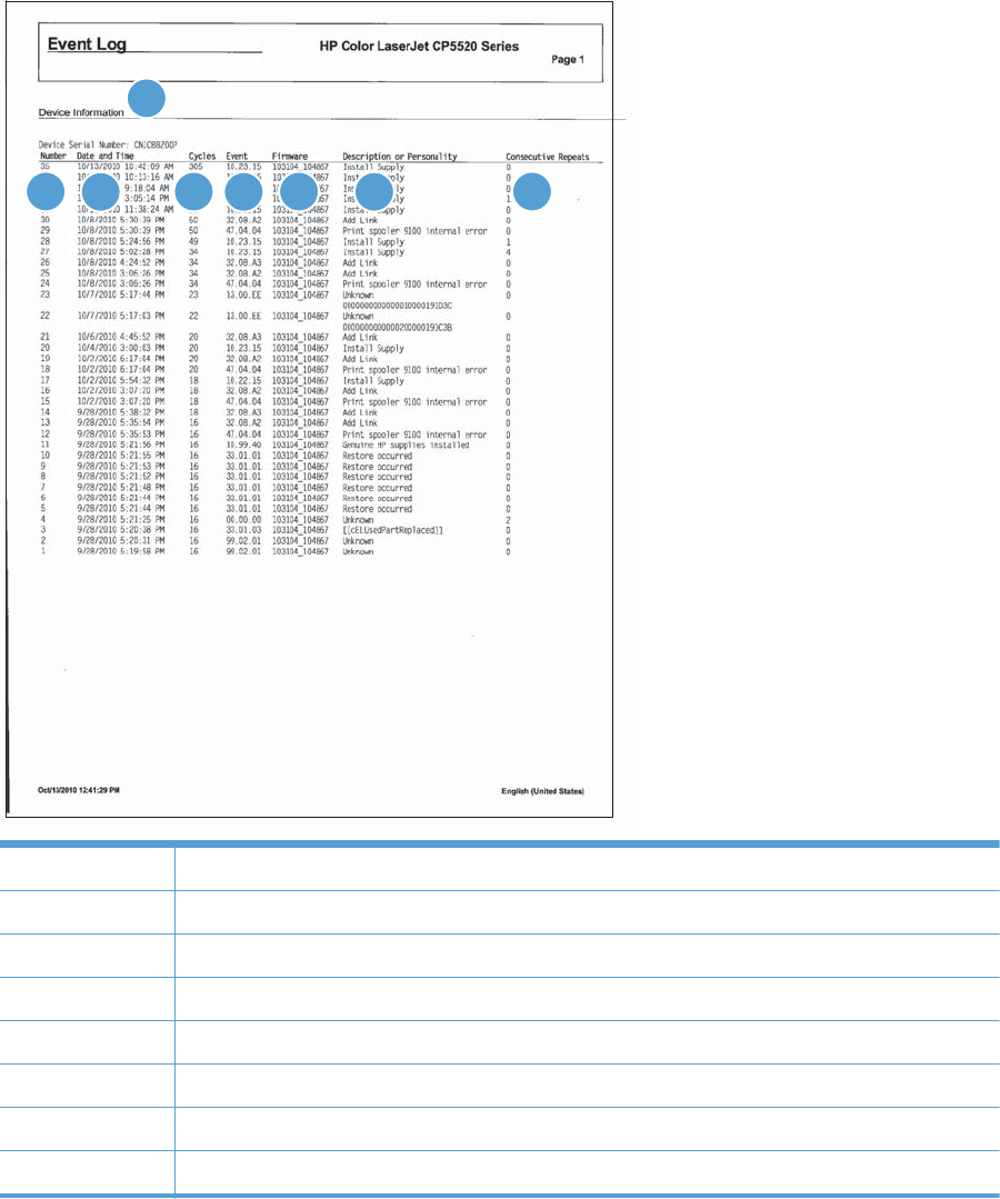
Event-log messages
This section describes messages that only appear in the event log. For additional numeric messages,
see the control-panel message section of this manual
Figure 3-53 Sample event log
56
1
2348
7
1 Product information
2Event number
3 Date and time
4 Engine cycles
5Event log code
6 Firmware version number
7 Description of personality
8 Consecutive Repeats
492 Chapter 3 Solve problems ENWW

Print an event log
NOTE: Printing an event log by using the Administration menu shows only a subset of events. To
print a complete event log, use the Service menu.
Print the event log from the Administration menu
1. Press the Home button .
2. Open the following menus:
●Administration
●Troubleshooting
3. Use the Down arrow button to select the Print Event Log item, and then press the OK button.
Print the event log from the Service menu
1. Press the Home button .
2. Open the following menus:
●Device Maintenance
●Service
The PIN required for the Service menu is 11552010.
3. Use the Down arrow button to select the Print Event Log item, and then press the OK button.
View an event log
NOTE: Viewing an event log by using the Administration menu shows only a subset of events. To
print a complete event log, use the Service menu.
View an event log from the Administration menu
1. Press the Home button .
2. Open the following menus:
●Administration
●Troubleshooting
3. Use the Down arrow button to select the View Event Log item, and then press the OK
button.
ENWW Tools for troubleshooting 493

Viewing the event log from the Service menu
1. Press the Home button .
2. Open the following menus:
●Device Maintenance
●Service
The PIN required for the Service menu is 11552010.
3. Use the Down arrow button to select the View Event Log item, and then press the OK
button.
Clear an event log
1. Press the Home button .
2. Open the following menus:
●Device Maintenance
●Service
The PIN required for the Service menu is 11552010.
3. Use the Down arrow button to select the Clear Event Log item, and then press the OK
button.
494 Chapter 3 Solve problems ENWW

Clear jams
Common causes of jams
The product is jammed.
Cause Solution
The paper does not meet specifications. Use only paper that meets HP specifications. See the product
user guide.
A component is installed incorrectly. Verify that the transfer belt and transfer roller are correctly
installed.
You are using paper that has already passed through a
printer or copier.
Do not use paper that has been previously printed on or
copied.
An input tray is loaded incorrectly. Remove any excess paper from the input tray. Make sure that
the stack is below the maximum stack height mark in the tray.
The paper is skewed. The input-tray guides are not adjusted correctly. Adjust them
so they hold the stack firmly in place without bending it.
The paper is binding or sticking together. Remove the paper, flex it, rotate it 180°, or flip it over. Reload
the paper into the input tray.
The paper is removed before it settles into the output bin. Reset the product, and then resend the print job. Wait until the
page completely settles in the output bin before removing it.
During two-sided printing, you removed the paper before the
second side of the document was printed.
Reset the product and print the document again. Wait until the
page completely settles in the output bin before removing it.
The paper is in poor condition. Replace the paper.
The internal tray rollers are not picking up the paper. If the paper is heavier than the heaviest supported weight for
the tray, it might not be picked from the tray.
The rollers are worn. Replace the rollers.
The paper has rough or jagged edges. Replace the paper.
The paper is perforated or embossed. Perforated or embossed paper does not separate easily. Feed
single sheets from Tray 1.
Paper was not stored correctly. Replace the paper in the trays. Paper should be stored in the
original packaging in a controlled environment.
Not all product packing material was removed. Verify that the packing tape, cardboard, and plastic shipping
locks have been removed from the product.
ENWW Clear jams 495
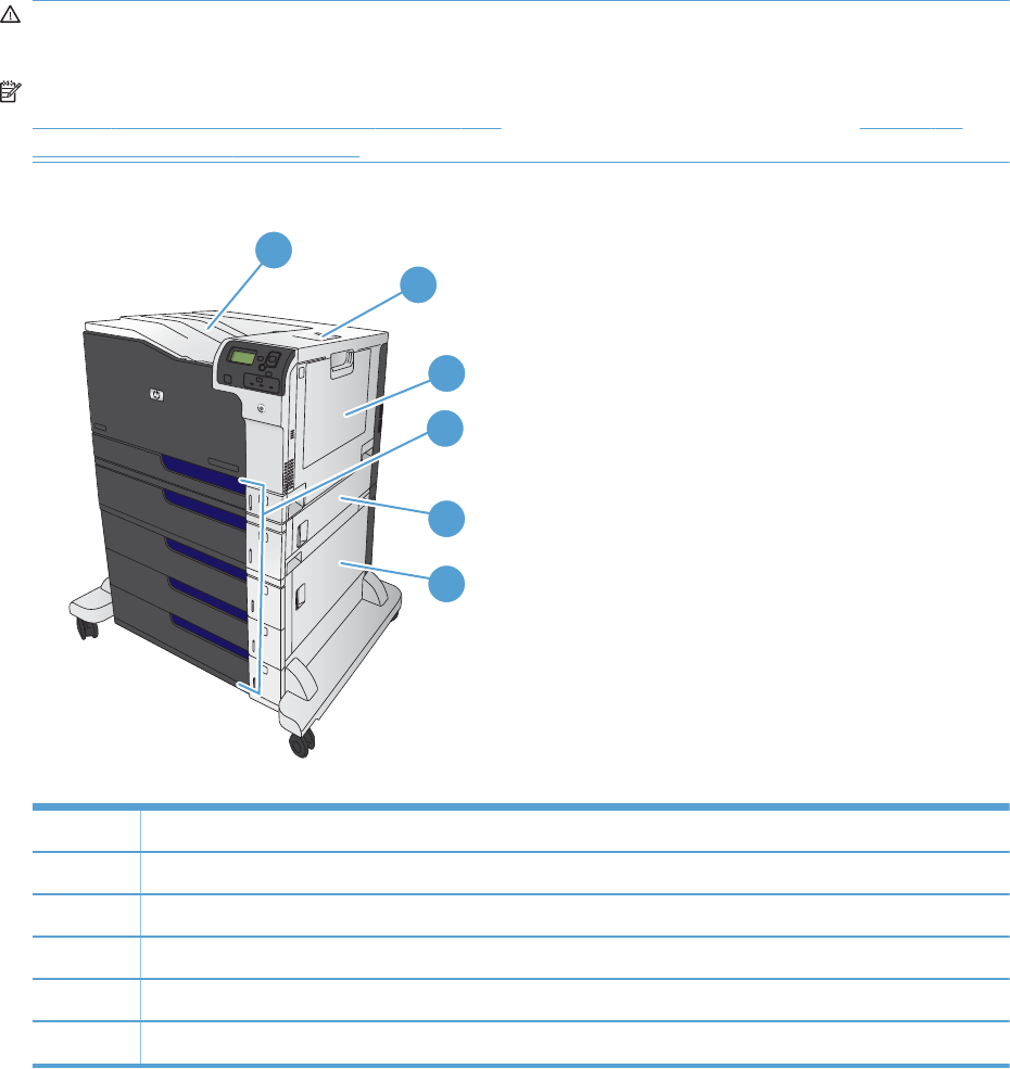
Jam locations
Use this illustration to identify locations of jams. In addition, instructions appear on the control panel to
direct you to the location of jammed paper and how to clear it. Internal areas of the product that might
need to be opened to clear jams, have green handles or green labels.
WARNING! To avoid electrical shock, remove any necklaces, bracelets, or other metal items before
reaching into the inside of the product.
NOTE: Sensors in the paper path generate event codes if a jam occurs. For sensor locations, see
Figure 3-55 Paper path jam sensors on page 497. For jam event code information, see Table 3-47
Event codes for jams on page 498.
Figure 3-54 Jam locations
2
3
5
1
4
6
1 Output bin
2 Upper right door
3Tray 1 area
4 Tray 2, Tray 3, and optional Trays 4, 5, and 6
5 Middle right door
6 Lower right door
496 Chapter 3 Solve problems ENWW
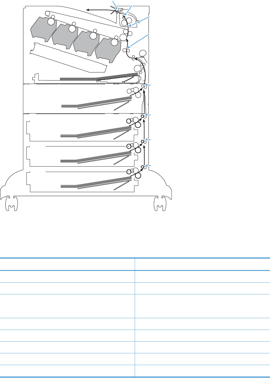
Figure 3-55 Paper path jam sensors
Y
B
C
M
PS10 PS6
PS7
PS8
PS5
SR1
SR1
SR81
SR91
Note: Both the 1 X 500-sheet feeder and the
3 X 500-sheet feeder use a SR1 tray feed sensor.
Table 3-46 Paper path jam sensors
Sensor Description
PS5 Registration sensor
PS6 Fuser output sensor
PS7
PS8
Loop sensor
PS10 Bin full sensor
SR1 Tray 3 feed sensor
SR1 Tray 4 feed sensor
SR81 Tray 5 feed sensor
SR91 Tray 6 feed sensor
ENWW Clear jams 497

Table 3-47 Event codes for jams
Jam event code Jammed paper location
13.A3.D3 Leading edge of paper fed from Tray 3 is stopped before SR1
13.A3.D4 Leading edge of paper fed from Tray 4 is stopped before SR1 after passing Tray 4 SR1
13.A3.D5 Leading edge of paper fed from Tray 5 is stopped before SR1 after passing Tray 4 SR1
13.A3.D6 Leading edge of paper fed from Tray 6 is stopped before SR1 after passing Tray 4 SR1
13.A3.FF At auto-flushing : Paper stays at SR1
13.A4.D4 Leading edge of paper fed from Tray 4 is stopped before Tray 4 SR1
13.A4.D5 Leading edge of paper fed from Tray 5 is stopped before Tray 4 SR1 after passing
SR81
13.A4.D6 Leading edge of paper fed from Tray 6 is stopped before Tray 4 SR1 after passing
SR81
13.A4.FF At auto-flushing : Paper stays at Tray 4 SR1
13.A5.D5 Leading edge of paper fed from Tray 5 is stopped before SR81
13.A5.D6 Leading edge of paper fed from Tray 6 is stopped before SR81 after passing SR91
13.A5.FF At auto-flushing: paper stays at SR81
13.A6.D6 Leading edge of paper fed from Tray 6 is stopped before SR91
13.A6.FF At auto-flushing : Paper stays at SR91
13.B2.A1 Paper stays at PS5 – media longer than allowed from Tray 1
13.B2.A2 Paper stays at PS5 - media longer than allowed from Tray 2
13.B2.A3 Paper stays at PS5 - media longer than allowed from Tray 3
13.B2.A4 Paper stays at PS5 - media longer than allowed from Tray 4
13.B2.A5 Paper stays at PS5 - media longer than allowed from Tray 5
13.B2.A6 Paper stays at PS5 - media longer than allowed from Tray 6
13.B2.AD Paper stays at PS5 - media longer than allowed from Duplexer
13.B2.D1 Leading edge of paper fed from Tray 1 is stopped before PS5
13.B2.D2 Leading edge of paper fed from Tray 2 is stopped before PS5
13.B2.D3 Leading edge of paper fed from Tray 3 is stopped before PS5 after passing SR1
13.B2.D4 Leading edge of paper fed from Tray 4 is stopped before PS5 after passing SR1
13.B2.D5 Leading edge of paper fed from Tray 5 is stopped before PS5 after passing SR1
13.B2.D6 Leading edge of paper fed from Tray 6 is stopped before PS5 after passing SR1
13.B2.DD Duplex re-feed paper is stopped between PS6 and PS5
13.B2.FF At power on, door close, or auto-flushing: paper stays at PS5
13.B4.FF At power on, door close, or auto-flushing : paper stays at PS7/PS8
498 Chapter 3 Solve problems ENWW

Table 3-47 Event codes for jams (continued)
Jam event code Jammed paper location
13.B9.Az
NOTE: z is the fuser mode, see
Fuser modes for jam event codes (Z)
on page 499
Paper stays at PS6
13.B9.Cz
NOTE: z is the fuser mode, see
Fuser modes for jam event codes (Z)
on page 499
Paper is wrapping at fuser
13.B9.D1 Leading edge of paper is stopped between PS5 and PS6 – fed from tray 1
13.B9.D2 Leading edge of paper is stopped between PS5 and PS6 – fed from Tray 2
13.B9.D3 Leading edge of paper is stopped between PS5 and PS6 – fed from Tray 3
13.B9.D4 Leading edge of paper is stopped between PS5 and PS6 – fed from Tray 4
13.B9.D5 Leading edge of paper is stopped between PS5 and PS6 – fed from Tray 5
13.B9.D6 Leading edge of paper is stopped between PS5 and PS6 – fed from Tray 6
13.B9.DD Leading edge of paper is stopped between PS5 and PS6 – fed from Duplexer
13.B9.FF At power on, door close, or auto-flushing: paper stays at PS6
13.E1.Dz
NOTE: z is the fuser mode, see
Fuser modes for jam event codes (Z)
on page 499
Leading edge of paper is stopped before PS10 after passing PS6
13.00.EE Door was opened during printing
13.AA.EE Tray 3, 4, or 5 right tray access door was opened during print job
13.AB.EE Tray 4, 5, 6 right tray access door was opened during print job
13.BB.EE Front door was opened during print job
13.BA.EE Right door was opened during print job
13.FF.FF Jams at multiple sensors
Fuser modes for jam event codes (Z)
●1 = Normal auto sense
●2 = Normal non-auto sense
●3 = Light 1 to 3
●4 = Heavy 1
●5 = heavy 2
ENWW Clear jams 499
●6 = Heavy 3
●7 = Glossy 1
●8 = Glossy 2
●9 = Glossy 3
●A = Glossy film
●B = Transparancy
●C = Label
●D = Envelope 1 to 3
500 Chapter 3 Solve problems ENWW
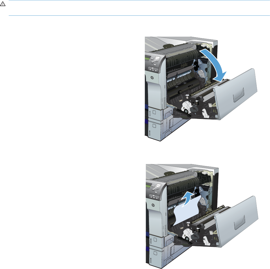
Clear jams in the upper-right door
WARNING! The fuser can be hot while the product is in use. Wait for the fuser to cool before
handling it.
1. Open the upper-right door.
2. Gently pull the paper out of the pickup area.
ENWW Clear jams 501
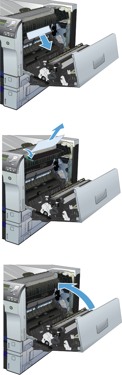
3. If paper is visible entering the bottom of the
fuser, gently pull downward to remove it.
CAUTION: Do not touch the transfer roller.
Contaminants on the roller can affect print
quality.
4. Paper could be jammed inside the fuser where
it would not be visible. Open the fuser jam
access door. If paper is jammed inside the
fuser, gently pull it straight up to remove it. If
the paper tears, remove all paper fragments.
WARNING! Even if the body of the fuser
has cooled, the rollers that are inside could still
be hot. Do not touch the fuser rollers until they
have cooled.
If no paper is found but the product still reports
a jam, remove the fuser to check for jammed
paper inside the fuser cavity. Remove any
paper, and then reinstall the fuser.
NOTE: Make sure that the fuser is reinstalled
correctly before closing the upper right door.
5. Close the upper-right door.
502 Chapter 3 Solve problems ENWW
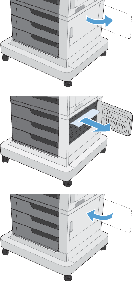
Clear jams in the lower-right door
1. Open the lower-right door.
2. If paper is visible, gently pull the jammed
paper up or down to remove it.
3. Close the lower-right door.
ENWW Clear jams 503
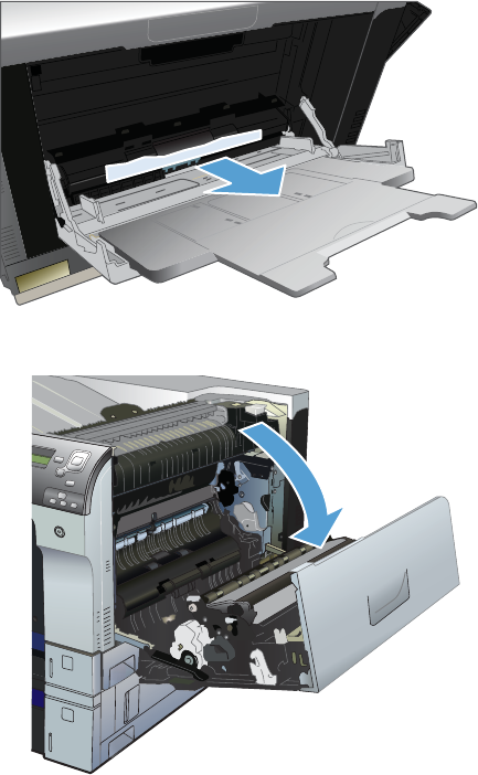
Clear jams in Tray 1
1. If jammed paper is visible in Tray 1, clear the
jam by gently pulling the paper straight out.
Press the OK button to clear the message.
2. If you cannot remove the paper, or if no
jammed paper is visible in Tray 1, close Tray
1 and open the upper right door.
504 Chapter 3 Solve problems ENWW
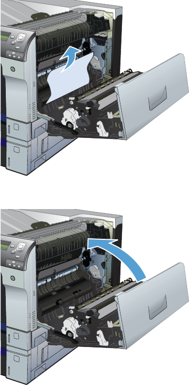
3. Gently pull the paper out of the pick up area.
4. Close the upper right door.
ENWW Clear jams 505
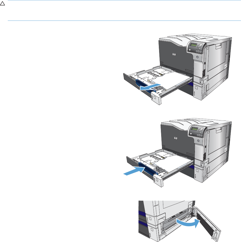
Clear jams from Tray 2, Tray 3, or an optional tray
CAUTION: Opening a tray when paper is jammed can cause the paper to tear and leave pieces of
paper in the tray, which might cause another jam. Be sure to clear jams from the upper and lower right
door before opening a tray.
1. Open the tray and make sure that the paper is
stacked correctly. Remove any jammed or
damaged sheets of paper. To access jammed
paper from the tray cavity, remove the tray
from the product.
2. Close the tray.
3. If the jam is in Tray 3, you also can open the
door on the right side of the tray, remove the
jammed paper, and then close the door.
506 Chapter 3 Solve problems ENWW
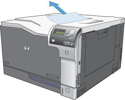
Clear jams in the output bin area
1. If paper is visible from the output bin, grasp
the leading edge and remove it.
ENWW Clear jams 507

Jam causes and solutions
Jams in the output bin
Table 3-48 Causes and solutions for delivery delay jam
Cause Solution
The output-bin full sensor flag is damaged. Examine the output-bin full sensor flag for damage. If the flag is damaged,
replace the paper delivery assembly. See Paper delivery assembly
on page 184.
See Output-bin-full sensor (PS10) on page 313 for troubleshooting
information.
Poor contact of the output-bin full sensor
connector.
If the product was recently repaired, check and reconnect the connector
(J181) on the DC controller PCA and the intermediate connector (J743).
The output bin full sensor (PS10) is defective. Check the output bin full sensor (PS10) using the manual sensor test. See
Output-bin-full sensor (PS10) on page 313.
Poor contact of the fuser-motor (M4)
connector.
Reconnect the connectors of the fuser motor (J516), and the DC controller PCA
(J81).
The fuser motor (M4) is defective. Execute the fuser-motor driving test in the component test (see Component tests
on page 314). If the motor is defective, replace the fuser motor (M4). See
Fuser motor (M4) on page 196.
Jams in the fuser and transfer area
Table 3-49 Causes and solutions for fuser delivery delay jams
Cause Solution
The fuser-output sensor connctor has a poor
connection.
Reconnect connector J131 on the DC controller PCA.
The fuser-output sensor (PS6) is defective. Check the fuser-output sensor (PS6) with the manual sensor test. See Fuser
output sensor (PS6) on page 297. If the sensor is defective, replace the fuser.
See Fuser on page 93.
Table 3-50 Causes and solutions for wrapping jams
Cause Solution
The fuser roller or pressure roller is dirty. Print a cleaning page. See Clean the paper path on page 349.
The fuser roller or the pressure roller is worn
or deformed.
Replace the fuser. See Fuser on page 93.
The output bin full sensor has a poor
connection.
Reconnect the connector J181 on the DC controller PCA, and the intermediate
connector J743.
The output bin full sensor is defective. Run the manual sensor test to verify the output bin full sensor is functioning
properly. See Output-bin-full sensor (PS10) on page 313. If not, replace the
fuser gear assembly. See Fuser gear assembly on page 176.
508 Chapter 3 Solve problems ENWW

Table 3-51 Causes and solutions for fuser delivery stationary jams
Cause Solution
The fuser roller or pressure roller is worn or
deformed.
Replace the fuser. See Fuser on page 93.
The fuser-delivery roller is deformed.
The gear of the fuser-delivery roller is
damaged.
Poor contact of the fuser-output sensor
connector.
Reconnect the connector J131 on the DC controller PCA.
The fuser-output sensor (PS6) is defective. Run the manual sensor test to verify that the fuser-output sensor is functioning
properly. See Fuser output sensor (PS6) on page 297. If it is not, replace the
fuser. See Fuser on page 93.
Jams in the duplex area (duplex models only)
Table 3-52 Causes and solutions for duplexing reverse jams
Cause Solution
The duplex reverse roller is worn or deformed. Replace the fuser. See Fuser on page 93.
The duplex feed roller is worn or deformed. Replace the right door. See Right-door assembly on page 126.
Poor contact of the duplex reverse-motor (M7)
connector
Reconnect the connectors (J520) on the duplex reverse motor, intermediate
connectors (J552L and J552D), connector (J1006) on the driver PCA, and
connectors (J93; J92; J91) on the DC controller PCA.
The duplex reverse motor is defective. Replace the duplex drive assembly. See Duplex drive assembly (duplex
models) on page 187.
Table 3-53 Causes and solutions for duplex repick jams
Cause Solution
The duplex re-pickup sensor lever is set
incorrectly or damaged.
Check the sensor lever to make sure it is set correctly. If it is damaged, replace
the right door assembly. See Right-door assembly on page 126.
The spring of the duplex re-pickup sensor
lever is unhooked.
Check the spring and place it in correct position.
Poor contact of the duplex reverse solenoid
(SL3) connector
Reconnect the intermediate connectors (J522L and J522D), connector (J1005)
on the driver PCA, and connectors (J93; J92; J91) on the DC controller PCA.
The duplex reverse solenoid is defective. Replace the duplex-drive assembly. See Duplex drive assembly (duplex
models) on page 187.
The duplex flapper is damaged or
malfunctioning.
Replace the delivery assembly. See Duplex drive assembly (duplex models)
on page 187.
The duplex reverse solenoid is defective. Replace the duplex-drive assembly. See Duplex drive assembly (duplex
models) on page 187.
ENWW Clear jams 509

Table 3-53 Causes and solutions for duplex repick jams (continued)
Cause Solution
The duplex flapper is damaged or
malfunctioning.
Replace the paper delivery assembly. See Paper delivery assembly
on page 184.
The duplex repick roller is worn or damaged. Replace the registration sensor assembly. See Registration sensor assembly
on page 142.
The duplex repick clutch is defective. Run the solenoid drive test in component test (see Component tests
on page 314)to verify that the duplex repick clutch is functioning properly. If it
is not, replace the duplex drive assembly. See Duplex drive assembly (duplex
models) on page 187.
Table 3-54 Causes and solutions for residual media jams
Cause Solution
Poor contact of the fuser loop-sensor
connector and fuser loop sensor 1 and 2.
Reconnect the connectors of the fuser loop sensor 1 and 2 (J13) and the
connector (J131) on the DC controller PCA.
The loop sensor is defective. Run the manual sensor test. See Fuser loop sensors 1 and 2 (PS7 and PS8)
on page 295 for information. If the sensor is defective, replace fuser. See
Fuser on page 93.
The spring of the fuser-output-sensor lever is
unhooked.
Check the spring of the fuser and right door and place it in the correct
position.
The fuser-output sensor lever is damaged. Replace the sensor (PS6).
Poor contact of the fuser-output sensor
connector.
Reconnect connector (J1055) of the fuser-output sensor and connector (J131)
on the DC controller PCA.
The fuser-output sensor is defective. Run the manual sensor test to make sure the fuser-delivery sensor is functioning
properly. See Fuser output sensor (PS6) on page 297 for information. If the
sensor is defective, replace the fuser. See Fuser on page 93.
The duplex pickup sensor lever is damaged. Replace the right door assembly. See Right-door assembly on page 126.
NOTE: Even if jammed paper is visible in Tray 1, clear the jam from the inside of the product by
opening the right door.
Jams in Tray 1, Tray 2 and internal paper path
Table 3-55 Causes and solutions for pickup delay jam 1: tray pickup
Cause Solution
The tray 1 pick up roller or the tray 1
separation pad is worn or deformed.
Replace the tray 1 pickup roller and separation pad. See Pickup roller (Tray 1)
on page 94 and Separation pad (Tray 1) on page 95. Replace the right door.
See Right-door assembly on page 126.
Poor contact of the tray 1 media-presence-
sensor connector
Reconnect the connectors of the tray media-feed sensor intermediate
connectors (J531L and J531D), and the connector (J152) on the DC controller.
Poor contact of the TOP sensor connector. Reconnect the intermediate connector (J554L and J554D) of the TOP sensor
and connector (J122) on the DC controller PCA.
510 Chapter 3 Solve problems ENWW

Table 3-55 Causes and solutions for pickup delay jam 1: tray pickup (continued)
Cause Solution
The TOP sensor is defective. Run the manual sensor test to verify that the TOP sensor is functioning
properly. If not, replace the registration assembly. See Registration sensor
assembly on page 142.
Poor contact of the MP-pickup-solenoid drive
connector
Reconnect the connector of the tray pickup solenoid intermediate connectors
(J530L and J530D), and the connector (J152) on the DC controller PCA.
The MP-pickup solenoid is defective. Execute the tray-pickup-solenoid driving test in the component test (see
Component tests on page 314). If the solenoid is defective, replace the right
door assembly. See Right-door assembly on page 126.
Poor contact of the pickup-motor drive
connector (M5)
Reconnect the picku-motor connector (J523) and connector (J260),
intermediate connectors (J535L and J535D), and the connector (J1003) on the
DC controller PCA.
The pickup motor is defective. Execute the pickup-motor driving test in the component test (see Component
tests on page 314). If the motor is defective, replace the paper pickup
assembly. See Paper pickup assembly on page 135.
Table 3-56 Causes and solutions for pickup delay jams Tray 2
Cause Solution
Poor contact of the pickup motor drive
connector.
Reconnect the connector J91on the DC controller PCA .
The pickup motor is defective. Execute the Tray 2 pickup motor test in the component test (see Component test
(special-mode test) on page 314). If the motor is defective, replace the paper
pickup assembly. See Paper pickup assembly on page 135.
The pickup roller is worn or deformed. Replace the pickup roller. See Pickup roller (Tray 2) on page 98.
The tray 2 separation roller is worn or
deformed.
Replace the separation roller. See Separation roller assembly (Tray 2)
on page 97.
Poor contact of the TOP sensor connector. Reconnect the connector J122 on the DC controller PCA.
The TOP sensor (PS5) is defective. Run the manual sensor test to verify that the TOP sensor is functioning properly.
See TOP (top-of-page) sensor (PS5) on page 294 for information. If it is not,
replace the registration sensor assembly. See Registration sensor assembly
on page 142.
Poor contact of the Tray 2 pickup solenoid
drive connector.
Reconnect the connector J1003 on the DC controller PCA.
The Tray 2 pickup solenoid is defective. Run the Tray 2 pickup solenoid test in the component test (see Component test
(special-mode test) on page 314) to verify that the Tray 2 pickup solenoid is
functioning properly. If it is not, replace the paper pickup assembly. See Paper
pickup assembly on page 135.
ENWW Clear jams 511

Table 3-57 Causes and solutions for pickup stationary jams
Cause Solution
Multiple feed of media Replace any worn or deformed parts (tray separation pad, tray feed roller, MP
tray pickup roller or MP tray separation pad).
Check the separation pad and MP tray separation pad to see if they are firmly
seated and coupled with the torque limiter.
Replace the separation pad and feed roller for the associated tray.
If the MP tray pickup roller if defective, replace the roller. See Pickup roller
(Tray 1) on page 94. If the MP tray separation pad is defective, replace the
separation pad assembly. See Separation pad (Tray 1) on page 95.
The secondary transfer roller is not set
correctly.
Place the secondary-transfer-roller unit in the correct position.
The secondary-transfer roller is worn or
deformed.
Replace the secondary-transfer-roller assembly. See Secondary transfer roller
on page 101.
Poor contact of the drum drive connector Reconnect the connectors of the ITB motor (J517) and the DC controller PCA
(J81).
The drum motor is defective. Execute the drum motor driving test in the component test (see Component tests
on page 314). If the motor is defective, replace the motor.
The ITB does not rotate smoothly. Replace the ITB. See Intermediate transfer belt (ITB) on page 102.
The TOP sensor lever is incorrectly positioned
or damaged
Check the sensor lever to make sure it is correctly positioned . If it is damaged,
replace the registration sensor assembly. See Registration sensor assembly
on page 142.
Poor contact of the TOP sensor connector Reconnect the connector J122 on the DC controller PCA.
The TOP sensor is defective. Run the manual sensor test to verify that the TOP sensor (PS5) is functioning
properly. See TOP (top-of-page) sensor (PS5) on page 294 for information. If it
is not, replace the registration sensor assembly. See Registration sensor
assembly on page 142.
Table 3-58 Causes and solutions for residual media jams
Cause Solution
A piece of paper remains at the sensor
detecting the jam.
Make sure that all paper, including small bits of paper, are removed from the
product when a jam is removed.
512 Chapter 3 Solve problems ENWW

Table 3-58 Causes and solutions for residual media jams (continued)
Cause Solution
The sensor detecting a residual media jam is
not working.
Test each sensor using the manual sensor test. See Manual sensor test
on page 289 for information. If the sensor does not respond, replace the
component indicated:
●TOP sensor (PS5): Replace the registration sensor assembly. See
Registration sensor assembly on page 142.
●Fuser-output sensor (PS6): Replace the fuser. See Fuser on page 93.
●Fuser loop sensors 1 and 2 (PS7 and PS8): Replace the fuser. See Fuser
on page 93.
If service was recently performed on the
product, a sensor connector might be
disconnected.
Run the manual sensor tests to verify which sensor detects the media. See
Manual sensor test on page 289 or Tray/Bin manual sensor test on page 300
for information. Reconnect the corresponding sensor connector:
●TOP sensor: Connector (J122) on the DC controller PCA
●Fuser-output sensor: Connector (J131) on the DC controller PCA
●Fuser Loop sensor 1 or 2: Connector (J131) on the DC controller PCA
Jams in Tray 3, 4, 5, and 6
Table 3-59 Causes and solutions for pickup delay and pickup stationary jams
Cause Solution
The paper-feeder pickup roller is worn or
deformed.
Replace the pickup roller. See Pickup roller, separation roller, and feed roller
(1 x 500-sheet and 3 x 500-sheet paper feeders) on page 99.
The paper-feeder separation roller is worn or
deformed.
Replace the separation roller. See Pickup roller, separation roller, and feed
roller (1 x 500-sheet and 3 x 500-sheet paper feeders) on page 99.
The paper-feeder feed roller is worn or
deformed.
Replace the feed roller. See Pickup roller, separation roller, and feed roller (1
x 500-sheet and 3 x 500-sheet paper feeders) on page 99.
Poor contact of the paper-feeder media-feed
sensor connectorS
A tray feed sensor is defective. Run the manual sensor test to verify that the paper-feeder media feed sensor is
functioning properly. See Tray/Bin manual sensor test on page 300 for
information. If it is not, replace the paper pickup assembly of the specific tray.
Poor contact of a paper-feeder pickup
solenoid drive connector
The paper-feeder pickup solenoid is defective. Run the solenoid drive test in the component test (see Component tests
on page 314) to verify that the paper-feeder pickup solenoid is functioning
properly. If it is not, replace the paper pickup assembly of the specific tray.
Poor contact of paper-feeder pickup motor
drive connector.
The paper-feeder pickup motor is defective. Run the pickup motor drive test in the component test (see Component tests
on page 314) to verify that the paper-feeder pickup motor is functioning
properly. If it is not, replace the pickup assembly of the specific tray.
ENWW Clear jams 513

Table 3-59 Causes and solutions for pickup delay and pickup stationary jams (continued)
Cause Solution
Multiple feed of media If the tray 3 pickup roller, separation roller, or feed roller is worn or deformed,
replace any defective parts.
The paper-feeder media-feed sensor lever is
set incorrectly or damaged.
Check the sensor lever to make sure it is set correctly. If it is damaged, replace
the paper-feeder assembly.
The spring of the paper-feeder media-feed
sensor lever is unhooked.
Check the spring and place it in correct position.
Poor contact of the paper-feeder media-feed
sensor connector.
Reconnect the connector (J406) on the connector PCA and connector (J22) of
the paper-feeder media feed sensor.
A tray feed sensor is defective. Run the manual sensor test to verify that the tray feed sensor is functioning
properly. See Tray/Bin manual sensor test on page 300 for information. If it is
not, replace the pickup assembly of the specific tray.
Table 3-60 Causes and solutions for residual media jams
Cause Solution
The sensor that detects residual paper jams is
set incorrectly or damaged.
Run the manual sensor test to verify which sensor detects the paper. See Tray/
Bin manual sensor test on page 300 for information. Check the sensor lever to
make sure it is set correctly. If it is damaged, replace the corresponding
pickup assembly.
The spring of the sensor lever that detects
residual paper jams is unhooked.
Run the manual sensor test to verify which sensor detects the paper. See Tray/
Bin manual sensor test on page 300 for information. Check the spring of the
sensor lever to make sure it is set correctly.
Poor contact exists in the sensor that detects
residual paper jams.
Run the manual sensor test to verify which sensor detects the paper. See Tray/
Bin manual sensor test on page 300 for information. Reconnect the following
corresponding sensor connectors:
The sensor that detects residual paper jams is
defective.
Run the sensor test in the sensor monitor mode to verify which sensor detects
the paper. Replace media feed sensor.
514 Chapter 3 Solve problems ENWW

Change jam recovery
This product provides a jam recovery feature that reprints jammed pages. The following options are
available:
●Auto — The product attempts to reprint jammed pages when enough memory is available. This is
the default setting.
●Off — The product does not try to reprint jammed pages. Because no memory is used to store the
most recent pages, performance is optimal.
NOTE: When using this option, if the product runs out of paper and the job is being printed on
both sides, some pages can be lost.
●On — The product always reprints jammed pages. Additional memory is allocated to store the
last few pages printed. This might cause overall performance to suffer.
Set the jam recovery feature
1. Press the Home button .
2. Open the following menus:
●Administration
●General Settings
●Jam Recovery
3. Press the Down arrow or Up arrow / button to highlight the appropriate setting, and then
press the OK button.
4. Press the Home button to return to the Ready state.
ENWW Clear jams 515

Solve paper-handling problems
Product feeds multiple sheets
Product feeds multiple sheets
Cause Solution
The input tray is overfilled. Open the tray and verify that the
paper stack is below the maximum stack height mark.
Remove excess paper from the input tray.
Print paper is sticking together. Remove paper, flex it, rotate it 180 degrees or flip it over,
and then reload it into the tray.
NOTE: Do not fan paper. Fanning can cause static
electricity, which can cause paper to stick together.
Paper does not meet the specifications for this product. Use only paper that meets HP paper specifications for this
product.
Trays are not properly adjusted. Make sure that the paper guides match the size of paper
being used.
Tray 2 feeds multiple sheets. Make sure Tray 2 is not overfilled. Open the tray and verify
that the paper stack is below the maximum stack height mark.
Remove paper from Tray 2 to avoid jams.
Product feeds incorrect page size
Product feeds incorrect page size
Cause Solution
The correct size paper is not loaded in the tray. Load the correct size paper in the tray.
The correct size paper is not selected in the software program
or printer driver.
Confirm that the settings in the software program and printer
driver are correct, because the software program settings
override the printer driver and control panel settings, and the
printer driver settings override the control panel settings.
The correct size paper for the tray is not selected in the
product control panel.
From the control panel, select the correct size paper for the
tray.
The paper size is not configured correctly for the tray. Print a configuration page or use the control panel to
determine the paper size for which the tray is configured.
The guides in the tray are not against the paper. Verify that the paper guides are touching the paper.
516 Chapter 3 Solve problems ENWW

Product pulls from incorrect tray
Product pulls from incorrect tray
Cause Solution
You are using a driver for a different product. Use a driver for this product.
The specified tray is empty. Load paper in the specified tray.
The paper size is not configured correctly for the input tray. Print a configuration page or use the control panel to
determine the paper size for which the tray is configured.
The guides in the tray are not against the paper. Verify that the guides are touching the paper.
Paper does not feed automatically
Paper does not feed automatically
Cause Solution
Manual feed is selected in the software program. Load Tray 1 with paper, or, if the paper is loaded, press the
OK button.
The correct size paper is not loaded. Load the correct size paper.
The input tray is empty. Load paper into the input tray.
Paper from a previous jam has not been completely removed. Open the product and remove any paper in the paper path.
The paper size is not configured correctly for the input tray. Print a configuration page or use the control panel to
determine the paper size for which the tray is configured.
The guides in the tray are not against the paper. Verify that the rear and width paper guides are touching the
paper.
The Manually Feed Prompt item is set to Always. The
product always prompts for manual feed, even if the tray is
loaded.
Open the tray, reload the media, and then close the tray.
Or, change the Manually Feed Prompt setting to Unless
loaded, so that the product prompts for manual feed only
when the tray is empty.
The Use Requested Tray setting on the product is set to
Exclusively, and the requested tray is empty. The product
will not use another tray.
Load the requested tray.
Or, change the setting from Exclusively to First on the
Manage Trays menu. The product can use other trays if no
media is loaded in the specified tray.
Paper does not feed from Tray 2, 3, 4, 5, or 6
Paper does not feed from Tray 2, 3, 4, 5, or 6
Cause Solution
The correct size paper is not loaded. Load the correct size paper.
ENWW Solve paper-handling problems 517

Paper does not feed from Tray 2, 3, 4, 5, or 6
Cause Solution
The input tray is empty. Load paper in the input tray.
The correct paper type for the input tray is not selected in the
product control panel.
From the product control panel, select the correct paper type
for the input tray. Trays configured for a paper type with a
specific weight range will not match a print job that specifies
an exact weight, even if the specified weight is within the
weight range.
Paper from a previous jam has not been completely removed. Open the product and remove any paper in the paper path.
Closely inspect the fuser area for jams.
None of the optional trays appear as input tray options. The optional trays only display as available if they are
installed. Verify that any optional trays are correctly installed.
Verify that the printer driver has been configured to recognize
the optional trays.
An optional tray is incorrectly installed. Print a configuration page to confirm that the optional tray is
installed. If not, verify that the tray is correctly attached to the
product.
The paper size is not configured correctly for the input tray. Print a configuration page or use the control panel to
determine the paper size for which the tray is configured.
The guides in the tray are not against the paper. Verify that the guides are touching the paper.
Transparencies or glossy paper will not feed
Transparencies or glossy paper will not feed
Cause Solution
The correct paper type is not specified in the software or
printer driver.
Verify that the correct paper type is selected in the software or
printer driver.
The input tray is overfilled. Remove excess paper from the input tray. Do not exceed the
maximum stack height marks for the tray.
Paper in another input tray is the same size as the
transparencies, and the product is defaulting to the other tray.
Make sure that the input tray containing the transparencies or
glossy paper is selected in the software program or printer
driver. Use the product control panel to configure the tray to
the paper type loaded.
The tray containing the transparencies or glossy paper is not
configured correctly for type.
Make sure that the input tray containing the transparencies or
glossy paper is selected in the software program or printer
driver. Use the product control panel to configure the tray to
the paper type loaded.
Transparencies or glossy paper might not meet supported
paper specifications.
Use only paper that meets the HP paper specifications for this
product.
High-humidity environments may cause glossy paper not to
feed, or to feed too many sheets.
Avoid printing glossy paper in high humidity conditions.
When printing glossy paper, removing the paper from the
wrapper and letting it rest for a few hours can improve
feeding into the product. However, letting paper rest in humid
environments may also cause blisters.
518 Chapter 3 Solve problems ENWW

Envelopes jam or will not feed in the product
Envelopes jam or will not feed in the product
Cause Solution
Envelopes are loaded in an unsupported tray. Only Tray 1
can feed envelopes.
Load envelopes into Tray 1.
Envelopes are curled or damaged. Try using different envelopes. Store envelopes in a controlled
environment.
Envelopes are sealing because the moisture content is too
high.
Try using different envelopes. Store envelopes in a controlled
environment.
Envelope orientation is incorrect. Verify that the envelope is loaded correctly.
This product does not support the envelopes being used. Refer to the HP LaserJet Printer Family Print Media Guide.
Tray 1 is configured for a size other than envelopes. Configure Tray 1 size for envelopes.
Output is curled or wrinkled
Output is curled or wrinkled
Cause Solution
Paper does not meet the specifications for this product. Use only paper that meets the HP paper specifications for this
product.
Paper is damaged or in poor condition. Remove paper from the input tray and load paper that is in
good condition.
Product is operating in an excessively humid environment. Verify that the printing environment is within humidity
specifications.
You are printing large, solid-filled areas. Large, solid-filled areas can cause excessive curl. Try using a
different pattern.
Paper used was not stored correctly and might have absorbed
moisture.
Remove paper and replace it with paper from a fresh,
unopened package.
Paper has poorly cut edges. Remove paper, flex it, rotate it 180 degrees or turn it over,
and then reload it into the input tray. Do not fan paper. If the
problem persists, replace the paper.
The specific paper type was not configured for the tray or
selected in the software.
Configure the software for the paper (see the software
documentation). Configure the tray for the paper.
The paper has previously been used for a print job. Do not re-use paper.
ENWW Solve paper-handling problems 519

Product will not duplex or duplexes incorrectly
Product will not duplex (print 2-sided jobs) or duplexes incorrectly
Cause Solution
You are trying to duplex on unsupported paper. Verify that the paper is supported for duplex printing.
The printer driver is not set up for duplex printing. Set up the printer driver to enable duplex printing.
The first page is printing on the back of preprinted forms or
letterhead.
Load preprinted forms and letterhead in Tray 1 with the
letterhead or printed side down, with the top of the page
leading into the product. For Tray 2 and 3, load the paper
printed side up with the top of the page toward the right of
the product.
The product model does not support automatic 2-sided
printing.
The HP Color LaserJet CP5525n does not support automatic 2-
sided printing.
The product configuration is not set for duplexing. In Windows, run the automatic configuration feature:
1. Click the Start button, point to Settings, and then click
Printers (for Windows 2000) or Printers and Faxes
(for Windows XP).
2. Right-click the HP product icon, and then click
Properties or Printing Preferences.
3. Click the Device Settings tab.
4. Under Installable Options, click Update Now in
the Automatic Configuration list.
520 Chapter 3 Solve problems ENWW

Use manual print modes
Try the following multi-purpose (MP) modes to see if they solve the image-quality problems. To access
the manual print modes, open the following menus:
●Administration
●General Settings
●Print Quality
●Adjust Paper Types
Table 3-61 MP modes under the Adjust Paper Types sub menu
Print Mode
●AUTOSENSE MODE
●NORMAL MODE
●LIGHT MODE
●HEAVY MODE
●CARDSTOCK MODE
●TRANSPARENCY MODE
●TRANSPARENCY MODE 2
●ENVELOPE MODE
●LABEL MODE
●TOUGH MODE
●EXTRA TOUGH MODE
●HEAVY GLOSSY MODE
●X-HVY GLOSSY MODE
●ROUGH MODE
●CARD GLOSSY MODE
●4MM TRNS MODE
●LIGHT ROUGH MODE
NOTE: Not all print modes are available for all paper
types.
RESISTANCE MODE Set to Up to resolve print-quality issues caused by poor
secondary transfer in low-humidity environments with resistive
or rough surface media.
ENWW Use manual print modes 521

Table 3-61 MP modes under the Adjust Paper Types sub menu (continued)
HUMIDITY MODE With glossy film, set to High when the product is in a high-
humidity environment and print-quality defects occur on HP
Tough Paper or Opaque film.
With transparencies, set to High when the product is in a
high-humidity environment and print-quality defects occur on
color transparencies on the first page of a print job.
With all other paper types, set to High when the product is in
a high-humidity environment and light density occurs on the
first page of a print job.
FUSER TEMP MODE If you are seeing a faint image of the page repeated at the
bottom of the page or on the following page, first make sure
the Paper Type and Print Mode settings are correct for the
type of paper you are using. If you continue to see ghost
images on your print jobs, set the Fuser Temp feature to one of
the Alternate settings . Try the ALTERNATE 1 setting first and
see if it solves the problem. If you continue to see the problem,
try ALTERNATE 2 and then ALTERNATE 3. Using the
ALTERNATE 2 and ALTERNATE 3 settings might cause an
extra delay between jobs.
PAPER CURL MODE Use in high-humidity and high-temperature environments. The
REDUCED setting decreases fuser temperature and increases
the interpage gap.
Table 3-62 MP modes under the Optimize submenu
NORMAL PAPER Set to SMOOTH when printing on smooth paper of normal
weight.
HEAVY PAPER Set to SMOOTH when printing on smooth, heavy media
types.
LIGHT MEDIA Set to SMOOTH when printing on smooth, light media types.
ENVELOPE CONTROL Set to REDUCED TEMP if envelopes are sticking due to
moisture in the envelop adhesive.
ENVIRONMENT Set to LOW TEMP if the product is operating in a low-
temperature environment and you are having problems with
print quality such as blisters in the printed image.
LINE VOLTAGE Set to LOW VOLTAGE if the product is operating in a low-
voltage environment and you are having problems with print
quality such as blisters in the printed image.
TRAY1 Set to ALTERNATE if you are seeing marks on the back side
of the paper when printing from Tray 1. This sets the product
to initiate a clean sequence every time a job finishes when the
product is set for Any Size and Any Type for Tray 1.
BACKGROUND Set to ALTERNATIVE 1 when a background occurs all over
the page. Set to ALTERNATIVE 2 when thin vertical lines
appear on the page. Set to ALTERNATIVE 3 when the other
alternatives do not correct the problem.
522 Chapter 3 Solve problems ENWW
ALTERNATE 1, 2, AND 3

Table 3-62 MP modes under the Optimize submenu (continued)
CLEANING CONTROL Changes the control of toner purge. Toner purge is executed
with the CRG in contact with the ITB. Toner purge is executed
right after this mode is selected at the control panel.
ALTERNATIVE 1: Use this option when ITB cleaning failure
occurs during lower coverage printing or when abnormal
noise occurs from ITB cleaning blade.
MEDIA TEMP Use ALTERNATIVE 1to preventing media in the output bin
from sticking together.
UNIFORMITY CONTROL Set to ALTERNATIVE 1 to improve uniformity on any paper
type. Set to ALTERNATIVE 2 to improve uniformity on
normal and light paper types. Set to ALTERNATIVE 3 when
the other alternatives do not correct the problem.
PRE-ROTATION Set to ALTERNATIVE 1 when horizontal banding occurs with
the drum pitch, or when 53 mm band occurs after leaving
engine for a long period of time.
Set to ALTERNATIVE 2 when the problems like fade finger
(trailing edge toner starvation) occur after high coverage
continuous printing.
REGISTRATION Set to ALTERNATIVE when color misregistration occurs.
TRANSFER CONTROL Set to ALTERNATIVE 1 to reduce primary transfer bias and
to resolve low density or blotchy images. Set to
ALTERNATIVE 2 to resolve ghosting outlines that look like a
finger or fingers. Set to ALTERNATIVE 3 when the other
alternatives do not correct the problem.
MOISTURE CONTROL Set to ALTERNATE when image failure occurs due to water
drops.
ENWW Use manual print modes 523
ALTERNATE
ALTERNATE
ALTERNATE 1, 2, AND 3
ALTERNATE 1 AND 2
ALTERNATE
ALTERNATE 1, 2, AND 3
Solve image-quality problems
Occasionally, you might encounter problems with print quality. The information in the following sections
helps you identify and resolve these issues.
Print quality examples
Some print quality problems arise from low or very low cartridges or other supplies. The solution is to
replace the low or very low supplies.
Some print quality problems arise from use of inappropriate paper.
●Use paper that meets HP paper specifications.
●The surface of the paper is too rough. Use paper that meets HP paper specifications.
●The printer driver setting or paper tray setting might be incorrect. Be sure that you have configured
the paper tray at the product control panel and have also selected the correct driver setting for the
paper that you are using.
●The print mode might be set incorrectly, or the paper might not meet recommended specifications.
●The transparencies you are using are not designed for proper toner adhesion. Use only
transparencies designed for HP Color LaserJet products.
●The moisture content of the paper is uneven, too high, or too low. Use paper from a different
source or from an unopened ream of paper.
●Some areas of the paper reject toner. Use paper from a different source or from an unopened
ream of paper.
●The letterhead you are using is printed on rough paper. Use a smoother, xerographic paper. If this
solves your problem, consult with the printer of your letterhead to verify that the paper used meets
the specifications for this product.
●Several optimize print modes can be used to address print quality issues. See the print modes
section of this manual.
If you are having problems with light streaks in an image, use the Administration menu to print the
supplies status page. If none of the cartridges has reached its estimated end of life, remove the
cartridges from the product, and then reinstall them. The product initiates a cleaning mechanism that
might correct the light streaks.
The following examples depict letter-size paper that has passed through the product short-edge first.
These examples illustrate problems that would affect all the pages that you print, whether you print in
color or in black only. The topics that follow list the typical cause and solution for each of these
examples.
524 Chapter 3 Solve problems ENWW
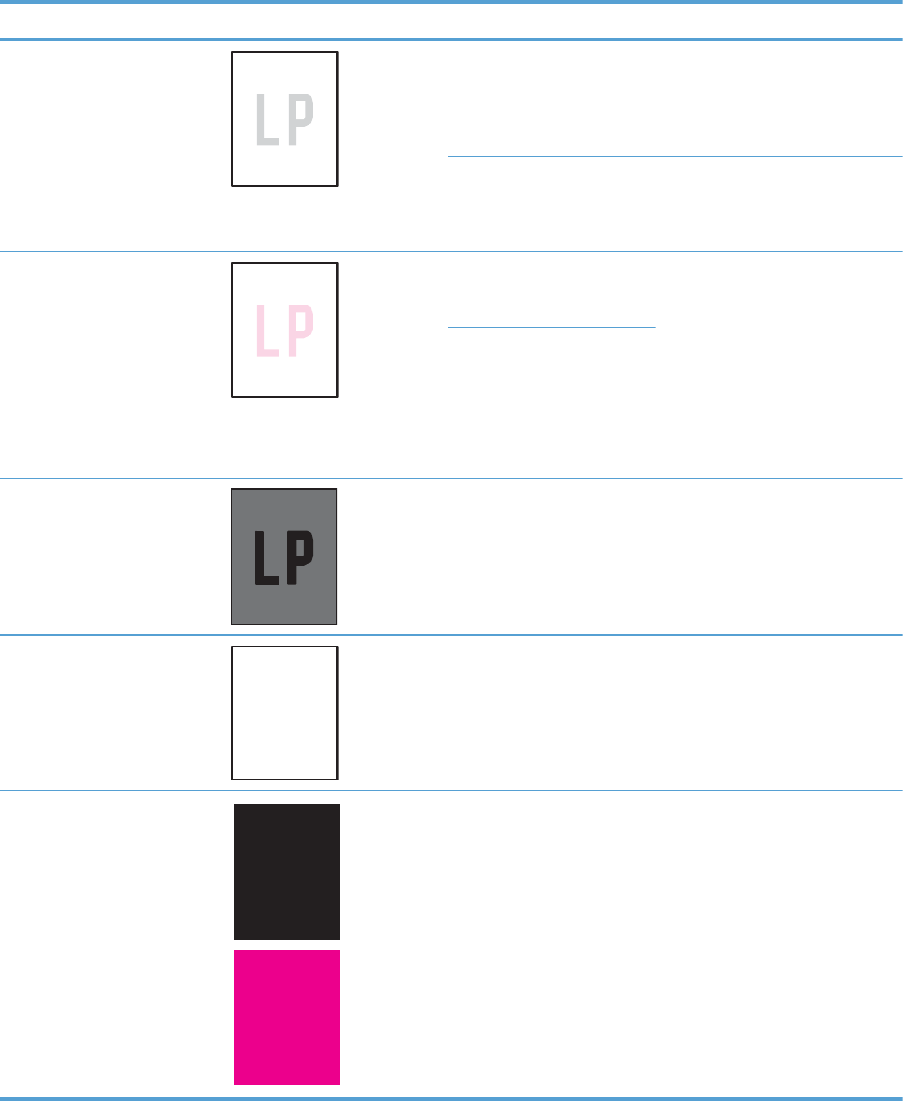
Problem Sample Cause Solution
Print is light or faded on entire
page.
Poor contacts exist on the ITB
unit and the product
grounding unit.
Clean the grounding contacts. If the
problem remains after cleaning,
check the contacts for damage.
Replace any deformed or damaged
parts.
Poor secondary transfer
contacts exist on the
secondary transfer roller and
the ITB.
Clean the contacts. If the problem
remains after cleaning, check the
contacts for damage. Replace any
deformed or damaged parts.
Print is light or faded in a
particular color.
Poor primary transfer bias
contacts on the ITB unit and
product.
Clean the contacts of the color that
produces the light print. If the
problem remains after cleaning,
check the contacts for damage.
Replace any deformed or damaged
parts.
Poor primary charging bias
contacts with the print
cartridge and product.
Poor developing bias contacts
with the print cartridge and
product.
Image is too dark. The registration density (RD)
sensor is defective.
Replace the RD sensor.
Page is blank. The imaging high-voltage
power-supply is defective (no
developing bias output).
Replace the imaging high-voltage
power-supply .
The page is all black or a solid
color.
Poor contact exists in the
primary charging bias or
developing bias contacts
between the print cartridge
and the product.
Clean each contact of the color that
produces the all black or solid color.
If the problem remains after
cleaning, check the contacts for
damage. Replace any deformed or
damaged parts. Replace the
affected print cartridge.
ENWW Solve image-quality problems 525
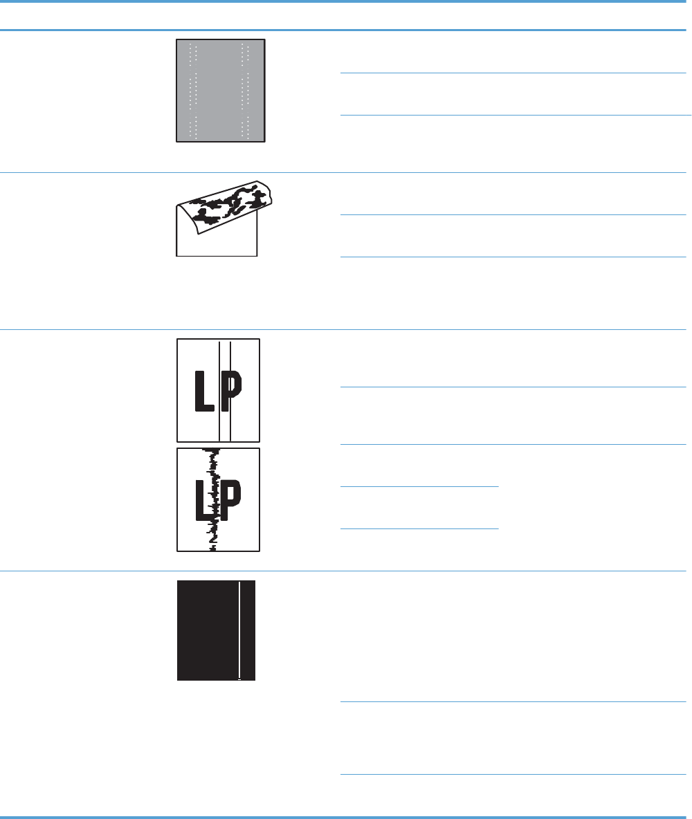
Problem Sample Cause Solution
White spots appear in an image Poor conductivity caused by
dirt on the static eliminator.
Clean the static eliminator.
The primary transfer roller is
deformed or has deteriorated.
Replace the ITB.
The secondary transfer roller
is deformed or has
deteriorated.
Replace the secondary-transfer-
roller.
The back of the page is dirty. The secondary transfer roller
is dirty.
Replace the secondary transfer
roller.
The fuser inlet guide or
separation guide is dirty.
Clean the dirty parts. If the dirt does
not come off, replace the guide.
The pressure roller is dirty. Run the cleaning page several times.
If the dirt does not come off, install a
fuser cleaning kit. If the issue
persists, replace the fuser.
Vertical streaks or bands appear
on the page.
Scratches are present on the
circumference of the
photosensitive drum.
Replace the print cartridge of the
color that matches the defect.
Scratches are present on the
circumference of the fuser
roller.
Replace the fuser.
Scratches are present on the
circumference of the ITB.
Replace the ITB.
The ITB drive roller is
deformed or has deteriorated.
The ITB cleaning mechanism is
malfunctioning.
Vertical white lines appear in a
particular color.
The laser beam window is
dirty.
Execute the Clean Laser Glass
item in the Calibration/Cleaning
submenu (in the Device
Maintenance menu)
If the error persists, manually clean
the window and remove any foreign
substances.
Scratches are present on the
circumference of the
developing cylinder or
photosensitive drum.
Replace the affected print cartridge.
If the problem persists, replace the
affected print cartridge.
The laser/scanner-unit mirror
is dirty.
Replace the laser/scanner assembly.
526 Chapter 3 Solve problems ENWW
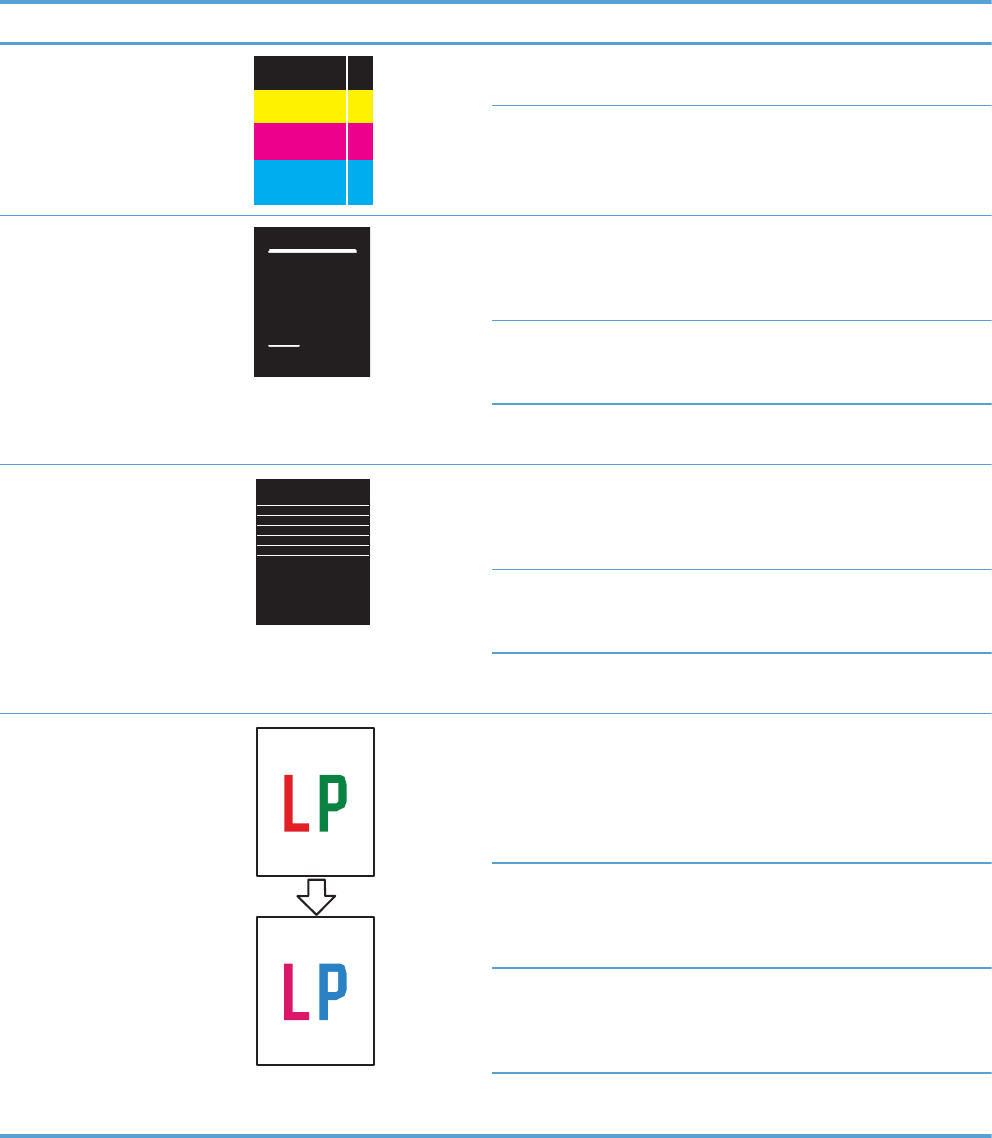
Problem Sample Cause Solution
Vertical white lines appear in all
colors.
Horizontal scratches on the
fuser roller.
Replace the fuser.
Scratches are present on the
circumference of the ITB.
Replace the affected print cartridge.
Replace the ITB.
Horizontal lines appear on the
page.
Repetitive horizontal lines
appear.
Use the repetitive defects ruler to
identify the dirty roller. Clean the
roller. If the roller cannot be
cleaned, replace the fuser.
Horizontal scratches are
present on the photosensitive
drum.
Replace the print cartridge of the
color that matches the defect.
Horizontal scratches are
present on the fuser roller.
Replace the fuser.
A horizontal white line appears
on the page.
Repetitive horizontal white
lines appear.
Use the repetitive defects ruler to
identify the dirty roller. Clean the
roller. If the roller cannot be
cleaned, replace the roller.
Horizontal scratches are
present on the photosensitive
drum.
Replace the print cartridge of the
color that matches the defect.
Scratches are present on the
circumference of the ITB.
Replace the ITB.
Image in a particular color does
not print in the correct color.
Poor contact exists in the
primary charging bias or
developing bias contacts
between the print cartridge
and the product.
Clean each contact of the color that
produces the missing color. If the
problem remains after cleaning,
check the contacts for damage.
Replace any deformed or damaged
parts.
The print cartridge (primary
charging roller, developing
roller, or photosensitive drum)
is defective.
Replace the print cartridge of the
color that matches the defect.
The imaging high-voltage
power-supply is defective (no
primary charging bias or
developing bias output).
Replace the imaging high-voltage
power-supply.
The laser/scanner unit is
defective.
Replace the laser/scanner assembly.
ENWW Solve image-quality problems 527
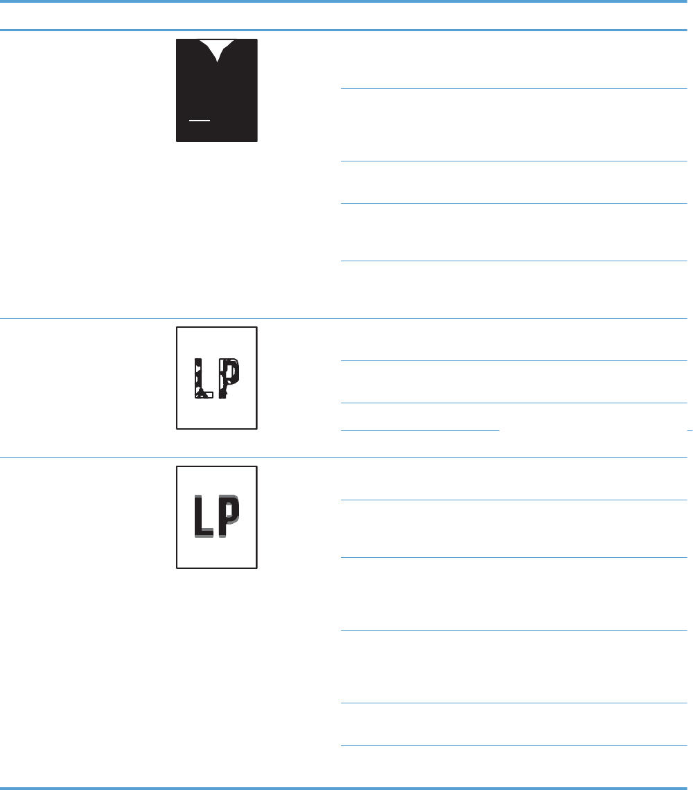
Problem Sample Cause Solution
Dropouts appear. The secondary transfer roller
is deformed or has
deteriorated.
Replace the secondary-transfer-
roller.
The primary charging roller,
developing roller, or
photosensitive drum is
deformed or has deteriorated.
Replace the print cartridge of the
color that matches the defect.
The fuser roller is deformed or
has deteriorated.
Replace the fuser.
The transfer 1 high-voltage
power-supply PCA is defective
(no transfer 1 bias output).
Replace the transfer 1 high-voltage
power-supply.
The transfer 2 high-voltage
power-supply PCA is defective
(no transfer 2 bias output).
Replace the transfer 2 high-voltage
power-supply.
The toner is not fully fused to the
paper.
The fuser roller or pressure
roller is scarred or deformed.
Replace the fuser.
The fuser control circuit is
defective.
Replace the low-voltage power
supply.
The thermistor is defective. Replace the fuser.
The fuser heater is defective.
Some color is misregistered. The product is incorrectly
calibrated.
Calibrate the product.
The ITB unit is defective. If the ITB does not rotate smoothly or
a cleaning malfunction occurs (ITB is
dirty), replace the ITB.
The drive gear of the ITB
motor is worn or chipped.
Check each drive gear between the
ITB drive roller and the ITB motor. If
the gear is worn or chipped,
replace the drive unit.
The RD sensor is defective. Open and close the right door
several times to clean the RD sensor.
If the problem persists, replace the
RD sensor.
The laser/scanner unit is
defective.
Replace the laser/scanner assembly.
The print cartridge is
defective.
Replace the print cartridge of the
affected color.
528 Chapter 3 Solve problems ENWW
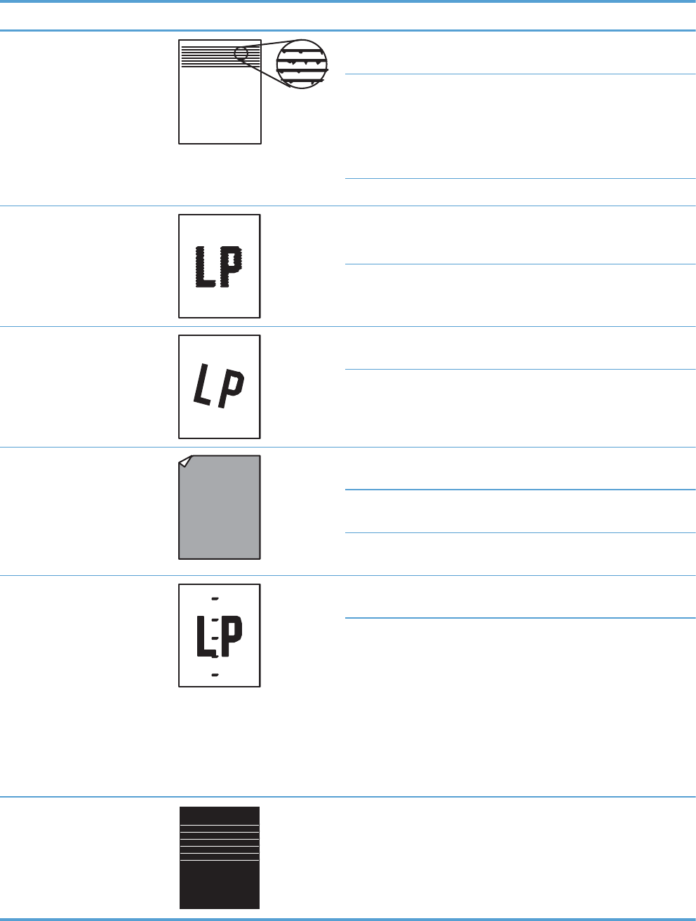
Problem Sample Cause Solution
Toner smears appear on the
media.
The product has residual
media.
Remove the residual media.
Poor contact exists in the
primary charging bias or
developing bias contacts
between the print cartridge
and the product.
Clean each contact of the color that
produces the missing color. If the
problem remains after cleaning,
check the contacts for damage.
Replace any deformed or damaged
parts.
The fuser inlet guide is dirty. Clean the fuser inlet guide.
The printed page contains
misformed characters.
The product is experiencing
page skew.
See the “Text or graphics are
skewed on the printed page” row in
this table.
The laser/scanner unit is
defective.
Replace the laser/scanner assembly.
Text or graphics are skewed on
the printed page.
The registration shutter spring
is unhooked.
Check the spring and place it in the
correct position.
The registration shutter spring
is deformed.
Replace the cassette pickup
assembly.
The printed page contains
wrinkles or creases.
The roller or media feed guide
is dirty.
Clean any dirty components.
A feed roller is deformed or
has deteriorated.
Replace any deformed or
deteriorated rollers.
The paper feed guide is
damaged.
Replace the paper-feed-guide unit.
The front of the page is dirty. The photosensitive drum is
dirty.
Replace the print cartridge.
The fuser roller or pressure
roller is dirty.
Execute a cleaning page to clean
the contaminate off the fuser. If the
dirt does not come off, replace the
fuser.
NOTE: Cleaning the fuser with HP
tough paper provides better results
than with plain paper. You might
need to execute the cleaning
process several times to remove all
contaminates on the fuser.
Repetitive horizontal lines Damaged or dirty roller. See repetitive image defect ruler.
Clean the indicated roller. If the
contaminate does not come off,
replace appropriate roller or
assembly.
ENWW Solve image-quality problems 529

Problem Sample Cause Solution
Pages have flecks of toner Dirty paper path. Execute a cleaning page to clean
the contaminate off the fuser. The
cleaning page may need to be run
several time to clean the fuser. Do
not replace the fuser.
NOTE: Cleaning the fuser with HP
tough paper provides better results
than with plain paper. You might
need to execute the cleaning
process several times to remove all
contaminates on the fuser. A fuser
cleaning kit (CC468-67919) is
available.
Pages have one or more skewed
color planes (can appear on the
right or left side of the page)
Print cartridge incorrectly
installed or damaged.
Remove, and then reinstall the print
cartridge associated with the defect.
530 Chapter 3 Solve problems ENWW

Clean the product
Over time, particles of toner and paper accumulate inside the product. This can cause print-quality
problems during printing. Cleaning the product eliminates or reduces these problems.
Clean the paper path and print-cartridge areas every time that you change the print cartridge or
whenever print-quality problems occur. As much as possible, keep the product free from dust and
debris.
To clean the product exterior, use a soft, water-moistened cloth.
Clean the paper path
NOTE: If you are processing a cleaning page to clean the fuser, repeat the process 1 to 6 times until
the paper comes out clean.
Process a cleaning page
1. Press the Home button .
2. Open the following menus:
●Device Maintenance
●Calibration/Cleaning
3. Press the Down arrow to highlight the Print Cleaning Page item, and then press the OK
button.
4. The product prints a cleaning page, and then returns to the main menu. Discard the printed page.
Set up an auto cleaning page
Use the procedure in this section to set up an automatic cleaning page.
1. Press the Home button .
2. Open the following menus:
●Device Maintenance
●Calibration/Cleaning
3. Press the Down arrow to highlight the Auto Cleaning item, and then select the Enabled
item. Press the OK button.
4. Press the Down arrow to highlight the Cleaning Interval item, and then use the arrow
buttons to select an interval. Press the OK button.
TIP: HP recommends processing a cleaning page after every 5000 printed pages.
5. Press the Down arrow to highlight the Auto Cleaning Size item, and then use the arrow
buttons to select the cleaning page size. Press the OK button.
ENWW Clean the product 531

Solve performance problems
Problem Cause Solution
Pages print but are totally blank. The document might contain blank
pages.
Check the document that you are
printing to see if content appears on all
of the pages.
The product might be malfunctioning. To check the product, print a
Configuration page.
All of the print cartridges might be very
low on toner.
Replace the toner cartridges if a
Supplies very low message is
displayed.
Pages print very slowly. Heavier paper types can slow the print
job.
Print on a different type of paper. Proper
fusing may require a slower print speed
to ensure the best print quality.
Complex pages can print slowly. Simplify the page.
Pages did not print. The product might not be pulling paper
correctly.
Make sure paper is loaded in the tray
correctly.
The paper is jamming in the product. Clear the jam. See Clear jams
on page 495.
The USB cable might be defective or
incorrectly connected.
●Disconnect the USB cable at both
ends and reconnect it.
●Try printing a job that has printed
in the past.
●Try using a different USB cable.
Other devices are running on your
computer.
The product might not share a USB port.
If you have an external hard drive or
network switchbox that is connected to
the same port as the product, the other
device might be interfering. To connect
and use the product, you must
disconnect the other device or you must
use two USB ports on the computer.
532 Chapter 3 Solve problems ENWW

Solve connectivity problems
Solve direct-connect problems
If you have connected the product directly to a computer, check the cable.
●Verify that the cable is connected to the computer and to the product.
●Verify that the cable is not longer than 2 m (6.5 ft). Replace the cable if necessary.
●Verify that the cable is working correctly by connecting it to another product. Replace the cable if
necessary.
Solve network problems
Check the following items to verify that the product is communicating with the network. Before
beginning, print a configuration page. See Configuration page on page 350.
Problem Solution
Poor physical connection Verify that the product is attached to the correct network port using a cable of the
correct length.
Verify that cable connections are secure.
Look at the network port connection on the back of the product, and verify that the
amber activity light and the green link-status light are lit.
If the problem continues, try a different cable or port on the hub.
The computer is unable to communicate
with the product.
Use the command prompt to ping the product from your computer. For example:
ping 192.168.45.39
Verify that the ping displays round-trip times, which indicates that it is working.
If the ping command failed, verify that the network hubs are on, and then verify that
the network settings, the product, and the computer are all configured for the same
network.
Incorrect link and duplex settings Hewlett-Packard recommends leaving this setting in automatic mode (the default
setting). See the user guide.
Incorrect IP address for the product on
the computer
Use the correct IP address. The IP address is listed on the configuration page.
If the IP address is correct, delete the product and then add it again.
New software programs have caused
compatibility problems.
Verify that any new software programs are correctly installed and that they use the
correct printer driver.
Your computer or workstation is set up
incorrectly.
Check the network drivers, printer drivers, and the network redirection.
Verify that the operating system is configured correctly.
The protocol is disabled, or other
network settings are incorrect.
Review the configuration page to check the status of the protocol. Enable it if
necessary.
Reconfigure the network settings if necessary. See the user guide.
ENWW Solve connectivity problems 533

Service mode functions
Service menu
The Service menu is PIN-protected for added security. Only authorized service people have access to
the Service menu. When you select Service from the list of menus, the product prompts you to enter
an eight-digit PIN number (Service Access Code). The PIN for the HP Color LaserJet Enterprise
CP5520 Printer Series is 11552010.
1. Press the Home button.
2. Open the following menus:
●Device Maintenance
●Service
●Service Access Code
3. Enter the eight-digit PIN using the arrow buttons.
NOTE: Only the Service Access Code can be used to access the Service menu. The
message Your user account does not have permission to access the selected item
displays if the correct Service Access Code is not used.
4. Press the OK button to enter the PIN and open the Service menu.
The following menu items appear in the Service menu:
First level Second level Third level Description
User Access Code Only the Service Access
Code can be used to access
the Service menu. The
message Your user
account does not have
permission to access the
selected item displays if the
correct Service Access
Code is not used.
Administrator Access
Code
Only the Service Access
Code can be used to access
the Service menu. The
message Your user
account does not have
permission to access the
selected item displays if the
correct Service Access
Code is not used.
Service Access Code This item allows access to the
Service sub menus.
Print Event Log Use this item to print the
service event log.
534 Chapter 3 Solve problems ENWW

First level Second level Third level Description
View Event Log Use this item to view the
service event log.
Clear Event Log Use this item to clear (erase)
the service event log.
Cycle Counts Mono Cycle Counts Use this item to reset the
mono print job page count.
Color Cycle Count Use this item to reset the color
print job page count.
Refurbish Cycle Count Use this item to reset the
refurbuish print job page
count.
Serial Number Use this item to reset the
product serial number.
Service ID Use this item to reset the
product service identification
number.
Cold Reset Paper Use this item to set the cold
reset paper size.
New Registration Roller Use this item to reset the
registration roller page count.
Media Sensor Value Use this item to record the
media sensor value found on
a replacement paper pickup
assembly.
Manual Laser Glass
Cleaning
Use this item to execute a
manual laser glass cleaning.
The laser shutters are moved
away from the laser glass
windows so that they can be
manually cleaned.
Test Support Continuous Print from
USB
Use this item to test print from
an external USB.
Automatic Calibrations Use this item to enable
automatic calibrations.
ENWW Service mode functions 535

Product resets
Restore factory-set defaults
1. Press the Home button .
2. Open the following menus:
●Administration
●General Settings
●Restore Factory Settings
3. Press the Down arrow button to highlight the select type of reset from a list, and then press the
OK button.
4. Press the Down arrow to highlight the Reset item, and then press the OK button.
Restore factory-set defaults values
●Calibration
◦Persisted calibration engine data
◦Engine color density data
◦LaserJet engine calibration data
●General
◦Display and sound settings for the control panel
◦Localization settings (for example, clock format and date format)
◦Error and warning log behavior
◦Default media settings
◦Sleep mode and delay setting
◦Internal backup file maximum size
◦Oxp installer solutions, tasks and pending tasks
◦Http job defaults
◦Clears the error, warning and info logs
◦Supported media types
◦Resets JetLink connected external devices
536 Chapter 3 Solve problems ENWW

●Print
◦Print default job, stored job and quick set settings
◦Some print job usage data
◦Print system configuration settings
●Security
◦Default Authentication agent
◦Authentication agents
◦Policy agents
◦Color access control
Clean Disk and Partial Clean functions
Active and repository firmware locations
The firmware bundle now consists of multiple parts. The main components are the Windows CE
Operating System and the printer/peripheral firmware files.
There are two locations/partitions on the hard drive where the firmware components are stored:
●The Active – where the Operating System and firmware currently are executing
●The Repository – the recovery location
If the Active location is damaged, or a Partial Clean was performed, the printer automatically copies
over the OS and firmware files from the Repository location and the printer recovers.
If both the Active and Repository locations are damaged, or a Clean Disk was performed, then both
locations are gone and the error message 99.09.67 appears on the control-panel display. The user
must upload the firmware to the printer in order for it to function again
CAUTION: The Clean Disk option performs a disk initialization for the entire disk. The operating
system, firmware files, and third party files (among other files) will be completely lost. HP does not
recommend this action.
Partial Clean
The Partial Clean option erases all partitions and data on the disk drive, except for the firmware
repository where a backup copy of the firmware file is stored. This allows the disk drive to be
reformatted without having to download a firmware upgrade file to return the product to a bootable
state.
ENWW Service mode functions 537

Characteristics of a Partial Clean
●Customer-defined settings, third-party solutions, firmware files, and the operating system are
deleted.
●Rebooting the product restores the firmware files from the Repository location, but does not restore
any customer-defined settings.
●For previous HP products, a Hard Disk Initialization is similar to executing the Partial Clean
function for this product.
CAUTION: HP recommends backing-up product configuration data before executing a Partial
Clean if you need to retain customer-defined settings. See the Backup/Restore item in the Device
Maintenance menu.
Reasons for performing Partial Clean
●The product continually boots up in an error state.
NOTE: Try clearing the error prior to executing a Partial Clean.
●The product will not respond to commands from the control panel.
●Executing the Partial Clean function is helpful for troubleshooting hard disk problems.
●To reset the product by deleting all solutions and customer-defined settings.
●The product default settings are not properly working.
Execute a Partial Clean
1. Turn the product on.
2. When the Ready, Data, and Attention LEDs are illuminated solid, press the Stop button.
3. Press the Down arrow button to highlight Administration, and then press the OK button.
4. Press the Down arrow button to highlight Partial Clean, and then press the OK button.
5. Press the OK button again.
6. Press the Back button to highlight Continue, and then press the OK button.
NOTE: The product initializes.
Clean Disk
The Clean Disk option erases the entire disk drive.
CAUTION: After executing a Clean Disk option, the product is not bootable.
538 Chapter 3 Solve problems ENWW

Characteristics of a Partial Clean
●Customer-defined settings, third-party solutions, firmware files, and the operating system are
deleted.
NOTE: Rebooting the product does not restore the firmware files.
●Rebooting the product restores the firmware files from the Repository location, but does not restore
any customer-defined settings.
●After executing the Clean Disk function, the message 99.09.67 displays on the control panel.
●After executing the Clean Disk function, the product firmware must be reloaded.
CAUTION: HP recommends that you do not use theClean Disk option unless an error occurs and
the solution in the product service manual recommends this solution. After executing the Clean Disk
function, the product is unusable.
HP recommends backing-up product configuration data before executing a Clean Disk if you need to
retain customer-defined settings. See the Backup/Restore item in the Device Maintenance menu.
Reasons for performing Clean Disk
●The product continually boots up in an error state.
NOTE: Try clearing the error prior to executing a Clean Disk.
●The product will not respond to commands from the control panel.
●Executing the Clean Disk function is helpful for troubleshooting hard disk problems.
●To reset the product by deleting all solutions and customer-defined settings.
Execute a Clean Disk
1. Turn the product on.
2. When the Ready, Data, and Attention LEDs are illuminated solid, press the Stop button.
3. Press the Down arrow button to highlight Administration, and then press the OK button.
4. Press the Down arrow button to highlight Clean Disk, and then press the OK button.
5. Press the OK button again.
NOTE: When the Clean Disk operation is complete, you will need to reload the product
firmware.
ENWW Service mode functions 539

Preboot menu options
If an error occurs while the product is booting, an error message appears on the control-panel display.
The user can access the Preboot menus. The Error menu item will not be seen if an error did not occur.
Access the Preboot menu
1. Turn the product on.
2. Press the Stop button when the Ready, Data, and Attention LEDs are illuminated solid.
3. Use the Down arrow button to navigate the Preboot menu options.
4. Press the OK button to select a menu item.
Cold reset using the Preboot menu
1. Turn the product on.
2. Press the Stop button when the Ready, Data, and Attention LEDs are illuminated solid.
3. Use the Down arrow button to highlight Administrator, and then press the OK button.
4. Use the Down arrow button to highlight Startup Options, and then press the OK button.
5. Use the Down arrow button to highlight Cold Reset, and then press the OK button.
6. Press the Back button twice to highlight Continue, and then press the OK button.
NOTE: The product will initialize.
Table 3-63 Preboot menu options (1 of 5)
Menu option First level Second level Third level Description
Continue Selecting theContinue item exits the Preboot menu and
continues the normal boot process.
If a selection is not made in the initial menu within 30 seconds,
the product returns to a normal boot (the same as selecting
Continue.
If the user navigates to another menu, the timeout does not
apply.
Sign In Enter the Administrator PIN or Service PIN if one is required to
access the Preboot menu.
540 Chapter 3 Solve problems ENWW

Table 3-63 Preboot menu options (1 of 5) (continued)
Menu option First level Second level Third level Description
Administrator This item navigates to the Administrator sub menus.
If authentication is required (and the user is not already signed
in) the Sign In displays. The user is required to sign in.
Download This item initiates a preboot firmware download process. A USB
device interface or a Network connection can be used to
download firmware.
Network See
Product updates on page 547.
USB See
Product updates on page 547.
Clean Disk This item reinitializes the disk and cleans all disk partitions.
CAUTION: Selecting the Clean Disk item removes all data.
A delete confirmation prompt is not provided.
The system is not bootable after this action—a firmware
download must be performed to return the system to a bootable
state.
Partial Clean This item reinitializes the disk (removing all data except the
firmware repository where the master firmware bundle is
downloaded and saved).
CAUTION: Selecting the Partial Clean item removes all
data except the firmware repository.
A delete confirmation prompt is not provided.
This allows user to reformat the disk by removing the firmware
image from the active directory without having to download new
firmware code (product remains bootable).
Change
Password
Select this item to set or change the administrator password.
Clear
Password
Select theClear Password item to remove a password from the
Administrator menu. Before the password is actually cleared, a
message will be shown asking to confirm that the password
should be cleared. Press the OK button to confirm the action.
When the confirmation prompt appears, press the OK button to
clear the password.
ENWW Preboot menu options 541

Table 3-64 Preboot menu options (2 of 5)
Menu option First level Second
level
Third level Description
Administrator
continued
Manage
Disk
Clear Disk Select the Clear Disk item to enable an external device
for job storage. Job storage is normally enabled only for
the Boot device. This will be grayed out unless the
99.09.68 error is displayed.
Lock Disk Select the Lock Disk item to lock (mate) a new secure
disk to this product.
The secure disk already locked to this product will remain
accessible to this product. Use this function to have more
then one encrypted disk accessible by the product when
using them interchangeably.
The data stored on the secure disk locked to this product
always remains accessible to this product.
Leave
Unlocked
Select the Leave Unlocked item to use a new secure
disk in an unlocked mode for single service event. The
secure disk that is already locked to this product will
remain accessible to this product and uses the old disk's
encryption password with the new disk.
The secure disk that is already locked to this product
remains accessible to this product.
Clear
Password
Select the Clear Password item to continue using the
non-secure disk and clear the password associated with
the yet to be installed secure disk.
CAUTION: Data on the missing secure disk will be
permanently inaccessible.
Retain
Password
Select the Retain Password item to use the non-secure
disk for this session only, and then search for the missing
secure disk in future sessions.
Boot Device
Secure
Erase
Select the Secure Erase item to erase all of the data on
the disk and unlock it if required.
This might take a long time.
NOTE: The system will be unusable until the system files
are reinstalled. ATA secure-erase command one pass
over write. Erases entire disk including firmware. The disk
remains an encrypted disk.
Erase and
Unlock
Select the Erase and Unlock item to cryptographically
erase all data on disk and unlock the disk to allow access
to it from any product.
NOTE: The system will be unusable until the system files
are reinstalled. Erases the crypto key. The disk becomes a
non-encrypted disk.
Get Status This item provides disk status information if any is
available.
542 Chapter 3 Solve problems ENWW

Table 3-65 Preboot menu options (3 of 5)
Menu option First level Second
level
Third level Description
Administrator
continued
Manage
Disk
continued
Internal
Device
Select the Internal Device item to erase the internal
device or get status about the internal device.
Secure
Erase
Select the Secure Erase item to erase all of the data on
the disk and unlock it if required.
This might take a long time.
NOTE: The system will be unusable until the system files
are reinstalled. ATA secure-erase command one pass
over write. Erases the entire disk, including firmware. The
disk remains an encrypted disk.
Erase and
Unlock
Select the Erase and Unlock item to cryptographically
erase all data on disk and unlock the disk to allow access
to it from any product.
NOTE: The system will be unusable until the system files
are reinstalled. Erases the crypto key. The disk becomes a
non-encrypted disk.
Get Status This item provides disk status information if any is
available.
External
Device
Select the External Device item to erase the internal
device or get status about the internal device.
Secure
Erase
Select the Secure Erase item to erase all of the data on
the disk and unlock it if required.
This might take a long time.
NOTE: The system will be unusable until the system files
are reinstalled. ATA secure-erase command one pass
over write. Erases the entire disk, including firmware. The
disk remains an encrypted disk.
Erase and
Unlock
Select the Erase and Unlock item to cryptographically
erase all data on disk and unlock the disk to allow access
to it from any product.
NOTE: The system will be unusable until the system files
are reinstalled. Erases the crypto key. The disk becomes a
non-encrypted disk.
Get Status This item provides disk status information if any is
available.
ENWW Preboot menu options 543

Table 3-66 Preboot menu options (4 of 5)
Menu option First level Second
level
Third level Description
Administrator
continued
Configure
LAN
Select the Configure LAN item to setup the network
settings for the PreBoot menu firmware upgrade.
The network can be configured obtain the network
settings from a DHCP server or as static.
DHCP Use this item for automatic IP address acquisition from
the DHCP server.
Static Use this item to manually assign the network addresses.
IP Address Use this item to manually enter the IP addresses.
Subnet
Mask
Use this item to manually enter the subnet mask.
Default
Gateway
Use this item to manually enter the default gateway.
Save and
Exit
Select the Save and Exit item to save the manual
settings.
544 Chapter 3 Solve problems ENWW

Table 3-67 Preboot menu options (5 of 5)
Menu option First level Second
level
Third level Description
Administrator
continued
Startup
Options
Select the Startup Options item to specify options that
can be set for the next time the product is turned on and
initializes to the to Ready state.
Cold Reset Check the Cold Reset item to clear the IP address and
all customer settings (this item also returns all settings to
factory defaults).
NOTE: Items in the Service menu are not reset.
First Power Not currently functional: This item allows the product
initialize as if it is the first time it has been turned on.
For example, the user is prompted to configure first time
settings like Select Date/Time, Select Language, and
other settings).
Check this item so that it is enabled for the next time the
product power is turned on.
When the product power is turned on the next time, this
item is unchecked so that the pre-configured settings are
used during configuration and the first time setting
prompt is not used.
Skip Plug-
ins
This item allows the device to be started without loading
the third party applications.
This means that files including Accessible Architecture on
the disk will not be available at bootup. This is useful for
troubleshooting problems with the hard disk without
having to remove the hard disk. It also applies to flash
file system disks on DIMMs.
In this case, this function will cause the printer to
configure the HP firmware first, followed by the third-
party applications.
NOTE: The files on the disk will be available after the
printer enters the Ready state.
Skip Cal Select the Skip Cal item to initialize the product the next
time the power is turned on without calibrating.
Show
Revision
Not currently functional: Check the Show Revision
item to allow the product to initialize and show the
firmware version when the device reaches the Ready
state.
Once the product power is turned on the next time, the
Show Revision item is unchecked so the firmware
revision is not shown.
Lock Service CAUTION: Select the Lock Service item to lock the
Service menu access (both PreBoot and Device
Maintenance application).
Service personnel must have the Administrator remove
the Lock Service setting before they can enter the
Service menu.
ENWW Preboot menu options 545

Table 3-68 Preboot menu options (5 of 5)
Menu
option
First level Second
level
Third
level
Description
Administrat
or
continued
Startup
Options
continued
Skip
Disk
Scan
Check the Skip Disk Scan item to allow
the product to initialize without scanning the
disk.
If the product is crashing on Step 4/8,
checking this item may allow the problem to
be isolated.
Once the device is turned on the next time,
the Skip Disk Scan item is unchecked and
the disk scan is not skipped.
Embedde
d
Jetdirect
Off
Check the Embedded Jetdirect Off item
to disable the embedded Jetdirect.
By default this item is unchecked so that
Jetdirect is always enabled.
Service
Tools
This item requires the Service access code.
Reset
Password
Use this item to clear the Administrator
password.
Subsystems For manufacturing use only. Do not change
these values.
546 Chapter 3 Solve problems ENWW

Product updates
To download the most recent firmware upgrade for the product, go to www.hp.com/support/
cljcp5525 or www.hp.com/go/cljcp5525_firmware.
Determine the installed revision of firmware
Print a configuration page to determine the installed revision of firmware. See Configuration page
on page 350.
On the configuration page, look in the section marked Device Information for the firmware datecode
and firmware revision.
Firmware datecode and firmware revision examples
●20100831 (firmware datecode)
●103067_104746 (firmware revision)
Perform a firmware upgrade
The firmware bundle is a xxxxxxx.bdl file. This file requires an interactive upgrade method. You
cannot upgrade the printer using the traditional FTP, LPR or Port 9100 methods of upgrading. Use one
of the following methods to upgrade the firmware for this product.
Embedded Web Server
1. Open an browser window.
2. Enter the product IP address in the URL line.
3. Select the Firmware upgrade link from within the Troubleshooting tab.
NOTE: If you get a warning screen, follow the instructions for setting an administrator password
from the Security tab.
4. Browse to the location that the firmware upgrade file was downloaded to, and then select the
firmware file. Select the Install button to perform the upgrade.
NOTE: Do not close the browser window until the Embedded Web Server (EWS) displays the
confirmation page.
5. Select Restart Now from the EWS confirmation page, or turn the product off, and then on again
using the power switch.
ENWW Product updates 547

USB storage device (Preboot menu)
1. Copy the xxxxxxx.bdl file to a portable USB flash memory storage device (thumb drive).
2. Turn the product on.
3. Press the Stop button when the Ready, Data and Attention LEDs illuminate solid.
4. Press the down arrow button to highlight Administrator, and then press the OK button.
5. Press the down arrow button to highlight Download, and then press the OK button.
6. Insert the portable USB storage device with the xxxxxxx.bdl file on it.
NOTE: If the error message No USB Thumbdrive Files Found appears on the control-panel
display, you might need to connect the storage device to the external USB connection on the
formatter or try using a different portable storage device.
7. Press the down arrow button to highlight USB Thumb Drive, and then press the OK button.
8. Press the down arrow button to highlight thexxxxxxx.bdl file, and then press the OK button.
NOTE: The upgrade process can take up to 10 minutes to complete.
TIP: If there is more than one xxxxxxx.bdl file on the storage device, make sure that you
select the correct file for this product.
9. When the message Complete appears on the control-panel display, press the Back button 3
times.
10. When the message Continue appears on the control-panel display, press the OK button. The
product will initialize.
11. When the upgrade process is complete, print a configuration page and verify that the upgrade
firmware version was installed. See Configuration page on page 350 and Determine the installed
revision of firmware on page 547.
548 Chapter 3 Solve problems ENWW

USB storage device (control-panel menu)
1. Copy the xxxxxxx.bdl file to a portable USB flash memory storage device (thumbdrive).
2. Turn the product on, and then wait until it reaches the Ready state.
3. Press the Home button or OK button.
4. Press the down arrow button to highlight Device Maintenance, and then press the OK
button.
5. Press the down arrow button to highlight USB Firmware Upgrade, and then press the OK
button.
6. Insert the portable USB storage device with the xxxxxxx.bdl file on it into the USB port on the
front of the product, and then press the OK button.
7. Press the down arrow button to highlight thexxxxxxx.bdl file, and then press the OK button.
TIP: If there is more than one xxxxxxx.bdl file on the storage device, make sure that you
select the correct file for this product.
8. A prompt to upgrade an older, newer, or reinstall the same version appears. Press the down
arrow button to highlight the desired option, and then press the OK button.
When the upgrade is complete, the product will initialize.
NOTE: The upgrade process can take up to 10 minutes to complete.
9. When the upgrade process is complete, print a configuration page and verify that the upgrade
firmware version was installed. See Configuration page on page 350 and Determine the installed
revision of firmware on page 547.
ENWW Product updates 549
550 Chapter 3 Solve problems ENWW

4 Parts and diagrams
●Order parts by authorized service providers
●How to use the parts lists and diagrams
●Assembly locations
●External covers, panels, and doors
●Right door assembly
●Internal components (1 of 9)
●Internal components (2 of 9)
●Internal components (3 of 9)
●Internal components (4 of 9)
●Internal components (5 of 9)
●Internal components (6 of 9)
●Internal components (7 of 9)
●Internal components (8 of 9)
●Internal components (9 of 9)
●1x250 cassette
●Paper pick-up assembly
●Paper delivery assembly
●Printed circuit assemblies
●1x500 paper feeder
●3x500 paper feeder
●Alphabetical parts list
●Numerical parts list
ENWW 551

Order parts by authorized service providers
Order parts, accessories, and supplies
Table 4-1 Order parts, accessories, and supplies
Order supplies and paper www.hp.com/go/suresupply
Order genuine HP parts or accessories www.partsurfer.hp.com
Order through service or support providers Contact an HP-authorized service or support provider.
Order using HP software For information about using the HP software to order parts,
accessories, and supplies, see the product user guide.
Related documentation and software
Table 4-2 Related documentation and software
Item Description Part number
HP Color LaserJet Enterprise CP5520 Printer Series User
Guide
Product user guide CE707-90901
HP Color LaserJet Enterprise CP5520 Printer Series Service
Manual
English service manual (this
manual)
CE707-90935
552 Chapter 4 Parts and diagrams ENWW

Supplies part numbers
Table 4-3 Supplies part numbers
Item Description Part number
HP LaserJet print cartridges with HP ColorSphere
toner
Black print cartridge CE270A (new)
CE270-67901 (service)
Cyan print cartridge CE271A (new)
CE271-67901 (service)
Yellow print cartridge CE272A (new)
CE272-67901 (service)
Magenta print cartridge CE273A (new)
CE273-67901 (service)
Customer self repair parts
Each kit includes parts and installation instructions. The customer self repair (CSR) level indicates the
expected difficulty the customer will experience when replacing this part:
●A = Easy
●B = Difficult
●C = Very difficult
Item Part number CSR level
1x250-sheet feeder (Tray 2)
●Tray 2 cassette
●Installation instructions
CE710-67906 A
1x500-sheet feeder (Tray 3) kit
●1x500-sheet feeder
●Installation instructions
CE860-67901 A
3x500-sheet feeder (Trays 4, 5, and 6) with stand
kit
●3x500-sheet feeder with stand
●Installation instructions
CE725-67901 A
ENWW Order parts by authorized service providers 553

Item Part number CSR level
Encrypted hard disk drive kit
●Encrypted hard disk drive, 120 GB
●Right rail
●Left rail
●Disk drive cradle
●Power/data cable assembly
●Installation instructions
CE709-67901 B
Formatter kit
●Formatter tray assembly
●Formatter assembly
●Screws
●EIO card guide
●Installation instructions
CE707-69001 A
Fuser kit
●Fuser assembly
●Installation instructions
110 volt: RM1-6180-000CN
220 volt: RM1-6181-000CN
A
Intermediate transfer belt (ITB) maintenance kit
●ITB assembly
●Secondary transfer roller assembly
●Tray 1 pick-up roller
●Tray 2 pick-up roller assembly
●Tray 2 separation roller assembly
●Tray 3, 4, 5, 6 pick-up rollers
●Tray 3, 4, 5, 6 feed roller assembly
●Installation instructions
CE979-67901 A
Intermediate transfer belt (ITB) repair kit
●ITB assembly
●Secondary transfer roller assembly
●Installation instructions
CE710-67903 A
Secondary transfer roller (T2) kit
●Secondary transfer roller assembly
●Installation instructions
CE710-67904 A
554 Chapter 4 Parts and diagrams ENWW

Item Part number CSR level
Solid state drive kit
●Solid state drive, 8 GB
●Driver retainer
●Installation instructions
CE707-67901 B
Toner collection unit kit
●Waste toner box assembly
●Toner cleaning cloth
●Installation instructions
CE980-67901 A
Tray 1 paper pick-up roller and separation pad kit
●Paper pick-up roller
●Separation pad
●Installation instructions
CE710-67909 A
Tray 2 paper pick-up roller kit
●Paper pick-up roller assembly
●Separation roller assembly
●Installation instructions
CE710-69007 A
Tray 3, 4, 5, and 6 paper pick-up roller kit
●Paper pick-up roller assembly
●Feed roller assembly
●Installation instructions
CE710-69008 A
Service replacement parts
Item Part number
DC controller assembly
●DC controller assembly
●Installation instructions
Simplex: CE707-67906
Duplex: CE708-67902
Front cover assembly kit
●Front cover assembly
●HP logo jewel
CE707-67902
ENWW Order parts by authorized service providers 555

Item Part number
Fuser drive unit
●Fuser drive assembly
●Installation instructions
CE707-67904
Inner door assembly
●Inner door assembly
●Four color cartridge labels
CE707-67909
Interconnect board (ICB) PCA
●ICB PCA
●Installation instructions
CE707-67907
Main drive assembly
●Main drive assembly
●Installation instructions
Simplex: CE707-67905
Duplex: CE708-67901
Paper pick-up assembly
●Paper pick-up assembly
●Installation instructions
CE707-67903
Toner vacuum kit
●Toner vacuum
●Instructions for use
110 volt: CC468-69002
220 volt: CC468-69003
Tray 1 separation pad kit
●Tray 1 separation pad assembly
●Installation instructions
CE707-67908
556 Chapter 4 Parts and diagrams ENWW

Accessories part numbers
Table 4-4 Accessories part numbers
Item Description Part number
Optional 1x500-sheet tray Optional tray to increase paper capacity. CE860A
Optional 3x500-sheet tray and
feeder unit
Optional tray to increase paper capacity. CE725A
USB cable 2-meter A-to-B cable C6518A
Power cord China 220V - 10A
Taiwan 110V - 13A
Korea 220V - 10A
Japan 110V - 12A
India 220V - 6A
Asia Pacific 220V - 10A
Australia/New Zealand 220V - 10A
Israel 220V - 10A
Denmark 220V - 10A
South Africa 220V - 10A
Switzerland 220V - 10A
Brazil 110V - 10A
Argentina 220V - 10A
North America 110V - 13A
Israel - Unique cord
Switzerland - Unique cord
Rest of World - Standard 2-wire RJ-11
8121-0943
8121-0964
8121-0731
8121-1143
8121-0564
8121-0739
8121-0837
8121-1004
8121-0733
8121-0737
8121-0738
8121-0734
8121-0729
8121-1141
8120-8913
8121-0844
8121-0811
ENWW Order parts by authorized service providers 557

How to use the parts lists and diagrams
The figures in this chapter show the major subassemblies in the product and their component parts. A
parts list table follows each exploded view assembly diagram. Each table lists the item number, the
associated part number, and the description of each part. If a part is not listed in the table, then it is not
a field replacement unit (FRU).
CAUTION: Be sure to order the correct part. When looking for part numbers for electrical
components, pay careful attention to the voltage that is listed in the description column. Doing so will
ensure that the part number selected is for the correct model.
NOTE: In this manual, the abbreviation “PCA” stands for “printed circuit-board assembly.”
Components described as a PCA might consist of a single circuit board or a circuit board plus other
parts, such as cables and sensors.
558 Chapter 4 Parts and diagrams ENWW
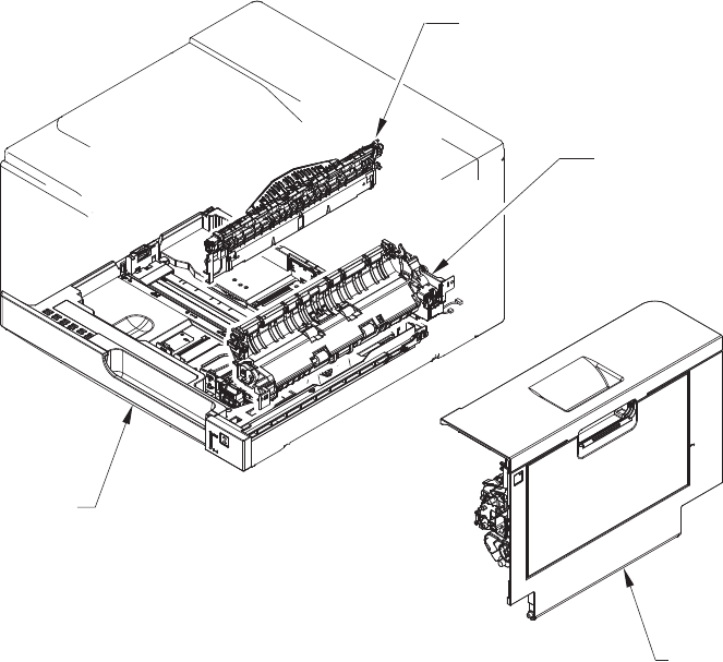
Assembly locations
1x250 cassette
Paper delivery assembly
Right door assembly
Paper pick-up assembly
ENWW Assembly locations 559
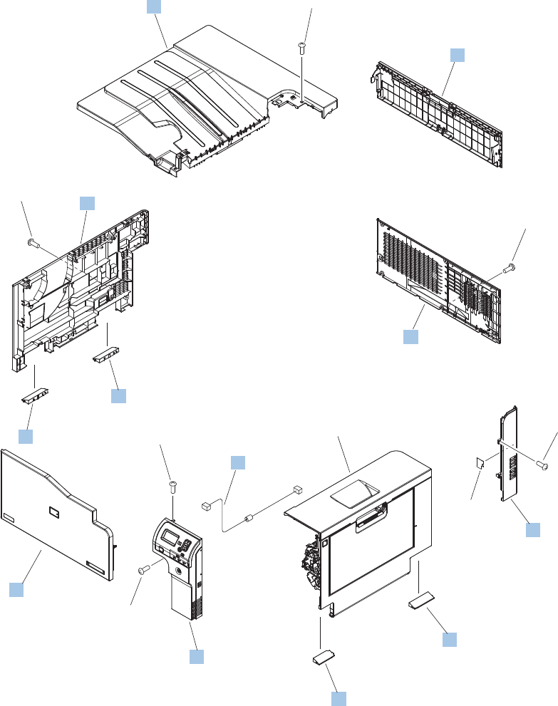
External covers, panels, and doors
Figure 4-1 External covers, panels, and doors
Right door assembly
(J2)
(J1)
8
1
4
10
10
6
7
2
11
5
9
3
*A01
*A01
*A01
*A01
*A01
*A03
*A02
560 Chapter 4 Parts and diagrams ENWW

Table 4-5 External covers, panels, and doors
Ref Description Part number Qty
1 Cover, top RM1-7148-000CN 1
2 Door, toner collection unit access RC2-7034-000CN 1
3 Cable, USB RK2-2901-000CN 1
4 Cover, rear RM1-7147-000CN 1
5 Cover, right rear RM1-7142-000CN 1
6 Cover, handle, lower-right, rear RC2-6626-000CN 1
7 Cover, handle, lower-right, front RC2-6627-000CN 1
8 Cover, right front assembly (includes control panel) RM1-7144-000CN 1
9 Cover, front assembly RM1-7133-000CN 1
10 Cover, handle, lower-left RC2-6625-000CN 2
11 Cover, left assembly RM1-7143-000CN 1
ENWW External covers, panels, and doors 561
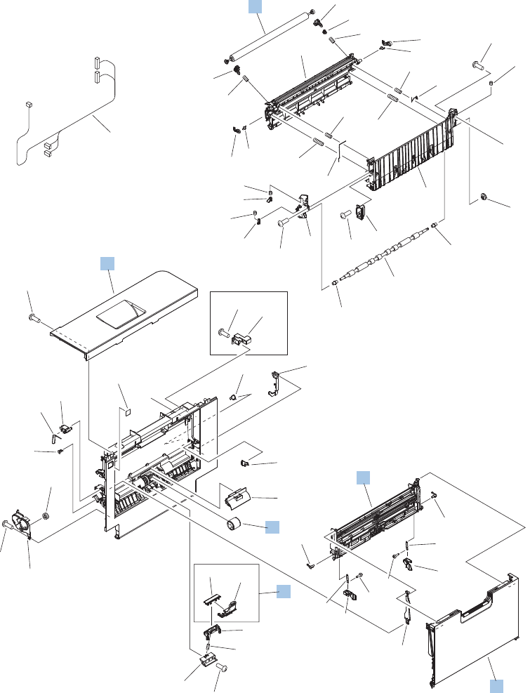
Right door assembly
Figure 4-2 Right door assembly
SIMPLEX MODEL
(J114D)
(J112)
(J152)
(J542D)
(J736D)
A
A
4
6
1
2
3
5
*A11
*A27
*A42
*A32
*A33
*A33
*A34
*A35
*A12
*A09
*A44
*A46
*A23
*A26
*A04
*A22
*A30
*A30
*A28
*A01
*A03
*A21
*A24
*A43
*A19
*A31
*A31
*A14
*A14
*A15
*A15
*A02
*A02
*A08
*A16
*A45
*A13
*A10
*A10
*A40
*A40
*A40
*A40
*A40
*A40
*A40 *A25
*A29
*A41
*A38
*A39
*A47
*A37
*A05
*A20
*A07
*A06
*A18
*A17
*A36
*A48
562 Chapter 4 Parts and diagrams ENWW

Table 4-6 Right door assembly
Ref Description Part number Qty
Right door assembly, duplex model RM1-6007-000CN 1
Right door assembly, simplex model RM1-6138-000CN 1
1 Roller, secondary transfer, T2 (included in the service kit) CE710-67904 1
2 Door, right upper RC2-7091-000CN 1
3 Roller, paper pick-up, Tray 1 (included in the service kit) CE710-67906 1
4 Lifter plate assembly, Tray 1 RM1-6043-030CN 1
5 Separation pad, Tray 1 (included in the service kit) CE710-67909 1
6 Tray 1 (MP tray) assembly RM1-6045-000CN 1
ENWW Right door assembly 563
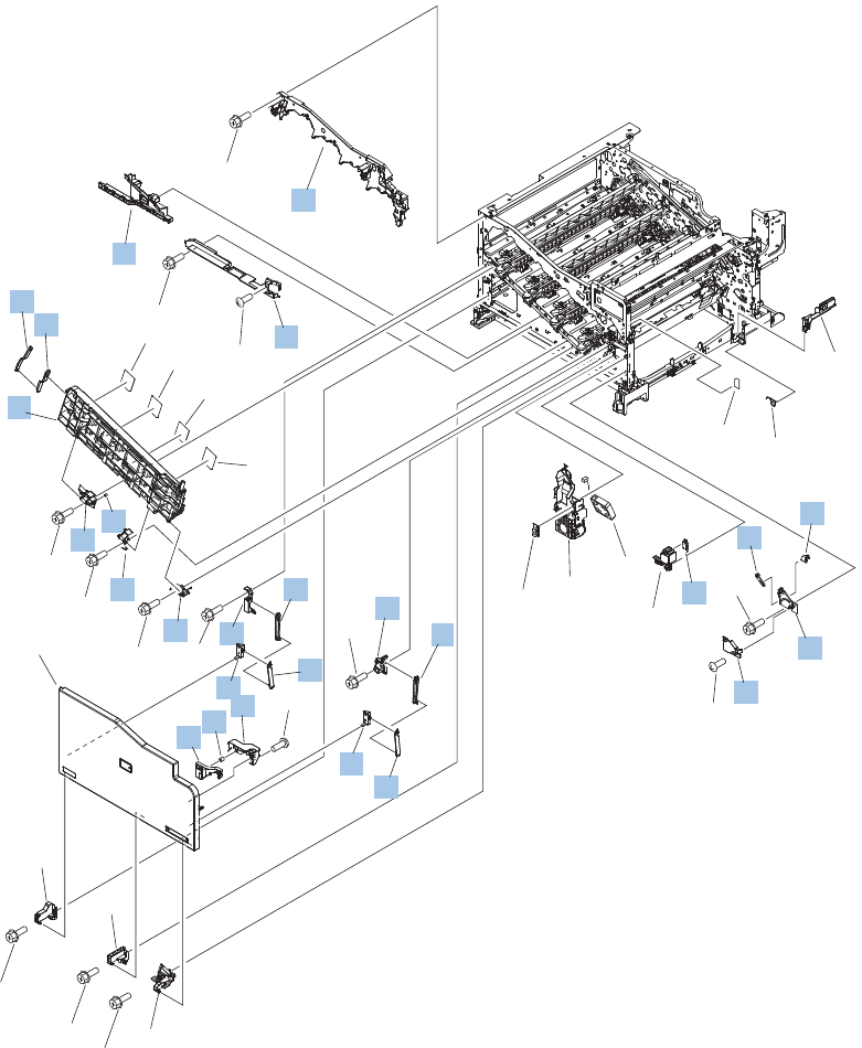
Internal components (1 of 9)
Figure 4-3 Internal components (1 of 9)
See
PCA
diagram
(J524L)
(FM2)
(SW2)
Front cover
assembly
1
32
35
31
13
25
12
17
3
5
14
16
16
18
18
15
46
24
20
22
19
19
34
11
2
33
7
8
9
10
21
27
23
28
29
26
30
*A01
*A02
*A02
*A02
*A02
*A02
*A02
*A02
*A02
*A02
*A03
*A02
*A04
*A04
*A02
564 Chapter 4 Parts and diagrams ENWW

Table 4-7 Internal components (1 of 9)
Ref Description Part number Qty
1 Upper cartridge guide assembly RM1-5990-000CN 1
2 Duct, front RC2-7300-000CN 1
3 Stopper, inner door, 1 RC2-6719-000CN 1
4 Stopper, inner door, 2 RC2-6736-000CN 1
5 Door, inner, service kit includes all labels CE707–67904 1
6 Cover, lower front RC2-6737-000CN 1
11 Spring, grounding RC2-7209-000CN 1
12 Hinge, inner door, left RC2-6716-000CN 1
13 Hinge, inner door, right RC2-6712-000CN 1
14 Rail, cartridge auxiliary RC2-6724-000CN 1
15 Mount, cover arm, front RC2-6735-000CN 1
16 Arm, front cover, 1 RC2-6732-000CN 2
17 Mount, inner door toggle RC2-6717-000CN 1
18 Arm, front cover, 2 RC2-6733-000CN 2
19 Mount, stopper arm RC2-6745-000CN 2
20 Mount, inner door rail RC2-6743-000CN 1
21 Spring, compression RU6-2721-000CN 1
22 Lever, inner door pressure RC2-6744-000CN 1
23 Hinge, front cover, left RC2-6713-000CN 1
24 Hinge, front cover, center RC2-6738-000CN 1
25 Hinge, front cover, right RC2-6715-000CN 1
26 Cover, guide RC2-7204-000CN 1
27 Guide, arm, front RC2-6632-000CN 1
28 Lever, push RC2-7198-000CN 1
29 Lever, lift, 2 RC2-7200-000CN 1
30 Microswitch WC4-5251-000CN 1
ENWW Internal components (1 of 9) 565
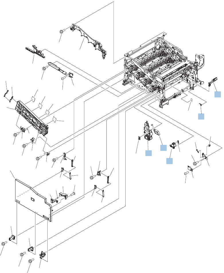
Internal components (2 of 9)
Figure 4-4 Internal components (2 of 9)
See
PCA
diagram
(J524L)
(FM2)
(SW2)
Front cover
assembly
1
32
35
31
13
25
12
17
3
5
14
16
16
18
18
15
46
24
20
22
19
19
34
11
2
33
7
8
9
10
21
27
23
28
29
26
30
*A01
*A02
*A02
*A02
*A02
*A02
*A02
*A02
*A02
*A02
*A03
*A02
*A04
*A04
*A02
566 Chapter 4 Parts and diagrams ENWW

Table 4-8 Internal components (2 of 9)
Ref Description Part number Qty
31 Holder, interlock switch RC2-6689-000CN 1
32 Fan, fuser RK2-2728-000CN 1
33 Holder, duplexing fan RC2-8357-000CN 1
34 Spring, leaf, grounding RC2-7092-000CN 1
35 Cover, handle guide RC2-6670-000CN 1
ENWW Internal components (2 of 9) 567
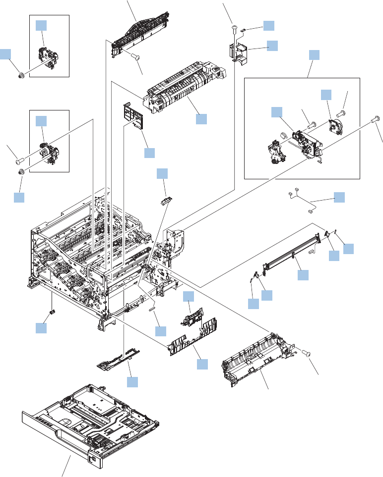
Internal components (3 of 9)
Figure 4-5 Internal components (3 of 9)
1x250 cassette
Paper delivery assembly
DUPLEX MODEL
SIMPLEX MODEL
Paper pick-up
assembly
(J131A)
(J516)
(J109F)
(M4)
(J522D)
(J552D)
(J525L)
(J554L)
6
7
14
12
8
18
3
16
13
11 10
10
15
9
17
5
20
2
4
1
19
19
1
*A01
*A01
*A01
*A02
*A01
*A01
*A01
568 Chapter 4 Parts and diagrams ENWW

Table 4-9 Internal components (3 of 9)
Ref Description Part number Qty
1 Drive assembly, duplex reverse, duplex model RM1-6005-000CN 1
1 Drive assembly, simplex reverse, simplex model RM1-6120-000CN 1
2 Guide, fuser, front RC2-6546-000CN 1
3 Cover, cable, protective RC2-6832-000CN 1
4 Fuser assembly, 110V (included in service kit) RM1-6180-000CN 1
4 Fuser assembly, 220V (included in service kit) RM1-6181-000CN 1
5 Guide, fuser, rear RC2-6547-000CN 1
6 Fuser drive assembly CE707-67904 1
7 Fuser motor assembly RM1-6074-000CN 1
8 Gear assembly, fuser RM1-7914-060CN 1
9 Cable, SB joint, low-voltage power supply, duplex model RM1-6867-000CN 1
10 Spring, tension, registration sensor RU6-2710-000CN 2
11 Support, frame, rear RC2-7197-000CN 1
12 Registration sensor assembly RM1-7922-000CN 1
13 Support, frame, front RC2-7196-000CN 1
14 Separation roller assembly (included in service kit) CE710-67907 1
15 Connector, snap tight, black VS1-7207-019CN 1
16 Guide, paper feed RC2-7297-000CN 1
17 Sensor, cassette last paper presence RM1-6164-000CN 1
18 Cover, connector, lower RC2-6642-000CN 1
19 Gear, 18T/29T RU6-0775-000CN 1
20 Label, fuser insert RU6-8042-000CN 1
ENWW Internal components (3 of 9) 569
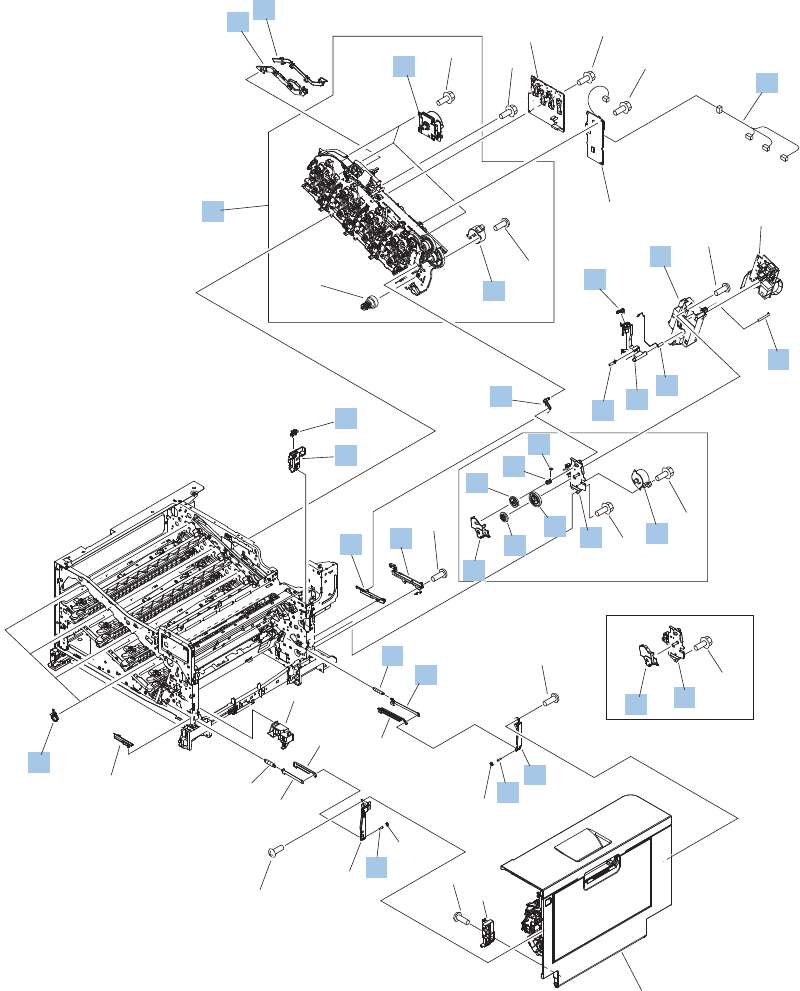
Internal components (4 of 9)
Figure 4-6 Internal components (4 of 9)
DUPLEX MODEL
Right door assembly
SIMPLEX MODEL
See PCA
diagram
See PCA
diagram
See PCA
diagram
(J538D)
(J1003)
(M1)
(J517)
(M2)
(J515)
(M3)
(J514)
(M6)
(J518)
(M7)
(J520)
(PS15)
(J544)
(J535D)(J521)
5
5
4
3
39
26
24
13
25
17
15
33
31
36
31
32
37
28
34
20
35
29
16
18
19
14
30
30
38
27
23
1
21
2
22 20
8
9
10
7
11
12
6
*A04
*A02
*A03
*A01
*A06
*A06
*A01
*A01
*A01
*A01
*A01
*A01
*A02
*A05
570 Chapter 4 Parts and diagrams ENWW

Table 4-10 Internal components (4 of 9)
Ref Description Part number Qty
1 Cover, main drive cable, lower RC2-6574-000CN 1
2 Guide, main drive cable RC2-6659-000CN 1
3 Main drive assembly, duplex model RM1-7931-000CN 1
3 Main drive assembly, simplex model RM1-6173-000CN 1
4 DC motor assembly RM1-6088-000CN 3
5 Motor, stepping, DC, duplex model RK2-3298-000CN 2
5 Motor, stepping, DC, simplex model RK2-3298-000CN 1
6 Cable, feed joint, duplex model RM1-6846-000CN 1
7 Spring, grounding, second-transfer high-voltage PCA RU6-2772-000CN 1
8 Holder, secondary transfer HVT RC2-6681-010CN 1
9 Cap, T2 contact, second-transfer high-voltage PCA RC2-6691-000CN 1
10 Spring, contact, second-transfer high-voltage PCA RU6-2771-000CN 1
11 Holder, secondary transfer, power dispatching RC2-6682-000CN 1
12 Spring, grounding, second-transfer high-voltage PCA RC2-6700-000CN 1
13 Link, ITB coupling release RC2-6823-000CN 1
14 Spring, tension, duplex model RU6-2671-000CN 1
15 Hook, duplexing spring, duplex model RC2-6932-000CN 1
16 Gear, 25T, duplex model RU6-0771-000CN 1
17 Cover, duplexing gear, duplex model RC2-6931-000CN 1
18 Gear, 25T, duplex model RU6-0772-000CN 1
19 Gear, 74T, duplex model RU6-0773-000CN 1
20 Plate, duplexing drive gear RL1-2266-000CN 1
21 Support, developing coupling RC2-6811-000CN 4
22 Cover, gear, simplex model RC3-0688-000CN 1
23 Sensor, right door WG8-5696-000CN 1
24 Holder, door sensor, right RC2-6645-000CN 1
25 Arm, ITB coupling release RC2-6824-000CN 1
26 Rail, door link, rear lower RC2-6635-000CN 1
27 Spring, tension, rear RU6-2744-000CN 1
28 Plate, right door link, rear RC2-7273-000CN 1
29 Plate, right door link, fixed, rear RL1-2282-000CN 1
30 Shaft, right door link RU5-4979-000CN 2
ENWW Internal components (4 of 9) 571
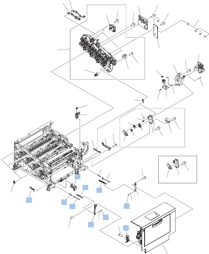
Internal components (5 of 9)
Figure 4-7 Internal components (5 of 9)
DUPLEX MODEL
Right door assembly
SIMPLEX MODEL
See PCA
diagram
See PCA
diagram
See PCA
diagram
(J538D)
(J1003)
(M1)
(J517)
(M2)
(J515)
(M3)
(J514)
(M6)
(J518)
(M7)
(J520)
(PS15)
(J544)
(J535D)(J521)
5
5
4
3
39
26
24
13
25
17
15
33
31
36
31
32
37
28
34
20
35
29
16
18
19
14
30
30
38
27
23
1
21
2
22 20
8
9
10
7
11
12
6
*A04
*A02
*A03
*A01
*A06
*A06
*A01
*A01
*A01
*A01
*A01
*A01
*A02
*A05
572 Chapter 4 Parts and diagrams ENWW

Table 4-11 Internal components (5 of 9)
Ref Description Part number Qty
31 Lock, door link, right RC2-7234-000CN 2
32 Link, right door, 2 rear RC2-7236-000CN 1
33 Link, right door, 2 front RC2-7233-000CN 1
34 Duct, joint RC2-8360-000CN 1
35 Plate, right door link, fixed, front RL1-2281-000CN 1
36 Hinge, right door, front RC2-7094-000CN 1
37 Plate, right door link, front RC2-7272-000CN 1
38 Spring, tension, front RU6-2727-000CN 1
39 Rail, door link, front lower RC2-6634-000CN 1
ENWW Internal components (5 of 9) 573
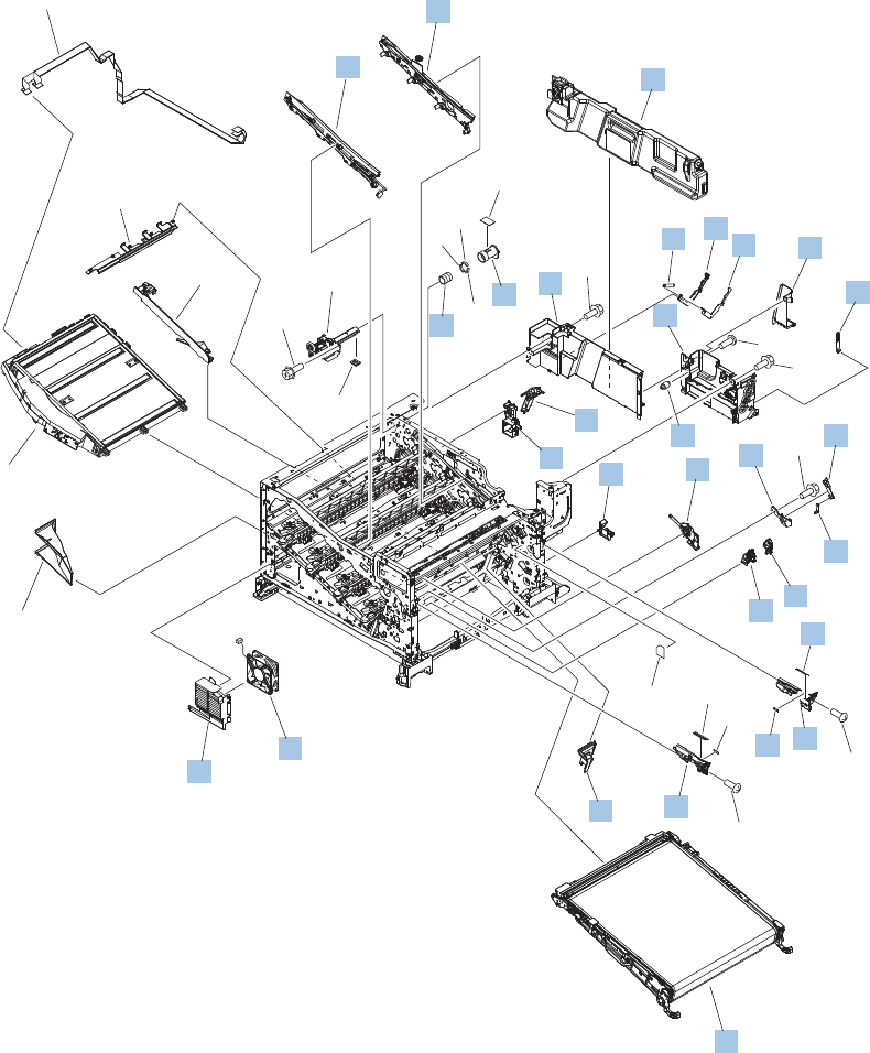
Internal components (6 of 9)
Figure 4-8 Internal components (6 of 9)
(J832)
(J831)
(J62)
(J106)
(FM1)
(J61)
28
17
1
2
32
9
3
34
29
27
35
31
37
36
26
24
25
23
41
40
18
19
20
21
22
16
10
5
14 15
7
33
86
4
11
12 38
38 38
39
30
13
*A02
*A02
*A04
*A01
*A03
*A01
*A01
*A01
574 Chapter 4 Parts and diagrams ENWW

Table 4-12 Internal components (6 of 9)
Ref Description Part number Qty
1 IT belt guide rail assembly RM1-6018-000CN 1
2 IT belt guide rail R1 assembly RM1-6037-000CN 1
3 Toner collection unit (included in the service kit) CE980-67901 1
4 Arm, waste toner, left RC2-7035-000CN 1
5 Cover, waste toner, 3 RC2-6963-000CN 1
6 Plate, arm reinforcement RC2-9649-000CN 1
7 Arm, waste toner, right RC2-7036-000CN 1
8 Spring, tension RU6-2831-000CN 1
9 Waste toner cover assembly RM1-6012-000CN 1
10 Cover, waste toner, 2 RC2-6962-000CN 1
11 Shutter, exhaust RC2-7010-000CN 1
12 Spring, compression RU6-2683-000CN 1
13 Guide, fuser AC cable RC2-6693-000CN 1
14 Guide, LVT cable RC2-6662-000CN 1
15 Clamp, edge RC2-6663-000CN 1
16 Gear, link worm RU6-0795-000CN 1
17 ITB guide rail assembly RM1-6019-000CN 1
18 Guide, slide RC2-7203-000CN 1
19 Slider, push RC2-7201-000CN 1
20 Lever, lift, 1 RC2-7199-000CN 1
21 Cover, main cross-member cable RC2-6650-000CN 1
22 Guide, main cross-member cable RC2-6600-000CN 1
23 Label, ITB set, RH RU5-8807-000CN 1
24 Rail, ITB guide RC2-7185-000CN 1
25 Label, ITB, RV RU5-8805-000CN 1
26 Rail, ITB guide, F3 RC2-7193-000CN 1
27 Guide, inside cable RC2-6589-000CN 1
28 ITB assembly (included in the service kit; includes transfer roller) CE710-67903 1
29 Fan, power supply RK2-2276-000CN 1
30 Holder, power supply fan RC2-7299-000CN 1
ENWW Internal components (6 of 9) 575
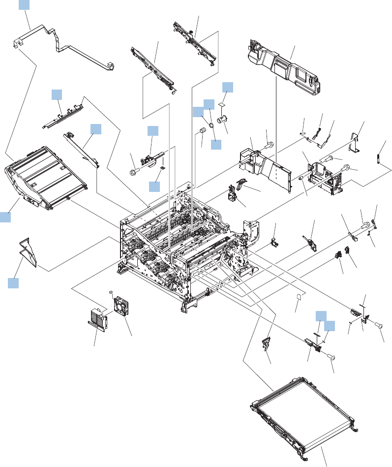
Internal components (7 of 9)
Figure 4-9 Internal components (7 of 9)
(J832)
(J831)
(J62)
(J106)
(FM1)
(J61)
28
17
1
2
32
9
3
34
29
27
35
31
37
36
26
24
25
23
41
40
18
19
20
21
22
16
10
5
14 15
7
33
86
4
11
12 38
38 38
39
30
13
*A02
*A02
*A04
*A01
*A03
*A01
*A01
*A01
576 Chapter 4 Parts and diagrams ENWW

Table 4-13 Internal components (7 of 9)
Ref Description Part number Qty
31 Duct, fan, 1 RC2-8388-000CN 1
32 Laser scanner assembly RM1-6122-070CN 1
33 Seal, toner supporter guide 1 RC2-7018-000CN 1
34 Toner feed assembly RM1-6040-000CN 1
35 Guide, laser RC2-6628-000CN 1
36 Holder, flat flexible cable RC2-6655-000CN 1
37 Cable assembly, flat-flexible RM1-6804-000CN 1
38 Seal, slide shutter RC3-1014-000CN 3
39 Sheet, slide seal RC3-1013-000CN 1
40 Label, ITB insert, FV RU5-8804-000CN 1
41 Label, ITB insert, FH RU5-8806-000CN 1
ENWW Internal components (7 of 9) 577
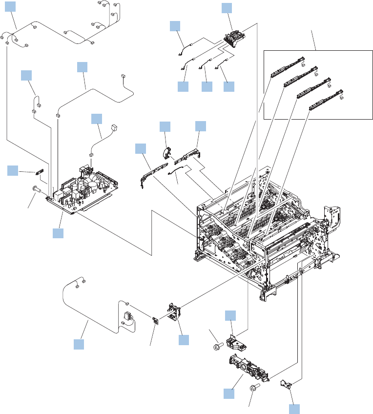
Internal components (8 of 9)
Figure 4-10 Internal components (8 of 9)
See PCA
diagram
(J557D)
(J558D)
(J559D)
(J560D)
See PCA
diagram
(J105)
(J304)
(J303)
(J301)
(J741D)
(J733DA)
(J733DB)
(J63) (J21)
(J25)
(J192)
(J305)
(J302)
(SW3)
(SW4)
(J1001)
(J710M)
(J108)
(J203)
(J711F)
(J1108)
(J109F)
(J110F)
(J707F)
(J1304)
10
9
1
3
2
23
8
6
54
7
14
12 11
13
16
18
17
15
*A01
*A01
*A01
578 Chapter 4 Parts and diagrams ENWW

Table 4-14 Internal components (8 of 9)
Ref Description Part number Qty
1 Holder, first power dispatching RC2-6680-000CN 1
2 Spring, contact RU6-2767-000CN 2
3 Spring, contact RU6-2768-000CN 2
4 Guide, cross-member cable, rear RC2-6588-000CN 1
5 Stopper, laser RC2-6646-000CN 1
6 Guide, cross-member cable, front RC2-6587-000CN 1
7 Spring, rod RC2-6611-000CN 1
8 Cover, cable, right rear RC2-8424-000CN 1
9 Lifter drive assembly RM1-6039-000CN 1
10 Auto close assembly RM1-6036-000CN 1
11 Holder, switch RC2-6666-000CN 1
12 Cable, switch RM1-6830-000CN 1
13 Low voltage power supply assembly, 110V RM1-6753-000CN 1
13 Low voltage power supply assembly, 220V RM1-6754-000CN 1
14 Guide, cable RC3-0684-000CN 1
15 Cable, low-voltage AC joint RM1-6811-000CN 1
16 Cable, low-voltage power supply RM1-6807-000CN 1
17 Cable, low-voltage power supply, test RM1-6813-000CN 1
18 Cable, left, high-voltage power supply to low-voltage power
supply
RM1-6833-000CN 1
ENWW Internal components (8 of 9) 579
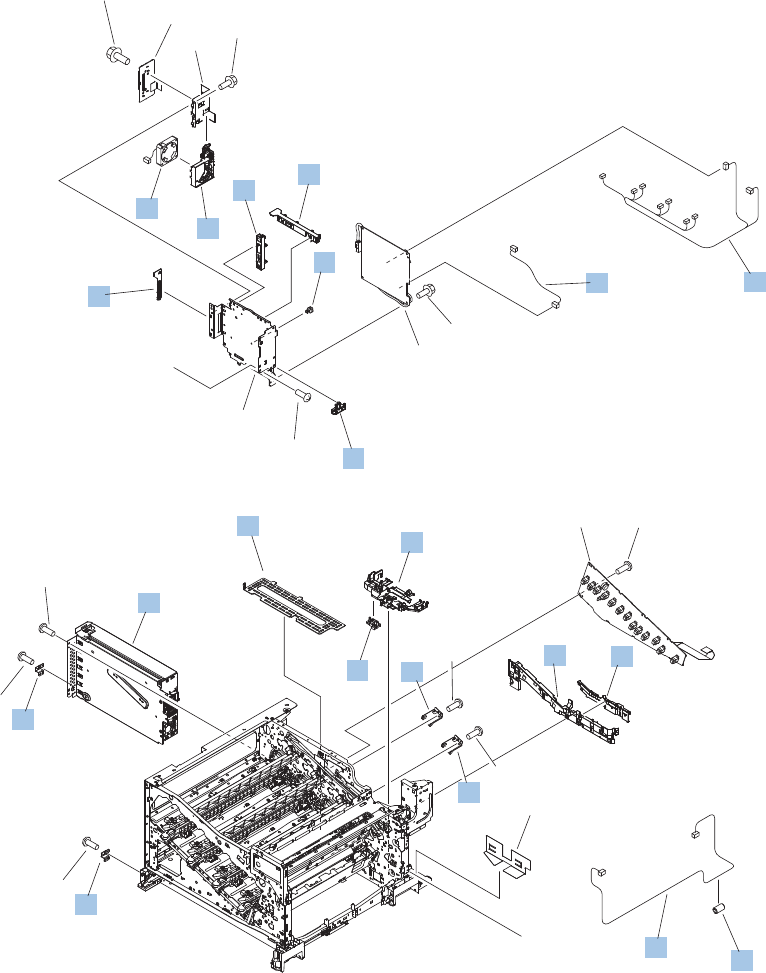
Internal components (9 of 9)
Figure 4-11 Internal components (9 of 9)
A
A
See PCA
diagram
See PCA
diagram
(J716H)
(J558H)
(J557H)
(J717H)
(J559H)
(J718H)
(J101)
(J116)
(J560H)
(J1001A)
(J72)
(J303ICB)
(J770)
(J142)
(FM3)
See PCA
diagram
9
15
14
13
13
6
10
3
5
18
17
2
17
419
8
11
12
16
16
*A02
*A02
*A01
*A05
*A05
*A05
*A05
*A03
*A04
*A04
*A06 *A04
*A02
580 Chapter 4 Parts and diagrams ENWW

Table 4-15 Internal components (9 of 9)
Ref Description Part number Qty
1 Clamp, edge, D RC2-6674-000CN 1
2 Guide, cable, right RC2-6842-000CN 1
3 Guide, cable, upper RC2-6841-000CN 1
4 Cable, PNL-H-HI RM1-6849-000CN 1
5 Spacer, DC controller PCA VT2-5176-004CN 5
6 Guide, DC cont. support cable RC2-6665-000CN 1
7 Cable, primary transfer RM1-6822-000CN 1
8 Cable, rear RM1-6863-000CN 1
9 Formatter case RM1-6065-000CN 1
10 Plate, FFC protective RC2-9687-000CN 1
11 Holder, paper pick-up connector RC2-6638-000CN 1
12 Connector, 8-pin, paper-pick-up VS1-7514-008CN 1
13 Plate, box pillar RC2-6673-000CN 2
14 Guide, imaging HVT cable RC2-6661-000CN 1
15 Cover, imaging HVT cable RC2-6573-000CN 1
16 Cross-member, cover, left RC2-6760-000CN 2
17 Holder, formatter fan RC2-6648-000CN 1
18 Fan, formatter RK2-3301-000CN 1
19 Core, ring WE8-6639-000CN 1
ENWW Internal components (9 of 9) 581
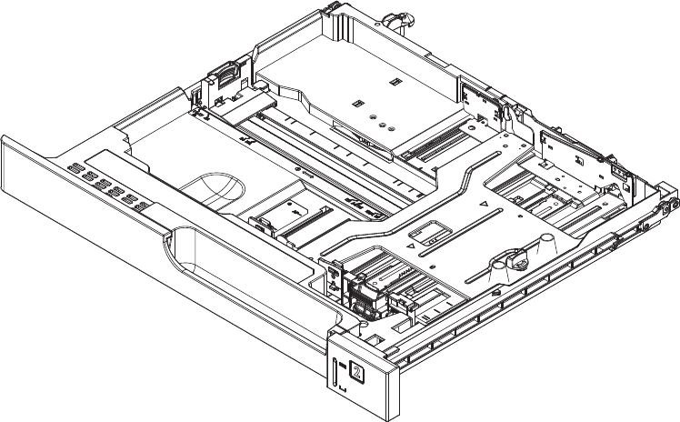
1x250 cassette
Figure 4-12 1x250 cassette
582 Chapter 4 Parts and diagrams ENWW

Table 4-16 1x250 cassette
Ref Description Part number Qty
Cassette CE710-67906 1
ENWW 1x250 cassette 583
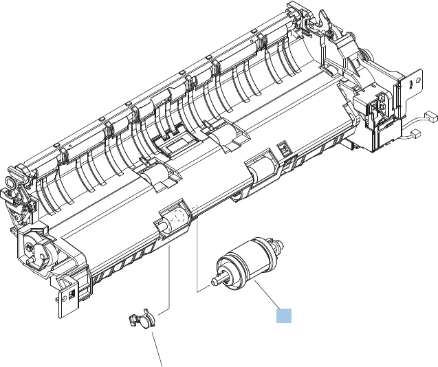
Paper pick-up assembly
Figure 4-13 Paper pick-up assembly
1
*A01
584 Chapter 4 Parts and diagrams ENWW

Table 4-17 Paper pick-up assembly
Ref Description Part number Qty
Paper pick-up assembly RM1-7916-000CN 1
1 Paper pick-up roller assembly (included in service kit) CE707-67903 1
ENWW Paper pick-up assembly 585
CE707-67903
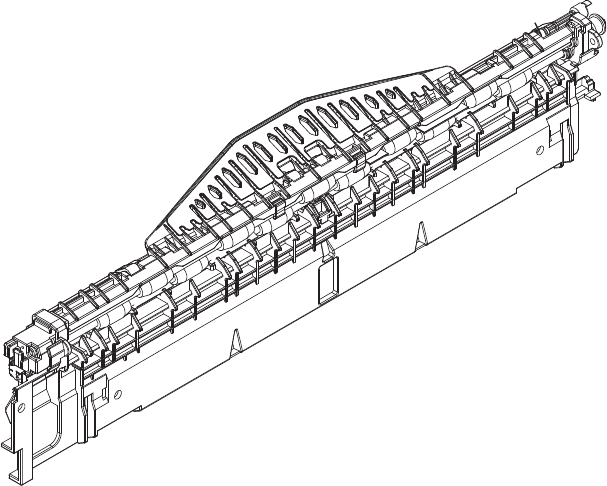
Paper delivery assembly
Figure 4-14 Paper delivery assembly
586 Chapter 4 Parts and diagrams ENWW

Table 4-18 Paper delivery assembly
Ref Description Part number Qty
Paper delivery assembly RM1-6165-000CN 1
ENWW Paper delivery assembly 587
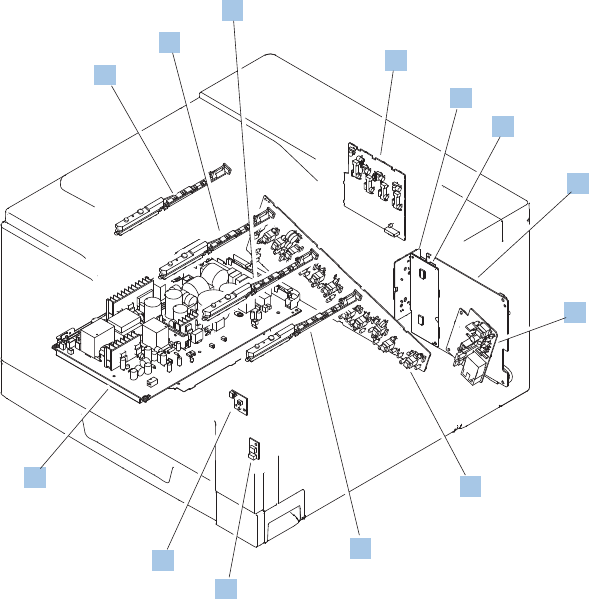
Printed circuit assemblies
Figure 4-15 PCAs
8
1
1
1
1
6
2
5
7
4
3
10
9
588 Chapter 4 Parts and diagrams ENWW

Table 4-19 PCAs
Ref Description Part number Qty
1 Toner remaining detect PCA RM1-6779-000CN 4
2 Primary transfer high-voltage PCA RM1-7004-000CN 1
3 Driver PCA (duplex model) RM1-6742-000CN 1
3 Driver PCA (simplex model) RM1-6783-000CN 1
4 DC Controller PCA (duplex model) CE708-67902 1
4 DC Controller PCA (simplex model) CE707-67906 1
5 Secondary transfer high-voltage PCA RM1-6802-000CN 1
6 Imaging high-voltage PCA RM1-6800-000CN 1
7 Environment sensor PCA RK2-2884-000CN 1
8 Power switch PCA RM1-6759-000CN 1
9 Low-voltage power supply PCA (110V) RM1-6753-000CN 1
9 Low-voltage power supply PCA (220V) RM1-6754-000CN 1
Not shown Formatter PCA CE707-69001 1
10 Inter connect board (ICB) PCA CE707-67907 1
ENWW Printed circuit assemblies 589
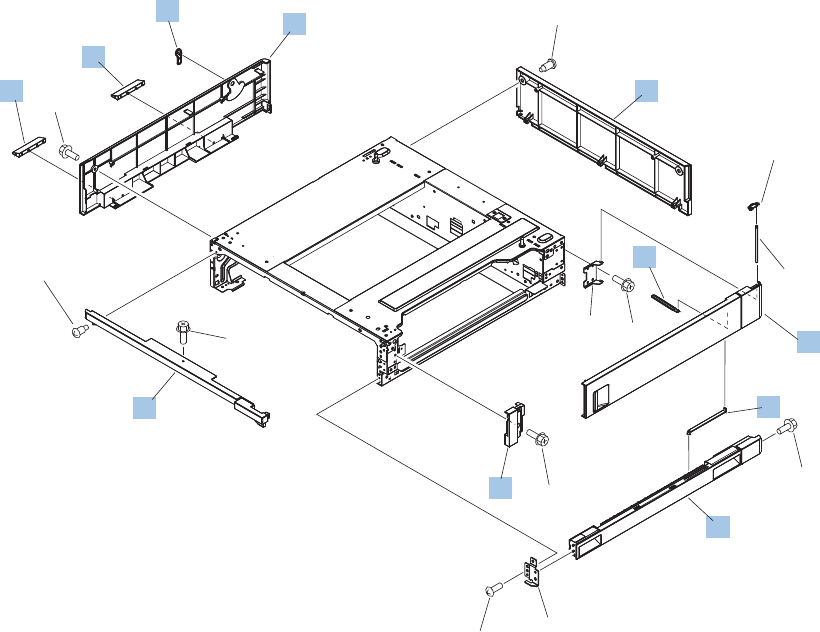
1x500 paper feeder
The 1x500 paper feeder is referred to as the 1x500PF.
1x500PF external components
Figure 4-16 1x500PF external components
2
8
9
3
7
4
5
1
6
6
10
*A06
*A03
*A05
*A03
*A01
*A02
*A04
*A04
*A04
*A07 *A04
*A04
590 Chapter 4 Parts and diagrams ENWW

Table 4-20 1x500PF external components
Ref Description Part number Qty
1 Handle, lock, rear (1x500PF) RC2-9303-000CN 1
2 Cover, right front (1x500PF) RC2-9320-000CN 1
3 Link, right door, lower (1x500PF) RC2-9327-000CN 1
4 Cover, rear (1x500PF) RC2-9330-000CN 1
5 Cover, left (1x500PF) RC2-9331-000CN 1
6 Cover, handle, lower (1x500PF) RC2-9332-000CN 2
7 Link, right door, upper (1x500PF) RC2-9335-000CN 1
8 Right door assembly (1x500PF) RM1-6946-000CN 1
9 Cover, right lower assembly (1x500PF) RM1-6948-000CN 1
10 Cover, upper front assembly (1x500PF) RM1-6949-000CN 1
ENWW 1x500 paper feeder 591
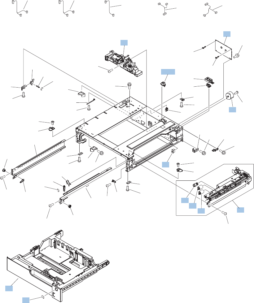
1x500PF internal components
Figure 4-17 1x500PF internal components
(SW1)
(J705)
(M1)
(J704)
(J704)
(J2004)
(J703D)
(J702D)
(J2003)
(J701D)
(J733LB)
(J734DA) (J734DB)
(J733LA)
(J2001)
(J2002)
(J2005)
(J705)
4
9
5
1
2
6
3
7
8
8
*A06
*A31
*A33
*A16
*A06 *A31
*A32
*A20
*A12
*A14
*A06
*A10 *A15
*A15
*A19
*A19
*A06*A13 *A06
*A06
*A10
*A06
*A11
*A24
*A09
*A19 *A08
*A07
*A04
*A04
*A01
*A02
*A05
*A06
*A21
*A26 *A27
*A28 *A29 *A30
*A23
*A06
*A06
*A18
*A17
*A06
*A24
*A11
*A22
*A25
*A03
*A19
592 Chapter 4 Parts and diagrams ENWW

Table 4-21 1x500PF internal components
Ref Description Part number Qty
1 Switch, bottom (1x500PF) WC2-5512-000CN 1
2 Motor, pick-up (1x500PF) RK2-1331-000CN 1
3 Lifter drive assembly (1x500PF) RM1-3819-000CN 1
4 Cassette (1x500PF) RM1-6942-000CN 1
5 Paper pick-up assembly (1x500PF) RM1-6944-000CN 1
6 Paper feeder driver PCA (1x500PF) RM1-6987-000CN 1
7 Roller, pick-up, paper feeder (included in service kit) CE710-67908 1
8 Roller, feed, paper feeder (included in service kit) CE710-67908 2
9 Label, cassette number (1x500PF) RC2-9363-000CN 1
A03 Connector, 8P (1x500PF) VS1-7514-008CN 1
ENWW 1x500 paper feeder 593
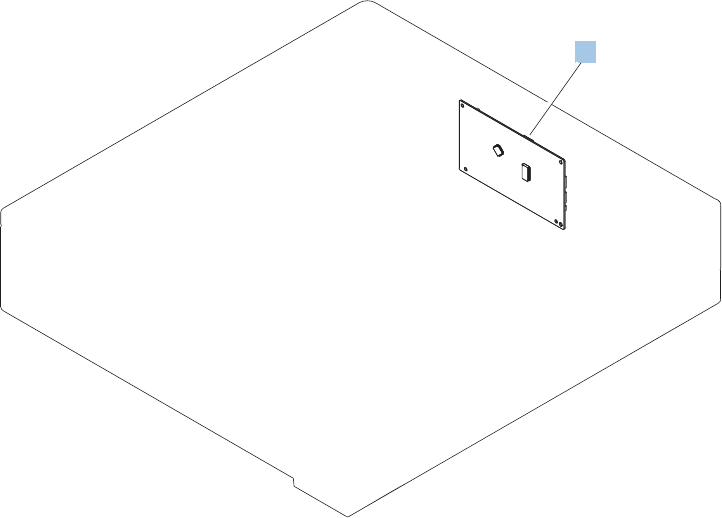
1x500PF PCA
Figure 4-18 1x500PF PCA
1
594 Chapter 4 Parts and diagrams ENWW

Table 4-22 1x500PF PCA
Ref Description Part number Qty
1 Paper feeder driver PCA (1x500PF) RM1-6987-000CN 1
ENWW 1x500 paper feeder 595
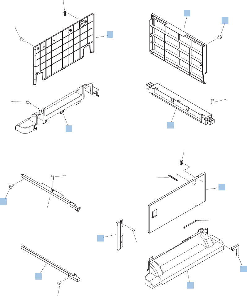
3x500 paper feeder
The 3x500 paper feeder is referred to as the 3x500PF.
3x500PF external components
Figure 4-19 3x500PF external components
7
10
1
8
9
11
13
4
3
12
6
2
5
14
14
*A01
*A01
*A01
*A01
*A01
*A01
*A02
596 Chapter 4 Parts and diagrams ENWW

Table 4-23 3x500PF external components
Ref Description Part number Qty
4 Cover, right corner (3x500PF) RC2-9343-000CN 1
5 Cover, right lower, 1 (3x500PF) RC2-9346-000CN 1
6 Cover, right lower, 2 (3x500PF) RC2-9347-000CN 1
7 Cover, rear (3x500PF) RC2-9348-000CN 1
8 Cover, left (3x500PF) RC2-9349-000CN 1
9 Cover, left lower (3x500PF) RC2-9350-000CN 1
10 Cover, rear lower (3x500PF) RC2-9357-000CN 1
12 Right door assembly (3x500PF) RM1-6953-000CN 1
13 Front lower cover assembly (3x500PF) RM1-6958-000CN 1
14 Screw, stepped (3x500PF) RS5-9099-000CN 3
ENWW 3x500 paper feeder 597
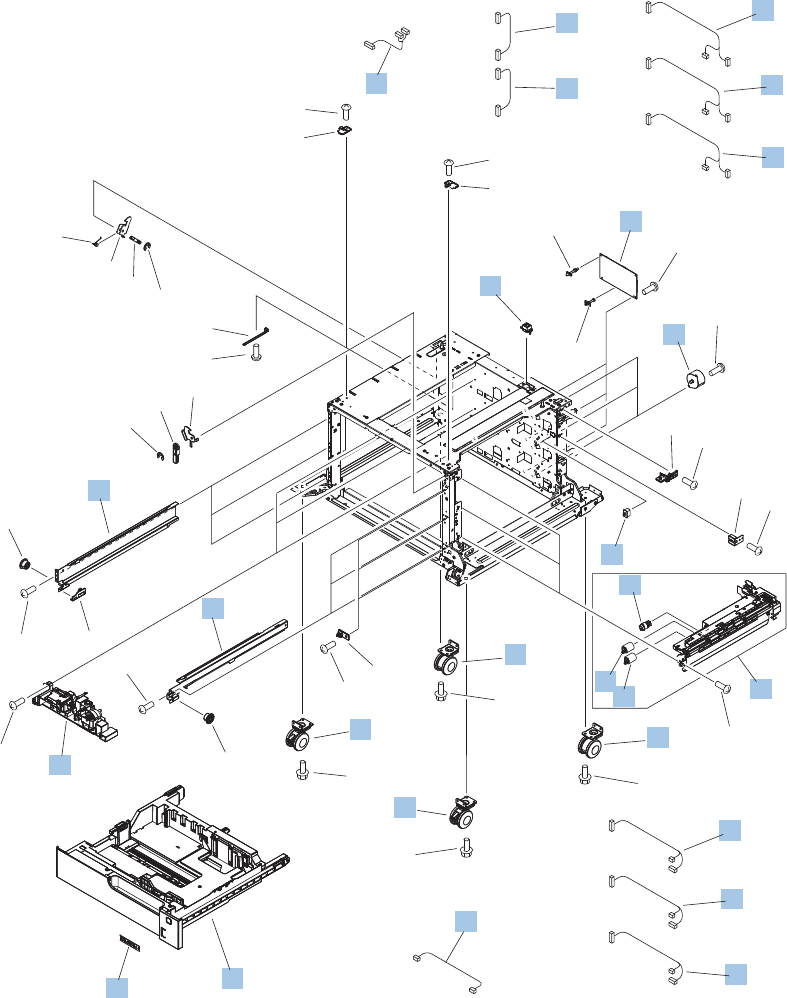
3x500PF internal components
Figure 4-20 3x500PF internal components
(M1)
(SW1)
(J704)
(J33LH)
(M81)
(J804)
(M91)
(J904)
(J2005)
(J705)
(J2004C)
(J903D)
(J904)
(J2003)
(J2002)
(J2001B)
(J2002B)
(J2001C)
(J701D)
(J702D)
(J2001)
(J33LB)
(J33LA)
(J2003B)
(J801D)
(J802D)
(J2003C)
(J901D)
(J902D)
(J2004B)
(J803D)
(J804)
(J2004)
(J703D)
(J704)
1
8
2
3
7
10
13
6
4
4
4
5
11
12
12 5
5
16
16 17
17
18
9
14
15
15
19
*A06
*A04
*A09
*A03
*A11
*A01
*A13
*A01
*A02*A08*A12
*A07
*A07
*A16
*A17
*A14
*A21
*A10
*A15
*A20
*A20
*A15
*A15
*A18
*A18
*A15
*A15
*A15
*A15
*A19
*A19
*A05
*A18
*A18
598 Chapter 4 Parts and diagrams ENWW

Table 4-24 3x500PF internal components
Ref Description Part number Qty
1 Motor, stepping, DC (3x500PF) RK2-1331-000CN 3
2 Rail, cassette, right (3x500PF) RL1-1390-000CN 3
3 Rail, cassette, left (3x500PF) RL1-1391-000CN 3
4 Cable, paper pick-up option (3x500PF) RM1-3575-000CN 3
5 Cable, multisensor (3x500PF) RM1-3647-000CN 3
6 Cable, door open switch (3x500PF) RM1-3651-000CN 1
7 Lifter drive assembly (3x500PF) RM1-3819-000CN 3
8 Cassette (3x500PF) RM1-6942-000CN 1
9 Paper pick-up assembly (3x500PF) RM1-6944-000CN 3
10 Feeder PCA (3x500PF) RM1-6989-000CN 1
11 Cable, engine interface (3x500PF) RM1-6991-000CN 1
12 Cable, PCA joint (3x500PF) RM1-6992-000CN 2
13 Switch, button (3x500PF) WC2-5512-000CN 1
14 Roller, pick-up (included in the service kit; 3x500PF) CE710-67908 1
15 Paper feed roller assembly (included in the service kit; 3x500PF) CE710-67908 2
16 Caster, double lock, front (3x500PF) RC1-9896-000CN 2
17 Caster, rear (3x500PF) RC1-9917-000CN 2
18 Connector, 8P (3x500PF) VS1-7500-008CN 1
19 Label, cassette number (3x500PF) RC3-1824-000CN 1
ENWW 3x500 paper feeder 599
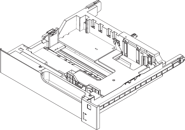
3x500PF cassette
Figure 4-21 3x500PF cassette
600 Chapter 4 Parts and diagrams ENWW

Table 4-25 3x500PF cassette
Ref Description Part number Qty
Cassette (3x500PF) RM1-6942-000CN 3
ENWW 3x500 paper feeder 601
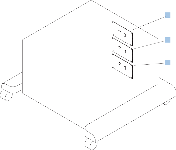
3x500PF PCAs
Figure 4-22 3x500PF PCAs
1
1
1
602 Chapter 4 Parts and diagrams ENWW

Table 4-26 3x500PF PCAs
Ref Description Part number Qty
1 Feeder PCAs (3x500PF) RM1-6989-000CN 3
ENWW 3x500 paper feeder 603

Alphabetical parts list
Table 4-27 Alphabetical parts list
Description Part number Table and page
Arm, front cover, 1 RC2-6732-000CN Internal components (1 of 9)
on page 565
Arm, front cover, 2 RC2-6733-000CN Internal components (1 of 9)
on page 565
Arm, ITB coupling release RC2-6824-000CN Internal components (4 of 9)
on page 571
Arm, waste toner, left RC2-7035-000CN Internal components (6 of 9)
on page 575
Arm, waste toner, right RC2-7036-000CN Internal components (6 of 9)
on page 575
Auto close assembly RM1-6036-000CN Internal components (8 of 9)
on page 579
Cable assembly, flat-flexible RM1-6804-000CN Internal components (7 of 9)
on page 577
Cable, door open switch (3x500PF) RM1-3651-000CN 3x500PF internal components
on page 599
Cable, engine interface (3x500PF) RM1-6991-000CN 3x500PF internal components
on page 599
Cable, feed joint, duplex model RM1-6846-000CN Internal components (4 of 9)
on page 571
Cable, left, high-voltage power supply to low-voltage power
supply
RM1-6833-000CN Internal components (8 of 9)
on page 579
Cable, low-voltage AC joint RM1-6811-000CN Internal components (8 of 9)
on page 579
Cable, low-voltage power supply RM1-6807-000CN Internal components (8 of 9)
on page 579
Cable, low-voltage power supply, test RM1-6813-000CN Internal components (8 of 9)
on page 579
Cable, multisensor (3x500PF) RM1-3647-000CN 3x500PF internal components
on page 599
Cable, paper pick-up option (3x500PF) RM1-3575-000CN 3x500PF internal components
on page 599
Cable, PCA joint (3x500PF) RM1-6992-000CN 3x500PF internal components
on page 599
Cable, PNL-H-HI RM1-6849-000CN Internal components (9 of 9)
on page 581
Cable, primary transfer RM1-6822-000CN Internal components (9 of 9)
on page 581
604 Chapter 4 Parts and diagrams ENWW

Table 4-27 Alphabetical parts list (continued)
Description Part number Table and page
Cable, rear RM1-6863-000CN Internal components (9 of 9)
on page 581
Cable, SB joint, low-voltage power supply, duplex model RM1-6867-000CN Internal components (3 of 9)
on page 569
Cable, switch RM1-6830-000CN Internal components (8 of 9)
on page 579
Cable, USB RK2-2901-000CN External covers, panels, and
doors on page 561
Cap, T2 contact, second-transfer high-voltage PCA RC2-6691-000CN Internal components (4 of 9)
on page 571
Cassette CE710-67906 1x250 cassette on page 583
Cassette (1x500PF) RM1-6942-000CN 1x500PF internal components
on page 593
Cassette (3x500PF) RM1-6942-000CN 3x500PF internal components
on page 599
Cassette (3x500PF) RM1-6942-000CN 3x500PF cassette
on page 601
Caster, double lock, front (3x500PF) RC1-9896-000CN 3x500PF internal components
on page 599
Caster, rear (3x500PF) RC1-9917-000CN 3x500PF internal components
on page 599
Clamp, edge RC2-6663-000CN Internal components (6 of 9)
on page 575
Clamp, edge, D RC2-6674-000CN Internal components (9 of 9)
on page 581
Connector, 8-pin, paper-pick-up VS1-7514-008CN Internal components (9 of 9)
on page 581
Connector, 8P (1x500PF) VS1-7514-008CN 1x500PF internal components
on page 593
Connector, 8P (3x500PF) VS1-7500-008CN 3x500PF internal components
on page 599
Connector, snap tight, black VS1-7207-019CN Internal components (3 of 9)
on page 569
Core, ring WE8-6639-000CN Internal components (9 of 9)
on page 581
Cover, cable, protective RC2-6832-000CN Internal components (3 of 9)
on page 569
Cover, cable, right rear RC2-8424-000CN Internal components (8 of 9)
on page 579
ENWW Alphabetical parts list 605

Table 4-27 Alphabetical parts list (continued)
Description Part number Table and page
Cover, connector, lower RC2-6642-000CN Internal components (3 of 9)
on page 569
Cover, duplexing gear, duplex model RC2-6931-000CN Internal components (4 of 9)
on page 571
Cover, front assembly RM1-7133-000CN External covers, panels, and
doors on page 561
Cover, gear, simplex model RC3-0688-000CN Internal components (4 of 9)
on page 571
Cover, guide RC2-7204-000CN Internal components (1 of 9)
on page 565
Cover, handle guide RC2-6670-000CN Internal components (2 of 9)
on page 567
Cover, handle, lower (1x500PF) RC2-9332-000CN 1x500PF external components
on page 591
Cover, handle, lower-left RC2-6625-000CN External covers, panels, and
doors on page 561
Cover, handle, lower-right, front RC2-6627-000CN External covers, panels, and
doors on page 561
Cover, handle, lower-right, rear RC2-6626-000CN External covers, panels, and
doors on page 561
Cover, imaging HVT cable RC2-6573-000CN Internal components (9 of 9)
on page 581
Cover, left (1x500PF) RC2-9331-000CN 1x500PF external components
on page 591
Cover, left (3x500PF) RC2-9349-000CN 3x500PF external components
on page 597
Cover, left assembly RM1-7143-000CN External covers, panels, and
doors on page 561
Cover, left lower (3x500PF) RC2-9350-000CN 3x500PF external components
on page 597
Cover, lower front RC2-6737-000CN Internal components (1 of 9)
on page 565
Cover, main cross-member cable RC2-6650-000CN Internal components (6 of 9)
on page 575
Cover, main drive cable, lower RC2-6574-000CN Internal components (4 of 9)
on page 571
Cover, rear RM1-7147-000CN External covers, panels, and
doors on page 561
Cover, rear (1x500PF) RC2-9330-000CN 1x500PF external components
on page 591
606 Chapter 4 Parts and diagrams ENWW

Table 4-27 Alphabetical parts list (continued)
Description Part number Table and page
Cover, rear (3x500PF) RC2-9348-000CN 3x500PF external components
on page 597
Cover, rear lower (3x500PF) RC2-9357-000CN 3x500PF external components
on page 597
Cover, right corner (3x500PF) RC2-9343-000CN 3x500PF external components
on page 597
Cover, right front (1x500PF) RC2-9320-000CN 1x500PF external components
on page 591
Cover, right front assembly (includes control panel) RM1-7144-000CN External covers, panels, and
doors on page 561
Cover, right lower assembly (1x500PF) RM1-6948-000CN 1x500PF external components
on page 591
Cover, right lower, 1 (3x500PF) RC2-9346-000CN 3x500PF external components
on page 597
Cover, right lower, 2 (3x500PF) RC2-9347-000CN 3x500PF external components
on page 597
Cover, right rear RM1-7142-000CN External covers, panels, and
doors on page 561
Cover, top RM1-7148-000CN External covers, panels, and
doors on page 561
Cover, upper front assembly (1x500PF) RM1-6949-000CN 1x500PF external components
on page 591
Cover, waste toner, 2 RC2-6962-000CN Internal components (6 of 9)
on page 575
Cover, waste toner, 3 RC2-6963-000CN Internal components (6 of 9)
on page 575
Cross-member, cover, left RC2-6760-000CN Internal components (9 of 9)
on page 581
DC Controller PCA (duplex model) CE708-67902 PCAs on page 589
DC Controller PCA (simplex model) CE707-67906 PCAs on page 589
DC motor assembly RM1-6088-000CN Internal components (4 of 9)
on page 571
Door, inner, service kit includes all labels CE707–67904 Internal components (1 of 9)
on page 565
Door, right upper RC2-7091-000CN Right door assembly
on page 563
Door, toner collection unit access RC2-7034-000CN External covers, panels, and
doors on page 561
Drive assembly, duplex reverse, duplex model RM1-6005-000CN Internal components (3 of 9)
on page 569
ENWW Alphabetical parts list 607

Table 4-27 Alphabetical parts list (continued)
Description Part number Table and page
Drive assembly, simplex reverse, simplex model RM1-6120-000CN Internal components (3 of 9)
on page 569
Driver PCA (duplex model) RM1-6742-000CN PCAs on page 589
Driver PCA (simplex model) RM1-6783-000CN PCAs on page 589
Duct, fan, 1 RC2-8388-000CN Internal components (7 of 9)
on page 577
Duct, front RC2-7300-000CN Internal components (1 of 9)
on page 565
Duct, joint RC2-8360-000CN Internal components (4 of 9)
on page 571
Environment sensor PCA RK2-2884-000CN PCAs on page 589
Fan, formatter RK2-3301-000CN Internal components (9 of 9)
on page 581
Fan, fuser RK2-2728-000CN Internal components (2 of 9)
on page 567
Fan, power supply RK2-2276-000CN Internal components (6 of 9)
on page 575
Feeder PCA (3x500PF) RM1-6989-000CN 3x500PF internal components
on page 599
Feeder PCAs (3x500PF) RM1-6989-000CN 3x500PF PCAs on page 603
Formatter case RM1-6065-000CN Internal components (9 of 9)
on page 581
Formatter PCA CE707-69001 PCAs on page 589
Front lower cover assembly (3x500PF) RM1-6958-000CN 3x500PF external components
on page 597
Fuser assembly, 110V (included in service kit) RM1-6180-000CN Internal components (3 of 9)
on page 569
Fuser assembly, 220V (included in service kit) RM1-6181-000CN Internal components (3 of 9)
on page 569
Fuser drive assembly CE707-67904 Internal components (3 of 9)
on page 569
Fuser motor assembly RM1-6074-000CN Internal components (3 of 9)
on page 569
Gear assembly, fuser RM1-7914-060CN Internal components (3 of 9)
on page 569
Gear, 18T/29T RU6-0775-000CN Internal components (3 of 9)
on page 569
Gear, 25T, duplex model RU6-0771-000CN Internal components (4 of 9)
on page 571
608 Chapter 4 Parts and diagrams ENWW

Table 4-27 Alphabetical parts list (continued)
Description Part number Table and page
Gear, 25T, duplex model RU6-0772-000CN Internal components (4 of 9)
on page 571
Gear, 74T, duplex model RU6-0773-000CN Internal components (4 of 9)
on page 571
Gear, link worm RU6-0795-000CN Internal components (6 of 9)
on page 575
Guide, arm, front RC2-6632-000CN Internal components (1 of 9)
on page 565
Guide, cable RC3-0684-000CN Internal components (8 of 9)
on page 579
Guide, cable, right RC2-6842-000CN Internal components (9 of 9)
on page 581
Guide, cable, upper RC2-6841-000CN Internal components (9 of 9)
on page 581
Guide, cross-member cable, front RC2-6587-000CN Internal components (8 of 9)
on page 579
Guide, cross-member cable, rear RC2-6588-000CN Internal components (8 of 9)
on page 579
Guide, DC cont. support cable RC2-6665-000CN Internal components (9 of 9)
on page 581
Guide, fuser AC cable RC2-6693-000CN Internal components (6 of 9)
on page 575
Guide, fuser, front RC2-6546-000CN Internal components (3 of 9)
on page 569
Guide, fuser, rear RC2-6547-000CN Internal components (3 of 9)
on page 569
Guide, imaging HVT cable RC2-6661-000CN Internal components (9 of 9)
on page 581
Guide, inside cable RC2-6589-000CN Internal components (6 of 9)
on page 575
Guide, laser RC2-6628-000CN Internal components (7 of 9)
on page 577
Guide, LVT cable RC2-6662-000CN Internal components (6 of 9)
on page 575
Guide, main cross-member cable RC2-6600-000CN Internal components (6 of 9)
on page 575
Guide, main drive cable RC2-6659-000CN Internal components (4 of 9)
on page 571
Guide, paper feed RC2-7297-000CN Internal components (3 of 9)
on page 569
ENWW Alphabetical parts list 609

Table 4-27 Alphabetical parts list (continued)
Description Part number Table and page
Guide, slide RC2-7203-000CN Internal components (6 of 9)
on page 575
Handle, lock, rear (1x500PF) RC2-9303-000CN 1x500PF external components
on page 591
Hinge, front cover, center RC2-6738-000CN Internal components (1 of 9)
on page 565
Hinge, front cover, left RC2-6713-000CN Internal components (1 of 9)
on page 565
Hinge, front cover, right RC2-6715-000CN Internal components (1 of 9)
on page 565
Hinge, inner door, left RC2-6716-000CN Internal components (1 of 9)
on page 565
Hinge, inner door, right RC2-6712-000CN Internal components (1 of 9)
on page 565
Hinge, right door, front RC2-7094-000CN Internal components (4 of 9)
on page 571
Holder, door sensor, right RC2-6645-000CN Internal components (4 of 9)
on page 571
Holder, duplexing fan RC2-8357-000CN Internal components (2 of 9)
on page 567
Holder, first power dispatching RC2-6680-000CN Internal components (8 of 9)
on page 579
Holder, flat flexible cable RC2-6655-000CN Internal components (7 of 9)
on page 577
Holder, formatter fan RC2-6648-000CN Internal components (9 of 9)
on page 581
Holder, interlock switch RC2-6689-000CN Internal components (2 of 9)
on page 567
Holder, paper pick-up connector RC2-6638-000CN Internal components (9 of 9)
on page 581
Holder, power supply fan RC2-7299-000CN Internal components (6 of 9)
on page 575
Holder, secondary transfer HVT RC2-6681-010CN Internal components (4 of 9)
on page 571
Holder, secondary transfer, power dispatching RC2-6682-000CN Internal components (4 of 9)
on page 571
Holder, switch RC2-6666-000CN Internal components (8 of 9)
on page 579
Hook, duplexing spring, duplex model RC2-6932-000CN Internal components (4 of 9)
on page 571
610 Chapter 4 Parts and diagrams ENWW

Table 4-27 Alphabetical parts list (continued)
Description Part number Table and page
Imaging high-voltage PCA RM1-6800-000CN PCAs on page 589
Inter connect board (ICB) PCA CE707-67907 PCAs on page 589
IT belt guide rail assembly RM1-6018-000CN Internal components (6 of 9)
on page 575
IT belt guide rail R1 assembly RM1-6037-000CN Internal components (6 of 9)
on page 575
ITB assembly (included in the service kit; includes transfer roller) CE710-67903 Internal components (6 of 9)
on page 575
ITB guide rail assembly RM1-6019-000CN Internal components (6 of 9)
on page 575
Label, cassette number (1x500PF) RC2-9363-000CN 1x500PF internal components
on page 593
Label, cassette number (3x500PF) RC3-1824-000CN 3x500PF internal components
on page 599
Label, fuser insert RU6-8042-000CN Internal components (3 of 9)
on page 569
Label, ITB insert, FH RU5-8806-000CN Internal components (7 of 9)
on page 577
Label, ITB insert, FV RU5-8804-000CN Internal components (7 of 9)
on page 577
Label, ITB set, RH RU5-8807-000CN Internal components (6 of 9)
on page 575
Label, ITB, RV RU5-8805-000CN Internal components (6 of 9)
on page 575
Laser scanner assembly RM1-6122-070CN Internal components (7 of 9)
on page 577
Lever, inner door pressure RC2-6744-000CN Internal components (1 of 9)
on page 565
Lever, lift, 1 RC2-7199-000CN Internal components (6 of 9)
on page 575
Lever, lift, 2 RC2-7200-000CN Internal components (1 of 9)
on page 565
Lever, push RC2-7198-000CN Internal components (1 of 9)
on page 565
Lifter drive assembly RM1-6039-000CN Internal components (8 of 9)
on page 579
Lifter drive assembly (1x500PF) RM1-3819-000CN 1x500PF internal components
on page 593
Lifter drive assembly (3x500PF) RM1-3819-000CN 3x500PF internal components
on page 599
ENWW Alphabetical parts list 611

Table 4-27 Alphabetical parts list (continued)
Description Part number Table and page
Lifter plate assembly, Tray 1 RM1-6043-030CN Right door assembly
on page 563
Link, ITB coupling release RC2-6823-000CN Internal components (4 of 9)
on page 571
Link, right door, 2 front RC2-7233-000CN Internal components (4 of 9)
on page 571
Link, right door, 2 rear RC2-7236-000CN Internal components (4 of 9)
on page 571
Link, right door, lower (1x500PF) RC2-9327-000CN 1x500PF external components
on page 591
Link, right door, upper (1x500PF) RC2-9335-000CN 1x500PF external components
on page 591
Lock, door link, right RC2-7234-000CN Internal components (4 of 9)
on page 571
Low voltage power supply assembly, 110V RM1-6753-000CN Internal components (8 of 9)
on page 579
Low voltage power supply assembly, 220V RM1-6754-000CN Internal components (8 of 9)
on page 579
Low-voltage power supply PCA (110V) RM1-6753-000CN PCAs on page 589
Low-voltage power supply PCA (220V) RM1-6754-000CN PCAs on page 589
Main drive assembly, duplex model RM1-7931-000CN Internal components (4 of 9)
on page 571
Main drive assembly, simplex model RM1-6173-000CN Internal components (4 of 9)
on page 571
Microswitch WC4-5251-000CN Internal components (1 of 9)
on page 565
Motor, pick-up (1x500PF) RK2-1331-000CN 1x500PF internal components
on page 593
Motor, stepping, DC (3x500PF) RK2-1331-000CN 3x500PF internal components
on page 599
Motor, stepping, DC, duplex model RK2-3298-000CN Internal components (4 of 9)
on page 571
Motor, stepping, DC, simplex model RK2-3298-000CN Internal components (4 of 9)
on page 571
Mount, cover arm, front RC2-6735-000CN Internal components (1 of 9)
on page 565
Mount, inner door rail RC2-6743-000CN Internal components (1 of 9)
on page 565
Mount, inner door toggle RC2-6717-000CN Internal components (1 of 9)
on page 565
612 Chapter 4 Parts and diagrams ENWW

Table 4-27 Alphabetical parts list (continued)
Description Part number Table and page
Mount, stopper arm RC2-6745-000CN Internal components (1 of 9)
on page 565
Paper delivery assembly RM1-6165-000CN Paper delivery assembly
on page 587
Paper feed roller assembly (included in the service kit; 3x500PF) CE710-67908 3x500PF internal components
on page 599
Paper feeder driver PCA (1x500PF) RM1-6987-000CN 1x500PF internal components
on page 593
Paper feeder driver PCA (1x500PF) RM1-6987-000CN 1x500PF PCA on page 595
Paper pick-up assembly RM1-7916-000CN Paper pick-up assembly
on page 585
Paper pick-up assembly (1x500PF) RM1-6944-000CN 1x500PF internal components
on page 593
Paper pick-up assembly (3x500PF) RM1-6944-000CN 3x500PF internal components
on page 599
Paper pick-up roller assembly (included in service kit) CE707-67903 Paper pick-up assembly
on page 585
Plate, arm reinforcement RC2-9649-000CN Internal components (6 of 9)
on page 575
Plate, box pillar RC2-6673-000CN Internal components (9 of 9)
on page 581
Plate, duplexing drive gear RL1-2266-000CN Internal components (4 of 9)
on page 571
Plate, FFC protective RC2-9687-000CN Internal components (9 of 9)
on page 581
Plate, right door link, fixed, front RL1-2281-000CN Internal components (4 of 9)
on page 571
Plate, right door link, fixed, rear RL1-2282-000CN Internal components (4 of 9)
on page 571
Plate, right door link, front RC2-7272-000CN Internal components (4 of 9)
on page 571
Plate, right door link, rear RC2-7273-000CN Internal components (4 of 9)
on page 571
Power switch PCA RM1-6759-000CN PCAs on page 589
Primary transfer high-voltage PCA RM1-7004-000CN PCAs on page 589
Rail, cartridge auxiliary RC2-6724-000CN Internal components (1 of 9)
on page 565
Rail, cassette, left (3x500PF) RL1-1391-000CN 3x500PF internal components
on page 599
ENWW Alphabetical parts list 613

Table 4-27 Alphabetical parts list (continued)
Description Part number Table and page
Rail, cassette, right (3x500PF) RL1-1390-000CN 3x500PF internal components
on page 599
Rail, door link, front lower RC2-6634-000CN Internal components (4 of 9)
on page 571
Rail, door link, rear lower RC2-6635-000CN Internal components (4 of 9)
on page 571
Rail, ITB guide RC2-7185-000CN Internal components (6 of 9)
on page 575
Rail, ITB guide, F3 RC2-7193-000CN Internal components (6 of 9)
on page 575
Registration sensor assembly RM1-7922-000CN Internal components (3 of 9)
on page 569
Right door assembly (1x500PF) RM1-6946-000CN 1x500PF external components
on page 591
Right door assembly (3x500PF) RM1-6953-000CN 3x500PF external components
on page 597
Right door assembly, duplex model RM1-6007-000CN Right door assembly
on page 563
Right door assembly, simplex model RM1-6138-000CN Right door assembly
on page 563
Roller, feed, paper feeder (included in service kit) CE710-67908 1x500PF internal components
on page 593
Roller, paper pick-up, Tray 1 (included in the service kit) CE710-67906 Right door assembly
on page 563
Roller, pick-up (included in the service kit; 3x500PF) CE710-67908 3x500PF internal components
on page 599
Roller, pick-up, paper feeder (included in service kit) CE710-67908 1x500PF internal components
on page 593
Roller, secondary transfer, T2 (included in the service kit) CE710-67904 Right door assembly
on page 563
Screw, stepped (3x500PF) RS5-9099-000CN 3x500PF external components
on page 597
Seal, slide shutter RC3-1014-000CN Internal components (7 of 9)
on page 577
Seal, toner supporter guide 1 RC2-7018-000CN Internal components (7 of 9)
on page 577
Secondary transfer high-voltage PCA RM1-6802-000CN PCAs on page 589
Sensor, cassette last paper presence RM1-6164-000CN Internal components (3 of 9)
on page 569
614 Chapter 4 Parts and diagrams ENWW

Table 4-27 Alphabetical parts list (continued)
Description Part number Table and page
Sensor, right door WG8-5696-000CN Internal components (4 of 9)
on page 571
Separation pad, Tray 1 (included in the service kit) CE710-67909 Right door assembly
on page 563
Separation roller assembly (included in service kit) CE710-67907 Internal components (3 of 9)
on page 569
Shaft, right door link RU5-4979-000CN Internal components (4 of 9)
on page 571
Sheet, slide seal RC3-1013-000CN Internal components (7 of 9)
on page 577
Shutter, exhaust RC2-7010-000CN Internal components (6 of 9)
on page 575
Slider, push RC2-7201-000CN Internal components (6 of 9)
on page 575
Spacer, DC controller PCA VT2-5176-004CN Internal components (9 of 9)
on page 581
Spring, compression RU6-2721-000CN Internal components (1 of 9)
on page 565
Spring, compression RU6-2683-000CN Internal components (6 of 9)
on page 575
Spring, contact RU6-2767-000CN Internal components (8 of 9)
on page 579
Spring, contact RU6-2768-000CN Internal components (8 of 9)
on page 579
Spring, contact, second-transfer high-voltage PCA RU6-2771-000CN Internal components (4 of 9)
on page 571
Spring, grounding RC2-7209-000CN Internal components (1 of 9)
on page 565
Spring, grounding, second-transfer high-voltage PCA RU6-2772-000CN Internal components (4 of 9)
on page 571
Spring, grounding, second-transfer high-voltage PCA RC2-6700-000CN Internal components (4 of 9)
on page 571
Spring, leaf, grounding RC2-7092-000CN Internal components (2 of 9)
on page 567
Spring, rod RC2-6611-000CN Internal components (8 of 9)
on page 579
Spring, tension RU6-2831-000CN Internal components (6 of 9)
on page 575
Spring, tension, duplex model RU6-2671-000CN Internal components (4 of 9)
on page 571
ENWW Alphabetical parts list 615

Table 4-27 Alphabetical parts list (continued)
Description Part number Table and page
Spring, tension, front RU6-2727-000CN Internal components (4 of 9)
on page 571
Spring, tension, rear RU6-2744-000CN Internal components (4 of 9)
on page 571
Spring, tension, registration sensor RU6-2710-000CN Internal components (3 of 9)
on page 569
Stopper, inner door, 1 RC2-6719-000CN Internal components (1 of 9)
on page 565
Stopper, inner door, 2 RC2-6736-000CN Internal components (1 of 9)
on page 565
Stopper, laser RC2-6646-000CN Internal components (8 of 9)
on page 579
Support, developing coupling RC2-6811-000CN Internal components (4 of 9)
on page 571
Support, frame, front RC2-7196-000CN Internal components (3 of 9)
on page 569
Support, frame, rear RC2-7197-000CN Internal components (3 of 9)
on page 569
Switch, bottom (1x500PF) WC2-5512-000CN 1x500PF internal components
on page 593
Switch, button (3x500PF) WC2-5512-000CN 3x500PF internal components
on page 599
Toner collection unit (included in the service kit) CE980-67901 Internal components (6 of 9)
on page 575
Toner feed assembly RM1-6040-000CN Internal components (7 of 9)
on page 577
Toner remaining detect PCA RM1-6779-000CN PCAs on page 589
Tray 1 (MP tray) assembly RM1-6045-000CN Right door assembly
on page 563
Upper cartridge guide assembly RM1-5990-000CN Internal components (1 of 9)
on page 565
Waste toner cover assembly RM1-6012-000CN Internal components (6 of 9)
on page 575
616 Chapter 4 Parts and diagrams ENWW
Also called Residual Toner Full
Sensor

Numerical parts list
Table 4-28 Numerical parts list
Part number Description Table and page
CE707-67903 Paper pick-up roller assembly (included in service kit) Paper pick-up assembly
on page 585
CE707-67904 Fuser drive assembly Internal components (3 of 9)
on page 569
CE707-67906 DC Controller PCA (simplex model) PCAs on page 589
CE707-67907 Inter connect board (ICB) PCA PCAs on page 589
CE707-69001 Formatter PCA PCAs on page 589
CE707–67904 Door, inner, service kit includes all labels Internal components (1 of 9)
on page 565
CE708-67902 DC Controller PCA (duplex model) PCAs on page 589
CE710-67903 ITB assembly (included in the service kit; includes transfer roller) Internal components (6 of 9)
on page 575
CE710-67904 Roller, secondary transfer, T2 (included in the service kit) Right door assembly
on page 563
CE710-67906 Roller, paper pick-up, Tray 1 (included in the service kit) Right door assembly
on page 563
CE710-67906 Cassette 1x250 cassette on page 583
CE710-67907 Separation roller assembly (included in service kit) Internal components (3 of 9)
on page 569
CE710-67908 Roller, pick-up, paper feeder (included in service kit) 1x500PF internal components
on page 593
CE710-67908 Roller, feed, paper feeder (included in service kit) 1x500PF internal components
on page 593
CE710-67908 Roller, pick-up (included in the service kit; 3x500PF) 3x500PF internal components
on page 599
CE710-67908 Paper feed roller assembly (included in the service kit; 3x500PF) 3x500PF internal components
on page 599
CE710-67909 Separation pad, Tray 1 (included in the service kit) Right door assembly
on page 563
CE980-67901 Toner collection unit (included in the service kit) Internal components (6 of 9)
on page 575
RC1-9896-000CN Caster, double lock, front (3x500PF) 3x500PF internal components
on page 599
RC1-9917-000CN Caster, rear (3x500PF) 3x500PF internal components
on page 599
RC2-6546-000CN Guide, fuser, front Internal components (3 of 9)
on page 569
ENWW Numerical parts list 617

Table 4-28 Numerical parts list (continued)
Part number Description Table and page
RC2-6547-000CN Guide, fuser, rear Internal components (3 of 9)
on page 569
RC2-6573-000CN Cover, imaging HVT cable Internal components (9 of 9)
on page 581
RC2-6574-000CN Cover, main drive cable, lower Internal components (4 of 9)
on page 571
RC2-6587-000CN Guide, cross-member cable, front Internal components (8 of 9)
on page 579
RC2-6588-000CN Guide, cross-member cable, rear Internal components (8 of 9)
on page 579
RC2-6589-000CN Guide, inside cable Internal components (6 of 9)
on page 575
RC2-6600-000CN Guide, main cross-member cable Internal components (6 of 9)
on page 575
RC2-6611-000CN Spring, rod Internal components (8 of 9)
on page 579
RC2-6625-000CN Cover, handle, lower-left External covers, panels, and
doors on page 561
RC2-6626-000CN Cover, handle, lower-right, rear External covers, panels, and
doors on page 561
RC2-6627-000CN Cover, handle, lower-right, front External covers, panels, and
doors on page 561
RC2-6628-000CN Guide, laser Internal components (7 of 9)
on page 577
RC2-6632-000CN Guide, arm, front Internal components (1 of 9)
on page 565
RC2-6634-000CN Rail, door link, front lower Internal components (4 of 9)
on page 571
RC2-6635-000CN Rail, door link, rear lower Internal components (4 of 9)
on page 571
RC2-6638-000CN Holder, paper pick-up connector Internal components (9 of 9)
on page 581
RC2-6642-000CN Cover, connector, lower Internal components (3 of 9)
on page 569
RC2-6645-000CN Holder, door sensor, right Internal components (4 of 9)
on page 571
RC2-6646-000CN Stopper, laser Internal components (8 of 9)
on page 579
RC2-6648-000CN Holder, formatter fan Internal components (9 of 9)
on page 581
618 Chapter 4 Parts and diagrams ENWW

Table 4-28 Numerical parts list (continued)
Part number Description Table and page
RC2-6650-000CN Cover, main cross-member cable Internal components (6 of 9)
on page 575
RC2-6655-000CN Holder, flat flexible cable Internal components (7 of 9)
on page 577
RC2-6659-000CN Guide, main drive cable Internal components (4 of 9)
on page 571
RC2-6661-000CN Guide, imaging HVT cable Internal components (9 of 9)
on page 581
RC2-6662-000CN Guide, LVT cable Internal components (6 of 9)
on page 575
RC2-6663-000CN Clamp, edge Internal components (6 of 9)
on page 575
RC2-6665-000CN Guide, DC cont. support cable Internal components (9 of 9)
on page 581
RC2-6666-000CN Holder, switch Internal components (8 of 9)
on page 579
RC2-6670-000CN Cover, handle guide Internal components (2 of 9)
on page 567
RC2-6673-000CN Plate, box pillar Internal components (9 of 9)
on page 581
RC2-6674-000CN Clamp, edge, D Internal components (9 of 9)
on page 581
RC2-6680-000CN Holder, first power dispatching Internal components (8 of 9)
on page 579
RC2-6681-010CN Holder, secondary transfer HVT Internal components (4 of 9)
on page 571
RC2-6682-000CN Holder, secondary transfer, power dispatching Internal components (4 of 9)
on page 571
RC2-6689-000CN Holder, interlock switch Internal components (2 of 9)
on page 567
RC2-6691-000CN Cap, T2 contact, second-transfer high-voltage PCA Internal components (4 of 9)
on page 571
RC2-6693-000CN Guide, fuser AC cable Internal components (6 of 9)
on page 575
RC2-6700-000CN Spring, grounding, second-transfer high-voltage PCA Internal components (4 of 9)
on page 571
RC2-6712-000CN Hinge, inner door, right Internal components (1 of 9)
on page 565
RC2-6713-000CN Hinge, front cover, left Internal components (1 of 9)
on page 565
ENWW Numerical parts list 619

Table 4-28 Numerical parts list (continued)
Part number Description Table and page
RC2-6715-000CN Hinge, front cover, right Internal components (1 of 9)
on page 565
RC2-6716-000CN Hinge, inner door, left Internal components (1 of 9)
on page 565
RC2-6717-000CN Mount, inner door toggle Internal components (1 of 9)
on page 565
RC2-6719-000CN Stopper, inner door, 1 Internal components (1 of 9)
on page 565
RC2-6724-000CN Rail, cartridge auxiliary Internal components (1 of 9)
on page 565
RC2-6732-000CN Arm, front cover, 1 Internal components (1 of 9)
on page 565
RC2-6733-000CN Arm, front cover, 2 Internal components (1 of 9)
on page 565
RC2-6735-000CN Mount, cover arm, front Internal components (1 of 9)
on page 565
RC2-6736-000CN Stopper, inner door, 2 Internal components (1 of 9)
on page 565
RC2-6737-000CN Cover, lower front Internal components (1 of 9)
on page 565
RC2-6738-000CN Hinge, front cover, center Internal components (1 of 9)
on page 565
RC2-6743-000CN Mount, inner door rail Internal components (1 of 9)
on page 565
RC2-6744-000CN Lever, inner door pressure Internal components (1 of 9)
on page 565
RC2-6745-000CN Mount, stopper arm Internal components (1 of 9)
on page 565
RC2-6760-000CN Cross-member, cover, left Internal components (9 of 9)
on page 581
RC2-6811-000CN Support, developing coupling Internal components (4 of 9)
on page 571
RC2-6823-000CN Link, ITB coupling release Internal components (4 of 9)
on page 571
RC2-6824-000CN Arm, ITB coupling release Internal components (4 of 9)
on page 571
RC2-6832-000CN Cover, cable, protective Internal components (3 of 9)
on page 569
RC2-6841-000CN Guide, cable, upper Internal components (9 of 9)
on page 581
620 Chapter 4 Parts and diagrams ENWW

Table 4-28 Numerical parts list (continued)
Part number Description Table and page
RC2-6842-000CN Guide, cable, right Internal components (9 of 9)
on page 581
RC2-6931-000CN Cover, duplexing gear, duplex model Internal components (4 of 9)
on page 571
RC2-6932-000CN Hook, duplexing spring, duplex model Internal components (4 of 9)
on page 571
RC2-6962-000CN Cover, waste toner, 2 Internal components (6 of 9)
on page 575
RC2-6963-000CN Cover, waste toner, 3 Internal components (6 of 9)
on page 575
RC2-7010-000CN Shutter, exhaust Internal components (6 of 9)
on page 575
RC2-7018-000CN Seal, toner supporter guide 1 Internal components (7 of 9)
on page 577
RC2-7034-000CN Door, toner collection unit access External covers, panels, and
doors on page 561
RC2-7035-000CN Arm, waste toner, left Internal components (6 of 9)
on page 575
RC2-7036-000CN Arm, waste toner, right Internal components (6 of 9)
on page 575
RC2-7091-000CN Door, right upper Right door assembly
on page 563
RC2-7092-000CN Spring, leaf, grounding Internal components (2 of 9)
on page 567
RC2-7094-000CN Hinge, right door, front Internal components (4 of 9)
on page 571
RC2-7185-000CN Rail, ITB guide Internal components (6 of 9)
on page 575
RC2-7193-000CN Rail, ITB guide, F3 Internal components (6 of 9)
on page 575
RC2-7196-000CN Support, frame, front Internal components (3 of 9)
on page 569
RC2-7197-000CN Support, frame, rear Internal components (3 of 9)
on page 569
RC2-7198-000CN Lever, push Internal components (1 of 9)
on page 565
RC2-7199-000CN Lever, lift, 1 Internal components (6 of 9)
on page 575
RC2-7200-000CN Lever, lift, 2 Internal components (1 of 9)
on page 565
ENWW Numerical parts list 621

Table 4-28 Numerical parts list (continued)
Part number Description Table and page
RC2-7201-000CN Slider, push Internal components (6 of 9)
on page 575
RC2-7203-000CN Guide, slide Internal components (6 of 9)
on page 575
RC2-7204-000CN Cover, guide Internal components (1 of 9)
on page 565
RC2-7209-000CN Spring, grounding Internal components (1 of 9)
on page 565
RC2-7233-000CN Link, right door, 2 front Internal components (4 of 9)
on page 571
RC2-7234-000CN Lock, door link, right Internal components (4 of 9)
on page 571
RC2-7236-000CN Link, right door, 2 rear Internal components (4 of 9)
on page 571
RC2-7272-000CN Plate, right door link, front Internal components (4 of 9)
on page 571
RC2-7273-000CN Plate, right door link, rear Internal components (4 of 9)
on page 571
RC2-7297-000CN Guide, paper feed Internal components (3 of 9)
on page 569
RC2-7299-000CN Holder, power supply fan Internal components (6 of 9)
on page 575
RC2-7300-000CN Duct, front Internal components (1 of 9)
on page 565
RC2-8357-000CN Holder, duplexing fan Internal components (2 of 9)
on page 567
RC2-8360-000CN Duct, joint Internal components (4 of 9)
on page 571
RC2-8388-000CN Duct, fan, 1 Internal components (7 of 9)
on page 577
RC2-8424-000CN Cover, cable, right rear Internal components (8 of 9)
on page 579
RC2-9303-000CN Handle, lock, rear (1x500PF) 1x500PF external components
on page 591
RC2-9320-000CN Cover, right front (1x500PF) 1x500PF external components
on page 591
RC2-9327-000CN Link, right door, lower (1x500PF) 1x500PF external components
on page 591
RC2-9330-000CN Cover, rear (1x500PF) 1x500PF external components
on page 591
622 Chapter 4 Parts and diagrams ENWW

Table 4-28 Numerical parts list (continued)
Part number Description Table and page
RC2-9331-000CN Cover, left (1x500PF) 1x500PF external components
on page 591
RC2-9332-000CN Cover, handle, lower (1x500PF) 1x500PF external components
on page 591
RC2-9335-000CN Link, right door, upper (1x500PF) 1x500PF external components
on page 591
RC2-9343-000CN Cover, right corner (3x500PF) 3x500PF external components
on page 597
RC2-9346-000CN Cover, right lower, 1 (3x500PF) 3x500PF external components
on page 597
RC2-9347-000CN Cover, right lower, 2 (3x500PF) 3x500PF external components
on page 597
RC2-9348-000CN Cover, rear (3x500PF) 3x500PF external components
on page 597
RC2-9349-000CN Cover, left (3x500PF) 3x500PF external components
on page 597
RC2-9350-000CN Cover, left lower (3x500PF) 3x500PF external components
on page 597
RC2-9357-000CN Cover, rear lower (3x500PF) 3x500PF external components
on page 597
RC2-9363-000CN Label, cassette number (1x500PF) 1x500PF internal components
on page 593
RC2-9649-000CN Plate, arm reinforcement Internal components (6 of 9)
on page 575
RC2-9687-000CN Plate, FFC protective Internal components (9 of 9)
on page 581
RC3-0684-000CN Guide, cable Internal components (8 of 9)
on page 579
RC3-0688-000CN Cover, gear, simplex model Internal components (4 of 9)
on page 571
RC3-1013-000CN Sheet, slide seal Internal components (7 of 9)
on page 577
RC3-1014-000CN Seal, slide shutter Internal components (7 of 9)
on page 577
RC3-1824-000CN Label, cassette number (3x500PF) 3x500PF internal components
on page 599
RK2-1331-000CN Motor, pick-up (1x500PF) 1x500PF internal components
on page 593
RK2-1331-000CN Motor, stepping, DC (3x500PF) 3x500PF internal components
on page 599
ENWW Numerical parts list 623

Table 4-28 Numerical parts list (continued)
Part number Description Table and page
RK2-2276-000CN Fan, power supply Internal components (6 of 9)
on page 575
RK2-2728-000CN Fan, fuser Internal components (2 of 9)
on page 567
RK2-2884-000CN Environment sensor PCA PCAs on page 589
RK2-2901-000CN Cable, USB External covers, panels, and
doors on page 561
RK2-3298-000CN Motor, stepping, DC, duplex model Internal components (4 of 9)
on page 571
RK2-3298-000CN Motor, stepping, DC, simplex model Internal components (4 of 9)
on page 571
RK2-3301-000CN Fan, formatter Internal components (9 of 9)
on page 581
RL1-1390-000CN Rail, cassette, right (3x500PF) 3x500PF internal components
on page 599
RL1-1391-000CN Rail, cassette, left (3x500PF) 3x500PF internal components
on page 599
RL1-2266-000CN Plate, duplexing drive gear Internal components (4 of 9)
on page 571
RL1-2281-000CN Plate, right door link, fixed, front Internal components (4 of 9)
on page 571
RL1-2282-000CN Plate, right door link, fixed, rear Internal components (4 of 9)
on page 571
RM1-3575-000CN Cable, paper pick-up option (3x500PF) 3x500PF internal components
on page 599
RM1-3647-000CN Cable, multisensor (3x500PF) 3x500PF internal components
on page 599
RM1-3651-000CN Cable, door open switch (3x500PF) 3x500PF internal components
on page 599
RM1-3819-000CN Lifter drive assembly (1x500PF) 1x500PF internal components
on page 593
RM1-3819-000CN Lifter drive assembly (3x500PF) 3x500PF internal components
on page 599
RM1-5990-000CN Upper cartridge guide assembly Internal components (1 of 9)
on page 565
RM1-6005-000CN Drive assembly, duplex reverse, duplex model Internal components (3 of 9)
on page 569
RM1-6007-000CN Right door assembly, duplex model Right door assembly
on page 563
624 Chapter 4 Parts and diagrams ENWW

Table 4-28 Numerical parts list (continued)
Part number Description Table and page
RM1-6012-000CN Waste toner cover assembly Internal components (6 of 9)
on page 575
RM1-6018-000CN IT belt guide rail assembly Internal components (6 of 9)
on page 575
RM1-6019-000CN ITB guide rail assembly Internal components (6 of 9)
on page 575
RM1-6036-000CN Auto close assembly Internal components (8 of 9)
on page 579
RM1-6037-000CN IT belt guide rail R1 assembly Internal components (6 of 9)
on page 575
RM1-6039-000CN Lifter drive assembly Internal components (8 of 9)
on page 579
RM1-6040-000CN Toner feed assembly Internal components (7 of 9)
on page 577
RM1-6043-030CN Lifter plate assembly, Tray 1 Right door assembly
on page 563
RM1-6045-000CN Tray 1 (MP tray) assembly Right door assembly
on page 563
RM1-6065-000CN Formatter case Internal components (9 of 9)
on page 581
RM1-6074-000CN Fuser motor assembly Internal components (3 of 9)
on page 569
RM1-6088-000CN DC motor assembly Internal components (4 of 9)
on page 571
RM1-6120-000CN Drive assembly, simplex reverse, simplex model Internal components (3 of 9)
on page 569
RM1-6122-070CN Laser scanner assembly Internal components (7 of 9)
on page 577
RM1-6138-000CN Right door assembly, simplex model Right door assembly
on page 563
RM1-6164-000CN Sensor, cassette last paper presence Internal components (3 of 9)
on page 569
RM1-6165-000CN Paper delivery assembly Paper delivery assembly
on page 587
RM1-6173-000CN Main drive assembly, simplex model Internal components (4 of 9)
on page 571
RM1-6180-000CN Fuser assembly, 110V (included in service kit) Internal components (3 of 9)
on page 569
RM1-6181-000CN Fuser assembly, 220V (included in service kit) Internal components (3 of 9)
on page 569
ENWW Numerical parts list 625
Also Called Residual Toner
Full Sensor

Table 4-28 Numerical parts list (continued)
Part number Description Table and page
RM1-6742-000CN Driver PCA (duplex model) PCAs on page 589
RM1-6753-000CN Low voltage power supply assembly, 110V Internal components (8 of 9)
on page 579
RM1-6753-000CN Low-voltage power supply PCA (110V) PCAs on page 589
RM1-6754-000CN Low voltage power supply assembly, 220V Internal components (8 of 9)
on page 579
RM1-6754-000CN Low-voltage power supply PCA (220V) PCAs on page 589
RM1-6759-000CN Power switch PCA PCAs on page 589
RM1-6779-000CN Toner remaining detect PCA PCAs on page 589
RM1-6783-000CN Driver PCA (simplex model) PCAs on page 589
RM1-6800-000CN Imaging high-voltage PCA PCAs on page 589
RM1-6802-000CN Secondary transfer high-voltage PCA PCAs on page 589
RM1-6804-000CN Cable assembly, flat-flexible Internal components (7 of 9)
on page 577
RM1-6807-000CN Cable, low-voltage power supply Internal components (8 of 9)
on page 579
RM1-6811-000CN Cable, low-voltage AC joint Internal components (8 of 9)
on page 579
RM1-6813-000CN Cable, low-voltage power supply, test Internal components (8 of 9)
on page 579
RM1-6822-000CN Cable, primary transfer Internal components (9 of 9)
on page 581
RM1-6830-000CN Cable, switch Internal components (8 of 9)
on page 579
RM1-6833-000CN Cable, left, high-voltage power supply to low-voltage power
supply
Internal components (8 of 9)
on page 579
RM1-6846-000CN Cable, feed joint, duplex model Internal components (4 of 9)
on page 571
RM1-6849-000CN Cable, PNL-H-HI Internal components (9 of 9)
on page 581
RM1-6863-000CN Cable, rear Internal components (9 of 9)
on page 581
RM1-6867-000CN Cable, SB joint, low-voltage power supply, duplex model Internal components (3 of 9)
on page 569
RM1-6942-000CN Cassette (1x500PF) 1x500PF internal components
on page 593
RM1-6942-000CN Cassette (3x500PF) 3x500PF internal components
on page 599
626 Chapter 4 Parts and diagrams ENWW

Table 4-28 Numerical parts list (continued)
Part number Description Table and page
RM1-6942-000CN Cassette (3x500PF) 3x500PF cassette
on page 601
RM1-6944-000CN Paper pick-up assembly (1x500PF) 1x500PF internal components
on page 593
RM1-6944-000CN Paper pick-up assembly (3x500PF) 3x500PF internal components
on page 599
RM1-6946-000CN Right door assembly (1x500PF) 1x500PF external components
on page 591
RM1-6948-000CN Cover, right lower assembly (1x500PF) 1x500PF external components
on page 591
RM1-6949-000CN Cover, upper front assembly (1x500PF) 1x500PF external components
on page 591
RM1-6953-000CN Right door assembly (3x500PF) 3x500PF external components
on page 597
RM1-6958-000CN Front lower cover assembly (3x500PF) 3x500PF external components
on page 597
RM1-6987-000CN Paper feeder driver PCA (1x500PF) 1x500PF internal components
on page 593
RM1-6987-000CN Paper feeder driver PCA (1x500PF) 1x500PF PCA on page 595
RM1-6989-000CN Feeder PCA (3x500PF) 3x500PF internal components
on page 599
RM1-6989-000CN Feeder PCAs (3x500PF) 3x500PF PCAs on page 603
RM1-6991-000CN Cable, engine interface (3x500PF) 3x500PF internal components
on page 599
RM1-6992-000CN Cable, PCA joint (3x500PF) 3x500PF internal components
on page 599
RM1-7004-000CN Primary transfer high-voltage PCA PCAs on page 589
RM1-7133-000CN Cover, front assembly External covers, panels, and
doors on page 561
RM1-7142-000CN Cover, right rear External covers, panels, and
doors on page 561
RM1-7143-000CN Cover, left assembly External covers, panels, and
doors on page 561
RM1-7144-000CN Cover, right front assembly (includes control panel) External covers, panels, and
doors on page 561
RM1-7147-000CN Cover, rear External covers, panels, and
doors on page 561
RM1-7148-000CN Cover, top External covers, panels, and
doors on page 561
ENWW Numerical parts list 627

Table 4-28 Numerical parts list (continued)
Part number Description Table and page
RM1-7914-060CN Gear assembly, fuser Internal components (3 of 9)
on page 569
RM1-7916-000CN Paper pick-up assembly Paper pick-up assembly
on page 585
RM1-7922-000CN Registration sensor assembly Internal components (3 of 9)
on page 569
RM1-7931-000CN Main drive assembly, duplex model Internal components (4 of 9)
on page 571
RS5-9099-000CN Screw, stepped (3x500PF) 3x500PF external components
on page 597
RU5-4979-000CN Shaft, right door link Internal components (4 of 9)
on page 571
RU5-8804-000CN Label, ITB insert, FV Internal components (7 of 9)
on page 577
RU5-8805-000CN Label, ITB, RV Internal components (6 of 9)
on page 575
RU5-8806-000CN Label, ITB insert, FH Internal components (7 of 9)
on page 577
RU5-8807-000CN Label, ITB set, RH Internal components (6 of 9)
on page 575
RU6-0771-000CN Gear, 25T, duplex model Internal components (4 of 9)
on page 571
RU6-0772-000CN Gear, 25T, duplex model Internal components (4 of 9)
on page 571
RU6-0773-000CN Gear, 74T, duplex model Internal components (4 of 9)
on page 571
RU6-0775-000CN Gear, 18T/29T Internal components (3 of 9)
on page 569
RU6-0795-000CN Gear, link worm Internal components (6 of 9)
on page 575
RU6-2671-000CN Spring, tension, duplex model Internal components (4 of 9)
on page 571
RU6-2683-000CN Spring, compression Internal components (6 of 9)
on page 575
RU6-2710-000CN Spring, tension, registration sensor Internal components (3 of 9)
on page 569
RU6-2721-000CN Spring, compression Internal components (1 of 9)
on page 565
RU6-2727-000CN Spring, tension, front Internal components (4 of 9)
on page 571
628 Chapter 4 Parts and diagrams ENWW
CE707-67903

Table 4-28 Numerical parts list (continued)
Part number Description Table and page
RU6-2744-000CN Spring, tension, rear Internal components (4 of 9)
on page 571
RU6-2767-000CN Spring, contact Internal components (8 of 9)
on page 579
RU6-2768-000CN Spring, contact Internal components (8 of 9)
on page 579
RU6-2771-000CN Spring, contact, second-transfer high-voltage PCA Internal components (4 of 9)
on page 571
RU6-2772-000CN Spring, grounding, second-transfer high-voltage PCA Internal components (4 of 9)
on page 571
RU6-2831-000CN Spring, tension Internal components (6 of 9)
on page 575
RU6-8042-000CN Label, fuser insert Internal components (3 of 9)
on page 569
VS1-7207-019CN Connector, snap tight, black Internal components (3 of 9)
on page 569
VS1-7500-008CN Connector, 8P (3x500PF) 3x500PF internal components
on page 599
VS1-7514-008CN Connector, 8-pin, paper-pick-up Internal components (9 of 9)
on page 581
VS1-7514-008CN Connector, 8P (1x500PF) 1x500PF internal components
on page 593
VT2-5176-004CN Spacer, DC controller PCA Internal components (9 of 9)
on page 581
WC2-5512-000CN Switch, bottom (1x500PF) 1x500PF internal components
on page 593
WC2-5512-000CN Switch, button (3x500PF) 3x500PF internal components
on page 599
WC4-5251-000CN Microswitch Internal components (1 of 9)
on page 565
WE8-6639-000CN Core, ring Internal components (9 of 9)
on page 581
WG8-5696-000CN Sensor, right door Internal components (4 of 9)
on page 571
ENWW Numerical parts list 629
630 Chapter 4 Parts and diagrams ENWW

A Service and support
●Hewlett-Packard limited warranty statement
●HP's Premium Protection Warranty: LaserJet print cartridge limited warranty statement
●Color LaserJet Fuser Kit, Transfer Kit, and Toner Collection Unit Limited Warranty Statement
●Data stored on the print cartridge
●End User License Agreement
●Customer self-repair warranty service
●Customer support
ENWW 631

Hewlett-Packard limited warranty statement
HP PRODUCT DURATION OF LIMITED WARRANTY
HP Color LaserJet CP5525n, CP5525dn, CP5525xh One-year on-site warranty
HP warrants to you, the end-user customer, that HP hardware and accessories will be free from defects
in materials and workmanship after the date of purchase, for the period specified above. If HP receives
notice of such defects during the warranty period, HP will, at its option, either repair or replace
products which prove to be defective. Replacement products may be either new or equivalent in
performance to new.
HP warrants to you that HP software will not fail to execute its programming instructions after the date
of purchase, for the period specified above, due to defects in material and workmanship when
properly installed and used. If HP receives notice of such defects during the warranty period, HP will
replace software which does not execute its programming instructions due to such defects.
HP does not warrant that the operation of HP products will be uninterrupted or error free. If HP is
unable, within a reasonable time, to repair or replace any product to a condition as warranted, you
will be entitled to a refund of the purchase price upon prompt return of the product.
HP products may contain remanufactured parts equivalent to new in performance or may have been
subject to incidental use.
Warranty does not apply to defects resulting from (a) improper or inadequate maintenance or
calibration, (b) software, interfacing, parts or supplies not supplied by HP, (c) unauthorized
modification or misuse, (d) operation outside of the published environmental specifications for the
product, or (e) improper site preparation or maintenance.
TO THE EXTENT ALLOWED BY LOCAL LAW, THE ABOVE WARRANTIES ARE EXCLUSIVE AND NO
OTHER WARRANTY OR CONDITION, WHETHER WRITTEN OR ORAL, IS EXPRESSED OR IMPLIED
AND HP SPECIFICALLY DISCLAIMS ANY IMPLIED WARRANTIES OR CONDITIONS OF
MERCHANTABILITY, SATISFACTORY QUALITY, AND FITNESS FOR A PARTICULAR PURPOSE. Some
countries/regions, states or provinces do not allow limitations on the duration of an implied warranty,
so the above limitation or exclusion might not apply to you. This warranty gives you specific legal rights
and you might also have other rights that vary from country/region to country/region, state to state, or
province to province.
HP's limited warranty is valid in any country/region or locality where HP has a support presence for
this product and where HP has marketed this product. The level of warranty service you receive may
vary according to local standards. HP will not alter form, fit or function of the product to make it
operate in a country/region for which it was never intended to function for legal or regulatory reasons.
TO THE EXTENT ALLOWED BY LOCAL LAW, THE REMEDIES IN THIS WARRANTY STATEMENT ARE
YOUR SOLE AND EXCLUSIVE REMEDIES. EXCEPT AS INDICATED ABOVE, IN NO EVENT WILL HP OR
ITS SUPPLIERS BE LIABLE FOR LOSS OF DATA OR FOR DIRECT, SPECIAL, INCIDENTAL,
CONSEQUENTIAL (INCLUDING LOST PROFIT OR DATA), OR OTHER DAMAGE, WHETHER BASED
IN CONTRACT, TORT, OR OTHERWISE. Some countries/regions, states or provinces do not allow the
exclusion or limitation of incidental or consequential damages, so the above limitation or exclusion may
not apply to you.
THE WARRANTY TERMS CONTAINED IN THIS STATEMENT, EXCEPT TO THE EXTENT LAWFULLY
PERMITTED, DO NOT EXCLUDE, RESTRICT OR MODIFY AND ARE IN ADDITION TO THE
MANDATORY STATUTORY RIGHTS APPLICABLE TO THE SALE OF THIS PRODUCT TO YOU.
632 Appendix A Service and support ENWW
HP's Premium Protection Warranty: LaserJet print
cartridge limited warranty statement
This HP product is warranted to be free from defects in materials and workmanship.
This warranty does not apply to products that (a) have been refilled, refurbished, remanufactured or
tampered with in any way, (b) experience problems resulting from misuse, improper storage, or
operation outside of the published environmental specifications for the printer product or (c) exhibit
wear from ordinary use.
To obtain warranty service, please return the product to place of purchase (with a written description of
the problem and print samples) or contact HP customer support. At HP's option, HP will either replace
products that prove to be defective or refund your purchase price.
TO THE EXTENT ALLOWED BY LOCAL LAW, THE ABOVE WARRANTY IS EXCLUSIVE AND NO
OTHER WARRANTY OR CONDITION, WHETHER WRITTEN OR ORAL, IS EXPRESSED OR IMPLIED
AND HP SPECIFICALLY DISCLAIMS ANY IMPLIED WARRANTIES OR CONDITIONS OF
MERCHANTABILITY, SATISFACTORY QUALITY, AND FITNESS FOR A PARTICULAR PURPOSE.
TO THE EXTENT ALLOWED BY LOCAL LAW, IN NO EVENT WILL HP OR ITS SUPPLIERS BE LIABLE
FOR DIRECT, SPECIAL, INCIDENTAL, CONSEQUENTIAL (INCLUDING LOST PROFIT OR DATA), OR
OTHER DAMAGE, WHETHER BASED IN CONTRACT, TORT, OR OTHERWISE.
THE WARRANTY TERMS CONTAINED IN THIS STATEMENT, EXCEPT TO THE EXTENT LAWFULLY
PERMITTED, DO NOT EXCLUDE, RESTRICT OR MODIFY AND ARE IN ADDITION TO THE
MANDATORY STATUTORY RIGHTS APPLICABLE TO THE SALE OF THIS PRODUCT TO YOU.
ENWW HP's Premium Protection Warranty: LaserJet print cartridge limited warranty statement 633
Color LaserJet Fuser Kit, Transfer Kit, and Toner
Collection Unit Limited Warranty Statement
This HP product is warranted to be free from defects in materials and workmanship until the printer
provides a low-life indicator on the control panel.
This warranty does not apply to products that (a) have been refurbished, remanufactured or tampered
with in any way, (b) experience problems resulting from misuse, improper storage, or operation outside
of the published environmental specifications for the printer product or (c) exhibit wear from ordinary
use.
To obtain warranty service, please return the product to place of purchase (with a written description of
the problem) or contact HP customer support. At HP’s option, HP will either replace products that prove
to be defective or refund your purchase price.
TO THE EXTENT ALLOWED BY LOCAL LAW, THE ABOVE WARRANTY IS EXCLUSIVE AND NO
OTHER WARRANTY OR CONDITION, WHETHER WRITTEN OR ORAL, IS EXPRESSED OR IMPLIED
AND HP SPECIFICALLY DISCLAIMS ANY IMPLIED WARRANTIES OR CONDITIONS OF
MERCHANTABILITY, SATISFACTORY QUALITY, AND FITNESS FOR A PARTICULAR PURPOSE.
TO THE EXTENT ALLOWED BY LOCAL LAW, IN NO EVENT WILL HP OR ITS SUPPLIERS BE LIABLE
FOR DIRECT, SPECIAL, INCIDENTAL, CONSEQUENTIAL (INCLUDING LOST PROFIT OR DATA), OR
OTHER DAMAGE, WHETHER BASED IN CONTRACT, TORT, OR OTHERWISE.
THE WARRANTY TERMS CONTAINED IN THIS STATEMENT, EXCEPT TO THE EXTENT LAWFULLY
PERMITTED, DO NOT EXCLUDE, RESTRICT OR MODIFY AND ARE IN ADDITION TO THE
MANDATORY STATUTORY RIGHTS APPLICABLE TO THE SALE OF THIS PRODUCT TO YOU.
634 Appendix A Service and support ENWW

Data stored on the print cartridge
The HP print cartridges used with this product contain a memory chip that assists in the operation of the
product.
In addition, this memory chip collects a limited set of information about the usage of the product, which
might include the following: the date when the print cartridge was first installed, the date when the print
cartridge was last used, the number of pages printed using the print cartridge, the page coverage, the
printing modes used, any printing errors that might have occurred, and the product model. This
information helps HP design future products to meet our customers' printing needs.
The data collected from the print cartridge memory chip does not contain information that can be used
to identify a customer or user of the print cartridge or their product.
HP collects a sampling of the memory chips from print cartridges returned to HP's free return and
recycling program (HP Planet Partners: www.hp.com/recycle). The memory chips from this sampling
are read and studied in order to improve future HP products. HP partners who assist in recycling this
print cartridge might have access to this data, as well.
Any third party possessing the print cartridge might have access to the anonymous information on the
memory chip. If you prefer to not allow access to this information, you can render the chip inoperable.
However, after you render the memory chip inoperable, the memory chip cannot be used in an HP
product.
ENWW Data stored on the print cartridge 635
End User License Agreement
PLEASE READ CAREFULLY BEFORE USING THIS SOFTWARE PRODUCT: This End-User License
Agreement (“EULA”) is a contract between (a) you (either an individual or the entity you represent) and
(b) Hewlett-Packard Company (“HP”) that governs your use of the software product (“Software”). This
EULA does not apply if there is a separate license agreement between you and HP or its suppliers for
the Software, including a license agreement in online documentation. The term “Software” may include
(i) associated media, (ii) a user guide and other printed materials, and (iii) “online” or electronic
documentation (collectively “User Documentation”).
RIGHTS IN THE SOFTWARE ARE OFFERED ONLY ON THE CONDITION THAT YOU AGREE TO ALL
TERMS AND CONDITIONS OF THIS EULA. BY INSTALLING, COPYING, DOWNLOADING, OR
OTHERWISE USING THE SOFTWARE, YOU AGREE TO BE BOUND BY THIS EULA. IF YOU DO NOT
ACCEPT THIS EULA, DO NOT INSTALL, DOWNLOAD, OR OTHERWISE USE THE SOFTWARE. IF
YOU PURCHASED THE SOFTWARE BUT DO NOT AGREE TO THIS EULA, PLEASE RETURN THE
SOFTWARE TO YOUR PLACE OF PURCHASE WITHIN FOURTEEN DAYS FOR A REFUND OF THE
PURCHASE PRICE; IF THE SOFTWARE IS INSTALLED ON OR MADE AVAILABLE WITH ANOTHER
HP PRODUCT, YOU MAY RETURN THE ENTIRE UNUSED PRODUCT.
1. THIRD PARTY SOFTWARE. The Software may include, in addition to HP proprietary software (“HP
Software”), software under licenses from third parties (“Third Party Software” and “Third Party
License”). Any Third Party Software is licensed to you subject to the terms and conditions of the
corresponding Third Party License. Generally, the Third Party License is in a file such as
“license.txt” or a “readme” file. You should contact HP support if you cannot find a Third Party
License. If the Third Party Licenses include licenses that provide for the availability of source code
(such as the GNU General Public License) and the corresponding source code is not included with
the Software, then check the product support pages of HP's website (hp.com) to learn how to
obtain such source code.
2. LICENSE RIGHTS. You will have the following rights provided you comply with all terms and
conditions of this EULA:
a. Use. HP grants you a license to Use one copy of the HP Software. “Use” means installing,
copying, storing, loading, executing, displaying, or otherwise using the HP Software. You
may not modify the HP Software or disable any licensing or control feature of the
HP Software. If this Software is provided by HP for Use with an imaging or printing product
(for example, if the Software is a printer driver, firmware, or add-on), the HP Software may
only be used with such product (“HP Product”). Additional restrictions on Use may appear in
the User Documentation. You may not separate component parts of the HP Software for Use.
You do not have the right to distribute the HP Software.
b. Copying. Your right to copy means you may make archival or back-up copies of the
HP Software, provided each copy contains all the original HP Software’s proprietary notices
and is used only for back-up purposes.
3. UPGRADES. To Use HP Software provided by HP as an upgrade, update, or supplement
(collectively “Upgrade”), you must first be licensed for the original HP Software identified by HP as
eligible for the Upgrade. To the extent the Upgrade supersedes the original HP Software, you may
no longer use such HP Software. This EULA applies to each Upgrade unless HP provides other
terms with the Upgrade. In case of a conflict between this EULA and such other terms, the other
terms will prevail.
636 Appendix A Service and support ENWW
4. TRANSFER.
a. Third Party Transfer. The initial end user of the HP Software may make a one-time transfer of
the HP Software to another end user. Any transfer will include all component parts, media,
User Documentation, this EULA, and if applicable, the Certificate of Authenticity. The transfer
may not be an indirect transfer, such as a consignment. Prior to the transfer, the end user
receiving the transferred Software will agree to this EULA. Upon transfer of the HP Software,
your license is automatically terminated.
b. Restrictions. You may not rent, lease or lend the HP Software or Use the HP Software for
commercial timesharing or bureau use. You may not sublicense, assign or otherwise transfer
the HP Software except as expressly provided in this EULA.
5. PROPRIETARY RIGHTS. All intellectual property rights in the Software and User Documentation are
owned by HP or its suppliers and are protected by law, including applicable copyright, trade
secret, patent, and trademark laws. You will not remove any product identification, copyright
notice, or proprietary restriction from the Software.
6. LIMITATION ON REVERSE ENGINEERING. You may not reverse engineer, decompile, or
disassemble the HP Software, except and only to the extent that the right to do so is allowed under
applicable law.
7. CONSENT TO USE OF DATA. HP and its affiliates may collect and use technical information you
provide in relation to (i) your Use of the Software or the HP Product, or (ii) the provision of support
services related to the Software or the HP Product. All such information will be subject to HP’s
privacy policy. HP will not use such information in a form that personally identifies you except to
the extent necessary to enhance your Use or provide support services.
8. LIMITATION OF LIABILITY. Notwithstanding any damages that you might incur, the entire liability
of HP and its suppliers under this EULA and your exclusive remedy under this EULA will be limited
to the greater of the amount actually paid by you for the Product or U.S. $5.00. TO THE
MAXIMUM EXTENT PERMITTED BY APPLICABLE LAW, IN NO EVENT WILL HP OR ITS SUPPLIERS
BE LIABLE FOR ANY SPECIAL, INCIDENTAL, INDIRECT, OR CONSEQUENTIAL DAMAGES
(INCLUDING DAMAGES FOR LOST PROFITS, LOST DATA, BUSINESS INTERRUPTION,
PERSONAL INJURY, OR LOSS OF PRIVACY) RELATED IN ANY WAY TO THE USE OF OR
INABILITY TO USE THE SOFTWARE, EVEN IF HP OR ANY SUPPLIER HAS BEEN ADVISED OF THE
POSSIBILITY OF SUCH DAMAGES AND EVEN IF THE ABOVE REMEDY FAILS OF ITS ESSENTIAL
PURPOSE. Some states or other jurisdictions do not allow the exclusion or limitation of incidental
or consequential damages, so the above limitation or exclusion may not apply to you.
9. U.S. GOVERNMENT CUSTOMERS. Software was developed entirely at private expense. All
Software is commercial computer software within the meaning of the applicable acquisition
regulations. Accordingly, pursuant to US FAR 48 CFR 12.212 and DFAR 48 CFR 227.7202, use,
duplication and disclosure of the Software by or for the U.S. Government or a U.S. Government
subcontractor is subject solely to the terms and conditions set forth in this End User License
Agreement, except for provisions which are contrary to applicable mandatory federal laws.
10. COMPLIANCE WITH EXPORT LAWS. You will comply with all laws, rules, and regulations (i)
applicable to the export or import of the Software, or (ii) restricting the Use of the Software,
including any restrictions on nuclear, chemical, or biological weapons proliferation.
11. RESERVATION OF RIGHTS. HP and its suppliers reserve all rights not expressly granted to you in
this EULA.
© 2009 Hewlett-Packard Development Company, L.P.
Rev. 04/09
ENWW End User License Agreement 637
Customer self-repair warranty service
HP products are designed with many Customer Self Repair (CSR) parts to minimize repair time and
allow for greater flexibility in performing defective parts replacement. If during the diagnosis period,
HP identifies that the repair can be accomplished by the use of a CSR part, HP will ship that part
directly to you for replacement. There are two categories of CSR parts: 1) Parts for which customer self
repair is mandatory. If you request HP to replace these parts, you will be charged for the travel and
labor costs of this service. 2) Parts for which customer self repair is optional. These parts are also
designed for Customer Self Repair. If, however, you require that HP replace them for you, this may be
done at no additional charge under the type of warranty service designated for your product.
Based on availability and where geography permits, CSR parts will be shipped for next business day
delivery. Same-day or four-hour delivery may be offered at an additional charge where geography
permits. If assistance is required, you can call the HP Technical Support Center and a technician will
help you over the phone. HP specifies in the materials shipped with a replacement CSR part whether a
defective part must be returned to HP. In cases where it is required to return the defective part to HP,
you must ship the defective part back to HP within a defined period of time, normally five (5) business
days. The defective part must be returned with the associated documentation in the provided shipping
material. Failure to return the defective part may result in HP billing you for the replacement. With a
customer self repair, HP will pay all shipping and part return costs and determine the courier/carrier to
be used.
638 Appendix A Service and support ENWW

Customer support
Get telephone support for your country/region
Have the product name, serial number, date of purchase, and
problem description ready.
Country/region phone numbers are on the flyer that was in
the box with your product or at www.hp.com/support/.
Get 24-hour Internet support www.hp.com/support/ljcp5520series
Get support for products used with a Macintosh computer www.hp.com/go/macosx
Download software utilities, drivers, and electronic
information
www.hp.com/go/ljcp5525series_software
Order additional HP service or maintenance agreements www.hp.com/go/carepack
Register your product www.register.hp.com
ENWW Customer support 639
640 Appendix A Service and support ENWW


Physical specifications
Table B-1 Product dimensions
Product Height Depth Width Weight
HP Color LaserJet CP5525n 465 mm (18 in) 586 mm (23 in) 544 mm (21.4 in) 53.3 kg (117.3 lb)
HP Color LaserJet CP5525dn 465 mm (18 in) 586 mm (23 in) 544 mm (21.4 in) 53.5 kg (117.8 lb)
HP Color LaserJet CP5525xh 885 mm (34.8 in) 688 mm (27 in) 745 mm (29.3 in) 84 kg (184.8 lb)
Power consumption, electrical specifications, and
acoustic emissions
See www.hp.com/support/cljcp5525 for current information.
Environmental specifications
Environmental condition Recommended Allowed
Temperature (product and print
cartridge)
17° to 25°C (63° to 77°F) 15° to 27°C (59° to 81°F)
Relative humidity 30% to 70% relative humidity (RH) 10% to 70% RH
Altitude N/A 0 m (0 ft) to 3000 m (9842 ft)
642 Appendix B Product specifications ENWW


FCC regulations
This equipment has been tested and found to comply with the limits for a Class A digital device,
pursuant to Part 15 of the FCC rules. These limits are designed to provide reasonable protection
against harmful interference in a residential installation. This equipment generates, uses, and can
radiate radio frequency energy, and if not installed and used in accordance with the instruction
manual, may cause harmful interference to radio communications. Operation of this equipment in a
residential area is likely to cause harmful interference in which case the user will be required to correct
the interference at his own expense.
NOTE: Any changes or modifications to the printer that are not expressly approved by HP could void
the user’s authority to operate this equipment.
Use of a shielded interface cable is required to comply with the Class A limits of Part 15 of FCC rules.
644 Appendix C Regulatory information ENWW

Environmental product stewardship program
Protecting the environment
Hewlett-Packard Company is committed to providing quality products in an environmentally sound
manner. This product has been designed with several attributes to minimize impacts on our
environment.
Ozone production
This product generates no appreciable ozone gas (O
3
).
Power consumption
Power usage drops significantly while in Ready and Sleep mode, which saves natural resources and
saves money without affecting the high performance of this product. To determine the ENERGY STAR®
qualification status for this product, see the Product Data Sheet or Specifications Sheet. Qualified
products are also listed at:
www.hp.com/go/energystar
Paper use
This product’s optional automatic duplex feature (two-sided printing) and N-up printing (multiple pages
printed on one page) capability can reduce paper usage and the resulting demands on natural
resources.
Plastics
Plastic parts over 25 grams are marked according to international standards that enhance the ability to
identify plastics for recycling purposes at the end of the product’s life.
HP LaserJet print supplies
It’s easy to return and recycle your HP LaserJet print cartridges after use—free of charge—with
HP Planet Partners. Multilingual program information and instructions are included in every new
HP LaserJet print cartridge and supplies package. You help reduce the toll on the environment further
when you return multiple cartridges together rather than separately.
HP is committed to providing inventive, high-quality products and services that are environmentally
sound, from product design and manufacturing to distribution, customer use and recycling. When you
participate in the HP Planet Partners program, we ensure your HP LaserJet print cartridges are recycled
properly, processing them to recover plastics and metals for new products and diverting millions of tons
of waste from landfills. Since this cartridge is being recycled and used in new materials, it will not be
returned to you. Thank you for being environmentally responsible!
NOTE: Use the return label to return original HP LaserJet print cartridges only. Please do not use this
label for HP inkjet cartridges, non-HP cartridges, refilled or remanufactured cartridges or warranty
returns. For information about recycling your HP inkjet cartridges please go to http://www.hp.com/
recycle.
ENWW Environmental product stewardship program 645

Return and recycling instructions
United States and Puerto Rico
The enclosed label in the HP LaserJet toner cartridge box is for the return and recycling of one or more
HP LaserJet print cartridges after use. Please follow the applicable instructions below.
Multiple returns (more than one cartridge)
1. Package each HP LaserJet print cartridge in its original box and bag.
2. Tape the boxes together using strapping or packaging tape. The package can weigh up to 31 kg
(70 lb).
3. Use a single pre-paid shipping label.
OR
1. Use your own suitable box, or request a free bulk collection box from www.hp.com/recycle or
1-800-340-2445 (holds up to 31 kg (70 lb) of HP LaserJet print cartridges).
2. Use a single pre-paid shipping label.
Single returns
1. Package the HP LaserJet print cartridge in its original bag and box.
2. Place the shipping label on the front of the box.
Shipping
For all HP LaserJet print cartridge recycling returns, give the package to UPS during your next delivery
or pickup, or take it to an authorized UPS drop-off center. For the location of your local UPS drop-off
center, call 1-800-PICKUPS or visit www.ups.com. If you are returning via USPS label, give the
package to a U.S. Postal Service carrier or drop off at a U.S. Postal Service Office. For more
information, or to order additional labels or boxes for bulk returns, visit www.hp.com/recycle or call
1-800-340-2445. Requested UPS pickup will be charged normal pickup rates. Information subject to
change without notice.
Residents of Alaska and Hawaii
Do not use the UPS label. Call 1-800-340-2445 for information and instructions. The U.S. Postal
Service provides no-cost cartridge return transportation services under an arrangement with HP for
Alaska and Hawaii.
Non-U.S. returns
To participate in HP Planet Partners return and recycling program, just follow the simple directions in
the recycling guide (found inside the packaging of your new product supply item) or visit
www.hp.com/recycle. Select your country/region for information on how to return your HP LaserJet
printing supplies.
646 Appendix C Regulatory information ENWW
Paper
This product is capable of using recycled papers when the paper meets the guidelines outlined in the
HP LaserJet Printer Family Print Media Guide. This product is suitable for the use of recycled paper
according to EN12281:2002.
Material restrictions
This HP product does not contain added mercury.
This HP product contains a battery that might require special handling at end-of-life. The batteries
contained in or supplied by Hewlett-Packard for this product include the following:
HP Color LaserJet Enterprise CP5520 Printer Series
Type Carbon monofluoride lithium
Weight 0.8 g
Location On formatter board
User-removable No
For recycling information, you can go to www.hp.com/recycle, or contact your local authorities or the
Electronics Industries Alliance: www.eiae.org.
Disposal of waste equipment by users in private households in the
European Union
This symbol on the product or on its packaging indicates that this product must not be disposed of with
your other household waste. Instead, it is your responsibility to dispose of your waste equipment by
handing it over to a designated collection point for the recycling of waste electrical and electronic
equipment. The separate collection and recycling of your waste equipment at the time of disposal will
help to conserve natural resources and ensure that it is recycled in a manner that protects human health
and the environment. For more information about where you can drop off your waste equipment for
recycling, please contact your local city office, your household waste disposal service or the shop
where you purchased the product.
ENWW Environmental product stewardship program 647

Chemical substances
HP is committed to providing our customers with information about the chemical substances in our
products as needed to comply with legal requirements such as REACH (Regulation EC No 1907/2006
of the European Parliament and the Council). A chemical information report for this product can be
found at: www.hp.com/go/reach.
Material Safety Data Sheet (MSDS)
Material Safety Data Sheets (MSDS) for supplies containing chemical substances (for example, toner)
can be obtained by accessing the HP Web site at www.hp.com/go/msds or www.hp.com/hpinfo/
community/environment/productinfo/safety.
For more information
To obtain information about these environmental topics:
●Product environmental profile sheet for this and many related HP products
●HP’s commitment to the environment
●HP’s environmental management system
●HP’s end-of-life product return and recycling program
●Material Safety Data Sheets
Visit www.hp.com/go/environment or www.hp.com/hpinfo/globalcitizenship/environment.
648 Appendix C Regulatory information ENWW

Declaration of Conformity
Declaration of Conformity
according to ISO/IEC 17050-1 and EN 17050-1
Manufacturer's Name: Hewlett-Packard Company DoC#: BOISB-0905-00 rel.1.0
Manufacturer's Address: 11311 Chinden Boulevard
Boise, Idaho 83714-1021, USA
declares, that the product
Product Name: HP LaserJet Enterprise CP5525 Series
Including:
CE860A – 500-sheet paper tray
CE725A – 3x500-sheet paper tray and stand
Regulatory Model Number
2)
BOISB-0905-00
Product Options: ALL
Print Cartridges: CE270A, CE271A, CE272A, CE273A
conforms to the following Product Specifications:
SAFETY: IEC 60950-1:2005 / EN60950-1: 2006
IEC 60825-1:2007 / EN 60825-1:2007 (Class 1 Laser/LED Product)
IEC 62311:2007 / EN62311:2008
GB4943-2001
EMC: CISPR22:2005 +A1 / EN55022:2006 +A1 - Class A
1), 2)
EN 61000-3-2:2006
EN 61000-3-3:1995 +A1 +A2
EN 55024:1998 +A1 +A2
FCC Title 47 CFR, Part 15 Class A
2)
/ ICES-003, Issue 4
GB9254-2008, GB17625.1-2003
ENERGY USE: Regulation (EC) No. 1275/2008
ENERGY STAR® Qualified Imaging Equipment Typical Electricity Consumption (TEC) Test Procedure
Supplementary Information:
The product herewith complies with the requirements of the EMC Directive 2004/108/EC and the Low Voltage Directive 2006/95/EC, the
EuP Directive 2005/32/EC and carries the CE-Marking accordingly.
ENWW Declaration of Conformity 649

This Device complies with Part 15 of the FCC Rules. Operation is subject to the following two Conditions: (1) this device may not cause
harmful interference, and (2) this device must accept any interference received, including interference that may cause undesired operation.
1. The product was tested in a typical configuration with Hewlett-Packard Personal Computer Systems.
2. The product meets the requirements of EN55022 & CNS13438 Class A in which case the following applies: “Warning – This is a
class A product. In a domestic environment this product may cause radio interference in which case the user may be required to take
adequate measures.”
3. 3) For regulatory purposes, this product is assigned a Regulatory model number. This number should not be confused with the product
name or the product number(s).
Boise, Idaho USA
October 2010
For regulatory topics only:
European Contact: Your Local Hewlett-Packard Sales and Service Office or Hewlett-Packard GmbH, Department HQ-
TRE / Standards Europe, Herrenberger Strasse 140, D-71034, Böblingen (FAX: +49-7031-14-3143)
www.hp.com/go/certificates
USA Contact: Product Regulations Manager, Hewlett-Packard Company, PO Box 15, Mail Stop 160, Boise, Idaho
83707-0015 (Phone: 208-396-6000)
650 Appendix C Regulatory information ENWW
Certificate of Volatility
This is a statement regarding the volatility of customer data stored in memory. This statement describes
how to securely erase data from the product.
Types of memory
Volatile memory
The product utilizes volatile memory (a total of 1024MB) to support the embedded OS and to store
customer data during the printing process. When the product is powered off, this volatile memory is
erased.
Non-volatile memory
The product utilizes non-volatile memory (EEPROM) to store system control data and user preference
settings. No customer print data is stored in non-volatile memory. This non-volatile memory can be
cleared and restored to factory defaults by performing a Cold Reset or Restore Factory Settings at the
control panel.
Hard-disk-drive memory
The product contains an internal hard disk drive that may retain data after the product is powered off.
The product also might contain additional optional compact flash storage, or an external EIO hard
disk. Data stored in these devices might be from stored print jobs or third-party solutions.
Some of this data can be erased by using the product control panel, but most must be erased using the
Secure Disk Erase feature available in the device BIOS Menu, the Embedded Web Server (EWS) for the
product, and from HP Web Jetadmin. Secure Storage Erase features comply with U.S. NIST Special
Publication 800-88 Guidelines for Media Sanitization.
ENWW Certificate of Volatility 651
Safety statements
Laser safety
The Center for Devices and Radiological Health (CDRH) of the U.S. Food and Drug Administration has
implemented regulations for laser products manufactured since August 1, 1976. Compliance is
mandatory for products marketed in the United States. The device is certified as a “Class 1” laser
product under the U.S. Department of Health and Human Services (DHHS) Radiation Performance
Standard according to the Radiation Control for Health and Safety Act of 1968. Since radiation
emitted inside the device is completely confined within protective housings and external covers, the
laser beam cannot escape during any phase of normal user operation.
WARNING! Using controls, making adjustments, or performing procedures other than those
specified in this user guide may result in exposure to hazardous radiation.
Canadian DOC regulations
Complies with Canadian EMC Class A requirements.
« Conforme à la classe A des normes canadiennes de compatibilité électromagnétiques. « CEM ». »
VCCI statement (Japan)
Power cord instructions
Make sure your power source is adequate for the product voltage rating. The voltage rating is on the
product label. The product uses either 100-127 Vac or 220-240 Vac and 50/60 Hz.
Connect the power cord between the product and a grounded AC outlet.
CAUTION: To prevent damage to the product, use only the power cord that is provided with the
product.
Power cord statement (Japan)
652 Appendix C Regulatory information ENWW
EMC statement (China)
EMC statement (Korea)
EMI statement (Taiwan)
Laser statement for Finland
Luokan 1 laserlaite
Klass 1 Laser Apparat
HP Color LaserJet CP5525n, CP5525dn, CP5525xh, laserkirjoitin on käyttäjän kannalta turvallinen
luokan 1 laserlaite. Normaalissa käytössä kirjoittimen suojakotelointi estää lasersäteen pääsyn laitteen
ulkopuolelle. Laitteen turvallisuusluokka on määritetty standardin EN 60825-1 (2007) mukaisesti.
VAROITUS !
Laitteen käyttäminen muulla kuin käyttöohjeessa mainitulla tavalla saattaa altistaa käyttäjän
turvallisuusluokan 1 ylittävälle näkymättömälle lasersäteilylle.
VARNING !
Om apparaten används på annat sätt än i bruksanvisning specificerats, kan användaren utsättas för
osynlig laserstrålning, som överskrider gränsen för laserklass 1.
HUOLTO
HP Color LaserJet CP5525n, CP5525dn, CP5525xh - kirjoittimen sisällä ei ole käyttäjän huollettavissa
olevia kohteita. Laitteen saa avata ja huoltaa ainoastaan sen huoltamiseen koulutettu henkilö.
Tällaiseksi huoltotoimenpiteeksi ei katsota väriainekasetin vaihtamista, paperiradan puhdistusta tai
muita käyttäjän käsikirjassa lueteltuja, käyttäjän tehtäväksi tarkoitettuja ylläpitotoimia, jotka voidaan
suorittaa ilman erikoistyökaluja.
ENWW Safety statements 653
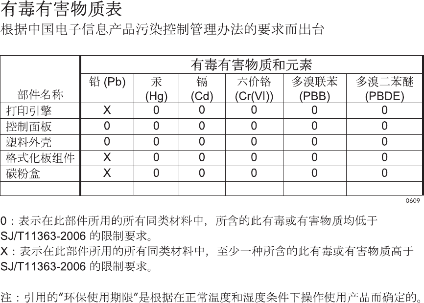
VARO !
Mikäli kirjoittimen suojakotelo avataan, olet alttiina näkymättömällelasersäteilylle laitteen ollessa
toiminnassa. Älä katso säteeseen.
VARNING !
Om laserprinterns skyddshölje öppnas då apparaten är i funktion, utsättas användaren för osynlig
laserstrålning. Betrakta ej strålen.
Tiedot laitteessa käytettävän laserdiodin säteilyominaisuuksista: Aallonpituus 775-795 nm Teho 5 m W
Luokan 3B laser.
GS statement (Germany)
Das Gerät ist nicht für die Benutzung im unmittelbaren Gesichtsfeld am Bildschirmarbeitsplatz
vorgesehen. Um störende Reflexionen am Bildschirmarbeitsplatz zu vermeiden, darf dieses Produkt
nicht im unmittelbaren Gesichtsfeld platziert werden.
Substances Table (China)
Restriction on Hazardous Substances statement (Turkey)
Türkiye Cumhuriyeti: EEE Yönetmeliğine Uygundur
654 Appendix C Regulatory information ENWW

Index
Symbols/Numerics
1 x 500-sheet paper feeder
assembly
components, removing 222
3 x 500-paper feeder assembly
components, removing 236
A
accessories
ordering 552
accessories installed, information
353
acoustic specifications 642
Administration menu, control
panel 261, 365
after-service checklist 86
B
Backup/Restore menu, control
panel 276, 406
bands, troubleshooting 526
batteries included 647
blank pages
troubleshooting 532
blank pages, troubleshooting 525
C
cable, USB
troubleshooting 532
Calibrate/Cleaning menu, control
panel 277, 407
calibration
information, printed 347
process 41
Canadian DOC regulations 652
cartridge
developing unit engagement
and disengagement 36
life detection 36
memory tag 36
ordering 553
part number 553
presence detection 36
toner level detection 36
cartridges
error messages 483
recycling 645
removing 87
replace message 483
warranty 633
cautions iii
characters, troubleshooting 529
checklists
after-service 86
preservice 86
circuit diagram 340
clean the paper path
cleaning page printing 349,
531
cleaning
product 531
color
diagnostic test 354
troubleshooting 347, 527
components
diagnostic tests 314
configuration page 284
configuration pages
information 353
printing 350
connectivity
solving problems 533
control panel
Administration menu 261,
365
assembly, removing 113
Backup/Restore menu 276,
406
Calibrate/Cleaning menu
277, 407
Display Settings menu 269,
384
General Settings menu 261,
367
Manage Supplies menu 270,
385
Manage Trays menu 271,
388
messages, troubleshooting
411
Network Settings menu 272,
391
Print Options menu 267, 382
Print Settings menu 266, 380
Reports menu 261, 365
Service menu 278, 409
Supplies menu 258, 360
Trays menu 260, 363
Troubleshooting menu 275,
401
USB Firmware Upgrade menu
277, 408
control-panel menus
Retrieve From USB Settings
266, 380
retrieve job from device
memory 257, 359
Retrieve Job From USB 257,
358
Sign In 257, 357
conventions, document iii
counts
page, reset 534
reset after replacing formatter
534
See also pages counts
ENWW Index 655
covers
control-panel assembly,
removing 113
front-door assembly, removing
123
identification and location 111
left, removing 115
rear, removing 116
right-door assembly, removing
126
right-front, removing 113
right-rear, removing 119
top, removing 121
creases, troubleshooting 529
crooked pages
troubleshooting 529
customer support
online 639
D
dark image, troubleshooting 525
date
codes for firmware 353
manufacture 352
DC controller
PCA, removing 207
DC controller, operation 9
defeating
interlocks 286
delivery unit
delivery drive assembly (simplex
models), removing 189
demo page 284
determine the problem source
279
developing stage 31
diagnostics
component 314
engine 285
LED 284
networks 396
page, printing 347
See also tests; troubleshooting
diagrams 551
Display Settings menu, control
panel 269, 384
disposal, end-of-life 647
document conventions iii
doors. See covers
driver PCA
removing 218
drum cleaning stage 34
duplex
paper path 63
duplexing unit
duplex drive assembly (duplex
models), removing 187
jam causes 509
E
electrical specifications 642
electrostatic discharge (ESD) 84
end-of-life disposal 647
engine
diagnostics 285
engine speed
paper type 59
engine test button 288
engine-control system 8
envelopes
jams 519
environment, specifications 642
Environmental Product Stewardship
Program 645
error messages, control panel
411
ESD (electrostatic discharge) 84
European Union, waste disposal
647
event log
clear 494
information 353
print 493
view 493
event-log messages 492
F
faded print 525
fans
fuser, removing 201
power-supply fan and fan duct,
removing 198
FCC regulations 644
Finnish laser safety statement 653
firmware
date codes 353
version information 352
firmware, downloading new 547
flowcharts
troubleshooting 280
formatter
case, removing 130
PCA, removing 105
resets after replacing 534
formatter fan
removing 204
formatter lights 284
fuser
jam causes 508
jams 501
motor, removing 196
operation 59
part number 554
fuser drive assembly
removing 172
fusing stage 33
G
General Settings menu, control
panel 261, 367
H
heartbeat LED 285
high-voltage power supply
removing, first transfer 214
removing, imaging
(developing) 213
removing, second transfer 216
HP Customer Care 639
HP Jetdirect print server
configuration page 352
lights 284
humidity requirements 642
humidity values, printed 347
I
ICB PCA
removing 204
image quality
calibration process 41
print, troubleshooting 524
imaging drums
diagnostic test 287
installation
verify for optional accessories
350
interlocks
defeating 286
656 Index ENWW
intermediate transfer belt (ITB)
102
IPv4 information 352
IPv6 information 352
ITB
part number 554
ITB cleaning stage 34
ITB unit
operation 38
J
jams
common causes of 495
detection theory 66
diagnostic test for 288
duplex area 509
envelopes 519
fuser 501
fuser area 508
locations 496
lower right door 503
output bin 507, 508
recovery 515
Tray 1 504
Tray 1 and Tray 2 510
Tray 2 506
Tray 3 506
Tray 3, 4, and 5 513
Tray 4 506
Tray 4, 5, or 6 503
Tray 5 506
Tray 6 506
upper right door 501
Japanese VCCI statement 652
Jetdirect print server
lights 284
K
Korean EMC statement 653
L
laser beam exposure stage 30
laser safety statements 652, 653
laser/scanner
assembly, removing 132
operations 24
LEDs. See lights
left cover, removing 115
license, software 636
lifter-drive assembly
removing 145
light print, troubleshooting 525
lights
formatter 284
troubleshooting with 284
lines, troubleshooting 526
link speed settings 400
loose toner, troubleshooting 528
low-voltage power supply
removing 209
lower right door
jams 503
M
Macintosh
support 639
main drive assembly
removing 157
Manage Supplies menu, control
panel 270, 385
Manage Trays menu, control
panel 271, 388
manual print modes 521
material restrictions 647
Material Safety Data Sheet
(MSDS) 648
memory
information 350
print cartridge 36
supply errors 411
memory chip, print cartridge
description 635
menus, control panel
Administration 261, 365
Backup/Restore 276, 406
Calibrate/Cleaning 277, 407
Display Settings 269, 384
General Settings 261, 367
Manage Supplies 270, 385
Manage Trays 271, 388
Network Settings 272, 391
Print Options 267, 382
Print Settings 266, 380
Reports 261, 365
Service 278, 409
Supplies 258, 360
Trays 260, 363
Troubleshooting 275, 401
USB Firmware Upgrade 277,
408
menus, control-panel
Retrieve From USB Settings
266, 380
retrieve job from device
memory 257, 359
Retrieve Job From USB 257,
358
Sign In 257, 357
mercury-free product 647
messages, control panel 411
model number 352
motors
developing motor, removing
195
developing-disengagement,
removing 197
drum motor, removing 194
fuser, removing 196
ITB, removing 192
paper path 47
N
Network Settings menu, control
panel 272, 391
networks
diagnostics 396
HP embedded Jetdirect
configuration page 352
link speed settings 400
security 391
notes iii
O
online support 639
operating environment
specifications 642
operations
engine-control system 8
laser/scanner 24
print cartridge memory 36
ordering
500-sheet tray 557
print cartridge 553
product documents 552
supplies and accessories 552
output bin
jam causes 508
jams 507
output quality
print, troubleshooting 524
ENWW Index 657
P
pages
blank 532
not printing 532
printing slowly 532
skewed 529
pages count
reset 534
See also counts
paper
pickup assembly, removing
135
stop in path for testing 314
wrinkled 529
paper delivery assembly
removing 184
paper jams
locations 496
paper movement
operation 44
paper path
diagnostic test 288
operation 55
stop movement for testing 314
paper-path
test, sensors 313
parameters, EP, troubleshooting
347
part number
500-sheet tray 557
print cartridge 553
parts 551
parts lists and diagrams
1x500 paper feeder 590
3x500 paper feeder 596
cassette 582
covers, panels, and doors 560
internal components 564,
566, 568, 570, 572, 574,
576, 578, 580
paper delivery assembly 586
paper pick-up assembly 584
printed circuit assemblies 588
right door components 562
using 558
password
Service menu PIN 534
pick-up rollers
part numbers 555
pliers, required 85
port configuration information
352
post-service tests 86
power
consumption 642
power supply
troubleshooting 282
power switch PCA
removing 220
pre-exposure stage 29
pre-troubleshooting checklist 279
preservice checklist 86
primary charging stage 29
primary transfer stage 32
print cartridge
developing unit engagement
and disengagement 36
life detection 36
memory tag 36
ordering 553
part number 553
presence detection 36
toner level detection 36
print cartridges
diagnostic test 287
error messages 483
memory chips 635
recycling 645
removing 87
replace message 483
warranty 633
Print Options menu, control panel
267, 382
print quality
built-in troubleshooting pages
344
manual print modes 521
test 86
test pages 344
troubleshooting 524
Print Quality menu options 521
Print Settings menu, control panel
266, 380
printing
modes, manual 521
stop for testing 314
troubleshooting 532
problem source
determine 279
problem-solving
event-log messages 492
networks 396
product specifications 641
Q
quality
print, troubleshooting 524
R
recycling
HP printing supplies returns and
environmental program 646
regulatory statements
environmental product
stewardship program 645
removing parts
1 x 500-sheet paper feeder
assembly 222
3 x 500-sheet paper feeder
assembly 236
cautions for 84
checklists 86
control-panel assembly 113
DC controller PCA 207
delivery drive assembly (simplex
models) 189
developing motor 195
developing-disengagement
motor 197
driver PCA 218
drum motor 194
duplex drive assembly (duplex
models) 187
environmental sensor 221
formatter case 130
formatter fan 204
formatter PCA 105
front-door assembly 123
fuser 93
fuser drive assembly 172
fuser fan 201
fuser gear assembly 176
fuser motor 196
high-voltage power supply, first
transfer 214
high-voltage power supply,
second transfer 216
ICB PCA 204
658 Index ENWW
imaging (developing) high-
voltage power supply 213
intermediate transfer belt 102
ITB motor 192
laser/scanner assembly 132
left cover 115
lifter-drive assembly 145
low-voltage power supply 209
main drive assembly 157
paper delivery assembly 184
paper pickup assembly 135
pickup roller (tray 1) 94
pickup roller (tray 2) 98
power switch PCA 220
power-supply fan and fan
duct 198
print cartridges 87
rear cover 116
registration sensor assembly
142
residual toner full sensor 152
residual-toner-feed assembly
190
right-door assembly 126
right-front cover 113
right-rear cover 119
secondary transfer roller 101
separation pad (Tray 1) 95
separation roller (tray 2) 97
toner-collection unit 91
tools, required 85
top cover 121
replace supplies message 483
replacing
parts 84
Reports menu, control panel 261,
365
Retrieve From USB Settings menu
266, 380
retrieve job from device memory
menu 257, 359
Retrieve Job From USB menu 257,
358
roller
pickup roller (Tray 1),
removing 94
pickup roller (Tray 2),
removing 98
rollers
separation roller (Tray 2),
removing 97
S
safety statements 652, 653
screwdrivers, required 85
screws
replacing 84
secondary transfer roller
part number 554
secondary transfer roller,
removing 101
secondary transfer stage 32
security
settings 391
security settings information 352
sensor tests manual
developer alienation sensor
(PS11) 298
front-door opening/closing
switch (PS14) 291
fuser loop sensors 1 and 2 (PS7
and PS8) 295
fuser output sensor (PS 6) 297
fuser pressure-release sensor
(PS9) 296
ITB alienation switch (SW5)
299
output-bin-full sensor (PS10)
313
right-door opening/closing
sensor (PS15) 292
TOP sensor (PS5) 294
tray 3 paper size sensors (SW2
and SW3) 308
tray 4 paper size sensors (SW2
and SW3) 311
sensor tests manual tray/bin
tray 1 paper sensor (PS2) 302
tray 2 paper sensor (PS1) 303
tray 2 paper size switches
(SW7 and SW8) 305
tray 2 paper surface (PS4)
304
tray 3 door opening/closing
sensor (SW1) 310
tray 3 feed sensor (SR1) 309
tray 3 paper sensor (SR1) 307
tray 3 paper sensor (SR3) 306
tray 4 door opening/closing
door sensor (SW1) 311
tray 4 feed sensor (X) 311
tray 4 paper sensor (SR3) 311
tray 4 paper surface sensor
(SR2) 311
tray 5 door opening/closing
sensor (SW1) 312
tray 5 feed sensor (SR81) 312
tray 5 paper sensor (SR83)
312
tray 5 paper size sensors
(SW82 and SW83) 312
tray 5 paper surface sensor
(SR82) 312
tray 6 door opening/closing
sensor (SW1) 312
tray 6 feed sensor (SR91) 312
tray 6 paper sensor (SR93)
312
tray 6 paper size sensors
(SW92 and SW93) 312
tray 6 paper surface sensor
(SR92) 312
sensors
diagnostic tests 313
environmental, removing 221
fuser gear assembly,
removing 176
paper path 46
registration sensor assembly,
removing 142
residual toner full sensor,
removing 152
tests, manual 289
tests, manual tray/bin 300
separation stage 33
service
tools, required 85
Service menu options 534
Service menu, control panel 278,
409
Sign In menu 257, 357
skew prevention 57
skewed pages
troubleshooting 529
smeared toner, troubleshooting
529
ENWW Index 659
software
software license agreement
636
solenoids
paper path 47
solve problems 253
solving
direct-connect problems 533
network problems 533
specifications
electrical and acoustic 642
operating environment 642
static precautions 84
status page 284
stop printing for test 314
streaks, troubleshooting 526
supplies
error messages 483
memory errors 411
ordering 552
recycling 645
replace message 483
Supplies menu, control panel
258, 360
support
online 639
T
Taiwan EMI statement 653
TCP/IP information 352
technical support
online 639
temperature
values, printed 347
temperature requirements 642
test page
engine 288
tests
color band 354
component tests list and
descriptions (1 of 2) 315
component tests list and
descriptions (2 of 2) 317
disable cartridge check 287
manual sensor 289
networks 396
paper path 288
paper-path sensors 313
post-service 86
print-quality 86
print/stop 314
tray/bin manual sensor 300
text, troubleshooting 529
tips iii
toner
loose, troubleshooting 528
smeared, troubleshooting 529
toner cartridges. See print
cartridges
toner collection unit
part number 555
removing 91
tools, required 85
transfer stage 32
transfer unit
operation 38
Tray 1
jams 504
Tray 2
jams 506
trays
jam causes 510, 513
Trays menu, control panel 260,
363
troubleshooting
about 279
blank pages 532
checklist 254, 279
clean the paper path 349,
531
color 347
configuration page 284
configuration pages for 350
control panel messages 411
demo page 284
direct-connect problems 533
duplexing 520
EP parameters 347
event log 284
flowchart 280
jams in duplex area 509
jams in fuser area 508
jams in output bin 508
jams in Tray 1 and Tray 2
510
jams in Tray 3, 4, and 5 513
lights, using 284
lines, printed pages 526
network problems 533
pages not printing 532
pages printing slowly 532
power 282
print quality 524
problem source 279
reports and tools 284
skewed pages 529
status page 284
text 529
toner smear 529
transparencies 518
USB cables 532
wrinkles 529
See also diagnostics
Troubleshooting menu, control
panel 275, 401
U
updates, downloading product
547
upper right door
jams 501
USB Firmware Upgrade menu,
control panel 277, 408
USB port
troubleshooting 532
V
version, hardware firmware 352
vertical lines, troubleshooting 526
W
warnings iii
warranty
customer self repair 638
license 636
print cartridges 633
product 632
Web sites
customer support 639
Macintosh customer support
639
Material Safety Data Sheet
(MSDS) 648
white spots, troubleshooting 526
wiring diagram 340
wrinkles, troubleshooting 529
660 Index ENWW

© 2010 Hewlett-Packard Development Company, L.P.
www.hp.com
*CE707-90935*
*CE707-90935*
CE707-90935
