Hp Storageworks Carrier Grade Modular Smart Array 2324Fc Users Manual 2312fc And User Guide
2324fc to the manual 130c4848-aa45-49a1-b57f-2340ef211d3c
2015-02-09
: Hp Hp-Hp-Storageworks-Carrier-Grade-Modular-Smart-Array-2324Fc-Users-Manual-548301 hp-hp-storageworks-carrier-grade-modular-smart-array-2324fc-users-manual-548301 hp pdf
Open the PDF directly: View PDF ![]() .
.
Page Count: 80
- HP StorageWorks Carrier-Grade 2324fc Modular Smart Array user guide
- Table of contents
- About this guide
- Overview
- Components
- Installing the enclosures
- Connecting hosts
- Basic operation
- LED descriptions
- Configuring a system for the first time
- Troubleshooting
- Parts catalog
- Environmental requirements and specifications
- Electrostatic discharge
- Regulatory compliance and safety
- Index

HP StorageWorks
Carrier-Grade 2324fc Modular Smart Array
user guide
Part number: 5991-8050
second edition: March 2009

Legal and notice information
© Copyright 2008-2009 Hewlett-Packard Development Company, L.P.
The information combined herein is subject to change without notice. The only warranties for HP products and services are set forth in the express
warranty statements accompanying such products and services. Nothing herein should be construed as constituting an additional warranty. HP shall
not be liable for technical or editorial errors or omissions contained herein.
Microsoft, Windows, Windows NT, and Windows XP are U.S. registered trademarks of Microsoft Corporation.
UNIX® is a registered trademark of The Open Group.
WARRANTY STATEMENT: To obtain a copy of the warranty for this product, see the warranty information website:
http://www.hp.com/go/storagewarranty.

HP StorageWorks 2324fc Modular Smart Array user guide 3
About this guide. . . . . . . . . . . . . . . . . . . . . . . . . . . . . . . . . . . . . . . . . . . . . . . . . . . . . . 11
Intended audience . . . . . . . . . . . . . . . . . . . . . . . . . . . . . . . . . . . . . . . . . . . . . . . . . . . . . . . . . . . . . . 11
Prerequisites. . . . . . . . . . . . . . . . . . . . . . . . . . . . . . . . . . . . . . . . . . . . . . . . . . . . . . . . . . . . . . . . . . . 11
Related documentation . . . . . . . . . . . . . . . . . . . . . . . . . . . . . . . . . . . . . . . . . . . . . . . . . . . . . . . . . . . 11
Document conventions and symbols . . . . . . . . . . . . . . . . . . . . . . . . . . . . . . . . . . . . . . . . . . . . . . . . . . 11
Rack stability . . . . . . . . . . . . . . . . . . . . . . . . . . . . . . . . . . . . . . . . . . . . . . . . . . . . . . . . . . . . . . . . . . 12
HP technical support . . . . . . . . . . . . . . . . . . . . . . . . . . . . . . . . . . . . . . . . . . . . . . . . . . . . . . . . . . . . . 12
Customer self repair . . . . . . . . . . . . . . . . . . . . . . . . . . . . . . . . . . . . . . . . . . . . . . . . . . . . . . . . . . . . . 12
Product warranties . . . . . . . . . . . . . . . . . . . . . . . . . . . . . . . . . . . . . . . . . . . . . . . . . . . . . . . . . . . . . . 13
Subscription service . . . . . . . . . . . . . . . . . . . . . . . . . . . . . . . . . . . . . . . . . . . . . . . . . . . . . . . . . . . . . 13
HP web sites . . . . . . . . . . . . . . . . . . . . . . . . . . . . . . . . . . . . . . . . . . . . . . . . . . . . . . . . . . . . . . . . . . 13
Documentation feedback . . . . . . . . . . . . . . . . . . . . . . . . . . . . . . . . . . . . . . . . . . . . . . . . . . . . . . . . . . 13
1 Overview . . . . . . . . . . . . . . . . . . . . . . . . . . . . . . . . . . . . . . . . . . . . . . . . . . . . . . . . 15
Features and benefits . . . . . . . . . . . . . . . . . . . . . . . . . . . . . . . . . . . . . . . . . . . . . . . . . . . . . . . . . . . . 15
2 Components . . . . . . . . . . . . . . . . . . . . . . . . . . . . . . . . . . . . . . . . . . . . . . . . . . . . . . 17
Front panel components . . . . . . . . . . . . . . . . . . . . . . . . . . . . . . . . . . . . . . . . . . . . . . . . . . . . . . . . . . 17
MSA2324fc . . . . . . . . . . . . . . . . . . . . . . . . . . . . . . . . . . . . . . . . . . . . . . . . . . . . . . . . . . . . . . . . 17
Hard drive bay numbers . . . . . . . . . . . . . . . . . . . . . . . . . . . . . . . . . . . . . . . . . . . . . . . . . . . . . . . . . . 18
Rear panel components . . . . . . . . . . . . . . . . . . . . . . . . . . . . . . . . . . . . . . . . . . . . . . . . . . . . . . . . . . 18
MSA2324fc . . . . . . . . . . . . . . . . . . . . . . . . . . . . . . . . . . . . . . . . . . . . . . . . . . . . . . . . . . . . . . . . 18
MSA2000 3.5 12-drive enclosure . . . . . . . . . . . . . . . . . . . . . . . . . . . . . . . . . . . . . . . . . . . . . . . . . . . 19
Cache . . . . . . . . . . . . . . . . . . . . . . . . . . . . . . . . . . . . . . . . . . . . . . . . . . . . . . . . . . . . . . . . . . . . . . . 19
Transportable CompactFlash . . . . . . . . . . . . . . . . . . . . . . . . . . . . . . . . . . . . . . . . . . . . . . . . . . . . . . . 19
Super-capacitor pack . . . . . . . . . . . . . . . . . . . . . . . . . . . . . . . . . . . . . . . . . . . . . . . . . . . . . . . . . . . . 20
3 Installing the enclosures. . . . . . . . . . . . . . . . . . . . . . . . . . . . . . . . . . . . . . . . . . . . . . . 21
Installation checklist . . . . . . . . . . . . . . . . . . . . . . . . . . . . . . . . . . . . . . . . . . . . . . . . . . . . . . . . . . . . . 21
Connecting controller and MSA2000 3.5 12-drive enclosures . . . . . . . . . . . . . . . . . . . . . . . . . . . . . . . . 22
Testing enclosure connections . . . . . . . . . . . . . . . . . . . . . . . . . . . . . . . . . . . . . . . . . . . . . . . . . . . . . . 24
Obtaining IP values. . . . . . . . . . . . . . . . . . . . . . . . . . . . . . . . . . . . . . . . . . . . . . . . . . . . . . . . . . . . . . 24
Setting management port IP addresses using DHCP . . . . . . . . . . . . . . . . . . . . . . . . . . . . . . . . . . . . . 24
Setting management port IP addresses using the CLI. . . . . . . . . . . . . . . . . . . . . . . . . . . . . . . . . . . . . 24
4 Connecting hosts . . . . . . . . . . . . . . . . . . . . . . . . . . . . . . . . . . . . . . . . . . . . . . . . . . . 27
Host system requirements. . . . . . . . . . . . . . . . . . . . . . . . . . . . . . . . . . . . . . . . . . . . . . . . . . . . . . . . . . 27
Connecting the enclosure to data hosts . . . . . . . . . . . . . . . . . . . . . . . . . . . . . . . . . . . . . . . . . . . . . . . . 27
Loop/Point-to-Point Topology . . . . . . . . . . . . . . . . . . . . . . . . . . . . . . . . . . . . . . . . . . . . . . . . . . . . . 27
Connecting direct attach configurations . . . . . . . . . . . . . . . . . . . . . . . . . . . . . . . . . . . . . . . . . . . . . 27
Single controller configuration . . . . . . . . . . . . . . . . . . . . . . . . . . . . . . . . . . . . . . . . . . . . . . . . . 27
One server/one HBA/single path . . . . . . . . . . . . . . . . . . . . . . . . . . . . . . . . . . . . . . . . . . . . 27
Dual controller configurations . . . . . . . . . . . . . . . . . . . . . . . . . . . . . . . . . . . . . . . . . . . . . . . . . . 27
One server/one dual-ported HBA/dual path . . . . . . . . . . . . . . . . . . . . . . . . . . . . . . . . . . . . . 27
Two servers/one dual-ported HBA per server/dual path . . . . . . . . . . . . . . . . . . . . . . . . . . . . . 28
Connecting switch attach configurations . . . . . . . . . . . . . . . . . . . . . . . . . . . . . . . . . . . . . . . . . . . . 28
Two servers/two switches . . . . . . . . . . . . . . . . . . . . . . . . . . . . . . . . . . . . . . . . . . . . . . . . . . 28
Connecting remote management hosts . . . . . . . . . . . . . . . . . . . . . . . . . . . . . . . . . . . . . . . . . . . . . . . . 28
5 Basic operation . . . . . . . . . . . . . . . . . . . . . . . . . . . . . . . . . . . . . . . . . . . . . . . . . . . . 29
Powering on/powering off. . . . . . . . . . . . . . . . . . . . . . . . . . . . . . . . . . . . . . . . . . . . . . . . . . . . . . . . . 29
Updating firmware . . . . . . . . . . . . . . . . . . . . . . . . . . . . . . . . . . . . . . . . . . . . . . . . . . . . . . . . . . . . . . 29
Selecting an appropriate time to perform the online upgrade . . . . . . . . . . . . . . . . . . . . . . . . . . . . . . 29
Contents
4
6 LED descriptions . . . . . . . . . . . . . . . . . . . . . . . . . . . . . . . . . . . . . . . . . . . . . . . . . . . 31
Front panel LEDs. . . . . . . . . . . . . . . . . . . . . . . . . . . . . . . . . . . . . . . . . . . . . . . . . . . . . . . . . . . . . . . . 31
Hard drive LEDs . . . . . . . . . . . . . . . . . . . . . . . . . . . . . . . . . . . . . . . . . . . . . . . . . . . . . . . . . . . . . . . . 32
Rear panel LEDs . . . . . . . . . . . . . . . . . . . . . . . . . . . . . . . . . . . . . . . . . . . . . . . . . . . . . . . . . . . . . . . . 34
MSA2324fc . . . . . . . . . . . . . . . . . . . . . . . . . . . . . . . . . . . . . . . . . . . . . . . . . . . . . . . . . . . . . . . . 34
MSA2000 3.5 12-drive enclosure . . . . . . . . . . . . . . . . . . . . . . . . . . . . . . . . . . . . . . . . . . . . . . . . . 36
Power supply LEDs. . . . . . . . . . . . . . . . . . . . . . . . . . . . . . . . . . . . . . . . . . . . . . . . . . . . . . . . . . . . 37
7 Configuring a system for the first time . . . . . . . . . . . . . . . . . . . . . . . . . . . . . . . . . . . . 39
Configuring your web browser for SMU . . . . . . . . . . . . . . . . . . . . . . . . . . . . . . . . . . . . . . . . . . . . . . . 39
Logging in to SMU from a local management host . . . . . . . . . . . . . . . . . . . . . . . . . . . . . . . . . . . . . . . . 39
Tips for using the main window . . . . . . . . . . . . . . . . . . . . . . . . . . . . . . . . . . . . . . . . . . . . . . . . . . . 39
Tips for using the help window . . . . . . . . . . . . . . . . . . . . . . . . . . . . . . . . . . . . . . . . . . . . . . . . . . . 40
Changing the system date and time . . . . . . . . . . . . . . . . . . . . . . . . . . . . . . . . . . . . . . . . . . . . . . . . . . 40
To use manual date and time settings . . . . . . . . . . . . . . . . . . . . . . . . . . . . . . . . . . . . . . . . . . . . 40
To obtain the date and time from an NTP server . . . . . . . . . . . . . . . . . . . . . . . . . . . . . . . . . . . . . 40
Using the Configuration Wizard. . . . . . . . . . . . . . . . . . . . . . . . . . . . . . . . . . . . . . . . . . . . . . . . . . . . . 41
Using the Provisioning Wizard. . . . . . . . . . . . . . . . . . . . . . . . . . . . . . . . . . . . . . . . . . . . . . . . . . . . . . 42
Testing the configuration . . . . . . . . . . . . . . . . . . . . . . . . . . . . . . . . . . . . . . . . . . . . . . . . . . . . . . . . . . 42
Logging out of SMU . . . . . . . . . . . . . . . . . . . . . . . . . . . . . . . . . . . . . . . . . . . . . . . . . . . . . . . . . . . . . 42
8 Troubleshooting . . . . . . . . . . . . . . . . . . . . . . . . . . . . . . . . . . . . . . . . . . . . . . . . . . . 43
Fault isolation methodology . . . . . . . . . . . . . . . . . . . . . . . . . . . . . . . . . . . . . . . . . . . . . . . . . . . . . . . . 43
Gather fault information . . . . . . . . . . . . . . . . . . . . . . . . . . . . . . . . . . . . . . . . . . . . . . . . . . . . . . . . 43
Determine where the fault is occurring . . . . . . . . . . . . . . . . . . . . . . . . . . . . . . . . . . . . . . . . . . . . . . 43
Review the event logs. . . . . . . . . . . . . . . . . . . . . . . . . . . . . . . . . . . . . . . . . . . . . . . . . . . . . . . . . . 43
Isolate the fault . . . . . . . . . . . . . . . . . . . . . . . . . . . . . . . . . . . . . . . . . . . . . . . . . . . . . . . . . . . . . . 43
If the enclosure does not initialize . . . . . . . . . . . . . . . . . . . . . . . . . . . . . . . . . . . . . . . . . . . . . . . . . 43
Correcting enclosure IDs. . . . . . . . . . . . . . . . . . . . . . . . . . . . . . . . . . . . . . . . . . . . . . . . . . . . . . . . 44
Diagnostic steps . . . . . . . . . . . . . . . . . . . . . . . . . . . . . . . . . . . . . . . . . . . . . . . . . . . . . . . . . . . . . . . . 44
Is the front panel Fault LED amber? . . . . . . . . . . . . . . . . . . . . . . . . . . . . . . . . . . . . . . . . . . . . . . . . 44
Is the controller back panel OK LED off? . . . . . . . . . . . . . . . . . . . . . . . . . . . . . . . . . . . . . . . . . . . . . 44
Is the controller back panel Fault/Service Required LED amber? . . . . . . . . . . . . . . . . . . . . . . . . . . . . 44
Are both drive module LEDs off (Online/Activity and Fault/UID)? . . . . . . . . . . . . . . . . . . . . . . . . . . . 45
Is the drive module Fault/UID LED blinking amber? . . . . . . . . . . . . . . . . . . . . . . . . . . . . . . . . . . . . . 45
Is a connected host port’s Host Link Status LED off? . . . . . . . . . . . . . . . . . . . . . . . . . . . . . . . . . . . . . 45
Is a connected port’s Expansion Port Status LED off?. . . . . . . . . . . . . . . . . . . . . . . . . . . . . . . . . . . . . 46
Is a connected port’s Ethernet link status LED off? . . . . . . . . . . . . . . . . . . . . . . . . . . . . . . . . . . . . . . . 46
Is the power supply’s AC Power Good LED off?. . . . . . . . . . . . . . . . . . . . . . . . . . . . . . . . . . . . . . . . 46
Is the drive enclosure back panel OK LED off?. . . . . . . . . . . . . . . . . . . . . . . . . . . . . . . . . . . . . . . . . 47
Is the drive enclosure Fault/Service Required LED amber?. . . . . . . . . . . . . . . . . . . . . . . . . . . . . . . . . 47
Controller failure in a single-controller configuration . . . . . . . . . . . . . . . . . . . . . . . . . . . . . . . . . . . . . . . 48
If the controller has failed or does not start, is the Cache Status LED on/blinking? . . . . . . . . . . . . . . . . 48
Transporting Cache . . . . . . . . . . . . . . . . . . . . . . . . . . . . . . . . . . . . . . . . . . . . . . . . . . . . . . . . . . . 48
Isolating a host-side connection fault . . . . . . . . . . . . . . . . . . . . . . . . . . . . . . . . . . . . . . . . . . . . . . . . . . 49
Isolating a controller module expansion port connection fault. . . . . . . . . . . . . . . . . . . . . . . . . . . . . . . . . 50
Resolving voltage and temperature warnings . . . . . . . . . . . . . . . . . . . . . . . . . . . . . . . . . . . . . . . . . . . . 50
Sensor locations . . . . . . . . . . . . . . . . . . . . . . . . . . . . . . . . . . . . . . . . . . . . . . . . . . . . . . . . . . . . . 51
Power supply sensors . . . . . . . . . . . . . . . . . . . . . . . . . . . . . . . . . . . . . . . . . . . . . . . . . . . . . . . . . . 51
Cooling fan sensors . . . . . . . . . . . . . . . . . . . . . . . . . . . . . . . . . . . . . . . . . . . . . . . . . . . . . . . . . . . 51
Temperature sensors . . . . . . . . . . . . . . . . . . . . . . . . . . . . . . . . . . . . . . . . . . . . . . . . . . . . . . . . . . 51
Power supply module voltage sensors. . . . . . . . . . . . . . . . . . . . . . . . . . . . . . . . . . . . . . . . . . . . . . . 52
A Parts catalog. . . . . . . . . . . . . . . . . . . . . . . . . . . . . . . . . . . . . . . . . . . . . . . . . . . . . . 53
B Environmental requirements and specifications . . . . . . . . . . . . . . . . . . . . . . . . . . . . . . 61
Safety requirements . . . . . . . . . . . . . . . . . . . . . . . . . . . . . . . . . . . . . . . . . . . . . . . . . . . . . . . . . . . . . 61
Site requirements and guidelines . . . . . . . . . . . . . . . . . . . . . . . . . . . . . . . . . . . . . . . . . . . . . . . . . . . . 61
Site wiring and AC power requirements . . . . . . . . . . . . . . . . . . . . . . . . . . . . . . . . . . . . . . . . . . . . . 61
Site wiring and DC power requirements . . . . . . . . . . . . . . . . . . . . . . . . . . . . . . . . . . . . . . . . . . . . . 61
HP StorageWorks 2324fc Modular Smart Array user guide 5
Weight and placement guidelines . . . . . . . . . . . . . . . . . . . . . . . . . . . . . . . . . . . . . . . . . . . . . . . . . 62
Electrical guidelines . . . . . . . . . . . . . . . . . . . . . . . . . . . . . . . . . . . . . . . . . . . . . . . . . . . . . . . . . . . 62
Ventilation requirements . . . . . . . . . . . . . . . . . . . . . . . . . . . . . . . . . . . . . . . . . . . . . . . . . . . . . . . . 62
Cabling requirements . . . . . . . . . . . . . . . . . . . . . . . . . . . . . . . . . . . . . . . . . . . . . . . . . . . . . . . . . . 62
Management host requirements . . . . . . . . . . . . . . . . . . . . . . . . . . . . . . . . . . . . . . . . . . . . . . . . . . . . . 62
Physical requirements . . . . . . . . . . . . . . . . . . . . . . . . . . . . . . . . . . . . . . . . . . . . . . . . . . . . . . . . . . . . 63
Environmental requirements . . . . . . . . . . . . . . . . . . . . . . . . . . . . . . . . . . . . . . . . . . . . . . . . . . . . . . . . 63
Electrical requirements. . . . . . . . . . . . . . . . . . . . . . . . . . . . . . . . . . . . . . . . . . . . . . . . . . . . . . . . . . . . 64
Site wiring and power requirements . . . . . . . . . . . . . . . . . . . . . . . . . . . . . . . . . . . . . . . . . . . . . . . . 64
Power cord requirements . . . . . . . . . . . . . . . . . . . . . . . . . . . . . . . . . . . . . . . . . . . . . . . . . . . . . . . 64
C Electrostatic discharge . . . . . . . . . . . . . . . . . . . . . . . . . . . . . . . . . . . . . . . . . . . . . . . 65
Preventing electrostatic discharge . . . . . . . . . . . . . . . . . . . . . . . . . . . . . . . . . . . . . . . . . . . . . . . . . . . . 65
Grounding methods to prevent electrostatic discharge. . . . . . . . . . . . . . . . . . . . . . . . . . . . . . . . . . . . . . 65
D Regulatory compliance and safety . . . . . . . . . . . . . . . . . . . . . . . . . . . . . . . . . . . . . . . 67
Regulatory compliance . . . . . . . . . . . . . . . . . . . . . . . . . . . . . . . . . . . . . . . . . . . . . . . . . . . . . . . . . . . 67
Federal Communications Commission notice . . . . . . . . . . . . . . . . . . . . . . . . . . . . . . . . . . . . . . . . . . 67
Class A equipment. . . . . . . . . . . . . . . . . . . . . . . . . . . . . . . . . . . . . . . . . . . . . . . . . . . . . . . . . . . . 67
Class B equipment . . . . . . . . . . . . . . . . . . . . . . . . . . . . . . . . . . . . . . . . . . . . . . . . . . . . . . . . . . . . 67
Declaration of conformity for products marked with the FCC logo, United States only. . . . . . . . . . . . . . 67
Modifications . . . . . . . . . . . . . . . . . . . . . . . . . . . . . . . . . . . . . . . . . . . . . . . . . . . . . . . . . . . . . . . 68
Cables . . . . . . . . . . . . . . . . . . . . . . . . . . . . . . . . . . . . . . . . . . . . . . . . . . . . . . . . . . . . . . . . . . . . 68
Regulatory compliance identification numbers . . . . . . . . . . . . . . . . . . . . . . . . . . . . . . . . . . . . . . . . . 68
Regulatory compliance label location . . . . . . . . . . . . . . . . . . . . . . . . . . . . . . . . . . . . . . . . . . . . . . . 68
Laser device . . . . . . . . . . . . . . . . . . . . . . . . . . . . . . . . . . . . . . . . . . . . . . . . . . . . . . . . . . . . . . . . 68
Laser safety warning . . . . . . . . . . . . . . . . . . . . . . . . . . . . . . . . . . . . . . . . . . . . . . . . . . . . . . . . . . 68
Certification and classification information . . . . . . . . . . . . . . . . . . . . . . . . . . . . . . . . . . . . . . . . . . . 68
Laser product label. . . . . . . . . . . . . . . . . . . . . . . . . . . . . . . . . . . . . . . . . . . . . . . . . . . . . . . . . . . . 69
International notices and statements . . . . . . . . . . . . . . . . . . . . . . . . . . . . . . . . . . . . . . . . . . . . . . . . . . 69
Canadian notice (avis Canadien) . . . . . . . . . . . . . . . . . . . . . . . . . . . . . . . . . . . . . . . . . . . . . . . . . 69
Class A equipment . . . . . . . . . . . . . . . . . . . . . . . . . . . . . . . . . . . . . . . . . . . . . . . . . . . . . . . . . 69
Class B equipment . . . . . . . . . . . . . . . . . . . . . . . . . . . . . . . . . . . . . . . . . . . . . . . . . . . . . . . . . 69
European Union notice . . . . . . . . . . . . . . . . . . . . . . . . . . . . . . . . . . . . . . . . . . . . . . . . . . . . . . . . . 69
BSMI notice . . . . . . . . . . . . . . . . . . . . . . . . . . . . . . . . . . . . . . . . . . . . . . . . . . . . . . . . . . . . . . . . 70
Japanese notice. . . . . . . . . . . . . . . . . . . . . . . . . . . . . . . . . . . . . . . . . . . . . . . . . . . . . . . . . . . . . . 70
Korean notices . . . . . . . . . . . . . . . . . . . . . . . . . . . . . . . . . . . . . . . . . . . . . . . . . . . . . . . . . . . . . . 70
Safety . . . . . . . . . . . . . . . . . . . . . . . . . . . . . . . . . . . . . . . . . . . . . . . . . . . . . . . . . . . . . . . . . . . . . . . 70
Battery replacement notice . . . . . . . . . . . . . . . . . . . . . . . . . . . . . . . . . . . . . . . . . . . . . . . . . . . . . . 70
Taiwan battery recycling notice . . . . . . . . . . . . . . . . . . . . . . . . . . . . . . . . . . . . . . . . . . . . . . . . . . . 71
Power cords . . . . . . . . . . . . . . . . . . . . . . . . . . . . . . . . . . . . . . . . . . . . . . . . . . . . . . . . . . . . . . . . 71
Japanese power cord notice . . . . . . . . . . . . . . . . . . . . . . . . . . . . . . . . . . . . . . . . . . . . . . . . . . . . . 71
Electrostatic discharge . . . . . . . . . . . . . . . . . . . . . . . . . . . . . . . . . . . . . . . . . . . . . . . . . . . . . . . . . 71
Preventing electrostatic damage. . . . . . . . . . . . . . . . . . . . . . . . . . . . . . . . . . . . . . . . . . . . . . . . . . . 71
Grounding methods . . . . . . . . . . . . . . . . . . . . . . . . . . . . . . . . . . . . . . . . . . . . . . . . . . . . . . . . 72
Index . . . . . . . . . . . . . . . . . . . . . . . . . . . . . . . . . . . . . . . . . . . . . . . . . . . . . . . . . . . . . 73
6

HP StorageWorks 2324fc Modular Smart Array user guide 7
Figures
1 Cabling connections between a single-controller enclosure and one MSA2000 3.5 12-drive enclosure 22
2 Cabling connections between a dual-controller enclosure and one MSA2000 3.5 12-drive enclosure . 23
3 Cabling connections between a dual-controller enclosure and up to three MSA2000 3.5 12-drive enclosures
23
4 MSA2312fc exploded view . . . . . . . . . . . . . . . . . . . . . . . . . . . . . . . . . . . . . . . . . . . . . . . . . . . . 54
5 MSA2324fc exploded view . . . . . . . . . . . . . . . . . . . . . . . . . . . . . . . . . . . . . . . . . . . . . . . . . . . . 56
6 MSA2000 3.5 12-drive enclosure exploded view . . . . . . . . . . . . . . . . . . . . . . . . . . . . . . . . . . . . . 58
8

HP StorageWorks 2324fc Modular Smart Array user guide 9
Tables
1 Document conventions . . . . . . . . . . . . . . . . . . . . . . . . . . . . . . . . . . . . . . . . . . . . . . . . . . . . . . . . . 11
2 Installation checklist . . . . . . . . . . . . . . . . . . . . . . . . . . . . . . . . . . . . . . . . . . . . . . . . . . . . . . . . . . . 21
3 Terminal emulator display settings . . . . . . . . . . . . . . . . . . . . . . . . . . . . . . . . . . . . . . . . . . . . . . . . . 25
4 Terminal emulator connection settings. . . . . . . . . . . . . . . . . . . . . . . . . . . . . . . . . . . . . . . . . . . . . . . 25
5 Hard drive LED combinations . . . . . . . . . . . . . . . . . . . . . . . . . . . . . . . . . . . . . . . . . . . . . . . . . . . . 32
6 Power supply sensors . . . . . . . . . . . . . . . . . . . . . . . . . . . . . . . . . . . . . . . . . . . . . . . . . . . . . . . . . . 51
7 Cooling fan sensor descriptions . . . . . . . . . . . . . . . . . . . . . . . . . . . . . . . . . . . . . . . . . . . . . . . . . . . 51
8 Controller module temperature sensors . . . . . . . . . . . . . . . . . . . . . . . . . . . . . . . . . . . . . . . . . . . . . . 51
9 Power supply temperature sensors . . . . . . . . . . . . . . . . . . . . . . . . . . . . . . . . . . . . . . . . . . . . . . . . . 52
10 Voltage sensor descriptions. . . . . . . . . . . . . . . . . . . . . . . . . . . . . . . . . . . . . . . . . . . . . . . . . . . . . . 52
11 MSA2312fc parts list . . . . . . . . . . . . . . . . . . . . . . . . . . . . . . . . . . . . . . . . . . . . . . . . . . . . . . . . . . 54
12 MSA2324fc parts list . . . . . . . . . . . . . . . . . . . . . . . . . . . . . . . . . . . . . . . . . . . . . . . . . . . . . . . . . . 56
13 MSA2000 3.5 12-drive enclosure parts list. . . . . . . . . . . . . . . . . . . . . . . . . . . . . . . . . . . . . . . . . . .58
14 Rackmount enclosure dimensions . . . . . . . . . . . . . . . . . . . . . . . . . . . . . . . . . . . . . . . . . . . . . . . . . . 63
15 Rackmount enclosure weights . . . . . . . . . . . . . . . . . . . . . . . . . . . . . . . . . . . . . . . . . . . . . . . . . . . . 63
16 Operating environmental specifications . . . . . . . . . . . . . . . . . . . . . . . . . . . . . . . . . . . . . . . . . . . . . 63
10
HP StorageWorks Carrier-Grade 2324fc Modular Smart Array user guide 11
About this guide
This guide provides information about the HP StorageWorks 2324fc Modular Smart Array.
Intended audience
This guide is intended for use by system administrators and technicians who are experienced with the
following:
•Direct attach storage (DAS) or storage area network (SAN) management
•Network administration
•Network installation
•Storage system installation and configuration
Prerequisites
Prerequisites for installing and configuring this product include familiarity with:
•Servers and computer networks
•Fibre Channel and Ethernet protocols
Related documentation
In addition to this guide, please refer to other documents for this product:
•HP StorageWorks MSA2000 Family SMU online help
•HP StorageWorks MSA2000 Family CLI online help
•HP StorageWorks MSA2000 Family CLI reference guide
These and other HP documents can be found on the HP documents web site: http://www.hp.com/support/.
Document conventions and symbols
Table 1 Document conventions
Convention Element
Medium blue text: Figure 1 Cross-reference links and e-mail addresses
Medium blue, underlined text
(http://www.hp.com)
Web site addresses
Bold font •Key names
•Text typed into a GUI element, such as into a box
•GUI elements that are clicked or selected, such as menu and list
items, buttons, and check boxes
Italics font Text emphasis
Monospace font •File and directory names
•System output
•Code
•Text typed at the command-line
Monospace, italic font •Code variables
•Command-line variables
Monospace, bold font Emphasis of file and directory names, system output, code, and text
typed at the command line

12
WARNING! Indicates that failure to follow directions could result in bodily harm or death.
CAUTION: Indicates that failure to follow directions could result in damage to equipment or data.
IMPORTANT: Provides clarifying information or specific instructions.
NOTE: Provides additional information.
TIP: Provides helpful hints and shortcuts.
Rack stability
WARNING! To reduce the risk of personal injury or damage to equipment:
•Extend leveling jacks to the floor.
•Ensure that the full weight of the rack rests on the leveling jacks.
•Install stabilizing feet on the rack.
•In multiple-rack installations, secure racks together.
•Extend only one rack component at a time. Racks may become unstable if more than one component is
extended.
HP technical support
Telephone numbers for worldwide technical support are listed on the HP support web site:
http://www.hp.com/support/.
Collect the following information before calling:
•Technical support registration number (if applicable)
•Product serial numbers
•Product model names and numbers
•Applicable error messages
•Operating system type and revision level
•Detailed, specific questions
For continuous quality improvement, calls may be recorded or monitored.
Customer self repair
HP customer self repair (CSR) programs allow you to repair your StorageWorks product. If a CSR part
needs replacing, HP ships the part directly to you so that you can install it at your convenience. Some parts
do not qualify for CSR. Your HP-authorized service provider will determine whether a repair can be
accomplished by CSR.
For more information about CSR, contact your local service provider. For North America, see the CSR
website:
http://www.hp.com/go/selfrepair

HP StorageWorks Carrier-Grade 2324fc Modular Smart Array user guide 13
Product warranties
For information about HP StorageWorks product warranties, see the warranty information website:
http://www.hp.com/go/storagewarranty
Subscription service
HP strongly recommends that customers sign up online using the Subscriber's choice web site:
http://www.hp.com/go/e-updates.
•Subscribing to this service provides you with e-mail updates on the latest product enhancements, newest
versions of drivers, and firmware documentation updates as well as instant access to numerous other
product resources.
•After signing up, you can quickly locate your products by selecting Business support and then Storage
under Product Category.
HP web sites
For other product information, see the following HP web sites:
•http://www.hp.com
•http://www.hp.com/go/storage
•http://www.hp.com/support/
•http://www.docs.hp.com
Documentation feedback
HP welcomes your feedback.
To make comments and suggestions about product documentation, please send a message to
storagedocs.feedback@hp.com. All submissions become the property of HP.
14

HP StorageWorks Carrier-Grade 2324fc Modular Smart Array user guide 15
1Overview
The 2324fc Modular Smart Array is a high-performance storage solution that combines outstanding
performance with high reliability, availability, flexibility, and manageability.
Features and benefits
Product features and supported options include:
•Supported servers
• HP ProLiant servers
• HP ProLiant C-Class Blade servers
•HP Integrity servers
•Certain PA-RISC servers
• Supports most multi-vendor industry standard 32-bit and 64-bit Intel and AMD-based (X86) servers
•Primary supported operating systems
•Microsoft Windows Server
•VMware
•Red Hat Enterprise Linux
•SuSE Linux
•HP-UX
NOTE: Check the QuickSpecs for a complete list of servers. QuickSpecs can be found from your HP MSA
products page at http://www.hp.com/go/msa. Select MSA SAN Arrays, and then select your product.
The link for QuickSpecs will be on the right.
•Capacity up to 99 small form factor (SFF) drives with MSA2324fc and three MSA70 enclosures
•Capacity up to four MSA2000 3.5 12-drive enclosures
•Capacity up to 60 drives in a mixed drive environment: one MSA2324fc (24 SFF) and three MSA2000
3.5 12-drive enclosures (36 LFF)
•Supported drives:
• MSA2 3.5-inch LFF drives:
• 450GB/300GB/146GB 15K RPM DP SAS
• 1TB/750GB/500GB 7.2K RPM DP SATA
• HP ProLiant 2.5-inch SFF drives:
•72GB/36GB 15K RPM SP SAS
•72GB/36GB 15K RPM DP SAS
•146GB/72GB 10K RPM SP SAS
•146GB/72GB 10K RPM DP SAS
• 120GB/60GB 5.4K RPM SATA
•250GB 5.4K RPM SATA
•Two 4-Gb FC ports per controller
• 1-GB cache module per controller
• Battery-free cache backup (with super-capacitor and CompactFlash card)
NOTE: Check the QuickSpecs for an updated list of supported operating systems and drives. QuickSpecs
can be found from your HP MSA products page at http://www.hp.com/go/msa. Select MSA SAN
Arrays, and then select your product. The link for QuickSpecs will be on the right.
16 Overview
HP StorageWorks Carrier-Grade 2324fc Modular Smart Array user guide 17
2Components
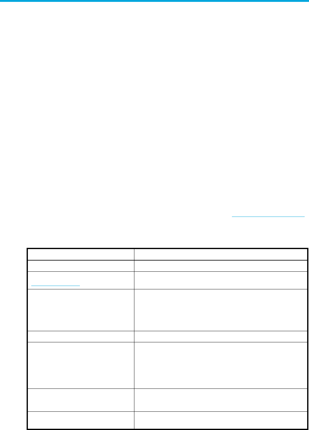
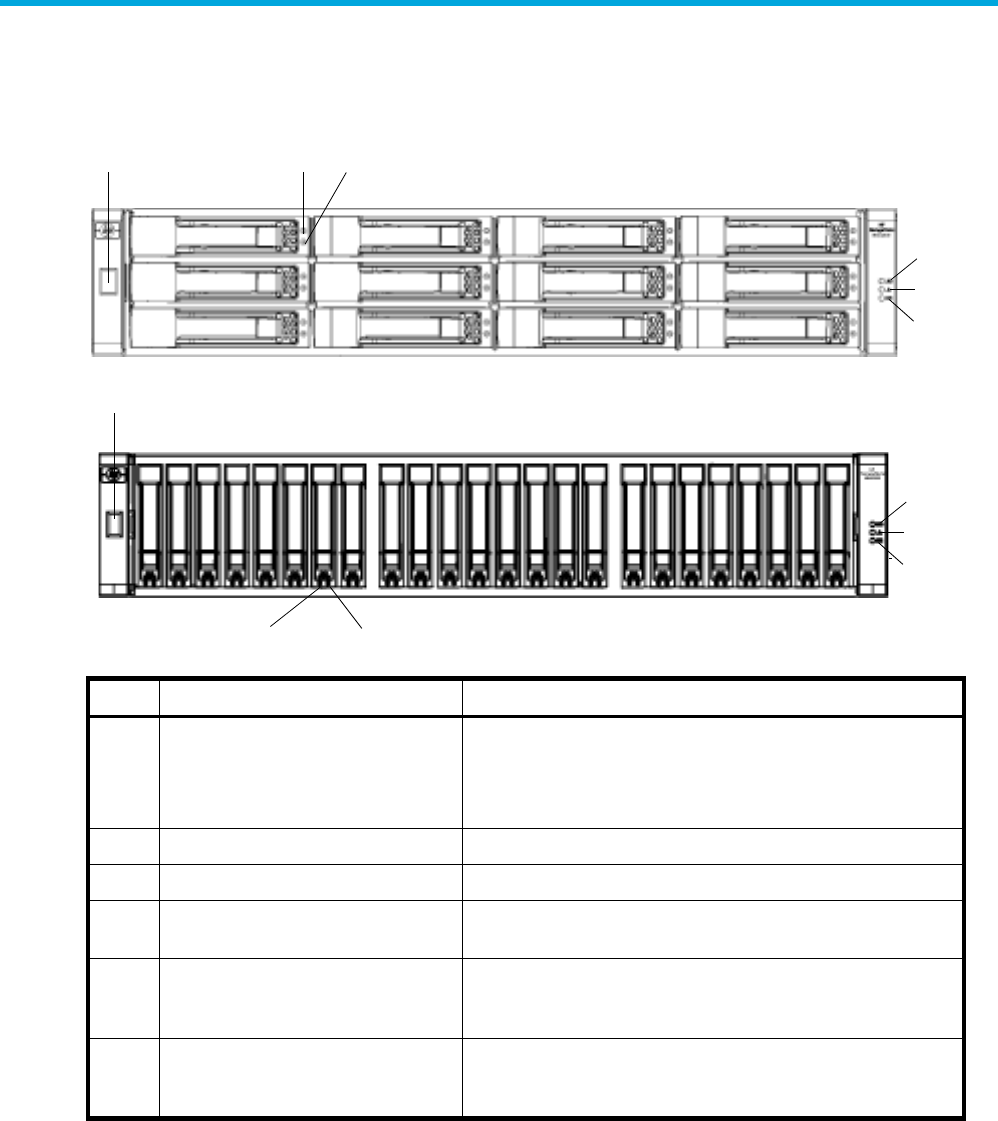
Front panel components
MSA2324fc
1Enclosure ID LED
2Hard drive Online/Activity LED
3Hard drive Fault/UID LED
4Unit Identification (UID) LED
5Fault ID LED
6Heartbeat LED
23
1
4
5
6
18 Components
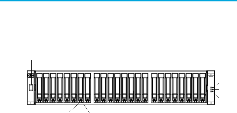
Hard drive bay numbers
MSA2324fc
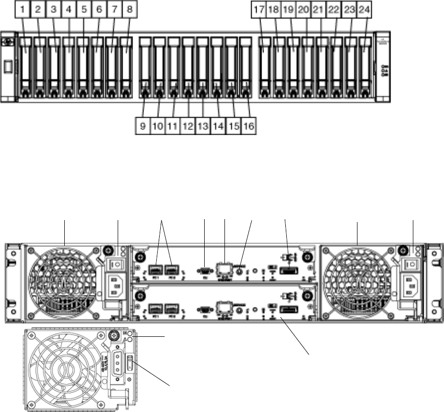
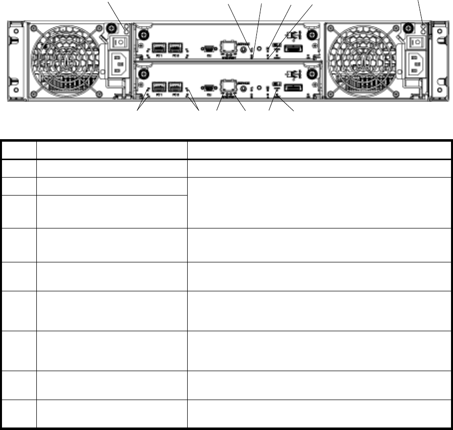
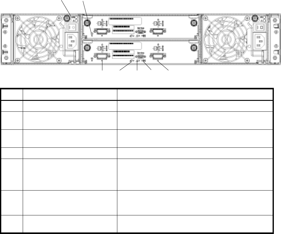
Rear panel components
MSA2324fc
1Power supplies — AC
2Power switches — AC
3Host ports
4CLI port
5Ethernet port
6Service port (used by service personnel only)
7Expansion port
8Optional FC controller
9DC Power supply (2) — (DC model only)
10 Power switches — DC
1234567 1
9
2
8
10
HP StorageWorks Carrier-Grade 2324fc Modular Smart Array user guide 19
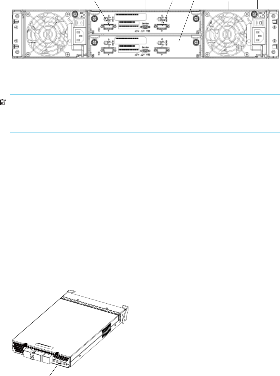
MSA2000 3.5 12-drive enclosure
NOTE: The MSA2324fc can also be attached to an MSA70 that is running firmware version 2.18 or later.
For information about the MSA70, see the HP StorageWorks 70 Modular Smart Array Enclosure user guide
located on the MSA2000 Software Support/Documentation CD shipped with your product or at
http://hp.com/support/manuals.
Cache
To enable faster data access from disk storage, the following two types of caching are performed:
•Posted-write caching. The controller writes user data in the cache memory on the module rather than
directly to the drives. Later, when the storage system is idle, the controller writes the data to the drive
array.
•Read-ahead caching. The controller detects sequential array access, reads ahead into the next
sequence of data, and stores the data in the read-ahead cache. Then, if the next read access is for
cached data, the controller immediately loads the data into the system memory, avoiding the latency of
a disk access.
Transportable CompactFlash
During a power loss or array controller failure, data stored in cache is saved off to non-volatile memory
(CompactFlash). This data is then written to disk after the issue is corrected. To protect against writing
incomplete data to disk, the image stored on the CompactFlash is verified before committing to disk.
In single-controller configurations, if the controller has failed or does not start, and the Cache Status LED is
on or blinking, the CompactFlash will need to be transported to a replacement controller to recover data
not flushed to disk. (See Controller failure in a single-controller configuration for more information.)
1Power supplies
2Power switches
3SAS In port (connects to a controller enclosure)
4Service port (used by service personnel only)
5SAS Out port (connects to another drive enclosure)
6Optional I/O module
13 4 5 12 2
6
CompactFlash

20 Components
CAUTION: To preserve the existing data stored in the CompactFlash, you must transport the
CompactfFash from the failed controller to the replacement controller using a procedure outlined in the HP
StorageWorks 2312fc/2324fc controller replacement instructions, shipped with the replacement controller.
Failure to use this procedure will result in the loss of data stored in the cache module. The CompactFlash
must stay with the same enclosure. If the CompactFlash is used/installed in a different enclosure, data
loss/data corruption will occur.
IMPORTANT: In dual controller configurations, there is no need to transport a failed controller’s cache to
a replacement controller because the cache is duplicated between the controllers.
Super-capacitor pack
To protect RAID controller cache in case of power failure, the MSA2324fc is equipped with super-capacitor
technology. The super-capacitor pack and CompactFlash memory in each controller module provide
unlimited cache memory backup time. The super-capacitor pack provides energy for backing up unwritten
data in the write cache to the CompactFlash in the event of a power failure. Unwritten data in
CompactFlash memory is automatically committed to disk media when power is restored. While the cache
is being maintained by the super-capacitor, the Cache Status LED flashes at a rate of 1/10 second on and
9/10 second off.
HP StorageWorks Carrier-Grade 2324fc Modular Smart Array user guide 21
3Installing the enclosures
Installation checklist
The following table outlines the steps required to install the enclosures and initially configure the system. To
ensure a successful installation, perform the tasks in the order they are presented.
NOTE: For help with installing your MSA2000 product, also see the MSA2000 Software
Support/Documentation CD shipped with your product.
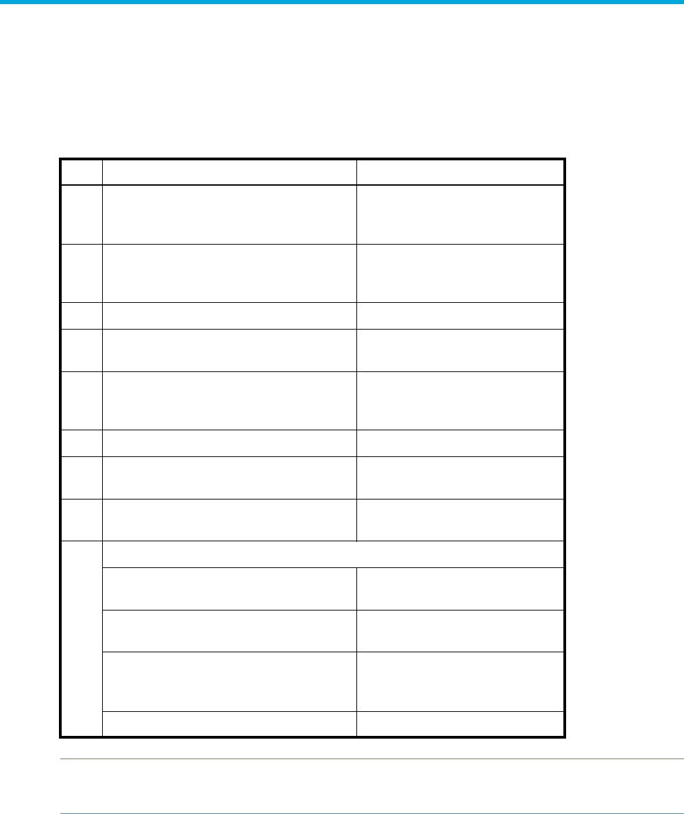
Table 2 Installation checklist
Step Task Where to find procedure
1. Install the controller enclosure and optional
drive enclosures in the rack, and attach ear
caps.
See the racking instructions
poster.
2. Connect enclosures and drive enclosures. See Connecting controller and
MSA2000 3.5 12-drive
enclosures.
3. Connect power cords. See the installation poster.
4. Test enclosure connections. See Testing enclosure
connections.
5. Obtain IP values and set management
port IP properties on the controller
enclosure.
See Obtaining IP values.
6. Install required host software. See Host system requirements.
7. Connect data hosts. See Connecting the enclosure to
data hosts.
8. Connect remote management hosts. See Connecting remote
management hosts.
9. Perform initial configuration tasks:
•Verify that controllers and enclosures
have the latest firmware.
See Updating firmware.
•Set the date and time on the controller
enclosure.
See Changing the system date
and time.
•Initially configure and provision the
system.
See Using the Configuration
Wizard and Using the
Provisioning Wizard.
•Test the configuration. See Testing the configuration.
22 Installing the enclosures
Connecting controller and MSA2000 3.5 12-drive enclosures
You can connect up to three MSA2000 3.5 12-drive enclosures to an MSA2324fc. The cabling diagrams
shown in this section show the recommended fault-tolerant cabling patterns.
IMPORTANT: Connecting an MSA2000 3.5 12-drive enclosure to an MSA2324fc requires mini SAS to
SAS cables. Check the QuickSpecs for an updated list of supported cables. QuickSpecs can be found from
your HP MSA products page at http://www.hp.com/go/msa. Select MSA SAN Arrays, and then select
your product. The link for QuickSpecs is on the right.
IMPORTANT: The MSA2324fc can also be attached to an MSA70 that is running firmware version 2.18 or
later. For information about the MSA70, see the HP StorageWorks 70 Modular Smart Array Enclosure user
guide located on the MSA2000 Software Support/Documentation CD shipped with your product or at
http://hp.com/support/manuals.
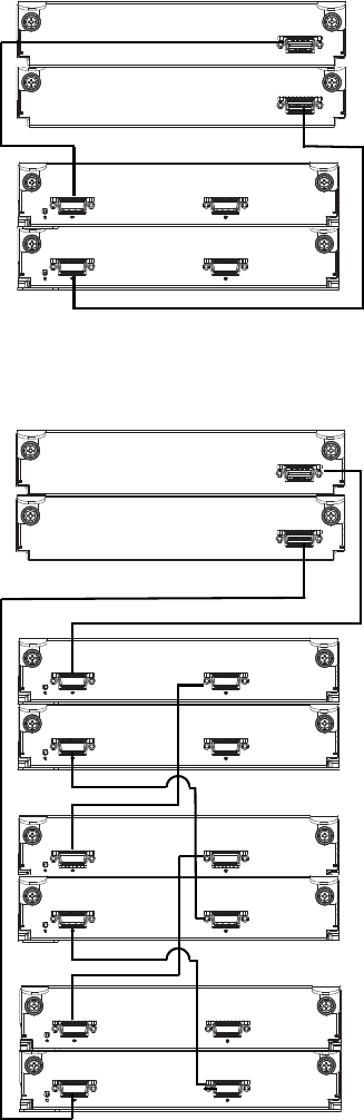
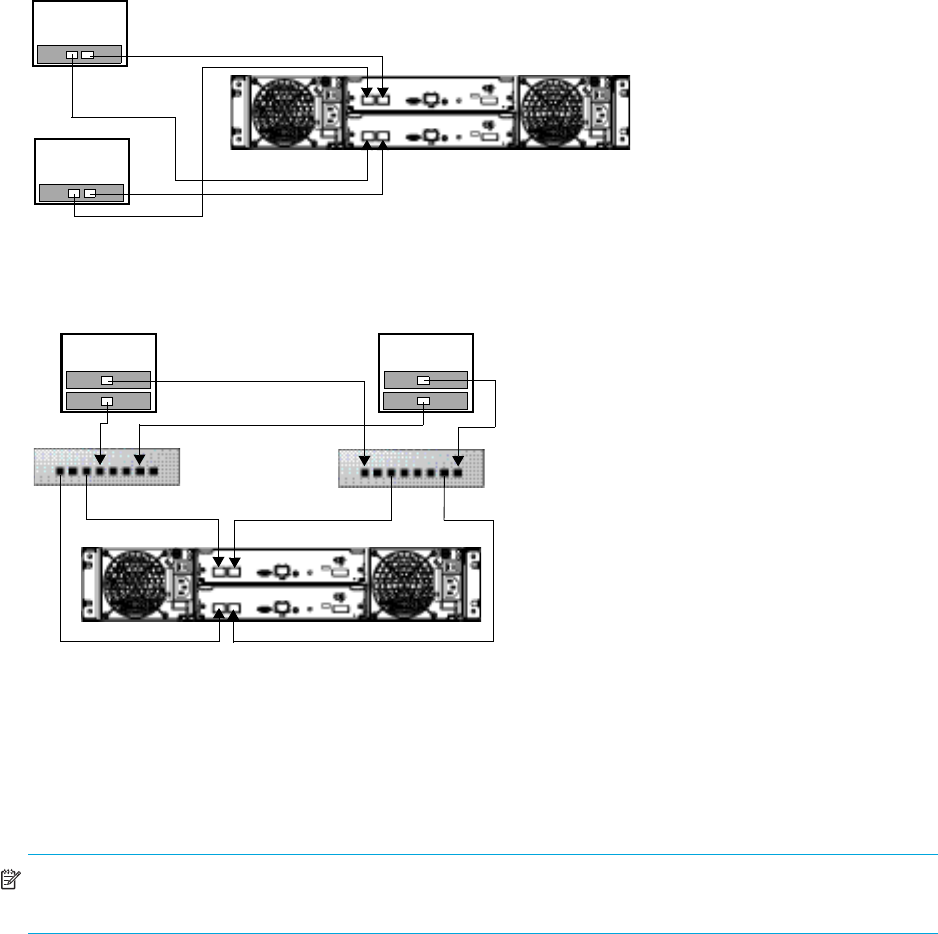
When connecting multiple drive enclosures, use reverse cabling to ensure the highest level of fault
tolerance. Controllers and I/O (expansion) modules are identified by
<enclosure-ID><controller-ID>. For example, Figure 3 shows controller 1A connected to I/O
module 2A, and the chain of connections continuing down. Controller 1B is connected to the lower
module (B) of the last drive enclosure in the chain, with connections moving in the opposite direction.
NOTE: For clarity, the schematic illustrations of the controllers shown in this section show only relevant
details such as expansion ports. For detailed illustrations showing all components, see Rear panel
components.
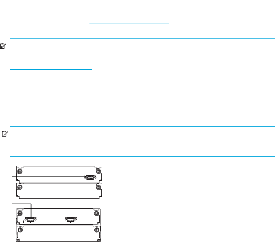
Figure 1 Cabling connections between a single-controller enclosure and one MSA2000 3.5 12-drive
enclosure
In Out
1B
1A
2A
2B
HP StorageWorks Carrier-Grade 2324fc Modular Smart Array user guide 23
Figure 2 Cabling connections between a dual-controller enclosure and one MSA2000 3.5 12-drive
enclosure
Figure 3 Cabling connections between a dual-controller enclosure and up to three MSA2000 3.5 12-drive
enclosures
In Out
In Out
1B
1A
2A
2B
In Out
In Out
1B
1A
In Out
In Out
In Out
In Out
2B
2A
3B
3A
4B
4A

24 Installing the enclosures
Testing enclosure connections
1. Press the power switches at the back of each drive enclosure to On.
IMPORTANT: This ensures that the disks in the enclosures have enough time to completely spin up before
being scanned by the RAID modules in the controller enclosure.
While enclosures power up, their LEDs blink. After the LEDs stop blinking, if no LEDs on the front and
back of the enclosure are amber, the power-on sequence is complete and no faults have been detected.
For a description of LED behavior and status, see LED descriptions.
2. Press the power switches at the back of the controller enclosure to On.
Depending on the number and type of drives in the system, it can take several minutes for the system to
power up.
If the enclosure’s power-on sequence succeeds as described in Step 1, the system is ready to use.
Obtaining IP values
NOTE: For help with configuring your MSA2000 product, also see the MSA2000 Software
Support/Documentation CD shipped with your product.
Setting management port IP addresses using DHCP
1. Look in the DHCP server’s pool of leased addresses for two IP addresses assigned to “HP
StorageWorks MSA Storage.”
2. Use a network management utility to discover “HP StorageWorks MSA2300fc” storage devices on the
local LAN through SNMP.
3. Use a ping broadcast to try to identify the device through the host’s ARP table.
If you do not have a DHCP server, you will need to ask your system administrator to allocate two IP
addresses and set them using the CLI during initial configuration (see Setting management port IP
addresses using the CLI).
Setting management port IP addresses using the CLI
NOTE: If you used DHCP to set the IP addresses, you do not have to set them using the CLI as described
in this section.
Ethernet Management ports on controller module A and controller module B are configured with the
following default values:
•Management Port IP Address: 10.0.0.2 (controller A), 10.0.0.3 (controller B)
•IP Subnet Mask: 255.255.255.0
•Gateway IP Address: 10.0.0.1
If the default IP addresses are not compatible with your network, you must set an IP address for each
management port using the command-line interface (CLI) embedded in each controller module. The CLI
enables you to access the system using RS-232 communication and terminal emulation software.
Use the CLI commands described in the steps below to set the IP address for the Ethernet management port
on each controller module.
Once new IP addresses are set, you can change them as needed using SMU.
NOTE: Changing IP settings can cause management hosts to lose access to the storage system.
HP StorageWorks Carrier-Grade 2324fc Modular Smart Array user guide 25
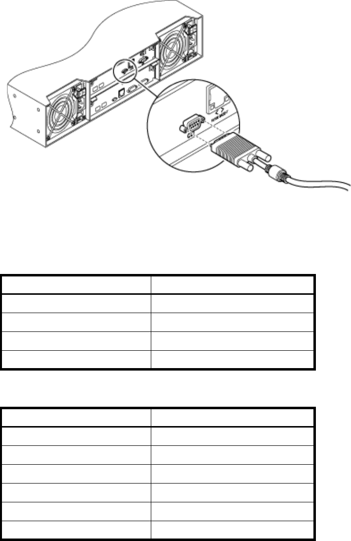
1. From your network administrator obtain an IP address, subnet mask, and gateway address for
controller A and controller B.
2. Use the provided micro-DB9 serial cable to connect controller A to a serial port on a host computer.
Your package contents include a micro-DB9-to-DB9 serial cable. If necessary, use a DB9-to-DB25 adapter
(not included) for connecting the serial cable to a DB25 serial port on the host computer.
3. Start and configure a terminal emulator, such as HyperTerminal or VT-100, using the display settings in
Table 3 and the connection settings in Table 4.
.
4. In the terminal emulator, connect to controller A.
5. Press Enter to display the CLI prompt (#).
Table 3 Terminal emulator display settings
Parameter Value
Terminal emulation mode VT-100 or ANSI (for color support)
Font Terminal
Translations None
Columns 80
Table 4 Terminal emulator connection settings
Parameter Value
Connector COM1 (typically)
Baud rate 115,200
Data bits 8
Parity None
Stop bits 1
Flow control None
26 Installing the enclosures
6. At the prompt, type the following command to set the values you obtained in Step 1 for each Ethernet
management port, first for controller A and then for controller B:
set network-parameters ip address netmask netmask gateway gateway controller a|b
where:
• address is the IP address of the controller
• netmask is the subnet mask
• gateway is the IP address of the subnet router
•a|b specifies the controller whose network parameters you are setting
For example:
# set network-parameters ip 192.168.0.10 netmask 255.255.255.0 gateway
192.168.0.1 controller a
# set network-parameters ip 192.168.0.11 netmask 255.255.255.0 gateway
193.168.0.1 controller b
7. Type the following command to verify the new IP addresses:
show network-parameters
Network parameters, including the IP address, subnet mask, and gateway address are displayed for
each controller.
a. From the CLI you can use the PING command to verify network connectivity
For example:
# ping 16.125.12.1
Info: Pinging 16.125.12.1 with 4 packets.
Success: Command completed successfully. The remote computer responded with 4 packets.
8. Disconnect from the CLI and exit the emulator.
9. In the host computer's command window, type the following command to verify Ethernet connectivity,
first for controller A and then for controller B:
ping IP-address
If you cannot your access your system for at least three minutes after changing the IP
address, your network might require you to restart the management controller using the serial CLI. When
you restart a management controller, communication with it is temporarily lost until it successfully restarts.
Type the following command to restart the management controller on both controllers:
restart mc both
Installing the HP seismic rack mounting kit
To install the HP Seismic Rack Mounting kit, follow these steps:
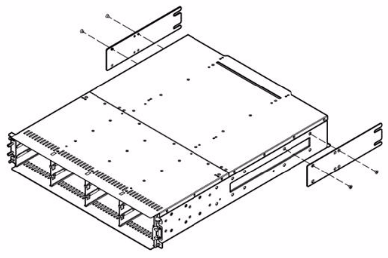
HP StorageWorks Carrier-Grade 2324fc Modular Smart Array user guide 27
1. Attach the rear brackets to the MSA2324 Carrier-Grade (CG).
2. Attach the left bracket assembly to the left rack rail.
3. Attach the right bracket assembly to the right rack rail.
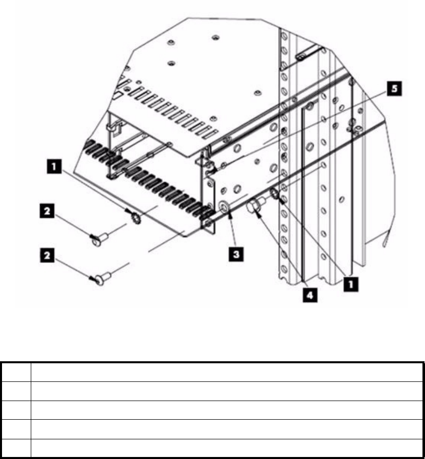
4. Insert cage nuts into the rack holes.
5. Align the MSA2324 CG with the rails, and then slide it into the rack until the ears of the MSA2324CG
are about 1 to 2 inches from the rack front rails.
6. Attach a flat washer between the right mounting ear (bottom hole) and the rack, and then loosely
attach the bracket to the rear bracket assemblies.
7. Attach the single-hole ground cable lug between the front right mounting ear (top hole) and the rack
with a lock washer and screw.
28 Installing the enclosures
Table 5 Callout locations
1Lock washer
2Screw
3Flat washer
4Bolt
5 Ground cable lug. Position between ear and rail (cable not shown).
HP StorageWorks Carrier-Grade 2324fc Modular Smart Array user guide 29
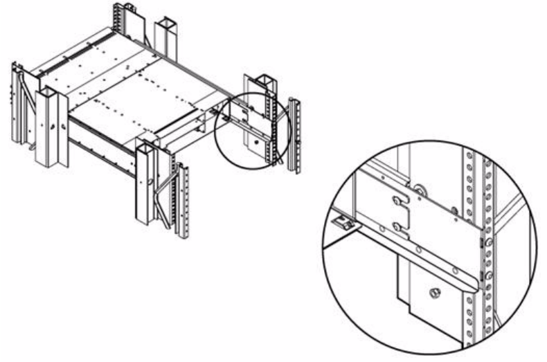
8. Loosely attach the rear brackets to the rear bracket assemblies.
9. Attach the loose end of the ground cable to the front rack ground rail.
10. Verify that the MSA2324 CG is evenly spaced between the right and left rack rails, and then tighten the
front and rear bracket screws.
30 Installing the enclosures
HP StorageWorks Carrier-Grade 2324fc Modular Smart Array user guide 27
4 Connecting hosts
Host system requirements
Data hosts connected to MSA2324fc arrays must meet the following requirements:
•Depending on your system configuration, data host operating systems may require that multipathing is
supported.
If fault tolerance is required, then multipathing software may be required. Host-based multipath
software should be used in any configuration where two logical paths between the host and any
storage volume may exist at the same time. This would include most configurations where there are
multiple connections to the host or multiple connections between a switch and the storage.
To obtain the MSA2000 Family MPIO DSM, go to the HP MSA products page at
http://www.hp.com/go/msa. Select MSA SAN Arrays, select your product, and go to Related
products.
•To prevent Microsoft Windows 2003 data hosts from displaying the Found New Hardware Wizard
when the storage system is discovered, install the MSA2000 Family SCSI Enclosure Services driver.
Download MSA2000 Family SCSI Enclosure Services (SES) driver package from
http://www.hp.com/go/msa. Select MSA SAN Arrays, select your product, and go to Related
products.
NOTE: The MSA2000 Family SCSI Enclosure Services driver is required for Microsoft Windows 2003.
Connecting the enclosure to data hosts
Cable connections vary depending on configuration. Common cable configurations are shown in this
section. For a complete list of supported configurations, go to the MSA2000 product site at
http://hp.com/support/manuals for the latest MSA2000 supported cable configurations guide. This
document is updated whenever newly supported configurations are added.
Loop/Point-to-Point Topology
The 2324fc Modular Smart Array uses Fibre Channel Arbitrated Loop (loop) topology by default.
Point-to-point topology is supported for switch attach configurations only.
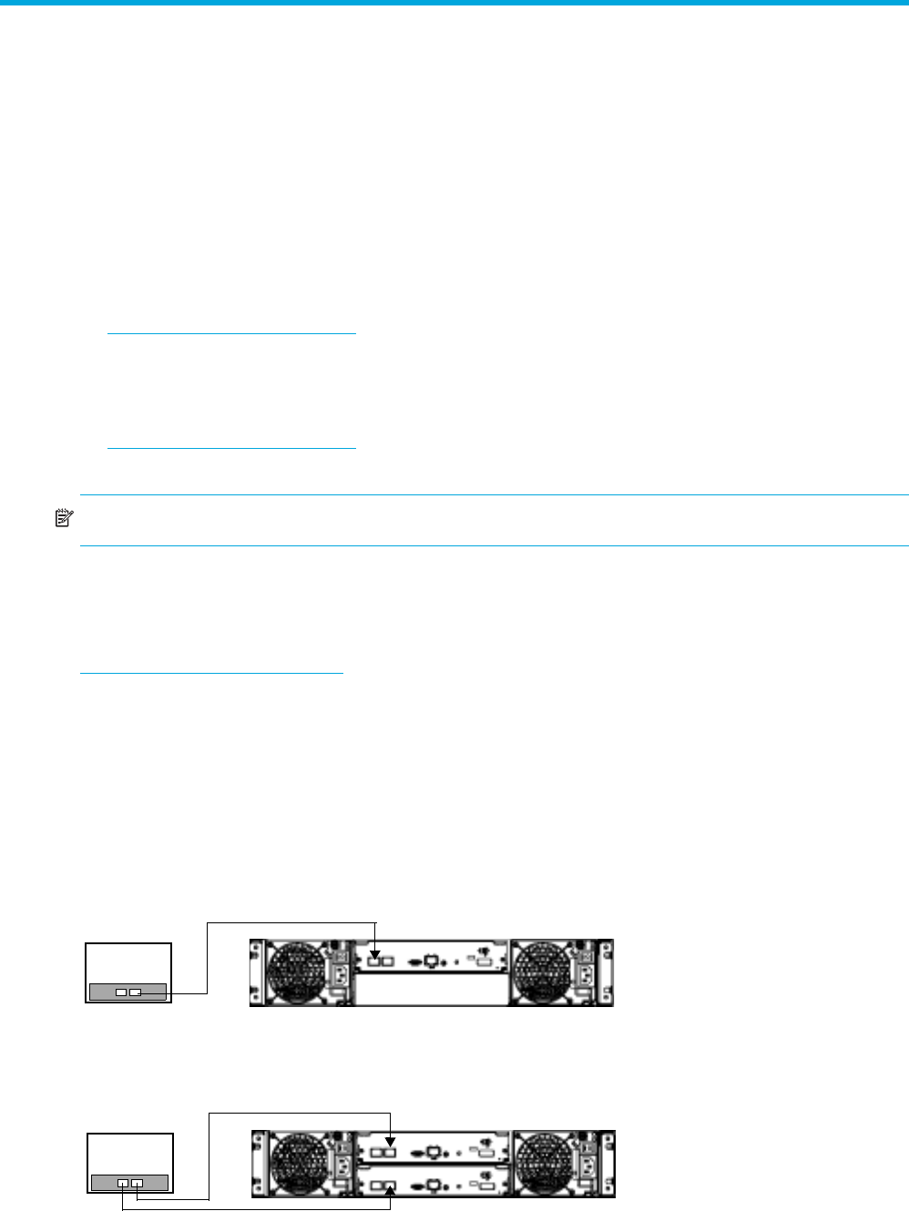
Connecting direct attach configurations
Single controller configuration
One server/one HBA/single path
Dual controller configurations
One server/one dual-ported HBA/dual path
Server 1
Server 1
28 Connecting hosts
Two servers/one dual-ported HBA per server/dual path
Connecting switch attach configurations
Two servers/two switches
Connecting remote management hosts
The management host directly manages systems out-of-band over an Ethernet network.
1. Connect an Ethernet cable to the Ethernet management port on each controller.
2. Connect the other end of each Ethernet cable to a network that your management host can access
(preferably on the same subnet).
NOTE: Connections to this device must be made with shielded cables with metallic RFI/EMI connector
hoods in order to maintain compliance with FCC Rules and Regulations.
Server 1
Server 2
Server 1 Server 2

HP StorageWorks Carrier-Grade 2324fc Modular Smart Array user guide 29
5 Basic operation
Powering on/powering off
Before powering on the enclosure for the first time:
•Install all hard drives in the enclosure so that the connected host controller can identify and configure
them at power-up.
•Connect the cables and power cords to the enclosure as explained in the Installation Poster.
•Generally when powering up, make sure to power up the enclosures and associated data host in the
following order:
•Drive enclosures first
• Controller enclosure next
• Data hosts last (if they are powered down for maintenance purposes)
To power on the system:
1. Press the power switches at the back of each drive enclosure to the On position.
2. Press the power switches at the back of the controller enclosure to the On position.
To power off the system:
1. Stop all I/O from hosts to the system.
2. Use SMU to shut down both controllers. See the SMU online help or CLI reference guide for information
on shutting down controller.s
Wait until SMU indicates that processing is complete.
3. Press the power switches at the back of the controller enclosure to the Off position.
4. Press the power switches at the back of each drive enclosure to the Off position.
Updating firmware
After installing the hardware and powering up the enclosure for the first time, be sure to verify that the
controllers and drive enclosures have the latest firmware. SMU enables you to view the software, hardware,
and other version information for each controller and the enclosures.
To view controller version information, in the Configuration View panel, right-click the system, select View >
Overview, and select the Versions button in the System Overview Table. To view drive enclosure
information, in the Configuration View panel, right-click the enclosure and select View > Overview. The
enclosure firmware is listed as EMP A Revision and EMP B Revision.
For software and firmware updates, including language packages and firmware update instructions, go to
http://www.hp.com/go/msa. Select MSA SAN Arrays, select your product, and go to Support.
Selecting an appropriate time to perform the online upgrade
To ensure the success of an online upgrade, selecting the appropriate time is essential. Selecting a period
of low I/O activity will ensure the upgrade completes as quickly as possible, and will avoid disruptions to
host and applications due to timeouts. Attempting to upgrade a storage system that is in the middle of
processing a large I/O intensive batch job will likely cause hosts to lose connectivity with the storage
system. Consequently, finding an appropriate time for the upgrade is very important.
For software and firmware updates, go to http://www.hp.com/go/msa. Select MSA SAN Arrays, select
your product, and go to Support.
For detailed steps on updating the firmware, see the reference guide or the CLI reference guide.
For information on logging into SMU, see Configuring a system for the first time.
30 Basic operation
HP StorageWorks Carrier-Grade 2324fc Modular Smart Array user guide 31
6 LED descriptions
Front panel LEDs
LED Description Definition
1 Enclosure ID Green — On
Enables you to correlate the enclosure with logical views
presented by management software. The enclosure ID for a
controller enclosure is 1.
2 Fault UID See Table 5, Hard drive LED combinations
3 Online/Activity See Table 5, Hard drive LED combinations
4 Unit Identification (UID) Blue — Identified
Off — Not identified
5 Fault ID Amber — Fault condition exists. The event has been
acknowledged but the problem needs attention.
Off — No fault condition exists.
6 Heartbeat Green — The enclosure is powered on with at least one power
supply operating normally.
Off — Both power supplies are off; the system is powered off.
123
4
5
6
1
4
5
6
32
32 LED descriptions
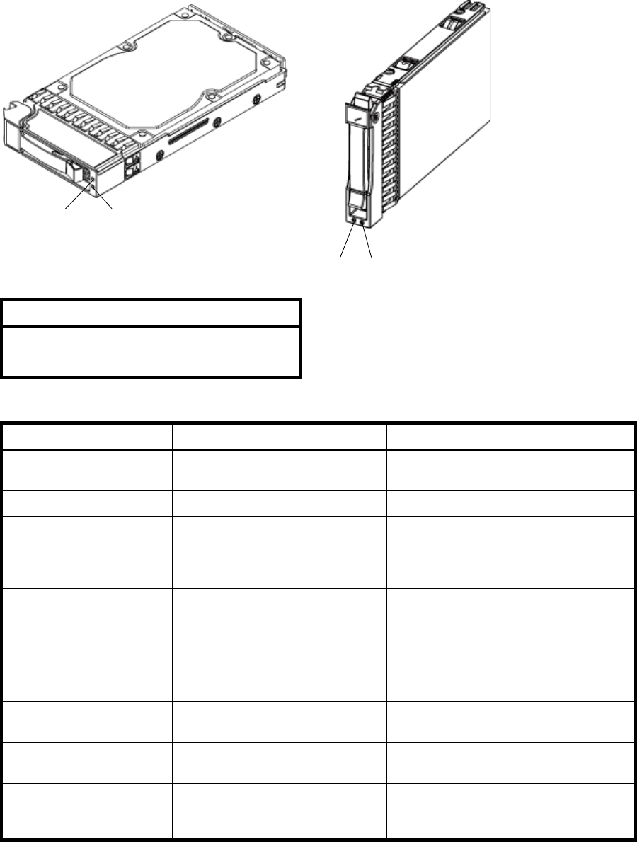
Hard drive LEDs
LED Description
1 Fault/UID (amber/blue)
2Online/Activity (green)
Table 5 Hard drive LED combinations
Online/Activity (green) Fault/UID (amber/blue) Description
On Off Normal operation. The drive is online, but it
is not currently active.
Blinking irregularly Off The drive is active and operating normally.
Off Amber; blinking regularly (1 Hz) Offline; the drive is not being accessed. A
predictive failure alert may have been
received for this device. Further
investigation is required.
On Amber; blinking regularly (1 Hz) Online; no activity. A predictive failure alert
may have been received for this device.
Further investigation is required.
Blinking irregularly Amber; blinking regularly (1 Hz) The drive is active, but a predictive failure
alert may have been received for this drive.
Further investigation is required.
Off Amber; solid Offline; no activity. A critical fault condition
has been identified for this drive.
Off Blue; solid Offline. The drive has been selected by a
management application (SMU).
On or blinking Blue; solid The controller is driving I/O to the drive,
and it has been selected by a management
application (SMU).
12
12

HP StorageWorks Carrier-Grade 2324fc Modular Smart Array user guide 33
Blinking regularly (1 Hz) Off
CAUTION: Do not remove the drive.
Removing a drive may terminate
the current operation and cause
data loss. The drive is rebuilding.
Off Off Either there is no power, the drive is offline,
or the drive is not configured.
Table 5 Hard drive LED combinations (continued)
Online/Activity (green) Fault/UID (amber/blue) Description
34 LED descriptions
Rear panel LEDs
MSA2324fc
LED Description Definition
1 Power supply LEDs See Power supply LEDs.
2 Host Link Status/Activity FC port 1 Blinking green (1 Hz) — No link is detected.
2G LED illuminates green — Link speed is 2 Gbit/sec.
4G LED illuminates green — Link speed is 4 Gbit/sec.
Both LEDs off — Link speed is 1 Gbit/sec.
3 Host Link Status/Activity FC port 2
4 OK to Remove Off — The controller module is not prepared for removal.
Blue — The controller module is prepared for removal.
5 Unit Locator Off — Normal operation
Blinking white— Physically identifies the controller module.
6 OK Green — Controller module is operating normally.
Blinking green — System is booting.
Off — Controller module is not OK.
7 Fault/Service Required Amber — A fault has been detected or a service action is required.
Blinking amber — Hardware-controlled powerup or a cache flush
or restore error.
8 Ethernet Link Status Green — The Ethernet link is up.
Off — The Ethernet port is not connected or the link is down.
9 Ethernet Activity Blinking green — The Ethernet link has I/O activity.
Off — The Ethernet link has no I/O activity.
1
2
456
7
8
3 9 10
1
11

HP StorageWorks Carrier-Grade 2324fc Modular Smart Array user guide 35
10 Cache Status Green — Cache is dirty (contains unwritten data) and operation is
normal.
Off — In a working controller, cache is clean (contains no
unwritten data).
Blinking green — A CompactFlash flush or cache self-refresh is in
progress. Indicates cache activity. (See also If the controller has
failed or does not start, is the Cache Status LED on/blinking?)
If the LED is blinking evenly, a cache flush is in progress. When a
controller module loses power and write cache is dirty (contains
data that has not been written to disk), the super-capacitor pack
provides backup power to flush (copy) data from write cache to
Compact Flash memory. When cache flush is complete, the cache
transitions into self-refresh mode.
If the LED is blinking momentarily slowly, the cache is in a
self-refresh mode. In self-refresh mode, if primary power is restored
before the backup power is depleted (3–30 minutes, depending on
various factors), the system boots, finds data preserved in cache,
and writes it to disk. This means the system can be operational
within 30 seconds, and before the typical host I/O timeout of 60
seconds at which point system failure would cause host-application
failure. If primary power is restored after the backup power is
depleted, the system boots and restores data to cache from
Compact Flash, which can take about 90 seconds.
The cache flush and self-refresh mechanism is an important data
protection feature; essentially four copies of user data are
preserved: one in each controller’s cache and one in each
controller’s CompactFlash.
11 Host Activity Blinking green — At least one host port has I/O activity.
Off — Host ports have no activity.
LED Description Definition
36 LED descriptions
MSA2000 3.5 12-drive enclosure
LED Description Definition
1 Power supply LEDs See Power supply LEDs.
2 Unit Locator Off — Normal operation
Blinking white— Physically identifies the expansion module.
3 SAS In Port Status Green — Port link is up and connected
Off — Port is empty or link is down
4 OK to Remove Not implemented
5 Fault/Service Required Amber — A fault has been detected or a service action is
required
Blinking amber — Hardware-controlled powerup or a cache
flush or restore error
6 OK Green — Expansion module is operating normally
Blinking green — System is booting
Off — Expansion module is not OK
7 SAS Out Port Status Green — Port link is up and connected
Off — Port is empty or link is down
1 2
4
356 7
HP StorageWorks Carrier-Grade 2324fc Modular Smart Array user guide 37
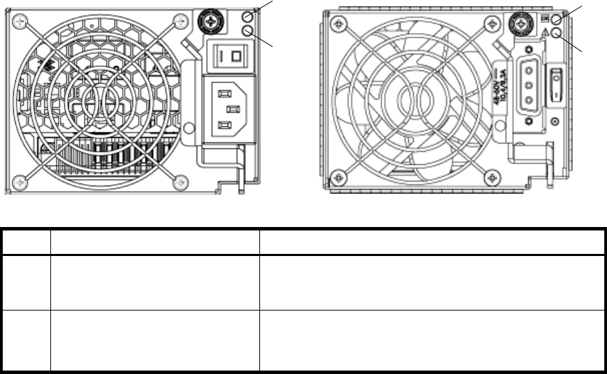
Power supply LEDs
Power redundancy is achieved through two independent load-sharing power supplies. In the event of a
power supply failure, or the failure of the power source, the storage system can operate continuously on a
single power supply. Greater redundancy can be achieved by connecting the power supplies to separate
circuits.
AC model DC model
LED Description Definition
1 Input Source Power good Green — Power is on and input voltage is normal.
Off — Power is off or input voltage is below the minimum
threshold.
2 DC Voltage/Fan Fault/Service
Required
Amber — DC output voltage is out of range or a fan is
operating below the minimum required RPM.
Off— DC output voltage is normal.
1
2
1
2
38 LED descriptions

HP StorageWorks Carrier-Grade 2324fc Modular Smart Array user guide 39
7 Configuring a system for the first time
Configuring your web browser for SMU
Before using SMU to perform remaining steps, ensure that your web browser is properly configured
according to the following guidelines:
•Your browser must be Internet Explorer 7 or Mozilla Firefox 1.5 or later. (Check the QuickSpecs for an
updated list of supported browsers. QuickSpecs can be found from your HP MSA products page at
http://www.hp.com/go/msa. Select MSA SAN Arrays, and then select your product. The link for
QuickSpecs will be on the right.)
•To see the help window, you must enable pop-up windows.
•To optimize the display, use a color monitor and set its color quality to the highest setting.
•To navigate beyond the Sign In page (with a valid user account):
• Set the browser’s local-intranet security option to medium or medium-low.
• Verify that the browser is set to allow cookies at least for the IP addresses of the storage-system
network ports.
Logging in to SMU from a local management host
To log in to SMU from a local management host:
1. In the web browser’s address field, type the IP address of one of the controller enclosure’s Ethernet
management ports and press Enter.
The SMU Sign In page is displayed. If the Sign-in page does not display, verify that you have entered
the correct IP address.
2. On the Sign In page, type the default management user name manage and default password
!manage.
If you are logging in to the SMU for the first time and no language packages have been installed, the
Language field displays user setting or English, either of which when selected results in English. See the
reference guide for information on configuring languages.
3. Click Sign In.
The System Overview page is displayed.
Tips for using the main window
• The Configuration View panel displays logical and physical components of the storage system. To
perform a task, select the component to act on and then either:
• Right-click to display a context menu and select the task to perform. This is the method that help
topics describe.
• Click a task category in the main panel and select the task to perform.
•The System Status panel shows how many events of each severity have occurred in the system. To view
event details, click a severity icon.
•Many tables can be sorted by a specific column. To do so, click the column heading to sort low to high;
click again to sort high to low.
•Do not use the browser's Back, Forward, Reload, or Refresh buttons. The application is essentially a
single page that is automatically updated to show current data. You do not need to refresh it and if you
click Back, you may exit the application.
•If an option name has an asterisk (*), the option is required.
40 Configuring a system for the first time
Tips for using the help window
•In the main panel, clicking the help icon displays help for the last-selected item, whether it is a
component in the Configuration View panel or a subpanel in the main panel.
•In the help window, clicking the arrowed border on the left displays or hides the help contents pane.
A topic remains displayed until you browse to another topic in the help window, display help for a different
item in the main window, or close the help window.
Changing the system date and time
You can change the storage system's date and time, which are displayed in the System Status panel. It is
important to set the date and time so that entries in system logs and event-notification email messages have
correct time stamps.
You can set the date and time manually or configure the system to use Network Time Protocol (NTP) to
obtain them from a network-attached server. When NTP is enabled, and if an NTP server is available, the
system time and date can be obtained from the NTP server. This allows multiple storage devices, hosts, log
files, and so forth to be synchronized. If NTP is enabled but no NTP server is present, the date and time are
maintained as if NTP was not enabled.
NTP server time is provided in Universal Time (UT), which provides several options:
•If you want to synchronize the times and logs between storage devices installed in multiple time zones,
set all the storage devices to use UT.
•If you want to use the local time for a storage device, set its time zone offset.
•If a time server can provide local time rather than UT, configure the storage devices to use that time
server, with no further time adjustment.
To use manual date and time settings
1. In the Configuration View panel, right-click the system and select Configuration > System Settings >
Date, Time. The date and time options appear.
2. Set the options:
• Time. Enter the time in the format hh:mm:ss.
•Month.
•Day.
• Year. Enter the year using four digits.
•NTP. Select Disabled.
3. Click Set Time Values.
To obtain the date and time from an NTP server
1. In the Configuration View panel, right-click the system and select Configuration > System Settings >
Date, Time. The date and time options appear.
2. Set the options:
•NTP. Select Enabled.
• NTP Time Zone Offset. Optional. If the system timestamps should use the NTP server's time zone
instead of the local time zone, enter the time zone offset.
• NTP Server Address. Optional. If the system should retrieve time values from a specific NTP server,
enter the address of an NTP server. If no IP server address is set, the system listens for time messages
sent by an NTP server in broadcast mode.
3. Click Set Time Values.
HP StorageWorks Carrier-Grade 2324fc Modular Smart Array user guide 41
Using the Configuration Wizard
The Configuration Wizard helps you initially configure the system or change system configuration settings.
The wizard has several steps, which are highlighted at the bottom of the panel as you complete them. The
last step prompts you to confirm changes before applying them. If you cancel the wizard, no changes are
made.
To use the wizard, in the Configuration View panel, right-click the system, select Wizards > Configuration
Wizard, and follow the online prompts to specify the basic settings described below. See the online help
for detailed information about the settings. When the configuration task is complete, you will be prompted
to provision the box at which time you are taken directly to the Provisioning Wizard.
•Password setup (manage and monitor).
•Network configuration, including IP addresses, IP mask, and gateway for controller A and controller B.
•System-management services, including:
• Web Browser Interface (WBI). The primary interface for managing the system. You can enable use
of HTTP, of HTTPS for increased security, or both.
• Command Line Interface (CLI). An advanced user interface for managing the system. You can
enable use of Telnet, of SSH (secure shell) for increased security, or both.
• Storage Management Initiative Spec (SMIS). Used for remote management of the system through
your network.
• File Transfer Protocol (FTP). Used as an alternative to the WBI for installing firmware updates and
collecting diagnostic bugs.
• Simple Network Mgmt Protocol (SNMP). Used for remote monitoring of the system through your
network.
• Service Interface. Used for technical support only.
• Service Debug. Used for technical support only.
In-band management interfaces operate through the data path and can slightly reduce I/O
performance. The in-band options are:
• Inband CAPI Capability. Used for in-band management of the system from custom, host-based
management applications written using the Configuration Application Programming Interface
(CAPI).
• Inband SES Capability. Used for in-band monitoring of system status based on SCSI Enclosure
Services (SES) data.
If a service is disabled, it continues to run but cannot be accessed.
•System information, including system name, contact, location, and description.
•Up to four email addresses and three SNMP trap hosts to receive notifications of system events.
•Parameters for FC and iSCSI controller host ports.
42 Configuring a system for the first time
Using the Provisioning Wizard
The Provisioning Wizard helps you create a vdisk with volumes and to map the volumes to hosts. The
wizard has several steps, which are highlighted at the bottom of the panel as you complete them. The last
step prompts you to confirm changes before applying them. If you cancel the wizard, no changes are
made.
To use the wizard, in the Configuration View panel, right-click the system, select Wizards > Provisioning
Wizard, and follow the online prompts to specify the settings described below. See the online help for
detailed information about the settings.
•The vdisk name and RAID level appropriate for the level of fault tolerance that the vdisk’s data will
require. If you select RAID-10 or RAID-50, you can select the number of sub-vdisks to use.
•Disks to include in the vdisk. The table specifies the minimum and maximum number of disks to select.
Only available disks can be selected.
•Number and size of volumes to create in the vdisk. By default the new vdisk will have one volume. You
can change the number of volumes and optionally change the default size and base name for the
volumes. To postpone creating volumes, you can change the number of volumes to zero.
•The default mapping allows no access to the volume by all hosts.
Testing the configuration
To determine that your system is ready for use, test the configuration as follows:
1. Using SMU, right-click the vdisk, and select View > Overview.
2. From the data host:
b. Create a file system on the volume.
c. Verify that you can access the mapped volume and the volume size shown on the data host matches
the size shown in SMU.
d. Verify that you can write data to the volume.
If the above tests succeed, your system is ready for use.
3. Optionally, unmount the volume and delete the vdisks for test.
Logging out of SMU
If you do not log out of SMU when you have finished using it, other manage users cannot log in to the
same controller module and your IP address stays logged in for 30 minutes (the default auto-logout timeout
setting).
1. Click Sign Out in the upper right-hand corner.
The Logout Request dialog is displayed.
2. Click Logout.

HP StorageWorks Carrier-Grade 2324fc Modular Smart Array user guide 43
8Troubleshooting
Fault isolation methodology
The MSA2000 Family storage system provides many ways to isolate faults within the system. This section
presents the basic methodology used to locate faults and the associated FRUs.
The basic fault isolation steps are:
•Gather fault information, including using system LEDs
•Determine where in the system the fault is occurring
•Review event logs
•If required, isolate the fault to a data path component
Gather fault information
When a fault occurs, it is important to gather as much information as possible. Doing so will help you
determine the correct action needed to remedy the fault.
Begin by reviewing the reported fault. Is the fault related to an internal data path or an external data path?
Is the fault related to a hardware component such as a drive module, controller module, or power supply?
By isolating the fault to one of the components within the storage system, you will be able to determine the
necessary action more rapidly.
Determine where the fault is occurring
Once you have an understanding of the reported fault, review the enclosure LEDs. The enclosure LEDs are
designed to alert users of any system faults and might be what alerted the user to a fault in the first place.
When a fault occurs, the Fault ID status LED on an enclosure’s right ear (see Front panel components)
illuminates. Check the LEDs on the back of the enclosure to narrow the fault to a FRU, connection, or both.
The LEDs also help you identify the location of a FRU reporting a fault.
Use SMU to verify any faults found while viewing the LEDs. SMU is also a good tool to use in determining
where the fault is occurring if the LEDs cannot be viewed due to the location of the system. SMU provides
you with a visual representation of the system and where the fault is occurring. It can also provide more
detailed information about FRUs, data, and faults.
Review the event logs
The event logs record all system events. It is very important to review the logs, not only to identify the fault,
but also to search for events that might have caused the fault to occur. For example, a host could lose
connectivity to a virtual disk if a user changes channel settings without taking the storage resources
assigned to it into consideration. In addition, the type of fault can help you isolate the problem to
hardware or software.
Isolate the fault
Occasionally it might become necessary to isolate a fault. This is particularly true with data paths due to
the number of components the data path consists of. For example, if a host-side data error occurs, it could
be caused by any of the components in the data path: controller module, cable, or data host.
If the enclosure does not initialize
It may take up to two minutes for the enclosures to initialize. If the enclosure does not initialize:
•Perform a rescan.
•Power cycle the system.
•Make sure the power cord is properly connected and check the power source that it is connected to.
•Check the event log for errors.

44 Troubleshooting
Correcting enclosure IDs
When installing a system with drive enclosures attached, the enclosure IDs might not agree with the
physical cabling order. This is because the controller might have been previously attached to some of the
same enclosures during factory testing and it attempts to preserve the previous enclosure IDs if possible. To
correct this condition, make sure that both controllers are up and perform a rescan using SMU or the CLI.
This will reorder the enclosures, but can take up to two minutes for the enclosure IDs to be corrected.
To perform a rescan using the CLI, type the following command:
rescan
To rescan using SMU:
1. Verify that both controllers are operating normally.
2. In the Configuration View panel, right-click the system and select Tools > Rescan Disk Channels.
3. Click Rescan.
Diagnostic steps
This section describes possible reasons and actions to take when an LED indicates a fault condition. See
LED descriptions for descriptions of all LED statuses.
Is the front panel Fault LED amber?
Is the controller back panel OK LED off?
Is the controller back panel Fault/Service Required LED amber?
Answer Possible Reasons Actions
No System functioning properly. No action required.
Yes A fault condition exists. •Check the LEDs on the back of the
controller to narrow the fault to a
FRU, connection, or both.
•Check the event log for specific
information regarding the fault.
Answer Possible Reasons Actions
No System functioning properly. No action required.
Yes The controller module is not
powered on.
The controller module has failed.
•Check that the controller module is
fully inserted and latched in place,
and that the enclosure is powered
on.
•Check the event log for specific
information regarding the failure.
Answer Possible Reasons Actions
No System functioning properly. No action required.
Yes (blinking) One of the following errors
occurred:
•Hardware-controlled
power-up error
•Cache flush error
•Cache self-refresh error
•Restart this controller from the other
controller using SMU or the CLI.
•Remove the controller and reinsert
it.
•Contact an authorized service
provider for assistance.
•Replace the controller.
HP StorageWorks Carrier-Grade 2324fc Modular Smart Array user guide 45
Are both drive module LEDs off (Online/Activity and Fault/UID)?
Is the drive module Fault/UID LED blinking amber?
Is a connected host port’s Host Link Status LED off?
Answer Possible Reasons Actions
Yes •There is no power.
•The drive is offline.
•The drive is not configured.
•Check that the drive is fully inserted
and latched in place, and that the
enclosure is powered on.
Answer Possible Reasons Actions
No, but the
Online/Activity LED is
blinking.
The drive is rebuilding. No action required.
NOTE: Do not remove a drive that is
rebuilding. Removing a drive might
terminate the current operation and
cause data loss.
Yes, and the
Online/Activity LED is off.
The drive is offline. A predictive
failure alert may have been
received for this device.
•Check the event log for specific
information regarding the fault.
•Isolate the fault.
•Contact an authorized service
provider for assistance.
Yes, and the
Online/Activity LED is
blinking.
The drive is active, but a
predictive failure alert may have
been received for this device.
•Check the event log for specific
information regarding the fault.
•Isolate the fault.
•Contact an authorized service
provider for assistance.
Answer Possible Reasons Actions
No System functioning properly. No action required.
Yes The link is down. •Check cable connections.
•Reseat cables.
•Replace cables.
•In SMU, review the event logs for
indicators of a specific fault in a
host data path component.

46 Troubleshooting
Is a connected port’s Expansion Port Status LED off?
Is a connected port’s Ethernet link status LED off?
Is the power supply’s AC Power Good LED off?
Answer Possible Reasons Actions
No System functioning properly. No action required.
Yes The link is down. •Check cable connections.
•Reseat cables.
•Replace cables.
•In SMU, review the event logs for
indicators of a specific fault in a
host data path component.
Answer Possible Reasons Actions
No System functioning properly. No action required.
Yes The link is down. Use standard networking
troubleshooting procedures to isolate
faults on the network.
Answer Possible Reasons Actions
No System functioning properly. No action required.
Yes The power supply is not receiving
adequate power.
•Verify that the power cord is
properly connected and check the
power source it is connected to.
•Check that the power supply FRU is
firmly locked into position.
•Check the event log for specific
information regarding the fault.
•Isolate the fault.
•Contact an authorized service
provider for assistance.

HP StorageWorks Carrier-Grade 2324fc Modular Smart Array user guide 47
Is the drive enclosure back panel OK LED off?
Is the drive enclosure Fault/Service Required LED amber?
Answer Possible Reasons Actions
No System functioning properly. No action required.
Yes The power supply unit or a fan is
operating at an unacceptable
voltage/RPM level, or has failed.
When isolating faults in the power
supply, remember that the fans in both
modules receive power through a
common bus on the midplane, so if a
power supply unit fails, the fans
continue to operate normally.
•Check that the power supply FRU is
firmly locked into position.
•Check that the AC cord is
connected to a power source.
•Check that the AC cord is
connected to the power supply.
Answer Possible Reasons Actions
No System functioning properly. No action required.
Yes (blinking) One of the following errors
occurred:
•Hardware-controlled
power-up error
•Cache flush error
•Cache self-refresh error
•Check the event log for specific
information regarding the fault.
•Isolate the fault.
•Contact an authorized service
provider for assistance.
•Replace if necessary.
Yes A fault occurred.
If installing an I/O module FRU,
the module has not gone online
and likely failed its self-test.
•Check the event log for specific
information regarding the fault.
•Isolate the fault.
•Contact an authorized service
provider for assistance.
•Replace if necessary.
•If installing an I/O module FRU, try
removing and reinstalling the new
I/O module, and check the event
log for errors.

48 Troubleshooting
Controller failure in a single-controller configuration
Cache memory is flushed to CompactFlash in the case of a controller failure or power loss. During the write
to CompactFlash process only the components needed to write the cache to the CompactFlash are
powered by the super-capacitor. This process typically takes 60 seconds per 1 Gbyte of cache. After the
cache is copied to CompactFlash, the remaining power left in the super-capacitor is used to refresh the
cache memory. While the cache is being maintained by the super-capacitor, the Cache Status LED flashes
at a rate of 1/10 second off and 9/10 second on.
IMPORTANT: Transportable cache only applies to single-controller configurations. In dual controller
configurations, there is no need to transport a failed controller’s cache to a replacement controller because
the cache is duplicated between the controllers.
If the controller has failed or does not start, is the Cache Status LED on/blinking?
Transporting Cache
To preserve the existing data stored in the CompactFlash, you must transport the CompactFlash from the
failed controller to a replacement controller using a procedure outlined in the HP StorageWorks
2312fc/2324fc controller replacement instructions, shipped with the replacement controller. Failure to use
this procedure will result in the loss of data stored in the cache module.
CAUTION: Remove the controller only after the copy process is complete, which is indicated by the
Cache Status LED being off.
Answer Actions
No, the Cache LED status is off, and the
controller doesn’t boot.
If valid data is thought to be in Flash, see Transporting
Cache; otherwise, replace the controller.
No, the Cache Status LED is off, and the
controller boots.
The system is flushing data to disks. If the problem
persists, replace the controller.
Yes, at a strobe 1:10 rate - 1 Hz, and the
controller doesn’t boot.
See Transporting Cache.
Yes, at a strobe 1:10 rate - 1 Hz, and the
controller boots.
The system is flushing data to disks. If the problem
persists, replace the controller.
Yes, at a blink 1:1 rate - 1 Hz, and the
controller doesn’t boot.
See Transporting Cache.
Yes, at a blink 1:1 rate - 1 Hz, and the
controller boots.
The system is flushing data to disks. If the problem
persists, replace the controller.

HP StorageWorks Carrier-Grade 2324fc Modular Smart Array user guide 49
Isolating a host-side connection fault
During normal operation, when a controller module host port is connected to a data host, the port’s host
link status LED and host link activity LED are green. If there is I/O activity, the host activity LED blinks green.
If data hosts are having trouble accessing the storage system, and you cannot locate a specific fault or
cannot access the event logs, use the following procedure. This procedure requires scheduled downtime.
IMPORTANT: Do not perform more than one step at a time. Changing more than one variable at a time
can complicate the troubleshooting process.
1. Halt all I/O to the storage system.
2. Check the host activity LED.
If there is activity, halt all applications that access the storage system.
3. Reseat the SFP and FC cable.
Is the host link status LED on?
• Yes – Monitor the status to ensure that there is no intermittent error present. If the fault occurs again,
clean the connections to ensure that a dirty connector is not interfering with the data path.
• No – Proceed to the next step.
4. Move the SFP and cable to a port with a known good link status.
This step isolates the problem to the external data path (SFP, host cable, and host-side devices) or to the
controller module port.
Is the host link status LED on?
• Yes – You now know that the SFP, host cable, and host-side devices are functioning properly. Return
the SFP and cable to the original port. If the link status LED remains off, you have isolated the fault
to the controller module’s port. Replace the controller module.
• No – Proceed to the next step.
5. Swap the SFP with the known good one.
Is the host link status LED on?
• Yes – You have isolated the fault to the SFP. Replace the SFP.
• No – Proceed to the next step.
6. Re-insert the original SFP and swap the cable with a known good one.
Is the host link status LED on?
• Yes – You have isolated the fault to the cable. Replace the cable.
• No – Proceed to the next step.
7. Replace the HBA with a known good HBA, or move the host side cable and SFP to a known good
HBA.
Is the host link status LED on?
• Yes – You have isolated the fault to the HBA. Replace the HBA.
• No – It is likely that the controller module needs to be replaced.
8. Move the cable and SFP back to its original port.
Is the host link status LED on?
• No – The controller module’s port has failed. Replace the controller module.
• Yes – Monitor the connection for a period of time. It may be an intermittent problem, which can
occur with SFPs, damaged cables, and HBAs.

50 Troubleshooting
Isolating a controller module expansion port connection fault
During normal operation, when a controller module’s expansion port is connected to a drive enclosure, the
expansion port status LED is green. If the connected port’s expansion port LED is off, the link is down. Use
the following procedure to isolate the fault.
This procedure requires scheduled downtime.
NOTE: Do not perform more than one step at a time. Changing more than one variable at a time can
complicate the troubleshooting process.
1. Halt all I/O to the storage system.
2. Check the host activity LED.
If there is activity, halt all applications that access the storage system.
3. Reseat the expansion cable.
Is the expansion port status LED on?
• Yes – Monitor the status to ensure there is no intermittent error present. If the fault occurs again,
clean the connections to ensure that a dirty connector is not interfering with the data path.
• No – Proceed to Step 4.
4. Move the expansion cable to a port on the RAID enclosure with a known good link status.
This step isolates the problem to the expansion cable or to the controller module’s expansion port.
Is the expansion port status LED on?
• Yes – You now know that the expansion cable is good. Return cable to the original port. If the
expansion port status LED remains off, you have isolated the fault to the controller module’s
expansion port. Replace the controller module.
• No – Proceed to the next step.
5. Move the expansion cable back to the original port on the controller enclosure.
6. Move the expansion cable on the drive enclosure to a known good expansion port on the drive
enclosure.
Is the expansion port status LED on?
• Yes – You have isolated the problem to the drive enclosure’s port. Replace the expansion module.
• No – Proceed to Step 7.
7. Replace the cable with a known good cable, ensuring the cable is attached to the original ports used
by the previous cable.
Is the host link status LED on?
• Yes – Replace the original cable. The fault has been isolated.
• No – It is likely that the controller module needs to be replaced
Resolving voltage and temperature warnings
1. Check that all of the fans are working by making sure each power supply’s DC Voltage/Fan
Fault/Service Required LED is off or by using SMU to check for yellow yield icon hardware warnings.
(In the Configuration View panel, right click the enclosure and click View > Overview.)
2. Make sure that all modules are fully seated in their slots and that their latches are locked.
3. Make sure that no slots are left open for more than two minutes.
If you need to replace a module, leave the old module in place until you have the replacement or use a
blank module to fill the slot. Leaving a slot open negatively affects the airflow and can cause the
enclosure to overheat.
4. Try replacing each power supply one at a time.
5. Replace the controller modules one at a time.
HP StorageWorks Carrier-Grade 2324fc Modular Smart Array user guide 51
Sensor locations
The storage system monitors conditions at different points within each enclosure to alert you to problems.
Power, cooling fan, temperature, and voltage sensors are located at key points in the enclosure. In each
controller module and expansion module, the enclosure management processor (EMP) monitors the status
of these sensors to perform SCSI enclosure services (SES) functions.
The following sections describe each element and its sensors.
Power supply sensors
Each enclosure has two fully redundant power supplies with load-sharing capabilities. The power supply
sensors described in the following table monitor the voltage, current, temperature, and fans in each power
supply. If the power supply sensors report a voltage that is under or over the threshold, check the input
voltage.
Cooling fan sensors
Each power supply includes two fans. The normal range for fan speed is 4000 to 6000 RPM. When a
fan’s speed drops below 4000 RPM, the EMP considers it a failure and posts an alarm in the storage
system’s event log. The following table lists the description, location, and alarm condition for each fan. If
the fan speed remains under the 4000 RPM threshold, the internal enclosure temperature may continue to
rise. Replace the power supply reporting the fault.
During a shutdown, the cooling fans do not shut off. This allows the enclosure to continue cooling.
Temperature sensors
Extreme high and low temperatures can cause significant damage if they go unnoticed. Each controller
module has six temperature sensors. Of these, if the CPU or FPGA temperature reaches a shutdown value,
the controller module is automatically shut down. Each power supply has one temperature sensor.
When a temperature fault is reported, it must be remedied as quickly as possible to avoid system damage.
This can be done by warming or cooling the installation location.
Table 6 Power supply sensors
Description Event/Fault ID LED condition
Power supply 1 Voltage, current, temperature, or fan
fault
Power supply 2 Votlage, current, temperature, or fan
fault
Table 7 Cooling fan sensor descriptions
Description Location Event/Fault ID LED condition
Fan 1 Power supply 1 < 4000 RPM
Fan 2 Power supply 1 < 4000 RPM
Fan 3 Power supply 2 < 4000 RPM
Fan 4 Power supply 2 < 4000 RPM
Table 8 Controller module temperature sensors
Description Normal operating
range
Warning
operating range
Critical operating
range
Shutdown values
CPU temperature 3–88C0–3C,
88–90C
> 90C0C
100C
FPGA temperature 3–97C0–3C,
97–100C
None 0C
100C
52 Troubleshooting
When a power supply sensor goes out of range, the Fault/ID LED illuminates amber and an event is
logged to the event log.
Power supply module voltage sensors
Power supply voltage sensors ensure that an enclosure’s power supply voltage is within normal ranges.
There are three voltage sensors per power supply.
Onboard temperature 1 0–70CNone None None
Onboard temperature 2 0–70CNone None None
Onboard temperature 3
(Capacitor temperature)
0–70CNone None None
CM temperature 5–50C<=5C,
>= 50C
<=0C,
>= 55C
None
Table 9 Power supply temperature sensors
Description Normal operating range
Power Supply 1 temperature –10–80C
Power Supply 2 temperature –10–80C
Table 8 Controller module temperature sensors (continued)
Description Normal operating
range
Warning
operating range
Critical operating
range
Shutdown values
Table 10 Voltage sensor descriptions
Sensor Event/Fault LED condition
Power supply 1 voltage, 12V < 11.00V
> 13.00V
Power supply 1 voltage, 5V < 4.00V
> 6.00V
Power supply 1 voltage, 3.3V < 3.00V
> 3.80V

HP StorageWorks Carrier-Grade 2324fc Modular Smart Array user guide 53
A. Parts catalog
This product contains the parts illustrated in Figure 4, Figure 5, and Figure 6.
Parts that are available for customer self repair (CSR) are indicated as follows:
NOTE: For an updated list of customer self repair parts, go to http://www.hp.com/support/.
Mandatory CSR Order the part directly from HP and repair the product yourself. On-site or
return-to-depot repair is not provided under warranty.
Optional CSR Order the part directly from HP and repair the product yourself, or you can request
that HP repair the product. If you request repair from HP, you may be charged for
the repair depending on the product warranty.
No CSR The part is not available for customer self repair. For assistance, contact an
HP-authorized service provider.
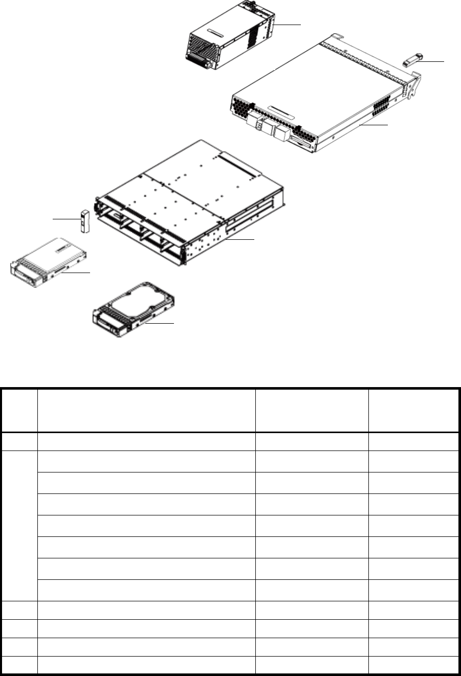
54 Parts catalog
F
Figure 4 MSA2312fc exploded view
Table 11 MSA2312fc parts list
Item Description Spares part number CSR
Mandatory
Optional
1 SPS-BLANK,HDD 481344-001 Mandatory
2 Hard drives — —
a) SPS—DRV, HD 146GB MSA2 3.5” 15K DP SAS 480937-001 Mandatory
b) SPS—DRV, HD 300GB MSA2 3.5” 15K DP SAS 480938-001 Mandatory
c) SPS—DRV, HD 450GB MSA2 3.5” 15K DP SAS 480939-001 Mandatory
d) SPS—DRV, HD 500GB MSA2 3.5” 7.2K SATA 480940-001 Mandatory
e) SPS—DRV, HD 750GB MSA2 3.5” 7.2K SATA 480941-001 Mandatory
f) SPS—DRV, HD 1TB MSA2 3.5” 7.2K SATA 480942-001 Mandatory
3SPS-EAR KIT 508296-001 Mandatory
4 SPS-CHASSIS-w/midplane 481321-001 Mandatory
5 SPS-CONTROLLER,2300fc 490092-001 Mandatory
6 SPS-SFP,XCVR 481345-001 Mandatory
6
3
7
4
5
2
1

HP StorageWorks Carrier-Grade 2324fc Modular Smart Array user guide 55
7Power supplies — —
SPS-POWER SUPPLY (AC) 481320-001 Mandatory
SPS-DC DISK ENCL, POWER SUPPLY 545764-001 Mandatory
Not
shown
SPS-RAIL KIT VLS9000 457637-001 Mandatory
Not
shown
SPS-CABLE KIT
(CLI and SAS expansion cables)
481322-001 Mandatory
Not
shown
SPS-CA KIT, DB9
DB9-M to DB9-F (CLI cable)
508297-001 Mandatory
Table 11 MSA2312fc parts list (continued)
Item Description Spares part number CSR
Mandatory
Optional
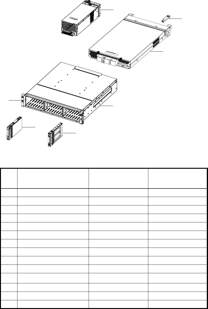
56 Parts catalog
Figure 5 MSA2324fc exploded view
Table 12 MSA2324fc parts list
Item Description Spares part number CSR
Mandatory
Optional
1 SPS-BLANK,HDD 376383-002 Mandatory
2 Hard drives — —
a) 36-GB SAS, 10K rpm 376596-001 Mandatory
b) 36-GB SAS, 15K rpm 432332-001 Mandatory
c) 72-GB SAS, 10K rpm 447447-021 Mandatory
d) 72-GB SAS, 15K rpm 418373-001 Mandatory
e) 146-GB SAS, 10K rpm 432320-001 Mandatory
f) 60-GB SATA, 5.4 rpm 405419-001 Mandatory
g) 80-GB SATA, 5.4 rpm 431907-00 Mandatory
h) 160GB SATA, 5.4 rpm 431909-00 Mandatory
3SPS-EAR KIT 508296-001 Mandatory
4 SPS-CHASSIS-w/midplane 490095-001 Mandatory
5 SPS-CONTROLLER,2300fc 490092-001 Mandatory
6SPS-SFP,XCVR 481345-001 Mandatory
6
3
7
2
4
1
5

HP StorageWorks Carrier-Grade 2324fc Modular Smart Array user guide 57
7Power supplies — —
a) SPS-POWER SUPPLY 481320-001 Mandatory
b) SPS-DC DISK ENCL, POWER
SUPPLY
545764-001 Mandatory
Not
shown
SPS-RAIL KIT VLS9000 457637-001 Mandatory
Not
shown
SPS-CABLE KIT
(CLI and SAS expansion cables)
481322-001 Mandatory
Not
shown
SPS-CA KIT, DB9
(DB9-M to DB9-F CLI cable)
508297-001 Mandatory
Table 12 MSA2324fc parts list (continued)
Item Description Spares part number CSR
Mandatory
Optional
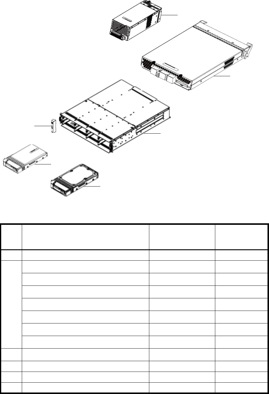
58 Parts catalog
Figure 6 MSA2000 3.5 12-drive enclosure exploded view
Table 13 MSA2000 3.5 12-drive enclosure parts list
Item Description Spares part number CSR
Mandatory
Optional
1 SPS-BLANK,HDD 481344-001 Mandatory
2 Hard drives — —
a) SPS—DRV, HD 146GB MSA2 3.5” 15K DP SAS 480937-001 Mandatory
b) SPS—DRV, HD 300GB MSA2 3.5” 15K DP SAS 480938-001 Mandatory
c) SPS—DRV, HD 400GB MSA2 3.5” 10K DP SAS 480939-001 Mandatory
d) SPS—DRV, HD 500GB MSA2 3.5” 7.2K SATA 480940-001 Mandatory
e) SPS—DRV, HD 750GB MSA2 3.5” 7.2K SATA 480941-001 Mandatory
f) SPS—DRV, HD 1TB MSA2 3.5” 7.2K SATA 480942-001 Mandatory
3SPS-EAR KIT 508296-001 Mandatory
4 SPS-CHASSIS-w/midplane 481321-001 Mandatory
5 SPS-ENCLOSURE,I/O MODULE 481342-001 Mandatary
6 SPS-POWER SUPPLY 481320-001 Mandatory
6
5
1
2
34

HP StorageWorks Carrier-Grade 2324fc Modular Smart Array user guide 59
•For more information about CSR, contact your local service provider. For North America, see the CSR
website at http://www.hp.com/go/selfrepair.
•To determine the warranty service provided for this product, see the warranty information website at
http://www.hp.com/go/storagewarranty.
•To order a replacement part, contact an HP-authorized service provider or see the HP Parts Store online
at http://www.hp.com/buy/parts.
Not
shown
SPS-RAIL KIT VLS9000 457637-001 Mandatory
Not
shown
SPS-CABLE KIT
(CLI and SAS expansion cables)
481322-001 Mandatory
Table 13 MSA2000 3.5 12-drive enclosure parts list (continued)
Item Description Spares part number CSR
Mandatory
Optional
60 Parts catalog

HP StorageWorks Carrier-Grade 2324fc Modular Smart Array user guide 61
B Environmental requirements and specifications
Safety requirements
Install the system in accordance with the local safety codes and regulations at the facility site. Follow all
cautions and instructions marked on the equipment.
Site requirements and guidelines
The following sections provide requirements and guidelines that you must address when preparing your site
for the installation.
When selecting an installation site for the system, choose a location not subject to excessive heat, direct
sunlight, dust, or chemical exposure. These conditions greatly reduce the system’s longevity and might void
your warranty.
Site wiring and AC power requirements
The following are required for all installations using AC power supplies:
•All AC mains and supply conductors to power distribution boxes for the rack-mounted system must be
enclosed in a metal conduit or raceway when specified by local, national, or other applicable
government codes and regulations.
•Ensure that the voltage and frequency of your power source match the voltage and frequency inscribed
on the equipment’s electrical rating label.
•To ensure redundancy, provide two separate power sources for the enclosures. These power sources
must be independent of each other, and each must be controlled by a separate circuit breaker at the
power distribution point.
•The system requires voltages within minimum fluctuation. The customer-supplied facilities’ voltage must
maintain a voltage with not more than 5 percent fluctuation. The customer facilities must also provide
suitable surge protection.
•Site wiring must include an earth ground connection to the AC power source. The supply conductors
and power distribution boxes (or equivalent metal enclosure) must be grounded at both ends.
•Power circuits and associated circuit breakers must provide sufficient power and overload protection. To
prevent possible damage to the AC power distribution boxes and other components in the rack, use an
external, independent power source that is isolated from large switching loads (such as air conditioning
motors, elevator motors, and factory loads).
Site wiring and DC power requirements
The following are required for all installations using DC power supplies:
•All DC mains and supply conductors to power distribution boxes for the rack-mounted system must
comply with local, national, or other applicable government codes and regulations.
•Ensure that the voltage of your power source matches the voltage inscribed on the equipment’s
electrical label.
•To ensure redundancy, provide two separate power sources for the enclosures. These power sources
must be independent of each other, and each must be controlled by a separate circuit breaker at the
power distribution point.
•The system requires voltages within minimum fluctuation. The customer-supplied facilities’ voltage must
maintain a voltage within the range specified on the equipment’s electrical rating label. The customer
facilities must also provide suitable surge protection.
•Site wiring must include an earth ground connection to the DC power source. Grounding must comply
with local, national, or other applicable government codes and regulations.
•Power circuits and associated circuit breakers must provide sufficient power and overload protection.
62 Environmental requirements and specifications
Weight and placement guidelines
Refer to Physical requirements for detailed size and weight specifications.
•The weight of an enclosure depends on the number and type of modules installed.
•Ideally, use two people to lift an enclosure. However, one person can safely lift an enclosure if its
weight is reduced by removing the power and cooling modules and drive modules.
•Do not place enclosures in a vertical position. Always install and operate the enclosures in a horizontal
orientation.
•When installing enclosures in a rack, make sure that any surfaces over which you might move the rack
can support the weight. To prevent accidents when moving equipment, especially on sloped loading
docks and up ramps to raised floors, ensure you have a sufficient number of helpers. Remove obstacles
such as cables and other objects from the floor.
•To prevent the rack from tipping and to minimize personnel injury in the event of a seismic occurrence,
securely anchor the rack to a wall or other rigid structure that is attached to both the floor and to the
ceiling of the room.
Electrical guidelines
•These enclosures work with single-phase power systems having an earth ground connection. To reduce
the risk of electric shock, do not plug an enclosure into any other type of power system. Contact your
facilities manager or a qualified electrician if you are not sure what type of power is supplied to your
building.
•Enclosures are shipped with a grounding-type (three-wire) power cord. To reduce the risk of electric
shock, always plug the cord into a grounded power outlet.
•Do not use household extension cords with the enclosures. Not all power cords have the same current
ratings. Household extension cords do not have overload protection and are not meant for use with
computer systems.
Ventilation requirements
Refer to Environmental requirements for detailed environmental requirements.
•Do not block or cover ventilation openings at the front and rear of an enclosure. Never place an
enclosure near a radiator or heating vent. Failure to follow these guidelines can cause overheating and
affect the reliability and warranty of your enclosure.
•Leave a minimum of 6 inches (15 cm) at the front and back of each enclosure to ensure adequate
airflow for cooling. No cooling clearance is required on the sides, top, or bottom of enclosures.
•Leave enough space in front and in back of an enclosure to allow access to enclosure components for
servicing. Removing a component requires a clearance of at least 15 inches (37 cm) in front of and
behind the enclosure.
Cabling requirements
•Keep power and interface cables clear of foot traffic. Route cables in locations that protect the cables
from damage.
•Route interface cables away from motors and other sources of magnetic or radio frequency
interference.
•Stay within the cable length limitations.
Management host requirements
A local management host with at least one serial port connection is recommended for the initial installation
and configuration of a controller enclosure. After you configure one or both of the controller modules with
an Internet Protocol (IP) address, you then use a remote management host on an Ethernet network to
configure, manage, and monitor.
HP StorageWorks Carrier-Grade 2324fc Modular Smart Array user guide 63
NOTE: Connections to this device must be made with shielded cables with metallic RFI/EMI connector
hoods in order to maintain compliance with FCC Rules and Regulations.
Physical requirements
The floor space at the installation site must be strong enough to support the combined weight of the rack,
controller enclosures, expansion enclosures, and any additional equipment. The site also requires sufficient
space for installation, operation, and servicing the enclosures, and also requires sufficient ventilation to
allow a free flow of air to all enclosures.
Table 14 and Table 15 list enclosure dimensions and weights. Weights are based on an enclosure having
12 drive modules, two controller or expansion modules, and two power supplies installed.
.
.
Environmental requirements
Table 14 Rackmount enclosure dimensions
Specifications Rackmount
Height 2U 3.5 inches (8.9 cm)
Width:
•Chassis
•To back of power supply handle
21.8 inch es (55. 4 c m )
23.7 inches (60.2 cm)
Table 15 Rackmount enclosure weights
Specifications Rackmount
2312fc Modular Smart Array
•SAS drives
•SATA drives
64.5 lb (29.3 kg)
65.5 lb (29.8 kg)
2324fc Modular Smart Array
•SAS drives
•SATA drives
58.5 lb (26.6 kg)
54.2 lb (24.6 kg)
MSA2000 3.5 12-drive enclosure (12
drives)
•SAS drives
•SATA drives 62 lb (28.2 kg)
63 lb (28.6 kg)
Table 16 Operating environmental specifications
Specification Range
Altitude To 9842 feet (3000 meters), derate 35.6ºF (2ºC)
for every 3281 feet (1 km) up to 9842 feet (3000
meters)
Relative humidity 10% to 90% RH, 104ºF (40ºC) non condensing
Temperature 41ºF to 104ºF (5ºC to 40ºC)
Shock 5.0 g, 10 ms, half-sine
Vibration 0.5 g, 1 octave/minute, 5 Hz to 500 Hz to 5
Hz, swept-sine
64 Environmental requirements and specifications
Electrical requirements
Site wiring and power requirements
Each enclosure has two power and cooling modules for redundancy. If full redundancy is required, use a
separate power source for each module. The AC power supply unit in each power and cooling module is
auto-ranging and is automatically configured to an input voltage range from 88–264 VAC with an input
frequency of 47–63 Hz. The power and cooling modules meet standard voltage requirements for both U.S.
and international operation. The power and cooling modules use standard industrial wiring with
line-to-neutral or line-to-line power connections.
Power cord requirements
Each enclosure is shipped with two AC power cords that are appropriate for use in a typical outlet in the
destination country. Each power cord connects one of the power and cooling modules to an independent,
external power source. To ensure power redundancy, connect the two power cords to two separate circuits;
for example, to one commercial circuit and one uninterruptible power source (UPS).

HP StorageWorks Carrier-Grade 2324fc Modular Smart Array user guide 65
C Electrostatic discharge
Preventing electrostatic discharge
To prevent damaging the system, be aware of the precautions you need to follow when setting up the
system or handling parts. A discharge of static electricity from a finger or other conductor may damage
system boards or other static-sensitive devices. This type of damage may reduce the life expectancy of the
device.
To prevent electrostatic damage:
•Avoid hand contact by transporting and storing products in static-safe containers.
•Keep electrostatic-sensitive parts in their containers until they arrive at static-free workstations.
•Place parts on a grounded surface before removing them from their containers.
•Avoid touching pins, leads, or circuitry.
•Always be properly grounded when touching a static-sensitive component or assembly.
Grounding methods to prevent electrostatic discharge
Several methods are used for grounding. Use one or more of the following methods when handling or
installing electrostatic-sensitive parts:
•Use a wrist strap connected by a ground card to a grounded workstation or computer chassis. Wrist
straps are flexible straps with a minimum of 1 megohm ± 10 percent resistance in the ground cords. To
provide proper ground, wear the strap snug against the skin.
•Use heel straps, toe straps or boot straps at standing workstations. Wear the straps on both feet when
standing on conductive floors or dissipating floor mats.
•Use conductive field service tools.
•Use a portable field service kit with a folding static-dissipating work mat.
If you do not have any of the suggested equipment for proper grounding, have an authorized reseller
install the part.
For more information on static electricity or assistance with product installation, contact an authorized
reseller.
66 Electrostatic discharge

HP StorageWorks Carrier-Grade 2324fc Modular Smart Array user guide 67
D Regulatory compliance and safety
Regulatory compliance
Federal Communications Commission notice
Part 15 of the Federal Communications Commission (FCC) Rules and Regulations has established Radio
Frequency (RF) emission limits to provide an interference-free radio frequency spectrum. Many electronic
devices, including computers, generate RF energy incidental to their intended function and are, therefore,
covered by these rules. These rules place computers and related peripheral devices into two classes, A and
B, depending upon their intended installation. Class A devices are those that may reasonably be expected
to be installed in a business or commercial environment. Class B devices are those that may reasonably be
expected to be installed in a residential environment (i.e., personal computers). The FCC requires devices
in both classes to bear a label indicating the interference potential of the device as well as additional
operating instructions for the user.
The rating label on the device shows which class (A or B) the equipment falls into. Class B devices have an
FCC logo or FCC ID on the label. Class A devices do not have an FCC logo or FCC ID on the label. Once
the class of the device is determined, refer to the following corresponding statement.
Class A equipment
This equipment has been tested and found to comply with the limits for a Class A digital device, pursuant
to Part 15 of the FCC Rules. These limits are designed to provide reasonable protection against harmful
interference when the equipment is operated in a commercial environment. This equipment generates,
uses, and can radiate radio frequency energy and, if not installed and used in accordance with the
instructions, may cause harmful interference to radio communications. Operation of this equipment in a
residential area is likely to cause harmful interference, in which case the user will be required to correct the
interference at personal expense.
Class B equipment
This equipment has been tested and found to comply with the limits for a Class B digital device, pursuant to
Part 15 of the FCC Rules. These limits are designed to provide reasonable protection against harmful
interference in a residential installation. This equipment generates, uses, and can radiate radio frequency
energy and, if not installed and used in accordance with the instructions, may cause harmful interference
to radio communications. However, there is no guarantee that interference will not occur in a particular
installation. If this equipment does cause harmful interference to radio or television reception, which can be
determined by turning the equipment off and on, the user is encouraged to try to correct the interference by
one or more of the following measures:
•Reorient or relocate the receiving antenna.
•Increase the separation between the equipment and receiver.
•Connect the equipment into an outlet on a circuit that is different from that to which the receiver is
connected.
•Consult the dealer or an experienced radio or television technician for help.
Declaration of conformity for products marked with the FCC logo, United States
only
This device complies with Part 15 of the FCC Rules. Operation is subject to the following two conditions:
(1) this device may not cause harmful interference, and (2) this device must accept any interference
received, including interference that may cause undesired operation.
For questions regarding your product, visit http://www.hp.com.
For questions regarding this FCC declaration, contact us by mail or telephone:
•Hewlett-Packard Company
P.O. Box 692000, M ailstop 510101
Houston, Texas 77269-2000

68 Regulatory compliance and safety
•1-281-514-3333
To identify this product, refer to the part, Regulatory Model Number, or product number found on the
product.
Modifications
The FCC requires the user to be notified that any changes or modifications made to this device that are not
expressly approved by Hewlett-Packard Company may void the user's authority to operate the equipment.
Cables
Connections to this device must be made with shielded cables with metallic RFI/EMI connector hoods in
order to maintain compliance with FCC Rules and Regulations.
Regulatory compliance identification numbers
For the purpose of regulatory compliance certifications and identification, your product has been assigned
a unique Regulatory Model Number. The RMN can be found on the product nameplate label, along with
all required approval markings and information. When requesting compliance information for this product,
always refer to this RMN. The Regulatory Model Number should not be confused with the marketing name
or model number of the product.
Regulatory compliance label location
The Regulatory Compliance label for the array is located behind the left ear on the side of the chassis.
Laser device
All HP systems equipped with a laser device comply with safety standards, including International
Electrotechnical Commission (IEC) 825. With specific regard to the laser, the equipment complies with
laser product performance standards set by government agencies as a Class 1 laser product. The product
does not emit hazardous light.
Laser safety warning
WARNING! To reduce the risk of exposure to hazardous radiation:
•Do not try to open the laser device enclosure. There are no user-serviceable components inside.
•Do not operate controls, make adjustments, or perform procedures to the laser device other than those
specified herein.
•Allow only HP authorized service technicians to repair the laser device.
Certification and classification information
This product contains a laser internal to the fiber optic (FO) transceiver for connection to the Fibre Channel
communications port.
In the USA, the FO transceiver is certified as a Class 1 laser product conforming to the requirements
contained in the Department of Health and Human Services (DHHS) regulation 21 CFR, Subchapter J. A
label on the plastic FO transceiver housing indicates the certification.
Outside the USA, the FO transceiver is certified as a Class 1 laser product conforming to the requirements
contained in IEC 825-1:1993 and EN 60825-1:1994, including Amendment 11:1996 and Amendment
2:2001.

HP StorageWorks Carrier-Grade 2324fc Modular Smart Array user guide 69
Laser product label
The optional label in Figure 6-1 or equivalent may be located on the surface of the HP supplied laser
device.
Figure 6-1 Class 1 Laser Product Label
International notices and statements
Canadian notice (avis Canadien)
Class A equipment
This Class A digital apparatus meets all requirements of the Canadian Interference-Causing Equipment
Regulations.
Cet appareil numérique de la classe A respecte toutes les exigences du Règlement sur le matériel brouilleur
du Canada.
Class B equipment
This Class B digital apparatus meets all requirements of the Canadian Interference-Causing Equipment
Regulations.
Cet appareil numérique de la classe B respecte toutes les exigences du Règlement sur le matériel brouilleur
du Canada.
European Union notice
Products bearing the CE marking comply with the EMC Directive (89/336/EEC) and the Low Voltage
Directive (73/23/EEC) issued by the Commission of the European Community and if this product has
telecommunication functionality, the R&TTE Directive (1999/5/EC).
Compliance with these directives implies conformity to the following European Norms (in parentheses are
the equivalent international standards and regulations):
•EN55022 (CISPR 22) - Electromagnetic Interference
•EN55024 (IEC61000-4-2, IEC61000-4-3, IEC61000-4- 4, IEC61000-4-5, IEC61000-4-6,
IEC61000 - 4-8, IEC61000 - 4 -11) - Electromagnetic Immunity
•Power Quality:
• EN61000-3-2 (IEC61000-3-2) - Power Line Harmonics
• EN61000-3-3 (IEC61000-3-3) - Power Line Flicker
•EN60950 (IEC60950) - Product Safety
•Also approved under UL 60950/CSA C22.2 No. 60950-00, Safety of Information Technology
Equipment.
This optional label indicates that the product is classified as a
CLASS 1 LASER PRODUCT. This label may appear on the
laser device installed in your product.
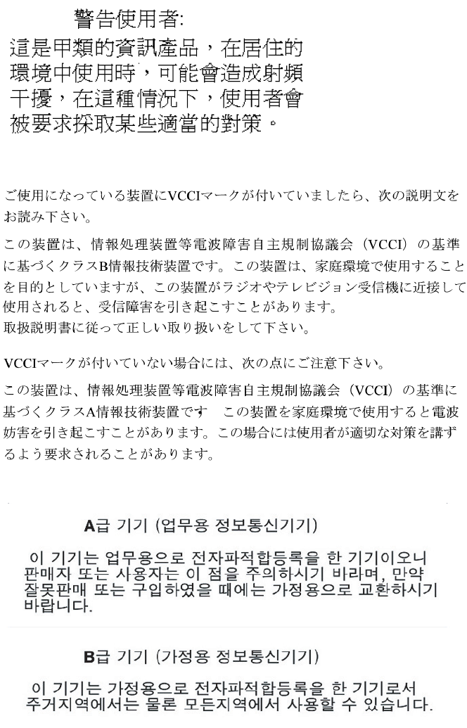
70 Regulatory compliance and safety
BSMI notice
Japanese notice
Korean notices
Safety
Battery replacement notice
Your computer is equipped with a lithium manganese dioxide, a vanadium pentoxide, or an alkaline
internal battery or battery pack. There is a danger of explosion and risk of personal injury if the battery is
incorrectly replaced or mistreated. Replacement is to be done by an HP authorized service provider using
the HP spare part designated for this product. For more information about battery replacement or proper
disposal, contact an HP authorized reseller or HP authorized service provider.
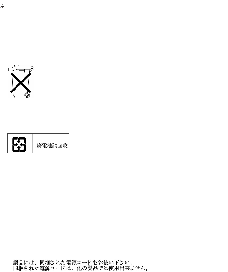
HP StorageWorks Carrier-Grade 2324fc Modular Smart Array user guide 71
WARNING! Yur computer contains an internal lithium manganese dioxide, a vanadium pentoxide, or an
alkaline battery pack. There is risk of fire and burns if the battery pack is not properly handled. To reduce
the risk of personal injury:
•Do not attempt to recharge the battery.
•Do not expose to temperatures higher than 60°C.
•Do not disassemble, crush, puncture, short external contacts, or dispose of in fire or water.
•Replace only with the HP spare part designated for this product.
For more information about battery replacement or proper disposal, contact an HP authorized reseller or
service provider.
Taiwan battery recycling notice
Power cords
The power cord set must meet the requirements for use in the country where the product was purchased. If
the product is to be used in another country, purchase a power cord that is approved for use in that
country.
The power cord must be rated for the product and for the voltage and current marked on the product
electrical ratings label. The voltage and current rating of the cord should be greater than the voltage and
current rating marked on the product. In addition, the diameter of the wire must be a minimum of
1.0 0 m m 2 or 18 AWG, and the length of the cord must be between 1.8 m (6 ft) and 3.6 m (12 ft). If you
have questions about the type of power cord to use, contact an HP authorized service provider.
Route power cords so that they will not be walked on and cannot be pinched by items placed upon or
against them. Pay particular attention to the plug, electrical outlet, and the point where the cords exit from
the product.
Japanese power cord notice
Electrostatic discharge
To prevent damage to the system, be aware of the precautions you need to follow when setting up the
system or handling parts. A discharge of static electricity from a finger or other conductor may damage
system boards or other static-sensitive devices. This type of damage may reduce the life expectancy of the
device.
Preventing electrostatic damage
To prevent electrostatic damage, observe the following precautions:
•Avoid hand contact by transporting and storing products in static-safe containers.
Batteries, battery packs, and accumulators should not be disposed of together with
the general household waste. To forward them to recycling or proper disposal,
please use the public collection system or return them to HP, an authorized HP
Partner, or their agents.
The Taiwan EPA requires dry battery manufacturing or importing
firms in accordance with Article 15 of the Waste Disposal Act to
indicate the recovery marks on the batteries used in sales,
giveaway or promotion. Contact a qualified Taiwanese recycler for
proper battery disposal.

72 Regulatory compliance and safety
•Keep electrostatic-sensitive parts in their containers until they arrive at static-free workstations.
•Place parts on a grounded surface before removing them from their containers.
•Avoid touching pins, leads, or circuitry.
•Always be properly grounded when touching a static-sensitive component or assembly (see “Grounding
methods” on page 72).
Grounding methods
There are several methods for grounding. Use one or more of the following methods when handling or
installing electrostatic-sensitive parts:
•Use a wrist strap connected by a ground cord to a grounded workstation or computer chassis. Wrist
straps are flexible straps with a minimum of 1 megohm (±10 percent) resistance in the ground cords. To
provide proper ground, wear the strap snug against the skin.
•Use heel straps, toe straps, or boot straps at standing workstations. Wear the straps on both feet when
standing on conductive floors or dissipating floor mats.
•Use conductive field service tools.
•Use a portable field service kit with a folding static-dissipating work mat.
If you do not have any of the suggested equipment for proper grounding, have an HP authorized reseller
install the part.
NOTE: For more information on static electricity, or assistance with product installation, contact your HP
authorized reseller.

HP StorageWorks 2312fc and 2324fc Modular Smart Array user guide 73
Index
A
accessing
the CLI 24
accessing the SMU 39
accumulators 71
audience 11
Avis Canadien, regulatory compliance
notice 69
B
batteries
recycling or disposal 71
replacement
notice 70
Taiwan EPA recycling and disposal 71
boot straps, using 72
BSMI, regulatory compliance notice 70
C
cables
FCC compliance statement 28, 63, 68
shielded 28, 63, 68
cabling
connecting controller enclosures to drive enclosures
22
connecting enclosure to data hosts 27
routing requirements 62
cache 19
self-refresh mode 35
status 35
transportable CompactFlash 19
Canada, regulatory compliance notice 69
certification and classification information, laser 68
Class A equipment, Canadian compliance statement 69
Class B equipment, Canadian compliance statement 69
clearance requirements
service 62
ventilation 62
command-line interface
using to set controller IP addresses 24
CompactFlash 19
transporting 48
components
front panel 18
rear panel 18
Configuration Wizard 41
configuring
direct attach configurations 27
switch attach configurations 28
connecting
controller enclosures to data hosts 27
serial cable to set IP address 24
to remote management hosts 28
connections
testing 24
console requirement 62
controller enclosures
connecting to data hosts 27
connecting to remote management hosts 28
conventions
document 11
cord See power cord
CSR See customer self repair 53
current rating 71
customer self repair (CSR)
parts catalog 53
D
data hosts
system requirements 27
date and time
changing using SMU 40
declaration of conformity 67
DHCP
obtaining IP addresses 24
direct attach configurations 27
disposal, battery 71
disposal, Taiwan EPA battery 71
dissipating floor mats 72
document
conventions 11
prerequisite knowledge 11
related documentation 11
documentation, HP web site 11
E
electromagnetic compatibility (EMC) 61
electrostatic damage prevention 71
enclosure
cabling 22
IDs, correcting 44
input frequency requirement 64
input voltage requirement 64
powering on 29
site requirements 63
troubleshooting 43
ESD (electrostatic discharge)
prevention measures 71
storing products 71
transporting products 71
Ethernet cables
requirements 28
European Union, regulatory compliance
notice 69
expansion port LED
troubleshooting 50
74
F
faults
isolating
a host-side connection 49
expansion port connection fault 50
methodology 43
FCC (Federal Communications Commission)
Class A Equipment, compliance notice 67
Class B Equipment, compliance notice 67
declaration of conformity 67
modifications 68
notice 67
Federal Communications Commission See FCC
firmware
checking versions 29
when to update 29
floor mats, dissipating 72
found new hardware wizard 27
G
ground strap specifications 72
grounding
methods 72
straps, wearing 72
suggested equipment for 72
H
hard drive
bay numbers 18
LEDs 32
heel straps, using 72
help, obtaining 12, 13
HP
address for
FCC questions 67
series number 68
storage web site 13
Subscriber’s choice web site 13
technical support 12
telephone number
FCC questions 67
humidity operating range 63
I
IDs, correcting for enclosure 44
IEC EMC, worldwide regulatory compliance notice 69
installing enclosures
checklist 21
IP addresses
setting using DHCP 24
setting using the CLI 24
J
Japan
regulatory compliance notice 70
K
Korean, regulatory compliance notice 70
L
label, laser 69
language field 39
laser
international certification and classification
information 68
product label 69
radiation, warning 68
regulatory compliance notice 68
LEDs
amber fault conditions 44
Cache Status 35
Enclosure ID 31
Ethernet Activity 34
Ethernet Link Status 34
Fault UID 31
Fault/Service Required 34
front panel 31
hard drive
Fault/UID 32
Online/Activity 32
Host Activity 35
Host Link Status/Activity 34
MSA2000 3.5 12-drive enclosure 36
Fault/Service Required 36
OK 36
OK to Remove 36
SAS In Port Status 36
SAS Out Port Status 36
Unit Locator 36
OK 34
OK to Remove 34
Online/Activity 31
power supply 34
rear panel 34
Unit Identification (UID) 31
Unit Locator 34
using to diagnose fault conditions 44
lithium battery 70
local management host requirement 62
loop topology 27
M
MPIO DSM, obtaining 27
MSA2000 3.5 12-drive enclosure
LEDs 36
ports 19
MSA2000 Family SCSI Enclosure Services (SES) driver
27
O
operating ranges, environmental 63
P
parts
proper handling 72
storing 72
transporting 72
HP StorageWorks 2312fc and 2324fc Modular Smart Array user guide 75
physical requirements 63
point-to-point topology 27
ports
MSA2000 3.5 12-drive enclosure 19
MSA2312fc 18
MSA2324fc 18
power cord
compliance notice 71
current rating 71
replacement 71
set 71
voltage rating 71
power cord requirements 64
power supply
LEDs 34
sensors 51
wiring requirements 61
powering on/powering off 29
prerequisite knowledge 11
preventing electrostatic damage 71
Provisioning Wizard 42
R
rack stability, warning 12
recycling, battery 71
recycling, Taiwan EPA battery 71
regulatory compliance
information number 68
notices
BSMI 70
Canada 69
Class A 67
Class B 67
European Union 69
HP series number 68
IEC EMC statement, worldwide 69
Japan 70
Korean 70
lasers 68
modifications 68
shielded cables 28, 63, 68
related documentation 11
remote management 28
replacing a power cord 71
requirements
cabling 62
clearance 62
Ethernet cables 28
host system 27
physical 63
ventilation 62
RFI/EMI connector hoods 28, 63, 68
S
safety precautions 61
sensors
locating 51
power supply 51
temperature 51
voltage 52
series number, regulatory compliance 68
service port 18, 19, 37
shock operating range 63
site planning
EMC 61
local management host requirement 62
physical requirements 63
safety precautions 61
SMU
changing system date and time 40
configuring 39
language field 39
logging in 39
logging out 42
testing system configuration 42
using the Configuration Wizard 41
using the Provisioning Wizard 42
static-dissipating work mat 72
static-safe containers
storing products 71
transporting products 71
storage system
powering on 29
testing configuration 42
straps, ground
boot 72
heel 72
toe 72
Subscriber’s choice, HP 13
super-capacitor pack 20
switch attach configurations 28
T
Taiwan EPA battery recycling and disposal 71
technical support, HP 12
telephone numbers
FCC questions 67
temperature operating range 63
toe straps, using 72
tools, conductive type 72
transportable CompactFlash 19
troubleshooting 43
controller failure, single controller configuration 48
correcting enclosure IDs 44
enclosure does not initialize 43
using system LEDs 44
V
ventilation requirements 62
version information
checking 29
vibration operating range 63
virtual disks
viewing status 42
voltage compliance rating 71
volumes
verifying 42
