Hp T1000 G3 Users Manual HP_1000_5115 Rev 2 Rel_Q3
HP T750 G2 to the manual 7a502d8a-6111-4174-8e4b-db074f99ccca
2015-02-09
: Hp Hp-Hp-T1000-G3-Users-Manual-548340 hp-hp-t1000-g3-users-manual-548340 hp pdf
Open the PDF directly: View PDF ![]() .
.
Page Count: 38
- HP T750 G2, HP T750J, HP T1000 G3, HP T1000J, HP T1500 G3, and HP T1500J UPS Models User Guide
- Special Symbols
- Regulatory compliance notices
- Electrostatic discharge
- Table of Contents
- Chapter 1 Introduction
- Chapter 2 Safety Warnings
- Chapter 3 Installation
- Chapter 4 Operation
- Chapter 5 Additional UPS Features
- Chapter 6 UPS Maintenance
- Chapter 7 Specifications
- Chapter 8 Troubleshooting
- Chapter 9 Warranty Infromation

HP T750 G2, HP T750J, HP T1000 G3,
HP T1000J, HP T1500 G3, and
HP T1500J UPS Models
User Guide
Part Number 505922-002
J
uly 2009 (Second Edition)
© Copyright 2009 Hewlett-Packard Development Company, L.P.
The information contained herein is subject to change without notice. The only warranties for HP products and services are set forth in the express
warranty statements accompanying such products and services. Nothing herein should be construed as constituting an additional warranty. HP
shall not be liable for technical or editorial errors or omissions contained herein.
Audience assumptions
This guide is for the person who operates, configures, maintains, and troubleshoots UPSs. HP assumes
you are qualified in the servicing of high-voltage equipment and trained in recognizing hazards in
products with hazardous energy levels.

Special Symbols
The following are examples of symbols used on the UPS to alert you to important information:
RISK OF ELECTRIC SHOCK - Observe the warning associated with the risk of electric shock symbol.
CAUTION: REFER TO OPERATOR'S MANUAL - Refer to your operator's manual for additional information,
such as important operating and maintenance instructions.
RJ-45 RECEPTACLE - For 230V units only: This receptacle provides network interface connections. Do not
plug telephone or telecommunications equipment into this receptacle.
LOAD ON/OFF - Press the button with this symbol to energize the output receptacles ( indicator illuminates)
or to de‐energize the output receptacles ( indicator is off).
Regulatory compliance notices
Regulatory compliance identification numbers
For the purpose of regulatory compliance certifications and identification, this product has been assigned a unique regulatory model number.
The regulatory model number can be found on the product nameplate label, along with all required approval markings and information.
When requesting compliance information for this product, always refer to this regulatory model number. The regulatory model number is not
the marketing name or model number of the product.
Federal Communications Commission notice
Class B equipment
This equipment has been tested and found to comply with the limits for a Class B digital device, pursuant to Part 15 of the FCC Rules. These
limits are designed to provide reasonable protection against harmful interference in a residential installation. This equipment generates, uses,
and can radiate radio frequency energy and, if not installed and used in accordance with the instructions, may cause harmful interference to
radio communications. However, there is no guarantee that interference will not occur in a particular installation. If this equipment does cause
harmful interference to radio or television reception, which can be determined by turning the equipment off and on, the user is encouraged to
try to correct the interference by one or more of the following measures:
SReorient or relocate the receiving antenna.
SIncrease the separation between the equipment and receiver.
SConnect the equipment into an outlet on a circuit that is different from that to which the receiver is connected.
SConsult the dealer or an experienced radio or television technician for help.
Declaration of conformity for products marked with the FCC logo, United States only
This device complies with Part 15 of the FCC Rules. Operation is subject to the following two conditions: (1) this device may not cause
harmful interference, and (2) this device must accept any interference received, including interference that may cause undesired operation.
For questions regarding this product, contact us by mail or telephone:
SHewlett-Packard Company
P. O. Box 692000, Mail Stop 530113
Houston, Texas 77269-2000
S1-800-HP-INVENT (1-800-474-6836). (For continuous quality improvement, calls may be recorded or monitored.)
For questions regarding this FCC declaration, contact us by mail or telephone:
SHewlett-Packard Company
P. O. Box 692000, Mail Stop 510101
Houston, Texas 77269-2000
S1-281-514-3333
To identify this product, refer to the part, series, or model number found on the product.
Modifications
The FCC requires the user to be notified that any changes or modifications made to this device that are not expressly approved by
Hewlett-Packard Company may void the user's authority to operate the equipment.
Cables
Connections to this device must be made with shielded cables with metallic RFI/EMI connector hoods in order to maintain compliance with
FCC Rules and Regulations.
Canadian notice (Avis Canadien)
Class B equipment
This Class B digital apparatus meets all requirements of the Canadian Interference-Causing Equipment Regulations.
Cet appareil numérique de la classe B respecte toutes les exigences du Règlement sur le matériel brouilleur du Canada.
European Union regulatory notice
This product complies with the following EU Directives:
SLow Voltage Directive 2006/95/EC
SEMC Directive 2004/108/EC
Compliance with these directives implies conformity to applicable harmonized European standards (European Norms) which are listed on the
EU Declaration of Conformity issued by Hewlett-Packard for this product or product family.
This compliance is indicated by the following conformity marking placed on the product:
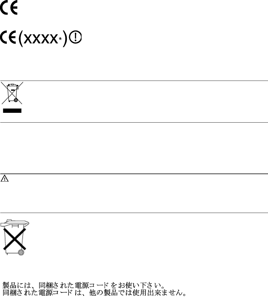
This marking is valid for non-Telecom products and EU harmonized Telecom products (e.g. Bluetooth).
This marking is valid for EU non-harmonized Telecom products.
*Notified body number (used only if applicable—refer to the product label)
Hewlett-Packard GmbH, HQ-TRE, Herrenberger Strasse 140, 71034 Boeblingen, Germany
This symbol on the product or on its packaging indicates that this product must not be disposed of with your other household
waste. Instead, it is your responsibility to dispose of your waste equipment by handing it over to a designated collection
point for the recycling of waste electrical and electronic equipment. The separate collection and recycling of your waste
equipment at the time of disposal will help to conserve natural resources and ensure that it is recycled in a manner that
protects human health and the environment. For more information about where you can drop off your waste equipment for
recycling, please contact your local city office, your household waste disposal service or the shop where you purchased the
product.
Japanese notice
このは、クラスBです。このは、ですることをとしていますが、
このがラジオやテレビジョンにしてされると、をきこすことがありま
す。にって しいりいをしてさい。VCCI-B
Battery replacement notice
WARNING: Power products contain sealed lead-acid battery modules. A risk of fire and burns exists if the battery is not
properly handled. To reduce the risk of personal injury:
SDo not attempt to recharge the battery.
SDo not expose the battery to temperatures higher than 60°C (140°F).
SDo not disassemble, crush, puncture, short external contacts, or dispose of in fire or water. The battery might explode.
Batteries, battery packs, and accumulators should not be disposed of together with the general household waste. To
forward them to recycling or proper disposal, use the public collection system or return them to HP, an authorized
HP Partner, or their agents.
For more information about battery replacement or proper disposal, contact an authorized reseller or an authorized service provider.
Power cord statement for Japan
Electrostatic discharge
Preventing electrostatic discharge
To prevent damaging the system, be aware of the precautions you need to follow when setting up the system or handling parts. A discharge
of static electricity from a finger or other conductor may damage system boards or other static-sensitive devices. This type of damage may
reduce the life expectancy of the device.
To prevent electrostatic damage:
SAvoid hand contact by transporting and storing products in static-safe containers.
SKeep electrostatic-sensitive parts in their containers until they arrive at static-free workstations.
SPlace parts on a grounded surface before removing them from their containers.
SAvoid touching pins, leads, or circuitry.
SAlways be properly grounded when touching a static-sensitive component or assembly.
Grounding methods to prevent electrostatic discharge
Several methods are used for grounding. Use one or more of the following methods when handling or installing electrostatic-sensitive parts:
SUse a wrist strap connected by a ground cord to a grounded workstation or computer chassis. Wrist straps are flexible straps with a
minimum of 1 megohm +10 percent resistance in the ground cords. To provide proper ground, wear the strap snug against the skin.
SUse heel straps, toe straps, or boot straps at standing workstations. Wear the straps on both feet when standing on conductive floors or
dissipating floor mats.
SUse conductive field service tools.
SUse a portable field service kit with a folding static-dissipating work mat.
If you do not have any of the suggested equipment for proper grounding, have an authorized reseller install the part.
For more information on static electricity or assistance with product installation, contact an authorized reseller.
HP T750 G2, HP T750J, HP T1000 G3, HP T1000J, HP T1500 G3, and HP T1500J UPS Models User Guide S 505922-002 i
Table of Contents
1Introduction 1. . . . . . . . . . . . . . . . . . . . . . . . . . . . . . . . . . . . . . . . . . . . . . . . . . . . . . . .
2Safety Warnings 3. . . . . . . . . . . . . . . . . . . . . . . . . . . . . . . . . . . . . . . . . . . . . . . . . . .
3Installation 4. . . . . . . . . . . . . . . . . . . . . . . . . . . . . . . . . . . . . . . . . . . . . . . . . . . . . . . . .
Inspecting the Equipment 4. . . . . . . . . . . . . . . . . . . . . . . . . . . . . . . . . . . . . . . . . . . . . . . . . . . . . . . . . .
Connecting the UPS Internal Battery 4. . . . . . . . . . . . . . . . . . . . . . . . . . . . . . . . . . . . . . . . . . . . . . . . .
Installing the UPS 6. . . . . . . . . . . . . . . . . . . . . . . . . . . . . . . . . . . . . . . . . . . . . . . . . . . . . . . . . . . . . . . . .
UPS Rear Panels 7. . . . . . . . . . . . . . . . . . . . . . . . . . . . . . . . . . . . . . . . . . . . . . . . . . . . . . . . . . . . . . . . . .
4Operation 10. . . . . . . . . . . . . . . . . . . . . . . . . . . . . . . . . . . . . . . . . . . . . . . . . . . . . . . . .
Turning the UPS On 10. . . . . . . . . . . . . . . . . . . . . . . . . . . . . . . . . . . . . . . . . . . . . . . . . . . . . . . . . . . . . . .
Starting the UPS on Battery 10. . . . . . . . . . . . . . . . . . . . . . . . . . . . . . . . . . . . . . . . . . . . . . . . . . . . . . . . .
Turning the UPS Off 11. . . . . . . . . . . . . . . . . . . . . . . . . . . . . . . . . . . . . . . . . . . . . . . . . . . . . . . . . . . . . . .
Standby Mode 11. . . . . . . . . . . . . . . . . . . . . . . . . . . . . . . . . . . . . . . . . . . . . . . . . . . . . . . . . . . . . . . . . . .
UPS Front Panel 11. . . . . . . . . . . . . . . . . . . . . . . . . . . . . . . . . . . . . . . . . . . . . . . . . . . . . . . . . . . . . . . . . .
Initiating the Self‐Test 12. . . . . . . . . . . . . . . . . . . . . . . . . . . . . . . . . . . . . . . . . . . . . . . . . . . . . . . . . . . . . .
5Additional UPS Features 13. . . . . . . . . . . . . . . . . . . . . . . . . . . . . . . . . . . . . . . . . . . . .
Voltage Configuration 13. . . . . . . . . . . . . . . . . . . . . . . . . . . . . . . . . . . . . . . . . . . . . . . . . . . . . . . . . . . . .
Communication Options 14. . . . . . . . . . . . . . . . . . . . . . . . . . . . . . . . . . . . . . . . . . . . . . . . . . . . . . . . . . .
USB Port 14. . . . . . . . . . . . . . . . . . . . . . . . . . . . . . . . . . . . . . . . . . . . . . . . . . . . . . . . . . . . . . . . . . . . . .
Serial Port 15. . . . . . . . . . . . . . . . . . . . . . . . . . . . . . . . . . . . . . . . . . . . . . . . . . . . . . . . . . . . . . . . . . . .
Network Transient Protector 16. . . . . . . . . . . . . . . . . . . . . . . . . . . . . . . . . . . . . . . . . . . . . . . . . . . . . . . .
HP Power Manager Software 16. . . . . . . . . . . . . . . . . . . . . . . . . . . . . . . . . . . . . . . . . . . . . . . . . . . . . . .
6UPS Maintenance 17. . . . . . . . . . . . . . . . . . . . . . . . . . . . . . . . . . . . . . . . . . . . . . . . . .
UPS and Battery Care 17. . . . . . . . . . . . . . . . . . . . . . . . . . . . . . . . . . . . . . . . . . . . . . . . . . . . . . . . . . . . .
Transporting the UPS 17. . . . . . . . . . . . . . . . . . . . . . . . . . . . . . . . . . . . . . . . . . . . . . . . . . . . . . . . . . . . . .
Storing the UPS and Batteries 18. . . . . . . . . . . . . . . . . . . . . . . . . . . . . . . . . . . . . . . . . . . . . . . . . . . . . . .
UPS Battery Spares 19. . . . . . . . . . . . . . . . . . . . . . . . . . . . . . . . . . . . . . . . . . . . . . . . . . . . . . . . . . . . . . .
Ordering Spares 19. . . . . . . . . . . . . . . . . . . . . . . . . . . . . . . . . . . . . . . . . . . . . . . . . . . . . . . . . . . . . . .
UPS Spare Parts List 19. . . . . . . . . . . . . . . . . . . . . . . . . . . . . . . . . . . . . . . . . . . . . . . . . . . . . . . . . . . .
Replacing Batteries 20. . . . . . . . . . . . . . . . . . . . . . . . . . . . . . . . . . . . . . . . . . . . . . . . . . . . . . . . . . . . . . .
Testing New Batteries 22. . . . . . . . . . . . . . . . . . . . . . . . . . . . . . . . . . . . . . . . . . . . . . . . . . . . . . . . . . . . .
Recycling the Used Battery or UPS 23. . . . . . . . . . . . . . . . . . . . . . . . . . . . . . . . . . . . . . . . . . . . . . . . . . .
7Specifications 24. . . . . . . . . . . . . . . . . . . . . . . . . . . . . . . . . . . . . . . . . . . . . . . . . . . . . .
8Troubleshooting 27. . . . . . . . . . . . . . . . . . . . . . . . . . . . . . . . . . . . . . . . . . . . . . . . . . . .
Audible Alarms and UPS Conditions 27. . . . . . . . . . . . . . . . . . . . . . . . . . . . . . . . . . . . . . . . . . . . . . . . .
Silencing an Audible Alarm 27. . . . . . . . . . . . . . . . . . . . . . . . . . . . . . . . . . . . . . . . . . . . . . . . . . . . .
Site Wiring Fault (100–120V Models Only) 27. . . . . . . . . . . . . . . . . . . . . . . . . . . . . . . . . . . . . . . .
Technical Support 29. . . . . . . . . . . . . . . . . . . . . . . . . . . . . . . . . . . . . . . . . . . . . . . . . . . . . . . . . . . . . . . .
Before You Contact HP 29. . . . . . . . . . . . . . . . . . . . . . . . . . . . . . . . . . . . . . . . . . . . . . . . . . . . . . . . .
HP Contact Information 30. . . . . . . . . . . . . . . . . . . . . . . . . . . . . . . . . . . . . . . . . . . . . . . . . . . . . . . . .
9Warranty Infromation 31. . . . . . . . . . . . . . . . . . . . . . . . . . . . . . . . . . . . . . . . . . . . . . .
Limited Warranty 31. . . . . . . . . . . . . . . . . . . . . . . . . . . . . . . . . . . . . . . . . . . . . . . . . . . . . . . . . . . . . . . . .
$250,000 Computer Load Protection Guarantee 31. . . . . . . . . . . . . . . . . . . . . . . . . . . . . . . . . . . . . .
Pre-Failure Battery Warranty 31. . . . . . . . . . . . . . . . . . . . . . . . . . . . . . . . . . . . . . . . . . . . . . . . . . . . . . .
HP T750 G2, HP T750J, HP T1000 G3, HP T1000J, HP T1500 G3, and HP T1500J UPS Models User Guide S 505922-002 1
Chapter 1 Introduction
The HP T750 G2, HP T750J, HP T1000 G3, HP T1000J, HP T1500 G3, and
HP T1500J Uninterruptible Power System (UPS) models protect your sensitive electronic
equipment from basic power problems such as power failures, power sags, power
surges, brownouts, and line noise.
Power outages can occur when you least expect them, and power quality can be
erratic. These power problems have the potential to corrupt critical data, destroy
unsaved work sessions, and damage hardware — causing hours of lost productivity
and expensive repairs.
With the HP T750 G2, HP T750J, HP T1000 G3, HP T1000J, HP T1500 G3, and
HP T1500J, you can safely eliminate the effects of power disturbances and guard the
integrity of your equipment. The UPS's flexibility to handle an array of network devices
makes it the perfect choice to protect your LANs, servers, workstations, and other
electrical equipment.
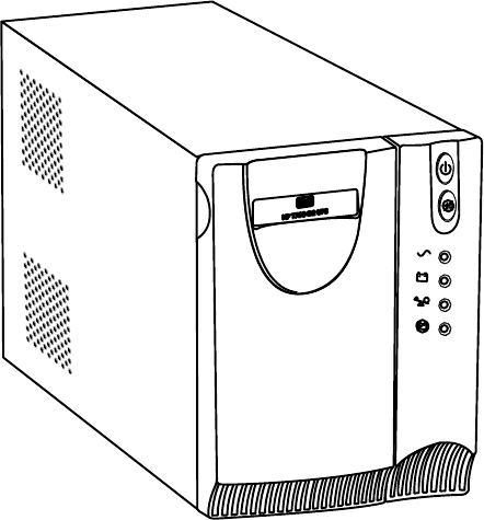
Figure 1 shows the HP T750 G2 UPS.
Figure 1 HP T750 G2 UPS
INTRODUCTION
HP T750 G2, HP T750J, HP T1000 G3, HP T1000J, HP T1500 G3, and HP T1500J UPS Models User Guide S 505922-002
2
Providing outstanding performance and reliability, the UPS's unique benefits include:
SBuck and Boost voltage regulation that ensures consistent voltage to your load by
correcting voltage fluctuations.
SAdvanced battery management to increase battery service life, optimize recharge
time, and provide a warning before the end of useful battery life.
SStart‐on‐battery capability for powering up the UPS even if utility power is not
available.
SHot‐swappable batteries that simplify maintenance by allowing you to replace
batteries safely without powering down the critical load.
STwo standard communication options (USB and serial port).
SNetwork transient protector that guards your network communications equipment
from surges. Low voltage models can also protect modems, fax machines, or other
telecommunications equipment.
SAdvanced power management with the HP Power Manager software for graceful
shutdowns and power monitoring.
SBacked by worldwide agency approvals.

HP T750 G2, HP T750J, HP T1000 G3, HP T1000J, HP T1500 G3, and HP T1500J UPS Models User Guide S 505922-002 3
Chapter 2 Safety Warnings
IMPORTANT SAFETY INSTRUCTIONS
SAVE THESE INSTRUCTIONS
This manual contains important instructions that you should follow during installation and
maintenance of the UPS and batteries. Please read all instructions before operating the
equipment and save this manual for future reference.
D A N G E R
This UPS contains LETHAL VOLTAGES. All repairs and service should be performed by
AUTHORIZED SERVICE PERSONNEL ONLY. There are NO USER SERVICEABLE
PARTS inside the UPS.
W A R N I N G
SThis UPS contains its own energy source (batteries). The output receptacles may carry
live voltage even when the UPS is not connected to an AC supply.
SFor 220–240V models, the output receptacles may remain electrically live. If the input
power source in your application is wired line-to-neutral (as in most European
applications), the voltage to the output receptacles is 0V. With line-to-line input wiring,
the voltage to the output receptacles is 100–120V (measured from line-to-ground or
line-to-neutral, depending on the UPS wiring).
SDo not remove or unplug the input cord when the UPS is turned on. This removes the
safety ground from the UPS and the equipment connected to the UPS.
STo reduce the risk of fire or electric shock, install this UPS in a temperature and humidity
controlled, indoor environment, free of conductive contaminants. Ambient temperature
must not exceed 40°C (104°F). Do not operate near water or excessive humidity (95%
maximum).
STo comply with international standards and wiring regulations, the total equipment
connected to the output of this UPS must not have an earth leakage current greater than
1.5 milliamperes.
C A U T I O N
SThe wall outlet must be within 2 meters of the equipment and accessible to the operator.
SBatteries can present a risk of electrical shock or burn from high short-circuit current. The
following precautions should be observed: 1) Remove watches, rings, or other metal
objects; 2) Use tools with insulated handles; 3) Do not lay tools or metal parts on top of
batteries; 4) Disconnect charging source prior to connecting or disconnecting battery
terminals.
SProper disposal of batteries is required. Refer to your local codes for disposal
requirements.
SNever dispose of batteries in a fire. Batteries may explode when exposed to flame.
SDo not open or mutilate the battery or batteries. Released electrolyte is harmful to the
skin and eyes and may be extremely toxic.
SReplace batteries with the same number and type of batteries as originally installed in
the UPS.
SIf the UPS requires any type of transportation, disconnect the internal UPS batteries
before transporting (see page 17).
HP T750 G2, HP T750J, HP T1000 G3, HP T1000J, HP T1500 G3, and HP T1500J UPS Models User Guide S 505922-002
4
Chapter 3 Installation
This section explains:
SEquipment inspection
SUPS internal battery connection
SUPS installation
SUPS rear panels
Inspecting the Equipment
If any equipment has been damaged during shipment, keep the shipping cartons and
packing materials for the carrier or place of purchase and file a claim for shipping
damage. If you discover damage after acceptance, file a claim for concealed damage.
To file a claim for shipping damage or concealed damage: 1) File with the carrier
within 15 days of receipt of the equipment; 2) Send a copy of the damage claim within
15 days to your service representative.
NOTE: Check the battery recharge date on the shipping carton label. If the date has
passed and the batteries were never recharged, do not use the UPS. Contact your service
representative.
Connecting the UPS Internal Battery
To ensure proper battery operation:
1 Verify that the UPS power is off and unplugged.
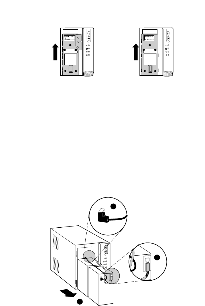
2 Pull the top left corner forward and remove the UPS front bezel (see Figure 2).
Figure 2 Removing the UPS Front Bezel
INSTALLATION
HP T750 G2, HP T750J, HP T1000 G3, HP T1000J, HP T1500 G3, and HP T1500J UPS Models User Guide S 505922-002 5
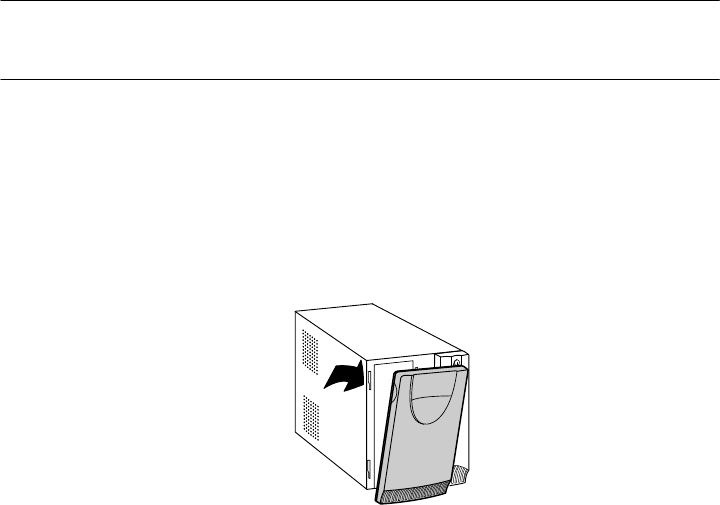
3 Slide up and remove the metal battery cover (see Figure 3). Do not remove any
screws.
NOTE: For HP T750 G2, HP T750J, and HP T1000 G3 models, carefully remove the metal
battery cover to avoid damaging the battery disconnect blades.
HP T1000J
HP T1500 G3, and
HP T1500J
HP T750 G2
HP T750J, and
HP T1000 G3
Figure 3 Removing the Battery Cover
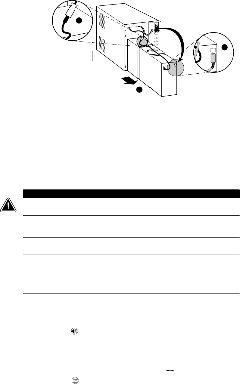
4 Remove the protective label from the internal battery connector (see Figure 4).
Figure 4 Removing the Protective Label
5 Connect the red wire to the positive ()) battery connector (see Figure 5).
NOTE: A small amount of arcing may occur when connecting the batteries. This is normal
and does not damage the unit or present any safety concern.
Figure 5 Connecting the Internal Battery Connector
6 Replace the metal battery cover.
7 Replace the UPS front bezel.
INSTALLATION
HP T750 G2, HP T750J, HP T1000 G3, HP T1000J, HP T1500 G3, and HP T1500J UPS Models User Guide S 505922-002
6
Installing the UPS
NOTE: Do not make unauthorized changes to the UPS or accessories; otherwise, damage
may occur to your equipment and void your warranty.
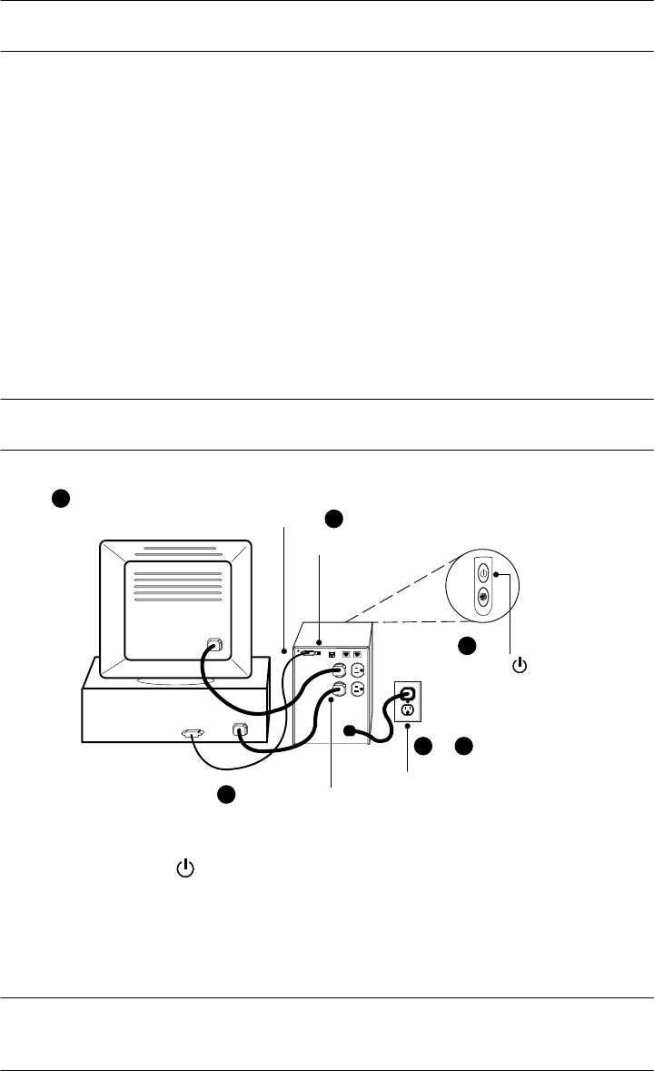
To install the UPS:
1 Verify that the DIP switch is set to the correct output voltage and input voltage
range (see Table 1 on page 14).
2 If you plan to use HP Power Manager software, first connect your computer to the
USB port or UPS serial port using the supplied cable. For more information about
communication options, see page 14.
3 For 230V models only, plug the detachable power cord into the input connector on
the UPS rear panel.
4 Plug the UPS power cord into a power outlet.
5 Plug the equipment to be protected into the UPS output receptacles.
NOTE: DO NOT connect laser printers to the UPS because of the exceptionally high power
requirements of the heating elements.
Press the (On/Off)
button (on the front panel)
2Connect communication cable
from computer to UPS (optional)
Connect UPS to power
3&4
5Connect equipment to UPS
6
1
Verify DIP switch
Figure 6 Typical UPS Installation (120V Model Shown)
6 Press and hold the (On/Off) button until you hear the UPS beep.
The (Power On) indicator illuminates green indicating that power is available
to your equipment. The UPS conducts a self‐test and enters Normal mode.
If the UPS beeps or a UPS alarm indicator stays on, see Table 10 on page 28.
NOTE: The batteries charge to 90% capacity in approximately 3 hours. However, to fully
charge, HP recommends that the batteries charge for 6 to 24 hours after installation or
long-term storage.
INSTALLATION
HP T750 G2, HP T750J, HP T1000 G3, HP T1000J, HP T1500 G3, and HP T1500J UPS Models User Guide S 505922-002 7
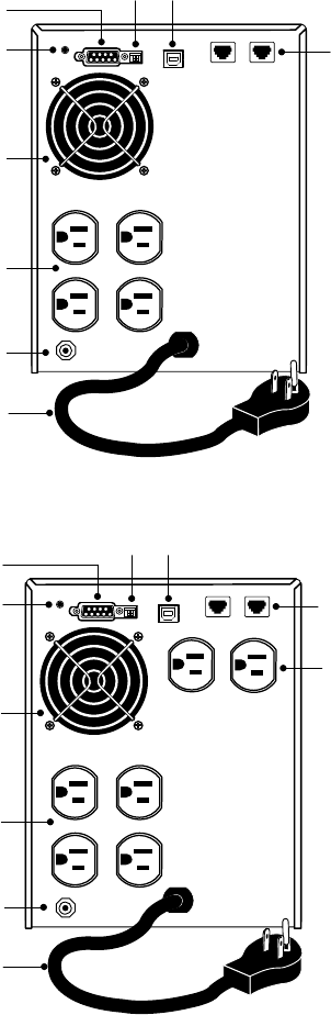
UPS Rear Panels
This section shows the UPS rear panels.
Four 5‐15
Receptacles
6-ft Power Cord
with 5‐15 Plug
Network Transient
Protector
Fan
Serial Port DIP Switches
Site Wiring Fault
Indicator
USB Port
Input Overcurrent
Protector
Figure 7 HP T750 G2 120V Rear Panel
Network Transient
Protector
Two 5‐15
Receptacles
Four 5‐15
Receptacles
6-ft Power Cord
with 5‐15 Plug
Fan
Serial Port DIP Switches
Site Wiring Fault
Indicator
USB Port
Input Overcurrent
Protector
Figure 8 HP T750J 100V and HP T1000 G3 120V Rear Panel
INSTALLATION
HP T750 G2, HP T750J, HP T1000 G3, HP T1000J, HP T1500 G3, and HP T1500J UPS Models User Guide S 505922-002
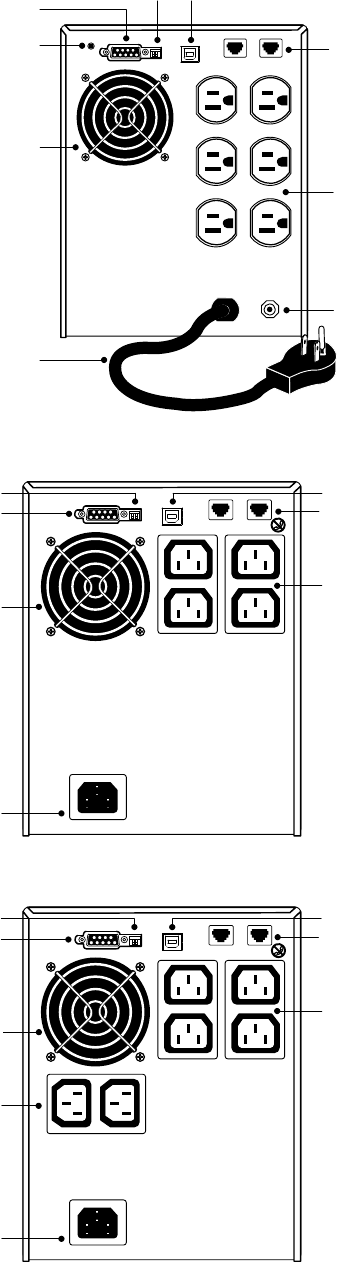
8
Six 5‐15 Receptacles
6-ft Power Cord
with 5‐15 Plug
Network Transient
Protector
Fan
Serial Port DIP Switches
Site Wiring Fault
Indicator
USB Port
Input Overcurrent
Protector
Figure 9 HP T1000J 100V, HP T1500J 100V, and HP T1500 G3 120V Rear Panel
Four 10A, IEC-320
Receptacles
DIP Switches
Network Transient
Protector
10A, IEC-320
Input Connector
Fan
Serial Port USB Port
Figure 10 HP T750 G2, 230V Rear Panel
Two 10A, IEC-320
Receptacles
Four 10A, IEC-320
Receptacles
10A, IEC-320
Input Connector
Fan
DIP Switches
Network Transient
Protector
Serial Port USB Port
Figure 11 HP T1000 G3, 230V Rear Panel
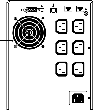
INSTALLATION
HP T750 G2, HP T750J, HP T1000 G3, HP T1000J, HP T1500 G3, and HP T1500J UPS Models User Guide S 505922-002 9
Six 10A, IEC-320
Receptacles
Fan
10A, IEC-320
Input Connector
DIP Switches
Network Transient
Protector
Serial Port USB Port
Figure 12 HP T1500 G3, 230V Rear Panel

HP T750 G2, HP T750J, HP T1000 G3, HP T1000J, HP T1500 G3, and HP T1500J UPS Models User Guide S 505922-002
10
Chapter 4 Operation
This section describes:
STurning the UPS on and off
SStarting the UPS on battery
SStandby mode
SThe UPS front panel and indicators
SInitiating the self‐test
Turning the UPS On
After the UPS is connected to a power outlet, the UPS enters Standby mode.
To turn on the UPS, press and hold the (On/Off) button until you hear the UPS beep.
After the UPS is turned on, it conducts a self‐test and enters Normal mode. The
(Power On) indicator illuminates green indicating that power is available to your
equipment.
Starting the UPS on Battery
NOTE: The UPS does not auto-detect the input frequency when starting on battery; the
default is the last frequency used by the UPS.
To turn on the UPS without using utility power, press and hold the (On/Off) button
for two seconds. The UPS starts up in Battery mode and supplies battery power to your
equipment. When the UPS starts on battery, it does not conduct a self‐test to conserve
battery power.
OPERATION
HP T750 G2, HP T750J, HP T1000 G3, HP T1000J, HP T1500 G3, and HP T1500J UPS Models User Guide S 505922-002 11
Turning the UPS Off
NOTE: Pressing the (On/Off) button while the UPS is in Battery mode causes the UPS to
shut down immediately.
To turn off the UPS:
1 Shut down the equipment connected to the UPS.
2 Press and hold the (On/Off) button for two seconds. The UPS transfers to
Standby mode (if utility power is available) and removes power from your
equipment.
3 Unplug the UPS from the power outlet.
If you do not unplug the UPS, it remains in Standby mode.
Standby Mode
When the UPS is turned off and remains plugged into a power outlet, the UPS is in
Standby mode. All indicators are off, and power is not available to your equipment.
The battery recharges when necessary.
NOTE: For 220–240V models, the output receptacles may remain electrically live (up to
110–120V). Unplug the UPS to ensure power is not available to the output receptacles.
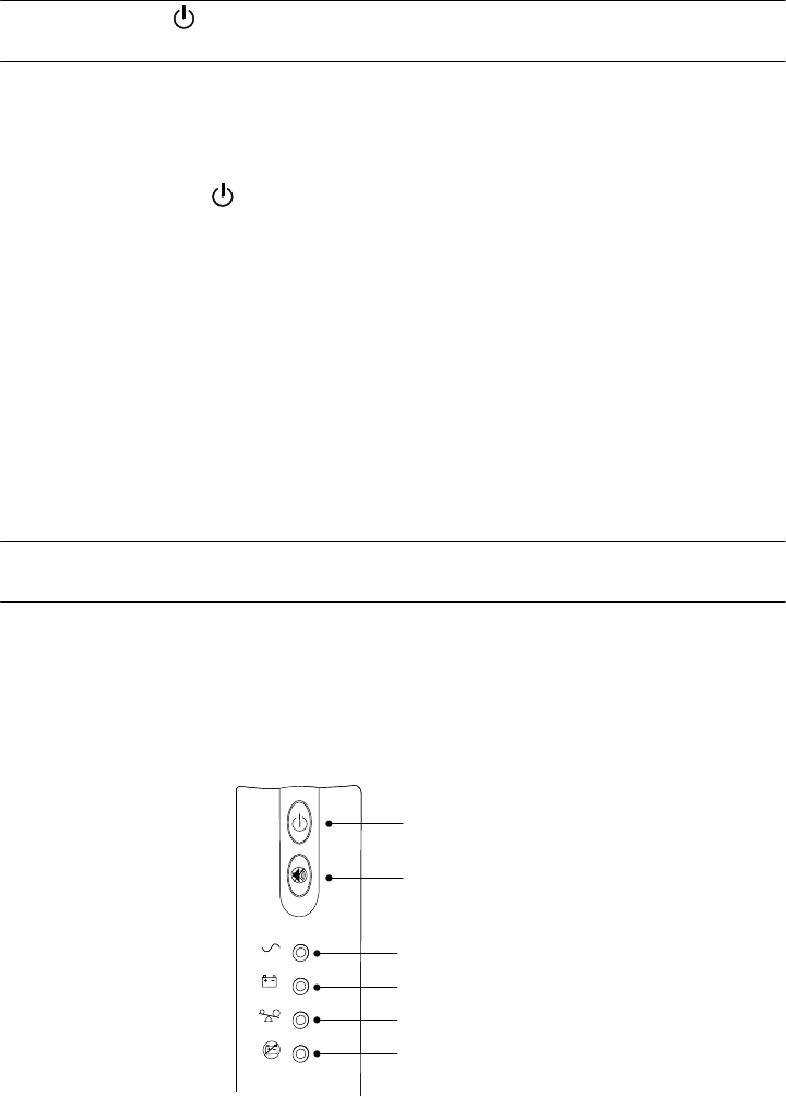
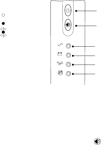
UPS Front Panel
The UPS front panel indicates the UPS status and also identifies potential power
problems. Figure 13 shows the UPS front panel indicators and controls.
On/Off Button
Test/Alarm Reset Button
Power On Indicator (green)
On Battery Indicator (yellow)
Overload Indicator (red)
Service Indicator (red)
Figure 13 UPS Front Panel
If the UPS beeps or a UPS alarm indicator stays on, see Table 10 on page 28 to
identify and correct the problem.

OPERATION
HP T750 G2, HP T750J, HP T1000 G3, HP T1000J, HP T1500 G3, and HP T1500J UPS Models User Guide S 505922-002
12
Initiating the Self‐Test
NOTE: The batteries must be fully charged and the UPS must not be in Battery mode to
perform the self‐test.
Press and hold the (Test/Alarm Reset) button for three seconds to initiate the self‐test.
During the five-second test, the bar graph indicators cycle through twice. If the UPS
beeps or a UPS alarm indicator stays on, see “Troubleshooting” on page 27.
HP T750 G2, HP T750J, HP T1000 G3, HP T1000J, HP T1500 G3, and HP T1500J UPS Models User Guide S 505922-002 13
Chapter 5 Additional UPS Features
This section describes:
SVoltage configuration
SUSB port and serial port
SNetwork transient protector
SHP Power Manager software
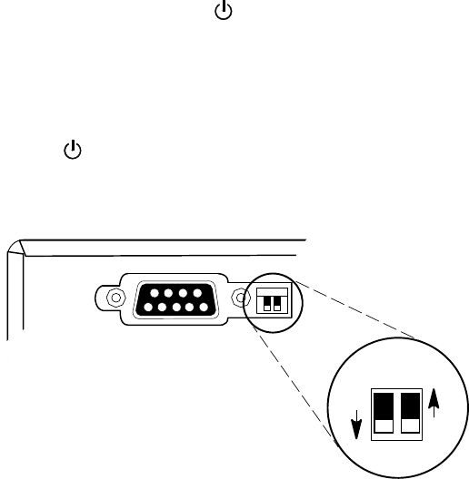
Voltage Configuration
The DIP switches on the rear panel of each unit (see Figure 14) are used to configure
the output voltage and input voltage range.
To configure voltage:
1 The UPS must be completely shutdown.
To turn off the UPS, press and hold the (On/Off) button for two seconds and
then unplug the UPS from the power outlet.
2 Set the DIP switches according to the configurations in Table 1 on page 14.
3 Plug the UPS power cord into a power outlet.
4 Press and hold the (On/Off) button until you hear the UPS beep to turn the UPS
on.
UPS Rear Panel
ON
OFF
21
Figure 14 DIP Switches
ADDITIONAL UPS FEATURES
HP T750 G2, HP T750J, HP T1000 G3, HP T1000J, HP T1500 G3, and HP T1500J UPS Models User Guide S 505922-002
14
Table 1 DIP Switch Settings
100V Models
Output Voltage Input Voltage Range DIP Switch 1 DIP Switch 2
100V 90–106V ON ON
120V Models
Output Voltage Input Voltage Range DIP Switch 1 DIP Switch 2
110V 99–116V ON OFF
120V* 108–127V* OFF OFF or ON
230V Models
Output Voltage Input Voltage Range DIP Switch 1 DIP Switch 2
220V 198–233V ON OFF
230V* 207–243V* OFF OFF or ON
240V 216–254V ON ON
* Default position
Communication Options
The UPS is equipped with a USB port and a serial port. Either the USB port or the serial
port may be used to monitor the UPS; however, they cannot operate simultaneously.
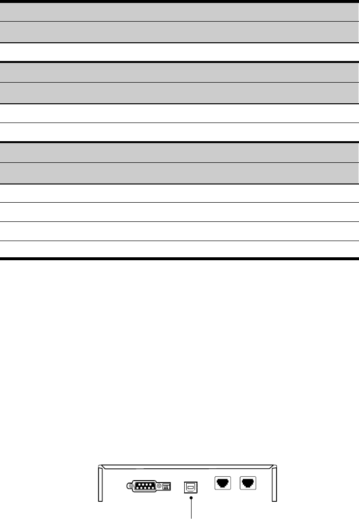
USB Port
The UPS can communicate with a USB-compliant computer using HP Power Manager
software.
To establish communication between the UPS and a computer:
1 Connect the USB cable to the USB port on the UPS rear panel.
Connect the other end of the USB cable to the USB port on your computer.
USB Port
Figure 15 The USB Port
2 Install the HP Power Manager software according to the instructions provided with
the software.
ADDITIONAL UPS FEATURES
HP T750 G2, HP T750J, HP T1000 G3, HP T1000J, HP T1500 G3, and HP T1500J UPS Models User Guide S 505922-002 15
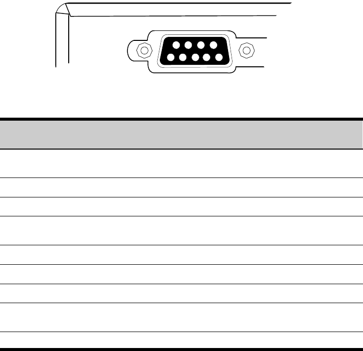
Serial Port
To establish communication between the UPS and a computer, connect your computer
to the UPS serial port using the supplied communication cable.
When the communication cable is installed, HP Power Manager software can exchange
data with the UPS. The software polls the UPS for detailed information on the status of
the power environment. If a power emergency occurs, the software initiates the saving
of all data and an orderly shutdown of the equipment.
The cable pins are identified in Figure 16, and the pin functions are described in
Table 2.
3
8
79
1
6
245
UPS Rear Panel
Figure 16 Serial Port
Table 2 Serial Port Pin Assignment
Pin
Number Signal Name Function Direction from
the UPS
1Low Batt Low battery relay contact; 20 mA, 30 Vdc
contact rating Out
2 TxD Transmit to external device Out
3 RxD Receive from external device In
4 DTR PnP (Plug and Play) from external device
(tied to Pin 6) In
5 GND Signal common (tied to chassis) —
6 DSR To external device (tied to Pin 4) Out
7 — No connection —
8AC Fail AC fail relay contact; 20 mA, 30 Vdc
contact rating Out
9Power Source +V (8 to 24 volts DC power) Out
ADDITIONAL UPS FEATURES
HP T750 G2, HP T750J, HP T1000 G3, HP T1000J, HP T1500 G3, and HP T1500J UPS Models User Guide S 505922-002
16
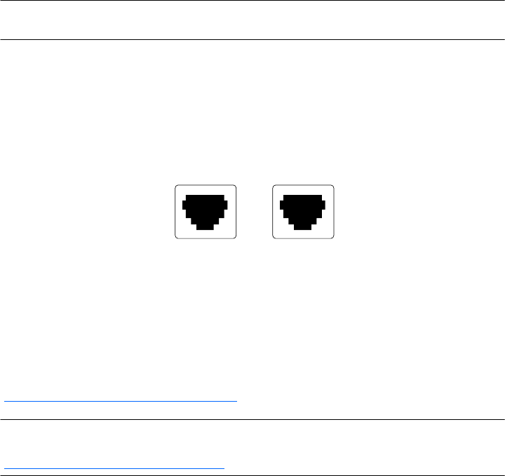
Network Transient Protector
The network transient protector, shown in Figure 17, is located on the rear panel and
has jacks labeled IN and OUT. This feature accommodates a single RJ‐45 (10BaseT)
network connector.
Low voltage models can also accommodate an RJ‐11 telephone connector that provides
protection for modems, fax machines, or other telecommunications equipment. As with
most modem equipment, it is not advisable to use this jack in digital PBX (Private Branch
Exchange) environments.
NOTE: DO NOT connect any telephone or fax/modem equipment (RJ-11) to the 230V
models; only connect network cables (RJ-45) to the 230V models.
1 Connect the input connector of the equipment you are protecting to the jack
labeled IN.
2 Connect the network or telephone (low voltage models only) cable to the jack
labeled OUT.
OUT IN
IN
OUT
Figure 17 Network Transient Protector
HP Power Manager Software
HP Power Manager software ensures maximum power reliability of computer systems
through comprehensive control of UPSs. The easy-to-use browser interface enables
novice users to configure and manage power protection settings. To download the latest
version of HP Power Manager software, see the HP website
(http://www.hp.com/go/rackandpower).
NOTE: To install and configure the software, see the software user guide. The software user
guide is available for download from the HP website
(http://www.hp.com/go/rackandpower).
HP Power Manager:
SDoes not require complex management systems, which simplifies deployment,
configuration, and management of UPS-protected environments.
SManages a graceful shutdown of attached devices during utility power failures.
SPrioritizes the timing of attached load device shutdowns.
SShuts down and reboots any UPS and attached load devices based on a
user-specified schedule.
SCustomizes alert generation with modifiable dialog boxes, command execution, and
email and broadcast messages.
SMonitors the status of the UPS and reports alarms.
SDisplays a power log for analysis.
HP T750 G2, HP T750J, HP T1000 G3, HP T1000J, HP T1500 G3, and HP T1500J UPS Models User Guide S 505922-002 17
Chapter 6 UPS Maintenance
This section explains how to:
SCare for the UPS and batteries
STransport the UPS
SStore the UPS and batteries
SOrder spare batteries
SReplace the batteries
STest new batteries
SRecycle used batteries or UPS
UPS and Battery Care
For the best preventive maintenance, keep the area around the UPS clean and dust‐free.
If the atmosphere is very dusty, clean the outside of the system with a vacuum cleaner.
For full battery life, keep the UPS at an ambient temperature of 25°C (77°F).
NOTE: The batteries in the UPS are rated for a 3–5 year service life. The length of service
life varies, depending on the frequency of usage and ambient temperature. Batteries used
beyond expected service life will often have severely reduced runtimes. Replace batteries at
least every 5 years to keep units running at peak efficiency.
Transporting the UPS
NOTE: The internal UPS batteries MUST be disconnected during transport.
If the UPS requires any type of transportation:
1 Verify that the UPS is unplugged and turned off.
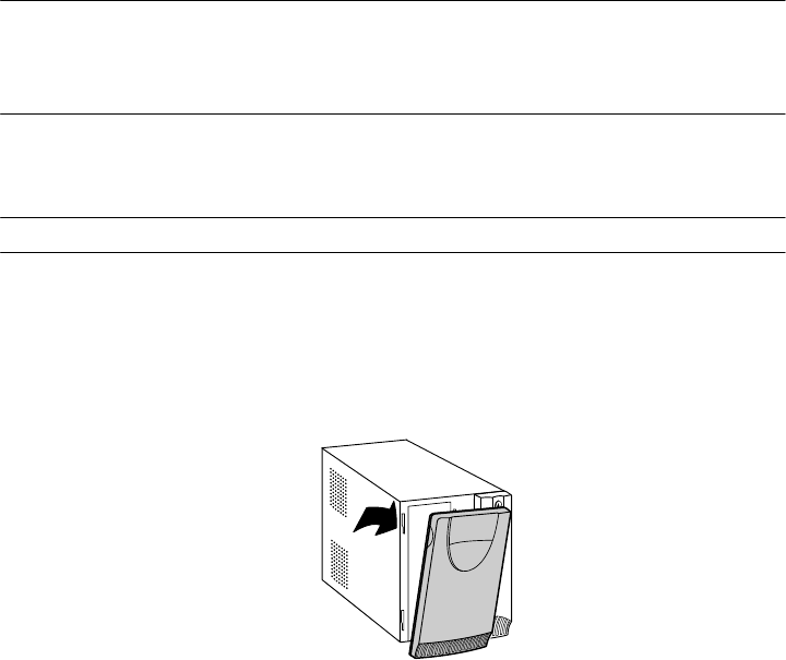
2 Pull the top left corner forward and remove the UPS front bezel (see Figure 18).
Figure 18 Removing the UPS Front Bezel
UPS MAINTENANCE
HP T750 G2, HP T750J, HP T1000 G3, HP T1000J, HP T1500 G3, and HP T1500J UPS Models User Guide S 505922-002
18
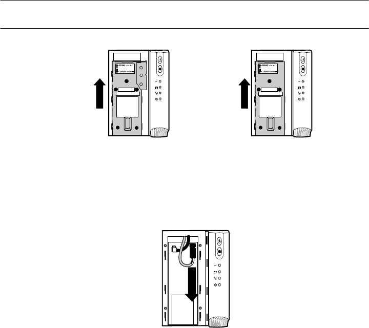
3 Slide up and remove the metal battery cover (see Figure 19). Do not remove any
screws.
NOTE: For HP T750 G2, HP T750J, and HP T1000 G3 models, carefully remove the metal
battery cover to avoid damaging the battery disconnect blades.
HP T1000J
HP T1500 G3, and
HP T1500J
HP T750 G2
HP T750J, and
HP T1000 G3
Figure 19 Removing the Battery Cover
4 Disconnect the red wire from the positive ()) battery connector (see Figure 20).
Figure 20 Disconnecting the Internal Battery Connector
5 Replace the metal battery cover.
6 Replace the UPS front bezel.
Storing the UPS and Batteries
If you store the UPS for a long period, recharge the battery every 6 months by plugging
the UPS into a power outlet. The batteries charge to 90% capacity in approximately
3 hours. However, to fully charge, HP recommends that the batteries charge for 6 to 24
hours after long-term storage.
Check the battery recharge date on the shipping carton label. If the date has passed
and the battery was never recharged, do not use the UPS. Contact your service
representative.

UPS MAINTENANCE
HP T750 G2, HP T750J, HP T1000 G3, HP T1000J, HP T1500 G3, and HP T1500J UPS Models User Guide S 505922-002 19
UPS Battery Spares
Ordering Spares
To order a spare, visit the HP website (http://h61003.www6.hp.com).
To replace parts under warranty, contact an HP authorized service representative.
UPS Spare Parts List
Description Spare part number
T750G2 UPS battery module 502538-001
T750J, T1000G3 UPS battery module 502539-001
T1000J, T1500J, T1500G3 UPS battery module 502540-001
T750G2 UPS unit NA 502532-001
T750G2 UPS unit INTL 502533-001
T750J UPS unit JPN 538256-001
T1000G3 UPS unit NA 502534-001
T1000G3 UPS unit INTL 502535-001
T1000J UPS unit JPN 538257-001
T1500 UPS unit NA 502536-001
T1500 UPS unit INTL 502537-001
T1500J UPS unit JPN 538258-001
UPS MAINTENANCE
HP T750 G2, HP T750J, HP T1000 G3, HP T1000J, HP T1500 G3, and HP T1500J UPS Models User Guide S 505922-002
20
Replacing Batteries
NOTE: DO NOT DISCONNECT the batteries while the UPS is in Battery mode.
With the hot‐swappable battery feature, batteries can be replaced easily without turning
the UPS off or disconnecting the load.
If you prefer to remove input power to change the batteries, press and hold the
(On/Off) button for two seconds and then unplug the UPS.
Consider all warnings, cautions, and notes before replacing batteries.
W A R N I N G
SBatteries can present a risk of electrical shock or burn from high short circuit current.
The following precautions should be observed: 1) Remove watches, rings, or other
metal objects; 2) Use tools with insulated handles; 3) Do not lay tools or metal parts on
top of batteries.
SELECTRIC ENERGY HAZARD. Do not attempt to alter any battery wiring or connectors.
Attempting to alter wiring can cause injury.
SReplace batteries with the same number and type of batteries as originally installed in
the UPS.
C A U T I O N
Pull the battery out onto a flat, stable surface. The battery is unsupported when you pull it
out of the UPS.
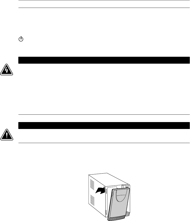
To replace the UPS internal battery:
1 Pull the top left corner forward and remove the UPS front bezel (see Figure 21).
Figure 21 Removing the UPS Front Bezel
UPS MAINTENANCE
HP T750 G2, HP T750J, HP T1000 G3, HP T1000J, HP T1500 G3, and HP T1500J UPS Models User Guide S 505922-002 21
2 Slide up and remove the metal battery cover (see Figure 22). Do not remove any
screws.
NOTE: For HP T750 G2, HP T750J, and HP T1000 G3 models, carefully remove the metal
battery cover to avoid damaging the battery disconnect blades.
HP T1000J
HP T1500 G3, and
HP T1500J
HP T750 G2
HP T750J, and
HP T1000 G3
Figure 22 Removing the Battery Cover
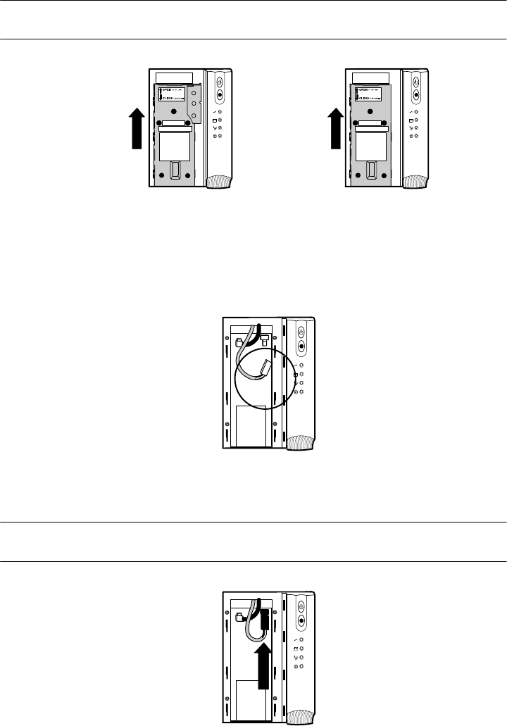
For HP T750 G2, HP T750J, and HP T1000 G3 models, see Figure 23. For HP T1000J,
HP T1500J, and HP T1500 G3 models, see Figure 24:
3 Disconnect the red battery cable.
4 Pull the battery out onto a flat, stable surface.
For HP T1000J, HP T1500 G3, and HP T1500J, slowly pull the battery out just far
enough to expose the cable retainer for the black battery lead and carefully
remove the battery lead from the cable retainer.
5 Carefully disconnect the black battery cable to the UPS.
3
5
4
Figure 23 Removing the Battery (HP T750 G2, HP T750J and HP T1000 G3 Models)
UPS MAINTENANCE
HP T750 G2, HP T750J, HP T1000 G3, HP T1000J, HP T1500 G3, and HP T1500J UPS Models User Guide S 505922-002
22
4
5
3
Cable Retainer
Figure 24 Removing the Battery (HP T1000J, HP T1500J, HP T1500 G3 Models)
6 Replace the battery. See “Recycling the Used Battery or UPS” on page 23 for
proper disposal.
7 Place the new battery pack in the same position with the battery terminals at the
top.
8 Connect the black battery cable to the new battery.
9 Slide the batteries into the UPS. For HP T1000J, HP T1500 G3, and HP T1500J,
carefully replace the black battery cable into the cable retainer.
C A U T I O N
To avoid damage to the battery leads, be sure that the cables do not bind against the
guide rail while reinstalling the battery.
10 Connect the red battery cable.
NOTE: A small amount of arcing may occur when connecting the batteries. This is normal
and does not damage the unit or present any safety concern.
11 Replace the metal battery cover and UPS front bezel.
Testing New Batteries
NOTE: Allow batteries to charge for 6 to 24 hours before testing.
NOTE: The batteries must be fully charged and the UPS must not be in Battery mode to
perform the self‐test.
Press and hold the (Test/Alarm Reset) button for three seconds to initiate a self-test.
The 15-second test automatically distributes the load to the battery and tests the battery's
performance. While the test is in progress, the indicators cycle through and the UPS
beeps. When complete, the UPS returns to Normal mode as indicated by the
(Power On) indicator.
If there is a problem with the battery, the UPS beeps, the +- (On Battery) indicator
illuminates and the (Service) indicator flashes. Check the battery connections and be
sure the battery is fully charged. Call your service representative if the problem persists.

UPS MAINTENANCE
HP T750 G2, HP T750J, HP T1000 G3, HP T1000J, HP T1500 G3, and HP T1500J UPS Models User Guide S 505922-002 23
Recycling the Used Battery or UPS
Contact your local recycling or hazardous waste center for information on proper
disposal of the used battery or UPS.
W A R N I N G
SDo not dispose of the battery or batteries in a fire. Batteries may explode. Proper
disposal of batteries is required. Refer to your local codes for disposal requirements.
SDo not open or mutilate the battery or batteries. Released electrolyte is harmful to the
skin and eyes. It may be toxic.
C A U T I O N
Do not discard the UPS or the UPS batteries in the trash. This product contains sealed,
lead‐acid batteries and must be disposed of properly. For more information, contact your
local recycling/reuse or hazardous waste center.
C A U T I O N
Do not discard waste electrical or electronic equipment (WEEE) in the trash. For proper
disposal, contact your local recycling/reuse or hazardous waste center.

HP T750 G2, HP T750J, HP T1000 G3, HP T1000J, HP T1500 G3, and HP T1500J UPS Models User Guide S 505922-002
24
Chapter 7 Specifications
This section provides the following specifications:
SModel list
SDimensions and weights
SElectrical input and output
SEnvironmental and safety
SBattery
Table 3 Model List
100V Models 120V Models 230V Models
UPS Models HP T750J (HSTNR-U017-N)
HP T1000J (HSTNR-U018-N)
HP T1500J (HSTNR-U018-J)
HP T750 G2 (HSTNR-U016-N)
HP T1000 G3 (HSTNR-U017-N)
HP T1500 G3 (HSTNR-U018-N)
HP T750 G2 (HSTNR-U016-I)
HP T1000 G3 (HSTNR-U017-I)
HP T1500 G3 (HSTNR-U018-I)
Table 4 Dimensions and Weights
100V Models 120V Models 230V Models
UPS Dimensions
(W H D)
HP T750 G2, HP T750J, and HP T1000 G3: 15.0 19.3 33.5 cm (5.9” 7.6” 13.2”)
HP T1000J, HP T1500 G3, and HP T1500J: 15.0 19.3 39.0 cm (5.9” 7.6” 15.4”)
UPS Weights HP T750 G2: 12.4 kg (27.3 lb)
HP T750J and HP T1000 G3: 12.6 kg (27.8 lb)
HP T1000J and HP T1500 G3: 16.8 kg (37.0 lb)
HP T1500J: 17.2 kg (37.9 lb)
Table 5 Electrical Input
100V Models 120V Models 230V Models
Nominal Voltage 100V 110V, 120V selectable 220V, 230V, 240V selectable
Voltage Range ±20% for nominal voltage at full load
Nominal Frequency 45–65 Hz, 50/60 Hz auto-sensing
Efficiency (Normal mode) 95%
Noise Filtering Full-time EMI/RFI filtering
Overcurrent Protection Resettable input overcurrent protector N/A
Connections 6-ft, 5-15P power cord (90° angle) 10A, IEC-320 input connector

SPECIFICATIONS
HP T750 G2, HP T750J, HP T1000 G3, HP T1000J, HP T1500 G3, and HP T1500J UPS Models User Guide S 505922-002 25
Table 6 Electrical Output
100V Models 120V Models 230V Models
Power Levels (rated at nominal
inputs)
100V: 750 VA, 500W
1000 VA, 680W
1200 VA, 980W
110V and 120V: 750 VA, 500W
1000 VA, 670W
120V: 1400 VA, 950W
750 VA, 500W
1000 VA, 670W
1400 VA, 950W
Power Factor 0.67
Regulation (Normal mode) -10% to +6% of nominal voltage
Regulation (Battery mode),
Nominal Voltage ±5%
Same as selected nominal input
voltage
100V
Same as selected nominal input
voltage
110V, 120V
Same as selected nominal
input voltage
220V, 230V, 240V
Voltage Waveform Sine wave
Overcurrent Protection Inverter saturation current limited
Output Receptacles HP T750J, HP T1000J, and
HP T1500J: (6) 5-15 HP T750 G2: (4) 5-15
HP T1000 G3 and HP T1500 G3:
(6) 5-15
HP T750 G2:
(4) 10A, IEC-320
HP T1000 G3 and HP
T1500 G3: (6) 10A, IEC-320
Table 7 Environmental and Safety
100/120V Models 230V Models
Operating Temperature Up to 1,500 meters: 0°C to 40°C (32°F to 104°F); UL tested 25°C (77°F)
Above 1,500 meters: 0°C to 35°C (32°F to 95°F)
Transit/Storage Temperature -15°C to 55°C (5°F to 131°F)
Relative Humidity 5–95% noncondensing
Operating Altitude Up to 3,000 meters above sea level
Audible Noise Less than 45 dBA typical
Surge Suppression ANSI C62.41 Category A (formerly IEEE 587)
Safety Conformance UL 1778 2nd Edition; UL 497A;
CSA C22.2, No. 107.1 IEC/EN 62040-1-1 and IEC/EN 60950-1
Safety Markings cULus, cUL, NOM-NYCE CE, TÜV, C-Tick, GOST R, EK, IRAM, TISI
EMC (Class B) FCC Part 15, ICES-003, VCCI IEC/EN 62040-2, FCC Part 15, ICES-003, VCCI

SPECIFICATIONS
HP T750 G2, HP T750J, HP T1000 G3, HP T1000J, HP T1500 G3, and HP T1500J UPS Models User Guide S 505922-002
26
Table 8 Battery
UPS Configuration HP T750 G2: (2) 12V, 7 or 7.2 Ah internal batteries
HP T750J and HP T1000 G3: (2) 12V, 9 Ah internal batteries
HP T1000J, HP T1500 G3, and HP T1500J: (3) 12V, 9 Ah internal batteries
Voltage HP T750 G2, HP T750J, and HP T1000 G3: 24 Vdc
HP T1000J, HP T1500 G3, and HP T1500J: 36 Vdc
Type Sealed, maintenance‐free, valve‐regulated, lead‐acid
Charging Advanced charging for faster recovery; approximately 3 hours to 90% usable capacity at nominal line
and no supplementary power supply load
Monitoring Advanced monitoring for earlier failure detection and warning
Table 9 Battery Runtimes (in Minutes)
UPS Models by VA Ratings
Load (VA) Watts 750 1000 1400
200 128 38 41 58
300 192 27 28 41
500 320 14 15 28
600 402 9 10 19
750 503 6 8 14
900 603 6 10
1000 670 5 8
1200 804 6
1400 938 5
NOTE Battery times are approximate and may vary depending on the load configuration and battery charge.
HP T750 G2, HP T750J, HP T1000 G3, HP T1000J, HP T1500 G3, and HP T1500J UPS Models User Guide S 505922-002 27
Chapter 8 Troubleshooting
This section explains:
SUPS alarms and conditions
SHow to silence an alarm
SSite wiring fault (100–120V models only)
SService and support
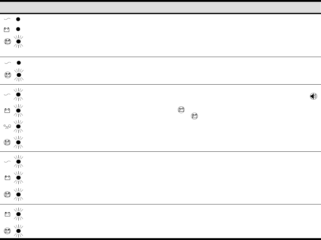
Audible Alarms and UPS Conditions
The UPS has an audible alarm feature to alert you of potential power problems. Use
Table 10 to determine and resolve the UPS alarms and conditions.
On/Off Button
Test/Alarm Reset Button
Power On Indicator (green)
On Battery Indicator (yellow)
Overload Indicator (red)
Service Indicator (red)
Flashing
Unlit
Lit
Indicator Legend
Figure 25 UPS Front Panel
Silencing an Audible Alarm
Before silencing an alarm, check the alarm condition and perform the applicable action
to resolve the condition (see Table 10).
To silence the alarm for an existing fault, press the (Test/Alarm Reset) button. If UPS
status changes, the UPS beeps, overriding the previous alarm silencing.
The alarm does not silence if there is a UPS fault, low battery condition, or if the battery
needs to be replaced.
Site Wiring Fault (100–120V Models Only)
The Site Wiring Fault indicator on the UPS rear panel illuminates if the ground wire
connection does not exist or the line and neutral wires are reversed in the line
receptacle. This indicator stays on until the condition is resolved. Have a qualified
electrician correct the wiring fault. The UPS operates when the indicator is illuminated,
but does not provide rated noise and surge suppression.

TROUBLESHOOTING
HP T750 G2, HP T750J, HP T1000 G3, HP T1000J, HP T1500 G3, and HP T1500J UPS Models User Guide S 505922-002
28
Table 10 Troubleshooting Guide
Alarm or Condition Possible Cause Action
The indicator is not on; the UPS
does not start.
The power cord is not
connected correctly. Check the power cord connections.
The UPS is in Standby mode. Press and hold the (On/Off) button until you hear the UPS
beep to supply power to the connected equipment.
The wall outlet is faulty. Have a qualified electrician test and repair the outlet.
The UPS operates in Battery mode only,
even though normal utility power is
present.
The input overcurrent protector
is open (100–120V models
only).
Save your work and turn off your equipment. Turn off the UPS.
Reduce the load, then press the input overcurrent protector on
the UPS rear panel.
The UPS does not provide the expected
backup time. The batteries need charging or
service. Plug the UPS into a power outlet for 24 hours to charge the
battery. Press the (Test/Alarm Reset) button. If the UPS
beeps, see “Replacing Batteries” on page 20 to replace the
battery.
During an extended power outage, save your work and turn
off your equipment to conserve battery power.
Normal operation. None. The UPS is operating in Normal mode and
automatically provides consistent voltage with the Buck and
Boost feature.
1 beep every 4 seconds. The UPS is on battery due to a
utility failure. The UPS is powering your equipment with battery power.
Prepare your equipment for shutdown. During an extended
power outage, save your work and turn off your equipment to
conserve battery power.
1 beep every 2 seconds. The battery is running low. Two minutes or
l
ess o
f
b
attery power remains
d
epen
d
ing on
load configuration and battery charge.
Save your work and turn off your equipment. The alarm
cannot be silenced.
1 beep every 4 seconds. The UPS is running on battery
power because the input
voltage is too high or too low.
Correct the input voltage, if possible. The UPS continues to
operate on battery until the condition is corrected or the
battery is completely discharged.
If the condition persists, the input voltage in your area may
differ from the UPS nominal. Change the UPS input voltage to
match your local voltage (see “Voltage Configuration” on
page 13).
1 beep per second. Power requirements exceed UPS
capacity (overload is greater
than 120%) or the load is
defective.
The UPS will automatically shut down in 3 minutes. Save your
work immediately and turn off your equipment. Turn off the
UPS.
Remove some of the equipment from the UPS. You may need
to obtain a larger capacity UPS.
1 beep per second. The UPS is on battery, and the
power requirements exceed UPS
capacity (overload is greater
than 120%) or the load is
defective.
Shutdown is imminent (30 seconds). Save your work and turn
off your equipment. Turn off and unplug the UPS.
Remove some of the equipment from the UPS. Wait at least
5 seconds until all LEDs are off, and then restart the UPS. You
may need to obtain a larger capacity UPS.
Continuous beep. Battery test failed. Check the battery connections and be sure the battery is fully
charged.
If the (Service) indicator still flashes, see “Replacing
Batteries” on page 20. Call your service representative if the
problem persists.
TROUBLESHOOTING
HP T750 G2, HP T750J, HP T1000 G3, HP T1000J, HP T1500 G3, and HP T1500J UPS Models User Guide S 505922-002 29
Table 10 Troubleshooting Guide (continued)
ActionPossible CauseAlarm or Condition
Continuous beep. UPS internal temperature is too
high. Shutdown is imminent. Save your work and turn off your
equipment. Turn off the UPS.
Clear vents and remove any heat sources. Ensure the airflow
around the UPS is not restricted. Wait at least 5 minutes and
restart the UPS. If the condition persists, contact your service
representative.
Continuous beep. UPS fan fault. Save your work and turn off your equipment. Turn off the UPS.
Contact your service representative.
3 beeps every 10 seconds. Failed attempt to start the UPS
on battery. P
l
ug t
h
e UPS into a power out
l
et
f
or 24
h
ours to c
h
arge
the battery. After charging the battery, press and hold the
(Test/Alarm Reset) button for 3 seconds, and then check the
(Service) indicator.
If the (Service) indicator still flashes, see “Replacing
Batteries” on page 20.
Continuous beep. The output wave is abnormal
while the UPS is on battery. Shutdown is imminent. Save your work and turn off your
equipment. Turn off the UPS. Contact your service
representative.
Continuous beep. The output voltage is below or
above the limit while the UPS is
on battery.
Save your work and turn off your equipment. Turn off the UPS.
Contact your service representative.
Technical Support
Before You Contact HP
Be sure to have the following information available before you call HP:
STechnical support registration number (if applicable)
SProduct serial number
SProduct model name and number
SProduct identification number
SApplicable error messages
SAdd-on boards or hardware
SThird-party hardware or software
SOperating system type and revision level

TROUBLESHOOTING
HP T750 G2, HP T750J, HP T1000 G3, HP T1000J, HP T1500 G3, and HP T1500J UPS Models User Guide S 505922-002
30
HP Contact Information
For the name of the nearest HP authorized reseller:
SIn the United States, see the HP US service locator webpage
(http://www.hp.com/service_locator).
SIn other locations, see the Contact HP worldwide (in English) webpage
(http://welcome.hp.com/country/us/en/wwcontact.html).
For HP technical support:
SIn the United States, for contact options see the Contact HP United States webpage
(http://welcome.hp.com/country/us/en/contact_us.html). To contact HP by phone:
oCall 1-800-HP-INVENT (1-800-474-6836). This service is available 24 hours a
day, 7 days a week. For continuous quality improvement, calls may be recorded
or monitored.
oIf you have purchased a Care Pack (service upgrade), call 1-800-633-3600. For
more information about Care Packs, refer to the HP website
(http://www.hp.com/hps).
SIn other locations, see the Contact HP worldwide (in English) webpage
(http://welcome.hp.com/country/us/en/wwcontact.html).

HP T750 G2, HP T750J, HP T1000 G3, HP T1000J, HP T1500 G3, and HP T1500J UPS Models User Guide S 505922-002 31
Chapter 9 Warranty Infromation
Limited Warranty
To back up the wide range of features offered with the UPS, a 3-year limited warranty is
provided.
$250,000 Computer Load Protection Guarantee
In addition to the limited warranty, a $250,000 Computer Load Protection Guarantee
(provided by the original equipment manufacturer) is offered.
IMPORTANT: The $250,000 Computer Load Protection Guarantee is offered only in The
United States and Canada.
The $250,000 Computer Load Protection Guarantee only applies if:
SThe UPS is plugged into a suitably grounded and wired outlet using no extension
cords, adapters, other ground wires, or other electrical connections.
SThe UPS installation complies with all applicable electrical and safety codes specified
by the NEC.
SThe UPS is used under normal operating conditions and users comply with all
instructions and labels.
SThe UPS is not damaged by accident (other than a utility power transient), misuse, or
abuse.
oThe Guarantee applies only to the original end-user and is non-transferable.
oThe Guarantee does not include reimbursement for or restoration of any data
loss.
SThe UPS is either connected directly to an enterprise class PDU, which is then
connected directly to a server, workstation, or personal computer, or the UPS is
connected directly to a server, workstation, or personal computer.
Pre-Failure Battery Warranty
The Pre-Failure Battery Warranty, standard on all UPS units, extends the advantage of a
3-year limited warranty by applying it to the battery before it actually fails. The
Pre-Failure Battery Warranty ensures that the battery is replaced free of charge when a
notification that the battery might fail is received from power management software. The
battery warranty coverage is 3 years for parts. The warranty for the first year of
ownership includes parts and labor. If battery spares are not available for a particular
UPS model, the entire UPS, including its battery, is replaced.
A Pre-Failure Battery warning is given 30 days before a battery failure. The warning is
indicated in one or both of the following ways:
SAn LED showing the battery is low
SNotification from power management software
