Hp Ux Auto Port Aggregation Apa Software Administrators Guide Administrator's
2015-03-28
: Hp Hp-Hp-Ux-Auto-Port-Aggregation-Apa-Software-Administrators-Guide-669673 hp-hp-ux-auto-port-aggregation-apa-software-administrators-guide-669673 hp pdf
Open the PDF directly: View PDF ![]() .
.
Page Count: 133 [warning: Documents this large are best viewed by clicking the View PDF Link!]
- HP Auto Port Aggregation Administrator's Guide
- Table of Contents
- About This Document
- 1 Introduction
- 2 Installing the APA Software
- 3 Configuring APA
- HP APA Configuration Examples
- Preparing for Configuration
- Link Aggregate Advanced Parameters
- Failover Group Advanced Parameters
- Configuring a Link Aggregate
- Configuring a Failover Group
- Configuring an IP Address
- Configuring the Link Partner
- Configuring HP Serviceguard
- Creating VLANs Over APA
- Verifying the Configuration
- What Happens During Start Up?
- 4 Using the lanadmin Command
- 5 Administering HP APA
- 6 Troubleshooting HP APA
- A Product Specifications
- B HP APA Configuration Files
- C Configuring HP APA by Editing Files
- D VLANs over APA Using HP Procurve Switches
- E Switch Configuration Information
- Glossary
- Index

HP Auto Port Aggregation Administrator's
Guide
HP-UX 11i v1, 11i v2
HP Part Number: J4240-90046
Published: September 2008
Edition: September 2008, E0908
©Copyright 2008 Hewlett-Packard Development Company, L.P.
Confidential computer software. Valid license from HP required for possession, use or copying. Consistent with FAR 12.211 and 12.212, Commercial
Computer Software, Computer Software Documentation, and Technical Data for Commercial Items are licensed to the U.S. Government under
vendor's standard commercial license. The information contained herein is subject to change without notice. The only warranties for HP products
and services are set forth in the express warranty statements accompanying such products and services. Nothing herein should be construed as
constituting an additional warranty. HP shall not be liable for technical or editorial errors or omissions contained herein. UNIX is a registered
trademark of The Open Group.

Table of Contents
About This Document.........................................................................................................9
1 Introduction...................................................................................................................13
Conceptual Overview...........................................................................................................................13
Link Aggregate................................................................................................................................13
Load Balancing...........................................................................................................................14
Failover Group.................................................................................................................................15
Proactive Failover.......................................................................................................................15
TCP Segmentation Offload..............................................................................................................16
VLAN Support.................................................................................................................................16
Interoperability with HP Serviceguard................................................................................................17
Administrative Methods.......................................................................................................................17
HP System Administration Manager..............................................................................................17
lanadmin Command........................................................................................................................18
Manually Editing Configuration Files.............................................................................................18
2 Installing the APA Software.........................................................................................19
Installation Requirements.....................................................................................................................19
Hardware Requirements.................................................................................................................19
Supported Switches....................................................................................................................19
Supported LAN Cards...............................................................................................................19
Operating System Requirements.....................................................................................................20
Software Requirements ...................................................................................................................20
Installing the Software..........................................................................................................................20
Verifying the Installation .....................................................................................................................20
Removing the Software.........................................................................................................................21
3 Configuring APA..........................................................................................................23
HP APA Configuration Examples........................................................................................................23
Enterprise Intranet Client/Server Environment..............................................................................23
Internet or Large Enterprise Environments Using Routers............................................................24
Server-to-Server (Back-to-Back).......................................................................................................26
Hot Standby for High Availability..................................................................................................27
Server-to-Server with Switch (Not Recommended)........................................................................28
Failover Group.................................................................................................................................29
Failover Group Using Link Aggregates .........................................................................................30
Preparing for Configuration.................................................................................................................31
Link Aggregate Advanced Parameters.................................................................................................34
Failover Group Advanced Parameters.................................................................................................35
Configuring a Link Aggregate..............................................................................................................36
Configuring an FEC_AUTO Mode Link Aggregate.......................................................................36
Using SAM to Configure a MANUAL Mode Link Aggregate........................................................41
Configuring a Failover Group..............................................................................................................46
Configuring an IP Address...................................................................................................................47
Configuring the Link Partner................................................................................................................47
Configuring HP Serviceguard..............................................................................................................47
Creating VLANs Over APA..................................................................................................................47
Verifying the Configuration..................................................................................................................47
Table of Contents 3
What Happens During Start Up?..........................................................................................................48
4 Using the lanadmin Command..................................................................................51
Set Options............................................................................................................................................52
Display Options....................................................................................................................................54
Invoking lanadmin from the Command Line.......................................................................................57
Using lanadmin Interactively...............................................................................................................59
5 Administering HP APA.................................................................................................63
Modifying HP APA Global Parameters................................................................................................63
Logging Messages to the syslog.log File...............................................................................................63
Examples..........................................................................................................................................64
Viewing HP APA Statistics...................................................................................................................65
6 Troubleshooting HP APA.............................................................................................67
Operation..............................................................................................................................................67
Getting Started......................................................................................................................................67
Solving HP APA Problems...................................................................................................................67
Solving Link Aggregate Problems (MANUAL Mode)....................................................................70
Solving Link Aggregate Problems (LACP Mode)...........................................................................74
Solving Link Aggregate Problems (FEC Mode)..............................................................................79
Solving Failover Group Problems...................................................................................................83
Troubleshooting Tools Overview and Usage........................................................................................88
Testing Access to Internet Network Hosts......................................................................................89
Scanning the System Hardware......................................................................................................89
nettl Tracing and Logging Tool.............................................................................................................90
Reporting Problems .............................................................................................................................92
Gathering Information.....................................................................................................................92
A Product Specifications.................................................................................................95
B HP APA Configuration Files.........................................................................................97
hp_apaconf File.....................................................................................................................................97
hp_apaportconf File..............................................................................................................................99
lanconfig.ascii File...............................................................................................................................100
lanconfig File.......................................................................................................................................103
C Configuring HP APA by Editing Files......................................................................105
Editing Configuration Files for Link Aggregates...............................................................................105
Editing Files for MANUAL, FEC_AUTO, or LACP_AUTO Mode...............................................105
MANUAL Port Configuration Mode.......................................................................................105
FEC_AUTO Port Configuration Mode.....................................................................................106
LACP_AUTO Port Configuration Mode..................................................................................106
Editing Configuration Files for Failover Groups...........................................................................107
Example: Configuring a Failover Group..................................................................................108
Proactive Failover Examples....................................................................................................110
D VLANs over APA Using HP Procurve Switches.......................................................113
Configuring VLANs over Link Aggregates .......................................................................................113
Configuring VLANs over Failover Groups........................................................................................114
4 Table of Contents
E Switch Configuration Information.............................................................................119
Alteon Switches...................................................................................................................................119
Cisco 6509 Switches.............................................................................................................................119
Configuring a Single Port..............................................................................................................119
Showing a Single Port....................................................................................................................119
Creating an LACP Link Aggregation............................................................................................120
Creating an PAgP Link Aggregation.............................................................................................120
Displaying the Link Aggregation..................................................................................................120
Displaying a Port in a Link Aggregation.......................................................................................121
Displaying More LACP Information.............................................................................................121
Deleting a Link Aggregation.........................................................................................................122
Extreme Switches................................................................................................................................122
Configuring HP APA Link Aggregates.........................................................................................122
Configuring LACP Link Aggregates.............................................................................................123
Procurve Switches...............................................................................................................................123
Procurve 4000/8000........................................................................................................................123
Procurve 4108.................................................................................................................................123
Procurve 9304/8..............................................................................................................................124
Configuring HP APA................................................................................................................125
Glossary.........................................................................................................................127
Index...............................................................................................................................129
Table of Contents 5

List of Figures
3-1 Sample Enterprise Intranet Client/Server Configuration..............................................................24
3-2 Sample Router and Server Configuration (No Switch).................................................................25
3-3 Sample Router and Server Configuration (Switch).......................................................................26
3-4 Sample Server-to-Server Configuration (Back-to-Back)................................................................27
3-5 Sample Hot Standby Configuration for High Availability...........................................................28
3-6 Sample Server-to-Server Configuration with Switch (Not Recommended).................................29
3-7 Sample Failover Group (LAN_MONITOR) Configuration..........................................................30
3-8 Sample Failover Group Using Link Aggregates Configuration...................................................31
3-9 HP APA Configuration Worksheet...............................................................................................32
3-10 Displaying Link Aggregates..........................................................................................................37
3-11 Configuring Link Aggregates.......................................................................................................37
3-12 Link Aggregate Advanced Options .............................................................................................38
3-13 Network Physical Ports Supporting HP APA...............................................................................38
3-14 Modify Network Physical Port Attributes....................................................................................39
3-15 Example of Configured Link Aggregates.....................................................................................39
3-16 Status of Configured Link Aggregate is UP..................................................................................40
3-17 Configuring Link Aggregates.......................................................................................................40
3-18 Link Aggregate with Configured IP Address...............................................................................41
3-19 Link Aggregates Supporting HP APA..........................................................................................42
3-20 Network Physical Ports Supporting APA.....................................................................................42
3-21 Modify Network Physical Port Attributes....................................................................................43
3-22 Display Link Aggregates to Configure.........................................................................................43
3-23 Configuring Link Aggregates.......................................................................................................44
3-24 Link Aggregate Advanced Options .............................................................................................44
3-25 Adding Ports to or Deleting Ports from Link Aggregate..............................................................45
3-26 Adding Ports to or Deleting Ports from Link Aggregate..............................................................45
3-27 Configured Link Aggregates Display...........................................................................................46
3-28 Link Aggregate Displays with Status UP......................................................................................46
D-1 VLAN over a Link Aggregate.....................................................................................................113
D-2 VLAN over a Failover Group......................................................................................................115
6 List of Figures

List of Tables
1-1 Interoperability with HP Serviceguard.........................................................................................17
4-1 Summary of lanadmin -x and -X Options.....................................................................................51
A-1 HP APA and LAN Monitor Capabilities.......................................................................................95
C-1 lan900 Events and Proactive Failover (Equal Network Costs)....................................................111
C-2 lan900 Events and Proactive Failover (Unequal Network Costs)...............................................112
7

List of Examples
5-1 Sample Link Aggregate 32-Bit Statistics........................................................................................66
5-2 Sample Link Aggregate 64-Bit Statistics........................................................................................66
6-1 Sample ioscan –f Output...............................................................................................................90
B-1 Sample lanconfig.ascii Configuration File...................................................................................101
8 List of Examples

About This Document
This document (formerly titled HP Auto Port Aggregation Support Guide) describes how to install,
configure, and troubleshoot HP Auto Port Aggregation (APA) on HP-UX Version 11.0, 11i v1,
11i v2 platforms.
Document updates can be issued between editions to correct errors or document product changes.
To ensure that you receive the updated or new editions, subscribe to the appropriate product
support service. See your HP sales representative for details.
This document is not a tutorial.
Intended Audience
This document is intended for system and network administrators responsible for installing,
configuring, and managing HP APA. Administrators are expected to have knowledge of operating
system concepts, commands, and configuration.
A knowledge of Transmission Control Protocol/Internet Protocol (TCP/IP) networking concepts
and network configuration is also helpful.
New and Changed Information in This Edition
The September 2007 release of HP APA for HP-UX 11i v1 supports Nortel Split Multi-Link
Trunking (SMLT) technology and MANUAL mode link aggregate creation from ports with
different group capability values.
The September 2007 release of HP APA for HP-UX 11i v2 supports HP Serviceguard over failover
groups (LAN_MONITOR mode), Nortel Split Multi-Link Trunking (SMLT) technology, and
improved HP Integrity virtual machine support.
The document has been reorganized and the troubleshooting section updated.
Document Organization
This document is organized as follows:
Chapter 1 (page 13) Describes HP APA, its concepts, and administrative methods.
Chapter 2 (page 19) Describes HP APA installation requirements and how to install HP
APA.
Chapter 3 (page 23) Shows sample HP APA configurations, and describes the
information to gather and the steps to configure HP APA using the
System Administration Manager (SAM).
Chapter 4 (page 51) Describes how to administer HP APA using the lanadmin
command.
Chapter 5 (page 63) Describes those tasks that you perform for the day-to-day
administration of HP APA.
Chapter 6 (page 67) Describes how to diagnose and solve HP APA problems, including
reporting problems to HP.
Appendix A (page 95) Provides a summary of the HP APA product specifications.
Appendix B (page 97) Describes the HP APA configuration files and their fields.
Appendix C (page 105) Describes how to configure HP APA by editing the configuration
files.
Appendix D (page 113) Describes the steps to configure VLANs over HP APA using HP
Procurve switches.
Appendix E (page 119) Provides information on using various switches to configure link
aggregates.
9

Typographic Conventions
This document uses the following typographical conventions:
%,$, or #A percent sign represents the C shell system prompt. A dollar
sign represents the system prompt for the Bourne, Korn, and
POSIX shells. A number sign represents the superuser prompt.
audit(5) A manpage. The manpage name is audit, and it is located in
Section 5.
Command A command name or qualified command phrase.
Computer output Text displayed by the computer.
Ctrl+x A key sequence. A sequence such as Ctrl+x indicates that you
must hold down the key labeled Ctrl while you press another
key or mouse button.
ENVIRONMENT VARIABLE The name of an environment variable, for example, PATH.
[ERROR NAME] The name of an error, usually returned in the errno variable.
Key The name of a keyboard key. Return and Enter both refer to the
same key.
Term The defined use of an important word or phrase.
User input Commands and other text that you type.
Variable The name of a placeholder in a command, function, or other
syntax display that you replace with an actual value.
[] The contents are optional in syntax. If the contents are a list
separated by |, you must choose one of the items.
{} The contents are required in syntax. If the contents are a list
separated by |, you must choose one of the items.
... The preceding element can be repeated an arbitrary number of
times.
Indicates the continuation of a code example.
| Separates items in a list of choices.
WARNING A warning calls attention to important information that if not
understood or followed will result in personal injury or
nonrecoverable system problems.
CAUTION A caution calls attention to important information that if not
understood or followed will result in data loss, data corruption,
or damage to hardware or software.
IMPORTANT This alert provides essential information to explain a concept or
to complete a task
NOTE A note contains additional information to emphasize or
supplement important points of the main text.
Related Information
You can find additional information about HP APA in docs.hp.com in the Internet & Networking
topic area, in the I/O Cards and Networking Software collection under Auto Port Aggregation (APA)
at:
http://www.docs.hp.com/hpux/netcom/index.html#Auto%20Port%20Aggregation%20%28APA%29
Other documents in this collection include:
10

•HP Auto Port Aggregation (APA) Release Notes
•Performance and Scalability White Paper
•Using APA to Build a Screaming Fast Network Server Connection
Publishing History
The document printing date and part number indicate the document’s current edition. The
printing date will change when a new edition is printed. Minor changes may be made at reprint
without changing the printing date. The document part number will change when extensive
changes are made. Document updates may be issued between editions to correct errors or
document product changes. To ensure that you receive the updated or new editions, you must
subscribe to the appropriate product support service. See your HP sales representative for details.
You can find the latest version of this document on line at:
http://www.docs.hp.com.
Publication DateEdition NumberSupported VersionsSupported Operating
Systems
Manufacturing Part
Number
September 2008E1207B.11.00.xx
B.11.11.30
B.11.23.40
B.11.31.10
11.0
11i v1
11i v2
J4240–90046
September 2008E0908B.11.31.2011i v3J4240–90045
December 2007E1207B.11.00.xx
B.11.11.30
B.11.23.40
B.11.31.10
11.0
11i v1
11i v2
11i v3
J4240–90041
September 2007E0907B.11.00.xx
B.11.11.30
B.11.23.30
11.0
11i v1
11i v2
J4240–90039
February 2007E0207B.11.31.0211i v3J4240–90037
HP Encourages Your Comments
HP encourages your comments concerning this document. We are committed to providing
documentation that meets your needs. Send any errors found, suggestions for improvement, or
compliments to:
feedback@fc.hp.com
Include the document title, manufacturing part number, and any comment, error found, or
suggestion for improvement you have concerning this document.
11
12

1 Introduction
HP Auto Port Aggregation (APA) is a software product that creates link aggregates, often called
trunks, which provide a logical grouping of two or more physical ports into a single fat pipe.
This port arrangement provides more data bandwidth than would otherwise be available and
enables you to build large bandwidth logical links into the server that are highly available and
completely transparent to the client and server applications. HP APA provides the following
features:
• Automatic link failure detection and recovery
• Support for load balancing of network traffic across all of the links in the aggregation.
• Support for the creation of failover groups, providing a failover capability for links. In the
event of a link failure, LAN Monitor automatically migrates traffic to a standby link.
• Support for the TCP Segmentation Offload (Large Send) feature, if an aggregate is created
with all Ethernet cards capable of TCP Segmentation Offload (TSO).
• Support for Virtual VLANs (VLANs) over APA link aggregates and failover groups.
(September 2006 release of HP-UX 11i v2 (B.11.23.20) and later releases)
• Support for 64-bit MIB (RFC 2863) statistics, if all the interfaces within a link aggregate or
failover group support 64-bit statistics.
• Support for IPv6 addresses on a link aggregate or failover group. (December 2005 release
of APA for HP-UX 11i v2 (B.11.23.10) and later releases)
For release-specific information, see the release notes on the web at:
http://www.docs.hp.com
For a summary of HP APA capabilities, see Appendix A (page 95).
Conceptual Overview
HP APA offers you a comprehensive solution to create fast, highly available network server
connections with minimal IT support costs. HP APA enables this with four key benefits:
• Automatic link failure detection and recovery in case of network failures. A link aggregate
continues to operate as long as there is at least one port operating.
• Scalable high-performance link aggregates using Fast or Gigabit Ethernet and the HP APA
load-balancing algorithms. See “Load Balancing” (page 14) for more information.
• Fault management and isolation with the HP MIB Monitor and nettl logging facilities.
• Lower IT costs with automated configuration and management tools using the IEEE 802.3ad
or PAgP standards and the intuitive HP System Management Homepage (SMH) GUI.
This section describes the following features of HP APA:
• Link aggregate
• Failover group
• TCP segmentation offload
• VLAN support
• Interoperability with HP Serviceguard
• Administrative methods
Link Aggregate
HP APA enables you to combine 2 to 4 physical link ports (up to 32 for LACP mode) into one
link aggregate. This gives the link aggregation a theoretical bandwidth of 4 times that of a single
physical link (32 times for LACP mode). A link aggregate has the following characteristics:
Conceptual Overview 13

NOTE: The December 2005 and later releases of APA for HP-UX 11i v2 (B.11.23.10) enable you
to combine 2 to 8 physical link ports into one link aggregate.
• The physical ports in the link aggregation use the same MAC address.
The unique MAC address for a specific link aggregate is determined by using the MAC
address of one of the ports in the link aggregate. All ports will use the same MAC address.
When a physical port is removed from a link aggregate, the port's MAC address is reset to
its own MAC address.
• HP APA link aggregates can migrate the network traffic from a failed physical link in the
aggregate to the remaining operational links in the aggregate.
• HP APA distributes the outbound network traffic across the physical links in the link
aggregation using a load balancing algorithm.
Effective APA load balancing requires many simultaneous, active client connections. The
connections are distributed across the physical links. One client connection will have its
traffic sent on one physical link. The connection is defined by the load-balancing algorithm.
See “Load Balancing” (page 14) for more information.
• Each link aggregate can have one or more IP addresses assigned to it in the /etc/
rc.config.d/netconf file.
• The link partner (the switch, router, or server) ports connected to the server ports must be
configured for link aggregation (trunking). In addition, the mode on the link partner and
the server must be the same. For example, if ports 1, 2, 3, and 4 are connected to a link partner
switch's ports C1, C2, C3, and C4, respectively, and the server side is trunked using
LACP_AUTO mode, the partner switch must be configured to trunk ports C1, C2, C3, and
C4 using LACP_AUTO mode.
NOTE: MANUAL mode link aggregates using HOT_STANDBY load balancing can be
connected to different switches. In addition, do not enable trunking on the corresponding
switch ports.
• The link partner (the switch, router, or server) connected to the link aggregation can inhibit
the usefulness of HP APA in some environments. See “HP APA Configuration Examples”
(page 23) for more information.
• All the devices in the link aggregation must be the same type and must be configured for
the same speed, duplex, and MTU. See “Supported LAN Cards” (page 19) for the devices
HP APA supports.
Load Balancing
HP APA provides load balancing on outbound data transfers using a load distribution algorithm
that you select when you configure a link aggregate. The load distribution algorithms are based
on destination MAC address, IP address, or TCP/UDP port number. Inbound load balancing is
strictly determined by the link partner (switch, router, or remote server) and has no affect on the
outbound algorithms.
Although you can use each of these load distribution algorithms in all supported configurations,
they may not all provide the same load on each of the physical ports in the link aggregate.
Therefore, HP prefers you use the algorithm that is recommended for each supported
configuration. See “Preparing for Configuration” (page 31) for more information.
The load balancing algorithm consists of the following steps:
14 Introduction
1. Data Flow Lookup — The load distribution algorithm determines an index into a hash table
that includes the physical port through which the outbound data flow is forwarded.
2. Data Flow Physical Port Assignment — If the hash index for the data flow has not been
assigned a physical port (the entry is empty), a physical port in the link aggregate is assigned
to that specific hash index. The physical port is selected on a Round Robin basis.
3. Aging Data Flows — Over time, each data flow is checked to determine if it is still active.
If the data flow has not been active in the last 30 seconds, its specific hash index is cleared
(aged out). If the data flow restarts after being cleared from the hash table, it is reassigned
a new physical port on a Round Robin basis.
Each load distribution algorithm guarantees that it will not introduce any severe ordering
problems within a specific data flow. This is required to ensure that the performance is not
degraded significantly as a result of turning on one of the algorithms.
Also, all packets for a specific data flow always flow out through the same physical port until
the data flow is aged out of the distribution table. This means that in order to generate
simultaneous load on each of the physical ports in a link aggregate, start multiple data flows
over the link aggregate.
Failover Group
HP APA enables you to combine 2 to 32 physical link ports into one failover group. A failover
group is a link aggregate in LAN_MONITOR mode, but with the following differences:
• One port is the active link, and the others are standby links. Network traffic is sent and
received on the active port.
• LAN Monitor periodically exchanges APA packets between the links making up the failover
group. This enables better detection of non-operational links in the failover group.
• If the active port or its link partner fails, LAN Monitor automatically migrates the traffic to
one of the standby ports in the failover group. When a port with a higher priority than the
current active port recovers, the network traffic is migrated back to the previous active port.
Sometimes, it is desirable to have the network traffic remain on the current active port after
the failure and recovery of the previous active port. To achieve this, set the HP APA port
priorities the same for all ports in the failover group.
• You can use 100BT, Gigabit, or 10 Gigabit Ethernet (10GbE) devices in the failover group.
However, all the devices in the failover group must be of one type: 100BT, Gigabit, or 10GbE.
• The failover group can have one or more IP addresses assigned to it.
• The physical ports in the failover group do not share a common MAC address.
• You can include link aggregates in a failover group. This enables increased bandwidth and
load balancing in a failover group.
Proactive Failover
By default, the port in a failover group with the highest priority is the active port. This is called
priority-based failover. However, the May 2005 and later releases of APA for HP-UX 11i v1
(B.11.11.20) and PHNE_33116 (B.11.11.17) patch release also allow you to configure failover
groups with proactive failover.
With proactive failover, the port that is the most efficient at carrying traffic is the active port.
Efficiency is determined by assigning a cost to each port in a failover group. This cost is divided
by the port's current link speed to yield a normalized port cost; link speed is the number of links
in a link aggregate multiplied by the speed of a member link, or in the case of a single link, only
the link speed. The lower the normalized port cost, the higher the link's efficiency. If two links
have the same normalized cost, the one with the higher priority is preferred.
For each failover group, if you assign a cost value to one link, you must assign a cost value to all
other links in the group. If you do not specify a cost value for any of the failover group's links,
the failover group uses the default failover behavior based on priority.
Conceptual Overview 15

During certain LAN Monitor events (for example, link failure and link recovery), the normalized
port cost might change on the active or standby links. When these events occur, the normalized
port cost of the active link and the standby links are compared. If a standby link has a lower
normalized port cost than the active link, the standby link becomes the active link even if the
current active link is UP.
TCP Segmentation Offload
HP APA supports TCP Segmentation Offload (TSO), also known as Large Send, on link aggregates
and failover groups if all the Ethernet cards are capable of it. TSO is a mechanism by which the
host stack offloads certain portions of outbound TCP packet processing to the Network Interface
Card (NIC) thereby reducing host CPU utilization. This functionality can significantly reduce
the load on the server for certain applications which primarily transmit large amounts of data
from the system.
In link aggregates, TSO has the following behavior:
• If TSO is enabled on all of the physical ports in a link aggregate, TSO is enabled for the entire
link aggregate. If any of the ports within that link aggregate go DOWN or UP, the TSO status
of the link aggregate does not change. After the physical ports are added to the aggregate,
the TSO capability of the physical ports cannot be changed.
• If a port is removed from a link aggregate, the following occurs:
— If TSO was supported on the link aggregate before removing the port, TSO remains
enabled on the link aggregate.
— If TSO was disabled on the link aggregate before removing the port, TSO of the link
aggregate is based on remaining ports in the link aggregate. If all remaining ports
support TSO, TSO is enabled on the link aggregate; otherwise, TSO remains disabled.
• If a port is added to a link aggregate, the TSO settings are recalculated. If the added port
has TSO disabled, TSO is disabled on the link aggregate.
In failover groups, the TSO status depends on the TSO status of the current active port. When
the active port is changed, the TSO status of the failover group might change. For example, an
active port supports TSO and the standby port does not. Therefore, the failover group supports
TSO. If the active port goes down, the standby port becomes active and the failover group now
no longer supports TSO.
By default, TSO is disabled. To enable TSO on each specific interface, see the Ethernet Support
Guide, available in http://www.docs.hp.com, in the Networking and Communication section.
To verify if TSO is supported on an link aggregate or failover group, enter the following command:
# lanadmin -x vmtu linkAggPPA
Driver/Hardware does not support TCP Segmentation Offload
If TSO is supported, a message similar to the following is displayed:
Driver/Hardware supports TCP Segmentation Offload, Current VMTU = 32160
VLAN Support
For the September 2006 and later releases of HP APA for HP-UX 11i v2 (B.11.23.20), VLANs over
link aggregates and failover groups have the same advantages of VLANs over physical links,
but with the following additional features:
• VLANs over link aggregates offer higher bandwidth than VLANs over a single physical
link.
• VLANs over failover groups offer improved reliability. The VLANs continue to carry traffic
in case the active link failed.
• You can use VLANs over one link aggregate to serve multiple workgroups. This also enables
broadcast traffic to be isolated within the same broadcast domain, offering improved security
for workgroups.
16 Introduction

• The same link aggregate or failover group can offer different level of service for each user
using ToS. You gain more flexibility in how you deploy link aggregates and failover groups.
•You can create, remove, and modify VLANs over link aggregates and failover groups without
rebooting the system. This enables you to configure networking on a server without
disrupting other users.
For more information on managing and using VLANs, see HP-UX VLAN Administrator's Guide
and your switch documentation.
Appendix D (page 113) describes characteristics of using VLANs over link aggregates and failover
groups and guidelines for each configuration.
Interoperability with HP Serviceguard
Table 1-1 shows the HP APA interoperability with HP Serviceguard. For installation guidelines,
see “Configuring HP Serviceguard” (page 47).
Table 1-1 Interoperability with HP Serviceguard
Number of LinksSupported ModesHP APA Version
HP
Serviceguard
Version
4 (FEC_AUTO)FEC_AUTO, Hot StandbyB.11.23.10A.11.15,
A.11.16
8 (FEC_AUTO), 32 (LACP_AUTO)FEC_AUTO, LACP_AUTO, and Hot
Standby
B.11.23.10 and
PHNE_34774
patch
A.11.17 and
PHSS_35427
patch1,
A.11.18
8 (FEC_AUTO), 32 (LACP_AUTO)FEC_AUTO, LACP_AUTO, Hot
Standby, and LAN_MONITOR2
B.11.23.30
(September 2007)
A.11.17 and
PHSS_35427
patch1,
A.11.18
1 Supports LACP link aggregations and link aggregations with more than four ports.
2 HP Serviceguard Primary LAN interface only.
Administrative Methods
The following sections provide a brief overview of the methods for administering HP APA. HP
recommends that you use the System Administration Manager (SAM) whenever possible.
HP System Administration Manager
The HP System Administration Manager (SAM) enables you to administer your HP-UX system
locally via a graphical user interface (GUI) and terminal user interface (TUI). SAM produces
fewer errors and saves your configuration data permanently so configuration does not require
a reboot to take effect. It is the recommended method for configuring link aggregates.
NOTE: You cannot use SAM to configure failover groups. For more information, see “Editing
Configuration Files for Failover Groups” (page 107) and “Configuring VLANs over Failover
Groups” (page 114).
In this manual, wherever SAM is mentioned in relation to HP APA configuration tasks, it is
presumed that you know how to invoke it.
For more information about the System Administration Manager, see sam(1M) and the online
help.
Interoperability with HP Serviceguard 17
lanadmin Command
You can also use the lanadmin command from the HP-UX command line to make changes to
HP APA. By default, those changes are not preserved across reboots. For more information about
the lanadmin command and using it to administer APA, see lanadmin(1M) and Chapter 4
(page 51), respectively.
Manually Editing Configuration Files
Some sections of this manual describe the system files that are updated or modified when you
perform an administrative task. Experienced UNIX administrators might prefer to administer
their systems manually by editing these files, as opposed to invoking the documented utility;
however, HP strongly recommends that you use SAM to update the system files.
In many cases, the SAM is the best alternative to manually editing system files, thus it is the
utility that is most frequently discussed in this manual.
18 Introduction

2 Installing the APA Software
This chapter describes the information required in order to install APA on your system.
Installation Requirements
1. Log in to the HP-UX server as superuser.
2. Confirm that the /usr/bin,/usr/sbin, and /sbin directories are in your PATH by using
the echo $PATH command.
3. Use the uname -a command to determine the HP-UX version of your system.
4. Install the required patches for your system as described in the “Required Patches” section
of the release notes.
Hardware Requirements
Supported Switches
HP APA supports the Cisco FastEtherChannel (PAgP) protocol, the Link Aggregation Control
Protocol (LACP) (IEEE 802.3ad), and manual trunking mechanisms. HP has tested switches from
the following vendors to work with HP APA:
• 3Com
• Cisco
• HP Procurve
• Foundry
• Alteon
• Nortel
• Extreme
With the September 2007 release of HP APA for HP-UX 11i v1 and HP-UX 11i v2 (B.11.11.30 and
B.11.23.30, respectively), HP APA also supports Nortel's Split Multi-Link Trunking (SMLT)
technology. Specifically, HP has tested the Passport 8006 and Passport 8010 switches with the
version 3.7.13.0 of the software.
Supported LAN Cards
The following network interface cards are supported for HP-UX 11.0 and 11i v1:
• All HP HP-PB, HSC, and PCI 10/100Base cards (both FX and TX)
• All HP HSC and PCI 1000Base cards (both Base-T and SX)
• HP-PB and PCI Token Ring (failover groups only)
• HP-PB and PCI FDDI (failover groups only)
The following network interface cards are supported for HP-UX 11i v2:
• All HP PCI 10/100Base cards (both FX and TX)
NOTE: HP APA does not support the 10/100 BT Standard/Management LAN interface
found on some systems and controlled by the intl100 driver, and any other devices
controlled by the intl100 driver.
• All HP PCI 1000Base cards (both Base-T and SX)
• PCI-X 10 GbE Fiber cards (failover groups only)
• All HP PCI-X 2-port Combination cards (network ports only)
• PCI Token Ring (failover groups only)
• PCI FDDI (failover groups only)
Installation Requirements 19

Operating System Requirements
HP-UX 11.0, 11i v1, or 11i v2.
Software Requirements
For the December 2005 release of HP APA for HP-UX 11i v2 (B.11.23.10) and later releases, if you
want to use 8 ports for trunking HP APA requires the following software:
• Transport Optional Upgrade (TOUR) 3.0
• Streams Advance Release (STAR) 1.0
• IPFilter version A.03.05.12, if you use IP Filter
Installing the Software
Skip this section if you ordered product option 0D1—preinstallation.
1. To install the software from the installation media, enter the following command:
swinstall
2. Choose the appropriate Source Depot Type (for example, Local CD, Local tape, Local
Directory, Network Directory/CDROM).
3. Choose Source Host Name.
4. Choose Source Depot Path. If you do not know the exact path, you can click the Source
Depot Path button to display a list of valid choices.
5. Highlight the HP APA software:
J4240AA
6. Choose Mark for Install from the Actions menu.
7. Choose Install from the Actions menu to begin product installation and to display the Install
Analysis window.
8. Click OK in the Install Analysis window when the Status field displays a Ready message.
9. Click YES at the Confirmation window to confirm that you want to install the software. The
swinstall command loads the fileset, runs the control scripts for the filesets, and builds
the kernel. The estimated time for processing is 3 to 5 minutes depending on the complexity
of your system. When the status field indicates Ready, a Note window opens. Click OK on
the Note window to reboot the system.
NOTE: You must reboot the system after the software installation to configure HP APA
into the kernel.
After you have installed HP APA, it will be in MANUAL port configuration mode until you
configure it to aggregate eligible ports.
See swinstall(1M) for more information.
Verifying the Installation
To verify that the HP APA software (J4240AA) has been successfully installed, complete the
following steps:
20 Installing the APA Software

1. Verify that the product was installed by issuing the following command:
# swlist -l product | grep -i HP-APA
Output similar to the following displays:
HP-APA-FMT B.11.23.40 HP Auto-Port Aggregation APA formatter product.
HP-APA-KRN B.11.31.20 HP Auto-Port Aggregation kernel products.
HP-APA-LM B.11.31.20 HP Auto-Port Aggregation LM commands.
HP-APA-NETMOD B.11.31.20 HP Auto-Port Aggregation nwmgr/NCweb libraries.
HP-APA-RUN B.11.31.20 HP Auto-Port Aggregation APA command products.
If the sub-products are not displayed, reinstall the software. See “Installing the Software”
(page 20) for more information.
2. Verify that the software is configured in the kernel by issuing the following command:
# what /stand/vmunix | egrep -i hp_apa
Output similar to the following displays:
$Revision: hp_apa: HP Auto-Port Aggregation (APA): B.11.31.20 Aug 20 2008 11:30
If nothing is displayed, rebuild the kernel.
Removing the Software
If you need to remove the HP APA software, complete the following steps:
1. To remove the software from the system, enter the following command:
swremove
2. Highlight the HP APA software:
J4240AA
3. Choose Mark for Remove from the Actions menu.
4. Choose Remove from the Actions menu to begin product removal and to display the Remove
Analysis window.
5. Click OK in the Remove Analysis window when the Status field displays a Ready message.
6. Click YES at the Confirmation window to confirm that you want to remove the software.
The swremove command unloads the fileset, runs the control scripts for the filesets, and
builds the kernel. The estimated time for processing is 3 to 5 minutes depending on the
complexity of your system. When the status field indicates Ready, a Note window opens.
Click OK on the Note window to reboot the system.
NOTE: You must reboot the system after the software removal to deconfigure HP APA in
the kernel.
See swremove(1M) for more information.
Removing the Software 21
22

3 Configuring APA
This chapter describes how to configure HP APA on your system. This includes:
• Reviewing sample HP APA configurations
• Preparing for the configuration by gathering information
• Configuring systems in sample configurations
• Configuring a link aggregate
• Configuring a failover group
• Configuring the link partner
• Performing post-configuration tasks
HP APA Configuration Examples
This section shows some sample HP APA configurations. Select a configuration that most closely
matches the environment into which you want to configure HP APA on your system.
Enterprise Intranet Client/Server Environment
Figure 3-1 shows a sample enterprise client/server environment. This type of environment is a
good candidate for HP APA link aggregations, and has the following characteristics:
• Requires a switch capable of trunking or load balancing.
• Many clients produce many connections. This makes effective use of the HP APA outbound
network traffic distribution algorithms. The HP APA MAC address load-balancing algorithm
is a good choice. The IP address and TCP/UDP port address load-balancing algorithm also
works effectively in this configuration.
• The switch typically provides good inbound traffic distribution. Most switches use the data
packet's source MAC address, or a combination of the packet's source and destination MAC
addresses, to provide inbound load balancing.
• Depending on the network traffic bandwidth requirements, you can use two to four 100BT
interfaces or two to four Gigabit interfaces in an PAgP or MANUAL link aggregation. For
the December 2005 release (B.11.23.10), you can use two to eight interfaces. With LACP, you
can use up to 32 interfaces in the link aggregation. This enables bandwidth scalability as
network loads increase as the organization grows.
HP APA Configuration Examples 23
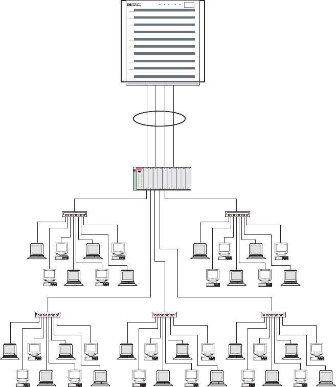
Figure 3-1 Sample Enterprise Intranet Client/Server Configuration
hp ProCurve
Switch 8000
HP APA 2–4 Port
Link Aggregation
HP ProCurve 8000 Switch
Hub Hub
1 2 3 4 5 6 7 0 1 2 3 4 5 6 7 0
1 2 3 4 5 6 7 0 1 2 3 4 5 6 7 0 1 2 3 4 5 6 7 0
Power Run Attn. Fault Remote
Internet or Large Enterprise Environments Using Routers
You can use HP APA link aggregation successfully in certain environments employing routers.
You must be careful because a particular router might not have a load balancing capability.
Additionally, switches employed between the server employing HP APA and the router inject
another level of complexity that you must analyze before determining that the environment is
a candidate for HP APA link aggregations.
Figure 3-2 (page 25) shows a sample router and server configuration with no switch. This
configuration makes the following assumptions:
• The router or switching router connected to the server provides trunking or load balancing
using an IP address-based load-balancing algorithm.
• There will be many TCP/UDP client connections. The HP APA IP address load-balancing
algorithm provides effective outbound network traffic load balancing, as does the TCP/UDP
port address algorithm. Do not use the MAC address algorithm because all packets
transmitted from the server would contain the same source and destination MAC addresses.
24 Configuring APA
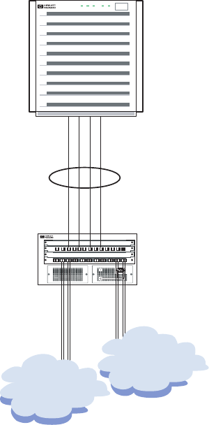
Figure 3-2 Sample Router and Server Configuration (No Switch)
HP APA 2–4 Port
Link Aggregation
Router or
Switching Router
Internet
Intranet
PowerRun Attn. Fault Remote
Figure 3-3 (page 26) shows a sample router and server configuration with a switch. In this
configuration, the switch might present problems because switches typically use a MAC address
load-balancing algorithm. This might make the switch a bottleneck point because the packets
from the router and from the server will contain the same source and destination MAC addresses,
thus defeating the load-balancing algorithm for both inbound and outbound data at the server.
This condition might be acceptable if the load balancing of inbound traffic to the server is not a
concern and the link between the switch and the router has greater bandwidth capacity than the
server's link aggregation. For example: The server's link aggregation is composed of 100BT links
and the link between the switch and the router is a Gigabit link.
HP APA Configuration Examples 25
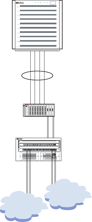
Figure 3-3 Sample Router and Server Configuration (Switch)
HP APA 2–4 Port
Link Aggregation
hp ProCurve
Switch 8000
Router or
Switching Router
Switch
Internet
Intranet
PowerRun Attn. Fault Remote
Server-to-Server (Back-to-Back)
Figure 3-4 (page 27) shows a sample server-to-server configuration. You create server-to-server
aggregations by directly connecting the physical ports in one server's link aggregation to the
physical ports in the other server's link aggregation. This configuration has the following
characteristics:
• It needs many TCP/UDP client connections between the servers in order for load balancing
to be effective. Therefore, use the HP APA TCP/UDP port load-balancing algorithm.
• Depending on the network traffic bandwidth requirements, use two to four 100BT interfaces
or two to four Gigabit interfaces in an PAgP or MANUAL link aggregation. For the December
2005 release (B.11.23.10), you can use two to eight interfaces. With LACP, you can use up
to 32 interfaces in the link aggregation. This enables bandwidth scalability as network loads
increase as the organization grows.
26 Configuring APA

Figure 3-4 Sample Server-to-Server Configuration (Back-to-Back)
HP APA 2–4 Port
Link Aggregation
PowerRun Attn. Fault Remote
PowerRun Attn. Fault Remote
Hot Standby for High Availability
Figure 3-5 (page 28) shows a sample MANUAL (Hot Standby) mode configuration. These link
aggregations provide high availability network access with an active link and a standby link.
NOTE: HP strongly recommends using failover groups (LAN_MONITOR mode) rather than
Hot Standby mode. Hot Standby aggregates are deprecated.
This configuration has the following characteristics:
• The Hot Standby active link carries network traffic until it or its link partner fails. In that
event, the standby link takes over the responsibility for delivering network traffic. If the
previous active link is configured with a higher port priority than the current active link,
when it recovers it resumes being the active link delivering the network traffic. If the port
priorities are the same, the current active link continues as the active link.
• The active and standby links must both be the same type of device: 100Base-T or Gigabit.
• Hot Standby link aggregations can be connected to any switch or hub. The ports must be
cabled to a switch and the switch ports must not be configured for an aggregation.
• Dual switches or hubs (as used in Figure 3-5) are not required. But dual switches and hubs
provide a more reliable network environment by removing single points of failure. Both
switches or hubs must be on the same subnet.
HP APA Configuration Examples 27
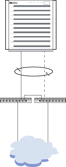
Figure 3-5 Sample Hot Standby Configuration for High Availability
HP APA 2-Port Hot
Standby Link Aggregation
Switch
or Hub Switch
or Hub
PowerRun Attn. Fault Remote
Primary
Standby
Server-to-Server with Switch (Not Recommended)
Figure 3-6 (page 29) shows a sample server–to–server HP APA link aggregation configuration
with a switch between the servers. This configuration will not work as intended for the following
reasons:
• The switch nullifies any load balancing of network traffic provided by HP APA.
• The switch uses a MAC address load-balancing algorithm. Because the servers' link
aggregations have fixed MAC addresses, the switch will not load balance; it will only transmit
data on one physical link.
28 Configuring APA
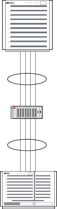
Figure 3-6 Sample Server-to-Server Configuration with Switch (Not Recommended)
HP APA 2–4 Port
Link Aggregation
HP APA 2–4 Port
Link Aggregation
PowerRun Attn. Fault Remote
PowerRun Attn. Fault Remote
hp ProCurve
Switch 8000
Switch
Failover Group
Figure 3-7 (page 30) shows a sample failover group (LAN_MONITOR mode) configuration. This
configuration provides high availability network access with an active link and a standby link,
and has the following characteristics:
• Dual switches or hubs are not required. However, dual switches and hubs provide a more
reliable network environment by removing the switch or hub as a single point of failure. If
two switches or hubs are used, there must be a data path between them to allow them to be
on the same subnet.
• You can connect failover groups to any switch or hub.
• The link partner does not require trunking to be enabled.
HP APA Configuration Examples 29
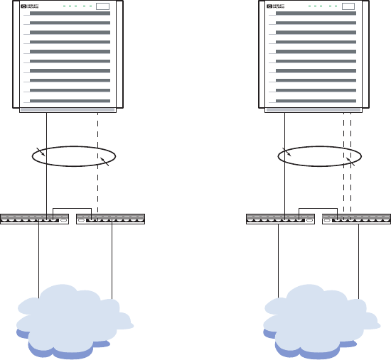
Figure 3-7 Sample Failover Group (LAN_MONITOR) Configuration
LAN Monitor 2-Port
Failover Group
LAN Monitor 3-Port
Failover Group
Switch
or Hub Switch
or Hub
PowerRun Attn. Fault Remote
Active
Standby
Switch
or Hub Switch
or Hub
PowerRun Attn. Fault Remote
Active
2 Standby
Links
Failover Group Using Link Aggregates
Figure 3-8 (page 31) shows a failover group that uses link aggregates as the active and standby
devices to increase the network bandwidth through load balancing across the physical links.
This configuration has the following characteristics:
• You can use any HP APA link aggregate, except Hot Standby, as a device in the failover
group.
• The standby link does not have to be a link aggregation. It can be a single physical link of
the same type as used in the link aggregation.
• Dual switches are not required. However, dual switches provide a more reliable network
environment by removing the switch as a single point of failure. If two switches are used,
there must be a data path between them.
• LAN Monitor failover groups using link aggregates are restricted to switches supported by
HP APA link aggregates.
30 Configuring APA
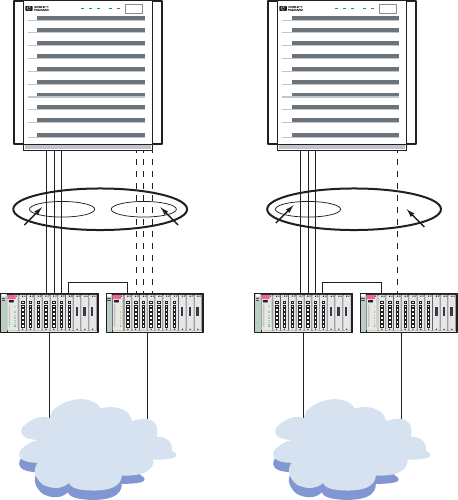
Figure 3-8 Sample Failover Group Using Link Aggregates Configuration
LAN Monitor failover
group using HP APA
link aggregations.
PowerRun Attn. Fault Remote
Active
LinkAgg
Standby
LinkAgg
Active
LinkAgg Standby
hp ProCurve
Switch 8000
hp ProCurve
Switch 8000
LAN Monitor failover
group using an HP APA
link aggregation as the
active link and one
physical link as a
standby link.
PowerRun Attn. Fault Remote
hp ProCurve
Switch 8000
hp ProCurve
Switch 8000
Preparing for Configuration
Before you configure the HP APA software, you must gather information about your system
and network environment. Figure 3-9 shows the APA Configuration Worksheet. The following
sections describe the information that you need to record on the worksheets. If you are viewing
this manual on line, you can use the print feature to print a copy of this worksheet.
Preparing for Configuration 31

Figure 3-9 HP APA Configuration Worksheet
HP APA Configuration Worksheet
Advanced Parameters (Link Aggregates)
Advanced Parameters (Failover Groups)
Aggregate Instance Number
Load Distribution
Algorithm
Mode
Failover
FEC_AUTO
LAN_MONITOR
Priority Based
LB_MAC
HOT_STANDBY
LB_IP LB_PORT
LACP_AUTO
Not_Enabled
Cost Based
MANUAL
Group Capability
Key
(FEC_AUTO only)
(LACP_AUTO only)
on off
Dead Count
Polling Interval
Rapid ARP
Rapid ARP Interval
Rapid ARP Count
Instance
Number:
Hardware
Path:
Interface
Type: Priority: Cost:
Aggregate Instance Number
The PPA number of the link aggregate or failover group. Enter a value. For example, use 900 for
lan900.
32 Configuring APA

NOTE: For HP-UX 11.0 releases, use 100 as the starting instance number.
Mode
The configuration mode of the link aggregate or failover group. Your choice will be determined
by the capabilities of the link partner (for example, switch, router, or server) to which the link
aggregate physical interfaces will be connected. See your link partner's documentation to
determine which modes it supports. Check the mode you want to use. The following choices are
available:
FEC_AUTO Automatically start the FEC protocol on the physical port.
LACP_AUTO Automatically start LACP on the physical port.
MANUAL HP APA does not automatically aggregate ports. You must manually add or
remove ports from a link aggregate.
LAN_MONITOR The ports are used for a failover group.
Not_Enabled Create the link aggregate with the Key, Group Capability, or Load Distribution
Algorithm set to a non-default value, but without any ports. You must add
ports to enable it.
Failover Policy
The mechanism by which LAN Monitor chooses the active port in a failover group. The following
choices are available:
Priority Based If the active port fails, LAN Monitor chooses the standby link that is UP
and that has the highest port priority (highest value) to be the new active
link. For the December 2005 and later releases of HP APA for HP-UX 11i
v1 (B.11.11.20) and PHNE_33116 (B.11.11.17) patch release.
Cost Based If the active port fails, LAN Monitor chooses the standby link that is UP
and has the lowest normalized port cost to be the new active link. This is
also called proactive failover. See “Proactive Failover” (page 15) for a
description of proactive failover and “Proactive Failover Examples”
(page 110) for proactive failover examples.
Check the failover policy you want to use.
Instance Number
The PPA numbers of the ports that will be in the link aggregation or failover group. Enter the
numbers on the sheet.
NOTE: Before adding ports to a failover group, you must check link connectivity between the
ports.
HW Path
The hardware path to the NIC associated with the port to include in the link aggregate or failover
group. A numeric string of hardware components, noted sequentially from the bus address to
the device address.
For link aggregates, this is a string in the form LinkAggxx, where xx is the last two digits of the
instance number (00 – 49).
This field is provided as a convenience in case you either do not know the PPA number of the
port or want a place to capture and save both values.
Interface Type
A short description of the NIC associated with the port. For example, 100Base-TX.
Preparing for Configuration 33
Priority
The port priority in a failover group (LAN_MONITOR mode) using priority-based failover or
cost-based failover. If you assign a priority value to one link, you must assign a priority value
to all links in the failover group. Leave this blank if you do not want to assign a priority value;
HP APA will assign it. For the December 2005 and later releases of HP APA for HP-UX 11i v1
(B.11.11.20) and PHNE_33116 (B.11.11.17) patch release.
Cost
The port cost in a failover group (LAN_MONITOR mode) using cost-based failover. A link that
has a lower normalized cost (cost divided by the link speed) is preferred over one with a higher
normalized cost. When both links have the same normalized cost, the one with the higher priority
is preferred. If you assign a cost value to one link, you must assign a cost value to all links in the
failover group. Leave this blank if you do not want to assign a cost value; HP APA will assign
it.
Link Aggregate Advanced Parameters
Load Distribution Algorithm
The algorithm to use for outbound data transfer. Inbound load balancing and data flow
distribution are strictly determined by the link partner and have no affect on the outbound
algorithm. For a complete description of load balancing, see “Load Balancing” (page 14). Check
the algorithm you want to use. The following choices are available:
LB_MAC This algorithm uses the least significant byte of the link level destination
MAC address of the data flow as an index into a table of 256 possible entries.
The physical port selected will be used to send packets for the duration of
the specific data flow.
This is the default algorithm for all link aggregates.
Recommended Configuration: Server-to-Switch
LB_IP This algorithm uses the least significant bytes of the source and destination
IP addresses of the data flow as an index into a table of 256 possible entries.
Recommended Configuration: Server-to-Router
LB_PORT This algorithm uses the TCP/UDP source and destination port numbers to
distribute traffic across the ports in a link aggregate.
Recommended configuration: Server-to-Server
HOT_STANDBY
(MANUAL mode
only)
This algorithm uses one link in the link aggregate on which to send all
outbound traffic; there is no actual load balancing across the network physical
ports in the link aggregate. The link is the one with highest port priority. If
the link goes down (for example, cable disconnect), all the traffic on the link
is automatically switched to a secondary link in the same link aggregate.
If you chose this option, the ports must be cabled to a switch and the switch
ports must not be configured for aggregation.
34 Configuring APA

Recommended configuration: Servers that need highly available network
interfaces.
CAUTION: For HP Serviceguard configurations, the member links of an
APA Hot Standby link aggregate must be bridged to function properly. If
they are not, the node or cluster might go down when a member link fails.
Group Capability
An integer value that determines which network physical ports can be aggregated into a common
FEC_AUTO mode link aggregate or MANUAL mode link aggregate for HP APA releases for
HP-UX 11i v1 prior to September 2007. The easiest way to create a value is to use the instance
number of the link aggregate as the group capability. You must use the same group capability
for all ports that you want to join this link aggregate and use the same group capability for the
link aggregate.
TIP: When configuring link aggregates, if more than one FEC_AUTO aggregation is used on
the system, each FEC_AUTO aggregation must have a different group capability.
Key
An integer value that determines which network physical ports can be aggregated into a common
LACP_AUTO mode link aggregate. The easiest way to create a value is to use the instance number
of the link aggregate as the key. You must use the same key value for all of the ports that you
want to join this link aggregate and use the same key value for the link aggregate.
Failover Group Advanced Parameters
Dead Count
The number of polling packets that are missed before LAN Monitor sends a nettl log message
to the user that indicates the link might have problems and the network must be checked. The
default is 3.
Polling Interval
The number of microseconds between polling messages. Polling messages are sent between links
in the specified interval for monitoring the health of all the links in the link aggregate. Default
is 10,000,000 (10 seconds).
Rapid ARP
Enables (on) or disables (off) the ability to transmit gratuitous ARP messages at intervals shorter
than 5 seconds. By default, this parameter is on.
By default, when the MAC address of a failover group changes, LAN Monitor transmits one
gratuitous ARP packet. Then, it transmits gratuitous ARP packets at a set interval
(LM_RAPID_ARP_INTERVAL) for a set number of times (LM_RAPID_ARP_COUNT) to ensure that
other clients and servers receive the new IP-MAC address mapping. LAN Monitor then transmits
gratuitous ARP packets every 5 seconds until 1 minute has elapsed from the first gratuitous ARP
packet.
If you disable this parameter, immediately after the MAC address changes LAN Monitor transmits
gratuitous ARP packets every 5 seconds for 1 minute.
Failover Group Advanced Parameters 35

Rapid ARP Interval
The number of microseconds between rapid gratuitous ARP messages. The range of valid values
is 1000000–4000000, inclusive (1 second to 4 seconds). The default value is 1000000 (1 second).
Specify a whole number of seconds because the value you specify is rounded up to the next
whole number of seconds. The value must be a valid integer. The rapid ARP interval multiplied
by the rapid ARP count must be less than or equal to 60 seconds.
Rapid ARP Count
The number of gratuitous ARP packets sent rapidly. The valid range is 5–60, inclusive. The
default value is 10. The value must be a valid integer. The rapid ARP interval multiplied by the
rapid ARP count must be less than or equal to 60 seconds.
Configuring a Link Aggregate
This section shows how to configure the following using SAM:
• FEC_AUTO mode link aggregates
• MANUAL mode link aggregates
For information on configuring link aggregates by editing configuration files, see “Editing
Configuration Files for Link Aggregates” (page 105).
Configuring an FEC_AUTO Mode Link Aggregate
When configuring an automatic link aggregate (FEC_AUTO or LACP_AUTO) using SAM, you
configure the link aggregation characteristics first, followed by the port's modes and characteristics.
NOTE: Although this example shows how to configure an FEC_AUTO mode link aggregate,
you can use these steps to configure an LACP_AUTO link aggregate. Substitute LACP_AUTO
for FEC_AUTO, and key for group_capability.
Complete the following steps:
1. Log in as superuser.
2. Enter sam at the HP-UX system prompt.
3. Double-click Networking and Communications, and then Auto Port Aggregation. A
window like the one in Figure 3-10 appears. The Networking and Communications screen's
List pull-down menu displays one of the following:
• Link Aggregates supported by HP APA. This is the list of all available link aggregates
in the system.
• Network Physical Ports that Support HP APA. This is the list of all physical ports in
the system that support HP APA.
36 Configuring APA
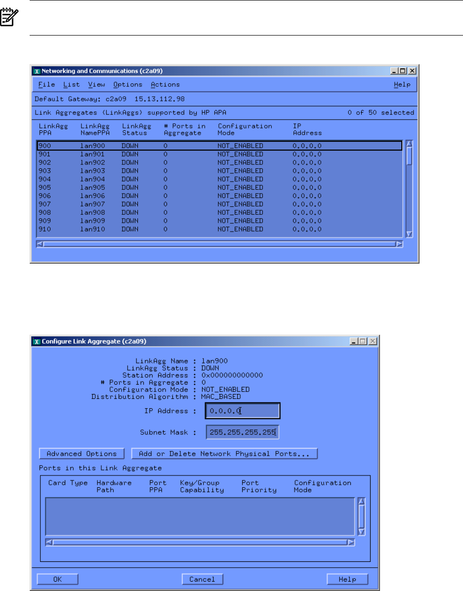
NOTE: The starting PPA number for link aggregates varies with the operating system
installed: for HP-UX 11.0, it is 100; and for all versions of 11i, it is 900.
Figure 3-10 Displaying Link Aggregates
4. Click on the link aggregate to be configured. From the Actions pull-down menu choose the
Configure Link Aggregate option. A window similar to Figure 3-11 will appear.
Figure 3-11 Configuring Link Aggregates
Configuring a Link Aggregate 37
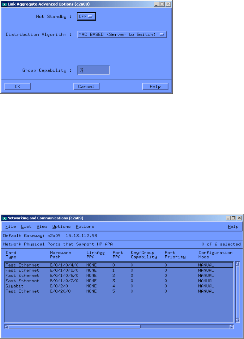
5. Click Advanced Options to display window similar to Figure 3-12.
Figure 3-12 Link Aggregate Advanced Options
6. Verify the correct settings for the load-balancing (distribution) algorithm. If required, make
the necessary changes.
7. Change the group capability of this link aggregate as required. The group capability must
be a nonzero number that differs from the group capability of any other link aggregate. It
must also match the group capability that will be assigned later to the ports intended to join
the link aggregate. Click OK, then click OK in the Configure Link Aggregate window.
8. Choose the Network Physical Ports that Support HP APA option from the List pull-down
menu. The displayed port configuration mode (column 7 in Figure 3-13) determines the
mode for the link aggregation. In Figure 3-13 the configuration mode for the ports that
support APA is, by default, set to MANUAL mode. You might need to adjust the horizontal
scroll bar to see all the window's fields.
Figure 3-13 Network Physical Ports Supporting HP APA
9. For each port to be configured in the automatic link aggregation, verify that the port's
configuration mode is set to the desired mode: FEC_AUTO. Check that the port's group
capability matches the group capability that was previously assigned to the link aggregation.
If changes are needed, go to the next step.
10. Highlight the port to configure by clicking on the port designated by its PPA.
11. In the Actions pull-down menu, choose the Modify Network Physical Port Attributes
option. You will see a window like the one in Figure 3-14.
38 Configuring APA
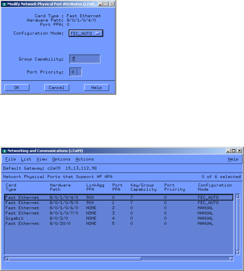
Figure 3-14 Modify Network Physical Port Attributes
12. In this window, make the necessary changes and click OK.
13. Repeat steps 8 through 12 to configure the remaining ports to be in the aggregate. Figure 3-15
shows a sample FEC_AUTO configuration using ports 0 and 1 with a group capability of 7.
Figure 3-15 Example of Configured Link Aggregates
14. From the List pull-down menu, choose the Link Aggregates Supported by HP APA option.
A window similar to Figure 3-16 will appear. Note that the link aggregate might not have
a status of UP immediately because HP APA and the switch or link partner might not have
completed the negotiation required for forming the link aggregation.
Wait for the link aggregate to change status to LINK_UP. Then, configure the IP address on
the link aggregate and continue with the next step.
Configuring a Link Aggregate 39
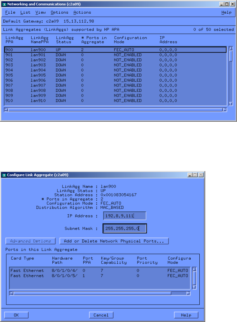
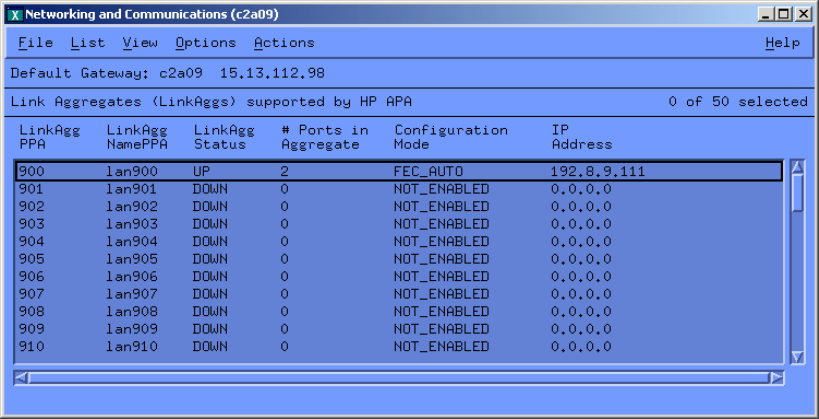
16. Fill in the desired IP address and subnet mask to be used for the link aggregate. Then click
OK. A window like that in Figure 3-18 will appear.
Figure 3-18 Link Aggregate with Configured IP Address
Perform one of the following:
• If the link aggregate has a status of UP
the configuration is complete. Exit SAM. Verify that the proper ports are configured in
the proper link aggregation with the lanadmin -x -v 900 command.
• If the link aggregate is DOWN
If the switch has not been configured, then exit SAM and configure the switch. The APA
configuration will have been permanently saved and can be modified later if needed.
If the switch has been configured, verify the switch and HP APA configuration and
make the required changes to bring them into agreement. If the link aggregate still does
not form correctly, see Chapter 6 (page 67).
SAM permanently saves the HP APA configuration values in the /etc/rc.config.d/
hp_apaconf and /etc/rc.config.d/hp_apaportconf files, which maintains the values
across reboots.
Using SAM to Configure a MANUAL Mode Link Aggregate
When configuring a manual link aggregate using SAM, you first configure the port's modes and
characteristics, then configure the link aggregate characteristics.
1. Log in as superuser.
2. Enter sam at the HP-UX system prompt.
3. Double-click Networking and Communications, and then Auto Port Aggregation. A
window like the one in Figure 3-19 appears. The Networking and Communications screen
List pull-down menu (Figure 3-19) displays either of the following:
• Link Aggregates supported by HP APA. This is the list of all available link aggregates
in the system.
• Network Physical Ports that Support HP APA. This is the list of all physical ports in
the system that support HP APA.
Configuring a Link Aggregate 41
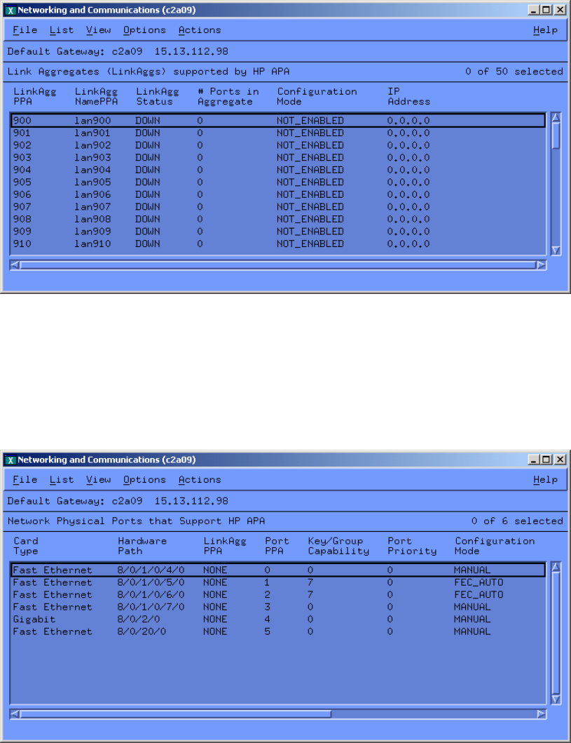
Figure 3-19 Link Aggregates Supporting HP APA
4. Choose the Network Physical Ports that Support HP APA option from the List pull-down
menu. The port configuration mode (shown in column 7 in Figure 3-20) determines the mode
for the link aggregate. In Figure 3-20, the configuration mode for the ports that support HP
APA is, by default, set to MANUAL mode. You might need to adjust the horizontal scroll
bar to see all the window's fields.
Figure 3-20 Network Physical Ports Supporting APA
5. For each port to be configured in the manual link aggregate, verify that the port's
configuration mode is set to the desired mode: MANUAL. Choose a group capability number
for each port and also for the aggregation. If changes are needed, go to the next step.
42 Configuring APA
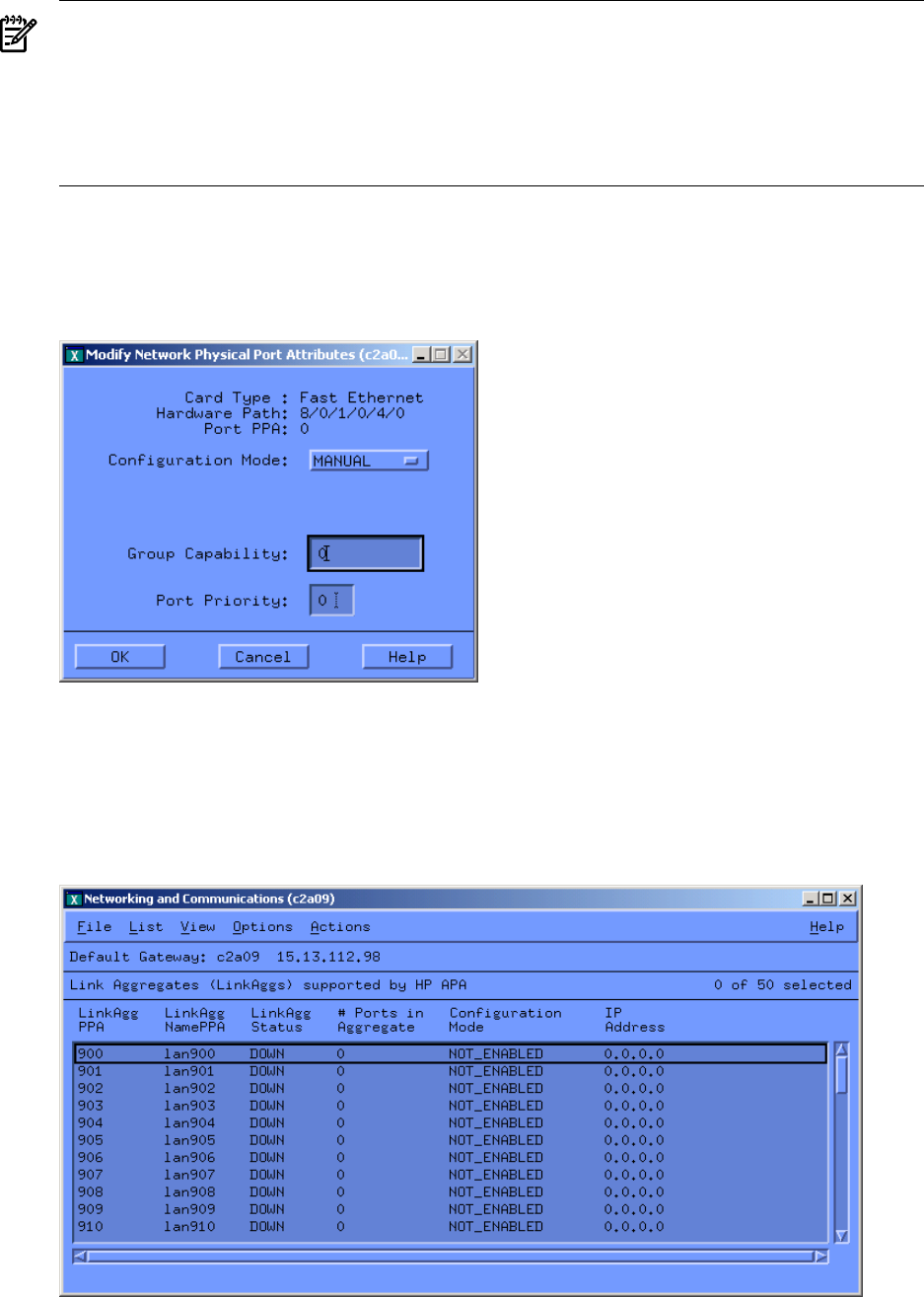
NOTE: Set the group capability to be the same as that of the link aggregate to which it
belongs. Ports going to different link aggregates must have different group capability
numbers.
For the September 2007 release of HP APA for HP-UX 11i v1 (B.11.11.30), you no longer
need to assign a group capability number to ports to be included in a MANUAL mode link
aggregate.
6. Highlight the port to configure by clicking on the port designated by its PPA.
7. In the Actions pull-down menu, choose the Modify Network Physical Port Attributes
option. A window similar to the one in Figure 3-21 appears.
Figure 3-21 Modify Network Physical Port Attributes
8. In this window make the necessary changes and click OK.
9. Repeat steps 4 through 7 to configure the remaining ports to be in the aggregate.
10. To configure the link aggregate characteristics, choose the Link Aggregates supported by
HP APA option from the List pull-down menu. A window similar to Figure 3-22 appears.
Figure 3-22 Display Link Aggregates to Configure
11. Click on the link aggregate being configured. Then, from the Actions pull-down menu,
choose the Configure Link Aggregate option. A window similar to Figure 3-23 appears.
Configuring a Link Aggregate 43
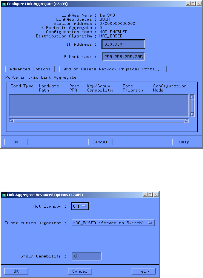
Figure 3-23 Configuring Link Aggregates
12. Fill in the desired IP address and subnet mask to be used for the link aggregate.
13. Click the Advanced Options button to display a window similar to Figure 3-24.
Figure 3-24 Link Aggregate Advanced Options
14. Verify the correct settings for the Group Capability (11i v1), assigned in step 4, and either
Hot Standby or the load balancing (distribution) algorithm (not both). Make the necessary
changes, if required. Then click OK.
15. Click Add or Delete Network Physical Ports. A window similar to Figure 3-25 appears.
44 Configuring APA
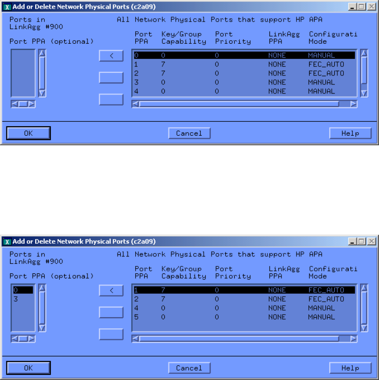
Figure 3-25 Adding Ports to or Deleting Ports from Link Aggregate
16. Highlight a port to be included in the link aggregate. Then use <to move it into the link
aggregate.
Figure 3-26 shows the result of moving lan0 and lan3 into the link aggregate, lan900.
Figure 3-26 Adding Ports to or Deleting Ports from Link Aggregate
17. Click OK to see the Configure Link Aggregates window (Figure 3-27) with all the link
aggregate information filled in.
Configuring a Link Aggregate 45
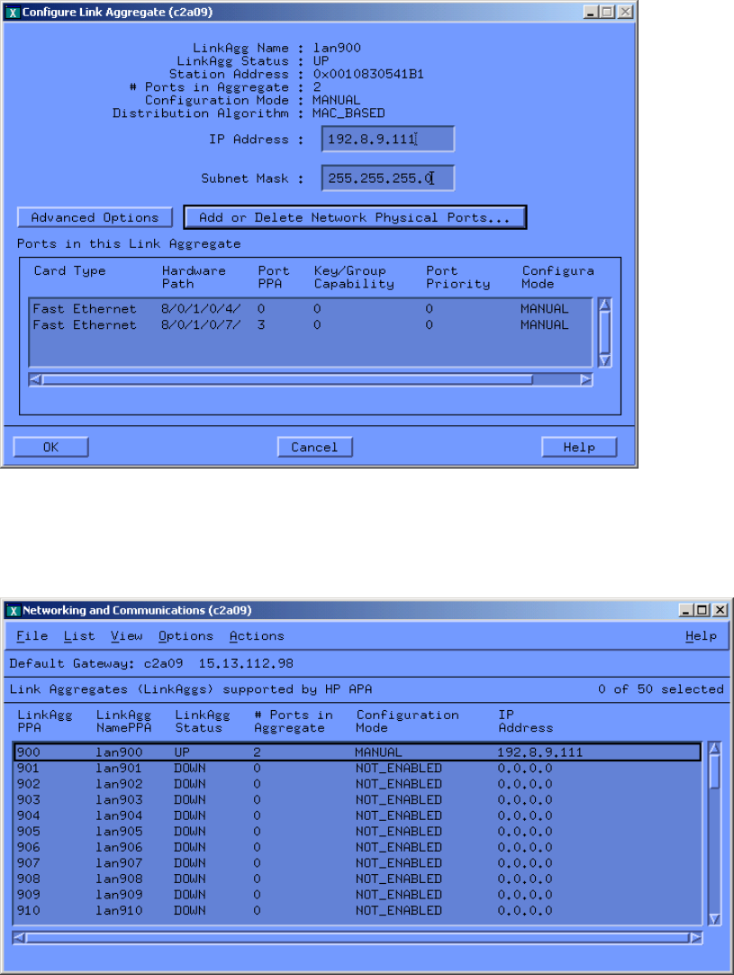
Figure 3-27 Configured Link Aggregates Display
18. Clicking OK displays the original window (Figure 3-28). It now shows lan900 configured
as a MANUAL mode link aggregate.
Figure 3-28 Link Aggregate Displays with Status UP
19. The link aggregate is configured. Configure the next MANUAL mode link aggregate, or exit
by choosing the Exit option from the File pull-down menu.
SAM permanently saves the HP APA configuration values in the /etc/rc.config.d/
hp_apaconf and /etc/rc.config.d/hp_apaportconf files, which maintains the values
across reboots.
Configuring a Failover Group
Edit the configuration files to configure a failover group. For more information, see “Editing
Configuration Files for Failover Groups” (page 107).
46 Configuring APA

Configuring an IP Address
After you configure HP APA, you must configure an IP address on the interface. To configure
an IP address for a link aggregate, use the following command:
# ifconfig lanxxx IP_address up
Where xxx is the link aggregate PPA number.
To make this change permament, edit the /etc/rc.config.d/netconf file and include the
appropriate entry. For more information, see ifconfig(1M).
For failover groups, you must configure an IP address on the interface that is to be the primary
link before running the lanqueryconf and lanapplyconf commands to configure the failover
group. For more information, see “Editing Configuration Files for Failover Groups” (page 107).
Configuring the Link Partner
HP APA also requires that you configure your switches' trunking mode (AUTO or MANUAL)
to match the mode being used on the server (for example, Cisco Fast EtherChannel (FEC), IEEE
802.3ad Link Aggregation Control Protocol (LACP), or MANUAL).
If you selected HOT_STANDBY as the load distribution algorithm for a MANUAL mode link
aggregate or configured a failover group, do not configure the switch ports for an aggregation.
See Appendix E (page 119) for additional switch information.
Configuring HP Serviceguard
HP recommends that you configure HP Serviceguard after configuring HP APA. You can then
use the link aggregates or failover groups in your HP Serviceguard configuration. See the HP
Serviceguard documentation for more information.
NOTE: Do not configure HP Serviceguard with ports that are part of a link aggregate or failover
group.
Creating VLANs Over APA
To create VLANs over link aggregates or failover groups, complete the following steps:
1. Decide what ports are to be part of the link aggregate or failover group. Then, decide on the
VLANs that will be created over the link aggregate or failover group.
2. Configure the trunks and VLANs on the switch according to the switch’s documentation.
If you want to enable a VLAN on a link aggregate, its trunk on the switch side must be
tagged with the VLAN’s ID.
If you want to enable a VLAN on a failover group, the member ports of the failover group
on the switch side must be tagged with the VLAN’s ID.
3. On the server side, create the link aggregates or failover groups. Then, create the VLANs
over the link aggregate or failover group.
After a link aggregate is in use, you can create, modify, and delete VLANs over it. Users can
leave behind VLANs after the link aggregate or failover group has been cleared. If the link
aggregate or failover group has been cleared, users can neither create VLANs nor modify any
VLANs on the link aggregate or failover group. Users can only delete the VLANs.
See Appendix D (page 113) for examples of configuring VLANs over APA using HP Procurve
switches.
Verifying the Configuration
HP APA configuration is complete when you can verify that a link aggregate has been formed.
To verify the HP APA configuration, complete the following steps:
Configuring an IP Address 47
1. To verify which link aggregates have been configured, enter either of the following
commands:
# lanscan
# lanscan -v
The Hardware Path column contains the link aggregates. Link aggregate names begin
with LinkAgg. The Hdw State column shows the link aggregate state. UP indicates the
link aggregate is operational. DOWN indicates the link aggregate was initialized but not
configured.
2. To verify that a link aggregate was formed correctly, use the link aggregate PPA from the
Crd In# column preceding step and enter the following command:
# lanadmin -x -i linkAggPPA
For example, to verify the physical ports associated with link aggregate 901, enter:
# lanadmin -x -i 901
3. To verify all physical ports in all configured link aggregates, enter:
# lanscan -q
This command lists the card instance number for each physical port and for the link
aggregates. Output similar to the following is displayed:
900 5 6 8 7
901
902
903
The preceding example shows that link aggregate 900 contains four ports: lan5,lan6,
lan8, and lan7.
If no link aggregates are formed, see Chapter 6 (page 67).
For more information on the lanscan command, see lanscan(1M). For more information on the
lanadmin command, see lanadmin(1M) and Chapter 4 (page 51).
What Happens During Start Up?
During the system boot-up, the following events occur:
1. HP APA software initializes
All the internal housekeeping initialization (for example, allocation of memory) for the
software is done. During this step, the default values are assigned for all the properties on
each port and link aggregate.
2. hp_apaportconf file is processed
Contains customization variables for each physical port. The features that can be set on each
port are Group Capability, Port Priority, and Configuration Mode. If no value is specified
for a given feature for a given port, the software assumes a default value for the same. The
port's mode is set at this stage.
3. hp_apaconf file is processed
The /etc/rc.config.d/hp_apaconf file contains customization variables for each link
aggregate. The features that can be set on each link aggregate are Load Balancing mode,
Hot Standby mode, and ports in a Manual link aggregate. The last feature allows manual
configuration of a link aggregate with the port(s) specified.
48 Configuring APA
4. HP APA software starts
Cisco's FEC or IEEE 802.3ad LACP protocol is started on the ports that have been marked
as such. No action is taken for the ports that have Cisco's FEC or IEEE 802.3ad LACP turned
off.
5. LAN Monitor ASCII file is processed
Process /etc/lanmon/lanconfig.ascii to create failover groups. If this file has not
been created, no action is taken.
After the system is up and running, you can distinguish a link aggregate from a normal
(unaggregated) port by running the lanscan command. For more information, see “Verifying
the Configuration” (page 47).
What Happens During Start Up? 49
50

4 Using the lanadmin Command
You can use the lanadmin command to administer HP APA. The command enables you to do
the following tasks from the command line:
• Display HP APA settings (-x option (lowercase x) with options)
• Change the HP APA configuration temporarily (-X option (uppercase X) with options)
You can also use lanadmin interactively.
CAUTION: The lanadmin command does not preserve changes across reboots. Use SAM or
edit the configuration files to permanently save the changes.
NOTE: HP APA also requires that you configure your switches' trunking mode (AUTO or
MANUAL) to match the mode being used on the server: Cisco's Fast EtherChannel (FEC), IEEE
802.3ad Link Aggregation Control Protocol (LACP), or MANUAL mode.
Table 4-1 summarizes the lanadmin options and their use.
Table 4-1 Summary of lanadmin -x and -X Options
-x (Display Options)-X (Set Options)Link/Port
Specific
Option
N/AAdd ports to a link aggregate.Link
-a
N/AClear a link aggregate (remove all ports).Link
-c
N/ADelete ports from link aggregate.Both
-d
Display the group capability.Set the group capability.Port
-g
Display help.Display help.N/A
-h
Display extended help.Display extended help.N/A
-H
Display link aggregate port status.N/APort
-i
Display the LACP_AUTO Administrative
Key.
Set the LACP_AUTO Administrative Key.Port
-k
Display the load distribution algorithm.Set the load distribution algorithm.Link
-l
Display link aggregate status.N/ALink
-m
Display status of all APA capable ports.N/APort
-n
N/AClear data flows for link aggregates.Link
-o
Display the port status.Set the port mode.Port
-p
Display the extended port status.N/APort
-q
Display the LACP_AUTO port system
priority.
Set the LACP_AUTO port system priority.Port
-s
Display the port priority.Set the port priority.Port
-t
Display status for a specific link aggregate.N/ALink
-v
Display Hot Standby status.Turn Hot Standby on or offLink
-y
Display the TSO status of link aggregate or
failover group.
N/ALink
vmtu
This chapter describes the lanadmin command set options and display options, and provides
command-line and interactive examples.
51

Set Options
To manage link aggregates and add ports to a link aggregate, use the following syntax and
options with the -X (uppercase) option:
lanadmin [-X -a portPPA [portPPA]]
[-X -c linkAggregatePPA]
[-X -d portPPA [portPPA]... linkAggregatePPA]
[-X -g portPPA group_capability anyLinkAggregatePPA]
[-X [–h| –H]anyLinkAggregatePPA]
[-X -k portPPA admin_key anyLinkAggregatePPA]
[-X -l load_balance_algorithm linkAggregatePPA ]
[-X -o linkAggregatePPA]
[-X -p portPPA config_mode anyLinkAggregatePPA]
[-X -s portPPA system_priority anyLinkAggregatePPA]
[-X -t portPPA port_priority anyLinkAggregatePPA]
[-X -y on|off linkAggregatePPA]
Where:
-a -X -a portPPA [portPPA]... linkAggregatePPA
Adds a port or ports with the specified portPPA to the link aggregate with the specified
linkAggregatePPA number.
CAUTION: Be careful when using the -a suboption. This might lead to an invalid link
aggregate. This command gives you full control over forming any link aggregate that you
want.
-c -X -c linkAggregatePPA
Clears (removes all) ports from a link aggregate with the specified linkAggregatePPA
number. This option fully deconfigures the link aggregate. After removal from a link
aggregate, the port's mode is set to MANUAL. The Administrative Key (LACP) or
group_capability (FEC_AUTO and MANUAL) is not changed.
-d -X -d portPPA [portPPA]... linkAggregatePPA
Deletes ports with the specified PPAs from the link aggregate with the specified
linkAggregatePPA number.
CAUTION: Failure to fully deconfigure a link aggregate (using the the -c suboption) can
result in some properties being retained in the link aggregate. Subsequently, when new
ports are added onto the link aggregate, they might not aggregate properly.
-g -X -g portPPA group_capability anyLinkAggregatePPA
Sets the group capability for a port with the specified portPPA. Ports going to different
link aggregates must have different group capabilities. The valid values for
group_capability are integer numbers starting at 0. This is applicable to MANUAL and
FEC_AUTO ports.
-h -X -h anyLinkAggregatePPA
Displays the -X and -x options help screen.
-H -X -H anyLinkAggregatePPA
Displays the extended -X and -x options help screen, which includes a detailed description
and syntax of the -X and -x options.
52 Using the lanadmin Command
-k -X -k portPPA admin_key anyLinkAggregatePPA
Sets the Administrative Key for an LACP_AUTO port or LACP_AUTO link aggregate. Applies
to LACP_AUTO only. An Administrative Key and Operational Key are associated with
each port. The Operational Key is used for forming aggregations in autonegotiation. The
Administrative Key can be set at anytime. At the port level, the Operational Key only copies
the Administrative Key value when the LACP protocol is not running. At the link aggregate
level, the Operational Key only copies the Administrative Key when the link aggregate is
not configured (no ports have joined the link aggregate).
For example: An LACP_AUTO port is in an aggregation. The admin_key and oper_key
are 1234. Use lanadmin -X -k admin_key anyLinkAggregatePPA to modify the
admin_key to 5432. The oper_key is not changed immediately. You must stop
LACP_AUTO for the port and then restart it for both keys to have the new value of 5432.
-l -X -l load_balance_algorithm linkAggregatePPA
Sets the load-balancing algorithm for a link aggregate with the specified
linkAggregatePPA number.
The following choices are valid for load_balance_algorithm:
•LB_MAC
•LB_IP
•LB_PORT
For a description of these parameters, see the load distribution algorithms in “Link Aggregate
Advanced Parameters” (page 34).
-o -X -o linkAggregatePPA
Clears data flows for a link aggregate specified by linkAggregatePPA. This rebalances
the link aggregate outbound traffic across the ports in the link aggregate.
-p -X -p portPPA config_mode anyLinkAggregatePPA
Sets mode for a port with the specified portPPA number. The following values are valid:
•LACP_AUTO
•FEC_AUTO
•MANUAL
•LAN_MONITOR
For a description of these parameters, see the mode descriptions in “Preparing for
Configuration” (page 31).
-s -X -s portPPA system_priority anyLinkAggregatePPA
Sets the system priority for an LACP_AUTO port. The default value is 0. This has no affect
on a MANUAL or FEC_AUTO port.
-t -X -t portPPA port_priority anyLinkAggregatePPA
Sets the port_priority for the port with the specified PPA Number. For LACP_AUTO,
this sets the priority value for the port. The lanapplyconf command assigns port priority
according to settings in lanconfig.ascii. You can change the priority of primary and
standby ports, but the primary port must have a higher priority. By default a primary port
is 5; standby is 3. This option is not applicable to PAgP. If the port is not in a standalone
state, attempting to set the port priority will fail. Check the port status using the lanadmin
-x -p command.
The valid values for port_priority are integral numbers starting at 0.
For HOT_STANDBY: The bigger the number, the higher the priority.
For LACP ports: The smaller the number, the higher the priority.
Set Options 53
-y -X -y on | off linkAggregatePPA
Turns Hot Standby on or off for the link aggregate with the specified linkAggregatePPA
number. For a description of Hot Standby, see the load distribution algorithms in “Link
Aggregate Advanced Parameters” (page 34) and the the description of
HP_APA_HOT_STANDBY in “hp_apaconf File” (page 97).
Turn on sets link aggregate load-balancing mode to LB_HOT_STANDBY. Turn off sets link
aggregate load-balancing mode to LB_MAC.
Display Options
To display HP APA information, use the following syntax and options with the -x (lowercase)
option:
lanadmin [-x -g portPPA anyLinkAggregatePPA]
[-x [–h –H]anyLinkAggregatePPA]
[-x -i linkAggregatePPA]
[-x -k portPPA anyLinkAggregatePPA]
[-x -l linkAggregatePPA]
[-x -m anyLinkAggregatePPA ]
[-x -n anyLinkAggregatePPA ]
[-x -p portPPA anyLinkAggregatePPA]
[-x -q portPPA anyLinkAggregatePPA]
[-x -s portPPA anyLinkAggregatePPA]
[-x -t portPPA anyLinkAggregatePPA]
[-x -v linkAggregatePPA]
[-x -y linkAggregatePPA]
[-x vmtu linkAggregatePPA]
Where:
-g -x -g portPPA anyLinkAggregatePPA
Displays the current group capability number of the specified port or link aggregate.
This applies to MANUAL and FEC_AUTO ports.
-h -x -h anyLinkAggregatePPA
Displays the help screen.
-H -x -H anyLinkAggregatePPA
Displays the extended help screen, which includes a list of the -x and -X options and
the syntax.
-i -x -i linkAggregatePPA
Displays the port status associated with the link aggregation or failover group. Following
is the information displayed for this option.
• Link aggregation or failover group PPA number.
• Link aggregation mode.
• Load-balancing mode used by the link aggregation.
• The port or ports of the link aggregation or failover group actively involved in
sending and receiving data traffic.
• For failover groups, the ports that are in state ready to takeover data traffic in case
the current active port fails.
54 Using the lanadmin Command

• The ports that are not ready to be used in a link aggregation or failover group. A
port can be in this list due to:
— The link state of the NIC is down.
— The NIC is experiencing a hardware problem, which is causing unexpected
failures.
—The NIC has been configured to run an APA auto protocol and it has not reached
a stable state.
• For failover groups, a list of the ports in the "ready" list that have connectivity to
the current active port. A port in the ready list might not be displayed in this field
because connectivity might have been lost after forming the failover group.
NOTE: This field might not be accurate after a link state change until POLL_INTERVAL
* DEAD_COUNT seconds have expired.
Following is sample output for link aggregation:
Link Aggregate PPA # : 900
Link Aggregation Mode : MANUAL
Load Balance Mode : IP Address based (LB_IP)
Active Ports PPA # : 3 4
Port(s) not ready : 5 6
Following is sample output for a failover group (LAN Monitor):
In this example, 3, 4, 5 are in same subnet and 6, 7 are in different subnet, and port 5 is
down.
Link Aggregate PPA # : 901
Link Aggregation Mode : LAN_MONITOR
Load Balance Mode : Hot Standby (LB_HOT_STANDBY)
Active Ports PPA # : 3
Port(s) ready : 4 6 7
Port(s) not ready : 5
Port(s) connected to active port : 4
-k -x -k portPPA lnyLinkAggregatePPA
Displays the Administrative and Operational Key for an LACP_AUTO port or link
aggregate. Applies to LACP_AUTO only.
-l -x -l linkAggregatePPA
Displays the current load-balancing algorithm for the link aggregate with the specified
linkAggregatePPA number.
-m -x -m anyLinkAggregatePPA
Displays the status for all link aggregates using any link aggregate in the command.
Sample results:
Number of elements=50
[0] ppa : 900
[0] index : 0
[0] num_ports : 1
[0] ports : 4
-----------------------
[1] ppa : 901
[1] index : 1
[1] num_ports : 3
[1] ports : 1 2 3
-----------------------
[2] ppa : 902
[2] index : 2
[2] num_ports : 0
[2] ports : -----------------------
.
Display Options 55
.
.
-n -x -n anyLinkAggregatePPA
Displays the status for all APA capable ports using any link aggregate in the command.
For example:
Number of elements=5
[0] ppa : 1
[0] reserved2 value : -1
[0] state : 1
-p -x -p portPPA anyLinkAggregatePPA
Displays the present status of a port with the specified portPPA number. For example:
**** PORT NUMBER: 3 *******
Port FEC Mode : FEC_AUTO
Port State : UP
Port Group Capability : 901
Port Priority : 0
-q -x -q portPPA anyLinkAggregatePPA
Displays the present status of a port with the specified portPPA in the extended format.
For example:
**** PORT NUMBER: 3 *******
pagpEnabled : ENABLED
ppMyData.deviceId : 00108318b907
ppMyData.distReq : LEARNCAP_AGPORT
ppMyData.portPriority : 0
ppMyData.sentPortIfIndex : 3
ppMyData.groupCapability : 901
ppMyData.groupIfIndex : 8
ppNoPagpTimerI : 0
ppNoTransTimerQ : 0
ppTHToTATimerS : 0
ppSlowHelloTimerA : 1
ppPartnerCount : 1
++++++++ PARTNER DATA ++++++++
PARTNER 0
ppPartnerData.deviceId : 000883756600
ppPartnerData.distReq : LEARNCAP_AGPORT
ppPartnerData.portPriority : 188
ppPartnerData.sentPortIfIndex : 188
ppPartnerData.groupCapability : 3
ppPartnerData.groupIfIndex : 211
ppTimerP : 902
Port LACP Mode : 1
++++++++ PARTNER DATA ++++++++
ppAutoMode.myAutoMode : 0
ppAutoMode.yourRequest : 0
ppMySlowHello : 1
portState : PAGP_STATE_UPPAGP
portNextState : PAGP_STATE_UPPAGP
portNextEvent : PAGP_EVENT_NULL
portXmitState : PAGP_XMIT_STATE_SLOW_U6
portXmitNextState : PAGP_XMIT_STATE_SLOW_U6
portXmitNextEvent : PAGP_XMIT_EVENT_NULL
-s -x -s portPPA anyLinkAggregatePPA
Displays the system priority for an LACP_AUTO port. This has no affect on a MANUAL
or FEC_AUTO port.
56 Using the lanadmin Command

-t -x -t portPPA anyLinkAggregatePPA
Displays the current port priority for the port with the specified portPPA number. For
LACP_AUTO, this shows the priority value for the port. For HOT_STANDBY, this shows
which port is used for traffic and which for standby. This option is not applicable to
PAgP (FEC_AUTO).
-v -x -v linkAggregatePPA
Displays the status for a given link aggregate with the specified linkAggregatePPA
number. For example:
Link Aggregate PPA # : 901
Number of Ports : 3
Ports PPA : 2 1 3
Link Aggregation State : LINKAGG AUTO
Group Capability : 901
Load Balance Mode : MAC Address based (LB_MAC)
-y -x -y linkaggregatePPA
Displays the Hot Standby status for the link aggregate with the specified
linkAggregatePPA number.
vmtu [-x vmtu linkaggregatePPA]
Displays the TSO status for a given link aggregate with the specified linkAggregatePPA
number. For example:
# lanadmin -x vmtu 903
Driver/Hardware does not support TCP Segmentation Offload
#
# lanadmin -x vmtu 905
Driver/Hardware supports TCP Segmentation Offload, Current VMTU = 32160
#
The following option is supported, but with a different meaning:
-a Displays the current station address of link aggregate with the specified
linkAggregatePPA number.
Invoking lanadmin from the Command Line
NOTE: Remember that the starting PPA number for link aggregates varies with the operating
system you have installed: for HP-UX 11.00, it is 100; and for 11i v1 and 11i v2, it is 900. The
following example uses HP-UX 11i.
•To obtain additional information on options for the lanadmin command, enter the following
command:
lanadmin -X -H linkAggregatePPA
Where linkAggregatePPA can be any valid link aggregate PPA value.
• To form a link aggregate of ports automatically using the Cisco Fast EtherChannel protocol
on that port, set the port configuration mode to FEC_AUTO. For example, if port 2 must be
trunked automatically, enter the following command:
lanadmin -X -p 2 FEC_AUTO 900
900 is the PPA of the first link aggregate. When the protocol completes successfully, HP
APA determines the link aggregate into which port 2 best fits and adds the port to an
aggregate based on the group_capability of ports and link aggregate. Ports in the same
link aggregate must be connected to the same host and in the same trunk.
• To form a link aggregate of ports automatically using the LACP protocol, use LACP_AUTO
in place of FEC_AUTO. In this case, key is used instead of group_capability.
Invoking lanadmin from the Command Line 57

• To manually configure ports with PPAs 6, 7, 8, and 9 into a link aggregate lan901, enter
the following command:
lanadmin -X -a 6 7 8 9 901
CAUTION: Be careful when using the -a suboption. This might lead to an invalid link
aggregate. This command gives you full control over forming any link aggregate that you
want. This example configures ports with PPAs 6, 7, 8, and 9 into a single link aggregate,
even if they are connected to different switches, which is an invalid configuration, and could
lead to problems.
• Before you can remove a port from an automatically formed link aggregate, you must turn
off Cisco's Fast EtherChannel or LACP protocol on that port. If a port with a PPA number
of 2 belongs to link aggregate lan900 (PPA number of 900), enter one of the following two
commands:
lanadmin -X -d 2 900
or
lanadmin -X -p 2 MANUAL 900
• To deconfigure FEC_AUTO (or LACP_AUTO) mode link aggregate 903, which has ports
with PPAs 6, 7, 8, and 9, enter the following commands in succession:
# lanadmin -X -p 6 MANUAL 903
# lanadmin -X -p 7 MANUAL 903
# lanadmin -X -p 8 MANUAL 903
# lanadmin -X -p 9 MANUAL 903
Alternatively, the following single command achieves the same result:
lanadmin -X -d 6 7 8 9 903
• To fully deconfigure a link aggregate, enter the following command:
lanadmin -X -c 903
IMPORTANT: Failure to fully deconfigure a link aggregate can result in some properties
being retained in the link aggregate. Subsequently, when you add new ports onto the link
aggregate, they might not aggregate properly.
•To delete a single port (for example, 8) from link aggregate 901, enter the following command:
lanadmin -X -d 8 901
To delete ports 6 and 9, enter:
lanadmin -X -d 6 9 901
• To deconfigure the link aggregate 901 completely, enter:
lanadmin -X -c 901
This deletes the remaining port, 7, from link aggregate 901 and clears all the properties from
the link aggregate; it becomes clean.
IMPORTANT: After you delete all the ports from link aggregate 901, (after using, for example,
lanadmin -X -d 7 901), use the -c suboption. Otherwise, some properties are retained
in link aggregate 901. Subsequently, when you add new ports to link aggregate 901, they
inherit old properties of the link aggregate and might not aggregate properly.
Configuring an FEC_AUTO Mode Link Aggregation using lanadmin
The following example works for all versions of 11i (link aggregate begins at 900).
58 Using the lanadmin Command

To add ports lan1 and lan2 (which are not aggregated) to link aggregate lan901 (which is not
enabled), with the group capability set to 901, do the following:
1. Configure the switch.
Configure your switches' trunking mode to match the mode being used on the server. The
mode is Cisco Fast EtherChannel (FEC).
2. Configure the server:
a. Set the link aggregate's group capability to 901. Enter:
lanadmin -X -g 901 901 900
b. Change the port's group capability to be the same as the link aggregate's group capability
(901).
# lanadmin -X -g 1 901 900
# lanadmin -X -g 2 901 900
c. Change ports lan1 and lan2 mode to FEC_AUTO.
# lanadmin -X -p 1 FEC_AUTO 900
# lanadmin -X -p 2 FEC_AUTO 900
NOTE: By default, the group_capability of each physical link is set to 5.
Using lanadmin Interactively
When you enter the lanadmin command either by itself or with the -t option, the command
becomes interactive. The following example illustrates the interactive use of lanadmin:
# lanadmin
LOCAL AREA NETWORK ONLINE ADMINISTRATION, Version 1.0
Tue , Oct 1,2007 14:05:56
Copyright 1994 Hewlett Packard Company.
All rights are reserved.
Test Selection mode.
lan = LAN Interface Administration
menu = Display this menu
quit = Terminate the Administration
terse = Do not display command menu
verbose = Display command menu
Enter command: lan
LAN Interface test mode. LAN Interface PPA Number = 1
clear = Clear statistics registers
display = Display LAN Interface status and statistics registers
end = End LAN Interface Administration, return to Test Selection
menu = Display this menu
ppa = PPA Number of the LAN Interface
quit = Terminate the Administration, return to shell
reset = Reset LAN Interface to execute its selftest
specific = Go to Driver specific menu
Enter command: ppa
Enter PPA Number. Currently 1: 901
LAN Interface test mode. LAN Interface PPA Number = 901
clear = Clear statistics registers
display = Display LAN Interface status and statistics registers
end = End LAN Interface Administration, return to Test Selection
menu = Display this menu
ppa = PPA Number of the LAN Interface
quit = Terminate the Administration, return to shell
Using lanadmin Interactively 59
reset = Reset LAN Interface to execute its selftest
specific = Go to Driver specific menu
Enter command: display
LAN INTERFACE STATUS DISPLAY
Tue , Oct 1,2002 14:07:10
PPA Number = 901
Description = lan901 Hewlett-Packard LinkAggregate Interface
Type (value) = ethernet-csmacd(6)
MTU Size = 1500
Speed = 300000000
Station Address = 0x108318b927
Administration Status (value) = up(1)
Operation Status (value) = up(1)
Last Change = 102502046
For link-aggregate MIB statistics, press <Return> to continue
Inbound Octets = 46821
Inbound Unicast Packets = 0
Inbound Non-Unicast Packets = 424
Inbound Discards = 1
Inbound Errors = 0
Inbound Unknown Protocols = 72
Outbound Octets = 41446
Outbound Unicast Packets = 346
Outbound Non-Unicast Packets = 346
Outbound Discards = 0
Outbound Errors = 0
Outbound Queue Length = 0
Specific = 0
LAN Interface test mode. LAN Interface PPA Number = 901
clear = Clear statistics registers
display = Display LAN Interface status and statistics registers
end = End LAN Interface Administration, return to Test Selection
menu = Display this menu
ppa = PPA Number of the LAN Interface
quit = Terminate the Administration, return to shell
reset = Reset LAN Interface to execute its selftest
specific = Go to Driver specific menu
Enter command: specific
Link Aggregation specific test mode. Valid LAN Interface PPAs: 2 1 3
linkagg = Link Aggregate status
port = Port's APA status
end = End Driver Specific Test Mode, return to Lan Interface
test mode.
menu = Display this menu
quit = Terminate the Administration, return to shell
Enter command: linkagg
Link Aggregate PPA # : 901
Number of Ports : 3
Ports PPA : 2 1 3
Link Aggregation State : LINKAGG AUTO
Group Capability : 901
Load Balance Mode : MAC Address based (LB_MAC)
Link Aggregation specific test mode. Valid LAN Interface PPAs: 2 1 3
linkagg = Link Aggregate status
port = Port's APA status
end = End Driver Specific Test Mode, return to Lan Interface
test mode.
menu = Display this menu
60 Using the lanadmin Command
quit = Terminate the Administration, return to shell
Enter command: port
Enter Port PPA number: 1
**** PORT NUMBER: 1 *******
pagpEnabled : ENABLED
ppMyData.deviceId : 00108318b907
ppMyData.distReq : LEARNCAP_AGPORT
ppMyData.portPriority : 0
ppMyData.sentPortIfIndex : 1
ppMyData.groupCapability : 901
ppMyData.groupIfIndex : 1
ppNoPagpTimerI : 0
ppNoTransTimerQ : 0
ppTHToTATimerS : 0
ppSlowHelloTimerA : 7
ppPartnerCount : 1
++++++++ PARTNER DATA ++++++++
PARTNER 0
ppPartnerData.deviceId : 000883756600
ppPartnerData.distReq : LEARNCAP_AGPORT
ppPartnerData.portPriority : 190
ppPartnerData.sentPortIfIndex : 190
ppPartnerData.groupCapability : 3
ppPartnerData.groupIfIndex : 211
ppTimerP : 85
ppSlowHelloRequestP : 1
++++++++ PARTNER DATA ++++++++
ppAutoMode.myAutoMode : 0
ppAutoMode.yourRequest : 0
ppMySlowHello : 1
portState : PAGP_STATE_UPPAGP
portNextState : PAGP_STATE_UPPAGP
portNextEvent : PAGP_EVENT_NULL
portXmitState : PAGP_XMIT_STATE_SLOW_U6
portXmitNextState : PAGP_XMIT_STATE_SLOW_U6
portXmitNextEvent : PAGP_XMIT_EVENT_NULL
Link Aggregation specific test mode. Valid LAN Interface PPAs: 2 1 3
linkagg = Link Aggregate status
port = Port's APA status
end = End Driver Specific Test Mode, return to Lan Interface
test mode.
menu = Display this menu
quit = Terminate the Administration, return to shell
Enter command: quit
Using lanadmin Interactively 61
62

5 Administering HP APA
Administering HP APA consists of performing the following tasks:
•“Modifying HP APA Global Parameters” (page 63)
•“Logging Messages to the syslog.log File” (page 63)
Modifying HP APA Global Parameters
The following HP APA global parameters are stored in the /etc/rc.config.d/hp_apaconf
file:
Default Port Mode The default configuration mode for link aggregates. The supported
values are as follows:
MANUAL Disables FEC and IEEE 802.3ad LACP on all
ports that support HP APA. You must manually
add or remove them from the specific link
aggregate. This is the default.
FEC_AUTO Starts FEC on all ports that support HP APA.
LACP_AUTO Starts IEEE 802.3ad LACP on all ports that
support HP APA.
LAN_MONITOR Disables FEC and IEEE 802.3ad LACP on all
ports that support HP APA. The ports will be
used for a failover group.
MAX Link Aggregates Sets the maximum number of link aggregates for the server. The
valid range is from 5 to 50, inclusive. The default value is 50. This
value takes effect only after a reboot.
LACP SYSID Mode LACP_AUTO only. Directs APA how to set up the LACP System
ID. The supported values are as follows:
FIRST_APA_PORT Sets the LACP System ID to the first
supported HP APA port. This is the
default.
FIRST_LACP_PORT Sets the LACP System ID to the first
active (UP) port that starts LACP.
LACP Timeout For the September 2007 release of HP APA for HP-UX 11i v1 and
v2 this specifies an interval of time between LACP Protocol Data
Units (PDUs) after which the server considers the LACP link
partner to be down. The supported values are as follows:
0 Specifies a slow timeout. This is approximately 30 seconds.
This is the default.
1 Specifies a fast timeout. This is approximately 3 seconds.
Use Syslog Enables (1) or disables (0) the logging of status messages to the
syslog.log file (for example, when a link aggregate or port fails
or comes up). The default value is 0. See Section (page 63) for
sample syslog.log messages and their meaning.
To change a global parameter, edit the /etc/rc.config.d/hp_apaconf and make the
necessary changes. For more information, see “hp_apaconf File” (page 97).
Logging Messages to the syslog.log File
For the May 2005 release of HP APA for HP-UX 11i v1 (B.11.11.20) and later, the PHNE_33116
(B.11.11.17) release, and the December 2005 release for HP-UX 11i v2 (B.11.23.10), you can enable
the logging of APA and LAN Monitor status messages to the syslog.log file. The status
Modifying HP APA Global Parameters 63

messages are a subset of the messages APA logs to the nettl log file, but are reworded for
readability and understandability.
For information on configuring APA to log status messages to the /var/adm/syslog/
syslog.log file, see “Modifying HP APA Global Parameters” (page 63).
Examples
This section contains sample status messages that might appear in the syslog.log file. In these
examples, a link is considered UP:
• If its Operation Status (ifOper) is UP (the link can carry network traffic) and
• If the link is part of a link aggregate and it has successfully negotiated via the protocol with
the link partner to become a member of the link aggregate.
A link is considered DOWN:
• Anytime its Operation Status (ifOper) status is DOWN (the link cannot carry network
traffic) or
• If the link is part of an automatic link aggregate and the protocol has failed to maintain the
membership of the port in the link aggregate.
Mar 3 08:49:54 hpserver1 vmunix: APA/LM: Product is now running. 1
Mar 3 08:49:54 hpserver1 vmunix: APA/LM: Product is now stopped. 2
Mar 3 08:50:20 hpserver1 vmunix: APA/LM: LA:lan900 - lan7 is up 3
Mar 3 08:50:20 hpserver1 vmunix: APA/LM: LA:lan900 is up
Mar 3 08:50:20 hpserver1 vmunix: APA/LM: LA:lan900 - lan8 is up
Mar 3 08:50:20 hpserver1 vmunix: APA/LM: LA:lan900 - lan9 is up
Mar 3 08:51:34 hpserver1 vmunix: APA/LM: LA:lan900 - lan8 is down 4
Mar 3 08:50:26 hpserver1 vmunix: APA/LM: LA:lan900 - lan9 is removed 5
Mar 3 08:52:05 hpserver1 vmunix: APA/LM: LA:lan900 - lan7 is down 6
Mar 3 08:52:05 hpserver1 vmunix: APA/LM: LA:lan900 is down
.
.
.
Mar 3 08:50:26 hpserver1 vmunix: APA/LM: LA:lan900 - lan8 is removed 7
Mar 3 08:50:26 hpserver1 vmunix: APA/LM: LA:lan900 - lan7 is removed
Mar 3 08:50:26 hpserver1 vmunix: APA/LM: LA:lan900 is cleared
1The /sbin/init.d/hpapa start command was issued, for example, at system boot
time.
2The /sbin/init.d/hpapa stop command was issued.
3Link aggregate (LA) 900 was created with three links 7, 8, and 9.
4Link 8 is not operational.
5Link 9 was removed from lan900; for example, by issuing the following command:
# lanadmin -X -d 9 900
6Link 7 and link aggregate 900 are not operational.
7Link aggregate 900 was cleared; for example, by issuing the following command:
# nwmgr -X -c 900
If link aggregate 900 is a failover group, lan900 has a FOG: prefix instead of LA: as shown in
the previous example.
For failover groups and Hot-standby mode link aggregates, the current active link is also displayed
as in the following example:
Mar 3 08:58:03 hpserver1 vmunix: APA/LM: FOG:lan900 - lan1 is up (lan1 is active)
Mar 3 08:58:03 hpserver1 vmunix: APA/LM: FOG:lan900 is up (lan1 is active)
Mar 3 08:58:03 hpserver1 vmunix: APA/LM: FOG:lan900 - lan2 is up (lan1 is active)
.
.
.
Mar 3 08:58:03 hpserver1 vmunix: APA/LM: FOG:lan900 - lan2 isn't receiving poll 1
Mar 3 08:58:03 hpserver1 vmunix: APA/LM: FOG:lan900 - lan2 now receiving poll \
64 Administering HP APA

packets (lan1 is active) 2
Mar 3 08:58:03 hpserver1 vmunix: APA/LM: FOG:lan900 - Proactive Failover Occurred \
(lan901 is active) 3
1Connectivity among links in the failover group was lost.
2The link in the failover group started receiving poll packets; it has recovered connectivity.
3Proactive failover occurred in the failover group.
For detailed log messages, use the NetTL subsystem. See nettl(1M) for more information.
Viewing HP APA Statistics
The link aggregate software keeps a counter for each statistic defined in RFC 1213 MIB II for
32-bit statistics or RFC 2863 for 64-bit statistics. Each counter is set to the negative of the sum of
all the physical ports in the link aggregate when it is created. When reporting the value of a
statistic, the sum of all the physical ports corresponding statistic counter is added to the link
aggregates counter.
For a detailed description of the statistics fields, see RFC 1213 for 32-bit statistics and RFC 2863
for 64-bit statistics.
When a physical port is removed from a link aggregate, each of its statistics is added to the
corresponding link aggregate statistic. When a physical port is added to a link aggregate, its
current statistics are subtracted from the link aggregates statistics.
NOTE: Cisco's Fast EtherChannel (FEC) packets are not counted in the link aggregate statistics.
This is required because the FEC packets never traverse the link aggregate, they only traverse
the port.
For the September 2004 release (B.11.23.05) and later of HP APA for HP-UX 11i v2 and the May
2005 release (B.11.11.20) and later of HP APA for HP-UX 11i v1, link aggregates support 64-bit
statistics based on the following rules:
• Aggregates support the 64-bit MIB (Management Information Base) if all the member links
are capable of 64-bit statistics when the aggregate is created.
• The 64-bit statistics capability will be downgraded to 32 bits if the aggregate membership
changes to include one or more links that are not 64-bit MIB capable. After the aggregate's
64-bit MIB capability is downgraded, it will never be upgraded again for the life of the
aggregate.
To display statistics, use the lanadmin -g linkAggPPA command. Example 5-1 shows 32-bit
MIB statistics returned from this command.
Viewing HP APA Statistics 65

Example 5-1 Sample Link Aggregate 32-Bit Statistics
# lanadmin -g 900
LAN INTERFACE STATUS DISPLAY
Fri, Jul 30, 2007 12:20:23
PPA Number = 900
Description = lan900 Hewlett-Packard LinkAggregate Interface
Type (value) = other(1)
MTU Size = 1500
Speed = 100 Mbps
Station Address = 0x00306E5FF047
Administration Status (value) = up(1)
Operation Status (value) = down(2)
Last Change = Thu Sep 28 18:35:11 2006
Inbound Octets = 1353732
Inbound Unicast Packets = 0
Inbound Non-Unicast Packets = 22064
Inbound Discards = 0
Inbound Errors = 0
Inbound Unknown Protocols = 22064
Outbound Octets = 0
Outbound Unicast Packets = 0
Outbound Non-Unicast Packets = 0
Outbound Discards = 0
Outbound Errors = 0
Outbound Queue Length = 0
Specific = 0
Example 5-2 shows 64-bit MIB statistics.
Example 5-2 Sample Link Aggregate 64-Bit Statistics
# lanadmin -g mibstats_ext 901
LAN INTERFACE STATUS DISPLAY
Fri, Jul 30, 2007 12:20:23
Interface Name = lan901
PPA Number = 901
Description = lan901 Hewlett-Packard LinkAggregate Interface
Interface Type(value) = other(1)
MTU Size = 1500
Speed = 3 Gbps
Station Address = 0x0012794371B4
Administration Status = up
Operation Status = down
Last Change = Thu Sep 28 18:35:11 2006
Inbound Octets = 1353732
Inbound Unicast Packets = 0
Inbound Multicast Packets = 0
Inbound Broadcast Packets = 0
Inbound Discards = 0
Inbound Errors = 0
Inbound Unknown Protocols = 22064
Outbound Octets = 0
Outbound Unicast Packets = 0
Outbound Multicast Packets = 0
Outbound Broadcast Packets = 0
Outbound Discards = 0
Outbound Errors = 0
Counter Discontinuity Time = Thu Sep 28 18:35:10 2006
Physical Promiscuous Mode = invalid
Physical Connector Present = false
Interface Alias =
Link Up/Down Trap Enable = enabled
66 Administering HP APA
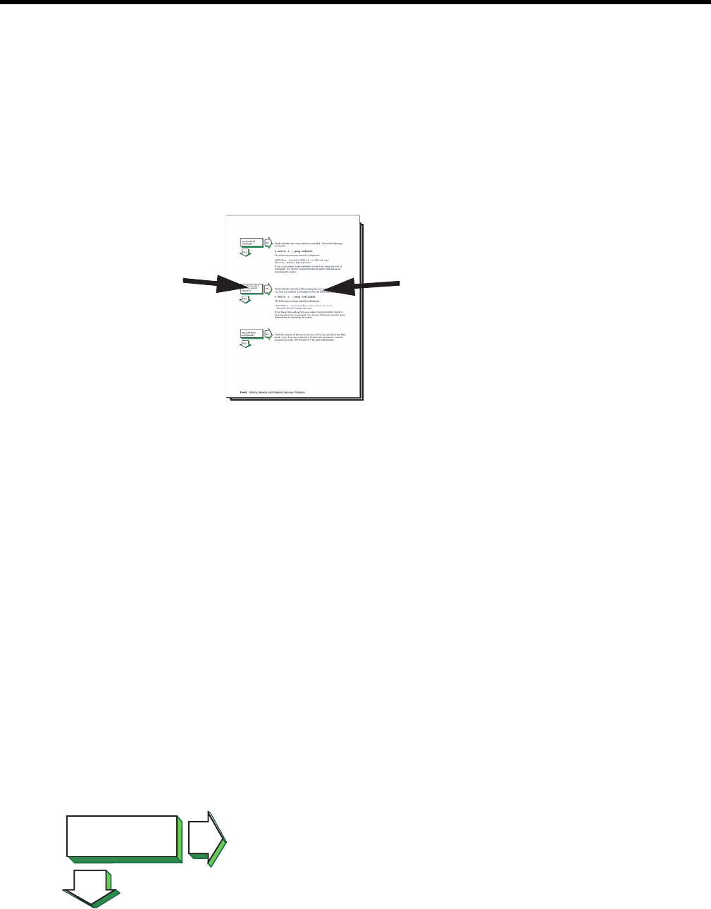
6 Troubleshooting HP APA
This chapter contains a diagnostic map to help you solve problems that might occur when you
use HP APA. Use this chapter with the appropriate HP and third-party switch documentation
to solve as many problems as possible at your level.
Operation
Network problems can occur for a number of reasons. The diagnostic map in this chapter help
you to isolate the problem. The following figure explains how to use the diagnostic map:
The left-hand column
asks questions about
the status of specific
events that occur as
you use the system.
The right-hand column
diagnoses negative
responses to those
questions.
After you isolate the problem, the map refers you to other chapters for instructions on using the
various problem solving tools and utilities. The map also refers you to other manuals for more
complete diagnostic information for particular devices and software products.
You might experience problems that are not documented in this manual when you use the HP
APA software with other products. See the documentation for the other products for additional
information.
Getting Started
Before you start troubleshooting, ensure that the communications hardware is ready for use.
Verify the following:
• The system's physical cable connections (the Ethernet connection and the transceiver
connection) are properly installed. See the documentation for your system and the NIC.
• Event logging is enabled in order to monitor network events. For information about the
Network Tracing and Logging (NetTL) tool, see “nettl Tracing and Logging Tool” (page 90).
For information about logging messages to syslog, see “Logging Messages to the syslog.log
File” (page 63).
Also see the product release notes for up-to-date information on known problems.
Solving HP APA Problems
System on? NO
YES
Turn on the power to your system. See the system manual for your
system's startup procedure and any problem solving information.
Operation 67
System booted
without errors? NO
YES
Edit the /etc/rc.log file and search for the string hpapa. This takes
you to the beginning of the HP APA start-up section. If there are
failover groups configured on your system, the following message
indicates an error:
ERROR: lanapplyconf failed
If there are no failover groups configured on your system, you can
ignore the error message.
If you see error messages about link aggregate attributes, do the
following:
1. Stop HP APA with the following commands:
# /sbin/init.d/hplm stop
# /sbin/init.d/hpapa stop
2. Correct the attribute in the appropriate configuration file.
3. Restart HP APA with the following commands:
# /sbin/init.d/hpapa start
# /sbin/init.d/hplm start
Search for the string hplm in the /etc/rc.log file. If there are failover
groups configured on your system, the preceding message indicates
an error. If there are no failover groups configured on your system,
you can ignore the error message.
Also look for any driver and network errors.
NIC installed? NO
YES
Do the following:
1. Verify that the network card is seated correctly and that it is
operational.
2. Check that your network physical port connectors between the
NIC and the switch (or wall plug) are fully connected.
NIC claimed? NO
YES
Verify that the NIC has been claimed by the operating system. Issue
the following command:
# ioscan -fkC lan
If the driver has been claimed, the driver name appears in the Driver
column and CLAIMED appears in the S/W State column for the lan
class and hardware path. See “Scanning the System Hardware”
(page 89) for more information on ioscan.
If the software state is UNCLAIMED, do the following:
1. If the class is unknown and driver is UNKNOWN, the interface driver
has not been generated into the kernel. Verify that the /stand/
vmunix file contains the appropriate keyword for the NIC you
are using with the following command:
# what /stand/vmunix | grep -i driver-name
For example, if you are using the 1000Base-T NIC, the igelan
keyword appears. If it does not, you must edit the file and create
a new kernel. For information on how to do this, see the Installing
and Administering LAN/9000 Software manual.
2. Verify that the NIC is seated correctly and that it is operational.
3. Reboot the system.
68 Troubleshooting HP APA
NIC operating? NO
YES
Verify that the NIC is operating. Enter the following command:
# lanscan
If the Hardware State is DOWN, do the following:
1. Check the status of the Link LED.
If the LED is off, check the connection to the switch. Make sure
that the switch is configured in the correct mode and is
autonegotiating, if necessary. Reset the NIC with following
command:
# lanadmin -r linkAggPPA
2. Make sure the link speed and duplex mode match the settings on
the switch. If they do not, set the correct link speed and duplex
mode and enable autonegotiating, if necessary. Then, reset the
NIC with the lanadmin command
3. Verify that your hardware state is UP by issuing the lanscan
command with no arguments. If it is not up, perform the steps for
NIC claimed?.
Network daemon
star ted? NO
YES
Verify that the network daemon (inetd) is running. Enter the following
command:
# ps -e | grep inetd
If no inetd daemon is running, start it using the following command:
# /sbin/init.d/inetd start
APA depot
installed? NO
YES
Verify that the HP APA depot is installed by issuing the following
command:
# swlist | grep J4240AA
If the product is installed, the following message is displayed:
J4240AA B.11.23.40 Auto-Port Aggregation Software
If the product is not installed, install it by using the swinstall
command. See Chapter 2 (page 19) and the Release Notes for more
information.
HP APA
configured
in kernel? NO
YES
Go to “Solving Link
Verify that the software is configured in the kernel by issuing the
following command:
# what /stand/vmunix | egrep -i hp_apa
Output similar to the following displays:
$Revision: hp_apa: HP Auto-Port Aggregation (APA): B.11.31.20
Aug 10 2008 11:30
If nothing is displayed, rebuild the kernel.
Aggregate Problems
(MANUAL Mode)”for
MANUAL mode link
aggregates, “Solving
Link Aggregate
Problems (LACP
Mode)” (page 74) for
LACP_AUTO mode link
aggregates, “Solving
Link Aggregate
Solving HP APA Problems 69
Problems (FEC Mode)”
(page 79) for
FEC_AUTO mode link
aggregates, or “Solving
Failover Group
Problems” (page 83) for
failover groups.
Solving Link Aggregate Problems (MANUAL Mode)
Link partner
configured? NO
YES
Do the following:
• Verify that the switch is configured correctly with the appropriate
ports enabled. See the appropriate switch documentation to
determine if the switch ports connected to the server are
configured correctly for manual link aggregation (trunking) and
do not run FEC or LACP.
Link aggregate
configured? NO
YES
Verify that the link aggregate is configured by issuing the lanscan
command. Link aggregate names begin with LinkAgg.
If the link aggregate is not configured, use the SAM to configure it. See
“Configuring a Link Aggregate” (page 36) for more information.
Link aggregate
enabled? NO
YES
Verify that the link aggregate is enabled by issuing the following
command:
# lanadmin -x -i linkAggPPA
If the aggregate is enabled, the Link Aggregation Mode is MANUAL.
If the aggregate is not enabled, do the following:
1. Check the cabling between the NIC and the switch.
2. Verify that the link partner is configured to run manual trunks.
Make any changes, if necessary. Then, verify that the link aggregate
is enabled.
3. Verify that all ports in the aggregate are set to the same MANUAL
mode by using the following command for each port:
# lanadmin -x -p portPPA linkAggPPA
If they are not, use the SAM to modify the link aggregate.
Correct ports in
link aggregate? NO
YES
Verify the ports in the link aggregate by issuing the following
command:
# lanadmin -x -i linkAggPPA
The Active Ports PPA # entry shows the ports that compose the
link aggregate.
If the link aggregate contains ports that you do not want in the
aggregate, delete the ports by issuing the following command:
# lanadmin -X -d portPPA linkAggPPA
where portPPA can be a list of multiple ports numbers separated by
a space.
If any ports you wanted in the link aggregate are members of another
link aggregate, delete the ports in the other aggregate by issuing the
following command:
70 Troubleshooting HP APA
# lanadmin -X -d -portPPA linkAggPPA
If there are ports you wanted in the link aggregate that are not members
of the link aggregate, do the following:
1. If FEC or LACP is enabled on the port, stop autonegotiation with
the following command:
# lanadmin -X -p portPPA MANUAL linkAggPPA
2. Verify the type, speed (including duplex), and MTU size of each
port you want with the following command:
# lanadmin -g portPPA
All ports must have the same values. If they do not, make any
changes as necessary on the server and the switch.
3. Add each port to the aggregate with the following command:
# lanadmin -X -a portPPA linkAggPPA
where portPPA can be a list of multiple ports numbers separated
by a space.
NOTE: Use SAM or edit the configuration files to make the
configuration changes permanent.
4. Check if there is an IP address or a VLAN on the port.
All ports active? NO
YES
Verify the active ports in the link aggregate by issuing the following
command:
# lanadmin -x -i linkAggPPA
The Active Ports PPA # field lists the active ports.
If there are ports in the Port(s) not ready field, verify the port's
operation status by issuing the following command:
# lanadmin -g portPPA
If the Operation Status is up, check the speed (including duplex) and
MTU for the port and another active port in the link aggregate with
the following command:
# lanadmin -s -m portPPA
If they do not match, correct the settings on the server and the switch.
See the steps for Link partner configured?. If they match, reset
the port.
If the status is DOWN, check the cabling from the NIC to the switch
and see the steps for NIC operating?.
On the switch, verify that all ports you expect to be in the link aggregate
are in the same MANUAL trunk.
NOTE: If you are using the HOT_STANDBY load distribution
algorithm, be sure the switch side port is not in any trunk.
Network
reachable? NO
YES
If a remote host's network is not reachable, the following message is
displayed in response to the ping command:
network is unreachable
Complete the following steps:
Solving HP APA Problems 71
1. Ensure that the network devices are configured properly on the
local host, using the netstat -i command.
2. Verify that the routing tables on the local host are correct, using
the netstat -r command.
Host known? NO
YES
If a host is not known, the following message is displayed:
unknown host
Complete the following steps:
1. Verify that the user is trying to reach the remote host using a valid
host name.
2. Verify that the remote host is in another name domain and that
the user specified the full domain name.
3. If your site uses the Domain Name System (DNS) for
name-to-address translation, look in the /etc/nsswitch.conf
file to see if nis is specified as a service for the hosts database
entry. If it is not, add it. Also, verify that the DNS service has
information about the remote host.
4. If your site uses the NIS name service for name-to-address
translation, look in the /etc/nsswitch.conf file to see if nis
is specified as a service for the hosts database entry. If it is not,
add it. Also, verify if the NIS service has information about the
remote host.
5. If your /etc/nsswitch.conf file lists files as the only
name-to-address translation mechanism, the /etc/hosts file
does not have information on the remote host. See nsswitch.conf(4)
for more information.
Host reachable? NO
YES
If a remote host is not reachable, the following message is displayed:
host is unreachable
Complete the following steps:
1. Inspect the cabling between the local host and the link partner.
Perform a loopback test on your own system by using the ping
command. If this is successful, your system is operating properly
to the Network Layer (OSI Layer 3).
2.
3. Verify the remote host is running, using the ping command. If
the remote host does not respond, ask the host's system
administrator to start the host. For additional information about
the ping command, see “Testing Access to Internet Network
Hosts” (page 89).
4. Verify that an entry exists for the remote host in your system's
ARP cache by entering the following command:
# arp hostname
If the entry is wrong or incomplete, enter the correct station
address by using the arp command. See arp(1M) for more
information.
5. Make sure the network devices are configured properly on the
local host, using the netstat -i command.
6. Verify that the routing tables on the local host are correct, using
the netstat -r command. Use the ping command to determine
whether the IP router is reachable.
72 Troubleshooting HP APA
7. Verify that the local host's address-to-name translation for the
remote host is correct by using the nslookup command.
8. Inspect the routers along the path to the remote host to determine
whether they have security features enabled that prevent you from
reaching the remote host.
File access
successful? NO
YES
If a file cannot be accessed using the rcp or rsh command, the
following message is displayed:
permission denied
Complete the following steps:
1. Verify that the user is intended to have access to the remote host.
The remote host might be intentionally preventing remote access.
2. Verify that the correct host and user definitions exist in the user's
.rhosts file on the remote host.
3. Verify that the /etc/hosts.equiv file is set up correctly.
4. Verify that the directory and file protection on the files to be copied
or the .rhosts file on the remote system are correct.
5. If you are using NFS, see the appropriate NFS documentation.
telnet command
successful? NO
YES
If the telnet command is not successful, there is a problem with the
Transport Layer (OSI Layer 4). Do the following:
1. Verify whether you have a problem with a pseudoterminal driver
(pty) on your system by issuing the ftp command to the remote
host. If the command is successful, there is a problem with a pty
on your system. Contact your HP representative. See “Reporting
Problems ” (page 92) for more information.
2. Check the /etc/protocols file on both hosts to ensure that TCP
is installed and configured. Neither telnet nor ftp will work if
TCP is not configured on both sides of the connection.
If it is not, install TCP and issue the telnet command again.
3. Transfer a file to a different remote host on the network. Use the
netstat command to check for lost packets.
If network congestion does not appear to be the cause, contact
your HP representative. See “Reporting Problems ” (page 92) for
more information.
Connection
stays up? NO
YES
If the connection terminates abnormally or a network application
appears to hang, complete the following steps:
1. Test the network to determine whether the problem is on the local
host, remote host, or a host on the path between the two.
Solving HP APA Problems 73
2. After you identify the host with the problem, do the following:
a. Confirm that the NIC is properly configured. Verify that the
broadcast address and address mask for the local host are
correct.
b. Make sure the local host's /etc/hosts file has the correct
IP address for the local host.
c. Make sure the cabling from the local host to the network is
intact and properly connected.
d. If connected over a local area network (LAN), verify that the
Address Resolution Protocol (ARP) entries are correct and
that the system is properly connected to the LAN.
e. Check the /var/adm/nettl.LOG000 file to see if there are
any errors (for example, cable disconnection messages).
Format the nettl.LOG000 file using the following command:
# netfmt -N nettl.LOG000
Problem still exists?
Report your problem to
HP. See “Reporting
Problems ” (page 92).
Solving Link Aggregate Problems (LACP Mode)
Link partner
configured? NO
YES
Verify that the switch is configured correctly with the appropriate
ports enabled and autonegotiation set to ON. See the appropriate
switch documentation to determine if the switch ports connected to
the server are configured correctly for link aggregation (trunking) and
support LACP.
Link aggregate
configured? NO
YES
Verify that the link aggregate is configured by issuing the lanscan
command. Link aggregate names begin with LinkAgg.
If the link aggregate is not configured, use SAM to configure it. See
“Configuring a Link Aggregate” (page 36) for more information.
Link aggregate
enabled? NO
YES
Verify that the link aggregate is enabled by issuing the following
command:
If the aggregate is enabled, the Link Aggregation Mode is
LACP_AUTO. This also indicates that any LACP automatic protocol
negotiation was successful.
If the aggregate is not enabled, do the following:
1. Check the cabling between the NIC and the switch.
2. Verify that the link partner is configured to run the IEEE 802.3ad
LACP protocol. Make any changes, if necessary, and wait 10
seconds. Then, verify that the link aggregate is enabled.
3. Verify that all ports in the aggregate are set to the same mode by
using the following command for each port:
If they are not, use the SAM to modify the link aggregate.
Correct ports in
link aggregate? NO
YES
Verify the ports in the link aggregate by issuing the following
command:
# lanadmin -x -i linkAggPPA
74 Troubleshooting HP APA

The Active Ports PPA # field shows the ports that compose the
link aggregate.
If the link aggregate contains ports that you do not want in the
aggregate, delete the ports by issuing the following command:
# lanadmin -X -d portPPA linkAggPPA
where portPPA can be a list of multiple ports numbers separated by
a space.
If any ports you wanted in the link aggregate are members of another
link aggregate, delete the ports in the other aggregate by issuing the
following command:
# lanadmin -X -d -portPPA linkAggPPA
If there are ports you wanted in the link aggregate that are not members
of the link aggregate, do the following:
1. Verify the type, speed (including duplex), MTU size, and checksum
offload of each port you want with the following command:
# lanadmin -g portPPA
All ports must have the same values.
NOTE: You cannot aggregate a port that has no CKO capability
with a port that has CKO capability, even if its CKO capability is
currently disabled.
To change an attribute, do the following:
a. Stop LACP on the port with the following command:
# lanadmin -X -p MANUAL portPPA
b. Set the attribute value with the lanadmin command.
c. Start LACP on the port with the following command:
# lanadmin -X -p LACP_AUTO portPPA
d. Verify that the port is in LACP mode with the following
command:
# lanadmin -g portPPA
If the port is not in LACP mode, possible reasons are:
• The port has IP addresses or VLANS configured on it.
Unconfigure them from the port and start LACP again.
• The port is not in full-duplex mode. Make sure the port
on the server and on the switch are set to full-duplex or
to autonegotiate. Start LACP again.
• The port is already in a link aggregate, failover group,
or in FEC_AUTO mode. Find another port to use.
• The port is not an Ethernet port or is not supported by
HP APA.
• The port is down. Wait for the port to come up. Verify
that the port is connected to the switch correctly. If it is,
reset the port.
e. Save the current configuration either by using SAM or editing
the configuration files.
2. Verify that the link aggregate has a key value specified with the
lanadmin -x -k linkAggPPA command. If it does not, set it
with the following command:
Solving HP APA Problems 75
# lanadmin -X -k value linkAggPPA
3. Verify that the port's key value matches the value of the link
aggregate. If it does not, do the following:
a. Set the port mode to MANUAL with the following command:
# lanadmin -X -p MANUAL portPPA
b. Set the key value and mode with the following commands:
# lanadmin -X -k value portPPA
# lanadmin -X -p LACP_AUTO portPPA
The ports then negotiate with the link partner (approximately
10 seconds) and join the link aggregate. Repeat this step for
each port you want in the aggregate.
c. Verify that the ports are in the link aggregate with the
lanadmin -x -i command.
d. Save the current configuration either by using SAM or editing
the configuration files.
All ports active? NO
YES
Verify the active ports in the link aggregate by issuing the following
command:
# lanadmin -x -i linkAggPPA
The Active Ports PPA # field lists the active ports.
If there are ports in the Port(s) not ready field, verify the port's
operation status by issuing the following command:
# lanadmin -g portPPA
If the Operation Status is up, see the steps for Link partner
configured?.
If the status is down, check the cabling from the NIC to the switch and
see the steps for NIC operating?.
Network
reachable? NO
YES
If a remote host's network is not reachable, the following message is
displayed in response to the ping command:
network is unreachable
Complete the following steps:
1. Ensure that the network devices are configured properly on the
local host, using the netstat -i command.
2. Verify that the routing tables on the local host are correct, using
the netstat -r command.
Host known? NO
YES
If a host is not known, the following message is displayed:
unknown host
Complete the following steps:
1. Verify that the user is trying to reach the remote host using a valid
host name.
2. Verify that the remote host is in another name domain and that
the user specified the full domain name.
3. If your site uses the Domain Name System (DNS) for
name-to-address translation, look in the /etc/nsswitch.conf
file to see if nis is specified as a service for the hosts database
76 Troubleshooting HP APA

entry. If it is not, add it. Also, verify that the DNS service has
information about the remote host.
4. If your site uses the NIS name service for name-to-address
translation, look in the /etc/nsswitch.conf file to see if nis
is specified as a service for the hosts database entry. If it is not,
add it. Also, verify if the NIS service has information about the
remote host.
5. If your /etc/nsswitch.conf file lists files as the only
name-to-address translation mechanism, the /etc/hosts file
does not have information on the remote host. See nsswitch.conf(4)
for more information.
Host reachable? NO
YES
If a remote host is not reachable, the following message is displayed:
host is unreachable
Complete the following steps:
1. Inspect the cabling between the local host and the link partner.
Perform a loopback test on your own system by using the ping
command. If this is successful, your system is operating properly
to the Network Layer (OSI Layer 3).
2.
3. Verify the remote host is running, using the ping command. If
the remote host does not respond, ask the host's system
administrator to start the host. For additional information about
the ping command, see “Testing Access to Internet Network
Hosts” (page 89).
4. Verify that an entry exists for the remote host in your system's
ARP cache by entering the following command:
# arp hostname
If the entry is wrong or incomplete, enter the correct station
address by using the arp command. See arp(1M) for more
information.
5. Make sure the network devices are configured properly on the
local host, using the netstat -i command.
6. Verify that the routing tables on the local host are correct, using
the netstat -r command. Use the ping command to determine
whether the IP router is reachable.
7. Verify that the local host's address-to-name translation for the
remote host is correct by using the nslookup command.
8. Inspect the routers along the path to the remote host to determine
whether they have security features enabled that prevent you from
reaching the remote host.
File access
successful? NO
YES
If a file cannot be accessed using the rcp or rsh command, the
following message is displayed:
permission denied
Complete the following steps:
1. Verify that the user is intended to have access to the remote host.
The remote host might be intentionally preventing remote access.
2. Verify that the correct host and user definitions exist in the user's
.rhosts file on the remote host.
3. Verify that the /etc/hosts.equiv file is set up correctly.
Solving HP APA Problems 77
4. Verify that the directory and file protection on the files to be copied
or the .rhosts file on the remote system are correct.
5. If you are using NFS, see the appropriate NFS documentation.
telnet command
successful? NO
YES
If the telnet command is not successful, there is a problem with the
Transport Layer (OSI Layer 4). Do the following:
1. Verify whether you have a problem with a pseudoterminal driver
(pty) on your system by issuing the ftp command to the remote
host. If the command is successful, there is a problem with a pty
on your system. Contact your HP representative. See “Reporting
Problems ” (page 92) for more information.
2. Check the /etc/protocols file on both hosts to ensure that TCP
is installed and configured. Neither telnet nor ftp will work if
TCP is not configured on both sides of the connection.
If it is not, install TCP and issue the telnet command again.
3. Transfer a file to a different remote host on the network. Use the
netstat command to check for lost packets.
If network congestion does not appear to be the cause, contact
your HP representative. See “Reporting Problems ” (page 92) for
more information.
Connection
stays up? NO
YES
If the connection terminates abnormally or a network application
appears to hang, complete the following steps:
1. Confirm that the NIC is properly configured.
Make sure the cabling from the local host to the network is intact
and properly connected.
2.
3. Test the network connectivity between the link aggregate and
other hosts on the same subnet using the ping command.
4. Verify the link aggregate membership. See the steps for Link
aggregate enabled?.
5. Verify that there is an IP address configured on the link aggregate
and that the IP interface is up with the ifconfig command. If it
is not up, bring it up with the following command:
# ifconfig interface-name up
Test the connection with the ping command.
6. Test the network connectivity between another interface on the
server and other hosts on the same subnet. If this fails, there is a
network problem.
7. Examine the traffic over the link aggregate. Heavy traffic might
cause the LACP system to lose communication, which can cause
the link aggregate to lose connection with other ports or cause the
LACP link aggregate to go down temporarily. Reduce the traffic
on the link aggregate.
78 Troubleshooting HP APA

All packets sent
or received
successfully? NO
YES
If you suspect or know that you are experiencing packet loss over your
connection, do the following:
1. LACP mode link aggregates require time to negotiate with the
switch. You might drop some packets during this time.
2. Check the trunk is configured correctly on the switch. Make sure
that ports connected to the ports on the server are assigned to the
LACP trunk. If the LACP trunk is assigned to any other ports on
the server, this can cause packets to be dropped.
3. Check the switch port configuration. Remove any port that is not
supposed to be in the trunk.
4. Verify the link aggregate membership. See the steps for Link
aggregate enabled?. If the number of ports in the link aggregate
is greater than the maximum number of ports in the LACP trunk
on the switch, delete the extra ports from the LACP link aggregate.
Problem still exists?
Report your problem to
HP. See “Reporting
Problems ” (page 92).
Solving Link Aggregate Problems (FEC Mode)
Link partner
configured? NO
YES
Verify that the switch is configured correctly. See the appropriate
switch documentation to determine if the switch ports connected to
the server are configured correctly for link aggregation (trunking) and
support the FEC protocol.
Link aggregate
enabled? NO
YES
Verify that the link aggregate is enabled by issuing the following
command:
If the aggregate is enabled, the Link Aggregation Mode is
FEC_AUTO. This also indicates that any FEC automatic protocol
negotiation was successful.
If the aggregate is not enabled, do the following:
1. Check the cabling between the NIC and the switch.
2. Verify that the link partner is configured to run the Cisco Fast
EtherChannel protocol. Make any changes, if necessary, and wait
10 seconds. Then, verify that the link aggregate is enabled.
3. Verify that all ports in the aggregate are set to the same mode by
using the following command for each port:
If they are not, use the SAM to modify the link aggregate.
Correct ports in
link aggregate? NO
YES
Verify the ports in the link aggregate by issuing the following
command:
# lanadmin -x -i linkAggPPA
The Active Ports PPA # entry shows the ports that compose the
link aggregate.
If the link aggregate contains ports that you do not want in the
aggregate, delete the ports by issuing the following command:
# lanadmin -X -d portPPA linkAggPPA
where portPPA can be a list of multiple ports numbers separated by
a space.
If any ports you wanted in the link aggregate are members of another
link aggregate, delete the ports in the other aggregate by issuing the
following command:
Solving HP APA Problems 79

# lanadmin -X -d portPPA linkAggPPA
If there are ports you wanted in the link aggregate that are not members
of the link aggregate, do the following:
1. Verify the type, speed (including duplex), MTU size, and checksum
offload of each port you want with the following command:
# lanadmin -g portPPA
All ports must have the same values.
NOTE: You cannot aggregate a port that has no CKO capability
with a port that has CKO capability, even if its CKO capability is
currently disabled.
To change an attribute, do the following:
a. Stop FEC on the port with the following command:
# lanadmin -X -p MANUAL portPPA
b. Set the attribute value with the lanadmin command.
c. Start FEC on the port with the following command:
# lanadmin -X -p FEC_AUTO portPPA
d. Verify that the port is in FEC mode with the following
command:
# lanadmin -g portPPA
If the port is not in FEC mode, possible reasons are:
• The port has IP addresses or VLANS configured on it.
Unconfigure them from the port and start FEC again.
• The port is not in full-duplex mode. Make sure the port
on the server and on the switch are set to full-duplex or
to autonegotiate. Start FEC again.
• The port is already in a link aggregate, failover group,
or in LACP_AUTO mode. Find another port to use.
• The port is not an Ethernet port or is not supported by
HP APA.
• The port is down. Wait for the port to come up. Verify
that the port is connected to the switch correctly. If it is,
reset the port.
e. Save the current configuration either by using SAM or editing
the configuration files.
2. Verify that the link aggregate has a group capability value
specified with the lanadmin -x -g linkAggPPA command.
If it does not, set it with the following command:
# lanadmin -X -g value linkAggPPA
80 Troubleshooting HP APA

3. Verify that the port's group capability value matches the value of
the link aggregate. If it does not, do the following:
a. Set the port mode to MANUAL with the following command:
# lanadmin -X -p MANUAL portPPA
b. Set the group capability and mode values with the following
commands:
# lanadmin -X -g value portPPA
# lanadmin -X -p FEC_AUTO portPPA
The ports then negotiate with the link partner (approximately
10 seconds) and join the link aggregate. Repeat this step for
each port you want in the aggregate.
c. Verify that the ports are in the link aggregate with the
lanadmin -x -i command.
d. Save the current configuration either by using SAM or editing
the configuration files.
All ports active? NO
YES
Verify the active ports in the link aggregate by issuing the following
command:
# lanadmin -x -i linkAggPPA
The Active Ports PPA # field lists the active ports.
If there are ports in the Port(s) not ready field, verify the port's
operation status by issuing the following command:
# lanadmin -g portPPA
If the Operation Status is up, see the steps for Link partner
configured?.
If the status is down, check the cabling from the NIC to the switch and
see the steps for NIC operating?.
Network
reachable? NO
YES
If a remote host's network is not reachable, the following message is
displayed in response to the ping command:
network is unreachable
Complete the following steps:
1. Ensure that the network devices are configured properly on the
local host, using the netstat -i command.
2. Verify that the routing tables on the local host are correct, using
the netstat -r command.
Host known? NO
YES
If a host is not known, the following message is displayed:
unknown host
Complete the following steps:
1. Verify that the user is trying to reach the remote host using a valid
host name.
2. Verify that the remote host is in another name domain and that
the user specified the full domain name.
3. If your site uses the Domain Name System (DNS) for
name-to-address translation, look in the /etc/nsswitch.conf
file to see if nis is specified as a service for the hosts database
Solving HP APA Problems 81
entry. If it is not, add it. Also, verify that the DNS service has
information about the remote host.
4. If your site uses the NIS name service for name-to-address
translation, look in the /etc/nsswitch.conf file to see if nis
is specified as a service for the hosts database entry. If it is not,
add it. Also, verify if the NIS service has information about the
remote host.
5. If your /etc/nsswitch.conf file lists files as the only
name-to-address translation mechanism, the /etc/hosts file
does not have information on the remote host. See nsswitch.conf(4)
for more information.
Host reachable? NO
YES
If a remote host is not reachable, the following message is displayed:
host is unreachable
Complete the following steps:
1. Inspect the cabling between the local host and the link partner.
Perform a loopback test on your own system by using the ping
command. If this is successful, your system is operating properly
to the Network Layer (OSI Layer 3).
2.
3. Verify the remote host is running, using the ping command. If
the remote host does not respond, ask the host's system
administrator to start the host. For additional information about
the ping command, see “Testing Access to Internet Network
Hosts” (page 89).
4. Verify that an entry exists for the remote host in your system's
ARP cache by entering the following command:
# arp hostname
If the entry is wrong or incomplete, enter the correct station
address by using the arp command. See arp(1M) for more
information.
5. Make sure the network devices are configured properly on the
local host, using the netstat -i command.
6. Verify that the routing tables on the local host are correct, using
the netstat -r command. Use the ping command to determine
whether the IP router is reachable.
7. Verify that the local host's address-to-name translation for the
remote host is correct by using the nslookup command.
8. Inspect the routers along the path to the remote host to determine
whether they have security features enabled that prevent you from
reaching the remote host.
File access
successful? NO
YES
If a file cannot be accessed using the rcp or rsh command, the
following message is displayed:
permission denied
Complete the following steps:
1. Verify that the user is intended to have access to the remote host.
The remote host might be intentionally preventing remote access.
2. Verify that the correct host and user definitions exist in the user's
.rhosts file on the remote host.
3. Verify that the /etc/hosts.equiv file is set up correctly.
82 Troubleshooting HP APA
4. Verify that the directory and file protection on the files to be copied
or the .rhosts file on the remote system are correct.
5. If you are using NFS, see the appropriate NFS documentation.
telnet command
successful? NO
YES
If the telnet command is not successful, there is a problem with the
Transport Layer (OSI Layer 4). Do the following:
1. Verify whether you have a problem with a pseudoterminal driver
(pty) on your system by issuing the ftp command to the remote
host. If the command is successful, there is a problem with a pty
on your system. Contact your HP representative. See “Reporting
Problems ” (page 92) for more information.
2. Check the /etc/protocols file on both hosts to ensure that TCP
is installed and configured. Neither telnet nor ftp will work if
TCP is not configured on both sides of the connection.
If it is not, install TCP and issue the telnet command again.
3. Transfer a file to a different remote host on the network. Use the
netstat command to check for lost packets.
If network congestion does not appear to be the cause, contact
your HP representative. See “Reporting Problems ” (page 92) for
more information.
Connection
stays up? NO
YES
If the connection terminates abnormally or a network application
appears to hang, complete the following steps:
1. Test the network to determine whether the problem is on the local
host, remote host, or a host on the path between the two.
2. After you identify the host with the problem, do the following:
a. Confirm that the NIC is properly configured. Verify that the
broadcast address and address mask for the local host are
correct.
b. Make sure the local host's /etc/hosts file has the correct
IP address for the local host.
c. Make sure the cabling from the local host to the network is
intact and properly connected.
d. If connected over a local area network (LAN), verify that the
Address Resolution Protocol (ARP) entries are correct and
that the system is properly connected to the LAN.
e. Check the /var/adm/nettl.LOG000 file to see if there are
any errors (for example, cable disconnection messages).
Format the nettl.LOG000 file using the following command:
# netfmt -N nettl.LOG000
Problem still exists?
Report your problem to
HP. See “Reporting
Problems ” (page 92).
Solving Failover Group Problems
Link partner
configured? NO
YES
Verify that the switch is configured correctly. Refer to the appropriate
switch documentation to determine if the switch ports connected to
the server are configured correctly for link aggregation (trunking).
Solving HP APA Problems 83
Link aggregate
configured? NO
YES
Verify that the failover group is configured by issuing the following
command:
# lanadmin -x -i linkAggPPA
If the failover group is not configured (Link Aggregation Mode is
MODE_UNDEFINED), edit the configuration files to configure it. For
more information, see “Editing Configuration Files for Failover Groups”
(page 107).
Failover group
UP? NO
YES
Verify that the failover group is up by issuing the following command:
# lanadmin -g linkAggPPA
If the failover group (LAN_MONITOR mode) is enabled, the Operation
Status is up.
If the Operation Status is down, do the following:
1. Check that all ports in the failover group are connected to the
switch.
2. Verify that the link partner is configured for no trunking. Make
any changes, if necessary, and wait 10 seconds. Then, verify that
the failover group is up.
Correct ports in
failover group? NO
YES
Verify the ports in the failover group by issuing the following
command:
# lanadmin -x -i linkAggPPA
The Active Port PPA #,Port(s) ready, and Port(s) not
ready fields show the ports that compose the failover group.
If the failover group contains ports that you do not want, edit the
configuration files and delete the ports from the failover group. For
more information, see “Editing Configuration Files for Failover Groups”
(page 107).
If any ports you wanted in the failover group are members of another
link aggregate, delete the ports in the other aggregate by editing the
configuration files and removing the ports from the link aggregate.
For more information, see “Editing Configuration Files for Failover
Groups” (page 107).
If there are ports in the failover group that are not members of the
failover group, verify the type, speed, duplex mode, MTU size, and
checksum offload capability of each port you want with the following
command:
# lanadmin -x -g portPPA
All ports must have the same values. To change a port attribute, edit
the configuration file and make any changes. For more information,
see “Editing Configuration Files for Failover Groups” (page 107).
Verify that the port is in LAN_MONITOR mode with the following
command:
# lanadmin -x -p portPPA linkAggPPA
If the port is not in LAN_MONITOR mode, possible reasons are:
84 Troubleshooting HP APA
•The port has IP addresses or VLANS configured on it. Unconfigure
them from the port and start LAN_MONITOR again.
• The port is not in full-duplex mode. Make sure the port on the
server and on the switch are set to full-duplex or to autonegotiate.
Start LAN_MONITOR again.
• The port is already in a link aggregate or failover group. Find
another port to use.
• The port is not an Ethernet port or is not supported by HP APA.
• The port is down. Wait for the port to come up. Verify that the
port is connected to the switch correctly. If it is, reset the port.
All ports UP? NO
YES
Verify the active port in the failover group by issuing the following
command:
# lanadmin -x -i linkAggPPA
where linkAggPPA is the failover group instance number.
The Active Port PPA # field lists the active port.
If there are ports in the Port(s) not ready field, verify the port's
operation status by issuing the following command:
# lanadmin -x -p portPPA linkAggPPA
If the Operation Status is up, wait 30 seconds to see if the port becomes
ready or active. If it does not, see the steps for Link partner
configured?. Then, reset the port with the following command and
wait 30 seconds:
# lanadmin -r portPPA
NOTE: Only reset physical ports, not link aggregates that are members
of the failover group.
If the port does not appear in the Port(s) ready list, edit the
configuration files and make any changes. For more information, see
“Editing Configuration Files for Failover Groups” (page 107).
If the Operation Status is down, do the following:
1. If the port is a link aggregate, see the appropriate troubleshooting
section for the specific type of link aggregate to resolve the
problem.
2. Check the cabling from the NIC to the switch. If the cable is
disconnected, reconnect it.
3. Verify that the NIC is operating. See the steps for NIC operating?.
4. Check the nettl log for any other messages.
5. Remove the port from the failover group.
Active port
correct? NO
YES
Verify that the active port is the one you intended by using the
following command:
# lanadmin -x -i linkAggPPA
where linkAggPPA is the failover group instance number.
If the active port is not the intended one and the intended port is listed
in the Port(s) connected to the active port field, the intended port is
connected to the current active port. For priority-based failover groups,
edit the configuration files and verify the port priority or port cost for
both ports.
Solving HP APA Problems 85
For cost-based failover groups, edit the configuration files and verify
the port cost for both ports.
If the active port priority is greater than the intended port priority,
modify the priority value for the intended port (making it greater than
the current active port).
If the active port cost is less than the intended port cost, modify the
cost value for the intended port (making it less than the current active
port).
For more information, see “Editing Configuration Files for Failover
Groups” (page 107).
Ready ports
match connected
ports? NO
YES
Verify that the ready ports are identical to the connected ports by using
the following command:
# lanadmin -x -i linkAggPPA
where linkAggPPA is the failover group instance number.
If the ready ports are different from the connected ports, some ports
are disconnected from the current active port. If the current active port
is not the intended active port, do the following:
1. Edit the configuration file and remove the port.
2. Issue the following commands:
# lanqueryconf -s
# lanapplyconf
For more information, see “Editing Configuration Files for Failover
Groups” (page 107).
Network
reachable? NO
YES
If a remote host's network is not reachable, the following message is
displayed in response to the ping command:
network is unreachable
Complete the following steps:
1. Ensure that the network devices are configured properly on the
local host, using the netstat -i command.
2. Verify that the routing tables on the local host are correct, using
the netstat -r command.
Host known? NO
YES
If a host is not known, the following message is displayed:
unknown host
Complete the following steps:
1. Verify that the user is trying to reach the remote host using a valid
host name.
2. Verify that the remote host is in another name domain and that
the user specified the full domain name.
3. If your site uses the Domain Name System (DNS) for
name-to-address translation, look in the /etc/nsswitch.conf
file to see if nis is specified as a service for the hosts database
entry. If it is not, add it. Also, verify that the DNS service has
information about the remote host.
4. If your site uses the NIS name service for name-to-address
translation, look in the /etc/nsswitch.conf file to see if nis
86 Troubleshooting HP APA
is specified as a service for the hosts database entry. If it is not,
add it. Also, verify if the NIS service has information about the
remote host.
5. If your /etc/nsswitch.conf file lists files as the only
name-to-address translation mechanism, the /etc/hosts file
does not have information on the remote host. See nsswitch.conf(4)
for more information.
Host reachable? NO
YES
If a remote host is not reachable, the following message is displayed:
host is unreachable
Complete the following steps:
1. Inspect the cabling between the local host and the link partner.
Perform a loopback test on your own system by using the ping
command. If this is successful, your system is operating properly
to the Network Layer (OSI Layer 3).
2.
3. Verify the remote host is running, using the ping command. If
the remote host does not respond, ask the host's system
administrator to start the host. For additional information about
the ping command, see “Testing Access to Internet Network
Hosts” (page 89).
4. Verify that an entry exists for the remote host in your system's
ARP cache by entering the following command:
# arp hostname
If the entry is wrong or incomplete, enter the correct station
address by using the arp command. See arp(1M) for more
information.
5. Make sure the network devices are configured properly on the
local host, using the netstat -i command.
6. Verify that the routing tables on the local host are correct, using
the netstat -r command. Use the ping command to determine
whether the IP router is reachable.
7. Verify that the local host's address-to-name translation for the
remote host is correct by using the nslookup command.
8. Inspect the routers along the path to the remote host to determine
whether they have security features enabled that prevent you from
reaching the remote host.
File access
successful? NO
YES
If a file cannot be accessed using the rcp or rsh command, the
following message is displayed:
permission denied
Complete the following steps:
1. Verify that the user is intended to have access to the remote host.
The remote host might be intentionally preventing remote access.
2. Verify that the correct host and user definitions exist in the user's
.rhosts file on the remote host.
3. Verify that the /etc/hosts.equiv file is set up correctly.
4. Verify that the directory and file protection on the files to be copied
or the .rhosts file on the remote system are correct.
5. If you are using NFS, see the appropriate NFS documentation.
Solving HP APA Problems 87
telnet command
successful? NO
YES
If the telnet command is not successful, there is a problem with the
Transport Layer (OSI Layer 4). Do the following:
1. Verify whether you have a problem with a pseudoterminal driver
(pty) on your system by issuing the ftp command to the remote
host. If the command is successful, there is a problem with a pty
on your system. Contact your HP representative. See “Reporting
Problems ” (page 92) for more information.
2. Check the /etc/protocols file on both hosts to ensure that TCP
is installed and configured. Neither telnet nor ftp will work if
TCP is not configured on both sides of the connection.
If it is not, install TCP and issue the telnet command again.
3. Transfer a file to a different remote host on the network. Use the
netstat command to check for lost packets.
If network congestion does not appear to be the cause, contact
your HP representative. See “Reporting Problems ” (page 92) for
more information.
Connection
stays up? NO
YES
If the connection terminates abnormally or a network application
appears to hang, complete the following steps:
1. Test the network to determine whether the problem is on the local
host, remote host, or a host on the path between the two.
2. After you identify the host with the problem, do the following:
a. Confirm that the NIC is properly configured. Verify that the
broadcast address and address mask for the local host are
correct.
b. Make sure the local host's /etc/hosts file has the correct
IP address for the local host.
c. Make sure the cabling from the local host to the network is
intact and properly connected.
d. If connected over a local area network (LAN), verify that the
Address Resolution Protocol (ARP) entries are correct and
that the system is properly connected to the LAN.
e. Check the /var/adm/nettl.LOG000 file to see if there are
any errors (for example, cable disconnection messages).
Format the nettl.LOG000 file using the following command:
# netfmt -N nettl.LOG000
Problem still exists?
Report your problem to
HP. See “Reporting
Problems ” (page 92).
Troubleshooting Tools Overview and Usage
To help you resolve problems with HP APA, the operating system provides tools you can use
to complete the following tasks:
• Test access to network hosts on the Internet
• Scan the system hardware
• Display the nettl log and trace files
• Report problems to HP
The following sections contain information about using the tools associated with these tasks.
88 Troubleshooting HP APA
Testing Access to Internet Network Hosts
Use the ping command to test your system's ability to reach a host on the Internet network. The
ping command has the following syntax:
/usr/sbin/ping [options] [hostname]
The ping command sends an Internet Control Message Protocol (ICMP) echo request to the host
specified. When the request is successful, the remote host sends the data back to the local host
where is printed to stdout. If the remote host does not respond to the request, the ping command
does not display any results.
To terminate the ping command output, press Ctrl+c. When terminated, the ping command
displays statistics on packets sent, packets received, the percentage of packets lost, and the
minimum, average, and maximum round-trip packet times.
You can use the output from the ping command to help determine the cause of direct and indirect
routing problems such as an unreachable host, a timed-out connection, or an unreachable network.
When using the ping command for fault isolation, first test the local host to verify it is running.
If the local host returns the data correctly, use the ping command to test remote hosts farther
and farther away from the local host.
If you do not specify command options, the ping command displays the results of each ICMP
request in sequence, the number of bytes received from the remote host, and the round-trip time.
If the output indicates lost packets, note the percentage. If you are losing ten percent or more,
this might indicate the network or remote host is extremely busy.
Also note the round-trip transmission times. Periodically high transmission times might indicate
the network or remote host is extremely busy. Consistently high transmission times might indicate
the local host is extremely busy.
See ping(1M) for more information on the command and its options.
Scanning the System Hardware
Use the ioscan command to scan the system hardware and list the results. If you enter ioscan
-f, output similar to the following is displayed:
Troubleshooting Tools Overview and Usage 89

Example 6-1 Sample ioscan –f Output
# ioscan -f
Class I H/W Path Driver S/W State H/W Type Description
====================================================================
bc 0 root CLAIMED BUS_NEXUS
bc 1 8 ccio CLAIMED BUS_NEXUS I/O Adapter
ba 0 8/4 GSCtoPCI CLAIMED BUS_NEXUS PCI Bus Bridge - GSCtoPCI
lan 4 8/4/1/0 igelan CLAIMED INTERFACE HP PCI 1000Base-T Core
lan 5 8/4/2/0 igelan CLAIMED INTERFACE HP PCI 1000Base-T Core
ba 1 8/8 GSCtoPCI CLAIMED BUS_NEXUS PCI Bus Bridge - GSCtoPCI
lan 6 8/8/1/0 igelan CLAIMED INTERFACE HP PCI 1000Base-T Core
lan 7 8/8/2/0 igelan CLAIMED INTERFACE PCI(10110009) -- Built-in #2
ba 2 8/12 GSCtoPCI CLAIMED BUS_NEXUS PCI Bus Bridge - GSCtoPCI
lan 8 8/12/1/0 igelan CLAIMED INTERFACE HP PCI 1000Base-T Core
lan 9 8/12/2/0 igelan CLAIMED INTERFACE HP PCI 1000Base-T Core
bc 2 10 ccio CLAIMED BUS_NEXUS I/O Adapter
ext_bus 0 10/0 c720 CLAIMED INTERFACE GSC built-in Fast/Wide SCSI
target 0 10/0.6 tgt CLAIMED DEVICE
disk 0 10/0.6.0 sdisk CLAIMED DEVICE HP C2490WD
target 1 10/0.7 tgt CLAIMED DEVICE
ctl 0 10/0.7.0 sctl CLAIMED DEVICE Initiator
bc 3 10/4 bc CLAIMED BUS_NEXUS Bus Converter
tty 0 10/4/0 mux2 CLAIMED INTERFACE MUX
lanmux 0 10/4/4 lanmux0 CLAIMED INTERFACE HP J2146A - 802.3 LAN
lan 1 10/4/4.1 lan3 CLAIMED INTERFACE
ba 3 10/8 GSCtoPCI CLAIMED BUS_NEXUS PCI Bus Bridge - GSCtoPCI
lan 2 10/8/1/0 igelan CLAIMED INTERFACE HP PCI 1000Base-T Core
lan 3 10/8/2/0 igelan CLAIMED INTERFACE HP PCI 1000Base-T Core
ba 4 10/12 bus_adapter CLAIMED BUS_NEXUS Core I/O Adapter
ext_bus 1 10/12/5 c720 CLAIMED INTERFACE Built-in SCSI
target 2 10/12/5.2 tgt CLAIMED DEVICE
target 3 10/12/5.7 tgt CLAIMED DEVICE
ctl 1 10/12/5.7.0 sctl CLAIMED DEVICE Initiator
lan 0 10/12/6 lan2 CLAIMED INTERFACE Built-in LAN
ps2 0 10/12/7 ps2 CLAIMED INTERFACE Built-in Keyboard/Mouse
processor 0 32 processor CLAIMED PROCESSOR Processor
processor 1 34 processor CLAIMED PROCESSOR Processor
memory 0 49 memory CLAIMED MEMORY Memory
ba 0 8/4 GSCtoPCI CLAIMED BUS_NEXUS PCI Bus Bridge - GSCtoPCI
lan 4 8/4/1/0 igelan CLAIMED INTERFACE HP PCI 1000Base-T Core
lan 5 8/4/2/0 igelan CLAIMED INTERFACE HP PCI 1000Base-T Core
If there are multiple network physical ports installed in the system, one line for each port is
displayed. The example shows multiple 1000Base-T cards installed. See ioscan(1M) for more
information.
nettl Tracing and Logging Tool
The nettl command captures network events and packets. The logging portion captures state
changes, errors, and connection establishment. The tracing portion capture inbound and outbound
packets going through the network and loopback and header information. Log messages are
written to the /var/adm/nettl.LOG000 file. To format and view the contents of this file, enter
the following command:
# netfmt -v -f /var/adm/nettl.LOG000 | more
Look for Error and Disaster messages.
APA also supports the logging of status messages to the syslog.log file. See “Logging Messages
to the syslog.log File” (page 63) for information on enabling this feature.
You can access the logging and tracing utility using either the graphical user interface (GUI)
version or the command line interface. The GUI version does the following:
• Guides you through logging and tracing tasks.
• Enables you to create and format reports.
• Collects logging and tracing information specific to a subsystem.
• Displays report screens that are updated instantaneously with current logging and tracing
information by the subsystem.
• Provides context-sensitive on-line help.
90 Troubleshooting HP APA
To access the GUI version of the logging and tracing utility, enter the following command:
nettladm
There are three levels of logging:
• At link aggregate level
• At Cisco's FEC level
• At IEEE 802.3ad LACP level
The following examples show how to perform different tasks from the command line:
• To turn on all logging at link aggregate level, enter:
nettl -log 0xf -e HP_APA
• To turn on all logging at Cisco's FEC level, enter:
nettl -log 0xf -e HP_APAPORT
• To turn on all logging at IEEE 802.3ad level, enter:
nettl -log 0xf -e HP_APALACP
• To examine the log file with cause and action descriptions, enter:
netfmt -v -f /var/adm/nettl.LOG00 | more
• To examine just the log messages in the log file, enter:
netfmt -f /var/adm/nettl.LOG00
• To check network logging and tracing status, enter:
nettl -status
• To start Cisco's FEC tracing to the file /tmp/tracefile.TRC0, enter:
nettl -traceon all -entity HP_APAPORT -file /tmp/tracefile
• To stop Cisco's FEC tracing, enter:
nettl -traceoff all -entity HP_APAPORT
• To start LACP tracing to the file /tmp/tracefile.TRC0, enter:
nettl -traceon all -entity HP_APALACP -file /tmp/tracefile
• To stop LACP tracing, enter:
nettl -traceoff all -entity HP_APALACP
• To format the tracefile into the file /tmp/traceout, enter:
nettl -f /tmp/tracefile.TRC0 > /tmp/traceout
Whenever the TSO status of a link aggregate or failover group changes, a warning message is
logged in the nettl.LOG000 file. For example, when the TSO capability is disabled on an
aggregate, a WARNING message similar to the following is logged:
----------------------Auto-Port Aggregation/9000 Networking--------------@#%
Timestamp : Wed Aug 18 PDT 2004 09:37:56.600031
Process ID : [ICS] Subsystem : HP_APA
User ID ( UID ) : -1 Log Class : WARNING
Device ID : 903 Path ID : 0
Connection ID : 0 Log Instance : 0
~~~~~~~~~~~~~~~~~~~~~~~~~~~~~~~~~~~~~~~~~~~~~~~~~~~~~~~~~~~~~~~~~~~~~~~~~~~~
<3014> HP Auto-Port Aggregation product disabled TCP Segmentation Offload
capability for link aggregation 903.
When the TSO capability is enabled on an aggregate, an INFORMATIVE message similar to the
following is logged:
----------------------Auto-Port Aggregation/9000 Networking--------------@#%
Timestamp : Wed Aug 18 PDT 2004 09:37:53.020072
nettl Tracing and Logging Tool 91

Process ID : [ICS] Subsystem : HP_APA
User ID ( UID ) : -1 Log Class : INFORMATIVE
Device ID : 903 Path ID : 0
Connection ID : 0 Log Instance : 0
~~~~~~~~~~~~~~~~~~~~~~~~~~~~~~~~~~~~~~~~~~~~~~~~~~~~~~~~~~~~~~~~~~~~~~~~~~~~
<4015> HP Auto-Port Aggregation product enabled TCP Segmentation Offload
capability for link aggregation 903. VMTU = 32160.
For more information on using the command line interface and the GUI version, see nettl(1M)
and nettladm(1M), respectively. See netfmt(1M) for information on creating a filter for trace
formatting.
Reporting Problems
If you are unable to solve a problem with HP APA, do the following:
1. Read the release notes for HP APA to see if the problem is known. If it is, follow the solution
offered to solve the problem.
2. Determine whether the product is still under warranty or whether your company purchased
support services for the product. Your operations manager can supply you with the necessary
information.
3. Access http://www.itrc.hp.com and search the technical knowledge databases to determine
if the problem you are experiencing has already been reported. The type of documentation
and resources you have access to depend on your level of entitlement.
NOTE: The ITRC resource forums at http://www.itrc.hp.com offer peer-to-peer support
to solve problems and are free to users after registration.
If this is a new problem or if you need additional help, log your problem with the HP
Response Center, either on line through the support case manager at http://www.itrc.hp.com,
or by calling HP Support. If your warranty has expired or if you do not have a valid support
contract for your product, you can still obtain support services for a fee, based on the amount
of time and material required to solve your problem.
4. If you are requested to supply any information pertaining to the problem, gather the necessary
information and submit it. The following section describes the information that you might
be asked to submit.
Gathering Information
To gather information to report a problem, complete the following steps:
1. Write a complete description of the problem. Describe the events leading up to and including
the problem. Attempt to describe the source and symptoms of the problem.
Include in your description: HP-UX commands used; communication subsystem commands
used; job streams; result codes and messages; and data that can reproduce the problem. Also
provide a network map with the host name, IP (Internet address), and station address of
each system connected to the HP system.
Illustrate as clearly as possible the context of any message(s). Prepare copies of information
displayed at the system console and user terminal.
2. Obtain the version, update, and fix information for all software. To check the HP APA
version number, enter the following command:
# what /stand/vmunix | grep -i -e hp_apa -e pagp -e lacp
To check the version of your kernel, enter uname -r.
This information enables HP to determine if the problem is already known and if the correct
software is installed at your site.
3. Prepare copies of the following files:
92 Troubleshooting HP APA
/etc/rc.config.d/netconf•
•/etc/rc.config.d/hp_apaconf
•/etc/rc.config.d/hp_apaportconf
•/etc/lanmon/lanconfig.ascii
4. Enter the dmesg command and record messages about the status of the NIC.
5. Enter the lanscan -v command and record the output.
6. Enter the display command of the lanadmin diagnostic on the HP APA interface and
record the output.
7. Record all error messages and numbers that appear at the user terminal and the system
console.
8. Save all network log files. Make sure that Error and Disaster log classes are enabled
when log files are collected.
Prepare the formatted output and a copy of the log file for your HP representative to further
analyze.
9. Prepare a listing of the HP-UX I/O configuration you are using for your HP representative
to further analyze. Use the ioscan command to help collect this information.
10. Prepare a list of your switch trunking configuration related to this problem.
11. Try to determine the general area within the software where you think the problem exists.
See the appropriate reference manual and follow the guidelines on gathering information
for that product.
12. Document your interim or workaround solution. You can typically find the cause of the
problem by comparing the circumstances in which it occurs with the circumstances in which
it does not occur.
13. Create copies of any Internet or HP APA link trace files that were active when the problem
occurred for your HP representative to further analyze.
14. In the event of a system failure, a full memory dump must be taken. Use the HP-UX
savecore utility to save a core dump. Send the output to your HP representative.
Reporting Problems 93
94

A Product Specifications
Table A-1 summarizes the capabilities of HP APA and LAN Monitor.
Table A-1 HP APA and LAN Monitor Capabilities
Integration with HP
Serviceguard in MANUAL1,
FEC_AUTO, LACP_AUTO,
and LAN_MONITOR Modes
Only
LAN_MONITOR ModeFEC_AUTO, LACP_AUTO,
MANUAL1Modes
22FEC_AUTO (1)
LACP_AUTO (1)
MANUAL (1)
Minimum Number of
Ports per Link
Aggregate
See “Interoperability with
HP Serviceguard” (page 17)
32FEC_AUTO (8)2
MANUAL (8)2
LACP_AUTO (32)
Maximum Number of
Ports per Link
Aggregate
MANUAL (HS) (1)
LAN_MONITOR (1)
Others (N/A)
1MANUAL (HS) (1)
Others (N/A)
Active Ports per Link
Aggregate
MANUAL (HS) (1 - 3)
LAN_MONITOR (1 - 3)
Others (N/A)
1 - 31MANUAL (HS) (0 - 7)
Others (N/A)
Standby Ports per
Link Aggregate
505050Maximum Number of
Link Aggregates per
System
MANUAL (LB and HS) 3
FEC_AUTO (LB)
LACP_AUTO (LB)
LAN_MONITOR (HS)
HSFEC_AUTO (LB)
LACP_AUTO (LB)
MANUAL (LB and HS)
Load Balancing (LB)
or Hot Standby (HS)
YesYesYesMIB Monitor Support
PCIPCIPCIBuses
100BT, Gigabit, 10 GbE
Fiber (LAN_MONITOR)
100BT, Gigabit, 10 GbE Fiber6
100BT, GigabitLinks45
YesYesYesWorkstation Support
See “Supported Switches”
(page 19)
See “Supported Switches”
(page 19)
See “Supported Switches”
(page 19)
Switches and Hubs
9007
9007
9007
Starting PPA#
See “Interoperability with
HP Serviceguard” (page 17)
HP Serviceguard
Version
Edit files
lan*conf commands
SAM or edit filesConfiguration
Methods
N/AYesYesInstant Ignition
YesYesYes5
Full and half-duplex8
95
1 MANUAL mode: Can be Load Balancing or Non-Load Balancing
• Load Balancing: MAC, IP, or LB_PORT algorithm
• Non–Load Balancing: Hot Standby mode
2 For HP-UX 11.0 and 11i v1, the maximum is 4.
3 Load Balancing is configurable for outbound traffic on Ethernet links only.
4 Links must be of the same speed and type (100Base-T or 1000Base-T).
5 LACP requires full duplex (FD) operation of the links.
6 You cannot reset the speed, duplex mode, or MTU size over a link aggregate.
7 For HP-UX 11.0, the starting number is 100.
8 This is for the total of link aggregates and failover groups combined.
96 Product Specifications

B HP APA Configuration Files
HP APA uses the following configuration files:
•/etc/rc.config.d/hp_apaconf
•/etc/rc.config.d/hp_apaportconf
•/etc/lanmon/lanconfig.ascii
The following sections describe each file and its parameters. For configuration examples that
describe editing these files, see Appendix C (page 105).
hp_apaconf File
The /etc/rc.config.d/hp_apaconf file contains the following general HP APA configuration
parameters for link aggregates. You must set each of the supported parameters on a specific link
aggregate prior to aggregating any physical ports. All of the link aggregate configuration
parameters begin with the prefix HP_APA_.
HP_APA_DEFAULT_PORT_MODE The default way to configure link aggregates is through
MANUAL port configuration mode. Ensure that switch
ports and server ports are set to the same trunking mode
(MANUAL or AUTO), duplex mode, and speed. Disable
PAgP or LACP on any switch ports not intended to be used
with APA. There are two variables governing the mode of
ports:
•HP_APA_DEFAULT_PORT_MODE in the /etc/
rc.config.d/hp_apaconf file. Sets the default
APA configuration mode for all ports. The
recommended mode is MANUAL. The APA product
is shipped with the entry in the hp_apaconf file set
to: HP_APA_DEFAULT_PORT_MODE=MANUAL.
•HP_APAPORT_CONFIG_MODE in the /etc/
rc.config.d/hp_apaportconf file. Sets the APA
configuration mode for a single port. This variable
takes precedence.
A port's mode is set to the value of
HP_APA_DEFAULT_PORT_MODE, unless you specify its
mode using the HP_APAPORT_CONFIG_MODE variable.
Example 1:
If the configuration mode of a port is not set with
HP_APAPORT_CONFIG_MODE and
HP_APA_DEFAULT_PORT_MODE is not set, the port's
configuration mode is MANUAL for HP-UX 11.0 and 11i
v1, and FEC_AUTO for HP-UX 11i v2.
Example 2:
If the configuration mode of a port is not set with
HP_APAPORT_CONFIG_MODE and
HP_APA_DEFAULT_PORT_MODE is set to MANUAL, the
port's configuration mode is MANUAL.
Example 3:
If the configuration mode of a port is set to FEC_AUTO
with HP_APAPORT_CONFIG_MODE and
HP_APA_DEFAULT_PORT_MODE is set to MANUAL, the
port's configuration mode is FEC_AUTO.
HP_APA_GROUP_CAPABILITY For FEC_AUTO (11i v1 and 11i v2) and MANUAL (11i v1)
only. An integer value used to determine which network
hp_apaconf File 97

physical ports can be aggregated into a common PAgP link
aggregate. Set the group capability to be the same for
all network physical ports in the same link aggregate. Ports
going to different link aggregates must have different
group capabilities. This value must match the value of
HP_APAPORT_GROUP_CAPABILITY in the /etc/
rc.config.d/hp_apaportconf file.
HP_APA_HOT_STANDBY Configure a link aggregate for Hot Standby mode. This
parameter is mutually exclusive with the
HP_APA_LOAD_BALANCE_MODE parameter. In addition,
HP_APA_HOT_STANDBY takes precedence over the
HP_APA_LOAD_BALANCE_MODE parameter. The
permissible values are on and off. The default is off.
CAUTION: For most versions of HP-UX, use lowercase
text when specifying on or off for HP_APA_HOT_STANDBY
in /etc/rc.config.d/hp_apaconf. Using uppercase
text might cause errors. This does not apply to HP APA
running on HP-UX 11i v2.
HP_APA_INTERFACE_NAME Name of the link aggregate. For example, lan900 and
lan901.
HP_APA_KEY For LACP_AUTO only. An integer value that determines
which network physical ports can be aggregated into a
common LACP link aggregate. Set the key to be the same
for all network physical ports in the same link aggregate.
Ports going to different link aggregates should have
different keys. Must match the value of HP_APAPORT_KEY
in the /etc/rc.config.d/hp_apaportconf file.
HP_APA_LACP_SYSTEM_ID_MODE For LACP_AUTO only, and for the May 2005 and later
releases of HP APA for HP-UX 11i v1 (B.11.11.20),
PHNE_33116 (B.11.11.17) patch release, and December
2005 and later releases of HP APA for HP-UX 11i v2
(B.11.23.10) only. Directs APA how to set up the LACP
System ID. The supported values are as follows:
FIRST_APA_PORT Sets the LACP System ID to the
first supported HP APA port. This
is the default.
FIRST_LACP_PORT Sets the LACP System ID to the
first active (UP) port that starts
LACP.
HP_APA_LACP_TIMEOUT For LACP_AUTO mode only. Specifies the length of the
LACP timeout. This is also a global parameter. For a
description of this parameter, see “Modifying HP APA
Global Parameters” (page 63).
HP_APA_LOAD_BALANCE_MODE Defines the load-balancing mode for the specified link
aggregate (HP_APA_INTERFACE_NAME). The supported
values are as follows:
•LB_MAC
•LB_IP
•LB_PORT
For a description of these parameters, see the load
distribution algorithms in “Link Aggregate Advanced
Parameters” (page 34).
98 HP APA Configuration Files

NOTE: Some IP applications might not have TCP/UDP
port numbers, or the TCP/UDP port numbers are
encrypted. For such cases, even if you choose LB_PORT,
it will fall back to the default LB_MAC.
HP_APA_MANUAL_LA Manually set ports for the specified link aggregate. Specify
the ports with PPA numbers. Separate each port by a
comma (,).
HP_APA_MAX_LINKAGGS Sets the maximum number of link aggregates for the server.
The valid range is from 5 to 50. The default value is 50.
This value takes effect only after a reboot.
HP_APA_USE_SYSLOG Enables (1) or disables (0) the logging of status messages
to the syslog.log file (for example, when a link
aggregate or port fails or comes up). The default value is
0. See Section for sample syslog.log messages and their
meaning. For the May 2005 and later releases of HP APA
for HP-UX 11i v1 (B.11.11.20), PHNE_33116 (B.11.11.17)
patch release, and December 2005 and later releases of HP
APA for HP-UX 11i v2 (B.11.23.10) only.
Examples
• To set the load-balancing mode to port based (LB_PORT) on lan900:
HP_APA_INTERFACE_NAME[0]="lan900"
HP_APA_LOAD_BALANCE_MODE[0]="LB_PORT"
HP_APA_HOT_STANDBY[0]="off"
• To create a manually formed link aggregate having ports with PPAs 2, 3, and 4:
HP_APA_INTERFACE_NAME[1]="lan900"
HP_APA_LOAD_BALANCE_MODE[1]="LB_PORT"
HP_APA_HOT_STANDBY[1]="off"
HP_APA_MANUAL_LA[1]="2,3,4"
NOTE: Ensure that the server and switch are set to the same mode—MANUAL.
hp_apaportconf File
The /etc/rc.config.d/hp_apaportconf file contains the following parameters that you
can specify for individual ports. All configuration parameters for physical ports begin with the
prefix HP_APAPORT_.
HP_APAPORT_CONFIG_MODE Set the configuration mode for a physical port. The
supported values are as follows:
•FEC_AUTO
•LACP_AUTO
•LAN_MONITOR
•MANUAL
For a description of these parameters, see the mode
descriptions in “Preparing for Configuration” (page 31).
HP_APAPORT_GROUP_CAPABILITY For FEC_AUTO only. An integer value used to determine
which network physical ports can be aggregated into a
common PAgP link aggregate. Set the group capability to
be the same for all network physical ports. The group
capability must match the group capability of the desired
aggregate that the user wants the port to join. This value
is set in the /etc/rc.config.d/hp_apaconf file. “Link
Aggregate Advanced Parameters” (page 34) describes how
hp_apaportconf File 99
to choose the group capability for link aggregates. Ports
going to different link aggregates should have different
group capabilities.
The default group capability is 5.
HP_APAPORT_INTERFACE_NAME Name of physical interface. For example, lan0 and lan1.
HP_APAPORT_KEY For LACP_AUTO only. An integer value that determines
which network physical ports can be aggregated into a
common LACP link aggregate. Set the key to be the same
for all network physical ports. The key must match the key
of the desired aggregate that the user wants the port to
join. This value is set in the /etc/rc.config.d/
hp_apaconf file. “Configuring a Link Aggregate”
(page 36) describes how to choose the key.
The default administrative key is 0.
HP_APAPORT_PRIORITY Set the port priority for the port. The port priority
determines which port in a link aggregate will be the
interface when the link aggregate is set to Hot Standby
mode (HP_APA_HOT_STANDBY=on).
The default port priority is 0.
HP_APAPORT_SYSTEM_PRIORITY For LACP_AUTO only. Set the port system priority for the
port specified by HP_APAPORT_INTERFACE_NAME. The
system priority gives control to the system to resolve
waiting ports to be added in a link aggregate.
The default system priority is 0.
lanconfig.ascii File
Example B-1 shows a sample /etc/lanmon/lanconfig.ascii ASCII configuration file. This
file contains configuration information that LAN Monitor uses for failover groups.
100 HP APA Configuration Files

Example B-1 Sample lanconfig.ascii Configuration File
#***********************************************
#******* LAN MONITOR CONFIGURATION FILE
#*** For complete details about the parameters and how
#*** to set them, consult the lanqueryconf(1m) manpage
#*** or your manual.
#*** All timeout values are microseconds; they are rounded up
#*** or down appropriately.
#***********************************************************
#***********************************************
# The valid range for POLLING_INTERVAL: 500,000-10,000,000 usec
# Default value for POLLING_INTERVAL: 10,000,000 usec
# Minimum value for DEAD_COUNT: 2
# Default value for DEAD_COUNT: 3
#**********************************************
POLLING_INTERVAL 10000000
DEAD_COUNT 3
#***********************************************
# By default, LM_RAPID_ARP is on.
# If LM_RAPID_ARP is on, the valid ranges are:
# LM_RAPID_ARP_INTERVAL: 1000000-4000000 (default:1000000 usec
# LM_RAPID_ARP_COUNT: 5 - 60 (default is 10)
# (LM_RAPID_ARP_INTERVAL * LM_RAPID_ARP_COUNT) <= 60s
#**********************************************
LM_RAPID_ARP off
LM_RAPID_ARP_INTERVAL 1000000
LM_RAPID_ARP_COUNT 10
# ****************************************************************
# Note: **
# **
# In Proactive Failover, the active port of a fail-over group **
# is the port with the minimum normalized port cost. This means **
# a fail-over group will change its active port to a ready port **
# having a lower normalized port cost, even when the current **
# active port remains up. You must use cost-based fail-over **
# groups in order to get the Proactive Failover behavior. **
# **
# To define a cost-based fail-over group, all the ports in the **
# fail-over group must have a cost defined. Cost has a valid **
# range of between 1 and 100, inclusive. The value must be **
# preceded by a colon (:) character. **
# **
# If one of the ports in a fail-over group does not have a cost **
# defined, the fail-over group is invalid. **
# **
# If all ports in a fail-over group have no cost defined, the **
# default failover behavior is used. The available port with **
# the highest priority becomes the active port. **
# **
# By default, the lanqueryconf -s command creates only **
# priority-based fail-over groups. **
# **
# Example with cost defined: **
# FAILOVER_GROUP lan903 **
# STATIONARY_IP 195.55.55.55 **
# # Pri/Stdby I/f Pri Cost **
# PRIMARY lan900 7 : 1 **
# STANDBY lan901 6 : 2 **
# **
# For more information on how to use proactive fail-over, see **
# the HP Auto Port Aggregation Administrator's Guide at **
# http://docs.hp.com. **
# ****************************************************************
lanconfig.ascii File 101

FAILOVER_GROUP lan900
STATIONARY_IP 193.33.33.33
STANDBY lan9 3
PRIMARY lan6 5
FAILOVER_GROUP lan901
STATIONARY_IP 195.55.55.55
PRIMARY lan4 5
STANDBY lan1 3
STANDBY lan2 3
STANDBY lan3 3
FAILOVER_GROUP lan902
STATIONARY_IP fe80::2
PRIMARY lan11 5
STANDBY lan10 3
The lanconfig.ascii configuration file contains the following fields:
NODE_NAME The name of the system as obtained by gethostname. This
must be the first line in the file.
FAILOVER_GROUP The name for a single LAN Monitor failover group. You must
specify a name for each LAN Monitor failover group on the
system. If the group consists of multiple ports (multiple PPAs),
the name format is lan9XX, where XX is a decimal number
starting with 00 (for example, lan900).
Each FAILOVER_GROUP can have the following keywords:
STATIONARY_IP The IPv4 or IPv6 (December 2005 and
later releases of HP-APA for HP-UX 11i
v2 (B.11.23.10)) address dedicated to the
failover group. This is a required field;
you must set it for each failover group
before running lanapplyconf.
PRIMARY Specifies the active port for the
FAILOVER_GROUP.
Each failover group must have one port.
This port is typically assigned the highest
priority or lowest cost value so it will be
the port that initially carries traffic. The
port must also have IP addresses
configured. After lanapplyconf creates
the failover group, the IP addresses on
the port (if present) are moved to the
failover group.
HP recommends that you always assign
the port the highest priority or the lowest
cost in a failover group.
STANDBY Specifies a standby port for the
FAILOVER_GROUP. A standby port is a
port that replaces the active port when
the active is incapable of carrying traffic.
Specify this keyword only if the failover
group has more than one port. A failover
group must have one or more standby
ports.
Both the PRIMARY and STANDBY keywords have the following
fields:
102 HP APA Configuration Files

• The LAN interface name (for example, lan0 and lan1).
• The port priority that will be assigned to the port. The port
with the highest priority is the port.
• A cost value for the LAN interface preceded by a colon (:).
This is an optional field. See “Proactive Failover” (p. 15)
for more information.
POLLING_INTERVAL The number of microseconds between polling messages. You
can specify this keyword multiple times in the configuration
file. A link aggregate's polling interval is set to the last specified
interval. For a description of this parameter, see “Failover
Group Advanced Parameters” (page 35).
DEAD_COUNT The number of polling packets that are missed before LAN
Monitor sends a nettl log message to the user that indicates
the link might have problems and the network should be
checked. For a description of this parameter, see “Failover
Group Advanced Parameters” (page 35).
LM_RAPID_ARP Enables (on) or disables (off) the ability to transmit gratuitous
ARP messages at intervals shorter than 5 seconds. By default,
LM_RAPID_ARP is off. For a description of this parameter, see
“Failover Group Advanced Parameters” (page 35).
LM_RAPID_ARP_INTERVAL The number of microseconds between rapid gratuitous ARP
messages. If the value is out of the valid range and
LM_RAPID_ARP is on, the interval value last processed with
the lanapplyconf command is used. If LM_RAPID_ARP is
off, this value is ignored for the corresponding failover group.
For a description of this parameter, see “Failover Group
Advanced Parameters” (page 35).
LM_RAPID_ARP_COUNT The number of gratuitous ARP packets sent rapidly. If the value
is not in the valid range and LM_RAPID_ARP is on, the count
value last processed with the lanapplyconf is used. If
LM_RAPID_ARP is off, this value is ignored for the
corresponding failover group. For a description of this
parameter, see “Failover Group Advanced Parameters”
(page 35).
If you specify the POLLING_INTERVAL,DEAD_COUNT,LM_RAPID_ARP_INTERVAL, and
LM_RAPID_ARP_COUNT fields once in the lanconfig.ascii file before all failover, the values
apply to all failover groups. If you specify them multiple times in the file, the values apply only
to those failover groups that follow these fields; you can set different values for failover groups.
lanconfig File
The /etc/lanmon/lanconfig file is a binary file that stores the current snapshot of the
aggregates. Because you cannot modify the aggregates using the lanadmin command, and you
cannot edit this file. It correctly represents the current configuration.
CAUTION: Do not edit the binary file because you can corrupt the data. Do not change the
name or directory location. Doing so can make the product malfunction.
lanconfig File 103
104

C Configuring HP APA by Editing Files
This appendix provides information about editing the different configuration files to configure
the following:
• Link aggregates
• Failover groups
Editing Configuration Files for Link Aggregates
This section shows how to configure the three modes associated with port aggregation.
For release-specific information, see the release notes on your system in the /opt/networkdocs
directory or on the web at:
http://www.docs.hp.com
IMPORTANT: The following information applies to each of the hpapa start and hpapa
stop sequences listed on the following pages.
If you are configuring more than one of the four port-configuration modes described here,
minimize the number of times you must enter hpapa stop (which can interrupt traffic on
existing link aggregates) by editing all configuration files first. You then only need to enter one
series of hplm stop (optional), hpapa stop,hpapa start, and hplm start (optional)
commands to activate the link aggregates and failover groups.
NOTE: HP APA also requires that you configure the trunking mode (AUTO or MANUAL) of
your switches to match the mode being used on the server: Cisco Fast EtherChannel (FEC), IEEE
802.3ad Link Aggregation Control Protocol (LACP), or MANUAL mode.
Editing Files for MANUAL, FEC_AUTO, or LACP_AUTO Mode
1. Ensure that the switch ports and the HP LAN card ports are set to the same APA (or trunking)
mode (MANUAL or AUTO), speed, and duplex mode.
2. Use the lanadmin command, if you need to verify that all HP LAN card ports intended for
aggregation are connected to the LAN.
3. Remember that APA instance numbers begin with 900 (all versions of HP-UX 11i) or 100
(HP-UX 11.0).
MANUAL Port Configuration Mode
To configure lan1 and lan2 in link aggregate 900 with MAC-based load balancing, do the
following:
1. Edit the /etc/rc.config.d/hp_apaconf file and add the following entries:
HP_APA_INTERFACE_NAME[0]=lan900
HP_APA_LOAD_BALANCE_MODE[0]=LB_MAC
HP_APA_MANUAL_LA[0]="1,2"
2. Edit the /etc/rc.config.d/hp_apaportconf file and add the following entries. If this
is the first-time configuration, the configuration mode is already set to the default of MANUAL:
HP_APAPORT_INTERFACE_NAME[0]=lan1
HP_APAPORT_CONFIG_MODE[0]=MANUAL
HP_APAPORT_INTERFACE_NAME[1]=lan2
HP_APAPORT_CONFIG_MODE[1]=MANUAL
Editing Configuration Files for Link Aggregates 105

3. Activate the new configuration by entering:
# /sbin/init.d/hplm stop 1
# /sbin/init.d/hpapa stop 2
# /sbin/init.d/hpapa start
# /sbin/init.d/hplm start 3
1If failover groups are also configured.
2This can interrupt traffic on existing link aggregates.
3For configuring failover groups.
FEC_AUTO Port Configuration Mode
To configure load balancing and group capability for link aggregate 901 with MAC-based load
balancing, do the following:
1. Edit the /etc/rc.config.d/hp_apaconf file and add the following entries:
HP_APA_INTERFACE_NAME[0]=lan901
HP_APA_LOAD_BALANCE_MODE[0]=LB_MAC
HP_APA_GROUP_CAPABILITY[0]=901
2. Edit the /etc/rc.config.d/hp_apaportconf file and add the following entries to put
lan1 and lan2 into link aggregate 901:
HP_APAPORT_INTERFACE_NAME[0]=lan1
HP_APAPORT_GROUP_CAPABILITY[0]=901
HP_APAPORT_CONFIG_MODE[0]=FEC_AUTO
HP_APAPORT_INTERFACE_NAME[1]=lan2
HP_APAPORT_GROUP_CAPABILITY[1]=901
HP_APAPORT_CONFIG_MODE[1]=FEC_AUTO
3. Activate the new configuration by entering:
# /sbin/init.d/hplm stop 1
# /sbin/init.d/hpapa stop 2
# /sbin/init.d/hpapa start
# /sbin/init.d/hplm start 3
1If failover groups are also configured.
2This can interrupt traffic on existing link aggregates.
3For configuring failover groups.
NOTE: Set the group capability in the previous examples to be the same as that of the link
aggregate to which it belongs. Ports going to different link aggregates should have different
group capabilities.
LACP_AUTO Port Configuration Mode
To configure load balancing and the port key for link aggregate 902 with MAC–based load
balancing, do the following:
1. Edit the /etc/rc.config.d/hp_apaconf file and add the following entries:
HP_APA_INTERFACE_NAME[0]=lan902
HP_APA_LOAD_BALANCE_MODE[0]=LB_MAC
HP_APA_KEY[0]=902
2. Edit the /etc/rc.config.d/hp_apaportconf file and add the following entries to put
lan1 and lan2 into link aggregate 902 and set the APA port key and the configuration
mode:
HP_APAPORT_INTERFACE_NAME[0]=lan1
HP_APAPORT_KEY[0]=902
HP_APAPORT_CONFIG_MODE[0]=LACP_AUTO
HP_APAPORT_INTERFACE_NAME[1]=lan2
106 Configuring HP APA by Editing Files

HP_APAPORT_KEY[1]=902
HP_APAPORT_CONFIG_MODE[1]=LACP_AUTO
NOTE: Set the LACP_AUTO key in the previous examples to be the same as that of the
link aggregate to which it belongs. Ports going to different link aggregates should have
different keys.
3. Activate the new configuration by entering:
# /sbin/init.d/hplm stop 1
# /sbin/init.d/hpapa stop 2
# /sbin/init.d/hpapa start
# /sbin/init.d/hplm start 3
1If failover groups are also configured.
2This can interrupt traffic on existing link aggregates.
3For configuring failover groups.
Editing Configuration Files for Failover Groups
If you are configuring a failover group for the first time, or if you have changed the failover
group configuration, do the following:
1. Connect the physical devices that are to be in the failover group to the same switch, or to
different switches or hubs on the same subnet to achieve switch/hub redundancy.
NOTE: Be sure that trunking is not enabled on the switch ports.
2. Check that there is link connectivity between the devices (linkloop). If it fails, resolve the
physical connection between the devices.
3. Edit the /etc/rc.config.d/hp_apaportconf file and assign the and standby physical
ports to LAN_MONITOR mode. For example, the following entries put lan1 and lan2 into
a failover group:
HP_APAPORT_INTERFACE_NAME[0]=lan1
HP_APAPORT_CONFIG_MODE[0]=LAN_MONITOR
HP_APAPORT_INTERFACE_NAME[1]=lan2
HP_APAPORT_CONFIG_MODE[1]=LAN_MONITOR
4. Activate the configuration by entering:
# /sbin/init.d/hplm stop
# /sbin/init.d/hpapa stop
# /sbin/init.d/hpapa start
# /sbin/init.d/hplm start
5. If the device to be the link does not have the desired IP address, add the IP address for the
port or link aggregation to /etc/rc.config.d/netconf. Editing that file or using SAM
will preserve the IP address permanently (across reboots).
Alternatively, you can also temporarily assign an IP address to the link and change the mode
of the link and all standby links to LAN_MONITOR. For example, ifconfig lan1
192.5.5.138
6. Query the system for possible link failover groups by entering the lanqueryconf -s -c
/tmp/filename command.
CAUTION: Running lanqueryconf -s will overwrite the original /etc/lanmon/
lanconfig.ascii file.
This command queries the system and network for all possible failover groups. The results
of the query are placed in the /tmp/filename configuration file. This file contains data
similar to the following:
Editing Configuration Files for Link Aggregates 107

POLLING_INTERVAL 10000000
DEAD_COUNT 3
LM_RAPID_ARP off
LM_RAPID_ARP_INTERVAL 1000000
LM_RAPID_ARP_COUNT 10
FAILOVER_GROUP lan900
STATIONARY_IP 192.1.1.1
STANDBY lan11 3
PRIMARY lan10 5
7. Compare the /etc/lanmon/lanconfig.ascii file with the /tmp/filename file.
If they are not the same, decide which file you want to use. If you want to use the file in
/tmp, copy that file to /etc/lanmon/lanconfig.ascii.
8. Edit the /etc/lanmon/lanconfig.ascii file and change the number of ports in the
failover groups, the dead count, poll interval, rapid ARP setting, rapid ARP interval, rapid
ARP count, and stationary IP address. The following example shows a failover group entry
that contains an IPv6 address:
FAILOVER_GROUP lan901
STATIONARY_IP fe80::1
STANDBY lan11 3
PRIMARY lan4 5
PRIMARY lan1 3
PRIMARY lan2 3
PRIMARY lan3 3
9. Verify that the configuration in /etc/lanmon/lanconfig.ascii is still valid by using
the lancheckconf command.
10. Create the failover groups specified in the configuration file by using the lanapplyconf
command.
This command creates the specified failover groups.
Check the failover groups by using the lanscan -q and netstat -in commands.
NOTE: If you later want to delete all the failover groups created, enter the landeleteconf
command.
11. The failover group is now operational. A reboot will restart the failover group as long as
the /etc/lanmon/lanconfig.ascii file is intact.
Example: Configuring a Failover Group
Suppose you want to configure a simple, two-port LAN Monitor failover group on a K-class
system. You enter the netstat and ioscan commands as follows:
# netstat -in
Name Mtu Network Address Ipkts Opkts
lan1 1500 192.1.1.0 192.1.1.153 9504123 12437048
lan0 1500 191.1.1.0 191.1.1.1 11202 257458
lo0 4136 127.0.0.0 127.0.0.1 417 417
# ioscan -fkC lan
Class I H/W Path Driver S/W State H/W Type Description
========================================================================
lan 1 8/8/1/0 igelan CLAIMED INTERFACE HP PCI 1000Base-T Core
lan 2 8/8/2/0 igelan CLAIMED INTERFACE HP PCI 1000Base-T Core
lan 3 8/12/1/0 igelan CLAIMED INTERFACE HP PCI 1000Base-T Core
lan 4 8/12/2/0 igelan CLAIMED INTERFACE HP PCI 1000Base-T Core
lan 0 10/12/6 lan2 CLAIMED INTERFACE Built-in LAN
#
The netstat output shows that lan1 is currently configured with IP address 192.1.1.153. The
ioscan output shows spare 1000Base-T devices lan2,lan3, and lan4.
You decide that lan2 will be the standby link for the failover group, with lan1 as the device.
To configure the failover group, do the following:
108 Configuring HP APA by Editing Files

1. Connect lan1 and lan2 to the same switch or to different switches or hubs on the same
subnet.
NOTE: Be sure that trunking is not enabled on the switch ports.
2. Obtain the station address for lan2 by issuing the lanscan command, as follows:
# lanscan
Hardware Station Crd Hdw Net-Interface NM MAC HP-DLPI DLPI
Path Address In# State NamePPA ID Type Support Mjr#
8/8/2/0 0x0060B04B7B83 2 UP lan2 snap2 3 ETHER Yes 119
8/12/2/0 0x0060B04B7B82 4 UP lan4 snap4 4 ETHER Yes 119
8/8/1/0 0x080009D43696 1 UP lan1 snap1 5 ETHER Yes 119
10/12/6 0x001083953C1C 0 UP lan0 snap0 6 ETHER Yes 119
8/12/1/0 0x001083953C1D 3 UP lan3 snap3 7 ETHER Yes 119
LinkAgg0 0x000000000000 900 DOWN lan900 snap900 9 ETHER Yes 119
LinkAgg1 0x000000000000 901 DOWN lan901 snap901 10 ETHER Yes 119
LinkAgg2 0x000000000000 902 DOWN lan902 snap902 11 ETHER Yes 119
LinkAgg3 0x000000000000 903 DOWN lan903 snap903 12 ETHER Yes 119
LinkAgg4 0x000000000000 904 DOWN lan904 snap904 13 ETHER Yes 119
The station address is 0x0060B04B7B83.
3. Verify that there is link connectivity between lan1 and lan2, as follows:
# linkloop -i 1 0x0060B04B7B83
Link connectivity to LAN station: 0x0060B04B7B83
-- OK
#
If there is no link connectivity, resolve the connectivity issue between the devices.
4. Verify that an entry exists in the /etc/rc.config.d/hp_apaportconf file for the and
standby interfaces that sets the interfaces' port configuration mode to LAN_MONITOR.
HP_APAPORT_INTERFACE_NAME[0]=lan1
HP_APAPORT_CONFIG_MODE[0]=LAN_MONITOR
HP_APAPORT_INTERFACE_NAME[1]=lan2
HP_APAPORT_CONFIG_MODE[1]=LAN_MONITOR
5. Activate the configuration by entering:
# /sbin/init.d/hplm stop
# /sbin/init.d/hpapa stop
# /sbin/init.d/hpapa start
# /sbin/init.d/hplm start
6. If the device to be the link does not have the desired IP address, enter ifconfig to assign
the IP address. Also add an entry to the /etc/rc.config.d/netconf file to assign the
IP address permanently (or use SAM to do it).
# ifconfig lan1 192.1.1.153
7. Enter the lanqueryconf -s command to query the system for possible failover groups.
# lanqueryconf -s
ASCII output is in the /etc/lanmon/lanconfig.ascii file.
a. Verify that the content of the ASCII file is valid. Enter lancheckconf:
# lancheckconf
b. View the contents of the /etc/lanmon/lanconfig.ascii file and verify that it
contains the configuration information you want.
# cat /etc/lanmon/lanconfig.ascii
See “lanconfig.ascii File” (page 100) for an example of this file.
c. Verify that /etc/lanmon/lanconfig.ascii has the failover group configured, as
planned.
# cat /etc/lanmon/lanconfig.ascii
d. Edit the file, if needed, and enter lancheckconf again.
Editing Configuration Files for Link Aggregates 109

8. Use the lanapplyconf command to build the failover group, and check it with the lanscan
-q and netstat -in commands:
# lanapplyconf
Reading ASCII file /etc/lanmon/lanconfig.ascii
Creating Fail-Over Group lan900
# lanscan -q
4
0
3
900 1 2
901
902
903
904
# netstat -in
Name Mtu Network Address Ipkts Opkts
lan0 1500 191.1.1.0 191.1.1.1 1794 1173
lo0 4136 127.0.0.0 127.0.0.1 390 390
lan900 1500 192.1.1.0 192.1.1.153 0 0
NOTE: If lanapplyconf encounters an invalid failover group, it stops reading the /etc/
lanmon/lanconfig.ascii file. Any failover groups created prior to this error are
unaffected.
9. The failover group is now operational. A reboot will restart the failover group as long as
the /etc/lanmon/lanconfig.ascii file is intact and the port or link aggregation has
an IP address in /etc/rc.config.d/netconf that matches the failover group's Stationary
IP entry in /etc/lanmon/lanconfig.ascii.
If lan1 fails, lan2 becomes the active port. Similarly, if the failover group consists of two link
aggregates, failover from the link aggregate to the standby link aggregate occurs only when all
ports in the link aggregate failed. However, the examples in the next section show how proactive
failover gives you greater control of the failover.
Proactive Failover Examples
For the May 2005 and later releases of HP APA for HP-UX 11i v1 (B.11.11.20) and PHNE_33116
(B.11.11.17) patch release, proactive failover relies on measuring and calculating efficiency. The
efficiency of a link aggregate or individual port in a failover group is affected by the following:
• The number of ports in each member of the failover group
• The effective throughput of the switch or router to which the failover group members are
connected
The following examples show how each affects the proactive failover operation.
Example 1
You want to configure a failover group (lan902) for proactive failover. You decide that failover
group consists of two link aggregates: lan900 and lan901. The lan900 aggregate consists of
ports 1, 2, and 3; the lan901 aggregate consists of ports 4 and 5. Ports 1, 2, 3, 4, and 5 have speeds
of 100 Mb/s. In addition, you want the link aggregate with the most operational ports at any
point in time to be the active link in the failover group.
NOTE: You can apply the methodology in this example to failover groups consisting of any
number of link aggregates and ports.
To configure the failover group for proactive failover, do the following:
1. Determine network efficiency.
In this example, you assign both lan900 and lan901 a cost of 1.
110 Configuring HP APA by Editing Files

2. Assign a priority to the aggregates.
If you prefer lan900 to be the active port when both link aggregates have the same number
of operational ports, assign lan900 a higher priority. If you do not, the active port changes
when one of the link aggregates becomes more efficient (has more operational ports or higher
bandwidth). In this example, you assign lan900 a priority of 5 and lan901 a priority of 3.
3. Edit the lanconfig.ascii configuration file.
FAILOVER_GROUP lan902
STATIONARY_IP 192.19.20.2
# Primary/Standby Interface Priority : Cost
# –––––––––––––––––––––––+–––––––––––––+––––––––––––––––
PRIMARY lan900 5 : 1
STANDBY lan901 3 : 1
Table C-1 lists lan900 events for this example and how proactive failover determines the active
port for lan902.
Table C-1 lan900 Events and Proactive Failover (Equal Network Costs)
Active Portlan901 Normalized Port
Cost
lan900 Normalized Port
Cost
lan900 Event
lan9002
1/200, or .0051/300, or .003Failover group constructed1
lan9003
1/200, or .0051/200, or .0051 port fails
lan9014
1/200, or .0051/100, or .011 port fails
lan9005
1/200, or .0051/200, or .005DOWN port becomes active
1 All ports in the link aggregates are operational.
2Normalized port cost is lower than lan901.
3Normalized port cost is the same, but it has a higher priority than lan901.
4Normalized port cost is lower than lan900.
5Normalized port cost is the same, but it has a higher priority than lan901.
If the priorities were the same, lan901 would continue as the active port until the third port in lan900 became
active.
Example 2
You want to configure a failover group (lan902) for proactive failover. You decide that the
failover group consists of two link aggregates: lan900 and lan901. The lan900 aggregate
consists of ports 2 and 3; the lan901 aggregate consists of ports 4 and 5. Ports 2, 3, 4, and 5 have
speeds of 100 Mb/s. In addition, the link aggregates are connected to different routers using
different speeds to connect to the network.
To configure the failover group for proactive failover, do the following:
1. Determine network efficiency.
In this example, you determine that the router connected to lan900 is 1.5 times more efficient
at delivering traffic to the network than the router connected to lan901. You assign lan900
a cost of 1 and lan901 a cost of 1.5. However, you must express cost values in the
lanconfig.ascii file using whole numbers (no decimal points). The ratio of 1 to 1.5 is
the same as the ratio of 2 to 3. Therefore, lan900 has a cost of 2 and lan901 has a cost of
3.
2. Assign a priority to the aggregates.
Because you prefer lan900 over lan901, you assign lan900 a priority of 8 and lan901
a priority of 7. That way, if both ports have the same normalized port cost, lan900 has
precedence over lan901.
Editing Configuration Files for Link Aggregates 111

3. Edit the configuration file.
FAILOVER_GROUP lan902
STATIONARY_IP 10.0.1.60
# Primary/Standby Interface Priority : Cost
# –––––––––––––––––––––––+–––––––––––––+––––––––––––––––
PRIMARY lan900 8 : 2
STANDBY lan901 7 : 3
Table C-2 lists lan900 events for this example and how proactive failover determines the active
port for lan902.
Table C-2 lan900 Events and Proactive Failover (Unequal Network Costs)
Active Portlan901 Normalized Port
Cost
lan900 Normalized Port
Cost
Event
lan9002
3/200, or .0152/200, or .010Failover group constructed1
lan9013
3/200, or .0152/100, or .020
Port 2 on lan900 is DOWN
lan9004
3/200, or .0152/200, or .010
Port 2 on lan900 is UP
lan9005
3/100, or .0302/200, or .010
Port 4 on lan901 is DOWN
lan9006
3/200, or .0152/200, or .010
Port 4 on lan901 is UP
lan9017
3/200, or .0150
Ports 2 and 3 on lan900 are
DOWN
1 All ports in the link aggregates are operational.
2Normalized port cost is lower than lan901.
3Normalized port cost is lower than lan900.
4Normalized port cost is lower than lan901.
5Normalized port cost is lower than lan901.
6Normalized port cost is lower than lan901.
7This behavior is the same as if lan902 were a priority-based failover group.
112 Configuring HP APA by Editing Files
D VLANs over APA Using HP Procurve Switches
For the September 2006 and later releases of HP APA for HP-UX 11i v2 (B.11.23.20), this appendix
describes how to create VLANs over trunks and ports on an HP Procurve switch. For more
information about creating VLANs on HP Procurve switches, see Procurve, Series 6400cl Switches,
Series 5300xl Switches, Series 3400cl Switches, Advanced Traffic Management Guide at:
ftp://ftp.hp.com/pub/networking/software/6400-5300-3400-AdvTrafficMgmt-Oct2005-59906051.pdf
Configuring VLANs over Link Aggregates
Figure D-1 (page 113) shows a configuration with a VLAN with ID 333 over lan900 using ports
lan3 and lan4, with lan3 and lan4 connected to ports F23 and F24 on the switch, respectively.
Figure D-1 VLAN over a Link Aggregate
hp ProCurve
Switch 8000
lan3 and lan4
form lan900
PowerRun Attn. Fault Remote
Switch1
lan3 lan4
F23 F24
F23,24 form Trk3
To configure the VLAN on the switch, complete the following steps:
1. Create the trunk on the switch side. Enter:
HP ProCurve Switch 5308xl#
HP ProCurve Switch 5308xl# configure
HP ProCurve Switch 5308xl(config)# trunk F23,F24 Trk3 trunk
HP ProCurve Switch 5308xl(config)# exit
F23 and F24 are configured to be a MANUAL trunk at trunk name Trk3.
2. Create the VLAN with ID 333 (vlan_333). Enter:
HP ProCurve Switch 5308xl#
HP ProCurve Switch 5308xl# configure
HP ProCurve Switch 5308xl(config)# vlan 333 name vlan_333
HP ProCurve Switch 5308xl(config)# exit
3. Tag the trunk Trk3 with the VLAN IDs to be used, in this case the ID is 333. Enter:
HP ProCurve Switch 5308xl(config)# vlan 333 tagged Trk3
HP ProCurve Switch 5308xl(config)# exit
Configuring VLANs over Link Aggregates 113
4. Verify that the VLAN with ID 333 is tagged to Trk3. Enter:
HP ProCurve Switch 5308xl# show vlan 333
Status and Counters - VLAN Information - Ports - VLAN 333
802.1Q VLAN ID : 333
Name : vlan_333
Status : Port-based
Voice : No
Port Information Mode Unknown VLAN Status
---------------- -------- ------------ ----------
Trk3 Tagged Learn Up
VLAN 333 has been successfully tagged to Trk3.
On the server side, complete the following steps:
1. Create link aggregate lan900 using ports lan3 and lan4. Enter:
# lanadmin -a 3 4 900
Added ports:3 4 to lan900
2. Create the VLAN with ID 333 over lan900. Enter:
# lanadmin -V create vlanid 333 900
Successfully configured.
lan5000: vlanid 333 name UNNAMED pri 0 tos 0 tos_override
IP_HEADER pri_override CONF_PRI ppa 900
Configuring VLANs over Failover Groups
You can improve the availability of VLANs by configuring VLANs over a failover group. To
ensure success, each port (or link aggregate) used in the failover group must be tagged with the
IDs of the VLANs to be created over it. Before creating the failover group, you must decide the
ports to include in the failover group.
Figure D-2 (page 115) shows the failover group lan902 consisting of MANUAL link aggregate
lan901 as the port with ports lan5 and lan6 as the standby ports. To protect against switch
failures, link aggregate lan901 is connected through Switch 1, and ports lan5 and lan6 are
connected to Switch 2. Switches 1 and 2 are connected to each other as well as the outgoing
network. Two VLANs, with IDs 333 and 334, operate over failover group lan902.
114 VLANs over APA Using HP Procurve Switches
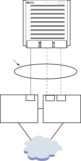
Figure D-2 VLAN over a Failover Group
Failover Group lan902:
lan901 (Primary),
lan5, 6 (Standby)
Switch1 Switch2
Trk4
Vlan 333
Vlan 334
Vlan 333
Vlan 334
F17 F18
PowerRun Attn. Fault Remote
lan901 lan5 lan6
As the first step in creating the failover group, associate the ports in link aggregate lan901 to
Trk4 on Switch 1; set the trunk type to trunk (MANUAL trunking). Connect ports lan5 and
lan6 to ports F17 and F18, respectively, on Switch 2.
To create the VLANs on Switch 1, complete the following steps:
1. Create the VLANs with IDs 333 and 334. Enter:
Switch 1#
Switch 1# configure
Switch 1(config)# vlan 333 name vlan_333
Switch 1(config)# vlan 334 name vlan_334
2. Tag Trk4 to VLANs 333 and 334. Enter:
Switch 1(config)# vlan 333 tagged Trk4
Switch 1(config)# vlan 334 tagged Trk4
Switch 1(config)# exit
Configuring VLANs over Failover Groups 115
3. Verify that the VLANs with IDs 333 and 334 are tagged correctly. Enter:
Switch 1# show vlan 333
Status and Counters - VLAN Information - Ports - VLAN 333
802.1Q VLAN ID : 333
Name : vlan_333
Status : Port-based
Voice : No
Port Information Mode Unknown VLAN Status
---------------- -------- ------------ ----------
Trk4 Tagged Learn Up
Switch 1# show vlan 334
Status and Counters - VLAN Information - Ports - VLAN 334
802.1Q VLAN ID : 334
Name : vlan_334
Status : Port-based
Voice : No
Port Information Mode Unknown VLAN Status
---------------- -------- ------------ ----------
Trk4 Tagged Learn Up
To create the VLANs on Switch 2, complete the following steps:
1. Create the VLANs with IDs 333 and 334. Enter:
Switch 2#
Switch 2# configure
Switch 2(config)# vlan 333 name vlan_333
Switch 2(config)# vlan 334 name vlan_334
2. Tag ports F17 and F18 to VLANs 333 and 334. Enter:
Switch 2(config)# vlan 333 tagged F17
Switch 2(config)# vlan 333 tagged F18
Switch 2(config)# vlan 334 tagged F17
Switch 2(config)# vlan 334 tagged F18
Switch 2(config)# exit
3. Verify that the VLANs with IDs 333 and 224 are tagged correctly. Enter:
Switch 2# show vlan 333
Status and Counters - VLAN Information - Ports - VLAN 333
802.1Q VLAN ID : 333
Name : vlan_333
Status : Port-based
Voice : No
Port Information Mode Unknown VLAN Status
---------------- -------- ------------ ----------
F17 Tagged Learn Up
F18 Tagged Learn Up
Switch 2# show vlan 334
Status and Counters - VLAN Information - Ports - VLAN 334
802.1Q VLAN ID : 334
Name : vlan_334
Status : Port-based
Voice : No
Port Information Mode Unknown VLAN Status
---------------- -------- ------------ ----------
F17 Tagged Learn Up
F18 Tagged Learn Up
116 VLANs over APA Using HP Procurve Switches
On the server side, complete the following steps:
1. Create link aggregate lan901.
2. Create failover group lan902.For HP-UX 11i v2 and earlier versions, the primary port in
the failover group must have an IP address configured on it.
3. Create VLANs 333 and 334 over lan902. Enter:
# lanadmin -V create vlanid 333 902
Successfully configured.
lan5000: vlanid 333 name UNNAMED pri 0 tos 0 tos_override
IP_HEADER pri_override CONF_PRI ppa 902
# lanadmin -V create vlanid 334 902
Successfully configured.
lan5000: vlanid 334 name UNNAMED pri 0 tos 0 tos_override
IP_HEADER pri_override CONF_PRI ppa 902
Configuring VLANs over Failover Groups 117
118

E Switch Configuration Information
This appendix provides some information on how to configure the following switches for use
with HP APA:
• Alteon
• Cisco
• Extreme
• Procurve
See your switch documentation for complete information.
Alteon Switches
Alteon switches have 8 ports. Fiber blades support 1500 and 9000 MTU (jumbo frames). The
following interactive dialog describes how to establish a console connection:
switchname 1
Username>username 2
switchname(37)>> sh po all 3
switchname(37)>> c alteon1 4
Password: password 5
53 Find the service name.
1Open a Console window. Enter the administrator
password.
42 Link to the serial port.Log in to the switch.
Cisco 6509 Switches
The throughput on the Cisco switch is different for fiber and copper ports. The fiber ports are
fabric enabled. This means that they hand off frames to one another with a throughput of 256
Gb/s. This is the equivalent of 64 GigE cards continuously transmitting and receiving at their
theoretical limits with no overhead. This section describes the following tasks:
• Configure a single port
• Show a single link
• Create an LACP link aggregation
• Create a PAgP link aggregation
NOTE: The information in this section pertains to Cisco IOS Version 12.2.
Configuring a Single Port
Router1#config term
config command 1
.
.
Ctrl+z
Switch1#interface gigabitethernet 9/5
Switch1(config-if)#switchport
Switch1(config-if)#no shutdown
Switch1(config-if)#end
1Enter configuration commands, one per line. End with Ctrl+z or end.
Showing a Single Port
Router1#show interface gigabitethernet 7/1
GigabitEthernet7/1 is up, line protocol is up (connected)
Hardware is C6k 1000Mb 802.3, address is 0001.63d1.6016 (bia 0001.63d1.6016)
MTU 9000 bytes, BW 1000000 Kbit, DLY 10 usec,
reliability 255/255, txload 1/255, rxload 1/255
Alteon Switches 119

Creating an LACP Link Aggregation
Switch1#enable
Password:password
Switch1#config term
config command 1
.
.
Ctrl+z
Switch1(config-if)#interface range gigabitethernet 3/1 - 3
Switch1(config-if-range)#no ip address
Switch1(config-if-range)#channel-protocol lacp
Switch1(config-if-range)#channel-group 1 mode active
Creating a port-channel interface Port-channel 1
Switch1(config-if-range)#end
Switch1#config term
config command
.
.
Ctrl+z
Switch1(config)#interface port-channel 1
Switch1(config-if)#no shutdown
Switch1(config-if)#end
1Enter configuration commands, one per line. End with Ctrl+z or end.
Creating an PAgP Link Aggregation
Switch1#enable
Password:password
Switch1#config term
config command 1
.
.
Ctrl+z
Switch1(config-if)#interface range gigabitethernet 7/1 - 4
Switch1(config-if-range)#no ip address
Switch1(config-if-range)#channel-protocol pagp
Switch1(config-if-range)#channel-group 7 mode desirable
Creating a port-channel interface Port-channel 7
Switch1(config-if-range)#end
Switch1#config term
config command
.
.
Ctrl+z
Switch1(config)#interface port-channel 7
Switch1(config-if)#no shutdown
Switch1(config-if)#end
1Enter configuration commands, one per line. End with Ctrl+z or end.
Displaying the Link Aggregation
Switch1#show etherchannel port-channel
Channel-group listing:
-----------------------
Group: 1
----------
Port-channels in the group:
----------------------
120 Switch Configuration Information
Port-channel: Po1 (Primary Aggregator)
------------
Age of the Port-channel = 00d:01h:46m:08s
Logical slot/port = 14/1 Number of ports = 3
Port state = Port-channel Ag-Inuse
Protocol = LACP
Ports in the Port-channel:
Index Load Port EC state No of bits
------+------+------+------------------+-----------
2 49 Gi3/1 Active 3
0 92 Gi3/2 Active 3
1 24 Gi3/3 Active 2
Time since last port bundled: 00d:01h:44m:15s Gi3/1
Displaying a Port in a Link Aggregation
Switch1#show interface GigabitEthernet 3/3 etherchannel
Port state = Up Mstr In-Bndl
Channel group = 1 Mode = Active Gcchange = -
Port-channel = Po1 GC = - Pseudo port-channel = Po1
Port index = 1 Load = 0xAA Protocol = LACP
Flags: S - Device is sending Slow LACPDUs F - Device is sending fast LACPDUs.
A - Device is in active mode. P - Device is in passive mode.
Local information:
LACP port Admin Oper Port Port
Port Flags State Priority Key Key Number State
Gi3/3 SA bndl 32768 0x1 0x1 0x303 0x3D
Partner's information:
Partner Partner Partner
Port System ID Port Number Age Flags
Gi3/3 00000,0030.6ef4.82380x5 19s SA
LACP Partner Partner Partner
Port Priority Oper Key Port State
0 0x384 0x3D
Displaying More LACP Information
Switch1#show lacp 1 neighbor
Flags: S - Device is sending Slow LACPDUs F - Device is sending Fast LACPDUs
A - Device is in Active mode P - Device is in Passive mode
Channel group 1 neighbors
Partner's information:
Partner Partner Partner
Port System ID Port Number Age Flags
Gi3/1 00000,0030.6ef4.82380x6 17s SA
LACP Partner Partner Partner
Port Priority Oper Key Port State
0 0x384 0x3D
Partner's information:
Partner Partner Partner
Cisco 6509 Switches 121

Port System ID Port Number Age Flags
Gi3/2 00000,0000.0000.00000x0 297s SP
LACP Partner Partner Partner
Port Priority Oper Key Port State
0 0x0 0x0
Partner's information:
Partner Partner Partner
Port System ID Port Number Age Flags
Gi3/3 00000,0030.6ef4.82380x5 4s SA
LACP Partner Partner Partner
Port Priority Oper Key Port State
0 0x384 0x3D
Deleting a Link Aggregation
Switch1(config)#no interface port-channel 1
Switch1(config)#no interface port-channel 5
Switch1(config)#end
Extreme Switches
This section provides information for the Extreme Black Diamond, 7i, and 400-48t switches.
NOTE: This switch only supports 100/1000 speeds; it does not support 10 Mb/s speeds. Therefore,
you will not be able to test a card with this setting. The speeds are stated on the back of the switch
itself.
To configure jumbo frames on all ports, enter:
enable jumbo-frame ports all
To verify all ports, enter:
show ports info
Configuring HP APA Link Aggregates
Before configuring a HP APA in Manual mode, do the following:
1. Verify port connections. Do the following:
a. From another system, send test packets to the target LANs. Enter:
llp lanlocal lan target system | grep OK
b. Disable ports on switch. Enter:
disable ports [portlist]
c. Verify you now cannot send test packets to the target LANs. Enter:
llp lanlocal lan target system | grep OK
d. Enable ports on switch. Enter:
enable ports [portlist]
2. Configure Manual aggregation on the switch. Enter:
enable sharing 7:2 grouping 7:2-7:3
3. Save the configuration. Enter:
save
122 Switch Configuration Information
Configuring LACP Link Aggregates
ExtremeWare v. 7.5 enables you to configure LACP. Use contiguous ports and let the first port
be the master. In the following command, port 23 is the master port:
enable sharing 23 grouping 23-27 dynamic
Then, display the aggregation using the show ports sharing command as follows:
Switch2 # show ports 23-27 sharing
Load Sharing Monitor
Config Current Ld Share Ld Share Link Link
Master Master Type Group Status Ups
==========================================================
23 23 dy 23 A 34
dy 24 A 35
dy 25 A 34
dy 26 A 34
dy 27 A 34
Link Status: (A) Active, (D) Disabled, (LB) Loopback, (ND) Not Distributing
(NP) Not Present, (R) Ready
Ld Share Type: (a) address based, (dy) dynamic
In the previous example, dy indicates LACP protocol.
Procurve Switches
This section describes information for the following Procurve switches:
• Procurve 4000/8000
• Procurve 4108
• Procurve 9304/8
Procurve 4000/8000
This section provides the following information that you might find useful in using these switches:
• Power cycling the Procurve switch turns flow control off. You must turn flow control on for
all ports after power cycling the switch.
• Both the 4000 and 8000 switch have backplane limitation of 3.8 Gb/s. This makes them
unsuitable for testing Gigabit Ethernet.
• The Procurve 4000/8000 does not support Jumbo frames.
To configure the switch, do the following:
1. Log in to the switch.
2. Press Enter several times to display the Main Menu.
3. Enter 3 (switch configuration).
4. Enter 2 (port configuration).
5. Use the arrow key to select edit.
6. Use the arrow key to select a field; press the space bar to cycle choices.
7. When finished, press Enter to return to the action keys.
8. Enter save.
9. Enter save again to display the Switch Configuration menu.
10. Enter 0 (zero) to display the Main Menu.
11. Enter 0 (zero) to logout. Then, enter Y to confirm.
12. Enter Ctrl+] to exit telnet.
Procurve 4108
The Procurve 4108 does not handle 9000 MTU.
After logging in to the switch, press Enter a few times to display the following prompt:
Procurve Switches 123
HP ProCurve Switch 4108GL#
Make sure that the ports you think you are aggregating on the switch are the right ones. This
can be combined with the process of creating switch aggregations. Do the following:
1. Log in to the switch.
2. Enter menu at the prompt.
3. Select Switch Configuration.
4. Select Port/Trunk Settings.
5. Verify which cards or ports are connected to the switch ports that you intend to configure.
Do the following:
a. On the computer, enter the following command for each port:
llp lanx
Verify that it returns OK.
b. On the switch, select Edit. Use the down arrow key to move to the switch ports you
want to disable. Type N for each port.
c. Press Enter to return to the choices at the bottom of the menu. Then, select Save.
d. On the computer, enter the following command for each port:
llp lanx
Verify that it returns an error. Leave the switch ports disabled.
6. Configure an aggregation on the ports. Do the following:
a. Use the right arrow key to move to the Group column.
b. Press the space bar to select Trk1, 2, and so on.
c. For an LACP or FEC aggregation, use the right arrow key to move to the Type column.
d. Press the space bar to select LACP or FEC. Select Trunk for a Manual aggregation.
e. Press Enter to return to the choices at the bottom of the menu. Then, select Save. The
Switch Configuration Menu displays.
f. Select 2 Port/Trunk Settings.
g. Select Edit. Use the down arrow to move to the switch ports you wish to enable. Enter
Y for each port.
h. Press Enter to return to the choices at the bottom of the menu. Then, select Save.
7. On the computer, enter the following command for each port:
llp lanx
Verify that it returns an error. Leave the switch ports disabled.
8. Configure HP APA for the same aggregation mode on the same ports on the computer.
Procurve 9304/8
The following information is helpful in working with Procurve 9304/8 switches:
• These switches have four modules. Modules 1, 2, and 3 have 24 100BT ports each. Module
4 has 8 GigE fiber ports.
• SNAP interfaces do not respond to broadcast pings on the Procurve 9304/9308. Unicast
SNAP traffic works.
• The Procurve 9304 does not handle GigE Jumbo frames.
After logging in to the switch, do the following:
1. Wait a short while, then press Enter. The following displays:
HP9304>
2. Enter the following:
HP9304>enable
3. Enter the following:
HP9304#configure terminal
124 Switch Configuration Information

4. The following prompt displays:
HP9304(config)#
TIP: Enter [command name] ? to display the syntax for a command.
Configuring HP APA
To configure HP APA to use the Procurve 9304/8 switch, do the following:
1. Verify port connections before configuring APA. Do the following:
a. Log in to the switch using the previous steps.
b. Enter the interface e [slot]/[port]command. For example:
HP9304(config)#interface e 2/1
c. Enter the following:
HP9304(config-if-e100-2/1)#disable
d. On the server system, verify the LAN is down with the following command:
llp lanx
The command displays output similar to the following:
===========================================================
CMD: linkloop -i 17 0x00306E04945F for hpatm247:lan17 ...
-----------------------------------------------------------
error: expected primitive 0x30, got DL_ERROR_ACK
dl_error_primitive = 0x2d
dl_errno = 0x04
dl_unix_errno = 57
error - did not receive data part of message
Link connectivity to LAN station: 0x00306E04945F
e. On the switch, enter enable.
f. Wait briefly, then on the server system, confirm the LAN has connectivity with the
following command:
llp lanx
The command displays output similar to the following:
===========================================================
CMD: linkloop -i 17 0x00306E04945F for hpatm247:lan17 ...
-----------------------------------------------------------
Link connectivity to LAN station: 0x00306E04945F
-- OK
Procurve Switches 125
2. Configure HP APA. Do the following:
a. Unplug all LAN connections to be aggregated.
b. Create the aggregations. They must be either 2 or 4 port trunks. For two-port
aggregations, the beginning port number must be odd. For four-port aggregations, the
beginning port number must be a number divisible by 4 plus 1 (for example, 1, 5, 9, 13).
Use the following command to create a four-port aggregation:
HP9304(config)#trunk server e 1/5 to 1/8
c. Save the configuration. Enter:
HP9304(config)#write mem
d. Reboot the switch. Enter the following:
HP9304(config)#exit
HP9304#reload
e. After switch reboots, plug in the cables and display the trunk configuration as follows:
HP9304>show trunk
Information similar to the following displays:
Configured trunks:
Trunk Type Ports
3 Server 1/5 1/6 1/7 1/8
5 Server 1/9 1/10 1/11 1/12
17 Server 2/1 2/2
19 Server 2/5 2/6
20 Server 2/7 2/8
21 Server 2/9 2/10
Operational trunks:
Trunk Type Ports Duplex Speed Tag Priority
3 Server 1/5 1/6 1/7 1/8 Full 100M No level0
5 Server 1/9 1/10 1/11 1/12 Full 100M No level0
17 Server 2/1 2/2 Full 100M No level0
19 Server 2/5 2/6 Full 100M No level0
20 Server 2/7 2/8
21 Server 2/9 2/10 Full 100M No level0
To remove the trunk in the previous example, enter the following:
no trunk server e 1/5 to 1/8
126 Switch Configuration Information

Glossary
A
administrative
key
An integer value that determines which network physical ports can be aggregated into a common
LACP link aggregate. The key must match the key of the desired aggregate that the user wants
the port to join
aggregate A group. For APA, a group of up to eight ports (32 ports for LACP aggregates) makes one link
aggregate. There can be 50 link aggregates per computer.
aggregation See aggregate.
APA Auto Port Aggregation
ARP Address Resolution Protocol. A TCP/IP protocol used to obtain a node's physical address.
Auto Port
Aggregation
APA. An HP software product that allows grouping up to eight ports into an aggregate to boost
performance and provide port failover. The eight port limit applies only for FEC_AUTO and
MANUAL mode.
F
failover group A logical grouping of one or more physical ports formed by LAN Monitor. The failover group
is used as an alternative if the link fails.
Fast
EtherChannel
See FEC.
FEC See Fast EtherChannel. The proprietary name of Cisco's port aggregation product. When referring
to FEC mode, it indicates use of PAgP on a link..
FEC_AUTO The automatic configuration mode of FEC.
flow A sequence of MAC frames between a pair of hosts where all of the MAC frames form part of
the same conversation between that pair of hosts.
G
group capability An integer value used to determine which network physical ports can be aggregated into an
FEC link aggregate.
H
Hot Standby A method of providing high availability
L
LACP_AUTO Link Aggregation Control Protocol
LAN Local Area Network
LB_IP Internet Protocol-based algorithm for server–to–router configurations.
LB_MAC MAC-based algorithm for server–to–switch configurations (this is the default algorithm).
See also for information..
LB_PORT TCP/UDP port-based algorithm for server–to–server (back-to-back) configurations
link aggregate A logical grouping of one or more physical ports into a single fat-pipe. This term is used to
describe LACP_AUTO, Manual, or PAgP (Cisco Fast EtherChannel) created logical ports.
link aggregation See link aggregate.
linkaggPPA The PPA or logical card instance number of a specific link aggregate.
load balancing A method of distributing traffic across the network physical ports in a link aggregate. Unicast
and multicast traffic is distributed across the network physical ports in a link aggregate.
Broadcast traffic is always sent out the first network physical port in a link aggregate
127
M
MAC Media Access Control
MANUAL The default mode of port configuration. Can be performed by using SMH (preferred) or by
editing two configuration files.
MIB Management Information Base
N
network adapter A network device which has one or more network physical ports.
network physical
port
The communications channel formed when you attach a network cable between a specific
network port (adapter card) and a LAN device.
P
PAgP See Port Aggregation Protocol.
PCI Peripheral Component Interconnect
physical point of
attachment
See PPA.
port The communications channel formed when you attach a network cable between a network
physical port and a LAN device.
port aggregate See link aggregate.
port aggregation See link aggregate.
Port Aggregation
Protocol (PAgP)
The proprietary port aggregation protocol, developed by Cisco Systems Inc., which automatically
determines a bidirectional connection between two network physical ports.
port priority An integer value used to determine which network physical port will be used as the port in a
link aggregate in hot standby mode.
PPA A unique integer identifier for each network physical port installed on a server.
S
SAM System Administration Manager
server–to–router See LB_IP.
server–to–server See LB_PORT.
server–to–switch See LB_MAC.
T
TCP Transmission Control Protocol
trunk See link aggregate.
TSO TCP Segmentation Offload
128 Glossary

Index
A
aggregate instance number, 32
algorithm
HOT_STANDBY, 34
LB_IP, 34
LB_MAC, 34
LB_PORT, 34
load balancing, 14
application
hang (failover group), 88
hang (FEC_AUTO mode), 83
hang (LACP_AUTO mode), 78
hang (MANUAL mode), 73
B
binary file
caution, 103
C
caution
binary file, 103
HP Serviceguard and HOT_STANDBY mode, 35
lanadmin -a option, 58
lanadmin command, 51
lanqueryconf command, 107
CKO
and link aggregates, 75, 80
command
ioscan, 89
lanadmin, 51
lanqueryconf, 107
lanscan, 47
nettl, 90
ping, 89
swlist, 20
swremove, 21
configuration, 31
(see also sample configuration)
FEC_AUTO mode example, 106
high availability, 27
LACP_AUTO mode example, 106
MANUAL mode example, 105
samples, 23–28
server-to-server with switch, 29
tip to display Procurve command syntax, 125
using SAM, 36–46
verifying, 47
configuration file, 100
(see also file)
lanconfig.ascii, 100
lanconfig.ascii fields, 102–103
configuration mode, 33
configuration worksheet, 31
connection
abnormal termination (failover group), 88
abnormal termination (FEC_AUTO mode), 83
abnormal termination (LACP_AUTO mode), 78
abnormal termination (MANUAL mode), 73
packet loss, 79
D
data flow
and load distribution, 14
dead count
specifying in lanconfig.ascii file, 103
specifying on configuration worksheet, 35
DEAD_COUNT, 103
depot
installing, 20
verifying installation, 69
destination MAC address
algorithm, 34
diagnostic map
how to use instructions, 67
F
failover group, 110
(see also proactive failover)
abnormal connection termination, 88
and SAM, 17
and telnet command, 88
and TSO, 16
and VLAN, 114
application hanging, 88
configuration example, 108
configuration with link aggregates, 30
configuring by editing files, 107
configuring IP address, 47
configuring switch for, 47
description, 15
host is unreachable message, 87
including a link aggregate, 15
name format in lanconfig.ascii file, 102
network is unreachable message, 86
permission denied message, 87
sample syslog status messages, 64
simple configuration, 29
switch restrictions, 30
unknown host message, 86
verifying active ports, 85
verifying configuration, 84
verifying correct active port, 85
verifying if enabled, 84
verifying member ports, 84
verifying ready port, 86
failover policy, 33
FAILOVER_GROUP, 102
features, 13
FEC_AUTO mode, 33
configuration example, 106
configuring by editing files, 105–107
129
configuring with lanadmin, 58
configuring with SAM, 36–41
verifying link partner configuration, 79
file
editing for APA configuration, 105–107
hp_apaconf, 48, 97–99
hp_apaportconf, 48, 99–100
netconf, 107
file access
verifying (failover group), 87
verifying (FEC_AUTO mode), 82
verifying (LACP_AUTO mode), 77
verifying (MANUAL mode), 73
FIRST_APA_PORT, 63
FIRST_LACP_PORT, 63
G
global parameter
default port mode, 63
LACP SYSID mode, 63
LACP timeout, 63
maximum link aggregates, 63
Use syslog, 63
group (see failover group)
group capability, 98
and multiple link aggregates, 35
specifying in hp_apaconf file, 97
specifying in hp_apaportconf file, 99
specifying on configuration worksheet, 35
H
host is unreachable message
in failover group, 87
in FEC_AUTO mode link aggregates, 82
in LACP_AUTO mode link aggregate, 77
in MANUAL mode link aggregate, 72
Hot Standby mode
sample configuration, 27
HOT_STANDBY algorithm, 34
and switch ports, 71
HOT_STANDBY mode
configuring switch for, 47
HP APA
configuring FEC_AUTO mode with lanadmin, 58
configuring using SAM, 36–46
HP Serviceguard
and HP APA, 17
and HP APA capabilities, 95
caution about link configuration, 35
when to configure, 47
HP_APA_DEFAULT_PORT_MODE, 97
HP_APA_GROUP_CAPABILITY, 97
HP_APA_HOT_STANDBY, 98
HP_APA_INTERFACE_NAME, 98
HP_APA_KEY, 98
HP_APA_LACP_SYSTEM_ID_MODE, 98
HP_APA_LOAD_BALANCE_MODE, 98
HP_APA_MANUAL_LA, 99
HP_APA_MAX_LINKAGGS, 99
HP_APA_USE_SYSLOG, 99
hp_apaconf file
parameters, 97–99
startup processing, 48
HP_APAPORT_CONFIG_MODE, 99
HP_APAPORT_GROUP_CAPABILITY, 99
HP_APAPORT_INTERFACE_NAME, 100
HP_APAPORT_KEY, 100
HP_APAPORT_PRIORITY, 100
HP_APAPORT_SYSTEM_PRIORITY, 100
hp_apaportconf file
parameters, 99–100
startup processing, 48
I
instance number
link aggregate, 32
port, 33
ioscan command
example, 89
IP address
algorithm, 34
and failover group, 15
and link aggregate, 14
and netconf file, 14
configuring on failover group, 47
configuring on link aggregate, 39, 47
K
key
specifying in hp_apaconf file, 98
specifying on configuration worksheet, 35
L
LACP
System ID, 63
timeout, 63
LACP_AUTO mode, 33
configuration example, 106
configuring by editing files, 105–107
configuring with SAM, 36–41
LAN_MONITOR mode, 33
capabilities, 95
configuration with link aggregates, 30
failover group example, 108
proactive failover example, 110
simple configuration, 29
switch restrictions, 30
lanadmin command
-a option caution, 58
-X options, 52–54
-x options, 54–57
caution, 51
command line use, 57
displaying statistics, 65
interactive use, 59
syntax, 52
tasks, 51
test selection, 59
130 Index
verifying TSO support, 16
lanconfig file, 103
lanconfig.ascii file
fields, 102–103
sample, 100
lanqueryconf
caution, 107
lanqueryconf command, 107
lanscan command
verifying HP APA configuration, 47
Large Send (see TSO)
LB_IP
algorithm, 34
specifying in hp_apaconf file, 98
LB_MAC
specifying in hp_apaconf file, 98
LB_MAC algorithm, 34
LB_PORT
specifying in hp_apaconf file, 98
LB_PORT algorithm, 34
link aggregate
adding ports using SAM, 45
and TSO, 16
and VLAN, 113
configuring by editing files, 105–107
configuring FEC_AUTO mode by editing files, 105–
107
configuring FEC_AUTO mode using SAM, 36–41
configuring IP address, 47
configuring LACP_AUTO mode by editing files, 105–
107
configuring LACP_AUTO mode using SAM, 36–41
configuring MANUAL mode by editing files, 105–107
configuring MANUAL mode using SAM, 41–46
configuring using SAM, 37, 40, 44
deleting ports using SAM, 45
description, 13
displaying advanced options using SAM, 38, 44
displaying status using SAM, 40
displaying using SAM, 37, 42, 43, 46
in failover groups, 30
including in failover group, 15
maximum number of, 63
not enabled, 33
parameters for, 97
sample syslog status messages, 64
switch restrictions in failover group, 30
verifying active ports (FEC_AUTO mode), 81
verifying active ports (LACP_AUTO mode), 76
verifying active ports (MANUAL mode), 71
verifying configuration (LACP_AUTO mode), 74
verifying configuration (MANUAL mode), 70
verifying if enabled (FEC_AUTO mode), 79
verifying if enabled (LACP_AUTO mode), 74
verifying if enabled (MANUAL mode), 70
verifying member ports (FEC_AUTO mode), 79
verifying member ports (LACP_AUTO mode), 74
verifying member ports (MANUAL mode), 70
link partner
configuring, 47
verifying configuration (failover group), 83
verifying configuration (FEC_AUTO mode), 79
verifying configuration (LACP_AUTO mode), 74
verifying configuration (MANUAL mode), 70
LM_RAPID_ARP, 103
LM_RAPID_ARP_COUNT, 103
LM_RAPID_ARP_INTERVAL, 103
load balancing, 34
(see also load distribution)
algorithm, 14
description, 14
parameter, 98
load distribution, 34
log
syslog, 63
M
MAC address
and failover group, 15, 35
and link aggregate, 14
load balancing, 34
MANUAL mode, 33
configuration example, 105
configuring by editing files, 105–107
configuring with SAM, 41–46
Maximum Transmission Unit (see MTU)
message, 63
(see also status message)
MTU
virtual, 16
N
netconf file, 107
and IP address, 14
nettl command, 90
TSO status messages, 91
network is unreachable message
in failover group, 86
in FEC_AUTO mode link aggregates, 81
in LACP_AUTO mode link aggregate, 76
in MANUAL mode link aggregate, 71
network physical port (see physical port)
NIC
verifying claiming, 68
verifying installation, 68
verifying operation, 69
NODE_NAME, 102
O
outbound data transfer, 34
P
packet loss, 79
packet ordering, 15
parameter, 63
(see also global parameter)
permission denied message
in failover group, 87
131
in FEC_AUTO mode link aggregates, 82
in LACP_AUTO mode link aggregate, 77
in MANUAL mode link aggregate, 73
physical port
displaying using SAM, 38, 42
modifying attributes using SAM, 39
modifying with SAM, 43
ping command, 89
polling interval
specifying in lanconfig.ascii file, 103
specifying on configuration worksheet, 35
POLLING_INTERVAL, 103
port
verifying active in failover group, 85
verifying membership in failover group, 84
verifying ready in failover group, 86
verifying UP in failover group, 85
port aggregation
statistics, 65
port cost, 34
port mode, 63
port priority, 34
PRIMARY, 102
priority-based failover
comparison with proactive failover, 15
proactive failover, 33
configuration example, 110
description, 15
problem
gathering information, 92
reporting to HP, 92
product
specifications, 95
R
rapid ARP
specifying in lanconfig.ascii file, 103
specifying on configuration worksheet, 35
rapid ARP count
specifying in lanconfig.ascii file, 103
specifying on configuration worksheet, 36
rapid ARP interval
specifying in lanconfig.ascii file, 103
specifying on configuration worksheet, 36
S
SAM, 17
adding ports, 45
and failover groups, 17
configuring FEC_AUTO mode link aggregate, 36–41
configuring LACP_AUTO mode link aggregate, 36–41
configuring link aggregates, 37, 40, 44
configuring MANUAL mode, 41–46
deleting ports, 45
displaying advanced options, 44
displaying link aggregate advanced options, 38
displaying link aggregate status, 40
displaying link aggregates, 37, 42, 43, 46
displaying physical ports, 38, 42
modifying physical port attributes, 39, 43
sample configuration
enterprise intranet client/server, 24
failover group, 30
hot standby, 27
LAN Monitor failover group with link aggregations,
31
LAN_MONITOR mode, 30
no switch between router and server, 25
server-to-server, 27
switch between router and server, 26
server-to-server configuration
back-to-back, 27
with switch, 28
Serviceguard (see HP Serviceguard)
software
capabilities, 95
configured in kernel, 21, 69
installation requirements, 19
installing, 20
removing, 21
startup, 48
verifying the installation, 20
specifications, 95
Split Multi-Link Trunking, 19
STANDBY, 102
startup event, 48
STATIONARY_IP, 102
statistics
displaying, 65
types of, 65
status message
logging to syslog, 63
sample, 64
switch
and Nortel SMLT support, 19
configuring, 47
limitations in router and server configuration, 26
potential limitations, 14
potential limitations server to server, 28
supported, 19
swlist command, 20
swremove command, 21
syslog
logging status messages, 63, 99
syslog.log file, 63
system
booted with errors, 68
power not on, 67
System Administration Manager (see SMH)
T
TCP Segmentation Offload (see TSO)
telnet command
verifying success (failover group), 88
verifying success (FEC_AUTO mode), 83
verifying success (LACP_AUTO mode), 78
verifying success (MANUAL mode), 73
test
132 Index
lanadmin command, 59
tip
displaying Procurve command syntax, 125
specifying group capability, 35
troubleshooting, 67
TSO
and failover group, 16
and link aggregate, 16
status messages, 91
verifying support, 16
U
unknown host message
in failover group, 86
in FEC_AUTO mode link aggregates, 81
in LACP_AUTO mode link aggregate, 76
in MANUAL mode link aggregate, 72
V
VLAN
and failover group, 16, 114
and link aggregate, 16, 113
configuring, 47
133
