Hp J3188A Users Manual 10Base T Hub 16M Installation And Reference Guide
J3188A to the manual 6617e8a7-6ebb-4be2-82f8-900c55aa8563
2015-02-09
: Hp Hp-J3188A-Users-Manual-550008 hp-j3188a-users-manual-550008 hp pdf
Open the PDF directly: View PDF ![]() .
.
Page Count: 100
- HP 10Base-T Hub-16M
- HP 10Base-T Hub-16M (J3188A)
- Chapter 1: Installing the Hub
- Chapter 2: Troubleshooting
- Chapter 3: Managing the Hub
- Setting up the ASCII Console
- Console Command Reference
- Syntax Conventions on Help Screen:
- When to Use IPconfig
- Configuring for Network Management
- Using Novell NetWare IPX
- Using IP
- Security Configuration Parameter Definitions
- Configuring Security on a Single Port
- Configuring Security on All Twisted-Pair Ports
- Showing the Security Configuration
- Clearing Security Violation Indicators
- Appendix A: Cables and Connectors
- Appendix B: Specifications
- Appendix C: Modem Configuration
- Appendix D: Network Addressing
- Appendix E: Backup Links
- Appendix F: Security Information
- Appendix G: Safety and Regulatory Statements
- Index

Installation and
Reference Guide
HP J3188A
HP 10Base-T Hub-16M
MUCHO.BK : cvrf-r1.ft5 Page 1 Thursday, June 26, 1997 11:37 AM
MUCHO.BK : cvrf-r1.ft5 Page 2 Thursday, June 26, 1997 11:37 AM

HP 10Base-T Hub-16M (J3188A)
Installation and Reference Guide
MUCHO.BK : ch0.fm5 Page i Thursday, June 26, 1997 11:37 AM
© Copyright 1997 Hewlett-Packard Company
All Rights Reserved.
This document contains information which is protected by
copyright. Reproduction, adaptation, or translation without
prior permission is prohibited, except as allowed under the
copyright laws.
Publication Number
J3188-90001
Edition 1
July 1997
Applicable Product
HP 10Base-T Hub-16M (J3188A)
Trademark Credits
MS-DOS® and Microsoft® are U.S. registered trademarks of
Microsoft Corporation. Ethernet is a registered trademark of
Xerox Corporation. CiscoView is a trademark of Cisco
Systems, Inc.
Disclaimer
The information contained in this document is subject to
change without notice.
HEWLETT-PACKARD COMPANY MAKES NO WARRANTY
OF ANY KIND WITH REGARD TO THIS MATERIAL,
INCLUDING, BUT NOT LIMITED TO, THE IMPLIED
WARRANTIES OF MERCHANTABILITY AND FITNESS
FOR A PARTICULAR PURPOSE. Hewlett-Packard shall not
be liable for errors contained herein or for incidental or
consequential damages in connection with the furnishing,
performance, or use of this material.
Hewlett-Packard assumes no responsibility for the use or
reliability of its software on equipment that is not furnished
by Hewlett-Packard.
Warranty
See the warranty booklet and the registration form included
with the product.
A copy of the specific warranty terms applicable to this
product and replacement parts can be obatined from your
Cisco Sales and Service Office or authorized dealer.
MUCHO.BK : ch0.fm5 Page ii Thursday, June 26, 1997 11:37 AM
iii
HP 10Base-T Hub-16M (J3188A)
HP 10Base-T Hub-16M (J3188A)
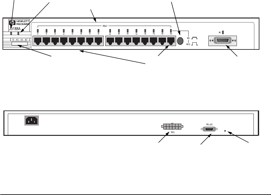
The HP 10Base-T Hub-16M (J3188A) is a multiport repeater with 16 twisted-
pair ports, and one AUI port. With this hub, you can connect computers,
printers, and servers together for file sharing. This hub is compliant with the
IEEE 802.3 Type 10Base-T standard and supports both 802.3 and Ethernet
networks. The HP Hub-16M follows these two standards by providing these
features:
■lighting the hub’s port LED when it detects the connected device is
powered on and cable is good.
■retransmitting data that did not successfully arrive at the destination
device (collision detection).
■temporarily disabling a port if a device connected to the port persistently
causes problems for the network (auto-partioning).
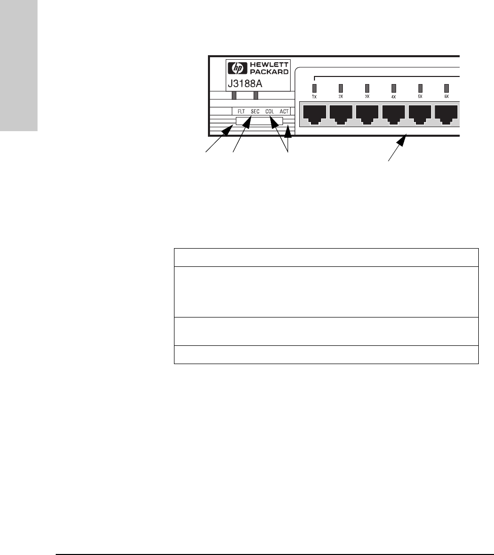
Twisted Pair port
status LEDs
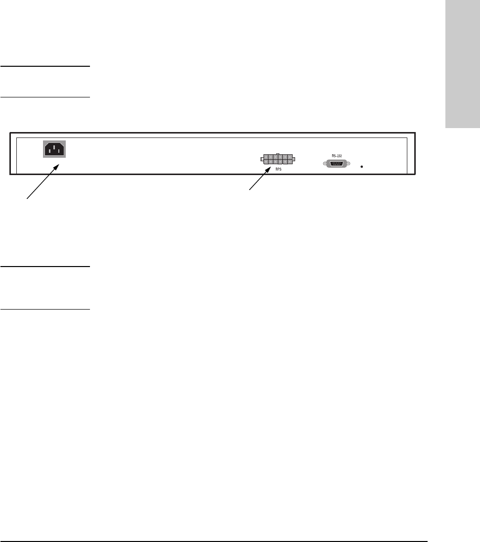
RPS Status
Twisted-pair
ports
MDI/MDI-X
switch for
port 16.
F
ront o
f
t
h
e
H
u
b
Hub status LEDs (Fault, Security,
Collision, Activity) AUI Connector for
External
Transceiver
System
B
ac
k
o
f
t
h
e
H
u
b
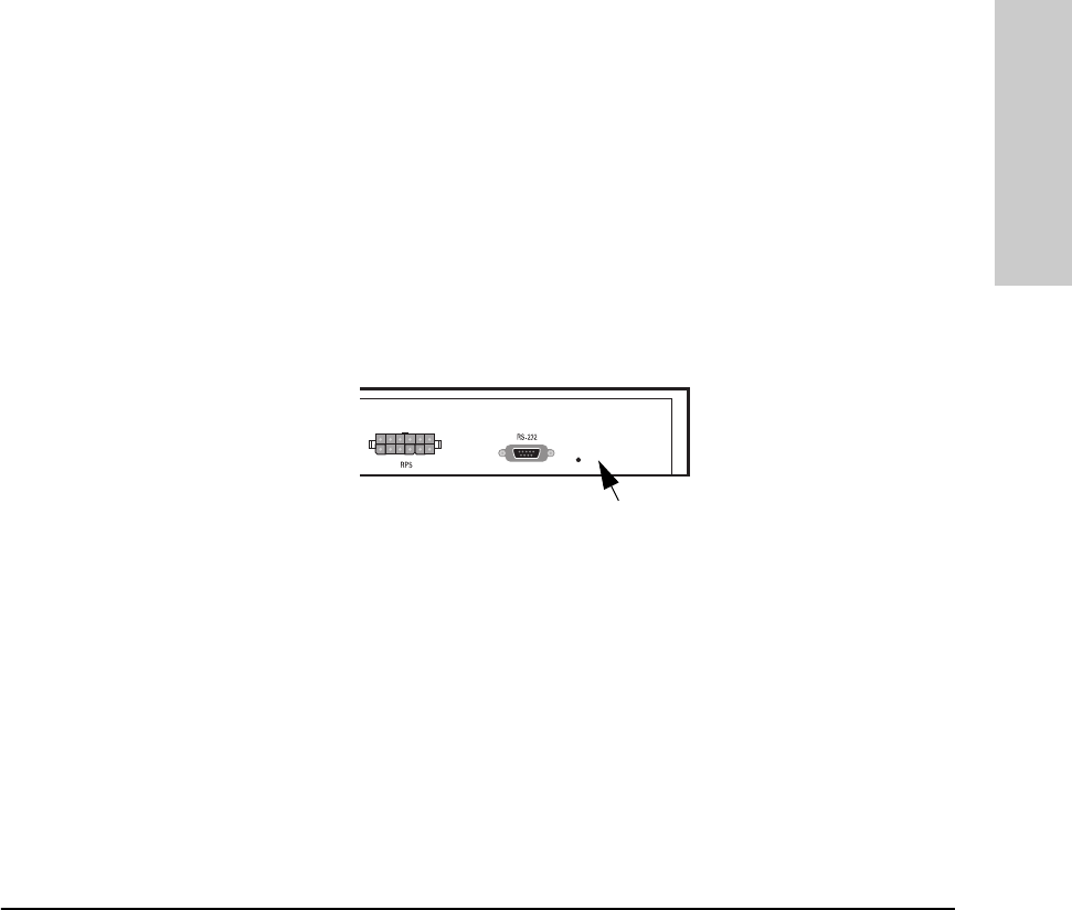
RPS connector Serial Port Password
Reset
Button
MUCHO.BK : ch0.fm5 Page iii Thursday, June 26, 1997 11:37 AM

iv
HP 10Base-T Hub-16M (J3188A)
Features
Network Connections •Sixteen RJ-45 (twisted-pair) ports to connect to end nodes or other devices.
•A Media Dependent Interface (MDI) switch for Port 16 which allows you to connect
either an end node (MDI-X position) or to cascade a hub (MDI position) to the port,
using a “straight-through” twisted-pair cable in both cases. Ports 1 through 15 always
are MDI-X. Port 16 has a factory default of MDI-X, but can be toggled to an MDI state
with the adjacent push-button.
•An AUI port in the front of the hub for several types of external transceivers, including
ThinLAN, twisted-pair, and fiber-optic. The twisted-pair transceiver adds another RJ-
45 port for a total of 17 twisted-pair ports on the hub. The fiber-optic transceiver
allows you to connect your hub to a fiber-optic backbone.
Easy-to-Use Design • Hub Status LEDs showing power, activity, collisions, RPS status, fault, security and
port status provide quick, easy-to-read hub status information and troubleshooting
help.
•Metal brackets (included with the hub) that can be easily attached to the hub for
mounting the hub in a standard 19-inch telco rack.
Standards-Based
Compatibility • IEEE 802.3 Type 10Base-T standard compatibility to support both 802.3 and Ethernet
networks.
•Advanced embedded SNMP agent code enabling the hub to be managed remotely
from a network management station that supports Simple Network Management
Protocol (SNMP) over IP (using the configured IP address) or Novell NetWare (IPX).
The agent code also provides HP EASE (Embedded Advanced Sampling Environment),
which samples network data for enhanced diagnostics from a network management
station.
Other Features • Extended hub management capabilities, providing a full set of management
commands that can be executed from an ASCII console session. These are described
later in this document in chapter 3, “Managing the Hub.”
•An RS-232 serial port that provides out-of-band management access including:
– An ASCII console to configure, monitor, and troubleshoot the hub.
– Variable baud rates on the hub’s out-of-band management RS-232 port, and
automatic sensing of the selected baud rate when connecting to a terminal device.
– Full V.22bis modem line control for remote out-of-band management access to the
hub.
– Updatable firmware that enables enhancements to be downloaded either from a
computer attached to the out-of-band management port or over the network.
•A Redundant Power Supply (RPS) connector that enables an RPS to be connected to
the hub, providing an alternative redundant power source.
•Advanced integrated design including an Intel i960 RISC processor, 1 megabyte RAM,
and 512 kilobytes of flash EEPROM for configuration and future upgrade capabilities.
MUCHO.BK : ch0.fm5 Page iv Thursday, June 26, 1997 11:37 AM

v
Contents
1 Installing the Hub
Installing and Configuring Your Hub . . . . . . . . . . . . . . . . . . . . . . . . . . . 1-2
1. Verify included parts . . . . . . . . . . . . . . . . . . . . . . . . . . . . . . . . . . . . . . . 1-2
2. Connect the external transceiver . . . . . . . . . . . . . . . . . . . . . . . . . . . . 1-2
3. Verify the hub operates correctly . . . . . . . . . . . . . . . . . . . . . . . . . . . . 1-2
4. Mount the hub . . . . . . . . . . . . . . . . . . . . . . . . . . . . . . . . . . . . . . . . . . . . 1-5
5. Connect the hub to your network . . . . . . . . . . . . . . . . . . . . . . . . . . . 1-7
Connecting Devices to the Hub . . . . . . . . . . . . . . . . . . . . . . . . . . . . . . . . 1-8
Connecting Hubs Together . . . . . . . . . . . . . . . . . . . . . . . . . . . . . . . . . . . 1-8
Interpreting LED Status . . . . . . . . . . . . . . . . . . . . . . . . . . . . . . . . . . . . . . 1-11
Interpreting Hub Status LEDs . . . . . . . . . . . . . . . . . . . . . . . . . . . . . . . . 1-12
Interpreting Port Status LEDs . . . . . . . . . . . . . . . . . . . . . . . . . . . . . . . . 1-13
2 Troubleshooting
Troubleshooting Approaches . . . . . . . . . . . . . . . . . . . . . . . . . . . . . . . . . . . 2-1
Using a Checklist to Diagnose the Hub . . . . . . . . . . . . . . . . . . . . . . . . . 2-2
LED Operation . . . . . . . . . . . . . . . . . . . . . . . . . . . . . . . . . . . . . . . . . . . . . . . . 2-3
Hub Maintenance Tasks . . . . . . . . . . . . . . . . . . . . . . . . . . . . . . . . . . . . . . . 2-5
Testing the Hub Only . . . . . . . . . . . . . . . . . . . . . . . . . . . . . . . . . . . . . . . . 2-5
Clearing a Password for the ASCII Console . . . . . . . . . . . . . . . . . . . . . 2-5
Running Connectivity Tests . . . . . . . . . . . . . . . . . . . . . . . . . . . . . . . . . . . 2-6
Obtaining Firmware Enhancements . . . . . . . . . . . . . . . . . . . . . . . . . . . . 2-6
3 Managing the Hub
Setting up the ASCII Console . . . . . . . . . . . . . . . . . . . . . . . . . . . . . . . . . . 3-1
Starting the Console . . . . . . . . . . . . . . . . . . . . . . . . . . . . . . . . . . . . . . . . . 3-3
Console Command Reference . . . . . . . . . . . . . . . . . . . . . . . . . . . . . . . . . . 3-4
MUCHO.BK : mucho.TOC Page v Thursday, June 26, 1997 11:37 AM

vi
A Cables and Connectors
Recommended Cables . . . . . . . . . . . . . . . . . . . . . . . . . . . . . . . . . . . . . . . . A-1
Twisted-Pair Cable/Connector Pin-Outs . . . . . . . . . . . . . . . . . . . . . . . A-3
Twisted-Pair Cable for Hub-to-Computer Network Connection . . . . A-3
RS-232 Connector and Cable Pin-Outs . . . . . . . . . . . . . . . . . . . . . . . . . A-4
Minimum Cable Pinout for ASCII Console Connection . . . . . . . . . . . A-5
RS-232 Modem Cable . . . . . . . . . . . . . . . . . . . . . . . . . . . . . . . . . . . . . . . A-5
Twisted-Pair Cable Pin Assignments . . . . . . . . . . . . . . . . . . . . . . . . . . A-6
B Specifications
Physical . . . . . . . . . . . . . . . . . . . . . . . . . . . . . . . . . . . . . . . . . . . . . . . . . . . B-1
Electrical . . . . . . . . . . . . . . . . . . . . . . . . . . . . . . . . . . . . . . . . . . . . . . . . . B-1
Environmental . . . . . . . . . . . . . . . . . . . . . . . . . . . . . . . . . . . . . . . . . . . . . B-1
Connectors . . . . . . . . . . . . . . . . . . . . . . . . . . . . . . . . . . . . . . . . . . . . . . . . B-2
Electromagnetic . . . . . . . . . . . . . . . . . . . . . . . . . . . . . . . . . . . . . . . . . . . B-2
C Modem Configuration
D Network Addressing
Communication Between the Hub and Network Management Station
D-1
IPX Addressing for Novell NetWare . . . . . . . . . . . . . . . . . . . . . . . . . . . D-2
IPX Addressing Notes: . . . . . . . . . . . . . . . . . . . . . . . . . . . . . . . . . . . . . . D-2
IP Addresses for IP and Non-IP Networks . . . . . . . . . . . . . . . . . . . . . D-2
Globally Assigned IP Network Addresses . . . . . . . . . . . . . . . . . . . . . . D-2
Device IP Configuration . . . . . . . . . . . . . . . . . . . . . . . . . . . . . . . . . . . . . D-3
Using BOOTP . . . . . . . . . . . . . . . . . . . . . . . . . . . . . . . . . . . . . . . . . . . . . . . . D-4
The BOOTP Process . . . . . . . . . . . . . . . . . . . . . . . . . . . . . . . . . . . . . . . . D-4
BOOTP Table File Entries . . . . . . . . . . . . . . . . . . . . . . . . . . . . . . . . . . . D-5
E Backup Links
How Backup Links Work . . . . . . . . . . . . . . . . . . . . . . . . . . . . . . . . . . . . . . E-1
Limitations . . . . . . . . . . . . . . . . . . . . . . . . . . . . . . . . . . . . . . . . . . . . . . . . E-2
MUCHO.BK : mucho.TOC Page vi Thursday, June 26, 1997 11:37 AM

vii
Additional Notes . . . . . . . . . . . . . . . . . . . . . . . . . . . . . . . . . . . . . . . . . . . E-2
Examples of Backup Links . . . . . . . . . . . . . . . . . . . . . . . . . . . . . . . . . . . . E-3
How the Backup Function Works . . . . . . . . . . . . . . . . . . . . . . . . . . . . . E-3
Configuring a Backup Link . . . . . . . . . . . . . . . . . . . . . . . . . . . . . . . . . . . . E-5
Configuration/Installation Sequence . . . . . . . . . . . . . . . . . . . . . . . . . . E-5
Identifying the Backup Link . . . . . . . . . . . . . . . . . . . . . . . . . . . . . . . . . . E-6
Indications of Backup Link Activation . . . . . . . . . . . . . . . . . . . . . . . . . E-6
Reactivating the Primary Link . . . . . . . . . . . . . . . . . . . . . . . . . . . . . . . . E-7
F Security Information
Understanding Network Security . . . . . . . . . . . . . . . . . . . . . . . . . . . . . . . F-1
How Intruder Prevention Works . . . . . . . . . . . . . . . . . . . . . . . . . . . . . . . F-2
How Eavesdrop Prevention Works . . . . . . . . . . . . . . . . . . . . . . . . . . . . . F-2
Authorized MAC address . . . . . . . . . . . . . . . . . . . . . . . . . . . . . . . . . . . . . F-2
Setting Inbound Security with Intruder Prevention . . . . . . . . . . . . . F-4
Auto Port Disable . . . . . . . . . . . . . . . . . . . . . . . . . . . . . . . . . . . . . . . . . . . F-5
Send Alarm . . . . . . . . . . . . . . . . . . . . . . . . . . . . . . . . . . . . . . . . . . . . . . . . . F-5
Setting Outbound Security with Eavesdrop Prevention . . . . . . . . . . F-6
G Safety and Regulatory Statements
Mounting Precautions . . . . . . . . . . . . . . . . . . . . . . . . . . . . . . . . . . . . . . . . G-1
Power Precautions . . . . . . . . . . . . . . . . . . . . . . . . . . . . . . . . . . . . . . . . . . . G-2
Safety Information . . . . . . . . . . . . . . . . . . . . . . . . . . . . . . . . . . . . . . . . . . . G-3
Informations concernant la sécurité . . . . . . . . . . . . . . . . . . . . . . . . . . . G-4
Hinweise zur Sicherheit . . . . . . . . . . . . . . . . . . . . . . . . . . . . . . . . . . . . . . G-5
Considerazioni sulla sicurezza . . . . . . . . . . . . . . . . . . . . . . . . . . . . . . . . G-6
Consideraciones sobre seguridad . . . . . . . . . . . . . . . . . . . . . . . . . . . . . G-7
Safety Information (Japanese) . . . . . . . . . . . . . . . . . . . . . . . . . . . . . . . G-8
Regulatory Statements . . . . . . . . . . . . . . . . . . . . . . . . . . . . . . . . . . . . . . . G-9
MUCHO.BK : mucho.TOC Page vii Thursday, June 26, 1997 11:37 AM
MUCHO.BK : mucho.TOC Page viii Thursday, June 26, 1997 11:37 AM

1
Installing the Hub
This chapter describes how to install the hub. Topics in this chapter include
■installing and configuring the hub
■connecting devices to the hub
■connecting hubs together
■interpreting hub LEDs
MUCHO.BK : ch1.fm5 Page 1 Thursday, June 26, 1997 11:37 AM

1-2
Installing the Hub
Installing and Configuring Your Hub
Installing the Hub
Installing and Configuring Your Hub
To install and configure your hub, you must complete five basic tasks. They
are:
■locating and verifying the necessary parts
■connecting an external transceiver (if necessary)
■connecting the hub to a power source
■mounting the hub
■connecting the hub to your network
1. Verify included parts
Each Hub-16M has the following components shipped with it:
■HP 10Base-T Hub-16M (J3188A) Installation and Reference Guide—
this manual (J3188-90001)
■A U.S./Canada/Mexico (8120-1378) power cord.
■Accessory kit (5064-2053):
• bumper feet (4)
• hub-to-rack screws 10-32 (4)
• bracket-to-hub screws 10-32 (4)
• nylon finishing washer (4)
• bracket-to-hub screws (2)
• AUI retainer assembly
2. Connect the external transceiver
Because of the way the external transceiver protrudes out from hub once it is
connected, you may want to install the external transceiver before installing
the hub. Inspect your installation site and identify whether enough room will
be available for the external transceiver to be connected. Then see your
external transceiver guide for installation instructions.
3. Verify the hub operates correctly
Before mounting the hub, connect it to a power source and verify the hub will
operate correctly.
MUCHO.BK : ch1.fm5 Page 2 Thursday, June 26, 1997 11:37 AM
1-3
Installing the Hub
Installing and Configuring Your Hub
Installing the Hub
1. Plug the power cord into the hub’s power cord receptacle and into an AC
(alternating current) power source. If you are using an RPS as your
primary power source, refer to the Cisco RPS User Guide for specific
instructions.
Note If your RPS is the primary power source for the hub, disconnect the AC power
cord connected directly to the hub for proper operation.
Note The hub does not have a power switch; it is powered on when the power cord
is plugged in. HP recommends that you only use one power source at a given
time.
If not connecting a Redundant Power Supply,
connect included power cord here and to an
alternating current power source.
(Optional) Connect Redundant Power Supply connector
cord clip here.
MUCHO.BK : ch1.fm5 Page 3 Thursday, June 26, 1997 11:37 AM
1-4
Installing the Hub
Installing and Configuring Your Hub
Installing the Hub
2. Check the LEDs on the hub’s front panel. When the hub is powered on, it
performs a power-on self test. See the table below for the LED pattern
that occurs during the self test.
Note that once you have connected cables to the hub, a Port LED stays
on if link beat has been detected at the port. A Port LED turns off if link
beat is not detected. The AUI port stays on if it is enabled.
When the self test completes successfully, the LEDs go into their normal
operational states. If a hub hardware fault exists, the hub will not
complete self test. This will be indicated by an abnormal LED pattern.
If the self test time elapses and the Fault LED continues to stay on instead
of turning off, the hub may have an error condition. If repeating the self
test does not correct the problem and the Fault LED still stays continu-
ously on, contact your reseller for replacement information. After the hub
has passed its self test, you are ready to mount the hub.
LED Pattern
Port LEDs,
Fault, Security,
AUI
ON for approximately 20 seconds, then enters normal operating
state.
Activity,
Collision, RPS ON for approximately five seconds, then enters normal operating
state.
System Stays ON.
On for 20 seconds,
then enters
normal operating
state.
On for 20 seconds,
then enters
normal operating
state.
On for five
seconds, then
enters normal
operating
state.
MUCHO.BK : ch1.fm5 Page 4 Thursday, June 26, 1997 11:37 AM

1-5
Installing the Hub
Installing and Configuring Your Hub
Installing the Hub
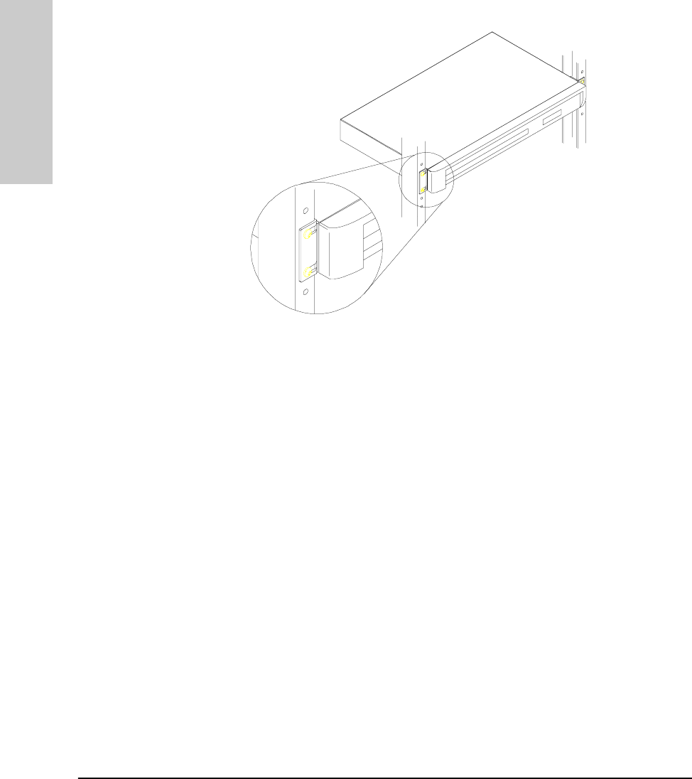
4. Mount the hub
The HP Hub-16M can be mounted in two ways:
1. in a rack or cabinet
2. on a table
The hardware for mounting the hub is included in the accessory kit
(5064-2053) packed with the hub. Before mounting the hub, unplug it.
See Appendix G, “Safety and Regulatory Standards,” for general mounting
precautions.
Rack or Cabinet Mounting
Warning The rack or cabinet should be adequately secured to prevent it from
becoming unstable and/or falling over. Please see Appendix G, “Safety
and Regulatory Standards,” for precautions and warnings associated with rack
mounting.
1. Using a Phillips T-10 screwdriver, attach the mounting brackets to the hub
with #10-32 x 7/16" silver screws (included in the accessory kit).
2. Position the hub in the rack or cabinet and slide it up or down until the
rack holes line up with the bracket holes.
3. Then attach the hub to the rack with the #10-32 x 5/8" black screws and
black nylon washers included in the accessory kit with a Phillips cross-
head screwdriver. (Some cabinets require number 12-24 screws instead.
Make sure you have screws that fit your cabinet or rack before mounting
the hub.)
MUCHO.BK : ch1.fm5 Page 5 Thursday, June 26, 1997 11:37 AM
1-6
Installing the Hub
Installing and Configuring Your Hub
Installing the Hub
Table Mounting
To place the hub on a table or other horizontal surface, no special tools are
necessary. Apply the four feet included in the accessory kit onto the bottom
of the hub. Be certain to pick a sturdy table in an uncluttered area. You may
want to secure the hub’s cables to the leg of the table to prevent people from
tripping over them.
MUCHO.BK : ch1.fm5 Page 6 Thursday, June 26, 1997 11:37 AM

1-7
Installing the Hub
Installing and Configuring Your Hub
Installing the Hub
5. Connect the hub to your network
Reconnect the hub to either an AC power source or the RPS, depending on
which source you are using. With the hub mounted, you are now ready to
connect the hub to your network. Typical hub connections are:
■hub-to-device connections. Connecting to network devices such as
computers, and printers.
■hub-to-hub connections. Connecting to another HP 10Base-T hub, or
other Ethernet hub.
■hub-to-network backbones. Connecting to a network backbone.
This section describes the different ways you can connect your hub to your
network.
MUCHO.BK : ch1.fm5 Page 7 Thursday, June 26, 1997 11:37 AM
1-8
Installing the Hub
Installing and Configuring Your Hub
Installing the Hub
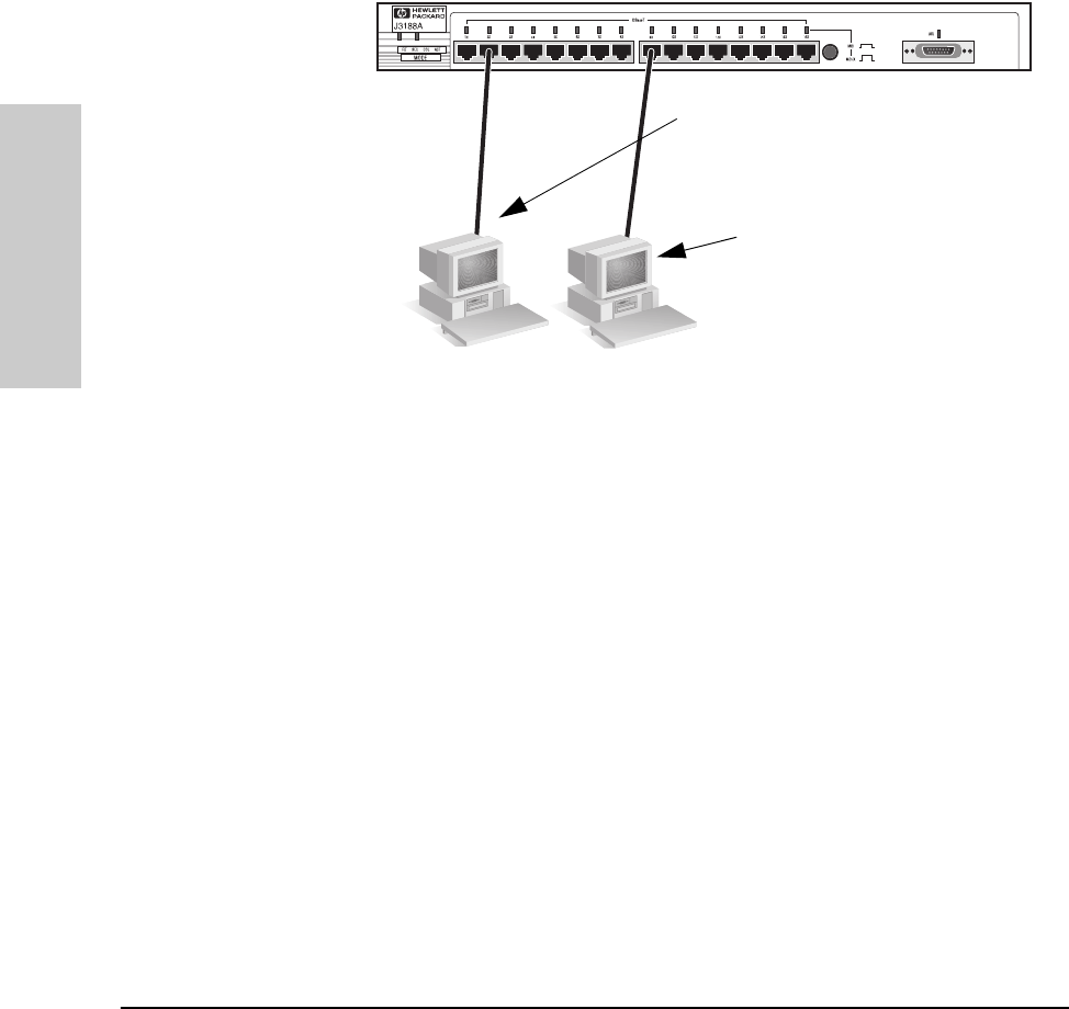
Connecting Devices to the Hub
To connect a device to the hub, push the RJ-45 plug into the RJ-45 jack until
the tab on the plug clicks into place.
Connecting Hubs Together
Twisted-Pair Cascade Connections
To expand your network, the hub can be connected to other hubs with
straight-through cable by using the Media Dependent Interface (MDI) switch.
The MDI/MDI-X switch controls how the signals are sent through the twisted-
pair cable connected to Port 16. The hub is shipped with the switch in the MDI-
X position. The switch has two positions:
■In the MDI position, use Port 16 to connect your hub to another hub. In
this position, the hub reverses the Tx and Rx port pairs for you. This allows
you to use “straight-through” cable rather than “cross-over” cable to
connect two hubs together. The cable can be up to 100 meters in length.
■In the MDI-X position, use Port 16 to connect your hub to a PC or similar
device using “straight-through” cable.
RJ-45
Connector
unshielded twisted-pair cable
Category 3, 4, or 5
Cat 3, 4 maximum distance: 100 meters
MDI/MDI-X switch
MUCHO.BK : ch1.fm5 Page 8 Thursday, June 26, 1997 11:37 AM
1-9
Installing the Hub
Installing and Configuring Your Hub
Installing the Hub
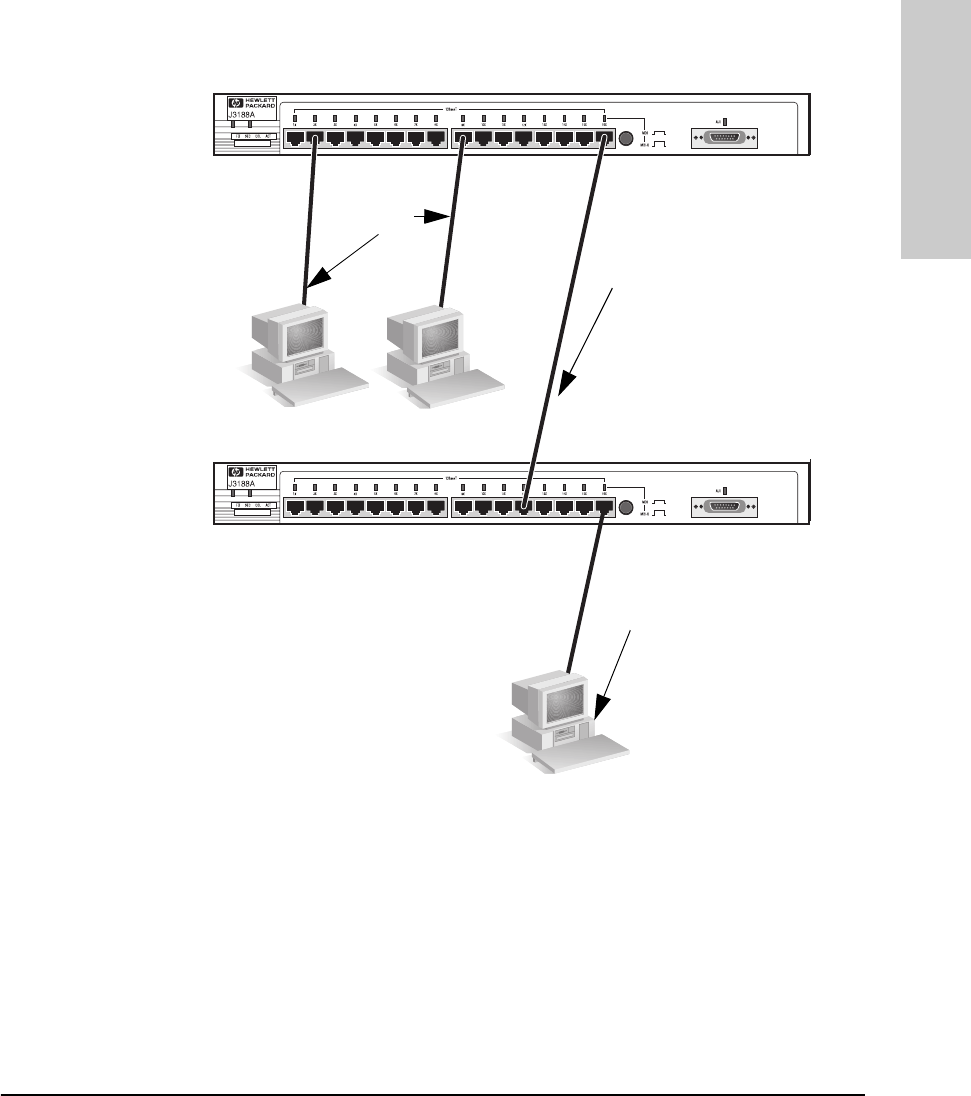
In the following illustration, the first hub is connected to two end nodes and
to a second hub. Note the second hub shows Port 16 connecting to a PC, using
a straight through cable with the port in the MDI-X position.
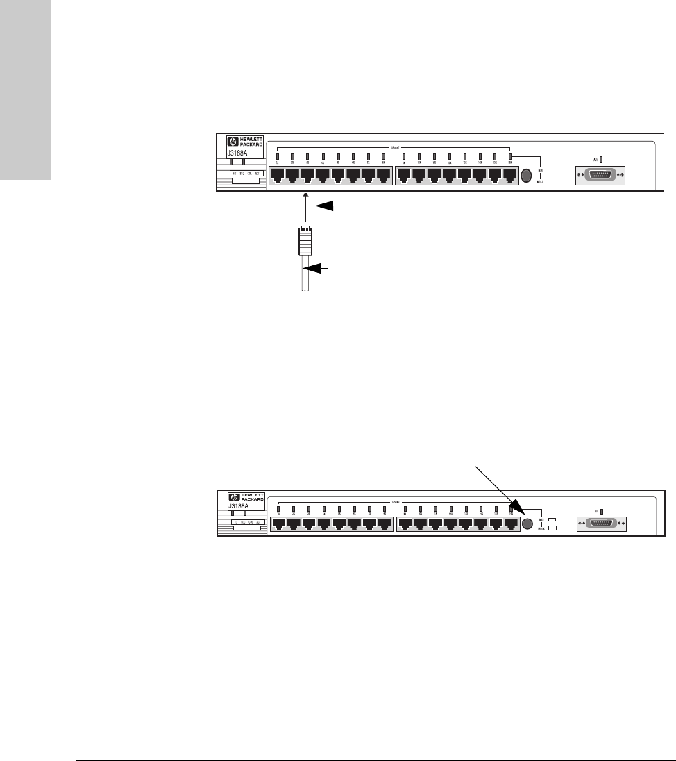
ThinLAN Connections
With an HP ThinLAN External Transceiver for 10Base2 networks, you can
connect your hub or a stack of hubs to a thin LAN network. The following
illustration shows a hub with an HP ThinLAN External Transceiver.
Hub attached to
Port 16: switch in
MDI position and
straight-through
cable is used.
Up to 100 meters
PC attached to
Port 16: switch in
MDI-X position
and straight-
through cable is
used.
Straight-
Through
Cable from
Hub to PCs
MUCHO.BK : ch1.fm5 Page 9 Thursday, June 26, 1997 11:37 AM
1-10
Installing the Hub
Installing and Configuring Your Hub
Installing the Hub
You can connect up to 30 hubs together on a common ThinLAN segment. The
ThinLAN segment can include a computer attached to a hub at one end of the
segment that can communicate with a computer attached to another hub at
the other end of the segment. By using the BNC port on the module, the
maximum repeater hop-count increment through the entire segment is only
two. The following illustration shows you how to connect three hubs together
from one ThinLAN port to another.
Note Each ThinLAN cable segment must be terminated using a 50-ohm terminator
at each end. In the illustration above, a 50-ohm terminator is placed at each
end of the cable segment.
ThinLAN coax
connecting the
hubs together
Hub-16M
Hub-16U
HP AdvanceStack
10Base-T Hub-24
50-ohm
terminator
50-ohm
terminator
MUCHO.BK : ch1.fm5 Page 10 Thursday, June 26, 1997 11:37 AM
1-11
Installing the Hub
Interpreting LED Status
Installing the Hub
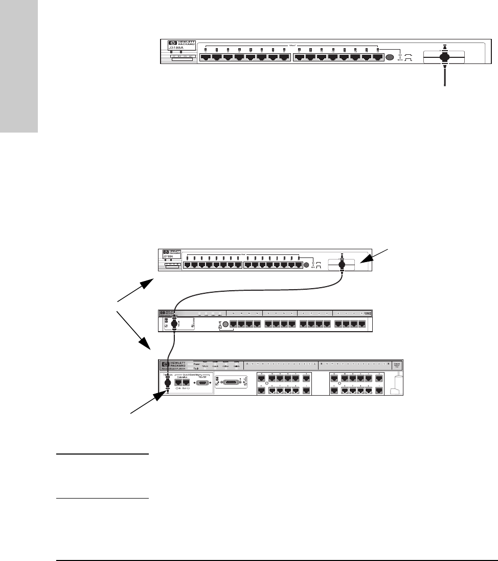
Connecting the Hub-16M to a Fiber-Optic Backbone
With an HP Fiber-Optic external transceiver for 10Base-FL networks, you can
connect your hub to a fiber-optic backbone. The following illustration shows
a hub with an HP Fiber-Optic external transceiver connected to a fiber-optic
backbone:
For more information about cabling configuration, see the documentation
accompanying the optional transceiver modules.
Interpreting LED Status
Two types of LEDs exist on the hub. They are:
■Hub Status LEDs. These LEDs reflect certain conditions that exist on the
hub at large and are not explicitly referring to a given port.
■Port Status LEDs. These LEDs reflect basic conditions (for example, Link
Beat being enabled) that exist on a specific port.
Status information for both are described in the following tables.
HP J2606A Fiber-Optic
Fiber-optic
cable to a
fiber-optic
backbone
MUCHO.BK : ch1.fm5 Page 11 Thursday, June 26, 1997 11:37 AM

1-12
Installing the Hub
Interpreting LED Status
Installing the Hub
Interpreting Hub Status LEDs
The hub status LEDs indicate whether the hub is functioning properly. For
further details on error conditions indicated by the Status LEDs, see chapter
2, “Troubleshooting”.
LED State Meaning of LED
SYSTEM
(Power)
(green)
On The hub is receiving power.
Off The hub is not receiving power.
ACT
(Activity)
(green)
Flickering ON while a packet is being transmitted. Normally, the LED appears
to flicker. In heavy traffic, it may appear on all the time.
FLT
(Fault)
(Orange)
On
Off
Flash
An error has been detected on the hub.
No error has been detected on the hub.
Flashes simultaneously with port LEDs, indicating the port is
partitioned.
SEC
(Security)
(Orange)
On
Off
Flash
A security violation has occurred.
Hub security has not been violated.
Flashes simultaneously with port LEDs, indicating the port had a
security violation.
RPS
(RPS)
(green)
On
Off The RPS is providing power.
The RPS is not providing power.
COL
(Collision)
(orange)
Flickering This LED is on while a collision is detected. If it appears on
continuously (with no flicker), it is a possible indicator of a network
fault or an improperly terminated cable.
MUCHO.BK : ch1.fm5 Page 12 Thursday, June 26, 1997 11:37 AM

1-13
Installing the Hub
Interpreting LED Status
Installing the Hub
Interpreting Port Status LEDs
The following table provides LED port information.
LED State Meaning of LED
Twisted-pair
Port (green) On Link beat is detected from the attached node.
Off The port is not receiving the link beat signal from the attached
node.
Slow
Flash* The port has been auto-partitioned. This port has been auto-
partitioned (disabled) due to excessive collisions. This port will
reenable when the connected device no longer causes
collisions.
AUI
Port (green) On The AUI port is enabled.
Off The AUI port is disabled.
Slow
Flash The port has been auto-partitioned.
* The slow flash is approximately once every 1.5 seconds.
MUCHO.BK : ch1.fm5 Page 13 Thursday, June 26, 1997 11:37 AM
MUCHO.BK : ch1.fm5 Page 14 Thursday, June 26, 1997 11:37 AM

2
Troubleshooting
This chapter describes ways to troubleshoot the hub. Topics covered are:
■troubleshooting approaches
■using a checklist to diagnose the hub
■interpreting the LED pattern during self test
■hub maintenance tasks
Troubleshooting Approaches
There are three primary ways to diagnose hub problems:
■By checking the LEDs on the front of the hub as described in the section,
“Using a Checklist to Diagnose the Hub” later in this chapter.
■By using the ASCII console’s diagnostic functions as described in chapter
3, “Managing the Hub.”
■By using the CiscoView network management application as described in
the CiscoView online help.
MUCHO.BK : ch2.fm5 Page 1 Thursday, June 26, 1997 11:37 AM

2-2
Troubleshooting
Using a Checklist to Diagnose the Hub
Troubleshooting
Using a Checklist to Diagnose the Hub
Use the following table to diagnose the problem with your HP Hub-16M.
Most problems with the hub can be diagnosed using the LEDs on its front
panel. The following section describes the normal LED pattern during self-
test, and LED patterns that indicate error conditions on the hub.
Problem Solution
How do I reset the hub? Remove the plug on the power cord from the
power source and reconnect it.
None of the LEDs are on. Verify that the power cord is plugged into an
active power source and to the hub. Make sure
these connections are snug. Try power cycling
the hub by unplugging and plugging the hub
back in.
If the Power LED is still not on, verify the AC
source works by plugging another device into
the outlet. Or try plugging the hub into a different
outlet or try a different power cord.
If this condition persists, call your
HP-authorized LAN dealer or HP representative
for assistance.
I lost the password. Press the password reset button for 10 seconds.
See page 2-4 for more details.
IP configuration errors have been
reported. Use the ASCII console’s IP Configuration
function as described in the chapter 3,
“Managing the Hub.”
I want to see if each cable is connected
correctly. Run TEstlink. See the command description in
chapter 3, “Managing the Hub.”
A user can’t send data to another user. Use the Connectivity tests in the ASCII console
or in CiscoView to test the cabling. The tests are
described in this chapter.
The Fault LED is on. Remove the plug on the power cord from the
power source and reconnect it. If problem
persists, the device has an internal failure.
Contact your HP authorized dealer or reseller.
The Security LED is flashing. How do I
get it to stop? Use the ASCII console or CiscoView to view the
intruder log and clear the security violations.
MUCHO.BK : ch2.fm5 Page 2 Thursday, June 26, 1997 11:37 AM

2-3
Troubleshooting
LED Operation
Troubleshooting
LED Operation
The tables on the following pages list the hub’s LEDs, their possible states,
and diagnostic tips to resolve any error conditions.
LED patterns indicating problems Diagnostic Tips
Power Coll Port LED Sec Fault RPS
OFF** ***Verify that the power cord is plugged
into an active power source and to the
hub. Make sure these connections are
snug. Try power cycling the hub by
unplugging and plugging the hub back
in.
If the Power LED is still not on, verify the
AC source works by plugging another
device into the outlet. Or try plugging
the hub into a different outlet or try a
different power cord.
If this condition persists, call your
HP-authorized LAN dealer or HP
representative for assistance.
ON*OFF***Check cabling on the indicated port all
the way out to the device attached to
that port. Faulty wiring or a bad
connection could exist somewhere in
that connection.
The end node or hub attached to the
port is off.
The port may be disabled. Use the
ASCII console or management
application to enable the port.
If Port 16, check the position of the
MDI/MDI-X switch. See the figure in
chapter 1 that details the MDI/MDI-X
switch.
ON ON * * * * Very frequent collisions are occurring,
which could indicate a network fault or
improperly terminated cable.
*This LED is not important for the diagnosis.
MUCHO.BK : ch2.fm5 Page 3 Thursday, June 26, 1997 11:37 AM

2-4
Troubleshooting
LED Operation
Troubleshooting
ON * Fast
Flash Fast
Flash **A security violation has occurred on
the port that is flashing. See SEcure
command for definition and details in
Chapter 3.
ON * Slow
Flash *Slow
Flash *The port has been auto-partitioned
because of an excessive collision
condition. Check cable connections
and status of attached network devices
for causes of the excess collisions. The
hub will automatically recover after
certain IEEE 802.3 criteria are
successfully met.
ON * * Fast
Flash **Network management security
violation occurred. See SEcure
command for details.
ON * * * ON * The hub has failed its self-test. Power-
cycle the hub. If this condition persists,
call your HP-authorized LAN dealer or
HP representative for assistance.
ON** **OFFThe internal power supply is operating
properly and the RPS is not being used.
ON** **ONThe internal power supply has failed or
has been unplugged and the RPS has
been activated as the current
operating power supply.
LED patterns indicating problems Diagnostic Tips
Power Coll Port LED Sec Fault RPS
*This LED is not important for the diagnosis.
MUCHO.BK : ch2.fm5 Page 4 Thursday, June 26, 1997 11:37 AM
2-5
Troubleshooting
Hub Maintenance Tasks
Troubleshooting
Hub Maintenance Tasks
There are several hub maintenance tasks you can perform. They include:
■testing the hub only
■clearing a password from the ASCII console
■running connectivity tests
Each of these tasks is described in the following sections.
Testing the Hub Only
If you believe that the hub is not operating correctly, remove and reinsert the
power cord for that hub. This procedure will cause the hub to complete its
power-on self-test. If any error conditions exist in the hub, the LEDs should
display the condition.
Clearing a Password for the ASCII Console
You can use the Password Reset button to clear a forgotten console password
that was previously configured on the hub. The password is configured from
the ASCII console.
To clear the password, follow these steps:
1. Verify the hub has powered-up, passed power-on test, and that the System
LED is lit.
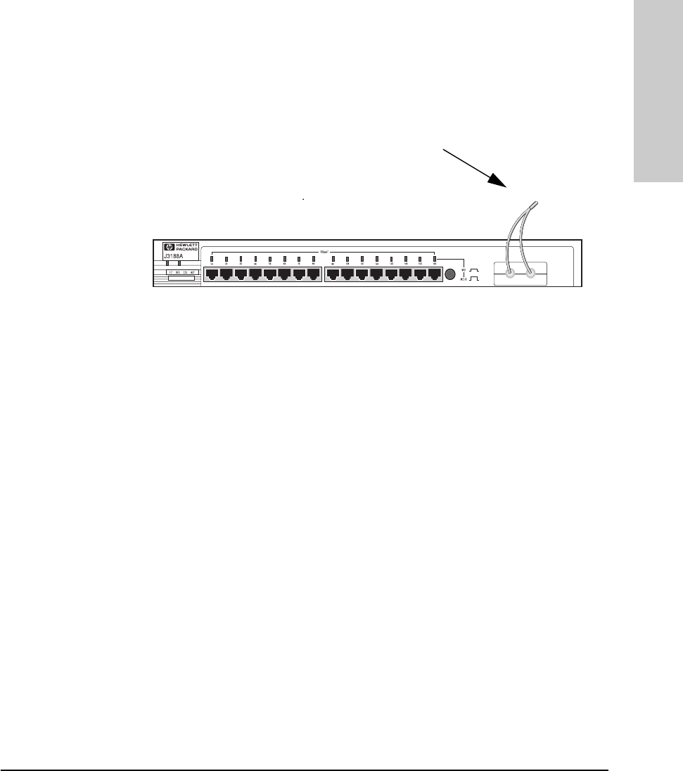
2. Press the Password Reset button on the back of the hub for 10 seconds.
Password
Reset
MUCHO.BK : ch2.fm5 Page 5 Thursday, June 26, 1997 11:37 AM
2-6
Troubleshooting
Hub Maintenance Tasks
Troubleshooting
Running Connectivity Tests
Both the hub and cabling can be tested by running an end-to-end communica-
tions test -- a test that sends known data from one network device to another
through the hub -- such that you can verify that the data was correctly
transmitted between the devices.
See your LAN adapter’s manual for information on running an end-to-end
communication test.
Obtaining Firmware Enhancements
In the future, Hewlett-Packard may provide improvements to this product
through firmware upgrades. The upgrade code can be downloaded from a PC
attached to the hub’s RS-232 port or over the network. The update procedures
are described in documents that come with the firmware enhancements.
You can determine the current firmware version on the hub from the ASCII
console. Look for the SNMP Agent EEPROM version number to determine the
revision. When you access the console, the version number appears.
PC sending test
packets.
PC responding to
the test packets.
MUCHO.BK : ch2.fm5 Page 6 Thursday, June 26, 1997 11:37 AM

3
Managing the Hub
This chapter describes the features available from an ASCII console. Topics
include:
■setting up the ASCII Console
■console command reference
The HP Hub-16M has SNMP that allows you to manage the hub using one of
the following utilities:
■an ASCII console
■CiscoWorks
■any SNMP-compliant network management product except HP
AdvanceStack Assistant.
Setting up the ASCII Console
You can begin a console session in the hub in the following ways:
■directly, using a serial cable and a terminal (or a PC using a terminal
emulator)
■remotely, using Telnet
■remotely, using a modem and a terminal
The HP Hub-16M supports a single console session only. If a console session
is already running, a second console session can override the current console
session.
MUCHO.BK : ch3.fm5 Page 1 Thursday, June 26, 1997 11:37 AM

3-2
Managing the Hub
Setting up the ASCII Console
Managing the Hub
Directly, Using A Serial Cable and a Terminal
To directly connect a terminal to a hub, follow these steps:
1. Connect an ASCII terminal, or a PC emulating an ASCII terminal, to the
RS-232 port using an RS-232-C “null modem” cable. (For pin-outs and
recommended cables see Appendix A, “Cables and Connectors”.)
2. Switch on the terminal’s power (or switch on the PC’s power and start the
terminal emulation program). Configure the terminal for 8 bits per char-
acter, 1 stop bit, no parity, Xon/Xoff handshaking, and a baud rate of 38400,
19200, 9600, 4800, 2400, or 1200.
3. Press [Enter] several times for the => or Password prompt. The baud rate
for communication between the hub and the terminal is set automatically
when you press [Enter].
Remotely, Using Telnet
The HP Hub-16M supports a Telnet console session. Your Telnet syntax
depends on your TCP/IP software or your terminal server. By default, Telnet
is enabled. You can disable Telnet by using the IPconfig console command
described on page 3-7.
To establish a Telnet session, follow these steps:
1. Verify that the hub has been configured with an IP address, and that it is
accessible via IP from your PC or workstation.
2. Enter the command telnet followed by the IP address or system name of
the hub, for example:
telnet 192.1.1.10
or
telnet your_hub
(Your Telnet syntax depends on your TCP/IP software or your terminal
server. You can use a system name if you have name resolution such as
DNS.)
To end the Telnet session, type DI (the DIsconnect command) to terminate
the console session. Or use your Telnet application’s command to close or quit
the Telnet session.
MUCHO.BK : ch3.fm5 Page 2 Thursday, June 26, 1997 11:37 AM

3-3
Managing the Hub
Setting up the ASCII Console
Managing the Hub
Remotely, Using a Modem and a Terminal
1. Use a full-duplex, asynchronous (character-mode) modem only.
2. Connect the modem to the hub’s RS-232 port using an RS-232-C modem
cable. (For pin-outs and recommended cables see Appendix A, “Cables
and Connectors”.)
3. Configure the modem as described in the Appendix C, “Modem
Configuration.”
4. At the remote site, connect the terminal (or PC emulating a terminal) to
the remote modem. Make sure the terminal and modems are functioning
properly, then establish the link between the terminal’s modem and the
hub’s modem according to the modem instructions.
5. Press [Enter] several times for the => or Password prompt. The baud rate
for communication between the hub and the modem is set automatically
when you press [Enter].
Starting the Console
The console session starts with a display similar to the following (the actual
version numbers may be different):
HP J3188A Hub-16M
ROM A.01.00
EEPROM A.01.00
HW A.01.00
Use console commands for hub configuration.
Enter password:
If a password has not been assigned with the PAssword command, then you
are not prompted for your password here.
If a console session is currently active, then you are prompted to break the
current active console session.
A console session is currently active.
Do you want to break in? (Y/[N]) Y
Connecting…
Enter a console command, or HE or? for help.
=>
MUCHO.BK : ch3.fm5 Page 3 Thursday, June 26, 1997 11:37 AM
3-4
Managing the Hub
Console Command Reference
Managing the Hub
Console Command Reference
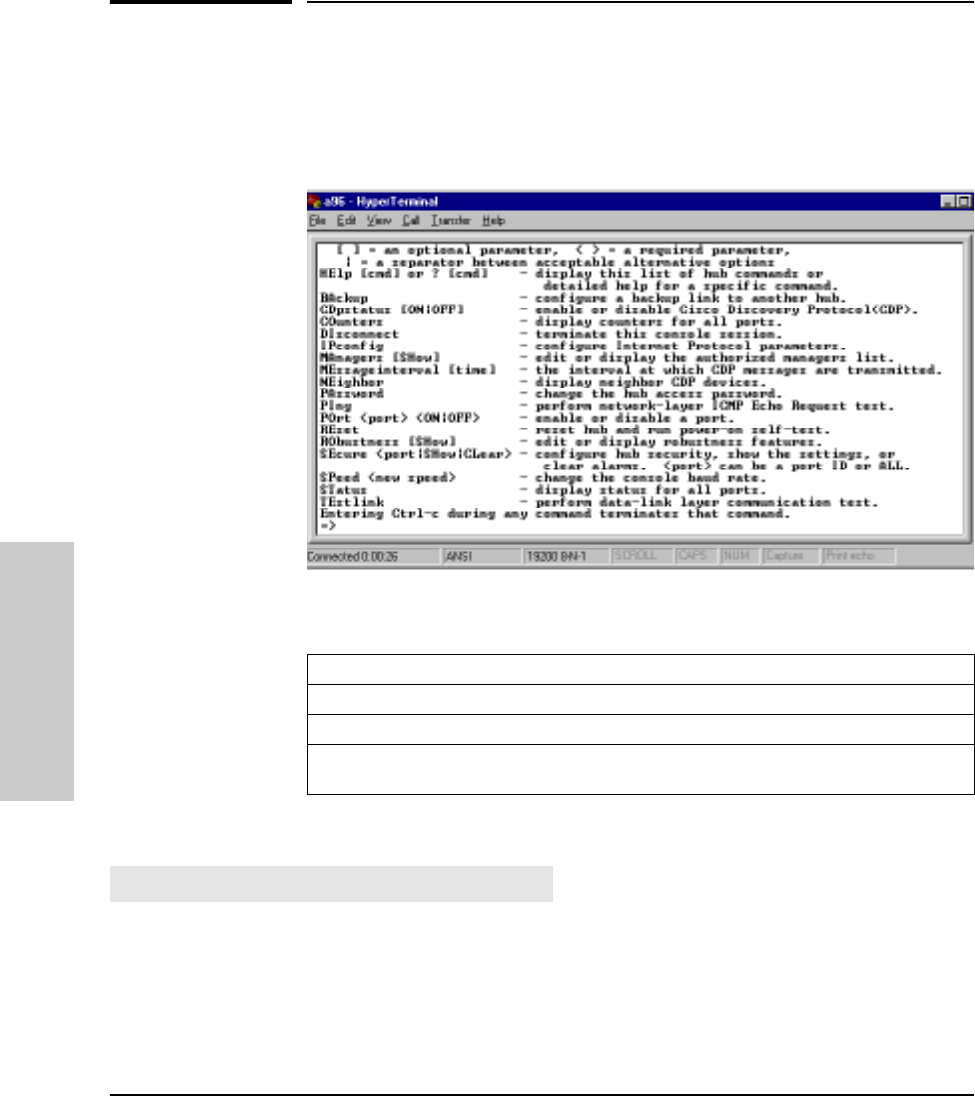
Enter at least the first two letters of a command to execute it, such as HE for
the Help command. The Help command displays a screen like the following,
listing all commands.
Syntax Conventions on Help Screen:
The commands are described in the rest of the chapter.
To see the help screen shown above or, if you include a specific
command, the syntax and description of that specific console
command. For the [cmd] parameter, use the first two letters of the command
you wish to see.
Example: HE ST (This displays help for the Status command.)
<> – Indicates a required parameter.
[ ] – Indicates an optional parameter.
| – Used as a separator between acceptable variable values.
For example, SE <port|SHow|CLear> indicates that either a port ID, or the characters SH
or CL, must be entered after the SE command.
HElp [cmd] or? [cmd]
MUCHO.BK : ch3.fm5 Page 4 Thursday, June 26, 1997 11:37 AM

3-5
Managing the Hub
Console Command Reference
Managing the Hub
To configure one of the hub’s ports for dedicated use in a backup
(redundant) link to another hub.
An HP Hub-16M allows you to use any two of its network ports for a redundant
link to another hub in your network. The backup link normally carries no
traffic, but it is automatically activated if the primary link fails. Note that any
of the ports can be the backup port to any other port.
When you enter the Backup command, you are prompted for these values:
The hub monitors the primary link by sending IEEE 802.2 Test packets at the
specified frequency to the specified remote hub. If “n” consecutive Response
packets are not returned from the remote hub, the primary port is disabled
and the backup port is enabled.
When the primary link is repaired, you must re-enable the primary port by
using the Port command. It is not automatically re-enabled. When the primary
port is re-enabled, the backup port is disabled automatically and returned to
backup mode. See the appendix on Backup Links. This appendix also covers
more information on backup links, including requirements, limitations, and
sample topologies.
BAckup
Default Description
Backup Port Disabled The port used for the backup link. Enter the port ID.
Or, enter DI (for disable) if you wish to remove an
existing backup link configuration.
Primary Port None The port used for the primary link. Enter the port ID.
Remote MAC
address 000000-000000 The 12-digit hexadecimal MAC address of the hub at
the remote end of the critical link.
Seconds Between
Test Packets 1 second How often you want the hub to send an IEEE 802.2
Test packet to the remote hub over the primary link.
Consecutive
Failures 2 failures The number of consecutive Test packet response
failures that will trigger activation of the backup link.
For example, enter 5 to activate the backup link on
the fifth failure.
MUCHO.BK : ch3.fm5 Page 5 Thursday, June 26, 1997 11:37 AM

3-6
Managing the Hub
Console Command Reference
Managing the Hub
To enable or disable the Cisco Discovery Protocol (CDP). The command takes
either an ON or an OFF argument. The initial setting is ON. ON enables the
protocol. OFF disables it. If no option is chosen, the current status is shown.
To display network activity counters for each network port, the hub’s
SNMP agent, and the global count for all ports.
The port counters are from the IEEE 802.3 Repeater Management
Specification. They are described below:
CDpstatus
COunters
Counter Name Definition Valid Range Corrective Action if over Valid
Range
Good Packets Number of error-free packets received. Less than 4000
packets per
second.*
Decrease the traffic level by
using a switch to segment the
network.
Collisions Number of times the port was involved
in a collision. A single collision will be
counted by all ports involved, so the
total collision counters may be less than
the sum of the port counts.
Less than 2 times
the number of good
packets.
Decrease the traffic level by
using a switch to segment the
network
Replace bad cables and/or
transceivers if problems persist.
Rarely, you may have a
defective LAN adapter.
Late Collisions Number of collisions which went
undetected by the sending end node. Less than.1% of
good packets. Too many repeaters between
end nodes, or cables which are
too long, or bad cable.
CRC/Alignment
Errors Number of packets transmitted
incorrectly and number of incorrectly
aligned packets.
Less than.1% of
good packets. This counter indicates faulty
cabling.
Giant Packets Number of packets larger than 1518
bytes. Less than.1% of
good packets. Update the LAN adapter drivers
on all nodes connected to the
port.
Broadcast Packets Number of packets addressed to
everyone in the network. These packets
consume CPU resources from each
node on the network.
Less than 200
packets per
second.*
Decrease the number of nodes
in an IP subnet or IPX network
by using more routers. Consult
Novell Netware documentation
on how to reduce broadcasts in
an IPX network.
*The port counters in the ASCII console show totals, not number of packets per second. For the Good Packets and
Broadcast packets, display counters twice over a period of one section to see if the value falls in the valid range.
MUCHO.BK : ch3.fm5 Page 6 Thursday, June 26, 1997 11:37 AM

3-7
Managing the Hub
Console Command Reference
Managing the Hub
To terminate the console session and reset the console port baud rate
to be automatically sensed. The command also disconnects the phone link
if you accessed the console using modems.
To set IP (Internet Protocol) configuration parameters on the hub.
By default, the hub is configured to use BOOTP (Internet Boot Protocol) to
automatically retrieve the IP parameters from a BOOTP server, and to enable
Telnet access to the hub’s console interface. Use this command if you want
to manually configure the IP address or disable Telnet.
The IP configuration must be carefully controlled. If each device’s IP address
is not unique on the network, severe network performance problems will
occur. A network administrator should maintain responsibility for the IP
settings. See Appendix D, “Network Addressing,” for information on setting
the IP configuration.
Note At the end of the process of changing the IP configuration, the hub will be
reset. This terminates the console session (and disconnects the phone line if
using a modem) and resets the console port baud rate to be automatically
sensed. To restart a console session, when the reset process completes, press
[Enter] several times for the prompt.
When to Use IPconfig
If any of the following is true, the hub’s IP parameters must be configured,
either on a BOOTP server or on the hub through the console interface:
■The hub will be managed remotely with a network management product,
such as CiscoWorks over an IP network (a network that uses IP commu-
nications, for example TCP/IP).
■The network cable segments attached to the hub will be tested using the
IP “Ping” test.
■Telnet access to the hub is desired.
DIsconnect
IPconfig
MUCHO.BK : ch3.fm5 Page 7 Thursday, June 26, 1997 11:37 AM

3-8
Managing the Hub
Console Command Reference
Managing the Hub
Configuring for Network Management
If the hub is to be managed from a network management station, it must use
the same networking protocol as the network management station. You have
these choices:
■Novell NetWare IPX
■IP
Using Novell NetWare IPX
The HP Hub-16M is designed to automatically use Novell NetWare’s IPX
protocol. If you are using the hub on a Novell NetWare network, no configu-
ration of the hub is required for it to communicate with a network management
station that is also using the IPX protocol.
The hub determines its IPX address automatically from information received
from a router or file server that is running IPX on the network, and from its
own MAC address, physical address, or Ethernet address). See your Novell
documentation for more information on IPX communications and addressing.
Using IP
You can use IP by using one of the following methods:
■using BOOTP by adding an entry for the hub in the BOOTP table on your
BOOTP server, and enabling BOOTP through the hub’s console interface
(this is the default setting)
■using the console interface to configure the IP parameters
BOOTP is covered in Appendix D, “Network Addressing.”
To use the console interface to configure the IP parameters, enter IP and the
following text appears:
=>IP
Active IP parameters:
BOOTP protocol enabled: YES
Telnet access enabled: YES
IP address: 0.0.0.0
Subnet mask: 0.0.0.0
Default router: 0.0.0.0
Time to live: 64
Change IP configuration? (Y/[N]):
The following table explains the IP parameters.
MUCHO.BK : ch3.fm5 Page 8 Thursday, June 26, 1997 11:37 AM

3-9
Managing the Hub
Console Command Reference
Managing the Hub
To configure the list of network management stations that are autho-
rized to access and manage this hub, and to specify which of those
stations should receive alarms. Use the SHow option to display the current
list of authorized management stations without being prompted to edit the list.
The list consists of the IP or IPX address of the network management station
and an indication of whether each management station should receive alarms
(indications of specific network events that are configured for the hub from
Parameter Default Value Definition
BOOTP protocol
enabled YES Keep or set this value to YES if you are using a BOOTP server to provide
the IP configuration to the hub. By default, the hub is configured to
automatically seek an IP address from a BOOTP server on the network.
This is done when the hub is powered on. If an IP address is not found,
the HP Hub-16M will seek an IP address every ten minutes until it finds
an IP address. Set this value to NO to disable this BOOTP process.
If you are not using BOOTP to provide the hub’s IP configuration, you
should set this parameter to NO.
Telnet access
enabled YES Determine whether users are allowed to use Telnet to access the hub’s
console interface.
IP address 0.0.0.0 The IP address of the hub (written in the format X.X.X.X).
Each X is a decimal number between 0 and 255 separated by a decimal
point. This address will be used unless the BOOTP protocol is enabled.
The default value (0.0.0.0) disables IP communications on the hub when
BOOTP is also disabled.
Subnet mask Must be supplied and
depends on the class of IP
address that has been
entered.
The bit mask defining which portion of the IP address is the subnet
address, written in the format X.X.X.X. All the devices on your network
should use the same subnet mask. See your network administrator for
the correct value.
Default router 0.0.0.0 The IP address of the nearest IP router in your network. If no IP routers
are in your network, enter the device’s own IP address.
Time to live 64 The number of IP routers a packet is allowed to cross before the packet
is discarded. Increase this value if the hub will be sending IP packets to
a destination that is more than 64 routers away. The maximum is 255.
MAnagers [SHow]
MUCHO.BK : ch3.fm5 Page 9 Thursday, June 26, 1997 11:37 AM

3-10
Managing the Hub
Console Command Reference
Managing the Hub
network management— also called SNMP event alarms). The start of the table
is shown below. Up to ten network management stations can be entered into
the table. Entry 0 (zero) is used for the “all managers allowed” entry.
The hub is initially shipped with all network management stations allowed to
manage the hub, but the “all managers” entry does not identify where alarms
are to be sent. Specific addresses must be entered into the table to identify
where the alarms should be sent.
Note If you want to restrict which management stations are allowed to manage the
hub, delete entry 0. Then add the allowed management stations with the A
command.
At the interface prompt, enter MA; the current authorized managers list is
displayed and you are prompted to add or delete an entry in the list, or to enter
E to end your editing.
To add an entry, enter A at the prompt. Enter the IP or IPX address of the
network management station, or enter A to allow all managers to manage the
hub, then indicate at the next prompt whether this management station should
receive alarms generated by the hub. A new entry is added to the list.
ID Manager Address (IP or IPX) Receive Alarms?
0 All managers allowed NA
1
2
MUCHO.BK : ch3.fm5 Page 10 Thursday, June 26, 1997 11:37 AM

3-11
Managing the Hub
Console Command Reference
Managing the Hub
Example: To add the network management station with IP address
190.40.101.10 to the list and to send alarms to that station, the process would
appear as follows:
Add entry (A), Delete entry (D), or End changes (E): A
Enter Manager Address, or (A) to allow all managers access: 190.40.101.10
Should this manager receive alarms: (Y/[N]):Y
Add entry (A), Delete entry (D), or End changes (E): E
Current authorized manager list:
To delete an entry, specify the ID number in the list corresponding to the
network management station to be deleted.
Example: To delete the entry made in the example above, the steps would be:
Add entry (A), Delete entry(D), or End changes (E): D
Enter ID of entry to delete: 1
Add entry (A), Delete entry (D), or End changes (E): E
The table entry with ID 1 would now be a blank line.
To enter a new value that will indicate how much time, in seconds, should
lapse between transmissions of CDP messages. Displays the current interval
if no time is specified. Acceptable values are decimal numbers from 5 to 900
(seconds). The default value is 60 seconds.
Displays the other devices that are using CDP protocol.
ID Manager Address (IP or IPX) Receive Alarms?
0 All managers allowed NA
1 190.40.101.10 YES
2
MEssageinterval
NEighbor
MUCHO.BK : ch3.fm5 Page 11 Thursday, June 26, 1997 11:37 AM

3-12
Managing the Hub
Console Command Reference
Managing the Hub
To set or change the password on the hub. The Password is used to
prevent unauthorized access to the hub from network management stations,
and through the console interface. The hub is initially shipped without a
password. Follow the prompts to enter a new password or to change the
existing password. If you assign a password, it is also used as the SNMP
community name.
If you decide to delete the password, enter the Password command, then press
[Enter] without entering any characters at the password prompt.
Press and hold the Password Reset button for approximately 10 seconds to
clear a password.
Note After the password has been cleared, access to the hub from the ASCII console
and from SNMP management stations will no longer be password protected.
A new password can be assigned from the ASCII console or CiscoWorks.
To test the path between the hub and another device that responds to
IP packets. The hub sends Internet Control Message Protocol (ICMP) Echo
Request (Ping) packets to another node with the specified IP address and
waits for Echo Response packets in return.
When you run the Ping command, you will be prompted for:
■the IP address of the destination device (in the format X.X.X.X)
■the number of packets to send
■the timeout value (the number of seconds to wait for a response)
If any errors are reported during this test, there may be a fault in the path used
during the test or in the destination device. For more information about testing
network links, see chapter 2, “Troubleshooting”.
PAssword
PIng
MUCHO.BK : ch3.fm5 Page 12 Thursday, June 26, 1997 11:37 AM

3-13
Managing the Hub
Console Command Reference
Managing the Hub
To enable (set to ON) or disable (set to OFF) a hub port. The initial
setting for all ports is enabled (ON). You can use the Status command to check
the current status of all the ports. The <port> parameter can be:
■twisted-pair port number
■XCVR or XC for the AUI port
■ALL or AL for all ports
Example 1: P0 7 OFF (Disables port 7)
Example 2: P0 AL ON (Enables all ports)
To reset the hub and run a hub self-test. This command also resets all
the network statistic counters, and the time since the last reset. The current
configuration is unchanged. The hub is not accessible from network manage-
ment software while it is being tested, but it continues to repeat data. If the
hub is faulty, at the end of the reset process, the Fault LED will stay on.
This command also terminates the console session (and disconnects the
phone line if you are using a modem to access the console) and resets the
console port baud rate to be automatically sensed. To restart the console
session, first re-establish the phone link (if used), then press [Enter] several
times for the prompt.
Allows you to invoke options to improve the hub’s ability to tolerate network
problems resulting from excessive collisions. The configurable options are:
■Intelligent Partition Recovery
■Late Collision Monitoring
By default, the robustness features are off. The Intelligent Partition Recovery
option makes it difficult for a problem port to automatically re-enable itself
to send traffic on the network.
POrt <port> <ON/OFF>
REset
RObustness
MUCHO.BK : ch3.fm5 Page 13 Thursday, June 26, 1997 11:37 AM

3-14
Managing the Hub
Console Command Reference
Managing the Hub
The Late Collision Monitoring option monitors ports for excessive late
collisions. If monitored ports experience excessive late collisions, these ports
are disabled.
See the section on Auto-Partitioning in the chapter that provides the Product
Description.
To control or display the hub’s security configuration, and to clear
security violation indicators. The <port> parameter can be:
■a twisted-pair port number only.
■XCVR or XC for the AUI port.
■ALL or AL for all ports
Security Configuration Parameter Definitions
The following security parameters are configurable on each of the hub’s
network ports. These parameters are defined on the next two pages:
■Address selection method, or authorized MAC address
■Send alarm when intruder detected
■Eavesdrop prevention
An additional parameter, “Disable port when intruder detected”, is set
automatically by your selection of the address selection method. See “Auto
Port Disable” in Appendix F, “Security Information,” on this parameter.
Address selection method, or authorized MAC address. This is the
method by which the hub automatically learns the address of the device that
is authorized to use the port, or you can enter a specific address. The following
methods are configurable:
■Learn Continuously—provides minimum port security (default secu-
rity state). The hub learns the address of the first device attached to the
port and makes it the authorized MAC address. If a different device is later
attached to the port, the new address is learned and becomes the autho-
rized address. Each new device attached becomes the authorized device.
You can be informed of any such changes by setting the Send Alarm
parameter to YES. In that case, when a new address is detected, the
SEcure <port|SHow|CLear>
MUCHO.BK : ch3.fm5 Page 14 Thursday, June 26, 1997 11:37 AM

3-15
Managing the Hub
Console Command Reference
Managing the Hub
Security and port LEDs flash, the intruder’s MAC address is displayed on
the console Status command screen, and an alarm is sent to the authorized
network management station(s).
■Use the First Address Heard—provides medium port security. The
hub learns the address of the first device attached to the port and makes
it the authorized MAC address. If you have any security configured for the
port (Send Alarm and/or Eavesdrop Prevention parameters are set to
YES), when a different device is later attached to the port, the new address
is registered as an “intruder address”; a security violation has occurred.
In that case, the port is automatically disabled, and the Security and
affected port LEDs flash. An alarm is also sent to the authorized network
management station(s) if the Send Alarm parameter is set to YES.
■Assign an Address—provides the highest security. You enter the
address of the device that is authorized to be attached to the port. If you
have any security configured for the port (Send Alarm and/or Eavesdrop
Prevention parameters are set to YES), when a different device is later
attached to the port, the new address is registered as an “intruder
address”; a security violation has occurred. In that case, the port is
automatically disabled, and the Security and affected port LEDs flash. An
alarm is also sent to the authorized network management station(s) if the
Send Alarm parameter is set to YES.
■Port Security Off—disables port security. This is a convenient way to
remove the port security. It automatically sets the Send Alarm and Eaves-
drop Prevention parameters to OFF (and therefore, the Disable Port
parameter will also be OFF).
Send Alarm when intruder detected. Configures the hub to send an
alarm (SNMP trap) to a network management station whenever an
unauthorized address (an intruder) is detected on the port. Note that for the
alarm to actually be sent, you must have first used the Managers command
to configure one or more network managers to receive alarms. See the
Managers command description earlier in this chapter.
Eavesdrop prevention. Configures the hub to prevent the port from
hearing data that is intended for another port. Only the data packets that have
a destination address that matches the port’s authorized address are sent to
the port. If Eavesdrop Prevention is not enabled on all ports, the hub functions
like a repeater and every packet seen by the hub is forwarded to the non-
Eavesdrop Prevention ports. See Appendix F, “Security Information,” for a
detailed description of this feature.
MUCHO.BK : ch3.fm5 Page 15 Thursday, June 26, 1997 11:37 AM

3-16
Managing the Hub
Console Command Reference
Managing the Hub
Configuring Security on a Single Port
To set or change the security configuration for a single port on the hub
(twisted-pair or AUI), enter SE and the port’s ID; for example, SE 4. The port’s
current security configuration is displayed, followed by a prompt to change
the configuration or not.
If you choose to change the configuration, you are then prompted for the
following parameters (defined on the previous page):
■Address selection method, or authorized MAC address
■You are first prompted if you want to change the address selection method
or the authorized address. Press [Enter] or enter N to retain the current
value. Enter Y to change the value and you are prompted to select one of
the following methods:
– learn address Continuously (enter C)
– use First address heard (enter F)
– Assign an address (enter A)
– port security Off (enter O)
■Send alarm when intruder detected
■Eavesdrop prevention
Note To enable security on a port, at least one of the parameters, Send Alarm or
Eavesdrop Prevention, must be set to ON.
Configuring Security on All Twisted-Pair Ports
To set or change the security configuration for all the twisted-pair ports
together, enter SE ALL. This method is most useful when you are using the
same security configuration for all the twisted-pair ports, either at initial setup
or when you want to change the configuration for all the ports. You are
prompted whether to continue this process or not. If you choose to continue,
you are then prompted for:
■Address selection method:
If you select First heard for all ports (F),learn continuously for all ports (C), or
security Off for all ports (O), the setting you select will be applied to all the
twisted-pair ports. If you enter F, the authorized address for each of the
twisted-pair ports will be the source address in the first packet received
from the attached device. If you enter C, each of the twisted-pair ports will
continuously update the authorized address when the attached devices
change. If you enter O, the security will be turned off for all the twisted-
MUCHO.BK : ch3.fm5 Page 16 Thursday, June 26, 1997 11:37 AM

3-17
Managing the Hub
Console Command Reference
Managing the Hub
pair ports; that is, the security parameters will all be set to NO (configured
address selection methods, and learned or assigned addresses are not
changed).
If you select assign Each port (E), a table like the following is displayed:
For each port, enter an address selection method (F, or C), or a specific
MAC address, or press [Enter] to retain the current value. Continue this
process until all of the ports are displayed. If you do not want to configure
all twisted-pair ports, note that you can terminate the address selection
method by pressing [Enter] once. In either case, you are then prompted for
the settings for the Send Alarm and Eavesdrop Prevention parameters, as
described on the next page.
Port
ADDRESS
SELECTION
METHOD AUTHORIZED
ADDRESS F, C, or
a MAC address
1
2
3
CONTINUOUS
CONTINUOUS
CONTINUOUS
NONE
NONE
NONE
MUCHO.BK : ch3.fm5 Page 17 Thursday, June 26, 1997 11:37 AM

3-18
Managing the Hub
Console Command Reference
Managing the Hub
■Send Alarm when intruder detected? and Eavesdrop prevention?:
These parameters are defined earlier in the chapter under “Security
Configuration Parameter Definitions”.
The values you select for these parameters will be applied to all the
twisted-pair ports for which you have selected (or retained) the address
selection method.
Showing the Security Configuration
Enter the command SE SH to display the security configuration for all of the
hubs ports. A table like the following is presented:
The vertical bar between Send Alarm and Disable Port indicates that the value
for the Disable Port parameter is not directly configurable. This parameter is
automatically set by the Address Selection Method. If the method is either
First Heard or Assigned, and if at least one of the other security parameters
is set to YES, the Disable Port parameter will be YES. If the method is
Continuous, the Disable Port parameter is always automatically set to NO.
Clearing Security Violation Indicators
Enter the command SE CL to clear any security violation indicators and to
“rearm” the indicators to be ready for the next intrusion. The indications are
slightly different between port security violations and network management
security violations, as described next.
For Port Security. The security violations are indicated by the Security
LED and the LED for the affected port blinking simultaneously, and the
intruder’s MAC address being added to the Status command screen for the
affected port. Security violations occur when a non-authorized address is
detected on a port and at least one of the intruder prevention parameters (Send
Alarm or Disable Port) is set to YES.
Port
ADDRESS
SELECTION
METHOD AUTHORIZED
ADDRESS EAVESDROP
PREVENTION SEND
ALARM DISABLE
PORT *
1
2
3
CONTINUOUS
CONTINUOUS
FIRST HEARD
123456-890123
NONE
123456-789012
YES
NO
YES
NO
NO
YES
NO
NO
YES
MUCHO.BK : ch3.fm5 Page 18 Thursday, June 26, 1997 11:37 AM

3-19
Managing the Hub
Console Command Reference
Managing the Hub
For Network Management Security. The security violations are indicated
by the Security LED flashing and the violating network management station’s
address being displayed on the Status command screen.
A network management security violation occurs when a network manage-
ment station that is not on the authorized management station list attempts
to issue SNMP “set” commands to the hub, or when a network management
station uses an invalid password (SNMP community name) to access the hub.
See the Managers command description, earlier in this chapter, for
information on the authorized management station list. By default, all network
management stations are allowed to manage the hub. Under this configura-
tion, network management security violations will not occur.
Notes If the port was disabled because of a security violation
(Disable Port = YES), to re-enable the port you must enter the port ON
command for that port.
The Security Clear command does not remove the cause of the security
violation, for example the wrong device being attached to a port. Until the
cause is removed, the violation can reoccur immediately after issuing
the SE CL command. It may appear as if the violation indication was never
cleared.
Change the console port baud rate. Normally, the baud rate is
automatically sensed. Use this command if you want to set the baud rate
explicitly to 1200, 2400, 4800, 9600, 19200, or 38400. You will be prompted to
set the terminal’s baud rate to the same speed and to press Enter for the
prompt. Example SP 9600. (Sets the baud rate to 9600.)
To display status information for the hub. The status information
includes:
■the time elapsed since the last reset (see the Reset command),
■the hub’s MAC address,
■if a network management security violation has occurred, the MAC
address of the violating network management station,
SPeed <new speed>
STatus
MUCHO.BK : ch3.fm5 Page 19 Thursday, June 26, 1997 11:37 AM

3-20
Managing the Hub
Console Command Reference
Managing the Hub
■Redundant Power Supply status:
• NOT CONNECTED means the RPS is not attached to the device.
• CONNECTED/FAULT means the RPS is attached but is reporting an
error.
• CONNECTED/GOOD means the RPS is attached with no errors, but
has not been enabled.
• CONNECTED/GOOD/ACTIVE means the RPS is attached with no
errors, and is active (the primary power supply is not operating and
the RPS has been initiated as a backup system).
■a table with the port information described as follows:
Status
Information What It Means
Port The port ID. (Additionally, bkup indicates that the port is configured as the
backup link, pri indicates that the port is the primary link—see the Backup
command).
Port Status The status of each port:
ON means the port is enabled and is not auto-segmented.
OFF means that the port has been disabled by the Port command or
because of a security violation.
PARTITIONED means the port has been auto-partitioned.
(See “Auto-Partitioning” in the
chapter that provides information on the
Product Description.
)
ON/REVERSED means that reversed wiring polarity on the receive pair has
been detected on a twisted-pair cable and the hub has compensated.
Link Beat Informs the hub of the presence of a device connected to it over twisted-
pair cable.
MAC address The unique 12-digit link-layer address for the hub. (Also called Ethernet
address or physical address.)
INTRUDER
ADDRESS The address of a device not authorized to access the hub.
MUCHO.BK : ch3.fm5 Page 20 Thursday, June 26, 1997 11:37 AM

3-21
Managing the Hub
Console Command Reference
Managing the Hub
To run a test of the link between the hub and another IEEE 802.3
device.
Note The destination device must be able to send an IEEE 802.2 Test Response
packet upon receipt of an IEEE 802.2 Test command packet. The HP Hub-
16M will respond with the correct packet.
You will be prompted for the 12-digit hexadecimal MAC address of the
destination device. You will then be prompted for the number of test packets
to send.
If any errors are reported during this test, there may be a fault on the link being
tested or on the destination device. For more information about testing
network links, see the chapter 2, “Troubleshooting”.
TEstlink
MUCHO.BK : ch3.fm5 Page 21 Thursday, June 26, 1997 11:37 AM
MUCHO.BK : ch3.fm5 Page 22 Thursday, June 26, 1997 11:37 AM

A
Cables and Connectors
This appendix lists cables that have been tested and verified for use with the
HP Hub-16M. The following topics are covered:
■recommended Cables
■twisted Pair Cable/Connector Pinouts
■RS-232 Connector and Cable Pinouts
It also includes minimum pin-out information so, if you wish to use an unlisted
cable, you can verify that the cables used in your installation are correctly
wired. Note that each pin-out does not necessarily match the pin-out for the
corresponding HP cable, but cables manufactured to follow the minimum pin-
out will function correctly.
Recommended Cables
The following table shows PC connections to the RS-232 port.
Console PC connection to the RS-232 port:
Purpose Cable Description Part No.
Connecting the
PC directly to
the module’s
RS-232 port
9-pin male RS-232 9-pin female to 9-pin
female null modem or “cross-
over” cable
F1047-80002 or
F1047-60901 or
5182-4794
25-pin male
25-pin female
RS-232C 9-pin female to 25-pin
male null modem or “cross-
over” cable
RS-232C 9-pin female to 25-
pin-female null modem or
“crossover” cable
24542G
(3 meters)
25442H
(3 meter)
Connecting a
modem to the hub’s
RS-232 port
25-pin female RS-232C 9-pin female to 25-pin
male standard modem or
“straight-through” cable
HP 24542M
MUCHO.BK : CA.FM5 Page 1 Thursday, June 26, 1997 11:37 AM

A-2
Cables and Connectors
Recommended Cables
Cables and Connectors
The following table shows network connections to the hub.
You can contact your HP authorized dealer or call HP at 1-800-538-8787 to
order these parts.
Cable Function Cable Type HP Product Number
Network connections to the hub:
Hub to end node
connection or hub to
hub connection
using the MDI/MDI-
X switch
Twisted-pair
“straight-through”
cable
92268A (4 pair, 4 meters)
92268B (4 pair, 8 meters)
92268C (4 pair, 16 meters)
92268D (4 pair, 32 meters)
92268N (4 pair, 300 meters)*
* The maximum total length of any twisted-pair segment is 100 meters.
MUCHO.BK : CA.FM5 Page 2 Thursday, June 26, 1997 11:37 AM
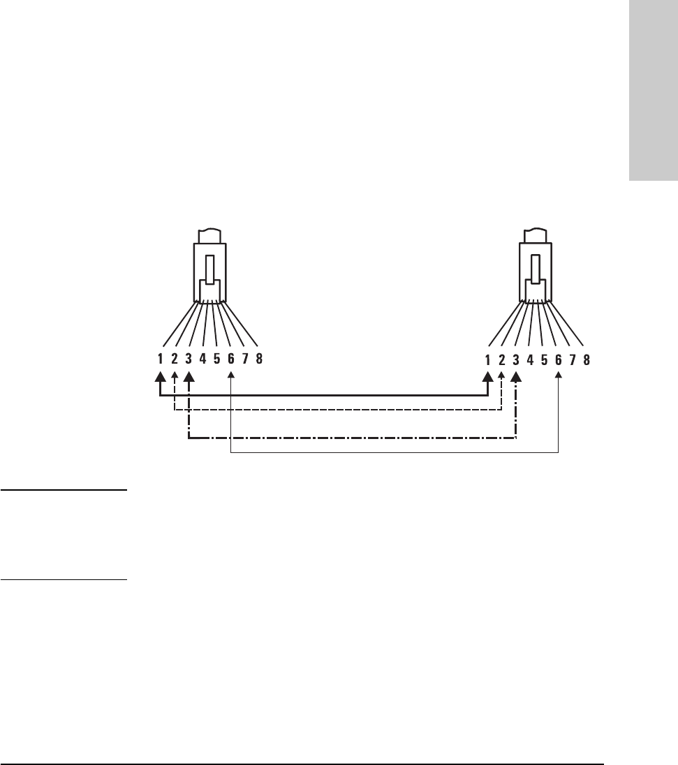
A-3
Cables and Connectors
Twisted-Pair Cable/Connector Pin-Outs
Cables and Connectors
Twisted-Pair Cable/Connector Pin-Outs
Twisted-Pair Cable for Hub-to-Computer Network
Connection
To connect PCs or other network devices to the hub, use a “straight-through”
10Base-T cable. The twisted-pair wires must be twisted through the entire
length of the cable. The wiring sequence must conform to AT&T 258A (not
USOC). See “Twisted-Pair Cable Pin Assignments” at the end of this chapter
for a listing of the signals used on each pin.
Note Pins 1 and 2 must be a twisted pair.
Pins 3 and 6 must be a twisted pair.
Pins 4, 5, 7, and 8 are not used in this application, although they may be wired
in the cable.
MUCHO.BK : CA.FM5 Page 3 Thursday, June 26, 1997 11:37 AM

A-4
Cables and Connectors
RS-232 Connector and Cable Pin-Outs
Cables and Connectors
RS-232 Connector and Cable Pin-Outs
The Management Module’s RS-232 port connector is wired as depicted in the
following table.
Use the RS-232 port to connect a PC to be used as the console. To make this
connection, you must use a null modem cable or you can use the minimum
cable pin-out described below.
This appendix lists cables that have been tested and verified for use with the
HP Hub-16M. It also includes minimum pin-out information so, if you wish to
use an unlisted cable, you can verify that the cables used in your installation
are correctly wired. Note that each pin-out does not necessarily match the
pin-out for the corresponding HP cable, but cables manufactured to follow
the minimum pin-out will function correctly.
Note Incorrectly wired cabling is the most common cause of problems for LAN
communications. HP recommends that you work with a qualified LAN cable
installer for assistance with your cabling requirements.
PIN US CCITT DIN
1 DCD 109 M5
2 Rx 104 D2
3 Tx 103 D1
4 DTR 108 S1
5 GND 102 -
6 DSR 107 M1
7 RTS 105 S2
8 CTS 106 M2
9 RI 125 M3
MUCHO.BK : CA.FM5 Page 4 Thursday, June 26, 1997 11:37 AM

A-5
Cables and Connectors
RS-232 Connector and Cable Pin-Outs
Cables and Connectors
Minimum Cable Pinout for ASCII Console Connection
RS-232 Modem Cable
PC end
9-pin male Hub end
9-pin male
22Rx
33Tx
55GND
Modem end
25-pin male Hub end
9-pin male Signal
23Tx
32Rx
47RTS
58CTS
66DSR
75GND
8 1 CD OR DCD
20 4 DTR
22 9 RI
23 DRS–typically on V.24 (European) modems
(not connected)
MUCHO.BK : CA.FM5 Page 5 Thursday, June 26, 1997 11:37 AM

A-6
Cables and Connectors
RS-232 Connector and Cable Pin-Outs
Cables and Connectors
Twisted-Pair Cable Pin Assignments
Twisted-Pair Straight-Through Cable
Hub End (MDI-X) Computer or Transceiver End
(MDI)
Signal Pins Pins Signal
(receive +)
(receive –)
(transmit +)
(transmit –)
1
2
3
6
1
2
3
6
(transmit +)
(transmit –)
(receive +)
(receive –)
MUCHO.BK : CA.FM5 Page 6 Thursday, June 26, 1997 11:37 AM

B
Specifications
Physical
Electrical
The hub automatically adjusts to any voltage between 100-127 and 200-240
volts and either 50 or 60 Hz.
The maximum current ratings represent the current that could be drawn with
an external transceiver attached to the hub.
Environmental
Width: 42.5 cm (16.8 in)
Depth: 23.8 cm(9.4 in)
Height: 4.36 cm (1.7 in)
Weight : 8 lbs and 7 oz. (8.7 lbs)
ac voltage: 100–127 volts 200–240 volts
Maximum current: 0.3A max 0.2A max
Frequency range: 50/60 Hz 50/60 Hz
Operating Non-Operating
Temperature: -5°C to 45°C (23°F to 113°F) -40°C to 70°C (-40°F to 158°F)
Relative humidity:
(non-condensing) 10% to 95% at 40°C (104°F) 10% to 90% at 65°C (149°F)
Maximum altitude: 3,000 m (9,843 ft) 3,000 m (9,843 ft)
MUCHO.BK : CB.FM5 Page 1 Thursday, June 26, 1997 11:37 AM

B-2
Specifications
Specifications
Connectors
The RJ-45 twisted-pair ports are compatible with the IEEE 802.3 Type
10Base-T standard.
Electromagnetic
Emissions: FCC part 15 Class A
EN 55022 Class A / CISPR-22 Class A
VCCI Level I
Complies with Canadian EMC Class A requirements.
Complies with Australia/New Zealand EMC Class A requirements.
Immunity: See the Declaration of Conformity for details at the end of Appendix
G, “Safety and Regulatory Statements” in this guide.
Safety: IEC950/EN60950
CSA950
NOM-019-SCFI-1993
UL1950
MUCHO.BK : CB.FM5 Page 2 Thursday, June 26, 1997 11:37 AM

C
Modem Configuration
Before installing the modems (one attached to the hub and one attached to
the terminal/PC), configure them by either issuing the appropriate AT
command or by setting the modem’s switches, as described in the tables in
the rest of this appendix.
Hayes Smartmodem Optima 28.8 (V.34)
Hayes ACCURA 288 V.34 + FAX
Hayes V-Series ULTRA Smartmodem 14400
US Robotics Courier V.FC/V.34
Megahertz XJ2288 PCMCIA card modem
At the hub end: Issue the following AT command:
A0101: AT&FQ2&C2&D3S0=1&W0 (if &C2 gives error, use &C0)
Next Rev: AT&FQ2&C1&D3S0=1&W0
At the user end: Issue the following AT command:
AT&FW1&C1&W
At the hub end: Issue the following AT command:
A0101: AT&F&C0S0=1&W0
Next Rev: AT&F&C1S0=1&W0
At the user end: Issue the following AT command:
AT&F&W
At the user end: Issue the following AT command:
AT&F\N0&W
MUCHO.BK : CC.FM5 Page 1 Thursday, June 26, 1997 11:37 AM

C-2
Modem Configuration
Modem Configuration
Practical Peripherals PM288MT II V.34
Intel 14.4EX
Supra FAX 288
At the hub end: Issue the following AT command:
A0101: AT&F0&C2S0=1Q2&D3&W0
Next Rev: AT&F0&C1S0=1Q2&D3&W0
At the user end: Issue the following AT command:
AT&F0&W0
At the hub end: Set the A/B switch to A
Issue the following AT command:
AT&F0&R1&W0
At the user end: Set the A/B switch to A
Issue the following AT command:
AT&F0&W0
At the hub end: Issue the following AT command:
A0101: AT&F0&C0S0=1Q2&D3&K3&W0
Next Rev: AT&F0&C1S0=1Q2&D3&K3&W0
At the user end: Issue the following AT command:
AT&F0&W0
MUCHO.BK : CC.FM5 Page 2 Thursday, June 26, 1997 11:37 AM

D
Network Addressing
This appendix describes how network address information is obtained and
used. Topics covered are:
■Communications Between Hub and Network Management
Station
■IPX Addressing for Novell NetWare
■IP Addresses for IP and non-IP Networks
■Using BOOTP
Communication Between the Hub and
Network Management Station
The HP Hub-16M can be managed over the network by CiscoWorks network
management software. These hubs can also be managed by any other network
management products that comply with the Simple Network Management
Protocol (SNMP) standard and have standard SNMP MIB-browser function-
ality.
The communication between the SNMP network management station and the
hub takes place using the network layer protocols, IPX for Novell networks,
or IP for TCP/IP networks.
Which protocol you use depends on the protocol being used by the network
management station. Additionally, if the network management station is on
the other side of a router from your hub, the protocol you run on both the hub
and the network management station depends on which protocol the router
can handle.
The network layer communications require that the hub have a network layer
address. This appendix provides some background information on IPX and IP
addressing.
MUCHO.BK : CD.FM5 Page 1 Thursday, June 26, 1997 11:37 AM

D-2
Network Addressing
IPX Addressing for Novell NetWare
Network Addressing
IPX Addressing for Novell NetWare
The Novell NetWare network operating system uses a proprietary protocol
called Internetwork Packet Exchange (IPX). The IPX protocol firmware is
always available on an HP Hub-16M; it becomes active when the hub gets an
IPX address. The IPX address consists of a network number and a device
identification. The address is automatically assigned to the hub as follows (no
IPX configuration of the hub is necessary):
■The network number is automatically assigned by a router or file server
on the network that is running the IPX protocol.
■The device identification is the hub’s MAC address (also known as the
Ethernet address or physical address). This address is a unique 12-digit
hexadecimal number assigned to the hub at the factory.
IPX Addressing Notes:
Because the IPX address is assigned automatically, no IPX configuration is
necessary; therefore no IPX configuration is provided on the hub console
interface. By default, the hub is ready to be managed by an SNMP network
management station that is configured for IPX communications.
IP Addresses for IP and Non-IP Networks
If you have chosen to manage your hub with an SNMP/IP network manager,
your hub must be configured with an IP address. If your network will be
connected with other networks that use IP addresses, you must use assigned
IP addresses. Otherwise, you can build your own IP addressing scheme.
Globally Assigned IP Network Addresses
If you intend to connect your network to other networks that use globally
administered IP addresses, Hewlett-Packard strongly recommends that you
use IP addresses that have a network address assigned to you. There is a
formal process for assigning unique IP addresses to networks worldwide.
Contact one of the following companies:
MUCHO.BK : CD.FM5 Page 2 Thursday, June 26, 1997 11:37 AM

D-3
Network Addressing
IP Addresses for IP and Non-IP Networks
Network Addressing
For more information, refer to Internetworking with TCP/IP: Principles,
Protocols and Architecture by Douglas E. Comer (Prentice-Hall, Inc.,
publisher).
Device IP Configuration
List all the manageable devices on your network and their IP configuration.
Make sure that every device has a unique IP address. Make sure that all devices
on the network have the same subnet mask.
The IP configuration parameters are as follows:
IP Address: The IP address of the hub is written in the format X.X.X.X, where
each X is a decimal number between 1 and 254. Every IP address on a network
must be unique.
The default value, 0.0.0.0, disables IP communications.
Subnet Mask: The bit mask defines which portion of the IP address is the
subnet address and is written in the format X.X.X.X. The default value is
automatically generated and depends on the class of IP address that you
entered. See your network administrator for the subnet mask address. All
devices on your IP network must use the same subnet mask address.
Default Router: The routing IP address of the nearest router in your network.
The default is 0.0.0.0. If no routers are in your network, enter the IP address
of this device.
Country Phone Number/E-Mail/URL Company Name/Address
United
States/Coun-
tries not in
Europe or
Asia/Pacific
1-703-742-4777
questions@internic.net
http://rs.internic.net
Network Solutions, Inc.
Attn: InterNIC Registration Service
505 Huntmar Park Drive
Herndon, VA 22070
Europe +31 20 592 5065
ncc@ripe.net
http://www.ripe.net
RIPE NCC Kruislaan
409NL-1098 SJ
Amsterdam, The Netherlands
Asia/Pacific domreg@apnic.net
http://www.apnic.net Attention: IN-ADDR.ARPA Registration
Asia Pacific Network Information Center
c/o Internet Initiative Japan, Inc.
Sanbancho Annex Bldg. 1-4 Sanban-cho
Chiyoda-ku Tokyo 102, Japan
MUCHO.BK : CD.FM5 Page 3 Thursday, June 26, 1997 11:37 AM

D-4
Network Addressing
Using BOOTP
Network Addressing
Time To Live: The number of IP routers a packet is allowed to cross before
the packet is discarded. The default value is 32. Increase this value if the hub
is managed from a network management station that is more than 32 routers
away. The maximum allowable value is 255.
Use the IP Configuration command in the ASCII console or CiscoView to
specify IP addresses.
Using BOOTP
BOOTP (Bootstrap Protocol) is used to download network configuration data
from a server (the BOOTP server) to the hub. The configuration data the hub
retrieves from the BOOTP server is:
■the IP address for the hub
■the subnet mask for the subnet on which the hub is installed
■the default router
If you have configured the hub’s IP parameters on a BOOTP server, you do
not need to use the IPConfig command in the ASCII console. As shipped from
the factory, the hub is configured to use BOOTP to retrieve the IP configura-
tion information.
The BOOTP Process
When the hub is powered on, it broadcasts BOOTP requests that contain the
hub’s MAC address. The BOOTP server receives the request and searches its
BOOTP table file for an entry that matches the hub’s MAC address. If a match
is found, the configuration data in the associated file entry is returned to the
hub as a BOOTP reply. For most UNIX systems, the BOOTP table is contained
in the /etc/bootptab file. The example below applies to the BOOTP table for
UNIX systems.
MUCHO.BK : CD.FM5 Page 4 Thursday, June 26, 1997 11:37 AM

D-5
Network Addressing
Using BOOTP
Network Addressing
BOOTP Table File Entries
An entry in the BOOTP table file /etc/bootptab for an HP Hub-16M would be
similar to the following:
hphub16M:\
ht=ether:\
ha=080009123456:\
ip=190.40.101.22:\
sm=255.255.255.0:\
gw=190.40.101.1:\
vm=rfc1048
Definitions of the table entry fields:
Notes for the bootptab file:
■Blank lines and lines beginning with the pound sign (#) are ignored.
■Make sure you include a colon (:) and a backslash (\) as a continuation
indication at the end of each line except the last one. Each record is a
single line. The colon (:) separates fields in the record. The backslash (\)
indicates the current record continues on the next line as if there were no
carriage return and linefeed characters.
■Spaces are not allowed between the characters on a line.
■Names, such as hphub16M must begin with a letter and can only contain
letters, numbers, periods, or hyphens.
hphub16M is a user-defined symbolic name to help you find the correct section of the
bootptab file. If you have multiple hubs that will be using BOOTP to get their
IP configuration, you should use a unique symbolic name for each hub.
ht is the “hardware type” tag. For the HP 10Base-T hubs, set this to ether (for
Ethernet).
This tag must precede the
ha
tag.
ha is the “hardware address” tag. Use the hub’s 12-digit MAC address.
ip is the IP address to be assigned to the hub. Enter the address in the dotted-
decimal format as shown in the example on the previous page.
sm is the subnet mask of the subnet in which the hub is installed.
gw is the IP address of the default router (or gateway) that allows the hub to
communicate with systems that are not on the local network segment. If there
is no default router, do no include this tag.
vm is a required entry that specifies the BOOTP report format.
For the HP 10Base-
T hubs, you must set this parameter to
rfc1048.
MUCHO.BK : CD.FM5 Page 5 Thursday, June 26, 1997 11:37 AM
MUCHO.BK : CD.FM5 Page 6 Thursday, June 26, 1997 11:37 AM

E
Backup Links
This chapter describes how to use Backup Links on the hub. Topics described
include:
■how backup links work
■examples of backup links
■configuring a backup link
■identifying a backup link
■indications of backup link activation
■reactivating the primary link
How Backup Links Work
In some network configurations a critical link exists, for example between
two workgroups that regularly share or exchange data over the network. To
maintain the integrity of such a critical link, the HP Hub-16M offer a backup
link feature. A backup link is a separate cable run between two hubs that is
automatically enabled if the connection designated as the primary link fails.
The hub on which the redundant link is configured (hub A in the illustration—
the “Monitoring Hub”), is responsible for monitoring the link. It sends IEEE
802.2 Test packets to the hub at the other end of the link (hub B in the
illustration—the “Remote Hub”) and looks for response packets from that
hub. If the response packets fail to come back, the primary link is considered
as having failed and the backup link, which had not been carrying any traffic,
is enabled automatically. If the primary link does fail, it is automatically
disabled until it can be repaired and re-enabled.
When the primary link is repaired, you must re-enable the primary port. It is
not re-enabled automatically. When the primary port is enabled, the backup
port is automatically disabled and returned to backup mode. See “Reactivating
the Primary Link” later in this appendix.
MUCHO.BK : CE.FM5 Page 1 Thursday, June 26, 1997 11:37 AM

E-2
Backup Links
How Backup Links Work
Backup Links
Limitations
■Each hub can monitor a single backup link (only one backup link can be
configured on each hub). But, the hub may be at the remote end of one
backup link and at the monitoring end of a backup link to a different hub.
■A given hub should be connected to the remote end of no more than two
backup links. If it is functioning as the remote hub in more than two
backup links, it may not be able to respond to the test packets fast enough
when there is a high level of data traffic on the network.
This ability to respond may be improved by increasing the time between
test packet transmissions on the monitoring hubs. For all the backup links
in which the remote hub is involved, the time configured on the moni-
toring hubs for those links should be increased by one second for each
additional backup link beyond two links. Add one to this count if the
remote hub is also functioning as a primary (monitoring) hub in a different
link.
Additional Notes
■Any port on the hub can be used for either the primary link or the backup
link.
■Any combination of media types can be used as a backup link by using
the AUI port. This accepts fiber, thin coax, and twisted pair external
transceivers.
■The primary link and the backup link cabling should be run over different
paths (through different conduits, for example) to reduce the possibility
that damage will occur to both cables simultaneously.
MUCHO.BK : CE.FM5 Page 2 Thursday, June 26, 1997 11:37 AM
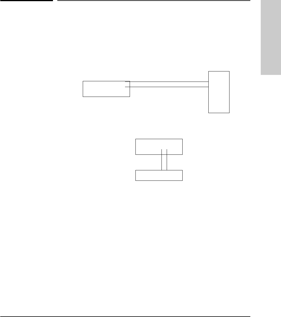
E-3
Backup Links
Examples of Backup Links
Backup Links
Examples of Backup Links
The Backup Link function allows you to specify a backup link between two
devices in case the primary link fails. An example of a backup link is shown
below.
A backup link is a separate path connected between the hub and a device. The
port through which the cable is connected between the two devices is auto-
matically enabled if the connection designated as the primary link fails.
How the Backup Function Works
The hub on which the redundant link is configured is responsible for moni-
toring the link. It sends packets to the station at the other end of the link and
looks for response packets from that station. If the response packets fail to
come back, the primary link is considered as having failed and the backup
link, which had not been carrying any traffic, is enabled automatically. If the
primary link does fail, it is automatically disabled until it can be repaired and
re-enabled.
Hub to a Server
Hub to a Switch
Primary Link (fiber)
Backup Link (twisted pair)
Server
Hub
Switch
Backup Link Primary Link
MUCHO.BK : CE.FM5 Page 3 Thursday, June 26, 1997 11:37 AM

E-4
Backup Links
Examples of Backup Links
Backup Links
When the primary link is repaired, you must re-enable the primary port. It is
not re-enabled automatically. When the primary port is enabled, the backup
port is automatically disabled and returned to backup mode. See “Reactivating
the Primary Link” later in this appendix.
Note ■Any combination of media types can be used as a backup link by attaching
an external transceiver to the AUI port. This port accepts fiber, thin coax,
twisted-pair external transceivers. For example, a thin coax link from the
ThinLAN port can act as a backup link to a twisted-pair link.
■The hub can monitor only one link.
■The remote device should have no more than 2 backup links connected
to it from a monitoring hub. If the remote device has more than 2 backup
links functioning, it may not be able to respond to the test packets fast
enough when there is a high level of data traffic on the network segments.
■This ability to respond may be improved by increasing the time between
test packet transmissions on the monitoring hubs. For all the backup links
in which the remote device is involved, the time configured on the
monitoring hubs for those links should be increased by one second for
each additional backup link beyond two links. Add one to this count if the
remote device is also functioning as a primary (monitoring) hub for a
different link.
Suggestion The primary link and the backup link cabling should be run over different
paths (through different conduits, for example) to reduce the possibility that
damage will occur to both cables simultaneously.
MUCHO.BK : CE.FM5 Page 4 Thursday, June 26, 1997 11:37 AM

E-5
Backup Links
Configuring a Backup Link
Backup Links
Configuring a Backup Link
Configure the Monitoring Hub Only. All configuration of the backup
links feature is performed from CiscoView or the ASCII console. On the
“remote” device, you only need to make sure the ports used for the primary
and backup links are both enabled.
Use the Backup Function. To configure this link, you use the Backup func-
tion in the ASCII console. You provide the following information:
■the device and port to be used for the backup link
■the device and port to be used for the primary link
■the MAC address of the device at the remote end of the link
■how frequently (in seconds) test packets (used to check the status of the
primary link) should be sent to the remote device
■how many consecutive response failures will trigger activation of the
backup link
Configuration/Installation Sequence
If a hub is installed in a network that includes two connections to another hub,
and the backup link has not yet been configured, a loop in the network now
exists that will cause some network performance degradation. For this reason,
it is better to configure the backup link on the hub before the hub is installed
in the network. It is best to follow these steps:
1. Attach a PC running an ASCII terminal emulator to the hub and start the
ASCII terminal emulator.
2. Use the Backup function to configure the backup link.
3. Complete the network cable connections between the monitoring hub and
the remote device. For cabling instructions, see Appendix A, “Cables and
Connectors,” in this manual.
4. On the remote device, make sure that the ports connected to both the
primary and backup links are enabled. On the monitoring hub, the status
of the primary and backup ports is controlled by the hub’s firmware; you
do not need to explicitly enable the monitoring hub’s ports.
MUCHO.BK : CE.FM5 Page 5 Thursday, June 26, 1997 11:37 AM

E-6
Backup Links
Identifying the Backup Link
Backup Links
5. Enable the primary port in software. This step is necessary because until
you have completed step 3 (connecting the cables), the test packets
cannot be successfully sent through the primary port. The primary port
will therefore be disabled and the backup port will be activated. Once you
enable the primary port, it assumes the active role.
Identifying the Backup Link
The ports designated as the primary and backup ports are identified in:
■the CiscoView Backup function window.
■ASCII console interface by using the Backup command
The primary port is identified by (pri), the backup port by (bkup).
Indications of Backup Link Activation
When the primary link fails (“n” consecutive test packet responses were not
received on the primary port from the other device), the backup link is
automatically enabled. The effect of this change is displayed on the monitoring
hub's LEDs and management interface. Activation of the backup link does not
change the status of any of the ports on the remote device.
On the monitoring hub's LEDs, the primary port LED goes off, and the backup
port LED goes on.
In the ASCII console or CiscoView, the status of the primary port changes from
“active” to “not active”, and the backup port changes from not active to active.
See the ASCII console help or CiscoView online help for more information.
MUCHO.BK : CE.FM5 Page 6 Thursday, June 26, 1997 11:37 AM

E-7
Backup Links
Reactivating the Primary Link
Backup Links
Reactivating the Primary Link
When the primary link is repaired, you can use any of the following methods
to re-enable the primary port:
■From the ASCII console, select “Port/Segment Configuration”, then
“Disable and enable ports option”, then enable ports.
■From CiscoView, re-enable the primary port. See the network manage-
ment product documentation for details on how to enable a port.
■Power-cycle the hub.
When the primary port is re-enabled, the backup port is automatically disabled
and returned to backup mode.
MUCHO.BK : CE.FM5 Page 7 Thursday, June 26, 1997 11:37 AM
MUCHO.BK : CE.FM5 Page 8 Thursday, June 26, 1997 11:37 AM

F
Security Information
This section describes how to set security for your product. It covers the
following topics:
■how intruder prevention works
■how eavesdrop prevention works
■setting inbound security with intruder prevention
■setting outbound security with eavesdrop prevention
Understanding Network Security
In addition to password protection and network access protection, the HP
Hub-16M provides two major types of per-port security:
■Intruder Prevention for inbound data (from the end user to the hub).
■Eavesdrop Prevention for outbound data (from the hub to the end user).
Both of these types of security can be configured on each port individually
(all twisted-pair ports and the AUI port through the SEcure command on the
ASCII console interface. These per-port security features are enabled by
comparing the source and destination address of each packet received or
transmitted by the hub to each port’s Authorized MAC address—the MAC
address of the device that is authorized to communicate through that hub port.
These features can be seen through the CiscoView network management
application.
MUCHO.BK : CF.FM5 Page 1 Thursday, June 26, 1997 11:37 AM

F-2
Security Information
How Intruder Prevention Works
Security Information
How Intruder Prevention Works
Intruder Prevention stops an unauthorized computer (or other device) from
actively gaining access to the network. When a port is configured for Intruder
Prevention, the hub examines the source address of each packet coming in
through that port and compares it with the authorized MAC address. If the
addresses are not the same, the hub concludes that an intruder is attempting
to gain access to the network and takes the appropriate action (as configured):
either disabling the port, sending an alarm to the network management
station, or both. See “Setting Inbound Security with Intruder Prevention” later
in this appendix.
How Eavesdrop Prevention Works
Eavesdrop Prevention stops a computer (or other device) from seeing
network traffic that is not intended for that port. When Eavesdrop Prevention
is configured on a port, the hub compares the port’s authorized MAC address
with the destination address of any outbound packet. If the addresses match,
the hub concludes that the packet is destined for the computer attached to
the port, and it sends the packet out through the port unaltered. However, if
the addresses do not match, the hub prevents the computer from seeing the
packet’s contents by substituting a meaningless string of 1’s and 0’s. Note that
broadcast and multicast packets are repeated to all the ports, even when
Eavesdrop Prevention is activated. See “Setting Outbound Security with
Eavesdrop Prevention” later in this appendix.
Authorized MAC address
To provide data security on a hub port, a single, unique MAC address must be
configured as the authorized MAC address for each port. You can configure
the authorized MAC address either by assigning it or by designating the port
to learn it automatically. This configuration is performed with the Secure
command from the hub’s console. See the Secure command description in the
chapter on Managing the Hub.
MUCHO.BK : CF.FM5 Page 2 Thursday, June 26, 1997 11:37 AM

F-3
Security Information
How Eavesdrop Prevention Works
Security Information
Assigning the Authorized MAC address
You can assign an authorized MAC address by entering it manually at the hub
console interface or at the network management station. Assigning a specific
address provides the maximum control of the port’s authorized MAC address.
The Intruder Prevention and Eavesdrop Prevention security that you have
configured for that port is implemented as soon as the address is
assigned.Learning the Authorized MAC address
You can set the hub to learn a port’s authorized MAC address automatically
by using either a “first heard” or a “learn continuous” method. The method
used to learn the authorized MAC address should be chosen based on the level
of data security required on a port. In each case, the security configuration for
that port is implemented when the port receives a packet from the attached
device. It learns the device’s address from the source address field in the
packet.
First-Heard Method. The “first heard” method automatically assigns the
first address detected on the port as the authorized MAC address. This method
is useful to quickly identify and authorize end users whose ports may require
both Eavesdrop Prevention and Intruder Prevention. Under this method, the
port will be disabled automatically if an intruder is detected on the port.
Learn-Continuous Method. The “learn continuous” method allows the hub
to continuously update the authorized MAC address configured for a port.
Each new device connected to the port becomes the new authorized device.
This security method is useful for dynamic workgroups that experience
frequent changes to end-user configuration and but require minimal data
security protection. In the “learn continuous” mode, the port may be config-
ured to provide the Eavesdrop Prevention data security and the send-alarm
security violation notification. Under this method, the port will not be disabled
if an intruder is detected.
MUCHO.BK : CF.FM5 Page 3 Thursday, June 26, 1997 11:37 AM
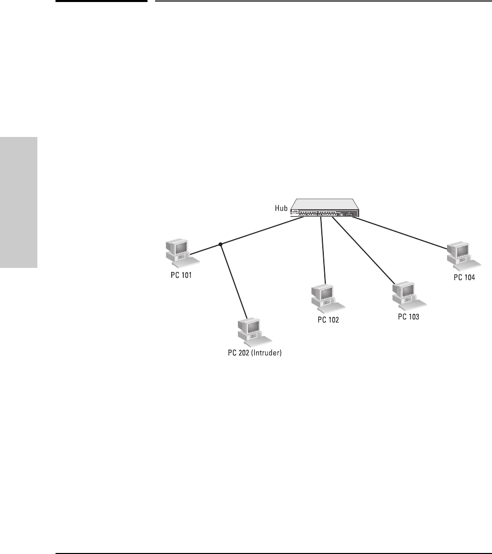
F-4
Security Information
Setting Inbound Security with Intruder Prevention
Security Information
Setting Inbound Security with Intruder
Prevention
The picture below illustrates the use of inbound security using Intruder
Prevention. This type of data security allows only one authorized user per port
to access the network. The authorized user is identified by the authorized MAC
address of the end node attached to the port.
Intruder prevention includes an “auto port disable” data security feature and
a “send alarm” security violation notification feature. These features are
described on the next page.
In the above illustration, the authorized end user is represented by PC 101,
and the intruder is represented by PC 202 (Intruder). (For illustration
purposes, the numbers 101, and 202 are used to represent 12-digit hexadecimal
MAC addresses.) The HP hub compares the authorized MAC address, 101, to
the source address of the packet received from the Intruder, 202. The hub
detects the unauthorized MAC address and automatically disables the port,
and sends an alarm (a security violation trap notification) to the authorized
network management station.
MUCHO.BK : CF.FM5 Page 4 Thursday, June 26, 1997 11:37 AM

F-5
Security Information
Setting Inbound Security with Intruder Prevention
Security Information
Auto Port Disable
Any port may be configured to be disabled automatically when an intruder’s
MAC address is detected. This feature is automatically controlled by your
selection of the Authorized Address Selection Method for the port: If the
address used is the “first heard” or an “assigned” address, the port will be
disabled automatically when an intruder is detected. If the address is “learned
continuously”, the port will not be automatically disabled.
Note Auto port disable may not be used on cascaded ports, ports connected to a
network with multiple end users, or ports configured to learn the authorized
MAC address continuously.
The auto port disable feature compares the authorized MAC address of the
port to the source address of the packet inbound to the hub at that port. If the
authorized address and the source address do not match, the HP hub will
automatically disable the port.
Once a port is disabled because of a security violation, to resume operation,
the port must be re-enabled either by using the hub console interface’s Port
command, or from the network management station.
A bit error in the source address field of the packet will not cause the port
to be disabled. In this case, the hub detects a CRC error for the packet and
does not consider it as a security violation.
Send Alarm
Any port may be configured to send an alarm (trap notification) to the network
management station when an unauthorized MAC address or a new MAC
address is detected on a secure port.
To use the “send alarm” feature, you must authorize at least one network
management station to receive the trap notifications by entering the IP or IPX
address of the network management station in the authorized managers list.
Use the Managers command from the hub’s console to configure these
addresses. See chapter 3, “Managing the Hub” for more information on this
command.
MUCHO.BK : CF.FM5 Page 5 Thursday, June 26, 1997 11:37 AM

F-6
Security Information
Setting Outbound Security with Eavesdrop Prevention
Security Information
Setting Outbound Security with
Eavesdrop Prevention
Eavesdrop Prevention allows a port to receive a packet transmitted on the
network as valid data only if the port’s MAC address matches the packet’s
destination address. If the port’s MAC address does not match the packet
destination address, the port will receive a packet containing a meaningless
data field of alternating 1’s and 0’s. Multicast and broadcast packets are
transmitted to all ports unmodified.
Note that sending a packet containing alternating 1’s and 0’s will continue to
allow the port to detect the traffic on the network, so that the CSMA/CD
network requirements are met. However, the port will correctly record the
invalid data packet received as a CRC error. An end-user attached to an HP
hub implementing Eavesdrop Prevention data security will normally record a
high number of CRC errors on the computer card statistics.
The illustration on the next page shows the use of outbound data security
using Eavesdrop Prevention. This type of data security should be enabled on
any port that is to receive data on a “need to know” basis. The port must have
an authorized MAC address configured and must be connected to only one
end-user.
Eavesdrop Prevention may not be used on cascaded ports, or ports connected
to a network with multiple end users.
In the illustration below, Server 104 is transmitting a packet destined for PC
101. (For illustration purposes, the numbers 101, 102, 103, and 104 are used to
represent 12-digit hexadecimal MAC addresses.) The ports for PC 101 and PC
102 have Eavesdrop Prevention enabled or configured ON. Because PC 101’s
MAC address matches the packet destination address, it receives the packet
unaltered. However, PC 102’s MAC address does not match the packet desti-
nation address and therefore it receives a useless packet (the packet data field
contains a meaningless pattern of alternating 1’s and 0’s.) The port for PC 103
does not have Eavesdrop Prevention enabled and therefore PC 103 receives
the packet unaltered from Server 104.
MUCHO.BK : CF.FM5 Page 6 Thursday, June 26, 1997 11:37 AM
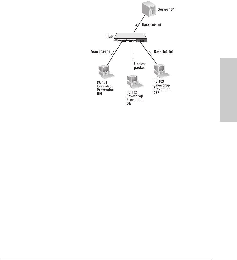
F-7
Security Information
Setting Outbound Security with Eavesdrop Prevention
Security Information
MUCHO.BK : CF.FM5 Page 7 Thursday, June 26, 1997 11:37 AM
MUCHO.BK : CF.FM5 Page 8 Thursday, June 26, 1997 11:37 AM

G
Safety and Regulatory Statements
This chapter covers the following topics:
■mounting precautions
■power precautions
■safety and regulatory statements
■Declaration of Conformity
Mounting Precautions
When you put a hub into a rack, follow these mounting precautions:
■The rack or cabinet should be adequately secured to prevent it from
becoming unstable and/or falling over. The hub should be mounted in a
position toward the bottom of the rack for stability and to make it easier
to stack the other hubs on top.
■Before mounting a hub, plan its location and orientation relative to other
devices and equipment. Also consider the cabling that will be attached to
the hub and the ports that will be used. Verify that there is room for the
grouped cables to trail out from the side of the hub. Allow at least 2.54 cm
(1 inch) in the front of the hub. In the back of the hub, allow at least 3.8
cm (1 1/2 inches) of space for the power cord. If you are using a Redundant
Power Supply, allow the appropriate amount of space for the RPS
connector.
■Ensure that the HP Hub-16M does not overload the power circuits, wiring,
and over-current protection. To determine the possibility of overloading
the supply circuits, add together the amperage ratings from the name-
plates of all your hubs (and other equipment) installed on the same
circuits and compare the total with the rating limits for the supply circuits.
■Make sure that the power source circuits are properly grounded, then use
the supplied power cord to connect the HP Hub-16M to the circuit. See
the Safety Statements in this chapter.
■Do not block airflow around the side and the back of the unit.
MUCHO.BK : CG.FM5 Page 1 Thursday, June 26, 1997 11:37 AM

G-2
Safety and Regulatory Statements
Power Precautions
Safety and Regulatory
Statements
Note If your installation requires a different power cord than the one supplied with
the hub, be sure to use a power cord displaying the mark of the safety agency
that defines the regulations for power cords in your country. The mark is your
assurance that the power cord can be used safely with the hub.
■Do not install the hub in an environment where the operating ambient
temperature might exceed 45°C (113°F).
■Make sure the air flow around the sides of the hub is not restricted.
Power Precautions
Follow these precautions when unplugging and plugging in power to the hub
as well as adding or removing modules.
Note The hub does not have a power switch; it is powered on when the power cord
is plugged in. The hub’s power supply automatically adjusts to any AC power
source between 100-127 volts and 200-240 volts. There are no voltage range
settings to configure.
When installing the hub, note that the AC outlet must be installed near the
equipment and should be easily accessible.
MUCHO.BK : CG.FM5 Page 2 Thursday, June 26, 1997 11:37 AM

G-3
Safety and Regulatory Statements
Safety Information
Safety and Regulatory
Statements
Safety Information
Grounding
These are safety class I products and have protective earthing terminals. There
must be an uninterruptible safety earth ground from the main power source
to the product’s input wiring terminals, power cord, or supplied power cord
set. Whenever it is likely that the protection has been impaired, disconnect
the power cord until the ground has been restored.
For LAN cable grounding:
■If your LAN covers an area served by more than one power distribu-
tion system, be sure their safety grounds are securely interconnected.
■LAN cables may occasionally be subject to hazardous transient volt-
ages (such as lightning or disturbances in the electrical utilities power
grid). Handle exposed metal components of the network with caution.
Servicing
There are no user-serviceable parts inside these products. Any servicing,
adjustment, maintenance, or repair must be performed only by service-trained
personnel.
These products do not have a power switch; they are powered on when the
power cord is plugged in.
Documentation reference symbol. If the product is marked with this
symbol, refer to the product documentation to get more information
about the product.
WARNING A WARNING in the manual denotes a hazard that can cause injury
or death.
CAUTION A CAUTION in the manual denotes a hazard that can damage
equipment.
Do not proceed beyond a WARNING or CAUTION notice until you
have understood the hazardous conditions and have taken appro-
priate steps.
!
MUCHO.BK : CG.FM5 Page 3 Thursday, June 26, 1997 11:37 AM

G-4
Safety and Regulatory Statements
Informations concernant la sécurité
Safety and Regulatory
Statements
Informations concernant la sécurité
Cet appareil est un produit de classe I et possède une borne de mise à la terre. La source
d'alimentation principale doit être munie d'une prise de terre de sécurité installée aux
bornes du câblage d'entrée, sur le cordon d'alimentation ou le cordon de raccordement
fourni avec le produit. Lorsque cette protection semble avoir été endommagée,
débrancher le cordon d'alimentation jusqu'à ce que la mise à la terre ait été réparée.
Mise à la terre du câble de réseau local:
■si votre réseau local s'étend sur une zone desservie par plus d'un système de
distribution de puissance, assurez-vous que les prises de terre de sécurité
soient convenablement interconnectées.
■Les câbles de réseaux locaux peuvent occasionnellement être soumis à des
surtensions transitoires dangereuses (telles que la foudre ou des perturba-
tions dans le réseau d'alimentation public). Manipulez les composants
métalliques du réseau avec précautions.
Aucune pièce contenue à l'intérieur de ce produit ne peut être réparée par l'utilisateur.
Tout dépannage, réglage, entretien ou réparation devra être confié exclusivement à un
personnel qualifié.
Cet appareil ne comporte pas de commutateur principal ; la mise sous tension est
effectuée par branchement du cordon d'alimentation.
Symbole de référence à la documentation. Si le produit est marqué de
ce symbole, reportez-vous à la documentation du produit afin d'obtenir
des informations plus détaillées.
WARNING Dans la documentation, un WARNING indique un danger susceptible
d'entraîner des dommages corporels ou la mort.
CAUTION Un texte de mise en garde intitulé CAUTION indique un danger suscep-
tible de causer des dommages à l'équipement.
Ne continuez pas au-delà d'une rubrique WARNING ou CAUTION
avant d'avoir bien compris les conditions présentant un danger et pris
les mesures appropriées.
!
MUCHO.BK : CG.FM5 Page 4 Thursday, June 26, 1997 11:37 AM

G-5
Safety and Regulatory Statements
Hinweise zur Sicherheit
Safety and Regulatory
Statements
Hinweise zur Sicherheit
Dies ist ein Gerät der Sicherheitsklasse I und verfügt über einen schützenden Erdung-
sterminal. Der Betrieb des Geräts erfordert eine ununterbrochene Sicherheitserdung
von der Hauptstromquelle zu den Geräteingabeterminals, den Netzkabeln oder dem
mit Strom belieferten Netzkabelsatz voraus. Sobald Grund zur Annahme besteht, daß
der Schutz beeinträchtigt worden ist, das Netzkabel aus der Wandsteckdose herausz-
iehen, bis die Erdung wiederhergestellt ist.
Für LAN-Kabelerdung:
■Wenn Ihr LAN ein Gebiet umfaßt, das von mehr als einem Stromverteilungs-
system beliefert wird, müssen Sie sich vergewissern, daß die
Sicherheitserdungen fest untereinander verbunden sind.
■LAN-Kabel können gelegentlich gefährlichen Übergangsspannungen aus-
gesetzt werden (beispielsweise durch Blitz oder Störungen in dem
Starkstromnetz des Elektrizitätswerks). Bei der Handhabung exponierter
Metallbestandteile des Netzwerkes Vorsicht walten lassen.
Dieses Gerät enthält innen keine durch den Benutzer zu wartenden Teile. Wartungs-,
Anpassungs-, Instandhaltungs- oder Reparaturarbeiten dürfen nur von geschultem
Bedienungspersonal durchgeführt werden.
Dieses Gerät hat keinen Netzschalter; es wird beim Anschließen des Netzkabels
eingeschaltet.
Symbol für Dokumentationsverweis. Wenn das Produkt mit diesem
Symbol markiert ist, schlagen Sie bitte in der Produktdokumentation
nach, um mehr Informationen über das Produkt zu erhalten.
WARNING Symbol für Dokumentationsverweis. Wenn das Produkt mit diesem
Symbol markiert ist, schlagen Sie bitte in der Produktdokumentation
nach, um mehr Informationen über das Produkt zu erhalten.
CAUTION Symbol für Dokumentationsverweis. Wenn das Produkt mit diesem
Symbol markiert ist, schlagen Sie bitte in der Produktdokumentation
nach, um mehr Informationen über das Produkt zu erhalten.
Fahren Sie nach dem Hinweis WARNING oder CAUTION erst fort,
nachdem Sie den Gefahrenzustand verstanden und die entsprech-
enden Maßnahmen ergriffen haben.
!
MUCHO.BK : CG.FM5 Page 5 Thursday, June 26, 1997 11:37 AM

G-6
Safety and Regulatory Statements
Considerazioni sulla sicurezza
Safety and Regulatory
Statements
Considerazioni sulla sicurezza
Questo prodotto è omologato nella classe di sicurezza I ed ha un terminale protettivo
di collegamento a terra. Dev'essere installato un collegamento a terra di sicurezza, non
interrompibile che vada dalla fonte d'alimentazione principale ai terminali d'entrata,
al cavo d'alimentazione oppure al set cavo d'alimentazione fornito con il prodotto.
Ogniqualvolta vi sia probabilità di danneggiamento della protezione, disinserite il cavo
d'alimentazione fino a quando il collegaento a terra non sia stato ripristinato.
Per la messa a terra dei cavi LAN:
■se la vostra LAN copre un'area servita da più di un sistema di distribuzione
elettrica, accertatevi che i collegamenti a terra di sicurezza siano ben collegati
fra loro;
■i cavi LAN possono occasionalmente andare soggetti a pericolose tensioni
transitorie (ad esempio, provocate da lampi o disturbi nella griglia d'alimen-
tazione della società elettrica); siate cauti nel toccare parti esposte in metallo
della rete.
Nessun componente di questo prodotto può essere riparato dall'utente. Qualsiasi
lavoro di riparazione, messa a punto, manutenzione o assistenza va effettuato esclusi-
vamente da personale specializzato.
Questo apparato non possiede un commutatore principale; si mette scotto tensione
all'inserirsi il cavo d'alimentazione.
Simbolo di riferimento alla documentazione. Se il prodotto è contras-
segnato da questo simbolo, fare riferimento alla documentazione sul
prodotto per ulteriori informazioni su di esso.
WARNING La dicitura WARNINGdenota un pericolo che può causare lesioni o
morte.
CAUTION La dicituraCAUTION denota un pericolo che può danneggiare le
attrezzature.
Non procedere oltre un avviso di WARNING o di CAUTIONprima di
aver compreso le condizioni di rischio e aver provveduto alle misure
del caso.
!
MUCHO.BK : CG.FM5 Page 6 Thursday, June 26, 1997 11:37 AM

G-7
Safety and Regulatory Statements
Consideraciones sobre seguridad
Safety and Regulatory
Statements
Consideraciones sobre seguridad
Este aparato se enmarca dentro de la clase I de seguridad y se encuentra protegido por
una borna de puesta a tierra. Es preciso que exista una puesta a tierra continua desde
la toma de alimentación eléctrica hasta las bornas de los cables de entrada del aparato,
el cable de alimentación o el juego de cable de alimentación suministrado. Si existe la
probabilidad de que la protección a tierra haya sufrido desperfectos, desenchufar el
cable de alimentación hasta haberse subsanado el problema.
Puesta a tierra del cable de la red local (LAN):
■Si la LAN abarca un área cuyo suministro eléctrico proviene de más de una
red de distribución de electricidad, cerciorarse de que las puestas a tierra
estén conectadas entre sí de modo seguro.
■Es posible que los cables de la LAN se vean sometidos de vez en cuando a
voltajes momentáneos que entrañen peligro (rayos o alteraciones en la red
de energía eléctrica). Manejar con precaución los componentes de metal de
la LAN que estén al descubierto.
Este aparato no contiene pieza alguna susceptible de reparación por parte del usuario.
Todas las reparaciones, ajustes o servicio de mantenimiento debe realizarlos sola-
mente el técnico.
Este producto no tiene interruptor de potencia; se activa cuando se enchufa el cable
de alimentación.
Símbolo de referencia a la documentación. Si el producto va mar-
cado con este símbolo, consultar la documentación del producto a
fin de obtener mayor información sobre el producto.
WARNING Una WARNING en la documentación señala un riesgo que podría
resultar en lesiones o la muerte.
CAUTION Una CAUTION en la documentación señala un riesgo que podría
resultar en averías al equipo.
No proseguir después de un símbolo de WARNING o CAUTION hasta
no haber entendido las condiciones peligrosas y haber tomado las
medidas apropiadas.
!
MUCHO.BK : CG.FM5 Page 7 Thursday, June 26, 1997 11:37 AM
G-8
Safety and Regulatory Statements
Safety Information (Japanese)
Safety and Regulatory
Statements
Safety Information (Japanese)
MUCHO.BK : CG.FM5 Page 8 Thursday, June 26, 1997 11:37 AM
G-9
Safety and Regulatory Statements
Regulatory Statements
Safety and Regulatory
Statements
Regulatory Statements
FCC Class A Statement (for U.S.A. Only)
This equipment has been tested and found to comply with the limits for a Class
A digital device, pursuant to Part 15 of the FCC Rules. These limits are
designed to provide reasonable protection against harmful interference when
the equipment is operated in a commercial environment. This equipment
generates, uses, and can radiate radio frequency energy and, if not installed
and used in accordance with the instruction manual, may cause harmful
interference to radio communications. Operation of this equipment in a
residential area may cause harmful interference in which case the user will be
required to correct the interference at his own expense.
VCCI Class 1 (For Japan Only)
European Community
This equipment complies with ISO/IEC Guide 22 and EN55022 Class A with
unshielded cables and EN55022 Note
With unshielded cables this is a Class A product. In a domestic environment,
this product may cause radio interference, in which case the user may be
required to take adequate measures.
Canada
This product complies with Class A Canadian EMC requirement.
MUCHO.BK : CG.FM5 Page 9 Thursday, June 26, 1997 11:37 AM
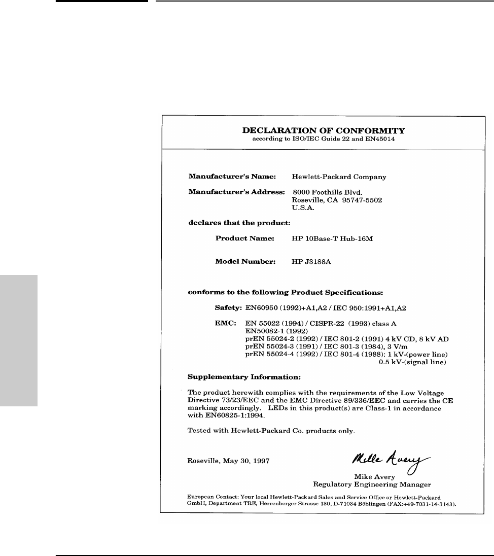
G-10
Safety and Regulatory Statements
Declaration of Conformity
Safety and Regulatory
Statements
Declaration of Conformity
The following Declaration of Conformity for the HP J3188A Hub-16M complies
with ISO/IEC Guide 22 and EN 45014. The declaration identifies the product,
the manufacturer’s name and address, and the specifications that are recog-
nized in the European community
MUCHO.BK : CG.FM5 Page 10 Thursday, June 26, 1997 11:37 AM

Index – 1
Index
Numerics
50-ohm terminator
for a ThinLAN cable segment … 1-10
A
Activity LED … 1-4, 1-12, 2-5
address selection method … 3-14
ASCII console … 3-1
AUI/Xcvr LED … 1-13
Authorized MAC address
assigning an address … 3-15
methods for selecting … 3-14
authorized MAC address … F-2
assigning … F-3
learning … F-3
Auto port disable, security feature … 3-14, 3-18
auto port disable, security feature … F-5
B
BAckup command … 3-5
Backup command … 3-5
backup link
configuration process … E-5
description … E-3
identification … E-6
indications of activation … E-6
limitations … E-2, E-4
operational notes … E-2, E-4
reactivating the primary link … E-7
Backup port … 3-5
BOOTP … 3-8, D-4
example BOOTP table entry … D-5
broadcast packets definition … 3-6
C
cabinet mounting
instructions for … 1-5
cables
network connections … A-2
RS-232 console port … A-1
twisted-pair connector pin-outs … A-3
CDpstatus command … 3-6
clearing a password … 2-5
Collision LED … 1-4, 1-12, 2-3
collision monitoring … 3-13
collisions definition … 3-6
command … 3-9
commands
BAckup … 3-5
COunters … 3-6
DIsconnect … 3-7
HElp … 3-4, 3-6, 3-11
IPconfig … 3-7
PIng … 3-12
POrt … 3-13
REset … 3-13
RObustness … 3-13
SEcure … 3-14
SPeed … 3-19
STatus … 3-19
TEstlink … 3-21
configuring a backup link … E-5
Connecting a console
using a terminal connected directly … 3-2
connections
hub to hub networking … 1-8
network … 1-7
connector specifications … B-2
Console
commands … 3-4
connecting a terminal directly … 3-2
starting a session … 3-1
syntax conventions for commands … 3-4
console
cables for connecting to RS-232 port … A-1
console commands … 3-4
console, using … 3-3
counter definitions … 3-6
COunters command … 3-6
countries
power cords for … 1-2
CRC Errors definition … 3-6
MUCHO.BK : mucho.IX Page 1 Thursday, June 26, 1997 11:37 AM

2 – Index
D
diagnosing with the LEDs … 2-2
diagnostic tests
testing the hub only … 2-5
DIsconnect command … 3-7
E
Eavesdrop prevention
configuration … 3-15
eavesdrop prevention … 3-14, F-2
electrical specifications… B-1
electromagnetic specifications … B-2
environmental specifications … B-1
Ethernet address
MAC address … 3-8
Ethernet networks … iii
examples
backup links … E-3
BOOTP table entry … D-5
external power supply … 1-2
F
Fault LED … 1-4, 1-12, 2-3
features
hub … iv
fiber-optic backbone … 1-11
firmware enhancements … 2-6
first heard method … F-3
front of the hub
status LEDs …1-12
G
giant packets definition … 3-6
H
HElp command … 3-4, 3-6, 3-11
Help command … 3-4
HP AdvanceStack SNMP Module
LED pattern during self-test … 2-3
HP Management Module
cables for … A-1
hub at a glance … iii
connecting to fiber-optic backbone … 1-11
description … iii
features … iv
mounting … 1-5
reference … 1-12
ThinLAN connections … 1-9
troubleshooting … 2-1
hub operation
verifying … 1-2
hub to hub network connections
with the MDI switch … 1-8
I
IEEE 802.3 Type 10Base-T standard … iii
included parts … 1-2
installing the hub
mounting procedures … 1-5
network connections … 1-7
verifying hub operation … 1-2
intruder … F-4–F-5
intruder prevention … F-2
iontelligent partition recovery … 3-13
IP address … D-2
IP parameters … 3-8
IPconfig command … 3-7
IPX address … D-2
L
late collision monitoring … 3-13
LED pattern … 1-4
LEDs
Activity … 1-12
AUI/Xcvr … 1-13
Collision … 1-12
diagnosing the hub status … 2-2
during self test … 1-4
patterns showing error conditions … 2-3
Power … 1-12
twisted-pair ports … 1-13
verifying hub operation … 1-4
list included parts … 1-2
MUCHO.BK : mucho.IX Page 2 Thursday, June 26, 1997 11:37 AM

Index – 3
M
MAC address
use in IPX address … 3-8, D-2
MAnagers command … 3-9
MDI switch
using … 1-8
MDI-X switch
using … 1-8
MEssageinterval command … 3-11
modem … 3-3
configuration … C-1
modem cable pin-out… A-5
monitoring
late collision … 3-13
mounting the hub … 1-5
in a rack or cabinet … 1-5
N
NEighbor command … 3-11
network addressing
IP address … D-2
IPX address … D-2
network connections … 1-7
hub to hub connections … 1-8
port connections … 1-8
Network management
security violations … 3-19
network management
communication with the hub … D-1
network management, configuration … 3-8
Novell NetWare … D-2
O
outbound … F-6
out-of-band management
RS-232 port pin-out … A-4
P
partition recovery … 3-13
parts list … 1-2
Password, clearing … 2-5
Physical address
MAC address … 3-8
physical specifications of hubs … B-1
PIng command …3-12
pin-outs
minimum cable … A-5
POrt command … 3-13
Port LED … 1-13
Port LEDs … 1-4, 2-3
port LEDs
twisted-pair … 1-13
ports
connection procedures … 1-8
power cord
plugging into the hub … 1-2
plugging into the wall … 1-3
Power LED … 1-4, 1-12, 2-3
power-on … 1-4
procedures
configuring a backup link … E-5
network connections to the hub … 1-7
network port connections … 1-8
R
rack mounting … 1-5
instructions for … 1-5
recommended cables
description … A-1
recovery
intelligent partition … 3-13
Redundant Power Supply … 1-3
remote connections … 3-2
REset command … 3-13
resetting the hub
troubleshooting procedure … 2-5
RJ-45 jack … 1-8
RObustness command … 3-13
RPS LED … 1-12, 2-3
S
SEcure command … 3-14
Security
auto port disable … 3-14
clearing the violation indicators … 3-18
configuring a single port … 3-16
configuring all twisted-pair ports … 3-16
eavesdrop prevention … 3-15
network management security violations … 3-19
send alarm … 3-15
showing the current configuration … 3-18
MUCHO.BK : mucho.IX Page 3 Thursday, June 26, 1997 11:37 AM

4 – Index
security
authorized … F-2
auto … F-5
detailed description … F-1
eavesdrop … F-2
intruder … F-2
send alarm … F-5
Security LED … 1-4, 1-12, 2-3
security parameters … 3-14
Security violation indicators
clearing … 3-18
network management security violations … 3-19
port security violations … 3-18
Security, configuring on single port … 3-16
security, configuring on twisted-pair ports … 3-16
Self Test … 2-3
Self test
LED pattern during … 1-4
send alarm … F-5
Send alarm, security parameter
configuration … 3-15
commands
MAnagers … 3-9
MAnagers … 3-9
specifications … B-1
connectors … B-2
electrical … B-1
electromagnetic … B-2
environmental … B-1
physical … B-1
SPeed command … 3-19
Starting a console session … 3-1
STatus command … 3-19
status LEDs
description … 1-12
Syntax conventions for console commands … 3-4
T
table mounting … 1-6
Telnet session
establishing … 3-2
terminator
for a thin LAN segment … 1-10
TEstlink command … 3-21
ThinLAN Connection … 1-9
ThinLAN connections … 1-9
ThinLAN port
and 50-ohm terminator … 1-10
troubleshooting
approaches … 2-1
diagnosing with the LEDs … 2-2
LED patterns showing errors … 2-3
testing the hub … 2-5
twisted-pair cable
hub-to-computer connection … A-3
pin assignments … A-6
pin-outs … A-3
twisted-pair ports
LED description … 1-13
V
verifying hub operation … 1-2
MUCHO.BK : mucho.IX Page 4 Thursday, June 26, 1997 11:37 AM
MUCHO.BK : cvrb-r1.ft5 Page 5 Thursday, June 26, 1997 11:37 AM

Technical information in this
document is subject to change
without notice.
© Copyright 1997
Hewlett-Packard Company
Printed in Singapore 6/97
Manual Part Number
J3188-90001
*J3188-90001*
MUCHO.BK : cvrb-r1.ft5 Page 6 Thursday, June 26, 1997 11:37 AM
