Hp Modular Cooling System Getting Started Guide 200/100 Site Preparation
2015-01-05
: Hp Hp-Modular-Cooling-System-Getting-Started-Guide-141010 hp-modular-cooling-system-getting-started-guide-141010 hp pdf
Open the PDF directly: View PDF ![]() .
.
Page Count: 93
- HP Modular Cooling System 200/100 Site Preparation Guide
- Abstract
- Notice
- Contents
- Overview
- Facility planning for implementation
- Appendix A: Forms and checklists
- Appendix B: Conversion factors and formulas
- Regulatory information
- Support and other resources
- Acronyms and abbreviations
- Documentation feedback
- Index

HP Modular Cooling System 200/100
Site Preparation Guide
Abstract
This document provides site preparation guidance for the MCS-
200/100.
Part Number: 749810-001
June 2014
Edition: 1
© Copyright 2014 Hewlett-Packard Development Company, L.P.
The information contained herein is subject to change without notice. The only warranties for HP products and services are set forth in the express
warranty statements accompanying such products and services. Nothing herein should be construed as constituting an additional warranty. HP shall
not be liable for technical or editorial errors or omissions contained herein.
Restricted rights legend
Use, duplication or disclosure by the U.S. Government is subject to restrictions as set forth in subparagraph (c) (1) (ii) of the Rights in Technical Data
and Computer Software clause at DFARS 252.227-70 1 3 for DOD agencies, and subparagraphs (c) (1) and (c) (2) of the Commercial Computer
Software Restricted Rights clause at FAR 52.227-1 9 for other agencies.
HEWLETT-PACKARD COMPANY, Palo Alto, CA 94304-1185, USA
HEWLETT-PACKARD COMPANY, HQ-TRE, 71004 Boeblingen, Germany

Contents 3
Contents
Overview ..................................................................................................................................... 5
Overview .................................................................................................................................................... 5
Product overview .......................................................................................................................................... 8
Key components ......................................................................................................................................... 12
MCS-100 components ...................................................................................................................... 13
MCS-200 components ...................................................................................................................... 15
Physical specifications ................................................................................................................................ 17
Electrical specifications ............................................................................................................................... 18
Facility planning for implementation .............................................................................................. 20
Facility planning overview ........................................................................................................................... 20
Space and positioning considerations .......................................................................................................... 20
Delivery space requirements .............................................................................................................. 21
Maneuvering space requirements ....................................................................................................... 21
Operational space requirements ........................................................................................................ 23
System positioning ........................................................................................................................... 25
Cable openings ............................................................................................................................... 26
Cabinet leveling feet ......................................................................................................................... 29
Floor loading considerations ............................................................................................................. 37
Electrical considerations .............................................................................................................................. 40
System grounding ............................................................................................................................ 41
Voltage fluctuations and outages ....................................................................................................... 43
Electrical planning around water-handling components ........................................................................ 43
Connecting to facility A/C power ...................................................................................................... 43
Coolant source planning ............................................................................................................................. 45
Plumbing considerations ................................................................................................................... 46
Piping approaches ........................................................................................................................... 51
Hose openings ................................................................................................................................. 52
Raised floor cutouts for the MCS unit .................................................................................................. 55
Chilled water system components ....................................................................................................... 67
Typical plumbing installation guidelines .............................................................................................. 70
Coolant requirements .................................................................................................................................. 71
General thermal requirements ............................................................................................................ 71
Cooling loop sizing .......................................................................................................................... 72
Determining heat load capacities ....................................................................................................... 72
Acceptable water quality specifications .............................................................................................. 78
Additional water precautions ............................................................................................................. 78
Plumbing materials to avoid .............................................................................................................. 79
Environmental considerations ...................................................................................................................... 79
Control system ........................................................................................................................................... 79
Before installing and running active components ................................................................................. 79
Appendix A: Forms and checklists ................................................................................................ 81
Delivery survey form ................................................................................................................................... 81
Pre-installation checklists ............................................................................................................................. 82
Site preparation checklist .................................................................................................................. 82
Contents 4
Appendix B: Conversion factors and formulas ................................................................................ 85
Conversion factors and formulas .................................................................................................................. 85
Conversion factors for refrigeration .................................................................................................... 85
Metric equivalents ............................................................................................................................ 85
kVa conversions ............................................................................................................................... 85
Formulas ......................................................................................................................................... 85
Regulatory information ................................................................................................................ 86
Safety and regulatory compliance ................................................................................................................ 86
Turkey RoHS material content declaration ..................................................................................................... 86
Ukraine RoHS material content declaration ................................................................................................... 86
Warranty information ................................................................................................................................. 86
Regulatory requirements for EXIT signs .......................................................................................................... 86
Support and other resources ........................................................................................................ 88
Before you contact HP ................................................................................................................................ 88
HP contact information ................................................................................................................................ 88
Acronyms and abbreviations ........................................................................................................ 89
Documentation feedback ............................................................................................................. 91
Index ......................................................................................................................................... 92
Overview 5
Overview
Overview
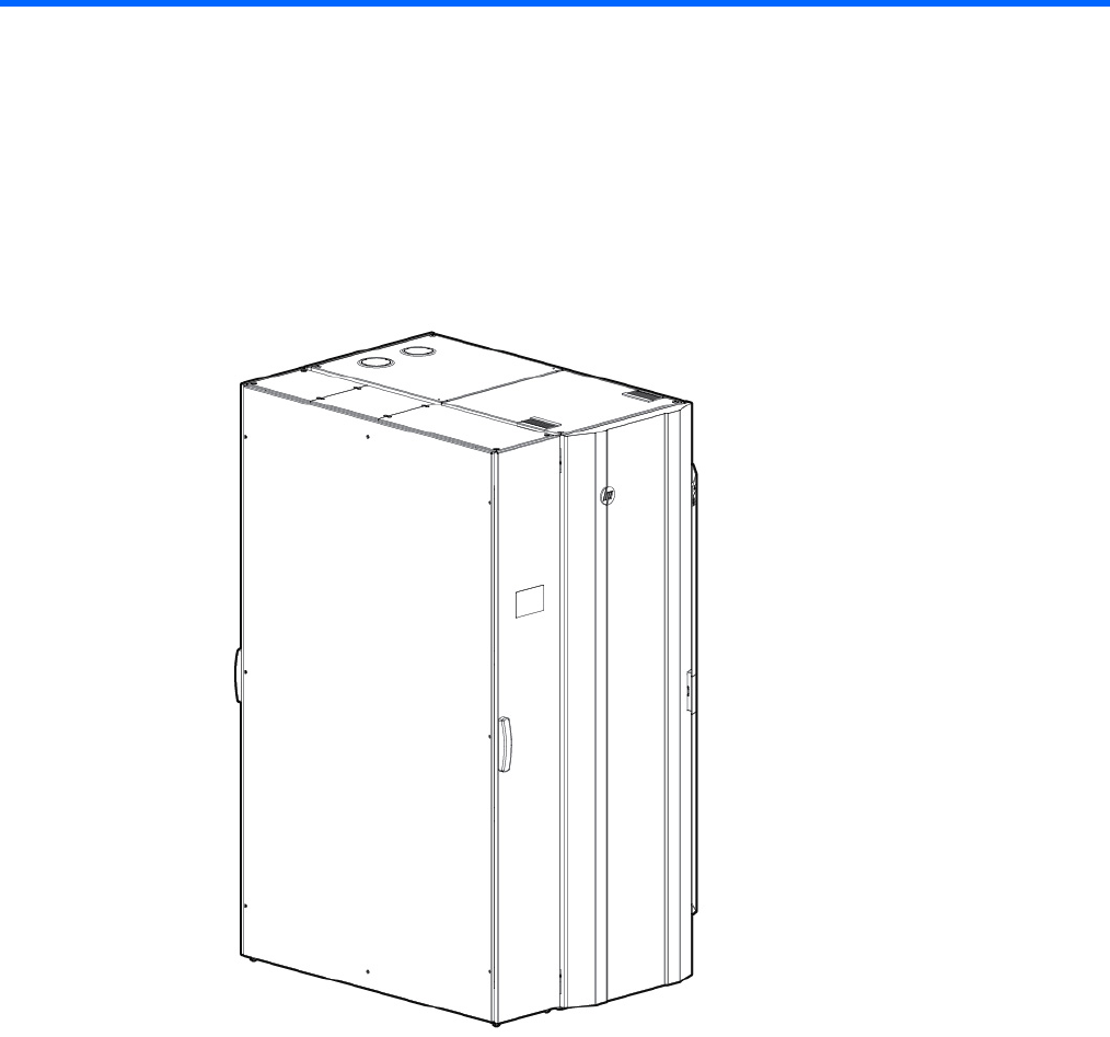
The MCS-200/100 is a supplemental cooling system for data centers. It is offered in four configurations:
• MCS-100 unit (single-rack configuration)
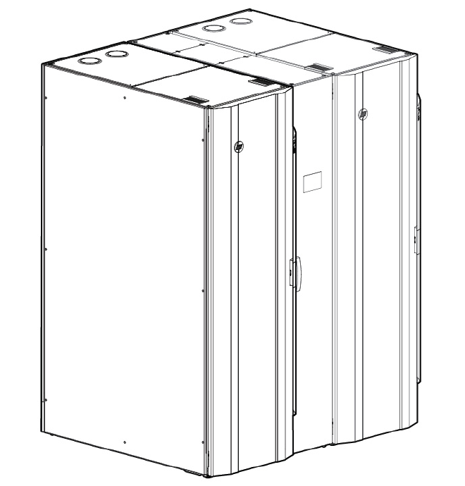
Overview 6
• MCS-100 unit (dual-rack configuration)
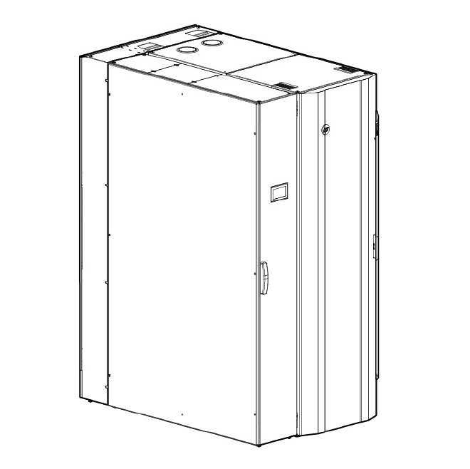
Overview 7
• MCS-200 unit (single-rack configuration)
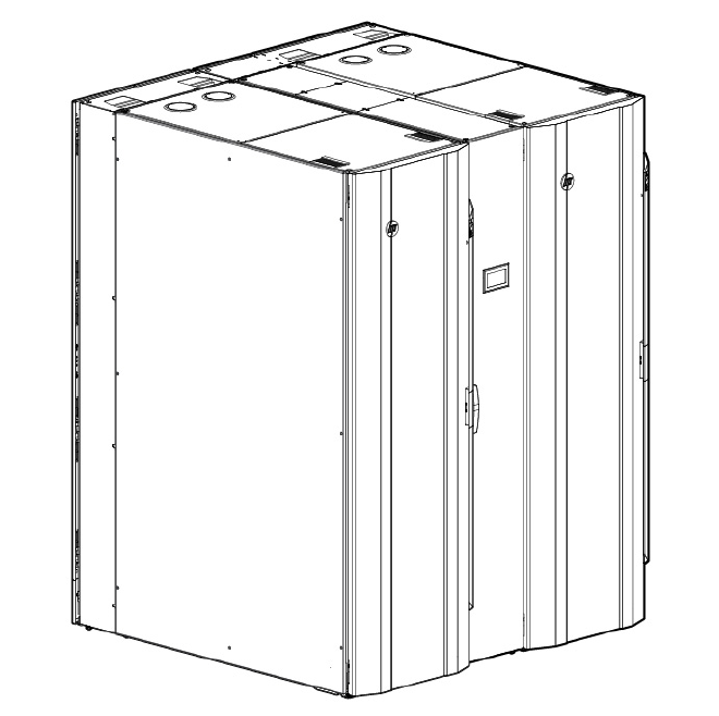
Overview 8
• MCS-200 unit (dual-rack configuration)
For successful site preparation, consider the following information:
• To provide dedicated cooling for servers and other IT equipment, the MCS-200/100 integrates with the
facility chilled water plant or a dedicated chilled water loop. HP recommends that you install a
dedicated cooling loop to the MCS-200/100.
• The system provides cooling, recirculation, and condensation management, and it requires a small
amount of AC electric power.
• Internal monitoring and control sensors assure server inlet air set points to be achieved and provide
constant performance feedback through local and network interfaces.
Product overview
The MCS-200/100 is a modular, distributed cooling solution that removes the high levels of heat generated
by current advanced server and mass storage systems. The MCS-200/100 provides a uniform, effective,
affordable, and distributed cooling approach for servers and other IT equipment installed in server racks. The
MCS-200/100 is a closed-loop cooling system integrated as part of a non-ventilated server enclosure, in
contrast to a conventional ”open” server enclosure with perforated front and rear doors.
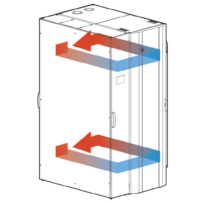
Overview 9
Air flow for MCS-100 (single-rack configuration)
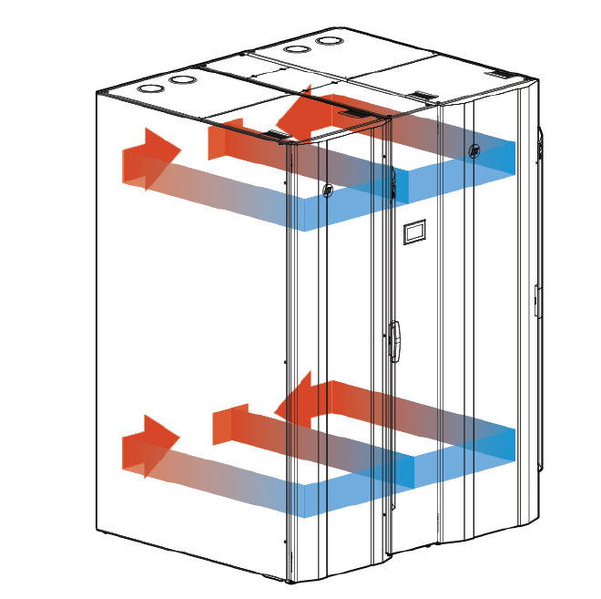
Overview 10
Air flow for MCS-100 (dual-rack configuration)
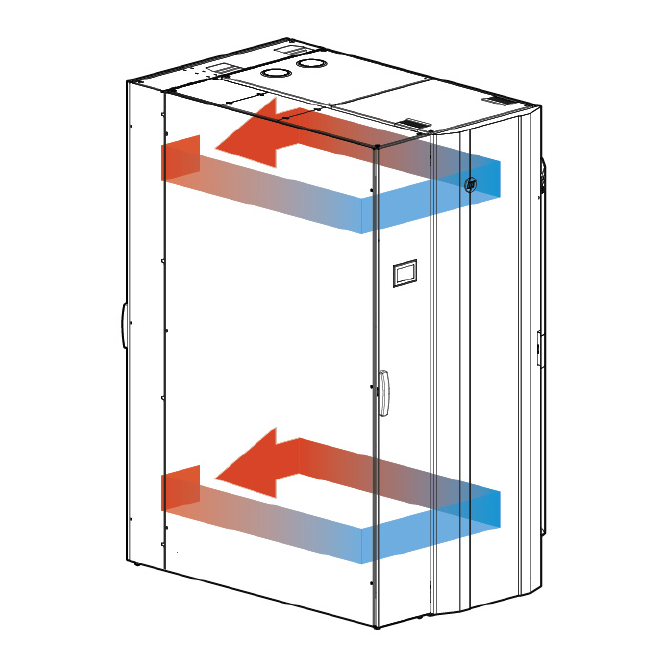
Overview 11
Air flow for MCS-200 (single-rack configuration)
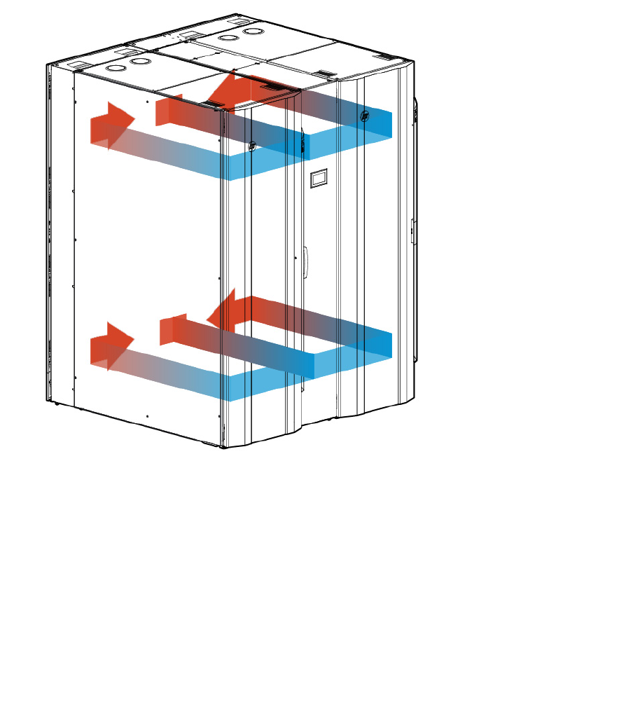
Overview 12
Air flow for MCS-200 (dual-rack configuration)
The special horizontal airflow of the MCS-200/100 fully supports the industry standard front-to-back cooling
principle, such as cold air drawing into the front of the server and warm air being expelled out the rear of the
unit. All devices receive adequate and evenly distributed cool air regardless of the mounting position within
the enclosure. The MCS-200/100 distributes precisely cooled and targeted air flow evenly across the front
of the IT equipment. Warmed air is then channeled from the rear of the IT equipment into the side-mounted
or center-mounted MCS-200/100 cooling unit. From there it is cooled and recirculated to the front of the
equipment stack.
Key components
The MCS-200/100 uses the following key components to provide cooling performance. Some of these
components are optional for MCS-100. For more information, see "MCS-100 components (on page 13)."
• Main breakers—Provide power for the MCS-200/100 through circuit breakers. They do not control
power at the input panel.
If the MCS-200/100 is still connected to a power source, voltage is applied before the circuit breakers
at the input panel
• Heat Exchanger Module (HEX)—Uses an air-to-water heat transfer device specially created for
demanding data center environments
• Display—Provides general cooling unit status
• Management module—Provides users with web-based capabilities to set, monitor, and control
temperature within the modular cooling unit, and displays the health of the unit
Overview 13
• Fan controller—Operates the fans, according to the cabinet air temperature
• Air bleeder valve—Enables air to manually bleed out of the system when coolant is initially filled
• Water controller—Senses condensation, leaks, water temperatures, flow rate, and the status of the
water valve, and sends this data to the management module
• AC input/network connection—Provides primary and secondary AC input connections, if available,
and a network management interface
• AC transfer switch—Provides dual-AC power with a fail-over feature for redundancy
• Fans—Provide circulation of cooled air through the computer equipment rack
• Water group—Includes the water valve, flow meter, check valve, and temperature sensors
A condensation pump with overflow and condensation lines connects to the water group.
Each MCS-200/100 has one water group.
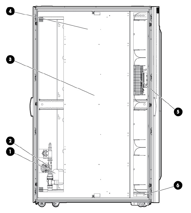
MCS-100 components
The MCS-100 is an air and water heat exchanger that removes high levels of excess heat generated by
equipment installed in HP racks. The installed equipment pulls cold air in through the front of the closed
MCS-100 and uses that air for internal cooling. After the air is warmed, the MCS-100 expels the air through
the rear vents.

Overview 14
Item Description
1 Control valve
2 Flow meter
3
Humidity sensor
4 Heat exchanger unit
5 Fan units (1 fan by default, 4 fans maximum)
6 Management module
HP provides several components to complement or complete your MCS-100. For more information, see the
HP Modular Cooling System 200/100 Options Installation Guide.
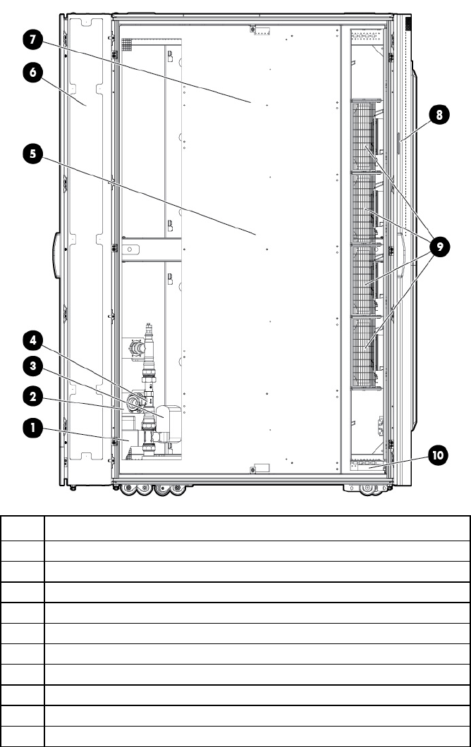
The following illustrations show the MCS-100 optional components.
Unit side view
Item Reference
1 Condensation pump (optional)
2 Condensation pump controller (optional)
3 Control valve
4 Flow meter
5 Humidity sensor
6 Rear extension (optional)
Overview 15
Item Reference
7 Heat exchanger unit
8 TFT touchscreen display (optional)
9
Fan units (1 fan by default, 4 fans maximum)
10 Management module
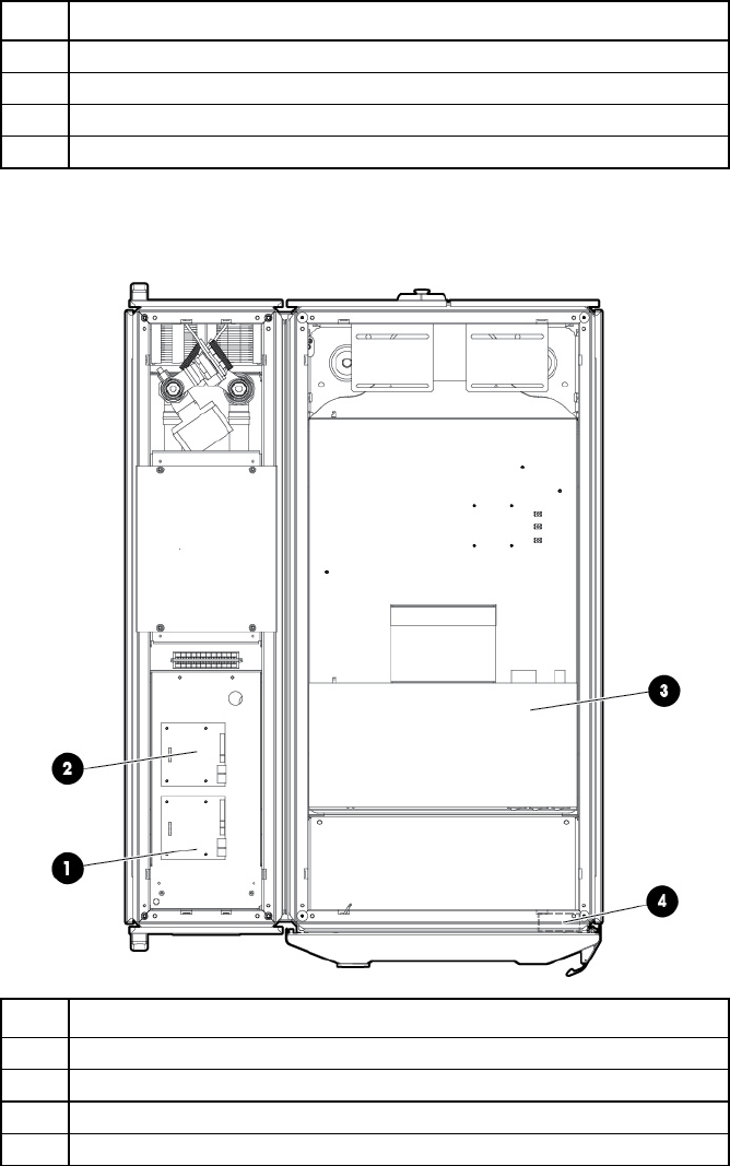
Unit top view
For easier viewing, the canopies are not shown in this illustration.
Item Reference
1 Water module
2 Fan module
3 AC power distribution unit (AC transfer switch optional)
4 Emergency door opening (optional)
MCS-200 components
The MCS-200 is an air and water heat exchanger that removes high levels of excess heat generated by
equipment installed in HP racks. The installed equipment pulls cold air in through the front of the closed
MCS-200 and uses the air for internal cooling. After the air is warmed, the MCS-200 expels the air through
the rear vents.
HP provides several components to complement or complete your MCS-200. For more information, see the
HP Modular Cooling System 200/100 Options Installation Guide.
Overview 16
The following illustrations show the MCS-200 optional components.
Unit side view
Item Reference
1
Condensation pump
2 Condensation pump controller
3 Control valve
4 Flow meter
5 Humidity sensor
6
Rear extension
7 Heat exchanger unit
8 TFT touchscreen display
9 Fan units (4 fans by default, 6 fans maximum)
10 Management module
Unit top view
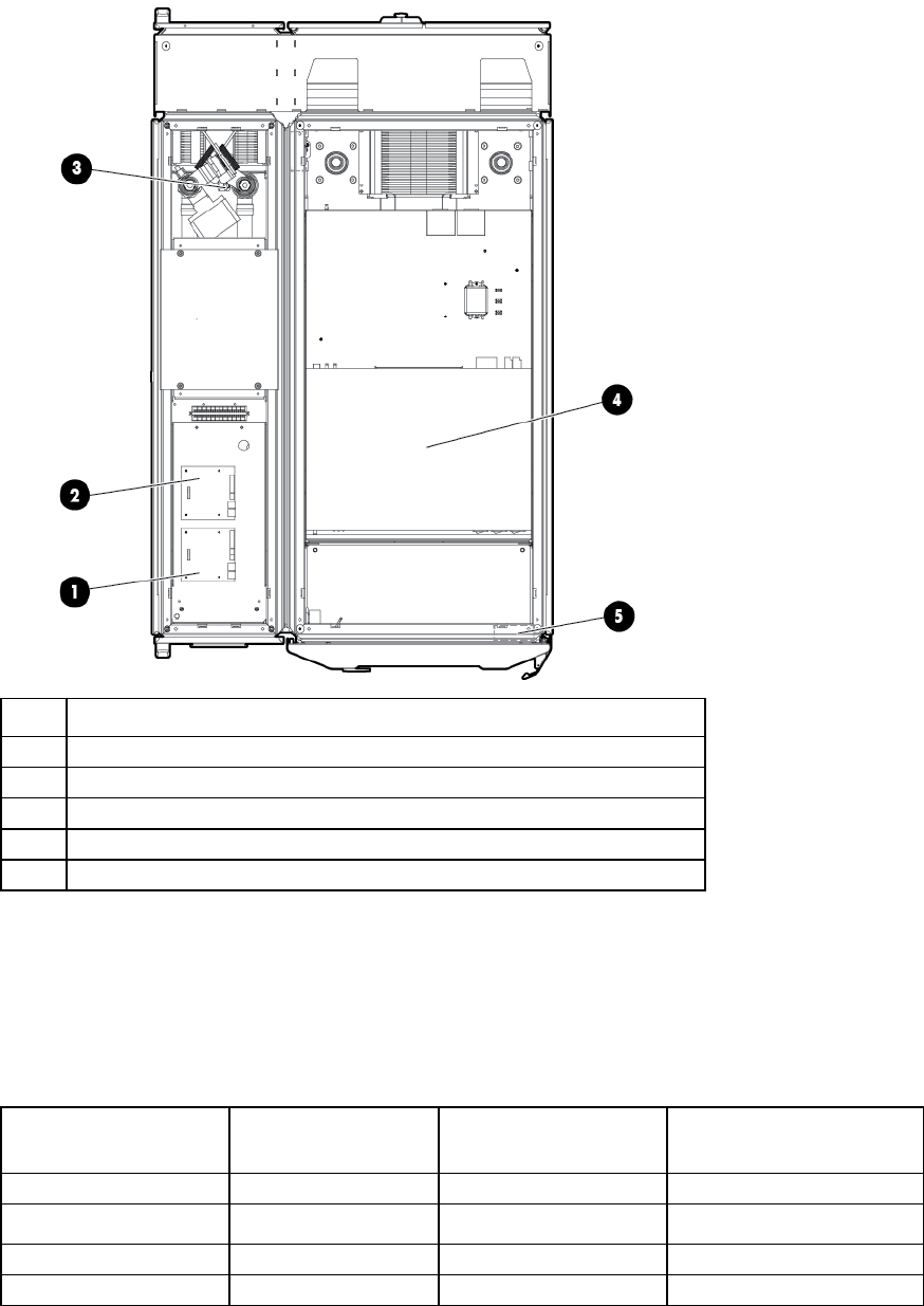
Overview 17
For easier viewing, the canopies are not shown in this illustration.
Item Reference
1 Water module
2 Fan module
3 Condensation pump transformer 277v (optional)
4 AC transfer switch
5 Emergency door opening
Physical specifications
The following table lists the approximate physical specifications of a single MCS-100 or MCS-200 as
received from the factory.
MCS-100 (single rack configuration) physical specifications
Parameter Packaged system (as
shipped on pallet)
Unpackaged system
(off pallet, unwrapped)
Unpackaged CTO system
Height 2285 mm (90 inches) 2007 mm (79 inches) 2007 mm (79 inches)
Width 1219 mm (48 inches) 904 mm (35.6 inches) 904 mm (35.6 inches)
Depth 1829 mm (72 inches) 1311 mm (51.6 inches) 1311 mm (51.6 inches)
Weight 670 kg (1479 lb)1 417 kg (919 lb)2 1324 kg (2919 lb)3
MCS-100 expansion rack physical specifications

Overview 18
Parameter Packaged system (as
shipped on pallet)
Unpackaged system
(off pallet, unwrapped)
Unpackaged CTO system
Height 2159 mm (85 inches) 2007 mm (79 inches) 2007 mm (79 inches)
Width 914.4 mm (36 inches) 600 mm (23.6 inches) 600 mm (23.6 inches)
Depth 1727 mm (68 inches) 1200 mm (47.2 inches) 1200 mm (47.2 inches)
Weight
265 kg (584 lb)1 135 kg (299 lb)2 1042 kg (2297 lb)3
MCS-200 (single rack configuration) physical specifications
Parameter Packaged system (as
shipped on pallet)
Unpackaged system
(off pallet, unwrapped)
Unpackaged CTO system
Height 2285 mm (90 inches) 2007 mm (79 inches) 2007 mm (79 inches)
Width 1219 mm (48 inches) 904 mm (35.6 inches) 904 mm (35.6 inches)
Depth
1829 mm (72 inches) 1510 mm (59.5 inches) 1510 mm (59.5 inches)
Weight 732 kg (1614 lb)1 478 kg (1054 lb)2 1521 kg (3353 lb)3
MCS-200 expansion rack physical specifications
Parameter Packaged system (as
shipped on pallet)
Unpackaged system
(off pallet, unwrapped)
Unpackaged CTO system
Height 2159 mm (85 inches) 2007 mm (79 inches) 2007 mm (79 inches)
Width 914.4 mm (36 inches) 600 mm (23.6 inches) 600 mm (23.6 inches)
Depth 1727 mm (68 inches) 1399 mm (55.1 inches) 1399 mm (55.1 inches)
Weight 308 kg (680 lb)1 179 kg (395 lb)2 1222 kg (2694 lb)3
1 Weight for a completely packaged system with unpopulated server rack
2 Weight for an unpackaged system with unpopulated server rack
3 Approximate weight for an unpackaged CTO system (actual weight varies, according to configuration)
If the top shipping bracket interferes with deploying the MCS-200/100, it can be removed. With the top
shipping bracket, the total height of the unpackaged system is 2069 mm (81.5 inches).
Electrical specifications
The following table lists the electrical specifications for the MCS-100 unit.
Parameter Value Comments
Operating voltage 230 VAC +/- 10%, 50 Hz
208 VAC +/- 10%, 60 Hz —
AC line phase Single —
Maximum input current 18 A Per line cord
Maximum inrush current 200 A Per line cord
Dropout/hold-up time at
minimum line voltage
20 ms —
Transfer time of AC transfer
switch
2 s —
Circuit breaker rating LAHJ Per cord
Power factor > 0.95 At all loads
Ground leakage current < 19.4 mA Per line cord

Overview 19
Parameter Value Comments
Power cord 230 V, 16 A
208 V, 18 A
IEC 309-to-Procon 700105
NEMA L6-20-to-Procon 700105
The following table lists the electrical specifications for the MCS-200 unit.
Parameter Value Comments
Operating voltage 230 VAC +/- 10%, 50 Hz,
277 VAC +/- 10%, 60 Hz,
and 208 VAC +/- 10%, 60 Hz
—
AC line phase Single —
Maximum input current 18 A Per line cord
Maximum inrush current 200 A Per line cord
Dropout/hold-up time at
minimum line voltage
20 ms —
Transfer time of AC transfer
switch
2 s —
Circuit breaker rating LAHJ Per cord
Power factor > 0.95 At all loads
Ground leakage current
< 19.4 mA Per line cord
Power cords 230 V, 16 A
208 V, 18 A IEC 309-to-Procon 700105 (Qty 2)
NEMA L6-20-to-Procon 700105

Facility planning for implementation 20
Facility planning for implementation
Facility planning overview
The MCS-200/100 offers an incremental data center cooling solution, capable of cooling 30 kW of heat
with the MCS-100 unit or 50 kW of heat with the MCS-200 unit.
In planning water supply and design, take into consideration short and long-term needs for cooling.
Immediate supply needs must meet the specifications and target cooling requirements, based on the
parameters defined in this site preparation guide. In anticipation of future heat loads, design and install
dedicated loop chilled water piping, based on specific cooling load increments (such as 50 kW or 250 kW),
the specific number of MCS-200/100 per row or loop, and other site build-out planning parameters. As
cooling, rack space, and equipment density requirements increase, you can add MCS-200/100 units to the
chilled water system.
To route water lines to your MCS-200/100 unit, use one of the following methods:
• Through an opening in the raised floor
• Lying on top of the floor (for MCS-200 only)
• Through the top of the MCS-200/100 unit
For more information on routing the water lines, see the Hook Up Kit installation instructions in the HP
Modular Cooling System 200/100 Options Installation Guide.
Installation service for the MCS-200/100 is order number UE005E.
For site evaluations and technical consulting for your site, see the HP Services website
(http://www.hp.com/services/criticalfacilities).
The implementation of the MCS-200/100 aligns with Data Center Best Practices. For more information, see
Optimizing Data Centers for High-Density Computing, which can be found on the HP website
(http://h18004.www1.hp.com/products/servers/proliantstorage/racks/10000series/documentation.ht
ml).
This section discusses key issues for site preparedness, including:
• Space considerations for delivery, operation, and service, and other space-related considerations such
as floor loading
• Electrical considerations
• Coolant source options and quality considerations
• Other considerations
A complete site preparation checklist is provided in Appendix A: Forms and checklists (on page 81).
Space and positioning considerations
When fully populated, the MCS-200/100 unit is larger and heavier than a standard 482.6 mm (19-inch)
equipment rack. Therefore, more space is required to maneuver, operate, and service the MCS-200/100.
Facility planning for implementation 21
Delivery space requirements
Be sure your facility has adequate space to receive and remove the MCS-200/100 from the shipping pallet.
Consider the following when unloading the racks:
• Forklifts must enter and transport the shipping pallet from the side.
• Delivery plans must include the possible removal of walls or doors.
MCS-200/100 dimension requirements
Dimension requirements MCS-200/100 MCS expansion rack
Total length allowed to safely remove the MCS-200/100
from the shipping pallet down the provided ramps
approximately 6.1 m (20
ft)
approximately 6.2 m
(20.6 ft)
Packaged dimensions of the MCS-200/100 (including
shock pallet and cartons)
2285 mm (90 inches)
height x 1219 mm (48
inches) width x 1829 mm
(72 inches) depth
2159 mm (85 inches)
height x 914.4 mm (36
inches) width x 1727 mm
(68 inches) depth
Maneuvering space requirements
WARNING: To reduce the risk of personal injury or damage to the equipment, do not attempt to
move equipment racks alone. Obtain adequate assistance to stabilize the rack during movement,
or hire professional equipment riggers.
WARNING: To reduce the risk of personal injury or damage to the equipment, use extreme care
when moving racks with casters. Sudden stops, excessive force, and uneven surfaces can cause
the product to overturn.
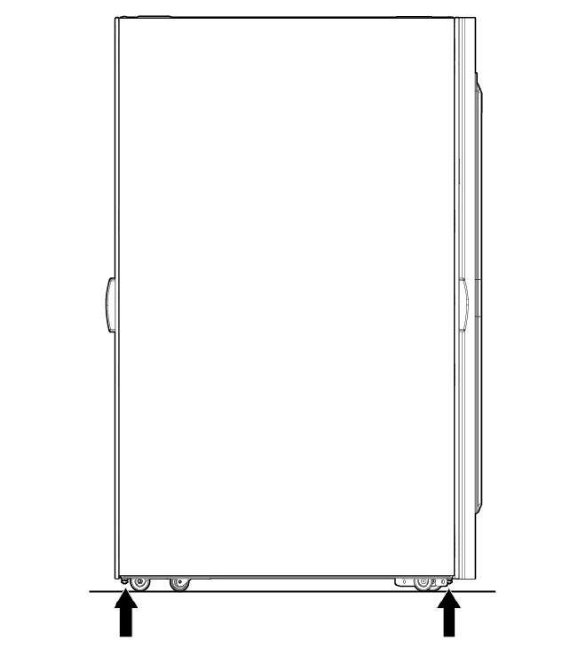
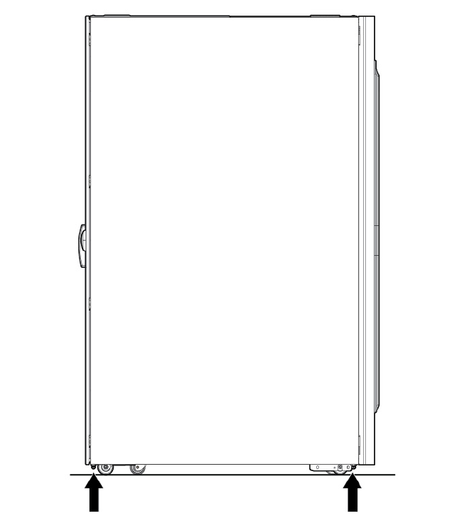
When maneuvering the MCS-200/100, use the following guidelines:
• Move racks that have casters with care. Sudden stops, excessive force, and uneven surfaces might
cause the product to overturn.
• Due to stability and safety concerns, the cooling unit and IT rack have casters that are fixed to the front
and swivel in the back. For more ease, move the MCS-200/100 with the back as the leading edge.
• For long and straight distances, roll the MCS-200/100 with the front fixed casters leading. For better
mobility, lead with the rear swiveling casters.
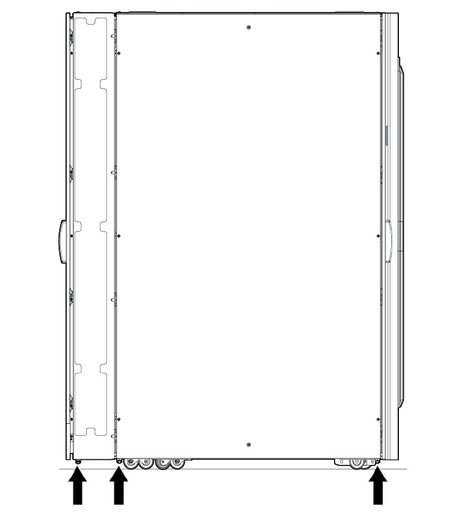
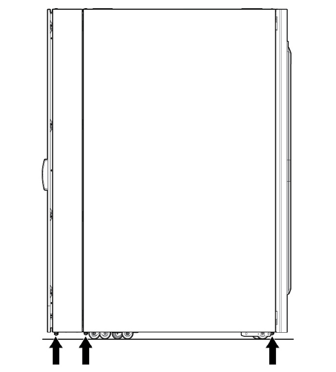
• When rolling the MCS-200/100, push firmly on the front doors frame and not the door mesh of the IT
rack. The points where you should push theMCS-200/100 are marked by the factory.
• Be sure that the rooms and doors are large enough to accommodate the movement of the
MCS-200/100 cabinet into the data center.
• When transporting the MCS-200/100 to a different building floor, ensure the elevators have adequate
load capacity, floor space, and door clearance to accommodate the rack. The MCS-200/100 pallet
can only be moved with forklifts from the side, which has a length of 1829mm (72 inches).
• When transporting the MCS-200/100 within a building, ensure that doorway thresholds are adequate
to hold the rack. HP does not recommend that you lift or transport the MCS-200/100 by eyebolts that
are attached to the upper corners of the cabinet.
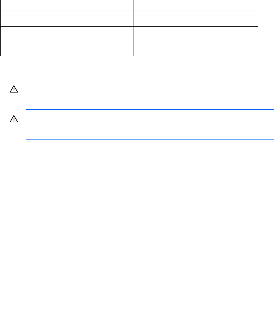
The following figure shows the maneuvering space required when unloading the MCS-100 and MCS-200
from a pallet. When planning to maneuver the unit, use the delivery forms provided in "Appendix A: Forms
and checklists (on page 81)."
Facility planning for implementation 22
CAUTION: HP recommends that a ramp angle of no greater than 5° be used to move the
MCS-200/100 up or down elevations. Typical data center ramps have a 5º angle (1 to 12
pitches).
MCS-200/100
Item Reference
1 MCS-200/100 shock pallet
2 3-piece ramp
3 MCS-200 rack (MCS-100 rack not shown)
Facility planning for implementation 23
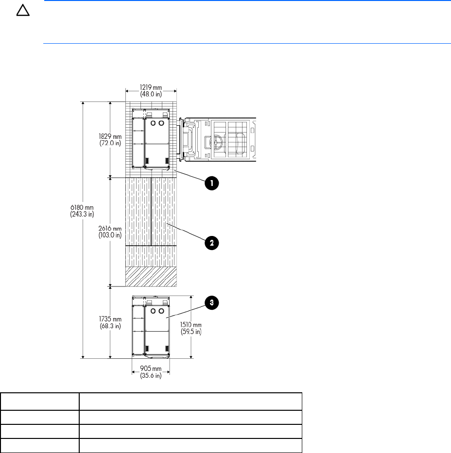
MCS-200/100 expansion rack
Item Reference
1 MCS-200/100 expansion rack shock pallet
2 4-piece ramp
3 MCS-200 expansion rack (MCS-100 expansion rack not
shown)
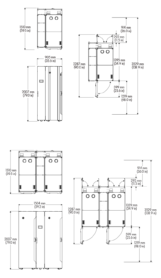
Operational space requirements
To provide space for internal airflow and housing of the cooling unit components, the MCS-200/100 is
wider and deeper than conventional HP racks.
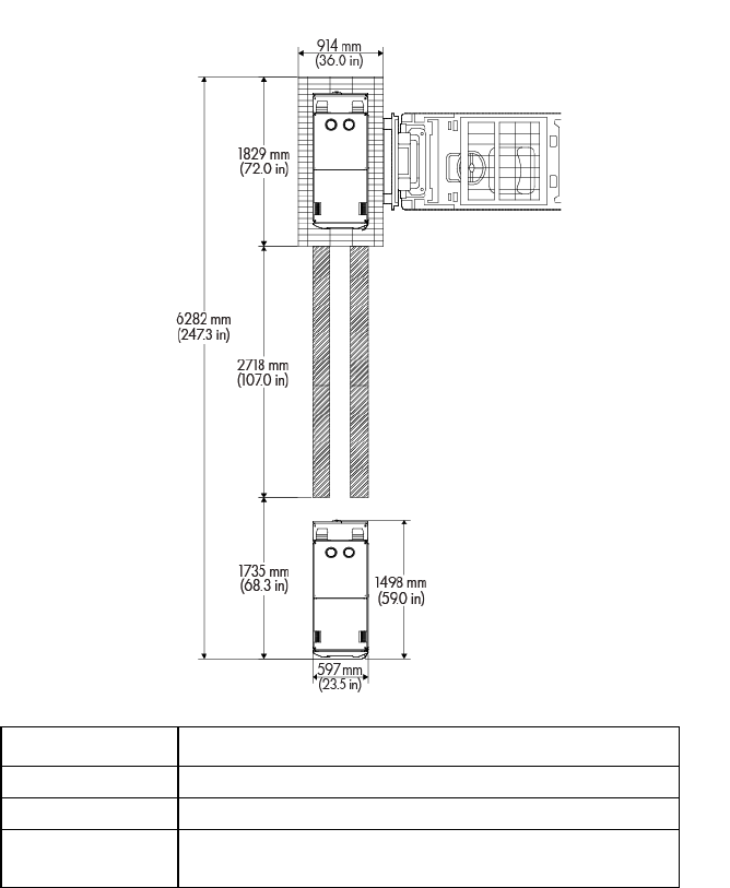
HP recommends the minimum access space for the MCS-200/100 be 1219 mm (4 ft) in the front and 914
mm (3 ft) in the rear, as shown in the following figures.
• With the top shipping bracket, the total height is 2069 mm (81.5 inches).
• The MCS-200/100 unit requires approximately 600 mm of additional width (space) to accommodate
the second IT rack, which is mounted to the left of the cooling unit.
Facility planning for implementation 24
MCS-100 unit (single-rack configuration)
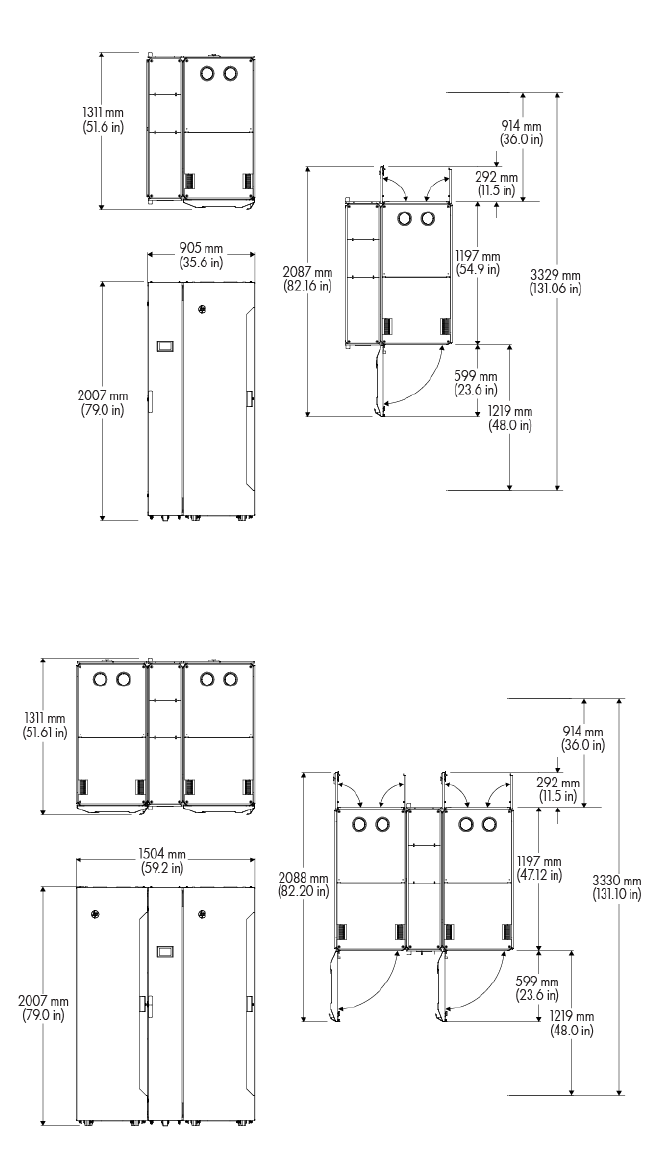
MCS-100 unit (dual-rack configuration)
Facility planning for implementation 25
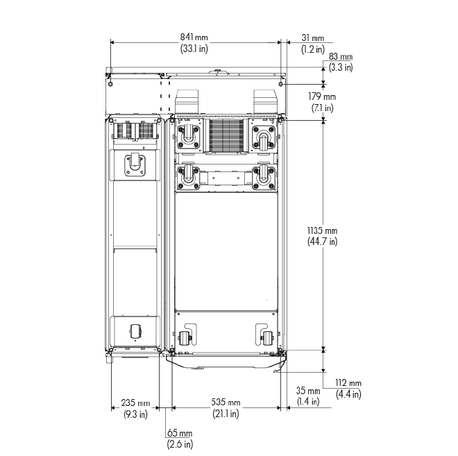
MCS-200 unit (single-rack configuration)
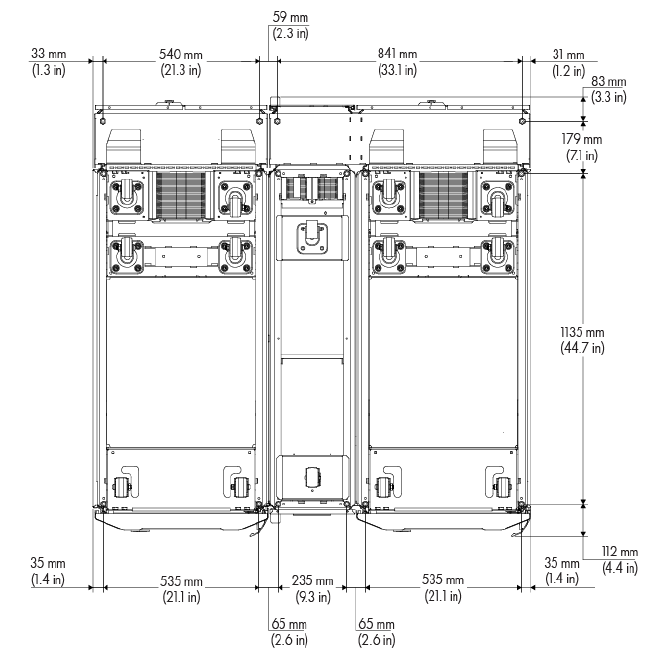
MCS-200 unit (dual-rack configuration)
System positioning
The MCS-200/100 can be installed next to an existing or new row of HP Intelligent Series racks. Based on
facility design requirements, the cabinets can be arranged in a flush front or flush rear configuration.
Facility planning for implementation 26
Flush front configuration examples
When arranging the MCS-100 or MCS-200/100 next to an HP Intelligent Series rack, and depending on the
configuration, be aware of the potential for slight rear door swing interference. Equipment might require the
removal of a door during installation to allow for unimpeded access.
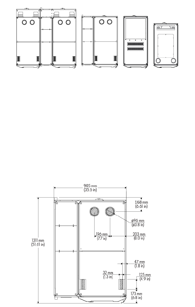
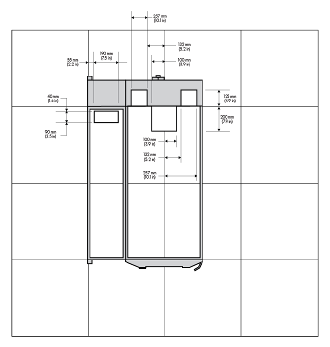
Cable openings
The MCS-100 and MCS-200 units have several useable cable openings at front top, rear bottom and rear
top of the IT rack.
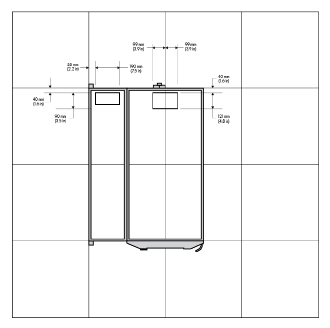
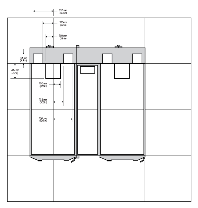
The following figure shows the size and position of the cable openings at the top and bottom in the MCS-100
(single-rack configuration).
• Top view
Facility planning for implementation 27
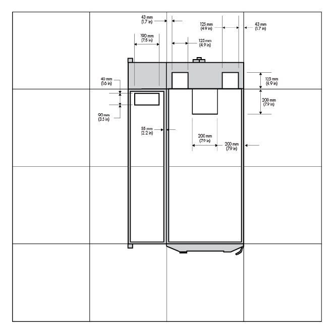
• Bottom view
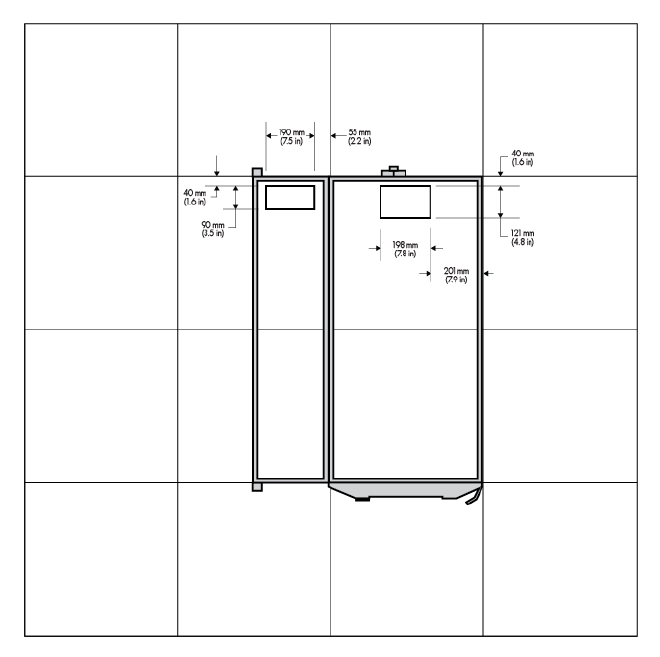
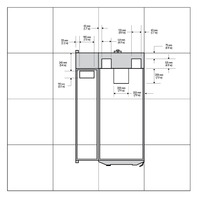
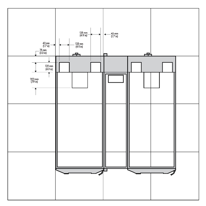
The following figure shows the size and position of the cable openings at the top and bottom in the MCS-100
(dual-rack configuration).
• Top view
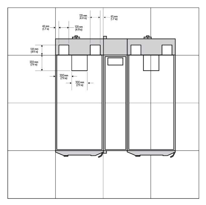
• Bottom view
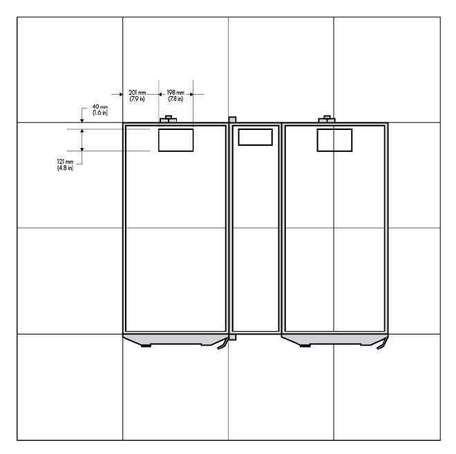
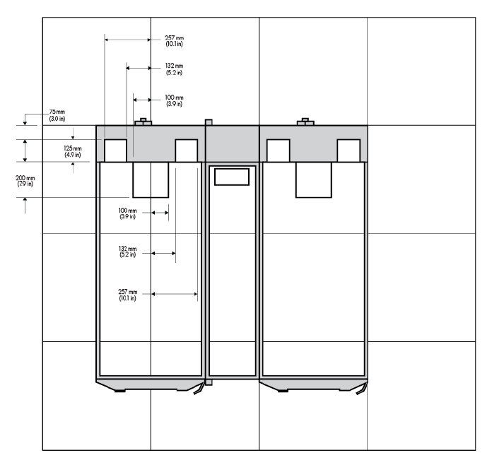
The following figure shows the size and position of the cable openings at the top and bottom in the MCS-200
(single-rack configuration).
Facility planning for implementation 28
• Top view
• Bottom view
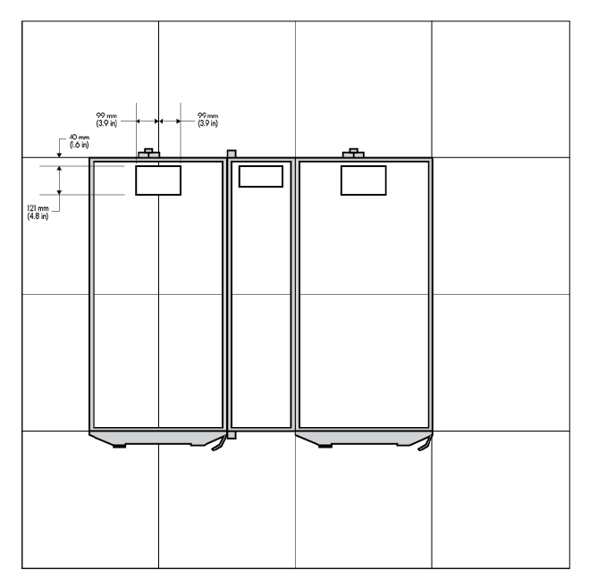
The following figure shows the size and position of the cable openings at the top and bottom in the MCS-200
(dual-rack configuration).
Facility planning for implementation 29
• Top view
• Bottom view
Cabinet leveling feet
Facility planning for implementation 30
WARNING: Static loading limits cannot be achieved if the rack is not on its leveling feet or is
rolled or pushed from its position. Your floor weight capacity might not support the full static load
capacity. Check with your floor provider before loading. HP is not responsible for floor damages
due to floor overloading.
CAUTION: To reduce the risk of damage to the casters, make sure that the full weight of the rack
rests on the leveling feet and feet pads, and not on the casters. The casters are designed only as
an aid in moving the rack into position. They are not designed to support the weight of the rack,
and the casters may become damaged if relied on to support the rack.
The MCS-200/100 includes leveling feet and does not require fastening to the floor. Care should be taken
during the loading of the equipment to ensure the rack remains stable during operation and servicing to
avoid personnel and equipment damage. MCS-200/100 both support approximately up to 1361 kg (3000
lb) of static equipment load on the leveling feet and feet pads.
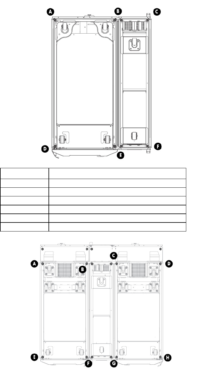
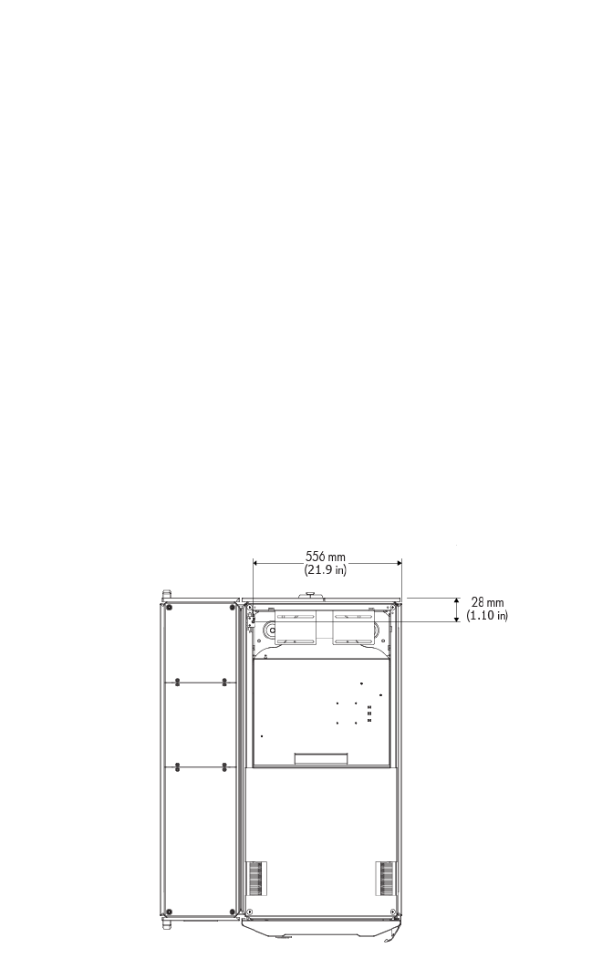
The following figures show the locations of the cabinet leveling feet. Be sure there is adequate floor and
remaining understructure support to handle the load-bearing leveling feet, especially immediately around the
cutout. After the MCS-200/100 is positioned in the proper location in the data center, it can be lowered into
place with the leveling feet and leveling feet pads.
MCS-100 cabinet leveling feet locations:
• Bottom view
o MCS-100 single-rack configuration

Facility planning for implementation 31
o MCS-100 dual-rack configuration
• IT rack side view
Facility planning for implementation 32
o MCS-100 single-rack configuration
Facility planning for implementation 33
o MCS-100 dual-rack configuration
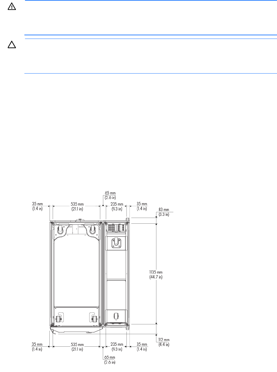
MCS-200 cabinet leveling feet locations:
• Bottom view
Facility planning for implementation 34
o MCS-200 single-rack configuration
Facility planning for implementation 35
o MCS-200 dual-rack configuration
• IT rack side view
Facility planning for implementation 36
o MCS-200 single-rack configuration
Facility planning for implementation 37
o MCS-200 dual-rack configuration
The leveling feet pads help to ensure weight distribution and help transfer the load to the support structure
below the floor. You must ensure proper orientation of the feet pads so that subsequent racks can be properly
accommodated.
Floor loading considerations
The computer room floor must be able to support the total weight of the installed server trays as well as the
weight of the MCS-200/100 as they are moved into position. This section contains information about raised
floor installations. HP cannot assume responsibility for determining the suitability of a particular raised floor
system. The customer or local agencies should determine installation requirements. An appropriate structural
engineer should verify any floor system under consideration for a server installation.
Raised floor loading is a function of the manufacturer’s load specification and the positioning of the
equipment relative to the raised floor grid. HP recommends the following guidelines:
• Some raised floor systems do not have grid stringers between floor stands. The lateral support for the
floor stands depends on adjacent panels being in place. To avoid compromising this type of floor
system when gaining under-floor access, remove only one floor panel at a time.
• Larger floor grids (bigger panels) are generally rated for lighter loads.
• MCS-200/100 both support approximately up to 1361 kg (3000 lb) of static loads of equipment on
the leveling feet and feet pads.

Facility planning for implementation 38
The MCS-200/100 has not been certified for seismic environments.
The following table can be used to calculate the weight load of each MCS-200/100 unit, including installed
equipment for proper floor planning.
MCS-100 weight calculation
Component Unit weight Quantity (multiple by) Total weight
MCS-100 (with no server
trays)
670 kg (1479 lb) 1 670 kg (1479 lb)
Component #1: HP
ProLiant SE2x8530a
Gen8 Server Tray*
11.21 kg (24.72 lb) 80 897 kg (1978 lb)
Component #2:
Component #3:
Component #4:
Rack Total:
*Component #1 text included as an example
MCS-200 weight calculation
Component Unit weight Quantity (multiple by) Total weight
MCS-200 (with no hose
kits or IT equipment
installed)
732 kg (1614 lb) 1 732 kg (1614 lb)
Component #1: Mellanox
Infiniband switch*
21.22 kg (46.8 lb) 1 21.22 kg (46.8 lb)
Component #2:
Component #3:
Component #4:
Rack Total:
*Component #1 text included as an example
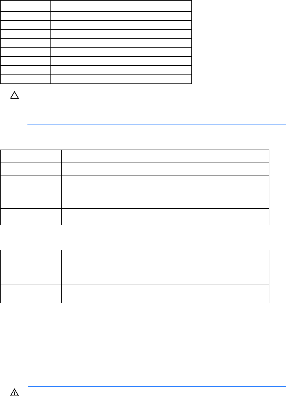
In the following figure, the load is in the center of the IT racks. Due to adjacency, the leveling feet are
combined to one concentrated weight.
Facility planning for implementation 39
The weight distribution on the leveling feet locations in MCS-100 and MCS-200 are very similar.
Item Weight
A 79 kg (174 lb)
B 458 kg (1010 lb)
C 385 kg (349 lb)
D 83 kg (183 lb)
E 457 kg (1008 lb)
F 375 kg (827 lb)
Facility planning for implementation 40
Item Weight
A 385 kg (849 lb)
B 455 kg (1003 lb)
C
458 kg (1010 lb)
D 385 kg (849 lb)
E 375 kg (827 lb)
F 457 kg (1007 lb)
G 457 kg (1007 lb)
H 375 kg (827 lb)
CAUTION: To reduce the risk of damage to the casters, make sure that the full weight of the rack
rests on the leveling feet and feet pads, and not on the casters. The casters are designed only as
an aid in moving the rack into position. They are not designed to support the weight of the rack,
and the casters may become damaged if relied on to support the rack.
Common floor-loading terms
Term Description
Dead load The weight rating for the load the floor can support expressed in kg/m² (lb/ft²)
Uniform load The load that the floor system can safely support; expressed in kg/m² (lb/ft² or kN/m²)
Concentrated load* The load that a floor panel can support on a 25 x 25 mm² (1 x 1 inches²) at the panels
weakest point (typically the center of the panel), without the surface of the panel
deflecting more than a predetermined amount
Rolling load The load a floor panel can support (without failure) when a wheel of specified diameter
and width is rolled across the panel
Example: Tate All Steel 1250 raised floor specifications
Item Rating
Dead load 34.2 kg/m² (7 lb/ft²)
Uniform load 1,552 kg/m² (400 lb/ft²)
Concentrated load* 567 kg (1,250 lb)
Rolling load 227 kg (500 lb)
*With 2.54 mm (0.10 inch) of span maximum deflection
Electrical considerations
The electrical practices and suggestions in this guide are based on North American practices. For regions
and areas outside North America, local electrical codes take precedence. An example would be the
recommendation that the protective ground conductor should be green with yellow stripes—this requirement
is a North American directive and does not override the local code requirements for a region or areas
outside North America.
WARNING: To avoid personal injury and damage to the equipment, be sure that an emergency
power shut off switch is in place and is easily accessible.
Facility planning for implementation 41
The MCS-200 provides two Walther Procon A5 series AC input connections and ships with one set of two
power cords for connecting to redundant AC power busses, when available. Only one power cord is
necessary for operation. The second cord can be connected to a redundant AC power bus to improve system
availability by protecting against power source failures or accidentally tripped circuit breakers.
These redundant connections and cords are optional for the MCS-100.
For more information, see "Connecting to facility A/C power (on page 43)."
System grounding
HP server systems require two methods of grounding: power distribution grounding for safety, and
high-frequency signal grounding for equipment performance. Power distribution grounding involves the main
building electrical service entrance, electrical conduit, facility power panels, and equipment cabinets
(including the MCS-200/100 and server cabinets), which should be grounded using green or yellow
insulated wire conductors according to the applicable electrical codes. High-frequency grounding consists of
using ground return conductors for intra- and inter-cabinet signal interconnects as well as chassis and cabinet
grounding.
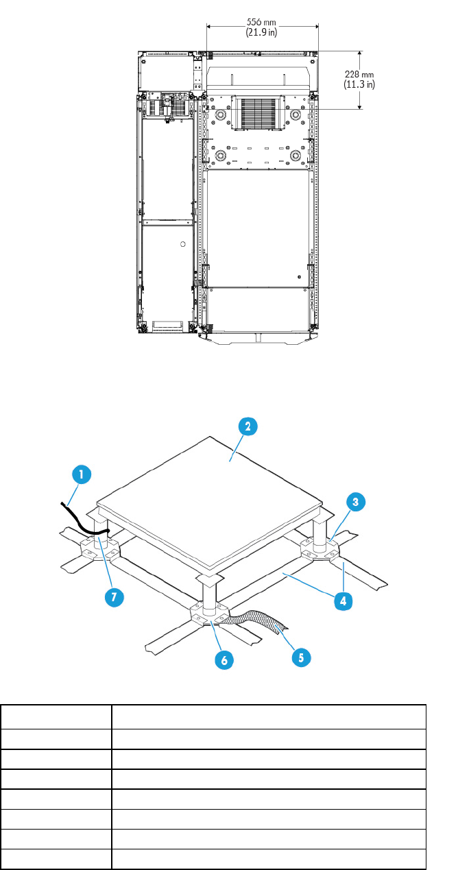
For MCS-200/100 and server systems installed on a raised floor, the floor assembly should be electrically
grounded to form a complete ground grid. An optimum raised-floor grounding solution is shown in the
following figure.
Each floor panel should have at least one supporting pedestal grounded to the power panel and another
pedestal grounded to an equipment cabinet. This broadband solution provides excellent grounding for
improved safety and performance.
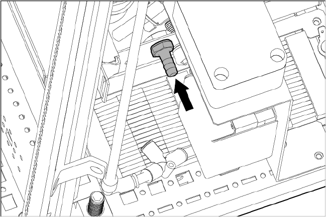
Central ground stud location inside the IT rack
MCS-100
Facility planning for implementation 42
MCS-200
Raised floor grounding
Item Description
1 Ground wire to power panel
2 Floor panel
3 Hex bolt
4 Grounding grid element
5
Grounding braid to computer equipment
6 Band and pedestal
7 Grounding clamp

Facility planning for implementation 43
Voltage fluctuations and outages
The MCS-200/100 is designed to provide immunity to power outages of less than one cycle. However,
testing cannot conclusively rule out loss of service. To obtain the best possible performance of power
distribution systems for HP equipment, observe the following guidelines:
• Dedicated power source—Isolates the power distribution system from other circuits in the facility
• Missing-phase and low-voltage detectors—Automatically shuts down equipment when a severe power
disruption occurs. For peripheral equipment, these devices are recommended but optional.
• Online UPS—Maintains constant input voltage for devices and should be considered if outages of
one-half cycle or more are common. For each situation, consult a qualified contractor or consultant.
You can protect the MCS-200/100 from the sources of many electrical disturbances by using:
• An isolated power distribution system
• Power conditioning equipment
• Over- and under-voltage detection and protection circuits
• Protection to reduce high-frequency electrical energy radiation
• Surge protective devices on power cables to protect equipment against electrical storms
Electrical planning around water-handling components
CAUTION: In case water is in contact with the power cables, shut down the main breaker before
cleaning up water in this area.
Because of potential condensation on non-insulated water connections or leaking water connections around
water-based cooling systems, consider the following during the electrical planning:
• Waterproofed connectors
• Watertight conduits for cables
• Leak detection systems
To identify waterproofed connectors, HP recommends that you use the IP rating of the connector based on the
international standard IEC 60529. HP recommends a connector that is rated at least IP 67.
Cable conduits are available in different styles, depending on flexibility and materials. The most common
materials are plastic, metal, nylon, or a composition of these materials. Watertight conduits are available in
both flexible and hard material, depending on the application.
A leak detection system for a data center usually uses leak sensor cables, which are installed on the subfloor
in a raised floor and connected to a facility management system.
Connecting to facility A/C power
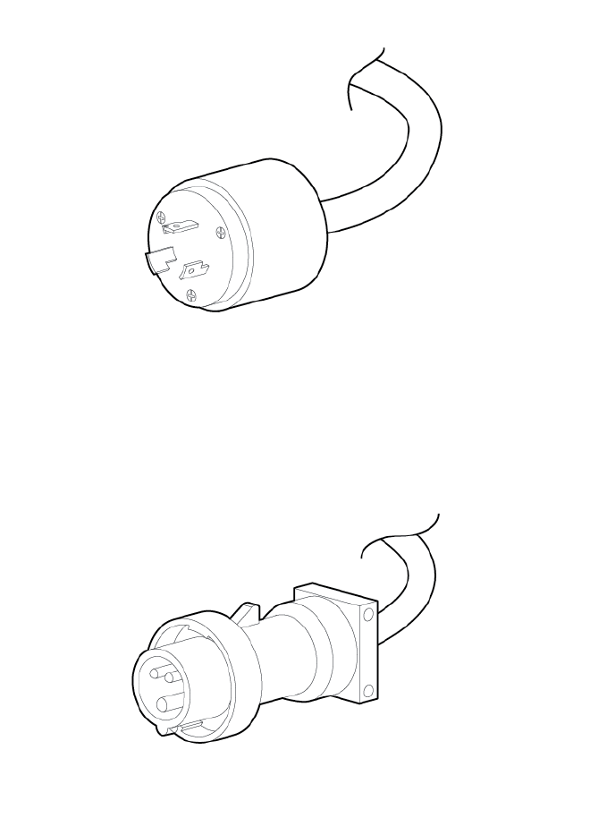
The MCS-200/100 accepts AC power through two Walther Procon A5 series power receptacles located at
the top rear patch panel. If available, the MCS-200 ships with one of each AC power cord set for connecting
to redundant AC power busses. The NEMA L6-20 power cord uses a NEMA L6-20 male plug for connecting
to a facility AC feed connector common to North America and Japan. The IEC 309 power cord uses an IEC
309 male plug for connecting to a facility AC feed connector common in various international regions.
These redundant connections and cords are optional for the MCS-100.
Facility planning for implementation 44
MCS-200/100 power L6-20 connector
MCS-200/100 IEC 309 power connector
At least one power cord must be used for MCS-200/100 operation. To improve system availability, the
second cord can connect to a redundant AC power bus (optional for the MCS-100). When the redundant
power is connected, the transfer switch assembly of the MCS-200/100 provides switch-over to the active
power bus, in the event of power source failures or accidentally tripped circuit breakers.
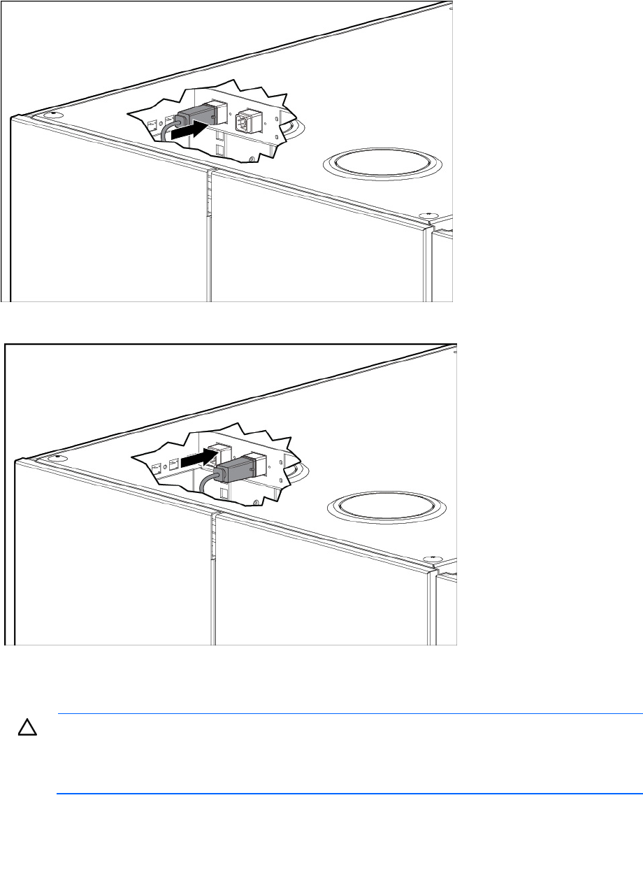
The power cords of the MCS-200/100 are 4 m (13.1 ft) long. The power connections are inside of the top
of the IT rack as shown in the following figures.
Facility planning for implementation 45
When using only a single, primary source for power, the AC power cord is connected to the left-most
receptacle.
When redundant AC power is available, the redundant AC power cord is connected to the right receptacle.
Coolant source planning
CAUTION: The minerals and chemicals typically found in tap water can react with metallic
elements used in the HP Modular Cooling System 200/100 closed-loop distribution system.
Electrochemical reactions can cause scaling, corrosion, leaks, and blockage, ultimately resulting
in reduced efficiency of the cooling system and even damage.
A number of factors relating to a facility water distribution system must be considered during the site
preparation process, including the following:
• Redundant water configurations. For more information, see Appendix B: Conversion factors and
formulas (on page 85).
Facility planning for implementation 46
• The water source should be shared water or dedicated facility water loop.
• Maximum and minimum temperatures of building chilled water plant, and target chilled water
temperature of dedicated loop, should be based on the total cooling capacity required and planned.
• The viscosity of the chilled liquid, combined with the length and elevation changes in piping determined
by selected route, can affect pipe size selection.
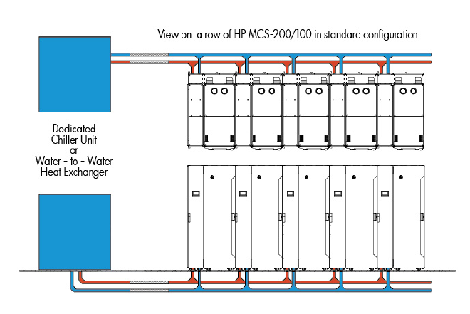
For the MCS-200/100, HP recommends using a water source that is a dedicated chiller unit or
water-to-water heat exchanger that enables line isolation, better control of individual systems, and regulated
water quality. The chilled water source for this loop is provided by one or more chiller systems. Advantages
of using a dedicated loop include the following:
• Easier scheduling of maintenance to either a building system or dedicated MCS-200/100 loop
• Easier maintenance of water quality parameters in the dedicated closed loop
• Better temperature and flow regulation to guarantee the needs of the MCS-200/100
• More flexibility to regulate water temperature in order to reduce the potential for condensation
The use of building-chilled water for the MCS-200/100 unit is possible under certain conditions. Consult with
a qualified facilities design expert, however, to determine whether this approach is possible within your
specific data center. Refer to the requirements for water quality, temperature, and flow rate described in this
section. Regardless of chilled water service approach, consult with a qualified facilities design expert to
analyze new and existing systems and specify new work to be sure that water quality, temperature, and
water flow requirements can be met. The new work must meet all local safety and building code requirements
as well as your facility quality standards. Piping drawings and schematics included here are diagrammatic
to convey a conceptual understanding of the MCS-200/100 connection requirements.
Dedicated chiller unit directly supplying the MCS-200/100
Plumbing considerations
When installing the MCS-200/100, consider the following plumbing factors:
• Installing water shut off valves to enable infrastructure system flushing for the inlet and outlet of each
MCS-200/100 (highly recommended by HP)
Facility planning for implementation 47
• Flow rate and pressure capacity of chilled water plant input to the design of the facility feed line and
dedicated water loop pipe diameters
• Material compatibility within piping system to minimize the potential for electrochemical corrosion, and
must be corrosion-resistant
• Minimization of elbows and other restrictions that increase flow resistance
• Insulation of piping to minimize risk of condensation and reduce incidental heating of supplied chilled
water
• Availability of a floor drain or reclamation system to capture system condensation
• Structural securing of piping to support weight of distribution network filled with water
• Water quality management, including particulate filtration, treatment, and flushing provisions, with
isolation valves for service requirements
• Availability and access to a data center leak detection system to monitor the infrastructure system for
leaks
• Air vents installed at the highest point in the pipe system
Each MCS-200/100 has an air vent, but additional vents in the supply piping system must be
considered.
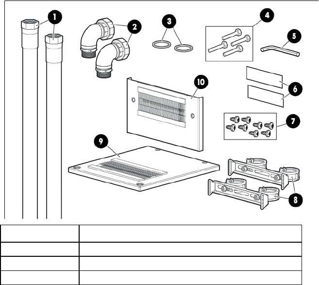
HP Water Hook-Up Kit
HP recommends using the MCS-200/100 Water Hook-up Option Kit BW971A, available on the HP website
(http://www.hp.com), to connect the MCS-200/100 to a facility chilled water system. Each kit includes the
hoses and accessories required for connecting the facility supply and return lines to the main inlet and outlet
connections of an MCS-200/100 unit and must be installed prior to the delivery of an MCS-200/100.
MCS-200/100 Water Hook-Up Option Kit contents
Item Description (quantity)
1 Main hose assembly* (2)
2 90-degree elbow assembly (2)
3 Teflon gasket (2)
Facility planning for implementation 48
Item Description (quantity)
4 M6 screw (4)
5 5mm Hex L-key (1)
6
Warning label (2)
7 M5.5 x 10 self-tapping screw (8)
8 Hose mounting brackets with hose clamps (2)
9 Top cover plate (1)
10 Rear cover plate (1)
*Not drawn to scale. The actual length of the main hose is approximately 3.5 m (11.5 ft).
CAUTION: You must properly connect the cabinet and facility cool water inlet and warm water
outlet hoses. The MCS-200/100 does include a check valve to prevent the reverse flow of
coolant.
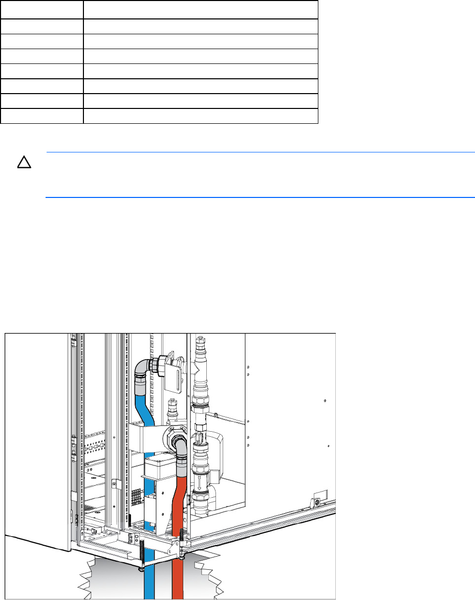
The MCS-200/100 has the connecting fittings inside the unit, approximately 600 mm (24 in) above the floor
on the rear side. It allows the main coolant hoses to be routed either down through the cutouts in a raised
floor, as per HP recommendation. The main coolant hoses can also be routed up through openings in the top
of the cabinet and above the unit, or through the back of the cabinet and above the floor (for MCS-200 only).
The left (blue) hose designates the chilled water supplied to the MCS-100 and the right (red) hose designates
the warm water exiting from the MCS-200/100.
Main coolant line hookup options for the MCS-200/100
• Through raised floor cutouts
Facility planning for implementation 49
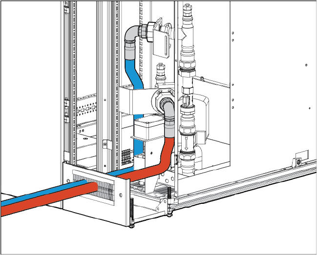
• Above the floor (for MCS-200 only)
Facility planning for implementation 50
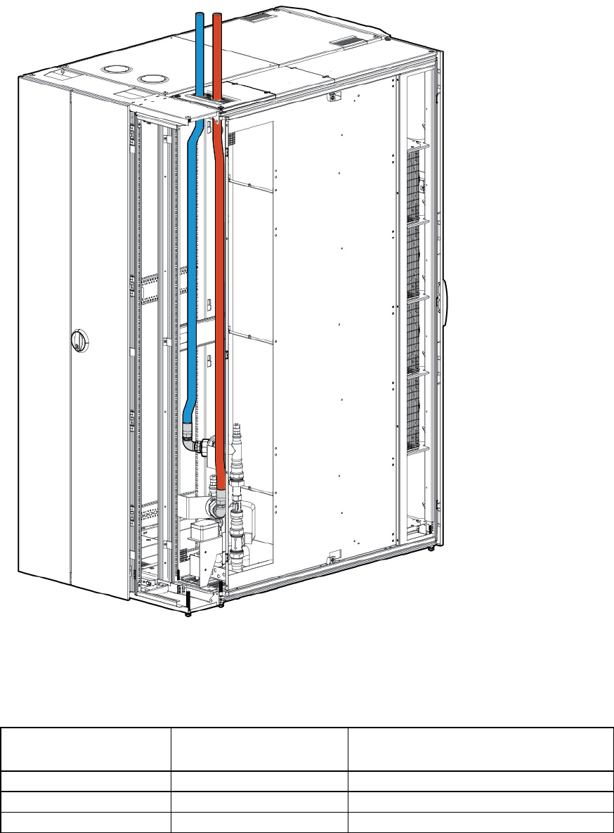
• Above the unit
An HP Water Hook Up Kit must be installed prior to activating an MCS-200/100. The kit contains
approximately 350 cm (138 inches) of flexible hose with terminated fittings on each end. The length that is
available outside the MCS-200/100 depends on the preferred type of connection.
Available hose lengths outside the MCS-200/100 by connection type
Connection type Approximate length supply
hose
Approximate length return hose
Bottom 280 cm (110 inches) 300 cm (118 inches)
Rear 280 cm (110 inches) 300 cm (118 inches)
Top 200 cm (79 inches) 180 cm (71 inches)
The following figure shows the location of the condensate and overflow in the rear of the cooling unit. The
MCS-200/100 includes both tubes for the hookup. Each tube is approximately 3 m (9 ft) in length. The
overflow hose has an inner diameter of 9 mm (0.35 inch) and the condensation hose has an outer diameter
Facility planning for implementation 51
of 8 mm (0.31 inch). The preferred method of routing for all hoses is downward at an angle of at least 3º
(pitch of 0.6 inch per 12 inches), without loops, and away from the MCS-200/100 cabinet. For MCS-200
only, pumped condensation and gravity-fed overflow hoses must be routed to a floor drain or reclaim system.
Flexible attachment hoses are intended to allow for deflection in any direction for equipment mounted on
dynamic platforms, or for slight relocation of cabinets. Installation service for this MCS-200/100 is order
number UE005E.
Piping approaches
HP recommends the following methods for facility plumbing orientation of the MCS-200/100:
• Direct rear approach
• Left rear approach
• Right rear approach
You can approach the MCS-200/100 from the front with piping for the top and bottom connection. This
approach, however, requires careful planning for accessible component locations and hose attachments.
Facility planning for implementation 52
The following figure shows the recommended facility piping approaches to the MCS-200/100.
Item Description
1 Preferred piping location: locate chilled water piping taps
behind the MCS-200/100—either under or above the
floor. Chilled water taps must approach laterally.
2 Do not locate piping connections or components under the
MCS-200/100.
3 Alternate piping location: locating chilled water piping
taps in front of the MCS-200/100. Under the floor is
possible. This option requires careful planning due to the
chilled water hose length limitation.
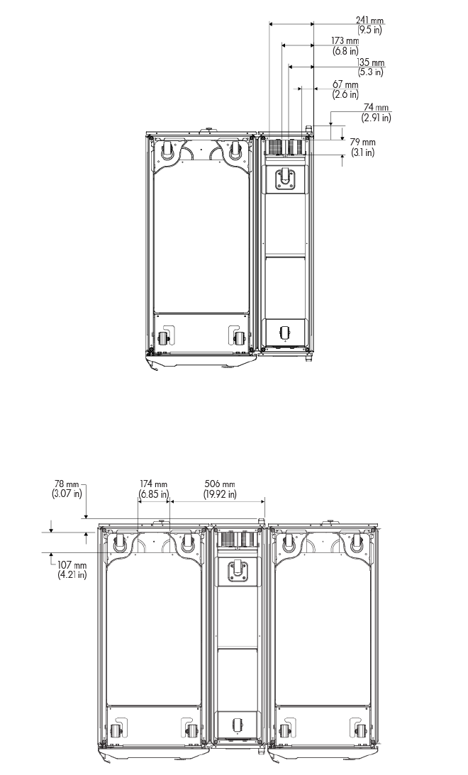
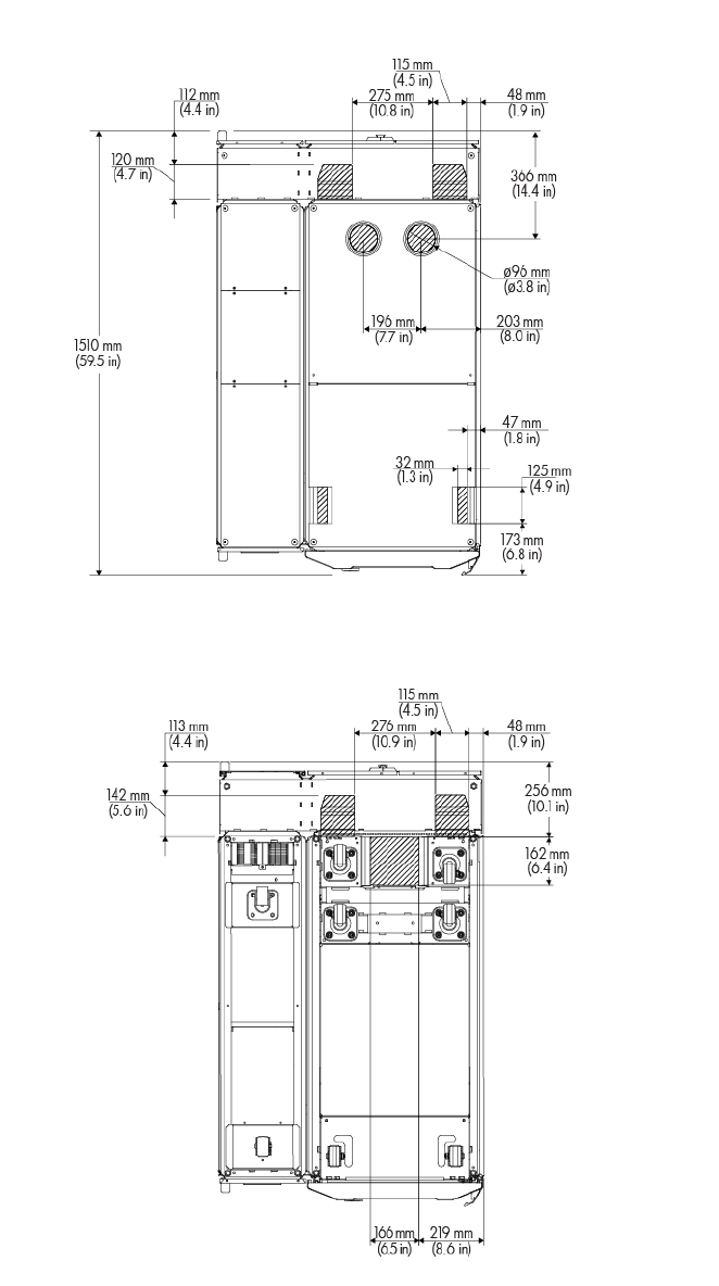
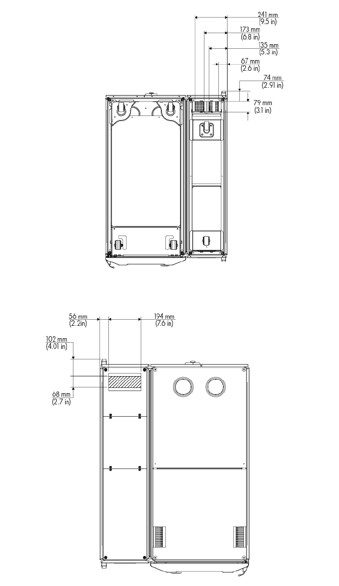
Hose openings
The following figures show the dimensions and locations of the various hose openings of the MCS-200/100.
MCS-100 hose openings
Facility planning for implementation 53
• Bottom view
• Top view
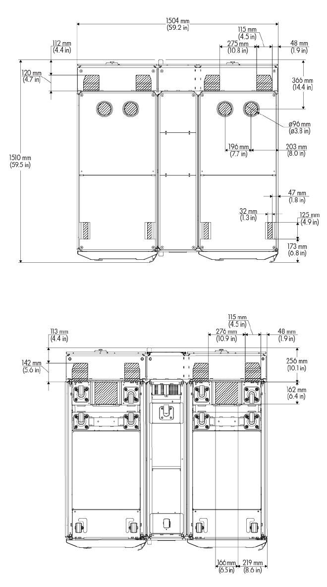
MCS-200 hose openings
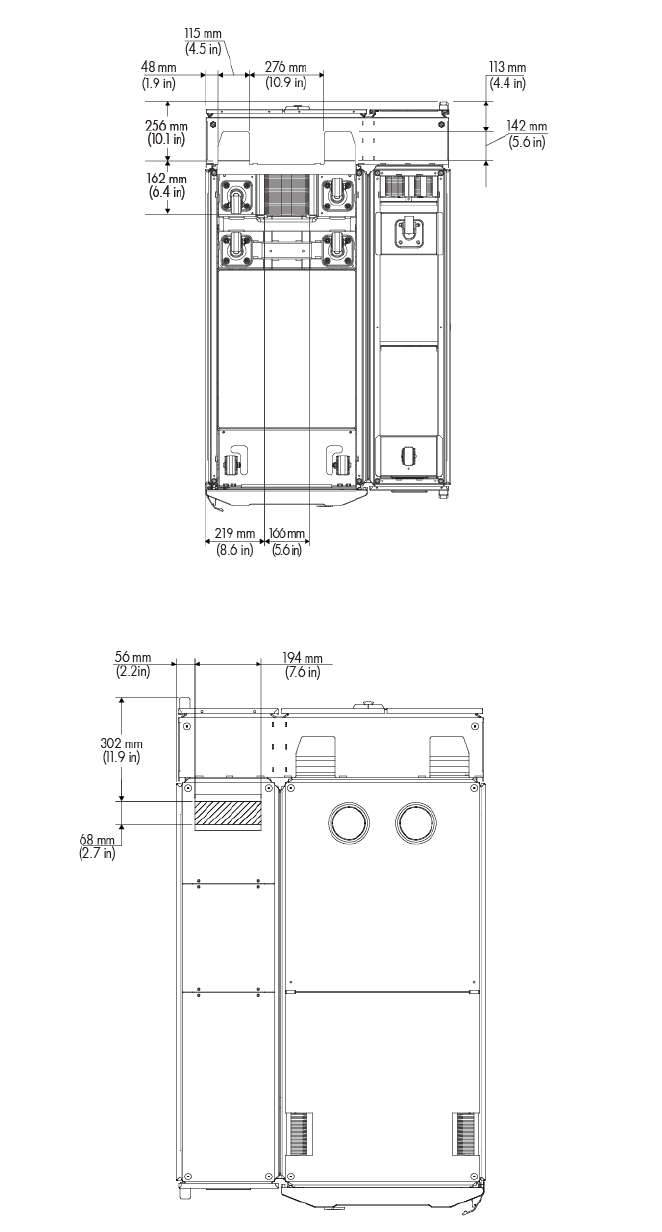
Facility planning for implementation 54
• Bottom view
• Top view
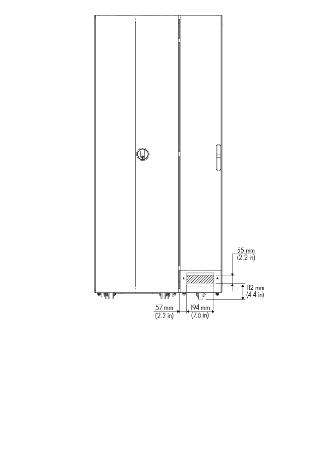
Facility planning for implementation 55
• Rear view
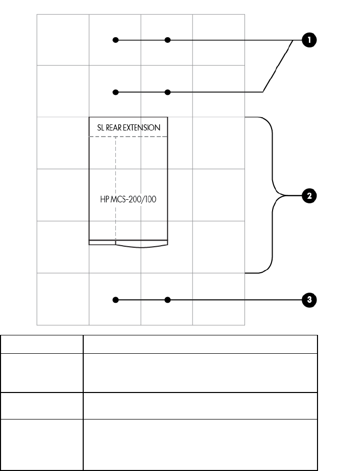
Raised floor cutouts for the MCS unit
A complete MCS-200/100 installation typically requires the following floor cutouts in a raised-floor facility
(standard rack configuration):
• One floor cutout for the chilled water hoses and drain hoses of the cooling unit
• One floor cutout for the power cords and data cables of the computer equipment rack, including power
supply to the MCS-200/100. For more information on the top openings, see "Cable openings (on page
26)."
Raised floor panels vary in size globally but create virtual grid lines or seams where panels come together.
These seams are ideal for positioning computer racks on the raised floor. The following figures reference the
locations of rack attributes aligned with raised floor seams to provide critical dimensions for floor cutouts.
MCS-100 floor tile cutouts
Facility planning for implementation 56
Recommended floor cutouts (single rack configuration)—Option 1 (MCS-100 cooling unit side flush to tile)
Facility planning for implementation 57
Recommended floor cutouts (single rack configuration)—Option 2 (MCS-100 rack side flush to tile)
Facility planning for implementation 58
Recommended floor cutouts (dual rack configuration)—Option 3 (MCS-100 cooling unit side to tile)
Facility planning for implementation 59
Recommended floor cutouts (dual rack configuration)—Option 4 (MCS-100 right side to tile)
MCS-200 floor tile cutouts
Facility planning for implementation 60
Recommended floor cutouts (single rack configuration)—Option 1 (MCS-200 cooling unit side and front flush
to tile)
Facility planning for implementation 61
Recommended floor cutouts (single rack configuration)—Option 2 (MCS-200 rack side and front flush to tile)

Facility planning for implementation 62
Recommended floor cutouts (single rack configuration)—Option 3 (MCS-200 cooling unit side and rear flush
to tile)
Facility planning for implementation 63
Recommended floor cutouts (single rack configuration)—Option 4 (MCS-200 cooling unit side and rear flush
to tile)
Facility planning for implementation 64
Recommended floor cutouts (dual rack configuration)—Option 5 (MCS-200 cooling unit side and front flush
to tile)
Facility planning for implementation 65
Recommended floor cutouts (dual rack configuration)—Option 6 (MCS-200 rack side and front flush to tile)
Facility planning for implementation 66
Recommended floor cutouts (dual rack configuration)—Option 7 (MCS-200 cooling unit side and rear flush to
tile)
Facility planning for implementation 67
Recommended floor cutouts (dual rack configuration)—Option 8 (MCS-200 cooling unit side and rear flush to
tile)
A wider opening in the back of the IT rack is optional with MCS-200. The floor tile sizes used in the above
options are 600 mm x 600 mm (23.6 inches x 23.6 inches). Floor tile sizes vary. The allowable tolerances
are +/- 3.2 mm (+/- 0.125 inch). When installing multiple MCS-200/100 units in a row, you must consider
the tolerances as you plan the cutouts.
Chilled water system components
Chilled water supply and return service are required for each MCS-200/100 in order to have a particular
combination of components for peak performance. These components are identified in the following figures
and tables. Components drawn with a solid line are strongly recommended. Components drawn with dotted
lines are advisable for a higher availability and serviceability.
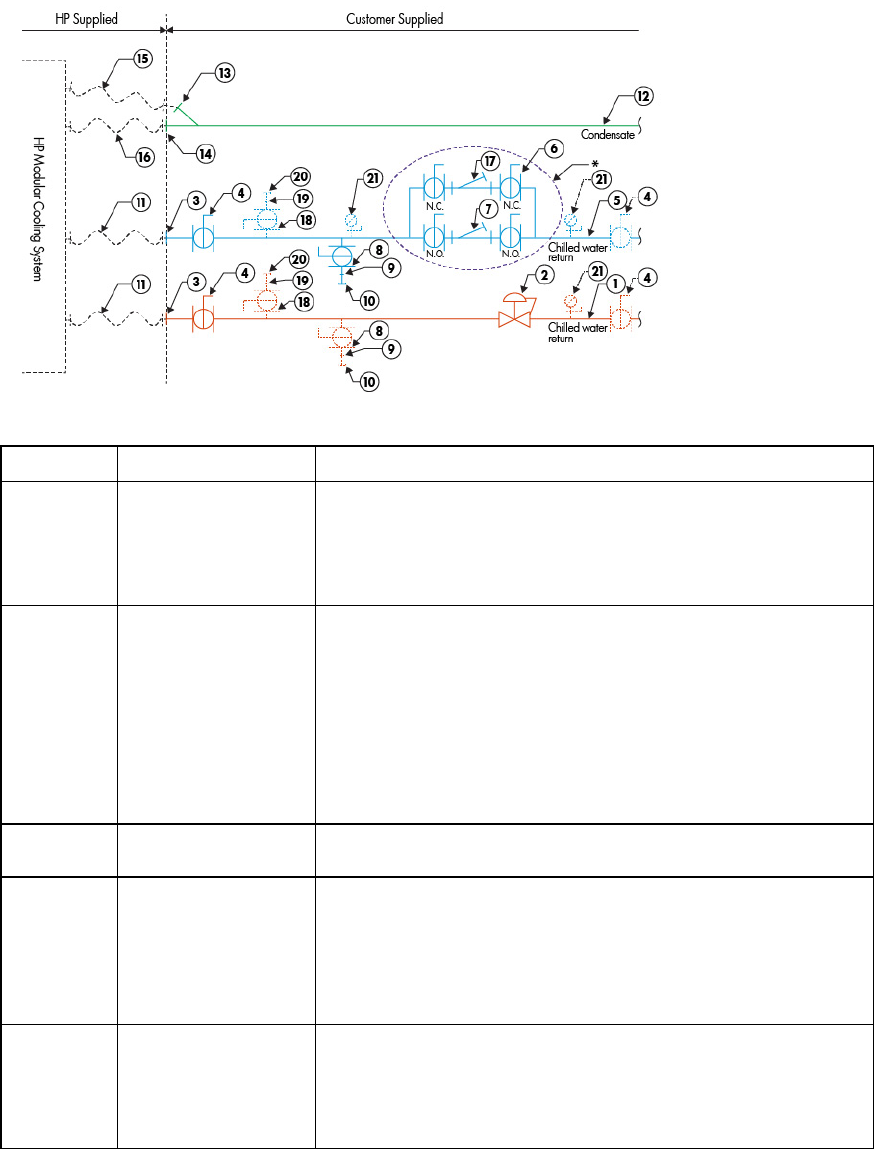
Facility planning for implementation 68
Recommended plumbing configuration for the MCS-200/100
Typical plumbing components for an MCS-200/100 configuration
Item Description Specifications
1 Chilled water return line
Pipe: 31.75-mm (1.25-inch), ASTM B 88, Type L, hard-drawn copper
Fittings: ASTM B16.22 Wrought copper
Solder: ASTM B 32, 95-5 Tin Antimony
Thread sealant: seal and assemble according to local materials and
practices
2 Flow/measurement
balancing valve Valve type: 31.75-mm (1.25-inch) bronze balancing valve, ball design,
with positive shutoff, integral checked metering ports, adjustable knob,
memory device, calibrated nameplate, integral drain port, and solder
end connections
Position: horizontal run of pipe
Orient drain port toward MCS-200/100. Avoid fittings closer to
measurement valve than five pipe diameters upstream and two pipe
diameters downstream for maximum performance.
Watts CSM-61 or equivalent, typical 1
3 Pipe 31.75 mm (1.25 inches) copper, male (NPT or BSPP) adapter to
connect the MCS-200/100 water hoses, typical 2
4 Isolation valves Valve type: 31.75-mm (1.25-inch), two-piece, full-port, brass ball valve,
with chrome plated brass ball, PTFE seats, steel handle, with female
connections and 31.75-mm (1.25-inch) bushing on the end toward
MCS-200/100 hoses.
Pressure rating: 600 psi WOG, 150 psi WSP
Watts FBV-3C or equivalent
5 Chilled water supply
line Pipe: 31.75-mm (1.25-inch), ASTM B 88, Type L, hard-drawn copper
Fittings: ASTM B16.22 Wrought copper
Solder: ASTM B 32, 95-5 Tin Antimony
Thread sealant: Seal and assemble according to local materials and
practices

Facility planning for implementation 69
Item Description Specifications
6 Strainer isolation valves Valve type: 31.75-mm (1.25-inch), two-piece, full-port, brass ball valve,
with chrome plated brass ball, PTFE seats, steel handle, with solder end
connections.
Pressure rating: 600 psi WOG, 150 psi WSP
Orientation: Stem vertical up for lateral level operation. Offset valves on
CHWS and CHWR piping to prevent interference from lever actuators
when closed.
Watts FBVS-3C or equivalent
typical 4
7 Strainer Type: 31.75-mm (1.25-inch) wye-patterned bronze strainer, with #30
stainless steel wire mesh liner, ¾-inch tapped retainer cap & gasket,
and solder end connections. Provide 19.05 mm (0.75 inch) ball valve
for blowdown with cap and chain.
Pressure rating: 400 psi WOG, 125psi WSP
Orientation: with basket and blowdown valve directed down
Watts S777 or equivalent
8 System drain valve Type: 19.05-mm (0.75-inch) two-piece, full-port, brass ball valve with
chrome plated brass ball, PTFE seats, and steel handle, with threaded
connections.
Pressure rating: 600 psi WOG, 150 psi WSP
Watts FBV-3C or equivalent
9 Nipple Type: 19.05-mm (0.75-inch) brass close nipple
10 Cap Type: 19.05-mm (0.75-inch) brass cap with chain
11 Hose Type: 1.25-inch flexible hose supplied with MCS-200/100 Water
Hook-up Kit.
12 Condensate line Pipe: 19.05-mm (0.75-inch) copper or Schedule 40 PVC
Fittings: Wrought Copper or Schedule 40 PVC
Orientation: Sloping downward in a minimum angle of 1º (0.25 inch
per 1 ft) and away from the MCS 5042 for gravity drain
13 Compression fitting Type: 6.35-mm (0.25-inch) male NPT X 8 mm (0.31-inch) compression
fitting, Parker Hannifin, FBMB8-1/4 Metrulok fitting, Festo
QB-1/4-5/16-U or equivalent and installed by plumbing contractor,
typical 1
14 Hose barb Type: 12.7-mm (0.50-inch) ID hose barb x 0.75-
inch male NPT, Parker
Hannifin, 125HBL-8-12, fitting or equivalent and installed by plumbing
contractor, typical 1
15 Hose Type: 8-mm (0.31-inch) OD flexible hose supplied with MCS-200/100
16 Hose Type: 9-mm (0.35-inch) ID flexible hose supplied with MCS-200/100
17 Filter* HP recommends 1μm filter for optimal long-term performance of the
MCS-200/100 cartridge or bag filter could be used in a full flow or
side stream flow configuration. Watts FM4X2 stainless steel housing or
equivalent. Provide dielectric unions on both connections. Provide
pleated cartridge rated for 1 μm. Depending on water quality, multiple
units in parallel might be required.
18 Manual air vent Type: 19.05-mm (0.75-inch) two-piece, full-port, brass ball valve with
chrome plated brass ball, PTFE seats, and steel handle, with threaded
connections.
Pressure rating: 600psi WOG, 150psi WSP
Watts® FBV-3C or equivalent
19 Nipple Type: 19.05-mm (0.75-inch) brass close nipple
20 Cap Type: 19.05-mm (0.75-inch) brass cap with chain
Facility planning for implementation 70
Item Description Specifications
21 Test plug Type: Corrosion-resistant brass body with core inserts, gasketed and
threaded cap, with extended stem for units to suit piping insulation
thickness
Watts TP or equivalent
*The 1μm filter might require a minimum of 762 mm (30 inches) clearance under the floor for installation. If a filter cannot
be installed under the roof because of space constraints, it may be installed further upstream in the pipe system.
Typical plumbing installation guidelines
CAUTION: The water supply system feeding the HP Modular Cooling System 200/100 must be
capable of withstanding operation with rapid and frequent changes in flow requirements.
• Installation service for this MCS-200/100 is order number UE005E.
• Contractors must install all valves, strainers, and other piping components to the specifications provided
in “Piping approaches (on page 51).” All components must be readily accessible.
• Contractor must flush all lines of debris and cap prior to MCS-200/100 installation.
• Contractors must furnish and install Armacell AP/Armaflex closed-cell elastomeric thermal insulation
with minimum 25-mm (1-inch) wall thickness on all customer piping and fittings. Contractors shall furnish
and install similar insulation type with minimum 6.4-mm (0.25-inch) wall thickness for MCS-200/100
chilled water hoses and fittings. The MCS-200/100 hoses have a 45-mm (1.75-inch) OD and a bolt
clamp that is 76 mm (3 inches) wide, 57 mm (2.25 inches) high, and 51 mm (2 inches) deep on the side
that must be connected to the infrastructure pipe. All insulation joints must be taped with AP/Armaflex®
Insulation Tape, 3 mm (0.125 inch) thick x 50 mm (2 inches) wide x 9.1 m (30 ft) long. Mitered fittings
must be cemented with Armaflex® 520 Adhesive.
• MCS-200/100 condensate and overflow hoses do not require insulation.
• Filters might require a minimum of a 762-mm (30-inches) clearance under the floor for installation. If the
filters cannot be installed under the floor due to space constraints, they can be placed upstream of the
piping system.
HP recommends that the MCS-200/100 Hook Up Kit (BW971A) be ordered for each MCS-200/100
installed.
The water supply system feeding the MCS-200/100 must capable of withstanding the following situations:
• Deadheading—operating with a closed line
• Operation with rapid and frequent changes in flow requirements
• Operation over long periods with zero water flow

Facility planning for implementation 71
Coolant requirements
General thermal requirements
The following table lists the coolant requirements that the facility must meet in order to support an
MCS-200/100 installation. In addition to the requirements listed, the coolant must meet the requirements
prescribed in the "Acceptable water quality specifications (on page 78)" section.
Parameter Value
Maximum heat load operational chilled water temperature 1
Minimum
Maximum
7°C (45°F) minimum
13°C (55°F) maximum
Chilled water flow rate (maximum) 1
MCS-100
MCS-200
Approximately 80 lpm(21 gpm)
Approximately 159 lpm (42 gpm)
Inlet/outlet water connections to MCS-200/100 2 (2) 2 1.75-inch BSPP (parallel-thread)
Inlet/outlet hose connections to facility 1.25-inch BSPP (parallel-thread)
Hose insulation thickness 6.3 mm (0.25 inch), min. closed cell
Condensate discharge tubing 3 m (118 inch) length,
8 mm (0.31 inch) outer diameter,
6 mm (0.24 inch) inner diameter
Overflow tubing 3 m (118 inches) length,
15 mm (0.59 inch) outer diameter,
9 mm (0.35 inch) inner diameter
Chilled water pressure differential at required flow 1 - 1.5 bar (15 – 22 psi) required 1
Cooling capacity 1
MCS-100
MCS-200
30 kW maximum
50 kW maximum
(Performance is affected by water
temperature)
1 For more information, see "Determining heat load capacities (on page 72)."
2 For more information, see "Plumbing considerations (on page 46)."
Perform the following steps to confirm that the coolant requirements and corresponding resources necessary
for effective implementation of the MCS-200/100:
1. Determine the maximum server heat load capacity.
2. Determine the desired server intake temperature. For more information, see the Rack Cooling Sizing
Chart in "Cooling loop sizing (on page 72)."
3. Consult the building cooling system administration, and obtain the maximum coolant temperature, for
example, 12.5ºC.
4. Find the amount of coolant required. For more information, see "Coolant source planning (on page
45)."

Facility planning for implementation 72
Cooling loop sizing
Sizing the cooling loops can be straight forward based on the planned cooling requirements of each
populated/planned MCS-200/100 server enclosure. The amount of heat, in watts, that needs to be removed
from each component in the server rack must be added together to obtain the total heat to be removed by the
MCS-200/100 cabinet. You can copy the following table for documenting individual cabinet calculations.
Calculations must include the equipment installed today and additional equipment planned for installation
over the design life of the system.
Rack Cooling Loop Sizing Chart
Installed
Component
Quantity Max. Watts
Generated
Max. CFM
Required
Max. Watts
Total
Max. CFM Total
Component 1:
Component 2:
Component 3:
Component 4:
Component 5:
Component 6:
Component 7:
Component 8:
Component 9:
Component 10:
Total for Cabinet*
*An approximate value can be estimated by assuming all power entering the cabinet is converted to heat.
After calculating the total expected required heat load, use the charts in “Determining heat load capacities
(on page 72)” to determine required water flow and pressure based on potential chilled water temperatures.
The PSID must be measured prior to the cold water inlet/after warm water outlet. All water system equipment,
materials, and installation must comply with any applicable construction codes and LAHJ.
Determining heat load capacities
The total airflow required by the equipment installed in each server rack must be compared with the total
available supply from the MCS-200/100, so it is not exceeded. The fans in the MCS-200/100 are
speed-controlled to reduce the airflow in case the maximum cooling capacity is not demanded from the
MCS-200/100.
MCS per rack capacity chart
Number of fans HP Modular
Cooling System
200/100
HP Modular
Cooling System
200/100 with
Expansion Rack
MCS-200/100 MCS-200/100 with
Expansion Rack
1 fan (BW978A) 10kW, 934 CFM 5kW, 467 CFM N/A N/A
2 fans 20kW, 1,866 CFM 10kW, 933 CFM N/A N/A
3 fans
30kW, 2,800 CFM 15kW, 1,400 CFM N/A N/A

Facility planning for implementation 73
Number of fans HP Modular
Cooling System
200/100
HP Modular
Cooling System
200/100 with
Expansion Rack
MCS-200/100 MCS-200/100 with
Expansion Rack
4 fans 30kW, 2,800 CFM
N+1 Redundancy
15kW, 1,400 CFM
N+1 Redundancy
30kW, 3,000 CFM
15kW, 1,600 CFM
5 fans N/A N/A 40kW, 3, 750 CFM
or 30kW N+1 20kW, 2,000 CFM
or 15kW N+1
6 fans N/A N/A 50kW, 4,500 CFM
or 40kW N+1,
30kW N+2
30kW, 2,400 CFM
or 20kW N+1, or
15kW N+2
Cooling performance is rated at 43 ˚F EWT. MCS with Expansion Rack capacity/airflow is pooled and does
not have to be evenly split between racks. For example, the HP Modular Cooling System 200/100 with 3
fans, provides at total of 2,800 CFM. One rack can use 2,000 CFM and the other can use 800 CFM.
A minimum heat load is necessary for operating the MCS-200/100 properly. This minimum depends on the
water supply temperature as shown in the following table.
MCS-200 minimum heat loads
Server air intake
temperature
Water supply
temperature
Minimum heat load
20°C (68ºF) 7ºC (45°F) 9 kW
10ºC (50°F) 7 kW
13ºC (55°F) 6 kW
16ºC (61°F) 6 kW
25°C (77ºF) 7–13°C (45–55°F) 16 kW
16ºC (61°F) 14 kW
18ºC (64°F) 10 kW
MCS-100 minimum heat loads
Server air intake
temperature
Water supply
temperature
Minimum heat load
20 C (68 F) 7ºC (45°F) 13 kW
11ºC (52°F) 7.5 kW
15ºC (59°F) 5 kW
19ºC (66°F) 3 kW
25 C (77 F) 11ºC (52°F) 13 kW
15ºC (59°F) 12 kW
11ºC (66°F) 6 kW
23ºC (73°F) 3 kW
30 C (86 F) 17ºC (63°F) 15 kW
21ºC (70°F) 13 kW
25ºC (77°F) 6 kW
29ºC (84°F) 3 kW
Facility planning for implementation 74
When the minimum heat load is not provided to the MCS-200/100, unstable control of the temperatures and
flow rates of the MCS-200/100 can occur.
For more information, contact your HP representative.
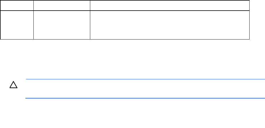
The following charts offer a guideline for determining the approximate amount of heat that can be removed
from MCS-200/100 based on 20°C (68°F) and 25°C (77°F) server intake air temperatures (in degrees,
Celsius), flow rates as liters per minute (lpm), or in US gallons per minute (gpm), delivered to the unit.
The term “water” in the following charts refers to the coolant described in “Acceptable water quality
specifications (on page 78).”
MCS-100 coolant flow requirements with 20°C (68°F) server intake air
Facility planning for implementation 75
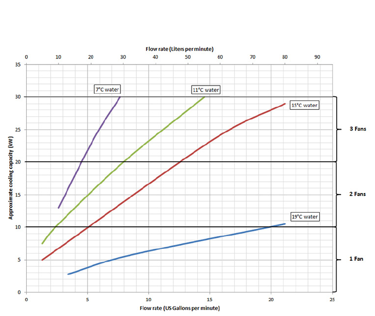
MCS-200 coolant flow requirements with 20°C (68°F) server intake air
MCS-100 coolant flow requirements with 25°C (77°F) server intake air
Facility planning for implementation 76
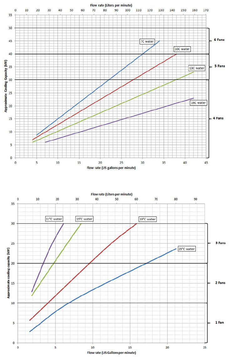
MCS-200 coolant flow requirements with 25°C (77°F) server intake air
MCS-100 coolant flow requirements with 30°C (86°F) server intake air
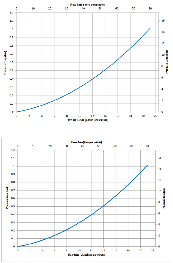
The following pressure-drop chart is provided as a reference to indicate water flow versus water pressure, for
a fully-opened MCS-200/100 water control valve.
Facility planning for implementation 77
Flow rate versus delta pressure (water control valve fully open)—MCS-100
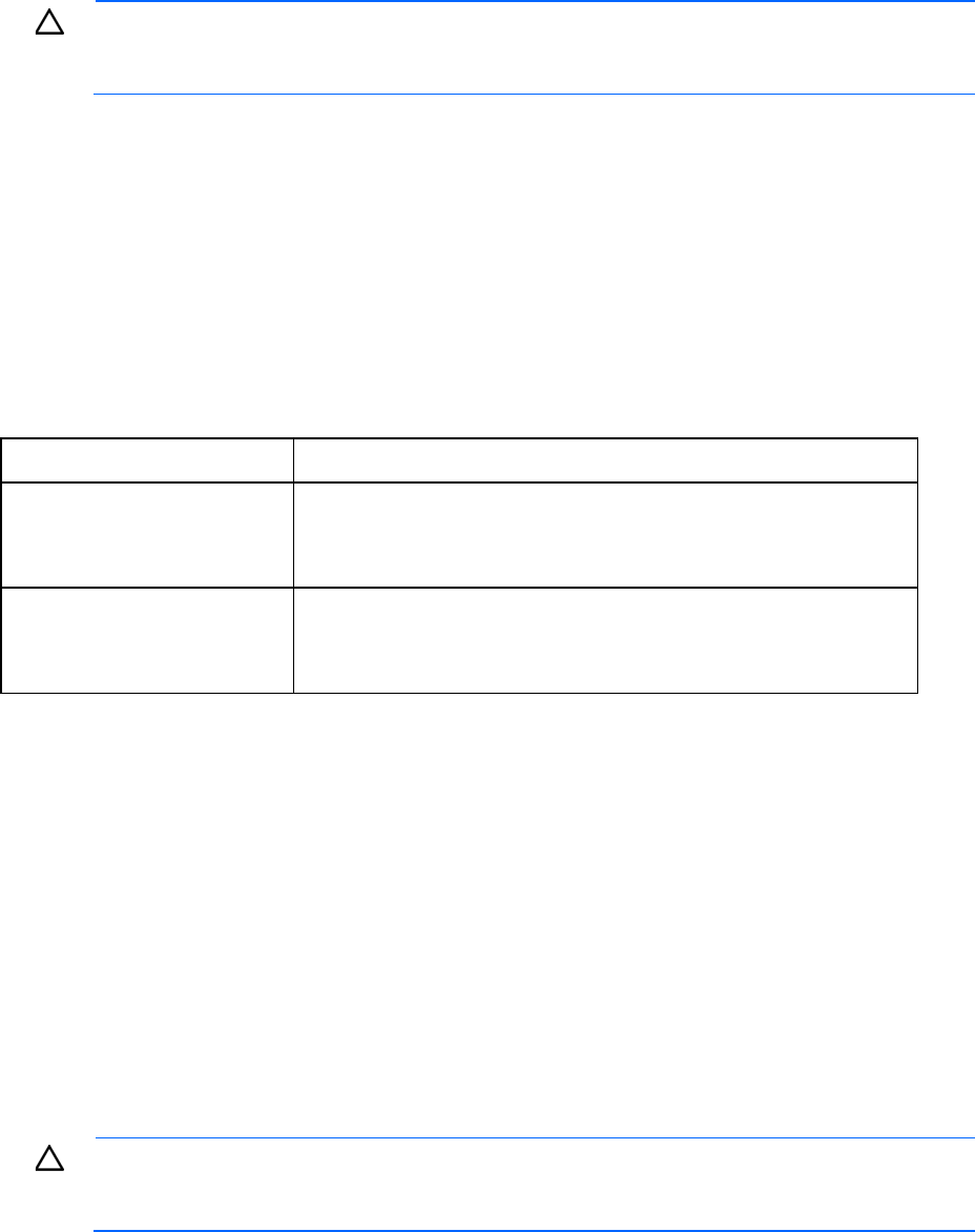
Flow rate versus delta pressure (water control valve fully open)—MCS-200
A minimum water pressure difference of 1.0 to 1.5 bar (15 to 20 psi) between facility supply and return is
required. The previous figures give the pressure difference with a fully opened control valve. In operation, the
control valve maintains the water flow to the MCS-200/100 by introducing pressure resistance to reduce
the flow to accommodate different water temperatures and cooling capacity. Therefore, the pressure loss in
operation appears higher than shown in the above figures. However, to have the full scale of water flow

Facility planning for implementation 78
available, the provided system pressure difference must be slightly higher than the maximum pressure loss
with a fully opened control valve.
Acceptable water quality specifications
Closed-loop water must not contain any lime scale deposits or loose debris. The water must have a low level
of hardness, particularly a low level of carbon hardness. Filters must be used to remove free floating
particulates and regularly maintained. The water must not be so soft that it corrodes the materials that it
comes into contact. You must periodically add new fresh water, and remove some of the enriched water. HP
recommends a #30 mesh filter for filtering water fed to the MCS-200/100 and a 1 µm filter for prolonged
performance.
The following values are water quality ranges required for continuous quality of performance.
Parameter Range
pH 7-9
Specific conductance at 25ºC (77ºF)
<2500 µmhos
Sulfur (SO
4
), total <100 ppm
Chloride (Cl) <50 ppm
Sulfide (S) <10 ppm
Hardness (CaCO
3
), total <200 ppm
Iron (Fe), total <3.0 ppm
Manganese (Mn), total <0.1 ppm
Bacteria <1000 CFUs/ml
Residue on evaporation <500 ppm
Turbidity 20
Corrosion inhibitor
Recommended
CAUTION: Contaminated water might cause decreased cooling capacity or disruption in
service. The water flowing into the MCS-200/100 unit must meet the guidelines stated in the HP
Modular Cooling System 200/100 Site Preparation Guide. Damage caused by contaminated
water is not covered by the MCS unit warranty.
If your water is out of range, consult a water quality expert.
HP recommends using particulate filtration on the dedicated water supply system connected to the
MCS-200/100 unit.
Additional water precautions
The following actions should be taken during the installation of the MCS-200/100:
• Be sure all foreign matter and particulates are flushed from the system prior to installing the water kits
for the MCS-200/100.
• Evaluate the short- and long-term system requirements against available water capacity.
• Be sure your facility water loop is properly designed for liquid cooling systems and separate from the
sanitary water systems within your building—for example, bathroom, sink, or drinking water.
Facility planning for implementation 79
• Be sure facility managers understand that additional load is being added to the facility water supply. Be
aware that the heat load being added might have an effect on other components being cooled by the
facility water plant.
CAUTION: The water supply system feeding the MCS-200/100 must be capable of withstanding
deadheading (operating with a closed line) and operation with rapid and frequent changes in
flow requirements, including long periods with zero water flow.
Plumbing materials to avoid
Do not use the following materials with a closed water system:
• Oxidizing biocides
• High zinc and brass components
• Non-stainless steel iron components
Environmental considerations
Parameter Value
Room temperature
Recommended
minimum/maximum
Allowable minimum/maximum
18°C(64.4°F)/27°C(80.6°F)
15°C (59°F)/32°C(90°F)
Humidity:
Recommended minimum
Recommended maximum
Allowable range
5.5°C (41.9°F) dew point
60% relative humidity and 15°C (59°F) dew point
20%–-80%
The temperatures stated are for an elevation of 0 to 5000 ft above sea level. The maximum operating
temperatures must be de-rated by 1ºC per 1000 ft for locations 5000 to 10,000 ft above sea level.
Control system
The MCS-200/100 includes a control system that constantly monitors the air temperatures, water
temperatures, and flow rate. The management module attempts to maintain the air temperature at the target
set point. If the set point temperature cannot be maintained, the HP Modular Cooling System 200/100
management module will generate an alarm and notify facility management systems, as configured.
For site evaluations and technical consulting services for your site, see the HP Modular Cooling System
200/100 User Guide.
Before installing and running active components
CAUTION: If the MCS-200/100 unit runs in manual mode for a period of time without an
adequate heat load being generated by servers or other computing/networking devices, excess
condensation could occur within the cabinet or system.
Prior to starting up any active components mounted in the MCS-200/100 rack, such as servers, storage
devices, and so on, the following actions must be performed:
Facility planning for implementation 80
• Be sure the chilled water source is on and flowing prior to the start-up of an MCS-200/100.
• Be sure the MCS-200/100 is operational and running before turning on the servers and closing the
front and rear cabinet doors.
For more information on the installation of the HP Modular Cooling System 200/100, see the HP Modular
Cooling System 200/100 Installation Guide.
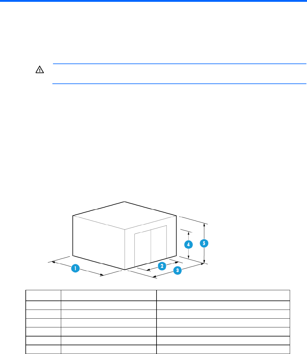
Appendix A: Forms and checklists 81
Appendix A: Forms and checklists
Delivery survey form
WARNING: To prevent possible serious personal injury or damage to equipment, do not move
the HP Modular Cooling System 200/100 up or down stairs.
The delivery survey form lists delivery or installation requirements. If any of the items on the list apply, enter
the appropriate information in the areas provided on the form. Special instructions or recommendations
should be entered on a special instructions or recommendations form. The following list gives examples of
special instructions or issues:
• Packaging restrictions at the facility, such as size and weight limitations
• Special delivery procedures
• Special equipment required for installation, such as tracking or hoists
• What time the facility is available for installation, after the equipment is unloaded
• Special security requirements applicable to the facility, such as security clearance
Complete the following information if an elevator is required to move equipment:
Item Dimension Measurement
1 Interior depth
2 Door width
3
Interior width
4 Door height
5 Interior height
6 Elevator weight capacity

Appendix A: Forms and checklists 82
Pre-installation checklists
Site preparation checklist
The tables below are site preparation checklists. For each item, check "yes" or "no" in the appropriate
column.
If the answer is no, then include a comment or explanation and the date. An alternative solution might be
required
Facility considerations
Item Area/condition Yes No Comment/date
1 Is there adequate clearance from the loading area to the installation
site to accommodate rack dimensions, including the pallet, if
applicable?
2 Is there a completed floor plan, including a detailed location of the
HP Modular Cooling System 200/100 relative to the floor tile breaks
and supports?
3 Is there adequate space for maintenance needs? Recommended
clearances are minimum 1,219 mm (48 inches) in front, minimum
914 mm (36 inches) in the rear.
4 Is access to the site or computer room restricted?
5 Is the computer room structurally complete? What is the expected
date of completion?
6 Is a raised floor installed and in good condition?
7 Is a raised floor system, including needed cutouts, able to adequately
support the fully loaded rack and MCS-200?
8 Are there channels or cutouts for cable routing?
9 Is there a network line available?
10 Are floor tiles in good condition and properly braced?
11 Is there a leak detector for the facility water system (external to the
MCS-200)?
12 Are masonite boards available for floor protection during rack
movement over carpets and thresholds?
Power and lighting considerations
Item Area/condition Yes No Comment/date
1 Are there AC outlets available for servicing needs (for example, for
laptop)?
2 Does the input voltage correspond to MCS-100 and MCS-200/100
specifications?
3 Is dual source power used? If so, identify types and evaluate
grounding.
4 Does the input frequency correspond to equipment specifications?
5 Is power conditioning equipment installed?

Appendix A: Forms and checklists 83
Item Area/condition Yes No Comment/date
6 Is there a dedicated branch circuit for equipment?
7 Is there a dedicated branch circuit less than 22.86 m (75 ft) away?
8 Are the input circuit breakers sized to protect their respective
receptacles for equipment loads?
Safety considerations
Item Area/condition Yes No Comment/date
1 Is there an emergency power shutoff switch?
2 Is there a telephone available for emergency purposes?
3 Is there a fire protection system in the computer room?
4 Is antistatic flooring installed?
Cooling considerations
Item Area/condition Yes No Comment/date
1 Can the room temperature be maintained between the recommended
range of 20°C to 25°C (68°F to 77°F) and allowable range of 15°C
to 32°C (59°F to 90°F) (up to 5,000 ft)? Derate 1°C/1,000 ft above
5,000 ft and up to 10,000 ft.
2 Can the humidity level be maintained at the recommended level of
40% to 50%, with allowable humidity levels of 20% to 60%?
3 Are air conditioning filters installed and clean?
Water preparation considerations
Item Area/condition Yes No Comment/date
1 Has the water been tested for acceptable quality for use in the HP
Modular Cooling System 200/100?
2 If the water quality is unacceptable, have adequate treatment
filtration measures been put in place?
3 Have the water temperature and flow been evaluated?
4 Has piping of an appropriate diameter, material, and pressure
tolerance been installed to reach the back of each MCS-100 and
MCS-200/100?
5 Is there a provision for fluid collected from the condensation and
overflow hoses at each MCS-100 and MCS-200/100?
6 Is there dedicated cabinet space for storage of water quality
chemicals and gloves?
7 Is there an available space to prepare and handle chemicals before
adding them to the system?
8 Is Nalprep 8349 (commercially available from Nalco Company)
available on site for the secondary loop cleaning procedure?
9 Has the approximate volume of water in the entire system been
determined? (Necessary for water chemical preparation)
10 Have the water treatment chemicals been evaluated and approved
through your facility EHS department?
Appendix A: Forms and checklists 84

Appendix B: Conversion factors and formulas 85
Appendix B: Conversion factors and formulas
Conversion factors and formulas
The conversion factors provided in this appendix are intended to ease data calculation for systems that do not
provide information in the format requested in this site preparation guide. The following list includes the
conversion factors used in this document, as well as additional conversion factors that might be helpful in
determining those factors required for site planning.
Conversion factors for refrigeration
• 1 watt = 0.86 kcal/hour
• 1 watt = 3.412 British thermal unit (BTU)/hour
• 1 ton = 200 BTU/minute
• 1 ton = 12,000 BTU/hour
• 1 ton = 3,517.2 W
Metric equivalents
• 1 centimeter = 0.3937 inches
• 1 meter = 3.28 feet
• 1 meter = 1.09 yards
• 1 inch = 2.54 centimeters
• 1 foot = 0.305 meters
• 1 cubic foot/minute = 1.7 cubic meters/hour
kVa conversions
• Three-phase kilovolt-amperes (kVA) = V x A x √3/1,000
• Single-phase kVA = V x A/1,000
Formulas
• kVA = [Voltage x Current (amps)]/1,000
• Watts = VA x power factor
• BTU = Watts x 3.41

Regulatory information 86
Regulatory information
Safety and regulatory compliance
For safety, environmental, and regulatory information, see Safety and Compliance Information for Server,
Storage, Power, Networking, and Rack Products, available at the HP website
(http://www.hp.com/support/Safety-Compliance-EnterpriseProducts).
Turkey RoHS material content declaration
Ukraine RoHS material content declaration
Warranty information
HP ProLiant and X86 Servers and Options (http://www.hp.com/support/ProLiantServers-Warranties)
HP Enterprise Servers (http://www.hp.com/support/EnterpriseServers-Warranties)
HP Storage Products (http://www.hp.com/support/Storage-Warranties)
HP Networking Products (http://www.hp.com/support/Networking-Warranties)
Regulatory requirements for EXIT signs
Manufacturers of tritium EXIT signs are “specific licensees,” meaning they are licensed by the NRC or an
Agreement State. The signs are considered “generally licensed devices,” because they are inherently safe
enough to be handled or used by anyone with no radiation training or experience. Although purchasers –
known as “general licensees” – do not need authorization from the NRC or a state regulatory agency to
possess the signs, they are subject to certain regulatory requirements regarding handling, transfer or disposal
of the signs. For more information, see the NRC website
(http://www.nrc.gov/reading-rm/doc-collections/fact-sheets/fs-tritium.html#_edn2). They are also subject
to NRC or Agreement State inspection and enforcement action (including fines) for violating those
requirements. Manufacturers must inform purchasers of the EXIT signs of the regulatory requirements for
generally licensed devices. The general licensee is required to designate an individual responsible for
complying with the regulatory requirements.
Regulatory information 87
Under NRC regulations, a general licensee using tritium EXIT signs:
• must NOT remove the labeling or radioactive symbol, or abandon a sign;
• must properly dispose of an unused sign (see below);
• must report to the NRC or the appropriate Agreement State any lost, stolen or broken signs;
• must inform the NRC or an Agreement State of a name change, change of address or replacement of
a general licensee’s designated representative;
• must NOT give away or sell the sign to another individual, company or institution unless the device is
to remain in use at its original intended location; in such a case, the transferor is to notify the recipient
of the regulatory requirements and must notify the NRC or Agreement State of the transfer within 30
days.
Tritium EXIT signs must NOT be disposed of as normal trash. To dispose of a sign properly, a general licensee
must transfer the sign to a specific licensee. This would typically be a manufacturer, distributor, licensed
radioactive waste broker, or a licensed low-level radioactive waste disposal facility. These facilities may
charge a fee for this service.
Within 30 days of disposing of a sign, the general licensee is required to file a report to the NRC or
Agreement State that includes:
• the device manufacturer’s (or distributor’s) name, model number and serial number;
• the name, address, and license number of the person receiving the device; and
• the date of the transfer.
Reports should be sent to Director, Office of Federal and State Materials and Environmental Management
Programs, ATTN: GLTS, U.S. Nuclear Regulatory Commission, Washington, D.C. 20555-0001.
For more information, see the Fact Sheet on Tritium EXIT Signs on the NRC website
(http://www.nrc.gov/reading-rm/doc-collections/fact-sheets/fs-tritium.html).

Support and other resources 88
Support and other resources
Before you contact HP
Be sure to have the following information available before you call HP:
• Active Health System log (HP ProLiant Gen8 or later products)
Download and have available an Active Health System log for 3 days before the failure was detected.
For more information, see the HP iLO 4 User Guide or HP Intelligent Provisioning User Guide on the HP
website (http://www.hp.com/go/ilo/docs).
• Onboard Administrator SHOW ALL report (for HP BladeSystem products only)
For more information on obtaining the Onboard Administrator SHOW ALL report, see the HP website
(http://www.hp.com/go/OAlog).
• Technical support registration number (if applicable)
• Product serial number
• Product model name and number
• Product identification number
• Applicable error messages
• Add-on boards or hardware
• Third-party hardware or software
• Operating system type and revision level
HP contact information
For United States and worldwide contact information, see the Contact HP website
(http://www.hp.com/go/assistance).
In the United States:
• To contact HP by phone, call 1-800-334-5144. For continuous quality improvement, calls may be
recorded or monitored.
• If you have purchased a Care Pack (service upgrade), see the Support & Drivers website
(http://www8.hp.com/us/en/support-drivers.html). If the problem cannot be resolved at the website,
call 1-800-633-3600. For more information about Care Packs, see the HP website
(http://pro-aq-sama.houston.hp.com/services/cache/10950-0-0-225-121.html).

Acronyms and abbreviations 89
Acronyms and abbreviations
BSPP
british standard pipe parallel
CHWR
chilled water return
CHWS
chilled water supply
CTO
configure to order
FRU
field replaceable unit
GRUB
gas, oil, water
HEX
heat exchanger
LAHJ
local authority has jurisdiction
NPT
national pipe thread
NPTF
American national taper pipe thread for dry-seal pressure-tight joints
PF
polytetrafluoroethylene
TN Grounding
grounding specification
Acronyms and abbreviations 90
UPS
uninterruptible power system
WSP
water steam pressure

Documentation feedback 91
Documentation feedback
HP is committed to providing documentation that meets your needs. To help us improve the documentation,
send any errors, suggestions, or comments to Documentation Feedback (mailto:docsfeedback@hp.com).
Include the document title and part number, version number, or the URL when submitting your feedback.

Index 92
A
acceptable water quality specifications 78
Appendix 81, 85
B
battery replacement notice 86
before installing/running active components 79
BSMI notice 86
C
cabinet leveling feet 29
cable openings 26
Canadian notice 86
chilled water 45, 67
Chilled Water Base Station, configuring 45
chilled water system components 67
chiller unit 67
common floor-loading terms 40
compliance 86
components 12, 67
components, identification 12
connecting to facility A/C power 43
contact information 88
contacting HP 88
control system 79
conversion factors for refrigeration 85
coolant requirements 71
coolant source planning 45
cooling 45, 67, 71, 72
cooling capacity 72
cooling considerations 83
cooling loop sizing 72
customer self repair (CSR) 88
D
Declaration of Conformity 86
delivery space requirements 21
delivery survey 81
disposal, battery 86
disposal, waste 86
documentation feedback 91
E
electrical 43
electrical considerations 40
electrical factors 40
electrical planning 43
electrical safety 43
electrical specifications 18
environmental considerations 78, 79
environmental specifications 79
European Union notice 86
EXIT signs 86
F
facility considerations 82
facility planning 20, 55, 82
Federal Communications Commission (FCC)
notice 86
floor cutouts 55
floor loading 37, 40
floor plan grid 55
formulas 85
G
grounding 41
grounding methods 41
grounding systems 41
H
heat load capacity 72
Hook Up Kit 47
hose openings 52
hoses 52
I
installation preparation 20, 46, 70, 79
installation prerequisites 20, 21, 23, 25, 37, 70
J
Japanese notice 86
Index
Index 93
K
key components 12
kVa conversions 85
M
Maneuvering space requirements 21
MCS-100 components 13
MCS-200 components 15
metric equivalents 85
modifications, FCC notice 86
O
operational space requirements 23
overview 5, 8
P
physical specifications 17, 20, 21
piping approaches 51
planning considerations 20, 37, 40, 46, 78, 79
planning overview 20
planning the installation 20, 21, 23, 25, 37
plumbing 46, 70, 79
plumbing considerations 46
plumbing installation guidelines 70
positioning 20, 25, 37
power and lighting considerations 82
power connections 43
power cord 43
power cord specifications 43
power errors 43
power surges 43
preinstallation checklist 82
product description 5, 8
product overview 5, 8
product purpose 8
R
radioactive material 86
regulatory compliance identification numbers 86
regulatory compliance notices 86
S
safety considerations 83, 86
series number 86
site preparation checklist 82
space and positioning considerations 20
space requirements 20, 21, 23
specifications 17, 18, 20
system grounding 41
System positioning 25
T
Taiwan battery recycling notice 86
Tate raised floor specifications 40
technical support 88
temperature 79
temperature ranges (environmental) 79
thermal requirements 71
thermal specifications 71
V
voltage fluctuations 43
W
warranty 86
Water Hook-Up Kit 47
water precautions 43, 78
water preperation considerations 83
water quality 78
water supply 45
water-handling components 43
