Hp Omnibook 800Ct Users Manual 800CS/CT PC Service Manual, F1360 90049
800CT to the manual 7fb783cd-6494-493d-92e0-dac34c65c2b7
2015-02-09
: Hp Hp-Omnibook-800Ct-Users-Manual-547174 hp-omnibook-800ct-users-manual-547174 hp pdf
Open the PDF directly: View PDF ![]() .
.
Page Count: 118 [warning: Documents this large are best viewed by clicking the View PDF Link!]

Service Manual
HP OmniBook 800CS/CT

Notice
In a continuing effort to improve the quality of our products,
technical and environmental information in this document is
subject to change without notice.
Hewlett-Packard makes no warranty of any kind with regard to
this material, including, but not limited to, the implied warranties
of merchantability and fitness for a particular purpose. Hewlett-
Packard shall not be liable for errors contained herein or for
incidental or consequential damages in connection with the
furnishing, performance, or use of this material.
Hewlett-Packard assumes no responsibility for the use or
reliability of its software on equipment that is not furnished by
Hewlett-Packard.
As an ENERGY STAR partner, HP has determined that these
products meet the ENERGY STAR guidelines for energy
efficiency.
All Certifications may not be completed at product introduction.
Please check with your HP reseller for certification status.
This equipment is subject to FCC rules. It will comply with the
appropriate FCC rules before final delivery to the buyer.
ENERGY STAR is a service mark of the U.S. Environmental
Protection Agency. IBM and OS/2 are registered trademarks
and TrackPoint is a trademark of International Business
Machines Corporation. Pentium and the Intel Inside logo are
registered trademarks and MMX is a trademark of Intel
Corporation. Photo CD is a registered trademark of Kodak
Corporation. Microsoft, MS-DOS, and Windows are registered
trademarks, and the Genuine Microsoft Products logo is a
trademark of Microsoft Corporation in the United States of
America and in other countries. Sound Blaster is a trademark of
Creative Technology Ltd.
Hewlett-Packard Company 1997.
All Rights Reserved. Reproduction, adaptation, or translation
without prior written permission is prohibited except as allowed
under copyright laws.
Printed in U.S.A.
F1360-90049

i
Table of Contents
List of Figures.............................................................................................................................iii
List of Tables..............................................................................................................................iv
Introduction .................................................................................................................................v
Product Overview........................................................................................................................1
What’s New .............................................................................................................................2
Product Features .....................................................................................................................3
Product at a Glance .................................................................................................................4
Product Comparisons...............................................................................................................6
Troubleshooting...........................................................................................................................3
Power-On Self-Test .................................................................................................................4
Beep Codes..........................................................................................................................4
Display Codes ......................................................................................................................5
OmniBook Diagnostics.............................................................................................................7
Running the diagnostics program..........................................................................................7
Main diagnostic screen.........................................................................................................7
Special test hardware requirements......................................................................................9
Loop Back Connectors........................................................................................................10
Command line options........................................................................................................12
User interface commands...................................................................................................13
Details on using the diagnostic tests ...................................................................................17
Desktop Management Interface (DMI)....................................................................................28
Description of DMI..............................................................................................................28
Contents of the DMI Package.............................................................................................28
Setup and Configuration ........................................................................................................31
SCU Main Screen...............................................................................................................31
System Menu Screen .........................................................................................................32
Password Configuration......................................................................................................34
Input/Output Menu Screen..................................................................................................35
Power Menu Screen ...........................................................................................................37
Default Menu Screen..........................................................................................................38
Exit Menu Screen...............................................................................................................39
Troubleshooting Tips..............................................................................................................40
OmniBook Components......................................................................................................40
CD ROM Drive Troubleshooting .........................................................................................45
Resolving Docking Station Operating Problems..................................................................46
Resolving OmniBook Docking Problems ............................................................................47
Hardware Repair .......................................................................................................................49
Battery (End User Replaceable).............................................................................................50
Memory (End User Replaceable) ...........................................................................................51
Hard Disk Drive (End User Replaceable) ..............................................................................53
Hard Disk Drive Breather Holes..........................................................................................57
Mouse (End User Replaceable)..............................................................................................58
Small Parts (End User Replaceable)......................................................................................59
Battery Latch......................................................................................................................59
I/O Door .............................................................................................................................59
Memory Cover....................................................................................................................59
PCMCIA Card Tray.............................................................................................................59
Rubber Feet .......................................................................................................................59
Keyboard (HP Authorized Service Providers Only) ................................................................60
Display (HP Authorized Service Providers Only)....................................................................62
CPU (HP Authorized Service Providers Only)........................................................................67
Heat Transfer Disk..............................................................................................................68
Logic PCA Board (HP Authorized Service Providers Only).....................................................70

ii
Electronic Serial Number....................................................................................................70
Paw Active (HP Authorized Service Providers Only)..............................................................73
Other Components and Accessories (HP Authorized Service Providers Only)........................74
Appendix A - Technical Specifications.......................................................................................78
Mass Storage Specifications..................................................................................................78
Hard Disk Drive..................................................................................................................78
Floppy Disk Drive...............................................................................................................78
CD-ROM Drive...................................................................................................................79
System Resources.................................................................................................................80
System Interrupts (IRQs)....................................................................................................80
DMA Channels ...................................................................................................................81
Memory Map ......................................................................................................................81
I/O Addresses.....................................................................................................................82
Appendix B - Hewlett-Packard Password Removal Policy..........................................................83
Appendix C - Hewlett-Packard TFT Display Quality Statement..................................................85
Appendix D - OmniBook Diagnostics BIOS Checksums ............................................................86
Appendix E - OmniBook Diagnostics Error Messages................................................................87
Hewlett-Packard supplied test messages............................................................................87
Watergate Software supplied test messages ......................................................................90
Appendix F - Part Numbers .......................................................................................................95

iii
List of Figures
Figure 1 - OmniBook 800 External Features................................................................................3
Figure 2 - OmniBook 800 External Features (continued) .............................................................3
Figure 3 - Exploded Diagram.......................................................................................................4
Figure 4 - Main Diagnostic Screen...............................................................................................8
Figure 5 - Serial Loop Back Connector ......................................................................................10
Figure 6 - Parallel Loop Back Connector ...................................................................................10
Figure 7 - SCSI Loop Back Connector.......................................................................................10
Figure 8 - SyCard Solder Bridges ..............................................................................................11
Figure 9 - Sycard Test Results ..................................................................................................19
Figure 10 - Keyboard Test Screen.............................................................................................21
Figure 11 - Mouse Test Screen (text mode)...............................................................................23
Figure 12 - Mouse Test Screen (graphics mode) .......................................................................24
Figure 13 - Dock Keyboard Test Screen ....................................................................................27
Figure 14 - DMI Components.....................................................................................................29
Figure 15 - Removing the Battery..............................................................................................50
Figure 16 - 8- and 16-MB Memory Modules...............................................................................51
Figure 17 - New and Old 32-MB Memory Module (respectively) ................................................51
Figure 18 - Removing the Memory Module................................................................................52
Figure 19 - Hard Drive Screws...................................................................................................53
Figure 20 - Folding the Keyboard Open.....................................................................................54
Figure 21 - Hard Drive Removal................................................................................................54
Figure 22 - Hard Drive Removal (continued) .............................................................................55
Figure 23 - Hard Drive Insulator Flap.........................................................................................55
Figure 24 - Inserting the Hard Drive...........................................................................................56
Figure 25 - Proper Keyboard Flex Cable Position ......................................................................56
Figure 26 - IBM and Toshiba Hard Drive Breather Holes (respectively) .....................................57
Figure 27 - Removing the Mouse...............................................................................................58
Figure 28 - Keyboard Screws.....................................................................................................60
Figure 29 - Folding the Keyboard Open.....................................................................................60
Figure 30 - Keyboard Flex Cables .............................................................................................61
Figure 31 - Keyboard Flex Cable Placement .............................................................................61
Figure 32 - Bottom Case Screws and Rubber Feet ....................................................................62
Figure 33 - Keyboard Support Plate Screws ..............................................................................63
Figure 34 - Display Flex Cables.................................................................................................64
Figure 35 - Top Case and Display Removal ..............................................................................65
Figure 36 - Intel Inside Sticker Placement .................................................................................66
Figure 37 - Removing the CPU..................................................................................................67
Figure 38 - Heat Transfer Disk and Keyboard Support Insulator ................................................68
Figure 39 - CPU Thermal Coupling............................................................................................68
Figure 40 - Logic PCA Removal ................................................................................................71
Figure 41 - Grommet and Bushing Placement...........................................................................72
Figure 42 - Paw Active Removal ...............................................................................................73

iv
List of Tables
Table 1 - Parts Identification........................................................................................................5
Table 2 - POST Beep Codes .......................................................................................................4
Table 3 - POST Display Codes....................................................................................................5
Table 4 - Diagnotic Command Line Options ..............................................................................12
Table 5 - Diagnostic Test Selection Commands ........................................................................13
Table 6 - Diagnostic Commands for Toggling Settings ..............................................................14
Table 7 - Diagnostic Hidden Commands....................................................................................15
Table 8 - Diagnostic Test Parameters........................................................................................16
Table 9 - System Menu Settings................................................................................................32
Table 10 - System Password Matrix ..........................................................................................34
Table 11 - Input/Output Menu Settings ......................................................................................35
Table 12 - Power Menu Settings................................................................................................37
Table 13 - Default Menu Settings ..............................................................................................38
Table 14 - Exit Menu Settings....................................................................................................39
Table 15 - OmniBook Troubleshooting Tips...............................................................................40
Table 16 - CD-ROM Troubleshooting Tips.................................................................................45
Table 17 - Hard Disk Drive Specifications..................................................................................78
Table 18 - Floppy Disk Drive Specifications...............................................................................79
Table 19 - CD-ROM Drive Specifications ..................................................................................79
Table 20 - Interrupts for F1171 - F1175 .....................................................................................80
Table 21 - Interrupts for F1360 ..................................................................................................80
Table 22 - DMA Channels for F1171 - F1175, and F1360..........................................................81
Table 23 - Memory Map for F1171 - F1175 ...............................................................................81
Table 24 - Memory Map for F1360 ............................................................................................81
Table 25 - I/O Address for F1171 - F1175 .................................................................................82
Table 26 - I/O Addresses for F1360...........................................................................................82
Table 27 - OmniBook F1171 - F1175 BIOS Checksums............................................................86
Table 28 - OmniBook F1360 BIOS Checksums.........................................................................86

v
Introduction
This document provides reference information for the HP OmniBook 800. It is intended to be
used by HP-qualified service personnel to help with the installation, servicing, and repair of these
HP OmniBook PCs.
It is a self-paced guide designed to train you to install, configure, and repair the OmniBook
Notebook PC. You can follow it without having any equipment available.
The following table lists additional sources where supplementary information can be obtained:
Resource Number/Address Comments
HP External Web http://hpcc998.external.hp.com/mcd/ No usage restriction
HP-MCD Internal Web http://webmcd.cv.hp.com Restricted to HP internet
access only
HP MCD Service
Engineer svc-eng_mcd@om.cv.hp.com Email address for service
related questions and
issues

Part 1
Product Overview
• What’s New
• Product Features
• Product at a Glance
• Product Comparisons

2
What’s New
This version of the HP OmniBook 800 Service Manual has been updated to include the HP
OmniBook 800 with MMX Technology (F1360A). The following is a list comparing the
technologies of the various models of the OmniBook 800.
Feature OmniBook 800 with MMX
(F1360) OmniBook 800
(F1171 - F1175)
Processor Intel Pentium 166-MHz with
MMX Technology Intel Pentium 100- and 133-
MHz processor
Cache 512-KB L2 256-KB L2
Video NeoMagic NM2093 128-bit
accelerated controller with
2MB video RAM and Zoom
Video
NeoMagic NM2070 128-bit
accelerated controller with
1MB RAM
PC Card CardBus support No CardBus support
Desktop Management
Interface Pre-installed DMI 1.1 software No DMI software installed
Advanced Power
Management APM 1.2 APM 1.1
3
Product Features
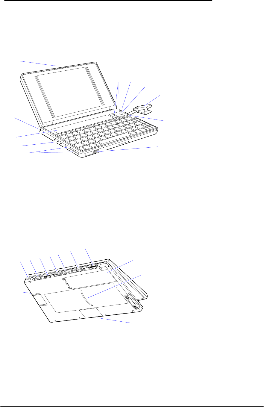
The following two illustrations point out the key external features of the OmniBook 800.
11
1
10
6
7
8
9
5
4
3
2
Figure 1 - OmniBook 800 External Features
1. Latch
2. Kensington security connector
3. Fn-key icon strip
4. Sound jacks
5. Card slots
6. Card-eject lever
7. On/Off key
8. Mouse
9. Mouse-eject button
10. Charging light
11. Display adjustments
1
2
21
20
19
22
18 17 16 15 14 13
Figure 2 - OmniBook 800 External Features (continued)
12. Docking/SCSI port
13. Parallel port connector
14. Infrared port (IrDA)
15. Serial port connector
16. Floppy drive port
17. VGA output connector
18. AC adapter socket
19. Reset button
20. Memory-expansion slot
21. Identification pocket
22. Battery
4
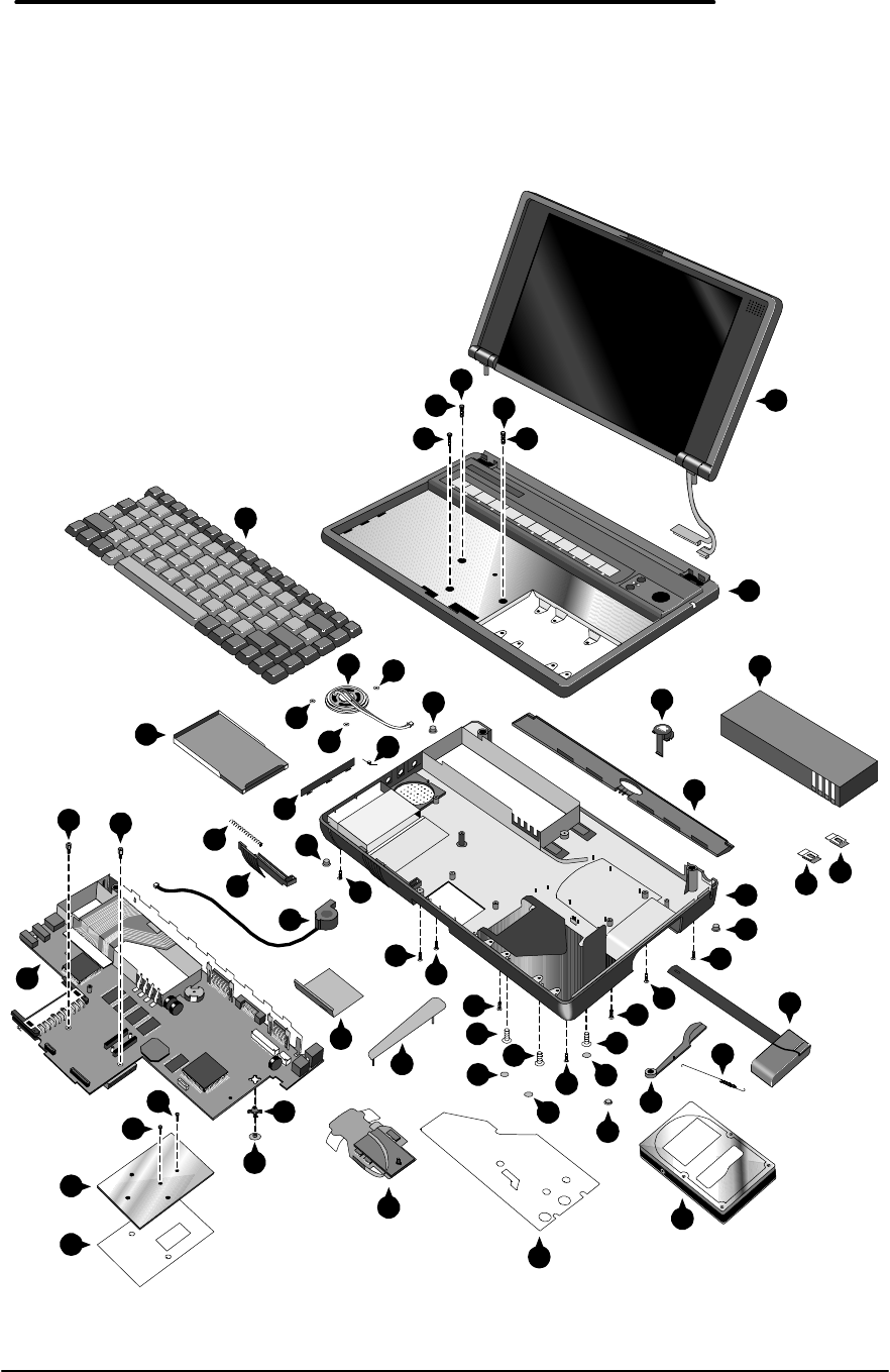
Product at a Glance
The following diagram represents all models of the OmniBook 800. Use Table 1 to identify each
part for the F1171 - F1175, and F1360 OmniBooks. Refer to the corresponding repair
procedure(s) in Part 3 for the exact placement of each component.
33
32
14
33
34
4
18
28
5
13
10
26
8
3
40 40
38
17
930
30
35
30
36
36
29
29
36
35
30
28
15
30
27
22
23
12
21
1
2
2
20
11
19
24
29
30
7
40
25
37
28
39
39
32
6
16
31
31
Figure 3 - Exploded Diagram

5
Table 1 - Parts Identification
DESCRIPTION PART
NUMBER EXCHANGE
PART NUMBER CUSTOMER
REPLACEABLE F1171 -
F1175 F1360
Only
1BATTERY - LI-ION F1121-80002 yes
2BATTERY LATCH F1170-40006 yes
3BUSHING F1170-40025 no
4CARD TRAY ASSY F1052-60005 yes
5CPU
CPU 100MHZ F1170-60919 F1170-69019 no
CPU 133MHZ F1170-60920 1170-69020 no
CPU 166MHZ F1360-60911 1360-69011 no
6DISPLAY
DISPLAY CSTN F1170-60902 F1170-69002 no
DISPLAY TFT F1170-60901 F1170-69001 no
DISPLAY TFT F1360-60901 F1360-69001 no
7DOOR - PIVOT LEFT F1052-40007 no
8EJECT ARM LEFT F1360-40005 no
9EJECT BUTTON LEFT F1170-40030 no
10 GROMMET F1360-40004 no
11 HARD DISK DRIVE
810MB HDD 0950-3084 F1191-69001 yes
1.44GB HDD 0950-3133 F1170-69012 yes
2.1GB HDD 0950-3193 F1360-69012 yes
12 I/O DOOR F1170-40010 yes
13 INSULATOR - CPU F1360-20007 no
14 KEYBOARD *no
15 KEYBOARD BOTTOMCASE
KEYBOARD BTMCASE F1170-60904 no
KEYBOARD BTMCASE F1360-60904 no
16 KEYBOARD TOPCASE
KEYBOARD TOPCASE F1170-60903 no
KEYBOARD TOPCASE F1360-60903 no
17 LOGIC PCA
LOGIC PCA 16MB F1170-60906 F1170-69006 no
LOGIC PCA 16MB F1360-60906 F1360-69006 no
18 MICROPHONE ASSY F1067-60012 no
19 PAW ACTIVE F1170-60909 no
20 PAW EJECT ARM F1170-40008 no
21 PAW EJECT BUTTON F1170-40005 no
22 PAW EJECT SPRING F1030-00016 no
23 PAW MECHANICAL 5061-4390 yes
24 PAW SHIELD F1170-00009 no
25 PIVOT DOOR SPRING F1030-00026 no
26 RAM DOOR F1170-40007 yes
27 RUBBER FEET - FALSE FOOT F1170-40009 yes
28 RUBBER FEET-SCREW COVER F1030-40018 yes
29 RUBBER HDD HOLE PLUG F1170-40018 yes
30 SCREW 2.0 X.4 6MM 0515-2396 yes
31 SCREW M1.6X.35X4 0515-2852 no
32 SCREW M2X.40X4.5WH 0515-2853 no
33 SCREW M2X.4X11.5WH 0515-2920 no
34 SCREW M2X.4X3.5WH 0515-2921 no
35 SCREW M2X.4X7PH T6 0515-2846 yes
36 SCREW M3X.5X5WH T6 0515-2847 yes
37 SPEAKER 9164-0422 no
38 SPRING EJECT LATCH F1030-00029 no
39 STANDOFF - HEX 0380-4606 no
40 TOPY SPRING NUT 0510-1634 no
Note, this is a partial parts list. For a complete parts list, please refer to Appendix F or the Product Support Plan.
* For a complete listing of localized keyboards, please refer to Appendix F or the Product Support Plan.

6
Product Comparisons
HP OmniBook 800
with MMX Technology HP OmniBook 800 HP OmniBook 5700
Size Closed 18.49 × 28.24 × 3.99 cm
(7.28 × 11.12 × 1.57 in) 18.49 × 28.24 × 3.99 cm
(7.28 × 11.12 × 1.57 in) 29.5 x 22.6 x 4.9 cm
(11.6 x 8.9 x 1.93 in)
Weight 1.77 kg (3.90 lb) 1.70 kg (3.75 lb) 3.27 kg (7.2 lb)
Processor 166-MHz Intel Pentium
with MMX Technology 100-, 133-MHz Intel
Pentium166- or 150-MHz Intel
Pentium with MMX
technology
Bus Architecture 32-bit PCI bus 32-bit PCI bus 32-bit PCI bus
Cache 512-KB external L2
cache 256-KB external L2
cache 512-KB burst-
synchronous L2 cache
Display Size • 10.4-inch TFT • 10.0-inch CSTN
• 10.4-inch TFT • 12.1-inch TFT
Display Resolution • SVGA TFT 800 x 600
x 64K colors • SVGA CSTN 800 x 600
x 256 colors
• SVGA TFT 800 x 600 x
256 colors
• XGA TFT 1024 x
768 x 64k colors
• SVGA TFT 800 x
600 x 16M colors
Pointing Device pop-up mouse pop-up mouse TrackPoint III
Video Bus Accelerated 128-bit PCI
bus Accelerated 128-bit PCI
bus 32-bit PCI bus
Video RAM 2MB 1MB 2MB
VGA-out Support • SVGA-out supports
1024×768×256 at 75
Hz and 800x600x64k
at 85 Hz
• MPEG software
support
• Zoomed Video
enabled
• SVGA-out supports up
to 1024×768×256
colors
• MPEG software support
• SVGA-out supports
up to 1024 x 768 x
64k colors
• Zoomed Video
enabled
Video Controller NeoMagic NM2093 NeoMagic NM2070 C&T 65554
Power • AC adapter 100 to 240
Vac (50 to 60 Hz) input
• 12 Vdc, 3.3 A output
• AC adapter 100 to 240
Vac (50 to 60 Hz) input
• 12 Vdc, 3.3 A output
• AC adapter 100 to
240 Vac (50 to 60
Hz) input
• 12 Vdc, 3.3 A output
Battery Type • 7.2 Vdc rechargeable
Lithium Ion battery • 7.2 Vdc rechargeable
Lithium Ion battery • 14.4-Vdc, 2.5-AH
rechargeable
Lithium-Ion battery
• Optional, 14.4-Vdc,
3.75-AH enhanced
Lithium Ion battery
Battery Life Battery life up to 3.0
hours. Battery life up to 3.0
hours. 1.75 to 2.5 hours with
one LiIon battery
(enhanced LiIon
battery adds 2.5 to
3.75 hours)
Recharge Rate Battery pack recharges
to high level in less than
2.5 hours using AC
adapter
Battery pack recharges to
high level in less than 2.5
hours using AC adapter
Battery recharges to
high level in 4 hours
using AC adapter
while PC is on or off
Advanced Power • Instant-on maintains • Instant-on maintains • Instant-on maintains

7
HP OmniBook 800
with MMX Technology HP OmniBook 800 HP OmniBook 5700
Management computer in ready-to-
work state for months
on a charge. Turn it on
again, and you're
instantly back where
you were.
• 2-minute low-battery
warning
• APM 1.2
computer in ready-to-
work state for months
on a charge. Turn it on
again, and you're
instantly back where
you were.
• 2-minute low-battery
warning
• APM 1.1
computer in ready-
to-work state for
weeks on a full
charge; returns you
to your application or
file instantly
• 2-minute low-battery
warning
• APM 1.2
Removable
Modules • Hard disk drive
• RAM
• Battery
• Hard disk drive
• RAM
• Battery
• Floppy disk drive
• Hard disk drive
• RAM
• Battery
Hard Disk Drive • 2.1-billion-byte
enhanced-IDE
• mode-4, PCI-bus
• 12.7 mm
• 810-million-byte, 1.44-
billion-byte enhanced-
IDE
• mode-4, PCI-bus
• 12.7 mm
• 3.0 billion-byte or 2.0
billion byte
enhanced- IDE
Floppy Disk Drive External ultra-thin,
three-mode floppy disk
drive (included with
product)
External ultra-thin, three-
mode floppy disk drive
(included with product)
Internal 3.5-inch, 1.44-
MB, standard
CD-ROM Drive Optional, external 8x
speed Optional, external 8x
speed Optional, internal, 10x
Memory • 16 MB standard VEDO
DRAM
• 60 ns
• upgradable to 80 MB
• 16-, 32-, 64-MB RAM
expansion cards
• 16 MB standard VEDO
DRAM
• 60 ns
• upgradable to 80 MB
• 8-, 16-, 32-, 64-MB
RAM expansion cards
• Self-refreshed FPM
DRAM
• 16 or 32-MB models,
expandable to 128
MB
• 8-, 16-, 32-, and 64-
MB RAM cards
available
Audio • 16-bit Sound Blaster
Pro stereo compatible.
• Two built-in speakers
(not stereo sound)
• 16-bit Sound Blaster
Pro stereo compatible.
• Two built-in speakers
(not stereo sound)
• 16-bit with Sound
Blaster and MIDI
support
• Stereo sound via two
built-in speakers
IO Ports • 9-pin, 115,200-b/s,
RS-232 port
• 25-pin EPP/ECP
parallel port
• SVGA-out (up to 1024
× 768 × 256)
• 4 Mbps Fast IRDA
• Docking system
connector (dock is
optional)
• SCSI-2 port available
with accessory cable
(fits in docking port)
• Floppy drive port
• Headphone/stereo-out
• 9-pin, 115,200-b/s,
RS-232 port
• 25-pin EPP/ECP
parallel port
• SVGA-out (up to 1024 ×
768 × 256)
• 4 Mbps Fast IRDA
• Docking system
connector (dock is
optional)
• SCSI-2 port available
with accessory cable
(fits in docking port)
• Floppy drive port
• Headphone/stereo-out
• 9-pin, 115,200-bps,
RS-232 port
• 25-pin bidirectional
ECP/EPP parallel
port
• SVGA-out (up to
1024 x 768 x 64K)
• Fast-IR-IRDA
compliant @ 4Mbps
• Expansion bus
connector
• PS/2
keyboard/mouse port
• Headphone/stereo-
out port

8
HP OmniBook 800
with MMX Technology HP OmniBook 800 HP OmniBook 5700
port
• Stereo-in and
microphone ports
port
• Stereo-in and
microphone ports
• Stereo-in and
microphone ports
• MIDI/joystick port
PCMCIA • One Type III PCMCIA
slot (or use as two
Type II slots)
• Zoomed video support
in upper slot
• CardBus-ready
• One Type III PCMCIA
slot (or use as two Type
II slots)
• One Type III
PCMCIA slot (or use
as two Type II slots)
with 3.3-V or 5-V
support
• Zoomed video
support for lower slot
• CardBus support
Docking Optional docking system
with EPP/ECP parallel,
serial, VGA-out (up to
1024 × 768), keyboard,
PS/2 or Microsoft
mouse, and SCSI-2
ports; external floppy
connector; stereo out;
and standard half-length
ISA/PCI slot.
Optional docking system
with EPP/ECP parallel,
serial, VGA-out (up to
1024 × 768), keyboard,
PS/2 or Microsoft mouse,
and SCSI-2 ports;
external floppy
connector; stereo out;
and standard half-length
ISA/PCI slot.
Optional docking
system with one
PCI/ISA and one ISA
slot, parallel, serial,
SVGA-out (up to 1024
x 768 x 64k),
keyboard, PS/2
mouse, MIDI/joystick,
audio and SCSI-2
Pre-installed
Software • Microsoft Windows
for Workgroups 3.11
and MS-DOS 6.22
dual-loaded with
Windows 95
• User upgradable Plug
and Play BIOS
• APM 1.2
• Diagnostic Software
• HP PIM and Financial
Calculator
• DMI 1.1 under
Windows 95 with
TopTOOLS
• On-line documentation
• Microsoft Windows
for Workgroups 3.11
and MS-DOS 6.22
dual-loaded with
Windows 95
• User upgradable Plug
and Play BIOS
• APM 1.1
• Diagnostic Software
• HP PIM and Financial
Calculator
• SystemSoft CardLite
and Monarch PC card
software
• On-line documentation
• Microsoft
Windows for
Workgroups 3.11
and MS-DOS 6.22
co-loaded with
Microsoft Windows
95*
• User upgradable
Plug and Play BIOS
• Advanced Power
Management 1.2
• DMI 1.1 under
Windows 95 with
TopTools
• HP PIM and
Financial Calculator
• On-line
documentation
Security Features • 2-level password
protection
• Hardware-based hard
drive password
• Kensington lock slots
• System administrator
password
• PC ID
• EEPROM-based serial
number for DMI
tracking
• 2-level password
protection
• Optional hardware-
based hard drive
password
• Kensington lock slots
• System administrator
password
• PC ID
• 2-level password
protection
• Hardware-based
hard drive password
• Electronic serial
number
• PC ID (tattooing)
• Drive lock
• Kensington lock slots
Warranty Free three-year world-
wide warranty (1-year on Free three-year world-
wide warranty (1-year on Free three-year world-
wide warranty (1-year

9
HP OmniBook 800
with MMX Technology HP OmniBook 800 HP OmniBook 5700
battery and accessories) battery and accessories) on battery and
accessories)

Part 2
Troubleshooting
• Power-On Self-Test
• OmniBook Diagnostics
• Desktop Management Interface
• System Configuration Utility
• Troubleshooting Tips

4
Power-On Self-Test
The OmniBook 800 BIOS includes a Power-On Self-Test (POST) facility that tests a number of
hardware and firmware items in the unit at each cold-start (BOOT or RESET).
The OmniBook self-test alone should not be used to diagnose a hardware problem. If the self-
test results are absolutely clear and repeatable, confirm the results with at least two other non-
self-test failure symptoms.
Within POST, there are three kinds of messages:
• Error Messages – These messages appear when there is a failure in hardware,
software, or firmware.
• Informational Messages – These messages provide information to the user but
require no action.
• Beep Codes – This kind of warning sounds when POST errors occur and the screen
is not yet available.
Beep Codes
These multiple beep codes indicate a failure in a simple test of:
• a portion of base memory
• flash BIOS checksum
• a portion of conventional memory
• a portion of extended memory
If the unit fails to boot, ensure that
• all accessories are removed, including:
memory, floppy drive, docking station, modems and other PC Cards, printers,
external displays, pointing devices, and keyboard
• clean AC power is provided (no “chained” battery chargers or auto adapters), and
press reset.
If the unit still fails to boot, it requires service.
Beep codes are used to identify a POST error that occurs when the screen is not available.
Once the screen is operating, diagnostic messages are reported to the screen. There are beep
codes for both fatal and non-fatal system board errors.
Table 2 - POST Beep Codes
Beep Code Description
S-S-S-P-S-S-L-P The DMA page registers are faulty.
S-S-S-P-S-L-S-P The refresh circuitry is faulty
S-S-S-P-S-L-L-P The ROM checksum is incorrect
S-S-S-P-L-S-S-P The CMOS RAM test failed
S-S-S-P-L-S-L-P The DMA controller is faulty
S-S-S-P-L-L-S-P The interrupt controller failed
S-S-S-P-L-L-L-P The 8042 keyboard controller failed
S-S-L-P-S-S-S-P No video adapter was found
S-S-L-P-S-S-L-P No RAM installed. No message is displayed.

5
Display Codes
There are a number of Power On Self Test (POST) tests that are performed after the Beep Code
tests. Failure of one or more of these tests will result in a displayed failure code (such as
03044). It is extremely important not to interpret a failure code immediately as a hardware
failure. The failure should be confirmed with a clean boot. A clean boot is defined as pressing
the reset button after removing all accessories (including additional memory, floppy drive,
modems, PC cards, and printers) and providing a reliable power source. Note, make sure the
display is adjusted to be visible.
The following tables lists common PC error messages. Not all of these messages will appear on
every model of the OmniBook 800.
Table 3 - POST Display Codes
Message Possible Cause
CLOCK NOT TICKING CORRECTLY The real time clock is not ticking.
COLOR/MONO SWITCH INCORRECT The COLOR/MONO switch on the system
board is incorrect for the installed
hardware.
CMOS CHECKSUM INVALID - RUN SCU CMOS RAM information has been
corrupted and needs to be reinitialized via
the System Configuration Utility.
CMOS FAILURE - RUN SCU CMOS RAM has lost power and needs to
be reinitialized via the System
Configuration Utility.
FLOPPY CONTROLLER FAILED The floppy controller failed to respond to
the reset command. Power down the
system and check all appropriate
connections. It the floppy controller
continues to fail, you may need to replace
it.
FLOPPY DISK TRACK 0 FAILED The floppy drive cannot read track 0 of
the floppy disk in the drive. Try another
diskette. If the problem persists, you may
need to replace the floppy drive.
FLOPPY INFORMATION INVALID - RUN SCU The drive parameters stored in CMOS do
not match the floppy drives detected in
the system.
HARD DISK CONTROLLER ERROR The hard disk controller failed to respond
to the reset command. Possible
solutions: 1) Check the drive parameters.
2) Power down the system and check all
appropriate connections. If the problem
persists, you may need to replace the
hard disk controller.
HARDWARE INFO DOES NOT MATCH VIDEO
CARD - RUN SCU The video adapter type specified in
CMOS RAM does not match the installed
hardware.
KEYBOARD CONTROLLER FAILURE The keyboard failed the self-test
command. Check to see if the keyboard
controller is properly installed. If the
problem continues, replace the controller.

6
Message Possible Cause
KEYBOARD FAILURE The keyboard failed to respond to the
RESET ID Command.
MACHINE IS LOCKED - TURN KEY The system will not continue the boot
sequence until you insert the key into the
key lock and turn it.
NO BOOTABLE FLOPPY DRIVE 0 INSTALLED No bootable floppy drive was detected.
Possible solutions: 1) Power down the
system and check all appropriate
connections, cables, etc. 2) In
configurations where no floppy drive is
installed, run System Configuration Utility
and make sure the diskette drive
configuration item is set to “None”. 3)
Replace the diskette drive if necessary.
NO INTERRUPTS FROM TIMER 0 The periodic timer interrupt is not
occurring.
RAM PARITY ERROR AT LOCATION xxxx A RAM parity error occurred at the
specified (hexadecimal) location.
ROM AT xxxx (LENGTH YYYY) WITH NON-ZERO
CHECKSUM (zz) An illegal adapter ROM was located at
the specified address. An external
adapter (such as a video card) may be
causing a conflict.
TIME/DATE CORRUPT - RUN SCU The time and date stored in the real time
clock have been corrupted, possibly by a
power loss.
UNEXPECTED AMOUNT OF MEMORY - RUN SCU The amount of memory detected by
POST does not match the amount
specified in CMOS RAM.
CMOS RAM TEST FAILED A walking built test of CMOS RAM
locations 0E (Hex) - 3F (Hex) failed.
DMA CONTROLLER FAULTY A sequential read/write of the transfer
count and transfer address registers
within the primary and secondary DMA
controllers failed.
FAULTY DMA PAGE REGISTERS A walking bit read/write of the 16 DMA
controller page registers starting at
location 80 Hex failed.
FAULTY REFRESH CIRCUIT A continuous read/write test of port 61h
found that bit 4 (Refresh Detect) failed to
toggle within an allotted amount of time.
INTERRUPT CONTROLLER FAILED A sequential read/write of various
Interrupt Controller registers failed.
ROM CHECKSUM INCORRECT A checksum of the ROM BIOS does not
match the byte value at F000:FFFF.

7
OmniBook Diagnostics
The OmniBook diagnostics program provides an effective tool for diagnosing and isolating a
hardware problem. The diagnostics software is intended for use in concert with additional
troubleshooting methods to accurately determine the cause of trouble. The diagnostics program
is not designed for unassisted end customer use.
Diag is a DOS program developed to test the OmniBook 800 computer and docking station. For
the most part Diag is a stand-alone program, testing components and subsystems independently.
Some tests require “loopback” adapters for complete testing, and some tests require other
hardware (e.g. SCSI devices). Basic knowledge of running software is assumed.
Running the diagnostics program
A “clean boot” is the environment from which to run Diag. For a system that normally boots up
to Windows for Workgroups, press F5 at bootup. For a Windows 95 system, press Shift+F5.
Alternatively, the CONFIG.SYS and AUTOEXEC.BAT files may be modified to exclude drivers
and/or launch Diag if desired. Please note that the SCSI tests do require loading some drivers;
those drivers will be addressed in the context of those tests.
The diagnostic program is located in the c:\omnibook\diag directory and is invoked by typing
diag followed by the Enter key.
Main diagnostic screen
The OmniBook diagnostic program is controlled primarily from a single screen. The top two
thirds of the screen reports the tests selected and test results. The bottom third is used to scroll
test results as the tests run. Thirty tests are listed under the Menu heading. See Figure 4 for a
sample of the main diagnostic screen.
Tests selected for looped running show a test level of 1 to 3 to the left of the test name. When a
test ends, the status of the test and the date and time are reported. As a test runs, ongoing
status can be reported either on the same line as the test, or scrolled into the bottom region.
When looping tests are performed, the bottom line reports when the loops begun and which loop
is currently running. If a test ever fails, a red ‘x’ appears to the left of the test name. The
version of Diag is reported near the bottom of the display, as is the version of the BIOS.
External monitor colors can be checked at a glance with the RED GREEN and BLUE colored
text boxes.

8
Figure 4 - Main Diagnostic Screen
Running selected tests
Tests may be initiated individually, or as a group. Some tests may be run at different levels. In
general, tests that can take a long time to be fully checked have levels that permit testing more
quickly while still providing a reasonable level of testing. An unselected test has a <Space>
before the test name. A test at a quick level has a <1> before the test name. A standard level
test has a <2> before the test name. A long test has a <3> before the test name. Every test has
a standard level. Some tests also have a quick level, and some tests also have a long level.
Some have both quick and long.
Menu Status Date Time
2 CPU Ok 08/08 14:36:18
2 Cache Ok 08/08 14:35:20
1 RAM, motherboard 16 MB Ok 08/08 14:36:22
1 RAM, plug in 00 MB Ok 08/08 14:36:23
2 BIOS flash ROMS OK C-F=8676? Altera=E56C? Boot=C600? 08/08 14:36:25
2 CMOS Ok 08/08 14:36:26
Upper PC Card
Lower PC Card
2 Timers Ok 08/08 14:36:26
2 Real time clock Ok 08/08 14:36:30
2 IRQ controller Ok 08/08 14:36:31
2 DMA controller Ok 08/08 14:36:32
IR port
Serial port
Printer port
1 Hard disk 813Mb Ok 08/08 14:36:32
Floppy disk
2 Battery Bat=LiIo (OK) Chg=FC B%=60 Vb=8.17 Ta=57.2 08/08 14:36:33
SCSI loopback
1 Keyboard Ok 08/08 14:36:36
1 HP mouse Ok 08/08 14:36:36
2 Audio Ok 08/08 14:36:39
1 Display Ok 08/08 14:36:42
1 Docked device Ok: NOTHING. 08/08 14:36:42
SCSI CD ROM
SCSI Hard disk
Dock slots
Dock keyboard
Dock PS2 mouse
Dock EEPROM
Keyboard Power-On Selftest
Keyboard IRQ Test
Keyboard Interface Test
+3708 +3695
DSP Chip
DMA Channel
Interrupt Lines
Sound Output Test
Version 04 Jan 97, Bios 97/01/29 RED GREEN BLUE
ARROW keys select tests. ENTER or 1, 2, 3 runs test. Or press SPACE to mark
tests then ENTER to run them. F1 or ? gives help. DIAG /? Shows options.
loops=2/20. Last loop begun at 08/08 14:36:18

9
The name of the currently selected test is always shown inversed.
To help monitor the progress of testing, the LEDs (near the On button) blink about once per
second from green to off. If a test has failed the LEDs blink from red to off. When Diag finishes
testing, the LEDs blink rapidly. If the system locks up for some reason, the LEDs generally stop
blinking.
Alternative methods for running tests
Individual tests may be run by moving the highlight to the desired test and running it. Move the
highlight and run the tests by the following means:
Keyboard – cursor <Up> and <Down> keys to select, <Enter> to run. Also <Space> to specify a
test level, <Backspace> to cancel a test, <Esc> to exit Diag. Many other features and options
are also available from the keyboard.
Contrast/Brightness buttons – <Down> to select (mimics the Down key), <Up> to run (mimics
the Enter key). This is most useful on production units that have no keyboard. For checking
“Newton rings” during display testing, it is necessary to adjust the contrast. To have the contrast
keys operate normally, press both at once. To have them mimic the Down and Enter keys, press
both again.
Mouse – when the -m command line option is specified, use the top or bottom “bumper” to
select, and left button to run. Also use the right button to specify test level (space), right bumper
to cancel a test (Backspace), and left bumper to exit Diag (Esc).
Serial – same keys as with a keyboard, but from a remote system (HP 100LX, etc) connected
into the RS232 port on the OmniBook. The remote computer’s serial port should be configured
for 9600,N,8,1. The communication program Kermit is well suited to communicate with Diag, in
that it sends cursor and function key codes as PC key codes (e.g. <Up> transmits <NULL> then
<;>). Controlling Diag via the serial port permits the same level of control of modes and toggles
as does direct keyboard control. Please note that the serial test cannot be run when the serial
port is used for control (though the serial port gets a decent workout controlling Diag anyway).
Special test hardware requirements
The following tests require the following hardware to operate:
• The Upper/Lower PC Card tests require a Sycard test card and a modified
extender card.
• The IR port test requires another OmniBook 800 running the fast IR test.
• The Serial port test requires an HP RS-232 serial loop back connector.
• The Printer port test requires an HP parallel port loop back connector.
• The SCSI test requires an HP SCSI port loop back connector.
• The SCSI CD ROM test requires a CD ROM device connected by SCSI cable.
• The SCSI Hard disk test requires a Hard disk connected by SCSI cable.
• The Dock slots test are currently unimplemented.
• The Dock keyboard test requires a docking station and an external keyboard.
• The Dock PS2 mouse test requires a docking station and a PS2 mouse.
• The Dock EEPROM test requires a docking station.
10
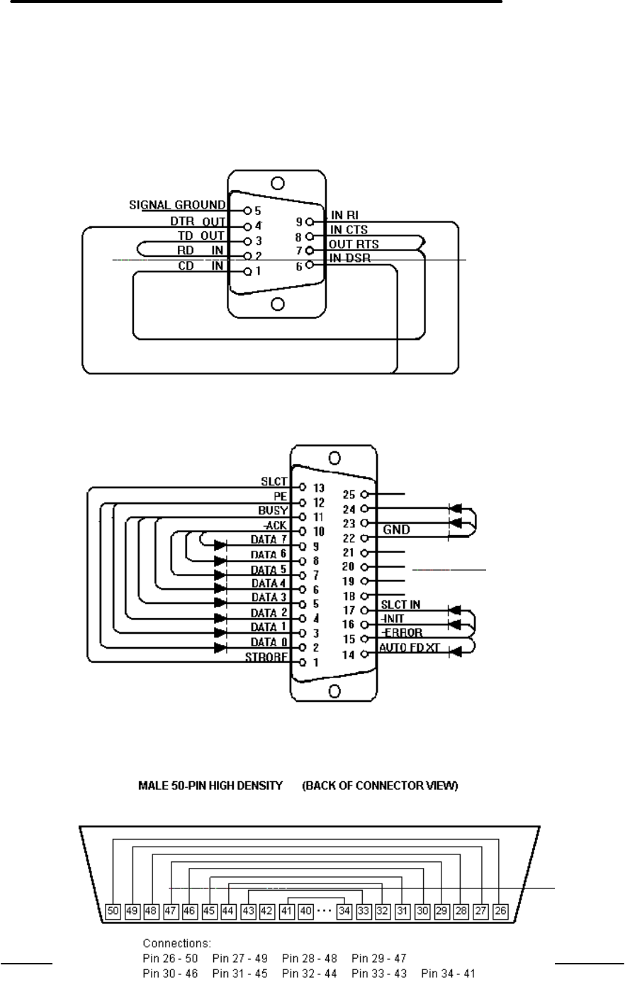
Loop Back Connectors
In order to run the RS232 serial port, parallel port, and SCSI port self-test, a loop back connector
is needed. The loop back may be placed on either the OmniBook port or at the end of the
corresponding cable. This feature is also helpful in diagnosing a defective serial, parallel, or
SCSI cable.
Loop back connectors may be purchased or can easily be constructed. The following illustrations
identify the correct pin-out configurations for the serial, parallel, and scsi loop back connectors.
Figure 5 - Serial Loop Back Connector
Figure 6 - Parallel Loop Back Connector
Figure 7 - SCSI Loop Back Connector
11
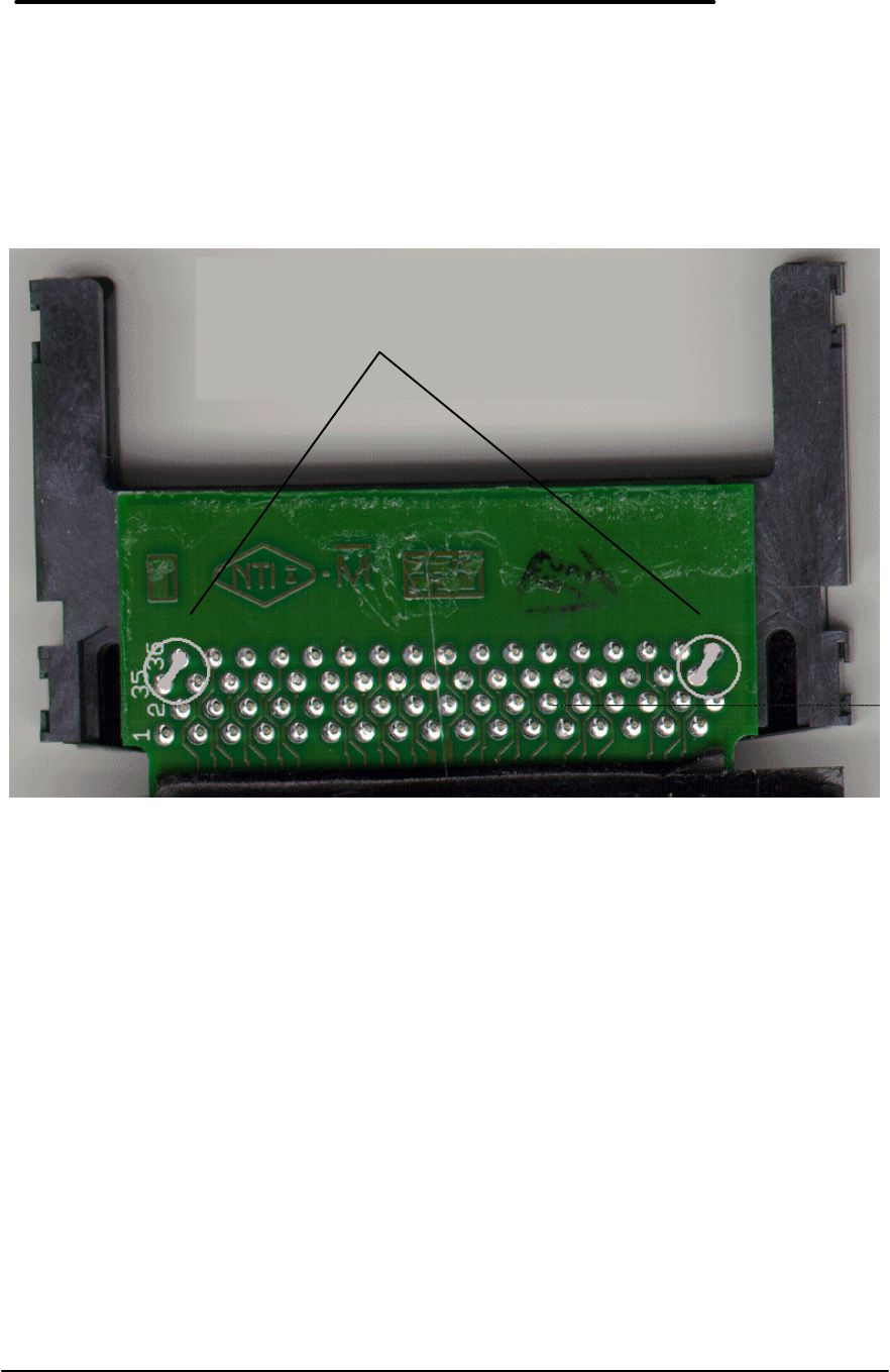
PCMCIA Type III extender card
The PCMCIA test that makes use of SyCard Technology’s SyCard also requires an extender
card modified with two jumpers or with solder bridges. In order for the Sycard to be detected,
CD1- and GND must be shorted together, and GND with CD2- must also be shorted together.
These are both pairs of endmost pins on the extender. Once these jumpers or solder bridges are
added, the SyCard will successfully be detected and the SyCard tests can be performed. See
Figure 8.
Figure 8 - SyCard Solder Bridges
Solder Bridges

12
Command line options
When Diag is run, either from the command line, or from a batch file, a number of switches (or
options) may be included to “customize” the operation of Diag. Switches must be specified
separately, and must begin with either a - or a / character. Upper or lower case may be used as
desired. Switches may be used in any order. The switches, a brief description, and their use are
described below:
Table 4 - Diagnotic Command Line Options
Switch Description
-? Report the standard command line options available.
-! Report standard and hidden command line and keyboard commands available.
-cNxxxx Specify Nth ROM checksum. The “BIOS flash ROMs” test the flash memory for
correctness. In order for Diag to maintain usefulness in the face of new and
different BIOSes, a way is needed to specify the BIOS ROM values. Though the
test will not fail (as of this writing) if the checksums are not specified, a ‘?’ will show
after a sum to indicate checksum uncertainty. All three checksums must be
specified to fully qualify the ROMs. As an example, to test a build with the
960701.ROM, the user would enter: Diag -c121E9 -c2D631 -c3C600. Batch files
that need to work with both F1175 and F1360 OmniBooks may specify two
checksums after each switch, the first one for the F1175 and the second one for the
F1360. For example, to test the 970121 ROMs for both units, use the following
switches: -c1B7386A45 -c2DC8CDC8C -c316001600.
-d Select Dock tests only. For testers wishing to test docks, this switch restricts the test
shown to those that pertain to the dock only. The set of tests shown in this mode
include the following: Serial port, Printer port, SCSI loopback, Audio, Floppy disk,
Docked device, Dock keyboard, Dock PS2 mouse, Dock EEPROM.
-f Run Fast IR loopback mode on startup. The IR port test needs a computer running
in “passive” mode to send IR data back to the computer being tested. An IR test
station can be automated by having the passive computer run Diag with the -f option
in its AUTOEXEC.BAT file. The key <Alt+F> can also be used to put the computer
into passive mode. Press <Esc> to exit from passive mode.
-k<file> Run a Keyboard macro file. This switch is by far the most powerful and versatile in
that it lets the operator set up different configurations and test sequences and play
them back later just as though they were typing the commands from the keyboard.
For information on creating a keyboard macro file, see the <Alt+R> command.
-m Enable Mouse keyboard control. For units that do not have a keyboard, use this
option to control Diag with a mouse. For more information on this feature, see the
<Alt+M> command
-r<test#> Run nth test and return exit code. For testing from a batch file, this switch can be
used to run a single test and return the test result in the errorlevel. 0=pass, 1=fail,
2=aborted, 3=no loop/can’t run. Tests are specified by ordinal number counting
from 1 at the top. Use the -1, -2, -3 option below to set the test level.
-s Disable control via Serial port. By default, the serial port can be used to control
Diag via a host computer (running Kermit connected at 9600, N, 8, 1) when no
keyboard is available, the unit cannot be easily accessed for entering commands, or
remote automated operation is needed. Serial control is always automatically
disabled during the serial port test, but if the serial port is used for other activities,
use this switch to completely disable control.
-x Test for the eXtra key on foreign keyboards. Foreign keyboards have an extra key
to the left of the space key. To include this key in the internal keyboard test, add a -
X parameter when running Diag. Because the keyboard test is scancode based (not
ASCII character), the key names are NOT localized to their foreign equivalents.

13
Also some key caps have characters that cannot be displayed with the text
characters available. Therefore, when running the keyboard test on a foreign
keyboard, the POSITION of the key within the keyboard should match the
POSITION of the key shown on the display, not necessarily the character printed on
the key (although in nearly all cases, it does match). When -x is specified, the extra
key appears as >< before the SP key.
-1 Mark all tests for quickest test available. This has the same effect as using the <M>
command once and is mainly used with the -r switch.
-2 Mark all tests for standard test available. This has the same effect as using the <M>
command twice and is mainly used with the -r switch
-3 Mark all tests for longest test available. This has the same effect as using the <M>
command thrice and is mainly used with the -r switch.
EDOCK An undocumented/hidden Diag switch: Set the dock serial number. Use this
undocumented switch to set the dock serial number in the dock EEPROM. The date
and time must be valid, and the date must be Jan 1 1996 or later. The serial
number is set to the following code: MDDHHMMS where M is month 1-9 A-C, DD is
day 01-31, HH is hour 00-23, MM is minute 00-59, and S is seconds 0-5 (tens of
seconds only).
User interface commands
The user interface commands of the diagnostics program are divided into three groups:
commands that select tests, commands that toggle test settings, and commands that set test
parameters.
Commands for test selection
The following table describes the various commands used to select test within the diagnostics
program.
Table 5 - Diagnostic Test Selection Commands
Command Description
Down Highlight the next test. At the bottom, wrap to the top test.
Up Highlight previous test. At the top, wrap to the bottom test.
Home Highlight the top test.
End Highlight the bottom test.
Space Mark the highlighted test. Tests that permit multiple levels progress from the
quickest test to the longest test then back to not selected.
MMark all tests. If no tests are selected, <M> will select all tests to run at the
quickest possible level. Another <M> sets all tests to the standard level.
Another <M> sets the longest possible level. Another <M> unselects all tests. If
any other mixture of tests is selected all tests are unselected.
Enter Run all selected tests. <Enter> is used to begin running a group of selected
tests. If no tests are selected, the highlighted test is run at the standard level.
1 2 3 Run highlighted test ONLY (short, standard, long). If short or long is not
available for the specified test, the standard test is run.
<Backspace> Stop current test. The <Backspace> key is universally used to abort a test that
is running. Some tests may not be able to quickly respond to the keyboard and
it may be necessary to depress the key a few times or hold the key down for it to
be recognized.
Esc Exit Self-test. Upon exit, the Diag display is cleared and the DOS display is
restored. Every attempt is made to restore all settings to their previous state

14
upon exit (no reboot necessary in most cases).
Alt+F12 Dump the text screen to a file named DIAG.xxx where xxx begins at 000 and
increases by one each time another screen dump is captured. Screen dumps
from previous runs of Diag are preserved.
? or F1 Display a help screen of keyboard commands.
Commands for toggling test settings
The following table describes the various commands used to toggle test settings within the
diagnostics program.
Table 6 - Diagnostic Commands for Toggling Settings
Command Description
Ctrl+C Toggle battery Charging on/off. This command sends a request to the charging
software in the BIOS to enable charging / disable charging.
Ctrl+E Toggle ignore Errors on/off (continue after error when on). Normally Diag stops
looping when an error occurs, but with this command, Diag will continue to loop
until all requested loops are complete.
Ctrl+L Toggle Logging to disk file (errors, all, all+status, none). This command appends
results to the file DIAG.LOG on the current drive and directory from which Diag
was run. The data logged is either: 1) only tests which fail, 2) all tests results, 3)
all test results, and all messages shown in the lower status window, or 4) none.
For looping tests, the loop count and time is logged at the start of each loop. If a
floppy or hard disk critical error happens when logging results, the normal “Abort,
Retry, Ignore” message may not be visible depending on the display mode. A
special error handler has been incorporated into diag to handle this case. A
flashing message will appear on the top line should an error of this type occur.
Press A, R, or I to continue. If no keyboard is available, press the Contrast Up
button to Retry, or the contrast Down button to Ignore the error.
Ctrl+N Toggle Noise (beep & flash) at test completion. When a test or set of tests
completes, Diag waits for the user to enter more commands. To help notify the
operator of when this happens, use Ctrl+N to cause Diag to invert the display and
sound a noise until the user responds in some way.
Ctrl+P Toggle Power management on/off. Tests that require measuring power levels
may require that Power management be on or off. This can be controlled directly
with this command.
Ctrl+T Toggle between the four types of mouse tests. The HP mouse tests are 1) text
mode mouse test, 2) graphic mode sine wave mouse test, 3) combined text and
sine tests, and 4) graphic draw mode test.
Ctrl+V Toggle Verbose test status reporting. Some tests can report more detailed
information. These tests include: all dock related tests (reports voltages), the HP
and External mouse tests (reports x/y data and button status).
Ctrl+W Toggle printing to Wired serial port (errors, all, all+status, none). Like the
<Ctrl+L> command that logs results to disk, this command similarly logs results to
the com 1 serial port.
Alt+A Toggle cAche on/off. If it is necessary to disable the cache, use this command.
Processor level commands are used to perform this operation.
Alt+K Toggle miKe on & line off, mike off & line on, both off.
Alt+M Toggle program control with Mouse on or off. Like the -m command line option,
Alt+M enables controlling Diag with a mouse. The mouse actions listed below
have the following keyboard equivalents:
Mouse switch Key Action

15
Top Bumper <Up> Highlight previous test.
Bottom Bumper <Down> Highlight next test.
Left Button <Enter> Run current or selected tests.
Right Button <Space> Mark highlighted test.
Right Bumper <Backspace> Cancel currently running test.
Left Bumper <Esc> Exit Diag.
Alt+P Toggle ‘Prompt to retry test after a failure.’ Sometimes it is useful to trap failures
and give the operator another opportunity to run a test before logging the test as
failed. When this option is enabled, if a test failed (other than user aborted) the
user is prompted with “Retry test now?”. If <Y> is pressed, the test is immediately
run again and no logging whatsoever of the failure is recorded anywhere. This
option has been useful for running tests manually where test fixtures need to be
installed prior to testing.
Alt+R Record keystrokes in a file for configuring tests. Used to record keystrokes for
later recall, the user is prompted for the name of a file to store the keystroke
names in (note that the extension used with the keyfile is automatically set to
.KEY). Once a unique name has been entered, every key press is recorded to the
file (except keys pressed during the execution of an individual test) until <Alt+R>
is pressed again, or Diag is exited. If Diag is exited, the final <Esc> key is
included in the key file. Please note that macro files run when Diag first starts up,
and that any keys pressed before <Alt+R> is pressed will NOT be included. In
particular, keys that select tests or test settings should be avoided before
recording a keyboard macro file. If you wish to avoid having to wait until AFTER a
set of tests is run to save the keyboard macro file simply enter all the keys you
need UP TO WHERE YOU WOULD PRESS THE ENTER KEY. At this point,
press <Esc> to exit Diag, then use EDIT or another ASCII text editor to add
“<Enter>” to the end of the file.
Alt+S Toggle Suspend hard disk at end of test. The hard disk can either be left spinning
(default) at the end of its test, or spun down and stopped.
Alt+T Toggle 1000Hz Tone on/off. The PC speaker generates a 1000Hz tone when this
option is enabled.
Alt+V Toggle Videos used between both, external, and internal. Diag can drive either or
both displays. When Diag is first run, the currently selected displays continue to
function (whatever the user has specified). The first <Alt+V> enables both
displays, the second enables the external display only, and the third enables the
internal display only.
Alt+W Walk through tests. Sometimes it is useful to advance slowly through a particular
test. By enabling this option, Diag will beep and wait for a keypress each time the
test would normally just check to see if the <Backspace> key was pressed.
The following two-key commands are hidden from general use:
Table 7 - Diagnostic Hidden Commands
Command Description
Alt+E + Alt+C Set the lost mickey Count threshold. Use this command to specify the
minimum number of “lost mickeys” at which a mouse “mickey” error can occur.
The default value is 530 mickeys. See also the Alt+E + Alt+T command, and
the mouse test section.
Alt+E + Alt+D Show dock EEPROM serial number (hidden function). Use this command to
verify the dock serial number is set.
Alt+E + Alt+H Set the Horizontal lost calibration speed thresholds used in the graphic draw
mouse test. The defaults limits are 300 to 500.

16
Alt+E + Alt+V Set the Vertical lost calibration speed thresholds used in the graphic draw
mouse test. The defaults limits are 200 to 400.
Alt+E + Alt+M Set mouse bumper failure threshold. The default number of mickeys for this is
1000. The number reflects how much bumper compression is permitted before
a bumper is rejected.
Alt+E + Atl+S Set sine mouse test threshold. For mice that exhibit sine wave patterns along
the left side of the screen, use this key to specify how much will be tolerated.
The default value is 10.
Alt+E + Alt+T Set the lost mickey Time threshold. Use this command to specify the minimum
number of “timer tics” at which a mouse “mickey” error can occur. The default
value is 10 timer tics. See the Alt+E + Alt+C command and the mouse test
section.
Alt+E + Alt+Z Shell out from Diag to a command prompt. This can be used to run small
tasks, (e.g. copy files) without losing any current diagnostic settings. When
ready to return to Diag, type EXIT.
Commands for setting test parameters
The following table describes the various commands used to set test parameters within the
diagnostics program.
Table 8 - Diagnostic Test Parameters
Command Description
#Set loop count limit for looping tests. By default 1 loop is run. If 0 loops are
specified, Diag will loop indefinitely. Other values will loop for the count specified.
Ctrl+A Set wakeup Alarm delay after suspend. The OmniBook can be set to
automatically wake up after a suspend by setting a wakeup alarm of 1 to 59 hours,
minutes, or seconds. By default, no wakeup is scheduled. If an alarm delay has
been set and multiple test loops are set then Diag will automatically suspend at the
completion of each loop.
Ctrl+D Set loop Delay interval. By default, looped testing runs as rapidly as possible with
no delays between loops. This command lets the user specify that each loop of
testing start from 1 to 59 hours, minutes, or seconds after the previous loop
started. No delay will occur if the tests have already run for the specified delay
time (for example, if 2 minutes of delay are specified and the tests selected ran for
2 minutes 10 seconds, then no delay would occur at the end of the loop.
Ctrl+H Report System Hardware found. This test reports on various OmniBook
components. The following are reported: CPU speed (100, 133, 150, etc); Display
technology (TFT, DSTN); Hard disk capacity (814M, 1.4G, etc); Cache size (256,
512, etc) and state (ON,OFF); OS version (varies); system RAM (16M, 24M, …
80M); and disk volume id (varies).
Ctrl+R Set Retries before reporting disk error. By default, 5 retries are permitted before a
disk error is reported. Specifying fewer retries will detect marginal media more
quickly. A related feature of Diag regarding soft read errors (checksum errors), is
that these sectors will be written back to disk to repair the checksum error.
Ctrl+S Enter Suspend state. This command will put the OmniBook into an off state
similar to pressing the Off key. Once suspended, the OmniBook will remain off
indefinitely unless a wakeup alarm has been set with <Ctrl+A>.
Alt+B Set Brightness 0-255. Specify a display brightness from 0 to 255 with this
command. This exceeds the normal range permitted with the brightness buttons
and can result in a blank display. Repeat the command with a less extreme value
to restore the display.

17
Alt+C Set Contrast 0-255. Systems with a DSTN display can specify a display contrast
from 0 to 255. This exceeds the normal range permitted with the contrast buttons
and can result in a blank display. Repeat the command with a less extreme value
to restore the display.
Alt+D Set device type that should be found in the dock port. Once specified, the
“Docked device” test will only pass if the correct device is found. The OmniBook
dock port can accept either a SCSI cable for connection to a tower, or a dock
device. Specify N, S, or D when prompted for nothing, SCSI cable, or dock.
Alt+F Set Fast IR loopback mode. The fast I/R test requires two OmniBooks with their
I/R ports directed at each other. One OmniBook must be run in fast IR loopback
mode. To put an OmniBook into this mode either use this command or use the /f
command line option when starting Diag. To exit this mode press the <Esc> key.
Alt+I Enter Idle state. This command puts the OmniBook in a low power state while still
maintaining full readiness to run. Press any key to resume.
Alt+N Enter a Note to log to disk file. When logging to a disk file has been enabled with
<Ctrl+L>, this command can be used to permit entering a line of text, then logging
the text to the log file DIAG.LOG
Details on using the diagnostic tests
Details for the various tests are described below. The levels permitted for each test and a brief
note on hardware or other options are described.
Numerous tests involve pattern testing to determine if the hardware can accept the various data
combinations required. Tests that make use of 18 data patterns use the following pattern set:
0FFFFh, 00000h, 0F0F0h, 0AAAAh, 05555h, 08080h, 04040h, 2020h, 01010h, 00808h, 00404h,
00202h, 00101h, 01111h, 02222h, 04444h, and 08888h. These data patterns are used in place
of “walking bits”, “checkerboards”, and “bit stuck high/low”.
CPU
Level: 2. The CPU test contains numerous subtests as follows. The CPU register test writes the
18 data patterns to the registers and reads them back to verify correctness. The CPU arithmetic
test performs ACD, ADD, DEC, DIV, IDIV, IMUL, INC, MUL, SBB and SUB with 16 and 32 bit
operands. The CPU logical test performs AND, NOT, OR, and XOR with 16 and 32 bit operands.
The CPU string test performs LODS, MOVS, SCAS, and STOS with 16 and 32 bit operands.
The CPU interrupts / exceptions tests software interrupts and real-mode accessible exceptions; if
Diag is running in a DOS box, Windows prevents testing all exceptions but divide by 0. The
coprocessor tests the numeric coprocessor register stack, exception handling, arithmetic,
comparison, and transcendental operations. Failures are reported by register and operation. A
final test of CPU speed is performed to ensure measured speed is within 10% of the expected
value, values below this will fail the test.
Cache
Level: 2. This tests the translation lookaside buffer and the Pentium on-chip cache first with
register addressability, then with the 18 test patterns. No memory managers may be installed for
this test to run.
RAM, motherboard
Levels: 1,2,3. The level 1 test performs an address test only with the 18 data patterns. The
level 2 test performs a pattern test, address test, bus throughput, and code test. The level 3 test
does what level 2 does except the pattern and address tests are repeated 10 times. The

18
operation of all tests depend on the presence or absence of XMS or EMS drivers. In general, if
there is no XMS and no EMS driver, then memory will be accessed directly in pseudo-32-bit
mode (i.e. with 4 GB selectors but from real code), if there is an XMS/EMS driver, the XMS
driver will be used to access memory. The recommended environment is real mode without
XMS or EMS drivers (i.e. a clean boot).
Pattern testing and address testing are similar. The pattern test sequentially writes the 18
patterns to memory and reads them back. The address test uses each individual memory
location as the pattern data, but otherwise the test functions just like a pattern test.
Base memory is always pattern/address tested in 16-KB blocks. Extended memory, if no
EMS/XMS drivers are present, will be tested in blocks of up to 1MB. The contents of the
memory is not preserved.
Bus throughput testing is only available for base memory. The test reads memory using a tight
REP LODSD loop, not checking the actual data, but looking out for parity errors (from the
memory, cache, and interface chips).
Code test is only available for extended memory. The test writes a 1-MB program to memory,
switches the CPU to protected mode and runs the program that is in extended memory. This
approach tests not only the data cache and fetch of a CPU, but also the code cache and fetch.
Exceptions and parity errors are also monitored in protected mode.
RAM, plug in
Levels: 1,2,3. These tests are identical to the RAM, motherboard tests except the RAM on the
plug in card is tested.
BIOS
Level: 2 - command line option. This tests the 256k bytes of flash ROM memory. Depending on
whether or not checksums are specified on the command line (with -C1xxxx -C2xxxx and -
C3xxxx) the test either confirms the checksums specified or just reports the checksums found. If
the checksums are unknown, run this test manually once to determine their value, then use these
values for regular testing by specifying the checksums reported on the command line when Diag
runs. The BIOS is logically divided into three sections named: C-F (BIOS memory C000:0000 to
F000:7FFF), Altera (BIOS memory F000:8000 to F000:BFFF), and Boot (BIOS memory from
F000:C000 to F000:FFFF).
CMOS
Level: 2. This tests CMOS addresses 010h - 03Fh of the nonvolatile real time clock CMOS RAM
with the 18 data patterns, and tests for a correct CMOS checksum.
Upper PC Card
Level: 2. This test uses the Sycard Technology PCMCIA test to check the TI PCI-1130,1131
controller. The controller is checked for I/O signals, VCC and VPP voltages, proper audio signal
generation, INPACK number generation, 3.3 and 5 volt operation and other aspects as detailed
in the following listing of a typical test result. Please note that during the Audio out test a 1KHz
tone should be heard. The Sycard test card is manufactured by Sycard Technology of Santa
Clara, California.

19
Figure 9 - Sycard Test Results
The OmniBook model F1360 supports zoom video and Cardbus. If a Sycard model 450
PCMCIA socket tester is found (in the upper slot only), a zoom video test will be run on that slot.
Lower PC Card
Level: 2. This test operates like the upper PC card test, but for the lower slot. Manual insertion
is generally required to test both slots.
Timers
Level: 2. This test checks that all three system timers are counting correctly, and that the control
lines of programmable clock 2 are functioning properly.
Real time clock
Level: 2. This test checks for generation of IRQ0, generation of interrupt 1C, time updates,
periodic interrupt, alarm interrupt, and time/date roll-over.
IRQ controller
Level: 2. This test checks the IRQ controllers’ mask register, request register, in-service register,
poll command, and EOI commands. Note that Windows prevents testing the poll command.
DMA controller
Level: 2. This test checks the DMA registers and page registers with the pattern registers, then a
DMA read/write transfer is tested. Note that Windows prevents testing the DMA controller.
IR port
Level: 2. This test requires a second OmniBook running in fast IR loopback mode. The second
OmniBook can be put in fast IR loopback mode either by running Diag with the /F command line
option, or by first running Diag then pressing Alt+F. When in loopback mode, all IR data
Sycard Technology PCCtest 27x/37x software v1.50a
Looking for Texas Instruments PCI-1130 PCI Controller…
TI PCI-1130 Found at Bus 00, Function 00, Device 04
TI PCI-1130 Successfully Configured for I/O address
3E0/3E1
Testing Slot 0
Socket Controller = Texas Instruments PCI-1130
Checking Socket Controller…............Passed
Power on delay (Vcc = 5 volt)….........Complete
Basic operational test…................Passed
Data pattern test….....................Passed
Address pattern test…..................Passed
Status bit pattern test…...............Passed
Wait bit test….........................Passed
Reset test…............................Passed
INPACK test…...........................Passed
Card voltage test….....................Passed
Audio out test…........................Complete
Power on delay (Vcc = 3.3 volt)….......Complete
Card voltage test (Vcc = 3.3 volt)…....Passed
Test completed with 0 errors - PASSED

20
received is echoed back to the host. The IR port is first tested in slow mode by sending /
receiving data packets at 115K baud. If this passes, then data packets are transmitted in high
speed at 1 megabit then 4 megabit. These IR transmission tests are repeated 3 times.
Serial port
Levels: 1,2. The level 1 test checks the internal operation of the serial port and does not require
a loopback. The internal registers are pattern tested to ensure the port can interrupt the system.
Then an internal loopback tests for proper internal character transmission. Finally, operation of
RTS, DTR, CTS, and DSR status signals are checked.
The level 2 test performs what level 1 does plus a test at various baud rates for successful
transmission of characters through a loop back connector.
Printer port
Level: 2. This test checks for command and data ports with the 18 data patterns, then uses the
parallel loopback connector for proper operation of signal lines and IRQ generation.
Hard disk
Levels: 1,2,3. The level 1 test checks to ensure the internal drive signals are functioning
correctly; if no errors occur the capacity of the drive is reported. The level 2 test checks all
sectors on the outermost and innermost tracks as follows: a sector of data is read, the data is
inverted and written, the data is read again and verified for correctness, finally the original data is
written back. At level 3, all data between the inner and outer tracks are read to ensure data
integrity. Any failure aborts further testing.
Note that the internal hard disk remaps the physical characteristics of the drive to a logical
collection of tracks, heads and sectors.
Floppy disk
Levels: 1,2,3. This test operates similarly to the hard disk test. Note that the level 1 test does
not require that the floppy disk be connected.
Battery
Level: 2. This test simply reports the status of the charging system: battery type (none or lithium
ion); charge state (NA - battery powered (no AC), NC - no charging, the battery is full, FC - fast
charging, TC - trickle charging, or EC - error charging); percent of battery charged (0 - 100);
battery voltage, and ambient system temperature (Celsius).
SCSI loopback
Levels: 1,2,3. The level 1 test requires a dock or SCSI cable, the devices are checked for
properly terminated signals. At level 2, an attached loopback device checks for opens and
shorts. At level 3, the level 2 test is run, then the user is prompted to remove the loopback, then
the level 1 test is run.

21
Keyboard
Levels: 1,2. The level 1 keyboard test checks that the keyboard responds appropriately to
commands sent from the CPU. The level 2 keyboard test also checks that each key functions
properly. The level 2 test passes when each key has been pressed or aborts if the <Space> or
<Esc> key is pressed three times in a row. The special keys that do not generate key codes (
<Fn>, <Contrast-Up>, and <Contrast-down> ) are tested after the other keys have been tested.
Press the key when prompted to complete the keyboard test. The display shown during the main
test mirrors the layout of the OmniBook keyboard.
Figure 10 - Keyboard Test Screen
HP mouse
Levels: 1,2. The HP mouse consists of a pop-up device with two mouse buttons. A sliding bar
holds this to the computer. Internal sensors detect when the mouse is against a top, bottom,
inner or outer edge. The output from the mouse is scaled so that moving the mouse from top to
bottom or left to right will match the physical dimensions of the display.
The level 1 checks that the mouse responds properly to reset and related commands. The level
2 test lets you operate the mouse and check for button, bumper, and motion activity in both
graphical or textual ways. The mouse test can be set to run in any of four modes selected using
the <Ctrl+T> key to toggle from mode to mode. The first and default mode presents the mouse
test screen used for testing general mouse movement, bumper, and button functionality. The
second mode is designed for measuring the “sine” mouse characteristics. The third mode runs
both the first and second modes. The fourth mode lets the operator draw on the screen similar
to how Paintbrush operates to test for button use and motion continuity. Each test is described
separately below.
Text mode mouse test
This is the default mouse test. The upper right corner of the screen shows the HP mouse, drawn
with line characters. In and around the mouse are names for mouse events. Initially, all events
are blinking to indicate that they have not been tested. When an event is active, it is displayed
in red text on a green background. After an event becomes inactive, it is displayed in green on a
black background.
The mouse is first tested in “I/O” mode: bumpers are observable as switches and do not cause
the mouse position to change (as is the normal case). After all switches have been operated and
the mouse moved in all directions, press a key to conclude the I/O mode test and begin the PS2
mode test. In the PS2 mode, the bumpers are no longer detectable switches but rather cause
Last Three Scan codes:
EC F1 F2 F3 F4 F5 F6 F7 F8 F9 F0 F1 F2 PS NL PA
1 2 3 4 5 6 7 8 9 0 - = BS HO
TB Q W E U T Y U I O P [ ] \ EN
CL A S D F G H H K L ; ‘ RT PU
SH Z X C V B N M , . / SH UP PD
CO AL `~ SP AL IN DE LE DO RI
>> Press SPACE Or ESC Three (3) Times To Exit. <<

22
the mouse position to change. Press both buttons and move the mouse in all directions, then
press a key again to exit the test. This will end the text mode mouse test.
IMPORTANT NOTE ON THE USE OF BOTH BUTTONS: any time both buttons are pressed
down, a release of just one button will NOT be recognized. BOTH buttons must be released to
clear the button status.
If verbose mode is enabled with Ctrl+V, then all switch changes are reported in a scrolling
window along the left edge. The following codes are used to report the various switches:
IN the left, or inner bumper is engaged
OUT the right, or outer bumper is
engaged
TOP the top bumper is engaged
BOT the bottom bumper is engaged
LEFT the left mouse button is engaged
RIGHT the right mouse button is engaged
Note: in PS2 mode, only LEFT and RIGHT are reported.
Whenever a button or switch engages or disengages, the current state of all switches and the
current mouse position is scrolled up into the display, and then the new state of the switches is
reported. If it is a button that is pressed, then the mouse position variables are also cleared to 0.
Mouse positions are indicated in a unit called mickeys, and there are roughly 2950 mickeys in
the horizontal (X) direction, and 1695 mickeys in the vertical (Y) direction. If the mouse is
moved very rapidly (faster than practical use will permit), signal loss occurs. To test for
acceptable signal strength the mouse should be moved right and left against both edge stops
repeatedly. After each full cycle, the time taken to complete the cycle together with the count of
lost mickeys is displayed in a table in the lower right portion of the screen. If the number of lost
mickeys is greater than the set limit and the time to complete the cycle is also longer than the set
limit, then Diag will report a MICKEY error. To clear the table of results (either to retest or run
the test in the perpendicular direction) press both mouse buttons simultaneously.
The TIC column reports the number of timer tics (1/18th of a second per tic) taken to move from
one bumper to the opposite one and back again. The CUR column reports the number of
mickeys off for the current motion cycle. The MIN column reports the minimum counts ever
recorded at that speed. The AVG column reports the average number of counts at that speed.
The MAX column reports the maximum counts ever recorded at that speed.
A sample screen dump for the text mode mouse test appears below. The results on the left half
of the display were generated from having verbose mode enabled with Ctrl+V. The results in the
lower right corner were generated by moving the mouse right and left against the bumpers.

23
Figure 11 - Mouse Test Screen (text mode)
Graphic mode mouse sine test
This mouse test is used to measure the maximum “sine effect” of the mouse. To select this test,
press <Ctrl+T> once before running the mouse test. When run, the screen switches to an
800x600 graphic mode, a blue box is drawn scaled to the expected distance the mouse can
move, and a prompt appears along top line as follows:
-10 +42 TOP
-3 OUT -1034 UP
+14 -46
+22 -95 BOT
-30 TOP +1635 LB RB
-3 +54
+21 -1688 BOT
-65 TOP +1640
+5 +48
+17 -658 BOT IN LEFT RIGHT OUT
-235 -4
+15 +93
+195 -688 BOT
+97 +25
-177 TOP +1639
+23 +48 DOWN
+411 -1145 BOT BOTTOM
+105 -33
+70 TOP +1667 Internal Mouse - I/O test
+8 +21 Move the mouse in all four directions.
+227 TOP -44 Press both mouse buttons.
+34 +47 Press the mouse against each edge stop
+169 -639 BOT Park the mouse when finished.
+42 -25 Press any key to exit the mouse test.
-44 TOP +1655
-15 +30
+129 OUT -730
+9 -24
-2815 -861 LEFT
-76 +22 20 43 43 43 43
+2802 OUT +145 19 12 12 12 12
+132 +166 17 2 2 2 2
-89 OUT -50 16 21 21 21 21
+89 +8 15 12 12 12 12
IN -2965 -223 14 48 27 47 66
+0 -25 13 69 40 67 93
IN +0 -16 12 91 0 45 91
-26 -19 11 21 21 56 81
+879 +39 RIGHT 10 40 40 40 40
+0 +2 9 41 1 23 71
+0 +0 LEFT 8 93 1 32 93
+0 +0 7 40 1 31 53
+0 -1 RIGHT 6 12 12 39 84
+0 +1 5 507 507 507 507
-1 -1 TIC CUR MIN AVG MAX
24
Figure 12 - Mouse Test Screen (graphics mode)
As the prompt indicates, to run this test, you must move the mouse to the corner where the white
box is displayed (initially the top right corner). When you activate BOTH bumpers at that corner,
the white box moves counterclockwise to the next corner. KEEP THE MOUSE PRESSED
AGAINST THE TOP BUMPER AS YOU MOVE. In order to ensure the mouse is moving in a
straight line, the mouse must stay in contact with the bumper. As you move the mouse, the path
of the mouse is drawn on the display. Move the mouse all the way to the top left corner and
press the mouse into the top left corner (careful not to press so hard that you “park” the mouse).
Once you engage BOTH bumpers at the new corner, the white box will advance to the next
corner. It is important to observe the white box to ensure that you have indeed engaged BOTH
bumpers at the corner you are moving to. To help you know when a bumper is engaged, a white
bar is displayed along an edge whenever the bumper for that edge is engaged. Continue to
move the mouse counterclockwise until you reach the lower right corner. At this point you should
see a red trail of dots indicating the path the mouse has traveled. This completes the first test
cycle. Now continue moving the mouse to the top right corner again to begin the second (and
last) test cycle. Blue is used during the second cycle to distinguish the first cycle from the
second. SUCCESSFUL OPERATION OF THIS TEST REQUIRES THAT THE MOUSE BE
MOVED TO THE CORNER WHERE THE WHITE BOX APPEARS; WHEN YOU GET TO THE
CORNER, GENTLY PRESS THE MOUSE INTO THE CORNER UNTIL BOTH BUMPERS ARE
ENGAGED. WHEN THIS IS DONE, THE WHITE BLOCK WILL ADVANCE TO THE NEXT
CORNER.
As the mouse moves, the status of the mouse is reported along the top line, for example:
Cycle=1/2, X=1050,Y=1, Err^=3 Errv=0 TopEdgeErr=0 BotEdgeErr=0
Cycle indicates which test cycle is in progress.
Xindicates the X position (0 is the left edge).
Yindicates the Y position (0 is the top edge).
Err^ indicates the current maximum error drift upward.
Errv indicates the current maximum error drift downward.
TopEdgeErr indicates the maximum total sine error along the top edge.
FOLLOW THE FROM CORNER TO CORNER. PRESS MOUSE INTO EDGE BUMPERS AS YOU MOVE.

25
BotEdgeErr indicates the maximum total sine error along the bottom edge.
When the two cycles are complete, the maximum of the top and bottom errors is compared
against a test threshold. If above, the test fails, else the test passes. The default threshold is 10
pixels. The threshold can be set with the command key <Alt+E><Alt+S>.
NOTE: for test stations that have no “bumpers” to indicate edge detection, the operator must
move the mouse to the top right corner, then press either mouse button to indicate the mouse is
in position. Proceed counterclockwise as normally, keeping the mouse pressed against the edge
of the test fixture.
Text mouse and graphic sine mouse tests selected.
This test simply combines the first and second mouse tests. Note that the sine test is not
repeated after the PS-2 text mode mouse test.
Graphic draw screen mouse test selected.
This test lets the operator draw on the display to visually inspect for the degree of mouse sine.
Hold the left button to draw in blue, the right to draw in yellow, and both to draw in green. The
cursor is a red heart shape. The prompt for the test is as follows:
LEFT=BLUE RIGHT=YELLOW BOTH=GREEN. ENTER OR ^ TO PASS, OTHERS FAIL
The raw mouse coordinate position is also reported to the right of the prompt. Additionally, as
bumper or button events occur, these events are reported on the right end of the top line as
rightward scrolling text that changes from white to red as new events occur. The characters L,
R, and four arrows pointing to each side indicate the event that has just occurred.
The mouse can be toggled between manual and automatic calibration. The current selection is
indicated by the word MANU or AUTO in the top left corner. Change the selection by pressing
the mouse into the top left corner. When manual calibration is selected, move the mouse to
each edge to calibrate the mouse (permit movement to all screen positions). When automatic
calibration is selected, move the mouse to an edge and hold it there to calibrate the mouse.
After drawing as desired, press <Enter> or the contrast up button (^) to indicate pass, any other
to indicate failure.
This test is can also be used for determining button signal strength at various positions on the
screen. Hold both buttons and draw to all regions of the display. Green dots only should appear
on the screen as you draw. Blue or yellow (or nothing at all) indicate button signal strength loss.
Mouse Calibration testing. To begin measuring lost calibration due to speed in the vertical
[horizontal] direction, move the mouse against the upper [left] edge and press the left mouse
button. The top line will prompt the operator to move the mouse in the selected direction. With
each sweep of the mouse the speed will be displayed within the expected speed range (e.g. a
speed of 400 when the low limit is 300 and the high limit is 500 shows as: 300<400<500 ). If the
speed is below the low limit the pixels are colored blue, if above the high limit they are colored
red, if within the limits they are colored white. To end speed testing with success, press <Enter>
or <Contrast_Up>. Press any other key to end with failure. To resume normal draw mode, move
the mouse to either the bottom or right edge and press the left button. If failure is returned, the
message “Vertical calibration lost”, or “Horizontal calibration lost” is reported.

26
Audio
Level: 2. This test checks the SoundBlaster compatible audio sound system. The DSP chip,
DMA Channel, and Interrupt Lines are checked for proper operation. An audible sound test
completes the test; a bong sound alternating between left and right speakers should be heard.
Display
Levels: 1,2,3. This test checks multiple display subsystems. When manual testing is done, the
display pixels are first tested with 7 operator-paced test patterns: one each for white, red, green,
blue, and black; then a vertical stripe pattern followed by a random display pattern. Press Enter
or Contrast Up to pass, Esc or Contrast Down to fail, until the automated test begins. The
automated display test first tests video memory by flipping to all video modes supported while
writing / reading the video buffer with the 18 test patterns. Lastly, the VGA controller registers
and VGA color-DAC registers are tested for proper operation.
Docked device
Levels: 1,2. The dock port can be left unconnected, connected to a SCSI tower via SCSI cable
or connected to a dock. The level 1 test simply reports what is connected. If a specific device
has been specified with the <Alt+D> command, then the test will report an error if anything other
than that which what was specified is found. If a dock is connected and level 2 is selected, then
the dock LED’s and latch are tested by blinking the selected LED and locking/unlocking.
Respond ‘Y’ or ‘N’ as prompted to pass or fail each test depending on the observed performance.
SCSI CD ROM
Levels: 1,2. This test checks a SCSI CD ROM using the MSCDEX API. Instead of a clean boot,
drivers must be loaded in CONFIG.SYS and AUTOEXEC.BAT. The following are a minimum
driver set to enable SCSI CD’s as well as SCSI hard disks. Note: the directories listed below are
the default.
CONFIG.SYS:
devicehigh=c:\scsi\aspi8xx.sys /v
devicehigh=c:\scsi\symcd.sys /d:aspicd0
devicehigh=c:\scsi\symdisk.sys
AUTOEXEC.BAT:
c:\windows\command\mscdex /d:aspicd0 /m:12 /l:H
The level 1 test does a quick random scan of the CD. The level 2 test does a linear scan,
random scan, and a funnel scan of the CD to test for proper operation.
SCSI Hard disk
Levels: 1,2,3. This test operates similarly to the hard disk test. If multiple SCSI hard disks are
present, only the first disk is tested. Load the SCSI hard disk drivers in CONFIG.SYS and
AUTOEXEC.BAT before running this test.
Dock slots
This test is unimplemented at this time.

27
Dock keyboard
Levels: 1,2. This test operates like the Keyboard test except that it uses a standard 101 key
keyboard connected to the dock. The display shown during this test mirrors the layout of a
standard 101 key keyboard. Its operation is similar to the internal keyboard test, but for an
external keyboard.
Figure 13 - Dock Keyboard Test Screen
Dock PS2 mouse
Levels: 1,2. This test operates much in the same way that the internal mouse test works.
Dock EEPROM
Level: 2. This test checks each of the 512 EEPROM bytes. Each byte is inverted and written,
then read back to ensure the inverted data is found. The original data is written back, restoring
the original data.
Last Three Scan codes:
EC F1 F2 F3 F4 F5 F6 F7 F8 F9 F0 F1 F2 PS SL PA
` 1 2 3 4 5 6 7 8 9 0 - = BS IN HO PU NL / * -
TB Q W E U T Y U I O P [ ] \ DL EN PD 7 8 9
CL A S D F G H H K L ; ‘ RT 4 5 6 +
SH Z X C V B N M , . / SH UP 1 2 3
CO AL SP AL CO LE DO RI 0 . EN
>> Press SPACE Or ESC Three (3) Times To Exit. <<

28
Desktop Management Interface (DMI)
The Desktop Management Task Force (DMTF) was founded in 1992 by a group of leading
computer manufacturers, including Hewlett-Packard, to define a standard method of managing
the physical and logical components of personal computers. The result of these efforts is the
Desktop Management Interface (DMI).
Description of DMI
DMI is basically a set of rules for accessing information about a personal computer. Using DMI,
an application program can determine, for example, which hardware and software components
are present in a personal computer, the operating system that is being used, and the number of
accessory board slots that are available. Using the DMI interface, a local or remote application
program can check what hardware and software components are installed on your computer,
how well they are working, and whether any needs replacing.
All this information is stored in a special Management Information Format (MIF) file, installed on
each personal computer as part of the DMI package. The MIF file specifies information about
components at two levels:
• Groups contain all the information concerning a particular hardware or software
component. If more than one component of the same type is present, as is often the
case with serial ports and hard disk drives, a group is repeated.
• Attributes are specific items of information relating to a group. Attributes of the Mouse
group, for example, include the number of mouse buttons and the name and version
number of the mouse driver being used.
Hewlett-Packard has developed a number of extensions to DMI to allow the enhanced features
of HP OmniBook Notebook PCs to be managed with DMI. These extensions cover:
• Administrator and user passwords.
• Tattooing: a string of characters that uniquely identifies the computer.
Note: The DMI software package included with the OmniBook can only be used with the HP
OmniBook Notebook PC.
For full details of the structure of the MIF file, including an explanation of the meaning of the
fields of groups and attributes and how to write an application program that accesses this
information, you can access the DMTF FTP server ftp.dmtf.org or the DMTF Web Pages at the
URL www.dmtf.org .
Contents of the DMI Package
The DMI software and associated documentation is supplied either pre-installed on the
OmniBook’s hard disk drive or on two flexible disks. The contents of the package are the same
in both cases.
Since the information accessed by the DMI software is specific to a particular computer, it must
be installed on each computer separately.
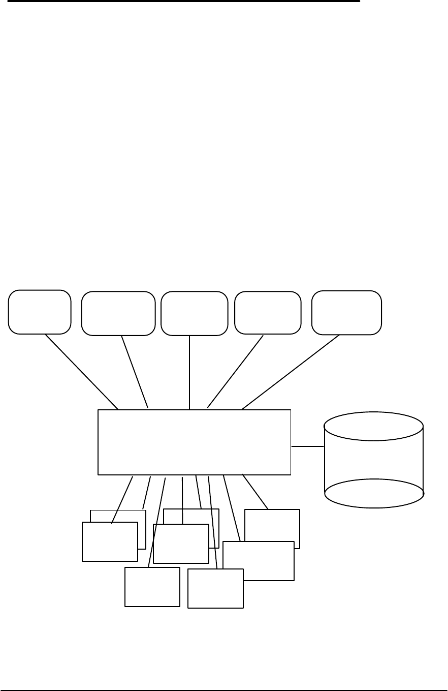
29
The following software is supplied with the DMI package:
• A Microsoft Windows utility, SETUP.EXE, to install and initialize the DMI software.
• A Windows utility, HP TopTools. After DMI is installed, this utility can be used to display
information about the computer through the DMI.
• A Management Information Format (MIF) file. This file contains information about
everything on the computer that can be controlled using DMI facilities, and is initialized
during installation.
• A component code, identifying the version of MIF file to use for specific models of HP
OmniBook Notebook PCs.
• Windows-compatible DMTF Service Layer software, which controls access to the DMI.
• A client agent. The HP Remote DMI Agent is a DMI application and also a network
server-side stream-based application. The Remote Agent is listening for Remote
Application connection requests. If the main window of the Remote Agent is hidden, then
no icon will appear on the screen when it is running.
Figure 14 provides a visual representation of the many components of the DMI package.
Management Applications
Management Interface (MI)
Service Layer
Component Interface (CI)
MIF
Database
Management
console
Desktop
management
application
LAN
management
application
Modem
Word
processor
Hard disk
CD-ROM
Spreadsheet
Printer
Manageable Products
Installation
or setup
program
Support
application
Figure 14 - DMI Components

30
Installing the DMI Package from Windows 95
The DMI package is included with the OmniBook, but it must be properly installed before it can
be used. The following steps explain how.
To install the DMI preloaded on the hard disk:
• Start Windows 95, if it is not already running.
• Click on “Start”.
• Go to “Programs - HP DMI”.
• Select and run “SETUP”.
To alternatively install the DMI from floppy disks;
• Copy the DMI software from the \omnibook\drivers\win95\dmi directory of either the hard
disk or Recovery CD to two floppy diskettes (copy contents of the \disk1 subdirectory to
diskette #1 and contents of the \disk2 subdirectory to diskette #2).
• Start Windows 95, if it is not already running.
• Insert diskette #1 into the floppy drive.
• Select and run the SETUP program from the diskette #1.
Uninstalling the DMI Package from Windows 95
• Go to the HP DMI group.
• Launch the program “Uninstall DMI”.
• Reboot the PC.
Using the DMI Interface
For a complete explanation of how to fully take advantage of DMI, the following documentation
is provided with the OmniBook:
• A README.TXT file.
• A Windows online help file describing Hewlett-Packard’s implementation of DMI (group and
attribute definitions). Since not all Hewlett-Packard enhanced features are supported on all
models, this document also describes any restrictions that apply.
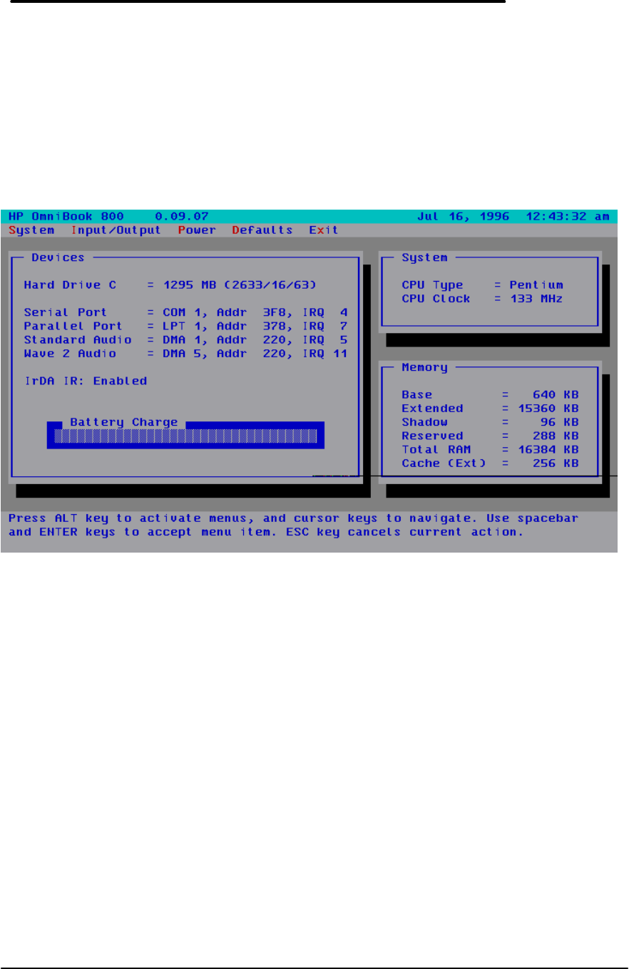
31
Setup and Configuration
The System Configuration Utility (SCU) is an operating system independent pop-up
program. It can only be accessed at boot-time by pressing F2.
SCU Main Screen
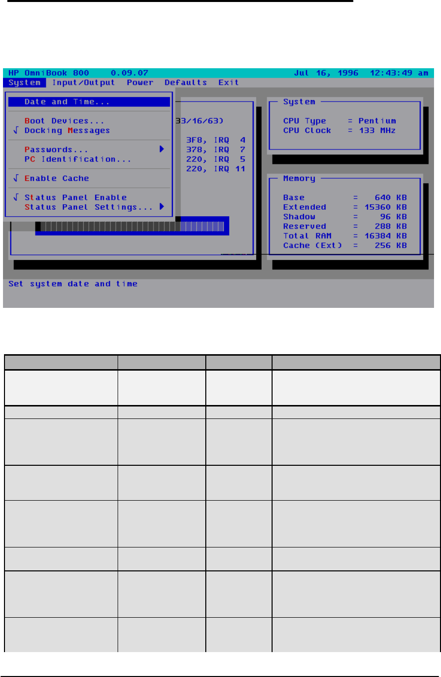
32
System Menu Screen
Table 9 - System Menu Settings
Setting Parameters Default Comment
Date and Time… Day; Month;
Year; Hour;
Minute; Second
n/a Enter appropriate settings for time
and date.
Boot Devices…
Boot Device FDD First; HDD
First FDD First Booting from HDD first is useful for
protecting a computer from
becoming infected by a boot-sector
virus.
CardBus Mode Legacy; Disable;
CardBus Mode Legacy Available only on F1360.
Determines the BIOS power up
mode for the CardBus controller.
Boot Configuration Full; Boot
devices only;
Auto-detect
Auto-Detect Fully configures all PnP devices;
Boot devices only is used with
Win95; Auto-detect will configure
for the loaded OS.
Fast Boot Selected; not
selected Not selected Fast Boot skips RAM test.
Force PCI Bridge
Configuration Selected; not
selected Not selected Configure PCI bridge for use with
Windows NT 3.51. Do not select
this option for other operating
systems.
Hot Dock: OS
Configure PCI Selected; not
selected Not selected Available only on F1360. Allows
the OS to configure PCI devices at
hot-dock.

33
Docking Messages Selected; not
selected Selected Not available if Boot devices only
is selected in Boot Devices
submenu.
Passwords…
Password options…
User Password
required to: Turn ON,
Always;
Turn ON, after
FN-OFF;
Undock;
Save Setup
changes
no
selections Password is required before
proceeding beyond the selected
items, and is ALWAYS required to
save changes to these
checkboxes.
Admin Password
required to save
changes to PC ID
Selected; not
selected Not selected Admin password can be used in
place of any user password.
Disable hard disk
drive lock Selected; not
selected Not selected Check to remove password locking
of hard drive.
Set Admin password none Allows entry of Admin password.
Set User password none Allows entry of User password.
PC Identification blank The text entered (max of 4 lines of
24 chars) will be displayed at boot.
Enable Cache Selected; not
selected Selected Enable cache for faster
performance.
Status Panel Enable Selected; not
selected Selected Enable status panel.
Status Panel
Settings…
Status Panel
Position Upper left; Lower
left; Upper right;
Lower right
Lower right Determine where status panel
appears in the display.
Items to Show in SP Determine what items are
displayed in the status panel, and
when they are displayed
Battery Status Always; Never;
Only when low. Always
Keyboard Status Always; Never;
Only when
locked.
Only when
locked
Hard Drive Status Always; Never;
Only when active Only when
active

34
Password Configuration
The Password Options dialog allows the User and an Administrator to control access to certain
portions of the OmniBook.
If an Administrator Password is set, then modification of the PC Identification Strings or some
SCU settings may be restricted by checking the appropriate checkboxes. Note that even if an
Administrator Password is required to Save setup changes, the User Password (and its
associated options) can still be changed without knowing the Administrator Password.
The Save setup changes option does not apply to changing PC Identification (PCID) Strings.
The ability to change PCID strings can only be restricted by the Save modifications to the PC ID
texts checkbox available under Admin Password.
If the User Password is set, then access to the machine may be restricted (at every turn-on, or
only at turn-ons after the machine was turned off by pressing FN+OFF). Also, if Undock is
checked, a password will be required before the machine can be undocked. Also, the User
Password may be required before some changes to the SCU, even if no Administrator Password
has been entered.
The following table illustrates which SCU settings are subject to password protection.
Table 10 - System Password Matrix
SCU Feature Password Never
Required Password may
be Required
Date/Time X
Boot Devices User or Admin
PC ID Admin only
Status Panel X
HDD Configuration User or Admin
COM Ports User or Admin
LPT Port/LPT Type User or Admin
Keyboard Setup X
External Devices X
Power Management X
Basic/Advanced Audio User or Admin
User PW or User PW Options User or Admin
Admin PW when none
currently exists User
Admin PW or Admin PW
Options (Admin PW exists) Admin
As mentioned above, PC Identification can only be password-protected via the Administrator
Password PC ID option.
Any time a password is required, the Administrator password (if defined) may be entered,
however, only the Administrator password may be (successfully) entered to satisfy the
conditions checked in the Administrator Password required to: group box.
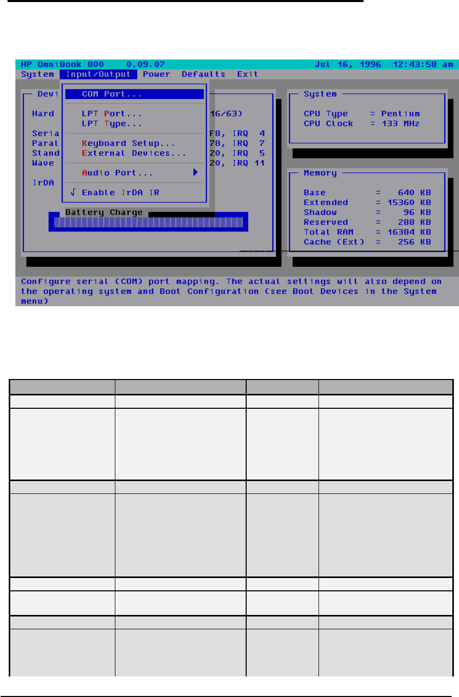
35
Input/Output Menu Screen
Table 11 - Input/Output Menu Settings
Setting Parameters Default Comment
COM Ports…
Serial Port: None
COM1, Addr 3F8, IRQ 4
COM2, Addr 2F8, IRQ 3
COM3, Addr 3E8, IRQ 4
COM4, Addr 2E8, IRQ 3
COM1, Addr
3F8, IRQ 4 The serial port will be
mapped to the selected
COM port. The actual
settings will also depend
on the operating system
and Boot Configuration.
LPT Port
Printer Port None
LPT1, Addr 378, IRQ7
LPT2, Addr 278, IRQ5
LPT1, Addr
378, IRQ7 The parallel printer port
will be mapped to the
selected LPT port. The
actual settings will also
depend on the operating
system and Boot
Configuration.
LPT Type
Port Definition Standard AT (Centronics)
Bidirectional (PS-2) Bidirectional
(PS-2) Select the parallel port
definition.
Keyboard Setup…
Key Delay ¼ sec; ½ sec; ¾ sec; 1
sec ½ sec Select the delay period to
wait (after a key is
pressed) before it will
begin to repeat.

36
Setting Parameters Default Comment
Key Repeat
Rate 2 cps; 6 cps; 10 cps; 15
cps; 20 cps; 30 cps 10 cps Select the rate at which
keys will be repeated when
they are held down longer
than the Key Delay period.
Keyboard
Numlock Selected, Not selected Not selected Start computer with NUM
LOCK enabled.
External Devices…
VGA Display
device External VGA if attached,
LCD off;
Both external VGA and
LCD
External
VGA if
attached,
LCD off;
When ‘External VGA…’ is
selected, if an external
VGA monitor is detected, it
will be enabled and the
LCD will be turned off.
When ‘Both external
VGA…’ is selected, both
are ALWAYS on.
Force
recognition of
external VGA
Selected; Not selected Not selected Available only when Both
external VGA and LCD is
selected.
Enable External
FN Key Selected; Not selected Selected When enabled, CTRL +
ALT on external keyboard
acts as FN key.
Ignore External
Pointing Device Selected; Not selected Not selected This will ignore any
external pointing device.
Audio Port…
Basic Audio…
Disable internal Selected; not selected. Not selected. Disabling internal sound
board removes any
possible conflict with a
sound board installed in
the dock.
Beeper volume: 0-7 4
Audio volume 0-7 4Sets master volume, not
volume ceiling.
Advanced Audio… If Boot devices only is
Audio selected in Boot Devices
IRQ 5, 7, 9, 10 5menu, then the Advanced
DMA
Channel 0, 1, 3 1Audio menu will be
Address 220, 230, 240, 250 220 disabled.
Wave 2 Audio
IRQ 11 11 IRQ is fixed at 11
DMA 0, 5, 6 5
Video Stretched Selected; not selected Not Selected Option available on F1360
only. Set video to
Stretched or Centered
mode (if hardware
capable).
Enabled IrDA IR Selected; not selected Selected Allocate resources needed
to enable IrDA Infrared
Port.
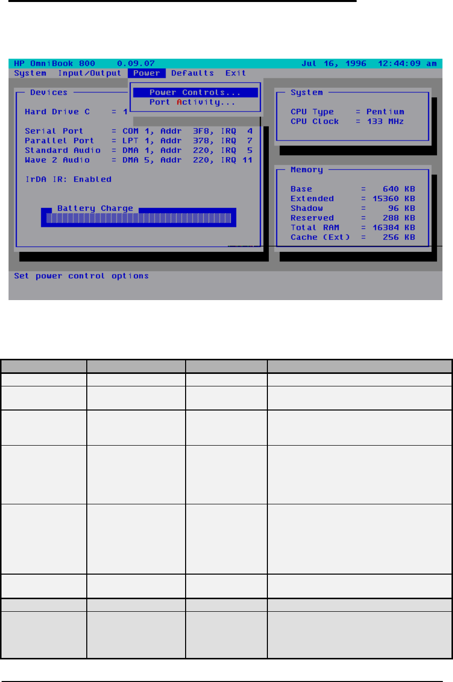
37
Power Menu Screen
Table 12 - Power Menu Settings
Setting Parameters Default Comment
Power Controls
CPU Power
Management Maximum;
Moderate; None Maximum Determine the amount of CPU-related
power savings.
Auto Turn-off
w/Battery: Never; after 1, 2, 3,
4, 5, 10, 15, 20, or
30 minutes
after 3 minutes When the system has been idle for the
selected period, the computer will be
turned off. (Battery power only.)
HDD power-
down
w/Battery:
Never; after 1, 2, 3,
4, 5, 10, or 15
minutes
1 minute The hard disk will be powered down if
there has been no disk access for the
selected period. Hard disk power will
be restored when the disk is needed
again. (Battery power only.)
Auto Turn-off
w/AC: Never; after 1, 2, 3,
4, 5, 10, 15, 20, or
30 minutes
Never The hard disk and display are powered
down if there is no disk access or user
input for the selected period. Hard
disk power is restored when the disk is
needed again. Display power is
restored when the ON key is pressed.
Enable audio
power savings Selected; Not
selected Not selected Enables power-down of audio analog
when idle. Also shuts off line-in.
Port Activity
Auto Turn-off,
Even if Active IRQ3, IRQ4, IRQ5,
IRQ7, IRQ9,
IRQ10, IRQ11,
IRQ15
none selected
(all selected on
F1360 only)
Indicate IRQ activity that should be
ignored with regard to automatic turn-
off.
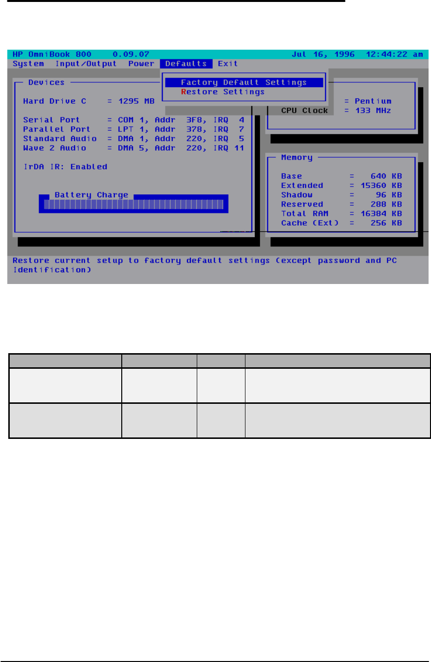
38
Default Menu Screen
Table 13 - Default Menu Settings
Setting Parameters Default Comment
Factory Default
Settings n/a Restore current setup to factory default
settings (except password and PC
Identification).
Restore Settings n/a Restore current setup to settings at
SCU startup (except password and PC
Identification).
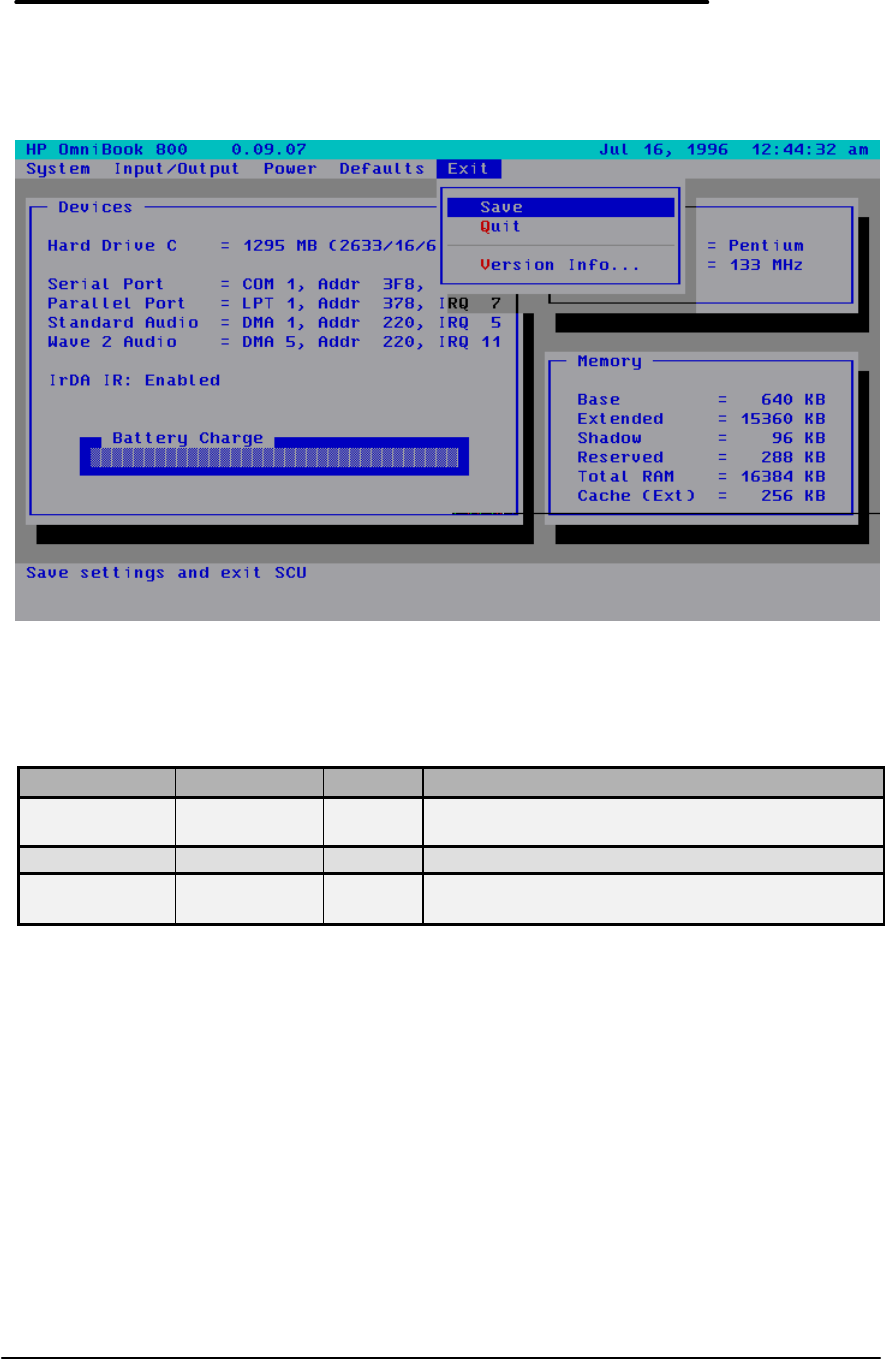
39
Exit Menu Screen
.
Table 14 - Exit Menu Settings
Setting Parameters Default Comment
Save n/a Save settings and exit SCU. The OmniBook will
automatically reboot.
Quit n/a Exit SCU without saving settings.
Version
Info… n/a Report current BIOS version info.

40
Troubleshooting Tips
This section provides various troubleshooting tips for the OmniBook 800 and its accessories. As
with all troubleshooting, these tips should be combined with other techniques and tools to
effectively diagnose hardware issues.
OmniBook Components
The following table lists various symptoms of several OmniBook components. Troubleshooting
techniques are then listed for both Call Center and Repair Center Personnel.
Table 15 - OmniBook Troubleshooting Tips
Symptom Call Center Repair Center
Mouse
Cursor moves on its own Is the link warped? (The link is
the flat piece of plastic Mouse grommet (Service Note
800-08). Alternatively, inspect
Cursor floats in direction
different for mouse
movement
connecting the mouse to the
computer) If so, send the
customer a new mouse.
for a burr on a contact inside
the hole the grommet fits in on
the logic board (carefully file
off the burr).
Cursor sticks to one side of
display after mouse has
moved in opposite direction
Otherwise, send in for repair. Sticking can be an open or
missing resistor on the logic
board. Replace logic assy.
Cursor won’t go to edge of
display Press firmly with mouse when
reaching edge of screen. If
problem still occurs, send in for
repair.
Mouse grommet or paw active
assy; if cursor won’t move at
all, most probably a bad paw
active assy. Also could be an
open resistor on logic board.
Cursor jitters Send in for repair Paw active assy or warped link.
Mouse button press not
recognized Does customer have access to
another OB with a mouse? If so,
swap mouse. If OB works now,
send a new mouse. If not, send
in for repair.
Mouse or paw active assembly
Stiff up/down motion Send in for repair Paw active assembly (Service
Note 800-10)
Fine positioning of cursor
difficult Some vertical backlash on the
right side of the display is
normal. It requires slightly more
mouse movement on the right
side before the cursor moves.
Paw active assembly
Display
Brightness does not adjust The adjustment steps are very
small and may not be very
noticeable. Also, TFT display
will not darken as much as a
CSTN, so customer’s previous
experiences with notebooks may
affect expectation.
Verify brightness adjusts
properly. If ineffective, replace
display.
Garbage on display when
first turned on Try a hard reset. If this doesn’t
help, send in for repair. Replace logic PCA if problem
occurs on both internal and

41
Symptom Call Center Repair Center
external displays.
Screen white Send in for repair. Replace display
Bright or missing pixels or
lines Explain display spec for missing
pixels. Send in for repair if it
fails display spec criteria.
Replace display if it fails
display spec criteria.
Intermittent or no display Press [Fn]+[SysRq]. If
ineffective, send in for repair. Check for display cable
pinched in case parts.
Power/battery
Short battery life Turn display brightness down. New BIOS v 1.02.00
New BIOS v 1.02.00 Run PWR800.exe to measure)
Set Computer and Hard Drive
“Idle Time Before Turn-off” to
equal values (Select OmniBook
Power Management in Control
Panel).
battery life (program obtainable
from the MCD Internal Web at
http//webmcd.cv.hp.com/prods
upp/ob800/software/index.htm
Remove any PCMCIA cards and
run PWR800.exe
If above ineffective, send in for
repair.
Battery gauge falls rapidly Normal behavior at higher levels.
Does the customer have another
battery to try?
Battery won’t charge Does customer have access to
another battery and ac adapter?
If so, have them try different
combinations to isolate to
battery, ac adapter or
OmniBook, and send defective
component in for replacement. If
not, send in all 3 for repair.
Isolate to defective component
(battery, ac adapter or logic
board).
Computer won’t turn
on/won’t boot
On ac or battery Is the charge light on when on
AC? If not, try another AC
adapter if available. If yes, hard
reset. If no response, remove
battery and AC, letting computer
sit for a minute. Reinsert battery
and press reset button. If this
works, update the BIOS. Any
sound? If yes, plug in external
display and press [Fn]+[SysRq].
Check for display cable
pinched in case parts. Is
charge light on when on AC? If
no, replace CPU board first,
then logic board. If yes, try to
boot off a floppy. If this works,
reburn BIOS. If it’s still bad,
then replace HD. If still bad,
replace logic board and
reinstall old HD.
On battery (OK on ac) What does the fuel gauge read?
If empty, press [f4]+[ON]. If still
empty, does customer have a 2nd
battery to try? If not, send in for
repair.
Try a known good battery first.
Examine battery contacts for
contamination or physical
damage. Then replace logic
board.
Error message: “Invalid
system disk” If floppy drive is connected,
check for non-system (boot)
floppy disk in drive. If so,
remove floppy and reset. Use
recovery CD to rebuild system if
still bad.
Will computer boot off floppy
drive? If yes, verify keyboard
support plate is of later design
or has I/O insulator (see
Service Note 800-09). Verify
hard drive insulator is above
Error message: “Floppy disk the keyboard support plate tabs

42
Symptom Call Center Repair Center
fault – insert valid boot disk
and press any key” and not trapped under them
(where they can short hard
drive PCA). Then try another
hard drive. If problem is
solved,
Error message: “Auto IDE
error” or “HDD not ready” Verify latest BIOS (v1.02.00).
Send in for repair. original HD may be corrupted,
have a virus or be defective. If
problem persists, reinstall old
HD and try replacing the CPU
board and if that doesn’t work,
then replace the logic board.
Lockup/computer freezes
After warm docking Verify latest BIOS (v1.02.00). New BIOS v 1.02.00
After hot docking Does the user have an external
monitor? If so, BIOS versions
after 1.00.00 may exhibit this
problem about 5% of the time. A
future revision of the BIOS will
address this issue.
After undocking Is there a card in dock? Remove
card from undocked
configuration.
Is the user an HP COE user? If
so, does the user use COE
Connect and COE Disconnect?
If not, refer them to their IT dept.
for instructions.
While booting Press reset button.
If ineffective, can user boot from
floppy? If no, send in for repair.
If yes, run CHKDSK /f on hard
drive, then attempt to boot from
HD again.
Can you boot from floppy? If
no, replace CPU first, then
logic board. If yes, run
CHKDSK /f on hard drive, then
attempt to boot from HD again.
Run Scandisk to check for HD
platter defects. Verify
keyboard support plate is of
later design or has I/O insulator
(Service Note 800-09).
After turning on New BIOS v 1.02.00 New BIOS v 1.02.00. Try
replacing HD, then CPU, and
then logic board.
When shutting down, during
“Windows 95 Shutting Down”
screen
Microsoft has a web page to help
with these problems, which are
usually the result of driver
conflicts.
(www.microsoft.com/kb/articles/q
145/9/26.htm)
If HP COE user, make certain
they are using COE Disconnect.
Refer them to their IT
department.
Keyboard
Keys stiff Is customer comparing OB800
keyboard to other notebook or
desktop keyboards? Is customer
If the keyboard is stiff, replace
with a new keyboard of
datecode Aug 1 or later.

43
Symptom Call Center Repair Center
comparing it to another OB800?
Is customer a heavy user?
Some or all keys not working Remove the 2 keyboard screws
and check keyboard flex cable
connections visually. If not
aligned properly in the
connector, send in for repair.
These connectors can be
damaged if the proper tool is not
used to disconnect the cables.
Check keyboard flex
connection. If OK, try another
keyboard. If still bad, replace
logic board.
Computer noisy but working
HDD “clunking or scratchy” Was the computer dropped?
Back the drive up immediately! Replace HD. Check computer
case for evidence of customer
abuse.
Buzzing or whining Back the drive up immediately!
Is the sound present when HD
not spinning? Is there a
PCMCIA hard drive in the slot
that is making the noise? Does
pressing a key cause the sound
to change? If yes, then this is
probably power supply noise.
Only if it is very objectionable
should computer be sent in for
repair.
Replace logic board.
Miscellaneous
Computer does not resume
after:
• Being suspended
• A reset
• An alarm from an
application
Try using reset button. Check
BIOS version and install latest
(v1.02.00). Otherwise, send in
for repair.
Replace CPU board (see
Service Note 800-02A).
File corruption Run a virus scan program. Boot
to DOS and run CHKDSK to look
for lost clusters, cross-linked
chains. If present, run CHKDSK
/f to fix. Then run Scandisk
surface scan to test for damaged
HD platter. Use Recovery CD to
recover Omnibook files
corrupted. If computer still has
problems, return for repair.
Try steps at left. If keyboard
support plate of old design
(without notch), add I/O
insulator to plate above HD
connector (see Service Note
800-09). Check for latest BIOS
(v 1.02.00). Run a virus
checker.
Computer gets hot It is normal for computer to get
hot, especially when charging.
DOS applications (games?) and
poorly written Windows
applications can contribute. Run
System Monitor and look at CPU
activity. Suspend applications
that drive CPU usage toward
100%. PCMCIA modem cards
normally get very hot when in
use.
Computer won’t time out Does the cursor jitter? If so, Does the cursor jitter? This will

44
Symptom Call Center Repair Center
(i.e., doesn’t automatically
turn off after a preset
interval)
send in for repair. If not, check
the timeout settings in Omnibook
Power Management in the
Control Panel. Set hard drive
timeout = computer timeout. A
future BIOS will address this
issue.
prevent timeout. If so, replace
paw active assembly.
Computer pauses and won’t
permit kybd or mouse input
for a few seconds
This is probably normal W95
behavior. The operating system
processes events in the
background and sometimes
these interfere with the
responsiveness of the
application.
If the hard disk has spun down to
conserve power, it can take up to
five seconds to spin back up.
You can hear this happen. You
can set the hard drive timeout
equal to the computer timeout
such that this does not happen
often.
COE users should use COE
Disconnect and recognize that
various COE activities (like virus
scans) are happening in the
background.
Some file browsers (like the one
in PowerPoint in the Insert
Picture dialog box) will process
and display a graphic image
before they respond to keys.
This can take twenty seconds.
File browsers may wait for
broken/non-existent network
connections to time out.
PCMCIA cards recognized
but not available for use. If this occurs with PCMCIA HD,
flash card or LAN card, it may be
the computer has run out of
IRQ’s. Check in System
Properties for available IRQ’s. If
card is an ATA card, install new
driver, SSHP800.VXD (see
Service Note 800-03). Also try
the card in another machine
and/or run diagnostics on the
card.
If card is an ATA card, install
new driver, SSHP800.VXD
(see Service Note 800-03).
If HP COE customer,
modems/PCMCIA cards not
recognized consistently
See local IT dept for a PC COE
Reliability Tracker patch which
solves this problem.
Difficult to install RAM
expansion door Was RAM expansion just
added? Does door work without
RAM expansion? If yes to both,
send in RAM for replacement.
Was RAM expansion just
added? Does door work
without RAM expansion? See
Service Note 800-11.

45
Symptom Call Center Repair Center
Dock latch jammed, won’t
permit computer to dock Try manual undocking to get the
system apart. See dock User’s
Guide (pg 1-13 English or
appropriate language’s page) for
procedure. Send in dock for
repair.
Replace dock
Clock won’t keep time In Control Panel, click on Power.
Power Management must be set
to Advanced. Has the computer
ever failed to resume and had a
dead battery (causing the clock
to stop)? If so, replace the
BIOS.
Verify that Power Management
is set to Advanced. Test clock
accuracy with unit suspended.
If still not accurate, replace
logic and retest.
Computer runs slow See: “Computer pauses and
won’t permit keyboard or mouse
input for a few seconds.”
Make sure cache is enabled in
SCU. If yes, then
press [Fn][+]. One beep
indicates slow mode, 2 beeps
fast mode. If problem persists,
send in for repair.
Verify problem and replace
CPU first, then logic board.
Hard drive errors Can use Spin Rite 4 to
thoroughly diagnose the
problem.
RAM module does not fit
into OmniBook connector If the RAM module does not
connect 1000% try another
module. A few of the RAM
modules received from the
vendor are out of alignment.
CD ROM Drive Troubleshooting
The following table lists several troubleshooting tips specifically for the optional CD-ROM drive.
Table 16 - CD-ROM Troubleshooting Tips
Trouble Possible CausesSolutions
• The POWER switch is
ON, but nothing appears
on the CD-ROM display.
• The power cable is not
plugged into the
OmniBook connector or
the DC IN jack.
• The batteries are not
installed correctly or are
dead.
• Plug in the power cable correctly.
• Install the batteries correctly or
replace with new ones.

46
Trouble Possible CausesSolutions
• The CD-ROM drive is not
accessible from the
OmniBook.
• For Windows 95, the CD-
ROM drive was not turned
on when you plugged it
into the OmniBook.
• For Windows for
Workgroups, the CD-ROM
drive was not turned on
when you rebooted the
OmniBook.
• Turn on the drive, then click Start,
Eject PC. When prompted, unplug
and reconnect the SCSI adapter
cable to the OmniBook.
• Turn on the drive, then exit
Windows and press
CTRL+ALT+DEL to reboot.
• The data from the CD is
not properly transmitted
to the OmniBook.
• The SCSI adapter cable is
not connected properly.
• Devices with duplicate
SCSI ID numbers are
connected to the
OmniBook.
• SCSI termination on the
CD-ROM drive is OFF.
• There is a problem with
the OmniBook software.
• Connect the SCSI adapter cable
correctly.
• Make sure each SCSI device
connected to the OmniBook has a
unique ID number.
• Change the terminator switch
(switch 4) on the CD-ROM drive
from OFF to ON.
• See the OmniBook User’s Guide.
• A “no dISC” message
appears on the display
after inserting a CD, the
sound skips, or data can
not be read.
• The CD is upside down.
• The CD is dirty.
• The CD is damaged.
• There is moisture on the
CD-ROM drive or the CD,
possibly due to
temperature change
condensation.
• Reinsert the CD with the label side
up.
• Clean the CD with a soft, dry cloth.
• Replace with new CD.
• Remove the CD from the CD-ROM
drive and do not use for 1 hour.
• The CD-ROM drive does
not play sound. • Headphones or amplified
speakers are not
connected to the CD-ROM
drive.
• VOLUME control is set to
“0”.
• Connect the headphones or
amplified speakers to the CD-ROM
drive PHONES jack.
• Set the VOLUME control to a
higher number.
• The control buttons do
not function. • CD-ROM drive has been
playing audio CD
controlled by OmniBook
software.
• Open and close the disk cover.
• The control buttons and
POWER switch do not
function.
• Disconnect the CD-ROM power
cable and remove the batteries,
then reconnect the power cable
and reinstall the batteries.
Resolving Docking Station Operating Problems
Below are several scenarios of Docking Station operating problems. Possible causes and
troubleshooting tips are provided for each.
If a serial or parallel device, external display, or floppy drive doesn’t work
• Make sure the OmniBook is fully inserted in the docking system. Connection should be snug.
• If the green light on the docking system isn’t on, check power to the docking system, then try
undocking and docking again.
If an external PS/2 mouse or keyboard doesn’t work
• Make sure the OmniBook is fully inserted in the docking system. Connection should be
snug.

47
• Make sure the mouse is plugged into the correct port. The mouse and keyboard ports look
the same.
• Turn the system off and on.
• Reboot the system.
• Undock the OmniBook, unplug and reconnect the ac adapter, then dock again.
If network connections don’t work
• Make sure that the LAN cable is connected.
• You normally lose connections when you turn off the system or undock. See if your network
software has a reconnect feature.
• Check your configuration files to make sure that the network drivers are properly installed.
• If the green light on the docking system isn’t on, check power to the docking system, then try
undocking and docking again.
• Check that there is no address or interrupt conflict. Check these settings on the network
board—or, if the board has configuration software, check the settings using that software—
see the manual for the network board. Also check these settings in your network software.
If SCSI devices don’t work
• Try rebooting and selecting a startup option that loads the SCSI drivers.
• Check the device id for conflicts.
• Make sure you turn on the SCSI devices before you reboot the system. They're configured at
boot time.
• Check your connections and SCSI termination.
• Check your configuration files to make sure that the SCSI drivers are properly installed.
• Try pushing the OmniBook into the docking system a bit harder.
• If the green light on the docking system isn’t on, check power to the docking system, then try
undocking and docking again.
• Check that there is no address or interrupt conflict. The SCSI interface normally uses I/O
address 3100F and interrupt 10.
If a network-enabled system locks up when rebooting
The following hints apply to Windows for Workgroups only:
• Edit AUTOEXEC.BAT to disable Windows for Workgroups network support for all non-
network startup options. Add the /N switch to the WIN command (win /n) for each of the non-
network options.
• Edit CONFIG.SYS and AUTOEXEC.BAT to load network drivers only for the “Docking
system” startup option, and not for undocked startup options.
For other operating systems:
• Check any available online tools—Device Wizard in Windows 95, for example—or check
with your system administrator.
Resolving OmniBook Docking Problems
Below are several scenarios of problems that may occur when docking the OmniBook. Possible
causes and troubleshooting tips are provided for each.
If your docking password isn’t accepted
• Check whether Num Lock is off.
• If you’ve forgotten your password, have your OmniBook at hand and call Hewlett-Packard
support. See your OmniBook Support and Service booklet.

48
If the OmniBook isn’t released after pressing the Undock button
• If you’re using a password, make sure it’s accepted.
• If you’re prompted about shutting down devices, and if no applications are using those
devices, press ENTER. Otherwise, close those applications and try undocking again.
• To override the undocking software, press a paper clip or other thin object into the security
opening in the docking system. Hold it in while sliding one release latch forward.

Part 3
Hardware Repair
• Battery
• Memory
• Hard Disk Drive
• Mouse
• Small Parts
• Keyboard
• Display
• CPU
• Logic PCA
• Paw Active
• Other Components and Accessories
CAUTION:Always provide proper grounding when performing any of the
following repairs. An electrostatic discharge may cause irreparable
damage to the OmniBook and its components
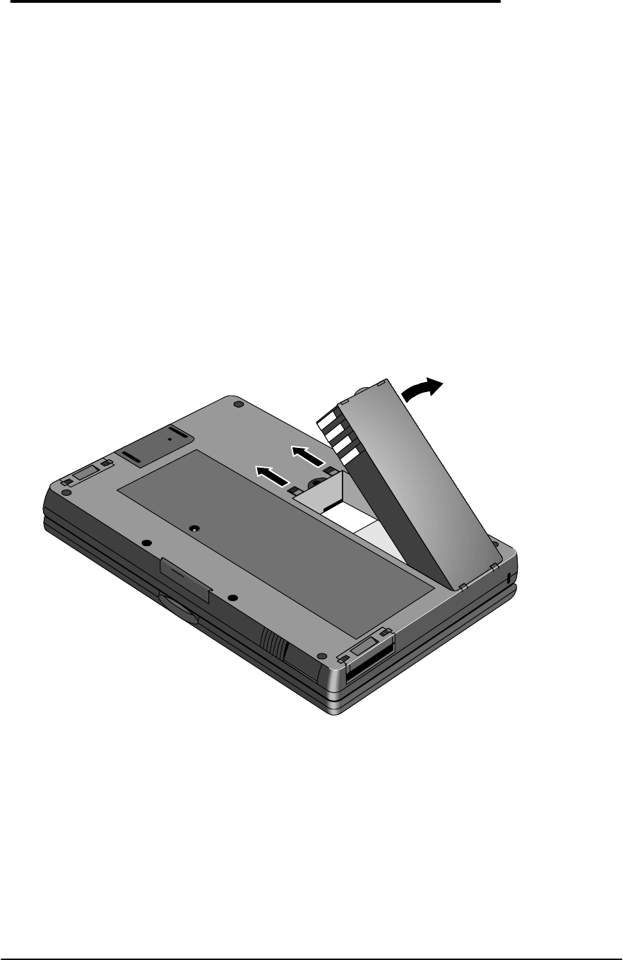
50
Battery
(End User Replaceable)
WARNING:Do not mutilate, puncture, or dispose of batteries in fire. The batteries can
burst or explode, releasing hazardous chemicals. A rechargeable battery
pack must be recycled or disposed of properly.
Required Equipment
• none
Removal Procedure
1. Turn the OmniBook off. If ac power is plugged in, don’t remove the ac power while the
battery is out.
2. Turn the unit over and slide the two latches away from body of battery and lift the battery
out. See Figure 15.
Replacement Procedure
1. Insert the new battery pack so the metal battery contacts on the pack line up with the
contacts in the compartment, then latch the cover.
Figure 15 - Removing the Battery
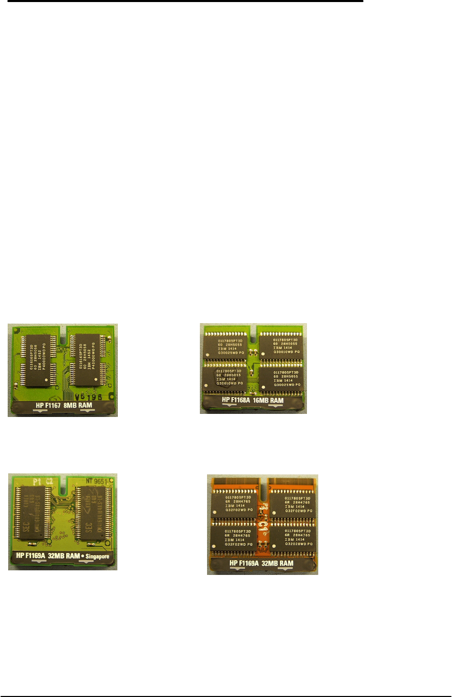
51
Memory
(End User Replaceable)
Required Equipment
• none
CAUTION:To avoid damage due to electrostatic discharge, handle the memory module
by the edges only.
Removal Procedure
1. Exit all applications, including Windows.
2. Remove the ac adapter and battery from the OmniBook.
3. Turn the unit upside down and slide the memory cover off by using the two finger grips. See
Figure 18 on page 52.
4. To remove the Memory Module, gently lift up the front of the module to disengage the pins.
CAUTION:If the memory module is an older model of the 32-MB RAM (see Figure 17)
take care not to crimp the flex cable end when removing or replacing.
Figure 16 - 8- and 16-MB Memory Modules
Figure 17 - New and Old 32-MB Memory Module (respectively)

52
Replacement Procedure
1. To replace, position the non-connector end first, then press the front of the module down into
the connector.
CAUTION:Apply pressure to the memory module only on the connector to avoid
damaging the circuit board.
Figure 18 - Removing the Memory Module
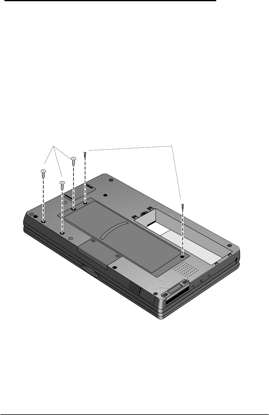
53
Hard Disk Drive
(End User Replaceable)
Required Equipment
• Torx #6 screwdriver
Removal Procedure
1. Exit all applications, including Windows.
2. Turn the OmniBook off and remove the battery and ac adapter.
3. Use a Torx-T6 screwdriver to remove the two keyboard screws and the three hard drive
screws (the exact location of the hard drive screws vary with the manufacturer of hard drive).
See Figure 19.
4. Turn the OmniBook over and open the cover. Grasp the top edge of the Keyboard and fold
out gently. Note – the Keyboard Flex Cables do not need to be disconnected. See Figure
20 on page 54.
CAUTION:To avoid damage due to keyboard flex cables, do not pull the cables out of
the connectors or pick up the OmniBook while the keyboard is still
connected.
Figure 19 - Hard Drive Screws
Hard Drive Screws
M3.0x0.5x5.0mm
1.5 - 3.5 in-lb
(p/n 0515-2847)
Keyboard Screws
M2.0x0.4x7.0mm
1.5-3.5 in-lb
(p/n 0515-2846)
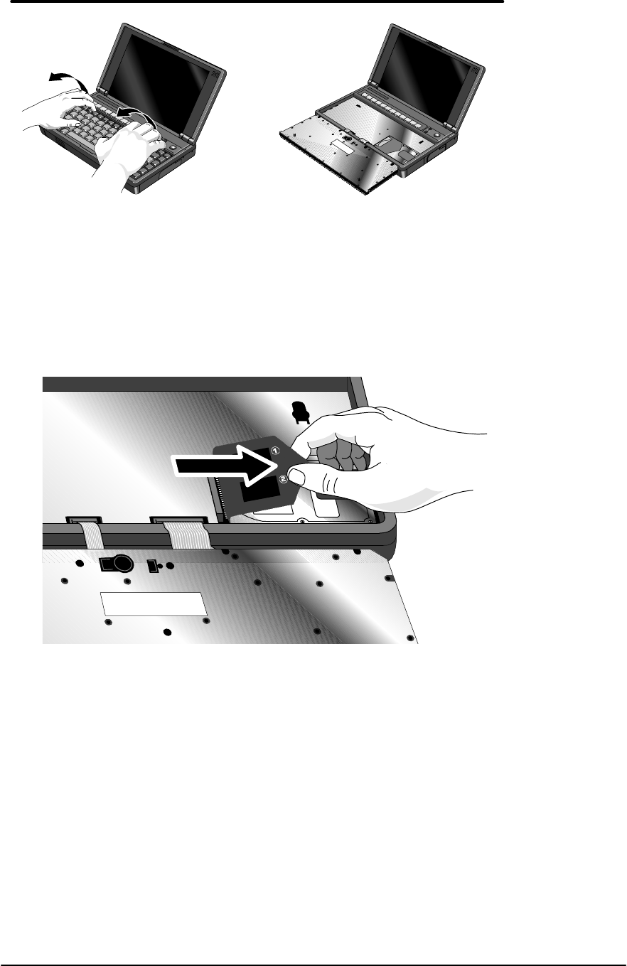
54
5. Disengage the hard drive connectors by grasping the left flap of the plastic insulator and
gently pulling straight to the right as shown in Figure 21.
CAUTION:To avoid damage to the hard drive connector, do not pull the hard drive
insulator up or at an angle – only straight to the right.
6. Lift up on the insulator sheet and remove the hard drive. See Figure 22. The insulator sheet
stays in place.
CAUTION:Handle the hard drive only by its edges to avoid damage from electrostatic
discharge.
Figure 20 - Folding the Keyboard Open
Figure 21 - Hard Drive Removal
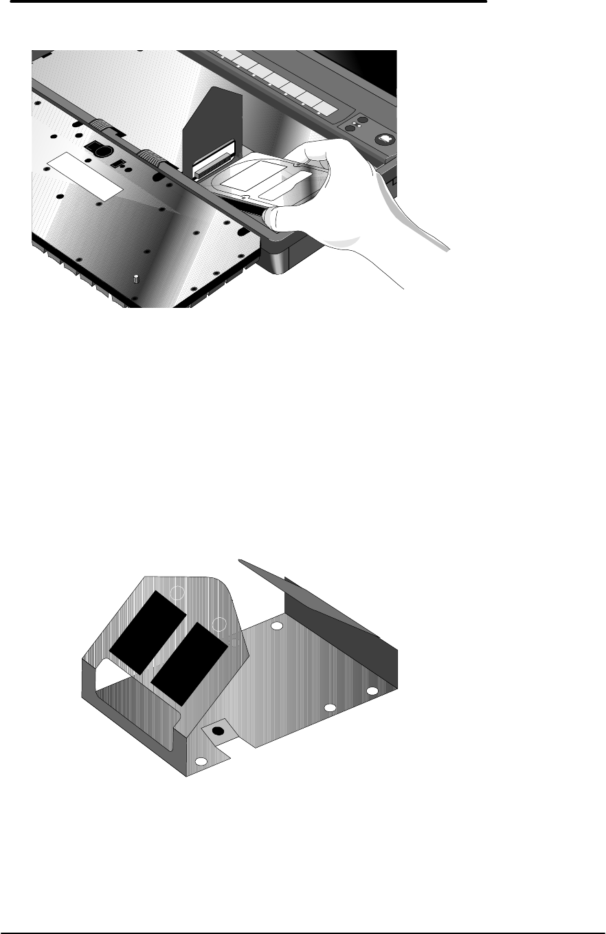
55
Replacement Procedure
1. If the new hard drive is from a different manufacturer than the old one, it may have screws in
different positions. Determine which mounting holes in the bottom case are needed; then, if
necessary, push out the rubber screw-hole covers from the inside of the bottom case. (From
the outside of the computer, insert the rubber covers into the holes that are not needed.)
2. If the new hard drive has screws in different positions from the old one, the insulator sheet
will also need to be adjusted. Compare the location of the screw-holes in the new hard drive
with those in the insulator sheet. If there is no screw at position A, then unfold the flap at
position A, and lay it flat before laying the hard drive down on the insulator. See Figure 23.
3. Holding the new hard drive by its edges, lay it in place. Grasp the right flap of the insulator
and pull to the left to engage the connection between the hard drive and the computer. See
Figure 24 on page 56. If the hard drive’s connectors do not engage the computer’s
connectors, pull the hard drive back out and try again. Then fold the insulator sheet back
over the hard drive.
Figure 22 - Hard Drive Removal (continued)
1
2
Figure 23 - Hard Drive Insulator Flap
A
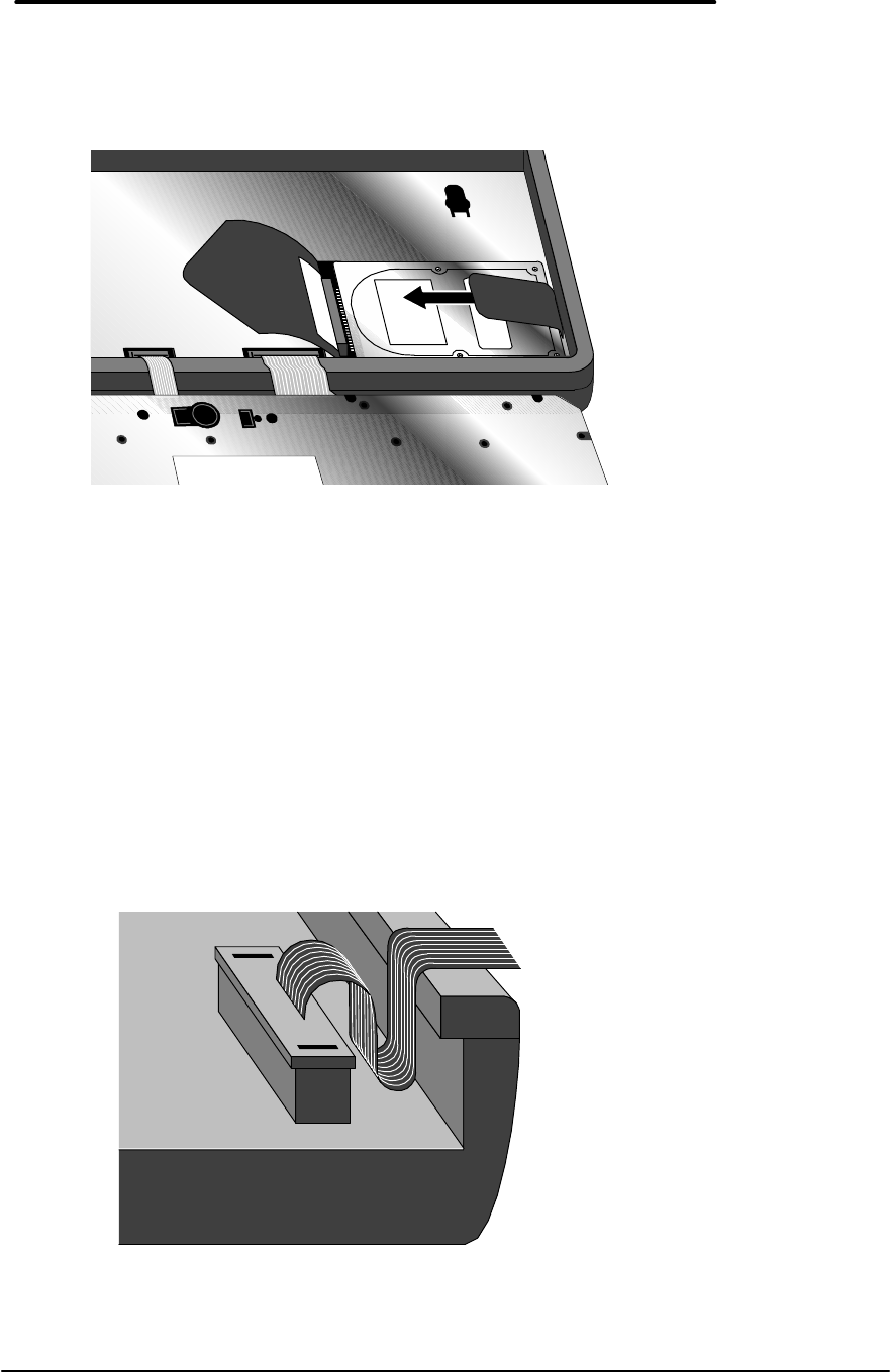
56
CAUTION:Do not force the drive into the connector or the pins may bend and cause
damage to the hard drive.
4. Holding the Keyboard in place, so as not to damage the flex cables, turn the OmniBook over
and re-insert the three hard drive screws removed in step one. Note, it may be necessary to
support the hard drive with one hand in order for the screws to engage.
CAUTION:Do not over-tighten the hard drive screws—screw just until you feel
resistance (1.7 in.-lbs.). If the screws are over-tightened, the HDD may not
function properly.
5. Fold the Keyboard in place and tuck the Keyboard Flex Cables into the frame of the
OmniBook. See Figure 25.
CAUTION:To avoid damage to the keyboard flex cables, they must be positioned
properly in the OmniBook frame.
Figure 24 - Inserting the Hard Drive
Figure 25 - Proper Keyboard Flex Cable Position
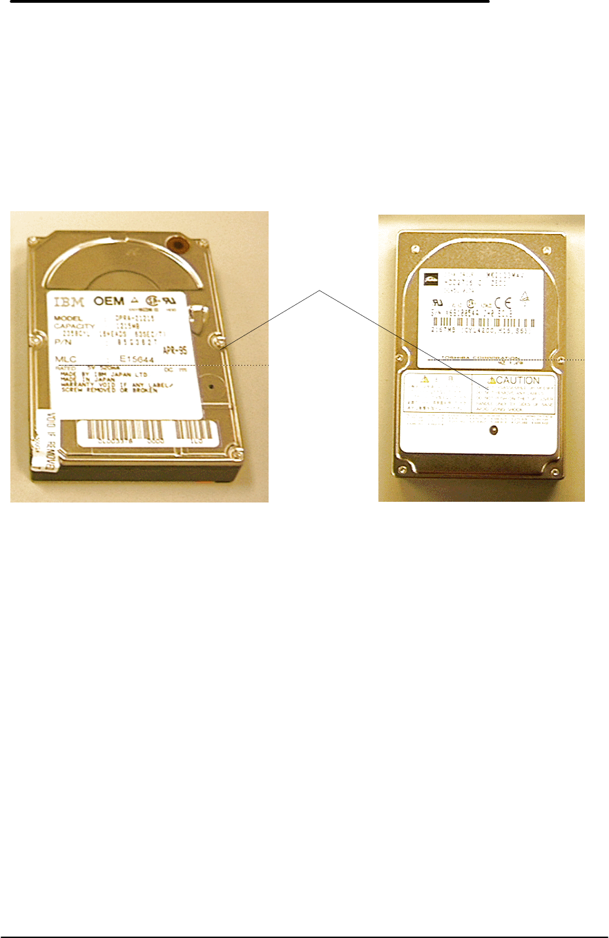
57
6. Replace the two Keyboard Screws and the remainder of the components and reboot.
Hard Disk Drive Breather Holes
Hard drives used in the OmniBook 800 have a breather hole located on the metal side of the
drive (see Figure 26 for location of breather holes for both IBM and Toshiba). The hole is
necessary to provide pressure equilibrium. The breather holes must not be obstructed. Any
labels covering this breather hole must be removed to prevent data loss on the hard drive.
Just below the metal surface of the drive, a white material can be seen through the breather
hole. This is a filter and should not be disturbed. A drive with this filter damaged should be
considered defective.
Figure 26 - IBM and Toshiba Hard Drive Breather Holes (respectively)
Breather
Holes

58
Mouse
(End User Replaceable)
Required Equipment
• none
Removal Procedure
1. Press the mouse-eject button to eject the mouse.
2. Pull the mouse firmly away from the OmniBook (see Figure 27). The entire mouse assembly
will pull free.
Replacement Procedure
1. Place the end of the mouse “stick” into the mouse housing.
2. Slide the mouse into the slot and firmly push the mouse until it is completely flush with the
side of the OmniBook.
Figure 27 - Removing the Mouse

59
Small Parts
(End User Replaceable)
The following small parts are all end user replaceable.
Battery Latch
Once the battery is removed (refer to the Battery Removal Procedure on page 50), the battery
latches will slide out of the bottom case. To replace, align the sides of the latches with the
grooves in the slots. Press firmly into place.
I/O Door
To remove the I/O door, open it fully. Flex the middle of the door until the side pins clear the
holes in the back case. Reverse to replace.
Memory Cover
Slide the memory cover off by using the two finger grips. Replace by aligning the edges of the
cover with the slots on the bottom case. Slide firmly into place.
PCMCIA Card Tray
Slide the two tray latches toward each other. Pull the tray out of the card slot. If present,
remove the PCMCIA card from the tray. To replace the tray, insert into the appropriate card slot.
Slide the two latches away from each other to secure the tray.
Rubber Feet
Place a probe or similar device between the rubber foot and the plastic of the bottom case. Pry
upward to pop the foot out. To replace, firmly press the foot into the hole.
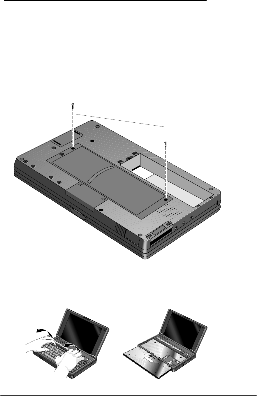
60
Keyboard
(HP Authorized Service Providers Only)
Required Equipment
• Torx #6 screwdriver
Removal Procedure
1. Exit all applications, including Windows.
2. Turn the OmniBook off and remove the battery and ac adapter.
3. Remove the two keyboard screws from the bottom case. See Figure 28.
4. Remove the keyboard by inserting your fingertips between the top row of keys and the case
and then lifting. Then fold the keyboard gently forward so that it lies upside down on the
table. Do not pick up the computer while the keyboard is in this position. See Figure 29.
Figure 28 - Keyboard Screws
Figure 29 - Folding the Keyboard Open
Keyboard Screws
M2.0x0.4x7.0
1.5-3.5 in-lb
(p/n 0515-2846)
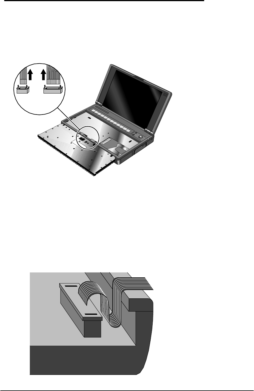
61
5. Lastly, remove the keyboard flex cables from the zero insertion force slots. If available, use
the provided Keyboard Flex Cable Removal Tool (part number 5182-7482) to assist in
“opening” the zero insertion force slots. Otherwise, a pick may be used to gently lift up the
top of the slots. See Figure 30.
CAUTION:To avoid damage to the solder joints, do not open the zero force insertion
connectors by prying against the case of the OmniBook.
Replacement Procedure
1. To replace, reverse the Removal Procedure. Once reconnected, the keyboard flex cables
must be tucked properly into the frame. See Figure 31.
CAUTION:To ensure a proper connection, be sure to place the keyboard flex cables
securely into the zero insertion force connectors.
To avoid damage to the keyboard flex cables, do not allow them to fold
under the keyboard.
Figure 30 - Keyboard Flex Cables
Figure 31 - Keyboard Flex Cable Placement
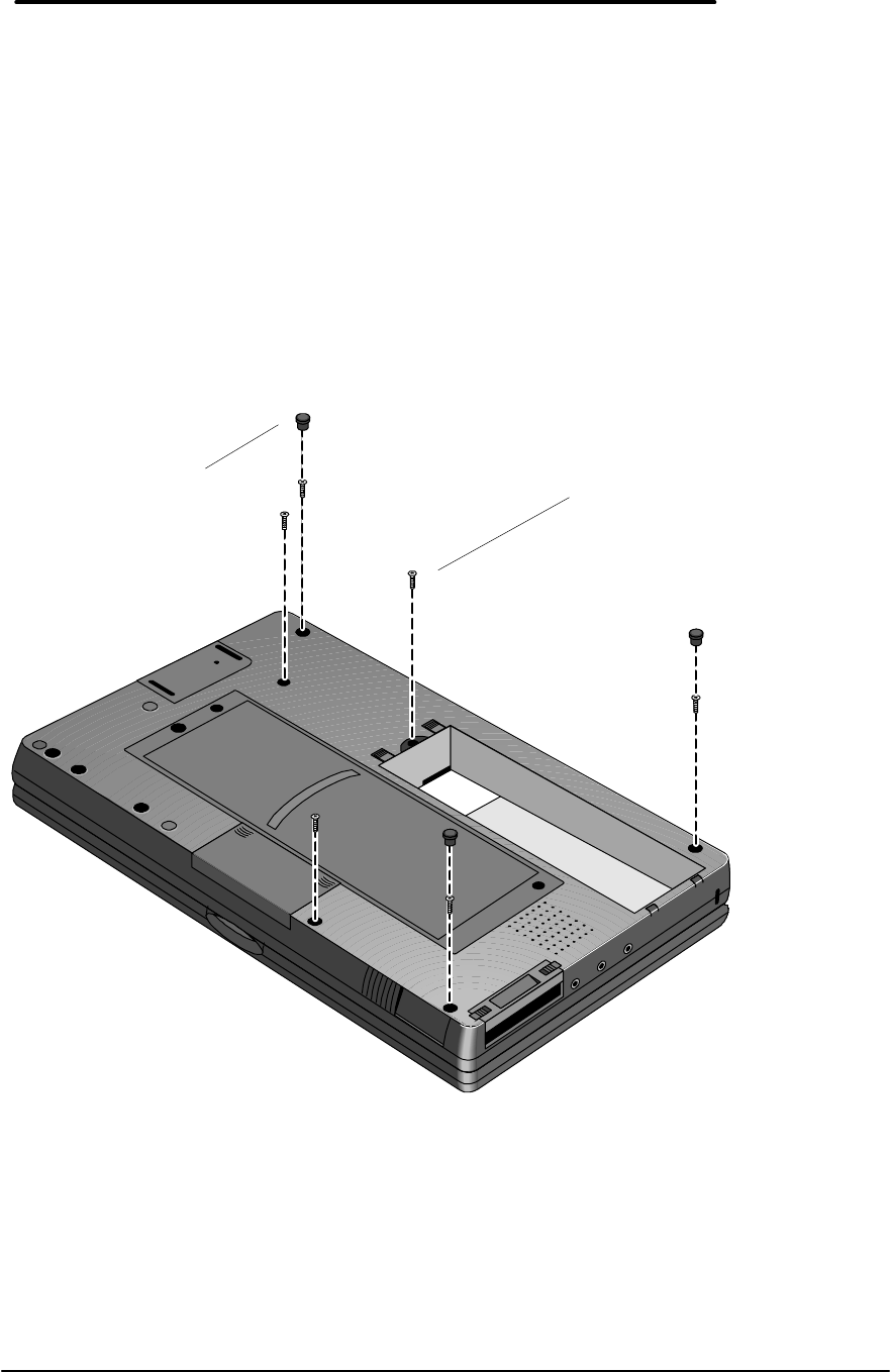
62
Display
(HP Authorized Service Providers Only)
Required Equipment
• Torx #6 screwdriver
Removal Procedure
1. Exit all applications, including Windows.
2. Turn the OmniBook off and remove the battery and ac adapter.
3. Follow the Hard Disk Drive Removal Procedure on page 53 and the Keyboard Removal
Procedure on page 60 to remove these components.
4. Remove the three rubber feet and six screws from the bottom case. See Figure 32.
5. Remove the Keyboard Support Plate Screws. Refer to Figure 33 for proper placement of
screws for each of the OmniBook 800s. The F1360 has three screws, while the F1171-
F1175 only have two. Note – If the Keyboard Support Plate Screws are impossible to
unfasten (due to thread corrosion or stripped head), remove the CPU Screws instead,
which can be accessed from the Keyboard Support Plate. The Top Case and Display
Figure 32 - Bottom Case Screws and Rubber Feet
Rubber Feet - qty
3
(p/n F1030-40018)
Bottom Case
Screws - qty 6
M2.0x0.4x6.0
2.5-4.0 in-lb
(p/n 0515-2396)
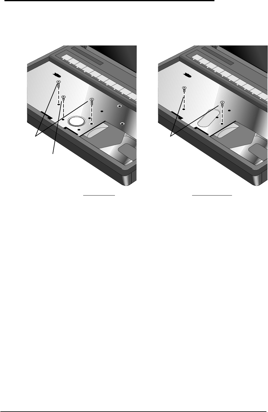
63
Assembly can then be removed with the CPU still attached to the underside of the
Keyboard Support Plate. This avoids causing damage to the CPU or Logic PCA.
6. Close the cover and gently pry the Top Case and Display Assembly from the Bottom Case
along the case seam. See Figure 34 on page 64 and Figure 35 on page 65. Take caution
of the Display Flex Cable(s) still connected to the Bottom Case, as it is the only
component now holding the Top Case and Display Assembly to the Bottom Case; do
not lay the Top Case and Display Assembly down at this point.
CAUTION:To avoid damage to the display cables, take care not to pull the cables out
of the connector while prying open the case.
Figure 33 - Keyboard Support Plate Screws
F1360 only F1171 - F1175
M2.0x0.4x4.5
qty 2
1.5-3.0 in-lb
(p/n 0515-2853)
M2.0x0.4x11.5
qty 2
1.5-3.0 in-lb
(p/n 0515-2920)
M2.0x0.4x3.5
qty 1
1.5-3.0 in-lb
(p/n 0515-2921)
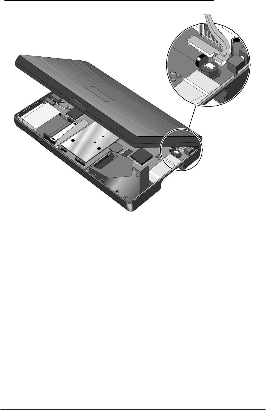
64
7. Note -- TFT displays (OmniBook 800CT) have two Display Flex Cables, while DSTN
displays (OmniBook 800CS) only have one. Take care to properly remove both cables on
TFT units (the smaller cable may be hidden under the larger cable). While still supporting
the Top Case and Display Assembly, remove the Display Flex Cable(s) from the connector
slot(s).
Figure 34 - Display Flex Cables
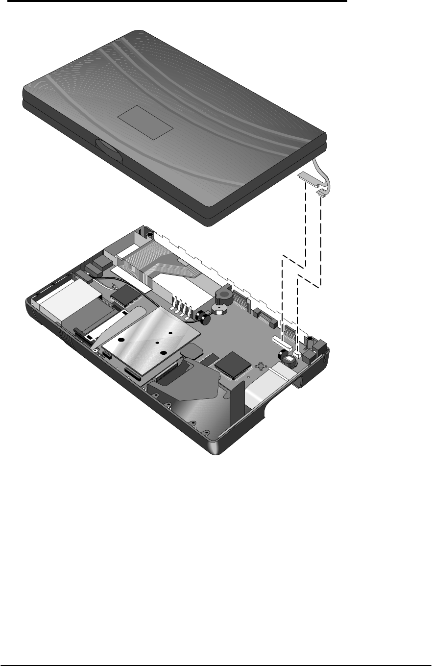
65
8. To separate the Display from the Top Case, thread the Display Flex Cable(s) through the
opening of the Top Case.
Replacement Procedure
1. If the replacement Display arrived without an Intel Inside sticker, one will need to be placed
equidistant between the edges of the Display. For the F1360 OmniBooks, the sticker is
placed about 7mm above the hinge. For F1171 - F1175 OmniBooks, the sticker is placed
about 10mm above the hinge. See Figure 36 for examples.
Figure 35 - Top Case and Display Removal

66
2. Thread the Display Flex Cable(s) of the replacement Display through the opening in the Top
Case and “close” the assembly comprising of the Top Case and Display Assembly.
3. Firmly place the Display Flex Cables(s) into the connector(s) on the Logic PCA.
4. Snap the Top Case and Display assembly in place and replace the keyboard support screws.
Note – For F1360 only, the two long screws MUST be replaced before the short screw.
CAUTION:Use care when replacing the top case and display assembly so as not to
pinch the display flex cables between the top case I/O backplane. Always
inspect the back seam of the OmniBook to ensure the cables are not
pinched.
5. Replace the remainder of the components and reboot.
Figure 36 - Intel Inside Sticker Placement
Intel Inside
Sticker for
F1360 only
(p/n 7121-7455)
Intel Inside
Sticker for
F1171 - F1175
(p/n 5182-5113)
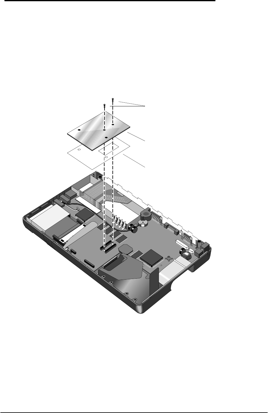
67
CPU
(HP Authorized Service Providers Only)
Required Equipment
• Torx #6 screwdriver
Removal Procedure
1. Follow the Display Removal Procedure to gain access to the CPU.
2. Remove the two CPU screws (see Figure 37).
3. Gently rock the CPU back and forth from front to back to remove from the connector.
Replacement Procedure
1. Ensure the CPU Insulator is positioned over the CPU connector on the Logic PCA.
2. Position the replacement CPU over the connector on the Logic PCA and press firmly but
gently. For F1360 units, please refer to the Heat Transfer Disk information on page 68.
CAUTION:To avoid damage, apply pressure to the CPU only directly above the
connector.
3. Replace the remainder of the components and reboot.
Figure 37 - Removing the CPU
CPU Screws
M1.6x0.35x4.0mm
1.0-2.0 in-lb
(p/n 0515-2852)
CPU Insulator
(p/n F1360-20007)
CPU
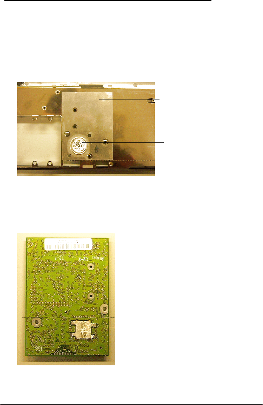
68
Heat Transfer Disk
(The following information applies to F1360 units only.)
With each replacement of the CPU, a new Heat Transfer Disk must be placed on the underside
of the Top Case. See Figure 38. Simply pull back the Keyboard Support Insulator, remove the
old Heat Transfer Disk, center the new Heat Transfer Disk in the indentation and reposition the
Insulator. Ensure the rectangle opening in the Insulator is positioned squarely over the Heat
Transfer Disk so that the edges of the Insulator opening retain the disk.
The heat generated by the CPU must be transferred through the CPU Thermal Coupling to the
Heat Transfer Disk. See Figure 39. The material used to facilitate the heat transfer is a paraffin-
based thermally conductive wax. When heated, the wax on the disk melts and flows to fill in
thermally restrictive air gaps between the Top Case and the CPU.
Figure 38 - Heat Transfer Disk and Keyboard Support Insulator
Figure 39 - CPU Thermal
Coupling
Keyboard Support Insulator
(p/n F1360-20004)
CPU Thermal Coupling
Heat Transfer Disk
(p/n F1360-20006)

69
Under normal conditions, it is important not to disturb the wax residue on the Top Case and
CPU. If the Top Case is replaced, it will have a new Heat Transfer Disk already in place on the
Keyboard Support Plate. However, to ensure the integrity of the heat transfer, this Heat Transfer
Disk should be replaced with a new disk after installation of the new Top Case Assembly.

70
Logic PCA Board
(HP Authorized Service Providers Only)
Electronic Serial Number
The OmniBook 800 (F1360 only) is shipped with an electronic serial number programmed in
EEPROM on the Logic PCA Board. This built-in serial number will help MIS managers in
tracking assets and software configuration. Serial numbers can also be used for security and in
tracking lost or stolen notebooks. The Desktop Management Interface (DMI) TopTools
application shipped with the OmniBook can be used to read the serial number locally and across
a network.
Programming the Electronic Serial Number
All replacement Logic PCA Boards will arrive with a temporary serial number programmed in
EEPROM. The following procedure provides the steps necessary to reprogram the electronic
serial number.
1. After installation of the replacement Logic PCA Board and upon reboot, the OmniBook will
halt with this prompt:
INVALID ELECTRONIC SERIAL NUMBER
PRESS ANY KEY TO CONTINUE
2. After a key is pressed, the OmniBook will continue a normal boot process. The HP
Authorized Service Provider must program a valid serial number before the OmniBook can
be shipped to the customer.
3. Run the ESN.EXE program located in the c:\omnibook\diag directory.
4. The ESN program will prompt for a valid serial number.
5. Enter the serial number located on the bottom of the OmniBook. The ESN program will burn
the serial number into EEPROM.
Overriding an Incorrect Electronic Serial Number
If an incorrect serial number is inadvertently burned into EEPROM, it can be corrected. Perform
the following steps:
1. Run the ESN.EXE program located in the c:\omnibook\diag directory.
2. The ESN program will prompt to confirm that the serial number is incorrect. It will then
generate a five (5) digit number key.
3. The HP Authorized Service Provider must contact Hewlett-Packard Technical Support at this
point.
4. HP Technical Support will ask for a CZ authorization number and the five (5) digit number
(from step 2).
5. HP Technical Support will provide a validation key to the HP Authorized Service Provider.
6. Enter the validation key. This will reset the electronic serial number with a temporary
number.
7. Follow the above steps in Programming the Electronic Serial Number to enter the correct
serial number.
Note, updating the BIOS on the OmniBook will not affect the electronic serial number.
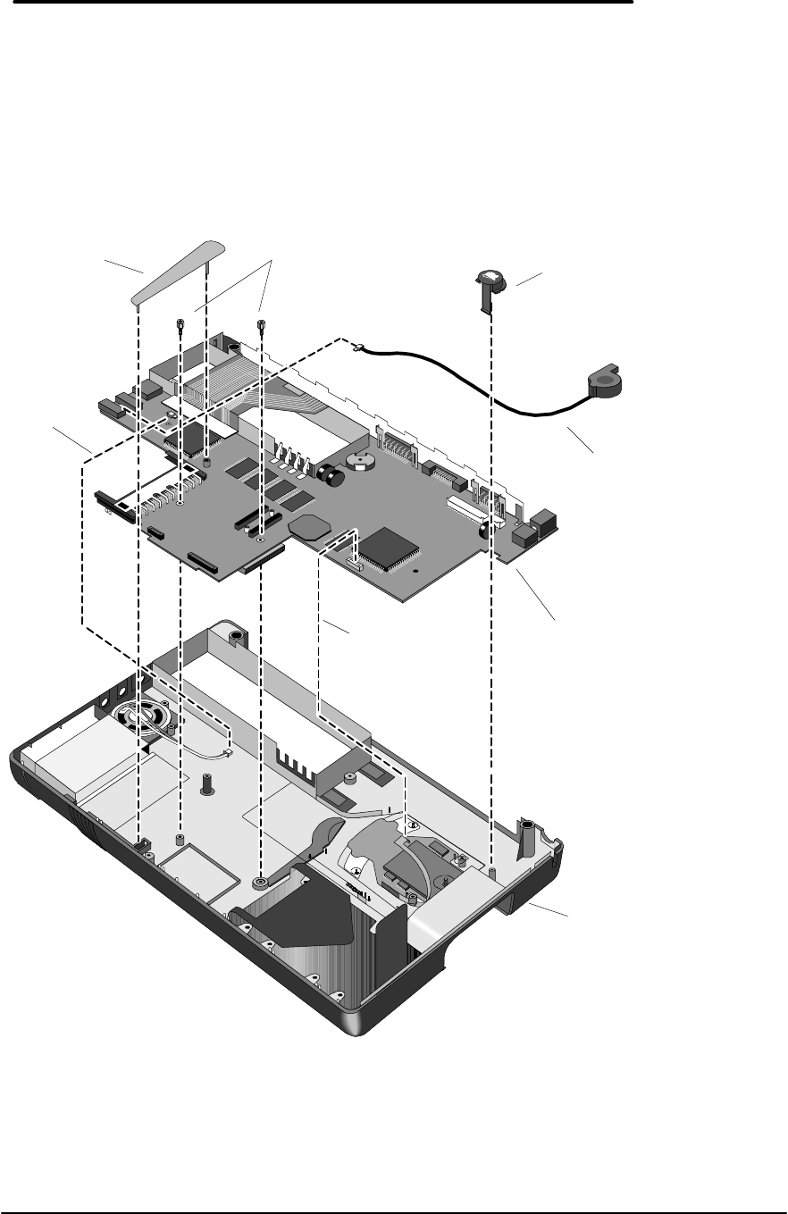
71
Required Equipment
• Torx #6 screwdriver
• 5mm hexdriver (F1171 & F1175 only)
Removal Procedure
1. Follow the Display Removal Procedure to gain access to the Logic PCA.
2. For convenience, the Microphone Assembly may be removed at this point. See Figure 40.
3. The Eject Button and Spring along with the Pivot Door and Spring do not need to be
removed to replace the Logic PCA. However, both of these springs are easily dislodged at
this point and can become lost. It is best to remove them and set them aside.
Figure 40 - Logic PCA Removal
Microphone
Assembly
(p/n F1067-60012)
Paw Eject Button
(p/n F1170-40005)
Paw Eject Arm
(p/n F1170-40008)
Standoffs
(p/n 0380-4606
F1171 - F1175
only)
Logic PCA
(p/n F1170-60906
F1171 - F1175)
(p/n F1360-60906
F1360 only)
Bottom Case
(p/n F1170-
60904
F1171 & F1175)
(p/n F1360-
60904
Speaker
Connection
Paw Active
Flex Cable
Connection
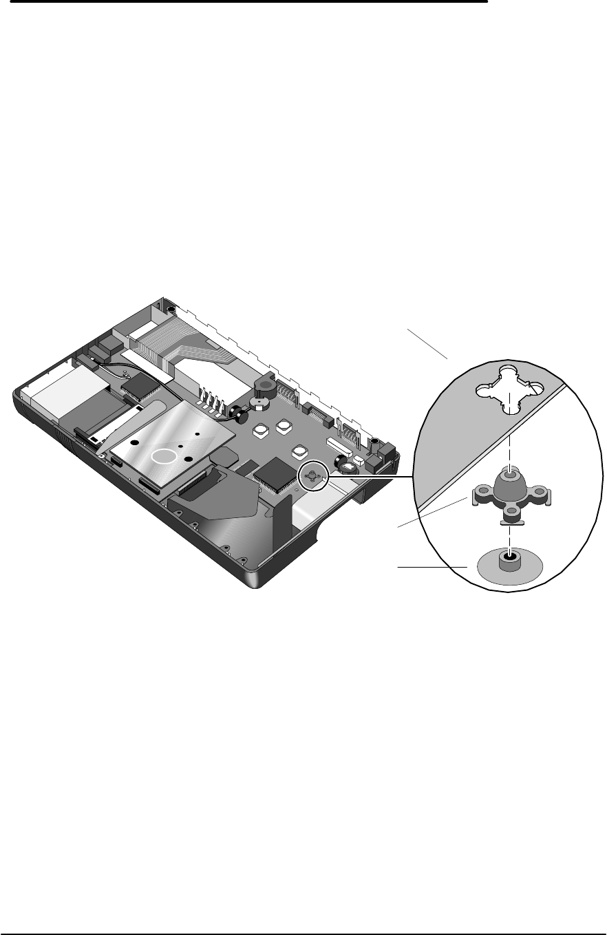
72
4. Remove the Paw Eject Arm, Paw Eject Button, two standoffs (F1171 - F1175 only, the CPU
must be removed to gain access to the two standoffs), and disconnect the Paw Active Flex
Cable and the Speaker Cable.
5. Remove the Logic PCA from the bottom case by first lifting up on the right-hand side . Note
– the Logic PCA fits snugly into the bottom case. Removing it will require a little
force; take care not to damage the I/O port connectors by lifting up on them.
Replacement Procedure
1. To replace the Logic PCA, reverse the above procedure. Ensure that the Grommet and
Bushing are in place on the Logic PCA (see
2. Figure 41).
CAUTION:To avoid damage to the OmniBook components, ensure the paw active flex
cable is completely and squarely inserted into the zero insertion force
connector.
Figure 41 - Grommet and Bushing Placement
Logic PCA
(top view)
Bushing
(p/n F1170-40025)
Grommet
(p/n F1360-40004)
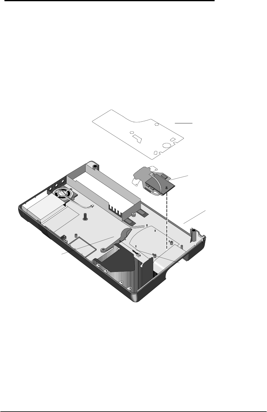
73
Paw Active
(HP Authorized Service Providers Only)
Required Equipment
• Torx #6 screwdriver
• 5mm hexdriver (F1171 - F1175 only)
Removal Procedure
1. Follow the Logic Board PCA Removal Procedure to gain access to the Paw Active.
2. Remove the Paw Shield. Refer to Figure 42 for location of components.
3. The Paw Eject Arm and Paw Eject Spring may be removed at this point for convenience.
4. Lift the Paw Active from the plastic posts holding it in place.
Replacement Procedure
1. To replace the Paw Active, reverse the steps in the Removal Procedure.
CAUTION:To avoid damage to the OmniBook components, ensure the paw active flex
cable is completely and squarely inserted into the zero insertion force
connector.
Figure 42 - Paw Active Removal
Paw Shield
(p/n F1170-00009)
Paw Active
(p/n F1170-60909)
Paw Eject Arm
(p/n F1170-40008)
Paw Eject Spring
(p/n F1030-00016)
Bottom Case
(p/n F1170-
60904
F1171 - F1175)
(p/n F1360-
60904

74
Other Components and Accessories
(HP Authorized Service Providers Only)
The below table list additional replaceable components and the disassembly procedure(s)
necessary to gain access to each.
Component Disassembly
Procedure(s)/Page
#
Equipment Special Notes
CD-ROM Drive • n/a • none This accessory
contains no repairable
parts. The entire unit
must be exchanged.
Docking Station • n/a • none This accessory
contains no repairable
parts. The entire unit
must be exchanged.
Top Case • Display • Torx #6 screwdriver
Bottom Case • Logic PCA Board
• Paw Active • Torx #6 screwdriver
• 5mm hexdriver (F1171
- F1175 only)
Grommet
Bushing • Logic PCA Board • Torx #6 screwdriver
• 5mm hexdriver (F1171
- F1175 only)
Mouse Button Latch • Display • Torx #6 screwdriver Also need to remove
the Topcase.
Mylar Mouse Shield • Logic PCA Board • Torx #6 screwdriver
• 5mm hexdriver (F1171
- F1175 only)
Eject Button
Eject Arm
Eject Arm Spring
• Display • Torx #6 screwdriver Also need to remove
the Topcase.
Pivot Door
Pivot Door Spring • Display • Torx #6 screwdriver Also need to remove
the Topcase.
Speaker Logic PCA Board • Torx #6 screwdriver
• 5mm hexdriver (F1171
- F1175 only)
Remove the three topy
spring nuts with a
probe or similar
device.

Appendices
• A - Technical Specifications
• B - Hewlett-Packard Password
Removal Policy
• C - Hewlett-Packard TFT Display
Quality Statement
• D - OmniBook Diagnostics BIOS
Checksums
• E - OmniBook Diagnostics Error
Messages
• F - Part Numbers

78
Appendix A - Technical Specifications
Mass Storage Specifications
Hard Disk Drive
The hard disk drive can be removed by the user for easy upgrades.
Hard drive manufacturers are subject to change without notice.
Table 17 - Hard Disk Drive Specifications
810-million-byte
Hard Drive 1.44-billion-byte
Hard Drive 2.1-billion-byte
Hard Drive
Manufacturer Toshiba IBM Toshiba
Size 12.7-mm (2.5-in) 12.7-mm (2.5-in) 12.7-mm (2.5-in)
Interface ATA-2 Interface ATA-3 Interface ATA-3 Interface
Recording Method Peek Detect PRML (Partial Response
Maximum Likelihood) PRML (Partial
Response Maximum
Likelihood)
Heads Thin Film MR (Magneto Resistive) MR (Magneto
Resistive)
Average seek (read) 13 ms 13 ms 13 ms
Track to track seek 3 ms 4 ms 3 ms
Full Track 25 ms 23 ms (read)
24 ms (write) 25 ms
Average latency 7.14 ms 7.5 ms 7.14 ms
Rotational speed 4200 +/- 0.1% rpm 4200 rpm 4,200 +/- 0.1% rpm
Media Transfer rate 24.7 (inner), 44.9
(outer) Mbits/sec 40 (inner), 61 (outer)
Mbits/sec 38.6 - 69.8 Mbits/sec
Buffer to host 16.6 Mbytes/sec 16.6 Mbytes/sec 16.6 Mbytes/sec
Buffer size 128 KB 96 KB 128 KB
Spindle start time 5 sec 2.3 sec 5 sec
Reliability:
MTBF: Power-on
Hours 300,000 hours 300,000 hours 300,000 hours
Unrecoverable errors 1.0E-13 bits transfer 1.0E-13 bits transfer 1.0E-13 bits transfer
Configuration:
Sector Size 512 Bytes 512 Bytes 512 Bytes
User Cylinders 2,920 2,800 5,160
Data Heads 6 4 6
Disks 3 2 3
Floppy Disk Drive
The floppy disk drive connects to a dedicated port, leaving the parallel port free. It is hot-
swappable and configurable as drive A.
Floppy disk drive manufacturers are subject to change without notice.
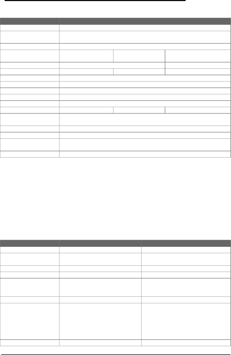
79
Table 18 - Floppy Disk Drive Specifications
3.5-inch Floppy Drive
Manufacturer TEAC
Size 10.67 cm (W) x 14.48 cm (D) x 1.40 cm (H)
(4.2 in (W) x 5.7 in (D) x 0.55 in (H))
Weight 250g (0.55 lbs)
Data Capacity 1.44MB (formatted)
2M (unformatted) 1.2MB (formatted)
1.6M (unformatted) 724KB (formatted)
1M (unformatted)
Data Transfer Rate 500k bits/sec 250k bits/sec
Disk Rotational Speed 300rpm 360 rpm 300rpm
Track Density 135tpi
Cylinders 80
Track-to-track Time 3ms
Average Seek Time 94ms
Start Time 480ms
Average latency 100ms 83.3ms 100ms
Mean Time Between
Failures 30,000 hours
Error Rate
Soft (recoverable) 1 or less per 109 bits read
Hard
(unrecoverable) 1 or less per 1012 bits read
Seek 1 or less per 106 bits read
CD-ROM Drive
The CD-ROM Drive is an accessory to the HP OmniBook 800 and can be purchased separately.
It is a SCSI device that connects to the OmniBook’s docking port via a proprietary docking-
connector-to-SCSI cable. The CD-ROM is can be powered with six AA batteries or by daisy-
chaining to the OmniBook’s ac adapter.
CD-ROM drive manufacturers are subject to change without notice.
Table 19 - CD-ROM Drive Specifications
4x CD-ROM Drive 8x CD-ROM Drive
Manufacturer Panasonic Panasonic
Size 138mm x 196mm x 37mm
(WxDxH) 138mm x 196mm x 37mm
(WxDxH)
Weight 450g (without battery) 430g (without battery)
Interface SCSI-2 SCSI-2
Transfer Rate 150 KB/s Normal Speed
300 KB/s Double Speed
600 KB/s Quad Speed
150 KB/s Normal Speed
1200KB/s Octo Speed
Buffer 128 KB 128 KB
Access Speed 350 ms (1/3 stroke; ac adapter)
600 ms (full stroke; ac adapter)
990 ms (1/3 stroke; alkaline
battery)
1500 ms (full stroke; alkaline
battery)
180 ms (1/3 stroke: ac adapter)
300 ms (full stroke: ac adapter)
Start up Time < 30 secs < 10 secs

80
Modes CD-DA, CD-ROM, CD-ROM XA
(except for ADPCM), Photo
CD, CD R, Video CD, CD-I
CD-DA, CD-ROM, CD-Extra, CD-
ROM XA (except for ADPCM),
Photo CD, CD R, Video CD, CD-I
Mean Time Between
Failures 25,000 hours 25,000 hours
System Resources
The following tables list the various system resources for each OmniBook 800 model.
System Interrupts (IRQs)
Table 20 - Interrupts for F1171 - F1175
0System timer
1Keyboard
2Redirect IRQ 9
3Free (COM2 or COM4 if modem installed)
4COM1 and COM3 (external serial port)
5ESS Sound Chip
6Floppy drive
7LPT1 (external parallel port)
8Real-time clock
9Free
10 SCSI
11 Wave 2 (sound)
12 Mouse
13 Math co-processor
14 Internal hard disk (primary IDE controller)
15 Infrared when undocked, PCI Card when docked (if installed)
Table 21 - Interrupts for F1360
0System timer
1Keyboard
2Redirect IRQ 9
3Free (COM2 or COM4 if modem installed)
4COM1 and COM3
5Sound
6Floppy drive
7LPT1 (or LAN)
8Real-time clock
9Free
10 Infrared/SCSI
11 Free
12 Mouse
13 Math co-processor
14 Internal hard disk (primary IDE controller)
15 Free
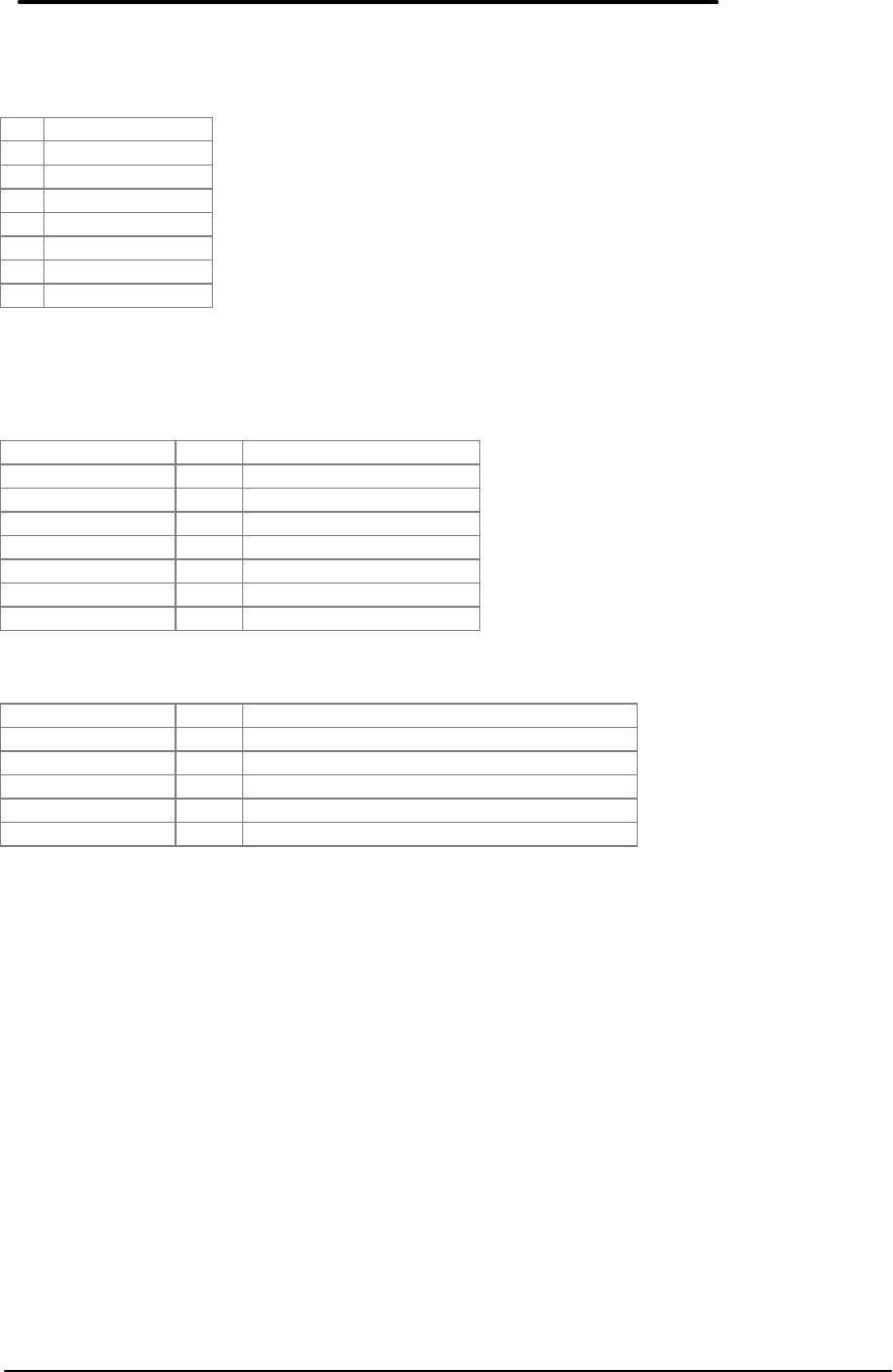
81
DMA Channels
Table 22 - DMA Channels for F1171 - F1175, and F1360
0Free
1Sound
2Floppy drive
3Free
4DMA Controller
5Wave 2
6Free
7Free
Memory Map
Table 23 - Memory Map for F1171 - F1175
F0000 - FFFFF 64K System BIOS
EC000 - EFFFF 16K PCI BIOS
E8800 - EBFFF 14K Plug-n-Play BIOS
E8000 - E87FF 2K Enhanced Parallel Port
D2000 - E7FFF 90K Free
D0000 - D1FFF 8K PCMCIA Memory
CA000 - CFFFF 24K Free
C0000 - C9FFF 40K NeoMagic Video
Table 24 - Memory Map for F1360
E8800 - FFFFF 82K Plug-n-Play, ISA, and PCI System BIOS
E8000 - E87FF 2K Enhanced Parallel Port
D2000 - E7FFF 90K Free
D0000 - D1FFF 8K PC Card (can be expanded if necessary)
CA000 - CFFFF 24K Free
C0000 - C9FFF 40K NeoMagic Video

82
I/O Addresses
Table 25 - I/O Address for F1171 - F1175
1F0 - 1F7 Internal Hard Disk
220 - 22F ESS Sound
2F8 - 2FF COM 2 (if modem installed)
330 - 331 Wave 2 (sound)
378 - 37A LPT1 (external parallel port)
388 - 38B Sound
3B0 - 3BF NeoMagic Video Adapter
3C0 - 3CF NeoMagic Video Adapter
3E0 - 3E1 PCMCIA Bridge on PCI
3F0 - 3F5 Floppy Controller
3F6 Internal Hard Disk
3F7 Floppy Controller
3F8 - 3FF COM1 (external serial support)
3000 - 301F PIC Infrared Controller
4100 - 41FF SymBIOS SCSI on PCI
FFFF Plug-n-Play
Table 26 - I/O Addresses for F1360
1F0 - 1F7 Internal Hard Disk
220 - 22F ESS Sound
2F8 - 2FF COM 2 (if modem installed)
330 - 331 Wave 2 (sound)
378 - 37A LPT1 (external parallel port)
388 - 38B Sound
3B0 - 3DF NeoMagic Video Adapter
3E0 - 3E1 PC Card Bridge on PCI
3F0 - 3F5 Floppy Controller
3F6 Internal Hard Disk
3F7 Floppy Controller
3F8 - 3FF COM1 (external serial support)
3000 - 301F PCI Infrared Controller
4100 - 41FF SymBIOS SCSI on PCI

83
Appendix B - Hewlett-Packard Password
Removal Policy
If the user forgets the system password, there is a master password that will
unlock the OmniBook. The user calls Technical Support to determine this
master password as follows:
1. Support will tell the user the keys to type at the password entry screen:
[Alt][Shift][f10]
2. The OmniBook generates and displays an encoded master password.
This is displayed under the normal password entry area. At this point, this
is the only password that will unlock the OmniBook unless the user
presses [ESC] to remove the encoded master from the password entry
screen. Then the user's stored password can be entered.
3. The user reads the encoded master password to Support.
4. Support runs a program that decodes the encoded password, and reads
the decoded password (alphanumeric) to the user.
5. The user types in the decoded password.
6. OmniBook decodes the encoded master password it generated and
compares it to the decoded password typed in by the user.
7. If the two passwords match, the OmniBook is unlocked. The forgotten
password is automatically erased. Support can then guide the user
through the process of entering a new password.
8. If the two passwords do not match, the previous sequence must be
repeated until the user correctly enters a master password.
The encoded master password is an eight-character alphanumeric sequence
that the OmniBook generates at random every time the appropriate keys are
pressed in the password entry screen. Because it is generated randomly, a
master password can only be used to unlock the OmniBook once. If the user
forgets the password at another time, it will require another call to Support. (If
the user presses the appropriate keys by mistake, pressing [ESC] will allow
entering the stored password.)
The password descramble programs for the HP OmniBook Notebook PCs are
protected as HP Company Private information. They may not be copied,
backed-up, printed or distributed. There are only six official copies of each
program.
In addition to the program being protected, its use is also controlled. Hewlett-
Packard and authorized support providers must ensure with written evidence
that the OmniBook that is being "descrambled" is actually in the hands of the
unit's actual and current owner. This requires a sales receipt showing the unit
serial number and owner's name, or a written statement from the owner
attesting that he or she is the owner of the unit. The statement can be a fax
copy of the document. The fact that the unit is in the hands of an HP
representative on behalf of the customer is not evidence of ownership. In
addition, HP will not descramble a unit for any non-owner, even if it involves

84
law enforcement agencies. If you receive such a request, you should notify
management and HP Corporate Legal immediately. (These requests may
require a court order prior to our participation.)
Further, you must log the name, serial number and date of the running of the
descramble program, and file the written backup with the log. The log and
backup are subject to standard record retention process and review.
The final issue relating to descramble of passwords is that HP cannot provide
information to users that would assist them in improperly descrambling a
password and opening a unit.

85
Appendix C - Hewlett-Packard TFT Display
Quality Statement
TFT display manufacturing is a high precision but imperfect technology and manufacturers
cannot currently produce large displays that are cosmetically perfect. Most, if not all, TFT
displays will exhibit some level of cosmetic imperfection. These cosmetic imperfections may be
visible to the customer under varying display conditions and can appear as bright, dim or dark
spots. This issue is common across all vendors supplying TFT displays in their products and is
not specific to the HP OmniBook display.
HP OmniBook TFT displays meet or exceed all TFT manufacturers’ standards for cosmetic
quality of TFT displays. HP does not warrant that the displays will be free of cosmetic
imperfections. TFT displays may have a small number of cosmetic imperfections and still
conform to the display manufacturers’ cosmetic quality specifications.
Here are some guidelines to use in determining what action to take on customers’ complaint of
cosmetic imperfection in their TFT display:
1. The unit should be viewed in the customer's normal operating condition.
This means if the customer uses the unit predominately in DOS, or Windows, or in some
other application or combination of applications, that is where the determination shall be
made. Self test is not a normal operating condition and is not a sufficient tool to interpret
display quality.
2. In the customer's normal operating mode:
a) If 4 or more variant pixels appear clustered in the area approximated by a
thumbprint on the display surface, then the display should be considered for
replacement.
b) On OmniBook 4000CT models, if more than 30 total pixels anywhere on the display
are bad, then the display should be considered for replacement. On OmniBook
600CT, OmniBook 800CT, OmniBook 5000CT, OmniBook 5500CT, and OmniBook
5700CT models, if more than 15 total pixels anywhere on the display are bad, then
the display should be considered for replacement.
These are the only conditions in this guideline that may call for a replacement due to a defect in
material or workmanship based on the HP Limited Warranty Statement.
3. If a display is considered for replacement, it should be clear to the customer that cosmetic
variations on the replacement display may also exist, and may require the customer to
use a work-around to obscure the cosmetic imperfection.
4. Customers with cosmetic-based complaints only, that do not conform to the above
conditions and tests will not normally be considered for display replacement. It will be left
to the judgment of the HP-responsible person working with the customer, to identify work-
arounds that are reasonable and appropriate for the individual customer. Customers who
must have a more perfect display solution should consider switching to an OmniBook with
a DSTN display.
We expect over time that the industry will continue to improve in its ability to produce displays
with fewer inherent cosmetic imperfections and we will adjust our HP guidelines as the
improvements are implemented.

86
Appendix D - OmniBook Diagnostics BIOS
Checksums
When running the OmniBook diagnostics program, these checksums can be specified on the
command line with the -c option.
Table 27 - OmniBook F1171 - F1175 BIOS Checksums
ROMDATE C_F
-C1 Altera
-C2 Boot
-C3 Total SUM
960808 3E55 DC8C C600 A0E1
960910 258F DC8C 1900 DB1B
960917 D040 DC8C 1900 85CC
961009 3C32 DC8C 0900 E1BE
961011 4024 DC8C 0900 E5B0
961018 5091 DC8C 0900 F61D
961025 3E93 DC8C 3500 101F
961028 3E93 DC8C 3500 101F
961031 9743 DC8C 3500 68CF
961111 7690 DC8C 3500 481C
961127 39C9 DC8C 3500 0B55
961209 5B2A DC8C 1600 0DB6
961219 3F4A DC8C 1600 F1D6
961231 2911 DC8C 1600 DB9D
970107 C12B DC8C 1600 73B7
970110 952B DC8C 1600 47B7
970113 E558 DC8C 1600 97E4
970121 B738 DC8C 1600 69C4
Table 28 - OmniBook F1360 BIOS Checksums
ROMDATE C_F
-C1 Altera
-C2 Boot
-C3 Total SUM
961018 DC97 DC8C 0900 8223
961025 CA99 DC8C 3500 9C25
961028 CA99 DC8C 3500 9C25
961031 2349 DC8C 3500 F4D5
961111 C19B DC8C 3500 9327
961127 84D4 DC8C 3500 5660
961209 A635 DC8C 1600 58C1
961219 2CF6 DC8C 1600 DF82
961231 16BD DC8C 1600 C949
970107 AED7 DC8C 1600 6163
970110 47D2 DC8C 1600 FA5E
970113 97FF DC8C 1600 4A8B
970121 6A45 DC8C 1600 1CD1

87
Appendix E - OmniBook Diagnostics Error
Messages
The following are messages that may appear when running the OmniBook diagnostics program.
Hewlett-Packard supplied test messages
The following test messages were supplied by Hewlett-Packard.
CPU
XXXMHz CPU, speed=XXX (failed).
BIOS flash roms
OK C-F=XXXX Altera=XXXX Boot=XXXX
FAIL C-F=XXXX#YYYY ...
PCMCIA CARDS (SyCard supplied)
Failed: no extender card
Failed: no SyCard
Voltage Sense 1 (VS1) Error - Stuck Low
Voltage Sense 1 (VS1) Error - Stuck High
Voltage Sense 2 (VS2) Error - Stuck Low
Voltage Sense 2 (VS2) Error - Stuck High
Error - INPACK failure
DMA Write Error - expected XX, received XX
DMA cycle did not complete:
Timeout error
Read Data error
Missing TC error
Premature TC error
Write Data error
Unknown DMA error
on DMA channel X
DMA Status Check Error - XXXX
DMA Not Complete - 8237A Status = XX
ERROR - Texas Instruments PCI-1130 not found on PCI Bus
Socket control r/w error - wrote XX, read back XX @ offset XX
Databook Socket control r/w error 2 - wrote XX, read back XX @ offset XX
Basic 8 bit I/O read/write failure, wrote XX, read XX
Basic 16 bit I/O read/write failure, wrote XXXX, read XXXX
Basic 16 bit common memory R/W failure, wrote XXXX, read XXXX
16 bit memory read error, wrote 4321, read XXXX
Data Error, expected XXXX, received XXXX
Vcc tolerance error (3.3V) = N.NN)
Vcc tolerance error (5V) = N.NN)
Vpp2 tolerance error (12V) = N.NN)
Vpp1 tolerance error (3.3V) = N.NN)
Vpp1 tolerance error (5V) = N.NN)
Vpp2 tolerance error (3.3V) = N.NN)
Vpp2 tolerance error (5V) = N.NN)
Vpp1 tolerance error (0V) = N.NN)
Vpp2 tolerance error (0V) = N.NN)

88
Vpp2 tolerance error (12V) = N.NN)
Card Vpp2 12V = N.NN (XX)
Vpp2 tolerance error (3.3V) = N.NN)
Vpp2 tolerance error (3.3V) = N.NN)
Vpp2 tolerance error (5V) = N.NN)
Vpp1 tolerance error (12V) = N.NN)
-REG bit error - stuck high
-REG bit error - stuck low
Address miscompare, access = XXXXXXXX, latched = XXXXXXXX
Address miscompare, access = XXXXXXXX, latched = XXXXXXXX
Error - Wait bit has no effect
BVD1/-STSCNG (Pin 63) error - stuck low
BVD1/-STSCNG (Pin 63) error - stuck high
BVD2/-SPKR (Pin 62) error - stuck low
BVD2/-SPKR (Pin 62) error - stuck high
WP/-IOIS16 (Pin 33) error - stuck low
READY/-IREQ (Pin 16) error - stuck low
Reset error - stuck low
Reset error - stuck high
Card Detect Error -CD1 stuck high
Card Detect Error -CD1 stuck low
Disk Drives (SCSI HD / internal HD / Floppy)
Internal Diag error: not enough memory for disk buffer.
Failed: no scsi or dock connection.
Error X resetting drive.
Error reading drive parameters.
Failed: no formatted Floppy in drive.
Failed: disk is write protected.
Error: data read does not match data written.
(Note: when the above error occurs, the status window will report the
offset where the mismatch occurred and four bytes of expected and actual
data as follows: Data ERROR offset NNN wrote:XX-XX-XX-XX read:XX-XX-XX-XX)
Error X at track T, head H, sector S.
1.4Mb/813Mb/1.4Gb Ok SeekRetries=N, ReadRetries=N, WriteRetriees=N
The codes reported translate to the following errors:
0x00 successful completion
0x01 invalid function in AH or invalid parameter
0x02 address mark not found
0x03 disk write-protected
0x04 sector not found/read error
0x05 reset failed (hard disk)
0x06 disk changed (floppy)
0x07 drive parameter activity failed (hard disk)
0x08 DMA overrun
0x09 data boundary error attempted DMA across 64K boundary or >80h sectors
0x0A bad sector detected (hard disk)
0x0B bad track detected (hard disk)
0x0C unsupported track or invalid media
0x0D invalid number of sectors on format (PS/2 hard disk)

89
0x0E control data address mark detected (hard disk)
0x0F DMA arbitration level out of range (hard disk)
0x10 uncorrectable CRC or ECC error on read
0x11 data ECC corrected (hard disk)
0x20 controller failure
0x31 no such drive (Compaq)
0x32 incorrect drive type stored in CMOS (Compaq)
0x40 seek failed
0x80 timeout (not ready)
0xAA drive not ready (hard disk)
0xBB undefined error (hard disk)
0xCC write fault (hard disk)
0xE0 status register error (hard disk)
0xFF sense operation failed (hard disk)
Battery
Battery type = None (OK), LiIo (OK), NiMH (OK), ERROR (BIOS not sure)
Charge state = NA (no bat), NC (no charger), FC (fast charge),
TC (trickle charge), EC (error charging), WC (waiting to charge)
B%=100 (percent of battery charged)
Vb=8.57 (battery voltage)
Ta=37.9 (Ambient temperature)
SCSI loopback test
Failure: "X" Register Read/Write Error
Failure: NO CABLE, Couldn't find SCSI controller #N
Failure: "X" Pin #N ("X") is stuck low.
Failure: "X" Pin #N ("X") is stuck high.
Failure: "X" Interrupt line problem
Failure: "X" can't Bus Master
Failure: "X" can't issue interrupt
HP mouse
Unable to prepare internal mouse for i/o.
Failed: "X" bumper ON while moving "X".
Failed: "X" bumper and movement "X" at the same time.
Failed: (one or more of LEFT RIGHT UP DOWN TOP BOTTOM IN OUT)
Failed: HMICKEYS or VMICKEYS
Failed: Vertical calibration lost
Failed: Horizontal calibration lost
Docked device
Ok: NOTHING
Ok: 800 DOCK
Failed: Red LED
Failed: Green LED
Failed: Dock Lock
Ok: SCSI CABLE
Error: UNCLEAR
Dock PS2 mouse
Failed: no dock connected for PS2 mouse.
Failure code N ("X" while enabling external PS2 mouse.
Failed: (one or more of LEFT RIGHT UP DOWN)

90
Dock EEPROM
FAILED at XXXX: wrote XX read XX.
System hardware configuration (invoked with Ctrl+H)
Cpu speed (CPU=100 133)
Display type (DSP=DSTN or TFT)
Hard disk size (HD=814M .. 1.3G)
L2 Cache (L2=000 or 256), On or Off
Op Sys Version (OS=0.04.09...)
Ram memory (RAM=08 .. 80)
Volume ID (VOL=1ORID14ABA...)
Watergate Software supplied test messages
The following test messages were supplied by Watergate Software.
CPU test responses
General Register Test "AX", "BX", "CX", "DX" -- " FAILED"
"EAX", "EBX", "ECX", "EDX" -- "FAILED
Index Register Test "SI", "DI" -- "FAILED"
"ESI", "EDI" -- "FAILED
Pointer Register Test "BP", "SP" -- "FAILED"
"EBP", "ESP" -- "FAILED
Segment Register Test "DS", "ES", "SS" -- "FAILED"
"FS", "GS" -- "FAILED"
Flag Register Test "CF", "PF", "AF", "ZF", "SF", "IF", "DF", "OF" -- "FAILED"
Simple Arithmetic "ADC", "ADD", "DEC", "DIV", "IDIV", "IMUL", "INC", "MUL",
"SBB", "SUB" -- "FAILED"
"ADC32", "ADD32", "DEC32", "DIV32", "IDIV32", "IMUL32",
"INC32", "MUL32", "SBB32", "SUB32" -- "FAILED"
Logical Operations "AND", "NOT", "OR", "XOR" -- "FAILED"
"AND32", "NOT32", "OR 32", "XOR 32" -- "FAILED"
String Operations "LODSB", "MOVSB", "SCASB", "STOSB" -- "FAILED"
"LODSW", "MOVSW", "SCASW", "STOSW" -- "FAILED"
"LODSD", "MOVSD", "SCASD", "STOSD" -- "FAILED"
Shift/Rotate "RCL", "RCR", "ROL", "ROR","SHL","SHR" -- "FAILED"
"RCL32", "RCR 32", "ROL32", "ROR 32","SHL32","SHR 32" --
"FAILED"
Interrupts "INT XXXH Failed"
Exceptions "Divide", "InvOpCode","CoProc" -- "FAILED"
Co-CPU test responses
Register Stack "Registers", "ST-Pointer"
"FLDLZ","FLDPI","FLDLN2","FLDLG2","FLDL2T","FLDL2E","FLD
1" -- "FAILED"
Exceptions "InvOp", "DenOp", "ZeroDiv", "OverF", "UnderF","Prec", "StackF"
-- "FAILED"
Arithmetics "FADD","FDIV","FIADD","FIDIV","FIMUL","FISUB","FMUL","FSU
B" -- "FAILED"
"FABS","FCHS","FPREM","FRNDINT","FSCALE","FSQRT","FXT
RACT" -- "FAILED"
"FPREM1" -- "FAILED"

91
Comparison "FBLD/FBSTP", "FILD/FIST","FLD/FST","FXCH" -- "FAILED"
"FCOM","FICOM","FTST","FXAM" -- "FAILED"
"FUCOM" -- "FAILED"
Trigonometry "F2XM1","FPATAN","FPTAN","FYL2X","FYL2XP1" -- "FAILED"
"FCOS","FSIN","FSINCOS" -- "FAILED"
Memory test responses
Suspend RAM test "Failed: memory manager loaded"
Extended Pattern And
Address Test "Could not allocate buffer"
"BIOS reports no extended memory available"
"Error at address XXXXXXXXH"
"Parity Error at blocks XXXXXXXH-YYYYYYYYH"
"Parity Error at blocks XXXXXXXH-YYYYYYYYH"
"Test aborted at block XXXXXXXH"
Base/UMB Pattern And
Address Test "Error at memory paragraph XXXXH"
"Parity Error at paragraphs XXXXH-YYYYH"
"Test aborted at paragraph XXXXH"
Base/UMB Bus Throughput
Test "Error at segment XXXXH"
"Bus Throughput Test aborted at segment XXXXH"
EMS Bus Throughput Test "Not Enough EMS Memory Available!"
"Could Not Allocate EMS Memory!"
"Error at segment XXXXH"
"Could Not Establish EMS Page Frame Location!"
EMS Pattern And Address
Test "Error on page XXXXX"
"Parity Error on page XXXXX"
"Test aborted at EMS page XXXXX"
Code Test "BIOS reports no extended memory available"
“PC-DOCTOR encountered an unexpected exception while code-
testing memory in protected mode. System halted (this error is
unrecoverable).'”
Cache test responses
Cache Test “Error at memory block XXXXXXXH”
“Parity Error at blocks XXXXXXH-YYYYYYYH”
“Test aborted at block XXXXXXXXH”
VGA test responses
Video Pages "Aborted at mode XXXH (III)"
"Mode XXXH (III) page Y failed"
Video Memory "Pattern Error in mode XXXH (III) plane Y, bits XXXXH Failed"
"Pattern Error in mode XXXH (III) bits XXXXH Failed"
Color Registers "Could not initialize mode 13H"
"DAC-register N " -- "Red ", "Green ", "Blue " -- "FAILED"
VGA Controller Registers "Video RAM Enable" -- "FAILED"
"Video IRQ" -- "FAILED"
"Map Mask Register" -- "FAILED"
"Set/Reset Register" -- "FAILED"
"Enable Set/Reset Register" -- "FAILED"
"Color Compare Register" -- "FAILED"
"Data Rotate Register" -- "FAILED"
"Read Map Select Register" -- "FAILED"

92
"Mode Register" -- "FAILED"
"Color Don't Care Register" -- "FAILED"
"Bit Mask Register"
Timer chip test responses
Timer chip test "Clock 0 Not Counting", "Clock 1 Not Counting" -- "FAILED"
"Clock 2 Not Counting"
"Could Not Control Clock 2"
CMOS RAM test responses
CMOS RAM Test "Addr XXH Failed, In YYH, Out ZZH"
"CMOS Checksum Failed, ChkSum is XXH, not YYH",
"CMOS Pattern Test" -- "FAILED"
Sound test responses
DSP "No sound card detected"
"DSP Chip Data Path Failed"
DMA "No sound card detected"
"No DMA Request Generated"
Interrupt "No sound card detected"
"No interrupt generated"
Sound output "No sound card detected"
Keyboard test responses
Keyboard Test "Failed: Fn key"
"Failed: Contrast Up button"
"Failed: Contrast Down button"
"Windows prevents keyboard testing"
"OS/2 prevents keyboard testing"
"Could not test keyboard because of stuck key(s)"
"Keyboard Power-On Selftest Failed"
"Keyboard IRQ Failed"
"Keyboard clock line stuck low"
"Keyboard clock line stuck high"
"Keyboard data line stuck low"
"Keyboard data line stuck high"
"Interface chip internal diagnostics error"
Manual keyboard test
Manual Keyboard Test "Error reading KBD file."
"Test aborted before all keys were pressed."
LPT test responses
Registers Test "Wrote XXH, Read YYH"
External Loopback "Interrupt Failed"
"DATA0-->ERROR"
"STROBE-->SLCT"

93
PCDR LOOPBACK PLUGS "AUTOFD-->PE"
"INIT-->ACK"
"SLCTIN-->BUSY"
ACER LOOPBACK PLUGS "DATA1-->SLCT"
"DATA2-->PE"
"DATA3-->ACK"
"DATA4-->BUSY"
COM test responses
Registers "Baud rate divisor failed"
"Divisor latch access bit failed"
"Line control register pattern test failed"
"Modem control register failed"
"Interrupt failed. It was not generated."
Loopback Tests
(Internal/External) "RTS-->CTS", "DTR-->DSR", "Delta-CTS", "Delta-DSR" --
"FAILED"
"Test aborted at XXXX BPS"
"Send timeout at XXXX BPS"
"Wrong character count at XXXX BPS (YY vs 96)"
"Data at XX should be YY, it is ZZ"
"Received data miscompare at XXXX BPS"
IRQ test resonses
IRQ Test "IRQ Controller 0", "IRQ Controller 1"
"(Masking)","(IRR)","(ISR)", "(PollCmd)","(NS-EOI)","(S-EOI)"
DMA test responses
DMA Test "Channel N register patterns failed"
"Channel N page register patterns failed"
"Channel N DMA transfer failed (with termination or no data or XX
NMIs)
HD test responses
HD Test "HD XX SelfTest Failed: FC=YY ER=ZZ SR=AA CS=BB",
"Error Seeking To Track XXX"
"Error verifying track XXX"
FD test responses
FD Test "Error verifying track XXX"
"Sector Read Failed"
"Could not establish drive parameters"
"Error seeking to track 0"
"Error Seeking To Track XXX"
"Error verifying track XXX Head YYY"
WRITE TESTS "Could not allocate buffer segment"
"Error writing track XX Head YY"
"Error reading track XX Head YY"
"Error in data of track XX Head YY"

94
CD ROM test responses
CD ROM Test "Invalid Drive";
"Not Ready";
"Error Code XX (II)"
"Error reading sector

95
Appendix F - Part Numbers
PART # EXCHANGE
PART # DESCRIPTION CUSTOMER
REPLACEABLE F1171 -
F1175 F1360
0380-4606 STANDOFF - HEX no
0515-1634 TOPY SPRING NUT no
0515-2396 SCREW 2.0 X.4 6MM yes
0515-2846 SCREW M2X.4X7PH T6 yes
0515-2847 SCREW M3X.5X5WH T6 yes
0515-2852 SCREW M1.6X.35X4 no
0515-2853 SCREW M2X.40X4.5WH no
0515-2920 SCREW M2X.4X11.5WH no
0515-2921 SCREW M2X.4X3.5WH no
5182-5110 LABEL PROD ID/CS yes
5182-5111 LABEL PROD ID/CT yes
5182-5113 LABEL - INTEL no
5182-7482 KEYBOARD REMOVAL
TOOL no
7121-7455 LABEL - INTEL MMX no
8120-6921 FLOPPY DRIVE CABLE yes
9164-0422 SPEAKER no
F1030-00016 PAW EJECT SPRING no
F1030-00026 PIVOT DOOR SPRING no
F1030-00029 SPRING EJECT LATCH no
F1030-40018 RUBBER FEET-SCREW
COVER yes
F1030-80063 FFC-THETA no
F1052-40007 DOOR - PIVOT LEFT no
F1052-60005 CARD TRAY ASSY yes
F1065-40019 IR LENS no
F1065-80010 LBL-CONTRAST CSTN yes
F1065-90042 BUSINESS CARD yes
F1067-20004 I/O INSULATOR no
F1067-60012 MICROPHONE ASSY no
F1067-80008 LBL-CONTRAST TFT yes
F1170-00009 PAW SHIELD no
F1170-40005 PAW EJECT BUTTON no
F1170-40006 BATTERY LATCH yes
F1170-40007 RAM DOOR yes
F1170-40008 PAW EJECT ARM no
F1170-40009 RUBBER FEET - FALSE
FOOT yes
F1170-40010 I/O DOOR yes
F1170-40018 RUBBER HDD HOLE
PLUG yes
F1170-40025 BUSHING no
F1170-40030 EJECT BUTTON LEFT no
F1170-60901 F1170-69001 SVC DISPLAY TFT no
F1170-60902 F1170-69002 SVC DISPLAY CSTN no

96
PART # EXCHANGE
PART # DESCRIPTION CUSTOMER
REPLACEABLE F1171 -
F1175 F1360
F1170-60903 SVC KYBRD TOPCASE no
F1170-60904 SVC KYBRD BTMCASE no
F1170-60906 F1170-69006 SVC LOGIC PCA 16MB no
F1170-60909 SVC PAW ACTIVE no
F1170-60919 F1170-69019 SVC CPU 100MHZ no
F1170-60920 F1170-69020 SVC CPU 133MHZ no
F1170-80020 REGULATORY LABEL no
F1170-80023 OL FN ICON WIN95 yes
F1170-80036 OL FN ICON WFW3.11 yes
F1360-20004 INSULATOR-KYBD SPRT no
F1360-20006 DISK - HEAT XFER no
F1360-20007 INSULATOR - CPU no
F1360-40004 GROMMET no
F1360-40005 EJECT ARM LEFT no
F1360-60901 F1360-69001 SVC DISPLAY TFT no
F1360-60903 SVC KYBRD TOPCASE no
F1360-60904 SVC KYBRD BTMCASE no
F1360-60906 F1360-69006 SVC LOGIC PCA 16MB no
F1360-60911 F1360-69011 SVC CPU 166MHZ no
F1360-80029 REGULATORY LABEL no
ACCESSORIES
0950-3043 AC/DC ADAPTER 40W yes
0950-3083 FLOPPY DRIVE yes
0950-3084 F1191-69001 810MB HDD yes
0950-3133 F1170-69012 1.44GB HDD yes
0950-3163 SVC CD-ROM (8X) yes
0950-3193 F1360-69012 2.1GB HDD yes
5061-4390 PAW MECHANICAL yes
F1063-80003 EXTERNAL BATTERY
CHARGER yes
F1064-60901 AUTO ADAPTOR yes
F1119-60001 F1119-69001 SVC 64MB RAM yes
F1121-80002 LI-ION BATTERY yes
F1140-60901 AC/DC ADAPTOR 60W yes
F1167-60001 F1167-69001 SVC 8MB RAM yes
F1168-60001 F1168-69001 SVC 16MB RAM yes
F1169-60001 F1169-69001 SVC 32MB RAM yes
F1177-60901 F1177-69001 SVC DOCKING SYSTEM yes
F1182-80001 SCSI CABLE yes
F1196-80001 CD-ROM POWER CABLE yes
POWER
CORDS
8120-2104 PWR CORD SWISS yes
8120-2956 PWR CORD DANISH yes
8120-4211 PWR CORD S. AFRICA yes
8120-5342 PWR CORD JAPAN yes

97
PART # EXCHANGE
PART # DESCRIPTION CUSTOMER
REPLACEABLE F1171 -
F1175 F1360
8120-6260 PWR CORD US yes
8120-6261 PWR CORD UK yes
8120-6262 PWR CORD EUROPE yes
8120-6346 PWR CORD AUSTRALIA yes
MANUALS
5965-0204 SUPP BKLT US yes
5965-0205 SUPP BKLT GERMAN yes
5965-0206 SUPP BKLT FRENCH yes
5965-0207 SUPP BKLT SPANISH yes
5965-0208 SUPP BKLT ITALIAN yes
5965-0241 SUPP BKLT-MULTILANG yes
5965-0242 ADDEND. SHEET - MULTI yes
F1170-90001 GET START ENGLISH yes
F1170-90002 GET START E,G,F,S,I,P yes
F1170-90003 GET START E,D,S,F,N yes
F1170-90004 GET START JAPAN yes
F1170-90005 GET START KOREA yes
F1170-90012 USERS GUIDE KOREA yes
F1170-90014 USERS GUIDE JAPAN yes
F1170-90049 OB800 FAMILIARIZATION
GUIDE yes
F1170-90051 OB LIGHTWEIGHT
GROUP TRAINING KIT yes
F1360-90001 SETUP GUIDE ENGLISH yes
F1360-90002 SETUP GUIDE E,G,F,S,I yes
F1360-90003 SETUP GUIDE E,D,S,F,N yes
F1360-90049 SERVICE MANUAL-
OB800 yes
KEYBOARDS
F1170-80005 KYBRD US no
F1170-80006 KYBRD GERMAN no
F1170-80007 KYBRD SPANISH no
F1170-80008 KYBRD FRENCH no
F1170-80009 KYBRD KOREA no
F1170-80010 KYBRD UK no
F1170-80011 KYBRD SWEDISH no
F1170-80012 KYBRD SWISS no
F1170-80013 KYBRD DANISH no
F1170-80014 KYBRD NORDIC no
F1170-80015 KYBRD ITALIAN no
F1170-80016 KYBRD JAPAN no
F1170-80037 KYBRD FRENCH
CANADIAN no
RECOVERY
KITS
F1170-60911 RECOVERY KIT -
ENGLISH yes
F1170-60912 RECOVERY KIT - yes
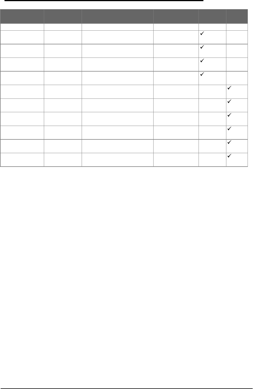
98
PART # EXCHANGE
PART # DESCRIPTION CUSTOMER
REPLACEABLE F1171 -
F1175 F1360
FRENCH
F1170-60913 RECOVERY KIT -
ITALIAN yes
F1170-60914 RECOVERY KIT -
GERMAN yes
F1170-60915 RECOVERY KIT -
SPANISH yes
F1170-60918 RECOVERY KIT -
SWEDISH yes
F1360-60912 RECOVERY KIT -
ENGLISH yes
F1360-60913 RECOVERY KIT -
FRENCH yes
F1360-60914 RECOVERY KIT -
ITALIAN yes
F1360-60915 RECOVERY KIT -
GERMAN yes
F1360-60916 RECOVERY KIT -
SPANISH yes
F1360-60917 RECOVERY KIT -
SWEDISH yes

HP Part Number
F1360-90049
