Hp Pcl Users Manual 5 Color Technical Reference ENWW
HP PCL/PJL reference (PCL 5 Color) - Technical Reference Manual bpl13212
PCL to the manual 636a0644-f4ac-4714-a45e-151d347c0e8b
2015-02-09
: Hp Hp-Pcl-Users-Manual-549281 hp-pcl-users-manual-549281 hp pdf
Open the PDF directly: View PDF ![]() .
.
Page Count: 286 [warning: Documents this large are best viewed by clicking the View PDF Link!]
- PCL 5 Color Technical Reference Manual
- Contents
- Color Printing Overview
- Using Color Modes
- Using Palettes
- Modifying Output Color
- The PCL Print Model
- Introduction
- Command Sequence
- Source Transparency Mode Command
- Pattern Transparency Mode Command
- Logical Operations
- Logical Operation Command
- Pixel Placement
- Pixel Placement Command
- Filling with Patterns
- Pattern ID (Area Fill ID) Command
- Select Current Pattern Command
- User-Defined Pattern Graphics
- Download Pattern Command
- Set Pattern Reference Point Command
- Pattern Control Command
- Rectangular Area Fills (Rules)
- Pattern Transparency for Rectangular Area Fill
- Rectangular Fill Examples
- Raster Graphics
- Introduction
- PCL 5 Color Raster Graphics
- Raster Graphics Command Sequence
- Raster Graphics Resolution Command
- Raster Graphics Presentation Mode Command
- Source Raster Height Command
- Source Raster Width Command
- Start Raster Graphics Command
- Raster Y Offset Command
- Set Compression Method Command
- End Raster Graphics Command
- Raster Scaling
- Raster Graphics Example
- Color Raster Graphics Example
- Color Vector Graphics (HP-GL/2)
- Color Printing Overview (Color LaserJet, 5, 5M, DeskJet)
- Using Color Modes (Color LaserJet, 5, 5M, DeskJet)
- Using Palettes (Color LaserJet, 5, 5M, DeskJet)
- Modifying Output Color (Color LaserJet, 5, 5M, DeskJet)
- Index

PCL 5 Color Technical
Reference Manual
Hewlett-Packard Company
11311 Chinden Boulevard
Boise, Idaho 83714 U.S.A.
Notice
The information contained in
this document is subject to
change without notice.
Copyright and
License
Copyright © 1999
Hewlett-Packard Company.
All rights are reserved. This
document contains proprietary
information which is protected
by copyright. Except as allowed
by copyright laws or herein,
reproduction, adaptation, or
translation without prior written
permission is prohibited.
Trademarks
Adobe, PostScript, and the
PostScript logo are trademarks
of Adobe Systems Incorporated
which may be registered in
certain jurisdictions. AppleTalk
is a registered trademark of
Apple Computer, Inc. PCL and
Resolution Enhancement are
registered trademarks of
Hewlett-Packard Company. IBM
is a registered trademark of
International Business
Machines Corporation.

iii
Inside This Manual
What You Can Learn From This Manual
This manual describes the PCL 5 commands used to print color on
the HP Color LaserJet printer family and the other Hewlett-Packard
PCL 5 color printers. Some of the main topics include an overview of
the color printing process, using palettes, choosing color modes,
adjusting output color to meet your requirements, printing color raster
graphics, and HP-GL/2 vector graphics. Examples are provided which
demonstrate the use of the PCL 5 color commands.
Note All commands described in this manual are not necessarily supported
by all printers. See the PCL 5 Comparison Guide for feature support
information for each printer.
This manual is written primarily for users that are already familiar with
PCL 5 printer features. For information on using PCL 5, see the
PCL 5 Printer Language Technical Reference Manual.
iv
Manual Organization
This manual contains seven chapters and four appendices. Chapters
2 through 4 describe command usage for the HP Color LaserJet 4500
and 8500 printers. Appendices A through D describe how these
functions are achieved on the HP Color LaserJet, Color LaserJet 5,
5M, and the DeskJet 1200C and 1600C printers. Chapters 5 through
7 pertain to all the color printers described in this manual. A brief
description of each chapter is provided below.
Chapter 1. Color Printing Overview
This chapter explains background information about printing color
documents using PCL 5. Topics include palettes, color selection, pixel
encoding, color modes, and color matching.
Chapter 2. Using Color Modes
Chapter 2 defines the color modes and describes how to use them,
including descriptions of sending color raster data using different pixel
encoding modes and color spaces.
Chapter 3. Using Palettes
This chapter describes the palettes associated with the color modes
and explains how palettes are created, saved, and modified.
Chapter 4. Modifying Output Color
This chapter explains the options for modifying the output color: the
Render Algorithm command, the Monochrome Print Mode command,
Driver Configuration command, and Finish Mode command.
Chapter 5. The PCL Print Model
Chapter 5 describes the print model and how it determines the
printed outcome when various patterns, colors, and images are
applied together on a page. This chapter discusses the role that
logical operations and transparency modes have on this process.
Chapter 6. Raster Graphics
This chapter describes the raster graphics commands and also
compressing raster graphics images using various compression
methods.
v
Chapter 7. Color Vector Graphics (HP-GL/2)
This chapter discusses printing color pages using HP-GL/2, the
vector graphics language included on all PCL 5 printers. The chapter
describes new and/or modified HP-GL/2 commands and how they are
used to print with HP color printers.
Appendix A. Color Printing Overview (Color LaserJet,
5, 5M, DeskJet)
Appendix A explains background information about printing color
documents using PCL 5. Topics include palettes, device-dependent
vs. device-independent color, color selection, pixel encoding, color
modes, and color matching.
Appendix B. Using Color Modes (Color LaserJet, 5,
5M, DeskJet)
Appendix B defines the color modes for the HP Color LaserJet, Color
LaserJet 5, 5M, and the DeskJet 1200C and 1600C printers, and
describes how to use them. It includes descriptions of sending color
raster data using different pixel encoding modes and color spaces.
Appendix C. Using Palettes (Color LaserJet, 5, 5M,
DeskJet)
Appendix C describes the use of palettes for the HP Color LaserJet,
5, and 5M, and DeskJet 1200C and 1600C printers. It explains the
palettes associated with the color modes and explains how palettes
are created, saved, and modified.
Appendix D. Modifying Output Color (Color LaserJet,
5, 5M, DeskJet)
Appendix D describes how to modify output color for the HP Color
LaserJet, Color LaserJet 5, 5M, and the DeskJet 1200C and 1600C
printers. This chapter explains how color can be optimized by
compensating for different conditions, such as variations in color due
to light sources, limitations of the original artwork and variations in
viewing monitors. The chapter details the use of halftone rendering
algorithms, color lookup tables, gamma correction, and viewing
illuminant commands. These commands are provided so that users
can request and receive color output that matches their expectations.
Index
An index offers quick access to PCL command information.
vi
Related Documents
The following documents provide related information about
Hewlett-Packard PCL 5 printers.
PCL 5 Printer Language Technical Reference Manual
The PCL 5 Printer Language Technical Reference Manual provides a
description of the printer command language that controls PCL 5
printers. The manual provides explanations of each PCL command,
and has examples demonstrating how the commands are used to
manipulate the printer. A large portion of the manual is devoted to
HP-GL/2, the vector-based graphics language in PCL 5 printers.
PCL 5 Comparison Guide
This document provides printer-specific information on paper
handling, internal fonts, PCL command support, and control panel
information. It identifies feature differences between the various
PCL 5 printers, and how the printers implement the commands
described in the PCL 5 Printer Language Technical Reference
Manual.
Printer Job Language Technical Reference Manual
This manual describes PJL, the HP printer job language used on
many of the Hewlett-Packard printers. PJL is used for switching
printer languages, requesting status information, changing display
messages, inquiring about feature settings, and other job-level
functions.
PCL/PJL Technical Quick Reference Guide
This booklet is designed to provide quick access to the syntax of each
PCL and PJL command. The commands are grouped by their
function so that those familiar with PCL and/or PJL can find the
syntax of a specific command without opening the manual.
EN Contents vii
Contents
PCL 5 Color Technical Reference Manual
Inside This Manual . . . . . . . . . . . . . . . . . . . . . . . . . . . . . . . . . . . . . . . . . . . . . . . iii
Manual Organization . . . . . . . . . . . . . . . . . . . . . . . . . . . . . . . . . . . . . . . . . . . . . . iv
Related Documents. . . . . . . . . . . . . . . . . . . . . . . . . . . . . . . . . . . . . . . . . . . . . . . vi
Chapter 1 Color Printing Overview
Introduction . . . . . . . . . . . . . . . . . . . . . . . . . . . . . . . . . . . . . . . . . . . . . . . . . . . . . . . .1-1
Working with color documents . . . . . . . . . . . . . . . . . . . . . . . . . . . . . . . . . . . . . .1-2
PCL 5 Color Concepts. . . . . . . . . . . . . . . . . . . . . . . . . . . . . . . . . . . . . . . . . . . . . . . .1-3
Color . . . . . . . . . . . . . . . . . . . . . . . . . . . . . . . . . . . . . . . . . . . . . . . . . . . . . . . . . .1-3
Color Specifications and Color Spaces . . . . . . . . . . . . . . . . . . . . . . . . . . . . . . .1-3
Color Management and the Standard Red, Green, Blue Color Space . . . . . . . .1-4
Palettes and Color Selection. . . . . . . . . . . . . . . . . . . . . . . . . . . . . . . . . . . . . . . .1-6
PCL 5 Color Graphics Context . . . . . . . . . . . . . . . . . . . . . . . . . . . . . . . . . . . . . .1-6
PCL 5 Color Mode . . . . . . . . . . . . . . . . . . . . . . . . . . . . . . . . . . . . . . . . . . . . . . .1-6
PCL 5 Raster Images . . . . . . . . . . . . . . . . . . . . . . . . . . . . . . . . . . . . . . . . . . . . .1-7
Pixels and Pixel Encoding. . . . . . . . . . . . . . . . . . . . . . . . . . . . . . . . . . . . . . . . . .1-7
Well-Behaved Raster . . . . . . . . . . . . . . . . . . . . . . . . . . . . . . . . . . . . . . . . . . . . .1-9
Chapter 2 Using Color Modes
Introduction . . . . . . . . . . . . . . . . . . . . . . . . . . . . . . . . . . . . . . . . . . . . . . . . . . . . . . . .2-1
Simple Color Mode . . . . . . . . . . . . . . . . . . . . . . . . . . . . . . . . . . . . . . . . . . . . . . . . . .2-3
PCL Imaging Mode . . . . . . . . . . . . . . . . . . . . . . . . . . . . . . . . . . . . . . . . . . . . . . . . . .2-5
Configure Image Data (CID) Command . . . . . . . . . . . . . . . . . . . . . . . . . . . . . . .2-5
HP-GL/2 Imaging Mode. . . . . . . . . . . . . . . . . . . . . . . . . . . . . . . . . . . . . . . . . . . . . .2-13
Chapter 3 Using Palettes
Introduction . . . . . . . . . . . . . . . . . . . . . . . . . . . . . . . . . . . . . . . . . . . . . . . . . . . . . . . .3-1
Saving the Palette . . . . . . . . . . . . . . . . . . . . . . . . . . . . . . . . . . . . . . . . . . . . . . . . . . .3-3
Push/Pop Palette Command. . . . . . . . . . . . . . . . . . . . . . . . . . . . . . . . . . . . . . . .3-3
Palette Management by ID . . . . . . . . . . . . . . . . . . . . . . . . . . . . . . . . . . . . . . . . . . . .3-5
Select Palette Command . . . . . . . . . . . . . . . . . . . . . . . . . . . . . . . . . . . . . . . . . .3-6
Palette Control ID . . . . . . . . . . . . . . . . . . . . . . . . . . . . . . . . . . . . . . . . . . . . . . . . . . .3-8
Palette Control. . . . . . . . . . . . . . . . . . . . . . . . . . . . . . . . . . . . . . . . . . . . . . . . . . . . . .3-9
Simple Color Palettes . . . . . . . . . . . . . . . . . . . . . . . . . . . . . . . . . . . . . . . . . . . . . . .3-11
. . .
. . .
. . .
Contents viii EN
CID Color Palettes. . . . . . . . . . . . . . . . . . . . . . . . . . . . . . . . . . . . . . . . . . . . . . . . . .3-13
Device RGB and sRGB Palettes. . . . . . . . . . . . . . . . . . . . . . . . . . . . . . . . . . . .3-13
Device CMY Palettes . . . . . . . . . . . . . . . . . . . . . . . . . . . . . . . . . . . . . . . . . . . .3-14
HP-GL/2 Palettes . . . . . . . . . . . . . . . . . . . . . . . . . . . . . . . . . . . . . . . . . . . . . . . . . .3-15
Foreground Color . . . . . . . . . . . . . . . . . . . . . . . . . . . . . . . . . . . . . . . . . . . . . . . . . .3-17
Foreground Color Command . . . . . . . . . . . . . . . . . . . . . . . . . . . . . . . . . . . . . .3-17
Programming Color Palettes . . . . . . . . . . . . . . . . . . . . . . . . . . . . . . . . . . . . . . . . . .3-19
Chapter 4 Modifying Output Color
Introduction . . . . . . . . . . . . . . . . . . . . . . . . . . . . . . . . . . . . . . . . . . . . . . . . . . . . . . . .4-1
Halftone Render Algorithms . . . . . . . . . . . . . . . . . . . . . . . . . . . . . . . . . . . . . . . . . . .4-2
Render Algorithm Command . . . . . . . . . . . . . . . . . . . . . . . . . . . . . . . . . . . . . . .4-2
Monochrome Printing . . . . . . . . . . . . . . . . . . . . . . . . . . . . . . . . . . . . . . . . . . . . . . . .4-3
Monochrome Print Mode Command. . . . . . . . . . . . . . . . . . . . . . . . . . . . . . . . . .4-3
Driver Configuration Command. . . . . . . . . . . . . . . . . . . . . . . . . . . . . . . . . . . . . . . . .4-4
Finish Mode Command . . . . . . . . . . . . . . . . . . . . . . . . . . . . . . . . . . . . . . . . . . . . . . .4-6
Chapter 5 The PCL Print Model
Introduction . . . . . . . . . . . . . . . . . . . . . . . . . . . . . . . . . . . . . . . . . . . . . . . . . . . . . . . .5-1
Command Sequence. . . . . . . . . . . . . . . . . . . . . . . . . . . . . . . . . . . . . . . . . . . . . . . . .5-6
Source Transparency Mode Command. . . . . . . . . . . . . . . . . . . . . . . . . . . . . . . . . . .5-7
Pattern Transparency Mode Command. . . . . . . . . . . . . . . . . . . . . . . . . . . . . . . . . . .5-8
Logical Operations . . . . . . . . . . . . . . . . . . . . . . . . . . . . . . . . . . . . . . . . . . . . . . . . . .5-9
Logical Operations and Transparency Interactions. . . . . . . . . . . . . . . . . . . . . .5-12
Logical Operation Command. . . . . . . . . . . . . . . . . . . . . . . . . . . . . . . . . . . . . . . . . .5-13
ROPs in the RGB Color Space. . . . . . . . . . . . . . . . . . . . . . . . . . . . . . . . . . . . .5-14
ROPs in the CMY Color Space. . . . . . . . . . . . . . . . . . . . . . . . . . . . . . . . . . . . .5-15
Using a ROP. . . . . . . . . . . . . . . . . . . . . . . . . . . . . . . . . . . . . . . . . . . . . . . . . . .5-16
Table of Logical Operations . . . . . . . . . . . . . . . . . . . . . . . . . . . . . . . . . . . . . . .5-18
Pixel Placement. . . . . . . . . . . . . . . . . . . . . . . . . . . . . . . . . . . . . . . . . . . . . . . . . . . .5-24
Pixel Placement Command . . . . . . . . . . . . . . . . . . . . . . . . . . . . . . . . . . . . . . . . . . .5-27
Filling with Patterns . . . . . . . . . . . . . . . . . . . . . . . . . . . . . . . . . . . . . . . . . . . . . . . . .5-28
Pattern ID (Area Fill ID) Command . . . . . . . . . . . . . . . . . . . . . . . . . . . . . . . . . . . . .5-29
Select Current Pattern Command . . . . . . . . . . . . . . . . . . . . . . . . . . . . . . . . . . . . . .5-32
User-Defined Pattern Graphics . . . . . . . . . . . . . . . . . . . . . . . . . . . . . . . . . . . . . . . .5-33
Using User-Defined Patterns . . . . . . . . . . . . . . . . . . . . . . . . . . . . . . . . . . . . . .5-33
How the Printer Tiles a Pattern. . . . . . . . . . . . . . . . . . . . . . . . . . . . . . . . . . . . .5-34
Pattern Reference Point . . . . . . . . . . . . . . . . . . . . . . . . . . . . . . . . . . . . . . . . . .5-36
Download Pattern Command . . . . . . . . . . . . . . . . . . . . . . . . . . . . . . . . . . . . . . . . .5-38
User-defined Pattern Example . . . . . . . . . . . . . . . . . . . . . . . . . . . . . . . . . . . . .5-40
Set Pattern Reference Point Command . . . . . . . . . . . . . . . . . . . . . . . . . . . . . . . . .5-43
Pattern Control Command. . . . . . . . . . . . . . . . . . . . . . . . . . . . . . . . . . . . . . . . . . . .5-44
Rectangular Area Fills (Rules) . . . . . . . . . . . . . . . . . . . . . . . . . . . . . . . . . . . . . . . .5-45
Pattern Transparency for Rectangular Area Fill. . . . . . . . . . . . . . . . . . . . . . . . . . . .5-50
EN Contents ix
Rectangular Fill Examples. . . . . . . . . . . . . . . . . . . . . . . . . . . . . . . . . . . . . . . . . . . .5-52
Solid Fill (Black/White) . . . . . . . . . . . . . . . . . . . . . . . . . . . . . . . . . . . . . . . . . . .5-52
Shaded Fill . . . . . . . . . . . . . . . . . . . . . . . . . . . . . . . . . . . . . . . . . . . . . . . . . . . .5-54
Chapter 6 Raster Graphics
Introduction . . . . . . . . . . . . . . . . . . . . . . . . . . . . . . . . . . . . . . . . . . . . . . . . . . . . . . . .6-1
PCL 5 Color Raster Graphics . . . . . . . . . . . . . . . . . . . . . . . . . . . . . . . . . . . . . . . . . .6-4
Raster Graphics Command Sequence . . . . . . . . . . . . . . . . . . . . . . . . . . . . . . . . . . .6-6
Raster Graphics Resolution Command. . . . . . . . . . . . . . . . . . . . . . . . . . . . . . . . . . .6-8
Raster Graphics Presentation Mode Command . . . . . . . . . . . . . . . . . . . . . . . . . . .6-10
Source Raster Height Command . . . . . . . . . . . . . . . . . . . . . . . . . . . . . . . . . . . . . .6-13
Source Raster Width Command . . . . . . . . . . . . . . . . . . . . . . . . . . . . . . . . . . . . . . .6-15
Start Raster Graphics Command . . . . . . . . . . . . . . . . . . . . . . . . . . . . . . . . . . . . . .6-17
Raster Y Offset Command . . . . . . . . . . . . . . . . . . . . . . . . . . . . . . . . . . . . . . . . . . .6-19
Set Compression Method Command . . . . . . . . . . . . . . . . . . . . . . . . . . . . . . . . . . .6-20
Unencoded (Method 0). . . . . . . . . . . . . . . . . . . . . . . . . . . . . . . . . . . . . . . . . . .6-21
Run-length Encoding (Method 1) . . . . . . . . . . . . . . . . . . . . . . . . . . . . . . . . . . .6-21
Tagged Image File Format Encoding (Method 2) . . . . . . . . . . . . . . . . . . . . . . .6-21
Delta Row Compression (Method 3). . . . . . . . . . . . . . . . . . . . . . . . . . . . . . . . .6-24
Adaptive Compression (Method 5) . . . . . . . . . . . . . . . . . . . . . . . . . . . . . . . . . .6-28
Transfer Raster Data Commands . . . . . . . . . . . . . . . . . . . . . . . . . . . . . . . . . . .6-32
Transfer Raster Data by Plane . . . . . . . . . . . . . . . . . . . . . . . . . . . . . . . . . . . . .6-33
Transfer Raster Data By Row/Block Command . . . . . . . . . . . . . . . . . . . . . . . .6-33
End Raster Graphics Command . . . . . . . . . . . . . . . . . . . . . . . . . . . . . . . . . . . . . . .6-35
Raster Scaling. . . . . . . . . . . . . . . . . . . . . . . . . . . . . . . . . . . . . . . . . . . . . . . . . . . . .6-36
Raster Graphics Example . . . . . . . . . . . . . . . . . . . . . . . . . . . . . . . . . . . . . . . . . . . .6-38
Color Raster Graphics Example . . . . . . . . . . . . . . . . . . . . . . . . . . . . . . . . . . . . . . .6-42
Chapter 7 Color Vector Graphics (HP-GL/2)
Introduction . . . . . . . . . . . . . . . . . . . . . . . . . . . . . . . . . . . . . . . . . . . . . . . . . . . . . . . .7-1
Enter HP-GL/2 Mode. . . . . . . . . . . . . . . . . . . . . . . . . . . . . . . . . . . . . . . . . . . . . . . . .7-2
MC (Merge Control). . . . . . . . . . . . . . . . . . . . . . . . . . . . . . . . . . . . . . . . . . . . . . . . . .7-6
PC (Pen Color) . . . . . . . . . . . . . . . . . . . . . . . . . . . . . . . . . . . . . . . . . . . . . . . . . . . .7-14
NP (Number of Pens) . . . . . . . . . . . . . . . . . . . . . . . . . . . . . . . . . . . . . . . . . . . . . . .7-17
CR (Color Range) . . . . . . . . . . . . . . . . . . . . . . . . . . . . . . . . . . . . . . . . . . . . . . . . . .7-19
PP (Pixel Placement) . . . . . . . . . . . . . . . . . . . . . . . . . . . . . . . . . . . . . . . . . . . . . . .7-20
Contents x EN
Appendix A Color Printing Overview (Color LaserJet, 5, 5M,
DeskJet)
Introduction . . . . . . . . . . . . . . . . . . . . . . . . . . . . . . . . . . . . . . . . . . . . . . . . . . . . . . . A-1
Color Concepts . . . . . . . . . . . . . . . . . . . . . . . . . . . . . . . . . . . . . . . . . . . . . . . . . . . . A-3
Palettes. . . . . . . . . . . . . . . . . . . . . . . . . . . . . . . . . . . . . . . . . . . . . . . . . . . . . . . A-3
Raster Mode . . . . . . . . . . . . . . . . . . . . . . . . . . . . . . . . . . . . . . . . . . . . . . . . . . . A-3
Raster Color vs. Non-Raster Color . . . . . . . . . . . . . . . . . . . . . . . . . . . . . . . . . . A-3
Device-Dependent vs. Device-Independent Color . . . . . . . . . . . . . . . . . . . . . . A-4
Black and White References. . . . . . . . . . . . . . . . . . . . . . . . . . . . . . . . . . . . . . . A-4
Color Selection . . . . . . . . . . . . . . . . . . . . . . . . . . . . . . . . . . . . . . . . . . . . . . . . . A-5
Pixel Encoding . . . . . . . . . . . . . . . . . . . . . . . . . . . . . . . . . . . . . . . . . . . . . . . . . A-6
Encoding by Plane . . . . . . . . . . . . . . . . . . . . . . . . . . . . . . . . . . . . . . . . . . . . . . A-6
Color Modes . . . . . . . . . . . . . . . . . . . . . . . . . . . . . . . . . . . . . . . . . . . . . . . . . . . A-7
Device-Dependent Color Spaces . . . . . . . . . . . . . . . . . . . . . . . . . . . . . . . . . . . A-8
Device-Independent Color Spaces . . . . . . . . . . . . . . . . . . . . . . . . . . . . . . . . . . A-8
Device-Independent Color. . . . . . . . . . . . . . . . . . . . . . . . . . . . . . . . . . . . . . . . . . . A-10
Device-Dependent Color. . . . . . . . . . . . . . . . . . . . . . . . . . . . . . . . . . . . . . . . . A-10
Device-Independent Color . . . . . . . . . . . . . . . . . . . . . . . . . . . . . . . . . . . . . . . A-10
Color Matching . . . . . . . . . . . . . . . . . . . . . . . . . . . . . . . . . . . . . . . . . . . . . . . . A-11
Processing Color Documents . . . . . . . . . . . . . . . . . . . . . . . . . . . . . . . . . . . . . . . . A-14
Non-Raster Color vs. Raster Color . . . . . . . . . . . . . . . . . . . . . . . . . . . . . . . . . A-14
Color Raster Data . . . . . . . . . . . . . . . . . . . . . . . . . . . . . . . . . . . . . . . . . . . . . . A-14
Appendix B Using Color Modes (Color LaserJet, 5, 5M, DeskJet)
Introduction . . . . . . . . . . . . . . . . . . . . . . . . . . . . . . . . . . . . . . . . . . . . . . . . . . . . . . . B-2
Simple Color Mode . . . . . . . . . . . . . . . . . . . . . . . . . . . . . . . . . . . . . . . . . . . . . . . . . B-4
PCL Imaging Mode . . . . . . . . . . . . . . . . . . . . . . . . . . . . . . . . . . . . . . . . . . . . . . . . . B-6
Configure Image Data (CID) Command . . . . . . . . . . . . . . . . . . . . . . . . . . . . . . B-6
Short Form of CID Command (Configure Image Data) . . . . . . . . . . . . . . . . . B-15
Long Form of CID Command (Configure Image Data) . . . . . . . . . . . . . . . . . . B-17
HP-GL/2 Imaging Mode. . . . . . . . . . . . . . . . . . . . . . . . . . . . . . . . . . . . . . . . . . . . . B-28
Appendix C Using Palettes (Color LaserJet, 5, 5M, DeskJet)
Introduction . . . . . . . . . . . . . . . . . . . . . . . . . . . . . . . . . . . . . . . . . . . . . . . . . . . . . . . C-1
Saving the Palette . . . . . . . . . . . . . . . . . . . . . . . . . . . . . . . . . . . . . . . . . . . . . . . . . . C-3
Push/Pop Palette Command. . . . . . . . . . . . . . . . . . . . . . . . . . . . . . . . . . . . . . . C-3
Palette Management by ID . . . . . . . . . . . . . . . . . . . . . . . . . . . . . . . . . . . . . . . . . . . C-5
Palette Control ID . . . . . . . . . . . . . . . . . . . . . . . . . . . . . . . . . . . . . . . . . . . . . . . . . . C-8
Palette Control. . . . . . . . . . . . . . . . . . . . . . . . . . . . . . . . . . . . . . . . . . . . . . . . . . . . . C-9
Simple Color Palettes . . . . . . . . . . . . . . . . . . . . . . . . . . . . . . . . . . . . . . . . . . . . . . C-11
CID Color Palettes. . . . . . . . . . . . . . . . . . . . . . . . . . . . . . . . . . . . . . . . . . . . . . . . . C-13
HP-GL/2 Palettes . . . . . . . . . . . . . . . . . . . . . . . . . . . . . . . . . . . . . . . . . . . . . . . . . C-16
Foreground Color . . . . . . . . . . . . . . . . . . . . . . . . . . . . . . . . . . . . . . . . . . . . . . . . . C-18
EN Contents xi
Programming Color Palettes . . . . . . . . . . . . . . . . . . . . . . . . . . . . . . . . . . . . . . . . . C-20
Color Component One . . . . . . . . . . . . . . . . . . . . . . . . . . . . . . . . . . . . . . . . . . C-20
Color Component Two . . . . . . . . . . . . . . . . . . . . . . . . . . . . . . . . . . . . . . . . . . C-20
Color Component Three . . . . . . . . . . . . . . . . . . . . . . . . . . . . . . . . . . . . . . . . . C-21
Assign Color Index . . . . . . . . . . . . . . . . . . . . . . . . . . . . . . . . . . . . . . . . . . . . . C-21
Appendix D Modifying Output Color (Color LaserJet, 5, 5M,
DeskJet)
Introduction . . . . . . . . . . . . . . . . . . . . . . . . . . . . . . . . . . . . . . . . . . . . . . . . . . . . . . . D-1
Halftone Render Algorithms . . . . . . . . . . . . . . . . . . . . . . . . . . . . . . . . . . . . . . . . . . D-3
Render Algorithm Command . . . . . . . . . . . . . . . . . . . . . . . . . . . . . . . . . . . . . . D-3
User-Defined Dithers . . . . . . . . . . . . . . . . . . . . . . . . . . . . . . . . . . . . . . . . . . . . D-6
Download Dither Matrix Command. . . . . . . . . . . . . . . . . . . . . . . . . . . . . . . . . . D-7
Multiple Dither Matrices . . . . . . . . . . . . . . . . . . . . . . . . . . . . . . . . . . . . . . . . . D-10
Color Lookup Tables . . . . . . . . . . . . . . . . . . . . . . . . . . . . . . . . . . . . . . . . . . . . . . . D-13
Gamma Correction . . . . . . . . . . . . . . . . . . . . . . . . . . . . . . . . . . . . . . . . . . . . . . . . D-17
Viewing Illuminant . . . . . . . . . . . . . . . . . . . . . . . . . . . . . . . . . . . . . . . . . . . . . . . . . D-18
Monochrome Printing . . . . . . . . . . . . . . . . . . . . . . . . . . . . . . . . . . . . . . . . . . . . . . D-20
Driver Configuration Command. . . . . . . . . . . . . . . . . . . . . . . . . . . . . . . . . . . . . . . D-21
Index
Contents xii EN
EN Color Printing Overview 1-1
1Color Printing
Overview
Introduction
This chapter provides an overview of color printing with
Hewlett-Packard printers. A primary goal for HP color printers has
always been WYSIWYG (What You See Is What You Get) color,
where the color displayed on the screen while creating a document is
the same as the color in the printed document. However, this goal has
been very difficult to realize due to a number of factors such as:
• Some colors that can be shown on a computer display cannot
be reproduced by a printer.
• The Cyan, Magenta, and Yellow colors used to create the
colors specified in a document can differ in hue and quality
from printer to printer, even printers from the same
manufacturer. Furthermore, the colors produced by a given
printer can change over time, due to internal changes as well
as temperature and humidity.
Until recently, these and other problems have led HP to approach
color matching by presenting a PCL 5 color command set giving
users the ability to make both major and minor color print quality
adjustments.
However, the emergence of sRGB (standard Red Green Blue) as an
international color data standard and the growing sophistication of
Hewlett-Packard printers has allowed HP to provide high quality
WYSIWYG color documents with a much simpler PCL color
command set. Therefore, this manual has two main parts: Chapters 1
through 7 present the latest, simplified PCL 5 color command set, and
the appendices describe the command set described in Chapters 1
through 4 as they are supported by the Color LaserJet, Color
LaserJet 5, DeskJet 1200C, and DeskJet 1600C printers.
Chapters 5 – 7 pertain to both sets of printers.
1-2 Color Printing Overview EN
Working with color documents
A document can be thought of as a series of text characters, vector
graphics objects and images. The parts of a document either have
color specifications in them, as do color images, or have color
specifications applied to them, as do color vectors or text. For color
images, the PCL 5 command set provides a way to specify the color
format so that the image data can be interpreted correctly. For vector
graphics and text, the PCL 5 color commands support the application
of a color from a palette of colors.
Each color printed is synthesized from a combination of three colors:
Cyan, Magenta, and Yellow. The way the three colors are combined to
produce the desired color is called a half-tone, and the PCL 5 color
command, Render Algorithm, specifies which half-tone to use for a
color. Advances in Hewlett-Packard printers have allowed HP to
reduce the number of render algorithms to Best, High, and Low. While
the actual implementation of each of these algorithms may vary from
printer to printer, HP has determined that the three algorithms are
sufficient to produce high quality color documents containing text and
graphics.
The colors that appear on a page also have one of two color
treatments applied to them:
1Screen Match (sRGB), which provides the best WYSIWYG color.
This is the default color treatment.
2The Vivid color treatment, which provides access to the entire
device gamut (range of colors the printer can produce). However,
these colors are less correlated to those shown on a monitor than
colors that have had the Screen Match treatment applied.
The following factors form the heart of the PCL color graphics state:
• The palette of colors to be used in a document
• The render algorithm to print the colors
• The color treatment to be applied to each color
Palettes of colors can be referenced by an ID, and so can PCL color
graphic states. At any given time there is an active palette to apply
colors from, along with a render algorithm and color treatment to be
applied to the colors. Palettes and their associated render algorithm
and color treatment can be stored and retrieved using a palette ID.
When a palette is retrieved and made the active palette, the render
algorithm and color treatment stored with the palette are set as the
current render algorithm and color treatment.
EN Color Printing Overview 1-3
The PCL language also allows users to use patterns in combination
with colors. These patterns and colors can be combined with text,
vector graphics, and images to create new, complex graphics objects.
The PCL Print Model determines the logical operations (known as
ROPs, Raster Operations) used to combine each part of the graphic
object.
PCL 5 Color Concepts
This section describes some of the concepts and terminology of color
science related to the PCL 5 color commands.
Color
Color is a combination of human physiological and psychological
responses to a relatively narrow band of frequencies in the
electromagnetic spectrum. The frequencies visible to the human eye
are called the visible spectrum. It’s useful to understand that color
comes both from direct light and indirect light that has reflected from a
surface. Reflected light absorbs all but the reflected frequency. The
colors seen on a color monitor are combinations of different-colored
lights traveling directly to the eye. They are called additive colors
since the different colors combine to form the resulting color. The
colors seen on a printed material such as paper are reflected from the
paper surface, which absorbs some of the light. Colors seen under
these conditions depend on the viewing conditions, the amount and
color of ambient light, as well as the amount and color of the reflected
light.
Color Specifications and Color Spaces
A given color can be described as particular amounts of three light
frequencies (red, green, and blue light). For example, equal amounts
of red, green, and blue light are perceived as white light. The absence
of all three primary light colors is black.
1-4 Color Printing Overview EN
Color can be described in ways other than amounts of red, green, and
blue light. Generally, these color specification systems are known as
color spaces. For example, The Cyan, Magenta, Yellow (CMY) color
space is used to describe colors that are printed by depositing varying
amounts of these three ink pigments (Cyan, Magenta, Yellow). The
absence of pigment is considered to be white, and the presence of all
three is black. The CMYK color space is similar to the CMY color
space, but black pigment is used in place of 100% C, M, Y since
imperfections in the hues of the C, M, Y pigments yield a dark brown
rather than black.
A color specification, then, depends on the color space as well as the
values used to describe a given color. Black in the RGB color space is
described using the three numbers (0, 0, 0), but in the CMY color
space it is described as (100, 100, 100), where the values are
percentages of each color.
Color Management and the Standard Red,
Green, Blue Color Space
For color to be reproduced in a predictable manner across different
devices and materials, it has to be described in a way that is
independent of the specific mechanisms and materials used to
produce it. For instance, color displays and color printers use very
different mechanisms for producing color. Traditionally, operating
systems have supported color by declaring support for a particular
color space (RGB in most cases). However, since the interpretation of
RGB values varies between devices, color was not reliably
reproduced across different devices.
The needs of the very high-end publishing sector could not be met by
the traditional means of color support, so the various computer
operating systems added support for using International Color
Consortium (ICC) profiles to characterize device-dependent colors in
a device-independent way. They used the profiles of the input device
that created an image, and the output device that displayed or printed
the image, to create a transform that moved the image from the color
space of the input device to that of the output device. This resulted in
very accurate color and access to the entire color gamut of both
devices. However, it also involved the overhead of transporting the
profile of the input device with the image and running the image
through the transform.

EN Color Printing Overview 1-5
Note HP’s ICC profiles are available through normal HP software
distribution channels. For those who want the additional control
available through building their own ICC profiles, there are several
vendors of profiling tools available. To provide access to the printer's
pure primaries and entire available printer gamut, the Vivid mode may
be used when profiling the printer, and subsequently when using the
ICC workflow.
However, there are a broad range of users that do not require this
level of flexibility and control in an embedded color profile
mechanism. Instead it is possible to define a single, standard default
color space for exchange and interpretation of color data. Additionally,
most existing file formats do not support color profile embedding, and
may never do so. There is also a broad range of uses that actually
discourages people from appending any extra data to their files. The
sRGB color space addresses these issues.
The sRGB color space maintains the advantage of a clear
relationship with ICC color management systems while minimizing
software processes and support requirements. Since the image is in
a known color space and the profile for that color space is included
within the operating system and display application, this enables
end-users to enjoy the benefits of color management without the
overhead of larger files. Application developers and users who do not
want the overhead of embedding profiles in documents or images
should convert them to sRGB. While it may be that profiles buy
slightly higher color accuracy, the benefits of using a standard color
space far outweigh the drawbacks for a wide range of users. The
migration of devices to support the standard color space (sRGB)
natively will further enhance the speed and quality of the user
experience.
The international standard color space sRGB (IEC 61966-2-1) is
designed to complement current color management strategies by
enabling a simple, robust method of handling color in the operating
systems, device drivers and the Internet. This solution provides good
quality and backward compatibility with minimum transmission and
system overhead. Based on a calibrated colorimetric RGB color
space well suited to cathode ray tube (CRT) displays, flat panel
displays, television, scanners, digital cameras, and printing systems,
the sRGB color space can be supported with minimum cost to
software and hardware vendors. The four major technical
components of the sRGB color space are the standard CRT primaries
(HDTV P22 phosphors); the simple gamma value of 2.2, a D65 white
point, and its well-defined viewing conditions.
1-6 Color Printing Overview EN
Palettes and Color Selection
The PCL 5 language allows the user to define a palette of colors.
Each color is specified by three quantities or values which are
interpreted depending on the color space. For example, the color
white in an RGB palette is (1, 1, 1) while this set of values in a CMY
palette defines the color black. Each color in the palette is accessed
using an index number, starting with 0 as the first color in the palette.
The largest palette holds 256 colors, which is approximately the
largest set of distinct colors the human eye can distinguish under
normal viewing conditions.
A color from a palette can be applied to either text or vector graphics
using the Foreground Color command. Once the command is invoked
the selected color will be applied to all text and vector graphics page
marking primitives, and to a certain extent to raster images.
Palettes can be identified with a Palette ID and then stored and
recalled as needed. A palette stack mechanism is also supported for
the convenience of applications that work well with a graphics stack.
PCL 5 Color Graphics Context
The Palette acts as the focal point of the PCL 5 color graphics
context. The color space, render algorithm, color treatment, and pixel
encoding mode are stored along with the palette. Therefore, selecting
or restoring a palette also restores these values.
PCL 5 Color Mode
The PCL language has four modes or ways of specifying and using
color:
• Black-and-White (monochrome) mode is the default mode so
that backward compatibility with previous printers is
maintained. When the printer is turned on it has a 2-entry
palette containing the color white at index 0 and black at
index 1. When the printer is reset with an ?E it reverts to this
mode.
• Simple Color mode is entered with the Simple Color
command, which creates one of three fixed color palettes:
zA monochrome, two-entry palette with white at index 0 and
black at index 1.
EN Color Printing Overview 1-7
zAn RGB, eight-entry palette with the following colors
starting at index 0: black, red, green, yellow, blue,
magenta, cyan, and white.
zA CMY, eight-entry palette with the following colors
starting at index 0: white, cyan, magenta, blue, yellow,
green, red and black.
• PCL Imaging mode is entered with the Configure Image Data
command that creates a programmable palette of a
programmed size. This palette can be programmed using the
color component and set index commands.
• HP-GL/2 Imaging mode is entered when HP GL/2 mode is
entered and the initialize command IN creates a
programmable palette that is shared between PCL and
HP-GL/2.
Any and all of the modes can be used on a page. For example, you
could enter the Simple Color mode to print a headline and bar chart,
PCL imaging mode to print a photographic image, and
Black-and-White mode for the text on the page. Each mode is
described in more detail in Chapter 2. “Using Color Modes.”
PCL 5 Raster Images
Monochrome PCL 5 raster images are made up of a series of zeros
and ones. A one indicates that a black dot should be deposited, a
zero indicates no dot, letting the white background show through. A
one-inch wide image with a resolution of 600 dots per inch (DPI) has
600 consecutive zeros and/or ones, which represent a horizontal slice
through the image starting at the left edge of the image. This slice is
known as a raster row. For an image one inch high and one inch wide,
at 600 dpi there are 600 hundred rows of 600 zeros and/or ones.
Color raster images follow the same conventions with this major
exception: the representation of a dot is changed from a single zero
or one to a color specification (a pixel).
Pixels and Pixel Encoding
Raster images can be thought of as being composed of a series of
pixels (picture elements). In the case of monochrome raster images,
a pixel is a single bit which takes on a value of zero or one. In color
images a pixel is essentially a color specification. However, there are
several ways of specifying a color, and how the color is specified is
called the Pixel Encoding Mode (PEM).

1-8 Color Printing Overview EN
The PCL 5 color command set supports several Pixel Encoding
Modes. The PEMs are categorized first by whether the pixel is an
index into a palette, or a color specification. The other PEM
categorization is whether the pixel data is divided into planes and
transferred one plane at a time or is transferred in sequential order.
There are four supported Pixel Encoding modes:
1Indexed by Plane
2Indexed by Pixel
3Direct by Plane
4Direct by Pixel (also known as 24-bit direct).
For example, the format known as direct by plane, uses a 3-bit pixel
where the first bit indicates the presence or absence of a red dot, the
second a green dot and the third a blue dot. The data is still arranged
in rows, but all the red data is sent, then the green and finally all the
blue. The example below represents the commands to transfer an
image with the direct by plane PEM. The underlined bits, while
transferred separately, are logically from the same pixel.
The direct by pixel PEM uses only the row transfer command. Each
pixel is composed of three bytes, one byte per component of the color
specification. All the bytes of a given pixel are transferred before the
next one is transferred.
The indexed by pixel PEM is similar to the direct pixel PEM but the
pixel occupies at most one byte and is an index into the current
palette.
The indexed by plane PEM is similar to the direct by plane PEM
except the pixel's value is an index into the current palette. The use of
this mode is discouraged due to the extra processing required to
combine the bits from each plane into a single number, which is then
used as an index into the current palette.
?*b#V row 1 plane 1 (red) b1 b1 b1 b1 b1 b1...
?*b#V plane 2 (green) b2 b2 b2 b2 b2 b2...
?*b#W plane 3 (blue) b3 b3 b3 b3 b3 b3...
?*b#V row 2 plane 1 (red) b1 b1 b1 b1 b1 b1...
?*b#W row x b1 b2 b3 b1 b2 b3 b1...
EN Color Printing Overview 1-9
Well-Behaved Raster
PCL raster images are processed most efficiently when the height
and width of the image are specified before the Raster Start
command begins an image data transfer. Furthermore, the entire
image should be transferred before using the End Raster command to
end the image. If the image is broken into pieces, certain print
artifacts such as lines or squares can appear in the image. These can
occur when “nearest neighbor operations” are applied to pixels that
appear to be at the edge of an image, but are really inside an image
that has been artificially broken up into smaller images.
1-10 Color Printing Overview EN
EN Using Color Modes 2-1
2Using Color Modes
Introduction
The PCL printer language has four color modes:
• Black-and-White
•Simple Color
• PCL Imaging
• HP-GL/2 Imaging
PCL allows you to use any mode or combination of modes to
accomplish your printing objectives most efficiently.
All four of the color modes create a palette. The palette for each mode
is discussed in the section describing that mode, and also in
Chapter 3 (“Using Palettes”).
Black-and-White Mode (Default)
Black-and-White Mode is the default color mode. PCL devices power
up in this mode and revert back to it whenever the printer receives an
?E reset. Black-and-White mode is also selectable using the Simple
Color command (?*r1U). This mode creates an unmodifiable, default
2-pen palette, with white at index 0 and black at index 1 (compatible
with existing monochrome PCL 5 printers).
Simple Color Mode
Simple Color Mode, entered by the Simple Color command (?*r#U),
creates a fixed-size, fixed-color, unmodifiable palette. Depending on
the value field, ?*r#U can create a 2-pen Black-and-White palette,
an 8-pen RGB palette, or an 8-pen CMY palette. When using the
Simple Color mode, the pixel encoding mode is always indexed
planar.
2-2 Using Color Modes EN
PCL Imaging Mode
PCL Imaging Mode, enabled by the Configure Image Data command
(?*v#W), allows a maximum of 24 bits per pixel for color
specification. Therefore, more colors may be specified than are
obtainable in Simple Color Mode. In the PCL Imaging Mode, pixel
encoding mode, bits per pixel, bits per primary, and the color palette
are all programmable.
HP-GL/2 Imaging Mode
In HP-GL/2, the Initialize (IN) command starts color imaging and
performs the following:
• Sets the pixel encoding mode to index by plane.
• Sets bits per index to 3.
• Creates an 8-pen palette that is reprogrammable in either PCL
or HP-GL/2 contexts (see Chapter 3, “Using Palettes,” for more
information).
Although default HP-GL/2 palettes are different than default PCL
palettes, an HP-GL/2 palette is modifiable in either PCL or HP-GL/2
(using the Assign Color Index [?*v#I] or Pen Color [PC] commands,
respectively). Likewise, a PCL palette created by the Configure Image
Data command (?*v#W) is modifiable in both PCL and HP-GL/2
using the same commands.
The active palette is always transferred between HP-GL/2 and PCL
contexts. Since only one palette at a time can be active, a new palette
created in either context overwrites the current palette.
EN Using Color Modes 2-3
Simple Color Mode
The Simple Color command (?*r#U) specifies color selection from a
fixed palette. RGB or CMY raster data must be sent by plane
(?*b#V) as well as by row (?*b#W). The last plane in each row is
sent using the ?*b#W command; all other planes are sent using the
?*b#V command. In Simple Color mode, the pixel encoding mode is
always indexed planar.
Simple Color Command
The Simple Color command creates a fixed-size palette, whose color
specification cannot be modified.
?*r#U
This command destroys the active palette and creates a new palette,
which becomes the active palette. When the Simple Color mode is
active, PCL and HP-GL/2 commands that modify the palette are
locked out (NP, PC, ?*v#A, ?*v#B, ?*v#C, ?*v#I). When a Simple
Color palette is popped from the stack (?*p#P), it cannot be
modified, and the pixel encoding mode reverts to indexed planar.
• A value field of 1 creates a 2-entry Black-and-White default
palette.
• A value field of 3 creates an 8-entry Device RGB palette
(compatible with a PCL Imaging Mode palette, but not an
HP-GL/2 default (IN) palette).
• A value field of –3 creates an 8-entry palette in Device CMY
color space.
# = –3 - 3 planes, device CMY palette
1 - Single plane K (Black) palette
3 - 3 planes, device RGB palette
Default =1
Range =–3, 1, 3
2-4 Using Color Modes EN
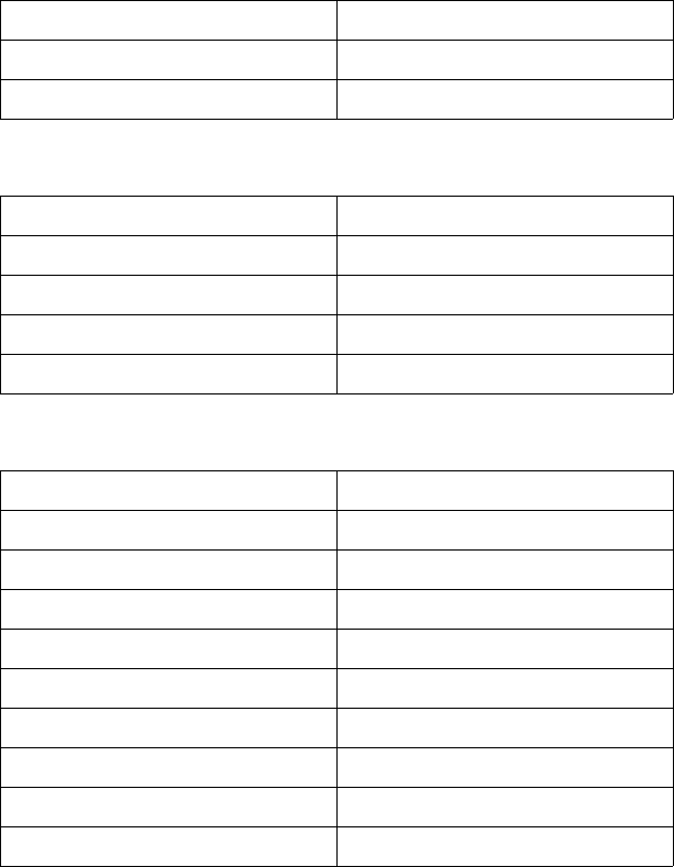
The Simple Color palettes are structured as follows:
Single Plane (value = 1)
3-Plane RGB (value = 3)
3-Plane CMY (value = –3)
Index Color
0White
1Black
Index Color
0Black
1Red
2Green
3Yellow
4Blue
5 Magenta
6Cyan
7White
Index Color
0White
1Cyan
2 Magenta
3Blue
4Yellow
5Green
6Red
7Black
EN Using Color Modes 2-5
PCL Imaging Mode
The PCL Imaging mode, entered using the Configure Image Data
(CID) command (?*v#W), creates a variable-sized programmable
palette. It provides multiple color spaces, pixel encoding modes, and
reprogrammable palettes.
Configure Image Data (CID) Command
The CID command provides configuration information for creating
palettes and transmitting raster data. The CID command performs the
following:
• Designates the color space for the newly created palette
• Designates the size of the palette
• Designates the Pixel Encoding Mode, the format of the raster
data
• Designates, in certain circumstances, the size, in bits, of the
three components of the color specifications. However, this
information is rarely useful since it applies only to the
direct-by-pixel PEM, where the format must be eight bits per
component for 24-bit direct color, and the direct-by-plane,
where there is one bit per component.
?*v6W b0 b1 b2 b3 b4 b5
Where:
6 = The number of bytes following the “W”
b0 = byte 0 The color space
b1 = byte 1 The Pixel Encoding Mode
b2 = byte 2 The number of bits per index which implies the
size of the palette
b3 = byte 3 The number of bits in color component
(primary) #1
b4 = byte 4 The number of bits in color component
(primary) #2
b5 = byte 5 The number of bits in color component
(primary) #3
2-6 Using Color Modes EN
The bytes are ordered as follows and are unsigned bytes:
Invalid configurations of the CID command are ignored and the data
discarded. A minus or a plus sign in the value field (-6 or 6) is ignored
The data fields in the command, bytes zero to five, must contain
byte-aligned binary data, not ASCII data.
Byte 0 (Color Space)
This byte specifies the color space. The range of values is 0 through
2. All other values are ignored.
Color space 2, sRGB, was the designation for Colorimetric RGB in
the Color LaserJet and Color LaserJet 5 printers. The value 2 is used
to represent sRGB since it is analogous to a standardized
Colorimetric RGB and the intent of the two color spaces is the same.
Byte 15 (MSB) 8 7 0 (LSB) Byte
0Color space Pixel encoding mode 1
2Bits/index Bits/primary #1 3
4Bits/primary #2 Bits/primary #3 5
Byte Value Color Space
0 Device Dependent RGB (default)
1 Device Dependent CMY
2 Standard RGB (sRGB)
EN Using Color Modes 2-7
Byte 1 (Pixel Encoding Mode)
This byte designates the format of any subsequent raster images.
The range of the value is zero to three. All other values for this field
are ignored.
The number of bits per index determines the size of the palette
created by this command. In the case of the Indexed by Plane mode
the number of planes needed to represent the index is also
determined by the number of bits per index. Therefore, if a 256 entry
palette is needed, then the bits per index is set to eight since
28= 256. If the Indexed by Plane mode is chosen, at most eight
planes are needed to represent each row of data.
The recommended pixel encoding mode is Direct by Pixel, since this
gives the most efficient raster processing. However, using this mode
means that delta row compression should be used since it exploits
redundancy between rows. Other PCL compression modes exploit
redundancy within a row. With Direct by Pixel the redundancy from
pixel to pixel in a row is masked by the differences at the byte level
within the pixel, that is, the differences between the red, green, and
blue bytes within the pixel.
Note Raster data in Index by Plane or Direct by Plane modes cannot be
compressed using raster compression mode 5.
You need one plane or one bit/pixel for each power of two colors in the
palette. For example, a 256-color palette requires 8 planes or
8bits/pixel (2
8 = 256).
Value Pixel Encoding
Mode Restrictions
0Indexed by Plane Bits/Index can only be 1, 2, 3, 4, 5, 6,
7, or 8. Bit/Components 1, 2, and 3
are ignored
1Indexed by Pixel Bits/Index can only be 1, 2, 4, or 8.
Bit/Components 1, 2, and 3 are
ignored
2Direct by Plane Bits/Components 1, 2, and 3 must
be 1
3Direct by Pixel Bits/Components 1, 2, and 3 must
be 8

2-8 Using Color Modes EN
PEM 0: INDEXED BY PLANE
In Pixel Encoding Mode 0, successive planes of data are sent for
each raster row. A plane contains one bit for each pixel in a row. A
pixel is not fully defined until all the planes for that row have been
received, which is signaled by a transfer raster row command. The
planes in a row form index numbers into the current palette. For
example, assuming three bits per index, the underlined column of bits
in the figure below is the palette index for pixel three of the first row (i1
is the least significant bit, i3 is the most significant bit). Note that the
Transfer Raster Data by Plane command (?*b#V) is used for all
planes except the last plane of each row, which is sent using the
Transfer Raster Data by Row command (?*b#W).
Example:
In the example below, the row transfer commands are shown in
binary for clarity, even though the actual data would be byte-aligned
binary data. The example is for an eight-pixel-wide image.
?*b#V row 1 plane 1 i1 i1 i1 i1 i1 i1
?*b#V plane 2 i2 i2 i2 i2 i2 i2
?*b#W plane 3 i3 i3 i3 i3 i3 i3
?*b#V row 2 plane 1 i1 i1 i1 i1 i1 i1
?*v6W 00 00 03 08 08 08 Binary data for CID represented
in hex. This command sets the
color space to RGB, the PEM to
Indexed by Plane, the palette size
to 8 (23). The last 3 bytes are
ignored.
?*r1A Start raster.
?*b1V10110000 Transfer plane 1 (the first bit for
each pixel in the first row).
?*b1V01110000 Transfer plane 2 (the second bit
for each pixel in the row).
?*b1W10101000 Transfer plane 3 (the third and
final bit for each pixel in the row)
and move to the next row. Note
that the ?*b#W command is
used to send the last plane of
each row.

EN Using Color Modes 2-9
PEM 1: INDEXED BY PIXEL
In this mode, each pixel in a row is fully specified before any bits are
sent for the next pixel. The bits for each pixel form a palette index
number. Assuming four bits per index, the underlined block below is
the palette index for pixel two of row one (i1 is the least significant bit).
?*b#W row 1 i4 i3 i2 i1 i4 i3 i2 i1 . . .
?*b#W row 2 i4 i3 i2 i1 i4 i3 i2 i1 . . .
?*b#W row 3 i4 i3 i2 i1 i4 i3 i2 i1 . . .
Example:
In the example below the data in the row transfer commands are
shown as two-digit hexadecimal numbers for clarity, even though the
actual data would be byte-aligned binary data. The example is for a
two-pixel-wide image.
?*v6W 00 01 04 08 08 08 Binary Data for the CID
command represented in
hexadecimal. This command
sets the color space to RGB, the
PEM to Indexed by Pixel, the
palette size to 16 (24). The last
three bytes are ignored.
?*r1A Start raster
?*b1W45 The most significant nibble
selects palette entry 4 for the
first pixel. The second pixel is set
to index 5. Move to next row.
?*b1W6A The first pixel is index 6, the
second pixel is index 10. Move to
the next row.
?*b1W03 The first pixel is index 0, the
second pixel is index 3.

2-10 Using Color Modes EN
MODE 2: DIRECT BY PLANE
In this mode, a pixel is composed of three, one-bit components. The
data is transferred a plane at a time, one plane for each component.
Therefore, each bit in a plane represents one component of a pixel.
The underlined bits below show the components for a pixel.
Example:
In the example below the data in the row transfer commands are
shown in binary for clarity, even though the actual data would be
byte-aligned binary data. The example is for an eight-pixel-wide
image.
?*b#V row 1 plane 1 (red) b1 b1 b1 b1 b1 b1
?*b#V plane 2 (green) b2 b2 b2 b2 b2 b2
?*b#W plane 3 (blue) b3 b3 b3 b3 b3 b3
?*b#V row 2 plane 1 (red) b1 b1 b1 b1 b1 b1
?*v6W 00 02 01 01 01 01 Binary Data for the CID command
represented in hexadecimal. This
command sets the color space to
RGB, the PEM to Direct by Plane.
The palette size is ignored. The
last three bytes are always one
for this mode.
?*r1A Start raster
?*b1V10110000 Transfer plane 1 (the first bit for
each pixel in the first row). Each
bit controls the red primary.
?*b1V01110000 Transfer plane 2 (the second bit
for each pixel in the row). Each bit
controls the green primary.
?*b1W10101000 Transfer plane 3 (the third and
final bit for each pixel in the row)
and move to the next row. Each
bit controls the blue primary. Note
that the ?*b#W command is
used to send the last plane of
each row.

EN Using Color Modes 2-11
MODE 3: DIRECT BY PIXEL
This mode specifies a pixel as three, eight-bit components, thus the
name 24-bit direct color. Assuming the RGB color space with the
mandatory eight bits per component, the underlined bytes below
define the first pixel of row two.
Example:
In the example below the data in the row transfer commands are
shown as two-digit hexadecimal numbers for clarity, even though the
actual data would be byte-aligned binary data. The example is for a
one-pixel-wide image.
Byte 2 (Number of Bits per Index)
This command creates a palette regardless of the PEM chosen. This
byte determines the size of the created palette. The palette size is two
raised to the power of n (2n), where n is the bits per index.
• In the Indexed-by-Plane PEM, where the raster data is
interpreted as palette indices, this value determines the
number of planes required per row.
?*b#W row 1 r7–r0 g7–g0 b7–b0 . . .
?*b#W row 2 r7–r0 g7–g0 b7–b0 . . .
?*b#W row 3 r7–r0 g7–g0 b7–b0 . . .
?*v6W 00 03 00 08 08 08 Binary Data for CID command
represented in hexadecimal.
This command sets the color
space to RGB, the PEM to
Direct by Pixel. The palette size
is ignored. The last three bytes
must be 8.
?*r1A Start raster
?*b3W 45 06 30 The three bytes specify a single
pixel. The first sets 45 as the red
component’s value, the second
sets the green value to 06, and
the third sets the blue value to
30.
2-12 Using Color Modes EN
• In the Indexed-by-Pixel PEM, where the raster data is
interpreted as palette indices, this value determines how to
interpret the byte-ordered row transfers. The following list
shows how each byte is translated into indices:
• In the Direct-by-Plane and Direct-by-Pixel PEMs, byte 2 does
not apply to the raster format.
Bytes 3, 4, and 5 (No. of Bits for Components 1, 2,
and 3)
These bytes are ignored for the Indexed by Plane and Indexed Direct
PEMs. For the Direct by Plane PEM they must be set to one bit per
component. For the Direct by Pixel PEM, they must be set to eight bits
per component.
Bits/Index Indices/Byte
18
24
42
81
EN Using Color Modes 2-13
HP-GL/2 Imaging Mode
The HP-GL/2 Imaging Mode provides a way of using vector
commands in printing documents. Although the default PCL and
HP-GL/2 palettes are not the same, when transferring from PCL to
HP-GL/2, active palette information does stay the same. You can
switch between PCL and HP-GL/2 and use the same palette, and you
can also modify palettes using either PCL or HP-GL/2.
Compared to monochrome printers, the HP Color LaserJet printer
family, DeskJet 1200C and 1600C color printers have some
commands that are new and/or modified for use with color printers.
Chapter 7 describes the new or modified HP-GL/2 commands.
If you are not familiar with using HP-GL/2, see the PCL 5 Printer
Language Technical Reference Manual. It provides a detailed
explanation of using HP-GL/2.
2-14 Using Color Modes EN
EN Using Palettes 3-1
3Using Palettes
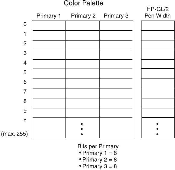
Introduction
A palette is a collection of color specifications selected using index
numbers. The figure below illustrates a palette. Each palette entry
associates an index number with three primary color components. For
HP-GL/2 purposes only, a pen width is also associated with each
palette entry.
3-2 Using Palettes EN
In non-raster mode, the current palette contains all the available
colors. In raster mode, indexed color selection uses the palette, but
direct selection does not.
Default palettes are created by all the PCL color modes (Black and
White, Simple Color, PCL Imaging, and HP-GL/2 Imaging). The active
palette may be modified when in the PCL Imaging or HP-GL/2
imaging modes, but not when in the Simple Color or Black and White
modes. When switching between PCL 5 and HP-GL/2 contexts, the
active palette is automatically transferred.
Multiple palettes can exist in the system via the Palette ID and Palette
Stack mechanism. However, only one palette at a time can be active.
A palette created in the PCL context remains active and unchanged
when switching to the HP-GL/2 context, and a palette created in the
HP-GL/2 context remains active and unchanged when switching to
the PCL context. Performing a reset or entering PJL overwrites the
active palette with the default black and white palette.
Whenever a new palette is created, the currently or previously active
palette is destroyed. A new palette is created by power-on and also by
the following commands:
• PCL Reset (?E)
•Simple Color (
?*r#U)
• Configure Image Data (?*v#W)
• HP-GL/2 Initialize (IN)
The active palette can be saved by pushing it onto the palette stack
with the Push/Pop Palette command (?*p#P). Popping a palette from
the stack destroys the active palette—the popped palette becomes
the active palette.
EN Using Palettes 3-3
Saving the Palette
The current palette is destroyed when a new palette is created. The
Push/Pop Palette command (?*p#P) can save (push) the current
palette and then restore (pop) it.
Push/Pop Palette Command
This command pushes or pops the palette from the palette stack.
?*p#P
A value of 0 (?*p0P) pushes a copy of the active palette onto the
palette stack. When a palette is pushed, the active palette is not
affected.
A value of 1 (?*p1P) pops the most recently pushed palette and
destroys the active palette; the popped palette becomes the active
palette. As with any stack, the last item pushed is the first item
popped.
Pushing a palette saves the following parameters:
• Color definitions for each palette entry
• Pen widths (for HP-GL/2 use)
• Color space specification
• Number of bits per index
• Pixel encoding mode
• Number of bits per primary
• Color treatment
• Render algorithm
# = 0 - Push (save) palette
1 - Pop (restore) palette
Default =0
Range = 0, 1 (invalid values are ignored)
3-4 Using Palettes EN
Pushing a palette does not save the following parameters.
• Foreground color
• Color components: 1st, 2nd, and 3rd
• Finish mode
• Monochrome print mode
The palette stack depth is limited by printer memory. Attempts to push
a palette with insufficient memory cause an out-of-memory error.
Attempts to pop from an empty stack are ignored.
Macros can push and pop palettes. A palette that was popped in an
executed macro remains in effect at the end of the macro (this is not
true for “called” or “overlaid” macros).
The PCL reset command (?E) or an exit to PJL causes the printer to
empty the palette stack and overwrite the active palette with a
non-programmable black and white palette. The HP-GL/2 commands
IN and DF have no effect on the palette stack, but they do destroy the
active palette and replace it with the default HP-GL/2 palette.
EN Using Palettes 3-5
Palette Management by ID
All palettes have a unique ID (identification number). The default
black and white palette created on power-up or ?E has an ID of 0.
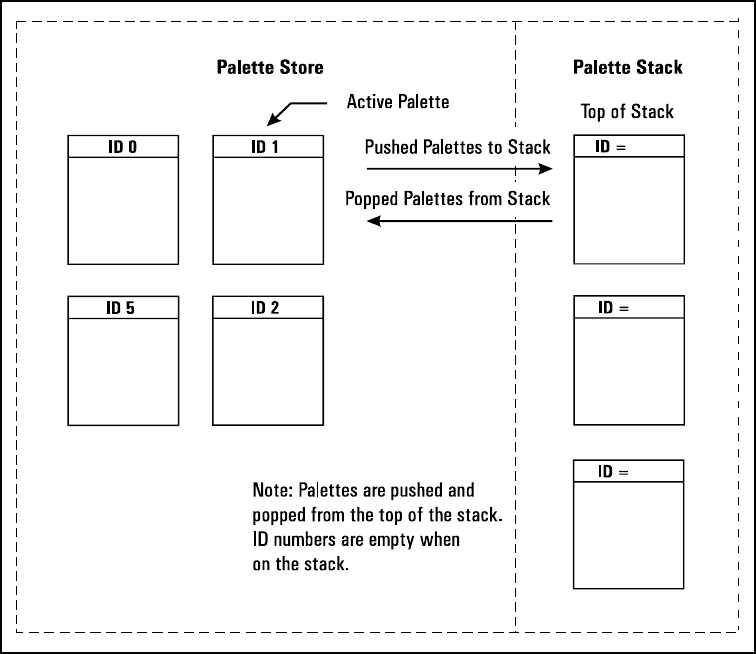
Palette management by ID lets applications have multiple palettes. As
shown below, multiple palettes can exist in two areas: the palette
stack and the palette store. The stack holds palettes that are pushed
via a Push/Pop Palette command; the store holds palettes having
palette IDs.
Palettes on the stack may not be selected by ID, since only a copy of
a palette is pushed onto the stack; the original palette and ID remain
in the palette store. A palette popped from the stack goes into the
palette store, becomes the new active palette, and assumes the ID of
the previously active palette, which is overwritten. Only one palette at
a time may be active.
3-6 Using Palettes EN
Management by ID allows applications to tag data, have multiple
raster configurations, and have palettes for different color spaces—all
without reconfiguring the active palette. For example, one palette can
be created for PCL text, one for HP-GL/2 primitives, one for simple
raster, and one for 24-bit raster. The application can then switch
between palettes according to what is being sent to the printer.
Selecting a new active palette changes the PCL graphics state.
Besides the color entries, a palette also has the graphics state which
contains the color space, color treatment, and render algorithm. This
ensures that the same color specification in a given palette will always
produce the same printed color.
As described below, the Select Palette (?&p#S), Palette Control
(?&p#C), and Palette Control ID (?&p#I) commands implement the
three basic operations of management by ID.
• Selection of the active palette
• Deletion of palettes
• Copying of palettes
Select Palette Command
The Select Palette command selects a new active palette by
specifying an ID number. The previously active palette is unchanged.
?&p#S
This command activates the designated palette in the palette store.
The command is ignored if the specified ID matches the active
palette's ID, or if no palette with that ID exists. The designated ID is
saved as the palette select ID for the duration of the print job, or until
another Select Palette command is received.
This command can be used to de-select the active palette and select
as the new active palette a palette created by the Palette Control
command (?&p#C). For example, to copy the active palette to an ID
of 44 and select the new palette to use or modify, send
?&p44i6c44S.
#= Palette ID number
Default =0
Range = 0 to 32767 (command is ignored for out- of-range
values)
EN Using Palettes 3-7
When a palette creation command is received such as Configure
Image Data (?*v#W), Simple Color (?*r#U), or an HP-GL/2 IN, the
created palette overwrites the active palette and is assigned the
current palette select ID.
A palette popped from the stack overwrites the active palette, and is
assigned the current palette select ID.
?E resets the palette select ID value to 0 and deletes all palettes in
the palette stack and palette store, including the active palette, which
is replaced by a default PCL fixed black and white palette with a
palette ID of 0.
Macros affect the palette select ID value as follows:
• Calling or Overlaying a macro—saves the ID value and a copy
of the active palette. Upon macro exit, the restored palette
again becomes the active palette with the restored ID. An
existing palette with this ID is deleted.
• Executing a macro—does not save the ID value or the active
palette; changes remain in effect.
3-8 Using Palettes EN
Palette Control ID
The Palette Control ID command specifies the ID number to be used
by the Palette Control Command.
?&p#I
The ID number specified by this command is saved as the palette
control ID and is used by the Palette Control command (?&p#C).
?E or power-up resets the palette control ID to 0, which is then the
default black and white palette ID.
Macros affect the palette control ID value as follows:
• Calling a macro—saves the value and restores the value at
exit.
• Executing a macro—does not save the value; changes remain
in effect at exit.
• Overlaying a macro—copies the value before resetting to 0,
and restores at exit.
# = Palette ID number
Default =0
Range = 0 to 32767 (command is ignored for out-of-range
values)

EN Using Palettes 3-9
Palette Control
The Palette Control command provides a mechanism for making and
deleting palettes.
?&p#C
• A value of 0 deletes all palettes except those on the palette
stack. The active palette is replaced by the default black and
white palette (ID 0). The palette control ID is not used.
• A value of 1 clears the palette stack. The active palette is
unaffected, and the palette control ID is not used.
• A value of 2 deletes the palette with the specified palette
control ID if it exists; otherwise the command is ignored. For
example, to delete palette 53, send ?&p53i2C. If the active
palette's ID is specified the active palette is replaced by the
default black and white palette. This option does not change
the palette control ID value.
Note When the active palette is replaced by the default black and white
palette, the graphics state associated with the previous palette is also
replaced.
• A value of 6 creates a copy of the active palette. The copy
receives the ID specified by the last Palette Control ID
command. For example, to copy the active palette to a palette
with an ID of 14, send ?&p14i6C. The copied palette
overwrites any palette that already has an ID equal to the
palette control ID. The copied palette does not become the
active palette. The command is ignored if a palette is to be
copied to its own ID.
# = 0 - Delete all palettes except those in the stack (active
palette deleted)
1 - Delete all palettes in the stack (active palette is not
affected)
2 - Delete palette (specified by Palette Control ID)
6 - Copy active palette to ID specified by Palette Control ID
Default =0
Range = 0, 1, 2, 6 (command is ignored for unsupported values)
3-10 Using Palettes EN
The Palette Control command provides a way of managing system
memory by deleting palettes in either the stack or store that are no
longer in use.
Palette Control that is exercised during macros can have significant
impact on palettes that exist within the system. Deleting all palettes,
or those on the stack, or the current palette, or all those except on the
stack can have adverse effects when the macro is exited. The
adverse effect could be the deletion of the desired palette, and
replacement with a black and white non-programmable palette.

EN Using Palettes 3-11
Simple Color Palettes
The Simple Color command (?*r#U) provides a quick way to select
colors from a fixed, non-programmable palette.
The Simple Color command overwrites the current palette with one of
the fixed palettes below. When the Simple Color command is in effect,
the PCL and HP-GL/2 commands that modify a palette entry (NP, PC,
?*v#A, ?*v#B, ?*v#C, ?*v*I, ?*t*I) are locked out. A popped
simple color palette cannot be modified and the pixel encoding mode
reverts to “index by plane”. Only the IN or the CID (?*v#W)
commands can create a modifiable palette.
As shown below, a value field of 1 (?*r1U) creates a black and white
palette. A value of 3 creates an 8-pen palette in Device RGB color
space. A value of –3 creates an 8-pen palette in Device CMY color
space. All of these Simple Color palettes are fixed and
non-programmable.
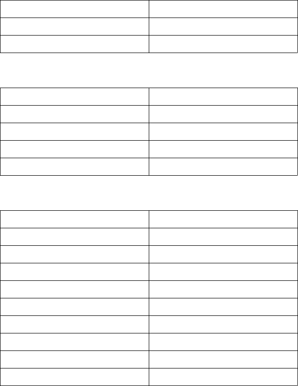
Single Plane (value = 1)
3-Plane RGB (value = 3)
Index Color
0White
1Black
Index Color
0Black
1Red
2Green
3Yellow
4Blue
5 Magenta
6Cyan
7White

3-12 Using Palettes EN
3-Plane CMY (value = –3)
Index Color
0White
1Cyan
2 Magenta
3Blue
4Yellow
5Green
6Red
7Black
EN Using Palettes 3-13
CID Color Palettes
The Configure Image Data command, explained in detail in Chapter
2, creates a palette based upon the parameters in its data field.
CID-created palettes are programmable: any entry can be reassigned
a different color using PCL commands (?*v#A, ?*v#B, ?*v#C,
?*v*I) or HP-GL/2 commands (PC, NP). Default palettes vary by
color space.
Device RGB and sRGB Palettes
Bits/Index = 1
Bits/Index = 2
Bits/Index = 3 through 8
Index Color
0White
1Black
Index Color
0Black
1Red
2Green
3White
Index Color
0Black
1Red
2Green
3Yellow
4Blue
5 Magenta
6Cyan
7White
n > 7 Black
3-14 Using Palettes EN
Device CMY Palettes
Bits/Index = 1
Bits/Index = 2
Bits/Index = 3 through 8
Index Color
0White
1Black
Index Color
0White
1Cyan
2 Magenta
3Black
Index Color
0White
1Cyan
2 Magenta
3Blue
4Yellow
5Green
6Red
7Black
n > 7 Black
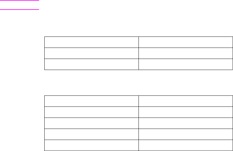
EN Using Palettes 3-15
HP-GL/2 Palettes
Regardless of the color space, a default PCL palette is always
different than a default HP-GL/2 palette. The following table shows
the default palettes established in HP-GL/2. Like a default CID
palette, a default HP-GL/2 palette can be modified in either PCL or
HP-GL/2 contexts using the following commands:
PCL
• Color Components 1, 2, and 3 (?*v#A, ?*v#B, ?*v#C)
• Assign Color Index (?*v#I)
HP-GL/2
• Number of Pens (NP)
• Pen Color Assignment (PC)
Note The IN command always establishes the 8-pen palette.
Two Pens
Four Pens
Pen Number Color
0White
1Black
Pen Number Color
0White
1Black
2Red
3Green
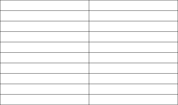
3-16 Using Palettes EN
Eight Pens
Pen Number Color
0White
1Black
2Red
3Green
4Yellow
5Blue
6 Magenta
7Cyan
n > 7 Black
EN Using Palettes 3-17
Foreground Color
All PCL marking entities utilize “foreground” color, which is selected
from the current palette using the Foreground Color command
(?*v#S). Foreground color interacts with raster color depending on
the print model commands in effect.
Foreground Color Command
The Foreground Color command sets the foreground color to the
specified index of the current palette.
?*v#S
Specified values that are out-of-range of the current palette are
mapped into a new index as follows:
Index = Specified foreground index modulo palette size
For example, specifying a foreground color index of 10 when the
current palette size is 8 maps to 10 modulo 8, which is equal to 2. If
the current palette was created under HP-GL/2, the index is mapped
according to the HP-GL/2 mapping function.
Foreground color affects the following PCL page marking primitives:
• Text characters (they change to the foreground color, including
underlining)
• Solid or monochrome patterned rectangular area fills (rules)
• Monochrome patterns (except HP-GL/2)
• Raster images
The following are not affected:
• User-defined color patterns (format 1 download patterns)
• HP-GL/2 marking primitives (HP-GL/2 uses “selected pen”, but
ignores foreground color)
# = Index number into current palette
Default =0
Range = 0 to 2(current palette size) – 1

3-18 Using Palettes EN
Note Foreground color interacts with color raster images. In the printer, all
color raster is resolved into three binary raster planes of CMY.
Foreground color is applied to these planes, modifying the color
image. For no interaction, set foreground color to black when sending
color raster images.
After a foreground color is selected, changing any of the following will
not change foreground color until a new Foreground Color command
(?*v#S) is issued:
• Active Palette
• Configure Image Data (CID) command
• Render Algorithm
EN Using Palettes 3-19
Programming Color Palettes
Except for the default black and white palette or the Simple Color
palettes (?*r#U), palette entries can be modified. The three primary
components of a color are specified and the resulting color is
assigned to the palette entry indicated by ?*v#I.
In the explanation below, the term “component” refers to the color
space primary colors. For example, if the current color space is
sRGB, component 1 indicates R, component 2 indicates G, and
component 3 indicates B.
Color Component One
This command specifies the first component of the palette entry
designated by the Assign Color Index command (?*v#I).
?*v#A
The Assign Color Index command actually applies this value and then
resets it to 0.
Color Component Two
This command specifies the second component of the palette entry
designated by the Assign Color Index command.
?*v#B
The Assign Color Index command actually applies this value and then
resets it to 0.
# = First Component
Default =0
Range = –32767.0000 to 32767.0000 (up to 4 decimal places;
command is ignored for invalid configurations)
# = Second Component
Default =0
Range = –32767.0000 to 32767.0000 (up to 4 decimal places;
command is ignored for invalid configurations)
3-20 Using Palettes EN
Color Component Three
This command specifies the third component of the palette entry
designated by the Assign Color Index command.
?*v#C
The Assign Color Index command actually applies this value and then
resets it to 0.
Assign Color Index
This command assigns the three current color components to the
specified palette index number.
?*v#I
This command resets the color components to 0 after assignment. If
the specified index number is greater than the palette size, no index
assignment is made, but the three color components are set to 0.
# = Third Component
Default =0
Range = –32767.0000 to 32767.0000 (up to 4 decimal places;
command is ignored for invalid configurations)
# = Index Number
Default =0
Range = 0 to 2n – 1, where n is the number of bits per index (no
assignment for out-of-range values)
EN Modifying Output Color 4-1
4Modifying Output Color
Introduction
The previous chapters of this manual have been concerned with
giving an overview of the color printing process, choosing color
modes, and using palettes. This portion of the manual explains how
color can be modified to produce a desired result, from using halftone
render algorithms to change the way color is rendered, to selecting a
color treatment and finish mode. The HP color printers can modify
colors using the following means:
•Halftone render algorithms provide a way to modify images
based on a dither cell concept. The algorithm chosen
determines how specified colors are “rendered” as dots on the
printed page.
•The Monochrome Print Mode command converts each color to
its grayscale equivalent for faster, draft printing.
• The Driver Configuration command provides a way to select a
color treatment.
• The Finish Mode command allows the user to specify the
finish, matte or glossy, to be applied to the document.
All of these methods of modifying output color are explained in the
following sections.
4-2 Modifying Output Color EN
Halftone Render Algorithms
The HP color printers have the capability of applying different halftone
render algorithms to achieve the desired output on the printed image.
Render algorithms allow you to change the characteristics of the
image by changing the way pixels are rendered. Each halftone render
algorithm produces a different affect on the output, varying the texture
and color appearance of the printed image.
To choose the type of rendering to be used, use the Render Algorithm
command, described below.
Render Algorithm Command
The Render Algorithm command selects the algorithm to be used for
rendering page marking entities on a given page.
?*t#J
Device Best Dither
This dither pattern produces the best results for many images. Note,
however, that the recommended dither pattern varies with the image,
the intended use of the image, and the subjective judgements of the
user.
# = 0 - Continuous tone detail (high lpi) (device best dither)
3 - Device best dither
15 - Continuous tone smooth (high lpi)
18 - Continuous tone basic (low lpi)
Default = 3
Range = 0, 3, 15, 18 (invalid values are ignored)
EN Modifying Output Color 4-3
Monochrome Printing
The Monochrome Print Mode command converts each color value to
its grayscale equivalent. This improves throughput, costs less to print,
and eliminates waste by providing a draft mode.
Monochrome Print Mode Command
The Monochrome Print Mode command designates whether to print
using the current rendering mode or a fast gray-scale equivalent.
Pages printed using the gray-scale equivalent do not use any color
and therefore print faster and more economically.
?&b#M
This command must be sent prior to printable data, or it is ignored.
The command must be sent at the start of a job, since few, if any,
applications support a mixture of color and monochrome printing of
color images within the same document.
# = 0 - Print in mixed render algorithm mode
1 - Print using gray-scale equivalent
Default =0
Range = 0, 1 (command is ignored for invalid values)
4-4 Modifying Output Color EN
Driver Configuration Command
This command specifies the color treatment applied to each color
specification.
?*o#W[device_id function_index Arguments]
device_id
function_index
The following paragraphs describe the function_index values and
their arguments.
Select Treatment
This value specifies which color treatment mode to use for rendering
the next job.
Vivid Graphics
This setting adds color saturation to the resulting image, and provides
access to the full gamut of the printer (at the cost of color matching).
#= Specifies the number of bytes to follow (device ID
function index arguments)
Default =N/A
Range = see description below
Value Printer
6 Color LaserJet printer family
8 Color LaserJet 4500 printer
function_
index Description Argument Range
4Select Color
Treatment 3 Vivid Graphics
6 Screen Match
EN Modifying Output Color 4-5
Screen Match
Due to the emergence of sRGB (standard Red Green Blue) as an
international color data standard, there is no longer a need to provide
color adjustments in the printer driver to account for alternate types of
RGB data. sRGB is the native color space of monitors, the default
color space of the World Wide Web, the default space of many digital
cameras and scanners. This treatment indicates that the printer
should be ready to accept sRGB data. This is the preferred mode of
operation to provide a good appearance match between the monitor
and the printed document
The table below lists the driver configuration commands for both color
treatments:
Note The device_id and function_index arguments after the ?*o3W (such
as 643) should actually be entered as ASCII-coded decimal. For
example, instead of 643 you would actually enter the ACK control
code, followed by the EOT and ETX control codes.
Treatment Command
LJ 4500 Other Color LaserJet
Family printers
Vivid Graphics ?*o3W843 ?*o3W643
Screen Match ?*o3W846 ?*o3W646
4-6 Modifying Output Color EN
Finish Mode Command
The Finish Mode command allows the user to specify the finish, matte
or glossy, to be applied to the document. A normal page has a matte
finish. Glossy finish can be requested to be applied to the page as it’s
printed. The finish is distinct from the type of media. Therefore, a
matte finish can be requested for glossy media, and a glossy finish
can be requested for plain or matte paper.
?&b#F
The finish mode must be set before the first page is marked and
applies to all the pages in the document. Each document defaults to a
matte finish.
# = 0 - Matte finish
1 - Glossy finish
Default =0
Range = 0, 1 (command is ignored for invalid values)
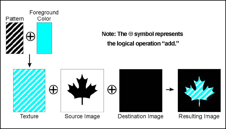
EN The PCL Print Model 5-1
5The PCL Print Model
Introduction
The Print Model feature allows images and characters to be filled with
color, with any of the printer's predefined shading or cross-hatch
patterns, or with a user-defined pattern. Images include any raster
graphic, such as one created with PCL raster graphics commands (as
described in Chapter 6, Raster Graphics); a rectangular fill area (as
described later in this chapter as PCL Rectangular Area Fill
Graphics); or characters selected from any font.
Figure 5-1 illustrates the use of the print model. The following
definitions are helpful in describing Print Model operation:
Figure 5-1 Print Model Imaging
5-2 The PCL Print Model EN
•Pattern—The design which is “painted” through the non-white
area of the source image onto the destination image. The
pattern is defined by the Current Pattern (?*v#T) command. It
may be a color pattern or a single-plane monochrome mask,
such as the printer's internal predefined shading or
cross-hatch patterns, or a user-defined pattern. Foreground
color is not applied to a user-defined color pattern.
When printing a page, text and raster images are printed using
the current pattern. Once the current pattern is specified, it
stays in effect until another is selected or the printer is reset. A
reset returns the current pattern to its default value (100%
black). The current pattern does not always apply to
rectangular area fill, which uses patterns defined by the
rectangular area fill pattern commands.
•Foreground Color—Foreground color is selected from the
current palette using the Foreground Color command
(?*v#S). Foreground color affects everything except
user-defined color patterns and HP-GL/2 primitives. Raster
color mixes with foreground color (see Chapter 6 “Color Raster
Graphics”).
•Texture—Texture is another name for the combination of
pattern and foreground color, or for a color pattern which is not
combined with a foreground color.
•Source Image—the Source Image is an image in which the
non-white bits are replaced by the specified pattern. The
source image functions like a stencil through which the pattern
is applied to the destination image. The source image may be
one of the following: HP-GL/2 primitives, rules, characters, or
raster images (single plane mask or multi-plane color)
•Destination Image—The image onto which the source
image/texture combination is placed. The destination image
includes any images placed through previous operations.
•Source Transparency Mode—The transparency or
opaqueness of the source image’s “white” pixels as they are
applied to the destination image (see the note below). Setting
the source transparency mode to 1 (opaque) applies the
source image's white pixels to the destination image; with a
setting of 0 (transparent), these pixels have no effect on the
destination.
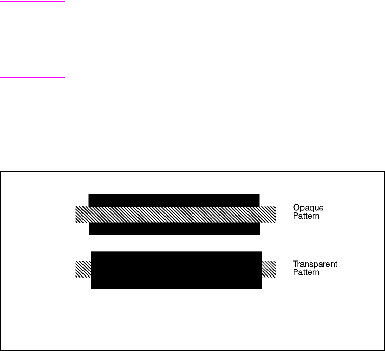
EN The PCL Print Model 5-3
•Pattern Transparency Mode—The transparency or
opaqueness of the “white pixels” in the pattern (see the note
below). When set to 0 (transparent), these pixels have no
effect on the destination; when set to 1 (opaque), they are
applied through the black pixels of the source pattern to the
destination.
•Logical Operations—the Print Model uses logical operations,
such as AND, OR, XOR, and NOT when determining which
bits of the source, pattern, and texture become part of the
resulting image. The Logical Operations command (?*l#O)
can vary the logical operation used, thus varying the outcome.
Note For RGB color images, “white” pixels are those for which all color
primaries are 255. For CMY color images, “white” pixels are those for
which all color primaries are 0.
For all rendering algorithms, white dots introduced in the dithering
process are not subject to transparency modes.
Figure 5-2 illustrates the effects of the source and pattern
transparency modes on the final image. (The transparency modes
work a little differently with rectangular area fill—see “Pattern
Transparency for Rectangular Area Fill” near the end of this chapter.)
Figure 5-2 Opaque and Transparency Modes
This example uses the default ROP. The output may appear differently
depending on the colors used.
5-4 The PCL Print Model EN
Figure 5-3 demonstrates the transparency modes. In the first example
(1a), the transparency mode for both the source image and the
pattern is transparent. Since the source mode is “transparent,” only
the non-white region (the circle) of the source image is overlaid on the
destination. Since the pattern mode is also transparent, the patterned
source image is applied only to the white areas of the destination.
In the second example (1b), the source mode is still “transparent,” but
the pattern mode is “opaque” – so the pattern's white pixels are
applied to the destination. The resulting image shows the entire circle
region visible and patterned.
In the third example (1c), the source mode is “opaque” and the
pattern mode is transparent. Since the source mode is opaque, the
entire source image (the circle and the surrounding square) appears
overlaid onto the destination. The pattern, however, is allowed to pour
through only onto the white-pixeled area of the destination. The circle
is visible in the result, but only two opposing quarters appear
patterned.
In the fourth example (1d), both source and pattern modes are
“opaque.” The entire source image is overlaid onto the destination,
and the entire circle is patterned.
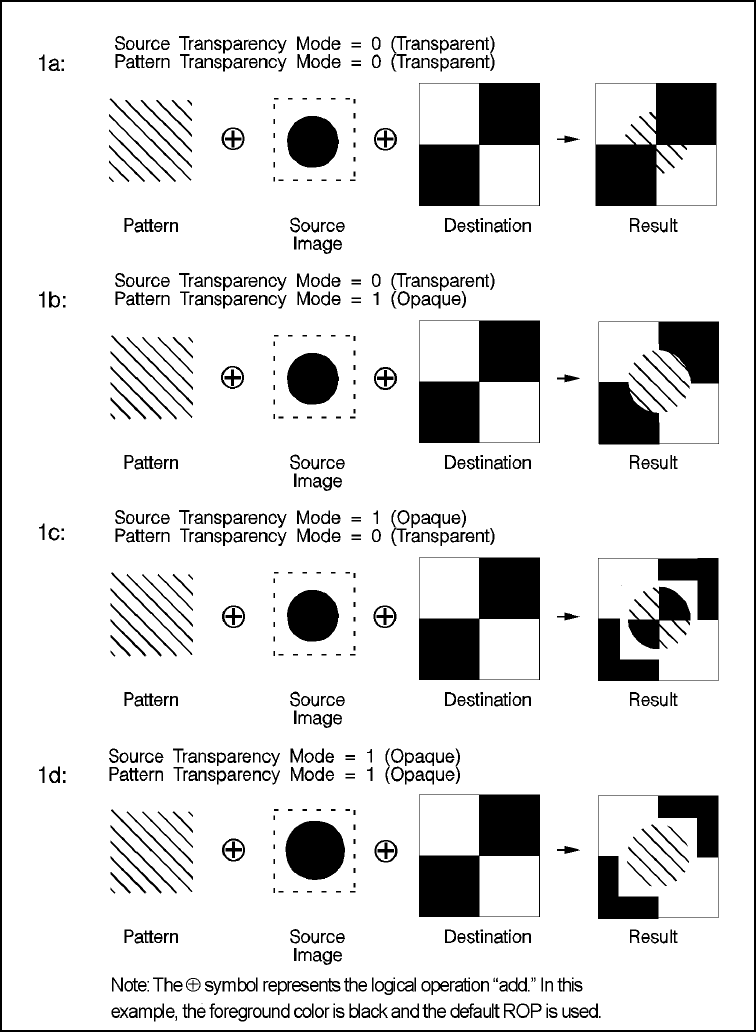
EN The PCL Print Model 5-5
Figure 5-3 Effect of Transparency Modes on Images
5-6 The PCL Print Model EN
Command Sequence
The table below shows the Print Model command sequence for
selecting a current pattern and using it to fill a destination image. The
commands for specifying transparency modes, logical operations,
and patterns are discussed beginning on the following page.
Foreground color is described in Chapter 3.
Operation Comments
Download Page Data Prior raster and character data
downloaded to the page is considered
destination image.
Select Transparency Modes ?*v#N (source) and/or ?*v#O (pattern)
Specify the Logical Operation If a logical operation other than the default
(TSo-252) is desired, specify the
operation with the ?*l#O command.
Select Specific Pattern ID Pattern ID ?*c#G
Download User-Defined Pattern If using a user-defined pattern, it must be
downloaded to the printer before using it.
Select Pattern ?*v4T (selects downloaded pattern)
Specify the Foreground Color For color printers, specify a Foreground
Color (?*v#S) if desired. (This step is
unnecessary if a color pattern is used.)
Download Source Image Data Raster image/characters
Return to regular print mode Default current pattern and transparency
modes: ?*v0T (100% black pattern
selected) and ?*v0N ?*v0O
(transparency modes selected).
Download remaining page data Transfer data for regular printing, or the
above process may be repeated to
produce another print model effect.
End of Page Data

EN The PCL Print Model 5-7
Source Transparency Mode Command
The Select Source Transparency Mode command sets the source
image's transparency mode to transparent or opaque. This command
determines whether the source's white pixels are applied to the
destination.
? * v # N
With a transparency mode of “0” (transparent), the white regions of
the source image are not copied onto the destination. With a
transparency mode of “1” (opaque), the white pixels in the source are
applied directly onto the destination. White pixels are unaffected by
pattern or foreground color; they are either white or transparent.
Note For RGB color images, “white” pixels are those for which all color
primaries are 255. For CMY color images, “white” pixels are those for
which all color primaries are 0.
White dots introduced in the dithering process are not subject to
transparency modes.
Refer to the preceding definitions and the discussion of Figure 5-3 for
an explanation of the effects of source transparency.
# = 0 - Transparent
1 - Opaque
Default =0
Range = 0, 1 (other values cause the command to be ignored)

5-8 The PCL Print Model EN
Pattern Transparency Mode Command
The Pattern Transparency Mode command sets the pattern's
transparency mode to transparent or opaque.
? * v # O
A transparency mode of “0” (transparent) means that the white
regions of the pattern image are not copied onto the destination. A
transparency mode of “1” (opaque) means that the white pixels in the
pattern are applied directly onto the destination.
Note When printing white rules, the pattern transparency is treated as if it
were “opaque”; white rules erase black rules regardless of the
transparency mode.
For RGB color images, “white” pixels are those for which all color
primaries are 255. For CMY color images, “white” pixels are those for
which all color primaries are 0.
White dots introduced in the dithering process are not subject to
transparency modes.
Refer to the preceding definitions and the discussion of Figure 5-2
and Figure 5-3 for an explanation of the effects of pattern
transparency.
# = 0 - Transparent
1 - Opaque
Default =0
Range = 0, 1 (other values cause the command to be ignored)
EN The PCL Print Model 5-9
Logical Operations
The basic print model defines how a pattern, source image, and
destination image are applied to each other using the print model’s
transparent and opaque modes to produce a resulting image. The
Logical Operations (?*l#O) command specifies which logical
operation is to be performed on the source, texture, and destination to
produce a new destination. Transparency modes should be specified
before the logical operation is performed or printable data is sent.
The print model process consists of the following steps:
1Specify source and/or pattern transparency modes, if desired.
2Specify the logical operation (or use the default).
3Define the desired operands (source, destination, pattern).
Definitions
Source: The source image may be one of the following:
• HP-GL/2 primitives
• Rules
• Characters
• Raster images (single plane mask or multiplane color)
Destination: The destination image contains whatever is currently
defined on the page. It includes any images placed through previous
operations.
Pattern or Texture: The pattern is defined by the Select Current
Pattern command (?*v#T). The terms pattern and texture are used
interchangeably in this section.
Transparency Modes: The white pixels of the source and/or pattern
may be made transparent (source transparency 0, pattern
transparency 0). The destination shows through these areas.
Transparency modes are set by the Source Transparency (?*v#N)
and Pattern Transparency (?*v#O) commands.
The Print Model allows logical operations, such as AND, OR, XOR,
NOT, to be performed on source, texture, and destination images.
Transparency modes and Logical Operation must be specified before
printable data is sent.
5-10 The PCL Print Model EN
Operators
• Source Transparency (specified before logical operation;
default is transparent)
• Pattern Transparency (specified before logical operation;
default is transparent)
• Logical Operators (default is Texture OR Source)
Operands
• Source objects: character cell, raster image, rule, HP-GL/2
vectors and polygons
• Texture: foreground color + pattern mask, color pattern
(format 1).
• Destination: current page definition
Operation
• IF (source transparent && source == white) RETURN
destination
• IF (pattern transparent && pattern == white &&
source != white) RETURN destination
• ELSE RETURN (logical op (source, texture, destination)
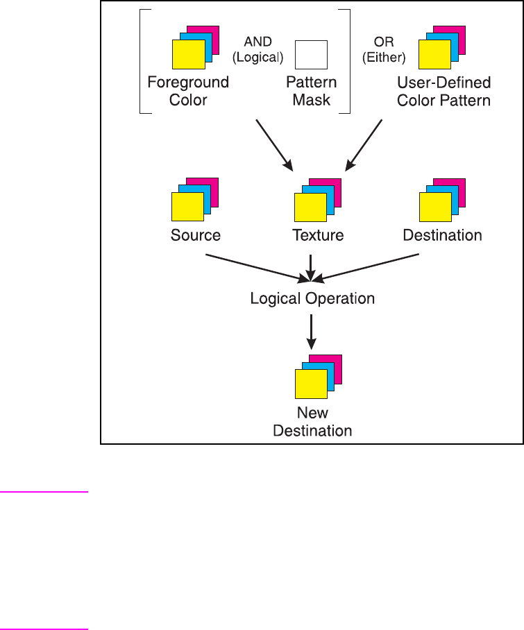
EN The PCL Print Model 5-11
Assuming three bits per pixel, the following diagram shows the
process.
Figure 5-4 Logical Operations and the Print Model
Note The Logical Operation command (?*l#O) provides 255 possible
logical operations. All of these logic operations map directly to their
ROP3 (raster operation) counterparts (see the Microsoft Document,
Reference, Volume 2, Chapter 11, Binary and Ternary Raster
Operation Codes).
The logical operations were defined for Microsoft Windows for an
RGB color space. In RGB space, a “1”' is white and a “0” is black.

5-12 The PCL Print Model EN
Logical Operations and Transparency
Interactions
As described above, transparency modes operate in addition to
logical operations. The Logical Operations (ROP3) in Table 5-4 are
true only if source and pattern transparency (for white pixels) are
explicitly set to opaque (?*v1N and ?*v1O). If source and/or pattern
transparency modes are transparent (defaulted), the additional
operations shown below must be performed to achieve the final result.
The four basic interactions are:
•Case 1: Source and Pattern are opaque.
Texture = Color & Pattern.
RETURN ROP3 ( Dest, Src, Texture ).
•Case 2: Source is opaque, Pattern is transparent.
Texture = Color & Pattern.
Temporary_ROP3 = ROP3 ( Dest, Src, Texture ).
Image_A = Temporary_ROP3, & Not Src.
Image_B = Temporary_ROP3 & Pattern.
Image_C = Not Pattern & Src & Dest.
RETURN Image_A | Image_B | Image_C
•Case 3: Source is transparent, Pattern is opaque.
Texture = Color & Pattern.
Temporary_ROP3 = ROP3 ( Dest, Src, Texture ).
Image_A = Temporary_ROP3 & Src.
Image_B = Dest & Not Src.
RETURN Image_A | Image_B
•Case 4: Source and Pattern are transparent
Texture = Color & Pattern.
Temporary_ROP3 = ROP3 ( Dest, Src, Texture ).
Image_A = Temporary_ROP3 & Src & Pattern.
Image_B = Dest & Not Src.
Image_C = Dest & Not Pattern.
RETURN Image_A | Image_B | Image_C.
Note The Transparency Mode is applied based on the color of each pixel.
However, the Logical Operation is applied on a bit-by-bit basis without
regard to color. In order to obtain a result consistent with the Logical
Operation, the transparency modes should be set to Source Opaque
and Pattern Opaque. In order to obtain a result consistent with the
desired transparency mode, the Logical Operation should be set to
252 and the foreground color set to black.

EN The PCL Print Model 5-13
Logical Operation Command
Specifies the logical operation (ROP) to be performed in RGB color
space on destination, source and texture to produce new destination
data. Texture is defined as a combination of pattern and foreground
color.
?*l # O
The Logical Operation code, or Raster OPeration (ROP) code, is
simply a systematic method of encoding all of the 256 possible ways
that a Texture, Source, and Destination can be combined. Table 5-4
gives a table of ROPs from ROP 0 to ROP 255, where each operation
is defined as a logic equation. This table can be difficult to understand
and use. Furthermore, it does not show the differences that depend
on the color space. A truth table is an alternative method for
understanding the results of a logical operation. When used with
ROPs for finding the resulting destination value, it is more easily
understood than the logic operation.
1 The first destination column is ignored and the second destination column is the result
of the ROP (White = [1,1,1] and Black = [0,0,0] ).
# = Logical operation value (see Table 5-4)
Default = 252 (TSo)
Range = 0 to 255
ROPRGB 252 (11111100)1
(T)exture (S)ource (D)estination (D)estination
11 1 1
11 0 1
10 1 1
10 0 1
01 1 1
01 0 1
00 1 0
00 0 0
5-14 The PCL Print Model EN
For example, the logic equation for ROP 252 in the RGB color space
is T OR S, which is shown as TSo in Table 5-4. The truth table for the
ROP is shown above, and can be seen to correspond to the logic
equation TSo, that is, D gets the value of T OR S without regard to the
current value of D. Furthermore, the binary value of 252 is 11111100
and corresponds with the value of the D for all the combinations of T
and S, when the truth table starts with (1, 1, 1) and ends with (0, 0, 0).
It’s possible to derive the logical operation for a truth table and to
create a truth table for a logical operation. However, the most
important point is that the binary value of the ROPs number gives the
Destination for all possible combinations of Texture, Source, and
Destination.
The way the bits of the ROPs number map to the combinations of
Texture, Source, and Destination depends on whether the color space
is RGB or CMY. The least significant bit of the RGB ROP value maps
to (0, 0, 0), the color black in RGB, and the most significant bit to
(1, 1, 1), white in RGB. On the other hand, the CMY ROP reverses
the mapping. This reversal hinges on the fact that RGB and CMY are
the inverse of each other, i.e., RGB Black is (0, 0, 0) and CMY Black
is (1, 1, 1), white. All other colors show the same relationship.
ROPs in the RGB Color Space
The RGB ROP truth tables shown in Table 5-1 illustrate how ROP 252
and ROP 90 work, and most importantly how the bits in the ROP map
show destination values for each combination of Texture, Source and
Destination. A “1” in the RGB color space represents white and a “0”
black, which makes determining what shows on paper cumbersome
for users since the paper is marked when the Destination has a “0”
value.
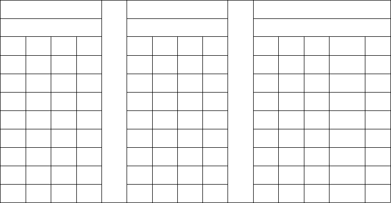
EN The PCL Print Model 5-15
Table 5-1. RGB ROP Truth Tables
ROPs in the CMY Color Space
The CMY ROP truth tables in Table 5-2 shows examples of how the
ROPs number determines the value of the Destination for all
combinations of Texture, Source, and Destination. In the CMY color
space a “0” is the absence of ink (white) and a “1” is the presence of
ink (black), the opposite of the RGB color space value for black and
white. Therefore, the ROPs results (Destination values) for the CMY
color space are the opposite (negation) of the RGB values. However,
a CMY ROP is easier to use when determining if the page is marked,
since a “1” denotes marking.
ROPrgb 252 ROPrgb 90 ROPrgb n
(11111100) (01011010) n=(b7b6b5b4b3b2b1b0)
TSDD TSDD TSDROP nD
1111 white 1110 white 111b
7b7
1101 1101 110b
6b6
1011 1010 101b
5b5
1001 1001 100b
4b4
0111 0111 011b
3b3
0101 0100 010b
2b2
0010 0011 001b
1b1
0000 black 0000 black 000b
0b0
5-16 The PCL Print Model EN
Table 5-2. CMY ROP Truth Tables
Using a ROP
The first step in using a ROP is to determine which color space you're
in: RGB or CMY. Then determine the binary value of the ROP used.
For example, suppose you want to use ROP 90 in the CMY color
space. The binary equivalent of 90 is 01011010 when written in most
significant to least significant bit order.
Looking at the truth table for ROP 90 in Table 5-2 you can see that the
only time the page is marked is when the Texture and Destination are
both “0” or both “1.” However, the same result is given by negating
each bit of the ROP number, 90, to give 10100101. Using the general
table for CMY ROPs (the rightmost table in Table 5-2) you can plug
the bit values from 90 into b7 through b0 to obtain the values in the
truth table for ROP 90. Similarly, using ROP 90 in the RGB color
space entails plugging 01011010 in the general table for RGB ROPS
(the rightmost table in Table 5-1) to obtain the values in the truth table
for ROPrgb 90 (also in Table 5-1). This process works for any value
from 0 to 255 and can be used to determine what will show for any
given ROP, in either the RGB or CMY color spaces.
ROPcmy 252 ROPcmy 90 ROPcmy n
(00000011) (10100101) n=(b7b6b5b4b3b2b1b0)
TSDD TSDD TSDROP nD
0000 white 0001 white 000b
7!b7
0010 0010 001b
6!b6
0100 0101 010b
5!b5
0110 0110 011b
4!b4
1000 1000 100b
3!b3
1010 1011 101b
2!b2
1101 1100 110b
1!b1
1111 black 1111 black 111b
0!b0

EN The PCL Print Model 5-17
Note Since PCL logical operations are interpreted in RGB space
(white = 1, black = 0) rather than in CMY space (white = 0, black = 1),
the results may not be intuitive. For example, ORing a white object
with a black object in RGB space yields a white object. This is the
same as ANDing the two objects in CMY space. It must be
remembered that the printer operates in CMY space and inverts the
bits. To convert from one color space to the other, write the ROP in
binary format, invert the bits, and reverse the order.
When source and/or pattern transparency modes are set opaque (not
defaulted), values specified by this command map directly to the
ROP3 (raster operation) table values on the following page. However,
when source and/or pattern transparency modes are set transparent,
the additional operations shown on the previous page must be
performed to achieve the final result.
Logical operations in the table are shown in RPN (reverse polish
notation). For example, the value 225 corresponds to TDSoxn, the
logical function of:
NOT (texture XOR (destination OR source))
Note ?*l # O is the PCL Version of the HP-GL/2 MC command.
This command sets the ROP value which affects not only PCL
operation but also the HP-GL/2 ROP value.
EXAMPLE
The Logical Operation default value is 252 (TSo), corresponding to a
logical function of:
(texture | source)
5-18 The PCL Print Model EN
The result is computed below (source and pattern opaque).
Table 5-3. Logical Operation (ROP3)
Each column of destination, source, and texture values are the input
to the logical function. The result, 252, is the value that would be sent
to identify the logical operation (refer to page 5-12 for source/pattern
transparency interactions).
Table of Logical Operations
The Logical Operations (ROP3) table (Table 5-4) shows the mapping
between input values and their logical operations. Note that the
logical operations are specified as RPN (reverse polish notation)
equations. Here is a key to describe what the Boolean Function
values mean;
Note Since logical operations are interpreted in RGB space (white = 1 and
black = 0) rather than in CMY space (white = 0 and black = 1), the
results may not be intuitive. For example, ORing a white object with a
black object in RGB space yields a white object. This is the same as
ANDing the two objects in CMY space. It must be remembered that
the printer operates in something similar to a CMY space and inverts
the bits and reverses the order.
Bits
7 6 5 4 3 2 1 0
Texture 1 1 1 1 0 0 0 0
Source 1 1 0 0 1 1 0 0
Destination 1 0 1 0 1 0 1 0
ROP3 (source & pattern) 11111100
(decimal 252)
S = Source a = AND
T = Texture o = OR
D = Destination n = NOT
x = EXCLUSIVE OR

EN The PCL Print Model 5-19
Table 5-4. Logical Operations (ROP3)
Input Value Boolean
Function Input Value Boolean
Function
0 0 27 SDTSxaxn
1 DTSoon 28 TSDTaox
2 DTSona 29 DSTDxaxn
3 TSon 30 TDSox
4 SDTona 31 TDSoan
5DTon32DTSnaa
6 TDSxnon 33 SDTxon
7 TDSaon 34 DSna
8 SDTnaa 35 STDnaon
9 TDSxon 36 STxDSxa
10 DTna 37 TDSTanaxn
11 TSDnaon 38 SDTSaox
12 STna 39 SDTSxnox
13 TDSnaon 40 DTSxa
14 TDSonon 41 TSDTSaoxxn
15 Tn 42 DTSana
16 TDSona 43 SSTxTDxaxn
17 DSon 44 STDSoax
18 SDTxnon 45 TSDnox
19 SDTaon 46 TSDTxox
20 DTSxnon 47 TSDnoan
21 DTSaon 48 TSna
22 TSDTSanaxx 49 SDTnaon
23 SSTxDSxaxn 50 SDTSoox
24 STxTDxa 51 Sn
25 SDTSanaxn 52 STDSaox
26 TDSTaox 53 STDSxnox

5-20 The PCL Print Model EN
Table 5-4. Logical Operations (ROP3) (continued)
Input Value Boolean
Function Input Value Boolean
Function
54 SDTox 81 DSTnaon
55 SDToan 82 DTSDaox
56 TSDToax 83 STDSxaxn
57 STDnox 84 DTSonon
58 STDSxox 85 Dn
59 STDnoan 86 DTSox
60 TSx 87 DTSoan
61 STDSonox 88 TDSToax
62 STDSnaox 89 DTSnox
63 TSan 90 DTx
64 TSDnaa 91 DTSDonox
65 DTSxon 92 DTSDxox
66 SDxTDxa 93 DTSnoan
67 STDSanaxn 94 DTSDnaox
68 SDna 95 DTan
69 DTSnaon 96 TDSxa
70 DSTDaox 97 DSTDSaoxxn
71 TSDTxaxn 98 DSTDoax
72 SDTxa 99 SDTnox
73 TDSTDaoxxn 100 SDTSoax
74 DTSDoax 101 DSTnox
75 TDSnox 102 DSx
76 SDTana 103 SDTSonox
77 SSTxDSxoxn 104 DSTDSonoxxn
78 TDSTxox 105 TDSxxn
79 TDSnoan 106 DTSax
80 TDna 107 TSDTSoaxxn

EN The PCL Print Model 5-21
Table 5-4. Logical Operations (ROP3) (continued)
Input Value Boolean
Function Input Value Boolean
Function
108 SDTax 135 TDSaxn
109 TDSTDoaxxn 136 DSa
110 SDTSnoax 137 SDTSnaoxn
111 TDSxnan 138 DSTnoa
112 TDSana 139 DSTDxoxn
113 SSDxTDxaxn 140 SDTnoa
114 SDTSxox 141 SDTSxoxn
115 SDTnoan 142 SSDxTDxax
116 DSTDxox 143 TDSanan
117 DSTnoan 144 TDSxna
118 SDTSnaox 145 SDTSnoaxn
119 DSan 146 DTSDToaxx
120 TDSax 147 STDaxn
121 DSTDSoaxxn 148 TSDTSoaxx
122 DTSDnoax 149 DTSaxn
123 SDTxnan 150 DTSxx
124 STDSnoax 151 TSDTSonoxx
125 DTSxnan 152 SDTSonoxn
126 STxDSxo 153 DSxn
127 DTSaan 154 DTSnax
128 DTSaa 155 SDTSoaxn
129STxDSxon156 STDnax
130DTSxna157DSTDoaxn
131 STDSnoaxn 158 DSTDSaoxx
132SDTxna159TDSxan
133 TDSTnoaxn 160 DTa
134 DSTDSoaxx 161 TDSTnaoxn

5-22 The PCL Print Model EN
Table 5-4. Logical Operations (ROP3) (continued)
Input Value Boolean
Function Input Value Boolean
Function
162 DTSnoa 189 SDxTDxan
163 DTSDxoxn 190 DTSxo
164 TDSTonoxn 191 DTSano
165TDxn192 TSa
166 DSTnax 193 STDSnaoxn
167 TDSToaxn 194 STDSonoxn
168 DTSoa 195 TSxn
169DTSoxn196STDnoa
170 D 197 STDSxoxn
171 DTSono 198 SDTnax
172 STDSxax 199 TSDToaxn
173DTSDaoxn200 SDToa
174 DSTnao 201 STDoxn
175DTno202DTSDxax
176 TDSnoa 203 STDSaoxn
177TDSTxoxn204 S
178 SSTxDSxox 205 SDTono
179 SDTanan 206 SDTnao
180 TSDnax 207 STno
181 DTSDoaxn 208 TSDnoa
182 DTSDTaoxx 209 TSDTxoxn
183SDTxan210TDSnax
184 TSDTxax 211 STDSoaxn
185DSTDaoxn212SSTxTDxax
186 DTSnao 213 DTSanan
187DSno214TSDTSaoxx
188 STDSanax 215 DTSxan

EN The PCL Print Model 5-23
Table 5-4. Logical Operations (ROP3) (continued)
Input Value Boolean
Function Input Value Boolean
Function
216 TDSTxax 236 SDTao
217 SDTSaoxn 237 SDTxno
218 DTSDanax 238 DSo
219STxDSxan239 SDTnoo
220 STDnao 240 T
221SDno241TDSono
222 SDTxo 242 TDSnao
223 SDTano 243 TSno
224 TDSoa 244 TSDnao
225TDSoxn245 TDno
226 DSTDxax 246 TDSxo
227TSDTaoxn247 TDSano
228 SDTSxax 248 TDSao
229TDSTaoxn249 TDSxno
230 SDTSanax 250 DTo
231 STxTDxan 251 DTSnoo
232 SSTxDSxax 252 TSo
233 DSTDSanaxxn 253 TSDnoo
234 DTSao 254 DTSoo
235DTSxno255 1
5-24 The PCL Print Model EN
Pixel Placement
HP PCL 5 printers place pixels at the intersection of the squares of a
theoretical, device-dependent grid covering the printable area on the
page. Depending on the image and the logical operation in effect, a
problem may occur when the sides of two polygons touch each
other—the pixels along the common border may be printed twice or
not at all. For example, a source rectangle consisting of all 1’s that is
XORed with a destination consisting of all 1’s produces a white
rectangle; but if another source rectangle is placed on the page
touching the first rectangle, the two rectangles will be white-filled
except at their common border ( (1^1) ^ 1 = 1).
To correct situations where this problem occurs, the PCL printer
language provides a choice of pixel placement models: grid
intersection and grid centered. The grid intersection model is the
default: pixels are rendered on the intersections of the
device-dependent grid covering the page. In the grid-centered model,
the number of rows and columns are each reduced by one, and pixels
are placed in the center of the squares, rather than at the
intersections.
The following example illustrates the concepts of the two models (see
Figure 5-5). Assume a rectangle extends from coordinate position
(1,1) to position (3,4). As shown below, for the same coordinates, the
grid-centered model produces a rectangle that is one dot row thinner
and one dot row shorter than the grid intersection model. Thus, the
grid-centered model should be selected when two or more polygons
on a page may share a common border.
Since PCL printers print only at the intersections of the grid, the
actual implementation of the grid-centered model is shown on the
right.
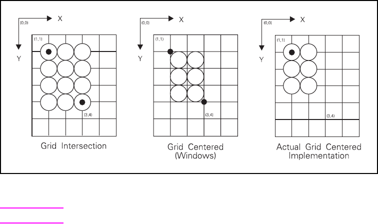
EN The PCL Print Model 5-25
Figure 5-5 Pixel Placement
Note The grid-centered method is used by Microsoft Windows.
When rectangular area fills are used and grid intersection is used, an
overlapping of pixels can occur if rectangular area fills are placed
adjacent to one another (as shown below). Depending on the raster
operation presently in effect, this overlap can produce undesirable
results in the final printed image. To avoid this problem, use the
grid-centered method.
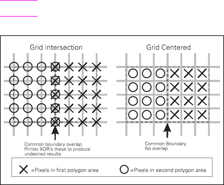
5-26 The PCL Print Model EN
Note Since PCL printers print only at intersections, grid- centered pixel
placement is implemented as shown on the right.
Figure 5-6 Pixel Placement Variations
There are two commands that modify the pixel placement function:
the PCL Pixel Placement command (?*l#R) and the HP-GL/2 Pixel
Placement command (PP).

EN The PCL Print Model 5-27
Pixel Placement Command
Determines how pixels are rendered in images.
?*l # R
Two models are used for rendering pixels when an image is placed on
paper:
• Grid Intersection Model
• Grid Centered Model
This command can be used multiple times per page. It has no effect
except to switch the model being used for imaging.
Note The PCL Pixel Placement command determines how pixels are
placed for both PCL and HP-GL/2 operation.
This command performs the same function as the HP-GL/2 PP
command described in Chapter 7.
# = 0 - Grid intersection
1 - Grid centered
Default =0
Range = 0, 1 (command is ignored for other values)
5-28 The PCL Print Model EN
Filling with Patterns
The procedure for applying patterns to text, raster images, and
rectangular areas is essentially the same, except that for text and
raster images the Current Pattern (?*v#T) command is used, and for
rectangular areas the Fill Rectangular Area (?*c#P) command is
used. The procedures below describe how to fill with PCL and
HP-GL/2 patterns.
Patterns for Text and Raster Images
Use the following general procedure to fill text and raster images with
a non-solid pattern.
1Specify the Pattern ID (?*c#G) command. For HP-defined
patterns, select an ID that specifies the desired pattern.
2Download the pattern (?*c#W). This step is for user-defined
patterns only. The downloaded pattern adopts the current
pattern ID.
3Apply the pattern to all subsequent text and raster images.
Specify the current pattern type (?*v#T).
Patterns for Rectangles
Use the following general procedure to apply a non-solid pattern to
rectangular areas.
1Specify the Pattern ID (?*c#G). For HP-defined patterns, select
an ID that matches an HP-defined pattern.
2Download the pattern (?*c#W). This step is for user-defined
patterns only. The downloaded pattern adopts the current
pattern ID.
3Define the rectangle. Position the cursor and specify the
rectangle size (?*c#A, ?*c#B or ?*c#H, ?*c#V).
4Apply the pattern to the rectangle. Send the Fill Rectangular Area
command (?*c#P).
HP-GL/2 Patterns
PCL patterns can be used in HP-GL/2 mode, but HP-GL/2 patterns
cannot be used in PCL mode. Using HP-GL/2, patterns are
downloaded using the RF (Raster Fill) command, and applied using
the FT (Fill Type) or SV (Screened Vectors) commands.

EN The PCL Print Model 5-29
Pattern ID (Area Fill ID) Command
The Pattern ID command (formerly called Area Fill ID) identifies the
specific shading, cross-hatch, or user-defined pattern. (This
command is also used for rectangular area fill, described later in this
chapter.)
? * c # G
For rectangular areas, the pattern “material” is determined by both
the pattern ID and the value of the Fill Rectangular Area command.
For other images, the pattern material is determined by the pattern ID
and the value of the Select Pattern command.
Figure 5-7 and Figure 5-8 illustrate the HP-defined shading patterns
and cross-hatched patterns, respectively.
Note This command is used for both the Select Pattern and Rectangular
Area Fill graphics.
For user-defined patterns, this command, sent prior to downloading a
user-defined pattern, assigns an ID pattern number to the
downloaded pattern. (For more information, see “User-Defined
Pattern Graphics,” later in this chapter.)
Selecting Shaded patterns: Selecting Cross-Hatch
patterns:
# = 1 thru 2 = 1- 2% shade # = 1 - Pattern #1
3 thru 10 = 3-10% shade 2 - Pattern #2
11 thru 20 = 11-20% shade 3 - Pattern #3
21 thru 35 = 21-35% shade 4 - Pattern #4
36 thru 55 = 36-55% shade 5 - Pattern #5
56 thru 80 = 56-80% shade 6 - Pattern #6
81 thru 99 = 81-99% shade
100 = 100% shade
Selecting User-Defined patterns:1
# = ID number of user-defined pattern
1 Not supported on all PCL 5 printers. Refer to the “PCL Feature Support Matrix” in
Chapter 1 of the PCL 5 Comparison Guide for specifics.
Default = 0 (no pattern)
Range = 0 – 32767 (values outside the range are ignored)
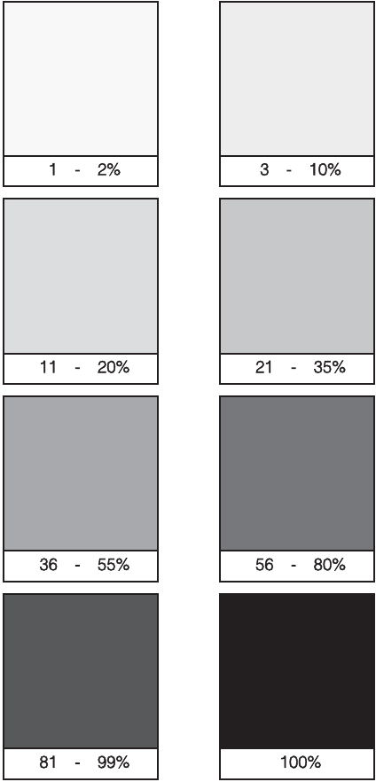
5-30 The PCL Print Model EN
Figure 5-7 Shading Patterns
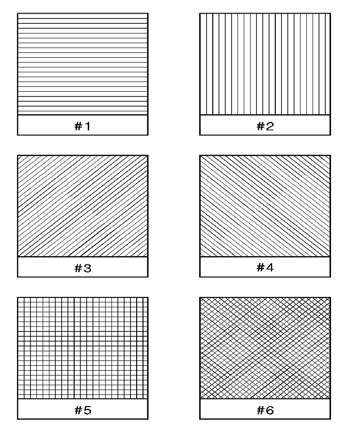
EN The PCL Print Model 5-31
Figure 5-8 Cross-Hatch Patterns

5-32 The PCL Print Model EN
Select Current Pattern Command
The Select Current Pattern command identifies the type of pattern to
be applied onto the destination.
? * v # T
This command selects which type of pattern is applied. For values 2,
3, and 4, the desired shading level, cross-hatch pattern, or
user-defined pattern number is identified by the Pattern ID command
described earlier in this chapter.
Note For selecting or changing the current pattern, the Select Current
Pattern (?*v#T) and the Pattern ID (?*c#G) commands work
together. Sending the current pattern (Select Current Pattern
command) alone does not change the current pattern; the Pattern
ID must be sent first. However, when selecting solid white (white
rule) or solid black (black rule), only the Select Current Pattern
command is required.
Once a current pattern is selected, that pattern applies to all images
placed on the page until a new pattern is selected.
# = 0 - Solid black or foreground color
1 - Solid white
2 - Shading pattern
3 - Cross-hatch pattern
4 - User-defined pattern
Default =0
Range = 0 - 4 (values outside of range are ignored)
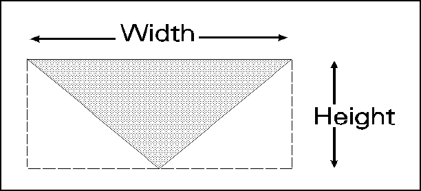
EN The PCL Print Model 5-33
User-Defined Pattern Graphics
In addition to the eight shading patterns and six cross-hatch patterns,
users can design their own fill patterns. These user-defined patterns
are downloaded to the printer and controlled using three commands:
• Download Pattern ?*c#W [data]
• Set Pattern Reference Point ?*p#R
• Pattern Control ?*p#Q
Using User-Defined Patterns
To create a new pattern, a user defines a binary raster data image as
a base pattern. This base pattern is downloaded to the printer using
the User-Defined Pattern command. Prior to downloading the pattern,
a Pattern ID command is sent to assign the user pattern an ID
number. This ID number is used to select the pattern for printing and
for pattern management.
To apply the pattern to an image, the printer duplicates or tiles (like
placing ceramic tiles) the pattern across and down the page. This
pattern can be applied to any image, including rectangular area fill.
Figure 5-9 User-Defined Base Pattern Example
A user-defined pattern may be applied to any image in the same
manner as the internal cross-hatch or shade patterns.

5-34 The PCL Print Model EN
Note For efficient memory usage and improved performance, it is strongly
recommended that user-defined patterns should be 8x8, 16x16, or
32x32 in size. Specification of patterns that are either 1 pixel in height
or width is strongly discouraged.
If user-defined halftones are also used, they need to be either the
same size or multiples of each other to avoid render anomalies due to
each pattern being rendered differently across the page (if tiled), or
due to variations
in xy position.
How the Printer Tiles a Pattern
A user-defined base pattern is a rectangular binary pattern stored in
the printer. To apply the pattern to an image area on the page, the
printer duplicates the base pattern across and down the page. This
process is referred to as tiling. (The pattern is only applied to those
areas on the page for which the pattern is required.)
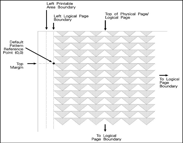
EN The PCL Print Model 5-35
Figure 5-10 Pattern Layout Across the Printable Area
5-36 The PCL Print Model EN
Pattern Reference Point
The pattern reference point is a position on the logical page at which
the base pattern is positioned for tiling. The upper left corner of the
base pattern is positioned at this point (see Figure 5-10). The default
pattern reference point is position 0,0. However, it is possible to set
the pattern reference point to the current cursor position. This allows
the pattern to be positioned or adjusted for fill areas. The pattern
reference point may be shifted more than once for as many fill areas
as there are on a page (the area must be filled before the tile point is
moved for the next fill area).
Figure 5-11 shows two areas filled with the pattern reference point
fixed at the default (0,0) position. The lower portion of the illustration
shows two areas in which the pattern reference point was moved to
the upper left corner of each area and the area filled separately.
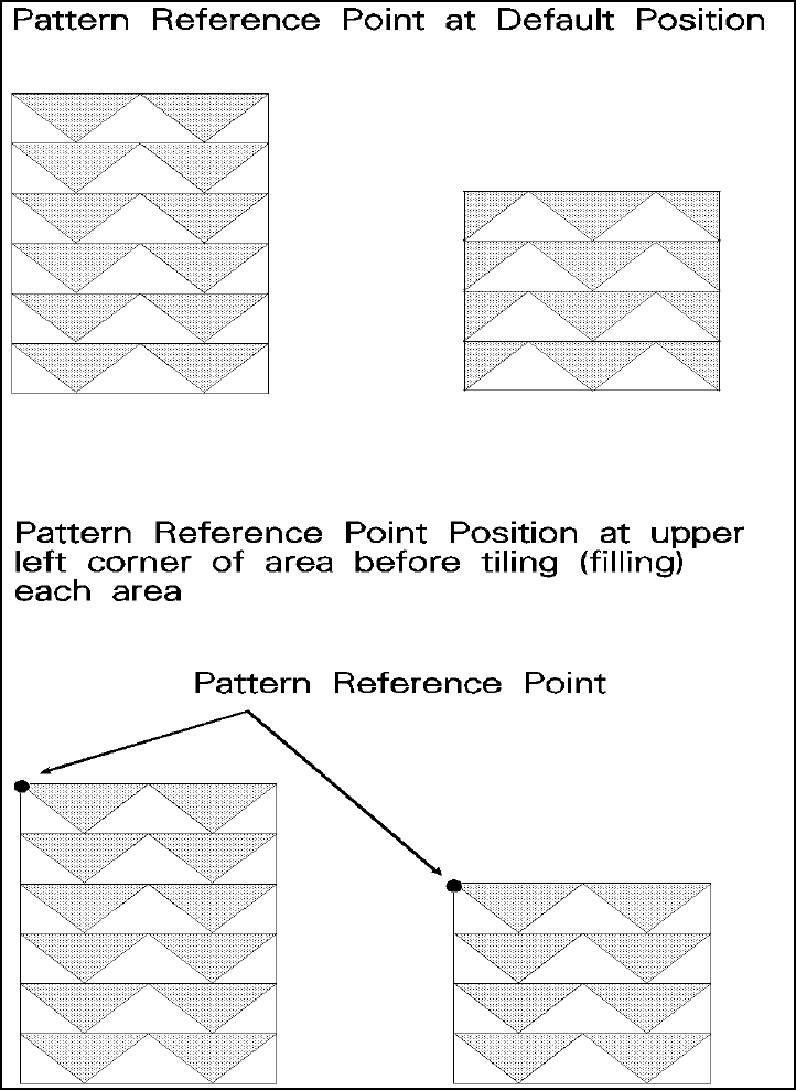
EN The PCL Print Model 5-37
Figure 5-11 Moving Pattern Reference Point for Pattern Filling
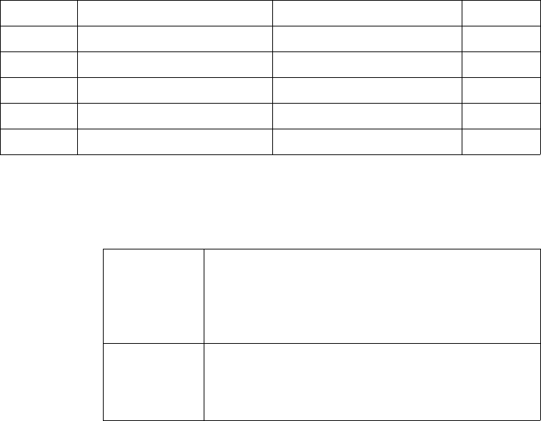
5-38 The PCL Print Model EN
Download Pattern Command
The Download Pattern command provides the means for
downloading the binary pattern data that defines the user pattern.
? * c # W [pattern data]
The value field (#) identifies the number of pattern data bytes that
follow the Download Pattern command. In addition to the binary
pattern data, there are eight bytes of pattern descriptor (header)
information included in this pattern data. The format for a 300 dpi
resolution header is shown in Table 5-5, below.
Table 5-5. User-Defined Pattern Header (300 dpi resolution)
Format (Byte 0)
This field indicates the downloadable pattern format:
# = Number of pattern data bytes
Default =0
Range = 0 – 32767 (HP Color LaserJet 8500 extends the range
to 0 to 65535; values outside the range are ignored)
Byte 15 - MSB 8 7 LSB-0 Byte
0 Format (0) Continuation (0) 1
2 Pixel Encoding (1) Reserved (0) 3
4 Height in Pixels 5
6 Width in Pixels 7
8 Pattern image
Format 0 1 bit per pixel: black-and-white or foreground color. A
“1” bit indicates black or foreground color for a color
pattern. A “0” indicates either white or transparency,
depending on the source and pattern transparency
modes. A “0” cannot be colored.
Format 1 1 or 8 bits per pixel. This format uses the current
palette. Data is sent pixel by pixel, and the bits/index
field of the pixel encoding byte determines the
number of bits defining a pixel.
EN The PCL Print Model 5-39
Continuation (Byte 1)
This field, byte 1, must be set to “0.” (This byte is for future printer
support and does not currently provide any continuation operation.)
Pixel Encoding (Byte 2)
The bits/index field may be either 1 or 8. If the value is 1, the color of
each pattern dot is specified by a single bit, supporting a two-color
palette, which need not be black and white. If the value is 8, the color
of each pattern dot is specified by one byte of data, allowing 256
colors. If the value of any byte is greater than the current palette size,
the modulo function is applied when rendering.
Reserved (Byte 3)
This field, byte 3, is not currently used and must be set to 0.
Height in Pixels (Bytes 4 and 5)
This field, bytes 4 and 5, identifies the number of raster rows (height)
of the pattern, specified at device resolution. If the height is 0, the
data is ignored and no pattern is defined. Pattern height must be less
than 32767 pixels.
Width in Pixels (Bytes 6 and 7)
This field, bytes 6 and 7, identifies the number of pixels (width) of the
pattern, specified at device resolution. If the width is 0, the data is
ignored and no pattern is defined. Pattern width must be less than
32767 pixels.
Pattern Image
This field contains the raster data for the pattern. Data rows must be
word-aligned. Pattern image data is formatted differently for each
format type (see the data description under “Format (Byte 0)” on the
previous page).
7 5 4 3 0
000 Unused Bits/Index
5-40 The PCL Print Model EN
User-defined Pattern Example
This example shows how the user-defined pattern command is used
to create new patterns. For this example, a pattern of triangles is
used. The first step is to design the base pattern triangle (in this case,
using 64 bytes of data). The base pattern binary data is shown below:
11111111111111111111111111111111
01111111111111111111111111111110
00111111111111111111111111111100
00011111111111111111111111111000
00001111111111111111111111110000
00000111111111111111111111100000
00000011111111111111111111000000
00000001111111111111111110000000
00000000111111111111111100000000
00000000011111111111111000000000
00000000001111111111110000000000
00000000000111111111100000000000
00000000000011111111000000000000
00000000000001111110000000000000
00000000000000111100000000000000
00000000000000011000000000000000
This translates into the following 64 bytes of hexadecimal values:
FF FF FF FF
7F FF FF FE
3F FF FF FC
1F FF FF F8
0F FF FF F0
07 FF FF E0
03 FF FF C0
01 FF FF 80
00 FF FF 00
00 7F FE 00
00 3F FC 00
00 1F F8 00
00 0F F0 00
00 07 E0 00
00 03 C0 00
00 01 80 00
EN The PCL Print Model 5-41
When using the 300 dpi User-Defined Pattern header (see Table 5-5),
set the eight bytes of header information to the following values:
Byte 0 – Format 0 (00 hex)
Byte 1 – Continuation 0 (00 hex)
Byte 2 – Pixel Encoding 1 (01 hex)
Byte 3 – Reserved 0 (00 hex)
Byte 4/5 – Height in Pixels 0 / 16 (00 / 10 hex)
Byte 6/7 – Width in Pixels 0 / 32 (00 / 20 hex)
Byte 8 – Begins the first bytes of binary data.
The PCL code below downloads the user-defined pattern and assigns
it an ID number of 3.
1. Specify the pattern ID number:
2. Send the User-defined Pattern command:
?*c3G Assigns an ID number of 3 to the pattern
data which follows.
?*c72W Specifies that 72 bytes are to follow (8
bytes for the header plus 64 bytes of
pattern data).

5-42 The PCL Print Model EN
Send the pattern header and binary data:
00 00 01 00 00 10 00 20
FF FF FF FF
7F FF FF FE
3F FF FF FC
1F FF FF F8
0F FF FF F0
07 FF FF E0
03 FF FF C0
01 FF FF 80
00 FF FF 00
00 7F FE 00
00 3F FC 00
00 1F F8 00
00 0F F0 00
00 07 E0 00
00 03 C0 00
00 01 80 00
Note There must be an even number of bytes in user-defined pattern data,
hence the trailing zeros (“padding”) in the last eight data rows above.
In the previous example, the raster data code is presented in
hexadecimal, however, the numbers in the escape sequences are
decimal.

EN The PCL Print Model 5-43
Set Pattern Reference Point Command
The Set Pattern Reference Point command causes the printer to tile
patterns with respect to the current cursor position (CAP). This
command also specifies whether the pattern rotates with the print
direction or remains fixed.
? * p # R
A value field of 0 rotates the patterns with changes in the print
direction (see Print Direction command). For a value field of 1,
patterns remain fixed for changes in print direction.
The default pattern reference point is the upper left corner of the
logical page at the top margin (position 0,0). If the Set Pattern
Reference Point command is not set, the pattern is tiled with respect
to the default reference point.
Note All patterns are rotated for changes in orientation, but the pattern
reference point remains the same (refer to “Logical Page Orientation
Command” in Chapter 5 of the PCL 5 Printer Language Technical
Reference Manual).
This command applies to user-defined, shading, and cross-hatch
patterns.
# = 0 - Rotate patterns with print direction
1 - Keep patterns fixed
Default =0
Range = 0,1 (values outside the range are ignored)
5-44 The PCL Print Model EN
Pattern Control Command
The Pattern Control command provides a means for manipulating
user-defined patterns.
? * c # Q
For value fields 2, 4, and 5, the Pattern ID (?*c#G) command is sent
prior to the Pattern Control command to identify the specific pattern to
which the Pattern Control command action is applied.
# = 0 - Delete all patterns (temporary & permanent)
1 - Delete all temporary patterns
2 - Delete pattern (last ID # specified)
4 - Make pattern temporary (last ID # specified)
5 - Make pattern permanent (last ID # specified)
Default =0
Range = 0, 1, 2, 4, 5 (command is ignored for other values)

EN The PCL Print Model 5-45
Rectangular Area Fills (Rules)
Rectangular area fills are a special case of source images—the
source transparency mode has no effect, since the printer treats the
rectangular area as a solid “black” (all 1’s) source.
Rectangular areas may be filled using patterns or textures. The
current Pattern ID (?*c#G) selects the pattern, and the Fill
Rectangular Area command (?*c#P) tiles an area whose
dimensions are specified by the Vertical and Horizontal Rectangle
size commands (?*c#A, ?*c#B, ?*c#H, ?*c#V). The rectangular
area does not exist and cannot be printed until the Fill Rectangular
Area command (?*c#P) has been issued, even though the
rectangular area has been specified.
Filling a rectangular area does not change the current active cursor
position (CAP). The filled rectangular area is not affected by
end-of-line wrap, perforation skip mode, or margins. A rectangular
area may extend beyond the margins, but it will be clipped to the
printable area of the logical page. Rectangular areas are not affected
by graphics resolution (?*t#R).
Except for the absence of white pixels in the source, pattern
transparency operates the same way for rectangular area fills as for
other sources. The non-white pixels of the pattern are poured through
the entire rectangular area onto the destination. The white bits of the
pattern are either applied or ignored, based on the pattern
transparency mode. If foreground color is used, it is applied to the
non-white bits of the pattern prior to pouring (except for user-defined
color patterns).
Note The Pixel Placement command (?*l#R) affects rules.
The commands used to print rectangular area fills are described
beginning on the next page.
5-46 The PCL Print Model EN
Horizontal Rectangle Size (PCL Units)
This command specifies the horizontal rectangle size in PCL Units.
? * c # A
The horizontal rectangle size is clipped to the bounds of the logical
page. Values greater than the logical page boundary are acceptable;
however, the final output is limited to the printable area of the logical
page. Values outside the range of 0 – 32767 are ignored.
The default rectangle size is 0. Power-up and reset return this value to
the default.
Horizontal Rectangle Size (Decipoints)
This command specifies the horizontal rectangle size in decipoints.
? * c # H
The horizontal rectangle size is clipped to the bounds of the logical
page. Values greater than the logical page boundary are acceptable;
however, the final output is limited to the printable area of the logical
page. Values outside the range of 0 – 32767 are ignored.
Decipoints are converted into printer dot values, and any fraction of a
dot is rounded up to the next full dot size.
The default rectangle size is 0. Power-up and reset return this value to
the default.
# = number of PCL Units (valid to 4 decimal places)
# = number of decipoints (valid to 4 decimal places)
EN The PCL Print Model 5-47
Vertical Rectangle Size (PCL Units)
This command specifies the vertical rectangle size in PCL Units.
? * c # B
The vertical rectangle size is clipped to the bounds of the logical
page. Values greater than the logical page boundary are acceptable;
however, the final output is limited to the printable area of the logical
page. Values outside the range of 0 – 32767 are ignored.
The default rectangle size is 0. Power-up and reset return this value to
the default.
Vertical Rectangle Size (Decipoints)
This command specifies the vertical rectangle size in decipoints.
? * c # V
The vertical rectangle size is clipped to the bounds of the logical
page. Values greater than the logical page boundary are acceptable;
however, the final output is limited to the printable area of the logical
page. Values outside the range of 0 – 32767 are ignored.
Decipoints are converted into printer dot values, and any fraction of a
dot is rounded up to the next full printable dot.
The default rectangle size is 0. Power-up and reset return this value to
the default.
# = number of PCL Units (valid to 4 decimal places)
# = number of decipoints (valid to 4 decimal places)

5-48 The PCL Print Model EN
Fill Rectangular Area
The Fill Rectangular Area command determines the type of pattern
used to fill the rectangle.
? * c # P
Note If a foreground color is selected, solid, shaded, and cross-hatch
patterns are printed in the foreground color. User-defined patterns are
not affected by the foreground color, but can contain color if they are
defined as such. Solid white fills are not affected by foreground color.
Black fill—fills the rectangular area with black fill or with the current
foreground color.
White fill—erases any fill in the rectangular area (it fills the
rectangular area with white fill). Pertaining to white fills, the pattern
transparency mode is always “opaque” (that is, the white pixels
always have an effect on the destination).
Shaded fill—fills the rectangular area with one of eight shading
patterns as specified by the Pattern ID command.
Cross-Hatch fill—fills the rectangular area with one of the six
cross-hatched patterns as specified by the Pattern ID command.
User-defined fill—fills the rectangular area with custom pattern data
as specified by the Pattern ID command and downloaded by the
User-Defined Pattern command.
Current Pattern—fills the rectangular area with the current pattern.
# = 0 - Solid black or foreground color
1 - Solid white fill
2 - Shaded fill
3 - Cross-hatch fill
4 - User-defined pattern fill
5 - Current pattern fill
Default =0
Range = 0 - 5 (out-of-range values are ignored)

EN The PCL Print Model 5-49
Note The current pattern is not applied to a rectangular area unless
specified by this command.
The order in which data (patterns/rules, text, raster) is received is the
order in which it is processed during the rasterization of the page.
The fill or pattern used as the current pattern is selected using the
Select Current Pattern (?*v#T) command.
Black fill (value field 0), also known as black rule, and the white fill
(value field of 1) “patterns” do not have a choice of different patterns,
and thus do not require a pattern specification using the Pattern ID
command.
The upper left corner of the rectangular area is located at the cursor
position when printing a rectangular area. After printing the
rectangular area the cursor is returned to the upper left corner; the
cursor position does not change positions as a result of printing a
rectangular area.
Rectangular areas are independent of the text area and perforation
skip mode; these boundaries are ignored (rectangles are not clipped
at these boundaries). Addressable rectangular areas are limited to
the logical page. Rectangular areas that extend outside the logical
page are clipped at the logical page boundaries (refer to the PCL 5
Printer Language Technical Reference Manual for logical page and
printable area boundary specifications).
The pattern transparency mode controls how the area fill pattern is
applied to the page. Refer to the following section for a description of
how the pattern transparency mode affects the rectangular fill area.
A white fill “erases” any data placed within the rectangular area,
regardless of the transparency mode settings. However, after a white
fill erases data within an area, data subsequently placed within that
area will be visible.

5-50 The PCL Print Model EN
Pattern Transparency for Rectangular Area Fill
Pattern transparency affects how a pattern is applied to the
rectangular fill area. The pattern and pattern type are selected by the
Pattern ID command (?*c#G) and the Fill Rectangular Area (?*c#P)
command (described earlier in this chapter).
Note Source transparency has no effect on the rectangular fill area since
the rectangular area is viewed as all 1’s (a solid black source image).
When applying a pattern (area fill) to the rectangular area, the pattern
transparency mode affects the final result the same as it does when
filling other images or text. The pattern transparency mode
determines the effect white pixels of the pattern have on the
destination for value fields 0 (black fill), 2 (shaded fill), 3 (cross-hatch
fill), or 5 (current pattern fill) of the Fill Rectangular Area command.
The “0'' bits of the fill pattern are either applied (opaque) or ignored
(transparent) based on the transparency mode setting (see
Figure 5-12). When a value field of 1 (white fill) is used, pattern
transparency mode is always treated as if it were opaque.
The effect of transparency modes on rectangular areas is illustrated
in Figure 5-12. In both examples, the source transparency mode is
opaque regardless of the actual setting. In the first example, the
pattern transparency mode is transparent; the white pixels in the
pattern are not applied to the destination, so that the pattern is visible
in only two quadrants of the destination. In the second example, the
pattern transparency mode is opaque, and the pattern is visible in the
entire rectangular area.
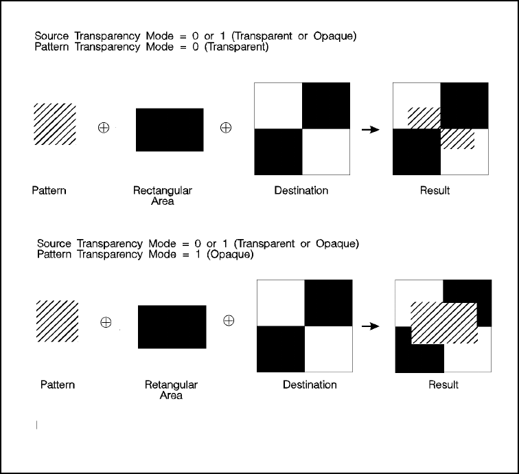
EN The PCL Print Model 5-51
Figure 5-12 Effect of Transparency Modes on Rectangular Areas
This example is a monochrome example and assumes the default ROP.
5-52 The PCL Print Model EN
Rectangular Fill Examples
Following are two examples that demonstrate the way to print and fill
rectangular shapes. The first example demonstrates filling rectangles
with solid fill and the second example demonstrates filling with a
shading pattern.
Solid Fill (Black/White)
To print a 900 by 1500 Unit black rule (3 inches by 5 inches at
300 units-per-inch), then “white fill” a small area inside the black
rectangle, perform the following steps.
1Position the cursor:
2Specify the width of the rule:
3Specify the height of the rule:
4Print the rule:
5Position the cursor inside the rectangular area:
6Specify the width and height for the smaller white fill rectangular
area:
?*p300x400Y This moves the cursor to PCL Unit
position (300, 400) within the PCL
coordinate system.
?*c900A This sets the rule width to 900 PCL Units
(3 inches at 300 units-per-inch).
?*c1500B This sets the rule height to 1500 PCL
Units (5 inches at 300 units-per-inch).
?*c0P This example prints a black filled
rectangular area.
?*p600x700Y
?*c300a600B
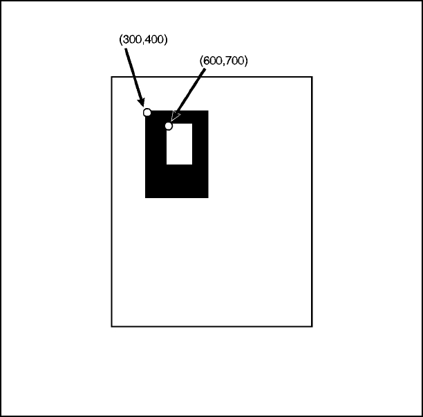
EN The PCL Print Model 5-53
7Select the white fill and print.
Figure 5-13 Solid Fill Example
?*c1P
5-54 The PCL Print Model EN
Shaded Fill
To print a 900 by 1500 Unit 25% shaded rectangle (3 inches by
5 inches at 300 units-per-inch), perform the following steps.
1Position the cursor:
2Specify the width of the rectangle:
3Specify the height of the rectangle:
4Specify the Pattern ID:
?*p300x400Y This moves the cursor to PCL Unit
position (300, 400) within the PCL
coordinate system.
?*c900A This sets the rectangle width to 900 PCL
Units (3 inches at 300 units-per-inch).
?*c1500B This sets the rectangle to 1500 PCL Units
(5 inches at 300 units-per-inch).
?*c25G This sets the Pattern ID to 25.
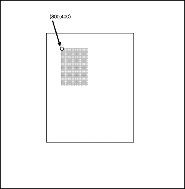
EN The PCL Print Model 5-55
5Print the rectangular shaded area:
Figure 5-14 Shaded Fill Example
?*c2P This example prints the following:
5-56 The PCL Print Model EN
EN Raster Graphics 6-1
6Raster Graphics
Introduction
A raster image is a made up of a series of discrete picture elements—
pixels. Pictures such as those in newspapers, television, and
documents from Hewlett-Packard printers are examples of raster
images. In comparison, pictures drawn with lines and geometric
objects such as circles, rectangles, and polygons are termed vector
graphic images. While some pictures could be produced using either
vector or raster graphics, raster graphics is best suited for printing
photographic images.
A raster image is invariably rectangular and divided into a gridwork of
pixels. Each pixel represents a small area of the image. In
monochrome images each pixel represents a black or white dot. In
color images each pixel is a colored dot. Therefore, the most
important characteristics of an image are its:
• Image width
• Image height
• Image resolution (the number of dots or pixels per inch)
An image is also divided into rows, where a row is a grouping of all
the pixels in a horizontal strip of the image, the width of the image and
one pixel high.
As noted before, a pixel represents a small area of the image. The
size of the area depends on the resolution of the image. The pixel
area for a 600 dot per inch (dpi) image is a square 1/600th of a inch
on a side. Courser resolutions cover more picture area per pixel. For
example, a 75 dpi pixel contains 0.0002 square inches, a 600 dpi
pixel contains 0.000003 square inches. Some printing and scanning
devices specify a resolution in the horizontal direction and another
resolution in the vertical direction, 300 by 600 dpi, for example.
However, PCL raster only supports identical resolutions in the
horizontal and vertical directions, and therefore, PCL 5 raster
graphics pixels are squares.
6-2 Raster Graphics EN
There is a direct connection between the resolution and the size of an
image. The image size is the number of pixels in the image multiplied
by the number of bits used to represent a pixel. The smaller the dpi,
the smaller the size of the image; the larger the dpi, the larger the size
of the image. There is a tradeoff in image size versus print quality.
Larger pixels give poorer print quality since diagonal lines can start
looking ragged or pixelated, but the image size is small. Smaller
pixels give good print quality but larger image size. As a rule, 150 dpi
provides a happy medium of good print quality at a relatively small
image size.
A printer has a printing resolution, 600 dpi for example. An image with
an image resolution smaller than the printer's resolution will undergo
a process of scaling as the image is converted to the printer's
resolution, also known as device resolution. For example, a 150 dpi
image is converted to a 600 dpi image at device resolution by
replicating each pixel four times in the horizontal direction and four
times in the vertical direction. Therefore, a single pixel of a 150 dpi
image is replicated by creating 15 new pixels. A 75 dpi pixel is
replicated by creating 63 new pixels.
The large scale replication of pixels for low resolution images is one of
the main reasons for poor print quality: first the image detail may be
missing from the image because of the large pixel size, and second a
blocky, pixelated effect occurs when the pixel is reproduced over and
over again. Various techniques have been devised to compensate for
this pixelated effect. For example, rather than copy or replicate the
pixel, a bi-linear or bi-cubic interpolation algorithm could be used to
smooth out the transitions by considering the surrounding pixels when
making new pixels. However, this tends to blur edges or sharp
transitions that are in the original image. As a rule, better print quality
results from higher resolution images, such as 150 or 300 dpi, that
use smaller pixels and cause less pixel replication.
Pixels represent specific spots within the picture. In a black and white
image, where a pixel is either black or transparent (white), a single
binary digit or bit can represent a pixel. This has been the standard
raster format for many years. See Figure 6-2 for an example.
However, in color images, or grayscale images, those with varying
black dot sizes which yield a range of grays when viewed by the
human eye, a single bit is not sufficient. Therefore, the general form of
a pixel is:
• The number of components in the pixel, which is generally
either one or three, and
• The number of bits per component.

EN Raster Graphics 6-3
This pixel format is sufficient to represent black and white images,
gray scale images, and color images. Furthermore, this format can
represent images where the color specification is directly in the
image, or where the pixel is an index into the palette. The table below
shows some possible combinations of the number of components and
the bits per component.
Image Type Number of
Components Bits per
Component
Black and White, direct 1 1
Black and White, indexed 1 1
Color, indexed 1 8
Color, direct 3 8
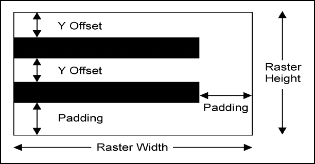
6-4 Raster Graphics EN
PCL 5 Color Raster Graphics
The PCL 5 color raster graphics command set provides support for
specifying an image's:
• Dimensions
• Resolution
• Pixel format, also known as the pixel encoding mode
• Compression mode
Large image size is one of the major concerns with raster images. For
example, the size of an 8 x 10 inch monochrome image at 150 dpi is
225 Kbytes. The size of a 24-bit color image with the same size and
resolution is 5.4 Mbytes. If the color image is 600 dpi, 24-bit color, its
size is 86 Mbytes. Therefore, the PCL 5 language supports several
compressions modes that exploit redundancy between adjacent
pixels or adjacent rows. Furthermore, several shortcuts are available
to avoid sending data that is really large blocks of zeros.
Figure 6-1 Raster Area
EN Raster Graphics 6-5
An image’s width and height define the extent of the image, that is,
the number of pixels in a row and the number of rows in the image.
The following commands and features eliminate the need to send
blocks of zero pixel values:
1The Y Offset command can be used to direct the printer to set all
the pixel values in the given number of rows to zero.
2If not enough data is sent for all the pixels in a row, the remaining
pixels are set to zero.
3If the image is ended before all rows have been received, the
values of the pixels in the remaining rows will be set to zero.
Furthermore, if too much data is sent the data extending outside the
raster area is clipped and discarded.

6-6 Raster Graphics EN
Raster Graphics Command Sequence
PCL raster commands include: Start Raster Graphics and End Raster
Graphics commands, Transfer Raster Data by Plane and Row, Raster
Compression, Raster Presentation, Raster Resolution, Raster Height
and Raster Width (which define the raster area), and Raster Y Offset
commands. For printing well-behaved raster graphics, the normal
sequence of execution for these commands is shown below.
Hewlett-Packard strongly recommends that developers use this
command sequence in their applications.
Note Although the source raster height and width commands are not
necessary, they improve memory efficiency.
Well-Behaved Raster Command Sequence
Raster Presentation
Raster Resolution
Raster Height
Raster Width
Start Raster Graphics
Y Offset
Raster Compression
Transfer Raster Data
…
Transfer Raster Data
Y Offset
Transfer Raster Data
…
Y Offset
Raster Compression
Transfer Raster Data
…
Raster Compression
Transfer Raster Data
End Raster Graphics

EN Raster Graphics 6-7
The emphasis in the previous command sequence is that the Raster
Presentation Mode, Raster Resolution, Raster Height, and Raster
Width are all set outside the start..data..end sequence of commands.
Also, the entire image is sent during the start..data..end sequence,
choosing the most effective compression method for each raster row
of data.
Raster Presentation, Raster Resolution, Raster Height, Raster Width,
and Raster Compression are all true modes. Once specified, the
printer remains in that mode unless explicitly changed by issuing the
command again, or reset to default values by a soft reset, self test,
font printout, or power cycle.
Note Only raster data appearing within the intersection of the logical page,
the printable area, the raster width, and height is printed. If raster
width and/or raster height have not been set, the intersection of the
logical page and the printable area determines where raster graphics
appear; raster data is clipped to the printable area.

6-8 Raster Graphics EN
Raster Graphics Resolution Command
Raster graphics can be printed at various resolutions. This command
designates the resolution of subsequent raster data transfers in dots
per inch.
? * t # R
This command must be sent prior to the start graphics command. The
factory default resolution is 75 dots-per-inch.
Note Lower resolution graphics occupy less user memory. For example, the
number of bits required to represent a two-inch by three-inch image at
75 dots-per-inch is 33,750. The same image at 300 dots-per-inch
requires 540,000 bits. Note that lower resolution graphics may not
give acceptable print quality.
When configured for 300 dpi resolution, the printer automatically
expands raster graphics transferred at resolutions less than
300 dots-per-inch to 300 dots-per-inch during printing. Figure 6-2
illustrates how a single bit is translated into the corresponding printed
dots in various graphics resolutions when the printer is configured for
300 dpi.
# = 75 - 75 dots-per-inch
100 - 100 dots-per-inch
200 - 200 dots-per-inch
150 - 150 dots-per-inch
300 - 300 dots-per-inch
600 - 600 dots-per-inch
Default =75
Range = 75, 100, 150, 200, 300, 600
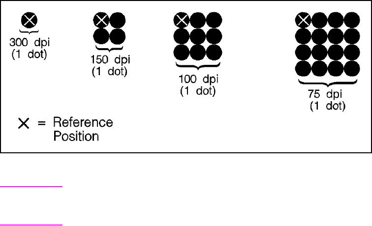
EN Raster Graphics 6-9
Figure 6-2 Raster Graphics Expansion - at 300 dpi
Note Rectangular area fills and character data are not affected by changes
in resolution. Rectangular Area fills and character data always print at
the maximum resolution, regardless of the resolution setting.
6-10 Raster Graphics EN
Raster Graphics Presentation Mode Command
The Raster Graphics Presentation command specifies the orientation
of the raster image on the logical page.
? * r # F
• A value of 0 indicates that a raster row will be printed in the
positive X-direction of the PCL coordinate system. (The print
direction translates the PCL coordinate system.)
• A value of 3 indicates that the raster graphics will be printed
along the width of the physical page, regardless of logical page
orientation. In portrait orientation, a raster row is printed in the
positive X-direction of the PCL coordinate system and a
subsequent raster row is printed beginning at the next dot row
position in the positive Y-direction. In landscape orientation, a
raster row is printed in the positive Y-direction of the PCL
coordinate system and a subsequent raster row is printed
beginning at the next dot row position in the negative
X-direction. Figures 6-3 and 6-4 illustrate presentation modes
0 and 3.
# = 0 - Raster image prints in orientation of logical page
3 - Raster image prints along the width of the physical
page
Default =3
Range =0, 3
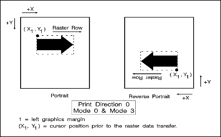
EN Raster Graphics 6-11
Figure 6-3 Raster Graphics Presentation Mode for Portrait Orientation
Raster
Presentation
Mode
Orientation Default Graphics Margin
0 portrait logical page left bound
0 reverse portrait logical page left bound
0 landscape logical page left bound
0 reverse landscape logical page left bound
3 portrait logical page left bound
3 reverse portrait logical page left bound
3 landscape 50 dots in from the logical page
top bound
3 reverse landscape 50 dots in from the logical page
top bound
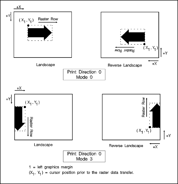
6-12 Raster Graphics EN
Figure 6-4 Raster Graphics Presentation Mode for Landscape Orientation

EN Raster Graphics 6-13
Source Raster Height Command
The Raster Height command specifies the height in raster rows of the
raster area. Height is the direction perpendicular to the direction that
raster rows are laid down, hence, height is subject to the current
raster presentation mode and print direction (see Figure 6-5).
? * r # T
* Greater values default to (logical page length - current Y cursor position).
Note Specifying the raster width and raster height improves memory
usage. Therefore it is highly recommended.
This command fills the raster area to the full raster height with zeroed
rows. Unspecified rows map to either white or transparent depending
on the source transparency mode (this is true only if index 0 is white).
When a Transfer Raster Data command is received that causes any
raster row to extend beyond the row boundary set by the Raster
Height command, the row outside the boundary is clipped. This
includes the case where the cursor is moved beyond the height
boundary with a Raster Y Offset command and the printing of raster
data is attempted.
If you have specified either a raster height or a raster width of 0 and a
Start Raster Graphics (or Transfer Raster Data) command is
received, then the entire raster graphic is clipped. If both a raster
height and a raster width are specified (non-zero) and a Start Raster
Graphics (or Transfer Raster Data) command is received, then the
raster area is guaranteed to be filled.
Note For color printers, a zero fill is not necessarily white.
If the raster height is not set, no padding or clipping of rows takes
place.
# = Height in raster rows
Default =N/A
Range = 0 to (logical page length – current Y- position of the 0,
cursor)*
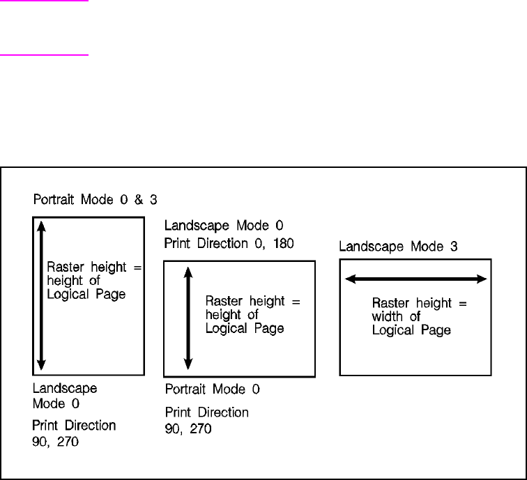
6-14 Raster Graphics EN
This command is ignored after the Start Raster Graphics or Transfer
Raster Data commands until the next End Raster Graphics
command.
Note Only raster data appearing within the intersection of the logical page,
the printable area, and if set, the raster width and height, is printed.
Data outside the intersection is clipped.
Upon receiving an End Raster Graphics (?*rC) command, the cursor
position is set to the left graphics margin of the next raster row after
the raster height boundary.
Figure 6-5 Maximum Raster Height

EN Raster Graphics 6-15
Source Raster Width Command
The Raster Width command specifies the width in pixels of the raster
area. Width is in the direction that the raster rows are laid down,
hence width is subject to the current raster presentation mode and
print direction (see Figure 6-6).
? * r # S
* Greater values default to the (logical page width – left graphics margin).
Note Specifying the raster width and raster height improves memory
usage. Therefore it is highly recommended.
This command allows you to implicitly tell the printer to pad raster
rows that are not specified for the full raster width with zeros.
Unspecified data maps to either white or transparent depending on
the source transparency mode (this is true only if index 0 is white).
Note For color printers, a zero fill is not necessarily white.
When a Transfer Raster Data command is received that specifies a
row of data that is longer than the raster width, the data that extends
beyond the raster width is clipped.
This command is ignored after the Start Raster Graphics or Transfer
Raster Data commands, until the next End Raster Graphics
command.
Note Only raster data appearing within the intersection of the logical page,
the printable area, and if set, the raster width and height is printed.
Data outside the intersection is clipped.
# = Width in pixels of the specified resolution
Default = depends on raster presentation mode: when
presentation mode is 0 then width = width of logical
page minus left graphics margin; when presentation
mode is 3 then width = dimension of logical page along
paper length minus left graphics margin.
Range = 0 to (logical page width minus left graphics margin)*
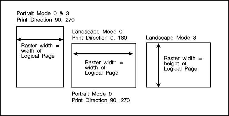
6-16 Raster Graphics EN
Figure 6-6 Maximum Raster Width
EN Raster Graphics 6-17
Start Raster Graphics Command
The Start Raster Graphics command identifies the beginning of the
raster data and also specifies the left graphics margin.
? * r # A
A value of 0 specifies that the left graphics margin is at the default left
margin of the page (X-position 0). A value of 1 specifies that the left
graphics margin is at the current X-position. Values of 2 or 3 are
equivalent to 0 and 1, but also enable resolution-independent scaling.
In presentation mode 3, the location of the left graphics margin varies
depending on the orientation.
Once a Start Raster Graphics command is received by the printer,
raster graphics resolution, raster graphics presentation mode, raster
height, raster width, and left raster graphics margin are fixed until an
end raster graphics command is received.
Once in Raster Graphics Mode, PCL commands and text imply an
End Raster Graphics (?*rC) except for the following commands:
• Transfer Raster Data by Row or by Plane
• Set Raster Compression Method
• Raster Y Offset
In addition, the following commands are ignored (i.e., locked out)
while in Raster Graphics Mode and do not imply an End Raster
Graphics command:
• Start Raster Graphics
• Set Raster Width
• Set Raster Height
• Set Raster Presentation Mode
# = 0 - Start graphics at default left graphics margin
(X-position 0).
1 - Start graphics at current cursor position (current
X-position).
2 - Raster scaling on—start at left boundary.
3 - Raster scaling on—start at CAP.
Default =0
Range = 0 - 3 (out-of-range values default to 0)

6-18 Raster Graphics EN
• Set Raster Graphics Resolution
• Palette Commands
• CID Command
• Color Treatment
• Render Algorithm
Note An implied End Raster Graphics resets the Raster Compression
Method 3 seed row, but does not reset the Raster Compression
Method nor the left raster graphics margin.
If source and/or transparency modes have been set, frequent
start/end graphics commands in an image can result in a memory
overflow condition.

EN Raster Graphics 6-19
Raster Y Offset Command
The Raster Y Offset command moves the cursor position vertically
the specified number of raster lines from the current raster position in
the raster area.
? * b # Y
This command is recognized only while in raster graphics mode and
only within the raster area.
This command zero-fills the offset area. For color printers, zero-fills
are filled with the color of index 0, which is not necessarily white.
For Delta Row compression (method 3), this command zeros the
seed row. For Adaptive compression (method 5), this command
applies to the entire raster data block.
Note Movement by this command is based upon the Raster Resolution
setting (?*t#R) and also the printer's resolution setting (75, 150, or
300 dpi).
# = Number of raster lines of vertical movement
Default =N/A
Range = 0 - 32767
6-20 Raster Graphics EN
Set Compression Method Command
The Set Compression Method command allows you to encode the
data in a given raster transfer, either by plane or by row. These
methods achieve data compression by exploiting byte-to-byte
redundancies, either within a row or between rows, without regard to
the pixel encoding mode of the data. While these methods reduce the
amount of data transferred from the host to the printer, they do not
reduce the memory requirements within the printer.
While PCL 5 compression methods are based on redundancies at the
byte level, the pixel encoding mode must be considered when
choosing a compression method. The direct by pixel mode transfers
the three bytes which make up a pixel, one after the other. Therefore,
compression formats that depend upon reducing redundancy within a
row will not do well, since the pixel to pixel redundancy is disguised by
the format. This is because, while two adjacent pixels have a fairly
high probability of being identical, the probability that the components
of a pixel are identical is very small. For example, consider a raster
image whose background is all one color. While there are a large
number of pixels that are identical, the only time the bytes within the
pixel will be identical are if the color is a gray somewhere between
white and black: such as (0, 0, 0), (128, 128, 128), (255, 255, 255). If
the pixel represents a non-gray color, the bytes within the pixel will not
be identical. Therefore, the only successful compression mode that
exploits redundancy between the rows is delta row compression.
Since the probability that a pixel is the same in the horizontal direction
is usually equivalent to the probability that it is the same in the vertical
direction, the bytes within a pixel will be redundant and therefore
compressible from row to row.
The remaining pixel encoding modes: index by plane, index by pixel,
and direct by plane, can be redundant within a row and are, therefore,
compressed well by compression methods such as run-length
encoding, and TIFF rev 4.0.
EN Raster Graphics 6-21
The Set Compression Mode command has the following form:
? * b # M
Unencoded (Method 0)
This is a simple transfer of binary data without any compression.
Run-length Encoding (Method 1)
Run-length encoding interprets raster data in pairs of bytes. The first
byte of each pair is the repetition count for the data in the second
byte. The second byte is the raster data to be printed. A repetition
count of 0 signifies the pattern in the data byte is not repeated (it
occurs only once). A repetition count of 1 signifies the pattern occurs
twice. The repetition count can range from 0 to 255 for a repetition of
1 to 256 times.
[(Repetition count byte 0-255)(pattern byte)] . [ . ] [ ]
Tagged Image File Format Encoding
(Method 2)
Tagged Image File Format encoding interprets raster data as TIFF
“Packbits.” This format combines features of methods 0 and 1. A
control byte precedes the raster data (pattern bytes). The control
byte identifies whether the pattern byte(s) represent a byte that is to
be repeated some number of times (up to 127), or represent some
number of bytes (up to 127) which are to be printed as is (literally).
# = 0 - Unencoded
1 - Run-length encoding
2 - Tagged Imaged File Format (TIFF) rev. 4.0
3 - Delta row compression
5 - Adaptive compression
Default =0
Range = 0 - 3, 5 (other values are ignored)
6-22 Raster Graphics EN
The sign of the number in the control byte identifies whether the byte
or bytes that follow represent a literal pattern or byte to be repeated. A
positive number (1 to 127) indicates that the bytes are literal. A
negative number (-1 to -127), represented by the twos complement,
indicates a repeated byte. The value of the number, if positive (literal),
identifies the number of pattern bytes which follow the control byte; if
negative (repeated), it identifies the number of times to repeat the
following byte. A pattern byte may be repeated up to 127 times; or up
to 127 literal bytes may follow the control byte.
As mentioned, for a byte to be repeated, the control byte must be a
negative value as represented by the twos complement. For example,
to repeat a pattern three times would require the twos complement of
the number 3. The twos complement is computed as follows. The
binary of 3 is 00000011. Complement each bit to get 11111100, then
add one to this value to produce 11111101, the twos complement.
The decimal value of this number, 253, used in the control byte,
produces a repetition of 3 bytes for a total of 4 occurrences of the
pattern.
The range of numbers for the control byte is shown below.
Literal Pattern Values
# of Bytes Binary value Decimal value
1
to
127
0000 0000
to
0111 1111
1
to
127
No Operation Value
NOP value Binary value Decimal value
128 (-128) 1000 0000 128
Repeated Pattern
Values
# of Repetitions Binary value* Decimal value
1 (-1)
to
127 (-127)
1111 1111
to
1000 0001
255
to
129
* These negative values are represented by taking the twos complement of the value
of the number.
EN Raster Graphics 6-23
Note Another method to calculate the number needed in the control byte
for some number of repetitions is to subtract the number of desired
repetitions from 256. For example, the control value for 3 repetitions
(4 occurrences) of a byte is 256 minus 3 = 253.
A zero or positive value in the control byte means that the subsequent
byte or bytes are non-replicated bytes of data. The value of the
control byte plus one indicates the number of data bytes that follow.
For example, a control byte of 0 means the following 1 byte is literal
raster data. A control byte of 6 indicates that the following 7 bytes are
literal raster data bytes.
TIFF encoding also allows you to include a non-operative (NOP)
control byte, represented by the value -128. This byte is ignored, and
the subsequent byte is treated as the new control byte.
Note It is more efficient to code two consecutive identical bytes as a
repeated byte. If these bytes are preceded and followed by literal
bytes, however, it is more efficient to code the entire group as literal
bytes.
Examples: Run-length and TIFF Compression
The following examples show how a raster row can be coded using
run-length and TIFF compression methods. Note that the
compression examples use characters to represent the binary data
stream.
Unencoded
?*r1A
?*b0m7WUUUUATT
?*rC
Byte
Number #1 #2 #3 #4 #5 #6 #7
Bits 01010101 01010101 01010101 01010101 01000001 01010100 01010100
ASCIIUUUUATT
6-24 Raster Graphics EN
Run-length Encoding
?*r1A
?*b1m6W(3)U(0)A(1)T
?*rC
TIFF Encoding
?*r1A
?*b2m6W(-3)U(0)A(-1)T or ?*b2m6W(-3)U(2)ATT
?*rC
In the TIFF encoding example above, parenthetical expressions are
used to identify control bytes. For example, the byte (-3) is shown to
represent the control byte for a repetition (minus value) of 3. The
actual value for this position is the decimal value 253. Additional
“encoded” control bytes in this sequence include: (0) for decimal 0,
(-1) for decimal 255, and (2) for decimal 2. The raster data (pattern)
bytes are represented by the ASCII character.
Delta Row Compression (Method 3)
Delta row compression identifies a section of bytes in a row that is
different from the preceding row, and then transmits only that data
that is different (the delta data). If a row is completely different from its
preceding row, then the entire row must be sent as the delta, which is
not very efficient; if only one bit is different, then only one byte is
identified and sent. To reassemble the raster data rows, the printer
takes the current row (the seed row) and makes the changes
indicated by the delta data, to create the new row. The new row
(which becomes the new seed row) is used by the next delta
compression data to create another row.
A delta compression row consists of two parts, a command byte and
the replacement bytes, as shown below:
[(Command byte)(1 to 8 Replacement bytes)]
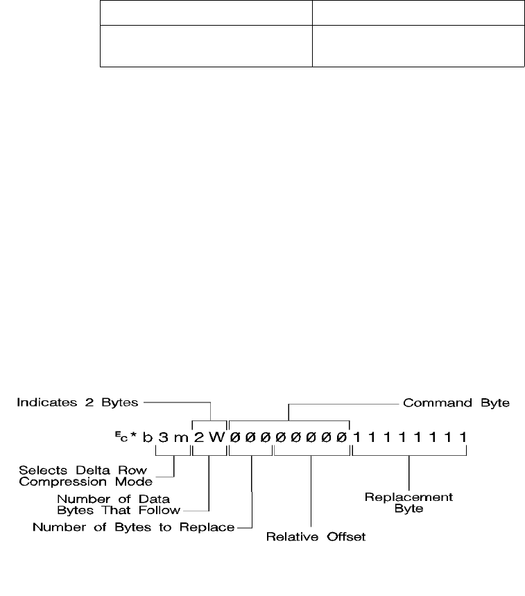
EN Raster Graphics 6-25
The command byte identifies two things: 1) the number of
replacement (delta) bytes that follow; and 2) where to position the
replacement byte string (the left offset). The replacement bytes are
some number (up to eight bytes) of consecutive bytes that are used to
create the new row from the seed row.
If more than eight replacement (delta) bytes are needed, additional
command byte/replacement bytes may be added, as shown below:
?*3m#W [(Command Byte)(1 to 8 Replacement
Bytes)][(Command Byte)(1 to 8 Replacement Bytes)]. . .
In the command byte, the upper three bits identify the number of
replacement (delta) bytes (which can be 1 to 8 bytes). The lower five
bits identify the location the replacement bytes are to be positioned.
This position is identified as the offset, or the number of bytes from
the treated byte. For example, if there are 5 replacement bytes and
the offset is 7, then the replacement bytes replace bytes 7, 8, 9, 10,
and 11 (the five bytes beginning at byte 7 from the seed row).
If there is more than one replacement in a row, the second offset is
counted from the next untreated byte in the row: the first byte
following the last replacement byte.
7 5 4 0
Number of bytes to replace (1-8) Relative offset from last untreated
byte
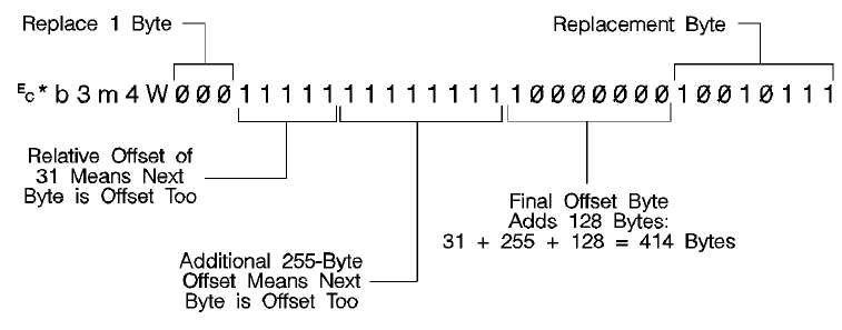
6-26 Raster Graphics EN
As mentioned, the offset contained in the lower five bits of the
command byte allows for offset values from 0 to 31. Compression
mode allows offsets larger than 31 bytes as follows:
• An offset value of 0-30 indicates that the replacement bytes
are offset from the 1st byte to the 31st byte.
• A value of 31 indicates that the next byte following the
command byte is an additional offset byte which adds to the
first (32) offset value. This allows offset values larger than 31.
Also, if this second offset byte is set to 255 (all ones),
additional offset bytes follow until the required offset value is
obtained. When the formatter detects an offset byte less than
255, it is assumed to be the last offset value and the offset
bytes are then totaled (added). The following example shows
an offset larger than 31:
The total offset is 414, which is the sum of the three offset values:
31 + 255 + 128.
Seed Row
The seed row is basically the current raster data row, the row being
printed. It is maintained by the printer for use by delta row
compression. The delta compression replacement bytes are applied
to the seed row to create the new row. This new data row is printed
and becomes the new seed row.
For color raster images, the printer operates on each plane
independently, and a separate seed plane is maintained for each
graphic plane. A Y offset, however, affects all planes and seed rows
simultaneously.

EN Raster Graphics 6-27
The seed row is updated by every raster graphic transfer, regardless
of the compression method. This allows the delta compression
method to be mixed with other methods to achieve better
compression performance.
Repeating a Row
?* b 0 W
When using the delta compression method, it is possible to repeat or
copy the previous raster row using the Raster Data Transfer
command. This is accomplished by setting the Raster Data Transfer
command value field to zero.
Printing A Zeroed Row (Setting the Seed Row to Zero)
?* b 1 Y
It is possible to print a row of all zeros using the Raster Y-Offset
command. Sending a Raster Y Offset command with a value field of 1
sets the seed row to zero and prints the zeroed row. Note that the
next delta row is applied to a zeroed seed row.
Other cursor position moves set the seed row to zeros. (Remember,
non-graphic cursor moves have the same effect as an end graphics
command.)
Note If the byte count of the Transfer Raster Data command value field is
less than the number of bytes that can be replaced, the byte count
has precedence. Also, if the last byte is a control byte, it is ignored.
Therefore, ?*b1W does not affect the seed row, but causes the
previous row to be replicated.
Example: Delta Row Compression
The following example demonstrates how to compress the following
data using the delta row compression. (The bytes highlighted in bold
type indicate those bytes needing replacement – those bytes that are
different from the previous row, the seed row.)
Byte No. 0 1 2 3 4
Row 1 00000000 11111111 00000000 00000000 00000000
Row 2 00000000 11111111 11110000 00000000 00000000
6-28 Raster Graphics EN
?*r1A – The start raster graphics command initializes the seed row
to all zeros.
Row 1 – ?*b3m2W(00000001)(11111111)
The 3m selects the delta row compression method and the 2W
indicates 2 bytes of data to follow. The first three bits of the first data
byte, the command byte, signify a single byte replacement (all three
bits are 0). The next five bits indicate an offset of 1 byte from the
current position. The replacement byte follows and contains
11111111.
Row 2 – ?*b2W(00000010)(11110000)
The first three bits of the command byte indicate that one byte will be
replaced, and the next five bits indicate a relative offset of 2, so the
replacement will occur 2 bytes from the current position. The
replacement byte follows and contains 11110000.
Row 3 – ?*b5W(00000000)(00001111)(00100010)
(10101010)(10101010)
As in the other rows, the first three bits of the command byte are zero,
indicating a single byte replacement. The five offset bytes indicate a
relative offset of zero bytes. The replacement byte follows and is
00001111. The third byte is another command byte and the first three
bits signify the replacement of two bytes (the top three bits are 001).
The offset bits indicate an offset of two bytes from the current
position. The fourth and fifth bytes are the two replacement bytes.
Adaptive Compression (Method 5)
Adaptive compression enables the combined use of any of the four
previous compression methods (0 through 3), and it includes the
ability to print empty (all zeros) rows or to duplicate rows.
Adaptive compression interprets a raster image as a block of raster
data rather than as individual rows. The result of this interpretation is
that the Transfer Raster Data (?*b#W) command is sent only once at
the beginning of a raster data transfer, and the value field (#) identifies
the number of bytes in the block of rows. For the other compression
methods, the Transfer Raster Data command is sent at the beginning
of each row and the value field (#) identifies the number of bytes for
that row only.
Row 3 00001111 11111111 11110000 10101010 10101010

EN Raster Graphics 6-29
The size of a block is limited to 32,767 bytes. (32,767 bytes is the
number of compressed bytes and not the size of the uncompressed
data). To transfer greater than 32,767 bytes, send multiple blocks.
Adaptive compression uses three control bytes at the beginning of
each row within the block. The first of these bytes, the command byte,
identifies the type of compression for the row. The two following bytes
identify the number of bytes or rows involved. The format for adaptive
compression raster rows is shown below:
<command byte><# of bytes/rows - upper byte><# of bytes/rows - lower byte> ...
... <first raster row byte> ... <last raster row byte>
The command byte designates the compression method, empty row,
or row duplication. Command byte values are shown below.
Value Compression Operation
0 – Unencoded
1 – Run-Length Encoding
2 – Tagged Image File Format (TIFF) rev 4.0
3 – Delta row
4 – Empty row
5 – Duplicate row
6-30 Raster Graphics EN
For command byte values 0 - 3, the two <# of bytes/rows> bytes
specify the number of bytes (row length) for the row. For command
byte values 4 and 5, these bytes identify the number of empty or
duplicate rows to print. The maximum value for these two bytes is
65,535; however, the image is clipped to the logical page. Thus, the
value of these bytes should not exceed the maximum number of
bytes/rows that can be printed on the current logical page size.
If an out-of-range command byte is encountered, the remainder of the
block is skipped, the cursor is not updated, and the seed row is
cleared.
Compression methods 0 - 3 are the compression methods used by
the Set Compression Method command. Value fields 4 and 5 are
features for the adaptive compression method and are explained
below.
Empty Row
A command byte of 4, empty row, causes a row of zero’s to be
printed. The number of rows printed depends on the value contained
in the two <# of bytes/rows> bytes following the command byte. The
empty row operation resets the seed row to zero and updates the
cursor position.
Duplicate Row
A command byte of 5, duplicate row, causes the previous row to be
printed again. The row can be duplicated the number of times
indicated by the value contained in the <# of bytes/row> byte.
Duplicate Row updates the cursor position but does not change the
seed row.

EN Raster Graphics 6-31
Adaptive Compression Operation Hints
Note Some HP LaserJet printers perform internal compression techniques
to support full-page graphics. Refer to Chapter 1 of the PCL 5
Comparison Guide for specifics.
• The compression methods cannot be mixed within one raster
row. A raster row must be compressed using only one method.
• The cursor position is updated with each row of the raster
block. The cursor position is also incremented when a block
count of less than 3 is sent.
• A Raster Y-Offset command moves the entire block of raster
data and initializes the seed row to zeros. The seed row is set
to zero even if the y-offset is zero.
• Block size takes precedence over row length. If the row length
of any line exceeds the block size, the row length is truncated
to the block size.
• For duplicate and empty rows, a row length value of zero does
not update the cursor, however the seed row is initialized to
zero.
• If an unsupported command byte for a raster row is
encountered, the remaining bytes for the block are skipped,
the seed row is cleared, and the cursor is not incremented.
• For method 1, run length encoded, if the row length is odd, the
cursor is incremented, the row data is skipped (thrown away),
and the seed row is left unchanged.
• For method 1, a row length value of zero increments the cursor
and zero fills the seed row.
• For method 2, TIFF, if row length terminates the data before
the control byte value is satisfied (literal byte count greater
than row length), the data following the control byte, if any, is
printed as text. The cursor is incremented.
• For Method 2—if row length is equal to one, the one byte is
consumed from the I/O and the cursor is incremented. The
data is ignored and the seed row is zeroed.
• For Method 3—delta row compression, within an adaptive
compression block, the seed row is updated by every raster
compression method or type of row. For example, a row
compressed with Method 2, TIFF, updates the seed row, while
the effect of an empty row initializes the seed row to zeros.
Maintaining the seed row allows Method 3 to be mixed with
other methods to achieve optimal compression performance.
6-32 Raster Graphics EN
• For Method 3—since delta row compression requires that the
seed row be available whenever raster graphics mode is
entered, the seed row is initialized to zeros upon raster
graphics mode entry (?*r#A). The seed row is also initialized
upon receipt and completion of each raster block.
• For Method 3—if the row length terminates the data before the
control byte value is satisfied (literal byte count greater than
row length), the data following the control byte, if any, is printed
as text. The cursor is incremented.
• For Method 3—if the row length is equal to one, the current
row is duplicated and the cursor is incremented.
Transfer Raster Data Commands
There are two Transfer Raster Data commands: Transfer Raster Data
by Plane and Transfer Raster Data by Row.
•Transfer Raster Data by Plane—This command (?*b#V) is
used when the raster data is encoded by plane as specified by
the Simple Color command (?*r#U) or the Configure Image
Data command (?*v#W). The Transfer Raster Data by Plane
command is used to send each plane in the row except the
last; the Transfer Raster Data by Row command (?*b#W)
must be used to send the last plane and advance the cursor to
the beginning of the next row.
•Transfer Raster Data by Row—This command (?*b#W)
moves the current active cursor position to the next pixel row
after its execution. It is used for monochrome printers for the
last plane in a multi-plane row, or for color raster transfer when
the data is encoded by pixel.
Both commands are described in detail in the following paragraphs.
Chapter 2 provides additional descriptions and examples using the
Transfer Raster Data commands to print color images.

EN Raster Graphics 6-33
Transfer Raster Data by Plane
This command sends a plane of data to the printer and advances to
the next plane (not to the next row).
? * b # V [raster data]
The value field (#) identifies the number of bytes in the plane. The
number of planes per row is specified by the Simple Color command
(?*r#U) or the Configure Image Data command (?*v#W),
depending on which color mode is used. The first plane sent
represents the least significant bit in the pixel.
Since ?*b#V does not advance the cursor to the beginning of the
next raster row, it cannot be used for the last plane or for single-plane
rows. Only ?*b#W can advance the cursor to the next row.
The amount of data sent varies from plane to plane and is
independent of raster width. Planes shorter than the raster width are
zero-filled. Empty planes can be sent using ?*b0V.
Note For monochrome printers, zero indicates a white pixel. For color
printers, the color indicated by zero depends on the current palette.
Transfer Raster Data By Row/Block Command
The Transfer Raster Data command is used to transfer a row of raster
data to the printer. This command is used for sending all raster
graphics data to monochrome printers. It is also used for color
printers when encoding the raster data by pixel rather than by plane.
When encoding color raster data by plane, this command is used for
single-plane rows, or for the last plane in a multi-plane row, since this
command advances the cursor position to the beginning of the next
raster row.
? * b # W [raster data]
Default =N/A
Range = 0 to 32767
Default =N/A
Range = 0 to 32767

6-34 Raster Graphics EN
The value field (#) identifies the number of bytes in the raster row.
These bytes are interpreted as one row of raster graphics data
printed at the current Y position at the left raster graphics margin.
Upon completion of this command, the cursor position is at the
beginning of the next raster row at the left raster graphics margin.
Raster graphics are independent of the text area and perforation skip
mode—these boundaries are ignored.
Raster graphic images, raster height, and raster width are limited to
the printable area; images that extend beyond the printable area are
clipped.
Byte Counts and the TIFF v4.0 Compression Mode
The byte count of the value field in the Transfer Raster Data command
has precedence over the literal, or the command byte, byte count of
the TIFF v. 4.0 compression mode. For example, the command,
?*b2m3W [binary data]
sets compression method=2 (TIFF v. 4.0) and sends 3 bytes of raster
data for the row. Suppose the binary data appears as follows:
00000010 00000001 00000001 00000001
The control (first) byte value of 2 indicates that 3 bytes of literal
(unencoded) raster data will follow. The Transfer Raster Data
command, however, specified only three bytes total (including the
control byte) in the raster row. The control byte and the following two
data bytes are read, and the remaining data byte is ignored.
If the last byte indicated by the value field in the Transfer Raster Data
command is a control byte, that byte is ignored.
Note If a Transfer Raster Data command is received without an
accompanying Start Raster Graphics command, any preceding start
raster values are used (such as left graphics margin, raster height
and width, etc.).

EN Raster Graphics 6-35
End Raster Graphics Command
The End Raster Graphics command signifies the end of a raster
graphic data transfer.
? * r C
Receipt of this command causes 5 operations:
• Resets the raster compression seed row to zeros.
• Moves the cursor to the raster row immediately following the
end of the raster area (if a source raster height was specified).
• Allows raster commands which were previously locked out to
be processed.
• Sets compression mode to 0 (no compression).
• Defaults the left graphics margin to X-position 0.
Note This command is a modified version of the ?*rB End Raster
Graphics command. The newer version (?*rC) performs two
additional operations: it resets the compression mode to 0 and
defaults the left graphics margin to 0.
This command (?*rC) is not supported by the HP LaserJet III or the
HP LaserJet IIID printers. Use the ?*rB End Raster Graphics
command to terminate raster graphic data transfers for these printers.
Refer to the “PCL Feature Support Matrix” in Chapter 1 of the PCL 5
Comparison Guide for specific printers which support these
commands.

6-36 Raster Graphics EN
Raster Scaling
Raster scaling provides the ability to enlarge or reduce raster images
using the Destination Raster Width and Destination Raster Height
commands. The Start Raster command (?*r#A) with a value field of
2 or 3 turns on scale mode. Scaling is independent of device
resolution.
Note To use raster scaling, the Configure Image Data command (?*r#W)
must be sent prior to the Start Raster command (?*r#A), which must
have a value field of 2 or 3 to enable scaling.
There are two types of raster scaling: Resolution and Arbitrary. The
scaling type is selected by the argument to the Start Raster
command. If either 0 or 1 are used then resolution scaling is
performed. If either 2 or 3 is used then arbitrary scaling is performed.
Resolution Scaling
This scaling is performed using the raster resolution in combination
with the device resolution. For example, if the raster resolution is set
to 300 dpi and the device resolution is 600 dpi, then the image is
scaled by a factor of two. This type of scaling does not depend on the
source or destination raster dimensions.
Arbitrary Scaling
This scaling is performed without regard to the raster resolution which
is unaffected by scale calculations. The scaling factor is determined
by the source and destination raster dimensions. If the destination
dimensions are not specified the graphics margin and printable area
are used to calculated destination dimensions while maintaining
isotropic scaling so that the entire image fits on the page. If only one
destination boundary is specified the other is calculated to maintain
isotropic scaling.
The destination width and height commands accept real numbers
with up to four decimal places of precision. This level of precision is
necessary when converting from decipoints to pixels so that round off
errors will not create visible print artifacts such as lines within the
image.
EN Raster Graphics 6-37
Destination Raster Width
The Destination Raster Width command defines the width in
decipoints of the destination raster picture denoted by the next Start
Raster command, which must have a value field of 2 or 3 (?*r2A or
?*r3A).
? * t # H
Zero or absent values default the destination width to a value that
preserves isotropic scaling.
A specified width that would cross the right physical page boundary is
clipped at the right physical page boundary, but the scale factor is
maintained.
Destination Raster Height
The Destination Raster Height command defines the height in
decipoints of the destination raster picture denoted by the next Start
Raster command, which must have a value field of 2 or 3 (?*r2A or
?*r3A).
? * t # V
Zero or absent values default the destination height to a value that
preserves isotropic scaling.
A specified height that is longer than the physical page is clipped at
the bottom of the physical page, but the scale factor is maintained.
# = Width (in decipoints)
Default = Right logical page boundary minus left graphics margin
Range = 0 – 32767.0000 (values outside the range are ignored)
# = Height (in decipoints)
Default = Bottom logical page boundary minus vertical CAP
Range = 0 – 32767.0000 (values outside the range are ignored)
6-38 Raster Graphics EN
Raster Graphics Example
To transfer an unencoded arrow-shaped raster graphic image (see
Figure 6-7) in the shape of an arrow, perform the following steps
(notice the well-behaved raster sequence is utilized):
1Position the cursor:
2Specify Raster Presentation Mode 0:
3Specify the raster graphics resolution:
4Specify the raster graphics height:
5Specify the raster graphics width:
6Specify the left raster graphics margin:
7Specify the Y offset:
?*p300x400Y Move the cursor to PCL Unit position
(300, 400) within the PCL coordinate
system.
?*r0F Print raster graphics in the orientation of
the logical page.
?*t75R Set raster resolution to 75 dpi.
?*r32T Specify a raster height of 32 pixels (32
rows of raster data).
?*r32S Specify a 32-pixel raster width.
?*r1A Set the left graphics margin to the current
X position (300).
?*b0Y This specifies a Y offset of 0 (this
command is not necessary here but
shows the proper command sequence).
EN Raster Graphics 6-39
8Specify the raster compression mode:
9Transfer the raster data to the printer:
10 Signify the end of the raster image transfer:
?*b0M No compression (unencoded).
Divide the image into dot rows and transfer each dot row to the
printer as a string of bytes, as illustrated on the following page.
?*rC This example prints the arrow as shown in
Figure 6-7.
Example of Raster Graphic Image Data
Raster Image Data Command Data
Dot
Row byte 1 byte 2 byte 3 byte 4 Decimal Equivalent
1 00000000 00000000 10000000 00000000 ?*b4W[ 0, 0,128, 0]
2 00000000 00000000 11000000 00000000 ?*b4W[ 0, 0,192, 0]
3 00000000 00000000 11100000 00000000 ?*b4W[ 0, 0,224, 0]
4 00000000 00000000 11110000 00000000 ?*b4W[ 0, 0,240, 0]
5 00000000 00000000 11111000 00000000 ?*b4W[ 0, 0,248, 0]
6 00000000 00000000 11111100 00000000 ?*b4W[ 0, 0,252, 0]
7 00000000 00000000 11111110 00000000 ?*b4W[ 0, 0,254, 0]
8 00000000 00000000 11111111 00000000 ?*b4W[ 0, 0,255, 0]
9 00000000 00000000 11111111 10000000 ?*b4W[ 0, 0,255,128]
10 11111111 11111111 11111111 11000000 ?*b4W[255,255,255,192]
11 11111111 11111111 11111111 11100000 ?*b4W[255,255,255,224]
12 11111111 11111111 11111111 11110000 ?*b4W[255,255,255,240]
13 11111111 11111111 11111111 11111000 ?*b4W[255,255,255,248]
14 11111111 11111111 11111111 11111100 ?*b4W[255,255,255,252]
15 11111111 11111111 11111111 11111110 ?*b4W[255,255,255,254]
16 11111111 11111111 11111111 11111111 ?*b4W[255,255,255,255]

6-40 Raster Graphics EN
The brackets and commas are not part of the raster data command;
they are used only to delineate the data.
17 11111111 11111111 11111111 11111111 ?*b4W[255,255,255,255]
18 11111111 11111111 11111111 11111110 ?*b4W[255,255,255,254]
19 11111111 11111111 11111111 11111100 ?*b4W[255,255,255,252]
20 11111111 11111111 11111111 11111000 ?*b4W[255,255,255,248]
21 11111111 11111111 11111111 11110000 ?*b4W[255,255,255,240]
22 11111111 11111111 11111111 11100000 ?*b4W[255,255,255,224]
23 11111111 11111111 11111111 11000000 ?*b4W[255,255,255,192]
24 00000000 00000000 11111111 10000000 ?*b4W[ 0, 0,255,128]
25 00000000 00000000 11111111 00000000 ?*b4W[ 0, 0,255, 0]
26 00000000 00000000 11111110 00000000 ?*b4W[ 0, 0,254, 0]
27 00000000 00000000 11111100 00000000 ?*b4W[ 0, 0,252, 0]
28 00000000 00000000 11111000 00000000 ?*b4W[ 0, 0,248, 0]
29 00000000 00000000 11110000 00000000 ?*b4W[ 0, 0,240, 0]
30 00000000 00000000 11100000 00000000 ?*b4W[ 0, 0,224, 0]
31 00000000 00000000 11000000 00000000 ?*b4W[ 0, 0,192, 0]
32 00000000 00000000 10000000 00000000 ?*b4W[ 0, 0,128, 0]
Example of Raster Graphic Image Data
Raster Image Data Command Data
Dot
Row byte 1 byte 2 byte 3 byte 4 Decimal Equivalent
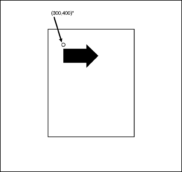
EN Raster Graphics 6-41
Figure 6-7 Example of Raster Graphic Image Data

6-42 Raster Graphics EN
Color Raster Graphics Example
This example demonstrates the Indexed by Pixel PEM of the CID
command. It produces a one inch wide by one half inch high image of
one inch high by 0.1 inch wide colored vertical bars. The pixels in the
image are eight byte indices, repeatedly ranging from 0 to 7, thus
giving the different colored vertical bars.
The PCL commands are decoded as follows:
In the textual equivalent of the PCL 5 commands shown below, the
following character representations are used:
• \e stands for the ASCII escape character
• \r is a carriage return
• \x00 to \x07 are the single byte, binary values from 00 to 07
PCL Command Description Command Arguments
<ESC>E Reset
<ESC>*v6W\x00\x01\x08\x
08\x08\x08 Configure Image Data Color space: device RGB
Pixel Encoding Mode:
indexed by pixel
Bits/Index: 8
Bits/Primary 1: 8
Pits/Primary 2: 8
Bits/Primary 3: 8
<ESC>*t600R Change graphics resolution 600
<ESC>*r600S Set Source Raster Width 600 pixel units
<ESC>*r300T Set Source Raster Height 300 pixel units
<ESC>*r0A Activate graphics mode
<ESC>*b0M Compression method unencoded
<ESC>*b#W Transfer raster data row (1) 600 bytes
<ESC>*b3M Compression method delta row
<ESC>*b#W Transfer raster data (299) 600 bytes
<ESC>*rC End raster graphics
<ESC>E Reset
EN Raster Graphics 6-43
Looking at the PCL commands, you'll notice that the first row is sent
unencoded and then the remaining rows replicated by switching to
delta row encoding and sending 299 zero rows. This method depends
on two features of the PCL 5 command set:
1The 1st row became the seed row at the end of the first row
transfer command.
2When in Delta Row compression mode, zero length transfers
cause the seed row to be replicated.
The first row is actually a good candidate for run length or TIFF pack
bits encoding but is not encoded for clarity.
\eE\r
\e*v6W\x00\x01\x08\x08\x08\x08\r
\e*t600R\e*r600S\e*r300T\e*r0A\e*b0M\r
\e*b600W\x00\x00\x00\x00\x00\x00\x00\x00\x00\x00\x00\x00\x00\x00\x
00\x00\x00\x00\x00\x00\x01\x01\x01\x01\x01\x01\x01\x01\x01\x01\x01\
x01\x01\x01\x01\x01\x01\x01\x01\x01\x02\x02\x02\x02\x02\x02\x02\x02
\x02\x02\x02\x02\x02\x02\x02\x02\x02\x02\x02\x02\x03\x03\x03\x03\x0
3\x03\x03\x03\x03\x03\x03\x03\x03\x03\x03\x03\x03\x03\x03\x03\x04\x
04\x04\x04\x04\x04\x04\x04\x04\x04\x04\x04\x04\x04\x04\x04\x04\x04\
x04\x04\x05\x05\x05\x05\x05\x05\x05\x05\x05\x05\x05\x05\x05\x05\x05
\x05\x05\x05\x05\x05\x06\x06\x06\x06\x06\x06\x06\x06\x06\x06\x06\x0
6\x06\x06\x06\x06\x06\x06\x06\x06\x07\x07\x07\x07\x07\x07\x07\x07\x
07\x07\x07\x07\x07\x07\x07\x07\x07\x07\x07\x07\x00\x00\x00\x00\x00\
x00\x00\x00\x00\x00\x00\x00\x00\x00\x00\x00\x00\x00\x00\x00\x01\x01
\x01\x01\x01\x01\x01\x01\x01\x01\x01\x01\x01\x01\x01\x01\x01\x01\x0
1\x01\x02\x02\x02\x02\x02\x02\x02\x02\x02\x02\x02\x02\x02\x02\x02\x
02\x02\x02\x02\x02\x03\x03\x03\x03\x03\x03\x03\x03\x03\x03\x03\x03\
x03\x03\x03\x03\x03\x03\x03\x03\x04\x04\x04\x04\x04\x04\x04\x04\x04
\x04\x04\x04\x04\x04\x04\x04\x04\x04\x04\x04\x05\x05\x05\x05\x05\x0
5\x05\x05\x05\x05\x05\x05\x05\x05\x05\x05\x05\x05\x05\x05\x06\x06\x
06\x06\x06\x06\x06\x06\x06\x06\x06\x06\x06\x06\x06\x06\x06\x06\x06\
x06\x07\x07\x07\x07\x07\x07\x07\x07\x07\x07\x07\x07\x07\x07\x07\x07
\x07\x07\x07\x07\x00\x00\x00\x00\x00\x00\x00\x00\x00\x00\x00\x00\x0
0\x00\x00\x00\x00\x00\x00\x00\x01\x01\x01\x01\x01\x01\x01\x01\x01\x
01\x01\x01\x01\x01\x01\x01\x01\x01\x01\x01\x02\x02\x02\x02\x02\x02\
x02\x02\x02\x02\x02\x02\x02\x02\x02\x02\x02\x02\x02\x02\x03\x03\x03
\x03\x03\x03\x03\x03\x03\x03\x03\x03\x03\x03\x03\x03\x03\x03\x03\x0
3\x04\x04\x04\x04\x04\x04\x04\x04\x04\x04\x04\x04\x04\x04\x04\x04\x
04\x04\x04\x04\x05\x05\x05\x05\x05\x05\x05\x05\x05\x05\x05\x05\x05\
x05\x05\x05\x05\x05\x05\x05\x06\x06\x06\x06\x06\x06\x06\x06\x06\x06
\x06\x06\x06\x06\x06\x06\x06\x06\x06\x06\x07\x07\x07\x07\x07\x07\x0
7\x07\x07\x07\x07\x07\x07\x07\x07\x07\x07\x07\x07\x07\x00\x00\x00\x
00\x00\x00\x00\x00\x00\x00\x00\x00\x00\x00\x00\x00\x00\x00\x00\x00\
x01\x01\x01\x01\x01\x01\x01\x01\x01\x01\x01\x01\x01\x01\x01\x01\x01
\x01\x01\x01\x02\x02\x02\x02\x02\x02\x02\x02\x02\x02\x02\x02\x02\x0
2\x02\x02\x02\x02\x02\x02\x03\x03\x03\x03\x03\x03\x03\x03\x03\x03\x
03\x03\x03\x03\x03\x03\x03\x03\x03\x03\x04\x04\x04\x04\x04\x04\x04\
x04\x04\x04\x04\x04\x04\x04\x04\x04\x04\x04\x04\x04\x05\x05\x05\x05
\x05\x05\x05\x05\x05\x05\x05\x05\x05\x05\x05\x05\x05\x05\x05\x05\e*
b3M\e*b0W\e*b0W\e*b0W\e*b0W\e*b0W\e*b0W\e*b0W\e*b0W\e*b0W\e*b
0W\e*b0W\e*b0W\e*b0W\e*b0W\e*b0W\e*b0W\e*b0W\e*b0W\e*b0W\e*b0
W\e*b0W\e*b0W\e*b0W\e*b0W\e*b0W\e*b0W\e*b0W\e*b0W\e*b0W\e*b0
6-44 Raster Graphics EN
W\e*b0W\e*b0W\e*b0W\e*b0W\e*b0W\e*b0W\e*b0W\e*b0W\e*b0W\e*b0
W\e*b0W\e*b0W\e*b0W\e*b0W\e*b0W\e*b0W\e*b0W\e*b0W\e*b0W\e*b0
W\e*b0W\e*b0W\e*b0W\e*b0W\e*b0W\e*b0W\e*b0W\e*b0W\e*b0W\e*b0
W\e*b0W\e*b0W\e*b0W\e*b0W\e*b0W\e*b0W\e*b0W\e*b0W\e*b0W\e*b0
W\e*b0W\e*b0W\e*b0W\e*b0W\e*b0W\e*b0W\e*b0W\e*b0W\e*b0W\e*b0
W\e*b0W\e*b0W\e*b0W\e*b0W\e*b0W\e*b0W\e*b0W\e*b0W\e*b0W\e*b0
W\e*b0W\e*b0W\e*b0W\e*b0W\e*b0W\e*b0W\e*b0W\e*b0W\e*b0W\e*b0
W\e*b0W\e*b0W\e*b0W\e*b0W\e*b0W\e*b0W\e*b0W\e*b0W\e*b0W\e*b0
W\e*b0W\e*b0W\e*b0W\e*b0W\e*b0W\e*b0W\e*b0W\e*b0W\e*b0W\e*b0
W\e*b0W\e*b0W\e*b0W\e*b0W\e*b0W\e*b0W\e*b0W\e*b0W\e*b0W\e*b0
W\e*b0W\e*b0W\e*b0W\e*b0W\e*b0W\e*b0W\e*b0W\e*b0W\e*b0W\e*b0
W\e*b0W\e*b0W\e*b0W\e*b0W\e*b0W\e*b0W\e*b0W\e*b0W\e*b0W\e*b0
W\e*b0W\e*b0W\e*b0W\e*b0W\e*b0W\e*b0W\e*b0W\e*b0W\e*b0W\e*b0
W\e*b0W\e*b0W\e*b0W\e*b0W\e*b0W\e*b0W\e*b0W\e*b0W\e*b0W\e*b0
W\e*b0W\e*b0W\e*b0W\e*b0W\e*b0W\e*b0W\e*b0W\e*b0W\e*b0W\e*b0
W\e*b0W\e*b0W\e*b0W\e*b0W\e*b0W\e*b0W\e*b0W\e*b0W\e*b0W\e*b0
W\e*b0W\e*b0W\e*b0W\e*b0W\e*b0W\e*b0W\e*b0W\e*b0W\e*b0W\e*b0
W\e*b0W\e*b0W\e*b0W\e*b0W\e*b0W\e*b0W\e*b0W\e*b0W\e*b0W\e*b0
W\e*b0W\e*b0W\e*b0W\e*b0W\e*b0W\e*b0W\e*b0W\e*b0W\e*b0W\e*b0
W\e*b0W\e*b0W\e*b0W\e*b0W\e*b0W\e*b0W\e*b0W\e*b0W\e*b0W\e*b0
W\e*b0W\e*b0W\e*b0W\e*b0W\e*b0W\e*b0W\e*b0W\e*b0W\e*b0W\e*b0
W\e*b0W\e*b0W\e*b0W\e*b0W\e*b0W\e*b0W\e*b0W\e*b0W\e*b0W\e*b0
W\e*b0W\e*b0W\e*b0W\e*b0W\e*b0W\e*b0W\e*b0W\e*b0W\e*b0W\e*b0
W\e*b0W\e*b0W\e*b0W\e*b0W\e*b0W\e*b0W\e*b0W\e*b0W\e*b0W\e*b0
W\e*b0W\e*b0W\e*b0W\e*b0W\e*b0W\e*b0W\e*b0W\e*b0W\e*b0W\e*b0
W\e*b0W\e*b0W\e*b0W\e*b0W\e*b0W\e*b0W\e*b0W\e*b0W\e*b0W\e*b0
W\e*b0W\e*b0W\e*b0W\e*b0W\e*b0W\e*b0W\e*b0W\e*b0W\e*b0W\e*rC\
eE\r
EN Color Vector Graphics (HP-GL/2) 7-1
7Color Vector Graphics
(HP-GL/2)
Introduction
The process involved in using HP-GL/2 with the HP Color LaserJet
family or DeskJet 1200C and 1600C color printers is nearly identical
with using HP-GL/2 on other color printers or plotters. However, these
two color printers add a few HP-GL/2 commands and expand the
functionality of some existing commands. This chapter describes
these commands and other pertinent points to keep in mind when
using HP-GL/2 with these color printers.
The HP-GL/2 commands explained in this chapter include the
following: The Merge Control (MC) command, which functions in a
similar way to the PCL logical operation command. The Pen Color
(PC) command, which modifies palette colors, the Number of Pens
(NP) command, which changes the palette size, the Pixel Placement
(PP) command, which determines how pixels are rendered in
HP-GL/2 polygons, and the Color Range (CR) command, which sets
the range for specifying relative color data (the CR command is not
supported by the HP Color LaserJet 4500 or 8500 printers).
In general, when using HP-GL/2 on the HP Color LaserJet family and
DeskJet 1200C and 1600C color printers, keep in mind that:
• Palette information stays the same when switching between
PCL 5 and HP-GL/2.
• The HP-GL/2 Initialize (IN) command sets the palette to the
default eight-pen palette, and also resets the ROP code (see
the MC command section later in this chapter) and the pixel
placement command.
• As with color plotters, to specify a particular color, you use the
SP (Select Pen) command.
If you are not familiar with using HP-GL/2, see the PCL 5 Printer
Language Technical Reference Manual.

7-2 Color Vector Graphics (HP-GL/2) EN
Enter HP-GL/2 Mode
This command causes the printer to interpret subsequent commands
as HP-GL/2 commands, instead of PCL printer language commands.
?%#B
As soon as the printer receives this command, it switches to HP-GL/2
mode, interpreting commands as HP-GL/2 commands until it receives
an Enter PCL Mode, ?E, or UEL command, or until the printer power
is switched off and on.
The value field (#) determines the cursor position once HP-GL/2
mode is entered.
Note HP Color LaserJet printers do not support ?%–1B, ?%2B, or
?%3B
•–1 — A value field of –1 creates a “single context” or
“stand-alone plotter” mode which has the following effects:
zThe current page is closed and printed and the HP-GL/2
environment is initialized (IN command).
zHP-GL/2 output begins on a new page.
zHP-GL/2 and PCL output cannot be combined on the
same page.
zNo PCL commands except ?E, ?%#A, and the PJL
command ?%-12345X are recognized by the printer.
zThe PCL picture presentation directives are ignored.
# = –1 - Stand-alone plotter mode (single context)
0 - Position pen at previous HP-GL/2 pen position
1 - Position pen at current PCL cursor position
2 - Use current PCL coordinate system and previous
HP-GL/2 pen position
3 - Use PCL dot coordinate system and the current PCL
CAP
Default =0
Range = 1 to 3 (unsupported negative values default to –1; all
other unsupported values are ignored)
EN Color Vector Graphics (HP-GL/2) 7-3
zThe ?%#A command closes HP-GL/2, prints the current
page, and performs an ?E before entering PCL.
zThe default HP-GL/2 orientation is reverse landscape.
zHard-clip limits are equal to the printable area.
zThe ?E command functions as usual.
When the single-context mode is used (?%–1B), the following steps
should be followed:
1Enter HP-GL/2 mode using the ?%–1B command.
2Transmit one or more HP-GL/2 drawings.
3Exit HP-GL/2 mode (?%#A).
•0 — This parameter option (?%0B) sets the pen position to
the previous HP-GL/2 position; if this is the first time HP-GL/2
mode is entered in the present print job (assuming an ?E has
been sent), the pen position is at the lower left corner of the
PCL Picture Frame (0,0).
•1 — This parameter option (?%1B) specifies that the pen
position and the label carriage return point become the same
as the current PCL cursor position.
•2 — ?%2B transfers the current PCL dot coordinate system
to HP-GL/2, including the PCL origin and axes, but uses the
previous HP-GL/2 pen position as the new pen position. Once
the PCL coordinate system is established with this command,
it is independent of the P1 and P2 positions.
•3 — This parameter option (?%3B) specifies that the pen
position and the label carriage return point become the same
as the current PCL cursor position. The current PCL dot
coordinate system and axes are also transferred to HP-GL/2;
once the PCL coordinate system is established with this
command, it is independent of the P1 and P2 positions.
When HP-GL/2 is entered using any dual-context mode (any variation
of the command except ?%-1B), the HP-GL/2 and PCL contexts can
be merged, resulting in the following:
• HP-GL/2 and PCL data can be combined on the same page.
• HP-GL/2 graphics can be integrated directly with text.
• The size and location of the PCL picture frame can be
specified.
• HP-GL/2 graphics can be scaled to fit within the picture frame.
7-4 Color Vector Graphics (HP-GL/2) EN
• The PCL palette and color configuration are transferred
between contexts.
• The current logical operation and pixel placement settings are
transferred between contexts.
• The current active position (CAP) is transferred between
HP-GL/2 and PCL (for ?%1B and ?%3B only).
• The PCL orientation determines the HP-GL/2 orientation.
In PCL mode, the Enter HP-GL/2 Mode command must be executed,
except when in display functions mode or within a binary data
transfer. HP-GL/2 ignores this command.
Default Settings when Entering HP-GL/2
When you enter HP-GL/2 mode, most vector graphics variables retain
their previous HP-GL/2 value. However, the following changes in the
PCL environment can affect the HP-GL/2 environment:
• Resetting the printer (?E or control panel reset):
zExecutes an IN (Initialize) command
zDefaults the PCL Picture Frame size
zDefaults the PCL Picture Frame anchor point
zDefaults the HP-GL/2 plot size
zDefaults the PCL logical page orientation
• A page size, page length, or orientation command:
zDefaults the PCL Picture Frame anchor point
zDefaults the PCL Picture Frame
zDefaults the HP-GL/2 plot size
zDefaults P1 and P2 (IP, IR commands)
zResets the soft-clip window to the PCL Picture Frame
boundaries (IW command)
zClears the polygon buffer (PM0, PM2)
zUpdates the cursor to the lower-left corner of the picture
frame (P1).
EN Color Vector Graphics (HP-GL/2) 7-5
• Redefining the PCL Picture Frame size or setting the anchor
point:
zDefaults P1 and P2 (IP, IR commands)
zResets the soft-clip window (IW) to the PCL Picture Frame
boundaries.
zClears the polygon buffer (PM0, PM2)
zUpdates the current pen position to the lower-left corner of
the picture frame (P1).
• Setting an HP-GL/2 plot size:
zChanges the picture frame scaling factor.
• Redefining the palette:
zChanges colors selected by the Select Pen (SP) command
and used in patterns defined by the Raster Fill Definition
(RF) command and/or used by the Fill Type (FT)
command.
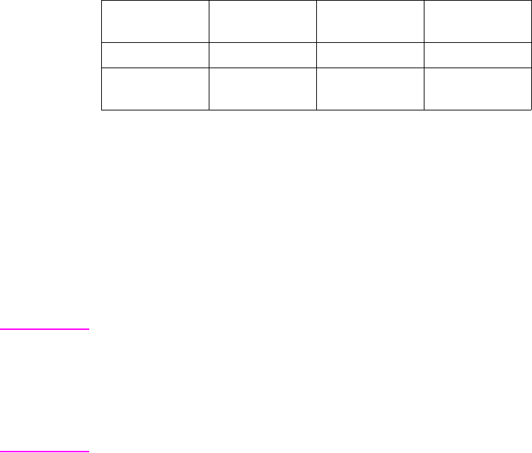
7-6 Color Vector Graphics (HP-GL/2) EN
MC (Merge Control)
The MC command controls the color of pixels where two or more
page marking primitives intersect on the page. This command
supports all 256 Microsoft Windows ternary (ROP3) raster operation
codes. A common application of the MC command is the rendering of
complex polygon fill patterns. Raster Operations specify how source,
destination, and patterns are combined to produce final images.
MC mode, [opcode][;]
•Mode — defines the merge control mode as follows:
Note This command is the HP-GL/2 version of the PCL Logical Operation
command.
This command sets a ROP value which affects not only HP-GL/2
operation but also the PCL ROP value.
The MC command is defaulted by an IN command.
Parameter Format Functional
Range Parameter
Default
mode clamped integer 0 or 1 0 (off)
opcode clamped integer 0 to 255 252 (mode=0),
168 (mode=1)
0 (off, default) Pixels in a primitive replace corresponding
destination pixels. If no opcode is specified,
252 is used.
1 (on) Pixels in a primitive merge with
corresponding destination pixels, creating a
new color based on the colors of the source
data and the contents of the destination
(frame buffer). If no opcode is specified,168
is used.

EN Color Vector Graphics (HP-GL/2) 7-7
•Opcode — Specifies the logical operations performed on a
source, destination, and pattern prior to drawing the final
image. These raster opcodes (ROPs) are listed on the
following pages in reverse polish notation (RPN) using the
following abbreviations:
D — Destination
S — Source
T — Texture
a — and
n — not
o — or
x — exclusive or
For example, when mode = 0, the opcode default is 252, which is the
logical function TSo (Texture OR Source).
The operation code (opcode) specifies the logical operations that are
performed on a source, destination, and patterned image prior to
drawing the final image. The opcodes are created by listing all
possible combinations of a single pattern, source and destination
pixel, and constructing the desired final pixel values. The following
table shows three common opcodes constructed by reading the
output values bottom up.
Pixel Combinations Desired Destination Values
Patter Pixel Source Pixel Destination
Pixel Source
Overwrite Transparency
(TR command) Source
Destination
000000
001011
010111
011110
100000
101011
110111
111110
Resulting Opcode 204 (0xCC) 238 (0xEE) 102 (0x66)

7-8 Color Vector Graphics (HP-GL/2) EN
Note When using the MC command, some pattern types will not produce
the expected ROP result. This only occurs when using the FT (Fill
Type) command pattern types 1, 2, 3, and 4, and when the ROP
includes an XOR operation. (This problem is due to the fact that these
patterns are the result of a vector operation and do not produce raster
data for use by a ROP operation.) All other Fill Type command
patterns (types, 10, 11, 21, or 22) operate as expected.
The MC command supports all 255 Microsoft Windows ROPS, which
are listed on the following page in reverse polish notation (RPN) using
the abbreviation listed above (D for Destination, S for Source, etc.).
Note See “Logical Operation Command” in Chapter 5 for usage and ROP
selection information.

EN Color Vector Graphics (HP-GL/2) 7-9
Table 7-1. Logical Operations (ROP3)
Input Value Boolean
Function Input Value Boolean
Function
0 0 27 SDTSxaxn
1 DTSoon 28 TSDTaox
2 DTSona 29 DSTDxaxn
3 TSon 30 TDSox
4 SDTona 31 TDSoan
5DTon32DTSnaa
6 TDSxnon 33 SDTxon
7 TDSaon 34 DSna
8 SDTnaa 35 STDnaon
9 TDSxon 36 STxDSxa
10 DTna 37 TDSTanaxn
11 TSDnaon 38 SDTSaox
12 STna 39 SDTSxnox
13 TDSnaon 40 DTSxa
14 TDSonon 41 TSDTSaoxxn
15 Tn 42 DTSana
16 TDSona 43 SSTxTDxaxn
17 DSon 44 STDSoax
18 SDTxnon 45 TSDnox
19 SDTaon 46 TSDTxox
20 DTSxnon 47 TSDnoan
21 DTSaon 48 TSna
22 TSDTSanaxx 49 SDTnaon
23 SSTxDSxaxn 50 SDTSoox
24 STxTDxa 51 Sn
25 SDTSanaxn 52 STDSaox
26 TDSTaox 53 STDSxnox

7-10 Color Vector Graphics (HP-GL/2) EN
Table 7-1. Logical Operations (ROP3) (continued)
Input Value Boolean
Function Input Value Boolean
Function
54 SDTox 81 DSTnaon
55 SDToan 82 DTSDaox
56 TSDToax 83 STDSxaxn
57 STDnox 84 DTSonon
58 STDSxox 85 Dn
59 STDnoan 86 DTSox
60 TSx 87 DTSoan
61 STDSonox 88 TDSToax
62 STDSnaox 89 DTSnox
63 TSan 90 DTx
64 TSDnaa 91 DTSDonox
65 DTSxon 92 DTSDxox
66 SDxTDxa 93 DTSnoan
67 STDSanaxn 94 DTSDnaox
68 SDna 95 DTan
69 DTSnaon 96 TDSxa
70 DSTDaox 97 DSTDSaoxxn
71 TSDTxaxn 98 DSTDoax
72 SDTxa 99 SDTnox
73 TDSTDaoxxn 100 SDTSoax
74 DTSDoax 101 DSTnox
75 TDSnox 102 DSx
76 SDTana 103 SDTSonox
77 SSTxDSxoxn 104 DSTDSonoxxn
78 TDSTxox 105 TDSxxn
79 TDSnoan 106 DTSax
80 TDna 107 TSDTSoaxxn

EN Color Vector Graphics (HP-GL/2) 7-11
Table 7-1. Logical Operations (ROP3) (continued)
Input Value Boolean
Function Input Value Boolean
Function
108 SDTax 135 TDSaxn
109 TDSTDoaxxn 136 DSa
110 SDTSnoax 137 SDTSnaoxn
111 TDSxnan 138 DSTnoa
112 TDSana 139 DSTDxoxn
113 SSDxTDxaxn 140 SDTnoa
114 SDTSxox 141 SDTSxoxn
115 SDTnoan 142 SSDxTDxax
116 DSTDxox 143 TDSanan
117 DSTnoan 144 TDSxna
118 SDTSnaox 145 SDTSnoaxn
119 DSan 146 DTSDToaxx
120 TDSax 147 STDaxn
121 DSTDSoaxxn 148 TSDTSoaxx
122 DTSDnoax 149 DTSaxn
123 SDTxnan 150 DTSxx
124 STDSnoax 151 TSDTSonoxx
125 DTSxnan 152 SDTSonoxn
126 STxDSxo 153 DSxn
127 DTSaan 154 DTSnax
128 DTSaa 155 SDTSoaxn
129STxDSxon156 STDnax
130DTSxna157DSTDoaxn
131 STDSnoaxn 158 DSTDSaoxx
132SDTxna159TDSxan
133 TDSTnoaxn 160 DTa
134 DSTDSoaxx 161 TDSTnaoxn

7-12 Color Vector Graphics (HP-GL/2) EN
Table 7-1. Logical Operations (ROP3) (continued)
Input Value Boolean
Function Input Value Boolean
Function
162 DTSnoa 189 SDxTDxan
163 DTSDxoxn 190 DTSxo
164 TDSTonoxn 191 DTSano
165TDxn192 TSa
166 DSTnax 193 STDSnaoxn
167 TDSToaxn 194 STDSonoxn
168 DTSoa 195 TSxn
169DTSoxn196STDnoa
170 D 197 STDSxoxn
171 DTSono 198 SDTnax
172 STDSxax 199 TSDToaxn
173DTSDaoxn200 SDToa
174 DSTnao 201 STDoxn
175DTno202DTSDxax
176 TDSnoa 203 STDSaoxn
177TDSTxoxn204 S
178 SSTxDSxox 205 SDTono
179 SDTanan 206 SDTnao
180 TSDnax 207 STno
181 DTSDoaxn 208 TSDnoa
182 DTSDTaoxx 209 TSDTxoxn
183SDTxan210TDSnax
184 TSDTxax 211 STDSoaxn
185DSTDaoxn212SSTxTDxax
186 DTSnao 213 DTSanan
187DSno214TSDTSaoxx
188 STDSanax 215 DTSxan

EN Color Vector Graphics (HP-GL/2) 7-13
Table 7-1. Logical Operations (ROP3) (continued)
Input Value Boolean
Function Input Value Boolean
Function
216 TDSTxax 236 SDTao
217 SDTSaoxn 237 SDTxno
218 DTSDanax 238 DSo
219STxDSxan239 SDTnoo
220 STDnao 240 T
221SDno241TDSono
222 SDTxo 242 TDSnao
223 SDTano 243 TSno
224 TDSoa 244 TSDnao
225TDSoxn245 TDno
226 DSTDxax 246 TDSxo
227TSDTaoxn247 TDSano
228 SDTSxax 248 TDSao
229TDSTaoxn249 TDSxno
230 SDTSanax 250 DTo
231 STxTDxan 251 DTSnoo
232 SSTxDSxax 252 TSo
233 DSTDSanaxxn 253 TSDnoo
234 DTSao 254 DTSoo
235DTSxno255 1

7-14 Color Vector Graphics (HP-GL/2) EN
PC (Pen Color)
This command changes the pen color in a palette created by the IN or
CID command (?*v#W). The PC command defaults the colors of all
pens as indicated in the table below.
PC [pen [,primary1, primary2, primary3;]]
or
PC [pen;]
or
PC[;]
•pen — specifies the number of the pen whose color is being
defined. An out-of-range pen parameter sets error 3 and the
command is ignored. (The range for the pen parameter is
determined by the size of the current color palette.)
•primary1, primary2, primary3 — specifies the primary
component values which are to be associated with that pen.
See the CR command description for the range associated
with the values. If a primary color is outside of the color range
defined in the CR command, the value is clamped to the color
range limits (the CR command is not supported by the
HP Color LaserJet 4500 or 8500 printers).
Parameter Format Functional
Range Parameter
Default
pen integer determined by NP see table
primary1,
primary2,
primary3
clamped real 0 to 255 (for those
printers supporting
the CR command,
the CR command
determines the
range)
see table
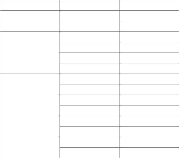
EN Color Vector Graphics (HP-GL/2) 7-15
The “PC;” command defaults the colors of all pens as shown in the
table below. The “PC pen;” command defaults the number of pens as
shown in the table on the following page for an HP-GL/2 palette.
When color device palettes larger than 8 pens default, the first 8 pen
colors are as defined for a palette of 8; all remaining pen colors are
device- dependent. If the palette is a non-default palette, it defaults in
accordance with the default palettes in Chapter 4.
For black and white printers that accept color descriptions and
palettes, pen 0 defaults to white; all remaining pen colors default to
“equivalent gray levels.” An equivalent gray level means that lighter
colors (for example, yellow) are converted to light gray shades, and
darker colors (for example, purple) are converted to dark gray shades.
The mapping algorithm is device-dependent. However, equivalent
gray levels represent solid colors, and any white pixels within them
are not subject to transparency mode (TR).
No. of Pens in Palette Pen Number Color
2 (“NP 2;”) 0 White
1Black
4 (“NP 4;”) 0 White
1Black
2Red
3Green
8 (“NP 8;”) 0 White
1Black
2Red
3Green
4Yellow
5Blue
6 Magenta
7Cyan

7-16 Color Vector Graphics (HP-GL/2) EN
Note In the “shading” Fill Type command (FT10;), the shading levels are
mapped between white (0% shading) and the equivalent gray level for
the currently selected pen (100% shading). In the “HP-GL/2
user-defined” Fill Type command (FT11;), each pixel in the RF pattern
is rounded to white or black based on the equivalent gray level of the
pen number for that pixel. This rounding should use a low enough
white/black threshold so that yellow will round to black.
For a black and white device, pen 0 defaults to white; all remaining
pen colors default to black.
This command is ignored if the current palette was created by the
Simple Color command (?*r#U). An IN command defaults pen colors
as indicated in the previous table.
EN Color Vector Graphics (HP-GL/2) 7-17
NP (Number of Pens)
The NP command resizes the palette after the IN or ?*v#W
commands.
NP [n;]
or
NP[;]
* The default palette size for the HP color printers is 8.
•n — the parameter n denotes the size of the HP-GL/2 palette,
where n is a power of two. If n is not a power of two, the next
larger power of two is used. The palette is an array of virtual
pens, each having an associated color value and an
associated width. Pen colors are defined in terms of RGB
components using the PC command. Widths are established
using the PW and WU commands. A pen is selected with the
SP command.
The maximum value for n is device-dependent, but is greater than or
equal to the number of distinct colors the printer is able to produce. If
n is larger than that maximum, the maximum-sized palette is
allocated. If n < 2, error 3 is set and the command is ignored.
The “NP;” command defaults the palette size. Receipt of this
command does not default pen colors and/or widths for existing pen
values. For example, if the palette size is initially 8 and is decreased
to 4, pen colors and widths for the new palette are retained from the
colors and widths of the first 4 pens of the old palette. If the palette
size is increased from 8 to 16, the colors and widths for the first 8
pens remain the same, and the colors and widths of the remaining
pens are defaulted. The pens are defaulted in accordance to how the
palette was created (either CID or Simple Color palettes).
Parameter Format Functional
Range Parameter
Default
n clamped
integer 2 to 32768 device-dependent*
7-18 Color Vector Graphics (HP-GL/2) EN
If the currently selected pen is outside the range of the new palette
size, the SP command modulo function is applied to obtain a pen
number which will index into the new palette; this clears the current
residue (the unused portion of a pattern) and terminates any
sequence of continuous vectors. For more information, see the
descriptions of the Line Attribute (LA) and Line Type (LT) commands
in the PCL 5 Printer Language Technical Reference Manual.
The number of pens is defaulted by an IN command.
This command is ignored if the current palette was created by the
Simple Color command (?*r#U) or ?E.

EN Color Vector Graphics (HP-GL/2) 7-19
CR (Color Range)
The CR command sets the range for specifying relative color data.
Note This command is only supported by the HP Color LaserJet, Color
LaserJet 5, 5M, and DeskJet printers. It is not supported by the
HP Color LaserJet 4500 or 8500 printers.
CR [b_ref_red, w_ref_red, b_ref_grn, w_ref_grn, b_ref_blue,
w_ref_blue;]
Relative color is in reference to a range defined by a black and white
reference value for each primary (red, green, and blue). For example,
if the white reference is set as red=63, green=63, blue=63, and the
black references are set as red = 0, green = 0, and blue = 0, then
white = 63, 63, 63; black = 0, 0, 0; and medium blue = 0, 0, 31.
However, if the white reference is set as red = 63, green = 127, blue =
31 and the black reference is set as red = 4, green = 0, and blue = 0,
then white = 63, 127, 31; black = 4, 0, 0; and medium blue = 4, 0, 15.
The first two parameters set the black and white references
(respectively) for red; the second pair sets the green references, and
the final pair the blue reference values. If the black reference value for
any primary is equal to the white reference value for the same
primary, the command is ignored.
The default for red, green, and blue “black references” is 0; the default
for red, green and blue “white references” is 255.
This command is defaulted by the “CR;” and IN commands.
Execution of this command causes current pen colors to be
remapped to the new range, so that current palette colors remain
unchanged.
Parameter Format Functional
Range Parameter
Default
b_ref (red,
green, blue) clamped real -32768 to 32768 0
w_ref (red,
green, blue) clamped real -32768 to 32768 255
7-20 Color Vector Graphics (HP-GL/2) EN
PP (Pixel Placement)
When printing, the printer places pixels at the intersection of the
squares of a theoretical, device-dependent grid covering the printable
area on a page. When the sides of two HP-GL/2 polygons touch each
other, the pixels along the border may be printed twice or not at all—
depending on the logical operation in effect. For example, if a source
rectangle consisting of all 1's is XORed with a destination consisting
of all 1’s, a white rectangle is printed. If another source rectangle is
placed on the page touching the first rectangle, the two rectangles are
white-filled except at their common border: that is, (1^1)^1 = 1.
To correct this situation, two models of pixel placement are used: grid
intersection and grid centered. The grid intersection model is the
default: pixels are rendered on the intersections of the
device-dependent grid covering the page. In the grid-centered model,
the number of rows and columns are each reduced by one, and pixels
are placed in the center of the squares, rather than at the
intersections.
The following example illustrates the concepts of the two models.
Assume a rectangle extends from coordinate position (1,1) to position
(3,4). As shown below, for the same coordinates, the grid-centered
model produces a rectangle that is one dot row thinner and one dot
row shorter than the grid intersection model. Thus, when two or more
polygons on a page share a common border, grid centering (value=1)
can be turned on.
Since PCL printers print only at the intersections of the grid, the
actual implementation of the grid-centered model is also shown in the
following illustration.
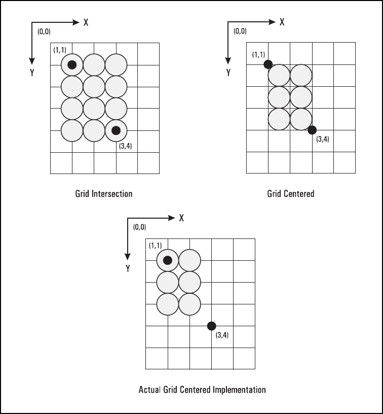
EN Color Vector Graphics (HP-GL/2) 7-21
Figure 7-1 Pixel Placement
7-22 Color Vector Graphics (HP-GL/2) EN
PP, Pixel Placement Command
The Pixel Placement (PP) command controls how pixels are placed
on the layout grid during polygon fills. The two pixel placement modes
are grid intersection or grid centered.
PP [mode;]
•mode
When the printer is set to grid-centered mode (mode 1), portions of a
polygon that are zero height or zero width are not rendered. When the
printer is set to grid intersection mode (mode 0), portions that are
zero height or width are rendered as lines. Portions that are both zero
height and width are rendered as dots.
This command affects only HP-GL/2 polygons; it has no effect on
characters, rules, or raster graphics. This command can be invoked
multiple times during a page; it has no effect except to switch the
model used for imaging.
This command is the HP-GL/2 version of the PCL Pixel Placement
command. Whatever mode is selected, using the HP-GL/2 PP
command also applies to PCL operation. Likewise the PCL Pixel
Placement command also affects HP-GL/2 pixel placement.
Note Microsoft Windows fills polygons based on the grid- centered method.
This command determines how pixels will be placed for both HP-GL/2
and PCL operation.
The PP command is not defaulted by an IN command.
Parameter Format Functional
Range Parameter
Default
mode clamped integer 0 or 1 0 (grid
intersection)
0 grid intersection; device draws pixels centered at grid
intersections (see Figure 7-1).
1 grid centered; device draws pixels centered inside the
boxes created by the grid (see Figure 7-1).

EN Color Printing Overview (Color LaserJet, 5, 5M, DeskJet) A-1
AColor Printing
Overview
(Color LaserJet, 5, 5M,
DeskJet)
Introduction
This appendix provides an overview of the way color is used in the
HP Color LaserJet, Color LaserJet 5, 5M, DeskJet 1200C, and
DeskJet 1600C printers. It previews the remaining appendices, which
describe the specific details of Hewlett-Packard color printing.
Note The features described in these appendices are a superset of those
supported by the HP Color LaserJet, Color LaserJet 5, 5M and
DeskJet printers. Some features are supported on one or more
printers, but not necessarily on all of them. See the PCL 5
Comparison Guide for specific feature support for each printer.
Processing a color document involves specifying a palette or palettes,
and then using the colors within the current palette to print. For
non-raster printing, items such as text, rules, and vectors are simply
printed in the currently active color, which is specified using the
Foreground Color command or Select Pen command if in HP-GL/2.
For raster printing, the color of each pixel is specified as either a
direct color specification, or as an index into the palette, depending on
the pixel encoding mode.
The PCL Print Model determines how color is applied to the page.
The printed result can vary in background and texture depending on
the source transparency mode, pattern transparency mode, and
selected logical operation (ROP). Besides the pre-defined shading
and patterns, users can define new monochrome or multicolor
patterns.
A-2 Color Printing Overview (Color LaserJet, 5, 5M, DeskJet) EN
When printing color pages, a user can choose one of several color
modes, depending on the desired results. Each color mode has a
palette associated with it. Simple Color Mode provides a palette of
fully saturated colors whose colors are similar to those of a plotter’s
pen colors. The palette is nonprogrammable, and is intended for
simple printing of items such as bar and pie charts. For applications
requiring different or more specific colors, the printer offers the PCL
Imaging and HP-GL/2 Imaging Modes. The palette colors in these two
modes can be modified to provide the desired result.
When choosing color for a particular application, the Color LaserJet
printer provides device-dependent and device-independent color (the
DeskJet 1200C and 1600C support only device-dependent color).
Device-independent color provides accurate color matching based on
an absolute color standard. It is preferred when users want a precise
color to match the output from another device or to match the color on
an existing page.
Besides providing device-independent color for precise color
matching, the HP printers can modify color to compensate for various
characteristics. The Color LaserJet printer supports the following
methods of modifying color (the DeskJet 1200C and 1600C printers
support halftone algorithms and gamma correction, but not color
lookup tables or the Viewing Illuminant command).
•Halftone render algorithms determine how colors are rendered
using the printers available colors. Halftone algorithms can be
used to change apparent resolution, change the texture of
images, reduce the number of colors, and change a color
image to monochrome.
•Color lookup tables can remap colors to compensate for
various differences in input data, such as unwanted color casts
caused by unbalanced photographic light sources.
•Gamma correction provides a way to adjust for color
differences in display monitors so that the display more closely
matches the printed output.
• Since the appearance of colors changes under different
viewing light sources, the Viewing Illuminant command allows
the application to modify output color based on the light source
used to view the printed page.
EN Color Printing Overview (Color LaserJet, 5, 5M, DeskJet) A-3
Color Concepts
This section describes some of the concepts and terminology used in
this chapter, such as palettes, raster vs. non-raster color,
device-independent vs. device-dependent color, black and white
references, color selection, pixel encoding, and color modes.
Palettes
A palette is a collection of colors that are selected by their index
numbers. You can create your own palette or choose from one of
several fixed palettes. Although only one palette is active at any time,
all palettes are assigned ID numbers and can be stored in the printer
for later selection using the ID number. They can be deleted when
desired. Palettes can also be saved (pushed) to a stack and later
retrieved (popped) when needed.
Raster Mode
Raster mode is entered explicitly by the Start Raster command
(?*r#A) or implicitly by a Transfer Raster command (?*b#V,
?*b#W). Raster mode is exited explicitly by an End Raster command
(?*rC) or implicitly by a non-raster command.
Raster Color vs. Non-Raster Color
Palettes are used differently depending on whether the printer is in
raster mode.
• In non-raster mode, the palette is always used for color
selection. The color of text or patterns is specified using the
Foreground Color command (?*v#S).
• In raster mode, the palette is only used for indexed color
selection; it is not used for direct color selection. (Indexed and
direct color selection are explained later in this section.)
A-4 Color Printing Overview (Color LaserJet, 5, 5M, DeskJet) EN
Device-Dependent vs. Device-Independent
Color
Device-dependent color spaces are relative to the device’s ability to
produce specific colors. For example, if red is specified in a
device-dependent color space, two different printers will combine the
same amounts of cyan, magenta, yellow, and black toner to produce
the color, but the results will be different because of the different
properties of the toner.
Device-independent color is specified absolutely, in a color coordinate
system that is independent of any device. For example, if red is
specified in a device-independent color space, two printers will always
produce the same result, even though they may need to combine
different amounts of cyan, magenta, yellow, and black toner. Printers
that produce device-independent color are calibrated to precise color
standards.
Black and White References
Device-dependent color specifications are based upon an arbitrary
range of values for each primary color component. The range
endpoints for each color component are called black and white
references for that component. Colors relative to these predefined
limits are derived by specifying the amount of each component.
For the Device RGB color space, the maximum limit is called the
white reference and the minimum limit is called the black reference.
Regardless of the number chosen, the white reference represents the
maximum value of a primary color that a device can produce, and the
black reference represents the minimum value of that primary color.
For example, if 100 is chosen as the white reference for red in the
RGB color model, it represents the reddest red the device can
produce. If 10 were chosen instead, then 10 would represent the
same red.
EN Color Printing Overview (Color LaserJet, 5, 5M, DeskJet) A-5
Example:
Assuming the white and black references are set as follows:
Scenario 1
Scenario 2
Using these reference values, 50% blue for scenario 1 is 31, and 50%
blue for scenario 2 is 15.
Color Selection
The HP color printers offer two methods for selecting colors:
• Indexed selection
• Direct selection
In indexed selection, colors are chosen using their palette index
numbers. For non-raster mode, the palette index number is specified
using the Foreground Color command. In raster mode, the data bit
combination for each pixel forms an index number. The example
below shows how the index numbers for an 8-color palette are
specified:
White Reference Black Reference
red = 63 red = 0
green = 63 green = 0
blue = 63 blue = 0
White Reference Black Reference
red = 63 red = 4
green = 127 green = 0
blue = 31 blue = 0
Three-bit combinations: 0 1 0 1 0 1 0 1
0 0 1 1 0 0 1 1
0 0 0 0 1 1 1 1
Palette index number: 0 1 2 3 4 5 6 7

A-6 Color Printing Overview (Color LaserJet, 5, 5M, DeskJet) EN
The number of colors in the palette dictates the number of bits per
pixel of raster data required to specify an index number. For example,
to specify 256 colors you need to send 8 bits of raster data per pixel
(28 = 256).
In direct selection, colors are specified using the proportions of their
primary components. For example, using a 24-bit-per- pixel
representation, the color specified by (0xff, 0xf0, 0x00) for red, green,
and blue would print a slightly red-tinted yellow. A palette is not used
for direct selection.
Pixel Encoding
Colors are encoded in a row of raster data using either plane or pixel
format. In planar format, all the pixels in a row are partially specified
by one plane (bit) before the next plane is sent. In pixel format, each
pixel is fully specified before sending the next pixel.
Encoding by Plane
Planar encoding uses successive data planes, each providing one bit
for each pixel in a row. Each plane builds upon the preceding planes
until the pixels in a row are fully defined. A pixel is not fully defined
until it has received all the planes for that row.
The planes in a row form index numbers that define a pixel by
selecting a palette entry. For example, an 8-entry palette requires
3planes (2
3 = 8). The underlined bits below compose the index of the
color of the third pixel in the first row.
?*b#V row 1 plane 1 (red) b1 b1 b1 b1 b1 b1 . . .
?*b#V plane 2 (grn) b2 b2 b2 b2 b2 b2 . . .
?*b#W plane 3 (blue) b3 b3 b3 b3 b3 b3 . . .
?*b#V row 2 plane 1 (red) b1 b1 b1 b1 b1 b1 . . .

EN Color Printing Overview (Color LaserJet, 5, 5M, DeskJet) A-7
Encoding by Pixel
When encoding by pixel, each pixel is fully specified before any bits
are sent for the next pixel. For example, if four bits are needed to
define a pixel, then every group of four bits in the data stream defines
a pixel. The underlined (c4 . . . c1) group below defines the second
pixel in the first row.
The table below shows the four PCL options for selecting colors and
encoding color raster data.
Color Modes
There are four PCL 5 color modes:
• Black and White mode
• Simple Color mode
• PCL Imaging mode
• HP-GL/2 Imaging mode
All four modes create a palette. The palettes used in the Black and
White mode and Simple Color mode are not modifiable. You can,
however, modify the palettes in the PCL Imaging and HP-GL/2
Imaging modes.
You can use more than one mode on the same page. For example,
you could enter the Simple Color mode to print a headline and a bar
chart, PCL Imaging mode to print a raster photograph, and Black and
White mode to print some body text. Each mode is described in more
detail in Appendix B, “Using Color Modes.”
?*b#W row 1 b4 b3 b2 b1 c4 c3 c2 c1 . . .
?*b#W row 2 b4 b3 b2 b1 . . .
Planar Encoding Pixel Encoding
Indexed
Selection Indexed planar Indexed pixel
Direct
Selection Direct planar Direct pixel
A-8 Color Printing Overview (Color LaserJet, 5, 5M, DeskJet) EN
Device-Dependent Color Spaces
The following PCL commands can alter color processing for
device-dependent color spaces:
• Rendering Algorithm (?*t#J)
• Gamma Correction (?*t#I)
• Color Lookup Tables (?*l#W)
• Configure Image Data (?*v#W)
•Simple Color (
?*r#U)
• Monochrome Print Mode (?&b#M)
Color lookup tables or gamma correction (which are mutually
exclusive) can modify the mapping of input to output.
Device-Independent Color Spaces
The following PCL commands can alter color processing for
device-independent color spaces:
• Rendering Algorithm (?*t#J)
• Gamma Correction (?*t#I)
• Color Lookup Tables (?*l#W)
• Configure Image Data (?*v#W)
• Viewing Illuminant (?*i#W)
• Monochrome Print Mode (?&b#M)
Device-independent color spaces are supported under the following
conditions:
1The Configure Image Data command (?*v#W) configures the
current palette and specifies a device-independent color space.
2The Render Algorithm command (?*t#J) is set to one of the
following algorithms (see “Halftone Render Algorithms” in
Appendix D for details):
• Continuous tone detail (?*t0J, ?*t16J)
• Continuous tone smooth (?*t15J, ?*t17J)
• Continuous tone basic (?*t18J, ?*t19J)
• Device best dither (?*t3J, ?*t5J)
• Error Diffusion (?*t4J, ?*t6J)
EN Color Printing Overview (Color LaserJet, 5, 5M, DeskJet) A-9
• Cluster Ordered Dither (?*t7J, ?*t8J)
• Ordered Dither (?*t11J, ?*t12J)
Color processing reverts to device-dependent processing if the
render algorithm is changed from one of the above. This is because
extensive device characterization is necessary to achieve
device-independence—calibration must be based on known
parameters that affect the device's color gamut. Render algorithms
such as Snap to Primaries (?*t1J), Snap Black to White and Colors
to Black (?*t2J), or User-Defined Halftone (?*t9J) either limit the
number of colors available, or are undefined to the extent that their
performance is not as precise. These algorithms, therefore, produce
device-dependent results. Device-independent color is again
generated if the render algorithm changes to one of the 5 listed above
and the color space has not changed.
A-10 Color Printing Overview (Color LaserJet, 5, 5M, DeskJet) EN
Device-Independent Color
The PCL language characterizes color as either device-dependent or
device-independent. Both categories encompass many color spaces,
each with unique characteristics.
Device-Dependent Color
Device-dependent color is relative to the device's inherent
characteristics. For example, the colors produced by plotters are
relative to the color of the installed plotter pens. Pen color varies
considerably, especially as pens wear out, changing the color of the
output. Likewise, for monitor screens, the red, green, and blue screen
phosphors determine the colors produced. Fully saturated colors can
vary greatly between screens. For printers, the color produced on a
page depends on the printer’s subtractive inks or toner (cyan,
magenta, yellow, and black).
When using device-dependent color, devices receiving relative color
specifications for the same color frequently do not produce the same
color. For example, a monitor’s saturated red may be different than a
plotter’s. In short, the same color page may appear considerably
different on different devices.
The HP color printers provide device-dependent color specified using
either the Device RGB or CMY color spaces.
Device-Independent Color
In contrast with device-dependent color, device-independent color is
based on an absolute color standard—the tristimulus values of
human vision. The device, whether a printer or otherwise, is
calibrated to match an independent color specification. The color
specification is translated in such a way that the resultant color is
independent of the device. Examples of color spaces based on
absolute standards include Kodak Photo YCC, CIE L*a*b*, YUV, and
the proposed YCrCb. Each is a transform from tristimulus CIE XYZ
space.
EN Color Printing Overview (Color LaserJet, 5, 5M, DeskJet) A-11
With proper calibration, any device can provide a transform from
device-independent color space to the device’s own color space,
producing output from different devices that have the same color
appearance. For example, if a monitor’s parameters are known
(gamma, gain, chromaticity coordinates for each primary, and the
white point), the monitor’s RGB pixel information can be transformed
into device-independent color.
The Color LaserJet printers provide device-independent color
specified using either the CIE L*a*b*, Colorimetric RGB, or
Luminance-Chrominance color spaces.
HP Color LaserJet 5 and 5M printers also provide device independent
color specified using either the CIE L*a*b*, Colorimetric RGB or
Luminance-Chrominance color spaces. However, HP Color
LaserJet 5 and 5M printers are somewhat restricted in what they
provide. Details of this can be found in Appendix D.
Color Matching
When attempting to match color produced by different devices, it is
important to know the difference between true color matching and
appearance matching.
Proper device calibration can achieve true color matching, so that a
side-by-side comparison of a printed page with the monitor on which
the page was designed will show an exact match. However, true color
matching is only satisfactory when using the monitor as a viewing
reference. Viewed away from the screen, the printed page may
appear flat and unsaturated because printers and monitors have
different dynamic ranges. For example, black on the screen appears
gray when compared to printed black, which is unacceptable if the
intent is pure black. Likewise, the white produced on a monitor screen
appears yellow or blue when compared to a white sheet of paper.
True color matching would require that gray be printed in the black
areas and colored dots be printed in the white areas.
A-12 Color Printing Overview (Color LaserJet, 5, 5M, DeskJet) EN
Color Appearance Matching
Color appearance matching goes beyond true color matching by
including adjustments for the dynamic ranges of the devices, so the
user's intent is maintained. For example, the white areas of a page
shown on a monitor display screen would be printed as white on a
printed page because the user specified white, even though the
screen cannot duplicate a white that truly matches white paper.
Although the printed color does not exactly match screen color, color
appearance does match, which is what users usually want. To
maximize user satisfaction, the PCL language uses appearance
matching when rendering device-independent color.
Color Lookup Tables
Color lookup tables, which provide additional control of the printed
output, are transformations that map input data into a new output
color range based upon point-by-point conversions.
Overhead transparencies provide one example of a good use for color
lookup tables. Let’s say a page is printed on plain paper and it
matches the user’s expectations. When printing the same document
on overhead transparency film, the resulting image looks unsaturated
and flat. To compensate, the user can send a color lookup table to
increase color saturation without changing composition (for example,
using the CIE L*a*b* color space to increase the a* and b*
parameters in equal amounts).
Color lookup tables can also be used to adjust data from a Kodak
CD-ROM, which uses the Photo YCC device- independent color
space. The gamma correction table is complex and cannot be
described by the traditional logarithmic expression. However, since
the data can be mapped into new data values via tables, the user can
provide a gamma correction table that essentially describes the
complex correction factors.
Color lookup tables can be used to “neutral-balance” an image. For
example, an underwater photograph produces a severe bluish cast
when printed. The user can eliminate that cast from the image by
providing a color lookup table that subtracts some color portion from
each of the primaries.
EN Color Printing Overview (Color LaserJet, 5, 5M, DeskJet) A-13
Illumination Models
Illumination sources have different spectral distributions, causing
colors to appear differently under one light source compared to
another. For example, printed colors that look normal in natural
sunlight shift in hue when viewed under fluorescent and tungsten
lighting. The PCL language allows the user to compensate for the
differences in viewing illumination using the Viewing Illuminant
command. It allows the user to select different illuminations.
A-14 Color Printing Overview (Color LaserJet, 5, 5M, DeskJet) EN
Processing Color Documents
To process a color page, PCL provides ways of specifying and
modifying color so that the printed result appears as the user desires.
This section provides a conceptual overview of the process.
Non-Raster Color vs. Raster Color
All color portions of a page consist of either:
• Page Marking Primitives (non-raster data)
• Color Raster Data
Page Marking Primitives
Non-raster data consists of HP-GL/2 and PCL page marking
primitives such as glyphs, rules, polygons, circles, and vectors. Page
marking primitives contain no color information about the image. They
merely mark the page with attributes assigned to the current working
environment (for example, colors, patterns, logical operation modes,
etc.). Page marking primitives act as stencils through which color
“paint” is poured, forming a homogeneous pattern.
Page marking primitives print in the currently specified color, which is
specified using the Foreground Color command. For example, if you
specify the color blue using the Foreground Color command, and then
send some text to the printer, the text will be printed blue.
Color Raster Data
Unlike page marking primitives, each pixel of a color raster image
contains color information. A color raster pixel may be defined by
either:
• Palette Entry Indices
• Direct Color Specifications
User-defined color patterns are a form of color raster, but each pixel
of a user-defined color pattern can be defined only by palette entry
indices, not by direct color specifications.
EN Color Printing Overview (Color LaserJet, 5, 5M, DeskJet) A-15
Color Processing Functions
Given these two color uses, page marking primitives and color raster
data, color processing must:
• Convert color attributes to an internal representation that can
be poured through the page marking stencil onto the
destination via some logical operation.
• Convert multiple-bit-per-pixel color raster to an internal
representation that can be merged into the destination via
some logical operation.
Color processing must have access to the following state variables,
which indicate the form and attributes by which the two color groups
are generated.
• Halftone (rendering algorithm)
• RGB gamma correction
• Device-dependent color lookup tables for each of the three
primaries
Appendix B describes in more detail how color raster data is
specified.
A-16 Color Printing Overview (Color LaserJet, 5, 5M, DeskJet) EN
EN Using Color Modes (Color LaserJet, 5, 5M, DeskJet) B-1
BUsing Color Modes
(Color LaserJet, 5, 5M,
DeskJet)
This appendix describes how color commands were supported on the
following printers:
• HP Color LaserJet, Color LaserJet 5 / 5M
• HP DeskJet 1200C and 1600C
Since then, the PCL 5 color command set has been simplified as
described in Chapter 1. Appendices A through D and Chapters 5
through 7 describe the color commands as they were supported for
these printers.
B-2 Using Color Modes (Color LaserJet, 5, 5M, DeskJet) EN
Introduction
The PCL printer language has four color modes:
• Black-and-White
•Simple Color
• PCL Imaging
• HP-GL/2 Imaging
PCL allows you to use any mode or combination of modes to
accomplish your printing objectives most efficiently.
All four of the color modes create a palette. The palette for each mode
is discussed in the section describing that mode, and also in
Appendix C (“Using Palettes”).
Black-and-White Mode (Default)
Black-and-White Mode is the default color mode. PCL devices power
up in this mode and revert back to it whenever the printer receives an
?E reset. Black-and-White mode is also selectable using the Simple
Color command (?*r1U). This mode creates an unmodifiable, default
2-pen palette, with white at index 0 and black at index 1 (compatible
with existing monochrome PCL 5 printers).
Simple Color Mode
Simple Color Mode, entered by the Simple Color command (?*r#U),
creates a fixed-size, fixed-color, unmodifiable palette. Depending on
the value field, ?*r#U can create a 2-pen Black-and-White palette,
an 8-pen RGB palette, or an 8-pen CMY palette. When using the
Simple Color mode, the pixel encoding mode is always indexed
planar.
PCL Imaging Mode
PCL Imaging Mode, enabled by the Configure Image Data command
(?*v#W), allows a maximum of 24 bits per pixel for color
specification. Therefore, more colors (produced by halftoning) may be
specified than are obtainable in Simple Color Mode. In the PCL
Imaging Mode, pixel encoding mode, bits per pixel, bits per primary,
white/black references, and the color palette are all programmable.
EN Using Color Modes (Color LaserJet, 5, 5M, DeskJet) B-3
HP-GL/2 Imaging Mode
In HP-GL/2, the Initialize (IN) command starts color imaging and
performs the following:
• Sets the pixel encoding mode to index by plane.
• Sets bits per index to 3.
• Creates an 8-pen palette that is reprogrammable in either PCL
or HP-GL/2 contexts (see Appendix C, “Using Palettes,” for
more information).
Although default HP-GL/2 palettes are different than default PCL
palettes, an HP-GL/2 palette is modifiable in either PCL or HP-GL/2
(using the Assign Color Index [?*v#I] or Pen Color [PC] commands,
respectively). Likewise, a PCL palette created by the Configure Image
Data command (?*v#W) is modifiable in both PCL and HP-GL/2
using the same commands.
The active palette is always transferred between HP-GL/2 and PCL
contexts. Since only one palette at a time can be active, a new palette
created in either context overwrites the current palette.
B-4 Using Color Modes (Color LaserJet, 5, 5M, DeskJet) EN
Simple Color Mode
The Simple Color command (?*r#U) specifies color selection from a
fixed palette. RGB or CMY raster data must be sent by plane
(?*b#V) as well as by row (?*b#W). The last plane in each row is
sent using the ?*b#W command; all other planes are sent using the
?*b#V command. In Simple Color mode, the pixel encoding mode is
always indexed planar.
Simple Color
Command
The Simple Color command creates a fixed-size palette, whose color
specification cannot be modified.
?*r#U
The absolute value of the value field specifies the number of planes
per row of raster data to be sent. The number of entries in the new
palette is 2n, with index values 0 to 2n – 1. For example, a 3-plane
palette has 8 entries, with index numbers 0 to 7.
This command destroys the active palette and creates a new palette,
which becomes the active palette. When the Simple Color mode is
active, PCL and HP-GL/2 commands that modify the palette are
locked out (NP, PC, ?*v#A, ?*v#B, ?*v#C, ?*v#I). When a Simple
Color palette is popped from the stack (?*p#P), it cannot be
modified, and the pixel encoding mode reverts to indexed planar.
• A value field of 1 creates a 2-entry Black-and-White default
palette.
• A value field of 3 creates an 8-entry Device RGB palette
(compatible with a PCL Imaging Mode palette, but not an
HP-GL/2 default (IN) palette).
• A value field of –3 creates an 8-entry palette in Device CMY
color space.
# = –3 - 3 planes, device CMY palette
1 - Single plane K (Black) palette
3 - 3 planes, device RGB palette
Default =1
Range =–3, 1, 3
EN Using Color Modes (Color LaserJet, 5, 5M, DeskJet) B-5
The Simple Color palettes are shown below:
Single Plane (value = 1)
3-Plane RGB (value = 3)
3-Plane CMY (value = –3)
Index Color
0White
1Black
Index Color
0Black
1Red
2 Green
3Yellow
4Blue
5 Magenta
6Cyan
7White
Index Color
0White
1Cyan
2 Magenta
3Blue
4Yellow
5 Green
6Red
7Black
B-6 Using Color Modes (Color LaserJet, 5, 5M, DeskJet) EN
PCL Imaging Mode
The PCL Imaging mode, entered using the Configure Image Data
(CID) command (?*v#W), creates a variable-sized programmable
palette. It provides halftoning in the printer, with multiple color spaces,
pixel encoding modes, and reprogrammable palettes.
Configure Image Data (CID) Command
The CID command provides configuration information for creating
palettes and transmitting raster data. The CID command performs the
following:
• Designates the color space for the default palette
• Designates the size of the palette to be created
• Provides data for transforming color-space-specific values into
device-specific values
• Provides data for transforming device-dependent data (monitor
RGB) to device-independent (Colorimetric RGB)
• Designates the format of raster data and how primary
components are combined to yield the raster representation
?*v#W[binary data]
Invalid configurations of the CID command are ignored and the data
discarded. Any signs in the value field are ignored.
The data fields in this command must contain byte-aligned binary
data, not ASCII data.
This command has two forms: the six-byte short form described
below, and the long form consisting of these six bytes, plus additional
information specific to the color space.
#= Number of data bytes
Default =NA
Range = Short form: 6 bytes
Long form: >6 bytes
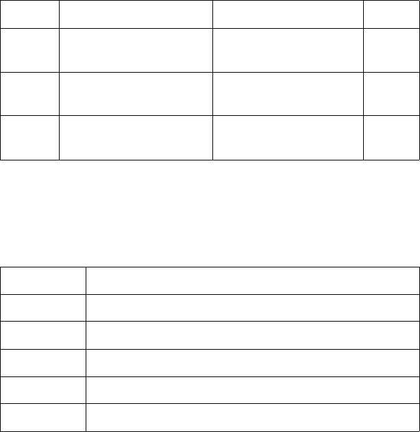
EN Using Color Modes (Color LaserJet, 5, 5M, DeskJet) B-7
Common 6-Byte Header
The short and long forms of the CID command use a common 6-byte
header, regardless of which color space is specified. The header data
fields, whose meaning may vary according to the color spaces, are
present in all color space specifications. The short form and long form
of the CID command are explained separately in the following pages.
Byte 0 (Color Space)
This byte specifies the color space. The range of values is 0 through
4. All other values are ignored.
Byte 15 (MSB) 8 7 0 (LSB) Byte
0Color space (UBYTE) Pixel encoding mode
(UBYTE) 1
2Bits/index
(UBYTE) Bits/primary #1
(UBYTE) 3
4Bits/primary #2
(UBYTE) Bits/primary #3
(UBYTE) 5
Byte Value Color Space
0 Device RGB (default)
1Device CMY
2 Colorimetric RGB Spaces
3 CIE L*a*b*
4 Luminance-Chrominance Spaces
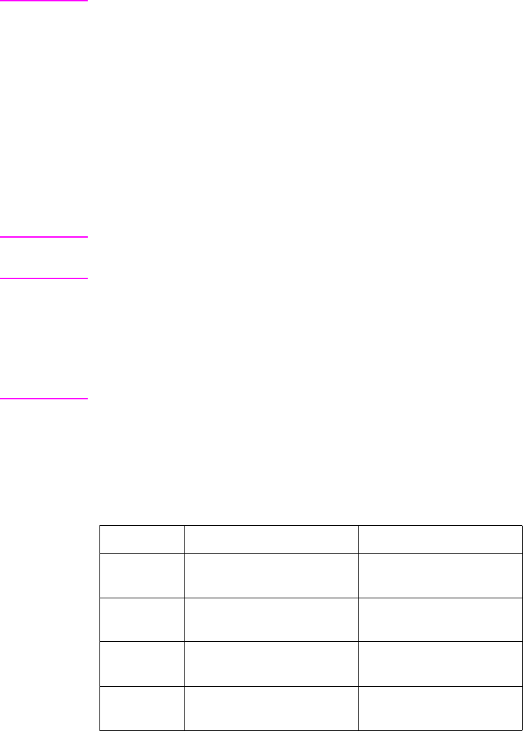
B-8 Using Color Modes (Color LaserJet, 5, 5M, DeskJet) EN
Note Colorimetric RGB color spaces are based on the 1931 standard
2-degree observer and specified by CIE xy chromaticity coordinates.
They use the standard D6500 viewing illuminant and a 45-degree
illumination model with a 0-degree collector geometry for reflective
data.
CIE L*a*b* is the CIE 1976 Uniform Color Space based on the 1931
standard 2-degree observer, and using a 45-degree illumination
model with a 0-degree collector geometry for reflective data. The
viewing illuminant is the standard D6500 illuminant.
Luminance-Chrominance spaces are a 3x3 linear transformation from
Colorimetric RGB. Like CIE L*a*b*, achromatic data is contained in
one channel and chromatic data shares the other two channels.
Note HP Color LaserJet 5 and 5M printers parse and discard the CID
command when Colorimetric RGB spaces are specified. Rather than
creating a Colorimetric RGB palette, a device RGB palette is created,
but it is populated with the default color of the Colorimetric RGB
palette. In addition, the ScreenMatch color table is selected to give
the impression of Colorimetric RGB behavior while working in a
device-dependent space
Byte 1 (Pixel Encoding Mode)
Byte number 1 designates the format in which raster data is to be
transmitted and interpreted. The range of this value field is 0 to 3. All
other values for this field are ignored.
Byte Value Pixel Encoding Mode Restrictions
0Indexed by Plane
(default) Bits/index must be
1, 2, 3, 4, 5, 6, 7, or 8
1Indexed by Pixel Bits/index must be
1, 2, 4, or 8
2Direct by Plane 1 bit per primary
(RGB or CMY only)
3Direct by Pixel 8 bits per primary
(All Color Spaces)

EN Using Color Modes (Color LaserJet, 5, 5M, DeskJet) B-9
You need one plane or one bit/pixel for each power of two colors in the
palette. For example, a 256-color palette requires 8 planes or 8
bits/pixel (28 = 256).
Note Direct pixel encoding modes (2, 3) cannot be compressed using
raster compression modes 1 or 2. Planar pixel encoding modes (0, 2)
cannot be compressed using raster compression mode 5.
MODE 0: INDEXED BY PLANE
In mode 0 (default), successive planes of data are sent for each raster
row. A plane contains one bit for each pixel in a row. A pixel is not fully
defined until it has received all the planes for that row. The planes in a
row form index numbers that define a pixel by selecting a palette
entry. Assuming 3 bits per index, the underlined column of bits below
is the palette index for pixel 3 of row 1 (i1 is lsb; i3 is msb). Note that
the Transfer Raster Data by Plane command (?*b#V) is used for all
planes except the last plane of each row, which uses the Transfer
Raster Data by Row command (?*b#W).
?*b#V row 1 plane 1 i1 i1 i1 i1 i1
?*b#V plane 2 i2 i2 i2 i2 i2
?*b#W plane 3 i3 i3 i3 i3 i3
?*b#V row 2 plane 1 i1 i1 i1 i1 i1

B-10 Using Color Modes (Color LaserJet, 5, 5M, DeskJet) EN
Example:
MODE 1: INDEXED BY PIXEL
In mode 1, each pixel in a row is fully specified before any bits are
sent for the next pixel. The bits for each pixel form a palette index
number. Assuming 4 bits per index, the underlined block below is the
palette index for pixel 2 of row 1 (i1 is lsb).
?*v6W 00 00 03 08 08 08 # Binary data for CID represented in
hex. Sets color space to RGB, pixel
encoding mode to 0, palette size to 8
(3 planes), last 3 bytes ignored.
?*r1A # Start raster.
?*b1V10110000 . . . # Transfer plane 1 (the first bit for
each pixel in the first row).
Combining each bit with its
corresponding bit in the other planes
forms the palette index number for
that pixel.
?*b1V01110000 . . . # Transfer plane 2 (the second bit for
each pixel in the row).
?*b1W10101000 . . . # Transfer plane 3 (the third bit for
each pixel in the row) and move to
the next row. Note that the ?*b#W
command is used to send the last
plane of each row.
?*b#W row 1 i4 i3 i2 i1 i4 i3 i2 i1 . . .
?*b#W row 2 i4 i3 i2 i1 i4 i3 i2 i1 . . .
?*b#W row 3 i4 i3 i2 i1 i4 i3 i2 i1 . . .

EN Using Color Modes (Color LaserJet, 5, 5M, DeskJet) B-11
Example:
MODE 2: DIRECT BY PLANE
In mode 2, the color raster data for each row is downloaded by
sequential planes, but the pixel color is directly specified, rather than
forming an index into the palette. The underlined block below defines
the actual primaries for pixel 3 of row 1.
?*v6W 00 01 04 04 04 04 # Binary data for CID
represented in hexadecimal.
Sets color space to RGB, pixel
encoding mode to 1, palette size
to 16 (4 bits to address palette
index). Last 3 bytes ignored.
?*r1A # Start raster.
?*b1W45 # Most significant nibble selects
palette index 4 for the first pixel.
Second pixel is set to index 5.
Move to the next row.
?*b1W6A # First pixel is index 6, second
pixel is index 10. Move to the
next row.
?*b1W03 # First pixel is index 0, second
pixel is index 3. Move to the next
row.
?*b#V row 1 red plane r r rrr
?*b#V green plane g g ggg
?*b#W blue plane b b bbb
?*b#V row 2 red plane r r r r r

B-12 Using Color Modes (Color LaserJet, 5, 5M, DeskJet) EN
Example:
MODE 3: DIRECT BY PIXEL
In mode 3, the color raster data is downloaded pixel by pixel (as in
mode 1), but each pixel directly specifies each color component (as in
mode 2). Assuming Device RGB space with 8 bits per primary, the
underlined block below defines the actual color primaries for pixel 1 of
row 2.
?*v6W 00 02 01 01 01 01 # Binary data for CID represented
in hex. Sets color space to RGB,
pixel encoding mode to 2. Palette
size is ignored because this is a
direct selection, not indexed. Last
3 bytes are always 1 for this
mode.
?*r1A # Start raster.
?*b1V10110000 . . . # Transfer plane for primary color
1. Each bit turns on or off the red
primary for the pixel defined by
the corresponding bits in each
plane.
?*b1V01110000 . . . # Transfer plane for primary color
2. Each bit turns on or off the
green primary of the pixel.
?*b1W10101000 . . . # Transfer plane for primary color
3 and move to the next row. Each
bit turns on or off the blue primary
of the pixel.
?*b#W row 1 r7–r0 g7–g0 b7–b0 . . .
?*b#W row 2 r7–r0 g7–g0 b7–b0 . . .
?*b#W row 3 r7–r0 g7–g0 b7–b0 . . .
EN Using Color Modes (Color LaserJet, 5, 5M, DeskJet) B-13
Example:
Byte 2 (Number of Bits per Index)
In all pixel encoding modes, this byte sets the size of the palette to 2n,
where n is the number of bits per index.
• In pixel encoding modes 0 and 1 (indexed), where raster data
is interpreted as indices into a palette, this value specifies the
number of bits required to access all palette entries.
• In pixel encoding modes 2 and 3 (direct), this value determines
palette size, but has no effect on the specification of raster
data.
Byte 3 (Number of Bits for Primary #1)
This byte is ignored in pixel encoding modes 0 and 1, but affects the
black and white references in device-dependent color spaces. In
Device RGB, the black reference for primary #1 is set to 0 and the
white reference is set to 2n– 1, where n is the number of bits for
primary #1. These references are reversed in Device CMY color
space.
•In pixel encoding mode 2, this byte is ignored except in Device
RGB and Device CMY color space, where it designates the
number of data bits needed to specify primary #1, as well as
the number of data planes to be sent for primary #1.
•In pixel encoding mode 3, this byte designates the number of
data bits needed to specify primary #1.
?*v6W 00 03 00 08 08 08 # Binary data for CID
represented in hex. Sets color
space to RGB, pixel encoding
mode to 3. Palette size is
ignored. Send 8 bits to address
each primary value for a pixel.
?*r1A # Start raster.
?*b3W 45 06 30 # Each byte sets a primary
value for the first pixel and
moves to the next row (45
specifies the red, 06 the green,
and 30 the blue component
value of that pixel).
B-14 Using Color Modes (Color LaserJet, 5, 5M, DeskJet) EN
A value of 0 defaults the black and white reference values for primary
#1 according to the color space.
Byte 4 (Number of Bits for Primary #2)
This byte is ignored in pixel encoding modes 0 and 1, but affects the
black and white references in device-dependent color spaces. In
Device RGB, the black reference for primary #2 is set to 0, and the
white reference is set to 2n– 1, where n is the number of bits for
primary #2. These references are reversed in Device CMY color
space.
•In pixel encoding mode 2, this byte is ignored except in Device
RGB and Device CMY color spaces, where it designates the
number of data bits needed to specify primary #2, as well as
the number of data planes to be sent for primary #2.
•In pixel encoding mode 3, this byte designates the number of
data bits needed to specify primary #2.
A value of 0 defaults the black and white reference values for primary
#2 according to the color space.
Byte 5 (Number of Bits for Primary #3)
This byte is ignored in pixel encoding modes 0 and 1, but affects the
black and white references in device-dependent color spaces. In
Device RGB, the black reference for primary #3 is set to 0, and the
white reference is set 2n– 1, where n is the number of bits for primary
#3. These references are reversed in Device CMY space.
•In pixel encoding mode 2, this byte is ignored except in Device
RGB and Device CMY color space, where it designates the
number of data bits needed to specify primary #3, as well as
the number of data planes to be sent for primary #3.
•In pixel encoding mode 3, this byte designates the number of
data bits needed to specify primary #3.
A value of 0 defaults the black and white reference values for primary
#3 according to the color space.

EN Using Color Modes (Color LaserJet, 5, 5M, DeskJet) B-15
Short Form of CID Command (Configure
Image Data)
The Short Form of the CID command involves sending just the
common 6-byte header. By changing the value of byte 0 (color
space), the short form can specify the following five color spaces:
The following data ranges are allowed in CIE L*a*b*. Hue is
preserved when out-of-range data is clipped.
L* = 0.0 to 100.0
a* = –100.0 to 100.0
b* = –100.0 to 100.0
Note CIE L*a*b* color space support is at HP Color LaserJet level for
HP Color LaserJet 5 and 5M printers.
• Colorimetric RGB (SMPTE RGB) ?*v6W[0x02, . . . ]
Non-linear SMPTE RGB with a 2.2 gamma and 1.0 gain is the default
Colorimetric RGB color space. The short form allows the following
ranges:
R = 0.0 to 1.0
G = 0.0 to 1.0
B = 0.0 to 1.0
Note HP Color LaserJet 5 and 5M printers bypass the Colorimetric RGB
process. In place of it, a device-dependent RGB process is
substituted with a Screen Match color table.
•Device RGB ?*v6W[0x00, . . . ]
•Device CMY ?*v6W[0x01, . . . ]
• CIE L*a*b* ?*v6W[0x03, . . . ]

B-16 Using Color Modes (Color LaserJet, 5, 5M, DeskJet) EN
• Luminance-Chrominance (YUV) ?*v6W[0x04, . . . ]
YUV, which is a linear transformation from SMPTE RGB, is the default
Luminance-Chrominance color space. The short form allows the
following ranges:
Y = 0.0 to 1.0
U = –0.89 to 0.89
V = –0.70 to 0.70
Note Luminance-Chrominance color space support is at HP Color LaserJet
level for HP Color LaserJet 5 and 5M printers.
Data Range Scaling
White and black references define the encoding range for
device-dependent color spaces. However, device-independent color
spaces require input data pre-scaled to the range 0 to 255. For
example, to use the short form for the default YUV color space, the
input data must have the following ranges:
Y = 0.0 to 1.0
U = –0.89 to 0.89
V = –0.70 to 0.70
The user must linearly scale (y = mx b) the input data to the
range0–255:
Y = 0 (0.0) to 255 (1.0)
U = 0 (–0.89) to 255 (0.89)
V = 0 (–0.70) to 255 (0.70)

EN Using Color Modes (Color LaserJet, 5, 5M, DeskJet) B-17
Long Form of CID Command (Configure
Image Data)
In addition to the short form, there is also a long form of the CID
command for each color space. In device-independent color spaces,
the long form can specify primaries other than the defaults provided
by the short form. For example, a Sony Trinitron RGB primary base
can be selected for Colorimetric RGB instead of the default non-linear
SMPTE RGB primaries.
Device RGB (Long Form)
The long form for the Device RGB color space (value field 18)
provides explicit entry of black and white references (range is –32767
to 32767). Black and white references are used in the direct pixel
encoding modes (2,3) to set relative limits for raster data; they are
also used when specifying the primary components of new palette
entries (?*v#A, ?*v#B, ?*v#C). Black and white references have
no effect on CID default palette colors. The reference values are
specified as 16-bit signed integers (sint16).
Note The short form for the Device RGB color space defaults each
primary's black reference to 0 and the white reference to 2n–1, where
n is the number of bits for that primary.
Byte 15 (msb) 8 7 (lsb) 0 Byte
0 Color space Pixel encoding mode 1
2 Bits per index Bits per primary #1 3
4 Bits per primary #2 Bits per primary #3 5
6 White reference for primary #1 (sint 16) 7
8 White reference for primary #2 (sint 16) 9
10 White reference for primary #3 (sint 16) 11
12 Black reference for primary #1 (sint16) 13
14 Black reference for primary #2 (sint16) 15
16 Black reference for primary #3 (sint16) 17
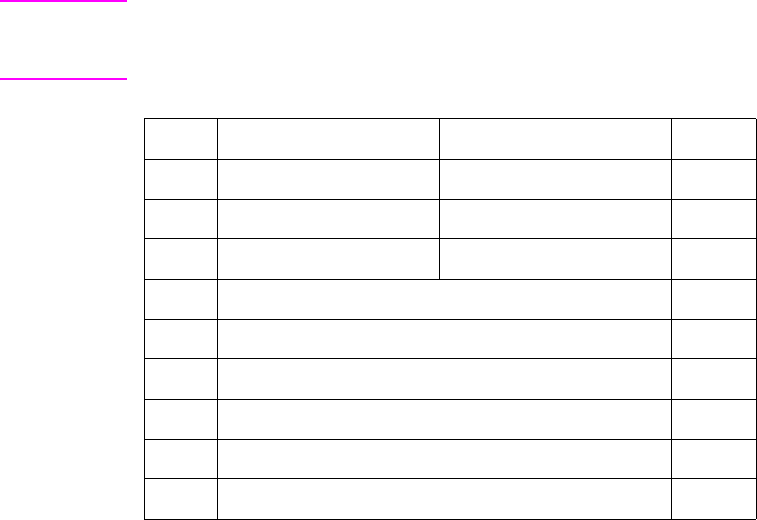
B-18 Using Color Modes (Color LaserJet, 5, 5M, DeskJet) EN
Device CMY (Long Form)
The long form for the Device CMY color space (value field is 18)
provides explicit entry of black and white references (range is –32767
to 32767). Black and white references are used in the direct pixel
encoding modes (2,3) to set relative limits for raster data; they are
also used when specifying the primary components of new palette
entries (?*v#A, ?*v#B, ?*v#C). Black and white references have
no effect on the default CID palette colors. The reference values are
specified as 16-bit signed integers (sint16).
Note The short form for the Device CMY color space defaults each
primary’s white reference to 0 and black reference to 2n–1, where n is
the number of bits for that primary.
CIE L*a*b* (Long Form)
The long form for the CIE L*a*b* color space allows a larger data
range than the short form defaults:
L* = 0.0 to 120.0 (greater than the short form by 20.0)
a* = –159.0 to 128.0 (less than the short form by –32.0 and greater
than the short form by 28.0)
b* = –120.0 to 80.0 (less than the short form by 20.0)
Byte 15 (msb) 8 7 (lsb) 0 Byte
0 Color space Pixel encoding mode 1
2 Bits per index Bits per primary #1 3
4 Bits per primary #2 Bits per primary #3 5
6 White reference for primary #1 (sint16) 7
8 White reference for primary #2 (sint16) 9
10 White reference for primary #3 (sint16) 11
12 Black reference for primary #1 (sint16) 13
14 Black reference for primary #2 (sint16) 15
16 Black reference for primary #3 (sint16) 17
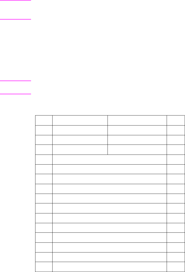
EN Using Color Modes (Color LaserJet, 5, 5M, DeskJet) B-19
Note Although the data ranges may extend beyond the default data ranges
specified in the short form of the CID command, the printer will clip
the data to the short form data ranges.
Maximum and minimum values are specified for each primary color.
Floating point data must be linearly scaled (y = mx b) to the range
0 – 255.
Since a* and b* have no theoretical limits, L*a*b* data may be sent
outside CID constraints. Then data is clipped to preserve hue and
compressed to the device's printable gamut.
Note CIE L*a*b* color space support is at HP Color LaserJet level for
HP Color LaserJet 5 and 5M printers.
The white point is based on the standard D6500 illuminant.
Byte 15 (msb) 8 7 (lsb) 0 Byte
0 Color space Pixel encoding mode 1
2 Bits per index Bits per primary #1 3
4 Bits per primary #2 Bits per primary #3 5
6 Minimum L* value (most significant word)* 7
8 Minimum L* value (least significant word)* 9
10 Maximum L* value (msw) 11
12 Maximum L* value (lsw) 13
14 Minimum a* value (msw) 15
16 Minimum a* value (lsw) 17
18 Maximum a* value (msw) 19
20 Maximum a* value (lsw) 21
22 Minimum b* value (msw) 23
24 Minimum b* value (lsw) 25
26 Maximum b* value (msw) 27
28 Maximum b* value (lsw) 29
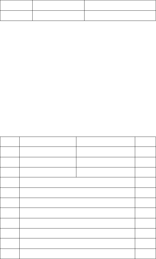
B-20 Using Color Modes (Color LaserJet, 5, 5M, DeskJet) EN
FLOATING POINT FORMAT
The following format is used for device-independent color floating
point specifications:
The above single-precision, 32-bit floating point specification is fully
compliant with the IEEE Floating Point Formats.
Colorimetric RGB (Long Form)
The long form for Colorimetric RGB allows specifications other than
the default non-linear SMPTE RGB with a 2.2 gamma and 1.0 gain.
Each RGB primary and the white point is specified in the CID data
field by chromaticity coordinates (CIE xy). The tristimulus luminance
Y value of the white point is assumed to be 100% and is therefore not
specified. For color spaces that are linear transformations from CIE
XYZ tristimulus coordinates, gamma and gain are set to 1.0;
otherwise they are set appropriately. Colorimetric RGB spaces can be
used for any monitor having primaries specified as CIE xy
chromaticity coordinates with white point, such as the Sony Trinitron
or Hitachi Color Monitor.
31 30 23 22 0
Sign Exponent Fractional Portion
Byte 15 (msb) 8 7 (lsb) 0 Byte
0 Color space Pixel encoding mode 1
2 Bits per Index Bits per primary #1 3
4 Bits per primary #2 Bits per primary #3 5
6 x Chromaticity for red primary (msw) 7
8 x Chromaticity for red primary (lsw) 9
10 y Chromaticity for red primary (msw) 11
12 y Chromaticity for red primary (lsw) 13
14 x Chromaticity for green primary (msw) 15
16 x Chromaticity for green primary (lsw) 17
18 y Chromaticity for green primary (msw) 19
20 y Chromaticity for green primary (lsw) 21
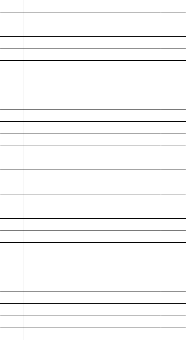
EN Using Color Modes (Color LaserJet, 5, 5M, DeskJet) B-21
22 x Chromaticity for blue primary (msw) 23
24 x Chromaticity for blue primary (lsw) 25
26 y Chromaticity for blue primary (msw) 27
28 y Chromaticity for blue primary (lsw) 29
30 x Chromaticity for white point (msw) 31
32 x Chromaticity for white point (lsw) 33
34 y Chromaticity for white point (msw) 35
36 y Chromaticity for white point (lsw) 37
38 Gamma for red primary (msw) 39
40 Gamma for red primary (lsw) 41
42 Gain for red primary (msw) 43
44 Gain for red primary (lsw) 45
46 Gamma for green primary (msw) 47
48 Gamma for green primary (lsw) 49
50 Gain for green primary (msw) 51
52 Gain for green primary (lsw) 53
54 Gamma for blue primary (msw) 55
56 Gamma for blue primary (lsw) 57
58 Gain for blue primary (msw) 59
60 Gain for blue primary (lsw) 61
62 Minimum red value (msw) 63
64 Minimum red value (lsw) 65
66 Maximum red value (msw) 67
68 Maximum red value (lsw) 69
70 Minimum green value (msw) 71
72 Minimum green value (lsw) 73
74 Maximum green value (msw) 75
Byte 15 (msb) 8 7 (lsb) 0 Byte
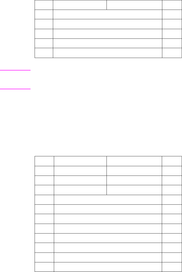
B-22 Using Color Modes (Color LaserJet, 5, 5M, DeskJet) EN
Note HP Color LaserJet 5 and 5M printers bypass the Colorimetric RGB
process. In place of it, a device-dependent RGB process is
substituted with a Screen Match color table.
Luminance-Chrominance (Long Form)
The long form for Luminance-Chrominance allows color spaces other
than the default YUV, such as Kodak Photo YCC, the proposed JPEG
and TIFF 6.0 YCrCb standard, YES, and YIQ. These
Luminance-Chrominance color spaces are derived from the
Colorimetric RGB space using a 3x3 transformation matrix. The
tristimulus luminance y value of the white point is assumed to be
100% and is therefore not specified.
76 Maximum green value (lsw) 77
78 Minimum blue value (msw) 79
80 Minimum blue value (lsw) 81
82 Maximum blue value (msw) 83
84 Maximum blue value (lsw) 85
Byte 15 (msb) 8 7 (lsb) 0 Byte
Byte 15 (msb) 8 7 (lsb) 0 Byte
0 Color space Pixel encoding mode 1
2 Bits per index Bits per primary #1 3
4 Bits per primary #2 Bits per primary #3 5
6 Encoding for primary #1 R (msw) 7
8 Encoding for primary #1 R (lsw) 9
10 Encoding for primary #1 G (msw) 11
12 Encoding for primary #1 G (lsw) 13
14 Encoding for primary #1 B (msw) 15
16 Encoding for primary #1 B (lsw) 17
18 Encoding for primary #2 R (msw) 19
20 Encoding for primary #2 R (lsw) 21

EN Using Color Modes (Color LaserJet, 5, 5M, DeskJet) B-23
22 Encoding for primary #2 G (msw) 23
24 Encoding for primary #2 G (lsw) 25
26 Encoding for primary #2 B (msw) 27
28 Encoding for primary #2 B (lsw) 29
30 Encoding for primary #3 R (msw) 31
32 Encoding for primary #3 R (lsw) 33
34 Encoding for primary #3G (msw) 35
36 Encoding for primary #3 G (lsw) 37
38 Encoding for primary #3 B (msw) 39
40 Encoding for primary #3 B (lsw) 41
42 Minimum primary #1 value (msw) 43
44 Minimum primary #1 value (lsw) 45
46 Maximum primary #1 value (msw) 47
48 Maximum primary #1 value (lsw) 49
50 Minimum primary #2 value (msw) 51
52 Minimum primary #2 value (lsw) 53
54 Maximum primary #2 value (msw) 55
56 Maximum primary #2 value (lsw) 57
58 Minimum primary #3 value (msw) 59
60 Minimum primary #3 value (lsw) 61
62 Maximum primary #3 value (msw) 63
64 Maximum primary #3 value (lsw) 65
66 x Chromaticity for red primary (msw) 67
68 x Chromaticity for red primary (lsw) 69
70 y Chromaticity for red primary (msw) 71
72 y Chromaticity for red primary (lsw) 73
74 x Chromaticity for green primary (msw) 75
Byte 15 (msb) 8 7 (lsb) 0 Byte

B-24 Using Color Modes (Color LaserJet, 5, 5M, DeskJet) EN
Note CIE L*a*b* color space support is at HP Color LaserJet level for
HP Color LaserJet 5 and 5M printers.
76 x Chromaticity for green primary (lsw) 77
78 y Chromaticity for green primary (msw) 79
80 y Chromaticity for green primary (lsw) 81
82 x Chromaticity for blue primary (msw) 83
84 x Chromaticity for blue primary (lsw) 85
86 y Chromaticity for blue primary (msw) 87
88 y Chromaticity for blue primary (lsw) 89
90 x Chromaticity for white point (msw) 91
92 x Chromaticity for white point (lsw) 93
94 y Chromaticity for white point (msw) 95
96 y Chromaticity for white point (lsw) 97
98 Gamma for red primary (msw) 99
100 Gamma for red primary (lsw) 101
102 Gain for red primary (msw) 103
104 Gain for red primary (lsw) 105
106 Gamma for green primary (msw) 107
108 Gamma for green primary (lsw) 109
110 Gain for green primary (msw) 111
112 Gain for green primary (lsw) 113
114 Gamma for blue primary (msw) 115
116 Gamma for blue primary (lsw) 117
118 Gain for blue primary (msw) 119
120 Gain for blue primary (lsw) 121
Byte 15 (msb) 8 7 (lsb) 0 Byte
EN Using Color Modes (Color LaserJet, 5, 5M, DeskJet) B-25
Examples Using the CID Command
The following examples illustrate using the CID command's short and
long forms for each color space. For clarity, data is shown as ASCII,
rather than binary and the CID command (?*v#W) is shown as
“CID”. The following format is used:
CID ( data , data , . . . )
Device RGB or Device CMY
SHORT FORM
Example:
The short form CID command, as a C function, can look like this:
short_cid(Color_mode, Pixel_mode, BitsperIndex,
BitsperColor_1, BitsperColor_2, BitsperColor_3)
{int Color_mode, Pixel_mode, BitsperIndex,
BitsperColor_1, BitsperColor_2, BitsperColor_3;
printf(“\033*v6W%c%c%c%c%c%c”,Color_mode,
Pixel_mode, BitsperIndex, BitsperColor_1,
BitsperColor_2, BitsperColor_3);
}
LONG FORM
CID(0,1,8,8,8,8) Device RGB, 8 bits/pixel indexed
CID(1,1,8,8,8,8) Device CMY, 8 bits/pixel indexed
CID(0,1,8,8,8,8, Device RGB, 8 bits/pixel indexed
0,0,0 White reference
100,100,100) Black reference
B-26 Using Color Modes (Color LaserJet, 5, 5M, DeskJet) EN
CIE L*a*b*
SHORT FORM
LONG FORM
Non-Linear SMPTE RGB, 2.2 Gamma, 1.0 Gain
SHORT FORM
LONG FORM
Non-Linear Sony Trinitron
SHORT FORM
Not Applicable
CID(3,3,0,8,8,8) L*a*b*, direct 8 bits/primary
CID(3,3,0,8,8,8, L*a*b*, direct 8 bits/primary
0.0, 100.0, L* data encoding
–100.0, 100.0, a* data encoding
–100.0, 100.0) b* data encoding
CID(2,3,0,8,8,8) RGB, direct 8 bits/primary
CID(2,3,0,8,8,8,
0.64, 0.34,
0.31, 0.60,
0.16, 0.07,
0.3127, 0.3290,
2.2, 1.0,
2.2, 1.0,
2.2, 1.0,
0.0, 1.0,
0.0, 1.0,
0.0, 1.0)
RGB, direct 8 bits/primary
|
| Chromaticity coordinates
| for RGB & White Point
|
*
* Gamma and gain for RGB
*
|
| Data range encoding
|
EN Using Color Modes (Color LaserJet, 5, 5M, DeskJet) B-27
LONG FORM
YUV Chrominance-Luminance Color Space
SHORT FORM
CID(4,3,0,8,8,8) YUV, direct 8 bits/primary
YUV Chrominance-Luminance with Sony Trinitron
LONG FORM
CID(2,3,0,8,8,8
0.62, 0.34,
0.30, 0.58,
0.15, 0.09,
0.2800, 0.2933,
2.3, 1.19,
2.3, 1.19,
2.3, 1.19,
0.0, 255.0,
0.0, 255.0,
0.0, 255.0)
RGB, direct 8 bits/primary
|
| Chromaticity coordinates
| for RGB
| White Point
*
* Gamma and gain for RGB
*
|
| Data range encoding
|
CID(2,3,0,8,8,8
0.30,0.59,0.11,
–0.30,0.59,0.89,
0.70,–0.59,–0.11,
0.0,255.0
–227.0,227.0,
–179.0,179.0
0.62,0.34,
0.30,0.58,
0.15,0.09,
0.2800, 0.2933,
2.3,1.19,
2.3,1.19,
2.3,1.19)
YUV, direct 8 bits/primary
|
| 3x3 YUV matrix
|
*
* Data encoding
*
|
| Chromaticity
| coordinates
| chromaticity white point
*
* Gamma and
* gain for RGB
B-28 Using Color Modes (Color LaserJet, 5, 5M, DeskJet) EN
HP-GL/2 Imaging Mode
The HP-GL/2 Imaging Mode provides a way of using vector
commands in printing documents. Although the default PCL and
HP-GL/2 palettes are not the same, when transferring from PCL to
HP-GL/2, active palette information does stay the same. You can
switch between PCL and HP-GL/2 and use the same palette, and you
can also modify palettes using either PCL or HP-GL/2.
Compared to monochrome printers, the Color LaserJet and DeskJet
1200C color printers have some commands that are modified for use
with color printers. Chapter 7 describes the new or modified HP-GL/2
commands.
If you are not familiar with using HP-GL/2, see the PCL 5 Printer
Language Technical Reference Manual. It provides a detailed
explanation of using HP-GL/2.
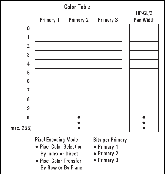
EN Using Palettes (Color LaserJet, 5, 5M, DeskJet) C-1
CUsing Palettes
(Color LaserJet, 5, 5M,
DeskJet)
Introduction
A palette is a collection of color specifications selected using index
numbers. The figure below illustrates a palette. Each palette entry
associates an index number with three primary color components. For
HP-GL/2 purposes only, a pen width is also associated with each
palette entry.
C-2 Using Palettes (Color LaserJet, 5, 5M, DeskJet) EN
In non-raster mode, the current palette contains all the colors
available to the printer. In raster mode, indexed color selection uses
the palette, but direct selection does not.
Default palettes are created by all the PCL color modes (Black and
White, Simple Color, PCL Imaging, and HP-GL/2 Imaging). The active
palette may be modified when in the PCL Imaging or HP-GL/2
imaging modes, but not when in the Simple Color or Black and White
modes. When switching between PCL 5 and HP-GL/2 contexts, the
active palette is automatically transferred.
Multiple palettes can exist in the system via the Palette ID and Palette
Stack mechanism. However, only one palette at a time can be active.
A palette created in the PCL context remains active and unchanged
when switching to the HP-GL/2 context, and a palette created in the
HP-GL/2 context remains active and unchanged when switching to
the PCL context. Performing a reset or entering PJL overwrites the
active palette with the default black and white palette.
Whenever a new palette is created, the currently or previously active
palette is destroyed. A new palette is created by power-on and also by
the following commands:
• PCL Reset (?E)
•Simple Color (
?*r#U)
• Configure Image Data (?*v#W)
• HP-GL/2 Initialize (IN)
The active palette can be saved by pushing it onto the palette stack
with the Push/Pop Palette command (?*p#P). Popping a palette from
the stack destroys the active palette—the popped palette becomes
the active palette.
EN Using Palettes (Color LaserJet, 5, 5M, DeskJet) C-3
Saving the Palette
The current palette is destroyed when a new palette is created. The
Push/Pop Palette command (?*p#P) can save (push) the current
palette and then restore (pop) it.
Push/Pop Palette Command
This command pushes or pops the palette from the palette stack.
?*p#P
A value of 0 (?*p0P) pushes a copy of the active palette onto the
palette stack. When a palette is pushed, the active palette is not
affected.
A value of 1 (?*p1P) pops the most recently pushed palette and
destroys the active palette; the popped palette becomes the active
palette. As with any stack, the last item pushed is the first item
popped.
Pushing a palette saves the following parameters:
• Color definitions for each palette entry
• Pen widths (for HP-GL/2 use)
• Color space specification
• Black and white references
• Number of bits per index
• Pixel encoding mode
• Number of bits per primary
• Gamma correction
• Viewing illuminant
• Color lookup tables
• Render algorithm
• Downloaded dither matrix
# = 0 - Push (save) palette
1 - Pop (restore) palette
Default =0
Range = 0, 1 (invalid values are ignored)
C-4 Using Palettes (Color LaserJet, 5, 5M, DeskJet) EN
Pushing a palette does not save the following parameters.
• Foreground color
• Color components: 1st, 2nd, and 3rd
• Finish mode
• Monochrome print mode
The palette stack depth is limited by printer memory. Attempts to push
a palette with insufficient memory cause an out-of-memory error.
Attempts to pop from an empty stack are ignored.
Macros can push and pop palettes. A palette that was popped in an
executed macro remains in effect at the end of the macro (this is not
true for “called” or “overlaid” macros).
PCL reset commands (?E) and exits to PJL cause the printer to
empty the palette stack and overwrite the active palette with a
non-programmable black and white palette. The HP-GL/2 commands
IN and DF have no effect on the palette stack, but they do destroy the
active palette and replace it with the default HP-GL/2 palette.
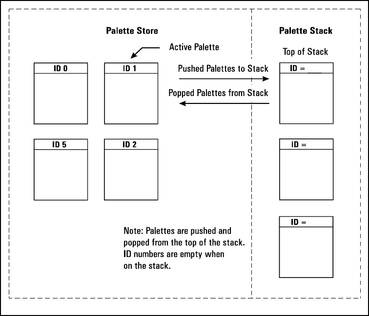
EN Using Palettes (Color LaserJet, 5, 5M, DeskJet) C-5
Palette Management by ID
All palettes have a unique ID (identification number). The default
black and white palette created on power-up or ?E has an ID of 0.
Palette management by ID lets applications have multiple palettes. As
shown below, multiple palettes can exist in two areas: the palette
stack and the palette store. The stack holds palettes that are pushed
via a Push/Pop Palette command; the store holds palettes having
palette IDs.
Palettes on the stack may not be selected by ID, since only a copy of
a palette is pushed onto the stack; the original palette and ID remain
in the palette store. A palette popped from the stack goes into the
palette store, becomes the new active palette, and assumes the ID of
the previously active palette, which is overwritten. Only one palette at
a time may be active.
C-6 Using Palettes (Color LaserJet, 5, 5M, DeskJet) EN
Management by ID allows applications to tag data, have multiple
raster configurations, and have palettes for different color spaces—all
without reconfiguring the active palette. For example, one palette can
be created for PCL text, one for HP-GL/2 primitives, one for simple
raster, and one for 24-bit raster. The application can then switch
between palettes according to what is being sent to the printer.
Selecting a new active palette changes the PCL graphics state.
Besides color entries, a palette also contains the graphics state at the
time the bitmap representation of the palette colors was created. This
guarantees color reproduction integrity by insuring that the same
color specification triplet always produces the same bitmap
representation.
As described below, the Select Palette (?&p#S), Palette Control
(?&p#C), and Palette Control ID (?&p#I) commands implement the
three basic operations of management by ID.
• Selection of the active palette
• Deletion of palettes
• Copying of palettes
Select Palette Command
The Select Palette command selects a new active palette by
specifying an ID number. The previously active palette is unchanged.
?&p#S
This command activates the designated palette in the palette store.
The command is ignored if the specified ID matches the active
palette's ID, or if no palette with that ID exists. The designated ID is
saved as the palette select ID in the current modified print
environment.
#= Palette ID number
Default =0
Range = 0 to 32767 (command is ignored for out- of-range
values)
EN Using Palettes (Color LaserJet, 5, 5M, DeskJet) C-7
This command can be used to de-select the active palette and select
as the new active palette a palette created by the Palette Control
command (?&p#C). For example, to copy the active palette to an ID
of 44 and select the new palette to use or modify, send
?&p44i6c44S.
When a palette creation command is received such as Configure
Image Data (?*v#W), Simple Color (?*r#U), or an HP-GL/2 IN, the
created palette overwrites the active palette and is assigned the
current palette select ID, which is unchanged.
A palette popped from the stack overwrites the active palette, and is
assigned the current palette select ID, which is unchanged.
?E resets the palette select ID value to 0 and deletes all palettes in
the palette stack and palette store, including the active palette which
is replaced by a default PCL fixed black and white palette with a
palette select ID value of 0.
Macros affect the palette select ID value as follows:
• Calling or Overlaying a macro—saves the ID value and a copy
of the active palette. Upon macro exit, the restored palette
again becomes the active palette with the restored ID. An
existing palette with this ID is deleted.
• Executing a macro—does not save the ID value or the active
palette; changes remain in effect.
C-8 Using Palettes (Color LaserJet, 5, 5M, DeskJet) EN
Palette Control ID
The Palette Control ID command specifies the ID number to be used
by the Palette Control Command.
?&p#I
The ID number specified by this command is saved as the palette
control ID in the current modified print environment and is used by the
Palette Control command (?&p#C).
?E or power-up resets the palette control ID to 0, which is then the
default black and white palette ID.
Macros affect the palette control ID value as follows:
• Calling a macro—saves the value and restores the value at
exit.
• Executing a macro—does not save the value; changes remain
in effect at exit.
• Overlaying a macro—copies the value before resetting to 0,
and restores at exit.
#= Palette ID number
Default =0
Range = 0 to 32767 (command is ignored for out- of-range
values)

EN Using Palettes (Color LaserJet, 5, 5M, DeskJet) C-9
Palette Control
The Palette Control command provides a mechanism for marking and
deletion of palettes.
?&p#C
• A value of 0 deletes all palettes except those on the palette
stack. The active palette is replaced by the default black and
white palette (ID 0). The palette control ID is not used.
• A value of 1 clears the palette stack. The active palette is
unaffected, and the palette control ID is not used.
• A value of 2 deletes the palette with the specified palette
control ID if it exists; otherwise the command is ignored. For
example, to delete palette 53, send ?&p53i2C. If the
active palette's ID is specified the active palette is replaced by
the default black and white palette. This option does not
change the palette control ID value.
Note When the active palette is replaced by the default black
and white palette, the graphics state associated with the previous
palette is also replaced.
• A value of 6 creates a copy of the active palette. The copy
receives the ID specified by the last Palette Control ID
command. For example, to copy the active palette to a palette
with an ID of 14, send ?&p14i6C. The copied palette
overwrites any palette that already has an ID equal to the
palette control ID. The copied palette does not become the
active palette. The command is ignored if a palette is to be
copied to its own ID.
# = 0 - Delete all palettes except those in the stack (active
palette deleted)
1 - Delete all palettes in the stack (active palette is not
affected)
2 - Delete palette (specified by Palette Control ID)
6 - Copy active palette to ID specified by Palette Control ID
Default =0
Range = 0, 1, 2, 6 (command is ignored for unsupported values)
C-10 Using Palettes (Color LaserJet, 5, 5M, DeskJet) EN
The Palette Control command provides a way of managing system
memory by deleting palettes in either the stack or store that are no
longer in use.
Palette Control that is exercised during macros can have significant
impact on palettes that exist within the system. Deleting all palettes,
or those on the stack, or the current palette, or all those except on the
stack can have adverse effects when the macro is exited. The
adverse effect could be the deletion of the desired palette, and
replacement with a black and white non-programmable palette.
EN Using Palettes (Color LaserJet, 5, 5M, DeskJet) C-11
Simple Color Palettes
The Simple Color command (?*r#U) provides a quick way to select
colors from a fixed, non-programmable palette.
The Simple Color command overwrites the current palette with one of
the fixed palettes below. When the Simple Color command is in effect,
the PCL and HP-GL/2 commands that modify a palette entry (NP, CR,
PC, ?*v#A, ?*v#B, ?*v#C, ?*v*I, ?*t*I) are locked out. A popped
simple color palette cannot be modified and the pixel encoding mode
reverts to “index by plane”. Only the IN or the CID (?*v#W)
commands can create a modifiable palette.
As shown below, a value field of 1 (?*r1U) creates a black and white
palette. A value of 3 creates an 8-pen palette in Device RGB color
space. A value of –3 creates an 8-pen palette in Device CMY color
space. All of these Simple Color palettes are fixed and
non-programmable.
Single Plane (value = 1)
3-Plane RGB (value = 3)
Index Color
0White
1Black
Index Color
0Black
1Red
2Green
3Yellow
4Blue
5 Magenta
6Cyan
7White

C-12 Using Palettes (Color LaserJet, 5, 5M, DeskJet) EN
3-Plane CMY (value = –3)
Index Color
0White
1Cyan
2 Magenta
3Blue
4Yellow
5Green
6Red
7Black
EN Using Palettes (Color LaserJet, 5, 5M, DeskJet) C-13
CID Color Palettes
The Configure Image Data command, explained in detail in
Appendix B, creates a palette based upon the parameters in its data
field. CID-created palettes are programmable: any entry can be
reassigned a different color using PCL commands (?*v#A, ?*v#B,
?*v#C, ?*v*I) or HP-GL/2 commands (CR, PC, NP). Default
palettes vary by color space.
Device RGB Palettes
The black and white references specified by the CID command have
no effect on the default palettes below. However, when a CID palette
entry is reprogrammed with a different color, the black and white
references are used to specify the primary components of the new
color.
Bits/Index = 1
Bits/Index = 2
Index Color
0White
1Black
Index Color
0Black
1Red
2Green
3White

C-14 Using Palettes (Color LaserJet, 5, 5M, DeskJet) EN
Bits/Index = 3 through 8
Index Color
0Black
1Red
2Green
3Yellow
4Blue
5 Magenta
6Cyan
7White
n > 7 Black
EN Using Palettes (Color LaserJet, 5, 5M, DeskJet) C-15
Device CMY and Device-Independent Palettes
A CID command specifying either a device-independent color space
or the Device CMY color space creates the same default palettes.
This is because device-independent colors are transformed into the
printer's native space, Device CMY.
Bits/Index = 1
Bits/Index = 2
Bits/Index = 3 through 8
Index Color
0White
1Black
Index Color
0White
1Cyan
2 Magenta
3Black
Index Color
0White
1Cyan
2 Magenta
3Blue
4Yellow
5Green
6Red
7Black
n > 7 Black

C-16 Using Palettes (Color LaserJet, 5, 5M, DeskJet) EN
HP-GL/2 Palettes
Regardless of the color space, a default PCL palette is always
different than a default HP-GL/2 palette. The following table shows the
default palettes established in HP-GL/2. Like a default CID palette, a
default HP-GL/2 palette can be modified in either PCL or HP-GL/2
contexts using the following commands:
PCL
• Color Components 1, 2, and 3 (?*v#A, ?*v#B, ?*v#C)
• Assign Color Index (?*v#I)
HP-GL/2
• Number of Pens (NP)
• Pen Color Assignment (PC)
• Set Relative Color Range (CR)
Note The IN command always establishes the 8-pen palette.
Two Pens
Four Pens
Pen Number Color
0White
1Black
Pen Number Color
0White
1Black
2Red
3Green

EN Using Palettes (Color LaserJet, 5, 5M, DeskJet) C-17
Eight Pens
Pen Number Color
0White
1Black
2Red
3Green
4Yellow
5Blue
6 Magenta
7Cyan
n > 7 Black
C-18 Using Palettes (Color LaserJet, 5, 5M, DeskJet) EN
Foreground Color
All PCL marking entities utilize “foreground” color, which is selected
from the current palette using the Foreground Color command
(?*v#S). Foreground color interacts with raster color depending on
the print model commands in effect.
Foreground Color Command
The Foreground Color command sets the foreground color to the
specified index of the current palette.
?*v#S
Specified values that are out-of-range of the current palette are
mapped into a new index as follows:
Index = Specified foreground index modulo palette size
For example, specifying a foreground color index of 10 when the
current palette size is 8 maps to 10 modulo 8, which is equal to 2. If
the current palette was created under HP-GL/2, the index is mapped
according to the HP-GL/2 mapping function.
Foreground color affects the following PCL page marking primitives:
• Text characters (they change to the foreground color, including
underlining)
• Solid or monochrome patterned rectangular area fills (rules)
• Monochrome patterns (except HP-GL/2)
• Raster images
The following are not affected:
• User-defined color patterns (format 1 download patterns)
• HP-GL/2 marking primitives (HP-GL/2 uses “selected pen”, but
ignores foreground color)
#= Index number into current palette
Default =0
Range = 0 to 2(current palette size) – 1

EN Using Palettes (Color LaserJet, 5, 5M, DeskJet) C-19
Note Foreground color interacts with color raster images. In the printer, all
color raster is resolved into three binary raster planes of CMY.
Foreground color is applied to these planes, modifying the color
image. For no interaction, set foreground color to black when sending
color raster images.
After a foreground color is selected, changing any of the following will
not change foreground color until a new Foreground Color command
(?*v#S) is issued:
• Active Palette
• Configure Image Data (CID) command
• Render Algorithm
• User Defined Dither Matrix
• Gamma Correction
• Color Lookup Tables
• Viewing Illuminant
As an exception, Monochrome Print Mode (?&b#M) immediately
maps foreground color to its equivalent gray. Similarly, deselection of
Monochrome Print Mode immediately returns foreground color to its
color equivalent.
C-20 Using Palettes (Color LaserJet, 5, 5M, DeskJet) EN
Programming Color Palettes
Except for the default black and white palette or the Simple Color
palettes (?*r#U), palette entries can be modified. The three primary
components of a color are specified and the resulting color is
assigned to the palette entry indicated by ?*v#I.
In the explanation below, the term “component” refers to the color
space primary colors. For example, if the current color space is CIE
L*a*b*, component 1 indicates CIE L*, component 2 indicates CIE a*,
and component 3 indicates CIE b*.
Color Component One
This command specifies the first primary of the palette entry
designated by the Assign Color Index command (?*v#I).
?*v#A
The Assign Color Index command actually applies this value and then
resets it to 0.
Color Component Two
This command specifies the second primary of the palette entry
designated by the Assign Color Index command.
?*v#B
The Assign Color Index command actually applies this value and then
resets it to 0.
#= First Component
Default =0
Range = –32767.0000 to 32767.0000 (up to 4 decimal places;
command is ignored for invalid configurations)
#= Second Component
Default =0
Range = –32767.0000 to 32767.0000 (up to 4 decimal places;
command is ignored for invalid configurations)
EN Using Palettes (Color LaserJet, 5, 5M, DeskJet) C-21
Color Component Three
This command specifies the third primary of the palette entry
designated by the Assign Color Index command.
?*v#C
The Assign Color Index command actually applies this value and then
resets it to 0.
Assign Color Index
This command assigns the three current color components to the
specified palette index number.
?*v#I
This command resets the color components to 0 after assignment. If
the specified index number is greater than the palette size, no index
assignment is made, but the three color components are set to 0.
#= Third Component
Default =0
Range = –32767.0000 to 32767.0000 (up to 4 decimal places;
command is ignored for invalid configurations)
#= Index Number
Default =0
Range = 0 to 2n – 1, where n is the number of bits per index (no
assignment for out-of-range values)
C-22 Using Palettes (Color LaserJet, 5, 5M, DeskJet) EN
EN Modifying Output Color (Color LaserJet, 5, 5M, DeskJet) D-1
DModifying Output Color
(Color LaserJet, 5, 5M,
DeskJet)
Introduction
The previous appendices of this manual have been concerned with
giving an overview of the color printing process, choosing color
modes, and using palettes. This portion of the manual explains how
color can be modified to produce a desired result, from using halftone
render algorithms to change the way color is rendered, to
compensating for the yellow cast caused by a tungsten light source in
a photograph. The HP color printers can modify colors using the
following means:
•Halftone render algorithms provide a way to modify images
based on a dither cell concept. The algorithm chosen
determines how specified colors are “rendered” as dots on the
printed page.
•Color lookup tables can remap palette colors to compensate
for unwanted color characteristics of input data. For example, if
a scanned photograph had a reddish cast, a color lookup table
could be used to make the printed image look as if it were
taken under a more balanced light source.
•Gamma correction provides a way to adjust for color
differences in display monitors.
• The Viewing Illuminant command allows you to vary the xy
chromaticity coordinates for the light source under which you
will be viewing a printed piece. For example, if the printed
document is to be viewed under a tungsten light, the command
modifies colors so that they have the correct appearance when
illuminated by a tungsten light bulb.
• The Monochrome Print Mode command converts each color to
its grayscale equivalent for faster draft printing.
D-2 Modifying Output Color (Color LaserJet, 5, 5M, DeskJet) EN
• The Driver Configuration command provides a way for a driver
to calibrate the output by adjusting color lightness, saturation,
and color map information.
All of these methods of modifying output color are explained in the
following sections.
EN Modifying Output Color (Color LaserJet, 5, 5M, DeskJet) D-3
Halftone Render Algorithms
The HP color printers have the capability of applying different halftone
render algorithms to achieve the desired output on the printed image.
Render algorithms allow you to change the characteristics of the
image by changing the way pixels are rendered. Each halftone render
algorithm produces a different affect on the output, varying the texture
and color appearance of the printed image.
To choose the type of rendering to be used, use the Render Algorithm
command, described below. This command allows you to choose one
of the existing rendering algorithms or to choose a user-defined
pattern created with the Download Dither Matrix command.
Render Algorithm Command
The Render Algorithm command selects the algorithm to be used for
rendering page marking entities on a given page.
?*t#J
# = 0 - Continuous tone (device best dither)
1 - Snap to primaries
2 - Snap black to white, color to black
3 - Device best dither
4 - Error diffusion
5 - Monochrome device best dither
6 - Monochrome error diffusion
7 - Cluster ordered dither
8 - Monochrome cluster ordered dither
9 - User-defined dither
10 - Monochrome user-defined dither
11 - Ordered dither
12 - Monochrome ordered dither
13 - Noise ordered dither
14 - Monochrome noise ordered dither
15 - Continuous tone smooth 150 lpi
D-4 Modifying Output Color (Color LaserJet, 5, 5M, DeskJet) EN
Snap to Primaries
This algorithm converts each component of a color specification to its
corresponding primary color. For example, assuming 8 bits per
primary, an RGB input value greater than 128 snaps to 255; a value
less than or equal to 128 snaps to 0.
Snap Black to White, Colors to Black
Choosing this option converts black to white and all other colors to
black. Input primary colors equal to a black specification are
converted to a white specification, and other color specifications for
the input primaries are converted to the black specification.
Device Best Dither
This dither pattern produces the best results for many images. Note,
however, that the recommended dither pattern varies with the image,
the intended use of the image, and the subjective judgements of the
user.
Error Diffusion
The input primaries of a given pixel (x,y) are printed at the closest
density available and the local error is propagated to the unprinted
neighboring pixels. Error diffusion applies only to raster data printed
using the Configure Image Data command.
16 - Monochrome continuous tone detail 300 lpi
17 - Monochrome continuous tone smooth 150 lpi
18 - Continuous tone basic 100 lpi
19 - Monochrome continuous tone basic 100 lpi
Default =3
Range = 0 to 19 (invalid values are ignored; values 1, 2, 9, and
10 are ignored for device independent color)

EN Modifying Output Color (Color LaserJet, 5, 5M, DeskJet) D-5
Ordered Dither and Clustered Ordered Dither
The ordered dither or cluster ordered dither causes a pixel to be
intensified at a point (x,y) depending on the desired intensity, I(x,y),
and on an n x n dither matrix, D, where:
i = x modulo n
j = y modulo n
For RGB color spaces, if I(x,y) < D(i, j), the point corresponding to
(x,y) is intensified; otherwise it is not. The intensity of each primary
color is determined according to this scheme. The relationship
between I and D depends on the specified color space.
Monochrome Rendering
Monochrome rendering generates a gray value from the three
primary colors. The gray value is computed according to the NTSC
standard, which for the Device RGB color space is:
Gray = 0.3 x Red 0.59 x Green 0.11 x Blue
User-Defined Dithering
For a user-defined dither, the input primaries are compared against
differently dimensioned dithers (e.g. MxN), which may vary for each
primary color.
Note Render algorithms 1, 2, 9 and 10 are not accessible when in a
device-independent color space because it is impossible to
characterize a printer for all possible dither algorithms. If one of these
render algorithms is selected when in a device-independent color
space, the device best dither algorithm will be used instead.
HP Color LaserJet 5 and 5M printers do not support user-defined
dithering.
D-6 Modifying Output Color (Color LaserJet, 5, 5M, DeskJet) EN
Non-Continuous Tone Algorithms
HP Color LaserJet 5 and 5M printers remap non-continuous tone
render algorithms into continuous tone algorithms. The following
remapping takes place:
User-Defined Dithers
The Download Dither Matrix command (?*m#W) can create a dither
matrix for one or all three primary colors, in effect providing halftone
screens. User-defined dither matrices can be used for optimizing the
printer's output capabilities when using device-dependent color
spaces. They are ignored for device-independent color spaces, since
the printer cannot be calibrated as is necessary for
device-independent color. User-defined halftones can be downloaded
for each component of the color space.
Snap to primaries = Snap to primaries
Snap black to white, color to black = Snap black to white, color to black
Device best dither = Continuous tone smooth 150 lpi
Error diffusion = Continuous tone smooth 150 lpi
Monochrome device best dither = Monochrome continuous tone smooth
150 lpi
Monochrome error diffusion = Monochrome continuous tone smooth
150 lpi
Cluster ordered dither = Continuous tone smooth 150 lpi
Monochrome cluster ordered dither = Monochrome continuous tone smooth
150 lpi
User-defined dither = Continuous tone smooth 150 lpi
Monochrome user-defined dither = Monochrome continuous tone smooth
150 lpi
Ordered dither = Continuous tone smooth 150 lpi
Monochrome ordered dither = Monochrome continuous tone smooth
150 lpi
Noise ordered dither = Continuous tone smooth 150 lpi
Monochrome noise ordered dither = Monochrome continuous tone smooth
150 lpi

EN Modifying Output Color (Color LaserJet, 5, 5M, DeskJet) D-7
A user-defined matrix is defined in additive colors (RGB values). The
dither matrix pixels are defined in terms of device-dependent
resolution.
When using the Download Dither Matrix command, you have several
options:
• You can choose whether to define a separate matrix for each
color plane, or use the same matrix for all three color planes.
• You set the height and width of the dither cell. When using
separate matrices for each plane, you can use different size
dither cells for each plane. For example, you can have a 4 x 4
pixel cell for red, a 4 x 6 cell for green, and a 6 x 8 cell for blue.
• You download the data bytes for each pixel of the cell. Each
data byte determines a threshold—every pixel with a value
greater than or equal to the threshold gets turned on and every
pixel with a value less than the threshold does not get turned
on.
Note HP Color LaserJet 5 and 5M printers do not support user-defined
dithers. When a Download Dither Matrix command is sent, the printer
parses and discards the matrix data and selects the continuous tone
smooth 150 lpi algorithm instead.
Download Dither Matrix Command
The Download Dither Matrix command specifies a single matrix for all
three primary colors, or three matrices (one for each primary), which
may have different sizes and contents.
?*m#W[data]
#= Number of bytes of byte-aligned binary data in the data
field
Default =0
Range = 7 to 32767 (command is ignored for values of 0 – 6;
values larger than 32767 or device limits are clamped;
signs are ignored)
D-8 Modifying Output Color (Color LaserJet, 5, 5M, DeskJet) EN
A downloaded user-defined dither will not take effect until after
explicitly selecting it via a render algorithm command with a value of 9
or 10. However, if the current render algorithm (or last render
algorithm received) was a user-defined algorithm (value 9 or 10), then
a user-defined matrix will take effect as soon as it is downloaded. In
this case, another render algorithm command (value 9 or 10) is not
needed to “select” the downloaded user-defined dither matrix. This is
due to the fact that the downloaded user-defined dither algorithm is
the currently selected render algorithm.
If the command is sent before downloading a user-defined dither
matrix, the device will use the device's user-defined dither default, if
available, or, if no default is available, will use the default render
algorithm.
Note The user-defined dither matrix must be defined for processing with
additive colors (RGB).
Since user-defined algorithms cannot be used when a
device-independent color space is active, trying to specify a
user-defined algorithm in this situation causes the default algorithm to
be used. The default is used until the algorithm is changed to
something other than user-defined, or until you specify a
device-dependent color space.
The table below shows the format for a dither matrix that is applied to
all three color primaries. The format for “multiple dither matrices” is
supplied after this explanation. (“uint 16” means unsigned 16-bit
integer; “ubyte” means unsigned byte.)
Byte 15 (msb) 8 7 (lsb) 0 Byte
0 Format = 0 Number of planes = 1 1
2 Dither matrix height in pixels (uint 16) 3
4 Dither matrix width in pixels (uint 16) 5
6 byte #0 (ubyte) byte #1 (ubyte) 7
8 byte #2 (ubyte) byte #3 (ubyte) 9
•
•
EN Modifying Output Color (Color LaserJet, 5, 5M, DeskJet) D-9
Format
This byte should be set to 0.
Number of Planes
This byte designates how many dither matrices are specified by the
command. The command is ignored and the data discarded for any
value other than 1 or 3.
Height and Width
These bytes designate the size of the dither matrix in pixels. For
example, a value of four for height and six for width produces a dither
cell that is four pixels wide by six pixels high. Values must be non-zero
and sized so the matrix contains no more than 32767 bytes.
Otherwise, the command is ignored and the data discarded. The
minimum dither matrix size is 1 x 1.
Data Bytes
After specifying the height and width of the cell, data bytes are sent
row-by-row (row-major order). Each data byte contains the
normalized probabilities, ranging from 0 to 255, of one cell.
For example, a 2 x 2 cell could have no pixels print for RGB values of
205 through 255, one pixel for values of 153 through 204, two pixels
from 101 through 152, three pixels for 49 through 100, and all four
pixels between 0 and 48 (see the illustration below, which represents
a halftone cell for one of the primary colors—note that the color data
is in RGB values).
Byte Value Value Description
1 One matrix applied to all primaries
3 Each primary has a separate matrix
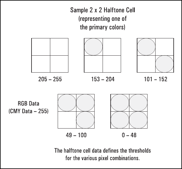
D-10 Modifying Output Color (Color LaserJet, 5, 5M, DeskJet) EN
Each dither matrix must be completely specified. Otherwise, the width
and height values may be misinterpreted if multiple matrices are sent.
If the width, height, and data specifications result in an odd number
data bytes, the next matrix specification will begin on an odd byte
boundary. No padding is provided for even-byte aligning.
Multiple Dither Matrices
As noted in the previous table, you set the number of planes field to 3
to send separate matrices for each primary. Each dither matrix must
have its own width and height data fields. As shown below, the matrix
specification for each primary follows the previous primary color’s
matrix specification.
EN Modifying Output Color (Color LaserJet, 5, 5M, DeskJet) D-11
Example
This example produces a 4 x 4 dither matrix that is applied to all three
color primaries (the number of planes is set to 1). The following
command would be sent to create this dither matrix:
?*m22W010404B0B1B2B3B4 . . . B15 (where the first 6 binary
bytes are shown as ASCII here for clarity, and B1 . . . B15 indicate the
binary byte data).
Byte 15 (msb) 8 7 (lsb) 0 Byte
0 Format = 0 Number of planes = 3 1
2 Dither matrix height in pixels (uint 16) 3
4 Dither matrix width in pixels (uint 16) 5
6 byte #0 (ubyte) byte #1 (ubyte) 7
8 byte #2 (ubyte) byte #3 (ubyte) 9
•
•
n Dither matrix height in pixels (uint 16) n + 1
n + 2 Dither matrix width in pixels (uint 16) n + 3
n + 4 byte #0 (ubyte) byte #1 (ubyte) n + 5
n + 6 byte #2 (ubyte) byte #3 (ubyte) n + 7
•
•
m Dither matrix height in pixels (uint 16) m + 1
m + 2 Dither matrix width in pixels (uint 16) m + 3
m + 4 byte #0 (ubyte) byte #1 (ubyte) m + 5
m + 6 byte #2 (ubyte) byte #3 (ubyte) m + 7
D-12 Modifying Output Color (Color LaserJet, 5, 5M, DeskJet) EN
The byte-aligned binary data field (shown as ASCII for clarity) would
be:
Note Do not use downloaded dither matrices as patterns since the
orientation of the pattern will not rotate with changes in orientation
and page rotation.
Note HP Color LaserJet 5 and 5M printers do not support the Download
Dither Matrix command. When this command is sent, the printer
parses and discards the matrix data. The printer selects the
Continuous Tone Smooth 150 lpi algorithm instead.
Byte 15 (msb) 8 7 (lsb) 0 Byte
00 1 1
20 4 3
40 4 5
6B0 B1 7
8B2 B3 9
•
•
20 B14 B15 21
EN Modifying Output Color (Color LaserJet, 5, 5M, DeskJet) D-13
Color Lookup Tables
Color lookup tables provide a way to re-map color data for the
following types of applications:
• Highlight and shadow modification
• Saturation and desaturation
• Unique gamma correction curves
• Special effects for tonal correction
• Neutral balancing
Color lookup tables map input data for each primary color into a new
output range based on point-by-point conversions. Color lookup
tables can modify input data for both device-dependent and
device-independent color spaces.
Like the CID command, the first byte of the data field identifies the
color space to which the lookup tables will be applied. These tables
specify on a point-per-point basis a transformation from an input
space of 0 . . . 255 into an output space of 0 . . . 255. Figure D-1 on
the next page illustrates the concept.
The unity lookup table (see the following illustration) is the default for
all color spaces; it performs a 1:1 mapping of input to output (that is,
129 is mapped to 129). The inversion lookup table performs a simple
color inversion; for example, it inverts the red primary of a
device-dependent RGB color space to create cyan output (from 255
red to 0 red, which is 255 cyan).
Color Lookup Tables Command
This command enables and specifies color lookup tables.
?*l#W[binary data]
A value of 0 resets or initializes the color lookup tables for each
primary to the unity curve (1:1). A value of 770 means the data for a
color lookup table will be following. The command is ignored and the
data is absorbed for any number of bytes not equal to 0 or 770.
#= Number of bytes of binary data
Default =0
Range = 0 or 770 (command is ignored for other values; sign is
ignored)
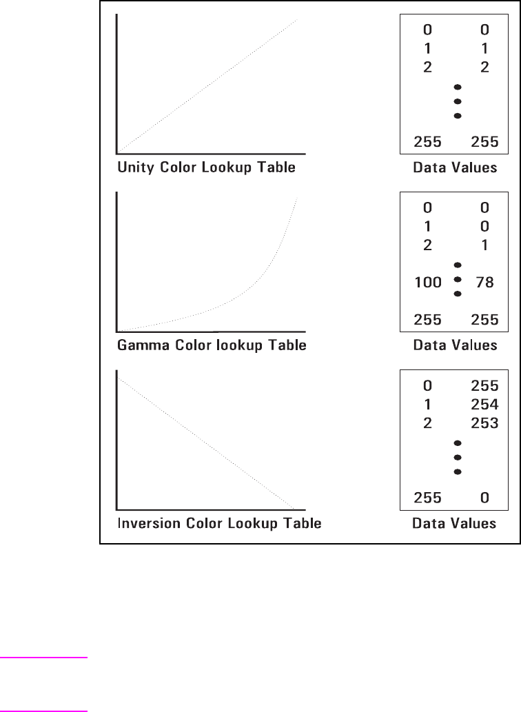
D-14 Modifying Output Color (Color LaserJet, 5, 5M, DeskJet) EN
Figure D-1 Color Lookup Tables
This command enables the color lookup tables until an ?E,
Configure Image Data (CID), or another Color Lookup Tables
command with a 0 value field is received.
Note RGB gamma correction (?*t#I) and color lookup tables for
device-dependent color spaces are mutually exclusive and overwrite
each other.
EN Modifying Output Color (Color LaserJet, 5, 5M, DeskJet) D-15
As shown below, the 256 point-by-point transformation curve for each
primary color is defined sequentially for a total of 768 bytes, with the
additional 2 bytes for specifying the color space and reserved data
field.
Byte 15 (msb) 8 7 (lsb) 0 Byte
0 Color Space Reserved Data Field 1
2 Color Component 1, Index 1 Color Component 1, Index 2 3
4 Color Component 1, Index 3 Color Component 1, Index 4 5
. . .
256 Color Component 1, Index 255 Color Component 1, Index 256 257
258 Color Component 2, Index 1 Color Component 2, Index 2 259
260 Color Component 2, Index 3 Color Component 2, Index 4 261
. . .
512 Color Component 2, Index 255 Color Component 2, Index 256 513
514 Color Component 3, Index 1 Color Component 3, Index 2 515
516 Color Component 3, Index 3 Color Component 3, Index 4 517
. . .
768 Color Component 3, Index 255 Color Component 3, Index 256 769
D-16 Modifying Output Color (Color LaserJet, 5, 5M, DeskJet) EN
Byte 0 (Color Space)
A color lookup table can be attached to one or more of the color
spaces anytime after a CID command. For example, a
Luminance-Chrominance space can have four lookup tables
specified, namely:
• Device-Dependent space
• CIE L*a*b* space
• Colorimetric RGB space
• Luminance-Chrominance space
A reset (?E), IN, or CID command sets each of the four levels of
color lookup tables for each primary to the unity curve.
Value Color Space
0 Device RGB (default)
1Device CMY
2 Colorimetric RGB Spaces
3 CIE L*a*b*
4 Luminance-Chrominance Spaces

EN Modifying Output Color (Color LaserJet, 5, 5M, DeskJet) D-17
Gamma Correction
Color monitors, which are by nature non-linear, appear incorrect when
given a linear ramp of some color. Gamma correction can significantly
improve perceptual correctness by adjusting the brightness or
darkness of the color data sent from the monitor to any other
non-linear device.
Gamma Correction Command
?*t#I
* The practical range for gamma values is 0.0 to 4.0.
Assuming 8 bits per primary (256 intensity levels per primary), the
corrected intensity for each color primary is calculated as follows:
Gamma correction is referred to in terms of device- dependent RGB.
This command does not destroy the contents of device-dependent
color lookup tables, but setting a gamma value supersedes any
lookup table input in either Device CMY or Device RGB.
Note The default value (0) gives the same result as a gamma value of 1.0,
which results in a unity gamma curve.
#= Gamma number
Default = 0 (gamma correction off)
Range = 0.0 to 32767.0 (command is ignored for invalid values)*
Intensity = 255 * Input
255
--------------
1
y
---
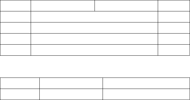
D-18 Modifying Output Color (Color LaserJet, 5, 5M, DeskJet) EN
Viewing Illuminant
Printed colors undergo a hue shift when viewed under different
illuminations (for example, fluorescent, tungsten, or daylight). Colors
with spectral characteristics outside the range of an illumination
source are not received, changing the appearance of mixed colors.
The Viewing Illuminant command (?*i#W) supports communication
of standard illuminations to the printer to allow the printer to
compensate for different lighting conditions when appearance
matching.
Viewing Illuminant Command
The Viewing Illuminant command specifies the relative white point
used in the determination of a viewing illuminant condition.
?*i#W[binary data]
The binary data field is formatted as follows:
The above firnat adheres to the IEEE floating point format as follows:
#= Number of binary bytes of data
Default =8
Range = 8 (command is ignored for invalid values; signs in the
value field are ignored
Byte 15 (msb) 8 7 (lsb) 0 Byte
0 x chromaticity white point (lsw) 1
2 x chromaticity white point (msw) 3
4 y chromaticity white point (lsw) 5
6 y chromaticity white point (msw) 7
31 30 23 22 0
Sign Exponent Fractional Portion
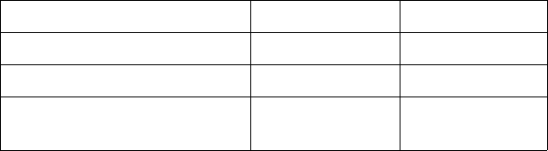
EN Modifying Output Color (Color LaserJet, 5, 5M, DeskJet) D-19
The PCL default viewing illuminant is D65 (6500K). Below is a table of
viewing illuminants and their chromaticity values.
This command affects only device-independent color. The command
acts like a state variable: it is ignored for White/Black, Device RGB, or
Device CMY palettes, but it becomes active when a new CID
command specifies a device-independent color space.
Illuminant x chromaticity y chromaticity
Daylight (D65) (6500K) 0.3127 0.3290
Tungsten (3200K) 0.4476 0.4074
Cool White Fluorescent
(5630K) 0.3904 0.3914
D-20 Modifying Output Color (Color LaserJet, 5, 5M, DeskJet) EN
Monochrome Printing
The Monochrome Print Mode command converts each color value to
its grayscale equivalent. This improves throughput, costs less to print,
and eliminates waste by providing a draft mode.
Monochrome Print Mode Command
The Monochrome Print Mode command designates whether to print
using the current rendering mode or a fast gray-scale equivalent.
Pages printed using the gray-scale equivalent do not use any color
and therefore print faster and more economically.
?&b#M
This command must be sent prior to printable data; otherwise, the
current page is closed and printed. It may be sent on a page-by-page
basis.
# = 0 - Print in mixed render algorithm mode
1 - Print using gray-scale equivalent
Default =0
Range = 0, 1 (command is ignored for invalid values)
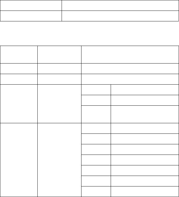
EN Modifying Output Color (Color LaserJet, 5, 5M, DeskJet) D-21
Driver Configuration Command
This command specifies the Lightness, Saturation, and Scaling
Algorithm to be applied to the document, and allows for the selection
and downloading of Color Maps.
?*o#W[device_id function_index Arguments]
device_id
function_index
#= Specifies the number of bytes to follow (device ID
function index arguments)
Default =N/A
Range = see description below
Value Printer
6 Color LaserJet printer
function_
index Description Argument Range
0 Lightness -100 to 100
1 Saturation -100 to 100
3 Scaling
Algorithm 0 Pixel Replication
1 Bilinear Interpolation
2 Modified Bilinear
Interpolation
4 Select Color
Treatment 0 No Adjustment1
1 Process Blue1
2 Vivid Graphics1
3 Transparency
4Out of Gamut
5 CIE Lab Match
6 Screen Match
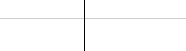
D-22 Modifying Output Color (Color LaserJet, 5, 5M, DeskJet) EN
1 For the original Color LaserJet printer, the color treatment arguments were slightly
different: (0 — Process Blue, 1 — Vivid, and 2 — Business Blue).
The following paragraphs describe the function_index values and
their arguments.
Lightness
Negative values darken (unlighten) the image, text or graphics color,
but do not have any effect on black or white data. Positive values
lighten the image. Zero turns the lightness adjustment off. This
function index requires three data bytes.
Saturation
Negative values desaturate (add gray to) the image, text or graphics
color, but will not have any effect on black or white data. Positive
values increase the amount of saturation, making the image more
vivid. Zero turns the saturation adjustment off. This function index
requires three data bytes.
Scaling
Pixel replication is a backward-compatible scaling algorithm. Bilinear
interpolation is a high-quality scaling algorithm for smooth-edge
interpolated scaling. Modified bilinear scaling only interpolates when
it is best to do so. This function index requires three data bytes.
Select Treatment
This value specifies which color treatment mode to use for rendering
the next job.
5 Download Color
Map 1 CMY Color Space
3 CIE Lab Color Space
See MapID List (14739 bytes)
function_
index Description Argument Range
EN Modifying Output Color (Color LaserJet, 5, 5M, DeskJet) D-23
No Adjustment
This setting provides linearization only (that is, the user sees the
device as a linear device).
Process Blue
This setting provides the same results as Vivid Graphics (linearization
plus user-preferred enhancements) with the addition of mapping
process blue, which looks slightly purple, to a blue closer to that of a
standard monitor. This setting is not supported by HP Color
LaserJet 5 and 5M printers.
Vivid Graphics
This setting adds color saturation to the resulting image.
Transparency
This setting uses a map to render the best color output on
transmissive media. This setting is not supported by HP Color
LaserJet 5 and 5M printers.
Out of Gamut
This setting prints colors in an image that are out of gamut—all colors
that are in gamut snap to white, all out-of-gamut colors are snapped
to the gamut surface. This setting only supports the
device-independent color map. This setting is not supported by
HP Color LaserJet 5 and 5M printers.
CIE L*a*b* Match
This map performs a true color match to the requested CIE L*a*b*
input (there are no appearance matching adjustments). This setting
only supports the device- independent color map. This setting is not
supported by HP Color LaserJet 5 and 5M printers.
Screen Match
This setting produces a simulated Colorimetric RGB effect of device
independent color to match the color to a Sony Trinitron monitor while
operating out of a device dependent color space. This setting is
supported only by HP Color LaserJet 5 and 5M printers.
D-24 Modifying Output Color (Color LaserJet, 5, 5M, DeskJet) EN
Note For screen matching, the long form of the Configure Image Data
command is used and the color maps are generated internally
dependent upon the monitor calibration data (the Driver Configuration
command is not needed).
Download Color Map
The printer supports the downloading of color adjustment maps
dependent upon the halftone requested, the type of color treatment
desired (including device-dependent or independent), and the type of
media.
Setting Description MapID
Device Dependent
No
adjustment Cluster-No Adjust-DD 1
Disperse-No Adjust-DD 2
Scatter-No Adjust-DD 3
ErrorDiffusion-No Adjust-DD 4
Process Blue Cluster-Process Blue-DD 5
Disperse-Process Blue-DD 6
Scatter-Process Blue-DD 7
ErrorDiffusion-Process Blue-DD 8
Transparency Cluster-Transparency-DD 9
Disperse-Transparency-DD 10
Scatter-Transparency-DD 11
ErrorDiffusion-Transparency-DD 12
Vivid
Graphics Cluster-VividGraphics-DD 13
Disperse-VividGraphics-DD 14
Scatter-VividGraphics-DD 15
ErrorDiffusion-VividGraphics-DD 16
EN Modifying Output Color (Color LaserJet, 5, 5M, DeskJet) D-25
Out of Gamut Cluster-OutOfGamut-DD 17
Disperse-OutOfGamut-DD 18
Scatter-OutOfGamut-DD 19
ErrorDiffusion-OutOfGamut-DD 20
CIELab Match Cluster-TrueMatch-DD 21
Disperse-TrueMatch-DD 22
Scatter-TrueMatch-DD 23
ErrorDiffusion-TrueMatch-DD 24
Setting Description MapID
D-26 Modifying Output Color (Color LaserJet, 5, 5M, DeskJet) EN
Device-Independent
No
Adjustment Cluster-No Adjust-DI 51
Disperse-No Adjust-DI 52
Scatter-No Adjust-DI 53
ErrorDiffusion-No Adjust-DI 54
Process Blue Cluster-Process Blue-DI 55
Disperse-Process Blue-DI 56
Scatter-Process Blue-DI 57
ErrorDiffusion-Process Blue-DI 58
Transparency Cluster-Transparency-DI 59
Disperse-Transparency-DI 60
Scatter-Transparency-DI 61
ErrorDiffusion-Transparency-DI 62
Vivid
Graphics Cluster-VividGraphics-DI 63
Disperse-VividGraphics-DI 64
Scatter-VividGraphics-DI 65
ErrorDiffusion-VividGraphics-DI 66
Out of Gamut Cluster-OutOfGamut-DI 67
Disperse-OutOfGamut-DI 68
Scatter-OutOfGamut-DI 69
ErrorDiffusion-OutOfGamut-DI 70
CIELab Match Cluster-TrueMatch-DI 71
Disperse-TrueMatch-DI 72
Scatter-TrueMatch-DI 73
ErrorDiffusion-TrueMatch-DI 74
Setting Description MapID
EN Index-1
Index
A
adaptive compression
block size 6-28, 6-31
compression methods 6-29
control bytes 6-29
cursor position 6-31
data block 6-28
delta row 6-29, 6-31
duplicate row 6-29, 6-30, 6-31
empty row 6-29, 6-30, 6-31
format 6-29
operation hints 6-31
row length 6-31
run-length encoded 6-29, 6-31
seed row 6-31
TIFF 6-29, 6-31
y-offset 6-31
area fill ID command
See also pattern ID command 5-29
area fill, user-defined patterns 5-33
assign color index command 3-20, C-21
B
base pattern 5-33
black and white references A-4
black rule 5-32
black-and-white mode 2-1, B-2
block size, adaptive compression 6-28
byte counts 6-34
C
chapter summary iv
CIE L*a*b* color space B-18
clipping raster area 6-13
coding efficiency, raster compression
6-23
color
concepts A-3
device-dependent A-2, A-4, A-10
device-independent A-2, A-4, A-10
foreground 3-17, C-18
lookup tables A-12, D-13
map 4-4, D-22
matching A-11
modes A-7
modifying output 4-1, D-1
processing documents A-14
raster vs. non-raster A-3, A-14
selection A-5
color appearance matching A-12
color component one command 3-19,
C-20
color component three command 3-20,
C-21
color component two command 3-19,
C-20
color lookup tables A-2
color lookup tables command D-13
color management 1-4
color modes
black-and-white mode 2-1, B-2
HP-GL/2 imaging mode 2-2, 2-13, B-3,
B-28
PCL imaging mode 2-2, 2-5, B-2, B-6
simple color mode 2-1, 2-3, B-2, B-4
color print model
command sequence 5-6
logical operations and transparency
5-12
rectangular area fills 5-45
color printing overview 1-1, A-1
color range (CR) command 7-19
color selection and palettes 1-6
color spaces 1-3
color specifications 1-3
color vector graphics (HP-GL/2) 7-1
Colorimetric RGB color space B-20
command
finish mode 4-6
logical operation 5-13
pixel placement 5-27
commands, PCL
?*c#G - Pattern (Area Fill) ID 5-29
End Raster Graphics 6-35
pattern control 5-44
pattern ID 5-29
pattern transparency mode 5-8
raster graphics presentation 6-10
raster graphics resolution 6-8
raster graphics, start 6-17
Raster Height command 6-13
Raster Width command 6-15
raster y offset 6-19
Select Current Pattern command 5-32
Set Pattern Reference Point 5-43
Set Raster Compression Method 6-20
Source Transparency Mode 5-7
Index-2 EN
transfer raster data 6-32
user-defined pattern 5-38
compression
adaptive 6-29
adaptive (operation hints) 6-31
byte counts 6-34
delta row 6-20, 6-24, 6-27
raster data 6-15, 6-23
run-length 6-21
TIFF 6-21
TIFF, raster data 6-20
compression method
adaptive 6-28
delta row 6-24
run-length encoding 6-21
setting 6-20
TIFF 6-21
unencoded 6-21
Configure Image Data (CID) command
2-5, B-6
examples B-25
long form B-17
short form B-15
continuation, user-defined pattern
descriptor 5-39
control bytes, adaptive compression 6-29
CR (color range) command 7-19
cross-hatch patterns selection 5-29
current pattern 5-2
Current Pattern command 5-32
cursor positioning
adaptive compression 6-31
raster graphic 6-34
D
data block, adaptive compression 6-28
data compression, raster data 6-15
data range scaling B-16
data, user-defined pattern 5-39
default palettes 3-15, C-16
delta row compression
adaptive compression 6-29, 6-31
raster graphics 6-20, 6-24
descriptor, user-defined pattern header
5-38
destination image 5-2
destination raster height command 6-37
destination raster width command 6-37
device CMY color space B-18
device RGB color space B-17
device-dependent color A-10
device-independent color A-10
direct color selection A-5
dither patterns 4-2, D-3
user-defined dithers D-6
dithers
download dither matrix command D-7
multiple dither matrices D-10
download dither matrix command D-7
download pattern command 5-38
driver configuration command 4-4, D-21
duplicate row, adaptive compression 6-29
E
empty row, adaptive compression 6-29
encoding
by pixel A-7
by plane A-6
end raster graphics command 6-35
enter HP-GL/2 mode 7-2
escape sequences (PCL)
?*b#M - Set Compression Method
6-20
?*b#Y - Raster Y Offset 6-19
?*c#Q - Pattern Control 5-44
?*c#W - User-Defined Pattern 5-38
?*l # R - Pixel Placement Command
5-27
?*l#O - Logical Operation 5-13
?*p#R - Set Pattern Reference Point
5-43
?*r#F - Raster Graphics Presentation
6-10
?*r#T - Raster Height 6-13
?*r#T - Raster Width 6-15
?*t#R - Raster Graphics Resolution
6-8
?*v#N - Source Transparency Mode
5-7
?*v#O - Pattern Transparency mode
5-8
?*v#T - Select Current Pattern
Command 5-32
F
Faster Y Offset command 6-19
fill rectangular area command 5-48
finish mode command 4-6
foreground color 5-2
foreground color command 3-17, C-18
format field, user-defined pattern
descriptor 5-38
G
gamma correction A-2, D-17
gamma correction command D-17
graphic patterns 5-29
graphics
raster 6-1
special effects 5-1
EN Index-3
transparency mode 5-2
user-defined patterns 5-33
grid centered, pixel 5-27
grid intersection, pixel 5-27
H
halftone render algorithms 4-2, A-2, D-3
height
pixels, user-defined pattern descriptor
5-39
Horizontal Rectangle Size command 5-46
HP-GL/2 graphics 7-1
HP-GL/2 imaging mode 2-2, 2-13, B-3,
B-28
HP-GL/2 pixel placement command 7-22
I
ICC profiles 1-4
illumination models A-13
image, raster 6-1
indexed color selection A-5
L
logical operation command 5-13
logical operations 5-3, 5-9
and transparency interactions 5-12
long form CID command B-17
luminance-chrominance color space B-22
M
manual organization iv
matching color A-11
MC (merge control) command 7-6
memory, raster graphics usage 6-8
merge control (MC) command 7-6
monochrome print mode command 4-3,
D-20
monochrome printing 4-3, D-20
N
NP (number of pens) command 7-17
number of pens (NP) command 7-17
O
operations, logical 5-9
orientation, raster graphics 6-10
overview 1-1, A-1
P
page-marking primitives A-14
palette control ID 3-8, C-8
palette, select 3-6, C-6
palettes 3-1, A-1, A-3, C-1
CID color 3-13, C-13
control 3-9, C-9
Control ID 3-8, C-8
default 3-15, C-16
device CMY 3-14, C-15
device RGB 3-13, C-13
device-independent 3-14, C-15
HP-GL/2 3-15, C-16
management by ID 3-5, C-5
palette stack 3-5, C-5
palette store 3-5, C-5
programming 3-19, C-20
saving 3-3, C-3
select palette command 3-6, C-6
simple color 3-11, C-11
palettes and color selection 1-6
pattern
current 5-2
reference point 5-36
shading 5-30
user-defined 5-33
pattern control command 5-44
patterns 5-44
Pattern ID (Area Fill ID) command 5-29
pattern transparency 5-50
pattern transparency mode 5-3
Pattern Transparency Mode command
5-8
patterns 5-2
download pattern command] 5-38
filling with 5-28
reference point 5-36
select current pattern command 5-32
set pattern reference point command
5-43
tiling 5-34
user-defined patterns 5-33
PC (pen color) command 7-14
PCL 5 color concepts 1-3
PCL 5 color graphics context 1-6
PCL 5 color mode 1-6
PCL 5 Comparison Guide vi
PCL 5 raster images 1-7
PCL imaging mode 2-2, 2-5, B-2, B-6
PCL print model 5-1
PCL/PJL Technical Quick Reference
Guide vi
pen color (PC) command 7-14
pixel encoding A-6, A-7
user-defined pattern descriptor 5-39
pixel placement 5-24, 5-27
command 5-27
HP-GL/2 command 7-22
PCL command 5-27
pixel placement (PP) command 7-20,
7-22
pixel placement command 5-27
Index-4 EN
pixels and pixel encoding 1-7
plane encoding A-6
position, rectangular area 5-49
PP (pixel placement) command 7-20,
7-22
PP command, HP-GL/2 7-22
primitives A-14
print model A-1
command sequence 5-6
current pattern 5-2
destination image 5-1
logical operations and transparency
5-12
pattern 5-1
pattern ID (area fill ID) command 5-29
pattern transparency mode 5-2, 5-8
rectangular area fills 5-45
rectangular areas, pattern ID command
5-29
Select Current Pattern command 5-32
source image 5-1
source transparency mode 5-2
printable area (raster graphics) 6-7
printing
patterns/shading 5-29
raster graphic resolution 6-8
push/pop palette command 3-3, C-3
R
raster graphics 6-1, 6-7
adaptive compression 6-28
clipping 6-13
command sequence 6-6
compression 6-20, 6-27
compression (example) 6-23, 6-27
compression, byte counts 6-34
compression, coding efficiency 6-23
compression, TIFF Encoding 6-21
data block 6-28
data compressions/reduction 6-15
delta row compression 6-20, 6-24
End command 6-35
end raster graphics command 6-35
Height command 6-13
image 6-1
left margin 6-17
memory usage 6-8
orientation 6-10
presentation 6-17
presentation mode 6-17
printable area 6-7
printing zeroed row 6-27
raster area height 6-13
raster graphics presentation mode
command 6-10
Raster Y Offset command 6-19
repeating row 6-27
resolution 6-17
run-length data compression 6-20,
6-21
seed row 6-26
Set Compression Method command
6-20
Start command 6-17
termination command 6-35
termination implied 6-17
TIFF data compression 6-20
Transfer Raster Data command 6-32,
6-33
Width command 6-15
zeroed rows 6-5
raster graphics presentation mode
command 6-10
raster graphics resolution command 6-8
raster height command 6-13
raster image 6-1
raster mode A-3
raster scaling 6-36
raster vs. non-raster color A-14
raster width command 6-15
Raster Y Offset command 6-19
rectangle
fill (transparency mode) 5-50
Horizontal Size command 5-46
position 5-49
transparency mode 5-49
Vertical Rectangle Size command 5-47
rectangular area fill examples 5-52
rectangular area fills 5-45
related documents vi
render algorithm command 4-2, D-3
render algorithms 4-2, A-2, D-3
resolution, raster graphics printing 6-8
ROP 5-13
ROP3 logical operation 5-13
rows, zeroed (in raster graphics) 6-5
rule
black 5-32
white 5-32
rules 5-45
run-length
adaptive compression 6-29
raster graphics compression 6-20
S
scaling, raster 6-36
seed row 6-24, 6-26
adaptive compression 6-31
raster graphic termination 6-17
Select Current Pattern command 5-32
Select Palette command 3-6, C-6
Set Compression Method command 6-20
EN Index-5
Set Pattern Reference Point command
5-33, 5-43
shaded fill
pattern selection 5-29
patterns 5-30
short form CID command B-15
Simple Color command 2-3, B-4
simple color mode 2-1, 2-3, B-2, B-4
source image 5-2
source raster height command 6-13
source raster width command 6-15
source transparency mode 5-2
Source Transparency Mode command
5-7
SP 6-13
sRGB color space 1-4
Start Raster Graphics command 6-17
T
Tagged Image File Format (TIFF)
Encoding (raster compression)
6-21
texture 5-2
TIFF
adaptive compression 6-29, 6-31
raster graphics compression 6-20
Transfer Raster Data command 6-28,
6-32, 6-33
transparency interactions and logical
operation 5-12
transparency mode 5-2
rectangular area 5-49
source 5-7
U
unencoded, adaptive compression 6-29
user-defined dithers D-6
user-defined pattern
assign ID 5-29
base pattern 5-33
data 5-38, 5-39
define pattern command 5-38
deleting 5-44
descriptor format (header) 5-38
example 5-40
header fields 5-38
introduction 5-33
Pattern Control command 5-44
permanent 5-44
reference point 5-36
selecting ID 5-29
Set Pattern Reference Point command
5-43
temporary 5-44
tiling 5-34
User-Defined Pattern command 5-38
user-defined patterns 5-33
V
Vertical Rectangle Size command
decipoints 5-47
PCL Units 5-47
viewing illuminant A-2
viewing illuminant command D-18
W
well-behaved raster 1-9
white rule 5-32
width
pixel, user-defined pattern descriptor
5-39
Y
Y offset command 6-19
Y-offset, adaptive compression 6-31
Z
zeroed rows (in raster graphics) 6-5
Index-6 EN