Hp Procurve Access Control Client Software Security Solutions Acs_impl
2015-03-28
: Hp Hp-Procurve-Access-Control-Client-Software-Security-Solutions-669809 hp-procurve-access-control-client-software-security-solutions-669809 hp pdf
Open the PDF directly: View PDF ![]() .
.
Page Count: 1194 [warning: Documents this large are best viewed by clicking the View PDF Link!]
- Contents
- Introduction
- Implementing 802.1X with ProCurve IDM and Endpoint Integrity
- Contents
- Introduction
- Configuring the ProCurve Switches
- Configuring the Windows Domain Controller
- Configuring the DHCP Server
- Configuring Certificate Services
- Configuring the Wireless Edge Services Modules
- Configuring the NAC 800s
- Manually Issue and Install Server Certificates
- Configuring Network Access Control with PCM+
- Configuring Network Access Control with IDM
- Setting Up Endpoints
- Activating Network Access Control
- Implementing 802.1X with Endpoint Integrity but without IDM
- Contents
- Introduction
- Configure the ProCurve Switches
- Configure Windows 2003 Services
- Configure IAS
- Install IAS
- Register IAS with Active Directory
- Install a Certificate on the IAS Server
- Configure IAS Properties
- Configure the Remote Access Policies
- Add RADIUS Clients
- Enable Remote Access Logging
- Install and Configure Connectors for Endpoint Integrity with the NAC 800
- Install the NAC 800’s CA Certificate as a Trusted Root on the IAS Server
- Configure the Wireless Edge Services zl Modules
- Configure the NAC 800s
- Set Up Endpoints
- Activate Network Access Control
- Implementing a VPN with Endpoint Integrity
- Contents
- Introduction
- Configuring the ProCurve Switches
- Configure Windows Services
- Configure Certificate Services
- Configure the ProCurve Secure Router 7000dl
- Configure the Physical and Virtual Interfaces
- Enable Telnet and SSH Access
- Configure the Routing Protocol
- Use Policy-Based Routing to Forward VPN Traffic Through the NAC 800
- Enable Routing to the Remote Endpoints
- Configure Network Address Translation (NAT)
- Establish the VPN
- Allow VPN Traffic on the Internet Interface
- Using Digital Certificates
- Secure Router 7000dl Running-Config
- Configuring the NAC 800
- Set Up Endpoints
- Using the NAC 800 in a RADIUS-Only Configuration
- Contents
- Introduction
- Switches
- Configure the Wireless Edge Services Module
- Configure OpenLDAP
- Configure the NAC 800 for a RADIUS- Only Deployment
- Configuring Network Access Control with IDM
- Configure Endpoints
- Enforcing Endpoint Integrity without Port Authentication
- Appendix A: Using IDM with eDirectory
- Appendix B: Glossary
- Addendum: ProCurve Access Control Solution 2.1 Update
- Contents
- Introduction
- Configuring the Windows Domain Controller
- Configuring the DHCP Server
- Configuring Certificate Services
- Configuring the NPS Server
- Join the Server to the Domain
- Install the NPS Server Role
- Install the Group Policy Management Feature
- Obtain a Computer Certificate on the NPS Server
- Configure 802.1X NAP Enforcement Using the NAP Configuration Wizard
- Verify NAP Policies
- Configure System Health Validators (SHVs)
- Configure NAP Client Settings in Group Policy
- Configure Security Filters for the NAP Client Settings
- Configuring the Wireless Edge Services Modules
- Install the Wireless Edge Services Modules
- Configure Initial Settings on the Wireless Edge Services Modules
- Configure WLAN Settings
- Configure SNMP on the Wireless Edge Services Modules
- Change Web-User Passwords
- Specify the Wireless Module’s DNS Server
- Configure the Time
- Set the Country Code
- Obtain a Server Certificate for the Wireless Module
- Install the Certificate on a Wireless Edge Services Module
- Configure the Endpoints
- Configuring Network Access Control with IDM
- Guest Access for Wireless Users
- Index

Access Control Security
Implementation Guide 2.1
www.procurve.com
ProCurve Solutions

ProCurve Access Control Security
Implementation Guide
May 2008
2.1.XX

Hewlett-Packard Company
8000 Foothills Boulevard
Roseville, California 95747
http://www.procurve.com/
© Copyright 2008 Hewlett-Packard Development Company, L.P.
The information contained herein is subject to change without
notice. All Rights Reserved.
This document contains proprietary information, which is
protected by copyright. No part of this document may be
photocopied, reproduced, or translated into another language
without the prior written consent of Hewlett-Packard.
Applicable ProCurve Products
Network Access Controller 800 (J9065A)
ProCurve Manager Plus (J9056A)
Identity Driven Manager (J9012A)
IPsec VPN Base Modules (J9026A, J8471A)
Secure Router 7102dl (J8752A)
Secure Router 7203dl (J8753A)
Switch 5406zl (J8697A)
Switch 5406zl-48G (J8699A)
Switch 5412zl (J8698A)
Switch 5412zl-96G (J8700A)
Switch 5304xl (J4850A)
Switch 5304xl-32G (J8166A)
Switch 5308xl (J4819A)
Switch 5308xl-48G (J8167A)
Switch 5348xl (J4849A)
Switch 5372xl (J4848B)
Switch 8212zl (J8715A)
Wireless Edge Services xl Module (J9001A)
Redundant Wireless Services xl Module (J9003A)
Wireless Edge Services zl Module (J9051A)
Redundant Wireless Services zl Module (J9052A)
AP 530 (J8986A)
AP 420 na/ww (J8130B, J8131B)
RP 210 (J9004A)
RP 220 (J9005A)
RP 230 (J9006A)
Trademark Credits
ActiveX, Microsoft, Windows, Windows NT, and Windows
XP are U.S. registered trademarks of Microsoft Corporation.
Apple, Mac OS, and QuickTime are registered trademarks of
Apple, Inc.
CRYPTOCard is a registered trademark of Cryptocard
Corporation.
eDirectory, NetWare, Novell, and SUSE are registered
trademarks of Novell, Inc.
Juniper Networks is a registered trademark of Juniper
Networks, Inc.
Linux is a registered trademark of Linus Torvalds.
OpenLDAP is a registered trademark of the OpenLDAP
Foundation.
Red Hat is a registered trademark of Red Hat, Inc.
Solaris is a registered trademark of Sun Microsystems, Inc.
Steel-Belted Radius is a registered trademark of Funk
Software, Inc.
Disclaimer
HEWLETT-PACKARD COMPANY MAKES NO WARRANTY
OF ANY KIND WITH REGARD TO THIS MATERIAL,
INCLUDING, BUT NOT LIMITED TO, THE IMPLIED
WARRANTIES OF MERCHANTABILITY AND FITNESS
FOR A PARTICULAR PURPOSE. Hewlett-Packard shall not
be liable for errors contained herein or for incidental or
consequential damages in connection with the furnishing,
performance, or use of this material.
The only warranties for HP products and services are set
forth in the express warranty statements accompanying
such products and services. Nothing herein should be
construed as constituting an additional warranty. HP shall
not be liable for technical or editorial errors or omissions
contained herein.
Hewlett-Packard assumes no responsibility for the use or
reliability of its software on equipment that is not furnished
by Hewlett-Packard.
Warranty
See the Customer Support/Warranty booklet included with
the related products.
A copy of the specific warranty terms applicable to your
Hewlett-Packard products and replacement parts can be
obtained from your HP Sales and Service Office or
authorized dealer.
Open Source Software Acknowledgment
Statement
This software incorporates open source components that
are governed by the GNU General Public License (GPL),
version 2. In accordance with this license, ProCurve
Networking will make available a complete, machine-
readable copy of the source code components covered by
the GNU GPL upon receipt of a written request. Send a
request to:
Hewlett-Packard Company, L.P.
Wireless Edge Services xl Module Program
GNU GPL Source Code
Attn: ProCurve Networking Support
MS: 5550
Roseville, CA 95747 USA

1
Contents
1 Introduction
Contents . . . . . . . . . . . . . . . . . . . . . . . . . . . . . . . . . . . . . . . . . . . . . . . . . . . . . . 1-1
Using This Guide . . . . . . . . . . . . . . . . . . . . . . . . . . . . . . . . . . . . . . . . . . . . . . 1-2
Network Access Control Solution 1 . . . . . . . . . . . . . . . . . . . . . . . . . . . . 1-2
Network Access Control Solution 2 . . . . . . . . . . . . . . . . . . . . . . . . . . . . 1-5
Network Access Control Solution 3 . . . . . . . . . . . . . . . . . . . . . . . . . . . . 1-6
Network Access Control Solution 4 . . . . . . . . . . . . . . . . . . . . . . . . . . . . 1-7
Network Access Control Solution 5 . . . . . . . . . . . . . . . . . . . . . . . . . . . . 1-8
Summary of the Access Control Solutions . . . . . . . . . . . . . . . . . . . . . . 1-9
Hardware and Software Versions . . . . . . . . . . . . . . . . . . . . . . . . . . . . . 1-11
2 Implementing 802.1X with ProCurve IDM and Endpoint
Integrity
Contents . . . . . . . . . . . . . . . . . . . . . . . . . . . . . . . . . . . . . . . . . . . . . . . . . . . . . . 2-1
Introduction . . . . . . . . . . . . . . . . . . . . . . . . . . . . . . . . . . . . . . . . . . . . . . . . . . 2-5
Configuring the ProCurve Switches . . . . . . . . . . . . . . . . . . . . . . . . . . . 2-13
Routing Switches . . . . . . . . . . . . . . . . . . . . . . . . . . . . . . . . . . . . . . . . . . . 2-14
Server Switch startup-config . . . . . . . . . . . . . . . . . . . . . . . . . . . . . . . . . 2-16
Edge Switches . . . . . . . . . . . . . . . . . . . . . . . . . . . . . . . . . . . . . . . . . . . . . 2-17
Wireless Services-Enabled Switch startup-config . . . . . . . . . . . . 2-17
Configuring the Windows Domain Controller . . . . . . . . . . . . . . . . . . 2-20
Install Windows Server 2003 . . . . . . . . . . . . . . . . . . . . . . . . . . . . . . . . . 2-20
Install Active Directory . . . . . . . . . . . . . . . . . . . . . . . . . . . . . . . . . . . . . . 2-21
Raise the Domain Functional Level . . . . . . . . . . . . . . . . . . . . . . . . . . . 2-27
Configure Windows Domain Groups . . . . . . . . . . . . . . . . . . . . . . . . . . 2-28
Configure Windows Domain Users . . . . . . . . . . . . . . . . . . . . . . . . . . . . 2-31
Configure DNS Services . . . . . . . . . . . . . . . . . . . . . . . . . . . . . . . . . . . . . 2-35

2
Configuring the DHCP Server . . . . . . . . . . . . . . . . . . . . . . . . . . . . . . . . . 2-42
Install the DHCP Service . . . . . . . . . . . . . . . . . . . . . . . . . . . . . . . . . . . . 2-43
Configure the DHCP Server . . . . . . . . . . . . . . . . . . . . . . . . . . . . . . . . . . 2-46
Configuring Certificate Services . . . . . . . . . . . . . . . . . . . . . . . . . . . . . . 2-53
Join the Windows Server 2003 Server to the Domain . . . . . . . . . . . . . 2-54
Install IIS and the Certificate Services . . . . . . . . . . . . . . . . . . . . . . . . . 2-56
Set Up Autoenrollment of Computer and User Certificates . . . . . . . 2-68
Set Up Autoenrollment of Computer Certificates . . . . . . . . . . . . 2-68
Create a Management Console for the CA . . . . . . . . . . . . . . . . . . 2-76
Customize the User Certificate Template . . . . . . . . . . . . . . . . . . . 2-82
Create the NAC 800 Certificate Template . . . . . . . . . . . . . . . . . . . 2-87
Deploy the New Certificate Templates to the CA . . . . . . . . . . . . 2-91
Set Up Autoenrollment of User Certificates . . . . . . . . . . . . . . . . . 2-92
Export the CA Root Certificate . . . . . . . . . . . . . . . . . . . . . . . . . . . 2-97
Configuring the Wireless Edge Services Modules . . . . . . . . . . . . . . 2-106
Install the Wireless Edge Services Modules . . . . . . . . . . . . . . . . . . . 2-106
Configure Initial Settings on the Wireless Edge Services
Modules . . . . . . . . . . . . . . . . . . . . . . . . . . . . . . . . . . . . . . . . . . . . . . . . . 2-107
Configure WLAN Settings . . . . . . . . . . . . . . . . . . . . . . . . . . . . . . . . . . . 2-109
Configure the Redundancy Group . . . . . . . . . . . . . . . . . . . . . . . . . . . 2-114
Configure SNMP on the Wireless Edge Services Modules . . . . . . . . 2-117
Configure the Time . . . . . . . . . . . . . . . . . . . . . . . . . . . . . . . . . . . . . . . . 2-125
Set the Country Code . . . . . . . . . . . . . . . . . . . . . . . . . . . . . . . . . . . . . . 2-129
802.1X Authentication for RPs . . . . . . . . . . . . . . . . . . . . . . . . . . . . . . . 2-130
Configuring 802.1X Authentication for RPs . . . . . . . . . . . . . . . . 2-131
Configuring the NAC 800s . . . . . . . . . . . . . . . . . . . . . . . . . . . . . . . . . . . 2-134
Install the NAC 800s . . . . . . . . . . . . . . . . . . . . . . . . . . . . . . . . . . . . . . . 2-134
Configure Basic Settings on the NAC 800s . . . . . . . . . . . . . . . . . . . . 2-135
Configure Initial Settings Through a Console Session . . . . . . . 2-135
Access the Web Browser Interface . . . . . . . . . . . . . . . . . . . . . . . 2-141
Configure More Basic Settings for the MS . . . . . . . . . . . . . . . . . 2-142
Create an Enforcement Cluster and Add ESs . . . . . . . . . . . . . . 2-146
Configure Quarantining . . . . . . . . . . . . . . . . . . . . . . . . . . . . . . . . . . . . 2-149
Add 802.1X Devices . . . . . . . . . . . . . . . . . . . . . . . . . . . . . . . . . . . . 2-151
Enable EAP-MD5 (Optional) . . . . . . . . . . . . . . . . . . . . . . . . . . . . . . . . 2-154

3
Configure Testing Methods . . . . . . . . . . . . . . . . . . . . . . . . . . . . . . . . . 2-155
Configure Agentless Credentials . . . . . . . . . . . . . . . . . . . . . . . . . 2-156
Enable the RPC Service on Endpoints . . . . . . . . . . . . . . . . . . . . 2-157
Select the Backup Testing Methods Suggested by the
NAC 800 . . . . . . . . . . . . . . . . . . . . . . . . . . . . . . . . . . . . . . . . . . . . . . 2-164
Configure NAC Policies . . . . . . . . . . . . . . . . . . . . . . . . . . . . . . . . . . . . 2-165
Manually Issue and Install Server Certificates . . . . . . . . . . . . . . . . 2-174
Create and Install a Certificate for the Wireless Edge
Services Module’s HTTPS Server . . . . . . . . . . . . . . . . . . . . . . . . . . . . 2-174
Create a Certificate Request on the Wireless Edge
Services Module . . . . . . . . . . . . . . . . . . . . . . . . . . . . . . . . . . . . . . . 2-174
Submit the Request to the CA and Create the Certificate . . . . . 2-182
Install the Certificate on a Wireless Edge Services Module . . . . . . 2-183
Enable the Certificate on the Wireless Edge Services
Module’s HTTPS Server . . . . . . . . . . . . . . . . . . . . . . . . . . . . . . . . 2-187
Create and Install a Certificate for HTTPS on a NAC 800 . . . . . . . . 2-188
Create a Certificate Request for HTTPS on a NAC 800 . . . . . . . 2-189
Submit the Request for the HTTPS Certificate to the CA . . . . . 2-191
Install the Certificates for HTTPS on a NAC 800 . . . . . . . . . . . . 2-193
Create and Install a Certificate for the NAC 800 RADIUS
Service . . . . . . . . . . . . . . . . . . . . . . . . . . . . . . . . . . . . . . . . . . . . . . . . . . 2-196
Create a Certificate Request for the RADIUS Service . . . . . . . . 2-196
Submit the Request for the RADIUS Server Certificate
to the CA . . . . . . . . . . . . . . . . . . . . . . . . . . . . . . . . . . . . . . . . . . . . . 2-198
Install the Certificate for RADIUS Services on a NAC 800 . . . . 2-199
Configuring Network Access Control with PCM+ . . . . . . . . . . . . . . 2-203
Install PCM+ . . . . . . . . . . . . . . . . . . . . . . . . . . . . . . . . . . . . . . . . . . . . . 2-203
Install IDM 2.2 . . . . . . . . . . . . . . . . . . . . . . . . . . . . . . . . . . . . . . . . . 2-221
Configuring Network Access Control with IDM . . . . . . . . . . . . . . . 2-229
Add NAC 800s to the Access.txt File . . . . . . . . . . . . . . . . . . . . . . . . . 2-229
Enable Endpoint Integrity . . . . . . . . . . . . . . . . . . . . . . . . . . . . . . . . . . 2-234
Add Access Policy Groups and Users . . . . . . . . . . . . . . . . . . . . . . . . . 2-237
Define Resources . . . . . . . . . . . . . . . . . . . . . . . . . . . . . . . . . . . . . . . . . 2-247
Create Access Profiles . . . . . . . . . . . . . . . . . . . . . . . . . . . . . . . . . . . . . 2-254
Configure Access Policy Groups . . . . . . . . . . . . . . . . . . . . . . . . . . . . . 2-267
Deploy Policies to the NAC 800s . . . . . . . . . . . . . . . . . . . . . . . . . . . . . 2-274

4
Setting Up Endpoints . . . . . . . . . . . . . . . . . . . . . . . . . . . . . . . . . . . . . . . . 2-276
Install Certificates . . . . . . . . . . . . . . . . . . . . . . . . . . . . . . . . . . . . . . . . . 2-276
Autoenroll for Certificates . . . . . . . . . . . . . . . . . . . . . . . . . . . . . . 2-276
Manually Enroll for Certificates . . . . . . . . . . . . . . . . . . . . . . . . . . 2-285
Configure the 802.1X Supplicant . . . . . . . . . . . . . . . . . . . . . . . . . . . . . 2-297
Configure the 802.1X Supplicant for EAP-TLS on an
Ethernet Connection . . . . . . . . . . . . . . . . . . . . . . . . . . . . . . . . . . . 2-298
Configure the 802.1X Supplicant for EAP-TLS on a
Wireless Connection . . . . . . . . . . . . . . . . . . . . . . . . . . . . . . . . . . . 2-301
Enable WZC . . . . . . . . . . . . . . . . . . . . . . . . . . . . . . . . . . . . . . . . . . 2-305
Pre-install the NAC EI Agent on Endpoints . . . . . . . . . . . . . . . . . . . . 2-306
Deploy the NAC EI Agent Automatically—Active
Directory Group Policy Object Software Installation . . . . . . . . 2-307
Activating Network Access Control . . . . . . . . . . . . . . . . . . . . . . . . . . 2-318
Activate Port Authentication . . . . . . . . . . . . . . . . . . . . . . . . . . . . . . . . 2-318
Activate Quarantining . . . . . . . . . . . . . . . . . . . . . . . . . . . . . . . . . . . . . . 2-319
3 Implementing 802.1X with Endpoint Integrity but
without IDM
Contents . . . . . . . . . . . . . . . . . . . . . . . . . . . . . . . . . . . . . . . . . . . . . . . . . . . . . . 3-1
Introduction . . . . . . . . . . . . . . . . . . . . . . . . . . . . . . . . . . . . . . . . . . . . . . . . . . 3-3
Configure the ProCurve Switches . . . . . . . . . . . . . . . . . . . . . . . . . . . . . . 3-9
Routing Switches . . . . . . . . . . . . . . . . . . . . . . . . . . . . . . . . . . . . . . . . . . . 3-10
Server Switch startup-config . . . . . . . . . . . . . . . . . . . . . . . . . . . . . . . . . 3-12
Edge Switches . . . . . . . . . . . . . . . . . . . . . . . . . . . . . . . . . . . . . . . . . . . . . 3-13
Wireless Services-Enabled Switch startup-config . . . . . . . . . . . . 3-13
Configure Windows 2003 Services . . . . . . . . . . . . . . . . . . . . . . . . . . . . . 3-15
Configure IAS . . . . . . . . . . . . . . . . . . . . . . . . . . . . . . . . . . . . . . . . . . . . . . . . 3-16
Install IAS . . . . . . . . . . . . . . . . . . . . . . . . . . . . . . . . . . . . . . . . . . . . . . . . . 3-16
Register IAS with Active Directory . . . . . . . . . . . . . . . . . . . . . . . . . . . . 3-19
Install a Certificate on the IAS Server . . . . . . . . . . . . . . . . . . . . . . . . . 3-21
Configure IAS Properties . . . . . . . . . . . . . . . . . . . . . . . . . . . . . . . . . . . . 3-30

5
Configure the Remote Access Policies . . . . . . . . . . . . . . . . . . . . . . . . . 3-34
Using the New Remote Access Policy Wizard . . . . . . . . . . . . . . . 3-37
Manually Create a Remote Access Policy . . . . . . . . . . . . . . . . . . . 3-43
Edit a Remote Access Policy . . . . . . . . . . . . . . . . . . . . . . . . . . . . . 3-62
Optional Remote Access Policy for Network
Administrators . . . . . . . . . . . . . . . . . . . . . . . . . . . . . . . . . . . . . . . . . 3-66
Add RADIUS Clients . . . . . . . . . . . . . . . . . . . . . . . . . . . . . . . . . . . . . . . . 3-79
Enable Remote Access Logging . . . . . . . . . . . . . . . . . . . . . . . . . . . . . . 3-82
Install and Configure Connectors for Endpoint Integrity with
the NAC 800 . . . . . . . . . . . . . . . . . . . . . . . . . . . . . . . . . . . . . . . . . . . . . . . 3-86
Install the Connector Files . . . . . . . . . . . . . . . . . . . . . . . . . . . . . . . 3-86
Configure VLAN Assignments in the SAIASConnector.ini
File . . . . . . . . . . . . . . . . . . . . . . . . . . . . . . . . . . . . . . . . . . . . . . . . . . . 3-89
Edit the IAS Server Registry . . . . . . . . . . . . . . . . . . . . . . . . . . . . . . 3-94
Install the NAC 800’s CA Certificate as a Trusted Root on
the IAS Server . . . . . . . . . . . . . . . . . . . . . . . . . . . . . . . . . . . . . . . . . . . . . 3-96
Configure the Wireless Edge Services zl Modules . . . . . . . . . . . . . 3-101
Configure the NAC 800s . . . . . . . . . . . . . . . . . . . . . . . . . . . . . . . . . . . . . 3-102
Configure Basic Settings on the NAC 800s . . . . . . . . . . . . . . . . . . . . 3-102
Access the Web Browser Interface . . . . . . . . . . . . . . . . . . . . . . . 3-102
Create the Enforcement Cluster and Add ESs . . . . . . . . . . . . . . . . . 3-103
Configure Quarantining . . . . . . . . . . . . . . . . . . . . . . . . . . . . . . . . . . . . 3-103
Add 802.1X Devices . . . . . . . . . . . . . . . . . . . . . . . . . . . . . . . . . . . . 3-106
Configure NAC Policies . . . . . . . . . . . . . . . . . . . . . . . . . . . . . . . . . . . . 3-109
Configure Endpoint Integrity Testing Methods . . . . . . . . . . . . . . . . . 3-109
Install SSL Certificates on the NAC 800s . . . . . . . . . . . . . . . . . . . . . . 3-110
Export a Self-signed Certificate from a NAC 800 and Install
it on the IAS Server . . . . . . . . . . . . . . . . . . . . . . . . . . . . . . . . . . . . . . . . 3-110

6
Set Up Endpoints . . . . . . . . . . . . . . . . . . . . . . . . . . . . . . . . . . . . . . . . . . . . 3-116
Activate Network Access Control . . . . . . . . . . . . . . . . . . . . . . . . . . . . 3-117
4 Implementing a VPN with Endpoint Integrity
Contents . . . . . . . . . . . . . . . . . . . . . . . . . . . . . . . . . . . . . . . . . . . . . . . . . . . . . . 4-1
Introduction . . . . . . . . . . . . . . . . . . . . . . . . . . . . . . . . . . . . . . . . . . . . . . . . . . 4-4
Configuring the ProCurve Switches . . . . . . . . . . . . . . . . . . . . . . . . . . . 4-10
Routing Switch startup-config . . . . . . . . . . . . . . . . . . . . . . . . . . . . . . . . 4-10
Configure Windows Services . . . . . . . . . . . . . . . . . . . . . . . . . . . . . . . . . . 4-12
Configure Certificate Services . . . . . . . . . . . . . . . . . . . . . . . . . . . . . . . . 4-13
Customize a Template for VPN Client Certificates . . . . . . . . . . . . . . . 4-14
Template for VPN Client Certificate Obtained Via a
Manual Request . . . . . . . . . . . . . . . . . . . . . . . . . . . . . . . . . . . . . . . . 4-14
Template for a VPN Client Certificate with an
Automatically Generated Subject Name . . . . . . . . . . . . . . . . . . . . 4-21
Customize the Template for the Router’s IPsec Certificate . . . . . . . 4-32
Enable Templates on the CA Server . . . . . . . . . . . . . . . . . . . . . . . . . . . 4-36
Export the CRL . . . . . . . . . . . . . . . . . . . . . . . . . . . . . . . . . . . . . . . . . . . . 4-38
Check the Key Size for the CA Root Certificate . . . . . . . . . . . . . . . . . 4-41
Configure the ProCurve Secure Router 7000dl . . . . . . . . . . . . . . . . . 4-48
Configure the Physical and Virtual Interfaces . . . . . . . . . . . . . . . . . . . 4-48
Configure the Ethernet Interface . . . . . . . . . . . . . . . . . . . . . . . . . . 4-48
Configure the WAN Interface . . . . . . . . . . . . . . . . . . . . . . . . . . . . . 4-50
Enable Telnet and SSH Access . . . . . . . . . . . . . . . . . . . . . . . . . . . . . . . 4-54
Configure the Routing Protocol . . . . . . . . . . . . . . . . . . . . . . . . . . . . . . 4-56
Use Policy-Based Routing to Forward VPN Traffic Through
the NAC 800 . . . . . . . . . . . . . . . . . . . . . . . . . . . . . . . . . . . . . . . . . . . . . . . 4-58
Enable Routing to the Remote Endpoints . . . . . . . . . . . . . . . . . . . . . . 4-61
Create the Route to the Remote Endpoints on the Secure
Router 7000dl . . . . . . . . . . . . . . . . . . . . . . . . . . . . . . . . . . . . . . . . . . 4-62
Configure RIP Filters . . . . . . . . . . . . . . . . . . . . . . . . . . . . . . . . . . . . 4-63
Configure Network Address Translation (NAT) . . . . . . . . . . . . . . . . . 4-67
Configure Source NAT . . . . . . . . . . . . . . . . . . . . . . . . . . . . . . . . . . 4-67
Configure Destination NAT with Port Forwarding . . . . . . . . . . . 4-70

7
Establish the VPN . . . . . . . . . . . . . . . . . . . . . . . . . . . . . . . . . . . . . . . . . . 4-73
Activate Crypto Commands . . . . . . . . . . . . . . . . . . . . . . . . . . . . . . 4-74
Create a Client Configuration Pool . . . . . . . . . . . . . . . . . . . . . . . . 4-74
Configure an IKE Policy . . . . . . . . . . . . . . . . . . . . . . . . . . . . . . . . . 4-76
Create ACLs for VPN Traffic . . . . . . . . . . . . . . . . . . . . . . . . . . . . . 4-83
Configure a Transform Set . . . . . . . . . . . . . . . . . . . . . . . . . . . . . . . 4-88
Create a Crypto Map . . . . . . . . . . . . . . . . . . . . . . . . . . . . . . . . . . . . 4-90
Create the Remote ID List . . . . . . . . . . . . . . . . . . . . . . . . . . . . . . . . 4-94
Apply the Crypto Map to an Interface . . . . . . . . . . . . . . . . . . . . . . 4-97
Allow VPN Traffic on the Internet Interface . . . . . . . . . . . . . . . . . . . . 4-98
Using Digital Certificates . . . . . . . . . . . . . . . . . . . . . . . . . . . . . . . . . . . 4-105
Obtain Digital Certificates . . . . . . . . . . . . . . . . . . . . . . . . . . . . . . 4-106
Manage Certificates . . . . . . . . . . . . . . . . . . . . . . . . . . . . . . . . . . . . 4-115
Secure Router 7000dl Running-Config . . . . . . . . . . . . . . . . . . . . . . . . 4-118
Configuring the NAC 800 . . . . . . . . . . . . . . . . . . . . . . . . . . . . . . . . . . . . 4-128
Install the NAC 800 . . . . . . . . . . . . . . . . . . . . . . . . . . . . . . . . . . . . . . . . 4-130
Configure Initial Settings on the New NAC 800 . . . . . . . . . . . . . . . . 4-131
Configure Initial Settings through a Console Session . . . . . . . . 4-131
Access the MS’s Web Browser Interface . . . . . . . . . . . . . . . . . . . . . . 4-136
Create the Enforcement Cluster . . . . . . . . . . . . . . . . . . . . . . . . . . . . . 4-136
Add the ES to the Enforcement Cluster . . . . . . . . . . . . . . . . . . . . . . . 4-140
Move an Existing ES to the New Cluster . . . . . . . . . . . . . . . . . . 4-142
Configure Quarantining . . . . . . . . . . . . . . . . . . . . . . . . . . . . . . . . . . . . 4-146
Set Up Accessible Services . . . . . . . . . . . . . . . . . . . . . . . . . . . . . . . . . 4-147
Other Settings for the NAC 800 . . . . . . . . . . . . . . . . . . . . . . . . . . . . . . 4-150
Activate Quarantining . . . . . . . . . . . . . . . . . . . . . . . . . . . . . . . . . . . . . . 4-150
Set Up Endpoints . . . . . . . . . . . . . . . . . . . . . . . . . . . . . . . . . . . . . . . . . . . . 4-153
Obtain a Certificate Using the Windows CA Web Enrollment
Pages . . . . . . . . . . . . . . . . . . . . . . . . . . . . . . . . . . . . . . . . . . . . . . . . . . . . 4-153

8
Configure the ProCurve VPN Client . . . . . . . . . . . . . . . . . . . . . . . . . . 4-154
Obtain the ProCurve VPN Client . . . . . . . . . . . . . . . . . . . . . . . . . 4-155
Install the ProCurve VPN Client . . . . . . . . . . . . . . . . . . . . . . . . . . 4-155
Install Certificates . . . . . . . . . . . . . . . . . . . . . . . . . . . . . . . . . . . . . 4-157
Configure a New Connection . . . . . . . . . . . . . . . . . . . . . . . . . . . . 4-173
Create a Security Policy . . . . . . . . . . . . . . . . . . . . . . . . . . . . . . . . 4-179
Test the VPN Connection . . . . . . . . . . . . . . . . . . . . . . . . . . . . . . . 4-184
Export the Policy and Certificates . . . . . . . . . . . . . . . . . . . . . . . . 4-185
User Instructions: Install the ProCurve VPN Client and the
Preconfigured Policy . . . . . . . . . . . . . . . . . . . . . . . . . . . . . . . . . . . . . . 4-194
Import the Policy Manually . . . . . . . . . . . . . . . . . . . . . . . . . . . . . . 4-199
Manually Import Certificates . . . . . . . . . . . . . . . . . . . . . . . . . . . . 4-201
5 Using the NAC 800 in a RADIUS-Only Configuration
Contents . . . . . . . . . . . . . . . . . . . . . . . . . . . . . . . . . . . . . . . . . . . . . . . . . . . . . . 5-1
Introduction . . . . . . . . . . . . . . . . . . . . . . . . . . . . . . . . . . . . . . . . . . . . . . . . . . 5-4
Configuring This Access Control Solution . . . . . . . . . . . . . . . . . . . . . . . 5-6
Example—the Existing Network Environment . . . . . . . . . . . . . . . . . . 5-6
VLANs . . . . . . . . . . . . . . . . . . . . . . . . . . . . . . . . . . . . . . . . . . . . . . . . . 5-7
DHCP and DNS Services . . . . . . . . . . . . . . . . . . . . . . . . . . . . . . . . . 5-10
Switches . . . . . . . . . . . . . . . . . . . . . . . . . . . . . . . . . . . . . . . . . . . . . . . . . . . . . 5-11
Concurrent Access Methods on the Same Port . . . . . . . . . . . . . . . . . . 5-11
Routing Switch Startup-Config . . . . . . . . . . . . . . . . . . . . . . . . . . . . 5-14
Server Switch Startup-Config . . . . . . . . . . . . . . . . . . . . . . . . . . . . . 5-16
Edge Switch Startup-Configs . . . . . . . . . . . . . . . . . . . . . . . . . . . . . 5-18
Configure the Wireless Edge Services Module . . . . . . . . . . . . . . . . . 5-21
Configure Initial Settings on the Wireless Edge Services
Modules . . . . . . . . . . . . . . . . . . . . . . . . . . . . . . . . . . . . . . . . . . . . . . . . . . 5-22
Configure WLAN Settings . . . . . . . . . . . . . . . . . . . . . . . . . . . . . . . . . . . . 5-25
Configure 802.1X as the Security for WLAN 1 . . . . . . . . . . . . . . . 5-25
Configure Web-Auth for WLANs 2 and 3 . . . . . . . . . . . . . . . . . . . . 5-33
Copying Logo Files to the Module’s Flash . . . . . . . . . . . . . . . . . . . . . . 5-50
Configure SNMP on the Wireless Edge Services Modules . . . . . . . . . 5-52
802.1X Authentication for RPs . . . . . . . . . . . . . . . . . . . . . . . . . . . . . . . . 5-60
Configure 802.1X Authentication for RPs . . . . . . . . . . . . . . . . . . . 5-61

9
Configure OpenLDAP . . . . . . . . . . . . . . . . . . . . . . . . . . . . . . . . . . . . . . . . . 5-63
Extend the OpenLDAP Schema to Support RADIUS . . . . . . . . . . . . . 5-64
Objects in the Standard OpenLDAP Schema . . . . . . . . . . . . . . . . 5-64
Create and Modify Files to Extend the Schema . . . . . . . . . . . . . . 5-65
RADIUS Objects . . . . . . . . . . . . . . . . . . . . . . . . . . . . . . . . . . . . . . . . 5-67
Create Objects in OpenLDAP . . . . . . . . . . . . . . . . . . . . . . . . . . . . . . . . 5-67
Bind to OpenLDAP . . . . . . . . . . . . . . . . . . . . . . . . . . . . . . . . . . . . . . . . . 5-73
Base DN and Administrator . . . . . . . . . . . . . . . . . . . . . . . . . . . . . . 5-74
Configure a Root CA with OpenSSL . . . . . . . . . . . . . . . . . . . . . . . . . . . 5-74
Create an Intermediate Certificate . . . . . . . . . . . . . . . . . . . . . . . . . . . . 5-77
Copy the Keys and Certificates to OpenLDAP . . . . . . . . . . . . . . . . . . 5-80
Configure the NAC 800 for a RADIUS-Only Deployment . . . . . . . . 5-81
Data Store Overview . . . . . . . . . . . . . . . . . . . . . . . . . . . . . . . . . . . . . . . . 5-81
Configuration Options . . . . . . . . . . . . . . . . . . . . . . . . . . . . . . . . . . . . . . 5-82
Initial Setup . . . . . . . . . . . . . . . . . . . . . . . . . . . . . . . . . . . . . . . . . . . . 5-83
Device Access . . . . . . . . . . . . . . . . . . . . . . . . . . . . . . . . . . . . . . . . . . 5-83
Specify the Quarantine Method (802.1X) . . . . . . . . . . . . . . . . . . . . . . . 5-83
Configure Authentication to an OpenLDAP Server . . . . . . . . . . . . . . 5-85
Test Authentication Settings . . . . . . . . . . . . . . . . . . . . . . . . . . . . . . . . . 5-89
Add NASs as 802.1X Devices . . . . . . . . . . . . . . . . . . . . . . . . . . . . . . . . . 5-94
Apply Changes . . . . . . . . . . . . . . . . . . . . . . . . . . . . . . . . . . . . . . . . . . . . . 5-98
Restart the RADIUS Server . . . . . . . . . . . . . . . . . . . . . . . . . . . . . . . . . . 5-98
Configure Exceptions . . . . . . . . . . . . . . . . . . . . . . . . . . . . . . . . . . . . . . 5-101
Configure Exceptions for the Cluster Default Settings . . . . . . . . . . 5-102
Configure Exceptions for a Particular Cluster . . . . . . . . . . . . . . 5-105
Configuring Network Access Control with IDM . . . . . . . . . . . . . . . 5-108
Add NAC 800s to the Access.txt File . . . . . . . . . . . . . . . . . . . . . . . . . 5-108
Import Users . . . . . . . . . . . . . . . . . . . . . . . . . . . . . . . . . . . . . . . . . . . . . 5-109
Install the OpenLDAP Server’s CA Certificate on PCM+ . . . . . 5-109
Editing IDM Configuration for LDAP Import . . . . . . . . . . . . . . . 5-111

10
Importing Users from an LDAP Server . . . . . . . . . . . . . . . . . . . . . . . . 5-113
Using Simple Authentication . . . . . . . . . . . . . . . . . . . . . . . . . . . . 5-115
Using Digest-MD5 Authentication . . . . . . . . . . . . . . . . . . . . . . . . 5-116
Using Kerberos-V5 Authentication . . . . . . . . . . . . . . . . . . . . . . . 5-117
Using External Authentication . . . . . . . . . . . . . . . . . . . . . . . . . . . 5-118
Using Anonymous Authentication . . . . . . . . . . . . . . . . . . . . . . . . 5-120
Extracting User and Group Information . . . . . . . . . . . . . . . . . . . 5-121
Define Resources . . . . . . . . . . . . . . . . . . . . . . . . . . . . . . . . . . . . . . . . . 5-127
Configure Locations . . . . . . . . . . . . . . . . . . . . . . . . . . . . . . . . . . . . . . . 5-131
Configure Times . . . . . . . . . . . . . . . . . . . . . . . . . . . . . . . . . . . . . . . . . . 5-133
Configure Holidays . . . . . . . . . . . . . . . . . . . . . . . . . . . . . . . . . . . . 5-135
Create Access Profiles . . . . . . . . . . . . . . . . . . . . . . . . . . . . . . . . . . . . . 5-137
Configure Access Policy Groups . . . . . . . . . . . . . . . . . . . . . . . . . . . . . 5-145
Configure Access Policy Group Rules . . . . . . . . . . . . . . . . . . . . . . . . 5-146
Configure Endpoints . . . . . . . . . . . . . . . . . . . . . . . . . . . . . . . . . . . . . . . . 5-150
Configuring the Wireless Zero Configuration Utility for
Wired Access . . . . . . . . . . . . . . . . . . . . . . . . . . . . . . . . . . . . . . . . . . . . . 5-150
Configuring the Wireless Zero Configuration Utility for
Wireless Access . . . . . . . . . . . . . . . . . . . . . . . . . . . . . . . . . . . . . . . . . . . 5-153
Enable WZC . . . . . . . . . . . . . . . . . . . . . . . . . . . . . . . . . . . . . . . . . . . . . . 5-158
6 Enforcing Endpoint Integrity without Port
Authentication
Contents . . . . . . . . . . . . . . . . . . . . . . . . . . . . . . . . . . . . . . . . . . . . . . . . . . . . . . 6-1
Introduction . . . . . . . . . . . . . . . . . . . . . . . . . . . . . . . . . . . . . . . . . . . . . . . . . . 6-3
Network Layout . . . . . . . . . . . . . . . . . . . . . . . . . . . . . . . . . . . . . . . . . . . . . . . 6-4
DHCP and DNS Services . . . . . . . . . . . . . . . . . . . . . . . . . . . . . . . . . . . . . 6-6
Configure ProCurve Switches . . . . . . . . . . . . . . . . . . . . . . . . . . . . . . . . . . 6-7
Routing Switch startup-config . . . . . . . . . . . . . . . . . . . . . . . . . . . . . . . . . 6-8
Server Switch startup-config . . . . . . . . . . . . . . . . . . . . . . . . . . . . . . . . . . 6-9
Edge Switch startup-config . . . . . . . . . . . . . . . . . . . . . . . . . . . . . . . . . . 6-10

11
Configure the AP 530 to Establish the Wireless Network . . . . . . . 6-11
Configure Initial Settings . . . . . . . . . . . . . . . . . . . . . . . . . . . . . . . . . . . . 6-11
Establish the WLANs . . . . . . . . . . . . . . . . . . . . . . . . . . . . . . . . . . . . . . . 6-13
Enable the Radios . . . . . . . . . . . . . . . . . . . . . . . . . . . . . . . . . . . . . . . . . . 6-17
Set Up the NAC 800 . . . . . . . . . . . . . . . . . . . . . . . . . . . . . . . . . . . . . . . . . . 6-19
Configure Basic Settings and Install the NAC 800s . . . . . . . . . . . . . . 6-19
Install the NAC 800 . . . . . . . . . . . . . . . . . . . . . . . . . . . . . . . . . . . . . 6-20
Access the NAC 800 Web Browser Interface . . . . . . . . . . . . . . . . 6-21
Configure Quarantining . . . . . . . . . . . . . . . . . . . . . . . . . . . . . . . . . . . . . 6-22
Configure Testing Methods . . . . . . . . . . . . . . . . . . . . . . . . . . . . . . . . . . 6-27
NAC EI Agent . . . . . . . . . . . . . . . . . . . . . . . . . . . . . . . . . . . . . . . . . . 6-28
ActiveX Testing Method . . . . . . . . . . . . . . . . . . . . . . . . . . . . . . . . . 6-28
Select the Backup Testing Methods Suggested by the
NAC 800 . . . . . . . . . . . . . . . . . . . . . . . . . . . . . . . . . . . . . . . . . . . . . . . 6-29
Configure NAC Policies . . . . . . . . . . . . . . . . . . . . . . . . . . . . . . . . . . . . . 6-31
Prevent Users from Circumventing Endpoint Integrity
Checking . . . . . . . . . . . . . . . . . . . . . . . . . . . . . . . . . . . . . . . . . . . . . . . . . . . . 6-38
DHCP Snooping . . . . . . . . . . . . . . . . . . . . . . . . . . . . . . . . . . . . . . . . . . . . 6-38
Enable DHCP Snooping . . . . . . . . . . . . . . . . . . . . . . . . . . . . . . . . . 6-38
Configure Trusted Ports for DHCP Snooping . . . . . . . . . . . . . . . 6-39
Define Authorized DHCP Servers . . . . . . . . . . . . . . . . . . . . . . . . . 6-40
View DHCP Snooping Settings . . . . . . . . . . . . . . . . . . . . . . . . . . . . 6-40
ARP Protection . . . . . . . . . . . . . . . . . . . . . . . . . . . . . . . . . . . . . . . . . . . . 6-41
Enable ARP Protection . . . . . . . . . . . . . . . . . . . . . . . . . . . . . . . . . . 6-42
Configure Trusted Ports for ARP . . . . . . . . . . . . . . . . . . . . . . . . . . 6-42
Configure Static IP-to-MAC Address Bindings . . . . . . . . . . . . . . . 6-43
View Information about ARP Protection . . . . . . . . . . . . . . . . . . . 6-44
Set Up Endpoints . . . . . . . . . . . . . . . . . . . . . . . . . . . . . . . . . . . . . . . . . . . . . 6-45
Pre-install the NAC EI Agent Manually . . . . . . . . . . . . . . . . . . . . . . . . 6-45
Open Ports on Non-Windows Firewalls . . . . . . . . . . . . . . . . . . . . . . . . 6-46
Configure the Wireless Zero Configuration Utility for Wireless
Access . . . . . . . . . . . . . . . . . . . . . . . . . . . . . . . . . . . . . . . . . . . . . . . . . . . . 6-46

12
A Appendix A: Using IDM with eDirectory
Contents . . . . . . . . . . . . . . . . . . . . . . . . . . . . . . . . . . . . . . . . . . . . . . . . . . . . . A-1
Synchronize IDM and Novell eDirectory . . . . . . . . . . . . . . . . . . . . . . . A-2
Modify the IDMImportServerComp.scp File . . . . . . . . . . . . . . . . . . . . A-2
Disable Active Directory Synchronization . . . . . . . . . . . . . . . . . . . . . . A-3
Import eDirectory Users . . . . . . . . . . . . . . . . . . . . . . . . . . . . . . . . . . . . . A-5
Using SSL . . . . . . . . . . . . . . . . . . . . . . . . . . . . . . . . . . . . . . . . . . . . . A-9
Using Simple Authentication . . . . . . . . . . . . . . . . . . . . . . . . . . . . A-10
Using Digest-MD5 Authentication . . . . . . . . . . . . . . . . . . . . . . . . A-11
Using Kerberos-V5 Authentication . . . . . . . . . . . . . . . . . . . . . . . A-12
Using External Authentication . . . . . . . . . . . . . . . . . . . . . . . . . . . A-13
Using Anonymous Authentication . . . . . . . . . . . . . . . . . . . . . . . . A-14
Importing X.509 User Certificates into a Keystore . . . . . . . . . . A-22
B Appendix B: Glossary
AD Addendum: ProCurve Access Control Solution 2.1 Update
Contents . . . . . . . . . . . . . . . . . . . . . . . . . . . . . . . . . . . . . . . . . . . . . . . . . . . . AD-1
Introduction . . . . . . . . . . . . . . . . . . . . . . . . . . . . . . . . . . . . . . . . . . . . . . . . AD-4
Configuring the Windows Domain Controller . . . . . . . . . . . . . . . . . AD-8
Installing Windows Server 2008 . . . . . . . . . . . . . . . . . . . . . . . . . . . . . AD-9
Configure Initial Settings . . . . . . . . . . . . . . . . . . . . . . . . . . . . . . . . . . AD-16
Set the Time Zone . . . . . . . . . . . . . . . . . . . . . . . . . . . . . . . . . . . . AD-16
Set Static IP Settings . . . . . . . . . . . . . . . . . . . . . . . . . . . . . . . . . . AD-18
Install Active Directory . . . . . . . . . . . . . . . . . . . . . . . . . . . . . . . . . . . . AD-21
Configure Windows Domain Groups . . . . . . . . . . . . . . . . . . . . . . . . AD-32
Configure Windows Domain Users . . . . . . . . . . . . . . . . . . . . . . . . . . AD-35
Configure DNS Services . . . . . . . . . . . . . . . . . . . . . . . . . . . . . . . . . . . AD-41
Configuring the DHCP Server . . . . . . . . . . . . . . . . . . . . . . . . . . . . . . . AD-49
Install the DHCP Service . . . . . . . . . . . . . . . . . . . . . . . . . . . . . . . . . . AD-50
Configure the DHCP Server . . . . . . . . . . . . . . . . . . . . . . . . . . . . . . . . AD-54

13
Configuring Certificate Services . . . . . . . . . . . . . . . . . . . . . . . . . . . . AD-64
Join the Windows Server 2008 Server to the Domain . . . . . . . . . . . AD-65
Install IIS and the Certificate Services . . . . . . . . . . . . . . . . . . . . . . . AD-67
Export the CA Root Certificate . . . . . . . . . . . . . . . . . . . . . . . . . AD-73
Configuring the NPS Server . . . . . . . . . . . . . . . . . . . . . . . . . . . . . . . . . AD-82
Join the Server to the Domain . . . . . . . . . . . . . . . . . . . . . . . . . . . . . . AD-83
Install the NPS Server Role . . . . . . . . . . . . . . . . . . . . . . . . . . . . . . . . AD-86
Install the Group Policy Management Feature . . . . . . . . . . . . . . . . AD-87
Obtain a Computer Certificate on the NPS Server . . . . . . . . . . . . . AD-90
Configure 802.1X NAP Enforcement Using the NAP
Configuration Wizard . . . . . . . . . . . . . . . . . . . . . . . . . . . . . . . . . . . . . AD-94
Verify NAP Policies . . . . . . . . . . . . . . . . . . . . . . . . . . . . . . . . . . . . . . AD-103
Configure System Health Validators (SHVs) . . . . . . . . . . . . . . . . . AD-106
Configure NAP Client Settings in Group Policy . . . . . . . . . . . . . . AD-110
Configure Security Filters for the NAP Client Settings . . . . . . . . AD-120
Configuring the Wireless Edge Services Modules . . . . . . . . . . . . AD-123
Install the Wireless Edge Services Modules . . . . . . . . . . . . . . . . . AD-123
Configure Initial Settings on the Wireless Edge Services
Modules . . . . . . . . . . . . . . . . . . . . . . . . . . . . . . . . . . . . . . . . . . . . . . . AD-124
Configure WLAN Settings . . . . . . . . . . . . . . . . . . . . . . . . . . . . . . . . . AD-126
Configure SNMP on the Wireless Edge Services Modules . . . . . . AD-131
Change Web-User Passwords . . . . . . . . . . . . . . . . . . . . . . . . . . . . . AD-134
Specify the Wireless Module’s DNS Server . . . . . . . . . . . . . . . . . . AD-137
Configure the Time . . . . . . . . . . . . . . . . . . . . . . . . . . . . . . . . . . . . . . AD-139
Set the Country Code . . . . . . . . . . . . . . . . . . . . . . . . . . . . . . . . . . . . AD-143
Obtain a Server Certificate for the Wireless Module . . . . . . . . . . AD-145
Create a Certificate Request on the Wireless Edge
Services Module . . . . . . . . . . . . . . . . . . . . . . . . . . . . . . . . . . . . . AD-145
Submit the Request to the CA and Create the Certificate . . . AD-153
Install the Certificate on a Wireless Edge Services Module . . . . AD-154
Enable the Certificate on the Wireless Edge Services
Module’s HTTPS Server . . . . . . . . . . . . . . . . . . . . . . . . . . . . . . AD-158

14
Configure the Endpoints . . . . . . . . . . . . . . . . . . . . . . . . . . . . . . . . . . . AD-160
Enable Run on the Start Menu . . . . . . . . . . . . . . . . . . . . . . . . . . . . . AD-160
Join the Windows Vista Computer to the Domain . . . . . . . . . . . . AD-160
Add the Windows Vista Computer to the NAP Client
Computers Group . . . . . . . . . . . . . . . . . . . . . . . . . . . . . . . . . . . . . . . AD-164
Verify Group Policy Settings . . . . . . . . . . . . . . . . . . . . . . . . . . . . . . AD-164
Configure Authentication Methods . . . . . . . . . . . . . . . . . . . . . . . . . AD-165
Configure the Local Area Connection . . . . . . . . . . . . . . . . . . . AD-165
Configure the Wireless Connection . . . . . . . . . . . . . . . . . . . . . AD-166
Configuring Network Access Control with IDM . . . . . . . . . . . . . AD-172
Install IDM . . . . . . . . . . . . . . . . . . . . . . . . . . . . . . . . . . . . . . . . . . . . . AD-173
Add the NPS Server to the Access.txt File . . . . . . . . . . . . . . . . . . . AD-179
Install the IDM Agent on the NPS Server . . . . . . . . . . . . . . . . . . . . AD-180
Verify That IDM Detects the NPS Server . . . . . . . . . . . . . . . . . . . . AD-186
Enable Endpoint Integrity . . . . . . . . . . . . . . . . . . . . . . . . . . . . . . . . AD-190
Add Access Policy Groups and Users . . . . . . . . . . . . . . . . . . . . . . . AD-193
Define Network Resources . . . . . . . . . . . . . . . . . . . . . . . . . . . . . . . AD-199
Create Access Profiles . . . . . . . . . . . . . . . . . . . . . . . . . . . . . . . . . . . AD-206
Configure Access Policy Groups . . . . . . . . . . . . . . . . . . . . . . . . . . . AD-217
Deploy Policies to the NPS Server . . . . . . . . . . . . . . . . . . . . . . . . . AD-224
Guest Access for Wireless Users . . . . . . . . . . . . . . . . . . . . . . . . . . . AD-226
Secure a WLAN with Web-Auth . . . . . . . . . . . . . . . . . . . . . . . . . . . . AD-226
Configure an IP Address on the Web-Auth VLAN . . . . . . . . . AD-227
Enable Web-Auth on the WLAN . . . . . . . . . . . . . . . . . . . . . . . . AD-229
Configure the Wireless Module’s Internal RADIUS Server . . . . . AD-232
Configure Initial RADIUS Settings . . . . . . . . . . . . . . . . . . . . . . AD-232
Configure a Guest Group . . . . . . . . . . . . . . . . . . . . . . . . . . . . . AD-234
Manage Guest User Accounts with the Web-User
Administrator . . . . . . . . . . . . . . . . . . . . . . . . . . . . . . . . . . . . . . . . . . . AD-237
Create a Web-User Administrator Account . . . . . . . . . . . . . . AD-238
Add Guest Accounts as a Web-User Administrator . . . . . . . . AD-242
Configure an ACL for the Guest VLAN on the Routing
Switch . . . . . . . . . . . . . . . . . . . . . . . . . . . . . . . . . . . . . . . . . . . . . . . . . AD-246

1-1
1
Introduction
Contents
Using This Guide . . . . . . . . . . . . . . . . . . . . . . . . . . . . . . . . . . . . . . . . . . . . . . . 1-2
Network Access Control Solution 1 . . . . . . . . . . . . . . . . . . . . . . . . . . . . 1-2
Network Access Control Solution 2 . . . . . . . . . . . . . . . . . . . . . . . . . . . . 1-5
Network Access Control Solution 3 . . . . . . . . . . . . . . . . . . . . . . . . . . . . 1-6
Network Access Control Solution 4 . . . . . . . . . . . . . . . . . . . . . . . . . . . . 1-7
Network Access Control Solution 5 . . . . . . . . . . . . . . . . . . . . . . . . . . . . 1-8
Summary of the Access Control Solutions . . . . . . . . . . . . . . . . . . . . . . 1-9
Hardware and Software Versions . . . . . . . . . . . . . . . . . . . . . . . . . . . . . 1-11

1-2
Introduction
Using This Guide
Using This Guide
This implementation guide is designed to be used in conjunction with the
ProCurve Access Control Security Design Guide. The design guide outlines
the planning process for creating a comprehensive access control solution: it
explains each step in the process and provides decision-making guidelines to
help you evaluate your company’s needs and design a solution that best meets
those needs.
After you plan your network access control solution, this implementation
guide is designed to help you deploy and configure the components required
for this solution, including the infrastructure devices, network access control-
lers, wireless devices, and RADIUS servers. To help you understand how these
devices and servers can be combined to provide a comprehensive access
control solution, this implementation guide provides the steps for implement-
ing access control solutions for five different network environments. Although
ProCurve Networking knows that your network environment will not match
any of these environments exactly, this guide will provide the information you
need to adapt the instructions as needed for your unique environment.
For each access control solution, this implementation guide will provide:
■A list of components used.
■Step-by-step instructions to lead you through the process of setting up the
components.
■Example network (including diagrams, IP addresses, and so on) that
illustrates exactly how the access control solution is applied. You can also
use these settings and instructions to set up a test network. You can also
substitute the IP addresses on your network and customize the instruc-
tions accordingly.
■Tables and worksheets to help you understand how to configure the
solution.
Network Access Control Solution 1
Solution 1 is designed to provide the strongest security for both wired and
wireless access. It implements 802.1X as the access control method for wired
access and 802.1X with Wi-Fi Protected Access (WPA/WPA2) for wireless
access. To protect the inside network from viruses, worms, and other attacks,
solution 1 also includes endpoint integrity checking.

1-3
Introduction
Using This Guide
This access control solution is implemented for a network environment that
includes:
■Microsoft Active Directory domain
■Microsoft Windows 2003 Servers, which provide services such as:
• Domain controller
• Dynamic Host Configuration Protocol (DHCP) services
• Domain Name System (DNS) services
• Certificate services (Public Key infrastructure, or PKI)
– Certificate Authority (CA) root
– Certificate templates
Note If you want to customize certificate templates as explained in Chapter 2:
“Implementing 802.1X with ProCurve IDM and Endpoint Integrity,” you must
use Windows 2003 Server Enterprise Edition. Although Windows 2003 Server
Standard Edition supports certificate templates, it does not allow you to
customize them.
■ProCurve Wireless Edge Services zl Module, which controls multiple
coordinated (or lightweight) Access Points (APs) referred to as radio
ports (RPs)
■ProCurve Redundant Wireless Edge Services zl Module, which provides
load balancing and redundancy for wireless services
■ProCurve Switch 5400zl Series
For this solution, several ProCurve Network Access Controller (NAC) 800s
provide RADIUS services for 802.1X access and endpoint integrity checking.
Accordingly, the NAC 800s are placed using the 802.1X deployment method.
The NAC 800 synchronizes with the Microsoft Windows domain controller and
uses it as its data store.
In addition, ProCurve Manager Plus (PCM+) and ProCurve Identity Driven
Management (IDM) are used to simplify the management tasks associated
with 802.1X and endpoint integrity.

1-4
Introduction
Using This Guide
Chapter 2: “Implementing 802.1X with ProCurve IDM and Endpoint Integrity”
describes this network access solution, providing detailed information for
configuring the following:
■Windows 2003 Server
• Installation
• Active Directory setup
• DHCP scopes
• DNS reverse lookups
• Domain users and groups
• Certificate services
■Wireless Edge Services zl Module
• Initial setup (such as setting the IP address and default gateway)
• Wireless LAN (WLAN) (using 802.1X with WPA/WPA2 for authentica-
tion and encryption)
• Certificate installation
• Redundancy group
• Simple Network Management Protocol (SNMP) settings
• 802.1X authentication for RPs
■NAC 800s
• Basic settings (such as server type, IP address, and passwords)
• Certificate installation
• Enforcement cluster settings
• Quarantine settings
• NAC policies
• Testing methods
■PCM+/IDM
• Installation
• Initial setup for enabling endpoint integrity
• Access profiles
• Policy groups
• Network resource assignments
■Endpoints
• Certificate installation
• 802.1X supplicant
• NAC EI agent
■Switches
• Activating port authentication

1-5
Introduction
Using This Guide
In addition, Chapter 2: “Implementing 802.1X with ProCurve IDM and End-
point Integrity” provides example startup-configs for:
■Routing switches
■Edge switches
■Server switches
Network Access Control Solution 2
Solution 2 is similar to solution 1. However, there are two significant differ-
ences:
■Solution 2 uses Microsoft Windows Internet Authentication Services
(IAS) as the RADIUS server (rather than NAC 800). The NAC 800 still
enforces endpoint integrity.
■Solution 2 does not incorporate PCM+ and IDM.
Chapter 3: “Implementing 802.1X with Endpoint Integrity but without IDM”
describes this solution, providing detailed instructions for configuring the
following:
■Installing IAS
■Registering IAS with Active Directory
■Installing a certificate on the IAS server
■Configuring properties
■Configuring remote access policies
■Adding RADIUS clients
■Enabling remote logging
■Installing and configuring the connectors for the NAC 800
■Configuring the NAC 800
In addition, Chapter 3: “Implementing 802.1X with Endpoint Integrity but
without IDM” provides example startup-configs for:
■Routing switches
■Edge switches
■Server switches
(For instructions on setting up the remainder of this solution, refer to
Chapter 2: “Implementing 802.1X with ProCurve IDM and Endpoint Integrity.”)

1-6
Introduction
Using This Guide
Network Access Control Solution 3
Solution 3 explains how to set up a client-to-site virtual private network (VPN)
using the ProCurve Secure Router 7000dl Series and the ProCurve VPN Client.
It also explains how to set up and configure endpoint integrity checking for
the remote endpoints accessing the network through this VPN. Because all
the users’ traffic is transmitted onto the network through the router, there is
a “choke point,” which means the NAC 800 is best implemented using the inline
deployment method.
Solution 3 focuses only on the devices that are providing and securing remote
access for users. The infrastructure devices used for this solution are added
to the network described in Chapter 2: “Implementing 802.1X with ProCurve
IDM and Endpoint Integrity.”
Chapter 4: “Implementing a VPN with Endpoint Integrity” describes this solu-
tion, providing instructions for configuring the following:
■Windows CA server
• Customizing templates
• Generating certificate requests and certificates
■ProCurve Secure Router 7000dl
• Ethernet interface settings
• WAN interface settings
• Routing Information Protocol (RIP) settings
•VPN settings
• Certificates
■NAC 800s
• Basic settings (such as server type, IP address, and passwords)
• Certificate installation
• Enforcement cluster settings
• Quarantine settings
• NAC policies
• Testing methods
■Endpoints
• ProCurve VPN Client
• Certificate for VPN access
In addition, Chapter 4: “Implementing a VPN with Endpoint Integrity” pro-
vides example startup-configs for:
■Routing switch
■Secure Router 7000dl

1-7
Introduction
Using This Guide
Network Access Control Solution 4
Solution 4 explains how to deploy and configure the NAC 800 to provide only
RADIUS services (without endpoint integrity checking) in an environment
that uses OpenLDAP as the directory service. The NAC 800 is used as the
RADIUS server to verify access for both wired and wireless connections, and
OpenLDAP provides the data store.
On the wired network, this solution imposes 802.1X as the access control
method for endpoints that support it. For endpoints that do not have this
capability, MAC authentication (MAC-Auth) is used to secure the port. For
some ports, both 802.1X and MAC-Auth are enabled, and 802.1X is imple-
mented in user-based mode for these ports.
On the wireless network, this solution uses 802.1X with WPA/WPA2 for one
WLAN and Web authentication (Web-Auth) for another WLAN.
In addition, PCM+ and IDM are used to simplify the management tasks
associated with 802.1X.
Chapter 5: “Using the NAC in a RADIUS-Only Configuration” describes this
network access solution, providing detailed information for configuring the
following:
■Wireless Edge Services zl Module
• Initial setup (such as setting the IP address and default gateway)
• Wireless LAN (WLAN)
– 802.1X with WPA/WPA2 a
– Web-Authentication
• Simple Network Management Protocol (SNMP) settings
• 802.1X authentication for RPs
■OpenLDAP
• Extending the schema to support RADIUS
• Creating users for a RADIUS environment
• Using OpenSSL to create a CA and intermediate certificate
• Loading the CA certificate on an OpenLDAP server
• Understanding how to bind to OpenLDAP

1-8
Introduction
Using This Guide
■NAC 800s
• Basic settings (such as server type, IP address, and passwords)
• Directory service settings (so that the NAC 800 can bind to OpenLDAP
and use the directory service as a data store)
• Quarantine settings
• Disabling endpoint integrity checking
• Configuring redundancy for the OpenLDAP data store
■PCM+/IDM
• Initial setup for NAC 800
• Access profiles
• Policy groups
• Network resource assignments
• Location and time restrictions for users
■Endpoints
• 802.1X supplicants (both wired and wireless)
■Switches
• Concurrent MAC-Auth and 802.1X access on a single port
• Activating port authentication
In addition, Chapter 5: “Using the NAC in a RADIUS-Only Configuration”
provides example startup-configs for:
■Routing switches
■Edge switches
■Server switches
Network Access Control Solution 5
Solution 5 enforces endpoint integrity checking for a network that does not
implement port authentication using an access control method. Access to
applications and data are secured through Novell eDirectory.
This solution does enforce endpoint integrity, using NAC 800s that are imple-
mented using the DHCP deployment method.
This solution also includes a wireless network, which is secured through WPA-
pre-shared key (PSK) encryption.
Chapter 6: “Enforcing Endpoint Integrity without Port Authentication”
describes this solution, providing detailed instructions for the following:

1-9
Introduction
Using This Guide
■ProCurve AP 530
•Initial settings
• WLAN setup using WPA-PSK
• Basic radio settings
■NAC 800s
• Basic settings (such as server type, IP address, and passwords)
• Enforcement cluster settings
• Directory service settings (so that the NAC 800 can use the directory
service as a data store)
• Quarantine settings
• NAC policies
• Testing methods
■Endpoints
• Windows Zero Configuration utility settings for WPA-PSK
In addition, Chapter 6: “Enforcing Endpoint Integrity without Port Authenti-
cation” explains how to enable DHCP snooping and ARP protection so that
untrusted endpoints must receive dynamic IP addresses before being allowed
to transmit traffic on the network. Because the DHCP deployment method
relies on endpoints receiving a dynamic IP address, this additional security
measure prevents a knowledgeable user from trying to circumvent integrity
checking by assigning his or her endpoint a static IP address.
Summary of the Access Control Solutions
Table 1-1 shows the variable elements of each access control solution. Use the
table to find the set of conditions that best match your setup, and then go to
the appropriate chapter for specific instructions on configuring those ele-
ments.
Table 1-1. Elements of Each Access Control Solution
Element Solution 1
(Chapter 2)
Solution 2
(Chapter 3)
Solution 3
(Chapter 4)
Solution 4
(Chapter 5)
Solution 5
(Chapter 6)
Endpoint integrity X X X X
802.1X access control X X X
Web-Auth access control X
MAC-Auth access control X

1-10
Introduction
Using This Guide
No access control (only
application and data
control through a
directory service)
X
WPA/WPA2 for wireless
access
XX X
WPA-PSK for wireless
access
X
Certificate services X X X X
NAC 800 deployment
methods
• 802.1X deployment
• Inline deployment
• DHCP deployment
XX
X
X
X
NAC Testing Methods
EI agent testing
Agentless
ActiveX testing
X
X
X
X
X
X
X
X
PCM+ X X X
ProCurve IDM X X X
NAC 800 RADIUS server X X
IAS server X
No RADIUS server X
Active Directory X X X
OpenLDAP directory X
Novell eDirectory X
VLANs XXXXX
VPN X
ProCurve Wireless Edge
Services Module
XX X
ProCurve AP 530 X
DHCP server X X X X
DNS serverXXX
DHCP snooping X
ARP protection X
Element Solution 1
(Chapter 2)
Solution 2
(Chapter 3)
Solution 3
(Chapter 4)
Solution 4
(Chapter 5)
Solution 5
(Chapter 6)

1-11
Introduction
Using This Guide
Hardware and Software Versions
Table 1-2 shows the hardware and software versions that were used to create
the instructions for this guide. If you are using a different version of the
software, refer to the documentation for that version.
Table 1-2. Hardware and Software Used in the Solutions
Solution instructions were devised using the following equipment:
Product Software Version Service Pack
ProCurve NAC 800 1.0.22 n/a
ProCurve 3500yl-24G Switch (routing, edge) K.12.25 n/a
ProCurve 5406zl Switch (servers) K.12.25 n/a
ProCurve Secure Router 7000dl J.08.03 n/a
ProCurve Wireless Edge Services xl Module WS.02.07 n/a
ProCurve Wireless Edge Services zl Module WS.02.02 n/a
ProCurve AP 530 WA.01.19 n/a
Laptop or workstation Windows XP Pro SP2
Server hardware PCM+ 2.2, IDM 2.2 n/a
Server hardware Windows Server 2003 SP2
Server hardware NetWare 6.5 SP3

1-12
Introduction
Using This Guide

2-1
2
Implementing 802.1X with ProCurve IDM and
Endpoint Integrity
Contents
Introduction . . . . . . . . . . . . . . . . . . . . . . . . . . . . . . . . . . . . . . . . . . . . . . . . . . . 2-5
Configuring the ProCurve Switches . . . . . . . . . . . . . . . . . . . . . . . . . . . . . . . 2-13
Routing Switches . . . . . . . . . . . . . . . . . . . . . . . . . . . . . . . . . . . . . . . . . . . 2-14
Server Switch startup-config . . . . . . . . . . . . . . . . . . . . . . . . . . . . . . . . . 2-16
Edge Switches . . . . . . . . . . . . . . . . . . . . . . . . . . . . . . . . . . . . . . . . . . . . . 2-17
Wireless Services-Enabled Switch startup-config . . . . . . . . . . . . 2-17
Configuring the Windows Domain Controller . . . . . . . . . . . . . . . . . . . . . . 2-20
Install Windows Server 2003 . . . . . . . . . . . . . . . . . . . . . . . . . . . . . . . . . 2-20
Install Active Directory . . . . . . . . . . . . . . . . . . . . . . . . . . . . . . . . . . . . . . 2-21
Raise the Domain Functional Level . . . . . . . . . . . . . . . . . . . . . . . . . . . 2-27
Configure Windows Domain Groups . . . . . . . . . . . . . . . . . . . . . . . . . . 2-28
Configure Windows Domain Users . . . . . . . . . . . . . . . . . . . . . . . . . . . . 2-31
Configure DNS Services . . . . . . . . . . . . . . . . . . . . . . . . . . . . . . . . . . . . . 2-35
Configuring the DHCP Server . . . . . . . . . . . . . . . . . . . . . . . . . . . . . . . . . . . . 2-42
Install the DHCP Service . . . . . . . . . . . . . . . . . . . . . . . . . . . . . . . . . . . . 2-43
Configure the DHCP Server . . . . . . . . . . . . . . . . . . . . . . . . . . . . . . . . . . 2-46
Configuring Certificate Services . . . . . . . . . . . . . . . . . . . . . . . . . . . . . . . . . . 2-53
Join the Windows Server 2003 Server to the Domain . . . . . . . . . . . . . 2-54
Install IIS and the Certificate Services . . . . . . . . . . . . . . . . . . . . . . . . . 2-56

2-2
Implementing 802.1X with ProCurve IDM and Endpoint Integrity
Contents
Set Up Autoenrollment of Computer and User Certificates . . . . . . . 2-68
Set Up Autoenrollment of Computer Certificates . . . . . . . . . . . . 2-68
Create a Management Console for the CA . . . . . . . . . . . . . . . . . . 2-76
Customize the User Certificate Template . . . . . . . . . . . . . . . . . . . 2-82
Create the NAC 800 Certificate Template . . . . . . . . . . . . . . . . . . . 2-87
Deploy the New Certificate Templates to the CA . . . . . . . . . . . . 2-91
Set Up Autoenrollment of User Certificates . . . . . . . . . . . . . . . . . 2-92
Export the CA Root Certificate . . . . . . . . . . . . . . . . . . . . . . . . . . . 2-97
Configuring the Wireless Edge Services Modules . . . . . . . . . . . . . . . . . . 2-106
Install the Wireless Edge Services Modules . . . . . . . . . . . . . . . . . . . 2-106
Configure Initial Settings on the Wireless Edge Services
Modules . . . . . . . . . . . . . . . . . . . . . . . . . . . . . . . . . . . . . . . . . . . . . . . . . 2-107
Configure WLAN Settings . . . . . . . . . . . . . . . . . . . . . . . . . . . . . . . . . . . 2-109
Configure the Redundancy Group . . . . . . . . . . . . . . . . . . . . . . . . . . . 2-114
Configure SNMP on the Wireless Edge Services Modules . . . . . . . . 2-117
Configure the Time . . . . . . . . . . . . . . . . . . . . . . . . . . . . . . . . . . . . . . . . 2-125
Set the Country Code . . . . . . . . . . . . . . . . . . . . . . . . . . . . . . . . . . . . . . 2-129
802.1X Authentication for RPs . . . . . . . . . . . . . . . . . . . . . . . . . . . . . . . 2-130
Configuring 802.1X Authentication for RPs . . . . . . . . . . . . . . . . 2-131
Configuring the NAC 800s . . . . . . . . . . . . . . . . . . . . . . . . . . . . . . . . . . . . . . 2-134
Install the NAC 800s . . . . . . . . . . . . . . . . . . . . . . . . . . . . . . . . . . . . . . . 2-134
Configure Basic Settings on the NAC 800s . . . . . . . . . . . . . . . . . . . . 2-135
Configure Initial Settings Through a Console Session . . . . . . . 2-135
Access the Web Browser Interface . . . . . . . . . . . . . . . . . . . . . . . 2-141
Configure More Basic Settings for the MS . . . . . . . . . . . . . . . . . 2-142
Create an Enforcement Cluster and Add ESs . . . . . . . . . . . . . . 2-146
Configure Quarantining . . . . . . . . . . . . . . . . . . . . . . . . . . . . . . . . . . . . 2-149
Add 802.1X Devices . . . . . . . . . . . . . . . . . . . . . . . . . . . . . . . . . . . . 2-151
Enable EAP-MD5 (Optional) . . . . . . . . . . . . . . . . . . . . . . . . . . . . . . . . 2-154
Configure Testing Methods . . . . . . . . . . . . . . . . . . . . . . . . . . . . . . . . . 2-155
Configure Agentless Credentials . . . . . . . . . . . . . . . . . . . . . . . . . 2-156
Enable the RPC Service on Endpoints . . . . . . . . . . . . . . . . . . . . 2-157
Select the Backup Testing Methods Suggested by
the NAC 800 . . . . . . . . . . . . . . . . . . . . . . . . . . . . . . . . . . . . . . . . . . 2-164
Configure NAC Policies . . . . . . . . . . . . . . . . . . . . . . . . . . . . . . . . . . . . 2-165

2-3
Implementing 802.1X with ProCurve IDM and Endpoint Integrity
Contents
Manually Issue and Install Server Certificates . . . . . . . . . . . . . . . . . . . . . 2-174
Create and Install a Certificate for the Wireless Edge
Services Module’s HTTPS Server . . . . . . . . . . . . . . . . . . . . . . . . . . . . 2-174
Create a Certificate Request on the Wireless Edge
Services Module . . . . . . . . . . . . . . . . . . . . . . . . . . . . . . . . . . . . . . . 2-174
Submit the Request to the CA and Create the Certificate . . . . . 2-182
Install the Certificate on a Wireless Edge Services Module . . . . . . 2-183
Enable the Certificate on the Wireless Edge Services
Module’s HTTPS Server . . . . . . . . . . . . . . . . . . . . . . . . . . . . . . . . 2-187
Create and Install a Certificate for HTTPS on a NAC 800 . . . . . . . . 2-188
Create a Certificate Request for HTTPS on a NAC 800 . . . . . . . 2-189
Submit the Request for the HTTPS Certificate to the CA . . . . . 2-191
Install the Certificates for HTTPS on a NAC 800 . . . . . . . . . . . . 2-193
Create and Install a Certificate for the NAC 800 RADIUS
Service . . . . . . . . . . . . . . . . . . . . . . . . . . . . . . . . . . . . . . . . . . . . . . . . . . 2-196
Create a Certificate Request for the RADIUS Service . . . . . . . . 2-196
Submit the Request for the RADIUS Server Certificate
to the CA . . . . . . . . . . . . . . . . . . . . . . . . . . . . . . . . . . . . . . . . . . . . . 2-198
Install the Certificate for RADIUS Services on a NAC 800 . . . . 2-199
Configuring Network Access Control with PCM+ . . . . . . . . . . . . . . . . . . 2-203
Install PCM+ . . . . . . . . . . . . . . . . . . . . . . . . . . . . . . . . . . . . . . . . . . . . . 2-203
Install IDM 2.2 . . . . . . . . . . . . . . . . . . . . . . . . . . . . . . . . . . . . . . . . . 2-221
Configuring Network Access Control with IDM . . . . . . . . . . . . . . . . . . . . 2-229
Add NAC 800s to the Access.txt File . . . . . . . . . . . . . . . . . . . . . . . . . 2-229
Enable Endpoint Integrity . . . . . . . . . . . . . . . . . . . . . . . . . . . . . . . . . . 2-234
Add Access Policy Groups and Users . . . . . . . . . . . . . . . . . . . . . . . . . 2-237
Define Resources . . . . . . . . . . . . . . . . . . . . . . . . . . . . . . . . . . . . . . . . . 2-247
Create Access Profiles . . . . . . . . . . . . . . . . . . . . . . . . . . . . . . . . . . . . . 2-254
Configure Access Policy Groups . . . . . . . . . . . . . . . . . . . . . . . . . . . . . 2-267
Deploy Policies to the NAC 800s . . . . . . . . . . . . . . . . . . . . . . . . . . . . . 2-274
Setting Up Endpoints . . . . . . . . . . . . . . . . . . . . . . . . . . . . . . . . . . . . . . . . . . 2-276
Install Certificates . . . . . . . . . . . . . . . . . . . . . . . . . . . . . . . . . . . . . . . . . 2-276
Autoenroll for Certificates . . . . . . . . . . . . . . . . . . . . . . . . . . . . . . 2-276
Manually Enroll for Certificates . . . . . . . . . . . . . . . . . . . . . . . . . . 2-285

2-4
Implementing 802.1X with ProCurve IDM and Endpoint Integrity
Contents
Configure the 802.1X Supplicant . . . . . . . . . . . . . . . . . . . . . . . . . . . . . 2-297
Configure the 802.1X Supplicant for EAP-TLS on an
Ethernet Connection . . . . . . . . . . . . . . . . . . . . . . . . . . . . . . . . . . . 2-298
Configure the 802.1X Supplicant for EAP-TLS on a
Wireless Connection . . . . . . . . . . . . . . . . . . . . . . . . . . . . . . . . . . . 2-301
Enable WZC . . . . . . . . . . . . . . . . . . . . . . . . . . . . . . . . . . . . . . . . . . 2-305
Pre-install the NAC EI Agent on Endpoints . . . . . . . . . . . . . . . . . . . . 2-306
Deploy the NAC EI Agent Automatically—Active Directory
Group Policy Object Software Installation . . . . . . . . . . . . . . . . . 2-307
Activating Network Access Control . . . . . . . . . . . . . . . . . . . . . . . . . . . . . . 2-318
Activate Port Authentication . . . . . . . . . . . . . . . . . . . . . . . . . . . . . . . . 2-318
Activate Quarantining . . . . . . . . . . . . . . . . . . . . . . . . . . . . . . . . . . . . . . 2-319

2-5
Implementing 802.1X with ProCurve IDM and Endpoint Integrity
Introduction
Introduction
This chapter teaches you how to build a network that implements network
access control using:
■802.1X
■Endpoint integrity
This network access control solution incorporates ProCurve Manager Plus
(PCM+) and ProCurve Identity Driven Manager (IDM), which simplify many
of the management tasks required for implementing both 802.1X and endpoint
integrity.
To meet the needs of most organizations, this solution is designed to control
access for both wired and wireless zones. (For more information about wired
and wireless zones, see the ProCurve Access Control Security Design Guide.)
Although this solution uses ProCurve Wireless Edge Services Modules to
provide the wireless zones and control wireless users’ access, you could
alternatively use an access point (AP) such as the ProCurve AP 530 or
ProCurve AP 420.
For this access control solution, it is assumed that the network has a Microsoft
Windows domain with a full Public Key Infrastructure (PKI), which allows
end-users to authenticate with digital certificates.
Note If you do not intend to implement a PKI, you can skip “Configuring Certificate
Services” on page 2-53. When you set up the endpoints, configure them for an
Extensible Authentication Protocol (EAP) method that does not require user
certificates.
In this chapter, you will learn how to configure, from beginning to end, all of
the components of such a network:
■Routing switches
■Edge switches
■Wireless Edge Services Modules
■Domain controller, which runs:
• Microsoft Active Directory
• Domain Name System (DNS) services
■Dynamic Host Configuration Protocol (DHCP) servers
■Certificate Authority (CA) server

2-6
Implementing 802.1X with ProCurve IDM and Endpoint Integrity
Introduction
■ProCurve Network Access Controller (NAC) 800s, which provide the
Remote Authentication Dial-In User Service (RADIUS) and endpoint
integrity services
■PCM+/IDM server
Although your network environment is probably not identical to this environ-
ment, the instructions should help you understand the processes involved so
that you can then modify the instructions as needed to meet your organiza-
tion’s unique requirements. To help you, the instructions include examples,
which will be based on a sample network for a university called ProCurve
University. The instructions also include tables and worksheets that you can
use to record information for your network.
ProCurve University includes three user groups:
■Network administrators
■Faculty
■Students
The network is divided into virtual local area networks (VLANs) that allow
users to access the resources that they require. Table 2-1 shows one approach
to designing the VLANs.

2-7
Implementing 802.1X with ProCurve IDM and Endpoint Integrity
Introduction
Table 2-1. Example VLANs
The VLANs divide into these general categories:
■Management VLAN—for infrastructure devices and the network admin-
istrators that manage them
Note This solution does not use the secure management VLAN feature. Instead,
switches are configured with the ip authorized-managers command to
allow management traffic only from sources within the management
VLAN or the NAC 800s.
■Server VLANs—for servers
In this example, servers are placed in different VLANs according to which
users need to access them. All users need the services in VLAN 4, which
includes DHCP servers and DNS servers. However, only the faculty should
be able to reach data stored in VLAN 5.
■User VLANs—one for each user group
You could create more VLANs and place users into different VLANs
according to when and how they connect to the network. For example,
you could create a Faculty_Wireless VLAN.
In this example, however, a particular user always receives the same
VLAN assignment, and IDM is used to grant users various resources under
various conditions.
VLAN Category Name ID Subnet
Management VLAN Management 2 10.2.0.0/16
Server VLAN Servers 4 10.4.0.0/16
Faculty_Databases 5 10.5.0.0/16
User VLAN Faculty 8 10.8.0.0/16
Students 10 10.10.0.0/16
Test and quarantine VLAN (for
endpoint integrity)
Quarantine_Faculty 32 10.32.0.0/16
Quarantine_Students 34 10.34.0.0/16
Infected VLAN (for endpoint
integrity)
Infected_Faculty 33 10.33.0.0/16
Infected_Studets 35 10.35.0.0/16

2-8
Implementing 802.1X with ProCurve IDM and Endpoint Integrity
Introduction
■Test and Quarantine VLANs—one for each set of endpoints to which
you want to apply a different NAC policy
The test VLAN is the VLAN for endpoints that have not yet been tested
(Unknown status); the quarantine VLAN is for endpoints that have failed
testing. In this example, the test and the quarantine VLANs are identical
and are together called the quarantine VLAN.
Often a network can use a single quarantine VLAN. Sometimes, however,
you want to apply different NAC policies to different endpoints. For
example, you may want to apply a stricter policy to wireless endpoints or
a less strict policy to guests who will receive limited access whether they
are using a wired or wireless connection.
A NAC 800 chooses the NAC policy it uses to test an endpoint based on
the endpoint’s IP address or domain name. To apply different NAC policies
to different endpoints, you can divide the endpoints to be tested into
different VLANs. For example, ProCurve University might accord faculty
members more trust than students. Faculty endpoints are placed in one
quarantine VLAN and student endpoints in another. The endpoints receive
IP addresses in different subnets, which have been associated with differ-
ent NAC policies.
For guidelines on designing NAC policies, see the ProCurve Access
Control Security Design Guide.
Note To keep the division in the NAC policies for post-connect tests, the
endpoints must be placed in different production (user) VLANs as well.
■Infected VLAN—for endpoints infected with malware (failed the Worms,
Viruses, and Trojans test)
You can place infected endpoints in the quarantine VLAN; however,
because the infected endpoints pose a present rather than potential
danger, you might want to place them in their own, even more restricted
VLAN.
You can use Table 2-2 to record information about your organization’s VLANs.
You can then refer to this table as you read the instructions that follow.

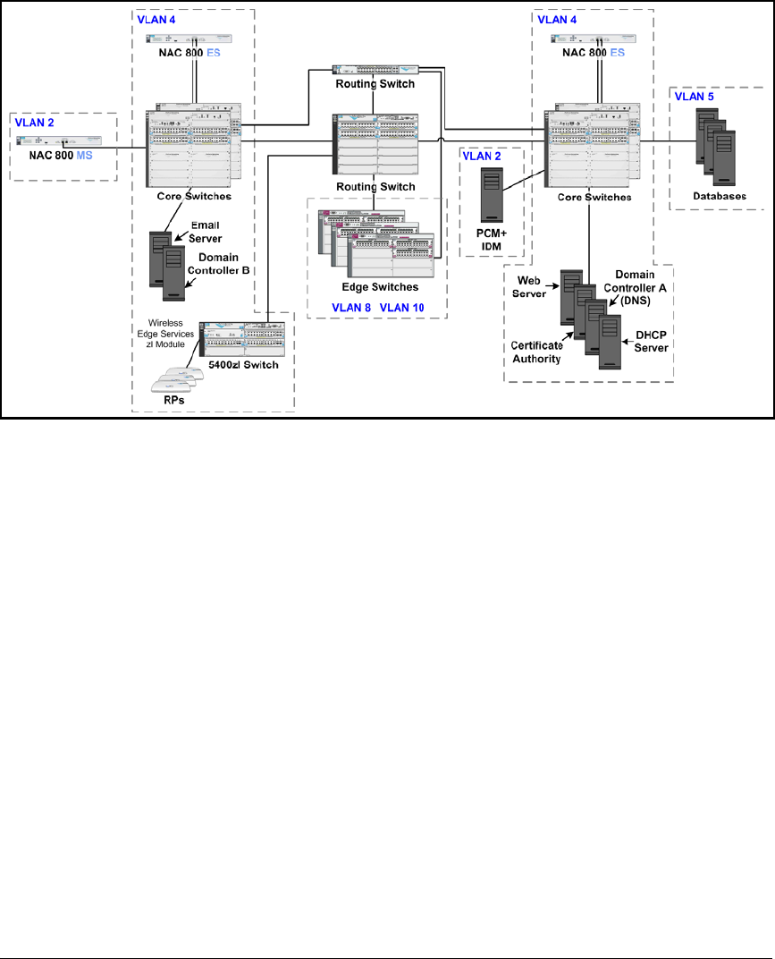
2-10
Implementing 802.1X with ProCurve IDM and Endpoint Integrity
Introduction
Figure 2-1. High-Level Network Design for ProCurve University
The instructions in this chapter sometimes call for typing a specific IP address.
Table 2-3 lists IP addresses for the example network. Fill in your devices’ IP
addresses and VLANs in the rightmost columns. You can then easily replace
the IP address given in the instructions with the correct address in your
environment.

2-11
Implementing 802.1X with ProCurve IDM and Endpoint Integrity
Introduction
Table 2-3. Example IP Addresses
Device Example IP
Address
Example
VLAN ID
Your Organization’s
IP Address
Your
Organization’s
VLAN ID
Domain controller 10.4.4.15 4
Backup domain controller 10.4.5.15 4
DNS servers 10.4.4.15
10.4.5.15
4
DHCP server 10.4.4.20 4
CA server 10.4.4.25 4
PCM+/IDM server 10.2.1.50 2
University Web server 10.4.6.30 4
Library Web server 10.4.6.35 4
Email server 10.4.6.40 4
Grade database 10.5.1.45 5
Test database 10.5.2.50 5
Other servers and databases
Routing Switch A • 10.2.0.1
• 10.4.0.1
• 10.5.0.1
• 10.8.0.1
• 10.10.0.1
• 10.32.0.1
• 10.33.0.1
• 10.34.0.1
• 10.35.0.1
•2
•4
•5
•8
•10
•32
•33
•34
•25
Routing Switch B • 10.2.4.1
• 10.4.4.1
• 10.5.4.1
• 10.8.4.1
• 10.10.4.1
• 10.32.4.1
• 10.33.4.1
• 10.34.4.1
• 10.35.4.1
•2
•4
•5
•8
•10
•32
•33
•34
•35
Switch A 10.2.0.5 2

2-12
Implementing 802.1X with ProCurve IDM and Endpoint Integrity
Introduction
Note In your network, some servers might run multiple services. For example, the
domain controllers might run DNS as well as Active Directory.
Other switches
Wireless Edge Services Module 10.2.0.20 2
Redundant Wireless Services Module 10.2.0.25 2
NAC 800 Management Server (MS) 10.2.1.40 2
NAC 800 Enforcement Server (ES) A 10.4.4.40 4
NAC 800 ES B 10.4.5.50 4
Device Example IP
Address
Example
VLAN ID
Your Organization’s
IP Address
Your
Organization’s
VLAN ID

2-13
Implementing 802.1X with ProCurve IDM and Endpoint Integrity
Configuring the ProCurve Switches
Configuring the ProCurve Switches
This section provides example configurations for ProCurve switches in a
network that implements 802.1X port authentication and endpoint integrity.
You can configure all of the settings manually, or you create a minimal
configuration (with IP, Simple Network Management Protocol [SNMP], and
VLAN settings) and then use PCM+ to configure other settings.
The following sections show example configurations for:
■A routing switch, which connects only to other switches
■A server switch, which connects to VLAN 4 servers and VLAN 5 servers
(faculty databases); uplink ports are A1 and B1
■An edge switch, which connects to endpoints (uplink ports are A1 and
B1); the edge switch is also a wireless services-enabled switch
Refer to the following sample configurations as you set up your network. If
you need step-by-step instructions, you should refer to the documentation for
your switch.
Note Users will receive dynamic VLAN assignments through IDM. However, if you
are adding 802.1X authentication to an existing network, edge ports must, of
course, retain their static assignment to a VLAN until you activate 802.1X
authentication.
For reference, these configurations allow the core switches to authenticate
the edge switches—the most secure option. However, take care when you
enable 802.1X authentication on ports connecting switches. The path to the
RADIUS server must be open for the authentication to complete. If you are
certain that uplink ports are secure, you can disable 802.1X authentication on
switch-to-switch ports.

2-14
Implementing 802.1X with ProCurve IDM and Endpoint Integrity
Configuring the ProCurve Switches
Routing Switches
The following is the startup-config for the routing switch used to test this
network.
; J8692A Configuration Editor; Created on release #K.12.XX
hostname "Routing_Switch"
module 1 type J86xxA
ip routing
snmp-server community "procurvero" Operator
snmp-server community "procurverw" Manager Unrestricted
snmp-server host 10.2.1.50 "public"
vlan 1
name "DEFAULT_VLAN"
no untagged 1-20
no ip address
exit
vlan 2
name "Management"
untagged 1-20
ip helper-address 10.4.4.20
ip address 10.2.0.1 255.255.0.0
exit
vlan 4
name "Server"
ip address 10.4.0.1 255.255.0.0
tagged 1-5
exit
vlan 5
name "Faculty_databases"
ip address 10.5.0.1 255.255.0.0
tagged 1-5
exit
vlan 10
name "Students"
ip helper-address 10.4.4.20
ip address 10.10.0.1 255.255.0.0
tagged 6-20
exit

2-15
Implementing 802.1X with ProCurve IDM and Endpoint Integrity
Configuring the ProCurve Switches
vlan 8
name "Faculty"
ip helper-address 10.4.4.20
ip address 10.8.0.1 255.255.0.0
tagged 6-20
exit
vlan 32
name "Quarantine_Faculty"
ip helper-address 10.4.4.20
ip address 10.32.0.1 255.255.0.0
tagged 6-20
exit
vlan 33
name "Infected_Faculty"
ip helper-address 10.4.4.20
ip address 10.33.0.1 255.255.0.0
tagged 6-20
exit
vlan 34
name "Quarantine_Students"
ip helper-address 10.4.4.20
ip address 10.34.0.1 255.255.0.0
tagged 6-20
exit
vlan 35
name "Infected_Students"
ip helper-address 10.4.4.20
ip address 10.35.0.1 255.255.0.0
tagged 6-20
exit
vlan 2100
name "Radio Port"
tagged 1-20
no ip address
exit
ip authorized-managers 10.2.0.0 255.255.0.0
ip authorized-managers 10.4.4.40 255.255.255.255
ip authorized-managers 10.4.5.50 255.255.255.255
ip dns domain-name "procurveu.edu"
ip dns server-address 10.4.4.15
aaa authentication port-access eap-radius
radius-server host 10.4.4.40 key procurvenac
radius-server host 10.4.5.50 key procurvenac

2-16
Implementing 802.1X with ProCurve IDM and Endpoint Integrity
Configuring the ProCurve Switches
aaa port-access authenticator 6-20 //These ports connect
to edge switches//
aaa port-access authenticator active //Do not enter this
command until you have completed setting up the entire
solution//
password manager
password operator
Server Switch startup-config
The following is the startup-config for the server switch used to test this
network.
; J8697A Configuration Editor; Created on release #K.12.XX
hostname "Server_Switch"
web-management management-url ""
module 1 type J8702A
module 2 type J8702A
ip default-gateway 10.2.0.1
snmp-server community "procurvero" Operator
snmp-server community "procurverw" Manager Unrestricted
snmp-server host 10.2.1.50 "public"
vlan 1
name "DEFAULT_VLAN"
no untagged A1-A24, B1-B24
no ip address
exit
vlan 2100
name "Radio Port"
tagged A1,B1
no ip address
exit
vlan 2
name "Management"
untagged A1,B1
ip address 10.2.0.3 255.255.0.0
exit
vlan 4
name "Server"
untagged B2-B24
tagged A1,B1
no ip address
exit

2-17
Implementing 802.1X with ProCurve IDM and Endpoint Integrity
Configuring the ProCurve Switches
vlan 5
name "Faculty_databases"
untagged A2-A24
tagged A1,B1
no ip address
exit
mirror 1 port B6 //Port 2 of a NAC 800 ES connects to port
B6//
ip authorized-managers 10.2.0.0 255.255.0.0
ip authorized-managers 10.4.4.40 255.255.255.255
ip authorized-managers 10.4.5.50 255.255.255.255
ip dns domain-name "procurveu.edu"
ip dns server-address 10.4.4.15
interface B2 //A DHCP server connects to port B2//
monitor all Both mirror 1
exit
password manager
password operator
Edge Switches
Your network will probably include many edge switches. An example config-
uration for an edge switch that also includes a Wireless Edge Services Module
follows. To improve readability, however, the encrypted Wireless Edge Ser-
vices Module commands have been omitted.
Wireless Services-Enabled Switch startup-config
In addition to housing the Wireless Edge Services Module, this switch func-
tions as an edge switch.
; J8697A Configuration Editor; Created on release #K.12.XX
hostname "Wireless Switch"
module 1 type J8702A
module 2 type J8702A
module 3 type J9051A
web-management management-url ""
ip default-gateway 10.2.0.1
snmp-server community "procurvero" Operator
snmp-server community "procurverw" Manager Unrestricted
snmp-server host 10.2.1.50 "public"

2-18
Implementing 802.1X with ProCurve IDM and Endpoint Integrity
Configuring the ProCurve Switches
vlan 1
name "DEFAULT_VLAN"
no untagged A1-B24,B1-B24
no ip address
exit
vlan 8
name "Faculty"
tagged A1,B1,CUP
exit
lldp auto-provision radio-ports auto-vlan 2100 auto
vlan 2100
name "Radio Ports"
tagged A1,B1,CDP
exit
vlan 10
name "Students"
untagged A2-A24,B2-B24
tagged A1,B1,CUP
exit
vlan 32
name "Quarantine_Faculty"
tagged A1,B1,CUP
exit
vlan 33
name "Infected_Faculty"
tagged A1,B1,CUP
exit
vlan 34
name "Quarantine_Students"
tagged A1,B1,CUP
exit
vlan 35
name "Infected_Students"
tagged A1,B1,CUP
exit
vlan 2
name "Management"
untagged A1,B1
ip address 10.2.0.5 255.255.0.0
tagged CUP
exit
ip authorized-managers 10.2.0.0 255.255.0.0
ip authorized-managers 10.4.4.40 255.255.255.255
ip authorized-managers 10.4.5.50 255.255.255.255

2-19
Implementing 802.1X with ProCurve IDM and Endpoint Integrity
Configuring the ProCurve Switches
ip dns domain-name "procurveu.edu"
ip dns server-address 10.4.4.15
aaa authentication port-access eap-radius
radius-server host 10.4.4.40 key procurvenac
radius-server host 10.4.5.50 key procurvenac
aaa port-access authenticator A2-A24,B2-B24 //802.1X
authentication is enforced on edge ports, but not uplink
ports.//
aaa port-access authenticator active //Do not enter this
command until you have completed setting up the entire
solution//
aaa port-access supplicant A1,B1
aaa port-access supplicant A1 identity "switch"
aaa port-access supplicant B1 identity "switch"
password manager
password operator

2-20
Implementing 802.1X with ProCurve IDM and Endpoint Integrity
Configuring the Windows Domain Controller
Configuring the Windows Domain
Controller
This section explains how to install Windows Server 2003 and set up the server
as a domain controller. By the end of the section, you will have installed the
Active Directory and DNS services. You will also have configured the groups
and users necessary for your access control solution.
Groups and users for the sample solution are displayed in Table 2-4. Of course,
a production network would include many more users and computers.
Table 2-4. Windows Domain Groups
Install Windows Server 2003
Install Windows Server 2003 with the default parameters. At this point, keep
the device a standalone server without domain membership. You will learn
how to install and configure various services later in this chapter.
During the installation, you will be prompted to type various parameters. Refer
to Table 2-5 for help in configuring these parameters.
Group Member Username Password
Administrators (a
default Windows
group)
AD Administrator Administrator ProCurve0
Network_Admins Switch Administrator adminswitch ProCurve1
Network_Admins Wireless Administrator adminwireless ProCurve2
Faculty Pauline Professor professor ProCurve3
Students Sam Student student ProCurve4
Domain Computers
(a default Windows
group)
DHCP servers, DNS
server, PCM+ server, and
CA server
server ProCurve5
RPs All radio ports (RPs) rp ProCurve6
Infrastructure
Devices
All switches switch ProCurve7
Printers and fax
machines
All headless devices printer ProCurve8

2-21
Implementing 802.1X with ProCurve IDM and Endpoint Integrity
Configuring the Windows Domain Controller
Table 2-5. Installation Parameters
Note Even if you intend this server to act as a CA, you must not install Certificate
Services during the installation process because Certificate Services requires
a server to have joined the domain first. (If you install Certificate Services
now, you will have to uninstall the services before the server will be able to
join a domain.)
Install Active Directory
After you install Windows Server 2003, the server is a standalone server
without membership in a domain. To make the server a domain controller,
configure Active Directory on the new server:
1. Connect the server to the network infrastructure.
For services to run properly, the server requires an active network con-
nection.
In the sample network, domain controllers connect to the 5400zl switches.
See Figure 2-1.
2. From the Windows Start menu, select Run and type dcpromo at the run
prompt.
Parameter Description Example
Server name a name that describes the server mycontroller.
procurveu.edu
IP address this server’s IP address 10.4.4.15
Subnet mask subnet mask for the server’s subnet 255.255.0.0
Router the server’s default router 10.4.0.1
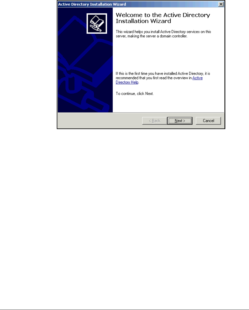
2-22
Implementing 802.1X with ProCurve IDM and Endpoint Integrity
Configuring the Windows Domain Controller
Figure 2-2. Active Directory Installation Wizard—Welcome Page
3. Click
Next
on the
Welcome to the Active Directory Installation Wizard
page.
4. Click Next on the Operating System Compatibility page.
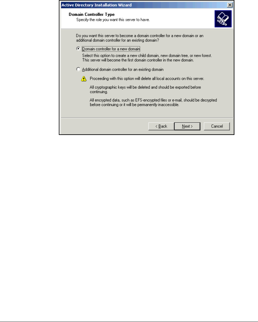
2-23
Implementing 802.1X with ProCurve IDM and Endpoint Integrity
Configuring the Windows Domain Controller
Figure 2-3. Active Directory Installation Wizard—Domain Controller
Type Page
5. Select Domain controller for a new domain and click Next.
6. Select Domain in a new forest and click Next.
7. Select No, just install and configure DNS on this computer and click Next.
Active Directory relies on DNS, so you often set up DNS on the same
server.
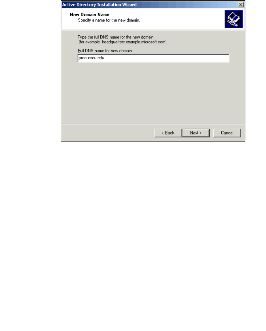
2-24
Implementing 802.1X with ProCurve IDM and Endpoint Integrity
Configuring the Windows Domain Controller
Figure 2-4. Active Directory Installation Wizard—New Domain Name Page
8. Type your organization’s domain name in the Full DNS name for new domain
box. As shown in Figure 2-4 for the sample network, type procurveu.edu.
Click Next.
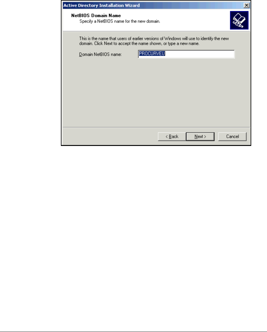
2-25
Implementing 802.1X with ProCurve IDM and Endpoint Integrity
Configuring the Windows Domain Controller
Figure 2-5. Active Directory Installation Wizard—NetBIOS Domain Name Page
9. In the Domain NetBIOS name box, type the domain name, without the top-
level domain, in all capital letters. Click Next.
In this example, the NetBIOS name is PROCURVEU.
10. Accept the default locations for the database and log files and click Next.
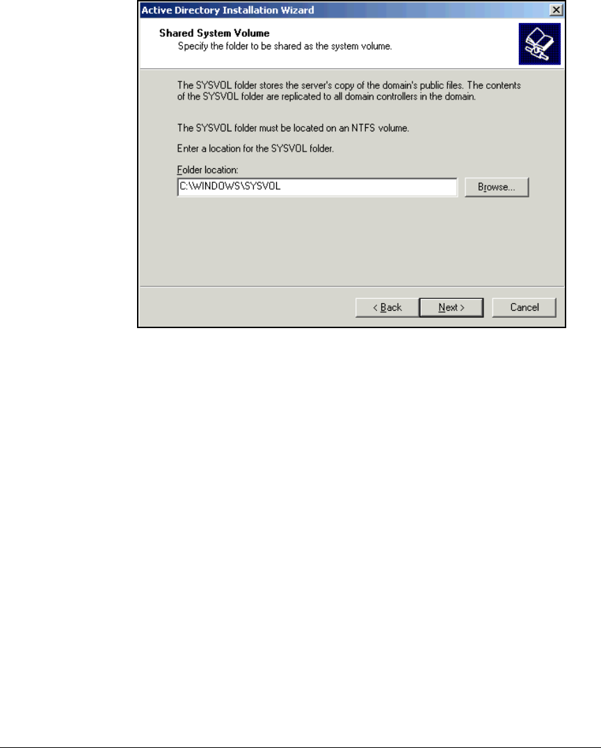
2-26
Implementing 802.1X with ProCurve IDM and Endpoint Integrity
Configuring the Windows Domain Controller
Figure 2-6. Active Directory Installation Wizard—Shared System Volume Page
11. Accept the default Shared System Volume folder location and click Next.
12. Select Permissions compatible only with Windows 2000 or Windows Server
2003 operating systems and click Next.
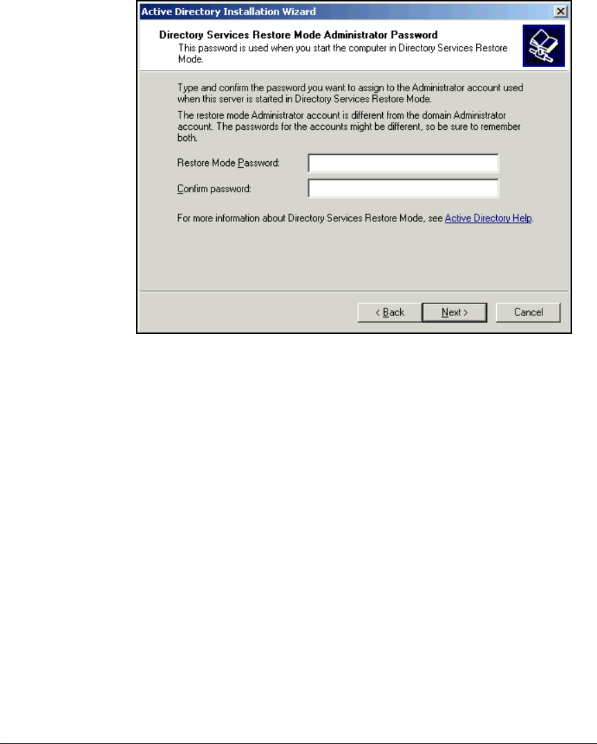
2-27
Implementing 802.1X with ProCurve IDM and Endpoint Integrity
Configuring the Windows Domain Controller
Figure 2-7. Active Directory Installation Wizard—Directory Resources Restore
Administrator Password Page
13. Leave the Restore Passwords boxes blank and click Next.
14. Click Next on the Summary page. The installation wizard begins installing
Active Directory. This process may take a few minutes.
15. Click Finish.
16. Click Restart Now.
Raise the Domain Functional Level
Active Directory installs with Windows 2000 Server settings, which by default
deny users remote access. (Although some settings refer to remote access as
“dial-in” access, remote access is often through a virtual private network
[VPN] or a wireless connection.) Because many users now commonly access
the network remotely, you will probably want to raise the functionality to
Windows Server 2003. In the resulting default policy, a user’s remote access is
controlled by a server such as a RADIUS server.
If you do not raise the functional level of Active Directory, you must manually
configure users’ accounts to allow remote access.

2-28
Implementing 802.1X with ProCurve IDM and Endpoint Integrity
Configuring the Windows Domain Controller
To raise the functional level, complete the following steps:
1. From the Windows Start menu, select Administrative Tools > Active Directory
Users and Computers. The Active Directory Users and Computers window is
displayed.
2. Right-click the domain name in the left panel and select Raise Domain
Functional Level in the menu that is displayed.
3. Select Windows Server 2003, and then click Raise to change the domain
functional level to Windows Server 2003.
4. Click OK.
5. Click OK again.
Configure Windows Domain Groups
You must create groups for the users who are authorized to access your
network. When a RADIUS server authenticates a user, it can check the user’s
group membership and use that information to apply the correct policies to
the user’s network access.
By default, Active Directory includes a number of groups such as the Domain
Admins and Domain Users groups. You can use these default groups and also
create new groups for your specific network. For the example ProCurve
University network, the network administrators have decided to create three
additional groups for users:
■Network_Admins
■Faculty
■Students
Users can have more than one group membership. For example, all members
of the groups listed above will also be members of the Domain Users group.
The groups listed above, however, are the groups that IDM will use to deter-
mine which rights to grant users.
Because network devices also authenticate to the network, the network
administrators want to add groups for the devices as well:
■Infrastructure devices
■RPs
Other devices such as servers are members of the Domain Computers group.
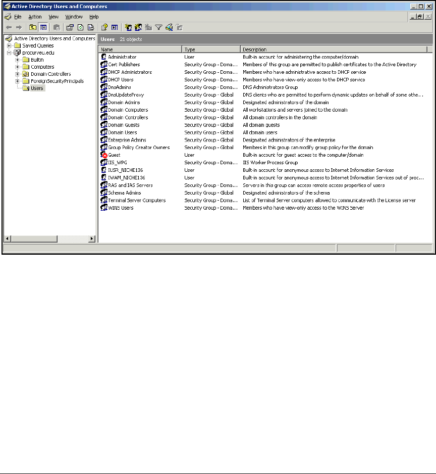
2-29
Implementing 802.1X with ProCurve IDM and Endpoint Integrity
Configuring the Windows Domain Controller
Complete these steps to configure the user groups:
1. From the Windows Start menu, select Administrative Tools > Active Directory
Users and Computers.
2. Expand the domain.
Figure 2-8. Active Directory Users and Computers Window
3. In the left pane, right-click Users and select New > Group.
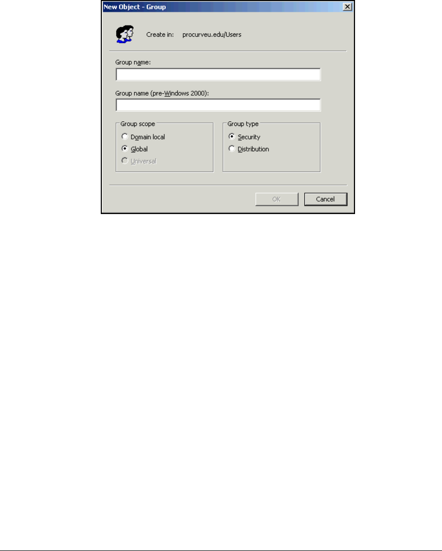
2-30
Implementing 802.1X with ProCurve IDM and Endpoint Integrity
Configuring the Windows Domain Controller
Figure 2-9. New Object – Group Window
4. Type the group name in the Group name box.
For example, you might type Faculty.
5. Accept the default setting of Global for the Group scope and Security for
the Group type.
The Global setting ensures that the group applies to the entire domain. The
group can contain only members of its own domain, but it can be granted
permissions to other domains in the same Microsoft forest.
The Security setting allows you to create groups that will control privileges
for users. Any group that affects network access should be a security
group. (The Distribution setting, on the other hand, is used for email
distribution lists.) For more information about these settings, refer to your
Microsoft documentation.
6. Click OK.
2-31
Implementing 802.1X with ProCurve IDM and Endpoint Integrity
Configuring the Windows Domain Controller
7. Repeat steps 3 through 6 to create additional groups.
For the example ProCurve University network, you would create these
additional groups:
• Network_Admins
•Students
• Infrastructure devices
•RPs
• Printers
Configure Windows Domain Users
Next, you should create users and assign the users to the appropriate groups.
Table 2-6 shows several users for the example ProCurve University network.
Of course, you would create many more users for a production network.
Table 2-6. Windows Domain Users
Note The passwords listed in Table 2-6 are for a test network only. The passwords
are easy to remember, but they do not meet the security requirements for a
production network. For your network, you should create passwords that
meet stringent security requirements. For example, passwords should not
include dictionary words, you should always change default passwords, and
you should include numerals and special characters.
You can enter information about your users in Table 2-7.
First Name Last Name Logon Name
(Username)
Password Group Membership
Administrator—a
default user
Administrator Administrator ProCurve0 Domain Admins
Switch Administrator adminswitch ProCurve1 Network_Admins
Wireless Administrator adminwireless ProCurve2 Network_Admins
Pauline Professor professor ProCurve3 Faculty
Sam Student student ProCurve4 Students
Wireless RP rp ProCurve6 RPs
Switch Switch switch ProCurve7 Infrastructure
Devices
Hewlett-Packard Printers printer ProCurve8 Printers and fax
machines

2-32
Implementing 802.1X with ProCurve IDM and Endpoint Integrity
Configuring the Windows Domain Controller
Table 2-7. My Windows Domain Users
First Name Last Name Logon Name
(Username)
Password Group Membership
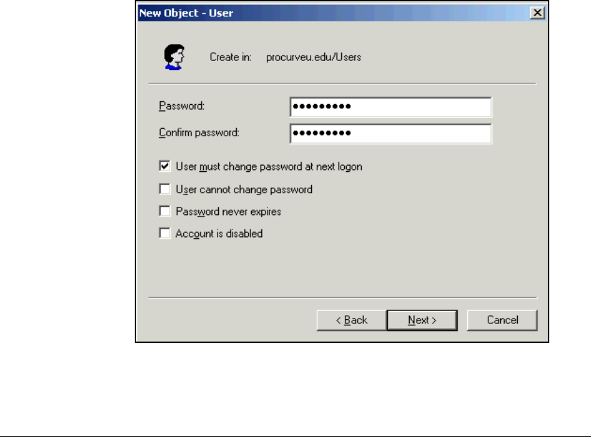
2-33
Implementing 802.1X with ProCurve IDM and Endpoint Integrity
Configuring the Windows Domain Controller
Follow these steps to add a user:
1. From the Windows Start menu, select Administrative Tools > Active Directory
Users and Computers.
2. Expand your domain.
3. In the left pane, right-click the Users folder and select New > User.
4. Type the user’s first name in the First name box.
5. Type the user’s last name in the Last name box.
6. Type the user’s username in the User logon name box.
This is the name that the user (or supplicant on a device) submits as part
of 802.1X authentication.
7. Click Next.
8. In the password and confirm password boxes, type the user’s (or device’s)
password.
Figure 2-10. New Object – User Window, Second Page
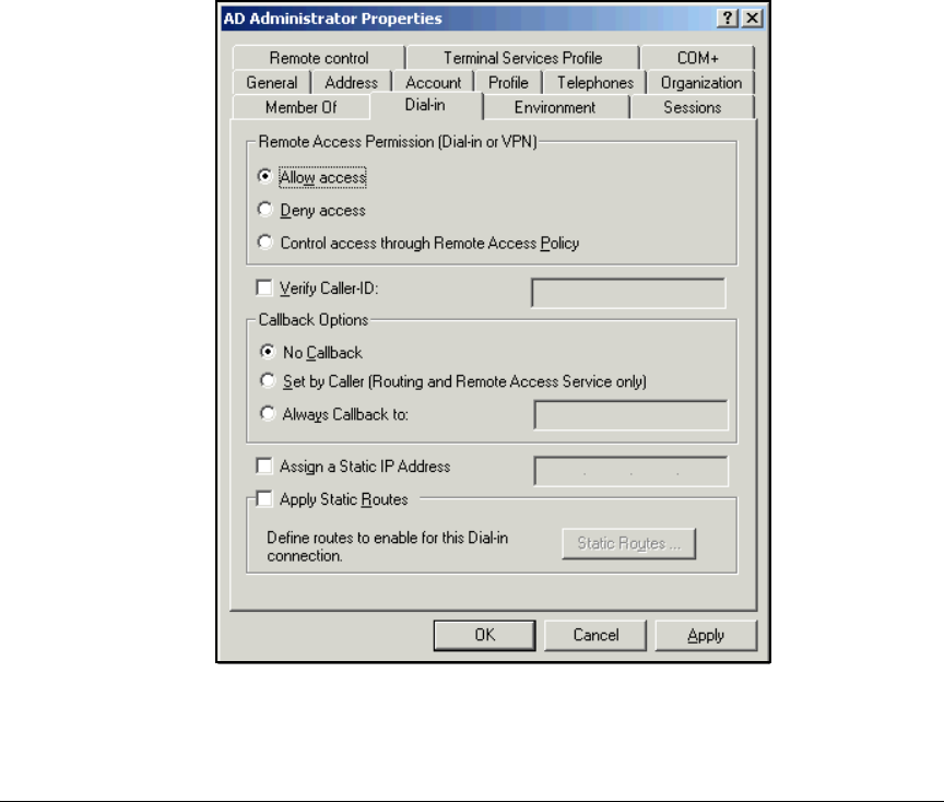
2-34
Implementing 802.1X with ProCurve IDM and Endpoint Integrity
Configuring the Windows Domain Controller
9. Select any password requirements.
Typically, a user should be forced to change the password the first time
that he or she logs in (so that no one else knows the password) and every
few weeks after that.
If you are defining password requirements for a device instead of a user,
do not select the User must change password at next logon check box, and
select the Password never expires check box.
10. Click Next.
11. Click Finish on the Summary page.
12. In the right pane of the Active Directory Users and Computers window, right-
click the newly created user and select Properties.
Figure 2-11. <username> Properties Window—Dial-in Tab
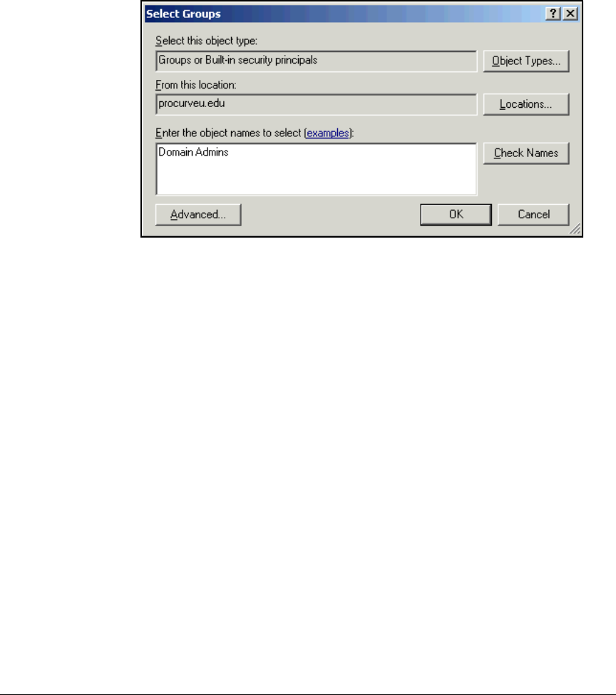
2-35
Implementing 802.1X with ProCurve IDM and Endpoint Integrity
Configuring the Windows Domain Controller
13. If you did not raise the domain function level, click the Dial-in tab and
select Allow access under Remote Access Permission.
14. Click the Member Of tab and click Add.
Figure 2-12. <username> Properties—Select Groups Window
15. In the Enter the object names to select box, type the name of the appropriate
group. For example, for Pauline Professor in the PCU network, you would
type Faculty.
16. Click Check Names. If the group name is valid, it will be underlined.
Click OK.
17. The group is displayed in the Member Of window. Click OK to apply the
changes.
18. Press [Alt]+[F4] to close the Active Directory Users and Computers window.
Configure DNS Services
Active Directory relies on DNS for several services. For example, endpoints
send DNS requests to locate the domain controllers. This section describes
how to configure the DNS services necessary for Active Directory. Specifi-
cally, you will create reverse lookup zones for each subnet in your network.
Table 2-8 displays the zones for the sample network.
Note that when you type a reverse lookup zone in the Windows New Zone
Wizard, you type it in non-reversed form. For example, for subnet 10.2.0.0/16,
you type 10.2. The wizard automatically reverses the zone.

2-36
Implementing 802.1X with ProCurve IDM and Endpoint Integrity
Configuring the Windows Domain Controller
Table 2-8. Reverse Lookup Zones
Complete these steps on the Windows 2003 Server that acts as domain
controller:
1. From the Windows Start menu, select Administrative Tools > DNS.
2. Select Forward Lookup Zones.
3. Check the right panel to verify that the DNS service is running.
VLAN Subnet Reverse Lookup
Zone
2 10.2.0.0/16 10.2
4 10.4.0.0/16 10.4
5 10.5.0.0/16 10.5
8 10.8.0.0/16 10.8
10 10.10.0.0/16 10.10
32 10.32.0.0/16 10.32
33 10.33.0.0/16 10.33
34 10.34.0.0/16 10.34
35 10.35.0.0/16 10.35
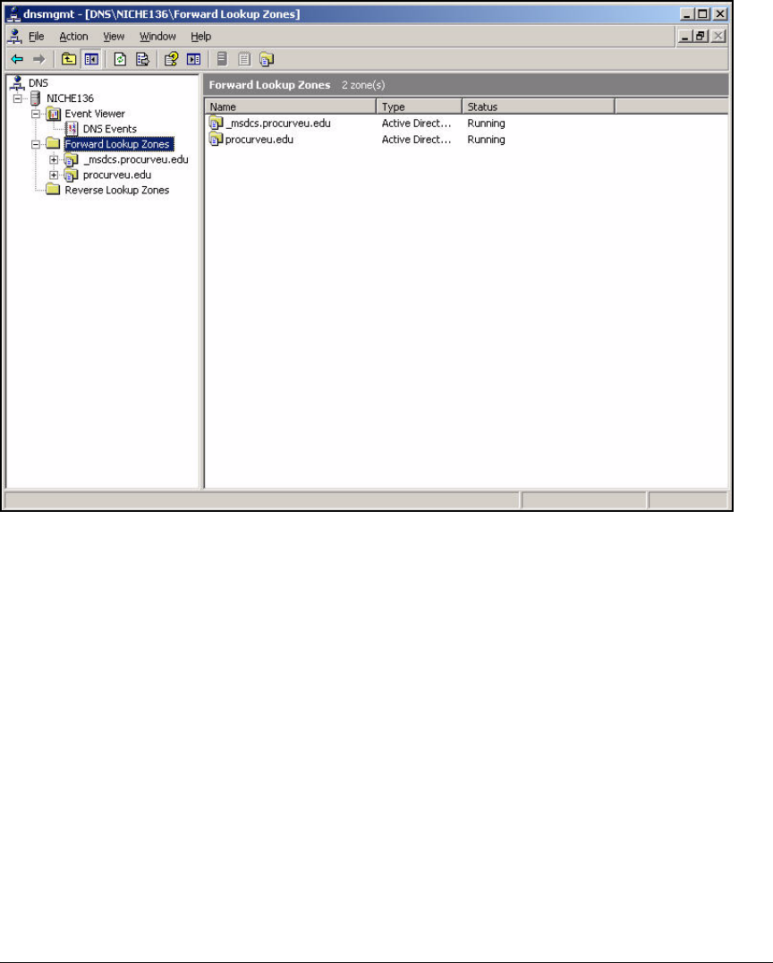
2-37
Implementing 802.1X with ProCurve IDM and Endpoint Integrity
Configuring the Windows Domain Controller
Figure 2-13. Ensuring That the Windows DNS Service Is Running
If the service is not running:
a. Right-click the domain name.
b. Select All Tasks > Start.
4. Double-click your domain (in this example, procurveu.edu).
5. Right-click Reverse Lookup Zones and select New Zone.

2-38
Implementing 802.1X with ProCurve IDM and Endpoint Integrity
Configuring the Windows Domain Controller
Figure 2-14. New Zone Wizard—Welcome Page
6. On the Welcome to the New Zone Wizard page, click Next.
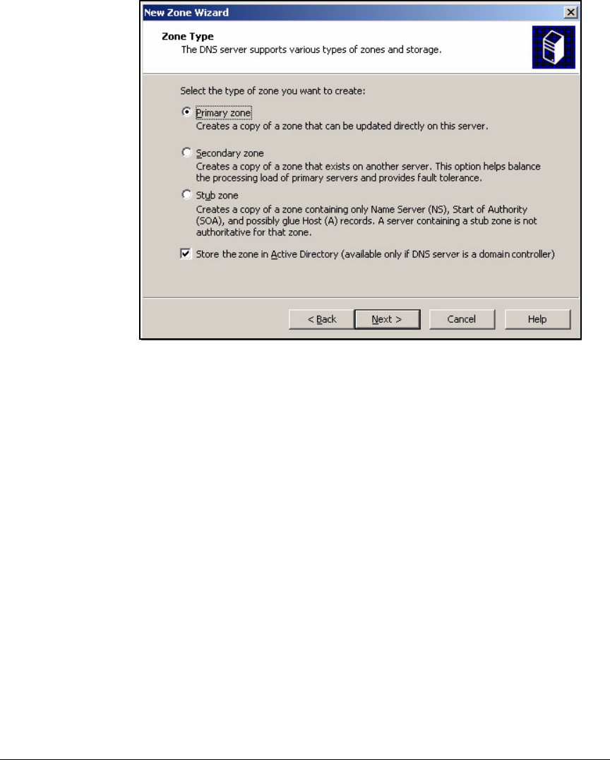
2-39
Implementing 802.1X with ProCurve IDM and Endpoint Integrity
Configuring the Windows Domain Controller
Figure 2-15. New Zone Wizard—Zone Type Page
7. Verify that Primary zone is selected and that the Store the zone in Active
Directory check box is selected. Click Next.
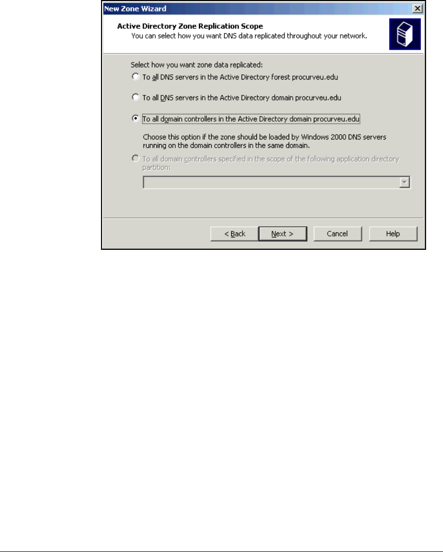
2-40
Implementing 802.1X with ProCurve IDM and Endpoint Integrity
Configuring the Windows Domain Controller
Figure 2-16. New Zone Wizard—Active Directory Zone Replication Scope Page
8. Select To all domain controllers in the Active Directory domain <name> and
click Next.
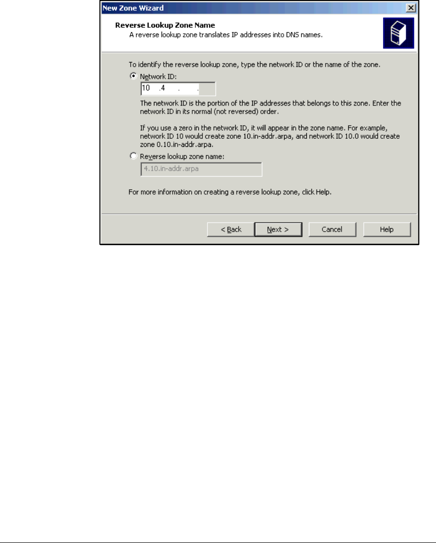
2-41
Implementing 802.1X with ProCurve IDM and Endpoint Integrity
Configuring the Windows Domain Controller
Figure 2-17. New Zone Wizard—Reverse Lookup Zone Name Page
9. Type the significant portion of the network address in the Network ID box.
The significant portion of the address includes the non-zero octets. For
example, the first two octets are significant in a /16 subnet (255.255.0.0).
The first three octets are significant in a /24 (255.255.255.0) subnet.
Leave the space for octets that are not significant blank. Do not enter 0s.
10. Click Next.
11. Select Allow only secure dynamic updates and click Next.
12. Click Finish.
13. Repeat steps 5 to 12 for each subnet in your domain.
14. Press [Alt]+[F4] to close the DNS windows.

2-42
Implementing 802.1X with ProCurve IDM and Endpoint Integrity
Configuring the DHCP Server
Configuring the DHCP Server
Your DHCP server (or servers) must include scopes (also called pools) for
each subnet for which devices request dynamic IP addresses. These subnets
typically include:
■User VLANs
■Quarantine, test, and infected VLANs
Many devices in the management VLAN have static IP addresses. In the
example network, however, the management VLAN still requires a DHCP
scope because some network administrators connect with endpoints set up
for DHCP. On the other hand, all servers in the sample network have static
addresses, so VLANs 4 and 5 do not require DHCP scopes.
Table 2-9 displays settings for DHCP scopes in this network. Note that the
range of IP addresses in each scope does not include all IP addresses available
in the corresponding subnet. Some addresses are statically assigned to various
network devices; others are reserved for future use.
Another important note: most scopes specify the network DNS servers
(10.4.4.15 and 10.4.5.15). However, the scopes for the quarantine, test, and
infected VLANs must specify the NAC 800s (10.4.4.40 and 10.4.5.50) as DNS
servers. This setting allows the NAC 800s to properly redirect quarantined
users who attempt to access Web sites.
Table 2-9. DHCP Scopes
Scope VLAN Subnet Range Default
Gateway
DNS Server Other Options
Management 2 10.2.0.0/16 10.2.16.1–
10.2.20.254
10.2.0.1 • 10.4.4.15
• 10.4.5.15
domain name=
procurveu.edu
Faculty 8 10.8.0.0/16 10.8.1.1–
10.8.10.254
10.8.0.1 • 10.4.4.15
• 10.4.5.15
domain name=
procurveu.edu
Students 10 10.10.0.0/16 10.10.1.1–
10.10.10.254
10.10.0.1 • 10.4.4.15
• 10.4.5.15
domain name=
procurveu.edu
Quarantine_Faculty 32 10.32.0.0/16 10.32.1.1–
10.32.10.254
10.32.0.1 • 10.4.4.40
• 10.4.5.50
domain name=
procurveu.edu
Infected_Faculty 33 10.33.0.0/16 10.33.1.1–
10.33.10.254
10.33.0.1 • 10.4.4.40
• 10.4.5.50
domain name=
procurveu.edu
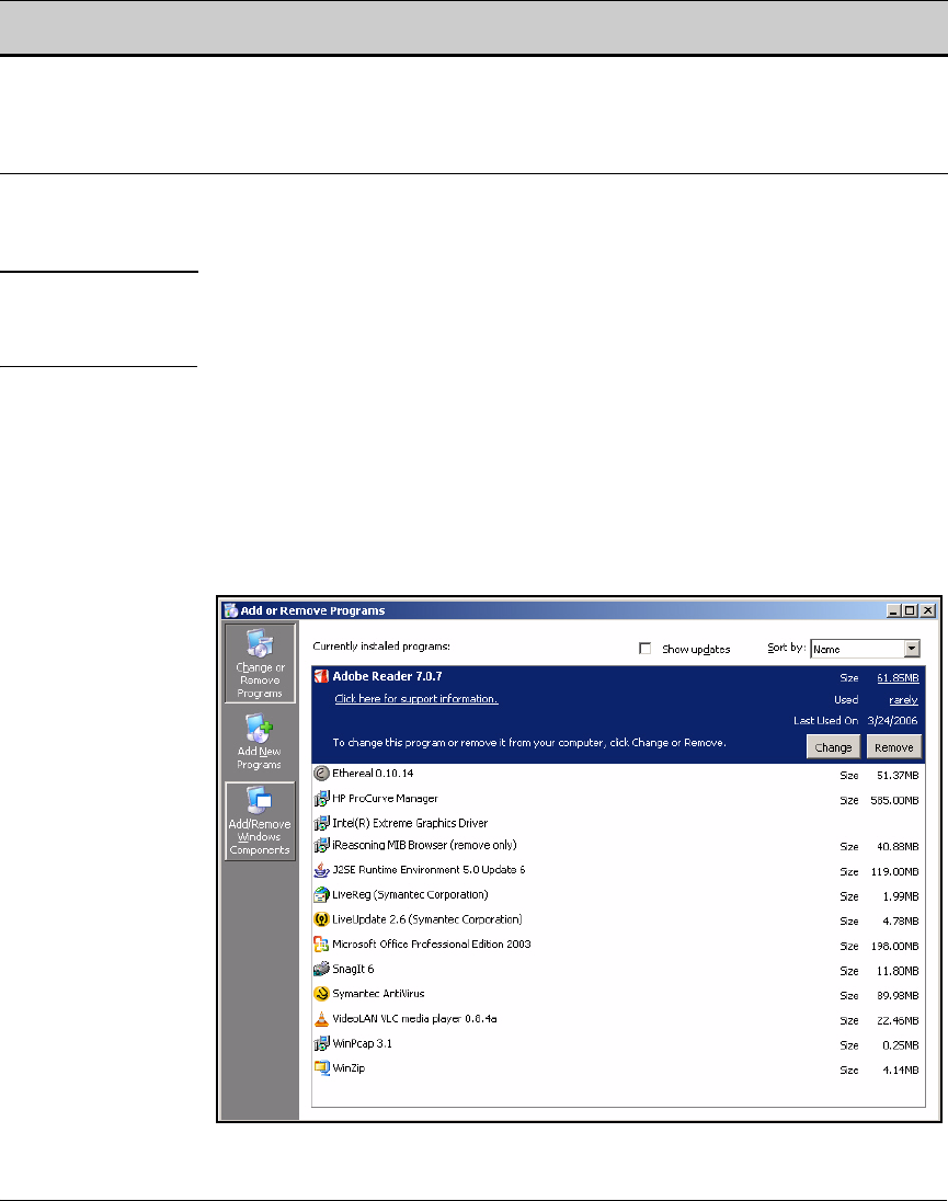
2-43
Implementing 802.1X with ProCurve IDM and Endpoint Integrity
Configuring the DHCP Server
You can configure the scopes on any DHCP server. The following sections
describe how to set up a Windows Server 2003 DHCP server.
Note Follow the instructions in “Install Windows Server 2003” on page 2-20 to begin
setting up Windows Server 2003. However, instead of making the server a
domain controller, join it to the domain.
Install the DHCP Service
Follow these steps to install the DHCP service on Windows Server 2003:
1. From the Windows Start menu, select Control Panel > Add or Remove
Programs.
Figure 2-18. Windows Server 2003 Add or Remove Programs
Quarantine_Students 34 10.34.0.0/16 10.34.1.1–
10.34.10.254
10.34.0.1 • 10.4.4.40
• 10.4.5.50
domain name=
procurveu.edu
Infected_Students 35 10.35.0.0/16 10.35.1.1–
10.35.10.254
10.35.0.1 • 10.4.4.40
• 10.4.5.50
domain name=
procurveu.edu
Scope VLAN Subnet Range Default
Gateway
DNS Server Other Options
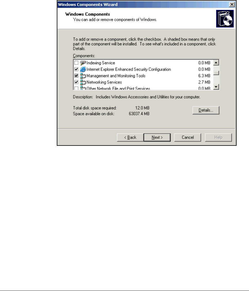
2-44
Implementing 802.1X with ProCurve IDM and Endpoint Integrity
Configuring the DHCP Server
2. Click the Add/Remove Windows Components button on the left of the
window.
Figure 2-19. Windows Component Wizard—Windows Components Page
3. Select Networking Services and click Details.
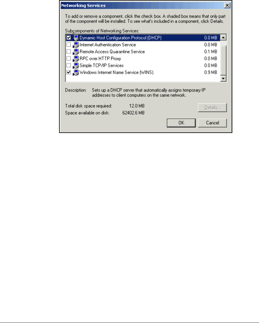
2-45
Implementing 802.1X with ProCurve IDM and Endpoint Integrity
Configuring the DHCP Server
Figure 2-20. Windows Component Wizard—Networking Services Window
4. Select the Dynamic Host Configuration Protocol (DHCP) and Windows Internet
Name Service (WINS) check boxes and click OK.
5. Click Next on the Windows Components page. The Configuring Components
page is displayed.
2-46
Implementing 802.1X with ProCurve IDM and Endpoint Integrity
Configuring the DHCP Server
Figure 2-21. Windows Components Wizard—Configuring Components Page
6. When the Completing the Windows Components Wizard page is displayed,
click Finish.
7. Press [Alt]+[F4] to close the Add or Remove Programs window.
Configure the DHCP Server
Follow these steps to authorize the DHCP in Active Directory and create the
DHCP scopes:
1. From the Windows Start menu, select Administrative Tools > DHCP.

2-47
Implementing 802.1X with ProCurve IDM and Endpoint Integrity
Configuring the DHCP Server
Figure 2-22. DHCP Manager
2. Right-click the server name and select Authorize.
3. With the server name still highlighted, select Action > Refresh.
4. Right-click the server name and select New Scope.
5. On the New Scope Wizard — Welcome page, click Next.
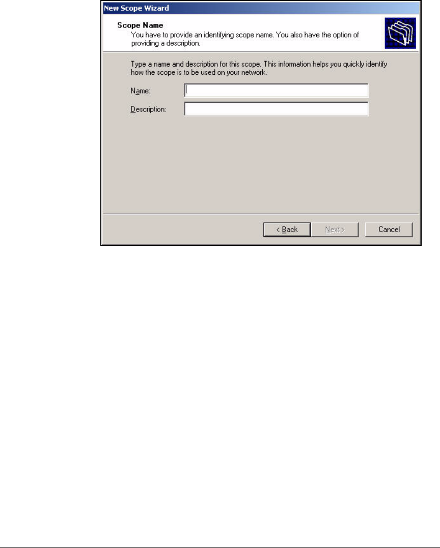
2-48
Implementing 802.1X with ProCurve IDM and Endpoint Integrity
Configuring the DHCP Server
Figure 2-23. New Scope Wizard—Scope Name Page
6. Type a name in the Name box. For example, to configure the first scope
shown above, type Management.
7. If desired, describe the function of this scope in the Description box. For
example, you might type For network administrators.
8. Click Next.
9. Type the range of IP addresses in the Start IP address and End IP address
boxes. For the example network, type 10.2.16.1 and 10.2.20.254.
10. Type the subnet prefix length in the Length box. For this example, type 16.
The Subnet mask box automatically fills with the correct value (here,
255.255.0.0).
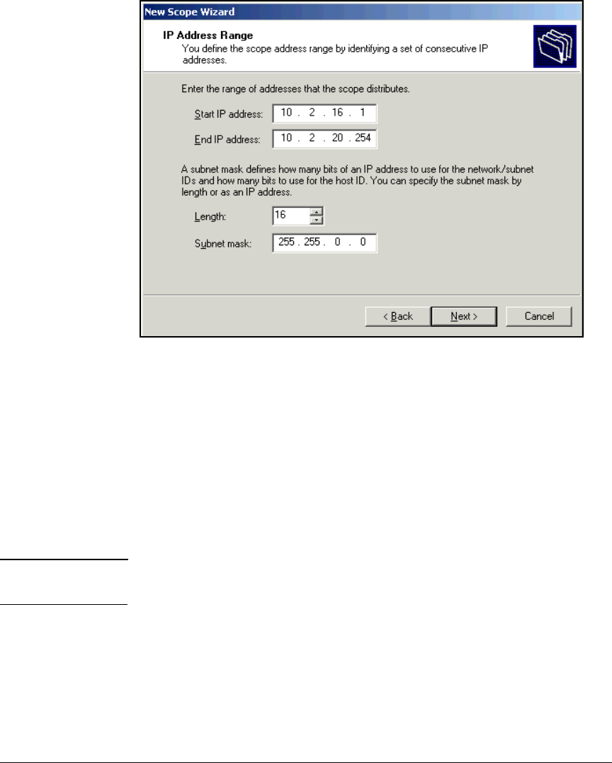
2-49
Implementing 802.1X with ProCurve IDM and Endpoint Integrity
Configuring the DHCP Server
Figure 2-24. New Scope Wizard—IP Address Range Page
11. Click Next.
12. If the range you specified includes IP addresses that are assigned to
devices statically, you must add exclusions in the Add Exclusions window.
In this example scope, the range does not include the IP addresses
assigned to network devices statically; therefore, you can click Next.
13. In the Lease Duration window, you can set how long a device can retain its
IP address without renewing it. Click Next to accept the default of eight
days.
Note The 802.1X quarantine method for endpoint integrity does not impose any
particular requirements on the lease duration.
14. Select Yes, I want to configure these options now and click Next.
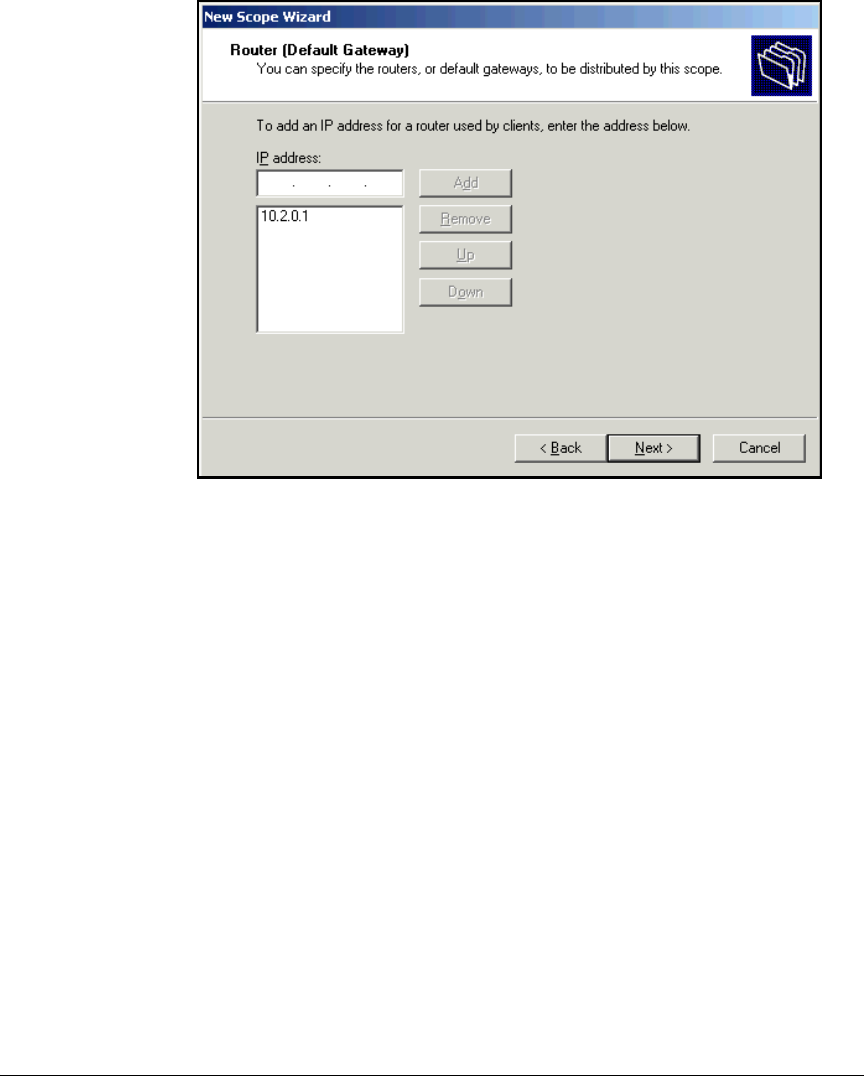
2-50
Implementing 802.1X with ProCurve IDM and Endpoint Integrity
Configuring the DHCP Server
Figure 2-25. New Scope Wizard—Router (Default Gateway) Page
15. Type the IP address of the subnet’s default router in the IP address box and
click Add. For this example, type 10.2.0.1.
16. Click Next.
17. Type your organization’s domain name in the Parent domain box. For this
example, type procurveu.edu.
18. Type the appropriate IP address in the IP address box and click Add. For
this example, type 10.4.4.15.
For user VLANs, type the IP address of one of your domain’s DNS servers
(often a domain controller). For the quarantine, test, and infected VLANs,
type the IP address of a NAC 800 ES.
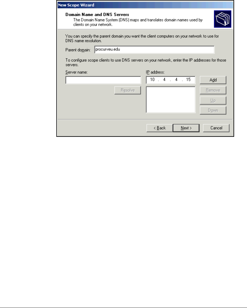
2-51
Implementing 802.1X with ProCurve IDM and Endpoint Integrity
Configuring the DHCP Server
Figure 2-26. New Scope Wizard—Domain Name and DNS Servers Page
19. Repeat the step above to add a secondary DNS server.
20. Click Next.
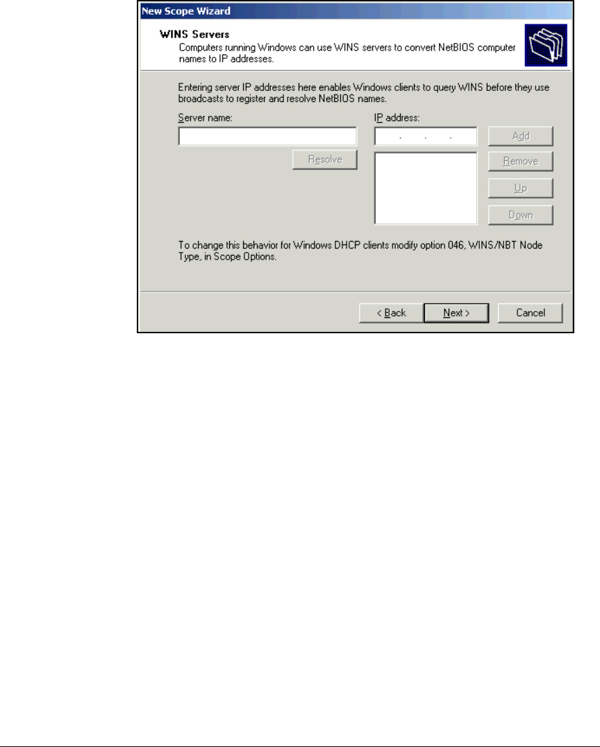
2-52
Implementing 802.1X with ProCurve IDM and Endpoint Integrity
Configuring the DHCP Server
Figure 2-27. New Scope Wizard—WINS Servers Page
21. Type the IP address of your network’s WINS server (if any) in the WINS
server box. Click Add and then click Next.
22. Select Yes, I want to activate this scope now and click Next.
23. Click Finish.
24. Repeat steps 4 to 23 for each scope that your network requires.
25. Press [Alt]+[F4] to close the DHCP Manager window.

2-53
Implementing 802.1X with ProCurve IDM and Endpoint Integrity
Configuring Certificate Services
Configuring Certificate Services
This section describes how to establish a PKI, which issues digital certificates
for your organization’s servers and users. Users can then complete EAP-
Transport Layer Security (TLS) authentication and establish secure commu-
nications with your private servers.
You have several options for your PKI:
■Three tier:
• A root CA, which is the ultimate trusted entity, and for security is kept
offline (standalone)
• Multiple intermediate CAs, which receive certificates from the root
CA and issue certificates to issuing CAs; typically kept offline as well
• Multiple issuing CAs, which are online (enterprise) and which issue
certificates to servers, endpoints, and end-users
■Two tier:
• A standalone root CA
• Multiple issuing enterprise CAs
■One tier:
• A root CA, which also issues certificates to servers, endpoints, and
end-users; must be kept online (enterprise root CA)
A multi-tiered approach offers higher security but requires a more complex
deployment.
This guide provides the steps for deploying a PKI using the one-tier approach.
Certificate services run on a Windows Server 2003 server that is an online
member of the Windows domain but is not a domain controller.
This section provides steps for:
■Joining a server to a domain
■Installing Internet Information Services (IIS) on Windows Server 2003
■Installing certificate services on Windows Server 2003
■Setting up autoenrollment of computers and users through Active Direc-
tory
■Customizing certificate templates to meet the requirements of your net-
work access solution
■Exporting the CA root certificate

2-54
Implementing 802.1X with ProCurve IDM and Endpoint Integrity
Configuring Certificate Services
Subsequent sections explain how to create certificate requests on the follow-
ing non-Windows devices, which require server certificates:
■Wireless Edge Services Modules
■NAC 800s
At that point, the guide explains how to submit the requests to your domain
CA and generate the server certificates. See “Manually Issue and Install Server
Certificates” on page 2-174.
Note On Web servers that members of the public contact, you should install a
certificate signed by a third-party CA instead of your root CA.
Join the Windows Server 2003 Server to the Domain
This solution calls for an enterprise CA server, which must be a member of
the domain. Follow these steps to join the server to the domain:
1. On the server that you selected to run CA services, click Start > Control
Panel > System.
2. Click the Computer Name tab.
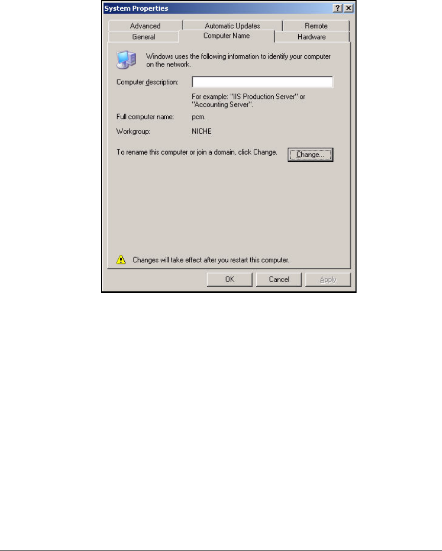
2-55
Implementing 802.1X with ProCurve IDM and Endpoint Integrity
Configuring Certificate Services
Figure 2-28. System Properties > Computer Name Tab
3. Click Change. The Computer Name Changes window is displayed. (See
Figure 2-29.)
4. Type a meaningful name for the Computer name. In this example: CA.
5. In the Member of area, click Domain.
6. Enter your domain name in the box below. In this example: procurveu.edu.
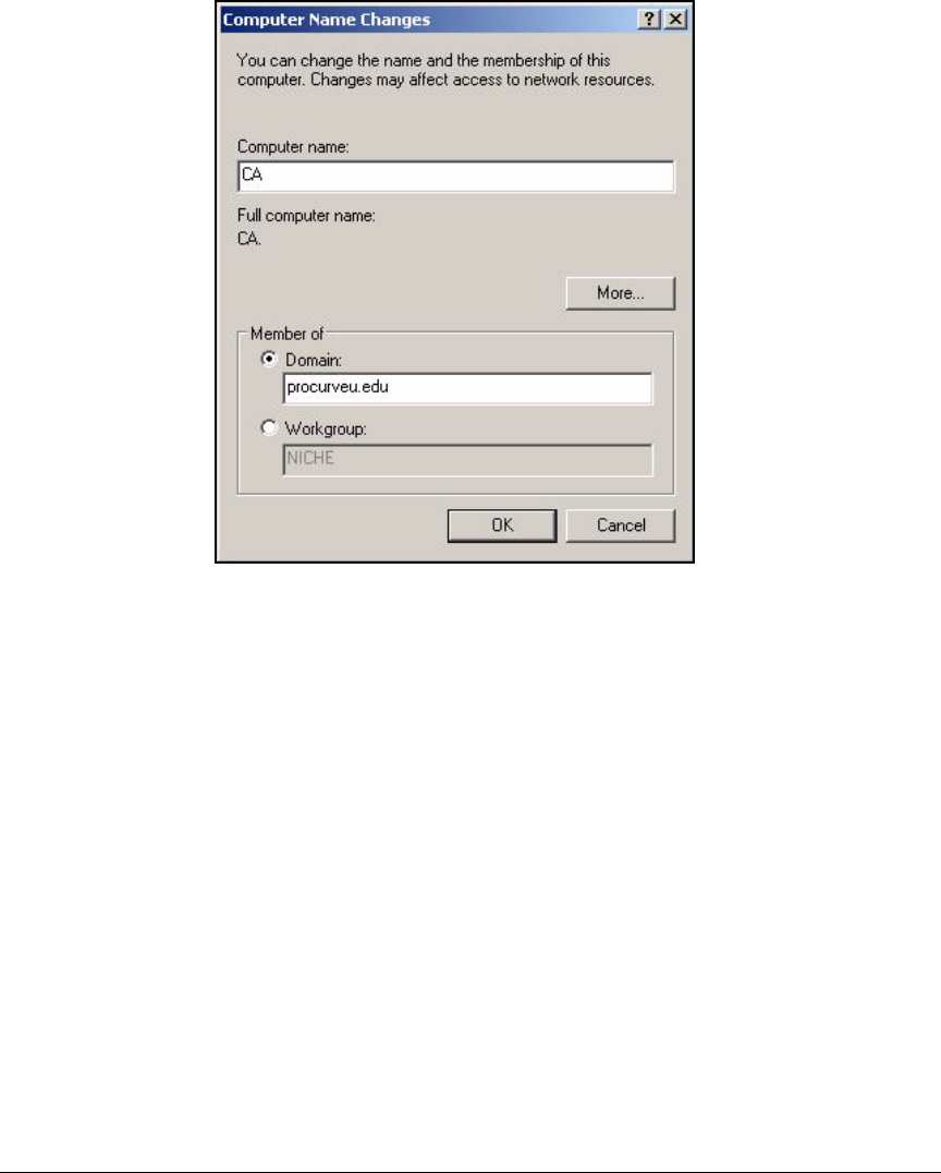
2-56
Implementing 802.1X with ProCurve IDM and Endpoint Integrity
Configuring Certificate Services
Figure 2-29. Computer Name Changes Window
7. Click OK.
8. A window is displayed asking for your credentials. Type the username and
password of a domain administrator and click OK.
9. Restart the server.
Install IIS and the Certificate Services
If the CA server runs IIS and ASP, it can present users with Web pages to help
them enroll for certificates. The Web enrollment pages are located at <CA
server IP address>/certsrv. Note that ASP can open security vulnerabilities,
so you might chose not to use this feature.
All IIS services are not necessary. You must install:
■Common Files
■Internet Information Services Manager
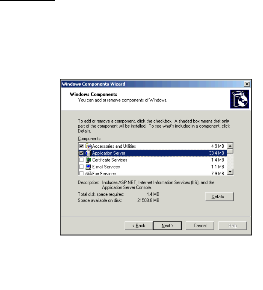
2-57
Implementing 802.1X with ProCurve IDM and Endpoint Integrity
Configuring Certificate Services
■World Wide We b Service:
• Active Server Pages (ASP)
• World Wide Web Service
You will install the Certificate Services at the same time as you install IIS.
Note Installing Certificate Services binds the server to its current name and domain.
Before completing the steps below, you must join the server to the domain as
described in the previous section.
Follow these steps to install the necessary services on the Windows Server
2003:
1. From the Start menu, select Control Panel > Add or Remove Programs > Add/
Remove Windows Components.
Figure 2-30. Windows Components Wizard—Windows Components Page
2. Select the Application Server check box and click Details.
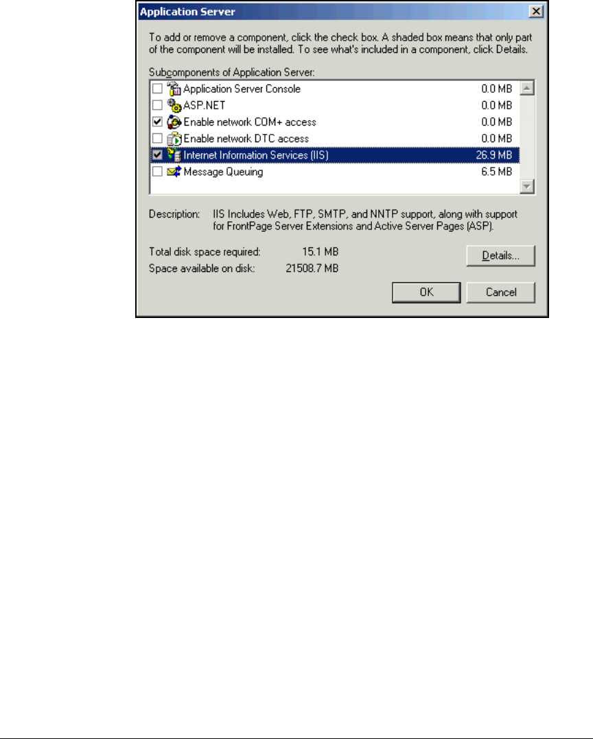
2-58
Implementing 802.1X with ProCurve IDM and Endpoint Integrity
Configuring Certificate Services
Figure 2-31. Windows Components Wizard—Application Server Page
3. Select the Internet Information Services (IIS) check box and click Details.
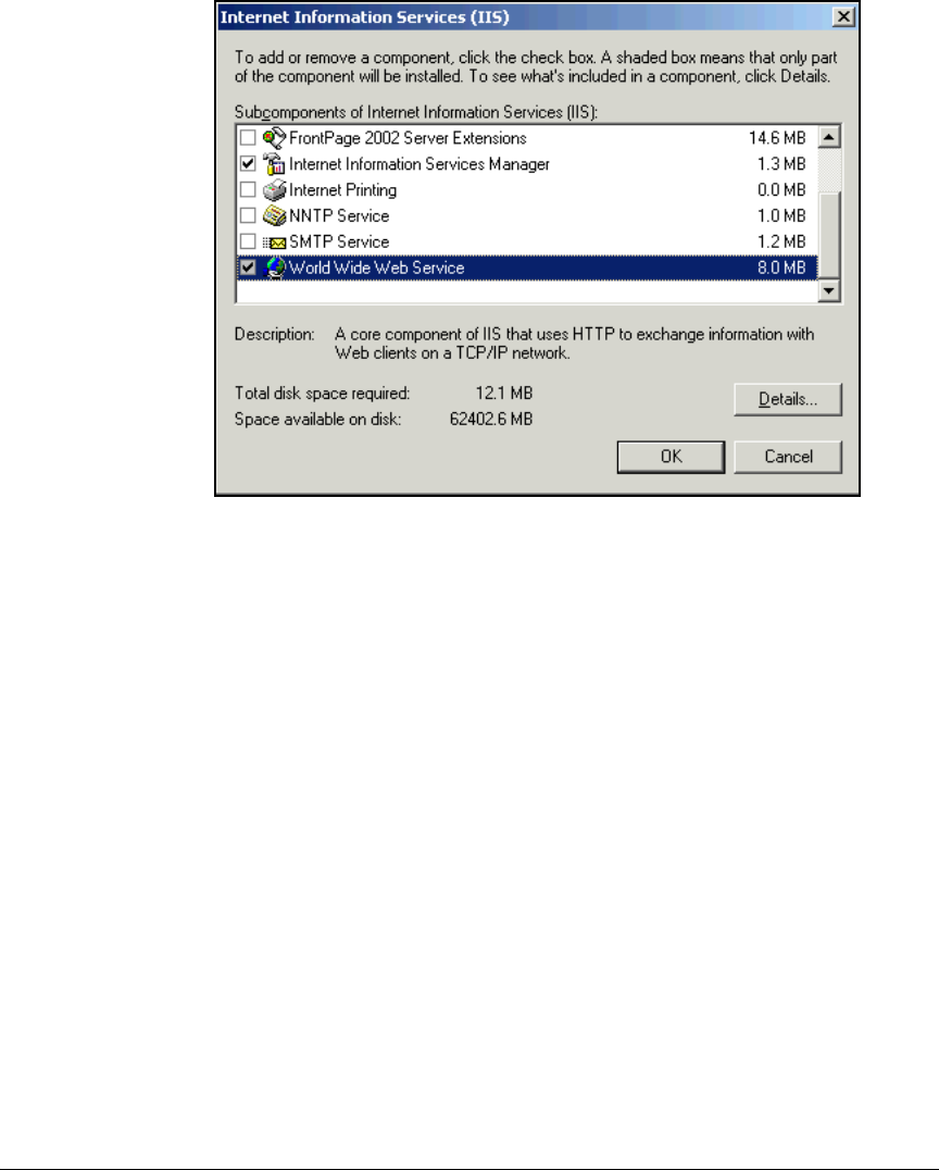
2-59
Implementing 802.1X with ProCurve IDM and Endpoint Integrity
Configuring Certificate Services
Figure 2-32. Windows Components Wizard—Internet Information Services
(IIS) Page
4. Select the check boxes for:
• Common Files
• Internet Information Services Manager
• World Wide Web Service
Clear all other check boxes.
5. Click World Wide Web Service and click Details.
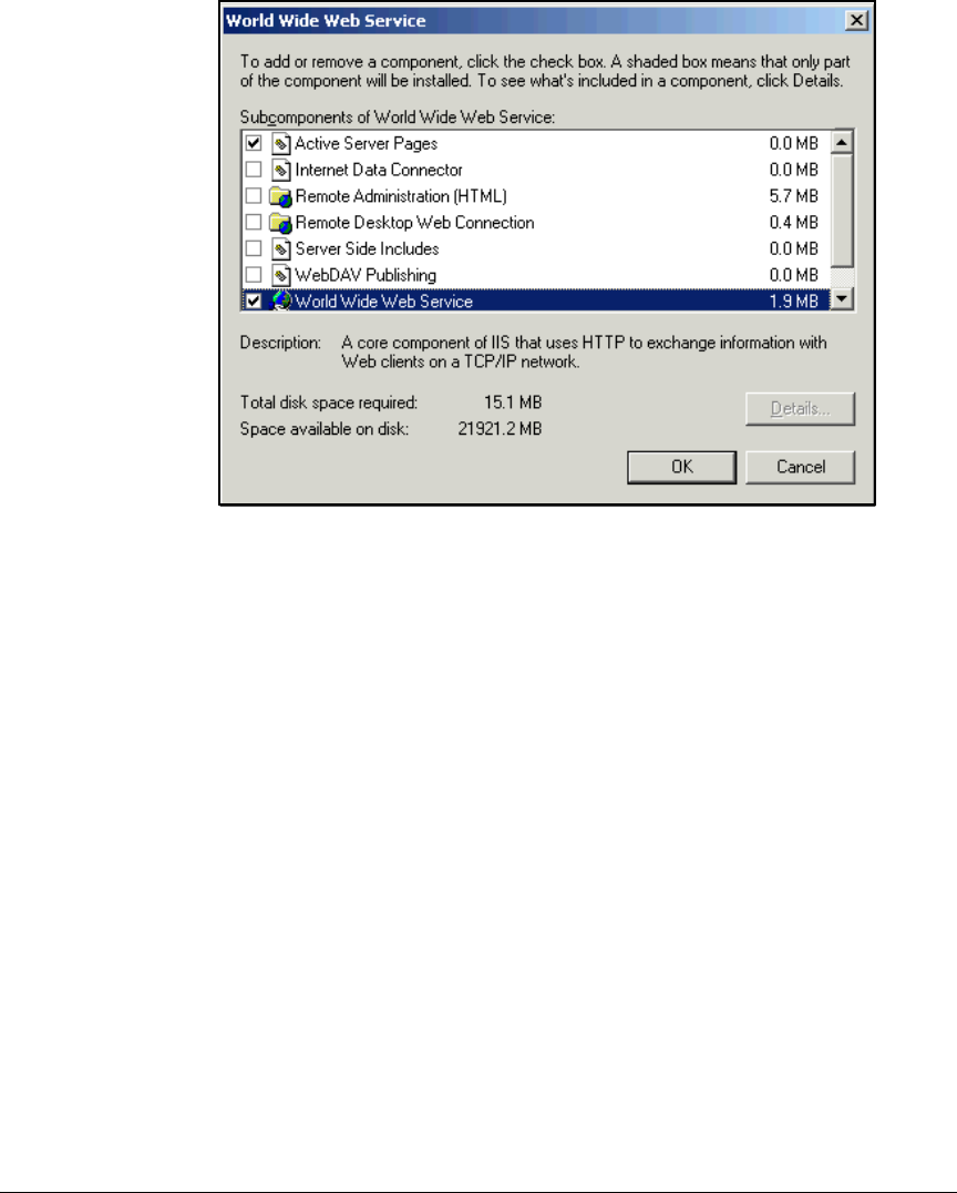
2-60
Implementing 802.1X with ProCurve IDM and Endpoint Integrity
Configuring Certificate Services
Figure 2-33. Windows Components Wizard—World Wide Web Service Page
6. Select the check boxes for:
• Active Server Pages (ASP)
• World Wide Web Service
Clear all other check boxes.
7. Click OK three times until you are in the Windows Components page.
8. Select Certificate Services.
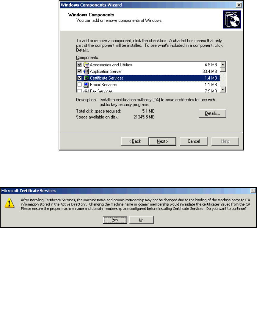
2-61
Implementing 802.1X with ProCurve IDM and Endpoint Integrity
Configuring Certificate Services
Figure 2-34. Windows Components Wizard—Windows Components Page
9. The Microsoft Certificate Services window is displayed.
Figure 2-35. Microsoft Certificate Services Message
10. Click Yes.
11. Click Next.
You are now presented with a series of pages in which you enter
information about the CA.
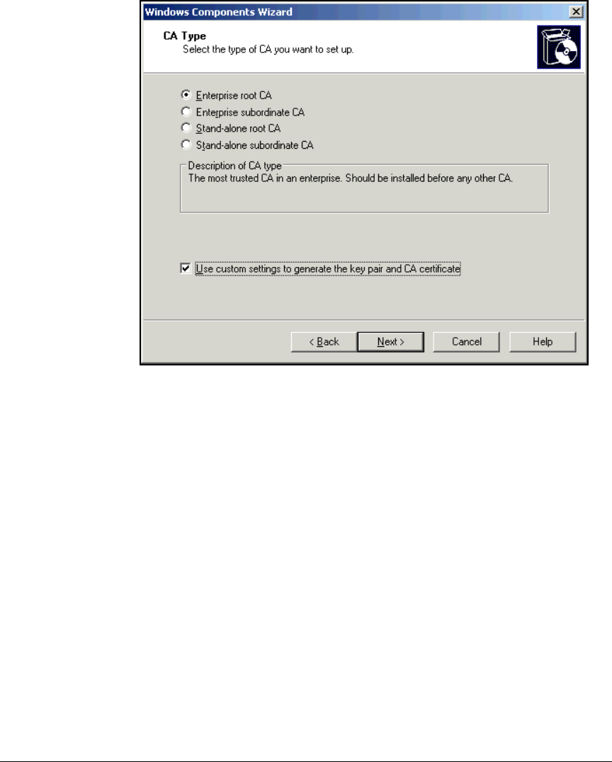
2-62
Implementing 802.1X with ProCurve IDM and Endpoint Integrity
Configuring Certificate Services
Figure 2-36. Windows Components Wizard—CA Type Page
12. In the CA Type, click Enterprise root CA.
13. Select the Use custom settings to generate the key pair and CA certificate
check box.
14. Click Next.
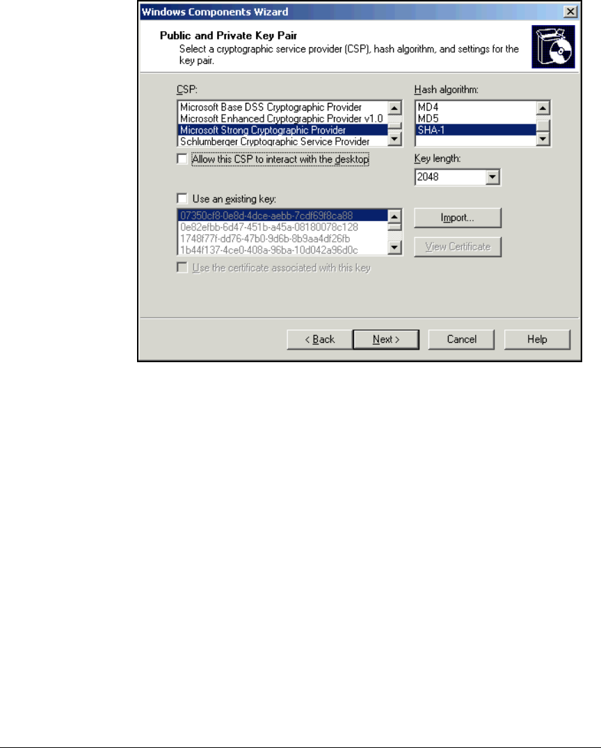
2-63
Implementing 802.1X with ProCurve IDM and Endpoint Integrity
Configuring Certificate Services
Figure 2-37. Windows Components Wizard—Public and Private Key Pair Page
15. Choose the settings for the CA’s private key. Generally, you can keep the
defaults. However, you might need to change the key length. For example,
some routers, including the ProCurve Secure Router 7000dl, require a key
length smaller than 2048. Choose 1024 from the Key length box.
16. Click Next.
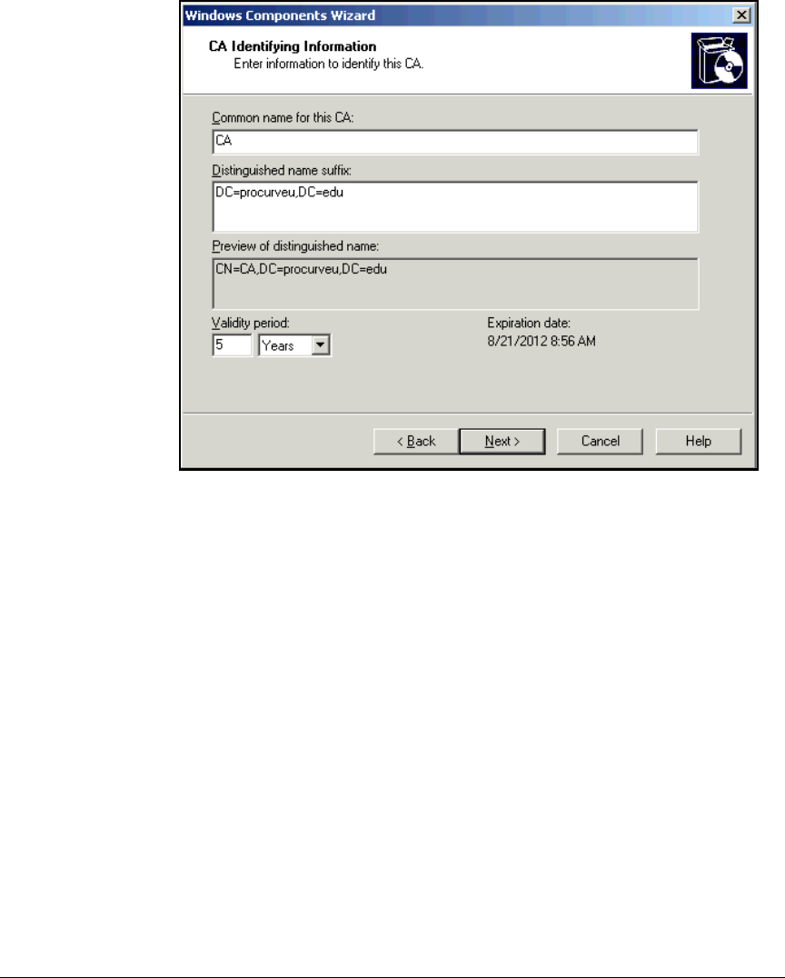
2-64
Implementing 802.1X with ProCurve IDM and Endpoint Integrity
Configuring Certificate Services
Figure 2-38. Windows Components Wizard—CA Identifying Information Page
17. In the Common name for this CA box, type the CA server’s name. In this
example: CA.
18. The Distinguished name suffix box shows your domain name in Lightweight
Directory Access Protocol (LDAP) format. In this example: DC=procur-
veu,DC=edu.
19. Click Next.
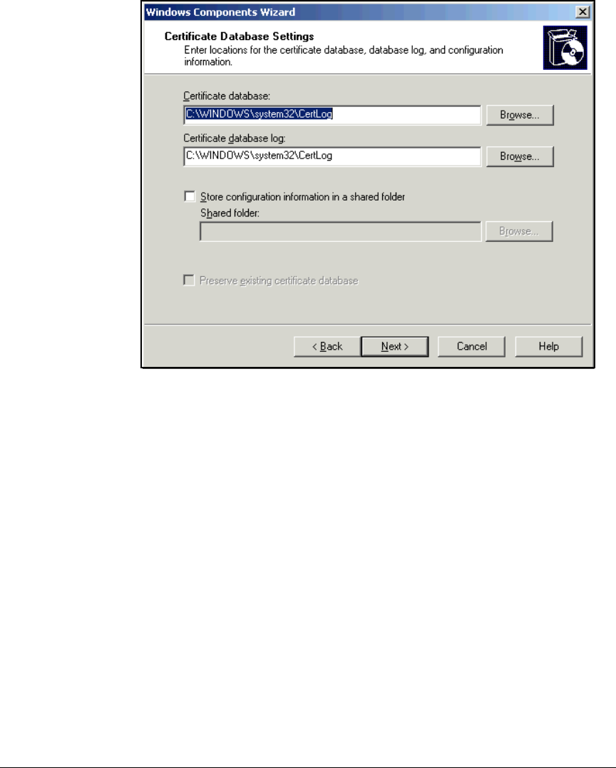
2-65
Implementing 802.1X with ProCurve IDM and Endpoint Integrity
Configuring Certificate Services
Figure 2-39. Windows Components Wizard—Certificate Database Settings Page
20. Accept the default storage locations by clicking Next.
21. The Configuring Components page is displayed.
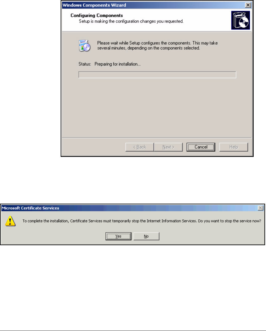
2-66
Implementing 802.1X with ProCurve IDM and Endpoint Integrity
Configuring Certificate Services
Figure 2-40. Windows Components Wizard—Configuring Components Page
22. If your server was already running IIS, you will see the window in
Figure 2-41. Click Yes.
Figure 2-41. Microsoft Certificate Services Message
23. You will see the window in Figure 2-42.
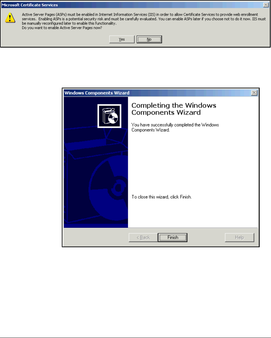
2-67
Implementing 802.1X with ProCurve IDM and Endpoint Integrity
Configuring Certificate Services
Figure 2-42. Microsoft Certificate Services Message
24. Click Yes if you want to use the web enrollment pages or No if you do not.
Figure 2-43. Completing the Windows Components Wizard
25. Click Finish.
26. Press [Alt]+[F4] to close the Add/Remove Programs window.

2-68
Implementing 802.1X with ProCurve IDM and Endpoint Integrity
Configuring Certificate Services
Set Up Autoenrollment of Computer and User
Certificates
This section teaches you how to enable autoenrollment for both computer and
user certificates. It also explains how to configure the following certificate
templates so that the CA issues certificates correctly for your environment:
■User template that allows autoenrollment of certificates
■NAC 800 template for the NAC 800’s RADIUS server
Set Up Autoenrollment of Computer Certificates
When you enable autoenrollment for computer certificates, each computer
automatically obtains a certificate the next time that it boots up and connects
to the domain. To configure computer certificate enrollment, follow these
steps on a domain controller:
1. From the Windows Start menu, select Administrative Tools > Active Directory
Users and Computers.

2-69
Implementing 802.1X with ProCurve IDM and Endpoint Integrity
Configuring Certificate Services
Figure 2-44. Management Console Window
2. In the left pane, right-click your domain name and select Properties.
3. Click the Group Policy tab.
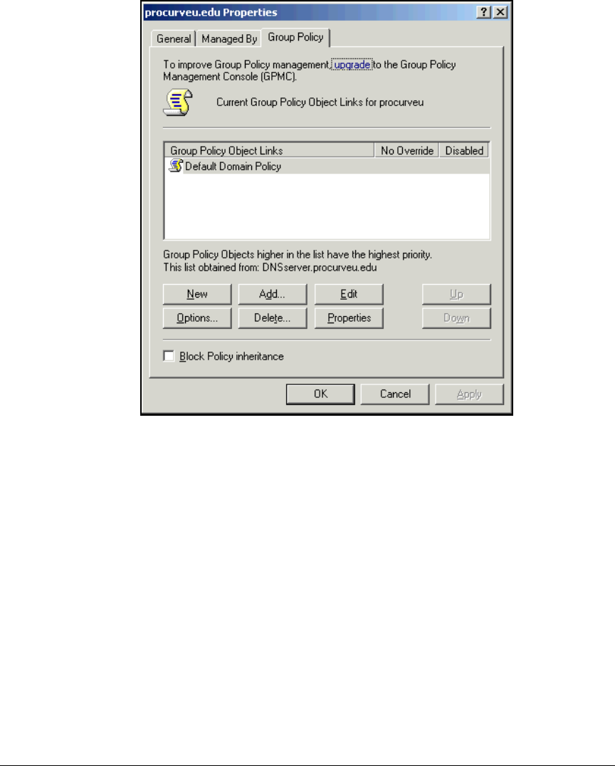
2-70
Implementing 802.1X with ProCurve IDM and Endpoint Integrity
Configuring Certificate Services
Figure 2-45. Management Console—<domain name> Properties Window
4. Select Default Domain Policy and click Edit.
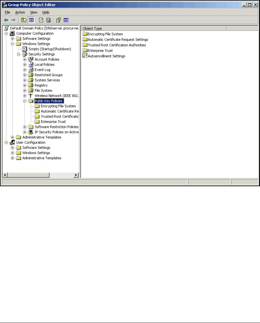
2-71
Implementing 802.1X with ProCurve IDM and Endpoint Integrity
Configuring Certificate Services
Figure 2-46. Management Console—Group Policy Object Editor Window
5. In the left pane, expand Computer Configuration > Windows Settings >
Security Settings > Public Key Policies.
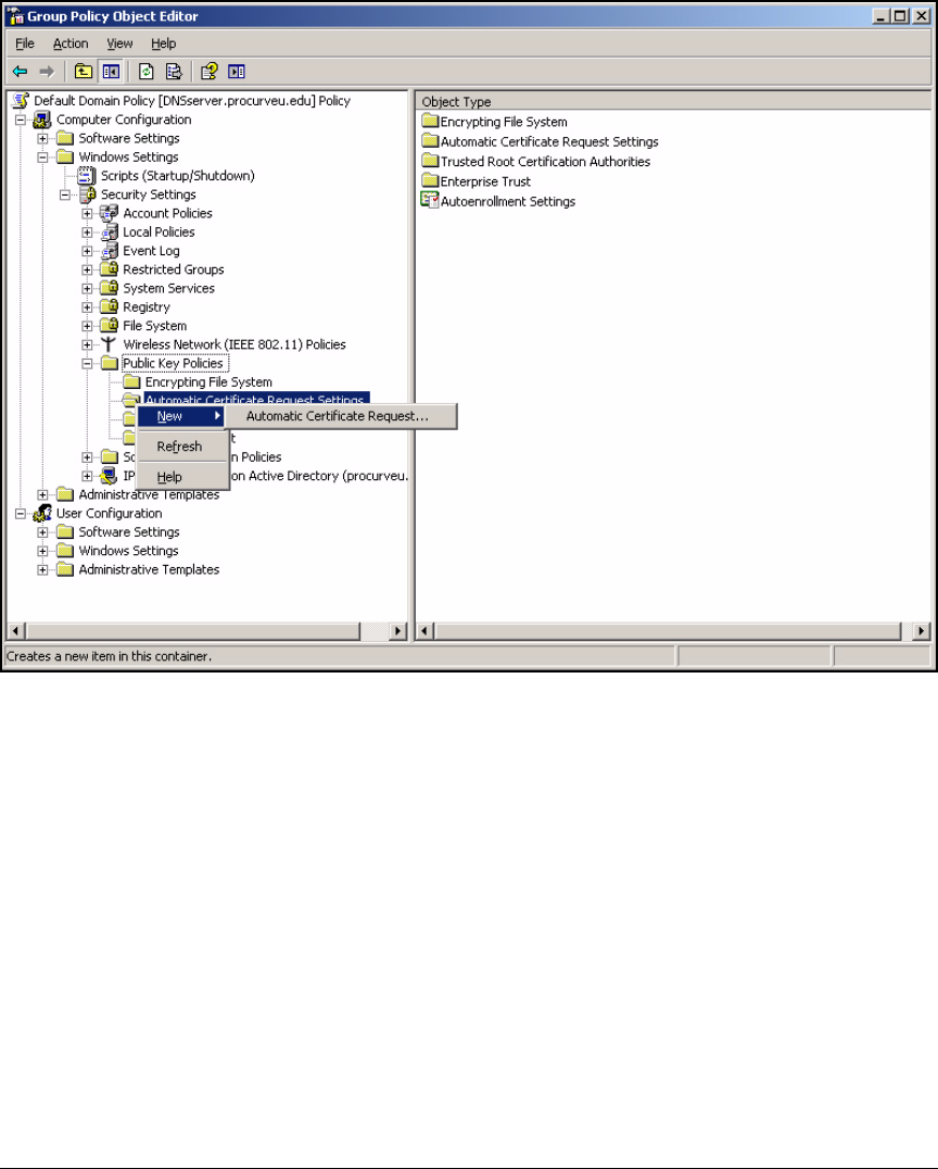
2-72
Implementing 802.1X with ProCurve IDM and Endpoint Integrity
Configuring Certificate Services
Figure 2-47. Management Console—Group Policy Object Editor—Automatic
Certificate Request Settings
6. Right-click Automatic Certificate Request Settings and select New >
Automatic Certificate Request.

2-73
Implementing 802.1X with ProCurve IDM and Endpoint Integrity
Configuring Certificate Services
Figure 2-48. Welcome to the Automatic Certificate Request Setup Wizard
7. Click Next on the Welcome page of the Automatic Certificate Request
Setup Wizard.
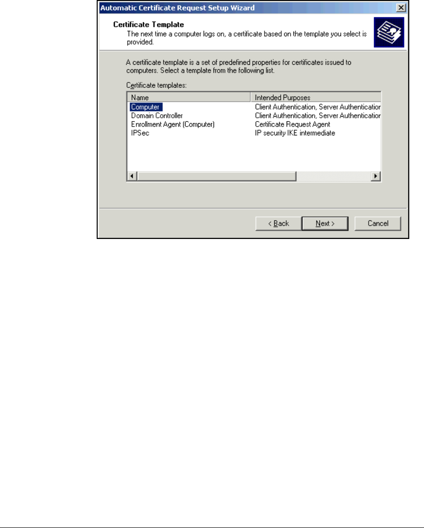
2-74
Implementing 802.1X with ProCurve IDM and Endpoint Integrity
Configuring Certificate Services
Figure 2-49. Automatic Certificate Request Setup Wizard—Certificate
Template Page
8. Select Computer from the Certificate templates list and click Next.
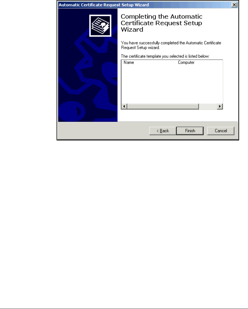
2-75
Implementing 802.1X with ProCurve IDM and Endpoint Integrity
Configuring Certificate Services
Figure 2-50. Automatic Certificate Request Setup Wizard—Completing
the Automatic Certificate Request Setup Wizard Page
9. Click Finish.
10. Select File > Exit to close the Group Policy Object Editor window.
11. Click OK in the <domain name> Properties window.
12. Press [Alt]+[F4] to close the Active Directory Users and Computers window.
13. To force a refresh of the computer Group Policy, access the command
prompt:
a. From the Windows Start menu, select Run.
b. Type cmd at the prompt and click OK.
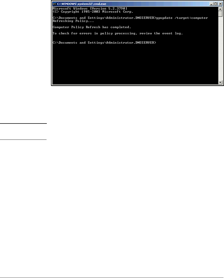
2-76
Implementing 802.1X with ProCurve IDM and Endpoint Integrity
Configuring Certificate Services
Figure 2-51. Command Interface—Force Group Update
c. At the command prompt, enter:
gpupdate /target:computer
Note When instructed to “enter” a command, you should type the string and press
[Enter].
d. Enter this command to close the command line:
exit
Create a Management Console for the CA
This section describes how to set up a Management Console. Throughout this
guide, you will add snap-ins to the console to control various services—in
particular those related to certificate services. You can configure the Manage-
ment Console on any Windows Server 2003 server; however, you will need to
log in as a user with rights to administer the CA. For example, you can log in
to either a domain controller or the CA server with the default domain
administrator account and complete the steps below:
1. Open the Management Console:
a. From the Windows Start menu, click Run.
b. Type mmc at the prompt and click OK.
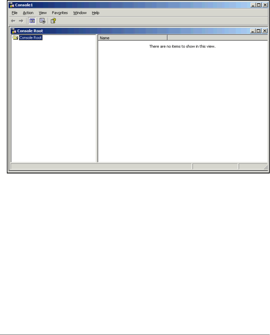
2-77
Implementing 802.1X with ProCurve IDM and Endpoint Integrity
Configuring Certificate Services
Figure 2-52. Open Management Console
2. In the File menu, click Add/Remove Snap-In.
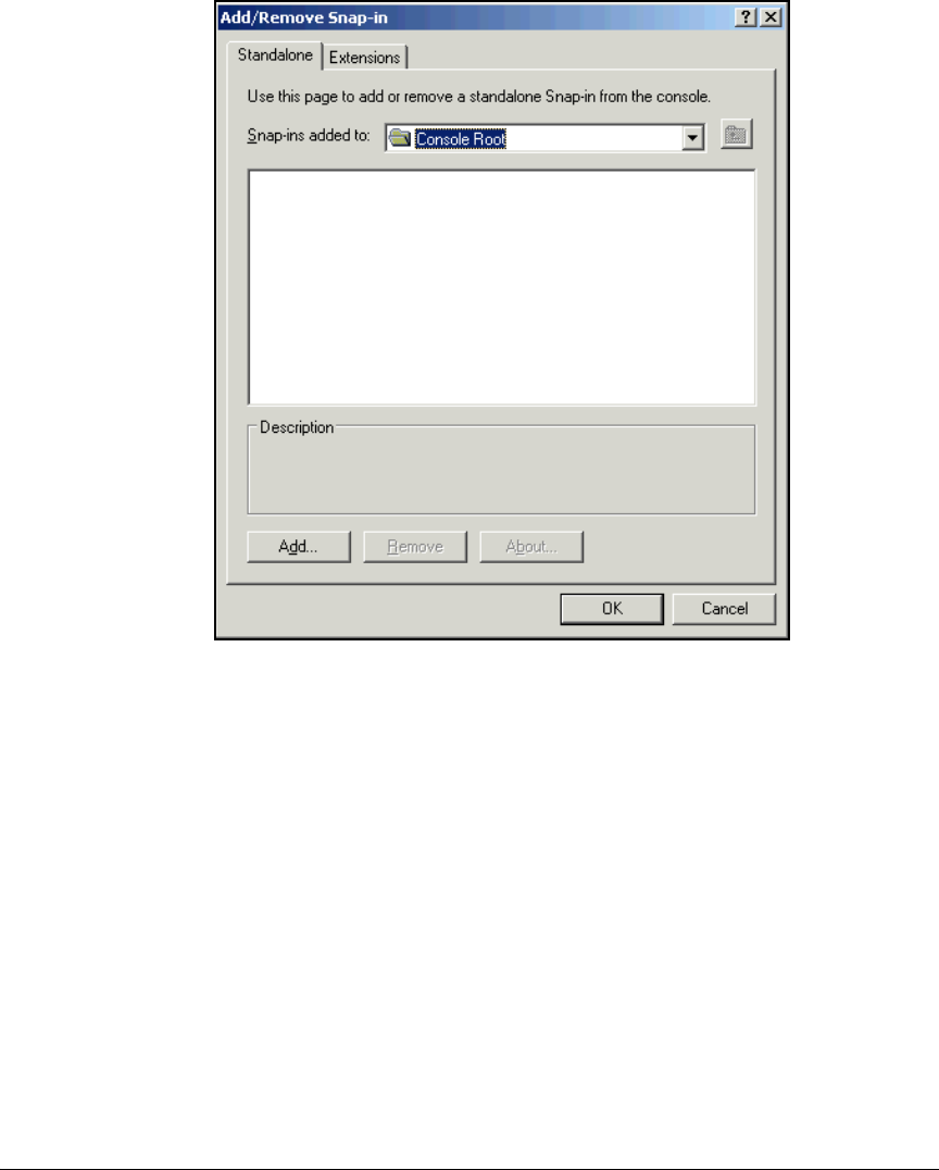
2-78
Implementing 802.1X with ProCurve IDM and Endpoint Integrity
Configuring Certificate Services
Figure 2-53. Add/Remove Snap-in
3. Click Add in the Add/Remove Snap-in window.
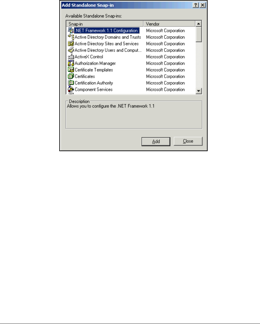
2-79
Implementing 802.1X with ProCurve IDM and Endpoint Integrity
Configuring Certificate Services
Figure 2-54. Add Standalone Snap-in
4. Select Certificate Templates from the Available Standalone Snap-ins window
and click Add.
5. Select Certification Authority from the Available Standalone Snap-in list and
click Add. The Certificate Authority window is displayed (see Figure 2-55).
6. Your next choice depends on where you have set up the Management
Console:
•On the CA server—Select Local computer and click Finish.
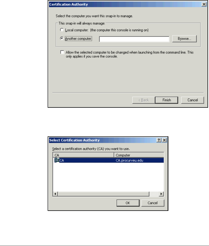
2-80
Implementing 802.1X with ProCurve IDM and Endpoint Integrity
Configuring Certificate Services
•On another server—Select Another computer and complete the fol-
lowing steps:
Figure 2-55. Certification Authority
i. Click Browse.
Figure 2-56. Certification Authority
ii. Select the CA server and click OK.
iii. Click Finish.
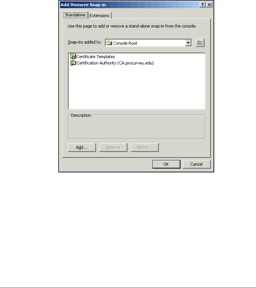
2-81
Implementing 802.1X with ProCurve IDM and Endpoint Integrity
Configuring Certificate Services
7. Click Close in the Add Standalone Snap-in window.
8. The Add/Remove Snap-in window should display the two snap-ins.
Click OK.
Figure 2-57. Add/Remove Snap-in Window—Certificate Templates and
Certification Authority
9. In the Management Console File menu, click Save.
10. Choose a name for the customized Management Console and type it in the
File name box.
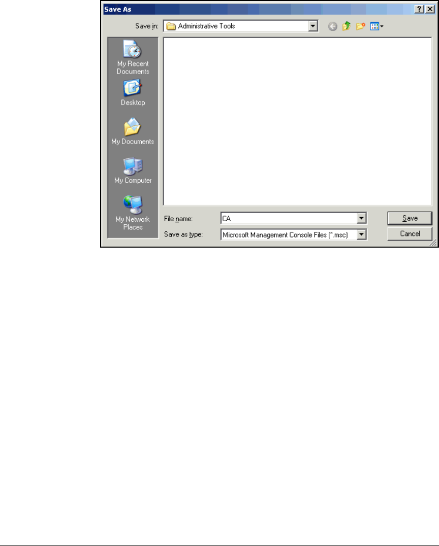
2-82
Implementing 802.1X with ProCurve IDM and Endpoint Integrity
Configuring Certificate Services
Figure 2-58. Save as Window
11. Click Save.
Customize the User Certificate Template
To configure autoenrollment for user certificates, you must configure the
certificate template to the CA.
In this solution, you will create a template based on the default User template.
However, you will adjust some settings for the subject name, and you will
enable autoenrollment.
Autoenrollment can occur automatically or with some user interaction (the
latter if you select Prompt the user during enrollment in the Request Handling tab
of the certificate template). The template also specifies whether the CA issues
the certificate automatically or whether an administrator must first approve
the request. Settings in the Issuance Requirements tab make this determination.
For this solution, you will accept default settings: autoenrollment proceeds
without user interaction and the CA automatically issues certificates to
domain members.
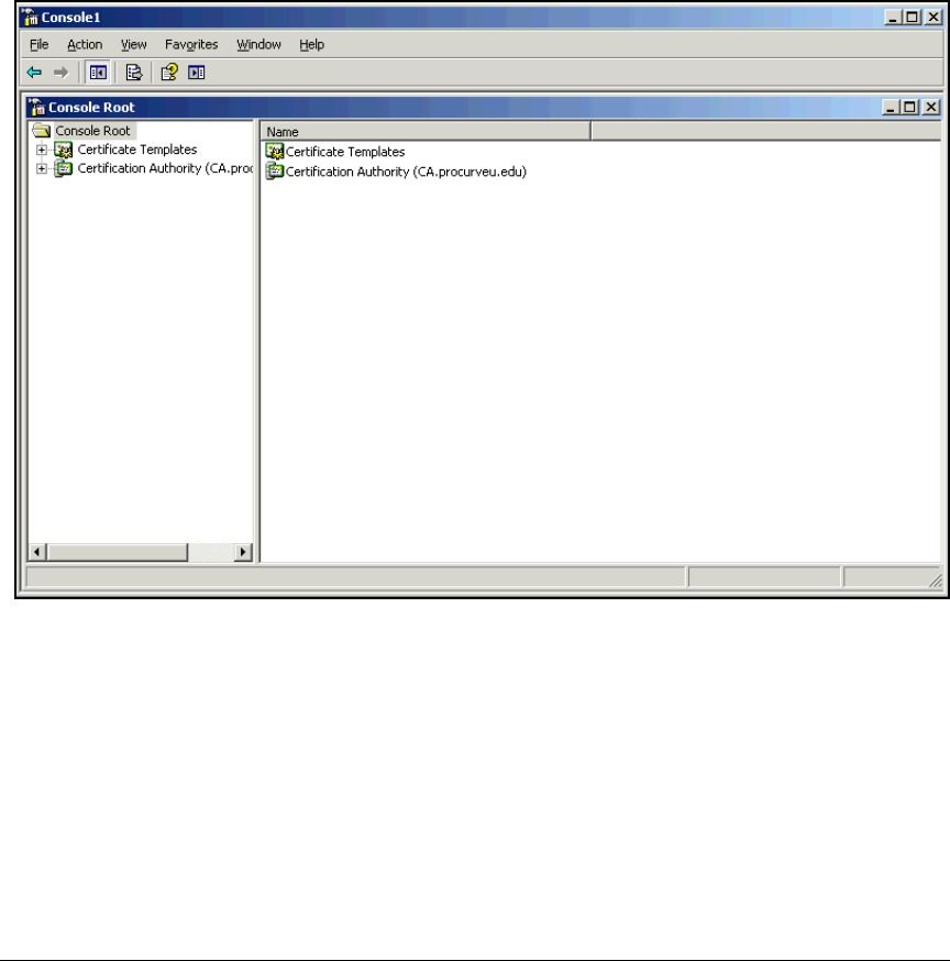
2-83
Implementing 802.1X with ProCurve IDM and Endpoint Integrity
Configuring Certificate Services
Follow these steps:
1. If necessary, re-open the Management Console.
a. From the Windows Start menu, select Run.
b. Type mmc at the prompt and click OK.
c. In the File menu > Open.
d. Select the console that you saved in the previous task.
Figure 2-59. Management Console Window
2. Click Certificate Templates in the left pane of the console window.
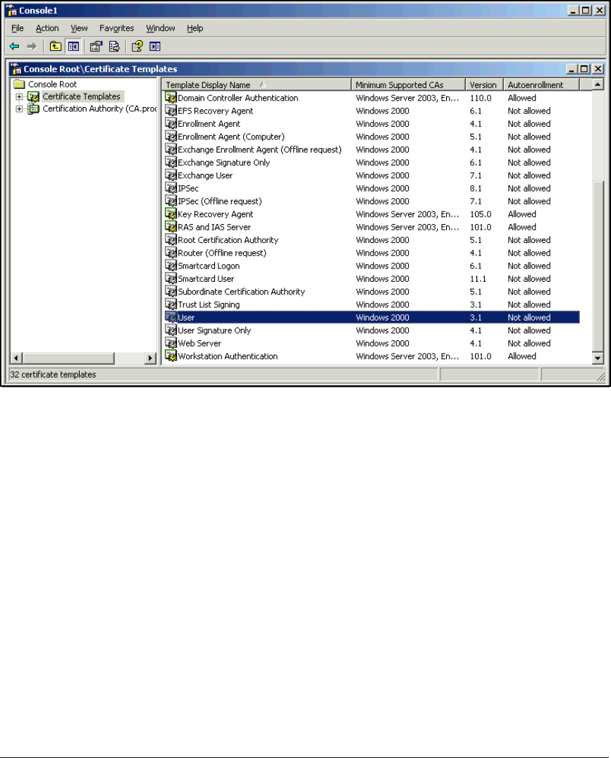
2-84
Implementing 802.1X with ProCurve IDM and Endpoint Integrity
Configuring Certificate Services
Figure 2-60. Management Console—Certificate Templates
3. In the right pane, scroll down to User. Right-click User and select Duplicate
Template.
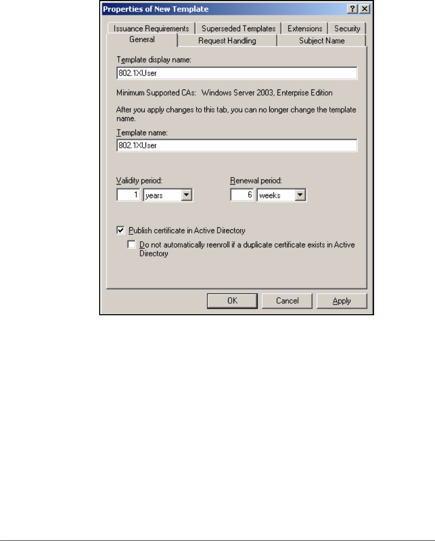
2-85
Implementing 802.1X with ProCurve IDM and Endpoint Integrity
Configuring Certificate Services
Figure 2-61. Properties of New Template Window—General Tab
4. At the General tab, type 802.1XUser for the Template display name.
5. Make sure that the Publish Certificate in Active Directory check box is
selected.
6. This step allows users to obtain their certificate even if their accounts do
not include an email address. You do not need to complete this step if
users always have an email address.
a. Click the Subject Name tab.
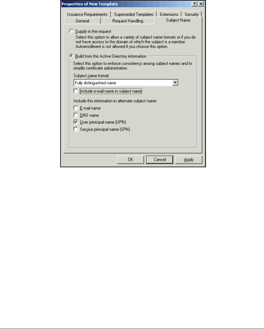
2-86
Implementing 802.1X with ProCurve IDM and Endpoint Integrity
Configuring Certificate Services
Figure 2-62. Properties of New Template Window—Subject Name Tab
b. Clear the following check boxes:
–Include e-mail name in subject name
–E-mail name under Include this information in alternate subject name
7. Click the Security tab.
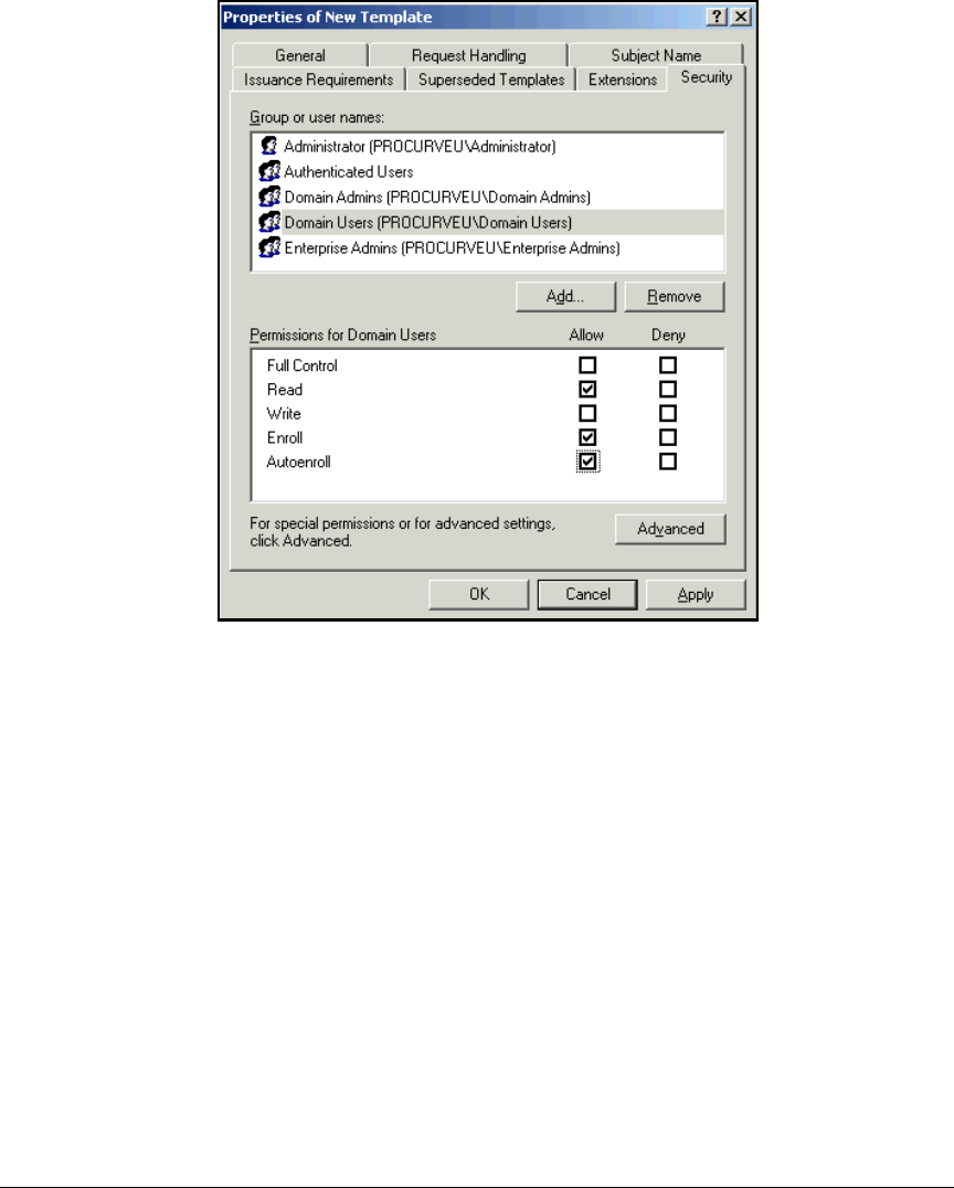
2-87
Implementing 802.1X with ProCurve IDM and Endpoint Integrity
Configuring Certificate Services
Figure 2-63. Properties of New Template Window—Security Tab
8. Select Domain Users in the Group or user names area.
9. Select the Read, Enroll, and Autoenroll check boxes in the Allow column of
the Permissions for Domain Users area.
10. Click OK.
Create the NAC 800 Certificate Template
The NAC 800s, which act as RADIUS servers, require server certificates that
allow them to perform client and server authentication. You must set up a
template for such a certificate.
Follow these steps:
1. If necessary, re-open the Management Console in which you added the
Certificate Templates snap-in.
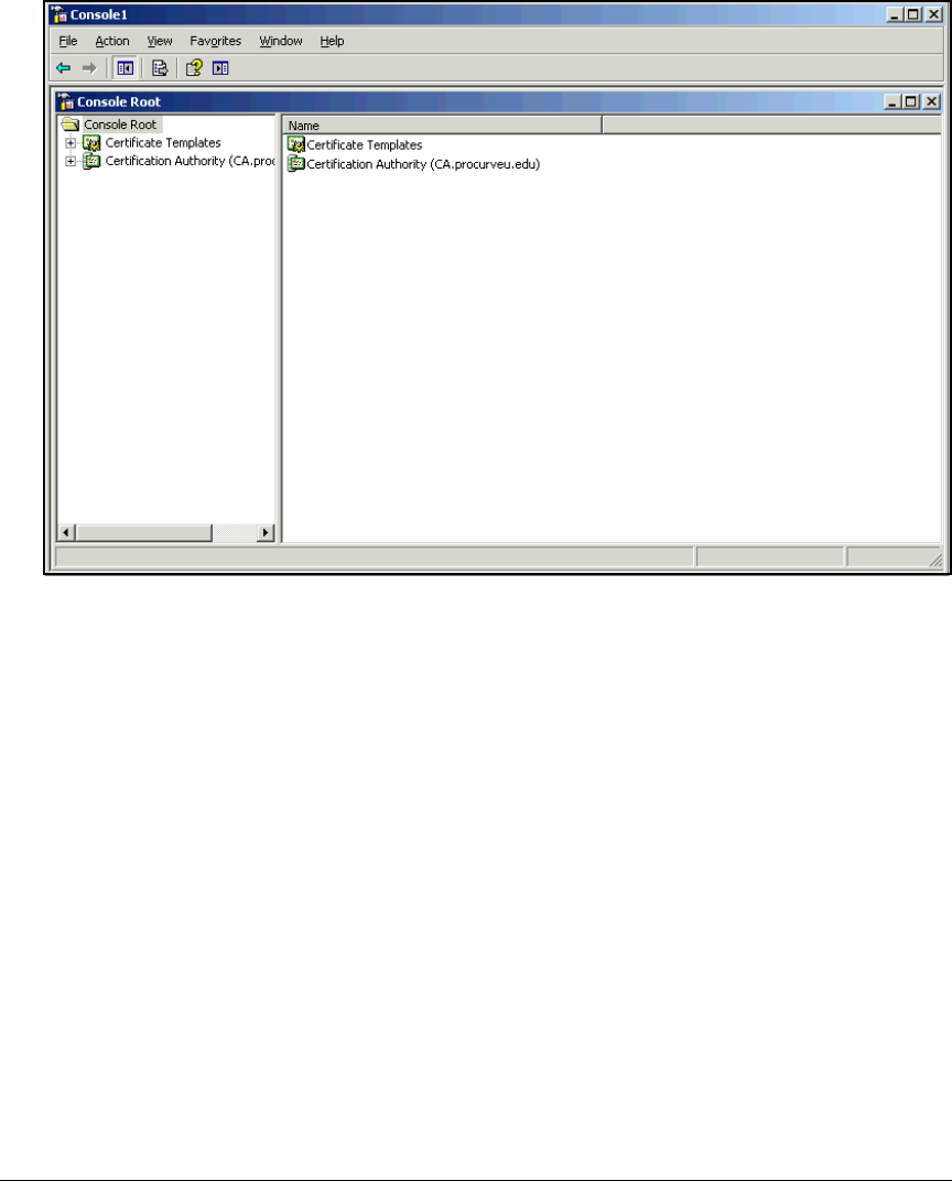
2-88
Implementing 802.1X with ProCurve IDM and Endpoint Integrity
Configuring Certificate Services
Figure 2-64. Management Console Window
2. Click Certificate Templates in the left pane of the console window.
3. Scroll to and right-click the RAS and IAS Server template. In the menu that
is displayed, click Duplicate Template.
4. You should be at the General tab.
5. In the Template display name box, type NAC 800.
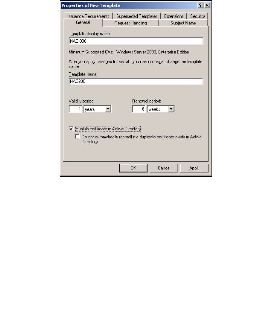
2-89
Implementing 802.1X with ProCurve IDM and Endpoint Integrity
Configuring Certificate Services
Figure 2-65. Properties of New Template Window—General Tab
6. Make sure the Publish certificate in Active Directory check box is selected.
7. Click the Subject Name tab.
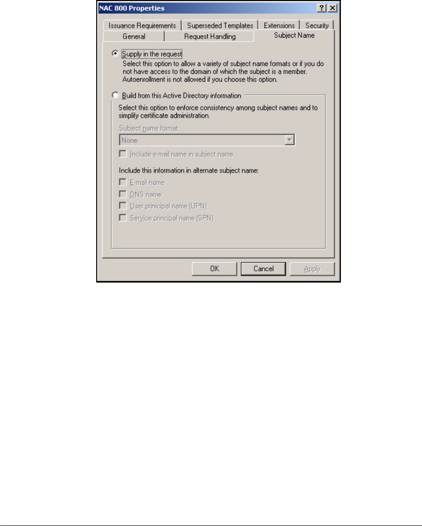
2-90
Implementing 802.1X with ProCurve IDM and Endpoint Integrity
Configuring Certificate Services
Figure 2-66. NAC 800 Properties Window—Subject Name Tab
8. Select the Supply in the request option.
You will create a request on the NAC 800, which will specify the NAC 800’s
subject name.
9. By default, Domain Admins and Enterprise Admins can enroll the NAC
800 for this certificate. Keep these default permissions.
10. Click OK.
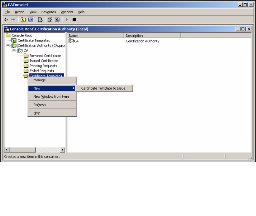
2-91
Implementing 802.1X with ProCurve IDM and Endpoint Integrity
Configuring Certificate Services
Deploy the New Certificate Templates to the CA
You will now make the new certificate templates available to the CA:
1. If necessary, re-open the Management Console with the Certificate
Authority snap-in:
a. From the Windows Start menu, select Run.
b. Type mmc at the prompt and click OK.
c. In the File menu, click Open and select the console.
2. In the left pane of the console, expand Certification Authority.
3.
4. Expand the CA server’s name. In this example, CA.
Figure 2-67. Management Console—Certificate Templates
5. Right-click Certificate Templates and select New > Certificate Template
to Issue.
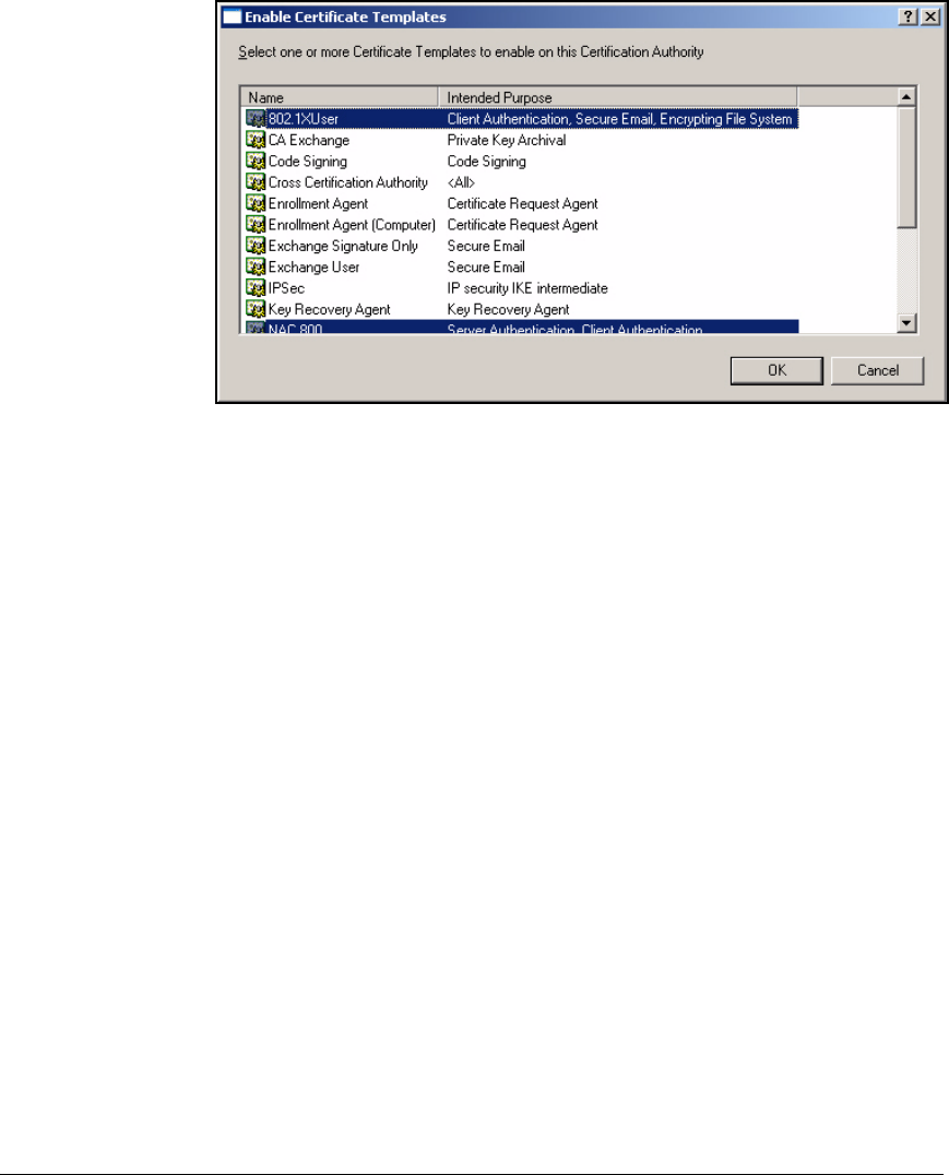
2-92
Implementing 802.1X with ProCurve IDM and Endpoint Integrity
Configuring Certificate Services
Figure 2-68. Management Console—Enable Certificate Templates Window
6. Click 802.1XUser.
7. Hold down [Ctrl] and scroll to and click NAC 800.
8. Click OK.
Set Up Autoenrollment of User Certificates
The 802.1XUser template allows autoenrollment. The other part of enabling
autoenrollment is allowing it in the domain Group Policy, which it is by default.
However, you might want to customize options for autoenrollment.
You can complete the steps below by opening Active Directory on a domain
controller as you did in “Configuring the Windows Domain Controller” on page
2-20. You can also add a snap-in for Active Directory to your Management
Console. The latter is the method described below:
1. If necessary, re-open your Management Console:
a. From the Windows Start menu, select Run.
b. Type mmc at the prompt and click OK.
c. In the File menu, click Open and select the console.
2. Select File > Add/Remove Snap-in.
3. Click Add.
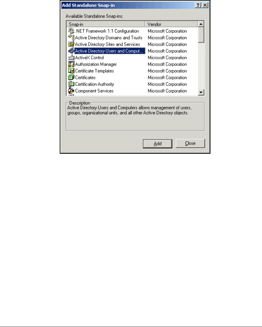
2-93
Implementing 802.1X with ProCurve IDM and Endpoint Integrity
Configuring Certificate Services
Figure 2-69. Management Console—Add Standalone Snap-in
Window
4. Select Active Directory Users and Computers from the Available Standalone
Snap-ins list and click Add.
5. Click Close.
6. Click OK in the Add/Remove Snap-in window.
7. In the left pane of the Management Console, expand Active Directory Users
and Computers.
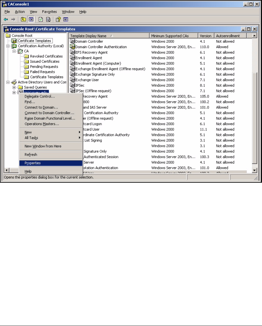
2-94
Implementing 802.1X with ProCurve IDM and Endpoint Integrity
Configuring Certificate Services
Figure 2-70. Management Console—<mydomain>
8. Right-click your domain name and select Properties.
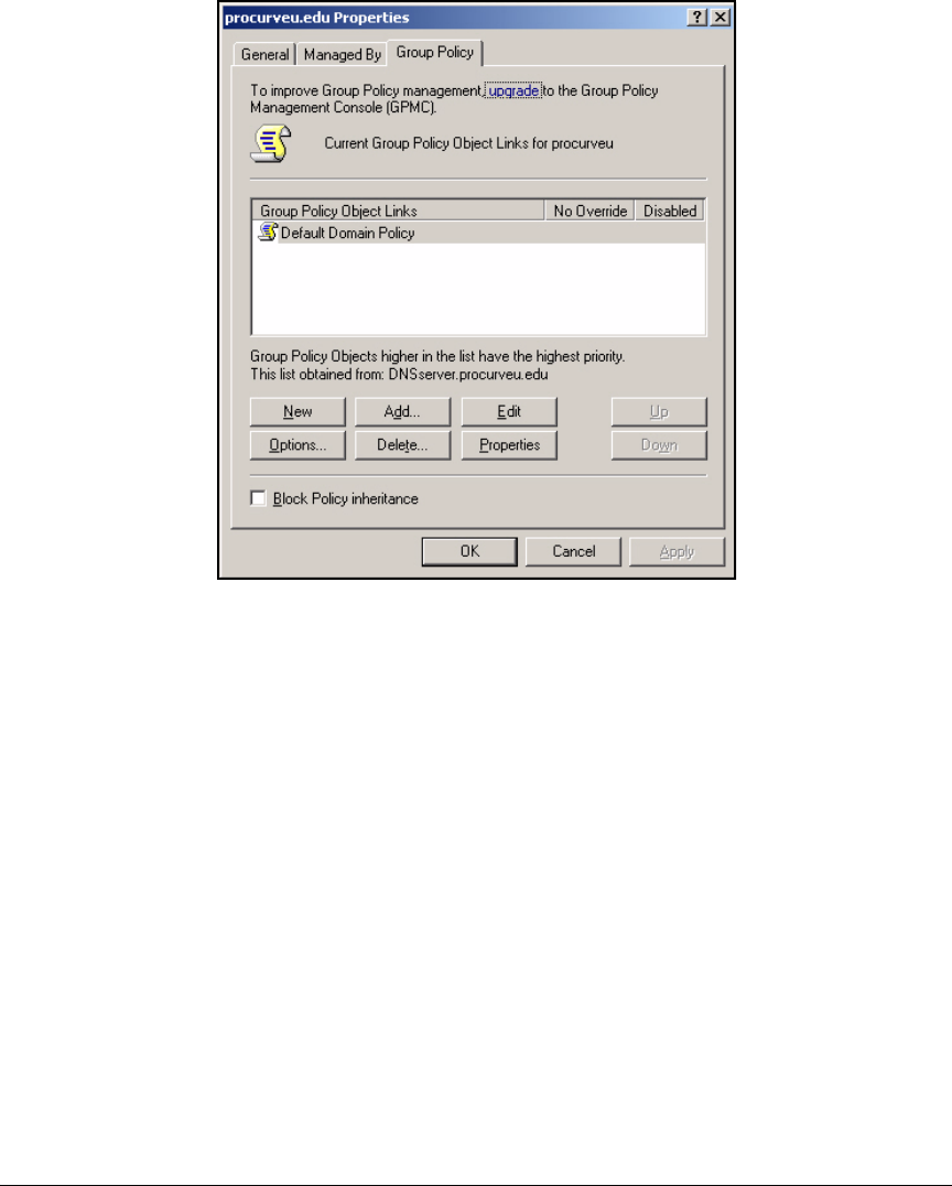
2-95
Implementing 802.1X with ProCurve IDM and Endpoint Integrity
Configuring Certificate Services
Figure 2-71. <mydomain> Properties Window
9. Click the Group Policy tab and click Edit.
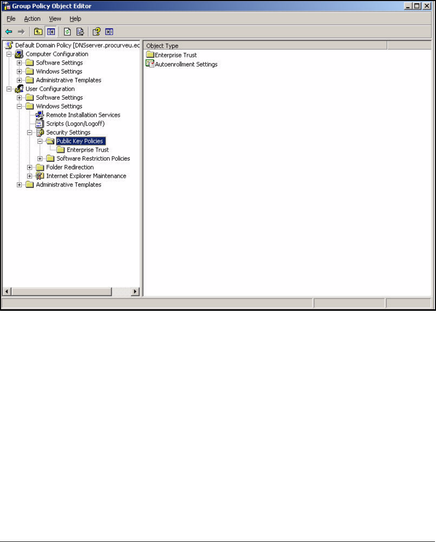
2-96
Implementing 802.1X with ProCurve IDM and Endpoint Integrity
Configuring Certificate Services
Figure 2-72. Group Policy Object Editor—Public Key Policies
10. Expand User Configuration > Windows Settings > Security Settings > Public
Key Policies.
11. In the right pane, double-click Autoenrollment settings.
12. Click Enroll certificates automatically and select the following check boxes:
• Renew expired certificates, update pending certificates, and remove
revoked certificates
• Update certificates that use certificate templates
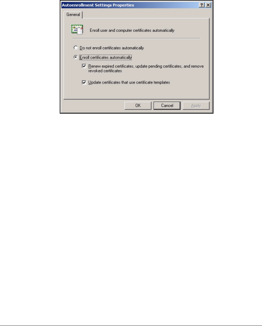
2-97
Implementing 802.1X with ProCurve IDM and Endpoint Integrity
Configuring Certificate Services
Figure 2-73. Management Console—Autoenrollment Settings
Properties Window
13. Click OK.
14. In the File menu, click Exit to close the Group Policy Object Editor.
15. Click OK in the Properties window.
16. In the File menu, click Save to preserve you changes to the Management
Console.
Export the CA Root Certificate
Users and computers receive the CA root certificate when they automatically
enroll for their certificates. However, you will need to manually import this
certificate to the NAC 800s and Wireless Edge Services Modules. The steps
below explain how to export your CA root certificate to a file. See “Manually
Issue and Install Server Certificates” on page 2-174 for instructions on import-
ing the certificate to the NAC 800s and Wireless Edge Services Modules.
1. If necessary, re-open your Management Console with the Certificate
Authority snap-in:
a. From the Windows Start menu, select Run.
b. Type mmc at the prompt and click OK.
c. In the File menu, click Open and select the console.
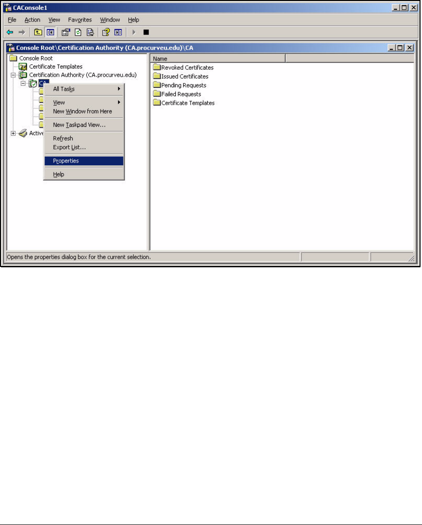
2-98
Implementing 802.1X with ProCurve IDM and Endpoint Integrity
Configuring Certificate Services
Figure 2-74. Management Console—CA
2. Expand Certification Authority.
3. Right-click the CA server name and, in the menu, select Properties.
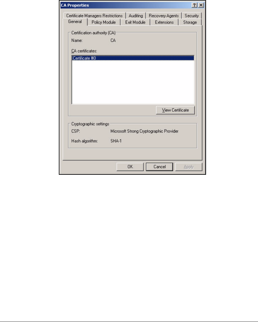
2-99
Implementing 802.1X with ProCurve IDM and Endpoint Integrity
Configuring Certificate Services
Figure 2-75. Management Console—CA Properties Window
4. At the General tab, click View Certificate.
5. Click the Details tab.
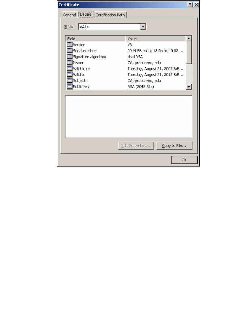
2-100
Implementing 802.1X with ProCurve IDM and Endpoint Integrity
Configuring Certificate Services
Figure 2-76. Management Console—Certificate Window—Details Tab
6. Click Copy to File. The Certificate Export Wizard is displayed.

2-101
Implementing 802.1X with ProCurve IDM and Endpoint Integrity
Configuring Certificate Services
Figure 2-77. Welcome to the Certificate Export Wizard
7. Click Next.
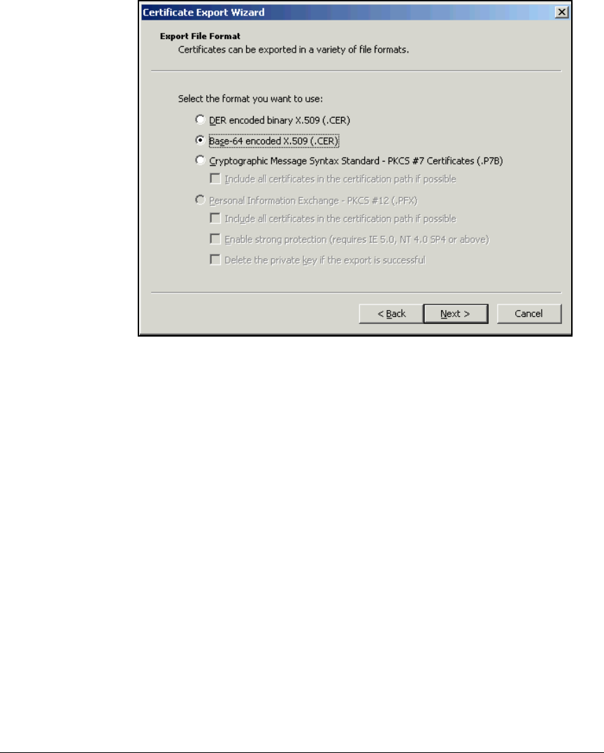
2-102
Implementing 802.1X with ProCurve IDM and Endpoint Integrity
Configuring Certificate Services
Figure 2-78. Certificate Export Wizard—Export File Format Page
8. Select a format supported by your devices. For the example, select Base-
64 encoded X.509 (.CER).
9. Click Next. A window is displayed, prompting you to save the certificate.
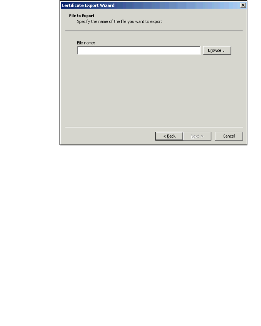
2-103
Implementing 802.1X with ProCurve IDM and Endpoint Integrity
Configuring Certificate Services
Figure 2-79. Certificate Export Wizard—File to Export Page
10. Specify the filename. Either:
• Type the name, including the path, in the File name box.
• Browse for the folder in which the certificate should be saved:
i. Click Browse.
ii. Navigate to the desired folder.
iii. Navigate to the location where you want to save the CA root
certificate.
iv. In the File name box, type a name for the certificate.
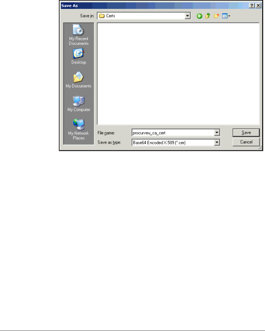
2-104
Implementing 802.1X with ProCurve IDM and Endpoint Integrity
Configuring Certificate Services
.
Figure 2-80. Certificate Export Wizard—Saving the CA Root Certificate
11. Click Save.
12. On the File to Export page, click Next.
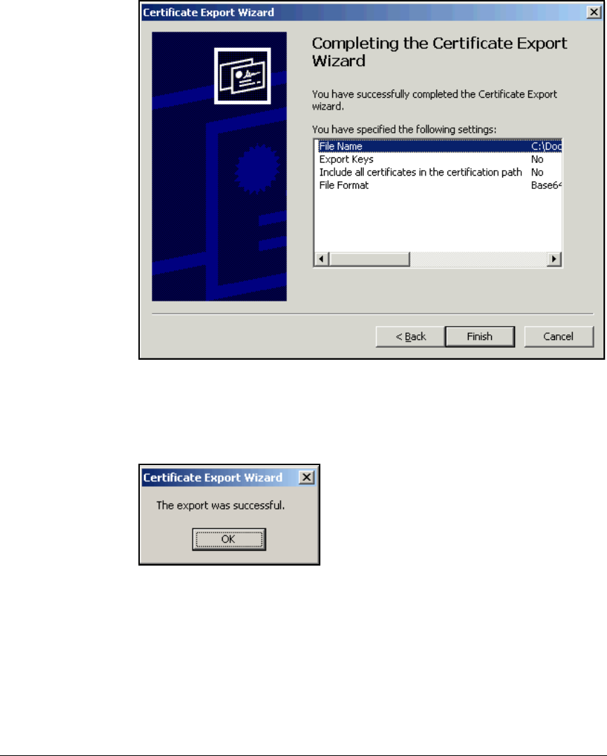
2-105
Implementing 802.1X with ProCurve IDM and Endpoint Integrity
Configuring Certificate Services
.
Figure 2-81. Certificate Export Wizard—Saving the CA Root Certificate
13. Check the information displayed in the Completing the Certificate Export
Wizard window. If it is correct, click Finish.
.
Figure 2-82. Certificate Export Wizard Window
14. Click OK.
15. Click OK in the Certificate Details and <CA server> Properties windows.
16. Press [Alt]+[F4] to close the Management Console.
17. When prompted, save the console.

2-106
Implementing 802.1X with ProCurve IDM and Endpoint Integrity
Configuring the Wireless Edge Services Modules
Configuring the Wireless Edge Services
Modules
The network in this access control solution provides wireless connectivity
with these devices:
■ProCurve Wireless Edge Services Module
■ProCurve Redundant Wireless Services Module
■Twelve ProCurve RPs
This section explains how to configure these devices to implement the access
control solution, beginning at installation. You must complete each task on
both modules.
Install the Wireless Edge Services Modules
You must install a Wireless Edge Services zl Module in a ProCurve Switch
5400zl or 8200zl series. After the module is installed, the switch is then referred
to as a wireless services-enabled switch. (For detailed instructions to install
the module into the switch, see the ProCurve Switch zl Module Installation
Guide.)
Note Alternatively, you can purchase a Wireless Edge Services xl Module and install
it in a ProCurve Switch 5300xl Series. Configuring an xl module is almost
exactly the same as configuring a zl module; however, the xl module has less
processing power and supports fewer RPs (up to 48 instead of up to 156).
The sample network for ProCurve University includes two 5400zl Switches.
To provide redundancy for the wireless network, the university has installed
one module in each switch.

2-107
Implementing 802.1X with ProCurve IDM and Endpoint Integrity
Configuring the Wireless Edge Services Modules
Configure Initial Settings on the Wireless Edge Services
Modules
Before you can access the Web browser interface on a Wireless Edge Services
Module, you must configure its IP settings through the wireless services-
enabled switch.
Follow these steps:
1. Access the wireless services-enabled switch’s command-line interface
(CLI) (through a console, Telnet, or Secure Shell [SSH] session).
2. Move to the wireless-services context with this command:
For example:
ProCurve# wireless-services c
Note The following instructions assume that the Wireless Edge Services Module is
at factory default settings. If it is not, return it to those settings by entering
erase startup-config. After the module reboots, access the wireless-services
context and continue following the instructions below.
3. Move to the global configuration mode context of the wireless-services
context:
ProCurve(wireless-services-C)# configure terminal
4. Move to the configuration mode context for the VLAN that you chose for
infrastructure devices:
In this example, the VLAN for infrastructure devices is 2. Enter:
ProCurve(wireless-services-C)(config)# interface
vlan2
Syntax: wireless-services <slot letter>
Moves to the wireless-services context on the wireless services-
enabled switch.
Replace <slot letter> with the letter for the chassis slot in which
the module is installed.
Syntax: interface vlan<ID>
Moves to a VLAN configuration mode context.
Replace <ID> with a number between 1 and 4094.

2-108
Implementing 802.1X with ProCurve IDM and Endpoint Integrity
Configuring the Wireless Edge Services Modules
5. Assign the VLAN an IP address.
For the example network, the Wireless Edge Services Module’s IP address
for VLAN 2 is 10.2.0.20 with a mask of 255.255.0.0. Enter:
ProCurve(wireless-services-C)(config-if)# ip address
10.2.0.20/16
6. Define this VLAN as the management VLAN.
ProCurve(wireless-services-C) (config-if)# management
7. Exit to the global configuration mode context:
ProCurve(wireless-services-C)(config-if)# exit
8. Specify the default router:
For the example network, type:
ProCurve(wireless-services-C)(config)# ip default-
gateway 10.2.0.1
9. You can optionally enable secure management, which restricts the module
to accepting management traffic that arrives on its management VLAN:
However, in this example, the setting is not necessary because the Wire-
less Edge Services Module has only one IP address, the management
address.
Syntax: ip address <A.B.C.D>/<prefix length>
Assigns the interface an IP address.
Replace <A.B.C.D> with the IP address and replace <prefix
length> with the Classless Inter-Domain Routing (CIDR) nota-
tion for the subnet mask.
Syntax: ip default-gateway <A.B.C.D>
Specifies the IP address for the default router.
Replace <A.B.C.D> with the IP address.
Syntax: management secure
Forces the module to accept management traffic only on the
management VLAN.

2-109
Implementing 802.1X with ProCurve IDM and Endpoint Integrity
Configuring the Wireless Edge Services Modules
10. Save the configuration:
You can now access the module’s Web browser interface, which you will use
to complete all remaining settings.
Configure WLAN Settings
This section explains how to set up a wireless LAN (WLAN) on the Wireless
Edge Services Module through its Web browser interface.
In a network that enforces 802.1X quarantining, you must set the WLAN
authentication to 802.1X. You can choose either Wired Equivalent Privacy
(WEP) or Wi-Fi Protected Access (WPA) for the encryption; however, WPA is
the much preferred option, and the one used in this example. (For more
information about the options for setting up WLAN security on the Wireless
Edge Services Module, see the ProCurve Access Control Security Design
Guide.)
Part of setting up the WLAN is specifying the RADIUS servers—in this case,
the NAC 800s. To roughly load balance authentication requests, specify one
NAC 800 as the primary server on one module and the other NAC 800 as the
secondary server on the other. (To locate the IP addresses for the NAC 800s,
which you will set up later, see Table 2-10. The ESs are the RADIUS servers.)
Table 2-10. Example NAC 800 IP Addresses
To configure the WLANs on the Wireless Edge Services Module, complete
these steps:
1. Open the Web browser interface on your management station. For the
URL, type the IP address that you configured on the module. In this
example: 10.2.0.20.
Your station must have the Java Runtime Environment (JRE).
Syntax: write memory
Saves the configuration changes to the startup-config.
Device Example IP
Address
Example
VLAN ID
Your Organization’s
IP Address
Your
Organization’s
VLAN ID
NAC 800 ES A 10.4.4.40 4
NAC 800 ES B 10.4.5.50 4

2-110
Implementing 802.1X with ProCurve IDM and Endpoint Integrity
Configuring the Wireless Edge Services Modules
Figure 2-83. Wireless Services Login Page
2. Log in with the default manager credentials:
•Username = manager
•Password = procurve
3. Click Network Setup > WLAN Setup.

2-111
Implementing 802.1X with ProCurve IDM and Endpoint Integrity
Configuring the Wireless Edge Services Modules
Figure 2-84. Wireless Edge Services Module Web Interface—Network Setup >
WLAN Setup Window
4. Select the first WLAN.
5. Click Edit.
6. Under Configuration, in the SSID box, type a name for the wireless network
(in this example, ProCurve University).
7. In the VLAN ID box, specify the VLAN for wireless traffic that is not
assigned dynamically to a different VLAN.
You might specify the VLAN for users with the fewest rights. In this
example, type the Students VLAN: 10.
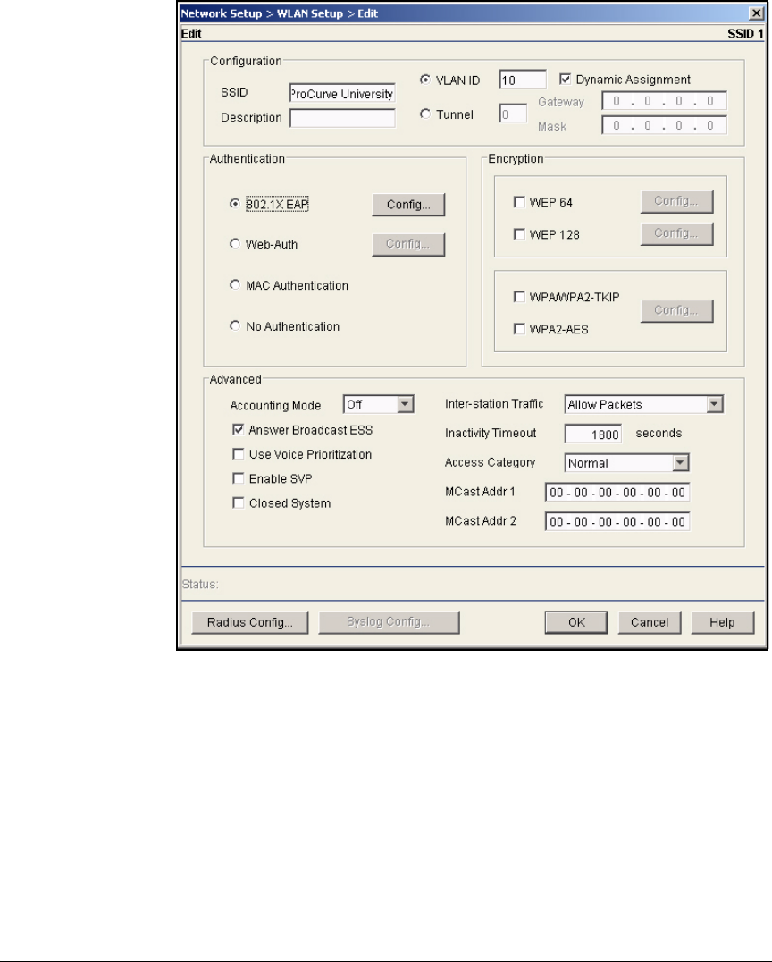
2-112
Implementing 802.1X with ProCurve IDM and Endpoint Integrity
Configuring the Wireless Edge Services Modules
Figure 2-85. Wireless Edge Services Module Web Interface—Network Setup >
WLAN Setup > Edit Window
8. The Dynamic Assignment check box should be selected. This setting
enables the Wireless Edge Services Module to apply dynamic VLAN
assignments that it receives from the NAC 800.
9. Under Encryption, select the WPA/WPA2-TKIP and the WPA2-AES check
boxes.
10. Under Authentication, select 802.1X EAP.
11. Click Radius Config at the bottom of the window. The Radius Configuration
window is displayed.
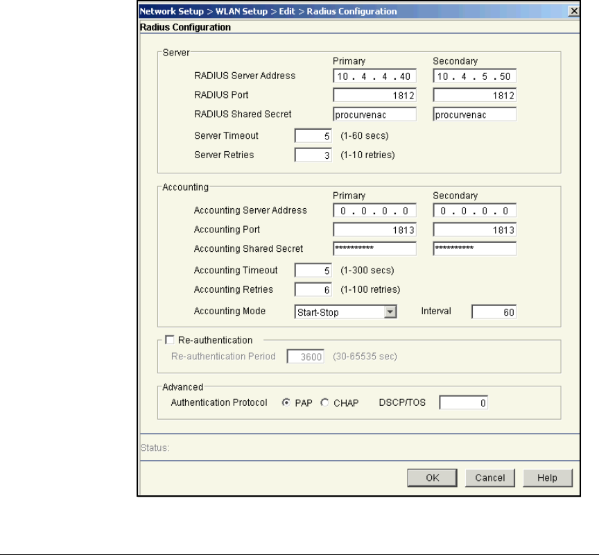
2-113
Implementing 802.1X with ProCurve IDM and Endpoint Integrity
Configuring the Wireless Edge Services Modules
12. Under Server, specify your NAC 800 ESs:
Type the settings for one NAC 800 setting in the Primary column:
a. In the RADIUS Server Address box, type the IP address of one NAC 800
ES: 10.4.4.40
b. Leave the RADIUS Port at the default value, 1812.
c. In the RADIUS Shared Secret box, type the secret that will be config-
ured for the module on the NAC 800 (in this example, procurvenac).
Type the settings for the other NAC 800 ES in the Secondary column
(10.4.5.50). Use the same shared secret.
Figure 2-86. Wireless Edge Services Module Web Interface—Radius
Configuration Window

2-114
Implementing 802.1X with ProCurve IDM and Endpoint Integrity
Configuring the Wireless Edge Services Modules
13. Click OK.
14. Click OK in the Network Setup > WLAN Setup > Edit window.
15. In the Network Setup > WLAN Setup window, verify that the WLAN you just
configured is selected. Click Enable.
Configure the Redundancy Group
This example network includes two Wireless Edge Services Modules to pro-
vide redundancy.
You will place the modules in a redundancy group in which both devices
function in active mode. In normal operation, both modules will adopt RPs
and support traffic from wireless users. (However, only the primary module
has the licenses that allow both modules to adopt RPs.) If one module fails,
the other module will provide failover and adopt all RPs.
Follow these steps:
1. You should be in the Wireless Edge Services Module’s Web browser
interface.
2. Select Network Setup > Redundancy Group. You begin at the
Configuration tab.
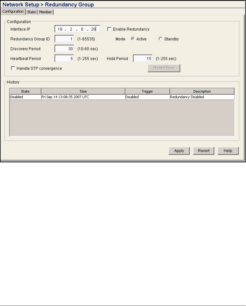
2-115
Implementing 802.1X with ProCurve IDM and Endpoint Integrity
Configuring the Wireless Edge Services Modules
Figure 2-87. Wireless Edge Services Module Web Interface—Network Setup >
Redundancy Group > Configuration Tab
3. Type the IP address of this module for the Interface IP. In this example:
10.2.0.20.
4. In the Redundancy Group ID box, leave the default: 1.
5. Select Active for the Mode.
6. Accept the defaults for other settings.
7. Click Apply.
8. Click the Member tab.
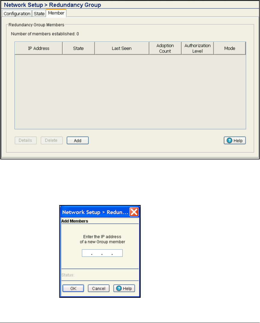
2-116
Implementing 802.1X with ProCurve IDM and Endpoint Integrity
Configuring the Wireless Edge Services Modules
Figure 2-88. Wireless Edge Services Module Web Interface—
Network Setup > Redundancy Group > Member Tab
9. Click Add. The Add Members window is displayed.
Figure 2-89. Wireless Edge Services Module Web Interface—
Add Members Window

2-117
Implementing 802.1X with ProCurve IDM and Endpoint Integrity
Configuring the Wireless Edge Services Modules
10. Type the IP address of the other module (in this example, 10.2.0.25).
11. Click OK. The module is now listed on the Network Setup > Redundancy
Group > Member window.
12. Repeat steps 2 to 11 on the Redundant Wireless Services Module. How-
ever, in step 3, enter the IP address of the redundant module and in step
10, enter the IP address of the primary module.
Note It is very important to configure redundancy on all members of the group
before enabling redundancy.
13. Click the Configuration tab.
14. Select the Enable Redundancy check box.
15. Click Apply.
16. Click Save at the top of the Web browser interface.
17. Click Yes and OK in the two windows that are displayed.
18. Repeat steps 13 to 16 on the redundant module.
Configure SNMP on the Wireless Edge Services
Modules
You must configure the Wireless Edge Services Modules’ SNMP settings to
allow PCM+ to manage it. SNMPv3 also controls access to the Module’s Web
browser interface.
Follow these steps to configure SNMP:
1. You should be in the Wireless Edge Services Module’s Web browser
interface.
2. Click Management > SNMP Access. You begin at the v1/v2c tab.

2-118
Implementing 802.1X with ProCurve IDM and Endpoint Integrity
Configuring the Wireless Edge Services Modules
Figure 2-90. Wireless Edge Services Module Web Interface—
Management > SNMP Access > V1/V2c Tab
3. Select public and click Edit. The Edit SnmpV1/V2c window is displayed.
4. For the Community Name, type the new name for the community (in this
example, procurvero).
Figure 2-91. Wireless Edge Services Module Web Interface—
Edit SnmpV1/V2c Window
5. Keep the default setting, Read Only, in the Access Control box.
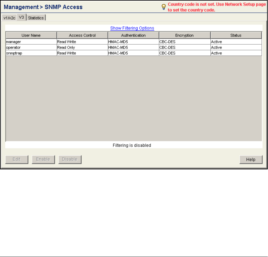
2-119
Implementing 802.1X with ProCurve IDM and Endpoint Integrity
Configuring the Wireless Edge Services Modules
6. Click OK.
7. Select private and click Edit.
8. In the Community Name box, type the new name for the community. In this
example: procurverw.
9. Keep the default setting, Read Write, in the Access Control box.
10. Click OK.
11. Click the V3 tab.
Figure 2-92. Wireless Edge Services Module Web Interface—Management >
SNMP Access > V3 Tab
12. Select snmptrap and click Edit. The Edit SnmpV3 window is displayed.

2-120
Implementing 802.1X with ProCurve IDM and Endpoint Integrity
Configuring the Wireless Edge Services Modules
Figure 2-93. Wireless Edge Services Module Web
Interface—Edit SnmpV3 Window
13. In the Old Password box, type the current password: trapuser.
14. In the New Password and Confirm Password boxes, type the new password
(in this example, procurve).
15. Click OK.
16. The other two default SNMPv3 users are also part of the Wireless Edge
Services Module’s Web-Users. You will control them on the window for
those users. Click Management > Web-Users.
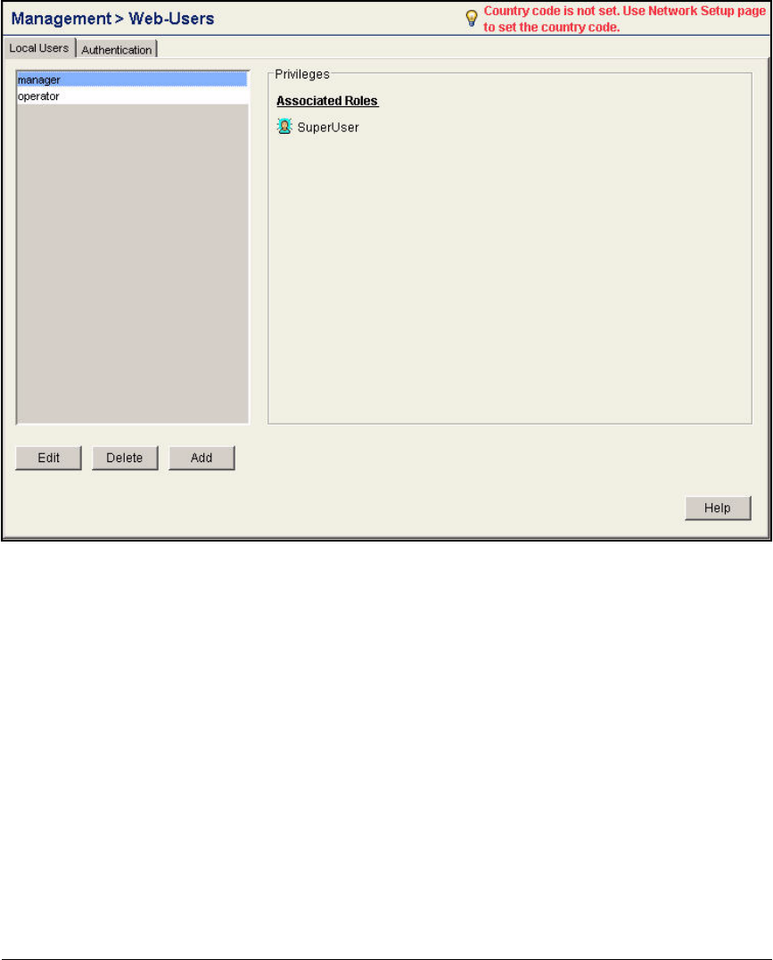
2-121
Implementing 802.1X with ProCurve IDM and Endpoint Integrity
Configuring the Wireless Edge Services Modules
Figure 2-94. Wireless Edge Services Module Web Interface—Management >
Web-Users
17. Select operator and click Edit.

2-122
Implementing 802.1X with ProCurve IDM and Endpoint Integrity
Configuring the Wireless Edge Services Modules
Figure 2-95. Wireless Edge Services Module Web Interface—
Management > Web-Users > Configuration (operator)
18. In the Password and Confirm Password boxes, type the new password (in
this example, procurveoperator).
19. Under Associated Roles, the Monitor check box is selected. Keep this
default setting.
20. Click OK.
21. Select manager and click Edit.

2-123
Implementing 802.1X with ProCurve IDM and Endpoint Integrity
Configuring the Wireless Edge Services Modules
Figure 2-96. Wireless Edge Services Module Web Interface—
Management > Web-Users > Configuration (manager)
22. In the Password and Confirm Password boxes, type the new password (in
this example, Procurve1).
23. Under Associated Roles, the SuperUser check box is selected. Keep this
default setting.
24. Click OK.
Note You must enter this new password the next time you log in to the Web browser
interface.
25. Select Management > SNMP Trap Configuration.

2-124
Implementing 802.1X with ProCurve IDM and Endpoint Integrity
Configuring the Wireless Edge Services Modules
Figure 2-97. Wireless Edge Services Module Web Interface—Management >
SNMP Trap Configuration > Configuration Tab
26. Select the Allow Traps to be generated check box.
27. To view the SNMP traps in a category, expand the category. To view the
SNMP traps in all categories, click Expand all items.
28. To enable all the traps, select All Traps and click Enable all sub-items.
29. To enable all the SNMP traps in a category, select the category and click
Enable all sub-items.

2-125
Implementing 802.1X with ProCurve IDM and Endpoint Integrity
Configuring the Wireless Edge Services Modules
Figure 2-98. Wireless Edge Services Module Web Interface—Management >
SNMP Trap Configuration > Configuration Tab
30. To enable a specific SNMP trap, select the trap and click Enable or double-
click the trap. A green check mark is displayed next to enabled traps. A
red x is displayed next to disabled traps.
31. Click Apply.
Configure the Time
Network devices check timestamps as a part of the authentication process (as
well as other processes). It is important that all your network devices keep
the same clock. Follow these steps to configure the time on the Wireless Edge
Services Module:
1. You should be in the module’s Web browser interface.
2. Click Network Setup. You should be at the Configuration tab.
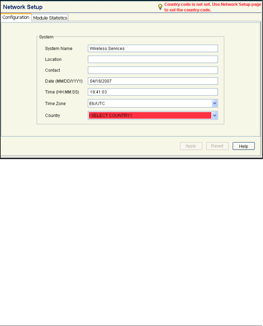
2-126
Implementing 802.1X with ProCurve IDM and Endpoint Integrity
Configuring the Wireless Edge Services Modules
Figure 2-99. Wireless Edge Services Module Web Interface—Network Setup >
Configuration Window
3. Select your time zone from the Time Zone box.
4. Click Apply.
5. Click Special Features > Secure NTP.
6. Click the NTP Neighbor tab.
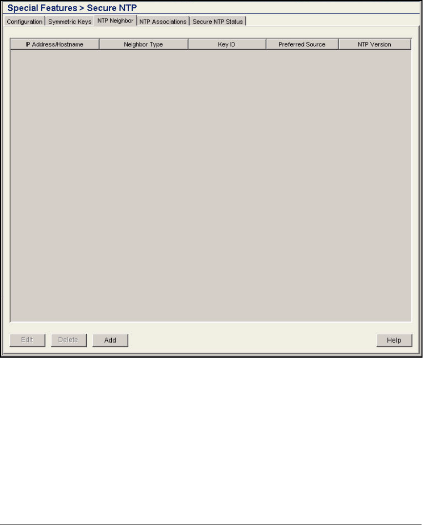
2-127
Implementing 802.1X with ProCurve IDM and Endpoint Integrity
Configuring the Wireless Edge Services Modules
Figure 2-100. Wireless Edge Services Module Web Interface—Special Features >
Secure NTP > NTP Neighbor Window
7. Click Add.
8. Click Server.
9. Select IP Address or Hostname and specify your NTP server. In this exam-
ple, the domain is using a public NTP server.
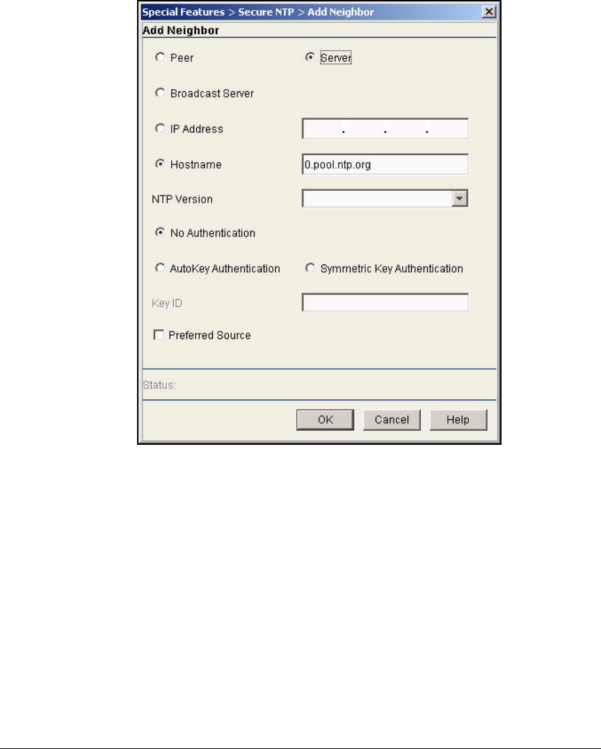
2-128
Implementing 802.1X with ProCurve IDM and Endpoint Integrity
Configuring the Wireless Edge Services Modules
Figure 2-101. Wireless Edge Services Module Web Interface—
Special Features > Secure NTP > Add Neighbor Window
10. Click OK.

2-129
Implementing 802.1X with ProCurve IDM and Endpoint Integrity
Configuring the Wireless Edge Services Modules
Set the Country Code
You must set the country code to enable the Wireless Edge Service Module to
adopt RPs. Follow these steps:
1. Click Network Setup. You should be at the Configuration tab.
Figure 2-102. Wireless Edge Services Module Web Interface—Network Setup >
Configuration Window
2. From the Country box, select your country. A Warning window is displayed.
Figure 2-103. Wireless Edge Services Module Web Interface—
Warning Window

2-130
Implementing 802.1X with ProCurve IDM and Endpoint Integrity
Configuring the Wireless Edge Services Modules
3. Click OK.
4. Click Apply.
5. Click Save at the top of the Web browser interface.
6. Click Yes and OK in the two windows that are displayed.
802.1X Authentication for RPs
To prevent users from disconnecting RPs and plugging rogue devices into the
RPs’ switch ports, you can enforce 802.1X authentication on these ports. The
ProCurve RPs 210, 220, and 230 include an 802.1X client so that they can
connect to ports that enforce such authentication. Using Message Digest 5
(MD5) authentication, the client automatically sends the RP’s credentials
when the RP connects to a network device. The switch to which the RP
connects forwards the credentials to an authentication server, and if the
credentials are correct, allows the RP to join the network.
The authentication server may store a VLAN setting for the RP, which it sends
to the switch after the RP authenticates. Such dynamic configuration of the
Radio Port VLAN can replace auto-provisioning on the wireless services-
enabled switch or manual configuration on an infrastructure switch.
Note When you implement 802.1X on a port, auto-provisioning is disabled on that
port. You must either manually set the port to the correct VLAN for the RP or
configure the VLAN assignment on the RADIUS server.
However, the wireless services-enabled switch can continue to implement
auto-provisioning on ports that do not enforce 802.1X.
The default username and password on all ProCurve 200 series RPs are
“admin” and “procurve.”
You should use pre-adoption to change these settings. That is, connect your
organization’s RPs directly to the wireless-services enabled switch (or, if the
switch does not support PoE, to a PoE switch that is configured to forward
Radio Port traffic to the wireless-services enabled switch). Verify that the
Wireless Edge Services Module adopts the RPs; then load new credentials on
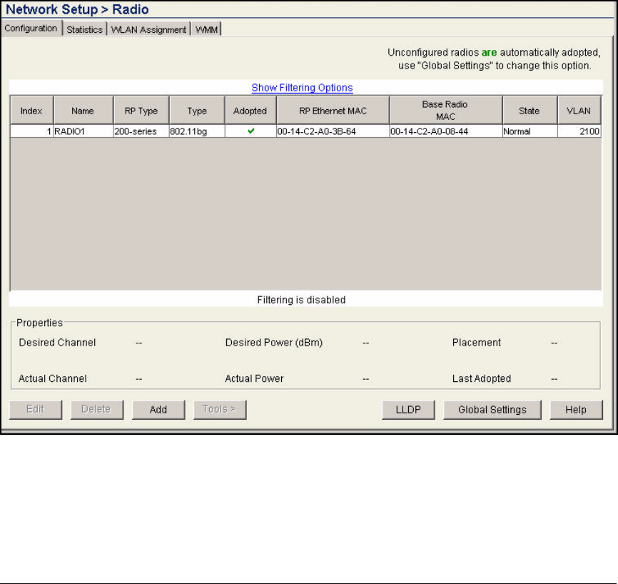
2-131
Implementing 802.1X with ProCurve IDM and Endpoint Integrity
Configuring the Wireless Edge Services Modules
the RPs as explained in the following section. After you have finished setting
up the access control solution, you can move the RPs to their final locations,
where they will authenticate to the network.
Configuring 802.1X Authentication for RPs
To configure 802.1X authentication for RPs, complete these steps:
1. Select Network Setup > Radio. You begin at the Configuration tab.
2. Verify that all of your organization’s RPs are listed in the window.
Figure 2-104. Wireless Edge Services Module Web Browser Interface—Network
Setup > Radio Window
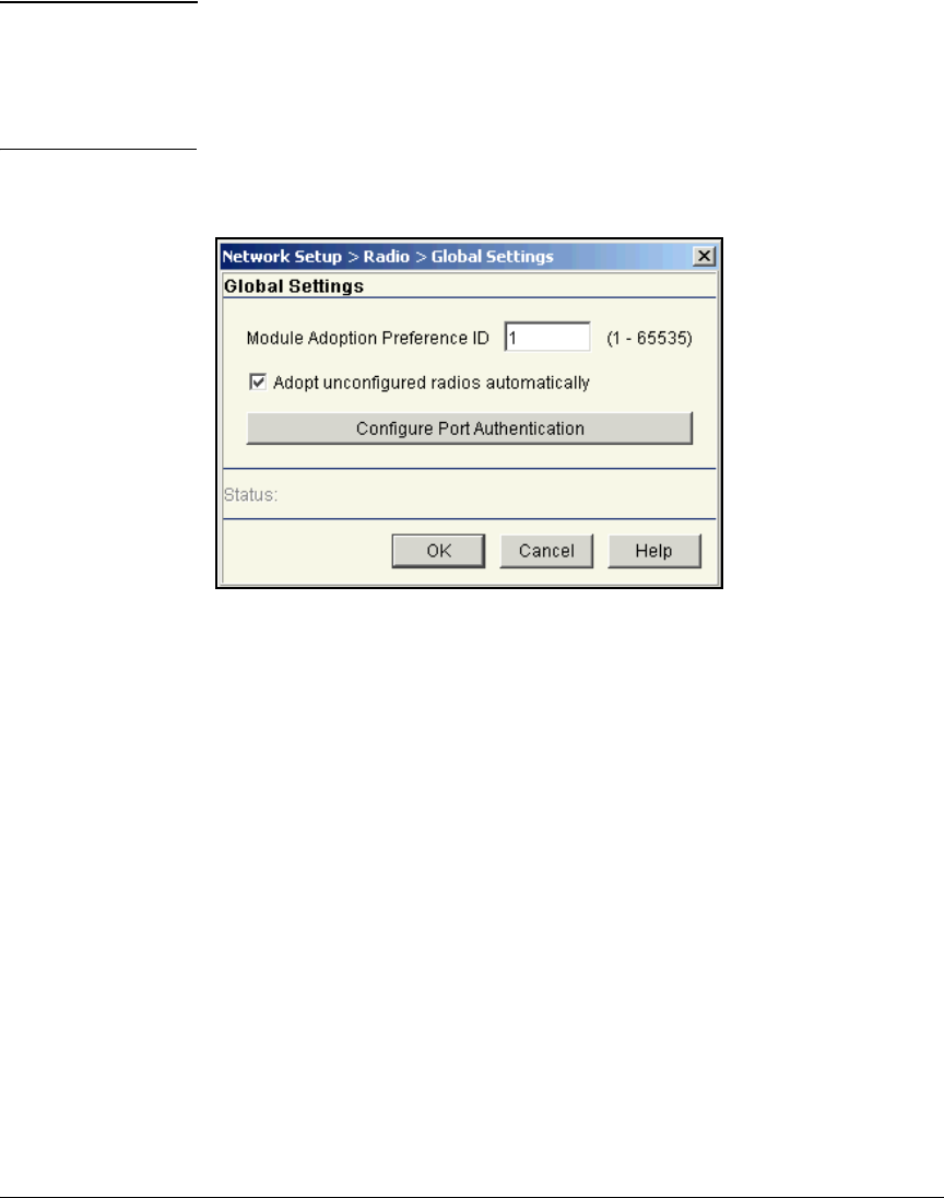
2-132
Implementing 802.1X with ProCurve IDM and Endpoint Integrity
Configuring the Wireless Edge Services Modules
Note It is important that all RPs be adopted at this time. When the Wireless Edge
Services Module pushes the username and password to the RPs, as you
are about to configure it to do, it does so as a one-time occurrence. Any
RP not adopted at this time does not receive the credentials even if it is
adopted later.
3. Click Global Settings.
Figure 2-105. Wireless Edge Services Module Web Browser
Interface—Network Setup > Radio >
Global Settings Window
4. Click Configure Port Authentication.
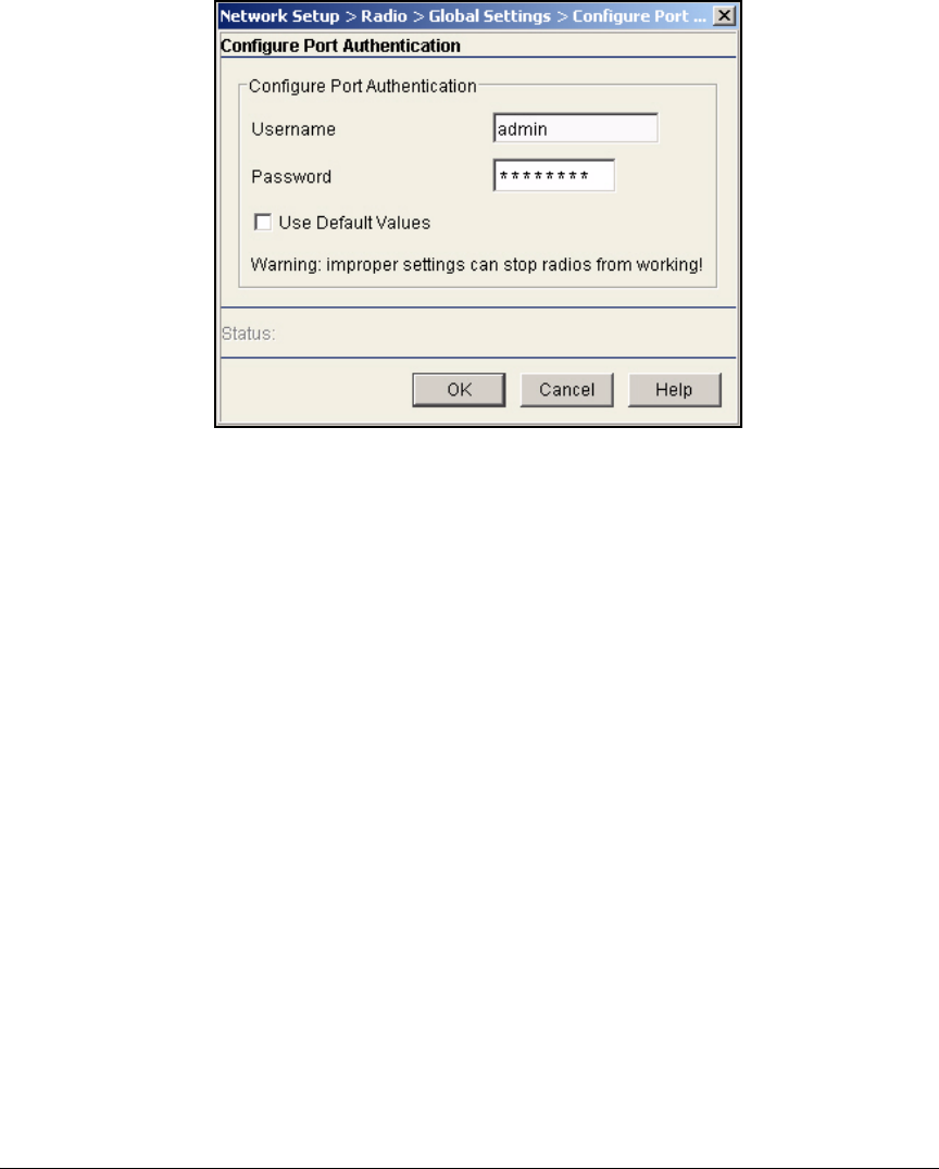
2-133
Implementing 802.1X with ProCurve IDM and Endpoint Integrity
Configuring the Wireless Edge Services Modules
Figure 2-106. Wireless Edge Services Module Web Browser
Interface—Configure Port Authentication Window
5. Configure a username and password. Do one of the following:
•In the Username and Password boxes, type the username and pass-
word that you want to use. In this example: rp and ProCurve6.
• Check the
Use Default Values
box to return to the default username and
password:
– username: admin
– password: procurve
6. Click OK, and then click OK in the Global Settings window.
7. Click Save.
8. Click Yes and OK in the two windows that are displayed.
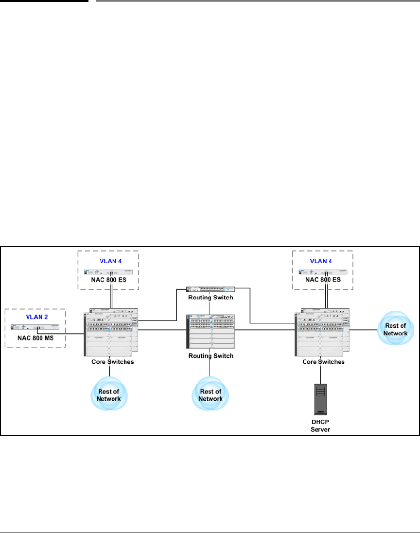
2-134
Implementing 802.1X with ProCurve IDM and Endpoint Integrity
Configuring the NAC 800s
Configuring the NAC 800s
This solution includes three NAC 800s:
■One MS
■Two E Ss
Install the NAC 800s
The NAC 800s in this solution enforce quarantining by issuing dynamic VLAN
assignments as RADIUS servers. Install the devices in the network core with
other servers.
As shown in Figure2-107, the NAC 800 MS is placed in the management VLAN
(VLAN 2) to help control access to the Web browser interface. The NAC 800
ESs, which act as RADIUS servers, are placed in the server VLAN (VLAN 4).
Each NAC 800 connects to its switch on its Ethernet port 1.
Figure 2-107. Placing the NAC 800s in the Core of the Example Network
Refer to the Network Access Controller 800 Hardware Installation Guide for
detailed mounting and installation instructions.

2-135
Implementing 802.1X with ProCurve IDM and Endpoint Integrity
Configuring the NAC 800s
Configure Basic Settings on the NAC 800s
Before you manage the NAC 800s through the MS’s Web browser interface,
you must configure some basic network settings on all the devices. This
section explains how to configure these settings through a console session.
The next section describes configuring the remainder of the basic settings
through the Web browser interface.
In this example, the NAC 800s will use the network settings in Table 2-11.
Table 2-11. NAC 800 Basic Settings
Configure Initial Settings Through a Console Session
The following steps guide you through initial configuration of one of your NAC
800s. You must repeat these steps on each of the devices. The only differences
are the server type and the IP addresses.
1. Your NAC 800 ships with a console cable. Plug the cable’s Ethernet (RJ-
45) connector into the Console Ethernet port, which is located on the left
front panel of the NAC 800.
2. Plug the cable’s DB-9 connector into a console port on your management
workstation.
3. Use terminal session software such as Tera Term to open a console session
with the NAC 800. Use the following settings:
• Baud rate = 9600
•Bits = 8
•Stop rate = 1
• Parity = None
• Flow control = None
• For the Windows Terminal program, clear the Use Function, Arrow, and
Ctrl Keys for Windows check box.
• For the Hilgraeve HyperTerminal program, select the Terminal keys
option for the Function, arrow, and ctrl keys act as parameter.
4. When prompted for your username, type admin.
Device Hostname IP Address Subnet Mask Default
Gateway
DNS Server Time Settings
NAC 800 MS MS.procurveu.edu 10.2.1.40 255.255.0.0 10.2.0.1 10.4.4.15 ntp.pool1.org
NAC 800 ES ESa.procurveu.edu 10.4.4.40 255.255.0.0 10.4.0.1 10.4.4.15 from MS
NAC 800 ES ESb.procurveu.edu 10.4.5.50 255.255.0.0 10.5.0.1 10.4.4.15 from MS
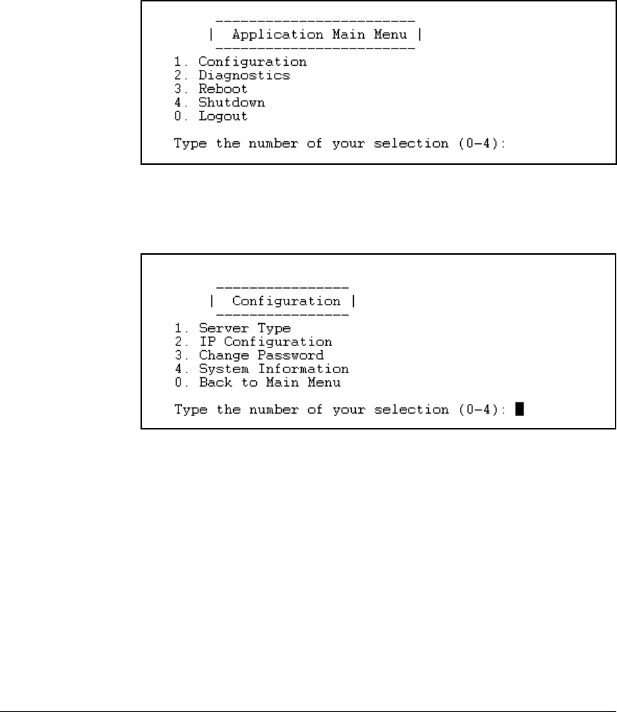
2-136
Implementing 802.1X with ProCurve IDM and Endpoint Integrity
Configuring the NAC 800s
5. When prompted, type your password (default, procurve).
You should now see the Application Main Menu.
Figure 2-108. NAC 800 Menu Interface—Application Main Menu
6. In the main menu, press [1] for Configuration.
Figure 2-109. NAC 800 Menu Interface—Main Menu > 1. Configuration
7. In the Configuration menu press [1] for Server Type.
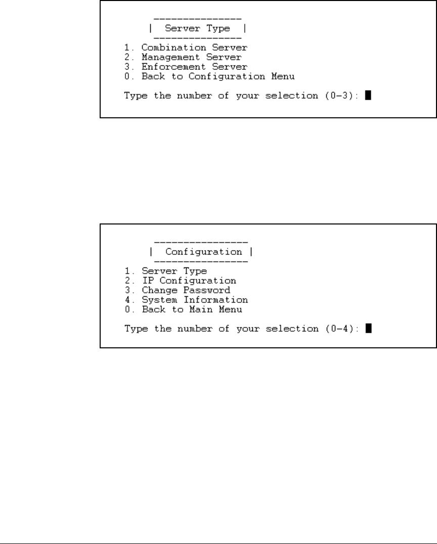
2-137
Implementing 802.1X with ProCurve IDM and Endpoint Integrity
Configuring the NAC 800s
Figure 2-110. NAC 800 Menu Interface—Application Main Menu > 1. Configuration
> 1. Server Type
8. Press [2] for Management Server, or if you are configuring one of the ESs,
press [3] for Enforcement Server.
9. Press [0] to return to the Configuration menu.
Figure 2-111. NAC 800 Menu Interface—Application Main Menu > 1. Configuration
10. You should change the password to the menu interface. Press [3] for
Change Password.
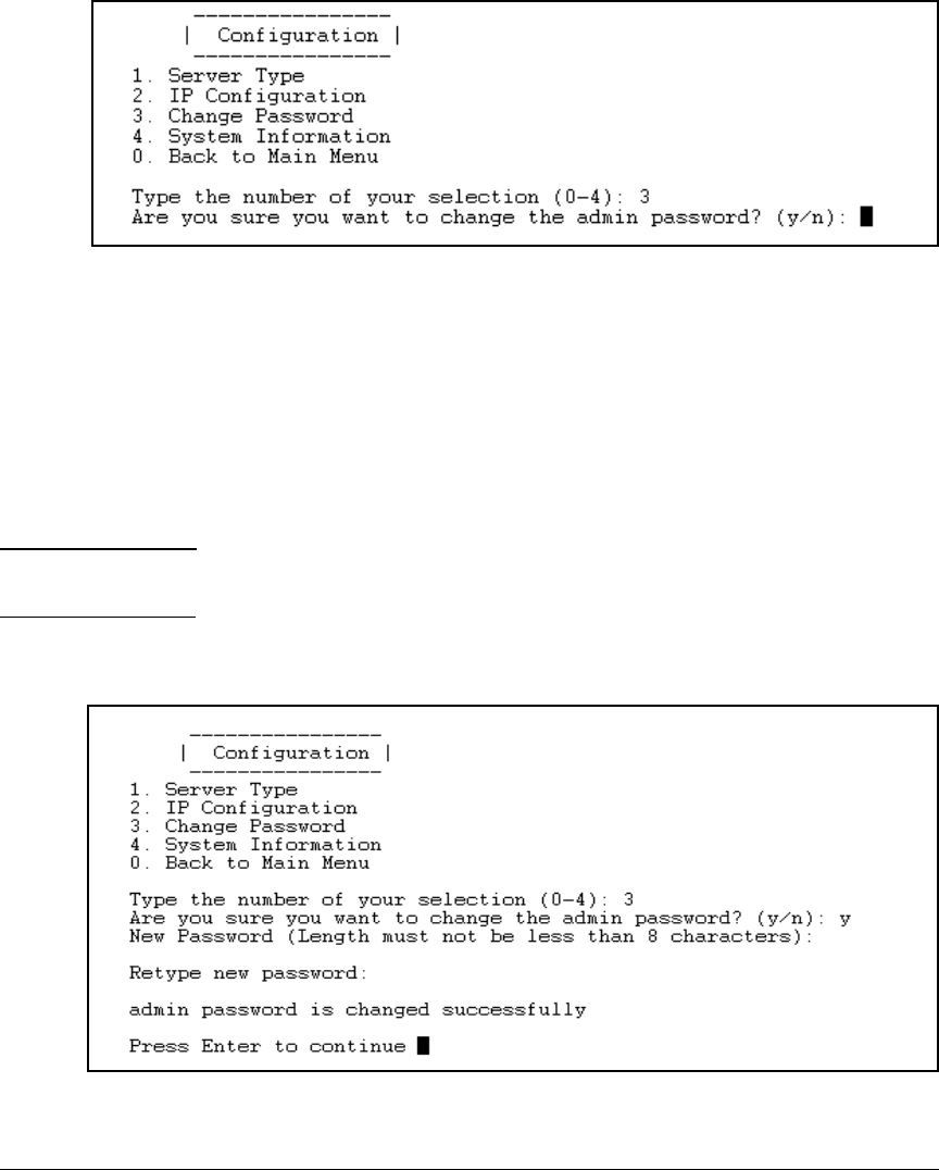
2-138
Implementing 802.1X with ProCurve IDM and Endpoint Integrity
Configuring the NAC 800s
Figure 2-112. NAC 800 Menu Interface — Main Menu > 1. Configuration >
3. Change Password
11. Type y to confirm that you want to change the password.
12. Type a password eight characters or longer. The password can include
alphanumeric and special characters but does not have specific complex-
ity requirements.
In the example, management access to NAC 800s is protected with this
password: procurvenac9.
Note If you want the menu password to match the password that you will create
for the Web browser interface, you must use a mix of letters and numbers.
13. When prompted, retype the same password.
Figure 2-113. NAC 800 Menu Interface—Application Main Menu > 1. Configuration
> 3. Change Password
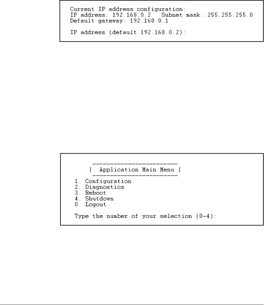
2-139
Implementing 802.1X with ProCurve IDM and Endpoint Integrity
Configuring the NAC 800s
14. Press [Enter].
15. Press [2] for IP Configuration.
Figure 2-114. NAC 800 Menu Interface—Application Main Menu > 1. Configuration
> 2. IP Configuration
16. The window displays the NAC 800’s default settings. Type the new IP
address. In this example, type the following for the MS: 10.2.1.40.
17. Type the subnet mask for the NAC 800’s subnet. In this example: 255.255.0.0.
18. Type the IP address of the default router on the NAC 800’s subnet. In this
example, type the following for the MS: 10.2.0.1.
19. When asked to confirm the settings, check them and (if they are correct)
type y.
20. Press [0].
Figure 2-115. NAC 800 Menu Interface—Application Main Menu
21. Press [2] for Diagnostics.
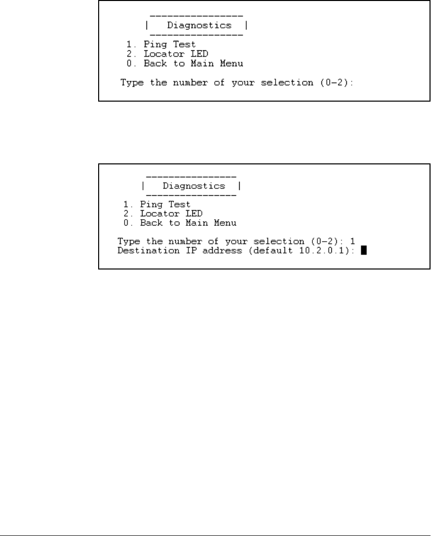
2-140
Implementing 802.1X with ProCurve IDM and Endpoint Integrity
Configuring the NAC 800s
Figure 2-116. NAC 800 Menu Interface—Application Main Menu > 2. Diagnostics
22. Press [1] for Ping Test.
Figure 2-117. NAC 800 Menu Interface—Application Main Menu > 2. Diagnostics >
1. Ping Test
23. Press [Enter] to ping the default gateway.
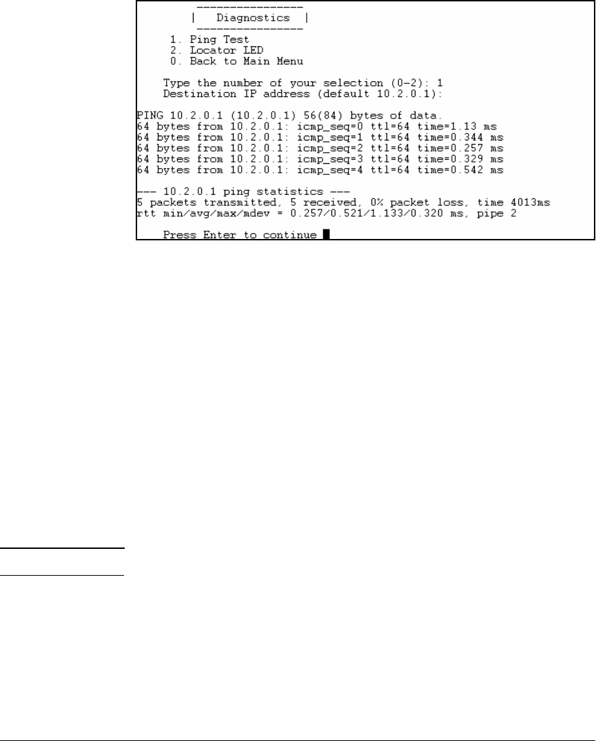
2-141
Implementing 802.1X with ProCurve IDM and Endpoint Integrity
Configuring the NAC 800s
Figure 2-118. NAC 800 Menu Interface—Application Main Menu > 2. Diagnostics >
1. Ping Test—Results
24. The results of the ping, including the times for the round trip, are dis-
played.
If the ping is successful, repeat steps 1 through 24 for the other two
NAC 800s.
Access the Web Browser Interface
The NAC 800s now have network connectivity. You will complete all remaining
configuration through the NAC 800 MS’s Web browser interface.
Follow these steps to access the Web browser interface:
1. Open the Web browser on your management station.
2. Type https://<NAC 800 IP address> (in this example, https://10.1.2.40).
Note The NAC 800 requires HTTPS (as opposed to HTTP) for stronger security.
3. Because the NAC 800 is using its self-signed certificate, your browser will
probably display a prompt, asking you to verify if you want to trust this
certificate. Answer yes.
You will install a new certificate on the NAC 800 when you complete the
instructions outlined in “Install the Certificates for HTTPS on a NAC 800”
on page 2-193.
4. The NAC 800’s Web browser interface opens.
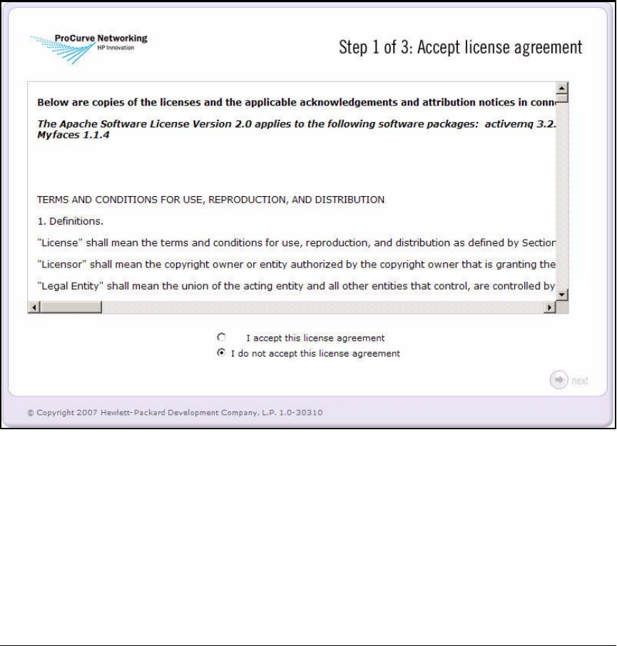
2-142
Implementing 802.1X with ProCurve IDM and Endpoint Integrity
Configuring the NAC 800s
Configure More Basic Settings for the MS
The first time that you connect to the Web browser interface, you must
complete this process:
1. When the Step 1 of 3: Accept license agreement window is displayed, read
the license and select the I accept this license agreement option.
Figure 2-119. NAC 800 Web Interface—Step 1 of 3: Accept license agreement
2. Click next. The Step 2 of 3: Enter management server settings window is
displayed.
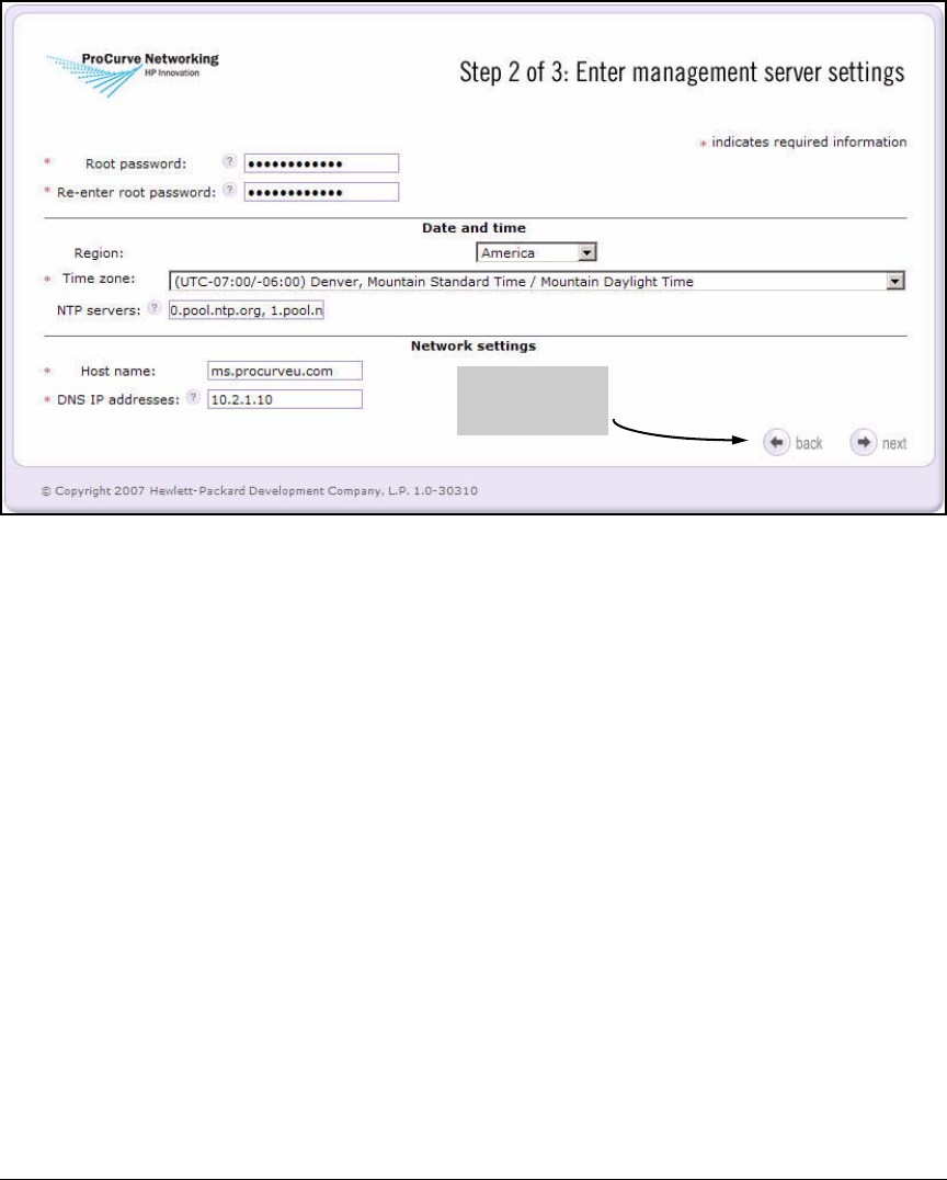
2-143
Implementing 802.1X with ProCurve IDM and Endpoint Integrity
Configuring the NAC 800s
Figure 2-120. NAC 800 Web Interface—Step 2 of 3: Enter management server
settings
3. Type a password in the Root password and Re-enter root password boxes.
You use the root password to log in to the command line of the NAC 800’s
OS. The password can include alphanumeric and special characters but
does not have specific complexity or length requirements.
In this example, you type the same password as for the menu interface:
procurvenac9.
4. Configure the NAC 800 to receive its date and time from a Network Time
Protocol (NTP) server:
a. Select your region from the Region list.
b. Select the correct time zone from the Time zone list.
c. In the NTP servers box, type the IP address or fully qualified domain
name (FQDN) of your network’s NTP server.
In this example, you use the default public NTP servers already listed
in the box.
Click back to see
the license
agreement again
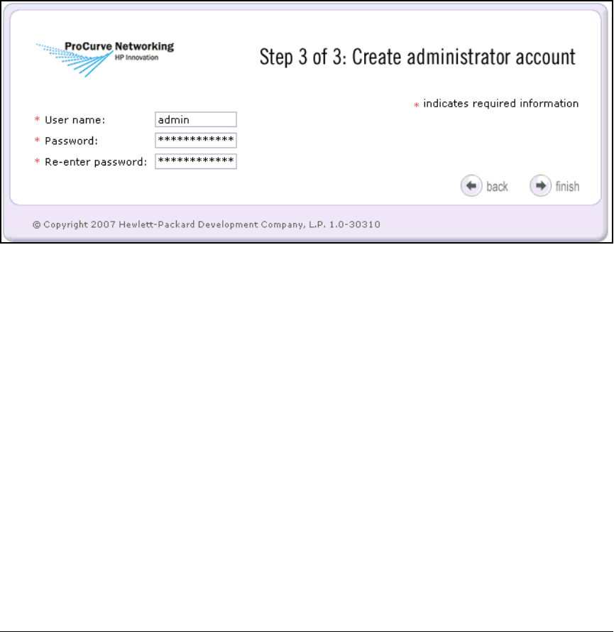
2-144
Implementing 802.1X with ProCurve IDM and Endpoint Integrity
Configuring the NAC 800s
5. Configure network settings.
a. Type the NAC 800’s FQDN in the Host name box. In this example:
ms.procurveu.edu.
b. Specify the IP address of at least one DNS server in the DNS IP
addresses box (in this example, 10.2.1.10).
6. Click next. The Step 3 of 3: Create administrator account window is displayed.
Figure 2-121. NAC 800 Web Interface—Step 3 of 3: Create administrator account
7. Create an account that grants access to the MS’s Web browser interface.
a. Type a name in the User name box (in this example, admin).
b. Type a name in the Password and Re-enter password boxes.
This password must include a mix of letters and numbers and be at
least eight characters long. It can also include special characters and
spaces.
In this example, the password is the same as that for the menu
interface and root access: procurvenac9.
8. Click finish.
You should see the NAC 800’s Home window. Because PCM+ will manage the
NAC 800s, you must set the correct SNMP community name:
1. Select System configuration > Management server.
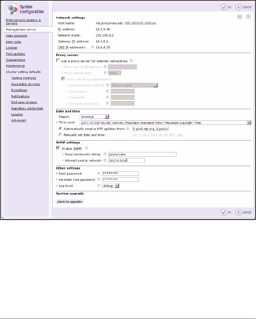
2-145
Implementing 802.1X with ProCurve IDM and Endpoint Integrity
Configuring the NAC 800s
Figure 2-122. NAC 800 Web Interface—Home > System configuration >
Management server—SNMP settings Area
2. Find the SNMP settings area.
3. Select the Enable SNMP check box.
4. Type a read-only community name that matches your SNMP server’s in
the Read community string box (in this example, procurvero).
5. Type the network address for the PCM+ server in CIDR notation in the
Allowed source network box.
In this example, the correct subnet is the management VLAN: 10.2.0.0/16.
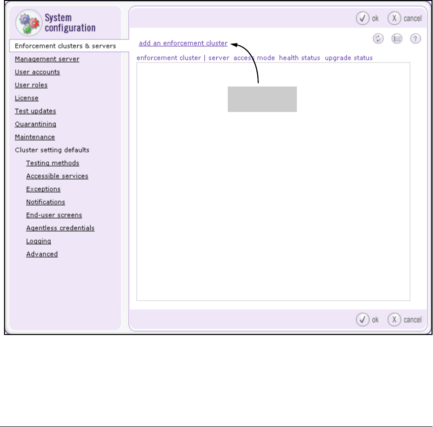
2-146
Implementing 802.1X with ProCurve IDM and Endpoint Integrity
Configuring the NAC 800s
6. Click ok.
Create an Enforcement Cluster and Add ESs
You can now add ESs and configure their basic settings. First, however, you
must create an enforcement cluster for the ESs. In this example, the cluster
will be called “802.1X.”
1. Select Home > System configuration > Enforcement clusters & servers.
Figure 2-123. NAC 800 Web Interface—Home > System configuration >
Enforcement clusters & servers—add an enforcement cluster
2. Click add an enforcement cluster.
Select this link to
create a cluster
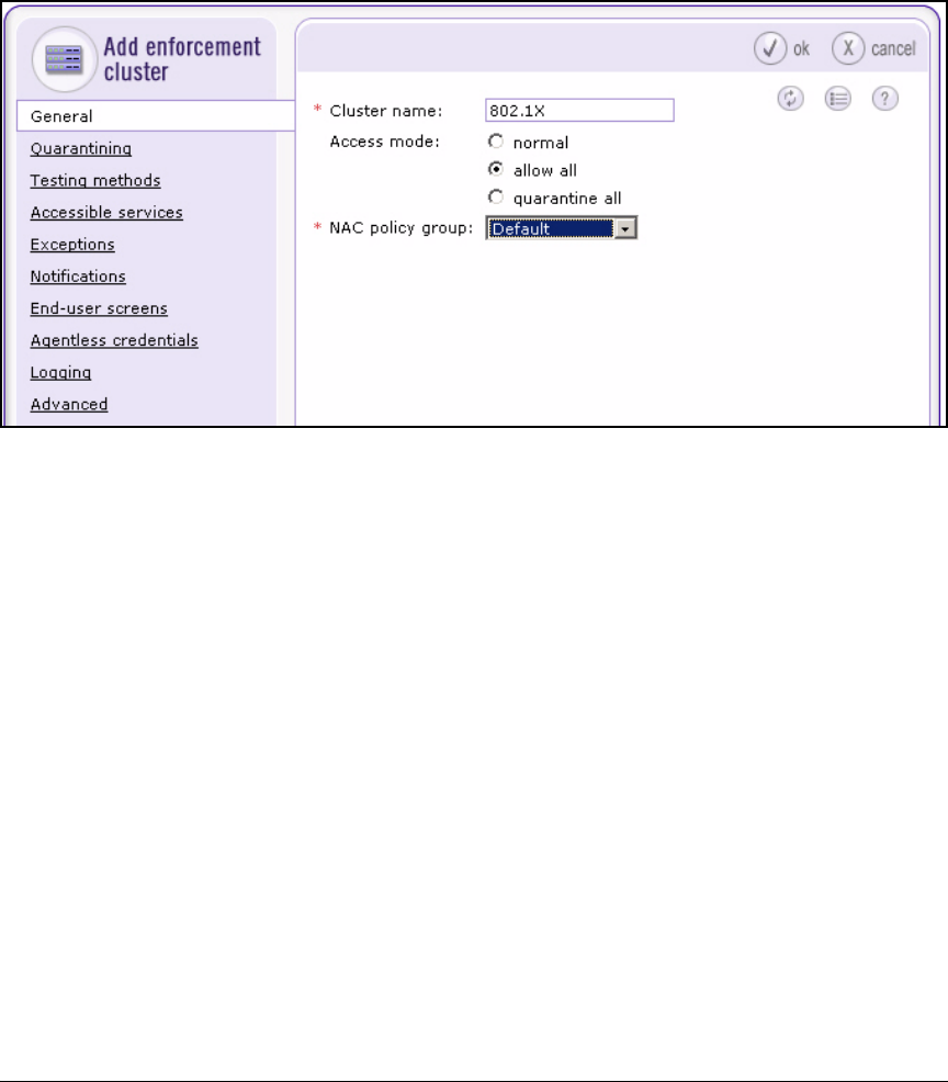
2-147
Implementing 802.1X with ProCurve IDM and Endpoint Integrity
Configuring the NAC 800s
The Add enforcement cluster window is displayed. The left navigation bar
lists several menu options; for now, you can ignore all options except
General, which is selected by default.
Figure 2-124. NAC 800 Web Interface—Home > System configuration >
Enforcement clusters & servers > Add enforcement cluster > General
3. In the Cluster name box, type a name that describes this cluster (in this
example, 802.1X).
4. At this point, select allow all for the Access mode. Later, you will change
the setting to normal to activate endpoint integrity.
5. From the NAC policy group list, select Default.
In a later section, you will create your own policies. For now, keep the
defaults.
6. Click ok.
7. Click add an enforcement server.
8. The Add enforcement server window is displayed.
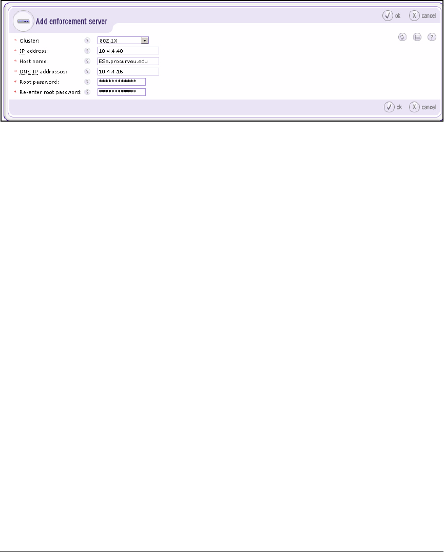
2-148
Implementing 802.1X with ProCurve IDM and Endpoint Integrity
Configuring the NAC 800s
Figure 2-125. NAC 800 Web Interface—Home > System configuration >
Enforcement clusters & servers > Add enforcement server
9. From the Cluster list, select the cluster that you just configured.
10. Type an ES’s IP address in the IP address box. In this example: 10.4.4.40.
You should have already set this IP address on the NAC 800 ES as
described in “Configure Initial Settings Through a Console Session” on
page 2-135.
11. Type the ES’s hostname in the Host name box. In this example:
ESa.procurveu.edu.
12. In the DNS IP addresses box, specify the IP address of at least one DNS
server. In this example: 10.4.4.15.
13. Type a password in the Root password and Re-enter root password boxes.
In this example, the root password for ESs is the same as for the MS:
procurvenac9.
14. Click ok.
15. You return to the Home > System configuration > Enforcement clusters &
servers window, which now displays the new ES.
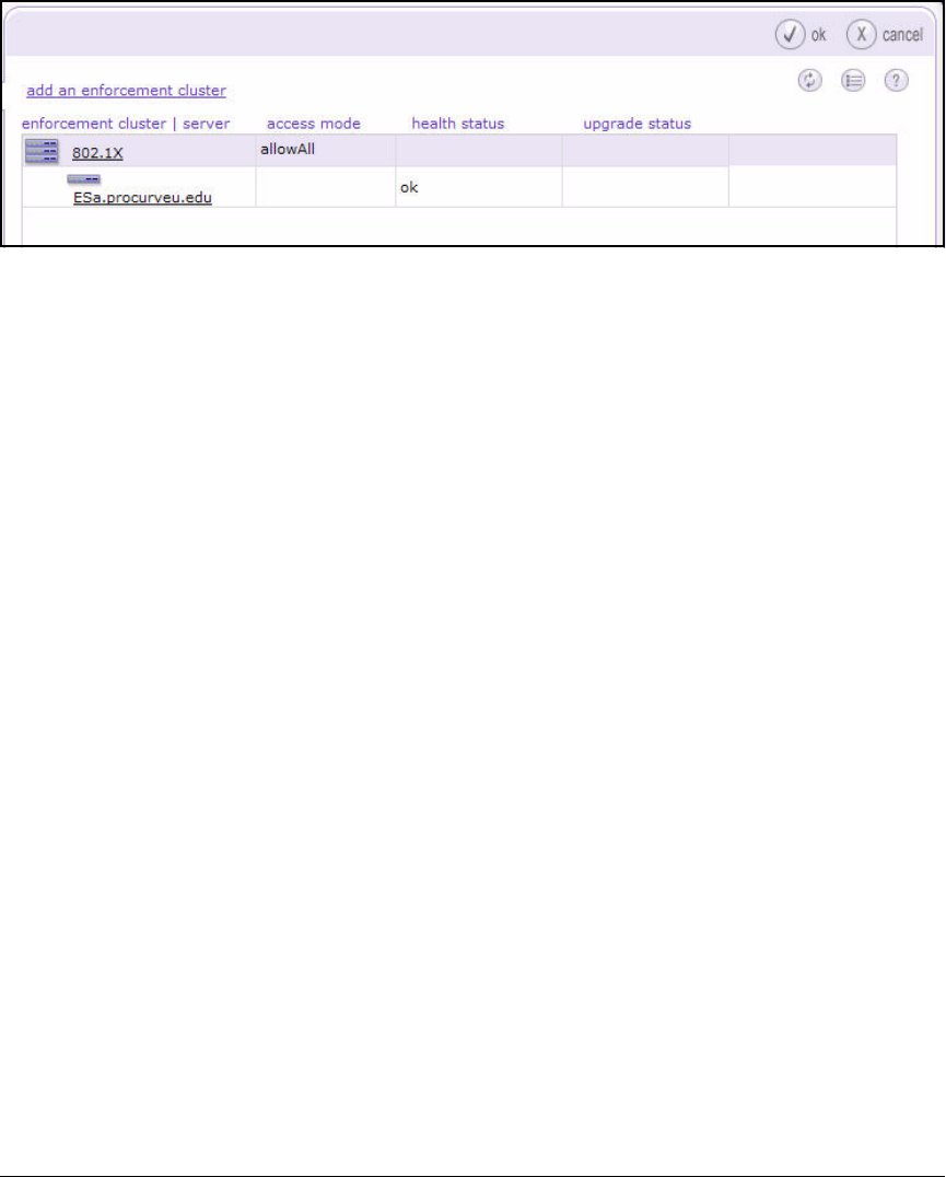
2-149
Implementing 802.1X with ProCurve IDM and Endpoint Integrity
Configuring the NAC 800s
Figure 2-126. NAC 800 Web Interface—Home > System configuration >
Enforcement clusters & servers
16. Repeat steps 7 through 14 to add other ESs.
Configure Quarantining
This section teaches you how to set up quarantining for this solution,
which uses:
■802.1X port authentication
■Active Directory
■IDM
Follow these steps:
1. Select Home > System configuration > Quarantining.
2. The cluster that you just configured should be selected, as shown in
Figure 2-127.
3. In the Quarantine method area, select 802.1X.
4. Find the Basic 802.1X settings area. For the IDM server IP address, type the
IP address of the server that runs PCM+ with IDM (in this example,
10.2.1.50).
5. For the Quarantine subnets, type in CIDR format the subnet addresses
associated with quarantine VLANs. Separate addresses with commas (in
this example, 10.32.0.0/14).

2-150
Implementing 802.1X with ProCurve IDM and Endpoint Integrity
Configuring the NAC 800s
Note The Quarantine subnets field does not configure the NAC 800s to place end-
points in the quarantine VLANs. (You will learn how to do that through IDM
in “Configuring Network Access Control with IDM” on page 2-229.) Instead,
this setting lets the NAC 800 reply to DNS requests from quarantined end-
points.
6. Select Local for the RADIUS server type.
In this solution, the NAC 800 must draw on its local database rather than
directly on Active Directory. This is because you are using EAP-TLS
(rather than Protected EAP [PEAP] or Tunneled TLS [TTLS] with Micro-
soft Challenge Handshake Authentication Protocol version 2 [MS-
CHAPv2]). But setting up the local database is easy; you will do it through
IDM. (See “Configuring Network Access Control with IDM” on page
2-229.)
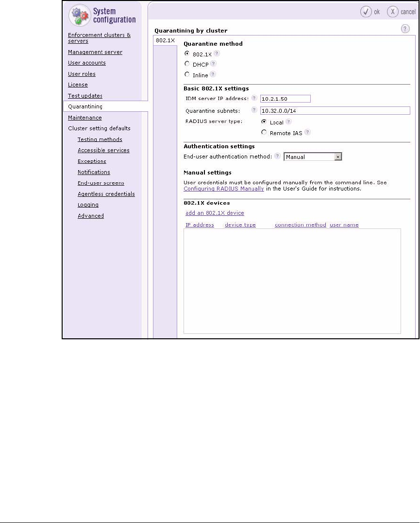
2-151
Implementing 802.1X with ProCurve IDM and Endpoint Integrity
Configuring the NAC 800s
Figure 2-127. NAC 800 Web Interface—Home > System configuration >
Quarantining
7. Click ok.
Add 802.1X Devices
The NAC 800’s list of 802.1X devices must include every device in your network
that can act as an authenticator. In this example, these are:
■Edge switches (which authenticate end-users and RPs)
■Core switches (which authenticate other switches)
■Wireless Edge Services Modules (which authenticate wireless users)

2-152
Implementing 802.1X with ProCurve IDM and Endpoint Integrity
Configuring the NAC 800s
When you add a device to the list you must specify:
■Device’s IP address
■Shared secret for RADIUS requests
■Device type
■Connection settings (which allow the NAC 800 to force reauthentication
of an endpoint after testing)
The NAC 800 can issue the reauthentication command through SSH,
Telnet, or SNMP (although some 802.1X devices do not support all of these
options). The example network is already using SNMP with PCM+, so the
NAC 800 will also use SNMP to communicate with the 802.1X devices.
Table 2-12 shows the settings for the example network. Of course, the actual
list would include many more devices.
Table 2-12. 802.1X Devices
Follow these steps to add the 802.1X devices:
1. Select Home > System Configuration > Quarantining.
You should have already completed the steps in “Configure Quarantining”
on page 2-149.
2. Click add an 802.1X device. The Add 802.1X device window is displayed.
IP Address Shared Secret Friendly Name Device Type SNMP Community
String
Other SNMP
Settings
10.2.0.20 procurvenac Primary Wireless
Module
ProCurve WESM procurverw default settings
10.2.0.25 procurvenac Redundant
Wireless Module
ProCurve WESM procurverw default settings
10.2.0.3 procurvenac Edge Switch A ProCurve Switch procurverw default settings
10.2.0.5 procurvenac Edge Switch B ProCurve Switch procurverw default settings
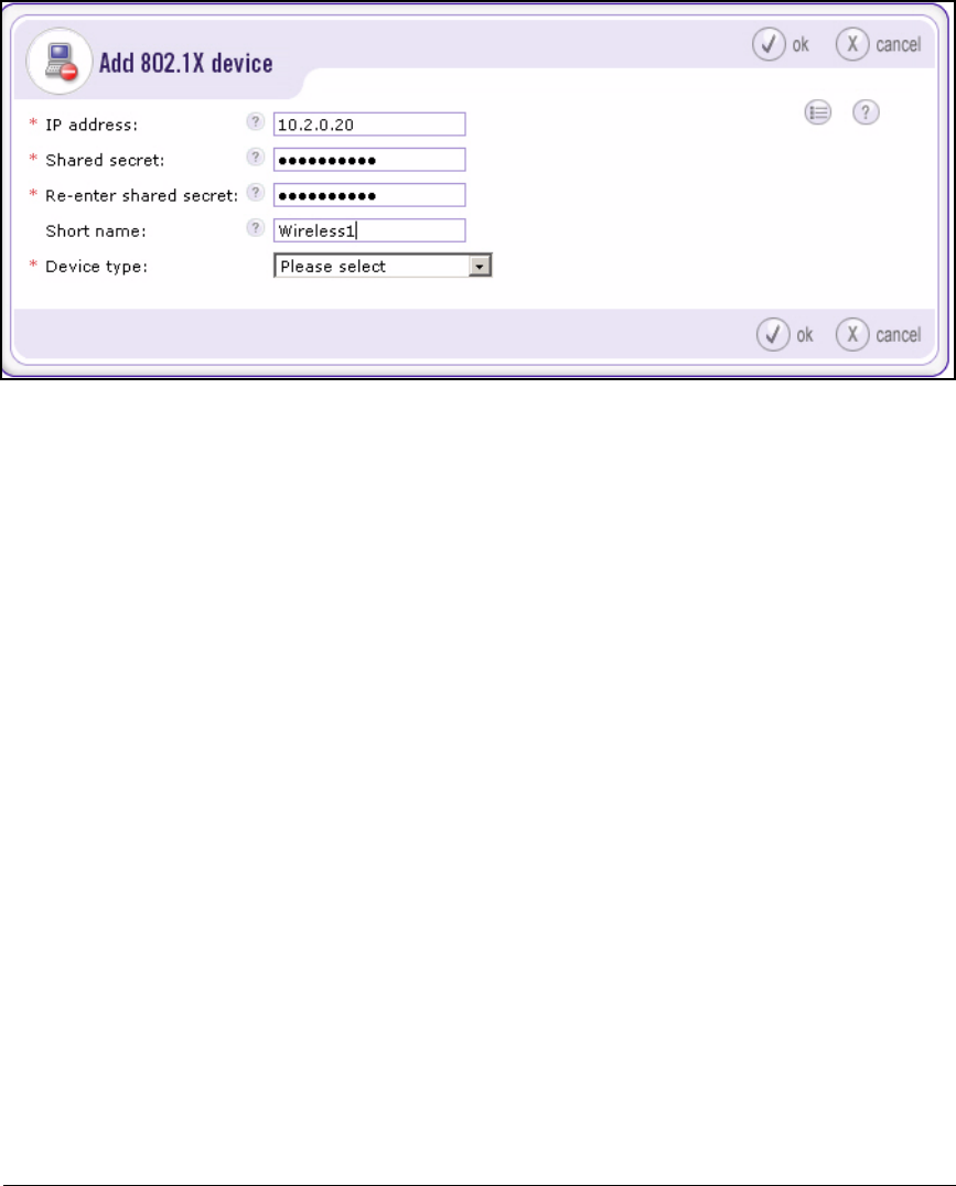
2-153
Implementing 802.1X with ProCurve IDM and Endpoint Integrity
Configuring the NAC 800s
Figure 2-128. NAC 800 Web Interface—Home > System configuration >
Quarantining (802.1X quarantine method) > add an 802.1X device
3. Type the 802.1X device’s IP address in the IP address box. In this example:
10.2.0.20
4. Type a character string in the Shared secret and Re-enter shared secret
boxes. In this example: procurvenac.
The string can include alphanumeric and special characters.
You will match this string when you set up port authentication on the
switches. (See “Configuring the ProCurve Switches” on page 2-13.) You
already configured this secret on the Wireless Edge Services Modules.
5. Optionally, type a descriptive name for the 802.1X device in the Short name
box.
6. From the Device type list, select the type of 802.1X device (that is, its
manufacturer and OS). The types for this network include ProCurve Switch
and ProCurve WESM.
7. When you select the device type, the window expands to include device-
specific settings.
8. Select a Connection method from the list, if this field is provided. In this
network, devices use SMNPv2.
Skip this step if you have selected ProCurve WESM, ProCurve 420 AP, or
ProCurve 530 AP for the Device type.

2-154
Implementing 802.1X with ProCurve IDM and Endpoint Integrity
Configuring the NAC 800s
9. Type the name of the ProCurve device’s read-write community in the
Community string box (in this example, procurverw).
10. Typically, you can leave all other default settings unchanged.
For more information about these settings, see Chapter 3: “System Con-
figuration” of the ProCurve Network Access Controller 800 Users’ Guide.
11. Click ok.
12. In the System configuration > Quarantining window, click ok to save the
changes.
Enable EAP-MD5 (Optional)
In this solution, RPs authenticate to edge switches and edge switches authen-
ticate to core switches. These ProCurve devices support EAP-MD5 authenti-
cation. The NAC 800 also supports EAP-MD5, but this method is not enabled
by default.
If you want your infrastructure devices to authenticate ProCurve devices
against a NAC 800 ES, you must follow these steps:
1. Log in as root to the NAC 800 ES:
a. Open a console or SSH session with the NAC 800.
b. For the username, enter root.
c. For the password, enter the root password set when this ES joined
the enforcement cluster. (See “Create an Enforcement Cluster and
Add ESs” on page 2-146.)
2. Enter this command to move to the proper directory:
ProCurve NAC 800:/# cd /etc/raddb
3. Edit the eap.conf file:
ProCurve NAC 800:/etc/raddb# vi eap.conf
4. Use the arrow keys or other vi commands to move to the “Supported EAP-
types” section.
5. Uncomment the “md5” section; that is, remove this character (#) in the
“md5” line and the line below.
The vi command for removing a single character is [x].

2-155
Implementing 802.1X with ProCurve IDM and Endpoint Integrity
Configuring the NAC 800s
Figure 2-129. eap.conf File—Supported EAP-types Section
6. Save and exit by entering this command:
:wq
7. Restart the RADIUS server with this command:
ProCurve NAC 800:/etc/raddb# service radiusd restart
Configure Testing Methods
In this section, you will ensure that your network supports your chosen testing
methods. Initially, the NAC 800 tries to test an endpoint in the background:
1. The NAC 800 tries to test the endpoint with the NAC EI agent.
2. If no agent is installed on the endpoint, the NAC 800 tries to install the
ActiveX agent.
3. If the ActiveX installation fails and if credentials for the endpoint or
domain exist, the NAC 800 tries to use agentless testing.
In the example network, you will attempt to pre-install the NAC EI agent on
as many endpoints as possible. As a backup, you will configure agentless
credentials for your domain (of which all users are members). As further
backup, you will allow the NAC 800 to interact with users to download the
NAC EI agent automatically.
See “Pre-install the NAC EI Agent on Endpoints” on page 2-306 to learn how
to complete this task. The sections below describe setting up the other testing
methods.
# Supported EAP-types
#
# We do NOT recommend using EAP-MD5 authentication
# for wireless connections. It is insecure, and does
# not provide for dynamic WEP keys.
#
md5 {
}
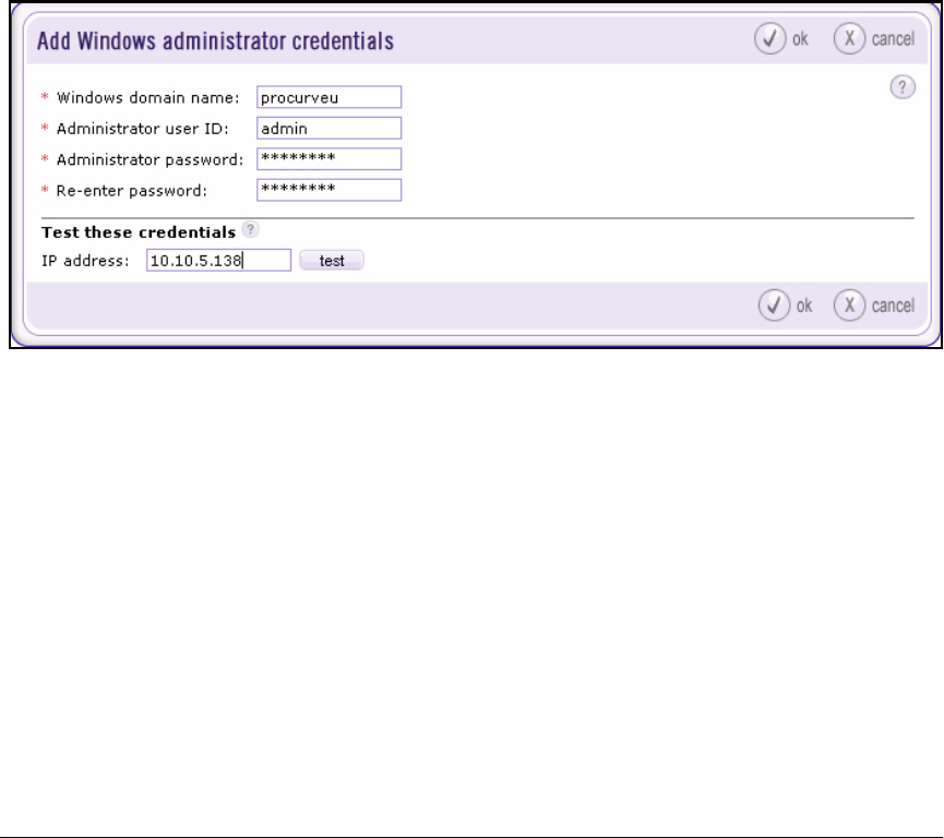
2-156
Implementing 802.1X with ProCurve IDM and Endpoint Integrity
Configuring the NAC 800s
Configure Agentless Credentials
Agentless testing works on endpoints that are members of your domain. You
configure credentials for a member of the domain administrators group on the
NAC 800. The NAC 800 can then perform administrative tasks on the endpoint.
Follow these steps to configure the credentials:
1. Log in to the Web browser interface on the NAC 800 MS.
2. Select Home > System configuration > Cluster settings defaults > Agentless
credentials.
3. Click add administrator credentials.
Figure 2-130. NAC 800 Web Interface—Home > System configuration > Cluster
settings defaults > Agentless credentials > Add Windows
administrator credentials
4. In the Windows domain name box, type the name of the domain. In this
example: procurveu.
5. In the Administrator user ID box, type the username of a domain adminis-
trator for domain administrators group on the NAC 800.
6. In the Administrator password box, type the administrator password.
7. You can test the credentials on an endpoint to make sure that you typed
them correctly:
a. Under Test these credentials, type the IP address of the endpoint in the
IP address box.
b. Click test.

2-157
Implementing 802.1X with ProCurve IDM and Endpoint Integrity
Configuring the NAC 800s
8. Click ok.
9. Click ok to save the credentials.
Note It is possible to configure agentless credentials for an endpoint that is not part
of a domain (although feasible only for small networks that expect few
guests). Leave the Windows domain name box empty, and type <computer
name>\<username> for Administrator user ID. The user specified must be an
account with administrator privileges on the endpoint. Type the password as
usual.
Enable the RPC Service on Endpoints
Agentless testing relies on Windows Remote Procedure Call (RPC). Endpoints
must run this service, and their firewalls must allow print and file sharing
traffic from the NAC 800s’ IP addresses. This section teaches you how to edit
your domain’s group policy to specify the correct settings.
1. Do one of the following:
• On a Windows 2003 server, open the Management Console to which
you added the Active Directory snap-in.
•From the Start menu of the domain controller, click Administrative
Tools > Active Directory Users and Computers.
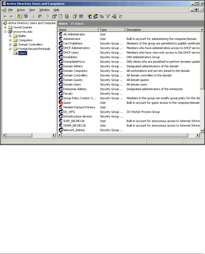
2-158
Implementing 802.1X with ProCurve IDM and Endpoint Integrity
Configuring the NAC 800s
Figure 2-131. Active Directory Users and Computers Window
2. Right-click your domain name and select Properties.
3. Click the Group Policy tab.
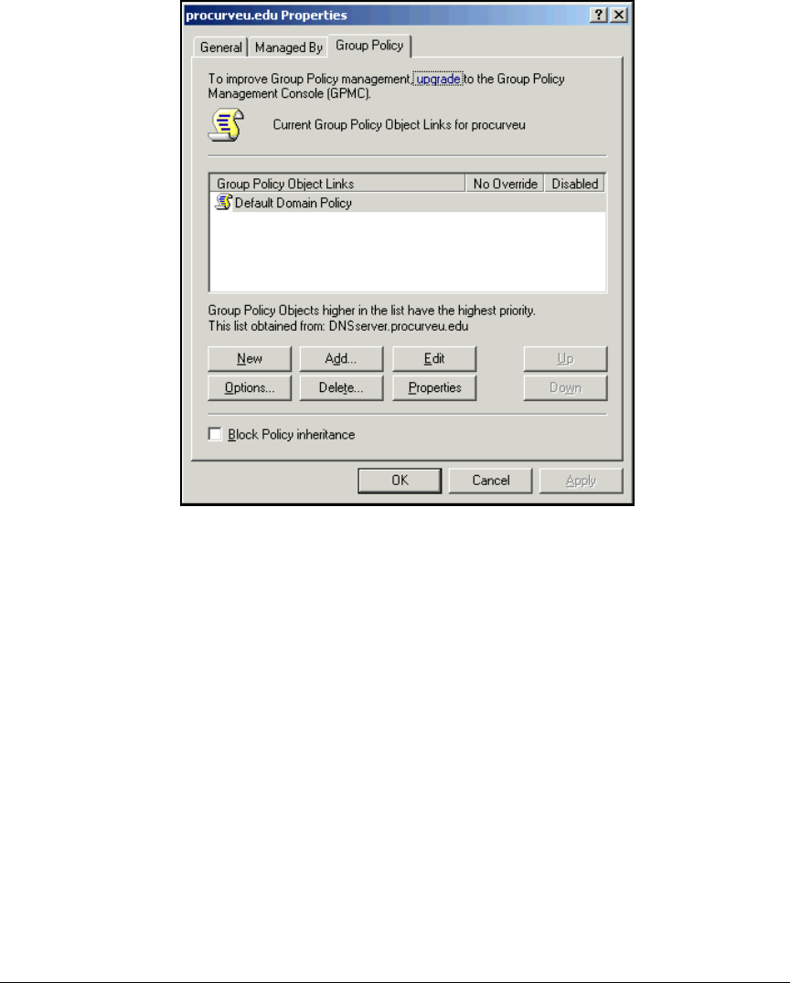
2-159
Implementing 802.1X with ProCurve IDM and Endpoint Integrity
Configuring the NAC 800s
Figure 2-132. <mydomain> Properties Window
4. Select Default Domain Policy and click Edit.
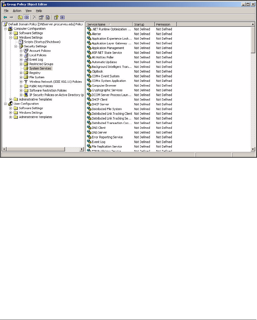
2-160
Implementing 802.1X with ProCurve IDM and Endpoint Integrity
Configuring the NAC 800s
Figure 2-133. Group Policy Object Editor Window—System Services
5. Expand Computer Configuration > Windows Settings > Security Settings and
select System Services.
6. In the right pane, scroll to and double-click Remote Procedure Call (RPC).
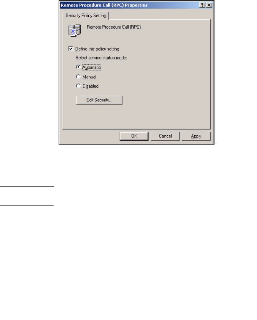
2-161
Implementing 802.1X with ProCurve IDM and Endpoint Integrity
Configuring the NAC 800s
Figure 2-134. Remote Procedure Call (RPC) Properties Window
7. Select Define this policy setting.
8. Select Automatic for the Select service startup mode.
Note Click Edit Security if you want to change who is allowed to change these
settings.
9. Click OK.
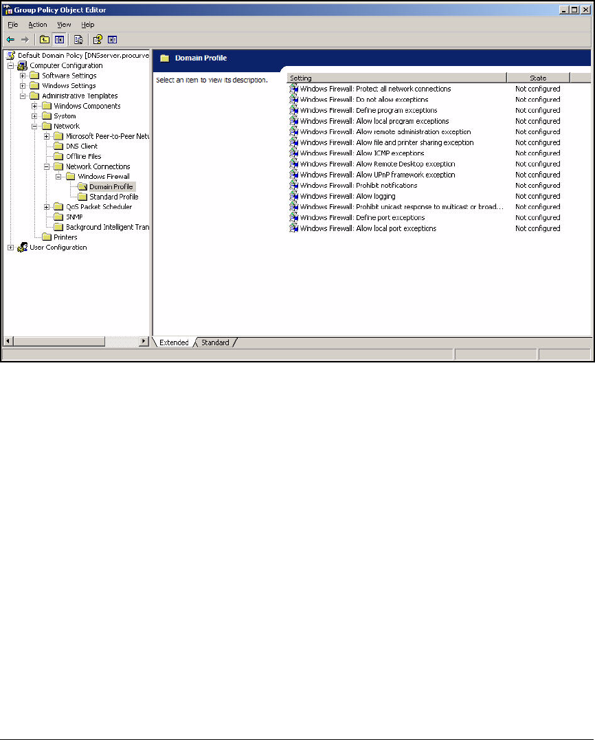
2-162
Implementing 802.1X with ProCurve IDM and Endpoint Integrity
Configuring the NAC 800s
Figure 2-135. Group Policy Object Editor Window—Windows Firewall Domain
Profile
10. In the left pane, expand Computer Configuration > Administrative Templates
> Network > Network Connections > Windows Firewall.
11. Click Domain Profile.
12. In the right pane, double-click Windows Firewall: Allow file and printer
sharing exception.
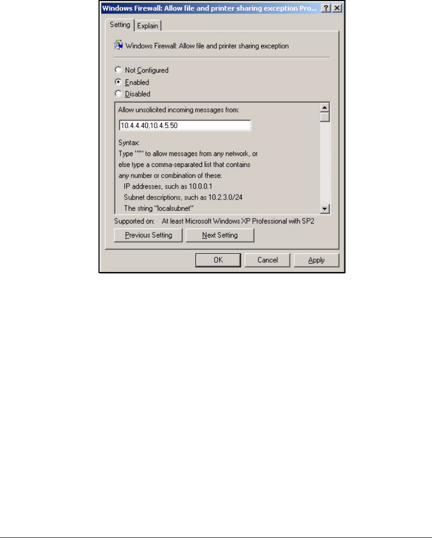
2-163
Implementing 802.1X with ProCurve IDM and Endpoint Integrity
Configuring the NAC 800s
Figure 2-136. Windows Firewall: Allow file and print
sharing exception Properties Window
13. In the Setting tab click Enabled.
14. In the Allow unsolicited incoming messages from box, type the IP addresses
of your NAC 800 ESs, separated by a comma (in this example,
10.4.4.40,10.4.5.50).
15. Click OK.
16. Select File > Exit to close the Group Policy Object Editor.
17. Click OK in the <domain name> Properties window.
18. Press [Alt]+[F4] to close the Active Directory Users and Computers window.
19. Force a refresh of the computer Group Policy:
a. From the Windows Start menu, select Run.
b. Type cmd at the prompt and click OK.

2-164
Implementing 802.1X with ProCurve IDM and Endpoint Integrity
Configuring the NAC 800s
Figure 2-137. Command Window—Force Group Update
c. At the command prompt, type gpupdate /target:computer and press
[Enter].
d. Type exit and press [Enter] to close the command line.
Select the Backup Testing Methods Suggested by the NAC 800
If the background testing fails, the NAC 800 can display end-user access
windows that instruct the user how to allow the testing to succeed. Follow
these steps to allow the NAC 800 to automatically download the NAC EI agent
to an end-user’s endpoint:
1. Log in to the Web browser interface on the NAC 800 MS.
2. Select System configuration > Cluster settings defaults > Testing methods.
3. Select the NAC agent check box.
4. Clear the ActiveX plug-in and Agentless check boxes.
5. Clear the Allow end users to cancel installation (NAC agent testing method
only) and Allow end users to cancel testing (all testing methods).
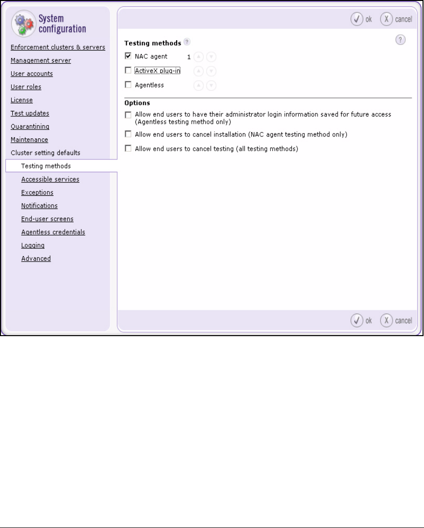
2-165
Implementing 802.1X with ProCurve IDM and Endpoint Integrity
Configuring the NAC 800s
Figure 2-138. NAC 800 Web Interface—Home > System configuration > Cluster
setting defaults > Testing methods
6. Click ok.
Configure NAC Policies
The NAC 800 has three default policies for testing endpoint integrity. By
default, the Low security NAC policy applies to all endpoints. This section
teaches you how to:
■create new NAC policies for your environment
■assign the policies to the correct endpoints
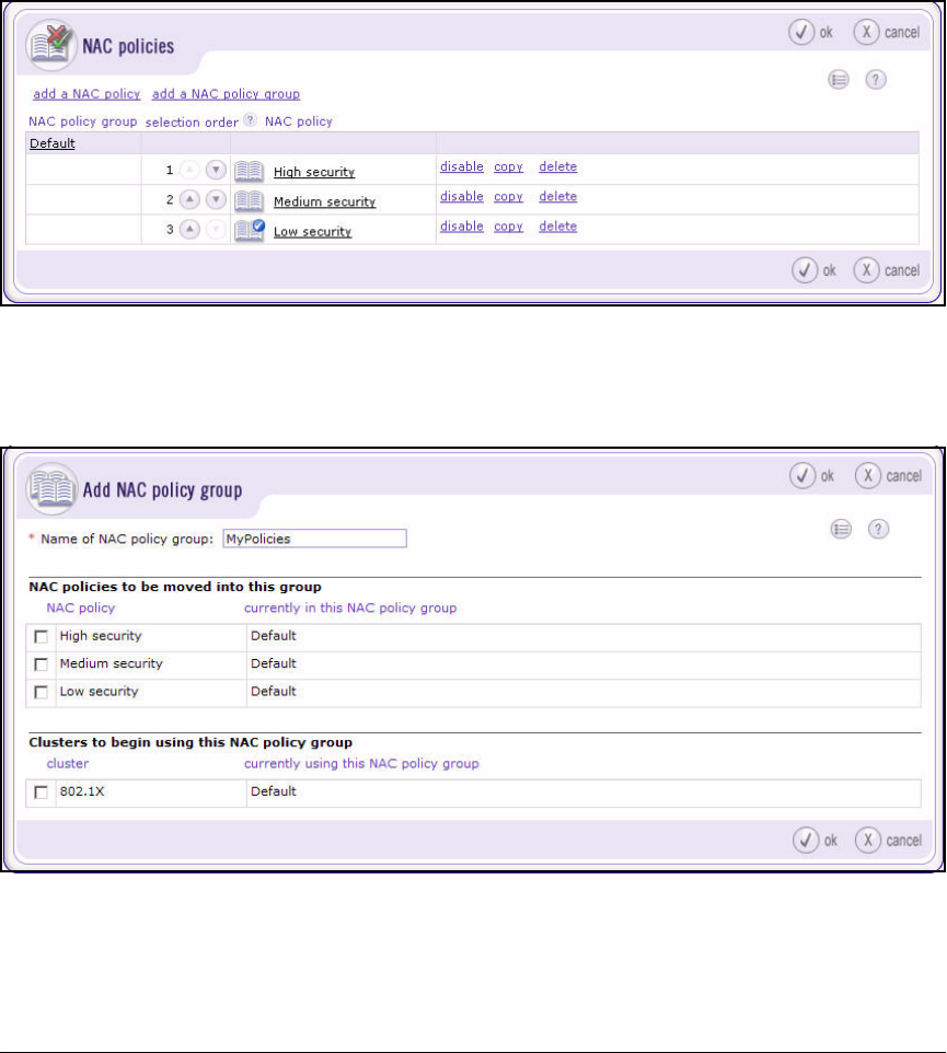
2-166
Implementing 802.1X with ProCurve IDM and Endpoint Integrity
Configuring the NAC 800s
Follow these steps:
1. Open your Web browser and log on to the MS.
2. Select NAC policies.
Figure 2-139. NAC 800 Web Interface—Home > NAC policies Window
3. Click add a NAC policy group.
Figure 2-140. NAC 800 Web Interface—Home > NAC policies > Add NAC policy
group Window
4. For Name of NAC policy group, type the name (in this example, MyPolicies).
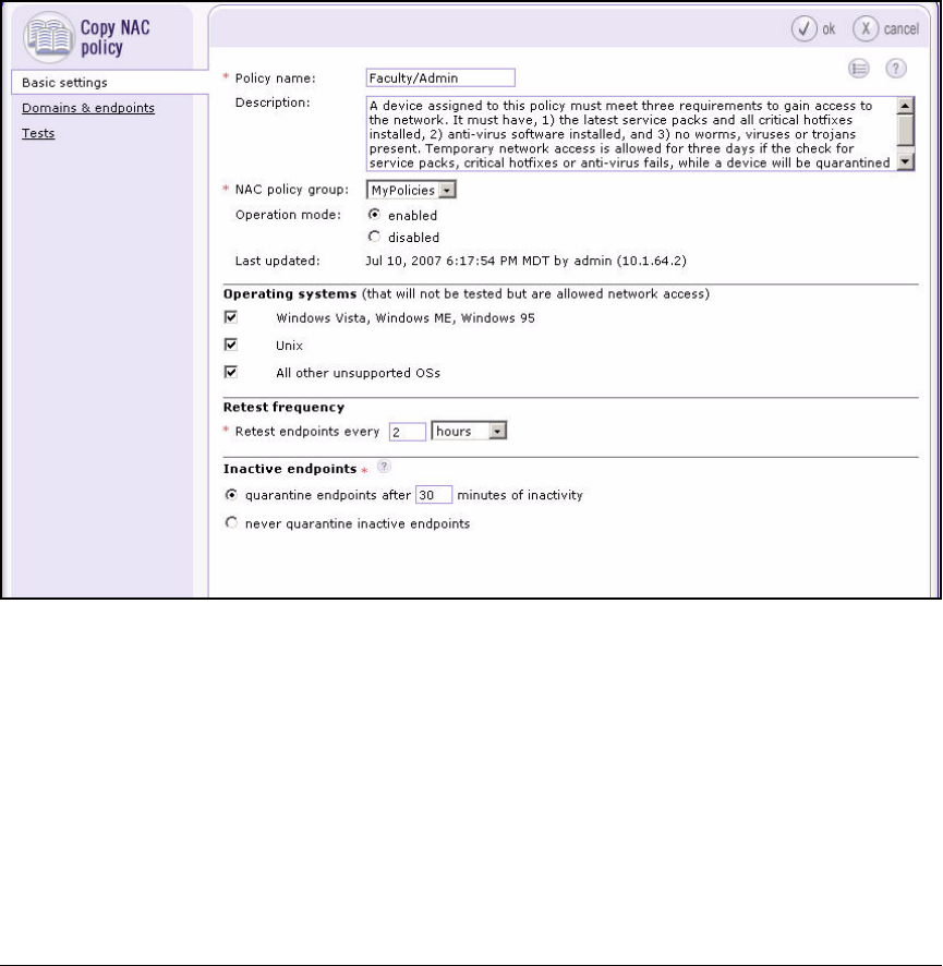
2-167
Implementing 802.1X with ProCurve IDM and Endpoint Integrity
Configuring the NAC 800s
5. Select the 802.1X cluster.
6. Click ok.
7. Next, you will create a NAC policy for testing the endpoints of faculty
members and network administrators. This policy will be based on the
Medium security policy. Begin by clicking the copy link next to Medium
security.
Figure 2-141. NAC 800 Web Interface—Home > NAC policies > Copy NAC policy
Window—Basic settings tab.
8. For the Policy name, type the name (in this example, Faculty/Admin).
9. From the NAC policy group list, select MyPolicies.
10. Click Domains & endpoints.
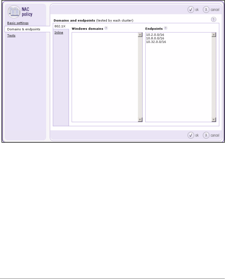
2-168
Implementing 802.1X with ProCurve IDM and Endpoint Integrity
Configuring the NAC 800s
Figure 2-142. NAC 800 Web Interface—Home > NAC policies > <NAC policy> >
Domains & endpoints Window
11. In the Endpoints box, type the subnets for faculty members and network
administrators—both the quarantine VLANs (and, if different, the test and
infected VLANs) and the production VLANs (for post-connect testing). In
this example:
10.2.0.0/16
10.8.0.0/16
10.32.0.0/16
10.33.0.0/16
12. Click ok.
13. Now, create the NAC policy for student endpoints. This policy will also
be based on the Medium security policy, but the Students policy will
include several more tests. Again, click the copy link next to Medium
security in the Home > NAC policies window.
14. In the Policy name box, type Students.
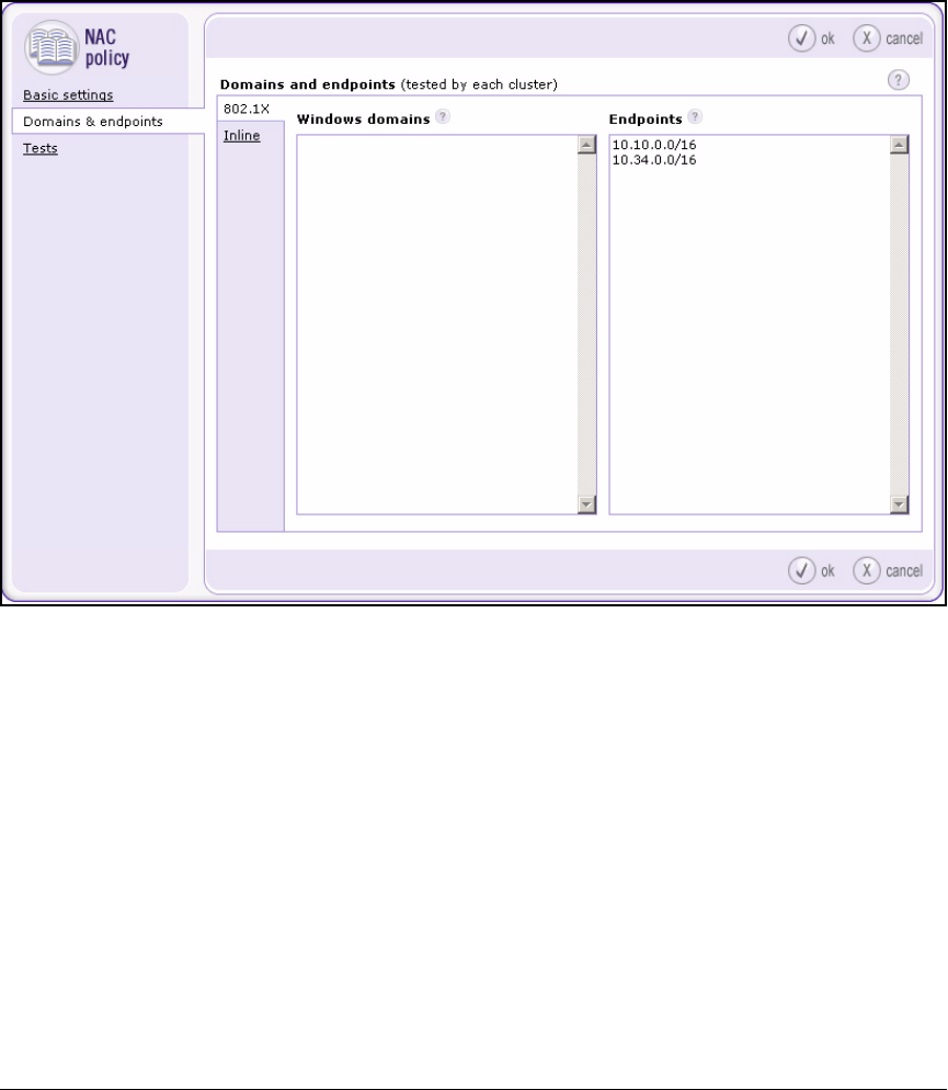
2-169
Implementing 802.1X with ProCurve IDM and Endpoint Integrity
Configuring the NAC 800s
15. From the NAC policy group list, select MyPolicies.
16. Click Domains & endpoints.
Figure 2-143. NAC 800 Web Interface—Home > NAC policies > <NAC policy> >
Domains & endpoints Window
17. In the Endpoints box, type the subnets for students—both the quarantine
VLAN (and, if different, the test and infected VLANs) and the production
VLAN (for post-connect testing). In this example:
10.10.0.0/16
10.34.0.0/16
10.35.0.0/16
18. Click Tests in the left pane.
The steps below show you how to set up several tests that are designed
to ensure that students do not set up rogue wireless networks. They also
prohibit all peer-to-peer software except AOL Instant Messenger (AIM).
These tests are just examples. Refer to the ProCurve Access Control
Design Guide for help in designing your policy.
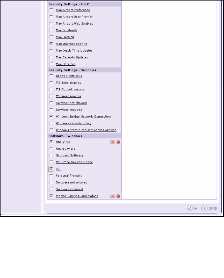
2-170
Implementing 802.1X with ProCurve IDM and Endpoint Integrity
Configuring the NAC 800s
Figure 2-144. NAC 800 Web Interface—Home > NAC policies > <NAC policy> >
Tests Window
19. Scroll to the Security Settings – OS X section and select the Mac Internet
Sharing check box.
20. Under Security Settings –Windows, select the Windows Bridge Network
Connection check box.
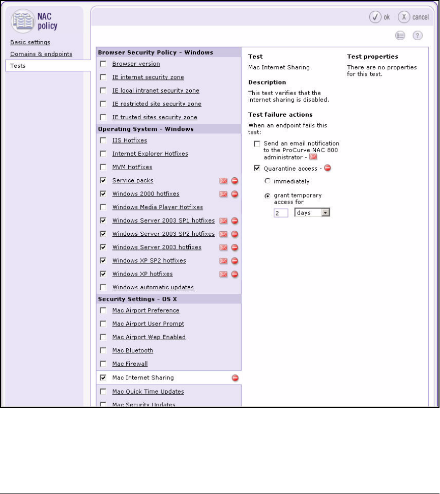
2-171
Implementing 802.1X with ProCurve IDM and Endpoint Integrity
Configuring the NAC 800s
21. Under Software – Windows, select the P2P check box. Leave the Anti Virus
and Worms, viruses and trojans check boxes selected.
22. Click the Mac Internet Sharing link.
Figure 2-145. NAC 800 Web Interface—Home > NAC policies > <NAC policy> >
Tests Window
23. Under Test failure actions, select the Quarantine access check box, then
select grant temporary access for.
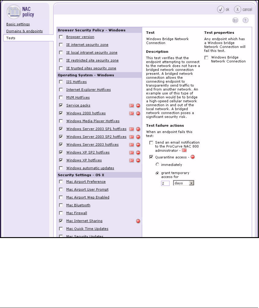
2-172
Implementing 802.1X with ProCurve IDM and Endpoint Integrity
Configuring the NAC 800s
24. Set a period of 2 days.
Figure 2-146. NAC 800 Web Interface—Home > NAC policies > <NAC policy> >
Tests Window
25. Select Windows Bridge Network Connection and set the Quarantine access
for 2 days.
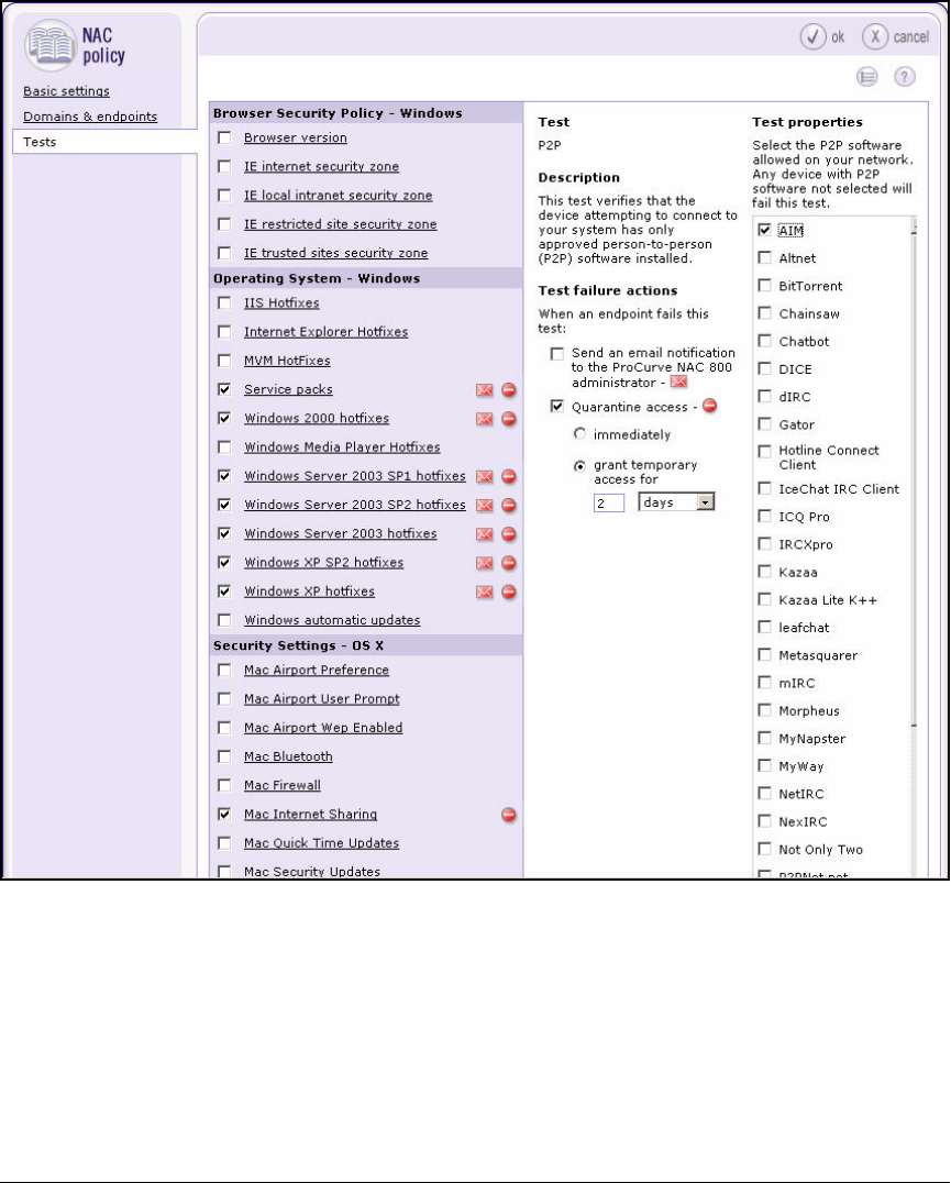
2-173
Implementing 802.1X with ProCurve IDM and Endpoint Integrity
Configuring the NAC 800s
Figure 2-147. NAC 800 Web Interface—Home > NAC policies > <NAC policy> >
Tests Window
26. Select P2P and set the temporary access to 2 days.
27. Under Test properties, select the AIM check box.
28. Click ok.

2-174
Implementing 802.1X with ProCurve IDM and Endpoint Integrity
Manually Issue and Install Server Certificates
Manually Issue and Install Server
Certificates
This network includes several non-Windows devices that require server cer-
tificates:
■Wireless Edge Services Modules’ internal HTTPS server
■The internal HTTPS servers on all the NAC 800s
■The internal RADIUS server on the NAC 800 ESs
This section describes how to create these certificates manually, using the CA
you configured in “Configuring Certificate Services” on page 2-53. For each
certificate, you will:
■Create a certificate request on the device that requires the certificate
■Submit the request to the CA and generate the server certificate
■Install the CA root certificate on the device
■Install the server certificate on the device
Create and Install a Certificate for the Wireless Edge
Services Module’s HTTPS Server
The Wireless Edge Services Module requires a Web Server (or SSL) certificate,
which enables it to authenticate itself and generate keys for encrypting traffic.
The following sections teach you how to install such a certificate.
Create a Certificate Request on the Wireless Edge Services
Module
Follow these steps to create a certificate request using the Wireless Edge
Services Module’s Certificates Wizard:
1. On your management workstation, open a Web browser.
2. Type the module’s IP address or DNS name for the URL. In this example:
10.2.0.20.
2-175
Implementing 802.1X with ProCurve IDM and Endpoint Integrity
Manually Issue and Install Server Certificates
Figure 2-148. Wireless Services Login Page
3. Log in the Web browser interface with the manager password that you set
earlier. (See step 22 on page 2-123.)
4. Select Management > Certificate Management.
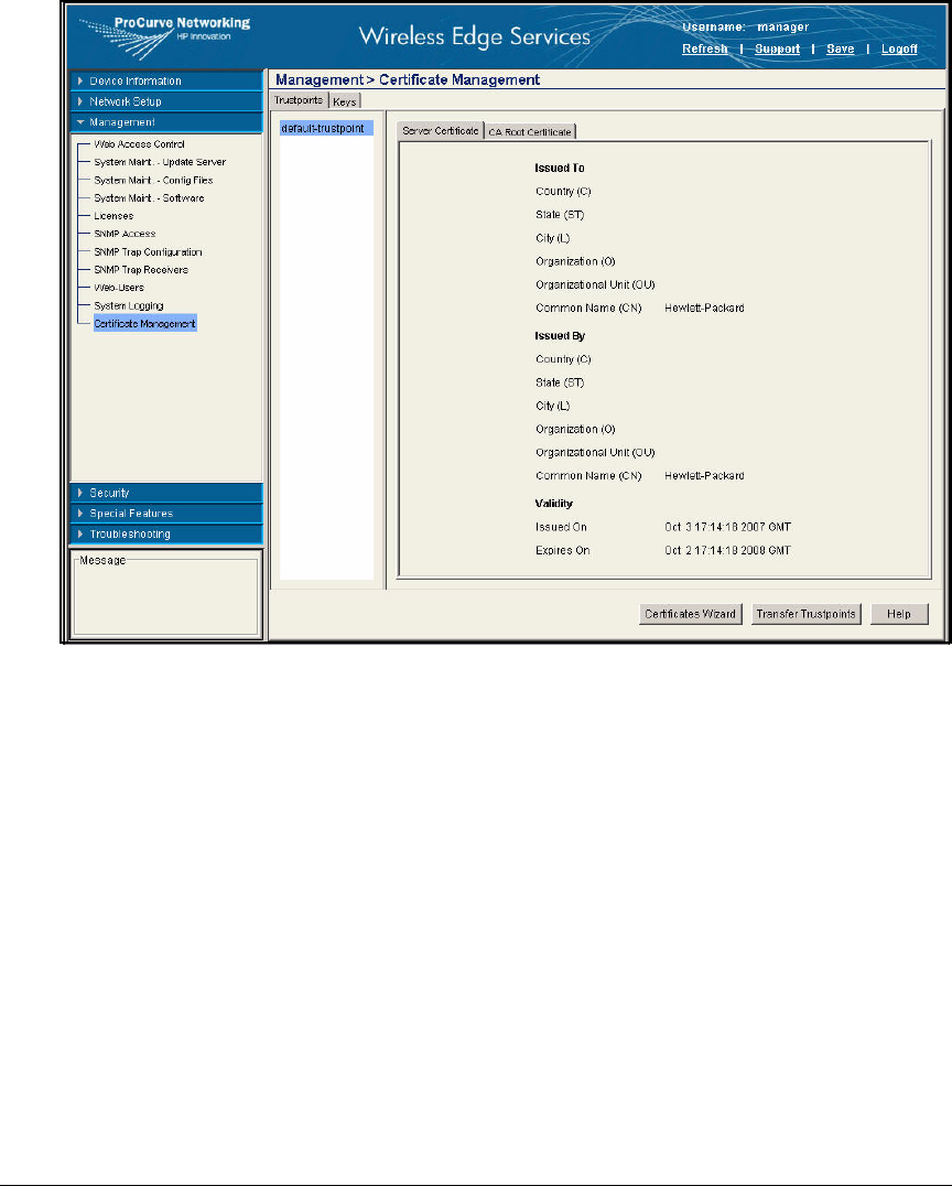
2-176
Implementing 802.1X with ProCurve IDM and Endpoint Integrity
Manually Issue and Install Server Certificates
Figure 2-149. Wireless Edge Services Module Web Browser Interface—
Management > Certificate Management Window
5. Click Certificates Wizard.
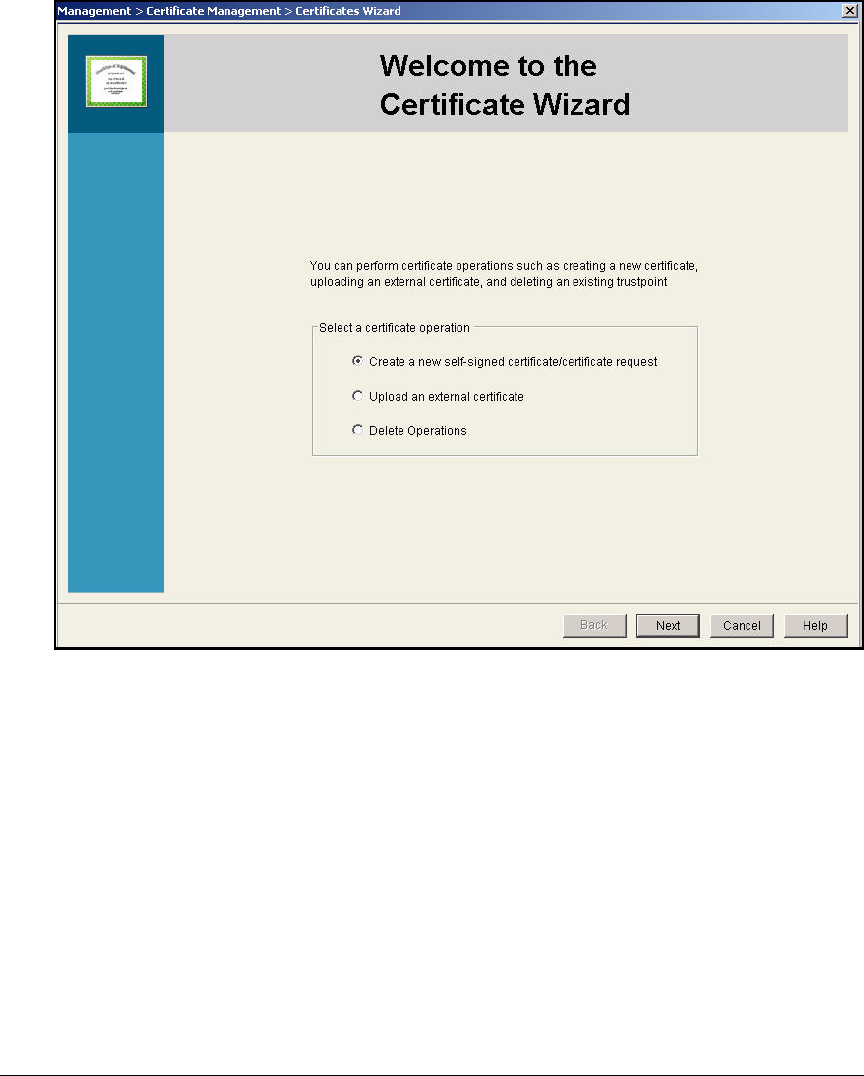
2-177
Implementing 802.1X with ProCurve IDM and Endpoint Integrity
Manually Issue and Install Server Certificates
Figure 2-150. Wireless Edge Services Module Web Browser Interface—Welcome
to the Certificate Wizard
6. On the Welcome to the Certificate Wizard window, select Create a new self-
signed certificate/certificate request.
7. Click Next. The window shown in Figure 2-151 is displayed.
8. In the Select a certificate operation section, select Prepare a certificate
request to send to a certificate authority.
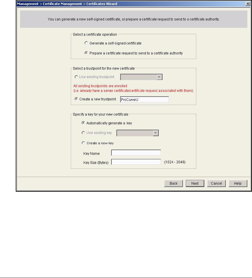
2-178
Implementing 802.1X with ProCurve IDM and Endpoint Integrity
Manually Issue and Install Server Certificates
9. In the Select a trustpoint for the new certificate section, select Create a new
trustpoint.
10. Type a descriptive name for trustpoint name in the box on the right—
typically, a name that identifies the CA. In this example: ProCurveU.
Figure 2-151. Wireless Edge Services Module Web Browser Interface—
Certificates Wizard—Select Certificate Operation
11. Leave the Automatically generate a key option selected.
12. Click Next.
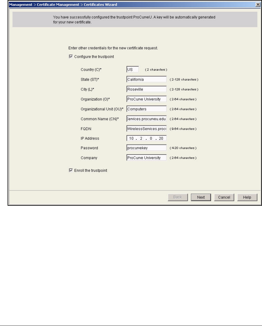
2-179
Implementing 802.1X with ProCurve IDM and Endpoint Integrity
Manually Issue and Install Server Certificates
Figure 2-152. Wireless Edge Services Module Web Browser Interface—
Certificates Wizard—Configure Trustpoint
13. Select the Configure the trustpoint check box and type the following cre-
dentials for the certificate:
•Country—the two-character country code (abbreviation) for your
country
•State—the state or province in which the module operates
•City—the city in which the module operates
•Organization—your organization (typically your company name)
•Organizational Unit—the module’s organizational unit

2-180
Implementing 802.1X with ProCurve IDM and Endpoint Integrity
Manually Issue and Install Server Certificates
•Common Name—the module’s exact FQDN, the URL at which the
module’s Web browser interface is accessed. The common name
cannot include spaces or special characters other than periods ( . )
and hyphens ( - ). In this example, the Common Name is WirelessSer-
vices.procurveu.edu.
Note Alternatively, type the Wireless Edge Services Module’s IP address.
•FQDN—the module’s FQDN. This field is optional.
•IP Address—the IP address for the wireless module or for the device
that wants the certificate. This field is optional but recommended.
• Password—a password that must be entered to install the certificate.
This field is optional.
•Company—the name of the company. It can be the same as the orga-
nization.
14. Select the Enroll the trustpoint check box.
15. Click Next. The window shown in Figure 2-153 is displayed.
16. The window shows the certificate request, which is in Base 64-encoded
Public Key Cryptography Standard #10 (PKCS#10) format. You have
several options for saving the certificate request. In this example, you will
save it to the hard disk on the management station.
a. Select the Save the certificate request check box. From the To list, select
Local Disk.
b. For the File, type a name for the request, including a valid path. For
example: C:\Certs\wireless_services.req. Alternatively, click the
browse button and browse for the directory in which to save the
request.
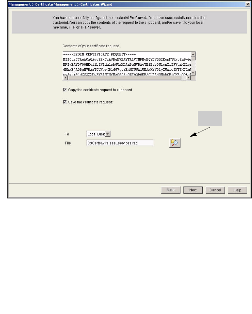
2-181
Implementing 802.1X with ProCurve IDM and Endpoint Integrity
Manually Issue and Install Server Certificates
Figure 2-153. Wireless Edge Services Module Web Browser Interface—
Certificates Wizard—Copy Request
17. Click Next. A completion window summarizes the certificate request
operation that you have performed.
18. Click Finish.
Browse
button
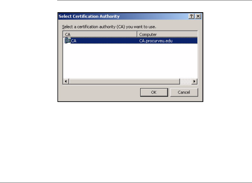
2-182
Implementing 802.1X with ProCurve IDM and Endpoint Integrity
Manually Issue and Install Server Certificates
Submit the Request to the CA and Create the Certificate
Follow these steps to submit the request to the CA and create the certificate
using the Web Server template:
1. In the previous section, you saved the certificate request from the Wireless
Edge Services Module to the management station. Now copy the request
to the CA server.
2. Access the command line on the CA server:
a. From the Windows Start menu, select Run.
b. Type cmd at the prompt and click OK.
3. Move to the directory in which you saved the certificate request.
4. Enter this command:
Figure 2-154. Select Certification Authority Window
5. In the window that is displayed, select the name of your CA and click OK.
6. In the Save Certificate window navigate to the location where you want to
save the certificate. Type a name for the certificate file.
Syntax: certreq -submit -attrib “CertificateTemplate:WebServer”
<request_filename>
Replace <request_filename> with the name of the certificate
request that you transferred to the CA server.
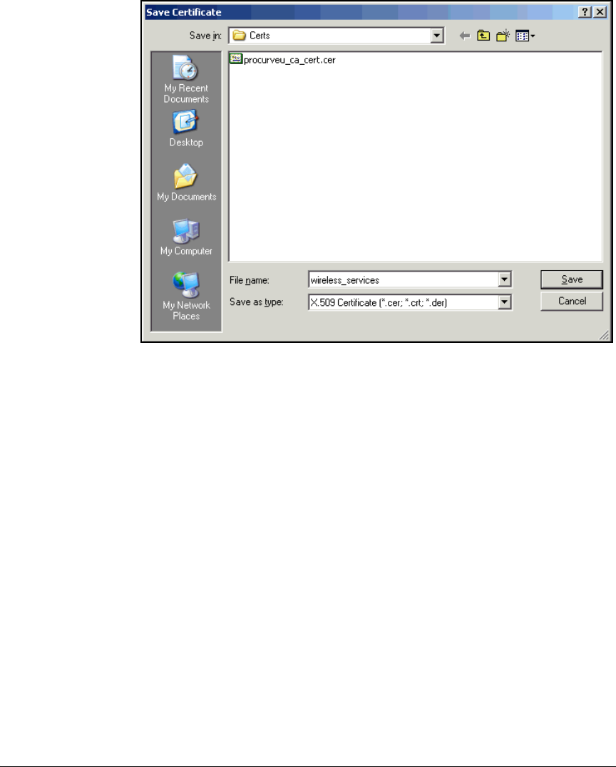
2-183
Implementing 802.1X with ProCurve IDM and Endpoint Integrity
Manually Issue and Install Server Certificates
Figure 2-155. Save Certificate Window
7. Click Save.
Install the Certificate on a Wireless Edge Services
Module
In the last task, you saved the Wireless Edge Services Module’s certificate as
a file on the hard drive of the CA server. In “Export the CA Root Certificate”
on page 2-97, you exported the CA root certificate to a file. Copy both
certificates to one of these locations:
■File Transfer Protocol (FTP) server
■Trivial FTP (TFTP) server
■Management station’s hard drive
Follow these steps to install the certificate:
1. Open the Web browser on your management station and navigate to the
Wireless Edge Services Module’s IP address.
2. Log in with a manager username and password.
3. Select Management > Certificate Management.
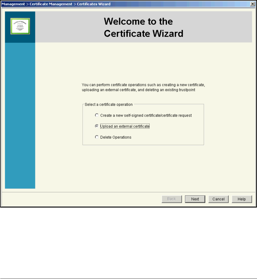
2-184
Implementing 802.1X with ProCurve IDM and Endpoint Integrity
Manually Issue and Install Server Certificates
4. Click the Trustpoints tab.
5. Click Certificates Wizard.
6. In the Welcome to the Certificate Wizard window, select Upload an external
certificate.
Figure 2-156. Wireless Edge Services Module Web Browser Interface—Welcome
to the Certificate Wizard
7. Click Next.

2-185
Implementing 802.1X with ProCurve IDM and Endpoint Integrity
Manually Issue and Install Server Certificates
Figure 2-157. Wireless Edge Services Module Web Browser Interface—
Certificates Wizard—Upload Certificates
8. From the Use existing trustpoint list, select the trustpoint you created in
“Create a Certificate Request on the Wireless Edge Services Module” on
page 2-174. In this example: ProCurveU.
9. Clear the Upload Server Certificate check box.
10. Select the Upload CA Root Certificate check box.
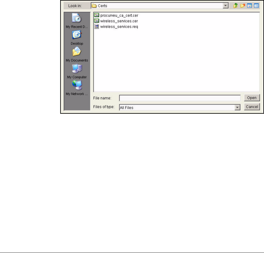
2-186
Implementing 802.1X with ProCurve IDM and Endpoint Integrity
Manually Issue and Install Server Certificates
11. Specify the file source for the certificate:
To upload the certificate from the workstation running the Web browser,
follow these steps:
a. From the From list, select Local Disk.
b. In the File box, type the certificate filename with a valid path (for
example, C:\Certs\procurveu_ca_cert.cer).
Alternatively, click the browse button and browse for the certificate.
(See Figure 2-158.) Click the certificate name and click Open.
Figure 2-158. Wireless Edge Services Module Web Browser Interface—Browse
for the Certificate
12. Click Next. The completion window summarizes the certificate upload
operation that you have performed.
13. Click Finish.
14. Repeat steps 5 to 13, this time selecting the Upload Server Certificate box
in step 10.

2-187
Implementing 802.1X with ProCurve IDM and Endpoint Integrity
Manually Issue and Install Server Certificates
Figure 2-159. Wireless Edge Services Module Web Browser Interface—
Completing the Certificate Management Wizard
Enable the Certificate on the Wireless Edge Services Module’s
HTTPS Server
To have the Wireless Edge Services Module use the new certificate for its
HTTPS server, follow these steps
1. Access the module’s Web browser interface.
2. Select Management > Web Access Control.
3. Make sure that the Enable HTTPS check box is selected. From the HTTPS
Trustpoint list, select the trustpoint you just created.

2-188
Implementing 802.1X with ProCurve IDM and Endpoint Integrity
Manually Issue and Install Server Certificates
Figure 2-160. Wireless Edge Services Module Web Browser Interface—
Management > Web Access Control Window
4. Click Apply.
5. Click Save.
6. Click Yes and OK in the two windows that are displayed.
Create and Install a Certificate for HTTPS on a NAC 800
All NAC 800s (both MSs and ESs) require a certificate for HTTPS. The sections
below guide you through requesting, creating, and installing these certificates.
Remember to repeat the tasks on each NAC 800 in your network.

2-189
Implementing 802.1X with ProCurve IDM and Endpoint Integrity
Manually Issue and Install Server Certificates
Create a Certificate Request for HTTPS on a NAC 800
Follow these steps on your NAC 800 to create a request for a new certificate
for HTTPS:
1. Log in as root to the NAC 800 OS:
a. Open an SSH session with the NAC 800.
b. Log in:
–username = root
– password = <root password>
Note You set the MS’s root password when you first accessed the Web browser
interface (see step 3 on page 2-143). You set the ES’s root password when
you added it to the enforcement cluster (see step 13 on page 2-148). In this
example, both passwords are procurvenac9.
2. Move to the /usr/local/nac/keystore directory:
ProCurve NAC 800:# cd /usr/local/nac/keystore
3. Remove the current keystore:
ProCurve NAC 800:/usr/local/nac/keystore# rm -f com-
pliance.keystore
4. Type this command:
For example:
ProCurve NAC 800:/usr/local/nac/keystore# keytool
-genkey -alias procurveu_esa -keyalg rsa -keystore
compliance.keystore
5. When prompted, type this password for the keystore: changeit. (Always
use this password.)
Next, you are prompted to type information that will be included in the
certificate that uses this key. For the first and last name, type the NAC
800’s exact IP address.
Syntax: keytool -genkey -alias <keyname> -keyalg [rsa | dsa] -keystore
compliance.keystore
Creates a new private/public keypair in the compliance.key-
store.
Replace <keyname> with a name that you choose for the key.
Replace [rsa | dsa] with either rsa or dsa.

2-190
Implementing 802.1X with ProCurve IDM and Endpoint Integrity
Manually Issue and Install Server Certificates
You are prompted for other information for the subject name such as your
organization name. However, the first and last name is the most important
setting.
6. The command line displays the information that you typed. If it is correct,
enter yes. If you need to edit the information, press [Enter] only.
7. The keytool utility prompts you to enter a password to protect the key or
press [Enter] to use the keystore’s password. You must press [Enter].
At this point, the keystore contains a private key and a public key wrapped
in a self-signed certificate. Next, generate a certificate request so that you
can replace the self-signed certificate with a CA-signed certificate.
8. Type this command to generate the certificate request:
For example:
ProCurve NAC 800:/usr/local/nac/keystore# keytool
-certreq -alias procurveu_esa -file esa_https.req
-keystore compliance.keystore
9. When prompted, type the password for the keystore.
10. Transfer the certificate request from the NAC 800.
You can transfer the certificate request to a Secure Copy (SCP) server.
PuTTY SCP (PSCP) is an SCP server that you can install on a Windows
server to communicate with a Linux device such as the NAC 800. On your
management server, follow these steps:
a. Access the command prompt on your management station. (From the
Windows Start menu, select Run. Type cmd at the prompt and click OK.)
b. Move to the directory in which PSCP is stored.
Syntax: keytool -certreq -alias <keyname> -file <filename> -keystore
compliance.keystore
Creates a certificate request that includes the public key and
LDAP information created for the specified alias.
Replace <keyname> with the name you specified in step 4.
Replace <filename> with the name you want to give to the
certificate request file.

2-191
Implementing 802.1X with ProCurve IDM and Endpoint Integrity
Manually Issue and Install Server Certificates
c. Type this command:
For example:
pscp root@10.2.1.40://usr/local/nac/keystore/
esa_https.req C:\Certs\esa_https.req
d. When prompted, type the NAC 800’s root password.
Submit the Request for the HTTPS Certificate to the CA
Follow these steps to submit the request to the CA and create the certificate
using the Web Server template:
1. In the previous section, you transferred the certificate request off the
NAC 800. Now save the request to the CA server.
2. Access the command line on the CA server.
a. From the Windows Start menu, select Run.
b. Type cmd at the prompt and click OK.
3. Move to the directory in which you saved the certificate request.
4. Enter this command:
Syntax: pscp root@<IP address>://usr/local/nac/keystore/<filename>
<path\filename>
Transfers a file from the NAC 800 to the local management
station.
Replace <IP address> with the NAC 800’s IP address.
Replace <filename> with the name that you gave the certificate
request in step 4.
Replace <path\filename> with the path and filename where you
want to save the request on your server.
Syntax: certreq -submit -attrib “CertificateTemplate:WebServer”
<request_filename>
Submits the certificate request to a CA.
Replace <request_filename> with the name of the certificate
request that you transferred to the CA server.
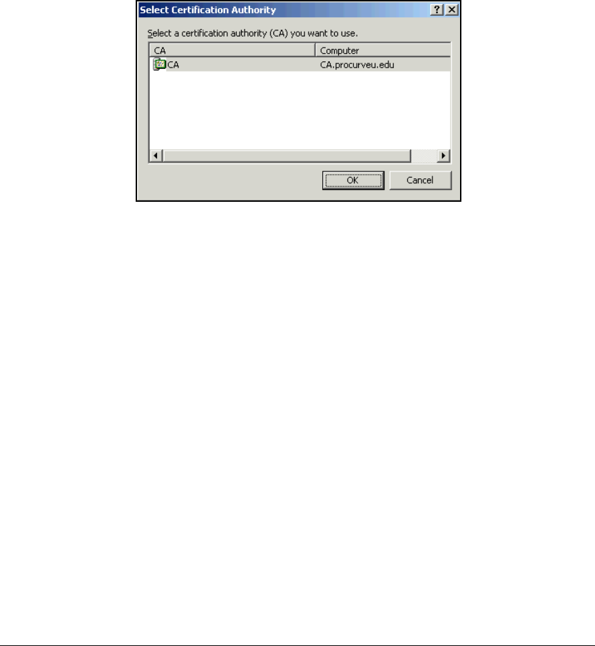
2-192
Implementing 802.1X with ProCurve IDM and Endpoint Integrity
Manually Issue and Install Server Certificates
5. For example:
C:\Certs> certreq -submit -attrib “CertificateTem-
plate:WebServer” esa_https.req
6. The Select Certification Authority window is displayed.
Figure 2-161. Select Certification Authority Window
7. Select the name of the CA server.
8. Click OK.
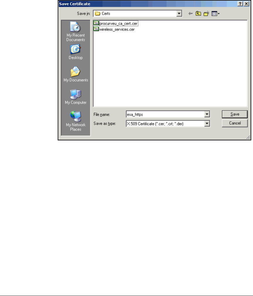
2-193
Implementing 802.1X with ProCurve IDM and Endpoint Integrity
Manually Issue and Install Server Certificates
9. Navigate to the location in which you want to save the certificate. Type
the name for the certificate file in the File name box.
Figure 2-162. Save Certificate Window
10. Click Save.
Install the Certificates for HTTPS on a NAC 800
In the last task, you saved the NAC 800’s HTTPS certificate as a file on the hard
drive of the CA server. In “Export the CA Root Certificate” on page 2-97, you
exported the CA root certificate to a file. Copy the certificates to your
management station’s hard drive. Then follow these steps:
1. Access the command-line prompt on your management workstation.
(Select Start > Run and type cmd.)
2. Move to the directory in which PSCP is stored.

2-194
Implementing 802.1X with ProCurve IDM and Endpoint Integrity
Manually Issue and Install Server Certificates
3. To save the CA root certificate to the NAC 800, type this command:
For example:
pscp C:\Certs\procurveu_ca.cer root@10.4.4.40://usr/
local/nac/keystore/procurveu_ca.cer
4. When prompted, enter the NAC 800’s root password.
5. Enter the command again, now saving the certificate for the HTTPS server
to the NAC 800:
For example:
pscp C:\certs\esa_https.cer root@10.4.4.40://usr/
local/nac/keystore/procurveu_esa.cer
6. When prompted, type the NAC 800’s root password.
7. Log in as root to the NAC 800’s OS.
8. Type this command:
ProCurve NAC 800:# cd /usr/local/nac/keystore
Syntax: pscp <path\filename> root@<IP address>://usr/local/nac/keystore/
<ca_cert_filename>
Replace <path\filename> with the location and filename of the
CA root certificate file.
Replace <IP address> with the IP address of the NAC 800.
Replace <ca_cert_filename> with a string of your choice, nam-
ing the CA root certificate file on the NAC 800.
Syntax: pscp <path\filename> root@<IP address>://usr/local/nac/keystore/
<cert_filename>
Replace <path\filename> with the location and filename of the
CA root certificate file.
Replace <IP address> with the IP address of the NAC 800.
Replace <cert_filename> with a string of your choice, naming
the certificate file on the NAC 800.

2-195
Implementing 802.1X with ProCurve IDM and Endpoint Integrity
Manually Issue and Install Server Certificates
9. Type this command:
For example:
ProCurve NAC 800:/usr/local/nac/keystore# keytool
-import -alias ca.procurveu.edu -file procurveu_ca.cer
-keystore /usr/local/java/jre/lib/security/cacerts
10. When prompted, type the password for the cacerts keystore (default:
changeit).
11. When prompted to trust the certificate, enter yes.
12. You should see this message:
Certificate was added to keystore.
13. Enter this command:
For example:
ProCurve NAC 800:/usr/local/nac/keystore# keytool
-import -alias procurveu_esa -trustcacerts -file
procurveu_esa.cer -keystore compliance.keystore
14. When prompted, enter the password: changeit.
15. You should see this message:
Certificate reply was added in keystore.
Syntax: keytool -import -alias <CA_name> -file <ca_cert_filename> -keystore
/usr/local/java/jre/lib/security/cacerts
Replace <CA_name> with the name of your CA.
Replace <ca_cert_filename> with the filename that you gave to
the CA certificate in step 3 on page 2-194.
Syntax: keytool -import -alias <keyname> -trustcacerts -file <cert_filename>
-keystore compliance.keystore
Replace <keyname> with the name you specified in step 4 on
page 2-189.
Replace <cert_filename> with the filename that you gave the
server certificate in step 5 on page 2-194.

2-196
Implementing 802.1X with ProCurve IDM and Endpoint Integrity
Manually Issue and Install Server Certificates
16. Restart the HTTPS server:
• On the MS—service nac-ms restart
•On the ESs—service nac-es restart
If the service fails to restart, you might have set the wrong password for
the compliance.keystore. Use changeit.
Create and Install a Certificate for the NAC 800 RADIUS
Service
The NAC 800 ESs act as RADIUS servers. As such, they require server
certificates that have these key extensions:
■Server authentication
■Client authentication
You already set up such a certificate template for the NAC 800, basing the
template on the one for RAS and IAS servers (see “Create the NAC 800
Certificate Template” on page 2-87). Now you must have the NAC 800s request
their certificates. You will then submit the request to the CA using the NAC
800 template.
Create a Certificate Request for the RADIUS Service
Follow these steps to create a certificate request for a NAC 800’s internal
RADIUS server:
1. Log in to the NAC 800 as root.
2. Enter this command:
ProCurve NAC 800:/# cd /etc/raddb/certs

2-197
Implementing 802.1X with ProCurve IDM and Endpoint Integrity
Manually Issue and Install Server Certificates
3. Enter this command to generate the certificate request:
For example:
ProCurve NAC 800:/etc/raddb/certs# openssl req -new
-newkey rsa:1024 -keyout procurveu_radkey.pem -out
nac_esa_rad.req
4. If you omitted the -nodes option, type and confirm a password (PEM
passphrase). In this example: mykey.
5. You will be prompted to enter information about the NAC 800. When
prompted for the Common Name (CN), type the NAC 800’s IP address (in
this example, 10.4.4.40).
The email and challenge password are optional.
6. Transfer the certificate request to an SCP server.
If you have installed PSCP on your management station, you can follow
these steps:
a. Access the command prompt on your management station and move
to the directory in which PSCP is installed.
Syntax: openssl req -new -newkey [rsa | dsa]:[512 | 1024 | 2048 | 4096] [-nodes]
-keyout <key_filename> -out <request_filename> {-outform [DER | PEM]}
The -newkey option generates a private/public keypair for this
certificate. Choose rsa or dsa for the algorithm and then choose
the key length (4096 is not a valid option for dsa).
The private key for the certificate is saved with the name you
enter for the <key filename>. The certificate request is saved
with the name you enter for the <request filename>. You can
choose the format (DER or PEM) for the request (default: PEM).
The -nodes option creates the private key without password
protection. For stronger security, omit this option when you
type the command. You will then be prompted to type the
password. In step 10 on page 2-201, you will edit the /etc/
raddb/eap.conf file and specify this password.

2-198
Implementing 802.1X with ProCurve IDM and Endpoint Integrity
Manually Issue and Install Server Certificates
b. Enter this command:
For example:
pscp root@10.4.4.40://etc/raddb/certs/
nac_esa_rad.req C:\Certs\nac_esa_rad.req
c. When prompted, type the NAC 800’s root password.
Submit the Request for the RADIUS Server Certificate to the
CA
Follow these steps to submit the request to the CA and create the certificate
using the NAC 800 template:
1. In the previous section, you saved the certificate request off the NAC 800.
Transfer the request to the CA server.
2. Access the command line on the CA server. (Select Start > Run, type cmd
at the prompt and click OK.)
3. Move to the directory in which you saved the certificate request.
4. Enter this command:
For example:
C:\Certs> certreq -submit -attrib “CertificateTem-
plate:NAC800” nac_esa_rad.req
5. Select the name of the CA server.
6. Click OK.
7. Navigate to the location in which you want to save the certificate. Type
the name for the certificate file.
Syntax: pscp root@<NAC 800 IP address>://etc/raddb/certs/<request filename>
<path\filename>
Replace <path\filename> with the directory path and filename
for the server certificate. The certificate is saved with the
name that you specify for <certificate filename>.
Syntax: certreq -submit -attrib “CertificateTemplate:NAC800”
<request_filename>
Replace <request_filename> with the name of the certificate
request that you transfered to the CA server.
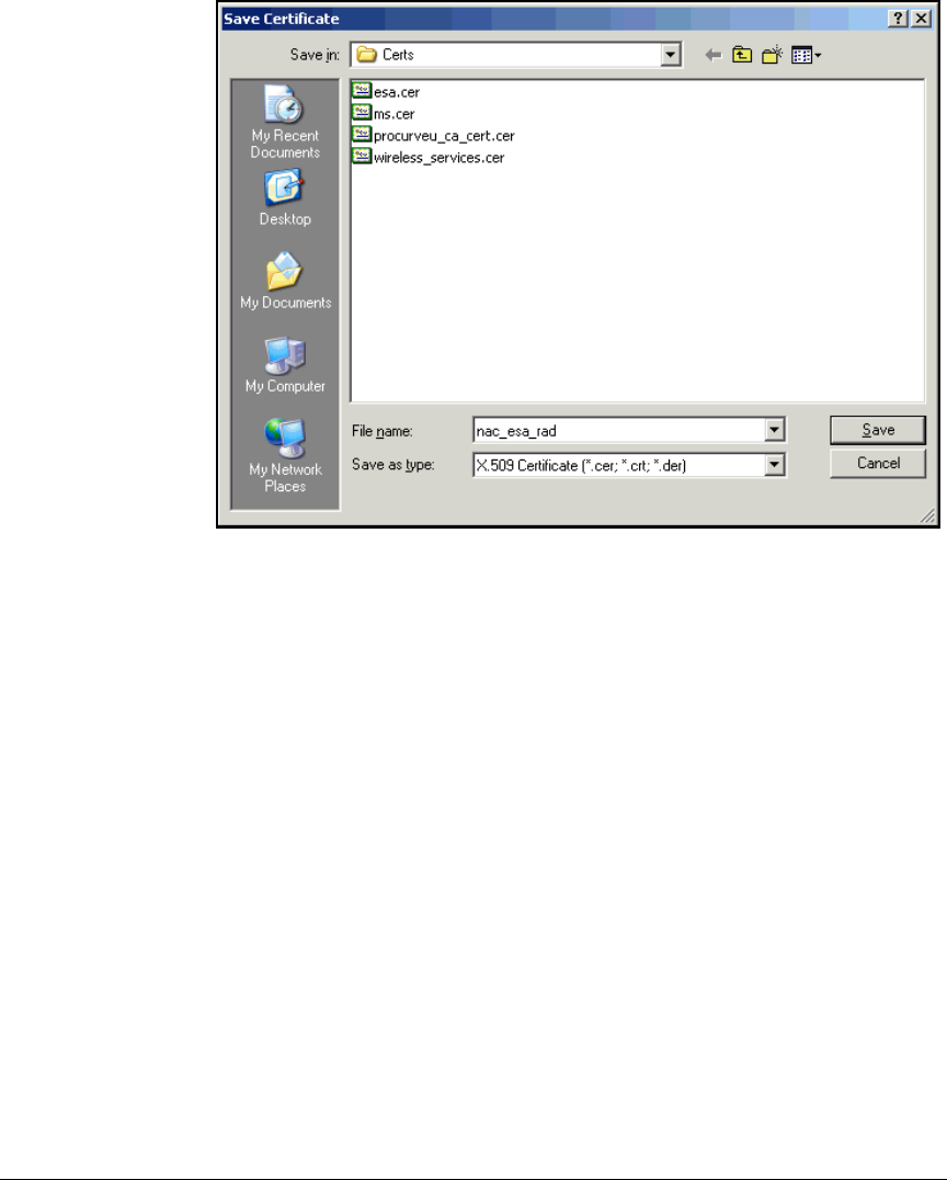
2-199
Implementing 802.1X with ProCurve IDM and Endpoint Integrity
Manually Issue and Install Server Certificates
Figure 2-163. Save Certificate Window
8. Click Save.
Install the Certificate for RADIUS Services on a NAC 800
In the last task, you saved the NAC 800’s RADIUS certificate as a file on the
hard drive of the CA server. Now you must copy it to the NAC 800. The steps
below show you how to do so from your management station, which has the
PSCP application.
Then follow these steps:
1. Transfer the certificate file to the management station’s hard drive.
2. Access the command-line prompt on your management workstation.
(Select Start > Run and type cmd.)
3. Move to the directory in which PSCP is stored.

2-200
Implementing 802.1X with ProCurve IDM and Endpoint Integrity
Manually Issue and Install Server Certificates
4. To save the RADIUS certificate to the NAC 800, type this command:
For example:
pscp C:\Certs\nac_esa_rad.cer root@10.4.4.40://etc/
raddb/certs/procurveu_rad.cer
5. When prompted, type the NAC 800’s root password.
6. Log in as root to the NAC 800 OS.
7. Type this command:
ProCurve NAC 800:/# cd /etc/raddb/certs
8. In “Install the Certificates for HTTPS on a NAC 800” on page 2-193, you
saved your domain CA root certificate to the NAC 800. Now copy this
certificate to the /etc/raddb/certs directory:
9. If the CA root certificate is not in Privacy Enhanced Mail (PEM) format,
convert it.
Convert from Distinguished Encoding Rules (DER) with this command:
For example, type:
ProCurve NAC 800:/etc/raddb/certs# openssl x509 -in
procurveu_ca.cer -inform DER -out procurveu_ca.pem
-outform PEM
Syntax: Syntax: pscp <path\filename> root@<IP address>://etc/raddb/certs/
<cert_filename>
Replace <path\filename> with the location and name of file on
the current station that stores the NAC 800’s RADIUS server
certificate.
Replace <IP address> with the NAC 800’s IP address.
Replace <cert_filename> with a string of your choice, naming
the RADIUS server certificate on the NAC 800.
Syntax: cp /usr/local/nac/keystore/<ca_cert_filename> <ca_cert_filename>
You chose the <ca_cert_filename> in step 3 on page 2-194.
Syntax: openssl x509 -in <ca_cert_filename> [-inform DER] -out
<ca_cert_filename> -outform PEM
You should change the filename extension to reflect the
changed format.

2-201
Implementing 802.1X with ProCurve IDM and Endpoint Integrity
Manually Issue and Install Server Certificates
Note If you attempt to convert a certificate with the .cer extension, and you receive
an error message, the certificate might already be in PEM format. You can skip
this step.
Convert from Personal Information Exchange (PFX) format with this
command:
10. Alter the /etc/raddb/eap.conf file to specify the new private key and certif-
icate files.
a. Type this command:
ProCurve NAC 800:/etc/raddb/certs# vi /etc/raddb/
eap.conf
b. Use the arrow keys or other vi commands to reach the “tls” section
of the configuration file. (See Figure 2-164.)
Figure 2-164. Example radiusd.conf File——tls Section
c. Press [i].
d. If you created a password for the private key, set
private_key_password to the same key that you chose earlier. For
example:
private_key_password = mykey
Syntax: openssl pkcs7 -in <certificate filename>.pfx -out <certificate file-
name>.pem
You should change the filename extension to reflect the
changed format.
tls {
private_key_password = whatever
private_key_file = ${raddbdir}/certs/cert-srv.pem
# If Private key & Certificate are located in
# the same file, then private_key_file &
# certificate_file must contain the same file
# name.
certificate_file = ${raddbdir}/certs/cert-srv.pem
# Trusted Root CA list
CA_file = ${raddbdir}/certs/demoCA/cacert.pem
dh_file = ${raddbdir}/certs/dh
random_file = ${raddbdir}/certs/random

2-202
Implementing 802.1X with ProCurve IDM and Endpoint Integrity
Manually Issue and Install Server Certificates
e. Set private_key_file to the same as the <key_filename> that you speci-
fied in step 3 on page 2-197. Keep the default path already included in
the configuration file (which works as long as you saved the key in
the proper directory). For example:
private_key_file = ${raddbdir}/certs/
procurveu_radkey.pem
f. Set certificate_file to the same as the <cert_filename> that you speci-
fied in step 4 on page 2-200. Keep the default path already included in
the configuration file (which works as long as you saved the certifi-
cate in the proper directory). For example:
certificate_file = ${raddbdir}/certs/
procurveu_rad.cer
g. Set CA_file to the same as the <ca_cert_filename> that you specified
in step 4 on page 2-200 or (if you converted the file to different format)
9 on page 2-200. Make sure to specify the certs directory (not the certs/
demoCA) because this is the location to which you saved the certifi-
cate. For example:
CA_file = ${raddbdir}/certs/procurveu_ca.pem
h. Press [Esc].
i. Type this command:
:wq
11. Restart the RADIUS server.
ProCurve NAC 800:/# service radiusd restart
If the RADIUS server fails to restart, you have probably mistyped the
filenames or private key password in step 10. Carefully recheck the
configuration. Also check the /etc/raddb/certs directory (dir) and verify it
contains the correct files.

2-203
Implementing 802.1X with ProCurve IDM and Endpoint Integrity
Configuring Network Access Control with PCM+
Configuring Network Access Control
with PCM+
This section describes how to install PCM+ 2.2 and IDM 2.2 on a Windows
Server 2003. The update occurs in two steps: first, you install PCM+ 2.2 with
IDM 2.15; then, you upgrade to IDM 2.2.
You can complete a variety of tasks with PCM+. In addition to explaining how
to install PCM+, this section describes how to configure both local and remote
mirroring, which is necessary for endpoint integrity as implemented in this
solution.
You will also implement port authentication with the Secure Access Wizard—
activating your network access control solution.
The next section, “Configuring Network Access Control with IDM” on
page 2-229, explains how to control network access with IDM.
Note Version 2.2 auto-update 2 is required for managing the NAC 800 with PCM+
and IDM.
Install PCM+
You can obtain the installation CD, which includes a 30-day trial version
of PCM+, with new ProCurve switches. You can also purchase PCM+ from a
ProCurve solutions provider.
The first step in installing PCM+ 2.2 is to ensure that your system meets the
system requirements for PCM+. The following OSs support PCM+:
■Windows 2000:
• Server
• Advanced Server
• Pro with Service Pack 4 (SP4) or later
■Windows Server 2003
■Windows XP Pro SP2 or later

2-204
Implementing 802.1X with ProCurve IDM and Endpoint Integrity
Configuring Network Access Control with PCM+
Table 2-13 shows the minimum and recommended hardware capabilities of
the server, which depend largely on the size of your network. These recom-
mendations apply to a server dedicated to running PCM+ and add-ons such as
IDM. (If you are using add-ons, plan for the recommended rather than the
minimum capabilities.)
Table 2-13. Recommended Hardware Capabilities of PCM+ Server
Follow these steps to install PCM+ version 2.2:
1. Launch the PCM install executable. The InstallAnywhere window is dis-
played.
Figure 2-165. PCM InstallAnywhere Window
2. Wait for the install wizard to open.
Network
Size
Processor RAM Free Disk Space NIC
Minimum Recommend Minimum Recommend Minimum Recommend Minimum Recommend
Small to
medium
50 to 250
managed
devices
2 GHz
Pentium IV
or
equivalent
3 GHz
Pentium IV
or
equivalent
1 GB 2 GB 10 GB 40 GB 1 Gbps 1 Gbps
Medium to
large
250 to 2000
managed
devices
3 GHz
Pentium IV
or
equivalent
Intel Xeon
or
equivalent
3 GB 4 GB 40 GB 80 GB 1 Gbps 1 Gbps
2-205
Implementing 802.1X with ProCurve IDM and Endpoint Integrity
Configuring Network Access Control with PCM+
Figure 2-166. ProCurve Manager Install Wizard—Introduction Page
3. Click Next.
Figure 2-167. ProCurve Manager Install Wizard—License Agreement Page
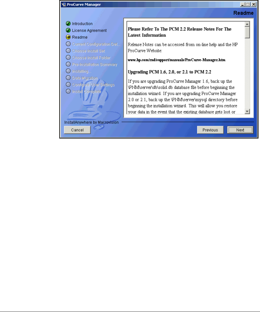
2-206
Implementing 802.1X with ProCurve IDM and Endpoint Integrity
Configuring Network Access Control with PCM+
4. Select I accept the terms of the License Agreement and click Next.
Figure 2-168. ProCurve Manager Install Wizard—Readme Page
5. Scroll through the Readme page if desired and then click Next.
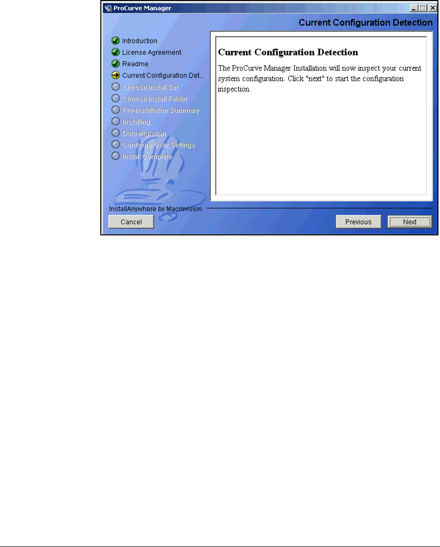
2-207
Implementing 802.1X with ProCurve IDM and Endpoint Integrity
Configuring Network Access Control with PCM+
Figure 2-169. ProCurve Manager Install Wizard—Current Configuration
Detection Page
6. Click Next.
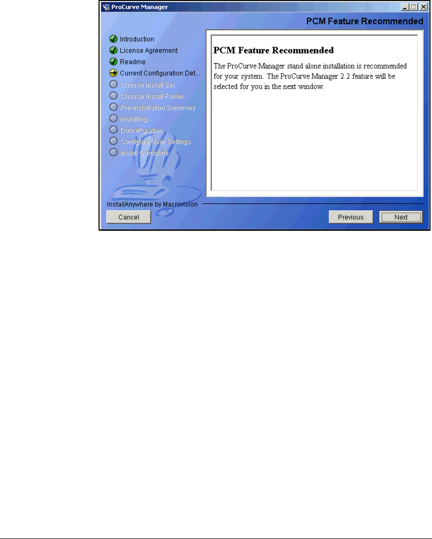
2-208
Implementing 802.1X with ProCurve IDM and Endpoint Integrity
Configuring Network Access Control with PCM+
Figure 2-170. ProCurve Manager Install Wizard—PCM Feature
Recommended Page
7. Click Next.
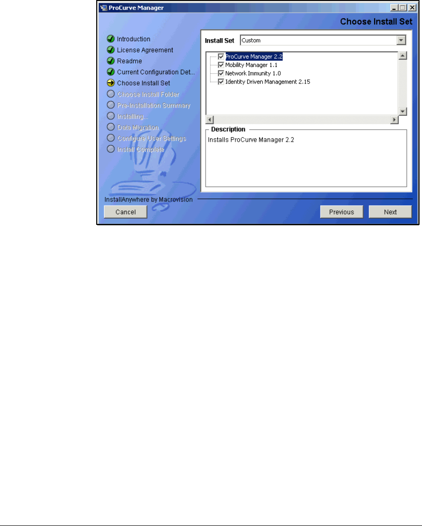
2-209
Implementing 802.1X with ProCurve IDM and Endpoint Integrity
Configuring Network Access Control with PCM+
Figure 2-171. ProCurve Manager Install Wizard—Choose Install Set Page
8. Select the ProCurve Manager 2.2 and Identity Driven Management 2.15 check
boxes. If desired, also select the Mobility Manager and Network Immunity
check boxes. (Configuring those options is beyond the scope of this
document.)
9. Click Next.

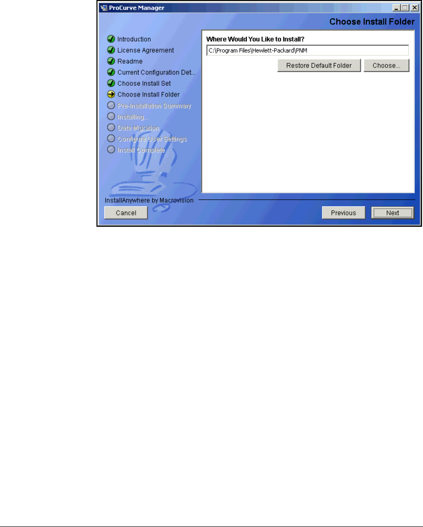
2-211
Implementing 802.1X with ProCurve IDM and Endpoint Integrity
Configuring Network Access Control with PCM+
Figure 2-173. ProCurve Manager Install Wizard—Choose Install Folder Page
11. Accept the default install folder or click Choose to select another install
folder.
12. Click Next.
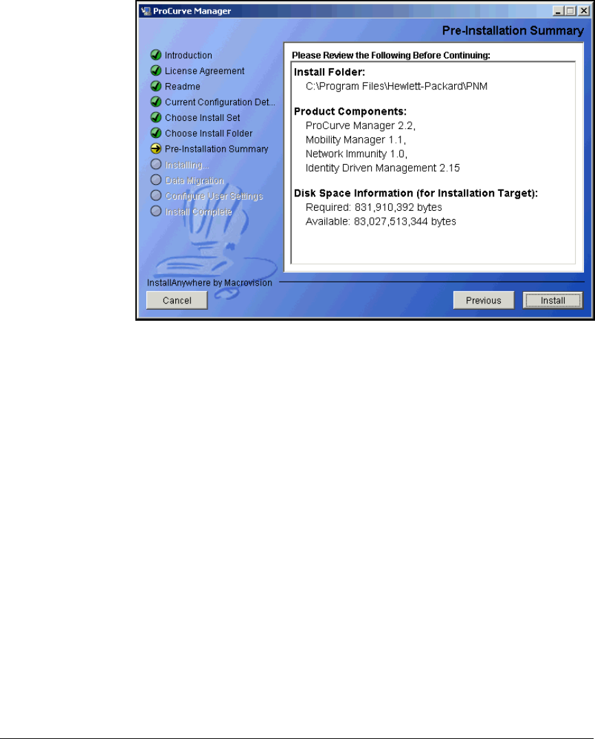
2-212
Implementing 802.1X with ProCurve IDM and Endpoint Integrity
Configuring Network Access Control with PCM+
Figure 2-174. ProCurve Manager Install Wizard—Pre-Installation Summary Page
13. Review the pre-installation summary and click Install.

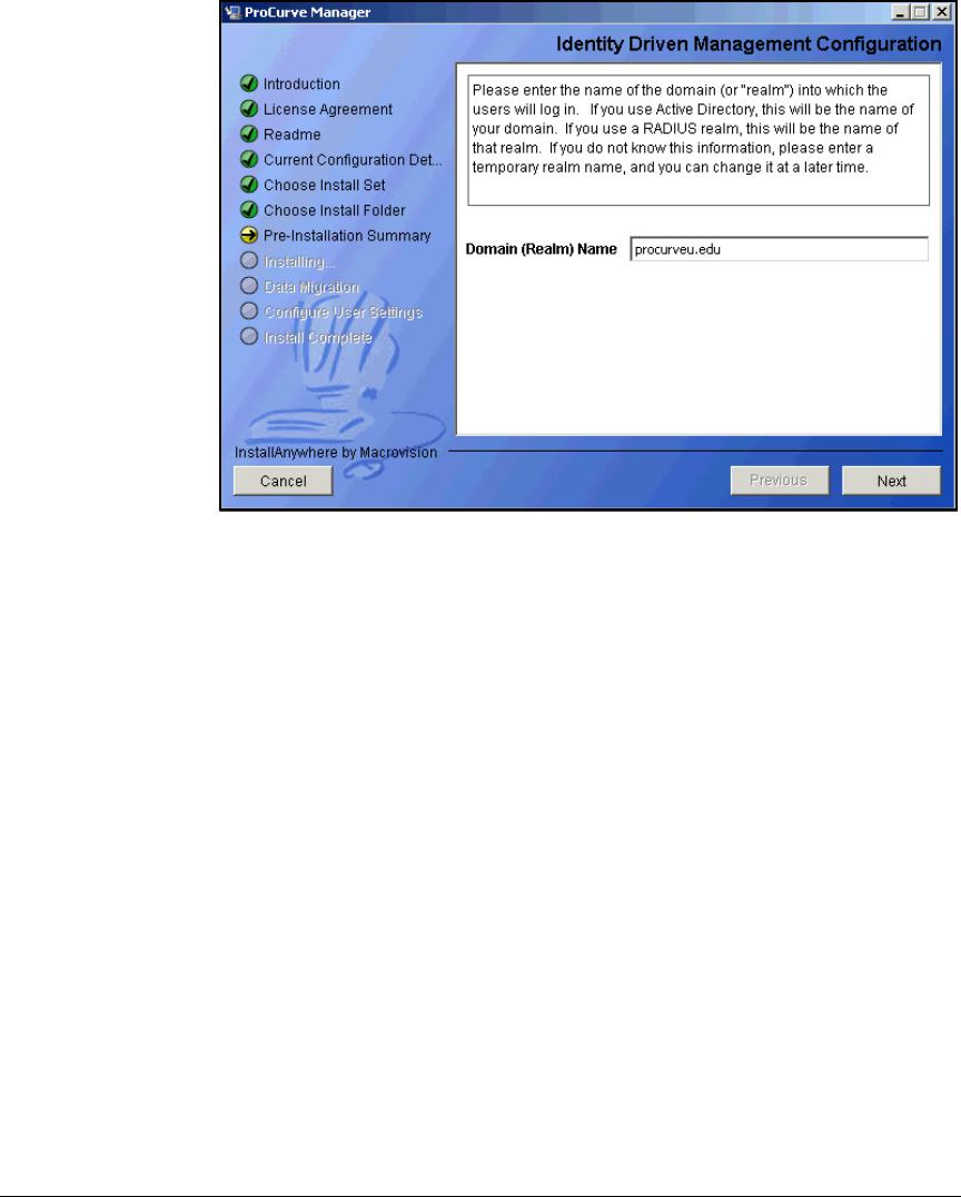
2-214
Implementing 802.1X with ProCurve IDM and Endpoint Integrity
Configuring Network Access Control with PCM+
Figure 2-176. ProCurve Manager Install Wizard — Identity Driven Management
Configuration Page
15. Type your domain name for the Domain (Realm) Name. This becomes IDM’s
default realm (in this example: procurveu.edu).
If the PCM+ server has already joined the domain, the realm is automati-
cally filled in.
16. Click Next.
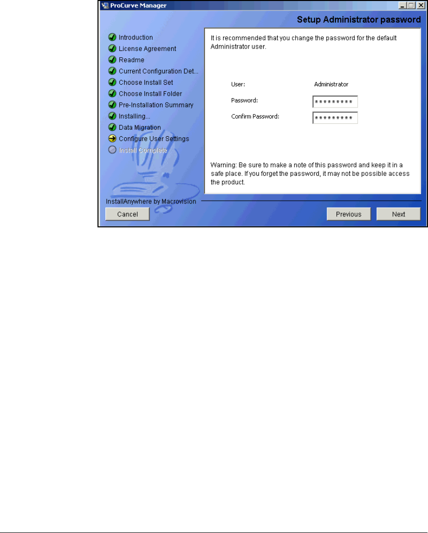
2-215
Implementing 802.1X with ProCurve IDM and Endpoint Integrity
Configuring Network Access Control with PCM+
Figure 2-177. ProCurve Manager Install Wizard—Setup Administrator
password Page
17. Type the Password for the PCM+ Administrator.
18. Retype the password in the Confirm Password box.
19. Take careful note of the password. You must enter it to access PCM+.
20. Click Next.
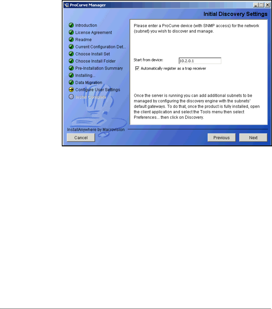
2-216
Implementing 802.1X with ProCurve IDM and Endpoint Integrity
Configuring Network Access Control with PCM+
21. In the Start from device box, type the IP address of a switch in the
Management VLAN. In this example, the address of the routing switch:
10.2.0.1.
Figure 2-178. ProCurve Manager Install Wizard—Initial Discovery Settings Page
22. The Automatically register as a trap receiver check box should be selected.
23. Click Next.
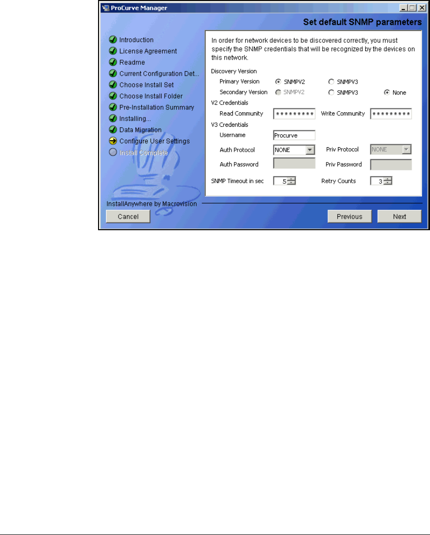
2-217
Implementing 802.1X with ProCurve IDM and Endpoint Integrity
Configuring Network Access Control with PCM+
Figure 2-179. ProCurve Manager Install Wizard—Set default SNMP parameters
Page
24. Configure SNMP settings to match those specified for network devices.
(You set up these settings in “Configuring the ProCurve Switches” on page
2-13, “Configure SNMP on the Wireless Edge Services Modules” on page
2-117, and “Configure More Basic Settings for the MS” on page 2-142.)
a. In this example, the network uses SNMPv2. Select the SNMPV2 option
for the Primary Version and None for the Secondary Version.
b. For the Read Community, type the string you selected for the read-only
community (in this example, procurvero).
c. For the Write Community, type the string you selected for the read-write
community (in this example, procurverw).
25. Click Next.
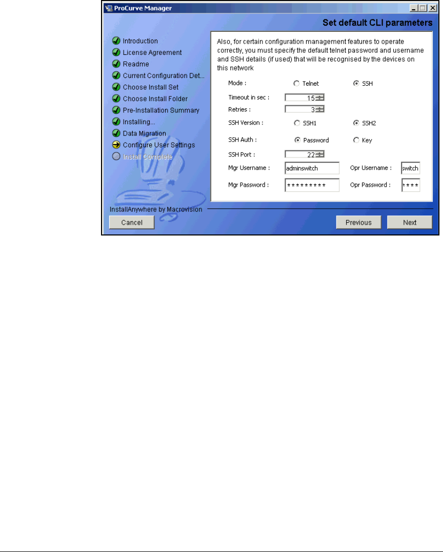
2-218
Implementing 802.1X with ProCurve IDM and Endpoint Integrity
Configuring Network Access Control with PCM+
Figure 2-180. ProCurve Manager Install Wizard—Set default CLI parameters Page
26. Configure CLI access from PCM+ to ProCurve devices. The default con-
figuration uses Telnet.
a. Select Telnet or SSH (secure).
a. In the Timeout in sec box, type a number between 1 and 60.
b. In the Retries box, type a number between 1 and 5.
c. If you have selected SSH, configure some settings:
i. For SSH Version, select SSH1 or SSH2.
ii. For SSH Auth, select Password or Key.
d. For Mgr Username, type the management username for devices in your
network. In this example: adminswitch.
e. For Mgr Password, type the associated password.
f. For Opr Username, type the username for operators in your network.
In this example: operatorswitch.
g. Type the associated password for the Opr Password.
h. Click Next.
27. Configure settings for an HTTP proxy if your network uses one. The
example network does not. Click Next.
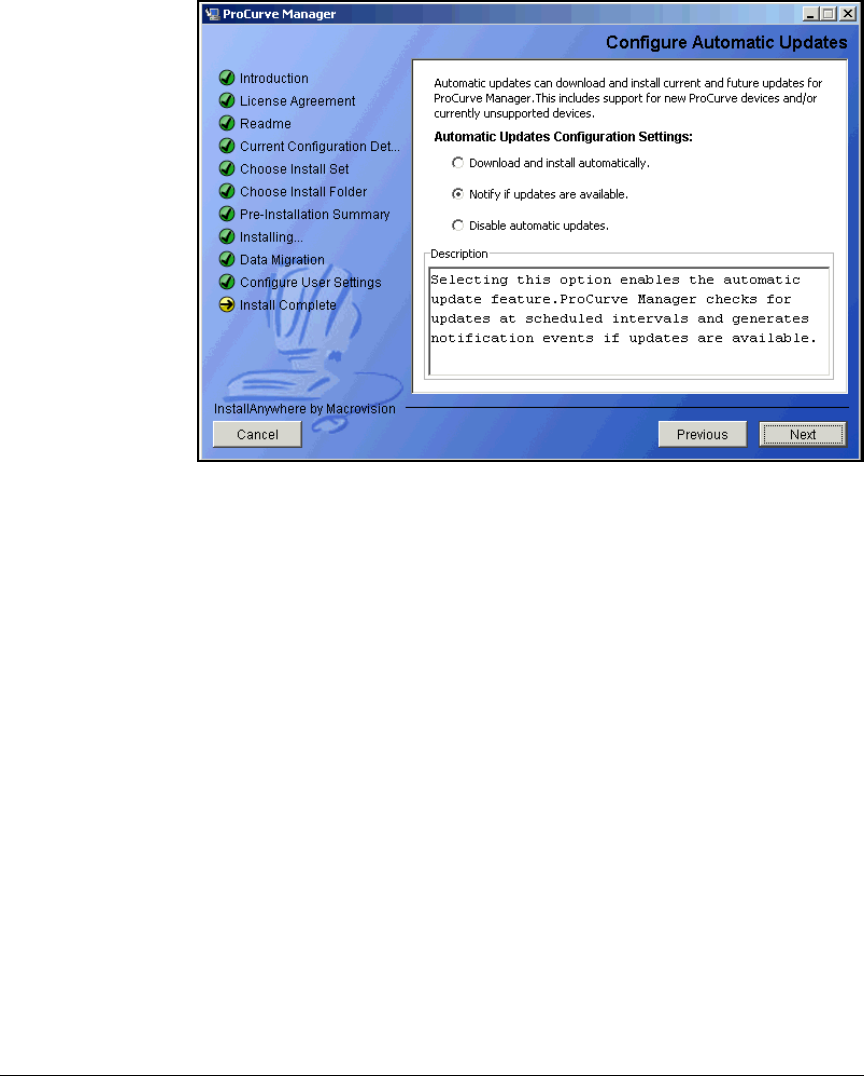
2-219
Implementing 802.1X with ProCurve IDM and Endpoint Integrity
Configuring Network Access Control with PCM+
Figure 2-181. ProCurve Manager Install Wizard—Configure Automatic Updates
Page
28. Configure settings for updates to PCM+. Select one of the following
options:
•Download and install automatically—PCM+ checks the ProCurve
Web site for updates and downloads them, without interaction from
you or another network administrator.
•Notify if updates are available—PCM+ checks the ProCurve Web
site for updates and logs an event message for every update available
for download. You can then review the PCM+ event log to identify
updates and install them manually.
•Disable automatic updates—PCM+ will not check for updates. You
must manually install updates.
After you make your selection, click Next. The Install Wizard Complete page
is displayed.
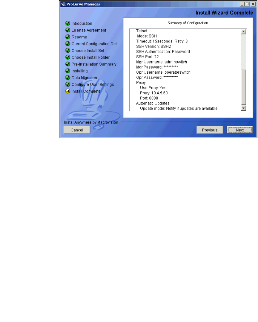
2-220
Implementing 802.1X with ProCurve IDM and Endpoint Integrity
Configuring Network Access Control with PCM+
Figure 2-182. ProCurve Manager Install Wizard—Install Wizard Complete Page
29. Click Next.
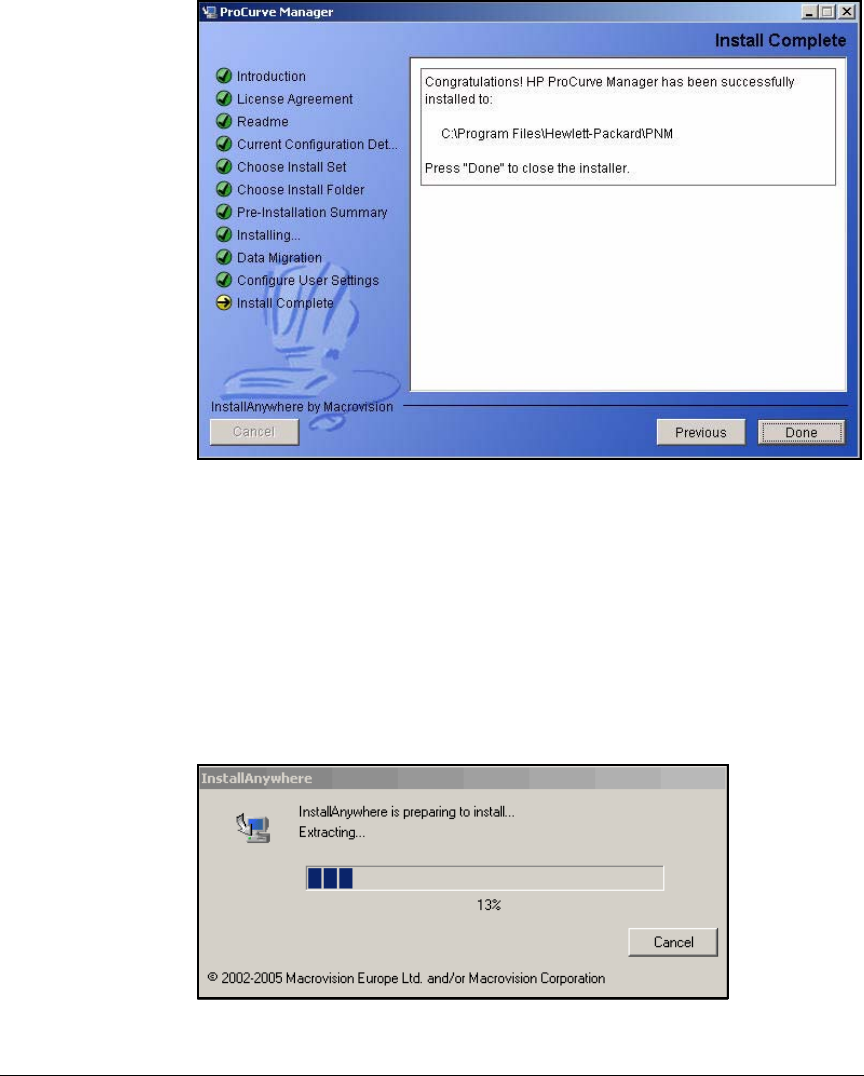
2-221
Implementing 802.1X with ProCurve IDM and Endpoint Integrity
Configuring Network Access Control with PCM+
Figure 2-183. ProCurve Manager Install Wizard—Install Wizard Complete Page
30. Click Done.
Install IDM 2.2
After you install or upgrade to PCM+ version 2.2, the IDM version is 2.15. Next
you must upgrade IDM to version 2.2. (You must install PCM+ 2.2 before IDM
2.2.) Follow these steps:
1. Launch the IDM 2.2 executable. The InstallAnywhere window is displayed.
Figure 2-184. IDM InstallAnywhere Window
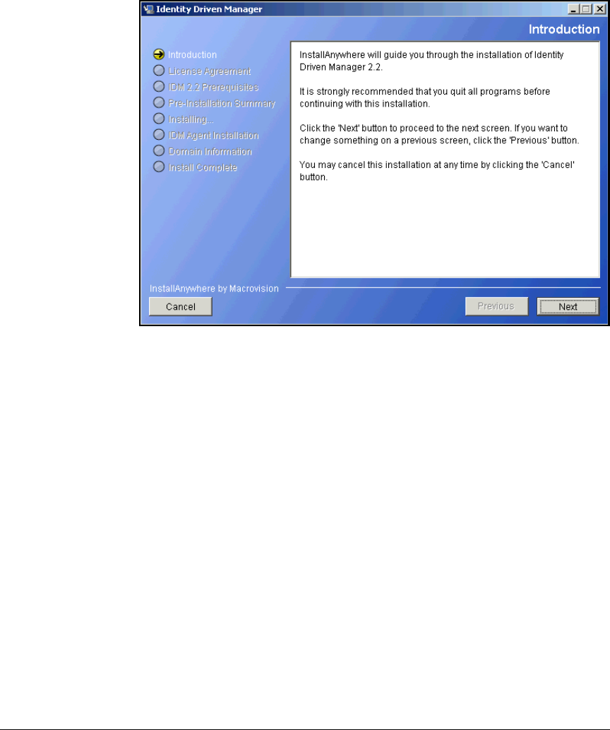
2-222
Implementing 802.1X with ProCurve IDM and Endpoint Integrity
Configuring Network Access Control with PCM+
2. Wait for the install wizard to open.
Figure 2-185. Identity Driven Manager Install Wizard—Introduction Page
3. Click Next.
4. Click I accept the terms of the License Agreement.
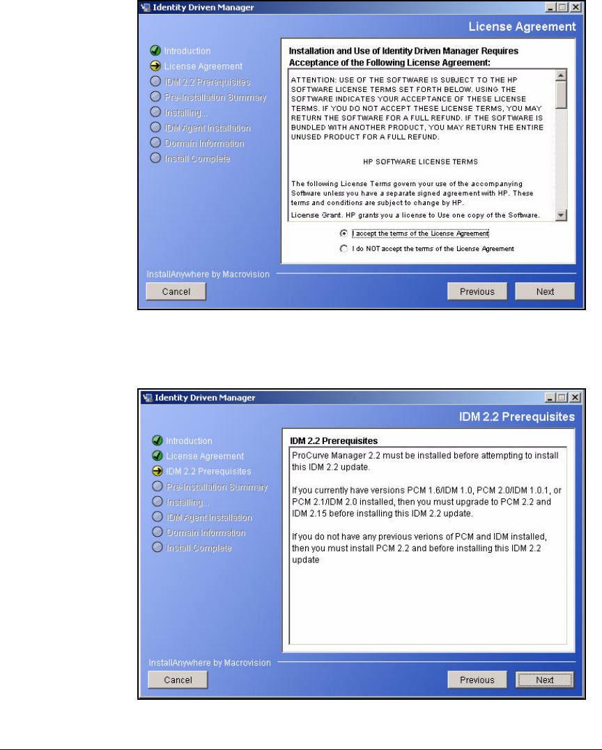
2-223
Implementing 802.1X with ProCurve IDM and Endpoint Integrity
Configuring Network Access Control with PCM+
Figure 2-186. Identity Driven Manager Install Wizard—License Agreement Page
5. Click Next.
Figure 2-187. ProCurve Manager Install Wizard—IDM 2.2 Prerequisites Page
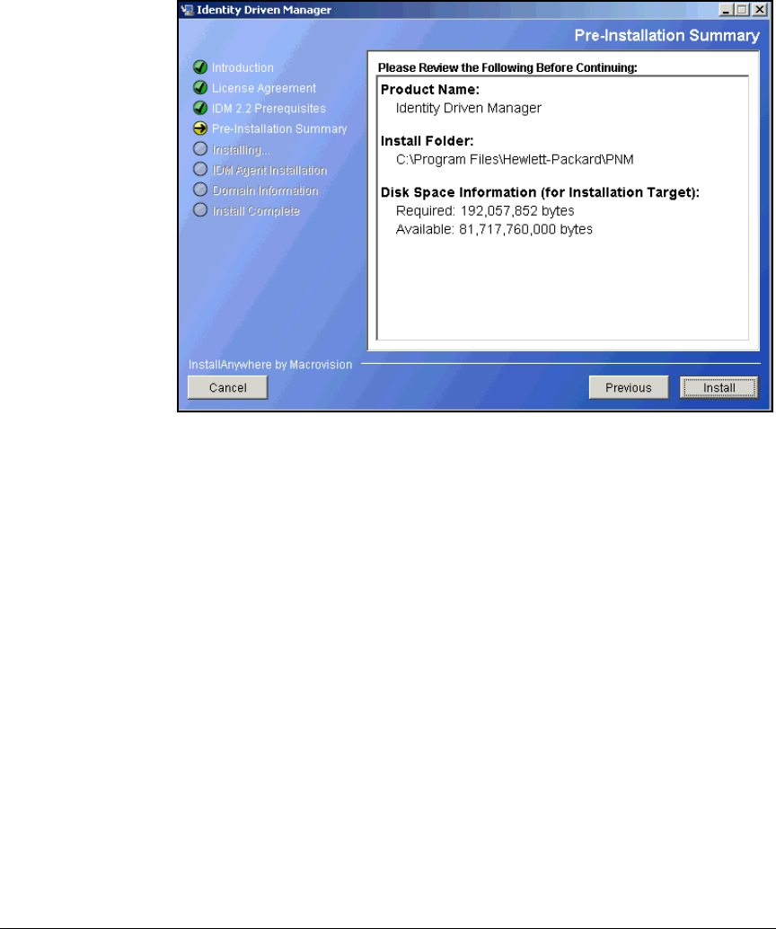
2-224
Implementing 802.1X with ProCurve IDM and Endpoint Integrity
Configuring Network Access Control with PCM+
6. Click Next.
Figure 2-188. Identity Driven Manager Install Wizard—Pre-Installation
Summary Page
7. Click Install. Wait several minutes while IDM installs.
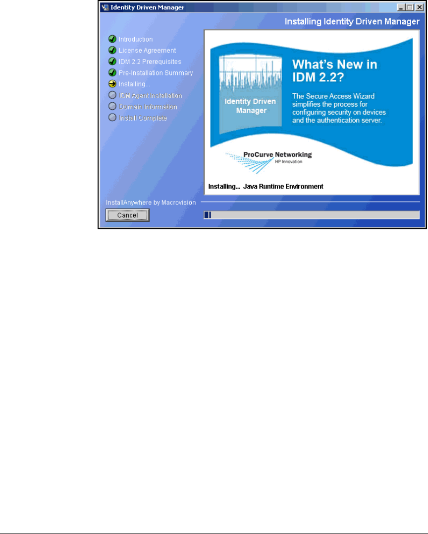
2-225
Implementing 802.1X with ProCurve IDM and Endpoint Integrity
Configuring Network Access Control with PCM+
Figure 2-189. Identity Driven Manager Install Wizard—Installing Page
8. The IDM Agent Installation page reminds you to download the new IDM
agents and install them on your RADIUS servers.
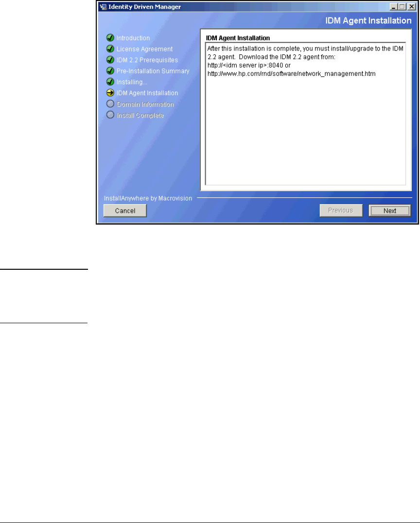
2-226
Implementing 802.1X with ProCurve IDM and Endpoint Integrity
Configuring Network Access Control with PCM+
Figure 2-190. Identity Driven Manager Install Wizard—IDM Agent Installation
Page
Note This solution uses NAC 800s as the RADIUS servers, which include the agent
by default. You can check the version of a NAC 800’s agent by logging in to the
device as root and entering more /root/version. Check the release notes for the
NAC 800 for instructions on updating the IDM agent, if necessary.
9. Click Next.

2-227
Implementing 802.1X with ProCurve IDM and Endpoint Integrity
Configuring Network Access Control with PCM+
Figure 2-191. Identity Driven Manager Install Wizard—Domain Information Page
10. On the Domain Information page, view the Realm and Alias boxes. Verify
that the Realm box includes your domain’s fully-qualified name and that
the Alias box includes the associated NetBIOS (workgroup) name.
If the PCM+/IDM server has not yet joined the domain, you must type the
correct values into the boxes yourself. It is important to specify both the
realm and the alias. Otherwise, IDM, which automatically creates realms
based on information in authentication requests, may create two separate
realms for the same domain.
11. Click Next.
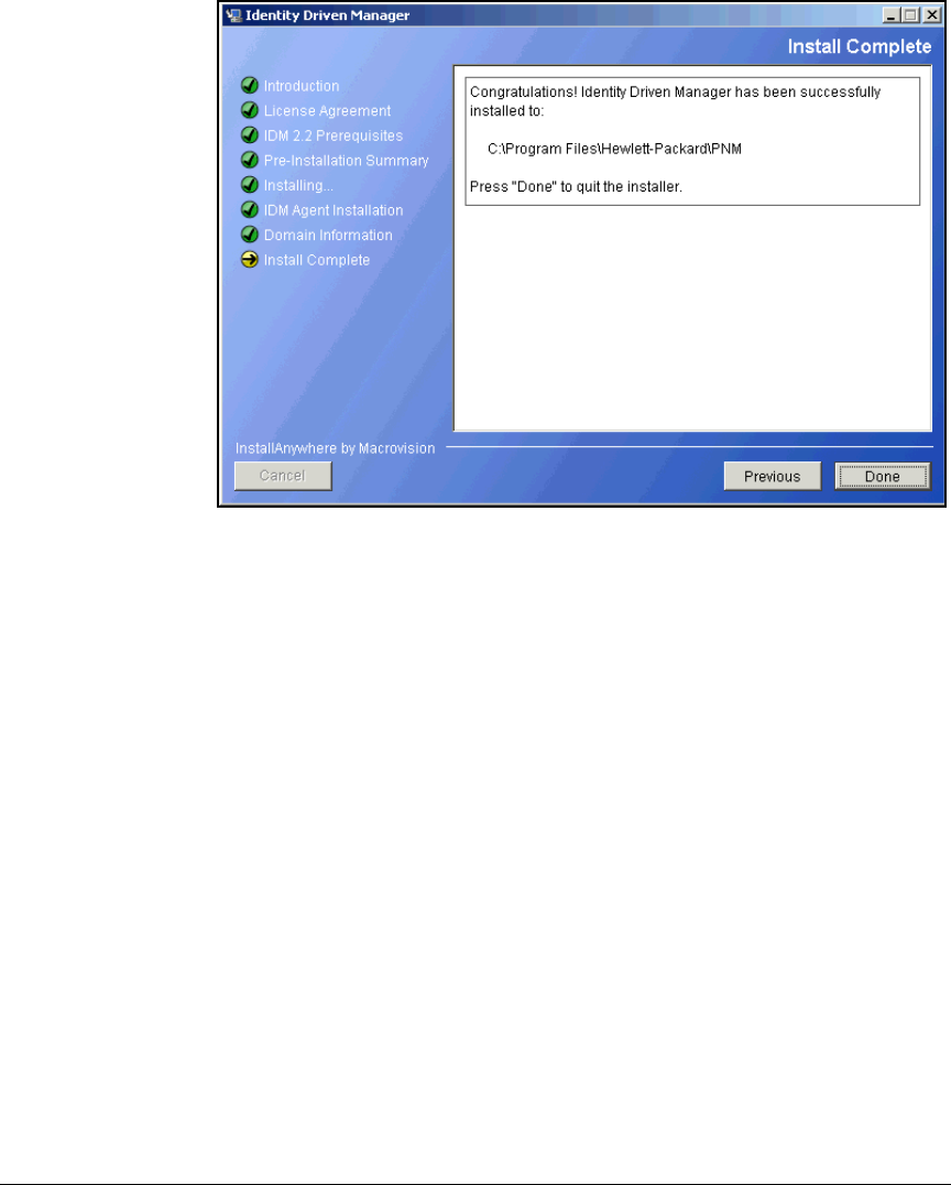
2-228
Implementing 802.1X with ProCurve IDM and Endpoint Integrity
Configuring Network Access Control with PCM+
Figure 2-192. Identity Driven Manager Install Wizard—Install Complete Page
12. Click Done on the Install Complete page.

2-229
Implementing 802.1X with ProCurve IDM and Endpoint Integrity
Configuring Network Access Control with IDM
Configuring Network Access Control
with IDM
IDM enables you to implement granular, user-based network access control
more easily than ever before. In this chapter, you learn how to configure IDM
to:
■Assign rights to successfully authenticated users
■Quarantine endpoints that fail to comply with security standards specified
in NAC policies
■Isolate endpoints that are infected with malware
You must:
1. Add the NAC 800s to the list of devices allowed to access the PCM+/IDM
server.
2. Enable endpoint integrity.
3. Add access policy groups and users.
4. Define resources to be controlled.
5. Create profiles (sets of rights).
6. Configure access policy group rules to assign profiles to users based on
various conditions.
7. Deploy the access policies to the NAC 800s.
Note In the following sections, the server that runs PCM+ with IDM is called the
IDM server.
Add NAC 800s to the Access.txt File
IDM will not add a NAC 800 to its managed devices unless the NAC 800’s IP
address is listed in the server’s access.txt file.
Follow these steps:
1. On the IDM server, open <PCM+ installation folder>\server\config\access.txt.
You chose the installation folder in step 11 on page 2-211. The default
location is: C:\Program Files\Hewlett-Packard\PNM\server\config\access.txt.
Open the file in a text-based editor such as Notepad or Wordpad.
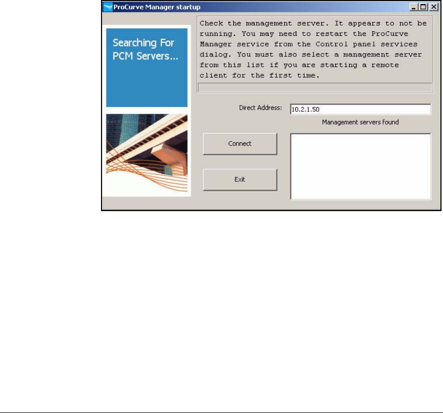
2-230
Implementing 802.1X with ProCurve IDM and Endpoint Integrity
Configuring Network Access Control with IDM
2. Add each NAC 800’s IP address or hostname on its own line. You need to
add only the ESs. In this example:
10.4.4.40
10.4.5.50
3. Save and close the file.
4. Open the PCM+ client, which automatically installed on the PCM+/IDM
server.
The first time that you access the client, you must choose the server.
Figure 2-193. ProCurve Manager startup Window
5. Click the server displayed in the Management servers found box and click
Connect.
Or enter the IP address of the PCM+ server in the Direct Address box.
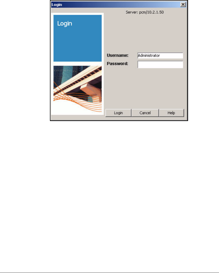
2-231
Implementing 802.1X with ProCurve IDM and Endpoint Integrity
Configuring Network Access Control with IDM
Figure 2-194. ProCurve Manager Login Window
6. In the Login window, enter the Administrator credentials that you set up
in step 17 on page 2-215:
a. Type Administrator for the Username.
b. Type the password that you chose for the Password.
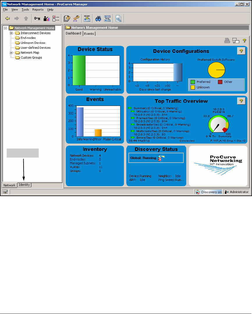
2-232
Implementing 802.1X with ProCurve IDM and Endpoint Integrity
Configuring Network Access Control with IDM
Figure 2-195. ProCurve Manager—Network Management Home Window
7. To open the Identity Management Home window, select the Identity tab at
the bottom of the left pane.
Identity tab

2-233
Implementing 802.1X with ProCurve IDM and Endpoint Integrity
Configuring Network Access Control with IDM
Figure 2-196. ProCurve Manager—Identity Management Home Window
8. In the left pane, expand Realms.
9. Expand your realm (in this example: procurveu.edu).
10. Expand the ProCurve Network Access Controllers folder.
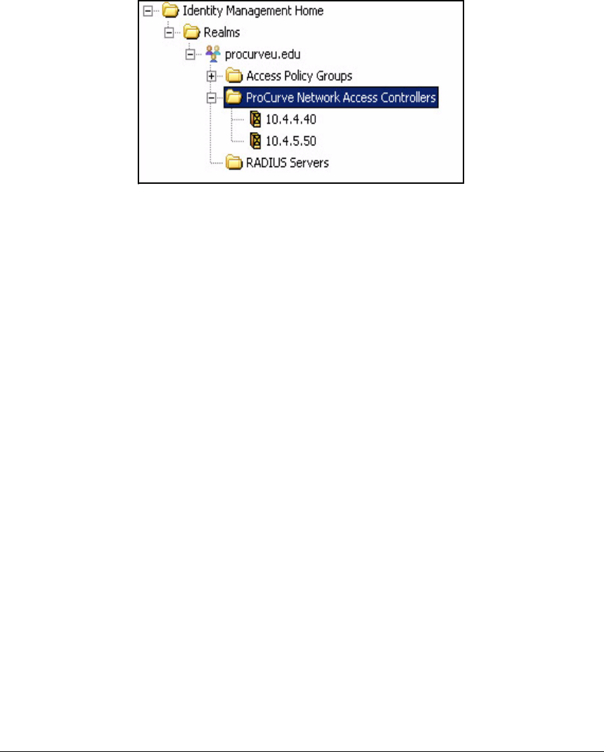
2-234
Implementing 802.1X with ProCurve IDM and Endpoint Integrity
Configuring Network Access Control with IDM
Figure 2-197. PCM+ Console, IDM Interface—Realms > <myrealm> > ProCurve
Network Access Controllers
11. Verify that the NAC 800s appear below.
Enable Endpoint Integrity
A bit later, you will set up access policy rules to quarantine endpoints that do
not comply with your security policies. First you must enable endpoint
integrity in IDM. Follow these steps:
1. You should be in the Identity Management Home window of PCM+.

2-235
Implementing 802.1X with ProCurve IDM and Endpoint Integrity
Configuring Network Access Control with IDM
Figure 2-198. ProCurve Manager—Identity Management Home Window
2. In the Tools menu, click Preferences. (Or click the Preferences button.)
3. Select Identity Management.
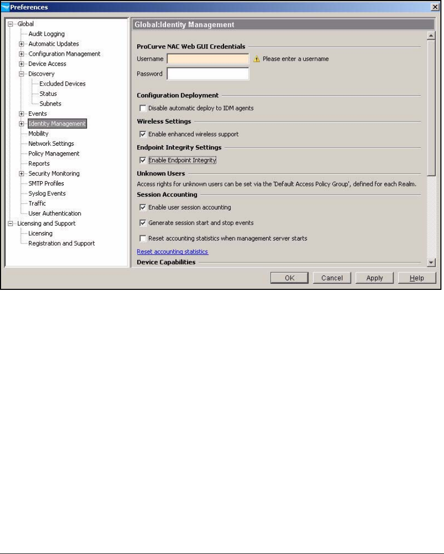
2-236
Implementing 802.1X with ProCurve IDM and Endpoint Integrity
Configuring Network Access Control with IDM
Figure 2-199. ProCurve Manager—Preferences > Global > Identity Management
Window
4. Select the Enable Endpoint Integrity check box.
5. Optionally, specify settings in the ProCurve NAC Web GUI Credentials so that
you can access the MS’s Web browser interface from IDM:
a. For Username, type the administrator username for Web access to the
NAC 800 MS. In this example: admin.
b. For Password, type the associated password. In this example:
procurvenac9.
6. Click OK.
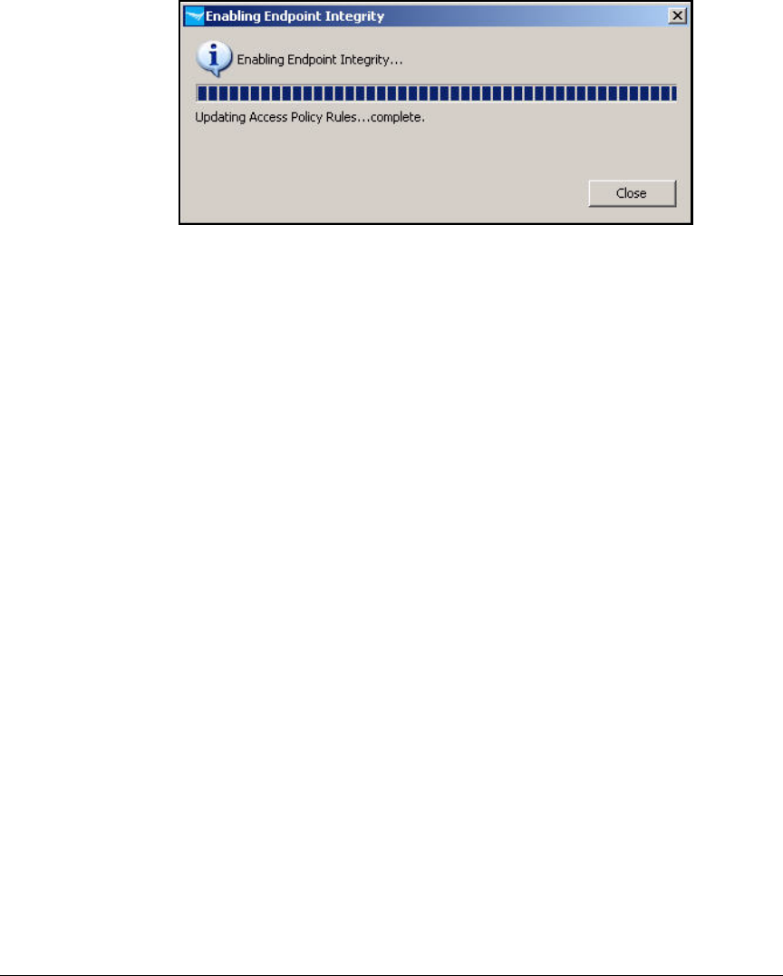
2-237
Implementing 802.1X with ProCurve IDM and Endpoint Integrity
Configuring Network Access Control with IDM
Figure 2-200. ProCurve Manager—Enabling Endpoint Integrity Window
7. Click Close in the Enabling Endpoint Integrity window.
Add Access Policy Groups and Users
In this solution, Active Directory stores credentials. IDM can synchronize with
Active Directory and add domain security groups as access policy groups.
When IDM synchronizes with a group, it automatically adds group members
as users in the corresponding policy group.
The NAC 800s, which are the network’s RADIUS servers, can query Active
Directory to authenticate users; however, the EAP type must be compatible
with NT LAN Manager (NTLM) authentication (for example, PEAP with MS-
CHAPv2). Because in this example you are using EAP-TLS, the NAC 800s
authenticate users against their local databases. You already configured the
NAC 800s for this option (see “Configuring the NAC 800s” on page 2-134). Now
you must configure the local databases using IDM.
Follow these steps to synchronize IDM with Active Directory and add users
to the NAC 800s’ local databases:
1. You should be in the Identity Management Home window of PCM+.
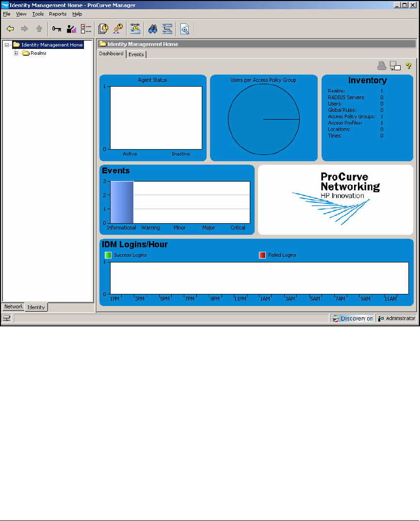
2-238
Implementing 802.1X with ProCurve IDM and Endpoint Integrity
Configuring Network Access Control with IDM
Figure 2-201. ProCurve Manager—Identity Management Home Window
2. In the left pane, right-click your domain’s realm name and select Modify
Realm.
3. For Alias, if not already specified, type the NetBIOS (workgroup) name
of your domain. In this example: PROCURVEU.
Some users may log in with the “procurve.edu” domain name and some
with the “PROCURVEU” NetBIOS name. Setting the alias ensures that
IDM does not create a separate realm for PROCURVEU the first time that
a user logs in with that name.
4. Select the Enable Local Authentication for ProCurve NAC d... check box.
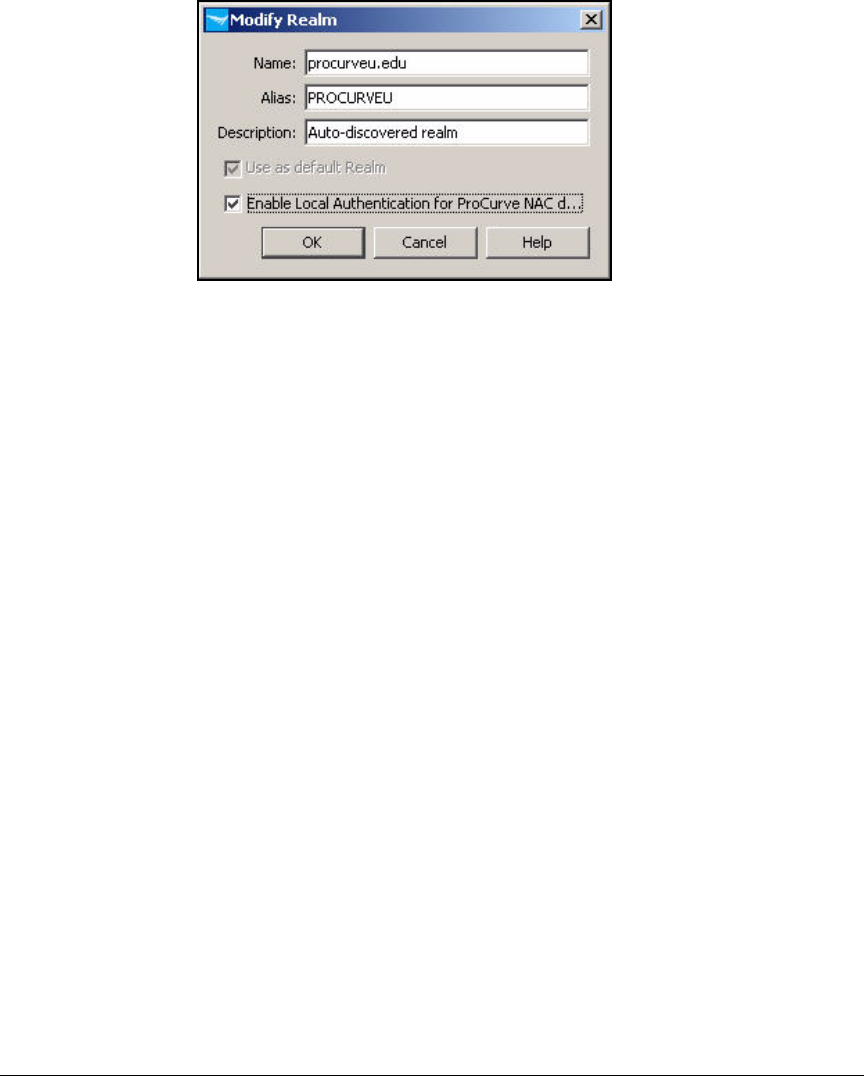
2-239
Implementing 802.1X with ProCurve IDM and Endpoint Integrity
Configuring Network Access Control with IDM
Figure 2-202. ProCurve Manager—Modify Realm Window
5. Click OK.
6. Verify the your NAC 800s are now using their local databases. In the left
pane, expand your realm and click ProCurve Network Access Controllers.
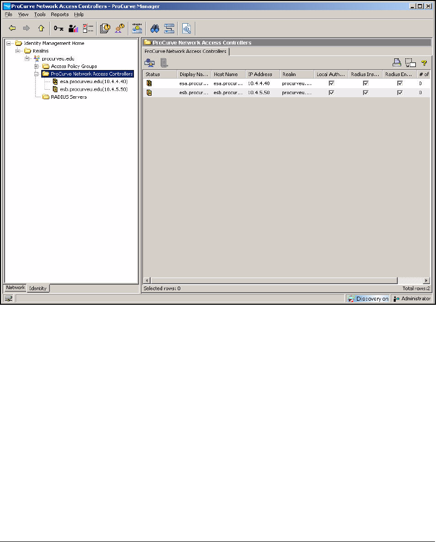
2-240
Implementing 802.1X with ProCurve IDM and Endpoint Integrity
Configuring Network Access Control with IDM
Figure 2-203. ProCurve Manager—ProCurve Network Access Controllers Window
7. In the next steps, you configure IDM to synchronize with Active Directory,
which adds your domain’s users and groups to IDM. In the Tools menu,
click Preferences. (Or click the Preferences button.)
8. Expand Identity Management and select User Directory Settings.

2-241
Implementing 802.1X with ProCurve IDM and Endpoint Integrity
Configuring Network Access Control with IDM
Figure 2-204. ProCurve Manager—Preferences > Global > Identity Management >
User Directory
9. Select the Enable automatic Active Directory synchronization check box.
10. In the Username and Password boxes, type credentials for an administrator
of the domain controller server. In this example: Administrator and
ProCurve0.
11. For Domain box, type your domain name. In this example: procurveu.edu.
12. Click Apply. Check the AD Status (above the OK button) for error messages.
If IDM successfully connects to the domain controller, you should see a
message such as: Listening for updates.
13. Click Add or Remove Groups.
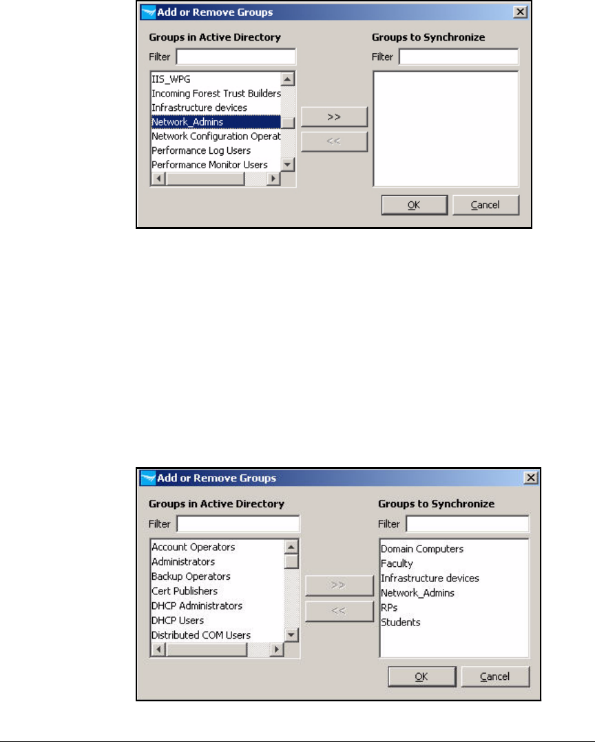
2-242
Implementing 802.1X with ProCurve IDM and Endpoint Integrity
Configuring Network Access Control with IDM
Figure 2-205. ProCurve Manager—Add or Remove Groups Window
14. The Add or Remove Groups window displays all Active Directory groups.
Select the name of a group and click the >> button so that IDM will
synchronize with it. Select all the groups that you set up for access rights.
In this example, these groups are:
• Network_Admins
• Faculty
•Students
•RPs
• Infrastructure devices
Figure 2-206. PCM+ Console—Add or Remove Groups Window
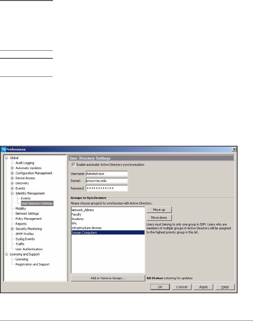
2-243
Implementing 802.1X with ProCurve IDM and Endpoint Integrity
Configuring Network Access Control with IDM
Note By default in many Windows systems, an endpoint can log in as a computer
before the user logs in. Then, when the user logs in, the user reauthenti-
cates and that authentication takes precedence. To allow computers to
log in, you can add Domain Computers to the Groups to Synchronize area.
It is important that the endpoint be set up to use computer with user
reauthentication. Otherwise, the user will not be controlled properly.
Note Although a user can be a member of multiple Active Directory groups, he
or she should be a member of only one group that is synchronized in IDM.
15. Click OK to save the settings and close the window.
16. If any users belong to more than one group, you must decide which group
will take precedence in IDM, because each user can belong to only one
group in IDM. In this example, the user groups are mutually exclusive, but
if you needed to move a group to a different position, you would select
the group name and click the Move up or Move down button to change its
position.
Figure 2-207. ProCurve Manager—Preferences > Identity Management > User
Directory Settings
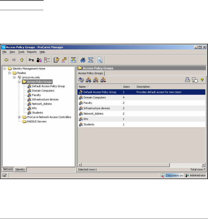
2-244
Implementing 802.1X with ProCurve IDM and Endpoint Integrity
Configuring Network Access Control with IDM
17. Click OK.
18. A window is displayed, telling you that the groups are being synchronized.
Click OK.
Each group is added to IDM as an access policy group. All users that
belong to the selected groups are imported with the current Windows user
login credentials.
Note IDM can import about 8 to 10 users per second.
19. In the left pane, select Access Policy Groups. The Users column now shows
how many users from Active Directory were imported into each group.
20. Click OK.
Figure 2-208. ProCurve Manager—Access Policy Groups
21. Because the NAC 800’s local database requires a password for every user
(even when they authenticate with certificates), you must add these
passwords if not present.
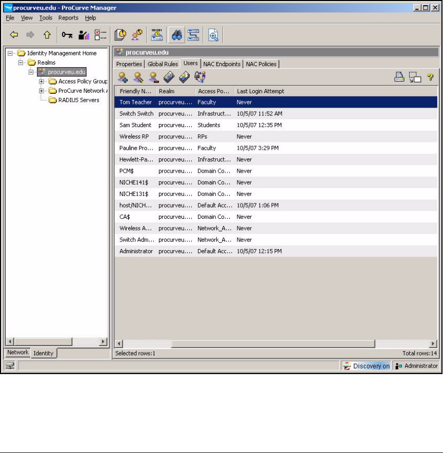
2-245
Implementing 802.1X with ProCurve IDM and Endpoint Integrity
Configuring Network Access Control with IDM
In this example, you already set up passwords for users in Active
Directory.
If you had not, you would follow these steps to add a password:
a. In the left pane, expand Access Policy Groups.
b. Select the name of the user’s group.
c. Click the Users tab.
Figure 2-209. ProCurve Manager—Access Policy Groups
d. Right-click the user’s name in the right pane and click Modify User.
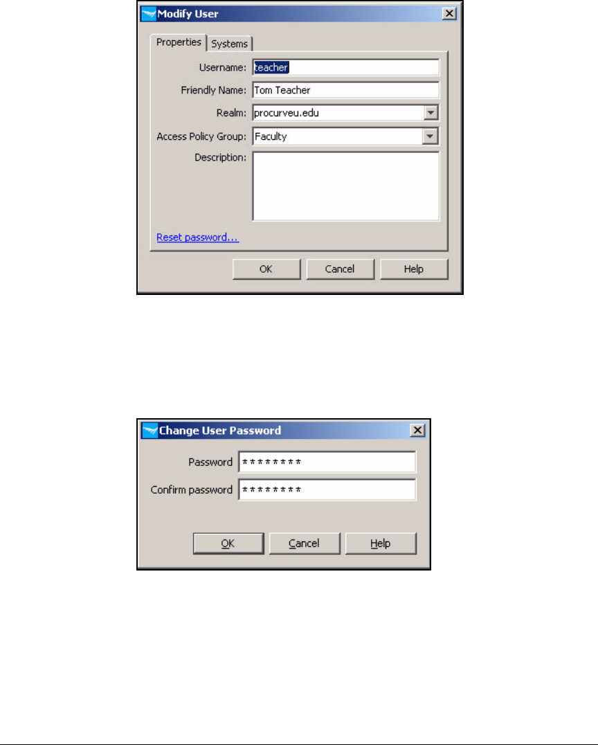
2-246
Implementing 802.1X with ProCurve IDM and Endpoint Integrity
Configuring Network Access Control with IDM
Figure 2-210. ProCurve Manager—Modify User Window
e. Click Reset password.
f. Type a string for the Password. Then retype it in the Confirm password
box.
Figure 2-211. ProCurve Manager—Change User Password Window
g. Click OK and then OK again.

2-247
Implementing 802.1X with ProCurve IDM and Endpoint Integrity
Configuring Network Access Control with IDM
Define Resources
You must define every resource that you want to control. These can include:
■A single device—an IP address
■Applications (such as DHCP, DNS, and HTTP)—TCP or UDP ports
(or other protocols)
■Applications on a single device—an IP address and TCP or UDP ports
■A VLAN—a subnet network address
Table 2-14 shows resources for the example network.
Table 2-14. PCU Resources
To define resources, follow these steps:
1. In the ProCurve Manager console, click the Identity tab.
Resource IP Address Protocol Port or Ports
NAC 800 A 10.4.4.40 IP Any
NAC 800 B 10.4.5.50 IP Any
DHCP Any UDP 67
DNS (UDP) Any UDP 53
DNS (TCP) Any TCP 53
Email 10.4.6.40 TCP 25, 143, 110
Other network
services
10.4.0.0/16 IP Any
Faculty databases 10.5.0.0/16 IP Any
Management
VLAN
10.2.0.0/16 IP Any
Faculty VLAN 10.8.0.0/16 IP Any
Students VLAN 10.10.0.0/16 IP Any
Private network 10.0.0.0/8 IP Any
Internet Any TCP 21, 80, 443

2-248
Implementing 802.1X with ProCurve IDM and Endpoint Integrity
Configuring Network Access Control with IDM
Figure 2-212. ProCurve Manager—Identity Management Home Window
2. Select your realm. In this example: procurveu.edu.
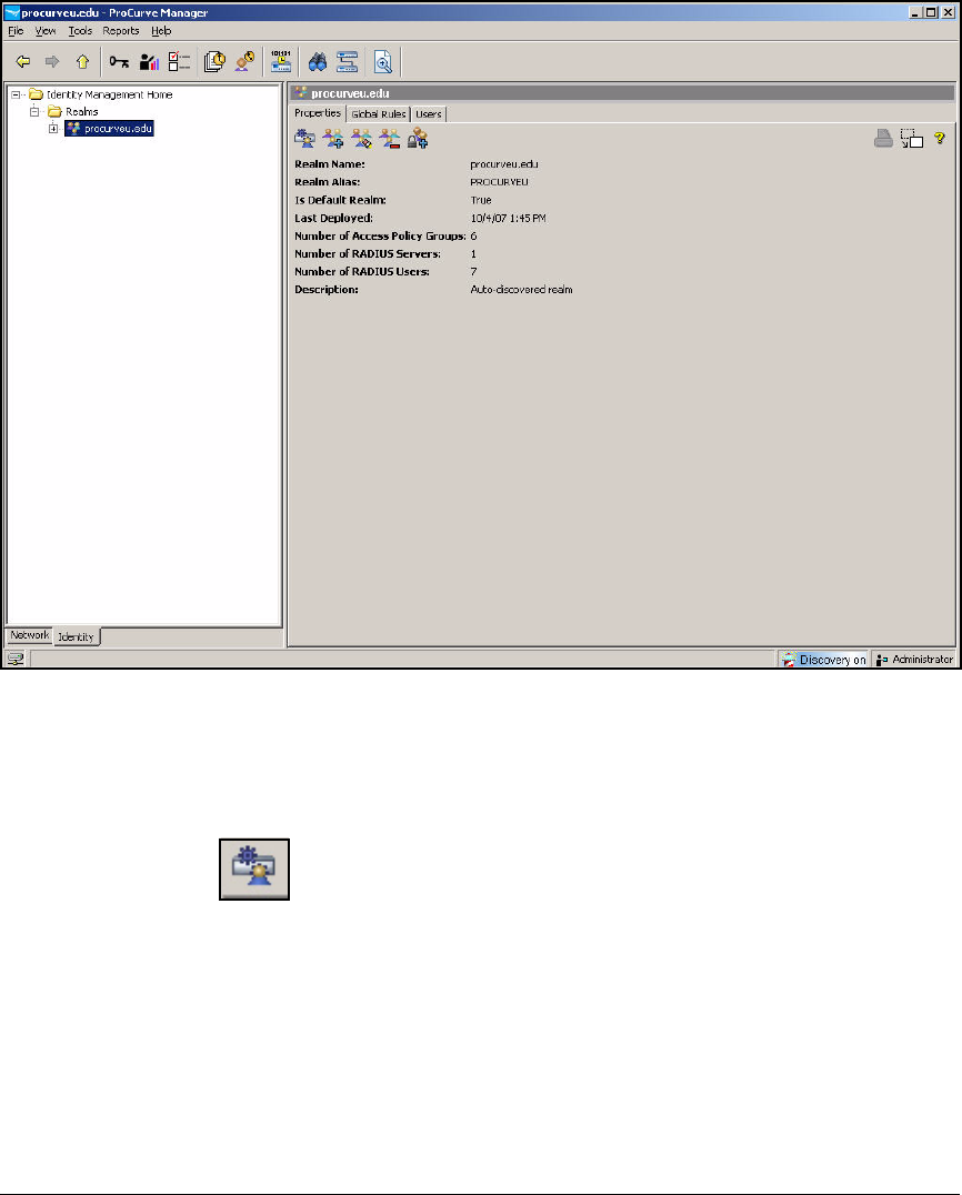
2-249
Implementing 802.1X with ProCurve IDM and Endpoint Integrity
Configuring Network Access Control with IDM
Figure 2-213. ProCurve Manager—<my realm>
3. In the right pane, make sure that the Properties tab is selected. Click the
Configure Identity Management button.
Figure 2-214. Identity Management—Configure Identity Management Button
4. Select Network Resources in the left pane of the Identity Management
Configuration window.
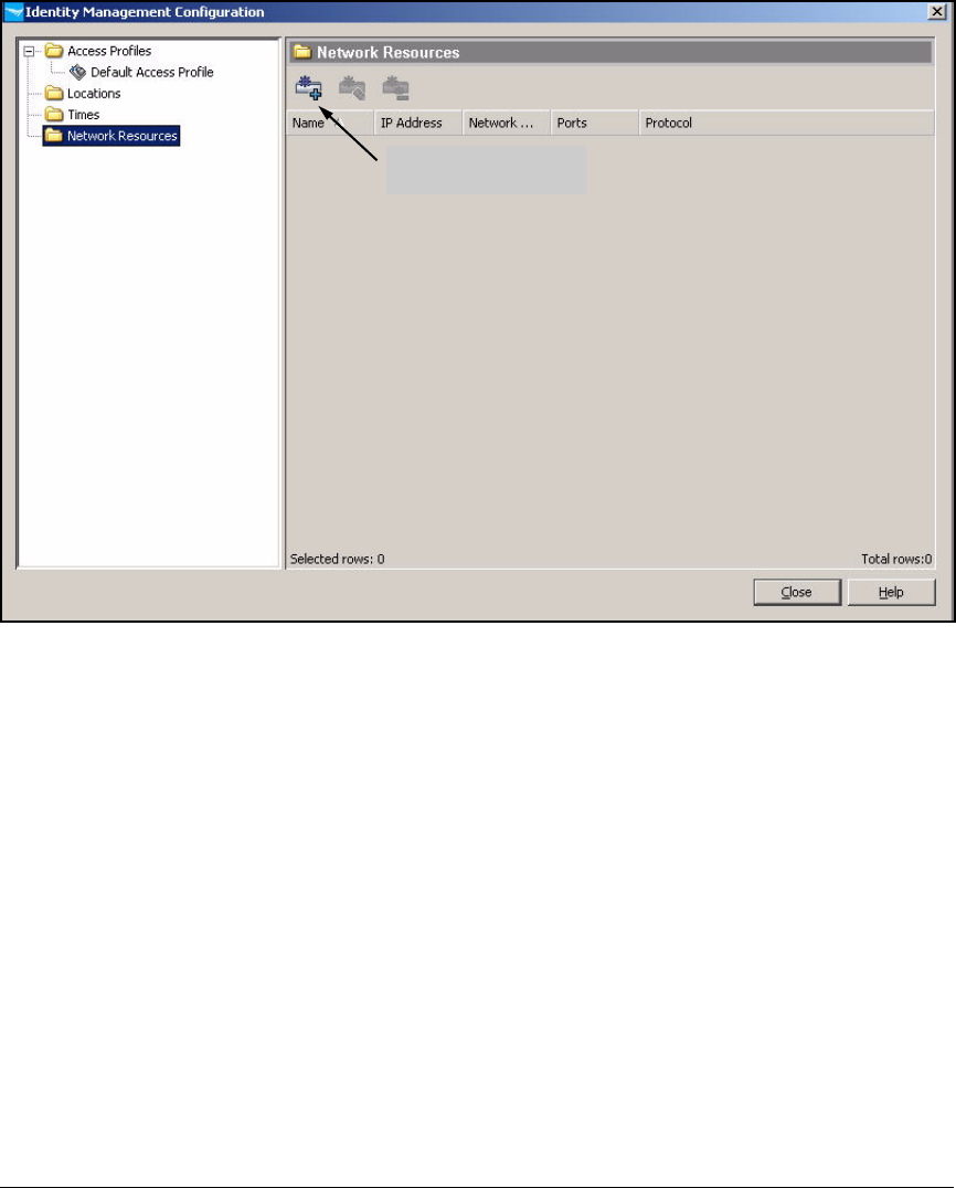
2-250
Implementing 802.1X with ProCurve IDM and Endpoint Integrity
Configuring Network Access Control with IDM
Figure 2-215. Identity Management Configuration Window
5. Click the Create a new Network Resource button in the right pane.
Create a new Network
Resource button
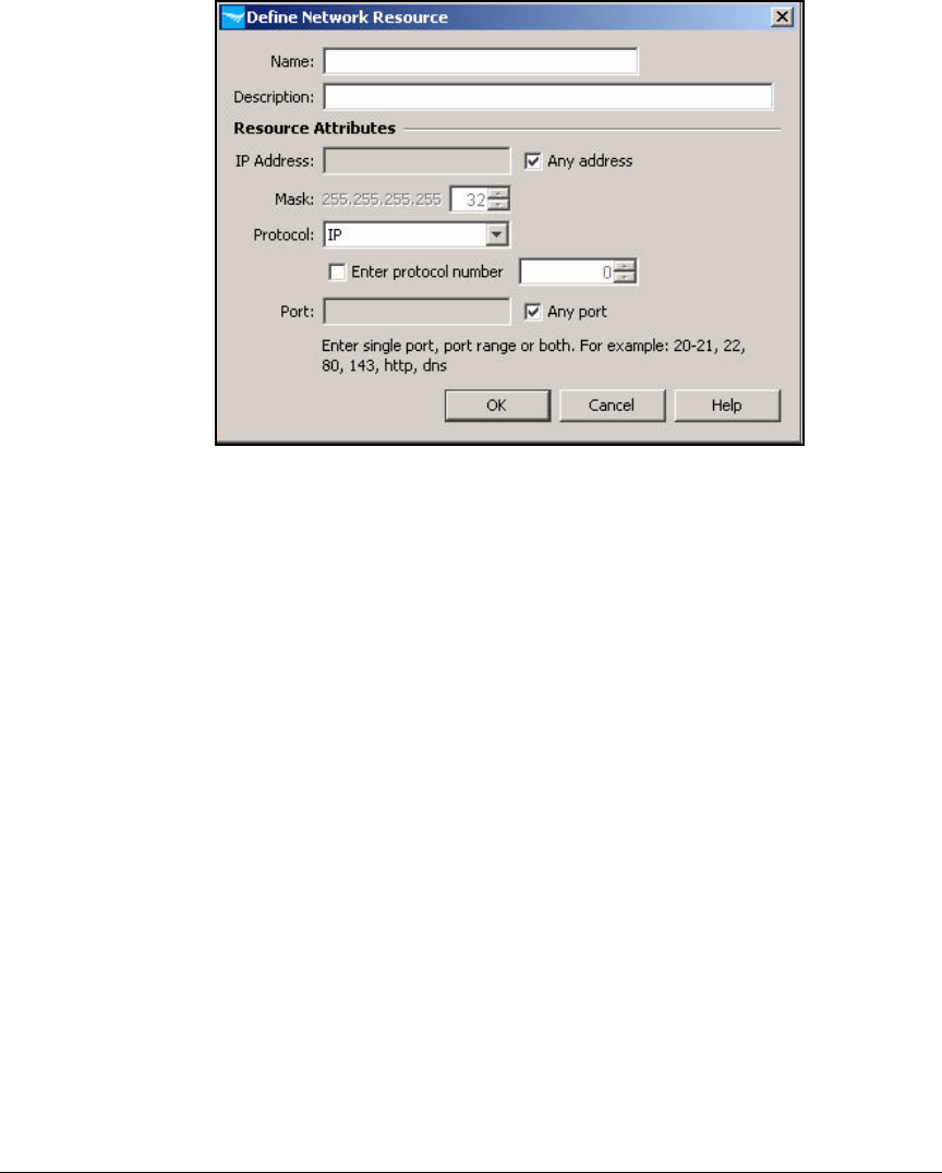
2-251
Implementing 802.1X with ProCurve IDM and Endpoint Integrity
Configuring Network Access Control with IDM
Figure 2-216. ProCurve Manager—Define Network Resource Window
6. Follow these steps to set up a resource that is a single device:
a. In the Define Network Resource window, type a string in the Name box
to identify the device (in this example, NAC 800 A).
b. In the Description box, type a description, if desired.
c. Clear the Any address check box.
d. For the IP Address, type the device’s IP address (in this example,
10.4.4.40).
e. For the Mask, keep the default: 32.
f. From the Protocol list, select the protocol (IP is the default and allows
all IP traffic). In this example, keep IP.
g. Set up the ports:
i. To allow any traffic to this device, select the Any port check box.
In this example, you should select the Any port check box. Quar-
antined and unknown devices need to reach the NAC 800 to be
tested.
ii. If you want to restrict access to one or several single applications,
clear the Any port check box and type the appropriate values for
the Port.
h. Click OK.
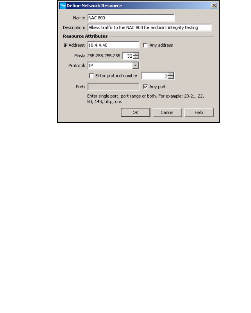
2-252
Implementing 802.1X with ProCurve IDM and Endpoint Integrity
Configuring Network Access Control with IDM
Figure 2-217. ProCurve Manager—Define Network Resource Window—
NAC 800
7. Follow these steps to set up a resource that is an application type such
as DHCP:
a. In the Define Network Resource window, type a string in the Name box
to identify the application or applications. In this example: DHCP.
b. In the Description box, type a description, if desired.
c. Select the Any address check box.
If desired, you could clear the check box and restrict users to access-
ing this application on a particular device or subnet. Type the appro-
priate IP address for the IP Address and Mask.
d. From the Protocol list, select the protocol. In this example, UDP.
e. Clear the Any port check box and type the appropriate values for the
Port. You can type one port, ranges of ports, or multiple, non-consec-
utive ports, separated by a comma. In this example: 67.
f. Click OK.

2-253
Implementing 802.1X with ProCurve IDM and Endpoint Integrity
Configuring Network Access Control with IDM
Figure 2-218. ProCurve Manager—Define Network Resource Window—
DHCP
8. To set up a resource that is an entire VLAN, follow these steps:
a. In the Define Network Resource window, type a string in the Name box
to identify the VLAN (in this example, Faculty databases).
b. In the Description box, type a description, if desired.
c. Clear the Any address check box.
d. For the IP Address, type the network address of the subnet associated
with the VLAN (in this example, 10.5.0.0).
e. For the Mask, type or select the prefix length for the subnet (in this
example, 16).
f. Leave IP for the Protocol.
g. Click OK.
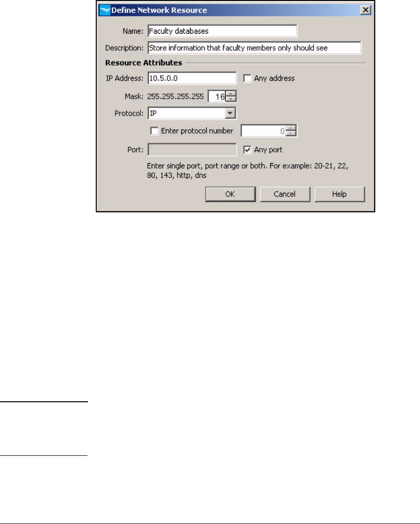
2-254
Implementing 802.1X with ProCurve IDM and Endpoint Integrity
Configuring Network Access Control with IDM
Figure 2-219. ProCurve Manager—Define Network Resource Window—
Faculty databases
9. Repeat step 5, 6, 7, or 8 to set up each resource for your network.
10. When you are finished, click Close.
Create Access Profiles
A profile defines a set of rights including:
■VLAN assignment
■Quality-of-service (QoS) settings
■Rate limit
■Resources allowed and resources denied
Note For each profile, you can also choose whether, by default, all resources not
specifically defined are denied or whether they are allowed. This is called the
default access option. In this example, you will allow specific resources and
deny all others; the default access option is deny.

2-255
Implementing 802.1X with ProCurve IDM and Endpoint Integrity
Configuring Network Access Control with IDM
While you can create several profiles for a single group of users—and then
assign those profiles under various circumstances—in this example, each user
group requires at most three:
■One profile for normal access
■One profile for quarantined access
■One profile for access if the endpoint is infected
Quarantined endpoints and infected endpoints can send DHCP traffic, as well
as traffic to the NAC 800. They are allowed no other traffic. However, the NAC
800 can act as a proxy for the endpoints, allowing them access to remediation
resources.
Note The quarantined and infected endpoints receive access to the same, very
limited, resources. However, they are placed in separate VLANs so that
malware on the infected endpoints does not spread to the potentially vulner-
able, but not-yet-infected endpoints.
The example profiles that you will learn how to create in this section are
displayed in Table 2-15.

2-256
Implementing 802.1X with ProCurve IDM and Endpoint Integrity
Configuring Network Access Control with IDM
Table 2-15. Network Resource Assignments per Access Profile
Access Profile VLAN ID QoS Ingress
Rate-
Limit
Allowed Resources Denied Resources Default
Access
Network_Admins 2 Don’t
override
Don’t
override
All None Allow
Faculty 8 Don’t
override
Don’t
override
•DHCP
• DNS (TCP)
•DNS (UDP)
• Email
• Other network services
• Faculty VLAN
• Faculty databases
• Internet
Private network Deny
Students 10 Don’t
override
Don’t
override
•DHCP
• DNS (TCP)
•DNS (UDP)
• Email
• Other network services
• Students VLAN
• Internet
Private network Deny
Quarantine_Faculty 32 Don’t
override
1000 Kbps • DHCP
• NAC 800 A
• NAC 800 B
None Deny
Infected_Faculty 33 Don’t
override
1000 Kbps • DHCP
• NAC 800 A
• NAC 800 B
None Deny
Quarantine_Students 34 Don’t
override
1000 Kbps • DHCP
• NAC 800 A
• NAC 800 B
None Deny
Infected_Students 35 Don’t
override
1000 Kbps • DHCP
• NAC 800 A
• NAC 800 B
None Deny
RPs 2100 Don’t
override
Don’t
override
All All Allow
Domain Computers (if
desired)
Don’t
override
Don’t
override
Don’t
override
•DHCP
• DNS (TCP)
•DNS (UDP)
• Other network services
• Student VLAN
None Deny
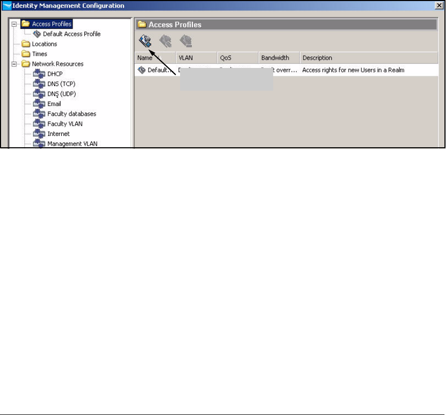
2-257
Implementing 802.1X with ProCurve IDM and Endpoint Integrity
Configuring Network Access Control with IDM
Follow these steps to create the profiles:
1. You should be at the Identity Management Home window. (In the ProCurve
Manager console, click the Identity tab.
2. Expand Realms.
3. Click your realm (in this example: procurveu.edu) in the left pane.
4. At the Properties tab in the right pane, click the Configure Identity Manage-
ment button.
5. Select the Access Profiles folder.
Figure 2-220. Identity Management Configuration—Access Profiles
6. Click the Create a new Access Profile button.
Create a new Access
Profile button
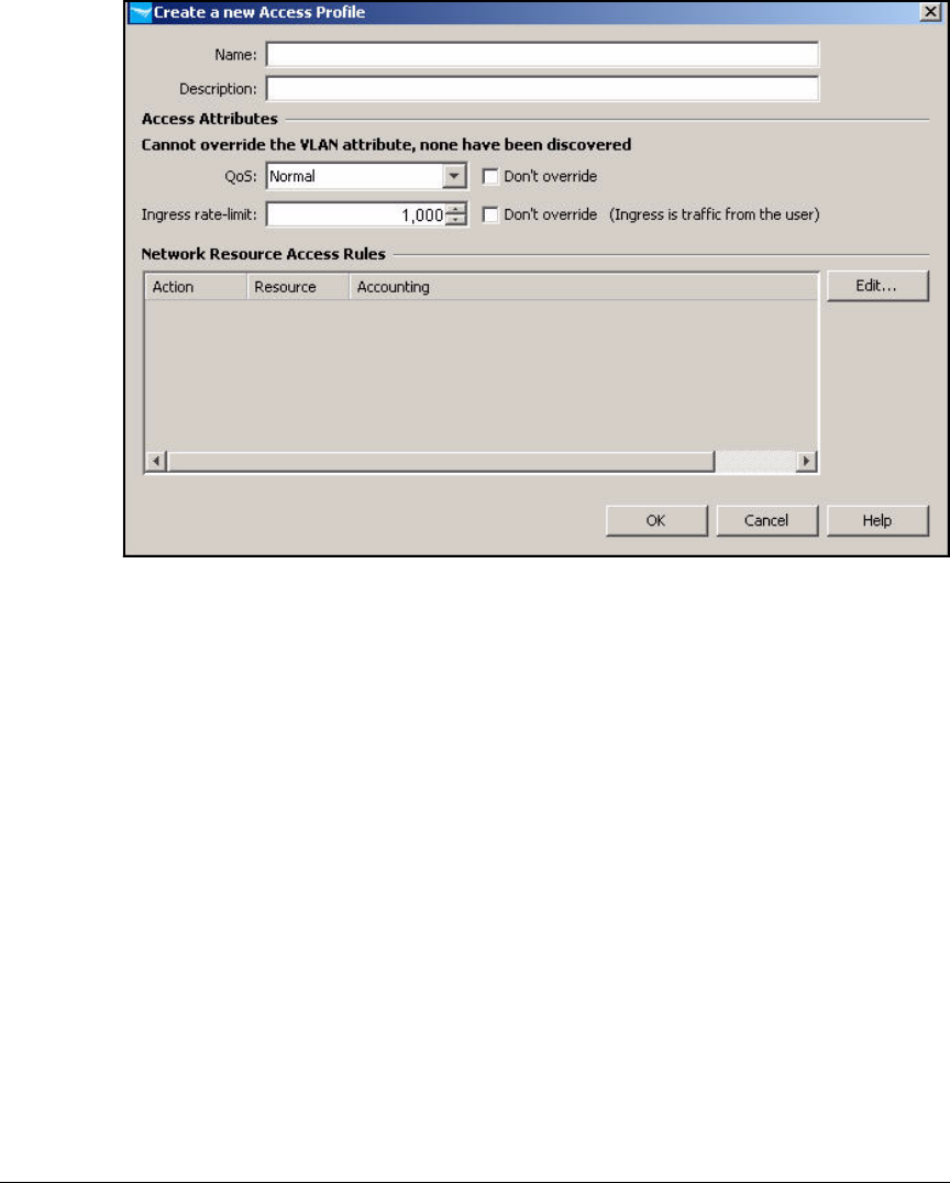
2-258
Implementing 802.1X with ProCurve IDM and Endpoint Integrity
Configuring Network Access Control with IDM
Figure 2-221. ProCurve Manager—Create a new Access Profile
7. In the Name box, type the name of the access profile. In this example, you
are creating the profile for the Faculty group under normal circumstances.
You name the profile Faculty.
8. In the Description box, type a description, if desired.
9. From the VLAN list, select the proper VLAN (in this example, 8).
10. For the QoS, either select the QoS level from the box or select the Don’t
override check box.
11. For the Ingress rate-limit, either type the rate limit in Kbps or select the
Don’t override check box.
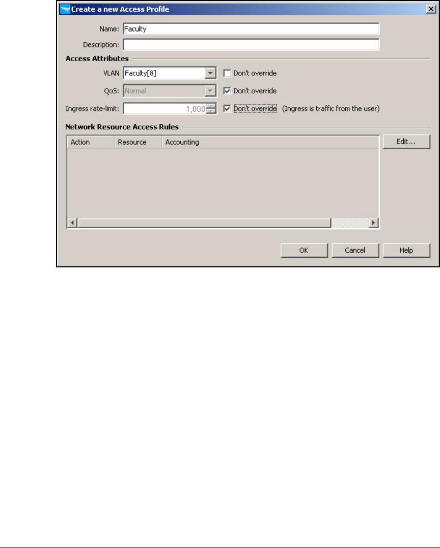
2-259
Implementing 802.1X with ProCurve IDM and Endpoint Integrity
Configuring Network Access Control with IDM
Figure 2-222. ProCurve Manager—Create a new Access Profile
12. In the Network Resource Access Rules area, click Edit.

2-260
Implementing 802.1X with ProCurve IDM and Endpoint Integrity
Configuring Network Access Control with IDM
Figure 2-223. Edit Network Resource Assignment Wizard—Welcome Page
13. In the Welcome to the Network Resource Assignment Wizard page, click Next.
14. From the Available Resources pane, select a resource and click the >>
button. Repeat for each network resource that you want to assign to this
profile.
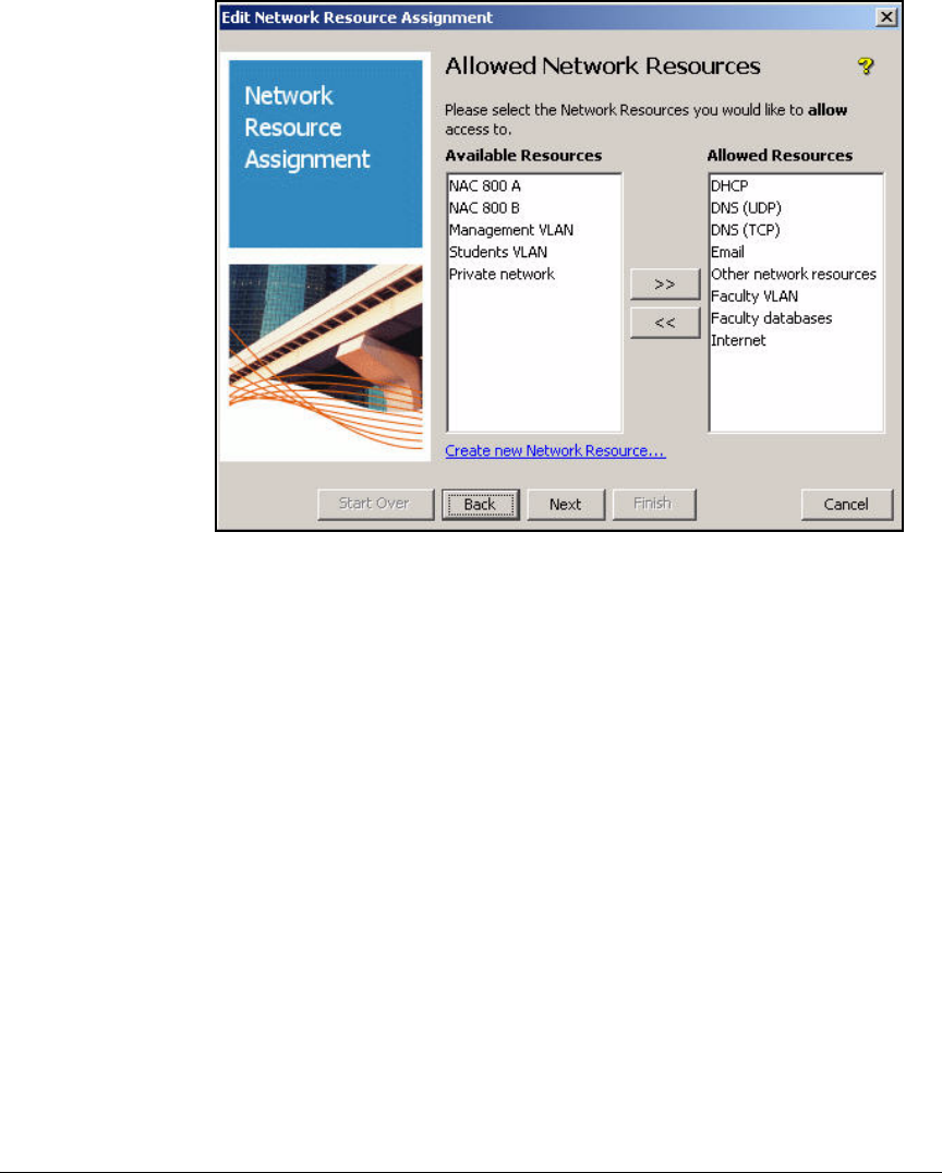
2-261
Implementing 802.1X with ProCurve IDM and Endpoint Integrity
Configuring Network Access Control with IDM
Figure 2-224. Edit Network Resource Assignment Wizard—Allowed Network
Resources Page
15. When all of the desired resources are in the Allowed Resources pane,
click Next.
16. If you would like to deny this group access to any of the remaining
resources, repeat the previous step for resources that you want to deny.
You might need to deny resources when:
• A resource is a subset of an allowed resource
For example, you can grant users access to an entire VLAN, but deny
them access to a single server in that VLAN.
In this example, you have granted users access to the Internet by
allowing them to send any FTP, HTTP, or HTTPS traffic. Now you will
deny access to a subset of that traffic: the entire private network.
Users, of course, can access the private resources to which you have
specifically granted them rights.
• You use the strategy of allowing all resources, by default

2-262
Implementing 802.1X with ProCurve IDM and Endpoint Integrity
Configuring Network Access Control with IDM
Figure 2-225. Edit Network Resource Assignment Wizard—Denied Network
Resources Page
17. When you are finished, click Next.
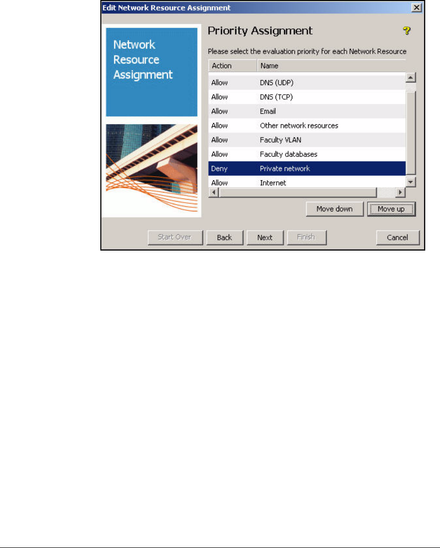
2-263
Implementing 802.1X with ProCurve IDM and Endpoint Integrity
Configuring Network Access Control with IDM
Figure 2-226. Edit Network Resource Assignment Wizard—Priority
Assignment Page
18. If you would like to assign any of the allow or deny actions a priority, select
the resource whose order you would like to modify. Then click either the
Move down or Move up button until it is in the desired order.
You only need to complete this step if the defined resources include
overlapping resources. Generally, the more-specific rule should have a
higher priority.
In this example, you must place the rules that allow specific private
resources first. Next is the rule that denies access to the rest of the private
network. Place the rule that allows access to the Internet at the end of
the list.
19. When you are finished, click Next.
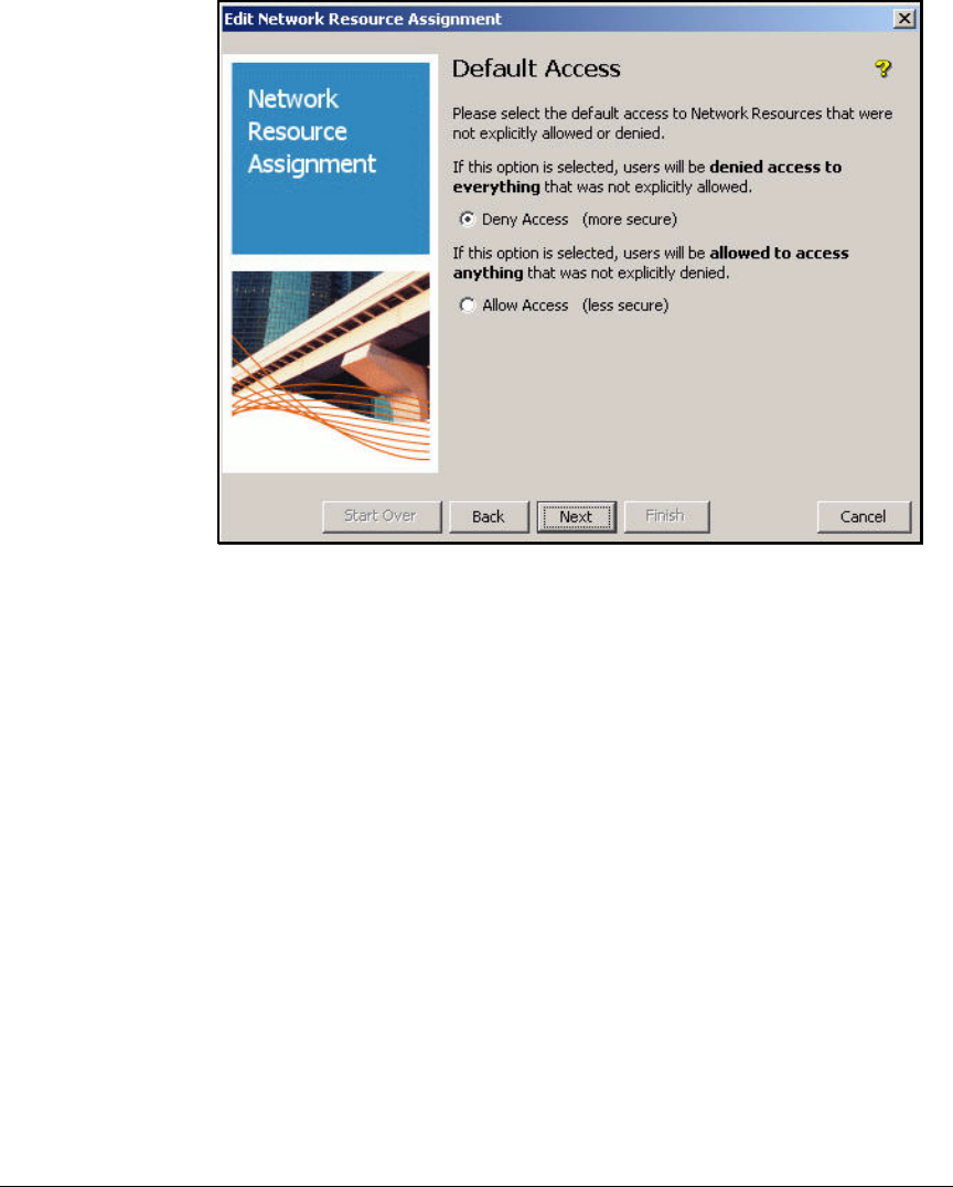
2-264
Implementing 802.1X with ProCurve IDM and Endpoint Integrity
Configuring Network Access Control with IDM
Figure 2-227. Edit Network Resource Assignment Wizard—Default Access Page
20. In the Default Access window, select Deny Access or Allow Access for any
resources that were not explicitly allowed or denied. The more secure
option is Deny Access.
21. Click Next.
22. In the Resource Accounting window, select the check box next to resources
for which you would like to enable accounting. Typically, you should
select only the check boxes for denied resources.
Logging every time traffic is allowed quickly fills logs with relatively
unimportant information.

2-265
Implementing 802.1X with ProCurve IDM and Endpoint Integrity
Configuring Network Access Control with IDM
Figure 2-228. Edit Network Resource Assignment Wizard—Resource
Accounting Page
23. Click Next.
24. Click Finish.

2-266
Implementing 802.1X with ProCurve IDM and Endpoint Integrity
Configuring Network Access Control with IDM
Figure 2-229. Edit Network Resource Assignment Wizard—Create a new Access
Profile Window
25. Click OK in the Create a new Access Profile window.
26. Repeat steps 6 through 24 for each profile that you designed for your
network.
Figure 2-230 shows the completed profiles planned in Table 2-15.
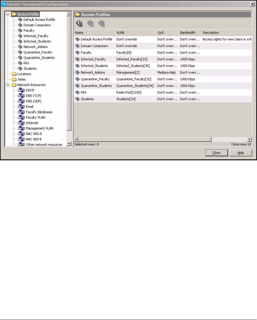
2-267
Implementing 802.1X with ProCurve IDM and Endpoint Integrity
Configuring Network Access Control with IDM
Figure 2-230. Identity Management Configuration > Access Profiles
Configure Access Policy Groups
An access policy group rule specifies the profile that an authenticated user in
that group receives, given a particular set of criteria, including:
■Time
■Location
■System (whether the endpoint is one that has been marked as belonging
to the user)
■WLAN
■Endpoint integrity status
In this example, network access will not be restricted based on location or
time: users are quite mobile, many students live on campus and access the
network at any time, and many faculty members keep irregular hours. In
addition, users sometimes log in on university equipment and sometimes on
their own equipment. Their access will not be affected by the system they use

2-268
Implementing 802.1X with ProCurve IDM and Endpoint Integrity
Configuring Network Access Control with IDM
to log in. Finally, users will receive the same type of access whether they
connect via Ethernet or wirelessly. (The WLAN uses WPA encryption, so this
policy does not open a security vulnerability).
In summary, the example network controls network access based on user
group and endpoint integrity status. Table 2-16 shows the example rules.
Table 2-16. Access Policy Group Rules
Note See the ProCurve Identity Driven Manager User’s Guide for more informa-
tion on settings up rules—for example, rules based on access time and
location.
Follow these steps to configure access policy group rules:
1. In the ProCurve Management console, click the Identity tab.
2. Expand your realm.
3. Expand Access Policy Groups in the left pane.
Group Endpoint
Integrity
Profile
Network_Admins Pass Network_Admins
Unknown Quarantine_Faculty
Fail Quarantine_Faculty
Infected Infected_Faculty
Faculty Pass Faculty
Unknown Quarantine_Faculty
Fail Quarantine_Faculty
Infected Infected_Faculty
Students Pass Students
Unknown Quarantine_Students
Fail Quarantine_Students
Infected Infected_Students
RPs Any RPs
Infrastructure
devices
Any Default access profile
Domain
Computers (if
desired)
Any Domain Computers
profile
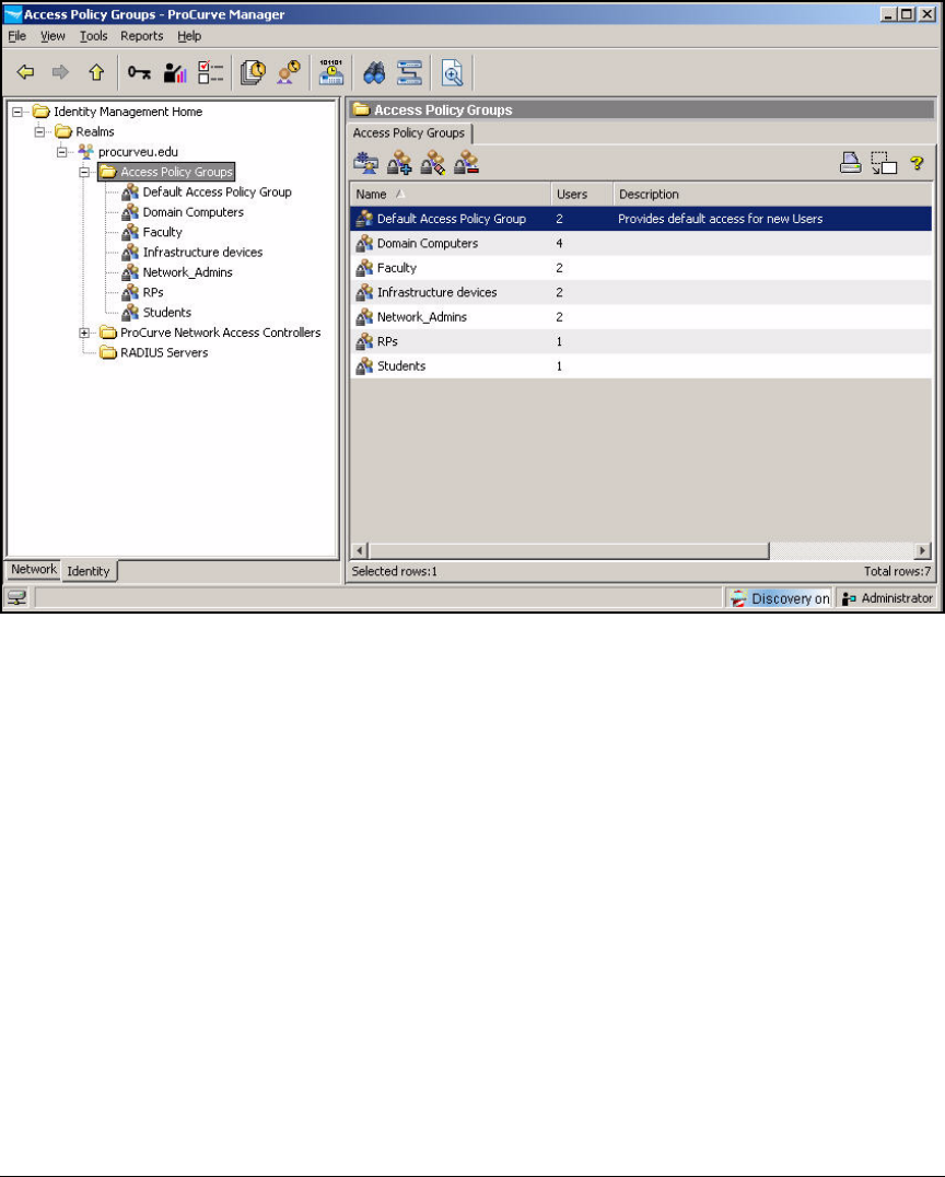
2-269
Implementing 802.1X with ProCurve IDM and Endpoint Integrity
Configuring Network Access Control with IDM
Figure 2-231. ProCurve Manager—Access Policy Groups
4. Under Access Policy Groups, the groups synchronized with Active Direc-
tory are displayed. Select the group for which you want to set up access
policy rules.
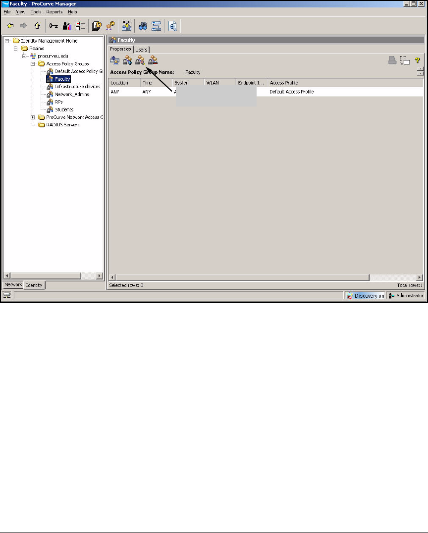
2-270
Implementing 802.1X with ProCurve IDM and Endpoint Integrity
Configuring Network Access Control with IDM
Figure 2-232. ProCurve Manager—<my access policy group>
5. Click the Modify Access Policy Group button.
6. By default, the access policy group includes a rule that grants default
access under all conditions. You must change this rule to specify the
access profile that you set up for this group. Select the rule and click Edit.
7. Set your criteria for users in this group that pass endpoint integrity tests:
a. For the Location, select a location or ANY.
b. For the Time, select a time or ANY.
c. For the System, select OWN (the endpoint associated with the user)
or ANY (any endpoint).
d. For the Endpoint Integrity, select PASS.
e. For the Access Profile, select the access profile that you created for
this group. For example, if you are configuring the Faculty access
policy group, select the Faculty access profile.
Modify Access
Policy Group button
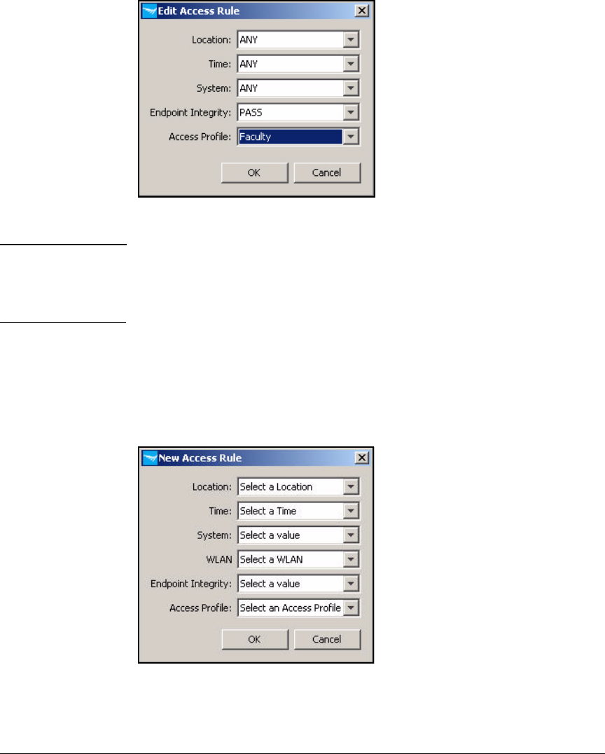
2-271
Implementing 802.1X with ProCurve IDM and Endpoint Integrity
Configuring Network Access Control with IDM
Figure 2-233. ProCurve Manager—Edit Access Rule Window
Note In this example, criteria such as location and time do not affect access. If you
want to designate a location or time other than ANY, you must configure that
location or time prior to editing the access rules. Refer to the ProCurve
Identity Driven Manager User’s Guide for more instructions.
8. Click OK.
9. Now, add rules for users with endpoints that have not passed endpoint
integrity tests and must be quarantined.
10. Click New.
Figure 2-234. ProCurve Manager—New Access Rule Window
11. Set the Location, Time, System, and WLAN values to ANY.
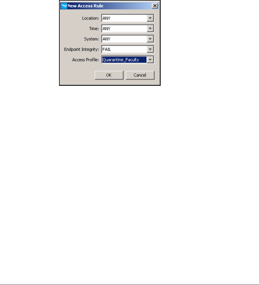
2-272
Implementing 802.1X with ProCurve IDM and Endpoint Integrity
Configuring Network Access Control with IDM
12. For Endpoint Integrity, select FAIL.
13. For the Access Profile, select the access profile that you created for
quarantined users in this group. For example, if you are configuring the
Faculty access policy group, select the Quarantine_Faculty access profile.
Figure 2-235. ProCurve Manager—New Access Rule Window
14. Click OK.
15. Repeat steps 10 through 13 for endpoints with the Unknown endpoint
integrity status, assigning them to the appropriate quarantine profile.
In this example, unknown endpoints receive the same profile as failed
endpoints, but you could create a different profile for these endpoints if
you wanted.
16. Repeat steps 10 through 13 for endpoints with the Infected endpoint
integrity status. However, this time choose the profile that you created for
infected endpoints—in this example, Infected_Faculty.
Figure 2-236 shows the final rules for the Faculty access policy group.
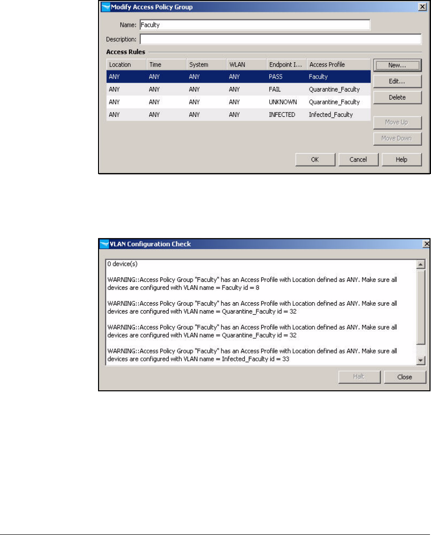
2-273
Implementing 802.1X with ProCurve IDM and Endpoint Integrity
Configuring Network Access Control with IDM
Figure 2-236. ProCurve Manager—Modify Access Policy Group Window
17. Click OK.
Figure 2-237. PCM+ Console, IDM Interface—VLAN Configuration Check Window
18. IDM warns you to check that your infrastructure devices support the
dynamic VLANs. Click Close.
If necessary, add VLAN tags to uplink ports on switches (or the uplink
port of a Wireless Edge Services Module).
19. Repeat steps 4 to 16 for each access policy group in your environment.
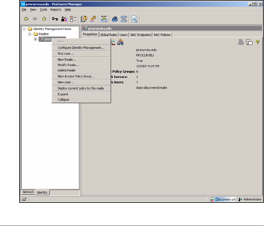
2-274
Implementing 802.1X with ProCurve IDM and Endpoint Integrity
Configuring Network Access Control with IDM
Deploy Policies to the NAC 800s
The policies you have configured take effect after you deploy them to the
RADIUS servers—in this case, the NAC 800s. Once deployed, the policies are
stored by the IDM agent on the NAC 800, and the NAC 800 enforces the policies
whether IDM is running or not.
Follow these steps:
1. You should be in the Identity Management Home window of PCM+.
2. In the left pane, expand Realms.
3. Right-click your domain’s realm name and select Deploy current policy to
this realm.
Figure 2-238. ProCurve Manager—Identity Management Home Window
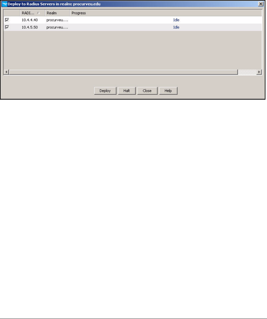
2-275
Implementing 802.1X with ProCurve IDM and Endpoint Integrity
Configuring Network Access Control with IDM
4. The Deploy to Radius Servers in realm: <myrealm> window is displayed.
Figure 2-239. Deploy to Radius Servers in realm: <myrealm> window
5. By default, the check boxes for every RADIUS server (including NAC
800s) are selected. You can clear a check box if you do not want to deploy
the policy to a particular server. In this example, leave all check boxes
selected.
6. Click Deploy.
7. When the Progress bar reaches 100 percent, click Close.

2-276
Implementing 802.1X with ProCurve IDM and Endpoint Integrity
Setting Up Endpoints
Setting Up Endpoints
By now, you have set up your network infrastructure and servers to support
your access control solution. Before enabling port authentication, however,
you must set up the endpoints as well. To function in this solution, endpoints
require:
■User certificates for EAP-TLS authentication
■802.1X supplicants
■NAC EI agents
Install Certificates
Before you implement port authentication, you should install user certificates
on the endpoints. The endpoints will submit the certificates to complete EAP-
TLS authentication when a user connects to the network.
The following section explains how users autoenroll for certificates.
Autoenroll for Certificates
You already set up templates on your CA to allow autoenrollment (see “Set
Up Autoenrollment of Computer and User Certificates” on page 2-68).
You accepted default autoenrollment settings in “Set Up Autoenrollment of
Computer and User Certificates” on page 2-68. Autoenrollment proceeds
without user interaction and the CA automatically issues certificates to
domain members.
In short, when a user logs in to the Windows domain, his or her endpoint
automatically enrolls for a user certificate and automatically installs it when
the CA server (also automatically) issues it. The endpoint also automatically
obtains and installs the root CA certificate.
Note The user must connect to the Windows domain in order to autoenroll for the
certificate. Set up autoenrollment several days before you begin to enforce
802.1X.
You should test the autoenrollment process.
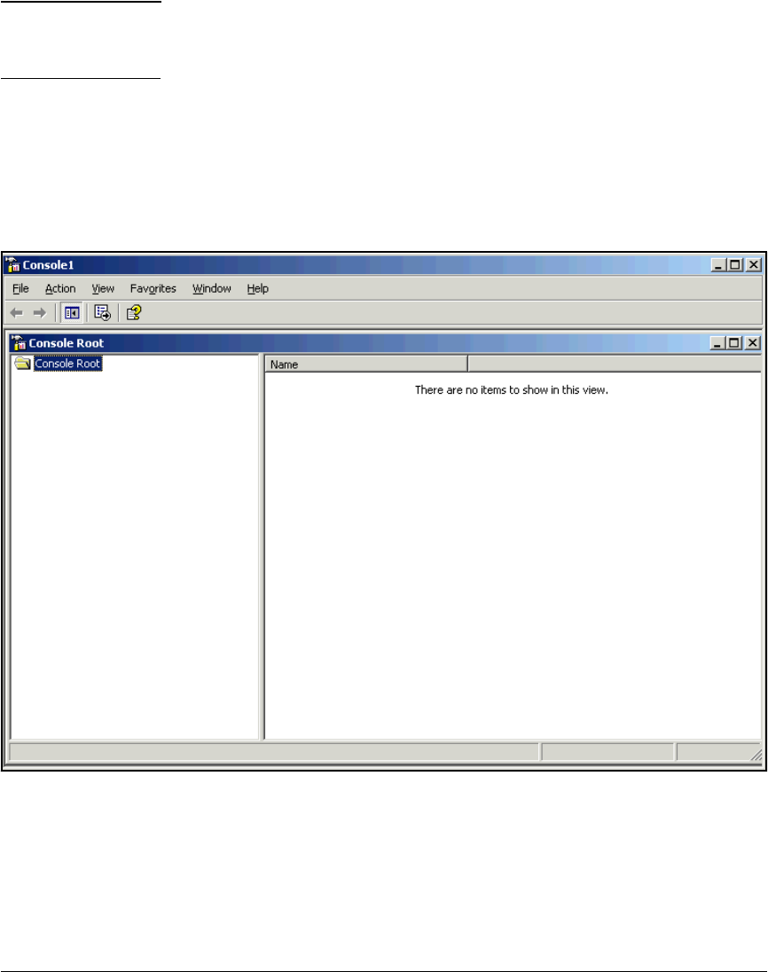
2-277
Implementing 802.1X with ProCurve IDM and Endpoint Integrity
Setting Up Endpoints
Note To complete the following steps, a user must be a local administrator on his
or her endpoint. Otherwise, the user can manage his or her user certificate but
not the computer certificate.
On your endpoint, log in to the domain (if you were already logged in before
autoenrollment was enabled, log out and then back in). Then follow these
steps to verify that the user certificate has installed on your endpoint:
1. Open a Management Console. (Select Start > Run; type mmc at the prompt
and click OK).
Figure 2-240. Management Console Window
2. Select File > Add/Remove Snap-in.
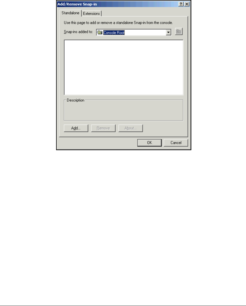
2-278
Implementing 802.1X with ProCurve IDM and Endpoint Integrity
Setting Up Endpoints
Figure 2-241. Management Console—Add/Remove Snap-in
Window
3. Click Add in the Add/Remove Snap-in window.
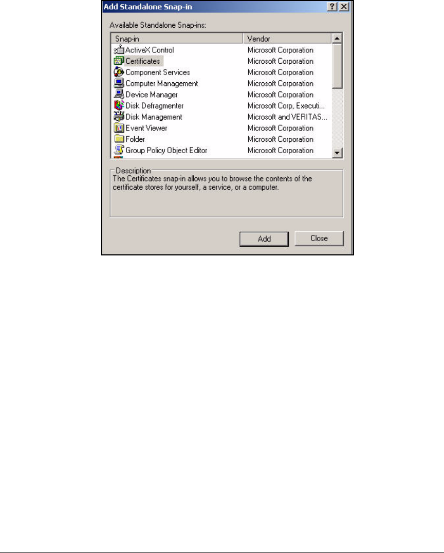
2-279
Implementing 802.1X with ProCurve IDM and Endpoint Integrity
Setting Up Endpoints
Figure 2-242. Management Console—Add/Remove Snap-in
Window
4. Click Certificates in the Available Standalone Snap-ins window.
5. Click Add.

2-280
Implementing 802.1X with ProCurve IDM and Endpoint Integrity
Setting Up Endpoints
Figure 2-243. Management Console—Certificates snap-in Window
6. Select My user account.
7. Click Finish.
8. You can add another snap-in to manage computer certificates:
a. Certificates should still be selected in the Available Standalone Snap-
ins window.
b. Click Add.
c. Click Computer account.
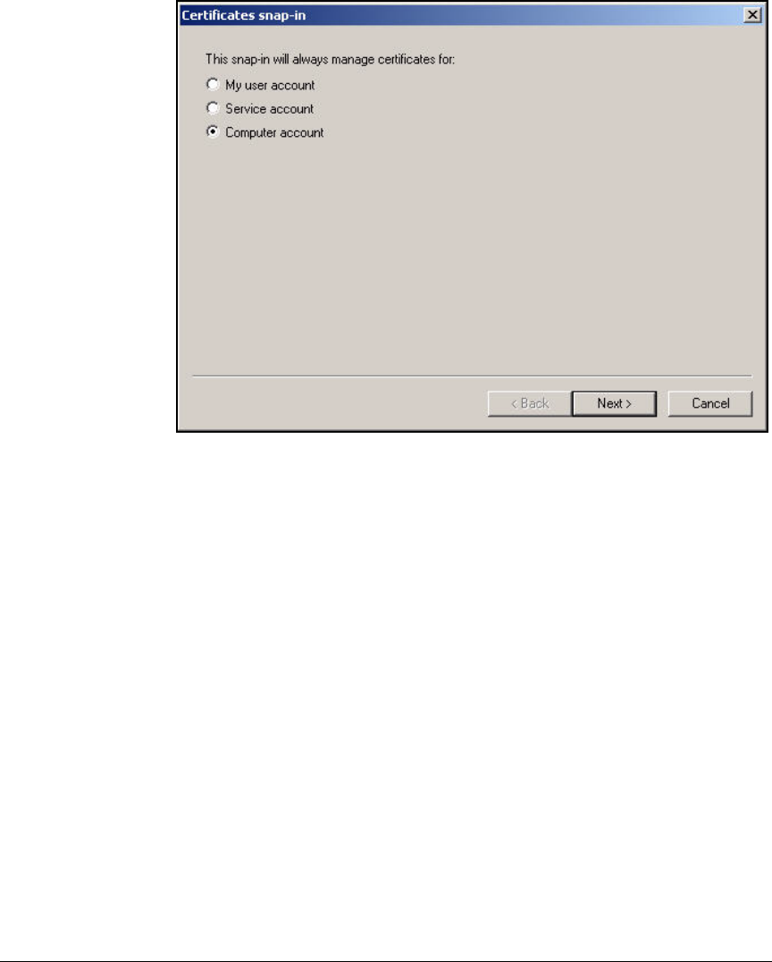
2-281
Implementing 802.1X with ProCurve IDM and Endpoint Integrity
Setting Up Endpoints
Figure 2-244. Management Console—Certificates snap-in Window
d. Click Next.
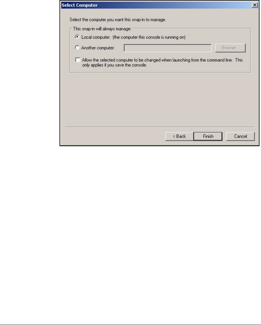
2-282
Implementing 802.1X with ProCurve IDM and Endpoint Integrity
Setting Up Endpoints
Figure 2-245. Management Console—Select Computer Window
e. Leave Local computer selected.
f. Click Finish.
9. The snap-ins are displayed in the Add/Remove Snap-in window. Click Close
in the Add Standalone Snap-in window.
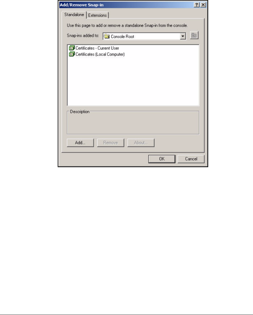
2-283
Implementing 802.1X with ProCurve IDM and Endpoint Integrity
Setting Up Endpoints
Figure 2-246. Management Console—Add/Remove Snap-in
Window—Standalone Tab
10. Click OK in the Add/Remove Snap-in window.
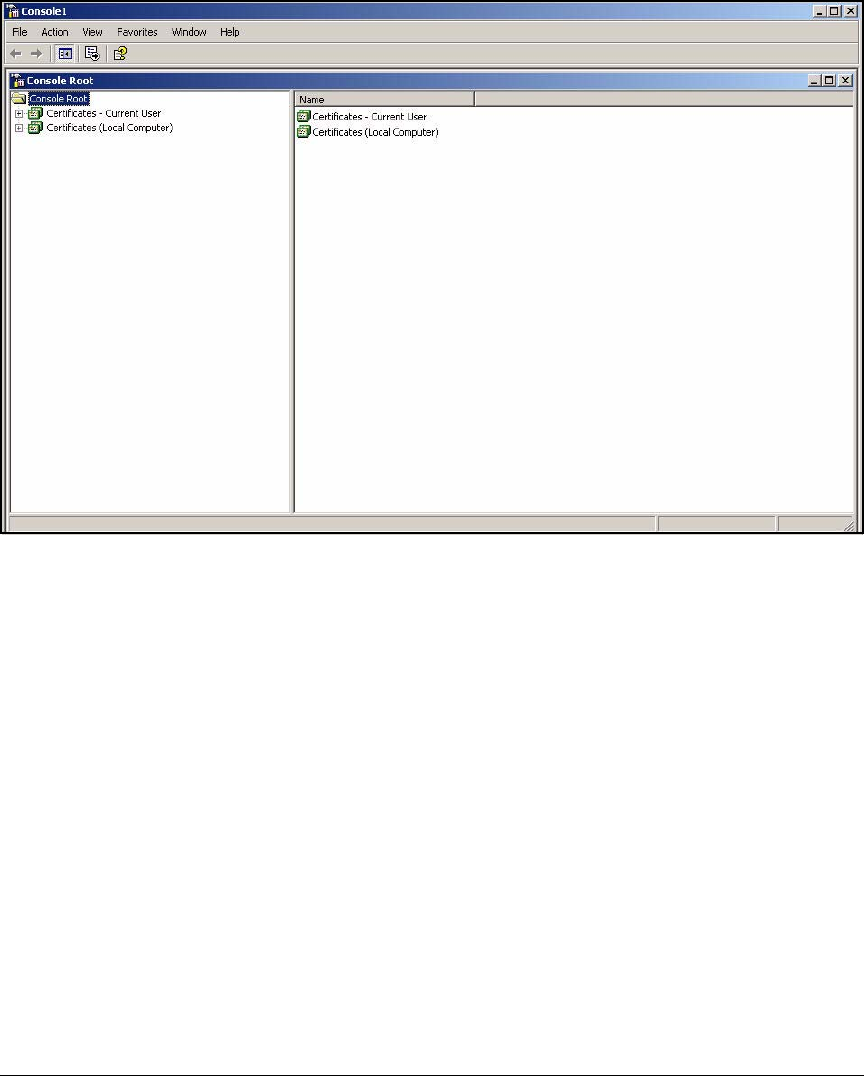
2-284
Implementing 802.1X with ProCurve IDM and Endpoint Integrity
Setting Up Endpoints
Figure 2-247. Management Console—Certificates Snap-ins
11. In the left pane, expand Certificates – Current User > Personal.
12. Click Certificates.
Your user certificate should be displayed in the right pane.
13. If the user certificate is not present, you can manually start autoenroll-
ment:
a. Right-click Certificates – Current User.
b. Select All Tasks > Automatically Enroll Certificates.
c. The certificate should install in about one minute.
14. Check the computer certificate in the same way:
a. Expand Certificates (Local Computer) > Personal.
b. Click Certificates.
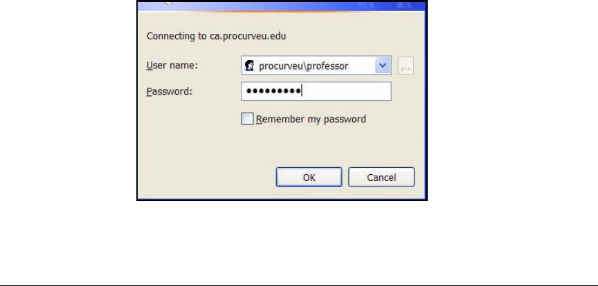
2-285
Implementing 802.1X with ProCurve IDM and Endpoint Integrity
Setting Up Endpoints
15. If necessary, manually start autoenrollment for the computer certificate:
a. Right-click Certificates (Local Computer).
b. Select All Tasks > Automatically Enroll Certificates.
c. The certificate should install in about one minute.
16. Press [Alt]+[F4] to close the Management Console.
17. Save the Management Console.
Manually Enroll for Certificates
This solution uses autoenrollment; however, you might choose to have users
enroll for certificates manually. They can do so in two ways:
■Web enrollment pages
■MMC
Web Enrollment Pages. Follow these steps to enroll for a user certificate
using the Windows CA Web enrollment pages:
1. Open a Web browser and type this URL: http://<CA server hostname>/
certsrv. In this example: http://ca.procurveu.edu/certsrv.
2. When prompted, type your domain username and password:
a. Type the User name in this format: <domain>\<username>. In this exam-
ple: procurveu\professor.
b. For the Password, type the user’s domain password. In this example:
ProCurve3.
Figure 2-248. Connect to <CA server>
3. Click OK.
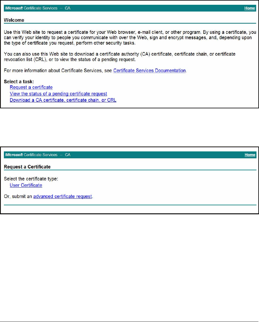
2-286
Implementing 802.1X with ProCurve IDM and Endpoint Integrity
Setting Up Endpoints
Figure 2-249. Certificate Services—Welcome Page
4. Click Request a certificate.
Figure 2-250. Certificate Services—Request a Certificate Page
5. Click advanced certificate request.
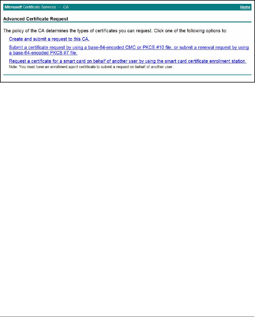
2-287
Implementing 802.1X with ProCurve IDM and Endpoint Integrity
Setting Up Endpoints
Figure 2-251. Certificate Services—Advanced Certificate Request Page
6. Click Create and submit a request to this CA.
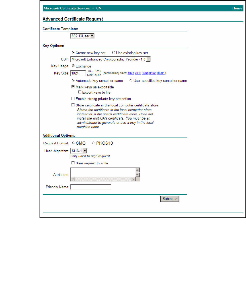
2-288
Implementing 802.1X with ProCurve IDM and Endpoint Integrity
Setting Up Endpoints
Figure 2-252. Certificate Services—Advanced Certificate Request Page
7. For the Certificate Template, select the template you customized for 802.1X
authentication. In this example: 802.1XUser.
8. You can leave all other settings at the defaults.
9. Click Submit.
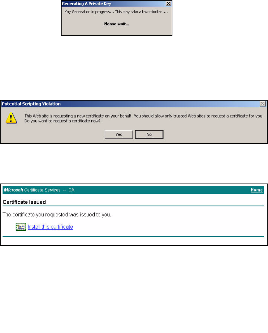
2-289
Implementing 802.1X with ProCurve IDM and Endpoint Integrity
Setting Up Endpoints
Figure 2-253. Generating a Private Key Window
10. Wait while the private key generates. After a minute or so, you should see
the page shown in Figure 2-255.
Depending on your security settings, you might first see the window in
Figure 2-254.
Figure 2-254. Potential Scripting Violation Window
If so, click Yes.
Figure 2-255. Certificate Services—Certificate Issued Page
11. Click Install this certificate.
12. You should see an Alert window when the certificate is installed. See
Figure 2-256.
Again, the Potential Scripting Violation window might be displayed. If so,
click Yes.

2-290
Implementing 802.1X with ProCurve IDM and Endpoint Integrity
Setting Up Endpoints
Figure 2-256. Alert Window
13. Click OK.
MMC. Users can manually enroll for a certificate through a Management
Console such as the one created in “Autoenroll for Certificates” on page 2-276.
(Note that to manually enroll for a computer certificate, the user must be an
administrator of the computer.)
Follow these steps:
1. Open the Management Console. (Select Start > Run; type mmc at the
prompt and click OK).


2-292
Implementing 802.1X with ProCurve IDM and Endpoint Integrity
Setting Up Endpoints
Figure 2-258. Management Console—Certificates Snap-ins
3. In the left pane, expand Certificates – Current User > Personal.
4. Right-click Certificates.
5. Select All Tasks > Request New Certificate. The Certificate Request Wizard
is displayed.
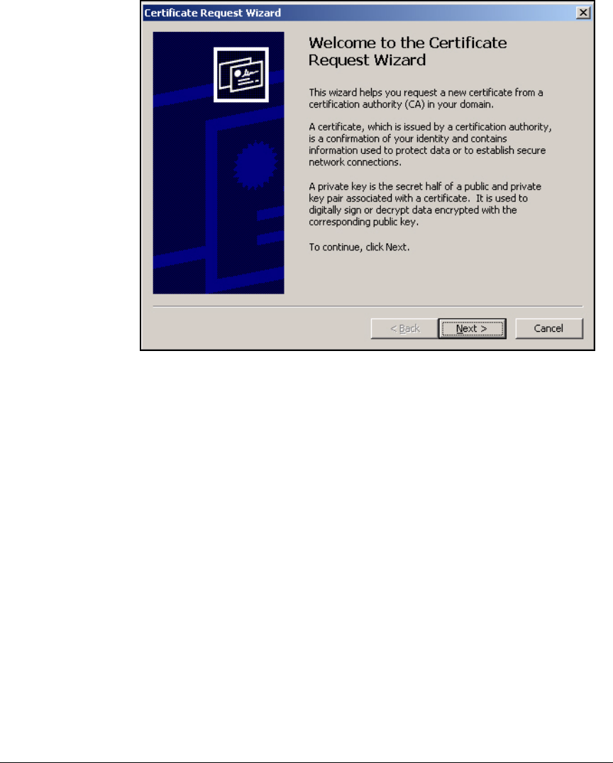
2-293
Implementing 802.1X with ProCurve IDM and Endpoint Integrity
Setting Up Endpoints
Figure 2-259. Certificate Request Wizard—Welcome Page
6. Click Next.
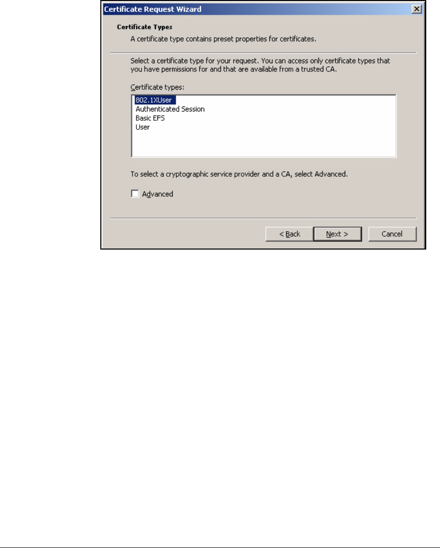
2-294
Implementing 802.1X with ProCurve IDM and Endpoint Integrity
Setting Up Endpoints
Figure 2-260. Certificate Request Wizard—Certificate Types Page
7. The Certificate types box lists the certificate templates for which this user
has Enroll privileges. Select the template created for users to authenticate
using 802.1X. In this example: 802.1XUser.
8. Click Next.
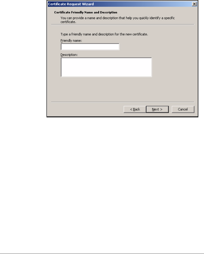
2-295
Implementing 802.1X with ProCurve IDM and Endpoint Integrity
Setting Up Endpoints
Figure 2-261. Certificate Request Wizard—Certificate Friendly Name and
Description Page
9. For the Friendly name, type a name to identify this certificate. For example,
you could identity the certificate by the CA. In this example: ProCurveU.
10. Optionally, type a longer description of the certificate and its purpose in
the Description box.
11. Click Next.
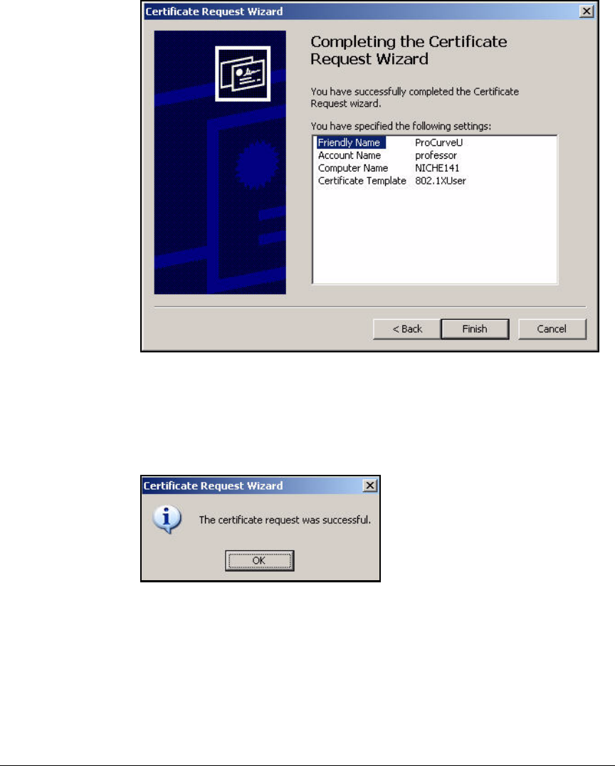
2-296
Implementing 802.1X with ProCurve IDM and Endpoint Integrity
Setting Up Endpoints
Figure 2-262. Certificate Request Wizard—Completing the Certificate Request
Wizard Page
12. Check the settings on the Completing the Certificate Request Wizard page
and click Finish.
Figure 2-263. Certificate Request Wizard Window
13. You should see the window in Figure 2-263. Click OK.
14. To manually enroll for a computer certificate, follow the same process:
a. Expand Certificates (Local Computer) > Personal.
b. Right-click Certificates.
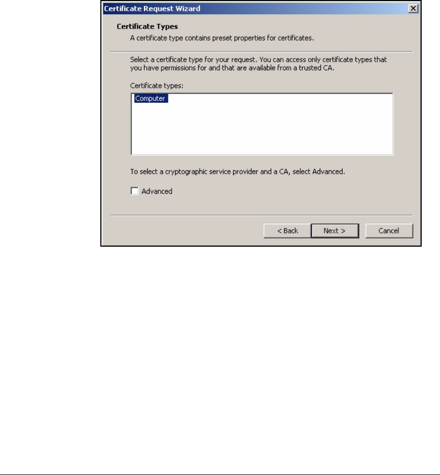
2-297
Implementing 802.1X with ProCurve IDM and Endpoint Integrity
Setting Up Endpoints
c. Select All Tasks > Request New Certificate. The Certificate Request
Wizard is displayed.
d. Complete the same steps as those for requesting a user certificate
(step 6 on page 2-293 to step 13 on page 2-296). The only difference is
that you select Computer for the certificate type. See Figure 2-264.
Figure 2-264. Certificate Request Wizard—Certificate Types Page
Configure the 802.1X Supplicant
This section teaches you how to set up the native Windows 802.1X supplicant
to authenticate with EAP-TLS. The steps differ slightly depending on whether
you are configuring 802.1X for an Ethernet connection or a wireless
connection.
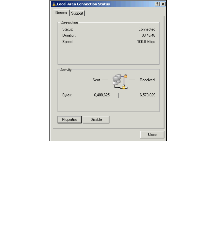
2-298
Implementing 802.1X with ProCurve IDM and Endpoint Integrity
Setting Up Endpoints
Configure the 802.1X Supplicant for EAP-TLS on an Ethernet
Connection
Follow these steps:
1. On the endpoint, select Start > Settings > Network Connections > Local Area
Connection.
Figure 2-265. Start > Settings > Network Connections >
Local Area Connection > Local Area Connection
Status Window—General Tab
2. Click Properties.
3. Click the Authentication tab.
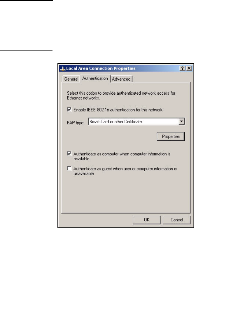
2-299
Implementing 802.1X with ProCurve IDM and Endpoint Integrity
Setting Up Endpoints
Note If the Authentication tab is not displayed, you may have one of two problems:
■The endpoint does not support 802.1X. Download the most recent Win-
dows SP.
■Wireless Zero Configuration (WZC) is not running. (This service enables
802.1X for both wired and wireless connections.) See “Enable WZC” on
page 2-305 to fix the problem.
Figure 2-266. Local Area Connection Status—Local Area Connection Properties—
Authentication Tab
4. The Enable IEEE 802.1X authentication for this network check box should be
selected.
5. Select Smart Card or other Certificate from the EAP type list.
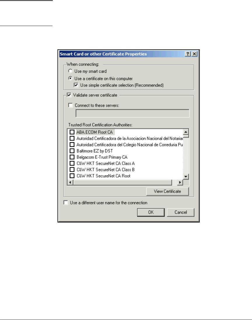
2-300
Implementing 802.1X with ProCurve IDM and Endpoint Integrity
Setting Up Endpoints
Note Clear the Authenticate as computer when computer information is available check
box if you do not want computers to be able to authenticate when a user is
not logged in.
6. Click Properties.
Figure 2-267. Local Area Connection Status—<EAP type> Properties Window
7. The Validate server certificate check box should be selected.
8. From the Trusted Root Certification Authorities list, select the check box of
your CA.
9. Click OK to close all open windows.
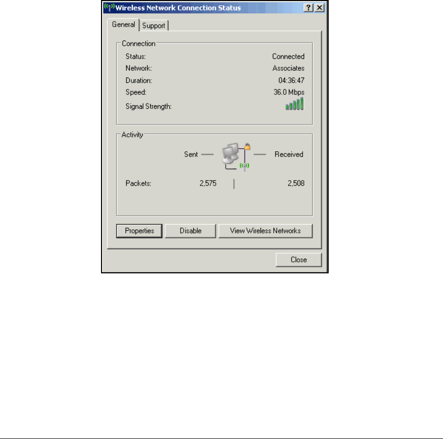
2-301
Implementing 802.1X with ProCurve IDM and Endpoint Integrity
Setting Up Endpoints
Configure the 802.1X Supplicant for EAP-TLS on a Wireless
Connection
The Microsoft Wireless Zero Configuration client can complete much of the
configuration in this section automatically. However, you might want to check
or configure some settings manually. Follow these steps:
1. Select Start > Settings > Network Connections > Wireless Network
Connection.
Figure 2-268. Start > Settings > Network Connections >
Local Area Connection > Wireless Network
Connection Status Window—General Tab
2. Click Properties.
3. Click the Wireless Networks tab.
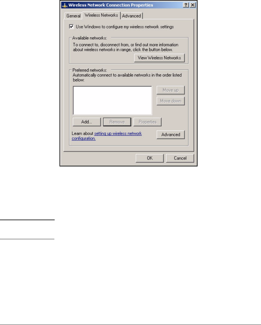
2-302
Implementing 802.1X with ProCurve IDM and Endpoint Integrity
Setting Up Endpoints
Figure 2-269. Wireless Network Connection Status—
Wireless Network Connection
Properties—Wireless Networks Tab
4. If not already selected, select the Use Windows to configure my wireless
network settings check box.
Note If the check box is not available, WZC is not running. See “Enable WZC”
on page 2-305 to fix the problem.
5. Click Add.
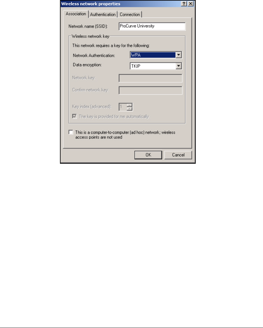
2-303
Implementing 802.1X with ProCurve IDM and Endpoint Integrity
Setting Up Endpoints
Figure 2-270. Wireless Network Connection Status—
Wireless network properties Window—
Association Tab
6. In the Network name (SSID) box, type the Service Set Identifier (SSID) for
your WLAN (in this example, ProCurve University).
7. For Network Authentication, select WPA.
8. For Data Encryption, select TKIP or AES (both are supported in the WLAN
in this example).
9. Click the Authentication tab.
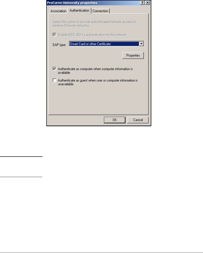
2-304
Implementing 802.1X with ProCurve IDM and Endpoint Integrity
Setting Up Endpoints
Figure 2-271. Wireless Network Connection Status—<SSID>
properties Window—Authentication Tab
10. Select Smart Card or other Certificate from the EAP type list.
Note Clear the Authenticate as computer when computer information is available check
box if you do not want computers to be able to authenticate when a user is
not logged in.
11. Click Properties.
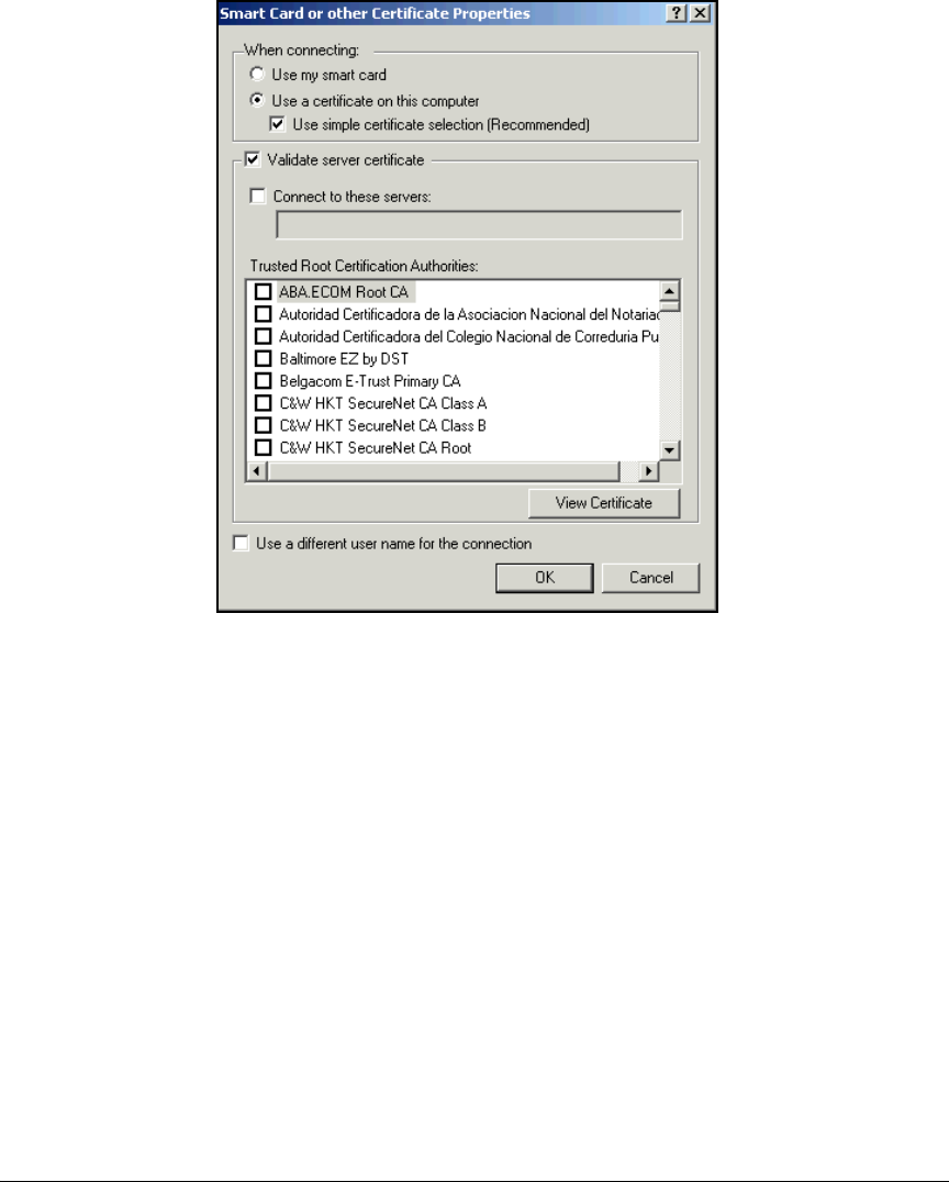
2-305
Implementing 802.1X with ProCurve IDM and Endpoint Integrity
Setting Up Endpoints
Figure 2-272. Wireless Network Connection Status—
<EAP type> Properties Window
12. The Validate server certificate check box should be selected.
13. From the Trusted Root Certification Authorities list, select the check box of
your CA.
14. Click OK to close all open windows.
Enable WZC
Typically, the WZC service starts automatically. However, sometimes a wire-
less card comes with a vendor client that disables WZC. You can use the vendor
client or re-enable WZC.
If you choose to re-enable WZC, follow these steps:
1. In the Start menu, select Control Panel.
2. Select Administrative Tools > Services.
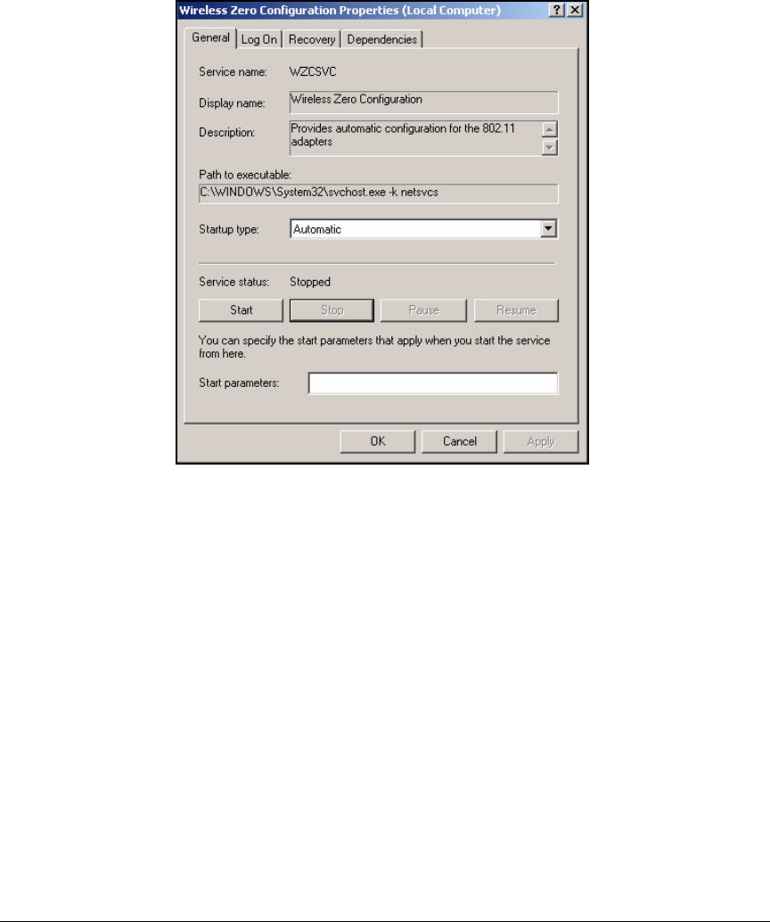
2-306
Implementing 802.1X with ProCurve IDM and Endpoint Integrity
Setting Up Endpoints
3. Scroll to and double-click the WZC service.
Figure 2-273. Wireless Zero Configuration Properties Window—
General Tab
4. For the Startup type, select Automatic.
5. Click Start.
6. Click OK.
Pre-install the NAC EI Agent on Endpoints
In this solution, network administrators want to pre-install the NAC EI agent
on endpoints before the NAC 800s begin to enforce endpoint integrity. They
can install the agent manually, but, in a large network, deploying the agent
automatically via Active Directory is much more efficient.

2-307
Implementing 802.1X with ProCurve IDM and Endpoint Integrity
Setting Up Endpoints
Deploy the NAC EI Agent Automatically—Active Directory
Group Policy Object Software Installation
This section explains how to use Active Directory’s software installation
feature to deploy the NAC EI agent. You will assign the NAC EI agent to domain
computers by editing a group policy object (GPO) in Active Directory. The
next time an endpoint such as a laptop or workstation connects to the domain,
it automatically downloads the agent. The agent also automatically installs on
the endpoint, typically at the next reboot.
Note There are other ways to deploy software using Active Directory. You can, for
example, assign the software to users rather than to computers. The advantage
of this latter option is that the agent downloads to a user’s endpoint no matter
what endpoint that happens to be. However, the user must trigger the actual
installation.
For this solution, because network administrators want the agent to install
with as little user interaction as possible, the software is assigned to comput-
ers. For more information on other options, search for information on “Group
Policy Software Installation” at http://www.microsoft.com.
Complete these steps to deploy the NAC EI agent with Active Directory:
1. Create the .msi file for the NAC EI agent.
2. Set up the folder with the .msi file as a network share.
3. In Active Directory, configure the GPO software installation settings.
Note You should complete these steps after setting up the NAC 800s and verifying
that they have network connectivity but before activating quarantining (for
example, by setting the cluster’s access mode to normal).
Create the .msi File. Active Directory’s software installation feature works
with .msi files. Complete the following steps to convert the NAC EI agent to
the correct format. Note that you must have access to the NAC 800 although
the device should not yet be enforcing quarantining.
1. Open a Web browser on the server you have selected to store the .msi file.
Type the following for the URL: https://<NAC IP address>:89/setup.exe.
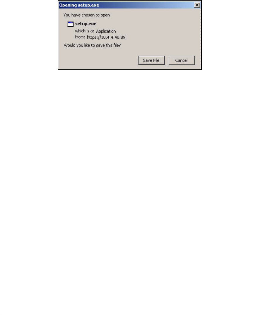
2-308
Implementing 802.1X with ProCurve IDM and Endpoint Integrity
Setting Up Endpoints
Figure 2-274. Opening setup.exe Window
2. A window such as the one in Figure 2-274 is displayed. Click Save File.
3. If prompted, choose the directory for the file.
4. Access the command line on your management station (From the Win-
dows Start menu, select Run. Type cmd at the prompt and click OK.)
5. Move to the directory to which the setup.exe file saved. Then enter this
command:
setup.exe /a
6. The InstallShield Wizard for creating the NAC EI agent .msi file is
launched.
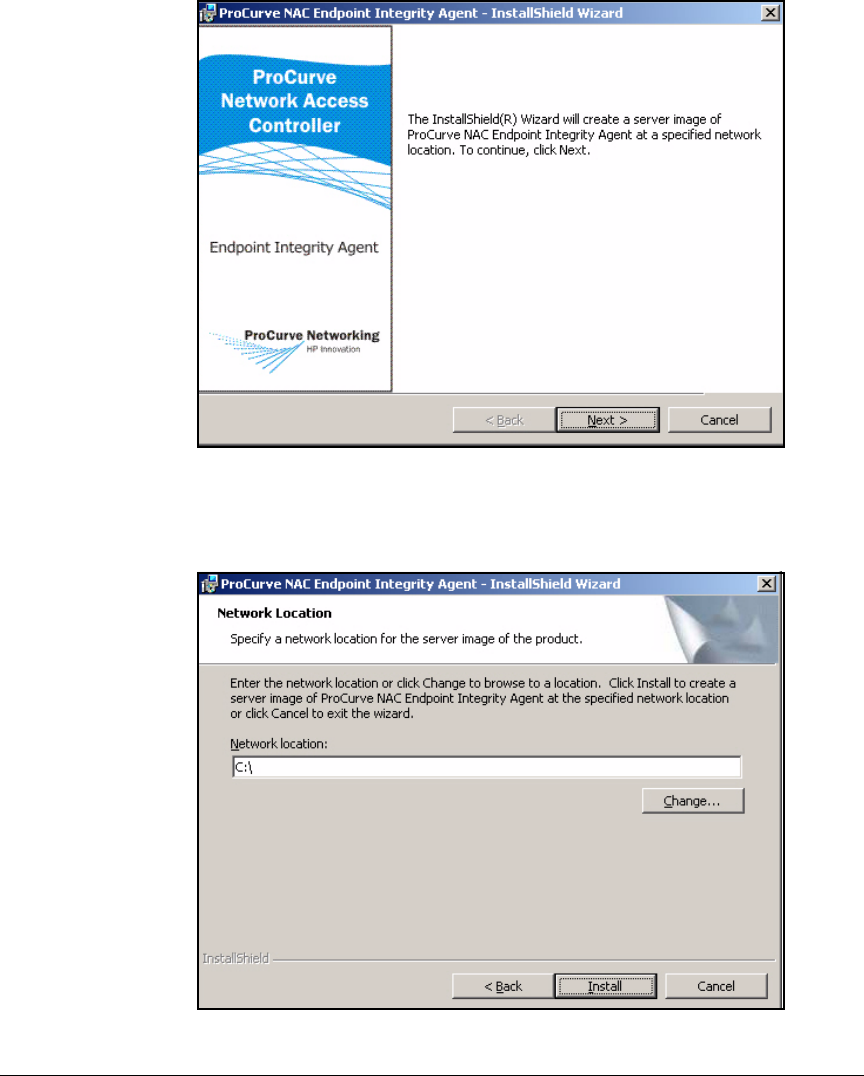
2-309
Implementing 802.1X with ProCurve IDM and Endpoint Integrity
Setting Up Endpoints
Figure 2-275. ProCurve NAC Endpoint Integrity Agent—InstallShield Wizard
7. Click Next.
Figure 2-276. InstallShield Wizard—Network Location Page
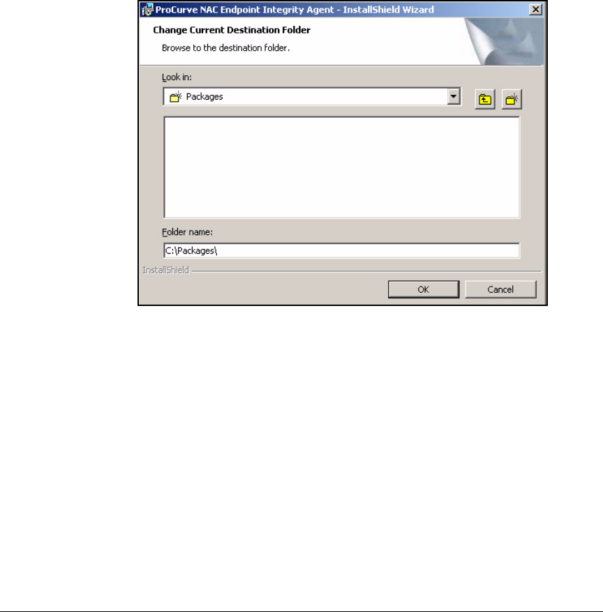
2-310
Implementing 802.1X with ProCurve IDM and Endpoint Integrity
Setting Up Endpoints
8. On the Network Location page, specify the folder, either on this computer
or another server, for the .msi package:
• Type the path to the folder in the Network location box.
• Or browse for the folder:
i. Click Change.
ii. On the Change Current Destination Folder page, use the Look in box
to navigate to the correct folder.
Figure 2-277. InstallShield Wizard—Change Current Destination Folder Page
iii. Click OK.
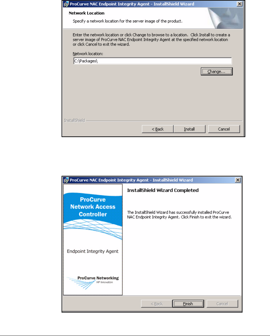
2-311
Implementing 802.1X with ProCurve IDM and Endpoint Integrity
Setting Up Endpoints
Figure 2-278. InstallShield Wizard—Network Location Page
9. Click Install.
Figure 2-279. InstallShield Wizard—Completed

2-312
Implementing 802.1X with ProCurve IDM and Endpoint Integrity
Setting Up Endpoints
10. Click Finish.
11. The ProCurve NAC Endpoint Integrity Agent.msi file is saved to the specified
folder.
Note The setup.exe /a command also created two directories, Program Files and
System32 and placed them in the same folder as the ProCurve NAC Endpoint
Integrity Agent.msi file. You can delete these directories, but take care that you
are deleting the correct directories (not ones that already exist on the server).
12. If you want the NAC EI agent to install without user interaction, return to
the command prompt and enter this command:
Enable Sharing on the Folder with the .msi File. All domain users—
and, depending on your preferences, guests as well—need access to the server
and the folder to which you saved the .msi file.
Follow these steps on a Windows server:
1. In the Start menu, click Programs > Accessories > Windows Explorer.
2. Navigate to the folder in which you created the .msi file in the previous
task.
3. Right-click the folder and click Sharing and Security.
Syntax: msiexec /package “<path>/ProCurve NAC Endpoint Integrity Agent.msi”
/quiet
Replace <path> with the path to the folder to which you saved
the .msi file.
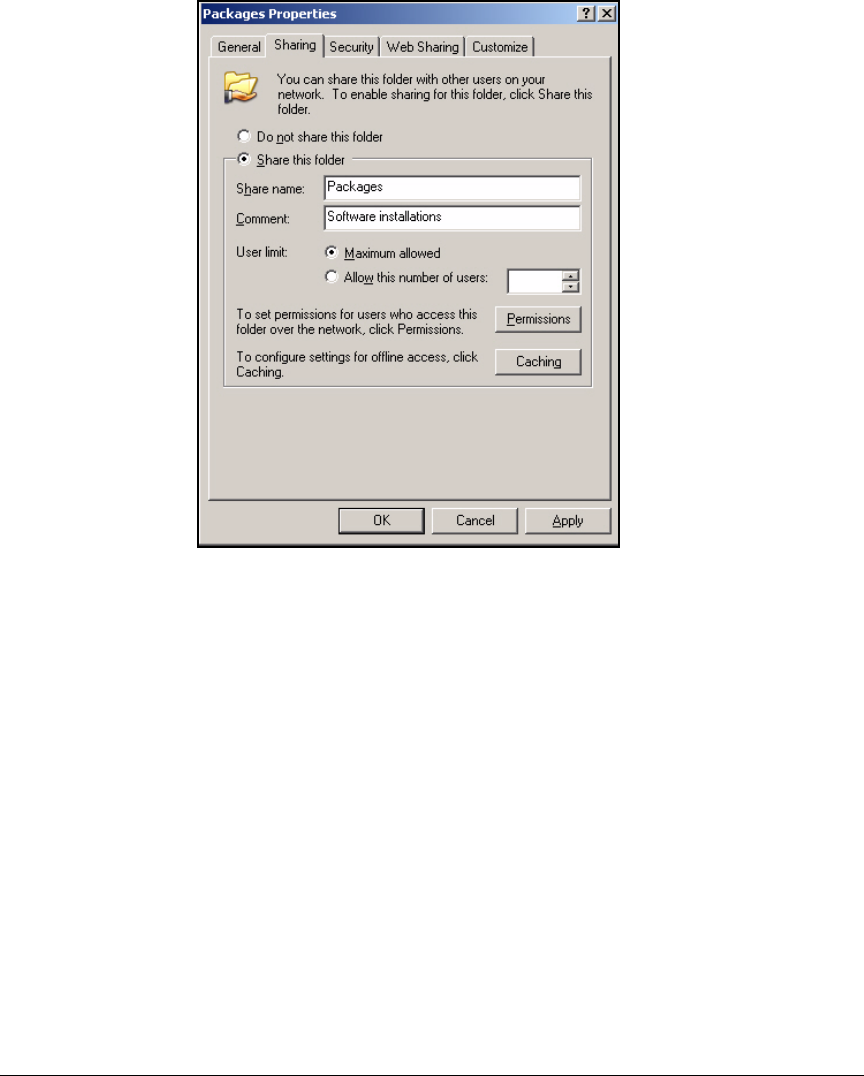
2-313
Implementing 802.1X with ProCurve IDM and Endpoint Integrity
Setting Up Endpoints
Figure 2-280. <Folder> Properties
4. Click Share this folder.
5. Leave the Share name the same as the folder name.
6. If you want to restrict who can access the folder, click Permissions. In this
example, you want everyone to be able to install the NAC EI agent, so you
leave the default permissions.
7. Click OK.
Configure the Group Policy Software Installation Settings. Com-
plete the following steps to assign the NAC EI agent installation package to
computers in your domain:
1. On a domain controller, from the Windows Start menu, select Administra-
tive Tools > Active Directory Users and Computers.
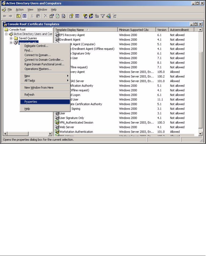
2-314
Implementing 802.1X with ProCurve IDM and Endpoint Integrity
Setting Up Endpoints
Figure 2-281. Management Console Window
2. In the left pane, right-click your domain name and select Properties.
3. Click the Group Policy tab.

2-315
Implementing 802.1X with ProCurve IDM and Endpoint Integrity
Setting Up Endpoints
Figure 2-282. <domain name> Properties Window
4. Select Default Domain Policy and click Edit.
In this example, you want to assign the software to all computers. If you
wanted to assign the software to a particular group, you could create a
new Group Policy Object (GPO) by clicking New.
5. In the left pane of the Group Policy Object Editor, expand Computer Config-
uration > Software Settings.
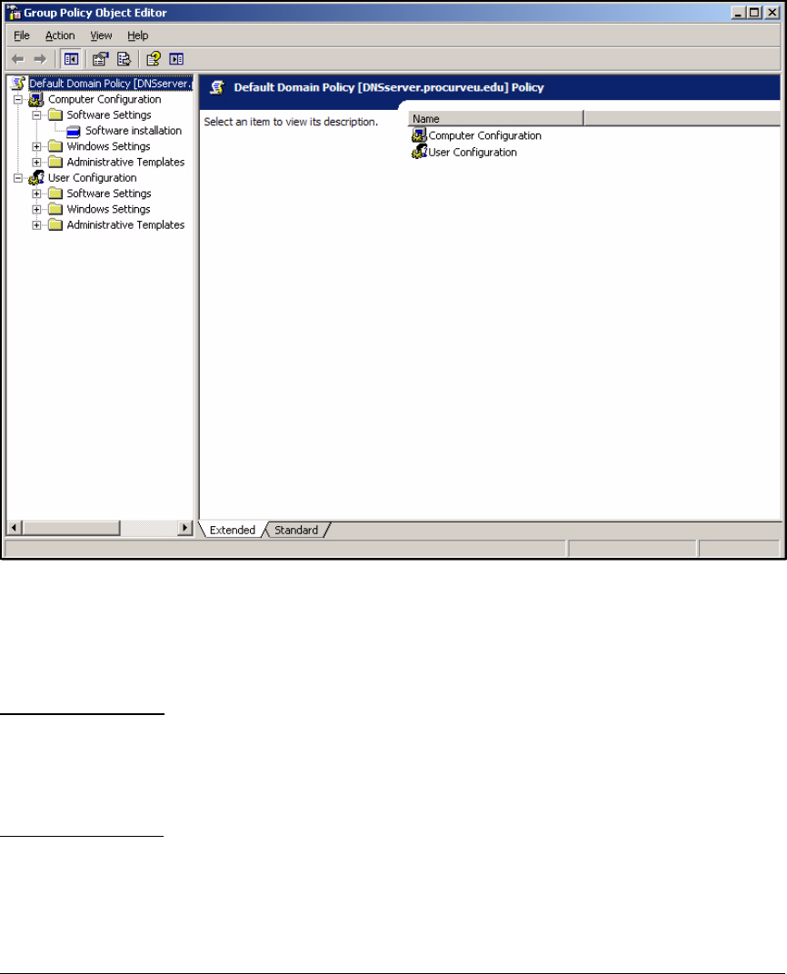
2-316
Implementing 802.1X with ProCurve IDM and Endpoint Integrity
Setting Up Endpoints
Figure 2-283. Group Policy Object Editor Window
6. Right-click Software installation; in the menu that is displayed, click New
> Package.
7. Navigate to the location of the NAC EI agent .msi file.
Note You must specify the location with the full Universal Naming Convention
(UNC) path. That is, the path must include the name of the file server. For
example: \\MyServer\Packages\. If you browse for the location, browse through
Network Places even if the file is stored on the server on which you are
configuring the group policy.
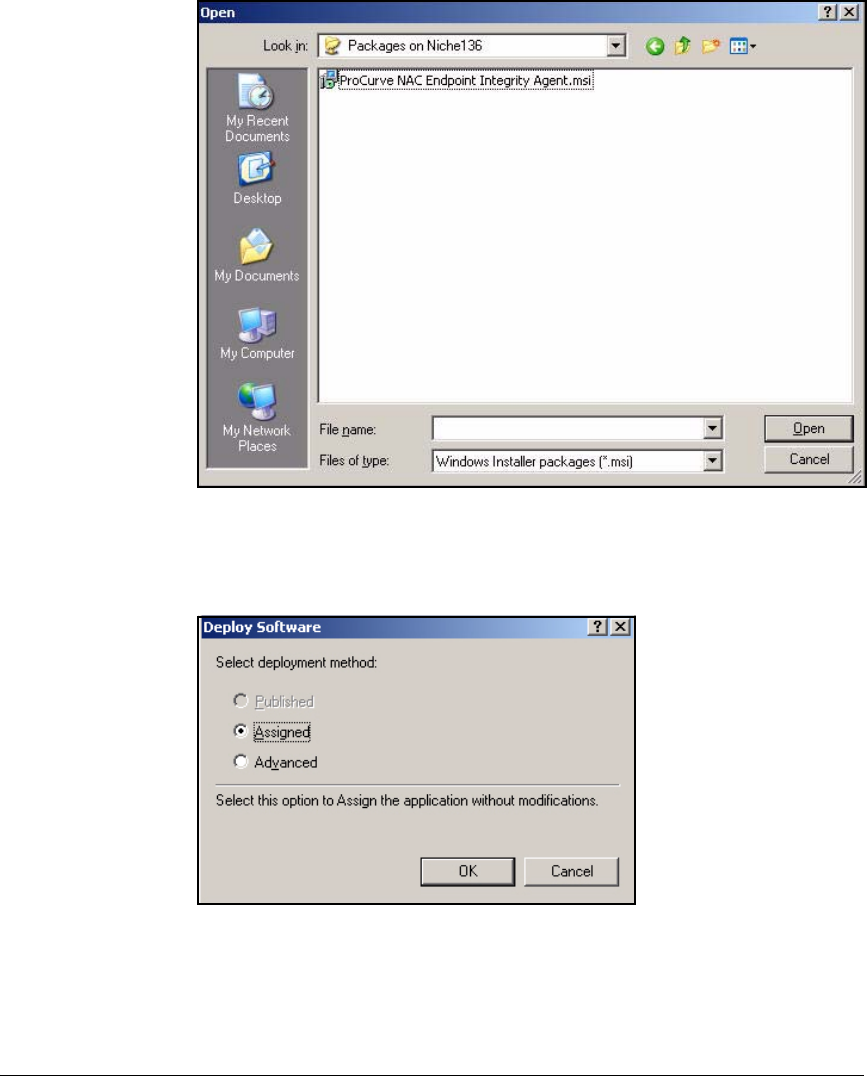
2-317
Implementing 802.1X with ProCurve IDM and Endpoint Integrity
Setting Up Endpoints
Figure 2-284. Open Window
8. Click the ProCurve NAC Endpoint Integrity Agent.msi file and click Open.
Figure 2-285. Deploy Software Window
9. In the Deploy Software window, click Assigned.
10. Click OK.

2-318
Implementing 802.1X with ProCurve IDM and Endpoint Integrity
Activating Network Access Control
Activating Network Access Control
It is recommended that, until you have completely configured and tested your
network access control solution, you do not activate:
■Port authentication
■Quarantining
Otherwise, you can inadvertently lock users—and even yourself—out of the
network. And, as explained in “Setting Up Endpoints” on page 2-276, end-
points, just as much as the network infrastructure and servers, must support
the solution. Whether the IT staff or users themselves will ready the endpoints,
you must allow sufficient time before enforcing network access control. For
example, after you install the NAC 800, you might wait several days before
activating endpoint integrity to give users time to download the NAC EI agent
from the NAC 800.
You should always test the solution before activating it throughout the net-
work. At a minimum, you should activate port authentication on a single
unused port, plug in your management station, and verify that you can log in
to the network. Log in as a user in each of your user groups and check the
resources you are allowed. As a next step for more rigorous testing, you might
implement port authentication on one or two switches for a trial period. Guide
users in the trial group through the process of connecting to the network and
note any problems that they encounter.
Once you are confident that the network infrastructure, endpoints, and users
are ready, activate your solution.
Activate Port Authentication
As suggested in “Configuring the ProCurve Switches” on page 2-13, wait to
activate port authentication until you have finished deploying and testing your
solution. Then type this command from the global configuration mode context
on all switches:
ProCurve Switch(config)# aaa port-access authenticator
active
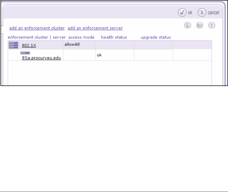
2-319
Implementing 802.1X with ProCurve IDM and Endpoint Integrity
Activating Network Access Control
Activate Quarantining
Throughout this chapter, you learned about deploying NAC 800s, setting up
quarantining with 802.1X, and configuring NAC policies and tests. As soon as
the NAC 800 ES (or Combination Server [CS]) detects an endpoint, it tests it.
However, in “Create an Enforcement Cluster and Add ESs” on page 2-146, you
set the access mode to allow all, which means that the testing does not affect
users’ access. To allow the NAC 800 to treat endpoints differently based on
test results, you must change the access mode.
Follow these steps:
1. Log in to the Web browser interface of the NAC 800 MS.
2. Select Home > System configuration > Enforcement clusters & servers.
Figure 2-286. NAC 800 Web Interface—Home > System configuration >
Enforcement clusters & servers
3. Select the name of your enforcement cluster (in this example, 802.1X).
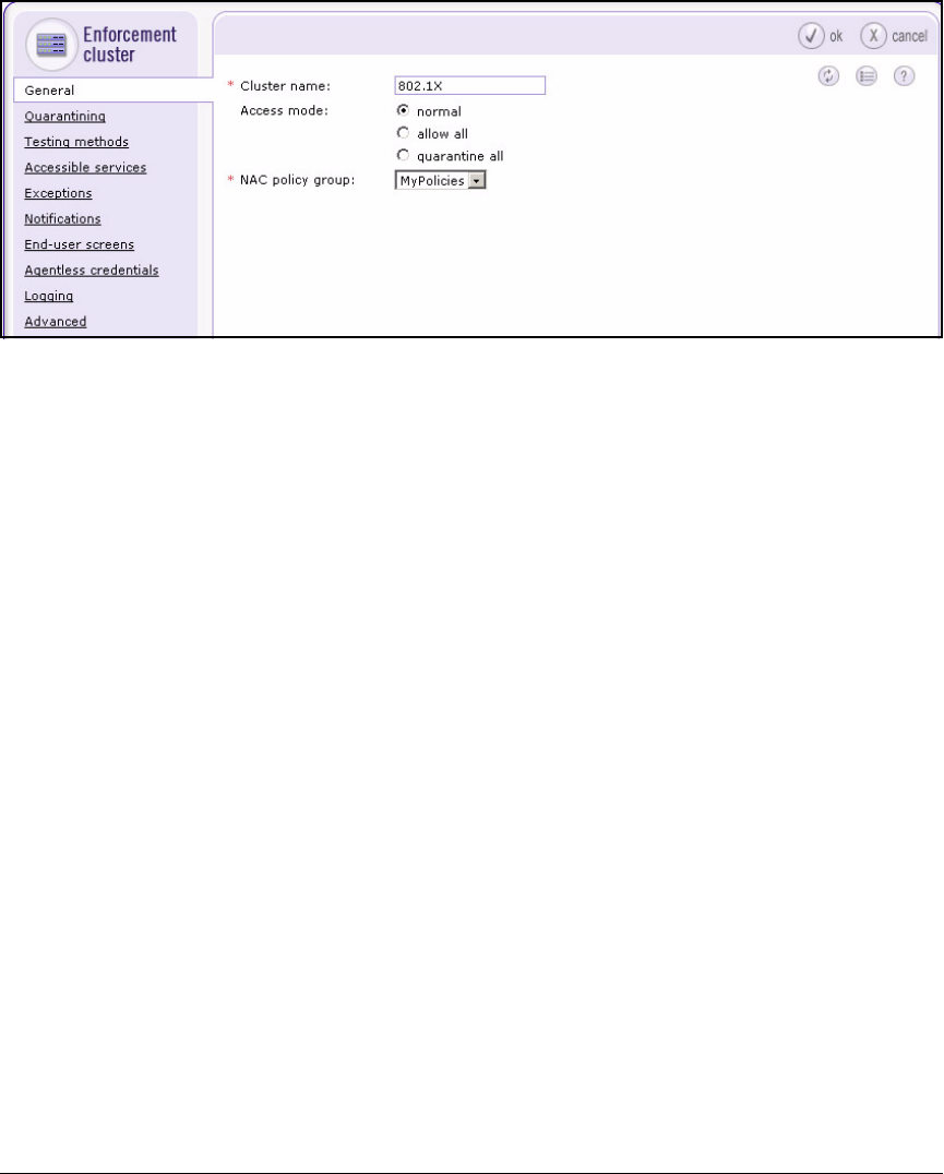
2-320
Implementing 802.1X with ProCurve IDM and Endpoint Integrity
Activating Network Access Control
Figure 2-287. NAC 800 Web Interface — Home > System configuration >
Enforcement clusters & servers > Add enforcement cluster >
General Tab
4. The General tab should be selected.
5. Select normal for the Access mode.
6. Click ok and then ok again.

3-1
3
Implementing 802.1X with Endpoint Integrity
but without IDM
Contents
Introduction . . . . . . . . . . . . . . . . . . . . . . . . . . . . . . . . . . . . . . . . . . . . . . . . . . . 3-3
Configure the ProCurve Switches . . . . . . . . . . . . . . . . . . . . . . . . . . . . . . . . . 3-9
Routing Switches . . . . . . . . . . . . . . . . . . . . . . . . . . . . . . . . . . . . . . . . . . . 3-10
Server Switch startup-config . . . . . . . . . . . . . . . . . . . . . . . . . . . . . . . . . 3-12
Edge Switches . . . . . . . . . . . . . . . . . . . . . . . . . . . . . . . . . . . . . . . . . . . . . 3-13
Wireless Services-Enabled Switch startup-config . . . . . . . . . . . . 3-13
Configure Windows 2003 Services . . . . . . . . . . . . . . . . . . . . . . . . . . . . . . . . 3-15
Configure IAS . . . . . . . . . . . . . . . . . . . . . . . . . . . . . . . . . . . . . . . . . . . . . . . . . 3-16
Install IAS . . . . . . . . . . . . . . . . . . . . . . . . . . . . . . . . . . . . . . . . . . . . . . . . . 3-16
Register IAS with Active Directory . . . . . . . . . . . . . . . . . . . . . . . . . . . . 3-19
Install a Certificate on the IAS Server . . . . . . . . . . . . . . . . . . . . . . . . . 3-21
Configure IAS Properties . . . . . . . . . . . . . . . . . . . . . . . . . . . . . . . . . . . . 3-30
Configure the Remote Access Policies . . . . . . . . . . . . . . . . . . . . . . . . . 3-34
Using the New Remote Access Policy Wizard . . . . . . . . . . . . . . . 3-37
Manually Create a Remote Access Policy . . . . . . . . . . . . . . . . . . . 3-43
Edit a Remote Access Policy . . . . . . . . . . . . . . . . . . . . . . . . . . . . . 3-62
Optional Remote Access Policy for Network Administrators . . 3-66
Add RADIUS Clients . . . . . . . . . . . . . . . . . . . . . . . . . . . . . . . . . . . . . . . . 3-79
Enable Remote Access Logging . . . . . . . . . . . . . . . . . . . . . . . . . . . . . . 3-82
Install and Configure Connectors for Endpoint Integrity with
the NAC 800 . . . . . . . . . . . . . . . . . . . . . . . . . . . . . . . . . . . . . . . . . . . . . . . 3-86
Install the Connector Files . . . . . . . . . . . . . . . . . . . . . . . . . . . . . . . 3-86
Configure VLAN Assignments in the SAIASConnector.ini File . 3-89
Edit the IAS Server Registry . . . . . . . . . . . . . . . . . . . . . . . . . . . . . . 3-94
Install the NAC 800’s CA Certificate as a Trusted Root on the
IAS Server . . . . . . . . . . . . . . . . . . . . . . . . . . . . . . . . . . . . . . . . . . . . . . . . . 3-96

3-2
Implementing 802.1X with Endpoint Integrity but without IDM
Contents
Configure the Wireless Edge Services zl Modules . . . . . . . . . . . . . . . . . . 3-101
Configure the NAC 800s . . . . . . . . . . . . . . . . . . . . . . . . . . . . . . . . . . . . . . . . 3-102
Configure Basic Settings on the NAC 800s . . . . . . . . . . . . . . . . . . . . 3-102
Access the Web Browser Interface . . . . . . . . . . . . . . . . . . . . . . . 3-102
Create the Enforcement Cluster and Add ESs . . . . . . . . . . . . . . . . . 3-103
Configure Quarantining . . . . . . . . . . . . . . . . . . . . . . . . . . . . . . . . . . . . 3-103
Add 802.1X Devices . . . . . . . . . . . . . . . . . . . . . . . . . . . . . . . . . . . . 3-106
Configure NAC Policies . . . . . . . . . . . . . . . . . . . . . . . . . . . . . . . . . . . . 3-109
Configure Endpoint Integrity Testing Methods . . . . . . . . . . . . . . . . . 3-109
Install SSL Certificates on the NAC 800s . . . . . . . . . . . . . . . . . . . . . . 3-110
Export a Self-signed Certificate from a NAC 800 and Install it
on the IAS Server . . . . . . . . . . . . . . . . . . . . . . . . . . . . . . . . . . . . . . . . . . 3-110
Set Up Endpoints . . . . . . . . . . . . . . . . . . . . . . . . . . . . . . . . . . . . . . . . . . . . . 3-116
Activate Network Access Control . . . . . . . . . . . . . . . . . . . . . . . . . . . . . . . 3-117

3-3
Implementing 802.1X with Endpoint Integrity but without IDM
Introduction
Introduction
This chapter teaches you how to build a network that implements network
access control using:
■802.1X
■Endpoint integrity
For this access control solution, the network has a Microsoft Windows domain
and uses the Windows Server 2003 Internet Authentication Service (IAS) for
its Remote Authentication Dial-In User Service (RADIUS) server. You will
learn how to configure these components—as well as how to deploy ProCurve
Network Access Controller (NAC) 800s to provide endpoint integrity for such
an environment.
To meet the needs of most organizations, this solution is designed to control
access for both wired and wireless zones. (For more information about wired
and wireless zones, see the ProCurve Access Control Security Design Guide.)
Although this solution uses ProCurve Wireless Edge Services zl Modules to
provide the wireless zones and control wireless users’ access, you could
alternatively use an access point (AP) such as ProCurve AP 530 or ProCurve
AP 420.
It is assumed that the Windows domain implements a full public key
infrastructure (PKI), which allows end-users to authenticate with digital
certificates.
Note If you do not intend to implement a PKI, when you select authentication
methods on IAS, choose PEAP MS-CHAPv2. (See “Configure the Remote
Access Policies” on page 3-34.)

3-4
Implementing 802.1X with Endpoint Integrity but without IDM
Introduction
In this chapter, you will learn how to configure all of the components of such
a network:
■Basic configurations for routing switches and edge switches
■Step-by-step instructions for:
• Wireless Edge Services zl Modules
• Domain controller, which runs:
– Microsoft Active Directory
– Domain Name System (DNS) services
• Dynamic Host Configuration Protocol (DHCP) services
• Certificate Authority (CA) services
•IAS
• NAC 800s
Although your network environment is probably not identical to this environ-
ment, the instructions should help you understand the processes involved,
and you can then modify the instructions as needed to meet your organiza-
tion’s unique requirements. To help you, the instructions include examples,
which will be based on a sample network designed for a site called ProCurve
University. The instructions also include tables and worksheets that you can
use to record information for your own network.
ProCurve University includes three user groups:
■Network administrators
■Faculty members
■Students
The network is divided into virtual LANs (VLANs) that allow users to access
the resources that they require. Table 3-1 shows one approach to designing
the VLANs.

3-5
Implementing 802.1X with Endpoint Integrity but without IDM
Introduction
Table 3-1. Example VLANs
As you can see, the VLANs comprise these general categories:
■Management VLAN—for infrastructure devices and the network admin-
istrators that manage them
Note This solution does not use the secure management VLAN feature. Instead,
switches are configured with the ip authorized-managers command to
allow management traffic only from sources within the management
VLAN or from the NAC 800s.
■Server VLANs—for servers
In this example, servers are placed in different VLANs according to which
users need to access them. All users need the services in VLAN 4, which
includes DHCP servers and DNS servers. However, only the faculty should
be able to reach the servers in VLAN 5.
■User VLANs—one for each user group
You could create more VLANs and place users into different VLANs
according to when and how they connect to the network. For example,
you could create a Faculty_Wireless VLAN.
■Test VLAN—a single VLAN for endpoints that have not yet been tested
(Unknown status)
■Quarantine VLAN—a single VLAN for endpoints that have failed at least
one test for which the penalty is quarantine
■Infected VLAN—a single VLAN for endpoints that are infected with
malware (failed the Worms, Viruses, and Trojans test)
You can place infected endpoints in the quarantine VLAN; however, the
infected endpoints can infect the vulnerable, non-compliant endpoints, so
you should place them in separate VLANs.
VLAN Category Name ID Subnet
Management VLAN Management 2 10.2.0.0/16
Server VLAN Servers 4 10.4.0.0/16
Faculty_Databases 5 10.5.0.0/16
User VLAN Faculty 8 10.8.0.0/16
Students 10 10.10.0.0/16
Test VLAN (for endpoint integrity) Test 32 10.32.0.0/16
Quarantine VLAN (for endpoint integrity) Quarantine 34 10.34.0.0/16
Infected VLAN (for endpoint integrity) Infected 36 10.36.0.0/16

3-6
Implementing 802.1X with Endpoint Integrity but without IDM
Introduction
You can use Table 3-2 to record information about your organization’s VLANs.
You can then refer to this table as you read the instructions that follow.
Table 3-2. My VLANs
Type Name ID Subnet
Management
Server
User
Test
Quarantine
Infected
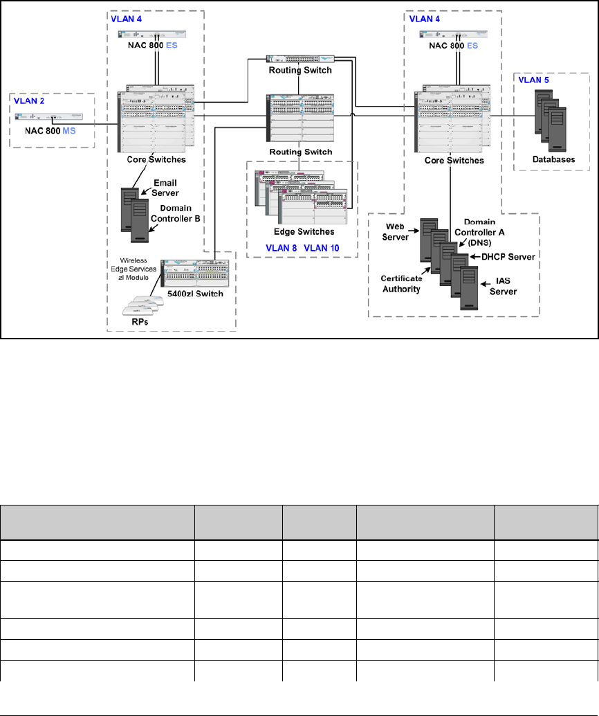
3-7
Implementing 802.1X with Endpoint Integrity but without IDM
Introduction
Figure 3-1 shows a high-level network design.
Figure 3-1. High-Level Network Design for ProCurve University
The instructions in this chapter sometimes call for entering a specific IP
address. Table 3-3 lists IP addresses for the example network. Fill in your
devices’ IP addresses and VLANs in the rightmost columns. You can then easily
replace the IP address given in the instructions with the correct address in
your environment.
Table 3-3. Example IP Addresses
Device Example IP
Address
Example
VLAN ID
Your Organization’s
IP Address
Your Organization’s
VLAN ID
Domain controller 10.4.4.15 4
Backup domain controller 10.4.5.15 4
DNS servers 10.4.4.15
10.4.5.15
4
DHCP server 10.4.4.20 4
CA server 10.4.4.25 4
IAS server 10.4.4.30 4

3-8
Implementing 802.1X with Endpoint Integrity but without IDM
Introduction
Note In your network, some servers might run multiple services. For example, the
domain controllers might run DNS as well as Active Directory.
University Web server 10.4.6.30 4
Library Web server 10.4.6.35 4
Email server 10.4.6.40 4
Grade database 10.5.1.45 5
Faculty file server 10.5.2.50 5
Other servers and databases 10.4.x.x
10.5.x.x
4
5
Routing Switch A • 10.2.0.1
• 10.4.0.1
• 10.5.0.1
• 10.8.0.1
• 10.10.0.1
• 10.32.0.1
• 10.34.0.1
• 10.36.0.1
•2
•4
•5
•8
•10
•32
•34
•36
Routing Switch B • 10.2.4.1
• 10.4.4.1
• 10.5.4.1
• 10.8.4.1
• 10.10.4.1
• 10.32.4.1
• 10.34.4.1
• 10.36.4.1
•2
•4
•5
•8
•10
•32
•34
•36
Switch A 10.2.0.5 2
Other switches
Wireless Edge Services zl Module 10.2.0.20 2
Redundant Wireless Services zl
Module
10.2.0.25 2
NAC 800 MS 10.2.1.40 2
NAC 800 ES A 10.4.4.40 4
NAC 800 ES B 10.4.5.50 4
Device Example IP
Address
Example
VLAN ID
Your Organization’s
IP Address
Your Organization’s
VLAN ID

3-9
Implementing 802.1X with Endpoint Integrity but without IDM
Configure the ProCurve Switches
Configure the ProCurve Switches
This section provides example configurations for ProCurve switches in a
network that implements 802.1X port authentication and endpoint integrity.
The following sections show example configurations for:
■A routing switch, which connects only to other switches.
■A server switch, which connects to VLAN 4 servers and VLAN 5 servers.
Its uplink ports are A1 and B1.
■An edge switch, which connects to endpoints. Its uplink ports are A1 and
B1. The edge switch is also a wireless services-enabled switch.
This solution controls users by granting them dynamic VLAN assignments.
The configuration for the routing switch shows an ACL that controls traffic
on one of those VLANs. This ACL is simply an example; refer to your switch
documentation for instructions on setting up your own ACLs.
Refer to the following sample configurations as you set up your network. If
you need step-by-step instructions, you should refer to the documentation for
your switch.
Note Users will receive dynamic VLAN assignments through IDM. However, if you
are adding 802.1X authentication to an existing network, edge ports must, of
course, retain their static assignment to a VLAN until you activate 802.1X
authentication.
For reference, these configurations allow the core switches to authenticate
the edge switches—the most secure option. However, take care when you
enable 802.1X authentication on ports connecting switches. The path to the
RADIUS server must be open for the authentication to complete. If you are
certain that uplink ports are secure, you can disable 802.1X authentication on
switch-to-switch ports.

3-10
Implementing 802.1X with Endpoint Integrity but without IDM
Configure the ProCurve Switches
Routing Switches
The following is the startup-config for the routing switch used to test this
network.
; J8692A Configuration Editor; Created on release #K.12.XX
hostname "Routing_Switch"
module 1 type J86xxA
ip access-list extended "Students"
10 deny 10.10.0.0 0.0.255.255 10.5.0.0 0.0.255.255
20 permit 0.0.0.0 255.255.255.255 0.0.0.0 255.255.255.255
exit
ip routing
snmp-server community "procurvero" Operator
snmp-server community "procurverw" Manager Unrestricted
vlan 1
name "DEFAULT_VLAN"
no untagged 1-20
no ip address
exit
vlan 2
name "Management"
untagged 1-20
ip helper-address 10.4.4.20
ip address 10.2.0.1 255.255.0.0
exit
vlan 4
name "Server"
ip address 10.4.0.1 255.255.0.0
tagged 1-5
exit
vlan 5
name "Faculty_databases"
ip address 10.5.0.1 255.255.0.0
tagged 1-5
exit
vlan 10
name "Students"
ip helper-address 10.4.4.20
ip address 10.10.0.1 255.255.0.0
tagged 6-20
ip access-group "Students" vlan
exit

3-11
Implementing 802.1X with Endpoint Integrity but without IDM
Configure the ProCurve Switches
vlan 8
name "Faculty"
ip helper-address 10.4.4.20
ip address 10.8.0.1 255.255.0.0
tagged 6-20
exit
vlan 32
name "Test"
ip helper-address 10.4.4.20
ip address 10.32.0.1 255.255.0.0
tagged 6-20
exit
vlan 34
name "Quarantine"
ip helper-address 10.4.4.20
ip address 10.34.0.1 255.255.0.0
tagged 6-20
exit
vlan 36
name "Infected"
ip helper-address 10.4.4.20
ip address 10.36.0.1 255.255.0.0
tagged 6-20
exit
vlan 2100
name "Radio Port"
tagged 1-20
no ip address
exit
ip authorized-managers 10.2.0.0 255.255.0.0
ip authorized-managers 10.4.4.40 255.255.255.255
ip authorized-managers 10.4.5.50 255.255.255.255
aaa authentication login privilege-mode //The RADIUS
server that authenticates the user logging in to the switch
also assigns the user rights.//
aaa authentication telnet login radius local //This
command allows managers to use their Windows credentials
to log in to the switch via Telnet.//
aaa authentication port-access eap-radius
aaa authentication web login radius local //This command
allows managers to log in to the switch’s Web browser
interface with their Windows credentials.//
radius-server host 10.4.4.30 key procurve12
ip dns domain-name "procurveu.edu"

3-12
Implementing 802.1X with Endpoint Integrity but without IDM
Configure the ProCurve Switches
ip dns server-address 10.4.4.15
aaa port-access authenticator 6-20 //These ports connect
to edge switches.//
aaa port-access authenticator active //Do not enter this
command until you have completed setting up the entire
solution//
password manager
password operator
Server Switch startup-config
The following is the startup-config for the server switch used to test this
network.
; J8697A Configuration Editor; Created on release #K.12.XX
hostname "Server_Switch"
web-management management-url ""
module 1 type J8702A
module 2 type J8702A
ip default-gateway 10.2.0.1
snmp-server community "procurvero" Operator
snmp-server community "procurverw" Manager Unrestricted
vlan 1
name "DEFAULT_VLAN"
no untagged A1-A24, B1-B24
no ip address
exit
vlan 2100
name "Radio Port"
tagged A1,B1
no ip address
exit
vlan 2
name "Management"
untagged A1,B1
ip address 10.2.0.3 255.255.0.0
exit
vlan 4
name "Server"
untagged B2-B24
tagged A1,B1
no ip address
exit

3-13
Implementing 802.1X with Endpoint Integrity but without IDM
Configure the ProCurve Switches
vlan 5
name "Faculty_databases"
untagged A2-A24
tagged A1,B1
no ip address
exit
mirror 1 port B6 //Port 2 of a NAC 800 ES connects to port
B6//
mirror 1 port B7 //Port 2 of a NAC 800 ES connects to port
B7//
ip authorized-managers 10.2.0.0 255.255.0.0
ip authorized-managers 10.4.4.40 255.255.255.255
ip authorized-managers 10.4.5.50 255.255.255.255
aaa authentication login privilege-mode
aaa authentication telnet login radius local
aaa authentication port-access eap-radius
aaa authentication web login radius local
radius-server host 10.4.4.30 key procurve12
ip dns domain-name "procurveu.edu"
ip dns server-address 10.4.4.15
interface B2 //A DHCP server connects to port B2//
monitor all Both mirror 1
exit
password manager
password operator
Edge Switches
Your network will probably include many edge switches. An example config-
uration for an edge switch that also includes a Wireless Edge Services Module
follows.
Wireless Services-Enabled Switch startup-config
In addition to housing the Wireless Edge Services zl Module, this switch
functions as an edge switch. To improve readability, however, the encrypted
Wireless Edge Services Module commands have been omitted.
; J8697A Configuration Editor; Created on release #K.12.XX
hostname "Wireless Switch"
module 1 type J8702A
module 2 type J8702A
module 3 type J9051A

3-14
Implementing 802.1X with Endpoint Integrity but without IDM
Configure the ProCurve Switches
web-management management-url ""
ip default-gateway 10.2.0.1
snmp-server community "procurvero" Operator
snmp-server community "procurverw" Manager Unrestricted
vlan 1
name "DEFAULT_VLAN"
no untagged A1,B1
untagged A2-A24,B2-B24
no ip address
exit
vlan 8
name "Faculty"
tagged A1,B1,CUP
exit
lldp auto-provision radio-ports auto-vlan 2100 auto
vlan 2100
name "Radio Port"
tagged A1,B1,CDP
exit
vlan 10
name "Students"
tagged A1,B1,CUP
exit
vlan 32
name "Test"
tagged A1,B1,CUP
exit
vlan 34
name "Quarantine"
tagged A1,B1,CUP
exit
vlan 36
name "Infected"
tagged A1,B1,CUP
exit
vlan 2
name "Management"
untagged A1,B1
ip address 10.2.0.5 255.255.0.0
tagged CUP
exit
ip authorized-managers 10.2.0.0 255.255.0.0
ip authorized-managers 10.4.4.40 255.255.255.255
ip authorized-managers 10.4.5.50 255.255.255.255

3-15
Implementing 802.1X with Endpoint Integrity but without IDM
Configure Windows 2003 Services
aaa authentication login privilege-mode
aaa authentication telnet login radius local
aaa authentication port-access eap-radius
aaa authentication web login radius local
radius-server host 10.4.4.30 key procurve12
ip dns domain-name "procurveu.edu"
ip dns server-address 10.4.4.15
aaa port-access authenticator A2-A24,B2-B24 //802.1X
authentication is enforced on edge ports, but not uplink
ports.//
aaa port-access authenticator active //Do not enter this
command until you have completed setting up the entire
solution//
aaa port-access supplicant A1,B1
aaa port-access supplicant A1 identity "switch"
aaa port-access supplicant B1 identity "switch"
password manager
password operator
Configure Windows 2003 Services
Before you install IAS, you must have Windows 2003, Active Directory, DNS,
DHCP, and certificate services running. Please refer to Chapter 2: “Implement-
ing 802.1X with ProCurve IDM and Endpoint Integrity” for instructions on the
following:
1. Install the Windows 2003 server (page 2-20).
2. Install Active Directory (page 2-21).
3. Configure Windows domain groups (page 2-28).
4. Configure Windows domain users (page 2-31).
5. Configure DNS services with reverse lookup zones (page 2-35).
6. Install DHCP services (page 2-43).
7. Configure DHCP services (page 2-46).
8. Install and configure certificate services (page 2-53).

3-16
Implementing 802.1X with Endpoint Integrity but without IDM
Configure IAS
Configure IAS
This section explains how to configure IAS, the RADIUS server for this
solution. You must:
1. Install IAS.
2. Register IAS with Active Directory.
3. Install a certificate on the IAS server.
4. Configure basic properties.
5. Configure remote access policies.
6. Add RADIUS clients.
7. Enable remote logging.
8. Install and configure the SAIASConnector for the NAC 800.
Later, you will learn about an optional final step: installing a trusted root CA
certificate. The IAS server must trust the CA that signed the NAC 800’s SSL
certificate—most often a concern when the NAC 800 uses a self-signed
certificate.
Install IAS
Complete these steps on the Windows 2003 server that you have selected to
run IAS:
1. Open Add or Remove Programs. (In the Start menu, select Control Panel >
Add or Remove Programs.)
2. Click Add/Remove Windows Components in the left pane.
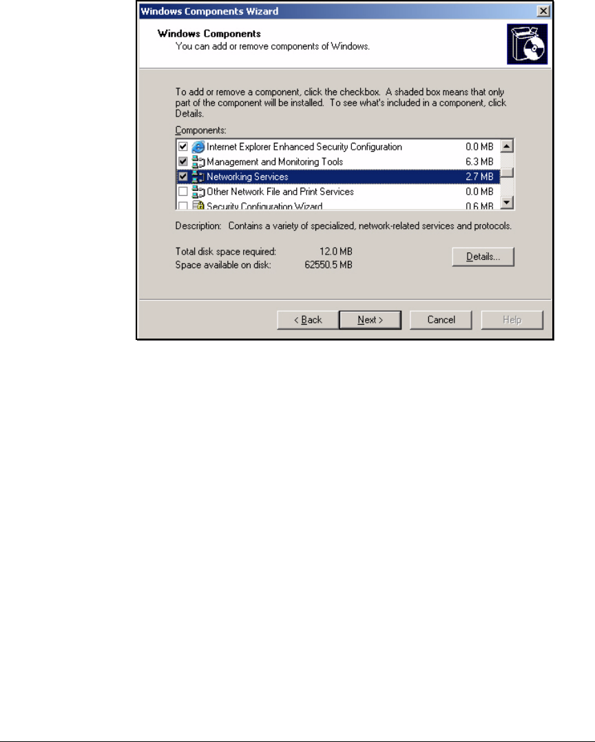
3-17
Implementing 802.1X with Endpoint Integrity but without IDM
Configure IAS
Figure 3-2. Windows Components Wizard—Windows Components Page
3. On the Windows Components page, select Network Services and click
Details.
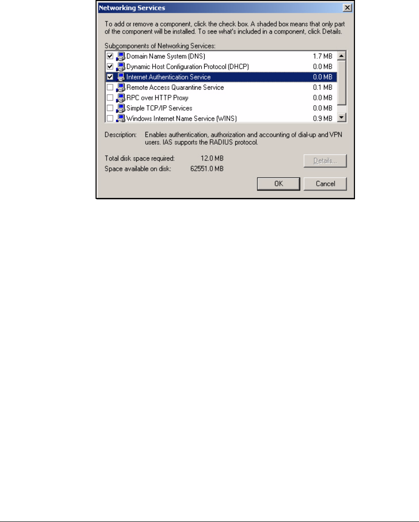
3-18
Implementing 802.1X with Endpoint Integrity but without IDM
Configure IAS
Figure 3-3. Windows Components Wizard—Networking Services Page
4. Select the Internet Authentication Service check box and click OK.
5. Click Next in the Windows Components page.
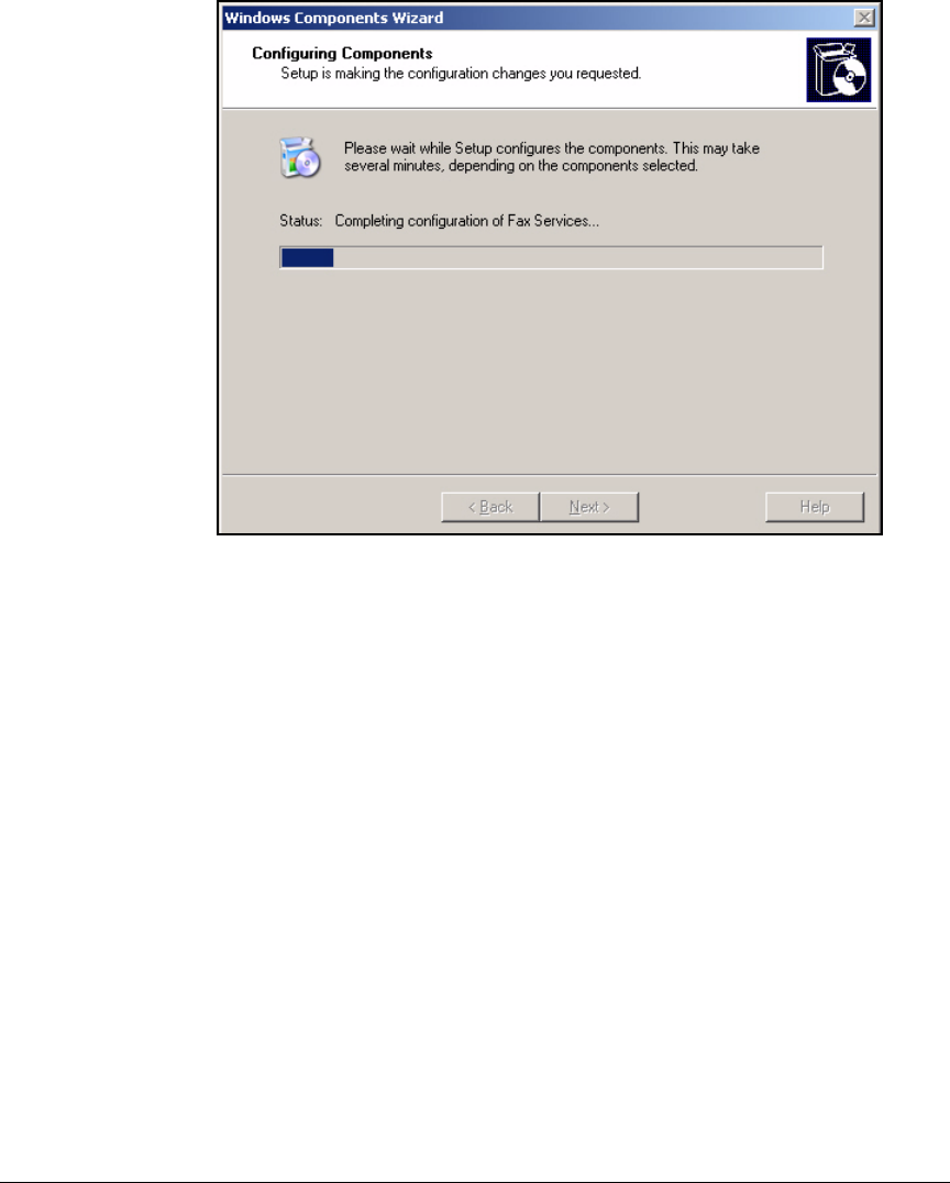
3-19
Implementing 802.1X with Endpoint Integrity but without IDM
Configure IAS
Figure 3-4. Windows Components Wizard—Configure Components Page
6. Wait several minutes while the components are configured.
7. Click Finish.
8. Close Add or Remove Programs. (Press [Alt]+[F4].)
Register IAS with Active Directory
1. In the Start menu, select Administrative Tools > Internet Authentication
Service.
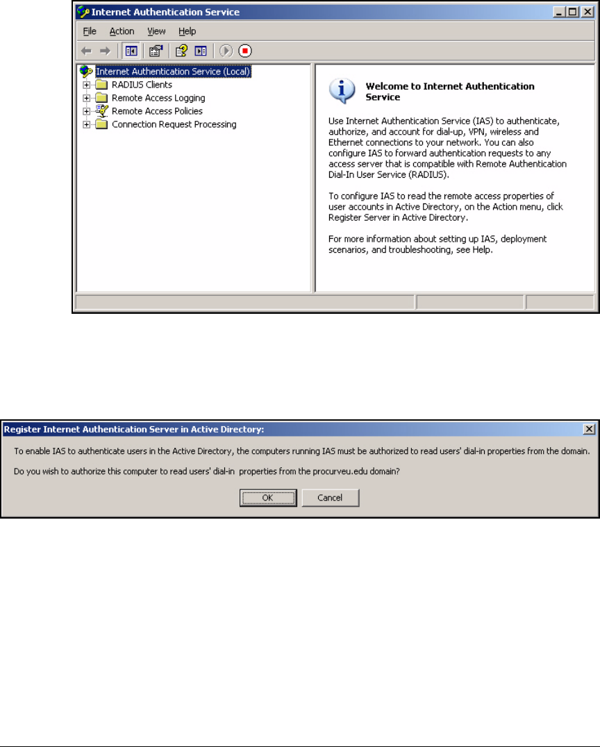
3-20
Implementing 802.1X with Endpoint Integrity but without IDM
Configure IAS
Figure 3-5. Internet Authentication Service Window
2. Right-click Internet Authentication Service (Local) and select Register Server
in Active Directory.
Figure 3-6. Register Internet Authentication Server in Active Directory Message
3. Click OK in the Register Internet Authentication Server in Active Directory
window.
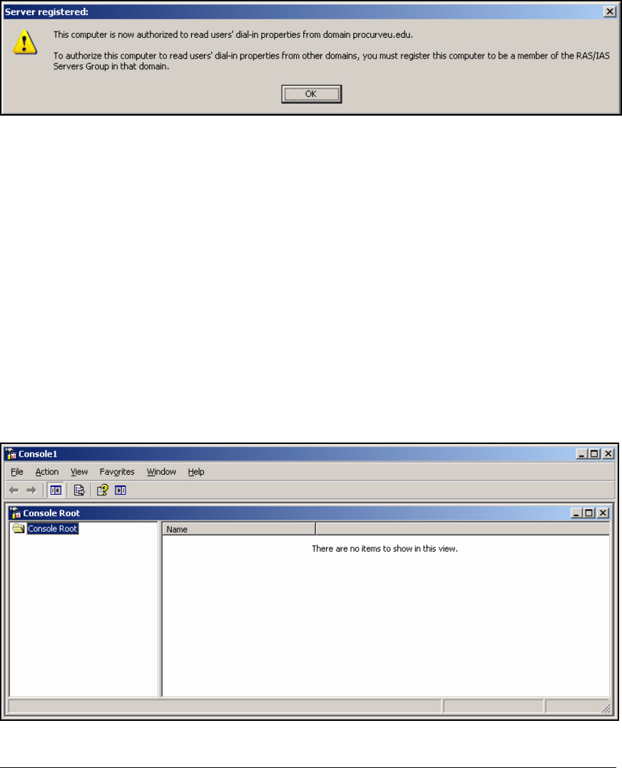
3-21
Implementing 802.1X with Endpoint Integrity but without IDM
Configure IAS
Figure 3-7. Server registered Message
4. Click OK in the Server registered window.
Install a Certificate on the IAS Server
A RADIUS server such as IAS requires a certificate for authenticating itself
(server authentication) and for authenticating endpoints (client authentica-
tion).
In this solution, the organization has a complete PKI with a domain CA that
will issue the certificates to IAS. Follow these steps to request and install the
certificate:
1. Open the Microsoft Management Console on the IAS server:
a. In the Start menu, select Run.
b. Type mmc and click OK.
Figure 3-8. Management Console
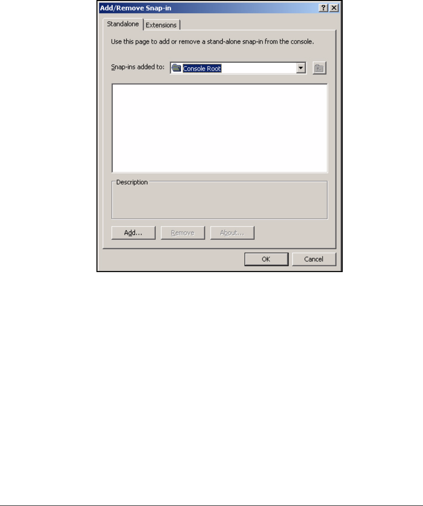
3-22
Implementing 802.1X with Endpoint Integrity but without IDM
Configure IAS
2. From the File menu, select Add/Remove Snap-in.
Figure 3-9. Add/Remove Snap-in Window
3. Click Add.
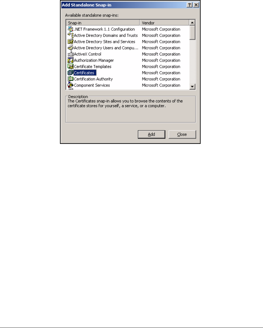
3-23
Implementing 802.1X with Endpoint Integrity but without IDM
Configure IAS
Figure 3-10. Add Standalone Snap-in Window
4. Select the Certificates snap-in and click Add.
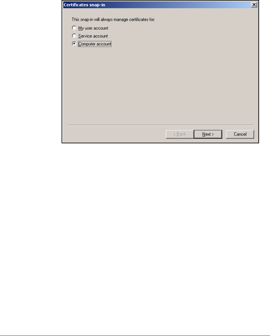
3-24
Implementing 802.1X with Endpoint Integrity but without IDM
Configure IAS
Figure 3-11. Certificates snap-in Window
5. Select Computer account and click Next.
6. Select Local Computer and click Finish.
7. Click Close.
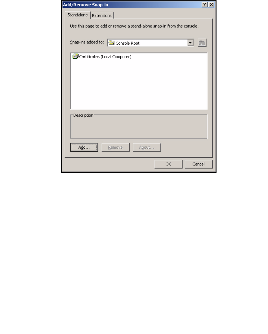
3-25
Implementing 802.1X with Endpoint Integrity but without IDM
Configure IAS
Figure 3-12. Add/Remove Snap-in Window
8. Click OK to exit.
9. Expand Certificates (Local Computer) under Console Root.
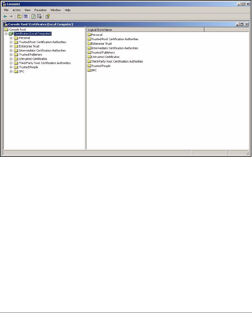
3-26
Implementing 802.1X with Endpoint Integrity but without IDM
Configure IAS
Figure 3-13. Management Console > Certificates (Local Computer)
10. Right-click the Personal folder and select All Tasks > Request New
Certificate.
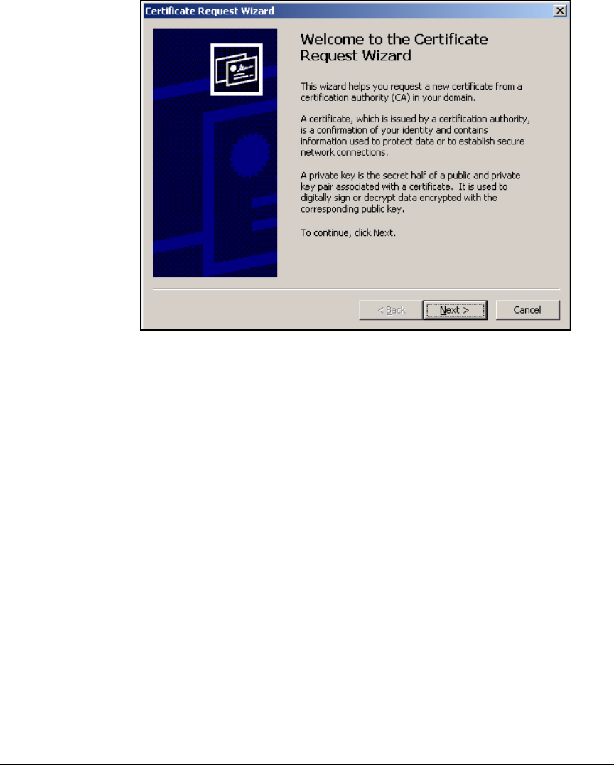
3-27
Implementing 802.1X with Endpoint Integrity but without IDM
Configure IAS
Figure 3-14. Certificate Request Wizard—Welcome Page
11. On the Certificate Request Wizard Welcome page, click Next.
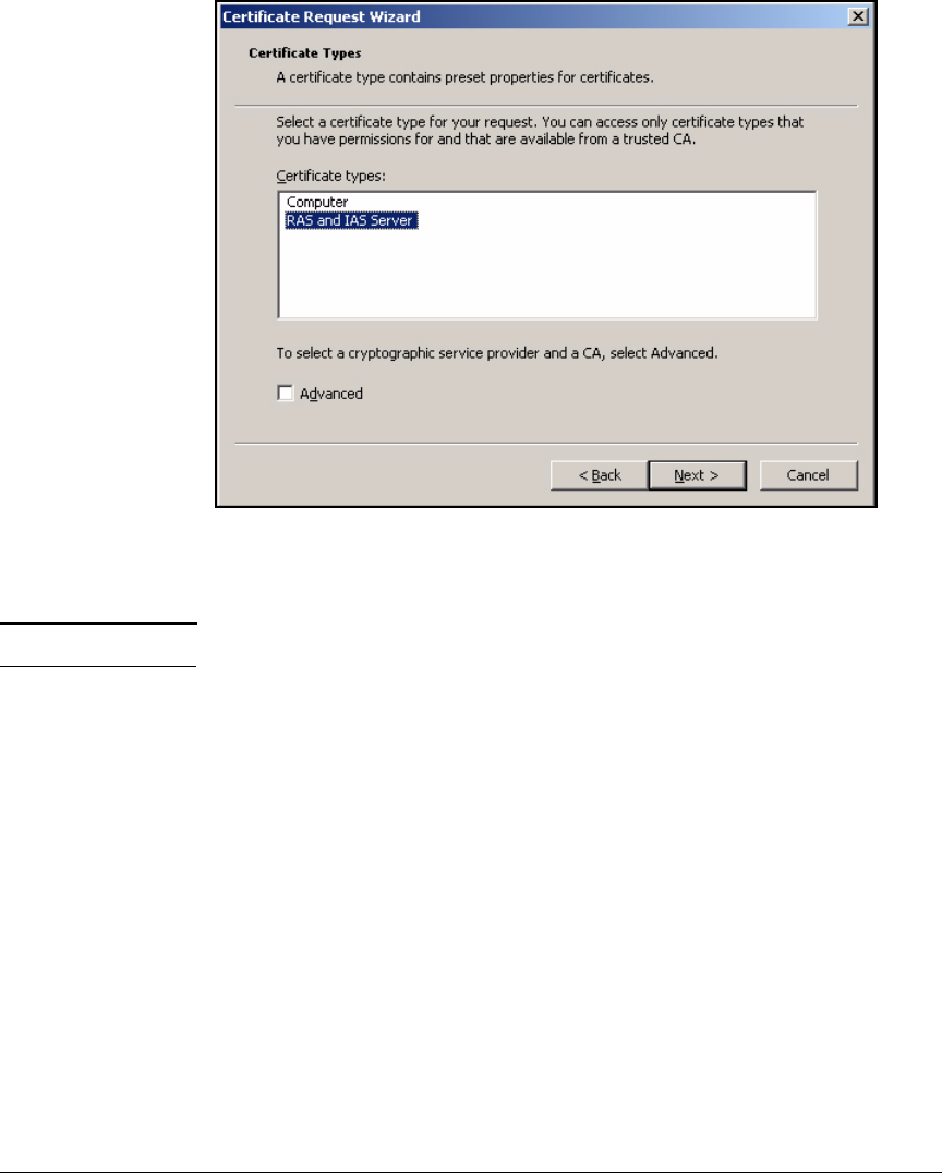
3-28
Implementing 802.1X with Endpoint Integrity but without IDM
Configure IAS
Figure 3-15. Certificate Request Wizard—Certificate Types Page
12. In the Certificate types box, select RAS and IAS Server.
Note If the RAS and IAS Server option does not appear, restart the server.
13. Click Next.
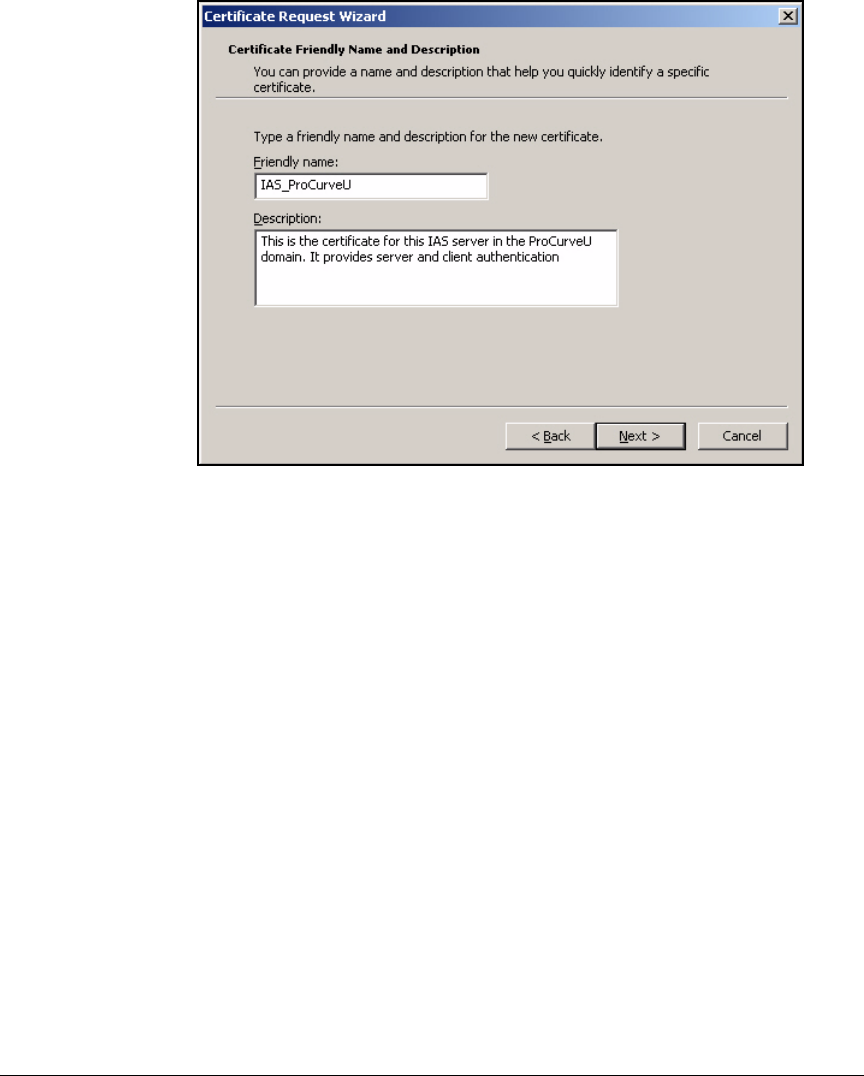
3-29
Implementing 802.1X with Endpoint Integrity but without IDM
Configure IAS
Figure 3-16. Certificate Request Wizard—Certificate Friendly Name and
Description Page
14. For the Friendly name, type a meaningful name for the certificate. In this
example, the name identifies the device that is requesting the certificate
(the IAS server) and the CA (ProCurveU CA): IAS_ProCurveU.
15. If you want, describe the certificate’s purpose in the Description box.
16. Click Next.
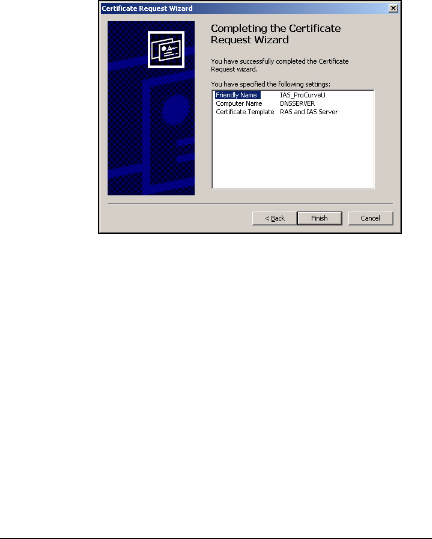
3-30
Implementing 802.1X with Endpoint Integrity but without IDM
Configure IAS
Figure 3-17. Certificate Request Wizard—Completing the Certificate Request
Wizard Page
17. Click Finish on the Completing the Certificate Request Wizard page. A mes-
sage is displayed, telling you the request was successful.
18. Press [Alt]+[F4] to close the Management Console.
19. Click Yes to save the console for later use.
20. Click Save to save the console. The default name is Console1.msc, but you
can give it any name you choose.
Configure IAS Properties
Basic IAS properties include the requests that IAS logs and the ports on which
IAS listens for authentication and accounting requests. Often, you can leave
the default properties, which are displayed in Table 3-4. However, if you want
change any of these settings, follow the steps below.
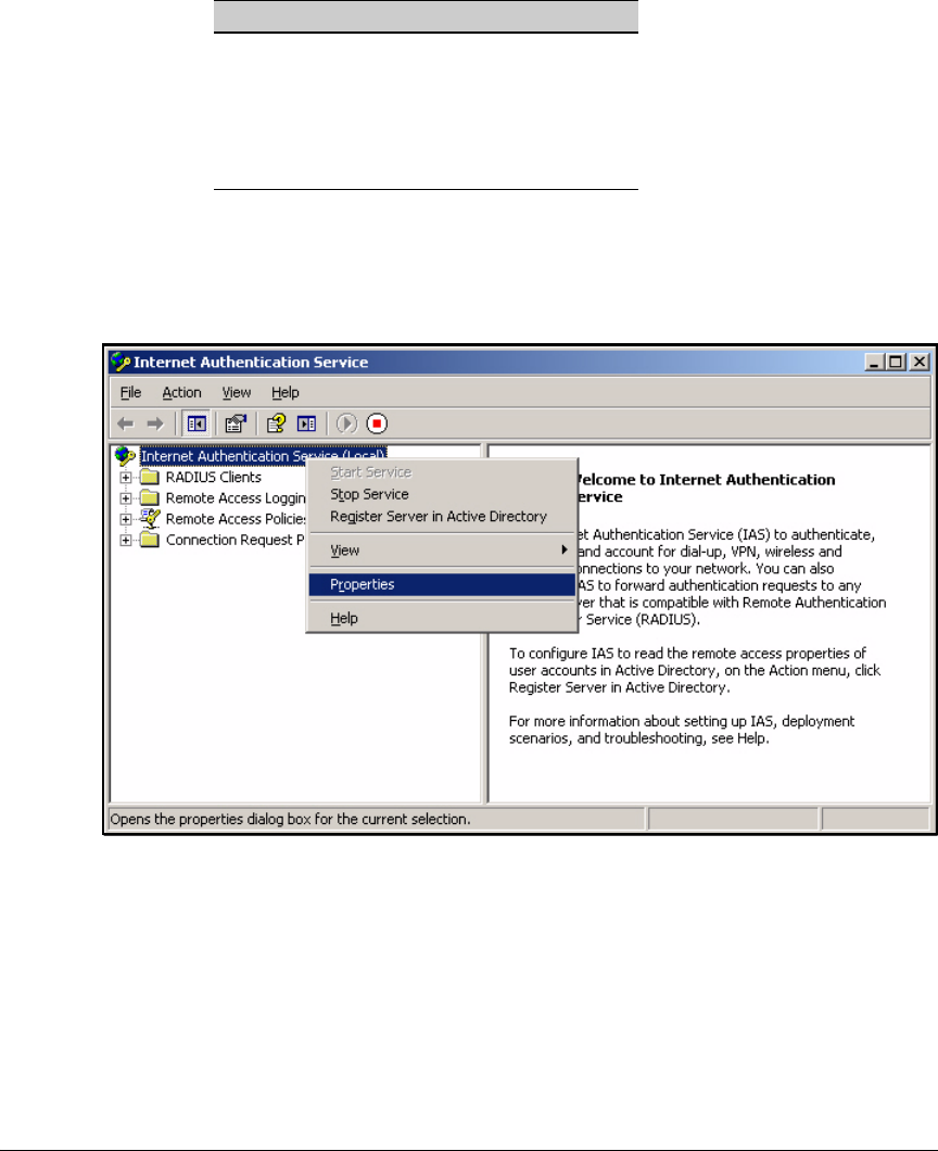
3-31
Implementing 802.1X with Endpoint Integrity but without IDM
Configure IAS
Table 3-4. Default IAS Settings
1. In the Start menu, click Administrative Tools > Internet Authentication
Service.
2. Right-click Internet Authentication Service (Local) and select Properties.
Figure 3-18. Internet Authentication Service Window
Parameter Default Setting
Server description IAS
Log • Rejected requests
• Accepted requests
Authentication port 1812, 1645
Accounting port 1813, 1646
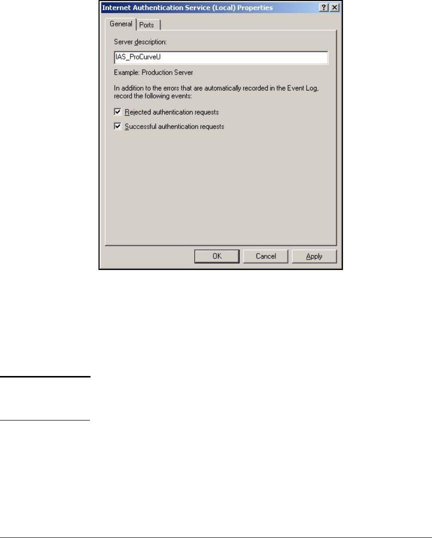
3-32
Implementing 802.1X with Endpoint Integrity but without IDM
Configure IAS
Figure 3-19. Internet Authentication Service (Local) Properties Window—
General Tab
3. On the General tab, type a meaningful name for the Server Description. For
example: IAS_ProCurveU.
4. Leave the Rejected authentication requests and Successful authentication
requests check boxes selected.
Note Typically, you should clear the Successful authentication requests check box
after the testing period. Otherwise, in a reasonably busy network, the log file
is quickly filled with successful log messages.
5. Click the Ports tab.
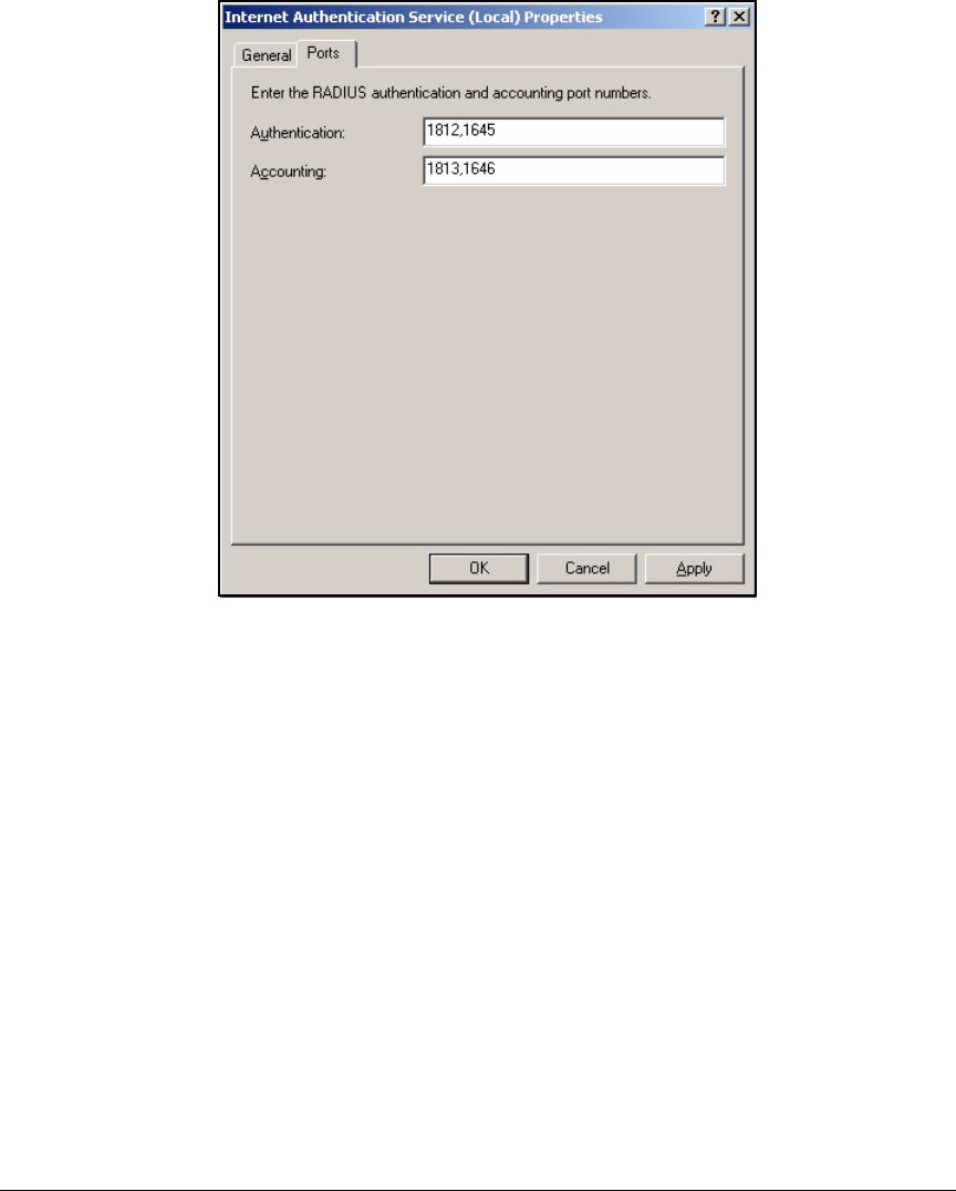
3-33
Implementing 802.1X with Endpoint Integrity but without IDM
Configure IAS
Figure 3-20. Internet Authentication Service (Local) Properties Window—
Ports Tab
6. In the Authentication box, type the UDP port number (or numbers) on
which IAS listens for authentication requests.
7. In the Authentication box, type the UDP port number (or numbers) on
which IAS listens for accounting requests.
8. Click OK.

3-34
Implementing 802.1X with Endpoint Integrity but without IDM
Configure IAS
Configure the Remote Access Policies
Next, you must create remote access policies for endpoints, which specify:
■Conditions—IAS determines the policy to use when handling an authen-
tication request by matching the request to the conditions.
Authentication requests are characterized by many variables, any of
which you can use to match the request to a policy. Some of the most
common ways include:
•By Windows group—You create a policy for each group that is
allowed network access. To match a request to a policy, IAS verifies
that the username belongs to the specified group. This is the strategy
that is used in the example network. See Table 3-5.
• By access method—For example, you can create different policies
for wired and wireless access.
•By time—You can create policies that allow, deny, or differentiate
access according to the time that the request is received.
■Authentication protocols—After IAS receives a RADIUS access
request from a NAS, it begins to authenticate the user. You can select one
or more protocols for this procedure.
■Advanced properties—These are the dynamic settings that IAS sends
to the NAS to enforce. This guide shows you how to set up dynamic VLAN
assignments.
The example network has several policies, which are outlined in Table 3-5.
Table 3-5. IAS Remote Access Policies
Remote Access Policy Condition for Matching
Requests
Authentication Protocols Dynamic Settings (Advanced)
Infrastructure Devices Group = Infrastructure
Devices
Connection type =
Ethernet
EAP-MD5
Network_Admins Group = Network_Admins EAP-TLS • Tunnel-Type = VLAN
• Tunnel-Medium-Type = 802
• Tunnel-Pvt-Group-ID = 2
Faculty Group = Faculty EAP-TLS • Tunnel-Type = VLAN
• Tunnel-Medium-Type = 802
• Tunnel-Pvt-Group-ID = 8
Students Group = Students EAP-TLS • Tunnel-Type = VLAN
• Tunnel-Medium-Type = 802
• Tunnel-Pvt-Group-ID = 10
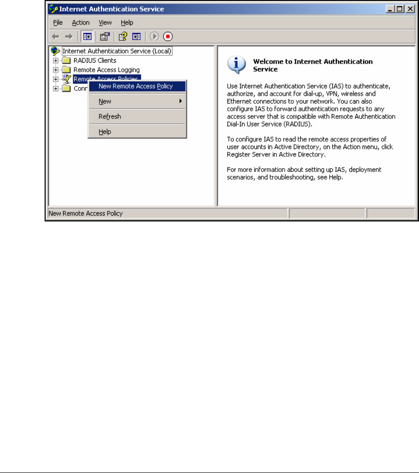
3-35
Implementing 802.1X with Endpoint Integrity but without IDM
Configure IAS
To create a policy, follow these steps:
1. In the Start menu, click Administrative Tools > Internet Authentication
Service.
Figure 3-21. Internet Authentication Service > Remote Access Policies
2. Right-click Remote Access Policies and click New Remote Access Policy.
3-36
Implementing 802.1X with Endpoint Integrity but without IDM
Configure IAS
Figure 3-22. New Remote Access Policy Wizard—Welcome Page
3. Click Next on the New Remote Access Policy Wizard Welcome page.
You must now choose between using the wizard to configure the policy
or setting up the policy manually.
The wizard uses the access method and either the username or the
Windows group as the policy’s conditions. The wizard also allows you to
select the authentication protocol but not advanced options (dynamic
settings). You must add those on your own.
Setting up the policy manually gives you greater flexibility but less
guidance.
The two sections below show you how to set up two example remote
access policies: one with the wizard and one manually.
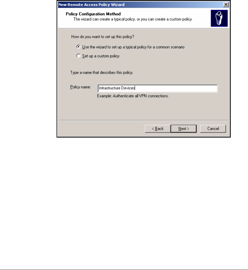
3-37
Implementing 802.1X with Endpoint Integrity but without IDM
Configure IAS
Using the New Remote Access Policy Wizard
Access the New Remote Access Policy Wizard, as described in the section
above. Click Next in the Welcome screen. You should see the screen in
Figure 3-23.
Figure 3-23. New Remote Access Policy Wizard—Policy Configuration
Method Page
Then follow these steps:
1. Select Use the wizard to set up a typical policy for a common scenario.
2. Type a meaningful description for the Policy name. For example, this
policy is intended to authenticate switches and APs and is named: Infra-
structure Devices.
3. Click Next.
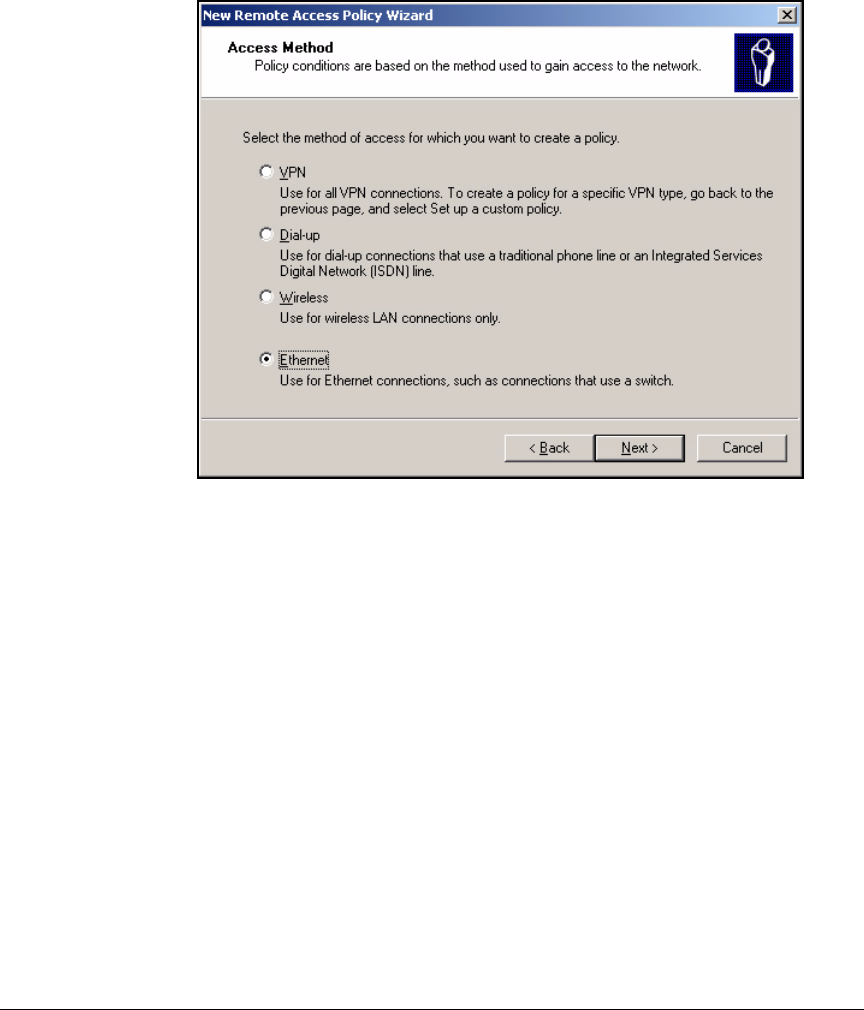
3-38
Implementing 802.1X with Endpoint Integrity but without IDM
Configure IAS
4. Select the access method. In this example, infrastructure devices are
authenticated at switch ports, so you would select Ethernet.
Figure 3-24. New Remote Access Policy Wizard—Access Method Page
5. Click Next.
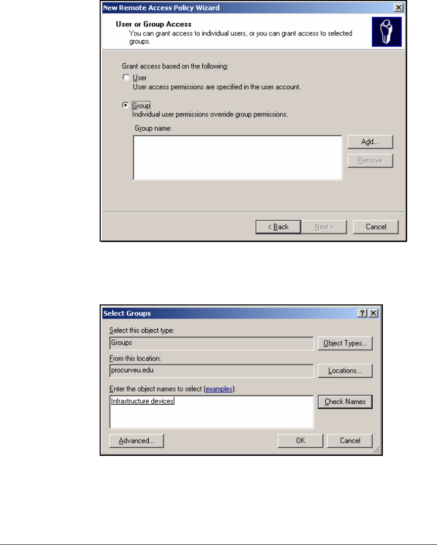
3-39
Implementing 802.1X with Endpoint Integrity but without IDM
Configure IAS
Figure 3-25. New Remote Access Policy Wizard—User or Group Access Page
6. Select Group and click Add.
Figure 3-26. Select Groups Window
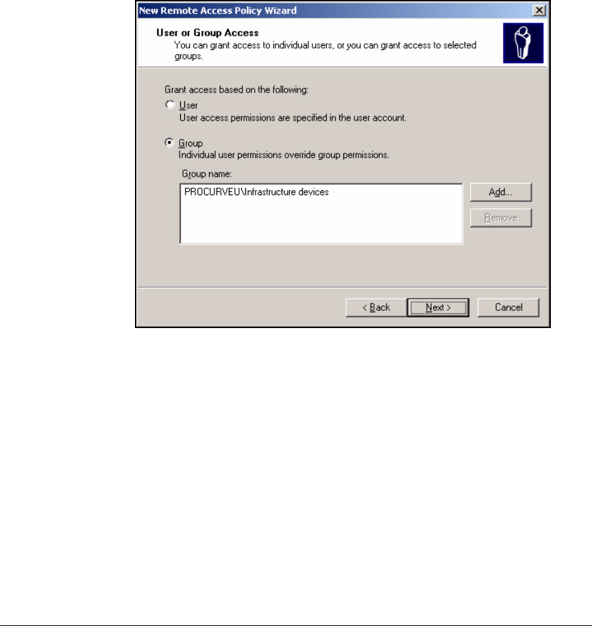
3-40
Implementing 802.1X with Endpoint Integrity but without IDM
Configure IAS
7. In the Select Groups window, make sure that From this location displays the
name of your domain.
8. Type the name of the group and click Check Names to verify that you have
typed the name correctly. If the group name is valid, it is underlined.
9. Click OK.
Figure 3-27. New Remote Access Policy Wizard—User or Group Access Page
10. If you want to add more object names, click Add. Otherwise, click Next.
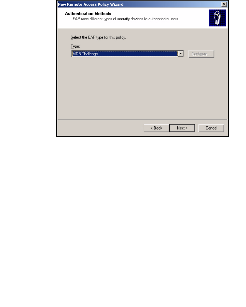
3-41
Implementing 802.1X with Endpoint Integrity but without IDM
Configure IAS
Figure 3-28. New Remote Access Policy Wizard—Authentication Methods Page
11. Select your EAP method. ProCurve devices support EAP-MD5, so for the
Infrastructure Devices policy, accept the default: MD5-Challenge.
12. Click Next.
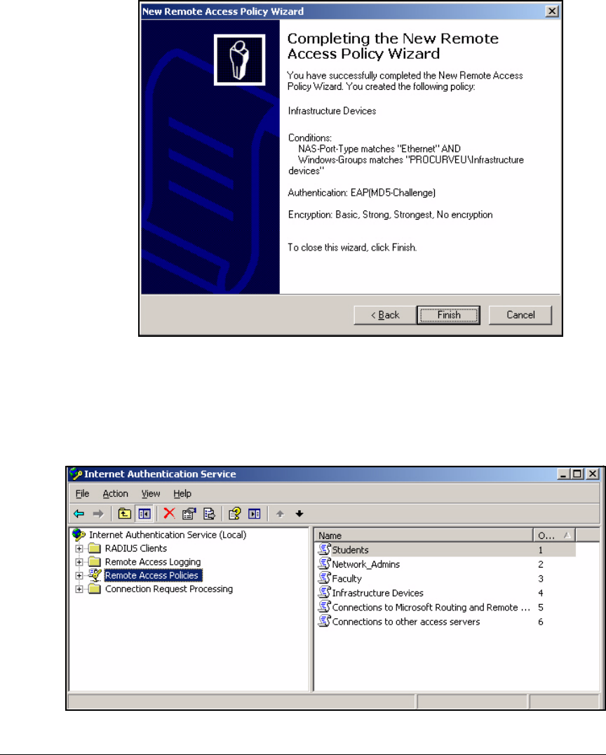
3-42
Implementing 802.1X with Endpoint Integrity but without IDM
Configure IAS
Figure 3-29. New Remote Access Policy Wizard—Completing the New Remote
Access Policy Wizard Page
13. Click Finish on the Completing the New Remote Access Policy Wizard page.
14. Select Remote Access Policies in the Internet Authentication Service window.
Figure 3-30. Internet Authentication Service > Remote Access Policies

3-43
Implementing 802.1X with Endpoint Integrity but without IDM
Configure IAS
15. Verify that the new policy is listed above the default polices:
• Connections to Microsoft Routing and Remote
• Connections to other access servers
If the new policy is below the default policies, select the policy name, then
click the Order column to move the policy up.
If you want, repeat these steps to create more policies.
You can also edit the policy and add conditions, choose supplemental authen-
tication methods, or configure advanced properties. See “Edit a Remote
Access Policy” on page 3-62.
Manually Create a Remote Access Policy
Sometimes you will want to create a remote access policy that does not fit the
options presented by the New Remote Access Policy Wizard. For example, the
PCU network administrators want to give faculty members the same access
whether they connect via Ethernet or the wireless network. However, the
wizard forces them to choose one or the other.
Follow these steps to create the policy manually:
1. Access the New Remote Access Policy Wizard.
a. Right-click Remote Access Policies in the Internet Authentication Service
window.
b. Select New Remote Access Policy.
2. Click Next on the Welcome page. You should see the page in Figure 3-31.

3-44
Implementing 802.1X with Endpoint Integrity but without IDM
Configure IAS
Figure 3-31. New Remote Access Policy Wizard—Policy Configuration
Method Page
3. Select Set up a custom policy.
4. In the Policy name box, type a meaningful description for this policy. In
this example, the policy is meant to control the access of members of the
Faculty group; type: Faculty.
5. Click Next.

3-45
Implementing 802.1X with Endpoint Integrity but without IDM
Configure IAS
Figure 3-32. New Remote Access Policy Wizard—Policy Conditions Page
6. On the Policy Conditions page, configure how IAS matches authentication
requests to this policy. Click Add to set up your first condition.
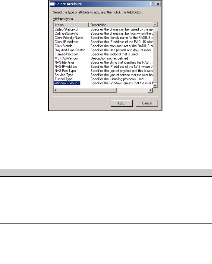
3-46
Implementing 802.1X with Endpoint Integrity but without IDM
Configure IAS
Figure 3-33. New Remote Access Policy Wizard—Select
Attribute Window
7. In the Select Attribute window, select the attribute for the condition against
which you want the policy to match requests. (Refer to Table 3-6.) In this
example, you want the policy to apply to all requests from members of
the Faculty group, so you select Windows-Groups.
Table 3-6. Conditions for Remote Access Policies
8. Click Add. A window is displayed that lets you select the value for the
condition attribute. In this example, the Groups window is displayed.
9. Click Add.
Condition Attribute Possible Values
Access method (Ethernet, wireless,
and so forth)
NAS-Port-Type • Ethernet
• Wireless — IEEE 802.11
• Virtual (VPN)
Group membership Windows-Group Name of group in Active Directory
Location (by switch or AP) NAS-Identifier or NAS-IP-Address IP address
Time Day-and-Time-Restriction Day of the week
Permitted or denied time periods
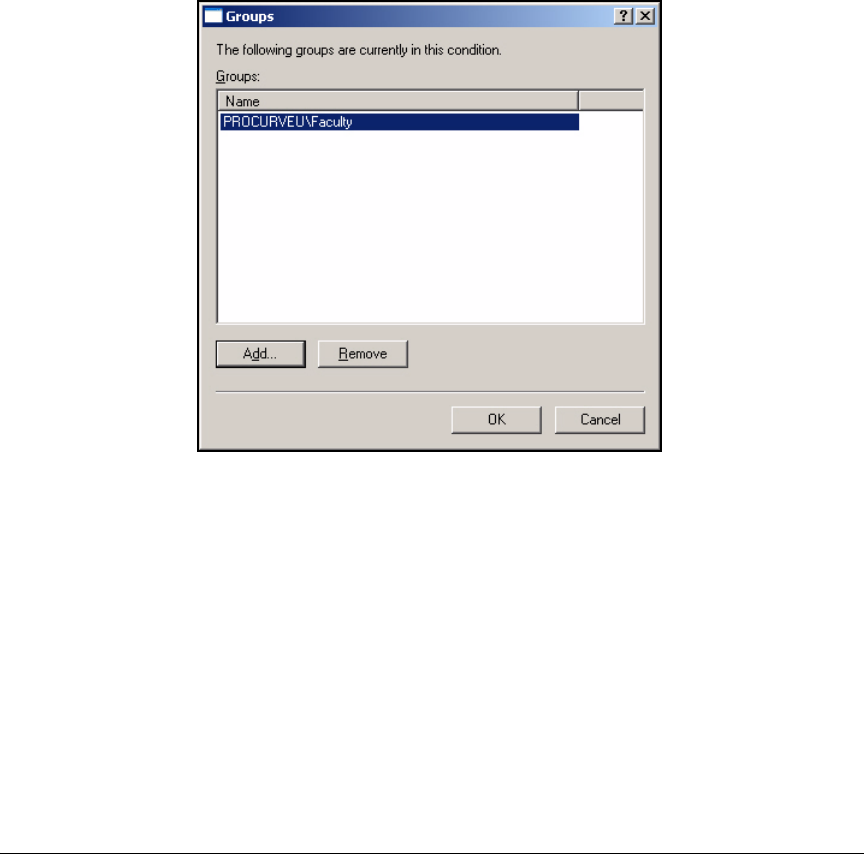
3-47
Implementing 802.1X with Endpoint Integrity but without IDM
Configure IAS
10. In the Select Groups window, make sure that From this location displays the
name of your domain.
11. In the Enter the object names to select box, type the name of the Windows
group to which you want to apply the policy. In this example: Faculty.
12. Click Check Names to verify that you have typed the name correctly. If the
group name is valid, it is underlined.
13. Click OK.
Figure 3-34. New Remote Access Policy Wizard—
Groups Window
14. Click Add to add another group to the condition or click OK if this is the
only group to which this policy applies. For the example network, click OK.
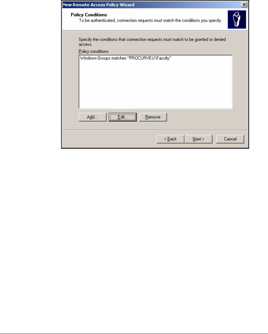
3-48
Implementing 802.1X with Endpoint Integrity but without IDM
Configure IAS
Figure 3-35. New Remote Access Policy Wizard—Policy Conditions Page
15. Click Add to add another policy to the condition or click Next if you have
finished setting conditions.
In this example, faculty members receive the same level of access
no matter the time nor place, so you are finished setting conditions.
Click Next.
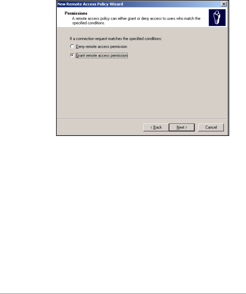
3-49
Implementing 802.1X with Endpoint Integrity but without IDM
Configure IAS
16. On the Permissions page, select Grant remote access permission.
Figure 3-36. New Remote Access Policy Wizard—Permissions Page
17. Click Next.
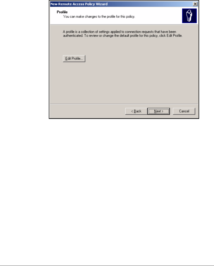
3-50
Implementing 802.1X with Endpoint Integrity but without IDM
Configure IAS
Figure 3-37. New Remote Access Policy Wizard—Profile Page
18. Click Edit Profile. The Edit Dial-in Profile window is displayed.

3-51
Implementing 802.1X with Endpoint Integrity but without IDM
Configure IAS
Figure 3-38. New Remote Access Policy Wizard—Edit Dial-in
Profile > Authentication Tab
19. Click the Authentication tab.
20. Select and clear check boxes to choose the authentication protocols that
you want to allow.
In this example, the PCU network enforces 802.1X authentication, so you
must choose an EAP method. Click EAP Methods.
21. In the Select EAP Providers window, click Add.
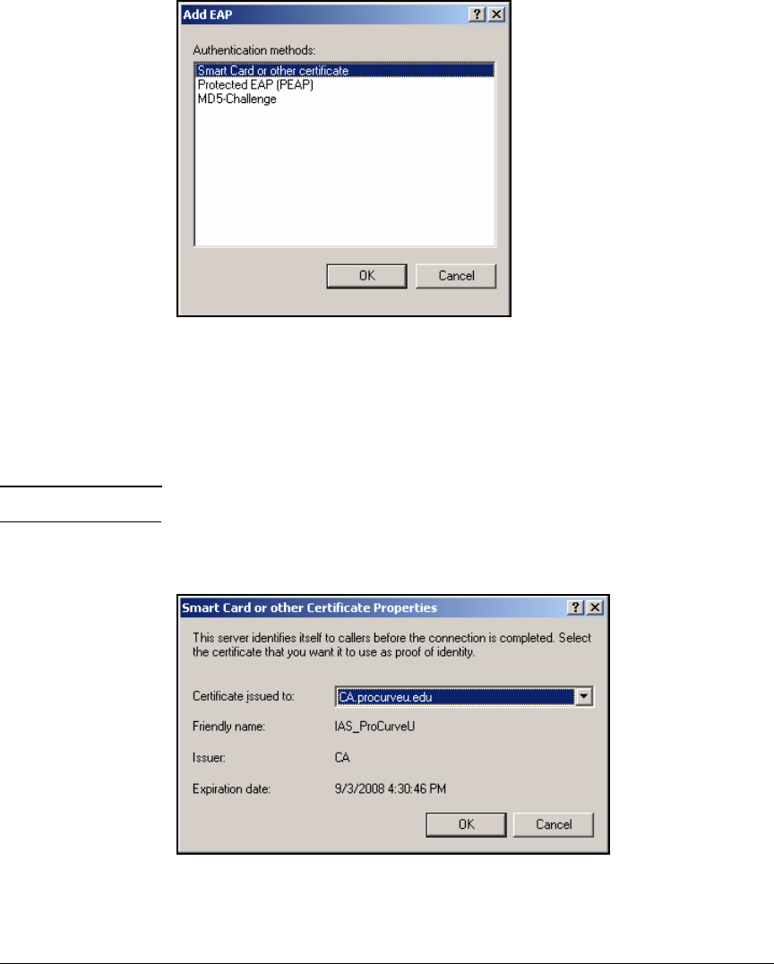
3-52
Implementing 802.1X with Endpoint Integrity but without IDM
Configure IAS
Figure 3-39. New Remote Access Policy Wizard—
Add EAP Window
22. In the Add EAP window, select your method.
In this example, the network has a PKI, so you select Smart Card or other
certificate for EAP-TLS.
Note You can repeat steps 21 and 22 to select multiple methods.
23. In the Select EAP Providers window, click Edit.
Figure 3-40. New Remote Access Policy Wizard—Smart Card
or other Certificate Properties Window
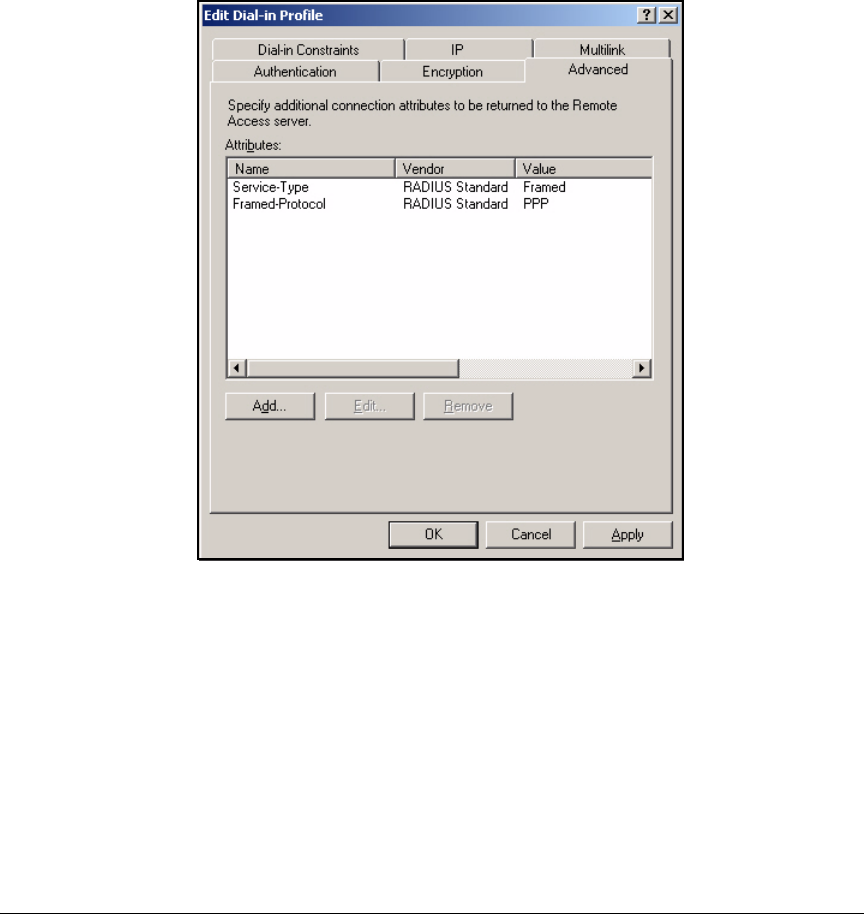
3-53
Implementing 802.1X with Endpoint Integrity but without IDM
Configure IAS
24. Select the certificate that you requested and installed for IAS in “Install a
Certificate on the IAS Server” on page 3-21. Click OK.
25. Click OK and then OK again to return to the Edit Dial-in Profile window.
26. Next, create the dynamic VLAN assignment for users granted access by
this policy. Click the Advanced tab.
Figure 3-41. New Remote Access Policy Wizard—Edit Dial-in Profile >
Advanced Tab
27. Click Add.
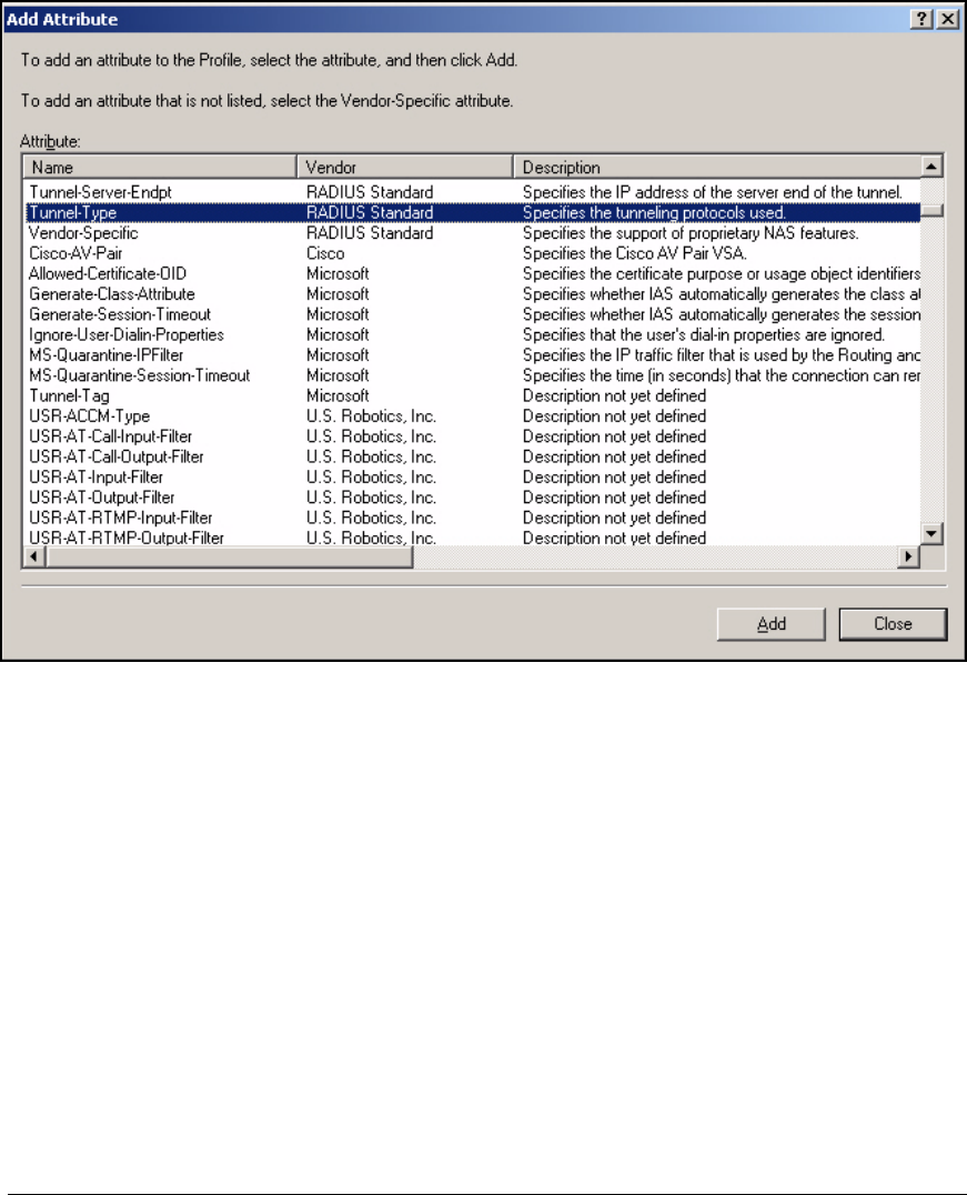
3-54
Implementing 802.1X with Endpoint Integrity but without IDM
Configure IAS
Figure 3-42. New Remote Access Policy Wizard—Add Attribute Window
28. From the Add Attribute list, select Tunnel-Type and click Add.
Originally, the Tunnel-Type attribute specified the tunneling protocol used
for remote access. In this case, however, the “tunnel” will be a VLAN.
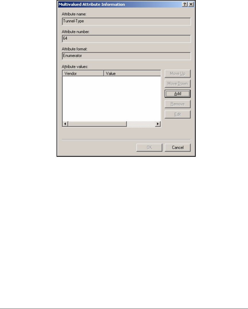
3-55
Implementing 802.1X with Endpoint Integrity but without IDM
Configure IAS
Figure 3-43. New Remote Access Policy Wizard—Multivalued
Attribute Information Window
29. In the Multivalued Attribute Information window, click Add.
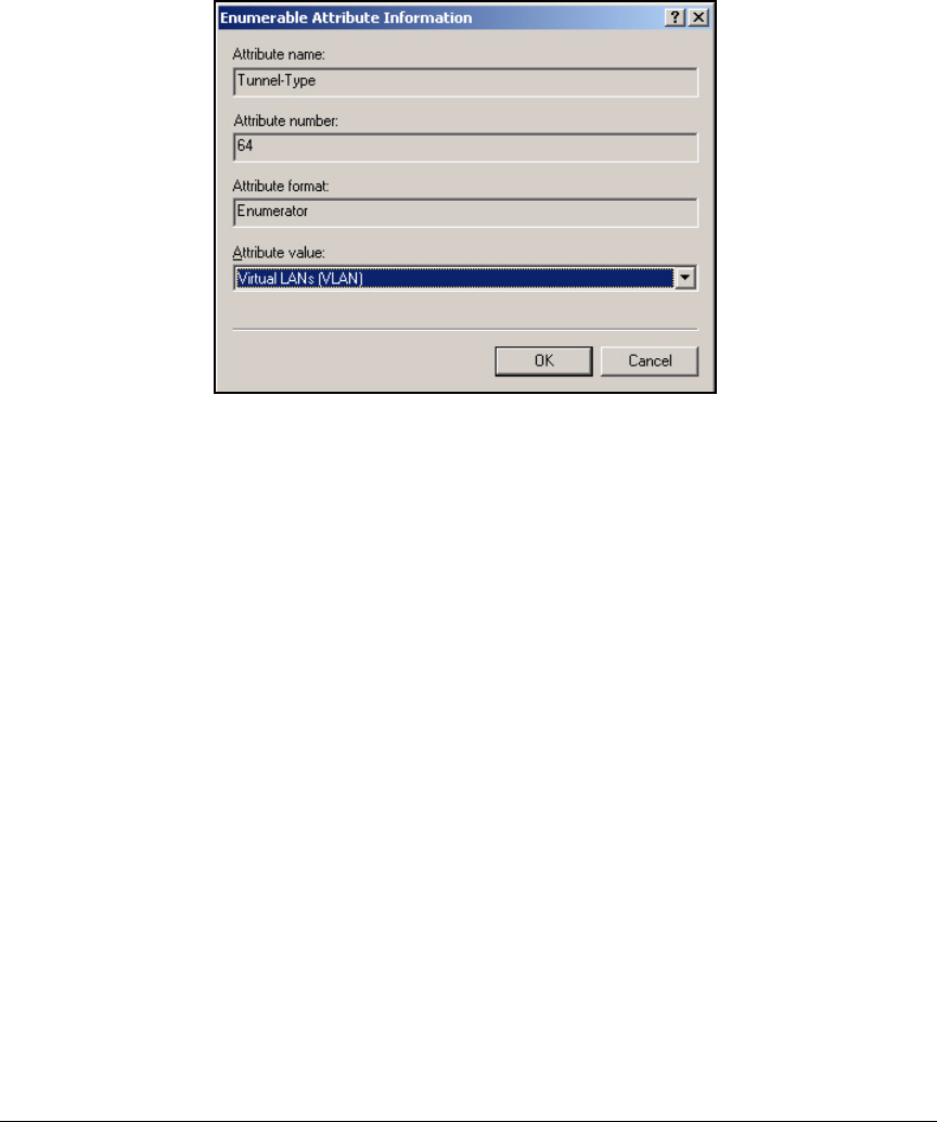
3-56
Implementing 802.1X with Endpoint Integrity but without IDM
Configure IAS
30. In the Enumerable Attribute Information window, select Virtual LANs (VLAN).
Figure 3-44. New Remote Access Policy Wizard—Enumerable
Attribute Information Window
31. Click OK and then OK again to return to the Add Attribute window.
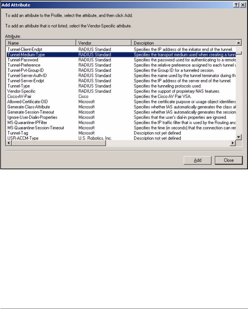
3-57
Implementing 802.1X with Endpoint Integrity but without IDM
Configure IAS
Figure 3-45. New Remote Access Policy Wizard—Add Attribute Window
32. In the Add Attribute window, select Tunnel-Medium-Type and click Add.
The Tunnel-Medium-Type attribute specifies the medium for the connec-
tion—in this case, you’ll choose 802 for Ethernet.
33. In the Multivalued Attribute Information window, click Add.

3-58
Implementing 802.1X with Endpoint Integrity but without IDM
Configure IAS
Figure 3-46. New Remote Access Policy Wizard—Enumerable
Attribute Information Window
34. Select 802.
35. Click OK and then OK again to return to the Add Attribute window.
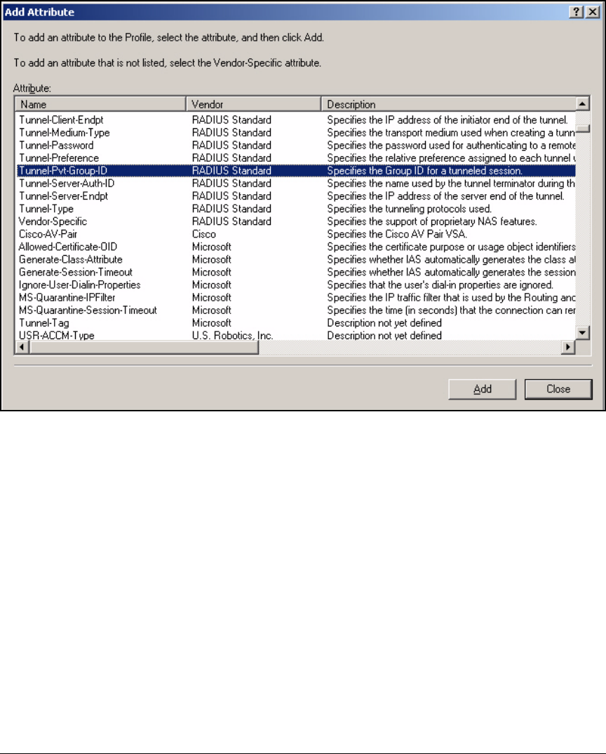
3-59
Implementing 802.1X with Endpoint Integrity but without IDM
Configure IAS
Figure 3-47. New Remote Access Policy Wizard—Add Attribute Window
The next attribute to select is Tunnel-Pvt-Group-ID, which specifies the
dynamic VLAN ID.
36. Click Add.
37. In the Multivalued Attribute Information window, click Add.
38. In the Attribute Information window, select String and type the VLAN ID in
the box below.
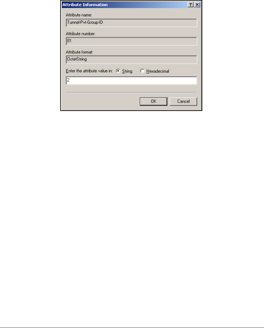
3-60
Implementing 802.1X with Endpoint Integrity but without IDM
Configure IAS
Figure 3-48. New Remote Access Policy Wizard—Attribute
Information Window
39. Click OK and then OK again to return to the Add Attribute window.
40. Click Close on the Add Attributes window. Figure 3-49 shows the Edit Dial-
in Profile window for the Faculty group in the example network.
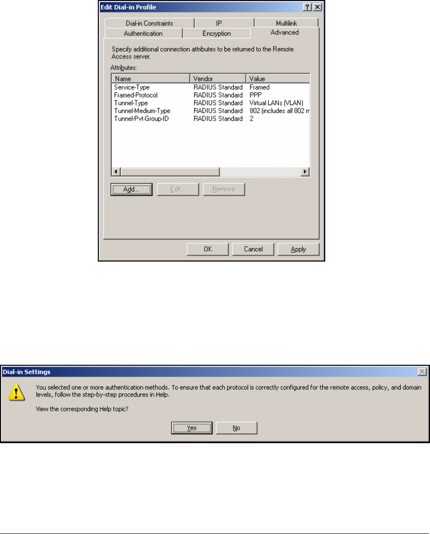
3-61
Implementing 802.1X with Endpoint Integrity but without IDM
Configure IAS
Figure 3-49. New Remote Access Policy Wizard—Edit Dial-in
Profile Window
41. Click Apply and OK.
If you selected authentication protocols, the Dial-in Settings message is
displayed.
Figure 3-50. New Remote Access Policy Wizard—Dial-in Settings Message
42. Click No.
43. Click Next in the New Remote Access Policy Wizard.
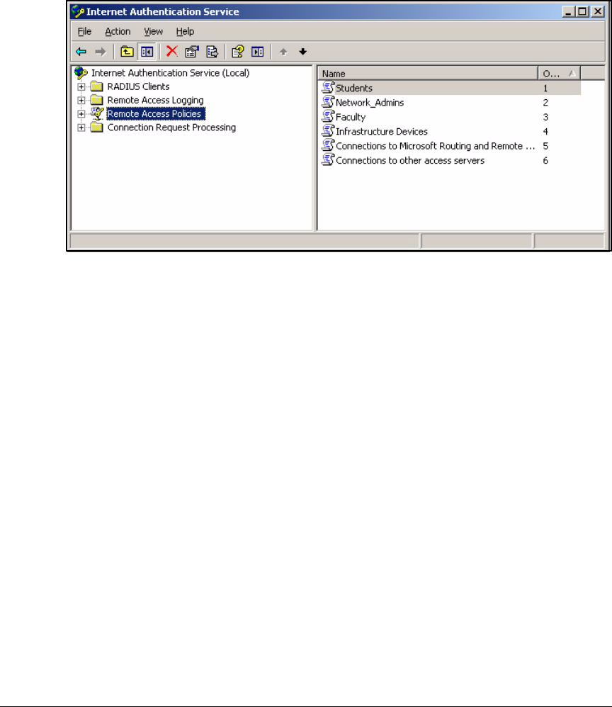
3-62
Implementing 802.1X with Endpoint Integrity but without IDM
Configure IAS
44. Click Finish.
45. Click Remote Access Policies in the Internet Authentication Service window.
Figure 3-51. Internet Authentication Service Window
46. Verify that the new policy is listed above the default polices:
• Connections to Microsoft Routing and Remote
• Connections to other access servers
If the new policy is below the default policies, select the policy name. Then
click the Order column to move the policy up.
If you want, repeat these steps to create other policies. In this example, you
must create four policies, one for each Windows groups to which users and
devices logging in to the network belong.
Edit a Remote Access Policy
No matter how you create a policy, you might want to edit it and change
conditions or alter the profile. Follow these steps:
1. In the Internet Authentication Service window, select Remote Access Policies
in the left pane.
2. In the right pane, right-click the policy that you want to modify and select
Properties.
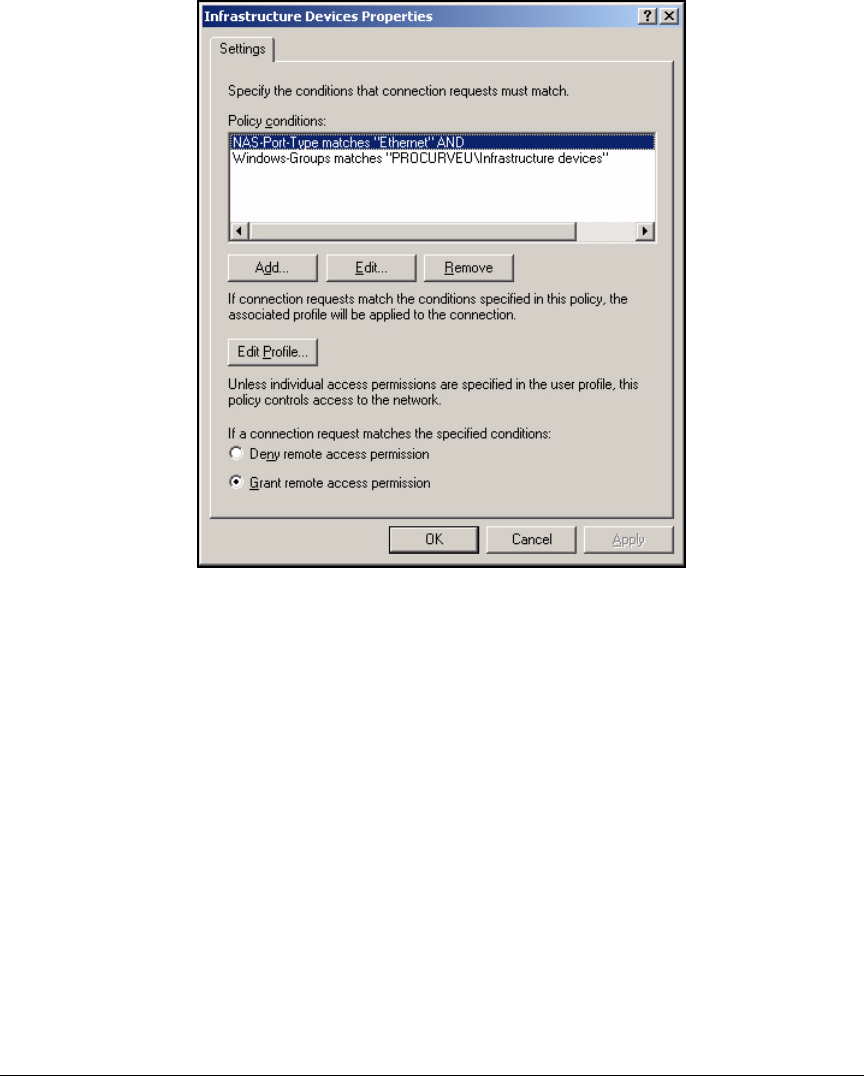
3-63
Implementing 802.1X with Endpoint Integrity but without IDM
Configure IAS
Figure 3-52. <remote access policy> Properties Window
3. In the Properties window, you can alter conditions:
• To add a value to an existing policy condition, select the policy
condition and click Edit.
For example, you might want a policy that is designed to control
Ethernet access to apply to wireless access as well.
You have two choices.
You could select NAS-Port-Type matches “Ethernet” AND and click
Remove. In this case IAS does not look at connection type when
choosing a policy.
Or you could select NAS-Port-Type matches “Ethernet” AND and click
Add. The NAS-Port-Type window is displayed; you select the additional
access method (Wireless - IEEE 802) and click Add >>.
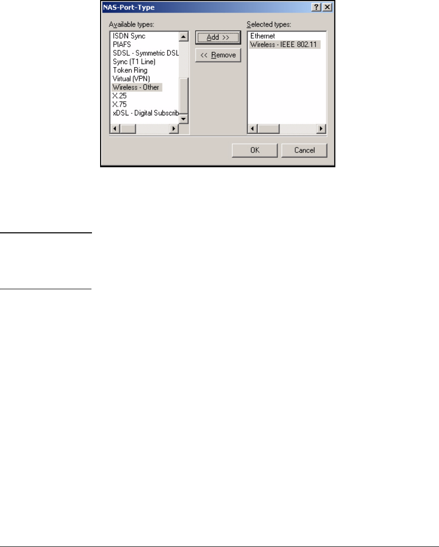
3-64
Implementing 802.1X with Endpoint Integrity but without IDM
Configure IAS
Figure 3-53. <remote access policy> Properties—
NAS-Port-Type Window
When you have finished adding types, click OK.
Note The new values are added to the condition as “OR” statements. In
other words, a request can have any of the selected values and meet
that particular condition. In this example, the request’s NAS port type
can be Ethernet or wireless 802.11.
• To add a new condition, click Add.
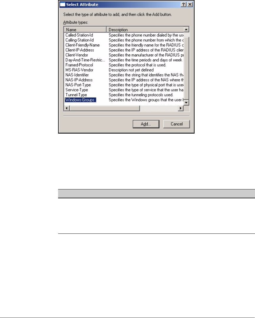
3-65
Implementing 802.1X with Endpoint Integrity but without IDM
Configure IAS
Figure 3-54. <remote access policy> Properties—
Select Attribute Window
In the Select Attribute window, select the attribute for the new condi-
tion. (Refer to Table 3-6.)
Table 3-7. Conditions for Remote Access Policies
Click Add. A window is displayed that lets you select the value (or
values) for the condition attribute. The exact steps for selecting the
value depend on the condition and are beyond the scope of this guide.
When you have finished configuring the condition, click OK to close
windows until you return to the Properties window.
4. In the Properties window, click Edit Profile.
5. Follow the steps that begin at step 18 on page 3-50 of “Manually Create a
Remote Access Policy.”
Condition Attribute
Access method (Ethernet, wireless, and so forth) NAS-Port-Type
Group membership Windows-Group
Location (by switch or AP) NAS-Identifier or NAS-IP-Address
Time Day-and-Time-Restriction

3-66
Implementing 802.1X with Endpoint Integrity but without IDM
Configure IAS
Optional Remote Access Policy for Network Administrators
You might want to allow network administrators to use their Windows domain
credentials to log in to the management interfaces of infrastructure devices.
That is, when an administrator attempts to open a session with a switch and
submits his or her credentials, the switch sends a RADIUS authentication
request to the network server rather than checks the credentials against its
local list.
The switch uses PAP, CHAP, or EAP-MD5 in the RADIUS request, so the access
policy on the RADIUS server must support those methods. Because it is not
generally best practice to allow EAP-MD5 in a policy for controlling users’
normal network access, you should create a new policy for the network
administrators.
You might also want to configure privileges for the managers in the access
policy. By default, the switch logs in all authenticated network administrators
with operator (read-only) privileges. To receive manager (read-write) privi-
leges, the user must enter an additional password. However, you can enter a
command on the switch (aaa authentication login privilege-mode) that allows
the RADIUS server to assign the privileges as the user authenticates. You will
learn how to specify the correct RADIUS attributes for these privileges in the
access policy on IAS.
Follow these steps:
1. Access the New Remote Access Policy Wizard (right-click Remote Access
Policies in the Internet Authentication Service window; select New Remote
Access Policy.)
2. Click Next on the Welcome page.
3. Select Set up a custom policy.
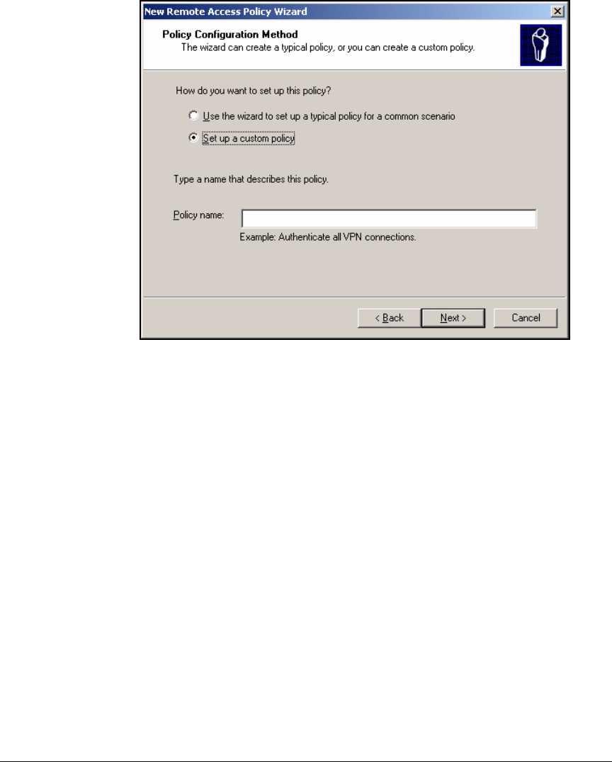
3-67
Implementing 802.1X with Endpoint Integrity but without IDM
Configure IAS
Figure 3-55. New Remote Access Policy Wizard—Policy Configuration
Method Page
4. In the Policy name box, type a meaningful description for this policy. For
example: Switch_Management.
5. Click Next.
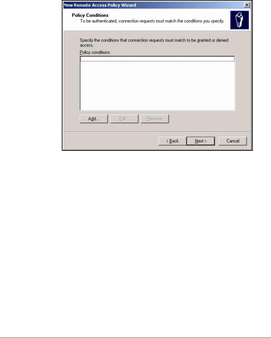
3-68
Implementing 802.1X with Endpoint Integrity but without IDM
Configure IAS
Figure 3-56. New Remote Access Policy Wizard—Policy Conditions Page
6. On the Policy Conditions page, click Add.
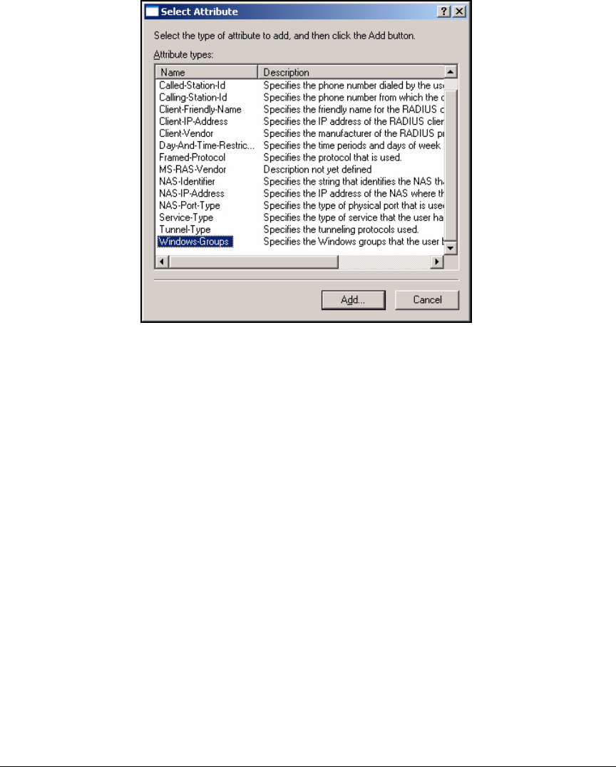
3-69
Implementing 802.1X with Endpoint Integrity but without IDM
Configure IAS
Figure 3-57. New Remote Access Policy Wizard—Select
Attribute Window
7. In the Select Attribute window, click NAS-Port-Type.
8. Click Add.
9. When a ProCurve switch creates an authentication request for a user
attempting to access its management interface, it sets the NAS-Port-Type
field to Virtual (VPN). Click that option in the Available types box.
10. Click Add.
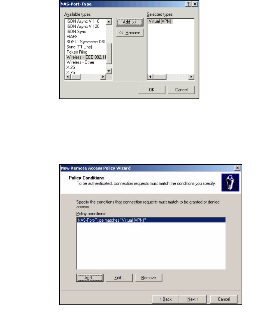
3-70
Implementing 802.1X with Endpoint Integrity but without IDM
Configure IAS
Figure 3-58. New Remote Access Policy Wizard—
NAS-Port-Type Window
11. Click OK.
12. The Policy Conditions page now lists your condition. You only want net-
work administrators to be able to log into your devices, so you must add
another condition.
Figure 3-59. New Remote Access Policy Wizard—Policy Conditions Page
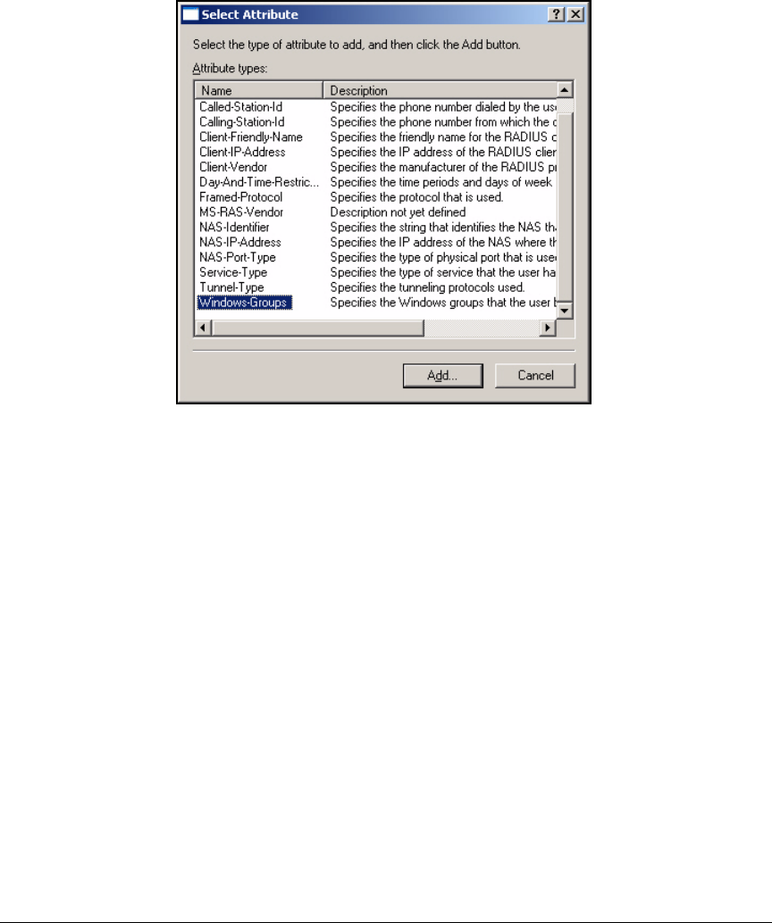
3-71
Implementing 802.1X with Endpoint Integrity but without IDM
Configure IAS
13. Click Add.
Figure 3-60. New Remote Access Policy Wizard—
Select Attribute Window
14. In the Select Attribute window, click Windows-Group.
15. Click Add. The Groups window is displayed.
16. Click Add.
17. In the Enter the object names to select box, type the name of the Windows
group that includes network administrators. In this example:
Network_Admins.
18. Click Check Names to verify that you have typed the name correctly. If the
group name is valid, it is underlined.
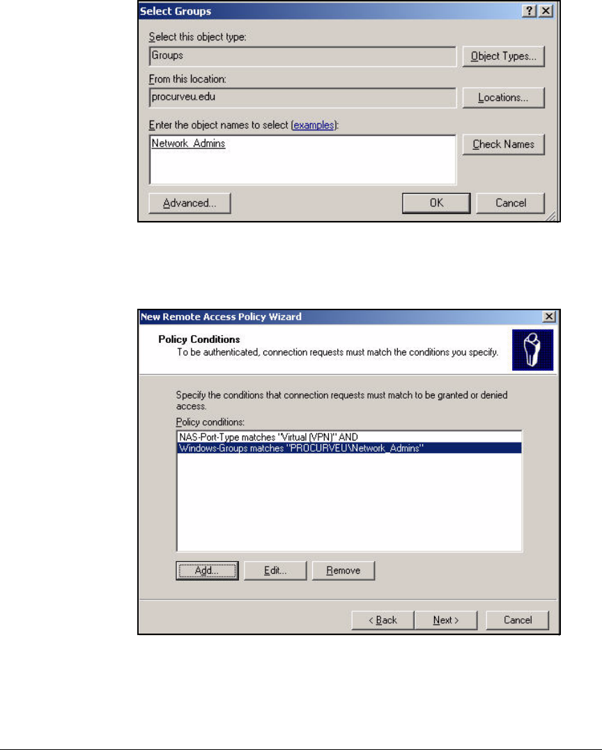
3-72
Implementing 802.1X with Endpoint Integrity but without IDM
Configure IAS
Figure 3-61. New Remote Access Policy Wizard—Select Groups Window
19. Click OK and OK again.
Figure 3-62. New Remote Access Policy Wizard—Policy Conditions Page
20. On the Policy Conditions page, click Next.
21. On the Permissions page, select Grant remote access permission.
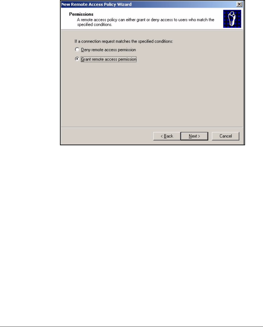
3-73
Implementing 802.1X with Endpoint Integrity but without IDM
Configure IAS
Figure 3-63. New Remote Access Policy Wizard—Permissions Page
22. Click Next.

3-74
Implementing 802.1X with Endpoint Integrity but without IDM
Configure IAS
Figure 3-64. New Remote Access Policy Wizard—Profile Page
23. Click Edit Profile. The Edit Dial-in Profile window is displayed.
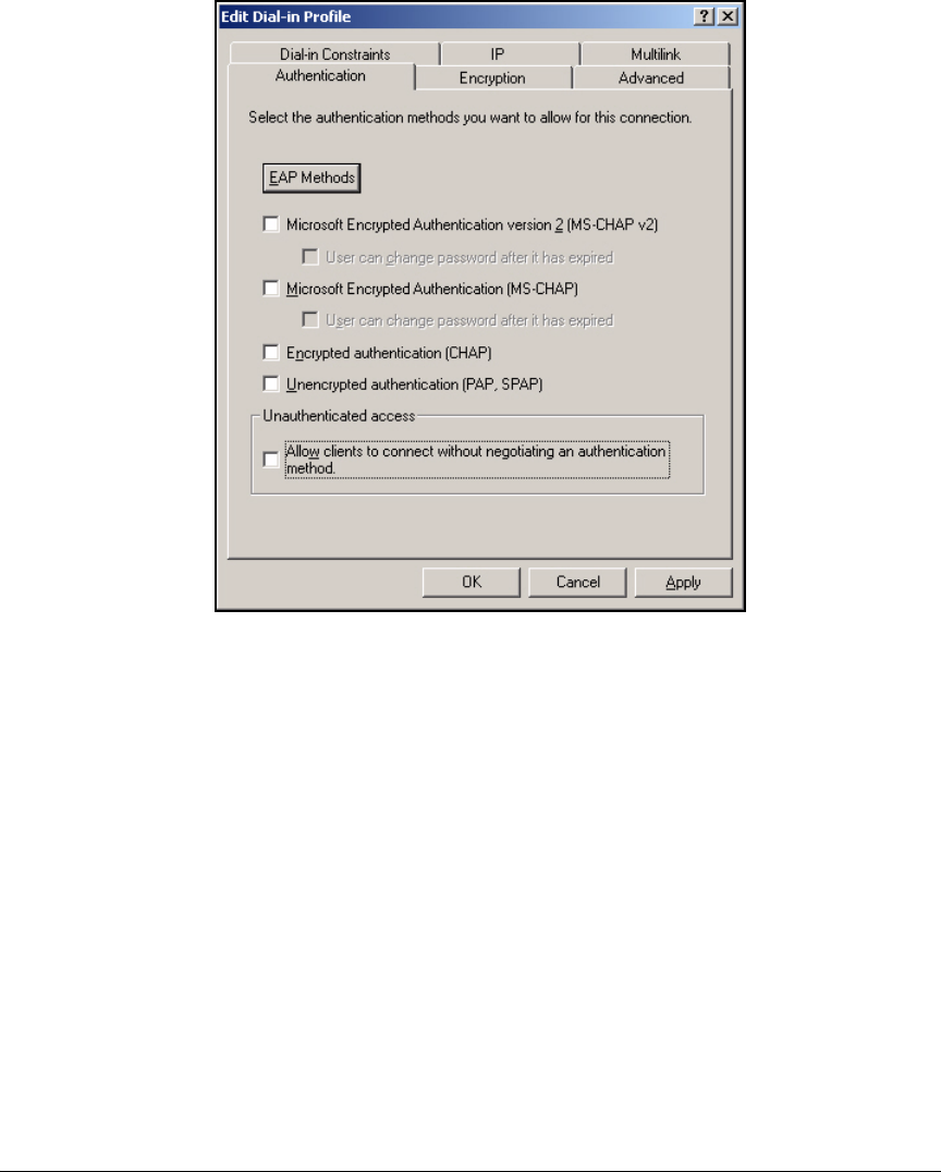
3-75
Implementing 802.1X with Endpoint Integrity but without IDM
Configure IAS
Figure 3-65. Edit Dial-in Profile > Authentication Tab
24. Click the Authentication tab.
25. Select the Encrypted authentication (CHAP) and Unencrypted authentication
(PAP, SPAP) check boxes.
26. Click EAP Methods.
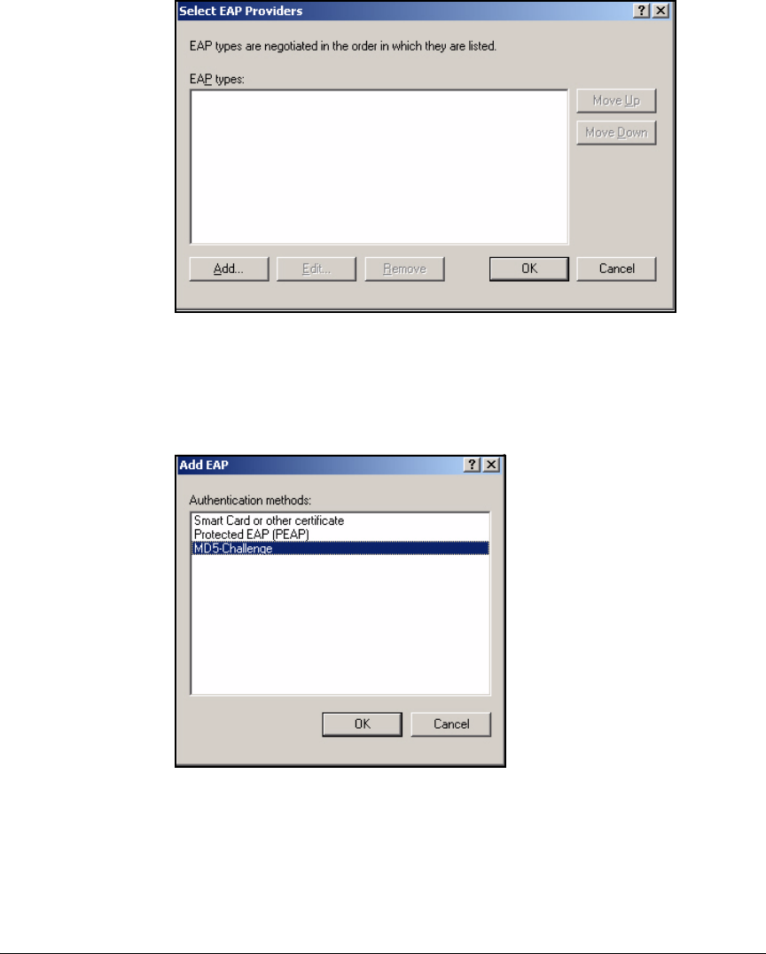
3-76
Implementing 802.1X with Endpoint Integrity but without IDM
Configure IAS
Figure 3-66. Edit Dial-in Profile—Select EAP Providers Window
27. In the Select EAP Providers window, click Add.
28. In the Add EAP window, click MD5-Challenge.
Figure 3-67. Edit Dial-in Profile—Add EAP Window
29. Click OK and then OK again to return to the Edit Dial-in Profile window.
30. Click the Advanced tab.

3-77
Implementing 802.1X with Endpoint Integrity but without IDM
Configure IAS
Figure 3-68. New Remote Access Policy Wizard—Edit Dial-in
Profile > Advanced Tab
31. Click Service-Type in the Attributes area and click Edit.
32. In the Enumerable Attribute Information window, select an Attribute value.
Select Administrative (for read-write privileges) or NAS-Prompt (for read-
only privileges).
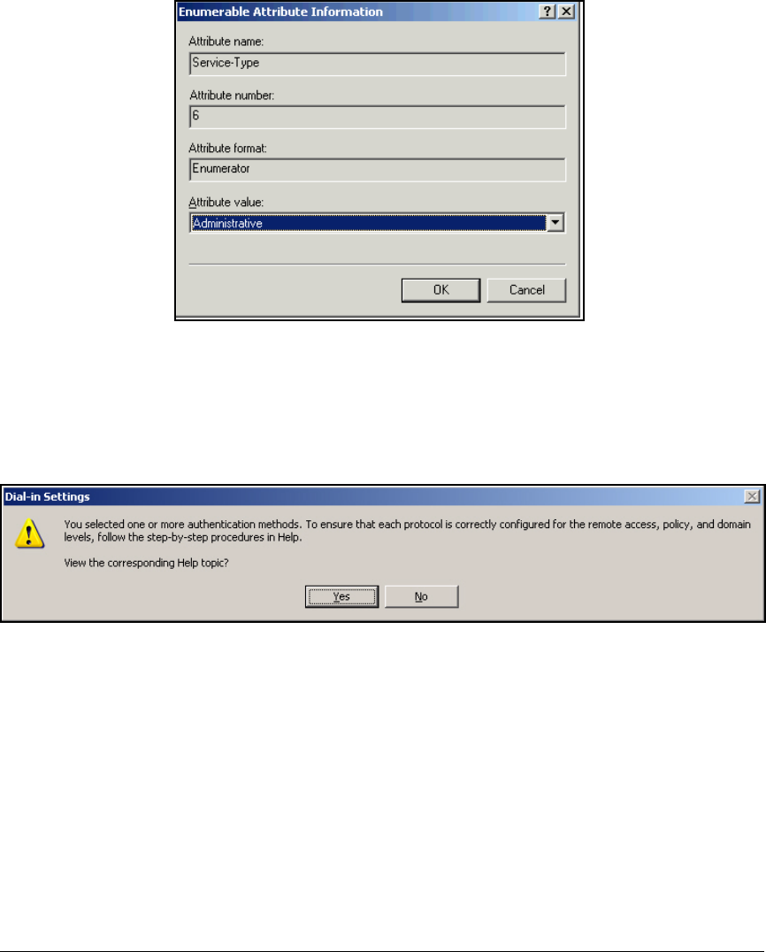
3-78
Implementing 802.1X with Endpoint Integrity but without IDM
Configure IAS
Figure 3-69. New Remote Access Policy Wizard—Enumerable
Attribute Information Window
33. Click OK.
34. Click Apply and OK.
Figure 3-70. New Remote Access Policy Wizard—Dial-in Settings Message
35. In the Dial-in Settings window, click No.
36. Click Next in the Profile page.
37. Click Finish.
38. Click Remote Access Policies in the Internet Authentication Service window
and verify that the new policy is listed above the default polices:
• Connections to Microsoft Routing and Remote
• Connections to other access servers
If the new policy is below the default policies, select the policy name. Then
click the Order column to move the policy up.
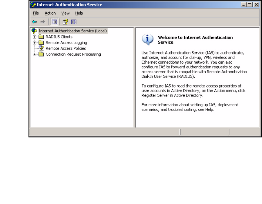
3-79
Implementing 802.1X with Endpoint Integrity but without IDM
Configure IAS
Add RADIUS Clients
You must add every NAS (switch, AP, or Wireless Edge Services Module) that
enforces port authentication as a RADIUS client. You can add clients individ-
ually by DNS name or by IP address. On a Windows Server 2003 Enterprise
IAS server, you can also list an entire subnet and IAS will accept requests from
any device in that subnet.
In this example, you will add the Management VLAN subnet as a RADIUS
client. Because the routing switch sends requests with its IP address on the
IAS server’s VLAN (VLAN 4), you will add a second client with that IP address
(10.4.0.1).
Follow these steps:
1. In the Start menu, select Administrative Tools > Internet Authentication
Services.
Figure 3-71. Internet Authentication Service Window
2. Right-click RADIUS Clients. Select New RADIUS Client.
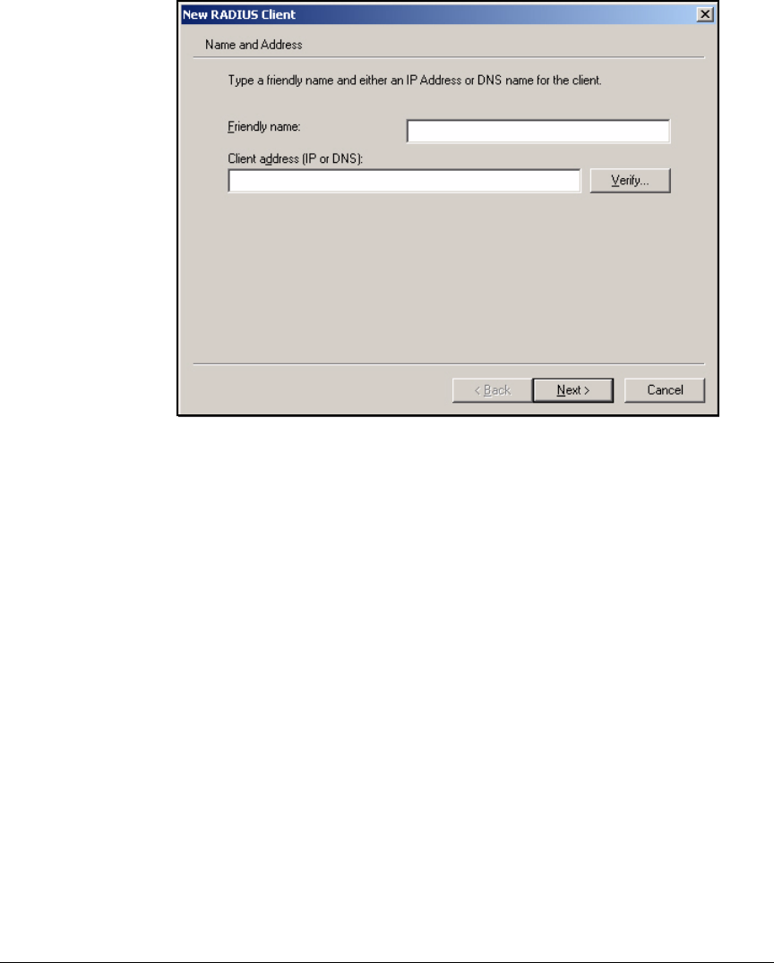
3-80
Implementing 802.1X with Endpoint Integrity but without IDM
Configure IAS
Figure 3-72. New RADIUS Client Wizard—Name and Address Page
3. On the New RADIUS Client page, type a descriptive name for the Friendly
name. For example: ManagementVLAN.
4. Type the IP address of the management VLAN subnet in the Client address
box. In this example: 10.2.0.0.
5. Click Next.
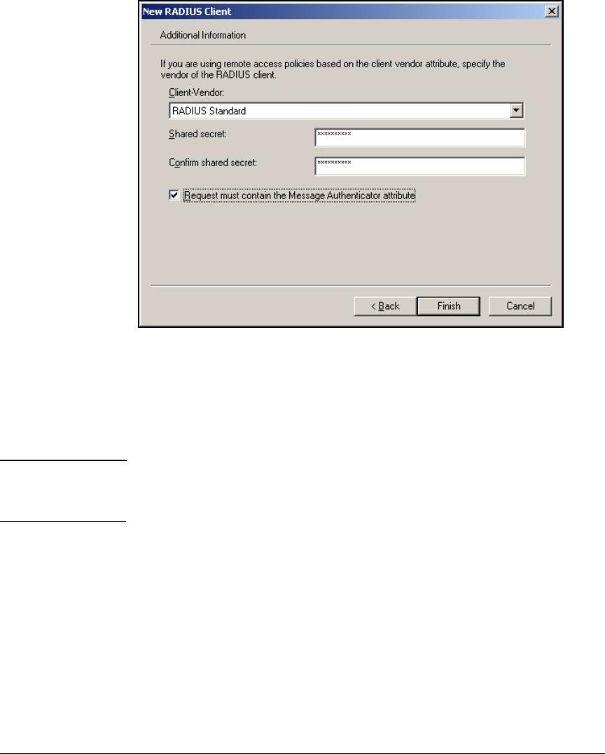
3-81
Implementing 802.1X with Endpoint Integrity but without IDM
Configure IAS
Figure 3-73. New RADIUS Client Wizard—Additional Information Page
6. Select RADIUS Standard from the Client-Vendor list.
7. Type a password in the Shared secret box. You must type this same
password when you configure the RADIUS server on the clients. In this
example: procurve12.
Note The shared secret is called the key on ProCurve switches. See “Configure
the ProCurve Switches” on page 3-9 for running-configs that include the
shared secret.
8. Re-type the password in the Confirm shared secret box.
9. Select the Request must contain the Message Authenticator attribute check
box.
10. Click Finish.
11. Repeat steps 2 to 10 to create another client. In this example, the client
has IP address 10.7.0.1 and uses the same shared secret (procurve12).
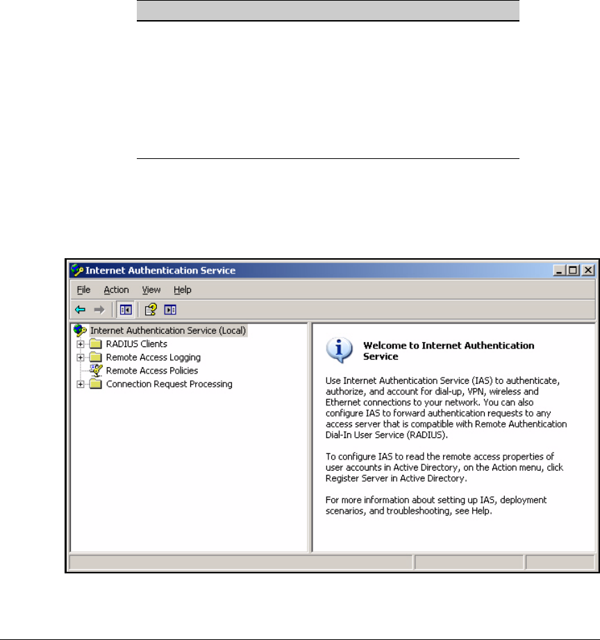
3-82
Implementing 802.1X with Endpoint Integrity but without IDM
Configure IAS
Enable Remote Access Logging
You should enable logging so that you can keep track of the users who access
your system, as well as troubleshoot problems that may occur. Typically, you
can accept the default properties, which are displayed in Table 3-8.
Table 3-8. Default IAS Logging Settings
To alter the logging settings, follow these steps:
1. In the Start menu, select Administrative Tools > Internet Authentication
Services.
Figure 3-74. Internet Authentication Service Window
Parameter Default Setting
Log • Accounting requests
• Authentication requests
• Periodic status
Local log file location C:\\Windows\system32\LogFile
Format IAS
Frequency for creating log files Daily
Log files deleted when the disk is full Enabled
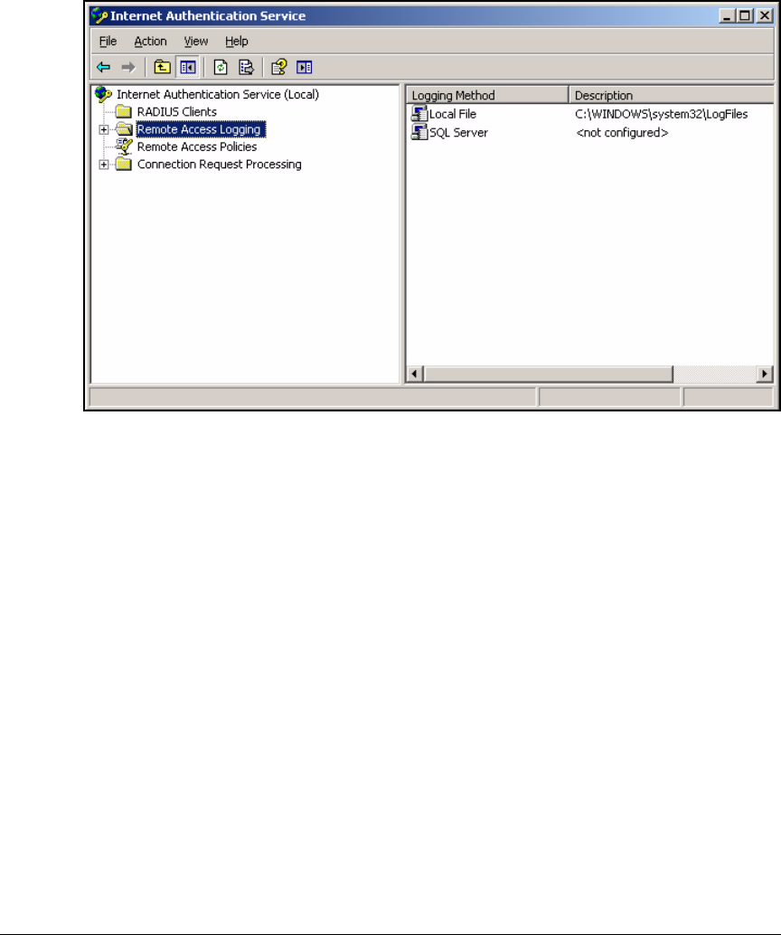
3-83
Implementing 802.1X with Endpoint Integrity but without IDM
Configure IAS
2. In the left pane, select Remote Access Logging.
Figure 3-75. Internet Authentication Service Window > Remote Access Logging
3. In the right pane, right-click Local File.
4. Select Properties.
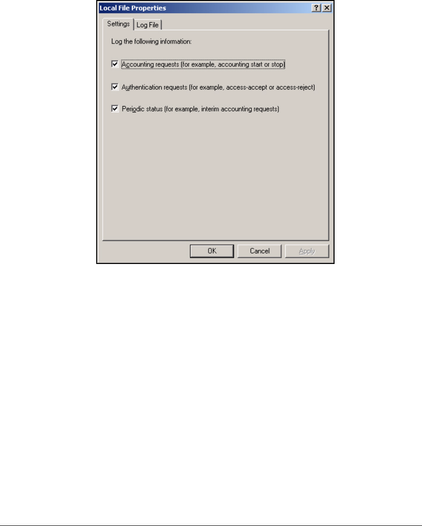
3-84
Implementing 802.1X with Endpoint Integrity but without IDM
Configure IAS
Figure 3-76. Local File Properties Window > Settings Tab
5. On the Settings tab, select the check boxes for any of the request or status
options that you are interested in logging.
6. Click the Log File tab.
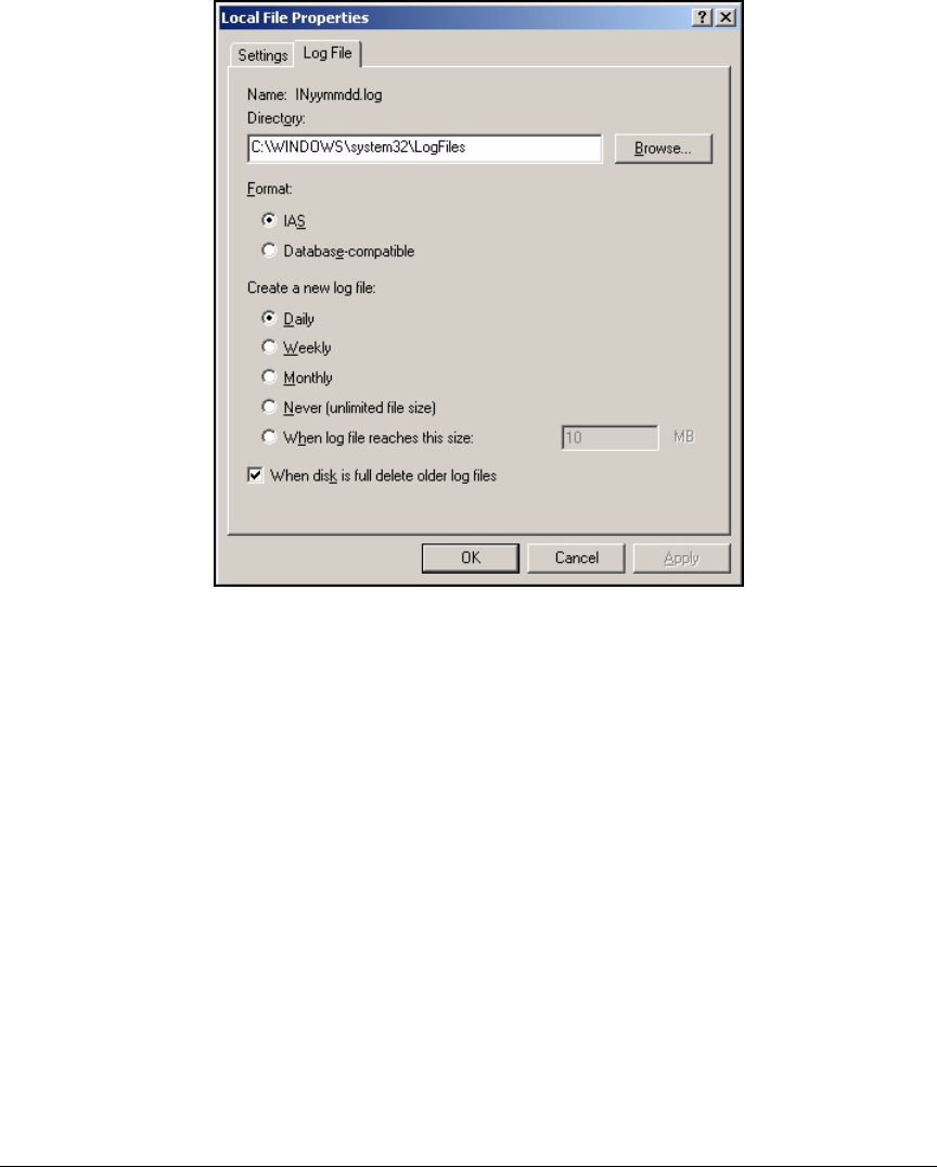
3-85
Implementing 802.1X with Endpoint Integrity but without IDM
Configure IAS
Figure 3-77. Local File Properties > Log File Tab
7. For the Directory, type (or browse for) the location where IAS should save
the log files.
8. For Format, select IAS.
If you intend to export logs to an Open Database Connectivity (ODBC)-
compliant database, select Database-compatible instead.
9. When IAS logs an event, it adds the log to an existing log file. IAS
periodically creates a new log file. Select an interval under Create a new
log file.
10. Typically, you should leave the When disk is full, delete older log files check
box selected.
11. Click OK.

3-86
Implementing 802.1X with Endpoint Integrity but without IDM
Configure IAS
Install and Configure Connectors for Endpoint Integrity
with the NAC 800
You have finished configuring IAS to authenticate users. Next, enable IAS to
contact the NAC 800, request endpoints’ integrity posture, and place the
endpoints in VLANs appropriately. You must complete these tasks:
1. Install the connector files.
2. Configure VLAN assignments for unknown, quarantined, and infected
endpoints in the connector file.
3. Edit the IAS server’s registry to include the .dll file.
Note These instructions apply to a solution without IDM.
Install the Connector Files
To integrate IAS with your endpoint integrity solution, the NAC 800, you must
install two IAS connector files on the IAS server:
■SAIASConnector.dll
■SAIASConnector.ini
IAS calls the SAIASConnector after authenticating an endpoint and during the
authorization phase. The connector contacts the NAC 800 and asks for the
integrity posture of the endpoint. By default, if the endpoint has a Healthy or
Check-up posture, the connector does not interfere with the attributes in the
IAS remote access policy. However, if the endpoint has an Unknown, Quaran-
tine, or Infected posture, the connector can override the IAS attributes with
the attributes configured in the SAIASConnector.ini file.
Figure 3-78 and Figure 3-79 illustrate this process.
Note The endpoint integrity testing occurs independently from the overall authen-
tication and authorization process. When the NAC 800 changes an endpoint’s
posture, it forces the NAS to reauthenticate the endpoint so that it can be
reauthorized for the appropriate rights.
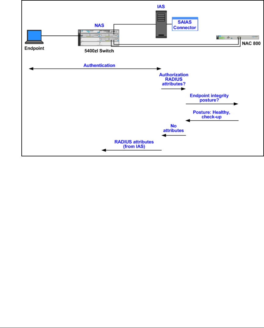
3-87
Implementing 802.1X with Endpoint Integrity but without IDM
Configure IAS
Figure 3-78. NAC 800-to-IAS Connector—Healthy or Check-up Posture
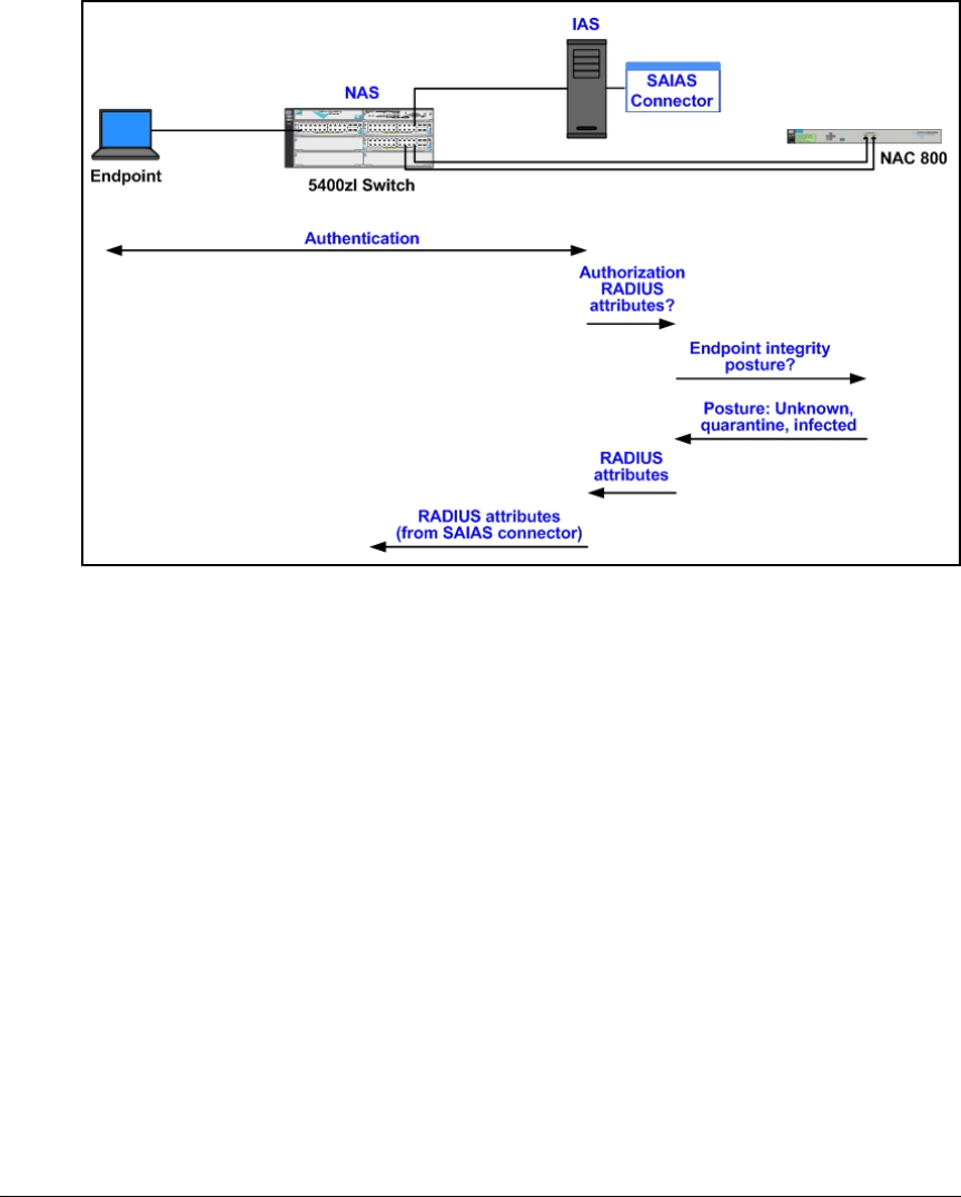
3-88
Implementing 802.1X with Endpoint Integrity but without IDM
Configure IAS
Figure 3-79. NAC 800-to-IAS Connector—Unknown, Quarantine, or Infected
Posture
Follow these steps to install and configure the connector files:
1. Download the zip file from http://www.procurve.com/nactools/.
Extract the four files:
• SAIASConnector.dll
• SAIASConnector.IDM.ini
• SAIASConnector.non-IDM.ini
• ProCurveNAC800Cert.cer
2. Rename SAIASConnector.non-IDM.ini to SAIASConnector.ini.
3. Transfer the SAIASConnector.dll and SAIASConnector.ini files to the IAS
server and copy them to the WINDOWS\system32 directory.

3-89
Implementing 802.1X with Endpoint Integrity but without IDM
Configure IAS
Note Your Windows Server 2003 directory might differ from the default
(WINDOWS). To check your directory, type echo %windir% at the server’s
command prompt.
Configure VLAN Assignments in the SAIASConnector.ini File
You must modify the SAIASConnector.ini file to specify VLAN assignments for
endpoints with these integrity postures:
■Quarantined—failed at least one test for which the penalty is quarantin-
ing (and a temporary access period, if allowed, has expired); or could not
be tested (and your network quarantines untestable endpoints)
■Infected—infected with malware (failed the Worms, Viruses, and Trojans
test)
■Unknown—not yet tested
In this solution, IAS, not the NAC 800, assigns VLAN assignments for endpoints
with the Healthy or Check-up posture.
Follow these steps to complete the task:
1. Use a text editor to open the SAIASConnector.ini file.
2. By default, debugging is off. If you want the SAIASConnector to create a
log file with debug messages, change the Debug=off line to:
Debug=on
3. Find this section:
[SAIASConnector-<NAS IP>]
4. Replace <NAS IP> with the IP address of the device that enforces 802.1X
authentication (a switch, AP, or Wireless Edge Services Module). In this
example:
[SAIASConnector-10.2.0.5]
5. Find this line:
ServerUrl=https://<SERVER IP>:89/servlet/
AccessControlServlet
Make sure the line is not commented. That is, there is no semi-colon (;)
preceding it.
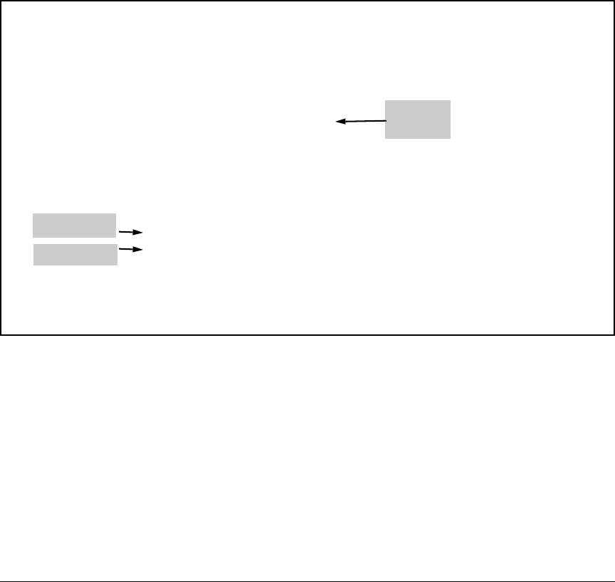
3-90
Implementing 802.1X with Endpoint Integrity but without IDM
Configure IAS
6. Replace <SERVER IP> with the IP address of one of your NAC 800 ESs. In
this example:
ServerUrl=https://10.4.4.40:89/servlet/AccessCon-
trolServlet
7. If your cluster has multiple ESs, copy the ServerURL line and paste it below.
In the original line, change ServerUrl to ServerUrl.1. In the new line, change
ServerUrl to ServerUrl.2 and replace <Server IP> with the second ES’s IP
address. Repeat until you have specified all of the ESs in the cluster (not
MSs). For this example, see Figure 3-80:
Figure 3-80. Configured SAIASConnector.ini File—Switch and NAC 800 ES
Addresses
8. Complete these steps if your network has multiple NASs:
a. Find these lines:
;[SAIASConnector-<NAS 2 IP>]
;Reference=SAIASConnector-<NAS 1 IP>
b. Uncomment the lines; that is, delete the semi-colons (;). Replace
<NAS 2 IP> with the IP address of a second NAS. Replace <NAS 1 IP>
with the IP address that you typed in step 4 on page 3-89.
[SAIASConnector]
Debug=on
DebugLevel=4
;
; TO DO - Replace <NAS IP> with the IP address of your 802.1x enabled
switch
;
[SAIASConnector-10.2.0.5]
;
; TO DO - Replace <SERVER IP> with the IP address of your NAC
; Enforcement Server. If there is more than one Enforcement
; Server, add more lines using the key "ServerUrl.1",
; "ServerUrl.2", ..., "ServerUrl.5". (You can only specify
; six ServerUrls at one time.)
;
ServerUrl.1=https://10.4.4.40:89/servlet/AccessControlServlet
ServerUrl.2=https://10.4.5.50:89/servlet/AccessControlServlet
;ServerUrl.3
;ServerUrl.4
;ServerUrl.5
Username=nacuser
Password=nacpwd
Edge
switch 1
NAC 800 ES A
NAC 800 ES B

3-91
Implementing 802.1X with Endpoint Integrity but without IDM
Configure IAS
c. Repeat until the file includes those two lines for every NAS in your
network.
For this example, see Figure 3-81:
Figure 3-81. Configured SAIASConnector.ini File—NAS Addresses
9. Move to the section below these lines:
; TO DO - Use the following settings for all non-Extreme
switches. Change the Tunnel-Pvt-GroupId settings to
match the VLAN ids on your switch
10. Find this section:
[Quarantine-Tunnel-Pvt-GroupId]
11. Below, set the value to the VLAN ID for your quarantine VLAN. In this
example:
Value = 34
12. Find this section:
[Unknown-Tunnel-Pvt-GroupId]
13. Below, set the value to the VLAN ID for your test VLAN. In this example:
Value = 32
14. Select the 12 lines that include attributes for Unknown endpoints. Copy
and paste them below. In the copied lines, change every instance of
Unknown to Infected.
15. Find this section:
[Infected-Tunnel-Pvt-GroupId]
16. Below, set the value to the VLAN ID for your infected VLAN. In this
example:
Value = 36
[SAIASConnector-10.2.0.6]
Reference=SAIASConnector-10.2.0.5
[SAIASConnector-10.2.0.7]
Reference=SAIASConnector-10.2.0.5
[SAIASConnector-10.2.0.20]
Reference=SAIASConnector-10.2.0.5 Wireless Edge
Services Module
Edge
switch 1
Edge
switch 2 Edge
switch 3

3-92
Implementing 802.1X with Endpoint Integrity but without IDM
Configure IAS
Note Be careful to change only the “Value” lines. You will see other lines for “Type,”
which specifies the RADIUS attribute in question, and “Data-Type,” which
specifies whether the value for that attribute is a string or a num ber or so fo rth .
You must keep these values as they are in the original file; otherwise, your
configuration will fail.
Figure 3-82 shows the correctly configured file for this example.

3-93
Implementing 802.1X with Endpoint Integrity but without IDM
Configure IAS
Figure 3-82. Configured SAIASConnector.ini File—Quarantine, Unknown, Infected
; TO DO - Use the following settings for all non-Extreme switches.
Change the Tunnel-Pvt-GroupId settings
; to match the VLAN ids on your switch
;
[Quarantine-Tunnel-Pvt-GroupId]
Type=81
DataType=1
Value=34
[Quarantine-Session-Timeout]
Type=27
DataType=3
Value=30
[Quarantine-Termination-Action]
Type=29
DataType=3
Value=1
[Unknown-Tunnel-Pvt-GroupId]
Type=81
DataType=1
Value=32
[Unknown-Session-Timeout]
Type=27
DataType=3
Value=30
[Unknown-Termination-Action]
Type=29
DataType=3
Value=1
[Infected-Tunnel-Pvt-GroupId]
Type=81
DataType=1
Value=36
[Infected-Session-Timeout]
Type=27
DataType=3
Value=3600
[Infected-Termination-Action]
Type=29
DataType=3
Value=1
Quarantine
VLAN ID
Infected
VLAN ID
Unknown
VLAN ID
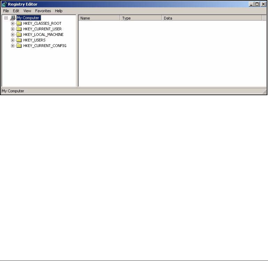
3-94
Implementing 802.1X with Endpoint Integrity but without IDM
Configure IAS
17. Save and close the file.
Edit the IAS Server Registry
Enable the SAIAS connector by adding the SAIASConnector.dll to the registry
that IAS checks at startup. Follow these steps:
1. In the Start menu, select Run.
2. Type regedit and click OK.
Figure 3-83. Registry Editor Window
3. Expand HKEY_LOCAL_MACHINE > SYSTEM > CurrentControlSet > Services.
4. Create an AuthSrv folder if it does not already exist:
a. Right-click Services and select New > Key.
b. Type AuthSrv for the folder name.
5. Create a Parameters folder inside the AuthSrv folder if it does not already
exist:
a. Right-click AuthSrv and select New > Key.
b. Type Parameters for the folder name.
6. Right-click Parameters and select New > Multi-String value.
7. Type AuthorizationDLLs for the name.
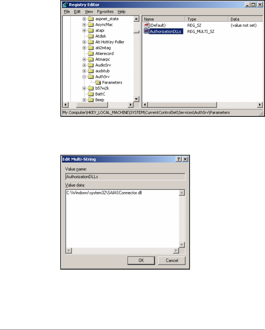
3-95
Implementing 802.1X with Endpoint Integrity but without IDM
Configure IAS
Figure 3-84. Registry Editor—AuthSrv > Parameters Window
8. Right-click AuthorizationDLLs and select Modify.
Figure 3-85. Registry Editor—Edit Multi-String Window
9. In the Value data box, type the path to your SAIASConnector. For example:
C:\Windows\system32\SAIASConnector.dll.
10. Click OK.

3-96
Implementing 802.1X with Endpoint Integrity but without IDM
Configure IAS
11. Close the Registry Editor (press [Alt]+[F4]).
12. Restart the Windows Server 2003.
Note If you turned on debugging in the SAIASConnector file, when IAS starts,
a log file (SAIASConnector.log) is created in the WINDOWS\system32 direc-
tory for debugging and troubleshooting purposes. If you open the file after
the Windows Server 2003 restarts, you should see this log entry:
NAC IAS plugin started.
Install the NAC 800’s CA Certificate as a Trusted Root
on the IAS Server
The SAIASconnector communicates with the NAC 800’s internal HTTPS
server. HTTPS requires a server (in this case, the NAC 800) to authenticate to
the client (the IAS server) with an certificate. So you must enable IAS to trust
the NAC 800’s certificate. In other words, you must install on the IAS server
the root certificate for the CA that signed the NAC 800’s certificate.
The NAC 800 has several options for its HTTPS server certificate:
■Certificate signed by your domain CA
If, as in this solution, you plan to install a certificate signed by your domain
CA, the IAS server already trusts that CA, and you do not need to complete
any further steps.
To learn how to install the server certificate on the NAC 800, see “Create
and Install a Certificate for HTTPS on a NAC 800” on page 2-188 of
Chapter 2: “Implementing 802.1X with ProCurve IDM and Endpoint Integ-
rity.”
■Certificate signed by a well-known CA
Similarly, if the NAC 800 uses a certificate signed by a well-known CA, the
IAS server probably already trusts the CA, and you do not need to
complete any further steps.
Again, see “Create and Install a Certificate for HTTPS on a NAC 800” on
page 2-188 of Chapter 2: “Implementing 802.1X with ProCurve IDM and
Endpoint Integrity.”
■Certificate signed by a less well-known CA
If the IAS server does not already trust the NAC 800’s CA, follow these
steps:
a. Obtain the CA certificate from the CA.
b. Follow the remaining steps in this section.
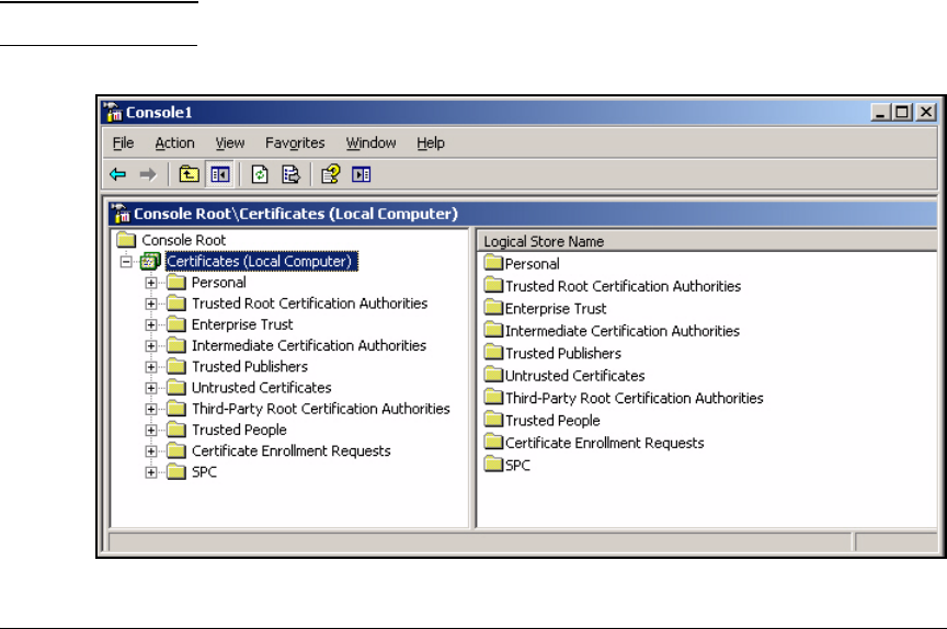
3-97
Implementing 802.1X with Endpoint Integrity but without IDM
Configure IAS
■Default self-signed certificate
By default, the NAC 800 uses a self-signed certificate installed at the
factory. If you plan to continue using that certificate:
a. Extract the ProCurveNAC800Cert.cer file from the zip file available at
http://www.procurve.com/nactools/. Transfer the file to the IAS
server.
b. Follow the remaining steps in this section.
■New self-signed certificate
You might create a new self-signed certificate on the NAC 800 that
includes the device’s correct IP address. (See “Create and Install a Certif-
icate for HTTPS on a NAC 800” on page 2-188 of Chapter 2: “Implementing
802.1X with ProCurve IDM and Endpoint Integrity.”) In this case, you must
complete the steps in “Export a Self-signed Certificate from a NAC 800
and Install it on the IAS Server” on page 3-110.
After you obtain the necessary CA certificate, install it as a trusted root on the
IAS server. Follow these steps:
1. Open the Management Console that you created on the IAS server. (In the
Start menu, select Run and type mmc; open your console.)
Note If the correct console is not opened, select it from the File menu.
Figure 3-86. Management Console—Certificates (Local Computer)
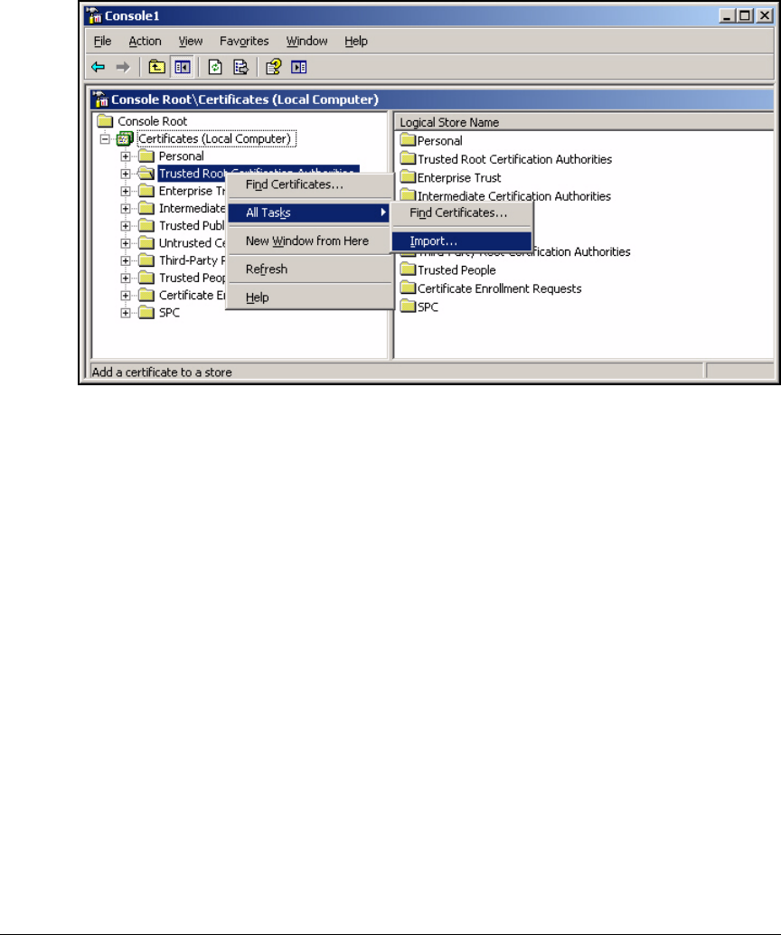
3-98
Implementing 802.1X with Endpoint Integrity but without IDM
Configure IAS
2. Expand Certificates (Local Computer).
Figure 3-87. Management Console—Certificates (Local Computer) > Trusted Root
Certificate Authorities
3. Right-click Trusted Root Certificate Authorities and select All Tasks > Import.
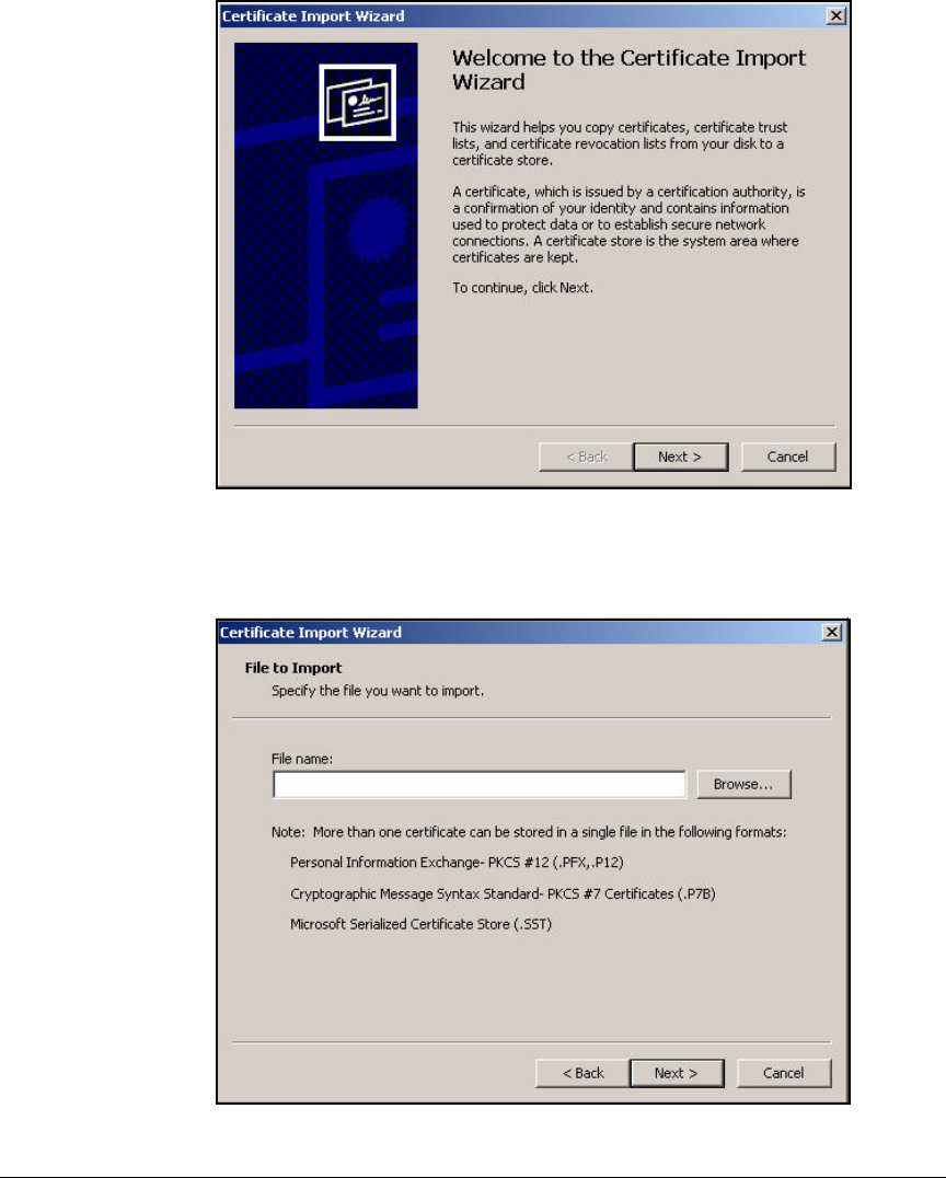
3-99
Implementing 802.1X with Endpoint Integrity but without IDM
Configure IAS
Figure 3-88. Certificate Import Wizard—Welcome Page
4. Click Next.
Figure 3-89. Certificate Import Wizard—File to Import Page
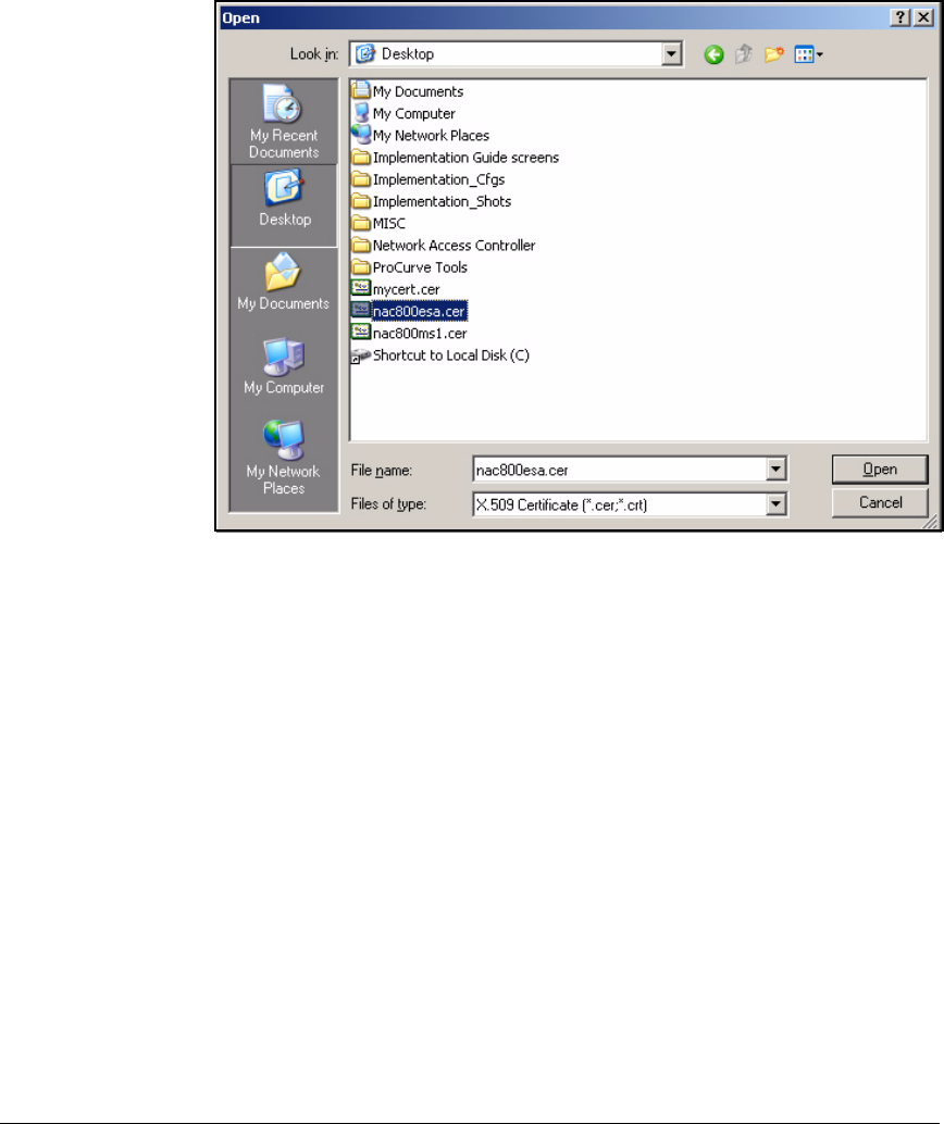
3-100
Implementing 802.1X with Endpoint Integrity but without IDM
Configure IAS
5. Click Browse and select the CA root certificate for the NAC 800.
Figure 3-90. Browsing for a File in the Certificate Import Wizard
6. Click Open.
7. Click Next.
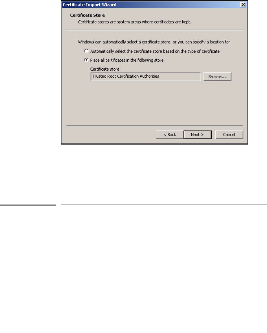
3-101
Implementing 802.1X with Endpoint Integrity but without IDM
Configure the Wireless Edge Services zl Modules
Figure 3-91. Certificate Import Wizard—Certificate Store Page
8. Accept the default: Place all certificates in the following store. Then click
Next again.
9. Click Finish.
Configure the Wireless Edge Services zl
Modules
Please refer to “Configuring the Wireless Edge Services Modules” on page
2-106 of Chapter 2: “Implementing 802.1X with ProCurve IDM and Endpoint
Integrity” for instructions on how to install and configure the following:
■Wireless Edge Services zl Module
■Redundant Wireless Services zl Module
■RPs
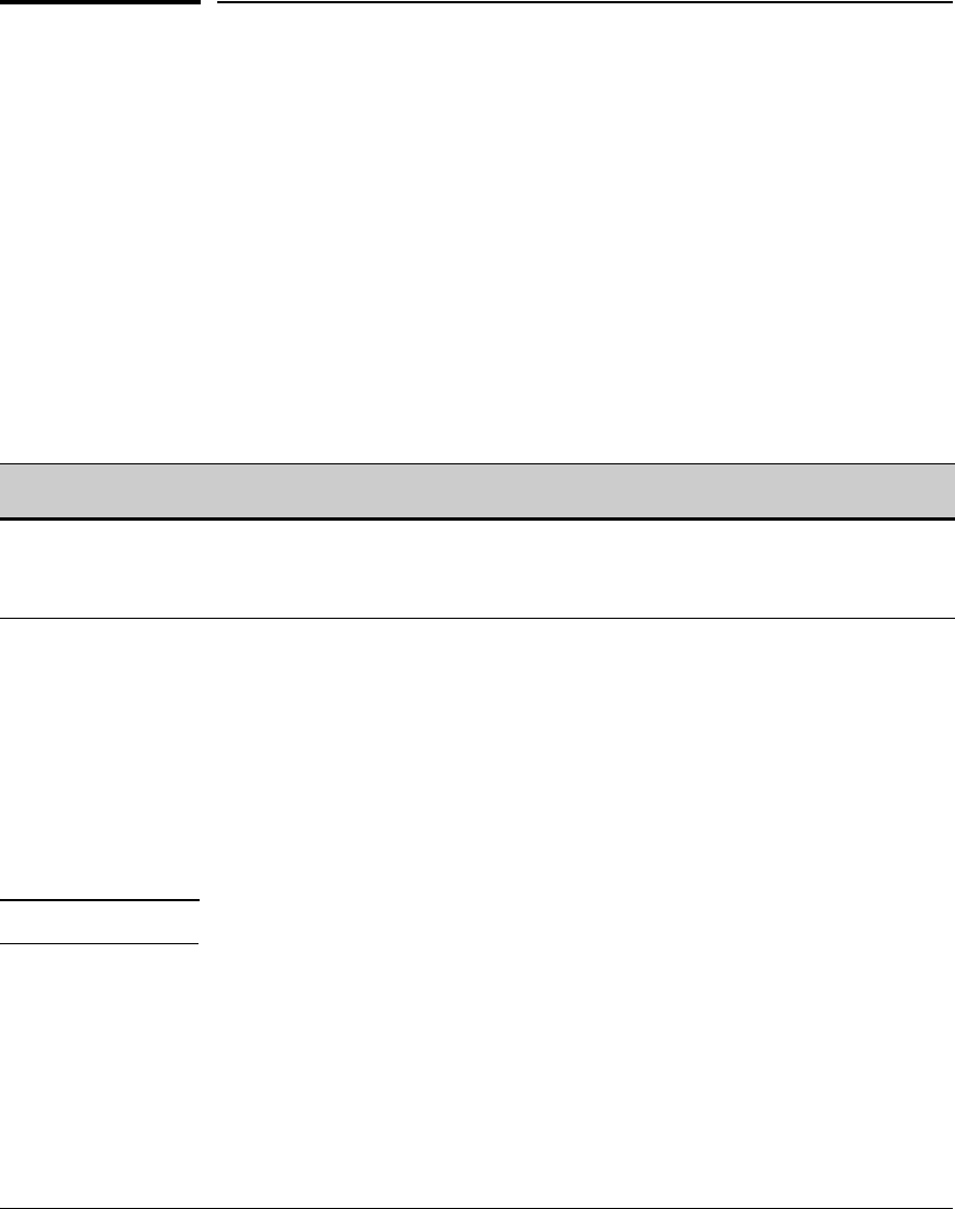
3-102
Implementing 802.1X with Endpoint Integrity but without IDM
Configure the NAC 800s
Configure the NAC 800s
For instructions on installing the NAC 800s, please refer to “Configuring the
NAC 800s” on page 2-134 of Chapter 2: “Implementing 802.1X with ProCurve
IDM and Endpoint Integrity.”
Configure Basic Settings on the NAC 800s
For instructions on configuring basic settings on the NAC 800, please refer to
“Configure Basic Settings on the NAC 800s” on page 2-135 of Chapter 2:
“Implementing 802.1X with ProCurve IDM and Endpoint Integrity.” In this
example, the NAC 800s will use the network settings in Table 3-9.
Table 3-9. NAC 800 Basic Settings
Access the Web Browser Interface
The NAC 800s now have network connectivity. You will complete all remaining
configuration through the NAC 800 MS’s Web browser interface.
Follow these steps to access the Web browser interface:
1. Open the Web browser on your management station.
2. Type https://<NAC 800 IP address>. For example: https://10.2.1.40.
Note The NAC 800 requires HTTPS (as opposed to HTTP) for greater security.
3. Since the NAC 800 is using its self-signed certificate, your browser will
probably ask you whether you want to trust this certificate. Answer yes.
4. You connect to the NAC 800’s Web browser interface.
Device Hostname IP Address Subnet Mask Default
Gateway
DNS Server Time Settings
NAC 800 MS MS.procurveu.edu 10.2.1.40 255.255.0.0 10.2.0.1 10.4.4.15 1.pool.ntp.org
NAC 800 ES ESa.procurveu.edu 10.4.4.40 255.255.0.0 10.4.0.1 10.4.4.15 from MS
NAC 800 ES ESb.procurveu.edu 10.4.5.50 255.255.0.0 10.4.0.1 10.4.4.15 from MS

3-103
Implementing 802.1X with Endpoint Integrity but without IDM
Configure the NAC 800s
If this is the first time that the Web browser interface has been accessed, you
must complete some initial tasks. See “Configure More Basic Settings for the
MS” on page 2-142 of Chapter 2: “Implementing 802.1X with ProCurve IDM
and Endpoint Integrity.”
Create the Enforcement Cluster and Add ESs
For instructions, please refer to “Create an Enforcement Cluster and Add ESs”
on page 2-146 of Chapter 2: “Implementing 802.1X with ProCurve IDM and
Endpoint Integrity.”
Configure Quarantining
The next task is setting up quarantining with the 802.1X method and an IAS
server:
1. Select Home > System configuration > Quarantining.
2. Make sure that the cluster you configured is selected.
3. In the Quarantine method area, select 802.1X.
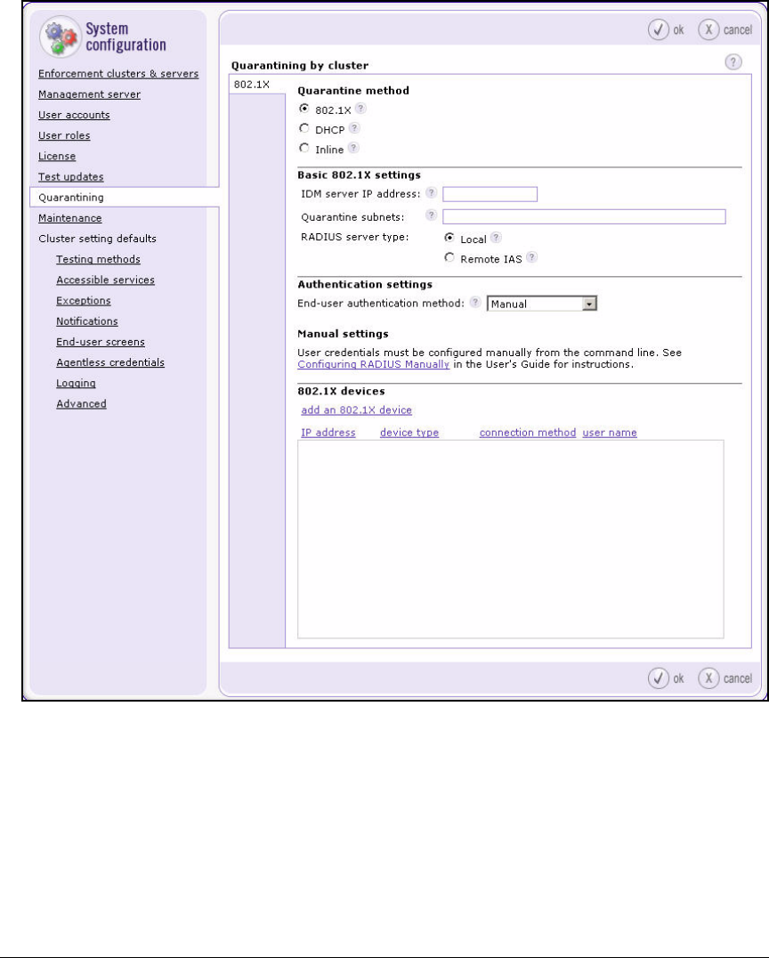
3-104
Implementing 802.1X with Endpoint Integrity but without IDM
Configure the NAC 800s
Figure 3-92. NAC 800 Web Interface—Home > System configuration > Quarantining
Window
4. In the Quarantine subnets box, type the subnet addresses associated with
Unknown (Test), Quarantine, and Infected VLANs. Refer to Table 3-1.
Separate the addresses with commas (,). In this example: 10.32.0.0/16,
10.34.0.0/16,10.36.0.0/16.
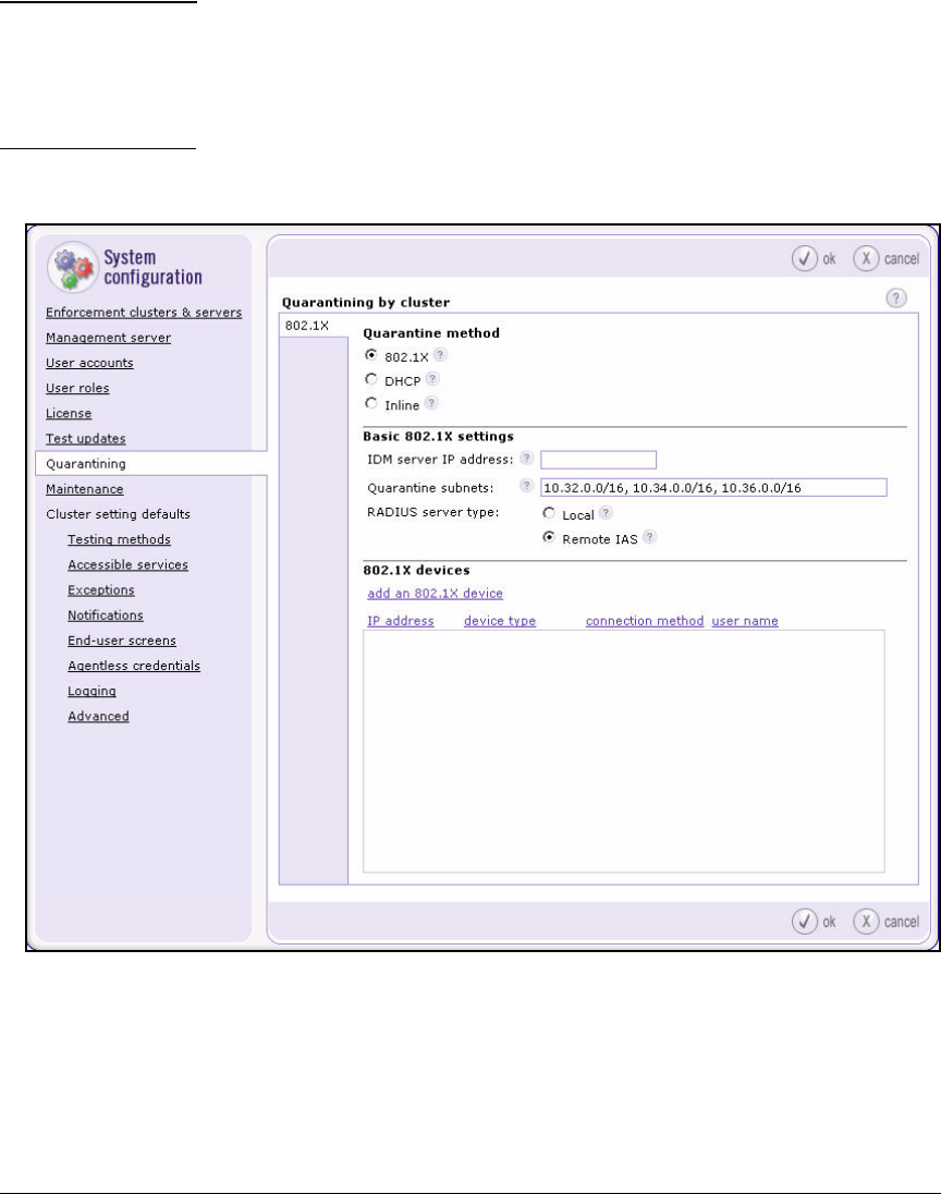
3-105
Implementing 802.1X with Endpoint Integrity but without IDM
Configure the NAC 800s
Note The Quarantine subnets setting allows the NAC 800 to respond to DNS
requests from endpoints in Test, Quarantine, and Infected VLANs. You
should have set up the corresponding VLAN IDs on the SAIASConnector.
See “Configure VLAN Assignments in the SAIASConnector.ini File” on
page 3-89.
5. Select Remote IAS for the RADIUS server type.
Figure 3-93. NAC 800 Web Interface—Home > System configuration > Quarantining
Window
6. Click ok.

3-106
Implementing 802.1X with Endpoint Integrity but without IDM
Configure the NAC 800s
Add 802.1X Devices
The NAC 800’s list of 802.1X devices must include every device in your network
that can act as an authenticator. In this example, these are:
■Edge switches (which authenticate end-users, RPs, and other switches)
■Core switches (which authenticate other switches)
■Wireless Edge Services Modules (which authenticate wireless users)
When you add a device to the list you must specify:
■Device’s IP address
■Device type
■Connection settings (which allow the NAC 800 to force reauthentication
of an endpoint after testing)
The NAC 800 can issue the reauthentication command through SSH,
Telnet, or SNMP (although some 802.1X devices do not support all of these
options). In this example, you will use SNMPv2.
Table 3-10 shows the settings for the example network. Of course, the actual
list would include many more devices.
Table 3-10. 802.1X Devices
Follow these steps to add the 802.1X devices:
1. Select Home > System Configuration > Quarantining.
You should have already completed the steps in “Configure Quarantining”
on page 3-103.
2. Click add an 802.1X device. The Add 802.1X device window is displayed.
IP Address Device Type SNMPv2 Read-Write
Community
Other SNMP
Settings
10.2.0.20 ProCurve WESM procurverw default
10.2.0.25 ProCurve WESM procurverw default
10.2.0.3 ProCurve Switch procurverw default
10.2.0.5 ProCurve Switch procurverw default

3-107
Implementing 802.1X with Endpoint Integrity but without IDM
Configure the NAC 800s
Figure 3-94. NAC 800 Web Interface—Home > System configuration >
Quarantining (802.1X quarantine method) > add an 802.1X device
Window
3. Type the 802.1X device’s IP address in the IP address box. In this example:
10.2.0.20
4. From the Device type box, select the type of 802.1X device (that is, its
manufacturer and OS). The types for this network include ProCurve Switch
and ProCurve WESM.
5. When you select the device type, the window expands to include device-
specific settings.
3-108
Implementing 802.1X with Endpoint Integrity but without IDM
Configure the NAC 800s
Figure 3-95. NAC 800 Web Interface—Home > System configuration > Quarantining
(802.1X quarantine method) > add an 802.1X device (Connection
settings) Window
6. Select a method from the Connection method box. In this network, devices
use SMNPv2.
Skip this step if you have selected ProCurve WESM, ProCurve 420 AP, or
ProCurve 530 AP for the Device type.
7. Type the name of the ProCurve device’s read-write community in the
Community string box (in this example, procurverw).
8. Typically, you can leave all other default settings unchanged.
For more information about these settings, see Chapter 3: “System Con-
figuration” of the ProCurve Network Access Controller 800 Users’ Guide.
9. Click ok.

3-109
Implementing 802.1X with Endpoint Integrity but without IDM
Configure the NAC 800s
10. In the System configuration > Quarantining window, click ok to save the
changes.
Configure NAC Policies
Next, you should set up NAC policies, which specify the requirements that
endpoints must meet to connect to the network. The NAC 800 has three default
policies for testing endpoint integrity (Low security, Medium security, and
High security). By default, the Low security NAC policy applies to all end-
points.
Please refer to “Configure NAC Policies” on page 3-109 of Chapter 2: “Imple-
menting 802.1X with ProCurve IDM and Endpoint Integrity” to learn how to:
■Create new NAC policies for your environment
■Assign NAC policies to the correct endpoints
Configure Endpoint Integrity Testing Methods
You must also ensure that NAC 800s can test endpoints. The NAC 800 always
attempts to test an endpoint transparently first:
1. The NAC 800 tries to test the endpoint with the NAC EI agent.
2. If no agent is installed on the endpoint, the NAC 800 tries to install the
ActiveX agent.
3. If the ActiveX installation fails and if credentials for the endpoint or
domain exist, the NAC 800 tries to use agentless testing.
If transparent testing fails, the NAC 800 presents users with end-user access
screens, which help the testing to proceed:
1. An end-user screen instructs the user to download and install the NAC EI
agent.
2. Or an end-user screen instructs the user how to enable the ActiveX agent
to download.
3. Or an end-user screen asks the user to submit administrator credentials
for the endpoint (for agentless testing).
Please refer to Chapter 2: “Implementing 802.1X with ProCurve IDM and
Endpoint Integrity” to learn how to:
■Select the testing methods presented in end-user access screens (page
2-164)
■Deploy the NAC EI agent (page 2-306)

3-110
Implementing 802.1X with Endpoint Integrity but without IDM
Configure the NAC 800s
■Configure agentless credentials (page 2-156)
■Enable the Remote Procedure Call (RPC) service for agentless testing
(page 2-157)
■Open necessary ports for various testing methods (page 2-157)
Install SSL Certificates on the NAC 800s
Each NAC 800 includes an internal HTTPS server. The SAIASConnector
contacts NAC 800 ESs’ HTTPS servers to check endpoints’ integrity posture.
The internal HTTPS server requires the NAC 800 to have an SSL certificate.
At factory defaults, the NAC 800 uses a self-signed certificate. However, you
should typically install a new certificate on the NAC 800, one signed either by
a trusted third-party CA or your domain’s own CA.
To learn how to request and install a certificate, please refer to “Create and
Install a Certificate for HTTPS on a NAC 800” on page 2-188 of Chapter 2:
“Implementing 802.1X with ProCurve IDM and Endpoint Integrity.”
Export a Self-signed Certificate from a NAC 800 and
Install it on the IAS Server
In this solution, the NAC 800s use certificates signed by a trusted CA. However,
you might choose to create a self-signed certificate on your device. (See
“Chapter 13: System Administration” of the ProCurve Network Access Con-
troller 800 Users’ Guide.) This section teaches you how to export such a
certificate and install it on the IAS server as a trusted root.
Note To create a self-signed certificate, you can also follow the steps in “Create and
Install a Certificate for HTTPS on a NAC 800” on page 2-188; stop after step 7
on page 2-190.
The easiest way to export a self-signed certificate from a NAC 800 is to connect
to its Web browser interface and download the certificate using your browser.
The following steps explain how to do so using Internet Explorer (IE) 7:
1. Open IE on the IAS server and navigate to this URL: https://<NAC 800
hostname>:89.
You can, alternatively, specify the NAC 800’s IP address.
2. Because the IAS server does not yet trust the certificate, you should see
a Web page such as the one in Figure 3-96.
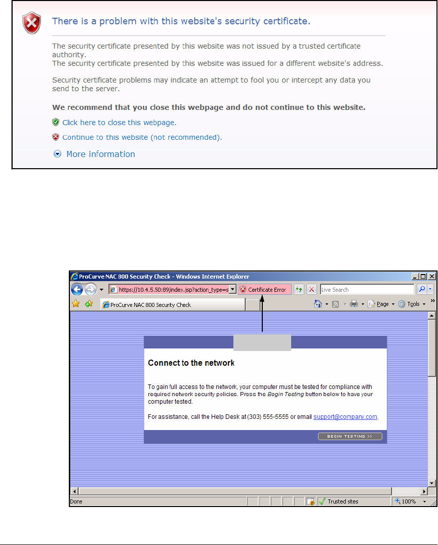
3-111
Implementing 802.1X with Endpoint Integrity but without IDM
Configure the NAC 800s
Figure 3-96. Problem with Security Certificate Web Page in IE 7
3. Click Continue to this website.
If prompted to add the site to your trusted site, do so.
4. You should see the page shown in Figure 3-97.
Figure 3-97. ProCurve NAC 800 Security Check Web Page
Click here.
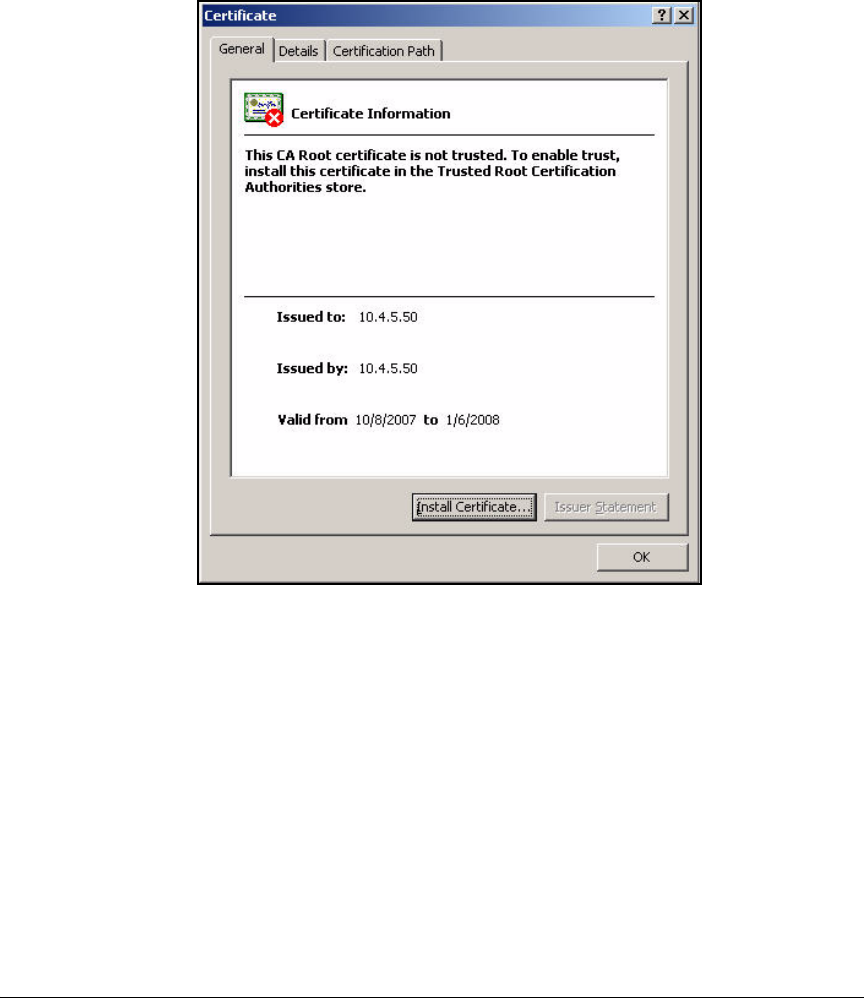
3-112
Implementing 802.1X with Endpoint Integrity but without IDM
Configure the NAC 800s
5. Click Certificate Error in the navigation bar.
6. Click View certificates. The Certificates window is displayed.
Figure 3-98. Certificate Window
7. Click Install Certificate. The Certificate Import Wizard is displayed.
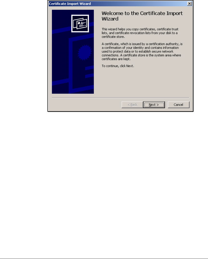
3-113
Implementing 802.1X with Endpoint Integrity but without IDM
Configure the NAC 800s
Figure 3-99. Certificate Import Wizard—Welcome Page
8. Click Next.
9. Click Place all certificates in the following store.
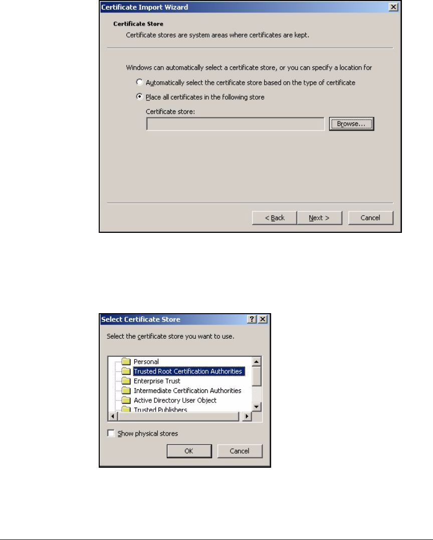
3-114
Implementing 802.1X with Endpoint Integrity but without IDM
Configure the NAC 800s
Figure 3-100.Certificate Import Wizard—Certificate Store Page
10. Click Browse.
11. Click the Trusted Root Certification Authorities folder.
Figure 3-101.Certificate Import Wizard—Certificate Store Page
12. Click OK.
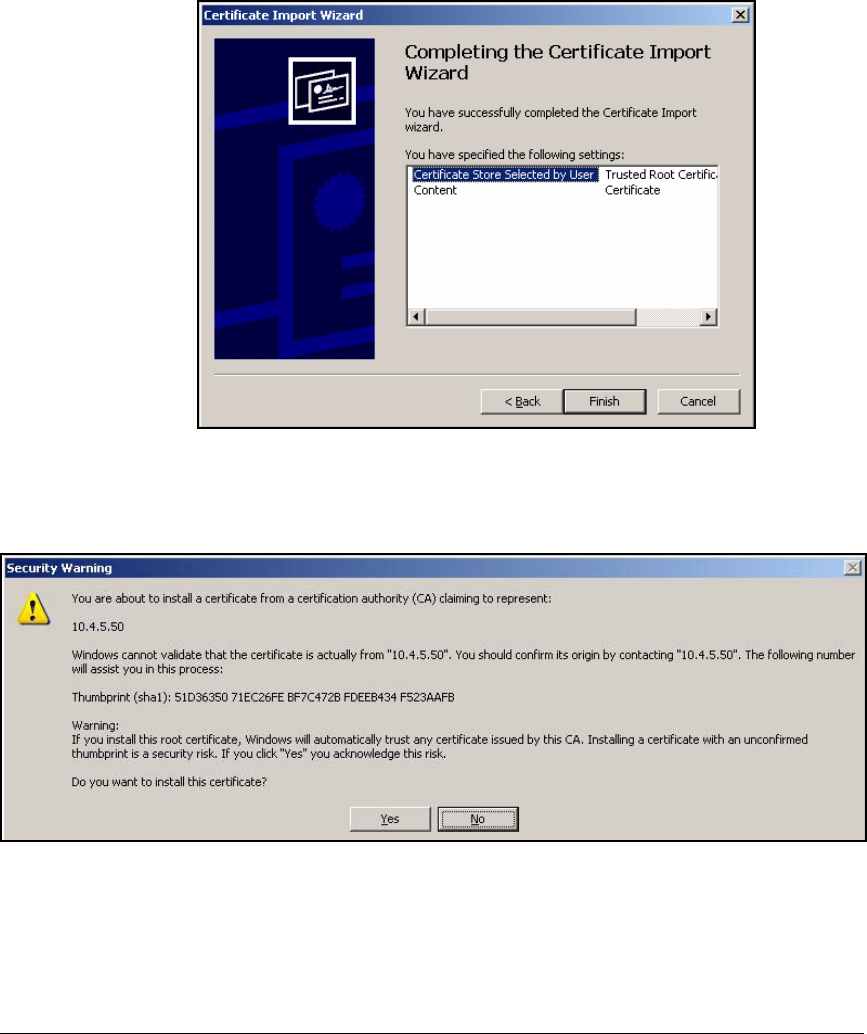
3-115
Implementing 802.1X with Endpoint Integrity but without IDM
Configure the NAC 800s
13. On the Certificate store page, click Next.
Figure 3-102.Completing the Certificate Import Wizard Page
14. Click Finish.
Figure 3-103.Security Warning Window
15. When asked if you want to install the certificate, click Yes.
16. A window should be displayed, informing you that the import was suc-
cessful. Click OK.

3-116
Implementing 802.1X with Endpoint Integrity but without IDM
Set Up Endpoints
Set Up Endpoints
By now, you have set up your network infrastructure and servers to support
your access control solution. Before enabling port authentication, however,
you must set up the endpoints as well.
Please refer to Chapter 2: “Implementing 802.1X with ProCurve IDM and
Endpoint Integrity” to learn how to:
■Enroll users for certificates (page 2-276)
■Configure Ethernet connections for 802.1X (page 2-298)
■Configure wireless connections for 802.1X (page 2-301)
■Install the NAC EI agent on endpoints (page 2-306)

3-117
Implementing 802.1X with Endpoint Integrity but without IDM
Activate Network Access Control
Activate Network Access Control
It is recommended that, until you have completely configured and tested your
network access control solution, you do not activate:
■Port authentication
■Quarantining
Otherwise, you can inadvertently lock users—and even yourself—out of the
network. And, as explained in “Set Up Endpoints” on page 3-116, endpoints as
well as the network infrastructure and servers must support the solution.
Whether the IT staff or users themselves will prepare the endpoints, you must
allow sufficient time before enforcing network access control. For example,
after you install the NAC 800, you might wait several days before activating
endpoint integrity to give users time to download the NAC EI agent from the
NAC 800. Even if you assign the NAC EI agent in Active Directory, you must
do so in advance because the agent does not install until the next reboot.
You should always test the solution before activating it throughout the net-
work. At a minimum, you should activate port authentication on a single
unused port, plug in your management station, and verify that you can log in
to the network. Log in as users in all of your user groups and check the
resources that they are allowed. As a next step for more rigorous testing, you
might implement port authentication on one or two switches for a trial period.
Guide users in the trial group through the process of connecting to the network
and note any problems that they encounter. You might select the IT depart-
ment as the trial group as these users tend to be best-equipped for handling
the new requirements.
Once you are confident that the network infrastructure, endpoints, and users
are ready, activate your solution.
Please refer to Chapter 2: “Implementing 802.1X with ProCurve IDM and
Endpoint Integrity” for instructions:
■Activate port authentication (page 2-318)
■Activate quarantining (page 2-319)

3-118
Implementing 802.1X with Endpoint Integrity but without IDM
Activate Network Access Control

4-1
4
Implementing a VPN with Endpoint Integrity
Contents
Introduction . . . . . . . . . . . . . . . . . . . . . . . . . . . . . . . . . . . . . . . . . . . . . . . . . . . 4-4
Configuring the ProCurve Switches . . . . . . . . . . . . . . . . . . . . . . . . . . . . . . . 4-10
Routing Switch startup-config . . . . . . . . . . . . . . . . . . . . . . . . . . . . . . . . 4-10
Configure Windows Services . . . . . . . . . . . . . . . . . . . . . . . . . . . . . . . . . . . . 4-12
Configure Certificate Services . . . . . . . . . . . . . . . . . . . . . . . . . . . . . . . . . . . 4-13
Customize a Template for VPN Client Certificates . . . . . . . . . . . . . . . 4-14
Template for VPN Client Certificate Obtained Via
a Manual Request . . . . . . . . . . . . . . . . . . . . . . . . . . . . . . . . . . . . . . . 4-14
Template for a VPN Client Certificate with an Automatically
Generated Subject Name . . . . . . . . . . . . . . . . . . . . . . . . . . . . . . . . 4-21
Customize the Template for the Router’s IPsec Certificate . . . . . . . 4-32
Enable Templates on the CA Server . . . . . . . . . . . . . . . . . . . . . . . . . . . 4-36
Export the CRL . . . . . . . . . . . . . . . . . . . . . . . . . . . . . . . . . . . . . . . . . . . . 4-38
Check the Key Size for the CA Root Certificate . . . . . . . . . . . . . . . . . 4-41
Configure the ProCurve Secure Router 7000dl . . . . . . . . . . . . . . . . . . . . . 4-48
Configure the Physical and Virtual Interfaces . . . . . . . . . . . . . . . . . . . 4-48
Configure the Ethernet Interface . . . . . . . . . . . . . . . . . . . . . . . . . . 4-48
Configure the WAN Interface . . . . . . . . . . . . . . . . . . . . . . . . . . . . . 4-50
Enable Telnet and SSH Access . . . . . . . . . . . . . . . . . . . . . . . . . . . . . . . 4-54
Configure the Routing Protocol . . . . . . . . . . . . . . . . . . . . . . . . . . . . . . 4-56
Use Policy-Based Routing to Forward VPN Traffic Through
the NAC 800 . . . . . . . . . . . . . . . . . . . . . . . . . . . . . . . . . . . . . . . . . . . . . . . 4-58
Enable Routing to the Remote Endpoints . . . . . . . . . . . . . . . . . . . . . . 4-61
Create the Route to the Remote Endpoints on the Secure
Router 7000dl . . . . . . . . . . . . . . . . . . . . . . . . . . . . . . . . . . . . . . . . . . 4-62
Configure RIP Filters . . . . . . . . . . . . . . . . . . . . . . . . . . . . . . . . . . . . 4-63

4-2
Implementing a VPN with Endpoint Integrity
Contents
Configure Network Address Translation (NAT) . . . . . . . . . . . . . . . . . 4-67
Configure Source NAT . . . . . . . . . . . . . . . . . . . . . . . . . . . . . . . . . . 4-67
Configure Destination NAT with Port Forwarding . . . . . . . . . . . 4-70
Establish the VPN . . . . . . . . . . . . . . . . . . . . . . . . . . . . . . . . . . . . . . . . . . 4-73
Activate Crypto Commands . . . . . . . . . . . . . . . . . . . . . . . . . . . . . . 4-74
Create a Client Configuration Pool . . . . . . . . . . . . . . . . . . . . . . . . 4-74
Configure an IKE Policy . . . . . . . . . . . . . . . . . . . . . . . . . . . . . . . . . 4-76
Create ACLs for VPN Traffic . . . . . . . . . . . . . . . . . . . . . . . . . . . . . 4-83
Configure a Transform Set . . . . . . . . . . . . . . . . . . . . . . . . . . . . . . . 4-88
Create a Crypto Map . . . . . . . . . . . . . . . . . . . . . . . . . . . . . . . . . . . . 4-90
Create the Remote ID List . . . . . . . . . . . . . . . . . . . . . . . . . . . . . . . . 4-94
Apply the Crypto Map to an Interface . . . . . . . . . . . . . . . . . . . . . . 4-97
Allow VPN Traffic on the Internet Interface . . . . . . . . . . . . . . . . . . . . 4-98
Using Digital Certificates . . . . . . . . . . . . . . . . . . . . . . . . . . . . . . . . . . . 4-105
Obtain Digital Certificates . . . . . . . . . . . . . . . . . . . . . . . . . . . . . . 4-106
Manage Certificates . . . . . . . . . . . . . . . . . . . . . . . . . . . . . . . . . . . . 4-115
Secure Router 7000dl Running-Config . . . . . . . . . . . . . . . . . . . . . . . . 4-118
Configuring the NAC 800 . . . . . . . . . . . . . . . . . . . . . . . . . . . . . . . . . . . . . . . 4-128
Install the NAC 800 . . . . . . . . . . . . . . . . . . . . . . . . . . . . . . . . . . . . . . . . 4-130
Configure Initial Settings on the New NAC 800 . . . . . . . . . . . . . . . . 4-131
Configure Initial Settings through a Console Session . . . . . . . . 4-131
Access the MS’s Web Browser Interface . . . . . . . . . . . . . . . . . . . . . . 4-136
Create the Enforcement Cluster . . . . . . . . . . . . . . . . . . . . . . . . . . . . . 4-136
Add the ES to the Enforcement Cluster . . . . . . . . . . . . . . . . . . . . . . . 4-140
Move an Existing ES to the New Cluster . . . . . . . . . . . . . . . . . . 4-142
Configure Quarantining . . . . . . . . . . . . . . . . . . . . . . . . . . . . . . . . . . . . 4-146
Set Up Accessible Services . . . . . . . . . . . . . . . . . . . . . . . . . . . . . . . . . 4-147
Other Settings for the NAC 800 . . . . . . . . . . . . . . . . . . . . . . . . . . . . . . 4-150
Activate Quarantining . . . . . . . . . . . . . . . . . . . . . . . . . . . . . . . . . . . . . . 4-150
Set Up Endpoints . . . . . . . . . . . . . . . . . . . . . . . . . . . . . . . . . . . . . . . . . . . . . 4-153
Obtain a Certificate Using the Windows CA Web Enrollment
Pages . . . . . . . . . . . . . . . . . . . . . . . . . . . . . . . . . . . . . . . . . . . . . . . . . . . . 4-153

4-3
Implementing a VPN with Endpoint Integrity
Contents
Configure the ProCurve VPN Client . . . . . . . . . . . . . . . . . . . . . . . . . . 4-154
Obtain the ProCurve VPN Client . . . . . . . . . . . . . . . . . . . . . . . . . 4-155
Install the ProCurve VPN Client . . . . . . . . . . . . . . . . . . . . . . . . . . 4-155
Install Certificates . . . . . . . . . . . . . . . . . . . . . . . . . . . . . . . . . . . . . 4-157
Configure a New Connection . . . . . . . . . . . . . . . . . . . . . . . . . . . . 4-173
Create a Security Policy . . . . . . . . . . . . . . . . . . . . . . . . . . . . . . . . 4-179
Test the VPN Connection . . . . . . . . . . . . . . . . . . . . . . . . . . . . . . . 4-184
Export the Policy and Certificates . . . . . . . . . . . . . . . . . . . . . . . . 4-185
User Instructions: Install the ProCurve VPN Client and
the Preconfigured Policy . . . . . . . . . . . . . . . . . . . . . . . . . . . . . . . . . . . 4-194
Import the Policy Manually . . . . . . . . . . . . . . . . . . . . . . . . . . . . . . 4-199
Manually Import Certificates . . . . . . . . . . . . . . . . . . . . . . . . . . . . 4-201

4-4
Implementing a VPN with Endpoint Integrity
Introduction
Introduction
This chapter teaches you how to set up a virtual private network (VPN) for
remote users and then implement endpoint integrity checks on the users’
endpoints. In this chapter, you will learn how to configure these network
components:
■ProCurve Secure Router 7000dl, which also acts as the VPN gateway
■ProCurve Network Access Controller (NAC) 800
You will also learn about setting up an endpoint for remote access using the
ProCurve VPN Client.
It is assumed that you have already implemented a network access control
solution for the LAN. Examples in this chapter will, when necessary, refer to
the LAN established in Chapter 2: “Implementing 802.1X with ProCurve IDM
and Endpoint Integrity,” which:
■Enforces 802.1X port authentication
■Has a wireless network:
• Controlled with a Wireless Edge Services Module
• Protected with Wi-Fi Protected Access (WPA) with 802.1X
■Enforces endpoint integrity with the 802.1X deployment (quarantine)
method
■Uses ProCurve Manager Plus (PCM+) and ProCurve Identity Driven Man-
ager (IDM) to simplify network management
Although your network environment is probably not identical to this environ-
ment, the instructions should help you understand the processes involved.
You can then modify the instructions as needed to meet your company’s unique
requirements.
To help you, the instructions include examples, which will be based on a
hypothetical network designed for a university called ProCurve University.
The instructions also include tables and worksheets that you can use to record
information for your network.
The ProCurve University network includes three user groups:
■Network administrators
■Faculty
■Students

4-5
Implementing a VPN with Endpoint Integrity
Introduction
Table 4-1 shows the virtual LANs (VLANs) and subnets in the LAN.
Table 4-1. Example VLANs
You can use Figure 4-2 to record information about your company’s VLANs.
Table 4-2. My VLANs
VLAN Category Name ID Subnet
Management VLAN Management 2 10.2.0.0/16
Server VLAN Servers 4 10.4.0.0/16
Faculty_Databases 5 10.5.0.0/16
User VLAN Faculty 8 10.8.0.0/16
Students 10 10.10.0.0/16
Test and quarantine VLAN (for
endpoint integrity)
Quarantine_Faculty 32 10.32.0.0/16
Quarantine_Students 34 10.34.0.0/16
Infected VLAN Infected_Faculty 33 10.33.0.0/16
Infected_Students 35 10.35.0.0/16
Type Name ID Subnet
Management
Server
User
Test

4-6
Implementing a VPN with Endpoint Integrity
Introduction
The university is adding a VPN so that faculty and students can access the
network while at home or on sabbatical. The university’s router, the Secure
Router 7203dl, will act as the VPN gateway, establishing secure tunnels with
remote endpoints using IP security (IPsec) with Internet Key Exchange (IKE).
PCU network administrators reserve a subnet for remote endpoints only. Of
course, the remote endpoints have their own IP addresses (public or private)
at the remote location. However, when they establish tunnels with the router,
IKE mode config assigns them IP addresses in this subnet, as shown in
Table 4-3.
Table 4-3. IP Addresses for Remote Users
IKE requires the VPN gateway and remote users to authenticate each other.
The university already has a full public key infrastructure (PKI), and the
domain CA will issue digital certificates to the router and remote users for this
authentication.
Because the remote users do not log in with 802.1X authentication, they are
no longer subject to the network’s endpoint integrity solution, which uses the
802.1X deployment (or quarantine) method. However, checking the integrity
of remote endpoints—which are outside the university’s control—is particu-
larly important.
Network administrators decide to add a NAC 800 deployed with the inline
method. As explained in Chapter 2: “Implementing 802.1X with ProCurve IDM
and Endpoint Integrity,” ProCurve University has already deployed a manage-
ment server (MS), so the university’s IT staff will configure the new NAC 800
as an enforcement server (ES).
Quarantine
Infected
User Category Private Subnet IP Address Range in IKE
Client Configuration Pool
Remote users 10.48.100.0/23 10.48.100.10–10.48.101.250
Type Name ID Subnet
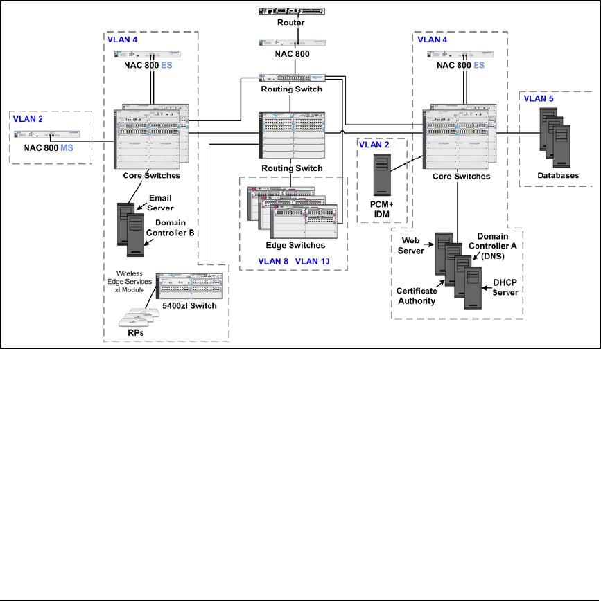
4-7
Implementing a VPN with Endpoint Integrity
Introduction
The Secure Router 7000dl, which connects to the LAN on its Ethernet port 0/
1, will connect to the NAC 800 on its port 0/2. The router will forward all traffic
from the VPN out this port so that it passes through the NAC 800 before
reaching the private network. The core routing switch, the NAC 800, and the
router’s Ethernet 0/2 port will all have IP addresses on the same subnet—in
this example, 10.3.0.0/24.
Figure 4-1 shows a high-level network design.
Figure 4-1. High-Level Network Design for ProCurve University
The instructions in this chapter sometimes require that you enter a specific
IP address. Table 4-4 lists the IP addresses you would use for the example
ProCurve University network. The table also provides spaces to list the IP
addresses and VLANs for your company’s network. You can easily replace
the IP address given in the instructions with the correct address in your
environment.

4-8
Implementing a VPN with Endpoint Integrity
Introduction
Table 4-4. Example IP Addresses
Device Example IP
Address
Example
VLAN ID
Your Company’s
IP Address
Your Company’s
VLAN ID
Domain controller 10.4.4.15 4
DNS servers 10.4.4.15
10.4.5.15
4
DHCP server 10.4.4.20 4
CA server 10.4.4.25 4
PCM+/IDM server 10.4.4.30 4
University Web server 10.4.6.30 4
Library Web server 10.4.6.35 4
Email server 10.4.6.40 4
Grade database 10.5.1.45 5
Test database 10.5.2.50 5
Other servers and databases
Secure Router 7000dl Ethernet 0/1—
10.2.0.100
Ethernet 0/2—
10.3.0.100
WAN—
192.168.1.1
No VLANs
Routing Switch A • 10.2.0.1
• 10.3.0.1
• 10.4.0.1
• 10.5.0.1
• 10.8.0.1
• 10.10.0.1
• 10.32.0.1
• 10.33.0.01
• 10.34.0.1
• 10.35.0.1
•2
•3
•4
•5
•8
•10
•32
•33
•34
•35

4-9
Implementing a VPN with Endpoint Integrity
Introduction
Note The “WAN” IP address in this example is a private IP address. In a production
environment, however, it would be a public IP address.
In your network, some servers might run multiple services. For example, the
Microsoft domain controllers might run Domain Name System (DNS).
Routing Switch B • 10.2.4.1
• 10.4.4.1
• 10.5.4.1
• 10.8.4.1
• 10.10.4.1
• 10.32.4.1
• 10.33.4.1
• 10.34.4.1
• 10.35.4.1
•2
•4
•5
•8
•10
•32
•33
•34
•35
Switch A 10.2.0.5 2
Other switches
Wireless Edge Services zl Module 10.2.0.20 2
Redundant Wireless Services zl
Module
10.2.0.25 2
NAC 800 MS 10.2.1.40 2
NAC 800 ES A 10.4.4.40 4
NAC 800 ES B 10.4.5.50 4
NAC 800 ES C 10.3.0.90 2
Device Example IP
Address
Example
VLAN ID
Your Company’s
IP Address
Your Company’s
VLAN ID

4-10
Implementing a VPN with Endpoint Integrity
Configuring the ProCurve Switches
Configuring the ProCurve Switches
This section provides an example configuration for the ProCurve routing
switch that connects to the ProCurve Secure Router 7000dl. For this solution,
the routing switch has been configured to exchange routes with the Secure
Router 7000dl; the devices use Routing Information Protocol (RIP) version 2.
Refer to the sample configuration as you set up your network. If you need step-
by-step instructions, you should refer to the documentation for your switch.
This solution focuses on remote access only, so it does not show configura-
tions for other core or edge switches. To implement solutions for access
control and endpoint integrity in the LAN, see the other chapters in this guide.
Routing Switch startup-config
The following is the startup-config for the routing switch (which is a ProCurve
Switch 5400zl Series) used to test this network.
; J8692A Configuration Editor; Created on release #K.12.XX
hostname "Routing_Switch"
module 1 type J86xxA
ip routing
snmp-server community "procurvero" Operator
snmp-server community "procurverw" Unrestricted
vlan 1
name "DEFAULT_VLAN"
no untagged 1-20
no ip address
exit
vlan 2
name "Management"
untagged 1-19
ip helper-address 10.4.4.20
ip address 10.2.0.1 255.255.0.0
exit
vlan 3
name "Inline_NAC"
untagged 20 //This port connects to the inline NAC 800
ES.//
ip address 10.3.0.1 255.255.255.0
exit

4-11
Implementing a VPN with Endpoint Integrity
Configuring the ProCurve Switches
vlan 4
name "Servers"
ip address 10.4.0.1 255.255.0.0
tagged 1-9
exit
vlan 5
name "Faculty databases"
ip address 10.5.0.1 255.255.0.0
tagged 1-9
exit
vlan 10
name "Students"
ip helper-address 10.4.4.20
ip address 10.10.0.1 255.255.0.0
tagged 10-19
exit
vlan 8
name "Faculty"
ip helper-address 10.4.4.20
ip address 10.8.0.1 255.255.0.0
tagged 10-19
exit
vlan 32
name "Quarantine_Faculty"
ip helper-address 10.4.4.20
ip address 10.32.0.1 255.255.0.0
tagged 10-19
exit
vlan 34
name "Quarantine_Students"
ip helper-address 10.4.4.20
ip address 10.34.0.1 255.255.0.0
tagged 10-19
exit
vlan 2100
name "Radio Ports"
tagged 1-19
no ip address
exit
ip authorized-managers 10.2.0.0 255.255.0.0
ip authorized-managers 10.4.4.40 255.255.255.255
ip authorized-managers 10.4.5.50 255.255.255.255
ip dns domain-name "procurveu.edu"
ip dns server-address 10.4.4.15

4-12
Implementing a VPN with Endpoint Integrity
Configure Windows Services
ip route 0.0.0.0 0.0.0.0 10.2.0.100
ip route 10.48.100.0 255.254.0.0 10.3.0.100 //Include
this static route to the remote endpoints instead of
activating RIP on the VLAN that connects to the NAC 800.//
router rip
redistribute connected
exit
vlan 2
ip rip 10.2.0.1
vlan 3
ip rip 10.3.0.1 //Activate RIP on this VLAN instead of
configuring a static route. Make sure that the Secure
Router properly advertises routes.//
exit
Configure Windows Services
This solution builds on an existing LAN with Windows Servers 2003 that run
Active Directory, DNS, Dynamic Host Configuration Protocol (DHCP), and
certificate services. Please refer to Chapter 2: “Implementing 802.1X with
ProCurve IDM and Endpoint Integrity” for instructions on the following:
1. Install the Windows Server 2003 (page 2-20).
2. Install Active Directory (page 2-21).
3. Configure Windows domain groups (page 2-28).
4. Configure Windows domain users (page 2-31).
5. Configure DNS services with reverse lookup zones (page 2-35).
6. Install DHCP services (page 2-43).
7. Configure DHCP services (page 2-46).

4-13
Implementing a VPN with Endpoint Integrity
Configure Certificate Services
Configure Certificate Services
This section teaches you how to configure an existing enterprise root CA to
issue the certificates necessary for an IPsec VPN. If you have not already
installed certificate services, refer to Chapter 2: “Implementing 802.1X with
ProCurve IDM and Endpoint Integrity” for instructions on these tasks:
■Install the Certificate Authority service (page 2-56).
■Create a Management Console for the CA (page 2-76).
You must then complete these tasks:
■Customize certificate templates for:
• VPN clients
• VPN gateway (Secure Router 7000dl)
■Export the Certificate Revocation List (CRL).
■Verify the CA certificate has the correct key size.
You will complete these tasks later in the configuration process:
■Issue a certificate to the router (see “Submit the Certificate Request to the
CA Server” on page 4-112).
■Issue the VPN client certificates (see “Submit the Certificate Request to
the CA” on page 4-165).
You have several options for installing VPN client certificates on remote
endpoints. This solution will discuss two:
■Network administrators obtain certificates for VPN users.
They generate one certificate for each set of users and distribute the
certificate, protected with a password, as part of the ProCurve VPN Client
installation package.
■Users obtain their own certificates.
They connect to the CA from the remote endpoint and request their own
certificate.
Note When you generate certificates and import certificates, you can avoid unnec-
essary problems by making sure that all your devices are set to the correct
time. For example, if the CA server has a later time than the device importing
the certificate, you will receive an error message, telling you that the certifi-
cate is not yet valid.

4-14
Implementing a VPN with Endpoint Integrity
Configure Certificate Services
Customize a Template for VPN Client Certificates
A VPN client requires a certificate with key usages for client authentication
and digital signatures. The template for such a certificate on the Windows CA
is Authenticated Session. However, you might need to modify the template for
your solution.
Template for VPN Client Certificate Obtained Via a Manual
Request
By default, the subject name for an Authenticated Session certificate comes
from Active Directory. However, you might want control the subject name
manually. In this case, network administrators should obtain the certificates
and distribute them with the VPN Client.
This solution uses a template with the following characteristics:
■The subject name should be generated from the certificate request rather
than from Active Directory.
The Secure Router 7000dl will identify remote users by the subject names
in their certificates, checking the names against entries in a remote ID list.
In all but the smallest networks, creating an entry for each separate user
is not feasible. Instead, you will set up two entries: one for faculty
members and one for students.
Distinguishing the two types of users is important because the Secure
Router 7000dl will use the remote ID to assign remote endpoints to the
proper crypto map entry. The crypto map entry, in turn, will specify the
ACL that controls which resources the user can access over the VPN
tunnel.
In the example, faculty members and students are in the same OU (Users),
so if the subject name were taken from Active Directory, the two types of
user could not be easily distinguished. Instead the subject name should
be configured manually in the certificate request.
Note If your users are divided into different OUs, the subject name can be
generated from the certificate request.
■Network administrators will be responsible for obtaining certificates for
the ProCurve VPN Clients. You must set permissions accordingly.
For tighter security, network administrators—not remote users—must
generate the certificate request. Otherwise, a student could request a
subject name with the OU set to Faculty and receive rights to faculty
resources.
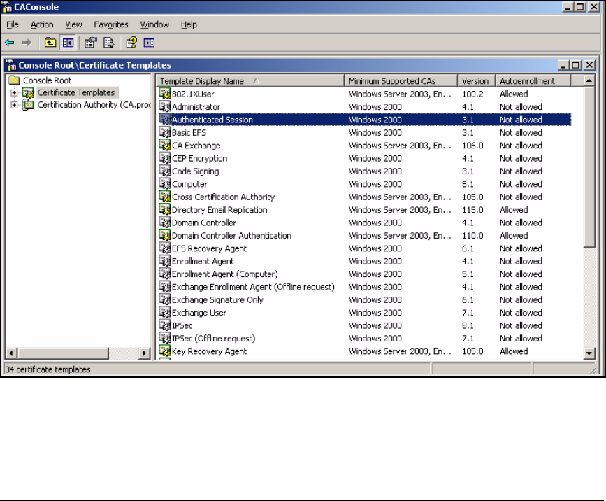
4-15
Implementing a VPN with Endpoint Integrity
Configure Certificate Services
■You should allow the private key to be exported.
To ease management, PCU network administrators will create only one
certificate for each user group. They will then password protect the
certificate and distribute it with the ProCurve VPN Client installation
package. For this solution to function, the private key must be exportable.
Follow these steps to customize the Authenticated Session template for your
environment:
1. Open a Management Console that has the Certificate Templates and the
Certificate Authority snap-ins. (See “Create a Management Console for
the CA” on page 2-76 of Chapter 2: “Implementing 802.1X with ProCurve
IDM and Endpoint Integrity.”)
2. Select Certificate Templates in the left pane of the console window.
Figure 4-2. Duplicate Authenticated Session Template
3. Right-click Authenticated Session in the right pane.
4. In the menu that is displayed, select Duplicate Template. The Properties of
New Template window is displayed.
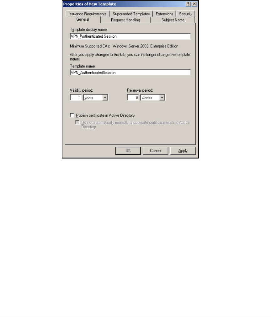
4-16
Implementing a VPN with Endpoint Integrity
Configure Certificate Services
5. At the General tab, type a new name for the template in the Template display
name box. In this example: VPN_Authenticated Session.
Figure 4-3. Properties of New Template > General Tab
6. Click the Subject Name tab.
7. As explained earlier, the subject name in the certificate should be speci-
fied manually in the certificate request. Select Supply in the request.
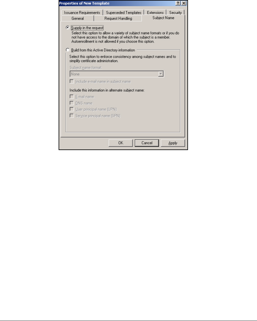
4-17
Implementing a VPN with Endpoint Integrity
Configure Certificate Services
Figure 4-4. Properties of New Template > Subject Tab
8. Click the Request Handling tab.
9. Select the Allow private key to be exported check box.
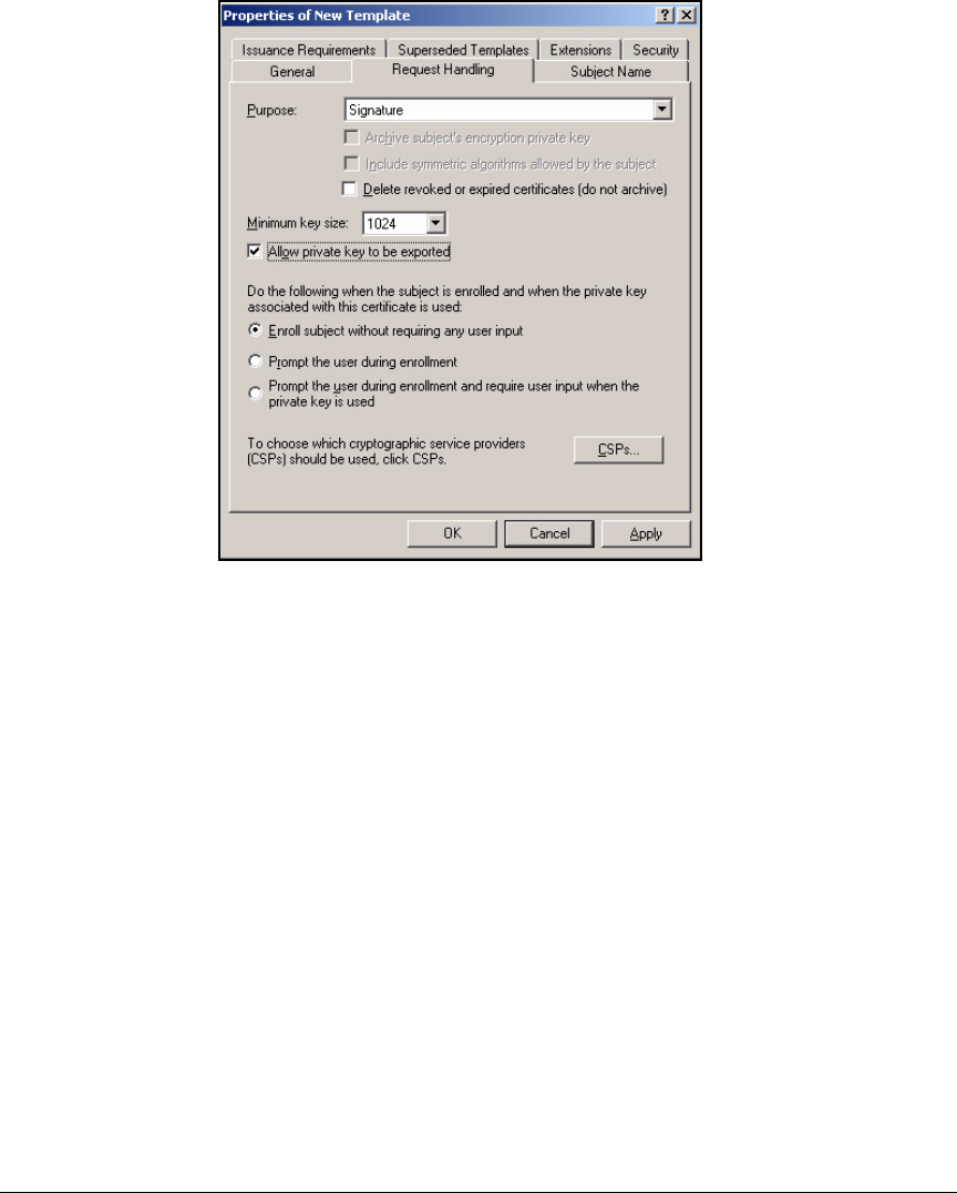
4-18
Implementing a VPN with Endpoint Integrity
Configure Certificate Services
Figure 4-5. Properties of New Template > Request Handling Tab
10. Click the Security tab.
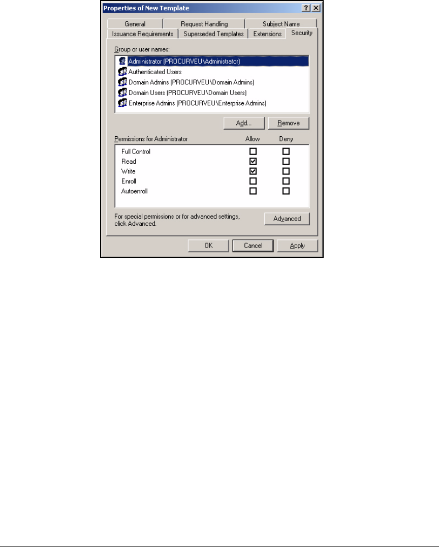
4-19
Implementing a VPN with Endpoint Integrity
Configure Certificate Services
Figure 4-6. Properties of New Template > Security Tab
11. Because the certificate’s subject name helps to control the user’s remote
access, you want to make sure the request includes the correct informa-
tion. You will allow only network administrators to enroll users for the
certificates:
a. Select Domain Users and click Remove.
b. Select Domain Admins and Enterprise Admins and clear the Enroll check
boxes.
c. Click Add.

4-20
Implementing a VPN with Endpoint Integrity
Configure Certificate Services
Figure 4-7. Select Users, Computers, or Groups Window
d. In the Enter the object name to select box, type the name of the group
for network administrators. In this example: Network_Admins.
e. Click Check Names to verify that you typed the name correctly; the
name should become underlined.
f. Click OK.
12. At the Security tab in the Properties window, select the name of the object
you added and select the Enroll check box.
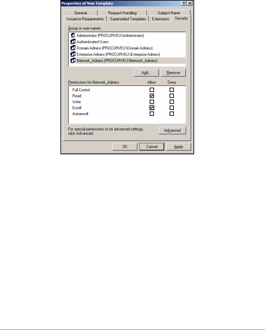
4-21
Implementing a VPN with Endpoint Integrity
Configure Certificate Services
Figure 4-8. Properties of New Template > Security Tab
13. Click OK.
Template for a VPN Client Certificate with an Automatically
Generated Subject Name
The subject name in a user’s digital certificate affects his or her level of access.
The subject name can be automatically generated from Active Directory, as
long as Active Directory organizes users in the same way that you want to
organize them in your VPN.
This solution uses a template with the following characteristics:
■The subject name should be generated from Active Directory.
In this solution, users are divided into two OUs in Active Directory:
Faculty or Students. The router’s remote ID list has two corresponding
entries, which match users to a crypto map entry (and ACL) based on the
OU in the subject name.
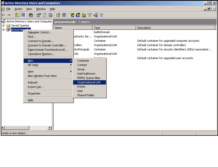
4-22
Implementing a VPN with Endpoint Integrity
Configure Certificate Services
By default, the Authenticated Session template generates the subject
name from Active Directory, so you do not need to change this setting.
(See “Create New OUs in Active Directory” on page 4-22 if you need
instructions on setting up a new OU and moving users into it.)
■Users allowed remote access become members of a new group, called, in
this example, VPN. These users will be responsible for enrolling for
certificates. You must set permissions accordingly.
See “Create Groups for VPN Users” on page 4-25 if you need instructions
on setting up the group.
Create New OUs in Active Directory. Follow these steps to create
new OUs:
1. From the Windows Start menu, select Administrative Tools > Active Directory
Users and Computers. Right-click the domain name and select New >
Organizational unit.
Figure 4-9. Active Directory Users and Computers Window
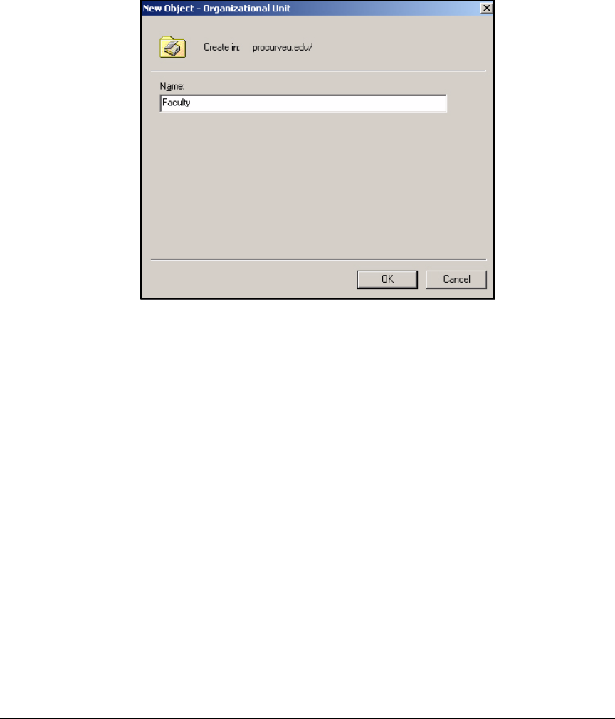
4-23
Implementing a VPN with Endpoint Integrity
Configure Certificate Services
2. In the New Object - Organization Unit window, type the new OU’s name. In
this example: Faculty.
Figure 4-10. New Object - Organization Unit Window
3. Click OK.
4. Repeat the steps for each new OU. In this example, you would also create
an OU for Students.
5. Move users into the correct OU:
a. In the Active Directory Users and Computers window, navigate to the
user object.
b. Right-click the user’s name and click Move.
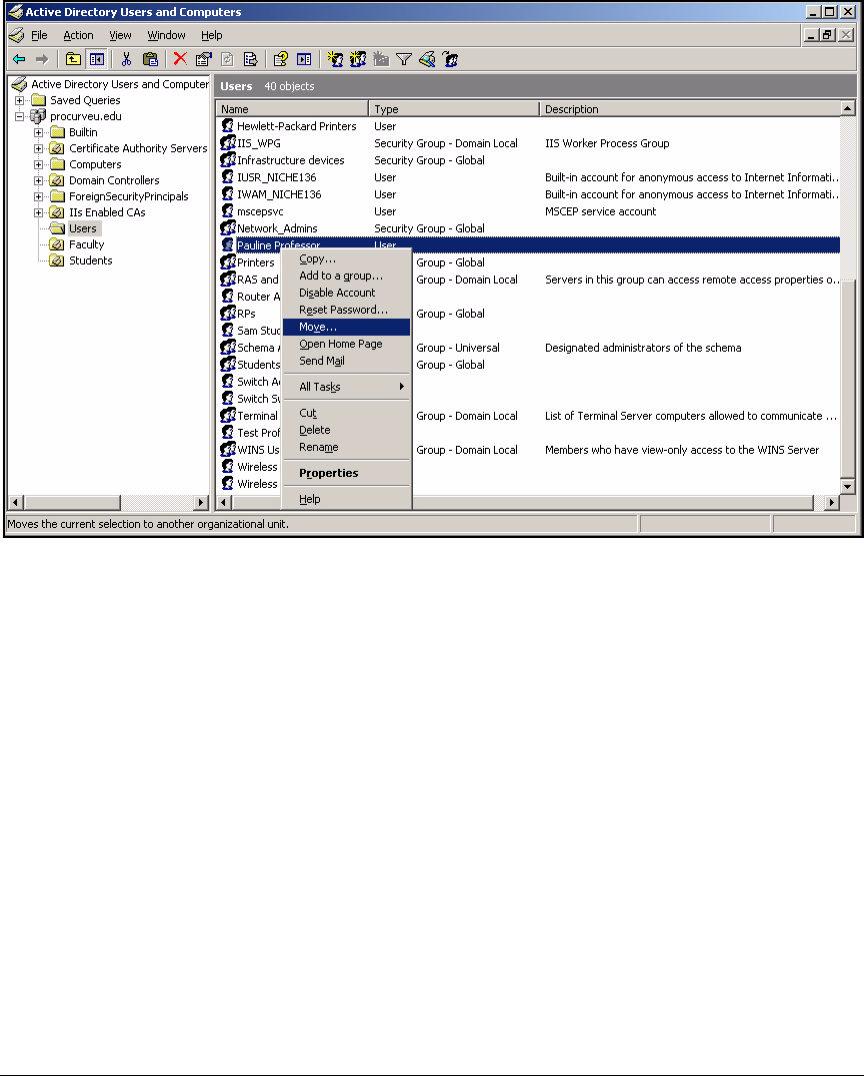
4-24
Implementing a VPN with Endpoint Integrity
Configure Certificate Services
Figure 4-11. Active Directory Users and Computers Window
c. In the Move window, select the new OU for the user.
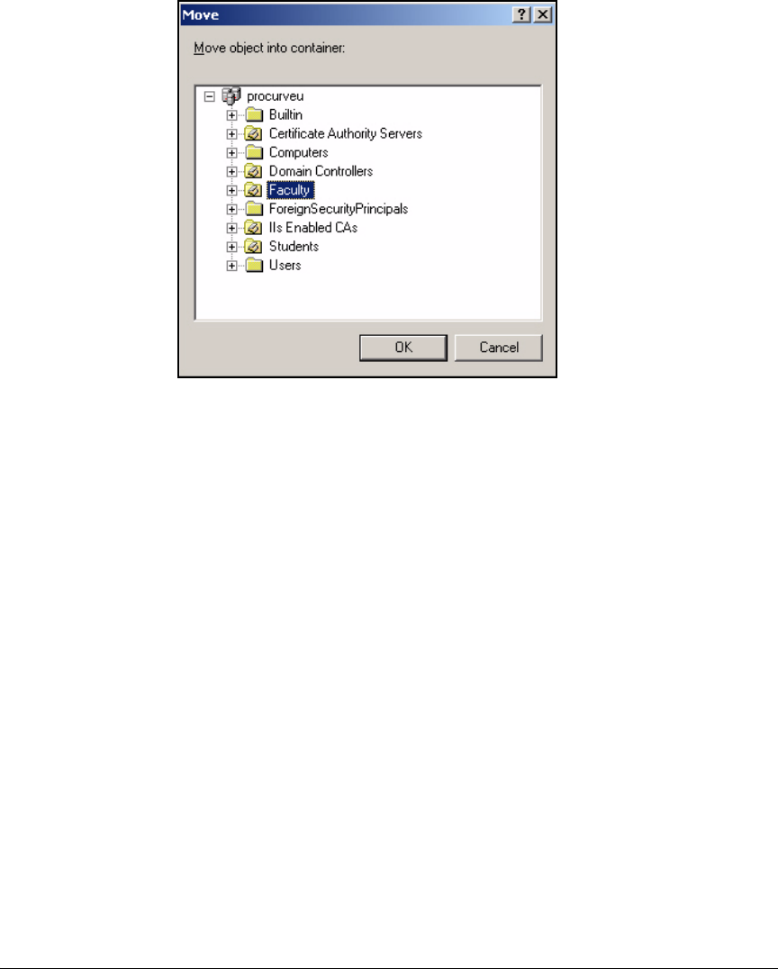
4-25
Implementing a VPN with Endpoint Integrity
Configure Certificate Services
Figure 4-12. Move Window
d. Click OK.
6. Press [Alt]+[F4] to close the window.
Create Groups for VPN Users. Follow these steps to create groups for
VPN users:
1. From the Windows Start menu, select Administrative Tools > Active Directory
Users and Computers.
2. Expand the domain.
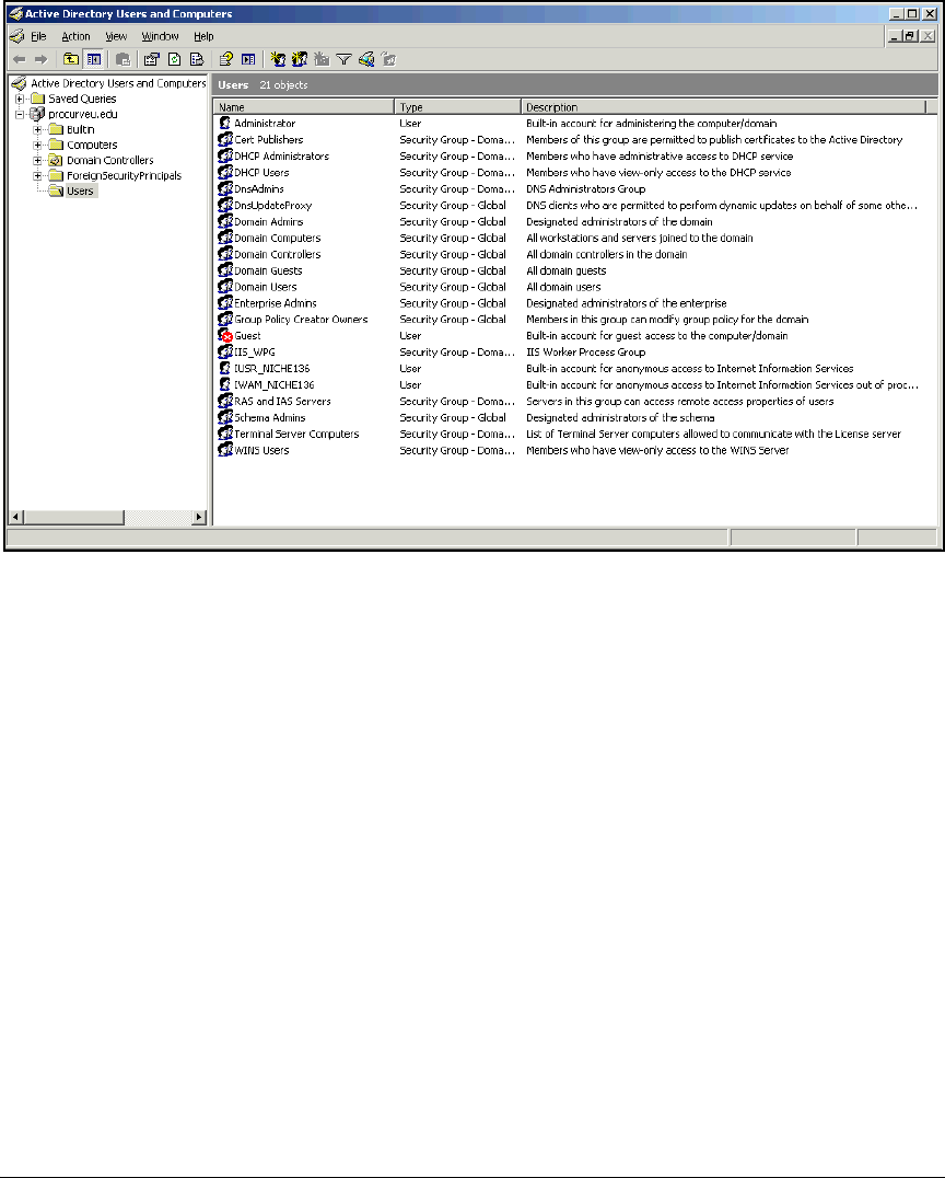
4-26
Implementing a VPN with Endpoint Integrity
Configure Certificate Services
Figure 4-13. Active Directory Users and Computers Window
3. In the left pane, right-click Users and select New > Group.

4-27
Implementing a VPN with Endpoint Integrity
Configure Certificate Services
Figure 4-14. New Object – Group Window
4. Type the group name in the Group name box. In this example: VPN.
5. Accept the default setting of Global for the Group scope and Security for
the Group type.
6. Click OK.
7. Add users who require remote access to the new group:
a. Expand an OU that contains VPN users. In this example: Faculty or
Students.
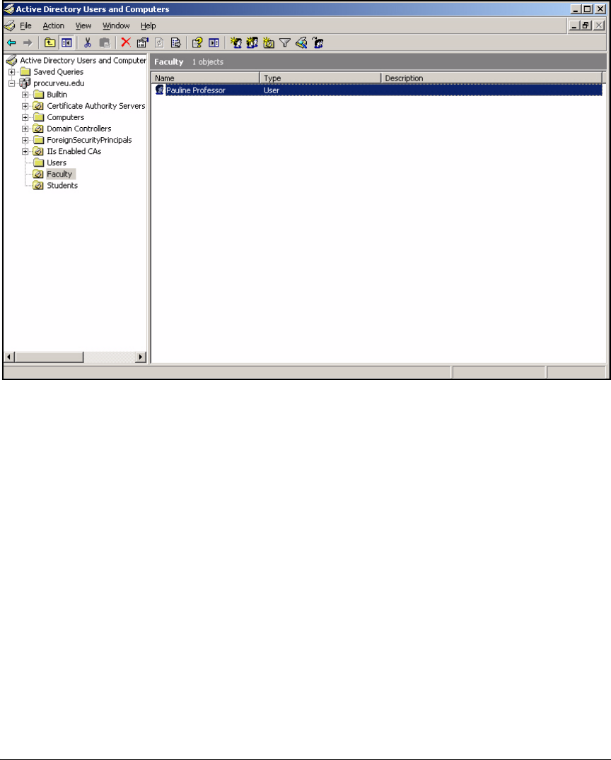
4-28
Implementing a VPN with Endpoint Integrity
Configure Certificate Services
Figure 4-15. Active Directory Users and Computers Window > <My OU>
b. Right-click the user and, in the menu that is displayed, click Properties.
c. Click the Member Of tab and click Add.
d. In the Enter the object names to select box, type the name of the
appropriate group. For the example network, you would type VPN.
e. Click Check Names. If the group name is valid, it will be underlined.
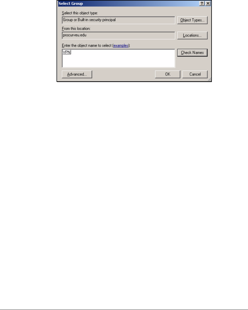
4-29
Implementing a VPN with Endpoint Integrity
Configure Certificate Services
Figure 4-16. Select Group Window
f. Click OK.
g. The group is displayed in the Member Of window. Click OK to apply
the changes.
h. Repeat until you have added the membership to all VPN users.
8. Press [Alt]+[F4] to close the window.
Set Permissions in the Authenticated Session Template. Follow these
steps to customize the Authenticated Session template for your environment:
1. Open a Management Console that has the Certificate Templates and the
Certificate Authority snap-ins. (See “Create a Management Console for
the CA” on page 2-76 of Chapter 2: “Implementing 802.1X with ProCurve
IDM and Endpoint Integrity.”)
2. Select Certificate Templates in the left pane of the console window.
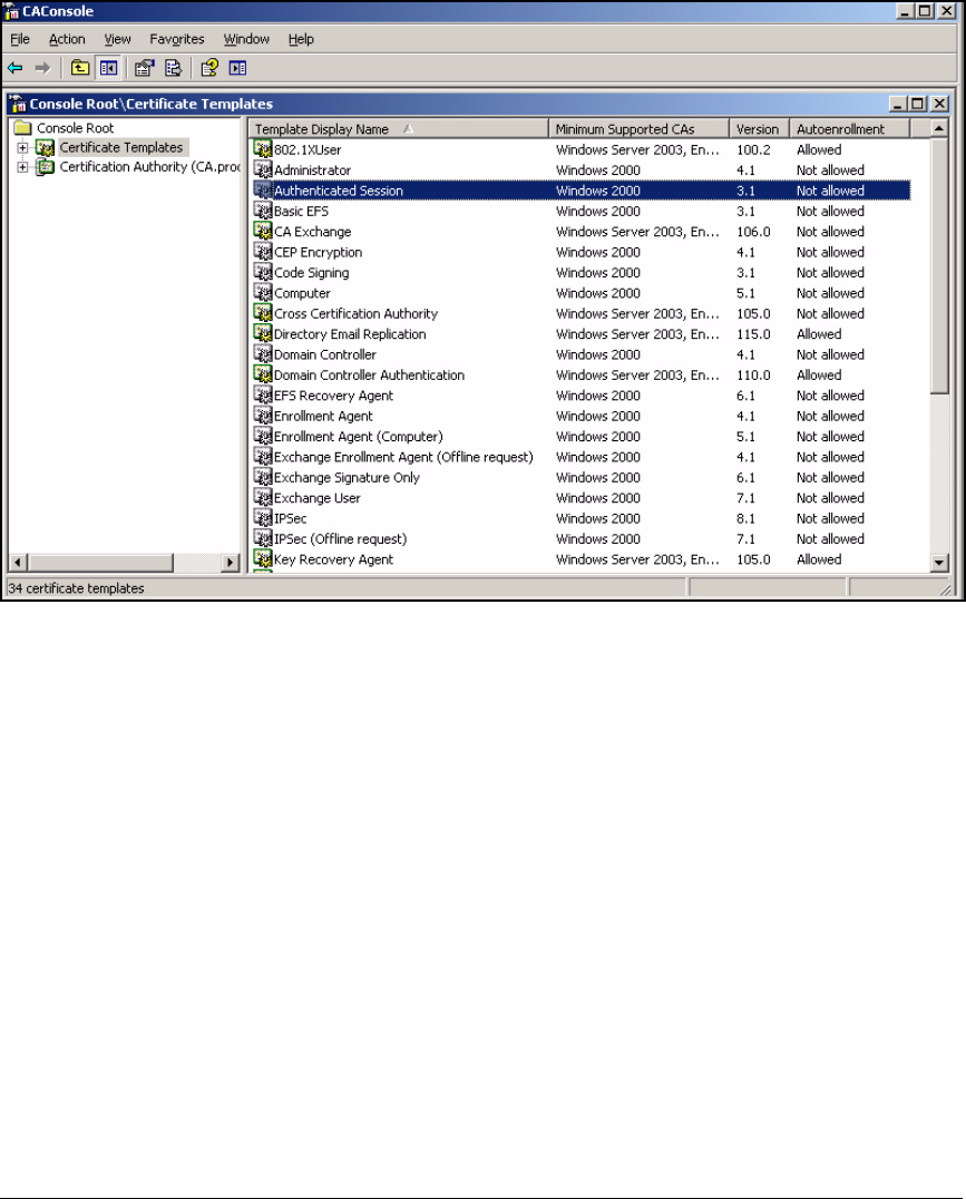
4-30
Implementing a VPN with Endpoint Integrity
Configure Certificate Services
Figure 4-17. Duplicate Authenticated Session Template
3. Right-click Authenticated Session in the right pane. In the menu that is
displayed, select Properties. The Properties of Authenticated Session win-
dow is displayed.
4. Click the Security tab.
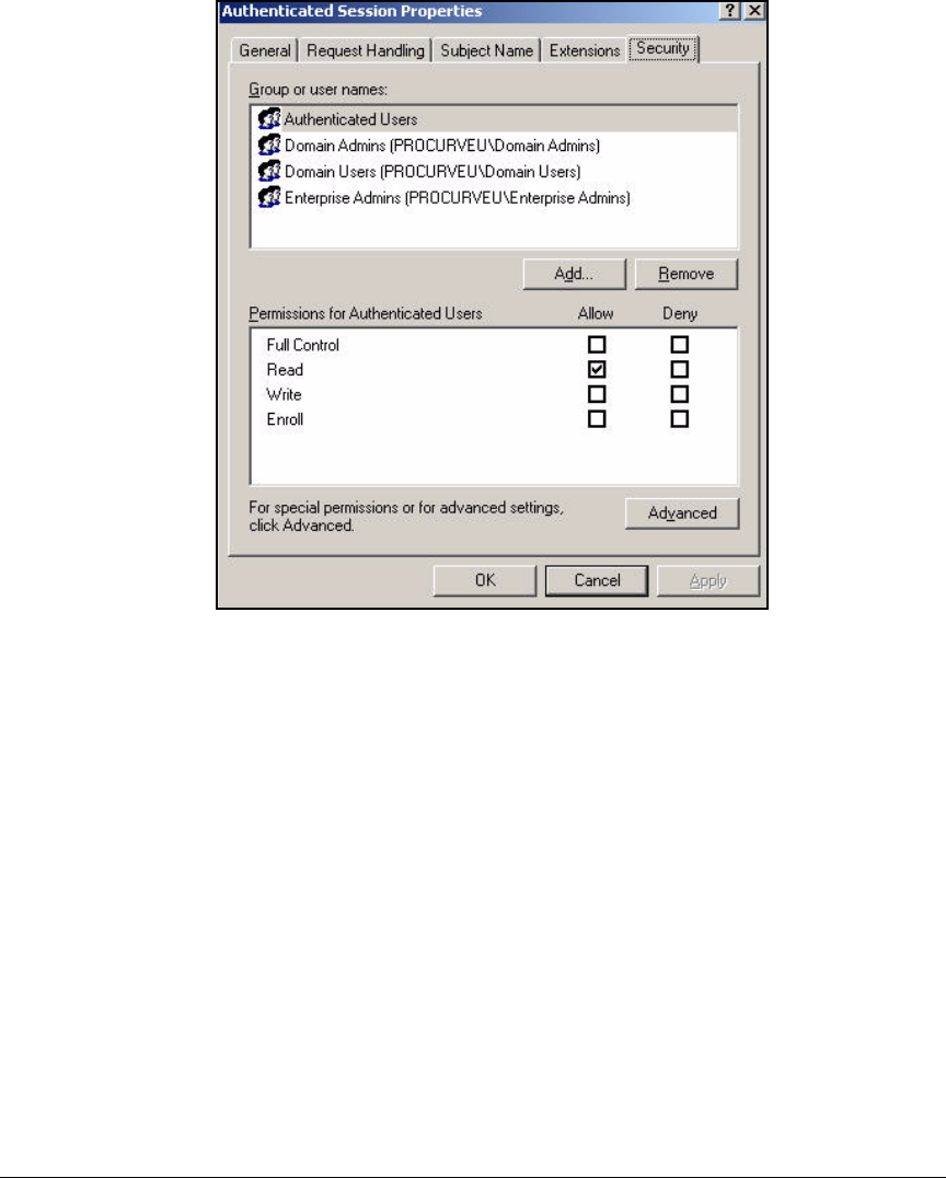
4-31
Implementing a VPN with Endpoint Integrity
Configure Certificate Services
Figure 4-18. Properties of New Template > Security Tab
5. You will allow only administrators and users in the VPN group to enroll
for certificates.
a. Select Domain Users and click Remove.
b. Click Add.
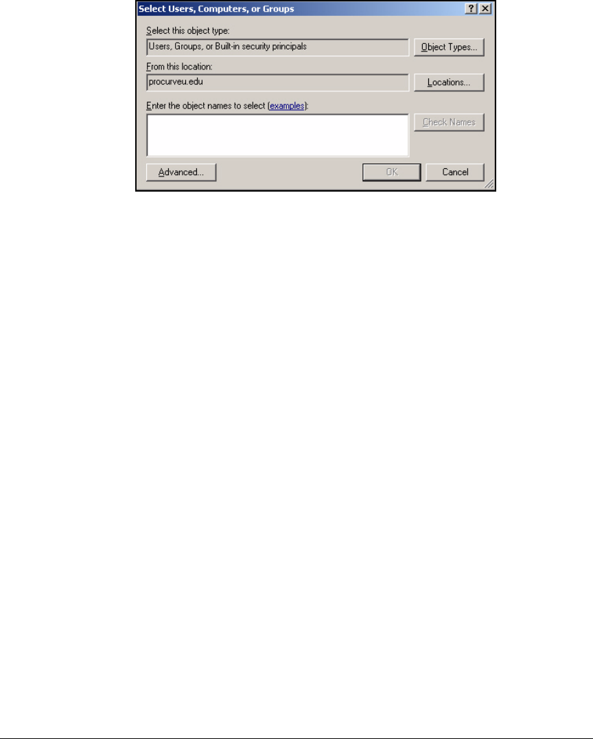
4-32
Implementing a VPN with Endpoint Integrity
Configure Certificate Services
Figure 4-19. Select Users, Computers, or Groups Window
c. In the Enter the object name to select box, type the name of the group
for network administrators. In this example: VPN.
d. Click Check Names to verify that you typed the name correctly; the
name should become underlined.
e. Click OK.
f. At the Security tab in the Properties window, click the name of the
object you added and select the Enroll check box.
g. Repeat steps b to f to add another group. In this example: Students.
6. Click OK.
Customize the Template for the Router’s IPsec
Certificate
Just as VPN clients require certificates, so does the VPN gateway (in this case,
the Secure Router 7000dl). You will generate the certificate request on the
router itself (see “Generate a Router Certificate Request” on page 4-109), so
the correct certificate template on a Windows CA is IPsec (Offline request).
The default template works in this environment. However, depending on how
tasks are divided in your network, you might want to grant Read and Enroll
permissions for the template specifically to managers of the Secure Router
7000dl. If so, follow these steps:
1. Open the Management Console you configured for the CA. (See “Create
a Management Console for the CA” on page 2-76 of Chapter 2: “Implement-
ing 802.1X with ProCurve IDM and Endpoint Integrity.”)
2. Select Certificate Templates in the left pane of the console window.
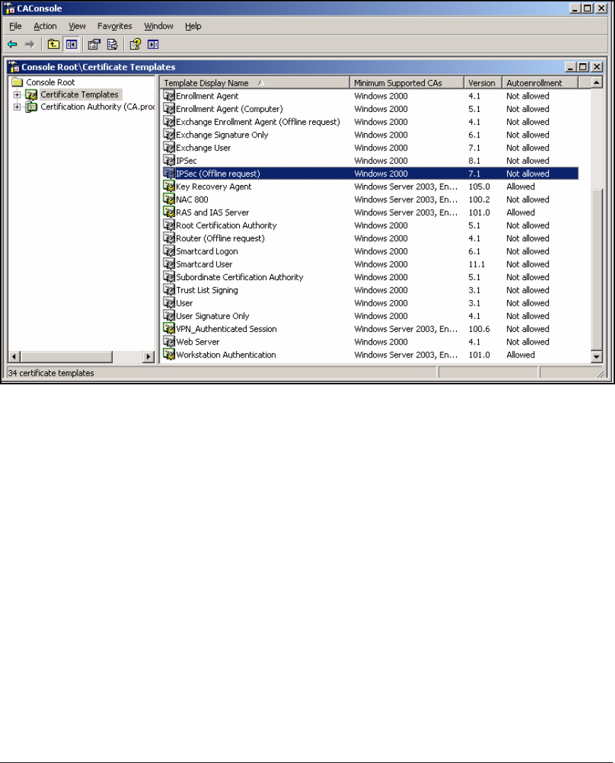
4-33
Implementing a VPN with Endpoint Integrity
Configure Certificate Services
Figure 4-20. Management Console > Certificate Templates
3. Double-click IPSec (Offline request) in the right pane.
4. In the IPSec (Offline request) Properties window, click the Security tab.
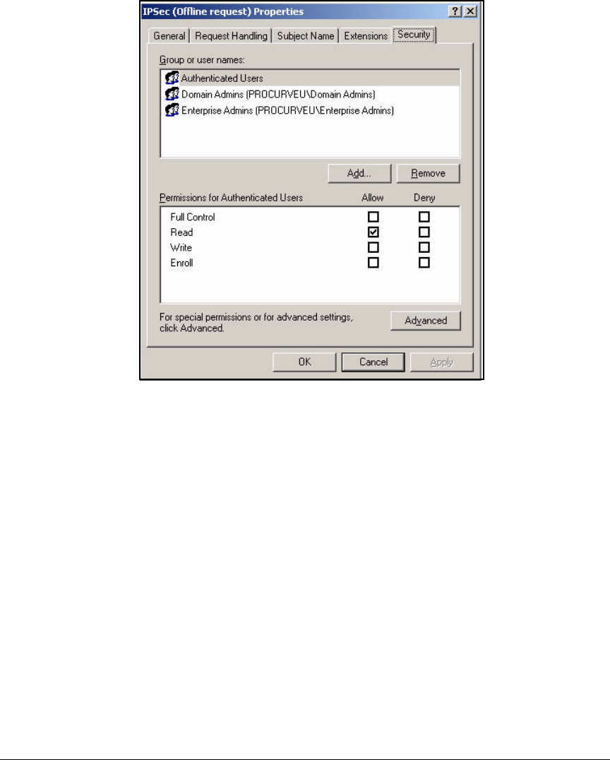
4-34
Implementing a VPN with Endpoint Integrity
Configure Certificate Services
Figure 4-21. Properties of New Template > Security Tab
5. Click Add.
6. Type the name of the group (or user) that you have decided should obtain
the router’s certificate. In this example: Network_Admins. Click Check
Names.
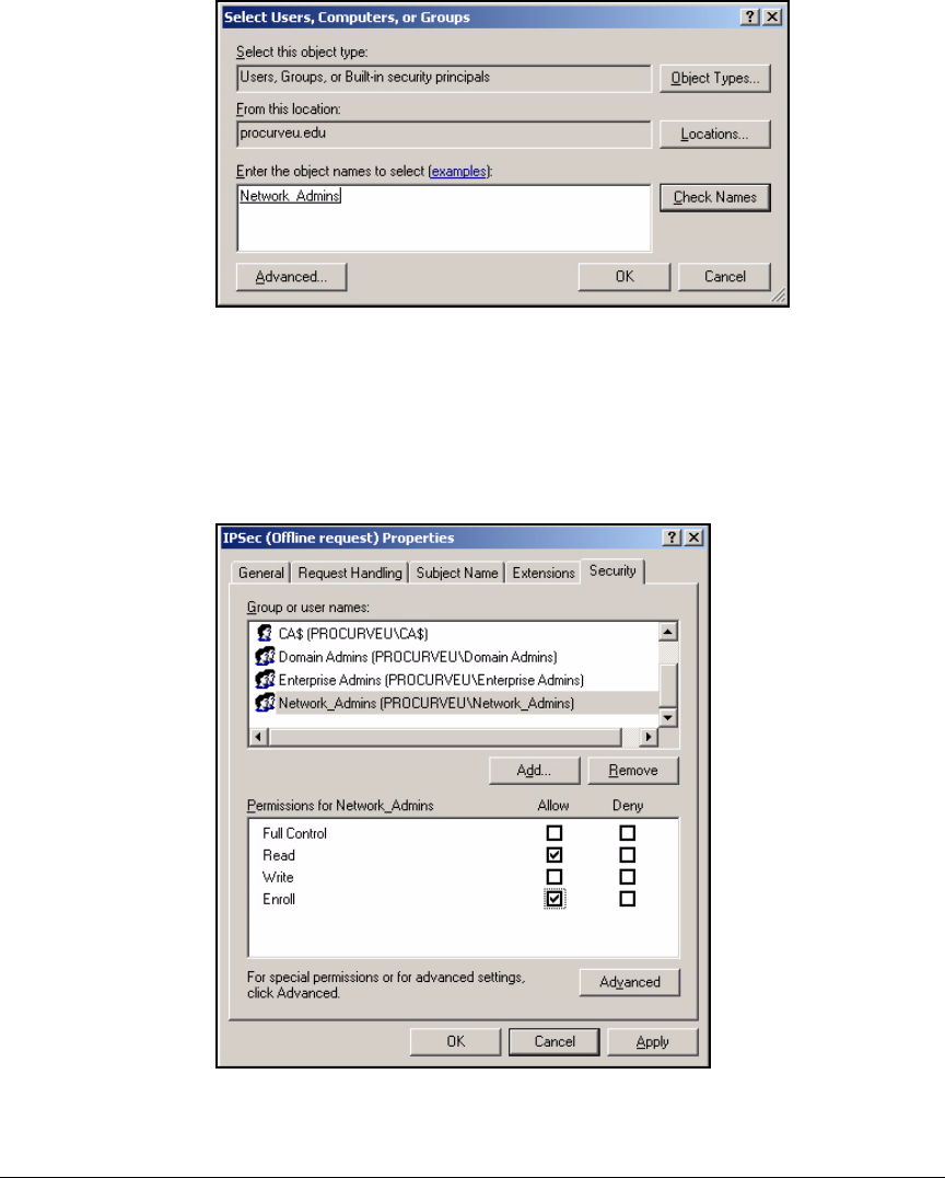
4-35
Implementing a VPN with Endpoint Integrity
Configure Certificate Services
Figure 4-22. Select Users, Computers, or Groups Window
7. Click OK.
8. At the Security tab, select the name of the new group (or user).
9. Select the Enroll check box.
Figure 4-23. Select Users, Computers, or Groups Window
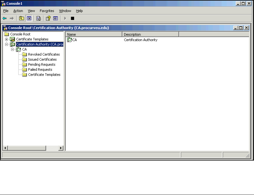
4-36
Implementing a VPN with Endpoint Integrity
Configure Certificate Services
10. If you do not want other types of administrators enrolling VPN gateways
for certificates, select Domain Admins and clear the Enroll check box.
Repeat for Enterprise Admins.
11. Click OK.
Enable Templates on the CA Server
You must enable the two templates so that the CA can issue certificates with
them. Follow these steps:
1. Open the Management Console you configured for the CA. (See “Create
a Management Console for the CA” on page 2-76 of Chapter 2: “Implement-
ing 802.1X with ProCurve IDM and Endpoint Integrity.”)
2. In the left pane of the console, expand Certification Authority.
3. Expand the CA server.
Figure 4-24. Management Console > Certification Authority
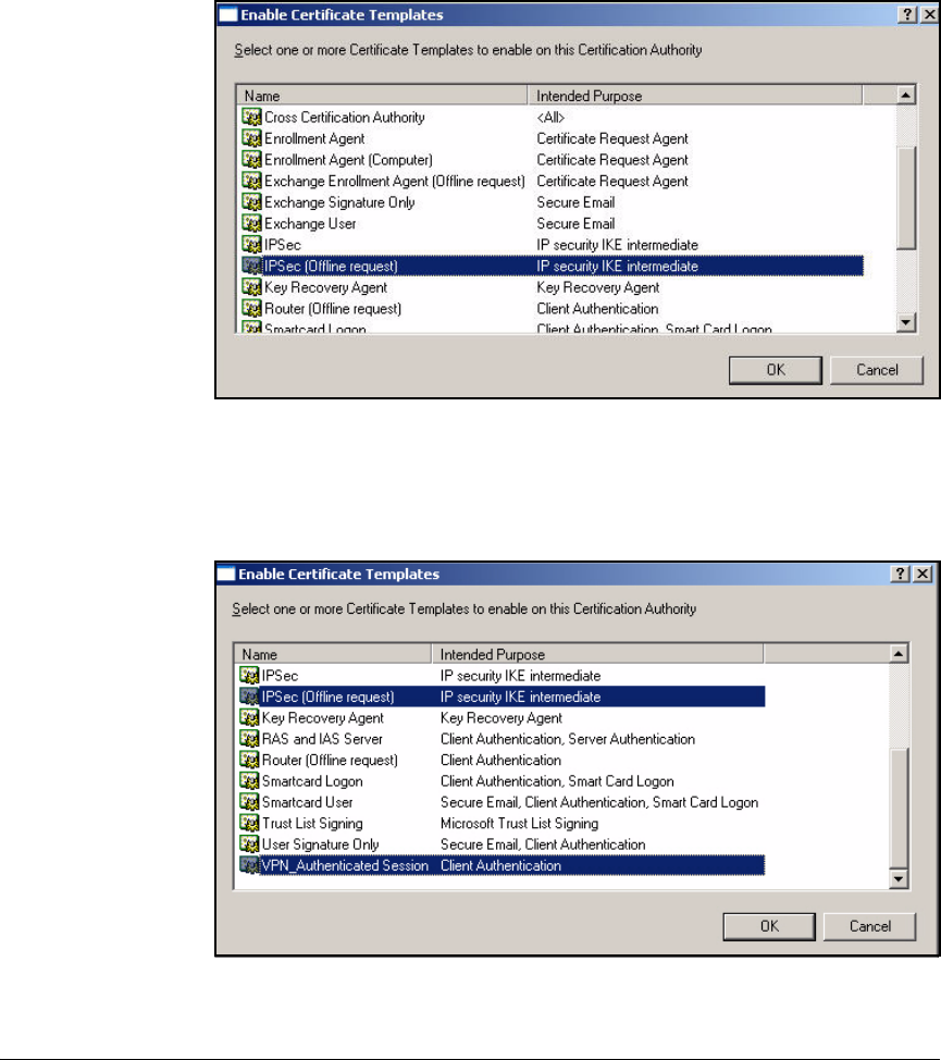
4-37
Implementing a VPN with Endpoint Integrity
Configure Certificate Services
4. Right-click Certificate Templates and select New > Certificate Template to
Issue.
5. Select IPSec (Offline request) in the window that is displayed.
Figure 4-25. Enable Certificate Templates Window
6. Hold down [Ctrl]; scroll to and select VPN_Authenticated Session (or Authen-
ticated Session).
Figure 4-26. Enable Certificate Templates Window
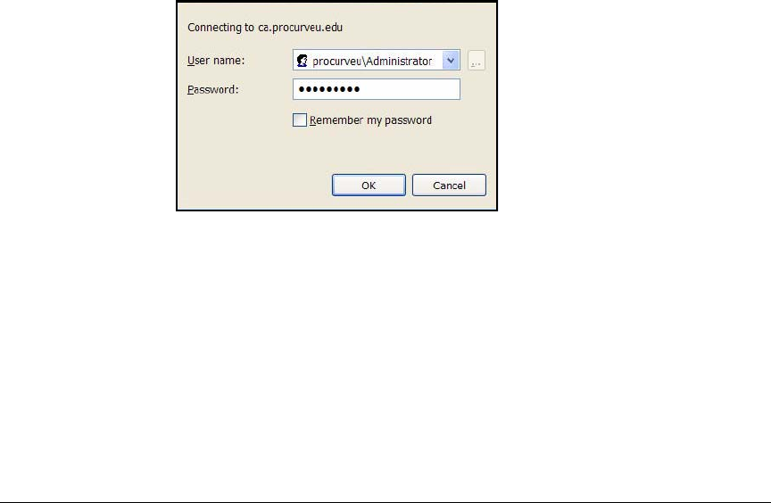
4-38
Implementing a VPN with Endpoint Integrity
Configure Certificate Services
7. Click OK.
Export the CRL
In addition to its own certificate, the Secure Router 7000dl requires a CRL,
which is a list of certificates that the CA has revoked and that the router should
reject. VPN clients should also have the CRL.
In this task, you will export your domain’s CRL to a file. Later, you will import
this file onto the Secure Router 7000dl and ProCurve VPN Client. One way to
export the CRL is through the CA’s Web enrollment pages. Follow these steps:
1. Open a Web browser and type this URL: http://<CA server hostname>/
certsrv. In this example: http://ca.procurveu.edu/certsrv.
2. When prompted, type an administrator’s domain credentials:
a. For the User name, use this format: <domain>\<username>. Do not
include the top-level domain in the domain name. In this example:
procurveu\Administrator.
b. For the Password, type the user’s password. In this example:
ProCurve0.
Figure 4-27. Connect to ca.procurveu.edu Window
3. Click OK.
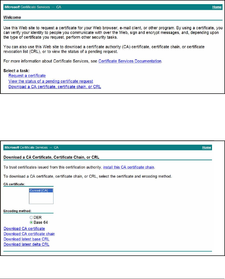
4-39
Implementing a VPN with Endpoint Integrity
Configure Certificate Services
Figure 4-28. Certificate Services > Welcome Page
4. You should see the Welcome page shown in Figure 4-28. Click Download
a CA certificate, certificate chain, or CRL.
5. For the Encoding method, select Base 64.
Figure 4-29. Certificate Services > Download a CA Certificate, Certificate Chain,
or CRL Page
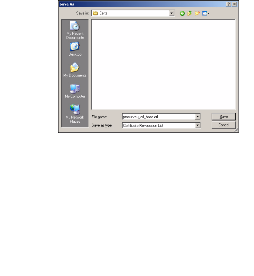
4-40
Implementing a VPN with Endpoint Integrity
Configure Certificate Services
6. Click Download latest base CRL.
7. If prompted, verify that you want to save the file.
8. In the window that is displayed, navigate to a directory and type a
filename.
Figure 4-30. Save As Window
9. Click Save.
10. In the Download complete window, click Close.
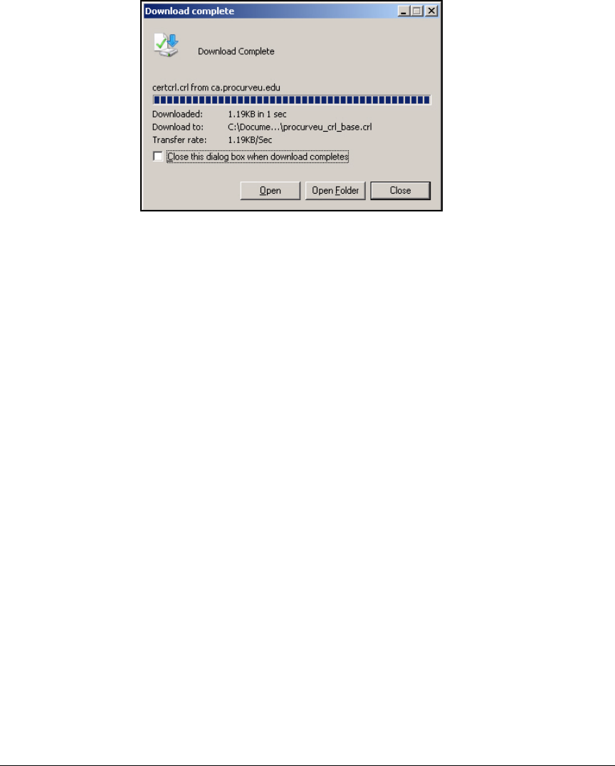
4-41
Implementing a VPN with Endpoint Integrity
Configure Certificate Services
Figure 4-31. Download complete Window
11. Return to the Web page shown in Figure 4-29, click Download latest
delta CRL.
12. Repeat steps 7 to 10.
Check the Key Size for the CA Root Certificate
The Secure Router 7000dl can import only CA root certificates with a key size
less than 2048 bits. To check the key size in your domain CA certificate, follow
these steps:
1. Open the Management Console that has the Certificate Authority snap-in.
2. In the left pane of the console, expand Certification Authority.
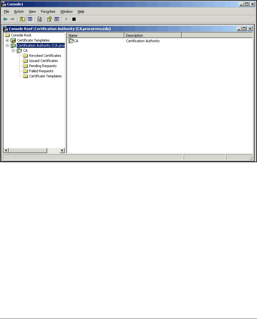
4-42
Implementing a VPN with Endpoint Integrity
Configure Certificate Services
Figure 4-32. Management Console > Certification Authority
3. Right-click the CA server. Select Properties in the menu that is displayed.
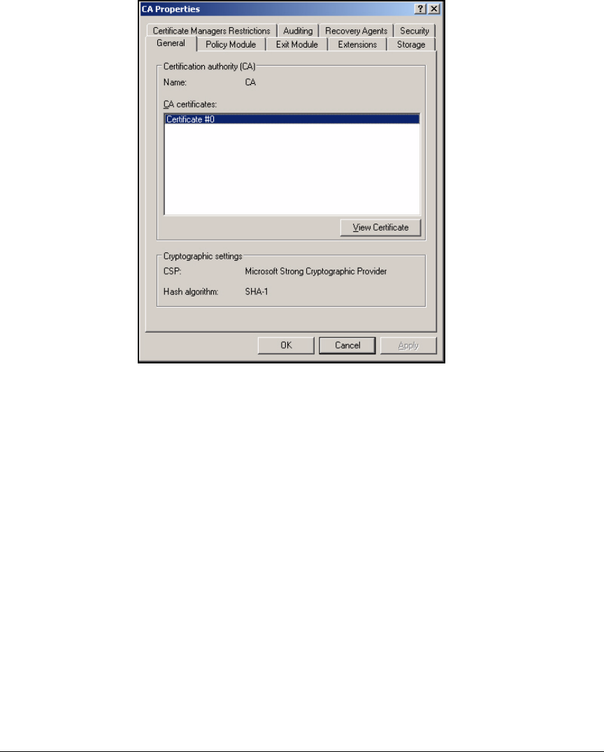
4-43
Implementing a VPN with Endpoint Integrity
Configure Certificate Services
Figure 4-33. CA Properties Window
4. At the General tab, select the certificate in the CA certificates box.
5. Click View Certificates.
6. Click the Details tab.
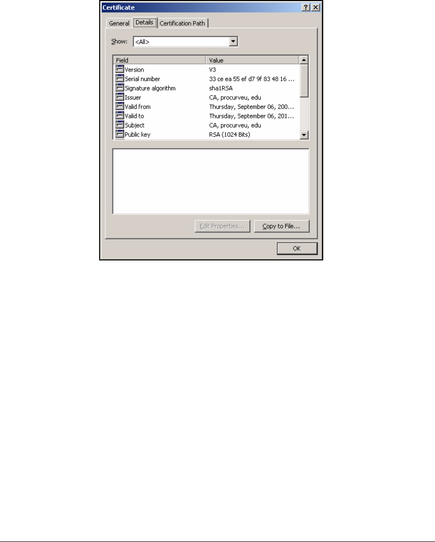
4-44
Implementing a VPN with Endpoint Integrity
Configure Certificate Services
Figure 4-34. Certificate Window > Details Tab
7. Check the key size; it is displayed in the Value column for the Public key.
8. Close the open windows.
The key in the certificate shown in Figure 4-34 is 1024 bits, so the certificate
can be loaded on the Secure Router 7000dl. However, if the key size is 2048
bits, it is too large for the router. You must re-issue the CA root certificate with
a key size of 1024 bits. By default, the CA generates a renewal key of the same
length as the existing key. You will need to create a policy that allows the key
to be 1024 bits.

4-45
Implementing a VPN with Endpoint Integrity
Configure Certificate Services
Follow these steps to create a new CA certificate with a key size of 1024 bits:
1. Open a text editor and type this text:
[Version]
Signature= "$Windows NT$"
[certsrv_server]
renewalkeylength=1024
RenewalValidityPeriodUnits=0x18
RenewalValidityPeriod=years
CRLPeriod = days
CRLPeriodUnits = 2
CRLDeltaPeriod = hours
CRLDeltaPeriodUnits = 4
2. Save the file as CAPolicy.inf.
3. Transfer the file to the CA server and copy it to the Windows directory.
4. You must complete the next steps on the CA server itself. Open a Manage-
ment Console that has the Certificate Authority (Local) snap-in.
5. In the left pane of the console, expand Certification Authority.
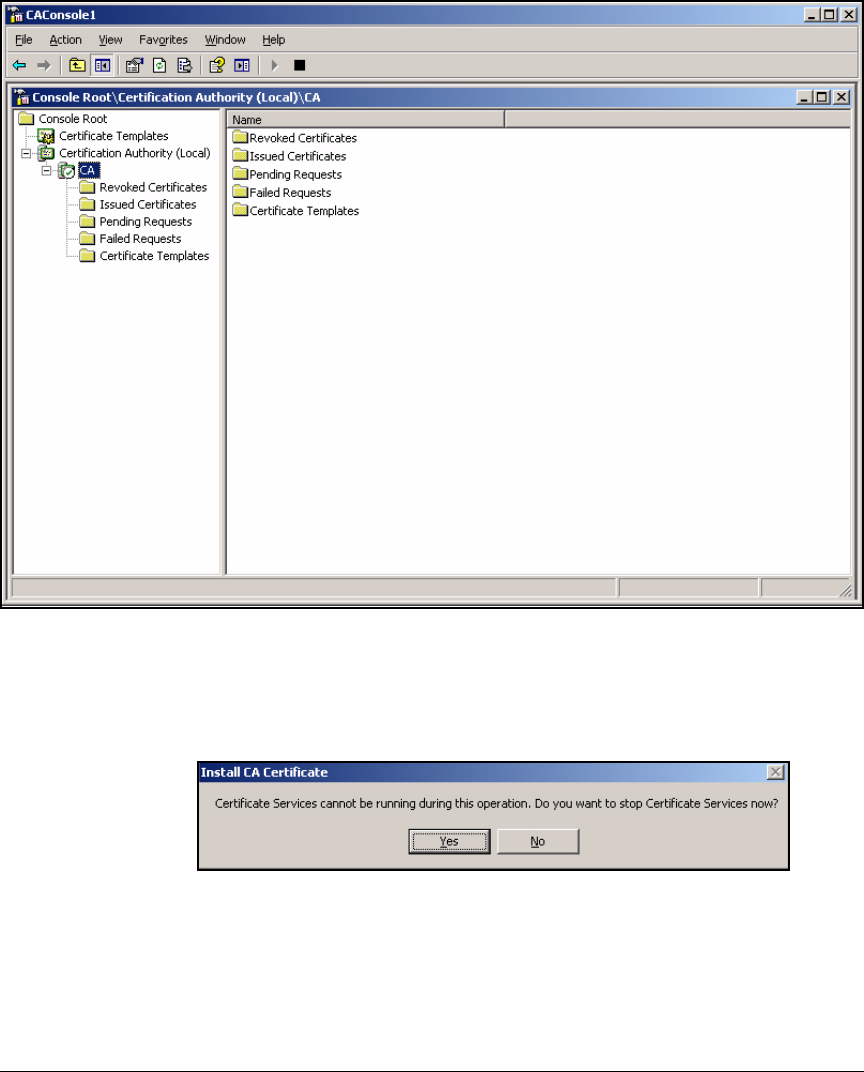
4-46
Implementing a VPN with Endpoint Integrity
Configure Certificate Services
Figure 4-35. Management Console > Certification Authority
6. Right-click the CA server. In the menu that is displayed, select All tasks >
Renew CA certificate.
Figure 4-36. Install CA Certificate Window
7. Click Yes in the Install CA Certificate window.
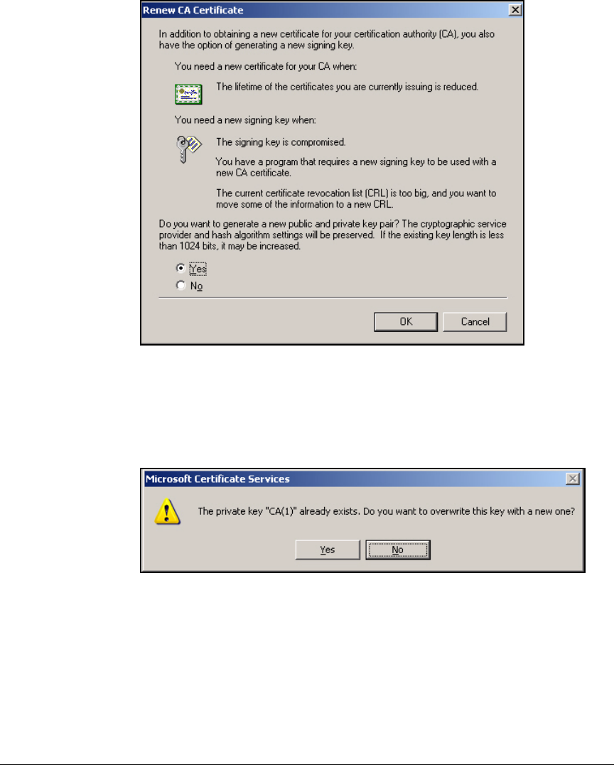
4-47
Implementing a VPN with Endpoint Integrity
Configure Certificate Services
Figure 4-37. Renew CA Certificate Window
8. In the Renew CA Certificate window, make sure that Yes is selected. This
setting ensures that the CA generates a new key when it creates the new
certificate.
Figure 4-38. Microsoft Certificate Services Warning Window
9. When asked if you want to overwrite an existing key, click Yes.
10. View the new CA root certificate and verify that the key size is 1024 bits
(see step 1 on page 4-41 to step 7 on page 4-44).

4-48
Implementing a VPN with Endpoint Integrity
Configure the ProCurve Secure Router 7000dl
Configure the ProCurve Secure Router
7000dl
This section teaches you how to set up a Secure Router 7000dl to support VPN
connections. It also provides instructions for configuring:
■The router’s physical and virtual interfaces
■The routing protocol, in this example, RIPv2
■Network address translation (NAT)
■The access control lists (ACLs) and access control policies (ACPs)
applied to the router’s Internet interface
Configure the Physical and Virtual Interfaces
After you complete this section, your router will be configured for both a LAN
and WAN connection. This section provides only the basic steps. For more
detailed information on configuring physical and virtual interfaces, see the
ProCurve Secure Router Basic Management and Configuration Guide.
Configure the Ethernet Interface
A Secure Router 7000dl has two Ethernet ports: the bottom port is numbered
0/1, and the top port is numbered 0/2. In this example, the 0/1 port connects
to a routing switch in the LAN.
Complete these steps to configure the Ethernet interface:
1. Access the Secure Router 7000dl’s command line interface (CLI):
a. Use a serial cable to connect the router’s console port to your man-
agement station’s console port.
b. Open a session with terminal session software (such as Tera Term).
Use these settings:
– Baud Rate = 9600
– Parity = None
– Data Bits = 8
–Stop Bits = 1
– Flow Control = None
2. You begin in the basic mode context, from which you can type a limited
number of commands. Move to the enable mode context:
ProCurveSR7000dl>enable

4-49
Implementing a VPN with Endpoint Integrity
Configure the ProCurve Secure Router 7000dl
3. Move to the global configuration mode context:
ProCurveSR7000dl#configure terminal
ProCurveSR7000dl(config)#
4. Configure a hostname for the Secure Router 7000dl:
For example:
ProCurveSR7000dl(config)# hostname SecureRouter
SecureRouter(config)#
5. Access the Ethernet configuration mode context:
For example:
SecureRouter(config)#interface ethernet 0/1
6. You can assign the interface a static IP address or have it request a DHCP
address.
Note A static IP address is preferred.
a. To assign a static IP address, type this command:
For example, type:
SecureRouter(config-eth 0/1)#ip address 10.2.0.100
/16
b. To enable the DHCP client on the Ethernet interface, type:
SecureRouter(config-eth 0/1)#ip address dhcp
Syntax: hostname <hostname>
Changes the Secure Router 7000dl’s hostname, as well as the
prompt in the CLI. Replace <hostname> with an alphanumeric
string up to 32 characters long.
Syntax: interface ethernet 0/<port>
Moves to the specified Ethernet interface. Replace <port>
with 1 for the bottom port and 2 for the top port.
Syntax: ip address <A.B.C.D> <subnet mask | /prefix length>
Assigns the specified IP address to the interface. You can type
the address with a subnet mask or with Classless Interdomain
Routing (CIDR) notation (a prefix length). (You must include
a space between the IP address and the / symbol in front of the
prefix length.)

4-50
Implementing a VPN with Endpoint Integrity
Configure the ProCurve Secure Router 7000dl
7. By default, all the interfaces on the Secure Router 7000dl are administra-
tively down. To enable the Ethernet interface, type:
SecureRouter(config-eth 0/1)#no shutdown
After you activate the interface, a message is displayed on the CLI,
reporting that the interface is administratively up. When the Ethernet
interface establishes a valid connection to the connected device, another
message is displayed, reporting that the interface is up.
8. Press [Enter] for the prompt.
9. Save your configuration changes to the startup-config:
SecureRouter(config-eth 0/1)#do write memory
Configure the WAN Interface
This section describes how to configure a Point-to-Point Protocol (PPP)
connection running over an E1 line. (Setting up a T1 line is very similar; you
simply choose a different range of channels for the TDM-group.) For the
purposes of establishing a VPN, the type of WAN connection does not matter.
You could use any type of WAN connection.
The following are just the basic instructions for setting up a PPP connection
running over an E1 line. For detailed information about setting up WAN
connections on the Secure Router 7000dl, see the ProCurve Secure Router
Basic Management and Configuration Guide.
1. Access the CLI (through a console, Telnet, or secure shell [SSH] session).
(To use SSH or Telnet, you must first enable this type of access on the
router.)
2. Move to the global configuration mode context:
SecureRouter> enable
SecureRouter# configure terminal

4-51
Implementing a VPN with Endpoint Integrity
Configure the ProCurve Secure Router 7000dl
3. Access the E1 interface configuration mode context:
For example:
SecureRouter(config)# interface e1 1/1
4. Configure the channels for the E1 line.
For example:
SecureRouter(config-e1 1/1)# tdm-group 1 timeslots
1-31
Note If you are configuring a T1 line, the maximum channel range is 1-24.
5. Configure the line coding.
Syntax: interface <interface> <slot>/<port>
Moves to the physical interface you specify.
Replace <interface> with the name of the specific interface,
such as e1, t1, or adsl.
Replace <slot> with the number of the slot in which the E1
module is installed.
Replace <port> with the port number used for this E1
connection.
Syntax: tdm-group <number> timeslots <range of numbers>
Creates a time division multiplexing (TDM) group and
assigns it a number of channels. The TDM-group number
relates directly to the interface that you are configuring. This
means that you can create a TDM group 1 for each E1 or T1
interface on the Secure Router 7000dl.
Replace <number> with a number between 1 and 255, and
replace <range of numbers> with the channels that will be used
for this connection.
Syntax: coding [ami | hdb3]
Defines how digital signals are configured for transport
through a physical transmission medium. Use the same line
coding as your public carrier.

4-52
Implementing a VPN with Endpoint Integrity
Configure the ProCurve Secure Router 7000dl
For example:
SecureRouter(config-e1 1/1)# coding ami
6. Configure the time source.
For example:
SecureRouter(config-e1 1/1)# clock source line
7. Activate the physical interface.
SecureRouter(config-e1 1/1)# no shutdown
8. Create the logical interface (in this example, a PPP interface).
For example:
SecureRouter(config-e1 1/1)# interface ppp 1
SecureRouter(config-ppp 1)#
Syntax: clock source [internal | line | through]
Use the line setting if the E1 or T1 interface will take the clock
source from the public carrier.
Use the internal setting if the E1 or T1 interface will provide
the clock for the connection. For example, if you connect the
Secure Router 7000dl to another router, one of the routers
must provide the clock source. If the local Secure Router
7000dl is providing the clock source, use the internal setting.
Use the through setting if you want the E1 or T1 interface to
take the clock from the other interface on that module.
Syntax: interface <interface> <number>
Creates the logical interface you specify and moves to its
configuration mode context.
Replace <interface> with the name of the specific interface,
such as ppp, fr, or atm.
Replace <number> with any number between 1 and 1024. Each
type of logical interface you configure must have a unique
number.

4-53
Implementing a VPN with Endpoint Integrity
Configure the ProCurve Secure Router 7000dl
9. Assign the PPP interface an IP address.
For example:
SecureRouter(config-ppp 1)# ip address 192.168.1.1
255.255.255.0
Note This example uses a private IP address. In a live configuration, you would use
a public address.
10. Bind the logical interface to the physical interface.
For example:
SecureRouter(config-ppp 1)# bind 1 e1 1/1 1 ppp 1
11. Activate the logical interface.
SecureRouter(config-ppp 1)# no shutdown
Syntax: ip address <A.B.C.D> <subnet mask | /prefix length>
Assigns a static IP address to the logical interface.
Replace <A.B.C.D> with the IP address.
Replace
<subnet mask>
with the subnet mask
or
replace
</prefix
length>
with the CIDR notation.
Syntax: bind <bind number
> <
physical interface
> <
slot
>/<
port
> <
tdm-group
number
> <
logical interface
> <
logical interface number
>
Replace <bind number> with a number that is globally signifi-
cant. That is, each bind command you type on the router must
have a unique bind number.
Replace <physical interface> with the type of WAN connection,
such as e1, t1, or serial. Replace <slot> and <port> with the
correct numbers to identify the physical interface’s location
on the Secure Router 7000dl.
If you are binding an E1 or T1 interface to the PPP interface,
replace <TDM-group number> with the TDM group number you
created on the E1 or T1 interface. If you are binding a serial
interface to the PPP interface, omit this option.
Replace <logical interface> with the type of logical connection
(for example, ppp) and replace <logical interface number> with
the number you assigned to this interface.

4-54
Implementing a VPN with Endpoint Integrity
Configure the ProCurve Secure Router 7000dl
12. Save your configuration changes to the startup-config.
SecureRouter(config-ppp 1)# do write memory
Enable Telnet and SSH Access
The Secure Router 7000dl supports Telnet and Secure Shell (SSH) for inline
management. However, by default, Telnet and SSH access is disabled. To
enable inline management, you must configure both an enable mode password
and a password for the type of session you want to use: Telnet or SSH.
Complete the following steps:
1. Establish a console session with the Secure Router 7000dl and move to
the global configuration mode context.
2. If you have already configured an enable mode password, continue with
step 6. To configure an enable mode password, type:
For example:
SecureRouter(config)# enable password md5 procurve
3. The Secure Router 7000dl supports up to five Telnet sessions, or lines. To
enable a line, move to its line configuration mode context:
Syntax: enable password [md5] <password>
Requires manager to type a password to move to the enable
mode context.
Replace <password> with any combination of up to 30 char-
acters.
Include the Message Digest 5 (md5) option to encrypt the
password; otherwise, the password is stored in the startup-
and running-configs in clear text.
Syntax: line telnet <0-4> [<0-4>]
Accesses the Telnet configuration mode context of the line that
you specify.
Replace <0-4> with the line that you want to configure. To
configure multiple lines at once, specify the range, separating
the two numbers by a space.

4-55
Implementing a VPN with Endpoint Integrity
Configure the ProCurve Secure Router 7000dl
For example:
SecureRouter(config)# line telnet 0 4
SecureRouter(config-telnet0—4)#
4. To configure the password for the line, type the password command:
For example:
SecureRouter(config-telnet0-4)# password md5
procurve0
5. Exit the Telnet configuration mode:
SecureRouter(config-telnet0-4)# exit
6. The Secure Router 7000dl also supports five SSH lines. However, to log in
to one of these lines, a user must type credentials configured in the router’s
local list. Type this global configuration command to add a user to the list:
For example:
SecureRouter(config)# username manager password
procurve0
Syntax: password [md5] <password>
Sets the password for this line.
Replace <password> with any combination of up to 30 char-
acters.
Include the Message Digest 5 (md5) option to encrypt the
password; otherwise, the password is stored in the startup-
and running-configs in clear text.
Syntax: username <username> password <password>
Adds a user to the router’s local login list and sets the user’s
password.
Replace <username> and <password> with any combination of
up to 30 characters each.

4-56
Implementing a VPN with Endpoint Integrity
Configure the ProCurve Secure Router 7000dl
7. To activate an SSH line, move to the SSH configuration mode context:
For example:
SecureRouter(config)# line ssh 0 4
SecureRouter(config-ssh0—4)#
8. Enable login through the local list:
SecureRouter(config-ssh—4)# login local-userlist
9. Save your configuration changes to the startup-config:
SecureRouter(config-ssh0—4)# do write memory
Configure the Routing Protocol
The Secure Router 7000dl in this example runs RIP to exchange routes with
LAN routing switches. This section gives the steps for a basic configuration.
It also shows you how to create a default route to the Internet router for
external traffic.
Follow these steps:
1. Access the CLI (through a console, Telnet, or SSH session).
2. Move to the global configuration mode context:
SecureRouter> enable
Password:
SecureRouter# configure terminal
3. Access the RIP configuration mode context:
SecureRouter(config)# router rip
4. Select the version:
Syntax: line ssh <0-4> [<0-4>]
Accesses the SSH configuration mode context of the line that
you specify.
Replace <0-4> with the line that you want to configure. To
configure multiple lines at once, specify the range, separating
the two numbers by a space.
Syntax: version [1 | 2]
Specifies RIPv1 or RIPv2.

4-57
Implementing a VPN with Endpoint Integrity
Configure the ProCurve Secure Router 7000dl
For example:
SecureRouter(config-rip)# version 2
5. Enable RIP on the LAN subnet:
For example:
SecureRouter(config-rip)# network 10.2.0.0
255.255.0.0
Note At this point, you should not activate RIP on the subnet on which the NAC
800 ES is installed. You will set up special routing to ensure that traffic
from the remote endpoints is forwarded on this subnet. (You may later
enable RIP on this subnet, but it is a decision you will make as you
continue on with the configuration process.) See “Use Policy-Based Rout-
ing to Forward VPN Traffic Through the NAC 800” on page 4-58 and
“Enable Routing to the Remote Endpoints” on page 4-61.
6. Exit to the global configuration mode context:
SecureRouter(config-rip)# exit
7. Add a default route to the Internet router:
For example:
SecureRouter(config)# ip route 0.0.0.0 /0 ppp 1
Syntax: network <A.B.C.D> <A.B.C.D>
Enables the router to advertise the specified subnet and to
exchange routes on interfaces with on that subnet.
Replace <A.B.C.D> <A.B.C.D> with the subnet address and
mask. For this command, you cannot use CIDR notation.
Syntax: ip route 0.0.0.0 /0 [<A.B.C.D> | <interface> <number>]
Creates a default route, which the Secure Router uses to route
all traffic for which it does not know an explicit route.
Replace <A.B.C.D> with the IP address of the Internet router,
or replace <interface> with the type of interface that connects
to the Internet such as ppp or atm. Replace <number> with the
number assigned to that interface when it was created. This
option ensures that the route remains valid even if the Inter-
net router changes its IP address.

4-58
Implementing a VPN with Endpoint Integrity
Configure the ProCurve Secure Router 7000dl
8. Save your configuration changes to the startup-config:
SecureRouter(config)# do write memory
Note You must, of course, enable the routing protocol with compatible settings on
routing switches in the LAN. In this solution, the routing switches need to run
RIP on the management VLAN, which is the VLAN on which the Secure Router
7000dl’s Ethernet interface resides, and they must redistribute connected
routes. They also require a default route to the Secure Router 7000dl.
Consult your switch documentation for instructions on setting up the
protocol. “Routing Switch startup-config” on page 4-10 gives an example
configuration.
Use Policy-Based Routing to Forward VPN Traffic
Through the NAC 800
In this example, endpoints on the inside network are secured by NAC 800s in
an 802.1X enforcement cluster, and PCU network administrators do not want
to forward these endpoints’ Internet traffic through the inline NAC 800.
Therefore a core routing switch in the LAN connects directly to the Secure
Router 7000dl’s Ethernet port 0/1.
The NAC 800 stands inline between the core routing switch and the router’s
Ethernet port 0/2. Policy-based routing (PBR) must then be configured to
ensure that all traffic from the remote endpoints is routed through port 0/2
and the NAC 800.
The steps below instruct you to select traffic from remote endpoints. The
correct IP addresses are those that you will later specify in an IKE client
configuration pool. (See “Create a Client Configuration Pool” on page 4-74.)
Table 4-5 shows the subnet used for remote endpoints in the PCU example
network.
Table 4-5. IP Addresses for Remote Users
Complete these steps to configure PBR on the Secure Router 7000dl:
1. Access the Secure Router CLI and move to the global configuration mode
context.
SecureRouter# configure terminal
IKE Client Configuration Pool
Subnet
My IKE Client Configuration
Pool Subnet
10.48.100.0/23

4-59
Implementing a VPN with Endpoint Integrity
Configure the ProCurve Secure Router 7000dl
2. Create an ACL that selects traffic for PBR:
For example:
SecureRouter(config)# ip access-list extended PBR_VPN
3. Deny traffic to the NAC 800’s subnet. (You are going to set up the routing
switch as the next hop IP address of the route, which works for most VPN
traffic. However, all traffic to the NAC 800’s subnet can be sent over the
normal route in the routing table.)
For example:
SecureRouter(config-ext-nacl)# deny ip any 10.3.0.0
0.0.0.255
4. Permit traffic from the remote endpoints that is destined to the private
network:
For example:
SecureRouter(config-ext-nacl)# permit ip 10.48.100.0
0.0.1.255 10.0.0.0 0.15.255.255
Syntax: ip access-list extended <listname>
Creates an extended ACL. Replace <listname> with a string
that uniquely identifies this ACL.
Syntax: deny ip any host <A.B.C.D>
Denies traffic destined to the specified destination.
Replace <A.B.C.D> with the IP address of the NAC 800 ES.
Syntax: permit ip <source A.B.C.D> <wildcard bits> <destination A.B.C.D>
<wildcard bits>
Selects traffic from the specified source.
Replace <source A.B.C.D> with the IP address of the subnet in
the IKE client configuration pool. Replace <wildcard bits> with
bits that use reverse logic from the subnet mask for this
subnet.
Replace <destination A.B.C.D> with the IP address of the private
subnet. Replace <wildcard bits> with bits that use reverse logic
from the subnet mask for this subnet.

4-60
Implementing a VPN with Endpoint Integrity
Configure the ProCurve Secure Router 7000dl
5. Create a route map entry:
For example:
SecureRouter(config-ext-nacl)# route-map PBR_VPN 10
6. Match the route map entry to the ACL that you created in step 2:
For example:
SecureRouter(config-route-map)# match ip address
PBR_VPN
7. Set the next-hop address for this traffic to the IP address of the core
routing switch on the NAC 800’s subnet:
For example:
SecureRouter(config-route-map)# set ip next-hop
10.3.0.1
8. You might want to configure the router to drop the traffic if this address
is unavailable. This prevents traffic from remote endpoints from reaching
the private network without passing through the NAC 800:
Syntax: route-map <name> <index>
Creates a route map entry.
Replace <name> with a string that uniquely identifies this
route map. Replace <index> with a number that determines
the priority for this entry.
Syntax: match ip address <listname>
Selects traffic permitted in the specified ACL for the route
configured in the map entry.
Replace <listname> with the name that you gave the ACL in
step 2.
Syntax: set ip next-hop <A.B.C.D>
Configures the router to forward selected traffic to this IP
address. Replace <A.B.C.D> with the IP address of the switch
connected to the NAC 800 (on the NAC 800’s VLAN).
Syntax: set interface null 0
Drops traffic that cannot be routed to the previously-specified
IP address.

4-61
Implementing a VPN with Endpoint Integrity
Configure the ProCurve Secure Router 7000dl
9. Apply the route map to the WAN interface:
a. Move to the WAN interface configuration mode context:
For example:
SecureRouter(config-route-map)# interface ppp 1
b. Apply the route map to incoming traffic:
For example:
SecureRouter(config-ppp 1)# ip policy route-map
PBR_VPN
10. Save your configuration to the startup-config.
SecureRouter(config-ppp 1)# do write memory
Enable Routing to the Remote Endpoints
You must ensure that devices in your private network can reach the remote
endpoints.
As you recall, in a client-to-site VPN, the remote endpoints are assigned IP
addresses from an IKE client configuration pool. The Secure Router 7000dl
tracks the VPN tunnel associated with each particular client configuration
address and forwards traffic destined to that address appropriately.
You must ensure that traffic destined to the remote endpoints is forwarded
back through the NAC 800 rather than to the Ethernet interface on which the
Secure Router receives other traffic destined to the Internet.
Syntax: interface <interface> <number>
Moves to the configuration mode context for the logical inter-
face you specify.
Replace <interface> with the name of the specific interface,
such as ppp, fr, or atm.
Replace <number> with the number assigned to the interface
when it was created.
Syntax: ip policy route-map <name>
Applies the route map to incoming traffic on the interface.
Replace <name> with the name of the route map, assigned
when you created it in step 5 on page 4-60.

4-62
Implementing a VPN with Endpoint Integrity
Configure the ProCurve Secure Router 7000dl
You have several options:
■On the routing switches, you can create static routes to the subnet
associated with the IKE client configuration pool. For the next hop,
specify the Secure Router’s IP address on the inline NAC 800’s subnet (in
this example, 10.3.0.100).
■Configure the Secure Router 7000dl to advertise routes to the LAN routing
switches:
• Advertise the route to the IKE client configuration pool subnet only
on the interface that connects to the NAC 800.
• Advertise other external routes, if any, on the interface that connects
directly to the core routing switch.
• Accept local routes on the interface that connects directly to the core
routing switch.
Typically, the first option is best for a network with only one or two routing
switches in the LAN. You can check your switch’s documentation for instruc-
tions on setting up static routes.
The sections below explain how to configure the second option in a network
that implements RIP.
Create the Route to the Remote Endpoints on the Secure
Router 7000dl
You have two options for creating routes to the remote endpoints.
You can enable reverse routing in a crypto map entry with this command:
reverse-route. Then, when the router establishes a VPN tunnel using that entry,
it adds a static route to the remote endpoint. This option is easy to set up;
however, it creates a separate route to each remote endpoint, which can
clutter route tables in a network with many remote users.
The preferred option for this solution is to create a static route to the entire
subnet associated with the IKE client configuration pool. Follow these steps:
1. Find the subnet planned for the IKE client configuration pool. For exam-
ple, PCU’s pool specifies IP addresses 10.48.100.10 to 10.48.101.250. This
is the entire 10.48.100.0/23 subnet (less several IP addresses excluded at
the beginning and the end).

4-63
Implementing a VPN with Endpoint Integrity
Configure the ProCurve Secure Router 7000dl
Table 4-6. IP Addresses for Remote Users
2. Access the Secure Router 7000dl CLI and move to the global configuration
mode context.
3. Create a static route to the subnet associated with the IKE client config-
uration pool. Specify the Internet interface for the gateway:
For example:
SecureRouter(config)# ip route 10.48.100.0 /23 ppp 1
Configure RIP Filters
To ensure that switches in the LAN route traffic back to the Secure Router
7000dl properly, the Secure Router 7000dl requires these filters:
■A filter that restricts advertisements on the interface that connects to the
NAC 800:
• Advertise only the route to the IKE client configuration pool subnet
■A filter that restricts advertisements on the interface that connects
directly to the core routing switch:
• Advertise any routes except the one to the IKE client configuration
pool subnet
IKE Client Configuration Pool
Subnet
My IKE Client Configuration
Pool Subnet
10.48.100.0/23
Syntax: ip route <A.B.C.D> <subnet mask | /prefix length> <interface> <number>
Creates a route to the specified subnet through the specified
interface.
Replace <A.B.C.D> with the IP address of the subnet associated
with the client configuration pool. You can either type a
subnet mask or use the Classless Interdomain Routing
(CIDR) notation (a prefix length). (You must include a space
between the IP address and the / symbol in front of the prefix
length.)
Replace <interface> with the type of interface that connects to
the Internet such as ppp or atm. Replace <number> with the
number assigned to that interface when it was created.

4-64
Implementing a VPN with Endpoint Integrity
Configure the ProCurve Secure Router 7000dl
■A filter that restricts routes accepted on the interface that connects to the
NAC 800:
• Accept no routes
The Secure Router 7000dl uses PBR to route traffic over this interface.
See “Use Policy-Based Routing to Forward VPN Traffic Through the
NAC 800” on page 4-58.
Follow these steps to create the proper filters:
1. Access the Secure Router CLI and move to the global configuration mode
context.
2. Create an ACL that selects static routes to be advertised on the interface
that connects to the NAC:
For example:
SecureRouter(config)# ip access-list standard
Routes_Ad_NAC
3. Permit the route to the IKE client configuration pool subnet:
For example:
SecureRouter(config-std-nacl)# permit 10.48.100.0
0.0.1.255
4. Create an ACL that selects static routes to be advertised on the interface
that connects directly to a routing switch in the LAN:
Syntax: ip access-list standard <listname>
Creates a standard ACL. Replace <listname> with a string that
uniquely identifies this ACL.
Syntax: permit <source A.B.C.D> <wildcard bits>
Selects routes that match the specified address.
Replace <source A.B.C.D> with the IP address of the subnet in
the IKE client configuration pool. Replace <wildcard bits> with
bits that use reverse logic from the subnet mask for this
subnet.
Syntax: ip access-list standard <listname>
Creates a standard ACL. Replace <listname> with a string that
uniquely identifies this ACL.

4-65
Implementing a VPN with Endpoint Integrity
Configure the ProCurve Secure Router 7000dl
For example:
SecureRouter(config-std-nacl)# ip access-list
standard Routes_Ad_Switch
5. Deny the IP address of the IKE client configuration pool subnet:
For example:
SecureRouter(config-std-nacl)# deny 10.48.100.0
0.0.1.255
6. Permit all other routes:
SecureRouter(config-std-nacl)# permit any
7. Create an ACL that restricts routes accepted on the interface that con-
nects to the NAC 800:
For example:
SecureRouter(config-std-nacl)# ip access-list
standard Routes_Accept_NAC
8. Deny all routes:
SecureRouter(config-std-nacl)# deny any
9. Access the RIP configuration mode context:
SecureRouter(config-std-nacl)# router rip
Syntax: deny <source A.B.C.D> <wildcard bits>
Denies routes that match the specified address.
Replace <source A.B.C.D> with the IP address of the subnet in
the IKE client configuration pool. Replace <wildcard bits> with
bits that use reverse logic from the subnet mask for this
subnet.
Syntax: ip access-list standard <listname>
Creates a standard ACL. Replace <listname> with a string that
uniquely identifies this ACL.

4-66
Implementing a VPN with Endpoint Integrity
Configure the ProCurve Secure Router 7000dl
10. Make sure that routing is enabled on the interface that connects to the
NAC 800. Specify this interface’s network IP address:
For example:
SecureRouter(config-rip)# network 10.3.0.0
255.255.255.0
11. Apply the filters to the proper interfaces using this command:
For example:
SecureRouter(config-rip)# distribute-list
Routes_Ad_NAC out eth 0/2
SecureRouter(config-rip)# distribute-list
Routes_Ad_Switch out eth 0/1
SecureRouter(config-rip)# distribute-list
Routes_Accept_NAC in eth 0/2
12. Redistribute static routes in the routing protocol.
SecureRouter(config-rip)# redistribute static
13. Save your configuration:
SecureRouter(config-rip)# do write memory
Syntax: network <A.B.C.D> <A.B.C.D>
Enables the router to advertise the specified subnet and to
exchange routes on interfaces with on that subnet.
Replace <A.B.C.D> <A.B.C.D> with the subnet address and mask.
For this command, you cannot use CIDR notation.
Syntax: distribute-list <listname> [in | out] <interface ID>
Applies a RIP filter to an interface. Replace <listname> with
the name that you assigned the filter.
Use the in keyword to filter accepted routes. Use the out
keyword to filter advertised routes.
Replace <interface ID> with the ID for the interface to which
you are applying the filter.

4-67
Implementing a VPN with Endpoint Integrity
Configure the ProCurve Secure Router 7000dl
Configure Network Address Translation (NAT)
You should configure the Secure Router 7000dl to perform source NAT on
traffic from the LAN destined to the Internet. The router will translate the
private source IP addresses to its own public IP address.
The Secure Router 7000dl can also perform destination NAT with port trans-
lation, which allows endpoints on the Internet to contact servers on your
private network using the router’s public IP address.
Configure Source NAT
Follow these steps to configure source NAT:
1. Access the CLI (through a console, Telnet, or SSH session) and move to
the global configuration mode context.
2. Enable the firewall.
SecureRouter(config)# ip firewall
3. Create a standard ACL:
For example:
SecureRouter(config)# ip access-list standard LAN
SecureRouter(config-std-nacl)#
Syntax: ip access-list standard <name>
Creates (or edits) an ACL of the specified name.
Replace <name> with a unique name that you choose to iden-
tify this ACL.

4-68
Implementing a VPN with Endpoint Integrity
Configure the ProCurve Secure Router 7000dl
4. Create an access control entry (ACE) that selects IP addresses for source
NAT. You should specify the IP addresses of all endpoints that require
Internet access. In this example, you will specify your entire private
network:
For example:
SecureRouter(config-std-nacl)# permit 10.0.0.0
0.255.255.255
5. Create the access control policy (ACP) for source NAT with this com-
mand:
For example:
SecureRouter(config)# ip policy-class Source_NAT
SecureRouter(config-access-policy)#
Syntax: permit <source A.B.C.D> <source wildcard bits>
Selects traffic with the specified source IP addresses.
Replace <source A.B.C.D> with the IP address of the subnet that
requires source NAT. Replace <source wildcard bits> with bits
that use reverse logic from the subnet mask for this subnet.
Syntax: ip policy-class <policyname>
Creates an ACP.
Replace <policyname> with a string that you choose to
uniquely define this ACP.

4-69
Implementing a VPN with Endpoint Integrity
Configure the ProCurve Secure Router 7000dl
6. Add a statement to perform source NAT with this command:
For example:
SecureRouter(config-access-policy)# nat source list
LAN interface ppp 1 overload
7. Exit the ACP configuration mode context:
SecureRouter(config-access-policy)# exit
8. Move to the configuration mode context for the interface on which local
traffic arrives:
Syntax: nat source list <listname> [address <A.B.C.D> | interface <interface>
<number>] overload
Translates the source IP addresses specified in the ACL to the
specified IP address.
Replace <listname> with the name of the ACL that you config-
ured in 3 on page 4-67.
Next, you should specify the Secure Router 7000dl’s public IP
address. You can specify the address manually (address
option), or you can specify the interface that connects to the
Internet and the router automatically translates to that inter-
face’s IP address (interface option).
Generally, you should choose the interface option to ensure
that the translated IP address remains correct even if the
interface’s address changes. Replace <interface> and <number>
with the interface type and number for the logical interface
that connects to the Internet.
Syntax: interface [eth <slot/port> | <interface> <number>]
Moves to the configuration mode context for the logical inter-
face you specify.
Replace <slot/port> with slot and port for the Ethernet inter-
face.
If local traffic arrives on a WAN interface, instead replace
<interface> with the type for the logical interface, such as ppp
or atm. Replace <number> with the number assigned to the
interface when it was created.

4-70
Implementing a VPN with Endpoint Integrity
Configure the ProCurve Secure Router 7000dl
For example:
SecureRouter(config)# interface eth 0/1
9. Apply the ACP to the interface:
For example:
SecureRouter(config-eth 0/1)# access-policy
Source_NAT
10. Save your configuration to the startup-config.
SecureRouter(config-eth 0/1)# do write memory
Configure Destination NAT with Port Forwarding
Without going into depth for all options, this section briefly explains how to
configure destination NAT to a private Web server and to an Email server.
Note Destination NAT allows all Internet users to reach these servers. VPN users
can reach these servers and other private services.
1. Access the CLI (through a console, Telnet, or SSH session) and move to
the global configuration mode context.
2. Create an extended ACL:
For example:
SecureRouter(config)# ip access-list extended
Webserver
SecureRouter(config-ext-nacl)#
Syntax: access-policy <policyname>
Applies the ACP to incoming traffic on the logical interface.
Replace <policyname> with the name that you gave the ACP in
step 6 on page 4-99.
Syntax: ip access-list extended <name>
Creates (or edits) an extended ACL of the specified name.
Replace <name> with a unique name that you choose to iden-
tify this ACL.

4-71
Implementing a VPN with Endpoint Integrity
Configure the ProCurve Secure Router 7000dl
3. Create an ACE that selects traffic that is destined to the Secure Router’s
public IP address on the port for the service in question:
For example:
SecureRouter(config-ext-nacl)# permit tcp any hostname
www.procurveu.edu eq www
4. Repeat step 3 if users can contact the server on another port. In this
example, the port for HTTPS:
SecureRouter(config-ext-nacl)# permit tcp any hostname
www.procurveu.edu eq https
5. Exit to the global configuration mode context.
SecureRouter(config-ext-nacl)# exit
6. Repeat steps 2 to 4 if you want to set up destination NAT for another
private server.
For example:
SecureRouter(config)# ip access-list extended Email
SecureRouter(config-ext-nacl)# permit tcp any hostname
email.procurveu.edu eq pop3
Syntax: permit [tcp | udp] any [hostname <FQDN> | host <destination address>
{ [eq | lt | gt | neq | range] <destination port>} [<packet bits>]
[log | log-input]
Selects traffic that matches the specified criteria.
Type tcp, or udp depending on the protocol used by the service
for which you are configuring destination NAT.
Type hostname and replace <FQDN> with the fully qualified
domain name that Internet users type to access the service.
Or type host and replace <destination address> with the
router’s public IP address.
Next, specify the port for the service. Typically, type eq and
replace <destination port> with the number or name of the
well-known port. Use the help command [?] for a list of port
names.
For information about other settings, see Chapter 5: “Apply-
ing Access Control to Router Interfaces” in the ProCurve
Secure Router 7000dl Series Advanced Management and
Configuration Guide.

4-72
Implementing a VPN with Endpoint Integrity
Configure the ProCurve Secure Router 7000dl
7. Create the ACP for destination NAT with this command:
For example:
SecureRouter(config)# ip policy-class Outside
SecureRouter(config-access-policy)#
8. Add a statement to perform destination NAT with this command:
For example:
SecureRouter(config-access-policy)# nat destination
list Webserver address 10.4.6.30
9. Repeat step 8 if you have created another ACL specifying a different
service. This time, specify the private IP address of the server as the
second service. For example:
SecureRouter(config-access-policy)# nat destination
list Email address 10.4.6.40
10. Exit the ACP configuration mode context:
SecureRouter(config-access-policy)# exit
Syntax: ip policy-class <policyname>
Creates an ACP.
Replace <policyname> with a string that you choose to
uniquely define this ACP.
Syntax: nat destination list <listname> address <A.B.C.D>
Translates the destination IP addresses specified in the ACL
to the IP address specified with the address option.
Replace <listname> with the name of the ACL that you config-
ured in 2 on page 4-70.
Replace <A.B.C.D> with the private IP address for the server
that runs the service selected in the ACL.

4-73
Implementing a VPN with Endpoint Integrity
Configure the ProCurve Secure Router 7000dl
11. Move to the configuration mode context for the interface on which
Internet traffic arrives:
For example:
SecureRouter(config)# interface ppp 1
12. Apply the ACP to the interface:
For example:
SecureRouter(config-ppp 1)# access-policy Outside
13. Save your configuration to the startup-config.
SecureRouter(config-ppp 1)# do write memory
Establish the VPN
To support a VPN, the Secure Router 7000dl requires one of the following
modules:
■IPsec VPN Base Module (J9026A)—Supports up to 10 VPN tunnels
■IPsec VPN Module (J8471A)—Supports up to 1000 VPN tunnels
After you purchase the module, install it in the rear panel of the router chassis.
(See the ProCurve Secure Router 7100/7200 IPsec Module Quick Start Guide
for installation information.) You can then activate the crypto commands.
Syntax: interface <interface> <number>
Moves to the configuration mode context for the logical inter-
face you specify.
Replace <interface> with the name of the specific interface,
such as ppp, fr, or atm.
Replace <number> with the number assigned to the interface
when it was created.
Syntax: access-policy <policyname>
Applies the ACP to incoming traffic on the logical interface.
Replace <policyname> with the name that you gave the ACP in
step 6 on page 4-99.

4-74
Implementing a VPN with Endpoint Integrity
Configure the ProCurve Secure Router 7000dl
In this section, you learn how to configure the Secure Router 7000dl to act as
the VPN gateway for a client-to-site VPN. You must complete the following
steps:
1. Activate crypto commands.
2. Create client configuration pools for remote users.
3. Configure IKE policies.
4. Configure a remote ID list that identifies valid remote users.
5. Create ACLs to select valid IP addresses for VPN traffic.
6. Create transform sets, which specify encryption and authentication algo-
rithms to secure the VPN tunnel.
7. Create crypto maps.
8. Apply the crypto map to the WAN interface.
In this example, the Secure Router 7000dl and remote endpoints authenticate
each other with digital certificates, so you must also obtain a certificate and
install it on the router.
Activate Crypto Commands
Establish a session with the Secure Router 7000dl and access the global
configuration mode context. Then, type this command to activate the crypto
commands needed to configure a VPN:
SecureRouter(config)#ip crypto
Create a Client Configuration Pool
A remote VPN user requires an IP address in the private LAN, as well as other
settings such as a DNS server. The Secure Router 7000dl assign the IP address
from a client configuration pool, which is similar to a DHCP pool. A client
configuration pool contains:
■A range of IP addresses for remote users
■One or two DNS servers’ IP addresses
■One or two WINS servers’ IP addresses (optional)

4-75
Implementing a VPN with Endpoint Integrity
Configure the ProCurve Secure Router 7000dl
You should choose private IP addresses not currently in use in the private
network. As indicated above, a client configuration pool specifies a range of
IP addresses, not a subnet per se. However, thinking about the addresses in
terms of a subnet can help you plan necessary ACLs and routes. You will learn
more about these settings in “Create ACLs for VPN Traffic” on page 4-83 and
“Enable Routing to the Remote Endpoints” on page 4-61.
For now, select an unused subnet for your range of client configuration
addresses. The maximum number of addresses allowed in a client configura-
tion pool on the Secure Router is 999, which is slightly smaller that a /22 subnet
(1024).
For the pool in the example network, administrators have selected an unused
/23 subnet within the 10.0.0.0/8 private subnet. The IP addresses in the pool
will span almost the entire subnet (512 addresses), but exclude several
addresses from the beginning and the end. See Table 4-7.
Table 4-7. Client Configuration Pools PCU’s Remote Users
You can use Table 4-8 to record the client configuration pool for your company.
Table 4-8. Client Configuration Pools
Follow these steps to create the client configuration pool:
1. From the global configuration mode context, type:
For example, to create the client configuration pool for the ProCurve
University faculty, you might type:
SecureRouter(config)# crypto ike client configuration
pool RemoteUsers
SecureRouter(config-ike-client-pool)#
Pool Name IP Address Range DNS Servers
RemoteUsers 10.48.100.10–10.48.101.250 10.4.4.15
10.4.5.15
Pool Name IP Address Range DNS Servers
Syntax: crypto ike client configuration pool <poolname>
Creates a client configuration pool. Replace <poolname> with
a string of your choice.

4-76
Implementing a VPN with Endpoint Integrity
Configure the ProCurve Secure Router 7000dl
2. Next, specify the range of IP addresses that the router can assign to remote
users:
For example, to specify the range of IP addresses for the Faculty pool,
type:
SecureRouter(config-ike-client-pool)# ip-range
10.48.100.10 10.48.101.250
3. Specify DNS servers in your private network:
For example, to specify the DNS servers for the Faculty configuration
pool, type:
SecureRouter(config-ike-client-pool)# dns-server
10.4.4.15 10.4.5.15
4. Exit the client configuration pool mode context:
SecureRouter(config-ike-client-pool)# exit
Configure an IKE Policy
After you set up the client configuration pool, you configure the IKE policy,
which dictates settings for the first IKE phase. During this first phase, the two
devices negotiate a temporary IKE tunnel, which is sometimes called the IKE
security association (SA). On the Secure Router 7000dl, you must use the same
IKE policy for all remote users in a client-to-site VPN.
Overview of IKE Policy Settings. An IKE policy specifies:
■The peers that are allowed to perform IKE
In a client-to-site VPN, the peer must be set to any.
■The client configuration pool with IP addresses for the remote endpoints
Syntax: ip-range <first A.B.C.D> <final A.B.C.D>
Specifies the range of IP addresses in the client configuration
pool. When a remote user connects to the VPN, the Secure
Router 7000dl chooses an IP address from this range and
assigns it to the user’s endpoint.
Syntax: dns-server <A.B.C.D> [<A.B.C.D>]
Specifies the IP address of a DNS server and an optional
secondary DNS server.

4-77
Implementing a VPN with Endpoint Integrity
Configure the ProCurve Secure Router 7000dl
■The local ID
By default, the Secure Router 7000dl sends its IP address (on the Internet
interface) to authenticate during IKE. However, it can also authenticate
with its:
• Fully qualified domain name (FQDN)
• Email address
• Abstract Syntax Notation 1 (ASN1) distinguished name (only when
using digital certificates)
The router must send the ID type request by the peer. (See “Configure a
New Connection” on page 4-173 for instructions on configuring this
setting on the ProCurve VPN Client.)
If the router authenticates with a digital certificate, the local ID that you
specify in the IKE policy must exactly match the subject name (or alter-
nate subject name) in this certificate. See “Generate a Router Certificate
Request” on page 4-109 for instructions on configuring the subject name.
■IKE initiate and respond mode
In a client-to-site VPN, the Secure Router 7000dl should not initiate IKE.
■Xauth settings
If you enable Xauth, remote users undergo a second authentication after
IKE authentication (preshared key or digital certificate) and before the
negotiation of the VPN tunnel.
This solution does not require Xauth.
■NAT-Traversal (NAT-T) settings
Often, a remote endpoint’s IP address undergoes NAT, which can cause
integrity checks on tunneled packets to fail. NAT-T fixes this problem.
Generally, you should allow both versions of NAT-T.
Table 4-9 displays available parameters for IKE policies, as well as selections
for the example network and a place for you to fill in your own selections.
A client-to-site VPN on the Secure Router 7000dl can use only one IKE policy
because one only policy can have the peer set to any.

4-78
Implementing a VPN with Endpoint Integrity
Configure the ProCurve Secure Router 7000dl
Table 4-9. Policies for IKE Phase 1:
There is one more important setting for the IKE policy: an attribute policy. An
attribute policy specifies:
■Authentication method (preshared key or digital certificates)
■Algorithms for securing the temporary tunnel:
• Encryption
• Hash
■Temporary tunnel lifetime
■Diffie-Hellman group
Parameter Options Default PCU IKE Policy 10 My IKE Policy 10
peer • any
•<A.B.C.D>
none any
client
configuration pool
<poolname> none RemoteUsers
local-id • address <A.B.C.D>
• asn1-dn
<distinguished name>
• fqdn <FQDN>
• user-fqdn <email
address>
address <Internet
interface A.B.C.D>
asn1-dn
“CN=SecureRouter,OU=
Computers,O=ProCurve
University,L=Roseville,
ST=California,C=US”
client
authentication
server list
<aaa listname> none none
nat-traversal v1 • allow
• disable
• force
allow allow
nat-traversal v2 • allow
• disable
• force
none allow
initiate mode • aggressive
• main
main no initiate
respond mode • aggressive
• main
• anymode
anymode main

4-79
Implementing a VPN with Endpoint Integrity
Configure the ProCurve Secure Router 7000dl
You can create multiple attribute policies for a single IKE policy, extending
support to clients with differing capabilities. A client’s IKE phase 1 settings
must match at least one attribute policy exactly. (The attribute policy with the
lowest priority value is preferred.)
Table 4-10 shows options for attribute policies, as well as some example
attribute policies.
Table 4-10. IKE Attribute Policies
You can use Table 4-11 to record options for your company’s IKE attribute
policies.
Attribute Options Selection for
IKE Policy 10:
Attribute Policy 10
Selection for
IKE Policy 10:
Attribute Policy 20
authentication
method
• pre-shared key
• digital certificate:
–rsa-sig
–dsa-sig
• digital certificate
–rsa-sig
• digital certificate
–rsa-sig
encryption • AES:
–256-bit
–192-bit
–128-bit
•3 DES
•DES
AES192-bit 3DES
hash • MD5
•SHA
SHA MD5
IKE SA lifetime • 60 to 86,400
seconds (1 minute
to 1 day)
240 seconds 240 seconds
group • Diffie-Hellman 1
• Diffie-Hellman 2
Diffie-Hellman 2 Diffie-Hellman 1

4-80
Implementing a VPN with Endpoint Integrity
Configure the ProCurve Secure Router 7000dl
Table 4-11. IKE Attribute Policies
Configuration Steps for the IKE Policy. Complete these steps to config-
ure an IKE policy for a client-to-site VPN:
1. Create the IKE policy by typing this command from the global configura-
tion mode context:
For example:
SecureRouter(config)# crypto ike policy 10
2. Set the peer:
SecureRouter(config-ike)# peer any
3. Set the local ID:
Attribute Selection for My IKE Policy 10:
Attribute Policy 10
Selection for My IKE Policy 10:
Attribute Policy 20
authentication
method
encryption
hash
IKE SA lifetime
group
Syntax: crypto ike policy <number>
Create an IKE policy.
Replace <number> with a number that indicates the policy’s
priority. The policy with lowest value is processed first.
Syntax: local-id [address <A.B.C.D> | asn1-dn <distinguished name> | fqdn
<FQDN> | user-fqdn <email address>]
Specifies the ID type and value that the Secure Router 7000dl
sends to authenticate itself during IKE. The type (selected
with the address, asn1-dn, fqdn, or user-fqdn option) must
match the type requested by the VPN client. And the value must
also match that specified on the client as a legitimate remote
device.

4-81
Implementing a VPN with Endpoint Integrity
Configure the ProCurve Secure Router 7000dl
4. For example:
SecureRouter(config-ike)# local-id asn1-dn
“CN=SecureRouter,OU=Computers,O=ProCurve
University,L=Roseville,ST=California,C=US”
5. Set the client configuration pool:
For example:
SecureRouter(config-ike)# client configuration pool
RemoteUsers
6. Turn off the initiate mode:
SecureRouter(config-ike)# no initiate
7. Set the respond mode to aggressive (faster), main (more secure), or both:
For example:
SecureRouter(config-ike)# respond main
8. Allow NAT-T version 2:
SecureRouter(config-ike)# nat-traversal v2 allow
9. Create an attribute policy:
For example:
SecureRouter(config-ike)# attribute 10
Syntax: client configuration pool <poolname>
Specifies the client configuration pool from which the Secure
Router 7000dl assigns remote users an IP address and other
settings.
Replace <poolname> with the name that you chose in step 1 of
“Create a Client Configuration Pool” on page 4-74.
Syntax: respond [aggressive | main | anymode]
Sets the IKE mode to which the router will respond.
Syntax: attribute <number>
Creates an attribute policy. The <number> dictates the prior-
ity. The policy with lowest value is processed first.

4-82
Implementing a VPN with Endpoint Integrity
Configure the ProCurve Secure Router 7000dl
10. Choose the authentication method:
For example:
SecureRouter(config-ike-attribute)# authentication
rsa-sig
11. Specify security settings for the temporary IKE tunnel:
For example:
SecureRouter(config-ike-attribute)# encryption aes-
192-cbc
SecureRouter(config-ike-attribute)# hash sha
SecureRouter(config-ike-attribute)# lifetime 240
SecureRouter(config-ike-attribute)# group 2
12. Exit the attribute policy configuration mode context:
SecureRouter(config-ike-attribute)# exit
Syntax: authentication [pre-share | rsa-sig | dsa-sig]
Selects the method by which the router and remote users
authenticate each other.
Include pre-share if you want to use preshared keys.
Include the rsa-sig or dsa-sig option if you want to use digital
certificates.
Syntax: encryption [aes-256-cbc | aes-192-cbc | 3des | aes-128-cbc | des]
Selects the encryption algorithm that protects the privacy of
data in the temporary IKE tunnel.
Syntax: hash [md5 | sha]
Selects the hash algorithm that protects the integrity of data
in the temporary IKE tunnel.
Syntax: lifetime <seconds>
Specifies the number of seconds that the router keeps the
temporary IKE tunnel open. (Valid values are from 60 to
84600.)
Syntax: group [1 | 2 | 5]
Specifies the Diffie-Hellman key group. (The peers use the
Diffie-Hellman exchange to generate encryption keys.)

4-83
Implementing a VPN with Endpoint Integrity
Configure the ProCurve Secure Router 7000dl
13. If you want, repeat steps 9 to 12 to create multiple attribute policies.
14. Exit the IKE policy configuration mode context:
SecureRouter(config-ike)# exit
15. Save your changes to the startup-config.
SecureRouter(config)# do write memory
Create ACLs for VPN Traffic
The Secure Router 7000dl checks an ACL to determine whether traffic is
allowed over a VPN tunnel. In this example, network administrators create
two ACLs to grant remote faculty members and remote students different
levels of access.
The ACL for a client-to-site VPN can include several ACEs:
■One ACE is mandatory; it permits this traffic:
•Source—IP address of the private network
Alternatively, you can specify a segment of the private network. For
example, your private network address is 10.0.0.0/15, but you only
want to open part of the network to remote access. You might then
specify 10.1.0.0/16, restricting remote users from 10.0.0.0/16.
When you set up the VPN client, you must specify this exact subnet
as the remote subnet. See “Configure a New Connection” on
page 4-173.
•Destination—IP addresses in the client configuration pool
■Optionally, you can add deny ACEs.
These ACEs prohibit remote users from accessing certain IP addresses or
ranges of IP addresses within the permitted private network. Because the
Secure Router 7000dl processes ACEs in order, you must specify these
ACEs before the permit ACE.
■If necessary, an ACE permitting access to the NAC 800 ES.
If you specify deny ACEs, make sure that they do not prevent remote users
from accessing the NAC 800 ES. If one ACE prevents this access, create
a permit ACE at the beginning of the list opening access to the NAC 800
ES. At the very least, TCP ports 88, 89 and 1500 must be open, as well as
UDP port 1500.

4-84
Implementing a VPN with Endpoint Integrity
Configure the ProCurve Secure Router 7000dl
Note The ACLs for a VPN are a little different from ACLs applied to an interface. To
grant remote endpoints access to a resource, you specify that resource as the
permitted source and the remote endpoint as the destination.
Note To specify multiple IP addresses in ACEs on the Secure Router 7000dl, you
enter wildcard bits, which use reverse logic from a subnet mask. For example,
to specify a /24 network (subnet mask 255.0.0.0), you would type these
wildcard bits: 0.0.0.255. To specify a /22 network (subnet mask 225.252.0.0),
you would type 0.0.3.255.
A quick rule: Find the IP address specified in the ACE. This is the first address
in the range. Add the wildcard bits that follow. The new IP address is the last
in the range. For example, 10.0.0.0 0.3.255.255 selects every IP address from
10.0.0.0 to 10.3.255.255.
PCU’s remote users require remote access to the following segment of the
private network: 10.0.0.0 /20. However, there are several ranges of addresses
within that segment that are forbidden to either faculty members, students,
or both. For example, faculty members can access the Faculty VLAN (10.8.0.0/
16), but students cannot access this VLAN nor the VLAN with faculty data-
bases (10.5.0.0/16). Neither students nor faculty members should be able to
reach the management VLAN (10.2.0.0/16). However, for endpoint integrity
testing, both groups must be able to communicate with the NAC 800 ES (IP
address, 10.3.0.90), which is on an otherwise forbidden subnet.
Table 4-12. Resources for PCU’s Remote Users
Table 4-13 shows the plan for PCU’s two ACLs.
User Group Permitted Resources
Faculty • Server VLAN (10.4.0.0/16)
• Faculty database VLAN (10.5.0.0/16)
• Faculty VLAN (10.8.0.0/16)
• Other VLANs (10.9.0.0/16-10.15.0.0/16)
Students • Server VLAN (10.4.0.0/16)
• Student VLAN (10.10.0.0/16)
• Other VLANs (10.11.0.0/16-10.15.0.0/16)

4-85
Implementing a VPN with Endpoint Integrity
Configure the ProCurve Secure Router 7000dl
Table 4-13. PCU VPN ACLs
You can use Table 4-14 to plan the ACLs for your network.
Table 4-14. VPN ACLs
Complete these steps to configure the ACL:
1. Access the router CLI and move to the global configuration mode context.
2. Create an extended ACL:
ACL ACE Type Protocol Source
IP Address
Source
Wildcard Bits
Destination
IP Address
Destination
Wildcard Bits
VPN_Faculty permit ip 10.3.0.90 any
deny ip 10.0.0.0 0.3.255.255 any
deny ip 10.6.0.0 0.1.255.255 any
permit ip 10.0.0.0 0.15.255.255 10.48.100.0 0.0.1.255
VPN_Students permit ip 10.3.0.90 any
deny ip 10.0.0.0 0.3.255.255 any
deny ip 10.5.0.0 0.0.255.255 any
deny ip 10.6.0.0 0.1.255.255 any
deny ip 10.8.0.0 0.1.255.255 any
permit ip 10.0.0.0 0.15.255.255 10.48.100.0 0.0.1.255
ACL ACE Type Protocol Source
IP Address
Source
Wildcard Bits
Destination
IP Address
Destination
Wildcard Bits
Syntax: ip access-list extended <name>
Creates (or edits) an ACL of the specified name.
Replace <name> with a unique name that you choose to iden-
tify this ACL.

4-86
Implementing a VPN with Endpoint Integrity
Configure the ProCurve Secure Router 7000dl
For example:
SecureRouter(config)# ip access-list extended
VPN_Faculty
SecureRouter(config-ext-nacl)#
3. You may plan, in a later ACE, to deny remote users access to the NAC 800
ES’s subnet. First add a permit ACE with NAC 800 ES as the source:
For example:
SecureRouter(config-ext-nacl)# permit ip host
10.3.0.90 10.48.100.0 0.0.1.255
Note If your inline enforcement cluster includes multiple ESs, add a permit ACE
for each.
4. If you want, add deny ACEs that prohibit remote users from accessing
certain IP addresses in the private network:
Syntax: permit ip host <source A.B.C.D> <destination A.B.C.D> <destination
wildcard bits>
Permits remote endpoints to reach the NAC 800 for endpoint
integrity testing.
Replace <source A.B.C.D> with the NAC 800 ES’s IP address.
Replace <destination A.B.C.D> with the IP address of the subnet
in the IKE client configuration pool. Replace <destination
wildcard bits> with bits that use reverse logic from the subnet
mask for this subnet.
Syntax: deny ip <source A.B.C.D> <source wildcard bits> [any | <destination
A.B.C.D> <destination wildcard bits>]
Denies traffic with the specified source and destination IP
addresses. Replace <source A.B.C.D> with the prohibited IP
address in the private network. To specify multiple IP
addresses, replace <source wildcard bits> with bits that use
reverse logic from subnet masks.
For the purposes on the VPN ACL, you can specify any for the
destination. All remote users that use the crypto map entry
associated with this ACL are denied access to the resource.

4-87
Implementing a VPN with Endpoint Integrity
Configure the ProCurve Secure Router 7000dl
For example, PCU network administrators deny faculty members access
to certain areas of the private network by typing these commands:
SecureRouter(config-ext-nacl)# deny ip 10.0.0.0
0.3.255.255 any
SecureRouter(config-ext-nacl)# deny ip 10.6.0.0
0.1.255.255 any
5. Add a permit ACE that specifies VPN traffic. (For the ProCurve University
network, refer to Table 4-13.)
For example:
SecureRouter(config-ext-nacl)# permit ip 10.0.0.0
0.15.255.255 10.48.100.0 0.0.1.255
6. Exit the extended ACL configuration mode context:
SecureRouter(config-ext-nacl)# exit
7. If necessary, repeat steps 2 to 6 to create an ACL for another set of remote
users.
In this example, network administrators type these commands to create
the ACL for students:
SecureRouter(config)# ip access-list extended
VPN_Students
SecureRouter(config-ext-nacl)# permit ip host
10.3.0.90 10.48.100.0 0.0.1.255
SecureRouter(config-ext-nacl)# deny ip 10.0.0.0
0.3.255.255 any
SecureRouter(config-ext-nacl)# deny ip 10.5.0.0
0.0.255.255 any
SecureRouter(config-ext-nacl)# deny ip 10.6.0.0
0.1.255.255 any
Syntax: permit ip <source A.B.C.D> <source wildcard bits> <destination A.B.C.D>
<destination wildcard bits>
Selects traffic with the specified source and destination IP
addresses. Replace <source A.B.C.D> and <destination A.B.C.D>
with IP addresses in the private network and the client
configuration pool, respectively. Replace <source wildcard
bits> and <destination wildcard bits> with bits that use reverse
logic from subnet masks.

4-88
Implementing a VPN with Endpoint Integrity
Configure the ProCurve Secure Router 7000dl
SecureRouter(config-ext-nacl)# deny ip 10.8.0.0
0.1.255.255 any
SecureRouter(config-ext-nacl)# permit ip 10.0.0.0
0.15.255.255 10.48.100.0 0.0.1.255
Exit to the global configurative mode and save your changes to the startup-
config.
SecureRouter(config-ext-nacl)# exit
SecureRouter(config)# do write memory
Configure a Transform Set
A transform set contains the hash and encryption algorithms used to secure
data transmitted over the permanent IPsec tunnel (as opposed to the tempo-
rary IKE tunnel, which is secured with the algorithms specified in the IKE
attribute policy).
1. Name the transform set; the setname is alphanumeric and must be unique.
2. Choose the IPsec protocol—Authentication Header (AH) or Encapsula-
tion Security Payload (ESP).
3. Specify the algorithms:
If you are using AH, you can select:
•One hash algorithm:
–MD5
–SHA
If you are using ESP, you can select:
• One encryption algorithm:
– AES (128-, 192-, or 256-bit key)
–3DES
–DES
– Null (no encryption)
• One hash algorithm (optional):
–MD5
–SHA
If you are using AH and ESP, you can select:
• One AH hash algorithm:
–MD5
–SHA

4-89
Implementing a VPN with Endpoint Integrity
Configure the ProCurve Secure Router 7000dl
• One ESP encryption algorithm (optional):
– AES (128-, 192-, or 256-bit key)
–3DES
–DES
– Null (no encryption)
• One ESP hash algorithm (optional):
–MD5
–SHA
4. Configure tunnel mode.
You complete the first three steps in a single command entered from the global
configuration mode context. Type one of these three commands:
Syntax: crypto ipsec transform-set <setname> [ah-sha-hmac | ah-md5-hmac]
Creates a transform set that uses AH with the hash algorithm
of your choice.
Replace <setname> with a unique name that you choose for
this transform set.
Syntax: crypto ipsec transform-set <setname> [esp-aes-256-cbc | esp-aes-192-
cbc | esp-3des | esp-aes-128-cbc | esp-des | esp-null] [esp-sha-hmac |
esp-md5-hmac]
Creates a transform set that uses ESP with the encryption and
hash algorithms of your choice. Specifying the encryption
algorithm is required (although you can choose esp-null to
disable encryption). Specifying the hash algorithm (esp-sha-
hmac or esp-md5-hmac) is optional but recommended.
Replace <setname> with a unique name that you choose for
this transform set.
Syntax: crypto ipsec transform-set <setname> [ah-sha-hmac | ah-md5-hmac]
[esp-aes-256-cbc | esp-aes-192-cbc | esp-3des | esp-aes-128-cbc | esp-
des | esp-null] [esp-sha-hmac esp-md5-hmac]
Creates a transform set that uses AH and ESP with the two or
three algorithms of your choice. You must choose one AH hash
algorithm and either or both one ESP encryption algorithm
and one ESP hash algorithm.
Replace <setname> with a unique name that you choose for
this transform set.

4-90
Implementing a VPN with Endpoint Integrity
Configure the ProCurve Secure Router 7000dl
The command that names the transform set and adds the algorithms also
moves you to the transform set configuration mode context. Specify tunnel
mode, which allows the Secure Router 7000dl to act as a gateway device for
endpoints behind it:
SecureRouter(cfg-crypto-trans)# mode tunnel
For the example network, type commands such as the following, which
configure the sets shown in Table 4-15:
SecureRouter(config)# crypto ipsec transform-set
ahEsp_shaAes192 ah-sha-hmac esp-aes-192-cbc
SecureRouter(cfg-crypto-trans)# mode tunnel
SecureRouter(cfg-crypto-trans)# crypto ipsec transform-
set esp_Aes192Sha esp-aes-192-cbc esp-sha-hmac
SecureRouter(cfg-crypto-trans)# mode tunnel
SecureRouter(cfg-crypto-trans)# crypto ipsec transform-
set esp_3des esp-3des
SecureRouter(cfg-crypto-trans)# mode tunnel
SecureRouter(cfg-crypto-trans)# exit
Table 4-15. PCU Transform Sets
Note The transform set names in Table 4-15 were designed to make it immediately
apparent which algorithms the set contains. This strategy might aid in trou-
bleshooting. You can, of course, choose simpler names if you prefer.
Create a Crypto Map
A crypto map entry specifies the security parameters that the Secure Router
7000dl proposes during IKE phase 2, the negotiation of the IPsec tunnel.
For each crypto map entry, you must specify:
■One or more transform sets, which specify which hash and/or encryption
algorithms secure data
■An extended ACL, which selects traffic allowed over the VPN tunnel
PCU Transform Set Protocol Algorithms
ahEsp_shaAes192 • AH
•ESP
•AH-SHA
• ESP-AES-192
esp_Aes192Sha ESP • ESP-AES-192
• ESP-SHA
esp_3des ESP ESP-3DES

4-91
Implementing a VPN with Endpoint Integrity
Configure the ProCurve Secure Router 7000dl
You can optionally specify:
■A perfect forward secrecy (PFS) group—the Diffie-Hellman group for
PFS, which forces the router and remote endpoint to generate new keys
for the IPsec tunnel rather than use the ones created for the temporary
IKE tunnel
■An IPsec tunnel lifetime—the length of time the VPN connection stays up
(without renegotiation)
Your client-to-site VPN requires at least as many crypto map entries as you
have created different ACLs to control different sets of remote users. To
ensure that the correct users are matched to the correct crypto map entry and
ACL, you will match a remote ID entry to the correct crypto map entry. (See
“Create the Remote ID List” on page 4-94.)
The PCU network administrators design two crypto map entries with the
settings shown in Table 4-16. In this example, the two entries are identical in
terms of security settings. However, with different ACLs, the crypto map
entries allow different users different levels of access.
Table 4-16. Crypto Map Entry Settings
Crypto Map Entry Parameter PCU Setting My Setting
VPN 10 ACL VPN_Faculty
Transform set • esp_Aes192Sha
• esp_3des
• ahEsp_shaAes192
PFS group 5
IPsec SA lifetime 7200 seconds
VPN 20 ACL VPN_Students
Transform set • esp_Aes192Sha
• esp_3des
• ahEsp_shaAes192
PFS group 5
IPsec SA lifetime 7200 seconds

4-92
Implementing a VPN with Endpoint Integrity
Configure the ProCurve Secure Router 7000dl
Complete the following steps to create a crypto map:
1. Create a crypto map entry by typing the following command from the
global configuration mode context:
For example:
SecureRouter(config)# crypto map VPN 10 ipsec-ike
You will enter the crypto map configuration mode:
SecureRouter(config-crypto-map)#
2. Match the crypto map entry to an extended ACL:
For example:
SecureRouter(config-crypto-map)# match address
VPN_Faculty
3. Assign at least one transform set to the crypto map entry.
Syntax: crypto map <mapname> <map index> ipsec-ike
Creates a crypto map.
Replace <mapname> with an alphanumeric string, the unique
name that you choose for this map.
Replace <map index> with a number between 0 and 65,535.
This number specifies the order in which the router should
process entries (lower numbers are processed first).
Syntax: match address <listname>
Specifies which traffic will be carried over the VPN tunnel.
Replace <listname> with the name of the ACL that you created
in step 2 on page 4-85.
Syntax: set transform-set <setname> [<additional setname>]
Assigns the transform set to the crypto map entry.
Replace <setname> with the name of the transform set.
Include <additional setname> if you want to specify more than
one transform set. You can specify a maximum of six.

4-93
Implementing a VPN with Endpoint Integrity
Configure the ProCurve Secure Router 7000dl
For example:
SecureRouter(config-crypto-map)# set transform-set
esp_Aes192Sha esp_3des ahEsp_shaAes192
4. Optionally, configure a PFS.
For example:
SecureRouter(config-crypto-map)# set pfs group5
5. Define the lifetime of an IPsec tunnel (the VPN connection). You can
define the lifetime in kilobytes or in seconds or both.
For example:
SecureRouter(config-crypto-map)# set security-
association lifetime seconds 7200
6. Exit the crypto map configuration mode context.
SecureRouter(config-crypto-map)# exit
7. Save your changes to the startup-config.
SecureRouter(config)# do write memory
Syntax: set pfs [group1 | group2 | group5]
Requires the router to generate new keys for the IPsec tunnel.
The options specify the Diffie-Hellman group: group1, group2,
or group5.
Syntax: set security-association lifetime [kilobytes <kilobytes> | seconds
<seconds>]
Defines the lifetime of the IPsec tunnel.
Include kilobytes with the appropriate number if you want to
define the lifetime in this way.
Include seconds with the appropriate number if you want to
define the lifetime in seconds.
If you set the SA lifetime in both kilobytes and seconds, the
VPN connection will close after whichever limit is reached
first.

4-94
Implementing a VPN with Endpoint Integrity
Configure the ProCurve Secure Router 7000dl
Create the Remote ID List
Next, you must configure the Secure Router 7000dl’s remote ID list. To add an
entry to the list, type this command from the global configuration mode
context:
The following sections give you additional guidelines in creating an entry:
■“ID Types and Values” on page 4-94
■“Additional Options” on page 4-96
■“Configuration Steps for PCU’s Remote ID List” on page 4-96
ID Types and Values. A user’s VPN client submits one of the following types
of ID to authenticate to the Secure Router 7000dl:
■IP address
■Fully qualified domain name (FQDN)
■Email address
If the remote user authenticates with a digital certificate, the router takes the
remote ID from the subject name in that certificate. That is, the user’s remote
ID is a Lightweight Directory Access Protocol (LDAP) distinguished name in
Abstract Syntax Notation 1 (ASN1) format. However, the certificate might also
include alternate subject names, which allow the client to request that the
router check one of the three types of ID listed above.
Syntax: crypto ike remote-id {address <A.B.C.D> <wildcard bits> | asn1-dn
<distinguished name> | email address <address> | fqdn <fqdn> | any} /
[preshared-key <key>] [crypto map <index>]
Allows a user with the specified ID to connect to the VPN. See
“ID Types and Values” on page 4-94 for more guidelines.
If the user authenticates with a preshared key rather than a
digital certificate, type the preshared-key option and replace
<key> with a string that matches the one configured on the
user’s client.
The command has several optional parameters, including,
among others not shown above, crypto map <name> <map index>;
replace <name> and <map index> with the name number for the
entry that you configured for this user (or, more likely, set of
users). See “Additional Options” on page 4-96.
4-95
Implementing a VPN with Endpoint Integrity
Configure the ProCurve Secure Router 7000dl
When you create an entry in the Secure Router 7000dl’s remote ID list, you
must be very careful to specify the exact ID type and value submitted by the
remote user’s VPN client. However, you can use wildcards (“?” for one char-
acter and “*” for multiple characters) to help you configure the list more
quickly. To specify multiple IP addresses, use wildcard bits, which have
reverse logic from subnet masks.
Table 4-17. Remote ID Types and Values
Note The value for C (country) must be the two-letter country code (or a wildcard).
Be very careful to type ST for the state (not S, which is shown in Windows).
In the example, network administrators leverage wildcards and decide to use
only two entries for the list. The remote IDs for these entries are shown in
Table 4-18.
Table 4-18. Remote IDs for PCU
You can use Table 4-19 to record remote IDs for your company.
Remote ID Type Command Syntax Example
IP address crypto ike remote-id address <A.B.C.D> <wildcard
bits>
crypto ike remote-id address 192.168.20.0
0.0.0.255
FQDN crypto ike remote-id fqdn <domain name> crypto ike remote-id fqdn *.procurveu.edu
email address crypto ike remote-id user-fqdn <email address> crypto ike remote-id address
*@procurveu.edu
ASN distinguished
name (for digital
certificates only)
crypto ike remote-id asn1-dn “CN=<common
name>, OU=<organizational unit>,
O=<organization>, L=<city>, ST=<state>,
C=<country code>”
crypto ike remote-id “CN=professor, C=US,
ST=*, L=*, O=ProCurve University,
OU=Faculty”
any crypto ike remote-id any crypto ike remote-id any
ID Type ID Value
ASN1-DN “CN=*, C=*, ST=*, L=*,O=ProCurve University, OU=Faculty”
ASN1-DN “CN=*, C=*, ST=*, L=*,O=ProCurve University, OU=Students”

4-96
Implementing a VPN with Endpoint Integrity
Configure the ProCurve Secure Router 7000dl
Table 4-19. My Remote IDs
Additional Options. In addition to specifying valid IDs, the remote ID list
matches users to the correct options for their VPN connection. If the user
authenticates with a preshared key, that key is specified here, in the user’s
remote ID entry. The entry can also match the user to a specific IKE policy, to
a crypto map entry, or to NAT-T and Xauth settings that override those in the
IKE policy.
In this solution, the only extra option that you must specify is the crypto map
entry, which enables the router to apply different ACLs to remote endpoints
based on the users’ identities. For example, you associate the remote ID of a
student with crypto map VPN 20, which is matched to the VPN_Students ACL.
This ACL prohibits access to resources (such as the faculty databases in the
10.5.0.0/16 subnet) that are inappropriate for students.
Table 4-20. Remote ID Options for PCU
To learn more about other options, see “Chapter 10: Virtual Private Networks”
in the ProCurve Secure Router 7000dl Series Advanced Management and
Configuration Guide.
Configuration Steps for PCU’s Remote ID List. Follow these steps to
configure the remote ID list for ProCurve University (PCU):
1. Move to the global configuration mode context.
ID Type ID Value
Remote ID Crypto Map Entry
asn1-dn “CN=*, C=*, ST=*, L=*,O=ProCurve University, OU=Faculty” VPN 10
asn1-dn “CN=*, C=*, ST=*, L=*,O=ProCurve University, OU=Students” VPN 20

4-97
Implementing a VPN with Endpoint Integrity
Configure the ProCurve Secure Router 7000dl
2. Type this command to configure the entry for faculty members:
SecureRouter(config)# crypto ike remote-id asn1-dn
“CN=*, C=*, ST=*, L=*,O=ProCurve University, OU=Fac-
ulty” crypto map VPN 10
3. Type this command to configure the entry for students:
SecureRouter(config)# crypto ike remote-id asn1-dn
“CN=*, C=*, ST=*, L=*,O=ProCurve University, OU=Stu-
dents” crypto map VPN 20
4. Save your changes to the startup-config.
SecureRouter(config)# do write memory
Apply the Crypto Map to an Interface
To activate the VPN, apply the crypto map to the appropriate logical interface,
almost always the interface that connects to the Internet router. Follow these
steps:
1. Access the router CLI and move to the global configuration mode context.
2. Move to the appropriate interface configuration mode context.
For example:
SecureRouter(config)#interface ppp 1
a. Apply the crypto map:
Syntax: interface <interface> <number>
Moves to the configuration mode context of the logical inter-
face.
Replace <interface> with the name of the specific interface,
such as ppp, fr, or atm.
Replace <number> with any number between 1 and 1024. Each
type of logical interface you configure must have a unique
number.
Syntax: crypto map <mapname>
Applies the crypto map (including all entries) to the logical
interface.
Replace <mapname> with name of the crypto map that you
created in step 1 on page 4-92.

4-98
Implementing a VPN with Endpoint Integrity
Configure the ProCurve Secure Router 7000dl
For example:
SecureRouter(config-ppp 1)#crypto map VPN
3. Save your configuration to the startup-config.
SecureRouter(config-ppp 1)#do write memory
Allow VPN Traffic on the Internet Interface
Your network design might call for access control implemented on the inter-
face that connects to the Internet, either with an ACL or an ACP. For example,
in “Configure Destination NAT with Port Forwarding” on page 4-70, you
learned how to create an ACP that allows Internet endpoints to reach selected
services in the private network.
This section explains how to ensure that, whatever your access controls, they
do not interfere with your VPN:
■You must ensure that UDP ports are open on the Secure Router’s public
IP address.
This allows the remote endpoints to contact the router and negotiate the
VPN connection.
■You must also allow the VPN traffic itself, which you do differently
depending on whether you are applying an ACP or an ACL to the interface:
• In an ACP, which is applied after VPN traffic is decapsulated, allow
the reverse list for the VPN ACLs.
• In an ACL, which is applied before VPN traffic is decapsulated, simply
allow all ESP and AH traffic to the Secure Router’s public IP address.
If you do not want to apply an ACL or ACP to the Internet interface, you can
skip this task.
Otherwise, complete the steps in the sections below.
Allow VPN Traffic in an ACP. The following section explains how to allow
VPN traffic in the ACP configured for destination NAT in “Configure Destina-
tion NAT with Port Forwarding” on page 4-70:
1. Access the Secure Router CLI and move to the global configuration mode
context.

4-99
Implementing a VPN with Endpoint Integrity
Configure the ProCurve Secure Router 7000dl
2. Create an ACL that selects traffic to ports that you want to open on the
Secure Router 7000dl’s IP interface:
SecureRouter(config)# ip access-list extended
Allow_VPN
SecureRouter(config-ext-nacl)#
3. Add an ACE that permits all UDP traffic to the Secure Router 7000dl’s
public interface:
For example:
SecureRouter(config-ext-nacl)# permit udp any host
192.168.1.1
4. Exit to the global configuration mode context.
SecureRouter(config-ext-nacl)# exit
5. If you want, create other ACLs to permit traffic from Internet (not VPN)
users to other IP addresses on your network. For example, you might want
to open the FTP port (TCP 21) or the HTTP port (TCP 80).
Note If you have already configured destination NAT, this step may not be
necessary.
6. Create the ACP, or access the existing ACP, with this command:
For example:
SecureRouter(config)# ip policy-class Outside
SecureRouter(config-access-policy)#
Syntax: ip access-list extended <listname>
Creates an extended ACL. Replace <listname> with a string
that uniquely identifies this ACL.
Syntax: permit udp any host <A.B.C.D>
Permits UDP traffic to the specified IP address. Replace
<A.B.C.D> with the router’s public IP address.
Syntax: ip policy-class <policyname>
Creates an ACP.
Replace <policyname> with a string that you choose to
uniquely define this ACP.

4-100
Implementing a VPN with Endpoint Integrity
Configure the ProCurve Secure Router 7000dl
7. Add statements, which specify how the Secure Router 7000dl handles
traffic selected by the ACLs. Take care to specify the statements in the
order that you want the router to process them. All traffic not explicitly
selected by an allow (or NAT) list is discarded.
At the least, allow the ACL that you configured to open all UDP ports on
the router’s public IP address. Use this command:
For example:
SecureRouter(config-access-policy)# allow list
Allow_VPN
8. Allow the ACLs that you configured for VPN traffic. Because those ACLs
specify the remote endpoints as the destination, you must reverse the lists
to allow traffic from the remote endpoints. Use this command:
For example:
SecureRouter(config-access-policy)# allow reverse
list Faculty_VPN
SecureRouter(config-access-policy)# allow reverse
list Students_VPN
9. Exit the ACP configuration mode context:
SecureRouter(config-access-policy)# exit
Syntax: [allow | discard] list <listname>
Specifies the action the Secure Router 7000dl takes on traffic
selected by an ACL. Type allow to have the router forward the
traffic and discard to have the router drop the traffic.
Replace <listname> with the name of the ACL.
Syntax: allow reverse list <listname>
Allows traffic selected by the ACL when its ACEs are reversed.
In other words, if the ACL permits traffic to a specific desti-
nation, the ACP permits traffic from that source.
Replace <listname> with the name of the ACL.

4-101
Implementing a VPN with Endpoint Integrity
Configure the ProCurve Secure Router 7000dl
10. If you are configuring a new ACP, apply it to the Internet interface:
a. Move to the configuration mode context of the logical interface that
connects to the Internet:
For example:
SecureRouter(config)# interface ppp 1
b. Apply the ACP to the interface:
For example:
SecureRouter(config-ppp 1)# access-policy Outside
11. Save your configuration to the startup-config.
SecureRouter(config-ppp 1)# do write memory
Allow VPN Traffic in an ACL. Instead of controlling incoming traffic with
an ACP, you can use an ACL. Follow these steps:
1. Access the Secure Router CLI and move to the global configuration mode
context.
Syntax: interface <interface> <number>
Moves to the configuration mode context for the logical inter-
face you specify.
Replace <interface> with the name of the specific interface,
such as ppp, fr, or atm.
Replace <number> with the number assigned to the interface
when it was created.
Syntax: access-policy <policyname>
Applies the ACP to incoming traffic on the logical interface.
Replace <policyname> with the name that you gave the ACP in
step 6 on page 4-99.

4-102
Implementing a VPN with Endpoint Integrity
Configure the ProCurve Secure Router 7000dl
2. To create an ACL, or, access an existing ACL, type this command:
For example, type:
SecureRouter(config)# ip access-list extended Internet
SecureRouter(config-ext-nacl)#
3. If you are modifying an existing ACL, you might need to remove a deny
ACE. ACEs are processed in order, so adding a permit ACE has no effect
if an earlier ACE already denies the traffic in question.
a. View the ACL with this command:
b. Look for an ACE that denies UDP, ESP, or AH traffic to the Secure
Router’s public IP address.
c. If you see such an ACE, re-type it with the no option. For example,
you see this ACE:
deny ip any host 192.168.1.1
So you type this command:
SecureRouter(config-ext-nacl)# no deny ip any host
192.168.1.1
4. Add an ACE that permits all UDP traffic to the Secure Router 7000dl’s
public address:
Syntax: ip access-list [standard | extended] <listname>
Creates an ACL. The standard option creates an ACL that
selects traffic by source IP address only. You probably want
to use the extended option, which allows traffic to be selected
by destination IP address, as well as other characteristics.
Replace <listname> with a string that uniquely identifies this
ACL.
Syntax: do show access-list <listname>
Displays the ACL. Replace <listname> with the name of the ACL
applied to incoming traffic on the router’s Internet interface.
Syntax: permit udp any host <A.B.C.D>
Permits UDP traffic to the specified IP address. Replace
<A.B.C.D> with the router’s public IP address.

4-103
Implementing a VPN with Endpoint Integrity
Configure the ProCurve Secure Router 7000dl
For example:
SecureRouter(config-ext-nacl)# permit udp any host
192.168.1.1
5. Add the ACE that permits ESP or AH traffic, depending on which protocol
is selected in your transform sets. Or add two ACEs and permit both:
For example:
SecureRouter(config-ext-nacl)# permit esp any host
192.168.1.1
SecureRouter(config-ext-nacl)# permit ah any host
192.168.1.1
6. Add other ACEs that open other ports. For example, you might want to
open the FTP port (TCP 21) or the HTTP port (TCP 80).
Syntax: permit [esp | ah] any host <A.B.C.D>
Permits ESP or AH traffic to the specified IP address. Replace
<A.B.C.D> with the router’s public IP address.

4-104
Implementing a VPN with Endpoint Integrity
Configure the ProCurve Secure Router 7000dl
Use this syntax:
For example:
SecureRouter(config-ext-nacl)# permit tcp any host
192.168.1.15 eq ftp
SecureRouter(config-ext-nacl)# permit tcp any host
192.168.1.30 eq www
7. You might need to add a deny ACE for other traffic, but often the implicit
deny ip any any at the end of the ACL is sufficient.
8. Exit the extended ACL configuration mode context:
SecureRouter(config-ext-nacl)# exit
Syntax: [permit | deny] <protocol> <source address> { [eq | lt | gt | neq | range]
<source port>} <destination address> { [eq | lt | gt | neq | range]
<destination port>} [<packet bits>] [log | log-input]
Creates an ACE in the ACL. The permit option selects the
specified traffic for action in the ACP. The deny option does
not select the traffic. (The traffic might match a later ACE in
this or another ACL in the ACP, but eventually, all unselected
traffic is dropped.)
For <protocol>, type ah, esp, gre, icmp, ip, tcp, or udp.
Replace <source address> with the source IP address. Use
wildcard bits (which operate on reverse logic from subnet
masks) to specify multiple addresses. If you want to specify
a single address, type host first (for example, host 10.1.1.1). To
specify all IP address, type any. If you have selected tcp or udp
for the protocol, you can optionally select a source port; type
eq to match a single port.
Similarly, replace <destination address> and, optionally, <des-
tination port> with the destination IP address (or addresses).
For information about other settings, see Chapter 5: “Apply-
ing Access Control to Router Interfaces” in the ProCurve
Secure Router 7000dl Series Advanced Management and Con-
figuration Guide.

4-105
Implementing a VPN with Endpoint Integrity
Configure the ProCurve Secure Router 7000dl
9. If you are configuring a new ACL, apply it to the Internet interface:
a. Move to the WAN interface configuration mode context:
For example:
SecureRouter(config)# interface ppp 1
b. Apply the ACL to incoming traffic:
10. Save your configuration to the startup-config.
SecureRouter(config-ppp 1)# do write memory
Using Digital Certificates
This network access control solution uses certificates to verify the identity of
both the users and the Secure Router 7000dl. (For more information about
certificates, see the ProCurve Access Control Security Design Guide.)
The example network has a full PKI with a root enterprise CA that will issue
certificates for the VPN. Because this solution builds on the network access
control solution described in Chapter 2: “Implementing 802.1X with ProCurve
IDM and Endpoint Integrity,” the instructions focus on using a Windows Server
2003 that is configured as a CA server.
If the CA server that you select supports Simple Certificate Enrollment
Protocol (SCEP), the Secure Router 7000dl can download and import certifi-
cates from it automatically.
Otherwise, you will have to paste these into the Secure Router 7000dl’s CLI.
Syntax: interface <interface> <number>
Moves to the configuration mode context for the logical inter-
face you specify.
Replace <interface> with the name of the specific interface,
such as ppp, fr, or atm.
Replace <number> with the number assigned to the interface
when it was created.
Syntax: ip access-group <listname> in
Applies the ACL to incoming traffic on the interface.
Replace <listname> with the name of the ACL, assigned when
you created it in 2 on page 4-102.

4-106
Implementing a VPN with Endpoint Integrity
Configure the ProCurve Secure Router 7000dl
You will need to obtain at least two certificates:
■A CA certificate
The router uses the CA certificate to decrypt and check the CA’s digital
signature. The router’s OS must include a CA certificate for each CA from
which it receives a certificate and from which it accepts certificates.
The CA certificate can be either a root certificate, which a CA issues to
itself, or a subordinate certificate, which a CA issues to a subordinate CA.
In this example, you will import the Windows domain CA’s root certificate
on to the Secure Router 7000dl.
■A personal certificate for the router (from here forward, called the
router certificate)
The router certificate is the certificate the Secure Router 7000dl uses to
authenticate its own identity. You must create the request for this certifi-
cate on the router itself; you can then submit it to the CA.
Obtain Digital Certificates
First, select a CA—in this example, your Windows domain CA.
If your CA server supports SCEP, you must complete these steps to load the
necessary certificates into the Secure Router 7000dl’s operating system:
1. Create a CA profile.
2. Import the CA certificate.
3. Generate a certificate request. The router automatically sends the request
to the CA and automatically installs the certificate returned by the CA.
This guide explains how to obtain the certificates manually without SCEP. You
must complete these steps:
1. Create a CA profile.
2. Publish the CA certificate to a file.
3. Import the CA certificate on to the Secure Router 7000dl.
4. Generate a certificate request.
5. Submit the certificate request to the CA. When the CA issues the certifi-
cate, download it to a file.
6. Import the router certificate and the CRL.
The CRL, which lists certificates issued to hosts and when they expire,
allows the router to determine whether a peer’s certificate is still valid.
You learned how to obtain the CRL in “Export the CRL” on page 4-38.

4-107
Implementing a VPN with Endpoint Integrity
Configure the ProCurve Secure Router 7000dl
Create a CA Profile. You must configure a profile for a CA before you can
load its certificate into the system. To create a CA profile, follow these steps:
1. Access the Secure Router CLI and move to the global configuration mode
context.
2. Type the following command to create the profile:
For example:
ProCurveRS7000dl(config)#crypto ca profile PCUCA
ProCurveRS7000dl(ca-profile)#
3. Specify the enrollment method:
In this solution, certificates are loaded manually. Type:
ProCurveRS7000dl(ca-profile)# enrollment terminal
Note The url and terminal options are mutually exclusive, and the most recently
entered option takes precedence. For example, if you type a URL for your CA
server and then type enrollment terminal, the URL will be erased.
Refer to Table 4-21 for the commands for specifying various information about
the router in the CA profile. The Secure Router 7000dl uses this information
to generate its subject name in the certificate request that you will create in
“Request a Certificate” on page 4-161.
Syntax: crypto ca profile <profile name>
Creates a CA profile, which stores information about the CA,
as well as information that the router will submit in its
request.
Replace <profile name> with a name that you choose to identify
the CA.
Syntax: enrollment {terminal | url http://<FQDN>/[<client program name>]}
Specifies the enrollment method for the CA.
If you are loading certificates manually, use the terminal
option.
If you are using SCEP, use the url option. Replace <FQDN> with
the URL for the CA server’s Web site. Replace <client program
name> with the name of a PKI program. If you do not include
a program name, the router will use the default program
pkiclient.exe.

4-108
Implementing a VPN with Endpoint Integrity
Configure the ProCurve Secure Router 7000dl
Entering this information now is optional. (Use the ? help tool to display the
commands you would use to enter the information.) You can also enter this
information later, in a dialog box, when you actually generate the request.
Table 4-21. Adding Information for a Self Certificate Request to a CA Profile
Publish the CA Certificate to a File. For instructions on publishing your
CA’s certificate to a file, refer to “Export the CA Root Certificate” on page 2-97
of Chapter 2: “Implementing 802.1X with ProCurve IDM and Endpoint Integ-
rity.” Export the certificate in Base-64 format.
Load the CA Certificate. You must load the CA certificate into the profile
before you can create a certificate request and import the router’s certificate.
Follow these steps:
1. Transfer the CA root certificate file to your management station.
2. Access the Secure Router 7000dl CLI and move to the global configuration
mode context.
3. Type this command:
For example:
ProCurveRS7000dl(config)#crypto ca authenticate PCUCA
4. Open the certificate file in a text editor. Select and copy the text. Then
follow the directions in the CLI to paste the certificate into the command
line. (See Figure 4-39.)
Information Command Syntax
IP address ip-address <A.B.C.D>
domain name fqdn <domain name>
email address email-address <email address>
subject name subject-name <name>
serial number serial-number
Syntax: crypto ca authenticate <profile name>
Loads a CA certificate on the router.
Replace <profile name> with the name you chose for the profile
(see step 2 of “Create a CA Profile” on page 4-107).

4-109
Implementing a VPN with Endpoint Integrity
Configure the ProCurve Secure Router 7000dl
Figure 4-39. Manually Loading a CA Certificate
5. The CLI terminal should display:
Do you accept this certificate?
6. Type y.
7. You should see this message:
CA certificate was successfully added.
Generate a Router Certificate Request. After you load the CA certifi-
cate, you must request a personal certificate for the router. As part of creating
the request, you will specify the Secure Router 7000dl’s subject name. See
Table 4-22.
ProCurve(config)# crypto ca authenticate MyCA
Enter the base 64 encoded CA certificate. End with two consecutive
carriage returns or the word "quit" on a line by itself:
-----BEGIN X509 CERTIFICATE-----
MIICTDCCAbWgAwIBAgICAS0wDQYJKoZIhvcNAQEFBQAwWjELMAkGA1UEBhMCRkkx
JDAiBgNVBAoTG1NTSCBDb21tdW5pY2F0aW9ucyBTZWN1cml0eTERMA8GA1UECxMI
V2ViIHRlc3QxEjAQBgNVBAMTCVRlc3QgQ0EgMTAeFw0wMzAxMDkxNjI1MTVaFw0w
MzEyMzEyMzU5NTlaMFoxCzAJBgNVBAYTAkZJMSQwIgYDVQQKExtTU0ggQ29tbXVu
aWNhdGlvbnMgU2VjdXJpdHkxETAPBgNVBAsTCFdlYiB0ZXN0MRIwEAYDVQQDEwlU
ZXN0IENBIDEwgZ0wDQYJKoZIhvcNAQEBBQADgYsAMIGHAoGBAI3wb1DaZUvk7L+d
sQxr8hD7YFSqUlTy6xJFKj7DzgulhU9w5JIt83qxeXp1aMcjhK//00feFhM4lEH+
JNi3Qk4Hbcwqtmz4jFW58ib0GSWq9LR7hFdakDVKQJtiCPLM9zZ8PY1REd04wwiH
IGCPKBZJdl/FjC3wyaw4CKgnJ5jTAgEloyMwITALBgNVHQ8EBAMCAYYwEgYDVR0T
AQH/BAgwBgEB/wIBMjANBgkqhkiG9w0BAQUFAAOBgQBOkEUE3E5bleCBKUMOKguX
zu8K0TlPkFtC3y37j3Ub4CRKcRuwbt2qLwfdZAwYfxTBb6C+0o4Diyi2dBqIBTnW
7Qami34yS/3ebz0LF4PZTlj9SUP1mIp6Dyf2trky3AQQN4JHFgdShThY2+ehlRJF
z7FLEJ7/xDDhd2I3IN5W9A==
-----END X509 CERTIFICATE-----
Hash: 81df9e48f5e9e8f4409ab407ce9c72ce
* Do you accept this certificate? [y]
CA certificate was successfully added.
ProCurveSR7102dl(config)#
Type y
Press [Enter] twice
Paste the CA root
certificate here.

4-110
Implementing a VPN with Endpoint Integrity
Configure the ProCurve Secure Router 7000dl
Table 4-22. PCU Router Certificate Subject Name and Alternate Subject Names
Table 4-23. My Router Certificate Subject Name and Alternate Subject Names
1. From the global configuration mode context, type this command:
2. The OS will then initiate a dialog with you. (See Figure 4-40.)
3. For the signature algorithm (the algorithm for the certificate’s private/
public keypair), type rsa or dsa and press [Enter].
You must choose the type you selected for the authentication method in
the IKE policy (see step 10 Table 4-11 on page 4-80). In this example: rsa.
4. For the modulus length, type a number for the key size in bits and press
[Enter]. Valid sizes include:
• 512
• 1024
Subject Name Type PCU Name
Subject name “CN=Router,OU=Computers,O=ProCurve University,L=Roseville,ST=California,C=US”
IP address 192.168.1.1
FQDN SecureRouter.procurveu.edu
Email address Not used
Subject Name Type My Name
Subject name
IP address
FQDN
Email address
Syntax: crypto ca enroll <profile name>
Generates a self certificate request.
Replace <profile name> with the name you choose for the profile
(see step 2 of “Create a CA Profile” on page 4-107).

4-111
Implementing a VPN with Endpoint Integrity
Configure the ProCurve Secure Router 7000dl
5. You will be prompted to enter any information not already configured
from the CA profile configuration mode context:
a. For the subject name, type an LDAP (ASN) format distinguished
name. In this example, this is the same name that you configured as
the local ID in the IKE policy:
“CN=SecureRouter,OU=Computers,O=ProCurve University,L=Roseville,
ST=California,C=US”
b. To include an IP address as an alternate name in the certificate, type
y. Then type the IP address of the WAN interface (in this example,
192.168.1.1).
c. Type y if you want to use the router’s FQDN as an alternate name.
Then type the router’s FQDN. In this example: SecureRouter.procur-
veu.edu.
d. Type y if you want to use the router’s email address as an alternate
name. Then type the router’s email address. In this example: type n.
Figure 4-40. Requesting the Router Certificate
ProCurve7000dl(config)# crypto ca enroll MyCA
**** Press CTRL+C to exit enrollment request dialog. ****
* Enter signature algorithm (RSA or DSS) [rsa]:
* Enter the modulus length to use [512]:1024
* Enter the subject name as an X.500 (LDAP) DN:”CN=Router,C=US,ST=Cal-
ifornia,L=Roseville,O=ProCurve University,OU=Computers”
--The subject name in the certificate will be
CN=Router,C=US,ST=California,L=Roseville,O=ProCurve Univer-
sity,OU=Computers
* Include IP address in subject alternate name [n]:y
* Enter IP address or name of interface to use:192.168.1.1
* Include fully qualified domain name [n]:
* Include an email address [n]:
Generating request (including keys)....
.............Done
* Display certificate request to terminal? [y]
-----BEGIN CERTIFICATE REQUEST-----
MIIBojCCAQsCAQAwQDELMAkGA1UEBhMCVVMxCzAJBgNVBAgTAkFMMRMwEQYDVQQH
EwpIdW50c3ZpbGxlMQ8wDQYDVQQDEwZSb3V0ZXIwgZ8wDQYJKoZIhvcNAQEBBQAD
gY0AMIGJAoGBALCZJHE4Bx1+ZzJQUFEQwfGcI2vE9RR68KqRmwGr+hZyMi49Eg85
UIBCUvCe15u/P4JYS9d//jT37+uh+jZxNvSUiPa99XatHcIcVLWQHzrn9+vWYReu
7418ZEbx/ETPKa6XqSpFqJ5ZG38VUaN05r2gwW+aZtsfxOyMUupstSypAgMBAAGg
IjAgBgkqhkiG9w0BCQ4xEzARMA8GA1UdEQQIMAaHBAoKCgEwDQYJKoZIhvcNAQEF
BQADgYEAidRLWBpm5pNnC38VylSXqvTrEAZtWNRSTxBEMnObbg+buHPIQet1bOpu
QF1wmBJUehLkVYlnmO4Di6IFcJbnF0AD/Jcoiw5jgRZdbcWSpIOg5uqXFpdltbg4
pIY+ZWviGolKZHo0EJuuzywFUf74QPScVf6Ci6eI16l9cYntP14=
-----END CERTIFICATE REQUEST-----
* Redisplay certificate request to terminal? [n]
Select digital signature
type (configured in the
IKE policy).
Type y
If you want, type
the Internet
interface (here
ppp 1) or an IP
address
Type ASN
distinguished
name
For manual
requests, copy
and paste to
submit to your CA
server.
Type n

4-112
Implementing a VPN with Endpoint Integrity
Configure the ProCurve Secure Router 7000dl
Note When you submit the request to the CA, the CA includes the information you
typed in the router’s certificate. VPN clients will check the subject name (or
alternate subject name) in the certificate to authenticate the Secure Router
7000dl. Make sure to match the name exactly. You can fill in Table 4-22 with
your information.
6. Type y when asked:
Display certificate request to the terminal?
7. Copy the text that is displayed and save it to a file in a text editor. For the
extension, you can use .req or .txt.
Note If you were obtaining certificates automatically, the OS would submit the
request for you. It would also automatically load the certificate and a CRL into
the CA profile. You would then have completed obtaining your certificates.
Submit the Certificate Request to the CA Server. You will complete
this task from the CA server. Follow these steps to submit the certificate
request to the CA:
1. Transfer the certificate request file that you created in “Generate a Router
Certificate Request” on page 4-109 to the server.
2. Open the command prompt (from the Start menu, select Run; type cmd and
click OK).
3. Type this command:
4. The Select Certification Authority window is displayed.
Syntax: certreq -submit -attrib “CertificateTemplate:IPSecIntermediateOffline”
<request_filename>
Submits the certificate request to a CA.
Replace <request_filename> with the name of the certificate
request that you transferred to the server. Make sure to specify
the correct path.
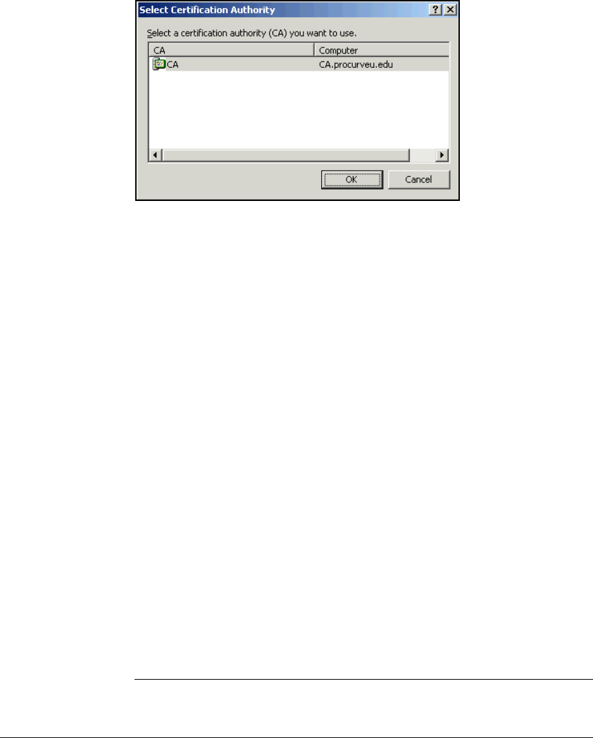
4-113
Implementing a VPN with Endpoint Integrity
Configure the ProCurve Secure Router 7000dl
Figure 4-41. Select Certification Authority Window
5. Select the name of the CA server.
6. Click OK.
7. A window is displayed for saving the certificate. Navigate to the location
in which you want to save the certificate. Type the name for the certifi-
cate file.
8. Click Save.
Import a Router Certificate and CRL. You must complete these steps
only if you are obtaining certificates manually:
1. Transfer the certificate file that you obtained in “Submit the Certificate
Request to the CA Server” on page 4-112 to the endpoint from which you
are managing the Secure Router 7000dl.
2. Also transfer the CRL file (or files) obtained in “Export the CRL” on
page 4-38.
3. Access the Secure Router 7000dl CLI and move to the global configuration
mode context.
4. Type the following command from the global configuration mode context:
Syntax: crypto ca import <profile name> certificate
Manually imports a certificate for the router.
Replace <profile name> with the name you choose for the profile
(see step 2 of “Create a CA Profile” on page 4-107).
4-114
Implementing a VPN with Endpoint Integrity
Configure the ProCurve Secure Router 7000dl
For example:
ProCurveRS7000dl(config)#crypto ca import PCUCA
certificate
5. Open the certificate file with a text editor.
6. Select and copy all of the text.
7. In the terminal session, paste the text where indicated. (See Figure 4-42.)
8. Press [Enter] twice. Or type quit and press [Enter].
You should see this message:
Success!
Figure 4-42. Manually Importing a Router Certificate
ProCurveSR7102dl(config)# crypto ca import MyCA certificate
Enter the PM-encoded certificate. End with two consecutive
carriage returns or the word "quit" on a line by itself:
-----BEGIN X509 CERTIFICATE-----
MIICZTCCAc6gAwIBAgIEP5/c2TANBgkqhkiG9w0BAQUFADBaMQswCQYDVQQGEwJG
STEkMCIGA1UEChMbU1NIIENvbW11bmljYXRpb25zIFNlY3VyaXR5MREwDwYDVQQL
EwhXZWIgdGVzdDESMBAGA1UEAxMJVGVzdCBDQSAxMB4XDTAzMTAyOTAwMDAwMFoX
DTAzMTIwMTAwMDAwMFowQDELMAkGA1UEBhMCVVMxCzAJBgNVBAgTAkFMMRMwEQYD
VQQHEwpIdW50c3ZpbGxlMQ8wDQYDVQQDEwZSb3V0ZXIwgZ8wDQYJKoZIhvcNAQEB
BQADgY0AMIGJAoGBALCZJHE4Bx1+ZzJQUFEQwfGcI2vE9RR68KqRmwGr+hZyMi49
Eg85UIBCUvCe15u/P4JYS9d//jT37+uh+jZxNvSUiPa99XatHcIcVLWQHzrn9+vW
YReu7418ZEbx/ETPKa6XqSpFqJ5ZG38VUaN05r2gwW+aZtsfxOyMUupstSypAgMB
AAGjUjBQMAsGA1UdDwQEAwIFoDAPBgNVHREECDAGhwQKCgoBMDAGA1UdHwQpMCcw
JaAjoCGGH2h0dHA6Ly9sZGFwLnNzaC5maS9jcmxzL2NhMS5jcmwwDQYJKoZIhvcN
AQEFBQADgYEAObiCh0AtS1qlIc0lfg1huYUcczLkqYm2UQ6uSvi0rpmgiEnIVqH+
y8at3D4Mr1xCGzTqSuXf7uAxCHwkjwS6OVw2wERIcy9X1j28XzKjZGpo3Z6aQPaX
ZBUvo6EcYtKxtiD1ONTzrxqBC9bvcV0pipzWleTYlpwPKzRvCuopiqA=
-----END X509 CERTIFICATE-----
quit
Success!
ProCurveSR7102dl(config)#
Paste in the PEM
certificate
Type quit.
Certificate loaded
successfully

4-115
Implementing a VPN with Endpoint Integrity
Configure the ProCurve Secure Router 7000dl
9. Type the following command from the global configuration mode context:
For example:
ProCurveRS7000dl(config)#crypto ca import PCUCA crl
10. Open the CRL file with a text editor.
11. Select and copy all of the text.
12. In the terminal session, paste the text where indicated.
13. Press [Enter] twice. Or type quit and press [Enter].
14. Save your changes to the startup-config:
SecureRouter(config)# do write memory
Manage Certificates
The certificates configured on the Secure Router 7000dl vouch for the router’s
identity. It is very important that the information in them be correct and up
to date.
This section gives you instruction for viewing and deleting certificates. If you
do not need to complete these tasks, you can move to the next section:
“Configuring the NAC 800” on page 4-128.
Viewing Certificates. Use the show crypto ca commands to view:
■Certificates
■CRLs
■CA profiles
You can view certificates to verify that the information in them is correct. You
should also keep track of when your certificates expire and periodically
update them. If the information in a router certificate is incorrect, you should
view the CA profile. Information may have been miskeyed into the profile,
which would cause the OS to include incorrect information in the certificate
request.
Syntax: crypto ca import <profile name> crl
Manually imports a CRL.
Replace <profile name> with the name you choose for the profile
(see step 2 of “Create a CA Profile” on page 4-107).

4-116
Implementing a VPN with Endpoint Integrity
Configure the ProCurve Secure Router 7000dl
Type this command from the enable mode context:
For example:
ProCurveRS7000dl#show crypto ca certificates
Figure 4-43 shows a sample display of certificates loaded on a router.
Figure 4-43. Viewing Certificates
Syntax: show crypto ca [certificates | crls | profiles]
Displays information about certificates, CRLs, or CA profiles.
Include the certificates option to view both CA and self certif-
icates.
Include the crls option to view the CRLs imported from this
CA.
Include the profiles option to view the profiles configured on
the router. The profile includes the enrollment method and
optionally information to be included in a request.
ProCurveSR7203dl#show crypto ca certificates
Self Certificate
Status: Available
Certificate Serial Number: 116aabb0000100000030
Subject Name: C=US,ST=California,L=Roseville,O=ProCurve University,
OU=Computers,CN=SecureRouter
Issuer: DC=edu,DC=procurveu,CN=CA
CRL Dist. Pt: DC=edu,DC=procurveu,CN=CA
Start date is Sep 16 20:50:12 2007 GMT
End date is Sep 15 20:50:12 2009 GMT
Key Usage:
CA Certificate
Status: Available
Certificate Serial Number: 26821e896eafd08643b5407a37414004
Subject Name: DC=edu,DC=procurveu,CN=CA
Issuer: DC=edu,DC=procurveu,CN=CA
CRL Dist. Pt: DC=edu,DC=procurveu,CN=CA
Start date is Sep 16 19:30:58 2007 GMT
End date is Sep 16 19:37:00 2012 GMT
Key Usage:
Key Agreement
Use when deleting
Use when deleting
Router subject name

4-117
Implementing a VPN with Endpoint Integrity
Configure the ProCurve Secure Router 7000dl
Deleting Certificates. Follow this process to delete a certificate:
1. View the certificate using the show crypto ca certificates command.
2. Find the certificate’s serial number.
3. Move to the global configuration mode context and access the certificate
chain command set for the corresponding CA profile:
4. Delete the certificate:
For example to delete the router certificate shown in Figure 4-43, type:
ProCurveRS7000dl(config)# crypto ca certificate chain
PCUCA
ProCurveRS7000dl(config-cert-chain)# no certificate
3f9fdcd9
Note The Secure Router OS uses the commands in the certificate chain command
set to load certificates. However, you should only use these commands only
to delete certificates.
Managing CRLs. A CRL is a list of digital certificate subscribers. It includes
information about each subscriber’s certificates, including:
■current status
■date of issue
■CA from which the certificate was obtained
Syntax: crypto ca certificate chain <profile name>
Accesses the certificate chain command.
Replace <profile name> with the name of the profile for CA that
signed the certificate you want to delete.
Syntax: no certificate [ca <serial number> | <serial number>]
Deletes a certificate.
To delete a CA certificate, type ca and replace <serial number>
with the serial number you located when you viewed the CA
certificate.
To delete a router certificate, replace <serial number> with the
serial number you located when you viewed the certificate.

4-118
Implementing a VPN with Endpoint Integrity
Configure the ProCurve Secure Router 7000dl
The CRL also lists revoked certificates, accompanied by the cause for the
revocation.
IKE uses the CRL to help determine whether a peer can be trusted to connect
over the VPN tunnel. To keep your private network secure, you should make
sure that the CA profile contains an up-to-date CRL.
To delete a CRL:
1. Access the certificate chain command set for the corresponding CA
profile:
2. Delete the CRL:
ProCurveRS7000dl(config-cert-chain)# no crl
Note Always reinstall a CRL after you delete one. Otherwise, the certificates do not
function properly.
Secure Router 7000dl Running-Config
This section includes the running-config for the example Secure Router 7203dl
after all configurations have been completed.
!
!
! ProCurve Secure Router 7203dl SROS version J08.03
! Boot ROM version J06.06
! Platform: ProCurve Secure Router 7203dl, part number
J8753A
! Serial number US449TS073
! Flash: 33554432 bytes DRAM: 268435455 bytes
! Date/Time: Thu Oct 11 2007, 11:02:10 MDT
!
!
hostname "SecureRouter"
enable password md5 encrypted
b46f9961af093fdfb9e177eda7784f09
!
clock timezone -8
Syntax: crypto ca certificate chain <profile name>
Accesses the certificate chain command.
Replace <profile name> with the name of the CA that issued the
CRL that you want to delete.

4-119
Implementing a VPN with Endpoint Integrity
Configure the ProCurve Secure Router 7000dl
!
ip subnet-zero
ip classless
ip routing
ip local policy route-map pbr_VPN
!
event-history on
no logging forwarding
no logging email
logging email priority-level info
!
no service password-encryption
!
username "manager" password "procurve"
!
!
ip firewall
no ip firewall alg msn
no ip firewall alg h323
!
!
!
!
!
!
no autosynch-mode
no safe-mode
!
!
!
!
!
!
!
ip crypto
!
crypto ike client configuration pool RemoteUsers
ip-range 10.48.100.10 10.48.101.250
dns-server 10.4.4.15 10.4.5.15
!

4-120
Implementing a VPN with Endpoint Integrity
Configure the ProCurve Secure Router 7000dl
crypto ike policy 10
no initiate
respond main
local-id asn1-dn CN=SecureRouter,OU=Computers,O=Pro-
Curve University,L=Roseville,ST=California,C=US
peer any
client configuration pool RemoteUsers
attribute 10
encryption aes-192-cbc
authentication rsa-sig
group 2
lifetime 240
attribute 20
encryption 3des
hash md5
authentication rsa-sig
lifetime 240
!
crypto ike remote-id asn1-dn "CN=*,OU=Faculty,O=ProCurve
University,L=*,ST=*,C=*" crypto map VPN 10
crypto ike remote-id asn1-dn "CN=*,OU=Students,O=ProCurve
University,L=*,ST=*,C=*" crypto map VPN 20
!
crypto ipsec transform-set esp_Aes192Sha esp-aes-192-cbc
esp-sha-hmac
mode tunnel
crypto ipsec transform-set esp_3des esp-3des
mode tunnel
crypto ipsec transform-set ahEsp_shaAes192 ah-sha-hmac
esp-aes-192-cbc
mode tunnel
!
crypto map VPN 10 ipsec-ike
match address VPN_Faculty
set transform-set ahEsp_shaAes192 esp_Aes192Sha
esp_3des
set security-association lifetime seconds 7200
set pfs group5
crypto map VPN 20 ipsec-ike
match address VPN_Students
set transform-set ahEsp_shaAes192 esp_Aes192Sha
esp_3des
set security-association lifetime seconds 7200
set pfs group5

4-121
Implementing a VPN with Endpoint Integrity
Configure the ProCurve Secure Router 7000dl
!
crypto ca profile "PCUCA"
!
crypto ca certificate chain "PCUCA"
certificate ca 0f79fa721a6f9da04118447f73a1f64c
-----BEGIN CERTIFICATE-----
MIIDVDCCAr2gAwIBAgIQD3n6chpvnaBBGER/
c6H2TDANBgkqhkiG9w0BAQUFADA9MRMwEQYKCZImiZPyLGQBGRYDZWR
1MRkwFwYKCZImiZPyLGQBGRYJcHJvY3VydmV1MQswCQYDVQQDEwJDQT
AeFw0wNzEwMDMyMDQ0MTJaFw0xMjEwMDMyMDUwMjRaMD0xEzARBgoJk
iaJk/IsZAEZFgNlZHUxGTAXBgoJkiaJk/
IsZAEZFglwcm9jdXJ2ZXUxCzAJBgNVBAMTAkNBMIGfMA0GCSqGSIb3D
QEBAQUAA4GNADCBiQKBgQDunj2ZyfkCtxbs4/
01YZsh9gAuoY78b5+ZsUdRGf3t+U+6TnAjyEhkw44/
0uN9+LRBA2Df6FU4HFQWPCIDdmf5ScKZrao8lBGrNt1Yi12OuCX62K+
pm5Cm9bQFT3XcEZ0Q729KhWqAqkjLzMdRxm1/
RhhjwHihlxjGZcZGvyxXIwIDAQABo4IBUzCCAU8wEwYJKwYBBAGCNxQ
CBAYeBABDAEEwCwYDVR0PBAQDAgGGMA8GA1UdEwEB/
wQFMAMBAf8wHQYDVR0OBBYEFEgZV2Z8x/
rS9nPwwRzr+DI3UwqyMIHoBgNVHR8EgeAwgd0wgdqggdeggdSGgaZsZ
GFwOi8vL0NOPUNBLENOPUNBLENOPUNEUCxDTj1QdWJsaWMlMjBLZXkl
MjBTZXJ2aWNlcyxDTj1TZXJ2aWNlcyxDTj1Db25maWd1cmF0aW9uLER
DPXByb2N1cnZldSxEQz1lZHU/
Y2VydGlmaWNhdGVSZXZvY2F0aW9uTGlzdD9iYXNlP29iamVjdENsYXN
zPWNSTERpc3RyaWJ1dGlvblBvaW50hilodHRwOi8vY2EucHJvY3Vydm
V1LmVkdS9DZXJ0RW5yb2xsL0NBLmNybDAQBgkrBgEEAYI3FQEEAwIBA
DANBgkqhkiG9w0BAQUFAAOBgQBTSh01OAC0Ff33m+CqNZtS0MRvy23N
COD47isfLqgiF1d1Vc6ZFtVrq3zuMWTEboKWHI10N8q1uTP1HllPzKn
M0Ll1UPt9LYwRBIqiNlQDX778lmhKT4AFUjSa+D1iwzhR7bdfUv1H5m
CimDo1PHp8DGcOYfHc9sFJAegcBZw8Jg==
-----END CERTIFICATE-----
quit
!
!
certificate 6102f09f000000000020
-----BEGIN CERTIFICATE-----
MIIE7TCCBFagAwIBAgIKYQLwnwAAAAAAIDANBgkqhkiG9w0BAQUFADA
9MRMwEQYKCZImiZPyLGQBGRYDZWR1MRkwFwYKCZImiZPyLGQBGRYJcH
JvY3VydmV1MQswCQYDVQQDEwJDQTAeFw0wNzEwMDgxOTU5MzZaFw0wO
TEwMDcxOTU5MzZaMGExCzAJBgNVBAYTAlVTMRMwEQYDVQQIEwpDYWxp
Zm9ybmlhMRIwEAYDVQQHEwlSb3NldmlsbGUxEjAQBgNVBAsTCUNvbXB
1dGVyczEVMBMGA1UEAxMMU2VjdXJlUm91dGVyMIGfMA0GCSqGSIb3DQ
EBAQUAA4GNADCBiQKBgQDMqOA6yOCw6aOiXdZYk7GoPfOScnH8uKBDQ
LYo5msDPQ5EcJPEvP3ehCa14Gi1hu+kbYCPOcA5d9dsHImddAVIyY+W

4-122
Implementing a VPN with Endpoint Integrity
Configure the ProCurve Secure Router 7000dl
o/
1Yck+OY2YW7691XyrCixwI5M4pGqNED5QVWvKMtqNlCZhPF1LrOZ7hQ
SvNycoiX7SIlIhIXPMn9e7XzwIDAQABo4ICzjCCAsowKwYDVR0RBCQw
IocEwKgBAYIaU2VjdXJlUm91dGVyLnByb2N1cnZldS5lZHUwHQYDVR0
OBBYEFFT4Pesfp7ICtXIGAdulinG/
VTehMB8GA1UdIwQYMBaAFEgZV2Z8x/
rS9nPwwRzr+DI3UwqyMIHoBgNVHR8EgeAwgd0wgdqggdeggdSGgaZsZ
GFwOi8vL0NOPUNBLENOPUNBLENOPUNEUCxDTj1QdWJsaWMlMjBLZXkl
MjBTZXJ2aWNlcyxDTj1TZXJ2aWNlcyxDTj1Db25maWd1cmF0aW9uLER
DPXByb2N1cnZldSxEQz1lZHU/
Y2VydGlmaWNhdGVSZXZvY2F0aW9uTGlzdD9iYXNlP29iamVjdENsYXN
zPWNSTERpc3RyaWJ1dGlvblBvaW50hilodHRwOi8vY2EucHJv
Y3VydmV1LmVkdS9DZXJ0RW5yb2xsL0NBLmNybDCB/
gYIKwYBBQUHAQEEgfEwge4wgaMGCCsGAQUFBzAChoGWbGRhcDovLy9D
Tj1DQSxDTj1BSUEsQ049UHVibGljJTIwS2V5JTIwU2VydmljZXMsQ04
9U2VydmljZXMsQ049Q29uZmlndXJhdGlvbixEQz1wcm9jdXJ2ZXUsRE
M9ZWR1P2NBQ2VydGlmaWNhdGU/
YmFzZT9vYmplY3RDbGFzcz1jZXJ0aWZpY2F0aW9uQXV0aG9yaXR5MEY
GCCsGAQUFBzAChjpodHRwOi8vY2EucHJvY3VydmV1LmVkdS9DZXJ0RW
5yb2xsL0NBLnByb2N1cnZldS5lZHVfQ0EuY3J0MD8GCSsGAQQBgjcUA
gQyHjAASQBQAFMARQBDAEkAbgB0AGUAcgBtAGUAZABpAGEAdABlAE8A
ZgBmAGwAaQBuAGUwDAYDVR0TAQH/
BAIwADALBgNVHQ8EBAMCBaAwEwYDVR0lBAwwCgYIKwYBBQUIAgIwDQY
JKoZIhvcNAQEFBQADgYEAR9zCzVCb/
gzUpHyRPF4MRVB8mJs5pljCOk77ZqFHsie7+sm66lWbQxVflbeEnR2F
paxBxlP2uT64LFVZhqNaLk7TqG3lJvXEpUD/
EkdYZIKum2pkmO3mGSVV5GWmC/eJ+crLpJ/
EHLhVPpoSUkYx83PvroqnbZjLH5pxq+7Vy4c=
-----END CERTIFICATE-----
quit
!
crl
-----BEGIN X509 CRL-----
MIIDFzCCAoACAQEwDQYJKoZIhvcNAQEFBQAwPTETMBEGCgmSJomT8ix
kARkWA2VkdTEZMBcGCgmSJomT8ixkARkWCXByb2N1cnZldTELMAkGA1
UEAxMCQ0EXDTA3MTAwMzIwNDQ0MFoXDTA3MTAxMTA5MDQ0MFqgggINM
IICCTAfBgNVHSMEGDAWgBRIGVdmfMf60vZz8MEc6/
gyN1MKsjAQBgkrBgEEAYI3FQEEAwIBADAKBgNVHRQEAwIBATAcBgkrB
gEEAYI3FQQEDxcNMDcxMDEwMjA1NDQwWjCB4wYDVR0uBIHbMIHYMIHV
oIHSoIHPhoGgbGRhcDovLy9DTj1DQSxDTj1DQSxDTj1DRFAsQ049UHV
ibGljJTIwS2V5JTIwU2VydmljZXMsQ049U2VydmljZXMsQ049Q29uZm
lndXJhdGlvbixEQz1wcm9jdXJ2ZXUsREM9ZWR1P2RlbHRhUmV2b2Nhd
Glvbkxpc3Q/
YmFzZT9vYmplY3RDbGFzcz1jUkxEaXN0cmlidXRpb25Qb2ludIYqaHR

4-123
Implementing a VPN with Endpoint Integrity
Configure the ProCurve Secure Router 7000dl
0cDovL2NhLnByb2N1cnZldS5lZHUvQ2VydEVucm9sbC9DQSsuY3JsMI
HDBgkrBgEEAYI3FQ4EgbUwgbIwga+ggayggamGgaZsZGFwOi8vL0NOP
UNBLENOPUNBLENOPUNEUCxDTj1QdWJsaWMlMjBLZXklMjBTZXJ2aWNl
cyxDTj1TZXJ2aWNlcyxDTj1Db25maWd1cmF0aW9uLERDPXByb2N1cnZ
ldSxEQz1lZHU/
Y2VydGlmaWNhdGVSZXZvY2F0aW9uTGlzdD9iYXNlP29iamVjdENsYXN
zPWNSTERpc3RyaWJ1dGlvblBvaW50MA0GCSqGSIb3DQEBBQUAA4GBAG
Co/Pi65V5xc1wexV9yQa8zZO8Psv/
QPCnbcICL8DHRwoyNxuYFqvaa5IHyn+RYYI6CihtrdxuOcPEW7BziAB
z6mcbt3UE6/YHd/
ZveA4L6xFSDBBKgPnyOWu61mpyv3o+cnq6JzJ0XmRRsUJ2yf50ahQ/
bDfVOovjkpoRV7Y4C
-----END X509 CRL-----
quit
!
!
!
!
interface eth 0/1
ip address 10.2.0.100 255.255.0.0
access-policy NAT_Source
no shutdown
!
!
interface eth 0/2
ip address 10.3.0.100 255.255.255.0
no shutdown
!
!
!
!
interface e1 2/1
coding ami
tdm-group 1 timeslots 1-31 speed 64
no shutdown
!
interface e1 2/2
clock source through
shutdown
!
interface t1 3/1
shutdown
!
interface t1 3/2

4-124
Implementing a VPN with Endpoint Integrity
Configure the ProCurve Secure Router 7000dl
shutdown
!
interface t1 3/3
shutdown
!
interface t1 3/4
shutdown
!
interface t1 3/5
shutdown
!
interface t1 3/6
shutdown
!
interface t1 3/7
shutdown
!
interface t1 3/8
shutdown
!
interface bri 1/3
shutdown
!
interface bri 1/1
shutdown
interface bri 1/2
shutdown
!
interface ppp 1
ip address 192.168.1.1 255.255.255.0
ip policy route-map pbr_VPN
access-policy Outside
crypto map VPN
no shutdown
bind 1 e1 2/1 1 ppp 1
!
!
!
!
router rip
version 2
redistribute static
network 10.2.0.0 255.255.0.0
network 10.3.0.0 255.255.255.0

4-125
Implementing a VPN with Endpoint Integrity
Configure the ProCurve Secure Router 7000dl
distribute-list Routes_Ad_Switch out eth 0/1
distribute-list Routes_Accept_NAC in eth 0/2
distribute-list Routes_Ad_NAC out eth 0/2
!
!
!
route-map pbr_VPN permit 10
match ip address pbr_VPN
set ip next-hop 10.3.0.1
set interface null 0
!
!
!
!
ip access-list standard LAN
permit 10.0.0.0 0.255.255.255
!
ip access-list standard Routes_Accept_NAC
deny any
!
ip access-list standard Routes_Ad_NAC
permit 10.48.100.0 0.0.1.255
!
ip access-list standard Routes_Ad_Switch
deny 10.48.100.0 0.0.1.255
permit any
!
!
ip access-list extended Email
permit tcp any host 192.168.1.1 eq pop3
!
ip access-list extended pbr_VPN
deny ip any 10.3.0.0 0.0.0.255
permit ip 10.48.100.0 0.0.1.100 10.0.0.0 0.15.255.255
!
ip access-list extended VPN_Faculty
permit ip host 10.3.0.90 10.48.100.0 0.0.1.255
deny ip 10.0.0.0 0.3.255.255 any
deny ip 10.6.0.0 0.1.255.255 any
permit ip 10.0.0.0 0.15.255.255 10.48.100.0 0.0.1.255
!
ip access-list extended VPN_Students
permit ip host 10.3.0.90 10.48.100.0 0.0.1.255
deny ip 10.0.0.0 0.3.255.255 any

4-126
Implementing a VPN with Endpoint Integrity
Configure the ProCurve Secure Router 7000dl
deny ip 10.5.0.0 0.0.255.255 any
deny ip 10.6.0.0 0.1.255.255 any
deny ip 10.8.0.0 0.1.255.255 any
permit ip 10.0.0.0 0.15.255.255 10.48.100.0 0.0.1.255
!
ip access-list extended Webserver
permit tcp any host 192.168.1.1 eq www
permit tcp any host 192.168.1.1 eq https
!
ip policy-class NAT_Source
nat source list LAN interface ppp 1 overload
!
ip policy-class Outside
nat destination list Webserver address 10.4.6.30
nat destination list Email address 10.4.6.40
allow list Allow_VPN
allow reverse list VPN_Faculty
allow reverse list VPN_Students
!
!
!
ip route 0.0.0.0 0.0.0.0 ppp 1
ip route 10.48.100.0 255.255.254.0 ppp 1
!
no ip tftp server
no ip tftp server overwrite
ip http server
ip http secure-server
no ip snmp agent
no ip ftp server
ip ftp server default-filesystem flash
no ip scp server
no ip sntp server
!
!
!
!
!
!
!
ip sip
ip sip proxy
!
!

4-127
Implementing a VPN with Endpoint Integrity
Configure the ProCurve Secure Router 7000dl
!
line con 0
no login
!
line telnet 0 4
login
password md5 encrypted a74989ae1872da969ab8395ae74ccfa2
no shutdown
line ssh 0 4
login local-userlist
no shutdown
!
!
end
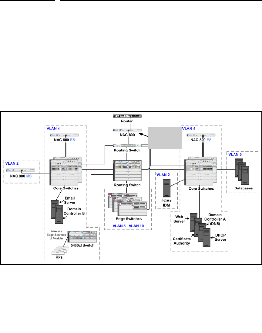
4-128
Implementing a VPN with Endpoint Integrity
Configuring the NAC 800
Configuring the NAC 800
This section describes how to add a NAC 800 ES deployed with the inline
method to an existing system of NAC 800s.
In the example, the PCU network has an existing set of NAC 800s, which test
and enforce endpoint integrity on local endpoints. Now network administra-
tors are adding one additional NAC 800 to control remote endpoints. They will
add the new NAC 800 as an ES on the existing MS, however, in a new
enforcement cluster. The new NAC 800 ES will be the only device in that
cluster. See Figure 4-44.
Figure 4-44. Inline Deployment—VPN with a NAC 800 That Is Part of an
Enforcement Cluster
New NAC
800: ES in its
own cluster
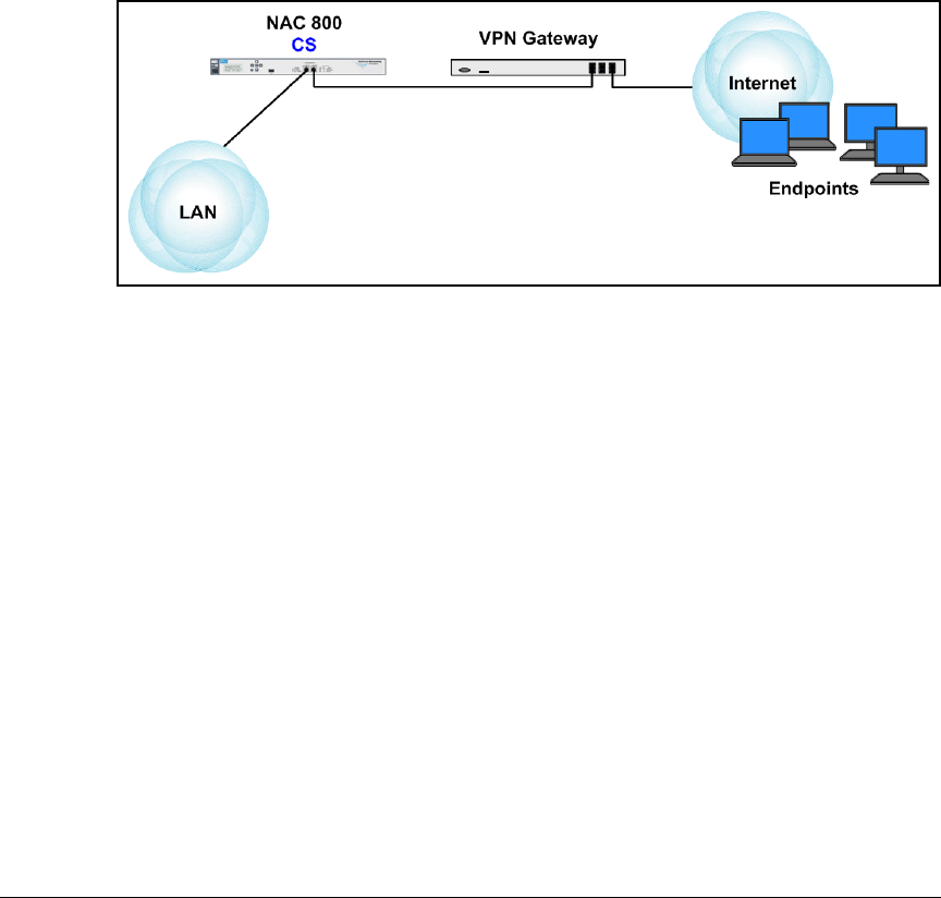
4-129
Implementing a VPN with Endpoint Integrity
Configuring the NAC 800
If your inline deployment is your network’s only deployment, you can follow
the steps in the sections below with just a few differences:
■In a network that requires only one NAC 800 (fewer than 3000 users with
no redundancy), configure the NAC 800 as a Combination Server (CS).
See Figure 4-45.
Complete the instructions in the sections that follow; when you are
instructed to configure the NAC 800 as an ES, configure it as a CS instead.
Then adapt the instructions as necessary for a CS; for example, skip the
instructions on creating enforcement clusters and adding ES.
Figure 4-45. Inline Deployment—VPN With a Single NAC 800
■In a network that requires multiple NAC 800s, designate one device as the
MS and the others as ESs. See Figure 4-46.
Then follow the instructions in “Install the NAC 800” on page 4-130 and
“Configure Initial Settings on the New NAC 800” on page 4-131 on all ESs
and the MS.
Other instructions should apply to your network as written; however, you
will need to configure some initial settings when you first access the MS
Web browser interface. See “Configure More Basic Settings for the MS”
on page 2-142 of Chapter 2: “Implementing 802.1X with ProCurve IDM and
Endpoint Integrity.”
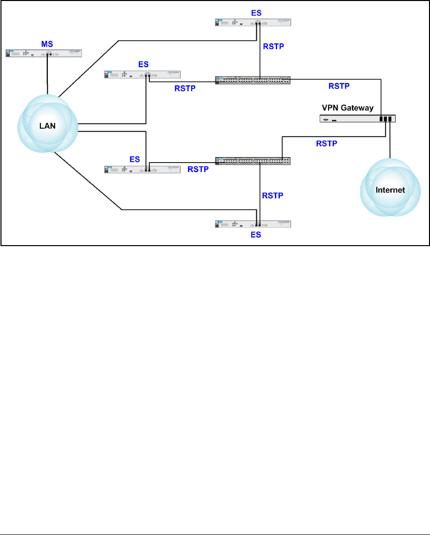
4-130
Implementing a VPN with Endpoint Integrity
Configuring the NAC 800
Figure 4-46. Inline Deployment—VPN with a Cluster of NAC 800s
Install the NAC 800
The NAC 800 in this solution enforces endpoint integrity by standing inline
between remote users and the LAN. It filters all traffic with its internal firewall
and allows only the following traffic:
■From sources that have passed the endpoint integrity test
■To accessible services
As you can see in Figure 4-44, Figure 4-45, and Figure 4-46, the NAC 800 ES is
deployed between a core switch in the LAN and the Secure Router 7000dl.
Port 1 on the NAC 800 connects to the core switch, and port 2 connects to the
router.
Refer to the Network Access Controller 800 Hardware Installation Guide for
more detailed mounting and installation instructions.

4-131
Implementing a VPN with Endpoint Integrity
Configuring the NAC 800
Configure Initial Settings on the New NAC 800
Before you can add the new NAC 800 to a network, you must configure some
initial settings on it.
In this example, the NAC 800s will use the network settings in Table 4-24.
Table 4-24. NAC 800 Basic Settings
Configure Initial Settings through a Console Session
The following steps guide you through initial configuration of a NAC 800 ES.
1. Your NAC 800 ships with a console cable. Plug the cable’s Ethernet (RJ45)
connector into the Console Ethernet port, which is located on the left
front panel of the NAC 800.
2. Plug the cable’s DB-9 connector into a console port on your management
workstation.
3. Use terminal session software such as Tera Term to open a console session
with the NAC 800. Use the following settings:
• Baud rate = 9600
•Bits = 8
•Stop rate = 1
• Parity = None
• Flow control = None
• For the Windows Terminal program, disable (uncheck) the “Use
Function, Arrow, and Ctrl Keys for Windows” option.
• For the Hilgraeve HyperTerminal program, select the “Terminal keys”
option for the “Function, arrow, and ctrl keys act as” parameter.
4. When prompted for your username, enter admin.
5. When prompted, enter your password (default, procurve).
You should now see the Application Main Menu.
Device Hostname IP Address Subnet Mask Default
Gateway
DNS Server Time Settings
NAC 800 ES ESc.procurveu.edu 10.3.0.90 255.255.255.0 10.3.0.1 10.4.4.15 From MS
(10.2.1.40)
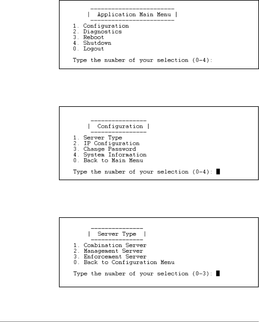
4-132
Implementing a VPN with Endpoint Integrity
Configuring the NAC 800
Figure 4-47. NAC 800 Menu Interface—Application Main Menu
6. In the main menu, press [1] for Configuration.
Figure 4-48. NAC 800 Menu Interface—Main Menu > 1. Configuration
7. Press [1] for Server Type.
Figure 4-49. NAC 800 Menu Interface—Application Main Menu > 1. Configuration >
1. Server Type
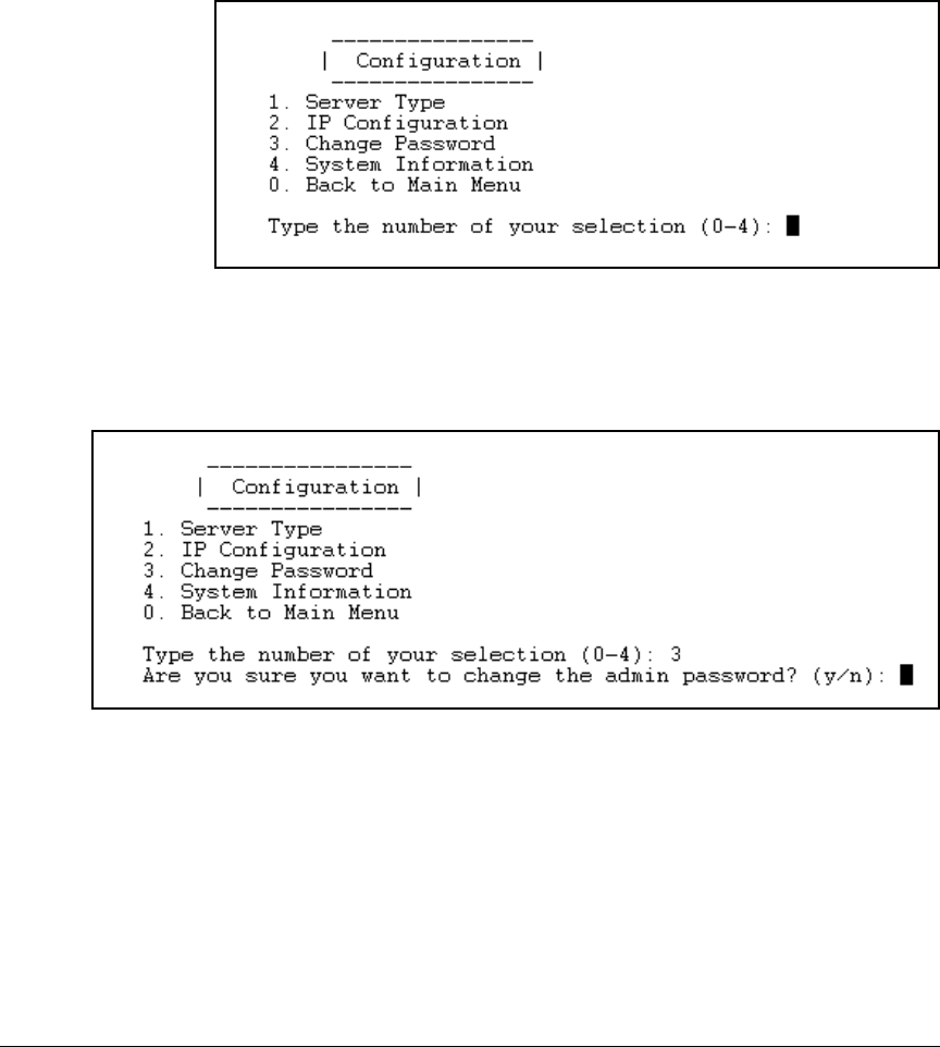
4-133
Implementing a VPN with Endpoint Integrity
Configuring the NAC 800
8. Press [3] for Enforcement Server.
9. Enter y when asked: Set the ProCurve NAC 800 to Enforcement Server only?
10. Press [0].
Figure 4-50. NAC 800 Menu Interface—Application Main Menu > 1. Configuration
11. You should change the password to the menu interface. Press [3] for
Change Password.
Figure 4-51. NAC 800 Menu Interface—Main Menu > 1. Configuration > 3. Change
Password
12. Enter y to confirm that you want to change the password.
13. Enter a password 8 characters or longer. The password can include
alphanumeric and special characters, but does not have specific complex-
ity requirements.
In our example, management access to NAC 800s is protected with this
password: procurvenac9.
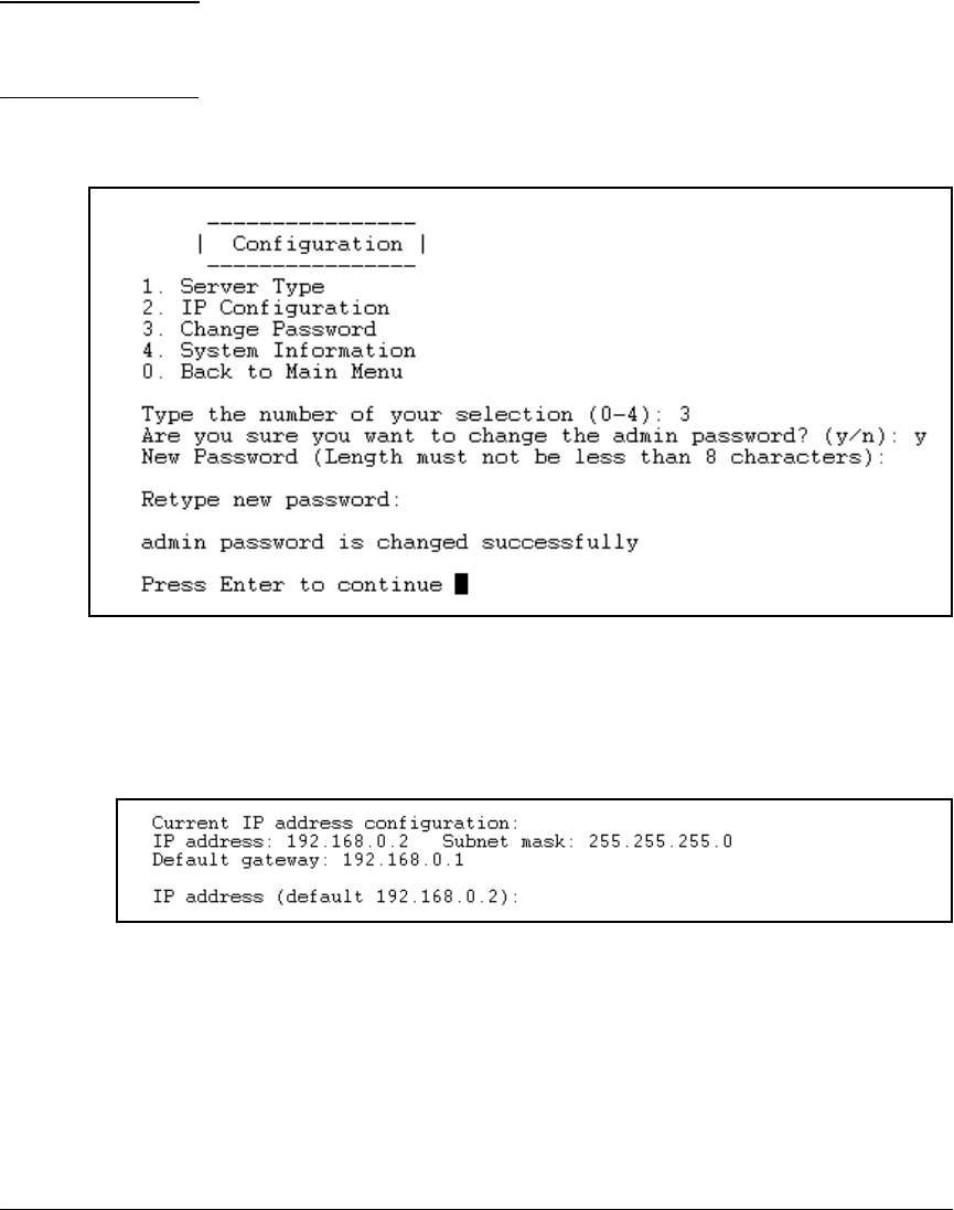
4-134
Implementing a VPN with Endpoint Integrity
Configuring the NAC 800
Note If you want the menu password to match the password created for the
administrator of the Web browser interface, you must use a mix of letters
and numbers.
14. When prompted, re-enter the same password.
Figure 4-52. NAC 800 Menu Interface—Main Menu > 1. Configuration
15. Press [Enter].
16. Press [2] for IP Configuration.
Figure 4-53. NAC 800 Menu Interface—Application Main Menu > 1. Configuration >
2. IP Configuration
17. The window displays the NAC 800’s default settings. Type the new IP
address. Because this NAC 800 is deployed inline, it must be on the same
subnet as the ports to which it connects. In this example: 10.3.0.90.
18. Enter the subnet mask for the NAC 800’s subnet. In this example:
255.255.0.0.
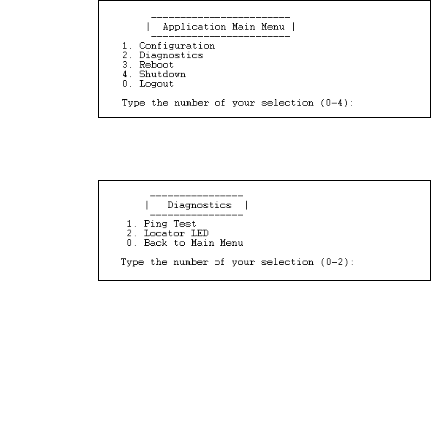
4-135
Implementing a VPN with Endpoint Integrity
Configuring the NAC 800
19. Enter the IP address of the default router on the NAC 800’s subnet. In this
example: 10.2.0.1.
20. When asked to confirm the settings, check them and (if they are correct),
enter y.
21. Press [Enter].
22. Press [0].
Figure 4-54. NAC 800 Menu Interface—Application Main Menu
23. Press [2] for Diagnostics.
Figure 4-55. NAC 800 Menu Interface—Application Main Menu > 2. Diagnostics
24. Press [1] for Ping test.
25. Press [Enter] to ping the default gateway.
The results of the ping, including the times for the round trip, are dis-
played.
If the ping is successful, you can close the session and move on to the next task.
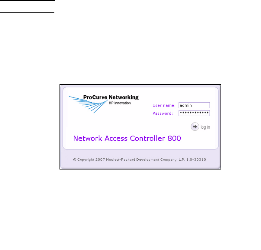
4-136
Implementing a VPN with Endpoint Integrity
Configuring the NAC 800
Access the MS’s Web Browser Interface
The NAC 800 now has network connectivity, so you can add it to an enforce-
ment cluster on the existing NAC 800 MS and finish configuring it. Follow
these steps:
1. Open the Web browser on your management station.
2. For the URL, type https://<NAC 800 MS hostname>. For example: https://
ms.procurveu.edu.
You can type the NAC 800’s IP address instead of its hostname.
Note The NAC 800 requires HTTPS (as opposed to HTTP) for stronger security.
3. You connect to the NAC 800’s Web browser interface. Log in with the
username and password that you created when you first accessed the
interface.
If this is the first time that you have accessed the MS’s interface, complete
the steps described in “Configure More Basic Settings for the MS” on page
2-142 of Chapter 2: “Implementing 802.1X with ProCurve IDM and End-
point Integrity.”
Figure 4-56. NAC 800 Web Interface—Login Page
Create the Enforcement Cluster
Next create a enforcement cluster for the new NAC 800. In this example, the
MS has an existing cluster called “802.1X.” The new cluster will be called
“Inline/VPN.”
1. Select Home > System configuration > Enforcement clusters & servers.
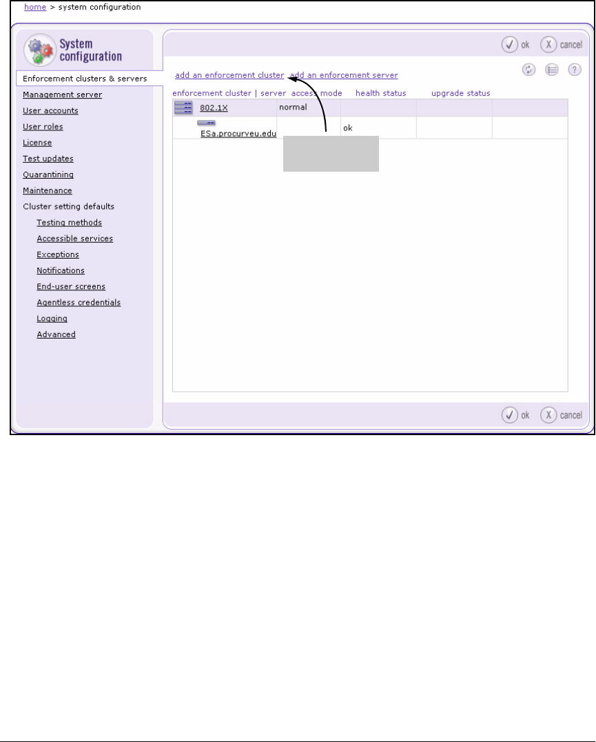
4-137
Implementing a VPN with Endpoint Integrity
Configuring the NAC 800
Figure 4-57. NAC 800 Web Interface—Home > System configuration > Enforcement
clusters & servers > add an enforcement cluster Window
2. Click add an enforcement cluster.
The Add enforcement cluster window is displayed. The left navigation bar
lists several menu options; for now, you can ignore all options except
General, which is selected by default.
Select this link to
create a cluster
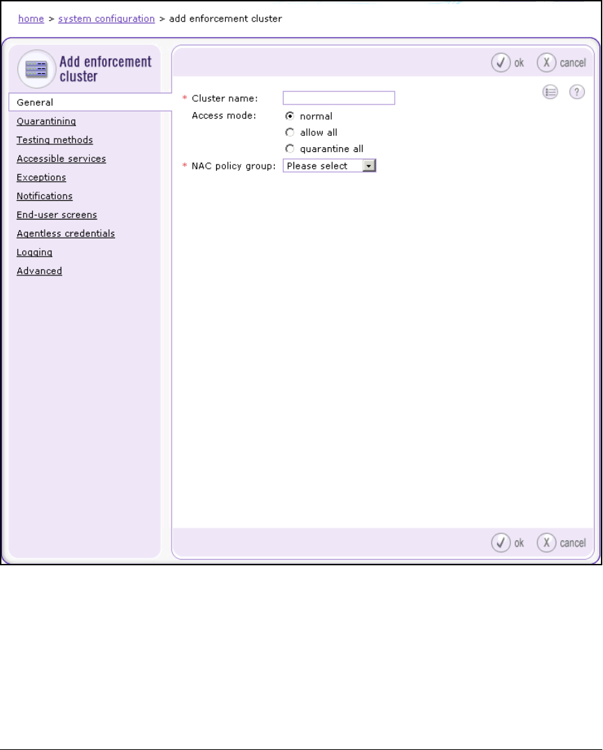
4-138
Implementing a VPN with Endpoint Integrity
Configuring the NAC 800
Figure 4-58. NAC 800 Web Interface—Home > System configuration > Enforcement
clusters & servers > Add enforcement cluster > General Window
3. In the Cluster name field, type a string that describes this cluster. For
example: Inline/VPN.
4. Choose the allow all for the Access mode.
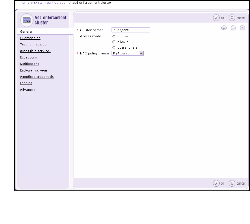
4-139
Implementing a VPN with Endpoint Integrity
Configuring the NAC 800
You will change the access mode to normal later. For now, the allow all
mode prevents you from disrupting network services while you ready the
endpoint integrity solution.
5. For the NAC policy group, select the policies you have established for
testing your endpoints. For example: MyPolicies.
In this example, the network administrators have already created NAC
policies for testing endpoints in the LAN, and they want to use the same
policies for remote endpoints. If you want, you can create and use
different policies. (See “Configure NAC Policies” on page 2-165 of
Chapter 2: “Implementing 802.1X with ProCurve IDM and Endpoint
Integrity.”)
Figure 4-59. NAC 800 Web Interface—Home > System configuration > Enforcement
clusters & servers > Add enforcement cluster > General Window
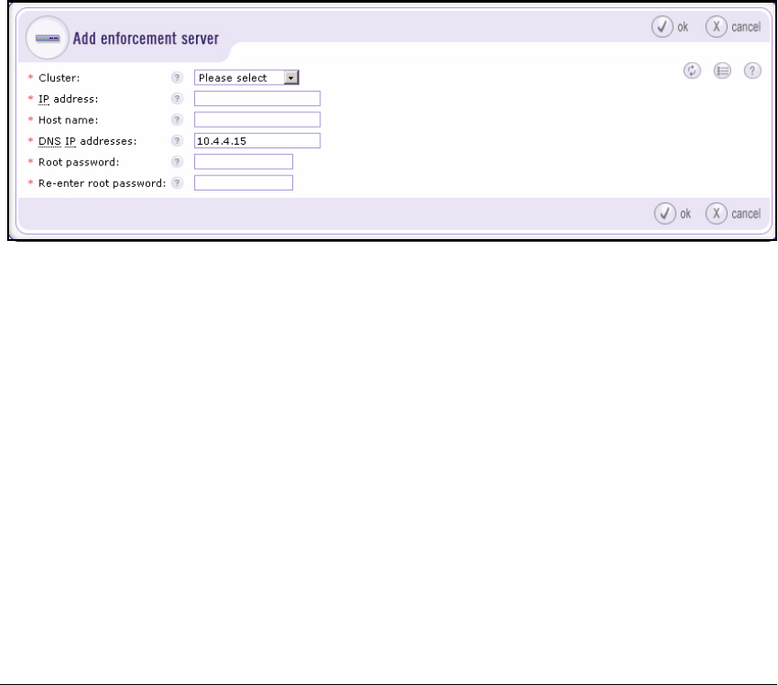
4-140
Implementing a VPN with Endpoint Integrity
Configuring the NAC 800
6. Click ok.
Add the ES to the Enforcement Cluster
The steps below describe how to add a new NAC 800 ES to the enforcement
cluster. If you want to move an existing NAC 800 ES to a different cluster,
follow the steps in “Move an Existing ES to the New Cluster” on page 4-142.
1. Access the Home > System configuration > Enforcement clusters & servers
window.
2. Click add an enforcement server. The Add enforcement server window is
displayed.
Figure 4-60. NAC 800 Web Interface—Home > System configuration > Enforcement
clusters & servers > Add enforcement server
3. From the Cluster drop-down menu, choose the cluster that you just con-
figured.
4. Type the ES’s IP address in the IP address field. For example: 10.3.0.90.
You should have already set this IP address as described in “Configure
Initial Settings through a Console Session” on page 4-131.
5. Type the ES’s hostname in the Host name field. For example:
ESc.procurveu.edu.
6. The DNS IP addresses box displays the IP address of the MS’s DNS server.
Typically, you should keep this DNS server, but you can specify the IP
address of a different one.
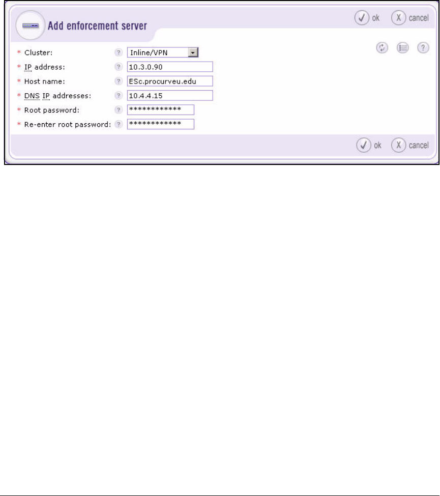
4-141
Implementing a VPN with Endpoint Integrity
Configuring the NAC 800
7. Type a password in the Root password and Re-enter root password fields.
In this example, the root password for the ES is the same as for the MS:
procurvenac9.
Figure 4-61. NAC 800 Web Interface—Home > System configuration > Enforcement
clusters & servers > Add enforcement server Window
8. Click ok.
You return to the Home > System configuration > Enforcement clusters &
servers window, where you can see the new ES.
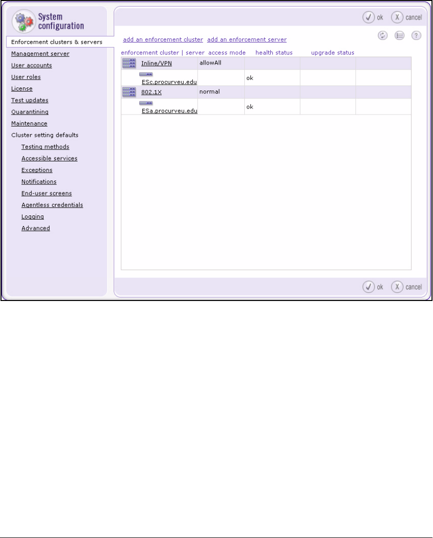
4-142
Implementing a VPN with Endpoint Integrity
Configuring the NAC 800
Figure 4-62. NAC 800 Web Interface—Home > System configuration > Enforcement
clusters & servers Window
Move an Existing ES to the New Cluster
Sometimes you may want to move an ES in one cluster to another cluster.
Follow these steps:
1. Power down the ES that you want to move to the new cluster.
2. Access the Home > System configuration > Enforcement clusters & servers
window in the MS Web browser interface.
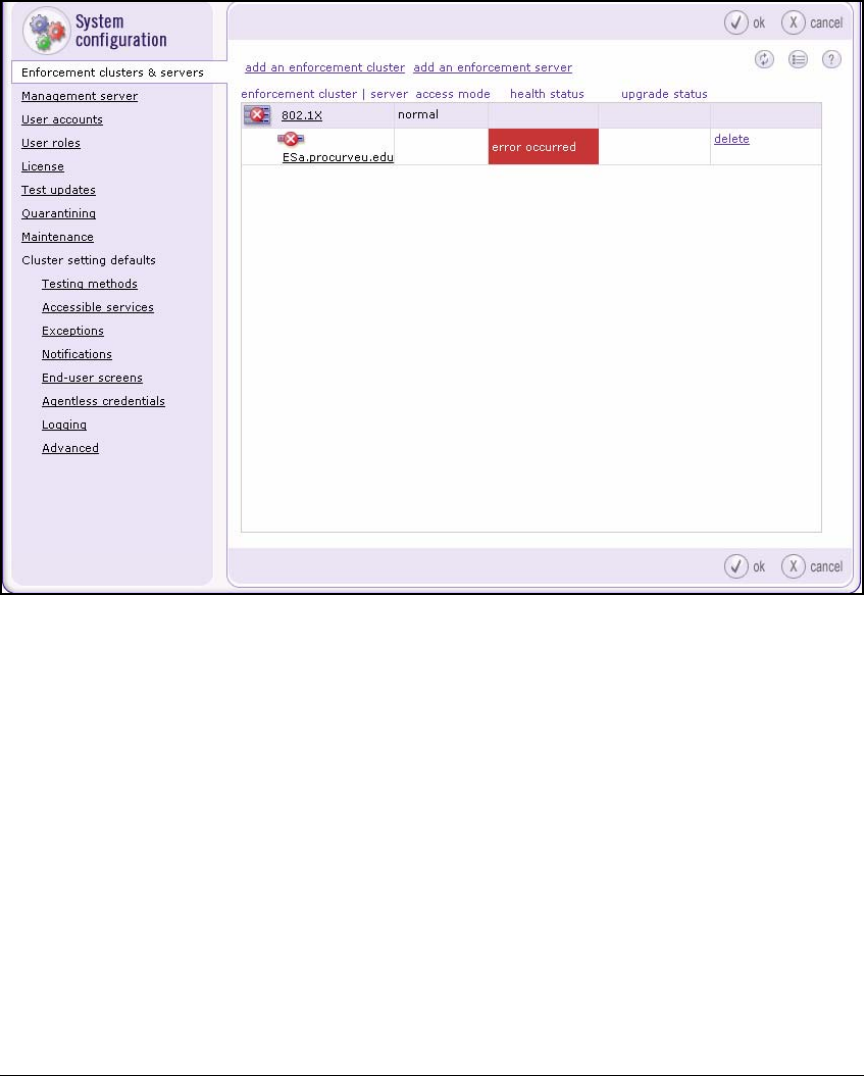
4-143
Implementing a VPN with Endpoint Integrity
Configuring the NAC 800
Figure 4-63. NAC 800 Web Interface—Home > System configuration > Enforcement
clusters & servers Window
3. Click the delete link next to the ES’s name.
4. Return power to the ES.
5. Log in as root to the ES OS:
a. Open a console or SSH session with the ES.
b. When prompted, type root for the username.
c. When prompted, type the root password. In this example:
procurvenac9.
6. Type this command:
ProCurve NAC 800:# resetSystem.py
7. When the ES has finished resetting, return to the MS Web browser
interface.
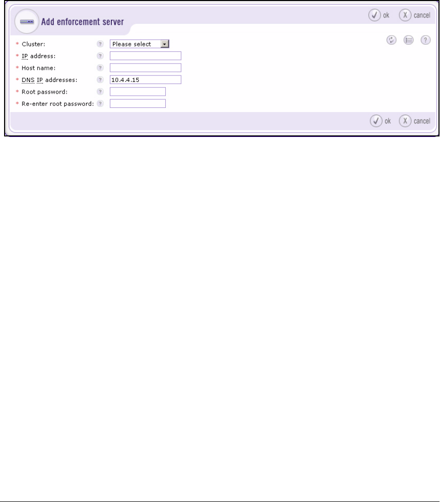
4-144
Implementing a VPN with Endpoint Integrity
Configuring the NAC 800
8. In the Home > System configuration > Enforcement clusters & servers window,
click add an enforcement server. The Add enforcement server window is
displayed.
Figure 4-64. NAC 800 Web Interface—Home > System configuration > Enforcement
clusters & servers > Add enforcement server
9. For the Cluster, select the new cluster that you configured in “Create the
Enforcement Cluster” on page 4-136.
10. Type the ES’s IP address in the IP address box. For example: 10.3.0.90.
You should have already set this IP address as described in “Configure
Initial Settings through a Console Session” on page 4-131.
11. Type the ES’s hostname in the Host name box. For example: ESc.procur-
veu.edu.
12. The DNS IP addresses box displays the IP address of the MS’s DNS server.
Typically, you should keep this DNS server, but you can specify the IP
address of a different one.
13. Type a password in the Root password and Re-enter root password fields.
Make sure to match the password that was already set on this ES. In this
example: procurvenac9.
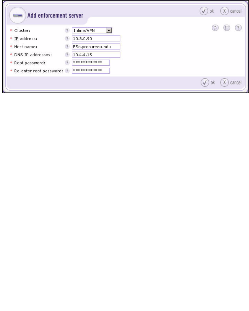
4-145
Implementing a VPN with Endpoint Integrity
Configuring the NAC 800
Figure 4-65. NAC 800 Web Interface—Home > System configuration > Enforcement
clusters & servers > Add enforcement server Window
14. Click ok.
You return to the Home > System configuration > Enforcement clusters &
servers window, where you can see the ES in the new cluster.
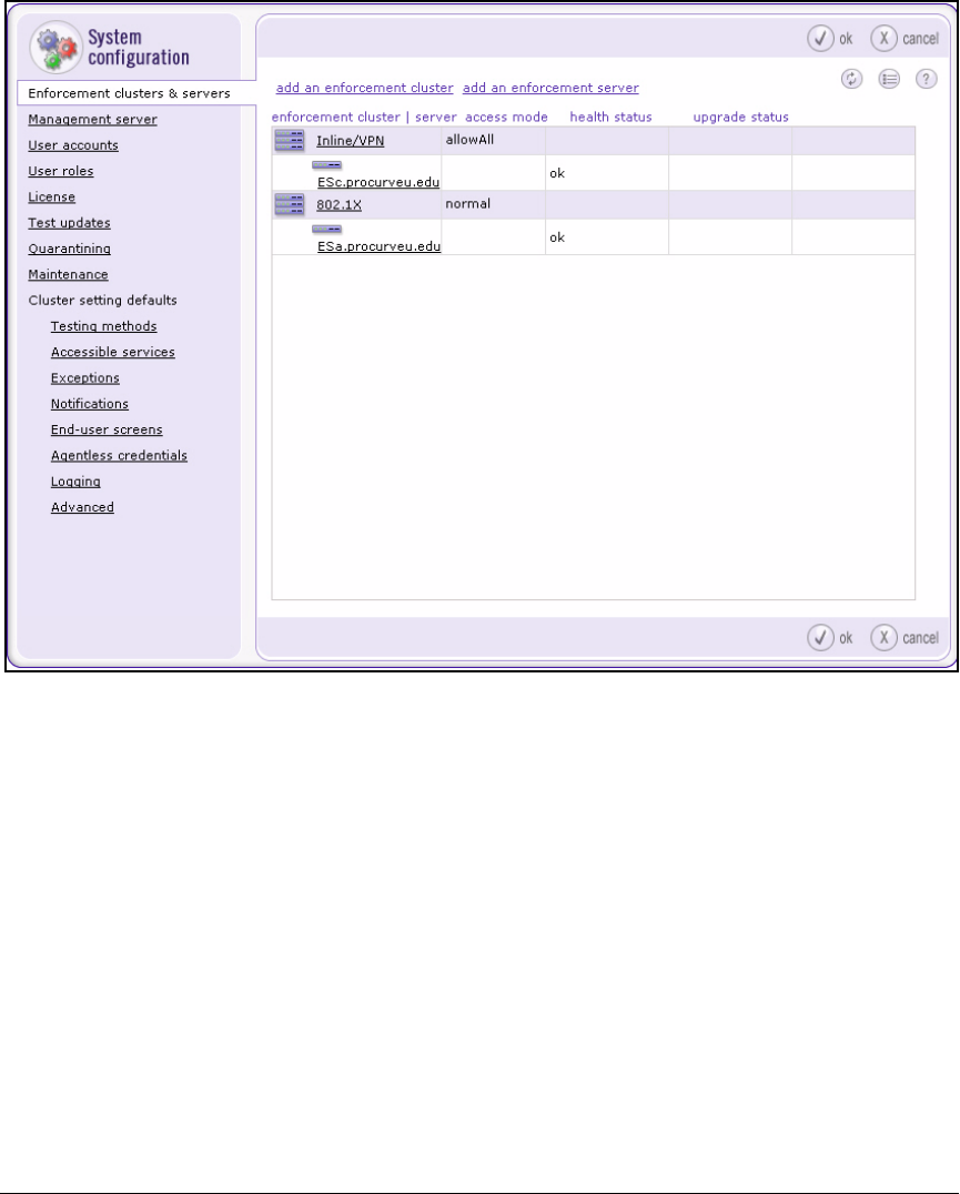
4-146
Implementing a VPN with Endpoint Integrity
Configuring the NAC 800
Figure 4-66. NAC 800 Web Interface—Home > System configuration > Enforcement
clusters & servers Window
Configure Quarantining
This section teaches you how to set up inline quarantining.
Follow these steps:
1. Select Home > System configuration > Quarantining.
2. Select the new cluster, which you created in “Create the Enforcement
Cluster” on page 4-136.
3. In the Quarantine method area, select Inline.
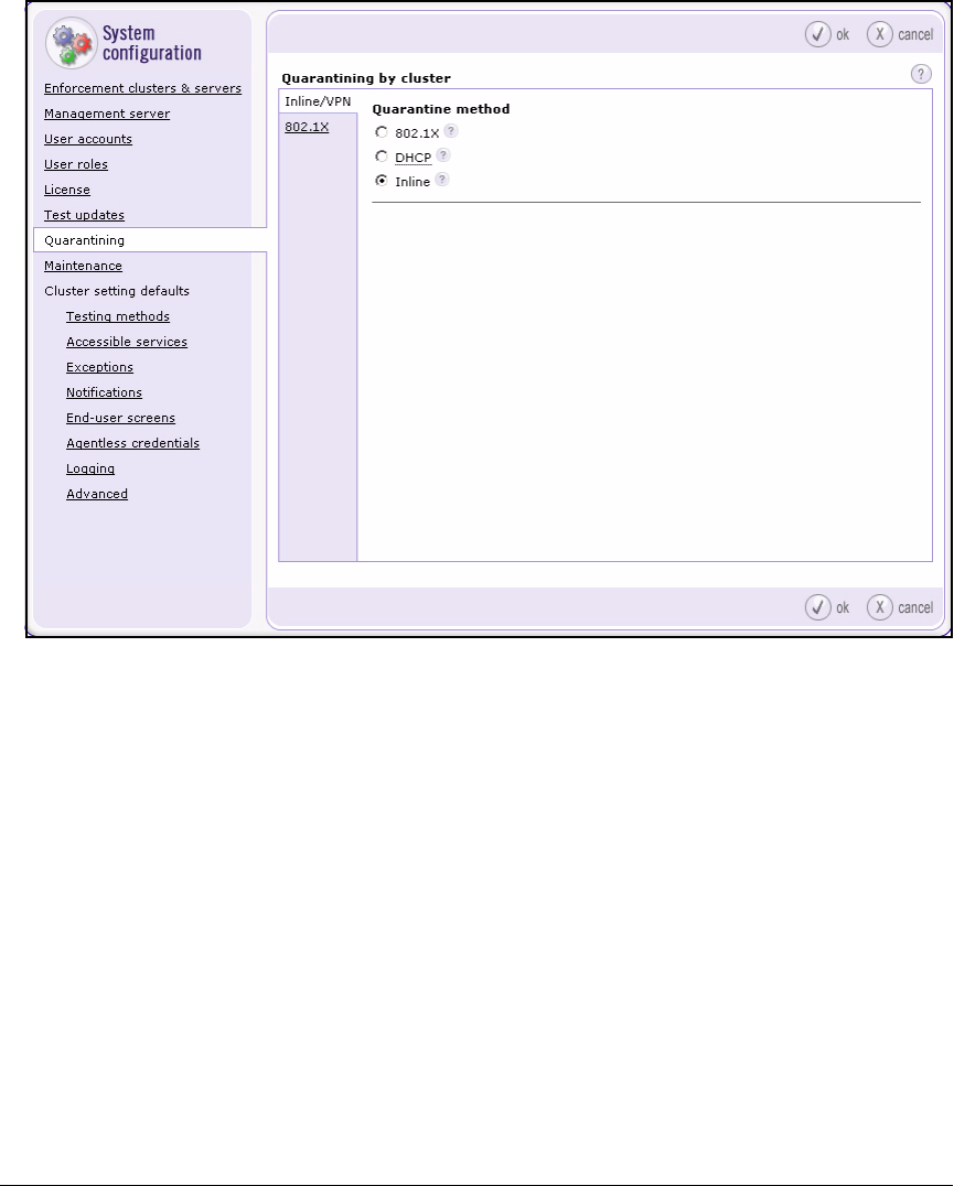
4-147
Implementing a VPN with Endpoint Integrity
Configuring the NAC 800
Figure 4-67. NAC 800 Web Interface—Home > System configuration > Quarantining
Window
4. Click ok.
Set Up Accessible Services
The accessible services list, by default, enables quarantined endpoints to
reach a variety of remediation services. But you might want to add your own
remediation services.
In addition, the NAC 800 ES’s internal firewall filters all traffic between its port
1 and port 2. This means that it might filter and drop some necessary traffic
destined from the LAN to the Secure Router 7000dl. Add the router’s IP address
to the accessible services.
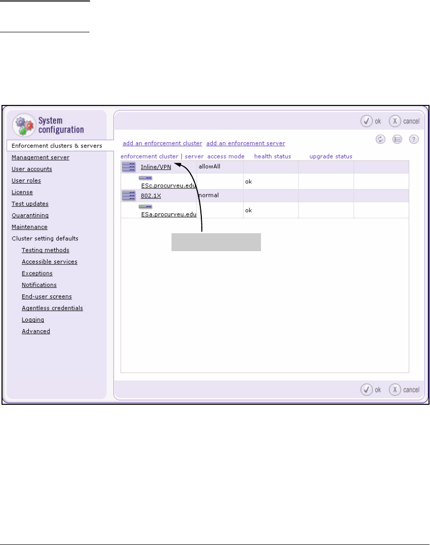
4-148
Implementing a VPN with Endpoint Integrity
Configuring the NAC 800
Note Another way to prevent the NAC 800 from dropping necessary traffic to the
router is to add the router’s IP address as an exception.
Follow these steps to add traffic to the list of accessible services for the inline
cluster only:
1. Select Home > System configuration > Enforcement clusters & servers.
Figure 4-68. NAC 800 Web Interface—Home > System configuration > Enforcement
clusters & servers Window
2. Click the name of the cluster configured for the inline quarantine method.
In this example: Inline/VPN.
Click this link
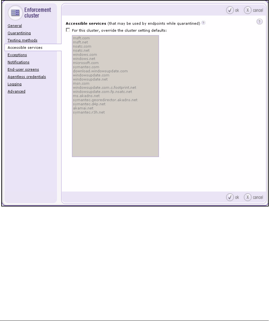
4-149
Implementing a VPN with Endpoint Integrity
Configuring the NAC 800
3. Click Accessible services in the left navigation bar.
Figure 4-69. NAC 800 Web Interface—Home > System configuration > Enforcement
clusters & servers > Accessible services Window
4. Select the For this cluster, override the cluster setting defaults check box.
5. Type the router’s IP address in the area. For example: 10.3.0.100.
6. If you want, enter another IP address to enable quarantined endpoints to
reach a remediation service.
The service must be specified as an IP address (not a hostname).
To enter a range of IPs, use a dash (-) between the IP addresses or CIDR
addresses. For example: 10.4.16.1-10.0.16.5
7. Click ok.

4-150
Implementing a VPN with Endpoint Integrity
Configuring the NAC 800
Other Settings for the NAC 800
After configuring the accessible services, refer to Chapter 2: “Implementing
802.1X with ProCurve IDM and Endpoint Integrity” and configure:
■Testing methods (page 2-155)
■NAC policies (page 2-165)
Also obtain a certificate for the NAC 800’s HTTPS server and install it on the
device. See “Create and Install a Certificate for HTTPS on a NAC 800” on page
2-188 of Chapter 2: “Implementing 802.1X with ProCurve IDM and Endpoint
Integrity.”
Activate Quarantining
Earlier, it was recommended that you set the access mode for the inline
enforcement cluster to allow all. Now that you have configured the accessible
services, you can change the access mode to normal.
It is best to do this after hours in case you need to fix a misconfiguration that,
for example, prevents the Secure Router 7000dl from receiving routes.
Follow these steps:
1. Log in to the Web browser interface of the NAC 800 MS.
2. Select Home > System configuration > Enforcement clusters & servers.
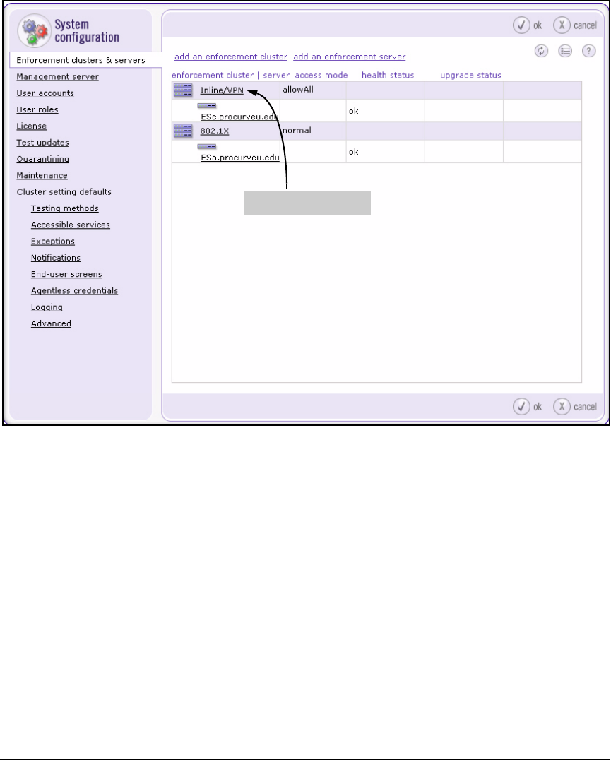
4-151
Implementing a VPN with Endpoint Integrity
Configuring the NAC 800
Figure 4-70. NAC 800 Web Interface—Home > System configuration > Enforcement
clusters & servers Window
3. Click the name of your enforcement cluster (in this example, Inline/VPN).
4. The General tab should be selected.
5. Select normal for the Access mode.
Click this link
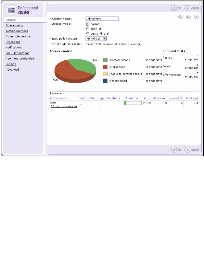
4-152
Implementing a VPN with Endpoint Integrity
Configuring the NAC 800
Figure 4-71. NAC 800 Web Interface—Home > System configuration >
Enforcement clusters & servers > Add enforcement cluster > General
Window
6. Click ok and then ok again.
The NAC 800 ES now quarantines non-compliant endpoints.
Make sure that the accessible services are functioning correctly:
■Can you access the Secure Router 7000dl’s management interfaces?
■Does the Secure Router 7000dl’s route table have the correct routes?
■If you have an SNMP server, can it still access the Secure Router 7000dl?

4-153
Implementing a VPN with Endpoint Integrity
Set Up Endpoints
Set Up Endpoints
This section explains how to configure the VPN client required for this
network access control solution. This example features the ProCurve VPN
Client.
This section also instructs you in obtaining certificates for the VPN client. As
discussed earlier, VPN client certificates can be obtained via automatically-
generated requests or via requests generated manually in the ProCurve VPN
Client. You should have already chosen one option and have set up your CA
server to support your solution. (See “Customize a Template for VPN Client
Certificates” on page 4-14.)
If you chose automatically-generated requests, follow the instructions in
“Obtain a Certificate Using the Windows CA Web Enrollment Pages” on page
4-153. Otherwise, you will learn how to create and submit a request as part of
configuring the ProCurve VPN client.
For information about installing the NAC EI agent on endpoints, see “Pre-
install the NAC EI Agent on Endpoints” on page 2-306 of Chapter 2: “Imple-
menting 802.1X with ProCurve IDM and Endpoint Integrity.”
Obtain a Certificate Using the Windows CA Web
Enrollment Pages
This section applies to solutions in which users obtain certificates for their
VPN clients in much the same way that they do user certificates for other types
of authentication. They do not need to create a manual request but instead
request a certificate through the CA’s web enrollment pages.
The users require access to the issuing CA server from the endpoints on which
they want to install the certificates—that is, the remote endpoints. If your
employees use laptops to connect remotely, they can bring in the laptops and
connect them to the private network. Otherwise, you must allow hosts on the
Internet to access your issuing CA server. Alternatively, to better secure your
CA server, allow the private key for VPN client certificates to be exported. In
this case, users will access the CA server from a local endpoint, install the
certificate, export the certificate to a file, and later install it on the remote
endpoint.

4-154
Implementing a VPN with Endpoint Integrity
Set Up Endpoints
Give users the steps in “Web Enrollment Pages” on page 2-285 of Chapter 2:
“Implementing 802.1X with ProCurve IDM and Endpoint Integrity.” However,
instruct them to choose the customized “Authenticated Session” template.
Configure the ProCurve VPN Client
The ProCurve VPN Client establishes remote, secure communication with
another device. It supports both secure client-to-client and client-to-gateway
communications (the latter is used in this solution).
The ProCurve VPN Client starts automatically when the user’s endpoint starts
and runs transparently behind other software programs. Through a system
tray icon, the user can determine the client’s communications status, open the
client’s components, and perform other actions, such as managing security
policies or viewing logs.
In addition to storing security policies and establishing the VPN connection,
the ProCurve VPN Client helps you to request, import, and export certificates
with its Certificate Manager.
To set up the client, you must:
1. Obtain the ProCurve VPN Client.
2. Install the ProCurve VPN Client.
3. Install digital certificates.
4. Configure the connection and associated security policies.
5. Test the VPN configuration.
6. You can optionally, export the policy and certificates.
In this solution, network administrators are in charge of configuring the client.
They will configure one set connection settings for both faculty members and
students. However, faculty members’ connections will differ from students’ in
one way: their clients will submit different certificates to authenticate to the
VPN gateway.
Network administrators will obtain one certificate for faculty members and
one for students. They will password protect these certificates and include
them, with the exported policies, in the ProCurve VPN Client installation
folders that they will distribute to the users who need remote access.
They will then verbally inform the users of the appropriate passwords.

4-155
Implementing a VPN with Endpoint Integrity
Set Up Endpoints
Obtain the ProCurve VPN Client
You can download a 10-user version of the ProCurve VPN Client from the
My ProCurve Web portal. If you have not used the My ProCurve Web portal
before, you can easily register. Go to http://my.procurve.com and click REG-
ISTER HERE. Then, complete the registration form and click Submit. You will
receive an email that contains a password for logging in to the portal.
After you log in to the My ProCurve Web portal, complete the following steps
to download the ProCurve VPN Client:
1. Click the My Software tab.
2. Click ProCurve 10 User VPN Client Software.
3. Select the I agree to the license terms check box and click Download.
After you download the zip file that contains the ProCurve VPN Client installa-
tion file and related support files, you can extract the files and install the client.
Install the ProCurve VPN Client
Before you begin to install the ProCurve VPN Client, ensure that your work-
station or laptop meets the minimum software requirements:
■IBM-compatible computer with Pentium processor or equivalent (not
Alpha platforms)
■10 MB hard disk space
■Native Microsoft TCP/IP communications protocol
■Compatible OS with minimum RAM, as outlined in Table 4-25
Table 4-25. Minimum RAM Requirements for ProCurve VPN Client
For dial-up connections, you also need:
■Non-encrypting modem
■Native Microsoft PPP dialer
For network connections, you need a network interface card (NIC) and a valid
Ethernet (or wireless) connection.
OS Minimum RAM
Microsoft® Windows® 95 16 MB
Windows 98 and Windows NT®
Workstation 4.0
32 MB
Windows Me and 2000 Professional 64 MB
Windows XP Home and Professional 64 MB; 128 MB recommended
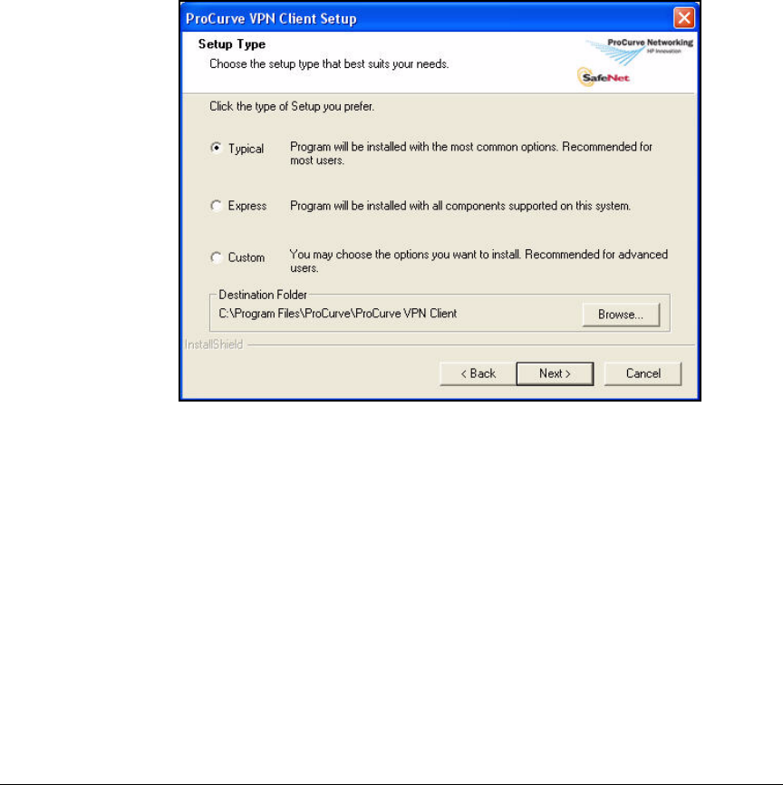
4-156
Implementing a VPN with Endpoint Integrity
Set Up Endpoints
If your endpoint meets these requirements, complete the following steps to
install the client:
1. Open the 10_User_ProCurveVPNClient.zip file and extract all contents.
2. Double-click the extracted Setup.exe file. The Welcome page is displayed.
3. Click Next. The License Agreement page is displayed.
4. Click Yes. The Setup Type page is displayed.
Figure 4-72. Setup Type Page in the ProCurve VPN Client Setup Program
5. Select Typical and click Next. The Start Copying Files page is displayed.
6. Click Next. The installation process begins.
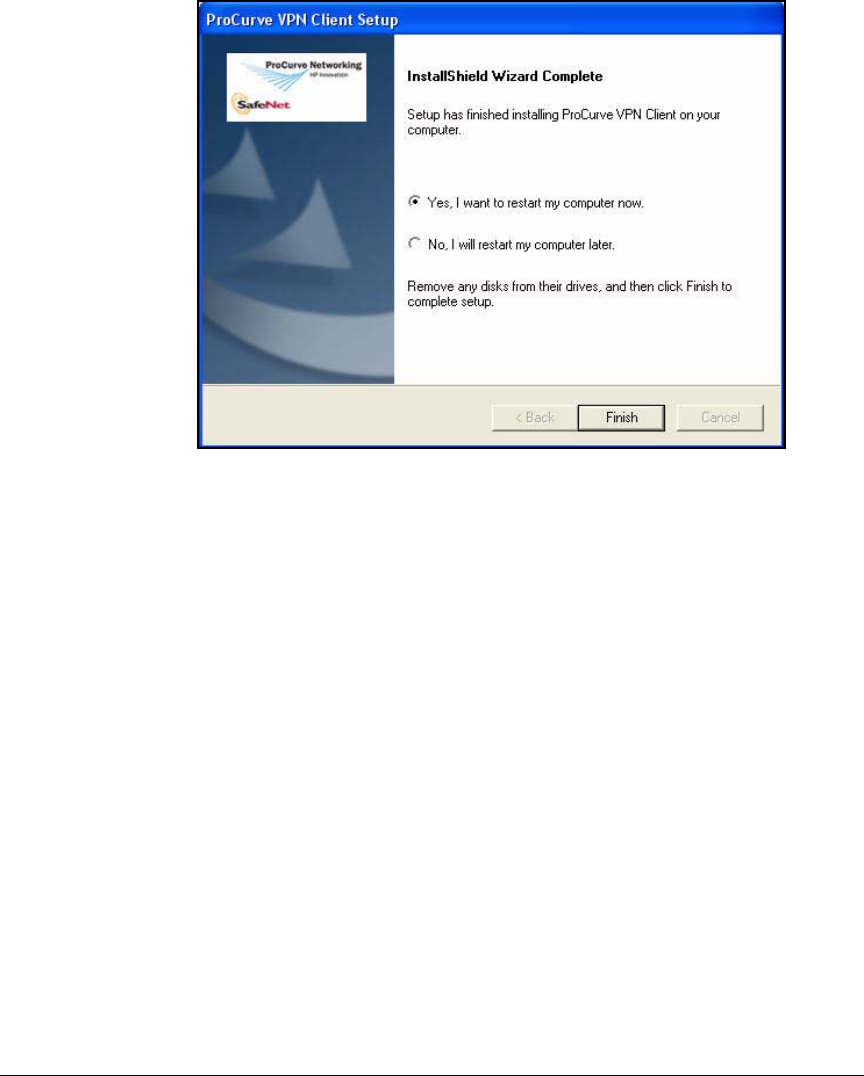
4-157
Implementing a VPN with Endpoint Integrity
Set Up Endpoints
Figure 4-73. InstallShield Wizard Complete Page in the ProCurve VPN Client
Setup Program
7. When the
InstallShield Wizard Complete
page is displayed, select
Yes, I want
to restart my computer now
and click
Finish
.
The ProCurve VPN Client includes two primary components for configuring
VPN connections:
■Certificate Manager—allows you to request, retrieve, import, and store
certificates you receive from CAs, as well as to set the client’s trust policy
■Security Policy Editor—allows you to create, import, and manage
connections and the associated proposals that make up each connection's
security policy
You can access these components by right-clicking the ProCurve VPN Client
icon in the notification area of the Windows taskbar. Or you can access them
from the Start menu.
Install Certificates
The ProCurve VPN Client requires the domain CA root certificate, as well as
a certificate for the client.

4-158
Implementing a VPN with Endpoint Integrity
Set Up Endpoints
Complete these tasks in the Certificate Manager:
1. Install the CA root certificate on the ProCurve VPN Client:
• If the CA certificate is already installed on the endpoint, configure the
trust policy to add the certificate to the ProCurve VPN Client.
• Otherwise, obtain the CA certificate and import it to the client.
2. Request a certificate for the VPN client.
3. Submit the certificate request to the CA.
4. Import the certificate into the VPN client.
The PCU network administrator in charge of configuring the VPN client must
complete the final three steps twice—once to obtain a certificate for faculty
members and once to obtain a certificate for students.
Configure the Trust Policy. The CA root certificate for the domain may
already be installed on the endpoint. Make sure that the ProCurve VPN Client
trusts the certificate by following these steps:
1. From the Windows Start menu, select Programs > ProCurve VPN Client >
Certificate Manager.
2. Click the Trust Policy tab.
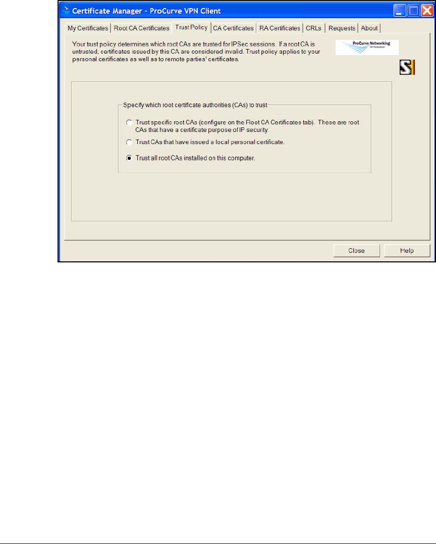
4-159
Implementing a VPN with Endpoint Integrity
Set Up Endpoints
Figure 4-74. Certificate Manager > Trust Policy Tab in the ProCurve VPN Client
3. Select Trust all root CAs installed on this computer.
4. Click the Root CA Certificates tab and verify that your CA’s root certificate
is present.
Import a CA Certificate. If the endpoint does not have the root certificate
for the CA that will sign its certificate, you must import the root certificate.
However, you can skip this task if you obtain a certificate chain, rather than
a simple certificate, when you submit the certificate request to the CA.
Otherwise, follow these steps:
1. Obtain the root certificate from your CA. See “Export the CA Root
Certificate” on page 2-97 of Chapter 2: “Implementing 802.1X with Pro-
Curve IDM and Endpoint Integrity.” Save the CA root certificate on the
endpoint.
2. In the Certificate Manager, click the Root CA Certificates tab.
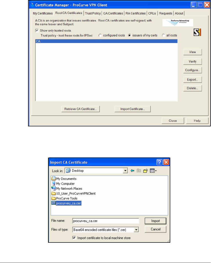
4-160
Implementing a VPN with Endpoint Integrity
Set Up Endpoints
Figure 4-75. Certificate Manager > CA Certificates Tab in the ProCurve VPN Client
3. Click Import Certificate.
Figure 4-76. Import CA Certificate
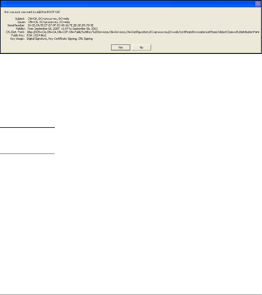
4-161
Implementing a VPN with Endpoint Integrity
Set Up Endpoints
4. Navigate to the directory in which you saved the CA root certificate. Select
the certificate.
5. Click Import.
Figure 4-77. Verify Import CA Certificate in the ProCurve VPN Client
6. When the window shown in Figure 4-135 is displayed, click Yes.
7. When asked if you want to trust the root CA certificate, click Yes again.
Request a Certificate. Complete this task if your solution calls for network
administrators to use the ProCurve VPN Client to request certificates on
behalf of remote users.
Note If users will obtain their own certificates (see “Obtain a Certificate Using the
Windows CA Web Enrollment Pages” on page 4-153), you can move to “Create
a Security Policy” on page 4-179.
Follow these steps:
1. From the Windows Start menu, select Programs > ProCurve VPN Client >
Certificate Manager.
2. Click the My Certificates tab.
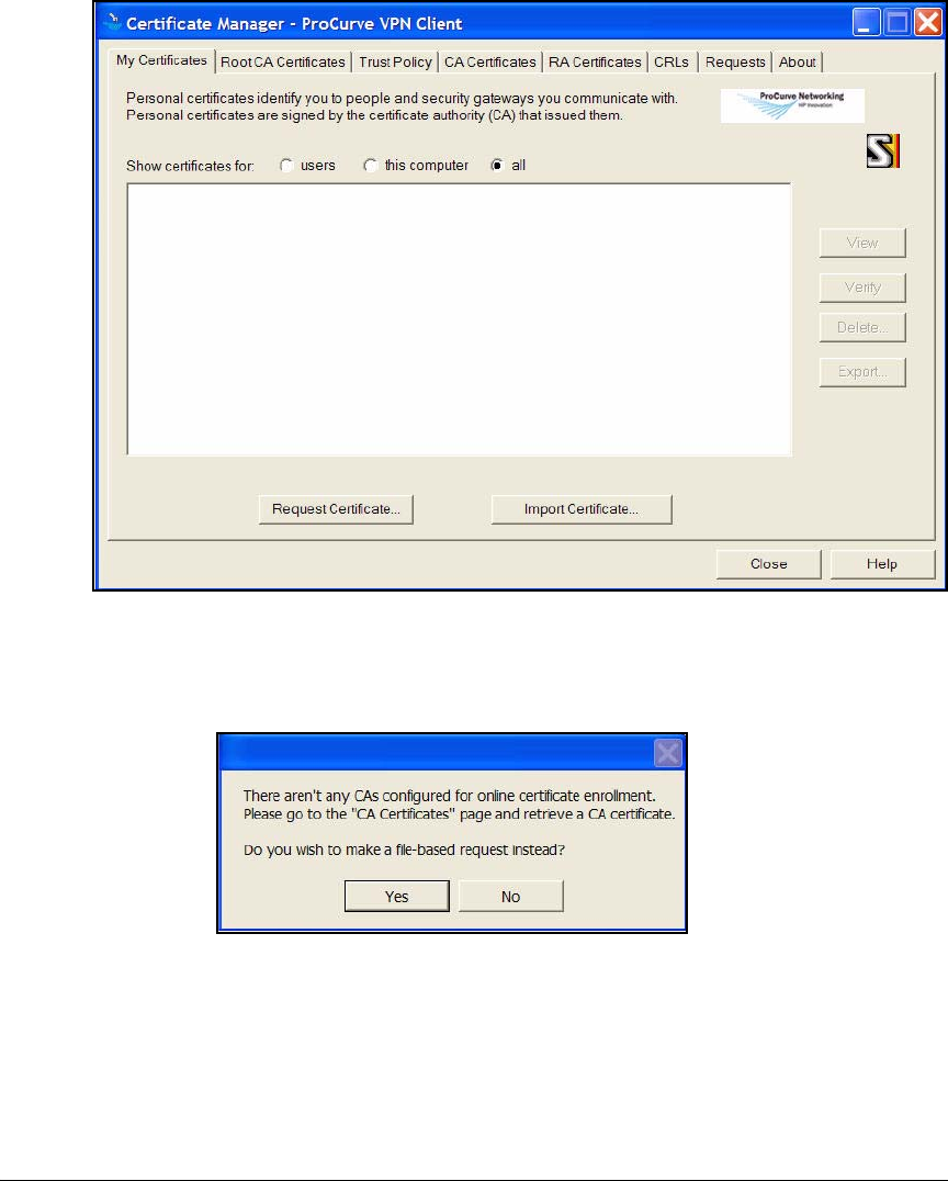
4-162
Implementing a VPN with Endpoint Integrity
Set Up Endpoints
Figure 4-78. Certificate Manager > My Certificates Tab in the ProCurve VPN Client
3. Click Request Certificate.
Figure 4-79. Request Certificate Query Window
4. In the window that is displayed, click Yes.
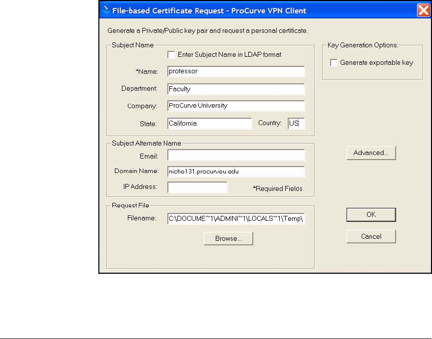
4-163
Implementing a VPN with Endpoint Integrity
Set Up Endpoints
5. In the File-based Certificate Request window, enter information about the
user in the Subject Name area.
Only the Name box requires an entry. However, the values entered for the
Subject Name must match exactly an entry in the VPN gateway’s remote
ID list, unless, of course, the value is a wildcard (*). See Table 4-26.
a. For Name, type the username. In this example: professor.
b. For Department, type the user’s group or organizational unit (OU). In
this example: Faculty.
c. For Company, type the name of your organization. In this example:
ProCurve University.
d. For State, type the full name of the user’s state. In this example:
California.
e. For Country, type the two-letter code for the user’s country. In this
example: US.
Figure 4-80. File-based Certificate Request in the ProCurve VPN Client
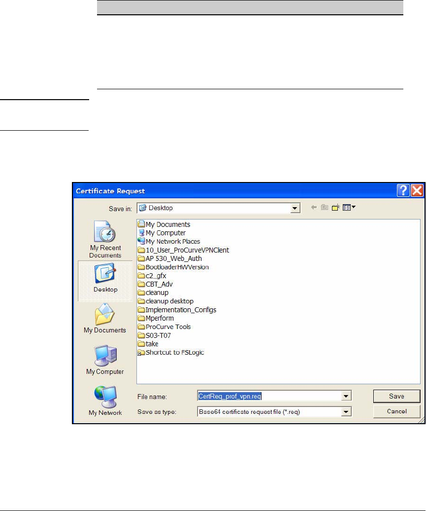
4-164
Implementing a VPN with Endpoint Integrity
Set Up Endpoints
Table 4-26. Translating Boxes in the ProCurve VPN Client Certificate Request to
LDAP format
Note The state portion of the subject name will display as S on the client. However,
on the Secure Router, you must specify ST.
6. In the File-based Certificate Request window, click Browse in the Request
File area.
Figure 4-81. Certificate Request—Save File
7. Navigate to the location to which you want to save the request. Type a
descriptive name for the File Name and click Save.
Box Name in the ProCurve VPN Client LDAP Format on the Secure Router
Name CN
Department OU
Company O
State ST
Country C
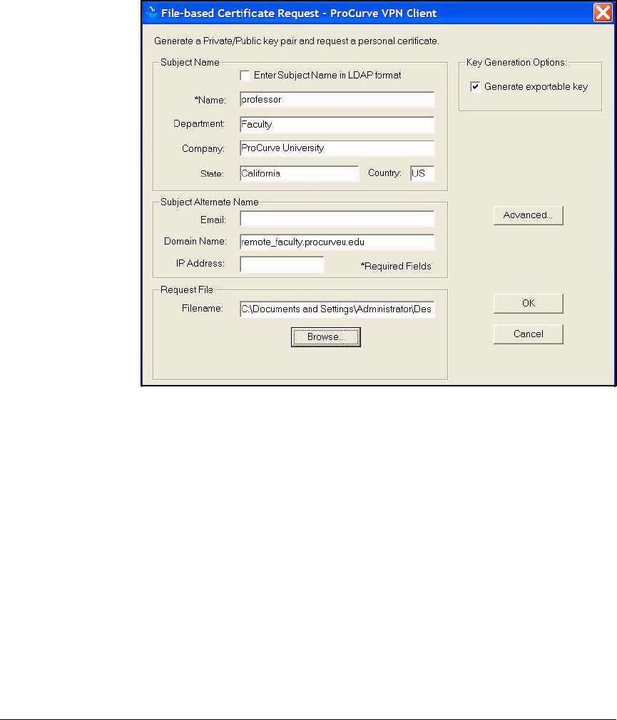
4-165
Implementing a VPN with Endpoint Integrity
Set Up Endpoints
8. In the File-based Certificate Request window, select the Generate exportable
key check box.
Figure 4-82. File-based Certificate Request in the ProCurve VPN Client
9. Click OK.
The request saves to the location you selected, ready for you to submit to
the CA.
Submit the Certificate Request to the CA. This section explains how to
submit the certificate request to a Windows CA using the web enrollment
pages. Follow these steps:
1. Open a Web browser and type this URL:
http://<CA server hostname>/certsrv. In this example: http://ca.procur-
veu.edu/certsrv.
2. When prompted, enter credentials for an administrator allowed to enroll
for the VPN client certificate.
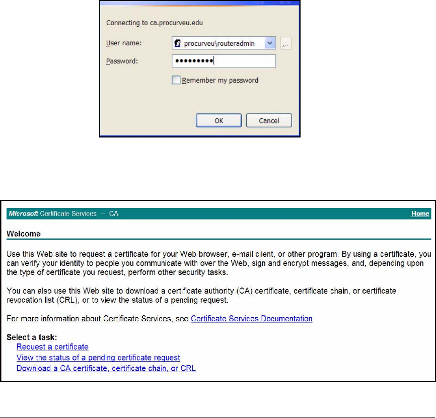
4-166
Implementing a VPN with Endpoint Integrity
Set Up Endpoints
You set up the permissions in “Customize a Template for VPN Client
Certificates” on page 4-14. In this example, network administrators have
permission to enroll clients for the certificates, and the username for the
network administrator in charge of managing the Secure Router 7000dl is
routeradmin.
a. Type the User name in this format: <domain>\<username>. In this exam-
ple: procurveu\routeradmin.
b. For the Password, type the user’s domain password. In this example:
ProCurve0.
Figure 4-83. Connect to ca.procurveu.edu
3. Click OK.
Figure 4-84. Certificate Services—Welcome Page
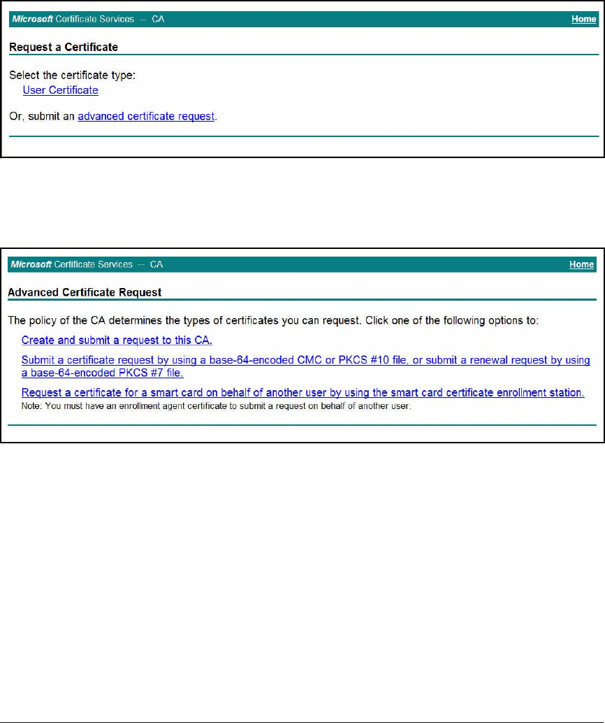
4-167
Implementing a VPN with Endpoint Integrity
Set Up Endpoints
4. Click Request a certificate.
Figure 4-85. Certificate Services—Request a Certificate Page
5. Click advanced certificate request.
Figure 4-86. Certificate Services—Advanced Certificate Request Page
6. Click Submit a certificate request by using a base-64-encoded CMC or PKCS
#10 file, or submit a renewal request by using a base-64[encoded PKCS #7 file.
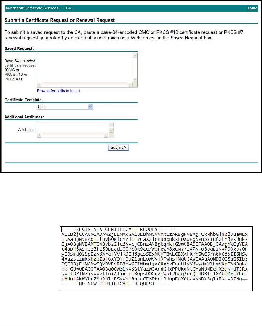
4-168
Implementing a VPN with Endpoint Integrity
Set Up Endpoints
Figure 4-87. Certificate Services—Submit a Certificate Request or Renewal
Request Page
7. The certificate request created in “Request a Certificate” on page 4-161
should be saved on the current endpoint. Open the file with a text editor.
Figure 4-88. Certificate Request File in a Text Editor
8. Select and copy the complete text.
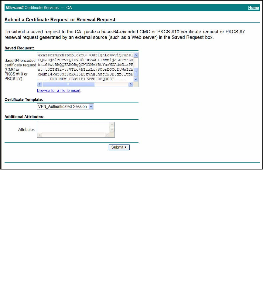
4-169
Implementing a VPN with Endpoint Integrity
Set Up Endpoints
9. Return to the open Web page and paste the text in the Base-64-encoded
certificate request box.
10. For Certificate Template, select the template you created for VPN users. In
this example: VPN_Authenticated Session.
Figure 4-89. Certificate Services—Submit a Certificate Request or Renewal
Request Page
11. Click Submit.
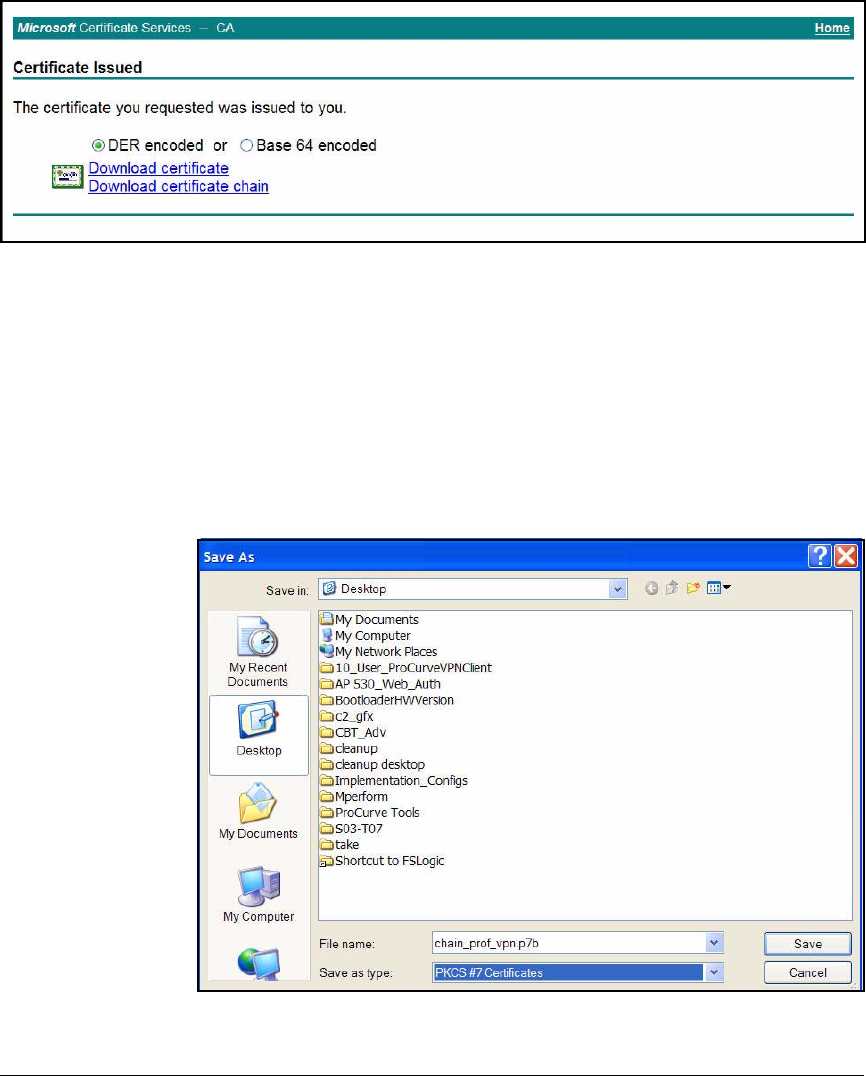
4-170
Implementing a VPN with Endpoint Integrity
Set Up Endpoints
Figure 4-90. Certificate Services—Certificate Issued Page
12. Download the certificate:
• If the ProCurve VPN Client already has the CA root certificate
installed on it, select Download certificate.
• If the ProCurve VPN Client does not have the CA root certificate,
select Download certificate chain.
13. When prompted, verify that you want to save the certificate and choose
the location.
Figure 4-91. Save the Certificate Chain
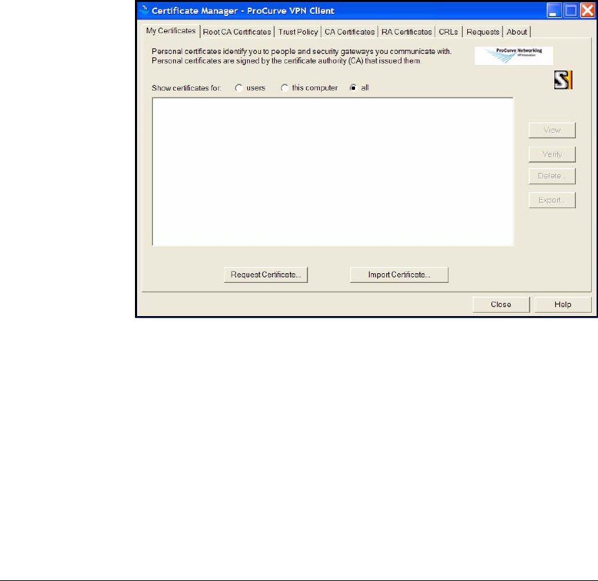
4-171
Implementing a VPN with Endpoint Integrity
Set Up Endpoints
You have now obtained the necessary certificate and can import it to the
ProCurve VPN Client.
Import a Certificate to the ProCurve VPN Client. Follow these steps to
import the certificate that you obtained for the ProCurve VPN Client:
1. From the Windows Start menu, select Programs > ProCurve VPN Client >
Certificate Manager.
2. Click the My Certificates tab.
Figure 4-92. Certificate Manager > My Certificates Tab in the ProCurve VPN Client
3. Click Import Certificate.
4. For Import Type, select Certificate Request Response File.
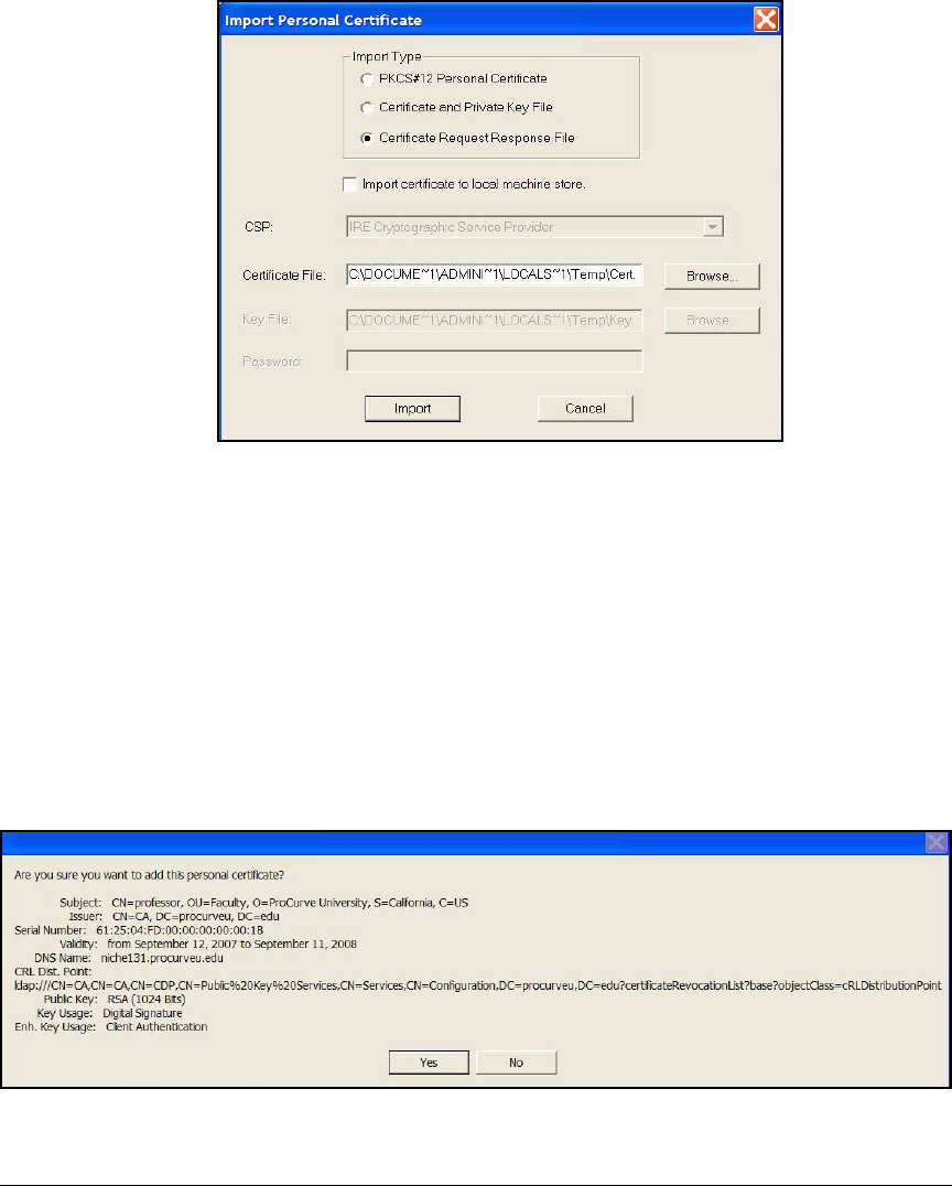
4-172
Implementing a VPN with Endpoint Integrity
Set Up Endpoints
Figure 4-93. Import Personal Certificate in the ProCurve VPN Client
5. For Certificate File, type the path and name of the file to which you saved
the certificate in “Submit the Certificate Request to the CA” on page 4-165.
Or click Browse to search for the file. (If you do not see the file in the
window that is displayed, make sure that you are looking for the correct
file types—probably CER or DER, but if you downloaded a certificate
chain, PKCS#7.)
6. Click Import.
7. A window is displayed that asks you to confirm the installation of the
certificate. Click Yes.
Figure 4-94. Verify Import Personal Certificate in the ProCurve VPN Client
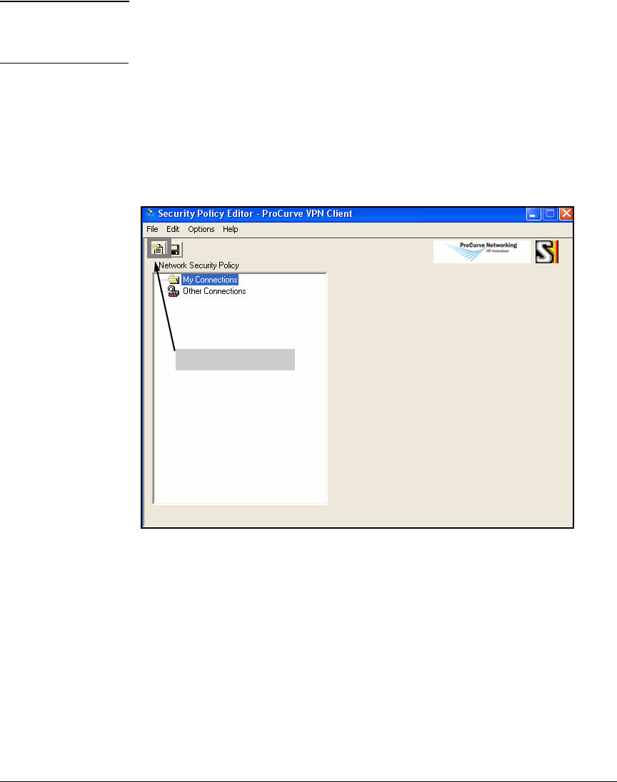
4-173
Implementing a VPN with Endpoint Integrity
Set Up Endpoints
Note If you have imported a complete certificate chain, you are first asked to verify
the CA certificate, then the personal certificate. Click Yes for both. Also click
Yes when asked if you want to trust the root CA certificate.
Configure a New Connection
Configure the connection to the Secure Router 7000dl.
1. From the Windows Start menu, select Programs > ProCurve VPN Client >
Security Policy Editor.
Figure 4-95. Security Policy Editor in the ProCurve VPN Client
2. Click the New Connection icon at the top left of the window. An icon is
added under My Connections in the left pane. Type a name for the connec-
tion. In this example: PCU_VPN.
3. Select the icon for the connection that you just added.
New Connection icon
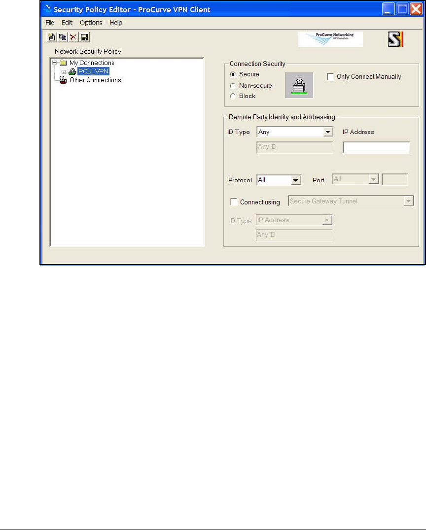
4-174
Implementing a VPN with Endpoint Integrity
Set Up Endpoints
Figure 4-96. New Connection in the ProCurve VPN Client
4. Set up the new connection.
a. Under Connection Security, select Secure.
b. Under Remote Party Identity and Addressing, select IP Subnet for ID Type.
c. For Subnet and Mask, type the network IP address and mask of the
private network.
This option specifies the LAN that the user is allowed to access and
must match exactly the permitted source address in the VPN ACL that
you configured in “Create ACLs for VPN Traffic” on page 4-83.
For example, type 10.0.0.0 as the IP address and 255.240.0.0 as the
subnet mask.
d. For Protocol, maintain the default setting of All.
e. Select the Connect using option and use the drop-down menu to select
Secure Gateway Tunnel.
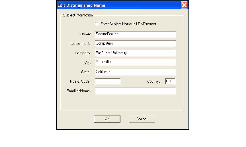
4-175
Implementing a VPN with Endpoint Integrity
Set Up Endpoints
f. In the left ID Type box, select Distinguished Name.
The choice of ID type depends on the local ID that you configured in
the IKE policy (see “Configure an IKE Policy” on page 4-76).
g. Click Edit Name.
h. In the Edit Distinguished Name window, type information about the
router.
The values must match exactly the subject name in the router’s
certificate. If the subject name does not include one of the attributes,
do not specify a value for that attribute.
i. For Name, type the router’s CN. In this example: SecureRouter.
ii. For Department, type the router’s OU. In this example: Computers.
iii. For Company, type your organization name. In this example: Pro-
Curve University.
iv. For City, type the router’s city. In this example: Roseville.
v. For State, type the router’s state. In this example: California.
vi. For Postal Code, type the router’s postal code. In this example, the
router’s subject name does not specify that attribute.
vii. For Country, type the two-letter code for the router’s country. In
this example: US.
viii. For Email address, type the router’s email address. In this example,
the router’s certificate does not include that alternate ID.
Figure 4-97. Edit Distinguished Name Window in ProCurve VPN Client

4-176
Implementing a VPN with Endpoint Integrity
Set Up Endpoints
Note To make sure that you are configuring the name correctly, you can access
the Secure Router CLI and view the certificate (show crypto ca certificates).
Refer to Table 4-27 for help translating the LDAP format name displayed
into the boxes in the Edit Distinguished Name window.
i. Click OK.
Table 4-27. Entering the Secure Router 7000dl LDAP Format Name in the ProCurve
VPN Client
j. For the right ID Type box in the window shown in Figure 4-98, select
Gateway IP Address.
k. Then type the IP address of the WAN interface on your router. The
WAN interface is the router interface that receives user’s traffic and
the address is usually a public IP address. In this example: 192.168.1.1.
LDAP Format on the Router Box Name in the ProCurve VPN Client
CN Name
OU Department
O Company
LCity
ST State
C Country
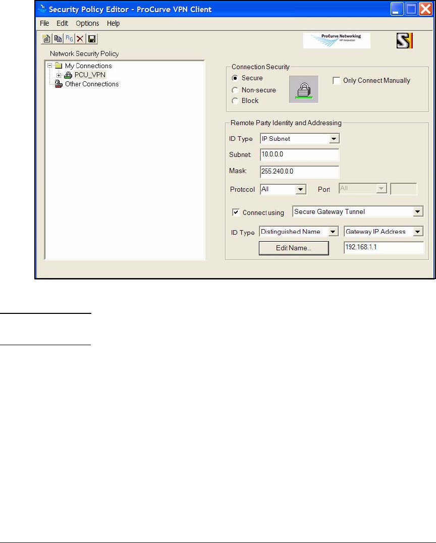
4-177
Implementing a VPN with Endpoint Integrity
Set Up Endpoints
Figure 4-98. New Connection in the ProCurve VPN Client
Note The “public” IP address, 192.168.1.1, is, in reality, a private address. It is
simply used as an example.
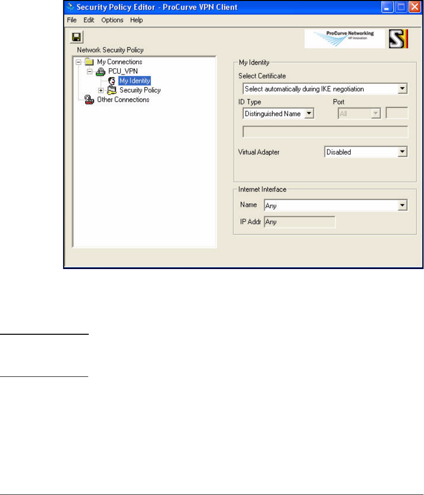
4-178
Implementing a VPN with Endpoint Integrity
Set Up Endpoints
5. In the left pane, expand the connection that you are configuring and click
My Identity.
Figure 4-99. Security Policy Editor > My Identity in the ProCurve VPN Client
6. Keep the default setting for Select Certificate: Select automatically during
IKE negotiation.
Note If your VPN used preshared keys instead, you would select None. The View
button becomes the Pre-Shared Key button; click it and configure the
preshared key in the window that is displayed.
7. For ID Type, select Distinguished Name.
As you can see in Figure 4-100, the box below ID Type displays the distin-
guished name in the certificate. Match this name exactly in the remote ID
list on the Secure Router 7000dl. (However, type ST instead of S for the
state.)
8. Leave all other fields on the My Identity window at the default settings.
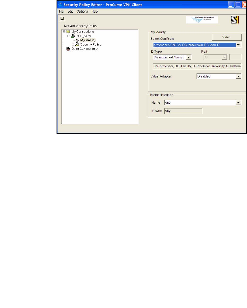
4-179
Implementing a VPN with Endpoint Integrity
Set Up Endpoints
Figure 4-100.My Identity Page in the ProCurve VPN Client
Create a Security Policy
To create and secure a connection to the Secure Router 7000dl, you must
configure a security policy by completing the following steps:
1. Under New Connection in the left pane, click Security Policy. The Security
Policy page is displayed.
2. Under Select Phase 1 Negotiation Mode, select the mode that matches the
respond mode in the router’s IKE policy. In this example: Main Mode.
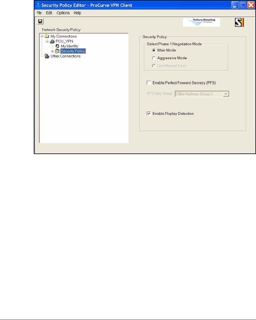
4-180
Implementing a VPN with Endpoint Integrity
Set Up Endpoints
Figure 4-101.Security Policy Page in the ProCurve VPN Client
3. If you configured PFS in the crypto map on the VPN gateway, follow these
steps:
a. Select the Enable Perfect Forward Secrecy (PFS) check box.
b. Select the Diffie-Hellman group for the PFS. The Secure Router 7000dl
supports group 1, 2, and 5. For the example network, select Diffie-
Hellman 5.
4. Expand the Security Policy section in the left pane. Two options are
displayed:
•Authentication (Phase 1)
•Key Exchange (Phase 2)
Expand both of these options.
5. Select Proposal 1 under Authentication (Phase 1), and configure the settings
for IKE phase 1. These settings must match IKE attribute polity settings
that are configured on the Secure Router 7000dl.
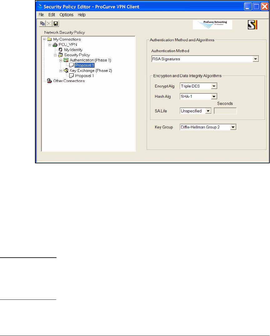
4-181
Implementing a VPN with Endpoint Integrity
Set Up Endpoints
Figure 4-102.Security Policy > Proposal 1 in the ProCurve VPN Client
a. For Authentication Method, select one of the following:
– DSA Signatures
– RSA Signatures
– DSA Signatures: Extended Authentication
– RSA Signatures: Extended Authentication
You would select one of the extended authentication methods if you
are using Xauth.
For the example network, select RSA Signatures.
Note If, in step 6 of “Configure a New Connection” on page 4-173, you
selected None for the certificate, these options are available for the
Authentication Method:
– Pre-Shared Key
– Pre-Shared Key; Extended Authentication

4-182
Implementing a VPN with Endpoint Integrity
Set Up Endpoints
b. For Encrypt Alg, select one of the following:
–DES
– Triple DES
– AES-128
– AES-192
– AES-256
For the example network, select AES-192.
c. For Hash Alg, select one of the following:
–MD5
–SHA-1
For the example network, select SHA-1.
d. For SA Life, select one of the following:
– Seconds—Then, type the number of seconds for the temporary
IKE tunnel lifetimes.
–Unspecified
For the example network, select Seconds and type 240.
e. For Key Group, select a Diffie-Hellman group. The Secure Router
7000dl supports group 1 and group 2. For the example network, select
Diffie-Hellman Group 2.
6. Click Proposal 1 under Key Exchange (Phase 2). These settings are used for
the IKE phase 2, which negotiates the IPsec parameters. They must match
settings in a Secure Router 7000dl crypto map entry (and associated
transform sets) exactly.
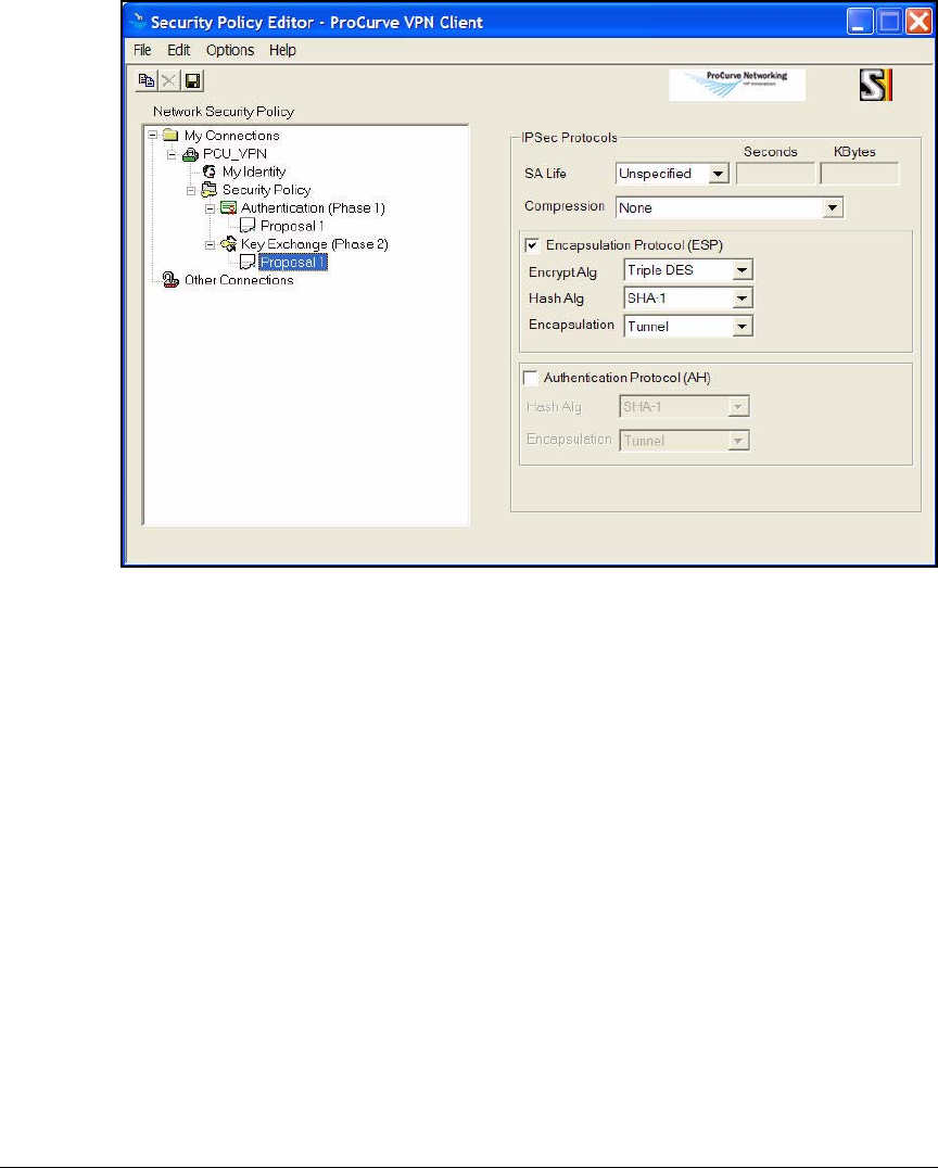
4-183
Implementing a VPN with Endpoint Integrity
Set Up Endpoints
Figure 4-103.Security Policy Editor in the ProCurve VPN Client
a. For SA Life, select one of the following:
– Unspecified
– Seconds—Type the number of seconds for the IPsec tunnel life-
time.
– Kbytes—Type the number of KB for IPsec tunnel lifetime.
– Both—Type the number of seconds and the KB IPsec tunnel
lifetime.
For the example network, select Seconds and type 7200.
b. For Compression, leave the default: None.
c. Select the Encapsulation Protocol (ESP) or Authenticate Protocol (AH)
check box. ESP allows encryption so you should use it whenever
possible. Select the corresponding check boxes. In this example:
select the Encapsulation Protocol (ESP) check box.

4-184
Implementing a VPN with Endpoint Integrity
Set Up Endpoints
d. If you have selected ESP, for Encrypt Alg, select one of the following:
– Triple DES
– Null
– AES-128
– AES-192
In this example: AES-192.
e. For Hash Alg (if you selected either ESP or AH), select one of the
following:
–MD5
–SHA-1
– DES-MAC (ESP only)
In this example: SHA-1.
f. For Encapsulation, select Tunnel.
7. Save the new connection. (Select File > Save.)
You have finished configuring the connection.
Test the VPN Connection
You should now test the VPN connection and verify that the Secure Router
7000dl and the ProCurve VPN Client are correctly configured and have all
necessary certificates. You may need to test the connection from home; your
endpoint must connect to the router through the Internet.
Follow these steps on the endpoint with the VPN client:
1. In the Start menu, select Programs > ProCurve VPN Client > Log Manager.
The Log Manager displays messages that help you troubleshoot the con-
nection.
2. Right-click the ProCurve VPN Client icon in the right of the Windows
taskbar.
3. Select Connect > MyConnections\<connection name>.

4-185
Implementing a VPN with Endpoint Integrity
Set Up Endpoints
Figure 4-104.Manual Connection Status Window in the
ProCurve VPN Client
4. Wait while the VPN tunnel is established. After a minute or two, you should
see the window shown in Figure 4-105.
You have successfully connected.
Figure 4-105.Manual Connection Status Window in the
ProCurve VPN Client—Success
If you do not see this window, check the Log Manager and look for messages
that indicate the error.
Export the Policy and Certificates
After testing your policy and ensuring that it works, you can export it from
the endpoint and distribute it to users. This section teaches you how to create
two prepackaged installations for two different sets of users.
The endpoint on which you configured the ProCurve VPN Client should have
the installation directory for the client—for example,
10_User_ProCurveVPNClient. Copy the directory once for each different pre-
packaged installation; then rename the new directories. For example:
■ProCurveVPNClient_Faculty
■ProCurveVPNClient_Students
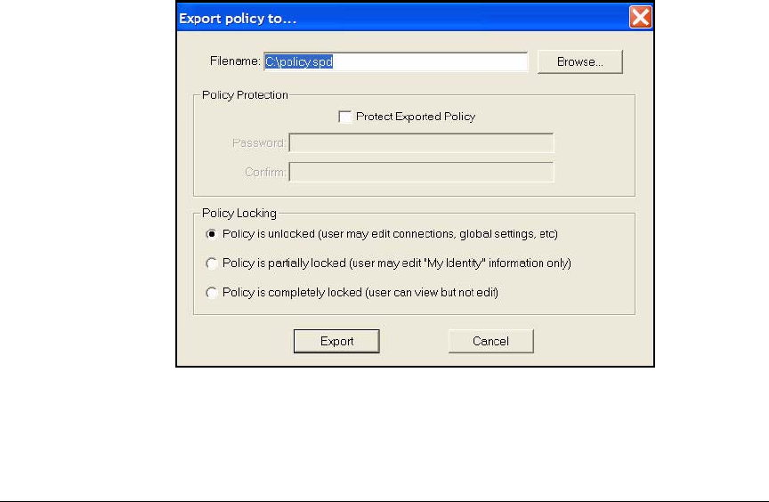
4-186
Implementing a VPN with Endpoint Integrity
Set Up Endpoints
These directories contain the installation files. You are going to add three files
to each:
■IPSecPolicy.spd—the preconfigured connection settings and security pol-
icies for this set of users
■IPSecCerts.p12—the correct VPN client certificate for this set of users
You do not need to add this file if users will obtain their own certificates.
■CaCert.cser—the root certificate for the CA that issued the VPN client
certificate
Using these exact names allows the policy and certificates to automatically
import at the same time that the client installs.
Export the Policy. Follow these steps to export the connection settings and
security policy:
1. In the Start menu, select Programs > ProCurve VPN Client > Security Policy
Editor.
2. Click one of the secure connections in the left pane.
3. Select File > Export Security Policy.
Figure 4-106.Export policy to Window in the ProCurve VPN Client
4. Click Browse next to the Filename box.
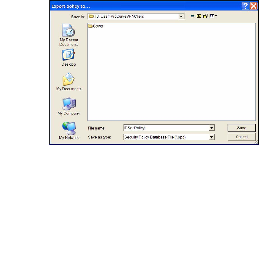
4-187
Implementing a VPN with Endpoint Integrity
Set Up Endpoints
5. Navigate to the prepackaged installation directory for the users for whom
you designed this policy.
6. For Filename, type this exact name: IPSecPolicy.
You can type a different name, but then the policy will not automatically
install.
7. Leave the default setting in the Save as type box: Security Policy Database
File (*.spd).
Figure 4-107.Export policy to Window
8. Click Save.
9. You return to the previous Export policy to window. Select the Protect
Exported Policy check box to password-protect the policy. Then, type the
password and confirm it.
10. Select one of the following options:
•Unlocked policy—Users can change any settings.
•Partially locked policy—Users can configure My Identity settings
only. For example, they can type a preshared key or select a
certificate.
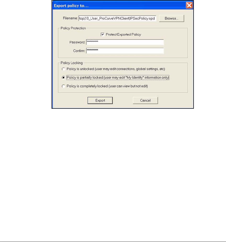
4-188
Implementing a VPN with Endpoint Integrity
Set Up Endpoints
•Completely locked policy—Users can view settings but cannot
change them.
For this solution, you should select Policy is partially locked. Completely
locking the policy prevents the user from selecting the correct certificate
and can cause the connection to fail.
Figure 4-108.Export policy to Window
11. Click Export.
12. Repeat steps 2 to 11. This time save the policy in the prepackaged
installation folder for the second set of users. You may also want to set a
different password.
Export the VPN Client Certificate. Follow these steps to export the cli-
ent certificate:
1. In the Start menu, select Programs > ProCurve VPN Client > Security Policy
Editor.
2. Click the My Certificates tab.
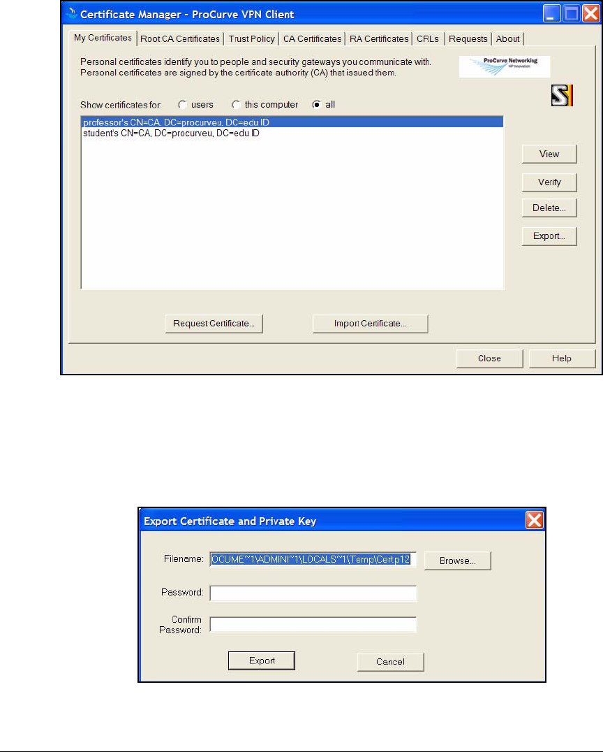
4-189
Implementing a VPN with Endpoint Integrity
Set Up Endpoints
Figure 4-109.Certificate Manager > My Certificates Tab in the ProCurve VPN Client
3. Select the correct certificate for the users for whom you designed this
prepackaged installation.
4. Click Export.
Figure 4-110.Export Certificate and Private Key Window
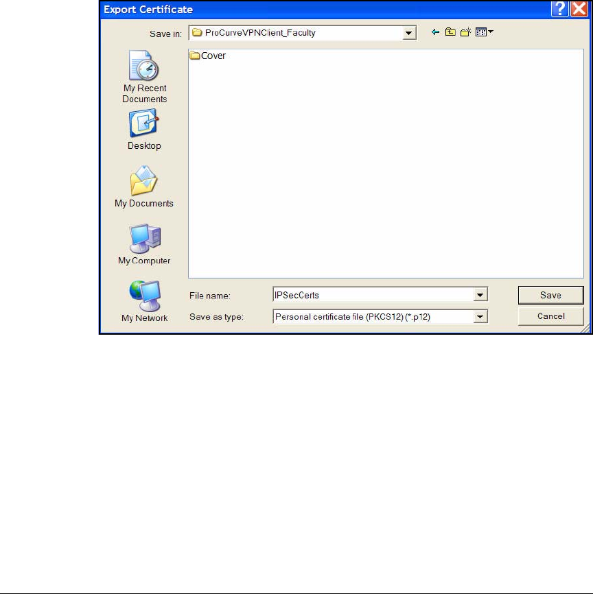
4-190
Implementing a VPN with Endpoint Integrity
Set Up Endpoints
5. Click Browse.
6. Navigate to the prepackaged installation directory.
7. For File name, type: IPSecCerts.
Use this exact filename to ensure that the certificate imports automati-
cally when the user installs the ProCurve VPN Client.
8. For Save as type, leave the default: Personal certificate file (PKCS12) (*.p12).
Figure 4-111.Export Certificate Window
9. Click Save.
10. In the Export Certificate and Private Key window, type a password in the
Password and Confirm Password boxes.
The password prevents users from importing and using a certificate grants
them rights they do not merit.
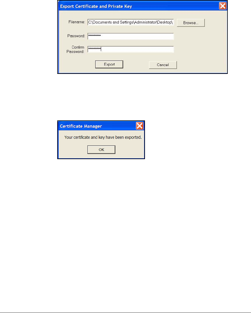
4-191
Implementing a VPN with Endpoint Integrity
Set Up Endpoints
Figure 4-112.Export Certificate and Private Key Window
11. Click Export.
12. You should see the window shown in Figure 4-113.
Figure 4-113.Certificate Manager Window
Export the CA Root Certificate. Follow these steps to export the certifi-
cate for the CA that signed the VPN client certificate:
1. In the Start menu, select Programs > ProCurve VPN Client > Security Policy
Editor.
2. Click the Root CA Certificates tab.
3. Select the Show only trusted roots check box.
4. Click issuers of my certs.
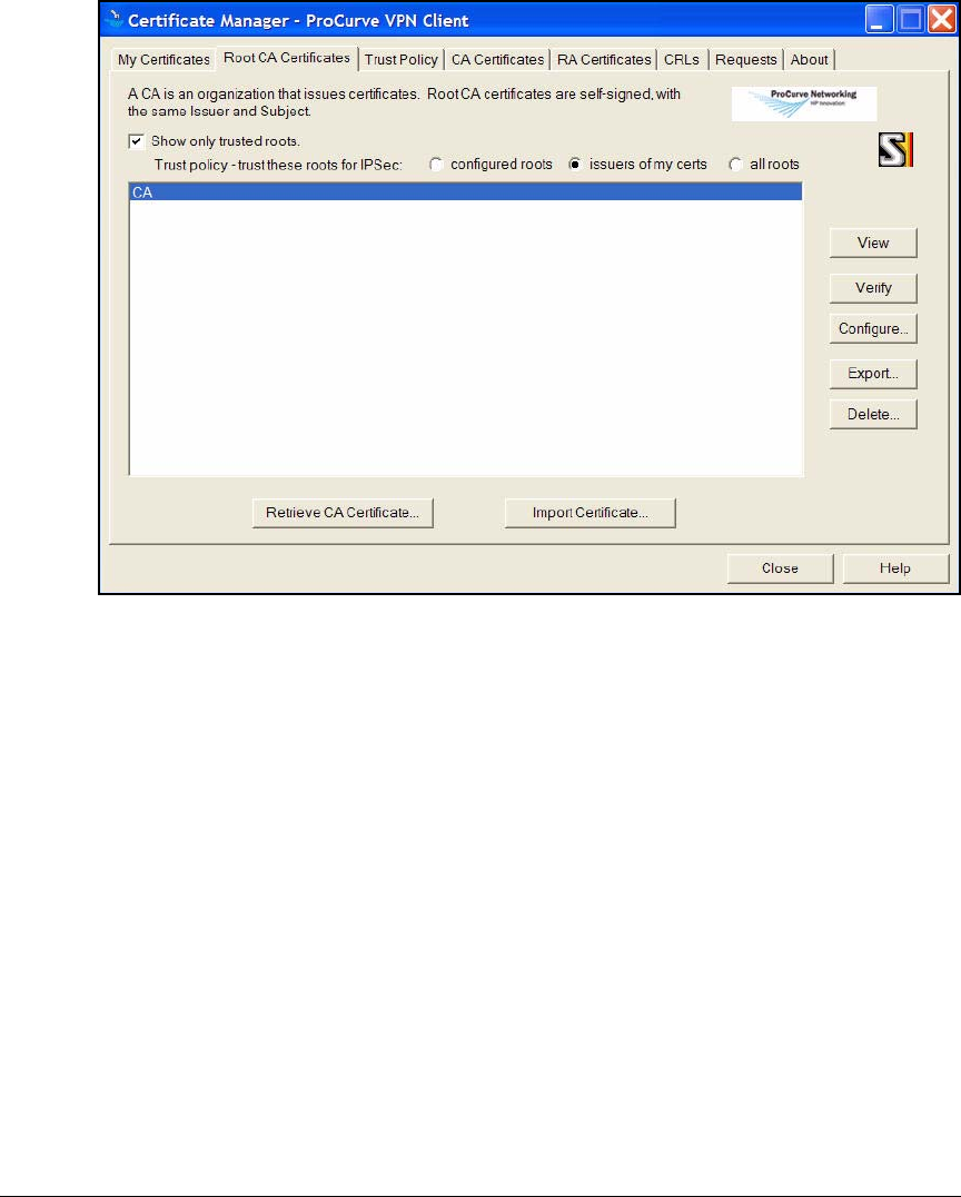
4-192
Implementing a VPN with Endpoint Integrity
Set Up Endpoints
Figure 4-114.Certificate Manager > Root CA Certificates Tab in the ProCurve
VPN Client
5. Select the CA root certificate.
6. Click Export.
7. Navigate to the prepackaged installation directory.
8. For File name, type: CaCert.
Use this exact filename to ensure that the certificate imports automati-
cally when the user installs the ProCurve VPN Client.
9. For Save as type, leave the default: Serialized certificate files (*.cser).
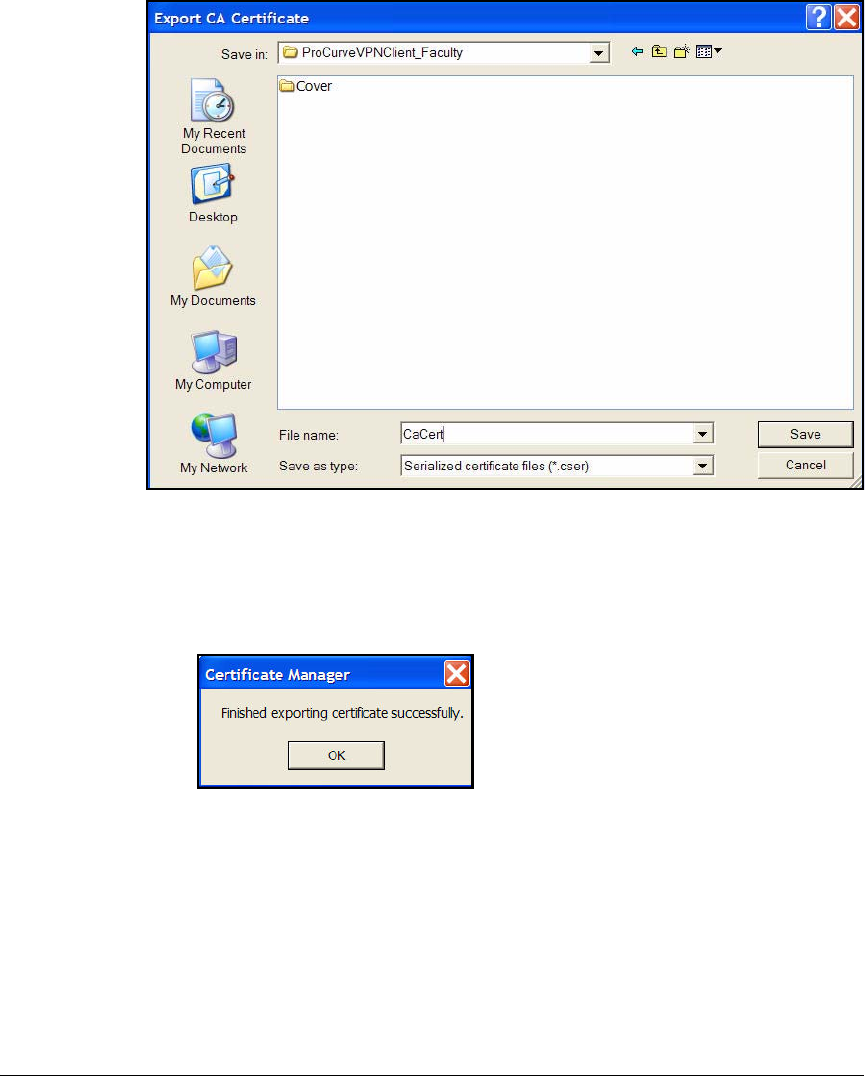
4-193
Implementing a VPN with Endpoint Integrity
Set Up Endpoints
Figure 4-115.Export CA Certificate Window
10. Click Save.
11. You should see the window shown in Figure 4-113.
Figure 4-116.Certificate Manager Window
Distribute the Prepackaged Installations. You can distribute the pre-
packaged installation directories through a network directory, a CD, or a Web
site.
Verbally inform users of the passwords that protect:
■Their policy
■Their VPN client certificate

4-194
Implementing a VPN with Endpoint Integrity
Set Up Endpoints
And tell the users the name in their personal certificate so that they can choose
the correct certificate in their My Identity settings.
Table 4-28 summarizes this information for PCU; you can fill in your settings
in Table 4-29.
Table 4-28. PCU Prepackaged Installations
Table 4-29. My Prepackaged Installations
Also distribute instructions such as the ones in the section below.
User Instructions: Install the ProCurve VPN Client and
the Preconfigured Policy
To install the ProCurve VPN Client and import the policy, complete these
simple steps:
1. Open the installation directory.
2. Double-click the extracted Setup.exe file. The Welcome page is displayed.
3. Click Next. The License Agreement page is displayed.
4. Click Yes. The Setup Type page is displayed.
PCU Faculty Member Installation PCU Student Installation
Directory name ProCurveVPNClient_Faculty ProCurveVPNClient_Students
Policy password ProCurve3 ProCurve4
VPN client certificate password ProCurve3 ProCurve4
VPN client certificate name professor student
Installation 1 Installation 2
Directory name
Policy password
VPN client certificate password
VPN client certificate name
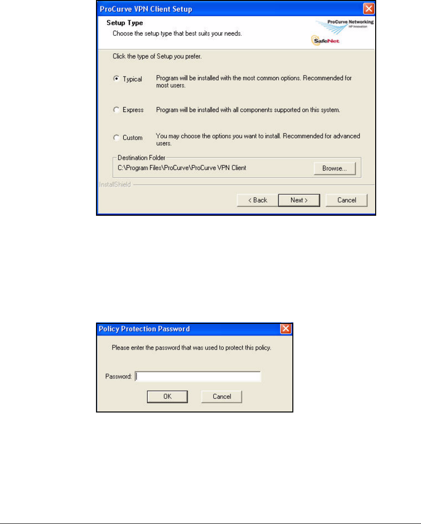
4-195
Implementing a VPN with Endpoint Integrity
Set Up Endpoints
Figure 4-117.Setup Type Page in the ProCurve VPN Client Setup Program
5. Select Typical and click Next. The Start Copying Files page is displayed.
6. Click Next. The installation process begins.
7. When the Policy Protection Password window is displayed, type the pass-
word that your network administrator told you for the policy.
Figure 4-118.Policy Protection Password Window
8. Click OK.

4-196
Implementing a VPN with Endpoint Integrity
Set Up Endpoints
Figure 4-119.InstallShield Wizard Complete Page in the ProCurve VPN Client Setup
Program
9. When the
InstallShield Wizard Complete
page is displayed, select
Yes, I want
to restart my computer now
and click
Finish
.
10. After your computer restarts, you should see the
Load Certificates and Keys
window.
Figure 4-120.Load Certificates and Keys Window
11. For
Password
, type the password that you network administrator told you
for the VPN client certificate password.
12. Click
Load
.
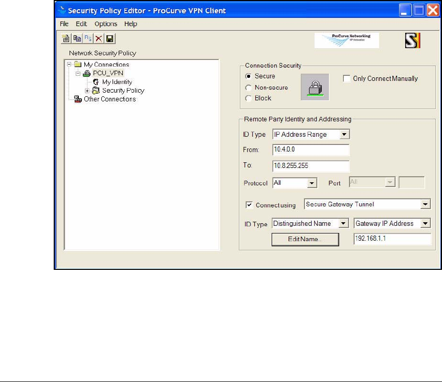
4-197
Implementing a VPN with Endpoint Integrity
Set Up Endpoints
13. From the
Start
menu, select
Programs
>
ProCurve VPN Client
>
Security Policy
Editor
.
The notification area of the Windows taskbar now contains an icon for
the ProCurve VPN Client. You can also right-click this icon and click
Security Policy Editor.
14. You should see a connection listed under My Connections in the left pane.
The connection should have a closed lock icon like the PCU_VPN connec-
tion in Figure 4-121.
If you do not see this connection, the policy failed to import. See “Import
the Policy Manually” on page 4-199.
15. Expand the connection.
Figure 4-121.Security Policy Editor in the ProCurve VPN Client
16. Click
My Identity
. The right pane displays settings for your local ID, as shown
in Figure 4-122.
17. From the
Selected Certificate
box, select the certificate that your network
administrator informed you is yours (or that you obtained yourself).
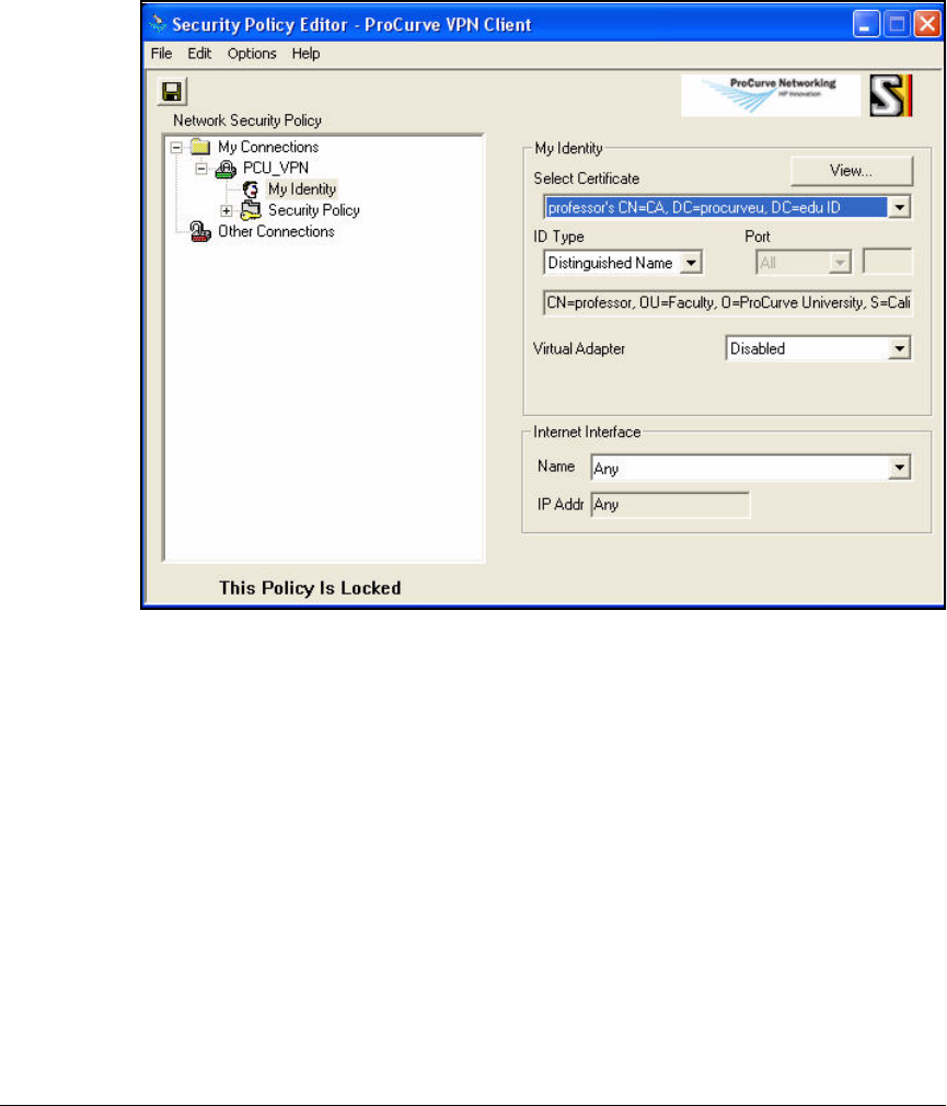
4-198
Implementing a VPN with Endpoint Integrity
Set Up Endpoints
If the certificate is not listed, you must manually import it. See “Manually
Import Certificates” on page 4-201.
Figure 4-122.Security Policy Editor > My Identity Window in the ProCurve VPN
Client
18. Select File > Save.
When you want to establish the VPN connection, follow these steps:
1. Right-click the ProCurve VPN Client icon in the right of the Windows
taskbar.
2. Select Connect > MyConnections\<connection name>.
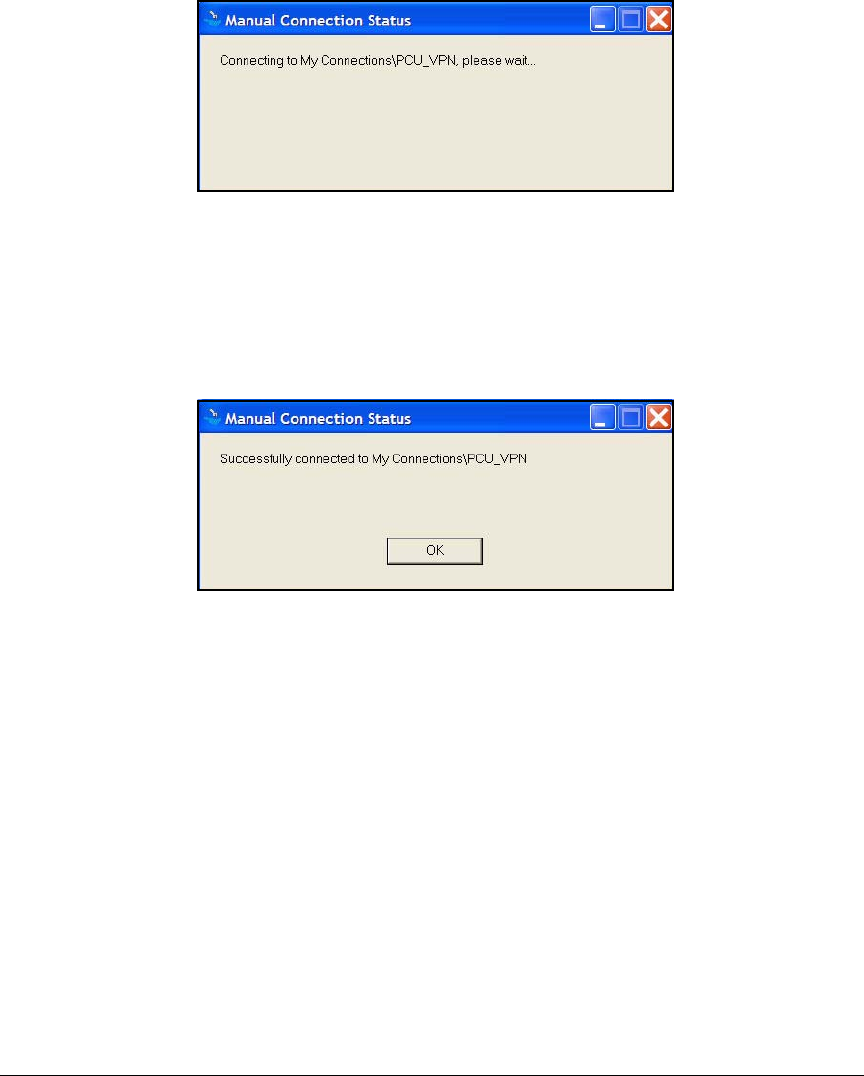
4-199
Implementing a VPN with Endpoint Integrity
Set Up Endpoints
Figure 4-123.Manual Connection Status Window in the
ProCurve VPN Client
3. Wait while the VPN tunnel is established. After a minute or two, you should
see the window shown in Figure 4-124.
You have successfully connected.
Figure 4-124.Manual Connection Status Window in the
ProCurve VPN Client—Success
If you do not see this window, contact your network administrator for help.
Import the Policy Manually
If the policy failed to import when you installed the ProCurve VPN Client,
follow these steps:
1. Open the Security Policy Editor (from the Start menu, select Programs >
ProCurve VPN Client > Security Policy Editor).
2. Select File > Import Security Policy. The Import Policy From window is
displayed.
3. Navigate to the prepackaged installation folder.
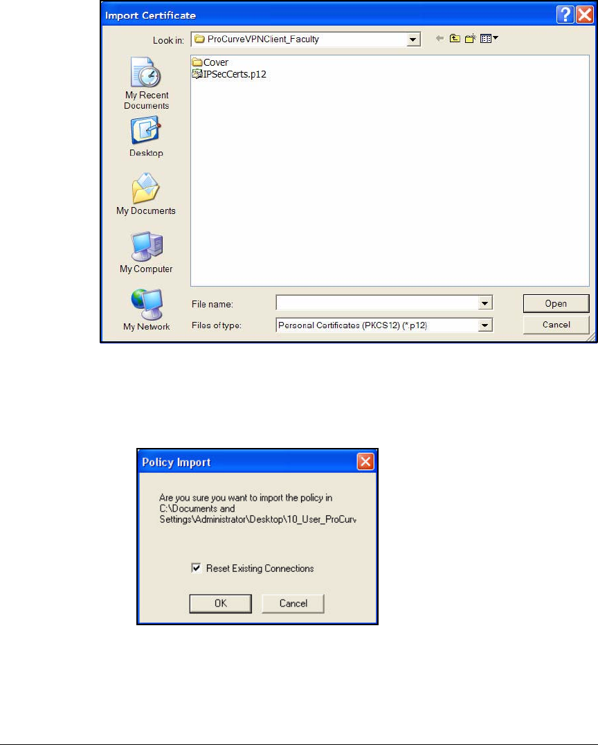
4-200
Implementing a VPN with Endpoint Integrity
Set Up Endpoints
Figure 4-125.Import Certificate Window
4. Locate and select the IPSecPolicy.spd file and then click Open. The Policy
Import window is displayed.
Figure 4-126.Policy Import Window in the ProCurve VPN Client
5. Click
OK
to verify that you want to import the policy.
6.
If the
Policy Protection Password window is displayed, type the password
that your network administrator gave you for the policy.
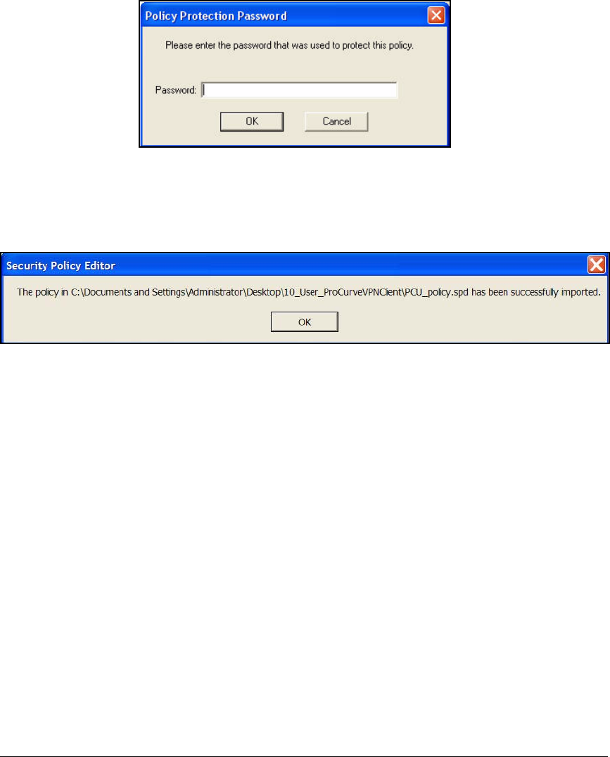
4-201
Implementing a VPN with Endpoint Integrity
Set Up Endpoints
Figure 4-127.Policy Protection Password Window
7. A confirmation message is displayed, telling you the security policy was
imported successfully. Click
OK
.
Figure 4-128.Security Policy Editor Message
Manually Import Certificates
Your VPN client requires two certificates:
■A CA certificate
■A personal certificate for your client
These certificates should be saved in your prepackaged installation directory.
The CA certificate probably has an extension such as .cser or .cer. The personal
certificate probably has an extension such as .cer, .der, or .p12.
Follow these steps to import the certificates:
1. From the Windows Start menu, select Programs > ProCurve VPN Client >
Certificate Manager.
2. Click the My Certificates tab.
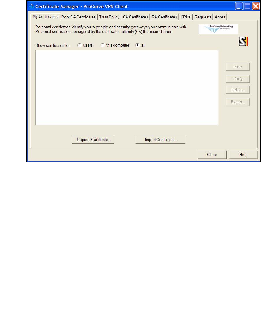
4-202
Implementing a VPN with Endpoint Integrity
Set Up Endpoints
Figure 4-129.Certificate Manager > My Certificates Tab in the ProCurve VPN Client
3. Click Import Certificate.
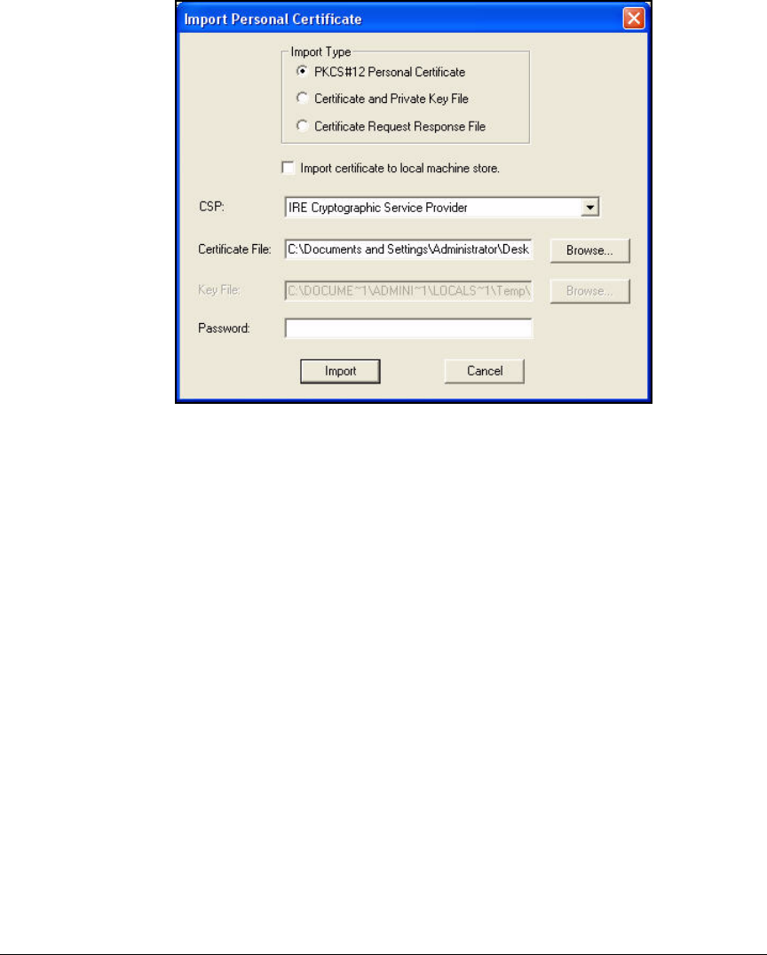
4-203
Implementing a VPN with Endpoint Integrity
Set Up Endpoints
Figure 4-130.Import Personal Certificate Window in the ProCurve
VPN Client
4. For Import Type, leave PKCS#12 Personal Certificate.
5. For Certificate File, click Browse to search for the file.
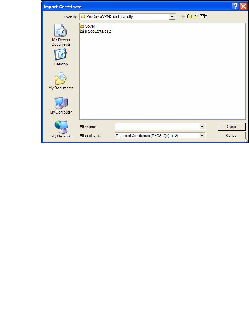
4-204
Implementing a VPN with Endpoint Integrity
Set Up Endpoints
Figure 4-131.Import Certificate Window
6. Navigate to your prepackaged installation directory. Or, if you obtained
your own certificate, navigate to the directory to which you saved it.
7. Select the certificate file. If you do not see the file in the window that is
displayed, try selecting All Files from the Files of type box.
8. Click Open.
9. If necessary, in the Import Personal Certificate window, in the Password box,
type the password that your network administrator gave you for the VPN
client certificate.
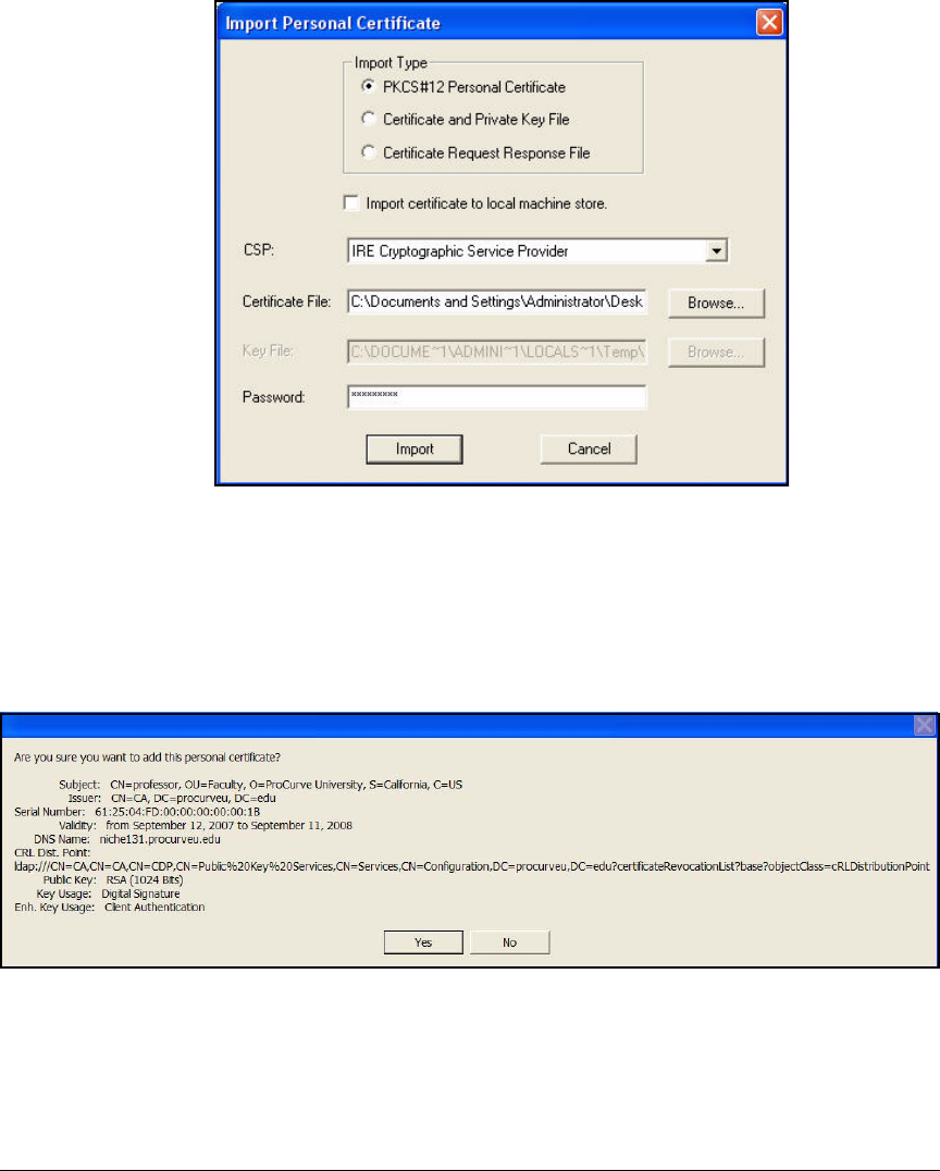
4-205
Implementing a VPN with Endpoint Integrity
Set Up Endpoints
Figure 4-132.Import Personal Certificate Window in the ProCurve
VPN Client
10. Click Import.
11. A window is displayed that asks you to confirm the installation of the
certificate. Click Yes.
Figure 4-133.Verify Import Personal Certificate in the ProCurve VPN Client
12. In the Certificate Manager, click the CA Root Certificates tab.
13. Click Import.
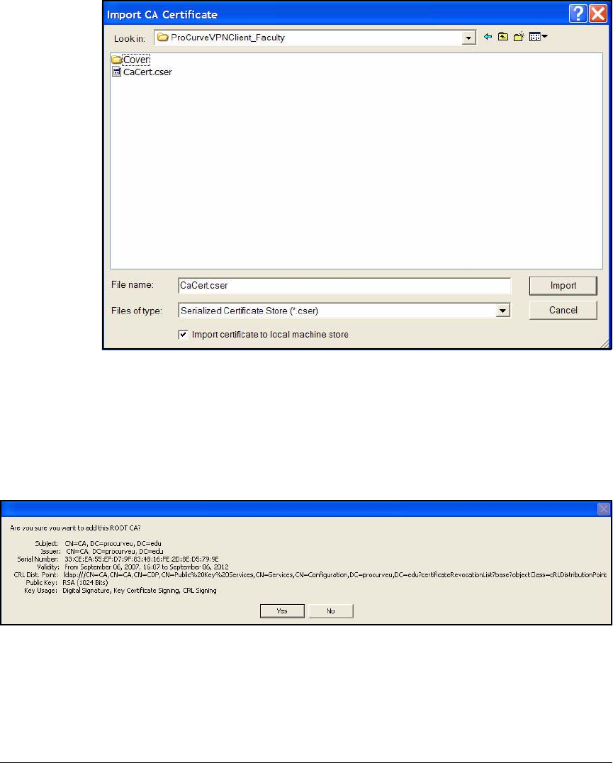
4-206
Implementing a VPN with Endpoint Integrity
Set Up Endpoints
Figure 4-134.Import CA Certificate
14. Navigate to the prepackaged installation directory, and select the CA
certificate. If you do not see the file in the window that is displayed, try
selecting All Files from the Files of type box.
15. Click Import.
Figure 4-135.Verify Import CA Certificate in the ProCurve VPN Client
16. When the window shown in Figure 4-135 is displayed, click Yes.
17. When asked if you want to trust the CA, click Yes.

5-1
5
Using the NAC 800 in a RADIUS-Only
Configuration
Contents
Introduction . . . . . . . . . . . . . . . . . . . . . . . . . . . . . . . . . . . . . . . . . . . . . . . . . . . 5-4
Configuring This Access Control Solution . . . . . . . . . . . . . . . . . . . . . . . 5-6
Example—the Existing Network Environment . . . . . . . . . . . . . . . . . . 5-6
VLANs . . . . . . . . . . . . . . . . . . . . . . . . . . . . . . . . . . . . . . . . . . . . . . . . . 5-7
DHCP and DNS Services . . . . . . . . . . . . . . . . . . . . . . . . . . . . . . . . . 5-10
Switches . . . . . . . . . . . . . . . . . . . . . . . . . . . . . . . . . . . . . . . . . . . . . . . . . . . . . . 5-11
Concurrent Access Methods on the Same Port . . . . . . . . . . . . . . . . . . 5-11
Routing Switch Startup-Config . . . . . . . . . . . . . . . . . . . . . . . . . . . . 5-14
Server Switch Startup-Config . . . . . . . . . . . . . . . . . . . . . . . . . . . . . 5-16
Edge Switch Startup-Configs . . . . . . . . . . . . . . . . . . . . . . . . . . . . . 5-18
Configure the Wireless Edge Services Module . . . . . . . . . . . . . . . . . . . . . . 5-21
Configure Initial Settings on the Wireless Edge Services
Modules . . . . . . . . . . . . . . . . . . . . . . . . . . . . . . . . . . . . . . . . . . . . . . . . . . 5-22
Configure WLAN Settings . . . . . . . . . . . . . . . . . . . . . . . . . . . . . . . . . . . . 5-24
Configure 802.1X as the Security for WLAN 1 . . . . . . . . . . . . . . . 5-25
Configure Web-Auth for WLANs 2 and 3 . . . . . . . . . . . . . . . . . . . . 5-33
Copying Logo Files to the Module’s Flash . . . . . . . . . . . . . . . . . . . . . . 5-50
Configure SNMP on the Wireless Edge Services Modules . . . . . . . . . 5-52
802.1X Authentication for RPs . . . . . . . . . . . . . . . . . . . . . . . . . . . . . . . . 5-60
Configure 802.1X Authentication for RPs . . . . . . . . . . . . . . . . . . . 5-61
Configure OpenLDAP . . . . . . . . . . . . . . . . . . . . . . . . . . . . . . . . . . . . . . . . . . . 5-63
Extend the OpenLDAP Schema to Support RADIUS . . . . . . . . . . . . . 5-64
Objects in the Standard OpenLDAP Schema . . . . . . . . . . . . . . . . 5-64
Create and Modify Files to Extend the Schema . . . . . . . . . . . . . . 5-65
RADIUS Objects . . . . . . . . . . . . . . . . . . . . . . . . . . . . . . . . . . . . . . . . 5-67

5-2
Using the NAC 800 in a RADIUS-Only Configuration
Contents
Create Objects in OpenLDAP . . . . . . . . . . . . . . . . . . . . . . . . . . . . . . . . 5-67
Bind to OpenLDAP . . . . . . . . . . . . . . . . . . . . . . . . . . . . . . . . . . . . . . . . . 5-73
Base DN and Administrator . . . . . . . . . . . . . . . . . . . . . . . . . . . . . . 5-74
Configure a Root CA with OpenSSL . . . . . . . . . . . . . . . . . . . . . . . . . . . 5-74
Create an Intermediate Certificate . . . . . . . . . . . . . . . . . . . . . . . . . . . . 5-77
Copy the Keys and Certificates to OpenLDAP . . . . . . . . . . . . . . . . . . 5-80
Configure the NAC 800 for a RADIUS-Only Deployment . . . . . . . . . . . . . 5-81
Data Store Overview . . . . . . . . . . . . . . . . . . . . . . . . . . . . . . . . . . . . . . . . 5-81
Configuration Options . . . . . . . . . . . . . . . . . . . . . . . . . . . . . . . . . . . . . . 5-82
Initial Setup . . . . . . . . . . . . . . . . . . . . . . . . . . . . . . . . . . . . . . . . . . . . 5-83
Device Access . . . . . . . . . . . . . . . . . . . . . . . . . . . . . . . . . . . . . . . . . . 5-83
Specify the Quarantine Method (802.1X) . . . . . . . . . . . . . . . . . . . . . . . 5-83
Configure Authentication to an OpenLDAP Server . . . . . . . . . . . . . . 5-85
Test Authentication Settings . . . . . . . . . . . . . . . . . . . . . . . . . . . . . . . . . 5-89
Add NASs as 802.1X Devices . . . . . . . . . . . . . . . . . . . . . . . . . . . . . . . . . 5-94
Apply Changes . . . . . . . . . . . . . . . . . . . . . . . . . . . . . . . . . . . . . . . . . . . . . 5-98
Restart the RADIUS Server . . . . . . . . . . . . . . . . . . . . . . . . . . . . . . . . . . 5-98
Configure Exceptions . . . . . . . . . . . . . . . . . . . . . . . . . . . . . . . . . . . . . . 5-101
Configure Exceptions for the Cluster Default Settings . . . . . . . . . . 5-102
Configure Exceptions for a Particular Cluster . . . . . . . . . . . . . . 5-105
Configuring Network Access Control with IDM . . . . . . . . . . . . . . . . . . . . 5-108
Add NAC 800s to the Access.txt File . . . . . . . . . . . . . . . . . . . . . . . . . 5-108
Import Users . . . . . . . . . . . . . . . . . . . . . . . . . . . . . . . . . . . . . . . . . . . . . 5-109
Install the OpenLDAP Server’s CA Certificate on PCM+ . . . . . 5-109
Editing IDM Configuration for LDAP Import . . . . . . . . . . . . . . . 5-111
Importing Users from an LDAP Server . . . . . . . . . . . . . . . . . . . . . . . . 5-113
Using Simple Authentication . . . . . . . . . . . . . . . . . . . . . . . . . . . . 5-115
Using Digest-MD5 Authentication . . . . . . . . . . . . . . . . . . . . . . . . 5-116
Using Kerberos-V5 Authentication . . . . . . . . . . . . . . . . . . . . . . . 5-117
Using External Authentication . . . . . . . . . . . . . . . . . . . . . . . . . . . 5-118
Using Anonymous Authentication . . . . . . . . . . . . . . . . . . . . . . . . 5-120
Extracting User and Group Information . . . . . . . . . . . . . . . . . . . 5-121
Define Resources . . . . . . . . . . . . . . . . . . . . . . . . . . . . . . . . . . . . . . . . . 5-127
Configure Locations . . . . . . . . . . . . . . . . . . . . . . . . . . . . . . . . . . . . . . . 5-131

5-3
Using the NAC 800 in a RADIUS-Only Configuration
Contents
Configure Times . . . . . . . . . . . . . . . . . . . . . . . . . . . . . . . . . . . . . . . . . . 5-133
Configure Holidays . . . . . . . . . . . . . . . . . . . . . . . . . . . . . . . . . . . . 5-135
Create Access Profiles . . . . . . . . . . . . . . . . . . . . . . . . . . . . . . . . . . . . . 5-137
Configure Access Policy Groups . . . . . . . . . . . . . . . . . . . . . . . . . . . . . 5-145
Configure Access Policy Group Rules . . . . . . . . . . . . . . . . . . . . . . . . 5-146
Configure Endpoints . . . . . . . . . . . . . . . . . . . . . . . . . . . . . . . . . . . . . . . . . . 5-150
Configuring the Wireless Zero Configuration Utility
for Wired Access . . . . . . . . . . . . . . . . . . . . . . . . . . . . . . . . . . . . . . . . . . 5-150
Configuring the Wireless Zero Configuration Utility
for Wireless Access . . . . . . . . . . . . . . . . . . . . . . . . . . . . . . . . . . . . . . . . 5-153
Enable WZC . . . . . . . . . . . . . . . . . . . . . . . . . . . . . . . . . . . . . . . . . . . . . . 5-158

5-4
Using the NAC 800 in a RADIUS-Only Configuration
Introduction
Introduction
This chapter explains how to implement an access control solution for an
existing wired network, which uses a directory service to control access to
data and applications. Specifically, this chapter explains how to set up 802.1X
as the predominant access control method for wired access with MAC authen-
tication (MAC-Auth) enforced for devices that do not support 802.1X.
In addition, this chapter explains how to set up Wireless LANs (WLANs),
which provide wireless services for different types of users. Accordingly, there
are several WLANs, and different access control methods are enforced for
each one:
■802.1X with Wi-Fi Protected Access (WPA)/WPA2
■Web authentication (Web-Auth) without encryption for the wireless trans-
missions
■Web authentication (Web-Auth) with WPA preshared key (WPA-PSK)
encryption
This access control solution does not enforce endpoint integrity.
This chapter provides detailed instructions for setting up this network access
control solution. To help you, the instructions include examples, which have
been designed for a hypothetical organization—the Medical Center associated
with ProCurve University.
Currently, the Medical Center is using Open Lightweight Directory Access
Protocol (OpenLDAP) to secure access to data and applications on the net-
work (although the Medical Center could just as easily be using Novell
eDirectory or Microsoft Active Directory). The IT staff has been asked to
implement a wireless network, which provides wireless access for employees
as well as patients. In addition, the IT staff must accommodate “headless”
devices such as Voice-over-IP (VoIP) phones and printers. (“Headless” refers
to devices that do not have a user interface.)
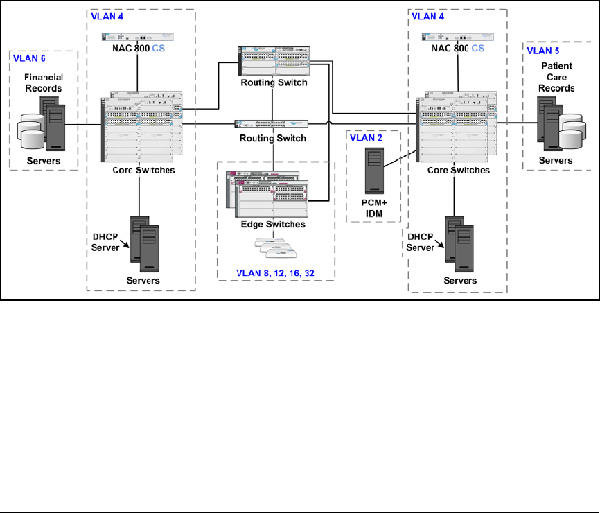
5-5
Using the NAC 800 in a RADIUS-Only Configuration
Introduction
As part of this effort, the IT staff has evaluated network security overall and
has conducted a needs assessment. (For more information about such an
assessment, see the ProCurve Access Control Security Design Guide.) From
this assessment, the IT staff has recommended that the Medical Center
strengthen network security by implementing:
■Access controls at the network edge when users attempt to access the
network
■Endpoint integrity
However, the Medical Center administration is concerned about the impact of
implementing both security measures at the same time. The Medical Center
administrators want to implement network access controls first and then
impose endpoint integrity checking in six months.
Figure 5-1. Sample Network for the Medical Center

5-6
Using the NAC 800 in a RADIUS-Only Configuration
Introduction
Configuring This Access Control Solution
In this chapter, you will learn how to configure, from beginning to end, the
components that provide the access control solution for the Medical Center
network:
■ProCurve Network Access Controller (NAC) 800s, which provide RADIUS
services
■ProCurve Identity Driven Manager (IDM), which is a a plug-in for Pro-
Curve Manager Plus (PCM+)
■ProCurve Wireless Edge Services Module, which controls multiple coor-
dinated (or lightweight) Access Points (APs) referred to as radio ports
(RPs)
■OpenLDAP, which is an LDAPv3 open source directory
■802.1X supplicants, which enable users to log in to an 802.1X-enabled
network
■Concurrent MAC-Auth and 802.1X access
In addition, this chapter provides the startup-configs for:
■Routing switch
■Server switch
■Edge Switches
Although your network environment is not identical to the Medical Center
network, the instructions should help you understand the processes involved
so that you can then modify the instructions as needed for your organization’s
unique environment.
Example—the Existing Network Environment
As discussed in the ProCurve Access Control Security Design Guide, you
must thoroughly understand your network environment before you begin to
implement an access control solution. When you conduct a needs assessment,
one of the first things you will try to discover is the users and the groups who
need to access the network.
For example, the Medical Center network serves the following groups:
■Network administrators
■Doctors and nurses
■Staff (except the Accounting department)
■Accounting department
■Patients

5-7
Using the NAC 800 in a RADIUS-Only Configuration
Introduction
Depending on the size of your organization, you may have many more groups.
VLANs
The Medical Center network is divided into virtual LANs (VLANs) that allow
users to access the resources they require. Table 5-1 shows one approach to
designing the VLANs.
Table 5-1. VLANs
As you can see, the VLANs divide into these general categories:
■Management VLAN—for infrastructure devices and the network admin-
istrators that manage them
■Server VLANs—for servers
In this example, servers are placed in different VLANs according to which
users need to access them. All users need to be able to access the servers
in VLAN 4. These include the OpenLDAP, DHCP, DNS, email, Web, and
directory servers. VLAN 5 houses the servers that hold patient care
information and the related applications. Only the doctors, nurses, and
other patient care staff should be able to access these servers. Finally,
only the Accounting department should be able to reach billing and
patients’ insurance information stored on the servers in VLAN 6.
■User VLANs—one for each user group
You could create VLANs for users according to when and how they
connect to the network. In this example, however, a particular user always
receives the same VLAN assignment, and IDM is used to grant users
various resources under various conditions.
Name ID Subnet
Network management and network administrators 2 10.2.0.0/16
Servers (OpenLDAP, DHCP, DNS, email, Web, scheduling
database)
Printers and VoIP phones
4 10.4.0.0/16
Patient care servers (patient care records and related
user applications)
5 10.5.0.0/16
Accounting servers (financial and insurance records) 6 10.6.0.0/16
Medical (doctors and nurses) 8 10.8.0.0/16
Staff (except Accounting) 12 10.12.0.0/16
Accounting 16 10.16.0.0/16
Patients 32 10.32.0.0/16
Radio Port VLAN for the RPs 2100 N/A

5-8
Using the NAC 800 in a RADIUS-Only Configuration
Introduction
You can use Table 5-2 to record VLANs used in your network.
Table 5-2. VLANs for Your Network
The Medical Center uses the addressing scheme outlined in Table 5-3. You can
use the rows provided to record the IP addresses used in your network. Then,
you can insert your IP addresses in the steps provided in this chapter.
Name ID Subnet

5-9
Using the NAC 800 in a RADIUS-Only Configuration
Introduction
Table 5-3. Example IP Addresses
Device IP Address VLAN ID Your Network IP Addresses Your VLAN ID
OpenLDAP server 10.2.1.10 2
DNS servers 10.4.4.15
10.4.5.15
4
DHCP server 10.4.7.20 4
Hospital Web server 10.4.6.30 4
Email server 10.4.6.40 4
Medical history database 10.5.1.45 5
Medical dictionary and diagnosis
database
10.5.2.55 4
Insurance records 10.6.2.50 6
Billing database 10.6.2.60 6
PCM+/IDM server 10.2.0.50 2
Routing switch
(3500yl Switch)
• 10.2.0.1
• 10.4.0.1
• 10.5.0.1
• 10.6.0.1
• 10.8.0.1
• 10.12.0.1
• 10.16.0.1
• 10.32.0.1
•2
•4
•5
•6
•8
•12
•16
•32
Edge switch
(5300zl Switch)
• 10.2.0.3
• 10.4.0.2
• 10.5.0.1
• 10.6.0.1
• 10.8.0.2
• 10.12.0.2
• 10.16.0.2
•2
•4
•5
•6
•8
•12
•16
Switch A
(5400zl Switch)
10.2.0.5 • 2
•4
Wireless Edge Services Module 10.2.0.99 2
NAC 800 CS A 10.4.7.50 4
NAC 800 CS B 10.4.6.50 4

5-10
Using the NAC 800 in a RADIUS-Only Configuration
Introduction
DHCP and DNS Services
You must have a functioning DHCP server and DNS server, properly config-
ured for your network environment. For the example Medical Center network,
the network administrators have configured the DHCP scopes listed in
Table 5-4.
Table 5-4. DHCP Scopes
In addition, the network administrators have configured their DNS servers
with the following reverse lookup zones:
■10.2.0.0/16
■10.4.0.0/16
■10.5.0.0/16
■10.6.0.0/16
■10.8.0.0/16
■10.12.0.0/16
■10.16.0.0/16
■10.32.0.0/16
Scope VLAN Subnet Range Default
Gateway
DNS Server Other Options
Management 2 10.2.0.0/16 10.2.16.0-
10.2.16.255
10.2.0.1
10.2.0.2
10.4.4.15
10.4.8.15
domain name=
medcenter.com
Medical
(doctors and
nurses)
8 10.8.0.0/16 10.8.16.0-
10.8.19.254
10.8.0.1
10.8.0.2
10.4.4.15
10.4.8.15
domain name=
medcenter.com
Staff (except
Accounting)
12 10.12.0.0/16 10.12.16.0-
10.12.19.254
10.12.0.1
10.12.0.2
10.4.4.15
10.4.8.15
domain name=
medcenter.com
Accounting 16 10.16.0.0/16 10.16.16.0-
10.16.19.254
10.16.0.1
10.16.0.2
10.4.4.15
10.4.8.15
domain name=
medcenter.com
Patients 32 10.32.0.0/16 10.32.16.0-
10.32.29.254
10.32.0.1
10.32.0.2
10.4.4.15
10.4.8.15
domain name=
medcenter.com

5-11
Using the NAC 800 in a RADIUS-Only Configuration
Switches
Switches
This section provides example configurations for:
■A routing switch, which connects only to other switches.
■A server switch, which connects to VLAN 4, 5, and 6 servers. Its uplink
ports are A1 and B1.
■An edge switch, which connects to endpoints. Its uplink ports are A1 and
B1. The edge switch is also a wireless services-enabled switch.
Refer to the following sample configurations as you set up your network. If
you need step-by-step instructions, you should consult the documentation for
your switch.
You can configure all of the settings manually, or you can create a minimal
configuration (with IP, SNMP, and VLAN settings) and then use PCM+ to
configure other settings.
Note In the startup-configs shown below, ports that connect to users’ endpoints are
not tagged for user VLANs because the users will receive dynamic VLAN
assignments through IDM. The ports that connect to printers and VoIP phones
are untagged members of VLAN 4.
Concurrent Access Methods on the Same Port
This section provides example configurations for ProCurve switches in a
network that implements:
■802.1X port authentication for the majority of endpoints
■MAC-Auth for some endpoints
On the example network, some ports require concurrent MAC-Auth and
802.1X authentication because the network includes headless devices, such
as printers and VoIP phones, which don’t support 802.1X, and the Medical
Center network administrators do not want to track which ports connect to
these devices and which connect to users’ workstations. In addition, users
might unplug their phone and workstation and reconnect them to different
ports. The Medical Center network administrators do not want to receive
support calls when users cannot access the network because they inadver-
tently plugged their workstation into a port that is enabled for MAC-Auth,
rather than 802.1X. By enabling both, the Medical Center network administra-
tors will allow the ports to apply MAC-Auth for devices and 802.1X for users.

5-12
Using the NAC 800 in a RADIUS-Only Configuration
Switches
There are other reasons for enabling MAC-Auth and 802.1X concurrently on
the same port. For example, your organization might want to use PXE imaging
to re-image workstations. For this scenario, you would want a user’s worksta-
tion to authenticate first via MAC-Auth and boot to a PXE server, receive an
image, and reboot with the new OS. You would then want the user to authen-
ticate through 802.1X.
You might also want to enable both MAC-Auth and 802.1X on the same port
so that you can authenticate new workstations via MAC-Auth and allow them
to access the Windows domain controller. Or, VoIP and users might connect
their VoIP phone and workstation to the same switch port. The VoIP phones
must be authenticated through MAC-Auth, and the users must be authenti-
cated through 802.1X.
In some environments, you might want to enable Web-Auth and 802.1X on the
same port instead. (MAC-Auth and Web-Auth are mutually exclusive. You
cannot enable them both on the same port.) For example, you might want to
allow guests to access the network on ports that are typically used by employ-
ees who are authenticated through 802.1X. You might also choose this config-
uration if you have some endpoints that do not support 802.1X. For these
endpoints, you want users to authenticate using Web-Auth. However, you do
not want to track which ports connect to these endpoints, so you decide to
enable both Web-Auth and 802.1X on your ports.
To set up concurrent access methods on the same port, you must configure
the switch to use 802.1X in user-based mode, rather than port-based mode.
In user-based mode, the port supports multiple authenticated clients. The
number of authenticated clients supported per port varies, depending on the
switch. For example, the 3500yl, 5400zl, and 6200yl Switches support up to 32
authenticated clients per port with user-based mode.
Requiring each of the multiple users or endpoints to authenticate before being
granted access strengthens security. At the same time, access to unauthenti-
cated users and endpoints is denied.
Port-based authentication, on the other hand, allows a single client to open
the port. However, it does not limit the clients that can subsequently access
the network through that port. Once a single client authenticates, any addi-
tional clients that access the network through that port are not required to
authenticate; the additional clients simply use the login credentials of the
authenticated user. Consequently, port-based mode is used for switch-to-
switch links.

5-13
Using the NAC 800 in a RADIUS-Only Configuration
Switches
When combined with MAC-Auth or Web-Auth, 802.1X in port-based mode is
subordinate. If 802.1X operates in port-based mode and MAC-Auth or Web-
Auth is enabled on the same port, the endpoint must successfully authenticate
through MAC-Auth or Web-Auth before the user can authenticate through
802.1X. As usual with port-based authentication, only one client must com-
plete 802.1X authentication. However, each client must authenticate through
Web-Auth or MAC-Auth.
In summary, you should configure 802.1X in user-based mode, and combine it
with MAC-Auth (or Web-Auth), when you want a switch port to enforce either
of the authentication methods on each client.
To configure the switch to use 802.1X in user-based mode, complete the
following steps:
1. Enable 802.1X on the selected ports. From the global configuration mode
context, type:
2. Configure 802.1X user-based authentication for those ports.:
Syntax: aaa port-access authenticator <port-list>
Enables the specified ports to operate as 802.1X authentica-
tors. 802.1X functions in port-based mode. (You must com-
plete step 2 to change it to user-based mode.)
Replace <port list> with the ports on which you want to enforce
802.1X in user-based mode.
Syntax: aaa port-access authenticator <port-list> client-limit <1–32>
Configures the specified ports to use 802.1X in user-based
mode.
Replace <port list> with the ports on which you want to enforce
802.1X in user-based mode.
Replace <1–32> with the number of client sessions you want
to allow on the specified ports.
If a port currently has no authenticated client sessions, the
next authenticated client session the port accepts determines
the untagged VLAN membership to which the port is assigned
during the session. If another client session begins later on
the same port while an earlier session is active, the later
session will be on the same untagged VLAN membership as
the earlier session.

5-14
Using the NAC 800 in a RADIUS-Only Configuration
Switches
3. Configure the 802.1X authentication method.
4. Specify the RADIUS host.
5. Enable 802.1X authentication on the switch.
After you configure 802.1X in user-based mode, you can configure MAC-Auth
as shown in “Edge Switch Startup-Configs” on page 5-18.
Routing Switch Startup-Config
; J8692A Configuration Editor; Created on release #K.12.XX
hostname “Routing_Switch”
module 1 type J86xxA
ip routing
snmp-server community "procurvero" Operator
snmp-server community "procurverw" Manager Unrestricted
snmp-server host 10.2.0.50 "public"
vlan 1
name "DEFAULT_VLAN"
no untagged 1-20
no ip address
exit
Syntax: aaa authentication port-access <local | eap-radius | chap-radius>
Determines the type of RADIUS authentication to use.
Include the appropriate option for the type of authentication
you want to use—local, EAP RADIUS, or CHAP-RADIUS
(MD5).
Syntax: radius host <ip-address> [key <key-string>]
Specifies the RADIUS server that the switch should contact to
verify login credentials.
Include the key option and replace <key-string> with the shared
key if it is required for the RADIUS server.
Syntax: aaa port-access authenticator active
Enables 802.1X authentication on the specified ports.

5-15
Using the NAC 800 in a RADIUS-Only Configuration
Switches
vlan 2
name "Management"
untagged 1-20
ip helper-address 10.4.7.20
ip address 10.2.0.1 255.255.0.0
exit
vlan 4
name "Servers"
ip address 10.4.0.1 255.255.0.0
tagged 11-20
exit
vlan 5
name "PatientServers"
ip address 10.5.0.1 255.255.0.0
tagged 11-20
exit
vlan 6
name "AcctgServers”
ip address 10.6.0.1 255.255.0.0
tagged 11-20
exit
vlan 8
name "Medical"
ip helper-address 10.4.7.20
ip address 10.8.0.1 255.255.0.0
tagged 1-10
exit
vlan 12
name "Staff"
ip helper-address 10.4.7.20
ip address 10.12.0.1 255.255.0.0
tagged 1-10
exit
vlan 16
name "Accounting"
ip helper-address 10.4.7.20
ip address 10.16.0.1 255.255.0.0
tagged 1-10
exit

5-16
Using the NAC 800 in a RADIUS-Only Configuration
Switches
vlan 32
name "Patients"
ip helper-address 10.4.7.20
ip address 10.32.0.1 255.255.0.0
tagged 1-10
exit
vlan 2100
name "RPs"
tagged 1-20
no ip address
exit
ip authorized-managers 10.2.0.0 255.255.0.0
ip authorized-managers 10.4.7.50 255.255.255.255
ip authorized-managers 10.4.6.50 255.255.255.255
ip dns domain-name "MedCenter.com"
ip dns server-address 10.4.4.15
ip dns server-address 10.4.8.15
aaa authentication port-access eap-radius
radius-server host 10.4.7.50 key procurvea
radius-server host 10.4.6.50 key procurveb
aaa port-access authenticator 1-10 //These ports connect
to edge switches//
aaa port-access authenticator active //Do not enter this
command until you have completed setting up the entire
solution//
password manager
password operator
Server Switch Startup-Config
; J8697A Configuration Editor; Created on release #K.12.XX
hostname "Server_Switch"
web-management management-url ""
module 1 type J8702A
module 2 type J8702A
module 3 type J8702A
ip default-gateway 10.2.0.1
snmp-server community "procurvero" Operator
snmp-server community "procurverw" Manager Unrestricted
snmp-server host 10.2.0.50 "public"
vlan 1
name "DEFAULT_VLAN"
no untagged A1-A24,B1-B24

5-17
Using the NAC 800 in a RADIUS-Only Configuration
Switches
no ip address
exit
vlan 2100
name "RPs"
tagged A1,B1
no ip address
exit
vlan 2
name "Management"
untagged A1,B1
ip address 10.2.0.3 255.255.0.0
exit
vlan 4
name "Servers"
untagged B2-B24,C1-C24 //Ports for DNS, DHCP, email,
and OpenLDAP servers//
tagged A1,B1
no ip address
exit
vlan 5
name "PatientServers"
untagged A2-A12
tagged A1,B1
no ip address
exit
vlan 6
name "AcctgServers"
untagged A12-A24
tagged A1,B1
no ip address
exit
ip authorized-managers 10.2.0.0 255.255.0.0
ip authorized-managers 10.4.7.50 255.255.255.255
ip authorized-managers 10.4.6.50 255.255.255.255
ip dns domain-name "MedCenter.com"
ip dns server-address 10.4.4.15
ip dns server-address 10.4.8.15
aaa authentication port-access eap-radius
radius-server host 10.4.7.50 key procurvea
radius-server host 10.4.6.50 key procurveb
aaa port-access mac-based C10-C20 //Ports for printers
and other headless devices//
password manager
password operator

5-18
Using the NAC 800 in a RADIUS-Only Configuration
Switches
Edge Switch Startup-Configs
Depending on the size of your network, you may have many edge switches.
This section provides a sample configuration of an edge switch that houses
the Wireless Edge Services Module. To improve readability, however, the
encrypted Wireless Edge Services Module commands have been omitted.
; J8697A Configuration Editor; Created on release #K.12.XX
hostname "Wireless Switch"
module 1 type J8702A
module 2 type J8702A
module 3 type J9051A
web-management management-url ""
ip default-gateway 10.2.0.1
snmp-server community "procurvero" Operator
snmp-server community "procurverw" Manager Unrestricted
snmp-server host 10.2.0.50 "public"
vlan 1
name "DEFAULT_VLAN"
no untagged A1-A24,B1-B24
no ip address
exit
vlan 4
name "Servers"
untagged A2-A24,B2-B11 //Ports that might connect to
printers or VoIP phones//
tagged A1,B1
no ip address
exit
vlan 8
name "Medical"
tagged A1,B1,CUP
exit
lldp auto-provision radio-ports auto-vlan 2100 auto
vlan 2100
name "RPs"
tagged A1,B1,CDP
exit
vlan 12
name "Staff"
tagged A1,B1,CUP
exit
vlan 16

5-19
Using the NAC 800 in a RADIUS-Only Configuration
Switches
name "Accounting"
tagged A1,B1,CUP
exit
vlan 32
name "Patients"
tagged A1,B1,CUP
exit
vlan 2
name "Management"
untagged A1,B1
ip address 10.2.0.5 255.255.0.0
tagged CUP
exit
ip authorized-managers 10.2.0.0 255.255.0.0
ip authorized-managers 10.4.7.50 255.255.255.255
ip authorized-managers 10.4.6.50 255.255.255.255
ip dns domain-name "MedCenter.com"
ip dns server-address 10.4.4.15
ip dns server-address 10.4.8.15
aaa authentication port-access eap-radius
radius-server host 10.4.7.50 key procurvea
radius-server host 10.4.6.50 key procurveb
aaa port-access authenticator A2-A24,B1,B12-B24
aaa port-access authenticator A2 client-limit 10 //If A1,
an uplink port, enforced 802.1X authentication, it should
operate in port-based mode.//
aaa port-access authenticator A3 client-limit 10
aaa port-access authenticator A4 client-limit 10
aaa port-access authenticator A5 client-limit 10
aaa port-access authenticator A6 client-limit 10
aaa port-access authenticator A7 client-limit 10
aaa port-access authenticator A8 client-limit 10
aaa port-access authenticator A9 client-limit 10
aaa port-access authenticator A10 client-limit 10
aaa port-access authenticator A11 client-limit 10
aaa port-access authenticator A12 client-limit 10
aaa port-access authenticator A13 client-limit 10
aaa port-access authenticator A14 client-limit 10
aaa port-access authenticator A15 client-limit 10
aaa port-access authenticator A16 client-limit 10
aaa port-access authenticator A17 client-limit 10
aaa port-access authenticator A18 client-limit 10
aaa port-access authenticator A19 client-limit 10
aaa port-access authenticator A20 client-limit 10

5-20
Using the NAC 800 in a RADIUS-Only Configuration
Switches
aaa port-access authenticator A21 client-limit 10
aaa port-access authenticator A22 client-limit 10
aaa port-access authenticator A23 client-limit 10
aaa port-access authenticator A24 client-limit 10
aaa port-access authenticator active //Do not enter this
command until you have completed setting up the entire
solution.//
aaa port-access supplicant A1, B1
aaa port-access supplicant A1 identity "switch"
aaa port-access supplicant B1 identity "switch"
aaa port-access mac-based A2-A24, B2-B11 //Only MAC-Auth
is enabled on ports B2-B11. Either MAC-Auth or 802.1X is
enforced on each client connected to ports A2-A24.//
aaa port-access mac-based A2 addr-limit 10
aaa port-access mac-based A3 addr-limit 10
aaa port-access mac-based A4 addr-limit 10
aaa port-access mac-based A5 addr-limit 10
aaa port-access mac-based A6 addr-limit 10
aaa port-access mac-based A7 addr-limit 10
aaa port-access mac-based A8 addr-limit 10
aaa port-access mac-based A9 addr-limit 10
aaa port-access mac-based A10 addr-limit 10
aaa port-access mac-based A11 addr-limit 10
aaa port-access mac-based A12 addr-limit 10
aaa port-access mac-based A13 addr-limit 10
aaa port-access mac-based A14 addr-limit 10
aaa port-access mac-based A15 addr-limit 10
aaa port-access mac-based A16 addr-limit 10
aaa port-access mac-based A17 addr-limit 10
aaa port-access mac-based A18 addr-limit 10
aaa port-access mac-based A19 addr-limit 10
aaa port-access mac-based A20 addr-limit 10
aaa port-access mac-based A21 addr-limit 10
aaa port-access mac-based A22 addr-limit 10
aaa port-access mac-based A23 addr-limit 10
aaa port-access mac-based A24 addr-limit 10
aaa port-access A1-A24,B1,B12-B24
password manager
password operator

5-21
Using the NAC 800 in a RADIUS-Only Configuration
Configure the Wireless Edge Services Module
Configure the Wireless Edge Services
Module
This section describes how to set up the Wireless Edge Services Module to
establish a wireless network for the Medical Center, which wants to provide
wireless access for the doctors, nurses, support staff, and patients in certain
areas of the Medical Center, such as the small cafeteria and some of the larger
waiting rooms.
Because of the need to protect patients’ billing and insurance records, how-
ever, the Accounting department is prohibited from accessing the network
through a wireless connection. Their access to this sensitive information is
limited to their workstations during business hours only.
As Table 5-5 shows, there are three WLANs for the Medical Center.
Table 5-5. Medical Center WLANs
In addition to describing how to set up these WLANs, this section also provides
step-by-step instructions for:
■Initial setup on the Wireless Edge Services Module
■Simple Network Management Protocol (SNMP) settings
■802.1X authentication for the RPs
This solution uses a Wireless Edge Services zl Module, which must be installed
in a ProCurve Switch 5400zl or 8200zl series. ProCurve Networking also offers
a Wireless Edge Services xl Module, which must be installed in a ProCurve
Switch 5300xl Switch. After the module is installed, the switch is then referred
to as a wireless services-enabled switch. (For detailed instructions to install
the module into the switch, see the ProCurve Switch zl Module Installation
Guide or the ProCurve Switch xl Module Installation Guide.)
Service Set
Identifier (SSID)
Users Open or Closed
System
Access Control Method
Medical Doctors, nurses, staff, and network
administrators
Closed 802.1X with WPA/WPA2
Staff Support staff Closed Web-Auth with WPA-PSK security
for the wireless communications
Patients Patients Open Web-Auth with no security for the
wireless communications

5-22
Using the NAC 800 in a RADIUS-Only Configuration
Configure the Wireless Edge Services Module
Configuration on both modules is nearly identical, so you can use the instruc-
tions in this section for either one.
Note You can purchase a Redundant Wireless Services Module and establish a
redundancy group to provide failover capabilities for your wireless network.
To provide higher availability, you should install the Redundant Wireless
Services Module in another switch (although you can install in the same switch
that holds the Wireless Edge Services Module). For instructions on setting up
a redundancy group, see “Configure the Redundancy Group” on page 2-114 in
Chapter 2: “Implementing 802.1X with ProCurve IDM and Endpoint Integrity.”
Configure Initial Settings on the Wireless Edge Services
Modules
Before you can access the Web browser interface on a Wireless Edge Services
Module, you must configure its IP settings through the wireless services-
enabled switch.
Complete these steps:
1. Access the wireless services-enables switch’s command line interface
(CLI) through a console, Telnet, or SSH session.
2. Move to the global configuration mode context of the wireless-services
switch.
Syntax: configure terminal
Moves you to the global configuration mode context.

5-23
Using the NAC 800 in a RADIUS-Only Configuration
Configure the Wireless Edge Services Module
3. Move to the wireless-services context by typing:
For example:
ProCurve Switch# wireless-services c
4. Move to the global configuration mode context.
5. Move to the configuration mode context for the management VLAN.
In this example, the management VLAN is 2.
ProCurve(wireless-services-C) (config)# interface
vlan2
6. Specify the IP address on the management VLAN:
The Wireless Edge Services Module’s IP address in that VLAN is 10.2.0.99.
ProCurve(wireless-services-C)(config-if)# ip address
10.2.0.99/16
7. Define this VLAN as the management VLAN.
ProCurve(wireless-services-C)(config-if)# management
8. Exit to the global configuration mode context:
ProCurve(wireless-services-C)(config-if)# exit
Syntax: wireless-services <slot letter>
Replace <slot letter> with the letter for the chassis slot in which
the module is installed.
Syntax: configure terminal
Moves you to the global configuration mode context.
Syntax: interface vlan<ID>
Replace <ID> with the number or name of the VLAN.
Syntax: ip address <A.B.C.D>/<prefix length>
Replace <A.B.C.D> with the IP address and <prefix length> with
the Classless Interdomain Routing (CIDR) notation.

5-24
Using the NAC 800 in a RADIUS-Only Configuration
Configure the Wireless Edge Services Module
9. Specify the default router:
For example:
ProCurve(wireless-services-C)(config)# ip default-
gateway 10.2.0.1
10. You can optionally enable secure management, which restricts the module
to accepting management traffic that arrives on its management VLAN:
11. Set the country code for the RPs.
For example:
ProCurve(wireless-services-C) (config)# country fr
12. Save the configuration:
You can now access the module’s Web browser interface, which you will use
to configure all remaining settings.
Syntax: ip default-gateway <A.B.C.D>
Replace <A.B.C.D> with the IP address of the default router.
Syntax: management secure
Permits management traffic only on this VLAN.
Syntax: country <code>
Replace <code> with the two-letter abbreviation for the coun-
try in which the Wireless Edge Services Module operates. Type
country ? to see a list of country codes.
Syntax: write memory
Saves changes to the startup-config.

5-25
Using the NAC 800 in a RADIUS-Only Configuration
Configure the Wireless Edge Services Module
Configure WLAN Settings
This section explains how set up a WLAN on the Wireless Edge Services
Module through its Web browser interface.
For this access control solution, you will set up WLANs with the settings
outlined in Table 5-6:
Table 5-6. WLANs
Configure 802.1X as the Security for WLAN 1
Because the Medical Center WLAN provides wireless services for doctors,
nurses, and other employees who will access confidential information, it must
be protected with the strongest security measures. To configure a WLAN that
uses 802.1X with WPA/WPA2, complete the following steps:
1. Open the Web browser interface on your management station. For the
URL, type the IP address that you configured on the Wireless Module. In
the example network, the IP address is 10.2.0.99.
Your station must have the Java Runtime Environment (JRE).
2. Log in with the default manager credentials:
• Username = manager
• Password = procurve
3. Select Network Setup > WLAN Setup > Configuration.
Setting WLAN 1 WLAN 2 WLAN 3
SSID Medical Staff Patients
VLAN ID 8 12 32
Radio 1, 2 1, 2 1, 2
Open or closed system Closed Closed Open
Authentication 802.1X Web-Auth Web-Auth
Encryption WPA/WPA2 (TKIP and AES) WPA-PSK None
Primary RADIUS server NAC 800 A NAC 800 A NAC 800 B
Shared secret for primary
RADIUS server
procurvea procurvea procurveb
Secondary RADIUS server NAC 800 B NAC 800 B NAC 800 A
Shared secret for secondary
RADIUS server
procurveb procurvea procurvea
Dynamic VLANs Yes Yes No
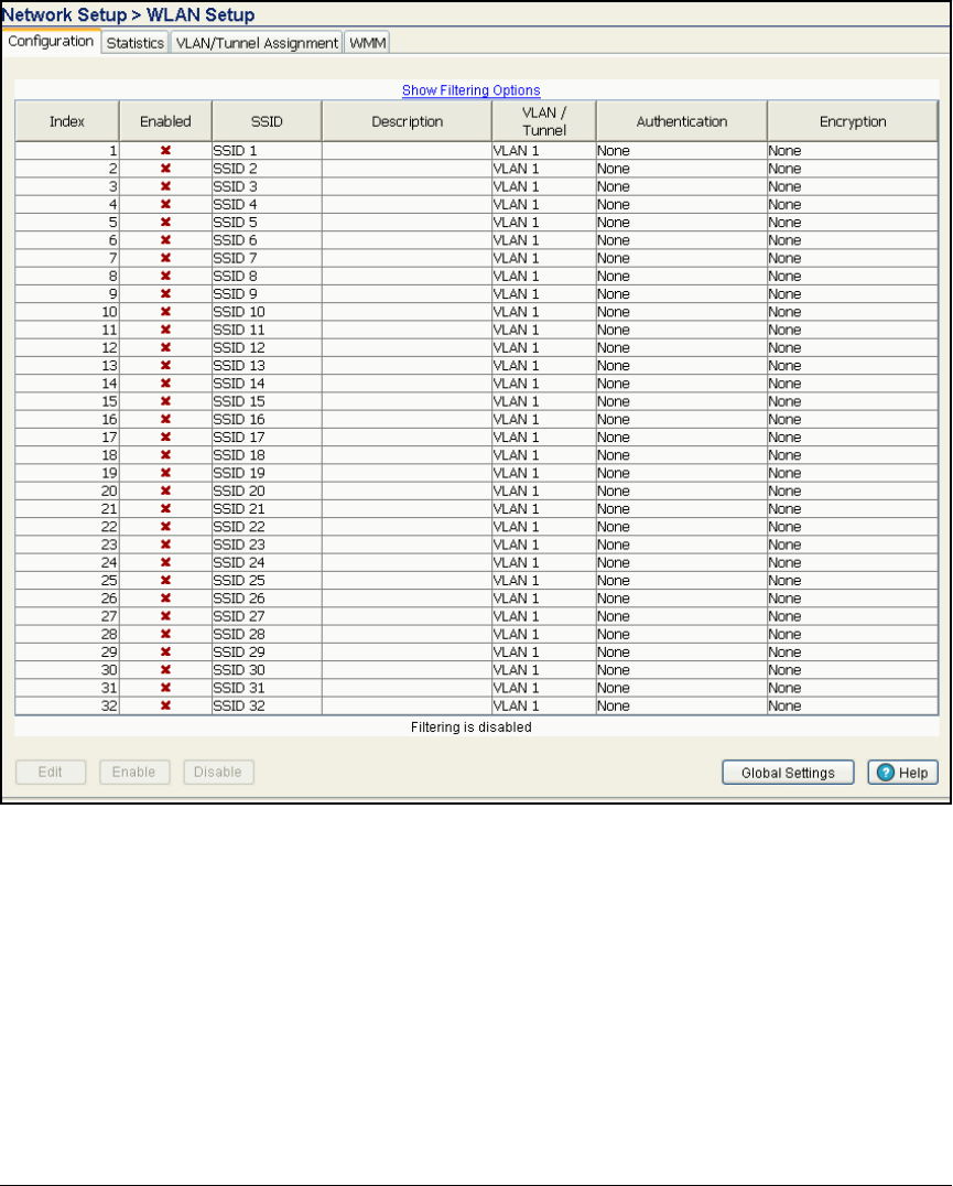
5-26
Using the NAC 800 in a RADIUS-Only Configuration
Configure the Wireless Edge Services Module
Figure 5-2. Network Setup > WLAN Setup > Configuration Window
4. Access the Edit window for the WLAN by selecting the WLAN and
clicking Edit.
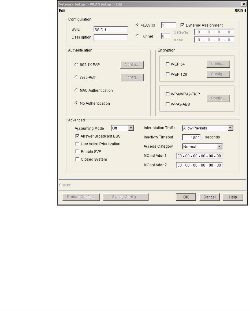
5-27
Using the NAC 800 in a RADIUS-Only Configuration
Configure the Wireless Edge Services Module
Figure 5-3. WLAN Edit Window
5. Under Configuration, in the SSID box, type the SSID that you have chosen
for this WLAN. For example: Medical.
When you enable the WLAN, the Wireless Edge Services Module automat-
ically configures this SSID on all adopted RP radios (as long as you are
using normal mode). (For more information about normal mode and the
alternative setting, advanced mode, see the ProCurve Wireless Edge
Services zl Module and Redundant Wireless Services zl Module Manage-
ment and Configuration Guide.)
6. In the Description box, type information about this WLAN to remind you
and other network administrators of its purpose. This setting is optional.
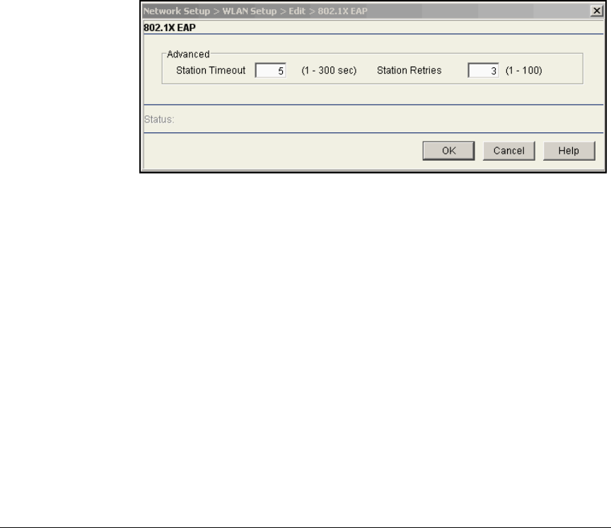
5-28
Using the NAC 800 in a RADIUS-Only Configuration
Configure the Wireless Edge Services Module
7. In the VLAN ID box, specify the VLAN to which the module maps wireless
traffic. The VLAN ID can be a value from 1 to 4096. For the example
network, you would type 8.
8. Check the Dynamic Assignment box to enable the Wireless Edge Services
Module to apply dynamic (or user-based) VLAN assignments received
from a RADIUS server.
9. Under Advanced, select Closed System if you do not want the RPs to
advertise the SSID.
10. Under Authentication, select 802.1X EAP.
11. Optionally, click Config next to 802.1X EAP to configure advanced settings
for the stations:
Figure 5-4. Specifying 802.1X EAP Settings
a. Type a value in the Station Timeout box to control how long the module
will wait for a station to authenticate itself.
The Station Timeout can be from 1 to 60 seconds, and the default
setting is 5 seconds.
b. Type a value in the Station Retries box to control how many times the
module will reissue a challenge to the station.
The setting for Station Retries can be from 1 to 10; the default setting
is 3.
c. Click OK. You are returned to the WLAN’s Edit window.
12. Under Encryption, select your encryption protocol:
• To use TKIP, select WPA/WPA2-TKIP.
The Wireless Edge Services Module and wireless stations will use
TKIP for all encryption. Note that both WPA and WPA2 stations can
connect, but WPA2 stations will use TKIP.
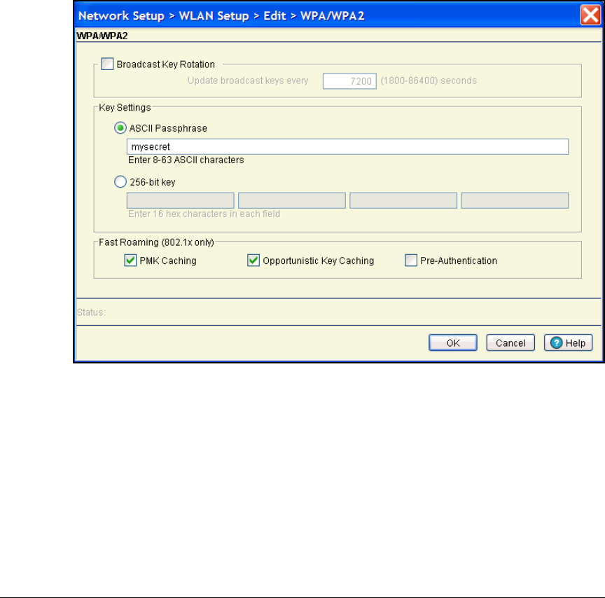
5-29
Using the NAC 800 in a RADIUS-Only Configuration
Configure the Wireless Edge Services Module
• To use AES, select WPA2-AES.
This option forces all wireless stations to use AES, which is the most
secure algorithm used for wireless encryption.
• To allow both protocols (mixed-mode), select both options.
13. If you want, you can also configure advanced encryption options.
a. Click Config in the WPA section of the Edit window. The WPA/WPA2
window is displayed.
Figure 5-5. Advanced Options for WPA/WPA2
b. If you want, check the Broadcast Key Rotation box.
Because all stations must use the same broadcast key, this key is
clearly more vulnerable to hackers than the per-session keys. Period-
ically changing the broadcast key helps to protect your WLAN.
By default, the Wireless Edge Services Module does not rotate the
broadcast key. However, if you enable the feature, the default rotation
period is every 7200 seconds (two hours).

5-30
Using the NAC 800 in a RADIUS-Only Configuration
Configure the Wireless Edge Services Module
In the Update broadcast keys every box, you can type any value from
60 seconds (one minute) through 86,400 seconds (one day). The
shorter the rotation period, the more secure, but also the more
overhead added by the key redistribution.
c. Enable fast roaming features (to speed roaming with 802.1X).
A station might roam back and forth between several RPs. Ideally,
such roaming is hidden from the wireless user, who need not know
when he or she connects to a new RP, but only that the wireless
connection remains good.
Fast roaming speeds authentication to a new RP, which can be the
most time-consuming phase of the roam, so it only applies to WLANs
that use 802.1X authentication.
Check these boxes to enable the Wireless Edge Services Module’s fast
roaming capabilities:
–PMK Caching—The RP and the wireless station agree on a PMK
identifier for their session, which each stores even after the
station disassociates. If the wireless station roams back to the RP,
the two can quickly exchange the PMK identifier and renegotiate
necessary keys, instead of completing the entire authentication
process.
Note When PMK caching is enabled, a WPA2 station that roams is no
longer controlled by any dynamic ACLs configured with IDM. If
you use IDM to assign ACLs to users with WPA2 connections, you
should disable PMK caching.
–Opportunistic Key Caching—This capability further speeds roam-
ing between RPs that are connected to the same module. The
wireless station can use the same PMK to associate to any RP that
connects to the module.
–Pre-Authentication—Pre-authentication speeds roaming for sta-
tions that move from an RP on a different Wireless Edge Services
to an RP on this module.
The station must also support pre-authentication. It listens for
beacons from other RPs that support its SSID and authenticates
to them before it roams. The station sends its EAP messages
through its current RP, and that RP’s module broadcasts the EAP
messages throughout the wired network. Pre-authentication
allows your module to listen for and respond to EAP messages
destined to its RPs.
d. After you have configured all the advanced options that you want,
click OK.
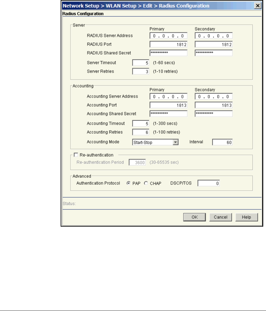
5-31
Using the NAC 800 in a RADIUS-Only Configuration
Configure the Wireless Edge Services Module
14. Click Radius Config at the bottom of the window. The Radius Configuration
window is displayed.
Figure 5-6. Radius Configuration Window
15. In the Radius Configuration window, under Server, specify settings for your
network’s RADIUS servers. For the example network, use the settings in
Table 5-7.

5-32
Using the NAC 800 in a RADIUS-Only Configuration
Configure the Wireless Edge Services Module
Table 5-7. RADIUS Settings for WLAN 1
a. Type the settings for your primary server in the Primary column:
i. In the RADIUS Server Address box, specify the IP address of your
network’s primary RADIUS server. (To use the module’s internal
server, type 127.0.0.1.)
ii. Leave the RADIUS Port box at the default value unless you know
that your server uses a different port. The default value is 1812.
iii. In the RADIUS Shared Secret box, type a character string up to 127
characters. The RADIUS server uses the secret to identify the
Wireless Edge Services Module as a legitimate client. You must
match the secret configured for the module in your RADIUS
server’s configuration. (If you are using the module’s internal
server, you do not need to type a shared secret.)
b. Optionally, type settings for a secondary RADIUS server in the boxes
in the Secondary column.
16. Check the Re-authentication box if you want to force stations to periodi-
cally re-authenticate to the network. Specify how often (in seconds)
stations must re-authenticate in the Re-authentication Period box.
Re-authentication occurs in the background. By default, re-authentication
is disabled, but if you enable it, the default period is one hour (3600
seconds). The valid range is 30 to 65,535 seconds.
17. Optionally, alter settings in the Server section:
• Type a value in the Server Timeout to control how long the Wireless
Edge Services Module will wait for a reply from the RADIUS server.
The Server Timeout can be from 1 to 60 seconds, and the default setting
is 5 seconds.
Setting WLAN 1
Primary RADIUS server NAC 800 A
Shared secret for primary server procurvea
IP address for primary server 10.4.7.50
Secondary RADIUS server NAC 800 B
Shared secret for secondary server procurveb
IP address for secondary sever 10.4.6.50

5-33
Using the NAC 800 in a RADIUS-Only Configuration
Configure the Wireless Edge Services Module
Note Depending on your network configuration, you may need to increase
the timeout value. If you have checked your OpenLDAP server and
NAC 800 settings, but users are not being granted access to the WLAN,
you may want to increase the timeout setting. (You can double-check
if this is a problem by using a protocol analyzer, such as Wireshark,
to capture and analyze the traffic between the NAC 800, OpenLDAP
server, and the Wireless Edge Services Module.)
• Type a value in the Server Retries box to control how many times the
module will reattempt to contact a server that does not reply.
The setting for Server Retries can be from 1 to 10. By default, the
Wireless Edge Services Module attempts to contact the server up to
four times (one initial try and three subsequent tries).
18. Optionally, type a value in the DSCP/TOS box to prioritize traffic to the
RADIUS server.
Valid values range from 0 through 63.
a. Leave the other settings at their defaults and click OK. You will return
to the WLAN’s Edit window.
19. Click OK to save all your configuration changes.
20. Click OK to return to the WLAN Setup window.
21. Select the Medical SSID and click Enable.
22. In the upper right corner of the Wireless Module Web browser interface,
click Save to save the changes to the startup-config.
Configure Web-Auth for WLANs 2 and 3
In the simplest configuration for Web-Auth, no security is required for the
802.11 association process. A user can simply open a wireless utility, select
the WLAN, and associate to it.
Because wireless transmissions are not protected, they are open to eavesdrop-
pers. To protect these transmissions, the Wireless Edge Services Module
supports optional encryption for Web-Auth WLANs, as shown in Table 5-8.

5-34
Using the NAC 800 in a RADIUS-Only Configuration
Configure the Wireless Edge Services Module
Table 5-8. Encryption Options for Web-Auth on the
Wireless Edge Services Module
The hypothetical organization used in this access control solution requires
two Web-Auth WLANs:
■WLAN for patients who will be given only Internet access
■
WLAN for support staff who may access some confidential information
For the Patients WLAN, no security is required for wireless transmissions.
The patients will be accessing only information on the Internet, so the Medical
Center does not need to worry about protecting its confidential information.
The burden of protecting wireless transmissions is left up to the patients
themselves. If they don’t want anyone to eavesdrop on their wireless trans-
missions, they must use a virtual private network (VPN) or a Secure Socket
Layer (SSL) connection.
However, the Medical Center wants to protect the transmissions of the
support staff, who may access some confidential information on the organi-
zation’s network. For example, they may access their compensation informa-
tion or the business contact information of other employees. For the Staff
WLAN, therefore, the organization will use WPA/WPA2-TKIP and WPA2-AES
to encrypt the wireless transmissions.
In addition, the Medical Center will use the settings listed in Table 5-9 for
WLANs 2 and 3.
Encryption Option Security Option
WEP 64 static WEP
WEP 128 static WEP
WPA/WPA2-TKIP WPA/WPA2-PSK
WPA2-AES WPA2-PSK
WPA/WPA2-TKIP and WPA2-AES WPA/WPA2-PSK

5-35
Using the NAC 800 in a RADIUS-Only Configuration
Configure the Wireless Edge Services Module
Table 5-9. Settings for WLANs 2and 3
Configure Web-Auth. To configure Web-Auth for a WLAN, complete the
following steps:
1. Select Network Setup > WLAN Setup > Configuration.
2. Select the WLAN that you want to use Web-Auth, and then click Edit. The
Edit window is displayed.
Setting WLAN 2 WLAN 3
SSID Staff Patients
VLAN ID 12 32
Radio Both Both
Closed system Yes No

5-36
Using the NAC 800 in a RADIUS-Only Configuration
Configure the Wireless Edge Services Module
Figure 5-7. WLAN Edit Window
3. Under Configuration, type an SSID for this WLAN in the SSID box. For
example: Staff.
4. In the Description box, you can type information that will help you identify
this WLAN. This is an optional setting.
5. By default, the Wireless Edge Services Module places all wireless traffic
in VLAN 1. If you want to assign this WLAN to a different VLAN, type the
number in the VLAN ID box. For example: 12.
Make sure that either your module or another infrastructure device is
configured to assign wireless stations DHCP addresses in this VLAN.
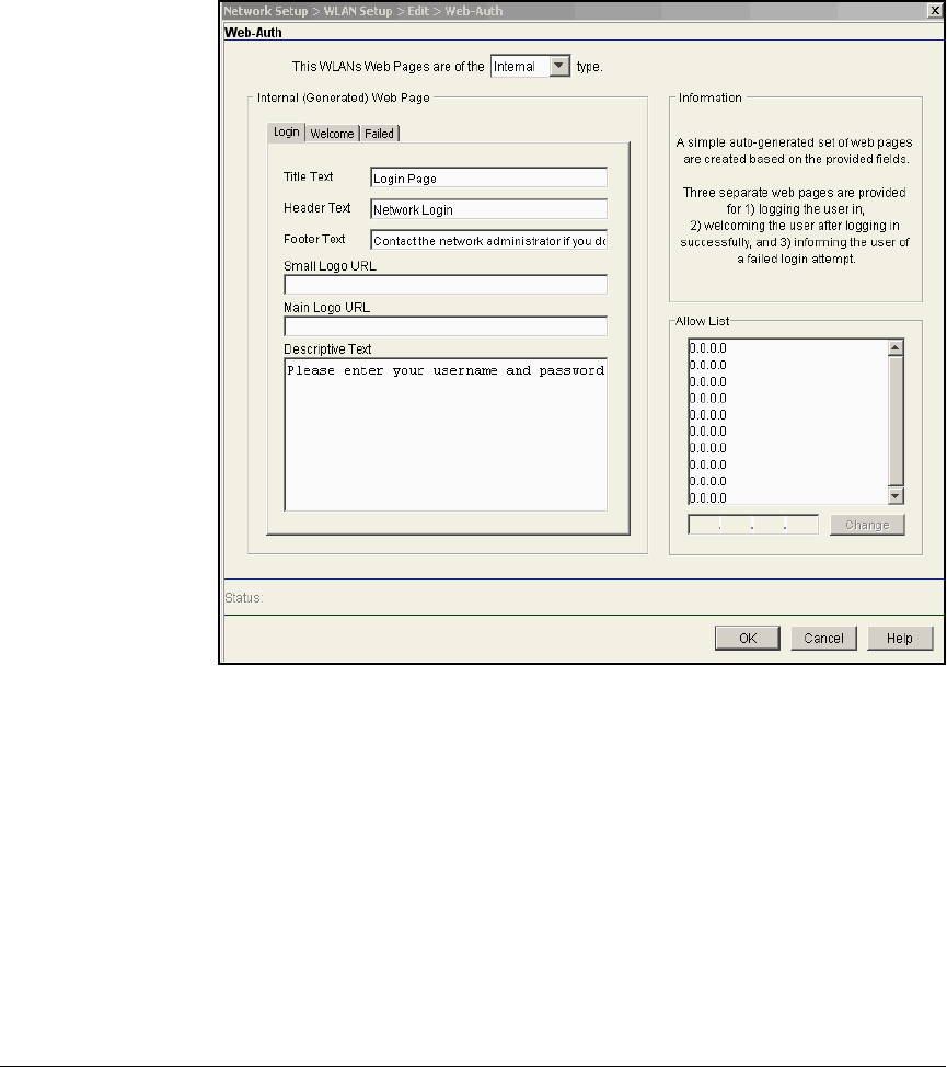
5-37
Using the NAC 800 in a RADIUS-Only Configuration
Configure the Wireless Edge Services Module
6. Under Authentication, select Web-Auth.
7. On the WLAN Edit window, under Authentication, click Config next to
Web-Auth. The Web-Auth window is displayed.
Figure 5-8. Configuring the Login Page
8. Select the location for the Web-Auth Web pages from the list at the top of
the window.
You can select one of three options for these Web pages:
•Internal—three default pages stored on the Wireless Edge Services
Module
•External—three pages stored on an external Web server
•Advanced—pages that you have loaded onto the Wireless Edge Ser-
vices Module’s flash memory
Select Internal from the list at the top of the window.
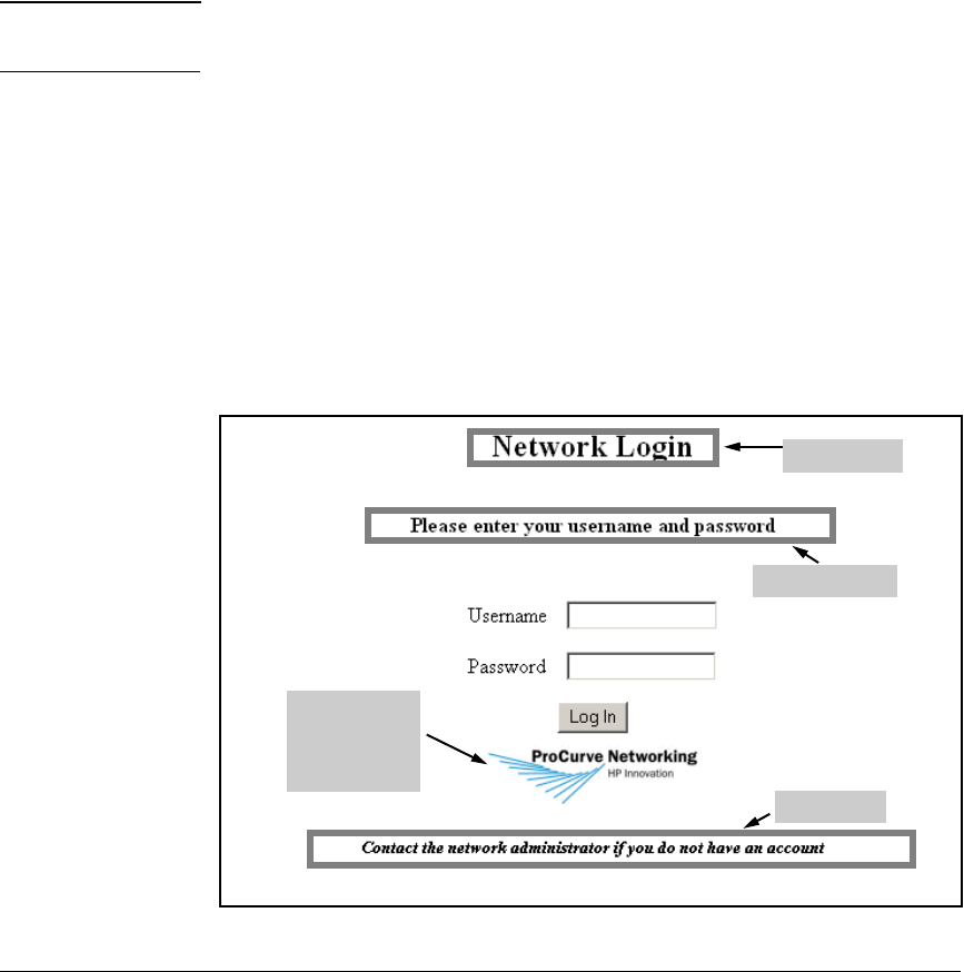
5-38
Using the NAC 800 in a RADIUS-Only Configuration
Configure the Wireless Edge Services Module
9. Under Internal (Generated) Web Page, click the Login tab to configure the
login page, which users see when they try to access your network services.
(See Figure 5-8.)
a. In the Title Text box, accept the default text shown on the window, or
type the text that you want to use.
b. In the Header Text box, accept the default text shown on the window,
or type the text that you want to be displayed at the top of the login
page. (See Figure 5-9.)
Note If you customize the Header Text, Footer Text, or Descriptive Text boxes, you can
type a maximum of 1024 characters.
c. In the Footer Text box, accept the default text shown on the window,
or type the text that you want to be displayed at the bottom of the
login page. (See Figure 5-9.) For example, you might want to type:
Call the IT department at ext. 1253 to receive a valid username and pass-
word.
d. In the Small Logo URL box, type the name of a logo file to include a
small logo on the login page. (See Figure 5-9.) You must copy this logo
to the flash on the Wireless Edge Services Module. (For instructions
on how to copy the logo file to flash, see “Copying Logo Files to the
Module’s Flash” on page 5-50.)
Figure 5-9. Displaying a Small Logo on the Web-Auth Login Page
Header text
Descriptive text
Footer text
The small logo
displays
beneath the
Log in button
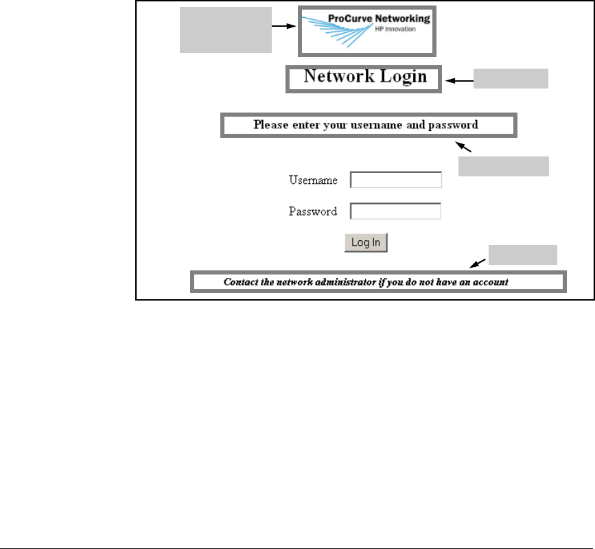
5-39
Using the NAC 800 in a RADIUS-Only Configuration
Configure the Wireless Edge Services Module
e. In the Main Logo URL box, type the name of a logo file to include a logo
at the top of the login page. (See Figure 5-10.) You must copy this logo
to the flash on the Wireless Edge Services Module. (For instructions
on how to copy the logo file to flash, see “Copying Logo Files to the
Module’s Flash” on page 5-50.)
f. In the Descriptive Text box, accept the default text shown on the
window, or type the text that you want to use. (See Figure 5-10.) For
example, you might type:
Enter the username and password you were assigned. Remember that both
the username and password are case sensitive.
Figure 5-10. Displaying the Main Logo on the Web-Auth Login Page
10. Configure the welcome page, which mobile users see if they type a valid
username and password and the RADIUS server authenticates them.
a. Click the Welcome tab. (See Figure 5-11.)
Descriptive text
The main logo is
displayed at the
top of the page
Footer text
Header text
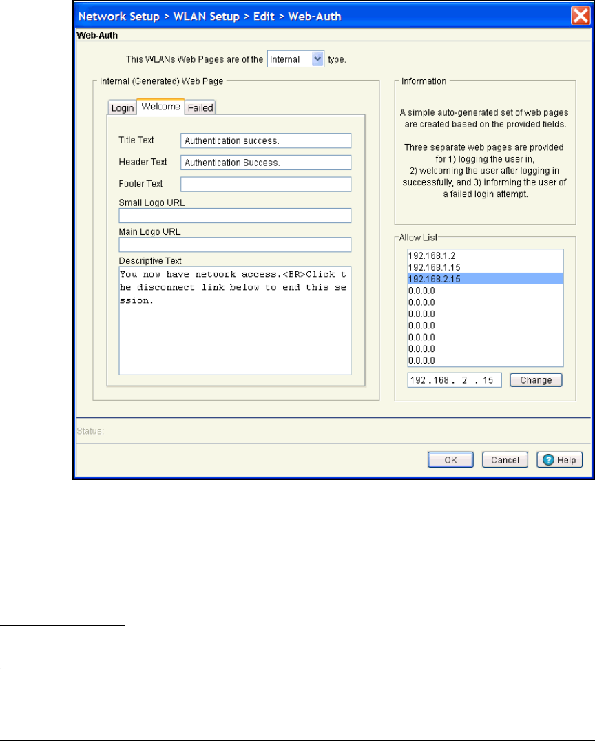
5-40
Using the NAC 800 in a RADIUS-Only Configuration
Configure the Wireless Edge Services Module
Figure 5-11. Configuring the Welcome Page
b. In the Title Text box, accept the default text shown on the window, or
type the text that you want to use.
c. In the Header Text box, accept the default text shown on the window,
or type the text that you want users to see when they log in. (See
Figure 5-12.)
Note If you customize the Header Text, Footer Text, or Descriptive Text boxes, you can
type a maximum of 1024 characters.
d. In the Footer Text box, type the text that will be displayed at the bottom
of the welcome page. By default, this box is empty.
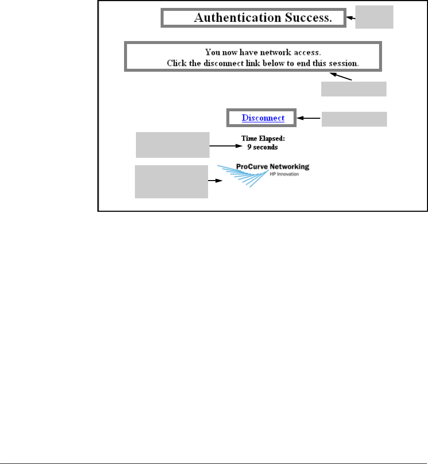
5-41
Using the NAC 800 in a RADIUS-Only Configuration
Configure the Wireless Edge Services Module
e. In the Small Logo URL box, type the name of a logo file to include a
small logo on the welcome page. (See Figure 5-12.) You must copy
this logo to the flash on the Wireless Edge Services Module. (For
instructions on how to copy the logo file to flash, see “Copying Logo
Files to the Module’s Flash” on page 5-50.)
Figure 5-12. Displaying a Small Logo on the Web-Auth Welcome Page
f. In the Main Logo URL box, type the name of a logo file to display a logo
at the top of the welcome page. (See Figure 5-13.) You must copy this
logo to the flash on the Wireless Edge Services Module. (For instruc-
tions on how to copy the logo file to flash, see “Copying Logo Files to
the Module’s Flash” on page 5-50.)
g. In the Descriptive Text box, accept the default text shown on the
window, or customize the text as needed. (See Figure 5-13.)
Descriptive text
The small logo is
displayed at the
bottom of the page
Header
text
Disconnect link
Duration of the
connection
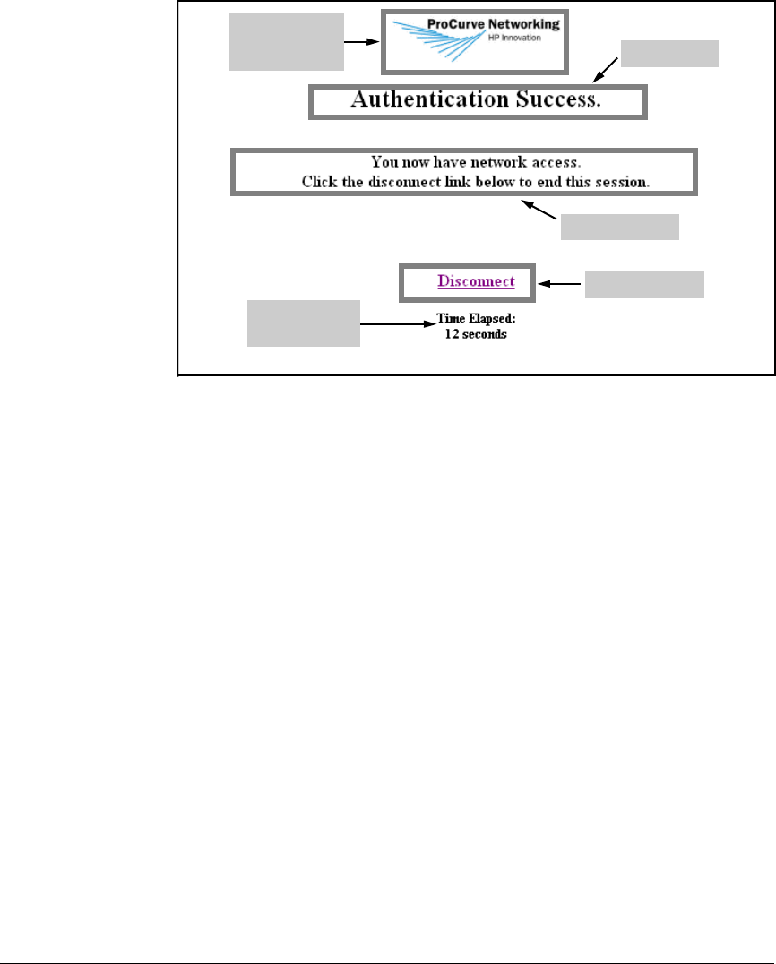
5-42
Using the NAC 800 in a RADIUS-Only Configuration
Configure the Wireless Edge Services Module
Figure 5-13. Displaying the Main Logo on the Web-Auth Welcome Page
11. Configure the failed page, which mobile users see if they type an invalid
username and password.
a. Click the Failed tab. (See Figure 5-14.)
Descriptive text
The main logo is
displayed at the
top of the page Header text
Disconnect link
Duration of the
connection
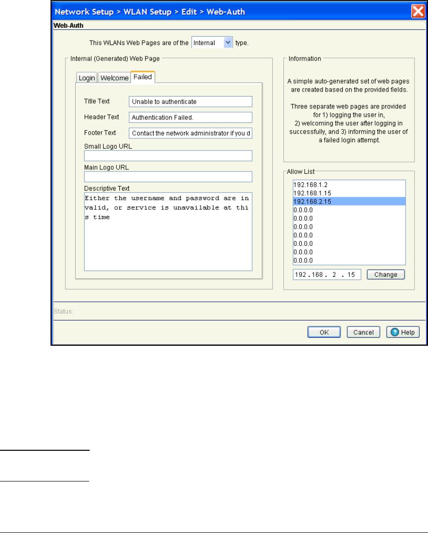
5-43
Using the NAC 800 in a RADIUS-Only Configuration
Configure the Wireless Edge Services Module
Figure 5-14. Configuring the Failed Page
b. In the Title Text box, accept the default text shown on the window, or
change the text as needed.
c. In the Header Text box, accept the default text shown on the window,
or type the text that you want users to see if they fail to log in. (See
Figure 5-15.)
Note If you customize the Header Text, Footer Text, or Descriptive Text boxes, you can
type a maximum of 1024 characters.
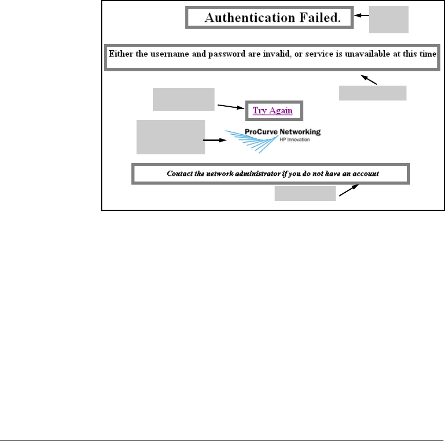
5-44
Using the NAC 800 in a RADIUS-Only Configuration
Configure the Wireless Edge Services Module
d. In the Footer Text box, accept the default text shown on the window,
or type the text that you want to be displayed at the bottom of the
failed page. (See Figure 5-15.) For example, you may want to add the
extension that users should call if they cannot log in.
e. In the
Small Logo URL
box, type the name of a logo file to include a small
logo on the failed page. (See Figure 5-15.) You must copy this logo to
the module’s flash. (For instructions on how to copy the logo file to flash,
see “Copying Logo Files to the Module’s Flash” on page 5-50.)
Figure 5-15. Displaying the Small Logo on the Web-Auth Failed Page
f. In the Main Logo URL box, type the name of a logo file to include a large
logo on the failed page. (See Figure 5-16.) You must copy this logo to
the flash on the Wireless Edge Services Module. (For instructions on
how to copy the logo file to flash, see “Copying Logo Files to the
Module’s Flash” on page 5-50.)
g. In the Descriptive Text box, accept the default text shown on the
window, or customize the text as needed. (See Figure 5-16.)
Header
text
Descriptive text
The small logo is
displayed above
the footer
Footer text
Link to the
login page
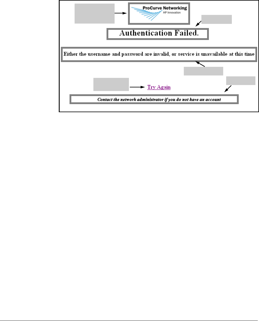
5-45
Using the NAC 800 in a RADIUS-Only Configuration
Configure the Wireless Edge Services Module
Figure 5-16. Displaying the Main Logo on the Web-Auth Failed Page
12. On the Web-Auth window, under Allow List, add the IP addresses that
unauthorized stations are allowed to access.
The Wireless Edge Services Module automatically handles traffic such as
DHCP and DNS requests. Therefore, you do not need to add any IP
addresses to the Allow list to make Web-Auth function correctly using the
internal pages.
13. Leave other settings at their defaults and click OK.
14. Web-Auth requires a RADIUS server to act as the authentication server.
Click Radius Config at the bottom of the window. The Radius Configuration
window is displayed.
Header text
Descriptive text
Footer text
Link to the
login page
The main logo is
displayed at the
top of the page
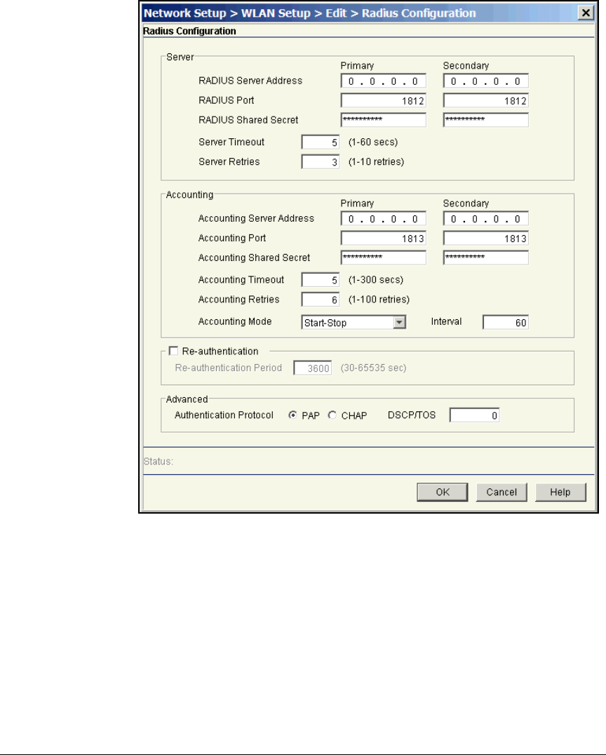
5-46
Using the NAC 800 in a RADIUS-Only Configuration
Configure the Wireless Edge Services Module
Figure 5-17. Radius Configuration Window
15. In the Radius Configuration window, under Server, specify settings for your
network’s RADIUS servers. For the example network, the network
administrators will use the settings shown in Table 5-10.

5-47
Using the NAC 800 in a RADIUS-Only Configuration
Configure the Wireless Edge Services Module
Table 5-10. RADIUS Settings for WLANs 2 and 3
Type settings for your primary server in the boxes in the Primary column:
a. In the RADIUS Server Address box, specify the IP address of your
network’s primary RADIUS server.
b. Leave the RADIUS Port box at the default value unless you know that
your server uses a different port.
The default value is 1812.
c. In the RADIUS Shared Secret box, type a character string up to 127
characters.
The RADIUS server uses the secret to identify the Wireless Edge
Services Module as a legitimate client. You must match the secret
configured for the module in your RADIUS server’s configuration.
d. If you have two NAC 800s, type settings for a secondary RADIUS
server in the boxes in the Secondary column.
16. Check the Re-authentication box if you want to force stations to periodi-
cally re-authenticate to the network. Specify how often (in seconds)
stations must re-authenticate in the Re-authentication Period box.
Re-authentication occurs in the background. By default, re-authentication
is disabled, but if you enable it, the default period is one hour (3600
seconds). The valid range is 30 to 65,535 seconds.
Setting WLAN 2 WLAN 3
Primary RADIUS server NAC 800 A NAC 800 B
Shared secret for primary server procurvea procurveb
IP address for primary server 10.4.7.50 10.4.6.50
Secondary RADIUS server NAC 800 B NAC 800 A
Shared secret for secondary server procurveb procurvea
IP address for secondary sever 10.4.6.50 10.4.7.50

5-48
Using the NAC 800 in a RADIUS-Only Configuration
Configure the Wireless Edge Services Module
17. Optionally, alter settings in the Server section:
• Type a value in the Server Timeout to control how long the Wireless
Edge Services Module will wait for a reply from the RADIUS server.
The Server Timeout can be from 1 to 60 seconds, and the default setting
is 5 seconds.
Note Depending on your network configuration, you may need to increase
the timeout value. If you have checked your OpenLDAP server and
NAC 800 settings, but users are not being granted access to the WLAN,
you may want to increase the timeout setting. (You can double-check
if this is a problem by using a protocol analyzer, such as Wireshark,
to capture and analyze the traffic between the NAC 800, OpenLDAP
server, and the Wireless Edge Services Module.)
• Type a value in the Server Retries boxes to control how many times
the module will reattempt to contact a server that does not reply.
The setting for Server Retries can be from 1 to 10. By default, the
Wireless Edge Services Module attempts to contact the server up to
four times (one initial try and three subsequent tries).
18. Choose the protocol in which the Wireless Edge Services Module pack-
ages users’ credentials. Select PAP (the default) or CHAP for the Authenti-
cation Protocol.
19. Optionally, type a value in the DSCP/TOS box to prioritize traffic to the
RADIUS server.
Valid values range from 0 through 63.
20. Leave the other settings at their defaults and click OK. You are returned
to the WLAN Edit window.


5-50
Using the NAC 800 in a RADIUS-Only Configuration
Configure the Wireless Edge Services Module
Table 5-11. Encryption Options for Web-Auth on the
Wireless Edge Services Module
For example, the Medical Center IT staff select WPA/WPA2-TKIP and
WPA2-AES for the Staff WLAN. They do not select any encryption options
for the Patients WLAN.
22. Click OK.
23. Select the WLAN and click Enable.
24. In the upper right corner of the Wireless Module Web browser interface,
click Save to save the settings to the startup-config.
Copying Logo Files to the Module’s Flash
If you want to display your organization’s logo on the Web-Auth login, wel-
come, or failed page, you must copy the logo file to the appropriate directory
on the Wireless Edge Services zl Module’s flash.
The module’s flash contains a hotspot directory that, in turn, contains a
subdirectory for each WLAN on the module. To display a logo on one of the
Web-Auth pages, you must copy the logo file to the hotspot subdirectory for
the WLAN that you are configuring. For example, if you are configuring
Web-Auth as the authentication method for WLAN 2, you must copy your
organization’s logo file to the /hotspot/wlan2 directory in the module’s flash. If
you are configuring Web-Auth for WLAN 1, you must copy your organization’s
logo file to the /hotspot/wlan1 directory.
To copy the logo file to the appropriate directory for the WLAN that you are
configuring, you can use either an FTP or TFTP server. Copy the logo file to
the FTP or TFTP server, and then complete these steps:
1. Select Management > System Maint.—Config Files.
2. Click Transfer Files at the bottom of the window. The Transfer window is
displayed. (See Figure 5-19.)
Encryption Option Security Option
WEP 64 static WEP
WEP 128 static WEP
WPA/WPA2-TKIP WPA/WPA2-PSK
WPA2-AES WPA2-PSK
WPA/WPA2-TKIP and WPA2-AES WPA/WPA2-PSK
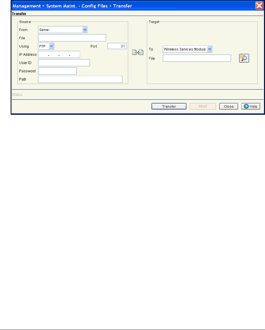
5-51
Using the NAC 800 in a RADIUS-Only Configuration
Configure the Wireless Edge Services Module
Figure 5-19. Management > System Maint.—Config Files > Transfer Window
3. Specify the source for the file transfer:
a. In the From box under Source, select Server from the list.
b. In the File box, type the name of the logo file.
c. In the Using box, select either FTP or TFTP from the list.
d. In the IP Address box, type the IP address of the FTP or TFTP server.
e. If you are using an FTP server, type the login credentials.
i. In the User ID box, type the username for the FTP server.
ii. In the Password box, type the password for this username.
f. In the Path box, type the path where the configuration is saved on the
server. If you are using an FTP server and the logo file is saved at the
server’s root level, type a period followed by a slash (./). If the logo
file resides at a different level on the FTP server, type the complete
path. (If you are using a TFTP server, this box may not be required.)
4. Specify the destination as the Wireless Edge Services zl Module:
a. In the To box under Target, select Wireless Services Module.
b. In the File box, type the hotspot directory, the WLAN subdirectory,
and the name of the logo file. Use the following syntax:
/hotspot/<WLAN subdirectory>/<logo filename>
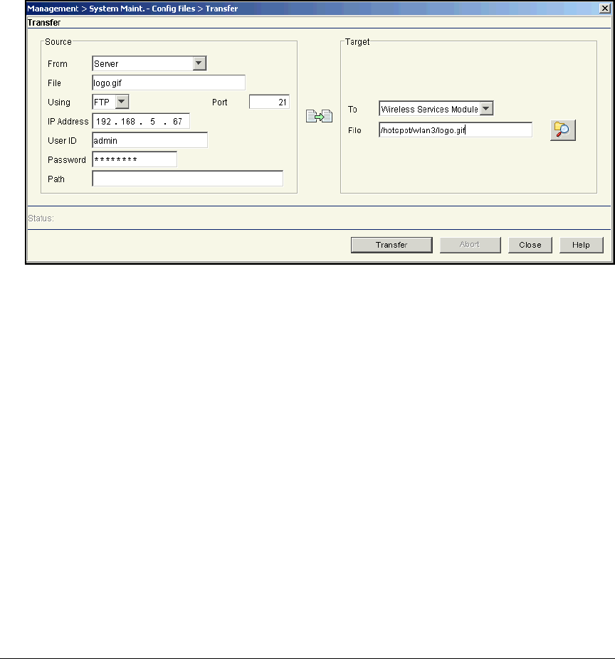
5-52
Using the NAC 800 in a RADIUS-Only Configuration
Configure the Wireless Edge Services Module
Replace <WLAN subdirectory> with the subdirectory for the WLAN that
you are configuring, and replace < logo filename> with the filename that
contains your organization’s logo. For example, if you are configuring
Web-Auth as the authentication method for WLAN 3, you would type:
/hotspot/wlan3/logo.gif
Figure 5-20. Management > System Maint.—Config Files > Transfer Window
5. Click Transfer. In the Status area at the bottom of the window, a message
is displayed, reporting whether the transfer was successful.
Configure SNMP on the Wireless Edge Services
Modules
You must configure the Wireless Edge Services Modules’ SNMP settings to
allow PCM+ to manage it. SNMPv3 also controls access to the Module’s Web
browser interface.
Complete the following steps to configure SNMP:
1. You should be in the Wireless Edge Services Module’s Web browser
interface.
2. Click Management > SNMP Access. You begin at the v1/v2c tab.
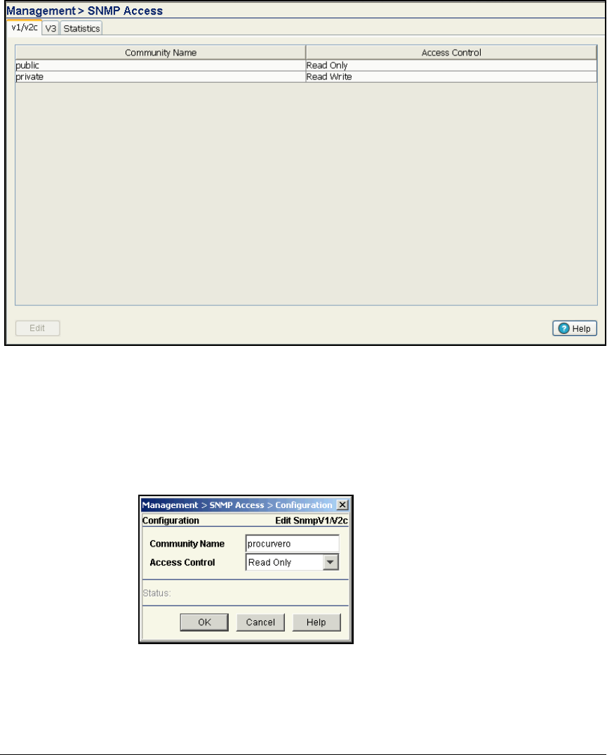
5-53
Using the NAC 800 in a RADIUS-Only Configuration
Configure the Wireless Edge Services Module
Figure 5-21. Wireless Edge Services Module Web Interface—
Management > SNMP Access > V1/V2c Tab
3. Select public and click Edit. The Edit SnmpV1/V2c window is displayed.
4. For the Community Name, type the new name for the community (in this
example, procurvero).
Figure 5-22. Wireless Edge Services
Module Web Interface—
Edit SnmpV1/V2c Window
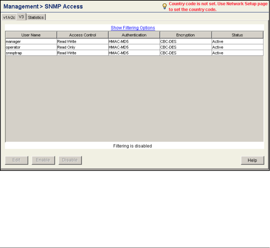
5-54
Using the NAC 800 in a RADIUS-Only Configuration
Configure the Wireless Edge Services Module
5. Keep the default setting, Read Only, in the Access Control box.
6. Click OK.
7. Select private and click Edit.
8. In the Community Name box, type the new name for the community. In this
example: procurverw.
9. Keep the default setting, Read Write, in the Access Control box.
10. Click OK.
11. Click the V3 tab.
Figure 5-23. Wireless Edge Services Module Web Interface—Management >
SNMP Access > V3 Tab
12. Select snmptrap and click Edit. The Edit SnmpV3 window is displayed.
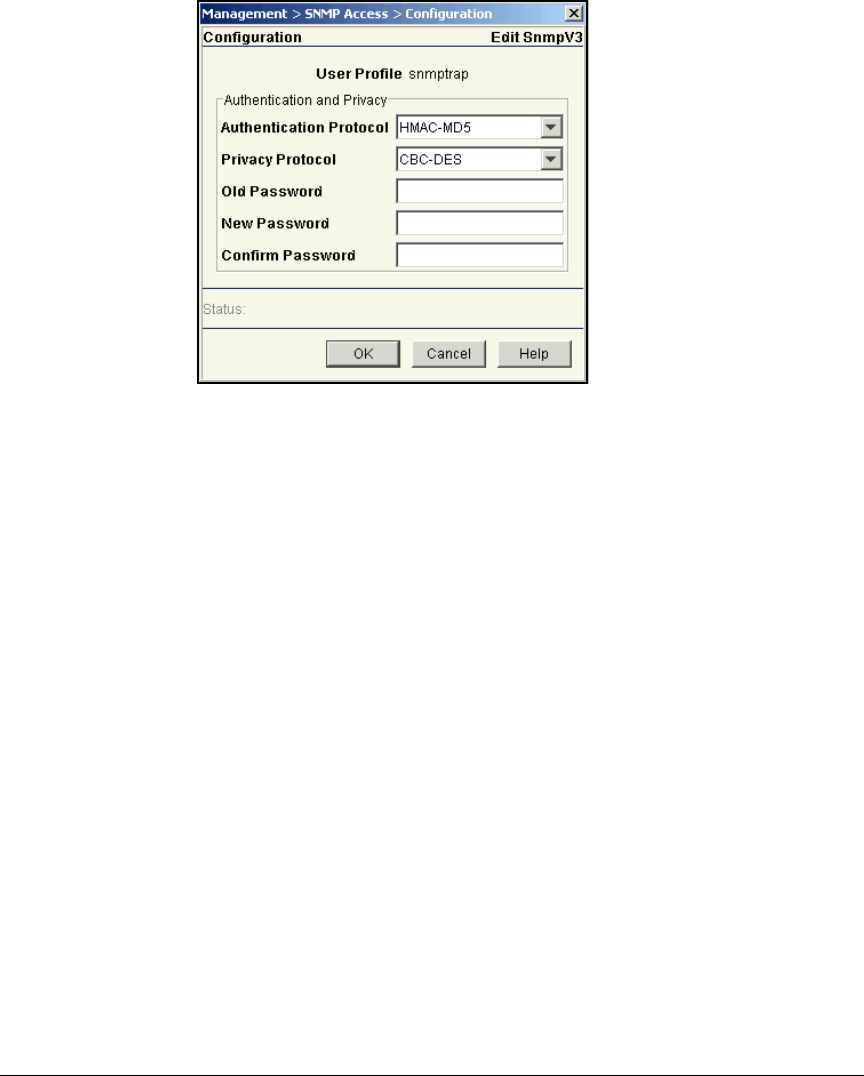
5-55
Using the NAC 800 in a RADIUS-Only Configuration
Configure the Wireless Edge Services Module
Figure 5-24. Wireless Edge Services Module Web
Interface—Edit SnmpV3 Window
13. In the Old Password box, type the current password: trapuser.
14. In the New Password and Confirm Password boxes, type the new password
(in this example, procurve).
15. Click OK.
16. The other two default SNMPv3 users are also part of the Wireless Edge
Services Module’s Web-Users. You will control them on the window for
those users. Click Management > Web-Users.

5-56
Using the NAC 800 in a RADIUS-Only Configuration
Configure the Wireless Edge Services Module
Figure 5-25. Wireless Edge Services Module Web Interface—Management >
Web-Users
17. Select operator and click Edit.
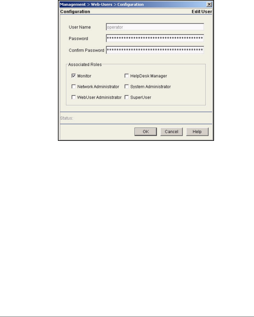
5-57
Using the NAC 800 in a RADIUS-Only Configuration
Configure the Wireless Edge Services Module
Figure 5-26. Wireless Edge Services Module Web Interface—
Management > Web-Users > Configuration (operator)
18. In the Password and Confirm Password boxes, type the new password (in
this example, procurveoperator).
19. Under Associated Roles, the Monitor check box is selected. Keep this
default setting.
20. Click OK.
21. Select manager and click Edit.
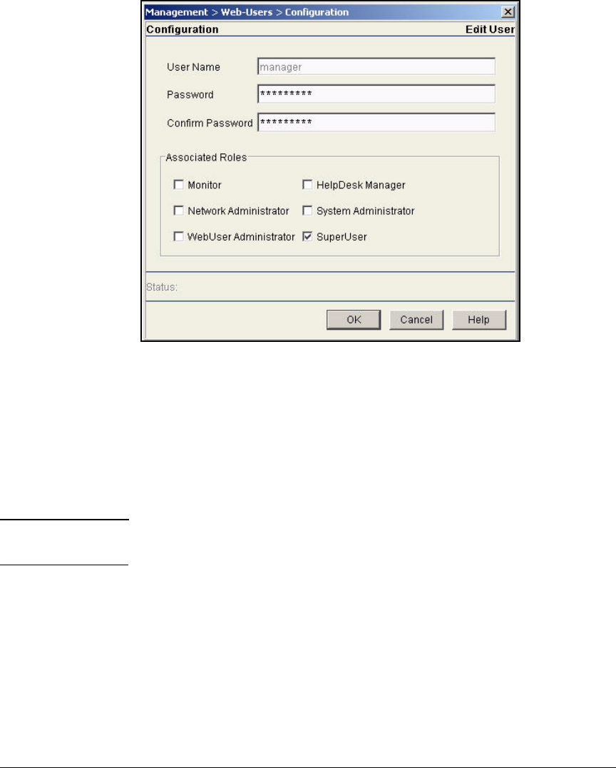
5-58
Using the NAC 800 in a RADIUS-Only Configuration
Configure the Wireless Edge Services Module
Figure 5-27. Wireless Edge Services Module Web Interface—
Management > Web-Users > Configuration (manager)
22. In the Password and Confirm Password boxes, type the new password (in
this example, Procurve1).
23. Under Associated Roles, the SuperUser check box is selected. Keep this
default setting.
24. Click OK.
Note You must enter this new password the next time you log in to the Web browser
interface.
25. Select Management > SNMP Trap Configuration.
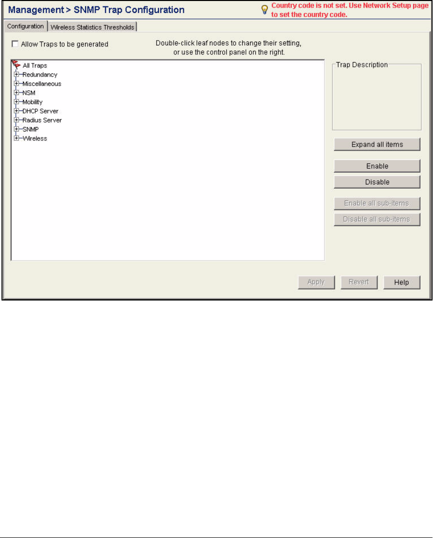
5-59
Using the NAC 800 in a RADIUS-Only Configuration
Configure the Wireless Edge Services Module
Figure 5-28. Wireless Edge Services Module Web Interface—Management >
SNMP Trap Configuration > Configuration Tab
26. Select the Allow Traps to be generated check box.
27. To view the SNMP traps in a category, expand the category. To view the
SNMP traps in all categories, click Expand all items.
28. To enable all the traps, select All Traps and click Enable all sub-items.
29. To enable all the SNMP traps in a category, select the category and click
Enable all sub-items.

5-60
Using the NAC 800 in a RADIUS-Only Configuration
Configure the Wireless Edge Services Module
Figure 5-29. Wireless Edge Services Module Web Interface—Management >
SNMP Trap Configuration > Configuration Tab
30. To enable a specific SNMP trap, select the trap and click Enable or double-
click the trap. A green check mark is displayed next to enabled traps. A
red x is displayed next to disabled traps.
31. Click Apply.
802.1X Authentication for RPs
Enforcing 802.1X authentication on your network switch ports can help you
prevent rogue RPs from being adopted by your Wireless Edge Services Mod-
ule. The ProCurve RPs 210, 220, and 230 include an 802.1X supplicant so that
they can connect to ports that enforce such authentication. Using MD5
authentication, the supplicant automatically sends the RP’s credentials when

5-61
Using the NAC 800 in a RADIUS-Only Configuration
Configure the Wireless Edge Services Module
the RP connects to a network device. The switch to which the RP connects
forwards the credentials to an authentication server and, if the credentials are
correct, allows the RP to join the network.
You must create an account for the RP on the RADIUS server. In the example
network used, the NAC 800 is the RADIUS server and uses OpenLDAP as its
data store. Therefore, you must create the account in OpenLDAP.
The authentication server may store a VLAN setting for the RP, which it sends
to the switch after the RP authenticates. Such dynamic configuration of the
Radio Port VLAN can replace auto-provisioning on the wireless services-
enabled switch or manual configuration on an infrastructure switch.
Note When you implement 802.1X on a port, auto-provisioning is disabled on that
port. You must either manually set the port to the correct VLAN for the RP or
configure the VLAN assignment on the RADIUS server.
However, the wireless services-enabled switch can continue to implement
auto-provisioning on ports that do not enforce 802.1X.
The default username and password on all ProCurve 200 Series RPs are admin
and procurve.
ProCurve Networking suggests that you use pre-adoption to change these
settings, using a Wireless Edge Services Module to load new credentials on
your organization’s RPs. You can then move these RPs to their final locations
and be sure that only these RPs can connect to your network.
Configure 802.1X Authentication for RPs
To configure 802.1X authentication for RPs, complete these steps:
1. Select Network Setup > Radio > Configuration.
2. Click Global Settings. The Global Settings window is displayed.
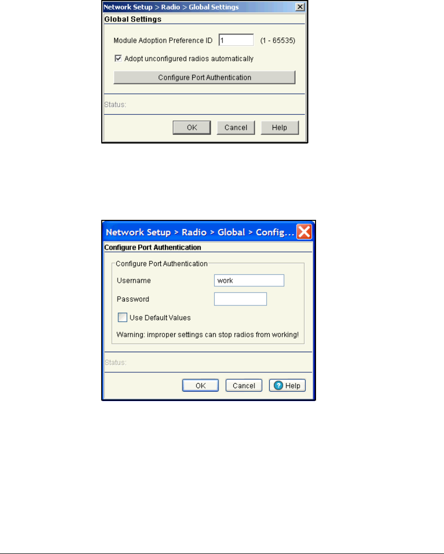
5-62
Using the NAC 800 in a RADIUS-Only Configuration
Configure the Wireless Edge Services Module
Figure 5-30. Radio Global Settings Window
3. Click Configure Port Authentication. The Configure Port Authentication win-
dow is displayed.
Figure 5-31. Configure Port Authentication Window
4. Configure a username and password.
• Check the
Use Default Values
box to use the default username and
password:
–Username: admin
–Password: procurve
•Or, in the Username and Password boxes, type the username and
password that you want to use.

5-63
Using the NAC 800 in a RADIUS-Only Configuration
Configure OpenLDAP
5. Click OK, and then click OK on the Global window.
Note The Wireless Edge Services Module pushes the username and password
to the RPs as a one time occurrence. You must complete these steps again
to configure the username and password on an RP that is adopted later.
6. Click Save at the top of the Web browser interface to save the changes to
the startup-config.
Configure OpenLDAP
Although a detailed discussion of an LDAP directory is beyond the scope of
this guide, this section is designed to provide instructions for the tasks related
to using OpenLDAP as the data store for network access control. If you are
not familiar with OpenLDAP, it will help you understand the basic structure
of OpenLDAP so that you can configure OpenLDAP settings on the NAC 800
and IDM.
If you are the OpenLDAP administrator, you already have an in-depth knowl-
edge of OpenLDAP and will simply need to ensure that you have extended the
OpenLDAP schema to support RADIUS and have uploaded a root Certificate
Authority (CA) certificate on OpenLDAP. You can then upload the same CA
certificate on both the NAC 800 and PCM+. This will allow you to secure
communications between OpenLDAP and the NAC 800 and OpenLDAP and
PCM+.
This section describes the following:
■Extending the OpenLDAP schema
■Creating objects in OpenLDAP
■Binding to OpenLDAP
■Using OpenSSL to create a root CA certificate and a server certificate for
the OpenLDAP directory
It is assumed that OpenLDAP is already installed and set up for your network
environment. (For information about installing OpenLDAP and completing
the initial setup, visit http://www.openldap.org or http://www.bind9.net/
download-openldap.)

5-64
Using the NAC 800 in a RADIUS-Only Configuration
Configure OpenLDAP
Extend the OpenLDAP Schema to Support RADIUS
OpenLDAP is an object-based directory service, and the types of objects it
supports—called object classes—are controlled by the schema. You can think
of the schema as the policies and rules that govern the directory. The schema
not only controls the type of objects that you can create, but also the attributes,
or characteristics, that you can define for each one. (For more detailed
information about OpenLDAP object classes and attributes, visit http://
www.openldap.org.)
Objects in the Standard OpenLDAP Schema
OpenLDAP installs with a standard schema that allows you to create
objects that:
■Help you organize the information you store in OpenLDAP
■Represent users and devices
For example, the organizational unit (OU) is a container object, which can
hold other objects. You can use an OU to organize your directory by branch
office, department, or types of objects.
For the purposes of access control, the most important object classes are:
■Person—This object class allows you to define objects for users. Sup-
ported attributes include common name (CN), surname (SN), userPass-
word, and mobileTelephoneNumber.
For the example network, you will also use the person object to define
accounts for RPs. This will allow you to manage the RPs through IDM.
(You will learn how to import person objects from OpenLDAP into IDM
in “Import Users” on page 5-109.)
Because other directories have user objects rather than person objects,
applications are often configured by default to search for user objects in
the directory tree. You must check the search settings in applications to
ensure that they are using the correct object classes and attributes for
OpenLDAP.
■Device—This object class allows you to define objects for devices such
as printers and VoIP phones. Headless devices such as printers and VoIP
phones can be authenticated using MAC-Auth. For MAC-Auth, you must
create an object that uses the device’s MAC address for both the CN or
unique ID (UID) and the userPassword.
By default, the device object does not support the UID or userPassword
attribute. You must extend the OpenLDAP schema to provide this support,
as described in the next section.

5-65
Using the NAC 800 in a RADIUS-Only Configuration
Configure OpenLDAP
■GroupofNames or GroupofuniqueNames—These container objects
allow you to group users with similar access rights. Although both
GroupofNames and GroupofuniqueNames create groups in OpenLDAP,
the latter imposes an additional requirement. When you define a
GroupofuniqueNames, you must assign it a name that is not used
anywhere else in the directory. Likewise, the uniqueMembers of the group
can be members of only one group.
When you define a GroupofNames, you typically rely on context to ensure
uniqueness. For example, you cannot create two Marketing Groupof-
Names objects in the same container object. However, you could create
two OU objects—one called Europe and one called Asia. You could then
create a Marketing group in each OU. The DN of both groups would be
unique:
cn=Marketing,ou=Europe,o=MyCompany.com
cn=Marketing,ou=Asia,o=MyCompany.com
In addition to the member attribute, GroupofNames supports the CN and
businessCategory attributes. The GroupofuniqueNames supports these
two attributes as well.
Again, other directories name this object class differently, using group,
rather than GroupofNames, so you will need to check the search settings
in applications that bind to OpenLDAP.
Create and Modify Files to Extend the Schema
The standard OpenLDAP schema does not support RADIUS. To use Open-
LDAP to verify login information for a RADIUS server, therefore, you must
first extend the schema to support RADIUS-related objects and attributes.
To download the file that you need to extend the schema, visit http://
www.freeradius.org/radiusd/doc/ and download the ldap_howto.txt file.
Using this file, complete the following steps to extend the schema:
1. Use a text editor to open the ldap_howto.txt file. Locate the “Begin
RADIUS-LDAPv3.schema” section and copy the entire section, until you
see the heading “End RADIUS-LDAPv3.schema.”
2. Create a file containing the text you copied and save it with the filename
RADIUS-LDAPv3.schema.
3. Copy the RADIUS-LDAPv3.schema file to the OpenLDAP directory that
contains the other schema files. Typically, this directory is:
/usr/local/etc/openldap/schema
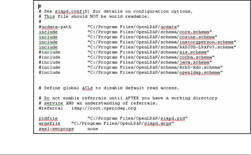
5-66
Using the NAC 800 in a RADIUS-Only Configuration
Configure OpenLDAP
If you are running OpenLDAP on Windows and you installed OpenLDAP
in the Program Files directory, the schema files are located in the follow-
ing directory:
C:/Program Files/OpenLDAP/schema
4. Modify the slapd.conf file, which is located in the main OpenLDAP
directory.
/usr/local/etc/openldap/schema
or
C:/Program Files/OpenLDAP/schema
a. Use a text editor to open the slapd.conf file.
b. Locate the include section, as shown in Figure 5-32.
c. Add a new line to the include section:
include /usr/local/etc/openldap/schema/
RADIUS-LDAPv3.schema
or
include C:/Program Files/OpenLDAP/schema/
RADIUS-LDAPv3.schema
Figure 5-32. The OpenLDAP slapd.conf File

5-67
Using the NAC 800 in a RADIUS-Only Configuration
Configure OpenLDAP
d. Save the change you made to the slapd.conf file and restart the
RADIUS server.
RADIUS Objects
After you extend the schema, OpenLDAP supports the object class
radiusprofile, which includes the attributes needed to allow a person object
to be authenticated through a RADIUS server that uses OpenLDAP as the data
store:
■UID
■userPassword
■dialupAccess
(These are only a few of the attributes that are added when you extend the
OpenLDAP schema to support RADIUS. For a more complete list, see the
ldap_howto.txt file at http://www.freeradius.org/radius/doc.)
If the NAC 800 is configured to use OpenLDAP as its data store and a user
attempts to access the network, the NAC 800 will search the OpenLDAP
directory for these three attributes. If the OpenLDAP schema has not been
extended to include the radiusprofile object and these attributes, OpenLDAP
cannot return values for the attributes. It will appear as if OpenLDAP is
rejecting the NAC 800’s bind request. (For more information about binding to
OpenLDAP, see “Bind to OpenLDAP” on page 5-73.)
Create Objects in OpenLDAP
To add objects such OUs, persons, and GroupofNames to OpenLDAP, you
must create a file and define the objects and their attributes using the Light-
weight Directory Interchange Format (LDIF) format. OpenLDAP can then
recognize the objects and add them to its database.
The LDIF format requires you to type the distinguished name (DN) for the
object you are creating. The DN includes the object name and the context in
the directory tree. You must also specify the object class and the attributes
you are configuring. Each object class has required attributes and optional
attributes. For example, when you create a person object, the CN, SN, and
userPassword attributes are required.

5-68
Using the NAC 800 in a RADIUS-Only Configuration
Configure OpenLDAP
To allow users to be authenticated through a RADIUS server, you add the
radiusprofile object as an auxiliary object class for person objects. When you
define an auxiliary object class, one object class must be used to establish the
object’s place in the directory. You would typically use the person object class
for this purpose. As an auxiliary object, the radiusprofile object class adds the
attributes required to support RADIUS. For the person object, the radiuspro-
file object adds the UID and dailupAccess attributes. The person object
already supports the userPassword attribute.
For the device object, however, the radiusprofile object adds the userPass-
word object as well. This allows the device object to be authenticated through
MAC-Auth.
To create the LDIF file to add objects to your OpenLDAP directory, complete
these steps.
1. Open a text editor and create a file.
2. Use the following syntax to add an OU to the directory:
For example, to create an OU for the Medical Center groups, type:
dn: ou=Medgroups,o=MedCenter.com
objectclass: organizational unit
ou: Medgroups
Syntax: dn: ou=<ou_name>,[o=<mydomain.com> | dc=<mydomain>,dc=<com>]
objectclass: organizational unit
ou: <ou_name>
Defines the OU that you want to create.
To specify the dn, type the ou followed by the location in the
OpenLDAP tree. Depending on how your directory is config-
ured, use either o= or dc= to specify the base dn.

5-69
Using the NAC 800 in a RADIUS-Only Configuration
Configure OpenLDAP
3. Use the following syntax to add a user object to the directory and define
the radiusprofile object as an auxiliary object class:
For example:
dn: cn=Heidi,o=MedCenter.com
objectclass: person
object class: radiusprofile
cn: Heidi
sn: Olson
userPassword: procurve101
uid: Heidi
dialupAccess: true
Syntax: dn: cn=<username>,[o=<mydomain.com> | dc=<mydomain>,dc=<com>]
objectclass: person
objectclass: radiusprofile
cn: <username>
son: <surname>
userPassword: <password>
uid: <username>
dialiupAccess: true
Specifies the user that you want to add to OpenLDAP.
To specify the dn, type the cn followed by the location in the
OpenLDAP tree where you want to create the user. Depending
on how your directory is configured, use either o= or dc=.
If you want to place the user in an OU, include the OU as part
of the dn:
dn: cn=<username>,ou=<ou_name>,[o=<mydomain.com> |
dc=<mydomain>,dc=<com>]
Replace <username>, <surname>, and <password> with infor-
mation specific to each user.
For the dialupAccess attribute, type the true value. This attri-
bute is required for RADIUS authentication.

5-70
Using the NAC 800 in a RADIUS-Only Configuration
Configure OpenLDAP
Because you want to use IDM to manage RADIUS attributes for users and
devices, you will use the person object to create accounts for devices.
That way, they can be imported into IDM. To define a person object for a
headless device, which will be authenticated through MAC-Auth, type:
dn: cn=000E35CE8290,o=MedCenter.com
objectclass: person
objectclass: radiusprofile
cn: 000E35CE8290
sn: printer
userPassword: 000E35CE8290
uid: 000E35CE8290
dialupAccess: true
For MAC-Auth, the userPassword must match the CN and UID, and you
must type it in the format used by the edge switch that submits the
endpoint’s MAC address as the login credentials. By default, the ProCurve
5300xl, 3500yl, 5400zl, and 6200yl Switches use the format aabbccddeeff.
You can define additional attributes for devices. For more information,
visit http://www.openldap.org.
4. To create a group and assign users or devices to that group, type:
Syntax: dn: cn=<group_name>,ou=<OU_name>,[o=<mydomain.com> |
dc=<mydomain>,dc=<com>]
objectclass: groupofnames
cn: <group_name>
member: cn=<username>,[o=<mydomain.com> |
dc=<mydomain>,dc=<com>]
Defines the group that you want to add to OpenLDAP.
Replace <group_name> with the name of the group you are
creating.
Replace <OU_name> and <mydomain> with information spe-
cific to your network.
Replace <username> with a person object that you have
already created in OpenLDAP.
Depending on how your directory is configured, use either o=
or dc= to define the DN.

5-71
Using the NAC 800 in a RADIUS-Only Configuration
Configure OpenLDAP
For example:
dn: cn=Staff,ou=Medgroups,o=MedCenter.com
objectclass: groupofnames
cn: Staff
member: cn=Heidi,o=MedCenter.com
member: cn=Hans,o=MedCenter.com
In a live network, you would, of course, add many users to this group.
5. Save the file with the .LDIF extension and copy it to your OpenLDAP
directory. (If you do not copy the file to your OpenLDAP directory, you
must include the path to the file when you type your ldapadd command,
as described in the next step.)
6. From the command line, move to the OpenLDAP directory and type the
following command. If you do not move to the OpenLDAP directory,
simply include the directory path before the ldapadd command.

5-72
Using the NAC 800 in a RADIUS-Only Configuration
Configure OpenLDAP
For example:
ldapadd -x -D “cn=Manager,o=MedCenter.com” -W -f
newuser.ldif
Syntax: <directory/>ldapadd [options] -f <LDIF_filename>
If you are not in the directory that contains ldapadd, include the
directory path where ldapadd resides in your command.
Options include:
-x
-D “cn=Manager,[o=<mydomain.com> | dc=<mydomain>,dc=com]”
-h <hostname>
-W
-w
Adds the objects specified in the LDIF file to the OpenLDAP
datastore.
Include -x to have the OpenLDAP server sort results before
sending the results to the client.
Include -D and the DN with which to authenticate to the server.
Specify a DN that has rights to search the directory and
enclose it in quotation marks. If your OpenLDAP server
supports anonymous searches, you do not need to include this
option.
Include -h and the hostname of the OpenLDAP server if you
are conducting a remote search. If you do not specify a host,
ldapadd command uses the localhost.
Include -W to be prompted for the password for the DN you
provided with -D.
Use -w to include the password in your ldapadd command. If
you do not specify a password, an anonymous search is used
(but your OpenLDAP server must support anonymous
searches).
Include -f and replace <LDIF_filename> with the name of the
file you created.
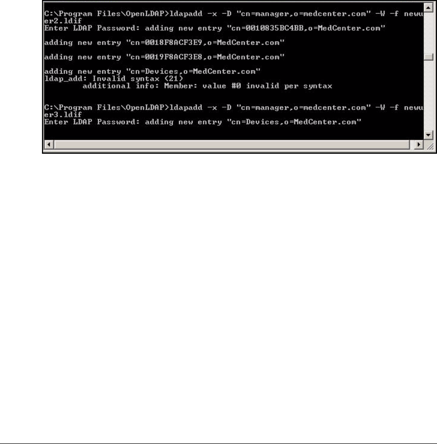
5-73
Using the NAC 800 in a RADIUS-Only Configuration
Configure OpenLDAP
If you use the correct syntax in your LDAPadd command, all the users you
configured will be added, and messages will be displayed at the command
prompt, listing the DN of the users added as shown in Figure 5-33.
If there is a problem with the syntax you typed in the LDIF file, ldapadd
will display a message to notify you of the problem. For example, the LDIF
file may contain entries with incorrect syntax, as shown in Figure 5-33.
You can then correct the LDIF file and re-type the ldapadd command.
Figure 5-33. Adding Users to an OpenLDAP Directory
Bind to OpenLDAP
When you use OpenLDAP as the data store for access controls, the NAC 800
must bind to OpenLDAP before submitting queries to verify users’ or devices’
login credentials. If you are using IDM, it must also bind to OpenLDAP if you
want to import user data from the directory into IDM.
To bind to OpenLDAP, the NAC 800 must know:
■The base DN, or root, of the directory
■The administrator with rights to the entire directory
■Object class for user accounts and the attribute that stores passwords
(userPassword in OpenLDAP)
(You will learn how to configure the OpenLDAP information in the NAC 800
Web browser interface later in this chapter. See “Configure Authentication to
an OpenLDAP Server” on page 5-85.)

5-74
Using the NAC 800 in a RADIUS-Only Configuration
Configure OpenLDAP
If you are using IDM to define policies for your users and you want to import
users from OpenLDAP, you will also need to know:
■Object class for group—groupofnames or groupofuniquenames, depend-
ing on which object class your organization uses
■Attributes for the person and groupofnames (or groupofuniquenames)
objects
(You will learn how to configure this information in IDM later in this chapter.
See “Importing Users from an LDAP Server” on page 5-113.)
Base DN and Administrator
The base DN and the administrator that resides there are defined when
OpenLDAP is installed. If you are not the OpenLDAP administrator, contact
the administrator and request this information. The base DN is typically
defined in one of the following ways:
dc=MedCenter,dc=com
or
o=MedCenter.com
In OpenLDAP, the administrator is a person object that has rights to the entire
directory. This object must be created at the base DN level of the directory.
When specifying the administrator, you typically type the CN and the object’s
context, or place, in the directory. To define a context in OpenLDAP, you must
include the object’s CN, the base DN, and any container objects in between.
Because the administrator must be created at the base DN, you would typically
type something like:
cn=Manager,dc=MedCenter,dc=com
or
cn=Manager,o=MedCenter.com
Configure a Root CA with OpenSSL
Whenever possible, you should use Transport Layer Security (TLS) to protect
the communications between the NAC 800 and the OpenLDAP server. Using
TLS requires you to load a CA certificate on the OpenLDAP server. You must
then load that CA certificate on the NAC 800 as well.

5-75
Using the NAC 800 in a RADIUS-Only Configuration
Configure OpenLDAP
You can request a CA certificate from a CA such as VeriSign. You can also
use OpenSSL to create a root CA certificate and a server, or intermediate,
certificate.
Because OpenLDAP requires OpenSSL (and several other software compo-
nents), you should already be running OpenSSL on your OpenLDAP server.
To create a CA certificate using OpenSSL, complete these steps.
1. Access a command prompt and move to the OpenSSL bin directory. For
example:
cd openssl\bin
If you are using a Linux system and do not move to this directory, include
the directory path where OpenSSL resides on your computer in the
commands that follow.
2. Create the private key for the CA certificate:
For example:
openssl genrsa -out -des3 cakey.pem 1024
3. When prompted, type and re-type a pass phrase (password). Ensure that
you are following best practices for creating a password.
Syntax: openssl genrsa [-out <key_name>] [<encryption options>] <size of
key>
Generates a private CA key.
Replace <key_name> with a name that meets the requirements
of your environment. By default, OpenLDAP is configured to
use the name cakey.pem. (You can change this name by editing
the CA.conf file.)
For encryption options, select one of the following or omit this
option for no encryption:
■-des
■-des3
■-idea
Replace <size of key> with 512, 1024, 2048, or 4096. Include this
option last in your command.
Other options are available for this command. See http://
www.openssl.org/docs/apps/genrsa.html for more informa-
tion.

5-76
Using the NAC 800 in a RADIUS-Only Configuration
Configure OpenLDAP
4. Create the public key and the CA certificate.
For example:
openssl req -x509 -days 365 -key cakey.pem -out ca.pem
5. When prompted, type the information for your directory:
Country name—Specify the two-digit country code.
State name—Specify the complete name of the state or province.
Locality—Specify the name of the city.
Organization—Type the name of the Organization object as defined in the
OpenLDAP.
Organization unit—Type the OU as defined in OpenLDAP.
Common name—Type the DN of your base DN in OpenLDAP.
Email—Type a valid email address.
For the example network, you would enter:
Syntax: openssl req -new -x509 -days <number of days> -key <key_name>
-out <certificate_name>
Generates a public CA key.
Include the -x509 option to generate a certificate (rather than
a request).
Replace <number of days> with the number of days that you
want the certificate to be valid. The default value is 30.
Replace <key_name> with a name that meets the requirements
of your environment. Type the name you specified for the
private key in step 3. By default, OpenLDAP is configured to
use the name cakey.pem.
Replace <certificate_name> with a name that meets the
requirements of your environment. By default, OpenLDAP is
configured to use the name ca.pem.
This command supports numerous options. For more infor-
mation, visit http://www.openssl.org/docs/apps/req.html.

5-77
Using the NAC 800 in a RADIUS-Only Configuration
Configure OpenLDAP
Table 5-12. Entering Information for a CA Certificate
for OpenLDAP
Create an Intermediate Certificate
You must now create an intermediate, or server, certificate.
1. Access a command prompt and move to the OpenSSL bin directory. For
example:
cd openssl\bin
If you do not move to this directory, include the directory path where
OpenSSL resides on your computer in the commands that follow.
2. Generate a private key by typing:
For example:
openssl genrsa -des3 -out serverkey.pem 1024
Encryption Option Security Option
Country name US
State name California
Locality Roseville
Organization MedCenter
Organization unit Medical
Common name MedCenter.com
Email ca@MedCenter.com
Syntax: openssl genrsa [-des | -des3 | idea] -out <server key name> <size of
key>
Generates a private key for the intermediate certificate.
Include -des, -des3, or idea to specify the type of encryption
you want to use.
Replace <server key name> with the name of the public key you
want to generate. OpenLDAP by default uses serverkey.pem as
the server key name.
Replace <size of key> with 512, 1024, 2048, or 4096. Include this
as the last option in your command.

5-78
Using the NAC 800 in a RADIUS-Only Configuration
Configure OpenLDAP
3. When prompted, type and re-type a password.
4. Create a certificate request:
For example:
openssl req -new -key serverkey.pem -out server.pem
5. When prompted, enter the pass phrase for the serverkey.pem.
6. When prompted, type the information for your directory. You should type
the same information you typed when you created the root CA certificate.
See Table 5-13.
Country name—Specify the two-digit country code.
State name—Specify the complete name of the state or province.
Locality—Specify the name of the city.
Organization—Type the name of the Organization object as defined in the
OpenLDAP.
Organization unit—Type the OU as defined in OpenLDAP.
Common name—Type the DN of your base DN in OpenLDAP.
Email—Type a valid email address.
When you are prompted for a challenge password and optional company
name, simply press Enter to skip.
Syntax: openssl req -new -key <server key name> -out <server CSR name>
Generates a certificate request.
Include the -new option to request a new certificate.
Replace <server key name> with the name of the public key you
generated in step 2. For example: serverkey.pem.
Replace <server CSR name> with the name you want to give the
certificate signing request (CSR) name. For example,
servercsr.pem.

5-79
Using the NAC 800 in a RADIUS-Only Configuration
Configure OpenLDAP
Table 5-13. Entering Information for the OpenLDAP Server Certificate
7. Type the following command to sign the request.
Encryption Option Security Option
Country name US
State name California
Locality Roseville
Organization MedCenter
Organization unit Medical
Common name MedCenter.com
Email ca@MedCenter.com
Syntax: openssl x509 -req -days <number of days> -in <server CSR name> -
CA <certificate name> -CAkey <public key name> -set_serial 01 -out
<server certificate name>
Signs a certificate request.
Replace <number of days> with the number of days that you
want the certificate to be valid. The default value is 30.
Replace <server CSR name> with the name you gave the CSR
in step 5. For example, servercsr.pem.
Replace <certificate_name> with the CA certificate you gener-
ated. For example, ca.pem.
Replace <public key name> with the public key you generated.
For example, cakey.pem.
Replace <server certificate name> with the name of the certifi-
cate you want to create. By default, OpenLDAP uses the name
server.pem.
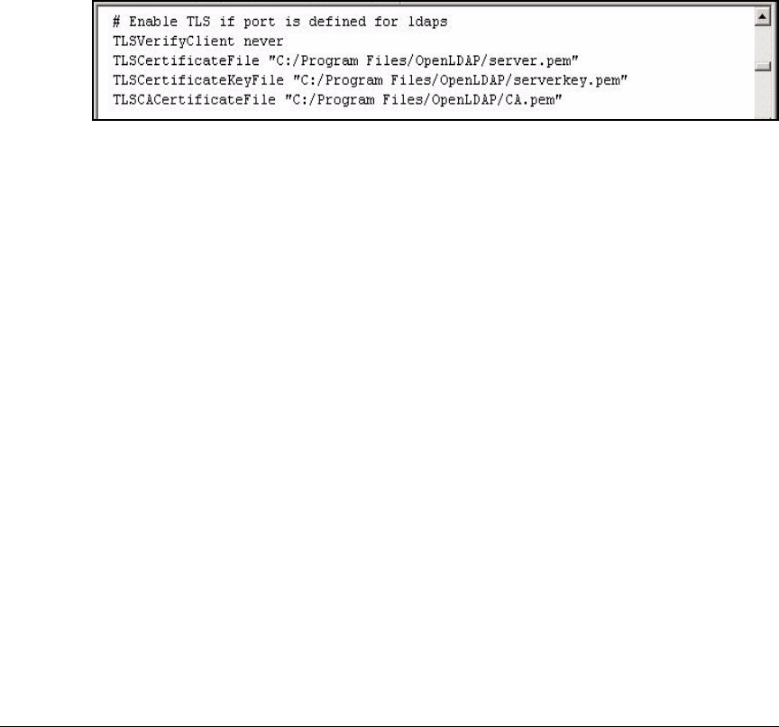
5-80
Using the NAC 800 in a RADIUS-Only Configuration
Configure OpenLDAP
Copy the Keys and Certificates to OpenLDAP
You must then copy the following to the OpenLDAP directory referenced in
the slapd.conf file:
■CA certificate, which is named cacrt.pem in the example
■Server key, which is named serverkey.pem in the example
■Server certificate, which is named servercrt.pem in the example
You must also ensure that the slapd.conf file uses the correct names for the
key and the certificates, as shown in Figure 5-34.
Figure 5-34. Certificate Section in the slapd.conf File
After you copy the files to the directory referenced in the
slapd.conf file and
ensure the names of the key and the certificates are correct, restart Open-
LDAP.
OpenLDAP should by default use TLS. However, you can include the
ldaps://
option when you start slapd to ensure that it uses TLS.
slapd ldaps://

5-81
Using the NAC 800 in a RADIUS-Only Configuration
Configure the NAC 800 for a RADIUS-Only Deployment
Configure the NAC 800 for a RADIUS-
Only Deployment
Other chapters in this implementation guide describe how to deploy the
ProCurve Network Access Controller (NAC) 800 as:
■Both an endpoint integrity solution and a RADIUS server
■Only an endpoint integrity solution
This chapter describes a third option for deploying the NAC 800—as a RADIUS
server only. If you are not yet ready to implement endpoint integrity checking,
you can use the NAC 800’s RADIUS services to:
■Implement 802.1X—You may want to implement 802.1X for your wired
network, your wireless network, or both. For example, an organization
that has been using a directory service (such as OpenLDAP, Active Direc-
tory, or Novell eDirectory) to control access to data and applications
might decide to implement 802.1X to strengthen security. Because the
NAC 800 integrates with these LDAP-compliant directory services, the
organization can easily add a NAC 800 to implement 802.1X.
■Provide redundancy for RADIUS services—If you are using 802.1X as
your access control method, you should eliminate any single point of
failure in your 802.1X setup—including the RADIUS server. Deploying
another RADIUS server provides failover capabilities and can also reduce
the workload on the existing RADIUS server.
The Medical Center IT staff has two reasons for selecting the NAC 800 for their
RADIUS server.
■It is an appliance and can be easily added to the existing network.
■It allows you to implement endpoint integrity checking at a later time.
Data Store Overview
When you deploy the NAC 800 as a RADIUS server, you must decide which
data store you will use. The NAC 800 can search one of several data stores for
a user’s credentials:
■A local database of users
■A Windows domain controller, which runs Active Directory
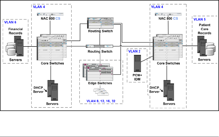
5-82
Using the NAC 800 in a RADIUS-Only Configuration
Configure the NAC 800 for a RADIUS-Only Deployment
■An LDAP server:
• OpenLDAP
• Novell eDirectory
■Another RADIUS server (via a proxy request)
This section provides instructions for using OpenLDAP.
Configuration Options
This access control solution has two NAC 800s, which are configured as
combination servers (CSs). All the settings are established on each CS indi-
vidually.
Because you are using both NAC 800s as RADIUS servers, you will use the
802.1X deployment method. For this deployment method, you can place the
NAC 800 as you would any RADIUS server. Network access servers (NASs)
throughout the network will need to contact the NAC 800, so you should
typically place it in a server VLAN in the network core.
Refer to the ProCurve Network Access Controller 800 Hardware Installation
Guide for more detailed mounting and installation instructions.
Figure 5-35. Placing the NAC 800s in the Network Core

5-83
Using the NAC 800 in a RADIUS-Only Configuration
Configure the NAC 800 for a RADIUS-Only Deployment
Initial Setup
After you install the NAC 800s, use the following settings to set up each one,
completing the steps outlined in “Configure Basic Settings on the NAC 800s”
on page 2-135 of Chapter 2: “Implementing 802.1X with ProCurve IDM and
Endpoint Integrity.”
■Server type = CS
■Hostname = CSa.MedCenter.com or CSb.MedCenter.com
■IP address = 10.4.7.50 or 10.4.6.50
■DNS server = 10.4.4.15 and 10.4.5.15
■SNMP community = procurvero
Note To manage NAC 800s through PCM+, you must configure the read-only and
read-write SNMP community on PCM+ to use the same community name. In
the example, you would type procurvero for both the read-only and read-write
communities.
Device Access
Configure the following settings to control access to the NAC 800:
Administrator access
■Administrator name = managernac
■Password = procurve0
Operator
■Operator name = operatornac
■Password = procurve0
Linux shell
■Root administrator name = root
■Password = procurve0
Specify the Quarantine Method (802.1X)
To act as a RADIUS server, the ProCurve NAC 800 must use the 802.1X
quarantine method. (However, you then disable the actual quarantining. See
“Configure Exceptions” on page 5-101.)
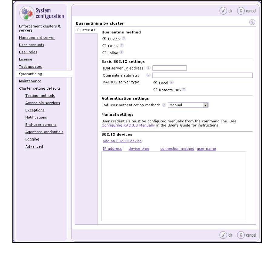
5-84
Using the NAC 800 in a RADIUS-Only Configuration
Configure the NAC 800 for a RADIUS-Only Deployment
Complete the following steps:
1. Select Home > System configuration > Quarantining.
If the NAC 800 is configured as a CS (as it is in the example network), the
default and only cluster is automatically selected. If you have a multiple
NAC 800 deployment (MS and multiple ESs), choose the cluster that
includes the RADIUS server ESs.
2. In the Quarantine method area, select 802.1X.
Figure 5-36. Home > System configuration > Quarantining

5-85
Using the NAC 800 in a RADIUS-Only Configuration
Configure the NAC 800 for a RADIUS-Only Deployment
3. In the Basic 802.1X settings area, type the IP address of the server that runs
PCM+ with IDM in the IDM server IP address box. For example, type
10.2.0.50.
4. For the RADIUS server type, select Local.
Note If you select Remote IAS for the RADIUS server type, you must also edit the
SAIASConnector.in file. For more information, see Chapter 3: Implementing
802.1X with Endpoint Integrity but without IDM.
You have now enabled the NAC 800 to make access control decisions as a
RADIUS server. Next, you must configure the RADIUS server’s authentication
settings.
Note The Quarantine subnets box applies only if the NAC 800 enforces endpoint
integrity. This setting allows the NAC 800 to respond to DNS requests from
endpoints in quarantine VLANs.
Configure Authentication to an OpenLDAP Server
This section describes how to configure the NAC 800’s authentication settings
to verify accounts through an OpenLDAP server. You should have already
completed the steps outlined in the preceding section.
1. From the Home > System configuration > Quarantining window, select Open-
LDAP for the End-user authentication method.
The OpenLDAP settings and Test OpenLDAP settings areas are displayed.
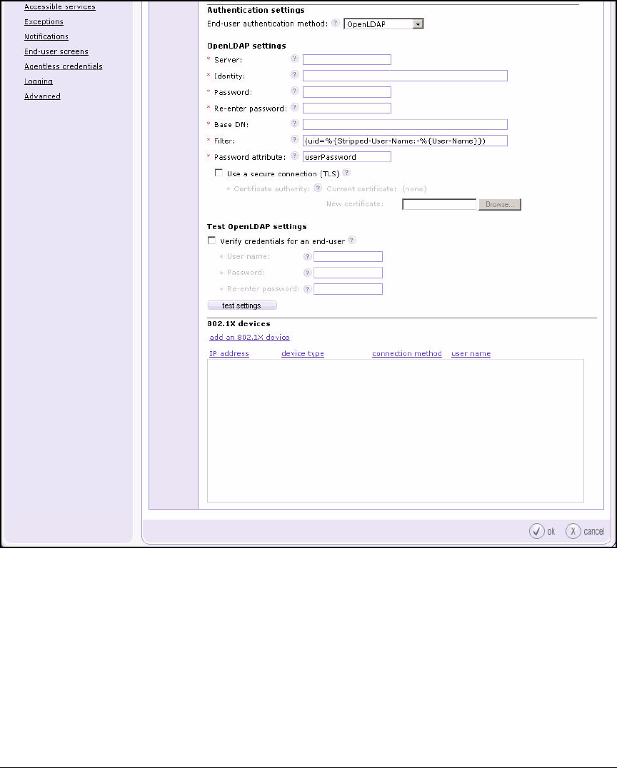
5-86
Using the NAC 800 in a RADIUS-Only Configuration
Configure the NAC 800 for a RADIUS-Only Deployment
Figure 5-37. Home > System configuration > Quarantining—OpenLDAP
Authentication Method
2. In the Server box, type the hostname or IP address of the OpenLDAP
server. For example:
10.2.1.10
If your OpenLDAP server is not using the standard port, append a colon
and port number to the IP address to specify the port it uses. For example:
10.2.10.10:1000

5-87
Using the NAC 800 in a RADIUS-Only Configuration
Configure the NAC 800 for a RADIUS-Only Deployment
If you do not specify the port, the NAC 800 uses one of the following:
• Uses port 389 if the connection is not secure
• Uses port 636 if the connection is secure
Step 9 on page 5-89 explains how to choose a secure connection.
Note If you specify a hostname, remember to check the NAC 800’s DNS server
setting to ensure that it is configured to use the correct server. Select Home
> System configuration > Management server. To edit the DNS server setting,
click edit network settings under Network settings.
3. In the Identity box, type the DN of an object in the directory with admin-
istrative rights.
Type the name in standard LDAP format. For example:
cn=Manager,o=MedCenter.com
or
cn=Manager,dc=MedCenter,dc=com
4. In the Password box, type the password for the object specified in the
previous step.
5. In the Re-enter password box, type this password again.
6. In the Base DN box, type the DN for the object at which the NAC 800 begins
searches—almost always the DN of the top level of the tree.
For example:
cn=Manager,o=MedCenter.com
or
dc=MedCenter,dc=com
The administrator specified in the Identity box should be in the base DN.
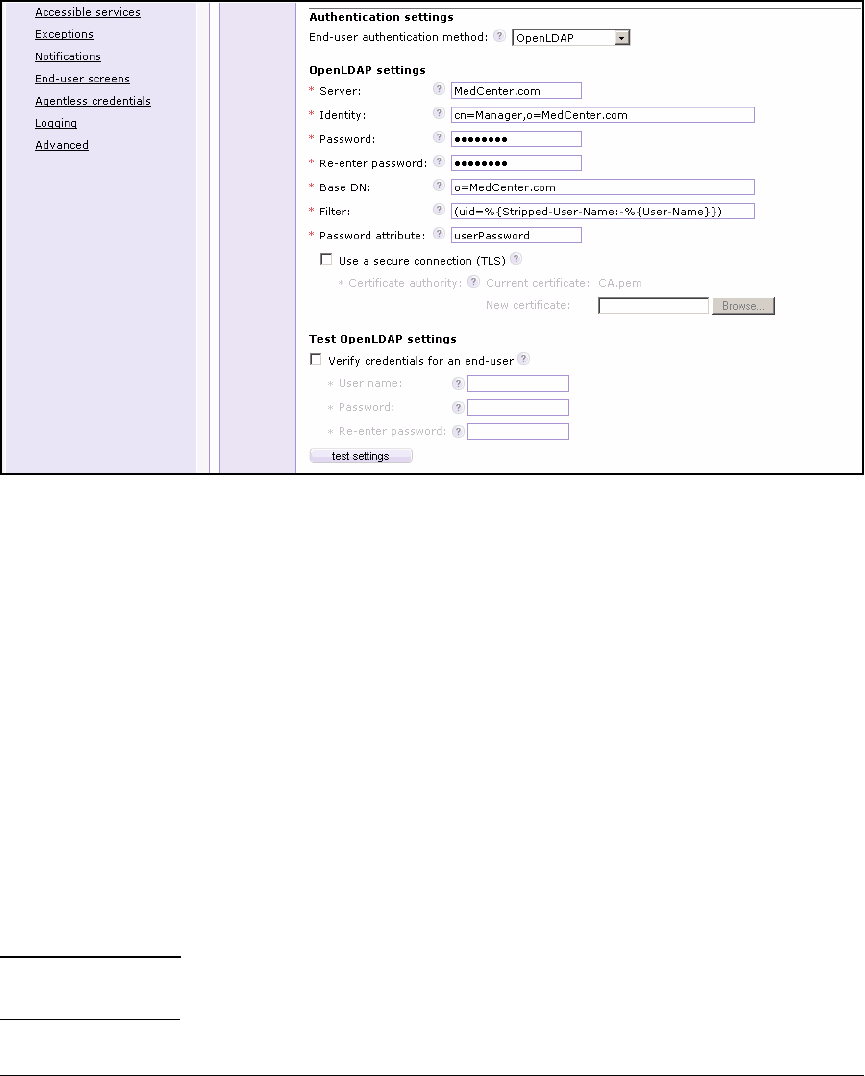
5-88
Using the NAC 800 in a RADIUS-Only Configuration
Configure the NAC 800 for a RADIUS-Only Deployment
Figure 5-38. Home > System configuration > Quarantining—OpenLDAP
Authentication Method
7. Typically, leave Filter and Password attribute at their default settings.
The user filter and password attribute help the NAC 800 perform searches
within the directory. Your settings must match up with attribute names
used in your OpenLDAP installation, and the syntax must follow LDAP
syntax.
The default filter is shown in Figure 5-37; it tells the NAC 800 to search
for an entry in which the “uid” attribute equals whatever username is
submitted in an authentication request. (The “Stripped-User-Domain”
portion of the filter allows the NAC 800 to remove an appended domain
name, which may be necessary to match the uid as stored in the directory.)
The password attribute (default “userPassword”) must match the name
of the attribute that stores passwords in your directory. Remember the
OpenLDAP directory must allow the NAC 800 “auth” access to this attri-
bute.
Note Be careful when altering the default settings: if you cause searches to fail,
you effectively lock out all users.

5-89
Using the NAC 800 in a RADIUS-Only Configuration
Configure the NAC 800 for a RADIUS-Only Deployment
8. Select the Use a secure connection (TLS) box.
ProCurve Networking recommends that you always enable this option.
The NAC 800 and the OpenLDAP server then perform a TLS handshake
to authenticate each other, as well as set up encryption keys to secure the
connection.
9. If you selected the box in the previous step, verify that the NAC 800 has
the proper certificate authority (CA) certificate.
The NAC 800 requires the CA certificate for the CA that signed the
OpenLDAP server’s certificate. (For information on configuring a CA
certificate on OpenLDAP, see “Configure a Root CA with OpenSSL” on
page 5-74.) Save this certificate on your management station. Then click
Browse next to New certificate to upload it to the NAC 800.
10. To verify that the NAC 800 can successfully bind to the OpenLDAP server,
click test settings.
See “Test Authentication Settings” on page 5-89 for more information on
setting up the test.
Note You may receive a message that the test failed because the LDAP query
returned no results. Do not worry: although the search did not return any
results, the bind completed successfully.
You can successfully bind to OpenLDAP in this test even if you have not
extended the OpenLDAP schema to support RADIUS. However, when a user
attempts to log in and the NAC 800 submits a RADIUS request to OpenLDAP,
the directory will not be able to respond appropriately. It will appear as if
OpenLDAP is rejecting the bind request. For more information, see “Extend
the OpenLDAP Schema to Support RADIUS” on page 5-64.
For information about other result messages, see Table 5-14 on page 5-93.
You are now ready to specify your network’s NASs. (See “Add NASs as 802.1X
Devices” on page 5-94.)
Test Authentication Settings
After configuring the OpenLDAP test method, you should test whether the
NAC 800 can:
■Contact the directory
■Bind to it
■Optionally, perform a successful search
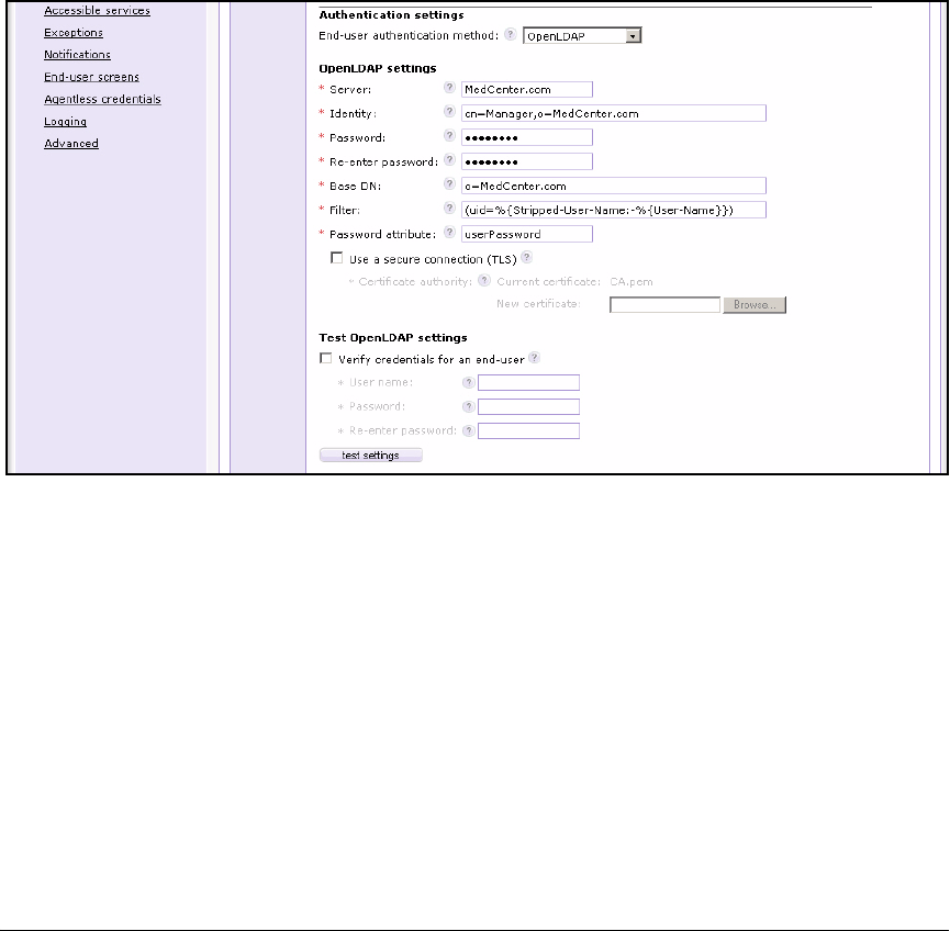
5-90
Using the NAC 800 in a RADIUS-Only Configuration
Configure the NAC 800 for a RADIUS-Only Deployment
You should test the settings to eliminate problems before the NAC 800 begins
to authenticate end-users on a live network.
Before testing these settings, you must complete the steps listed in:
■“Specify the Quarantine Method (802.1X)” on page 5-83
■“Configure Authentication to an OpenLDAP Server” on page 5-85
1. Locate the Test OpenLDAP settings area on the Home > System configuration
> Quarantining window, as shown in Figure 5-39.
Figure 5-39. Home > System configuration > Quarantining
2. If you are configuring a CS, you can skip this step. Otherwise, you must
select an ES from the Server to test from list.
In a multiple NAC 800 deployment, ESs (not the MS) bind to the LDAP
server when they need to authenticate end-users. When you test settings,
you must choose the appropriate ES.
3. Complete one of two tests:
• Test the bind operation only.
Click test settings.
This test verifies that:
– The NAC 800 can reach the domain controller or LDAP server.
– The administrator username and password are correct.
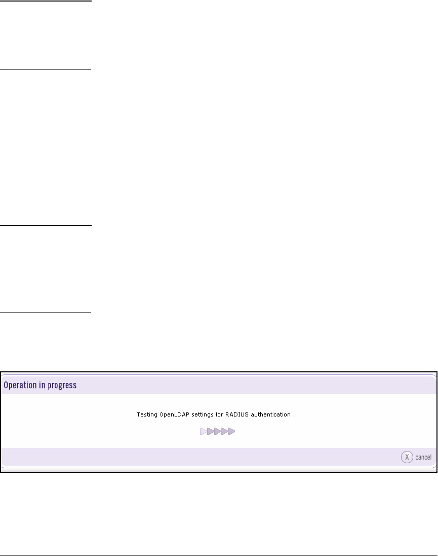
5-91
Using the NAC 800 in a RADIUS-Only Configuration
Configure the NAC 800 for a RADIUS-Only Deployment
Note If you choose this option, you may receive a message that the test
failed because the LDAP query returned no results or multiple results.
Do not worry: although the search didn’t return results, the bind
completed successfully. See Table 5-14 for results that do indicate a
problem.
• Test the bind operation and look up an end-user’s credentials:
i. Check the Verify credentials for an end-user box.
ii. Type the username for a valid user in the User name box.
iii. Type the user’s password in the Password box.
iv. Re-type the password in the Re-enter password box.
v. Click test settings.
This test verifies that:
– The NAC 800 can reach the LDAP server.
– The administrator username and password are correct.
– The filter and password attribute are correct.
– The end-user credentials that you typed are correct.
Note When you first test a configuration with the Verify credentials for an end-
user option, choose an end-user username and password that you are
certain are correct (for example, the administrator password). In that way,
you verify that the configuration itself functions correctly.
Later, if a particular user has difficulty connecting, you can use the Verify
credentials for an end-user option to check the user’s credentials.
The Operation in progress window is displayed.
Figure 5-40 shows the window for testing LDAP authentication settings.
Figure 5-40. Home > System configuration > Quarantining > test settings button
You might see, instead, the window shown in Figure 5-41.

5-92
Using the NAC 800 in a RADIUS-Only Configuration
Configure the NAC 800 for a RADIUS-Only Deployment
Figure 5-41. Home > System configuration > Quarantining > test settings button
This window is displayed when you have edited previously configured
authentication settings. To test the new settings, the NAC 800 must
temporarily write them over the old settings, which—if the NAC 800 is the
RADIUS server for an active network—can briefly interrupt service.
Click no to cancel the test (in which case you should also wait before
applying your new settings).
Click yes to proceed with the test.
Note that proceeding with the test only temporarily overwrites the old
settings. You must still click ok in the Home > System configuration >
Quarantining window to save the new settings.
When the test completes, you are returned to the Home > System configu-
ration > Quarantining window. The message at the top of the window
indicates the result. Refer to Table 5-14 for help interpreting the message.

5-93
Using the NAC 800 in a RADIUS-Only Configuration
Configure the NAC 800 for a RADIUS-Only Deployment
Table 5-14. Authentication Settings Test Results
Message Result Possible Cause of Failure
LDAP settings successfully
validated.
• The NAC 800 successfully bound to the
LDAP server.
• The NAC 800 successfully validated
the test credentials.
Test failed: LDAP query returned no
results.
• The NAC 800 successfully bound to the
LDAP server.
• You didn’t ask to verify credentials.
Test failed: LDAP query returned
more than one result.
• The NAC 800 successfully bound to the
LDAP server.
• You didn’t ask to verify credentials.
Test failed: [LDAP: error code 48 -
Inappropriate Authentication].
The NAC 800 failed to bind to the LDAP
server.
The bind password is incorrect.
Test failed: could not authenticate
identity.
The NAC 800 failed to bind to the LDAP
server.
• The bind username is incorrect.
• The base DN is incorrect.
Test failed: [LDAP: error code 32 -
NDS error: no such entry (-601)]
The NAC 800 failed to bind to the LDAP
server.
• The bind username is incorrect.
• The base DN is incorrect.
Test failed: [LDAP: error code 13 -
Confidentiality Required]
The NAC 800 failed to bind to the LDAP
server.
The LDAP server requires TLS, but this
option is not selected.
Test failed: connection error
(Connection refused).
The NAC 800 failed to bind to the LDAP
server.
The LDAP server requires TLS, but this
option is not selected.
Test failed: could not verify server's
certificate signature.
The NAC 800 failed to bind to the LDAP
server.
The CA certificate for TLS
authentication does not match the LDAP
server’s CA certificate.
Test failed: end-user <username>
not found.
• The NAC 800 successfully bound to the
LDAP server.
• The NAC 800 failed to validate the test
credentials.
• The test username is incorrect.
• The base DN is incorrect.
• The filter specifies the wrong
attribute name.
Test failed: password for end user
<username> is invalid.
• The NAC 800 successfully bound to the
LDAP server.
• The NAC 800 failed to validate the test
credentials.
The test password is incorrect.
Test failed: Attribute <attribute
name> not found.
• The NAC 800 successfully bound to the
LDAP server.
• The NAC 800 failed to validate the test
credentials.
The password attribute is incorrect.

5-94
Using the NAC 800 in a RADIUS-Only Configuration
Configure the NAC 800 for a RADIUS-Only Deployment
Add NASs as 802.1X Devices
A NAS is the device to which end-users connect—typically, a switch or an AP.
The NAS enforces port authentication on end-user ports, forwarding users’
authentication requests to a RADIUS server.
You must add each NAS that uses the NAC 800 as its RADIUS server to the
NAC 800’s list of 802.1X devices.
Note The NASs are often called RADIUS clients. The Web browser interface,
however, as well as this guide, will refer to them as 802.1X devices.
Follow these steps to add the 802.1X devices:
1. Complete the steps listed in “Specify the Quarantine Method (802.1X)” on
page 5-83.
2. Complete the steps for your selected authentication method. (See “Con-
figure Authentication to an OpenLDAP Server” on page 5-85.)
You should see a window similar to that illustrated in Figure 5-42.
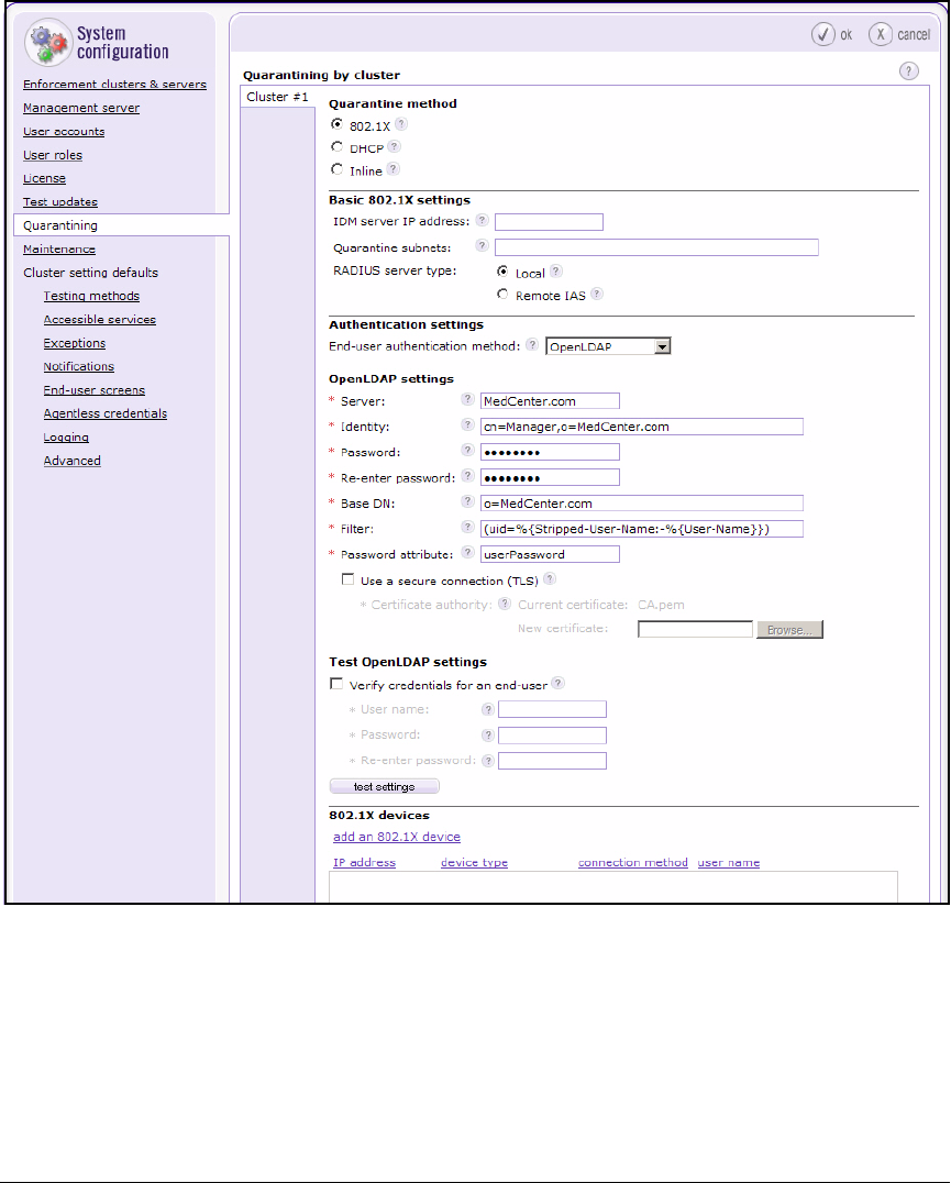
5-95
Using the NAC 800 in a RADIUS-Only Configuration
Configure the NAC 800 for a RADIUS-Only Deployment
Figure 5-42. Home > System configuration > Quarantining—802.1X quarantine
method
3. Click add an 802.1X device. The Add 802.1X device window is displayed.

5-96
Using the NAC 800 in a RADIUS-Only Configuration
Configure the NAC 800 for a RADIUS-Only Deployment
4. Type the 802.1X device’s IP address in the IP address box.
For example, in the example network endpoints connect to an edge switch
that has 10.2.0.3 for its management IP address. Type: 10.2.0.3.
For the example network, you would add all the edge switches and the
Wireless Edge Services Module as 802.1X devices.
5. Type a character string in the Shared secret box.
This string and the RADIUS server secret configured on the 802.1X device
must match exactly. You set this secret on the Wireless Edge Services
Module in “Configure WLAN Settings” on page 5-25. (See your device’s
documentation for more information on configuring this secret. Or use
PCM Plus’s Secure Access Wizard, described in the ProCurve Identity
Driven Manager User’s Guide.)
The secret can include alphanumeric and special characters.
6. Type the same character string in the Re-enter shared secret box.
7. Optionally, give the 802.1X device a descriptive name by typing a string in
the Short name box.
The name is displayed in logs and can include alphanumeric and special
characters.
8. From the Device type list, choose the type of 802.1X device (that is, its
manufacturer and OS).
The list includes several common devices, but the NAC 800 supports any
device that can act as a standard RADIUS client. If your device is not listed,
select Other.
9. Options for connecting to the selected device are displayed.
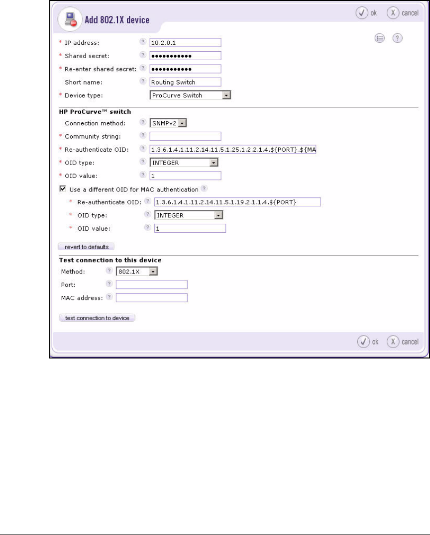
5-97
Using the NAC 800 in a RADIUS-Only Configuration
Configure the NAC 800 for a RADIUS-Only Deployment
Figure 5-43. Home > System configuration > Quarantining (802.1X quarantine
method) > Add an 802.1X device
Because you are using the NAC 800 as a RADIUS server only, the connec-
tion settings do not matter.
Leave the settings at the defaults; or for the ProCurve Wireless Edge
Services Module, ProCurve 420 AP, and ProCurve 530 AP, fill in only the
community name.
10. Click ok.
11. To apply and save the 802.1X device configuration, you must also click ok
in the Home > System configuration > Quarantining window.

5-98
Using the NAC 800 in a RADIUS-Only Configuration
Configure the NAC 800 for a RADIUS-Only Deployment
Apply Changes
Whenever you alter the configuration for the 802.1X and RADIUS settings
(including adding an 802.1X device), you must apply and save the changes.
When you apply the changes, the CS’s internal RADIUS server or the RADIUS
servers on all ESs in the cluster automatically restart.
Note The RADIUS server typically takes several seconds to restart. During this
period, the RADIUS server is unavailable for authenticating end-users. To
avoid interrupting services, configure 802.1X quarantining settings after
hours.
If you have not already done so, click ok in the Home > System configuration >
Quarantining window.
Clicking ok writes the change to both the startup-config and the running-
config.
Restart the RADIUS Server
Follow these steps if you need to restart the RADIUS server manually:
1. Select Home > System configuration > Enforcement clusters & servers.
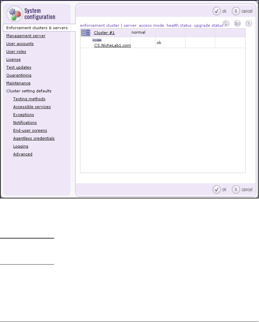
5-99
Using the NAC 800 in a RADIUS-Only Configuration
Configure the NAC 800 for a RADIUS-Only Deployment
Figure 5-44. Home > System configuration > Enforcement clusters & servers
2. Click the name of the CS or ES. The Enforcement server window is dis-
played.
Note Figure 5-45 shows the Enforcement server window for a CS. The window for an
ES features two menu options: General and Configuration. You should select
the General menu option.
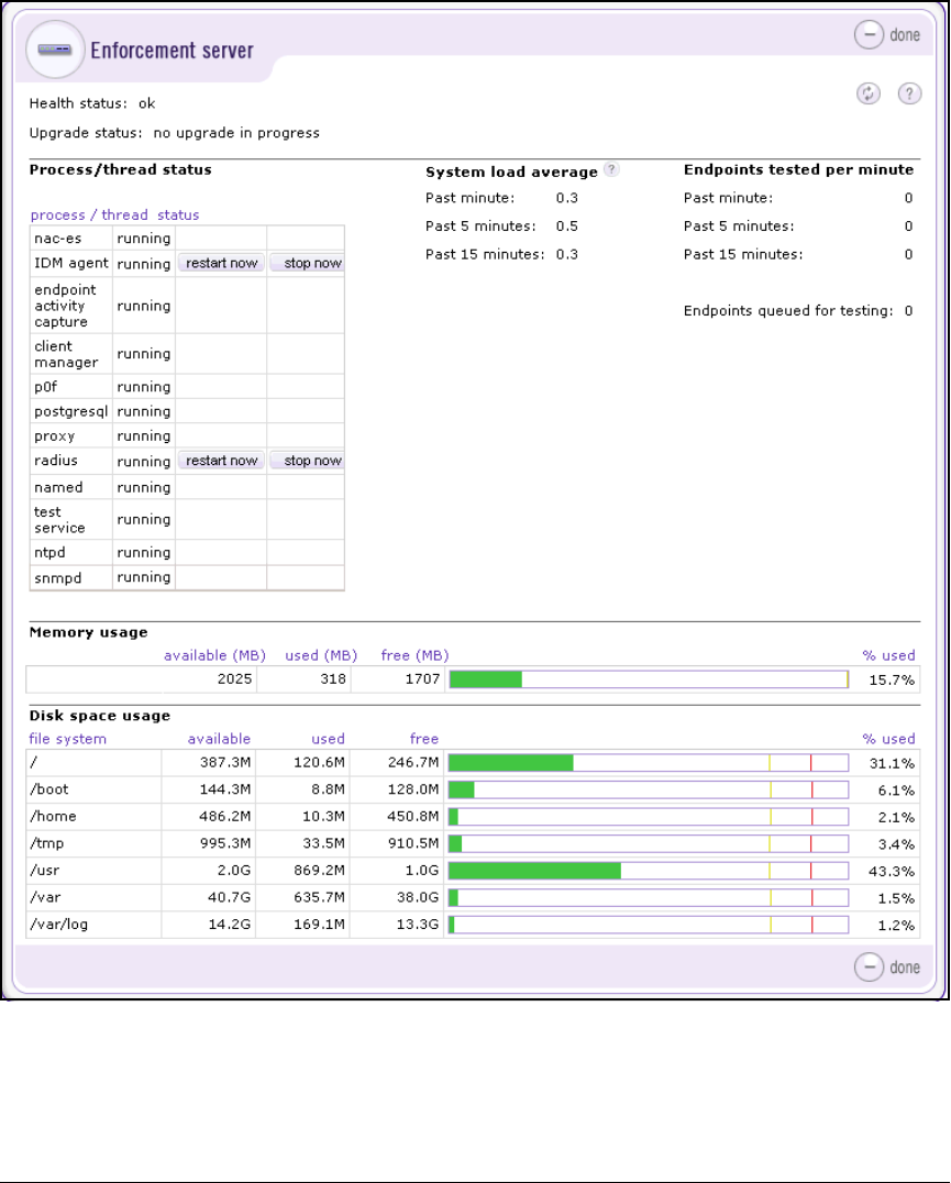
5-100
Using the NAC 800 in a RADIUS-Only Configuration
Configure the NAC 800 for a RADIUS-Only Deployment
Figure 5-45. Home > System configuration > Enforcement clusters & servers >
selected Enforcement server
3. The Process/thread status area lists a number of services. Click restart now
for radius. The Operation in progress window is displayed.
5-101
Using the NAC 800 in a RADIUS-Only Configuration
Configure the NAC 800 for a RADIUS-Only Deployment
Figure 5-46. Home > System configuration > Enforcement clusters & servers >
selected Enforcement server > radius restart now button
4. Within several seconds, the Operation in progress window should close.
At the top of the Enforcement server window, this message should be
displayed:
The radius process was restarted.
Note Typically, the RADIUS server restarts without a problem. If it encounters
difficulties, you should restart it from the root of the OS. Follow these steps:
1. Open an SSH or console session with the NAC 800.
2. When asked for your username and password, type root and the root
password (default, procurve).
3. Type this command:
service radiusd restart
4. Read any messages that display. For example, if you have altered config-
uration files, one of the files might have an error and fail to load.
Configure Exceptions
On the NAC 800, you configure exceptions for endpoints that you do not want
tested for endpoint integrity. When you designate an endpoint as an exception,
the NAC 800 discovers but does not test that endpoint.
To configure exceptions, you can type an address or a Windows domain name.

5-102
Using the NAC 800 in a RADIUS-Only Configuration
Configure the NAC 800 for a RADIUS-Only Deployment
For an address, you can specify:
■IP address—Type individual IP addresses or a range of IP addresses
using Classless Inter-Domain Routing (CIDR) format. For example, you
might type:
10.5.0.0/16
10.6.0.0/16
■MAC address—Use the standard MAC address format: FF:FF:FF:FF:FF.
For example, you might type:
00:11:43:66:68:CC
■NetBIOS name—To provide backward compatibility with a legacy Win-
dows system, type the NetBIOS name assigned to the device. For example,
you might type:
MyLaptop
To exclude an entire domain, type your organization’s domain name, such as:
ABCCompany.com
Because you are setting up the NAC 800 to function as a RADIUS server only,
you will typically specify a range or several ranges of addresses or a domain
name.
Configure Exceptions for the Cluster Default Settings
To configure exceptions as part of the cluster default settings, which are then
applied to all clusters, complete the following steps:
1. Select Home > System configuration.
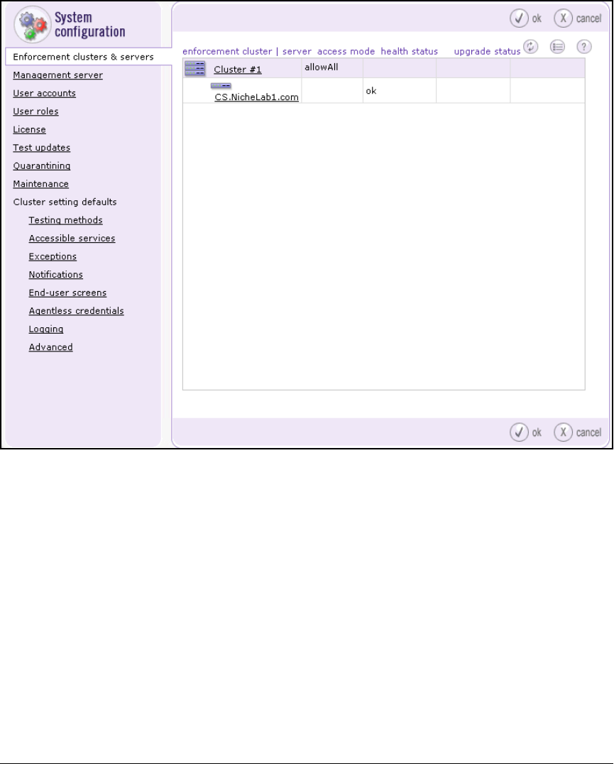
5-103
Using the NAC 800 in a RADIUS-Only Configuration
Configure the NAC 800 for a RADIUS-Only Deployment
Figure 5-47. Home > System configuration
2. Select Cluster setting defaults > Exceptions.
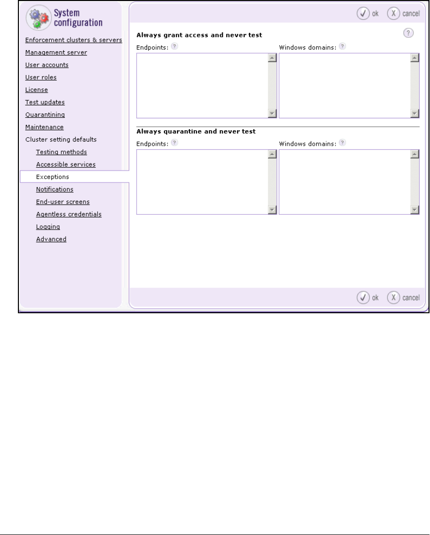
5-104
Using the NAC 800 in a RADIUS-Only Configuration
Configure the NAC 800 for a RADIUS-Only Deployment
Figure 5-48. Home > System configuration > Cluster setting defaults > Exceptions
3. Under Always grant access and never test, type either the addresses of
endpoints or the domain name you want to exclude.
•Under Endpoints, type an IP address, a range of IP addresses in CIDR
format, a MAC address, or a NetBIOS name.
•Under Windows domain, type the domain name.
Separate addresses and names with carriage returns, as shown below:
10.2.0.0.0/16
10.4.0.0/16
10.5.0.0/16
10.6.0.0/16
10.12.0.0/16
10.16.0.0/16
10.32.0.0/16
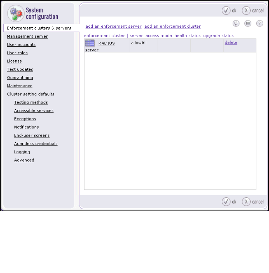
5-105
Using the NAC 800 in a RADIUS-Only Configuration
Configure the NAC 800 for a RADIUS-Only Deployment
4. Click ok.
Configure Exceptions for a Particular Cluster
If you want to disable endpoint integrity for only one of the clusters you have
configured on the Management Server (MS), complete the following steps:
1. Select Home > System configuration.
Figure 5-49. Home > System configuration
2. Click Enforcement clusters & servers and select the link for the cluster that
implements RADIUS without endpoint integrity.
The Enforcement cluster window is displayed.
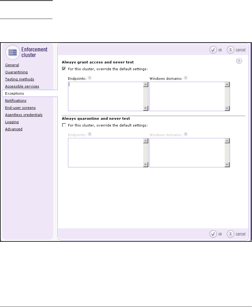
5-106
Using the NAC 800 in a RADIUS-Only Configuration
Configure the NAC 800 for a RADIUS-Only Deployment
3. Click Exceptions.
Note The settings you configure for a particular cluster override the cluster setting
defaults.
4. Select the For this cluster, override the default settings check box.
Figure 5-50. Home > System configuration > Enforcement clusters & servers >
cluster_name > Exceptions

5-107
Using the NAC 800 in a RADIUS-Only Configuration
Configure the NAC 800 for a RADIUS-Only Deployment
5. Under Always grant access and never test, type either the addresses of
endpoints or the domain name you want to exclude.
•Under Endpoints, type an IP address, a range of IP addresses in CIDR
format, a MAC address, or a NetBIOS name.
•Under Windows domain, type the domain name.
Separate addresses and names with carriage returns, as shown below:
10.5.0.0/16
10.6.0.0/16
MedCenter.com
6. Click ok.

5-108
Using the NAC 800 in a RADIUS-Only Configuration
Configuring Network Access Control with IDM
Configuring Network Access Control
with IDM
IDM enables you to implement granular, user-based network access control
more easily than is possible by configuring a RADIUS server directly. In this
section, you learn how to configure IDM to assign rights to successfully
authenticated users.
You must complete the following steps:
1. Install and complete the initial setup on PCM+. For installation and setup
instructions, see “Install PCM+” on page 2-203 of Chapter 2: “Implement-
ing 802.1X with ProCurve IDM and Endpoint Integrity.”
2. Add the NAC 800s to the list of devices allowed to access the PCM+/IDM
server.
3. Import users from OpenLDAP.
4. Define resources to be controlled.
5. Define times and locations.
6. Create profiles (sets of rights).
7. Configure access policy group rules to assign profiles to users based on
various conditions.
Add NAC 800s to the Access.txt File
IDM will not add a NAC 800 to its list of managed devices unless the NAC 800’s
IP address is listed in the server’s access.txt file. To add the NAC 800 to this
file, complete these steps:
1. On the IDM server, open C:\Program Files\Hewlett-Packard\PNM\server\
config\access.txt.
Open the file in a text-based editor such as Notepad or Wordpad.
2. Add each NAC 800’s IP address or hostname on its own line. If you have
a NAC 800 cluster, you only need to add the ESs. In the example network,
you would add both CSs. For example:
10.4.7.50
10.4.6.50
3. Save and close the file.

5-109
Using the NAC 800 in a RADIUS-Only Configuration
Configuring Network Access Control with IDM
4. Open PCM+ and click the Identity Manager tab.
5. Expand your realm.
6. Expand the Network Access Controller 800 folder.
7. Verify that the NAC 800s appear below.
Import Users
IDM includes an Import Wizard, which allows you to add users to IDM from
another source, such as an LDAP v3 server. The IDM Import Wizard also
synchronizes the IDM user database with the import source directory and
allows you to delete users from the IDM user database that are not found in
the import source directory.
IDM does this by copying the list of users from the directory to an XML file,
comparing users in the XML file to users in the IDM user database, and listing
the differences for you to add or remove the mismatched users in the IDM
user database.
Importing users from your directory services allows you to automatically
populate your IDM directory. If the directory service contains group assign-
ments, users can be automatically assigned to the appropriate policy group
(based on membership in the directory service).
To keep IDM up-to-date with changes made to OpenLDAP, you can periodically
import users from the directory.
Install the OpenLDAP Server’s CA Certificate on PCM+
Whenever possible, you should use SSL to secure the communications
between the PCM+ server and the OpenLDAP server. You should first ensure
that your OpenLDAP server supports SSL, as explained in “Configure a Root
CA with OpenSSL” on page 5-74.
You must then load the OpenLDAP server’s CA certificate on PCM+. If you are
not the OpenLDAP administrator, contact the appropriate person to get
the CA certificate that the OpenLDAP server is using. Then complete the
following steps:
1. Copy the certificate to the PCM+ Java trust store. If PCM is installed under
Program Files\Hewlett-Packard, the Java trust store is in the following
directory:
C:\Program files\Hewlett-Packard\PNM\jre\
lib\security
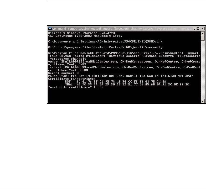
5-110
Using the NAC 800 in a RADIUS-Only Configuration
Configuring Network Access Control with IDM
2. Access the command prompt and move to this directory. Type:
3. During the process of loading the certificate, PCM+ displays a prompt,
asking you if you want to trust this certificate. Answer Yes.
Figure 5-51. Loading the OpenLDAP Server’s Certificate on PCM+
If the certificate is imported successfully, the following message is dis-
played:
Certificate was added to the keystore.
4. Restart the PCM+ server.
Syntax: C:> ..\..\bin\keytool -import -file <ldapcertfile> -alias myldapcert
-keystore cacerts -keypass <certificate_password> -trustcacerts
-storepass <keystore_password>
Replace <ldapcertfile> with the name of the CA certificate on
your OpenLDAP server.
Replace <certificate_password> with the password assigned to
the CA certificate.
Replace <keystore_password> with the password assigned to
the PCM+ keystore. The default keystore password is changeit.

5-111
Using the NAC 800 in a RADIUS-Only Configuration
Configuring Network Access Control with IDM
Editing IDM Configuration for LDAP Import
The IDM server includes several configuration files that control how user and
group information is imported from OpenLDAP. The default configuration
settings will work if you are using Microsoft Active Directory. If you are using
another LDAP directory—such as OpenLDAP or Novell eDirectory—you will
need to modify the LDAP directory settings in:
C:\Program Files\Hewlett-Packard\PNM\server\config\
IDMImportServerComp.scp
The default settings in the IDMImportServerComp.scp file are shown below.
Comments are indicated by "//".
LDAP_SERVER_CONFIG {
PORT=389 //Port where LDAP server receives bind
request.
SSL_PORT=636 // Port where LDAP server receives SSL
bind requests.
BATCH_SIZE=50 // Internal to IDM.
COUNT_LIMIT=0 // Internal to IDM.
SASL_CONFIGURATION { // This section is for SSL
configuration: Digest MD5, Kerberos V5 and External.
QOP=auth-conf,auth-int,auth // Quality of protection.
Valid values are 1 and more of "auth-conf", auth-int",
"auth" separated by ",".
ENCRYPTION_STRENGTH=high,medium,low // Strength of
encryption. Valid values are 1 and more of "high",
"medium", "low" separated by ",".
MUTUAL_AUTHENTICATION=true // If both LDAP server and
IDM server wants to authenticate each other. }
KERBEROS_JAAS_CONFIG { // This section is for Kerberos
authentication method.
KERBEROS_AUTH_MODULE=IDMKerberos // Kerberos authen-
tication module name. If this entry is changed, you
must also change the module name in
idm_kerberos_jass.conf file.
KERBEROS_JAAS_CONFIG_FILE=config/
idm_kerberos_jaas.conf // configuration file for JAAS
Kerberos configuration. } }
LDAP_DIRECTORY_CONFIG {Configuration for LDAP direc-
tory. Following values are for Active Directory. Change
as needed per object class and attributes in LDAP

5-112
Using the NAC 800 in a RADIUS-Only Configuration
Configuring Network Access Control with IDM
directory being used.
USER { // User object
OBJECT_CLASS=User // User object class
LOGON_NAME=sAMAccountName // Login name attribute.
COMMON_NAME=cn // Common Name attribute
DESCRIPTION=description // User description attribute
DISPLAY_NAME=displayName // User display name attri-
bute
}
GROUP { // Group object
OBJECT_CLASS=Group // Object class for Group
COMMON_NAME=cn // common name attribute
DESCRIPTION=description // Group Description attribute
MEMBER=member // Group member attribute
USER_MEMBER_ATTRIBUTE=cn // User attribute used to
link member users from Group objects.
}
}
You would modify the LDAP_Server_Config section only if your LDAP
server is using a port other than the standard port (389).
You must edit the LDAP_DIRECTORY_CONFIG section for OpenLDAP as
follows:
OBJECT_CLASS=Person // User object class
LOGON_NAME=UID // Login name attribute
Depending on how your OpenLDAP directory is configured, you may need
to use CN for the LOGON_NAME, as shown below.
OBJECT_CLASS=Person // User object class
LOGON_NAME=cn // Login name attribute
You must also edit the group object class as follows:
OBJECT_CLASS=GroupofNames // Object class for Group
If you select any of SASL or Kerberos authentication methods, edit the
related sections of the config file as needed to match custom configurations.
After you make these edits, you must restart PCM+.
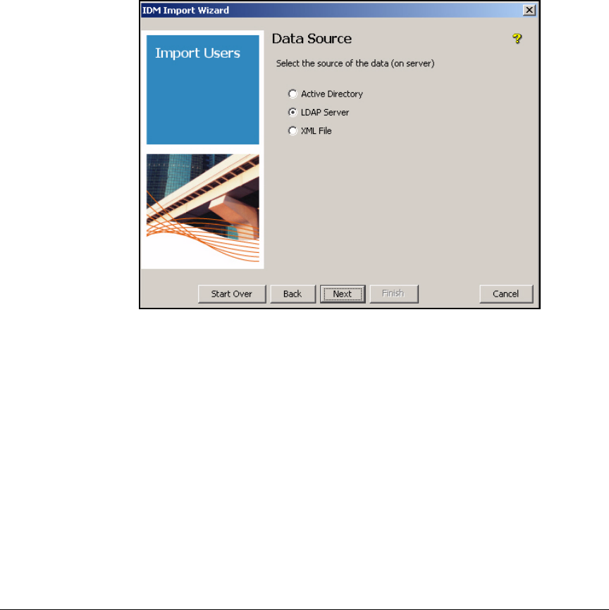
5-113
Using the NAC 800 in a RADIUS-Only Configuration
Configuring Network Access Control with IDM
Importing Users from an LDAP Server
To import user information from an OpenLDAP Server into IDM, complete
these steps:
1. From Tools in the global toolbar, select IDM User Import to launch the IDM
User Import Wizard.
2. Click Next. The Data Source page is displayed.
Figure 5-52. Data Source Page
3. Select LDAP Server as the data source and click Next. The LDAP Authenti-
cation page is displayed.
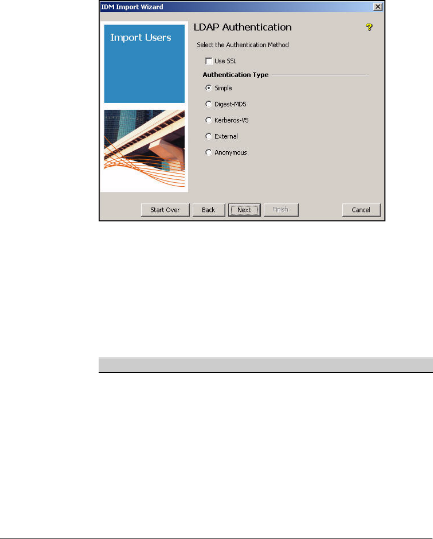
5-114
Using the NAC 800 in a RADIUS-Only Configuration
Configuring Network Access Control with IDM
Figure 5-53. LDAP Authentication Page
4. Select the Use SSL check box. (You must first load the OpenLDAP’s CA
certificate as explained in “Install the OpenLDAP Server’s CA Certificate
on PCM+” on page 5-109.)
5. Then select the LDAP authentication type to be used. Table 5-15 lists
authentication methods that IDM supports. Note that you cannot select
External if you have already selected the Use SSL check box.
Table 5-15. Authentication Methods
Authentication Description
Simple This method if not very secure. The fully qualified DN of the client (user)
and the client’s password are sent in clear text.
Digest-MD5 The server generates a challenge, and the client responds with a shared
secret (password).
Kerberos-V5 This method is used with either a password or a smart card for
interactive logon.
External (TLS) This method uses authentication services provided by lower-level
network services such as TLS.
Anonymous No authentication is required by the OpenLDAP server.

5-115
Using the NAC 800 in a RADIUS-Only Configuration
Configuring Network Access Control with IDM
6. Click Next. The authentication information you type varies slightly,
depending on the authentication method you select. For all authentication
methods, however, you must type the following information:
•Server—The IP Address or DNS name (fully qualified domain name)
of the OpenLDAP server. The IP address can be used for:
–Simple
– Anonymous
– Kerberos-V5 authentication in non-SSL mode
•Domain—The domain name that will be used to create the realm
in IDM.
•Base DN—The Base DN, or the location in the directory where the
search for users and groups will begin. For the domain MedCenter,
the base DN entry would be:
o=MedCenter.com
Your base DN might be:
dc=<MyCompany>,dc=com
Select the authentication type you want to use and then continue with
the appropriate instructions, as listed in Table 5-16.
Table 5-16. instructions
Using Simple Authentication
If you choose simple authentication, complete these steps:
1. In the Server box, type the IP address of the OpenLDAP server.
2. In the Domain box, type a name that you have chosen for the IDM realm
into which you will import the users.
3. In the Base DN box, type the DN of the container in which you want IDM
to begin to look to import users.
4. In the User box, type the DN for the root admin account.
Authentication Instructions
Simple “Using Simple Authentication” on page 5-115
Digest-MD5 “Using Digest-MD5 Authentication” on page 5-116
Kerberos-V5 “Using Kerberos-V5 Authentication” on page 5-117
External-TLS “Using External Authentication” on page 5-118
Anonymous “Using Anonymous Authentication” on page 5-120
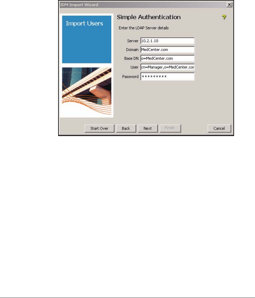
5-116
Using the NAC 800 in a RADIUS-Only Configuration
Configuring Network Access Control with IDM
5. In the Password box, type the password for the user that you designated
in the User box.
Figure 5-54. IDM Import Wizard—Simple Authentication Page
6. Click Next. The Extract Users and Groups page is displayed.
7. Continue with “Extracting User and Group Information” on page 5-121.
Using Digest-MD5 Authentication
The SASL Digest MD5 authentication window is used to define the LDAP data
source for Digest-MD5. In Digest-MD5, the server generates a challenge and
the client responds with a shared secret (password). Values for these options
can be obtained from the LDAP server administrator.
To configure the IDM Import Wizard to use Digest MD5 authentication,
complete the following steps:
1. In the Server box, type the DNS name of the LDAP server.
2. In the Domain box, type the domain name, which is used to create a realm
in IDM.
3. Optionally, in the Base DN box, type the Base DN. IDM will search only
for users and groups from this node of a directory tree.
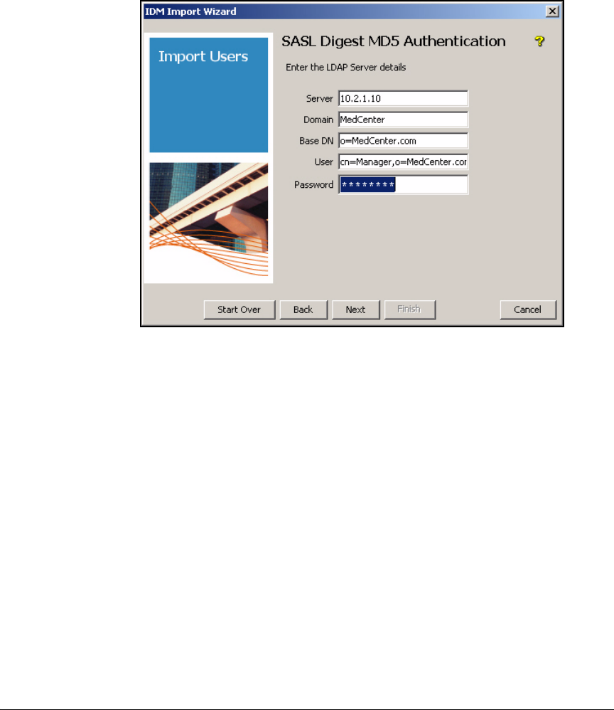
5-117
Using the NAC 800 in a RADIUS-Only Configuration
Configuring Network Access Control with IDM
4. In the User box, type the user DN used to access the LDAP server.
5. In the Password box, type the password associated with the user.
Figure 5-55. SASL Digest MD5 Authentication Page
6. Click Next. The Extract Users and Groups page is displayed.
7. Continue with “Extracting User and Group Information” on page 5-121.
Using Kerberos-V5 Authentication
The SASL Kerberos V5 authentication window is used to define the LDAP data
source for Kerberos. Kerberos V5 authentication requires that your Open-
LDAP server is set up with a Key Distribution Center (KDC). If you are not the
OpenLDAP administrator, contact him or her to determine if your OpenLDAP
server has a KDC.
To set up Kerberos V5 authentication, complete the following steps:
1. In the Server box, type the IP address or DNS name of the LDAP server.
2. In the Domain box, type the domain name. It will be used to create a realm
in IDM.
3. Optionally, in the Base DN box, type the Base DN. IDM will search only
for users and groups from this node of a directory tree.
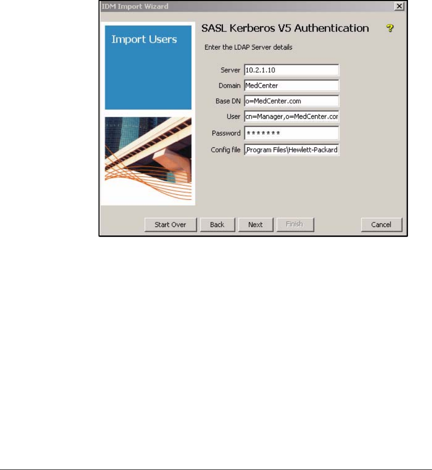
5-118
Using the NAC 800 in a RADIUS-Only Configuration
Configuring Network Access Control with IDM
4. In the User box, type the user name used to access the LDAP server.
5. In the Password box, type the password associated with the user.
6. In the Config file box, type the complete path and filename of the
configuration file that identifies the domain of the KDC.
Figure 5-56. SASL Kerberos V5 Authentication Page
7. Click Next. The Extract Users and Groups page is displayed.
8. Continue with “Extracting User and Group Information” on page 5-121.
Using External Authentication
The SASL External authentication window is used to define the external LDAP
data source. External authentication uses an X509 certificate for user
authentication. The LDAP X509 User Certificate must be installed in a keystore
on the IDM server, and the LDAP server’s certificate must be stored in the trust
store under your JRE installation on the IDM server.
See “Install the OpenLDAP Server’s CA Certificate on PCM+” on page 5-109
for details on importing LDAP X509 User certificates for use with IDM.
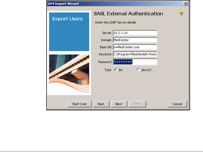
5-119
Using the NAC 800 in a RADIUS-Only Configuration
Configuring Network Access Control with IDM
To set up external authentication, complete the following steps:
1. In the Server box, type the DNS name of the LDAP server.
2. In the Domain box, type the domain name. It is used to create a realm in
IDM.
3. Optionally, in the Base DN box, type the Base DN. IDM will search only
for users and groups from this section of the directory tree.
4. In the Keystore box, type the keystore file name. For JKS, the Keystore is
the location on the IDM server where you installed the keystore. (For
example: c:\idmuser\mykeystore.) For PKCS12, type the PKCS certificate
in the Keystore box.
5. In the Password box, type the password. For JKS, type the password of
the keystore on the IDM Server. For PKCS12, type the PKCS12 key in the
Password box
6. Select the Type: either jks, or pkcs12.
Figure 5-57. SASL Authentication Page
7. Click Next. The Extract Users and Groups page is displayed.
8. Continue with “Extracting User and Group Information” on page 5-121.
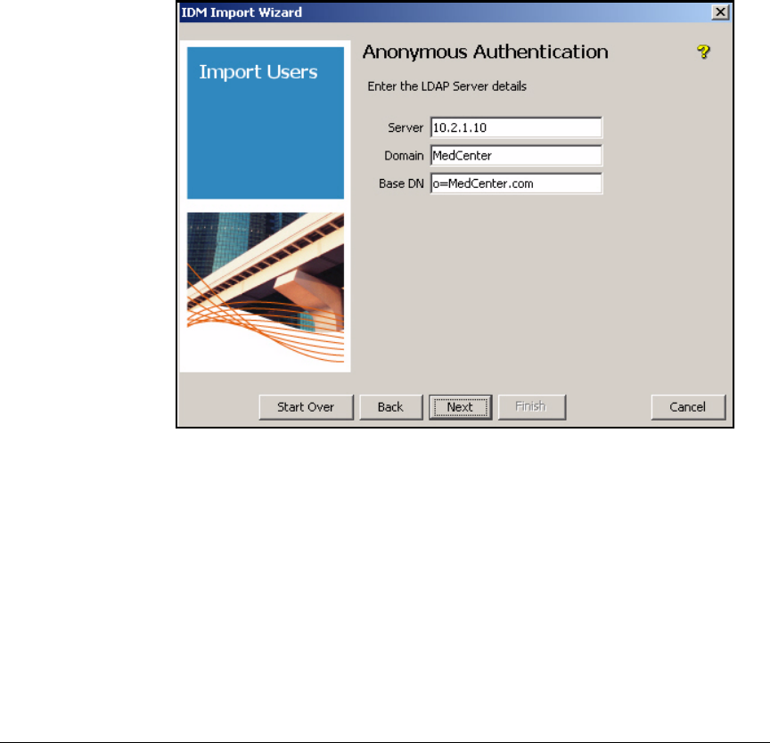
5-120
Using the NAC 800 in a RADIUS-Only Configuration
Configuring Network Access Control with IDM
Using Anonymous Authentication
To configure anonymous authentication, complete the following steps:
1. In the Server box, type the IP address of the OpenLDAP server.
2. In the Domain box, type a name that you have chosen for the IDM realm
into which you will import the users.
3. In the Base DN box, type the DN of the directory in which you want IDM
to begin to look to import users.
Figure 5-58. Anonymous Authentication Page
4. Click Next. The Extract Users and Groups page is displayed.
5. Continue with “Extracting User and Group Information” on page 5-121.
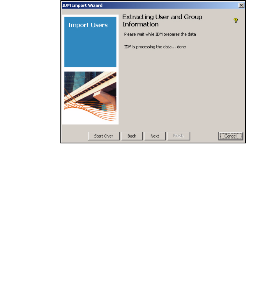
5-121
Using the NAC 800 in a RADIUS-Only Configuration
Configuring Network Access Control with IDM
Extracting User and Group Information
When the Extracting User and Group Information page is displayed, continue with
the steps that follow:
Figure 5-59. IDM Import Wizard—Extracting User and Group Information Page
1. When the phrase “IDM is processing the data... done” is displayed,
click Next.
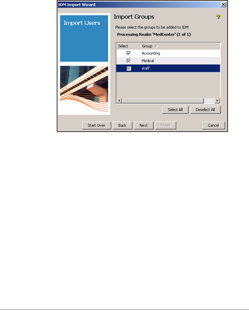
5-122
Using the NAC 800 in a RADIUS-Only Configuration
Configuring Network Access Control with IDM
Figure 5-60. Import Groups Page
2. On the Import Groups page, select all of the groups that you want to import
or click Select All. Then, click Next.
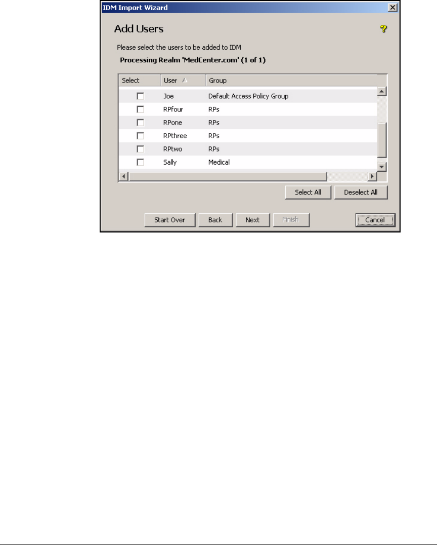
5-123
Using the NAC 800 in a RADIUS-Only Configuration
Configuring Network Access Control with IDM
Figure 5-61. Add Users Page
3. On the Add Users page, select the users you want to add or click Select All.
Then, click Next.
4. On the Remove Users page, select any users that you want to delete from
IDM. This page might be populated if you have imported user and groups
from OpenLDAP in the past. IDM will compare the information you
downloaded before to the information you are currently downloading. If
a user or group exists on IDM but not on the OpenLDAP server, IDM will
list it on this page. You then have the option of deleting it or keeping it.
Click Next.
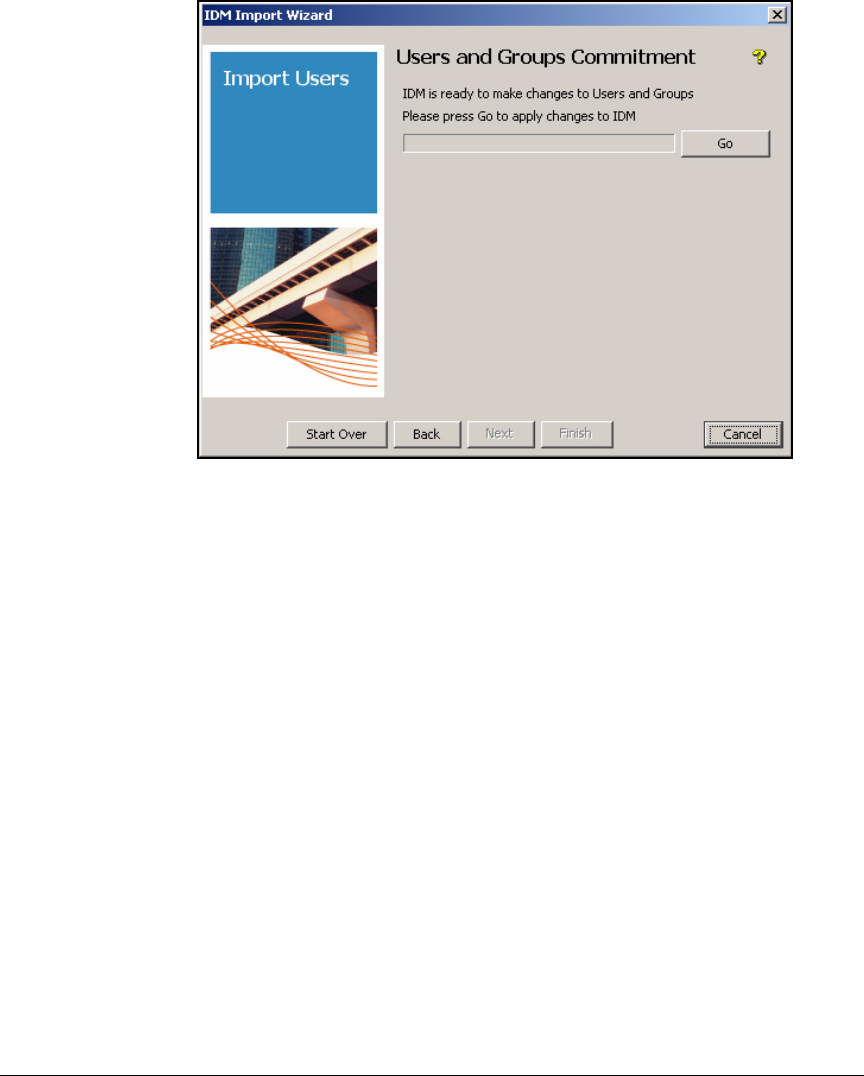
5-124
Using the NAC 800 in a RADIUS-Only Configuration
Configuring Network Access Control with IDM
Figure 5-62. Users and Groups Commitment Page
5. When the Users and Groups Commitment page is displayed, click Go to begin
the actual import process. Then click Next.
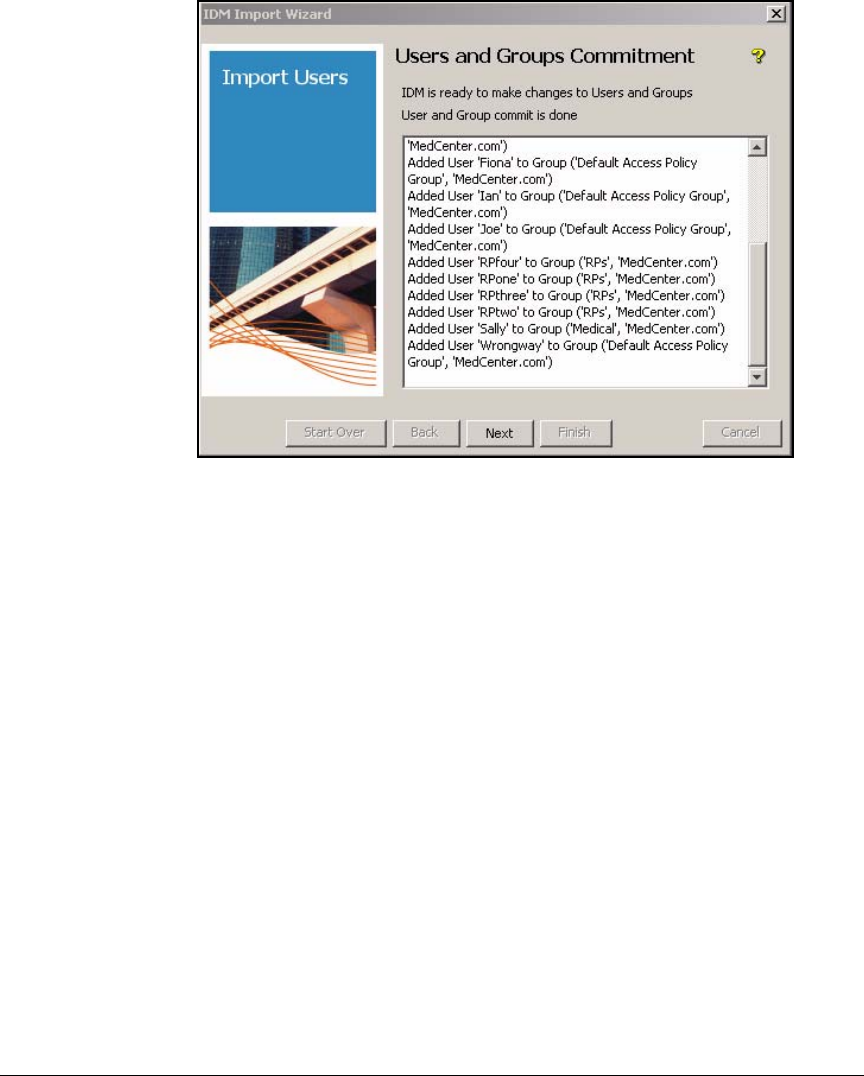
5-125
Using the NAC 800 in a RADIUS-Only Configuration
Configuring Network Access Control with IDM
Figure 5-63. IDM Import Wizard—Users and Groups Commitment Page
6. Review the changes that IDM will make. If you approve of the changes,
click Next.
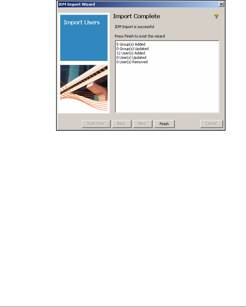
5-126
Using the NAC 800 in a RADIUS-Only Configuration
Configuring Network Access Control with IDM
Figure 5-64. IDM Import Wizard—Import Complete Page
7. The Import Complete page shows you how many users and groups were
imported. Click Finish.
8. Click the Identity tab in the left pane of the PDM+ interface.
9. Expand Realms > <myrealm> > Access Policy Groups. You should see your
user groups from OpenLDAP in the right pane along with the right number
of users in each group.
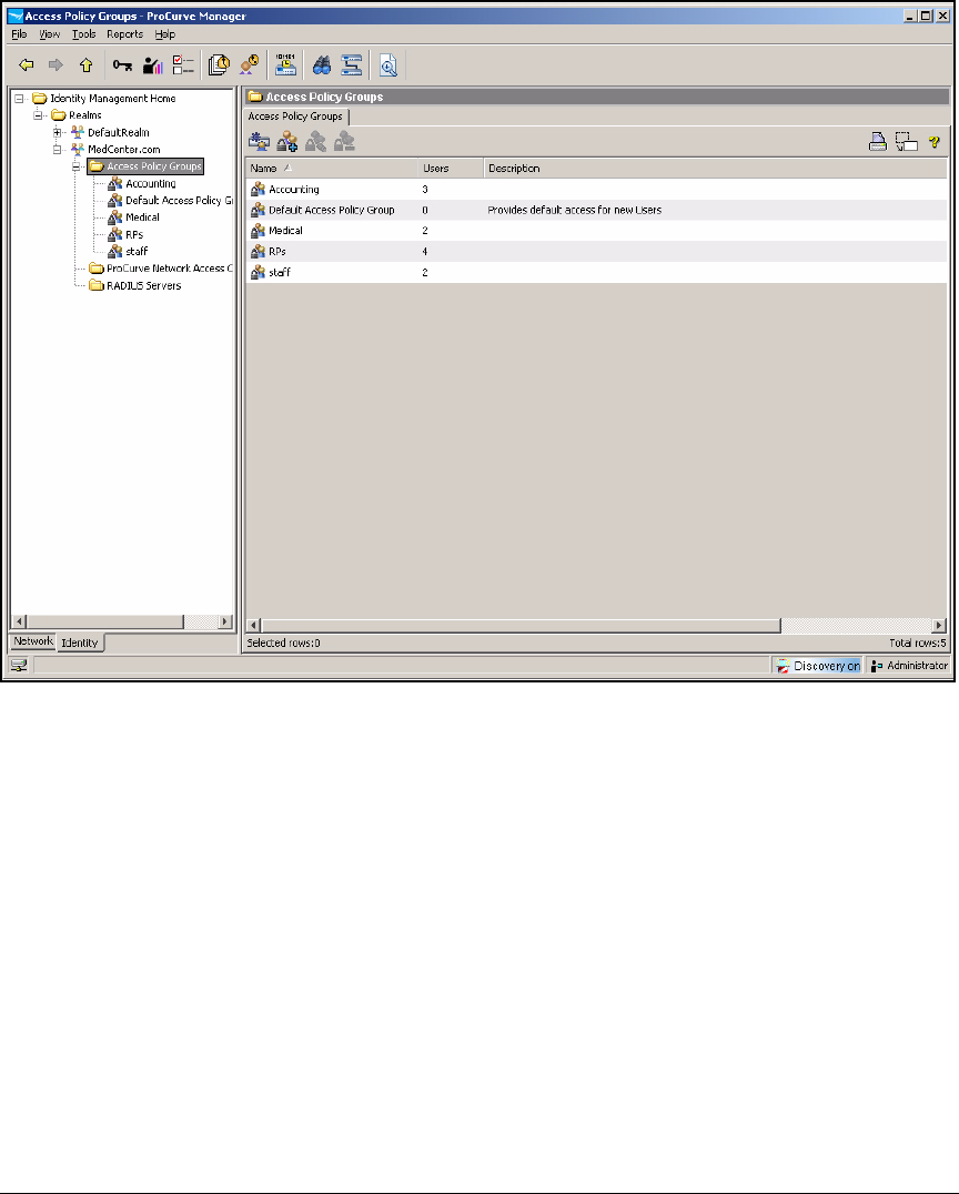
5-127
Using the NAC 800 in a RADIUS-Only Configuration
Configuring Network Access Control with IDM
Figure 5-65. IDM Access Policy Groups Window
Define Resources
You must define every resource that you want to control. These can include:
■A single device—an IP address
■Applications (such as DHCP, DNS, and HTTP)—TCP or UDP ports
■Applications on a single device—an IP address and TCP or UDP ports
■A VLAN—a subnet network address
Table 5-17 shows the resources for the example network.
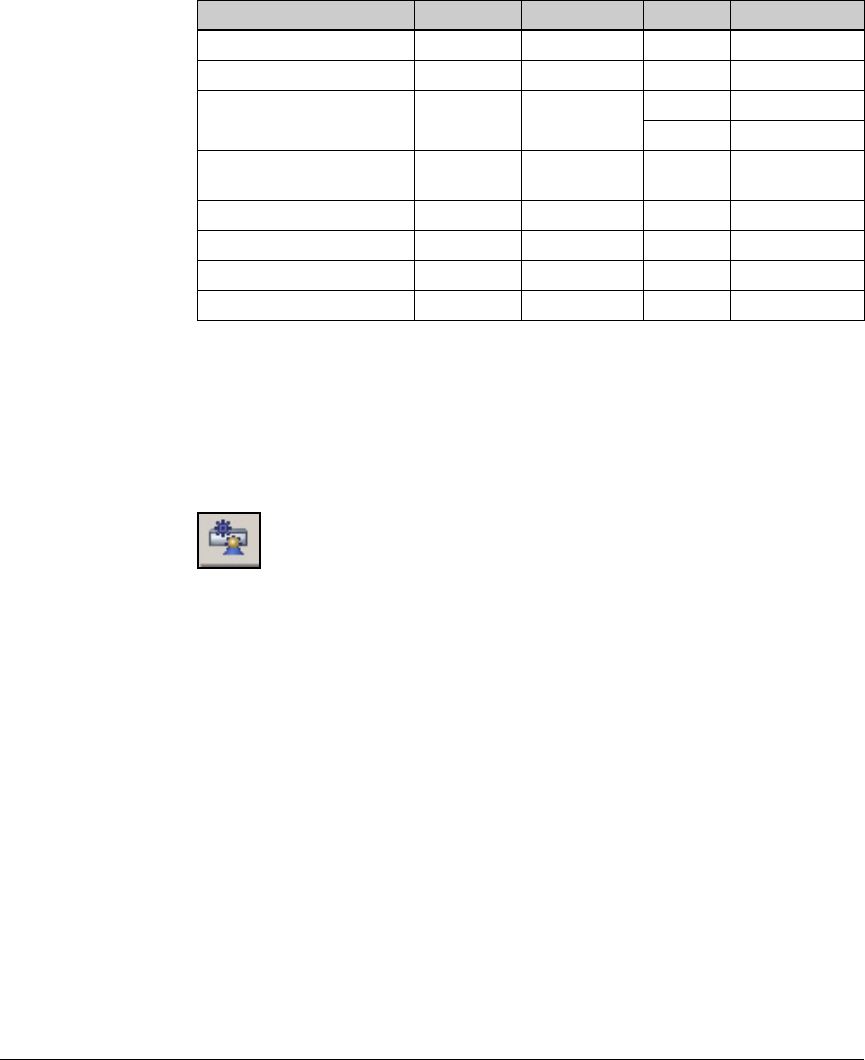
5-128
Using the NAC 800 in a RADIUS-Only Configuration
Configuring Network Access Control with IDM
Table 5-17. Medical Center Resources
To define resources, complete these steps:
1. In the PCM+, click the Identity tab.
2. Select your realm (MedCenter.com in the example).
3. Under the Properties tab, click the Configure Identity Management button.
Figure 5-66. PCM+ Console, IDM Interface—Configure Identity Management
Button
4. Select Network Resources in the left pane.
5. Click the Create a new Network Resource button in the right pane.
Resource VLAN ID IP Address Protocol Port or Ports
Management VLAN 2 10.2.0.0./16 IP Any
Server VLAN 4 10.4.0.0/16 IP Any
Medical Server VLAN 5 10.5.0.0/16 IP Any
Accounting VLAN 6 10.6.0.0/16 IP Any
Medical VLAN (doctors and
nurses)
8 10.8.0.0/16 IP Any
Staff VLAN 12 10.12.0.0/16 IP Any
Accounting VLAN 16 10.16.0.0/16 IP Any
Patients VLAN 32 10.32.0.0/16 IP Any
DHCP, DNS, Web Any UDP 53, 67, 80, 443
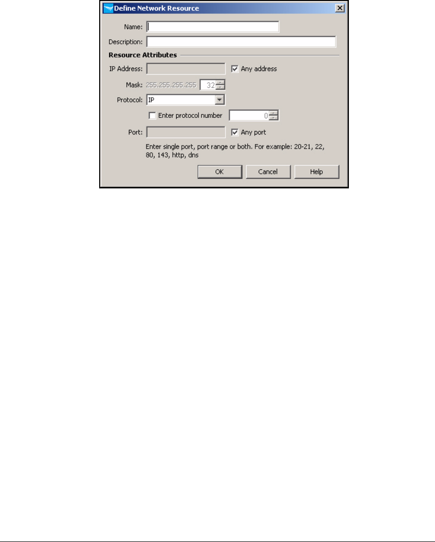
5-129
Using the NAC 800 in a RADIUS-Only Configuration
Configuring Network Access Control with IDM
Figure 5-67. PCM+ Console, IDM Interface—Define Network
Resource Window
6. To set up a resource that is an entire VLAN, follow these steps:
a. In the Define Network Resource window, type a string in the Name box
to identify the VLAN (in this example, Management VLAN).
b. In the Description box, type a description, if desired.
c. Clear the Any address check box.
d. For the IP Address, type the network address of the subnet associated
with the VLAN (in this example, 10.2.0.0).
e. For the Mask, type or select the prefix length for the subnet (in this
example, 16).
f. Leave IP for the Protocol.
g. Click OK.
7. Follow these steps to set up a resource that is an application type such
as DHCP:
a. In the Define Network Resource window, type a string in the Name box
to identify the application or applications. For example: DHCP, DNS,
and Web.

5-130
Using the NAC 800 in a RADIUS-Only Configuration
Configuring Network Access Control with IDM
Note In this example, the network administrators have grouped these three
applications because they are all necessary for the most basic level
of access. Depending on your environment, you might create a differ-
ent resource for each.
b. In the Description box, type a description if you want.
c. Select the Any address check box.
You could clear the check box and restrict users to accessing this
application on a particular device or subnet. In this case, type the
appropriate IP address for the IP Address and Mask.
d. From the Protocol list, select the protocol: TCP or UDP (in this example,
UDP).
e. Clear the Any port check box and type the appropriate values for the
Port. You can type ranges of ports or multiple, non-consecutive ports,
separated by a comma (in this example: 53, 67, 80, 443).
f. Click OK.
8. Follow these steps to set up a resource that is a single device:
a. In the Define Network Resource window, type a string in the Name box
to identify the device (in this example, VLAN 4).
b. In the Description box, type a description, if desired.
c. Clear the Any address check box.
d. For the IP Address, type the device’s IP address.
e. For the Mask, type or select the prefix length.
f. From the Protocol list, select the protocol (IP is the default and allows
all IP traffic).
g. To allow any traffic to this device, select the Any port check box. If you
want to restrict access to one or several single applications, clear the
Any port check box and type the appropriate values for the Port.
h. Click OK.
9. Repeat step 5, 8, 7, or 6 to set up each resource for your network.

5-131
Using the NAC 800 in a RADIUS-Only Configuration
Configuring Network Access Control with IDM
Configure Locations
IDM allows you to control the locations from which users log in to the
network. For example, the Medical Center network administrators want the
Accounting department employees to log in only from their workstations in
their area of the building. Physical access to this area of the building is
restricted, so that patients or other employees cannot look over the shoulder
of an Accounting employee and view a patient’s confidential financial infor-
mation.
Table 5-18. Define Locations from Which Users Can Access the Network
Doctors and nurses, on the other hand, must be allowed to access information
from many locations in the Medical Center. The network administrators will
not limit their access to a certain location.
The support staff are also mobile. For example, receptionists often fill in for
one another, moving to different areas in the building as needed.
You can use Table 5-19 to list your users and the location from which they
should log in.
Table 5-19. Locations
1. Click the Identity tab.
2. Click your realm (MedCenter.com in the example).
3. Click the Configure Identity Management button.
4. Click the Locations folder.
Name Description Device Group Device IP Address Ports
Acctg_area 3rd floor west side Wired 5400zl 10.2.0.3 C1-C24
Name Description Device Group Device IP Address Ports
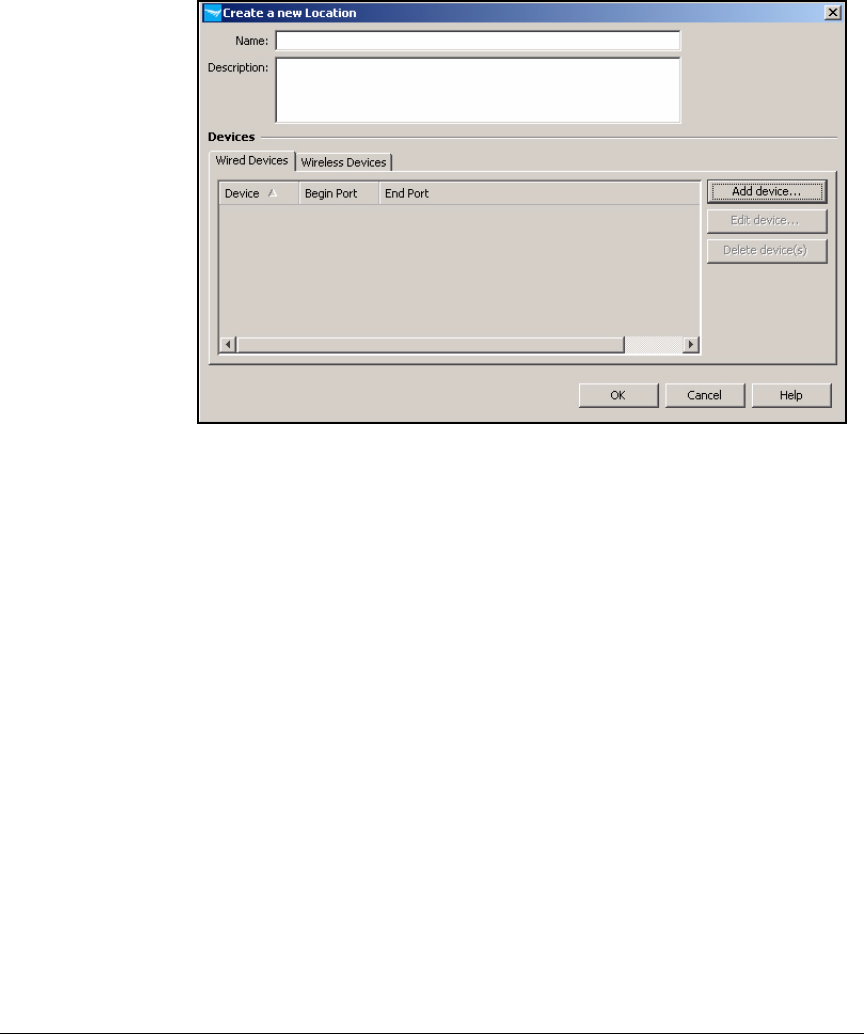
5-132
Using the NAC 800 in a RADIUS-Only Configuration
Configuring Network Access Control with IDM
5. Click the New Locations button.
Figure 5-68. New Locations Button
6. From the Select Device Group list, select a device group.
7. In the Name box, type a name for the location. For the example network,
enter Accounting floor.
8. You must add at least one device. Click Add device.
9. From the Select Device Group list, select a device group. In the example,
you would select the edge switch that connects to the Accounting users’
workstations.
10. From the Select Device list, select the IP address of the device or check
the Manually enter device address check box and type the IP or DNS name
in the box below.
11. Select Any port or Select Ports. If you select the latter, select the beginning
and ending ports from the Begin port and End port lists. For example, the
Accounting users’ workstations might connect to ports B2 to B24 and C2
to C10.
12. Click OK. If you need to add more ports, click Add device again and repeat
steps.
5-133
Using the NAC 800 in a RADIUS-Only Configuration
Configuring Network Access Control with IDM
Configure Times
With IDM you can specify times when an access policy group is active. For
example, you might want to specify that the users who connect to the
accounting databases can access the network only during business hours on
weekdays. As an added security measure, the example organization—Medical
Center—wants to limit the times when the accounting department can access
the accounting database. The accounting department can access the database
only during business hours, which the Medical Center defines as 7:30 a.m. to
6:30 p.m.
Other users, however, may need to access the network after business hours.
The Medical Center, for example, must ensure that doctors and nurses can
access patient records 24 hours a day, seven days a week.
Note If you restrict the times when users can access the network, you should also
force them to re-authenticate periodically. Otherwise, a user could log in to
the network before the restricted time and remain logged in. In the example
network, an accounting user could log in at 6:50 p.m. and remain logged past
7 p.m.—the time that should be off-limits to accounting users.
Table 5-20. Times
1. Click the Identity tab.
2. Click your realm (MedCenter.com).
3. Click the Configure Identity Management button.
4. Click the Times folder.
5. Click the Create a new Time button.
Name Description Time Days of Week Holidays Start Date End Date
Business Hours Regular hours
of operation
from 6:30 AM to
7:00 PM
weekdays yes default no end date
After Hours Non-business
hours
from 6:00 PM to
7:00 AM
all yes default no end date
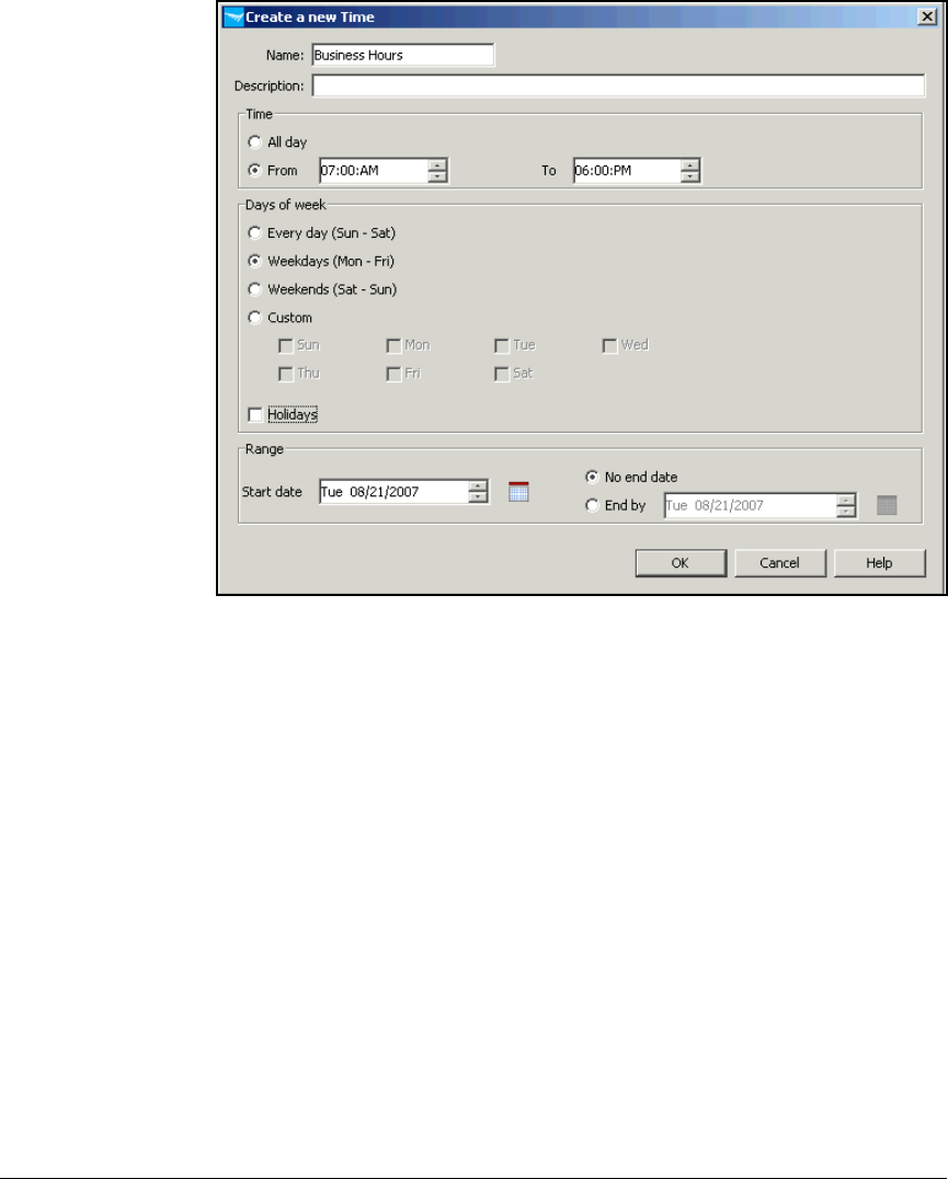
5-134
Using the NAC 800 in a RADIUS-Only Configuration
Configuring Network Access Control with IDM
Figure 5-69. Create a new Time Window
6. In the Name box, type a name for the time. Type a description in the
Description box.
7. In the Time section, select All day or From. If you select From, select start
and ending times. For the example network, you would type 6:30 a.m. for
From and 7 p.m. for To.
8. In the Days of week section, select the days when this time applies. If you
want this time to apply on holidays as well, check the Holidays check box.
9. In the Range section, accept the default (today) or click the calendar icon
to select a day on which the time policy will be enforced.
10. Select No end date or End by. If you select End by, click the calendar icon to
select a day on which the policy will stop being enforced.
11. Click OK.
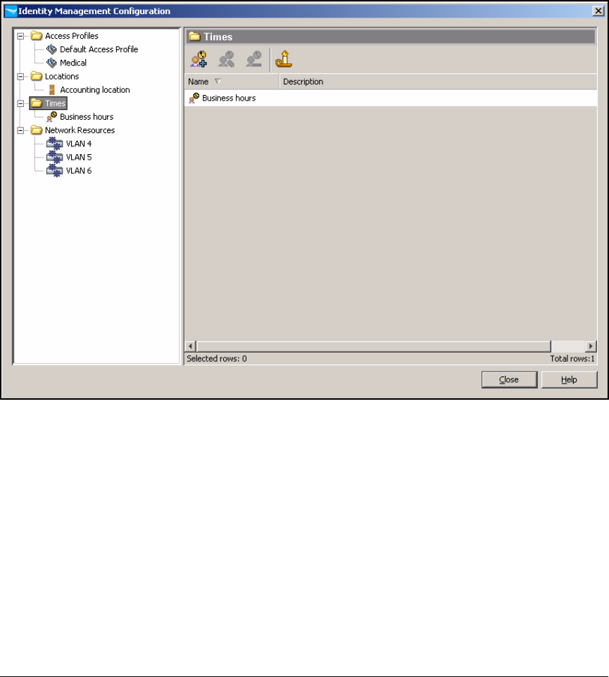
5-135
Using the NAC 800 in a RADIUS-Only Configuration
Configuring Network Access Control with IDM
Configure Holidays
You can configure holidays on which the Times can be activated. For example,
you might want to activate the Business Hours time on holidays.
Figure 5-70. Configure Holidays Button
1. Click the Holiday button.
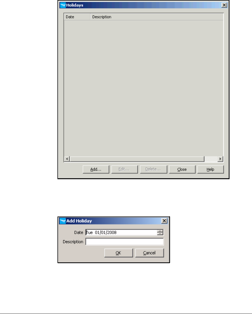
5-136
Using the NAC 800 in a RADIUS-Only Configuration
Configuring Network Access Control with IDM
Figure 5-71. Holidays List
2. Click Add.
Figure 5-72. Add Holiday Window
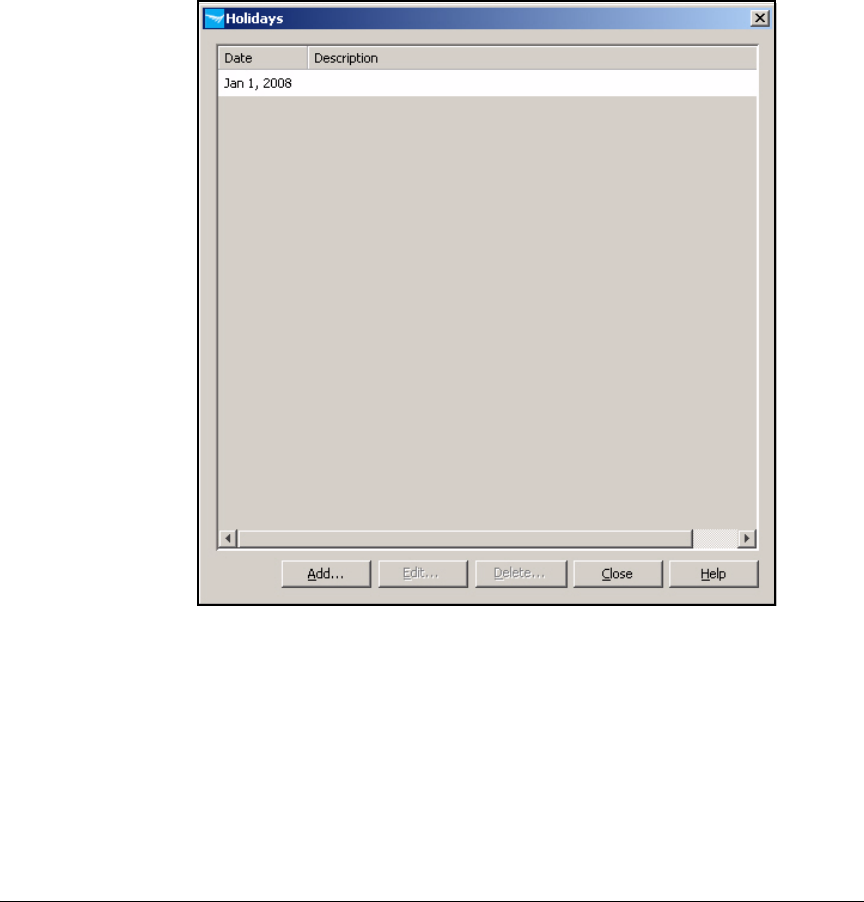
5-137
Using the NAC 800 in a RADIUS-Only Configuration
Configuring Network Access Control with IDM
3. In the Date box, type the day of the holiday. If you do not know the day of
the week, type the mm/dd/yyyy portion and the day will be selected
automatically. In this example, type 1/1/200X, replacing X with the appro-
priate number for next year.
4. In the Description box, type the name of the holiday.
5. Click OK.
Figure 5-73. Holiday Added
Create Access Profiles
A profile defines a set of rights including:
■VLAN assignment
■Quality-of-service (QoS) settings
■Rate limit
■Resources allowed and resources denied

5-138
Using the NAC 800 in a RADIUS-Only Configuration
Configuring Network Access Control with IDM
Note For each profile, you can also choose whether, by default, all resources not
specifically defined are denied or whether they are allowed. This is called the
default access option. In this example, you will allow specific resources and
deny all others; the default access option is deny.
Although you can create several profiles for a single group of users—and then
assign those profiles under various circumstances—in this example, each user
group requires only one profile for normal access.
The example profiles that you will learn how to create in this section are
displayed in Table 5-21.
Table 5-21. Network Resource Assignments per Access Profile
Follow these steps to create the profiles:
1. In the PCM+ console, click the Identity tab.
2. Select your realm (MedCenter.com).
Access Profile VLAN ID QoS Ingress Rate-Limit Allowed Resources Default Access
Network_Admins 2 Don’t override Don’t override • DHCP, DNS, and Web
•Server VLAN
• Medical Server VLAN
• Accounting Server VLAN
• Management VLAN
• Medical VLAN
• Accounting VLAN
•Staff VLAN
• Patients VLAN
• Radio Port VLAN
Deny
Medical 8 Don’t override Don’t override • DHCP, DNS, and Web
•Server VLAN
• Medical Server VLAN
• Medical VLAN
Deny
Staff 12 Don’t override 1000 Kbps • DHCP, DNS, and Web
•Server VLAN
•Staff VLAN
Deny
Accounting 16 Don’t override 1000 Kbps • DHCP, DNS, and Web
•Server VLAN
• Accounting Server VLAN
• Accounting VLAN
Deny
Patients 32 Don’t override 1000 Kbps • DHCP, DNS, and Web Deny
RPs 2100 Don’t override Don’t override All Allow
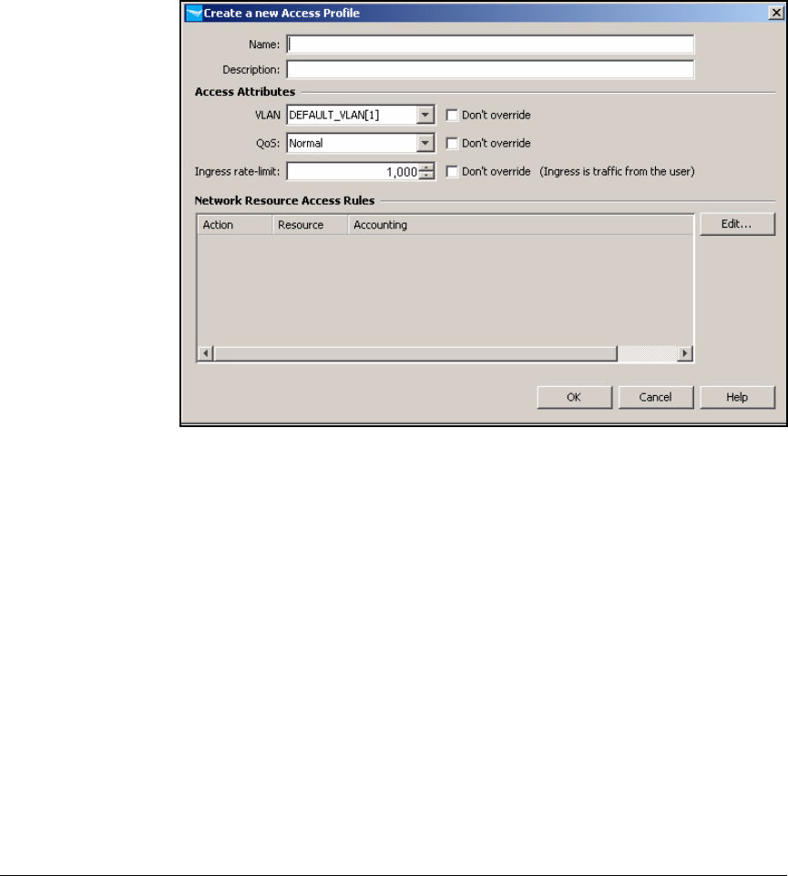
5-139
Using the NAC 800 in a RADIUS-Only Configuration
Configuring Network Access Control with IDM
3. Under the Properties tag, click the Configure Identity Management button.
4. Select the Access Profiles folder.
5. Click Create a new Access Profile.
Figure 5-74. PCM+ Console, IDM Interface—Create a new Access Profile
6. In the Name box, type the name of the access profile. In this example, you
are creating the profile for the Network_Admins group under normal
circumstances. You name the profile Network_Admins.
7. In the Description box, type a description, if desired.
8. From the VLAN list, select the proper VLAN (in this example, 2).
9. For the QoS, either select the QoS level from the list or select the Don’t
override check box.
10. For the Ingress rate-limit, either type the rate limit in Kbps or select the
Don’t override check box.
11. In the Network Resource Access Rules area, click Edit.
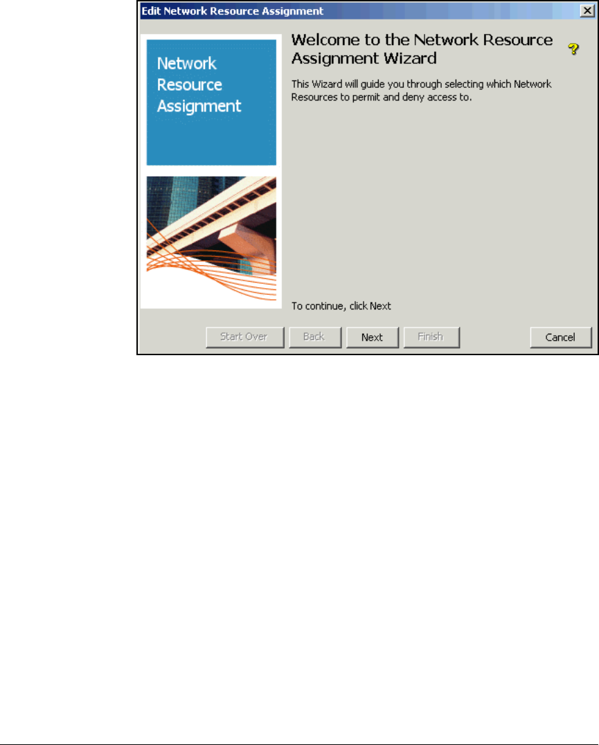
5-140
Using the NAC 800 in a RADIUS-Only Configuration
Configuring Network Access Control with IDM
Figure 5-75. Edit Network Resource Assignment Wizard—Welcome Page
12. In the Welcome to the Network Resource Assignment Wizard page, click Next.

5-141
Using the NAC 800 in a RADIUS-Only Configuration
Configuring Network Access Control with IDM
Figure 5-76. Edit Network Resource Assignment Wizard—Allowed Network
Resources Page
13. From the Available Resources pane, select a resource and click the >>
button. Repeat for each network resource that you want to assign to this
profile.
14. When all of the desired resources are in the Allowed Resources pane,
click Next.
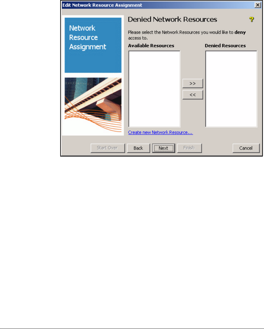
5-142
Using the NAC 800 in a RADIUS-Only Configuration
Configuring Network Access Control with IDM
Figure 5-77. Edit Network Resource Assignment Wizard—Denied Network
Resources Page
15. If you would like to deny the group access to any other resources, repeat
the previous step for resources that you want to deny. If not, click Next.
You might need to deny resources when:
• A resource is a subset of an allowed resource
For example, you can grant users access to an entire VLAN, but deny
them access to a single server in that VLAN.
• You use the strategy of allowing all resources, by default
Neither condition applies to this access profile, so you click Next.
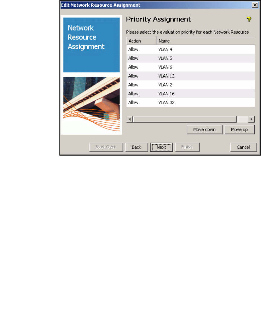
5-143
Using the NAC 800 in a RADIUS-Only Configuration
Configuring Network Access Control with IDM
Figure 5-78. Edit Network Resource Assignment Wizard—Priority
Assignment Page
16. If you would like to assign any of the allow or deny actions a priority, select
the resource whose order you would like to modify. Then click either Move
down or Move up until it is in the desired order. Click Next.
You only need to complete this step if the defined resources include
overlapping resources. The more-specific rule should have a higher
priority.
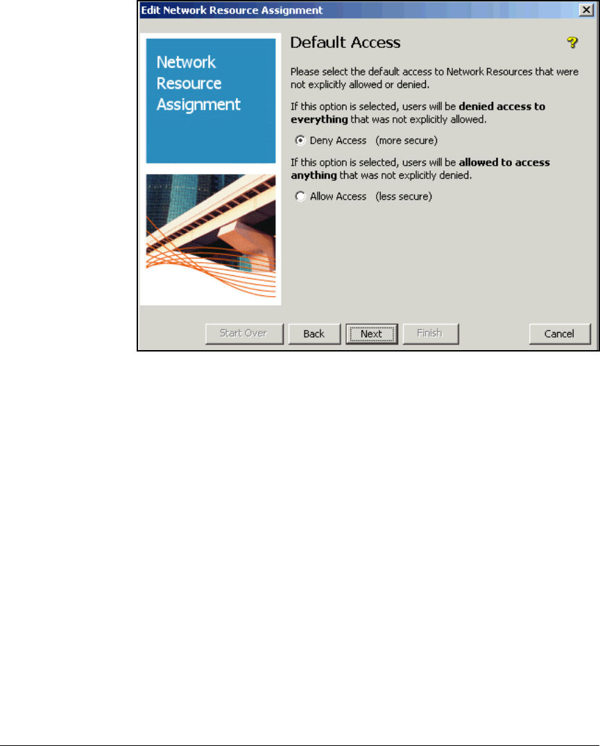
5-144
Using the NAC 800 in a RADIUS-Only Configuration
Configuring Network Access Control with IDM
Figure 5-79. Edit Network Resource Assignment Wizard—Default Access Page
17. In the Default Access window, select Deny Access or Allow Access for any
resources that were not explicitly allowed or denied. The more secure
option is Deny Access. Click Next.
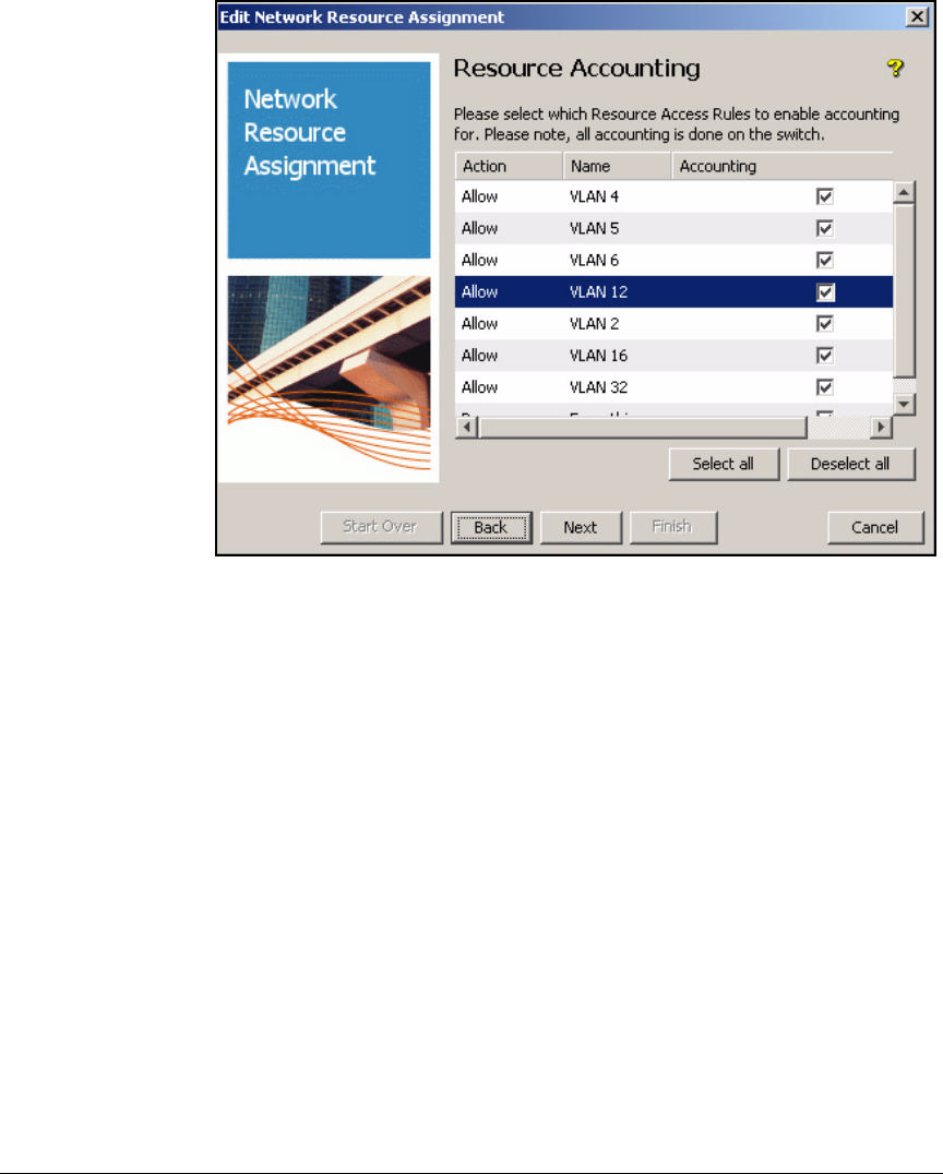
5-145
Using the NAC 800 in a RADIUS-Only Configuration
Configuring Network Access Control with IDM
Figure 5-80. Edit Network Resource Assignment Wizard—Resource
Accounting Page
18. In the Resource Accounting window, select the check box next to resources
for which you would like to enable accounting. For this example, click
Select all. Click Next.
19. Click Finish; then click OK.
20. Repeat steps 5 through 19 for each profile that you designed for your
network.
Configure Access Policy Groups
The Accounting users will have their access controlled by two criteria in
addition to group:
■Time
■Location
Other support staff and the doctors, nurses, and other patient care employees
who are part of the medical group will be able to access the network any time
from any location.

5-146
Using the NAC 800 in a RADIUS-Only Configuration
Configuring Network Access Control with IDM
Table 5-22. Access Policy Groups
Configure Access Policy Group Rules
An access policy group rule specifies the profile that an authenticated user in
that group receives, given a particular set of criteria. Follow these steps to
configure access policy group rules:
1. In the PCM+ console, click the Identity tab.
2. Expand your realm.
3. Expand Access Policy Groups in the left pane.
Group Rule Time WLAN Profile
Administrator 1 ANY Medical Administrator
Medical 1 ANY Medical Medical
Accounting 1 6:30 a.m. to 7 p.m. None Accounting staff
Staff 1 ANY Staff Staff
Patients 1 Normal Patients Patients
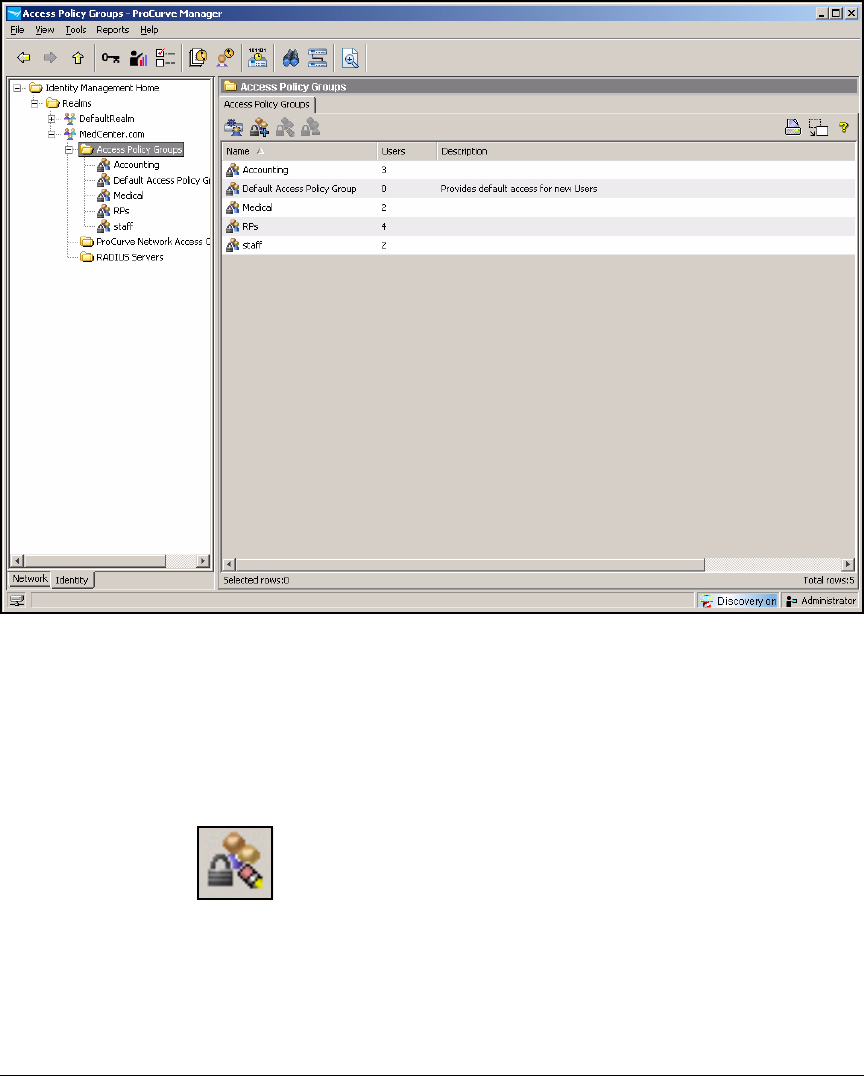
5-147
Using the NAC 800 in a RADIUS-Only Configuration
Configuring Network Access Control with IDM
Figure 5-81. PCM+ Console, IDM Interface—Access Policy Groups
4. Under Access Policy Groups, the groups synchronized with OpenLDAP
are displayed. Select the group for which you want to set up access policy
rules.
5. Click the Modify Access Policy Group button.
Figure 5-82. PCM+ Console, IDM Interface—Modify Access Policy Group Button
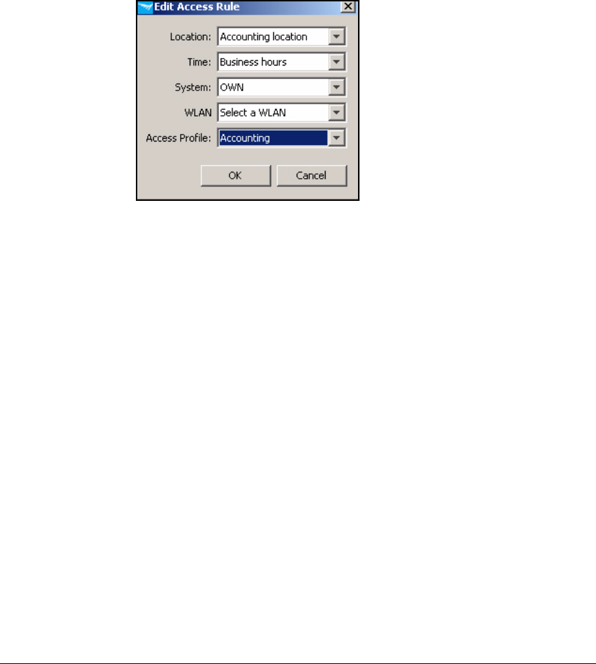
5-148
Using the NAC 800 in a RADIUS-Only Configuration
Configuring Network Access Control with IDM
6. By default, the access policy group includes a rule that grants default
access under all conditions. You must change this rule to specify the
access profile that you set up for this group. Select the default rule and
click Edit.
Figure 5-83. PCM+ Console, IDM Interface—
Edit Access Rule Window
7. Set your criteria for users in this group:
a. For the Location, select a location or ANY.
b. For the Time, select a time or ANY.
c. For the System, select OWN (the endpoint associated with the user)
or ANY (any endpoint).
d. For the Endpoint Integrity, select PASS.
In this example, criteria such as location and time do not affect access.
e. For the Access Profile, select the access profile that you created for
this group. For example, if you are configuring the Faculty access
policy group, select the Faculty access profile.
8. Click OK.
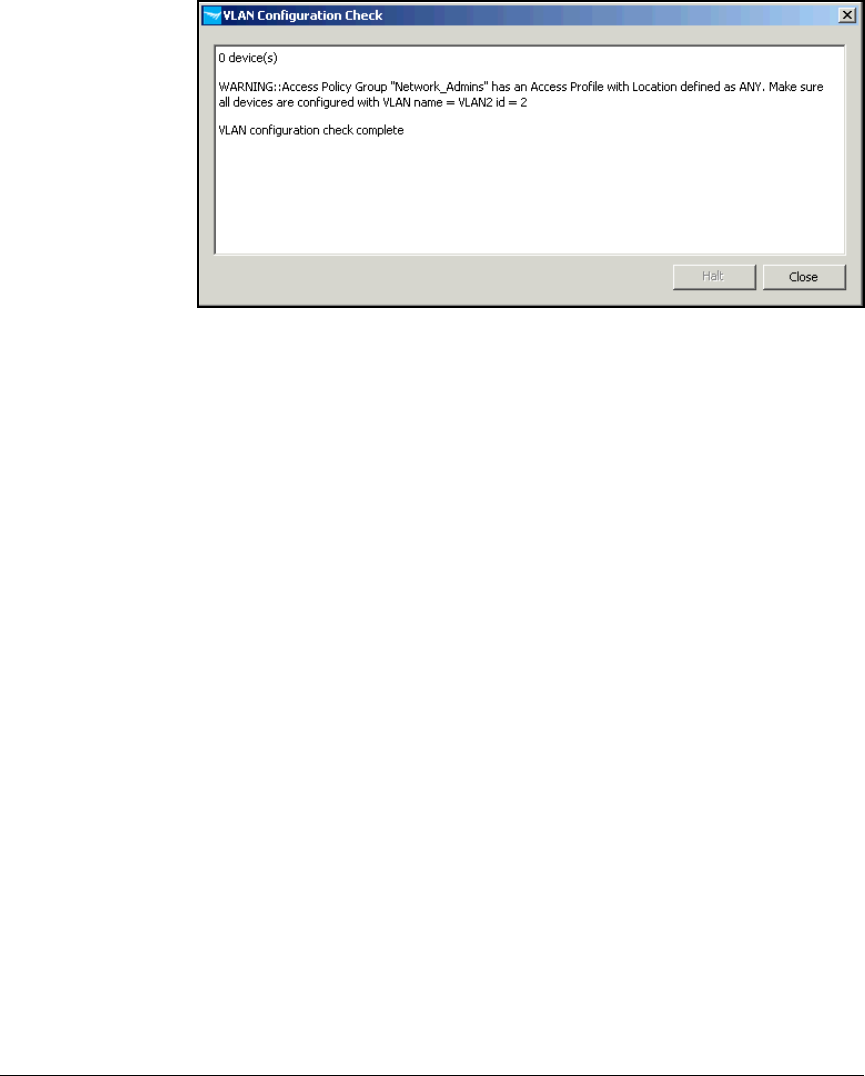
5-149
Using the NAC 800 in a RADIUS-Only Configuration
Configuring Network Access Control with IDM
Figure 5-84. PCM+ Console, IDM Interface—VLAN Configuration Check Window
9. IDM verifies that all the locations to which these users can connect
support the VLAN that was specified in the access profile.
10. If necessary, add the VLAN to the ports on switches (or the uplink port of
a Wireless Edge Services Module) that must carry traffic from the VLAN.
Click Close.
11. Repeat steps 4 to 10 for each access policy group in your environment.
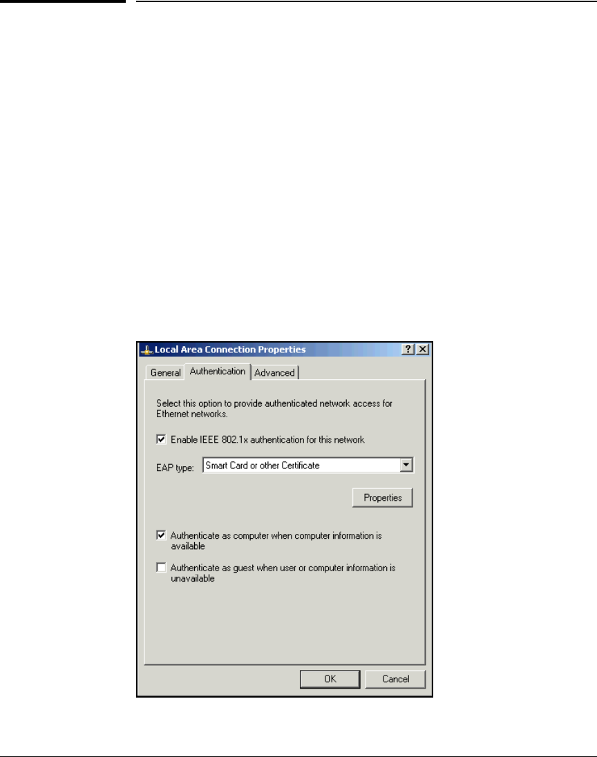
5-150
Using the NAC 800 in a RADIUS-Only Configuration
Configure Endpoints
Configure Endpoints
In this section, you will learn how to configure the Microsoft Wireless Zero
Configuration (WZC) utility, which enables 802.1X for both wired and wireless
access on a Windows workstation.
Configuring the Wireless Zero Configuration Utility for
Wired Access
To configure Wireless Zero Configuration utility for wired access, complete
the following steps:
1. From the Windows Start menu, click Settings > Network Connections.
2. Right-click Local Area Connection and select Properties.
3. Click the Authentication tab.
Figure 5-85. Local Area Connection Properties Window
on a Windows XP Endpoint

5-151
Using the NAC 800 in a RADIUS-Only Configuration
Configure Endpoints
Note If the Authentication tab is not displayed, you may have one of two problems:
■The endpoint does not support 802.1X. Download the most recent Win-
dows service pack (SP).
■Wireless Zero Configuration (WZC) is not running. (This service enables
802.1X for both wired and wireless connections.) See “Enable WZC” on
page 5-158 to fix the problem.
4. Select the Enable IEEE 802.1X authentication for this network check box.
5. Use the EAP type list to select one of the following:
•Smart Card or other Certificate—If you select this option, complete the
steps outlined in Chapter 2: Implementing 802.1X with ProCurve
IDM and Endpoint Integrity.
• Protected EAP (PEAP)—If you select this option, continue with step 6.
• MD5-Challenge—If you select this option, continue with step 7.
6. Configure PEAP settings.
a. Under EAP type, click Properties.
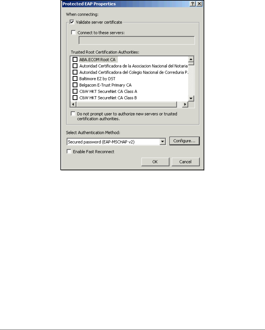
5-152
Using the NAC 800 in a RADIUS-Only Configuration
Configure Endpoints
Figure 5-86. Protected EAP Properties Window in the
Windows XP Supplicant
b. If you want, select the Validate server certificate. This is optional, but
even if you clear this option, the server must have a certificate.
c. Under Trusted Root Certification Authorities, select the certificate you
want to trust.
d. If you want, select the Do not prompt user to authorize new servers or
trusted certification authorities check box. Otherwise, users will be
prompted to authorize new servers and CAs.
e. Under Select Authentication Method, ensure that Secured password
(EAP-MSCHAP v2) is selected.
f. Click Configure.

5-153
Using the NAC 800 in a RADIUS-Only Configuration
Configure Endpoints
Figure 5-87. EAP MSCHAPv2 Properties Window
in the Windows XP Supplicant
g. Ensure the Automatically use my Windows logon name and password
(and domain if any) check box is selected if this is how you authenticate
to the network. Clear the check box if you use a different username
and password. Because the example network is using OpenLDAP, the
users would clear this option.
h. Click OK.
i. Click OK.
7. On the Local Area Connection Properties window, select or clear these
options:
•Authenticate as computer when computer information is available—
Select this option if you are authenticating the endpoint in addition
to authenticating the user.
•Authenticate as guest when user or computer information is unavailable—
Select this option if you have configured a guest account for users
that do not have a valid network account.
8. Click OK.
Configuring the Wireless Zero Configuration Utility for
Wireless Access
Complete the following steps to configure Wireless Zero Configuration client
for wireless access:
1. Select Start > Settings > Network Connections
2. Right-click Wireless Network Connection and select Properties.
3. Click the Wireless Networks tab.
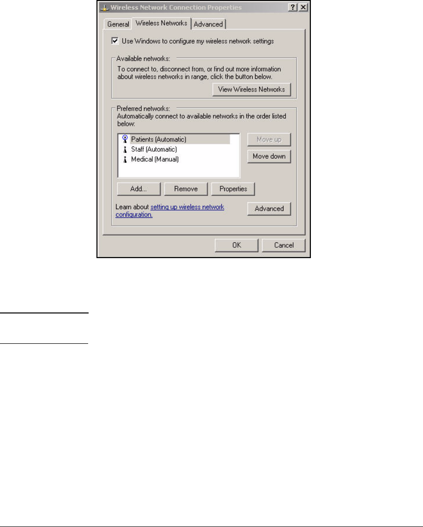
5-154
Using the NAC 800 in a RADIUS-Only Configuration
Configure Endpoints
Figure 5-88. Wireless Network Connection
Status—Wireless Network Connection
Properties—Wireless Networks Tab
Note If the wireless interface has been disabled, the Wireless Networks tab will not
be displayed.
4. Click Add.
5. In the Network name (SSID) box, type the Service Set Identifier (SSID) for
your WLAN. For example: Medical, Staff, or Patients.
6. For Network Authentication, select one of the following:
•Open
•Shared
•WPA
•WPA2 (if the endpoint supports it)
•WPA-PSK
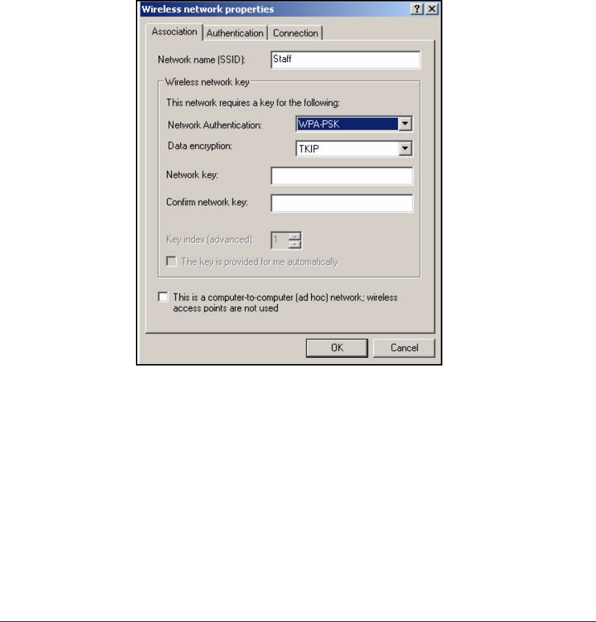
5-155
Using the NAC 800 in a RADIUS-Only Configuration
Configure Endpoints
For the Medical WLAN, you would select WPA. For the Staff WLAN, you
would select WPA-PSK, and for the Patients WLAN, you would select Open.
7. Select the Data encryption option. The options available depend on the
Network Authentication option you selected. For the example network, you
would select TKIP or AES for both the Medical WLAN and the Staff WLAN.
For the Patients WLAN, you would select Disabled.
Figure 5-89. Wireless Network Connection
Status—Wireless network properties
Window—Association Tab
8. If you did not select WPA-PSK for Network Authentication or disable Data
Encryption, select the Authentication tab.
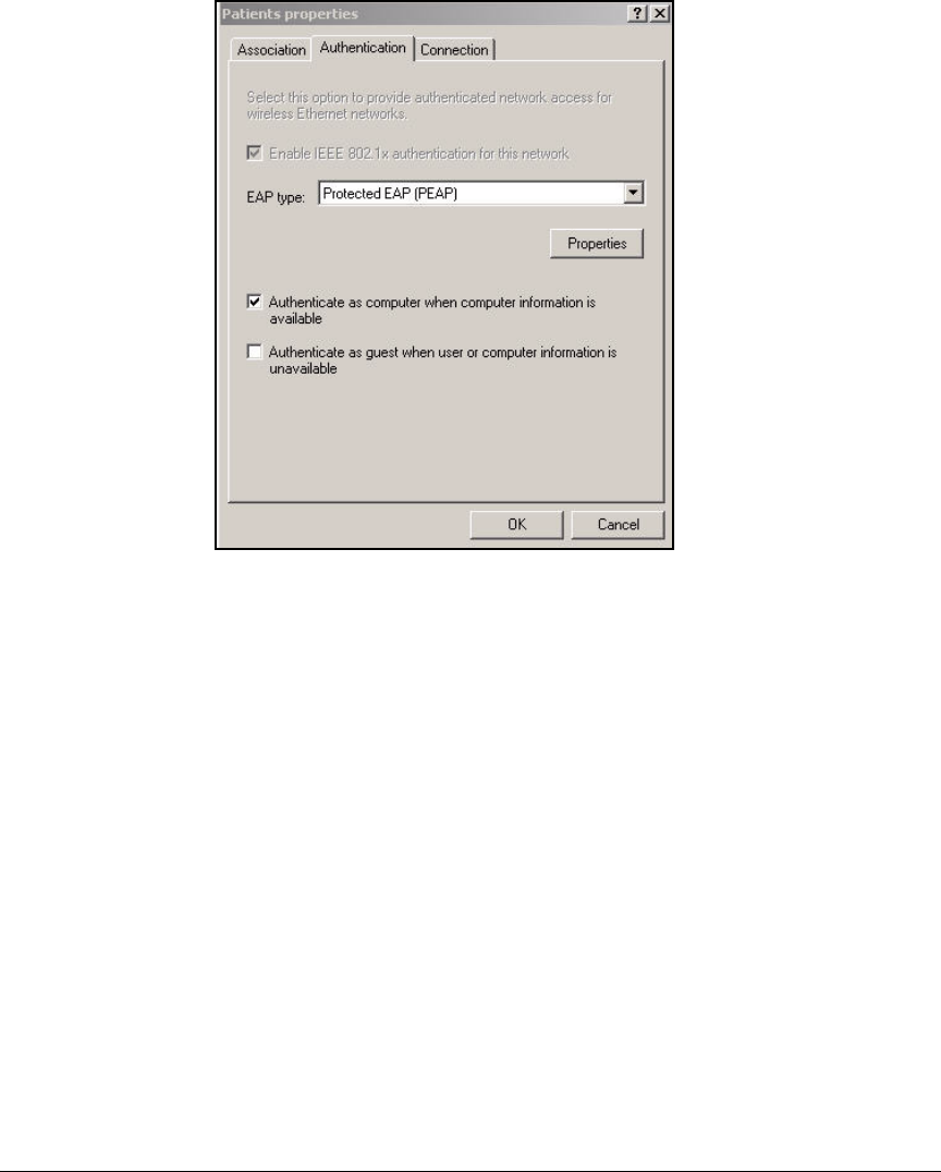
5-156
Using the NAC 800 in a RADIUS-Only Configuration
Configure Endpoints
Figure 5-90. Wireless Network Connection Status—
<SSID> properties Window—Authentication Tab
9. Select Protected EAP (PEAP) for the EAP type. This network solution does
not incorporate smart cards or certificates for stations.
10. Click Properties.
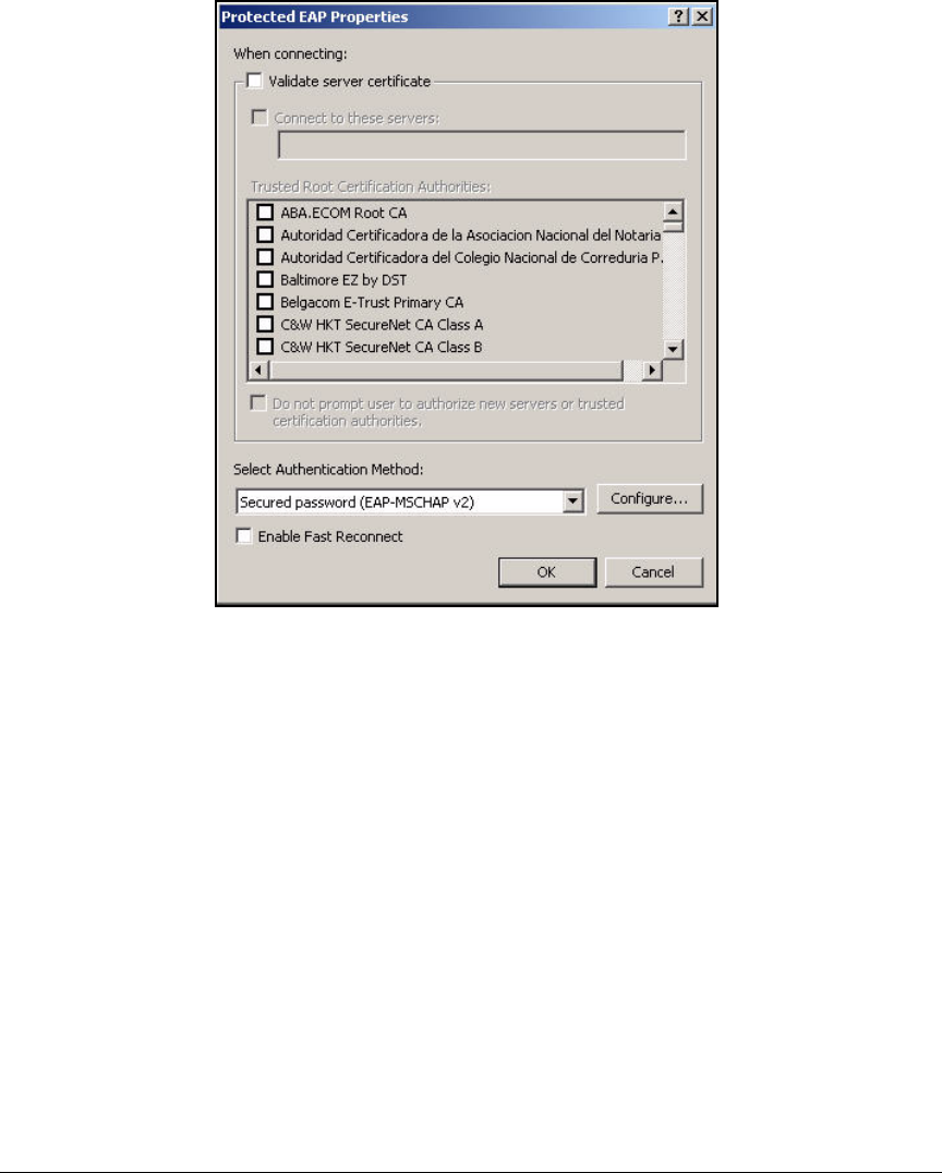
5-157
Using the NAC 800 in a RADIUS-Only Configuration
Configure Endpoints
Figure 5-91. Wireless Network Connection Status—
<EAP type> Properties Window
11. If you want, select the Validate server certificate check box.
12. From the Trusted Root Certification Authorities list, select the check box for
your CA.
13. For Select Authentication Method, select Secured password (EAP-
MSCHAP v2).
a. Click Configure.
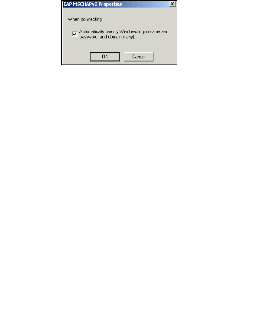
5-158
Using the NAC 800 in a RADIUS-Only Configuration
Configure Endpoints
Figure 5-92. EAP MSCHAPv2 Properties Window
in the Windows XP Supplicant
b. Ensure the Automatically use my Windows logon name and password
(and domain if any) check box is selected if this is how you authenticate
to the network. Clear the check box if you use a different username
and password. Because the example network is using OpenLDAP, the
network administrators would clear this option.
c. Click OK.
14. Click OK to close all open windows.
Enable WZC
Typically, the WZC service starts automatically. However, sometimes a wire-
less card comes with a vendor client that disables WZC. You can use the vendor
client or re-enable WZC.
If you choose to re-enable WZC, follow these steps:
1. In the Start menu, select Control Panel.
2. Select Administrative Tools > Services.
3. Scroll to and double-click the WZC service.
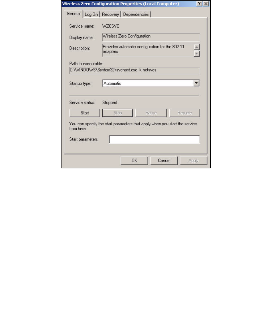
5-159
Using the NAC 800 in a RADIUS-Only Configuration
Configure Endpoints
Figure 5-93. Wireless Zero Configuration Properties Window—
General Tab
4. For the Startup type, select Automatic.
5. Click Start.
6. Click OK.

5-160
Using the NAC 800 in a RADIUS-Only Configuration
Configure Endpoints

6-1
6
Enforcing Endpoint Integrity without Port
Authentication
Contents
Introduction . . . . . . . . . . . . . . . . . . . . . . . . . . . . . . . . . . . . . . . . . . . . . . . . . . . 6-3
Network Layout . . . . . . . . . . . . . . . . . . . . . . . . . . . . . . . . . . . . . . . . . . . . . . . . 6-4
DHCP and DNS Services . . . . . . . . . . . . . . . . . . . . . . . . . . . . . . . . . . . . . 6-6
Configure ProCurve Switches . . . . . . . . . . . . . . . . . . . . . . . . . . . . . . . . . . . . . 6-7
Routing Switch startup-config . . . . . . . . . . . . . . . . . . . . . . . . . . . . . . . . . 6-8
Server Switch startup-config . . . . . . . . . . . . . . . . . . . . . . . . . . . . . . . . . . 6-9
Edge Switch startup-config . . . . . . . . . . . . . . . . . . . . . . . . . . . . . . . . . . 6-10
Configure the AP 530 to Establish the Wireless Network . . . . . . . . . . . . . 6-11
Configure Initial Settings . . . . . . . . . . . . . . . . . . . . . . . . . . . . . . . . . . . . 6-11
Establish the WLANs . . . . . . . . . . . . . . . . . . . . . . . . . . . . . . . . . . . . . . . 6-13
Enable the Radios . . . . . . . . . . . . . . . . . . . . . . . . . . . . . . . . . . . . . . . . . . 6-17
Set Up the NAC 800 . . . . . . . . . . . . . . . . . . . . . . . . . . . . . . . . . . . . . . . . . . . . 6-19
Configure Basic Settings and Install the NAC 800s . . . . . . . . . . . . . . 6-19
Install the NAC 800 . . . . . . . . . . . . . . . . . . . . . . . . . . . . . . . . . . . . . 6-20
Access the NAC 800 Web Browser Interface . . . . . . . . . . . . . . . . 6-21
Configure Quarantining . . . . . . . . . . . . . . . . . . . . . . . . . . . . . . . . . . . . . 6-22
Configure Testing Methods . . . . . . . . . . . . . . . . . . . . . . . . . . . . . . . . . . 6-27
NAC EI Agent . . . . . . . . . . . . . . . . . . . . . . . . . . . . . . . . . . . . . . . . . . 6-28
ActiveX Testing Method . . . . . . . . . . . . . . . . . . . . . . . . . . . . . . . . . 6-28
Select the Backup Testing Methods Suggested by
the NAC 800 . . . . . . . . . . . . . . . . . . . . . . . . . . . . . . . . . . . . . . . . . . . 6-29
Configure NAC Policies . . . . . . . . . . . . . . . . . . . . . . . . . . . . . . . . . . . . . 6-31

6-2
Enforcing Endpoint Integrity without Port Authentication
Contents
Prevent Users from Circumventing Endpoint Integrity Checking . . . . . . 6-38
DHCP Snooping . . . . . . . . . . . . . . . . . . . . . . . . . . . . . . . . . . . . . . . . . . . . 6-38
Enable DHCP Snooping . . . . . . . . . . . . . . . . . . . . . . . . . . . . . . . . . 6-38
Configure Trusted Ports for DHCP Snooping . . . . . . . . . . . . . . . 6-39
Define Authorized DHCP Servers . . . . . . . . . . . . . . . . . . . . . . . . . 6-40
View DHCP Snooping Settings . . . . . . . . . . . . . . . . . . . . . . . . . . . . 6-40
ARP Protection . . . . . . . . . . . . . . . . . . . . . . . . . . . . . . . . . . . . . . . . . . . . 6-41
Enable ARP Protection . . . . . . . . . . . . . . . . . . . . . . . . . . . . . . . . . . 6-42
Configure Trusted Ports for ARP . . . . . . . . . . . . . . . . . . . . . . . . . . 6-42
Configure Static IP-to-MAC Address Bindings . . . . . . . . . . . . . . . 6-43
View Information about ARP Protection . . . . . . . . . . . . . . . . . . . 6-44
Set Up Endpoints . . . . . . . . . . . . . . . . . . . . . . . . . . . . . . . . . . . . . . . . . . . . . . 6-45
Pre-install the NAC EI Agent Manually . . . . . . . . . . . . . . . . . . . . . . . . 6-45
Open Ports on Non-Windows Firewalls . . . . . . . . . . . . . . . . . . . . . . . . 6-46
Configure the Wireless Zero Configuration Utility
for Wireless Access . . . . . . . . . . . . . . . . . . . . . . . . . . . . . . . . . . . . . . . . . 6-46

6-3
Enforcing Endpoint Integrity without Port Authentication
Introduction
Introduction
This chapter explains how to implement endpoint integrity in a network that
does not enforce port authentication.
The example organization highlighted in this chapter uses Novell eDirectory
to control users’ access to network resources. At this time, the organization
has not opted for the higher security of port authentication. However, it does
want to test endpoints and verify that they are free from viruses and meet basic
security requirements.
The best endpoint integrity deployment method for such an organization is
Dynamic Host Configuration Protocol (DHCP). This chapter explains how to
place the NAC 800 for a DHCP deployment—between the DHCP servers and
the rest of the network. The NAC 800 can then test endpoints and assign non-
compliant endpoints IP addresses in a quarantine subnet.
The DHCP deployment method is less secure than the 802.1X or inline deploy-
ment method. A knowledgeable user could assign his or her endpoint a static
IP address to avoid endpoint integrity checking. To prevent users from cir-
cumventing endpoint integrity checking in this way, you can set up DHCP
snooping and ARP protection—if your switches support these features. (The
ProCurve Switch 3500yl, 5400zl, 6200yl, and 8200zl Series all support these
features.) When DHCP snooping and ARP protection are properly configured,
endpoints must receive dynamic IP addresses before they can transmit traffic
on the network. The traffic from endpoints with static IP addresses is dropped.
(You can configure the switches to transmit traffic from servers with static IP
addresses.)
In this chapter, you will learn how to configure, from beginning to end, all of
the components of a network for such an organization:
■ProCurve Network Access Controller (NAC) 800 (functioning as a com-
bination server, or CS)
■DHCP server on Novell eDirectory
■ProCurve Access Point (AP) 530s
■Wired endpoints
■Wireless endpoints
In addition, this chapter provides the startup-configs for:
■Routing switch
■Server switch
■Edge switch

6-4
Enforcing Endpoint Integrity without Port Authentication
Network Layout
Network Layout
Because this organization primarily controls access to resources with the
directory, its VLAN design is quite simple:
■Management VLAN—for managing network infrastructure devices
The example network uses ProCurve’s secure management VLAN, so
network administrators require IP addresses in the management VLAN.
Their Ethernet ports are statically assigned to this VLAN.
■Server VLAN—for all directory servers and other network resources
■User VLAN—for all users
On the user VLAN, you will set up a quarantine subnet within the existing
subnet. You will not actually create another VLAN and subnet for the quaran-
tined endpoints. Instead, you will designate an unused segment of the existing
subnet for quarantined endpoints. You’ll learn more about how to do so as you
complete the instructions in this chapter.
Table 6-1 displays the example network’s VLAN settings.
Table 6-1. VLANs
Note In this solution, the network administrators’ endpoints on VLAN 2 require
endpoint integrity checks. For this reason, the solution features quarantining
on the management VLAN. Otherwise, only the user VLAN would require
quarantining.
Figure 6-1 shows a high-level network design.
Name VLAN Subnet
Management 2 • 10.2.0.0/16
• 10.2.240.0/20—quarantine segment
Server 4 10.4.0.0/16
User 8 • 10.8.0.0/16
• 10.8.128.0/17—quarantine segment
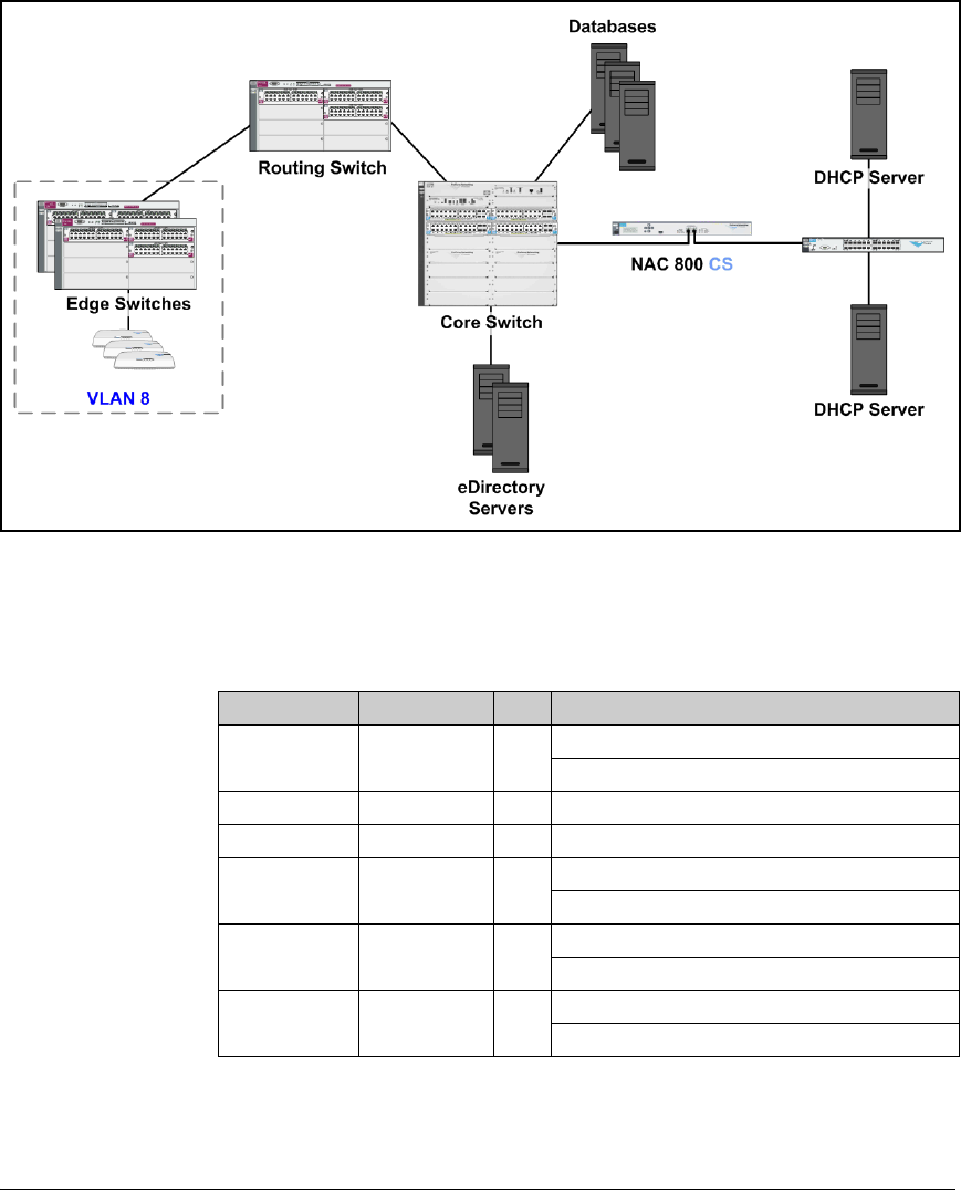
6-5
Enforcing Endpoint Integrity without Port Authentication
Network Layout
Figure 6-1. High-Level Network Design
You can use Table 6-2 to record the VLANs for your own network.
Table 6-2. My VLANs
Type Name ID Subnet
Management Production:
Optional quarantine segment:
Server
User Production:
Quarantine segment:
Production:
Quarantine segment:
Production:
Quarantine segment:

6-6
Enforcing Endpoint Integrity without Port Authentication
Network Layout
The instructions in this chapter sometimes call for typing a specific IP address.
Table 6-3 lists IP addresses for the example network. Fill in your devices’ IP
addresses and VLANs in the rightmost columns. You can then easily replace
the IP address given in the instructions with the correct address in your
environment.
Table 6-3. Example IP Addresses
DHCP and DNS Services
You must have a functioning DHCP server and DNS server, properly config-
ured for your network environment. For the example network, the network
administrators have configured the DHCP scopes listed in Table 6-4.
Table 6-4. DHCP Scopes
Device IP Address VLAN ID My IP Address My VLAN ID
eDirectory servers 10.4.4.1
10.4.8.1
4
4
DNS servers 10.4.8.1 4
DHCP servers 10.4.4.1 4
Company Web server 10.4.6.30 4
Email server 10.4.6.40 4
Financial database 10.4.7.45 4
Routing Switch 10.2.0.1
10.4.0.1
10.8.0.1
2
4
8
Edge Switch 10.2.0.3 2
AP 530 A 10.2.0.10 2
AP 530 B 10.2.0.20 2
AP 530 C 10.2.0.30 2
NAC 800 CS 10.4.4.40 4
Scope VLAN Subnet Range Default Gateway DNS Server
Management 2 10.2.0.0/17 10.2.0.60-
10.2.0.200
10.2.0.1
10.2.0.2
10.4.8.1
Users 8 10.8.0.0/17 10.8.16.0-
10.8.19.254
10.8.0.1
10.8.0.2
10.4.4.40

6-7
Enforcing Endpoint Integrity without Port Authentication
Configure ProCurve Switches
In addition, the network administrators have configured their DNS servers
with the following reverse lookup zones:
■10.2.0.0/16
■10.4.0.0/16
■10.8.0.0/16
Configure ProCurve Switches
This section includes examples of the most basic configurations necessary for
for ProCurve switches to establish the network. Specifically, you must config-
ure:
■Management IP address
■Default gateway
■VLANs:
• Management VLAN untagged on uplink ports and ports connected to
AP 530s
• User and Server VLANs tagged on uplink ports
• User VLAN tagged on ports connected to AP 530s
• User VLAN untagged on ports connecting to user endpoints
• Server VLAN untagged on ports connecting to servers
■Passwords for local device security—for example:
• manager = procurveswitch
• operator = operatorswitch
Routing switches require these additional settings:
■IP addresses for all VLANs
■IP routing enabled
■On the User VLAN, IP helper addresses to:
• The network DHCP servers
•The NAC 800
Note In this example, network administrators receive IP addresses on the manage-
ment VLAN, so that VLAN requires the same helper addresses as the User
VLAN.

6-8
Enforcing Endpoint Integrity without Port Authentication
Configure ProCurve Switches
The following sections show example configurations for:
■A routing switch, which connects only to other switches
■A server switch, which connects to servers; the uplink port is A1
■An edge switch, which connects to endpoints and APs; the uplink port
is A1
Refer to the configurations as you set up your network. If you need step-by-
step instructions, you should refer to the documentation for your switch.
Routing Switch startup-config
The following is the startup-config for the routing switch used to test this
network.
; J8692A Configuration Editor; Created on release #K.12.XX
hostname "Routing_Switch"
module 1 type J86xxA
ip routing
vlan 1
name "DEFAULT_VLAN"
no untagged 1-20
no ip address
exit
vlan 2
name "Management"
untagged 1-20
ip helper-address 10.4.4.1 //IP addresses of the DHCP
server//
ip helper-address 10.4.4.40 //IP addresses of the
NAC 800//
ip address 10.2.0.1 255.255.0.0
exit
vlan 4
name "Server"
ip address 10.4.0.1 255.255.0.0
tagged 11-20
exit
vlan 8
name "Users"
ip helper-address 10.4.4.1 //IP addresses of the DHCP
server//
ip helper-address 10.4.4.40 //IP addresses of the
NAC 800//
ip address 10.8.0.1 255.255.0.0

6-9
Enforcing Endpoint Integrity without Port Authentication
Configure ProCurve Switches
tagged 1-10
exit
ip authorized-managers 10.2.0.0 255.255.0.0
ip authorized-managers 10.4.4.40 255.255.255.255
ip dns domain-name "procurveu.edu"
ip dns server-address 10.4.8.1
password manager
password operator
Server Switch startup-config
The following is the startup-config for the server switch used to test this
network.
; J8697A Configuration Editor; Created on release #K.12.XX
hostname "Server_Switch"
web-management management-url ""
module 1 type J8702A
module 2 type J8702A
ip default-gateway 10.2.0.1
vlan 1
name "DEFAULT_VLAN"
no untagged A1-A24, B1-B24
no ip address
exit
vlan 2
name "Management"
untagged A1,B1
ip address 10.2.0.3 255.255.0.0
exit
vlan 4
name "Server"
untagged B2-B24
tagged A1,B1
no ip address
exit
ip authorized-managers 10.2.0.0 255.255.0.0
ip authorized-managers 10.4.4.40 255.255.255.255
ip dns domain-name "procurveu.edu"
ip dns server-address 10.4.8.1
password manager

6-10
Enforcing Endpoint Integrity without Port Authentication
Configure ProCurve Switches
Edge Switch startup-config
Your network will probably include many edge switches; this is the configu-
ration for a 5400zl.
; J8697A Configuration Editor; Created on release #K.12.XX
hostname "Edge Switch"
module 1 type J8702A
module 2 type J8702A
web-management management-url ""
ip default-gateway 10.2.0.1
vlan 1
name "DEFAULT_VLAN"
no untagged A1,B1
no ip address
no untagged A2-A24,B2-B24
exit
vlan 2
name "Management"
untagged A1,B2-B4,B21-B24 //A1 is the uplink port.
B1-B3 connect to AP 530s. B21-B24 connect to management
stations//
ip address 10.2.0.5 255.255.0.0
exit
vlan 8
name "Users"
tagged A1,B1-B3 //A1 is the uplink port. B1-B3 connect
to AP 530s.//
untagged A2-A24,B4-B20
exit
ip authorized-managers 10.2.0.0 255.255.0.0
ip authorized-managers 10.4.4.40 255.255.255.255
dhcp-snooping
dhcp-snooping authorized-server 10.4.4.1
dhcp-snooping authorized-server 10.4.4.40
dhcp-snooping vlan 2 8
ip dns domain-name "procurveu.edu"
ip dns server-address 10.4.8.1
interface A1
dhcp-snooping trust
exit
arp-protect
arp-protect trust A1,B1-B3 //The ports that connect to
the APs must send ARP packets, so they must be trusted.//
arp-protect vlan 2 8
password manager
password operator

6-11
Enforcing Endpoint Integrity without Port Authentication
Configure the AP 530 to Establish the Wireless Network
Configure the AP 530 to Establish the
Wireless Network
This section provides basic configuration steps for an AP 530:
■Initial settings:
• Manager password
•IP settings
• Country code
■Wireless LAN (WLAN) that enforces WPA/WPA2-PSK
■Radio settings
Configure Initial Settings
Before installing an AP 530 in its final location, you should configure some
basic settings that allow you to access it remotely.
1. Connect the AP 530 to a power source.
The AP 530 can receive Power over Ethernet (PoE) or plug into an
external power supply using the cable shipped with it.
2. Use a serial cable to connect the COM port on your management station
to the console port on the back of the AP 530.
3. On the management station, use a terminal session application to open a
session with the AP 530, using the following settings:
• COM1 (or other console port) for the port
• 9600 baud
• 8-bit data
• No parity
• 1-bit stop
• No flow control
4. When prompted for your username and password, type admin for both.
You should change this default password as soon as possible.
5. Move to the global configuration mode context:
ProCurve AP 530# config
ProCurve AP 530(config)#

6-12
Enforcing Endpoint Integrity without Port Authentication
Configure the AP 530 to Establish the Wireless Network
6. Set a new management password:
For example:
ProCurve AP 530(config)# password manager procurveAP!
7. Specify the AP 530’s hostname:
8. Move to the Ethernet interface configuration mode context:
ProCurve AP 530(config)# interface ethernet
9. Assign the Ethernet interface a static IP address:
For example:
ProCurve AP 530(ethernet)# ip address 10.2.0.10/16
10. Specify the AP 530’s default gateway:
For example:
ProCurve AP 530(ethernet)# ip default-gateway 10.2.0.1
11. Exit to the global configuration mode.
ProCurve AP 530(ethernet)# exit
12. If you are configuring an AP 530ww or an AP 530na in Canada or Mexico,
you must specify the country code. (By default, the code is us on the AP
530na.)
Syntax: password manager <password>
Replace <password> with a string that meets your security
requirements for a secure password.
Syntax: hostname <hostname>
Replace <hostname> with a string that matches the string
mapped to the AP 530’s IP address on the DNS server.
Syntax: ip address <A.B.C.D>/<prefix length>
Replace <A.B.C.D>/<prefix length> with an IP address for the AP
530 and the correct prefix length for the AP 530’s subnet.
Syntax: ip default-gateway <A.B.C.D>
Replace <A.B.C.D> with the IP address of the AP 530’s default
router.

6-13
Enforcing Endpoint Integrity without Port Authentication
Configure the AP 530 to Establish the Wireless Network
Type your country code:
For example:
ProCurve AP 530(config)# country fr
13. Ping the default router to ensure network connectivity:
14. Save your configuration.
ProCurve AP 530(config)# write memory
15. Close the terminal session.
You can now install each AP 530 in its final location. (See the ProCurve Access
Point 530 Hardware Installation Guide.) You will complete further configu-
rations through the AP 530s’ Web browser interface.
Establish the WLANs
Complete these steps to access the AP 530’s Web browser interface and
establish the WLAN for the example organization:
1. On your management station, open a Web browser. Type the AP 530’s IP
address or hostname for the URL.
2. Log in to the AP 530’s Web browser interface:
•For the User name, type admin.
•For the Password, type the password you set in step 6 on page 6-12.
3. Select Network Setup > WLANs.
Syntax: country <code>
Replace <code> with the two-digit code for the country in
which you are operating the AP 530. If you do not know this
code, you can get a list by typing country ?.
Syntax: ping <A.B.C.D>
Sends an ICMP echo request to the specified IP address.
Replace <A.B.C.D> with the IP address of the device to which
you want to test connectivity.
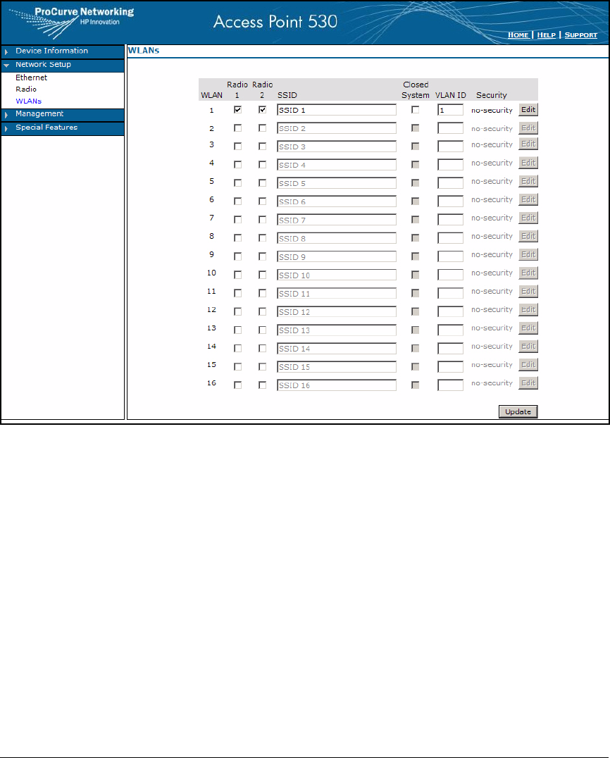
6-14
Enforcing Endpoint Integrity without Port Authentication
Configure the AP 530 to Establish the Wireless Network
Figure 6-2. AP 530 Web Interface—Network Setup > WLANs
4. In the SSID box for WLAN 1, type a name for your WLAN. In this example:
ProCurve University.
5. In the VLAN ID box, type the VLAN for wireless users. In this example,
network administrators place users in the same VLAN as wired users, 8.
However, you might want to separate wired and wireless users.
6. The Radio 1 and Radio 2 check boxes should be selected.
Optionally, clear one of the boxes to use only one of the AP 530’s radios.
7. Click Update.
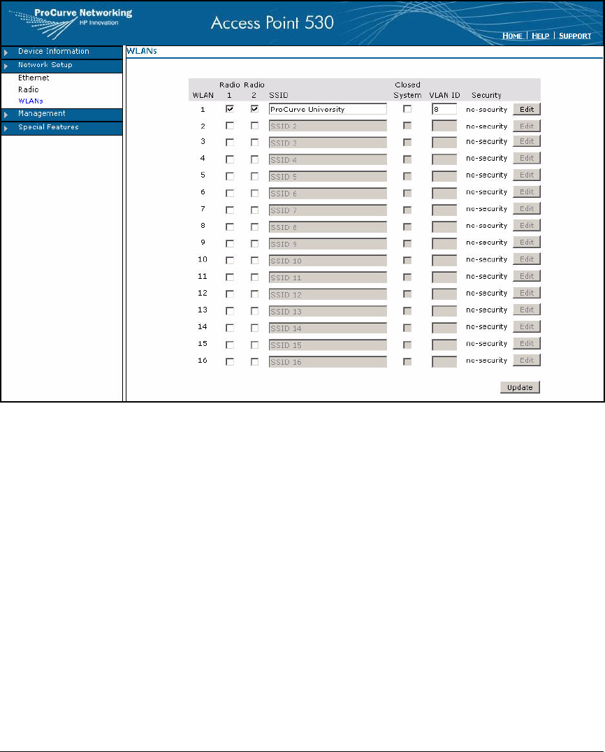
6-15
Enforcing Endpoint Integrity without Port Authentication
Configure the AP 530 to Establish the Wireless Network
Figure 6-3. AP 530 Web Interface—Network Setup > WLANs
8. Click Edit in the WLAN 1 row.
9. For Security Mode, select WPA-PSK.
10. For Cipher Suites, select TKIP (wider support), CCMP (AES) (higher secu-
rity), or Both.
11. In the Preshared key box, type a string of at least 8 characters, which is the
password for your wireless network. For example: ProCurve@Wless.
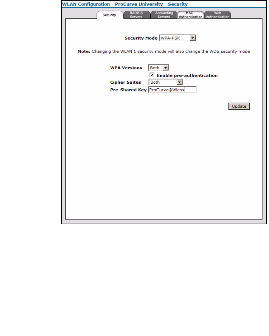
6-16
Enforcing Endpoint Integrity without Port Authentication
Configure the AP 530 to Establish the Wireless Network
Figure 6-4. AP 530 Web Interface—Network Setup > WLANs > Edit
12. Click Update.
13. A warning is displayed, telling you that your wireless settings will be
updated and wireless clients might be disconnected. Click OK.
14. Press [Alt] + [F4] to close the WLAN Configuration Security screen.
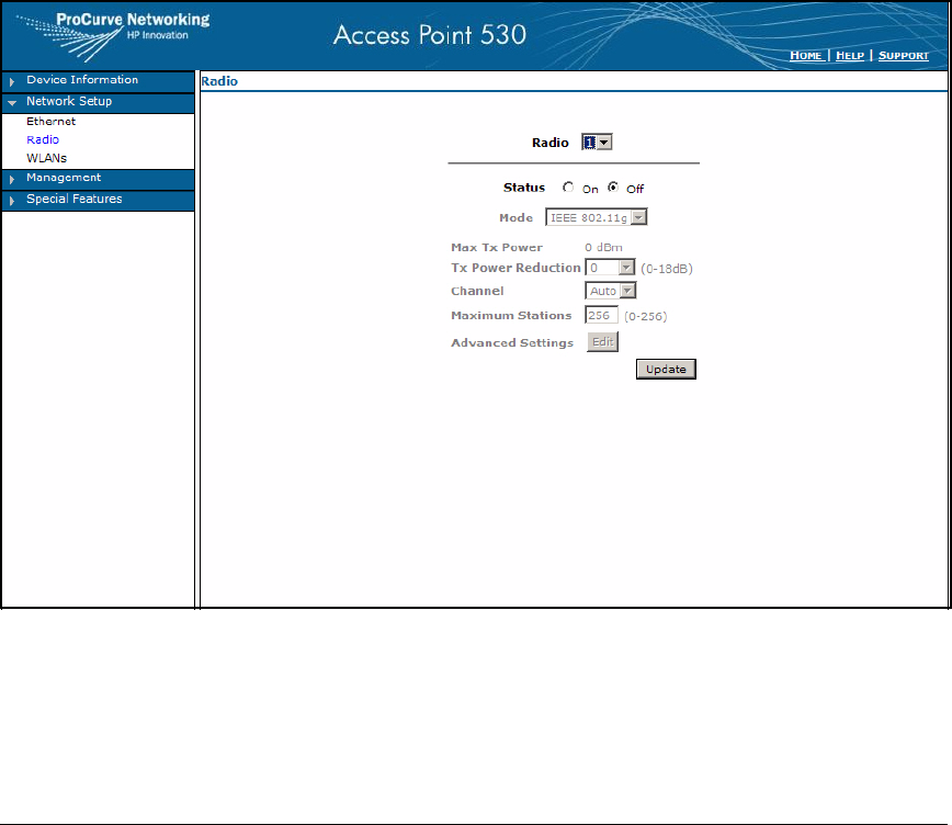
6-17
Enforcing Endpoint Integrity without Port Authentication
Configure the AP 530 to Establish the Wireless Network
Enable the Radios
The AP 530 has two built-in radios:
■Radio 1—802.11bg
■Radio 2—802.11a/bg
Details on configuring radio settings are beyond the scope of this guide. (For
example, it is often a good idea to manually set channels on nearby APs to
non-overlapping channels. Or you might want to configure your radios for
external antennas. See the product documentation.) The following instruc-
tions, however, give you the most basic steps for enabling radios:
1. Click Network Setup > Radio.
Figure 6-5. AP 530 Web Interface—Network Setup > Radio
2. Ensure that 1 is selected for Radio.
3. For Status, select On.
4. Verify that Mode is IEEE 802.11g.
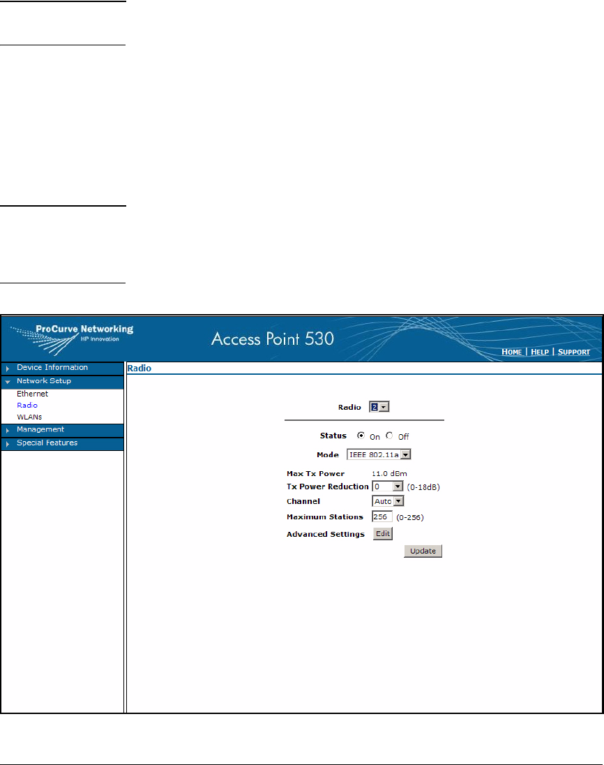
6-18
Enforcing Endpoint Integrity without Port Authentication
Configure the AP 530 to Establish the Wireless Network
Note By default, the IEEE 802.11g mode supports 802.11g and 802.11b wireless
endpoints.
5. Click Update.
6. A warning is displayed, telling you that your wireless settings will be
updated and wireless clients might be disconnected. Click OK.
7. Select 2 from the Radio box.
8. For Status, select On.
9. Verify that Mode is IEEE 802.11a.
Note Radio 2 supports 802.11bg mode as well as 802.11a. However, only one
internal radio on the AP 530 is allowed to operate in 802.11bg mode. If you
want both radios to operate in 802.11bg, you must install an external
antenna on one of the radios.
Figure 6-6. AP 530 Web Interface—Network Setup > Radio

6-19
Enforcing Endpoint Integrity without Port Authentication
Set Up the NAC 800
10. Click Update.
11. A warning is displayed, telling you that your wireless settings will be
updated and wireless clients might be disconnected. Click OK.
Set Up the NAC 800
You will now learn how to install and configure a NAC 800 that enforces
endpoint integrity with the DHCP deployment method.
The instructions below apply to a network that requires only one NAC 800, a
CS. If your network requires multiple NAC 800s—one Management Server
(MS) and multiple Enforcement Servers (ESs)—you can follow the same
instructions for the most part. However, you must configure the initial settings
on both the MS and the ESs. You must also create an enforcement cluster and
add the ESs to it. (See “Create an Enforcement Cluster and Add ESs” on page
2-146 of Chapter 2: “Implementing 802.1X with ProCurve IDM and Endpoint
Integrity” for more information about creating an enforcement cluster). Then
you can complete the remaining tasks in the Web browser interface of the MS.
Configure Basic Settings and Install the NAC 800s
Before you install the NAC 800 (or NAC 800s) in its final location, access it
through a console session. Log in with the admin username and default
password (procurve). Then configure the settings shown in Table 6-5. For step-
by-step instructions, see “Configure Basic Settings on the NAC 800s” on page
2-135 of Chapter 2: “Implementing 802.1X with ProCurve IDM and Endpoint
Integrity.”
Table 6-5. NAC 800 Basic Settings
Note The NAC 800 requires an IP address on the same subnet as the DHCP server.
Server Type Menu Interface
Password
IP Address Subnet Mask Default Gateway
Combination Server procurvenac9 10.4.4.40 255.255.0.0 10.4.0.1
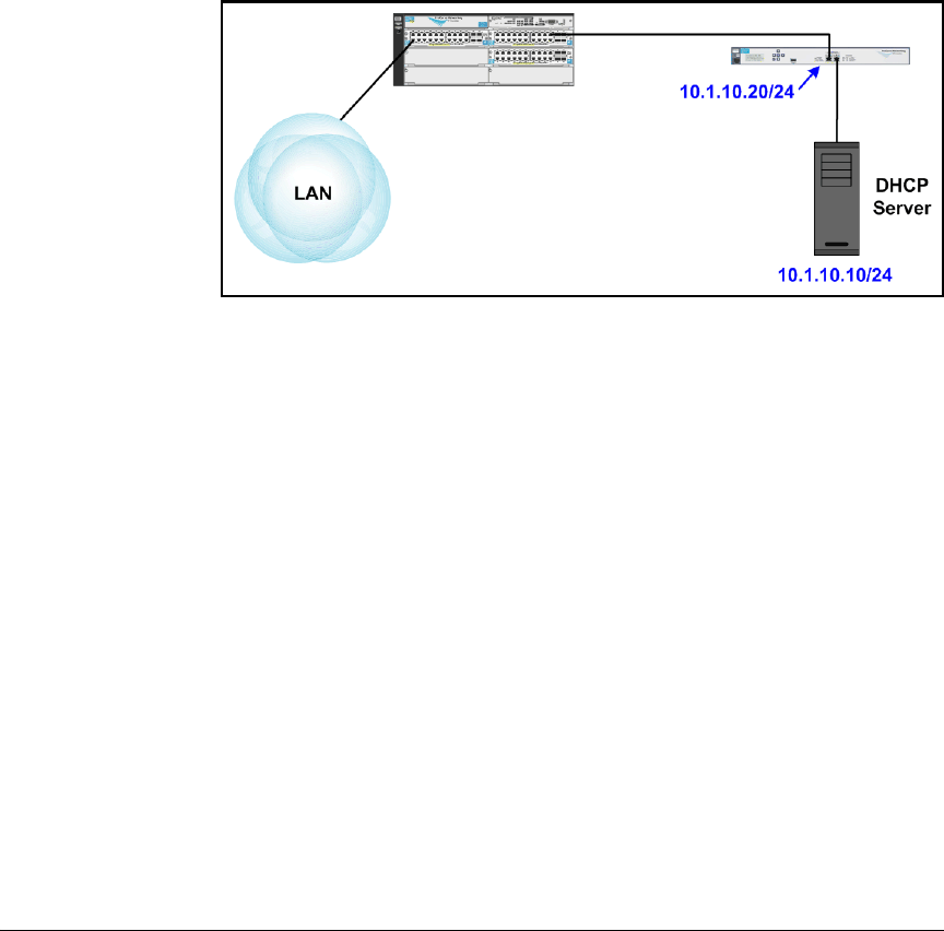
6-20
Enforcing Endpoint Integrity without Port Authentication
Set Up the NAC 800
Install the NAC 800
The NAC 800 in this solution enforces quarantining by intercepting DHCP
requests. For a DHCP deployment, you must install the NAC 800 between the
DHCP server and the rest of the network.
On its port 1, the NAC 800 connects to a switch (typically, the one to which
the DHCP server would otherwise connect); the NAC 800 connects to the
DHCP server on its port 2. Figure 6-7 shows an example installation.
Figure 6-7. DHCP Deployment Method—Single DHCP Server
Figure 6-8 shows a design for a network with multiple DHCP servers. On its
port 2, the NAC 800 connects to a switch to which the DHCP servers connect.
(For a network with more 3000 endpoints, you could also attach other NAC
800s to the DHCP servers’ switch and configure the NAC 800s as ESs in a
cluster. You would also need one NAC 800 that functions as an Management
Server [MS] installed somewhere on the network.)
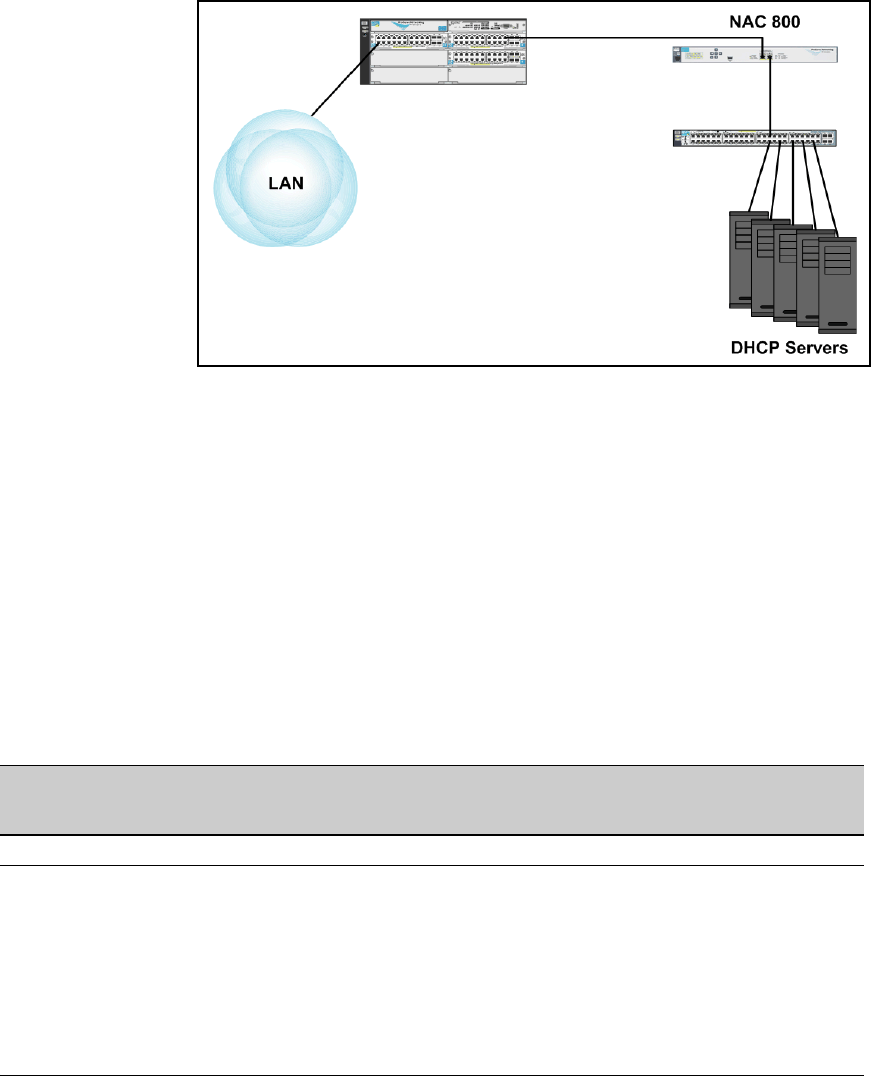
6-21
Enforcing Endpoint Integrity without Port Authentication
Set Up the NAC 800
Figure 6-8. DHCP Deployment Method—Multiple DHCP Servers
Refer to the Network Access Controller 800 Hardware Installation Guide for
detailed mounting and installation instructions.
Access the NAC 800 Web Browser Interface
To access the NAC 800 Web browser interface, open a Web browser and type
the NAC 800’s IP address or hostname for the URL.
The first time that you access the NAC 800’s Web browser interface, you must
complete some basic setup. For example, PCU network administrators con-
figure the settings shown in Table 6-6. See Chapter 2: “Implementing 802.1X
with ProCurve IDM and Endpoint Integrity” for step-by-step instructions.
Table 6-6. NAC 800 Initial Web Browser Setup
Root Password Hostname Time Zone Time Servers DNS Server Web
Administrator
Username
Web
Administrator
Password
procurvenac9 CS.procurveu.edu GMT -8 Default 10.4.8.1 admin procurvenac9
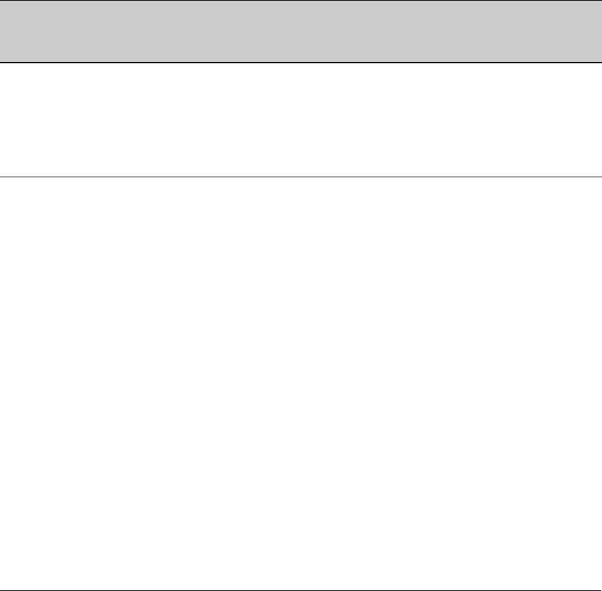
6-22
Enforcing Endpoint Integrity without Port Authentication
Set Up the NAC 800
Configure Quarantining
The DHCP quarantine method requires you to set up a quarantine area for each
subnet (VLAN) with endpoints that will be tested and controlled. The areas
for the example are shown in Table 6-7. Note that just as a DHCP range is often
smaller than the complete subnet, the current DHCP range for the quarantine
segment is smaller than that segment. Administrators can later add addresses
to the range if necessary.
Table 6-7. Quarantine Areas
Follow these steps to configure the DHCP quarantine method:
1. Select Home > System configuration > Quarantining.
Quarantine
Area
Non-
quarantined
Subnets
Quarantine
Segment
DHCP Range
for the
Quarantine
Segment
Default
Gateway
Domain Suffix DHCP
Quarantine
Option
VLAN 2
(Management
and Servers)
10.2.0.0/17
10.2.128.0/18
10.2.192.0/19
10.2.224.0/20
10.2.240.0/20 10.2.240.0–
10.2.240.255
10.2.0.1 procurveu.edu Static routes
VLAN 4 (Users) 10.8.0.0/17 10.8.128.0/17 10.8.128.0–
10.8.131.255
10.8.0.1 procurveu.edu Static routes
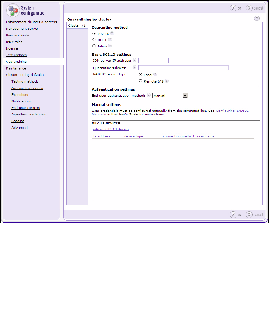
6-23
Enforcing Endpoint Integrity without Port Authentication
Set Up the NAC 800
Figure 6-9. Home > System configuration > Quarantining
2. Select DHCP as the Quarantine method.
6-24
Enforcing Endpoint Integrity without Port Authentication
Set Up the NAC 800
Figure 6-10. Home > System configuration > Quarantining
3. In the DHCP enforcement area, keep the default setting: Enforce DHCP
requests from all IP addresses.
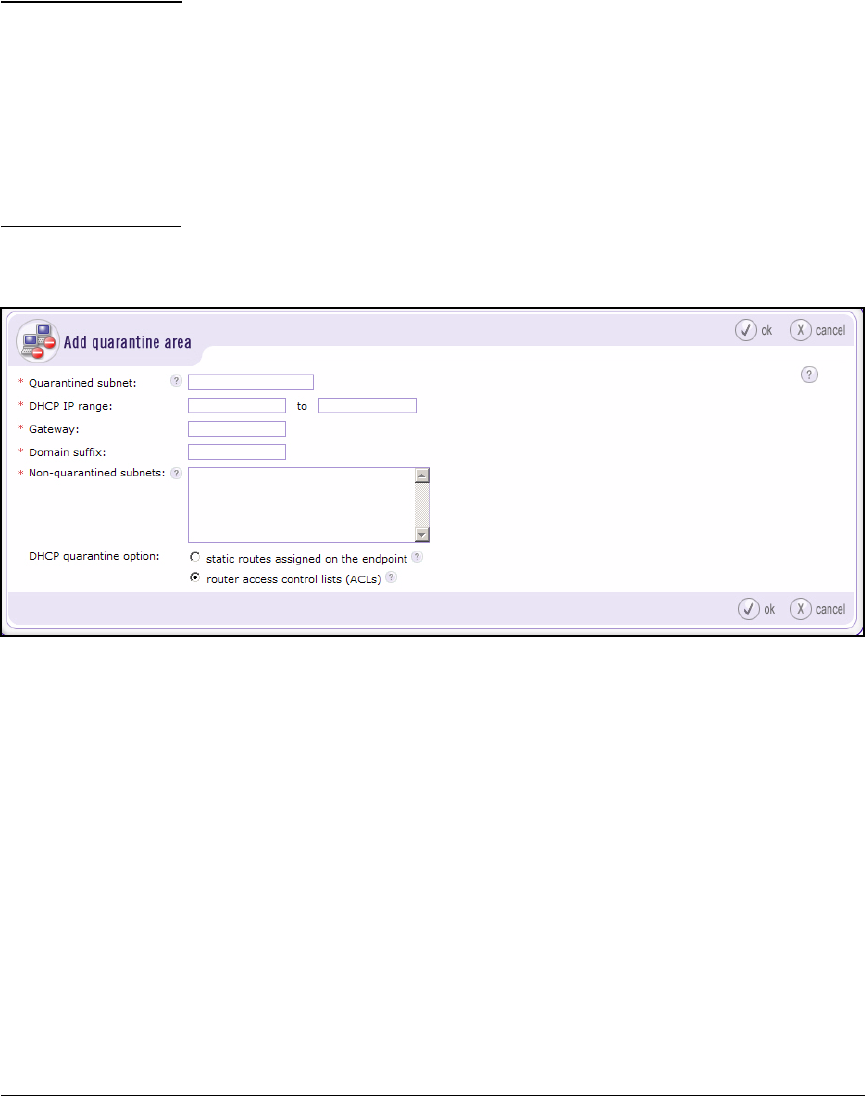
6-25
Enforcing Endpoint Integrity without Port Authentication
Set Up the NAC 800
Note You would select a different option if you had a subnet with endpoints that
you did not wa nt to quar antine b ut th at request DHCP addresses. For example,
you might not want to quarantine network administrator endpoints. In this
case, select Restrict enforcement of DHCP requests to quarantine and non-quaran-
tine subnets. Do not add a quarantine area that specifies the subnet in question
in the Non-quarantined subnets box.
The NAC 800 will still test the endpoints. You can configure an exception to
change this behavior.
4. Click add a quarantine area.
Figure 6-11. Home > System configuration > Quarantining > Add quarantine area
5. In the Quarantined subnet box, type the IP address of the subnet you have
chosen for quarantining endpoints. For example, you would add the
following for the 10.2.0.0 subnet:
10.2.240.0/20
For the 10.8.0.0 subnet, you would add the following:
10.8.128.0/17
6. In the DHCP IP range boxes, type the first and last IP addresses in a range
of addresses within the quarantined subnet.
For example, you would add the following for the 10.2.0.0 subnet:
10.2.240.0 and 10.2.240.255.

6-26
Enforcing Endpoint Integrity without Port Authentication
Set Up the NAC 800
For example, you would add the following for the 10.8.0.0 subnet:
10.8.128.0 and 10.8.131.255.
7. In the Default gateway box, specify the IP address of the default gateway.
For example: 10.2.0.1 or 10.8.0.1.
8. In the Domain suffix box, type your company’s domain name. For example:
procurveu.edu.
9. In the Non-quarantine subnets box, specify the non-quarantined segment
of the subnet. This segment must not overlap with the quarantine segment,
so you cannot simply type the IP address of the entire production subnet.
Specifying the non-quarantine subnet is easy when you divide the produc-
tion subnet evenly—half for non-quarantined endpoints and half for quar-
antined endpoints. For example, in the 10.8.0.0/16 subnet, 10.8.128.0/17 is
the quarantine subnet. For the single non-quarantine subnet, type:
10.8.0.0/17
On the other hand, you might select a smaller range of IP addresses for
quarantined than for non-quarantined endpoints. In this case, you must
type multiple network IP addresses in the Non-quarantine subnets box in
order to specify the entire non-quarantine range.
For example, in the 10.2.0.0/16 subnet, 10.2.240.0/20 is the quarantine
subnet. The rest of the subnet (non-quarantined) is specified by the
following network addresses:
• 10.2.0.0/17
• 10.2.128.0/18
• 10.2.192.0/19
• 10.2.224.0/20
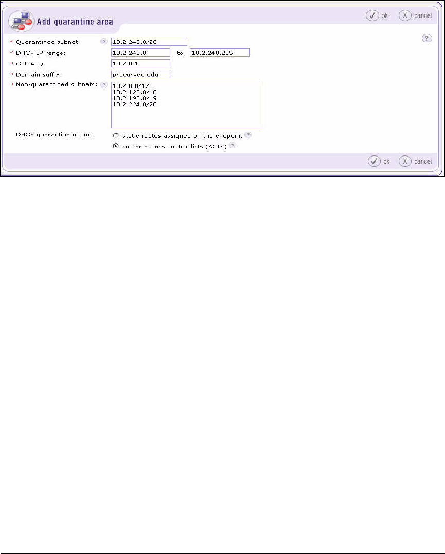
6-27
Enforcing Endpoint Integrity without Port Authentication
Set Up the NAC 800
Figure 6-12. Home > System configuration > Quarantining > Add quarantine area
10. For the DHCP quarantine option, select static routes assigned on the endpoint.
11. Click ok.
12. To configure quarantining of endpoints on another VLAN, repeat steps 4
through 11.
13. Click ok in the Home > System configuration > Quarantining window.
Configure Testing Methods
The NAC 800 supports three testing methods:
■NAC EI agent
■ActiveX
■Agentless testing
Initially, the NAC 800 tries to test an endpoint in the background:
1. The NAC 800 tries to test the endpoint with the NAC EI agent.
2. If no agent is installed on the endpoint, the NAC 800 tries to install the
ActiveX agent.
3. If the ActiveX installation fails and if credentials for the endpoint or
domain exist, the NAC 800 tries to use agentless testing.
To ensure that the NAC 800 can successfully test the endpoints in the back-
ground, you must set up your network to support the testing methods you
want to use.

6-28
Enforcing Endpoint Integrity without Port Authentication
Set Up the NAC 800
In this section, you will learn how to set up the network to use the two testing
methods chosen for the example network—the NAC EI agent and ActiveX.
Because ProCurve University is using Novell eDirectory, the agentless testing
method, which functions best in a Windows domain, is not a good fit.
NAC EI Agent
In this example, the network has a small IT staff. Rather than pre-installing
the NAC EI agent on endpoints, network administrators will allow the NAC
800 to interact with users to download the NAC EI agent automatically. (See
“Select the Backup Testing Methods Suggested by the NAC 800” on page 6-29.)
The NAC EI agent and the NAC 800 communicate on TCP and UDP ports 1500.
In most cases, the agent can automatically open the correct ports through the
endpoints’ firewall.
Note This rule has one exception. You must manually open port 1500 on an endpoint
that meets all of these three conditions:
■Is unmanaged
■Runs Windows XP
■Uses a non-SP2 firewall such as Norton
ActiveX Testing Method
ActiveX testing requires the endpoint’s Web browser to be open for every test.
The Web browser must be Internet Explorer version 5.0 or 6.0. The ActiveX
agent uses ActiveX content and Java script. The endpoint’s browser security
settings must allow such content from the NAC 800.
If a user closes IE after his or her endpoint has gained access, the NAC 800
cannot retest the endpoint. The user can continue to connect to the network—
even if the endpoint becomes non-compliant—for as long as IE is closed.
ActiveX testing works best when IE’s default security settings are used:
■Internet – High
■Local Intranet – Medium-Low
■Trusted Sites – Medium
■Restricted Sites – High
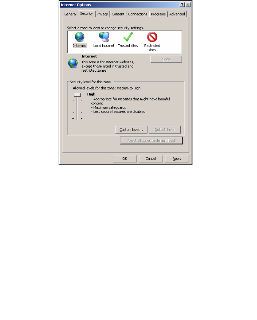
6-29
Enforcing Endpoint Integrity without Port Authentication
Set Up the NAC 800
Figure 6-13. Microsoft IE—Tools > Internet Options >
Security Tab
Like the NAC EI agent, ActiveX requires port 1500 to be open, but typically
the ActiveX agent can automatically open the correct ports through the
endpoints’ firewall.
Select the Backup Testing Methods Suggested by the NAC 800
If the background testing fails, the NAC 800 can display end-user access
windows that instruct the user how to allow the testing to succeed. Follow
these steps to allow the NAC 800 to automatically download the NAC EI agent
to an end-user’s endpoint:
1. Log in to the Web browser interface on the NAC 800 MS.
2. Select System configuration > Cluster settings defaults > Testing methods.
3. Select the NAC agent and ActiveX plug-in check boxes.
4. Clear the Agentless check box.
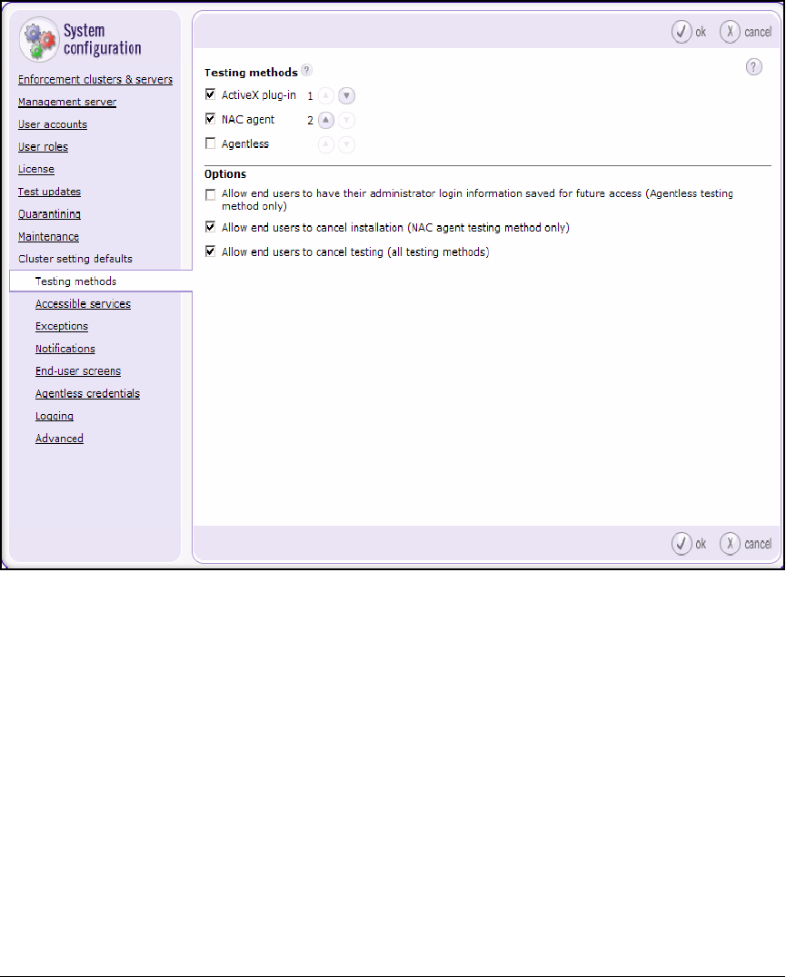
6-30
Enforcing Endpoint Integrity without Port Authentication
Set Up the NAC 800
Figure 6-14. NAC 800 Web Interface—Home > System configuration > Cluster
setting defaults > Testing methods
5. Under options, clear the following:
Allow end users to cancel installation (NAC agent testing method only)
Allow end users to cancel testing (all testing methods)
6. Click ok.
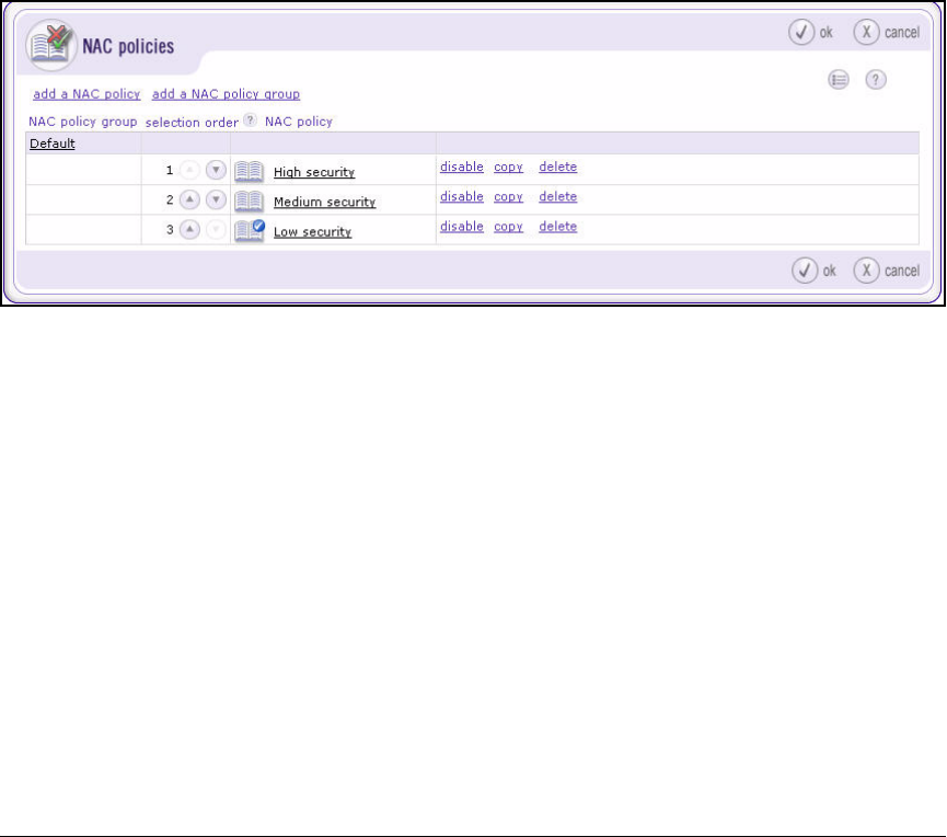
6-31
Enforcing Endpoint Integrity without Port Authentication
Set Up the NAC 800
Configure NAC Policies
The NAC 800 has three default policies for testing endpoint integrity. By
default, the Low security NAC policy applies to all endpoints. This section
teaches you how to:
■Create new NAC policies for your environment
■Assign the policies to the correct endpoints
Complete these steps:
1. Open your Web browser and log on to the CS.
2. Select NAC policies.
Figure 6-15. NAC 800 Web Interface—Home > NAC policies Window
3. Click add a NAC policy group.
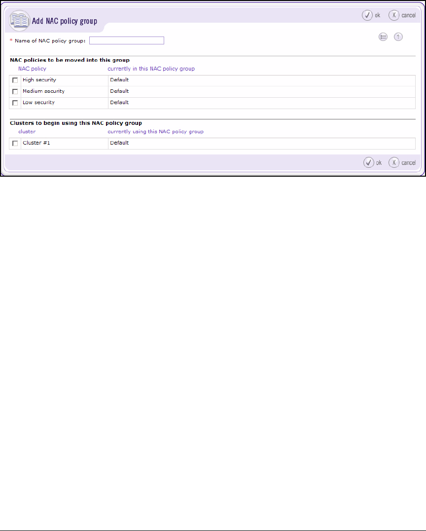
6-32
Enforcing Endpoint Integrity without Port Authentication
Set Up the NAC 800
Figure 6-16. NAC 800 Web Interface—Home > NAC policies > Add NAC
policy group
4. For Name of NAC policy group, type the name (in this example,
PCUPolicies).
5. Under Clusters to begin using this NAC policy group, select the cluster you
want to use this policy group. Because this example network uses a CS,
only one cluster will be listed with the default name of Cluster #1. Select
the check box for this cluster.
6. Click ok.
7. Create the NAC policy for network administrators’ endpoints. This policy
will be based on the Medium security policy but will include several more
tests. Click the copy link next to Medium security in the Home > NAC policies
window.
8. In the Policy name box, type Network Admins.
9. From the NAC policy group list, select PCUPolicies.
10. Click Domains & endpoints in the left pane.
11. In the Endpoints box, type the subnets for users—both the production and
the quarantine segments. In this example:
10.2.0.0/16
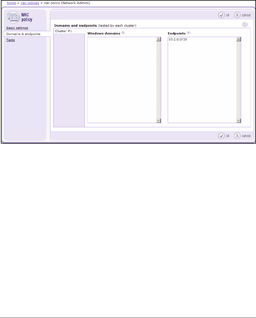
6-33
Enforcing Endpoint Integrity without Port Authentication
Set Up the NAC 800
Figure 6-17. NAC 800 Web Interface—Home > NAC policies > <NAC policy> >
Domains & endpoints
12. Click Tests in the left pane.
The steps below show you how to configure additional tests that are not
included in the default Medium security policy. These tests are just
examples. Refer to the ProCurve Access Control Design Guide for help
in designing your company’s policies.
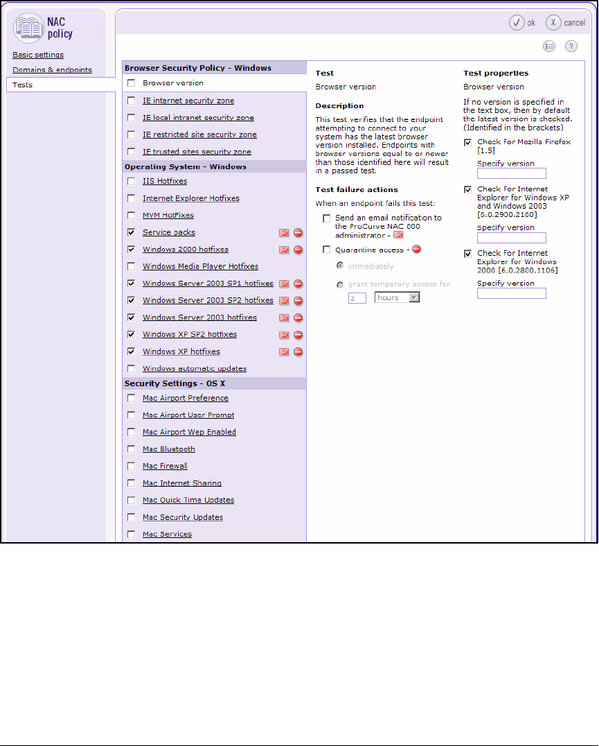
6-34
Enforcing Endpoint Integrity without Port Authentication
Set Up the NAC 800
Figure 6-18. NAC 800 Web Interface—Home > NAC policies > <NAC policy> > Tests
13. Select the Browser Version check box. Use the default settings for the
version number or specify a different version in the boxes provided. You
can specify a version for Mozilla Firefox, Internet Explorer on Windows
2003, or Internet Explorer on Windows 2000.
14. Under Operating System –Windows, select the Internet Explorer Hotfixes
check box.
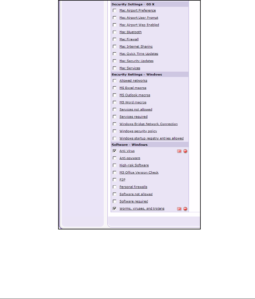
6-35
Enforcing Endpoint Integrity without Port Authentication
Set Up the NAC 800
15. Under Operating System –Windows, select the Windows Automatic Updates
check box.
Figure 6-19. NAC 800 Web Interface—Home > NAC policies > <NAC policy> > Tests
16. Under Software—Windows, select the Anti-spyware and Personal firewalls
check boxes.
17. Click ok. You are returned to the Home > NAC policies window.
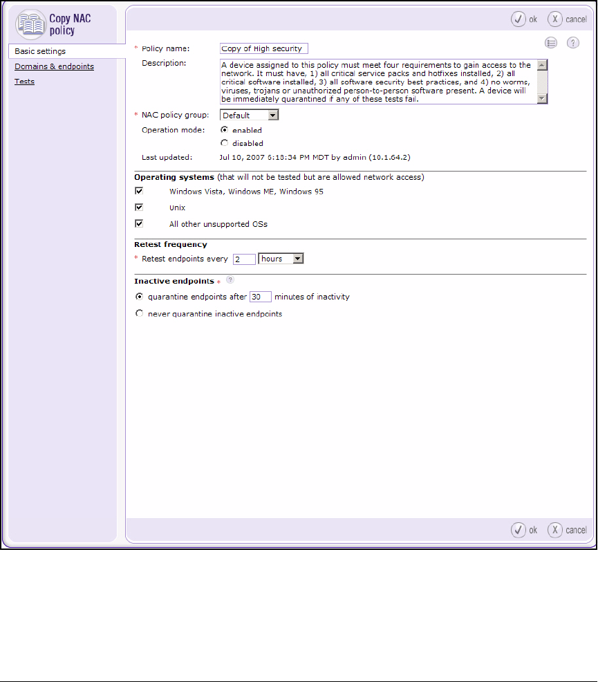
6-36
Enforcing Endpoint Integrity without Port Authentication
Set Up the NAC 800
18. Next, you will create a NAC policy for testing the endpoints of ProCurve
University users. This policy will be based on the High security policy.
Begin by clicking the copy link next to High security.
Figure 6-20. NAC 800 Web Interface—Home > NAC policies > Copy NAC policy
Window—Basic settings tab.
19. For the Policy name, type the name (in this example, PCU).
20. From the NAC policy group list, select PCUPolicies.
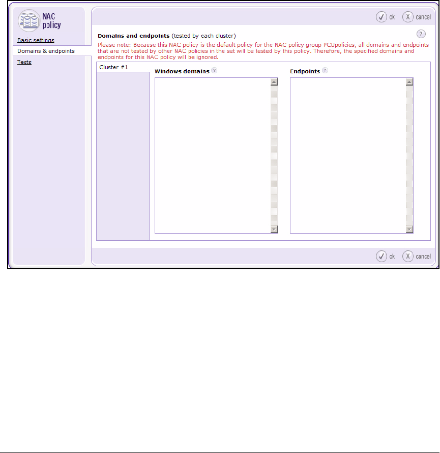
6-37
Enforcing Endpoint Integrity without Port Authentication
Set Up the NAC 800
21. Click Domains & endpoints in the left pane. Because you have defined this
policy last, the NAC 800 makes it the default policy for this policy group
and displays the message shown in Figure 6-21. If the NAC 800 detects an
endpoint that is not in the subnets or domains that you defined for other
policies in this policy group, it will use the default policy. You can change
this default setting on the Home > NAC policies window, by using the
Arrows next to the policy name.
Figure 6-21. NAC 800 Web Interface—Home > NAC policies > <NAC policy> >
Domains & endpoints
22. As long as this policy is the default policy, you do not need to complete
this step. If you decide to make another policy the default policy, type the
subnets for users (both the quarantine and non-quarantine segments) in
the Endpoints box. In this example:
10.8.0.0/16
23. Click ok.
24. Click ok.

6-38
Enforcing Endpoint Integrity without Port Authentication
Prevent Users from Circumventing Endpoint Integrity Checking
Prevent Users from Circumventing
Endpoint Integrity Checking
More knowledgeable users may try to circumvent endpoint integrity checking
by assigning themselves a static IP address. If you have a switch that supports
DCHP snooping and ARP protection, you can close this security hole and allow
traffic from the static IP addresses you specify. The ProCurve 3500yl, 5400zl,
6200yl, and 8200zl Switches support these features.
DHCP Snooping
DHCP snooping is designed to protect your network against DHCP attacks.
When you enable DHCP snooping, the switch takes the role of a security guard,
overseeing DHCP exchanges and ensuring that endpoints behave as they
should.
With DHCP snooping, the switch distinguishes between trusted and untrusted
ports. You define the ports that connect to your trusted devices, such as DHCP
servers, as trusted ports. The switch then allows DHCP packets to flow freely
on these ports. All other ports are, by default, untrusted. On these ports, the
switch filters DHCP packets and determines whether they are allowed.
For example, DHCP server packets should not originate from untrusted ports,
so if the switch detects these types of packets, it immediately discards them.
The switch also verifies information in the DHCP client header and packet
before allowing the packet onto the network. For example, the switch drops
packets in which the source MAC address does not match the DHCP MAC
address—a sign of spoofing.
This verify MAC check is enabled by default when you activate DHCP snoop-
ing. You can disable this check if you no longer want the switch to perform it.
(Type the no dhcp-snooping verify mac command.)
Enable DHCP Snooping
You first enable DHCP snooping globally on the switch. Move to the global
configuration mode context and type:
ProCurve Switch(config)# dhcp-snooping
The switch will begin to build a DHCP snooping table (or database).

6-39
Enforcing Endpoint Integrity without Port Authentication
Prevent Users from Circumventing Endpoint Integrity Checking
You must then enable the DHCP snooping feature for particular VLANs by
typing:
For example:
ProCurve Switch(config)# dhcp-snooping vlan 2 8
Configure Trusted Ports for DHCP Snooping
Stations that are connected to untrusted ports should not be transmitting
DHCP server packets, but your DHCP server must be able to send these
packets. You must define trusted ports so that the switch does not disable
DHCP entirely.
To define trusted ports, type:.
For example, you would designate an uplink port and the port that connects
to a DHCP server as trusted ports. When you define a trusted port, the switch
does not filter any DHCP packets on that port.
For a DHCP endpoint integrity deployment, you define the switch port that
connects to the NAC 800 as a trusted port. You also define the uplink port, as
shown below:
ProCurve (config)# dhcp-snooping trust a1,b1
Syntax: dhcp-snooping vlan <vlan_range>
Enables DHCP snooping on the VLAN.
Replace <vlan-range> with the VLAN ID (number or name).
Use a hyphen to specify a range. To specify multiple, non-
contiguous VLANs, separate the IDs with spaces.
Syntax: dhcp-snooping trust <ports>
Specifies which ports are trusted.
Replace <ports> with the ID of the trusted port. Use a hyphen
to specify a range. To specify multiple, non-contiguous ports,
separate the IDs with commas.

6-40
Enforcing Endpoint Integrity without Port Authentication
Prevent Users from Circumventing Endpoint Integrity Checking
Define Authorized DHCP Servers
In addition to defining trusted ports, you can define the authorized DHCP
servers on your network. In this case, the switch allows a DHCP server packet
only if it meets two criteria: the packet is from an authorized DHCP server,
and it is transmitted from a trusted port.
To define an authorized server, type the following command from the global
configuration mode context. If you have more than one DHCP server, type the
command multiple times:
For example:
ProCurve (config)# dhcp-snooping authorized-server
10.4.8.1
View DHCP Snooping Settings
To determine if DHCP snooping is enabled, type:
ProCurve Switch# show dhcp-snooping
This command also lists the VLANs for which DHCP snooping is enabled, and
you can see which ports are trusted or untrusted.
Syntax: dhcp-snooping authorized-server <A.B.C.D>
Identifies the DHCP server.
Replace <A.B.C.D> with IP address of the DHCP server.
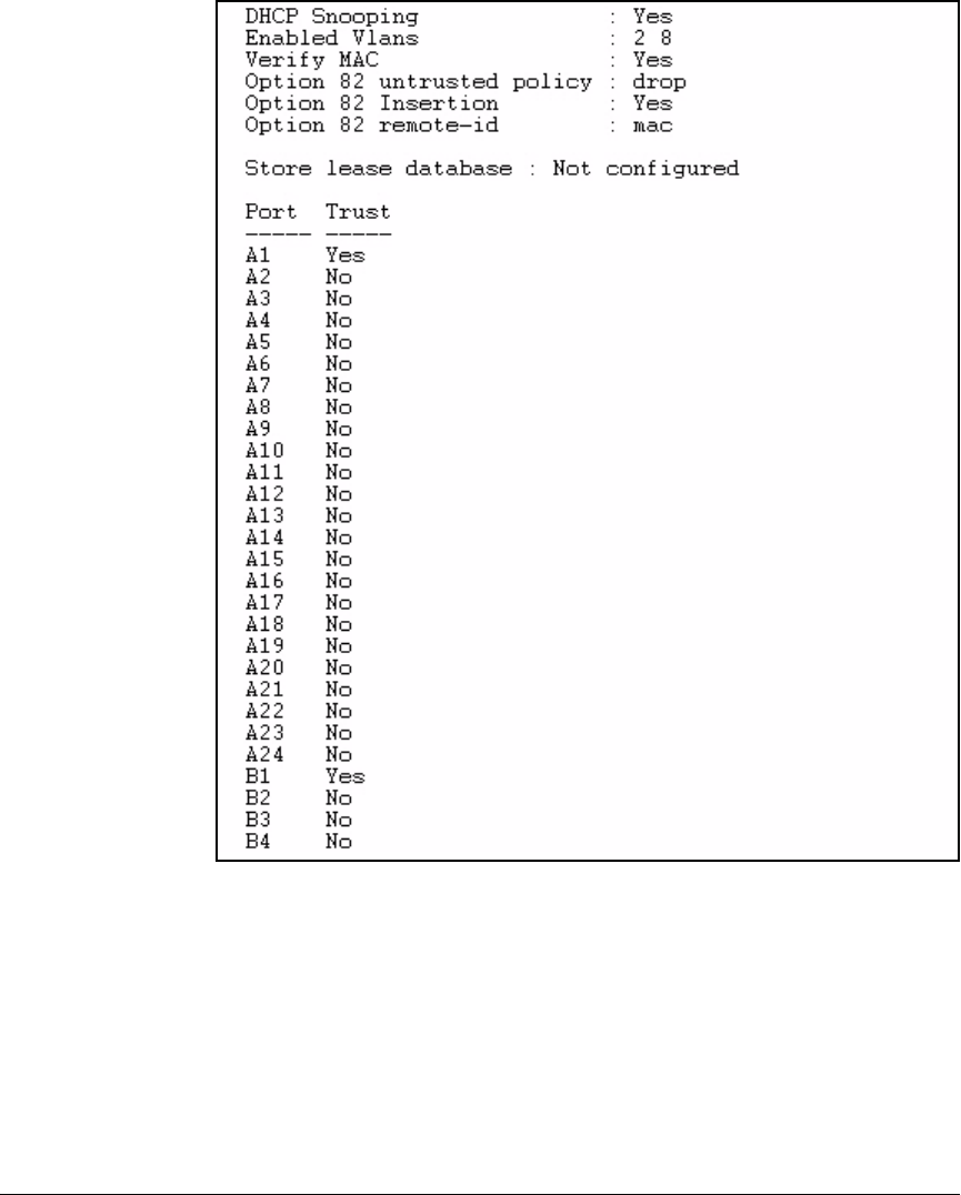
6-41
Enforcing Endpoint Integrity without Port Authentication
Prevent Users from Circumventing Endpoint Integrity Checking
Figure 6-22. show dhcp-snooping
ARP Protection
DHCP snooping allows the 3500yl, 5400zl, and 6200yl Switches to protect your
network from other attacks as well. It does so by capitalizing on the informa-
tion it learns while filtering DHCP packets. The switch builds and maintains
a DHCP snooping table, which tracks the MAC address, IP address, lease time,
binding type, VLAN number, and interface information that corresponds to
each DHCP lease through an untrusted port.

6-42
Enforcing Endpoint Integrity without Port Authentication
Prevent Users from Circumventing Endpoint Integrity Checking
You can add to this table any static bindings that you have. For example, you
can add the IP address and MAC address of servers that have a static IP
address.
Using this table to verify IP-to-MAC bindings, the switch determines which IP
addresses should legitimately send traffic on which ports and detects mali-
cious hosts that try to spoof ARP packets. It can also detect users who try to
assign their workstation a static IP address to avoid integrity checking.
Whether such traffic originates from a malicious host or a devious user, the
switch does not allow it on the network. It drops the traffic.
Enable ARP Protection
You first enable ARP protection globally on the switch. Move to the global
configuration mode context and type:
ProCurve Switch(config)# arp-protect
You must then enable ARP protection for a particular VLAN or for multiple
VLANs.
To enable ARP protection, type:
For example:
ProCurve Switch(config)# arp-protect vlan 2 8
Configure Trusted Ports for ARP
By default, all ports are untrusted in the context of ARP protection. This means
that the switch will check the ARP requests and responses received on all the
ports that are members of the protected VLANs.
Syntax: arp-protect <vlan-range>
Activates ARP protection on the switch.
Replace <vlan-range> with the VLAN ID (number or name).
Use a hyphen to specify a range. To specify multiple, non-
contiguous VLANs, separate the IDs with spaces.

6-43
Enforcing Endpoint Integrity without Port Authentication
Prevent Users from Circumventing Endpoint Integrity Checking
To ensure that the switch can exchange ARP traffic with other switches on
the network, you should define the uplink port as trusted for ARP. The switch
will not check the ARP requests and responses that it receives on the trusted
port. Type:
For example:
ProCurve Switch(config)# arp-protect trust a1,b1
Configure Static IP-to-MAC Address Bindings
You can type static IP-to-MAC address bindings if your network does not use
DHCP or if some devices have fixed, manually assigned, IP addresses. The
switch uses the bindings you type for both DHCP snooping and dynamic ARP
protection.
To configure a static IP-to-MAC address binding, type:
For example, to configure a binding for the DNS server on the example
network, type:
ProCurve Switch(config)# ip source-binding 4 10.4.8.1
0011436668CC a8
Syntax: arp-protect trust <port>
Specifies which ports are trusted.
Replace <ports> with the ID of the trusted port. Use a hyphen
to specify a range. To specify multiple, non-contiguous ports,
separate the IDs with commas.
Syntax: ip source-binding <vlan-ID> <A.B.C.D> <MAC_address> <port>
Adds a static IP-to-MAC address binding to the DHCP snoop-
ing table.
Replace <vlan-ID> with the number or name of the VLAN.
Replace <A.B.C.D> with the static IP address of the device.
Replace <MAC_address> with the MAC address of the device
that has the static IP address.
Replace <port> with the ID of the trusted port.

6-44
Enforcing Endpoint Integrity without Port Authentication
Prevent Users from Circumventing Endpoint Integrity Checking
Note You only need to add IP-to-MAC address bindings for devices on VLANs on
which the switch enforces ARP protection. In the example network, the switch
does not run ARP protection on the Server VLAN (VLAN 4), so the binding is
not necessary. The command is included for your reference only.
View Information about ARP Protection
To view your ARP protection settings, type:
ProCurve Switch(config)# show arp-protect
To view statistics related to ARP protection, type:
For example:
ProCurve Switch(config)# show arp-protect statistics 8
Syntax: show arp-protect statistics <vlan-ID>
Shows statistics related to ARP protection on a VLAN. Statis-
tics include the number of packets dropped and the reason.
Replace <vlan-ID> with the number or name of the VLAN.
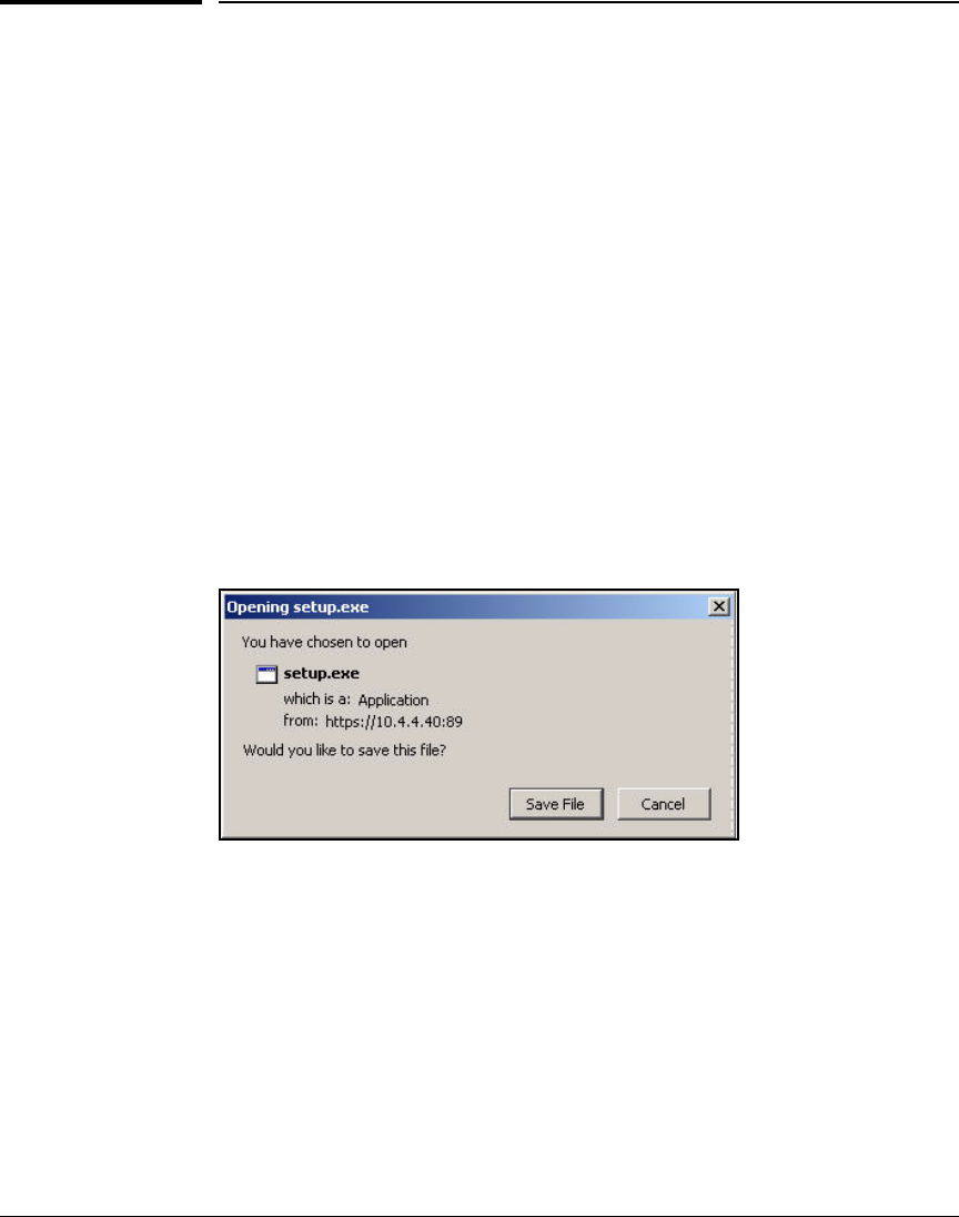
6-45
Enforcing Endpoint Integrity without Port Authentication
Set Up Endpoints
Set Up Endpoints
This section covers some minimal configurations on endpoints to ready them
for endpoint integrity and wireless access.
Pre-install the NAC EI Agent Manually
In this solution, pre-installing NAC EI agent is optional. However, you might
encourage users to download and install the agent during the trial period
(before you activate quarantining). Explain that this easy task will help
everyone connect to the network more smoothly when endpoint integrity is
enforced. Although some users may choose not to install the agent, they will
receive another chance the first time that the NAC 800 attempts to test them.
Give users the following instructions:
1. Open a Web browser and type the following for the URL: https://<NAC IP
address>:89/setup.exe.
Figure 6-23. NAC 800 Web Interface—Home > System
configuration > Quarantining (802.1X
quarantine method) > add an 802.1X device
2. A window such as the one in Figure 6-23 is displayed. Click Save File.
3. After the file is downloaded, open it and allow it to run.

6-46
Enforcing Endpoint Integrity without Port Authentication
Set Up Endpoints
Note Users may want to pre-install the NAC EI agent on endpoints that cannot reach
the NAC 800—for example, laptops that they only sometimes bring to work.
You can, of course, obtain the setup.exe file from the NAC 800 and copy it, for
interested users, to a CD or removable flash device.
Open Ports on Non-Windows Firewalls
Typically, the NAC EI agent (and the ActiveX agent) automatically open all
necessary ports on the endpoint’s personal firewall. However, tell users to
open ports manually if both of the following are true:
■Their endpoint runs Windows XP.
■They use a non-Windows firewall.
The users should refer to the documentation for their firewall and open TCP
and UDP ports 1500.
Configure the Wireless Zero Configuration Utility for
Wireless Access
Complete the following steps to configure the Wireless Zero Configuration
client for wireless access:
1. Select Start > Settings > Network Connections > Wireless Network
Connection.
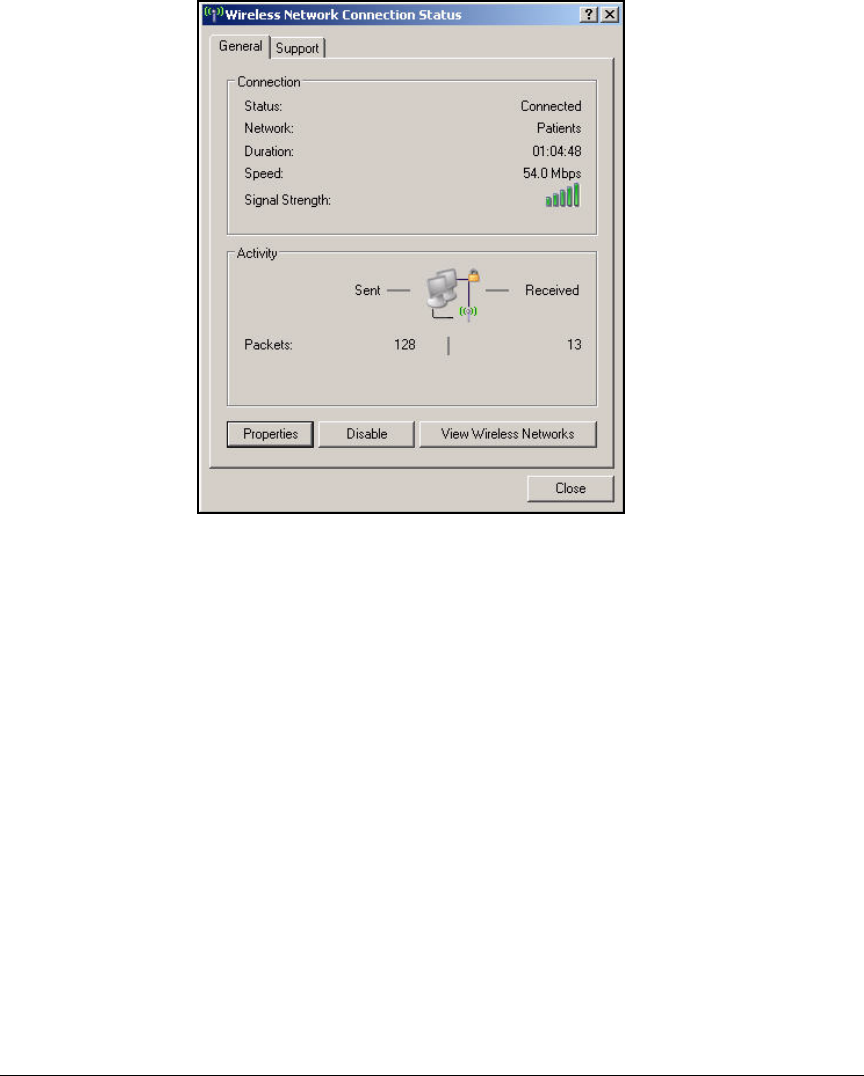
6-47
Enforcing Endpoint Integrity without Port Authentication
Set Up Endpoints
Figure 6-24. Start > Settings > Network Connections >
Local Area Connection > Wireless Network
Connection Status Window—General Tab
2. Click Properties.
3. Click the Wireless Networks tab.
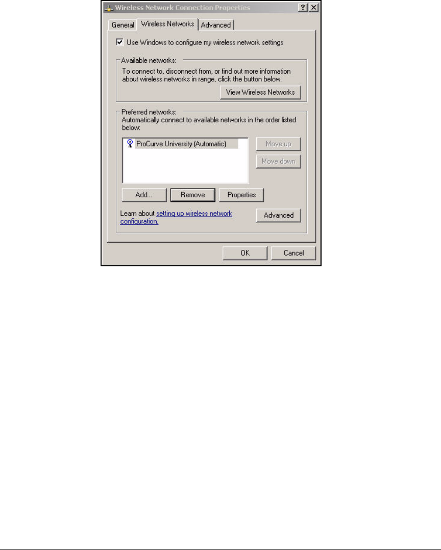
6-48
Enforcing Endpoint Integrity without Port Authentication
Set Up Endpoints
Figure 6-25. Wireless Network Connection Status—
Wireless Network Connection Properties—
Wireless Networks Tab
4. Click Add.
5. In the Network name (SSID) box, type the Service Set Identifier (SSID) for
your WLAN. For example: ProCurve University.
6. For Network Authentication, select WPA-PSK.
7. Select the Data encryption option. The options available depend on the
Network Authentication option you selected. For the example network,
you would select TKIP or AES, if your wireless NIC supports it.
8. Type and re-type the network key.
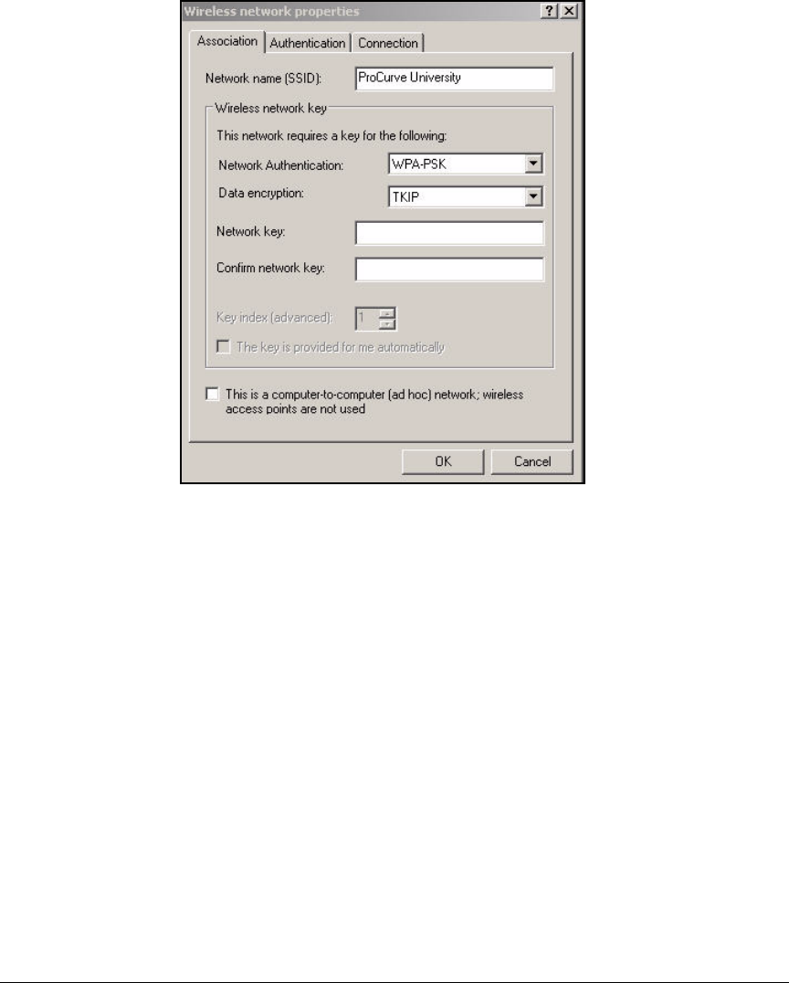
6-49
Enforcing Endpoint Integrity without Port Authentication
Set Up Endpoints
Figure 6-26. Wireless Network Connection Status—
Wireless network properties Window—
Association Tab
9. Click OK.
Enable WZC. Typically, the WZC service starts automatically. However,
sometimes a wireless card comes with a vendor client that disables WZC. You
can use the vendor client or re-enable WZC.
If you choose to re-enable WZC, follow these steps:
1. In the Start menu, select Control Panel.
2. Select Administrative Tools > Services.
3. Scroll to and double-click the WZC service.
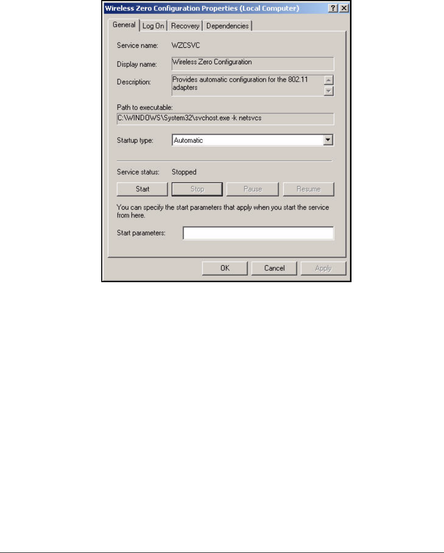
6-50
Enforcing Endpoint Integrity without Port Authentication
Set Up Endpoints
Figure 6-27. Wireless Zero Configuration Properties Window—
General Tab
4. For the Startup type, select Automatic.
5. Click Start.
6. Click OK.

A-1
A
Appendix A: Using IDM with eDirectory
Contents
Synchronize IDM and Novell eDirectory . . . . . . . . . . . . . . . . . . . . . . . . . . . . A-2
Modify the IDMImportServerComp.scp File . . . . . . . . . . . . . . . . . . . . . A-2
Disable Active Directory Synchronization . . . . . . . . . . . . . . . . . . . . . . . A-3
Import eDirectory Users . . . . . . . . . . . . . . . . . . . . . . . . . . . . . . . . . . . . . . A-5
Using SSL . . . . . . . . . . . . . . . . . . . . . . . . . . . . . . . . . . . . . . . . . . . . . . A-9
Using Simple Authentication . . . . . . . . . . . . . . . . . . . . . . . . . . . . . A-10
Using Digest-MD5 Authentication . . . . . . . . . . . . . . . . . . . . . . . . . A-11
Using Kerberos-V5 Authentication . . . . . . . . . . . . . . . . . . . . . . . . A-12
Using External Authentication . . . . . . . . . . . . . . . . . . . . . . . . . . . . A-13
Using Anonymous Authentication . . . . . . . . . . . . . . . . . . . . . . . . . A-14
Importing X.509 User Certificates into a Keystore . . . . . . . . . . . A-22
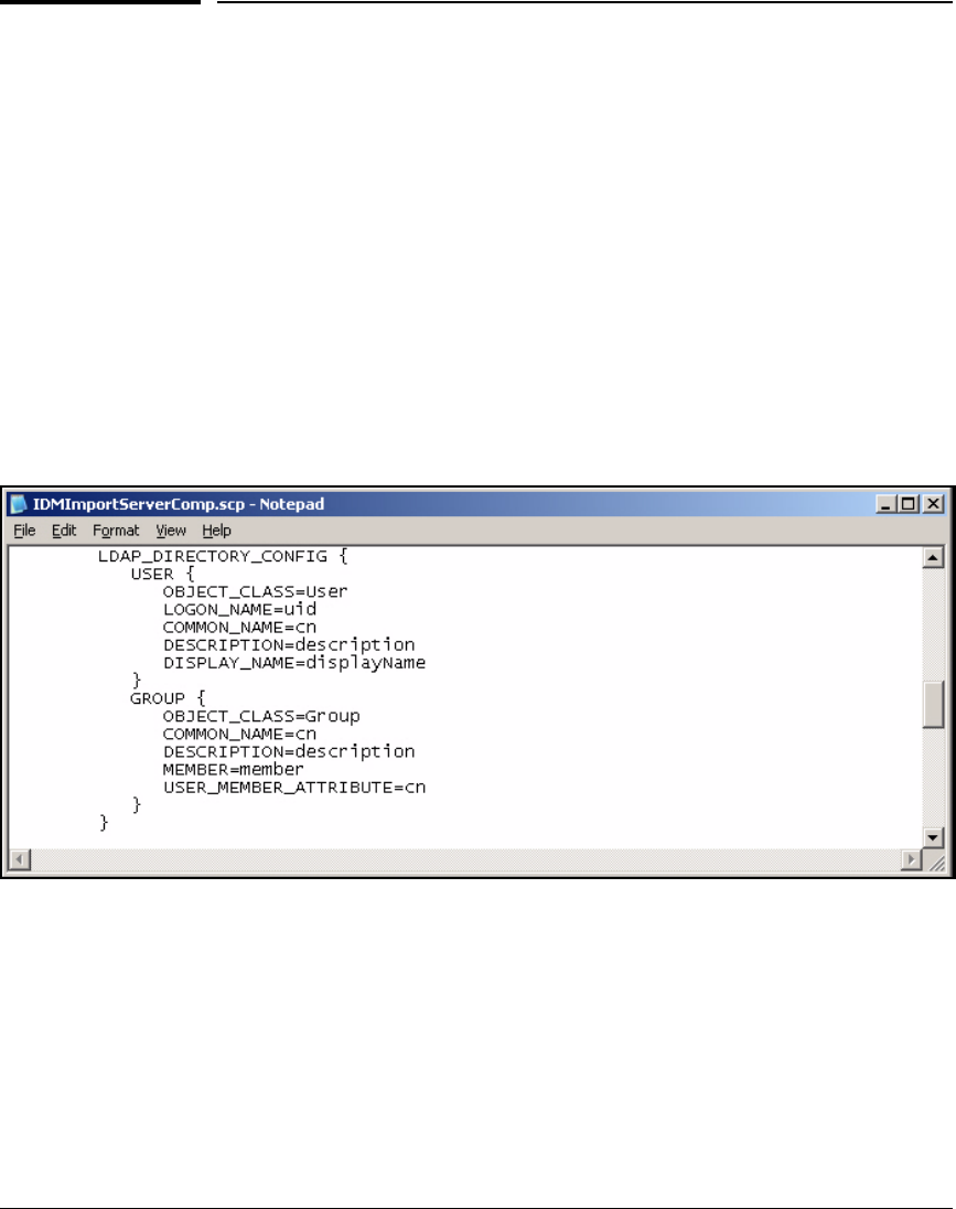
A-2
Appendix A: Using IDM with eDirectory
Synchronize IDM and Novell eDirectory
Synchronize IDM and Novell eDirectory
If you are using the ProCurve Network Access Controller (NAC) 800 in an
802.1X deployment and you want to use Novell eDirectory as the datastore for
authentication and ProCurve Identity Manager (IDM) to manage access, you
will need to bind eDirectory to IDM.
Modify the IDMImportServerComp.scp File
To import user accounts from eDirectory, you will need to modify the LDAP
directory settings in ~Program Files\Hewlett-Packard\PNM\server\
config\IDMImportServerComp.scp on the server that runs IDM.
1. Open the file IDMImportServerComp.scp in a text editor.
Figure A-1. IDMImportServerComp.scp file
2. Scroll down to the LDAP_DIRECTORY_CONFIG section.
3. Change the LOGON_NAME line as follows:
LOGON_NAME=uid
4. Save and close the file.
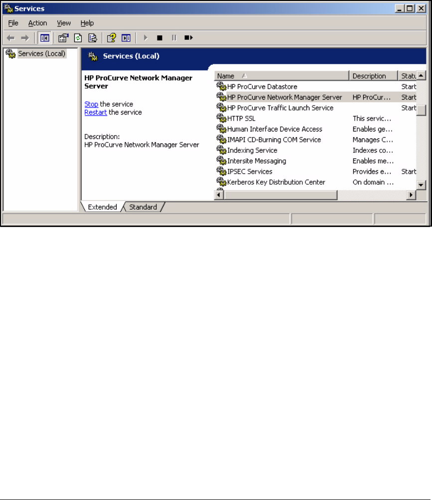
A-3
Appendix A: Using IDM with eDirectory
Synchronize IDM and Novell eDirectory
5. Restart PCM+.
a. Select Start > Administrative Tools > Services.
Figure A-2. Start > Administrative Tools > Services
b. Scroll down to HP ProCurve Network Manager Server.
c. Click Restart the service.
Disable Active Directory Synchronization
If Active Directory synchronization has been enabled on IDM, you must
disable it before you can import eDirectory users.
1. In the PCM+ console, select Tools > Preferences.
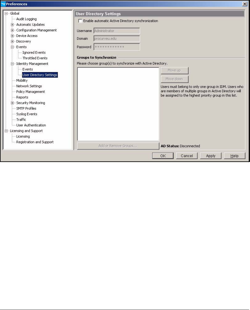
A-4
Appendix A: Using IDM with eDirectory
Synchronize IDM and Novell eDirectory
Figure A-3.
2. Expand Identity Management and select User Directory Settings.
3. Clear the Enable automatic Active Directory synchronization check box.
4. Click OK.
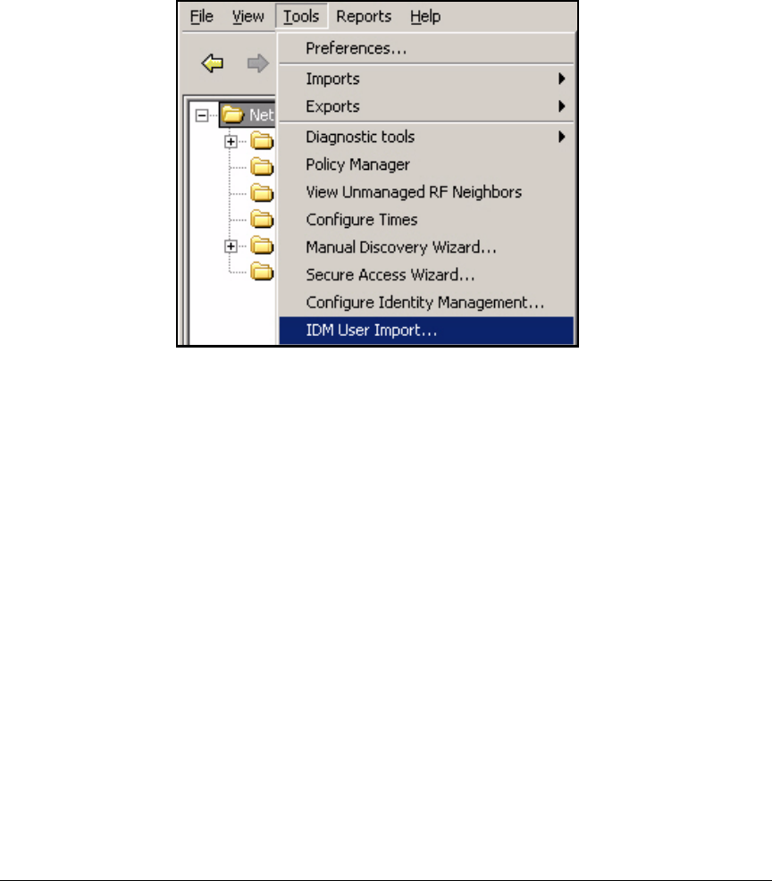
A-5
Appendix A: Using IDM with eDirectory
Synchronize IDM and Novell eDirectory
Import eDirectory Users
Follow these steps to synchronize IDM with eDirectory:
Figure A-4. Tools > IDM User Import
1. In the PCM+ interface, select Tools > IDM User Import.
2. The IDM User Import wizard opens.
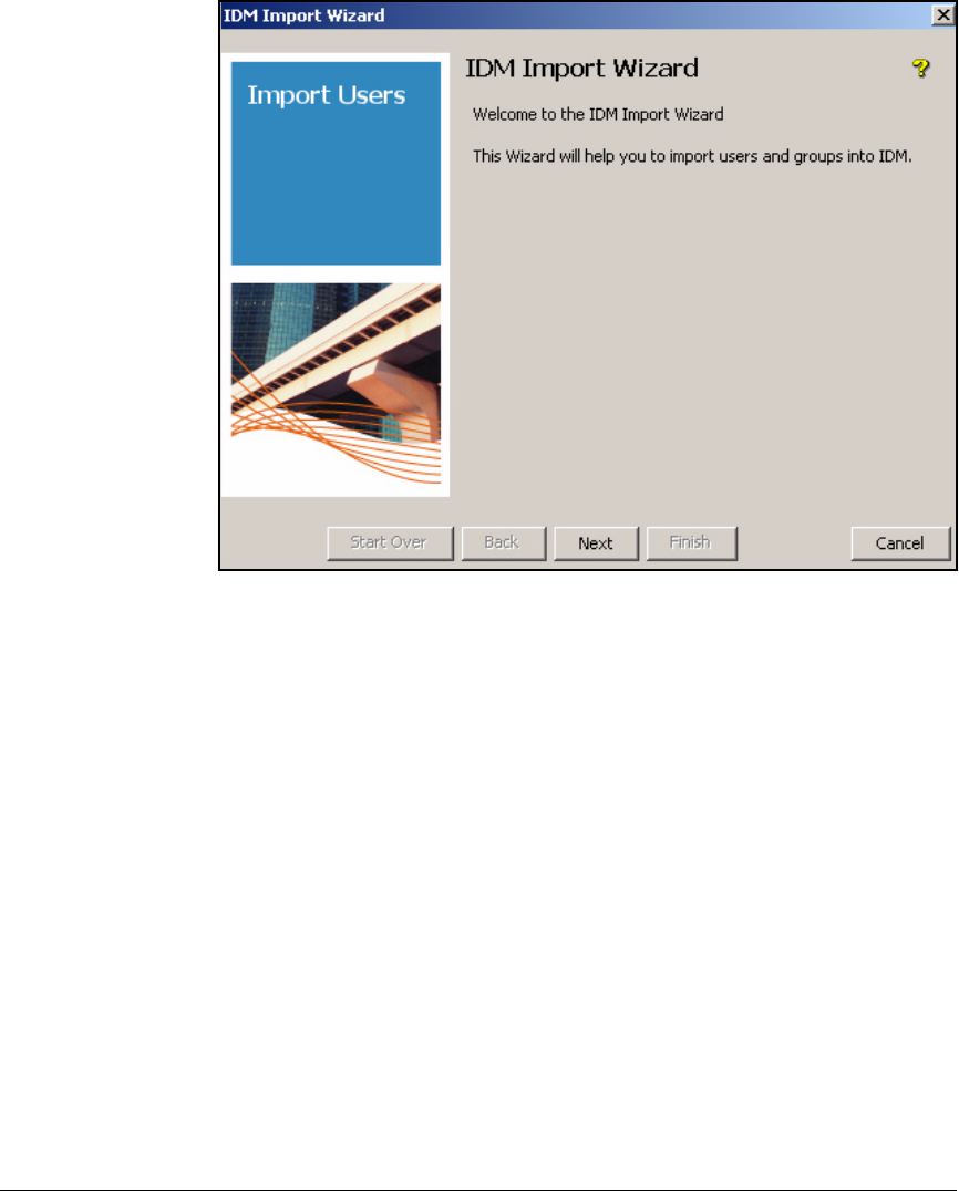
A-6
Appendix A: Using IDM with eDirectory
Synchronize IDM and Novell eDirectory
Figure A-5. IDM Import Wizard—Welcome Page
3. Click Next.
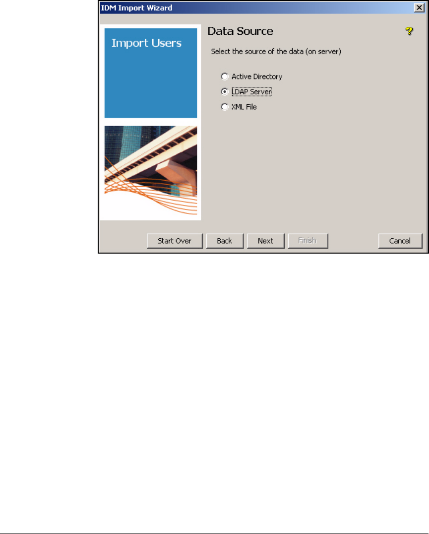
A-7
Appendix A: Using IDM with eDirectory
Synchronize IDM and Novell eDirectory
Figure A-6. IDM Import Wizard—Data Source Page
4. On the Data Source page, select LDAP Server and click Next.
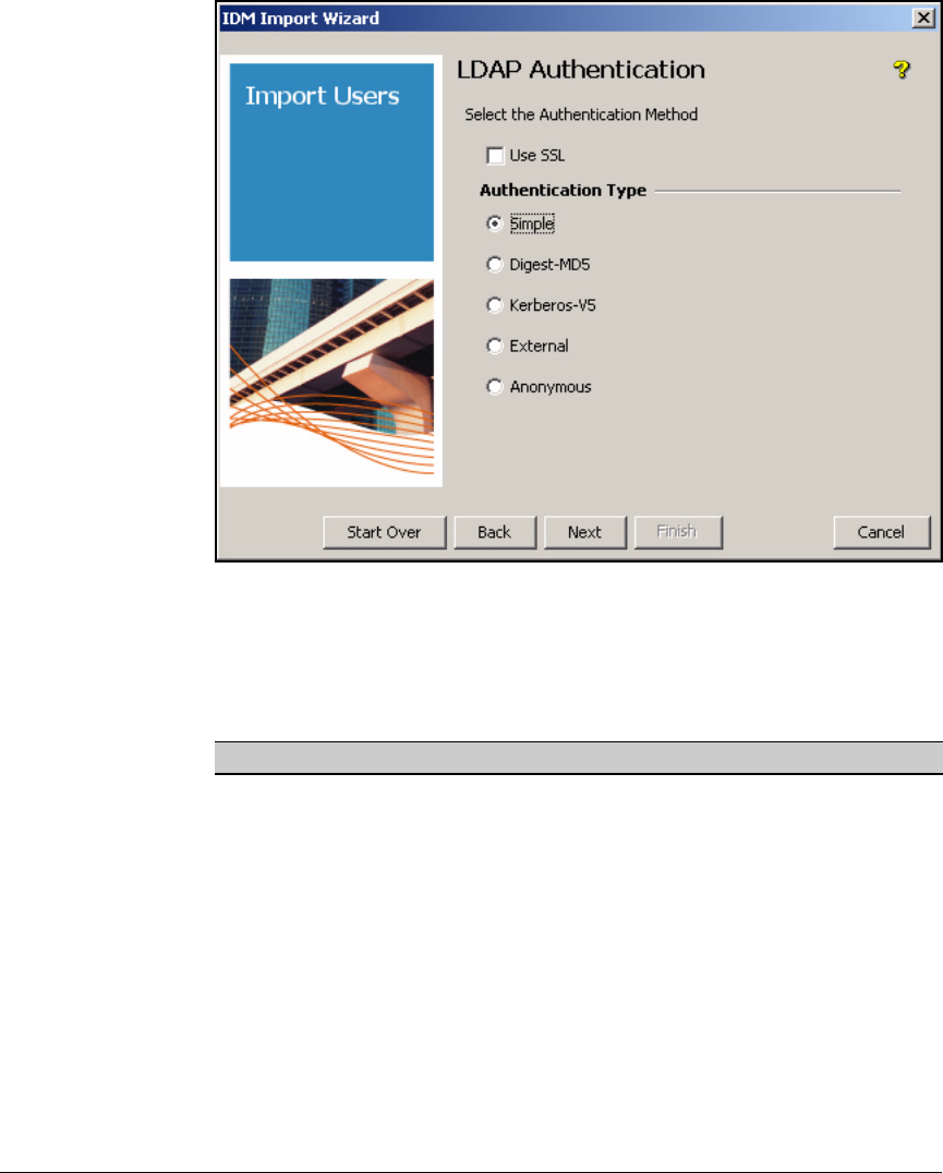
A-8
Appendix A: Using IDM with eDirectory
Synchronize IDM and Novell eDirectory
Figure A-7. IDM Import Wizard—LDAP Authentication Page
5. On the LDAP Authentication page, select the type of authentication that you
have configured for your NetWare server.
Table A-1. Authentication Methods
The authentication details will vary based on the authentication type
selected. See the sections below for details.
Authentication Description
Simple Not very secure, it sends the eDirectory the fully qualified DN of the
client (user) and the client's clear-text password.
Digest-MD5 The server generates a challenge and the client responds with a shared
secret (password).
Kerberos-V5 Used with either a password or a smart card for interactive logon.
External-TLS Uses authentication services provided by lower-level network services
such as TLS.
Anonymous No authentication is required by eDirectory server.

A-9
Appendix A: Using IDM with eDirectory
Synchronize IDM and Novell eDirectory
Using SSL
To use SSL, ensure that the X.509 certificate for your eDirectory server is
installed in your Java trust store on the server that runs PCM.
1. Put the certificate somewhere on the PCM server.
2. If PCM is installed under Program Files\Hewlett-Packard, for example,
type the following in the command interface:
C:> cd c:\Program Files\Hewlett-Packard\PNM\jre\lib
\security
3. Type the following:
4. Restart the PCM server before attempting to synchronize IDM with eDi-
rectory.
Syntax: ..\..\bin\keytool -import -file <ldapcertfile> -alias myldapcert -keystore
cacerts -keypass <certificatepassword> -trustcacerts -storepass
<keystorepassword>
Installs the certificate in the Java trust store.
Replace <ldapcertfile> with the path and filename of the eDi-
rectory certificate, replace <certificatepassword> with the cer-
tificate’s password, if any, and replace <keystorepassword>
with the password for the keystore (default: changeit).
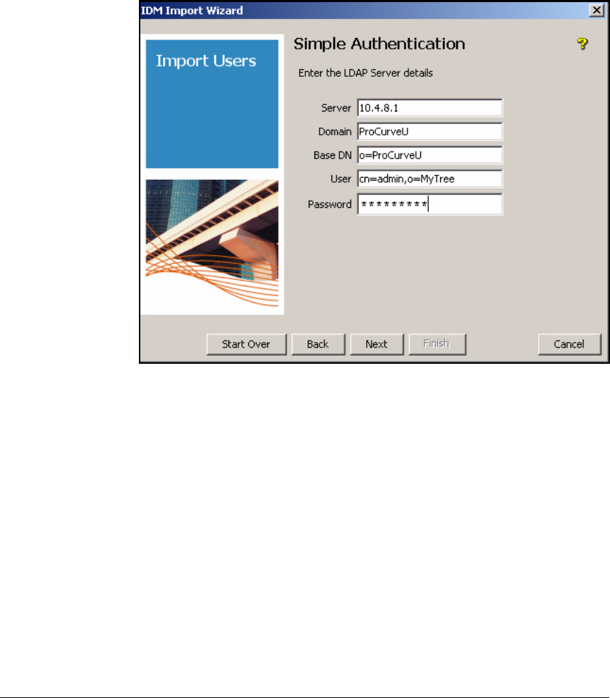
A-10
Appendix A: Using IDM with eDirectory
Synchronize IDM and Novell eDirectory
Using Simple Authentication
If you choose simple authentication, complete the page as shown below:
Figure A-8. IDM Import Wizard—Simple Authentication Page
1. In the Server box, type the IP address of the NetWare server that hosts
eDirectory.
2. In the Domain box, type a name that you have chosen for the IDM realm
into which you will import the users.
3. In the Base DN box, type the distinguished name of the container in which
you want IDM to begin to look to import users.
4. In the User box, type the distinguished name for the root admin account.
5. In the Password box, type the password for the user that you designated
in the User box.
6. Click Next and go to page A-15.
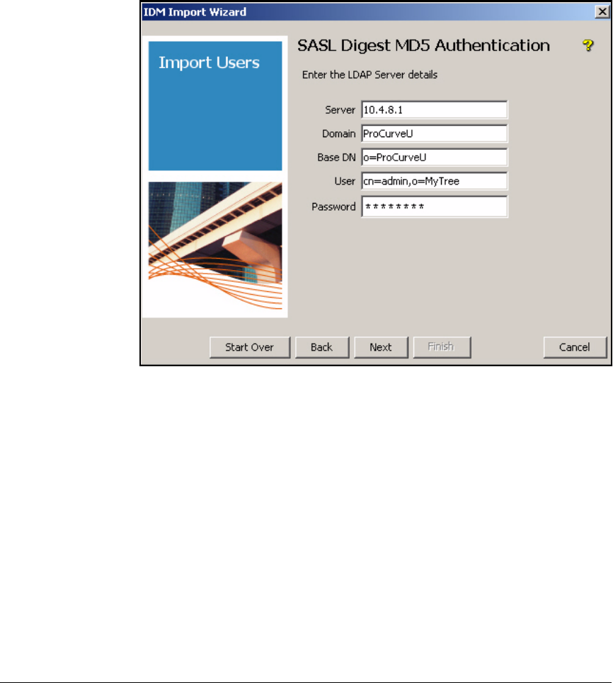
A-11
Appendix A: Using IDM with eDirectory
Synchronize IDM and Novell eDirectory
Using Digest-MD5 Authentication
In Digest-MD5, the server generates a challenge and the client responds with
a shared secret (password).
Figure A-9. IDM Import Wizard—SASL Digest MD5 Authentication Page
1. In the Server box, type the IP address of the NetWare server that hosts
eDirectory.
2. In the Domain box, type a name that you have chosen for the IDM realm
into which you will import the users.
3. In the Base DN box, type the distinguished name of the container in which
you want IDM to begin to look to import users.
4. In the User box, type the distinguished name for the root admin account.
5. In the Password box, type the password for the user that you designated
in the User box.
6. Click Next and go to page A-15.
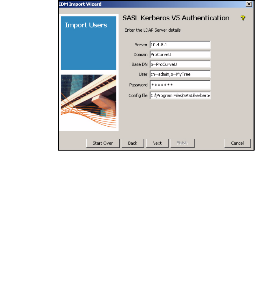
A-12
Appendix A: Using IDM with eDirectory
Synchronize IDM and Novell eDirectory
Using Kerberos-V5 Authentication
Kerberos-V5 authentication requires that your eDirectory server be set up with
a key distribution center.
Figure A-10. IDM Import Wizard—SASL Kerberos V5 Authentication Page
1. In the Server box, type the IP address of the NetWare server that hosts
eDirectory.
2. In the Domain box, type a name that you have chosen for the IDM realm
into which you will import the users.
3. In the Base DN box, type the distinguished name of the container in which
you want IDM to begin to look to import users.
4. In the User box, type the distinguished name for the root admin account.
5. In the Password box, type the password for the user that you designated
in the User box.
6. In the Config file box, type the complete path and filename of the config-
uration file that identifies the domain of the key distribution center.
7. Click Next and go to page A-15.
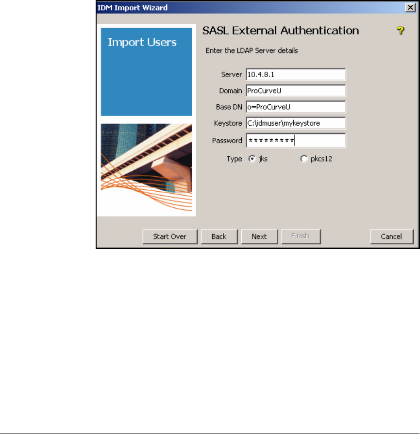
A-13
Appendix A: Using IDM with eDirectory
Synchronize IDM and Novell eDirectory
Using External Authentication
External authentication uses an X.509 certificate for user authentication. The
LDAP X.509 user certificate must be installed in a keystore on the IDM server,
and the LDAP server’s certificate must be stored in the trust store under your
JRE installation on the IDM server. To import X.509 certificates for use with
IDM, see “Importing X.509 User Certificates into a Keystore” on page A-22.
Figure A-11. IDM Import Wizard—SASL External Authentication Page
1. In the Server box, type the IP address of the NetWare server that hosts
eDirectory.
2. In the Domain box, type a name that you have chosen for the IDM realm
into which you will import the users.
3. In the Base DN box, type the distinguished name of the container in which
you want IDM to begin to look to import users.
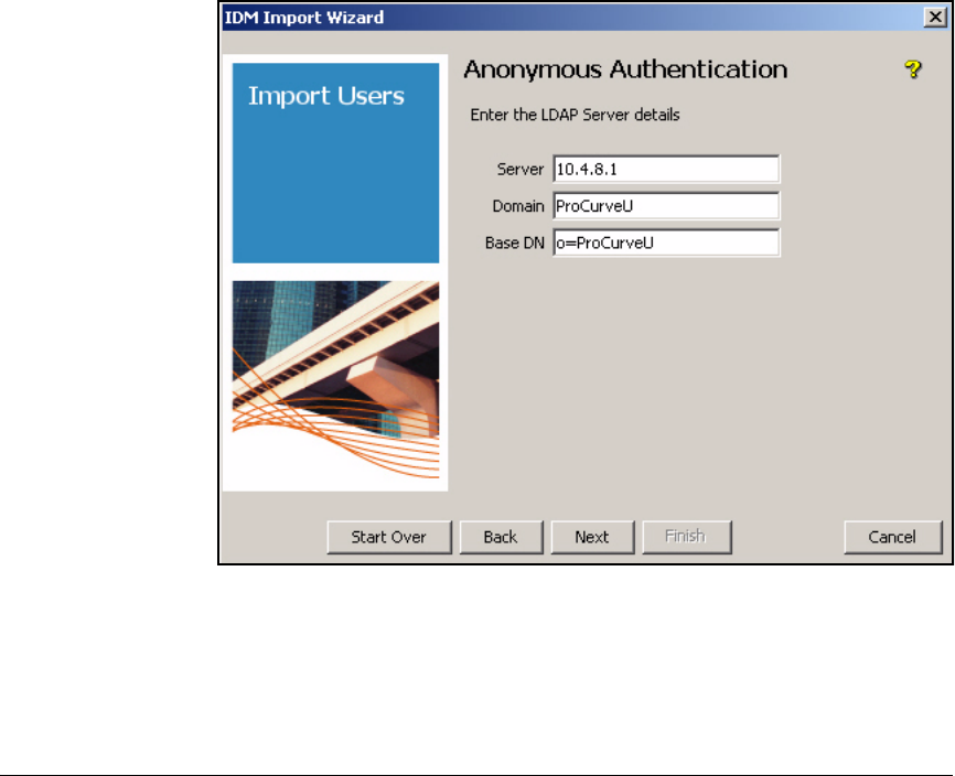
A-14
Appendix A: Using IDM with eDirectory
Synchronize IDM and Novell eDirectory
4. In the Keystore box, type the keystore file name:
For JKS, the keystore is the location on the IDM server where you installed
the keystore, for example: c:\idmuser\mykeystore
For PKCS12, enter the PKCS certificate name in the Keystore box.
5. In the Password box, type the password:
For JKS, enter the password of the keystore on the IDM server.
For PKCS12, enter the PKCS12 key in the Password box
6. For Type, select jks or pkcs12.
7. Click Next and go to page A-15.
Using Anonymous Authentication
Figure A-12. IDM Import Wizard—Anonymous Authentication Page
1. In the Server box, type the IP address of the NetWare server that hosts
eDirectory.
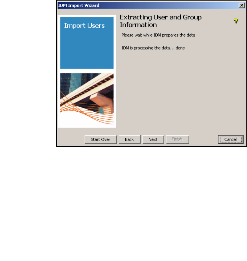
A-15
Appendix A: Using IDM with eDirectory
Synchronize IDM and Novell eDirectory
2. In the Domain box, type a name that you have chosen for the IDM realm
into which you will import the users.
3. In the Base DN box, type the distinguished name of the container in which
you want IDM to begin to look to import users.
4. Click Next.
Figure A-13. IDM Import Wizard—Extracting User and Group Information Page
5. When the phrase “IDM is processing the data... done” appears, click Next.
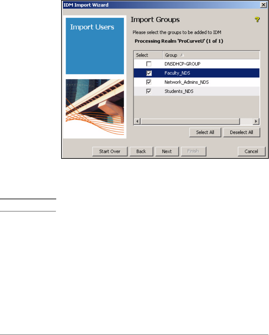
A-16
Appendix A: Using IDM with eDirectory
Synchronize IDM and Novell eDirectory
Figure A-14. IDM Import Wizard—Import Groups Page
6. On the Import Groups page, select all of the groups that you want to import
and click Next.
Note It is not necessary to import the group DNSDHCP-GROUP.
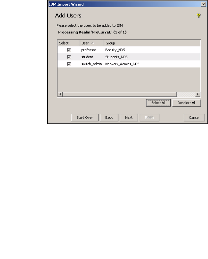
A-17
Appendix A: Using IDM with eDirectory
Synchronize IDM and Novell eDirectory
Figure A-15. IDM Import Wizard—Add Users Page
7. On the Add Users page, click Select All and click Next.
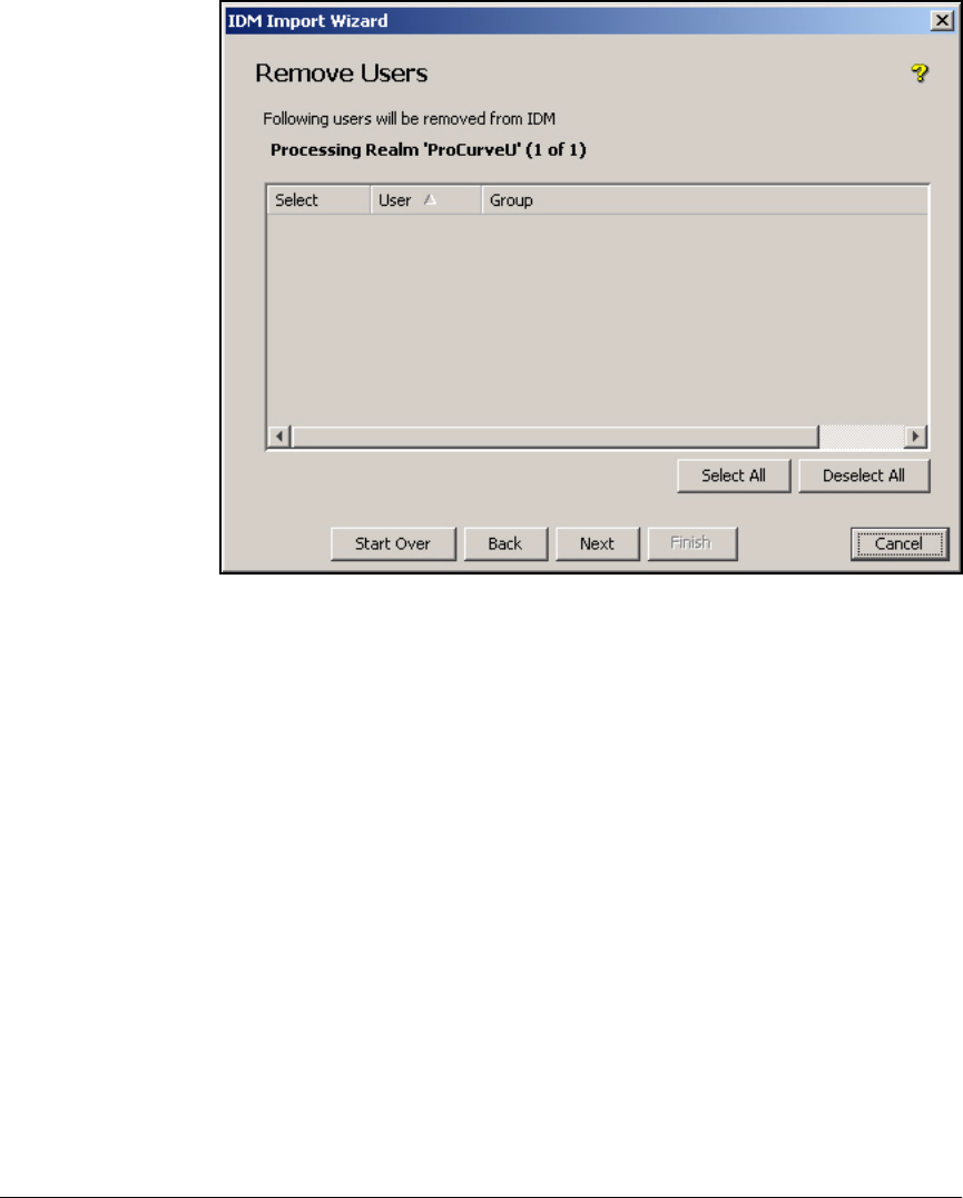
A-18
Appendix A: Using IDM with eDirectory
Synchronize IDM and Novell eDirectory
Figure A-16. IDM Import Wizard—Remove Users Page
8. On the Remove Users page, click Next.
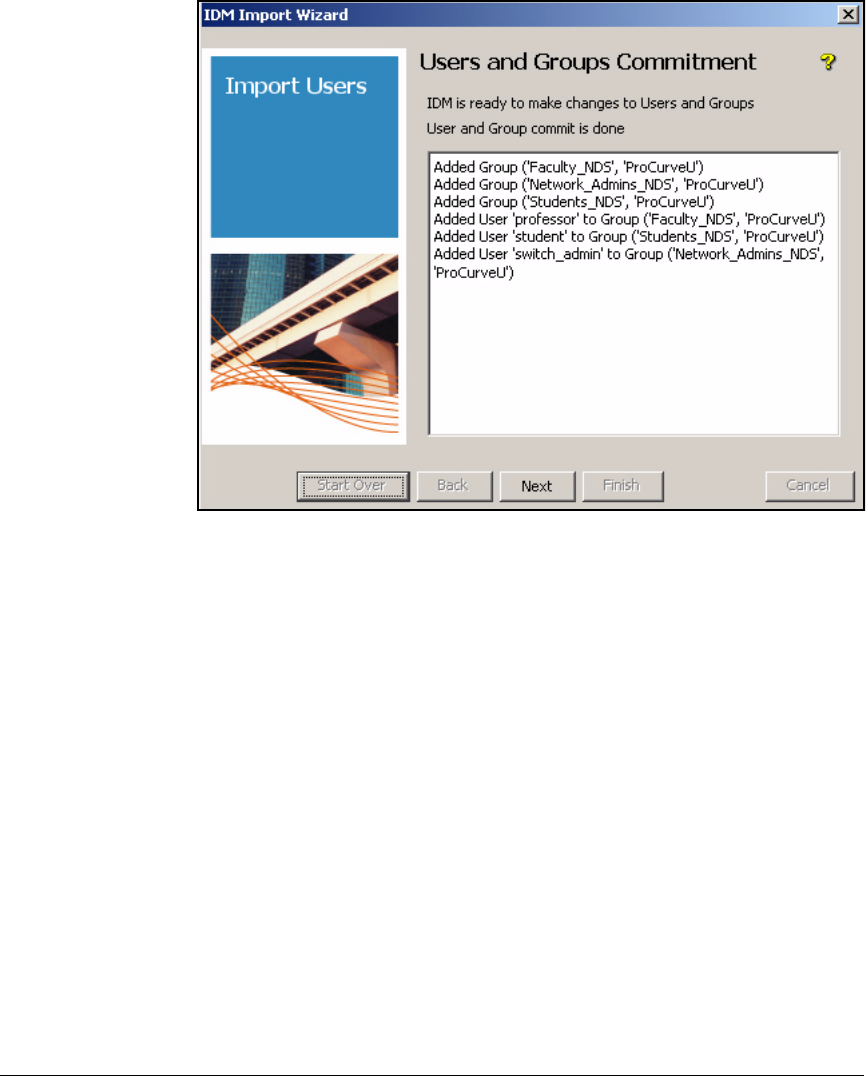
A-19
Appendix A: Using IDM with eDirectory
Synchronize IDM and Novell eDirectory
Figure A-17. IDM Import Wizard—Users and Groups Commitment Page
9. When the phrase “User and Group commit is done” appears, click Next.
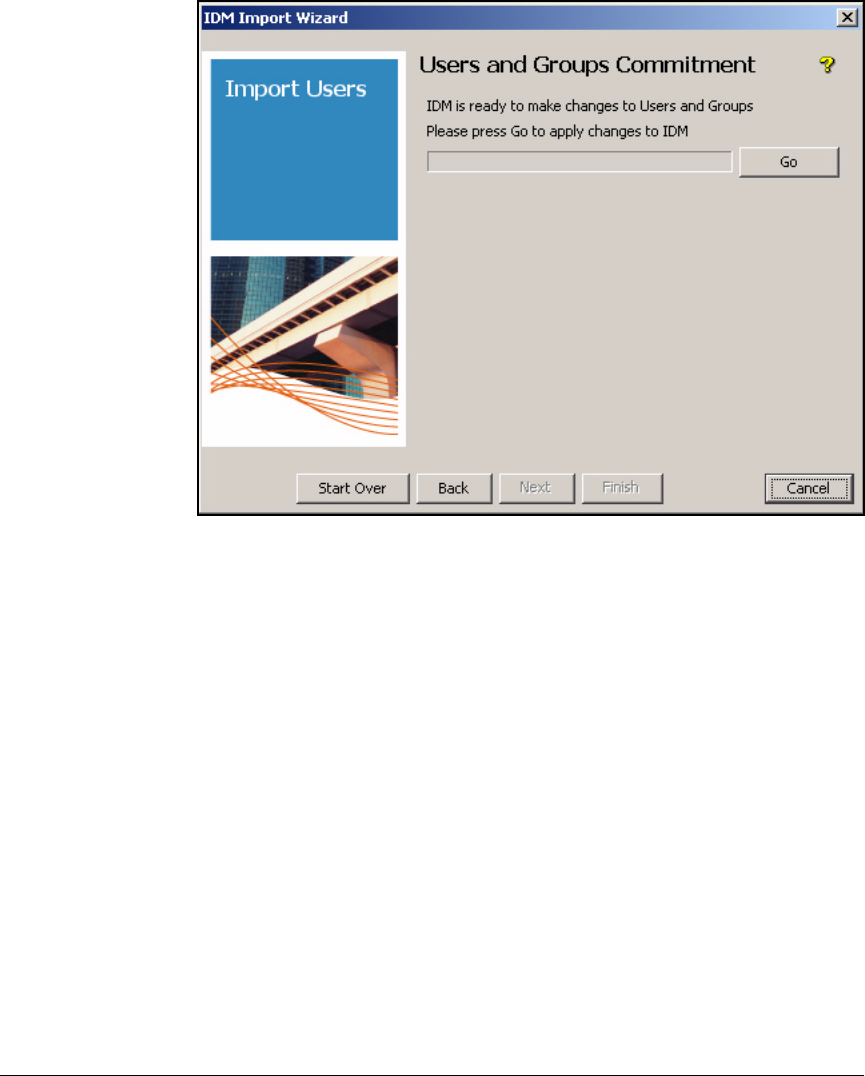
A-20
Appendix A: Using IDM with eDirectory
Synchronize IDM and Novell eDirectory
Figure A-18. IDM Import Wizard—Users and Groups Commitment Page
10. On the second Users and Groups Commitment page, click Go.
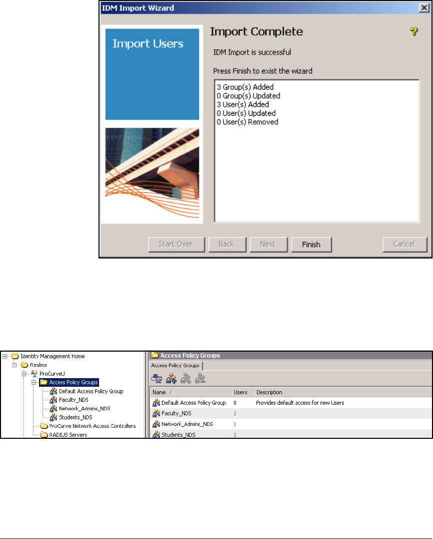
A-21
Appendix A: Using IDM with eDirectory
Synchronize IDM and Novell eDirectory
Figure A-19. IDM Import Wizard—Import Complete Page
11. The Import Complete page shows you how many users and groups were
imported. Click Finish.
12. Click the Identity tab in the left pane of the PDM+ interface.
Figure A-20. PCM+ Console, IDM Interface—Realms > <myrealm> > Access
Policy Groups
13. Expand Realms > <myrealm> > Access Policy Groups. You should see your
user groups from eDirectory in the right pane along with the right number
of users in each group.

A-22
Appendix A: Using IDM with eDirectory
Synchronize IDM and Novell eDirectory
Importing X.509 User Certificates into a Keystore
You can use SSL to secure the communications between the PCM+ server and
the eDirectory server. If you are not the eDirectory administrator, contact the
appropriate person. Ensure that your eDirectory server supports SSL and
request the CA certificate that the eDirectory server is using. Then complete
the following steps:
1. Copy the certificate to the PCM+ Java trust store. If PCM is installed under
Program Files\Hewlett-Packard, the Java trust store is in the following
directory:
C:\Program files\Hewlett-Packard\PNM\jre\
lib\security
2. Access the command prompt and move to this directory. Type:
3. During the process of loading the certificate, PCM+ displays a prompt,
asking you if you want to trust this certificate. Answer Yes.
4. Restart the PCM+ server.
Syntax: C:> ..\..\bin\keytool -import -file <ldapcertfile>
-alias myldapcert -keystore cacerts -keypass <certificate_password> -
trustcacerts -storepass <keystore_password>
Replace <ldapcertfile> with the name of the CA certificate on
your eDirectory server.
Replace <certificate_password> with the password assigned to
the CA certificate.
Replace <keystore_password> with the password assigned to
the PCM+ keystore. The default keystore password is changeit.

B-1
B
Appendix B: Glossary
Numeric
3DES A version of DES, also called “Triple DES” (TDES), in which three encryption
phases are applied. For more information, see NIST Special Publication 800-
67 at http://csrc.nist.gov/publications/nistpubs/800-67/SP800-67.pdf.
802.11 The standard for wireless LANs. For more information, see IEEE 802.11 at
http://standards.ieee.org/getieee802/802.11.html for all 802.11 standards.
802.11a A version of 802.11 that broadcasts at 5 GHz and provides a maximum speed
of 54 Mbps.
802.11b A version of 802.11 that broadcasts at 2.4 GHz and provides a maximum speed
of 11 Mbps.
802.11g A version of 802.11 that broadcasts at 2.4 GHz and provides a maximum speed
of 54 Mbps.
802.1X A port-based authentication standard for 802.1. 802.1X forces endpoints to
authenticate, establishing a point-to-point connection if authentication suc-
ceeds or blocking the connection if authentication fails. By basing authenti-
cation on secure EAP methods, 802.1X authentication can prevent
eavesdroppers from reading intercepted messages. The 802.1X standard
requires three components: the supplicant, which runs on the endpoint device;
the authenticator, which is typically a switch or AP; and the authentication server,
which is usually a RADIUS server. For more information, see IEEE 802.1X at
http://www.ieee802.org/1/pages/802.1x.html.
802.1X
deployment
method
The deployment method that corresponds to the 802.1X quarantine method. In this
method, the NAC 800 is connected to a switch via both its Ethernet ports. Port
1 receives authentication requests, and port 2 receives mirrored DHCP traffic.
See also DHCP deployment method and inline deployment method.

B-2
Appendix B: Glossary
802.1X quarantine
method
One of the NAC 800’s three methods for quarantining endpoints that fail to
comply with the NAC policy. This method draws on the authentication and
authorization component of 802.1X, assigning end-users to a VLAN based not
just on identity but also on endpoint integrity posture. The NAC 800 can enforce
802.1X quarantining by working with an existing RADIUS server or by acting as
a RADIUS server itself. See also inline quarantine method and DHCP quarantine
method.
802.1X device The authenticator in the 802.1X framework, which forwards authentication
requests from endpoints to the NAC 800 that is acting as a RADIUS server. When
enforcing endpoint integrity, the NAC 800 sends a VLAN assignment for an
endpoint to the 802.1X device based on the endpoint’s integrity posture; the
802.1X device enforces the assignment.
A
AAA Authentication, Authorization, and Accounting. Processes that are used to
control network access and enforce security policies. For more information,
see RFC 2989 at http://www.ietf.org/rfc/rfc2989.txt. See also authentication,
authorization, and accounting.
access control The ability to determine which endpoints can access the network and the level
of access they receive. Access can be controlled based on an endpoint’s
compliance with network standards, for example, or on other configurable
settings.
access control
status
The label that the NAC 800 gives to an endpoint to define its ability to access
the network. Access control status are further defined by the rule that pro-
duced the status.
access control
zone
A physical area of an organization that is defined by the way that users (public
or private) will access the network (wired or wireless). For example, a foyer
where non-employees access the network through a wireless connection is a
public wireless zone, whereas the internal offices where employees use wired
workstations is a private wired zone.
access method The way in which an endpoint connects to the network. Options include VPN,
dial-up, wireless, or Ethernet.

B-3
Appendix B: Glossary
access mode An option that controls whether NAC 800s in a particular enforcement cluster
quarantine endpoints or allow them access to the network. Three settings are
possible: normal, allow all, or quarantine all. Normal grants access to all end-
points that pass the NAC tests, allow all permits access to all endpoints
regardless of test results, and quarantine all isolates all endpoints regardless
of test results.
access point See AP.
accessible services Those services that are made available to quarantined endpoints so that they
can perform remediation. Services include access to Web sites with service
patch downloads or plug-ins. The network administrator can configure which
services are available to quarantined endpoints.
accounting The process of collecting information about how resources are used. The
collected information can then be used for trend analysis, billing, auditing, or
regulatory compliance. The NAC 800 can provide RADIUS accounting services.
ACE Access Control Entry. A single rule that determines which endpoints or users
can access a network resource. An ACL comprises a list of ACEs.
ACL Access Control List. A set of rules (ACEs) that network edge devices such as
routers, switches, and wireless APs use to control access to network
resources and to identify packets that require special handling such as QoS or
NAT. An ACL can be configured to select packets according to values in their
headers, such as IP protocol, source and destination IP address, and source
and destination TCP or UDP ports.
Active Directory An LDAP-based directory service created by Microsoft that is included with all
Microsoft network servers.
ActiveX A Microsoft technology that enables interactive Web content. An endpoint
must accept ActiveX content from the NAC 800 to be tested via the ActiveX
plug-in. For more information, see the Microsoft Developer Center library at
http://msdn2.microsoft.com/en-us/library/aa751968.aspx.
ActiveX test
method
An endpoint integrity-testing method that relies on the ActiveX control opera-
tion of signed and safe controls. The NAC 800 uses ActiveX to download a
temporary agent to the endpoint. All versions of the Windows operating
system are supported, and no ports on an endpoint’s personal Windows
firewall need to be opened. As long as the firewall allows Internet Explorer
access and Internet Explorer settings allow ActiveX, the endpoint can be
tested. However, non-Internet Explorer browsers are not supported, and the
endpoints cannot be retested after end-users close their browsers.

B-4
Appendix B: Glossary
ADSL Asymmetric Digital Subscriber Line. A technology that permits the user to
connect to an Internet service provider over the existing telephone infrastruc-
ture. Data is transmitted on unused frequencies that are not used in a voice
telephone call.
AES Advanced Encryption Standard. The successor to DES, a block cipher that
was adopted as an encryption standard. It is often used in symmetric key
cryptology. The key length in bits is specified as AES-128, AES-192, and AES-
256. For more information, see FIPS PUB 197 at http://www.csrc.nist.gov/
publications/fips/fips197/fips-197.pdf.
agent See NAC EI agent.
agent testing
method
An endpoint integrity-testing method that employs the NAC EI agent, which is
installed once onto the endpoint and periodically updated. This method is
supported by Windows OS versions 98 and later and by Mac OSX 10.3.7 and
later. The agent can be used through a firewall. See also NAC EI agent.
agentless test
method
A testing method that does not require that an agent be installed on the
endpoint. Using the Windows RPC service, agentless testing allows the NAC
800 to begin testing, provide test results, and grant access to compliant
endpoints without any interaction from the user. Of the three testing methods,
agentless testing is the easiest to deploy, requiring less administrative effort
and no memory on the endpoint. However, you cannot use this test method
with legacy Windows operating systems (Windows 95, ME, and earlier) or non-
Windows endpoints. Agentless testing requires that file and print sharing be
enabled on the endpoint, that ports 137, 138, 139, and 445 be open on the
endpoint’s firewall, that the endpoint’s browser security settings allow Java
scripting, and that administrator credentials be known for the endpoint.
AH Authentication Header. A part of the IPsec protocol suite that guarantees
connectionless integrity and data origin authentication of IP packets. For more
information, see RFC 4302 at http://tools.ietf.org/html/rfc4302. Also see ESP.
allow all An access mode that permits all endpoints to access the network regardless of
test results.
AMI Alternate Mark Inversion. A type of bipolar encoding that is used on T1 lines.
See also HDB3.
AP Access Point. A network component that receives and sends WLAN signals to
wireless network cards through its anntena(s). An AP is functionally equiva-
lent to a switch.

B-5
Appendix B: Glossary
ARP Address Resolution Protocol. A protocol that is used to map MAC addresses
to IP addresses. For more information, see RFC 2390 at http://tools.ietf.org/
html/rfc2390.
ARP protection Technology to prevent attackers from populating a device’s ARP cache with
unsolicited ARP replies that list the attacker’s device as a subnet gateway.
authentication The process of confirming an endpoint’s or an end-user’s identity before
granting a network connection. Authentication can be implemented through
the use of passwords, keys, or digital certificates. A RADIUS or TACACS+ server
can handle authentication for the entire network.
authentication
protocols
Protocols that allow the peers in a connection to verify each other’s identity.
In the PPP protocol suite, authentication protocols include PAP, CHAP, and EAP.
authentication
server
A server whose function it is to authenticate end-users and endpoints. In the
802.1X framework, the component that decides whether to grant an end-user
access.
authenticator The component of the 802.1X framework that enforces authentication and
authorization. When an endpoint connects to the authenticator, the authentica-
tor forces it to authenticate to the network. The authenticator passes the
endpoint’s supplicant messages to the authentication server and enforces the
decisions made by that server. These decisions include whether the endpoint
is allowed any access at all as well as the level of access. Also called the 802.1X
device (in the NAC 800 Web browser interface) and NAS (in the RADIUS
protocol). See also 802.1X device and NAS.
authorization The process of controlling the network resources and services that an end-
user can access, usually based on the end-user’s identity; with the NAC 800,
authorization is also based on endpoint integrity. A RADIUS or TACACS+ server
or a NAC 800 can act as an authorization server. Authorization is sometimes
called “access control” although access control is properly broader than
authorization alone.
authorization
server
A device to make authorization decisions that are enforced by other infrastruc-
ture devices.
C
CA Certificate Authority. A trusted third party that verifies the identity of parties
that want to communicate with one another. CAs are responsible for generat-
ing, distributing, and revoking digital authentication certificates, which
uniquely identify the owner of the certificate and the owner’s data. See also
certificate.

B-6
Appendix B: Glossary
CBC Cipher Block Chaining. A block cipher mode of operation wherein the
previous encrypted block is used to transform the next block, prior to its
encryption. For more information, see NIST Special Publication 800-38A at
http://csrc.nist.gov/publications/nistpubs/800-38a/sp800-38a.pdf.
certificate An electronic document that contains a public key and is digitally signed by a
third-party issuer such as a CA. Digital certificates are used for network
authentication. They contain the certificate holder’s name or other identifying
information, a serial number, the expiration date, and a copy of the certificate
holder’s public key, which validates data signed by the corresponding private
key.
certificate
authority
See CA.
CHAP Challenge Handshake Authentication Protocol. An authentication protocol
that is supported by PPP and also incorporated in RADIUS. With CHAP, the
authenticator sends the client a “challenge” text. The client creates a hash
value from its pre-shared password and the text. The authenticator also
creates a hash value from the same text. The authenticator compares the hash
values. If they match, authentication succeeds and the link is established. For
more information, see RFC 2759 at http://www.ietf.org/rfc/rfc2759.txt.
CIDR Classless Inter-Domain Routing. A method of interpreting IP addresses that
allows for blocks of addresses to appear in a single routing table entry. For
example, 10.2.0.40 /24 indicates a 24-bit subnet mask, or 255.255.255.0. For
more information, see RFC 1518 at http://tools.ietf.org/html/rfc1518.
CLI Command-Line Interface. An interface that requires that the user manually
type commands at a command prompt, one line at a time.
cluster See enforcement cluster.
combination
server
See CS.
community name In SNMP, a shared secret that is used for the authentication of SNMP clients.
credentials A username and its corresponding password.
CRL Certificate Revocation List. In PKI, a list of certificates that are no longer valid
or that have been revoked. For more information, see RFC 3280 at http://
tools.ietf.org/html/rfc3280.
crypto commands In ProCurve routers, a set of commands that manage encryption functions.

B-7
Appendix B: Glossary
crypto map In ProCurve routers, something that binds the assorted crypto parameters
with a specific remote gateway.
CS Combination Server. A NAC 800 that functions as both an ES and an MS and
acts as a stand-alone device.
CSR Certificate Signing Request. In PKI systems, a request for a digital certificate
that is sent to a CA by an applicant.
D
Data Encryption
Standard
See DES.
data store The location where an endpoint’s credentials are stored. Possible data stores
are: a local database of users, a Windows domain controller that runs AD, an
LDAP server such as OpenLDAP or Novell eDirectory, or another RADIUS server
(accessed via proxy requests).
deployment
method
Sometimes called “deployment option,” the way in which the NAC 800 is
connected to the LAN relative to other components such as routers, switches,
DHCP servers, and the Internet. The deployment method is determined by the
quarantine method and the access method that the network will employ. The
NAC 800 supports three deployment methods: 802.1X deployment, inline deploy-
ment, and DHCP deployment.
DER Distinguished Encoding Rules. A method for encoding data objects. For more
information, see ITU-T X.690 at http://www.itu.int/ITU-T/studygroups/
com17/languages/X.690-0207.pdf.
DES Data Encryption Standard. A published encryption algorithm that uses a 56-
bit symmetric key to encrypt data in 64-bit blocks. IPSec, the industry standard
for VPNs, supports 3DES. For more information, see FIPS PUB 46-3 at http://
csrc.nist.gov/publications/fips/fips46-3/fips46-3.pdf.
DHCP Dynamic Host Configuration Protocol. A protocol that allows network
administrators to set up a server to manage IP addresses, automatically
assigning IP addresses to devices on the network. DHCP simplifies IP man-
agement, eliminating the need to manually assign IP addresses to devices and
then track those addresses. For more information, see RFC 2131 at http://
www.ietf.org/rfc/rfc2131.txt.

B-8
Appendix B: Glossary
DHCP deployment
method
A deployment method for networks that are not 802.1X compatible. In this
method, the NAC 800 is placed between a switch and a DHCP server and
intercepts DHCP requests from non-tested or non-compliant endpoints. See
also DHCP quarantine method.
DHCP
enforcement
An option to configure when employing the DCHP quarantine method. The NAC
800 can either examine, and possible intercept, all DHCP requests or only those
requests forwarded by particular devices.
DHCP quarantine
method
A quarantine method that gives non-compliant endpoints an IP address in a
quarantine subnet, where they have access only to remediation services.
DHCP quarantine
option
An option that determines how endpoints in the quarantine subnet are con-
trolled when employing the DCHP quarantine method. Options are static routes
and router ACLs.
DHCP snooping A security feature that differentiates between trusted and untrusted ports,
builds and maintains a DHCP snooping table, and filters DHCP requests
received on an untrusted port.
Diffie-Hellman key
exchange
A cryptographic protocol that was developed by Whitfield Diffie and Martin
Hellman in 1976, which allows two devices that have no prior knowledge of
each other to establish a shared key over a non-secure communications
channel. For more information, see RFC 2631 at http://tools.ietf.org/html/
rfc2631.
digital certificate See certificate.
distinguished
name
See DN.
DN Distinguished Name. In LDAP, a unique identifier for each object in a domain,
such as servers, printers, and end-user accounts. The format requires that each
subdomain to which the object belongs be identified, for example, DC=engi-
neering, DC=ProCurveU, DC=com, O=UNIX, OU=BSD4.
DNS Domain Name System. A service that associates Internet domain names (such
as www.abccompany.com) with their corresponding IP addresses.
domain In LDAP, a logical grouping of devices that allows the network administrator
to manage all of the objects in a domain at the same time, for example, to
control who has access to the objects in the domain. Also, the name of a virtual
host on the Internet, designated with a name and a suffix: procurveu.edu.
domain controller A Microsoft Windows server that controls activities such as end-user access
in an LDAP domain.

B-9
Appendix B: Glossary
domain name
system
See DNS.
DSA Digital Signature Algorithm. A standard for digital signatures that is part of
the DSS. For more information, see FIPS PUB 186-2 at http://csrc.nist.gov/
publications/fips/fips186-2/fips186-2-change1.pdf.
DSS Digital Signature Standard. A method for key generation, signing, and
verifying. For more information, see FIPS PUB 186-2 at http://csrc.nist.gov/
publications/fips/fips186-2/fips186-2-change1.pdf.
Dynamic Host
Configuration
Protocol
See DHCP.
E
EAP Extensible Authentication Protocol. A protocol that allows PPP to use authen-
tication protocols that are not part of the PPP suite. For more information, see
RFC 3748 at http://www.ietf.org/rfc/rfc3748.txt. See also CHAP and PAP
EAP-TLS EAP with TLS. An implementation of EAP that provides mutual certificate
authentication between client and server. For more information, see RFC 2716
at http://tools.ietf.org/html/rfc2716.
eDirectory An LDAP-based directory service from Novell that can interoperate with
NetWare, AIX, HP-UX, Solaris, Windows, and Linux-based network servers.
EI See endpoint integrity.
endpoint A device that connects to a network, such as a desktop computer, a laptop
computer, or a server.
endpoint integrity The functionality that examines all endpoints that attempt to attach to the
network and prohibits unsafe or non-compliant endpoints from gaining
access. Endpoint integrity ensures that an endpoint that attaches to the edge
of the network is clean and meets configured criteria (antivirus program
present and running with current signatures, for example) before allowing it
to access network resources.
end-user screen NAC 800 message windows that appear on the end-user’s monitor; they show
information such as the endpoint’s test status and remediation steps, permitting
the user to download an agent, cancel testing, and get more information about
why a test failed.

B-10
Appendix B: Glossary
enforcement
cluster
A logical group of one or more ESs that are controlled by an MS. Each cluster
can support only one deployment method, but an MS can control multiple ESs,
each supporting a different deployment method.
enforcement
server
See ES.
ES Enforcement Server. In a multiple-NAC 800 installation, the ES applies the
NAC policies that are defined on the MS and enforces quarantining.
ESP Encapsulating Security Protocol. A part of the IPsec protocol suite that
provides confidentiality protection, origin authenticity, and integrity for pack-
ets. For more information, see RFC 4303 at http://tools.ietf.org/html/rfc4303.
See also AH.
Ethernet ports On the NAC 800, port 1 connects to the LAN and provides inband management.
The use of port 2 varies, depending on the deployment method. For the inline
deployment method, port 2 might connect to a VPN or RAS. For the DCHP
deployment method, port 2 connects to a DHCP server. For the 802.1X develop-
ment method, port 2 connects to a port configured to mirror the DHCP server
connection.
exception A rule that exempts a particular endpoint or group of endpoints from testing.
You can specify that the excepted endpoints be either always or never granted
access.
Extensible
Authentication
Protocol
See EAP.
F
FR Full Rate. A digital speech encoding standard used in GSM phones.
FQDN Fully Qualified Domain Name. In DNS, an unambiguous, unique name for an
object that designates exactly where an object belongs in the DNS tree, for
example: engineering.ProCurveU.com.

B-11
Appendix B: Glossary
H
hash A number generated by running a string of text through an algorithm. The hash
is substantially smaller than the text itself and is unique, because algorithms
transform data in such a way that it is extremely unlikely that some other text
will produce the same hash value. The hash is also irreversible: the encryption
cannot be reversed to obtain the original text.
HDB3 High-Density Bipolar of order 3 code. A telecommunications line code used
mainly in Australia, Europe, and Japan. It is similar to AMI.
headless A device that does not have a user interface that accepts credentials, such as
a printer or fax machine.
HMAC keyed-Hash MAC. A type of MAC that is calculated with a hash function and
a secret key. It can be used to verify both data integrity and authenticity. For
more information, see RFCs 2104 and 2202 at http://tools.ietf.org/html.
I
IANA Internet Assigned Numbers Authority. An organization whose purpose is to
assign IP addresses, manage DNS root zones, and make other IP assignments.
IAS Internet Authentication Services. The Microsoft implementation of RADIUS.
ICMP Internet Control Message Protocol. Part of the core IP suite, a service used to
tell networked computers whether a particular service is available. For more
information, see RFC 792 at http://tools.ietf.org/html/rfc792.
IDM Identity Driven Manager. A ProCurve networking application that provides
management of user-based profiles (including ACLs, QoS settings, and rate
limits). IDM assigns various profiles to end-users based on their identity
(community), access time, access location, and endpoint integrity posture.
IE Microsoft’s Internet Explorer browser.
IIS Internet Information Services. A Microsoft Windows-based Web server.
IKE Internet Key Exchange. A protocol that is used to set up an SA in the IPsec
protocol suite.
inline deployment
method
The NAC 800 is placed between a “choke point” and the rest of the network
such that all traffic to be quarantined passes through the NAC 800. See also
inline quarantine method.

B-12
Appendix B: Glossary
inline quarantine
method
A quarantine method that relies on the NAC 800’s placement in the network.
The NAC 800 functions as a layer-2 bridge that imposes a firewall between its
Ethernet port 1 and port 2. Only traffic from endpoints whose integrity posture is
“Healthy” or “Check-Up” can pass through the NAC 800.
integrity posture The state of an endpoint in terms of its compliance with NAC policies. The
integrity posture is used to determine an endpoint’s access control state along
with other factors such as an exception, access grace period, and access mode.
See Appendix C, “Integrity Postures.”
inter-station
blocking
see p. 4-59 of ProCurve WLAN system. xxx
IPsec Internet Protocol security. A suite of protocols that are used to establish a
VPN tunnel between devices that communicate over the Internet, thereby
protecting their data. For more information, see the IPsec Working Group
home page at http://www.ietf.org/html.charters/OLD/ipsec-charter.html.
K
KDC Key Distribution Center. In cryptography, a service that authenticates users,
then permits them to use a particular service.
Kerberos A network authentication protocol that was developed at Massachusetts Insti-
tute of Technology to provide secure authentication. It uses symmetric keys
and requires a trusted third party. For more information, see the Kerberos page
at http://web.mit.edu/kerberos.
key In cryptography, a key is a unique value or string of text that is used to encrypt
data when that data is run through an encryption or hash algorithm. To decrypt
or dehash the data, a device must apply the correct key to the encrypted data.
The length of a key generally determines how difficult it will be to decrypt the
data. Keys can be either symmetric or asymmetric.
keyname A user-defined name for a keypair that is generated by a CA.
keypair The set of two keys that are used in asymmetric encryption. A keypair consists
of a public key and private key. The public key decrypts data encrypted by the
private key and vice versa.

B-13
Appendix B: Glossary
L
LCD Liquid Crystal Display. On the NAC 800, a display that is located on the front
panel of the chassis and that shows both information about the device and
error messages. The LCD also displays a menu interface; you can use the panel
buttons to configure basic settings—such as IP address and gateway—for the
device.
LDAP Lightweight Directory Access Protocol. A set of protocols that allow a host to
look up and access directory services. For more information, see RFC 2251 at
http://www.ietf.org/rfc/rfc2251.txt.
LDIF LDAP Directory Interchange Format. A standard format to represent LDAP
data and queries. For more information, see RFC 2849 at http://tools.ietf.org/
html/rfc2849.
lightweight
directory access
protocol
See LDAP.
LLDP Link-Layer Discovery Protocol. A layer-2 protocol that permits a network
device to broadcast its identity and capabilities on a LAN. For more informa-
tion, see IEEE 802.1AB-2005 at http://standards.ieee.org/getieee802/down-
load/802.1AB-2005.pdf.
load balancing Distribution of integrity checking among two or more devices. The NAC 800
distributes the testing of endpoints across all ESs in a cluster. The NAC 800
uses a hashing algorithm based on MAC or IP addresses to distribute the
endpoints between the ESs.
local mirroring Copying all traffic transmitted on one port (the monitored port) to another
port on the same device (the mirror port).
M
MAC Message Authentication Code. In encryption, a short piece of information that
is used to authenticate a message.
MAC-Auth MAC Authentication. Authentication that is based on the endpoint’s media
access control (MAC) address rather than on the user’s credentials. MAC-Auth
does not require device configuration or end-user interaction; instead, the
authenticator sends the MAC address to the authentication server to be
checked against black lists and white lists.

B-14
Appendix B: Glossary
malware Software designed to infiltrate or damage a computer system. The term
encompasses computer viruses, worms, Trojans, spyware, and adware. In law,
malware is sometimes known as a computer contaminant. Malware is not
defective software that has a legitimate purpose but contains errors or bugs.
management
server
See MS.
MD5 Message-Digest algorithm 5. A hash algorithm used to create digital signa-
tures. MD5 is a one-way hash function that transforms and condenses data
into a fixed string of digits called a message digest. A variety of protocols use
MD5 to check a message’s data integrity as well as authenticate the sender.
Some protocols, such as EAP-MD5, require passwords to be transmitted as
hashes rather than in plaintext. For more information, see RFC 1321 at http:/
/tools.ietf.org/html/rfc1321.
mirroring, local See local mirroring.
mirroring, remote See remote mirroring.
MS Management Server. When using a NAC 800 in a multiple-server installation,
the server that is used for managing and controlling the ESs.
MS-CHAP Microsoft CHAP. The Microsoft implementation of CHAP. For more informa-
tion, see RFC 2759 at http://tools.ietf.org/html/rfc2759.
N
NAC Network Access Controller. The generic term for any device that controls
network access, particularly based on compliance with network policies
(endpoint integrity).
NAC EI agent A ProCurve-developed agent that is installed permanently on an endpoint to
enable testing. The agent runs as a new Windows service.
NAC agent test
method
Also called “agent test method,” a test method that requires a one-time interac-
tion from end-users. After end-users download and install the NAC EI agent,
the endpoint is always available for retesting, and the agent is automatically
updated when a new version of the agent is available. All versions of Windows
are supported by this testing method.

B-15
Appendix B: Glossary
NAC policy A collection of tests that evaluate the security status of endpoints that attempt
to access the network. A policy includes a list of activated tests, their proper-
ties, and actions, as well as a list of endpoints to which the policy applies. In
addition, the policy defines how to handle endpoints that run OSs that the
NAC 800 does not support, retest frequency, and how to handle inactive
endpoints. Three default NAC policies are provided: high, medium, and low.
You can also define your own policies.
NAC policy group A logical set of NAC policies that applies to one or more enforcement clusters.
Each cluster uses only one NAC policy group.
NAC test actions The procedures that the NAC 800 performs when an endpoint fails the test. The
failure actions can be: send a notification email to the network administrator,
quarantine the endpoint, or grant temporary access before quarantining.
NAC test
properties
The criteria that an endpoint must meet to pass a particular test. For example,
the NAC 800 can test for the presence of certain prohibited applications. If the
endpoint has one of the prohibited applications, the endpoint fails the test.
The NAC test properties for that test is the list of prohibited software.
NAC tests Used to determine if an endpoint complies with your company’s network
policies. Test categories are Windows security settings, security settings on
other OSs, Windows software, Windows operating system, and Windows
browser security policies.
NAS Network Access Server. A server that provides endpoints with network access
and that enforces the decisions of AAA servers, thereby guarding access to the
Internet, printers, phone networks, or other protected resources. While a NAS
does not contain information about which endpoints and end-users can con-
nect, it does send an end-user’s credentials to the AAA server, which processes
them and directs the NAS how to proceed.
NAT Network Address Translation. A method of reusing IP addresses wherein
endpoints inside the network have IP addresses that are different from those
that are presented to the Internet. For more information, see RFC 3022 at http:/
/tools.ietf.org/html/rfc3022.
NAT-T NAT-Traversal. An IKE method for UDP encapsulation of ESP packets so that
they pass better through firewalls. For more information, see RFC 3947 at
http://tools.ietf.org/html/rfc3947 and RFC 3948 at http://tools.ietf.org/html/
rfc3948.
NDS Novell Directory Services. An old name for eDirectory. Some eDirectory
modules and files still use this abbreviation.

B-16
Appendix B: Glossary
network access
control
A security implementation that attempts to control access to a network by
enforcing security policies, restricting prohibited traffic types, identifying and
containing end-users that break rules or are noncompliant with policies, and
stopping and mitigating security threats.
network access
controller
See NAC.
network access
server
See NAS.
NIC Network Interface Card. A printed circuit board that includes a cable jack or
an antenna to give a computing device access to a network. Every NIC has an
address (MAC address) that is unique to that card.
NMAS Novell Modular Authentication Service. A NetWare service that provides
different ways to authenticate to eDirectory.
normal An access mode that mandates that endpoints’ network access be subject to
the results of endpoint integrity testing. See also quarantine.
NTLM NT LAN Manager. A Microsoft authentication protocol that is used with SMB.
It is similar to MS-CHAP.
NTP Network Time Protocol. A protocol to synchronize a computer or server’s
internal clock with Coordinated Universal Time (UTC). For more information,
see the NTP status pages at http://tools.ietf.org/wg/ntp.
O
OBDC Open DataBase Connectivity. An application programming interface stan-
dard for database management systems that is designed to be independent of
programming languages and platforms.
OpenLDAP A free, open-source version of LDAP that is platform-independent. For more
information, see the official Web site at http://www.openldap.org.
OpenSSL Open SSL. An open-source implementation of SSL and TLS protocols that runs
on most UNIX-derived platforms such as Solaris, Linux, Mac OS X and the four
open source BSD operating systems, as well as OpenVMS and Microsoft
Windows For more information, see the project Web site at http://
www.openssl.org.

B-17
Appendix B: Glossary
opportunistic key
caching
A fast-roaming technique that permits a wireless station to authenticate to a
new AP with the same PMK that it used to authenticate to another AP on the
same subnet (or another RP that is controlled by the same Wireless Edge
Services Module) without pre-authenticating. Also called “proactive key cach-
ing.”
OSPF Open Shortest Path First. A layer-3 router protocol that uses Dijkstra’s
algorithm to calculate the shortest path across routers to a destination. For
more information, see the IETF OSPF working group at http://www.ietf.org/
html.charters/ospf-charter.html.
P
P2P Peer-to-Peer. A P2P network is comprised of peer nodes rather than clients
and servers. P2P software allows end-users to connect directly to other end-
users and is used for file sharing. Many P2P software packages are considered
spyware, and their use can be discouraged or even prohibited by corporate
policies.
PAP Password Authentication Protocol. A protocol used to authenticate a client
to a remote server or an Internet service provider. PAP transmits usernames
and passwords in unencrypted plaintext, making it unsecure. For more infor-
mation, see RFC 1334 at http://www.ietf.org/rfc/rfc1334.txt.
PCM ProCurve Manager. ProCurve’s SNMP solution. The current version is PCM
Plus (PCM+).
PEAP Protected EAP. A transport mechanism that was developed to provide much of
the security of EAP-TLS without forcing endpoints to use digital certificates,
thereby drastically cutting the work to implement the protocol. PEAP requires
only a server-side PKI certificate to create a secure TLS tunnel to protect end-
user authentication.
peer-to-peer See P2P.
PEM Privacy Enhanced Mail. An IETF proposal to secure emails with public keys.
PEM depends on prior distribution of a hierarchical PKI with a single root. For
more information, see RFCs 1421–1424 at http://www.ietf.org/rfc.html.
PFS Perfect Forward Secrecy. A key-establishment protocol that is used to secure
VPN connections, wherein the key that was used to protect the transmission
of data is not used to derive any additional keys.

B-18
Appendix B: Glossary
PKI Public Key Infrastructure. A system of digital certificates, CAs, and other
registration authorities that verify and authenticate each party in an Internet
transaction. PKI enables devices to privately exchange data using a public
infrastructure such as the Internet by managing keys and certificates. From a
trusted CA, an end-user obtains a certificate, which includes the user’s iden-
tification information, a public key, and the CA’s signature. The end-user also
obtains the corresponding private key. The user authenticates with the certif-
icate. In addition, devices can encrypt messages destined to the user with the
user’s public key, which the user’s endpoint then decrypts with the private key.
See also DSS.
PMK Pairwise Master Key. A symmetric key that is derived by the 802.1X supplicant
and the authentication server and that is bound to that particular session
between the supplicant and the authenticator.
PMK caching A fast-roaming technique that permits a wireless station to reauthenticate to
an AP or RP after it has disassociated from it by using the same key as in its
previous session.
post-connect
testing
NAC 800 tests that are run on endpoints after they have already connected
successfully to the network. The network administrator configures the length
of the retest frequency. If a device has become infected or no longer complies
with an organization’s security policies, the NAC 800 quarantines it.
posture See integrity posture.
PPP Point-to-Point Protocol. A layer-2 protocol that connects a device such as a
personal computer to a server through a phone line. PPP uses a serial interface
and is sometimes considered part of the TCP/IP protocol suite. For more
information, see RFC 1661 at http://tools.ietf.org/html/rfc1661.
pre-
authentication
A fast-roaming technique that speeds up the time it takes for a station to roam
to a new AP for the first time. While the station is authenticated and associated
with an AP, it can complete the 802.1X pre-authentication process to another
AP, establish a security association, and cache the security association. If the
station subsequently roams to the other AP, the station already has a security
association with that AP, reducing the time it takes the station to re-authenti-
cate. (For the Wireless Edge Services Module, pre-authentication is used when
stations roam to an RP that is controlled by a different Wireless Edge Services
Module.)
pre-connect
testing
Testing performed by the NAC 800 before an endpoint is granted access to the
network. See also post-connect testing.
pre-shared key See PSK.

B-19
Appendix B: Glossary
private key One of a pair of keys that is generated from a single, large random number.
The private key is kept secret, not distributed, and is used to decrypt a message
that was encrypted using the public key. If used to encrypt a message, it “signs”
that message as originating from the private key’s owner.
PSCP PuTTY with SCP.
PSK Pre-Shared Key. An alphanumeric character string agreed upon by two parties
in advance. In IKE negotiations, peers can exchange a pre-shared key that is
between 8 and 255 characters long to authenticate each other before opening
the IKE SA.
public key One of a pair of keys that is generated from a single, large random number.
The public key is distributed widely and is used to encrypt a message that can
be decrypted using only the private key. The public key also verifies data signed
by the private key.
public key
infrastructure
See PKI.
PuTTY A terminal emulation program that combines Telnet and SSH for Win32 and
Unix platforms. For more information, see http://
www.chiark.greenend.org.uk/~sgtatham/putty.
Q
quarantine The isolation of endpoints or systems to prevent potential infection of other
endpoints or systems. The NAC 800 determines whether to quarantine an
endpoint by applying the following policies in this order: access mode, tempo-
rarily quarantine/grant access setting, exceptions, NAC policies (the results of
tests in the policy).
quarantine all An access mode that mandates that all endpoints be quarantined regardless of
test results.
quarantine area See quarantine subnet.
quarantine
method
The way in which non-compliant endpoints are quarantined. The NAC 800
supports three methods: 802.11X quarantine method, inline quarantine method,
and DHCP quarantine method. The quarantine method must be the same as the
deployment method.

B-20
Appendix B: Glossary
quarantine subnet A tightly controlled subnet that is isolated from the rest of the network.
Quarantined endpoints are assigned to this subnet where the endpoints cannot
access network resources except those that are defined by the network
administrator.
QoS Quality of Service. A service provided by some network protocols such that
the network prioritizes traffic or guarantees a particular level of performance
to a type of data flow.
R
radio port See RP.
RADIUS Remote Authentication Dial-In User Service. An AAA protocol that allows a
server to store all of the security information for a network in a single, central
database. The server stores and manages end-user information so that it can
authenticate the end-users. The server also maps end-users to the services that
they are allowed to access. For more information, see RFC 2865 at http://
www.ietf.org/rfc/rfc2865.txt.
RADIUS server A common type of AAA server. The RADIUS server authenticates end-users,
using protocols such as PAP, CHAP, and EAP. If the end-user passes authentica-
tion, the server authorizes access to the network based on policies such as
valid access times. The server can also authorize the end-user for a specific
level of access by sending dynamic settings for the NAS to enforce. As an
accounting server, the RADIUS server can also be notified when a session
starts and stops.
RAS Remote Access Server. A server that is dedicated to handling end-users that
are not on a LAN but need remote access to it. The RAS allows end-users to
gain access to files and print services on the LAN from a remote location.
redundancy group A group of two modules: a Wireless Edge Services Module and a Redundant
Wireless Edge Services Module. The group is configured for failover between
the two modules.
remediation The process by which a non-compliant endpoint is made compliant. For
example, if a Windows service pack is missing on an endpoint, the end-user
must install the service pack before being allowed network access. The NAC
800 would send an end-user screen to give the end-user instructions for running
Windows Update.
remote access
server
See RAS.

B-21
Appendix B: Glossary
remote mirroring Technology that enables you to send mirrored traffic from network devices to
a remote analyzer using the network infrastructure rather than a dedicated
line.
remote procedure
call
See RPC.
reverse lookup
zone
In Domain Name System (DNS), a reverse lookup zone is used to find host
names based on their IP address. Typically, reverse lookup zones are used to
identify the subnets in a domain.
RIP Routing Information Protocol. A protocol that allows routers to tell other
routers which routers they can reach and how far away those routers are. For
more information, see RFC 1058 for version 1 at http://tools.ietf.org/html/
rfc1058 or RFC 2453 for version 2 at http://tools.ietf.org/html/rfc2453.
RP Radio Port. A “thin” AP that has an antenna and transceiver but that does not
store an ACL or other configuration information. RPs are controlled centrally
from a Wireless Edge Services Module.
RPC Remote Procedure Call. A procedure where arguments or parameters are sent
to a program on a remote system. The remote program executes and returns
the results. RPC can be used as an alternative to an agent for NAC testing.
RSA Rivest-Shamir-Adleman. A public-key encryption technology that was devel-
oped by RSA Data Security, Inc. The RSA algorithm is based on the fact that
there is no efficient way to factor very large numbers. Deducing an RSA key,
therefore, requires an extraordinary amount of computer processing power
and time. RSA supports keys between 1024 and 2048 bits long. RSA keys can
be used for signing digital certificates. For more information, see the RSA
Cryptography Standard at http://www.rsa.com/rsalabs/node.asp?id=2125.
S
SA Security Association. Secure communication between two network devices
that is created from shared security information. A SA is used in IKE. For more
information, see RFC 4306 at http://tools.ietf.org/html/rfc4306.
SASL Simple Authentication and Security Layer. A framework for authentication
and data security in Internet protocols. For more information, see RFC 4422
at http://tools.ietf.org/html/rfc4422.

B-22
Appendix B: Glossary
SCEP Simple Certificate Enrollment Protocol. A PKI communication protocol to
provide secure issuance of certificates in a scalable manner. For more infor-
mation, see the Internet Draft at http://www.ietf.org/internet-drafts/draft-
nourse-scep-15.txt.
scope A range of IP addresses that is grouped for special use by the DHCP service.
Also called a “pool.”
SCP Secure Copy Protocol. Encrypts data packets over an SSH connection.
SHA-1 Secure Hash Algorithm One. One of five cryptographic hash functions that
were designated by the National Security Agency. SHA-1 is used in TLS, SSL,
and IPsec and is considered to be a successor to MD5. For more information,
see RFC 3174 at http://tools.ietf.org/html/rfc3174.
shared secret Any authentication information such as a password that is “known” by two or
more network devices. The shared secret is identical on both devices.
slapd standalone LDAP daemon. An LDAP directory server that runs on various
UNIX platforms.
smart card A plastic card that has integrated circuits embedded in it that can process
information. The card is either run through or placed near a reader, which
reads the data that is stored in the integrated circuits.
SNMP Simple Network Management Protocol. An application-layer protocol that
supports the exchange of management information between network devices.
An SNMP network consists of agents, managed devices, and network-manage-
ment systems. Hierarchically organized information about network devices is
stored in and accessed from a MIB. The NAC 800 supports SNMPv2, which
controls access based on community. For example, a server that knows the
NAC 800’s read-only community name can read. For more information, see RFC
1157 at http://www.ietf.org/rfc/rfc1157.txt.
SSH Secure SHell. A program/network protocol that allows an end-user to log on
to another computer over a network, execute commands in the remote
machine’s OS, and move files from one machine to another. SSH provides
strong authentication. It secures communications over unsecured channels
and can be used when tunneling. For more information, see the SSH Internet
Draft at http://www.free.lp.se/fish/rfc.txt.
SSID Service Set IDentifier. A user-defined name for a WLAN subnet. All of the
devices on the same wireless subnet use the same SSID. When a wireless
network card searches for a WLAN, the SSID for each detected network is
displayed.

B-23
Appendix B: Glossary
SSL Secure Sockets Layer. A protocol that was developed by Netscape for securing
the transmission of messages over the Internet. SSL works by using asymmetric
keys to encrypt message data. For more information, see http://
wp.netscape.com/eng/ssl3/draft302.txt.
supplicant The component of 802.1X that requests access to a network. It communicates
with the RADIUS server to submit an end-user’s credentials (and also to authen-
ticate the RADIUS server to the endpoint). An endpoint must have an 802.1X
supplicant to connect to a segment of the network that enforces 802.1X
quarantining. Supplicants supported by the NAC 800 include native suppli-
cants on Windows Vista, XP SP2, and 2000 SP4; MAC OS 10.3; as well as Juniper
Odyssey 4.2 and Open1X Xsupplicant 1.2.8.
T
TDM Time Division Multiplexing. A method of sending two or more digital bit-
streams over one communications channel.
Teln et TELephone NETwork. A TCP/IP protocol that provides a fairly general, bi-
directional, 8-bit, byte-oriented communications facility. It is typically used to
provide user-oriented command-line login sessions between hosts on the
Internet. The name “Telnet” came about because the protocol was designed
to emulate a single terminal attached to the other computer. For more infor-
mation, see RFC 854 at http://www.ietf.org/rfc/rfc0854.txt.
temporary access
period
The time during which an endpoint is allowed access to the network, overriding
the endpoint’s quarantine status. The network administrator configures the
length of this period.
testing methods Methods that the NAC 800 uses to perform tests. The NAC 800 supports three
testing methods: agent test method, ActiveX test method, and agentless test
method.
test properties See NAC test properties.
test status The status in which an endpoint is categorized during and after the testing
process.
test updates ProCurve periodically updates the NAC 800 tests to check for new hot fixes
and virus definitions. The NAC 800 automatically updates its testing software
and database by querying MyProCurve Web servers for these updates.

B-24
Appendix B: Glossary
TFTP Trivial File Transfer Protocol. A protocol that uses UDP to transmit and
receive files and provides no security features. TFTP is often used by servers
to boot diskless workstations, X-terminals, and routers. It can also be used as
a file server. For more information, see RFC 1350 at http://www.ietf.org/rfc/
rfc1350.txt.
TKIP Temporal Key Integrity Protocol. A link-layer security protocol that is used
in WPA to correct deficiencies in WEP. For more information, see http://
standards.ieee.org/getieee802/download/802.11i-2004.pdf.
TLS Transport Layer Security. The successor to SSL. It prevents eavesdropping
on communications between Internet client and server. For more information,
see RFC 2240 at http://www.ietf.org/rfc/rfc2246.txt.
transform set An acceptable combination of security protocols and algorithms.
trustpoint In PKI, a CA that is implicitly trusted without verification from a third party.
U
UDP User Datagram Protocol. A stateless protocol that is part of the IP protocol
suite. Using UDP, programs on network computers can send datagrams to one
another. UDP does not provide the reliability and ordering guarantees that
TCP does; datagrams may arrive out of order or go missing without notice.
However, UDP is faster and more efficient for many lightweight or time-
sensitive programs. For more information, see RFC 768 at http://www.ietf.org/
rfc/rfc0768.txt.
unmanaged
endpoint
A device that is not under the company’s administrative control. Examples
include a guest’s computer or a contractor’s computer. Such a device is still
subject to the company’s network security policies.
untestable
endpoint
A device that is running an operating system that the NAC 800 does not
currently support or whose Internet Explorer security setting is “High.
V
vi A display-oriented interactive text editor that was created for Unix systems.
For more information, see the original document at http://webauth.stan-
ford.edu/protocol.html.

B-25
Appendix B: Glossary
virus A computer program that can copy itself and damage a computer system. A
virus cannot self-propagate as a worm can but is spread via infected removable
media (floppy disks, zip drives, USB drives) or by sending it over a network.
Viruses can be programmed to do all kinds of damage, such as erasing hard
drives, deleting files, or corrupting executables, or they can be relatively
benign (showing text or a graphic), but even the benign viruses use up
computer resources such as hard drive space, memory, and processor cycles.
Like biological viruses, they can modify themselves upon replication to avoid
easy detection.
VLAN Virtual Local Area Network. A standard that enables network administrators
to group end-users by logical function rather than by physical location. VLANs
are created on switches to segment networks into smaller broadcast domains,
enhance network security, and simplify network management. For more
information, see IEEE 802.1Q at http://www.ieee802.org/1/pages/
802.1Q.html.
VoIP Voice over Internet Protocol. Also called “IP telephony,” the routing of voice
conversations via packets over an IP network such as the Internet.
VPN Virtual Private Network. A network that is tunneled through another network,
often a connection to a private network over the Internet. The tunneling is
usually achieved through authentication and encryption.
W
WZC Wireless Zero Configuration. A service that is included with Windows XP or
later that dynamically selects a WLAN to connect to based on user preferences
and default settings.
Web-Auth A method for authenticating end-users that does not require a client utility on
the endpoints. The NAS redirects end-users to a Web page in which the end-
users submit their credentials. The NAS retrieves the credentials and submits
them to an authentication server.
WEP Wired Equivalent Privacy. A protocol that is part of the IEEE 802.11 suite of
protocols for wireless LANs. Its purpose is to provide security equivalent to
an unsecured wired LAN. It has been superseded by WPA and IEEE 802.11i. For
more information, see IEEE 802.11 at http://standards.ieee.org/getieee802/
802.11.html.
WINS Windows Internet Name Service. Microsoft’s implementation of NetBIOS
Name Server on Windows.

B-26
Appendix B: Glossary
Wireless Edge
Services Module
A ProCurve product that is used to manage WLANs. The module, which is
installed in a switch, controls multiple RPs (coordinated APs).
WPA Wi-Fi Protected Access. A standard created by IEEE and the Wi-Fi Alliance to
address the security weaknesses in WEP. For more information, see the Wi-Fi
Alliance white paper at http://www.wi-fi.org/white_papers/whitepaper-
042903-wpa.
WPA-PSK WPA using a Preshared Key. PSK refers to a key that is shared between two
stations before it needs to be used, such as over a secured channel or non-
electronically (the end-user is told the correct key).
X
X.509 A strong authentication standard for PKI. One of its functions is to specify a
standard format for public key certificates and a path for certification valida-
tion. For more information, see ITU Recommendation X.509 at http://
www.itu.int/rec/T-REC-X.509/en.
Xauth eXtended authentication. An IKE extension that permits the use of legacy
protocols such as RADIUS, SecurID, and OTP. For more information, see the
Internet Draft at http://www.vpnc.org/ietf-xauth/draft-beaulieu-ike-xauth-
02.txt.

AD-1
AD
Addendum: ProCurve Access Control
Solution 2.1 Update
Contents
Introduction . . . . . . . . . . . . . . . . . . . . . . . . . . . . . . . . . . . . . . . . . . . . . . . . . AD-4
Configuring the Windows Domain Controller . . . . . . . . . . . . . . . . . . . . . AD-8
Installing Windows Server 2008 . . . . . . . . . . . . . . . . . . . . . . . . . . . . . AD-9
Configure Initial Settings . . . . . . . . . . . . . . . . . . . . . . . . . . . . . . . . . . AD-16
Set the Time Zone . . . . . . . . . . . . . . . . . . . . . . . . . . . . . . . . . . . . AD-16
Set Static IP Settings . . . . . . . . . . . . . . . . . . . . . . . . . . . . . . . . . . AD-18
Install Active Directory . . . . . . . . . . . . . . . . . . . . . . . . . . . . . . . . . . . . AD-21
Configure Windows Domain Groups . . . . . . . . . . . . . . . . . . . . . . . . AD-32
Configure Windows Domain Users . . . . . . . . . . . . . . . . . . . . . . . . . . AD-35
Configure DNS Services . . . . . . . . . . . . . . . . . . . . . . . . . . . . . . . . . . . AD-41
Configuring the DHCP Server . . . . . . . . . . . . . . . . . . . . . . . . . . . . . . . . . . AD-49
Install the DHCP Service . . . . . . . . . . . . . . . . . . . . . . . . . . . . . . . . . . AD-50
Configure the DHCP Server . . . . . . . . . . . . . . . . . . . . . . . . . . . . . . . . AD-54
Configuring Certificate Services . . . . . . . . . . . . . . . . . . . . . . . . . . . . . . . . AD-64
Join the Windows Server 2008 Server to the Domain . . . . . . . . . . . AD-65
Install IIS and the Certificate Services . . . . . . . . . . . . . . . . . . . . . . . AD-67
Export the CA Root Certificate . . . . . . . . . . . . . . . . . . . . . . . . . AD-73
Configuring the NPS Server . . . . . . . . . . . . . . . . . . . . . . . . . . . . . . . . . . . AD-82
Join the Server to the Domain . . . . . . . . . . . . . . . . . . . . . . . . . . . . . . AD-83
Install the NPS Server Role . . . . . . . . . . . . . . . . . . . . . . . . . . . . . . . . AD-86
Install the Group Policy Management Feature . . . . . . . . . . . . . . . . AD-87
Obtain a Computer Certificate on the NPS Server . . . . . . . . . . . . . AD-90
Configure 802.1X NAP Enforcement Using the NAP
Configuration Wizard . . . . . . . . . . . . . . . . . . . . . . . . . . . . . . . . . . . . . AD-94
Verify NAP Policies . . . . . . . . . . . . . . . . . . . . . . . . . . . . . . . . . . . . . . AD-103

AD-2
Addendum: ProCurve Access Control Solution 2.1 Update
Contents
Configure System Health Validators (SHVs) . . . . . . . . . . . . . . . . . AD-106
Configure NAP Client Settings in Group Policy . . . . . . . . . . . . . . AD-110
Configure Security Filters for the NAP Client Settings . . . . . . . . AD-120
Configuring the Wireless Edge Services Modules . . . . . . . . . . . . . . . . AD-123
Install the Wireless Edge Services Modules . . . . . . . . . . . . . . . . . AD-123
Configure Initial Settings on the Wireless Edge Services
Modules . . . . . . . . . . . . . . . . . . . . . . . . . . . . . . . . . . . . . . . . . . . . . . . AD-124
Configure WLAN Settings . . . . . . . . . . . . . . . . . . . . . . . . . . . . . . . . . AD-126
Configure SNMP on the Wireless Edge Services Modules . . . . . . AD-131
Change Web-User Passwords . . . . . . . . . . . . . . . . . . . . . . . . . . . . . AD-134
Specify the Wireless Module’s DNS Server . . . . . . . . . . . . . . . . . . AD-137
Configure the Time . . . . . . . . . . . . . . . . . . . . . . . . . . . . . . . . . . . . . . AD-139
Set the Country Code . . . . . . . . . . . . . . . . . . . . . . . . . . . . . . . . . . . . AD-143
Obtain a Server Certificate for the Wireless Module . . . . . . . . . . AD-145
Create a Certificate Request on the Wireless Edge
Services Module . . . . . . . . . . . . . . . . . . . . . . . . . . . . . . . . . . . . . AD-145
Submit the Request to the CA and Create the Certificate . . . AD-153
Install the Certificate on a Wireless Edge Services Module . . . . AD-154
Enable the Certificate on the Wireless Edge Services
Module’s HTTPS Server . . . . . . . . . . . . . . . . . . . . . . . . . . . . . . AD-158
Configure the Endpoints . . . . . . . . . . . . . . . . . . . . . . . . . . . . . . . . . . . . . AD-160
Enable Run on the Start Menu . . . . . . . . . . . . . . . . . . . . . . . . . . . . . AD-160
Join the Windows Vista Computer to the Domain . . . . . . . . . . . . AD-160
Add the Windows Vista Computer to the NAP Client
Computers Group . . . . . . . . . . . . . . . . . . . . . . . . . . . . . . . . . . . . . . . AD-164
Verify Group Policy Settings . . . . . . . . . . . . . . . . . . . . . . . . . . . . . . AD-164
Configure Authentication Methods . . . . . . . . . . . . . . . . . . . . . . . . . AD-165
Configure the Local Area Connection . . . . . . . . . . . . . . . . . . . AD-165
Configure the Wireless Connection . . . . . . . . . . . . . . . . . . . . . AD-166
Configuring Network Access Control with IDM . . . . . . . . . . . . . . . . . . AD-172
Install IDM . . . . . . . . . . . . . . . . . . . . . . . . . . . . . . . . . . . . . . . . . . . . . AD-173
Add the NPS Server to the Access.txt File . . . . . . . . . . . . . . . . . . . AD-179
Install the IDM Agent on the NPS Server . . . . . . . . . . . . . . . . . . . . AD-180
Verify That IDM Detects the NPS Server . . . . . . . . . . . . . . . . . . . . AD-186
Enable Endpoint Integrity . . . . . . . . . . . . . . . . . . . . . . . . . . . . . . . . AD-190
Add Access Policy Groups and Users . . . . . . . . . . . . . . . . . . . . . . . AD-193

AD-3
Addendum: ProCurve Access Control Solution 2.1 Update
Contents
Define Network Resources . . . . . . . . . . . . . . . . . . . . . . . . . . . . . . . AD-199
Create Access Profiles . . . . . . . . . . . . . . . . . . . . . . . . . . . . . . . . . . . AD-206
Configure Access Policy Groups . . . . . . . . . . . . . . . . . . . . . . . . . . . AD-217
Deploy Policies to the NPS Server . . . . . . . . . . . . . . . . . . . . . . . . . AD-224
Guest Access for Wireless Users . . . . . . . . . . . . . . . . . . . . . . . . . . . . . . AD-226
Secure a WLAN with Web-Auth . . . . . . . . . . . . . . . . . . . . . . . . . . . . AD-226
Configure an IP Address on the Web-Auth VLAN . . . . . . . . . AD-227
Enable Web-Auth on the WLAN . . . . . . . . . . . . . . . . . . . . . . . . AD-229
Configure the Wireless Module’s Internal RADIUS Server . . . . . AD-232
Configure Initial RADIUS Settings . . . . . . . . . . . . . . . . . . . . . . AD-232
Configure a Guest Group . . . . . . . . . . . . . . . . . . . . . . . . . . . . . AD-234
Manage Guest User Accounts with the Web-User
Administrator . . . . . . . . . . . . . . . . . . . . . . . . . . . . . . . . . . . . . . . . . . . AD-237
Create a Web-User Administrator Account . . . . . . . . . . . . . . AD-238
Add Guest Accounts as a Web-User Administrator . . . . . . . . AD-242
Configure an ACL for the Guest VLAN on the Routing Switch . . AD-246

AD-4
Addendum: ProCurve Access Control Solution 2.1 Update
Introduction
Introduction
This addendum is designed to be used in conjunction with the ProCurve
Access Control Security Design Guide, which describes a process for design-
ing an access control solution for your company. In specific, this addendum
shows how to implement the ProCurve Access Control Solution 2.1, which is
described in the Addendum to the ProCurve Access Control Security Design
Guide. The addendum to the design guide covers the main enhancements
provided by the ProCurve Access Control Solution 2.1 and describes Microsoft
Network Access Protection (NAP), explaining how the ProCurve Access
Control Solution integrates with NAP.
This addendum to the ProCurve Access Control Security Implementation
provides step-by-step instructions for implementing an access control solu-
tion that is designed to control access for both wired and wireless zones. (For
more information about wired and wireless zones, see the ProCurve Access
Control Security Design Guide.) This access control solution uses the follow-
ing security controls:
■802.1X as the access control method for wired access
■Wi-Fi Protected Access (WPA) and WPA2 with 802.1X for wireless access
■Web authentication (Web-Auth) for wireless guest access
■Web-Users who can create guest accounts on the Wireless Module’s
internal RADIUS database
In this addendum, you will learn how to configure, the following components,
which are used to build this solution
■ProCurve Manager Plus (PCM+) and ProCurve Identity Driven Manager
(IDM), which simplify many of the management tasks required for imple-
menting both 802.1X and endpoint integrity.
■ProCurve Wireless Edge Services zl Module, which controls multiple
Radio Ports (RPs) that set up the wireless network and provides RADIUS
authentication for wireless guest users
■ProCurve intelligent edge switches, which help enforce the policies set
up in IDM and NAP
■Microsoft NAP, the integrity-checking solution that is included with Micro-
soft Windows Server 2008
The Microsoft Network Policy Server (NPS), which is a component of the
NAP architecture, also provides RADIUS authentication for domain users.

AD-5
Addendum: ProCurve Access Control Solution 2.1 Update
Introduction
■Windows domain controller, which runs:
• Microsoft Active Directory
• Domain Name System (DNS) services
• Dynamic Host Configuration Protocol (DHCP) servers
Although your network environment is probably not identical to this environ-
ment, the instructions should help you understand the processes involved so
that you can then modify the instructions as needed to meet your organiza-
tion’s unique requirements.
To help you, the instructions include examples, which will be based on a
example network for a university called ProCurve University. The instruc-
tions also include tables and worksheets that you can use to record informa-
tion for your company’s network.
ProCurve University includes three user groups:
■Network administrators
■Faculty
■Students
The network is divided into virtual local area networks (VLANs) that allow
users to access the resources that they require. Table AD-1 shows one
approach to designing the VLANs.
Table AD-1. VLANs for the Example Network
VLAN Category Name ID Subnet
Management VLAN Management 2 10.2.0.0/16
Server VLAN Servers 4 10.4.0.0/16
Faculty_Databases 5 10.5.0.0/16
User VLAN Faculty 8 10.8.0.0/16
Students 10 10.10.0.0/16
Guest VLAN Guests 11 10.11.0.0/16
Computer VLAN Computers 9 10.9.0.0/16
Quarantine VLAN (for non-
compliant endpoints)
Quarantine 32 10.32.0.0/16

AD-6
Addendum: ProCurve Access Control Solution 2.1 Update
Introduction
The VLANs are divided into these general categories:
■Management VLAN—for infrastructure devices and the network admin-
istrators that manage them
Note This solution does not use the secure management VLAN feature. Instead,
switches are configured with the ip authorized-managers command to
allow management traffic only from sources within the management
VLAN or the NAC 800s.
■Server VLANs—for servers
In this example, servers are placed in different VLANs according to which
users need to access them. All users need the services in VLAN 4, which
includes DHCP servers and DNS servers. However, only the faculty should
be able to reach data stored in VLAN 5.
■User VLANs—one for each user group
You could create more VLANs and place users into different VLANs
according to when and how they connect to the network. For example,
you could create a Faculty_Wireless VLAN. In this example, however, a
particular user always receives the same VLAN assignment—unless his
or her endpoint is non-compliant.
■Guest VLAN—a VLAN for guest users who are allowed limited network
access
■Computer VLAN—a VLAN for users computers
When users access the network, their computers will first be authenti-
cated. Then, they will be prompted to enter their user credentials to log
in to the domain. In the brief period between when the computer connects
and when the user logs in, the computer have an IP address in the
computer VLAN. After the user logs in, the computer will receive a new
VLAN assignment.
■Quarantine VLAN—one for all endpoints that are not compliant with
NAP policies
You can use Table AD-2 to record information about your organization’s
VLANs. You can then refer to this table as you read the instructions that follow.

AD-7
Addendum: ProCurve Access Control Solution 2.1 Update
Introduction
Table AD-2. My VLANs
Type Name ID Subnet
Management
Server
User
Computer
Quarantine
Guest

AD-8
Addendum: ProCurve Access Control Solution 2.1 Update
Configuring the Windows Domain Controller
Configuring the Windows Domain
Controller
This section explains how to install Windows Server 2008 and set up the server
as a domain controller. By the end of the section, you will have installed both
Active Directory and DNS services. You will also have configured the groups
and users necessary for your access control solution.
Groups and users for the example solution are displayed in Table AD-3. Of
course, a production network would include many more users and computers.
Table AD-3. Windows Domain Groups
Group Member Username Password
Administrators (a
default Windows
group)
AD Administrator Administrator ProCurve0
Network_Admins Switch Administrator adminswitch ProCurve1
Network_Admins Wireless Administrator adminwireless ProCurve2
Faculty Pauline Professor professor ProCurve3
Students Sam Student student ProCurve4
NAP client
computers
Endpoints n/a n/a
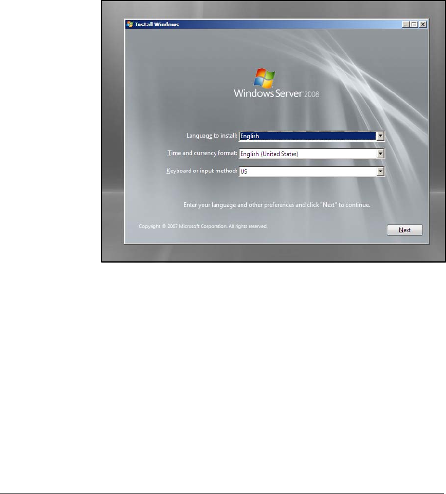
AD-9
Addendum: ProCurve Access Control Solution 2.1 Update
Configuring the Windows Domain Controller
Installing Windows Server 2008
1. Insert Windows Server 2008 CD or DVD. The Install Windows window is
displayed.
Figure AD-1.Windows Server 2008 Install Windows Window
2. Select the language to install, time and currency format, an keyboard or
input method. For this example, leave the default settings.
3. Click Next. The Install Now window is displayed.
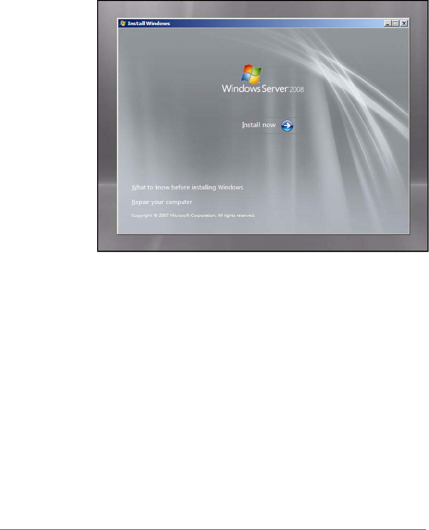
AD-10
Addendum: ProCurve Access Control Solution 2.1 Update
Configuring the Windows Domain Controller
Figure AD-2.Windows Server 2008 Install Windows—Install Now Window
4. Click Install now. A Please Wait message is displayed for a few minutes.
Then, the following window is displayed.
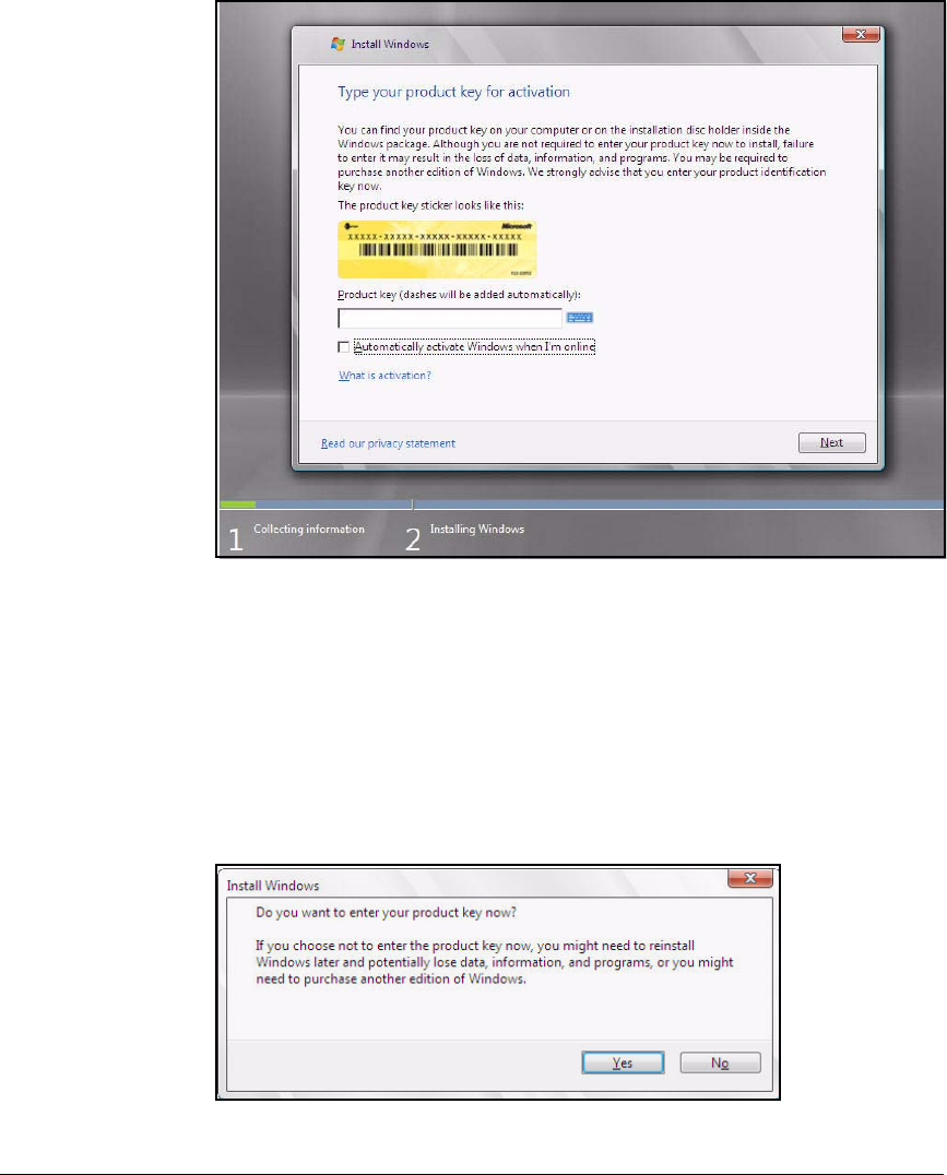
AD-11
Addendum: ProCurve Access Control Solution 2.1 Update
Configuring the Windows Domain Controller
Figure AD-3.Windows Server 2008 Install Windows—Product Key Activation
Window
5. Type the product key. The server must be connected to the Internet. (Enter
only the alpha-numerics—dashes are added automatically.) Optionally
select or clear the Automatically activate Windows when I'm online check
box. Click Next. If you entered a product key, continue with step 8.
If you chose not to enter the product key, a window is displayed, asking
if you want to enter your product key now.
Figure AD-4.Product Key Warning Window
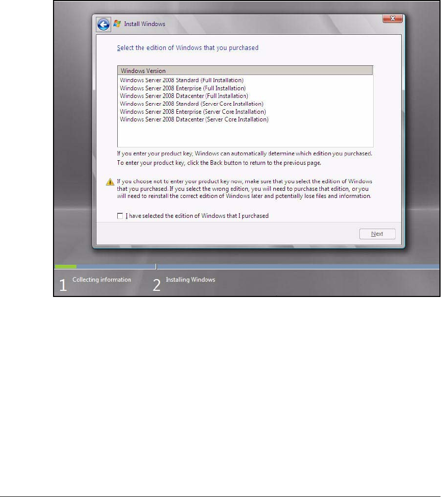
AD-12
Addendum: ProCurve Access Control Solution 2.1 Update
Configuring the Windows Domain Controller
Click Yes or No.
6. If you again chose not to enter the product key the Select edition window
is displayed.
Figure AD-5.Windows Server 2008 Install Windows—Select Edition Window
7. You must complete these steps:
a. Select the version of Windows Server 2008 that you purchased.
b. Select the I have selected the edition of Windows that I purchased check
box.
c. Click Next.
8. On the Licensing agreement window, select I accept the license terms and
click Next. The Select Installation Type window is displayed.
9. Select an installation type. For this example, select Custom (advanced).
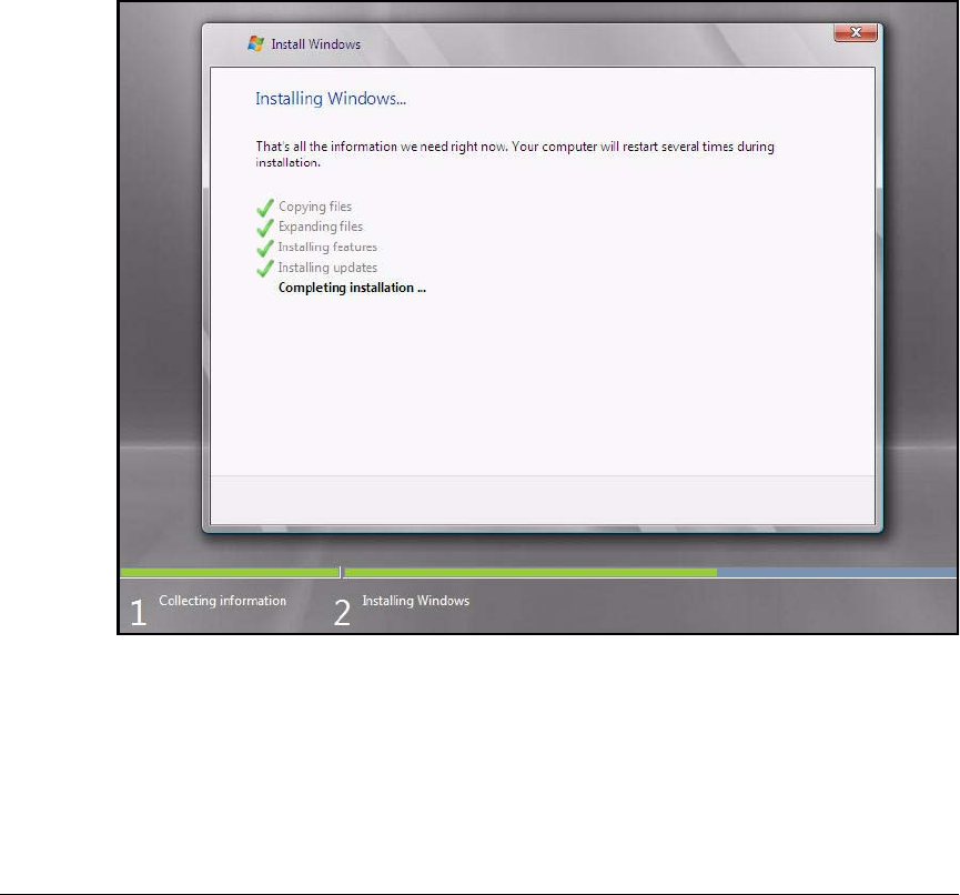
AD-13
Addendum: ProCurve Access Control Solution 2.1 Update
Configuring the Windows Domain Controller
10. Select where you want to install Windows Server 2008 and click Next.
If you are installing Windows Server 2008 on a computer that is already
running another version of Windows, a warning message is displayed,
telling you that the hard drive or partition you selected already has files
from a previous installation. Click OK to proceed.
Windows Server 2008 will automatically begin installing everything you
need. This process will take several minutes.
Your computer will automatically reboot to complete the installation.
After the computer has rebooted, the window in Figure AD-6 is displayed.
Figure AD-6.Windows Server 2008 Install Windows—Completing Installation
Window
11. After the Completing Installation task is finished, your computer will reboot
again. The following window is displayed.
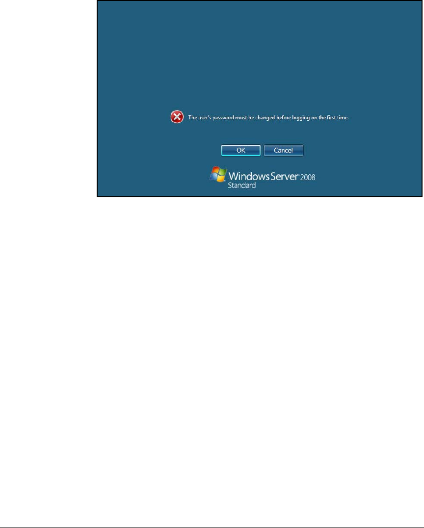
AD-14
Addendum: ProCurve Access Control Solution 2.1 Update
Configuring the Windows Domain Controller
Figure AD-7.Windows Server 2008 Create Password Warning Window
12. You must reset the administrative password before logging in to the
Windows Server 2008 for the first time. Click OK.
13. In the two fields below the Administrator icon, type a new password, and
then retype the password. For this example, type !@ProCurve.
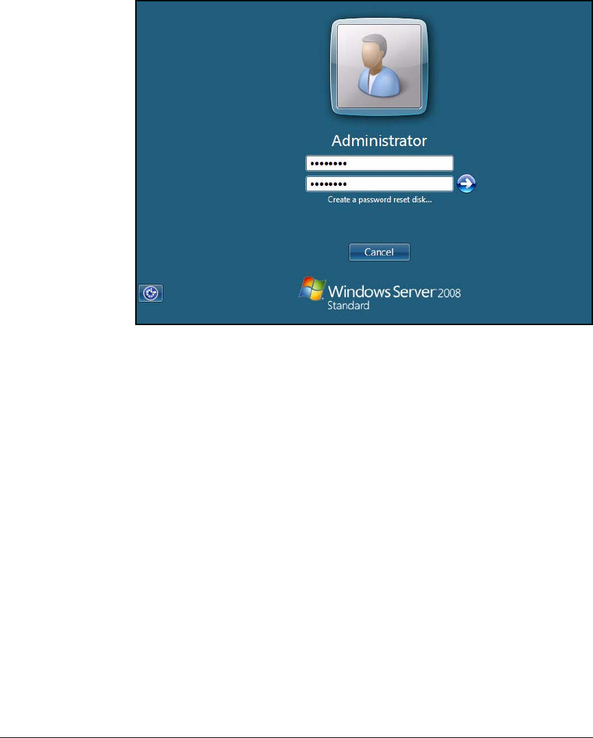
AD-15
Addendum: ProCurve Access Control Solution 2.1 Update
Configuring the Windows Domain Controller
Figure AD-8.Windows Server 2008 Log In Window
14. Click the arrow icon or press [Enter].
Your password must include both capital and lower case letters as well
as either a number or a symbol character. If you do not meet these rules,
a warning will be displayed, and you will be forced to choose another
password.
15. A window is displayed that confirms your password change. Click OK. A
message informs you that your desktop is being prepared. Then the Log
In window is displayed.
16. Type your new password and click the right arrow or press [Enter]. The
Initial Configuration Tasks window is displayed.
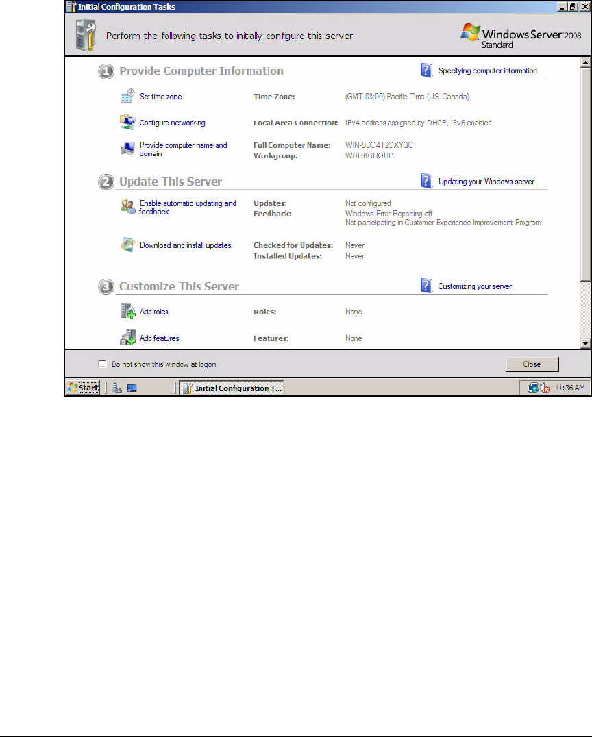
AD-16
Addendum: ProCurve Access Control Solution 2.1 Update
Configuring the Windows Domain Controller
Figure AD-9.Windows Server 2008—Initial Configuration Tasks Window
You have now installed Windows Server 2008. Before you can begin assigning
roles to the server, you must configure some initial settings.
Configure Initial Settings
Before you can begin assigning roles to the server, you must configure some
initial settings:
■Time zone
■Static IP settings
Set the Time Zone
1. From the Initial Configuration Tasks window, click Set Time zone. The Date
and Time window is displayed.
Or you can access the control panel and double-click Date and Time.
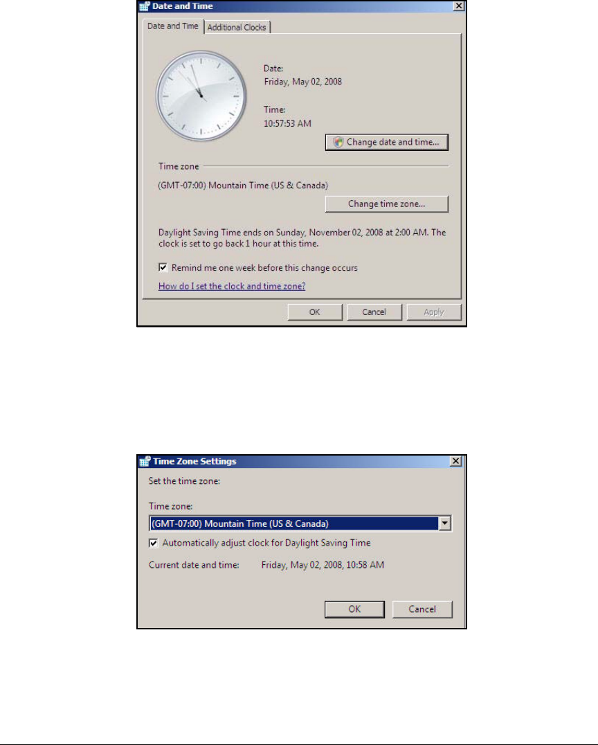
AD-17
Addendum: ProCurve Access Control Solution 2.1 Update
Configuring the Windows Domain Controller
Figure AD-10.Windows Server 2008—Date and Time Window
2. The Date and Time tab should be selected. Ensure that the time, date, and
time zone are correct:
a. To change the time zone, click Change time zone. Select your time zone
from the list and click OK.
Figure AD-11.Windows Server 2008—Time Zone Settings Window
b. To change the current date and time, click Change date and time. Make
any adjustments needed and then click OK.
3. Click OK.
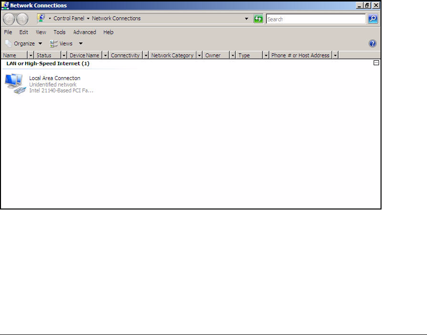
AD-18
Addendum: ProCurve Access Control Solution 2.1 Update
Configuring the Windows Domain Controller
Set Static IP Settings
Windows Server 2008 requires you to set both static IPv4 and IPv6 addresses
even if you plan to disable IPv6. Complete the following steps:
1. Access the Network Connections window from one of the following two
locations:
•The Initial Configuration Tasks window
i. In the Initial Configuration Tasks window, click Configure network-
ing.
ii. The Network Connections window is displayed.
•The Server Manager window
i. Click Start > Administrative Tools > Server Manager.
ii. In the Server Manager window, under Server Summary, click View
Network Connections.
iii. The Network Connections window is displayed.
Figure AD-12.Windows Server 2008—Network Connections Window
iv. Right-click Local Area Connection.
v. Click Properties. The Local Area Connection Properties window is
displayed.
vi. In this implementation, the network uses IPv4 addresses. Clear
the Internet Protocol Version 6 (TCP/IPv6) check box.
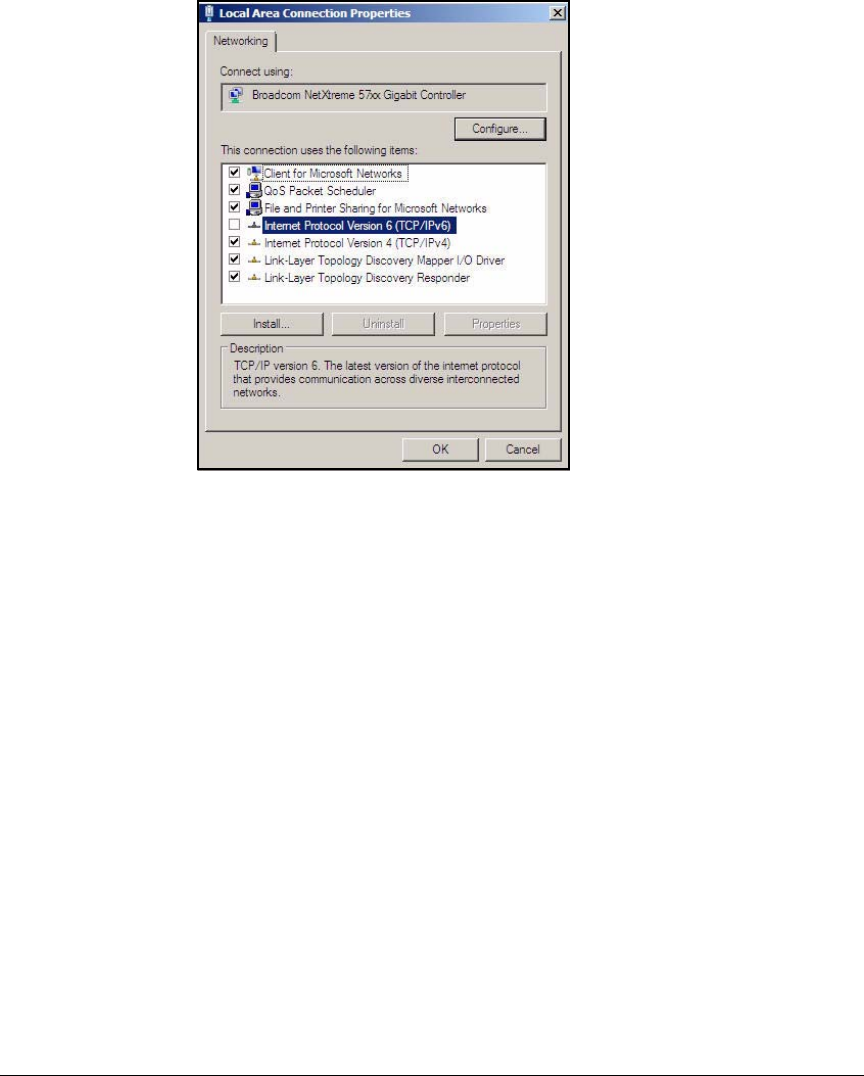
AD-19
Addendum: ProCurve Access Control Solution 2.1 Update
Configuring the Windows Domain Controller
Figure AD-13.Windows Server 2008—Local Area
Connection Properties Window
2. Select Internet Protocol Version 4 (TCP/IPv4) and click Properties. The Internet
Protocol Version 4 (TCP/IPv4) Properties window is displayed.
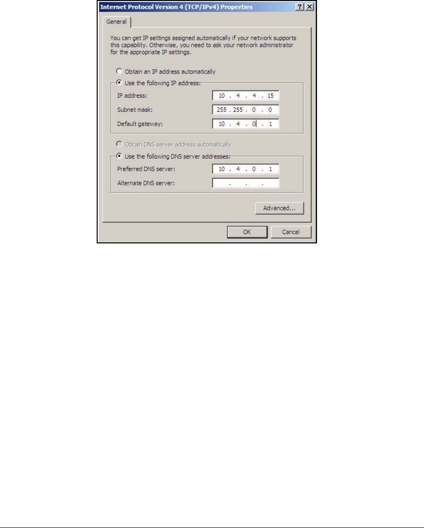
AD-20
Addendum: ProCurve Access Control Solution 2.1 Update
Configuring the Windows Domain Controller
Figure AD-14.Windows Server 2008—Internet Protocol
Version 4 (TCP/IPv4) Properties Window
3. Select Use the following address.
4. For IP address, type an IPv4 address. In the example, type 10.4.4.15.
5. For Subnet mask, type the appropriate mask for your address. In this
example, type 255.255.0.0.
6. For Default gateway, type the appropriate prefix length for your address.
In this example, type 10.4.0.1.
7. Select Use the following DNS server addresses.
8. For Preferred DNS server, type the IPv4 address of your DNS server. In this
example, the Windows Server 2008 will serve as its own DNS server.
You can type the address that you set in the IP address box or the loopback
address (127.0.0.1).
9. Click OK.
10. Click Close.
11. Press [Alt] + [F4].
You are now ready to add roles to your Windows Server 2008.

AD-21
Addendum: ProCurve Access Control Solution 2.1 Update
Configuring the Windows Domain Controller
Install Active Directory
After you install Windows Server 2008, the server is a standalone server
without membership in a domain. To make the server a domain controller,
configure Active Directory on the new server:
1. If you have not yet connected the server to the network infrastructure,
connect it now.
For services to run properly, the server requires an active network con-
nection. In the example network, the domain controller connects to the
core routing switch.
2. Access the Add Roles Wizard. There are two ways to access the wizard:
•From the Initial Configuration Tasks window, complete this step:
i. Under Customize this Server, click Add Roles.
• From the Server Manager window, complete these steps:
i. Click Start > Administrative Tools > Server Manager. The Server
Manager window is displayed.
ii. In the left pane, click Roles.
iii. In the right pane, click Add Roles.
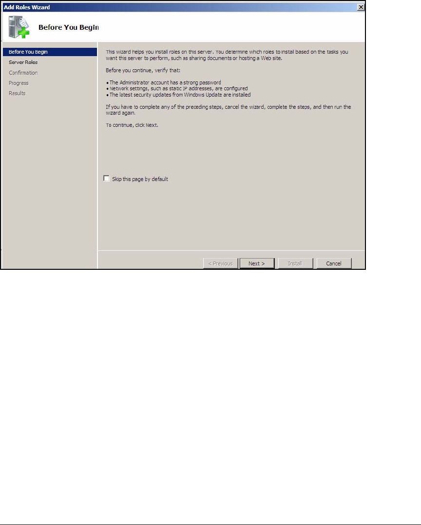
AD-22
Addendum: ProCurve Access Control Solution 2.1 Update
Configuring the Windows Domain Controller
Figure AD-15.Add Roles Wizard—Before You Begin Page
3. In the
Before You Begin
page, select
Skip this page by default
check box.
4. Click
Next
.
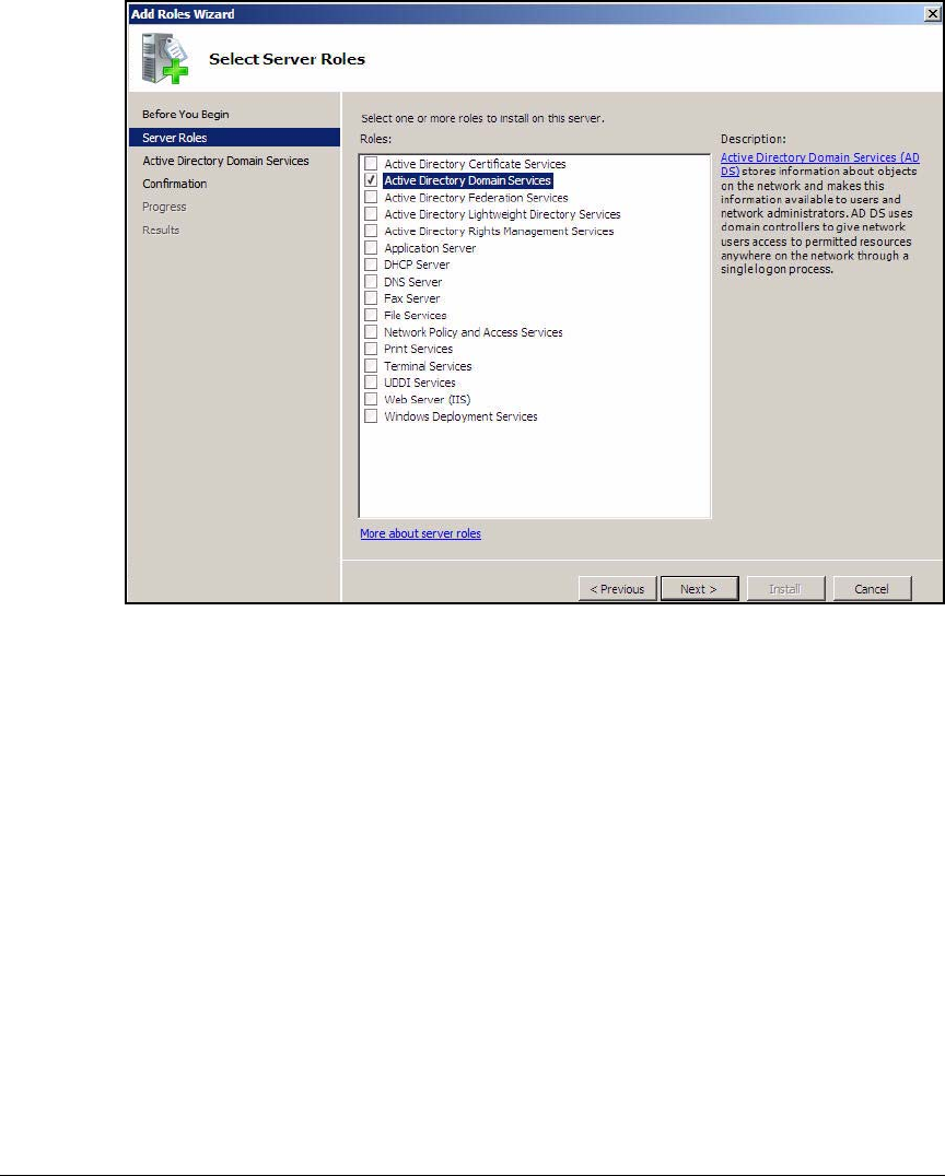
AD-23
Addendum: ProCurve Access Control Solution 2.1 Update
Configuring the Windows Domain Controller
Figure AD-16.Add Roles Wizard—Server Roles Page
5. Select the Active Directory Domain Services check box on the Select Server
Roles page.
All other roles build on the Active Directory Domain Services role, so you
must add this role first.
6. Click Next.
7. In the Introduction to Active Directory Domain Services page, click Next.
8. In the Confirm Installation Selections page, click Install. The Active Direc-
tory Domain Services role is installed. This process can take several
minutes.
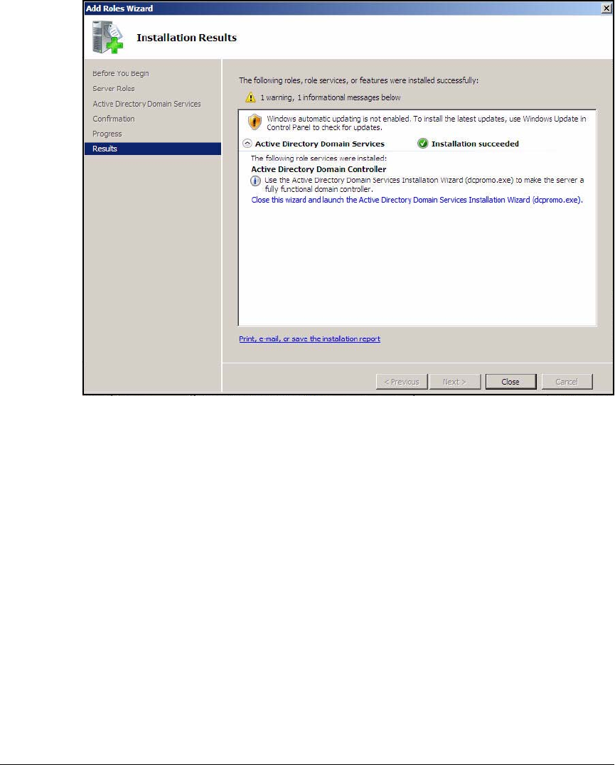
AD-24
Addendum: ProCurve Access Control Solution 2.1 Update
Configuring the Windows Domain Controller
Figure AD-17.Add Roles Wizard—Installation Results Page
9. Click Close.
10. Launch the Active Directory Domain Services Installation Wizard.
a. Click the Close this wizard and launch the Active Directory Domain
Services Installation Wizard (dcpromo.exe) link. The Active Directory
Domain Services Installation Wizard is displayed.
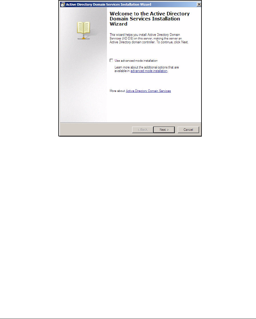
AD-25
Addendum: ProCurve Access Control Solution 2.1 Update
Configuring the Windows Domain Controller
Figure AD-18.Active Directory Domain Services Installation
Wizard—Welcome Page
11. On the Welcome page, click Next.
12. On the Operating System Compatibility page, click Next.
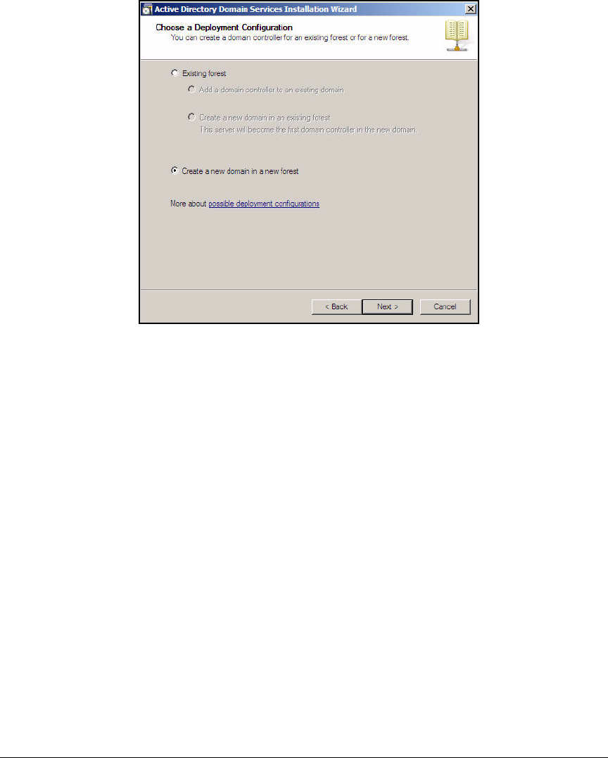
AD-26
Addendum: ProCurve Access Control Solution 2.1 Update
Configuring the Windows Domain Controller
Figure AD-19.Active Directory Domain Services Installation
Wizard—Deployement Configuration Page
13. In the Choose a Deployment Configuration page, select Create a new domain
in a new forest and click Next.
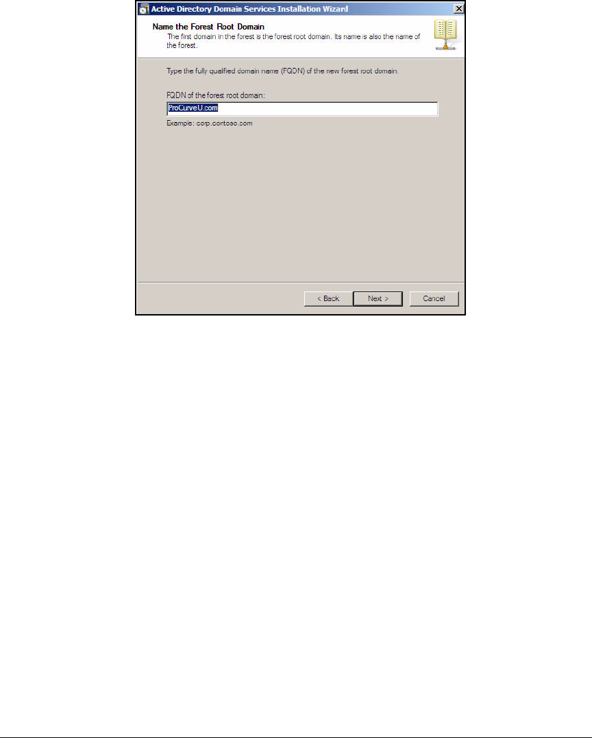
AD-27
Addendum: ProCurve Access Control Solution 2.1 Update
Configuring the Windows Domain Controller
Figure AD-20.Active Directory Domain Services Installation
Wizard—New Domain Name Page
14. Type your organization’s domain name in the FQDN of the forest root domain:
box. Type ProCurveU.com and click Next. The server checks that the forest
name is not already in use.
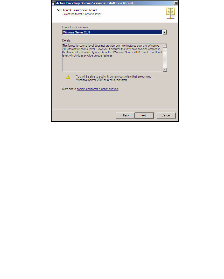
AD-28
Addendum: ProCurve Access Control Solution 2.1 Update
Configuring the Windows Domain Controller
Figure AD-21.Active Directory Domain Services Installation
Wizard—Forest Functional Level Page
15. From the Forest functional level list, select Windows Server 2008.
16. Click Next.
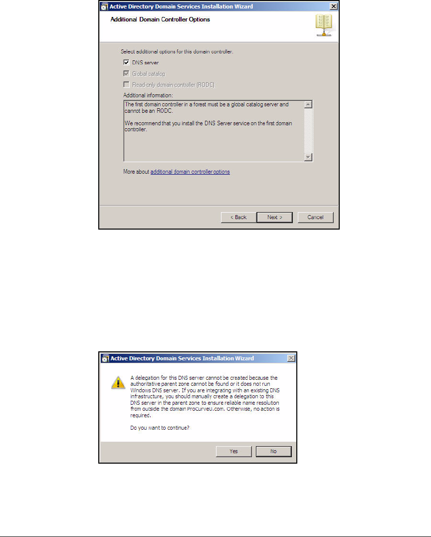
AD-29
Addendum: ProCurve Access Control Solution 2.1 Update
Configuring the Windows Domain Controller
Figure AD-22.Active Directory Domain Services Installation
Wizard—Additional Domain Controller Options Page
17. Select the DNS server check box.
Active Directory relies on DNS, so you often set up DNS on the same
server.
18. Click Next. A warning may be displayed.
Figure AD-23.Active Directory Domain Services Installation
Wizard—DNS Warning Window
19. If the warning is displayed, click Yes.
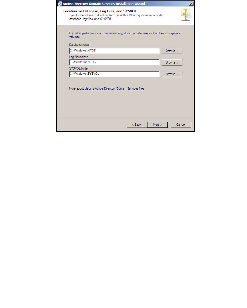
AD-30
Addendum: ProCurve Access Control Solution 2.1 Update
Configuring the Windows Domain Controller
Figure AD-24.Active Directory Domain Services Installation
Wizard—Locations Page
20. Accept the default folder locations for all three settings and click Next.
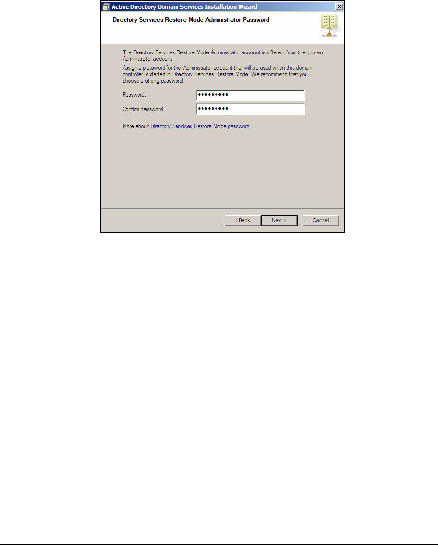
AD-31
Addendum: ProCurve Access Control Solution 2.1 Update
Configuring the Windows Domain Controller
Figure AD-25.Active Directory Domain Services Installation
Wizard—Administrator Password Page
21. In the Password and Confirm password fields, type an administrator pass-
word for the Directory Services Restore mode. In this example, type
ProCurve0 and click Next.
Best practice dictates that this password be different from the Windows
Server 2008 administrator password. Your password must include both
capitol and lower case letters as well as either a number or a symbol
character. If you do not meet these rules, a warning will be displayed, and
you will be forced to choose another password.
22. In the Summary page, click Next.
23. Select the Reboot on completion check box.
24. In the Completing Active Directory Domain Services Installation Wizard page,
click Finish.

AD-32
Addendum: ProCurve Access Control Solution 2.1 Update
Configuring the Windows Domain Controller
Configure Windows Domain Groups
You must create groups for the users who are authorized to access your
network. When a RADIUS server authenticates a user, it can check the user’s
group membership and use that information to apply the correct policies to
the user’s network access.
By default, Active Directory includes a number of groups such as the Domain
Admins and Domain Users groups. You can use these default groups and also
create new groups for your specific network. For the example ProCurve
University network, the network administrators have decided to create three
additional groups for users:
■Network_Admins
■Faculty
■Students
Users can have more than one group membership. For example, all members
of the groups listed above will also be members of the Domain Users group.
The groups listed above, however, are the groups that IDM will use to deter-
mine which rights to grant users.
In addition, you must create a NAP client computers group, which includes
all the endpoints with which users access the network. Other devices such as
servers are members of the Domain Computers group.
Note In this solution, the network provides wireless guest access. However,
accounts for guests are configured on the Wireless Edge Services Module
rather than in Active Directory.
Complete these steps to configure the AD groups:
1. From the Windows Start menu, click Administrative Tools > Active Directory
Users and Computers.
2. Expand the domain.
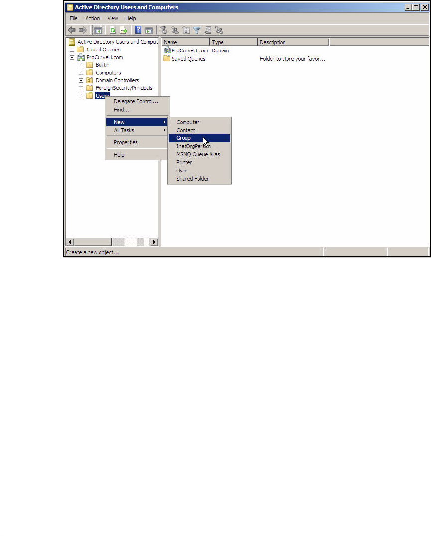
AD-33
Addendum: ProCurve Access Control Solution 2.1 Update
Configuring the Windows Domain Controller
Figure AD-26.Windows Server 2008—Active Directory Users and Computers
Window (Add New Group)
3. In the left pane, right-click Users and select New > Group.
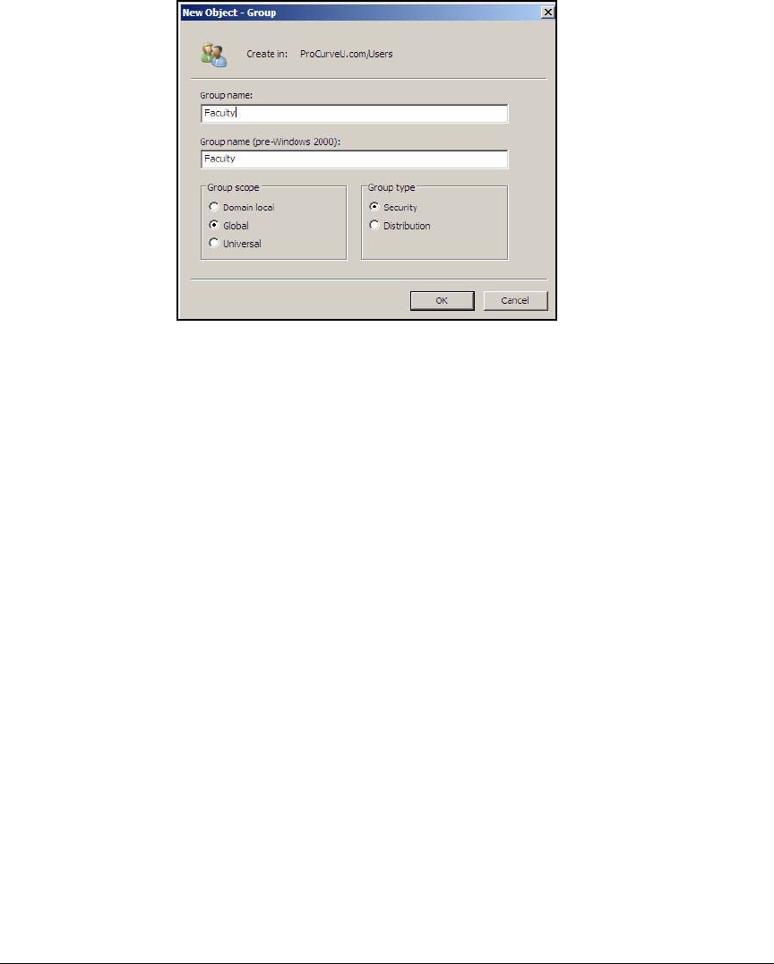
AD-34
Addendum: ProCurve Access Control Solution 2.1 Update
Configuring the Windows Domain Controller
Figure AD-27.Windows Server 2008—New Object – Group
Window
4. For Group name, type the group name. In this example, type Faculty.
5. Accept the default setting of Global for the Group scope and Security for
the Group type.
The Global setting ensures that the group applies to the entire domain. The
group can contain only members of its own domain, but it can be granted
permissions to other domains in the same Microsoft forest.
The Security setting allows you to create groups that will control privileges
for users. Any group that affects network access should be a security
group. (The Distribution setting, on the other hand, is used for email
distribution lists.) For more information about these settings, refer to your
Microsoft documentation.
6. Click OK.
AD-35
Addendum: ProCurve Access Control Solution 2.1 Update
Configuring the Windows Domain Controller
7. Repeat steps 3 to 6 to create additional groups.
For the example ProCurve University network, you would create these
additional groups:
• Network_Admins
•Students
Configure Windows Domain Users
Next, you should create users and assign the users to the appropriate groups.
Table AD-4 shows several users for the example ProCurve University net-
work. Of course, you would create many more users for a production network.
Table AD-4. Windows Domain Users
Note The passwords listed in Table AD-4 are for a test network only. The passwords
are easy to remember, but they do not meet the security requirements for a
production network. For your network, you should create passwords that
meet stringent security requirements. For example, passwords should not
include dictionary words, you should always change default passwords, and
you should include numerals and special characters.
You can enter information about your users in Table AD-5.
First Name Last Name Logon Name
(Username)
Password Group Membership
Administrator —a default user Administrator ProCurve0 Domain Admins
Switch Administrator adminswitch ProCurve1 Network_Admins
Wireless Administrator adminwireless ProCurve2 Network_Admins
Pauline Professor professor ProCurve3 Faculty
Sam Student student ProCurve4 Students

AD-36
Addendum: ProCurve Access Control Solution 2.1 Update
Configuring the Windows Domain Controller
Table AD-5. My Windows Domain Users
First Name Last Name Logon Name
(Username)
Password Group Membership
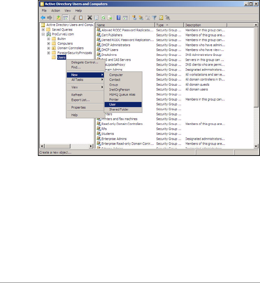
AD-37
Addendum: ProCurve Access Control Solution 2.1 Update
Configuring the Windows Domain Controller
Follow these steps to add a user:
1. From the Windows Start menu, select Administrative Tools > Active Directory
Users and Computers.
2. Expand your domain.
Figure AD-28.Windows Server 2008—Active Directory Users and Computers
Window (Add New User)
3. In the left pane, right-click the Users folder and select New > User.
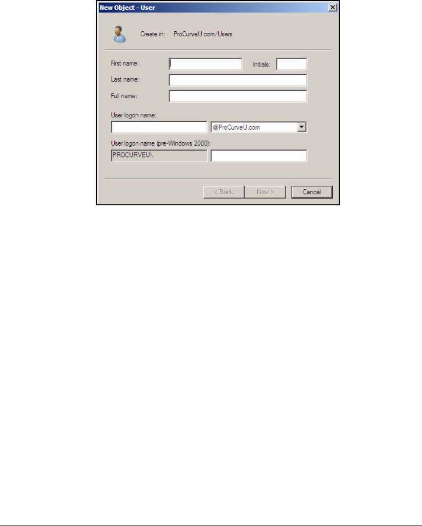
AD-38
Addendum: ProCurve Access Control Solution 2.1 Update
Configuring the Windows Domain Controller
Figure AD-29.Windows Server 2008—New Object—User Name
Window
4. For First name, type the user’s first name.
5. For Last name, type the user’s last name.
6. For User logon name, type the user’s username.
This is the name that the user (or supplicant on a device) submits as part
of 802.1X authentication.
7. Click Next.
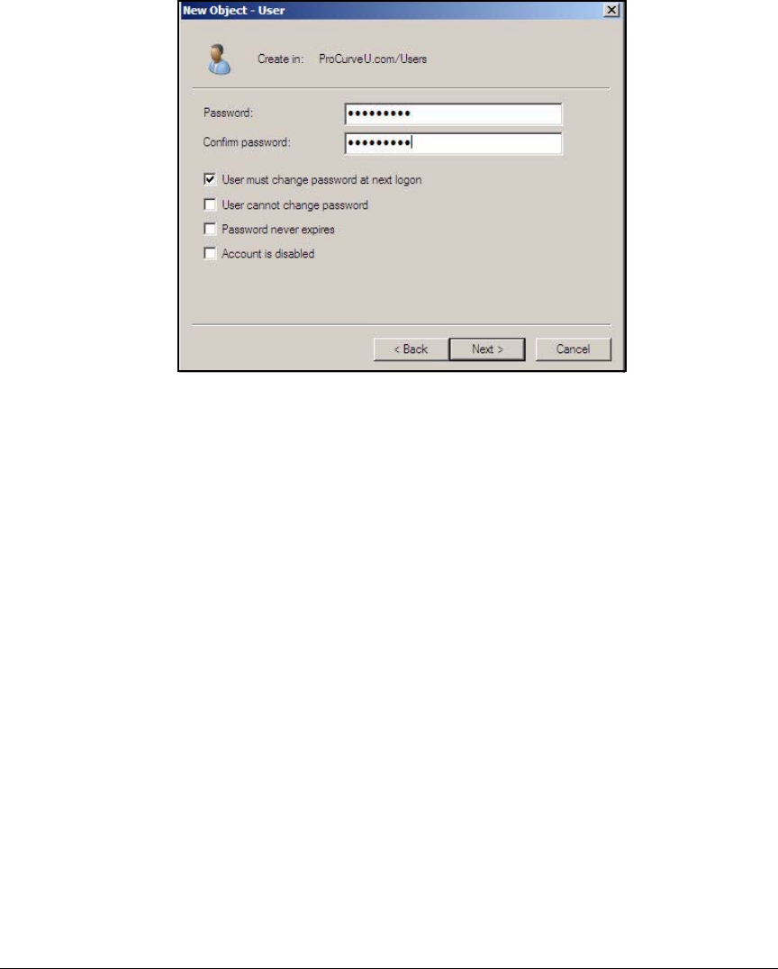
AD-39
Addendum: ProCurve Access Control Solution 2.1 Update
Configuring the Windows Domain Controller
Figure AD-30.Windows Server 2008—New Object—User
Password Window
8. In the Password and Confirm password boxes, type the user’s (or device’s)
password.
Select any password requirements.
Typically, a user should be forced to change the password the first time
that he or she logs in (so that no one else knows the password) and every
few weeks after that.
If you are defining password requirements for a device instead of a user,
do not select the User must change password at next logon check box, and
select the Password never expires check box.
9. Click Next.
10. Click Finish on the Summary page.
11. In the right pane of the Active Directory Users and Computers window, right-
click the newly created user and click Properties.
12. Click the Dial-in tab.
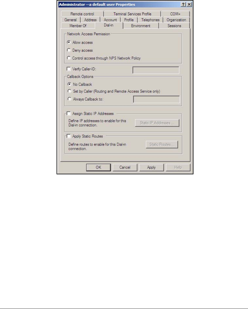
AD-40
Addendum: ProCurve Access Control Solution 2.1 Update
Configuring the Windows Domain Controller
Figure AD-31.Windows Server 2008—<username> Properties
Window—Dial-in Tab
13. For Network Access Permission, select Control access through NPS Network
Policy.
14. Click the Member Of tab and click Add.
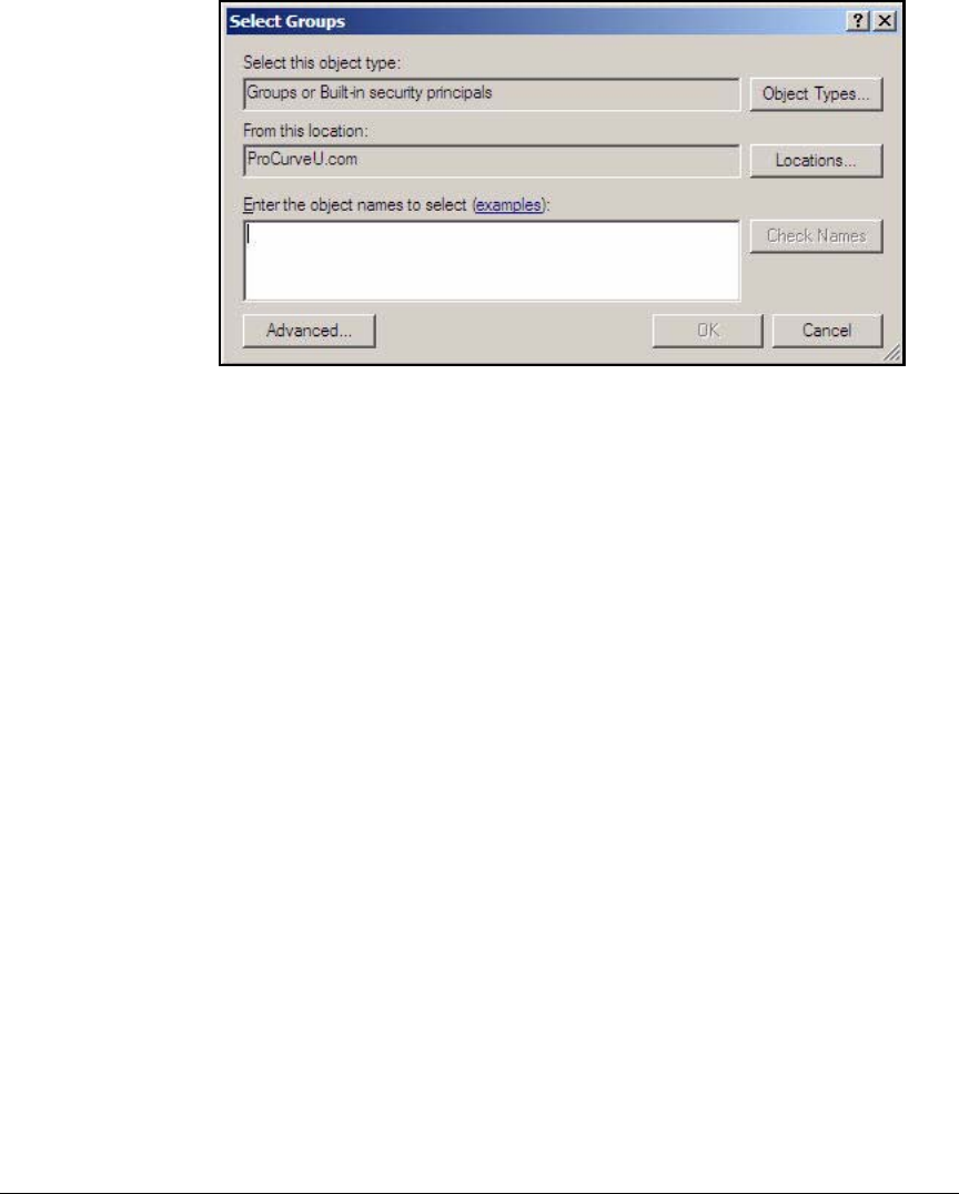
AD-41
Addendum: ProCurve Access Control Solution 2.1 Update
Configuring the Windows Domain Controller
Figure AD-32.Windows Server 2008—<username> Properties—Select Groups
Window
15. In the Enter the object names to select field, type the name of the appropriate
group. For example, for Pauline Professor in the PCU network, you would
type Faculty.
16. Click Check Names. If the group name is valid, it will be underlined.
17. Click OK.
18. The group is displayed in the Member Of window. Click OK to apply the
changes.
19. Press [Alt] + [F4] to close the Active Directory Users and Computers window.
Configure DNS Services
Active Directory relies on DNS for several services. For example, endpoints
send DNS requests to locate the domain controllers. This section describes
how to configure the DNS services necessary for Active Directory. Specifi-
cally, you will create reverse lookup zones for each subnet in your network.
Table AD-6 displays the zones for the example network.
Note that when you type a reverse lookup zone in the Windows New Zone
Wizard, you type it in non-reversed form. For example, for subnet 10.2.0.0/16,
you type 10.2. The wizard automatically reverses the zone.
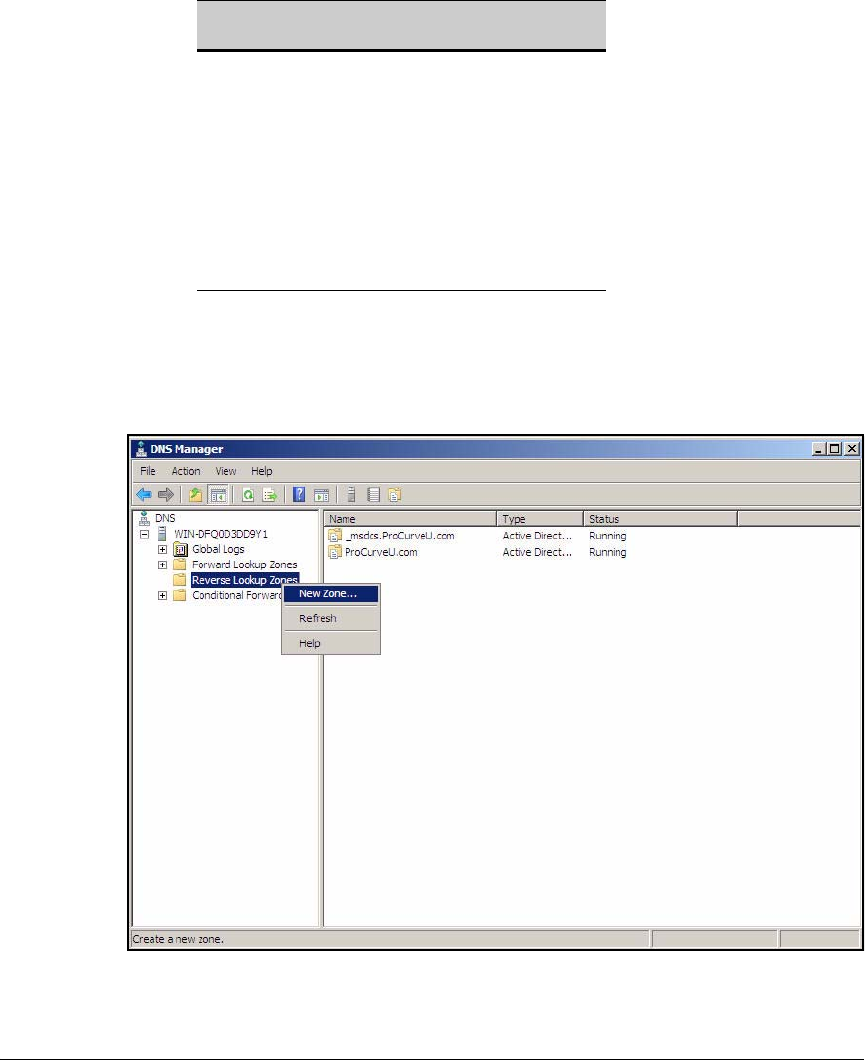
AD-42
Addendum: ProCurve Access Control Solution 2.1 Update
Configuring the Windows Domain Controller
Table AD-6. Reverse Lookup Zones
Complete these steps on the Windows 2008 Server that acts as domain
controller:
1. From the Windows Start menu, click Administrative Tools > DNS.
Figure AD-33.Windows Server 2008—DNS Manager Window
VLAN Subnet Reverse Lookup
Zone
2 10.2.0.0/16 10.2
4 10.4.0.0/16 10.4
5 10.5.0.0/16 10.5
8 10.8.0.0/16 10.8
9 10.9.0.0/16 10.9
10 10.10.0.0/16 10.10
12 10.12.0.0/16 10.12
32 10.32.0.0/16 10.32
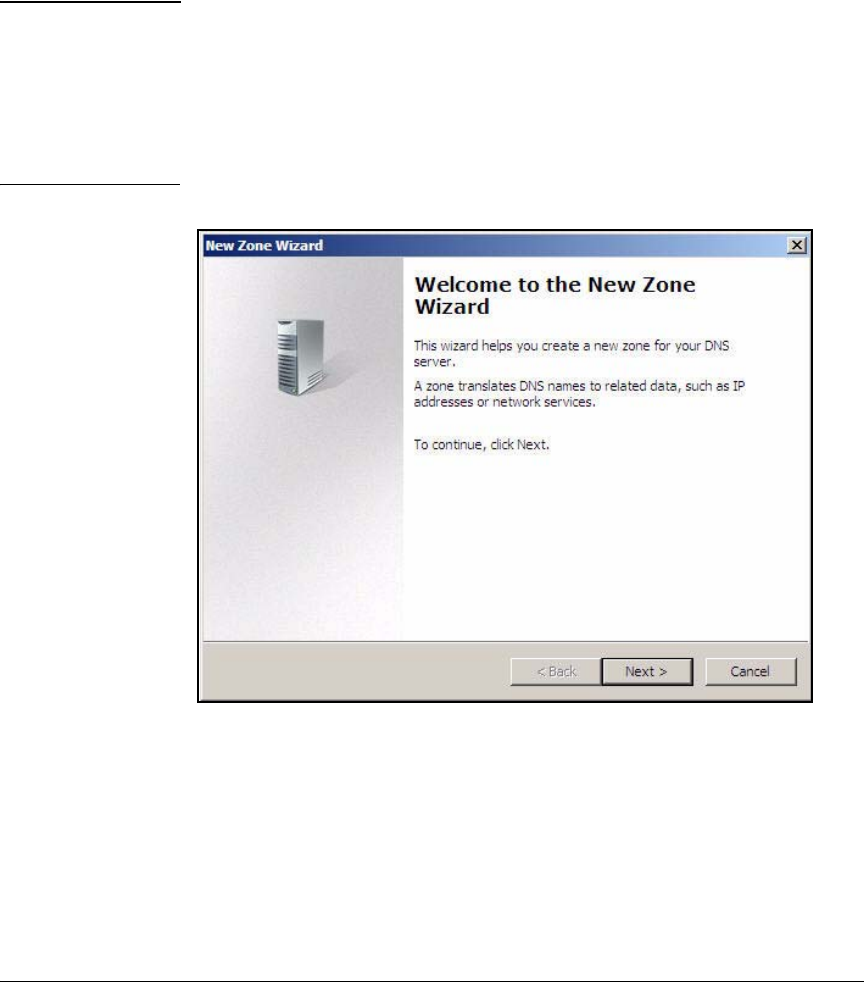
AD-43
Addendum: ProCurve Access Control Solution 2.1 Update
Configuring the Windows Domain Controller
2. In the left pane, expand your server.
3. In the left pane, click.
4. Right-click Reverse Lookup Zones and click New Zone.
Note If New Zones is not an available option, check that the DNS service is
running by clicking Forward Lookup Zones in the left pane. The Status
column for your domain should list Running.
If the service is not running:
a. Right-click the domain name.
b. Select All Tasks > Start.
Figure AD-34.New Zone Wizard—Welcome to the New Zone Wizard Page
5. On the Welcome to the New Zone Wizard page, click Next.
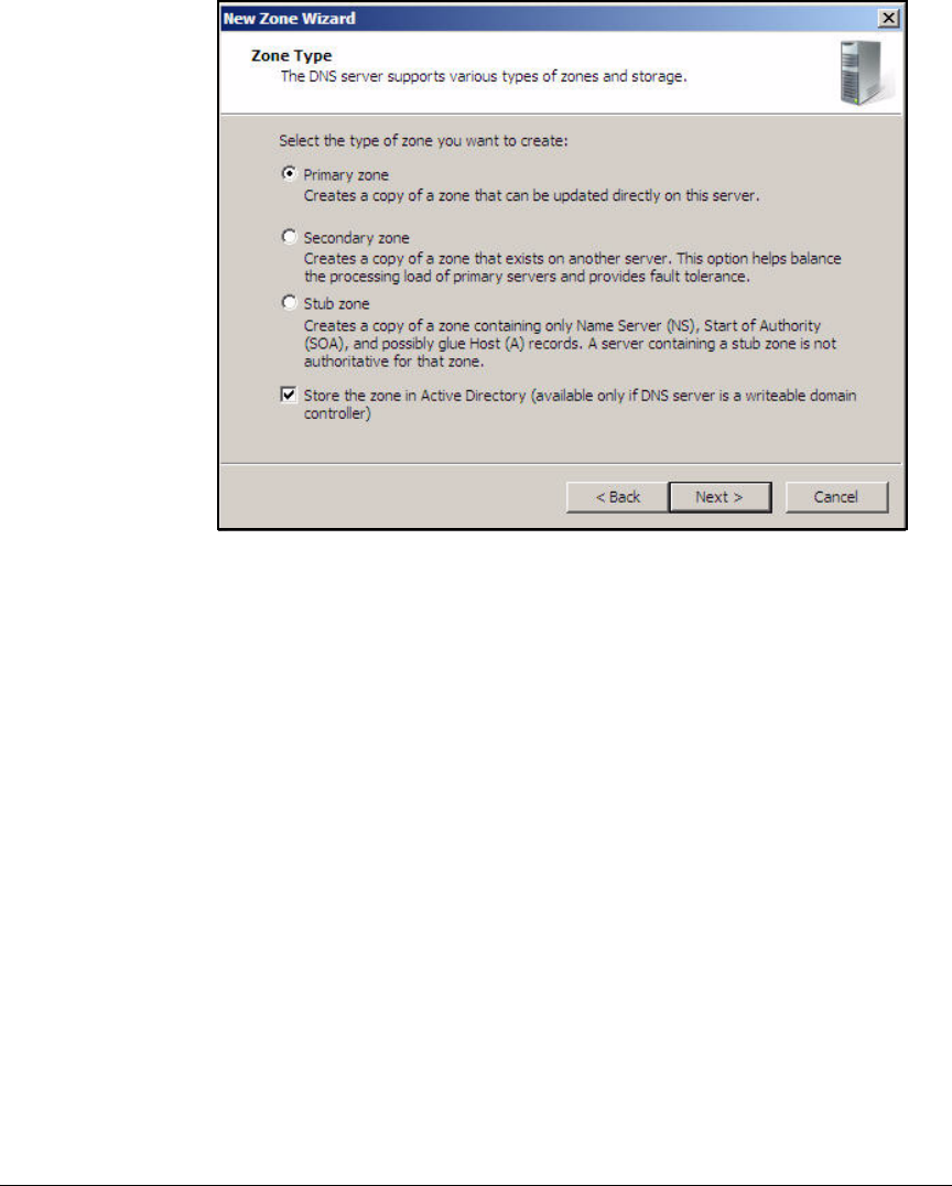
AD-44
Addendum: ProCurve Access Control Solution 2.1 Update
Configuring the Windows Domain Controller
Figure AD-35.New Zone Wizard—Zone Type Page
6. Verify that Primary zone is selected and that the Store the zone in Active
Directory check box is selected. Click Next.
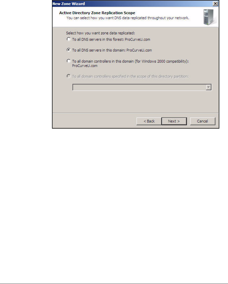
AD-45
Addendum: ProCurve Access Control Solution 2.1 Update
Configuring the Windows Domain Controller
Figure AD-36.New Zone Wizard—Active Directory Zone Replication Scope Page
7. Select To all DNS servers in this domain.
If your domain includes Windows 2000 domain controllers, select To all
domain controllers in this domain (for Windows 2000 compatibility): <name>
8. Click Next.
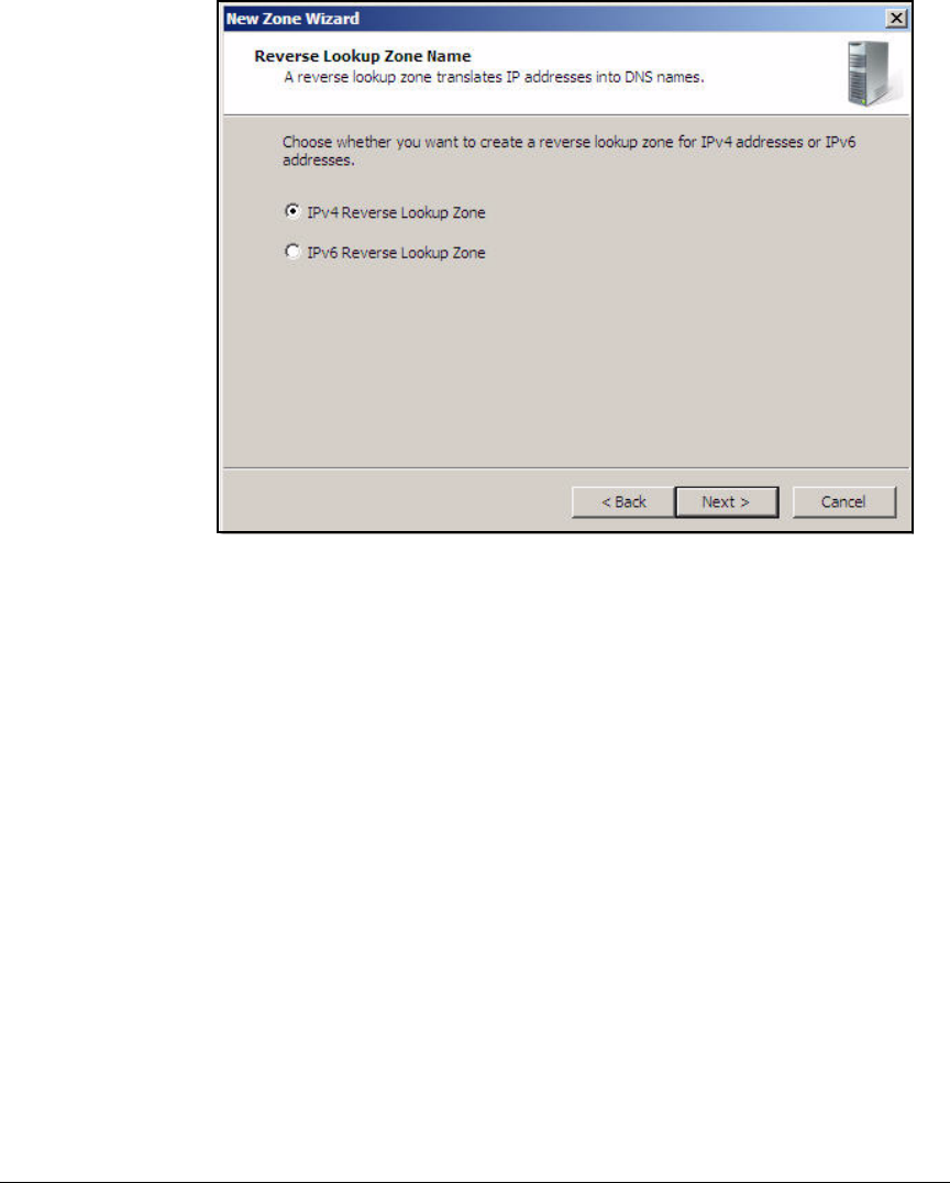
AD-46
Addendum: ProCurve Access Control Solution 2.1 Update
Configuring the Windows Domain Controller
Figure AD-37.New Zone Wizard—Reverse Lookup Zone Name Page
9. Select the IP version for the reverse lookup zone. If you plan to offer both
IPv4 and IPv6 access to your network, you will need to create a reverse
lookup zone for each version. In this example, select IPv4 Reverse Lookup
Zone.
10. Click Next.
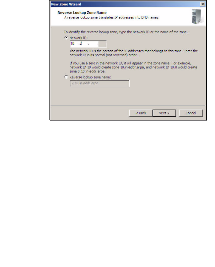
AD-47
Addendum: ProCurve Access Control Solution 2.1 Update
Configuring the Windows Domain Controller
Figure AD-38.New Zone Wizard—Reverse Lookup Zone Name Page
11. Type the significant portion of the network address in the Network ID box.
The significant portion of the address includes the network (as opposed
to the host) portion of the address—typically, the non-zero octets. For
example, the first two octets are significant in a /16 subnet (255.255.0.0).
The first three octets are significant in a /24 (255.255.255.0) subnet.
Leave the space for octets that are not significant blank. Do not enter 0s.
12. Click Next.
13. Select Allow only secure dynamic updates and click Next.
14. Click Finish.
15. Repeat steps 5 to 14 for each subnet in your domain.
Figure AD-39 displays the reverse lookup zones for the example network.
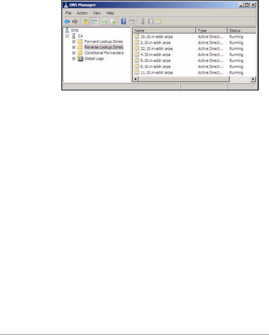
AD-48
Addendum: ProCurve Access Control Solution 2.1 Update
Configuring the Windows Domain Controller
Figure AD-39.Windows Server 2008—DNS Manager > Reverse Lookup Zones
Page (Zones Added)
16. Press [Alt]+[F4] to close the DNS Manager window.

AD-49
Addendum: ProCurve Access Control Solution 2.1 Update
Configuring the DHCP Server
Configuring the DHCP Server
Your DHCP server (or servers) must include scopes (also called pools) for
each subnet for which devices request dynamic IP addresses. For this solution,
these subnets include:
■User VLANs
■Computer VLAN
■The VLAN for non-compliant endpoints
For security purposes, the management VLAN does not use dynamic IP
addresses. If a network administrator wants to connect to the management
VLAN, he or she must configure a static IP address on their management
station. All servers in the example network have static addresses, so VLANs
4 and 5 do not require DHCP scopes either.
Table AD-7 displays settings for DHCP scopes in this network. Note that the
range of IP addresses in each scope does not include all IP addresses available
in the corresponding subnet. Some addresses are statically assigned to various
network devices; others are reserved for future use.
Note also that the DHCP scope for the Computer VLAN has the shortest
possible lease time (here, 1 minute). This setting ensures that the computer
will obtain an IP address in the dynamic VLAN assigned to the computer after
the user logs in.
Table AD-7. DHCP Scopes
Scope VLAN Subnet Range Lease Default
Gateway
DNS Server Other Options
Faculty 8 10.8.0.0/16 10.8.1.1–
10.8.10.254
8 days 10.8.0.1 10.4.4.15 domain name=
procurveu.edu
Computer 9 10.9.0.0/16 10.9.1.1-
10.9.20.254
1 minute 10.9.0.1 10.4.4.15 domain name=
procurveu.edu
Students 10 10.10.0.0/16 10.10.1.1–
10.10.10.254
8 days 10.10.0.1 10.4.4.15 domain name=
procurveu.edu
Guests 11 10.11.0.0/16 10.11.1.1–
10.11.10.254
8 days 10.11.0.1 10.4.4.15 domain name=
procurveu.edu
Quarantine 32 10.32.0.0/16 10.32.1.1–
10.32.2.254
8 days 10.32.0.1 10.4.4.15 domain name=
procurveu.edu
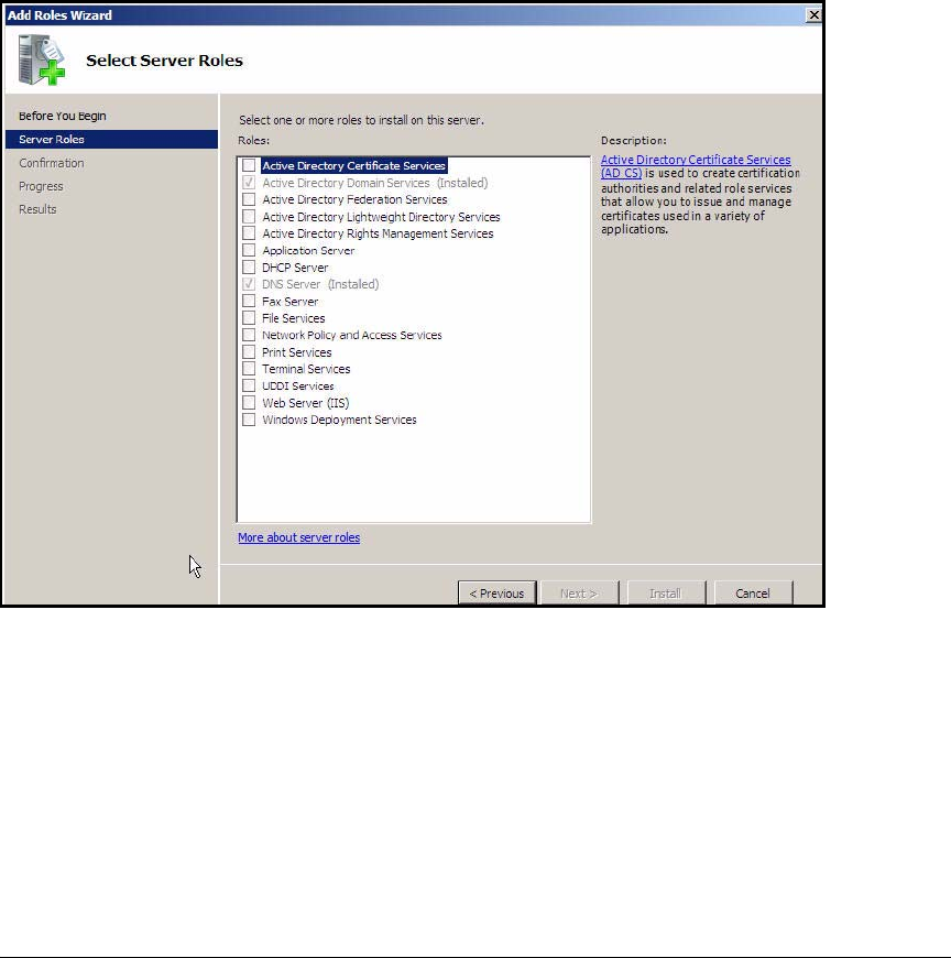
AD-50
Addendum: ProCurve Access Control Solution 2.1 Update
Configuring the DHCP Server
You can configure the scopes on any DHCP server. The following sections
describe how to set up a Windows Server 2008 DHCP server.
Install the DHCP Service
Follow these steps to install the DHCP service on Windows Server 2008:
1. Access the Add Roles Wizard. See step 2 on page AD-21.
Figure AD-40.Add Roles Wizard—Select Server Roles
2. Select the DHCP Server check box and click Next.
3. In the Introduction to DHCP Server page, click Next.
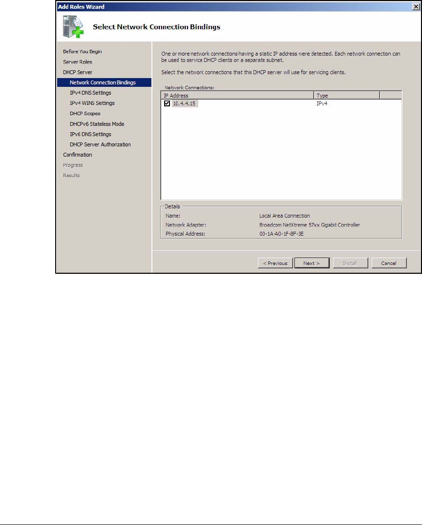
AD-51
Addendum: ProCurve Access Control Solution 2.1 Update
Configuring the DHCP Server
Figure AD-41.Add Roles Wizard—Select Network Connection Bindings Page
4. Verify that the selected IP address is the address your DHCP server will
use. Click Next.
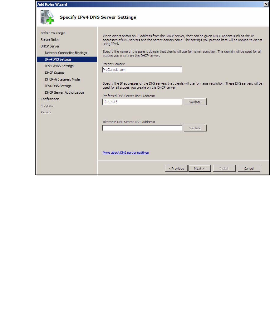
AD-52
Addendum: ProCurve Access Control Solution 2.1 Update
Configuring the DHCP Server
Figure AD-42.Add Roles Wizard—Specify IPv4 DNS Server Settings
5. Verify that the Parent Domain and Preferred DNS Server IPv4 Address settings
are correct. Click Next.
6. In the Specify IPv4 WINS Server Settings page, select WINS is not required
for applications on this network and click Next.
7. In the Add or Edit DHCP Scopes page, click Next. Scopes can be added from
this page, but you will add them later in the chapter.
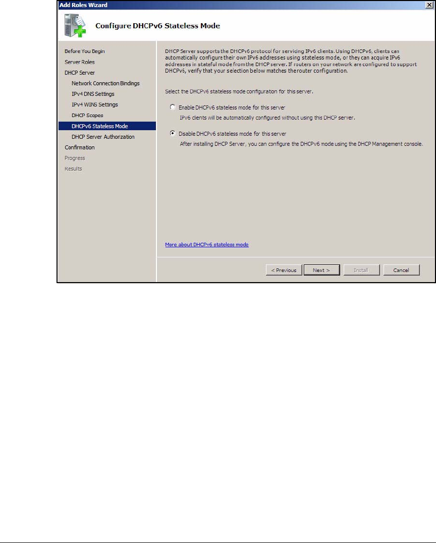
AD-53
Addendum: ProCurve Access Control Solution 2.1 Update
Configuring the DHCP Server
Figure AD-43.Add Roles Wizard—Configure DHCPv6 Stateless Mode Page
8. Enable or disable DHCPv6 stateless mode for this server. For this exam-
ple, select Disable DHCPv6 stateless mode for this server.
9. Click Next.
10. In the Authorize DHCP Server page, accept the default Use the current
credentials and click Next.
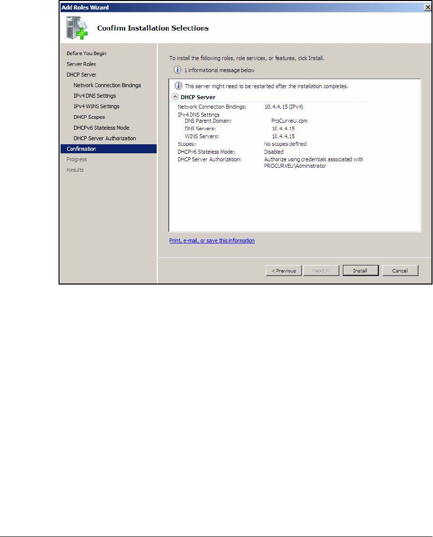
AD-54
Addendum: ProCurve Access Control Solution 2.1 Update
Configuring the DHCP Server
Figure AD-44.Add Roles Wizard—Confirm Installation Selections
11. Verify the installation selections and click Install.
12. Press [Alt]+[F4] to close the Add or Remove Programs window.
Configure the DHCP Server
Follow these steps to authorize the DHCP in Active Directory and create the
DHCP scopes:
1. From the Start menu, click Administrative Tools > DHCP.
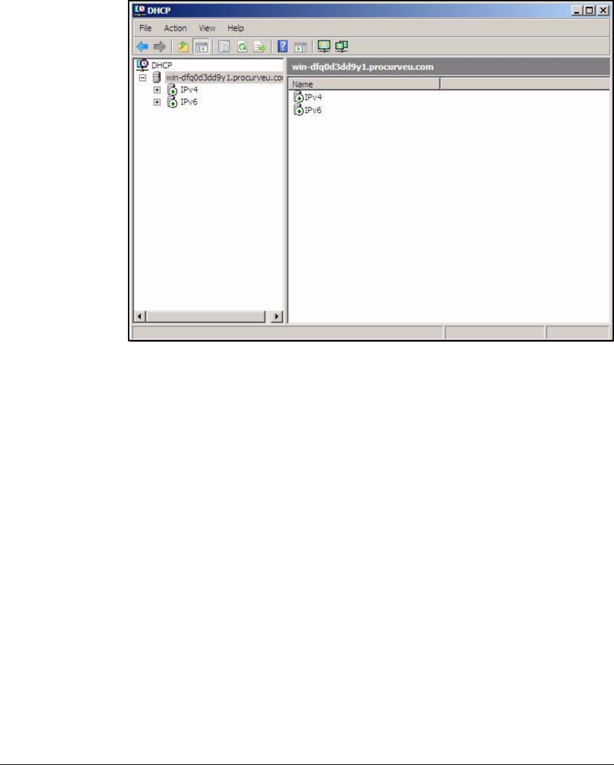
AD-55
Addendum: ProCurve Access Control Solution 2.1 Update
Configuring the DHCP Server
Figure AD-45.Windows Server 2008—DHCP Manager
2. Expand the server name
3. Right-click IPv4 or IPv6 and select New Scope. In this example, right-click
IPv4. The New Scope Wizard is displayed.
4. In the Welcome to the New Scope Wizard page, click Next.
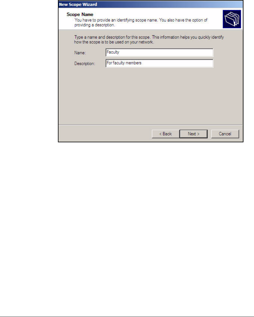
AD-56
Addendum: ProCurve Access Control Solution 2.1 Update
Configuring the DHCP Server
Figure AD-46.New Scope Wizard—Scope Name Page
5. For Name, type a name for the scope. For example, to configure the first
scope shown above, type Faculty.
6. If desired, describe the function of this scope in the Description box. For
example, you might type For faculty members.
7. Click Next.
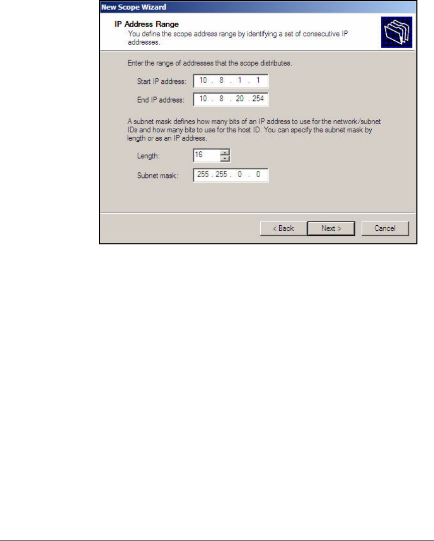
AD-57
Addendum: ProCurve Access Control Solution 2.1 Update
Configuring the DHCP Server
Figure AD-47.New Scope Wizard—IP Address Range Page
8. Type the range of IP addresses in the Start IP address and End IP address
boxes. For the example network, type 10.8.1.1 and 10.8.20.254.
9. Type the subnet prefix length in the Length box. For this example, type 16.
The Subnet mask box automatically fills with the correct value (here,
255.255.0.0).
10. Click Next.
11. If the range you specified includes IP addresses that are assigned to
devices statically, you must add exclusions in the Add Exclusions page.
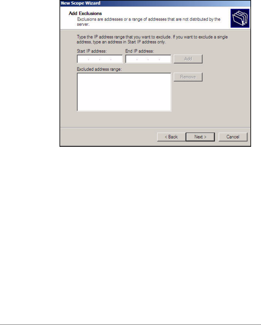
AD-58
Addendum: ProCurve Access Control Solution 2.1 Update
Configuring the DHCP Server
Figure AD-48.New Scope Wizard—IP Exclusions Page
In this example scope, the range does not include the IP addresses
assigned to network devices statically; therefore, you can click Next.
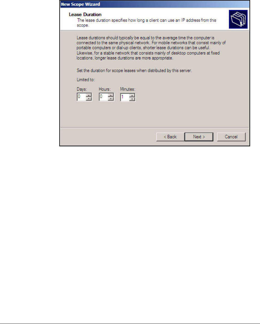
AD-59
Addendum: ProCurve Access Control Solution 2.1 Update
Configuring the DHCP Server
Figure AD-49.New Scope Wizard—Lease Duration Page
12. On the Lease Duration page, you can set how long a device can retain its
IP address without renewing it. For the computer VLAN—VLAN 11 in this
example—configure a short lease duration, such as 1 minute. For the
other VLANs, accept the default setting of eight days.
13. Click Next.
14. Select Yes, I want to configure these options now and click Next.

AD-60
Addendum: ProCurve Access Control Solution 2.1 Update
Configuring the DHCP Server
Figure AD-50.New Scope Wizard—Router (Default Gateway) Page
15. For IP address, type the IP address of the subnet’s default router. For this
example, type 10.8.0.1.
16. Click Add.
17. Click Next.
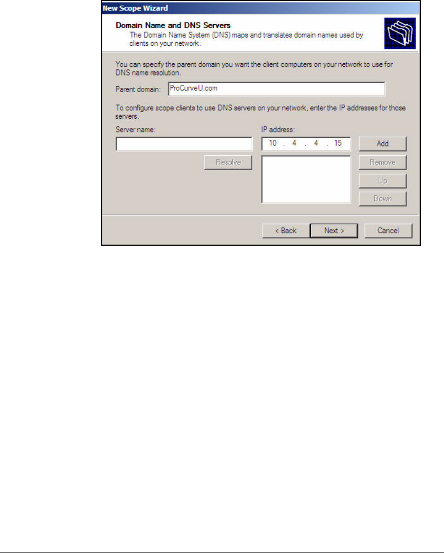
AD-61
Addendum: ProCurve Access Control Solution 2.1 Update
Configuring the DHCP Server
Figure AD-51.New Scope Wizard—Domain Name and DNS Servers Page
18. For Parent domain, type your organization’s domain name. For this exam-
ple, type ProCurveU.com.
19. For IP address, type the IP address of the DNS server and click Add. For
this example, type 10.4.4.15.
Repeat this step to add a secondary DNS server.
20. Click Next.
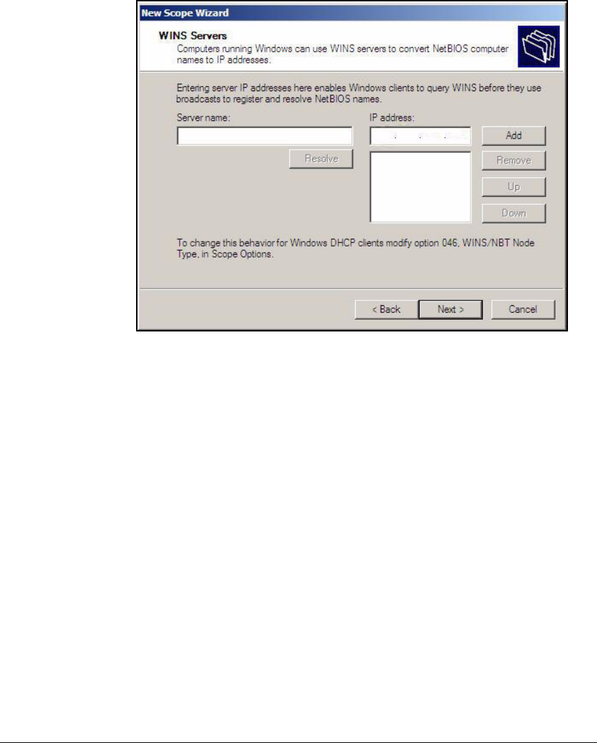
AD-62
Addendum: ProCurve Access Control Solution 2.1 Update
Configuring the DHCP Server
Figure AD-52.New Scope Wizard—WINS Servers Page
21. Type the IP address of your network’s WINS server (if any) in the WINS
server box. Click Add and then click Next. In this example, the network
does not use WINS.
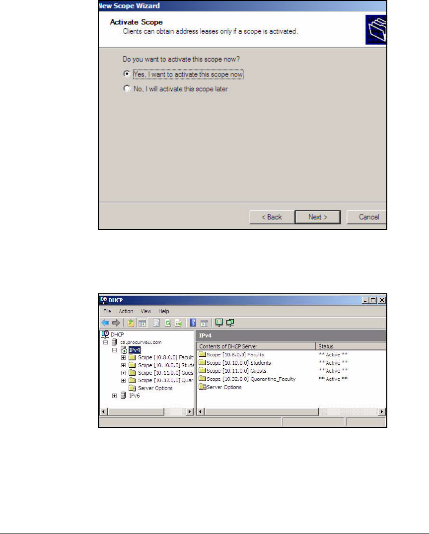
AD-63
Addendum: ProCurve Access Control Solution 2.1 Update
Configuring the DHCP Server
Figure AD-53.New Scope Wizard—Activate Scope Page
22. Select Yes, I want to activate this scope now and click Next.
23. New Scope Wizard—WINS Servers Page
24. Click Finish.
25. Repeat steps 3 to 24 for each scope that your network requires.
26. Close the DHCP Manager window.

AD-64
Addendum: ProCurve Access Control Solution 2.1 Update
Configuring Certificate Services
Configuring Certificate Services
This section describes how to establish a PKI, which issues digital certificates
for your organization’s servers and users. Users can then complete EAP-
Transport Layer Security (TLS) authentication and establish secure commu-
nications with your private servers.
You have several options for your PKI:
■Three tier:
• A root CA, which is the ultimate trusted entity, and for security is kept
offline (standalone)
• Multiple intermediate CAs, which receive certificates from the root
CA and issue certificates to issuing CAs; typically kept offline as well
• Multiple issuing CAs, which are online (enterprise) and which issue
certificates to servers, endpoints, and end-users
■Two tier:
•A standalone root CA
•Multiple issuing enterprise CAs
■One tier:
• A root CA, which also issues certificates to servers, endpoints, and
end-users; must be kept online (enterprise root CA)
A multi-tiered approach offers higher security but requires a more complex
deployment.
This guide provides the steps for deploying a PKI using the one-tier approach.
Certificate services run on a Windows Server 2008 server that is an online
member of the Windows domain but is not a domain controller.
This section provides steps for:
■Joining a server to a domain
■Installing Internet Information Services (IIS) on Windows Server 2008
■Installing certificate services on Windows Server 2008
■Exporting the CA root certificate
A subsequent section explains how to create a certificate request on the
Wireless Edge Services Module. At that point, the guide explains how to
submit the request to your domain CA and generate the server certificate. See
“Obtain a Server Certificate for the Wireless Module” on page AD-145.
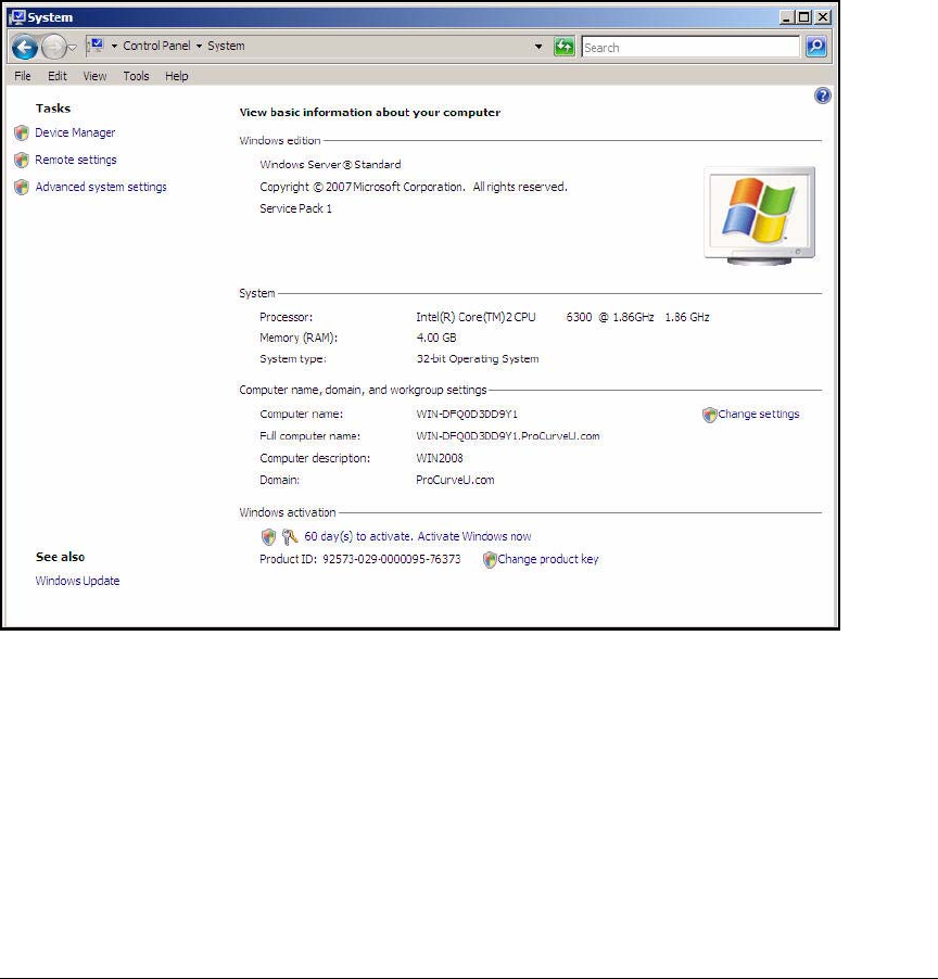
AD-65
Addendum: ProCurve Access Control Solution 2.1 Update
Configuring Certificate Services
Join the Windows Server 2008 Server to the Domain
This solution calls for an enterprise CA server, which must be a member of
the domain. Follow these steps to join the server to the domain:
1. On the server that you selected to run CA services, click Start > Control
Panel > System.
Figure AD-54.Windows Server 2008—Control Panel > System Window
2. Under Computer name, domain, and workgroup settings, click the Change
settings.The Computer Name tab is selected.
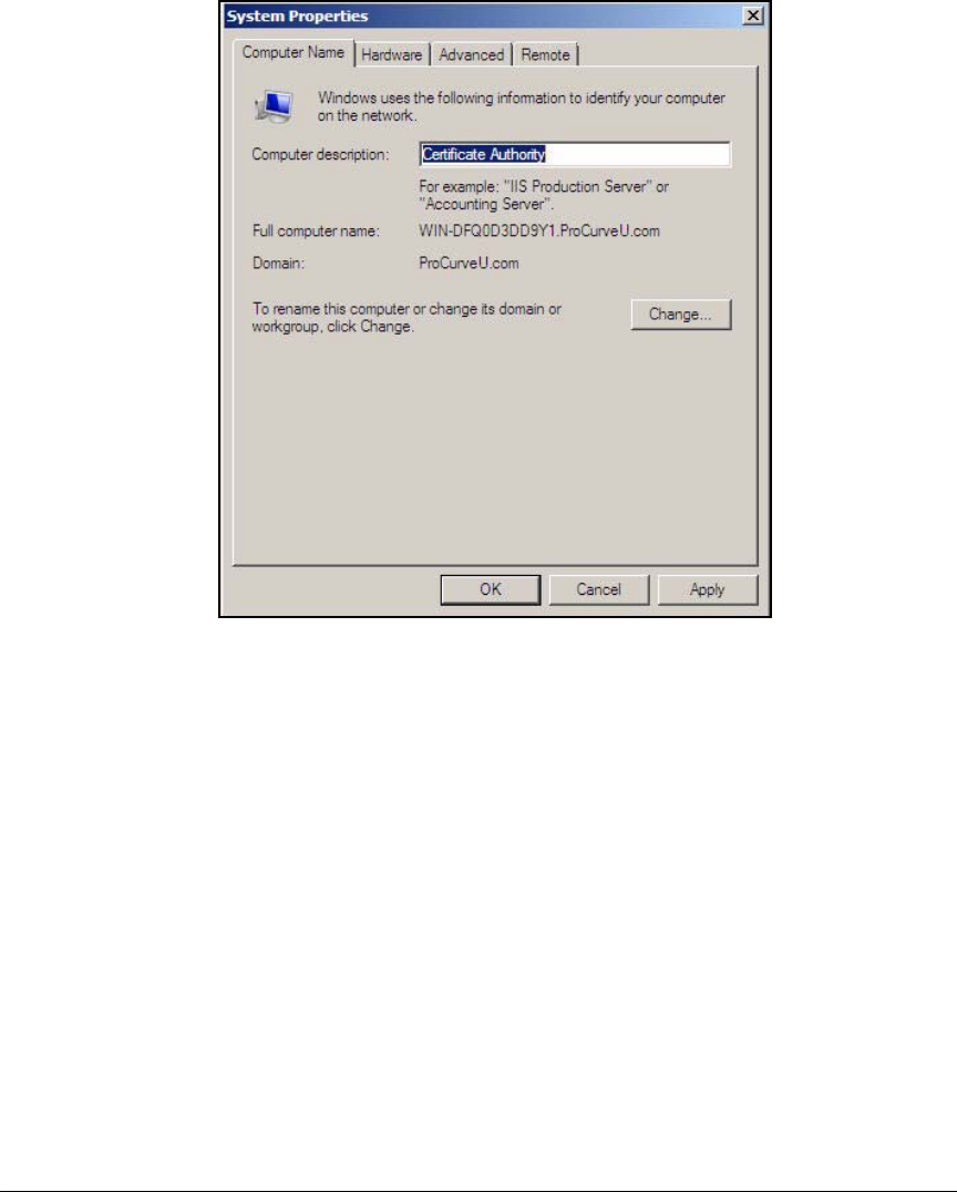
AD-66
Addendum: ProCurve Access Control Solution 2.1 Update
Configuring Certificate Services
Figure AD-55.Windows Server 2008—System Properties >
Computer Name Tab
3. In the Computer description field, type a meaningful description for your
server. In this example, type Certificate Authority.
4. Click Change.
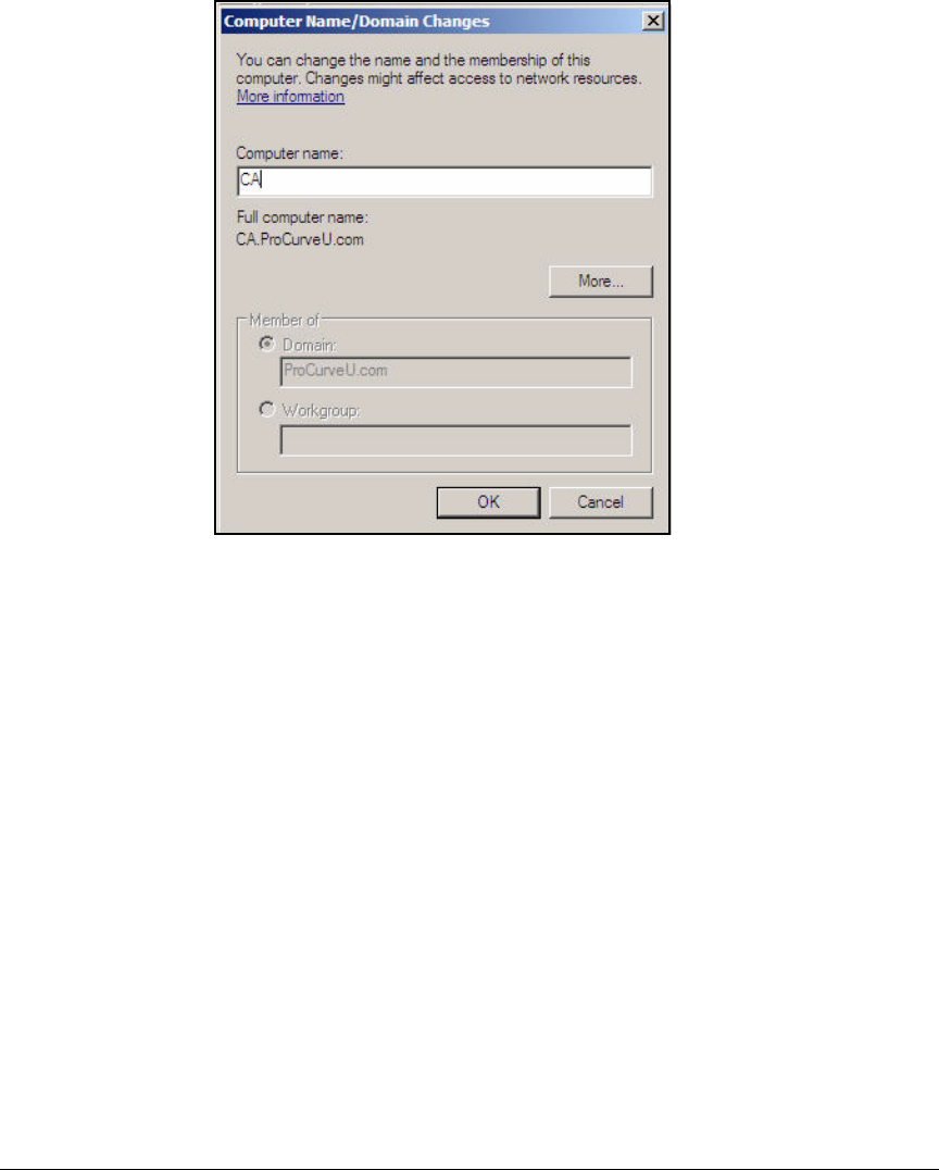
AD-67
Addendum: ProCurve Access Control Solution 2.1 Update
Configuring Certificate Services
Figure AD-56.Windows Server 2008—Computer
Name/Domain Changes Window
5. Type a meaningful name for the Computer name. In this example: CA.
6. Click OK. A window is displayed that tells you that you must restart your
computer before any changes will take place. Click OK.
7. Click Close in the System Properties window. A window is displayed which
reminds you that no changes will take place until you restart the computer.
8. Click Restart Now.
Install IIS and the Certificate Services
If the CA server runs IIS and ASP, it can present users with Web pages to help
them enroll for certificates. The Web enrollment pages are located at <CA
server IP address>/certsrv. Note that ASP can open security vulnerabilities,
so you might chose not to use this feature.
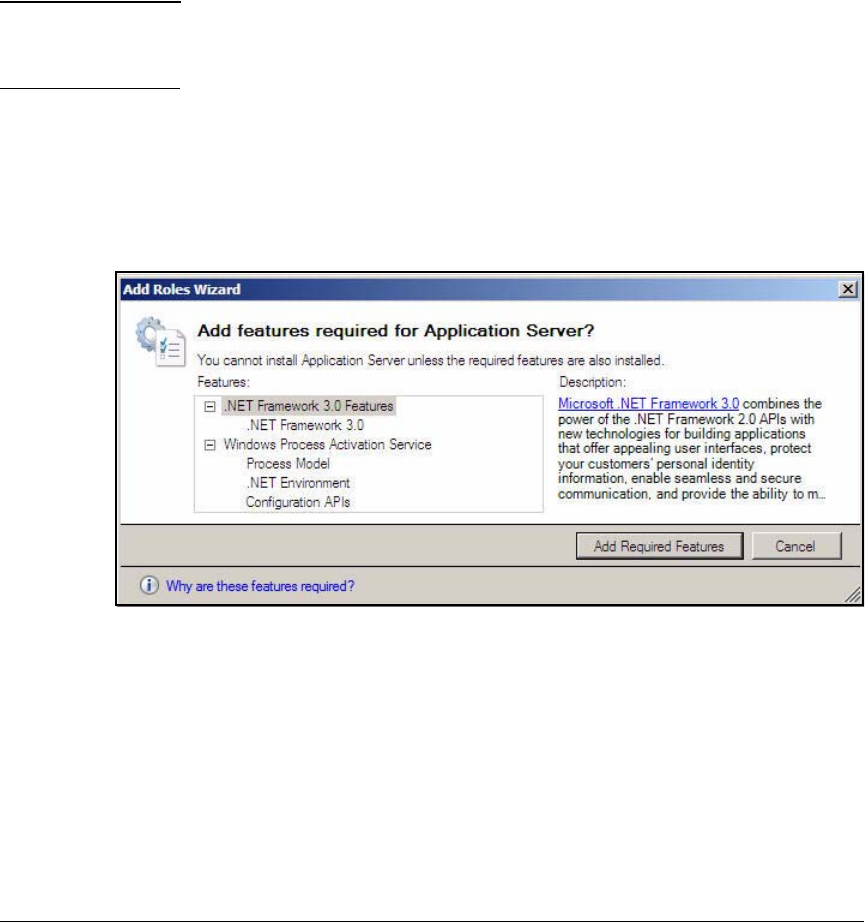
AD-68
Addendum: ProCurve Access Control Solution 2.1 Update
Configuring Certificate Services
All IIS services are not necessary. You must install:
■Application Server Foundation
■Web Server (IIS) Support
■HTTP Activation
You will install the Certificate Services at the same time as you install IIS.
Note Installing Certificate Services binds the server to its current name and domain.
Before completing the steps below, you must join the server to the domain as
described in the previous section.
Follow these steps to install the IIS on the Windows Server 2008:
1. Access the Add Roles Wizard. See step 2 on page AD-21.
2. Select the Application Server check box. A window is displayed which
offers you the required features for this role.
Figure AD-57.Add Roles Wizard—Add Required Features Window
3. Click Add Required Features.
4. Select the Web Server (IIS) and Active Directory Certificate Services check
boxes.
5. Click Next.
6. In the Introduction to Application Server page, click Next.
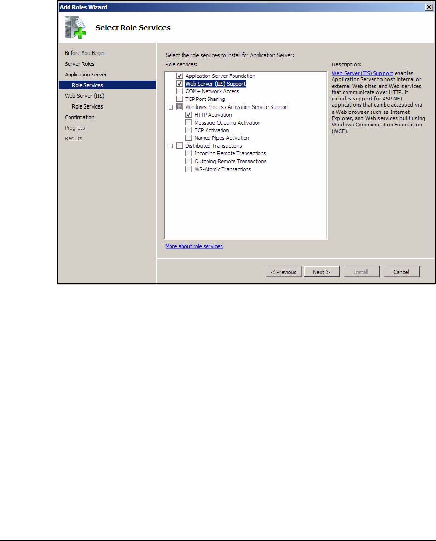
AD-69
Addendum: ProCurve Access Control Solution 2.1 Update
Configuring Certificate Services
Figure AD-58.Add Roles Wizard—Select Role Services Page
7. Select the Web Server (IIS) Support check box.
8. Click Add Required Role Services in the window that is displayed.
9. In the Select Role Services page, verify that these services are selected:
• Application Server Foundation
• Web Server (IIS) Support
• HTTP Activation
10. Click Next.
11. In the Introduction to Active Directory Certificate Services page, click Next.
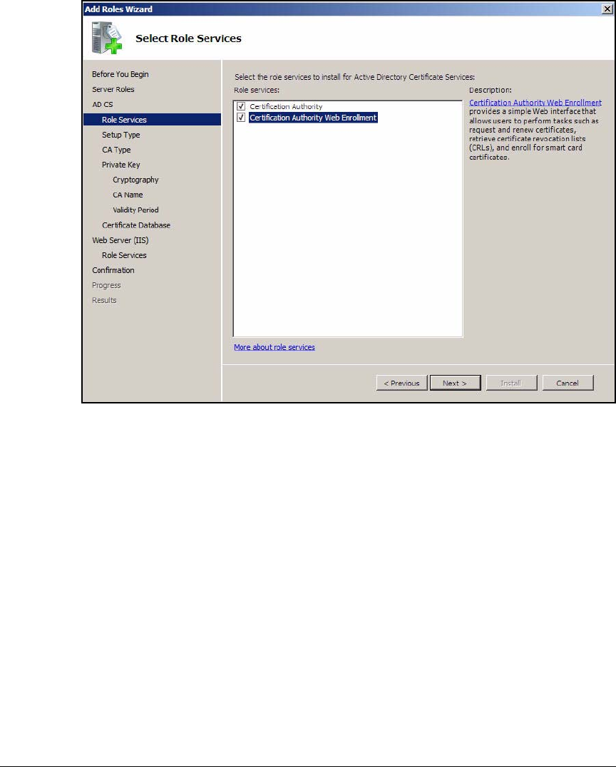
AD-70
Addendum: ProCurve Access Control Solution 2.1 Update
Configuring Certificate Services
Figure AD-59.Add Roles Wizard—Select Role Services Page
12. Select the Certification Authority Web Enrollment check box.
13. In the next window that is displayed, click Add Required Role Services.
14. Click Next.
15. Select the Active Directory Certificate Services check box and click Next.
16. In the Specify Setup Type page, select Enterprise and click Next.
17. In the Specify CA Type page, select Root CA and click Next.
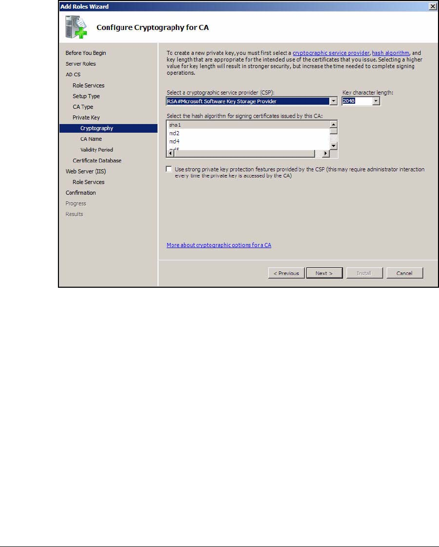
AD-71
Addendum: ProCurve Access Control Solution 2.1 Update
Configuring Certificate Services
Figure AD-60.Add Roles Wizard—Configure Cryptography for CA Page
18. In the Configure Cryptography for CA page, accept the default settings and
click Next.
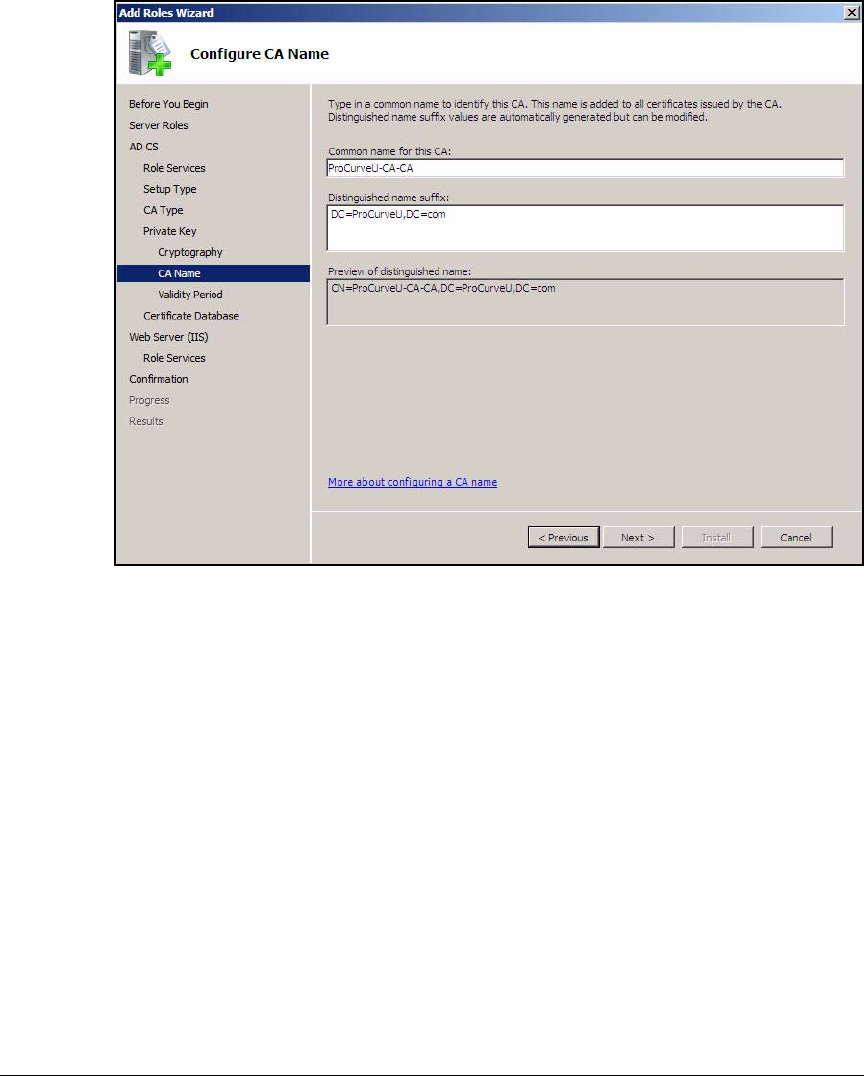
AD-72
Addendum: ProCurve Access Control Solution 2.1 Update
Configuring Certificate Services
Figure AD-61.Add Roles Wizard—Configure CA Name Page
19. In the Configure CA Name page, accept the default settings and click Next.
20. In the Set Validity Period Page, accept the default setting of 5 years and
click Next.
21. In the Introduction to Web Server (IIS) page, click Next.
22. Accept the default role services and click Next.
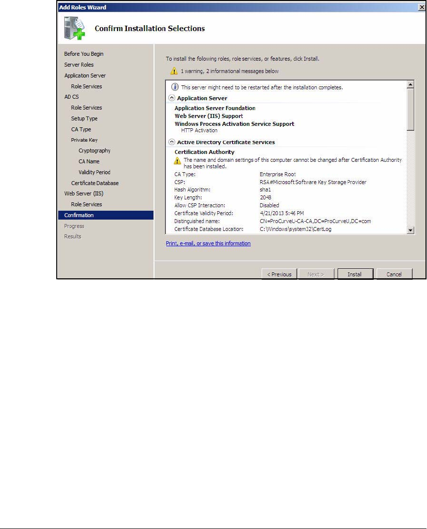
AD-73
Addendum: ProCurve Access Control Solution 2.1 Update
Configuring Certificate Services
Figure AD-62.Add Roles Wizard—Confirm Installation Selections Page
23. Verify that the installation settings are correct. Then click Install.
24. In the Installation Results page, click Close.
Export the CA Root Certificate
Users and computers receive the CA root certificate when they automatically
enroll for their certificates. However, you will need to manually import a
certificate to Wireless Edge Services Modules. The steps below explain how
to export your CA root certificate to a file. See “Obtain a Server Certificate for
the Wireless Module” on page AD-145 for instructions on importing the
certificate to the Wireless Edge Services Modules.
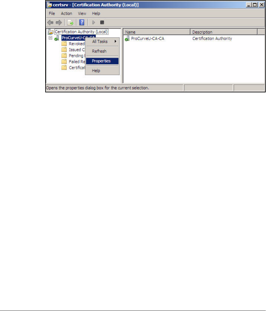
AD-74
Addendum: ProCurve Access Control Solution 2.1 Update
Configuring Certificate Services
1. From the Start menu of the CA server, click Administrative Tools > Certifi-
cate Authority.
Figure AD-63.Windows Server 2008—Certification Authority (Local) Window
2. Expand Certification Authority.
3. Right-click the CA server name and click Properties.
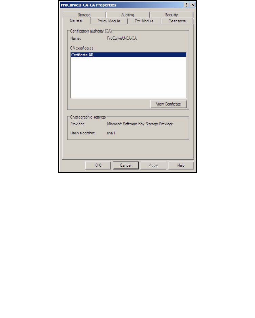
AD-75
Addendum: ProCurve Access Control Solution 2.1 Update
Configuring Certificate Services
Figure AD-64.Windows Server 2008 Management Console—
<MyCA> Properties Window
4. At the General tab, click View Certificate.
5. Click the Details tab.
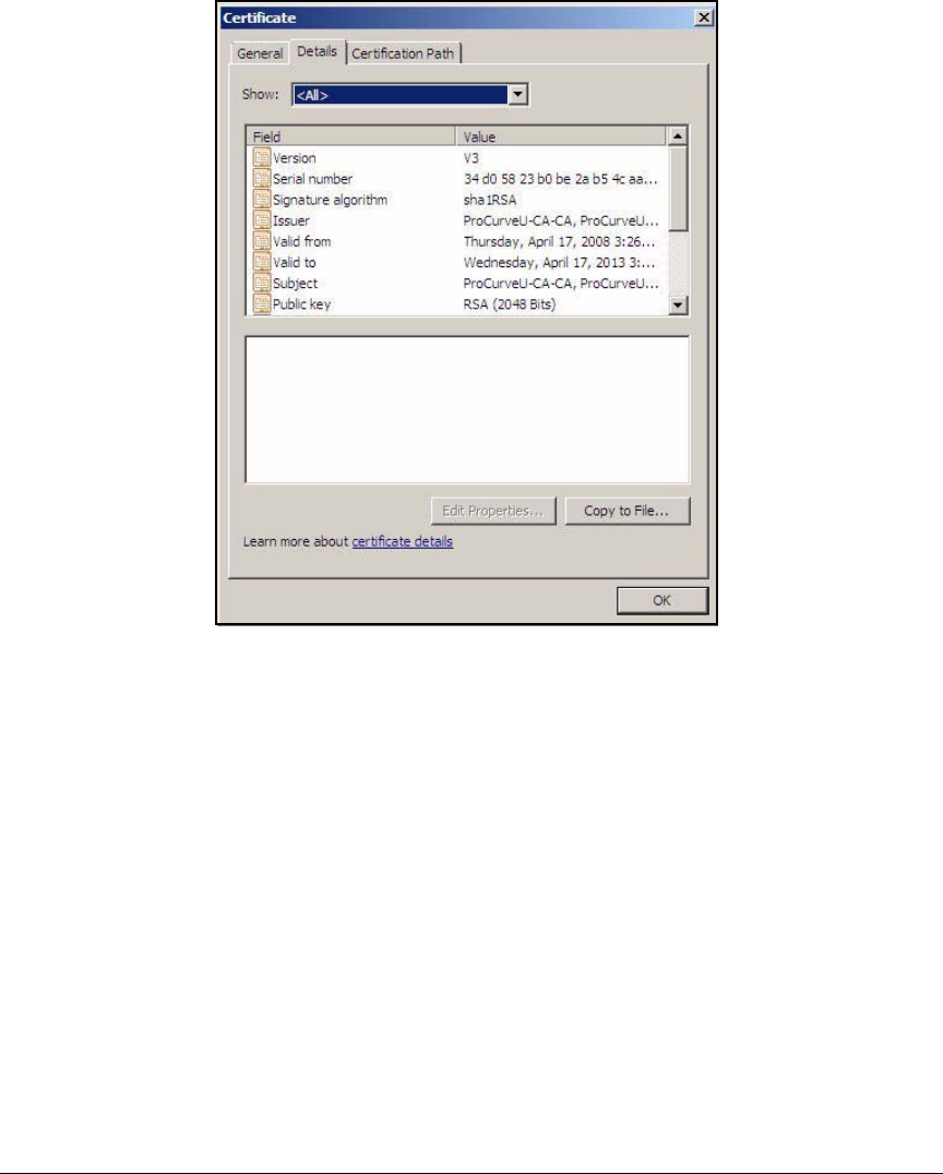
AD-76
Addendum: ProCurve Access Control Solution 2.1 Update
Configuring Certificate Services
Figure AD-65.Windows Server 2008—<MyCA> Properties >
Details Window
6. Click Copy to File. The Certificate Export Wizard is displayed.
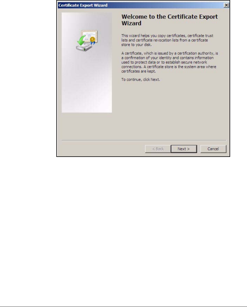
AD-77
Addendum: ProCurve Access Control Solution 2.1 Update
Configuring Certificate Services
Figure AD-66.Certificate Export Wizard—Welcome Page
7. Click Next.
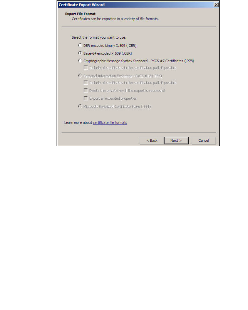
AD-78
Addendum: ProCurve Access Control Solution 2.1 Update
Configuring Certificate Services
Figure AD-67.Certificate Export Wizard—Export File Format Page
8. Select a format supported by your devices. In this example, select Base-
64 encoded X.509 (.CER).
9. Click Next.
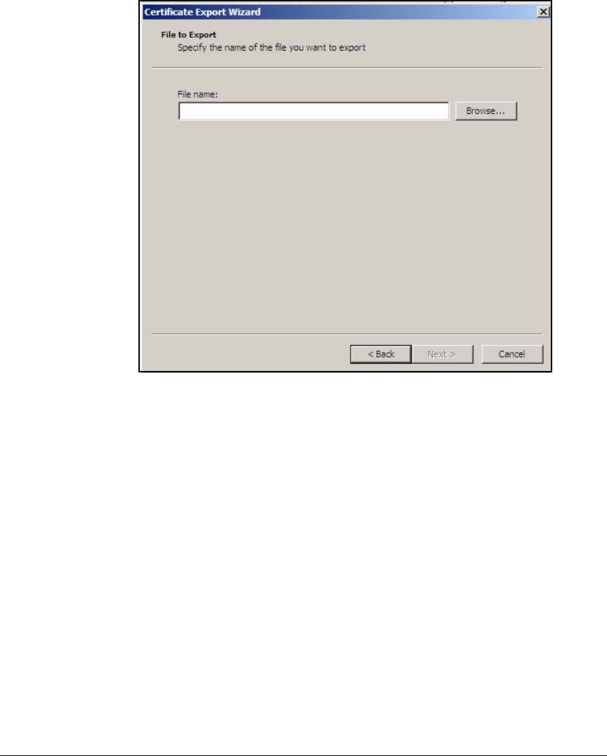
AD-79
Addendum: ProCurve Access Control Solution 2.1 Update
Configuring Certificate Services
Figure AD-68.Certificate Export Wizard—File to Export Page
10. In the File to Export page, specify the filename. Either:
• Type the name, including the path, in the File name box (for example,
C:\Certs\procurve_ca_cert).
• Browse for the folder in which the certificate should be saved:
i. Click Browse.
ii. Navigate to the desired folder.
iii. Navigate to the location where you want to save the CA root
certificate.
iv. For File name, type a name for the certificate (for example,
procurve_ca_cert).
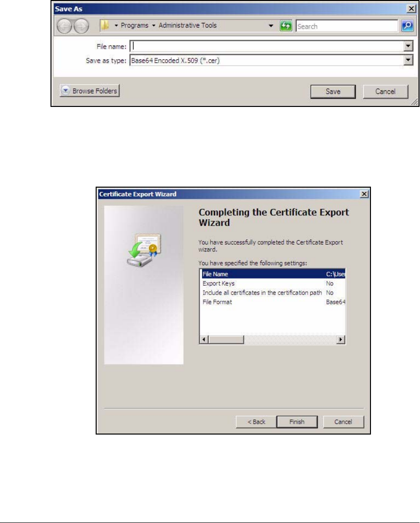
AD-80
Addendum: ProCurve Access Control Solution 2.1 Update
Configuring Certificate Services
.
Figure AD-69.Certificate Export Wizard—Save As Window
v. Click Save.
11. On the File to Export page, click Next.
.
Figure AD-70.Certificate Export Wizard—Saving the CA Root Certificate Page
12. Check the information displayed in the Completing the Certificate Export
Wizard page. If it is correct, click Finish.

AD-81
Addendum: ProCurve Access Control Solution 2.1 Update
Configuring Certificate Services
.
Figure AD-71.Certificate Export Wizard Window
13. Click OK.
14. Click OK in the Certificate Details and <MyCA> Properties windows.
15. Press [Alt]+[F4] to close the Certification Authority (Local) window.

AD-82
Addendum: ProCurve Access Control Solution 2.1 Update
Configuring the NPS Server
Configuring the NPS Server
This section explains how to configure the NPS server, which will provide
RADIUS services for the network. The NPS server will authenticate both wired
and wireless users and computers.
To configure the NPS, you must follow these steps:
1. Install Windows Server 2008.
See “Installing Windows Server 2008” on page AD-9.
2. Set the time.
See “Set the Time Zone” on page AD-16.
3. Set the static IP settings.
See “Set Static IP Settings” on page AD-18.
Use these settings:
•IPv4
– IP address: 10.4.4.16
– Subnet mask: 255.255.0.0
– Default gateway: 10.4.0.1
– Preferred DNS server: 10.4.4.15
•IPv6
– IP address: 2001:db8::3
– Subnet prefix length: 32
– Default gateway: 2001:db8::1
– Preferred DNS server: 2001:db8::2
4. Join the server to the ProCurveU.com domain.
See “Join the Server to the Domain” on page AD-83.
5. Install the NPS server role.
See “Install the NPS Server Role” on page AD-86.
6. Install the Group Policy Management role.
See “Install the Group Policy Management Feature” on page AD-87.
7. Obtain a computer certificate for the NPS server.
See “Obtain a Computer Certificate on the NPS Server” on page AD-90.
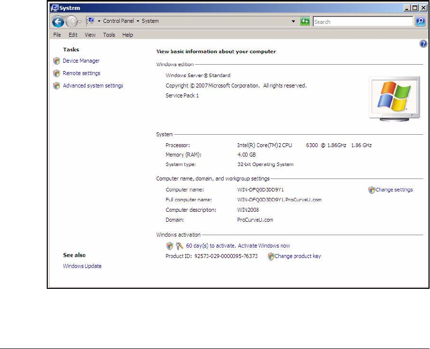
AD-83
Addendum: ProCurve Access Control Solution 2.1 Update
Configuring the NPS Server
8. Configure the NPS policies.
See “Configure 802.1X NAP Enforcement Using the NAP Configuration
Wizard” on page AD-94.
9. Configure System Health Validators (SHVs).
See “Configure System Health Validators (SHVs)” on page AD-106.
10. Configure NAP client settings in a group policy.
See “Configure NAP Client Settings in Group Policy” on page AD-110.
Join the Server to the Domain
1. On the server that you selected to run NAP services, click Start > Control
Panel > System.
Figure AD-72.Windows Server 2008—Control Panel > System Window
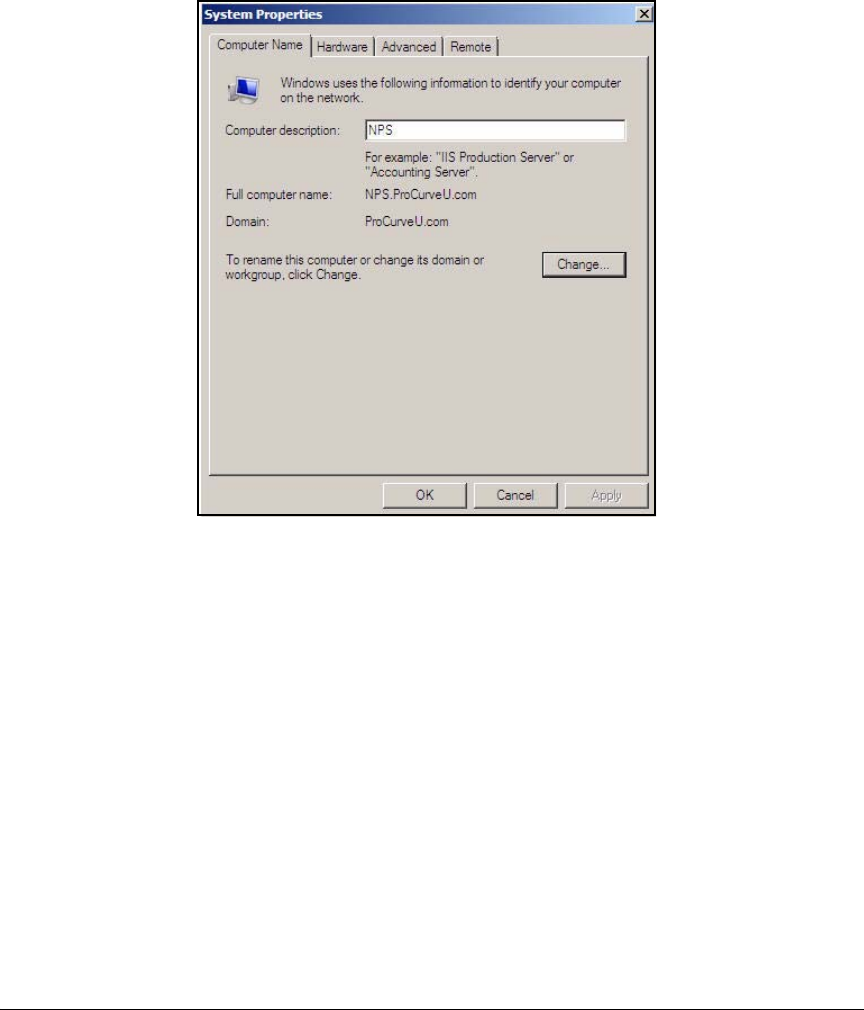
AD-84
Addendum: ProCurve Access Control Solution 2.1 Update
Configuring the NPS Server
2. Under Computer name, domain, and workgroup settings, click the Change
settings.The Computer Name tab is selected.
Figure AD-73.NPS Server—System Properties Window
3. In the Computer description field, type a meaningful name for your server.
In this example, type NPS.
4. Click Change.
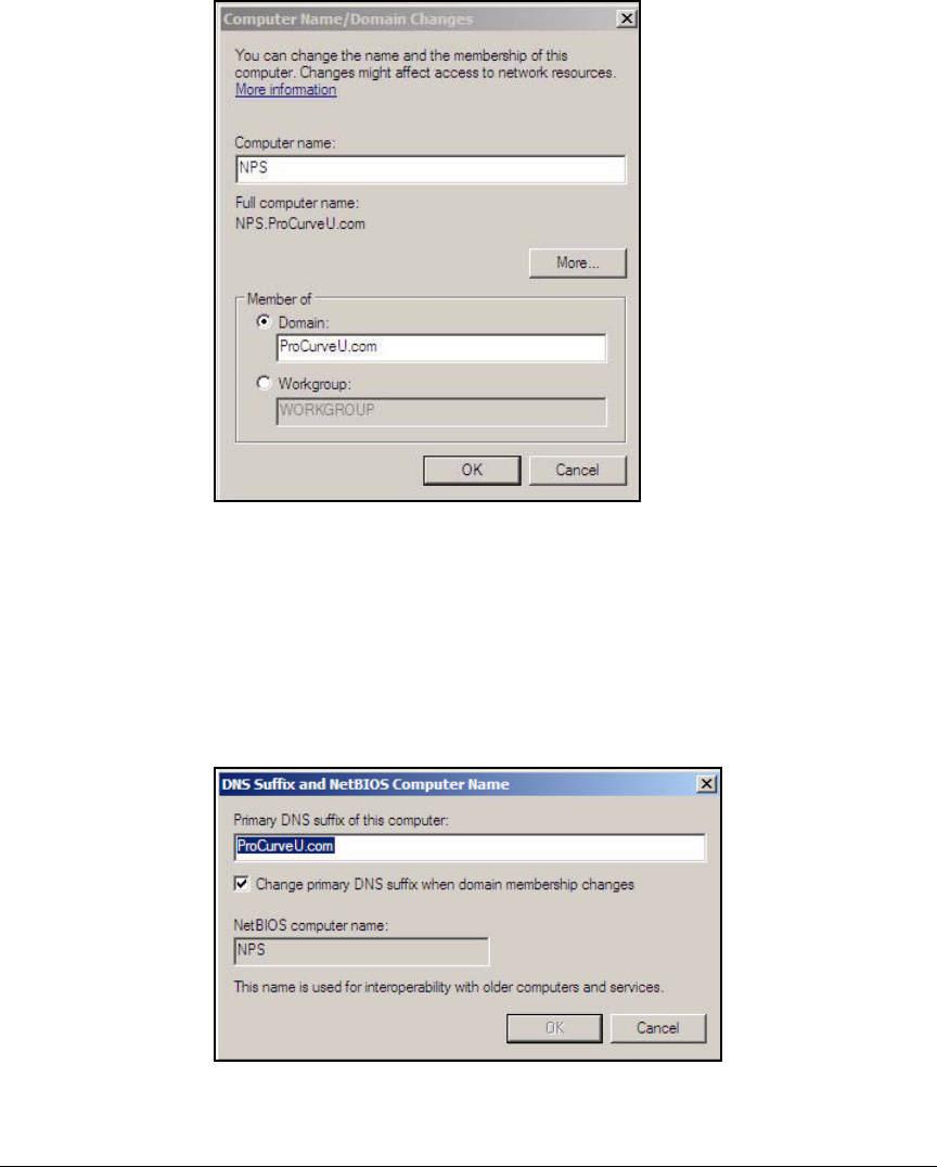
AD-85
Addendum: ProCurve Access Control Solution 2.1 Update
Configuring the NPS Server
Figure AD-74.NPS Server—Computer Name/Domain
Changes Window
5. In the Computer name field, type a name for your server. In this example,
type NPS.
6. Under Member of, select Domain.
7. For Domain, type ProCurveU.com. Click More.
Figure AD-75.NPS Server—DNS Suffix and NetBIOS Computer
Name Window

AD-86
Addendum: ProCurve Access Control Solution 2.1 Update
Configuring the NPS Server
8. For Primary DNS suffix of this computer, type the name of your domain. In
this example, type ProCurveU.com.
9. Select Change primary DNS suffix when domain membership changes.
10. Click OK to return to the Computer Name/Domain Changes window.
11. Click OK. A warning telling you that you must restart your computer before
your changes can take place is displayed. Click OK.
12. A window should be displayed, welcoming you to the domain.
13. Click Close. A window is displayed, informing you that must restart your
computer before your changes can take place.
14. Click Restart Now.
Install the NPS Server Role
You will now install the NPS server role. Follow these steps.
1. Access the Add Roles Wizard. There are two ways to access the wizard:
•From the Initial Configuration Tasks window, complete this step:
i. Under Customize this Server, click Add Roles.
• From the Server Manager window, complete these steps:
i. Click Start > Administrative Tools > Server Manager. The Server
Manager window is displayed.
ii. In the left pane, click Roles.
iii. In the right pane, click Add Roles.
2. In the Select Server Roles page, select the Network Policy and Access
Services check box.
3. Click Next twice.
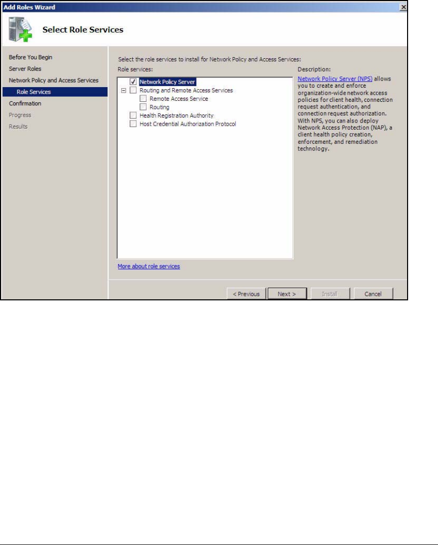
AD-87
Addendum: ProCurve Access Control Solution 2.1 Update
Configuring the NPS Server
Figure AD-76.Add Roles Wizard—Select Role Services Page
4. Select the Network Policy Server check box, click Next.
5. In the Confirm Installation Selections page, click Install.
6. In the Installation Results page, click Close to close the Add Roles Wizard
window.
Install the Group Policy Management Feature
Endpoints that are running the following operating systems include the NAP
agent, which is necessary for connecting to a network that enforces NAC with
Microsoft NAP:
■Windows Vista
■Windows XP SP3
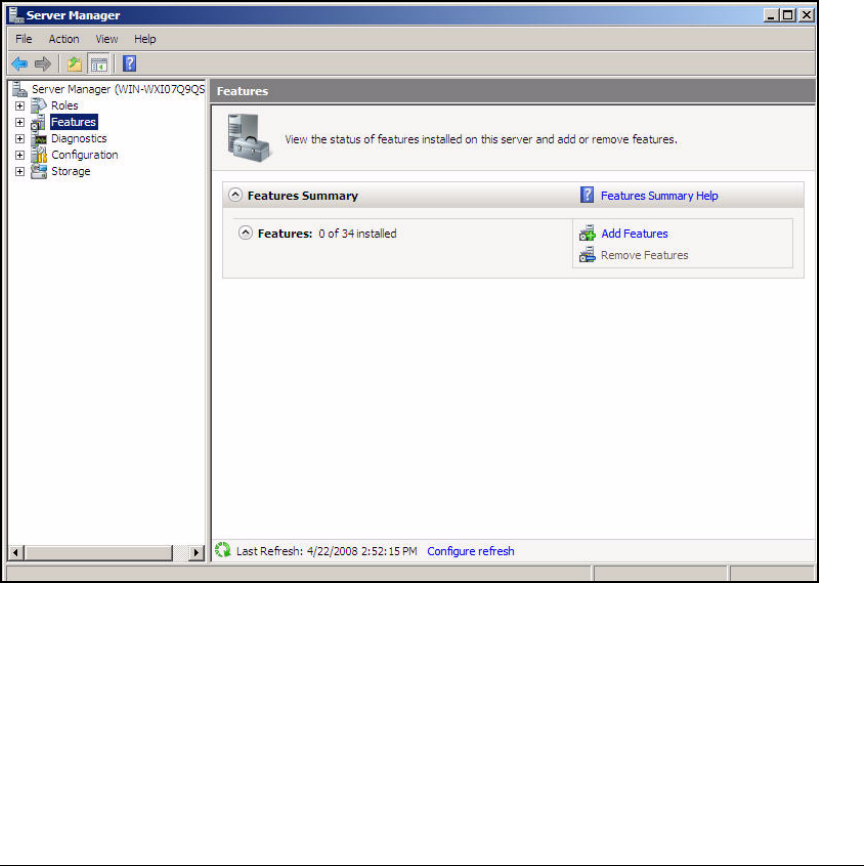
AD-88
Addendum: ProCurve Access Control Solution 2.1 Update
Configuring the NPS Server
Although the endpoints include the NAP agent by default, you might need to
configure several settings to ensure that the endpoint can connect success-
fully. The next section explains how to use a Group Policy to configure NAP
client settings on all endpoints in the domain. To do so, you must first install
the Group Policy Management feature on the NPS server. Follow these steps:
1. In the Start menu, click Administrative Tools > Server Manager.
2. In the right pane of the Server Manager window, click Features.
Figure AD-77.NPS Server—Server Manager > Features
3. Under Feature Summary, click Add Features.
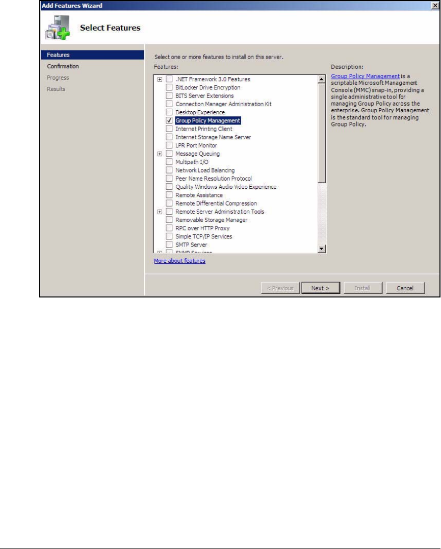
AD-89
Addendum: ProCurve Access Control Solution 2.1 Update
Configuring the NPS Server
Figure AD-78.Add Features Wizard—Select Features
4. In the Select Features page, select the Group Policy Management check box.
5. Click Next.
6. In the Confirm Installation Selections page, click Install.
7. After the feature has been installed, click Close to close the Add Features
Wizard dialog box.
8. Close the Server Manager window.
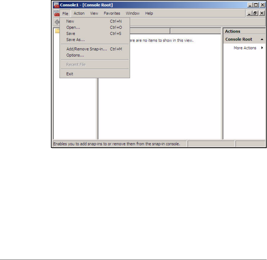
AD-90
Addendum: ProCurve Access Control Solution 2.1 Update
Configuring the NPS Server
Obtain a Computer Certificate on the NPS Server
In this solution, the NPS server authenticates users using PEAP with
MSCHAPv2. This EAP method requires the server to authenticate to clients
with a digital certificate, which is stored in the server’s local computer certifi-
cate store. Follow these steps to obtain a certificate from your domain CA:
1. Click Start > Run.
2. Type mmc at the prompt and click OK.
Figure AD-79.NPS Server—Consol1 Window
3. In the File menu, click Add/Remove Snap-in.
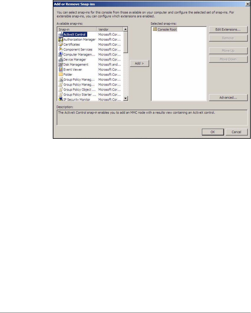
AD-91
Addendum: ProCurve Access Control Solution 2.1 Update
Configuring the NPS Server
Figure AD-80.NPS Server—Console1 > Add or Remove Snap-ins Window
4. In the Add or Remove Snap-ins window, click Certificates and then click
Add>. The Certificates snap-in window is displayed.
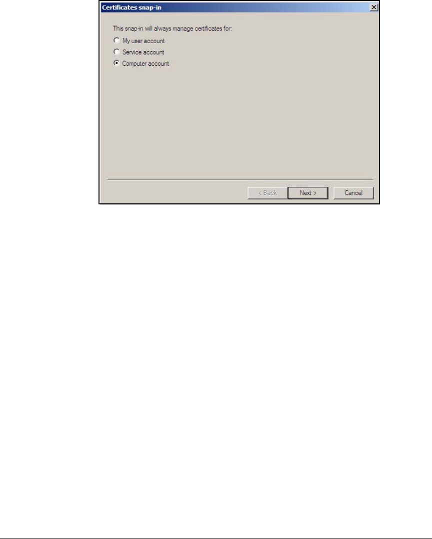
AD-92
Addendum: ProCurve Access Control Solution 2.1 Update
Configuring the NPS Server
Figure AD-81.NPS Server—Console 1 > Add or Remove Snap-ins >
Certificates snap-in Window
5. Select Computer account and click Next.
6. Accept the default setting Local computer (the computer on which this
console is running) and click Finish.
7. Certificates (Local Computer) is now displayed below Selected snap-ins.
Click OK to close the Add or Remove Snap-ins window.
8. In the left pane of the Console1 window, double-click Certificates (Local
Computer).
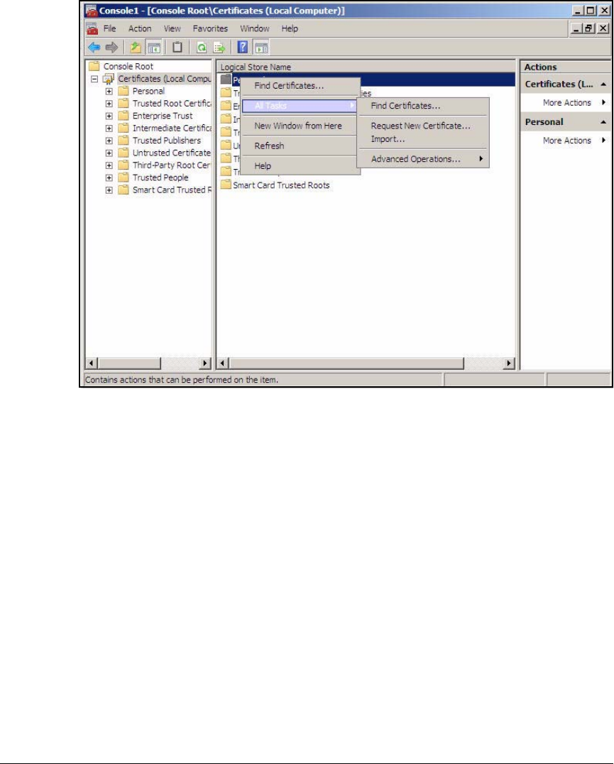
AD-93
Addendum: ProCurve Access Control Solution 2.1 Update
Configuring the NPS Server
Figure AD-82.NPS Server—Console1 Window
9. In the center pane, right-click Personal and click All Tasks > Request New
Certificate. The Certificate Enrollment window is displayed.
10. Click Next.
11. Select the Computer check box and click Enroll.
12. Verify that the status of the certificate installation is Succeeded and click
Finish.
13. Close the Console1 window.
14. Click No when prompted to save console settings.

AD-94
Addendum: ProCurve Access Control Solution 2.1 Update
Configuring the NPS Server
Configure 802.1X NAP Enforcement Using the NAP
Configuration Wizard
The NAP configuration wizard helps you set up the NPS server as a NAP health
policy server. When you select one of the 802.1X options, the wizard also helps
you to set up the NPS server as a RADIUS server. After you run the wizard,
you will have configured the basic policies necessary to control endpoints in
your environment. With the 802.1X deployment option, you will have created
these policies:
■A connection request policy
A connection request policy specifies the type of requests to which the
NPS RADIUS server responds. In this solution, the NPS server authenti-
cates endpoints seeking wired or wireless access. Because the wizard only
allows you to set up one type of access initially, you will edit the policy
after you complete the wizard.
■Three network policies
A network policy specifies the settings for a connection, customizing the
access based on criteria such as the user’s identity and the endpoint’s
health state.
The wizard creates three network policies:
• One policy for compliant endpoints
• One policy for non-compliant endpoints
• One policy for endpoints that are not NAP-capable and cannot be
tested
In this solution, you will leave the network policies empty. IDM will
manage policies for access rights.
■Two health policies
Health policies define compliance and non-compliance:
• One health policy defines compliant endpoints
This policy specifies that endpoints that meet the requirements of all
selected SHVs are compliant.
• One health policy defines non-compliant endpoints
This policy specifies that endpoints that fail to meet one or more of
the requirements of any of the selected SHVs are non-compliant.
You will configure SHVs a bit later.
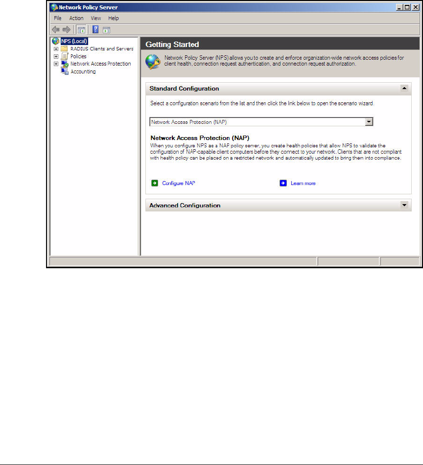
AD-95
Addendum: ProCurve Access Control Solution 2.1 Update
Configuring the NPS Server
You can access the NAP configuration wizard from the NPS console. To use
the wizard to configure NAP, follow these steps:
1. On your NPS server, click Start > Administrative Tools > Network Policy
Server.
Figure AD-83.NPS Server—Network Policy Server Window
2. In the left pane of the Network Policy Server window, click NPS (Local).
3. In the right pane, under Standard Configuration, click Configure NAP. The
Configure NAP Wizard is displayed.
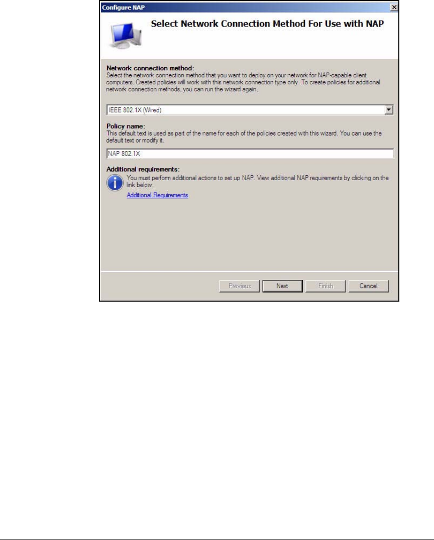
AD-96
Addendum: ProCurve Access Control Solution 2.1 Update
Configuring the NPS Server
Figure AD-84.Configure NAP Wizard—Select Network Connection Method
For Use with NAP Page
4. From the Network connection method list, select IEEE 802.1X (Wired).
5. Under Policy name, type a descriptive name for your policy. For example,
if you plan to expand the policy to include wireless users, alter the name
to reflect that plan. In this example, type NAP 802.1X and click Next.
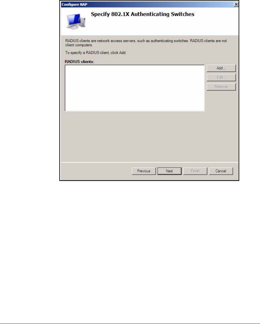
AD-97
Addendum: ProCurve Access Control Solution 2.1 Update
Configuring the NPS Server
Figure AD-85.Configure NAP Wizard—Specify the 802.1X Authenticating
Switches Page
6. In the Specify 802.1X Authenticating Switches page, click Add.
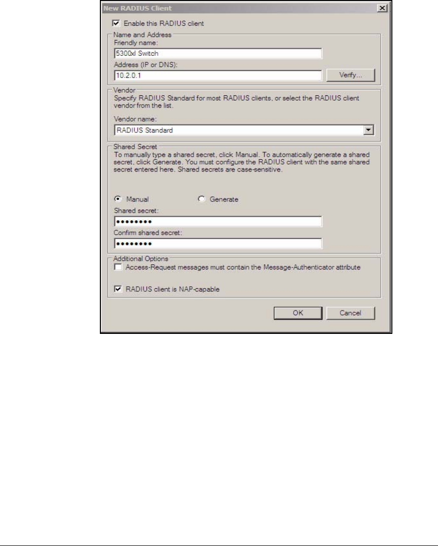
AD-98
Addendum: ProCurve Access Control Solution 2.1 Update
Configuring the NPS Server
Figure AD-86.Configure NAP Wizard—Specify the 802.1X Authenticating
Switches Page > New RADIUS Client Window
7. For Friendly name, type a descriptive name for a device that offers network
access such as a switch, AP, or Wireless Edge Services Module. In this
example, type Wireless Module.
At this point, the wizard is configuring the NPS server to respond only to
requests for wired access. However, you plan to add wireless access, so
you add the wireless RADIUS clients as well.
8. For Address (IP or DNS), type the IP address or resolvable DNS name of the
switch, AP, or Wireless Module. In this example, type 10.2.0.20.
9. Under Shared Secret, accept the default selection, Manual.
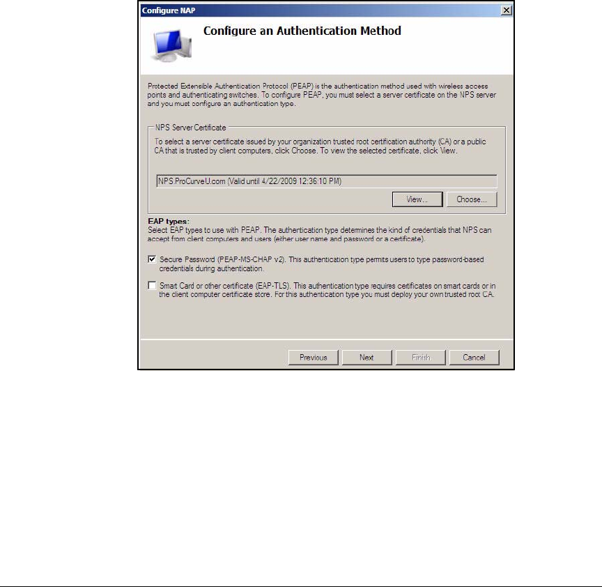
AD-99
Addendum: ProCurve Access Control Solution 2.1 Update
Configuring the NPS Server
10. In the Shared secret and Confirm the shared secret fields, type the shared
secret that you configured on the device. In this example, type procurve.
11. Select the RADIUS client is NAP-capable check box. This allows the NPS to
send endpoint integrity status to IDM.
12. Click OK to return to the Specify 802.1X Authenticating Switches page.
13. Click Next.
14. In the Configure User Groups and Machine Groups page, click Next.
Figure AD-87.Configure NAP Wizard—Configure an Authentication
Method Page
15. In the Configure an Authentication Method page, accept the default setting
of Secure Password (PEAP-MSCHAP v2) and click Next.
16. The next page allows you to configure dynamic VLAN assignments. For
this solution, do not configure VLANS as part of your Windows policy. You
will use IDM to configure VLANS. Click Next.
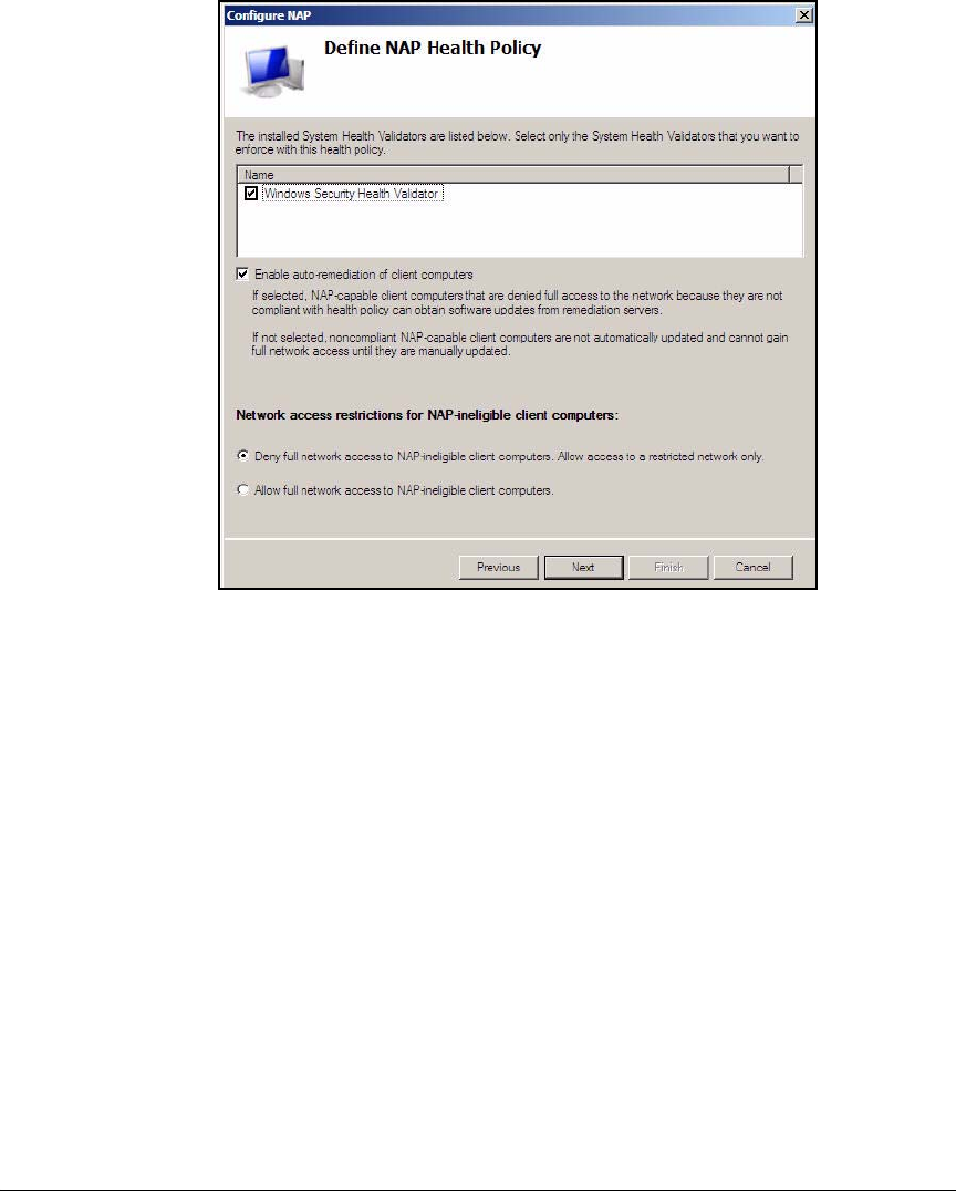
AD-100
Addendum: ProCurve Access Control Solution 2.1 Update
Configuring the NPS Server
Figure AD-88.Configure NAP Wizard—Define NAP Health Policy Page
17. In the Define NAP Health Policy page, verify that Windows Security Health
Validator and Enable auto-remediation of client computers check boxes are
selected. Ensure that the Deny full network access to NAP-ineligible client
computers check box is selected. Click Next.
18. In the Completing NAP Enforcement Policy and RADIUS Client Configuration
page, click Finish.
19. In the left pane of the Network Policy Server window, expand Policies and
click Connection Request Policies.
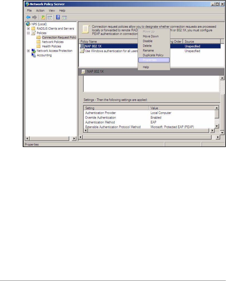
AD-101
Addendum: ProCurve Access Control Solution 2.1 Update
Configuring the NPS Server
Figure AD-89.NPS Server—Network Policy Server Window
20. Verify that the policy that you just created, NAP 802.1X, is listed first. If it
is not, right-click the policy name and click Move Up.
21. Right-click the policy name and click Properties.
22. Click the Conditions tab.
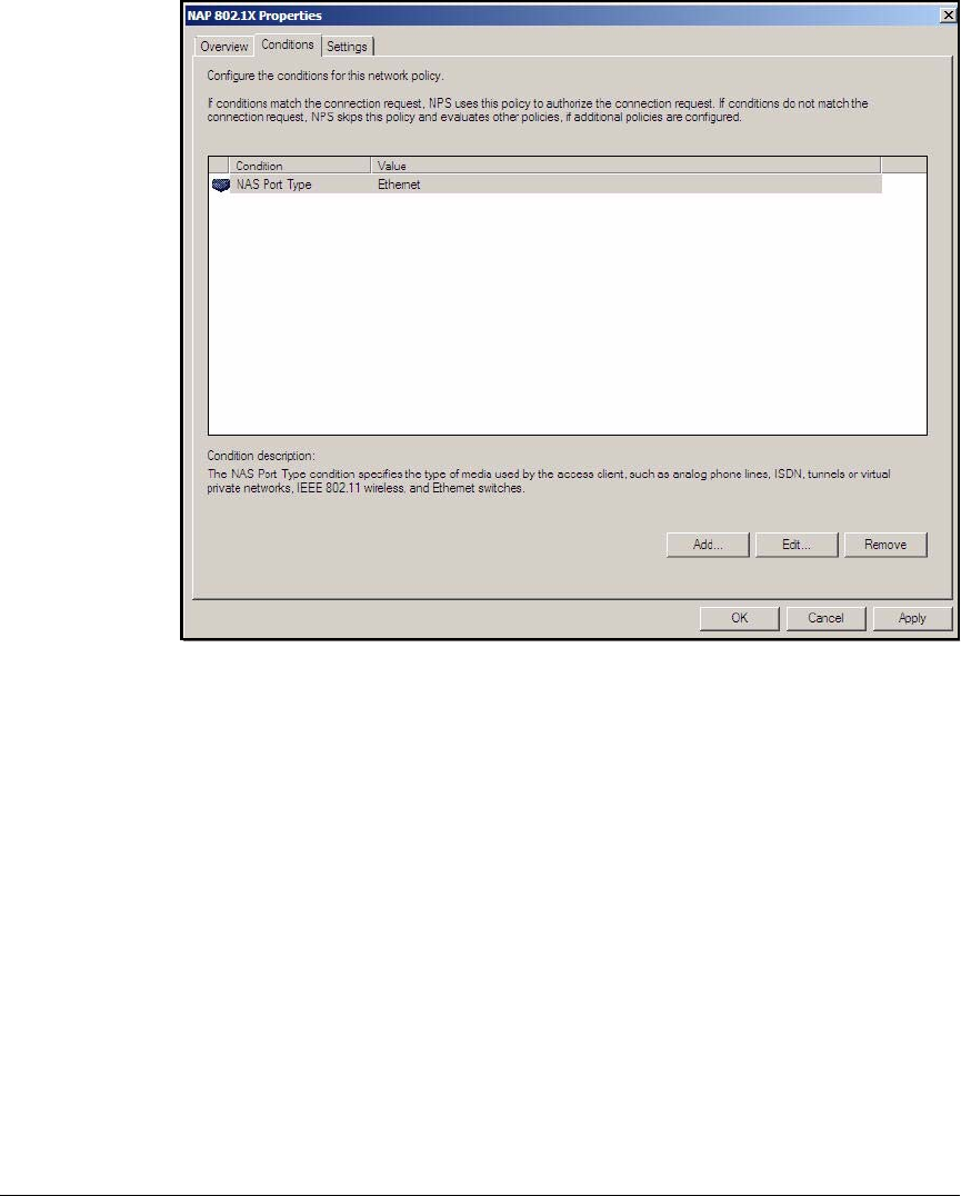
AD-102
Addendum: ProCurve Access Control Solution 2.1 Update
Configuring the NPS Server
Figure AD-90.NPS Server—NAP 802.1X Properties Window
The NAS Port Type condition is displayed.
23. Select NAS Port Type and click Edit.
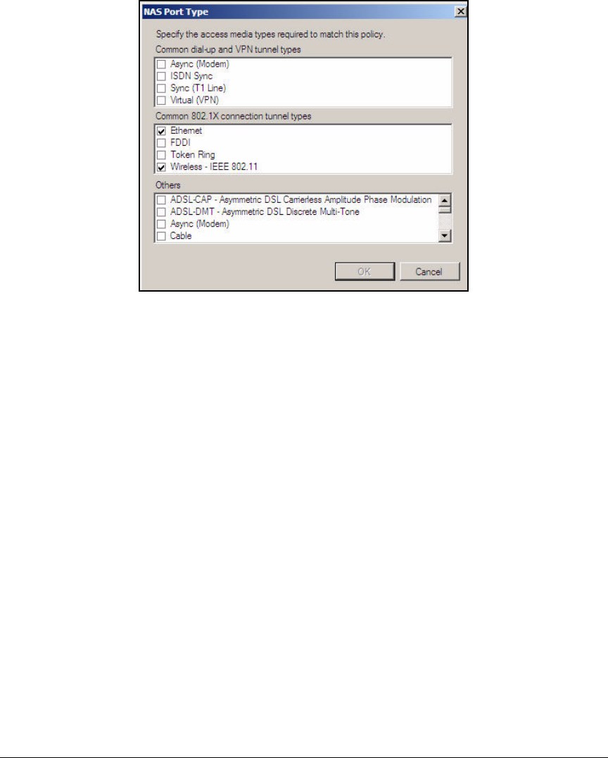
AD-103
Addendum: ProCurve Access Control Solution 2.1 Update
Configuring the NPS Server
Figure AD-91.NPS Server—NAS Port Type Window
24. In the NAS Port Type window, under Common 802.1X connection tunnel types,
select the Wireless - IEEE 802.11 check box. Leave the Ethernet check box
selected.
25. Click OK.
26. Verify that the NAS Port Type condition displays both conditions. The NPS
server will now allow requests that match either of these conditions. In
other words, it will grant network access to authenticated wired and
wireless users.
27. Click OK to close the NAP 802.1X Properties window.
Verify NAP Policies
As discussed previously, the NAP configuration wizard automatically creates
several policies. However, the policies are given a lower priority than default
policies. You must verify that the new policies are enabled and place them in
the correct order. Follow these steps.
1. You should be in the Network Policy Server window. If you are not, click
Start > Administrative Tools > Network Policy Server.
2. In the left pane of the Network Policy Server window, expand Policies, and
then click Connection Request Policies.
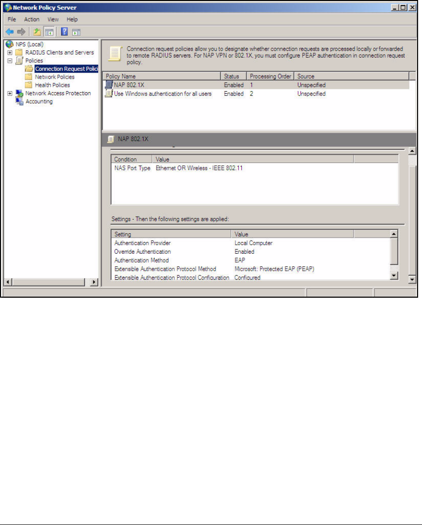
AD-104
Addendum: ProCurve Access Control Solution 2.1 Update
Configuring the NPS Server
Figure AD-92.NPS Server—Netowrk Policy Server > Connection Request Polices
Window
3. The list in the center pane shows the order in which the policies are
processed. The first policy listed is the first policy processed. In the
previous task, you moved the policy that you created to the top of the list,
as shown in Figure AD-92. Also check the Status column; verify that the
status of your policy is Enabled.
4. In the left pane of the Network Policy Server window, click Network
Policies.
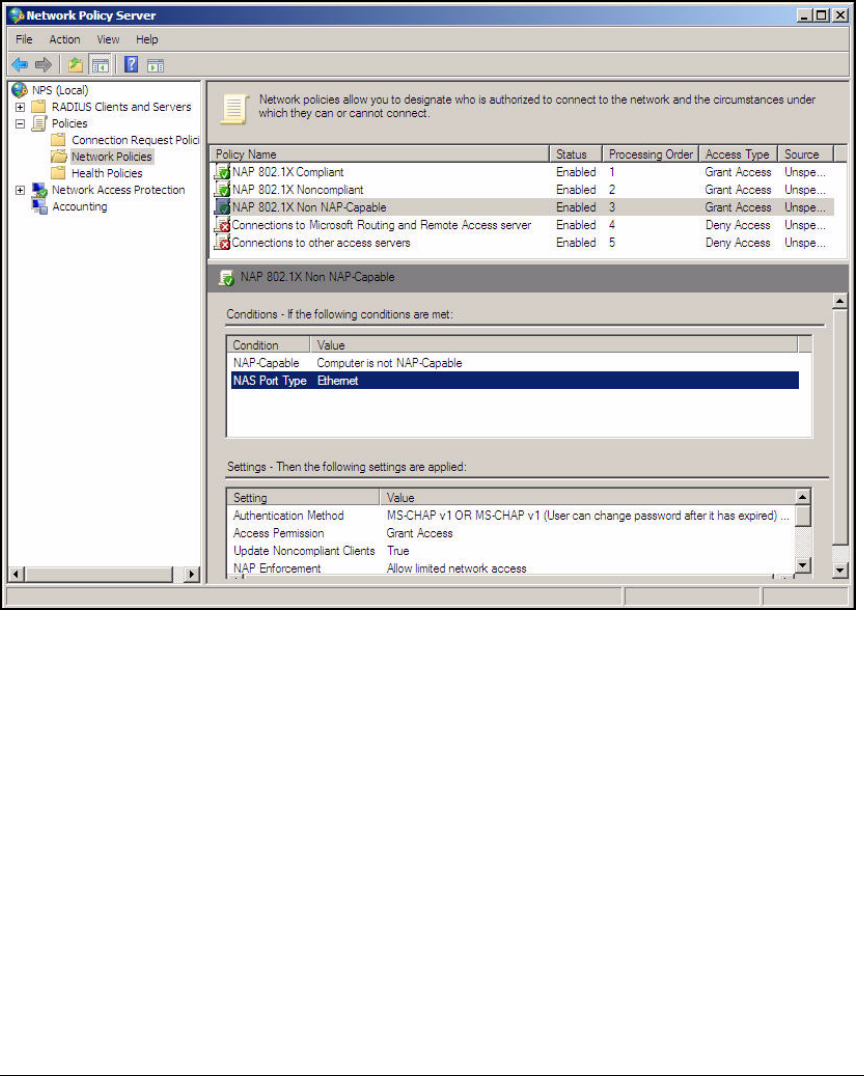
AD-105
Addendum: ProCurve Access Control Solution 2.1 Update
Configuring the NPS Server
Figure AD-93.NPS Server—Network Policy Server > Policies > Network Policies
Window
5. Again verify that the network policies that you created are listed first and
that the status of these policies is Enabled. The NAP configuration wizard
assigns the three network policies these default names:
•<policy name> Compliant
•<policy name> Noncompliant
•<policy name> Non NAP-Capable
If you need to change the order of a policy, right-click the policy and click
Move Up.
6. In the left pane of the Network Policy Server window, click Health Policies.
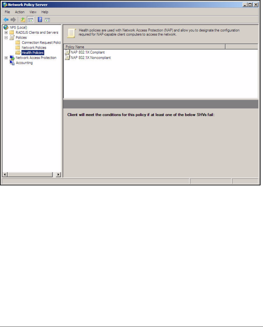
AD-106
Addendum: ProCurve Access Control Solution 2.1 Update
Configuring the NPS Server
Figure AD-94.NPS Server—Network Policy Server > Health Policies Window
7. Verify that two policies were created. These policies should be named:
•<policy name> Compliant
•<policy name> Noncompliant
In a new installation, the policies created by the wizard are the only
policies listed.
Configure System Health Validators (SHVs)
You will now configure an SHV. The SHV defines the tests with which your
NPS server checks endpoints that attempt to authenticate and access the
network. For example, an SHV can include a requirement that the endpoint’s
firewall is enabled.
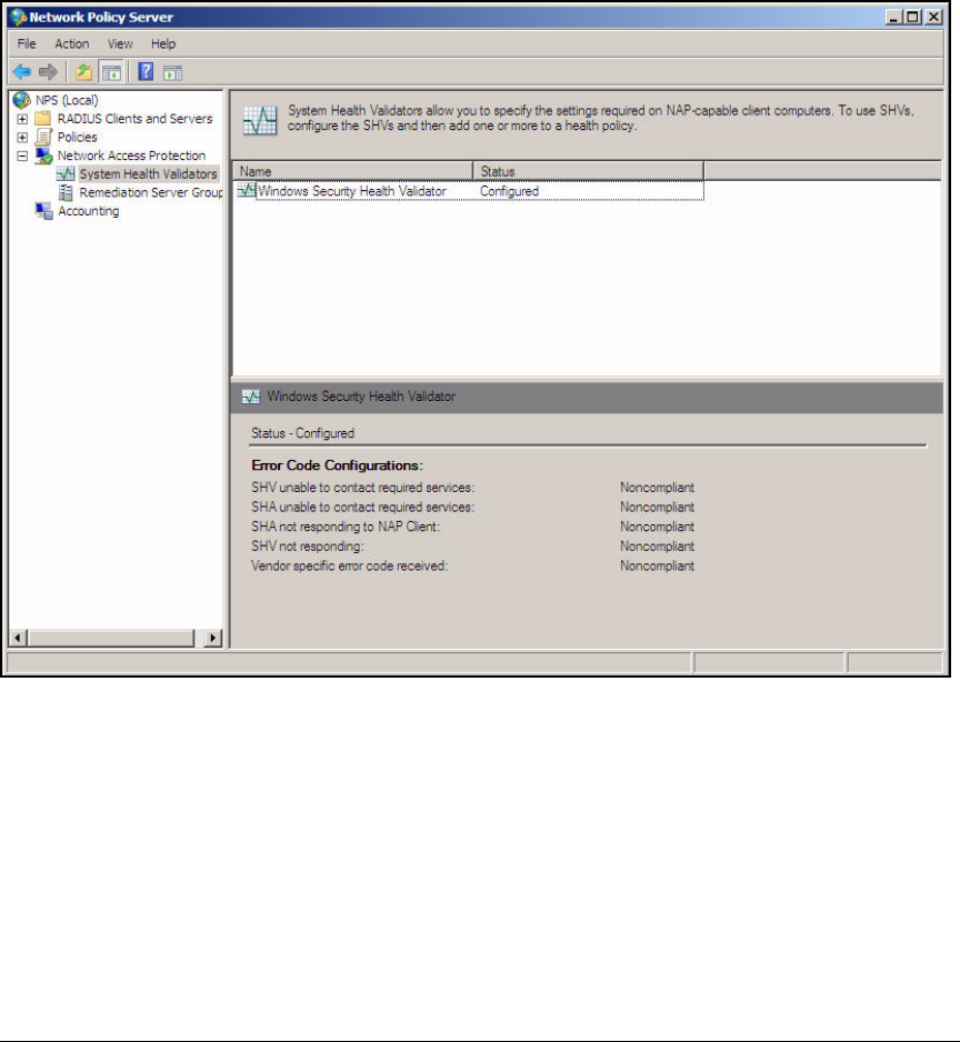
AD-107
Addendum: ProCurve Access Control Solution 2.1 Update
Configuring the NPS Server
Follow these steps to configure a SHV:
1. Access the Network Policy Server window.
2. In the left pane, expand Network Access Protection and click System Health
Validators.
Figure AD-95.NPS Server—Network Policy Server (System Health Validators)
Window
3. In the right pane, right-click Windows Security Health Validator and click
Properties.
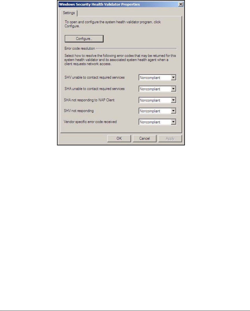
AD-108
Addendum: ProCurve Access Control Solution 2.1 Update
Configuring the NPS Server
Figure AD-96.NPS Server—Windows Security Health
Validator Properties Window
4. In the Windows Security Health Validator Properties window, click Configure.
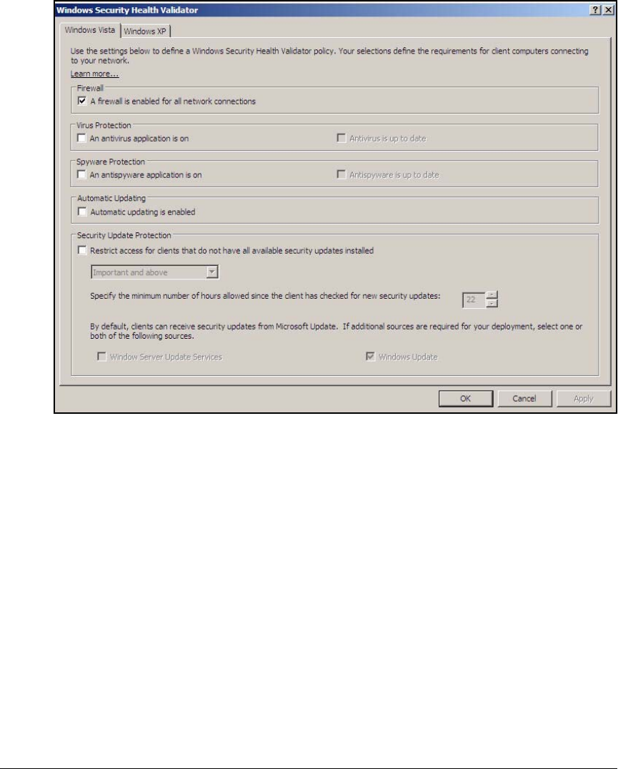
AD-109
Addendum: ProCurve Access Control Solution 2.1 Update
Configuring the NPS Server
Figure AD-97.NPS Server—Windows Security Health Validator Window
5. Click the Windows XP tab and configure requirements for endpoints that
run Windows XP SP3:
a. To require endpoints to use the Windows firewall, select the check
box under Firewall.
b. To require endpoints to run an antivirus application, select the check
box under Virus Protection. To ensure that endpoints are running the
latest software and virus signatures, select Antivirus is up to date.
c. To require endpoints to use Windows Automatic Updates, select the
check box under Automatic Updating.

AD-110
Addendum: ProCurve Access Control Solution 2.1 Update
Configuring the NPS Server
d. To require endpoints to have patches, hotfixes, and other security
updates, select the check box under Security Update Protection.
You can select which updates are required. You can select one of the
following settings:
– Critical only
– Important updates and above
– Moderate and above
– Low and above
–All
The default requirement is for important updates and above.
You can also configure how often the endpoint checks for updates.
The default setting is 22 hours.
In this example, clear all check boxes except the check box under Firewall.
6. Click the Windows Vista tab and configure requirements for endpoints that
run Vista. Follow the same steps as for step 5. Note that there is an
additional option for Vista endpoints: You can require Vista endpoints to
run antisypware.
7. Click OK to close the Windows Security Health Validator window.
8. Click OK to close the Windows Security Health Validator Properties window.
9. Close the Network Policy Server window.
Configure NAP Client Settings in Group Policy
As mentioned earlier, endpoints require several settings and services for NAP
to function correctly. In this section, you create a Group Policy object that
configures the correct settings on domain endpoints. The settings include:
■Network Access Protection Agent service—collects information
about the endpoint’s settings and generates the System State of Health
(SSoH). You will configure this service to start automatically.
■Wired Autoconfig service—helps the endpoint to successfully com-
plete 802.1X authentication on the wired connection. You will configure
this service to start automatically.
■NAP enforcement clients—requests access to the network and submits
the SSoH to the NAP enforcement server. In this solution, the enforcement
option is 802.1X, so you will enable the 802.1X EAP enforcement client.
■Security Center user interface—helps users activate security features
such as firewalls and antivirus software so that the can make their
endpoint compliant. You will enable this interface.
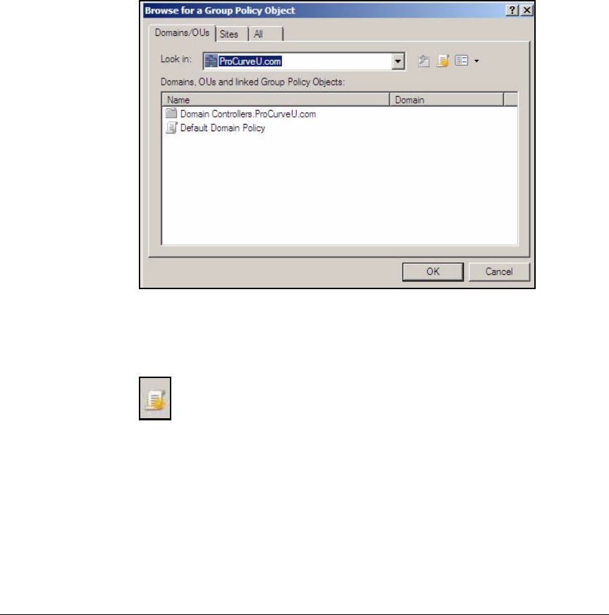
AD-111
Addendum: ProCurve Access Control Solution 2.1 Update
Configuring the NPS Server
■Automatic Certificate Request—configures the computer to automat-
ically obtain a certificate the first time that it joins the domain so that it
can later authenticate itself with 802.1X
Follow these steps:
1. Click Start > Run.
2. Type gpme.msc at the prompt and click OK.
Figure AD-98.NPS Server—Browse for a Group Policy Object Window
3. In the Browse for a Group Policy Object window, click the New Group icon.
Figure AD-99.NPS Server—New Group Icon
4. Type the name of the new Group Policy object and click OK. In this
example, type NAP client computers. The Group Policy Management Editor
window is displayed.
5. In the left pane, click Computer Configuration > Policies > Windows Settings
> Security Settings > System Services.
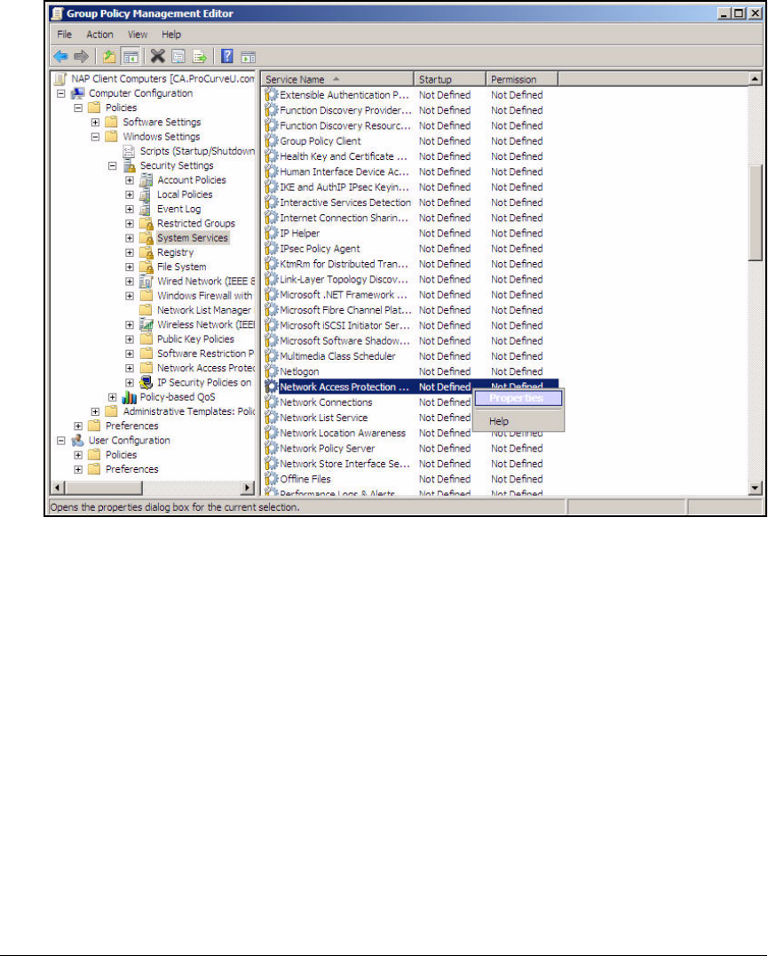
AD-112
Addendum: ProCurve Access Control Solution 2.1 Update
Configuring the NPS Server
Figure AD-100.NPS Server—Group Policy Management Editor Window
6. In the right pane, right-click Network Access Protection Agent and click
Properties.
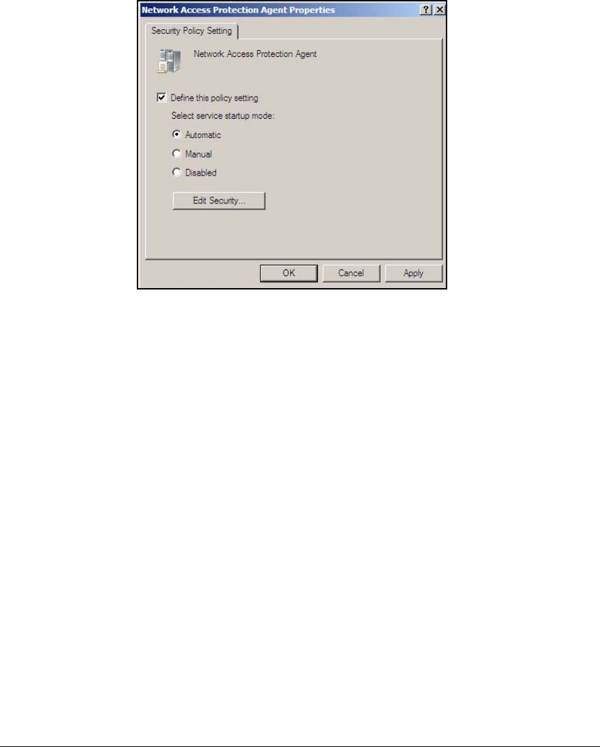
AD-113
Addendum: ProCurve Access Control Solution 2.1 Update
Configuring the NPS Server
Figure AD-101.NPS Server—Network Access Protection
Agent Properties Window
7. In the Network Access Protection Agent Properties window, select the Define
this policy setting check box.
8. For Select service startup mode, choose Automatic and click OK.
9. In the right pane, scroll to Wired AutoConfig. Repeat steps 6 to 8.
10. In the left pane of the Group Policy Management Editor window, click
Network Access Protection and click NAP Client Configuration > Enforcement
Clients.
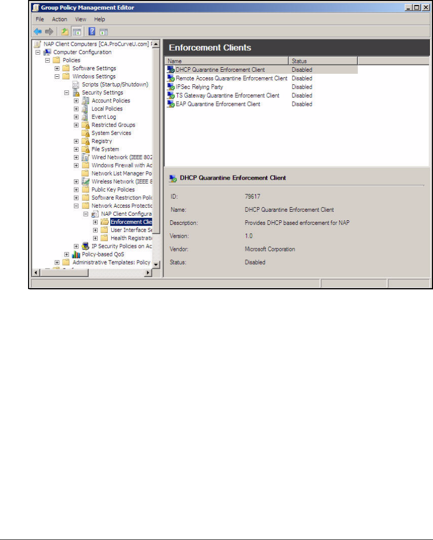
AD-114
Addendum: ProCurve Access Control Solution 2.1 Update
Configuring the NPS Server
Figure AD-102.NPS Server—Group Policy Management Editor Window
11. In the right pane, right-click EAP Quarantine Enforcement Client and click
Enable.
12. In the left pane, right-click NAP Client Configuration and click Apply.
13. In the left pane, navigate to Computer Configuration > Policies > Administra-
tive Templates > Windows Components > Security Center.
14. In the right pane, right-click Turn on Security Center (Domain PCs only) and
click Properties.
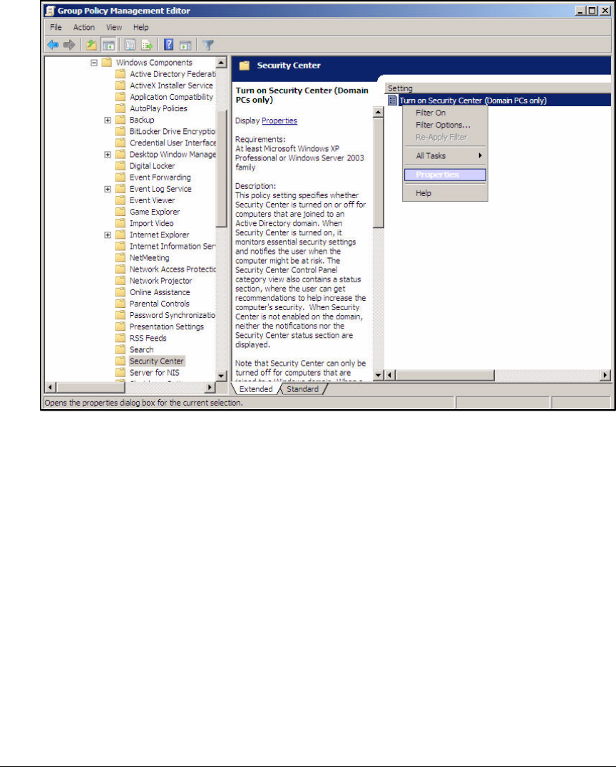
AD-115
Addendum: ProCurve Access Control Solution 2.1 Update
Configuring the NPS Server
Figure AD-103.NPS Server—Group Policy Management Editor Window

AD-116
Addendum: ProCurve Access Control Solution 2.1 Update
Configuring the NPS Server
Figure AD-104.NPS Server—Turn on Security Center (Domain
PCs only) Properties Window
15. Select Enabled and click OK.
16. In the left pane, navigate to Computer Configuration > Policies > Windows
Settings > Security Settings > Public Key Policies.
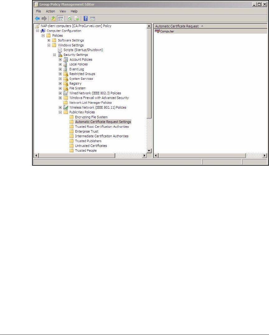
AD-117
Addendum: ProCurve Access Control Solution 2.1 Update
Configuring the NPS Server
Figure AD-105.Group Policy Management Editor
17. Right-click Automatic Certificate Request Settings and click New >
Automatic Certificate Request.
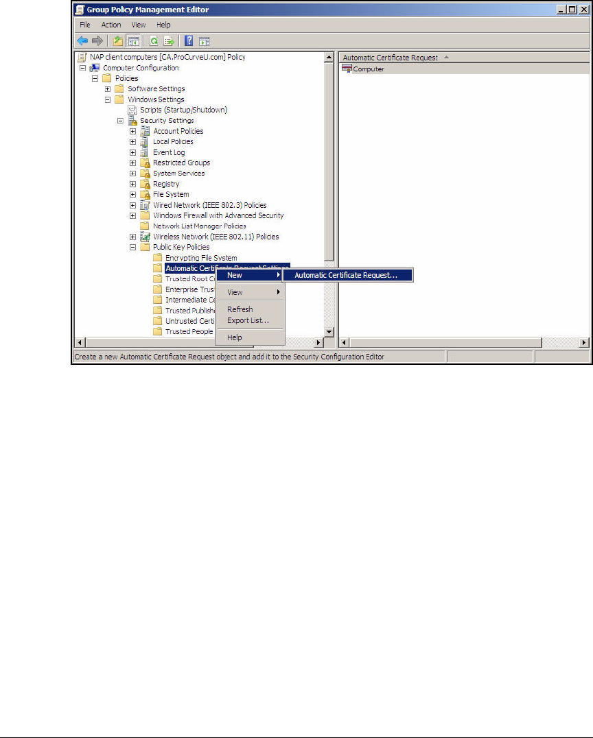
AD-118
Addendum: ProCurve Access Control Solution 2.1 Update
Configuring the NPS Server
Figure AD-106.Group Policy Management Editor—Opening the Automatic
Certificate Request Wizard
The Automatic Certificate Request Setup Wizard opens.
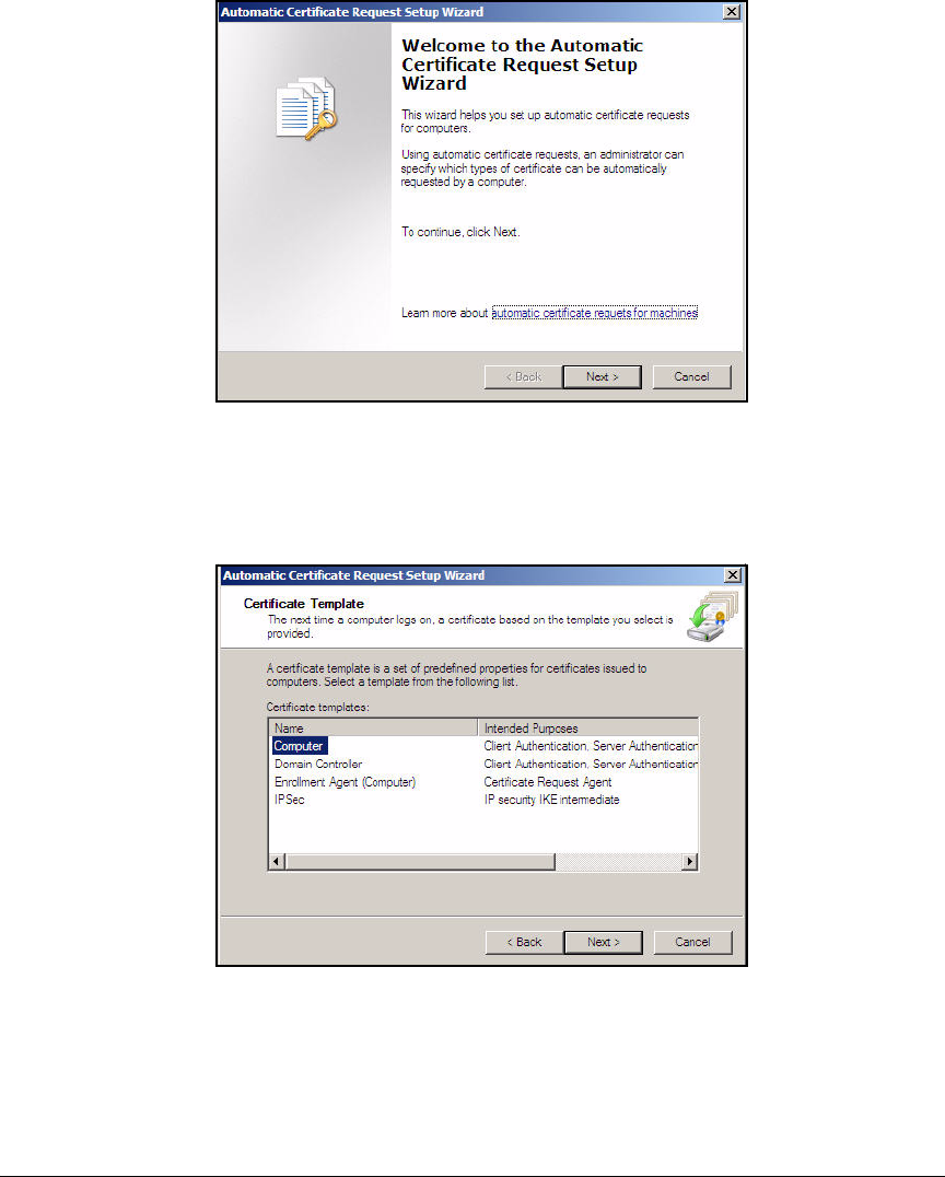
AD-119
Addendum: ProCurve Access Control Solution 2.1 Update
Configuring the NPS Server
Figure AD-107.Automatic Certificate Request Setup Wizard—
Welcome Page
18. Click Next.
Figure AD-108.Automatic Certificate Request Setup Wizard—
Certificate Template Page
19. Select Computer and click Next.
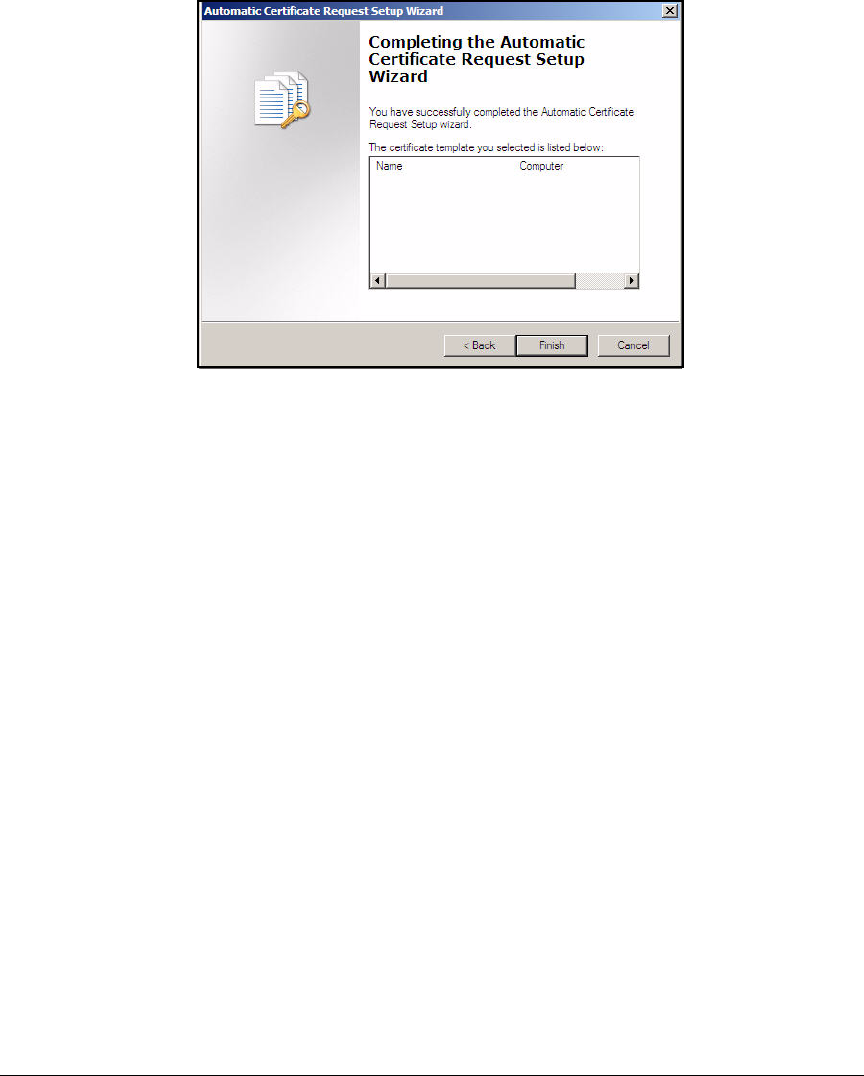
AD-120
Addendum: ProCurve Access Control Solution 2.1 Update
Configuring the NPS Server
Figure AD-109.Automatic Certificate Request Setup Wizard—
Completion Page
20. On the Completing the Automatic Certificate Request Setup Wizard page, click
Finish.
21. Close the Group Policy Management Editor window.
22. If you are prompted to apply settings, click Yes.
Configure Security Filters for the NAP Client Settings
Security filters control which domain endpoints receive the settings that you
established in the Group Policy object. You must configure security filters so
that NAP client settings are not applied to domain servers.
To configure security filters, complete the steps:
1. In the Windows Start menu, click Administrative Tools > Group Policy
Management.
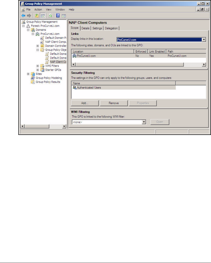
AD-121
Addendum: ProCurve Access Control Solution 2.1 Update
Configuring the NPS Server
Figure AD-110.NPS Server—Group Policy Management Window
2. In the left pane of the Group Policy Management window, expand
Forest:ProCurveU.com > Domains > Your Domain Name > Group Policy Objects.
NAP client computers.
3. In the right pane, under Security Filtering, click Authenticated Users.
4. Click Remove.
5. When prompted to confirm this action, click OK.
6. Click Add.
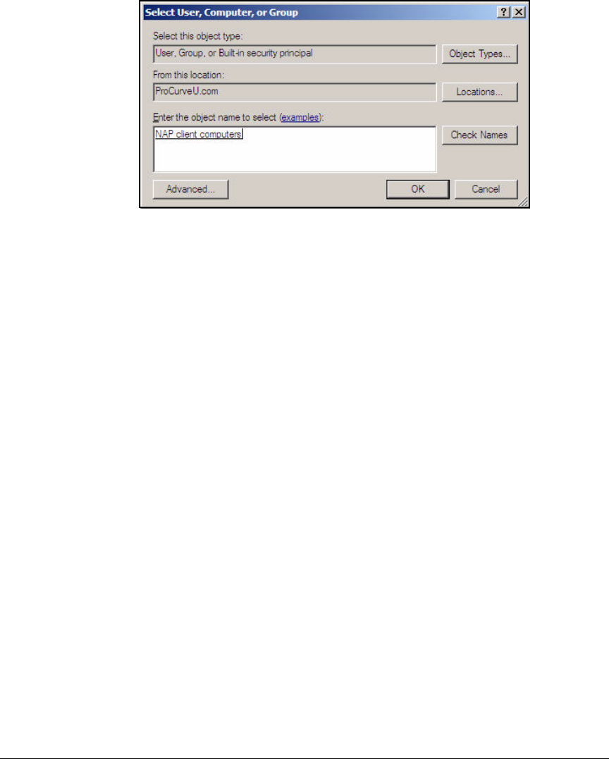
AD-122
Addendum: ProCurve Access Control Solution 2.1 Update
Configuring the NPS Server
Figure AD-111.NPS Server—Select User, Computer, or Group Window
7. In the Select User, Computer, or Group window, in the Enter the object name
to select field, type NAP client computers.
8. Click Check Names. If the server can verify the name of the group it will
become underlined.
9. Click OK.
10. Close the Group Policy Management window.

AD-123
Addendum: ProCurve Access Control Solution 2.1 Update
Configuring the Wireless Edge Services Modules
Configuring the Wireless Edge Services
Modules
The network in this access control solution provides wireless connectivity
with these devices:
■ProCurve Wireless Edge Services Module
■ProCurve Redundant Wireless Services Module
■Twelve ProCurve RPs
This section explains how to configure these devices to implement the access
control solution, beginning at installation. You must complete each task on
both modules.
Install the Wireless Edge Services Modules
You must install a Wireless Edge Services zl Module in a ProCurve Switch
5400zl or 8200zl. After the module is installed, the switch is then referred to
as a wireless services-enabled switch. (For detailed instructions to install the
module into the switch, see the ProCurve Switch zl Module Installation
Guide.)
Note Alternatively, you can purchase a Wireless Edge Services xl Module and install
it in a ProCurve Switch 5300xl Series. Configuring an xl module is almost
exactly the same as configuring a zl module; however, the xl module has less
processing power and supports fewer RPs (up to 48 instead of up to 156).
The example network for ProCurve University includes two 5400zl Switches.
To provide redundancy for the wireless network, the university has installed
one module in each switch.

AD-124
Addendum: ProCurve Access Control Solution 2.1 Update
Configuring the Wireless Edge Services Modules
Configure Initial Settings on the Wireless Edge Services
Modules
Before you can access the Web browser interface on a Wireless Edge Services
Module, you must configure its IP settings through the wireless services-
enabled switch.
Follow these steps:
1. Access the wireless services-enabled switch’s command-line interface
(CLI) (through a console, Telnet, or Secure Shell <SSH> session).
2. Move to the wireless-services context with this command:
For example:
ProCurve# wireless-services c
Note The following instructions assume that the Wireless Edge Services Module is
at factory default settings. If it is not, return it to those settings by entering
erase startup-config. After the module reboots, access the wireless-services
context and continue following the instructions below.
3. Move to the global configuration mode context of the wireless-services
context:
ProCurve(wireless-services-C)# configure terminal
4. Move to the configuration mode context for the VLAN that you chose for
infrastructure devices:
In this example, the VLAN for infrastructure devices is 2. Enter:
ProCurve(wireless-services-C)(config)# interface
vlan2
Syntax: wireless-services <slot letter>
Moves to the wireless-services context on the wireless services-
enabled switch.
Replace <slot letter> with the letter for the chassis slot in which
the module is installed.
Syntax: interface vlan<ID>
Moves to a VLAN configuration mode context.
Replace <ID> with a number between 1 and 4094.

AD-125
Addendum: ProCurve Access Control Solution 2.1 Update
Configuring the Wireless Edge Services Modules
5. Assign the VLAN an IP address.
For the example network, the Wireless Edge Services Module’s IP address
for VLAN 2 is 10.2.0.20 with a mask of 255.255.0.0. Enter:
ProCurve(wireless-services-C)(config-if)# ip address
10.2.0.20/16
6. Define this VLAN as the management VLAN.
ProCurve(wireless-services-C) (config-if)# management
7. Exit to the global configuration mode context:
ProCurve(wireless-services-C)(config-if)# exit
8. Specify the default router:
For the example network, type:
ProCurve(wireless-services-C)(config)# ip default-
gateway 10.2.0.1
9. Save the configuration:
Syntax: ip address <A.B.C.D>/<prefix length>
Assigns the interface an IP address.
Replace <A.B.C.D> with the IP address and replace <prefix
length> with the Classless Inter-Domain Routing (CIDR) nota-
tion for the subnet mask.
Syntax: ip default-gateway <A.B.C.D>
Specifies the IP address for the default router.
Replace <A.B.C.D> with the IP address.
Syntax: write memory
Saves the configuration changes to the startup-config.

AD-126
Addendum: ProCurve Access Control Solution 2.1 Update
Configuring the Wireless Edge Services Modules
10. Before closing your session with the switch, you must tag the Wireless
Module’s uplink port for the management VLAN. From the switch’s global
configuration context, enter this command:
In this example, enter:
ProCurve(config)# vlan 2 tagged bup
11. You can optionally enable secure management, which restricts the module
to accepting management traffic that arrives on its management VLAN:
However, in this example, the setting is not necessary because the Wire-
less Edge Services Module has only one IP address, the management
address.
12. Save the configuration:
You can now access the module’s Web browser interface, which you will use
to complete all remaining settings.
Configure WLAN Settings
This section explains how to set up a wireless LAN (WLAN) on the Wireless
Edge Services Module through its Web browser interface.
In a network that enforces 802.1X quarantining, you must set the WLAN
authentication to 802.1X. You can choose either Wired Equivalent Privacy
(WEP) or Wi-Fi Protected Access (WPA) for the encryption; however, WPA is
the much preferred option, and the one used in this example. (For more
information about the options for setting up WLAN security on the Wireless
Edge Services Module, see the ProCurve Access Control Security Design
Guide.)
Syntax: vlan <VLAN ID> tagged <slot>up
Tags the Wireless Module’s uplink port for the specified VLAN.
Replace <VLAN ID> with the ID for the VLAN. Replace <slot>
with the letter for the slot in which the module is installed.
Syntax: management secure
Forces the module to accept management traffic only on the
management VLAN.
Syntax: write memory
Saves the configuration changes to the startup-config.
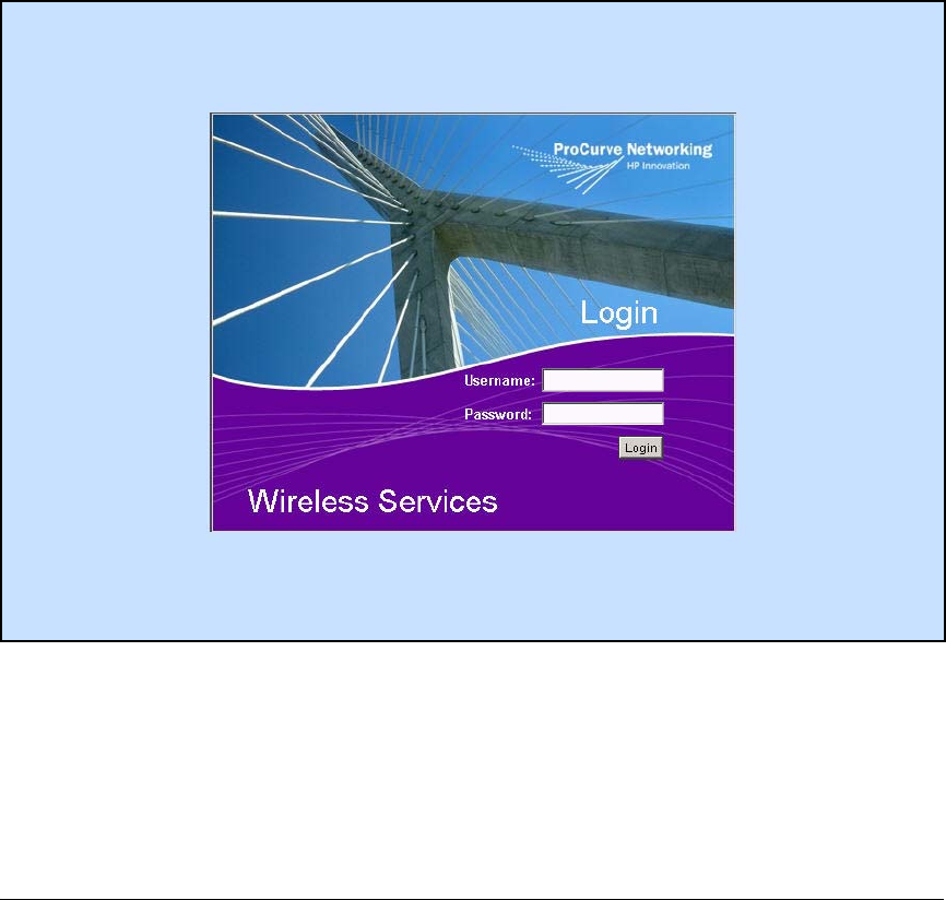
AD-127
Addendum: ProCurve Access Control Solution 2.1 Update
Configuring the Wireless Edge Services Modules
Part of setting up the WLAN is specifying the RADIUS servers—in this case,
the NPS.
To configure the WLANs on the Wireless Edge Services Module, complete
these steps:
1. Open the Web browser interface on your management station. For the
URL, type the IP address that you configured on the module. In this
example: 10.2.0.20.
Your station must have the Java Runtime Environment (JRE).
Figure AD-112.Wireless Services Login Page
2. Log in with the default manager credentials:
•Username = manager
•Password = procurve
3. Click Network Setup > WLAN Setup.
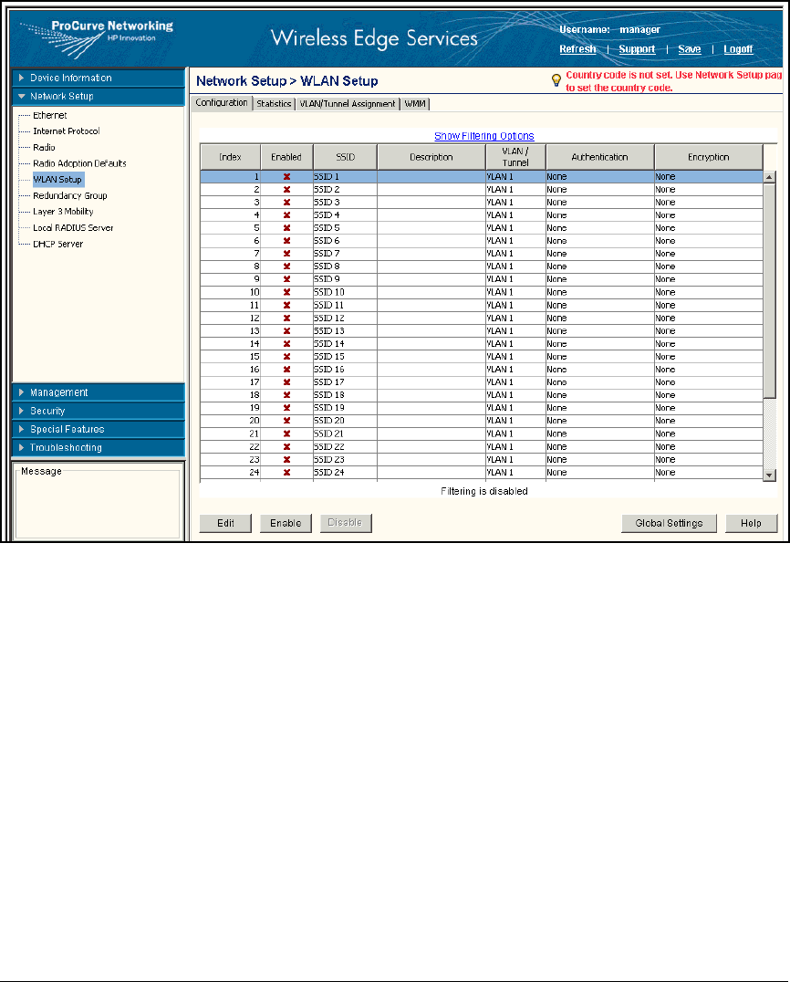
AD-128
Addendum: ProCurve Access Control Solution 2.1 Update
Configuring the Wireless Edge Services Modules
Figure AD-113.Wireless Edge Services Module Web Interface—Network Setup >
WLAN Setup Window
4. Select the first WLAN.
5. Click Edit.
6. Under Configuration, in the SSID box, type a name for the wireless network
(in this example, ProCurve University).
7. In the VLAN ID box, specify the static VLAN, which, in this implementation,
is the temporary VLAN for computers (pre-user-login). In this example,
type 9.
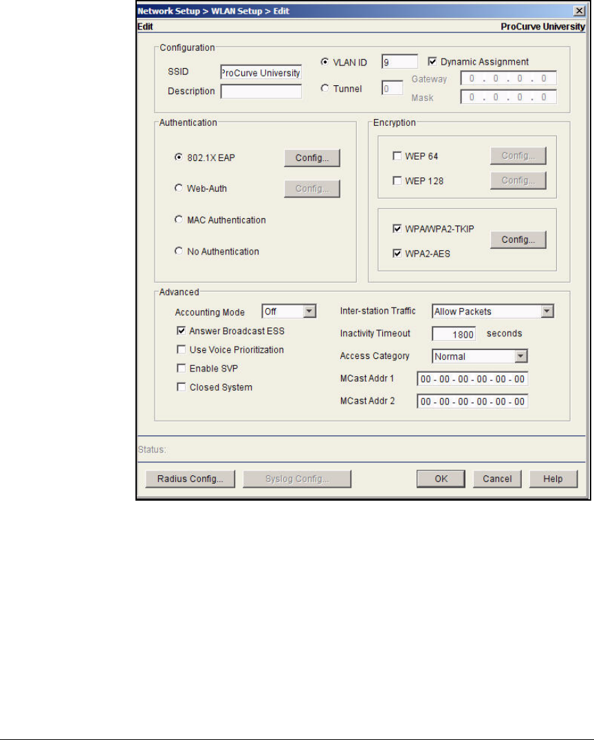
AD-129
Addendum: ProCurve Access Control Solution 2.1 Update
Configuring the Wireless Edge Services Modules
Figure AD-114.Wireless Edge Services Module Web Interface—Network Setup >
WLAN Setup > Edit Window
8. The Dynamic Assignment check box should be selected.
9. Under Encryption, select the WPA/WPA2-TKIP and the WPA2-AES check
boxes.
10. Under Authentication, select 802.1X EAP.
11. Click Radius Config at the bottom of the window. The Radius Configuration
window is displayed.
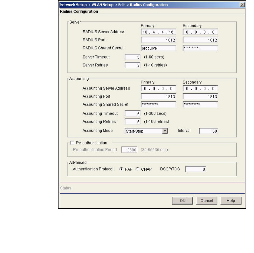
AD-130
Addendum: ProCurve Access Control Solution 2.1 Update
Configuring the Wireless Edge Services Modules
12. Under Server, specify your NPS server:
Type the settings for one NPS setting in the Primary column:
a. In the RADIUS Server Address box, type the IP address of the NPS. In
this example, type 10.4.4.16.
b. Leave the RADIUS Port at the default value, 1812.
c. In the RADIUS Shared Secret box, type the secret that you configured
for the module on the NPS. In this example, type procurve.
Figure AD-115.Wireless Edge Services Module Web Interface—Radius
Configuration Window
13. Click OK.
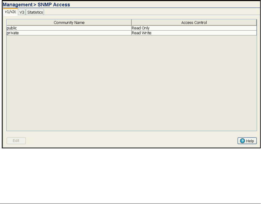
AD-131
Addendum: ProCurve Access Control Solution 2.1 Update
Configuring the Wireless Edge Services Modules
14. Click OK in the Network Setup > WLAN Setup > Edit window.
15. In the Network Setup > WLAN Setup window, verify that the WLAN you just
configured is selected. Click Enable.
Configure SNMP on the Wireless Edge Services
Modules
You must configure the Wireless Edge Services Modules’ SNMP settings to
allow PCM+ to manage it.
Follow these steps to configure SNMP:
1. You should be in the Wireless Edge Services Module’s Web browser
interface.
2. Click Management > SNMP Access. You begin at the v1/v2c tab.
Figure AD-116.Wireless Edge Services Module Web Interface—
Management > SNMP Access > V1/V2c Tab
3. Select public and click Edit. The Edit SnmpV1/V2c window is displayed.
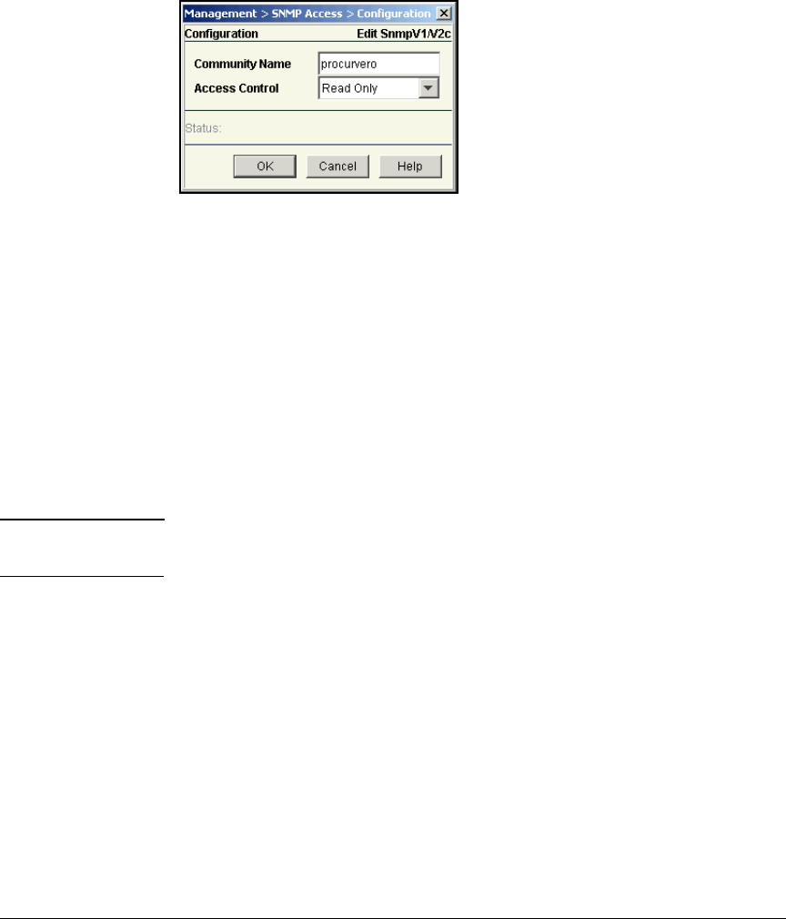
AD-132
Addendum: ProCurve Access Control Solution 2.1 Update
Configuring the Wireless Edge Services Modules
4. For the Community Name, type the new name for the read-only community.
In this example, type procurvero.
Figure AD-117.Wireless Edge Services
Module Web Interface—
Edit SnmpV1/V2c Window
5. For Access Control, keep the default setting, Read Only.
6. Click OK.
7. Select private and click Edit.
8. In the Community Name box, type the new name for the read-write com-
munity. In this example, type procurverw.
9. For Access Control, keep the default setting, Read Write.
10. Click OK.
Note You can also configure SNMPv3 settings by clicking the V3 tab in the Manage-
ment > SNMP Access window. For this example, we will not use SNMPv3.
11. Select Management > SNMP Trap Configuration.

AD-133
Addendum: ProCurve Access Control Solution 2.1 Update
Configuring the Wireless Edge Services Modules
Figure AD-118.Wireless Edge Services Module Web Interface—Management >
SNMP Trap Configuration > Configuration Tab
12. Select the Allow Traps to be generated check box.
13. To view the SNMP traps in a category, expand the category. To view the
SNMP traps in all categories, click Expand all items.
14. To enable all the traps, select All Traps and click Enable all sub-items.
15. To enable all the SNMP traps in a category, select the category and click
Enable all sub-items.
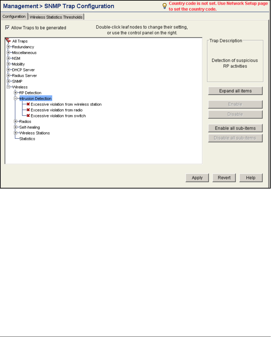
AD-134
Addendum: ProCurve Access Control Solution 2.1 Update
Configuring the Wireless Edge Services Modules
Figure AD-119.Wireless Edge Services Module Web Interface—Management >
SNMP Trap Configuration > Configuration Tab
16. To enable a specific SNMP trap, select the trap and click Enable or double-
click the trap. A green check mark is displayed next to enabled traps. A
red x is displayed next to disabled traps.
17. Click Apply.
Change Web-User Passwords
The Web-Users are users who are allowed to log in to the Wireless Module’s
Web browser interface. By default, the module has two Web-Users: manager,
who has complete read-write access, and operator, who has read-only access.
In this section, you will change the passwords for the default users. In a later
section, you will learn about creating other Web-Users.
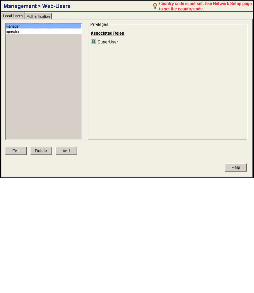
AD-135
Addendum: ProCurve Access Control Solution 2.1 Update
Configuring the Wireless Edge Services Modules
Follow these steps to change the passwords:
1. Click Management > Web-Users. The Local Users tab should be selected.
Figure AD-120.Wireless Edge Services Module Web Interface—Management >
Web-Users
2. Select operator and click Edit.
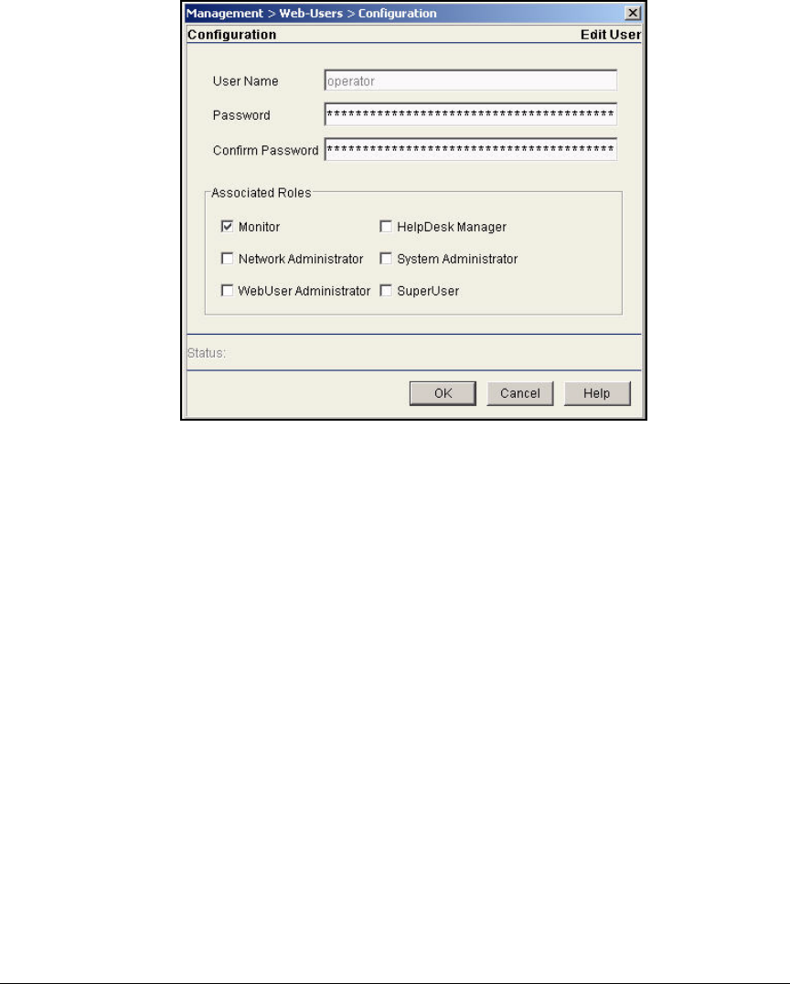
AD-136
Addendum: ProCurve Access Control Solution 2.1 Update
Configuring the Wireless Edge Services Modules
Figure AD-121.Wireless Edge Services Module Web Interface—
Management > Web-Users > Configuration (operator)
3. In the Password and Confirm Password boxes, type the new password (in
this example, procurve).
4. Under Associated Roles, the Monitor check box is selected. Keep this
default setting.
5. Click OK.
6. Select manager and click Edit.
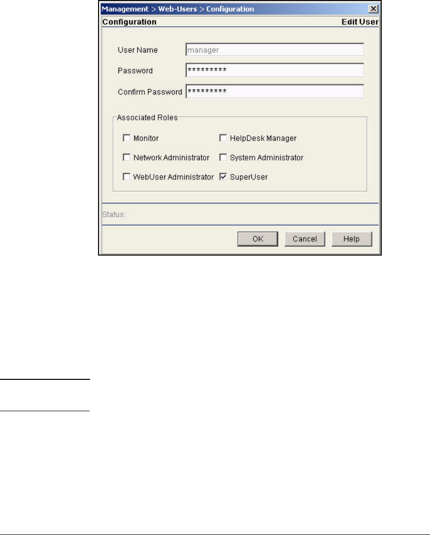
AD-137
Addendum: ProCurve Access Control Solution 2.1 Update
Configuring the Wireless Edge Services Modules
Figure AD-122.Wireless Edge Services Module Web Interface—
Management > Web-Users > Configuration (manager)
7. In the Password and Confirm Password boxes, type the new password (in
this example, procurve).
8. Under Associated Roles, the SuperUser check box is selected. Keep this
default setting.
9. Click OK.
Note You must enter this new password the next time you log in to the Web browser
interface.
Specify the Wireless Module’s DNS Server
You should specify a DNS server for the Wireless Module. Having a valid DNS
server is important particularly when the module enforces Web-Auth on a
WLAN.
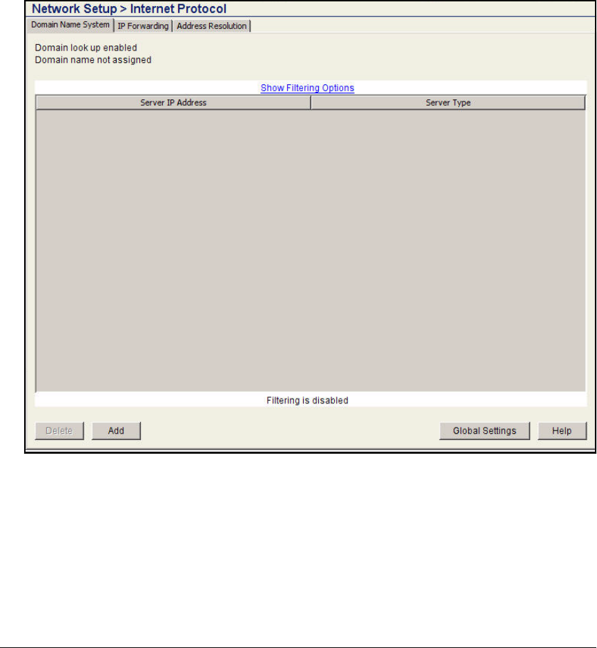
AD-138
Addendum: ProCurve Access Control Solution 2.1 Update
Configuring the Wireless Edge Services Modules
Follow these steps:
1. You should be in the module’s Web browser interface.
2. Click Network Setup > Internet Protocol. The Domain Name System tab
should be selected.
Figure AD-123.Wireless Edge Services Module Web Interface—Network Setup >
Internet Protocol > Domain Name System Window
3. Click Add.
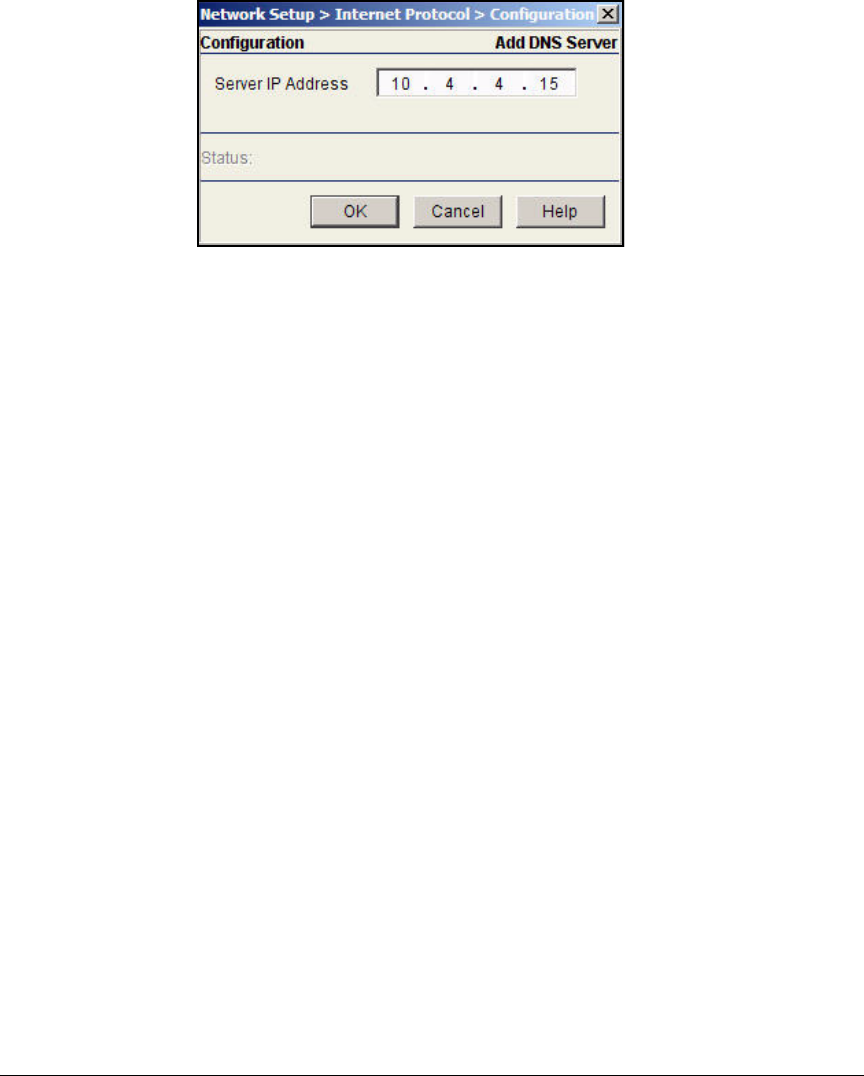
AD-139
Addendum: ProCurve Access Control Solution 2.1 Update
Configuring the Wireless Edge Services Modules
Figure AD-124.Wireless Edge Services Module Web
Interface—Add DNS Server Window
4. Type the IP address of the DNS server. In this example, type 10.4.4.15.
5. Click OK.
Configure the Time
Network devices check timestamps as a part of the authentication process (as
well as other processes). It is important that all your network devices keep
the same clock. Follow these steps to configure the time on the Wireless Edge
Services Module:
1. You should be in the module’s Web browser interface.
2. Click Network Setup. You should be at the Configuration tab.

AD-140
Addendum: ProCurve Access Control Solution 2.1 Update
Configuring the Wireless Edge Services Modules
Figure AD-125.Wireless Edge Services Module Web Interface—Network Setup >
Configuration Window
3. Select your time zone from the Time Zone list.
4. Click Apply.
5. Click Special Features > Secure NTP.
6. Click the NTP Neighbor tab.

AD-141
Addendum: ProCurve Access Control Solution 2.1 Update
Configuring the Wireless Edge Services Modules
Figure AD-126.Wireless Edge Services Module Web Interface—Special Features >
Secure NTP > NTP Neighbor Window
7. Click Add.
8. Click Server.
9. Select IP Address or Hostname and specify your NTP server. In this exam-
ple, the domain is using a public NTP server.

AD-142
Addendum: ProCurve Access Control Solution 2.1 Update
Configuring the Wireless Edge Services Modules
Figure AD-127.Wireless Edge Services Module Web Interface—
Special Features > Secure NTP > Add Neighbor Window
10. Click OK.
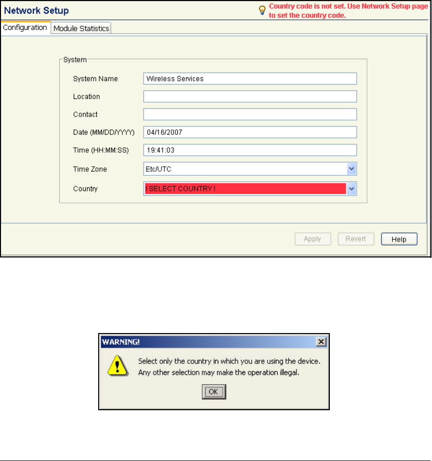
AD-143
Addendum: ProCurve Access Control Solution 2.1 Update
Configuring the Wireless Edge Services Modules
Set the Country Code
You must set the country code to enable the Wireless Edge Service Module to
adopt RPs. Follow these steps:
1. Click Network Setup. You should be at the Configuration tab.
Figure AD-128.Wireless Edge Services Module Web Interface—Network Setup >
Configuration Window
2. From the Country box, select your country. A Warning window is displayed.
Figure AD-129.Wireless Edge Services Module Web Interface—
Warning Window
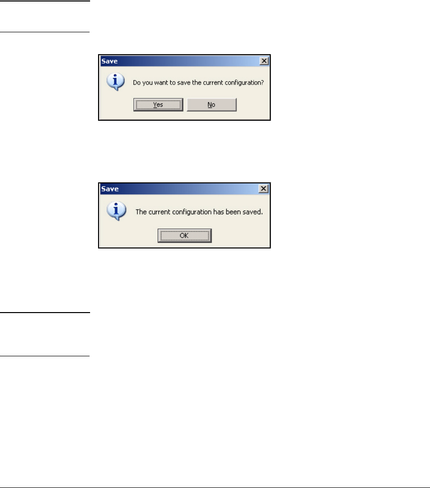
AD-144
Addendum: ProCurve Access Control Solution 2.1 Update
Configuring the Wireless Edge Services Modules
3. Click OK.
4. Click Apply.
5. Click Save at the top of the Web browser interface.
Note You must remember to click Save to preserve your configurations in the
Wireless Module’s startup-config.
Figure AD-130.Wireless Module—Save Window
6. Click Yes to confirm the save.
Figure AD-131.Wireless Module—Second
Save Window
7. Click OK.
Note Future instructions in this guide may remind you to save your configuration.
However, they will assume that you can complete the final two steps (clicking
Yes and OK) without explicit instructions.

AD-145
Addendum: ProCurve Access Control Solution 2.1 Update
Configuring the Wireless Edge Services Modules
Obtain a Server Certificate for the Wireless Module
The Wireless Edge Services Module uses digital certificates for several pur-
poses. In this solution, the module uses a certificate to authenticate and
encrypt HTTPS sessions to the Web browser interface.
The module has a default self-signed certificate, which it can use for HTTPS.
However, you should install a certificate that has been signed by your domain
CA and is automatically trusted by your endpoints.
This section explains how to obtain such a certificate:
1. Create a certificate request on Wireless Module.
2. Submit the request to your domain CA and generate the server certificate.
3. Install the CA root certificate on the Wireless Module.
4. Install the server certificate on the Wireless Module.
5. Configure the module’s HTTPS server to use the new certificate.
Create a Certificate Request on the Wireless Edge Services
Module
Follow these steps to create a certificate request using the Wireless Edge
Services Module’s Certificates Wizard:
1. On your management workstation, open a Web browser.
2. Type the module’s IP address or DNS name for the URL. In this example:
10.2.0.20.

AD-146
Addendum: ProCurve Access Control Solution 2.1 Update
Configuring the Wireless Edge Services Modules
Figure AD-132.Wireless Services Login Page
3. Log in the Web browser interface with the manager password that you set
earlier. (See step 7 on page AD-137.)
4. Select Management > Certificate Management.

AD-147
Addendum: ProCurve Access Control Solution 2.1 Update
Configuring the Wireless Edge Services Modules
Figure AD-133.Wireless Edge Services Module Web Browser Interface—
Management > Certificate Management Window
5. Click Certificates Wizard.

AD-148
Addendum: ProCurve Access Control Solution 2.1 Update
Configuring the Wireless Edge Services Modules
Figure AD-134.Wireless Edge Services Module Web Browser Interface—Welcome
to the Certificate Wizard
6. On the Welcome to the Certificate Wizard window, select Create a new self-
signed certificate/certificate request.
7. Click Next. The window shown in Figure AD-135 is displayed.
8. In the Select a certificate operation section, select Prepare a certificate
request to send to a certificate authority.

AD-149
Addendum: ProCurve Access Control Solution 2.1 Update
Configuring the Wireless Edge Services Modules
9. In the Select a trustpoint for the new certificate section, select Create a new
trustpoint.
10. Type a descriptive name for trustpoint name in the box on the right—
typically, a name that identifies the CA. In this example, type ProCurveU.
Figure AD-135.Wireless Edge Services Module Web Browser Interface—
Certificates Wizard—Select Certificate Operation
11. Leave the Automatically generate a key option selected.
12. Click Next.
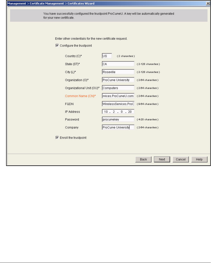
AD-150
Addendum: ProCurve Access Control Solution 2.1 Update
Configuring the Wireless Edge Services Modules
Figure AD-136.Wireless Edge Services Module Web Browser Interface—
Certificates Wizard—Configure Trustpoint
13. Select the Configure the trustpoint check box and type the following cre-
dentials for the certificate:
•Country—the two-character country code (abbreviation) for your
country
•State—the state or province in which the module operates
•City—the city in which the module operates
•Organization—your organization (typically your company name)
•Organizational Unit—the module’s organizational unit

AD-151
Addendum: ProCurve Access Control Solution 2.1 Update
Configuring the Wireless Edge Services Modules
•Common Name—the module’s exact FQDN, the URL at which the
module’s Web browser interface is accessed. The common name (CN)
cannot include spaces or special characters other than periods ( . )
and hyphens ( - ). In this example, the CN is
WirelessServices.procurveu.edu.
Note Alternatively, type the Wireless Edge Services Module’s IP address.
•FQDN—the module’s FQDN. This field is optional.
•IP Address—the IP address for the wireless module or for the device
that wants the certificate. This field is optional but recommended.
•Password—a password that must be entered to install the certificate.
This field is optional.
•Company—the name of the company. It can be the same as the
organization.
14. Select the Enroll the trustpoint check box.
15. Click Next. The window shown in Figure AD-137 is displayed.
16. The window shows the certificate request, which is in Base 64-encoded
Public Key Cryptography Standard #10 (PKCS#10) format. You have
several options for saving the certificate request. In this example, you will
save it to the hard disk on the management station.
a. Select the Save the certificate request check box. From the To list, select
Local Disk.
b. For the File, type a name for the request, including a valid path. For
example: C:\Certs\wireless_services.req. Alternatively, click the
browse button and browse for the directory in which to save the
request.

AD-152
Addendum: ProCurve Access Control Solution 2.1 Update
Configuring the Wireless Edge Services Modules
Figure AD-137.Wireless Edge Services Module Web Browser Interface—
Certificates Wizard—Copy Request
17. Click Next. A completion window summarizes the certificate request
operation that you have performed.
18. Click Finish.
Browse
button
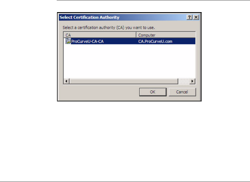
AD-153
Addendum: ProCurve Access Control Solution 2.1 Update
Configuring the Wireless Edge Services Modules
Submit the Request to the CA and Create the Certificate
Follow these steps to submit the request to the CA and create the certificate
using the Web Server template:
1. In the previous section, you saved the certificate request from the Wireless
Edge Services Module to the management station. Now copy the request
to the CA server.
2. Access the command line on the CA server:
a. From the Windows Start menu, select Run.
b. Type cmd at the prompt and click OK.
3. Move to the directory in which you saved the certificate request.
4. Enter this command:
Figure AD-138.Select Certification Authority Window
5. In the window that is displayed, select the name of your CA and click OK.
6. In the Save Certificate window navigate to the location where you want to
save the certificate. Type a name for the certificate file.
Syntax: certreq -submit -attrib “CertificateTemplate:WebServer”
<request_filename>
Replace <request_filename> with the name of the certificate
request that you transferred to the CA server.
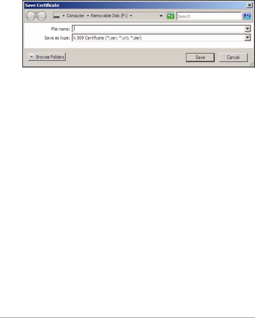
AD-154
Addendum: ProCurve Access Control Solution 2.1 Update
Configuring the Wireless Edge Services Modules
Figure AD-139.Save Certificate Window
7. Click Save.
Install the Certificate on a Wireless Edge Services
Module
In the last task, you saved the Wireless Edge Services Module’s certificate as
a file on the hard drive of the CA server. In “Export the CA Root Certificate”
on page AD-73, you exported the CA root certificate to a file. Copy both
certificates to one of these locations:
■File Transfer Protocol (FTP) server
■Trivial FTP (TFTP) server
■Management station’s hard drive
Follow these steps to install the certificate:
1. Open the Web browser on your management station and navigate to the
Wireless Edge Services Module’s IP address.
2. Log in with a manager username and password.
3. Select Management > Certificate Management.
4. Click the Trustpoints tab.
5. Click Certificates Wizard.
6. In the Welcome to the Certificate Wizard window, select Upload an external
certificate.
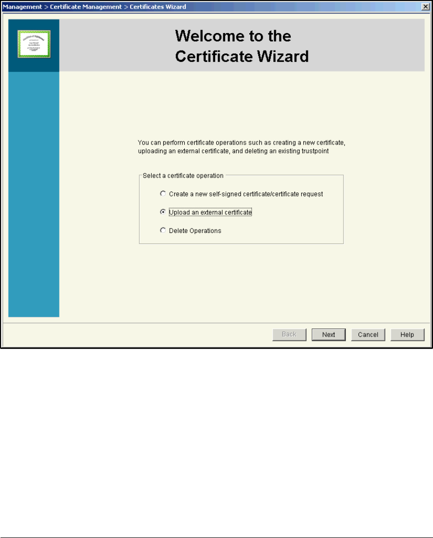
AD-155
Addendum: ProCurve Access Control Solution 2.1 Update
Configuring the Wireless Edge Services Modules
Figure AD-140.Wireless Edge Services Module Web Browser Interface—Welcome
to the Certificate Wizard
7. Click Next.
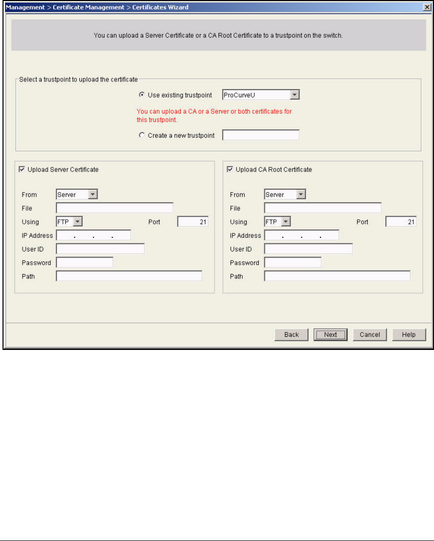
AD-156
Addendum: ProCurve Access Control Solution 2.1 Update
Configuring the Wireless Edge Services Modules
Figure AD-141.Wireless Edge Services Module Web Browser Interface—
Certificates Wizard—Upload Certificates
8. From the Use existing trustpoint list, select the trustpoint you created in
“Create a Certificate Request on the Wireless Edge Services Module” on
page AD-145. In this example: ProCurveU.
9. Clear the Upload Server Certificate check box.
10. Select the Upload CA Root Certificate check box.

AD-157
Addendum: ProCurve Access Control Solution 2.1 Update
Configuring the Wireless Edge Services Modules
11. Specify the file source for the certificate that you exported in “Export the
CA Root Certificate” on page AD-73:
To upload the certificate from the workstation running the Web browser,
follow these steps:
a. From the From list, select Local Disk.
b. In the File box, type the certificate filename with a valid path (for
example, C:\Certs\procurveu_ca_cert.cer).
Alternatively, click the browse button and browse for the certificate.
(See Figure AD-139.) Click the certificate name and click Open.
12. Click Next. The completion window summarizes the certificate upload
operation that you have performed.
13. Click Finish.
14. Repeat steps 5 to 13, this time selecting the Upload Server Certificate box
in step 10 and using the certificate you created in “Submit the Request to
the CA and Create the Certificate” on page AD-153.
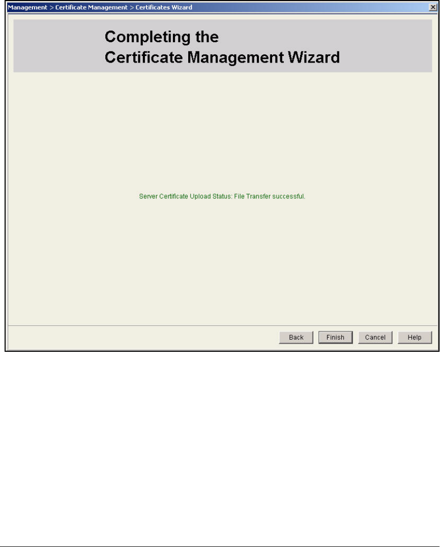
AD-158
Addendum: ProCurve Access Control Solution 2.1 Update
Configuring the Wireless Edge Services Modules
Figure AD-142.Wireless Edge Services Module Web Browser Interface—
Completing the Certificate Management Wizard
Enable the Certificate on the Wireless Edge Services Module’s
HTTPS Server
To have the Wireless Edge Services Module use the new certificate for its
HTTPS server, follow these steps
1. Access the module’s Web browser interface.
2. Select Management > Web Access Control.
3. Make sure that the Enable HTTPS check box is selected. From the HTTPS
Trustpoint list, select the trustpoint you just created.
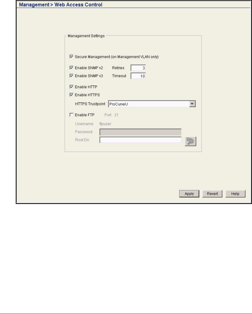
AD-159
Addendum: ProCurve Access Control Solution 2.1 Update
Configuring the Wireless Edge Services Modules
Figure AD-143.Wireless Edge Services Module Web Browser Interface—
Management > Web Access Control Window
4. Click Apply.
5. Click Save.

AD-160
Addendum: ProCurve Access Control Solution 2.1 Update
Configure the Endpoints
Configure the Endpoints
This section describes how to configure a Windows Vista computer so that it
can be tested by NAP before being granted access to the network.
You will complete these steps:
■Enable Run on the Start menu.
■Join the Windows Vista computer to the domain.
■Add the computer to the NAP client computers group and then restart the
computer.
■Verify Group Policy settings.
■Configure authentication methods.
Note The instructions in this section are for Vista computers that are using the Vista
view (rather than the Classic view).
Enable Run on the Start Menu
By default, the Start menu may not include Run. Add this option so that you
can complete the tasks that follow:
1. On the Windows Vista computer, right-click Start and click Properties.
2. In the Taskbar and Start Menu Properties window, select Start menu and
click Customize.
3. In the Customize Start Menu window, select the Run command check box.
4. Click OK twice.
Join the Windows Vista Computer to the Domain
Before the Windows Vista computer can be tested, it must join your organiza-
tion’s domain.
Complete these steps.
1. Click Start, right-click Computer, and then click Properties.
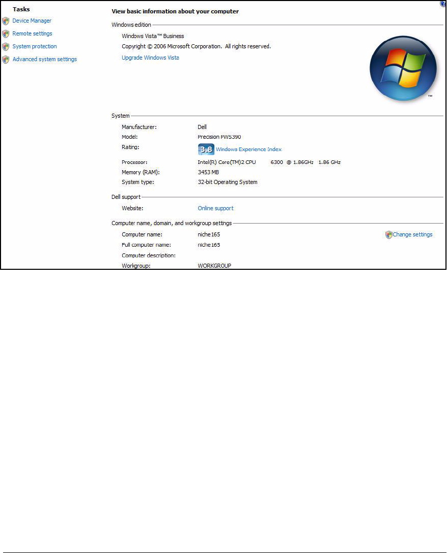
AD-161
Addendum: ProCurve Access Control Solution 2.1 Update
Configure the Endpoints
Figure AD-144.Windows Vista Endpoint—Computer Properties Window
2. Click Change settings.
3. In the System Properties window, the Computer Name tab should be
selected.
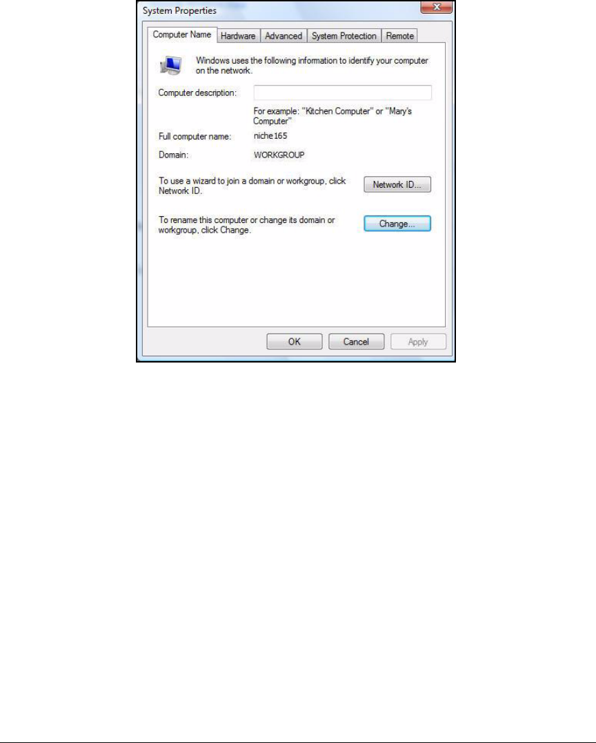
AD-162
Addendum: ProCurve Access Control Solution 2.1 Update
Configure the Endpoints
Figure AD-145.Windows Vista Endpoint—System Properties >
Computer Name Window
4. Click Change. The Computer Name/Domain Changes window is displayed.
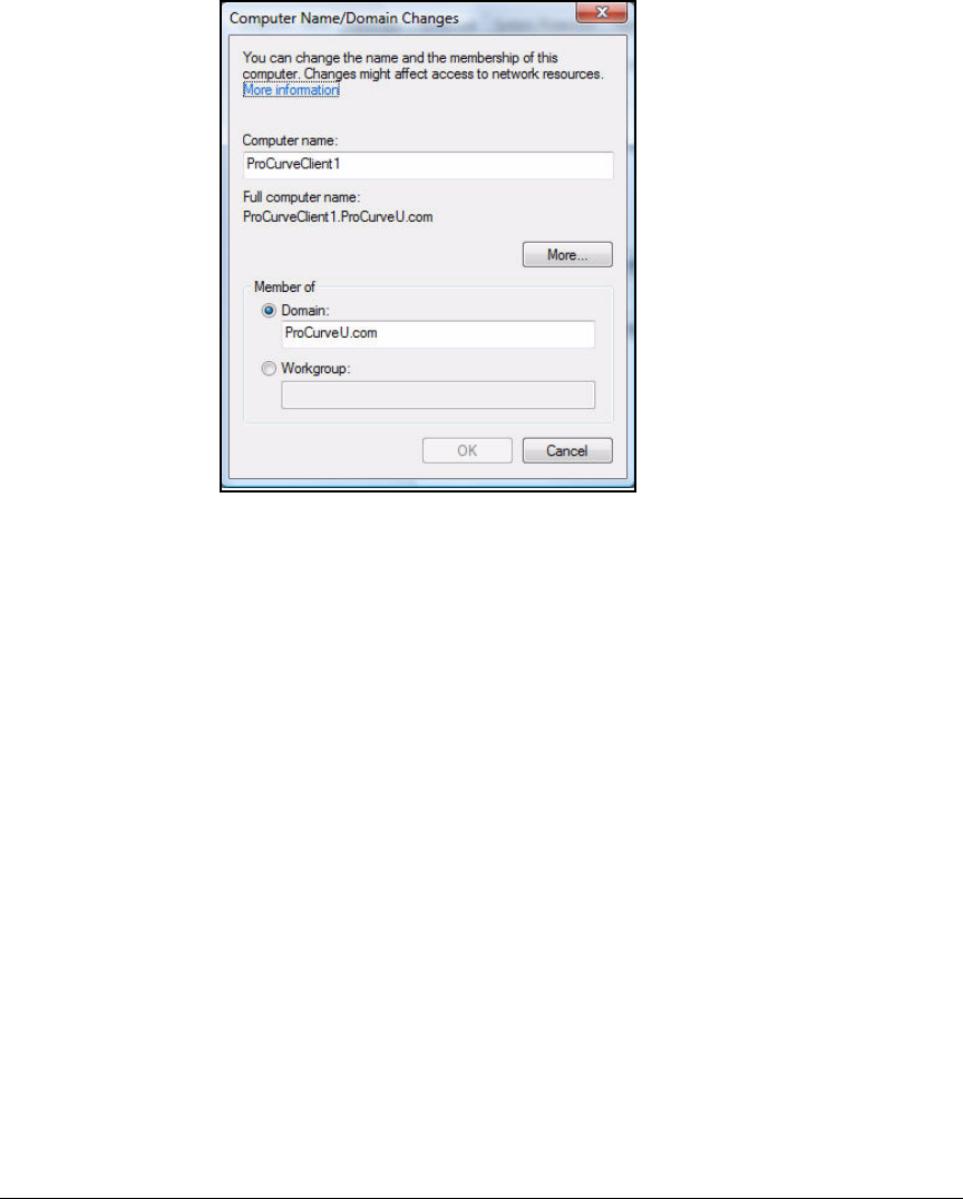
AD-163
Addendum: ProCurve Access Control Solution 2.1 Update
Configure the Endpoints
Figure AD-146.Windows Vista Endpoint—Computer
Name/Domain Changes Window
5. For Computer name, type the name of the endpoint. For this example, type
ProCurveClient1.
6. Under Member of, select Domain and then type your organization’s domain
name. In this example, type ProCurveU.com.
7. Click More. Under the Preferred DNS suffix of this computer, type your
organization’s domain name, and then click OK twice.
8. When prompted for a user name and password, type a valid username and
password and click Submit. If you enter a valid username and password,
a window is displayed, welcoming you to the domain.
9. Click OK. A window is displayed, telling you that you must restart the
computer to apply changes.
10. Click OK.
11. On the System Properties window, click Close. A dialog box is displayed,
prompting you to restart the computer.
12. Click Restart Later. You must first add the Windows Vista computer to the
NAP client computers group so that it will receive NAP client settings from
the group policy.

AD-164
Addendum: ProCurve Access Control Solution 2.1 Update
Configure the Endpoints
Add the Windows Vista Computer to the NAP Client
Computers Group
You must now add the computer to the NAP client computers security group
so that it can receive NAP client settings.
Complete these steps.
1. On the Windows domain controller, click Start, click Administrative Tools,
and then click Active Directory Users and Computers.
2. In the console tree, click your organization’s domain name.
3. In the details pane, double-click NAP client computers.
4. In the NAP client computers Properties dialog box, click the Members tab,
and then click Add.
5. Under Select this object type, click Object Types, select the Computers check
box, and then click OK.
6. Under Enter the object names to select (examples), type the computer name
and click OK.
7. Verify that the computer name is displayed below Members and then
click OK.
8. Click OK to close the Active Directory Users and Computers console.
9. Restart the Windows Vista computer to apply the new security group
membership.
10. When you log in to the computer, make sure to log in to the domain (as a
user that has administrative rights to this computers).
Note If you log in as a different user, your desktop and Start menu settings may
change. If necessary, again complete the steps in “Enable Run on the Start
Menu” on page AD-160.
Verify Group Policy Settings
When the Windows Vista computer is restarted, it should receive the group
policy settings, which enable the NAP Agent service and EAP enforcement
client.
To verify that the computer received these settings, complete these settings.
1. Click Start and click Command Prompt.

AD-165
Addendum: ProCurve Access Control Solution 2.1 Update
Configure the Endpoints
2. In the command window, type netsh nap client show grouppolicy and press
[Enter].
3. In the output, look under Enforcement clients and verify that the Admin
status of the EAP Quarantine Enforcement Client is enabled.
4. In the command window, type netsh nap client show state and press [Enter].
5. In the output, look under Enforcement client state and verify that the
initialized status of the EAP Quarantine Enforcement Client is yes.
6. Close the command window.
Configure Authentication Methods
You must now enable NAP health checks in the authentication methods for
the local area connection and for the wireless connection.
Note You can also configure NAP client settings as part of the group policy using
the Wired Network (IEEE 802.3) Policies node in the Group Policy Management
Editor window. If you are using a Windows 2003 domain controller, however,
you must update the Active Directory schema before you can configure the
NAP client settings in this way. (The schema controls the structure of a
directory service, essentially setting up the “rules” for directory service. It
controls, for example, the type of objects that can be added and the properties
each object supports.) Extending the AD schema is outside the scope of this
guide. For information about extending the AD schema, see Active Directory
Schema Extensions for Windows Vista Wired and Wired Group Policy
Enhancements (http://go.microsoft.com/fwlink/?LinkId=70195).
Configure the Local Area Connection
To enable the NAP agent to perform health checks on the wired connection,
follow these steps:
1. Click Start, right-click Network, and then click Properties.
2. Click Manage network connections.
3. Right-click Local Area Connection and then click Properties.
4. Click the Authentication tab and verify that Enable IEEE 802.1X authentication
is selected.
5. Click Settings.
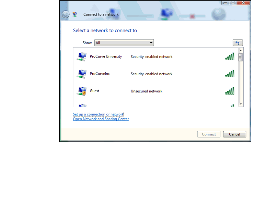
AD-166
Addendum: ProCurve Access Control Solution 2.1 Update
Configure the Endpoints
6. In the Protected EAP Properties dialog box, clear the Enable Fast Reconnect
check box and verify that only the following check boxes are selected, as
shown in the following example:
• Validate server certificate
• Enable Quarantine checks
7. Click Configure, verify that Automatically use my Windows logon name and
password (and domain if any) is selected, and then click OK.
8. Click OK twice.
Configure the Wireless Connection
To enable the NAP agent to perform health checks on the wireless connection,
follow these steps:
1. In the Start menu, click Connect to.
Figure AD-147.Windows Vista Endpoint—Connect to a network Window
2. Click the Set up a connection or network link.
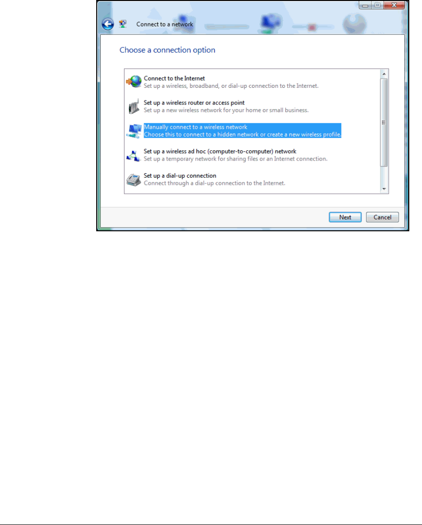
AD-167
Addendum: ProCurve Access Control Solution 2.1 Update
Configure the Endpoints
Figure AD-148.Windows Vista Endpoint—Connect to a network Window (Choose a
connection option)
3. In the Choose a connection option window, click Manually connect to a
wireless network.
4. Click Next.
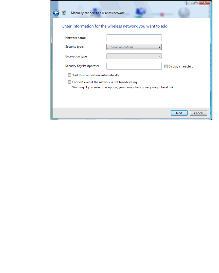
AD-168
Addendum: ProCurve Access Control Solution 2.1 Update
Configure the Endpoints
Figure AD-149.Windows Vista Endpoint—Manually connect to a wireless network
Window
5. In Manually connect to a wireless network window, enter settings for your
WLAN:
a. For Network name, type the SSID. In this example, type ProCurve
University.
b. From the Security type list, select the security option configured on
this WLAN. In this example, select WPA-Enterprise, which is WPA with
802.1X authentication.
c. For Encryption type, select the encryption enforced on the WLAN. In
this example, select TKIP.
d. Select the two check boxes:
– Start this connection automatically
– Connect even if the network is not broadcasting
6. Click Next.
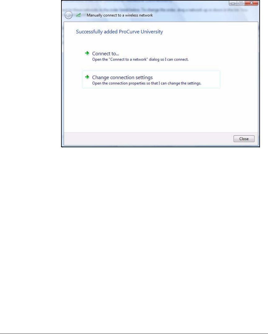
AD-169
Addendum: ProCurve Access Control Solution 2.1 Update
Configure the Endpoints
Figure AD-150.Windows Vista Endpoint—Manually connect to a wireless network
Window (Successfully added <WLAN>)
7. Click Change connection settings.
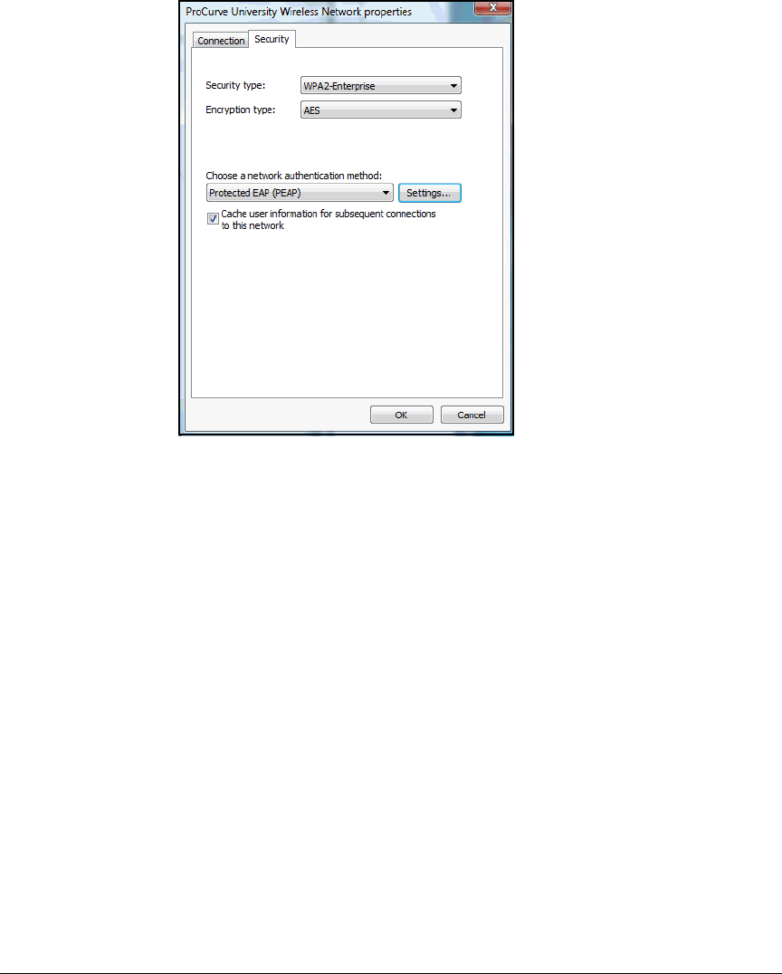
AD-170
Addendum: ProCurve Access Control Solution 2.1 Update
Configure the Endpoints
Figure AD-151.Windows Vista Endpoint—<WLAN>
Wireless Network properties Window
8. In the Wireless Network properties window for your WLAN, verify that you
are at the Security tab. Click Settings next to Protected EAP (PEAP).
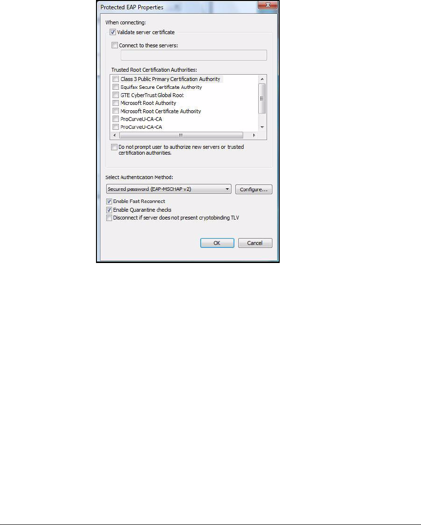
AD-171
Addendum: ProCurve Access Control Solution 2.1 Update
Configure the Endpoints
Figure AD-152.Windows Vista Endpoint—Protected
EAP Properties Window
9. In the Protected EAP Properties window, verify that these check boxes are
selected:
• Validate server certificate
• Enable Quarantine checks
10. Click Configure, verify that Automatically use my Windows logon name and
password (and domain if any) is selected, and then click OK.
11. Click OK in the other windows until you have closed all windows.

AD-172
Addendum: ProCurve Access Control Solution 2.1 Update
Configuring Network Access Control with IDM
Configuring Network Access Control
with IDM
In this implementation, IDM controls users’ access to the network, integrating
with Microsoft NAP to do so. The NPS server authenticates users and checks
endpoints’ health state (integrity). IDM manages policies that control authen-
ticated users and compliant and non-compliant endpoints. It configures these
policies on the NPS server automatically so that you do not have to configure
them manually.
In this section, you will learn how to use IDM to perform these functions:
■Assign rights to successfully authenticated users
■Quarantine endpoints that fail to comply with NAP’s health requirements
Note After you complete the tasks below, NAP will be activated. Do not complete
the tasks until all endpoints in your network have had a chance to receive the
proper settings for NAP from the domain (see “Configure the Endpoints” on
page AD-160).
You must:
1. Install IDM on a server that runs PCM+.
See “Install IDM” on page AD-173. You can also install PCM+ and IDM at
the same time.
2. Add the NPS server to the list of devices allowed to access the PCM+/IDM
server.
See “Add the NPS Server to the Access.txt File” on page AD-179.
3. Install the IDM agent on the NPS server.
See “Install the IDM Agent on the NPS Server” on page AD-180.
4. Configure IDM:
a. Enable endpoint integrity.
See “Enable Endpoint Integrity” on page AD-190.
b. Add access policy groups and users.
See “Add Access Policy Groups and Users” on page AD-193.
c. Define resources to be controlled.
See “Define Network Resources” on page AD-199.

AD-173
Addendum: ProCurve Access Control Solution 2.1 Update
Configuring Network Access Control with IDM
d. Create profiles (sets of rights):
For this solution, you will create these profiles:
– One profile for normal access for each user group (authenticated
users with compliant endpoints)
– One profile for non-compliant endpoints
See “Create Access Profiles” on page AD-206.
e. Configure access policy group rules to assign profiles to users based
on various conditions.
For this solution, you will assign profiles based on user group and
endpoint compliance.
See “Configure Access Policy Groups” on page AD-217.
f. Deploy the access policies to the NPS server.
“Deploy Policies to the NPS Server” on page AD-224.
Note In the following sections, the server that runs PCM+ with IDM is called the
IDM server.
Install IDM
ProCurve Identity Driven Manager (IDM) is a plug-in to ProCurve Manager
Plus (PCM+), which, it is assumed in this example implementation, already
runs in your network. It is also assumed that ProCurve Mobility Manager
(PMM) is already installed.
1. Launch the installation executable. The InstallAnywhere progress window
is displayed; then the Identity Driven Manager Installation Wizard is
displayed.
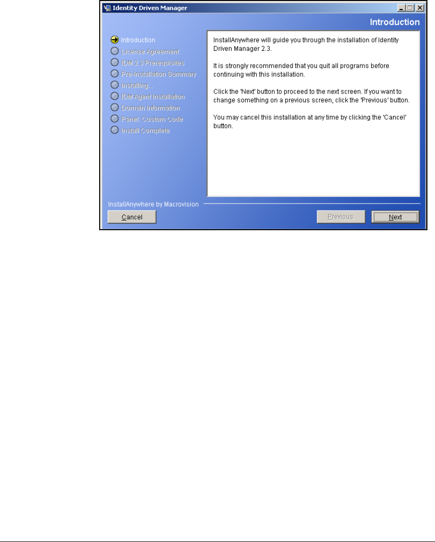
AD-174
Addendum: ProCurve Access Control Solution 2.1 Update
Configuring Network Access Control with IDM
Figure AD-153.Identity Driven Manager Wizard—Introduction Page
2. On the Introduction page, click Next.
3. On the License Agreement page, select I accept the terms of the License
Agreement, and then click Next.
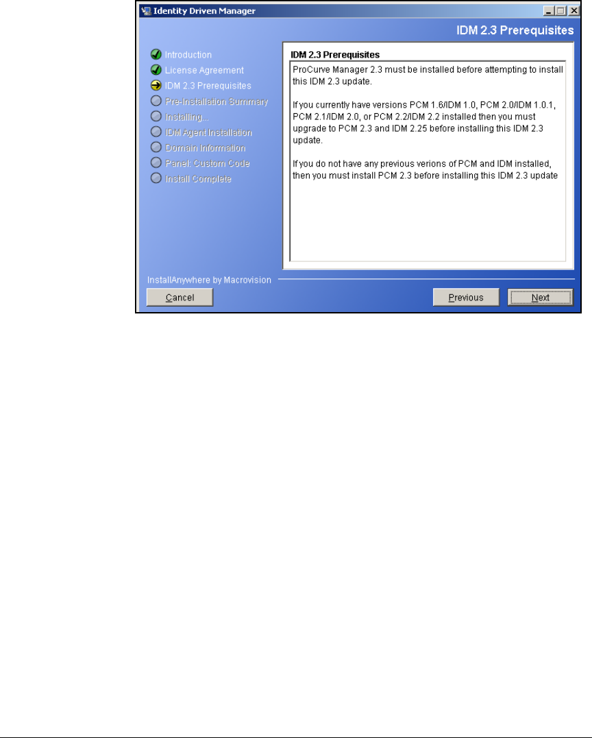
AD-175
Addendum: ProCurve Access Control Solution 2.1 Update
Configuring Network Access Control with IDM
Figure AD-154.Identity Driven Manager Wizard—IDM 2.3 Prerequisites Page
4. On the IDM 2.3 Prerequisites Page, click Next.
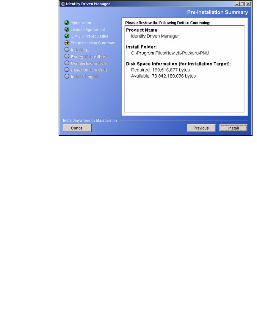
AD-176
Addendum: ProCurve Access Control Solution 2.1 Update
Configuring Network Access Control with IDM
Figure AD-155.Identity Driven Manager Wizard—Pre-Installation Summary Page
5. On the Pre-Installation Summary page, click Install. IDM will now be
installed. This process may take several minutes. During this time, several
windows will be displayed and closed. After this process is finished, the
IDM Agent Installation page is displayed.
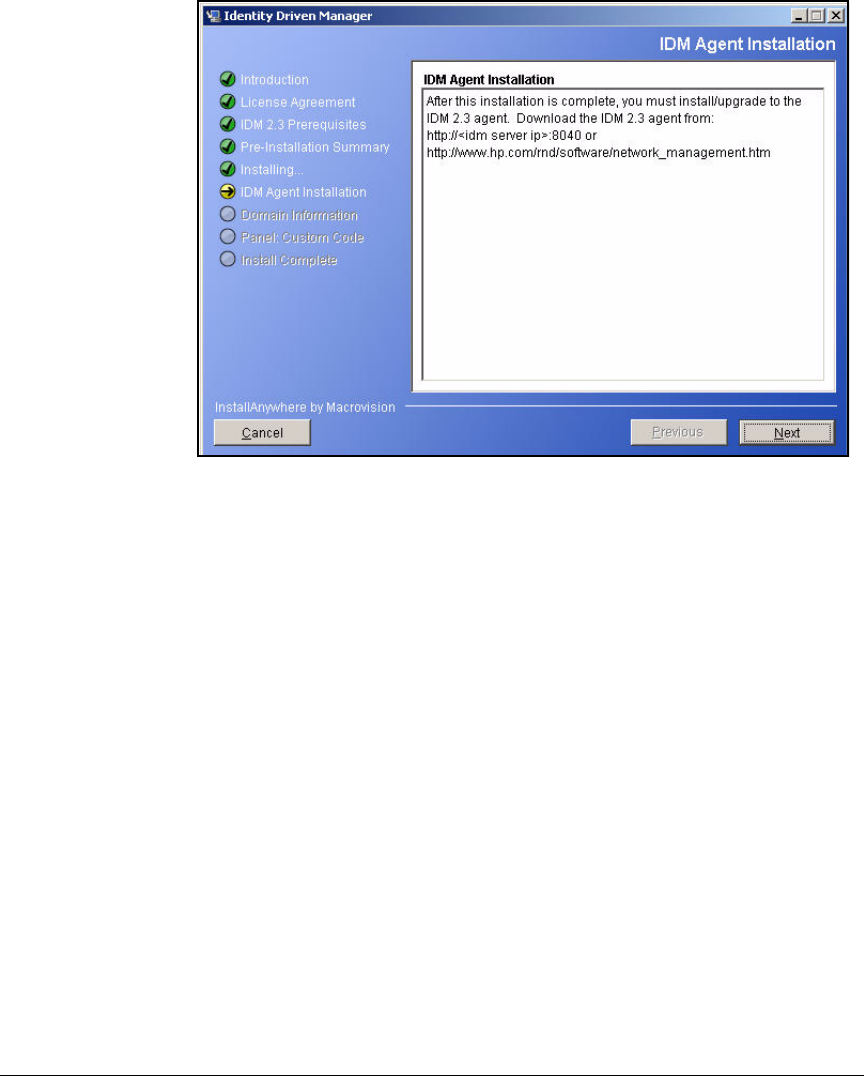
AD-177
Addendum: ProCurve Access Control Solution 2.1 Update
Configuring Network Access Control with IDM
Figure AD-156.Identity Driven Manager Wizard—IDM Agent Installation Page
6. In the IDM Agent Installation page, click Next.
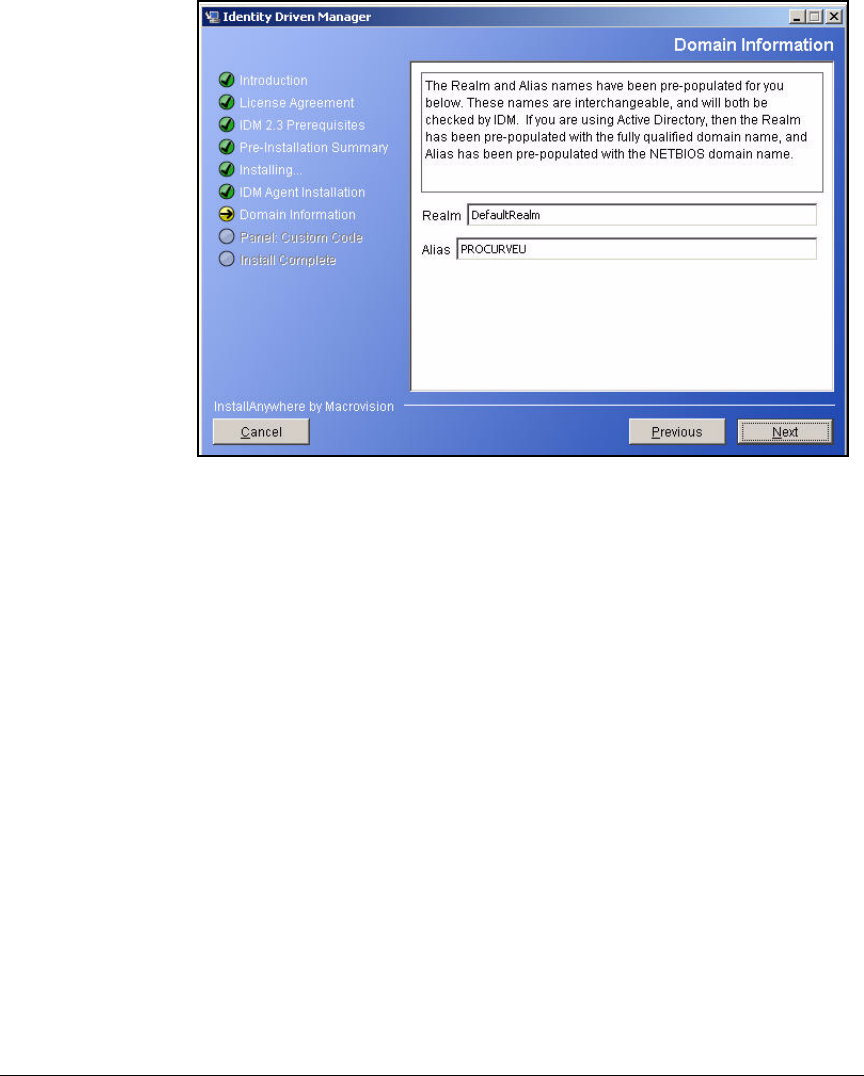
AD-178
Addendum: ProCurve Access Control Solution 2.1 Update
Configuring Network Access Control with IDM
Figure AD-157.Identity Driven Manager Wizard—Domain Information Page
7. In the Domain Information page, accept the default settings and click Next.
8. In the Database Migration page, click Next.
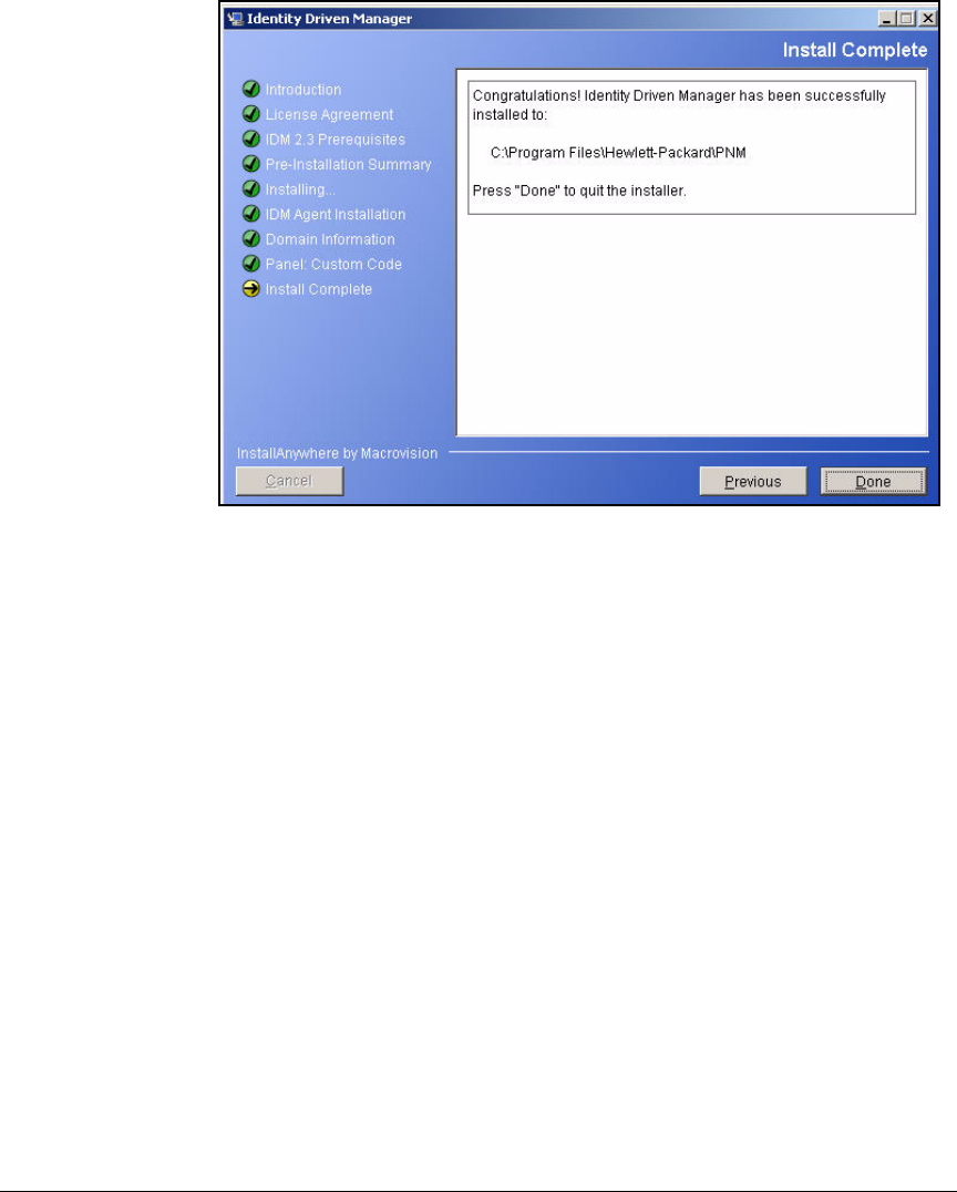
AD-179
Addendum: ProCurve Access Control Solution 2.1 Update
Configuring Network Access Control with IDM
Figure AD-158.Identity Driven Manager Wizard—Install Complete Page
9. In the Install Complete page, click Done.
Add the NPS Server to the Access.txt File
IDM will not add a NPS server to its managed devices unless the server’s IP
address is listed in PCM+’s access.txt file.
Follow these steps:
1. On the IDM server, open <PCM+ installation folder>\server\config\access.txt.
You chose the installation folder when you installed it. The default loca-
tion is: C:\Program Files\Hewlett-Packard\PNM\server\config\access.txt.
Open the file in a text-based editor such as Notepad or Wordpad.
2. Type the NPS server’s IP address or hostname. If you have multiple NPS
servers, type the address of each server on its own line. In this example,
type 10.4.4.16.
3. Save and close the file.
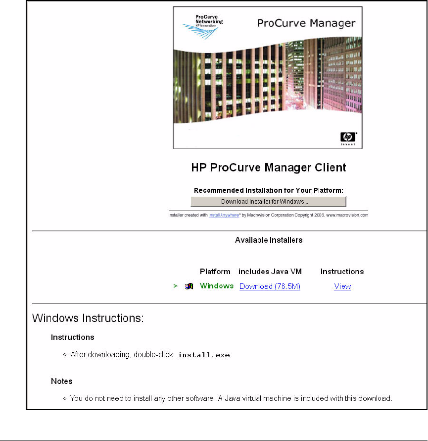
AD-180
Addendum: ProCurve Access Control Solution 2.1 Update
Configuring Network Access Control with IDM
Install the IDM Agent on the NPS Server
You can now install the IDM agent client on the NPS server. Follow these steps:
1. On the NPS server, open a Web browser such as Internet Explorer.
2. For the URL, type the IP address of the PCM+ server followed by a colon
and port 8040. In this example, you would type 10.2.1.50:8040.
Figure AD-159.HP ProCurve Manager Client Download (PCM+ Server:8040)
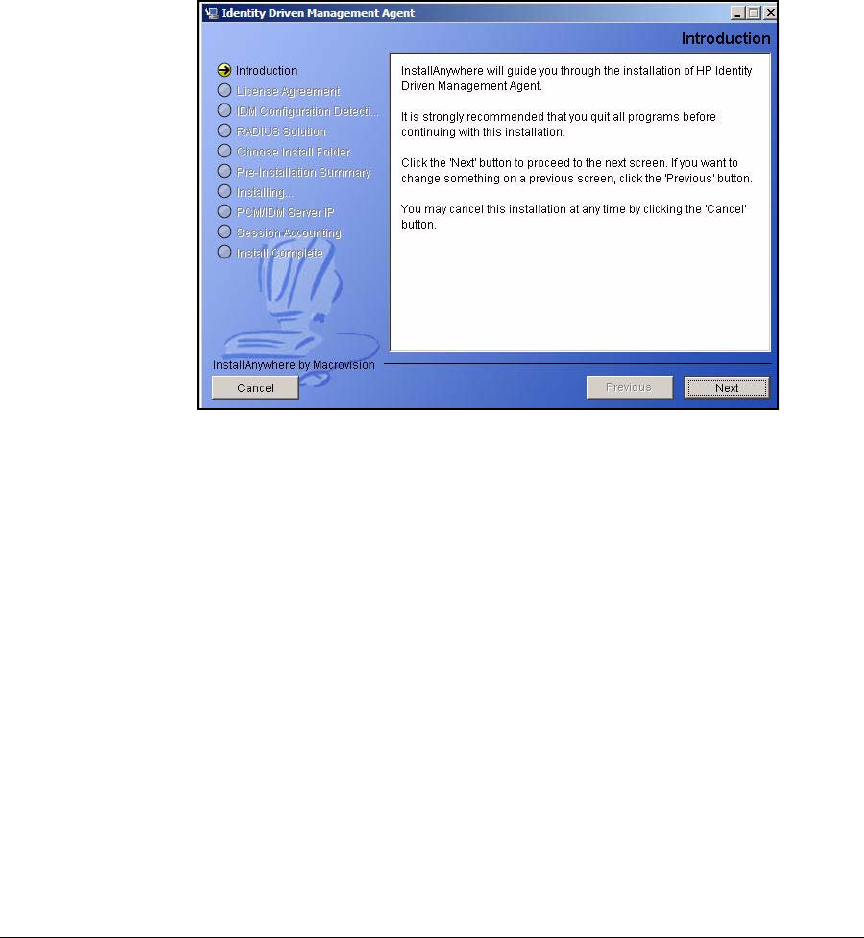
AD-181
Addendum: ProCurve Access Control Solution 2.1 Update
Configuring Network Access Control with IDM
3. Click the download link.
4. Save the install.exe file on the server.
5. When the file has downloaded, double-click it to start the installation. The
Identity Driven Management Agent installation is launched.
Figure AD-160.Identity Driven Management Agent—Introduction Page
6. In the Introduction page, click Next.
7. In the License Agreement page, select I accept the terms of the License
Agreement.
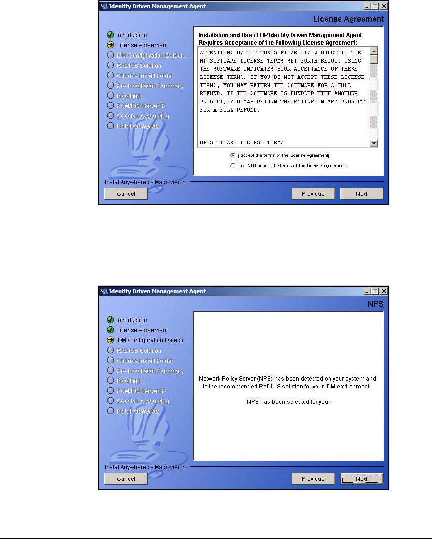
AD-182
Addendum: ProCurve Access Control Solution 2.1 Update
Configuring Network Access Control with IDM
Figure AD-161.Identity Driven Management Agent—License Agreement Page
8. Click Next.
9. In the IDM Configuration Detection page, click Next.
Figure AD-162.Identity Driven Management Agent—NPS Page
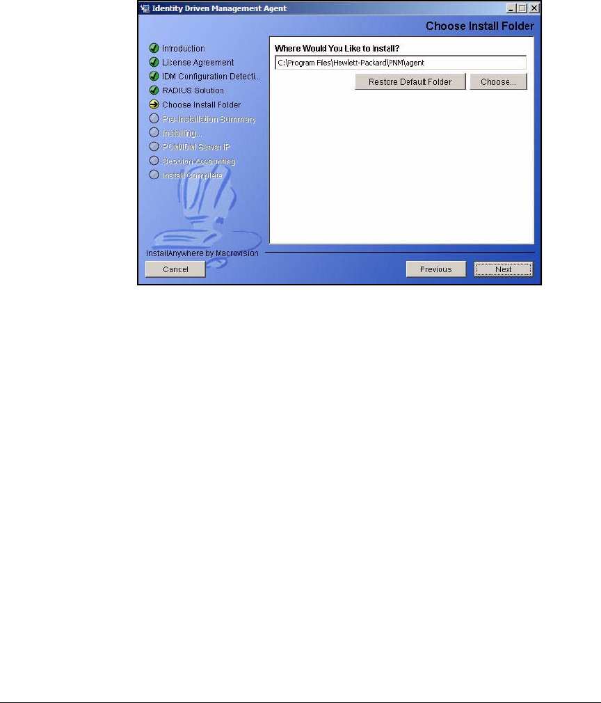
AD-183
Addendum: ProCurve Access Control Solution 2.1 Update
Configuring Network Access Control with IDM
10. The installation application detects that this server runs NPS. In the NPS
page, click Next.
Figure AD-163.Identity Driven Management Agent—Choose Install Folder Page
11. In the Choose Install Folder page, keep the default folder. Click Next.
12. In the Pre-Installation Summary page, click Install.
13. The page shown in Figure AD-164 is displayed. Wait while the agent
installs.
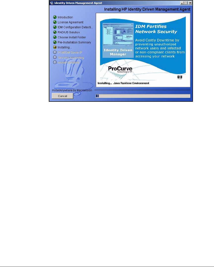
AD-184
Addendum: ProCurve Access Control Solution 2.1 Update
Configuring Network Access Control with IDM
Figure AD-164.Identity Driven Management Agent—Installing HP Identity
Driven Management Page
14. If the firewall is enabled on the NPS server (the default setting), the page
shown in Figure AD-164 is displayed. Verify that the Allow IDM Agent
Firewall Access check box is selected.

AD-185
Addendum: ProCurve Access Control Solution 2.1 Update
Configuring Network Access Control with IDM
Figure AD-165.Identity Driven Management Agent—Add Firewall Rules
for IDM Page
15. Click Next.
16. In the PCM/IDM Server IP page, type the IP address of the server that runs
PCM+/IDM. In this example, type 10.2.1.50.
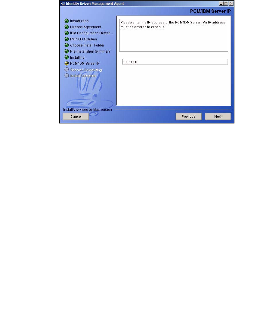
AD-186
Addendum: ProCurve Access Control Solution 2.1 Update
Configuring Network Access Control with IDM
Figure AD-166.Identity Driven Management Agent—PCM/IDM Server IP Page
17. Click Next.
18. In the Install Complete page, click Done.
Verify That IDM Detects the NPS Server
You should that IDM detects the NPS server and adds it as a RADIUS server:
1. Open the PCM+ client, which is automatically installed on the PCM+/IDM
server.
The first time that you access the client, you must choose the server.
2. Click the server displayed in the Management servers found box and click
Connect.
Or enter the IP address of the PCM+ server in the Direct Address box.

AD-187
Addendum: ProCurve Access Control Solution 2.1 Update
Configuring Network Access Control with IDM
Figure AD-167.ProCurve Manager Login Window
3. In the Login window, enter the Administrator credentials that you set up
when you installed PCM+.

AD-188
Addendum: ProCurve Access Control Solution 2.1 Update
Configuring Network Access Control with IDM
Figure AD-168.ProCurve Manager—Network Management Home Window
4. To open the Identity Management Home window, click the Identity tab at the
bottom of the navigation tree.
Identity tab
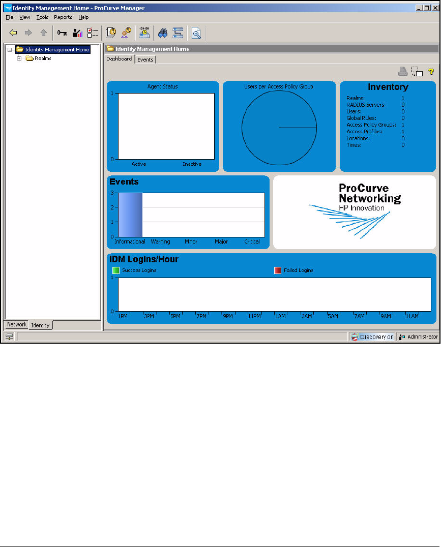
AD-189
Addendum: ProCurve Access Control Solution 2.1 Update
Configuring Network Access Control with IDM
Figure AD-169.ProCurve Manager—Identity Management Home Window
5. In the IDM navigation tree, expand Realms.
6. Expand your realm. In this example, expand ProCurveU.com).
7. Expand the RADIUS Servers folder.

AD-190
Addendum: ProCurve Access Control Solution 2.1 Update
Configuring Network Access Control with IDM
Figure AD-170.PCM+ Console, IDM Interface—
Realms > <myrealm> > ProCurve
Network Access Controllers
8. Verify that the NPS server is displayed in the RADIUS Servers folder.
Enable Endpoint Integrity
Later you will set up access policy rules to quarantine endpoints that do not
comply with the NAP health requirements. First, however, you must enable
endpoint integrity in IDM. Follow these steps:
1. You should be in the Identity Management Home window of PCM+.

AD-191
Addendum: ProCurve Access Control Solution 2.1 Update
Configuring Network Access Control with IDM
Figure AD-171.ProCurve Manager—Identity Management Home Window
2. In the Tools menu, click Preferences. (Or click the Preferences button.)
3. Select Identity Management.
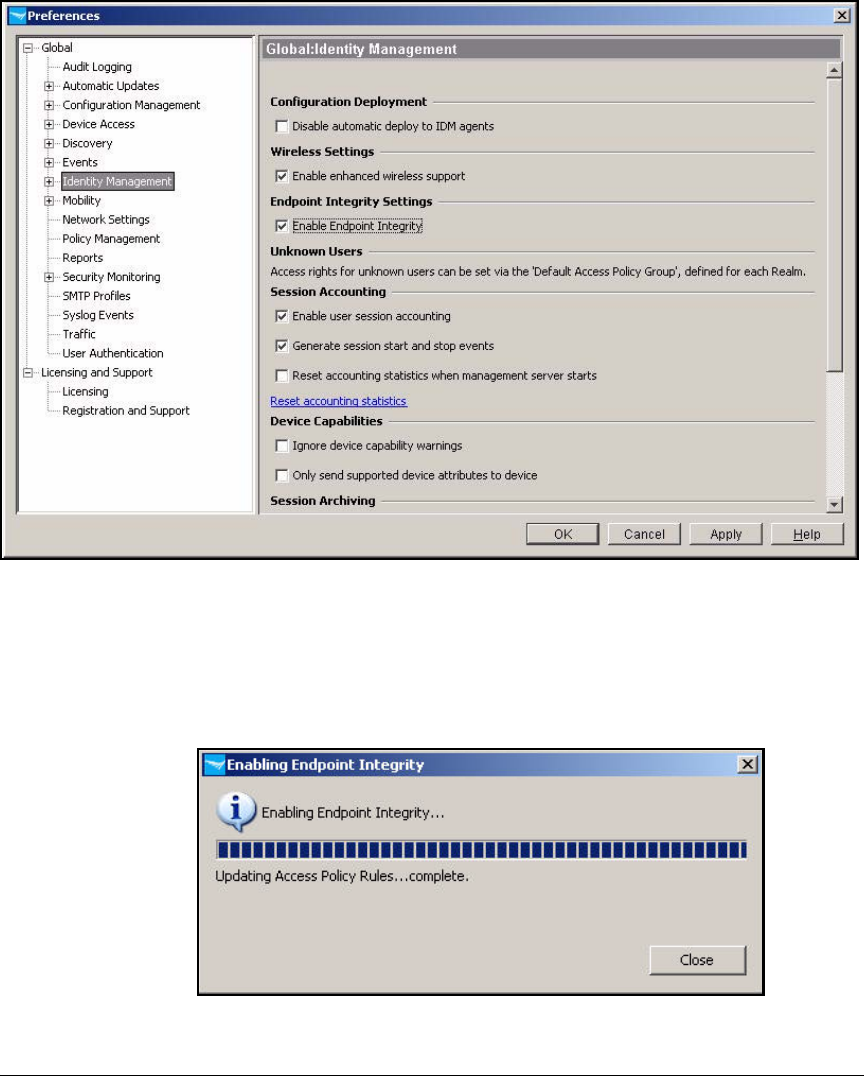
AD-192
Addendum: ProCurve Access Control Solution 2.1 Update
Configuring Network Access Control with IDM
Figure AD-172.ProCurve Manager—Preferences > Global > Identity Management
Window
4. Select the Enable Endpoint Integrity check box.
5. Click OK.
Figure AD-173.ProCurve Manager—Enabling Endpoint Integrity Window
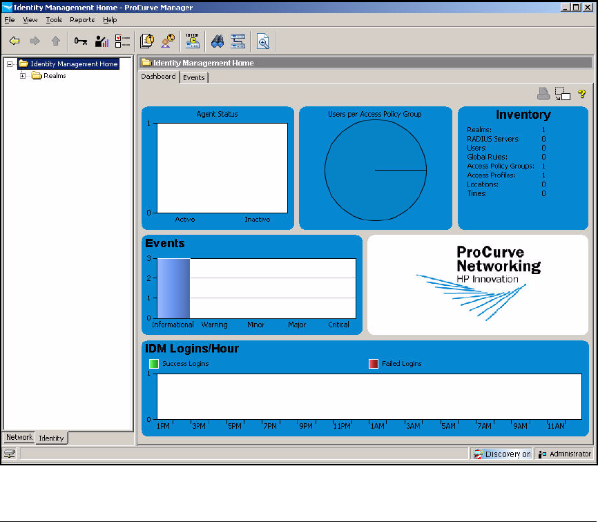
AD-193
Addendum: ProCurve Access Control Solution 2.1 Update
Configuring Network Access Control with IDM
6. Click Close in the Enabling Endpoint Integrity window.
Add Access Policy Groups and Users
In this implementation, the NPS server authenticates users against Active
Directory accounts. IDM can synchronize with Active Directory and add
domain security groups as access policy groups. When IDM synchronizes with
a group, it automatically adds group members as users in the corresponding
policy group.
Follow these steps to synchronize IDM with Active Directory:
1. You should be in the Identity Management Home window of PCM+.
Figure AD-174.ProCurve Manager—Identity Management Home Window
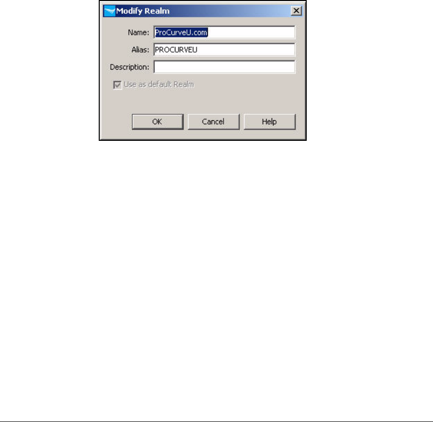
AD-194
Addendum: ProCurve Access Control Solution 2.1 Update
Configuring Network Access Control with IDM
2. In the left pane, right-click your domain’s realm name and select Modify
Realm.
3. For Alias, if not already specified, type the NetBIOS (workgroup) name
of your domain. In this example: PROCURVEU.
Some users may log in with the “ProCurve.com” domain name and some
with the “PROCURVEU” NetBIOS name. Setting the alias ensures that
IDM does not create a separate realm for PROCURVEU the first time that
a user logs in with that name.
Figure AD-175.ProCurve Manager—Modify Realm Window
4. Click OK.
5. In the Tools menu, click Preferences. (Or click the Preferences icon in the
global toolbar.)
6. Expand Identity Management and select User Directory Settings.
7. Select the Enable automatic Active Directory synchronization check box.
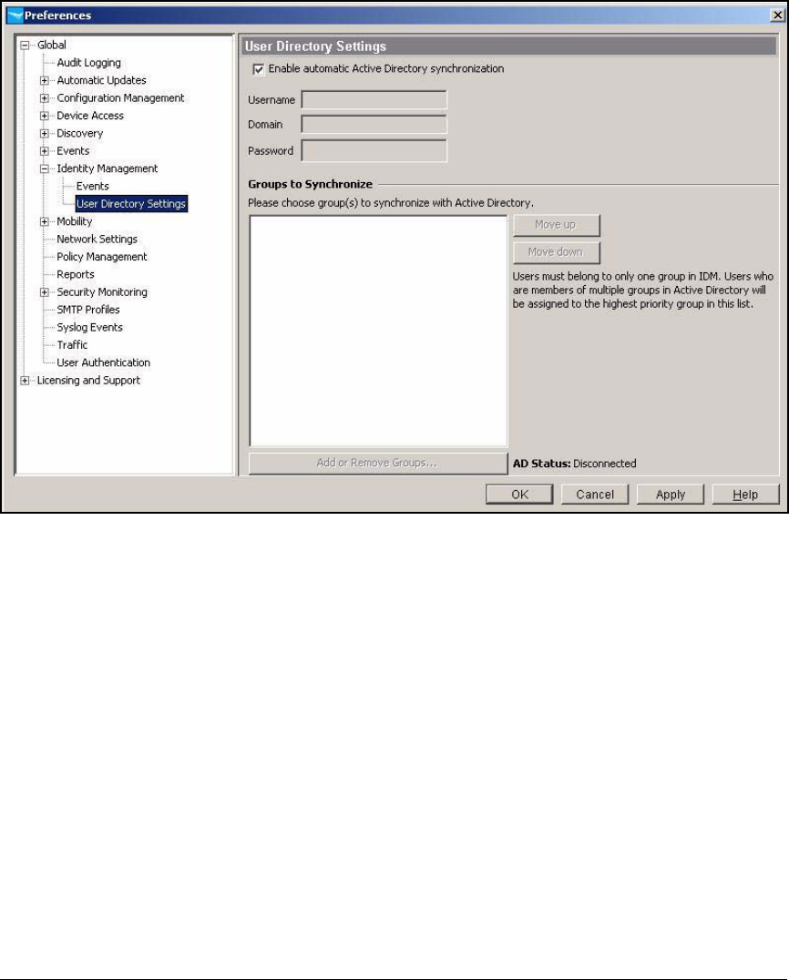
AD-195
Addendum: ProCurve Access Control Solution 2.1 Update
Configuring Network Access Control with IDM
Figure AD-176.ProCurve Manager—Preferences > Global > Identity Management >
User Directory
8. In the Username and Password boxes, type credentials for an administrator
of the domain. In this example, type Administrator and ProCurve0.
9. For Domain, type your domain name. In this example, type ProCurveU.com.
10. Click Add or Remove Groups.
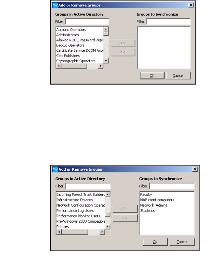
AD-196
Addendum: ProCurve Access Control Solution 2.1 Update
Configuring Network Access Control with IDM
Figure AD-177.ProCurve Manager—Add or Remove Groups Window
11. The Add or Remove Groups window displays all Active Directory groups.
Select the name of a group and click the >> button so that IDM will
synchronize with it. Select all the groups that you set up for access rights.
In this example, these groups are:
• Faculty
• NAP client computers
• Network_Admins
• Students
Figure AD-178.PCM+ Console—Add or Remove Groups Window
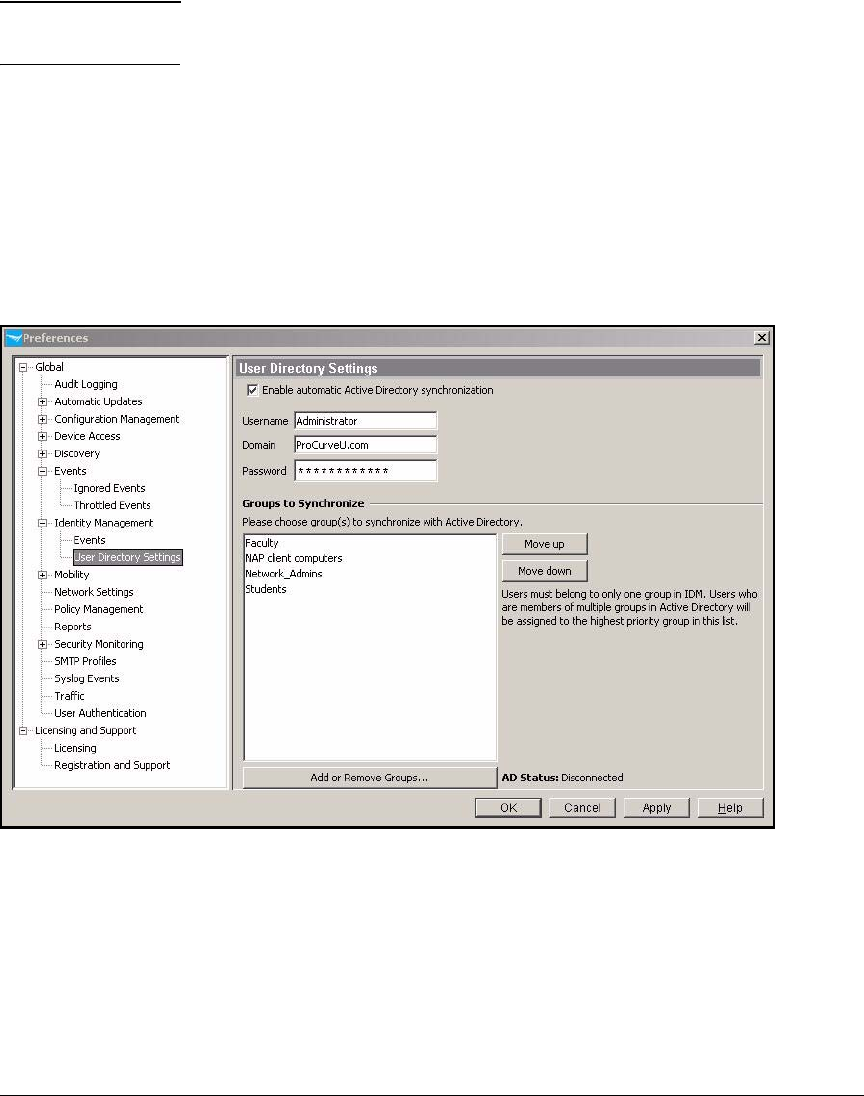
AD-197
Addendum: ProCurve Access Control Solution 2.1 Update
Configuring Network Access Control with IDM
Note Although a user can be a member of multiple Active Directory groups, he
or she should be a member of only one group that is synchronized in IDM.
12. Click OK to save the settings and close the window.
13. If any users belong to more than one group, you must decide which group
will take precedence in IDM because each user can belong to only one
group in IDM. IDM will assign the user to the group that is listed first in
the Groups to Synchronize pane. In this example, the user groups are
mutually exclusive, but if you needed to move a group to a different
position, you would select the group name and click the Move up or Move
down button to change its position.
Figure AD-179.ProCurve Manager—Preferences > Identity Management > User
Directory Settings
14. Click OK.
Each group is added to IDM as an access policy group. All users who
belong to the selected groups are imported with the current Windows user
login credentials.
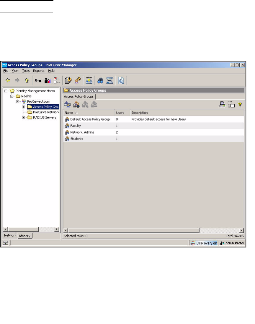
AD-198
Addendum: ProCurve Access Control Solution 2.1 Update
Configuring Network Access Control with IDM
Note IDM can import about 8 to 10 users per second.
15. In the left pane, expand your realm and select Access Policy Groups. The
Users column now shows the number of Active Directory user accounts
that were imported into each group.
16. Click OK.
Figure AD-180.ProCurve Manager—Access Policy Groups

AD-199
Addendum: ProCurve Access Control Solution 2.1 Update
Configuring Network Access Control with IDM
Define Network Resources
You must define every resource that you want to control. These can include:
■A single device—an IP address
■Applications (such as DHCP, DNS, and HTTP)—TCP or UDP ports
(or other protocols)
■Applications on a single device—an IP address and TCP or UDP ports
■A VLAN—a subnet network address
Table AD-8 shows resources for the example network.
Table AD-8. PCU Resources
To define resources, follow these steps:
1. In the ProCurve Manager console, click the Identity tab.
Resource IP Address Protocol Port or Ports
NPS 10.4.4.16 IP Any
DHCP Any UDP 67
DNS (UDP) Any UDP 53
DNS (TCP) Any TCP 53
Email 10.4.6.40 TCP 25, 143, 110
Other network
services
10.4.0.0/16 IP Any
Faculty databases 10.5.0.0/16 IP Any
Management
VLAN
10.2.0.0/16 IP Any
Faculty VLAN 10.8.0.0/16 IP Any
Students VLAN 10.10.0.0/16 IP Any
Computer VLAN 10.9.0.0/16 IP Any
Private network 10.0.0.0/8 IP Any
Internet Any TCP 21, 80, 443

AD-200
Addendum: ProCurve Access Control Solution 2.1 Update
Configuring Network Access Control with IDM
Figure AD-181.ProCurve Manager—Identity Management Home Window
2. Click your realm. In this example, click ProCurveU.com.
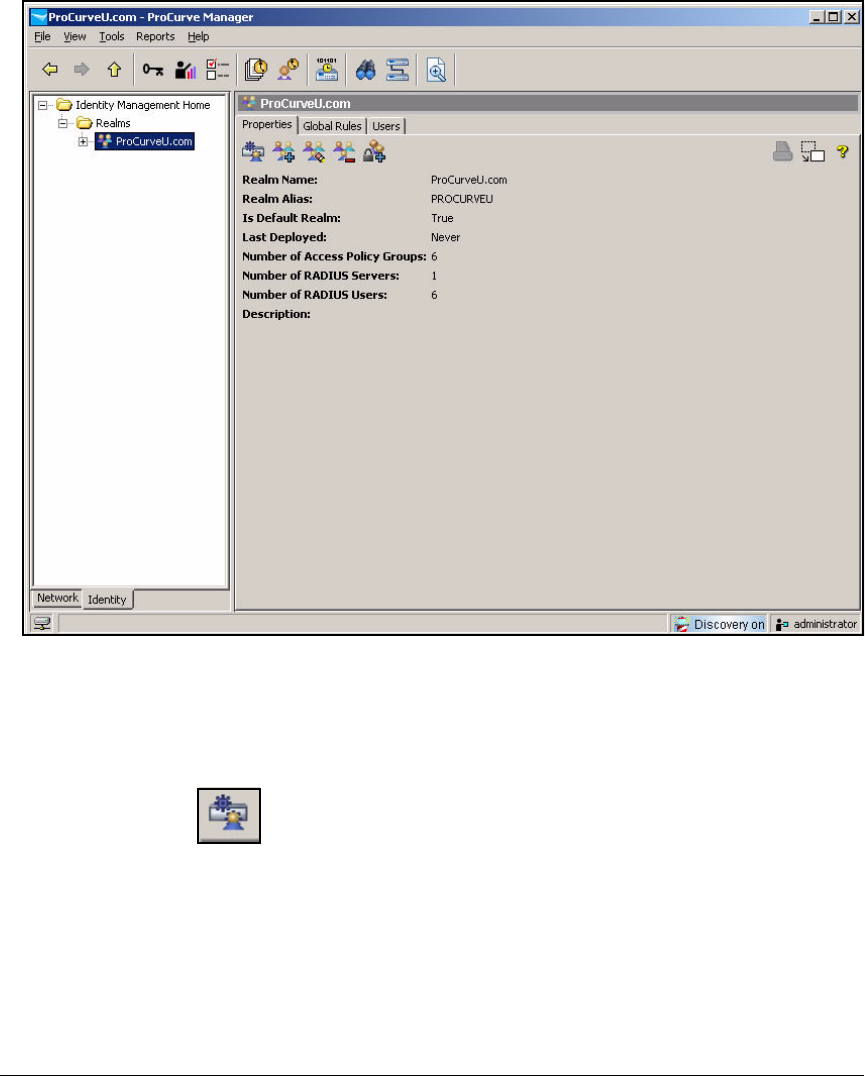
AD-201
Addendum: ProCurve Access Control Solution 2.1 Update
Configuring Network Access Control with IDM
Figure AD-182.ProCurve Manager—<my realm>
3. In the right pane, make sure that the Properties tab is selected. Click the
Configure Identity Management button.
Figure AD-183.Identity Management—Configure Identity Management Button
4. Click Network Resources in the left pane of the Identity Management Con-
figuration window.

AD-202
Addendum: ProCurve Access Control Solution 2.1 Update
Configuring Network Access Control with IDM
Figure AD-184.Identity Management Configuration Window
5. Click the Create a new Network Resource button in the right pane.
Create a new Network
Resource button
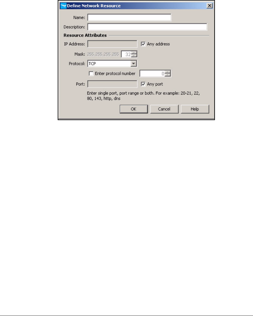
AD-203
Addendum: ProCurve Access Control Solution 2.1 Update
Configuring Network Access Control with IDM
Figure AD-185.ProCurve Manager—Define Network Resource Window
6. Follow these steps to set up a resource that is an application type such
as DHCP:
a. In the Define Network Resource window, type a string in the Name box
to identify the application or applications. In this example, type DHCP.
b. In the Description box, type a description, if desired.
c. Select the Any address check box.
If you want, you could clear the check box and restrict users to
accessing this application on a particular device or subnet. Type the
appropriate IP address for the IP Address and Mask.
d. From the Protocol list, select the protocol. In this example, select UDP.
e. Clear the Any port check box and type the appropriate values for the
Port. You can type one port, ranges of ports, or multiple, non-
consecutive ports, separated by a comma. In this example, type 67.
f. Click OK.
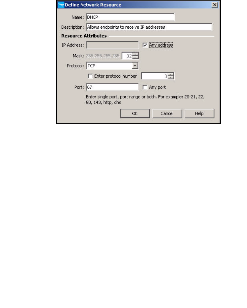
AD-204
Addendum: ProCurve Access Control Solution 2.1 Update
Configuring Network Access Control with IDM
Figure AD-186.ProCurve Manager—Define Network Resource Window—
DHCP
7. To set up a resource that is an entire VLAN, follow these steps:
a. In the Define Network Resource window, type a string in the Name box
to identify the VLAN. In this example, type Faculty databases.
b. In the Description box, type a description, if desired.
c. Clear the Any address check box.
d. For the IP Address, type the network address of the subnet associated
with the VLAN. In this example, type 10.5.0.0.
e. For the Mask, type or select the prefix length for the subnet. In this
example, type 16.
f. For Protocol, select IP.
g. Click OK.

AD-205
Addendum: ProCurve Access Control Solution 2.1 Update
Configuring Network Access Control with IDM
Figure AD-187.ProCurve Manager—Define Network Resource Window—
Faculty databases
8. Follow these steps to set up a resource that is a single device:
a. In the Define Network Resource window, type a string in the Name box
to identify the device. In this example, type NPS.
b. In the Description box, type a description, if desired.
c. Clear the Any address check box.
d. For the IP Address, type the device’s IP address. In this example, type
10.4.4.16.
e. For the Mask, select the 16.
f. From the Protocol list, select the protocol (IP is the default and allows
all IP traffic). In this example, select IP.
g. Set up the ports:
i. To allow any traffic to this device, select the Any port check box.
ii. If you want to restrict access to one or several single applications,
clear the Any port check box and type the appropriate values for
the Port.
In this example, you should select the Any port check box.
h. Click OK.
9. Repeat step 5, 6, 7, or 8 to set up each resource for your network.
10. When you are finished, click Close.

AD-206
Addendum: ProCurve Access Control Solution 2.1 Update
Configuring Network Access Control with IDM
Create Access Profiles
A profile defines a set of rights, including:
■VLAN assignment
■Quality-of-service (QoS) settings
■Rate limit
■Resources allowed and resources denied
Note For each profile, you can also choose whether, by default, all resources not
specifically defined are denied or whether they are allowed. This is called the
default access option. In this example, you will allow specific resources and
deny all others; the default access option is deny.
Although you can create several profiles for a single group of users—and then
assign those profiles under various circumstances—in this example, each user
group requires at least two profiles:
■One profile for normal access
■One profile for quarantined access for non-compliant endpoints
All access policy groups will share the same profile for non-compliant
endpoints.
Non-compliant endpoints are allowed to send DHCP traffic and traffic to
the NPS so that they can be retested. They can also send traffic within the
Quarantine VLAN, in which remediation servers are installed.
Note NAP client computers will use the default profile.
l
The example profiles that you will learn how to create in this section are
displayed in Table AD-9.

AD-207
Addendum: ProCurve Access Control Solution 2.1 Update
Configuring Network Access Control with IDM
Table AD-9. Network Resource Assignments per Access Profile
Follow these steps to create the profiles:
1. You should be at the Identity Management Home window. (In the ProCurve
Manager console, click the Identity tab.)
2. Expand Realms and click your realm. In this example, click ProCurveU.com.
3. At the Properties tab in the right pane, click the Configure Identity Manage-
ment button.
4. In the Identity Management Configuration window, click Access Profiles in
the navigation tree.
Access Profile VLAN ID QoS Ingress
Rate-
Limit
Allowed Resources Denied Resources Default
Access
Network_Admins 2 Don’t
override
Don’t
override
All None Allow
Faculty 8 Don’t
override
Don’t
override
•DHCP
• DNS (TCP)
•DNS (UDP)
• Email
• Other network services
• Faculty VLAN
• Faculty databases
• Internet
Private network Deny
Students 10 Don’t
override
Don’t
override
•DHCP
• DNS (TCP)
•DNS (UDP)
• Email
• Other network services
• Students VLAN
• Internet
Private network Deny
Non-Compliant 32 Don’t
override
1000 Kbps • DHCP
•NPS
None Deny
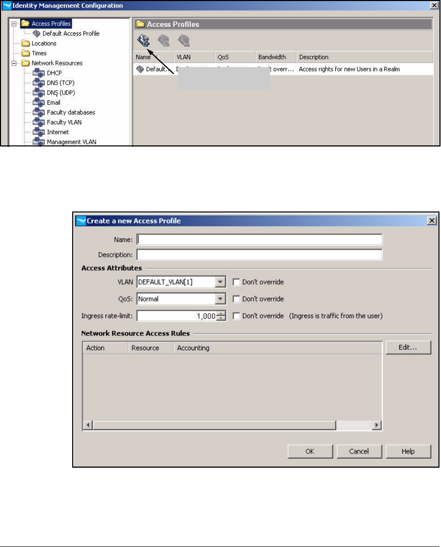
AD-208
Addendum: ProCurve Access Control Solution 2.1 Update
Configuring Network Access Control with IDM
Figure AD-188.Identity Management Configuration—Access Profiles
5. Click the Create a new Access Profile button.
Figure AD-189.ProCurve Manager—Create a new Access Profile
Create a new Access
Profile button
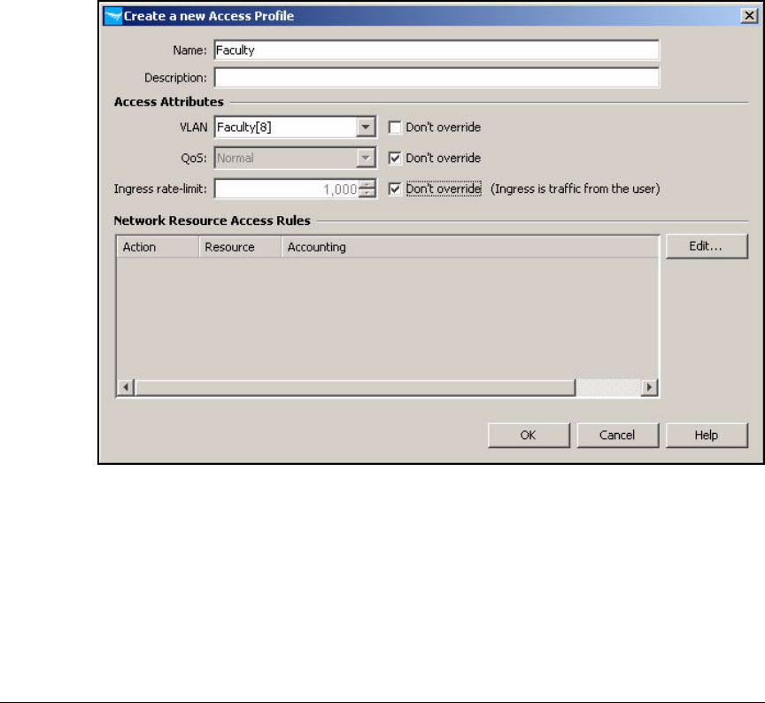
AD-209
Addendum: ProCurve Access Control Solution 2.1 Update
Configuring Network Access Control with IDM
6. In the Name box, type the name of the access profile. In this example, you
are creating the profile for the Faculty group under normal circumstances.
You name the profile Faculty.
7. In the Description box, type a description, if desired.
8. From the VLAN list, select the ID for the users’ normal VLAN. In this
example, select 8.
9. For QoS, either select the QoS level or select the Don’t override check box.
10. For Ingress rate-limit, either type the rate limit in Kbps or select the Don’t
override check box.
Figure AD-190.ProCurve Manager—Create a new Access Profile
11. In the Network Resource Access Rules area, click Edit.

AD-210
Addendum: ProCurve Access Control Solution 2.1 Update
Configuring Network Access Control with IDM
Figure AD-191.Edit Network Resource Assignment Wizard—Welcome Page
12. In the Welcome to the Network Resource Assignment Wizard page, click Next.
13. From the Available Resources pane, select a resource and click the >>
button. Repeat for each network resource that you want to assign to this
profile. In this example, add the resources shown in the Allowed Resources
area in Figure AD-192.
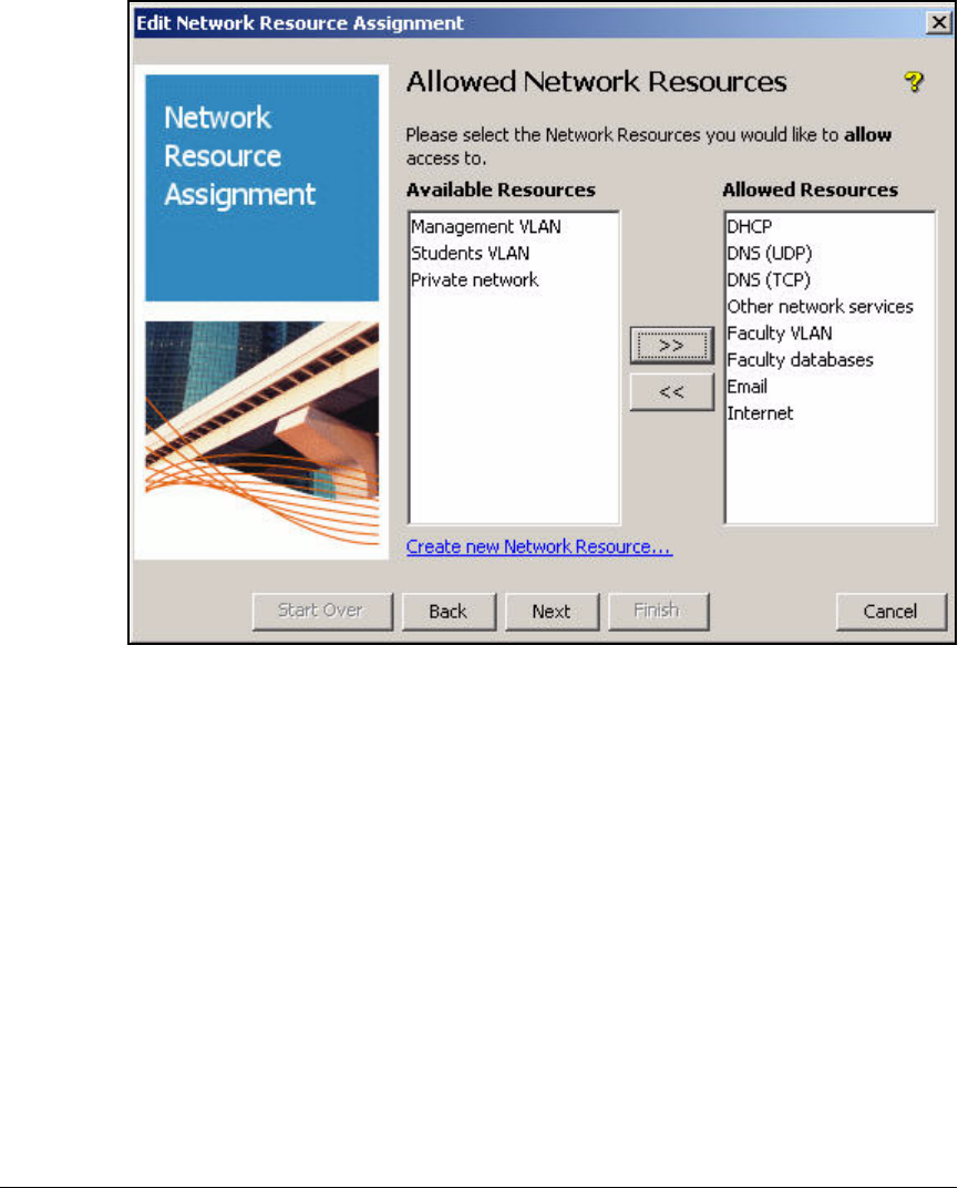
AD-211
Addendum: ProCurve Access Control Solution 2.1 Update
Configuring Network Access Control with IDM
Figure AD-192.Edit Network Resource Assignment Wizard—Allowed Network
Resources Page
14. When all of the desired resources are in the Allowed Resources pane,
click Next.
15. If you would like to deny this group access to any of the remaining
resources, repeat the previous step for resources that you want to deny.
You might need to deny resources when:
• A resource is a subset of an allowed resource
For example, you can grant users access to an entire VLAN, but deny
them access to a single server in that VLAN.
In this example, you have granted users access to the Internet by
allowing them to send any FTP, HTTP, or HTTPS traffic. Now you will
deny access to a subset of that traffic: the entire private network.
Users, of course, can access the private resources to which you have
specifically granted them rights.
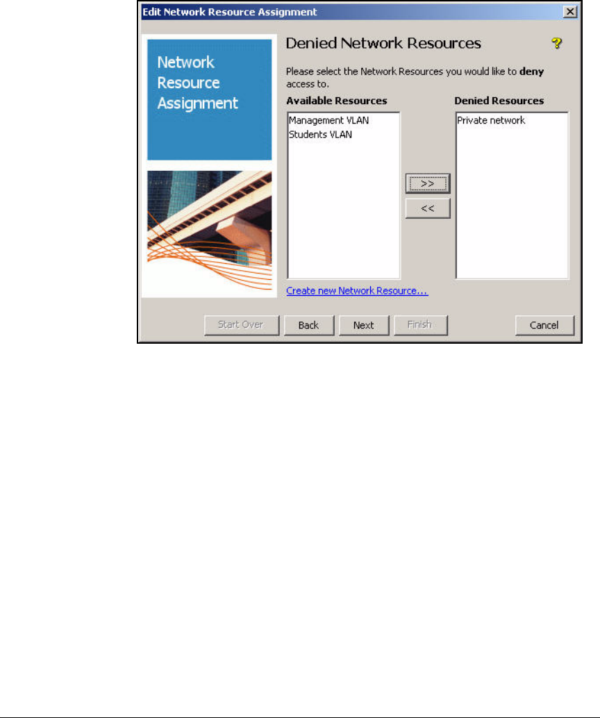
AD-212
Addendum: ProCurve Access Control Solution 2.1 Update
Configuring Network Access Control with IDM
• You use the strategy of allowing all resources, by default
Figure AD-193.Edit Network Resource Assignment Wizard—Denied Network
Resources Page
16. When you are finished, click Next.

AD-213
Addendum: ProCurve Access Control Solution 2.1 Update
Configuring Network Access Control with IDM
Figure AD-194.Edit Network Resource Assignment Wizard—Priority
Assignment Page
17. If you would like to assign any of the allow or deny actions a priority, select
the resource for which you would like to modify the order. Then click
either the Move down or Move up button until it is in the desired order.
You only need to complete this step if the defined resources include
overlapping resources. Generally, the more-specific rule should have a
higher priority.
In this example, you must place the rules that allow specific private
resources first. Next is the rule that denies access to the rest of the private
network. Place the rule that allows access to the Internet at the end of
the list.
18. When you are finished, click Next.

AD-214
Addendum: ProCurve Access Control Solution 2.1 Update
Configuring Network Access Control with IDM
Figure AD-195.Edit Network Resource Assignment Wizard—Default Access Page
19. In the Default Access window, select Deny Access or Allow Access for any
resources that were not explicitly allowed or denied. The more secure
option is Deny Access.
20. Click Next.
21. In the Resource Accounting window, select the check box next to resources
for which you would like to enable accounting. Typically, you should
select only the check boxes for denied resources.
Logging every time traffic is allowed quickly fills logs with relatively
unimportant information.
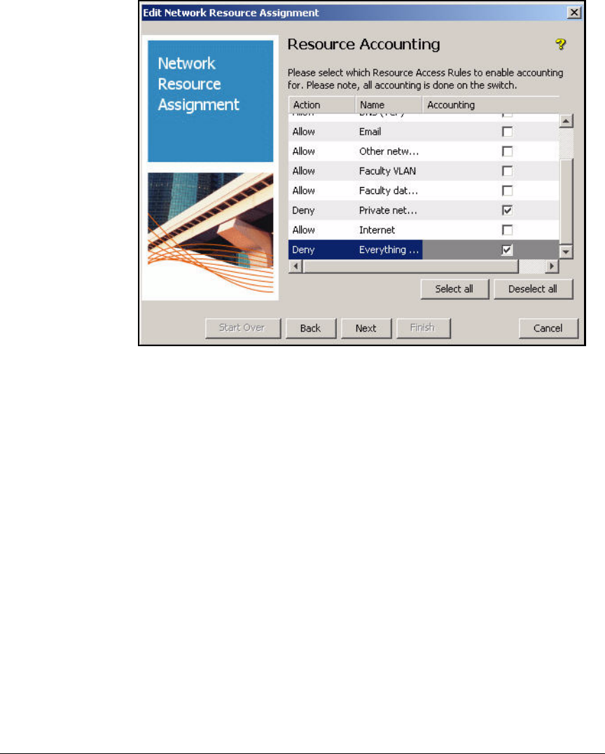
AD-215
Addendum: ProCurve Access Control Solution 2.1 Update
Configuring Network Access Control with IDM
Figure AD-196.Edit Network Resource Assignment Wizard—Resource
Accounting Page
22. Click Next.
23. Click Finish.
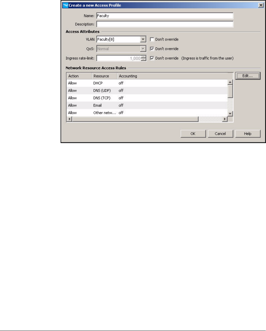
AD-216
Addendum: ProCurve Access Control Solution 2.1 Update
Configuring Network Access Control with IDM
Figure AD-197.Edit Network Resource Assignment Wizard—Create a new Access
Profile Window
24. Click OK in the Create a new Access Profile window.
25. Repeat steps 5 through 23 for each profile that you designed for your
network.
Figure AD-198 shows the completed profiles planned in Table AD-9.
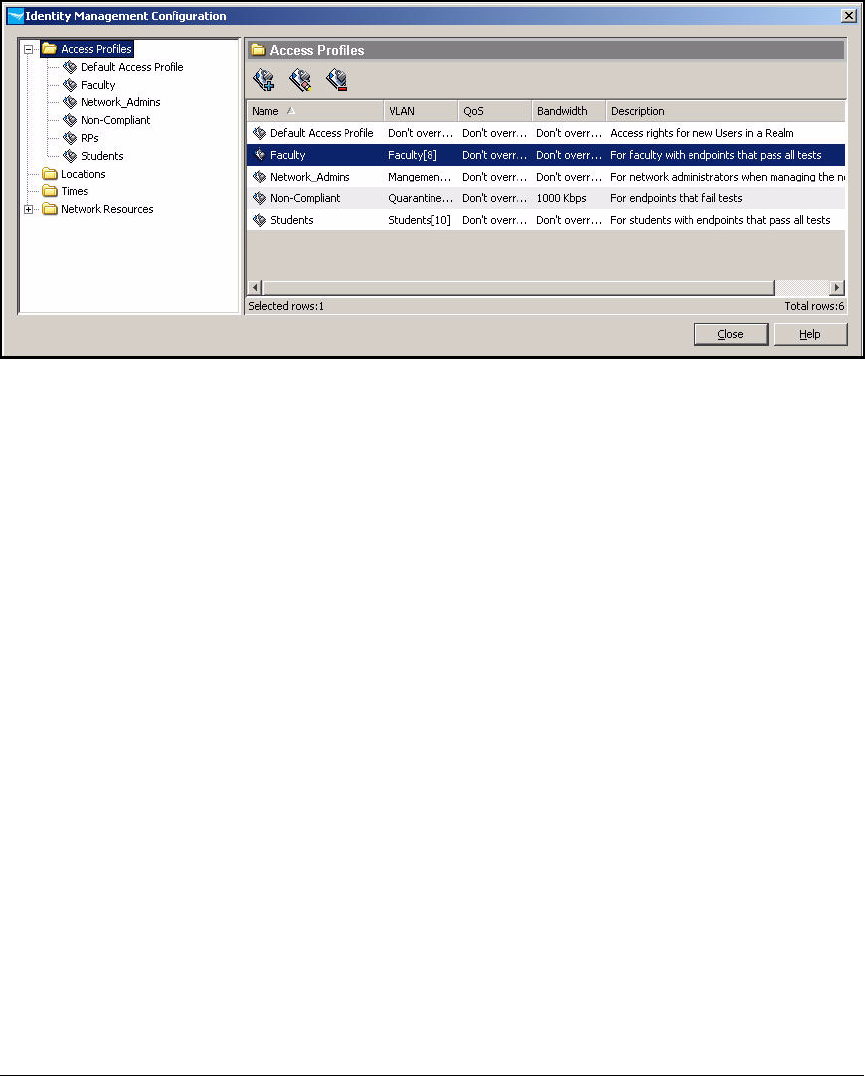
AD-217
Addendum: ProCurve Access Control Solution 2.1 Update
Configuring Network Access Control with IDM
Figure AD-198.Identity Management Configuration > Access Profiles
26. Click Close on the Identity Management Configuration window.
Configure Access Policy Groups
An access policy group rule specifies the profile that an authenticated user in
that group receives, given a particular set of criteria, including:
■Time
■Location
■System (whether the endpoint is one that has been marked as belonging
to the user)
■WLAN
■Endpoint integrity status
In this example, network access will controlled solely based on user group
and endpoint integrity status. Table AD-10 shows the example rules.

AD-218
Addendum: ProCurve Access Control Solution 2.1 Update
Configuring Network Access Control with IDM
Table AD-10.Access Policy Group Rules
Note See the ProCurve Identity Driven Manager User’s Guide for more informa-
tion on settings up rules—for example, rules based on access time and
location.
Follow these steps to configure access policy group rules:
1. In the ProCurve Management console, click the Identity tab.
2. Expand Realms > <your realm> > Access Policy Groups in the left pane.
Group Endpoint
Integrity
Profile
Network_Admins Pass Network_Admins
Unknown Non-Compliant
Fail Non-Compliant
Faculty Pass Faculty
Unknown Non-Compliant
Fail Non-Compliant
Students Pass Students
Unknown Non-Compliant
Fail Non-Compliant
NAP client
computers
Pass Default access profile
Unknown Non-Compliant
Fail Non-Compliant
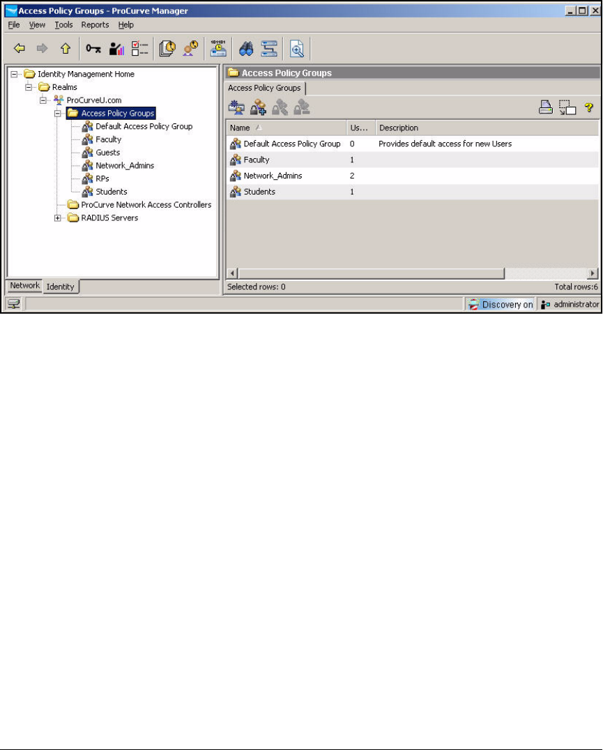
AD-219
Addendum: ProCurve Access Control Solution 2.1 Update
Configuring Network Access Control with IDM
Figure AD-199.ProCurve Manager—Access Policy Groups
3. Under Access Policy Groups, the groups synchronized with Active Direc-
tory are displayed. Select the group for which you want to set up access
policy rules.
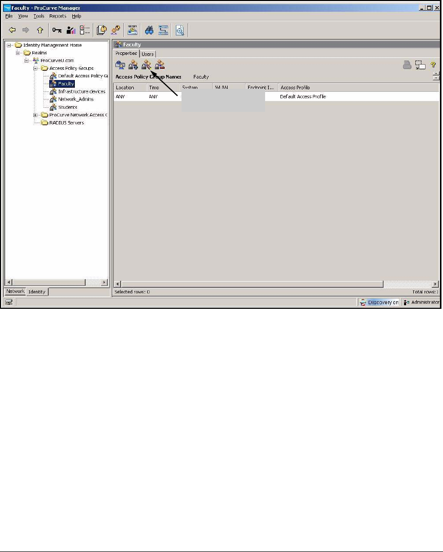
AD-220
Addendum: ProCurve Access Control Solution 2.1 Update
Configuring Network Access Control with IDM
Figure AD-200.ProCurve Manager—<my access policy group>
4. Click the Modify Access Policy Group button.
5. By default, the access policy group includes a rule that grants default
access under all conditions. You must change this rule to specify the
access profile that you set up for this group. Select the rule and click Edit.
6. Set your criteria for users in this group that pass endpoint integrity tests:
a. For the Location, select a location or ANY. In this example, keep the
default, ANY.
b. For the Time, select a time or ANY. In this example, keep the default,
ANY.
c. For the System, select OWN (the endpoint associated with the user)
or ANY (any endpoint). In this example, keep the default, ANY.
d. For WLAN, select a specific WLAN or ANY. In this example, select ANY.
e. For the Endpoint Integrity, select PASS.
Modify Access
Policy Group button
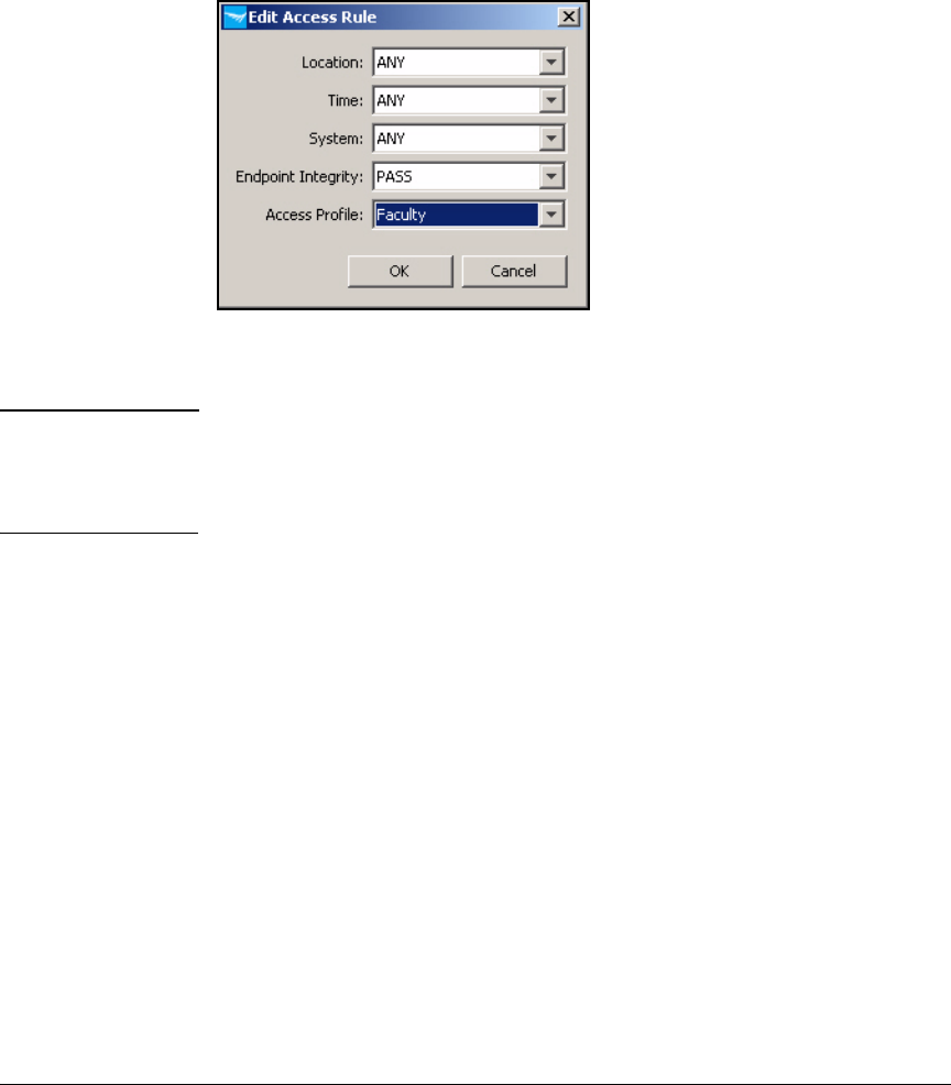
AD-221
Addendum: ProCurve Access Control Solution 2.1 Update
Configuring Network Access Control with IDM
f. For the Access Profile, select the access profile that you created for
this group. For example, if you are configuring the Faculty access
policy group, select the Faculty access profile.
Figure AD-201.ProCurve Manager—Edit
Access Rule Window
Note In this example, criteria such as location and time do not affect access. If you
want to designate a location or time other than ANY, you must configure that
location or time prior to editing the access rules. Refer to the ProCurve
Identity Driven Manager User’s Guide for more instructions.
7. Click OK.
8. Now, add rules for users with endpoints that have not passed endpoint
integrity tests and must be quarantined.
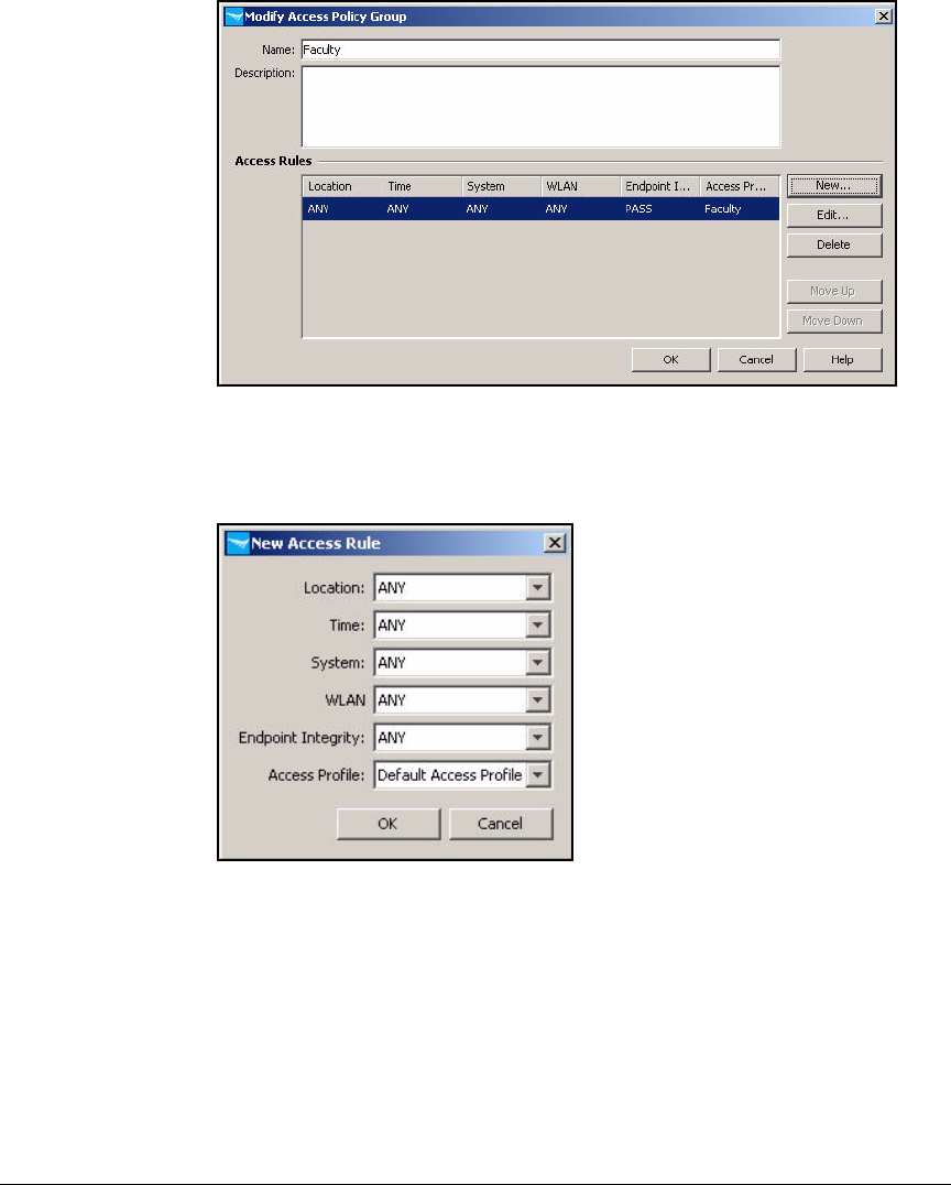
AD-222
Addendum: ProCurve Access Control Solution 2.1 Update
Configuring Network Access Control with IDM
Figure AD-202.ProCurve Manager—Modify Access Policy Group Window
9. Click New.
Figure AD-203.ProCurve Manager—New
Access Rule Window
10. Set the Location, Time, System, and WLAN values to ANY.
11. For Endpoint Integrity, select FAIL.
12. For the Access Profile, select the access profile that you created for non-
compliant endpoints. In this example, select Non-Compliant.
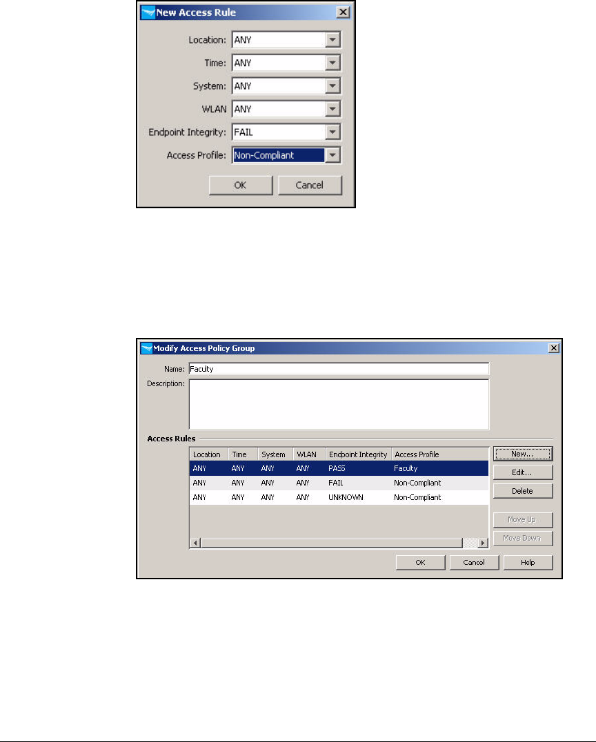
AD-223
Addendum: ProCurve Access Control Solution 2.1 Update
Configuring Network Access Control with IDM
Figure AD-204.ProCurve Manager—New
Access Rule Window
13. Click OK.
Figure AD-205 shows the final rules for the Faculty access policy group.
Figure AD-205.ProCurve Manager—Modify Access Policy Group Window
14. Click OK.
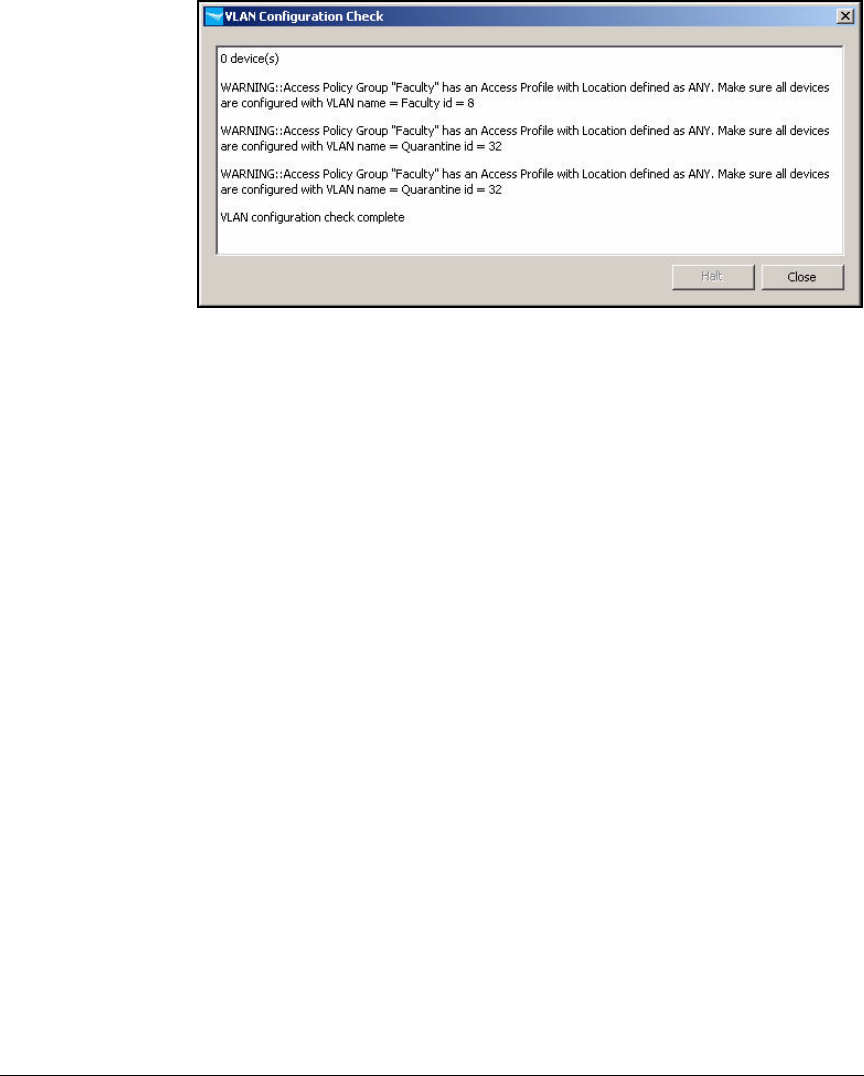
AD-224
Addendum: ProCurve Access Control Solution 2.1 Update
Configuring Network Access Control with IDM
Figure AD-206.PCM+ Console, IDM Interface—VLAN Configuration Check Window
15. IDM warns you to check that your infrastructure devices support the
dynamic VLANs. Click Close.
If necessary, add VLAN tags to uplink ports on switches (or the uplink
port of a Wireless Edge Services Module).
16. Repeat steps 4 to 15 for each access policy group in your environment.
Deploy Policies to the NPS Server
The policies you have configured take effect after you deploy them to the
RADIUS servers—in this case, the NPS server. Once deployed, the policies are
stored by the IDM agent on the NPS server, and the server enforces the policies
whether IDM is running or not.
Follow these steps:
1. You should be in the Identity Management Home window of PCM+.
2. In the navigation tree, expand Realms.
3. Right-click your domain’s realm name and select Deploy current policy to
this realm.
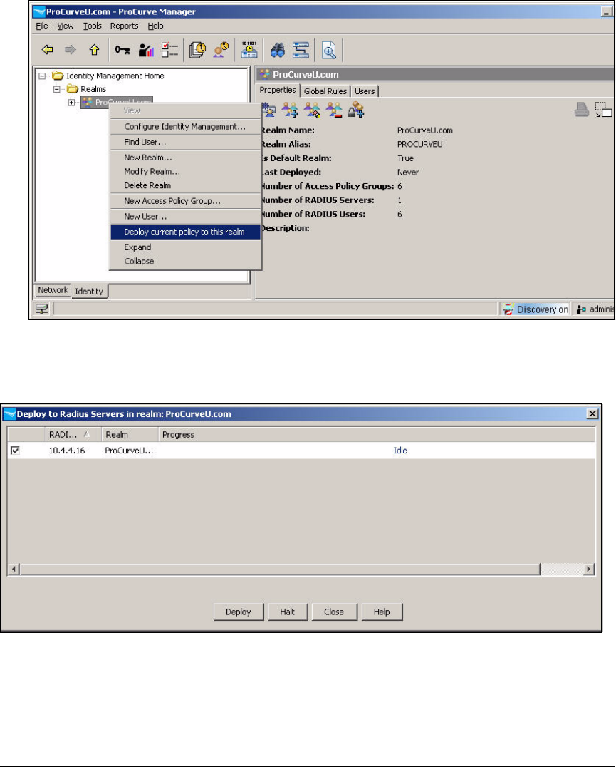
AD-225
Addendum: ProCurve Access Control Solution 2.1 Update
Configuring Network Access Control with IDM
Figure AD-207.ProCurve Manager—Identity Management Home Window
4. The Deploy to Radius Servers in realm: <myrealm> window is displayed.
Figure AD-208.Deploy to Radius Servers in realm: <myrealm> Window
5. Select the check box for your NPS server.
6. Click Deploy.
7. When the Progress bar reaches 100 percent, click Close.

AD-226
Addendum: ProCurve Access Control Solution 2.1 Update
Guest Access for Wireless Users
Guest Access for Wireless Users
The final component of this solution is guest access. In this solution, the
network requires guest access only for wireless users, and guest access is
controlled on the Wireless Edge Services Module. You will learn how to
complete these tasks:
■Secure a WLAN that is reserved for guests with Web-Auth.
■Configure the Wireless Module’s internal RADIUS server.
■Manage guest user accounts with the Web-User administrator.
■Configure an access control list (ACL) for the Guest VLAN on the routing
switch.
After carefully weighing the benefits of endpoint integrity against the loss of
convenience to guest users, ProCurve University has decided not to imple-
ment an endpoint integrity solution for guest users. In addition, network
administrators know that for now only a portion of guest users will have
computers that are running Windows Vista or Windows XP with SP 3. Com-
puters running other operating systems cannot be tested by the NPS server.
Secure a WLAN with Web-Auth
Many companies use Web-Auth to secure the WLAN that guests must access.
This access control method allows users to authenticate to a WLAN using their
familiar Web browser interface. If you do not require encryption for the WLAN,
users do not have to configure their wireless client at all, making it easy for
them to associate to the Wireless Module or AP. Then when they open their
Web browser interface to access the Internet, it is redirected to a login page,
which makes it easy for them to enter login credentials.
This section teaches you how to secure a WLAN with Web-Auth on the
Wireless Module. You must complete these tasks:
■Configure an IP address on the Web-Auth VLAN.
■Enable Web-Auth on the VLAN and configure RADIUS settings.
■Configure Web-Auth pages.
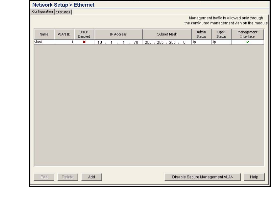
AD-227
Addendum: ProCurve Access Control Solution 2.1 Update
Guest Access for Wireless Users
Configure an IP Address on the Web-Auth VLAN
The first step in configuring Web-Auth for the Wireless Module is to assign an
IP address to the VLAN associated with the Web-Auth WLAN. Typically, when
you set up a WLAN and associate it with a VLAN, you do not need to worry
about assigning the Wireless Module an IP address on that VLAN. The Wireless
Module simply forwards traffic in the correct VLAN.
For Web-Auth, however, the Wireless Module must present wireless users with
Web pages before they log in. The simplest way to ensure that the wireless
users can reach these Web pages is typically to assign the Wireless Module an
IP address on the users’ WLAN.
To configure an IP address for a VLAN, complete the following steps:
1. In the Wireless Modules’s Web interface, select Network Setup > Ethernet.
The Configuration tab should be selected.
Figure AD-209.Wireless Module—Network Setup > Ethernet > Configuration
Window
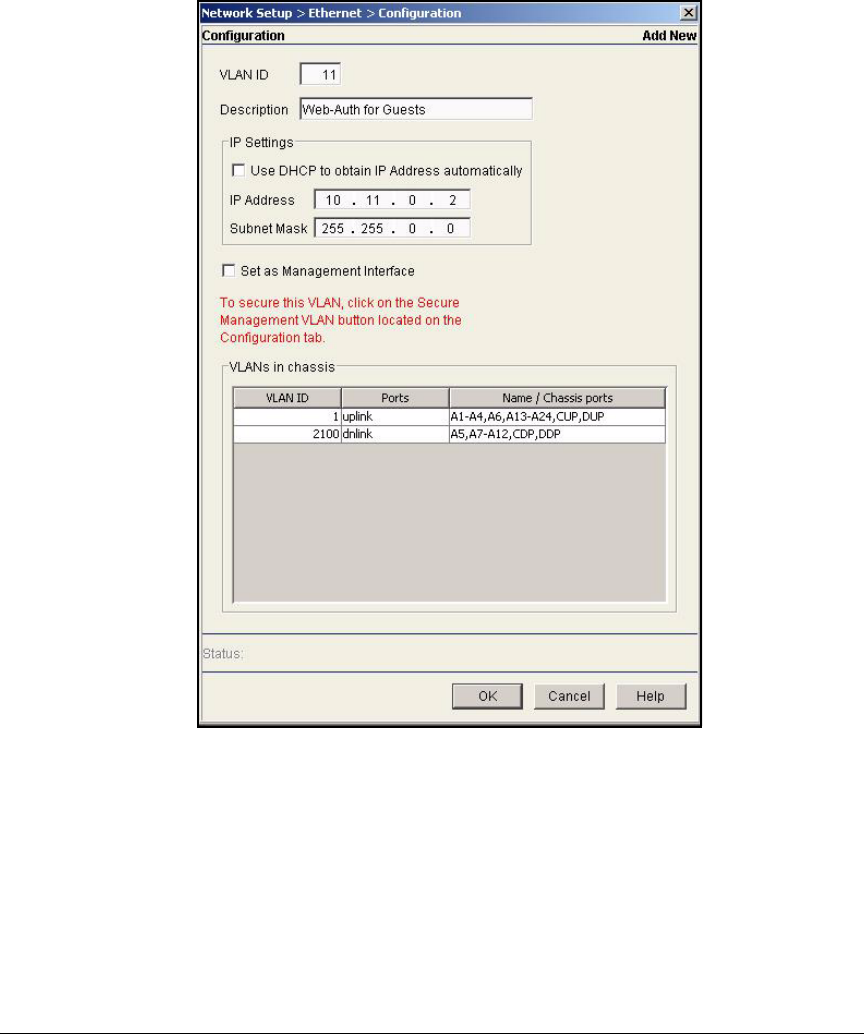
AD-228
Addendum: ProCurve Access Control Solution 2.1 Update
Guest Access for Wireless Users
2. Click Add.
Figure AD-210.Wireless Module—Network Setup > Ethernet >
Configuration> Add New Window
3. In the VLAN ID field, type the static VLAN for the Web-Auth WLAN. In this
example, type 11.
4. In the Description field, type a meaningful description for the VLAN. In this
example, the VLAN is intended for wireless guest users connecting via
Web-Auth, so you type Web-Auth for Guests.
5. For IP Address, type an IP address for the Wireless Module. In this example,
type 10.11.0.2.
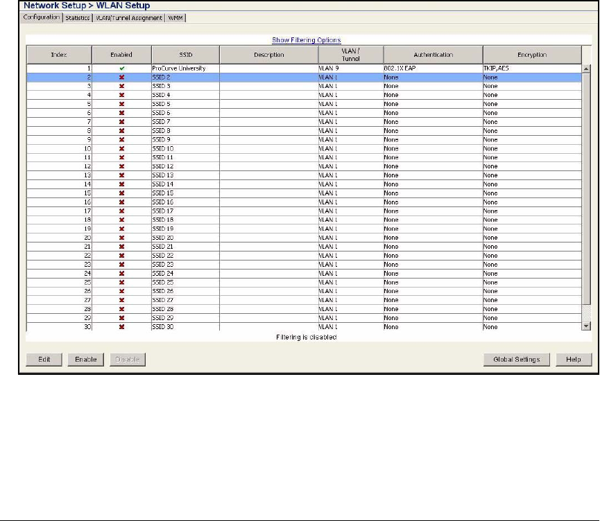
AD-229
Addendum: ProCurve Access Control Solution 2.1 Update
Guest Access for Wireless Users
6. For Subnet Mask, type the mask for the subnet associated with the VLAN.
In this example, type 255.255.0.0.
7. Click OK.
Enable Web-Auth on the WLAN
After you assign an IP address to the VLAN for the Web-Auth WLAN, you can
configure the Web-Auth security settings that the Wireless Module will down-
load to its adopted RPs.
Follow these steps to select Web-Auth security for a WLAN:
1. Select Network Setup > WLAN Setup. You should be at the Configuration tab.
Figure AD-211.Network Setup > WLAN Setup > Configuration Window
2. Select the WLAN on which you want to configure Web-Auth. In this
example, click WLAN 2.
3. Click Edit.
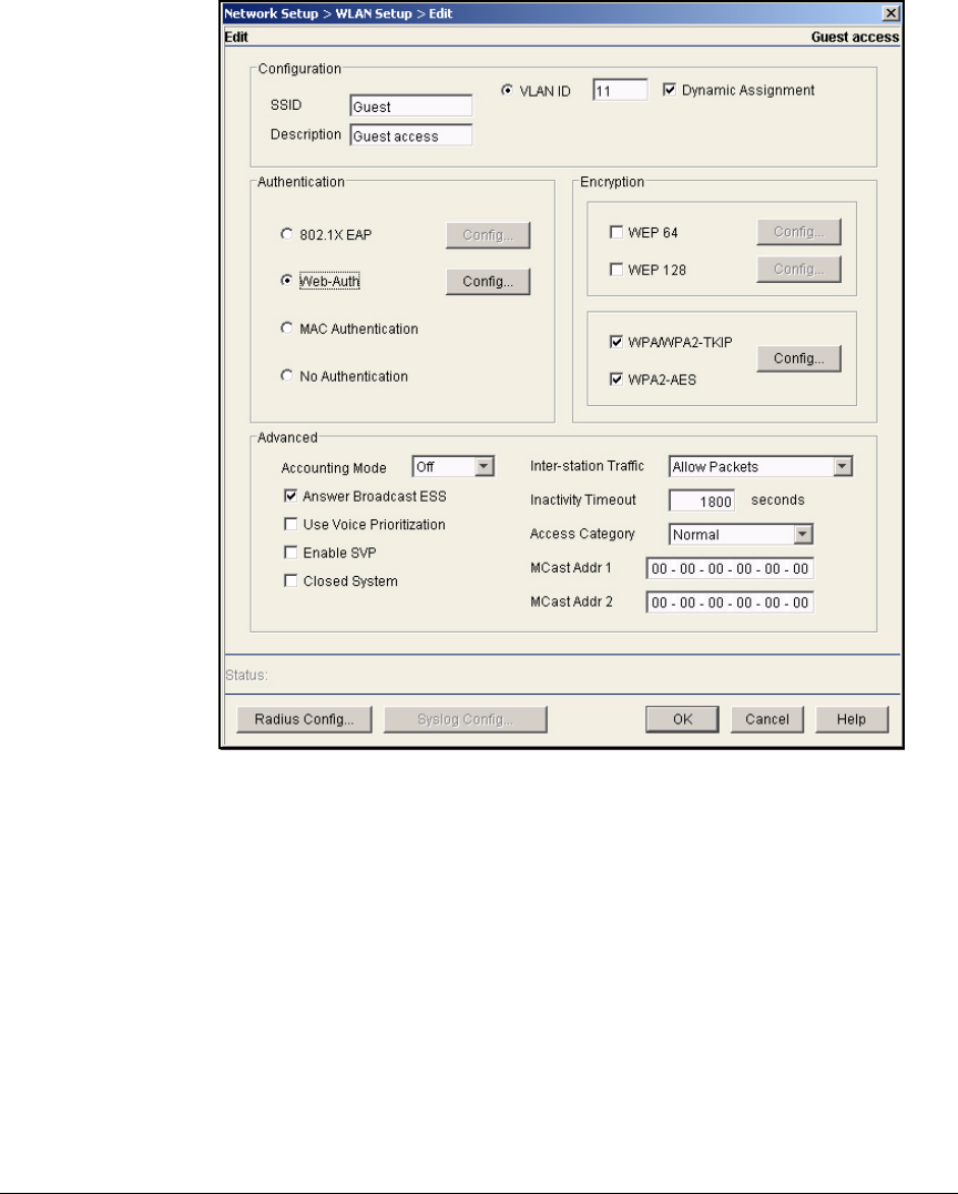
AD-230
Addendum: ProCurve Access Control Solution 2.1 Update
Guest Access for Wireless Users
Figure AD-212.Network Setup > WLAN Setup > Edit Window (Web-Auth)
4. Specify the SSID and VLAN ID. In this example, type Guest for SSID and
11 for VLAN ID.
5. Under Authentication, select Web-Auth.
6. The Wireless Module will authenticate the wireless users to a RADIUS
server. To configure the RADIUS settings, click the Radius Config button.
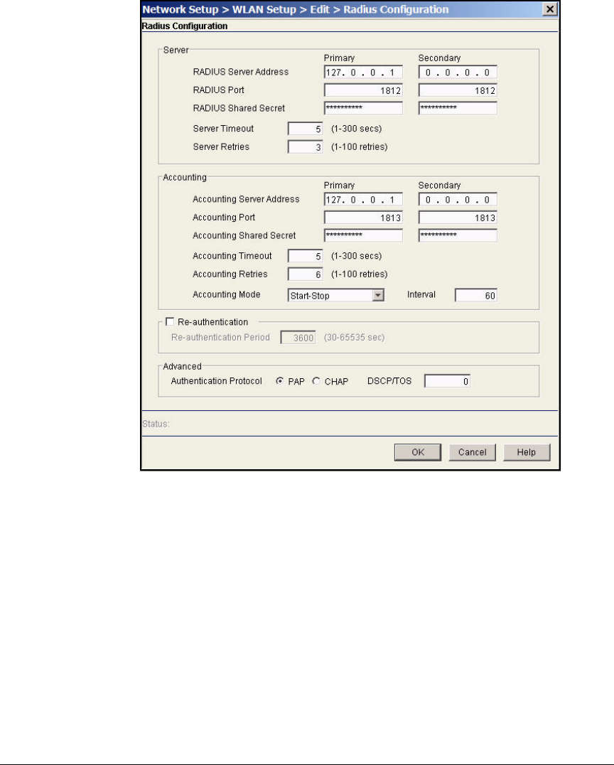
AD-231
Addendum: ProCurve Access Control Solution 2.1 Update
Guest Access for Wireless Users
Figure AD-213.Wireless Module—Network Setup > WLAN Setup > Edit >
Radius Configuration Window (Local RADIUS Server)
7. Under Server in the Primary column, configure the settings for the internal
RADIUS server:
a. For RADIUS Server Address, type 127.0.0.1.
b. For RADIUS Port, accept the default, 1812.
c. Do not type anything in the RADIUS Shared Secret box.
If you are altering the configuration of a WLAN for which you previ-
ously set a shared secret, clear the box.

AD-232
Addendum: ProCurve Access Control Solution 2.1 Update
Guest Access for Wireless Users
8. Under Accounting in the Primary column, configure the settings for the
internal RADIUS server:
a. For RADIUS Server Address, type 127.0.0.1.
b. For RADIUS Port, accept the default, 1813.
c. Do not type anything in the RADIUS Shared Secret box.
If you are altering the configuration of a WLAN for which you previ-
ously set a shared secret, clear the box.
9. Click OK twice to close both windows.
10. Click Save.
Configure the Wireless Module’s Internal RADIUS
Server
The user accounts that the WebUser administrator creates are stored in the
Wireless Module’s local database. The WLAN that guest users access must be
configured to use the Wireless Module’s internal RADIUS server, and you must
configure the internal RADIUS server to use its local database.
In addition, you must also create a guest group for the internal RADIUS server.
When the WebUser administrator creates guest users, he or she must assign
the users to a guest group. However, the WebUser administrator does not have
rights to create this group. You must set up the group in advance.
Configure Initial RADIUS Settings
Follow these steps to begin setting up your RADIUS server. You must select
the EAP type, the server certificate, and the location of the data store. Follow
these steps:
1. Select Network Setup > Local RADIUS Server.
2. Click the Authentication tab.
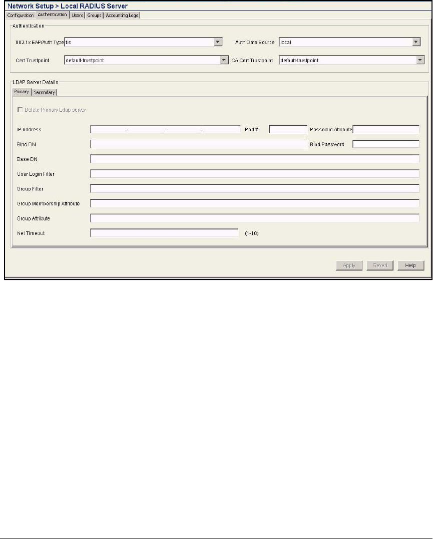
AD-233
Addendum: ProCurve Access Control Solution 2.1 Update
Guest Access for Wireless Users
Figure AD-214.Wireless Module—Network Setup > Local RADIUS Server >
Authentication Window
3. Because the Wireless Module is authenticating users with Web-Auth, you
do not need to configure these settings:
•802.1x EAP/Auth Type
•Cert Trustpoint
•CA Cert Trustpoint.
4. For Auth Data Source, select local. If local is already selected for Auth Data
Source, skip to “Configure a Guest Group” on page AD-234.
5. Click Apply.
AD-234
Addendum: ProCurve Access Control Solution 2.1 Update
Guest Access for Wireless Users
Figure AD-215.Wireless Module—Confirm Restart
Window
6. When prompted to restart the server, click Yes.
7. Click Save.
Configure a Guest Group
When you create a guest group, you assign it a VLAN. The Wireless Module
will then place the users traffic in this VLAN. For this example, the VLAN for
guest access is VLAN 11.
To configure a guest group, complete these steps:
1. Select Network Setup > Radius Server and click the Groups tab.
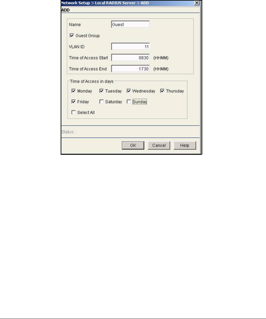
AD-235
Addendum: ProCurve Access Control Solution 2.1 Update
Guest Access for Wireless Users
2. Click Add.
Figure AD-216.Wireless Module—Network Setup > Local
RADIUS Server > Add Window
3. For Name, type a string that uniquely identifies this group. In this example,
type Guest.
4. Select the Guest Group check box.
5. For VLAN ID, type the ID for the dynamic VLAN to which users in this group
should be assigned. In this example, type 11.
Dynamic VLANs can cause issues in a WLAN that enforces Web-Auth. In
this example, users in the Guest group are the only users who should
connect to the Guest WLAN, which uses Web-Auth. Set the static VLAN
for this WLAN to the same ID as this group, which will resolve any
problems with Web-Auth.
If you only have one WLAN on your Wireless Module that authenticates
to the local RADIUS server, you can simply leave the VLAN ID at 0 and
have the module place users in the WLAN’s static VLAN. In this example,
however, guests can authenticate to the non-guest WLAN (the Wireless

AD-236
Addendum: ProCurve Access Control Solution 2.1 Update
Guest Access for Wireless Users
Module RADIUS server grants an authorized user access to any WLAN
that uses it as the RADIUS server). You want to make sure that guests are
always placed in the correct VLAN.
6. Specify the times of day when users in this group can connect to the
wireless network.
a. For Time of Access Start, type the earliest time that users can connect.
b. For Time Access End, type the latest time users can connect.
Always enter times in four digits, the first two digits being the hour in the
24-hour clock and the second two digits being the minutes.
In this example, type 0830 and 1730.
7. In the Time of access in days area, select check boxes to specify the days
of the week when users in this group can connect to the wireless network.
In this example, clear the Saturday and Sunday check boxes.
8. Click OK.
9. When prompted to restart the server, click Yes.
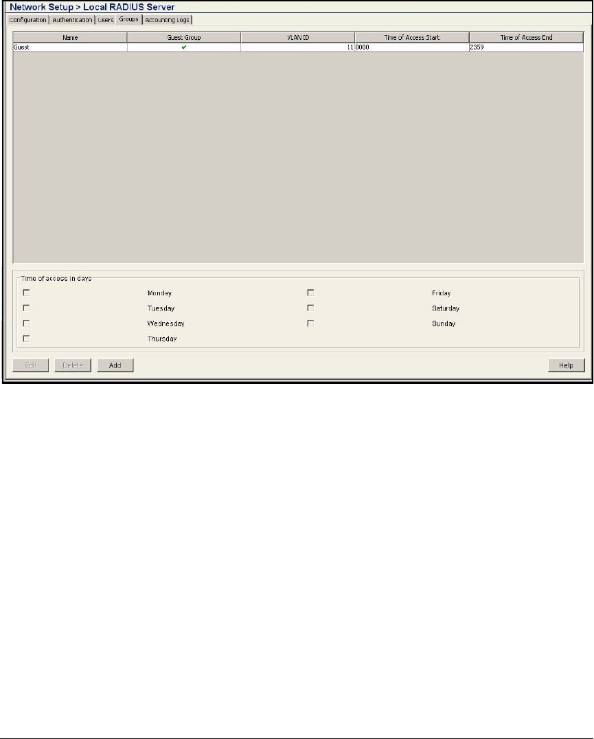
AD-237
Addendum: ProCurve Access Control Solution 2.1 Update
Guest Access for Wireless Users
Figure AD-217.Wireless Module—Network Setup > Local RADIUS Server > Groups
(Guest Group Added)
The group is displayed in the top section of the Network Setup > Local RADIUS
Server > Groups window.
Manage Guest User Accounts with the Web-User
Administrator
Because guest user accounts are temporary and constantly changing, you may
want to assign this task to a help desk technician or even an administrative
assistant. Delegating this task to another employee can free up your IT staff,
allowing them to concentrate on other network tasks.
For example, ProCurve University provides Internet access to prospective
students and parents who visit the university. The IT staff does not want to
receive calls from different departments every time a visitor needs access to
the Internet.

AD-238
Addendum: ProCurve Access Control Solution 2.1 Update
Guest Access for Wireless Users
The Wireless Edge Services Module allows you to create a management
account for a WebUser administrator, who has very limited rights to the
module’s Web browser interface. (The WebUser administrator has no rights
to the command line interface, or CLI.) Specifically, the WebUser administra-
tor can access the Wireless Module’s Web browser interface and add guest
accounts to the module’s local database. When the WebUser administrator
logs in to the Web browser interface, a unique interface is displayed. This
interface helps guide less experienced users through the process of adding
guest accounts.
Note The Web-User administrator can only add guest user accounts to existing
guest groups. Before turning management of guest accounts over to the Web-
User administrator or administrators, you must configure at least one guest
group. For information about configuring the RADIUS server and a guest
account, see “Configure the Wireless Module’s Internal RADIUS Server” on
page AD-232.
Create a Web-User Administrator Account
The WebUser administrator is just one of the administrative roles that the
Wireless Edge Services Module supports. There are six administrative roles,
which allow you to delegate management responsibilities to certain IT mem-
bers while granting them only the rights they need to perform their designated
tasks:
■WebUser, which grants rights to create guest accounts
■Monitor, which grants rights to view settings and statistics
■Helpdesk manager, which grants rights to view settings and statistics and
manage logs and troubleshooting snapshots
■Network administrator, which grants rights to view settings and statistics
and manage guest accounts
■System administrator, which grandiosities to view settings and statistics,
manage logs, and manage the module
■SuperUser, which grants rights to configure all network and security
settings, manage the module, manage guest accounts, manage logs and
troubleshooting snapshots, and view settings and statistics
The default manager user has the SuperUser role, and the default operator
user has the monitor role.
As you can see, the WebUser administrator has the least rights. This adminis-
trator can complete only one task: creating guest users.

AD-239
Addendum: ProCurve Access Control Solution 2.1 Update
Guest Access for Wireless Users
ProCurve University will create several administrative accounts that have the
WebUser administrator role. To distribute the workload, the IT staff will create
five WebUser administrators. Each one will handle one or two departments.
In addition, the IT staff will create a GuestAdmin account, which can be used
by helpdesk technicians who respond to users who cannot reach the WebUser
assigned to a particular department.
Table AD-11.WebUser Administrator Accounts for ProCurve University
WebUser Administrator Account University Department
Angela Mathematics and Engineering
Hans English and Humanities
Casandra University administration
Jorge Science
Miriam Psychology
GuestAdmin IT department
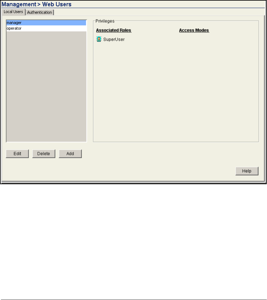
AD-240
Addendum: ProCurve Access Control Solution 2.1 Update
Guest Access for Wireless Users
To create a WebUser administrator, complete the following steps:
1. In the Wireless Module Web browser interface, select Management > Web
Users. The Local Users tab should be selected.
Figure AD-218.Wireless Module—Management > Web-Users > Local Users
Window
2. Click Add. The Add User window is displayed.
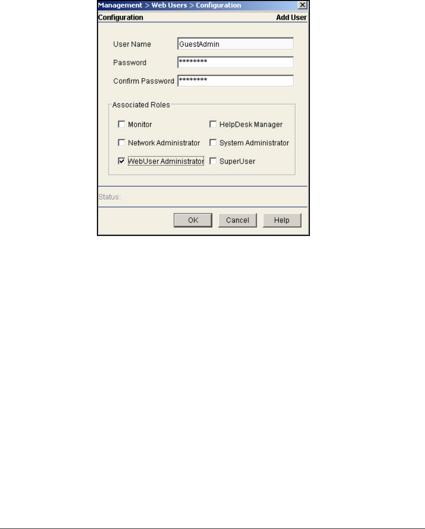
AD-241
Addendum: ProCurve Access Control Solution 2.1 Update
Guest Access for Wireless Users
Figure AD-219.Wireless Module—Management > Web-Users >
Configuration > Add User Window (Web-User
Administrator)
3. For User Name, type the username, which must be a string between 1 and
28 characters. You can include spaces and special characters. In this
example, type GuestAdmin.
4. For Password and Confirm Password, type a password between 8 and 32
characters. The password can include spaces and special characters. For
this example, type procurve4.
5. Select the WebUser Administrator check box.
6. Click OK.
7. Click Save.
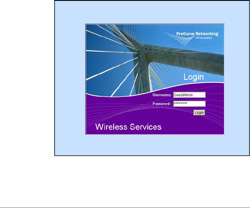
AD-242
Addendum: ProCurve Access Control Solution 2.1 Update
Guest Access for Wireless Users
Add Guest Accounts as a Web-User Administrator
After you create the WebUser administrator account and at least one guest
group, the WebUser administrator can begin creating guest accounts.
Although the Web browser windows that are designed for the WebUser
administrator are intuitive, you may want to take some time to teach the
person you assign this role how to log in and create the guest accounts. In fact,
you can copy the instructions from this guide and give it to the WebUser
administrator at your company.
Complete the following steps to create a guest account:
1. Open a Web browser and type the IP address of the Wireless Module for
the URL. In this example, type 10.2.0.20. The Wireless Module’s Login
window is displayed.
Figure AD-220.Wireless Module Login Page
2. For Username, type the name configured for the Web-User administrator.
In this example, type GuestAdmin.
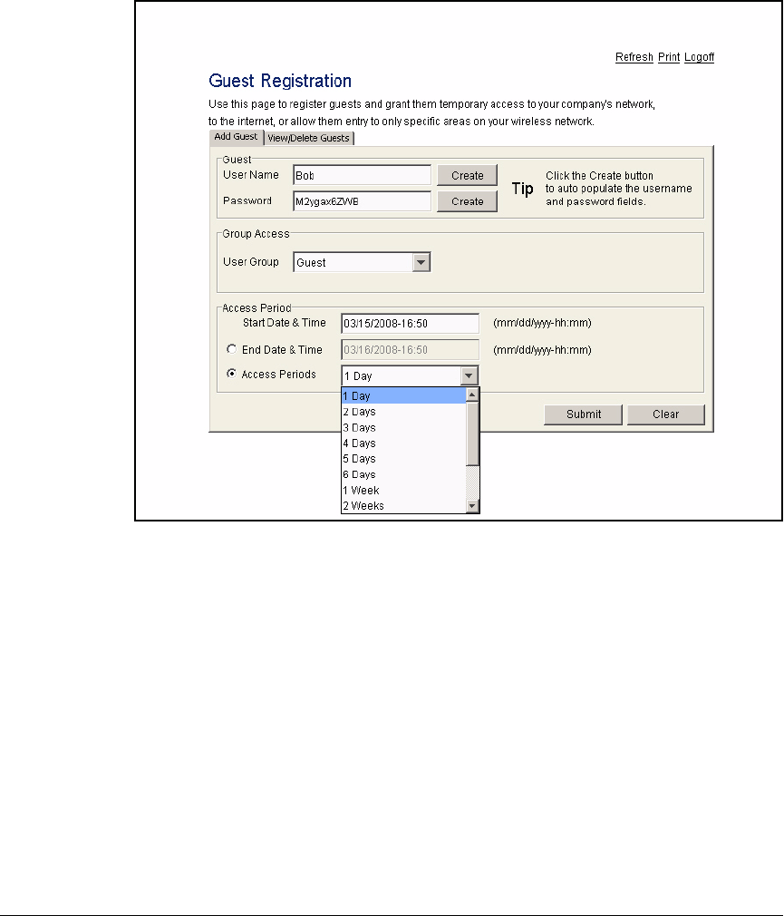
AD-243
Addendum: ProCurve Access Control Solution 2.1 Update
Guest Access for Wireless Users
3. For Password, type the Web-User administrator’s password. In this exam-
ple, type, procurve4.
Figure AD-221.Wireless Module—Guest Registration > Add Guest Window
4. The Guest Registration window is displayed. The Add Guest tab should be
selected.
5. Add the guest user account:
a. For User Name, type the name that the guest will use to log in. To
generate a random username, click Create. For this example, type
Maria.
The username can be up to 64 characters and can include alphanu-
meric and special characters. It is case sensitive.
b. For Password, type the guest’s password. You can also generate a
random password by clicking Create.
The password can include up to 21 alphanumeric and special charac-
ters. It is case sensitive.
AD-244
Addendum: ProCurve Access Control Solution 2.1 Update
Guest Access for Wireless Users
c. For User Group, select the group to which this guest belongs and which
determines this guests’ rights.
If the User Group list does not include any groups, contact a network
administrator who has management access to the Wireless Module.
This administrator must create a guest group for you.
d. By default, the guest user account becomes active immediately. (The
Start Date & Time box in the Access Period area is automatically filled
with the current time.) However, you can type a different desired date
and time for the account to become active. The correct format is mm/
dd/yyyy-hh:mm, in which mm indicates months; dd, the day; yyyy, years
(four-digit); hh, hours (on the 24-hour clock); and mm, minutes.
e. Next, configure the date and time at which the temporary account
becomes inactive (the user can no longer log in). Select one of two
options:
– You can select End Date & Time and enter an exact date and time
in the box to the right.
– You can select Access Periods and choose a certain duration for
the account from the list shown in Figure AD-221.
In this example, select Access Periods and 2 Days.
f. Click Submit.
Figure AD-222.Wireless Module—
Guest Registration Window
g. Click Yes to confirm that you want to create the user account.
h. Repeat these steps to create other users.
6. Verify that the users have been added to the Wireless Module’s RADIUS
database. Click the View/Delete Guests tab.
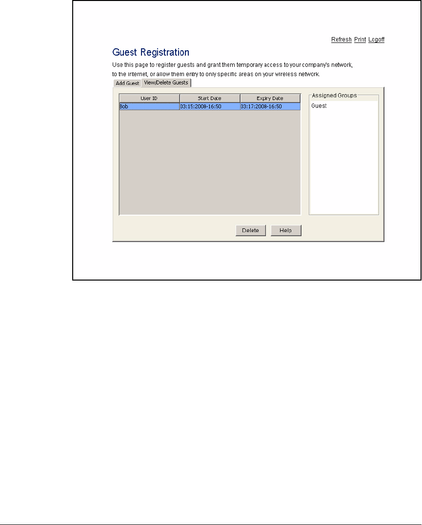
AD-245
Addendum: ProCurve Access Control Solution 2.1 Update
Guest Access for Wireless Users
Figure AD-223.Wireless Module—Guest Registration > View/Delete Guests
Window
As you can see, the new user account is displayed. If you see a problem, click
Delete and reconfigure the account on the Add Guest tab.
7. To create a record of the guest account, follow these steps:
a. Click the Print link in the top right corner of the window.
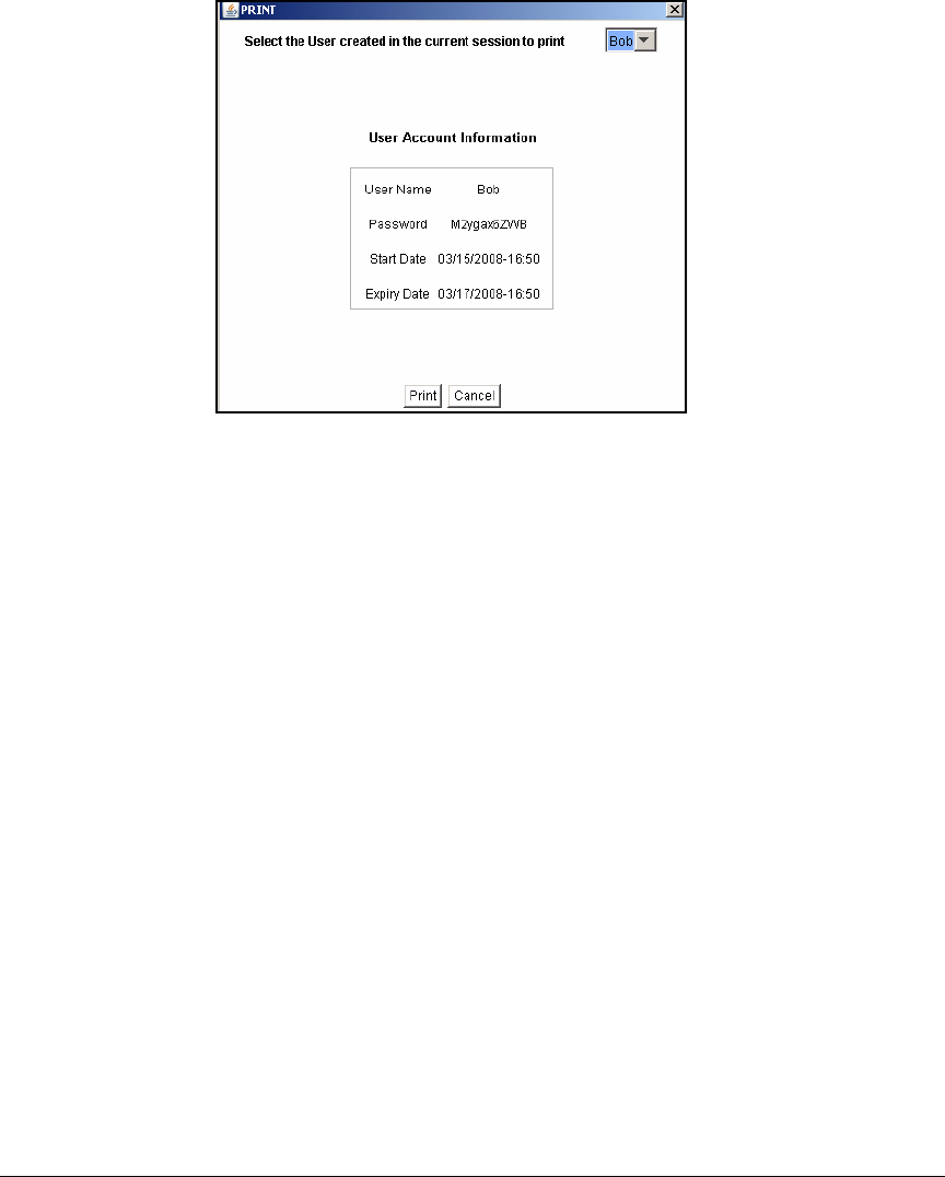
AD-246
Addendum: ProCurve Access Control Solution 2.1 Update
Guest Access for Wireless Users
Figure AD-224.Wireless Module—Guest Registration >
Print Window
b. Select the username from the list at the top of the window. The
account information is displayed below.
c. Click Print.
d. A window is displayed (windows differ depending on your manage-
ment station). Follow the steps indicated and print the record.
e. Select a different username to print that account.
f. When you are finished printing account information, close the Print
window.
When you are finished configuring guest accounts, click the Logoff link.
Configure an ACL for the Guest VLAN on the Routing
Switch
Typically, you want to grant guests only limited access to your network. In this
solution, you will control guests’ access with an ACL configured on the default
router for the Guest VLAN.

AD-247
Addendum: ProCurve Access Control Solution 2.1 Update
Guest Access for Wireless Users
The steps below guide you through configuring an ACL on a ProCurve Switch
5400zl. The example ACL will allow guests to access the Internet but not the
private network.
1. Access the CLI of the Switch 5400zl.
2. Move to the global configuration mode context:
ProCurve# configure terminal
3. Configure the access control entries. Typically, you should create entries
for an extended ACL so that you can control the destination of the traffic.
Refer to your switch’s management and configuration guide for the cor-
rect syntax for the commands. Below are commands for the example list:
ProCurve(config)# ip access-list extended Guest
ProCurve(config-ext-nacl)# permit udp any any 67
ProCurve(config-ext-nacl)# permit udp any 10.4.4.15 53
ProCurve(config-ext-nacl)# permit tcp any 10.4.4.15 53
ProCurve(config-ext-nacl)# deny ip any 10.0.0.0
255.0.0.0 log
ProCurve(config-ext-nacl)# permit ip any any
4. Apply the list to the Guest VLAN:
In this example, enter this command:
ProCurve(config)# vlan 11 ip access-group Guest vlan
5. Save the configuration:
ProCurve(config)# write memory
Syntax: vlan <ID> ip access-group <identifier> vlan
Assigns the ACL to the VLAN interface.
Replace <ID> with the ID for the Guest VLAN. Replace <identi-
fier> with the name of the ACL that you just created.

AD-248
Addendum: ProCurve Access Control Solution 2.1 Update
Guest Access for Wireless Users

Index – 1
Index
Numerics
3DES … 4-182
802.1X … 2-112, AD-129
authenticator … 5-94
client on RP … 5-60
deployment method
RADIUS services and … 5-83
deployment method on NAC 800 … 2-149
devices
adding on NAC 800 … 2-151, 5-94
shared secret on NAC 800 … 2-152, 3-106
supplicant
wireless … 2-301
A
access control
See network access control
access control policy
See ACP
access policy groups
IDM … 5-145
access profiles
IDM … 2-254, 5-137, AD-206
access.txt file … AD-179
accessible services
NAC 800 … 4-147
ACE … 4-68
ACLs … 4-67, 4-107
extended … 4-85
VPN traffic … 4-83
applying to crypto map … 4-92
ACP … 4-68, 4-72, 4-98
Active Directory
groups … 2-30, 4-27, AD-32
installing … 2-21, AD-21
registering with IAS … 3-19
synchronizing with IDM … 2-237, AD-193
test settings … 5-93
users … AD-35
AD See Active Directory
Add/Remove Snap-in
Windows certificate templates … 2-78
AES … 4-79, 4-182
agent
NAC EI … 2-164, 2-306, 6-29
agentless testing … 2-156
AH … 4-98
allow list
Wireless Edge Services Module … 5-45
AP 530s … 6-11
enabling radios … 6-17
password … 6-15
WLAN configuration … 6-13
ARP protection
on switches … 6-41
ASN1 … 4-94
attributes
enumerable … 3-56, 3-58, 3-77
multivalued … 3-55
OpenLDAP objects … 5-88
authentication
user-based 802.1X … 5-12
authentication methods
for IAS remote access policies … 3-41
B
binding
logical router interface to physical
interface … 4-53
NAC 800 to
OpenLDAP … 5-73, 5-85
TLS connection … 5-89
PPP interface to E1 or T1 … 4-53
broadcast key
Wireless Edge Services Module … 5-29
browser interface
NAC 800 … 4-136
C
CA
loading certificate … 4-108
profile … 4-107, 4-108
root certificate … 2-97, AD-73
SCEP … 4-105, 4-106
submitting self certificate request to … 4-109
CaCert.cser … 4-186

2 – Index
caching
opportunistic key … 5-30
PMK … 5-30
certificate revocation list
See CRL
certificate services
installing … 2-56
certificates
CA … 4-106
OpenLDAP … 5-109
router … 4-105
check key size … 4-41
configuring
autoenrollment … 2-68, 2-92, 2-276
NAC 800 template … 2-87
wireless … 2-82
converting format … 2-200
create request … 2-189
create using OpenSSL … 5-74
CRL … 4-38, 4-117
deleting … 4-117
deploying to CA … 2-91
export … 4-185
CA root … 4-191
policies … 4-186
VPN client … 4-188
IIS … 2-56, AD-67
import
CA … 4-159
to VPN client … 4-171
installing on
endpoints … 2-276
IAS … 3-21
NAC 800s … 2-193
RADIUS server … 2-196
Wireless Edge Services Module … 2-183,
AD-154
installing, services … AD-67
manual import … 4-201
obtaining automatically … 4-107
obtaining manually
configuring profile … 4-107
importing self certificate … 4-113
loading CA certificate … 4-109
password
RADIUS … 2-197
Wireless Edge Services Module … 2-180
request … 4-161
self … 4-106
self-signed
exporting from NAC 800 … 3-110
services … 2-53, AD-64
submit request to CA … 4-165
templates
enable on CA server … 4-36
router IPsec … 4-32
VPN clients … 4-14
using CA web-enrollment … 4-153
viewing … 4-115
VPN client … 4-157
Windows snap-in … 2-280
clusters, NAC 800 … 4-130
activating quarantining … 2-319
enforcement … 4-137, 4-138
exceptions … 5-102, 5-105
commands
AP 530
enter interface configuration mode … 6-12
save configuration … 6-13
set management password … 6-12
specify country code … 6-13
specify default router … 6-12
specify interface IP address … 6-12
CA server
save RADIUS certificate to NAC
800 … 2-200
transfer certificate request to
server … 2-182, AD-153
NAC 800
alter eap.conf file … 2-201
convert DER to PEM … 2-200
convert PFX to PEM … 2-201
copy certificate to certs directory … 2-200
create new private/public keypair … 2-189
enter keystore directory … 2-189
generate certificate request … 2-190
generate certificate request for RADIUS
server … 2-197
import key to NAC 800 … 2-195
quit … 2-202
remove current keystore … 2-189
restart HTTPS server … 2-196
restart RADIUS server … 2-202
save CA certificate to keystore … 2-195
save CA root certificate to NAC 800… 2-194

Index – 3
save HTTPS server certificate to NAC
800 … 2-194
set CA file to CA cert filename … 2-202
set certificate file to the cert
filename … 2-202
set private key file to key filename … 2-202
set private key password … 2-201
submit certificate request to CA … 2-191
submit request to CA and create certificate
with NAC 800 template … 2-198
transfer certificate request to SCP
server … 2-198
transfer file from NAC 800 to local
station … 2-191
OpenLDAP
add objects to datastore … 5-71
add OU to directory … 5-68
add user to directory … 5-69
create group and assign users … 5-70
OpenSSL
create certificate request … 5-78
create private key for CA certificate … 5-75
create public key and CA certificate … 5-76
generate private key … 5-77
sign X.509 request … 5-79
router
access certificate chain command … 4-117
activate logical interface … 4-53
activate SSH line … 4-56
activate the physical interface … 4-52
add a permit ACE … 4-86
add ACE to permit all UDP traffic to public
interface … 4-99
add ACL … 4-87
add default route to Internet router … 4-57
add deny ACEs … 4-86
add entry to remote ID list … 4-94
add statement to perform source
NAT … 4-69
add statement to specify how traffic is
handled … 4-100
apply ACL to incoming traffic … 4-105
apply ACP to interface … 4-70, 4-73, 4-101
apply crypto map to logical interface… 4-97
assign IP address to PPP interface … 4-53
assign static IP address … 4-49
assign transform set to crypto map
entry … 4-92
bind logical interface to physical … 4-53
choose authentication method … 4-82
configure a hostname … 4-49
configure channels for E1 line … 4-51
configure enable mode password … 4-54
configure line coding … 4-51
configure password for Telnet
session … 4-55
configure PFS … 4-93
configure remote ID list … 4-96
configure time source … 4-52
create ACE … 4-68
create ACL to select traffic to ports to open
on IP interface … 4-59, 4-99
create ACP for destination NAT … 4-72
create CA profile … 4-107
create client configuration pool … 4-75
create crypto map entry … 4-92
create extended ACL … 4-70, 4-85
create IKE policy … 4-80
create logical interface … 4-52
create or access ACL … 4-102
create or access ACP … 4-99
create standard ACL … 4-67
create static route to IKE client configura-
tion pool subnet … 4-63
create the ACP … 4-68
define lifetime of IPsec tunnel … 4-93
delete certificate … 4-117
delete CRL … 4-118
enable Ethernet interface … 4-50
enable RIP on LAN subnet … 4-57
generate self certificate request … 4-110
load CA certificate on router … 4-108
manually import certificate … 4-113
manually import CRL … 4-115
match crypto map to extend ACL … 4-92
perform destination NAT … 4-72
select RIP version … 4-56
set response mode … 4-81
set the client configuration pool … 4-81
set the local ID … 4-80
set the peer … 4-80

4 – Index
specify DNS servers in private
network … 4-76
specify enrollment method … 4-107
specify IP range for remote users … 4-76
specify security settings for temporary IKE
tunnel … 4-82
submit certificate request to CA … 4-112
view ACL … 4-102
view certificate, CRL, or CA profile
information … 4-116
switches
activate port authentication … 2-318
configure 802.1X authentication
method … 5-14
configure static IP-to-MAC address
binding … 6-43
configure user-based authentication … 5-13
define authorized DHCP server … 6-40
define trusted ports for ARP
protection … 6-43
define trusted ports for DHCP
snooping … 6-39
enable 802.1X on switch … 5-14
enable ARP protection … 6-42
enable DHCP snooping … 6-39
enable ports for 802.1X
authentication … 5-13
specify RADIUS host … 5-14
view ARP protection statistics … 6-44
view DHCP snooping settings … 6-40
Wireless Edge Services Module
enable secure management … 5-24
enter global configuration mode … 2-107,
AD-124
enter management VLAN configuration
mode … 2-107, AD-124
enter wireless-services context … 2-107,
AD-124
save configuration … 2-109, AD-125, AD-126
secure management … 2-108, AD-126
set country code … 5-24
specify default router … 2-108, 5-24, AD-125
specify IP address for management
VLAN … 2-108, AD-125
specify IP address for module … 5-23
compliance.keystore
password … 2-196
console session
NAC 800s … 4-131
country code
setting on Wireless Edge Services
Module … AD-143
CRL … 4-117
deleting … 4-118
export … 4-38
importing manually … 4-113
managing … 4-117
crypto commands
activate … 4-74
crypto map … 4-90
CSs … 5-82
D
data store
supported with IDM … 5-81
defining resources … 2-247
deployment
NAC 800 in RADIUS only … 5-81
deployment method
802.1X … 2-134
DHCP … 6-3
inline … 4-129
DER format
converting from … 2-200
DES … 4-182
DHCP … 4-49
authorizing … 2-46
configuring … 2-42, AD-49
define authorized server … 6-40
installing … 2-43
quarantining … 6-22
snooping … 6-38
Windows, server … AD-49
authorizing … AD-54
installing … AD-50
Diffie-Hellman
group … 4-79, 4-82, 4-180, 4-182
DN … 4-95, 4-96
OpenLDAP … 5-87
DNS
endpoints … 2-35, AD-41
installing … 2-21, AD-21
Windows … AD-41

Index – 5
domain controller … 2-20
password … 2-241
Domain Name System
See DNS
domains … 2-20, AD-8
controller … AD-8
groups … 2-28, AD-32
global settings … AD-34
raising the functional level … 2-27
users … 2-31, AD-35
DSA … 4-181
DSCP/TOS … 5-33, 5-48
E
eap.conf file … 2-201
EAP-TLS … 2-112, 2-298, AD-129
wireless … 2-301
encryption … 5-34, 5-50
algorithm
ESP … 4-88
VPN … 4-182
WLAN … 2-303
endpoint integrity
allow all … 2-147
connectors … 3-86
DHCP lease duration … 2-49
enabling … 2-234
enabling in IDM … AD-190
NAC policies … 2-165, 6-31
postures … 3-86, 3-89
quarantining … 3-105, 5-85
statuses … 2-268, AD-217
endpoints
802.1X supplicant … 2-297, 2-301
agentless credentials … 2-156
autoenrollment for user certificate … 2-276
certificates … 2-276
change access mode … 2-319
configuring … AD-160
DNS … 2-35, AD-41
enable routing to … 4-61
enabling RPC … 2-157
export policy and certificates … 4-185
NAC EI agent
downloading … 2-164, 6-29
installing … 2-306
testing
credentials … 2-156
methods … 2-155, 6-27
troubleshooting authentication … 2-299, 5-151
enforcement clusters
See ESs
enforcement servers
See ESs
enumerable attributes … 3-56, 3-58, 3-77
ESP … 4-98
encryption algorithm … 4-88
ESs … 4-140
adding to cluster … 2-146
clusters … 2-146
creating … 2-136
move to cluster … 4-142
exceptions … 5-101
addresses … 5-102
cluster default settings … 5-102
excluding domain names … 5-102
particular cluster, NAC 800 … 5-105
Extensible Authentication Protocol … 2-298
F
fast layer-2 roaming … 5-30
files
access.txt … 2-229, 5-108, AD-179
CaCert.cser … 4-186
DER … 2-200
eap.conf
CA-signed certificate … 2-201
export CA root certificate to … 2-97, AD-73
IDMImportServerComp.scp … 5-111
IPSecCerts.p12 … 4-186
IPSecPolicy.spd … 4-186
log
database … 2-25
IAS … 3-31, 3-84, 3-85, 3-96
IAS remote access … 3-82
remote access … 3-82
logo, for Web-Auth pages … 5-50
PEM … 2-200, 2-202
PFX … 2-201
policy.spd … 4-200
print and file sharing … 2-157
radiusd.conf … 2-201
SAIASConnector … 3-86, 3-89

6 – Index
setup.exe … 2-308, 6-45
slapd.conf … 5-66, 5-80
source for certificate … 2-186, AD-157
firewall ports
opening … 6-46
flash memory
logo files in … 5-50
G
group policy
NAP client settings in Windows … AD-110
Group Policy Management
installing … AD-87
installing on NPS server … AD-87
groups
access policy … 2-267, AD-217
IDM … 2-267, 5-145, AD-217
synchronizing with Active
Directory … 2-237, AD-193
access profiles … 2-258, 5-139, AD-209
Active Directory … 2-30, 4-27
versus IDM … 2-243, AD-197
domain … 2-28, AD-32
domain administrators … 2-156
global settings … 2-30
NAC policy … 2-166, 6-31
policies
autoenrollment … 2-92
automatic certificate request … 2-75
RPC … 2-157
policy object editor … 2-71
redundancy … 2-114
refresh policy … 2-75
Windows domain … 2-20, 2-28, AD-8, AD-32
H
hash algorithm
HA … 4-88, 4-182
headless devices … 5-4
holidays
policies for in IDM … 5-135
HTTPS server
restarting … 2-196
I
IAS
certificates … 3-21
configure … 3-16
editing the registry … 3-94
installing … 3-16
registering with Active Directory … 3-19
shared secret … 3-81
Identity Driven Management
See IDM
IDM … 2-229, AD-172
access policy groups … 2-267, AD-193, AD-217
access profiles … 2-254, 5-137, AD-206
adding NPS server to PCM+ access.txt
file … AD-179
agent on NPS server … AD-180
data stores … 5-81
defining resources … 2-247, AD-199
detecting NPS server … AD-186
enabling endpoint integrity … AD-190
endpoint integrity status … AD-217
identity management … 2-249, 5-128, AD-201
installing … AD-173
IP address … 2-149
server … 5-85
synchronizing with Active Directory … 2-237,
AD-193
user password … 2-245
IDM Import Wizard … 5-113
IIS … 2-56, AD-67
IKE
attribute policies … 4-79, 4-81
policies … 4-76, 4-78, 4-80
temporary tunnel settings … 4-82
inline deployment method … 4-129
installations
prepackaged … 4-193
installing … 2-106
interfaces
CLI
PCM+ … 2-218
terminal
NAC 800 … 2-135
Wireless Edge Services Module … 2-107,
5-22

Index – 7
web browser
NAC 800 … 2-141, 3-102
Wireless Edge Services Module … 2-109,
5-25
Internet Information Services
See IIS
IP addresses
802.1X device … 2-153, 3-107
IDM server … 2-149
IPv4
for Windows Server 2008 … AD-18
for Wireless Edge Services
Module … AD-125
IPv6
for Windows Server 2008 … AD-18
IP security
See IPsec
IPsec
encryption algorithm … 4-88
hash algorithm … 4-88
mode … 4-90
IPsec SA
lifetime … 4-93
security parameters
configuring in crypto map … 4-91
configuring in transform set … 4-88
IPSecCerts.p12 … 4-186
K
keystore
password … 2-189, 2-195
L
LDAP format … 4-94, 5-87
LDIF format … 5-67
locations … 5-131
policies for in IDM … 5-131
log files
database … 2-25
IAS … 3-31, 3-84, 3-85, 3-96
IAS remote access … 3-82
remote access … 3-82
logo
adding to
failed page … 5-44
login page … 5-38, 5-39
welcome page … 5-41
copying to internal flash … 5-50
M
MAC-Auth … 5-11
management servers … 2-142
MD5 … 4-79, 4-182
MSs
configuring … 2-142
multivalued attribute … 3-55
N
NAC 800s
access mode … 2-320, 4-151
accessible services … 4-147
binding to
OpenLDAP … 5-73, 5-85
TLS connection … 5-89
cluster … 4-130
installing … 2-134
certificates … 2-193
interface
terminal … 2-135
web browser … 2-141, 3-102
password
change … 2-137
menu … 2-138
root … 2-136
ping test … 2-140, 4-135
policies … 2-165, 3-109, 6-31
creating … 2-167, 6-36
group … 2-166, 6-31
NAC EI agent … 2-164, 2-306, 6-29
NAC policy group … 4-139
NAP
agent … AD-165
and wireless connections … AD-166
agent service … AD-110, AD-164

8 – Index
client settings … AD-110, AD-120, AD-165
security filters for … AD-120
configuration wizard … AD-94
enforcement clients … AD-110
health policy server … AD-94
policies … AD-103
NAS
adding as RADIUS client … 5-94
port … 3-64
NAT … 4-67
NAT-T … 4-77, 4-81
NAT-Traversal
See NAT-T
NetBIOS domain name … 2-25
network access control
activating … 2-318
configuring … 2-203
IDM … 2-229
SNMP … 2-118, 5-54
Network Address Translation
See NAT
network resources … 2-247, AD-199
configuring in IDM … 5-138
defining in IDM … AD-199
NPS server
802.1X NAP enforcement … AD-94
adding to PCM+ access.txt file … AD-179
configuration steps … AD-82
installing, role … AD-86
joining to a domain … AD-83
obtaining computer certificate on … AD-90
RADIUS server for Wireless Edge Services
Module … AD-130
NT LAN Manager … 2-237
O
OpenLDAP
authentication … 5-85
binding to … 5-85
NAC 800 … 5-73
settings … 5-87
test settings … 5-93
certificates … 5-109
extending the schema … 5-65
IDM configuration file … 5-111
objects … 5-64
schema … 5-67
TLS connection … 5-89
OpenSSL … 5-74
opportunistic key caching … 5-30
P
password
Windows domain user … AD-39
Wireless Edge Services Module … AD-127
passwords
AP 530…6-15
change NAC 800 … 2-137
compliance.keystore … 2-196
console … 5-101
domain controller … 2-241
enable mode … 4-54
IAS … 3-81
IDM user … 2-245
keystore … 2-189, 2-195
NAC 800 … 4-133, 5-83
NAC 800 root … 2-136, 2-143, 2-144, 2-148
PCM+ … 2-215
manager and operator … 2-218
port authentication … 2-133
private key … 2-201
RADIUS certificate request … 2-197
restore admin … 2-27
router Telnet session … 4-55
RPs … 2-130
rules
NAC 800 … 2-138
NAC 800 menu … 2-138
NAC 800 Web access … 2-144
user object … 2-34
SNMP … 2-120, 5-55
SSH session … 5-101
Telnet and SSH1 … 2-218
Wireless Edge Services Module … 2-110, 5-25
certificates … 2-180
PCM+ … 2-203, AD-173
configure
CLI access … 2-218
updates … 2-219
installing … 2-203
password … 2-215
manager and operator … 2-218
server requirements … 2-204
Windows domain group … 2-20, AD-8

Index – 9
PEM format … 4-114
converting to … 2-200
perfect forward secrecy
See PFS
PFS … 4-91, 4-93
specifying group … 4-93
PFX format
converting from … 2-201
ping test
NAC 800 … 2-140
NAC 800s … 4-135
PKI … 2-53, 4-6, AD-64
PMK caching … 5-30
PoE … 6-11
policies
copying NAC 800 … 2-167
default domain … 2-159
export certificate … 4-186
group … 2-69, 2-75, 2-314
NAC 800 … 2-166, 6-31
NAC 800 … 2-165, 3-109, 6-31
prioritizing … 3-62, 3-78
public key … 2-71
remote access
conditions … 3-65
creating manually … 3-43
editing … 3-62
RPC … 2-161
trust … 4-158
port authentication
configuring … 2-132
password … 2-133
port-based 802.1X authentication … 5-12
ports
auto-provisioning…2-130
Ethernet … 2-135
NAS … 3-64
RADIUS … 2-113, AD-130
resources … 2-247, AD-199
UDP … 3-33
power over Ethernet … 6-11
PPP interface
binding to
E1 or T1…4-53
pre-authentication … 5-30
prepackaged installations … 4-193
ProCurve Identity Driven Manager
See IDM
ProCurve Manager Plus
See PCM+
public key infrastructure
See PKI
PXE imaging … 5-12
Q
quarantine area … 6-25
quarantining
802.1X … 2-149
RADIUS-only … 5-83
activate … 4-150
activating … 2-319
configuring … 4-146
DHCP … 6-22
endpoint integrity … 3-105, 5-85
granting temporary access … 2-171, 6-35
inline … 4-146
subnet
802.1X method … 3-105, 5-85
R
radio ports
See RPs
RADIUS clients
adding to IAS … 3-79
adding to NAC 800 … 5-94
wizard … 3-80
RADIUS server
apply changes … 5-98
certificates … 2-196
for Web-Auth … 5-45
for WLAN … 2-109, AD-127
internal, Wireless Module
access times in group policy … AD-236
dynamic VLAN assignment … AD-235
restart
root … 5-101
Web browser interface … 5-98
shared secret … 2-113, AD-130
shared secret on Wireless Module … 5-32
RADIUS-only NAC 800
quarantine method … 5-83
re-authentication to network, user … 5-32
registry editor
IAS server … 3-94

10 – Index
remote access
logging … 3-82
policies
conditions … 3-65
creating manually … 3-43
editing … 3-62
prioritizing … 3-62, 3-78
wizard … 3-36
remote ID
list … 4-94
types and values … 4-95
remote users … 4-75
restart
HTTPS server … 2-196
RADIUS server … 2-202
root … 5-101
Web browser … 5-98
reverse logic … 4-84
RIP … 4-56
roaming
fast Layer 2 … 5-30
role
Windows Server 2008 … AD-86
root
CA … 2-62
CA certificate
exporting … 2-97, AD-73
installing on endpoint … 2-276
save to NAC 800 … 2-194
upload … 2-185, AD-156
password
NAC 800 … 2-136, 2-143, 2-144, 2-148, 2-189
restart
RADIUS server … 5-101
trusted certification authorities … 2-300, 2-305,
5-157
router
certificates … 4-105
client configuration pools … 4-74
crypto map … 4-90
physical and virtual interfaces … 4-48
protocol … 4-56
remote ID list … 4-94
running-config … 4-118
security policy … 4-179
transform set … 4-88
tunnel mode … 4-89
wildcard bits … 4-84
Routing Information Protocol … 4-56
RPC … 2-157
policies … 2-161
RPs … 1-3, 2-114, 5-6
802.1X authentication … 2-130, 2-131, 5-60, 5-61
password … 2-130
rogue…5-60
RSA … 4-181
rules
LDAP format … 5-87
shared secret … 5-96
S
SA life…4-182
SAIAS connector … 3-86
SAISConnector file … 3-90
SCEP … 4-105, 4-106, 4-107
Security Center user interface … AD-110
security policy … 4-179
importing … 4-194
self certificate
importing manually … 4-113
requesting … 4-109
server certificate
for Wireless Edge Services Module … AD-145
server role
NPS … AD-86
SHA … 4-79, 4-182
shared secret
802.1X device … 5-96
802.1X devices … 2-152
IAS … 3-81
RADIUS server … 2-113, AD-130
shared system volume … 2-26
SHV
configuring … AD-106
Simple Certificate Enrollment Protocol
See SCEP
slapd.conf … 5-80
snap-ins
Active Directory … 2-157
Add/Remove
certificates … 2-277
Certificate Authority … 2-97
for Windows certificate templates … 2-78
for Windows Certificates … 2-280

Index – 11
SNMP
access control … 2-118, 5-54
community name … 2-118, 2-119, 5-53, 5-54,
AD-132
passwords … 2-120, 5-55
traps … 2-119, 5-54
Wireless Edge Services Module … AD-131
SSID … 5-27, 5-154, 6-48
Start menu
enabling on Vista computers … AD-160
subnet
quarantine … 6-25
System Health Validators
configuring … AD-106
T
telnet
enable router access … 4-54
testing
authentication settings for OpenLDAP … 5-89
autoenrollment … 2-276
bind operation … 5-90
endpoint integrity … 3-109
methods … 2-155
agentless credentials … 2-156
backup … 2-164, 6-29
parameters … 2-169
time division multiplexing … 4-51
times … 5-133
configuring for policies in IDM … 5-133
TLS
OpenLDAP bind … 5-89
transform sets … 4-90
tunnel mode … 4-90
troubleshooting
endpoint authentication … 2-299, 5-151
trust policy … 4-158
U
UDP … 4-98
UID … 5-64
username
console … 5-101
SSH session … 5-101
Wireless Edge Services Module … 5-25
V
Vista, Windows … AD-160
VLANs … 2-6, AD-5
VPN
client … 4-154, 4-155
certificates … 4-157
export certificate … 4-188
import certificate … 4-171
clients
certificate templates … 4-14
connection … 4-173
connection lifetime … 4-93
encryption … 4-182
establishing … 4-73
security policy … 4-179
W
WAN interface … 4-50
WCZ … 2-305
Web-Auth … 5-12, 5-33
adding logo to
failed page … 5-44
login page … 5-38, 5-39
welcome page … 5-41
RADIUS server … 5-45, 5-48
Web pages
copying logo to flash … 5-50
failed page … 5-42
login page … 5-38
logos for … 5-50
welcome page … 5-39
Web-User … AD-237
on Wireless Edge Services Module … AD-134
Web-User Administrator … AD-242
WEP … 2-109, AD-126
WESM
See Wireless Edge Services Module
Wi-Fi
See WLANs
Wi-Fi Protected Access … 2-109, AD-126
wildcard bits … 4-84
Windows 2003 Server
installing … 2-20

12 – Index
Windows domain … 2-31
controller … 2-20, AD-8
controller, configuring … AD-8
groups … AD-32
joining server to … AD-65, AD-83
test settings … 5-93
users … AD-35
passwords … AD-39
Windows Server 2008
certificate services … AD-64
DHCP services … AD-49
group policy settings … AD-164
initial settings … AD-16
installing … AD-9
IP settings … AD-18
joining to a domain … AD-65
Windows Vista computer … AD-160
Wired Autoconfig service … AD-110
Wireless Edge Services Module … 2-106
accessing Web browser interface … AD-127
certificate on … AD-145
configuring … 5-21
configuring WLANs on … AD-126
country code … AD-143
guest access … AD-226
installing … AD-123
installing certificates … 2-183, AD-154
interfaces
terminal … 2-107, 5-22
web … 2-109
web browser … 5-25
internal RADIUS server … AD-232
passwords … 2-110, AD-127
RADIUS settings … 5-32, 5-47
redundancy … 2-114
SNMP settings … AD-131
time settings … AD-139
Web-Auth … 5-33, AD-226
Web-Users … AD-134
Wireless Equivalent Privacy … 2-109, AD-126
wireless guest access … AD-226
wireless LAN
See WLANs
Wireless Zero Configuration
See WZC
wizards
Automatic Certificate Request Setup … 2-73
Certificate Request … 3-27
IDM Import … 5-109, 5-113
Install Active Directory … 2-21
New RADIUS Client … 3-80
New Zone … 2-37
Remote Access Policy … 3-36, 3-44, 3-67
Windows Components … 2-44, 2-57, 3-17
WLANs
AP 530…6-11
configuring on Wireless Edge Services
Module … AD-126
EAP-TLS … 2-301
encryption … 2-303
SSID … 5-27
VLAN, mapped to
specifying … 5-28
Web-Auth … AD-226
WPA … 2-303
WPA/WPA2 … 2-109, 5-154, 6-48, AD-126
broadcast key on Wireless Edge Services
Module … 5-29
selecting protocol … 5-28
WZC … 5-153, 5-158, 6-46
X
Xauth … 4-77, 4-181

Technical information in this
document is subject to change
without notice.
© Copyright 2008
Hewlett-Packard Development
Company, L.P. Reproduction,
adaptation, or translation without
prior written permission is
prohibited except as allowed
under the copyright laws.
5 May 2008
