Hp Server 695523 005 Users Manual BladeSystem Onboard Administrator Command Line Interface User Guide
695523-005 to the manual ed324464-286f-432a-9a9c-a8449b1b973d
2015-02-09
: Hp Hp-Server-695523-005-Users-Manual-549794 hp-server-695523-005-users-manual-549794 hp pdf
Open the PDF directly: View PDF ![]() .
.
Page Count: 226 [warning: Documents this large are best viewed by clicking the View PDF Link!]
- HP BladeSystem Onboard Administrator Command Line Interface User Guide
- Abstract
- Notice
- Contents
- Introduction
- Accessing the command line interface
- Command line
- General commands
- Rack commands
- User account commands
- ADD USER
- ASSIGN
- ASSIGN OA
- DISABLE USER
- DISABLE STRONG PASSWORDS
- ENABLE STRONG PASSWORDS
- ENABLE USER
- HISTORY
- REMOVE USER
- SET MINIMUM PASSWORD LENGTH
- SET PASSWORD
- SET SESSION TIMEOUT
- SET USER ACCESS
- SET USER CONTACT
- SET USER FULLNAME
- SET USER PASSWORD
- SHOW PASSWORD SETTINGS
- SHOW SESSION TIMEOUT
- SHOW USER
- SLEEP
- UNASSIGN
- UNASSIGN OA
- Two-Factor Authentication commands
- Directory commands
- ADD LDAP CERTIFICATE
- ADD LDAP GROUP
- ASSIGN for LDAP
- ASSIGN OA LDAP GROUP
- DISABLE LDAP
- DOWNLOAD LDAP CERTIFICATE
- ENABLE LDAP
- REMOVE LDAP CERTIFICATE
- REMOVE LDAP GROUP
- SET LDAP GROUP ACCESS
- SET LDAP GROUP DESCRIPTION
- SET LDAP NAME MAP
- SET LDAP GCPORT
- SET LDAP PORT
- SET LDAP SEARCH
- SET LDAP SERVER
- SHOW LDAP CERTIFICATE
- SHOW LDAP GROUP
- SHOW LDAP INFO
- TEST LDAP
- UNASSIGN for LDAP
- UNASSIGN OA LDAP GROUP
- HP SIM commands
- General management commands
- Enclosure Bay IP Addressing commands
- Enclosure network configuration commands
- ADD OA ADDRESS IPV6
- ADD OA DNS
- ADD OA DNS IPV6
- ADD SSHKEY
- ADD SNMP TRAPRECEIVER
- ADD SNMP TRAPRECEIVER V3
- ADD SNMP USER
- ADD TRUSTED HOST
- CLEAR LOGIN_BANNER_TEXT
- CLEAR NTP
- CLEAR SSHKEY
- CLEAR VCMODE
- DISABLE ALERTMAIL
- DISABLE DHCPV6
- DISABLE ENCLOSURE_ILO_FEDERATION_SUPPORT
- DISABLE ENCLOSURE_IP_MODE
- DISABLE HTTPS
- DISABLE FQDN_LINK_SUPPORT
- DISABLE IPV6
- DISABLE IPV6DYNDNS
- DISABLE LOGIN_BANNER
- DISABLE NTP
- DISABLE SECURESH
- DISABLE SLAAC
- DISABLE SNMP
- DISABLE TELNET
- DISABLE TRUSTED HOST
- DISABLE XMLREPLY
- DOWNLOAD CONFIG
- DOWNLOAD SSHKEY
- ENABLE ALERTMAIL
- ENABLE DHCPV6
- ENABLE ENCLOSURE_ILO_FEDERATION_SUPPORT
- ENABLE ENCLOSURE_IP_MODE
- ENABLE FQDN_LINK_SUPPORT
- ENABLE HTTPS
- ENABLE IPV6DYNDNS
- ENABLE LOGIN_BANNER
- ENABLE IPV6
- ENABLE NTP
- ENABLE SECURESH
- ENABLE SLAAC
- ENABLE SNMP
- ENABLE TELNET
- ENABLE TRUSTED HOST
- ENABLE XMLREPLY
- REMOVE OA ADDRESS IPV6
- REMOVE OA DNS
- REMOVE OA DNS IPV6
- REMOVE SNMP TRAPRECEIVER
- REMOVE SNMP TRAPRECEIVER V3
- REMOVE SNMP USER
- REMOVE TRUSTED HOST
- SET ALERTMAIL MAILBOX
- SET ALERTMAIL SENDERDOMAIN
- SET ALERTMAIL SENDERNAME
- SET ALERTMAIL SMTPSERVER
- SET FIPS MODE
- SET IPCONFIG
- SET LOGIN_BANNER_TEXT
- SET NTP POLL
- SET NTP PRIMARY
- SET NTP SECONDARY
- SET OA GATEWAY
- SET OA NAME
- SET OA UID
- SET SECURESH SERVER KEX DHG1
- SET SERIAL BAUD
- SET SNMP COMMUNITY
- SET SNMP ENGINEID
- SET SNMP CONTACT
- SET SNMP LOCATION
- SHOW FIPS MODE
- SHOW HEALTH
- SHOW LOGIN_BANNER
- SHOW NETWORK
- SHOW SNMP
- SHOW SNMP USER
- SHOW SSHFINGERPRINT
- SHOW SSHKEY
- SHOW VCMODE
- TEST ALERTMAIL
- TEST SNMP
- Enclosure management commands
- ADD LANGUAGE
- CLEAR SYSLOG
- CONNECT ENCLOSURE
- DISABLE DHCP_DOMAIN_NAME
- DISABLE GUI_LOGIN_DETAIL
- DISABLE LLF
- ENABLE DHCP_DOMAIN_NAME
- ENABLE GUI_LOGIN_DETAIL
- ENABLE LLF
- REMOVE LANGUAGE
- RESTART OA
- SET DATE
- SET DISPLAY EVENTS
- SET ENCLOSURE ASSET
- SET ENCLOSURE NAME
- SET ENCLOSURE PART_ NUMBER
- SET ENCLOSURE PDU_TYPE
- SET ENCLOSURE SERIAL_NUMBER
- SET ENCLOSURE UID
- SET LLF INTERVAL
- SET OA DOMAIN_NAME
- SET OA USB
- SET POWER MODE
- SET POWER LIMIT
- SET POWER SAVINGS
- SET TIMEZONE
- SHOW CONFIG
- SHOW DATE
- SHOW DISPLAY EVENTS
- SHOW ENCLOSURE FAN
- SHOW ENCLOSURE INFO
- SHOW ENCLOSURE LCD
- SHOW ENCLOSURE POWER_SUMMARY
- SHOW ENCLOSURE POWERSUPPLY
- SHOW ENCLOSURE STATUS
- SHOW ENCLOSURE TEMP
- SHOW FRU
- SHOW LANGUAGES
- SHOW OA
- SHOW OA CERTIFICATE
- SHOW OA INFO
- SHOW OA NETWORK
- SHOW OA STATUS
- SHOW OA UPTIME
- SHOW OA USB
- SHOW POWER
- SHOW SYSLOG
- SHOW SYSLOG OA
- SHOW SYSLOG HISTORY
- UPDATE
- UPDATE ILO
- UPDATE IMAGE FW_ISO
- UPLOAD CONFIG
- UPLOAD SUPPORTDUMP
- UPLOAD SYSLOG
- Enclosure Firmware Management commands
- DISCOVER FIRMWARE SERVER
- DISABLE FIRMWARE MANAGEMENT
- ENABLE FIRMWARE MANAGEMENT
- SET FIRMWARE MANAGEMENT
- SET FIRMWARE MANAGEMENT URL
- SET FIRMWARE MANAGEMENT POLICY
- SET FIRMWARE MANAGEMENT POWER
- SET FIRMWARE MANAGEMENT SCHEDULE
- SET FIRMWARE MANAGEMENT BAYS_TO_INCLUDE SERVER
- SET FIRMWARE MANAGEMENT FORCE DOWNGRADE
- SHOW FIRMWARE
- SHOW FIRMWARE MANAGEMENT
- SHOW FIRMWARE MANAGEMENT LOG
- SHOW FIRMWARE SUMMARY
- SHOW FIRMWARE SUMMARY CSV
- SHOW FIRMWARE LOG SERVER
- SHOW FIRMWARE LOG SESSION
- SHOW SERVER FIRMWARE
- UPDATE FIRMWARE SERVER
- Blade management commands
- CONNECT SERVER
- HPONCFG
- POWEROFF SERVER
- POWERON SERVER
- REBOOT SERVER
- SET NIC
- SET SERVER BOOT
- SET SERVER BOOT FIRST
- SET SERVER BOOT ONCE
- SET SERVER POWERDELAY
- SET SERVER UID
- SHOW SERVER BOOT
- SHOW SERVER INFO
- SHOW SERVER LIST
- SHOW SERVER NAMES
- SHOW SERVER PORT MAP
- SHOW SERVER POWERDELAY
- SHOW SERVER STATUS
- SHOW SERVER TEMP
- SHOW SYSLOG SERVER
- UNASSIGN SERVER
- Interconnect management commands
- ASSIGN INTERCONNECT
- CLEAR INTERCONNECT SESSION
- CONNECT INTERCONNECT
- POWEROFF INTERCONNECT
- POWERON INTERCONNECT
- RESTART INTERCONNECT
- SET INTERCONNECT ADMIN_PASSWORD FACTORY
- SET INTERCONNECT FACTORY
- SET INTERCONNECT POWERDELAY
- SET INTERCONNECT UID
- SHOW INTERCONNECT
- SHOW INTERCONNECT INFO
- SHOW INTERCONNECT LIST
- SHOW INTERCONNECT PORT MAP
- SHOW INTERCONNECT POWERDELAY
- SHOW INTERCONNECT SESSIONS
- SHOW INTERCONNECT STATUS
- Active Health System commands
- Enclosure DVD commands
- Remote syslog commands
- USB support commands
- VLAN commands
- HP Insight Remote Support commands
- ADD REMOTE_SUPPORT CERTIFICATE
- DOWNLOAD REMOTE_SUPPORT CERTIFICATE
- ENABLE REMOTE_SUPPORT DIRECT
- ENABLE REMOTE_SUPPORT IRS
- ENABLE REMOTE_SUPPORT MAINTENANCE
- DISABLE REMOTE_SUPPORT
- DISABLE REMOTE_SUPPORT MAINTENANCE
- REMOVE REMOTE_SUPPORT CERTIFICATE
- SEND REMOTE_SUPPORT DATACOLLECTION
- SET REMOTE_SUPPORT DIRECT ONLINE_REGISTRATION_COMPLETE
- SET REMOTE_SUPPORT DIRECT PROXY
- SHOW REMOTE_SUPPORT
- SHOW REMOTE_SUPPORT CERTIFICATE
- SHOW REMOTE_SUPPORT EVENTS
- TEST REMOTE_SUPPORT
- Enclosure Dynamic Power Cap commands
- Event notifications
- Support and other resources
- Time zone settings
- Acronyms and abbreviations
- Documentation feedback
- Index

HP BladeSystem Onboard Administrator
Command Line Interface
User Guide
Abstract
This guide details using the command-
line interface for configuration, operation, and management of the HP BladeSystem Onboard Administrator
4.20 (or later) and the enclosure Insight Display.
Part Number: 695523-005
April 2014
Edition: 22
© Copyright 2006, 2014 Hewlett-Packard Development Company, L.P.
The information contained herein is subject to change without notice. The only warranties for HP products and services are set forth in the express
warranty statements accompanying such products and services. Nothing herein should be construed as constituting an additional warranty. HP shall
not be liable for technical or editorial errors or omissions contained herein.
Confidential computer software. Valid license from HP required for possession, use or copying. Consistent with FAR 12.211 and 12.212,
Commercial Computer Software, Computer Software Documentation, and Technical Data for Commercial Items are licensed to the U.S. Government
under vendor’s standard commercial license.
Microsoft® and Windows® are U.S. registered trademarks of Microsoft Corporation.

Contents 3
Contents
Introduction ................................................................................................................................ 11
What's new ............................................................................................................................................ 11
Accessing the command line interface ........................................................................................... 13
Remote access to the Onboard Administrator .............................................................................................. 13
Local access to the Onboard Administrator ................................................................................................. 13
Command line ............................................................................................................................ 15
Command line overview ........................................................................................................................... 15
Command line conventions ....................................................................................................................... 15
Reserved words ............................................................................................................................. 15
HP Integrity server blade restrictions ........................................................................................................... 16
Access level and privileges ....................................................................................................................... 16
Account authentication ................................................................................................................... 18
AutoLogin to iLO ........................................................................................................................... 18
General commands ..................................................................................................................... 20
CLEAR SCREEN ...................................................................................................................................... 20
EXIT ....................................................................................................................................................... 20
HELP ...................................................................................................................................................... 20
LOGOUT ............................................................................................................................................... 20
QUIT ..................................................................................................................................................... 21
Rack commands ......................................................................................................................... 22
SET RACK NAME .................................................................................................................................... 22
SHOW RACK INFO ................................................................................................................................ 22
SHOW RACK NAME .............................................................................................................................. 23
SHOW TOPOLOGY ................................................................................................................................ 23
User account commands .............................................................................................................. 25
ADD USER ............................................................................................................................................. 25
ASSIGN ................................................................................................................................................. 25
ASSIGN OA ........................................................................................................................................... 26
DISABLE USER ........................................................................................................................................ 26
DISABLE STRONG PASSWORDS .............................................................................................................. 26
ENABLE STRONG PASSWORDS .............................................................................................................. 26
ENABLE USER ......................................................................................................................................... 27
HISTORY ................................................................................................................................................ 27
REMOVE USER ....................................................................................................................................... 28
SET MINIMUM PASSWORD LENGTH ........................................................................................................ 28
SET PASSWORD ..................................................................................................................................... 28
SET SESSION TIMEOUT ........................................................................................................................... 29
SET USER ACCESS .................................................................................................................................. 29
SET USER CONTACT ............................................................................................................................... 29
SET USER FULLNAME .............................................................................................................................. 30
SET USER PASSWORD ............................................................................................................................ 30
SHOW PASSWORD SETTINGS ................................................................................................................ 30
SHOW SESSION TIMEOUT ..................................................................................................................... 31
Contents 4
SHOW USER .......................................................................................................................................... 31
SLEEP .................................................................................................................................................... 32
UNASSIGN ............................................................................................................................................ 32
UNASSIGN OA ...................................................................................................................................... 32
Two-Factor Authentication commands ............................................................................................ 34
ADD CA CERTIFICATE ............................................................................................................................. 34
DISABLE CRL........................................................................................................................................... 34
DISABLE TWOFACTOR ............................................................................................................................ 34
DOWNLOAD CA CERTIFICATE ................................................................................................................ 35
DOWNLOAD USER CERTIFICATE ............................................................................................................. 35
REMOVE CA CERTIFICATE ....................................................................................................................... 36
REMOVE USER CERTIFICATE .................................................................................................................... 36
SET USER CERTIFICATE ............................................................................................................................ 36
SHOW CA CERTIFICATES ........................................................................................................................ 37
SHOW TWOFACTOR INFO .................................................................................................................... 37
Directory commands ................................................................................................................... 39
ADD LDAP CERTIFICATE .......................................................................................................................... 39
ADD LDAP GROUP .................................................................................................................................. 39
ASSIGN for LDAP .................................................................................................................................... 40
ASSIGN OA LDAP GROUP ...................................................................................................................... 40
DISABLE LDAP......................................................................................................................................... 40
DOWNLOAD LDAP CERTIFICATE ............................................................................................................. 41
ENABLE LDAP ......................................................................................................................................... 41
REMOVE LDAP CERTIFICATE .................................................................................................................... 41
REMOVE LDAP GROUP ........................................................................................................................... 42
SET LDAP GROUP ACCESS ...................................................................................................................... 42
SET LDAP GROUP DESCRIPTION .............................................................................................................. 42
SET LDAP NAME MAP ............................................................................................................................. 43
SET LDAP GCPORT .................................................................................................................................. 43
SET LDAP PORT ....................................................................................................................................... 43
SET LDAP SEARCH .................................................................................................................................. 43
SET LDAP SERVER ................................................................................................................................... 44
SHOW LDAP CERTIFICATE ....................................................................................................................... 44
SHOW LDAP GROUP .............................................................................................................................. 45
SHOW LDAP INFO ................................................................................................................................. 45
TEST LDAP .............................................................................................................................................. 46
UNASSIGN for LDAP ............................................................................................................................... 46
UNASSIGN OA LDAP GROUP ................................................................................................................. 46
HP SIM commands ...................................................................................................................... 47
ADD HPSIM CERTIFICATE ........................................................................................................................ 47
DOWNLOAD HPSIM CERTIFICATE ........................................................................................................... 47
REMOVE HPSIM CERTIFICATE .................................................................................................................. 48
SET HPSIM TRUST MODE ......................................................................................................................... 48
SHOW HPSIM INFO ............................................................................................................................... 48
General management commands ................................................................................................. 50
DISABLE URB .......................................................................................................................................... 50
DOWNLOAD OA CERTIFICATE ................................................................................................................ 50
ENABLE URB .......................................................................................................................................... 51
FORCE TAKEOVER .................................................................................................................................. 51
GENERATE CERTIFICATE ......................................................................................................................... 51
GENERATE CERTIFICATE prompts ................................................................................................... 52
Contents 5
GENERATE KEY ...................................................................................................................................... 53
PING ..................................................................................................................................................... 54
SET DEVICE SERIAL_NUMBER BLADE ........................................................................................................ 54
SET FACTORY ........................................................................................................................................ 55
SET SCRIPT MODE .................................................................................................................................. 55
SET URB ................................................................................................................................................. 55
SHOW ALL ............................................................................................................................................ 56
SHOW DEVICE SERIAL_NUMBER BLADE ................................................................................................... 58
SHOW URB ........................................................................................................................................... 58
TEST URB ............................................................................................................................................... 59
Enclosure Bay IP Addressing commands ........................................................................................ 60
ADD EBIPA ............................................................................................................................................. 60
ADD EBIPAV6 ......................................................................................................................................... 60
DISABLE EBIPAV6 .................................................................................................................................... 60
ENABLE EBIPA ........................................................................................................................................ 61
ENABLE EBIPAV6 .................................................................................................................................... 61
REMOVE EBIPA ...................................................................................................................................... 62
REMOVE EBIPAV6 .................................................................................................................................. 62
SAVE EBIPA ............................................................................................................................................ 62
SAVE EBIPAV6 ........................................................................................................................................ 63
SET EBIPA INTERCONNECT ..................................................................................................................... 63
SET EBIPA SERVER ................................................................................................................................... 64
SET EBIPAV6 INTERCONNECT ................................................................................................................. 65
SET EBIPAV6 SERVER ............................................................................................................................... 66
SHOW EBIPA ......................................................................................................................................... 68
SHOW EBIPAV6 ..................................................................................................................................... 70
Enclosure network configuration commands ................................................................................... 75
ADD OA ADDRESS IPV6 .......................................................................................................................... 75
ADD OA DNS ........................................................................................................................................ 75
ADD OA DNS IPV6 ................................................................................................................................. 76
ADD SSHKEY ......................................................................................................................................... 76
ADD SNMP TRAPRECEIVER ...................................................................................................................... 77
ADD SNMP TRAPRECEIVER V3 ................................................................................................................. 77
ADD SNMP USER ................................................................................................................................... 78
ADD TRUSTED HOST ............................................................................................................................... 79
CLEAR LOGIN_BANNER_TEXT ................................................................................................................. 80
CLEAR NTP ............................................................................................................................................ 80
CLEAR SSHKEY ....................................................................................................................................... 80
CLEAR VCMODE .................................................................................................................................... 80
DISABLE ALERTMAIL ................................................................................................................................ 81
DISABLE DHCPV6 ................................................................................................................................... 81
DISABLE ENCLOSURE_ILO_FEDERATION_SUPPORT .................................................................................... 81
DISABLE ENCLOSURE_IP_MODE .............................................................................................................. 82
DISABLE HTTPS ....................................................................................................................................... 82
DISABLE FQDN_LINK_SUPPORT ............................................................................................................... 82
DISABLE IPV6 ......................................................................................................................................... 83
DISABLE IPV6DYNDNS ............................................................................................................................ 83
DISABLE LOGIN_BANNER ....................................................................................................................... 83
DISABLE NTP .......................................................................................................................................... 84
DISABLE SECURESH ................................................................................................................................ 84
DISABLE SLAAC ...................................................................................................................................... 84
DISABLE SNMP ....................................................................................................................................... 85
Contents 6
DISABLE TELNET ..................................................................................................................................... 85
DISABLE TRUSTED HOST .......................................................................................................................... 85
DISABLE XMLREPLY .................................................................................................................................. 86
DOWNLOAD CONFIG ........................................................................................................................... 86
DOWNLOAD SSHKEY ............................................................................................................................ 86
ENABLE ALERTMAIL ................................................................................................................................. 87
ENABLE DHCPV6 .................................................................................................................................... 87
ENABLE ENCLOSURE_ILO_FEDERATION_SUPPORT .................................................................................... 87
ENABLE ENCLOSURE_IP_MODE ............................................................................................................... 88
ENABLE FQDN_LINK_SUPPORT ................................................................................................................ 88
ENABLE HTTPS ....................................................................................................................................... 89
ENABLE IPV6DYNDNS ............................................................................................................................ 89
ENABLE LOGIN_BANNER ....................................................................................................................... 89
ENABLE IPV6 .......................................................................................................................................... 90
ENABLE NTP .......................................................................................................................................... 90
ENABLE SECURESH ................................................................................................................................ 90
ENABLE SLAAC ...................................................................................................................................... 91
ENABLE SNMP ....................................................................................................................................... 91
ENABLE TELNET ...................................................................................................................................... 91
ENABLE TRUSTED HOST .......................................................................................................................... 92
ENABLE XMLREPLY .................................................................................................................................. 92
REMOVE OA ADDRESS IPV6.................................................................................................................... 92
REMOVE OA DNS .................................................................................................................................. 93
REMOVE OA DNS IPV6 ........................................................................................................................... 93
REMOVE SNMP TRAPRECEIVER ................................................................................................................ 93
REMOVE SNMP TRAPRECEIVER V3 ........................................................................................................... 94
REMOVE SNMP USER ............................................................................................................................. 94
REMOVE TRUSTED HOST ......................................................................................................................... 94
SET ALERTMAIL MAILBOX ........................................................................................................................ 95
SET ALERTMAIL SENDERDOMAIN ............................................................................................................ 95
SET ALERTMAIL SENDERNAME ................................................................................................................ 96
SET ALERTMAIL SMTPSERVER ................................................................................................................... 96
SET FIPS MODE ...................................................................................................................................... 96
SET IPCONFIG ....................................................................................................................................... 97
SET LOGIN_BANNER_TEXT ...................................................................................................................... 97
SET NTP POLL ......................................................................................................................................... 98
SET NTP PRIMARY ................................................................................................................................... 98
SET NTP SECONDARY ............................................................................................................................ 99
SET OA GATEWAY ................................................................................................................................. 99
SET OA NAME ..................................................................................................................................... 100
SET OA UID ......................................................................................................................................... 100
SET SECURESH SERVER KEX DHG1 ........................................................................................................ 100
SET SERIAL BAUD.................................................................................................................................. 100
SET SNMP COMMUNITY....................................................................................................................... 101
SET SNMP ENGINEID ........................................................................................................................... 101
SET SNMP CONTACT ........................................................................................................................... 102
SET SNMP LOCATION .......................................................................................................................... 102
SHOW FIPS MODE ............................................................................................................................... 102
SHOW HEALTH .................................................................................................................................... 103
SHOW LOGIN_BANNER ...................................................................................................................... 105
SHOW NETWORK ............................................................................................................................... 105
SHOW SNMP ...................................................................................................................................... 108
SHOW SNMP USER .............................................................................................................................. 108
Contents 7
SHOW SSHFINGERPRINT ...................................................................................................................... 109
SHOW SSHKEY .................................................................................................................................... 109
SHOW VCMODE ................................................................................................................................. 109
TEST ALERTMAIL ................................................................................................................................... 110
TEST SNMP .......................................................................................................................................... 110
Enclosure management commands ............................................................................................. 111
ADD LANGUAGE ................................................................................................................................. 111
CLEAR SYSLOG .................................................................................................................................... 111
CONNECT ENCLOSURE ....................................................................................................................... 111
DISABLE DHCP_DOMAIN_NAME ........................................................................................................... 112
DISABLE GUI_LOGIN_DETAIL ................................................................................................................. 112
DISABLE LLF .......................................................................................................................................... 112
ENABLE DHCP_DOMAIN_NAME ........................................................................................................... 113
ENABLE GUI_LOGIN_DETAIL ................................................................................................................. 113
ENABLE LLF .......................................................................................................................................... 113
REMOVE LANGUAGE ........................................................................................................................... 114
RESTART OA ........................................................................................................................................ 114
SET DATE ............................................................................................................................................. 114
SET DISPLAY EVENTS ............................................................................................................................ 115
SET ENCLOSURE ASSET ........................................................................................................................ 115
SET ENCLOSURE NAME ........................................................................................................................ 116
SET ENCLOSURE PART_ NUMBER .......................................................................................................... 116
SET ENCLOSURE PDU_TYPE ................................................................................................................... 116
SET ENCLOSURE SERIAL_NUMBER ......................................................................................................... 117
SET ENCLOSURE UID ............................................................................................................................ 117
SET LLF INTERVAL .................................................................................................................................. 117
SET OA DOMAIN_NAME ...................................................................................................................... 118
SET OA USB ......................................................................................................................................... 118
SET POWER MODE ............................................................................................................................... 119
SET POWER LIMIT ................................................................................................................................. 119
SET POWER SAVINGS .......................................................................................................................... 119
SET TIMEZONE ..................................................................................................................................... 120
SHOW CONFIG .................................................................................................................................. 120
SHOW DATE ....................................................................................................................................... 121
SHOW DISPLAY EVENTS ....................................................................................................................... 121
SHOW ENCLOSURE FAN ..................................................................................................................... 122
SHOW ENCLOSURE INFO .................................................................................................................... 122
SHOW ENCLOSURE LCD ...................................................................................................................... 123
SHOW ENCLOSURE POWER_SUMMARY ............................................................................................... 124
SHOW ENCLOSURE POWERSUPPLY ...................................................................................................... 125
SHOW ENCLOSURE STATUS ................................................................................................................. 126
SHOW ENCLOSURE TEMP .................................................................................................................... 126
SHOW FRU .......................................................................................................................................... 127
SHOW LANGUAGES ............................................................................................................................ 129
SHOW OA .......................................................................................................................................... 130
SHOW OA CERTIFICATE ....................................................................................................................... 130
SHOW OA INFO ................................................................................................................................. 130
SHOW OA NETWORK ......................................................................................................................... 131
SHOW OA STATUS .............................................................................................................................. 132
SHOW OA UPTIME .............................................................................................................................. 133
SHOW OA USB ................................................................................................................................... 133
SHOW POWER .................................................................................................................................... 134
SHOW SYSLOG ................................................................................................................................... 134
Contents 8
SHOW SYSLOG OA ............................................................................................................................. 135
SHOW SYSLOG HISTORY ..................................................................................................................... 136
UPDATE ............................................................................................................................................... 137
UPDATE ILO ......................................................................................................................................... 138
UPDATE IMAGE FW_ISO ....................................................................................................................... 138
UPLOAD CONFIG ................................................................................................................................. 139
UPLOAD SUPPORTDUMP ....................................................................................................................... 140
UPLOAD SYSLOG ................................................................................................................................. 140
Enclosure Firmware Management commands ............................................................................... 141
DISCOVER FIRMWARE SERVER .............................................................................................................. 141
DISABLE FIRMWARE MANAGEMENT ..................................................................................................... 141
ENABLE FIRMWARE MANAGEMENT ...................................................................................................... 141
SET FIRMWARE MANAGEMENT ............................................................................................................ 141
SET FIRMWARE MANAGEMENT URL ...................................................................................................... 142
SET FIRMWARE MANAGEMENT POLICY ................................................................................................ 142
SET FIRMWARE MANAGEMENT POWER ................................................................................................ 142
SET FIRMWARE MANAGEMENT SCHEDULE ........................................................................................... 143
SET FIRMWARE MANAGEMENT BAYS_TO_INCLUDE SERVER ................................................................... 143
SET FIRMWARE MANAGEMENT FORCE DOWNGRADE .......................................................................... 144
SHOW FIRMWARE ............................................................................................................................... 144
SHOW FIRMWARE MANAGEMENT ....................................................................................................... 144
SHOW FIRMWARE MANAGEMENT LOG ............................................................................................... 145
SHOW FIRMWARE SUMMARY .............................................................................................................. 145
SHOW FIRMWARE SUMMARY CSV ....................................................................................................... 147
SHOW FIRMWARE LOG SERVER............................................................................................................ 148
SHOW FIRMWARE LOG SESSION ......................................................................................................... 149
SHOW SERVER FIRMWARE ................................................................................................................... 149
UPDATE FIRMWARE SERVER .................................................................................................................. 150
Blade management commands ................................................................................................... 151
CONNECT SERVER ............................................................................................................................... 151
HPONCFG ........................................................................................................................................... 151
POWEROFF SERVER .............................................................................................................................. 153
POWERON SERVER .............................................................................................................................. 153
REBOOT SERVER .................................................................................................................................. 154
SET NIC ............................................................................................................................................... 154
SET SERVER BOOT ................................................................................................................................ 154
SET SERVER BOOT FIRST ....................................................................................................................... 155
SET SERVER BOOT ONCE ..................................................................................................................... 155
SET SERVER POWERDELAY .................................................................................................................... 156
SET SERVER UID .................................................................................................................................... 156
SHOW SERVER BOOT .......................................................................................................................... 157
SHOW SERVER INFO ............................................................................................................................ 157
SHOW SERVER LIST .............................................................................................................................. 159
SHOW SERVER NAMES ........................................................................................................................ 160
SHOW SERVER PORT MAP .................................................................................................................... 160
SHOW SERVER POWERDELAY ............................................................................................................... 162
SHOW SERVER STATUS ........................................................................................................................ 163
SHOW SERVER TEMP ............................................................................................................................ 164
SHOW SYSLOG SERVER ....................................................................................................................... 166
UNASSIGN SERVER .............................................................................................................................. 167
Interconnect management commands .......................................................................................... 168
Contents 9
ASSIGN INTERCONNECT ..................................................................................................................... 168
CLEAR INTERCONNECT SESSION ......................................................................................................... 168
CONNECT INTERCONNECT ................................................................................................................. 168
POWEROFF INTERCONNECT ................................................................................................................ 169
POWERON INTERCONNECT ................................................................................................................ 169
RESTART INTERCONNECT ..................................................................................................................... 169
SET INTERCONNECT ADMIN_PASSWORD FACTORY .............................................................................. 170
SET INTERCONNECT FACTORY ............................................................................................................. 170
SET INTERCONNECT POWERDELAY ...................................................................................................... 171
SET INTERCONNECT UID ...................................................................................................................... 171
SHOW INTERCONNECT ....................................................................................................................... 171
SHOW INTERCONNECT INFO .............................................................................................................. 173
SHOW INTERCONNECT LIST ................................................................................................................ 175
SHOW INTERCONNECT PORT MAP ...................................................................................................... 176
SHOW INTERCONNECT POWERDELAY ................................................................................................. 176
SHOW INTERCONNECT SESSIONS ...................................................................................................... 177
SHOW INTERCONNECT STATUS ........................................................................................................... 177
Active Health System commands................................................................................................. 179
ENABLE ACTIVE HEALTH SYSTEM ........................................................................................................... 179
DISABLE ACTIVE HEALTH SYSTEM .......................................................................................................... 179
Enclosure DVD commands ......................................................................................................... 180
SET SERVER DVD .................................................................................................................................. 180
SHOW SERVER DVD ............................................................................................................................. 180
Remote syslog commands .......................................................................................................... 182
DISABLE SYSLOG REMOTE .................................................................................................................... 182
ENABLE SYSLOG REMOTE ..................................................................................................................... 182
SET REMOTE SYSLOG PORT .................................................................................................................. 182
SET REMOTE SYSLOG SERVER ............................................................................................................... 183
SHOW SYSLOG SETTINGS ................................................................................................................... 183
TEST SYSLOG ....................................................................................................................................... 183
Remote syslog example .......................................................................................................................... 184
USB support commands ............................................................................................................. 185
DOWNLOAD CONFIG using USB key .................................................................................................... 185
SET SERVER DVD for USB key ................................................................................................................. 185
SHOW USBKEY .................................................................................................................................... 185
UPDATE IMAGE using USB key ............................................................................................................... 186
UPLOAD CONFIG using USB key............................................................................................................ 187
VLAN commands ...................................................................................................................... 188
ADD VLAN ........................................................................................................................................... 188
DISABLE VLAN ...................................................................................................................................... 188
EDIT VLAN ........................................................................................................................................... 188
ENABLE VLAN ...................................................................................................................................... 189
REMOVE VLAN..................................................................................................................................... 189
SAVE VLAN .......................................................................................................................................... 189
SET VLAN DEFAULT ............................................................................................................................... 189
SET VLAN FACTORY ............................................................................................................................. 190
SET VLAN INTERCONNECT ................................................................................................................... 190
SET VLAN IPCONFIG ............................................................................................................................ 190
SET VLAN IPCONFIG DHCP ................................................................................................................... 191
SET VLAN IPCONFIG SAVE ................................................................................................................... 191
Contents 10
SET VLAN IPCONFIG STATIC ................................................................................................................. 191
SET VLAN OA ...................................................................................................................................... 192
SET VLAN REVERT ................................................................................................................................. 192
SET VLAN SERVER ................................................................................................................................. 192
SHOW VLAN ....................................................................................................................................... 192
HP Insight Remote Support commands ......................................................................................... 194
ADD REMOTE_SUPPORT CERTIFICATE .................................................................................................... 194
DOWNLOAD REMOTE_SUPPORT CERTIFICATE ....................................................................................... 194
ENABLE REMOTE_SUPPORT DIRECT ........................................................................................................ 195
ENABLE REMOTE_SUPPORT IRS ............................................................................................................. 196
ENABLE REMOTE_SUPPORT MAINTENANCE .......................................................................................... 196
DISABLE REMOTE_SUPPORT .................................................................................................................. 197
DISABLE REMOTE_SUPPORT MAINTENANCE .......................................................................................... 197
REMOVE REMOTE_SUPPORT CERTIFICATE .............................................................................................. 197
SEND REMOTE_SUPPORT DATACOLLECTION ......................................................................................... 197
SET REMOTE_SUPPORT DIRECT ONLINE_REGISTRATION_COMPLETE ........................................................ 198
SET REMOTE_SUPPORT DIRECT PROXY ................................................................................................... 198
SHOW REMOTE_SUPPORT .................................................................................................................... 198
SHOW REMOTE_SUPPORT CERTIFICATE ................................................................................................. 199
SHOW REMOTE_SUPPORT EVENTS ....................................................................................................... 200
TEST REMOTE_SUPPORT ........................................................................................................................ 200
Enclosure Dynamic Power Cap commands .................................................................................. 202
SET ENCLOSURE POWER_CAP .............................................................................................................. 202
SET ENCLOSURE POWER_CAP_BAYS_TO_EXCLUDE ................................................................................ 202
SHOW ENCLOSURE POWER_CAP ......................................................................................................... 203
SHOW ENCLOSURE POWER_CAP_BAYS_TO_EXCLUDE ........................................................................... 203
Event notifications ..................................................................................................................... 204
Enclosure event notifications ................................................................................................................... 204
Command line event notifications ............................................................................................................ 204
Support and other resources ...................................................................................................... 207
Before you contact HP ............................................................................................................................ 207
HP contact information ........................................................................................................................... 207
Time zone settings .................................................................................................................... 208
Universal time zone settings .................................................................................................................... 208
Africa time zone settings ........................................................................................................................ 208
Americas time zone settings .................................................................................................................... 209
Asia time zone settings .......................................................................................................................... 210
Oceanic time zone settings ..................................................................................................................... 211
Europe time zone settings ....................................................................................................................... 212
Polar time zone settings .......................................................................................................................... 212
Acronyms and abbreviations ...................................................................................................... 214
Documentation feedback ........................................................................................................... 217
Index ....................................................................................................................................... 218

Introduction 11
Introduction
What's new
The following changes have been made to this guide, published with the release of Onboard Administrator
firmware version 4.20:
• The ADD CA CERTIFICATE command restrictions were updated.
• The ADD LANGUAGE command description was updated.
• The ADD HPSIM CERTIFICATE command restrictions were updated.
• The ADD LDAP CERTIFICATE command restrictions were updated.
• The ADD OA ADDRESS IPV6 command restrictions were updated.
• The ADD REMOTE_SUPPORT CERTIFICATE command restrictions were updated.
• The ADD SSHKEY command restrictions were updated.
• The ADD TRUSTED HOST command restrictions were updated.
• The DISABLE FQDN_LINK_SUPPORT command was added.
• The DISABLE IPV6 command description was updated.
• The DOWNLOAD CA CERTIFICATE command description and restrictions were updated.
• The DOWNLOAD CONFIG command description was updated.
• The DOWNLOAD HPSIM CERTIFICATE command description was updated.
• The DOWNLOAD LDAP CERTIFICATE command description and restrictions were updated.
• The DOWNLOAD OA CERTIFICATE command description and restrictions were updated.
• The DOWNLOAD REMOTE_SUPPORT CERTIFICATE command description and restrictions were
updated.
• The DOWNLOAD SSHKEY command description and restrictions were updated.
• The DOWNLOAD USER CERTIFICATE command restrictions were updated.
• The ENABLE FQDN_LINK_SUPPORT command was added.
• The ENABLE DHCPV6 command description and restrictions were updated.
• The ENABLE SLAAC command description and restrictions were updated.
• The GENERATE CERTIFICATE command description and restrictions were updated. The GENERATE
CERTIFICATE prompts information for Alternative Name was updated.
• The GENERATE KEY command description and restrictions were updated.
• The PING command line, description, and restrictions were updated.
• The SET ALERTMAIL SENDERNAME command was added.
• The SET EBIPAV6 INTERCONNECT command line and restrictions were updated.
Introduction 12
• The SET EBIPAV6 SERVER command line and restrictions were updated.
• The SET FACTORY command description was updated.
• The SET FIPS MODE command restrictions were updated.
• The SET FIRMWARE MANAGEMENT command restrictions were updated.
• The SET INTERCONNECT ADMIN_PASSWORD FACTORY command was added.
• The SET INTERCONNECT FACTORY command was added.
• The SET OA GATEWAY command line, description, and restrictions were updated.
• The SET POWER SAVINGS command description and restrictions were updated.
• The SET USER CERTIFICATE restrictions were updated.
• The SHOW EBIPAV6 command example was updated.
• The SHOW NETWORK command description and example were updated.
• The SHOW OA NETWORK command restrictions and example were updated.
• The UPDATE IMAGE FW_ISO command description was updated.
• The UPLOAD CONFIG command description was updated.
• The UPLOAD SUPPORTDUMP command description was updated.
• The UPLOAD SYSLOG command description was updated.

Accessing the command line interface 13
Accessing the command line interface
Remote access to the Onboard Administrator
The Onboard Administrator CLI can be accessed remotely through any Telnet or SSH session.
Telnet session
1. Open a command-line window from a network-connected client.
2. At the prompt, telnet to the IP address of the Onboard Administrator and press Enter.
For example, telnet 192.168.100.130, where the IP address is the address of your Onboard
Administrator.
3. Enter a valid user name and press Enter.
4. Enter a valid password and press Enter. The CLI command prompt displays.
5. Enter commands for the Onboard Administrator.
6. To terminate the remote access telnet session, enter Exit, Logout, or Quit at the CLI command
prompt.
SSH session
1. Start a SSH session to the Onboard Administrator using any SSH client application.
2. When prompted, enter the assigned IP address or DNS name of the Onboard Administrator and press
Enter.
3. Enter a valid user name and press Enter.
4. Enter a valid password and press Enter. The CLI command prompt displays.
5. Enter commands for the Onboard Administrator.
6. To terminate the remote access SSH session, close the communication software or enter Exit,
Logout, or Quit at the CLI command prompt.
Local access to the Onboard Administrator
The Onboard Administrator can be accessed locally through a serial port connector on the rear of the
Onboard Administrator module. Use a laptop or another computer as a serial console to communicate with
the Onboard Administrator. A laptop or PC connected to the Onboard Administrator serial port requires a
null-modem cable. The minimum connection to an external console is pins 2, 3, and 5.
1. Connect a serial cable between the serial port on the computer and the corresponding serial port on the
Onboard Administrator module. The following table is for the DB9 serial (RS232) port and shows the
pinout and signals for the RS232 connector. The signal direction is DTE (computer) relative to the DCE
(modem).
Pin Name Signal direction Description
1 CD <<-- Carrier detect
2 RXD <<-- Receive data
3 TXD -->> Transmit data

Accessing the command line interface 14
Pin Name Signal direction Description
4 DTR -->> Data terminal ready
5 GND System ground
6 DSR <<-- Data set ready
7 RTS -->> Request to send
8 CTS <<-- Clear to send
9 RI <<-- Ring indicator
2. Use any standard communication software to launch a terminal emulation session with the following
parameters:
Parameter Value
Transmission rate
9600 bps
Data bits 8
Parity None
Stop bits 1
Protocol None
3. When prompted, enter a valid user name, and then press Enter.
4. Enter a valid password, and press Enter. The CLI command prompt appears.
5. Enter commands for the Onboard Administrator.
6. To terminate the terminal session, enter Exit at the prompt.

Command line 15
Command line
Command line overview
The CLI can be used as an alternative method for managing the Onboard Administrator. Using the CLI can
be useful in the following scenarios:
• HP Management Applications (for example: Systems Insight Manager, Insight Control tools, and so on)
can query the Onboard Administrator for information these tools need to present a complete
management view of HP BladeSystem enclosures and the devices contained within. This interface is
also used by the Management tools to execute provisioning and configuration tasks to devices within
the enclosure.
• Users can develop tools that utilize Onboard Administrator functions for data collection and for
executing provisioning and configuration tasks.
• When no browser is available or you prefer to use a Linux command line interface to access
management data and perform configuration tasks.
Command line conventions
CLI input is case-insensitive except when otherwise noted. Commands are organized into a tree, with
approximately 30 base commands. Each of these commands can have any number of subcommands.
Subcommands can also have further subcommands.
Each command used in this guide follows the conventions listed in the following table.
Symbol Description
<lower case> Denotes the variable within the symbols that must be substituted with a value, such as
a user name. Symbols must be removed.
UPPER CASE Denotes input to be entered as shown.
Unless noted, symbols are not case-sensitive.
|
Used to separate input options.
{ } Denotes a list of mandatory choices that must be made.
For example, SET ENCLOSURE UID {ON | OFF} must be in the form of either of the
following:
•
SET ENCLOSURE UID ON
•
SET ENCLOSURE UID OFF
[ ]
Denotes an optional argument or set of characters.
" "
Used to enclose command arguments that contain spaces and special characters.
Reserved words
The following words can only be used in specific situations with the Onboard Administrator CLI:
• PASSWORD

Command line 16
• TEST
Because these words indicate specific functions within the Onboard Administrator firmware, they are only
allowed where explicitly defined in the help documentation for a command. Attempts to use reserved words
in a command where not allowed results in an Invalid Arguments error.
A local user account cannot be created by using these reserved words.
HP Integrity server blade restrictions
HP Integrity server blades do not support all commands. See specific commands for restrictions on HP
Integrity server blades.
The following commands are not applicable to HP Integrity server blades
• Hponcfg
• Set Server Boot
• Set Server Boot Once
• Show Server Boot
• Show Syslog Server
• Update iLO
Access level and privileges
Onboard Administrator accounts are created with a username, password, privilege level, and permissions to
Device bays and Interconnect bays on the Onboard Administrator. You cannot delete or modify the
privileges of the default Administrator account on the Onboard Administrator. You can only change the
password for the Administrator account. The following table indicates the capabilities of the user based on
their privileges and permitted bays.
Account classification Capabilities Account name /
Privilege level
Bays selected for this
account
Administrator
•
All commands
•
Local account, not
LDAP
•
Only account
remaining after a
reset Onboard
Administrator to
factory defaults
(account retains
configured
Administrator
password)
•
Administrator
account password
can be reset to
factory default
through the Onboard
Administrator serial
port using
L
lost
Administrator /
administrator
All

Command line 17
Account classification Capabilities Account name /
Privilege level Bays selected for this
account
password recovery
option
•
Can download, add,
and clear SSHKey.
This key only works
with the
Administrator
account.
OA administrator
•
All commands
•
Allows access to all
aspects of the HP
BladeSystem
Enclosure and
Onboard
Administrator
including
configuration,
firmware updates,
user management,
and resetting default
settings.
username / administrator OA bays (all bays
automatically selected)
administrator
•
Can perform all
operations to
permitted device
bays and
interconnect bays
including virtual
power and console
access
•
administrator
permission on device
iLO
username / administrator No OA bays and only
selected device bays and
interconnect bays
OA operator
•
Allows access to all
aspects of the HP
BladeSystem
Enclosure and
Onboard
Administrator, with
the exception of user
management
username / operator OA bays and can have other
bays selected, but the
capabilities for the other bays
are defined in operator*
operator
•
Can perform all
operations to
permitted device
bays and
interconnect bays
including virtual
power and console
access
•
operator permission
on device iLO
username / operator Selected device bays and
interconnect bays
OA user
•
Can view status and username / user OA bays and can have other

Command line 18
Account classification Capabilities Account name /
Privilege level Bays selected for this
account
information of
enclosure
•
Can view CLI history
bays selected, but the
capabilities for the other bays
are defined in user
user
•
Can view status and
information of
selected bays
•
Can view CLI history
•
Can set password for
own account
•
Can set user contact
information for own
account
•
Can show CLI
commands
username / user No OA bays and some
device bays and interconnect
bays
*EBIPA and VLAN features allow access to all bays for an OA operator.
Account authentication
Local users
• This is the default setting. Local user accounts are directly authenticated against a password for each
account stored on the active Onboard Administrator.
• Account modifications are automatically synchronized between both Onboard Administrator modules
if two are present.
• Local users may be disabled if LDAP is enabled, leaving the Administrator account as the only local
account that cannot be disabled.
LDAP users
• The Enable/Disable LDAP is an optional setting. LDAP enabled can be used with local users enabled or
disabled.
• The Onboard Administrator will use configured LDAP server and search context to request account
authentication.
• Configuration of the LDAP group will determine the privileges instead of the username.
• If a user is configured for multiple groups with different privileges and bay permissions, then the user will
have the highest privileges and the combination of all permitted bays.
• In version 2.10 or higher, if the user logged into the Onboard Administrator is an LDAP user then the
Onboard Administrator enforces the iLO license and requires that the iLO have a Select license before
allowing the AutoLogin to iLO.
AutoLogin to iLO
The following table indicates Onboard Administrator account privileges mapped to iLO privileges when
using Onboard Administrator AutoLogin.

Command line 19
iLO privileges administrator operator user
Administer user accounts X
Remote console access X X
Virtual power and reset X X
Virtual media X X
Configure iLO settings X
Login to iLO X X X

General commands 20
General commands
CLEAR SCREEN
• Command:
CLEAR SCREEN
• Description:
Clears the terminal screen
• Access level:
Administrator, Operator, User
EXIT
• Command:
EXIT
• Description:
Exits the command line interpreter
• Access level:
Administrator, Operator, User
HELP
• Command:
HELP <command>
• Description:
If you supply a command, the usage and help text for the command appears. If no argument is given,
all base commands appear.
• Access level:
Administrator, Operator, User
• Example:
OA-0018FE27577F> HELP
ADD | ASSIGN | CLEAR | CONNECT | DISABLE | DISCOVER | DOWNLOAD | EDIT | ENABLE
| EXIT | FORCE | GENERATE | HELP | HISTORY | HPONCFG | LOGOUT | PING | POWEROFF
| POWERON | QUIT | REBOOT | REMOVE | RESET | RESTART | SAVE | SEND | SET |
SHOW | SLEEP | TEST | UNASSIGN | UPDATE | UPLOAD
LOGOUT
• Command:
General commands 21
LOGOUT
• Description:
Exits the command line interpreter
• Access level:
Administrator, Operator, User
QUIT
• Command:
QUIT
• Description:
Exits the command line interpreter
• Access level:
Administrator, Operator, User

Rack commands 22
Rack commands
SET RACK NAME
• Command:
SET RACK NAME <rack name>
• Description:
Sets the rack name
• Access level/Bay level:
OA administrator, OA operator
• Restrictions:
The <rack name> must be a maximum of 32 characters long and includes all alphanumeric, the dash,
and the underscore characters.
UnnamedRack is the default rack name.
SHOW RACK INFO
• Command:
SHOW RACK INFO
• Description:
Displays the rack information for the enclosure
• Access level/Bay level:
All
• Restrictions:
None
• Example:
OA-0018FE27577F> SHOW RACK INFO
Rack Information:
Product Description: ASSY, RACK 10642 G2
Part Number: 383573-001
Rack Identifier: 2UJ848000H
Rack U Height: 42
Or
Location hardware not found (No hardware support)
Or
Location data error (Hardware support available – invalid data)
Rack commands 23
SHOW RACK NAME
• Command:
SHOW RACK NAME
• Description:
Displays the user defined rack name setting for the enclosure
• Access level/Bay level:
All
• Restrictions:
None
• Example:
OA-0018FE27577F> SHOW RACK NAME
Rack Name: UnnamedRack
SHOW TOPOLOGY
• Command:
SHOW TOPOLOGY [IPV6]
• Description:
o Displays information about the enclosures connected by the enclosure link
o Displays a table with the enclosure name, UUID, Enclosure Rack U Position, overall health of the
enclosure, and the IP address
o Displays IPv4 information by default. To display IPv6 information, enter the IPV6 keyword
• Access level/Bay level
All
• Restrictions:
To display IPv6 address and address type only, use the IPv6 keyword.
• Example:
OA-0018FE2F6941> show topology
Detecting linked enclosures ..
Rack Topology (top-down)
Rack UUID: 09USE818AMMP
Rack Name: r12
Enclosure Name Status Local IP Address UUID
Rack U Position
-------------------------------- -------- ----- ---------------
-------------- ----------
USE818AMMP OK Yes 172.16.1.58 09USE818AMMP 6
USE812AMMP OK No 172.16.1.59 09USE812AMMP
--hardware not found--
Rack commands 24
USE813AMMP OK No 172.16.1.60 09USE813AMMP
--data error--
OA-E4115BECFBAB> SHOW TOPOLOGY IPV6
Detecting linked enclosures ....
Rack Topology (top-down)
Rack UUID: 09SGH211PHT1
Warning! Enclosures have different rack names!
Enclosure Name Rack Name
-------------------------------- --------------------------------
OA-E83935AC65EF UnnamedRack
1234567890 Rack103
Enclosure Name Local IP Address
-------------------------------- -----
---------------------------------------
OA-E83935AC65EF No
2001:acdc:aabb:bbcc:ccdd:dddd:eeee:183
1234567890 Yes
2001:acdc:aabb:bbcc:ccdd:dddd:eeee:163

User account commands 25
User account commands
ADD USER
• Command:
ADD USER "<user name>" ["<password>"]
• Description:
Adds a user to the system. If you do not provide a password, you are prompted for one. If SCRIPT
MODE is enabled and the password is not provided, the password is assigned an unmatched string.
This unmatched string requires an enclosure administrator to change the password to allow the new
user to access the system.
• Access level/Bay level:
OA administrator
• Restrictions:
o You can add a maximum of 30 users, including the reserved accounts.
o The <user name> is case sensitive and must be unique to all other user names and group names. The
<user name> must be 1 to 40 characters long and can include all alphanumeric characters, the
dash, and the underscore.
o The <user name> must begin with a letter.
o The <password> must be three to eight characters long for firmware 1.00 through 1.30 and 3 to 40
characters long for firmware 2.00 and later. The character set includes all printable characters. If
you do not enter a password, you are prompted to enter one.
o Reserved user names are: ALL (case insensitive) ADMINISTRATOR (case insensitive), switch1,
switch2, switch3, switch4, switch5, switch6, switch7, switch8, ldapuser, and nobody.
ASSIGN
• Command:
• ASSIGN {SERVER | INTERCONNECT} {<bay number> | ALL | <bay number>-<bay
number>} {"<user name>" | LDAP GROUP "<LDAP group name>"} *OR* ASSIGN OA
{"<user name>" | LDAP GROUP "<LDAP group name>"}
Assigns one or more bays to a user or group
• Access level/Bay level:
OA administrator
• Restrictions:
The <user name> is case sensitive. If a bay is presently assigned to a user, you must unassign the bay
first.
User account commands 26
ASSIGN OA
• Command:
ASSIGN OA {"<user name>" | LDAP GROUP "<LDAP group name>"}
• Description:
Assigns the Onboard Administrators specified to an existing user or group
• Access level/Bay level:
OA administrator
• Restrictions:
The <user name> is case sensitive.
DISABLE USER
• Command:
DISABLE USER "<user name>"
• Description:
Disables a user account. The system immediately logs out the user and prevents the user from logging
in until the account is enabled. CLI sessions are terminated and all future SOAP web accesses fail.
• Access level/Bay level:
OA administrator
• Restrictions:
o The <user name> is case sensitive.
o You cannot disable the built-in Administrator account
DISABLE STRONG PASSWORDS
• Command:
DISABLE STRONG PASSWORDS
• Description:
Removes strong password requirements for user passwords
• Access level/Bay level:
OA administrator
• Restrictions:
o Only Administrators with Onboard Administrator permission are allowed to manage strong
passwords.
o You cannot disable strong passwords when in FIPS Mode ON/DEBUG.
ENABLE STRONG PASSWORDS
• Command:
User account commands 27
ENABLE STRONG PASSWORDS
• Description:
When enabled, this command requires that a user's password contain at least one character from three
of the four categories.
The four categories include:
o Uppercase
o Lowercase
o Numeric
o Nonalphanumeric
• Access level/Bay level:
OA administrator
• Restrictions:
o Only Administrators with Onboard Administrator permission are allowed to manage strong
passwords.
o Strong passwords are enabled by default in FIPS Mode ON/DEBUG.
ENABLE USER
• Command:
ENABLE USER "<user name>"
• Description:
Enables a user account that was previously disabled by the DISABLE USER command
• Access level/Bay level:
OA administrator
• Restrictions:
The <user name> is case sensitive.
HISTORY
• Command:
HISTORY
• Description:
Shows the history of commands for the current session
• Access level/Bay level:
All
• Restrictions:
None
User account commands 28
REMOVE USER
• Command:
REMOVE USER {ALL | "<user name>" | CERTIFICATE "<user name>"}
• Description:
Removes a user from the system and/or any certificate mapped to the user. If you specify ALL, then the
command is run for all users except the default system accounts.
• Access level/Bay level:
OA administrator
• Restrictions:
o The <user name> is case sensitive.
o You cannot remove the Administrator account.
SET MINIMUM PASSWORD LENGTH
• Command:
SET MINIMUM PASSWORD LENGTH <length>
• Description:
Sets a minimum length for passwords. When set, a user's password must contain at least the number of
characters specified.
• Access level/Bay level:
OA administrator
• Restrictions:
o The minimum password length can be set between 3 and 40 characters.
o In FIPS Mode ON/DEBUG, the minimum password length can be set between 8 and 40 characters.
SET PASSWORD
• Command:
SET PASSWORD ["<password>"]
• Description:
Sets the password of the user that executed the command. If you do not provide a password on the
command line, you are prompted for one.
• Access level/Bay level:
All
• Restrictions:
o The <password> must be 3 to 8 characters long for firmware 1.00 through 1.30 and 3 to 40
characters long for firmware 2.00 and later. When in FIPS Mode ON/DEBUG, the password
length must be between 8 and 40 characters. The minimum password length setting may be
overwritten through the SET MINIMUM PASSWORD LENGTH command.
User account commands 29
o When in FIPS Mode OFF, the character set includes all printable characters. When in FIPS Mode
ON/DEBUG, the password must contain at least one character from three of the four types of
characters. The four types are upper-case, lower-case, numeric, and non-alphanumeric.
SET SESSION TIMEOUT
• Command:
SET SESSION TIMEOUT <timeout>
• Description:
Sets the number of minutes before inactive sessions are removed. The default setting is 1440.
• Access level/ Bay level:
OA administrator
• Restriction:
Valid session timeout values range from 10 to 1440 minutes (24 hours).
SET USER ACCESS
• Command:
SET USER ACCESS "<user name>" {ADMINISTRATOR | OPERATOR | USER}
• Description:
Sets the user access level. Additionally, use the ASSIGN command to give the user access rights to the
Onboard Administrator, server bays, and interconnect bays.
• Access level/Bay level:
OA administrator
• Restrictions:
None
SET USER CONTACT
• Command:
SET USER CONTACT ["<user name>"] "<contact info>"
• Description:
Sets the contact information field for the user. If there is no <user name>, the command modifies the
contact information of the user who executed the command.
• Access level/Bay level:
o All users can modify their own contact information.
o The OA administrator can modify all users.
• Restrictions:
o The <user name> is case sensitive. The <contact info> must be a maximum of 20 characters long
and includes all alphanumeric characters, the dash, the underscore, and spaces.
o The default contact information is blank.
User account commands 30
o You must use double quotes if the contact information contains any spaces.
SET USER FULLNAME
• Command:
SET USER FULLNAME ["<user name>"] "<full name>"
• Description:
Sets a user's full name. If you do not specify a <user name>, then the command modifies the full name
of the user who is currently logged in.
• Access level/Bay level:
o OA administrator
o All users can modify their own full name.
• Restrictions:
o The <user name> is case sensitive. The <full name> must be a maximum of 20 characters long and
includes all alphanumeric, the dash, the underscore, and the space characters.
o The default full name is blank.
SET USER PASSWORD
• Command:
SET USER PASSWORD "<user name>" ["<new password>"]
• Description:
Sets a user's password. If you do not supply a password on the command line, you are prompted for
one.
• Access level/Bay level
OA administrator
OA operator and User access level users can change their own passwords.
• Restrictions:
o Only OA administrators can modify another user's password. Only the Administrator account can
modify the password of the Administrator account.
o The <user name> is case sensitive.
o The <password> must be 3 to 8 characters long for firmware 1.00 through 1.30 and 3 to 40
characters long for firmware 2.00 and later. When in FIPS Mode ON/DEBUG, the password
length must be between 8 and 40 characters. The minimum password length setting may be
overwritten through the SET MINIMUM PASSWORD LENGTH command.
o When in FIPS Mode OFF, the character set includes all printable characters. When in FIPS Mode
ON/DEBUG, the password must contain at least one character from three of the four types of
characters. The four types are upper-case, lower-case, numeric, and non-alphanumeric.
SHOW PASSWORD SETTINGS
• Command:
User account commands 31
SHOW PASSWORD SETTINGS
• Description:
Displays the current minimum password length and strong password settings
• Access level/Bay level:
All users
• Restrictions:
None
• Example:
OA-0018FE27577F>SHOW PASSWORD SETTINGS
Strong Passwords: Disabled
Minimum Password Length: 3
SHOW SESSION TIMEOUT
• Command:
SHOW SESSION TIMEOUT
• Description:
Displays the current Onboard Administrator user session timeout. The session timeout is the number of
minutes before inactive sessions are removed.
• Access level/Bay level:
All
• Restriction:
None
• Example:
>SHOW SESSION TIMEOUT
Session Timeout: 1440 minutes
SHOW USER
• Command:
SHOW USER [LIST | "<user name>"]
• Description:
o Displays the user's full name, contact information, access rights, account status, and bays that the
user can access.
o If you enter LIST and you are an OA administrator, the information for every user is listed. An
asterisk before a user name denotes the current user.
o If a user name or LIST are not entered, information for the current user is displayed.
• Access level/Bay level:
All
• Restrictions:
o The <user name> is case sensitive.
User account commands 32
o Users who do not have OA administrator access levels can only view their user information.
• Example:
OA-0018FE27577F> SHOW USER
Local User "Administrator" Information:
Full name: System Administrator
Contact Info:
User Rights: Admin
Account Status: Enabled
Server Bay Access List: 1 1A 1B 2 2A 2B 3 3A 3B 4 4A 4B 5 5A 5B 6
6A 6B
7 7A 7B 8 8A 8B
Interconnect Bay Access List: 1 2 3 4
OA Access: Yes
SLEEP
• Command:
SLEEP <seconds>
• Description:
Pauses the sessions for a fixed period of time. This command is useful for adding delays to scripts.
After the pause has started, you cannot continue the session before time runs out. However, you can
terminate the session and start another session.
• Access level/Bay level:
All
• Restrictions:
The <seconds> field must be a whole number from 1 to 86400.
UNASSIGN
• Command:
UNASSIGN {SERVER | INTERCONNECT} {<bay number> | ALL | <bay number>-<bay
number>} {"<user name>" | LDAP GROUP "<LDAP group name>"} *OR* UNASSIGN OA
{"<user name>" | LDAP GROUP "<LDAP group name>"}
• Description:
Removes a bay from the user
• Access level/Bay level:
OA administrator
• Restrictions:
The <user name> is case sensitive.
UNASSIGN OA
• Command:
User account commands 33
UNASSIGN {SERVER | INTERCONNECT} {<bay number> | ALL | <bay number>-<bay
number>} {"<user name>" | LDAP GROUP "<LDAP group name>"} *OR* UNASSIGN OA
{"<user name>" | LDAP GROUP "<LDAP group name>"}
• Description:
Removes the Onboard Administrator from the control of the user that it is currently assigned
• Access level/Bay level:
OA administrator
• Restrictions:
The <user name> is case sensitive.

Two-Factor Authentication commands 34
Two-Factor Authentication commands
ADD CA CERTIFICATE
• Command:
ADD CA CERTIFICATE <end marker> <\n> <certificate> <\n> <end marker>
• Description:
Adds a CA certificate on the command line. To add the certificate:
a. Start with a string that does not appear within the certificate (the end marker).
b. Insert a newline character by pressing Enter.
c. Paste in the certificate.
d. Insert a newline character by pressing Enter.
e. Insert the end marker.
f. Issue the command by pressing Enter.
Failure to give a proper end marker before and after the certificate might cause the interface to wait for
the appropriate end marker indefinitely.
• Access level/Bay level:
OA administrator
• Restrictions:
o This command is only available in script mode.
o When the Onboard Administrator is operating in FIPS Mode, the minimum RSA key length is 2048
bits, and the signature hash algorithm must be SHA1, SHA-224, SHA-256, SHA-384, or SHA-512.
DISABLE CRL
• Command:
DISABLE CRL
• Description:
Disables certificate revocation checks
• Access level/Bay level:
OA administrator
• Restrictions:
None
DISABLE TWOFACTOR
• Command:
Two-Factor Authentication commands 35
DISABLE TWOFACTOR
• Description:
Disables Two-Factor Authentication
• Access level/Bay level:
OA administrator
• Restrictions:
None
DOWNLOAD CA CERTIFICATE
• Command:
DOWNLOAD CA CERTIFICATE "<url>"
• Description:
o Downloads a CA certificate to act as the trusted certification authority to validate user certificates
when using Two-Factor Authentication.
o Specify a URL where this certificate can be found.
o Supported protocols are HTTP, FTP, and TFTP.
o Format the URL as protocol://host/path/file.
o If your FTP server does not support anonymous connections, you can specify a user name and
password in the format ftp://username:password@host/path/file.
o The URL syntax for IPv4 addresses is protocol://<ipv4 address>/path/file.
o The URL syntax for IPv6 addresses is protocol://[<ipv6 address>]/path/file.
• Access level/Bay level:
OA administrator
• Restrictions:
o Allows the download of up to five different certificates.
o When the Onboard Administrator is operating in FIPS Mode, the minimum RSA key length is 2048
bits, and the signature hash algorithm must be SHA1, SHA-224, SHA-256, SHA-384, or SHA-512.
DOWNLOAD USER CERTIFICATE
• Command:
DOWNLOAD USER CERTIFICATE "<user name>" <url>
• Description:
o Downloads an x.509 certificate for the user from <url>. The file at <url> must be a Base64 PEM
encoded file.
o Downloads a CA certificate used in Two-Factor Authentication.
• Access level/Bay level:
OA administrator
• Restrictions:
Two-Factor Authentication commands 36
When the Onboard Administrator is operating in FIPS Mode, the minimum RSA key length is 2048 bits,
and the signature hash algorithm must be SHA1, SHA-224, SHA-256, SHA-384, or SHA-512.
REMOVE CA CERTIFICATE
• Command:
REMOVE CA CERTIFICATE "<certificate name>"
• Description:
• Removes the trust certificate corresponding to the SHA1 <certificate name>. Any users having their
certificates issued by this CA can no longer login if Two-Factor Authentication is enabled.
• Access level/Bay level:
OA administrator
• Restrictions:
None
REMOVE USER CERTIFICATE
• Command:
REMOVE USER CERTIFICATE "<user name>"
• Description:
Removes the user certificate. If Two-Factor Authentication is enabled, this user no longer has access
through HTTPS.
• Access level/Bay level:
OA administrator
• Restrictions:
None
SET USER CERTIFICATE
• Command:
SET USER CERTIFICATE "<user name>" <end marker> <\n> <certificate> <\n> <end
marker>
• Description:
Maps a certificate (for certificate-based authentication) to the specified Onboard Administrator user
account. To add the certificate:
a. Start with a string that does not appear within the certificate (the end marker).
b. Insert a newline character by pressing Enter.
c. Paste in the certificate.
d. Insert a newline character by pressing Enter.
e. Insert the end marker.
f. Issue the command by pressing Enter.
Two-Factor Authentication commands 37
Failure to give a proper end marker before and after the certificate might cause the interface to wait for
the appropriate end marker indefinitely.
• Access level/Bay level:
OA administrator
• Restrictions:
o This command is only available in script mode.
o When the Onboard Administrator is operating in FIPS Mode, the minimum RSA key length is 2048
bits, and the signature hash algorithm must be SHA1, SHA-224, SHA-256, SHA-384, or SHA-512.
SHOW CA CERTIFICATES
• Command:
SHOW CA CERTIFICATES
• Description:
Displays a list of installed CA certificates
• Access level/Bay level:
OA Administrator
• Restrictions:
None
• Example:
OA-0016355E560A> SHOW CA CERTIFICATE
Details for ca certificate 1
certificateVersion = 3
issuerOrganization = ca.com
issuerOrganizationalUnit = IT Infrastructure
issuerCommonName = Hewlett-Packard Primary Class 2 Certification
Authority
subjectOrganization = hp.com
subjectOrganizationalUnit = IT Infrastructure
subjectCommonName = Hewlett-Packard Primary Class 2 Certification
Authority
validFrom = 1997-12-30T00:00:00Z
validTo = 2012-12-29T23:59:59Z
serialNumber
=83:B7:1B:E9:27:AB:5C:61:F8:8F:90:30:E:0D:17:DE:C6
extensionCount = 7
md5Fingerprint =
B6:22:5B:B8:43:CD:1A:66:64:19:33:B:3:C1:80:BF:B6
sha1Fingerprint =
CF:5C:89:7B:84:7B:73:C4:C5:3E:3F:E:7:93:09:53:EB:C4:28:BE:CF
SHOW TWOFACTOR INFO
• Command:
SHOW TWOFACTOR INFO
• Description:
Displays the configuration details for Two-Factor Authentication
Two-Factor Authentication commands 38
• Access level/Bay level:
All
• Restrictions:
None
• Example:
OA-0018FE27577F> SHOW TWOFACTOR INFO
Two Factor Authentication:
Enabled : Disabled
Certificate Revocation : Disabled
Certificate Owner Field : Subject

Directory commands 39
Directory commands
ADD LDAP CERTIFICATE
• Command:
ADD LDAP CERTIFICATE <end marker> <\n> <certificate> <\n> <end marker>
• Description:
Adds an LDAP certificate on the command line. To add the certificate:
a. Start with a string that does not appear within the certificate (the end marker).
b. Insert a newline character by pressing Enter.
c. Paste in the certificate.
d. Insert a newline character by pressing Enter.
e. Insert the end marker.
f. Issue the command by pressing Enter.
Failure to give a proper end marker before and after the certificate might cause the interface to wait for
the appropriate end marker indefinitely.
• Access level/Bay level:
OA administrator
• Restrictions:
o The certificate text cannot exceed 3071 characters.
o When the Onboard Administrator is operating in FIPS Mode, the minimum RSA key length is 2048
bits, and the signature hash algorithm must be SHA1, SHA-224, SHA-256, SHA-384, or SHA-512.
ADD LDAP GROUP
• Command:
ADD LDAP GROUP "<group name>"
• Description:
Adds an LDAP group to the group. This group must match a group in the directory server.
• Access level/Bay level:
OA administrator
• Restrictions:
o The maximum number of LDAP groups is 30.
o Group name must be 1 to 255 characters in length.
o Character set includes all printable characters, except quotation marks and new lines.
o The group name must start with an alpha character.

Directory commands 40
ASSIGN for LDAP
• Command:
ASSIGN {SERVER | INTERCONNECT} {<bay number> | ALL | <bay number>-<bay
number>} {"<user name>" | LDAP GROUP "<LDAP group name>"} *OR* ASSIGN OA
{"<user name>" | LDAP GROUP "<LDAP group name>"}
• Description:
Assigns the bay to a specified LDAP group, providing access to the bay at the access level of the group
• Access level/Bay level:
OA administrator
• Restrictions:
None
ASSIGN OA LDAP GROUP
• Command:
ASSIGN OA {"<user name>" | LDAP GROUP "<LDAP group name>"}
• Description:
Assigns access to the Onboard Administrator to the specified group
• Access level/Bay level:
OA administrator
• Restrictions:
None
DISABLE LDAP
NOTE: If LDAP is enabled, local accounts are disabled, and the LDAP server becomes
unavailable, you can recover by booting into Lost Password mode.
When booting in Lost Password mode, the local Administrator password will be reset, LDAP is
disabled, and Local Logins are re-enabled
• Command:
DISABLE LDAP
• Description:
• Disables directory authentication
• Access level/Bay level:
OA administrator
• Restrictions:
None

Directory commands 41
DOWNLOAD LDAP CERTIFICATE
• Command:
DOWNLOAD LDAP CERTIFICATE "<url>"
• Description:
o Downloads an LDAP certificate to establish a trusted relationship with the LDAP server.
o The <url> specifies the location of the certificate to be downloaded.
o Supported protocols are HTTP, FTP, and TFTP.
o Format the URL as protocol://host/path/file.
o The URL syntax for IPv4 addresses is protocol://<ipv4 address>/path/file.
o The URL syntax for IPv6 addresses is protocol://[<ipv6 address>]/path/file.
o If your FTP server does not support anonymous connections, then you can specify a user name and
password in the format ftp://username:password@host/path/file.
• Access level/Bay level:
OA administrator
• Restrictions:
When the Onboard Administrator is operating in FIPS Mode, the minimum RSA key length is 2048 bits,
and the signature hash algorithm must be SHA1, SHA-224, SHA-256, SHA-384, or SHA-512.
ENABLE LDAP
NOTE: If LDAP is enabled, local accounts are disabled, and the LDAP server becomes
unavailable, you can recover by booting into Lost Password mode.
When booting in Lost Password mode, the local Administrator password will be reset, LDAP is
disabled, and Local Logins are re-enabled
• Command:
ENABLE LDAP [NOLOCAL]
• Description:
Enables directory authentication. If you use the NOLOCAL option, local users are not enabled.
• Access level/Bay level:
OA administrator
• Restrictions:
Before you can enable LDAP, configuration must be complete.
REMOVE LDAP CERTIFICATE
• Command:
REMOVE LDAP CERTIFICATE "<certificate name>"
• Description:
o Removes the trust certificate corresponding to the MD5 <certificate name>.
Directory commands 42
o This command revokes trust in the LDAP server associated with the certificate.
• Access level/Bay level:
OA administrator
• Restrictions:
None
REMOVE LDAP GROUP
• Command:
REMOVE LDAP GROUP {ALL | "<group name>"}
• Description:
Removes the LDAP group from the system. If you specify ALL, then all LDAP groups are removed from
the system.
• Access level/Bay level:
OA administrator
• Restrictions:
Before you can enable the LDAP group, configuration must be complete.
SET LDAP GROUP ACCESS
• Command
SET LDAP GROUP ACCESS "<group name>" {ADMINISTRATOR | OPERATOR | USER}
• Description:
o Sets the LDAP group access level.
o Additionally, use the ASSIGN OA command to give a user or group rights to the Onboard
Administrator.
• Access level/Bay level:
OA administrator
• Restrictions:
None
SET LDAP GROUP DESCRIPTION
• Command:
SET LDAP GROUP DESCRIPTION "<group name>" "<description>"
• Description:
Sets the LDAP group description field
• Access level/Bay level:
OA administrator
• Restrictions:
Directory commands 43
o Must be 0 to 58 characters in length.
o Valid characters are all alphanumeric, the underscore (_), the dash (-), and spaces.
o If the group name or description field contains spaces or zero characters, use double quotes.
SET LDAP NAME MAP
• Command:
SET LDAP NAME MAP {ON|OFF}
• Description:
Turns on NT name mapping to enable the user to enter their NT domain\username
• Access level/Bay level:
OA administrator
• Restrictions:
None
SET LDAP GCPORT
• Command:
SET LDAP GCPORT { <port number> | NONE }
• Description:
Sets the TCP port number of the LDAP Global Catalog SSL service. Port 3269 is the standard value.
• Access level/Bay level:
OA administrator
• Restrictions:
The valid port number range is 1 to 65535.
SET LDAP PORT
• Command:
SET LDAP PORT { <port number> | NONE }
• Description:
Sets the TCP port number of the LDAP SSL service. Port 636 is the standard value.
• Access level/Bay level:
OA administrator
• Restrictions:
The valid port number range is 1 to 65535
SET LDAP SEARCH
• Command:
Directory commands 44
SET LDAP SEARCH {1-6 } "<search content>"
• Description:
Sets up to six search contexts in priority order
• Access level/Bay level:
OA administrator
• Restrictions:
None
SET LDAP SERVER
• Command:
SET LDAP SERVER {<ip address> | <dns name> | NONE }
• Description:
o Sets the IP address or the DNS name of the LDAP server used for authentication.
o To set the LDAP server field to blank, use keyword NONE.
• Access level/Bay level:
OA administrator
• Restrictions:
<ip address> can be either an IPv4 address or an IPv6 address. IPv6 addresses must be informed
without the network prefix length.
o IPv4 address—###.###.###.### where ### ranges from 0 to 255
o IPv6 address—####:####:####:####:####:####:####:#### where #### ranges from 0 to
FFFF. A compressed version of the same IPv6 address is also supported.
SHOW LDAP CERTIFICATE
• Command:
SHOW LDAP CERTIFICATE
• Description:
Displays all LDAP certificates that are in effect on the Onboard Administrator
• Access level/Bay level:
OA administrator
• Restrictions:
None
• Example:
OA-0016355E560A> SHOW LDAP CERTIFICATE
1 Certificate name: 17D6A5ECBF51A1A47D44C1CDD29D19EE.pem
-----BEGIN CERTIFICATE-----
MIIHIzCCBgugAwIBAgIKFTKZbQAAAFx1EDANBgkqhkiG9w0BAQUFADB4MRMwEQYK
CZImiZPyLGQBGRYDbmV0MRcwFQYKCZImiZPyLGQBGRYHY3BxY29ycDEbMBkGCgmS
JomT8ixkARkWC2FzaWFwYWNpZmljMSswKQYDVQQDEyJIUFEgSXNzdWluZyBDQSBB
c2lhLVBhY2lmaWMgUmVnaW9uMB4XDTA3MTAyMDIyMzU0M1oXDTA5MTAxOTIyMzU0
Directory commands 45
M1owKTEnMCUGA1UEAxMeY2NlZ2NhbTAxLmFtZXJpY2FzLmhwcWNvcnAubmV0MIGf
MA0GCSqGSIb3DQEBAQUAA4GNADCBiQKBgQDNYsB8T6rJhJQXbKvM5JLi6EXNAtFL
ayV11QVyrtjRtOjRGySwFCk9KNzRS7PIP/p9gH20Ic+ZvgX0fRPnnU/2imMeTGr2
raIYGRSFBJ4sCpAP87m/7Hzk0kiyZ+7KJq92Q61Pipkea...................
-----END CERTIFICATE-----
SHOW LDAP GROUP
• Command:
SHOW LDAP GROUP {LIST | "<group name>"}
• Description:
This command displays the LDAP group information. If you specify LIST, then a list of all the LDAP
groups appears.
• Access level/Bay level:
OA administrator, OA operator, OA user
• Restrictions:
None
• Example:
OA-0018FE27577F> SHOW LDAP GROUP LIST
Privilege LDAP Group /
Level Description
----------- ----------------
Operator Widget.OPS.Team@hp.com
Widget operators
SHOW LDAP INFO
• Command:
SHOW LDAP INFO
• Description:
Displays the LDAP settings, including enabled or disabled status, LDAP server, LDAP port, search
contexts, and NT mapping state
• Access level/Bay level:
All
• Restrictions:
None
• Example:
OA-0018FE27577F> show ldap info
Directory Services (LDAP)
Enabled : Disabled
Local Users Enabled : Enabled
NT Name Mapping : Disabled
Directory Server :
Directory Server SSL Port : 0
Search Context #1 :
Search Context #2 :
Search Context #3 :
Directory commands 46
Search Context #4 :
Search Context #5 :
Search Context #6 :
TEST LDAP
• Command:
TEST LDAP "<username>" "<password>"
• Description:
Run LDAP tests and optionally attempt to login to the LDAP server using the username and password.
• Access level/Bay level:
OA administrator
• Restrictions:
None
UNASSIGN for LDAP
• Command:
UNASSIGN {SERVER | INTERCONNECT} {<bay number> | ALL | <bay number>-<bay
number>} {"<user name>" | LDAP GROUP "<LDAP group name>"} *OR* UNASSIGN OA
{"<user name>" | LDAP GROUP "<LDAP group name>"}
• Description:
Disables access to the bays for the group specified
• Access level/Bay level:
OA administrator
• Restrictions:
None
UNASSIGN OA LDAP GROUP
• Command:
UNASSIGN OA {"<user name>" | LDAP GROUP "<LDAP group name>"}
• Description:
Disables access to the Onboard Administrator for the group specified
• Access level/Bay level:
OA administrator
• Restrictions:
None

HP SIM commands 47
HP SIM commands
ADD HPSIM CERTIFICATE
• Command:
ADD HPSIM CERTIFICATE <end marker> <\n> <certificate> <\n> <end marker>
• Description:
Adds an HP SIM certificate on the command line. To add the certificate:
a. Start with a string that does not appear within the certificate (the end marker).
b. Insert a newline character by pressing Enter.
c. Paste in the certificate.
d. Insert a newline character by pressing Enter.
e. Insert the end marker.
f. Issue the command by pressing Enter.
Failure to give a proper end marker before and after the certificate might cause the interface to wait for
the appropriate end marker indefinitely.
• Access level/Bay level:
OA administrator
• Restrictions:
o This command is only available in script mode.
o The certificate text cannot exceed 3071 characters.
o When the Onboard Administrator is operating in FIPS Mode, the minimum RSA key length is 2048
bits, and the signature hash algorithm must be SHA1, SHA-224, SHA-256, SHA-384, or SHA-512.
DOWNLOAD HPSIM CERTIFICATE
• Command:
DOWNLOAD HPSIM CERTIFICATE { <host> }
• Description:
o Downloads an HP SIM certificate from the specified IP address or fully-qualified DNS system name
(for example, nwest-office.acme.com).
o The <host> value can be an IPv4 address, an IPv6 address, or a DNS name.
o For IPv4, specify the address in the form ###.###.###.###, where each ### ranges from 0 to
255.
o For IPv6, specify the address in the form ####:####:####:####:####:####:####:####, where
each #### ranges from 0 to FFFF.
• Access level/Bay level:
HP SIM commands 48
OA administrator
• Restrictions:
o Do not include the network prefix length with IPv6 addresses.
o When the Onboard Administrator is operating in FIPS Mode, the minimum RSA key length is 2048
bits, and the signature hash algorithm must be SHA1, SHA-224, SHA-256, SHA-384, or SHA-512.
o Onboard Administrator 4.11 and later contains HP SSO application support for determining the
minimum SSO certificate requirements.
REMOVE HPSIM CERTIFICATE
• Command:
REMOVE HPSIM CERTIFICATE "<certificate name>"
• Description:
Removes the trust certificate corresponding to the <certificate name>. Disables HP SIM SSO through the
application (for example HP SIM) that provided the certificate without disabling other HP SIM
applications.
The <certificate name> can be obtained using the SHOW HPSIM INFO command.
• Access level/Bay level:
OA administrator
• Restrictions:
None
SET HPSIM TRUST MODE
• Command:
SET HPSIM TRUST MODE {CERTIFICATE [ON] | DISABLED [OFF]}
• Description:
Enables or disables the HP SIM SSO mode. When enabled, the trusted applications can access the
Onboard Administrator GUI data without requiring additional authentication.
• Access level/Bay level:
OA administrator
• Restrictions:
The CERTIFICATE (On) mode trusts only applications with certificates that have been uploaded to the
Onboard Administrator.
SHOW HPSIM INFO
• Command:
SHOW HPSIM INFO
• Description:
Displays the current HP SIM SSO configuration for the Onboard Administrator.
HP SIM commands 49
The data includes the current HP SIM SSO Trust Mode (see SET HPSIM TRUST MODE) and a list of
names that the Onboard Administrator is configured to trust using a trust certificate.
• Access level/Bay level:
OA administrator
• Restrictions:
None
• Example:
OA-0018FE27577F> SHOW HPSIM INFO
HPSIM Trust Mode: Disabled
Trusted Server Certificates
No certificates were found.

General management commands 50
General management commands
DISABLE URB
• Command:
DISABLE URB
• Description:
Disables URB reporting.
• Access level/Bay level:
OA Administrator, OA Operator
• Restrictions:
None
• Example:
OA-0018FE27577F> disable urb
Utility Ready Blade (URB) reporting has been disabled.
DOWNLOAD OA CERTIFICATE
• Command:
DOWNLOAD OA CERTIFICATE [<bay number> | ACTIVE | STANDBY] <url>
• Description:
o Downloads a CA supplied pkcs#7 file to replace the current security certificate on the system.
o If the bay number is not specified, the certificate is generated for the current Onboard Administrator.
o Specify a URL where this certificate can be found.
o Supported protocols are HTTP, FTP, and TFTP.
o Format the URL as protocol://host/path/file.
o The URL syntax for IPv4 addresses is protocol://<ipv4 address>/path/file.
o The URL syntax for IPv6 addresses is protocol://[<ipv6 address>]/path/file.
o If your FTP server does not support anonymous connections, you can specify a user name and
password in the format ftp://username:password@host/path/file.
• Access level/Bay level:
OA administrator
• Restrictions:
When the Onboard Administrator is operating in FIPS Mode, the minimum RSA key length is 2048 bits,
and the signature hash algorithm must be SHA1, SHA-224, SHA-256, SHA-384, or SHA-512.
General management commands 51
ENABLE URB
• Command:
ENABLE URB { HTTP | SMTP | BOTH }
• Description:
Enables URB reporting
• Access level/Bay level:
OA Administrator, OA Operator
• Restrictions:
The URB URL and interval must be set before enabling URB reporting.
• Example:
OA-0018FE275723> enable urb
Utility Ready Blade (URB) reporting has been enabled.
FORCE TAKEOVER
• Command:
FORCE TAKEOVER
• Description:
Forces the redundant Onboard Administrator to become the active Onboard Administrator. The active
becomes the standby and the standby becomes the active.
• Access level/Bay level:
OA administrator
• Restrictions:
None
GENERATE CERTIFICATE
• Command:
GENERATE CERTIFICATE [REQUEST | SELFSIGNED]
• Description:
o Generates a pkcs#10 certificate request or a self-signed certificate. You are prompted for the
following fields to generate a certificate:
— OA Host Name (CN)
— Organization Name (O)
— City or Locality (L)
— State or Province (ST)
— Country (C)
— Organizational Unit
— Contact Person

General management commands 52
— Email Address
— Surname
— Given Name
— Alternative Name
— Initials
— DN Qualifier
— Challenge Password
— Unstructured Name
o The Alternative Name field is used to create the X509v3 Subject Alternative Name extension
attribute. The field must be empty or contain a list of keyword:value pairs separated by commas. The
valid keyword:value entries include IP:<ip address> and DNS:<domain name>.
• Access level/Bay level:
OA administrator
• Restrictions:
This command is not valid in SCRIPT MODE.
GENERATE CERTIFICATE prompts
Prompt Description Restrictions
OA Host Name (CN) This is the most important field.
This is the Onboard
Administrator name that
appears in the browser web
address field. This certificate
attribute is generally referred to
as the common name.
Must be 1 to 60 characters long. To prevent
security alerts, the value of this field must match
the host name exactly as it is known by the web
browser. The browser compares the host name
in the resolved web address to the name that
appears in the certificate. For example, if the
web address in the address field is
https://oa-001635.xyz.com, then the value
must be oa-001635.xyz.com.
Organization Name (O) The company or organization
that owns this Onboard
Administrator. When this
information is used to generate
a certificate signing request,
the issuing certificate authority
can verify that the organization
requesting the certificate is
legally entitled to claim
ownership of the given
company name or
organization name.
Must be 1 to 60 characters long.
City or Locality (L) The city or locality where the
Onboard Administrator is
located.
Must be 1 to 50 characters long.
State or Province (ST) The state or province where the
Onboard Administrator is
located.
Must be 1 to 30 characters long.
Country (C) The two-character country code
that identifies the country Must be a two-character country code.

General management commands 53
Prompt Description Restrictions
where the Onboard
Administrator is located.
Organizational Unit The unit within the company or
organization that owns the
Onboard Administrator.
(Optional) Must be 0 to 60 characters long.
Contact Person The person responsible for the
Onboard Administrator. (Optional) Must be 0 to 60 characters long.
Email Address
The email address of the
contact person responsible for
the Onboard Administrator.
(Optional) Must be 0 to 60 characters long.
Surname The surname of the person
responsible for the Onboard
Administrator.
(Optional) Must be 0 to 60 characters long.
Given Name The given name of the person
responsible for the Onboard
Administrator.
(Optional) Must be 0 to 60 characters long.
Alternative Name An alternative name of the
person responsible for the
Onboard Administrator. The
name is used for creating the
X509v3 Subject Alternative
Name extension attribute.
(Optional) Must be 0 to 512 characters long.
The field must either be empty or contain a list of
keyword:value pairs separated by commas.
The valid keyword:value entries include IP:<ip
address> and DNS:<domain name>.
Initials The initials of the person
responsible for the Onboard
Administrator.
(Optional) Must be 0 to 20 characters long.
DN Qualifier The distinguished name
qualifier of the Onboard
Administrator.
(Optional) Must be 0 to 60 characters long.
Challenge Password The password to the
certificate-signing request.
(Optional) Must be 0 to 20 characters long.
Unstructured Name This is for additional
information (for example, an
unstructured name that is
assigned to the Onboard
Administrator).
(Optional) Must be 0 to 60 characters long.
GENERATE KEY
• Command:
GENERATE KEY { ALL | SECURESH | SSL } [ 1024 | 2048 ][HASH_ALGORITHM {SHA1
| SHA-224 | SHA-256 | SHA-384 | SHA-512}]
• Description:
o Generates new private keys associated with the Onboard Administrator SSH service or SSL web
services.
o If the optional key size is not specified, 2048 is the default.
o If the hash algorithm is not specified, SHA-256 is the default for SSL keys.
o Any self-signed or uploaded web service certificates generated using existing keys are reset.
o The key type is always RSA.
• Access level/Bay level:
General management commands 54
OA administrator
• Restrictions:
o The SHA-224 hash algorithm may not work with some web browsers without the latest encryption
libraries.
o When the Onboard Administrator is operating in FIPS Mode, the minimum RSA key length is 2048
bits, and the signature hash algorithm must be SHA1, SHA-224, SHA-256, SHA-384, or SHA-512.
PING
• Command:
PING [IPv6 [INTERNAL]] [<number>] {ip address> | "<server name>"}
• Description:
o Sends ICMP echo messages to a remote IP device.
o If INTERNAL is specified, the command tries to reach only those hosts internal to the enclosure (iLO
or interconnect management interfaces only).
o If <number> is omitted, then only four packets are sent. If <number> is zero, then the command
attempts to trace the network route to the host (IPv4 only).
o Specify an IPv4 address in the form ###.#i##.###.###, where each ### ranges from 0 to 255.
o Specify an IPv6 address in the form ####:####:####:####:####:####:####:####, where
each #### ranges from 0 to FFFF.
o Packets are sent out at one-second intervals to prevent strain on the network.
• Access level/Bay level:
All
• Restrictions:
o The <number> value cannot be greater than 9999 or negative. A <number> greater than 9999
results in an error or four packets being sent. A negative number results in an error.
SET DEVICE SERIAL_NUMBER BLADE
• Command:
SET DEVICE SERIAL_NUMBER BLADE <bay number> "<serial number>"
• Description:
Sets the serial number of the specified Storage, Tape, or I/O expansion blade.
• Access level/Bay level:
OA administrator
• Restrictions:
o Length must be 10 characters. All printable characters are allowed.
o This operation cannot be performed on server blades.

General management commands 55
SET FACTORY
• Command:
SET FACTORY
• Description:
o Restores the Onboard Administrator to its factory defaults. The Administrator account password
does not change.
o The Onboard Administrator restarts after all changes are made.
o All existing settings are lost when this operation is run.
IMPORTANT: Before resetting factory defaults, save your configuration. To upload a script
containing your current configuration, use the UPLOAD CONFIG (on page 139) command. You
can use this script later to restore settings that are lost after a factory reset.
NOTE: After a factory reset, the enclosure IPv6 network settings (IPv6, SLAAC, and DHCPv6) are
enabled by default.
• Access level/Bay level:
OA administrator
• Restrictions:
You cannot run SET FACTORY in FIPS Mode ON/DEBUG.
SET SCRIPT MODE
• Command:
SET SCRIPT [MODE] {ON | OFF}
• Description:
o This command ceases all prompting and verifying of entries when SCRIPT MODE is on.
o The ADD USER command must have a password argument if executed in SCRIPT MODE.
o Default values are used for any parameters that would normally require user interaction.
o This setting is only effective for the current CLI session.
• Access level/Bay level:
All
• Restrictions:
None
SET URB
• Command:
SET URB [ URL | INTERVAL | PROXY URL | SMTPSERVER | MAILBOX ]
• Description:
Sets settings for URB reporting
SET URB URL { <url> } sets the URB endpoint URL.
General management commands 56
SET URB PROXY URL { <url> } sets the proxy URL to use when sending URB messages.
SET URB INTERVAL { HOURLY <minute> | DAILY <hour> | WEEKLY <day> <hour> |
MONTHLY <day> <hour> } sets the interval at which URB messages are sent.
• Access level/Bay level:
OA Administrator, OA Operator
• Restrictions:
SET URB URL { <url> }: The URL must be either an HTTP or HTTPS URL and can be no longer than
128 characters.
SET URB PROXY URL { <url> }: The URL can be no longer than 128 characters.
SET URB INTERVAL { HOURLY <minute> | DAILY <hour> | WEEKLY <day> <hour> |
MONTHLY <day> <hour> }:
o The minutes parameter must be 0-59.
o The DAILY hour parameter must be 0-23.
o The WEEKLY day parameter must be 1-7 where 1 is Sunday and 7 is Saturday.
o The MONTHLY day parameter must be 1-31.
SHOW ALL
• Command:
SHOW ALL
• Description:
Executes all SHOW commands in succession
• Access level/Bay level:
All
• Restrictions:
o This command only displays the bays for which you have privileges.
o To save the output, you must configure your Telnet software to log the session to a file or increase the
history buffer size so that the output can be copied and pasted into another file.
o The SHOW ALL command is a series of individual CLI commands, as shown in the example that
follows. For specific command output examples, see the individual commands in this guide.
• Example:
C3000-OA2> show all
>SHOW HEALTH
>SHOW CONFIG
>SHOW DATE
>SHOW DISPLAY EVENT
>SHOW EBIPA
>SHOW EBIPAV6
>SHOW ENCLOSURE FAN ALL
>SHOW ENCLOSURE INFO
>SHOW ENCLOSURE LCD
>SHOW ENCLOSURE POWER_CAP
>SHOW ENCLOSURE POWER_CAP_BAYS_TO_EXCLUDE
>SHOW ENCLOSURE POWERSUPPLY ALL
General management commands 57
>SHOW ENCLOSURE POWER_SUMMARY
>SHOW ENCLOSURE STATUS
>SHOW ENCLOSURE TEMP
>SHOW FIPS MODE
>SHOW OA INFO
>SHOW OA NETWORK
>SHOW OA STATUS ALL
>SHOW OA UPTIME ALL
>SHOW OA CERTIFICATE
>SHOW SYSLOG OA 1
>SHOW SYSLOG OA 2
>SHOW SYSLOG HISTORY
>SHOW SYSLOG HISTORY 0 1
>SHOW SYSLOG HISTORY 0 2
>SHOW NETWORK
>SHOW POWER
>SHOW RACK NAME
>SHOW RACK INFO
>SHOW SECURESH SERVER KEX DHG1
>SHOW SNMP
>SHOW SNMP USER LIST
>SHOW SSHFINGERPRINT
>SHOW SSHKEY
>SHOW HPSIM INFO
>SHOW INTERCONNECT INFO ALL
>SHOW INTERCONNECT LIST
>SHOW INTERCONNECT LIST IPV6
>SHOW INTERCONNECT SESSION
>SHOW INTERCONNECT STATUS ALL
>SHOW INTERCONNECT PORT MAP ALL
>SHOW INTERCONNECT POWERDELAY ALL
>SHOW SERVER LIST
>SHOW SERVER LIST IPV6
>SHOW SERVER NAMES
>SHOW FRU
>SHOW SERVER INFO ALL
>SHOW SERVER PORT MAP ALL
>SHOW SERVER STATUS ALL
>SHOW SERVER TEMP ALL
>SHOW SERVER DVD ALL
>SHOW SERVER POWERDELAY ALL
>SHOW SERVER BOOT ALL
>SHOW SYSLOG SERVER ALL
>SHOW SYSLOG ILO ALL
>SHOW TOPOLOGY
>SHOW TOPOLOGY IPV6
>SHOW USBKEY
>SHOW USER (current user)
>SHOW USER LIST
>SHOW LDAP INFO
>SHOW LDAP CERTIFICATE
>SHOW LDAP GROUP LIST
>SHOW CA CERTIFICATE
>SHOW TWOFACTOR INFO
>SHOW PASSWORD SETTINGS
>SHOW UPDATE
>SHOW SYSLOG SETTINGS
>SHOW VCMODE
>SHOW SESSION TIMEOUT
General management commands 58
>SHOW VLAN
>SHOW URB
>SHOW FIRMWARE SUMMARY
>SHOW FIRMWARE SUMMARY CSV
>SHOW FIRMWARE MANAGEMENT
>SHOW FIRMWARE MANAGEMENT LOG
>SHOW FIRMWARE LOG SERVER ALL
>SHOW SERVER FIRMWARE ALL
>SHOW REMOTE_SUPPORT
>SHOW REMOTE_SUPPORT CERTIFICATE
>SHOW REMOTE_SUPPORT EVENT
>SHOW DEVICE SERIAL_NUMBER BLADE ALL
>SHOW SOLUTIONSID
>SHOW LOGIN_BANNER
>SHOW LANGUAGES
>SHOW VARIABLE LIST
SHOW DEVICE SERIAL_NUMBER BLADE
• Command:
SHOW DEVICE SERIAL_NUMBER BLADE <bay number>
• Description:
Shows the specified direct attached blade device serial number
• Access level/Bay level:
o All
o Bay specific
• Restrictions:
Dependent on bay privileges
• Example:
OA-0016355E560A> SHOW DEVICE SERIAL_NUMBER BLADE 1
Serial Number: USM81500RP
SHOW URB
• Command:
SHOW URB
• Description:
Displays the URB reporting settings
• Access level/Bay level:
OA Administrator, OA Operator
• Restrictions:
None
• Example:
OA-0018FE275723> show urb
URB Reporting: Enabled
URB Endpoint URL:
General management commands 59
URB Proxy URL:
URB Interval: Daily at hour 0
Last Attempt: None
TEST URB
• Command:
TEST URB
• Description:
Manually sends the URB message to the endpoint. This command can be useful for testing the
configuration or resending a message after a failure. If the test fails, executing the TEST URB command
updates the last attempt status and log a syslog message.
• Access level/Bay level:
OA Administrator, OA Operator
• Restrictions:
Only works if URB reporting is enabled
• Example:
OA-0018FE27577F> test urb
The OA is preparing to send a Utility Ready Blade (URB) notification. Once
the message has been sent, the status will be reflected in the SHOW URB
command.

Enclosure Bay IP Addressing commands 60
Enclosure Bay IP Addressing commands
ADD EBIPA
• Command:
ADD EBIPA {SERVER | INTERCONNECT} DNS <ip address> [{ , | - } <bay number>]
• Description:
Adds a DNS server IP address to the list of DNS servers for either SERVER bays or INTERCONNECT
bays
• Access Level/Bay level:
Administrator, Operator
• Restrictions:
o A maximum of three DNS servers can be added for EBIPA.
o The <ip address> must be in the form ###.###.###.###, where each ### ranges from 0 to 255.
ADD EBIPAV6
• Command:
ADD EBIPAV6 { SERVER | INTERCONNECT } DNS <ipv6 address> [ ALL | <bay number>
[{ , | - } <bay number>] ]
• Description:
Adds an EBIPA DNS server IPv6 address to the list of DNS servers for either server bays or interconnect
bays.
• Access Level/Bay level:
OA administrator, OA operator
• Restrictions:
o A maximum of three IPv6 DNS servers can be added for EBIPA.
o A bay number or bay range may be specified. If no bay number or bay range is specified, the IPv6
DNS server is added to all servers or interconnects.
o The <ip address> must be in the form ####:####:####:####:####:####:####:####/###,
where #### ranges from 0 to FFFF. A compressed version of the same IPv6 address is also
supported.
DISABLE EBIPAV6
• Command:
DISABLE EBIPAV6 { SERVER | INTERCONNECT } [ ALL | <bay number> [{ , | - }
<bay number>] ]

Enclosure Bay IP Addressing commands 61
• Description:
Disables the ability of the Onboard Administrator to give devices in the bays IPv6 addresses using
DHCPv6.
If no bay numbers are specified, then EBIPA IPv6 is disabled for all bays. Devices in bays receive IP
addresses from an external server.
This causes a reset of the iLO, which causes it to attempt to get an IPv6 address from an external
DHCPv6 server. The interconnect is power-cycled.
• Access level/Bay level:
Administrator, Operator
• Restrictions:
None
ENABLE EBIPA
CAUTION: This command can cause a loss of connectivity to the configured devices or
interconnects.
• Command:
ENABLE EBIPA {SERVER|INTERCONNECT} [ALL | <bay number> [{ , | - } <bay
number>]]
• Description:
Enables the Onboard Administrator to provide IP addresses to the devices in the bays using DHCP.
If you do not specify any bay numbers, then EBIPA is enabled for all bays.
DHCP traffic from iLO and the switch modules can no longer go outside the enclosure.
This causes a reset of the iLO, which causes it to attempt to get an IP address. The interconnect is
power-cycled.
• Access level/Bay level:
Administrator, Operator
• Restrictions:
Before using this command you must set up the EBIPA settings. This includes setting the initial IP address,
the netmask, and the default gateway.
ENABLE EBIPAV6
CAUTION: This command can cause a loss of connectivity to the configured devices or
interconnects.
• Command:
ENABLE EBIPAV6 { SERVER | INTERCONNECT } [ ALL | <bay number> [{ , | - } <bay
number>] ]
• Description:
Enables the Onboard Administrator to provide IPv6 addresses to the servers or interconnects in the bays
using DHCPv6. If no bay numbers are specified, then EBIPA IPv6 is enabled for all bays.
Enclosure Bay IP Addressing commands 62
• Access level/Bay level:
OA administrator, OA operator
• Restrictions:
Before using this command, you must set up the EBIPA IPv6 settings. This includes setting the initial IP
address.
REMOVE EBIPA
• Command:
REMOVE EBIPA {SERVER|INTERCONNECT} DNS <ip address> [{ , | - } <bay number>]
• Description:
Removes the DNS server specified by the <ip address> from the list of DNS servers for either SERVER
bays or INTERCONNECT bays
• Access level/Bay level:
Administrator, Operator
• Restrictions:
The <ip address> and must be in the form ###.###.###.###, where each ### ranges from 0 to 255.
REMOVE EBIPAV6
• Command:
REMOVE EBIPAV6 { SERVER | INTERCONNECT } DNS <ipv6 address> [ ALL | <bay
number> [{ , | - } <bay number>] ]
• Description:
Removes an EBIPA DNS server IPv6 address from the list of DNS servers for either server bays or
interconnect bays.
• Access level/Bay level:
OA administrator, OA operator
• Restrictions:
o A bay number or bay range may be specified. If no bay number or bay range is specified, the IPv6
DNS server is removed from all servers or interconnects.
o The <ip address> must be in the form ####:####:####:####:####:####:####:####/###,
where #### ranges from 0 to FFFF. A compressed version of the same IPv6 address is also
supported.
SAVE EBIPA
• Command:
SAVE EBIPA
• Description:
Saves EBIPA settings for server bays or interconnect bays.

Enclosure Bay IP Addressing commands 63
• Access level/Bay level:
OA administrator, OA operator
• Restrictions:
If SCRIPT MODE is ON when EBIPA is configured (either by running EBIPA commands manually using
the CLI or downloading a configuration script using the DOWNLOAD CONFIG (on page 86) command),
you must include the SAVE EBIPA command to ensure all EBIPA settings are saved.
SAVE EBIPAV6
• Command:
SAVE EBIPAV6
• Description:
Saves EBIPA IPv6 settings for device or interconnect bays.
• Access level/Bay level:
OA administrator, OA operator
• Restrictions:
If SCRIPT MODE is ON when EBIPA is configured (either by running EBIPA commands manually using
the CLI or downloading a configuration script using the DOWNLOAD CONFIG (on page 86) command),
you must include the SAVE EBIPA command to ensure all EBIPA settings are saved.
SET EBIPA INTERCONNECT
• Command:
SET EBIPA INTERCONNECT { <IP address> <netmask> } | { NETMASK <netmask> }
| { GATEWAY <gateway> } | { DOMAIN <domain> } | { NTP PRIMARY | SECONDARY
<IP address> } [ ALL | <bay number> [{- | ,} <bay number>] ]
• Description:
Sets EBIPA settings for interconnect bays. If the bay number parameter is not specified, the settings are
applied to all interconnect bays. You can specify an IP fixed address for a specific bay, or you can
specify the starting IP fixed address for a range of bays, where EBIPA automatically assigns consecutive
addresses to the bays in the range, starting with the specified address. You can specify a domain name
for a specific bay or range of bays.
NOTE: The Onboard Administrator documentation refers to EBIPA IP addresses as "fixed IP
addresses" or "fixed DHCP addresses," meaning that each of these addresses is an IP address
permanently associated with a specific bay number independent of the actual device currently
attached to the bay.
To clear the IP address and netmask values, use keywords NONE NONE. For example, to clear the
address and netmask for bay 3, specify this command:
SET EBIPA INTERCONNECT NONE NONE 3
To clear a specific bay, use the bay number.
• Access level/Bay level:

Enclosure Bay IP Addressing commands 64
OA administrator, OA operator
• Restrictions:
o The <IP address> and <netmask> must be in the form ###.###.###.###, where each ###
ranges from 0 to 255.
o Do not use the 169.254.x.x range when configuring EBIPA-assigned addresses, as this network
address range is reserved for use by the Onboard Administrator.
o The <domain name> is a string containing letters (a–z, A–Z), digits (0–9), or a dash (-).
The OA accepts domain name character strings subject to the following constraints:
— The string must be between 1 and 255 characters in length.
— The characters are case insensitive.
— The first character of the domain name must be alphanumeric, while the last character can be
either alphanumeric or a period.
— The characters between the first and last character can be alphanumeric, dash or period.
— If one or more periods appear in the name, they are used to delimit labels.
— Labels are between 1 and 63 characters long and begin and end with an alphanumeric
character.
— The last label is referred as the top-level domain and cannot consist of all numeric characters.
SET EBIPA SERVER
• Command:
SET EBIPA SERVER { <IP address> <netmask> } | { NETMASK <netmask> } | { GATEWAY
<gateway> } | { DOMAIN <domain> } [ ALL | <bay number> [{- | ,} <bay number>]
]
• Description:
Sets EBIPA settings for device server bays. If the bay number parameter is not specified, the settings will
be applied to all device bays. You can specify an IP fixed address for a specific bay, or you can specify
the starting IP fixed address for a range of bays, where EBIPA automatically assigns consecutive
addresses to the bays in the range, starting with the specified address. You can specify a domain
name for a specific bay or range of bays.
NOTE: The Onboard Administrator documentation refers to EBIPA IP addresses as "fixed IP
addresses" or "fixed DHCP addresses," meaning that each of these addresses is an IP address
permanently associated with a specific bay number independent of the actual device currently
attached to the bay.
To clear the IP address and netmask values, use keywords NONE NONE. For example, to clear the
address and netmask for bay 3, specify this command:
SET EBIPA SERVER NONE NONE 3
To clear a specific bay, use the bay number.
• Access level/Bay level:
OA administrator, OA operator
• Restrictions:

Enclosure Bay IP Addressing commands 65
o The <IP address> and <netmask> must be in the form ###.###.###.###, where each ###
ranges from 0 to 255.
o Do not use the 169.254.x.x range when configuring EBIPA-assigned addresses, as this network
address range is reserved for use by the Onboard Administrator.
o The <domain name> is a string containing letters (a–z, A–Z), digits (0–9), or a dash (-).
The OA accepts domain name character strings subject to the following constraints:
— The string must be between 1 and 255 characters in length.
— The characters are case insensitive.
— The first character of the domain name must be alphanumeric, while the last character can be
either alphanumeric or a period.
— The characters between the first and last character can be alphanumeric, dash or period.
— If one or more periods appear in the name, they are used to delimit labels.
— Labels are between 1 and 63 characters long and begin and end with an alphanumeric
character.
— The last label is referred as the top-level domain and cannot consist of all numeric characters.
SET EBIPAV6 INTERCONNECT
• Command:
SET EBIPAV6 INTERCONNECT {<IPv6 address>{/prefix length}} | {DOMAIN
<domain>} {GATEWAY <gateway>} | [ ALL | <bay number> [{- | ,} <bay number>]]
• Description:
Sets EBIPA IPv6 address settings for interconnect bays. If the bay number is not specified, the settings
will apply to all interconnects. You can specify an IPv6 fixed address for a specific bay, or you can
specify the starting IPv6 fixed address for a range of bays, where EBIPA automatically assigns
consecutive addresses to the bays in the range, starting with the specified address. (See the following
example.) You can specify a domain name for a specific bay or range of bays.
NOTE: The Onboard Administrator documentation refers to EBIPA IP addresses as "fixed IP
addresses" or "fixed DHCP addresses," meaning that each of these addresses is an IP address
permanently associated with a specific bay number independent of the actual device currently
attached to the bay.
To clear the IPv6 address, use the keyword NONE. For example, to clear the address for bay 3, specify
the following command:
SET EBIPAV6 INTERCONNECT NONE 3
• Access level/Bay level:
OA administrator, OA operator
• Restrictions:
o The <IPv6 address> must be in the form
####:####:####:####:####:####:####:####/###, where #### ranges from 0 to FFFF. A
compressed version of the same IPv6 address is also supported.

Enclosure Bay IP Addressing commands 66
o The /prefix length ranges from 0 to 128. The prefix length is mandatory except when specifying the
gateway address.
o Do not use the fe80::/10 prefix when configuring EBIPA-assigned addresses, as this network prefix
is reserved for link local SLAAC addresses.
o For the gateway, do not specify a prefix. The gateway is assumed reachable from within the
network.
Regardless of the type of IPv6 address specified, the interconnect GUI always displays the Link-Local
IPv6 address of the gateway. If no gateway exists at the Link-Local IPv6 address, no gateway will be
configured on the interconnects.
o The <domain name> is a string containing letters (a–z, A–Z), digits (0–9), or a dash (-). To clear the
domain name, use an empty string enclosed by double quotes ("").
o For EBIPA IPv6 fixed addresses to be successfully configured, the IPv6 protocol must be enabled. To
enable this setting, see the ENABLE IPV6 (on page 90, "ENABLE EBIPAV6" on page 61) command.
The SLAAC and DHCPv6 settings have no effect on EBIPA IPv6 functionality.
• Example:
OA-A0B3CCE63B65> set ebipav6 interconnect 4001::5aaa/64
Entering anything other than 'YES' will result in the command not executing.
It may take each interconnect several minutes to acquire the new settings.
Are you sure you want to change the IPv6 address for the specified
interconnect bays? yes
Successfully set interconnect bay # 1 to IPv6 address 4001::5aaa/64
Successfully set interconnect bay # 2 to IPv6 address 4001::5aab/64
Successfully set interconnect bay # 3 to IPv6 address 4001::5aac/64
Successfully set interconnect bay # 4 to IPv6 address 4001::5aad/64
For the IPv6 addresses to be assigned EBIPAv6 must be enabled.
SET EBIPAV6 SERVER
• Command:
SET EBIPAV6 SERVER {<IPv6 address>{/prefix length}} | {DOMAIN <domain>}
{GATEWAY <gateway>} | [ ALL | <bay number> [{- | ,} <bay number>] ]
• Description:
Sets EBIPA IPv6 address settings for server bays and resets the iLO processor. If the bay number
parameter is not specified, the settings will be applied to all device bays. You can specify an IPv6 fixed
address for a specific bay, or you can specify the starting IPv6 fixed address for a range of bays, where
EBIPA automatically assigns consecutive addresses to the bays in the range, starting with the specified
address. (See the following example.) You can specify a domain name for a specific bay or range of
bays.
NOTE: The Onboard Administrator documentation refers to EBIPA IP addresses as "fixed IP
addresses" or "fixed DHCP addresses," meaning that each of these addresses is an IP address
permanently associated with a specific bay number independent of the actual device currently
attached to the bay.
To clear the IPv6 address, use the keyword NONE. For example, to clear the address for bay 3, specify
the following command:

Enclosure Bay IP Addressing commands 67
SET EBIPAV6 SERVER NONE 3
• Access level/Bay level:
OA administrator, OA operator
• Restrictions:
o The <IPv6 address> must be in the form
####:####:####:####:####:####:####:####/###, where #### ranges from 0 to FFFF. A
compressed version of the same IPv6 address is also supported.
o The /prefix length ranges from 0 to 128. The prefix length is mandatory except when specifying the
address of the gateway.
o Do not use the fe80::/10 prefix when configuring EBIPA-assigned addresses, as this network prefix
is reserved for link local SLAAC addresses.
o For the gateway, do not specify a prefix. The gateway is assumed reachable from within the
network.
Regardless of the type of IPv6 address specified, the GUI always displays the Link-Local IPv6
address of the gateway. If no gateway exists at the Link-Local IPv6 address, no iLO gateway will be
configured.
o The <domain name> is a string containing letters (a–z, A–Z), digits (0–9), or a dash (-). To clear the
domain name, use an empty string enclosed by double quotes ("").
o For EBIPA IPv6 fixed addresses to be successfully configured, the IPv6 protocol must be enabled. To
enable this setting, see the ENABLE IPV6 (on page 90, "ENABLE EBIPAV6" on page 61) command.
The SLAAC and DHCPv6 settings have no effect on EBIPA IPv6 functionality.
• Example:
OA-A0B3CCE63B65> set ebipav6 server 4001::4bbc/64 all
Entering anything other than 'YES' will result in the command not executing.
Changing the IPv6 address for device (iLO) bays that are enabled
causes the iLOs in those bays to be reset.
Are you sure you want to change the IPv6 address for the specified
device (iLO) bays? yes
Successfully set device (iLO) bay # 1 to IPv6 address 4001::4bbc/64
Successfully set device (iLO) bay # 2 to IPv6 address 4001::4bbd/64
Successfully set device (iLO) bay # 3 to IPv6 address 4001::4bbe/64
Successfully set device (iLO) bay # 4 to IPv6 address 4001::4bbf/64
Successfully set device (iLO) bay # 5 to IPv6 address 4001::4bc0/64
Successfully set device (iLO) bay # 6 to IPv6 address 4001::4bc1/64
Successfully set device (iLO) bay # 7 to IPv6 address 4001::4bc2/64
Successfully set device (iLO) bay # 8 to IPv6 address 4001::4bc3/64
Successfully set device (iLO) bay #1A to IPv6 address 4001::4bc4/64
Successfully set device (iLO) bay #2A to IPv6 address 4001::4bc5/64
Successfully set device (iLO) bay #3A to IPv6 address 4001::4bc6/64
Successfully set device (iLO) bay #4A to IPv6 address 4001::4bc7/64
Successfully set device (iLO) bay #5A to IPv6 address 4001::4bc8/64
Successfully set device (iLO) bay #6A to IPv6 address 4001::4bc9/64
Successfully set device (iLO) bay #7A to IPv6 address 4001::4bca/64
Successfully set device (iLO) bay #8A to IPv6 address 4001::4bcb/64
Successfully set device (iLO) bay #1B to IPv6 address 4001::4bcc/64
Successfully set device (iLO) bay #2B to IPv6 address 4001::4bcd/64
Successfully set device (iLO) bay #3B to IPv6 address 4001::4bce/64
Successfully set device (iLO) bay #4B to IPv6 address 4001::4bcf/64
Enclosure Bay IP Addressing commands 68
Successfully set device (iLO) bay #5B to IPv6 address 4001::4bd0/64
Successfully set device (iLO) bay #6B to IPv6 address 4001::4bd1/64
Successfully set device (iLO) bay #7B to IPv6 address 4001::4bd2/64
Successfully set device (iLO) bay #8B to IPv6 address 4001::4bd3/64
For the IPv6 addresses to be assigned EBIPAv6 must be enabled.
SHOW EBIPA
• Command:
SHOW EBIPA
• Description:
Displays EBIPA information
• Access level/Bay level:
Administrator, Operator, user
• Restrictions:
None
• Example:
OA-0018FE27577F> SHOW EBIPA
EBIPA Device Server Settings
Bay Enabled EBIPA/Current Netmask Gateway DNS
Domain
--- ------- --------------- --------------- --------------- ---------------
------
1 Yes 172.16.211.111 255.255.0.0 172.16.0.1 172.16.0.1
test.com
172.16.211.111 172.16.0.2
172.16.0.3
1A Yes 172.16.211.119 255.255.0.0 172.16.0.1 172.16.0.1
test.com
172.16.0.2
172.16.0.3
1B Yes 172.16.211.127 255.255.0.0 172.16.0.1 172.16.0.1
test.com
172.16.0.2
172.16.0.3
2 Yes 172.16.211.112 255.255.0.0 172.16.0.1 172.16.0.1
test.com
172.16.211.112 172.16.0.2
172.16.0.3
2A Yes 172.16.211.120 255.255.0.0 172.16.0.1 172.16.0.1
test.com
172.16.0.2
172.16.0.3
2B Yes 172.16.211.128 255.255.0.0 172.16.0.1 172.16.0.1
test.com
172.16.0.2
172.16.0.3
3 Yes 172.16.211.113 255.255.0.0 172.16.0.1 172.16.0.1
test.com
Enclosure Bay IP Addressing commands 69
172.16.0.2
172.16.0.3
3A Yes 172.16.211.121 255.255.0.0 172.16.0.1 172.16.0.1
test.com
172.16.0.2
172.16.0.3
3B Yes 172.16.211.129 255.255.0.0 172.16.0.1 172.16.0.1
test.com
172.16.0.2
172.16.0.3
4 Yes 172.16.211.114 255.255.0.0 172.16.0.1 172.16.0.1
test.com
172.16.211.114 172.16.0.2
172.16.0.3
4A Yes 172.16.211.122 255.255.0.0 172.16.0.1 172.16.0.1
test.com
172.16.0.2
172.16.0.3
4B Yes 172.16.211.130 255.255.0.0 172.16.0.1 172.16.0.1
test.com
172.16.0.2
172.16.0.3
5 Yes 172.16.211.115 255.255.0.0 172.16.0.1 172.16.0.1
test.com
172.16.0.2
172.16.0.3
5A Yes 172.16.211.123 255.255.0.0 172.16.0.1 172.16.0.1
test.com
172.16.0.2
172.16.0.3
5B Yes 172.16.211.131 255.255.0.0 172.16.0.1 172.16.0.1
test.com
172.16.0.2
172.16.0.3
6 Yes 172.16.211.116 255.255.0.0 172.16.0.1 172.16.0.1
test.com
172.16.0.2
172.16.0.3
6A Yes 172.16.211.124 255.255.0.0 172.16.0.1 172.16.0.1
test.com
172.16.0.2
172.16.0.3
6B Yes 172.16.211.132 255.255.0.0 172.16.0.1 172.16.0.1
test.com
172.16.0.2
172.16.0.3
7 Yes 172.16.211.117 255.255.0.0 172.16.0.1 172.16.0.1
test.com
172.16.0.2
172.16.0.3
7A Yes 172.16.211.125 255.255.0.0 172.16.0.1 172.16.0.1
test.com
172.16.0.2
172.16.0.3
7B Yes 172.16.211.133 255.255.0.0 172.16.0.1 172.16.0.1
test.com
172.16.0.2
172.16.0.3
Enclosure Bay IP Addressing commands 70
8 Yes 172.16.211.118 255.255.0.0 172.16.0.1 172.16.0.1
test.com
172.16.0.2
172.16.0.3
8A Yes 172.16.211.126 255.255.0.0 172.16.0.1 172.16.0.1
test.com
172.16.0.2
172.16.0.3
8B Yes 172.16.211.134 255.255.0.0 172.16.0.1 172.16.0.1
test.com
172.16.0.2
172.16.0.3
EBIPA Device Interconnect Settings
Bay Enabled EBIPA/Current Netmask Gateway DNS
NTP Domain
--- ------- --------------- --------------- --------------- ---------------
--------------- ------
1 Yes 172.16.211.183 255.255.0.0 172.16.0.1 172.16.0.1
2.3.4.5 testIO.com
0.0.0.0
2 Yes 172.16.211.184 255.255.0.0 172.16.0.1 172.16.0.1
2.3.4.5 testIO.com
0.0.0.0
3 Yes 172.16.211.185 255.255.0.0 172.16.0.1 172.16.0.1
2.3.4.5 testIO.com
4 Yes 172.16.211.186 255.255.0.0 172.16.0.1 172.16.0.1
2.3.4.5 testIO.com
SHOW EBIPAV6
• Command:
SHOW EBIPAV6
• Description:
Displays EBIPA IPv6 information
• Access level/Bay level:
Administrator, Operator, user
• Restrictions:
None
• Example:
OA-0018FE27577F> SHOW EBIPAV6
EBIPAv6 Device Blades Settings
Bay: 1 Enabled: Yes
EBIPA: 1000::500:10:2/64
Current: (Not Set)
Gateway: (Not Set)
DNS 1: 1000::1
DNS 2: 1000::5
DNS 3: (Not Set)
Domain: bladeslab.com
------------------------------------------------------------------------
Enclosure Bay IP Addressing commands 71
Bay: 1B Enabled: No
EBIPA: (Not Set)
Current: (Not Set)
Gateway: (Not Set)
DNS 1: (Not Set)
DNS 2: (Not Set)
DNS 3: (Not Set)
Domain: (Not Set)
------------------------------------------------------------------------
Bay: 2 Enabled: Yes
EBIPA: 1000::500:10:2/64
Current: (Not Set)
Gateway: (Not Set)
DNS 1: 1000::1
DNS 2: 1000::5
DNS 3: (Not Set)
Domain: bladeslab.com
------------------------------------------------------------------------
Bay: 2A Enabled: No
EBIPA: (Not Set)
Current: (Not Set)
Gateway: (Not Set)
DNS 1: (Not Set)
DNS 2: (Not Set)
DNS 3: (Not Set)
Domain: (Not Set)
------------------------------------------------------------------------
Bay: 2B Enabled: No
EBIPA: (Not Set)
Current: (Not Set)
Gateway: (Not Set)
DNS 1: (Not Set)
DNS 2: (Not Set)
DNS 3: (Not Set)
Domain: (Not Set)
------------------------------------------------------------------------
Bay: 3 Enabled: Yes
EBIPA: 1000::500:10:3/64
Current: (Not Set)
Gateway: (Not Set)
DNS 1: 1000::1
DNS 2: 1000::5
DNS 3: (Not Set)
Domain: bladeslab.com
------------------------------------------------------------------------
Bay: 3A Enabled: No
EBIPA: (Not Set)
Current: (Not Set)
Gateway: (Not Set)
DNS 1: (Not Set)
DNS 2: (Not Set)
DNS 3: (Not Set)
Domain: (Not Set)
------------------------------------------------------------------------
Bay: 3B Enabled: No
EBIPA: (Not Set)
Current: (Not Set)
Gateway: (Not Set)
DNS 1: (Not Set)
Enclosure Bay IP Addressing commands 72
DNS 2: (Not Set)
DNS 3: (Not Set)
Domain: (Not Set)
------------------------------------------------------------------------
Bay: 4 Enabled: Yes
EBIPA: 1000::500:10:4/64
Current: (Not Set)
Gateway: (Not Set)
DNS 1: 1000::1
DNS 2: 1000::5
DNS 3: (Not Set)
Domain: bladeslab.com
------------------------------------------------------------------------
Bay: 4A Enabled: No
EBIPA: (Not Set)
Current: (Not Set)
Gateway: (Not Set)
DNS 1: (Not Set)
DNS 2: (Not Set)
DNS 3: (Not Set)
Domain: (Not Set)
------------------------------------------------------------------------
Bay: 4B Enabled: No
EBIPA: (Not Set)
Current: (Not Set)
Gateway: (Not Set)
DNS 1: (Not Set)
DNS 2: (Not Set)
DNS 3: (Not Set)
Domain: (Not Set)
------------------------------------------------------------------------
Bay: 5 Enabled: Yes
EBIPA: 1000::500:10:5/64
Current: (Not Set)
Gateway: (Not Set)
DNS 1: 1000::1
DNS 2: 1000::5
DNS 3: (Not Set)
Domain: bladeslab.com
------------------------------------------------------------------------
Bay: 5A Enabled: No
EBIPA: (Not Set)
Current: (Not Set)
Gateway: (Not Set)
DNS 1: (Not Set)
DNS 2: (Not Set)
DNS 3: (Not Set)
Domain: (Not Set)
------------------------------------------------------------------------
Bay: 5B Enabled: No
EBIPA: (Not Set)
Current: (Not Set)
Gateway: (Not Set)
DNS 1: (Not Set)
DNS 2: (Not Set)
DNS 3: (Not Set)
Domain: (Not Set)
------------------------------------------------------------------------
Bay: 6 Enabled: Yes
Enclosure Bay IP Addressing commands 73
EBIPA: 1000::500:10:6/64
Current: (Not Set)
Gateway: (Not Set)
DNS 1: 1000::1
DNS 2: 1000::5
DNS 3: (Not Set)
Domain: bladeslab.com
------------------------------------------------------------------------
Bay: 6A Enabled: No
EBIPA: (Not Set)
Current: (Not Set)
Gateway: (Not Set)
DNS 1: (Not Set)
DNS 2: (Not Set)
DNS 3: (Not Set)
Domain: (Not Set)
------------------------------------------------------------------------
Bay: 6B Enabled: No
EBIPA: (Not Set)
Current: (Not Set)
Gateway: (Not Set)
DNS 1: (Not Set)
DNS 2: (Not Set)
DNS 3: (Not Set)
Domain: (Not Set)
------------------------------------------------------------------------
Bay: 7 Enabled: Yes
EBIPA: 1000::500:10:7/64
Current: (Not Set)
Gateway: (Not Set)
DNS 1: 1000::1
DNS 2: 1000::5
DNS 3: (Not Set)
Domain: bladeslab.com
------------------------------------------------------------------------
Bay: 7A Enabled: No
EBIPA: (Not Set)
Current: (Not Set)
Gateway: (Not Set)
DNS 1: (Not Set)
DNS 2: (Not Set)
DNS 3: (Not Set)
Domain: (Not Set)
------------------------------------------------------------------------
Bay: 7B Enabled: No
EBIPA: (Not Set)
Current: (Not Set)
Gateway: (Not Set)
DNS 1: (Not Set)
DNS 2: (Not Set)
DNS 3: (Not Set)
Domain: (Not Set)
------------------------------------------------------------------------
Bay: 8 Enabled: Yes
EBIPA: 1000::500:10:8/64
Current: (Not Set)
Gateway: (Not Set)
DNS 1: 1000::1
DNS 2: 1000::5
Enclosure Bay IP Addressing commands 74
DNS 3: (Not Set)
Domain: bladeslab.com
------------------------------------------------------------------------
Bay: 8A Enabled: No
EBIPA: (Not Set)
Current: (Not Set)
Gateway: (Not Set)
DNS 1: (Not Set)
DNS 2: (Not Set)
DNS 3: (Not Set)
Domain: (Not Set)
------------------------------------------------------------------------
Bay: 8B Enabled: No
EBIPA: (Not Set)
Current: (Not Set)
Gateway: (Not Set)
DNS 1: (Not Set)
DNS 2: (Not Set)
DNS 3: (Not Set)
Domain: (Not Set)

Enclosure network configuration commands 75
Enclosure network configuration commands
ADD OA ADDRESS IPV6
• Command:
ADD OA ADDRESS IPV6 [{<bay number>}| ACTIVE | STANDBY] <ipv6 address/prefix
length>
• Description:
Adds an IPv6 static address for the Onboard Administrator. If IPv6 is enabled, this setting takes effect
immediately. If none of the optional arguments are specified (Onboard Administrator bay number,
ACTIVE, or STANDBY), the command defaults to the active Onboard Administrator.
• Access level/Bay level:
OA administrator, OA operator
• Restrictions:
o The prefix length is mandatory.
o The <ip address> must be in the form ####:####:####:####:####:####:####:####/###,
where each #### ranges from 0 to FFFF. A compressed version of the same IPv6 address is also
supported. The prefix /### ranges from 0 to 128.
o Do not specify a Link Local Address as the IPv6 static address.
ADD OA DNS
• Command:
ADD OA DNS [<bay number>] <ip address>
• Description:
Adds an IP address of a DNS server to the list. DNS servers are used if the system is configured to use
a static IP address. When the Onboard Administrator is configured for both IPv4 and IPv6, the Onboard
Administrator uses the first three valid DNS servers from those configured for the supported network
configuration modes in the following order:
a. Static IPv4
b. Static IPv6
c. DHCPv4
d. DHCPv6
If a bay number is not specified, then the command defaults to the active Onboard Administrator.
• Access level/Bay level:
OA administrator, OA operator
• Restrictions:
A maximum of two DNS servers can be added.
Enclosure network configuration commands 76
The <ip address> must be in the form ###.###.###.###, where each ### ranges from 0 to 255.
ADD OA DNS IPV6
• Command:
ADD OA DNS IPV6 [<bay number>] <ipv6 address{/prefix length}>
• Description:
Adds an IPv6 address to the list of DNS servers. The network prefix length is optional. When the
Onboard Administrator is configured for both IPv4 and IPv6, the Onboard Administrator uses the first
three valid DNS servers from those configured for the supported network configuration modes in the
following order:
a. Static IPv4
b. Static IPv6
c. DHCPv4
d. DHCPv6
If a bay number is not specified, then the command defaults to the active Onboard Administrator.
• Access level/Bay level:
OA administrator, OA operator
• Restrictions:
o A maximum of two DNS servers can be added.
o The <ipv6 address> must be in the form ####:####:####:####:####:####:####:#### or
####:####:####:####:####:####:####:####/### (with a prefix), where each #### ranges
from 0 to FFFF. A compressed version of the same IPv6 address is also supported. The prefix /###
ranges from 0 to 128.
ADD SSHKEY
• Command:
ADD SSHKEY <end marker> <\n> <key> <\n> <end marker>
• Description:
Adds an SSH key or keys to the Administrator local account. Multiple SSHKEYs can be concatenated in
the string. To add a key:
a. Start with a string that does not appear within the key (the end marker).
b. Insert a newline character by pressing Enter.
c. Paste in the key.
d. Insert a newline character by pressing Enter.
e. Insert the end marker.
f. Issue the command by pressing Enter.
Failure to give a proper end marker before and after the key might cause the interface to wait for the
appropriate end marker indefinitely.
• Access level/Bay level:
Enclosure network configuration commands 77
OA administrator
• Restrictions:
o SSHKEY is only available for the Administrator local account.
o SSHKEY works only in script mode.
o SSHKEY string is limited to 4KB on Onboard Administrator versions prior to 2.30.
o SSHKEY string is limited to 8KB on Onboard Administrator version 2.30 and later.
o This command is only valid in script mode.
o When the Onboard Administrator is operating in FIPS Mode, the minimum RSA key length is 2048
bits, and the signature hash algorithm must be SHA1, SHA-224, SHA-256, SHA-384, or SHA-512.
ADD SNMP TRAPRECEIVER
• Command:
ADD SNMP TRAPRECEIVER <host> ["<community name>"]
• Description:
Adds a new trap receiver address to the SNMP configuration. Defaults for the traps are version v1 and
port 162. The SNMP Trap community string is set to public or the optional "<community name>". The
"<community name>" string, if specified, must be 1 to 20 characters in length. Acceptable characters
include any printable character excluding quotes and newlines.
• Access level/Bay level:
OA administrator, OA operator
• Restrictions:
o A maximum of eight IP addresses can be added to receive SNMP traps.
o Only v1 traps are supported.
o The <host> value can be an IPv4 address, an IPv6 address, or a DNS name (maximum of 64
characters).
o IPv6 addresses must be typed without the network prefix length.
ADD SNMP TRAPRECEIVER V3
• Command:
ADD SNMP TRAPRECEIVER V3 {<host> <user name>
[NoAuthNoPriv|authNoPriv|authPriv] [INFORM]}
• Description:
Adds a new trap receiver address to the SNMP configuration. This command is an extension of the
existing ADD SNMP TRAPRECEIVER command. The additional V3 parameter indicates this command
is an SNMPv3 trap and requires addition parameters.
• Access level/Bay level:
OA administrator, OA operator
• Restrictions:
o Eight v1/2c traps and eight v3 traps are allowed, for a total of 16 traps.

Enclosure network configuration commands 78
o The <host> value can be an IPv4 address, an IPv6 address, or a DNS name (maximum of 64
characters).
o IPv6 addresses must be typed without the network prefix length.
• Command parameters
Name Description
User name An SNMPv3 user account used to send the
trap/inform
•
NOAUTHNOPRIV
•
AUTHNOPRIV
•
AUTHPRIV
Minimal level of security required for operation. By
default, operation is required to be signed but not
encrypted (authNoPriv).
•
No authorization or encryption
•
Authorization but no encryption
•
Authorization and encryption
INFORM Indicates an acknowledged inform instead of a
trap. By default, the event will be a trap.
ADD SNMP USER
• Command:
ADD SNMP USER "<username>" {MD5|SHA1} "<auth passphrase"> {DES|AES128} ["<priv
passphrase">] [ENGINEID <"engineID"> | [noAuthNoPriv|authNoPriv|authPriv]] ["RW"]]
• Description:
o Creates a new user to be used for SNMPv3 queries, traps, and informs.
o A commented out version if this command is included in the configuration script. The original
passwords cannot be retrieved. Therefore, the original command cannot be issued.
• Access level/Bay level:
OA administrator
• Restrictions:
o Each user name/engine ID pair must be unique.
o Up to ten distinct users are allowed.
o When FIPS Mode is enabled, DES and MD5 are not allowed, and users are limited to read-only
access.
• Command parameters
Name Description
User name An alphanumeric string up to 32 characters in length
MD5 or SHA1 Use the MD5 or SHA1 algorithm to encode the
authorization passphrase. MD5 is not allowed when
FIPS Mode is enabled.
Auth passphrase Authorization passphrase used to sign operations. This
entry must be at least eight characters in length.
DES or AES128 Use the DES or AES128 algorithm to encode the privacy
passphrase. DES is not allowed when FIPS Mode is
enabled.

Enclosure network configuration commands 79
Name Description
Privacy passphrase Privacy passphrase used to encrypt operations. This
entry must be at least eight characters in length. If not
specified, the authorization passphrase is used.
noAuthNoPriv|authN
oPriv|authPriv
Only applies to local users. A minimal level of security is
required for operation. By default, the operation is
required to be signed but not encrypted (authNoPriv).
•
noAuthNoPriv—Allows unauthenticated operations
•
authNoPriv—Requires authentication
•
authPriv—Required encryption
ENGINEID Sets the engine ID for the user account. If set, the engine
ID must be a series of hexadecimal characters, up to 32
bytes or 64 characters in length. This parameter is used
for creating remote accounts used with INFORM
messages.
RW Specifies that this user has read/write access to the OID
tree. If not specified, the user has read-only access.
ADD TRUSTED HOST
• Command:
ADD TRUSTED HOST <ip address>
• Description:
Adds a new IPv4 or IPv6 address to the list of addresses being handled by the IP Security feature.
• Access level /Bay level:
OA administrator, OA operator
• Restrictions:
o You can add a maximum of five IP addresses to the IP Manager.
o When specifying an IPv6 address, do not specify the prefix length.
NOTE: RFC 4941 describes an extension to IPv6 SLAAC that allows for generation of
global-scope temporary IPv6 addresses using interface identifiers that change over time. When
an OS that supports RFC 4941 reboots or the current address expires, a new temporary IPv6
address is generated. Windows 7 is an example of an OS that supports RFC 4941.
CAUTION: RFC 4941 describes an IPv6 SLAAC extension that allows for generation of
global-scope temporary IPv6 addresses using interface identifiers that change over time. When
an OS that supports RFC 4941 reboots or the current address expires, a new temporary IPv6
address is generated. Windows 7 is an example of an OS that supports RFC 4941.
With trusted hosts enabled, if you are accessing the Onboard Administrator from a client hosted
on an OS with RFC 4941 support, a reboot of the client OS can result in the inability to reconnect
to the Onboard Administrator. The connection fails because the client’s new temporary IPv6
address does not match the IPv6 address con
figured for the client in the Trusted Addresses list. To
avoid this issue, either disable generation of global-scope temporary IPv6 addresses in the OS, or
reconfigure the Trusted Host IP address with the newly generated client IPv6 address.
Enclosure network configuration commands 80
CLEAR LOGIN_BANNER_TEXT
• Command:
CLEAR LOGIN_BANNER_TEXT
• Description:
Clears the currently configured login banner text.
• Access level /Bay level:
OA administrator
• Restrictions:
Clearing the login banner text disables the login banner option.
CLEAR NTP
• Command:
CLEAR NTP {PRIMARY | SECONDARY}
• Description:
Disables access to the Primary or Secondary NTP server
• Access level/Bay level:
OA administrator, OA operator
• Restrictions:
Clearing the Primary NTP server disables NTP.
CLEAR SSHKEY
• Command:
CLEAR SSHKEY
• Description:
Removes the authorized key file used for SSH login
• Access level/Bay level:
Administrator
• Restrictions:
None
CLEAR VCMODE
• Command:
CLEAR VCMODE
• Description:
Clears Virtual Connect Mode settings.
• Access level/Bay level:
Enclosure network configuration commands 81
OA Administrator
OA Bays
• Restrictions:
o All servers in the enclosure should be powered off before clearing the VCMODE.
o The enclosure will no longer be managed by Virtual Connect, and servers will revert to default
Ethernet MAC and Fibre Channel WWN assignments. Virtual Connect might disconnect the servers
from Ethernet networks and Fibre Channel fabrics.
DISABLE ALERTMAIL
• Command:
DISABLE ALERTMAIL
• Description:
Disables the sending of emails when events occur
• Access level/Bay level:
OA administrator, OA operator
• Restrictions:
None
DISABLE DHCPV6
• Command:
DISABLE DHCPV6
• Description:
Disable DHCPv6 mode for management interfaces of all devices in the enclosure. With DHCPv6
disabled, the IPv6 and DNS addresses are not obtained from the DHCPv6 Server. This setting takes
effect immediately.
• Access level/Bay level:
OA administrator, OA operator
• Restrictions:
None
DISABLE ENCLOSURE_ILO_FEDERATION_SUPPORT
• Command:
DISABLE ENCLOSURE_ILO_FEDERATION_SUPPORT
• Description:
Disables the Onboard Administrator support required to allow peer-to-peer network communication
necessary for iLO Federation among suitably capable iLOs within the enclosure. To enable, this
support, see the ENABLE ENCLOSURE_ILO_FEDERATION_SUPPORT (on page 87) command.
• Access level/Bay level:
Enclosure network configuration commands 82
OA administrator, OA operator
• Restrictions:
None
DISABLE ENCLOSURE_IP_MODE
• Command:
DISABLE ENCLOSURE_IP_MODE
• Description:
Disables Enclosure IP Mode.
Active and Standby Onboard Administrators retain their current IP addresses.
After disabling Enclosure IP Mode and a takeover occurs, there will no longer be a single IP address for
the enclosure.
• Access level/Bay level:
OA administrator, Operator
• Restrictions:
None
DISABLE HTTPS
• Command:
DISABLE HTTPS
• Description:
Disables HTTPS access to the Onboard Administrator, which prevents access to the web-based user
interface
• Access level/Bay level:
OA administrator, OA operator
• Restrictions:
None
DISABLE FQDN_LINK_SUPPORT
• Command:
DISABLE FQDN_LINK_SUPPORT
• Description:
Disables the Onboard Administrator from displaying an FQDN-based web address link in addition to
the usual IP-based web address links used for accessing an iLO or interconnect from the Onboard
Administrator GUI.
When the FQDN setting is disabled, the FQDN links of all the enclosure devices are removed from the
Onboard Administrator and hence are not displayed.
• Access level/Bay level:

Enclosure network configuration commands 83
OA administrator, OA operator
• Restrictions:
None
DISABLE IPV6
• Command:
DISABLE IPV6
• Description:
Disables IPv6 protocol for management interfaces of all devices in the enclosure.
CAUTION: If you disable IPv6 in an IPv6-
only environment, you will lose your connection to the
Onboard Administrator GUI and any SSH sessions. To reestablish your connection, you must
perform the initial enclosure configuration via IPv4 networking, the Insight Display, or the
Onboard Administrator serial console interface. When disabling IPv6, all connections that
depend on the IPv6 protocol are closed.
• Access level/Bay level:
OA administrator, OA operator
• Restrictions:
None
DISABLE IPV6DYNDNS
• Command:
DISABLE IPV6DYNDNS [<bay number> | ACTIVE | STANDBY]
• Description:
Disables Dynamic DNS using IPv6 for the specified bay, Active Onboard Administrator, or Standby
Onboard Administrator.
• Access level/Bay level:
OA administrator, OA operator
• Restrictions:
None
DISABLE LOGIN_BANNER
• Command:
DISABLE LOGIN_BANNER
• Description:
Disables the login banner from appearing when the user attempts to log in to Onboard Administrator.
• Access level /Bay level:
OA administrator
Enclosure network configuration commands 84
• Restrictions:
None
DISABLE NTP
• Command:
DISABLE NTP
• Description:
Disables the synchronizing of time and date with a remote server using the NTP protocol. Does not clear
any NTP servers that have been configured.
• Access level/Bay level:
OA administrator, OA operator
• Restrictions:
None
DISABLE SECURESH
• Command:
DISABLE SECURESH
• Description:
Disables SSH access to the Onboard Administrator.
Disabling SSH prevents access to the web-based user interface and the SSH terminal interface until a
terminal session re-enables the SSH protocol.
• Access level/Bay level:
OA administrator, OA operator
• Restrictions:
None
DISABLE SLAAC
• Command:
DISABLE SLAAC
• Description:
Disables auto-configuration of IPv6 addresses from SLAAC messages for management interfaces of all
devices in the enclosure.
• Access level/Bay level:
OA administrator, OA operator
• Restrictions:
Enclosure network configuration commands 85
None
DISABLE SNMP
• Command:
DISABLE SNMP
• Description:
Disables SNMP support for the Onboard Administrator.
Does not clear the SNMP trap receivers that have been configured.
SNMP trap receivers can still be added and removed.
If you disable SNMP, then Insight Manager Agents do not work properly.
• Access level/Bay level:
OA administrator, OA operator
• Restrictions:
This operation is not allowed in FIPS Mode ON/DEBUG.
DISABLE TELNET
• Command:
DISABLE TELNET
• Description:
Disables telnet access to the Onboard Administrator
• Access level/Bay level:
OA administrator, OA operator
• Restrictions:
None
DISABLE TRUSTED HOST
• Command:
DISABLE TRUSTED HOST
• Description:
Disables the host-based access to the Onboard Administrator. Disabling TRUSTED HOSTS allows all
hosts to connect to the Onboard Administrator.
• Access level/Bay level:
OA administrator, Operator
• Restrictions:
None
Enclosure network configuration commands 86
DISABLE XMLREPLY
• Command:
DISABLE XMLREPLY
• Description:
Disables XML reply data return over the HTTP port
• Access level/Bay level:
OA administrator, OA operator
• Restrictions:
None
DOWNLOAD CONFIG
• Command:
DOWNLOAD CONFIG <url>
• Description:
o Downloads a previously saved configuration script file from a specific IP host, and then executes it.
o Supported protocols are HTTP, FTP, TFTP, and USB.
o Format the <URL> as protocol://host/path/file.
o The URL syntax for IPv4 addresses is protocol://<ipv4 address>/path/file.
o The URL syntax for IPv6 addresses is protocol://[<ipv6 address>]/path/file.
o If your FTP server does not support anonymous connections, you can specify a user name and
password in the format ftp://username:password@host/path/file.
• Access level/Bay level:
OA administrator
• Restrictions:
o The file cannot change the Administrator account password.
o The user password is not saved or restored by the DOWNLOAD CONFIG command.
DOWNLOAD SSHKEY
• Command:
DOWNLOAD SSHKEY <url>
• Description:
o Downloads an authorized key file to use for SSH logins. The file contains the public keys for users.
o Supported protocols are HTTP, FTP, and TFTP.
o Format <url> as protocol://host/path/file.
o The URL syntax for IPv4 addresses is protocol://<ipv4 address>/path/file.
o The URL syntax for IPv6 addresses is protocol://[<ipv6 address>]/path/file.

Enclosure network configuration commands 87
o If your FTP server does not support anonymous connections, you can specify a user name and
password in the format ftp://username:password@host/path/file.
• Access level/Bay level:
OA administrator
• Restrictions:
When the Onboard Administrator is operating in FIPS Mode, the minimum RSA key length is 2048 bits,
and the signature hash algorithm must be SHA1, SHA-224, SHA-256, SHA-384, or SHA-512.
ENABLE ALERTMAIL
• Command:
ENABLE ALERTMAIL
• Description:
Enables the sending of alert emails when an event occurs
• Access level/Bay level:
OA administrator, OA operator
• Restrictions:
You can only issue this command if the configuration has been set up.
ENABLE DHCPV6
• Command:
ENABLE DHCPV6
• Description:
Enables the active (and standby, if configured) Onboard Administrator to request a DHCPv6 IP address.
Allows DHCPv6 traffic on the enclosure management network. When this mode is enabled, all IPv6 and
DNS addresses are obtained from the DHCPv6 Server. If IPv6 is enabled, the ENABLE DHCPV6 setting
takes effect immediately. To enable IPv6, use the ENABLE IPV6 (on page 90, "ENABLE EBIPAV6" on
page 61) command.
NOTE: For DHCPv6 addresses to be successfully configured, the ENABLE DHCPv6 setting must
be enabled on the enclosure and a DHCPv6 server configured on the management network. iLOs
and interconnects must be configured separately to request a DHCPv6 address. If they are
configured to request DHCPv6 addresses, the ENABLE DHCPV6 and ENABLE IPV6 settings must
be enabled to allow the necessary traffic on the enclosure management network.
• Access level/Bay level:
OA administrator, OA operator
• Restrictions:
For the ENABLE DHCPV6 setting to take effect, IPv6 must be enabled.
ENABLE ENCLOSURE_ILO_FEDERATION_SUPPORT
• Command:

Enclosure network configuration commands 88
ENABLE ENCLOSURE_ILO_FEDERATION_SUPPORT
• Description:
Enables the Onboard Administrator support required to allow peer-to-peer network communication
necessary for iLO Federation among suitably capable iLOs within the enclosure.
IMPORTANT: Enable Enclosure iLO Federation Support only enables Onboard Administrator
support to allow the peer-to-peer network communication necessary for iLO Federation among
iLOs within the enclosure. To fully enable iLO Federation, each iLO must have the appropriate
firmware and be configured to participate in iLO Federation. For more information, see the HP
iLO 4 User Guide at the HP website (http://www.hp.com/go/ilo/docs).
• Access level/Bay level:
OA administrator, OA operator
• Restrictions:
None
ENABLE ENCLOSURE_IP_MODE
• Command:
ENABLE ENCLOSURE_IP_MODE
• Description:
Enables Enclosure IP Mode
• Access level/Bay level:
OA administrator, Operator
• Restrictions:
o When using enclosure IP mode only replace the standby OA module while the enclosure is powered
on to ensure persistence of Enclosure IP Mode settings.
o You cannot ENABLE ENCLOSURE_IP_MODE in FIPS Mode ON/DEBUG.
ENABLE FQDN_LINK_SUPPORT
• Command:
ENABLE FQDN_LINK_SUPPORT
• Description:
Enables the Onboard Administrator to display an FQDN-based web address link in addition to the
usual IP-based web address links used for accessing an iLO or interconnect from the Onboard
Administrator GUI. The Onboard Administrator queries a DNS server that performs a reverse lookup for
the FQDN of the device and generates the FQDN-based web address (formatted as
host-name.domain-name.com).
When the FQDN setting is enabled, the lists of URL links for all the appropriate devices (iLOs and
interconnects) are automatically refreshed and updated with the corresponding FQDNs.
FQDN link support is useful in IPv6-based remote access environments that depend on an IPv4-based
enclosure management network with IPv4 DNS. It is not meant for pure IPv6 environments with IPv6
DNS.

Enclosure network configuration commands 89
• Access level/Bay level:
OA administrator, OA operator
• Restrictions:
o An IPv4 DNS server must be configured on the Onboard Administrator, and the devices to be
accessed must be registered for reverse lookup with the DNS name server.
o A DNS IP address must be configured on the Onboard Administrator (use the ADD OA DNS (on page
75) command).
ENABLE HTTPS
• Command:
ENABLE HTTPS
• Description:
Enables HTTPS access to the Onboard Administrator
• Access level/Bay level:
OA administrator, OA operator
• Restrictions:
None
ENABLE IPV6DYNDNS
• Command:
ENABLE IPV6DYNDNS [<bay number> | ACTIVE | STANDBY]
• Description:
Enables Dynamic DNS using IPv6 for either the specified bay, Active Onboard Administrator, or
Standby Onboard Administrator. DDNS allows you to use a host name for the Onboard Administrator.
The host name is registered with a DNS server. DDNS (DDNS) updates the DNS server with new or
changed records for IP addresses. This allows you to use the same host name over time, although the
dynamically assigned IP address might change.
• Access level/Bay level:
OA administrator, OA operator
• Restrictions:
IPv6 Dynamic DNS requires that a valid DNS server (either IPv4 or IPv6) be configured on the Onboard
Administrator.
ENABLE LOGIN_BANNER
• Command:
ENABLE LOGIN_BANNER
• Description:
Enables the display of the configured login banner when the user attempts to log in to the Onboard
Administrator.
Enclosure network configuration commands 90
• Access level /Bay level:
OA administrator
• Restrictions:
None
ENABLE IPV6
• Command:
ENABLE IPV6
• Description:
Enables IPv6 protocol for management interfaces of all devices in the enclosure.
• Access level/Bay level:
OA administrator, OA operator
• Restrictions:
None
ENABLE NTP
• Command:
ENABLE NTP
• Description:
Enables NTP support for the Onboard Administrator
• Access level/Bay level:
OA administrator, OA operator
• Restrictions:
None
ENABLE SECURESH
• Command:
ENABLE SECURESH
• Description:
Enables SSH support for the Onboard Administrator
• Access level/Bay level:
OA administrator, OA operator
• Restrictions:
None

Enclosure network configuration commands 91
ENABLE SLAAC
• Command:
ENABLE SLAAC
• Description:
Enables auto-configuration of IPv6 addresses from SLAAC messages for management interfaces of all
devices in the enclosure.
NOTE: For SLAAC addresses to be successfully configured, the ENABLE SLAAC setting must be
enabled on the enclosure. In addition, an IPv6 router must be configured on the enclosure
management network to provide the SLAAC addresses via Router Advertisements. iLOs may need
to be configured separately to obtain SLAAC addresses. To allow the necessary traffic on the
enclosure management network, both the ENABLE SLAAC and ENABLE IPV6 settings must be
enabled.
• Access level/Bay level:
OA administrator, OA operator
• Restrictions:
For the ENABLE SLAAC setting to take effect, IPv6 must be enabled. To enable IPv6, use the ENABLE
IPV6 (on page 90, "ENABLE EBIPAV6" on page 61) command.
ENABLE SNMP
• Command:
ENABLE SNMP
• Description:
Enables SNMP Trap support for the Onboard Administrator
• Access level/Bay level:
OA administrator, OA operator
• Restrictions:
None
ENABLE TELNET
• Command:
ENABLE TELNET
• Description:
Enables telnet access to the Onboard Administrator
• Access level/Bay level:
OA administrator, OA operator
• Restrictions:
You cannot enable TELNET in FIPS Mode ON/DEBUG.
Enclosure network configuration commands 92
ENABLE TRUSTED HOST
• Command:
ENABLE TRUSTED HOST
• Description:
Enables IP security for the Onboard Administrator
• Access level/Bay level:
OA administrator
• Restrictions:
None
ENABLE XMLREPLY
• Command:
ENABLE XMLREPLY
• Description:
Enables XML reply data over an HTTP connection
• Access Level/Bay Level:
OA administrator, OA operator
• Restrictions:
None
REMOVE OA ADDRESS IPV6
• Command:
REMOVE OA ADDRESS IPV6 {<bay number>} <ipv6 address/prefix length>
• Description:
Removes the IPv6 static address for the Onboard Administrator. If IPv6 is enabled, then this command
takes effect immediately. If no Onboard Administrator number is provided, the command defaults to the
active Onboard Administrator.
• Access level/Bay level:
OA administrator, OA operator
• Restrictions:
o The prefix length is mandatory.
o The <ip address> value must be in the form
####:####:####:####:####:####:####:####/###, where each #### ranges from 0 to FFFF.
A compressed version of the same IPv6 address is also supported. The prefix /### ranges from 0
to 128.
Enclosure network configuration commands 93
REMOVE OA DNS
• Command:
REMOVE OA DNS [<OA bay number>] <ip address>
• Description:
Removes the IP address of a DNS server from the list for the specified Onboard Administrator.
The DNS servers are used only if the system is configured to use a static IP address.
If no bay number is provided, the command default to the active Onboard Administrator.
• Access level/Bay level:
OA administrator, OA operator
• Restrictions:
The <ip address> must be in the form ###.###.###.###, where each ### ranges from 0 to 255.
REMOVE OA DNS IPV6
• Command:
REMOVE OA DNS IPV6 {<OA bay number>} <ipv6 address{/prefix length}>
• Description:
Removes the specified DNS IPv6 address from the list of DNS addresses for the specified Onboard
Administrator. If a bay number is not specified, then the command defaults to the active Onboard
Administrator.
• Access level/Bay level:
OA administrator, OA operator
• Restrictions:
o A maximum of two DNS servers can be added.
o The <ip address> must be in the form ####:####:####:####:####:####:####:#### or
####:####:####:####:####:####:####:####/### (with a prefix), where each #### ranges
from 0 to FFFF and the prefix /### ranges from 0 to 128.
REMOVE SNMP TRAPRECEIVER
• Command:
REMOVE SNMP TRAPRECEIVER <host> {"<community name>"}
• Description:
o Removes an IP address from the list of systems that receive SNMP traps. If the same IP address is
listed multiple times with different communities, all instances of the IP address disappear unless
<community> specifies which one is to be removed.
o Removes an existing trap receiver from the SNMP configuration. If the same <host> is listed multiple
times with different communities, all instances of the <host> disappears unless <community name>
specifies which one is to be removed.
o The <host> value can be either an IPv4 address, an IPv6 address, or a DNS name.
Enclosure network configuration commands 94
• Access level/Bay level:
OA administrator, OA operator
• Restrictions:
IPv6 addresses cannot specify the network prefix length.
REMOVE SNMP TRAPRECEIVER V3
• Command:
REMOVE SNMP TRAPRECEIVER V3 {<host> [<user name>]}
• Description:
o Removes an existing trap receiver address from the SNMP configuration.
o This command is an extension of the existing REMOVE SNMP TRAPRECEIVER command. If a user
name is specified, all traps matching the host/user name combination are removed. If no user name
is specified, all traps matching the host name are removed.
• Access level/Bay level:
OA administrator, OA operator
• Restrictions:
o The <host> value can be an IPv4 address, an IPv6 address, or a DNS name (maximum of 64
characters).
o IPv6 addresses must be typed without the network prefix length.
REMOVE SNMP USER
• Command:
REMOVE SNMP USER "<username>" [ENGINEID "<engineid>"]
• Description:
Deletes the user specified by the username parameter. If the engineid parameter is not set, all users
with matching username are deleted. Otherwise, users matching the username and engine ID pair are
deleted.
All traps/informs associated with this user are also deleted.
• Access level/Bay level:
OA administrator
• Restrictions:
The engine ID parameter must be a series of hexadecimal characters up to 32 bytes or 64 characters
in length. The engine ID can be prefixed with "0x."
REMOVE TRUSTED HOST
• Command:
REMOVE TRUSTED HOST <ip address>
• Description:
Enclosure network configuration commands 95
Removes an IPv4 or IPv6 address from the list of addresses being handled by the IP Security feature.
• Access level/Bay level:
OA administrator, OA operator
• Restrictions:
None
SET ALERTMAIL MAILBOX
• Command:
SET ALERTMAIL MAILBOX "<email address>"
• Description:
Sets the email address where events are sent
• Access level/Bay level:
OA administrator, OA operator
• Restrictions:
None
SET ALERTMAIL SENDERDOMAIN
• Command:
SET ALERTMAIL SENDERDOMAIN "<domain>"
• Description:
Sets the AlertMail domain. This command is the DNS domain where the Onboard Administrator is
located (for example, http://www.AB.com).
• Access level/Bay level:
OA administrator, OA operator
• Restrictions:
The OA accepts domain name character strings subject to the following constraints:
— The string must be between 1 and 255 characters in length.
— The characters are case insensitive.
— The first character of the domain name must be alphanumeric, while the last character can be
either alphanumeric or a period.
— The characters between the first and last character can be alphanumeric, dash or period.
— If one or more periods appear in the name, they are used to delimit labels.
— Labels are between 1 and 63 characters long and begin and end with an alphanumeric
character.
— The last label is referred as the top-level domain and cannot consist of all numeric characters.
Enclosure network configuration commands 96
SET ALERTMAIL SENDERNAME
• Command:
SET ALERTMAIL SENDERNAME "<name>"
• Description:
Sets the AlertMail sender's name. This name is attached to the email address in the from field in an
alertmail message.
• Access level/Bay level:
OA administrator, OA operator
• Restrictions:
o The <name> value may contain alphanumeric, dash(-), underscore(_), and space characters.
o Maximum length is 40 characters.
SET ALERTMAIL SMTPSERVER
• Command:
SET ALERTMAIL SMTPSERVER [ <host> ]
• Description:
Sets the SMTP server. This is the mail server where the Onboard Administrator delivers its e-mail based
events.
The <host> value can be either an IPv4 address, an IPv6 address, or a DNS name.
• Access level/Bay level
Administrator, OA operator
• Restrictions:
IPv6 addresses cannot specify the network prefix length.
SET FIPS MODE
• Command:
SET FIPS MODE {ON [“<password>”] | DEBUG [“<password>”] | OFF }
• Description:
o Using FIPS MODE ON enforces use of the Onboard Administrator in a FIPS 140-2-compliant mode,
using only FIPS 140-2 approved algorithms such as AES and TLSv1.2. Setting this option to OFF
also enables other SSLv3 algorithms such as RSA, RC4, and MD5.
o Using the DEBUG option sets the Onboard Administrator to a FIPS MODE ON similar environment.
FIPS MODE DEBUG has the functionality of FIPS MODE ON but is not considered FIPS-compliant
because of the debug option.
o The Onboard Administrator restarts after all changes are made.
o All existing settings are lost when this operation is run. Any change to the FIPS Mode setting
performs a Restore to Factory Default operation.

Enclosure network configuration commands 97
o If the change is to FIPS MODE ON or FIPS MODE DEBUG, strong passwords are enabled, minimum
password length is set to eight characters, and a new Administrator account password is requested.
• Access level/Bay level:
OA administrator
• Restrictions:
o When the Onboard Administrator is operating in FIPS Mode, certificates must have a minimum RSA
key length of 2048 bits, and the signature hash algorithm must be SHA1, SHA-224, SHA-256,
SHA-384, or SHA-512. Certificates are used in various features such as the following:
— Onboard Administrator certificate signing requests (for more information, see the GENERATE
CERTIFICATE (on page 51) command)
— LDAP (for more information, see "Directory commands (on page 39)")
— Two-Factor Authentication (for more information, see "Two-Factor Authentication commands (on
page 34)")
— Insight Remote Support (for more information, see "HP Insight Remote Support commands (on
page 194)")
— HP SIM Single Sign-On (for more information, see "HP SIM commands (on page 47)")
SET IPCONFIG
• Command:
SET IPCONFIG {DHCP | STATIC} [<OA bay number>] [DYNAMICDNS] <ip address>
<netmask> [<gateway> [<DNS1address> [<DNS2 address>]]]
• Description:
o Configures IP settings for the Onboard Administrator to DHCP mode or static mode.
o In STATIC mode, the IP address and Netmask are set to <ip address> and <netmask> respectively.
These settings take effect immediately. If the Gateway address and/or DNS addresses are cleared,
they are omitted. The Gateway and DNS address can also be set by using the SET OA GATEWAY
and ADD OA DNS commands.
o SET IPCONFIG STATIC [<OA bay number>] <ip address> <netmask> [<gateway>
[<DNS1 address> [<DNS2 address>]]]
o In DHCP mode, the IP address, Netmask, Gateway address, and DNS addresses are obtained from
the DHCP. This setting immediately takes effect. If DYNAMICDNS is specified, then the DNS server
is notified of the new IP address of the system when it is received from the DHCP server.
o SET IPCONFIG DHCP [<OA bay number>] [DYNAMICDNS]
• Access level/Bay level:
OA administrator, OA operator
• Restrictions:
None
SET LOGIN_BANNER_TEXT
• Command:
Enclosure network configuration commands 98
SET LOGIN_BANNER_TEXT <end marker> <\n> <banner text> <\n> <end marker>
• Description:
Sets the login banner text to be displayed when the user attempts to log in to the Onboard
Administrator.
To enter the login banner text:
a. Start with a string that does not appear within the certificate (the end marker).
b. Insert a newline character by pressing Enter.
c. Paste in the certificate.
d. Insert a newline character by pressing Enter.
e. Insert the end marker.
f. Issue the command by pressing Enter.
Failure to give a proper end marker before and after the banner text might cause the interface to wait
for the appropriate end marker indefinitely.
• Access level /Bay level:
OA administrator
• Restrictions:
o This command is only available in script mode.
o The end marker must not consist of all numeric characters (for example, 1245, 85213, and so on).
o The minimum length of the banner text must be 1 character and the banner text cannot exceed 1500
characters.
o The command accepts English (ASCII) characters only.
o The characters ‘%’ and ‘\’ are not permitted as part of the banner text itself, but you can use them
as characters in the end marker to make a unique string.
o The banner text must contain at least one visible character.
SET NTP POLL
• Command:
SET NTP POLL <seconds>
• Description:
Sets the polling interval of the NTP servers
• Access level/Bay level:
OA administrator, OA operator
• Restrictions:
Poll time should be between 60 and 86,400 seconds.
SET NTP PRIMARY
• Command:
SET NTP PRIMARY <host>

Enclosure network configuration commands 99
• Description:
Sets the primary server used for synchronizing time and date using the NTP. The <host> value can be
an IPv4 address, an IPv6 address, or a DNS name.
• Access level/Bay level:
OA administrator, OA operator
• Restrictions:
IPv6 addresses cannot specify the network prefix length.
SET NTP SECONDARY
• Command:
SET NTP SECONDARY <host>
• Description:
Sets the secondary server used for synchronizing time and date using the NTP. The <host> value can be
either an IPv4 address, an IPv6 address, or a DNS name.
• Access level/Bay level:
OA administrator, OA operator
• Restrictions:
IPv6 addresses cannot specify the network prefix length.
SET OA GATEWAY
• Command:
SET OA GATEWAY [IPV6] [<bay number> | ACTIVE | STANDBY] <ip address>
• Description:
o Sets the network default gateway for IPv4 or IPv6.
o This gateway is used only if the system is configured to use a static IP address rather than the DHCP
protocol.
o If you do not specify a bay number, the command defaults to the current Onboard Administrator
and the IPv4 default gateway.
o If you specify IPV6, the static default gateway IPv6 address is added to the default IPv6 gateway
list. If Router Advertisements provide IPv6 gateway configuration, the default is already configured.
Their configuration overrides the static IPv6 gateway setting. To determine the IPv6 gateway
currently in use by the Onboard Administrator, use either the SHOW NETWORK (on page 105) or
SHOW OA NETWORK (on page 131) command.
• Access level/Bay level:
OA administrator, OA operator
• Restrictions:
The <ip address> must be in the form ###.###.###.###, where each ### ranges from 0 to 255.
When using the IPV6 option, the <ip address> must be in the form
####:####:####:####:####:####:####:####/###, where each #### ranges from 0 to FFFF. A
compressed version of the same IPv6 address is also supported.
Enclosure network configuration commands 100
SET OA NAME
• Command:
SET OA NAME [<bay number> | ACTIVE | STANDBY] "<OA name>"
• Description:
Sets the Onboard Administrator name. If a bay number is not specified, the command defaults to the
active Onboard Administrator.
• Access level/Bay level:
OA administrator, OA operator
• Restrictions:
The Onboard Administrator name is 1 to 32 characters long including all alphanumeric characters and
the dash (-).
SET OA UID
• Command:
SET OA UID [<bay number> | ACTIVE | STANDBY] {ON | OFF}
• Description:
Sets the Onboard Administrator UID on or off.
If you do not specify a bay number, the command defaults to the active Onboard Administrator.
• Access level/Bay level:
All
• Restrictions:
None
SET SECURESH SERVER KEX DHG1
• Command:
SET SECURESH SERVER KEX DHG1 [ ENABLE | DISABLE ]
• Description:
Enables insecure diffie-hellman-group1-sha1 key exchange on the Onboard Administrator's SSH
server.
• Access level/Bay level:
OA administrator
• Restrictions:
The default is disabled on Onboard Administrator 4.01 and later. Enable only if compatibility with
older client applications is required.
SET SERIAL BAUD
• Command:
Enclosure network configuration commands 101
SET SERIAL BAUD [ 9600 | 19200 | 38400 | 57600 | 115200]
• Description:
Configures the baud rate settings for the OA serial console port.
• Access level/Bay level:
OA administrator (only allowed from Active OA)
• Restrictions:
None
SET SNMP COMMUNITY
• Command:
SET SNMP COMMUNITY {READ | WRITE} "<community name>"
• Description:
Sets the community name for the read or write SNMP community. If a blank write community name is
given, then SNMP set commands are disabled until a non-empty community name is given.
• Access level/Bay level:
OA administrator, OA operator
• Restrictions:
o The write <community name> must be no more than 20 characters long, and the read <community
name> must be 1 to 20 characters long.
o All printable characters are valid.
o The default read community name is public.
o The default write community name is public.
SET SNMP ENGINEID
• Command:
SET SNMP ENGINEID "<engineid>"
• Description:
Sets the SNMPv3 engine ID for the enclosure. The final engine ID will be a hexadecimal string derived
from the <engineID> value.
Use the SHOW SNMP command to display the current engine ID.
• Access level/Bay level:
OA administrator, OA operator
• Restrictions:
o The <engineid> must be between 1and 27 characters in length. The final engine ID will be a
hexadecimal string derived from this value.
o Any local users must be deleted and recreated after changing the local engine ID.
Enclosure network configuration commands 102
• Example:
OA> set snmp engineid testid
SNMP engine id set to "0x8000000b04746573746964"
SET SNMP CONTACT
• Command:
SET SNMP CONTACT "<contact>"
• Description:
Configures the name of the system contact. The default contact is blank.
• Access level/Bay level:
OA administrator, OA operator
• Restrictions:
o The <contact> must be no more than 20 characters long.
o Any printable character is acceptable. If <contact> includes spaces or hash signs, include it
within double quotes.
SET SNMP LOCATION
• Command:
SET SNMP LOCATION "<location>"
• Description:
Configures the SNMP location of the enclosure. The default location is blank.
• Access level/Bay level:
OA administrator, OA operator
• Restrictions:
o The <location> must be no more than 20 characters long.
o Any printable character is acceptable. If <location> includes spaces or hash signs, include it
within double quotes.
SHOW FIPS MODE
• Command:
SHOW FIPS MODE
• Description:
Displays the FIPS Mode setting.
• Access level/Bay level:
OA administrator, OA user
• Restrictions:
Enclosure network configuration commands 103
o In ON mode, Onboard Administrator is in a FIPS 140-2-compliant mode, using only FIPS 140-2
approved algorithms such as AES and TLSv1.2.
o In DEBUG mode, Onboard Administrator is in a similar state as ON but with option for HP debug
support.
• Example:
OA-E4115BECFBAB> show fips mode
FIPS Mode is Off
SHOW HEALTH
• Command:
SHOW HEALTH
• Description:
Displays current health of all components in the enclosure. If a component is degraded or failed, a
cause and corrective action are provided.
• Access level/Bay level:
All
• Restrictions:
None
• Example:
Enclosure Health:
Enclosure: OK
Power Subsystem: OK
Cooling Subsystem: OK
Blade Health:
Bay Status Problem Corrective Action
--- -------------------- ----------------------
--------------------------------
1 OK
2 Absent
3a Error Management Processor An iLO failure has been
detected. Make sure you
have a
suitable iLO firmware
loaded.
Reseating the blade or
resetting
iLO may also help.
Other iLO Network The network connectivity
of iLO
is impaired. This could be
due
to bad gateway, DNS or
netmask
Enclosure network configuration commands 104
info. It could take up to
3
minutes for devices to
gain
connectivity after
insertion.
3b OK
4 Absent
5a OK
5b OK
6 Absent
7 Absent
8a OK
8b OK
9 Subsumed
10 OK
11a OK
11b OK
12a OK
12b OK
13 Absent
14 Absent
15 Absent
16 Absent
Interconnect Health:
Bay Status Problem Corrective Action
--- -------------------- ----------------------
--------------------------------
1 OK
2 Absent
3 OK
4 OK
5 OK
6 Subsumed
7 OK
8 Subsumed
Power Supply Health:
Bay Status Problem Corrective Action
--- -------------------- ----------------------
--------------------------------
1 OK
2 OK
3 OK
4 OK
5 OK
6 OK
Fan Health:
Bay Status Problem Corrective Action
--- -------------------- ----------------------
--------------------------------
1 OK
2 OK
3 OK
Enclosure network configuration commands 105
4 OK
5 OK
6 OK
7 OK
8 OK
9 OK
10 OK
Onboard Administrator Health:
Bay Status Problem Corrective Action
--- -------------------- ----------------------
--------------------------------
1 Absent
2 OK
SHOW LOGIN_BANNER
• Command:
SHOW LOGIN_BANNER
• Description:
Displays the login banner settings including:
o Login banner display on user login enabled/disabled
o Currently configured login banner text (if any)
• Access level /Bay level:
OA administrator, OA operator, OA user
• Restrictions:
None
• Example:
OA-0018FE2757AD> show login_banner
Login Banner:
Status : Enabled
Login Banner Text : This is sample login banner text.
Do not attempt to access this system without proper authorization.
Using this system without proper authorization can result in serious
penalties.
SHOW NETWORK
• Command:
SHOW NETWORK
• Description:
Displays network settings of Onboard Administrator, including:
o Enclosure
Enclosure network configuration commands 106
o IPv4 information
o IPv6 information
o DHCP state
o SLAAC
o Dynamic DNS state
o Static Default Gateway
o Current Default Gateway
o IP address subnet mask
o Gateway address
o Primary and secondary DNS addresses
o MAC address
o HTTP and HTTPS server status
o SNMP status
o SSH status
o FIPS Mode
o Trusted Host status
o HPSIM trust mode status
o Telnet status
o AlertMail status
o NTP status
o Network link settings
o Enclosure IP mode
o GUI login status
o Active Health System status
o VLAN status
o Enclosure iLO Federation Support status
o FQDN link support status
• Access level/Bay level:
All
• Restrictions:
VLAN ID information displays only when VLAN is enabled.
• Example:
OA-E4115BECFBAB> show network
Enclosure Network Settings:
- - - - - IPv6 Information - - - - -
IPv6: Enabled
DHCPv6: Disabled
Stateless address autoconfiguration (SLAAC): Enabled
Onboard Administrator Network Settings:
Enclosure network configuration commands 107
- - - - - IPv4 Information - - - - -
DHCP: Enabled - Dynamic DNS
IPv4 Address: 16.84.194.23
Netmask: 255.255.252.0
Gateway Address: 16.84.192.1
- - - - - IPv6 Information - - - - -
Link-local Address: fe80::e611:5bff:feec:fbab/64
Static Address: Not Set
Stateless address autoconfiguration (SLAAC) Addresses:
(Not Set)
Static IPv6 DNS 1: Not Set
Static IPv6 DNS 2: Not Set
IPv6 Dynamic DNS: Enabled
IPv6 Static Default Gateway: (Not set)
IPv6 Current Default Gateway: (Not set)
- - - - - General Information - - - - -
Active DNS Addresses:
Primary: 16.110.135.52
Secondary: 16.110.135.51
Tertiary: Not Set
MAC Address: E4:11:5B:EC:FB:AB
Network Link Settings: Link Auto-negotiation
Onboard Administrator Protocol Status:
Web (HTTP/HTTPS): Enabled
SNMP: Disabled
SecureSH: Enabled
FIPS Mode: Off
Trusted Hosts: Disabled
HPSIM Trust Mode: Disabled
Telnet: Disabled
AlertMail: Disabled
Mailbox: Not Set
SMTP Server: Not Set
Sender Domain: Not Set
Sender Name: Not Set
Sender Email: Not Set
XML Reply: Enabled
NTP: Disabled
Primary NTP server: Not Set
Secondary NTP server: Not Set
Server Poll-Interval: 720 seconds
Link Loss Failover: Disabled
Link Loss Interval: 60 seconds
Enclosure IP Mode: Disabled
GUI Login Detail: Enabled
Active Health System: Enabled
VLAN: Disabled
Enclosure iLO Federation Support: Enabled
Enclosure enabled iLO Federation bays: 8, 16
Fully Qualified Domain Name (FQDN) Link Support: Enabled
Enclosure network configuration commands 108
SHOW SNMP
• Command:
SHOW SNMP
• Description:
Displays the SNMP configuration, including:
o SNMP system name
o Location
o Contact
o Read community name
o Write community name
o Engine ID
o List of the trap destinations
• Access level/Bay level:
All
• Restrictions:
None
• Example:
OA> SHOW SNMP
SNMP Configuration:
Status: Enabled
System Name: USE818AMMS
System Location: bottom rack1
System Contact: admin@localhost
Read Community Name: public
Write Community Name: private
Engine ID: 0x8000000b0466697665
Trap Receiver host: 16.84.189.215 public
localhost private
16.84.189.215 bob authPriv v3
SHOW SNMP USER
• Command:
SHOW SNMP USER {LIST |"<username>"}
• Description:
Displays the current information regarding SNMPv3 users. If LIST is specified, the list of current users
is displayed. If a user name is specified, information regarding that user is displayed.
• Access level/Bay level:
All
• Restrictions:
None
Enclosure network configuration commands 109
• Example:
OA> show snmp user list
SNMPv3 User Local Access Security EngineID
-------------------------------- ------ ------ -------- -----------
Bob local none none
0x8000000b044866463948746b6773726b694c534756
OA> show snmp user bob
User: bob
Local: yes
Access: read-only
Authentication Protocol: MD5
Privacy Protocol: DES
Minimum Security Level: auth
EngineID: 0x8000000b0466697665
SHOW SSHFINGERPRINT
• Command:
SHOW SSHFINGERPRINT
• Description:
Displays the key fingerprint of the Onboard Administrator host public key.
• Access level/Bay level:
OA administrator, OA operator, OA user
• Restrictions:
None
• Example:
OA-0018FE27577F> SHOW SSHFINGERPRINT
1024 3f:5c:33:0a:a1:2e:9b:2c:da:eb:fe:90:87:34:13:b7 /etc/ssh/id_dsa.pub
SHOW SSHKEY
• Command:
SHOW SSHKEY
• Description:
Displays the contents of the existing SSH authorized key files.
• Access level/Bay level:
Administrator
• Restrictions:
None
SHOW VCMODE
• Command:
Enclosure network configuration commands 110
SHOW VCMODE
• Description:
Displays Virtual Connect Mode settings
• Access level/Bay level:
All
• Restrictions:
None
• Example:
OA-0018FE27577F> SHOW VCMODE
Virtual Connect Mode: Disabled
TEST ALERTMAIL
• Command:
TEST ALERTMAIL
• Description:
Sends a test AlertMail message to the configured email address
• Access level/Bay level:
Administrator, operator
Restrictions:
You must have OA permission to perform this command.
TEST SNMP
• Command:
TEST SNMP
• Description:
Sends a test SNMP trap to all of the configured trap destinations
• Access level/Bay level:
OA administrator, OA operator
• Restrictions:
To use this function, you must enable SNMP.

Enclosure management commands 111
Enclosure management commands
ADD LANGUAGE
• Command:
ADD LANGUAGE <URL>
• Description:
o Uploads and installs a language pack.
o Supported protocols are HTTP, FTP, TFTP, and USB.
o The URL should be formatted as protocol://host/path/file.
o The URL syntax for IPv4 addresses is protocol://<ipv4 address>/path/file.
o The URL syntax for IPv6 addresses is protocol://[<ipv6 address>]/path/file.
o If your FTP server does not support anonymous connections, you can specify a user name and
password in the format ftp://username:password@host/path/file.
• Access level/Bay level:
OA administrator, OA operator
• Restriction:
None
CLEAR SYSLOG
CAUTION: You cannot restore this information after you delete it.
• Command:
CLEAR SYSLOG {ENCLOSURE | OA <bay number>}
• Description:
Clears the Onboard Administrator system log. If you do not specify a bay number, the Active Onboard
Administrator system log is cleared.
• Access level/Bay level:
OA administrator, OA operator
• Restrictions:
None
CONNECT ENCLOSURE
• Command:
CONNECT ENCLOSURE
Enclosure management commands 112
• Description:
Connects to the OA CLI on a linked enclosure. To get a list of linked enclosure names, use the SHOW
TOPOLOGY command.
• Access level/Bay level:
All
• Restriction:
None
DISABLE DHCP_DOMAIN_NAME
• Command:
DISABLE DHCP_DOMAIN_NAME [<bay number> | ACTIVE | STANDBY]
• Description:
o Disables the DHCP domain name, allowing the user to enter a domain name instead of the one
supplied by DHCP. For more information, see the SET OA DOMAIN_NAME (on page 118)
command.
o This command requires that Dynamic DNS is enabled. If bay number is not specified, the command
will default to the OA where the command is being run.
o If the user has previously disabled the DHCP-supplied domain name, this command will cause the
specified OA to revert to using the DHCP domain name.
o If Dynamic DNS is enabled, then ENABLE will succeed, otherwise the ENABLE command will fail
with an error message: Dynamic DNS is not enabled.
• Access level/Bay level:
OA administrator, OA operator
• Restrictions:
None
DISABLE GUI_LOGIN_DETAIL
• Command:
DISABLE GUI_LOGIN_DETAIL
• Description:
Disables extended enclosure information available in the GUI on the login page
• Access level/Bay level:
OA administrator, OA operator
• Restriction:
None
DISABLE LLF
• Command:
Enclosure management commands 113
DISABLE LLF
• Description:
Disables Link Loss Failover for Onboard Administrator Redundancy.
• Access level/Bay level::
Operator, Administrator
• Restrictions:
You must have Onboard Administrator permission to perform this command.
ENABLE DHCP_DOMAIN_NAME
• Command:
ENABLE DHCP_DOMAIN_NAME [<bay number> | ACTIVE | STANDBY]
• Description:
o Enables the DHCP domain name.
o This command requires that Dynamic DNS is enabled. If bay number is not specified, the command
will default to the OA where the command is being run.
o If the user has previously disabled the DHCP-supplied domain name, this command will cause the
specified OA to revert to using the DHCP domain name.
o If Dynamic DNS is enabled, then ENABLE will succeed, otherwise the ENABLE command will fail
with an error message: Dynamic DNS is not enabled.
• Access level/Bay level:
OA administrator, OA operator
• Restrictions:
None
ENABLE GUI_LOGIN_DETAIL
• Command:
ENABLE GUI_LOGIN_DETAIL
• Description:
Enables extended enclosure information available in the GUI on the login page
• Access level/Bay level:
OA administrator, OA operator
• Restriction:
None
ENABLE LLF
• Command:
ENABLE LLF
Enclosure management commands 114
• Description:
Enables Link Loss Failover for Onboard Administrator Redundancy.
• Access level/Bay level:
Operator, Administrator
• Restrictions:
You must have OA permission to perform this command
REMOVE LANGUAGE
• Command:
REMOVE LANGUAGE { <language> | <language code> }
• Description:
Removes the user specified language. <language> is the language name. <Language code> is a
two-letter designation for a language (EN—English, JA—Japanese, ZH—Chinese). To get a list of
installed language packs, use SHOW LANGUAGES command.
• Access level/Bay level:
OA administrator, OA operator
• Restriction:
None
RESTART OA
• Command:
RESTART OA [<bay number>]
• Description:
Resets the Onboard Administrator module specified by <bay number>. If no bay number is given, then
the Onboard Administrator the user is logged in to is restarted.
• Access level/Bay level:
OA administrator, OA operator
• Restrictions:
None
SET DATE
• Command:
SET DATE MMDDhhmm [[CC]YY][TZ]
• Description:
Sets the date of the enclosure with the following definitions:
o MM: Month
o DD: Day
Enclosure management commands 115
o hh: Hour (24-hour time)
o mm: Minute
o CC: Century
o YY: Year
o TZ: Time zone
If you leave the time zone variable blank, then the current time zone is left in effect.
• Access level/Bay level:
OA administrator, OA operator
• Restrictions:
Date and time can only be set if NTP is disabled.
MM is an integer from 01 to 12.
DD is an integer from 01 to 31.
hh is an integer from 00 to 24.
mm is an integer from 00 to 60.
For valid time zones, see "Time Zone settings (on page 208)".
SET DISPLAY EVENTS
• Command:
SET DISPLAY EVENTS {ON | OFF}
• Description:
o Turns the displaying of events that are triggered by status changes in the system on or off.
o This command is specific to the CLI session, and must be issued for every CLI session to display
events in that session.
• Access level/Bay level:
All
• Restrictions:
Only for bays for which you have privileges
SET ENCLOSURE ASSET
• Command:
SET ENCLOSURE ASSET [TAG] "<asset tag>"
• Description:
o Sets the enclosure asset tag
o The default enclosure asset tag is blank
• Access level/Bay level:
OA administrator, OA operator
• Restrictions:
Enclosure management commands 116
The <asset tag> must be 0 to 32 characters long and includes all alphanumeric, underscore (_), and
dash (-) characters.
SET ENCLOSURE NAME
• Command:
SET ENCLOSURE NAME "<enclosure name>"
• Description:
o Changes the enclosure name
o The default enclosure name is the mid-plane serial number
• Access level/Bay level:
OA administrator, OA operator
• Restrictions:
The <enclosure name> must be 1 to 32 characters long and includes all alphanumeric, underscore (_),
and dash (-) characters.
SET ENCLOSURE PART_ NUMBER
• Command:
SET ENCLOSURE PART_NUMBER "<part number>"
• Description:
Sets the part number of the enclosure
• Access level/Bay level:
OA administrator
• Restrictions:
Must be 10 characters in length and the first character must be a digit. Acceptable characters are all
alphanumeric and the dash (-).
SET ENCLOSURE PDU_TYPE
• Command:
SET ENCLOSURE PDU_TYPE {1|2|3|4|5}
• Description:
Sets the enclosure PDU type to:
o 1=Single-phase
o 2=Three-phase
o 3=Three-phase, international
o 4=DC Power Input Module
o 5=Single phase IPD
• Access level/Bay level:
Enclosure management commands 117
OA administrator
• Restrictions:
1, 2, 3, 4, 5
SET ENCLOSURE SERIAL_NUMBER
• Command:
SET ENCLOSURE SERIAL_NUMBER "<serial number>"
• Description:
Sets the enclosure serial number.
• Access level/Bay level:
OA administrator
• Restrictions:
o Must be 10 characters in length. Acceptable characters include alphanumeric, dash, and
underscore.
o Remote Support must be disabled. For more information, see the DISABLE REMOTE_SUPPORT (on
page 197) command.
SET ENCLOSURE UID
• Command:
SET ENCLOSURE UID {ON | OFF}
• Description:
Turns the UID LED of the enclosure on or off.
• Access level/Bay level:
OA administrator, OA operator
• Restrictions:
None
SET LLF INTERVAL
• Command:
SET LLF INTERVAL <seconds>
• Description:
Set the Link Loss Failure Interval
• Access level/Bay level:
Operator, Administrator
Restrictions:
Must have OA permission to perform this command.
Enclosure management commands 118
SET OA DOMAIN_NAME
• Command:
SET OA DOMAIN_NAME [ <bay number> | active | standby ] {“<domain-name>” |
NONE}
• Description:
o Sets the Onboard Administrator domain name for the active or standby OA.
o The combination of Onboard Administrator host name and domain name must be 1-255 characters
in length.
o The name must not begin or end with a dash (-); it must consist only of letters, numbers, and dashes;
and it cannot be entirely numeric.
o To clear the current domain name, specify NONE.
o If the DHCP domain name has been disabled, the domain name specified by this command will
override the DHCP domain name. This command requires that Dynamic DNS is enabled.
o The setting is not effective until Dynamic DNS is enabled on OA.
o The response depends on the domain name the user provides and also the domain_name_override
state:
— If the name has a syntax error, an Invalid Arguments error message appears, followed by
the help text for the command.
— If the domain name is valid and not used currently, the following message appears: OA in bay
X (ACTIVE/STANDBY) set to XXX.
• Access level/Bay level:
OA administrator
• Restrictions:
The OA accepts domain name character strings subject to the following constraints:
— The string must be between 1 and 255 characters in length.
— The characters are case insensitive.
— The first character of the domain name must be alphanumeric, while the last character can be
either alphanumeric or a period.
— The characters between the first and last character can be alphanumeric, dash or period.
— If one or more periods appear in the name, they are used to delimit labels.
— Labels are between 1 and 63 characters long and begin and end with an alphanumeric
character.
— The last label is referred as the top-level domain and cannot consist of all numeric characters.
SET OA USB
• Command:
SET OA USB {FRONT | BACK}
• Description:
Allows the Onboard Administrator to select which USB controller to enable.
Enclosure management commands 119
The FRONT controller enables the internal DVD drive and the front USB connector.
The BACK controller enables the two USB ports on the rear of the KVM Option Module.
This command has no effect on c3000 Onboard Administrator boards that are hardware revision level
'CO' and later as displayed with SHOW OA INFO.
• Access level/Bay level:
OA Administrator
• Restrictions:
A small number of c3000 Onboard Administrator boards can use only one USB controller at a time.
SET POWER MODE
• Command:
SET POWER MODE {NOTREDUNDANT | REDUNDANT | POWERSUPPLY}
• Description:
o Configures redundancy settings.
o The NOTREDUNDANT setting enables all power supplies to function without regard for redundancy.
o The POWERSUPPLY setting enables one power supply to fail without being over committed on
power.
o The REDUNDANT setting enables half of the power supplies to fail without being over committed on
power.
• Access level/Bay level:
OA administrator, OA operator
• Restrictions:
None
SET POWER LIMIT
• Command:
SET POWER LIMIT {<number> | OFF}
• Description:
Sets or removes a limit on how much input power can be consumed by the enclosure. This setting is
helpful if the enclosure receives power from a PDU with a limited power rating
• Access level/Bay level:
OA administrator, OA operator
• Restrictions:
None
SET POWER SAVINGS
• Command:
SET POWER SAVINGS {ON | OFF}
Enclosure management commands 120
• Description:
o Turns power savings mode on or off. Enabling power savings (specify ON) turns unneeded power
supplies off. (In the Onboard Administrator GUI, you turn power savings mode on or off using the
Enable Dynamic Power setting from the Power Management screen.)
o The increased load on the remaining power supplies increases their efficiency, resulting in less
power consumption.
o The default is OFF.
• Access level/Bay level:
OA administrator, OA operator
• Restrictions:
Power savings is supported with all c3000 power supplies. It supports c7000 power supplies only if
operating with high-line input voltage (such as 220V AC). It is not supported with c7000 -48V DC
power supplies.
SET TIMEZONE
• Command:
SET TIMEZONE "<timezone>"
• Description:
Sets the time zone
See Time zone settings (on page 208) for appropriate time zones. Some that are commonly used
include: CET, CST6CDT, EET, EST, EST5EDT, GB, GMT, HST, MET, MST, MST7MDT, NZ, PRC,
PST8PDT, UCT, and UTC.
• Access level/Bay level
OA administrator, OA operator
• Restrictions:
None
SHOW CONFIG
• Command:
SHOW CONFIG
• Description:
Displays the script required to recreate the settings of the enclosure. Passwords are not included for any
user.
• Access level/Bay level:
OA administrator
• Restrictions:
None
• Example:
OA-0018FE27577F> SHOW CONFIG
#Script Generated by Administrator
Enclosure management commands 121
#Generated on: Tue Apr 15 10:34:32 2008
#Set Enclosure Time
SET TIMEZONE CST6CDT
#SET DATE MMDDhhmm{{CC}YY}
#Set Enclosure Information
SET ENCLOSURE ASSET TAG "ENC-0000Short"
SET ENCLOSURE NAME "Shorty"
SET RACK NAME "UnnamedRack"
SET POWER MODE NONE
SET POWER SAVINGS ON
#Power limit must be within the range of 950-8750
SET POWER LIMIT OFF
#Set PowerDelay Information
SET INTERCONNECT POWERDELAY 1 0
SET INTERCONNECT POWERDELAY 2 0
SET INTERCONNECT POWERDELAY 3 0
SET INTERCONNECT POWERDELAY 4 0
SET SERVER POWERDELAY 1 0
SET SERVER POWERDELAY 2 0
SET SERVER POWERDELAY 3 0
SET SERVER POWERDELAY 4 0
SET SERVER POWERDELAY 5 0
SET SERVER POWERDELAY 6 0
SET SERVER POWERDELAY 7 0
SET SERVER POWERDELAY 8 0
SET SERVER POWERDELAY 1A 0
SET SERVER POWERDELAY 2A 0
SET SERVER POWERDELAY 3A 0
SET SERVER POWERDELAY 4A 0
SET SERVER POWERDELAY 5A 0
SET SERVER POWERDELAY 6A 0
SET SERVER POWERDELAY 7A 0
SET SERVER POWERDELAY 8A 0
--More-- (20% of 4709 bytes)
SHOW DATE
• Command:
SHOW DATE
• Description:
Displays the current date, time, and time zone of the internal clock of the enclosure
• Access level/Bay level:
All
• Restrictions:
None
• Example:
OA-0018FE27577F> SHOW DATE
Date: 2008-04-15T10:36:46-05:00 Time Zone: CST6CDT
SHOW DISPLAY EVENTS
• Command:
Enclosure management commands 122
SHOW DISPLAY EVENTS
• Description:
Displays whether event notification is on or off
• Access level/Bay level:
All
• Restrictions:
None
• Example:
OA-0018FE27577F> SHOW DISPLAY EVENTS
Display Events is set to OFF.
SHOW ENCLOSURE FAN
• Command:
SHOW ENCLOSURE FAN {<fan number> | ALL}
• Description:
Displays information about, and current status of the specified enclosure fan
• Access level/Bay level:
All
• Restrictions:
None
• Example:
OA-0018FE27577F> show enclosure fan 1
Fan #1 information:
Status: OK
Speed: 48 percent of Maximum speed
Maximum speed: 18000
Minimum speed: 10
Power consumed: 21
Product Name: Active Cool 200 Fan
Part Number: 412140-B21
Spare Part Number: 413996-001
Version: 2.7
Diagnostic Status:
Internal Data OK
Location OK
Device Failure OK
Device Degraded OK
Missing Device OK
SHOW ENCLOSURE INFO
• Command:
SHOW ENCLOSURE INFO
• Description:
Displays:
Enclosure management commands 123
o Enclosure name
o Enclosure type
o Onboard Administrator hardware version
o Enclosure Rack U Position
o Enclosure part number
o Serial number
o Asset tag
o Onboard Administrator MAC address
• Access level/Bay level:
All
• Restrictions:
None
• Example:
OA-0018FE2F6941> show enclosure info
Enclosure Information:
Enclosure Name: USE818AMMP
Enclosure Type: BladeSystem c7000 Enclosure
Enclosure Rack U Position: 6
Part Number: 412152-B21
Serial Number: USE818AMMP
UUID: 09USE818AMMP
Asset Tag:
Midplane Spare Part Number: 414050-001
Solutions ID: 0000000000000000
Power Distribution Unit:
PDU Type: HP AC Module, Single Phase
PDU Spare Part Number: 413494-001
Onboard Administrator Tray Information:
Type: HP BladeSystem c7000 Onboard Administrator Tray
Spare Part Number: 416000-001
Serial Number: OI84MP1625
SHOW ENCLOSURE LCD
• Command:
SHOW ENCLOSURE LCD
• Description:
Displays information about the Insight Display screen
• Access level/Bay level:
All
• Restrictions:
None
• Example:
OA-0018FE27577F> SHOW ENCLOSURE LCD
Status : OK
Display : Off
Enclosure management commands 124
Name : BladeSystem c3000 Insight Display
Spare Part# : 441831-001
Manufacturer: HP
Fw Version : 2.0
Diagnostic Status:
Internal Data OK
SHOW ENCLOSURE POWER_SUMMARY
• Command:
SHOW ENCLOSURE POWER_SUMMARY
• Description:
Displays a detailed summary of the enclosure's present power state.
• Access level/Bay level:
OA Administrator
• Restrictions:
Administrator account privileges are required.
• Example:
OA-0018FE27577F> show enclosure power_summary
Enclosure Bay Output Allocation:
Bay Power Allocated (Watts DC)
------------- --------------------------
Devices 1314
Interconnects + 25
Fans + 480
-------
= 1819
Enclosure Output Power Summary:
Enclosure Watts DC
---------------- --------
Power Capacity 3600
Power Allocation - 1819
Power Available = 1781
Enclosure Input Power Summary:
Enclosure Watts AC
----------------- --------
Present Power 822
Max Input Power 8500
Dynamic Power Cap Not Set
Power Limit 8500
Device Bay Power Summary:
Power Allocated
Bay Name (Watts DC)
--- -------------------- ---------------
1 Slammer 212
2 test45667 419
3A linux 261
3B linux 265
4 YOUR-EYZCGYAYBB 157
Enclosure management commands 125
-------
= 1314
Interconnect Bay Power Summary:
Bay Name Power Allocated (Watts DC)
--- -------------------------------- --------------------------
1 GbE2c Ethernet Blade Switch 25
2 0
-------
= 25
Fan Power Summary:
Total Fans Fan Rule Present Power Power Allocated
(Number of Fans) (Number of Fans) (Watts DC) (Watts DC)
---------------- ---------------- -------------- ---------------
6 6 148 480
SHOW ENCLOSURE POWERSUPPLY
• Command:
SHOW ENCLOSURE POWERSUPPLY {ALL | <power supply number> [{ , | - } <power
supply number>]}
• Description:
Displays:
o Power supply status
o AC input status
o Capacity
o Input voltage range #1 (measured in V)
o Input voltage range #2 (if necessary; measured in V)
o Input frequency range (measured in Hz)
o Part number
o Serial number
o Hardware revision for the specified power supply (if one is specified)
o Range of power supplies, or for all power supplies (if ALL is specified).
• Access level/Bay level:
All
• Restrictions:
None
• Example:
OA-0018FE27577F> show enclosure powersupply 1
Power Supply #1 Information:
Status: OK
AC Input Status: OK
Capacity: 1200 Watts
Current Power Output: 590 Watts
Serial Number: 531300ALL00233
Product Name: HP PROLIANT SERVER PS
Part Number: 438203-001
Enclosure management commands 126
Spare Part Number: XXXXXX-001
Product Ver:
Diagnostic Status:
Internal Data OK
Device Failure OK
Power Cord OK
SHOW ENCLOSURE STATUS
• Command:
SHOW ENCLOSURE STATUS
• Description:
Displays the basic health and status of the enclosure subsystem
• Access level/Bay level:
All
• Restrictions:
None
• Example:
OA-0018FE27577F> SHOW ENCLOSURE STATUS
Enclosure:
Status: OK
Unit Identification LED: Off
Diagnostic Status:
Internal Data OK
Onboard Administrator:
Status: OK
Power Subsystem:
Status: OK
Power Mode: Not Redundant
Power Capacity: 3600 Watts DC
Power Available: 2685 Watts DC
Present Power: 463 Watts AC
Cooling Subsystem:
Status: OK
Fans Good/Wanted/Needed: 6/6/5
Fan 1: 9497 RPM (53%)
Fan 2: 7342 RPM (41%)
Fan 3: 9493 RPM (53%)
Fan 4: 9495 RPM (53%)
Fan 5: 7343 RPM (41%)
Fan 6: 9508 RPM (53%)
SHOW ENCLOSURE TEMP
• Command:
SHOW ENCLOSURE TEMP
• Description:
Displays the highest ambient temperature being reported by the installed blade devices. If no blade
devices are installed, displays the temperature of the OA module as an approximation of the ambient
temperature.
Enclosure management commands 127
• Access level/Bay level:
All
Bay specific
• Restrictions:
None
• Example:
OA-0018FE27577F> SHOW ENCLOSURE TEMP
Locale Temp Status Temp Caution Critical
-------------------------- ----------- -------- ------- --------
Enclosure N/A 26C/ 78F --- ---
Onboard Administrator 1 OK 26C/ 78F 75C 80C
Blade Bay 7 N/A 20C/ 68F 38C 43C
Blade Bay 8 N/A 25C/ 77F 45C 60C
Blade Bay 2A N/A 25C/ 77F 40C 45C
Blade Bay 2B N/A 27C/ 80F 40C 45C
Interconnect Module 1 OK ---- --- ---
SHOW FRU
• Command:
SHOW FRU
• Description:
o The FRU Summary section provides information on all field replaceable units within the enclosure.
o Information provided in this section can quickly aid the administrator in contacting HP Customer
Service for troubleshooting, repair, and ordering replacements.
• Access level/Bay level:
All
Bay specific
• Restrictions:
You must have access to the specified bay.
• Example:
OA-0018FE27577F> show fru
Enclosure
Model: BladeSystem c3000 Enclosure
Manufacturer: HP
Serial Number: 0987654321
Part Number: 437506-B21
Enclosure Midplane
Manufacturer: HP
Spare Part Number: 441829-001
Onboard Administrator 1
Model: BladeSystem c3000 Onboard Administrator
Manufacturer: HP
Serial Number: P30590A9VUQ04B
Part Number: 448589-B21
Spare Part Number: 441832-001
Enclosure management commands 128
Firmware Version: 2.40
HwVersion: A0
Blade 1
Model: ProLiant BL480c G1
Manufacturer: HP
Serial Number: USM64204B1
Part Number: 416667-B21
Spare Part Number: 410293-001
Blade 2
Model: Integrity BL860c
Manufacturer: hp
Serial Number: CSJ0634214
Part Number: AD323A
Spare Part Number: AD217-60001
Blade 7
Model: ProLiant BL460c G1
Manufacturer: HP
Serial Number: USM62401EP
Part Number: 404664-B21
Spare Part Number: 410299-001
Interconnect 1
Model: GbE2c Ethernet Blade Switch
Manufacturer: HP
Serial Number: MY36290EMT
Part Number: 410917-B21
Spare Part Number: 414037-001
Interconnect 2
Model: HP 1/10Gb VC-Enet Module
Manufacturer: HP
Serial Number: TW2702004K
Part Number: 399593-B22
Spare Part Number: 399725-001
Fan 1
Model: Active Cool 200 Fan
Part Number: 412140-B21
Spare Part Number: 413996-001
Fan 2
Model: Active Cool 200 Fan
Part Number: 412140-B21
Spare Part Number: 413996-001
Fan 3
Model: Active Cool 200 Fan
Part Number: 412140-B21
Spare Part Number: 413996-001
Fan 4
Model: Active Cool 200 Fan
Part Number: 412140-B21
Spare Part Number: 413996-001
Fan 5
Enclosure management commands 129
Model: Active Cool 200 Fan
Part Number: 412140-B21
Spare Part Number: 413996-001
Fan 6
Model: Active Cool 200 Fan
Part Number: 412140-B21
Spare Part Number: 413996-001
Power Supply 1
Model: 438203-001
Serial Number: 531300ALL00233
Spare Part Number: XXXXXX-001
Power Supply 2
Model: 438203-001
Serial Number: 531300ALL00014
Spare Part Number: XXXXXX-001
Power Supply 3
Model: 438203-001
Serial Number: 531300ALL00399
Spare Part Number: XXXXXX-001
Insight Display
Model: BladeSystem c3000 Insight Display
Manufacturer: HP
Spare Part Number: 441831-001
Firmware Version: 2.2.2
SHOW LANGUAGES
• Command:
SHOW LANGUAGES
• Description:
Displays all language support packs installed. Language support packs enable the Onboard
Administrator GUI to display information in languages other than English.
• Access level/Bay level:
OA administrator, OA operator, OA user
• Restriction:
None
• Example:
OA-E4115BECFBAB> show languages
Found 2 language support pack(s). Language support packs enables OA GUI to
display information in languages other than English.
Language Version Date Code File name
------------------------------------------------------------------------
-------
English | 4.10 | Nov 06 2013 | en | Embedded
Chinese | 4.10 | Sep 30 2013 | zh |
OA_410_130930_zh.lpk
Enclosure management commands 130
SHOW OA
• Command:
SHOW OA {CERTIFICATE | INFO | NETWORK | STATUS | UPTIME | USB} [ALL | <bay
number> [{ , | - } <bay number>] | ACTIVE | STANDBY]]
• Description:
Displays the certificate information, network configuration, status, uptime, or USB mode of the Onboard
Administrator. You can use the alias Active or Standby for the <bay number>.
• Access level/Bay level:
All
• Restrictions:
None
SHOW OA CERTIFICATE
• Command:
SHOW OA CERTIFICATE [ALL | <bay number> [{ , | - } <bay number> ] | ACTIVE
| STANDBY]]
• Description:
Shows the certificate information for the Onboard Administrator
• Access level/Bay level:
All
• Restrictions:
None
• Example:
OA-0018FE27577F> SHOW OA CERTIFICATE
Onboard Administrator #1 Certificate Information:
Issued by: OA-0018FE27577F
Valid from: 2007-02-01T09:54:30Z
Valid until: 2017-01-29T09:54:30Z
Serial Number: 1A:TT:66:77:FF:2D
Version: 1
MD5 Fingerprint: F08:87:33:89:D9:E1:W3:BC:6D:88:C1:77:A4:KI:DC:AA
SHA1 Fingerprint:
78:B8:14:09:ED:98:66:3D:58:ED:C2:U5:80:AB:78:4L:4B:4F:12:34
Subject:
Common Name (CN): OA-1234FE27577F
Country (C):
State or Province (ST):
City or Locality (L):
Organization Name (0): Hewlett-Packard
Organizational Unit: Onboard Administrator
SHOW OA INFO
• Command:
Enclosure management commands 131
SHOW OA INFO [ALL | <bay number> [{ , | - } <bay number>] | ACTIVE | STANDBY]]
• Description:
Displays information about the Onboard Administrator. If the Onboard Administrator is not specified,
the command defaults to the Active Onboard Administrator.
• Access level/Bay level:
All
• Restrictions:
None
• Example:
OA-0018FE27577F> SHOW OA INFO
Onboard Administrator #1 information:
Product Name : BladeSystem c3000 Onboard Administrator
Part Number : 123456-B21
Spare Part No.: 123456-001
Serial Number : PLO590A9FDJ8
UUID : 123P4R5T6YVUQ04B
Manufacturer : HP
Firmware Ver. : 2.20
Hw Version : A0
Loader Version: U-Boot 1.2.1 (Dec 7 2012 - 13:27:25)
Serial Port:
Baud Rate : 9600
Parity : None
Data bits : 8
Stop bits : 1
Flow control: None
SHOW OA NETWORK
• Command:
SHOW OA NETWORK [ALL | <bay number> [{ , | - } <bay number>] | ACTIVE | STANDBY]]
• Description:
Displays the network configuration for the specified Onboard Administrator. If you do not specify the
Onboard Administrator (ACTIVE or STANDBY), the command defaults to the active Onboard
Administrator. If the domain name is set, it is displayed in the output under the “- - - - - IPv4 Information
- - - - -“ heading.
• Access level/Bay level:
OA administrator, OA operator, OA user
• Restrictions:
VLAN ID information appears only when VLAN is enabled.
• Example:
OA-E4115BECFBAB> show oa network
show oa network
Enclosure Network Settings:
- - - - - IPv6 Information - - - - -
IPv6: Enabled
Enclosure management commands 132
DHCPv6: Disabled
Stateless address autoconfiguration (SLAAC): Enabled
Onboard Administrator #1 Network Information:
Name: OA-E4115BECFBAB
- - - - - IPv4 Information - - - - -
DHCP: Enabled - Dynamic DNS
DHCP-Supplied Domain Name: Enabled
Domain Name: americas.hpqcorp.net
IPv4 Address: 16.84.194.23
Netmask: 255.255.252.0
Gateway Address: 16.84.192.1
- - - - - IPv6 Information - - - - -
Link-local Address: fe80::e611:5bff:feec:fbab/64
Static Address: Not Set
Stateless address autoconfiguration (SLAAC) Addresses:
(Not Set)
Static IPv6 DNS 1: Not Set
Static IPv6 DNS 2: Not Set
IPv6 Dynamic DNS: Enabled
IPv6 Static Default Gateway: (Not set)
IPv6 Current Default Gateway: (Not set)
- - - - - General Information - - - - -
Active DNS Addresses:
Primary: 16.110.135.52
Secondary: 16.110.135.51
Tertiary: Not Set
MAC Address: E4:11:5B:EC:FB:AB
Link Settings: Auto-Negotiation, 1000 Mbps, Full Duplex
Link Status: Active
Enclosure IP Mode: Disabled
- - - - - Advanced Settings - - - - -
User-Supplied Domain Name: Not Set
SHOW OA STATUS
• Command:
SHOW OA STATUS [ALL | <bay number> [{ , | - } <bay number>] | ACTIVE | STANDBY]]
• Description:
Displays health status for the Onboard Administrator. If you do not specify the Onboard Administrator,
the command defaults to the Active Onboard Administrator.
• Access level/Bay level:
All
• Restrictions:
None
• Example:
OA-0018FE27577F> SHOW OA STATUS
Onboard Administrator #1 Status:
Enclosure management commands 133
Name: OA-0018FE27577F
Role: Active
UID: Off
Status: OK
Diagnostic Status:
Internal Data OK
Firmware Mismatch OK
OA Battery OK
SHOW OA UPTIME
• Command:
SHOW OA UPTIME [ALL | <bay number> [{ , | - } <bay number>] | ACTIVE | STANDBY]]
• Description:
Displays uptime for the Onboard Administrator. If you do not specify the Onboard Administrator, the
command defaults to the Active Onboard Administrator.
• Access level/Bay level:
All
• Restrictions:
None
• Example:
OA-0018FE27577F> SHOW OA UPTIME
active all standby
OA-0018FE27577F> SHOW OA UPTIME ACTIVE
Onboard Administrator #1:
Role: Active
Uptime: 0 days, 0 hours, 43 min
CPU Load: 0.00, 0.02, 0.06
SHOW OA USB
• Command:
SHOW OA USB
• Description:
o Displays which USB controller is currently enabled.
o The FRONT controller enables the internal DVD drive and the front USB connector.
o The BACK controller enables the two USB ports on the near KVM Option Module.
o This command has no effect on HP c3000 Onboard Administrator boards that are hardware
revision level C0 and later. Hardware revision is found using the SHOW OA INFO command.
• Access level/Bay level:
All
• Restrictions:
None
• Example:
OA-0018FE27577F> SHOW OA USB
Enclosure management commands 134
Onboard Administrator USB setting = FRONT
SHOW POWER
• Command:
SHOW POWER
• Description:
Displays the current power configuration
• Access level/Bay level:
All
• Restrictions:
None
• Example:
OA-0018FE27577F> SHOW POWER
Power Mode: Not Redundant
Dynamic Power: Enabled
Set Power Limit: Not Set
Power Capacity: 3600 Watts DC
Power Available: 2685 Watts DC
Power Allocated: 915 Watts DC
Present Power: 476 Watts AC
Power Limit: 4378 Watts AC
SHOW SYSLOG
• Command:
SHOW SYSLOG {SERVER <bay number> | ILO <bay number> | ENCLOSURE | OA <bay
number> | HISTORY | SETTINGS}
• Description:
Displays the syslog of the enclosure with 22 lines per screen. To quit the command, enter q. Any other
key shows the next screen, if there is more information to display.
• Access level/Bay level:
Bay specific
All
• Restrictions:
You must have access to the specified bay.
• Example:
OA-0016355E560A> SHOW SYSLOG SERVER
Retrieving Server syslog(s) ...
Server 1 Syslog:
<EVENT_LOG DESCRIPTION="Integrated Management Log">
<EVENT
SEVERITY="Informational"
CLASS="Maintenance"
LAST_UPDATE="02/12/2007 18:01"
INITIAL_UPDATE="02/12/2007 18:01"
Enclosure management commands 135
COUNT="1"
DESCRIPTION="IML Cleared (iLO user:Administrator)"
OA-0016355E560A> SHOW SYSLOG ENCLOSURE
Apr 23 12:25:03 OA: Authentication failure for user larry from 18.84.33.55,
requesting authenticate_user
Apr 23 12:25:13 OA: Authentication failure for user larry from 18.84.33.55,
requesting authenticate_user
Apr 23 12:25:33 OA: Authentication failure for user larry from 18.84.33.55,
requesting authenticate_user
Apr 23 12:26:36 OA: Authentication failure for user larry from 18.84.33.55,
requesting authenticate_user
Apr 23 12:26:50 OA: demo logged into the Onboard Administrator
Apr 23 13:18:43 OA: Tim.r.bowlers@hp.com logged into the Onboard
Administrator
OA-0018FE27577F> SHOW SYSLOG SETTINGS
Remote log: Disabled
Address:
Port: 514
SHOW SYSLOG OA
• Command:
SHOW SYSLOG OA [<bay number>]
• Description:
Displays the syslog for the Onboard Administrator. If no bay number is given, then the Active Onboard
Administrator syslog appears.
• Access level/Bay level:
OA administrator, OA operator, OA user
• Restrictions:
None
• Example:
OA-0018FE27577F> SHOW SYSLOG OA
Apr 2 16:21:22 in.ftpd[25446]: connection from 12.34.567.890
Apr 2 16:21:24 in.ftpd[25446]: exiting due to EOF from client
Apr 2 16:21:35 in.ftpd[25451]: connection from 12.34.567.890
Apr 2 16:21:36 in.ftpd[25451]: exiting due to EOF from client
Apr 2 16:24:29 in.ftpd[25222]: exiting due to EOF from client
Apr 2 16:25:01 in.ftpd[25558]: connection from 12.34.567.890
Apr 2 16:25:02 in.ftpd[25558]: user logged in
Apr 2 16:25:03 in.ftpd[25559]: connection from 12.34.567.890
Apr 2 16:25:05 in.ftpd[25559]: userlogged in
Apr 2 16:25:13 in.ftpd[25559]:
Apr 2 16:31:44 in.ftpd[25559]:
Apr 2 16:32:58 OA: Administrator logged into the Onboard Administrator
Apr 2 16:34:27 in.ftpd[25559]: exiting due to EOF from client
Apr 2 16:55:02 in.ftpd[25558]: exiting due to timeout (idle time 1800)
Apr 2 16:59:12 OA: Administrator logged out of the Onboard Administrator
Apr 2 19:30:05 in.ftpd[31241]: connection from 12.34.567.890
Apr 2 19:30:07 in.ftpd[31241]: guest logged in
Apr 2 19:30:12 in.ftpd[31245]: connection from 12.34.567.890
Apr 2 19:30:13 in.ftpd[31245]: user logged in
Enclosure management commands 136
Apr 2 19:30:27 in.ftpd[31245]: Can't change directory to standby.xml: No
such
file or directory
Apr 2 19:30:29 in.ftpd[31241]: Can't change directory to standby.xml: No
such
file or directory
Apr 2 19:31:09 in.ftpd[31245]:
Apr 2 19:33:55 in.ftpd[31245]:
Apr 2 19:37:40 in.ftpd[31245]:
Apr 2 19:40:07 in.ftpd[31241]: exiting due to read error from client:
Connection reset by peer
SHOW SYSLOG HISTORY
• Command:
SHOW SYSLOG HISTORY { <number of entries> } [ <bay number> | ACTIVE | STANDBY
]
• Description:
Displays the extended system log history for the Onboard Administrator. To display all logged entries,
use 0. The extended system log appears for the Active Onboard Administrator.
• Access level/Bay level:
OA administrator, OA operator, OA user
• Restrictions:
None
• Example:
OA-0018FE27577F> SHOW SYSLOG HISTORY 20
Apr 2 16:21:22 in.ftpd[25446]: connection from 12.34.567.890
Apr 2 16:21:24 in.ftpd[25446]: exiting due to EOF from client
Apr 2 16:21:35 in.ftpd[25451]: connection from 12.34.567.890
Apr 2 16:21:36 in.ftpd[25451]: exiting due to EOF from client
Apr 2 16:24:29 in.ftpd[25222]: exiting due to EOF from client
Apr 2 16:25:01 in.ftpd[25558]: connection from 12.34.567.890
Apr 2 16:25:02 in.ftpd[25558]: user logged in
Apr 2 16:25:03 in.ftpd[25559]: connection from 12.34.567.890
Apr 2 16:25:05 in.ftpd[25559]: user logged in
Apr 2 16:25:13 in.ftpd[25559]:
Apr 2 16:31:44 in.ftpd[25559]:
Apr 2 16:32:58 OA: Administrator logged into the Onboard Administrator
Apr 2 16:34:27 in.ftpd[25559]: exiting due to EOF from client
Apr 2 16:55:02 in.ftpd[25558]: exiting due to timeout (idle time 1800)
Apr 2 16:59:12 OA: Administrator logged out of the Onboard Administrator
Apr 2 19:30:05 in.ftpd[31241]: connection from 12.34.567.890
Apr 2 19:30:07 in.ftpd[31241]: guest logged in
Apr 2 19:30:12 in.ftpd[31245]: connection from 12.34.567.890
Apr 2 19:30:13 in.ftpd[31245]: user logged in
Apr 2 19:30:27 in.ftpd[31245]: Can't change directory to standby.xml: No
such
file or directory

Enclosure management commands 137
UPDATE
• Command:
UPDATE {IMAGE | ILO | SHOW | DEVICE | FIRMWARE }
• Description:
o The UPDATE SHOW (or SHOW UPDATE) command displays enclosure devices that are available for
firmware upgrade.
o The UPDATE DEVICE command executes the firmware upgrade process on one or more available
enclosure devices.
o The device must be restarted after the firmware update by UPDATE command.
o The updated firmware version in the NewVersion column is already available in the Onboard
Administrator firmware code and does not have to be downloaded from the HP website.
• Access level/Bay level:
OA administrator
• Restrictions:
The UPDATE DEVICE FORCE ALL command is not allowed. You can update single devices only by
using UPDATE DEVICE FORCE.
CAUTION: When a firmware upgrade is in process, do not disconnect the Onboard
Administrator modules. Disconnecting these modules could render the Onboard Administrator
unusable.
• Notes:
o Updating components using this command might interrupt server connectivity.
o Updating partner blade management firmware requires the corresponding server be powered off
first, then the component updated, and then the server can be powered back on.
o Some components may require power cycling after the firmware update for the new firmware to be
activated.
o The discovery PIC is identified as a BLD string.
• Example:
>update show
Device Name Location Version
NewVersion
-----------------------------------------------------------------------
------------
TRAY | BladeSystem c7000 Onboard Administrator Tray | - | 1.7 |
1.7
ICBAY | HP 1Gb Ethernet Pass-Thru Module for c-Class | 1A | 2.8.3 |
3.0.3
ICBAY | HP 1Gb Ethernet Pass-Thru Module for c-Class | 2A | 2.8.3 |
3.0.3
ICBAY | HP 1Gb Ethernet Pass-Thru Module for c-Class | 3A | 2.8.3 |
3.0.3
ICBAY | HP 1Gb Ethernet Pass-Thru Module for c-Class | 4A | 2.8.3 |
3.0.3
ICBAY | HP 4Gb Fibre Channel Pass-thru Module for c-C | 5A | 2.4.3 |
2.10.3
Enclosure management commands 138
ICBAY | HP 4Gb Fibre Channel Pass-thru Module for c-C | 6A | 2.4.3 |
2.10.3
ICBAY | HP 4Gb Fibre Channel Pass-thru Module for c-C | 7A | 2.4.3 |
2.10.3
ICBAY | HP 4Gb Fibre Channel Pass-thru Module for c-C | 8A | 2.4.3 |
2.10.3
BLD | BladeSystem Location Device | - |1.10
| 1.10
Update 1Gb Ethernet PT module 1A via command UPDATE device ICBAY 1A
Update 4Gb Fibre Channel PT module 8A via command: UPDATE device ICBAY 8A
UPDATE ILO
• Command:
UPDATE ILO {ALL | <bay number> [{ , | - } <bay number>]} <url> [TPM_FORCE]
• Description:
o The UPDATE ILO command downloads a new flash image from the network and uses it to update
the firmware for iLO.
o Supported protocols are HTTP, HTTPS, TFTP, and FTP.
o The URL must be formatted as protocol://host/path/filename.
o If your FTP server does not support anonymous logins, then a username and password can be
specified within the URL that is formatted as: ftp://username/password@host/path/filename.
o If TPM is installed and enabled on the server blade, the UPDATE ILO command must include the
TPM_force option after the URL.
o Upgrading an iLO without performing the proper OS encryption procedure will result in loss of
access to your server data if a TPM is enabled. If you do not have your recovery key or have not
suspended encryption, do not flash iLO.
• Access level/Bay level:
Administrator
Blade bay
• Restrictions:
o If maximum users exist in iLO (12), then this command fails. A user account must be available to
execute this command.
o This command is not applicable to HP Integrity server blades.
UPDATE IMAGE FW_ISO
• Command:
UPDATE IMAGE {[FORCE] FW_ISO <url> | SYNC}
• Description:
o The IMAGE command downloads a new flash image from the network and uses it to update the
Onboard Administrator firmware. If a redundant Onboard Administrator is present in the system,
then this command flashes and validates its firmware before attempting to flash the active Onboard
Administrator.

Enclosure management commands 139
o Updates the Onboard Administrator firmware using an image on a firmware CD. Enclosure
Firmware Management must be configured with a valid ISO URL.
o Supported protocols are HTTP, FTP, and TFTP.
o The URL must be formatted as: protocol://host/path/file.
o The URL syntax for IPv4 addresses is protocol://<ipv4 address>/path/file.
o The URL syntax for IPv6 addresses is protocol://[<ipv6 address>]/path/file.
o If your FTP server does not support anonymous connections, you can specify a user name and
password in the format ftp://username:password@host/path/file.
o Use FORCE to enable downgrading firmware even if settings and passwords might be lost.
o The UPDATE IMAGE SYNC command initiates a firmware sync of the Active and Standby Onboard
Administrators.
o For USB protocol, see the SHOW USBKEY (on page 185) command.
• Access level/Bay level:
OA administrator, OA operator
• Restrictions:
You cannot use the FORCE option for a downgrade in FIPS Mode ON/DEBUG.
CAUTION: When a firmware upgrade is in process, do not disconnect the Onboard
Administrator modules. Disconnecting these modules could render the Onboard Administrator
unusable.
UPLOAD CONFIG
• Command:
UPLOAD CONFIG {"<url>" | USB "<filename>"}
• Description:
o Uploads to the specified URL a script that duplicates the current runtime configuration.
o Supported protocols are FTP, TFTP, and USB.
o Format the URL as follows: protocol://host/path/file.
o The URL syntax for IPv4 addresses is protocol://<ipv4 address>/path/file.
o The URL syntax for IPv6 addresses is protocol://[<ipv6 address>]/path/file.
o If your FTP server does not support anonymous connections, you can specify a user name and
password in the format ftp://username:password@host/path/file.
o To save an Onboard Administrator configuration file to a USB key, use the USB keyword and
provide a file name.
• Access level/Bay level:
OA administrator
• Restriction:
The user password is not saved or restored by the UPLOAD CONFIG command.
Enclosure management commands 140
UPLOAD SUPPORTDUMP
• Command:
UPLOAD SUPPORTDUMP {"<url>"}
• Description:
o Uploads supportdump data to the specified URL.
o Supported protocols are FTP, TFTP, and USB.
o The URL must be formatted as: protocol://host/path/file.
o The URL syntax for IPv4 addresses is protocol://<ipv4 address>/path/file.
o The URL syntax for IPv6 addresses is protocol://[<ipv6 address>]/path/file.
o If your FTP server does not support anonymous connections, you can specify a user name and
password in the format ftp://username:password@host/path/file.
o To upload to the enclosure's connected USB drive, use the command UPLOAD SUPPORTDUMP
USB://D1/LOG1 (where D is the USB drive letter and 1 is the USB drive number). Up to four USB
drives are supported, so the number must be between 1 and 4.
• Access level/Bay level:
OA administrator
• Restriction:
You cannot use the UPLOAD SUPPORTDUMP command in FIPS Mode ON/DEBUG.
UPLOAD SYSLOG
• Command:
UPLOAD SYSLOG [<URL>]
• Description:
o Uploads the extended system log history for the current Onboard Administrator.
o Supported protocols are FTP, TFTP, and USB.
o The URL must be formatted as: protocol://host/path/file.
o The URL syntax for IPv4 addresses is protocol://<ipv4 address>/path/file.
o The URL syntax for IPv6 addresses is protocol://[<ipv6 address>]/path/file.
o If your FTP server does not support anonymous connections, you can specify a user name and
password in the format ftp://username:password@host/path/file.
• Access level/Bay level:
OA administrator, OA operator, OA user
• Restrictions:
None

Enclosure Firmware Management commands 141
Enclosure Firmware Management commands
DISCOVER FIRMWARE SERVER
• Command:
DISCOVER FIRMWARE SERVER { ALL | <bay number> [{- | ,} <bay number>] }
• Description:
Manual firmware discovery. The blade is reset, which simulates a removal and insertion of the blade.
• Access level/Bay level:
OA administrator, server administrator
• Restrictions:
None
DISABLE FIRMWARE MANAGEMENT
• Command:
DISABLE FIRMWARE MANAGEMENT
• Description:
Disables enclosure firmware management
• Access level/Bay level:
OA administrator
• Restrictions:
None
ENABLE FIRMWARE MANAGEMENT
• Command:
ENABLE FIRMWARE MANAGEMENT
• Description:
Enables enclosure firmware management
• Access level/Bay level:
OA administrator
• Restrictions:
None
SET FIRMWARE MANAGEMENT
• Command:
Enclosure Firmware Management commands 142
SET FIRMWARE MANAGEMENT { URL | POLICY | POWER | SCHEDULE | BAYS_TO_INCLUDE
| FORCE DOWNGRADE }
• Description:
Configures various enclosure firmware management settings
• Access level/Bay level:
OA administrator
• Restrictions:
None
SET FIRMWARE MANAGEMENT URL
• Command:
SET FIRMWARE MANAGEMENT URL { DVD | <url> | NONE }
• Description:
Sets the location on the management network of the HP Firmware ISO image. Supported protocols are
HTTP, USB, and DVD. Format the URL as: protocol://host/path/filename. The URL syntax for
IPv6 addresses is protocol://[<ipv6 address>]/path/filename. If Enclosure Firmware
Management is disabled, NONE clears the location of the HP Firmware ISO image.
• Access level/Bay level:
OA administrator
• Restrictions:
If the image is being used, the URL cannot be changed.
SET FIRMWARE MANAGEMENT POLICY
• Command:
SET FIRMWARE MANAGEMENT POLICY { MANUAL | AUTO DISCOVER | AUTO UPDATE }
• Description:
Sets the Enclosure Firmware Management policy for the enclosure. To update and discover manually,
use the MANUAL option. To automatically discover server firmware on insertion, use the AUTO
DISCOVER option. To automatically update server firmware on insertion, use the AUTO UPDATE option.
• Access level/Bay level:
OA administrator
• Restrictions:
None
SET FIRMWARE MANAGEMENT POWER
• Command:
SET FIRMWARE MANAGEMENT POWER { OFF| POWEROFF | FORCE }
• Description:
Sets the Enclosure Firmware Management power control policy for the enclosure.
Enclosure Firmware Management commands 143
• Access level/Bay level:
OA administrator
• Restrictions:
o OFF—The server must be powered off or the Onboard Administrator cancels the operation. This
setting is the default.
o POWEROFF—The Onboard Administrator attempts to softly shut down the server. This is equivalent
to pressing the Momentary Press virtual button for the server. If server power remains on for more
than five minutes, the Onboard Administrator cancels the operation.
o FORCE—The Onboard Administrator forces an immediate hard shutdown of the server. This is
equivalent to pressing the Press and Hold virtual button for the server.
SET FIRMWARE MANAGEMENT SCHEDULE
• Command:
SET FIRMWARE MANAGEMENT SCHEDULE { <YYYY-MM-DD> <HH:MM> | NONE }
• Description:
Sets the date and time to run a scheduled update. Enclosure Firmware Management must be enabled
and a firmware management URL must be specified. Use NONE to disable scheduled firmware updates.
• Access level/Bay level:
OA administrator
• Restrictions:
None
SET FIRMWARE MANAGEMENT
BAYS_TO_INCLUDE SERVER
• Command:
SET FIRMWARE MANAGEMENT BAYS_TO_INCLUDE SERVER { ALL | <bay number> [{ , |
- } <bay number>] | NONE }
• Description:
Configures which server bays are included in the Enclosure Firmware Management policy. If bays were
included in a previous operation, then you must reselect the bays.
• Access level/Bay level:
OA administrator
• Restrictions:
o Bay ranges must be completely specified. Base bays, side a bays, and side b bays cannot be mixed
in a single range. Ranges such as 1a-4b or 5-7a are not valid. For example, the following command
designates base bays 1 through 5 only. Side a or side b bays are not included:
set firmware management bays_to_include server 1-5
Multiple ranges must be specified in the same statement, for example:
set firmware management bays_to_include server 1-4, 1a-3a, 1b-2b
Enclosure Firmware Management commands 144
o The bays_to_include feature only applies to ProLiant server blades. Integrity server blades do
not support this feature. Partner blade support is provided through the associated server blade
based on whether the firmware ISO supports the PCIe adapter card in the partner blade.
SET FIRMWARE MANAGEMENT FORCE
DOWNGRADE
• Command:
SET FIRMWARE MANAGEMENT FORCE DOWNGRADE { ENABLE| DISABLE }
• Description:
Sets the firmware update force downgrade policy. Enable this option to force all devices to have
firmware updated to the version supplied by the ISO, even if a newer version is currently installed on the
device. This option is disabled by default.
• Access level/Bay level:
OA administrator
• Restrictions:
o When forcing a downgrade of the Onboard Administrator to an earlier version of the firmware,
current settings that are inapplicable to the earlier version may be lost.
o When the Onboard Administrator is in VC mode and IPv6 is enabled, the Virtual Connect Manager
may specify a minimum expected firmware version for the Onboard Administrator. When this
situation occurs, disabling Onboard Administrator IPv6 communication prior to the downgrade
attempt makes it possible for VC to interoperate with older Onboard Administrator versions.
SHOW FIRMWARE
• Command:
SHOW FIRMWARE { MANAGEMENT | SUMMARY | LOG }
• Description:
Displays all the firmware management settings followed by a list of all firmware in the enclosure. It
includes a list of the extended server firmware information on all servers that have completed discovery
or update.
SHOW FIRMWARE MANAGEMENT
• Command:
SHOW FIRMWARE MANAGEMENT
• Description:
Displays enclosure firmware management configuration settings
• Access level/Bay level:
All
• Restrictions:
None
Enclosure Firmware Management commands 145
• Example:
OA-00215AB0EA21> show firmware management
Enclosure Firmware Settings
Enclosure: OA-984BE1601C55
Firmware Management: Enabled
- Force Downgrade: Enabled
- Firmware ISO URL: http://16.84.188.24/mycompany.com/FW.iso
- Firmware Power Policy: FORCE
- Firmware Policy: Automatic Update
- Firmware Date: Not Set
- Bays to Include
Server Bays: 1 1A 1B 2 2A 2B 3 3A 3B 4 4A 4B 5 5A 5B 6 6A 6B 7 7A
7B 8 8A 8B 9 9A 9B 10 10A 10B 11 11A 11B 12 12A 12B 13 13A 13B 14 14A 14B
15 15A 15B 16 16A 16B
Firmware ISO Information:
- ISO URL Status: Valid URL
Version: 2012.02.0
Name: HP Smart Update Firmware DVD
- ISO OA Version: 3.60
SHOW FIRMWARE MANAGEMENT LOG
• Command:
SHOW FIRMWARE MANAGEMENT LOG
• Description:
Displays the enclosure firmware management log
• Access level/Bay level:
OA Administrator
• Restrictions:
None
SHOW FIRMWARE SUMMARY
• Command:
SHOW FIRMWARE SUMMARY
• Description:
Displays a summary of enclosure firmware components. An exclamation mark (!) indicates firmware
mismatch or missing firmware information. If the CSV keyword is used, the summary will be output in
CSV format.
• Access level/Bay level:
o All
o Bay specific
• Restrictions:
Enclosure Firmware Management commands 146
You must have access to the specified bay number.
• Example:
iLO2 1.81 Jan 15 2010
Power Management Controller
Device Bay: 12
Discovered: Mon 2010-09-13 17:18:28
Firmware Component Current Version Firmware ISO
Version
-------------------------------------- --------------------
--------------------
System ROM A14 2009.12.09 A14 2009.12.09
ILO2 1.81 1.82
Power Management Controller ERROR
HP NC532i Dual Port 10GbE Multifunction Boot code: 5.2.7 Boot code: 5.2.7
iSCSI: 3.1.5 iSCSI: 3.1.5
Device Bay: 13
Discovered: Mon 2010-09-13 17:19:08
Firmware Component Current Version Firmware ISO
Version
-------------------------------------- --------------------
--------------------
System ROM I15 2009.07.10 I15 2009.07.10
ILO2 1.70 1.82
Power Management Controller
HP NC373i Multifunction Gigabit Server Boot code: 4.4.1 Boot code: 4.4.1
CLP: 1.3.6 CLP: 1.3.6
HP NC373i Multifunction Gigabit Server Boot code: 4.4.1 Boot code: 4.4.1
CLP: 1.3.6 CLP: 1.3.6
Smart Array E200i 1.86 1.86
- DG036A8B53 (Bay 0) HPD7
- DG036A9BB6 (Bay 1) HPD0
P700m SAS Controller 7.18 1.86
- DG036A8B53 (Bay 0) HPD7
- DG036A9BB6 (Bay 1) HPD0
Device Bay: 14A
Discovered: Mon 2010-09-13 17:27:14
Firmware Component Current Version Firmware ISO
Version
-------------------------------------- --------------------
--------------------
System ROM I19 2009.07.10 I19 2009.07.10
ILO2 1.82 1.82
Power Management Controller ERROR
HP NC326i PCIe Dual Port Gigabit Serve Boot code: 3.28 Boot code: 3.28
Device Bay: 14B
Discovered: No
Firmware Component Current Version Firmware ISO
Version
-------------------------------------- --------------------
--------------------
Enclosure Firmware Management commands 147
System ROM I19 07/10/2009
iLO2 1.79 Aug 28 2009
Power Management Controller 3.4
SHOW FIRMWARE SUMMARY CSV
• Command:
SHOW FIRMWARE SUMMARY CSV
• Description:
Displays a summary of enclosure firmware components in comma separated value format. An
exclamation mark (!) indicates firmware mismatch or missing firmware information. If the CSV keyword
is used, the summary will be output in CSV format.
• Access level/Bay level:
o All
o Bay specific
• Restrictions:
You must have access to the specified bay number.
• Example:
OA-00215AB0EA21> show firmware summary csv
Bay Number, Device Name, Discovered, Firmware Component, Current Version,
Firmware ISO Version
1, ProLiant BL495c G5, No, System ROM, A14 12/09/2009, , iLO2, 1.82 Mar 31
2010, , Power Management Controller, , ,
2, ProLiant BL460c G6, Tue 2010-09-14 09:33:55, System ROM, I24 2010.03.30,
I24 2010.03.30, ILO2, 2.01, 1.82, Power, 3.4, 3.4, HP NC532i Dual Port 10GbE
Multifunction BL-c Adapter , Boot code: 5.2.7, Boot code: 5.2.7, HP NC532i
Dual Port 10GbE Multifunction BL-c Adapter , iSCSI: 3.1.5, iSCSI: 3.1.5, Smart
Array P410i, 3.00, 3.00, - DG072BB975 (Bay 0), HPDD, ,
3, ProLiant BL495c G5, Mon 2010-09-13 17:19:34, System ROM, A14 2009.12.09,
A14 2009.12.09, ILO2, 1.81, 1.82, Power Management Controller, ERROR, ,
4, ProLiant BL465c G1, Mon 2010-09-13 17:21:30, System ROM, A13 2009.12.08,
A13 2009.12.08, ILO2, 1.82, 1.82, Power Management Controller, 0.5, , HP
NC370i Multifunction Gigabit Server Adapter , Boot code: 1.9.6, Boot code:
1.9.6, HP NC370i Multifunction Gigabit Server Adapter , Boot code: 1.9.6,
Boot code: 1.9.6, Smart Array E200i, 1.86, 1.86,
5, ProLiant BL460c G1, Mon 2010-09-13 17:19:48, System ROM, I15 2009.07.10,
I15 2009.07.10, ILO2, 1.70, 1.82, Power Management Controller, , , HP NC373i
Multifunction Gigabit Server Adapter , Boot code: 4.4.1, Boot code: 4.4.1,
HP NC373i Multifunction Gigabit Server Adapter , CLP: 1.3.6, CLP: 1.3.6, HP
NC373i Multifunction Gigabit Server Adapter , Boot code: 4.4.1, Boot code:
4.4.1, HP NC373i Multifunction Gigabit Server Adapter , CLP: 1.3.6, CLP:
1.3.6, Smart Array E200i, 1.86, 1.86, - DG036A9BB6 (Bay 0), HPD0, ,
6A, ProLiant BL2x220c G5, Mon 2010-09-13 17:20:10, System ROM, I19
2009.07.10, I19 2009.07.10, ILO2, 1.79, 1.82, Power Management Controller,
0.5, ,
6B, ProLiant BL2x220c G5, Mon 2010-09-13 17:24:17, System ROM, I19
2009.07.10, I19 2009.07.10, ILO2, 1.79, 1.82, Power Management Controller,
0.5, ,
9, ProLiant BL460c G1, No, System ROM, I15 11/13/2007, , iLO2, 1.79 Aug 28
2009, , Power Management Controller, , ,
11, ProLiant BL460c G1, No, System ROM, I15 07/10/2009, , iLO2, 1.81 Jan 15
2010, , Power Management Controller, , ,
Enclosure Firmware Management commands 148
12, ProLiant BL495c G6, Mon 2010-09-13 17:18:28, System ROM, A14 2009.12.09,
A14 2009.12.09, ILO2, 1.81, 1.82, Power Management Controller, ERROR, , HP
NC532i Dual Port 10GbE Multifunction BL-c Adapter , Boot code: 5.2.7, Boot
code: 5.2.7, HP NC532i Dual Port 10GbE Multifunction BL-c Adapter , iSCSI:
3.1.5, iSCSI: 3.1.5,
13, ProLiant BL460c G1, Mon 2010-09-13 17:19:08, System ROM, I15 2009.07.10,
I15 2009.07.10, ILO2, 1.70, 1.82, Power Management Controller, , , HP NC373i
Multifunction Gigabit Server Adapter , Boot code: 4.4.1, Boot code: 4.4.1,
HP NC373i Multifunction Gigabit Server Adapter , CLP: 1.3.6, CLP: 1.3.6, HP
NC373i Multifunction Gigabit Server Adapter , Boot code: 4.4.1, Boot code:
4.4.1, HP NC373i Multifunction Gigabit Server Adapter , CLP: 1.3.6, CLP:
1.3.6, Smart Array E200i, 1.86, 1.86, - DG036A8B53 (Bay 0), HPD7, , -
DG036A9BB6 (Bay 1), HPD0, , P700m SAS Controller, 7.18, 1.86, - DG036A8B53
(Bay 0), HPD7, , - DG036A9BB6 (Bay 1), HPD0, ,
14A, ProLiant BL2x220c G5, Mon 2010-09-13 17:27:14, System ROM, I19
2009.07.10, I19 2009.07.10, ILO2, 1.82, 1.82, Power Management Controller,
ERROR, , HP NC326i PCIe Dual Port Gigabit Server Adapter , Boot code: 3.28,
Boot code: 3.28,
14B, ProLiant BL2x220c G5, No, System ROM, I19 07/10/2009, , iLO2, 1.79 Aug
28 2009, , Power Management Controller, 3.4, ,
SHOW FIRMWARE LOG SERVER
• Command:
SHOW FIRMWARE LOG SERVER { ALL | <bay number> [{ , | - } <bay number>] }
• Description:
Displays the firmware log for the selected server or range of servers
• Access level/Bay level:
o All
o Bay specific
• Restrictions:
You must have access to the specified bay number.
• Example:
OA-00215AB0EA21> show firmware log server 5
Bay 5 firmware log
Sep 13 17:09:01 Started session with iLO2.
Sep 13 17:09:01 Powering off blade with button press.
Sep 13 17:09:11 Blade successfully powered off.
Sep 13 17:09:11 Powering on blade with button press.
Sep 13 17:09:21 Blade has powered on.
Sep 13 17:09:24 Connected to Virtual Serial Port.
Sep 13 17:09:26 Inserted http://mycompany.com/DVD.iso into virtual CD-ROM.
Sep 13 17:09:26 Booting virtual CD-ROM.
Sep 13 17:10:03 Loading firmware image.
Sep 13 17:19:43 Update blade firmware successfully completed.
Sep 13 17:19:43 Blade has been rebooted.
Sep 13 17:19:45 Removed http:// mycompany.com/DVD.iso from virtual CD-ROM.
Sep 13 17:19:45 Disconnect from Virtual Serial Port.
Sep 13 17:19:46 Terminated iLO2 session.
Sep 13 17:19:48 Firmware Management successfully completed.
Enclosure Firmware Management commands 149
SHOW FIRMWARE LOG SESSION
• Command:
SHOW FIRMWARE LOG SESSION { ALL | <bay number> [{ , | - } <bay number>] }
• Description:
Displays the firmware log session for the selected server or range of servers
• Access level/Bay level:
o All
o Bay specific
• Restrictions:
You must have access to the specified bay number.
SHOW SERVER FIRMWARE
• Command:
SHOW SERVER FIRMWARE { ALL | <bay number> [{ , | - } <bay number>]}
• Description:
Displays the firmware log for the selected server or range of servers. Displays a summary of firmware
components in the specified server or range of servers. An exclamation mark (!) indicates firmware
mismatch or missing firmware information.
• Access level/Bay level:
o All
o Bay specific
• Restrictions:
o You must have access to the specified bay number.
o Different sides of the server bay cannot be designated within the same range.
• Example:
OA-00215AB0EA21> show server firmware 5
Device Firmware Information
Device Bay: 5
Discovered: Mon 2010-09-13 17:19:48
Firmware Component Current Version Firmware ISO
Version
-------------------------------------- --------------------
--------------------
System ROM I15 2009.07.10 I15 2009.07.10
ILO2 1.70 1.82
Power Management Controller 3.4 3.4
HP NC373i Multifunction Gigabit Server Boot code: 4.4.1 Boot code: 4.4.1
CLP: 1.3.6 CLP: 1.3.6
HP NC373i Multifunction Gigabit Server Boot code: 4.4.1 Boot code: 4.4.1
CLP: 1.3.6 CLP: 1.3.6
Smart Array E200i 1.86 1.86
- DG036A9BB6 (Bay 0) HPD0

Enclosure Firmware Management commands 150
UPDATE FIRMWARE SERVER
• Command:
UPDATE FIRMWARE SERVER { ALL | <bay number> [{ , | - } <bay number>]}
• Description:
Initiates manual update of the selected servers, using the configured HP firmware ISO image URL.
• Access level/Bay level:
OA administrator, server administrator
• Restrictions:
You must have access to the specified bay number.
CAUTION: When a firmware upgrade is in process, do not disconnect or power down the server
or the Onboard Administrator until the upgrade is finished.

Blade management commands 151
Blade management commands
CONNECT SERVER
• Command:
CONNECT SERVER [SERIAL] <bay number>
• Description:
Opens a Text Console session to the iLO specified. If the optional argument SERIAL is specified, a
Virtual Serial Port session is started.
• Access level/Bay level:
All
Bay specific
• Restrictions:
The User privilege level cannot use the CONNECT SERVER SERIAL command. User accounts don't
have console privileges.
HPONCFG
• Command:
HPONCFG [NOAUTOLOGIN] [SUBSTITUTE [TEST] {“variable”=”value”
[,”variable”=”value”[,…]]}] {ALL | <bay number> [{ , | - } <bay number>]}
{<< <end marker> <\n>| <from_url> [<to_url>]<\n> <end marker>}
• Description:
Sends a RIBCL iLO configuration script to the specified HP ProLiant server blades with the access level
and privilege of the current user. The script is an XML file. To use the login credentials in the script as is,
specify NOAUTOLOGIN.
To use variable substitution, specify the SUBSTITUTE keyword followed by a list of variable
assignments. The list of variable assignments must be a string that contains each variable name and its
corresponding value. Each variable assignment (the variable name and assigned value) must be
separated by an equal sign (=), and the name and the value should each be enclosed by double quotes.
Separate multiple key value pairs with a ‘,’ (comma) delimiter.
You can download the script from a FTP, TFTP, HTTP, or HTTPS URL (<from_URL>). You can upload the
results to a TFTP or FTP location (<to_URL>).
To manually enter a RIBCL:
a. Type "<<" followed by a space.
b. Enter a string that does not appear within the RIBCL script (the end marker).
c. Enter a newline character by pressing ENTER.
d. Paste the RIBCL script.
e. Enter a newline character by pressing ENTER.
Blade management commands 152
f. Finish the command with the end marker.
To view the RIBCL script that will be sent to the iLO, specify TEST.
• Access level/Bay level:
All
Bay specific
• Restrictions:
o You must have access to the specified bays.
o For the iLO Update_Firmware script, the Onboard Administrator must be able to download the iLO
firmware file referenced in the script within 2 minutes.
o This command is not applicable to HP Integrity server blades.
o To use variable substitution, HPONCFG 1.2 or greater is required. Variables must be specified in the
XML RIBCL script before executing the HPONCFG command. Anything enclosed by two % characters
in the XML file is considered a variable.
o Quotes are required for strings containing spaces.
o Variable assignments:
— Variable name and the value can include spaces, numbers, or any printable characters.
— Up to 25 variables are supported.
— The maximum length of a variable name is 48 characters.
— The maximum length of a variable value is 256 characters.
• Example:
The following command specifies an iLO configuration script for bay 1, using variable substitution. The
end marker is "EOF". The TEST command displays the RIBCL script, and so the script is not executed.
OA-9C8E99224631 [SCRIPT MODE]> HPONCFG SUBSTITUTE TEST
"username"="riosa","user"="riosa","password"="password" 1 << EOF
<RIBCL VERSION="2.0">
<LOGIN USER_LOGIN="%s" PASSWORD="%s">
<USER_INFO MODE="write">
<ADD_USER USER_NAME="%username%" USER_LOGIN="%user%"
PASSWORD="%password%">
</ADD_USER>
</USER_INFO>
</LOGIN>
</RIBCL>
EOF
Bay 1: Resulting RIBCL script.
<RIBCL VERSION="2.0">
<LOGIN USER_LOGIN="hiddenValue" PASSWORD="hiddenValue">
<USER_INFO MODE="write">
<ADD_USER USER_NAME="riosa" USER_LOGIN="riosa" PASSWORD="password">
</ADD_USER>
</USER_INFO>
</LOGIN>
</RIBCL>

Blade management commands 153
POWEROFF SERVER
CAUTION: This command can cause a server blade to lose data or become unstable.
• Command:
POWEROFF SERVER {ALL | <bay number> [{ - | , } <bay number>]} [FORCE]
• Description:
o Performs a graceful shutdown of the server in the specified bay.
o This command returns the user to the CLI immediately but the shutdown actions can take up to 5
minutes to complete.
o If the FORCE argument is given, the server blade is immediately shut down and might lose data or
become unstable.
o If no blade is in the specified bay, you are notified that the bay is empty.
• Access level/Bay level:
Administrator, operator
Bay specific
• Restrictions:
o You must have access to the specified bay number.
o This command is not applicable to storage blades. The FORCE argument is only valid for server
bays.
POWERON SERVER
• Command:
POWERON SERVER {ALL | <bay number> [{ - | , } <bay number>]} [{NORMAL | PXE
| HDD | RBSU | CD | FLOPPY | USB }]
• Description:
o Powers on the specified server blade or all server blades.
o Adding an optional boot argument forces the server blade to abandon the regular boot order and
boot using the specified method.
o If no blade is in the specified bay, you are notified that the bay is empty.
• Access level/Bay level:
Administrator, operator
Bay specific
• Restrictions:
o You must have access to the specified bay number.
o This command is not applicable to storage blades.

Blade management commands 154
REBOOT SERVER
• Command:
REBOOT SERVER { ALL | <bay number> [{ , | - } <bay number>]} [FORCE] [{ NORMAL
|PXE | HDD | RBSU | CD | FLOPPY | USB }]
• Description:
o Sends a request to the server to perform a system reset.
o If the FORCE option is specified, a request is sent to the server to perform a cold boot resulting in the
server being power cycled.
o When a one-time boot device is specified, the server boots to the target device on the resulting
server reboot.
WARNING: Executing this command does not provide the server OS the opportunity to perform
a graceful shutdown.
• Access level/Bay level:
Administrator, operator
Bay specific
• Restrictions:
o You must have access to the specified bay number.
o This command is not applicable to storage blades.
SET NIC
• Command:
SET NIC {AUTO | FORCED}
• Description:
Configures the external NIC for Auto-negotiation or forced link settings.
• Access level/Bay level:
OA administrator, OA operator
• Restrictions:
None
SET SERVER BOOT
• Command:
SET SERVER BOOT {FIRST | ONCE} {NORMAL | CD | HDD | PXE | USB | FLOPPY} {ALL
| <bay number> [{ - | , } <bay number>]}
• Description:
o Stores a setting for the IPL to be passed to the specified servers at the next reboot.
o SET SERVER BOOT FIRST (on page 155) sets the boot order of the blade.
Blade management commands 155
o SET SERVER BOOT ONCE (on page 155) sets the boot device to be used on the next boot of the
bays specified.
• Access level/Bay level:
OA administrator, OA operator
Bay specific
• Restrictions:
o You must have access to the specified bay number.
o This command is not applicable to storage blades.
o This command is not applicable to HP Integrity server blades.
o The RBSU and NORMAL options are only available for SET SERVER BOOT ONCE.
o The USB option is only available for SET SERVER BOOT FIRST.
o This setting is only valid on present blades and cleared if the blade is removed.
o This version of Onboard Administrator firmware does not support boot options for servers
configured in UEFI boot mode.
SET SERVER BOOT FIRST
• Command:
SET SERVER BOOT FIRST {HDD | FLOPPY | PXE | CD} {ALL | <bay number> [{ - |
, } <bay number>]}
• Description:
o Stores a setting for the IPL to be passed to the specified servers at the next reboot.
o HDD sets the boot order of the blade to Hard Disk Drive, PXE.
o PXE sets the boot order of the blade to PXE, Hard Disk Drive.
o Sets the boot device to be used on the next boot of the bays specified.
• Access level/Bay level:
OA administrator, OA operator
Bay specific
• Restrictions:
o You must have access to the specified bay number.
o This command is not applicable to storage blades.
o This command is not applicable to HP Integrity server blades.
o This setting is valid only on present blades and is cleared if the blade is removed.
o This version of Onboard Administrator firmware does not support boot options for servers
configured in UEFI boot mode.
SET SERVER BOOT ONCE
• Command:
SET SERVER BOOT ONCE {NORMAL | HDD | FLOPPY | PXE | RBSU | CD} {ALL | <bay
number> [{ - | , } <bay number>]}
Blade management commands 156
• Description:
o Stores a setting for the IPL to be passed to the specified servers at the next reboot.
o HDD sets Hard Disk Drive as the boot device to be used on the next boot.
o PXE sets the PXE Server as the boot device to be used on the next boot.
o RBSU sets the ROM Based Setup Utility as the boot device to be used on the next boot.
o Sets the boot device to be used on the next boot of the bays specified.
• Access level/Bay level:
OA administrator, OA operator
Bay specific
• Restrictions:
o You must have access to the specified bay number.
o This command is not applicable to storage blades.
o This command is not applicable to HP Integrity server blades.
o This setting is valid only on present blades and is cleared if the blade is removed.
o This version of Onboard Administrator firmware does not support boot options for servers
configured in UEFI boot mode.
SET SERVER POWERDELAY
• Command:
SET SERVER POWERDELAY {ALL | <bay number> [{ - | , } <bay number>]} {number
of seconds to delay power | NOPOWERON}
• Description:
Set the PowerDelay status for the specified server or range of servers. If the delay is zero, the delay has
no effect on the device. If the delay is NOPOWERON, the device cannot poweron until all devices have
completed their delays.
• Access level/Bay level:
Administrator
Bay specific
• Restrictions:
You must have access to the specified bay number.
SET SERVER UID
• Command:
SET SERVER UID {ALL | <bay number> [{ - | , } <bay number>]} {ON | OFF}
• Description:
Turns a server blade UID LED on or off
• Access level/Bay level:
All
Blade management commands 157
Bay specific
• Restrictions:
You must have access to the specified bay number.
SHOW SERVER BOOT
• Command:
SHOW SERVER BOOT {ALL | <bay number> [{ - | , } <bay number>]}
• Description:
Displays the boot settings for the specified servers.
• Access level/Bay level:
All
Bay specific
• Restrictions:
o You must have access to the specified bay.
o This command is not applicable to HP Integrity server blades.
o Different sides of the server bay cannot be designated within the same range.
• Example:
OA-0018FE27577F> SHOW SERVER BOOT 1
Server Blade #1 Boot Information:
One time boot from: None
IPL Devices (Boot Order):
CD-ROM
Floppy Drive (A:)
USB
Hard Drive (C:)
PXE NIC 1
SHOW SERVER INFO
• Command:
SHOW SERVER INFO {ALL | <bay number> [{ , | - } <bay number>]}
• Description:
Displays the following fields:
o Type
o Name
o Part number
o Serial number
o Asset tag
o BIOS version
o All CPU types and associated maximum speeds
o Memory
Blade management commands 158
o NICs name and slot number
o iLO name, iLO IP address, and iLO firmware version
o Power Management Controller version
o VLAN ID
o IPv6 information
o iLO Federation capability
• Access level/Bay level:
All
Bay specific
• Restrictions:
o You must have access to the specified bay number.
o MAC and WWN information is no longer included in the output for this command with Onboard
Administrator firmware version 3.60.
o Different sides of the server bay cannot be designated within the same range.
• Example:
OA-984BE179846D> show server info 11
Server Blade #11 Information:
Type: Server Blade
Manufacturer: HP
Product Name: ProLiant BL460c G7
Part Number: 603591-B21
System Board Spare Part Number: 605659-001
Serial Number: MXQ1281CFX
UUID: 35333036-3139-584D-5131-323831434658
Server Name: host is unnamed
Asset Tag: [Unknown]
ROM Version: I27 05/05/2011
CPU 1: Intel(R) Xeon(R) CPU E5506 @ 2.13GHz (4 cores)
CPU 2: Not present
Memory: 6144 MB
FlexFabric Embedded Ethernet
Ethernet LOM:1-a 9C:8E:99:1F:CA:30
iSCSI HBA LOM:1-b 9C:8E:99:1F:CA:31
FCoE HBA LOM:1-b 10:00:9C:8E:99:1F:CA:
Ethernet LOM:2-a 9C:8E:99:1F:CA:34
iSCSI HBA LOM:2-b 9C:8E:99:1F:CA:35
FCoE HBA LOM:2-b 10:00:9C:8E:99:1F:CA:
This server does not contain any mezzanine cards
Management Processor Information:
Type: iLO3
Name: ILOMXQ1281CFX
Firmware Version: 1.50 Apr 14 2012
IP Address: 10.0.0.111
MAC Address: 9C:8E:99:17:02:1E
Power Management Controller Version: 1.6
Blade management commands 159
Management Processor IPv6 Information:
Link Local Address: fe80::9e8e:99ff:fe17:21e/64
Static Address: 4001::1/64
Stateless address autoconfiguration (SLAAC):
2001:1::9e8e:99ff:fe17:21e/64
Stateless address autoconfiguration (SLAAC):
2003:2::9e8e:99ff:fe17:21e/64
iLO Federation capable: Yes
SHOW SERVER LIST
• Command:
SHOW SERVER LIST [IPV6]
• Description:
o Displays a brief description of all server blades to which the current user has access
o Displays by default IPv4 information; to display IPv6 information, enter the IPV6 keyword
• Access level/Bay level:
All
Bay specific
• Restrictions:
o You must have access to the specified bay number.
o Use the IPV6 keyword to display IPv6 address and address type only.
• Example:
OA-0018FE27577F> SHOW SERVER LIST
Bay iLO Name iLO IP Address Status Power UID
Partner
--- ---------------------------- ---------------- --------- ------- ---
--------
1 [Absent]
.
.
.
10 ILOMXQ1281CDZ 192.168.13.109 OK On Off
11 [Absent]
.
.
.
Totals: 1 server blades installed, 0 powered on.
OA-0018FE27577F> SHOW SERVER LIST IPV6
Bay iLO Name iLO IP Address
Type
--- -----------------------------
-------------------------------------------- ------
1 [Absent]
.
.
.
Blade management commands 160
10 ILOMXQ1281CDZ fe80::9e8e:99ff:fe17:b0f9
LL
2001::aaaa:bbbb:6666
Static
2001:acdc:aabb:bbcc:ccdd:dddd:eeee:20b DHCP
11 [Absent]
.
.
.
Totals: 1 server blades installed, 0 powered on.
SHOW SERVER NAMES
• Command:
SHOW SERVER NAMES
• Description:
Displays a brief description of all server blades to which the current user has access
• Access level/Bay level:
All
Bay specific
• Restrictions:
You must have access to the specified bay number.
• Example:
OA-0018FE27577F> show server names
show server names
Bay Server Name Serial Number Status Power UID
Partner
--- ----------------------------- --------------- -------- ------- ---
-------
1 First89123HostNameInILO USM64204B1 OK On Off
2 Integrity BL860c CSJ0634214 OK On Off
3 [Absent]
4 [Absent]
5 [Subsumed]
6 [Subsumed]
7 YOUR-EYZCGYAYBB USM62401EP OK On On
8 [Absent]
Totals: 3 server blades installed, 3 powered on.
SHOW SERVER PORT MAP
• Command:
SHOW SERVER PORT MAP {ALL | <bay number> [{ , | - } <bay number>]}
• Description:
Blade management commands 161
Displays the port mapping for the server specified by the bay number
• Access level/Bay level:
All
Bay specific
• Restrictions:
o You must have access to the specified bay number.
o This command is not applicable to storage blades.
o Different sides of the server bay cannot be designated within the same range.
• Example:
OA-0018FE27577F> SHOW SERVER PORT MAP ALL
Mezz
Mezz Mezz Device Port Interconnect Interconnect
Slot Device Port Status Bay Bay Port Device ID
---- ------ ------ ---------- ------------ ------------ ----------------
------------------------------- Blade 001 -------------------------------
1 Not Present
2 Not Present
3 Not Present
Embedded Ethernet
Port 1 OK Bay 1 Port 5 00:19:BB:24:51:0C
iSCSI 1 OK Bay 1 Port 5 00:19:BB:24:51:0D
Port 2 OK Bay 1 Port 13 00:19:BB:24:51:24
iSCSI 2 OK Bay 1 Port 13 00:19:BB:24:51:25
Port 3 OK Bay 1 Port 1 00:19:BB:21:ED:EF
Port 4 OK Bay 1 Port 9 00:19:BB:21:ED:F0
------------------------------- Blade 002 -------------------------------
1 Not Present
2 Not Present
3 Not Present
Embedded Ethernet
Port 1 OK Bay 1 Port 6 00:19:BB:34:A1:5A
iSCSI 1 OK Bay 1 Port 6 00:19:BB:34:A1:5B
Port 2 OK Bay 1 Port 14 00:19:BB:34:91:FE
iSCSI 2 OK Bay 1 Port 14 00:19:BB:34:91:FF
Port 3 OK Bay 1 Port 2 00:19:BB:29:91:33
Port 4 OK Bay 1 Port 10 00:19:BB:29:91:34
------------------------------- Blade 003 -------------------------------
<absent>
------------------------------- Blade 004 -------------------------------
1 Not Present
2 Not Present
Embedded Ethernet
Port 1 OK Bay 1 Port 4 00:16:35:C5:EF:26
iSCSI 1 OK Bay 1 Port 4 00:16:35:C5:EF:27
Port 2 OK Bay 1 Port 12 00:16:35:C5:EF:3A
iSCSI 2 OK Bay 1 Port 12 00:16:35:C5:EF:3B
------------------------------- Blade 005 -------------------------------
Blade management commands 162
<absent>
------------------------------- Blade 006 -------------------------------
<absent>
------------------------------- Blade 007 -------------------------------
<absent>
------------------------------- Blade 008 -------------------------------
<absent>
SHOW SERVER POWERDELAY
• Command:
SHOW SERVER POWERDELAY {ALL | <bay number> [{ - | , } <bay number>]}
• Description:
Displays the PowerDelay status for the specified server blade or range of server blades
• Access level/Bay level:
All
Bay specific
• Restrictions:
o You must have access to the specified bay number.
o Different sides of the server bay cannot be designated within the same range.
• Example:
OA-0018FE27577F> SHOW SERVER POWERDELAY ALL
Current PowerDelay Status: Not in Progress
Bay Device PowerDelay State Delay (seconds)
--- -------------------------------- ------------
1 Absent Disabled 0
1A Absent Disabled 0
1B Absent Disabled 0
2 Subsumed Disabled 0
2A ProLiant BL2x220c G5 Disabled 0
2B ProLiant BL2x220c G5 Disabled 0
3 Absent Disabled 0
3A Absent Disabled 0
3B Absent Disabled 0
4 Absent Disabled 0
4A Absent Disabled 0
4B Absent Disabled 0
5 Absent Disabled 0
5A Absent Disabled 0
5B Absent Disabled 0
6 Absent Disabled 0
6A Absent Disabled 0
6B Absent Disabled 0
7 ProLiant BL460c G1 Disabled 0
7A Absent Disabled 0
7B Absent Disabled 0
Blade management commands 163
8 AiO SB600c Storage Disabled 0
8A Absent Disabled 0
8B Absent Disabled 0
SHOW SERVER STATUS
• Command:
SHOW SERVER STATUS {ALL | <bay number> [{ , | - } <bay number>]}
• Description:
Displays the following settings of server blade:
o Power (OK or off)
o Health (OK, CPU failure, or power module failure)
o Thermal (OK, warm, caution, or critical)
o UID LED
If the power management controller is outdated or is in a lockup condition, a power management
controller error appears.
• Access level/Bay level:
All
Bay specific
• Restrictions:
o You must have access to the specified bay number.
o Different sides of the server bay cannot be designated within the same range.
• Example:
OA-0018FE27577F> show server status all
Blade #1 Status:
Power: On
Current Wattage used: 212
Health: OK
Unit Identification LED: Off
Diagnostic Status:
Internal Data OK
Management Processor OK
I/O Configuration OK
Power OK
Cooling OK
Location OK
Device Failure OK
Device Degraded OK
iLO Network OK
Blade #2 Status:
Power: On
Current Wattage used: 360
Internal Health: OK
System Health: Degraded
Unit Identification LED: Off
Diagnostic Status:
Internal Data OK
Management Processor OK
I/O Configuration OK
Blade management commands 164
Power OK
Cooling OK
Location OK
Device Failure OK
Device Degraded OK
Blade #3 Status:
Power: No Server Blade Installed
Blade #4 Status:
Power: No Server Blade Installed
Blade #5 Status:
Server Blade Type: Bay Subsumed
Blade #6 Status:
Server Blade Type: Bay Subsumed
Blade #7 Status:
Power: On
Current Wattage used: 153
Health: Degraded
Unit Identification LED: On
Diagnostic Status:
Internal Data OK
Management Processor OK
I/O Configuration OK
Power OK
Cooling OK
Location OK
Device Failure OK
Device Degraded Failed
iLO Network OK
IML Reported Main Memory Errors
Uncorrectable Memory Error
Processor 1, Memory Module 2
Corrected Memory Error threshold exceeded
Processor 1, Memory Module 2
• Example of Power Management Controller Error:
OA-00215AB0DAF1> show server status 12
Blade #12 Status:
Power: On
Current Wattage used: 143
Health: Other Unit Identification
LED: Off Virtual
Fan: 27%
Diagnostic Status:
Internal Data OK
Management Processor OK
I/O Configuration OK
Power OK
Cooling OK
Location OK
Device Failure OK
Device Degraded OK
iLO Network OK
Power Mgmt Cntlr Other
SHOW SERVER TEMP
• Command:
Blade management commands 165
SHOW SERVER TEMP {ALL | <bay number> [{ , | - } <bay number>]}
• Description:
Displays the temperature sensor information for a specified server blade or range of server blades
• Access level/Bay level:
All
Bay specific
• Restrictions:
o You must have access to the specified bay number.
o Different sides of the server bay cannot be designated within the same range.
• Example:
OA-0018FE27577F> SHOW SERVER TEMP ALL
Device Bay #1 Temperature Information
Locale Status Temp Caution
Critical
----------------------------------- ------ -------- -------
--------
Memory Zone OK 37C/ 98F 81C 86C
CPU Zone OK 30C/ 86F 70C 75C
CPU 1 OK 34C/ 93F 95C 100C
CPU 1 OK 34C/ 93F 95C 100C
Ambient Zone OK 20C/ 68F 38C 43C
CPU 2 OK N/A
CPU 2 OK N/A
Virtual Fan: 37%
Device Bay #2 Temperature Information
Locale Status Temp Caution
Critical
----------------------------------- ------ -------- -------
--------
Memory Zone OK 44C/111F 81C 86C
CPU Zone OK 39C/102F 70C 75C
CPU 1 OK 58C/ 0F 95C 100C
CPU 1 OK 58C/ 0F 95C 100C
System Zone OK 26C/ 78F 40C 45C
CPU 2 OK 58C/ 0F 95C 100C
CPU 2 OK 58C/ 0F 95C 100C
Ambient Zone OK 24C/ 75F 40C 45C
Virtual Fan: 51%
Device Bay #3 Temperature Information
No Server Blade Installed
Device Bay #4 Temperature Information
Locale Status Temp Caution
Critical
----------------------------------- ------ -------- -------
--------
System Zone OK 41C/105F 80C 85C
CPU Zone OK 36C/ 96F 65C 70C
CPU 1 OK 53C/127F 95C 100C
CPU 1 OK 53C/127F 95C 100C
Blade management commands 166
CPU Zone OK 35C/ 95F 70C 75C
CPU 2 OK N/A
CPU 2 OK N/A
Memory Zone OK 56C/ 0F 85C 100C
Ambient Zone OK 22C/ 71F 38C 43C
Virtual Fan: 25%
Device Bay #5 Temperature Information
Server Blade Type: Bay Subsumed
Device Bay #6 Temperature Information
Server Blade Type: Bay Subsumed
Device Bay #7 Temperature Information
No Server Blade Installed
Device Bay #8 Temperature Information
No Server Blade Installed
SHOW SYSLOG SERVER
• Command:
SHOW SYSLOG SERVER { All | <bay number> [{ ,| - } <bay number>]}
• Description:
Displays the syslog for the specified server blade
• Access level/Bay level:
All
Bay specific
• Restrictions:
o You must have access to the specified bay number.
o This command is not applicable to HP Integrity server blades.
• Example:
OA-0018FE27577F> show syslog server 7
Retrieving Server syslog(s) ...
Server 7 Syslog:
<EVENT_LOG DESCRIPTION="Integrated Management Log">
<EVENT
SEVERITY="Informational"
CLASS="Rack Infrastructure"
LAST_UPDATE="10/07/2007 23:51"
INITIAL_UPDATE="10/07/2007 23:51"
COUNT="1"
DESCRIPTION="Server Blade Enclosure LAN Settings Changed (Enclosure Serial
Num
ber shorty-lab)"
/>
<EVENT
SEVERITY="Informational"
CLASS="Rack Infrastructure"
LAST_UPDATE="10/08/2007 01:31"
Blade management commands 167
INITIAL_UPDATE="10/08/2007 01:31"
COUNT="1"
DESCRIPTION="Server Blade Enclosure LAN Settings Changed (Enclosure Serial
Num
ber shorty-lab)"
/>
<EVENT
SEVERITY="Informational"
CLASS="Rack Infrastructure"
LAST_UPDATE="10/08/2007 01:46"
INITIAL_UPDATE="10/08/2007 01:46"
COUNT="1"
DESCRIPTION="Server Blade Enclosure LAN Settings Changed (Enclosure Serial
Num
ber shorty-lab)"
/>
<EVENT
SEVERITY="Informational"
CLASS="Rack Infrastructure"
LAST_UPDATE="10/08/2007 01:54"
INITIAL_UPDATE="10/08/2007 01:54"
COUNT="1"
DESCRIPTION="Server Blade Enclosure LAN Settings Changed (Enclosure Serial
Num
ber shorty-lab)"
/>
<EVENT
SEVERITY="Informational"
CLASS="Rack Infrastructure"
LAST_UPDATE="10/08/2007 13:54"
INITIAL_UPDATE="10/08/2007 13:54"
COUNT="1"
DESCRIPTION="Server Blade Enclosure LAN Settings Changed (Enclosure Serial
Num
ber shorty-lab)"
/>
--More--
UNASSIGN SERVER
• Command:
UNASSIGN SERVER {ALL | <bay number> [{ , | - } <bay number>]} {"<user name>"
| LDAP GROUP "<LDAP group name>"}
• Description:
Removes specified servers from control of the user or group to which they are currently assigned
• Access level/Bay level:
OA administrator
• Restrictions:
None

Interconnect management commands 168
Interconnect management commands
ASSIGN INTERCONNECT
• Command:
ASSIGN INTERCONNECT {ALL | <bay number> [{ , | - } <bay number>]} {"<user
name | LDAP GROUP <LDAP group name>"}
• Description:
Assigns interconnects specified to an existing user or group
• Access level/Bay level:
OA administrator
• Restrictions:
None
CLEAR INTERCONNECT SESSION
• Command:
CLEAR INTERCONNECT SESSION <bay number>
• Description:
Terminates a serial console session of a user on an interconnect. The termination is not graceful and the
user loses any unsaved work.
• Access level/Bay level:
Administrator, operator
Bay specific
• Restrictions:
You must have explicit access to a bay given by the ASSIGN INTERCONNECT command.
CONNECT INTERCONNECT
• Command:
CONNECT INTERCONNECT <bay number>
• Description:
Connects the user to the serial console of the interconnect present in the interconnect module bay
• Access level/Bay level:
All
Bay specific
• Restrictions:
Interconnect management commands 169
You must have explicit access to a bay given by the ASSIGN INTERCONNECT command.
POWEROFF INTERCONNECT
• Command:
POWEROFF INTERCONNECT {ALL | <bay number> [{ - | , } <bay number>]}
• Description:
Sends a request to power off the interconnect module
• Access level/Bay level:
Administrator, operator
Bay specific
• Restrictions:
You must have explicit access to a bay given by the ASSIGN INTERCONNECT command.
POWERON INTERCONNECT
• Command:
POWERON INTERCONNECT {ALL | <bay number> [{ - | , } <bay number>]}
• Description:
Powers on the specified interconnect
• Access level/Bay level:
Administrator, operator
Bay specific
• Restrictions:
You must have explicit access to a bay given by the ASSIGN INTERCONNECT command.
RESTART INTERCONNECT
• Command:
RESTART INTERCONNECT <bay number>
• Description:
Resets the interconnect tray in the specified bay
• Access level/Bay level:
Administrator, operator
Bay specific
• Restrictions:
You must have explicit access to a bay given by the ASSIGN INTERCONNECT command.

Interconnect management commands 170
SET INTERCONNECT ADMIN_PASSWORD
FACTORY
• Command:
SET INTERCONNECT ADMIN_PASSWORD FACTORY [<bay number>]
• Description:
Causes the interconnect to change the Administrator password to the factory default. When you issue
the command, you are prompted to confirm that this is your intention. To proceed with the change,
answer YES. Upon successful execution of the command, the following message is logged to the
Onboard Administrator syslog:
OA: Interconnect module x Admin password has been reset by user Administrator.
If the interconnect does not support the command, the Onboard Administrator displays the following
message:
This command is not supported by the interconnect.
• Access level/Bay level:
Administrator
Bay specific
• Restrictions:
You must have access to the specified bay number.
SET INTERCONNECT FACTORY
• Command:
SET INTERCONNECT FACTORY [<bay number>]
• Description:
o Causes the interconnect to perform a factory reset, restoring all settings to their factory defaults.
o Causes the Administrator password to be reset to the default factory password.
o All configuration data and connections will be lost. You are prompted to confirm that you want to
restore factory settings. To proceed with the change, answer YES. Upon successful execution of the
command, the following message is logged to the Onboard Administrator syslog:
OA: Interconnect module x has been Factory Reset by user Administrator.
IMPORTANT: Before resetting factory defaults, save your configuration.
o If the interconnect does not support the command, the Onboard Administrator displays the following
message:
This command is not supported by the interconnect.
• Access level/Bay level:
Administrator
Bay specific
Interconnect management commands 171
• Restrictions:
You must have access to the specified bay number.
SET INTERCONNECT POWERDELAY
• Command:
SET INTERCONNECT POWERDELAY {ALL | <bay number> [{ - | , } <bay number>]}
{number of seconds to delay power | NOPOWERON}
• Description:
Sets the PowerDelay status for the specified interconnect or range of interconnects. If the delay is zero,
the delay has no effect on the device. If the delay is NOPOWERON, the device cannot power on until
all devices have completed their delays.
• Access level/Bay level:
Administrator
Bay specific
• Restrictions:
You must have access to the specified bay number.
SET INTERCONNECT UID
• Command:
SET INTERCONNECT UID {ALL | <bay number> [{ , | - } <bay number>]} {ON | OFF}
• Description:
Turns an interconnect UID on or off
• Access level/Bay level:
All
Bay specific
• Restrictions:
You must have explicit access to a bay given by the ASSIGN INTERCONNECT command.
SHOW INTERCONNECT
• Command:
SHOW INTERCONNECT {INFO | LIST [IPV6] | PORT MAP | POWERDELAY | SESSIONS |
STATUS} [ALL | <bay number> | <bay number>-<bay number>]
• Description:
o Displays the following information, depending on the keyword specified:
— Interconnect type
— IPv4 information
— IPv6 information
— Manufacturer name
Interconnect management commands 172
— Product name
— Product part number
— Product version
— Product serial number
— Asset tag
— VLAN ID
o INTERCONNECT STATUS displays status information, UID state, and health state for the specified
interconnects.
o INTERCONNECT PORT MAP displays port mapping information for the specified interconnects.
o INTERCONNECT SESSIONS shows which users, if any, have serial console sessions in progress for
each interconnect.
o INTERCONNECT POWERDELAY shows the status and delay times for the specified interconnects.
o See also the SHOW INTERCONNECT INFO (on page 173) and SHOW INTERCONNECT LIST (on
page 175) commands.
• Access level/Bay level:
All
Bay specific
• Restrictions:
You must have explicit access to a bay given by the ASSIGN INTERCONNECT command.
• Example:
OA-0018FE27577F> show interconnect info 1
show interconnect info all
1. Ethernet
Product Name: HP VC FlexFabric 10Gb/24-Port Module
Width: Single
URL to Management interface: http://172.16.1.70/
In-Band IPv4 Address: 172.16.1.70
User Assigned Name:
Part Number: 571956-B21
Spare Part Number: [Unknown]
Serial Number: TW29460027
Temperature Sensor: Present
JS2 Connector: Absent
Internal Ethernet Interface to OA: Present
Internal Ethernet Route to OA: Enabled
Internal Serial Interface to OA: Present
Internal Serial Route to OA: Enabled
Serial Port Baud Rate: 115200
External Serial Port Interface: Absent
External Ethernet Interface: Absent
Manufacturer: HP
Firmware Version: 4.10
Interconnect management commands 173
SHOW INTERCONNECT INFO
• Command:
SHOW INTERCONNECT INFO {PORT MAP | POWERDELAY | SESSIONS | STATUS} [ALL |
<bay number> | <bay number>-<bay number>]
• Description:
Displays:
o Interconnect type
o IPv4 information
o IPv6 information
o Manufacturer name
o Product name
o Product part number
o Product version
o Product serial number
o Asset tag
o VLAN ID
• Access level/Bay level:
All
Bay specific
• Restrictions:
You must have explicit access to a bay given by the ASSIGN INTERCONNECT command.
• Example:
OA-0018FE27577F> show interconnect info all
show interconnect info all
1. Ethernet
Product Name: HP VC Flex-10 Enet Module
Width: Single
URL to Management interface: http://172.16.1.149/
In-Band IPv4 Address: 172.16.1.149
User Assigned Name:
Part Number: 455880-B21
Spare Part Number: 456095-001
Serial Number: TW2931005D
Temperature Sensor: Present
JS2 Connector: Absent
Internal Ethernet Interface to OA: Present
Internal Ethernet Route to OA: Enabled
Internal Serial Interface to OA: Present
Internal Serial Route to OA: Enabled
Serial Port Baud Rate: 115200
External Serial Port Interface: Absent
External Ethernet Interface: Absent
Manufacturer: HP
Firmware Version: 4.10
VLAN ID: 1
Interconnect management commands 174
IPv6 Information:
LL Address: fe80::223:7dff:fe43:9c4e/64
LL URL: http://[fe80::223:7dff:fe43:9c4e]
SLAAC Address: 1000::223:7dff:fe43:9c4e/64
SLAAC URL: http://[1000::223:7dff:fe43:9c4e]
DHCPv6 Address: 1000::56d5:ce5e:3a8e:b91a/64
DHCPv6 URL: http://[1000::56d5:ce5e:3a8e:b91a]
2. Ethernet
Product Name: HP VC Flex-10 Enet Module
Width: Single
URL to Management interface: http://172.16.2.156/
In-Band IPv4 Address: 172.16.2.156
User Assigned Name:
Part Number: 455880-B21
Spare Part Number: 456095-001
Serial Number: TW28420199
Temperature Sensor: Present
JS2 Connector: Absent
Internal Ethernet Interface to OA: Present
Internal Ethernet Route to OA: Enabled
Internal Serial Interface to OA: Present
Internal Serial Route to OA: Enabled
Serial Port Baud Rate: 115200
External Serial Port Interface: Absent
External Ethernet Interface: Absent
Manufacturer: HP
Firmware Version: 4.10
VLAN ID: 1
IPv6 Information:
LL Address: fe80::21c:c4ff:fefa:16d8/64
LL URL: http://[fe80::21c:c4ff:fefa:16d8]
SLAAC Address: 1000::21c:c4ff:fefa:16d8/64
SLAAC URL: http://[1000::21c:c4ff:fefa:16d8]
DHCPv6 Address: 1000::9217:4323:14a:1e2/64
DHCPv6 URL: http://[1000::9217:4323:14a:1e2]
3. <absent>
4. <absent>
5. <absent>
6. <absent>
7. <absent>
8. Fibre Channel
Product Name: HP 4Gb VC-FC Module
Width: Single
URL to Management interface:
In-Band IPv4 Address: 0.0.0.0
User Assigned Name:
Part Number: 409513-B21
Spare Part Number: 410152-001
Serial Number: MXK743004L
Temperature Sensor: Present
JS2 Connector: Absent
Internal Ethernet Interface to OA: Present
Internal Ethernet Route to OA: Enabled
Internal Serial Interface to OA: Absent
Internal Serial Route to OA: Enabled
Interconnect management commands 175
External Serial Port Interface: Absent
External Ethernet Interface: Absent
Manufacturer: HP
VLAN ID: 1
SHOW INTERCONNECT LIST
• Command:
SHOW INTERCONNECT LIST [IPV6]
• Description:
o Displays the interconnect list
o Displays IPv4 information by default. To display IPv6 information, enter the IPV6 keyword
• Access level/Bay level:
All
Bay specific
• Restrictions:
You must have explicit access to a bay given by the ASSIGN INTERCONNECT command.
• Example:
OA-0018FE27577F> SHOW INTERCONNECT LIST
Bay Interconnect Type Manufacturer Power Health UID
Management IP
--- ----------------- -------------------- ----- -------- ---
--------------
1 Ethernet HP On OK Off
172.16.1.149
2 [Absent] HP On OK Off
172.16.2.156
3 [Absent]
4 [Absent]
5 [Absent]
6 [Absent]
7 [Absent]
8 Fibre Channel HP On OK Off 0.0.0.0
Totals: 3 interconnect modules installed, 3 powered on.
OA-0018FE275723> SHOW INTERCONNECT LIST IPV6
Bay Interconnect Type Power Management IP
Type
--- ----------------- ------- ---------------------------------------
-------
1 Ethernet On fe80::2e27:d7ff:febe:100 LL
2001:acdc:aabb:bbcc:ccdd:dddd:eeee:142
DHCPv6
2 [Absent]
3 [Absent]
4 Ethernet On
5 [Absent]
6 [Absent]
7 [Absent]
8 [Absent]
Interconnect management commands 176
Totals: 2 interconnect modules installed, 2 powered on.
SHOW INTERCONNECT PORT MAP
• Command:
SHOW INTERCONNECT PORT MAP {ALL | <bay number> | <bay number>-<bay number>}
• Description:
Displays the port mapping for the interconnect specified by the bay number
• Access level/Bay level:
All
Bay specific
• Restrictions:
You must have explicit access to a bay given by the ASSIGN INTERCONNECT command.
• Example:
OA-0018FE27577F> SHOW INTERCONNECT PORT MAP ALL
1: Cisco Catalyst Blade Switch 3120X for HP w/ IP Base
Type: Ethernet
Width: Single
Status: OK
Port 1 2 3 4 5 6 7 8 9 10 11 12 13 14
15 16
Status OK OK OK
OK
Blade 2A 7 2B
7
Mezz/Nic NI NI NI
NI
Port 1 1 1
2
2. <absent>
3. <absent>
4. <absent>
SHOW INTERCONNECT POWERDELAY
• Command:
SHOW INTERCONNECT POWERDELAY {ALL | <bay number> [{ - | , } <bay number>]}
• Description:
Displays the PowerDelay status for the specified interconnects or range of interconnects
• Access level/Bay level:
All
Bay specific
• Restrictions:
You must have access to the specified bay.
• Example:
OA-0018FE27577F> SHOW INTERCONNECT POWERDELAY ALL
Interconnect management commands 177
Current PowerDelay Status: Not in Progress
Bay Device PowerDelay State Delay (seconds)
--- -------------------------------- ------------
1 Cisco Catalyst Blade Switch 3120 Disabled
2 Absent Disabled
3 Absent Disabled
4 Absent Disabled
SHOW INTERCONNECT SESSIONS
• Command:
SHOW INTERCONNECT SESSIONS
• Description:
Displays which users have serial console sessions in progress for each interconnect
• Access level/Bay level:
OA administrator, OA operator
Bay specific
• Restrictions:
You must have access to the specified bay.
• Example:
OA-0018FE27577F> SHOW INTERCONNECT SESSION
Interconnect Bay User
------------------ --------------
No Interconnect remote console sessions were detected.
SHOW INTERCONNECT STATUS
• Command:
SHOW INTERCONNECT STATUS {ALL | <bay number> | <bay number>-<bay number>}
• Description:
Displays interconnect status information.
• Access level/Bay level:
All
Bay specific
• Restrictions:
You must have explicit access to a bay given by the ASSIGN INTERCONNECT command.
• Example:
OA-0018FE27577F> SHOW INTERCONNECT STATUS ALL
Interconnect Module #1 Status:
Status : OK
Thermal: OK
CPU Fault: OK
Health LED: OK
UID: Off
Powered: On
Diagnostic Status:
Interconnect management commands 178
Internal Data OK
Management Processor OK
Thermal Warning OK
Thermal Danger OK
I/O Configuration OK
Device Failure OK
Device Degraded OK
Interconnect Module #2 Status:
Interconnect Module Type: No Interconnect Module Installed
Interconnect Module #3 Status:
Interconnect Module Type: No Interconnect Module Installed
Interconnect Module #4 Status:
Interconnect Module Type: No Interconnect Module Installed

Active Health System commands 179
Active Health System commands
ENABLE ACTIVE HEALTH SYSTEM
• Command:
ENABLE ACTIVE_HEALTH_SYSTEM
• Description:
• Enables logging of inventory and health status for shared infrastructure items such as fans and power
supplies to the blades that depend upon them.
• Access level/Bay level:
OA administrator
• Restrictions:
None
DISABLE ACTIVE HEALTH SYSTEM
• Command:
DISABLE ACTIVE_HEALTH_SYSTEM
• Description:
• Disables logging of inventory and health status for shared infrastructure items such as fans and power
supplies to the blades that depend upon them.
• Access level/Bay level:
OA administrator
• Restrictions:
None

Enclosure DVD commands 180
Enclosure DVD commands
SET SERVER DVD
• Command:
SET SERVER DVD {CONNECT | DISCONNECT} [USB://url] {ALL | <bay number> [{ ,
| - } <bay number>]}
• Description:
Connects or disconnects the specified server or range of servers from the enclosure DVD drive. The
DISCONNECT argument detaches any URL in addition to the enclosure DVD. USB://url is an optional
parameter that matches the URL to an .iso file displayed by the SHOW USBKEY command.
• Access level/Bay level:
Administrator, operator
Bay specific
• Restrictions:
You must have access to the specified bay number.
SHOW SERVER DVD
• Command:
SHOW SERVER DVD {ALL | <bay number> [{ , | - } <bay number>]}
• Description:
Displays the DVD connection status for the specified server or range of servers
• Access level/Bay level
All
Bay specific
• Restrictions:
o You must have access to the specified bay number.
o Different sides of the server bay cannot be designated within the same range.
• Example:
OA-0018FE27577F> SHOW SERVER DVD ALL
DVD Drive: Present
DVD Media: Present
Server DVD connections:
Bay Connected Device or image URL
--- --------- -------------------------------------
1 - [Bay empty]
2A No
2B No
3 - [Bay empty]
4 - [Bay empty]
Enclosure DVD commands 181
5 - [Bay empty]
6 - [Bay empty]
7 No
8 - [Non-server blade]

Remote syslog commands 182
Remote syslog commands
DISABLE SYSLOG REMOTE
• Command:
DISABLE SYSLOG REMOTE
• Description:
Disables remote system logging
• Access level/Bay level:
OA administrator, OA operator
Restrictions:
To perform this command, you must be an operator or administrator with OA permission.
ENABLE SYSLOG REMOTE
• Command:
ENABLE SYSLOG REMOTE
• Description:
Enables remote system logging
• Access level/Bay level:
OA administrator, OA operator
• Restrictions:
To perform this command, you must be an operator or administrator with OA permission.
SET REMOTE SYSLOG PORT
• Command:
SET REMOTE SYSLOG PORT <port>
• Description:
Sets the IP port number for remote system log. Setting the remote port is optional. If the remote port is not
set, then the default UDP port 514 is used to send system log messages.
• Access level/Bay level:
OA administrator, OA operator
• Restrictions:
The remote port must be an integer between 1 and 65535 inclusive.
Remote syslog commands 183
SET REMOTE SYSLOG SERVER
• Command:
SET REMOTE SYSLOG SERVER {<IPv4/IPv6> | <dns name>}
• Description:
Sets the IP address or DNS name for remote system log messages
• Access level/Bay level:
OA administrator, OA operator
• Restrictions:
None
SHOW SYSLOG SETTINGS
• Command:
SHOW SYSLOG SETTINGS
• Description:
Displays the remote syslog settings for the Onboard Administrator
• Access level/Bay level:
Operator, Administrator
• Restrictions:
You must have OA permission to perform this command.
• Example:
OA-0018FE27577F> SHOW SYSLOG SETTINGS
Remote log: Disabled
Address:
Port: 514
TEST SYSLOG
• Command:
TEST SYSLOG
• Description:
Tests the remote system log settings by logging a test message to the syslog.
The test message will also appear in the local OA administrator system log
• Access level/Bay level:
Operator, Administrator
• Restriction:
You must have OA permission to perform this command.
Remote syslog commands 184
Remote syslog example
The remote syslog consists of a date and time stamp, the Onboard Administrator IP address, text, and a
priority number. The date and time stamp, and the text match the Onboard Administrator syslog entry.
Sep 9 16:00:28 10.128.126.204 OA: Remote system logging enabled to server 16.83.33.81, port 514
(priority 13)

USB support commands 185
USB support commands
DOWNLOAD CONFIG using USB key
• Command:
DOWNLOAD CONFIG <url>
• Description:
Downloads a saved configuration file from a specific IP host. The file is not checked for errors but is
automatically executed in SCRIPT MODE. Supported protocols are HTTP, FTP, TFTP, and USB. Format
the <url> as protocol://host/path/file. If your FTP server does not support anonymous connections,
then you can specify a username and password by replacing the host part in the previous format with
username:password@host. To execute a configuration script from a USB key, use usb://<directory
name>/<script file name>.
• Access level/Bay level:
OA administrator
• Restrictions:
o The file cannot change the Administrator account password.
o The user password is not saved or restored by the DOWNLOAD CONFIG command.
SET SERVER DVD for USB key
• Command:
SET SERVER DVD {CONNECT | DISCONNECT} [USB://url] {ALL | <bay number> [{ ,
| - } <bay number>]}
• Description:
Connects or disconnects the specified server or range of servers from the enclosure DVD drive. The
DISCONNECT argument detaches any URL in addition to the enclosure DVD. USB://url is an optional
parameter that matches the URL to an .iso file displayed by the SHOW USB command.
• Access level/Bay level:
Administrator, operator
Bay specific
• Restrictions:
You must have access to the specified bay number.
SHOW USBKEY
• Command:
SHOW USBKEY
USB support commands 186
• Description:
Displays a list of Firmware images, configuration scripts, and ISO images present on the enclosure USB
media
• Access level/Bay level:
OA administrator, OA operator
• Restriction:
None
• Example:
OA-00215AB195CB> show usbkey
Firmware Image Files Image Version
--------------------------------------- -------------
usb://d1/hpoa225.bin 2.25
Configuration Script Files
---------------------------------------
usb://d1/USE62317RY.cfg
ISO Image Files
---------------------------------------
usb://d1/win2003sp4.iso
usb://d1/BB130.2008_0822.11.iso
usb://d1/HPSUMForce.iso
usb://d1/FW820.2008_0730.61.iso
UPDATE IMAGE using USB key
• Command:
UPDATE IMAGE {{[FORCE] {<url> | FW_ISO}} | SYNC}
• Description:
o The UPDATE IMAGE command downloads a new flash image from the network and uses it to
update the Onboard Administrator firmware. If a redundant Onboard Administrator is present in
the system, then this command flashes and validates its firmware before attempting to flash the
active Onboard Administrator.
o Supported protocols are HTTP, FTP, and TFTP.
o The URL must be formatted as: protocol://host/path/filename.
o The URL syntax for IPv6 addresses is protocol://[<ipv6 address>]/path/file.
o If your FTP server does not support anonymous logins, a user name and password can be specified
within the URL formatted as: ftp://username:password@host/path/filename.
o Use FORCE to enable downgrading firmware even if settings and passwords might be lost.
o The UPDATE IMAGE SYNC command initiates a firmware sync of the Active and Standby Onboard
Administrators.
o For USB protocol, see the SHOW USBKEY (on page 185) command.
• Access level/Bay level:
OA administrator, OA operator
• Restrictions:

USB support commands 187
You cannot use the FORCE option for downgrade in FIPS Mode ON/DEBUG.
CAUTION: When a firmware upgrade is in process, do not disconnect the Onboard
Administrator modules. Disconnecting these modules could render the Onboard Administrator
unusable.
UPLOAD CONFIG using USB key
• Command:
UPLOAD CONFIG {"<url>" | USB "<filename>"}
• Description:
o Uploads to the specified URL a script that duplicates the current runtime configuration.
o Supported protocols are FTP, TFTP, and USB.
o Format the URL as follows: protocol://host/path/file.
o The URL syntax for IPv4 addresses is protocol://<ipv4 address>/path/file.
o The URL syntax for IPv6 addresses is protocol://[<ipv6 address>]/path/file.
o If your FTP server does not support anonymous connections, you can specify a user name and
password in the format ftp://username:password@host/path/file.
o To save an Onboard Administrator configuration file to a USB key, use the USB keyword and
provide a file name.
• Access level/Bay level:
OA administrator
• Restriction:
The user password is not saved or restored by the UPLOAD CONFIG command.

VLAN commands 188
VLAN commands
ADD VLAN
• Command:
ADD VLAN <VLAN ID> ["<VLAN NAME>"]
• Description:
Creates a VLAN ID and an optional VLAN NAME.
• Access level/Bay level:
OA administrator, OA operator
• Restrictions:
o The VLAN ID is an integer from 1 to 4094.
o The VLAN Name is limited to 31 alphanumeric characters.
DISABLE VLAN
• Command:
DISABLE VLAN
• Description:
This command disables or turns off VLAN on the enclosure.
• Access level/Bay level:
OA administrator, OA operator
• Restrictions:
None
EDIT VLAN
• Command:
EDIT VLAN <VLAN ID> ["<VLAN NAME>"]
• Description:
Edits VLAN NAME (truncated to 31 alphanumeric characters) for the specified VLAN ID.
• Access level/Bay level:
OA administrator, OA operator
• Restrictions:
The VLAN Name is limited to 31 alphanumeric characters.
VLAN commands 189
ENABLE VLAN
• Command:
ENABLE VLAN
• Description:
This command enables or turns on VLAN on the enclosure.
• Access level/Bay level:
OA administrator, OA operator
• Restrictions:
None
REMOVE VLAN
• Command:
REMOVE VLAN <VLAN ID>
• Description:
Removes a VLAN ID. All devices currently using that VLAN ID are moved to the default VLAN ID.
• Access level/Bay level:
OA administrator, OA operator
• Restrictions:
The user cannot remove the default VLAN ID.
SAVE VLAN
• Command:
SAVE VLAN
• Description:
Save VLAN configuration data to FLASH.
• Access level/Bay level:
OA administrator, OA operator
• Restrictions:
This command only applies to VLAN configuration data.
SET VLAN DEFAULT
• Command:
SET VLAN DEFAULT <VLAN ID>
• Description:
Sets or changes the default VLAN ID for the enclosure. Devices using the current default are reassigned
to the new ID.
VLAN commands 190
• Access level/Bay level:
OA administrator, OA operator
• Restrictions:
The VLAN ID is a value between 1 and 4094.
SET VLAN FACTORY
• Command:
SET VLAN FACTORY
• Description:
Restores the VLAN settings to factory defaults. VLAN is disabled and all devices are grouped in VLAN
ID 1. To execute the command, enter YES when asked if you are sure you want to restore VLAN settings
to factory defaults.
• Access level/Bay level:
OA administrator, OA operator
• Restrictions:
None
SET VLAN INTERCONNECT
• Command:
SET VLAN INTERCONNECT <VLAN_ID> { ALL | <bay number> [{ , | - } <bay number>]
}
• Description:
Sets the VLAN ID for the specified interconnect or range of interconnects.
• Access level/Bay level:
OA administrator, OA operator
• Restrictions:
o You must create a VLAN ID using the ADD VLAN command, before using the SET VLAN
INTERCONNECT command, or the command is rejected.
o All Virtual Connects that belong to the same domain must be on the same VLAN.
SET VLAN IPCONFIG
• Command:
SET VLAN IPCONFIG { DHCP | STATIC | SAVE }
• Description:
Temporarily sets the OA VLAN ID and IP mode to DHCP or STATIC. The IP mode setting applies to the
specific OA, and the VLAN ID setting applies to both OAs. If a VLAN ID does not exist, it is created. This
command (typically used to test a new network setting) will undo its changes in 5 minutes. To
permanently save the changes, issue the SET VLAN IPCONFIG SAVE command.
VLAN commands 191
• Access level/Bay level:
OA administrator, OA operator
• Restrictions:
None
SET VLAN IPCONFIG DHCP
• Command:
SET VLAN IPCONFIG DHCP [<OA bay number>] <OA VLAN ID>
• Description:
Temporarily sets the OA to DHCP mode and the specified VLAN ID (0 to 4094). Setting the VLAN ID
number to 0 disables enclosure VLAN. Any other setting enables enclosure VLAN.
• Access level/Bay level:
OA administrator, OA operator
• Restrictions:
VLAN ID must be an integer between 0 and 4094.
SET VLAN IPCONFIG SAVE
• Command:
SET VLAN IPCONFIG SAVE
• Description:
Saves the VLAN IPCONFIG changes to FLASH.
• Access level/Bay level:
OA administrator, OA operator
• Restrictions:
None
SET VLAN IPCONFIG STATIC
• Command:
SET VLAN IPCONFIG STATIC [<OA bay number>] <ip address> <netmask> [<gateway>]
<OA VLAN ID>
• Description:
Temporarily sets the OA to static IP mode and the specified VLAN ID (0 to 4094). Setting the VLAN ID
number to 0 disables enclosure VLAN. Any other setting enables the enclosure VLAN.
• Access level/Bay level:
OA administrator, OA operator
• Restrictions:
VLAN ID must be an integer between 0 and 4094.
VLAN commands 192
SET VLAN OA
• Command:
SET VLAN OA <VLAN ID>
• Description:
Sets or changes the VLAN ID of the Onboard Administrator. Loss of connectivity to the Onboard
Administrator will occur if this is improperly set.
• Access level/Bay level:
OA administrator, OA operator
• Restrictions:
None
SET VLAN REVERT
• Command:
SET VLAN REVERT <delay>
• Description:
Reverts VLAN settings back to saved FLASH configuration data in <delay> seconds. Use a delay of 0
to cancel the command. Any newly issued revert command takes precedence over an outstanding one.
• Access level/Bay level:
OA administrator, OA operator
• Restrictions:
None
SET VLAN SERVER
• Command:
SET VLAN SERVER <VLAN_ID> { ALL | <bay number> [{ , | - } <bay number>] }
• Description:
Sets the VLAN ID for the specified server or range of servers.
• Access level/Bay level:
OA administrator, OA operator
• Restrictions:
o You must create a VLAN ID using the ADD VLAN command, before using the SET VLAN SERVER
command, or the command is rejected.
o All multi-blade servers must be on the same VLAN.
SHOW VLAN
• Command:
VLAN commands 193
SHOW VLAN
• Description:
Shows VLAN settings.
• Access level/Bay level:
OA administrator, OA operator, OA user
• Restrictions:
None
• Example:
OA-0018FE27577F> show vlan
show vlan
VLAN is enabled. OA VLAN ID = 1. Default VLAN ID (untagged) = 1.
VLAN VLAN NAME
---- ---------
1 Default
Device Settings
BAY VLAN
--- ----
1 1
2 1
3 1
4 1
5 1
6 1
7 1
8 1
Interconnect Settings
BAY VLAN
--- ----
1 1
2 1
3 1
4 1

HP Insight Remote Support commands 194
HP Insight Remote Support commands
ADD REMOTE_SUPPORT CERTIFICATE
• Command:
ADD REMOTE_SUPPORT CERTIFICATE <end marker> <\n> <certificate> <\n> <end
marker> <press enter>
• Description:
Adds the specified HP Remote Support certificate to the Onboard Administrator. Certificates ensure that
the Onboard Administrator sends information securely to the Insight Remote Control server. To add the
certificate:
a. Start with a string that does not appear within the certificate (the end marker).
b. Insert a newline character by pressing Enter.
c. Paste in the certificate.
d. Insert a newline character by pressing Enter.
e. Insert the end marker.
f. Issue the command by pressing Enter.
Failure to give a proper end marker before and after the certificate might cause the interface to wait for
the appropriate end marker indefinitely.
• Access level/Bay level:
OA administrator
• Restrictions
o Only one certificate may be added per command.
o A maximum of 8 certificates can be added to the Onboard Administrator.
o This command is only available in script mode.
o A valid certificate is required if connecting to an HP Insight Remote Support Hosting Device and the
Onboard Administrator is operating in FIPS Mode.
o When the Onboard Administrator is operating in FIPS Mode, the minimum RSA key length is 2048
bits, and the signature hash algorithm must be SHA1, SHA-224, SHA-256, SHA-384, or SHA-512.
DOWNLOAD REMOTE_SUPPORT CERTIFICATE
• Command:
DOWNLOAD REMOTE_SUPPORT CERTIFICATE "<url>"
• Description:
o Downloads the specified HP Remote Support certificate to the Onboard Administrator. The
certificate ensures that the Onboard Administrator sends information securely to the Insight Remote
Control server.

HP Insight Remote Support commands 195
o Specify the URL where the certificate can be found.
o Supported protocols are HTTP, FTP, and TFTP.
o Format the URL as protocol://host/path/file.
o The URL syntax for IPv4 addresses is protocol://<ipv4 address>/path/file.
o The URL syntax for IPv6 addresses is protocol://[<ipv6 address>]/path/file.
o If your FTP server does not support anonymous connections, you can specify a user name and
password in the format ftp://username:password@host/path/file.
• Access level/Bay level:
OA administrator
• Restrictions:
o Only one certificate may be downloaded per command.
o A maximum of 8 certificates can be downloaded to the Onboard Administrator.
o A valid certificate is required if connecting to an HP Insight Remote Support Hosting Device and the
Onboard Administrator is operating in FIPS Mode.
o When the Onboard Administrator is operating in FIPS Mode, the minimum RSA key length is 2048
bits, and the signature hash algorithm must be SHA1, SHA-224, SHA-256, SHA-384, or SHA-512.
ENABLE REMOTE_SUPPORT DIRECT
• Command:
ENABLE REMOTE_SUPPORT DIRECT {"<user-id> <password>}
• Description:
Registers the Onboard Administrator enclosure for Remote Support Direct Connect (DIRECT mode),
allowing the enclosure to communicate directly to HP without the need to set up an HP Insight Remote
Support centralized Hosting Device in your local environment.
After entering the command, you are asked to confirm that you agree to have Insight Remote Support
send data to HP and that you agree to the terms and conditions of the HP Software License Agreement
and the HP Insight Management Additional License Authorization (located at the HP website
(http://www.hp.com/go/SWLicensing)). For information about the type of data collected by HP, see
the HP BladeSystem Onboard Administrator User Guide.
To confirm your agreement, answer YES. This completes the first of two steps of the registration process.
IMPORTANT: This command completes step 1 of the registration process. To complete the
process, you must perform step 2, which is to register at the Insight Online portal.
To complete the second step of the registration process, register at the Insight Online portal:
a. Navigate to the HP Insight Online website (http://www.hp.com/go/insightonline.), and then log in
with your HP Passport account credentials.
b. Follow the onscreen instructions in Insight Online, and provide your site, contact, and partner
information so HP can deliver service for your enclosure. For detailed instructions, see the HP Insight
Remote Support and Insight Online Setup Guide for ProLiant Gen8 Servers and c-Class BladeSystem
Enclosures.
After you complete these steps, confirm registration completion by using the SET REMOTE_SUPPORT
DIRECT ONLINE_REGISTRATION_COMPLETE (on page 198) command. You can then use the TEST
HP Insight Remote Support commands 196
REMOTE_SUPPORT (on page 200) command to send a test event to confirm the connection between
OA and Insight Remote Support.
If your enclosure uses a web proxy server to access the Internet, enter proxy information with the SET
REMOTE_SUPPORT DIRECT PROXY (on page 198) command.
• Access level/Bay level:
OA administrator
• Restrictions
Version 4.01 or later of the Onboard Administrator firmware must be installed.
ENABLE REMOTE_SUPPORT IRS
• Command:
ENABLE REMOTE_SUPPORT IRS {"<hostname | IP address>" <port>}
• Description:
Registers the Onboard Administrator enclosure for Remote Support Central Connect (IRS mode),
allowing the enclosure to communicate to HP through an HP Insight Remote Support centralized Hosting
Device in your local environment.
After registering, you can use the TEST REMOTE_SUPPORT (on page 200) command to send a test
event to confirm the connection between Onboard Administrator and Insight Remote Support.
• Access level/Bay level:
OA administrator
• Restrictions
o Insight Remote Support 7.0.5 or later must be installed and configured on the Insight Remote
Support centralized hosting device.
o Version 3.60 or later of the Onboard Administrator firmware must be installed.
o A valid certificate is required if connecting to an HP Insight Remote Support Hosting Device and the
Onboard Administrator is operating in FIPS Mode.
ENABLE REMOTE_SUPPORT MAINTENANCE
• Command:
ENABLE REMOTE_SUPPORT MAINTENANCE { MIN | HOUR | DAY | WEEK } <interval>
• Description:
Enables and starts the Remote Support maintenance window for the time interval specified
• Access level/Bay level:
OA administrator
• Restrictions:
Remote Support must be enabled before running ENABLE REMOTE_SUPPORT MAINTENANCE. This
setting is not recorded when you run the SHOW CONFIG command.
HP Insight Remote Support commands 197
DISABLE REMOTE_SUPPORT
• Command:
DISABLE REMOTE_SUPPORT
• Description:
Unregisters the Onboard Administrator from the Remote Support server
• Access level/Bay level:
OA administrator
DISABLE REMOTE_SUPPORT MAINTENANCE
• Command:
DISABLE REMOTE_SUPPORT MAINTENANCE
• Description:
Disables the Remote Support maintenance window
• Access level/Bay level:
OA administrator
REMOVE REMOTE_SUPPORT CERTIFICATE
• Command:
REMOVE REMOTE_SUPPORT CERTIFICATE "<certificate name>"
• Description:
• Removes the Remote Support trust certificate corresponding to the SHA1 <certificate name>.
• Access level/Bay level:
OA administrator
• Restrictions:
None
SEND REMOTE_SUPPORT DATACOLLECTION
• Command:
SEND REMOTE_SUPPORT DATACOLLECTION
• Description:
Sends a data collection to the remote server
• Access level/Bay level:
OA administrator
• Restrictions:
HP Insight Remote Support commands 198
Remote Support must be enabled before sending a data collection. If the enclosure contains a large
number of blades, the test might take several minutes. After the test is complete, the status is reflected in
the SHOW REMOTE_SUPPORT command output.
SET REMOTE_SUPPORT DIRECT
ONLINE_REGISTRATION_COMPLETE
• Command:
• SET REMOTE_SUPPORT DIRECT ONLINE_REGISTRATION_COMPLETE
• Description:
Upon entering this command, you are asked to confirm that you registered at the HP Insight Online
website (http://www.hp.com/go/insightonline.). This is the second of two steps to finish registering for
Insight Remote Support through a direct connection to HP Insight Online. To confirm that you have
completed this step, answer YES.
To send a test event to confirm the connection between OA and Insight Remote Support, use the TEST
REMOTE_SUPPORT (on page 200) command.
• Access level/Bay level:
OA administrator
• Restrictions
If your enclosure uses a web proxy server to access the Internet, enter proxy information with the SET
REMOTE_SUPPORT DIRECT PROXY (on page 198) command. Proxy settings must be kept up to date
to enable your c-Class enclosure to continue to send remote support data to HP.
SET REMOTE_SUPPORT DIRECT PROXY
• Command:
SET REMOTE_SUPPORT DIRECT PROXY {NONE | "<proxy server>" <proxy port>
["<proxy username>"] ["<proxy password>"]}
• Description:
Sets Remote Support proxy settings required if the Onboard Administrator enclosure uses a proxy server
to access the Internet.
• Access level/Bay level:
OA administrator
• Restrictions
Proxy settings must be kept up to date to enable your c-Class enclosure to continue to send remote
support data to HP.
SHOW REMOTE_SUPPORT
• Command:
SHOW REMOTE_SUPPORT
• Description:
HP Insight Remote Support commands 199
Displays Remote Support settings and information such as:
o Remote Support status
o Connection type: DIRECT or IRS (Insight Remote Support)
o Online passport name
o Online Registration status
o Web Proxy Server
o Data collection status
• Access level/Bay level:
OA administrator
• Example:
OA-E4115BECFBAB> show remote_support
Status : Enabled
Connection type : DIRECT
Online passport name : oa_user
Online Registration complete : Yes
Web Proxy Server :
Collection Interval(days) : 30
Last successful registration : 2013-11-11T12:21:40 CST
Last successful unregistration : 0000-00-00T00:00:00
Last successful Data Collection : 2013-11-11T12:22:05 CST
Last Data Collection transmission: 2013-11-11T12:22:05 CST
Next scheduled Data Collection : 2013-12-11T12:21:00 CST
Last successful Service Event : 2013-11-11T12:25:18 CST
Failed Data Collection attempts : 0
Failed Service Event attempts : 0
Maintenance Mode : Disabled
SHOW REMOTE_SUPPORT CERTIFICATE
• Command:
SHOW REMOTE_SUPPORT CERTIFICATE
• Description:
Displays the details of the Remote Support certificates that have been added.
• Access level/Bay level:
OA administrator
• Restrictions
None
• Example:
OA-0022643431AB> show remote_support certificate
Details for ca certificate 1
certificateVersion = 3
issuerOrganization = Hewlett-Packard Company
issuerOrganizationalUnit = Hewlett-Packard Insight
Remote Support
issuerCommonName = pdehost24.ac.hp.com
HP Insight Remote Support commands 200
subjectOrganization = Hewlett-Packard Company
subjectOrganizationalUnit = Hewlett-Packard Insight
Remote Support
subjectCommonName = pdehost24.ac.hp.com
validFrom = 2012-10-08T22:57:20Z
validTo = 2013-10-09T22:57:20Z
serialNumber =
6C:FB:78:3C:94:40:88:F1:DE:DF:26:55:3B:6B:C0:5B
extensionCount = 0
md5Fingerprint =
A2:79:25:F9:43:7F:C6:B7:48:47:E1:FA:EA:F1:83:00
sha1Fingerprint =
15:28:B5:19:28:F3:90:B5:BB:FE:54:12:03:18:9F:86:C0:5A:14:B0
SHOW REMOTE_SUPPORT EVENTS
• Command:
SHOW REMOTE_SUPPORT EVENTS
• Description:
Displays Remote Support events that have been sent
• Access level/Bay level:
OA administrator
• Example:
OA-E4115BECFBAB> show remote_support events
Id Time Event
Device Serial Perceived Submission
Number Generated Type Type
Number Bay Severity Status
------------------------------------ ----------------------- ------
---------- ----------- --- --------- ---------
80965f29-7f7e-42ba-afb4-8bdc348c75bb 2013-11-11T12:23:09 CST Test
Enclosure ENC1234567 0 Info OK
b6cd7095-a561-4384-98b2-5e44744ea2dc 2013-11-11T12:25:09 CST Test
Enclosure ENC1234567 0 Info OK
f7824402-6646-4e02-b584-4c7a84b49504 2013-11-11T12:25:11 CST Test
Enclosure ENC1234567 0 Info OK
d45e1b4c-fa23-4b7e-917d-f9d3857aedfb 2013-11-11T12:25:12 CST Test
Enclosure ENC1234567 0 Info OK
TEST REMOTE_SUPPORT
• Command:
TEST REMOTE_SUPPORT
• Description:
Sends a test service alert
• Access level/Bay level:
OA administrator
HP Insight Remote Support commands 201
• Restrictions:
Remote Support must be enabled before sending a test event. If the enclosure contains a large number
of blades, the test might take several minutes. After the test has completed, the status is reflected in the
SHOW REMOTE_SUPPORT command output.

Enclosure Dynamic Power Cap commands 202
Enclosure Dynamic Power Cap commands
SET ENCLOSURE POWER_CAP
• Command:
SET ENCLOSURE POWER_CAP { <cap> [<derated_circuit_capacity>
<rated_circuit_capacity>] | OFF }
• Description:
Sets the Enclosure Dynamic Power Cap in watts AC. OFF disables the Enclosure Dynamic Power Cap.
Average power cannot exceed cap or derated_circuit_capacity. Peak power cannot exceed
rated_circuit_capacity. For example, suppose the PDU powering the enclosure has a rated capacity of
30 amps. In North America and Japan, the standard de-rating ratio is 80%, so the PDU has a derated
capacity of 24 amps (0.80 * 30). At 208 volts, the Rated Circuit Capacity would be entered as 6240
watts (30 * 208), and the Derated Circuit Capacity would be entered as 4992 watts (24 * 208). When
specifying only cap, the other values are calculated using the standard de-rating ratio for North
America. Therefore derated_circuit_capacity is equal to cap and rated_circuit_capacity is equal to
1.25 * cap. The Enclosure Dynamic Power Cap and Derated Circuit Capacity can be specified as any
value in the allowable range. The Derated Circuit Capacity must be at least as large as the Enclosure
Dynamic Power Cap and no larger than the Rated Circuit Capacity. The Enclosure Dynamic Power Cap
can be used to limit enclosure power consumption based on a cooling constraint that might be lower
than the Derated Circuit Capacity.
• Access level/Bay level:
OA administrator, OA operator
• Restrictions:
o A redundant Onboard Administrator is required.
o The Power Cap must be in the range displayed by the command SHOW ENCLOSURE POWER_CAP.
o In scripts, if both SET POWER LIMIT and SET ENCLOSURE POWER_CAP are set to non-zero values,
whichever command is used last takes precedence.
SET ENCLOSURE
POWER_CAP_BAYS_TO_EXCLUDE
• Command:
SET ENCLOSURE POWER_CAP_BAYS_TO_EXCLUDE [NONE | <bay number> {[ , | - ] <bay
number>}]
• Description:
Specifies bays to omit from Enclosure Dynamic Power Cap. Blades in omitted bays are treated as
unmanaged components of the system: They receive a maximum power allocation even when the
power is not being consumed, raising the minimum Enclosure Dynamic Power Cap value that can be
applied to the enclosure. Any blades in bays not specified are managed.
Enclosure Dynamic Power Cap commands 203
If you have previously specified bays to exclude, using this command again replaces that specification
rather than augmenting it.
• Access level/Bay level:
OA administrator, OA operator
• Restriction:
You can exclude no more than one fourth of the bays.
SHOW ENCLOSURE POWER_CAP
• Command:
SHOW ENCLOSURE POWER_CAP
• Description:
Displays the current Enclosure Dynamic Power Cap in watts.
• Access level/Bay level:
All
• Restriction:
None
• Example:
OA-0018FE27577> SHOW ENCLOSURE POWER_CAP
Enclosure Dynamic Power Cap: Disabled
Derated Circuit Capacity: Disabled
Rated Circuit Capacity: Disabled
Allowable Enclosure Dynamic Power Cap: 3123 - 7676 Watts AC
Allowable Derated Circuit Capacity: 3123 - 7676 Watts AC
Allowable Rated Circuit Capacity: 3428 - 7676 Watts AC
SHOW ENCLOSURE
POWER_CAP_BAYS_TO_EXCLUDE
• Command:
SHOW ENCLOSURE POWER_CAP_BAYS_TO_EXCLUDE
• Description:
Displays the bays in the enclosure that are exempt from the Enclosure Dynamic Power Cap.
• Access level/Bay level:
All
• Restriction:
None
• Example:
OA-0018FE27577F> show enclosure power_cap_bays_to_exclude
Bays opted out: None

Event notifications 204
Event notifications
Enclosure event notifications
Enclosure events produce screen messages with the show events option enabled. If you are directly
affected by an event, a message is produced whether the show events option is enabled or disabled.
Event messages include the device affected, the device name, and the date and time of the event. Some
examples of event messages are:
• The enclosure is in a degraded state.
• Blade X has experienced a failure.
• The temperature on Blade X has exceeded the failed threshold.
• Fan X has experienced a failure.
• The power supplies are no longer redundant.
• Power supply X is in a degraded state.
• The enclosure temperature has exceeded the degraded threshold.
Command line event notifications
When the SET DISPLAY EVENTS option is turned on, the terminal interface displays error, warning, and status
messages, depending on the behavior of the enclosure and components.
The syntax for these messages are:
• <error>—Description of error
• <warning>—Description of warning
• <status>—Description of status
The following table lists causes of the error, warning, or status events that appear.
Event Cause
Bay Event A bay was assigned or unassigned from a
group.
Blade Inserted A blade was inserted into the enclosure.
Blade Thermal Status
Changed
The thermal status of a blade changed.
Blade Removed A blade was removed from the enclosure.
Blade Port Map Info The port mapping information of a blade was
updated.
Enclosure Status Change A change in status has occurred because of a
change in the state of one or more hardware
components or server readings.
Enclosure Name Change The name of the enclosure was changed.

Event notifications 205
Event Cause
Fan Status Change The status of a fan has changed.
Fan Inserted A fan has been inserted.
Fan Removed A fan has been removed.
Interconnect Inserted An interconnect module was inserted into the
enclosure.
Interconnect Thermal Status
Changed
The thermal status of an interconnect module
changed.
Interconnect Removed An interconnect module was removed from the
enclosure.
Interconnect Power Reset The power of an interconnect module was reset.
Interconnect Port Map Info The port mapping information of an
interconnect module was updated.
LDAP Group Removed A LDAP group was removed from the Onboard
Administrator. If you are logged into the
Onboard Administrator under this LDAP group,
you are disconnected.
OA System Log Cleared The Onboard Administrator system log was
cleared.
OA Name Changed The Onboard Administrator DNS name was
changed.
OA Inserted A redundant Onboard Administrator was
inserted into the enclosure.
OA Removed The redundant Onboard Administrator was
removed from the enclosure.
OA Takeover The redundant and active Onboard
Administrators are switching roles. The Active
Onboard Administrator reboots into Standby
Mode and the redundant Onboard
Administrator transitions to Active Mode.
Power Supply Status Change The status of a power supply has changed.
Power Supply Inserted A power supply has been inserted.
Power Supply Removed A power supply has been removed.
Power Supply Redundancy
Change
The power supplies are either now redundant or
are no longer redundant.
Power Supply Overload The power supplies are being asked to draw
more current than they are able.
Restart Event The Onboard Administrator is about to start.
Rack Name Change The rack name stored on the enclosure was
changed.
Rack Topology Enclosures were connected or disconnected
from the enclosure link.
Thermal Status Change A thermal sensor has changed state.
User Removed A user was removed from the Onboard
Administrator. If you are logged in as this user,
you are disconnected from the Onboard
Administrator.
User Disabled A user was disabled. If you are logged in as this
user, you are disconnected from the Onboard
Administrator.

Event notifications 206
Event Cause
User Rights The privilege level of a user on the Onboard
Administrator was changed. If you are logged
in as this user, you are disconnected from the
Onboard Administrator. You can log in again
with your new privilege level.

Support and other resources 207
Support and other resources
Before you contact HP
Be sure to have the following information available before you call HP:
• Active Health System log (HP ProLiant Gen8 or later products)
Download and have available an Active Health System log for 3 days before the failure was detected.
For more information, see the HP iLO 4 User Guide or HP Intelligent Provisioning User Guide on the HP
website (http://www.hp.com/go/ilo/docs).
• Onboard Administrator SHOW ALL report (for HP BladeSystem products only)
For more information on obtaining the Onboard Administrator SHOW ALL report, see the HP website
(http://www.hp.com/go/OAlog).
• Technical support registration number (if applicable)
• Product serial number
• Product model name and number
• Product identification number
• Applicable error messages
• Add-on boards or hardware
• Third-party hardware or software
• Operating system type and revision level
HP contact information
For United States and worldwide contact information, see the Contact HP website
(http://www.hp.com/go/assistance).
In the United States:
• To contact HP by phone, call 1-800-334-5144. For continuous quality improvement, calls may be
recorded or monitored.
• If you have purchased a Care Pack (service upgrade), see the Support & Drivers website
(http://www8.hp.com/us/en/support-drivers.html). If the problem cannot be resolved at the website,
call 1-800-633-3600. For more information about Care Packs, see the HP website
(http://pro-aq-sama.houston.hp.com/services/cache/10950-0-0-225-121.html).

Time zone settings 208
Time zone settings
Universal time zone settings
IMPORTANT: Time zones must be entered exactly as they appear.
The following table provides the Universal time zone settings that are supported by the Onboard
Administrator.
CET Etc/GMT+2 Etc/GMT+8 Etc/UCT MST
CST6CDT Etc/GMT-3 Etc/GMT-9 Etc/Universal MST7MDT
EET Etc/GMT+3 Etc/GMT+9 Etc/UTC Navajo
EST
Etc/GMT-4
Etc/GMT-10
Etc/Zulu
PST8PDT
EST5EDT Etc/GMT+4 Etc/GMT+10 Factory UCT
Etc/GMT Etc/GMT-5 Etc/GMT-11 GMT Universal
Etc/GMT0 Etc/GMT+5 Etc/GMT+11 GMT+0 UTC
Etc/GMT-0
Etc/GMT-6
Etc/GMT-12
GMT0
WET
Etc/GMT+0 Etc/GMT+6 Etc/GMT+12 GMT-0 W-SU
Etc/GMT-1 Etc/GMT-7 Etc/GMT-13 Greenwich Zulu
Etc/GMT+1 Etc/GMT+7 Etc/GMT-14 HST —
Etc/GMT-2 Etc/GMT-8 Etc/Greenwich MET —
Africa time zone settings
IMPORTANT: Time zones must be entered exactly as they appear.
The following table provides the African time zone settings that are supported by the Onboard Administrator.
Africa/Abidjan Africa/Ceuta Africa/Kinshasa Africa/Niamey
Africa/Accra Africa/Conakry Africa/Lagos Africa/Nouakchott
Africa/Addis_Ababa Africa/Dakar Africa/Libreville Africa/Ouagadougou
Africa/Algiers Africa/Dar_es_Salaam Africa/Lome Africa/Porto-Novo
Africa/Asmara Africa/Djibouti Africa/Luanda Africa/Sao_Tome
Africa/Asmera Africa/Douala Africa/Lubumbashi Africa/Timbuktu
Africa/Bamako Africa/El_Aaiun Africa/Lusaka Africa/Tripoli
Africa/Bangui Africa/Freetown Africa/Malabo Africa/Tunis
Africa/Banjul Africa/Gaborone Africa/Maputo Africa/Wjndhoek
Africa/Bissau Africa/Harare Africa/Maseru Egypt
Africa/Blantyre Africa/Johannesburg Africa/Mbabane Libya
AfricaBrazzaville
Africa/Juba
Africa/Mogadishu
—
Africa/Bujumbura Africa/Kampala Africa/Monrovia —

Time zone settings 209
Africa/Cairo
Africa/Khartoum
Africa/Nairobi
—
Africa/Casablanca Africa/Kigali Africa/Ndjamena —
Americas time zone settings
IMPORTANT: Time zones must be entered exactly as they appear.
The following table provides the Americas time zone settings that are supported by the Onboard
Administrator.
America/Adak America/Guatemala America/Rainy_River
America/Anchorage America/Guayaquil America/Rankin_Inlet
America/Anguilla America/Guyana America/Recife
America/Antigua
America/Halifax
America/Regina
America/Araguaina America/Havana America/Resolute
America/Argentina/Buenos_Aires America/Hermosillo America/Rio_Branco
America/Argentina/Catamarca America/Indiana/Indianapolis America/Rosario
America/Argentina/ComodRivadav
ia
America/Indiana/Knox America/Santa_Isabel
America/Argentina/Cordoba America/Indiana/Marengo America/Santarem
America/Argentina/Jujuy America/Indiana/Petersburg America/Santiago
America/Argentina/La_Rioja America/Indiana/Tell_City America/Santo_Domingo
America/Argentina/Mendoza America/Indiana/Vevay America/Sao_Paulo
America/Argentina/Rio_Gallegos America/Indiana/Vincennes America/Scoresbysund
America/Argentina/Salta America/Indiana/Winamac America/Shiprock
America/Argentina/San_Juan America/Indianapolis America/Sitka
America/Argentina/San_Luis America/Inuvik America/St_Barthelemy
America/Argentina/Tucuman America/Iqaluit America/St_Johns
America/Argentina/Ushuaia America/Jamaica America/St_Kitts
America/Aruba America/Jujuy America/St_Lucia
America/Asuncion America/Juneau America/St_Thomas
America/Atikokan America/Kentucky/Louisville America/St_Vincent
America/Atka
America/Kentucky/Monticello
America/Swift_Current
America/Bahia America/Knox_IN America/Tegucigalpa
America/Bahia_Banderas America/Kralendijk America/Thule
America/Barbados America/La_Paz America/Thunder_Bay
America/Belem America/Lima America/Tijuana
America/Belize America/Los_Angeles America/Toronto
America/Blanc-Sablon America/Louisville America/Tortola
America/Boa_Vista America/Lower_Princes America/Vancouver
America/Bogota America/Maceio America/Virgin
America/Boise America/Managua America/Whitehorse
America/Buenos_Aires America/Manaus America/Winnipeg
America/Cambridge_Bay America/Marigot America/Yakutat

Time zone settings 210
America/Campo_Grande
America/Martinique
America/Yellowknife
America/Cancun America/Matamoros Brazil/Acre
America/Caracas America/Mazatlan Brazil/DeNoronha
America/Catamarca America/Mendoza Brazil/East
America/Cayenne America/Menominee Brazil/West
America/Cayman America/Merida Canada/Atlantic
America/Chicago America/Metlakatla Canada/Central
America/Chihuahua America/Mexico_City Canada/Eastern
America/Coral_Harbour America/Miquelon Canada/East-Saskatchewan
America/Cordoba America/Moncton Canada/Mountain
America/Costa_Rica America/Monterrey Canada/Newfoundland
America/Creston America/Montevideo Canada/Pacific
America/Cuiaba America/Montreal Canada/Saskatchewan
America/Curacao America/Montserrat Canada/Yukon
America/Danmarkshavn America/Nassau Chile/Continental
America/Dawson America/New_York Chile/EasterIsland
America/Dawson_Creek America/Nipigon Cuba
America/Denver America/Nome Jamaica
America/Detroit America/Noronha Mexico/BajaNorte
America/Dominica America/North_Dakota/Beulah Mexico/BajaSur
America/Edmonton America/North_Dakota/Center Mexico/General
America/Eirunepe America/North_Dakota/New_Sal
em
US/Alaska
America/El_Salvador America/Ojinaga US/Aleutian
America/Ensenada America/Panama US/Arizona
America/Fort_Wayne America/Pangnirtung US/Central
America/Fortaleza
America/Paramaribo
US/Eastern
America/Glace_Bay America/Phoenix US/East-Indiana
America/Godthab America/Port_of_Spain US/Indiana-Starke
America/Goose_Bay America/Port-au-Prince US/Michigan
America/Grand_Turk America/Porto_Acre US/Mountain
America/Grenada America/Porto_Velho US/Pacific
America/Guadeloupe America/Puerto_Rico US/Pacific-New
Asia time zone settings
IMPORTANT: Time zones must be entered exactly as they appear.
The following table provides the Asian time zone settings that are supported by the Onboard Administrator.
Asia/Aden Asia/Dhaka Asia/Khandyga Asia/Qyzylorda Asia/Ulaanbaatar
Asia/Almaty Asia/Dili Asia/Kolkata Asia/Rangoon Asia/Ulan_Bator
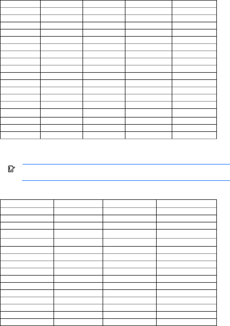
Time zone settings 211
Asia/Amman
Asia/Dubai
Asia/Krasnoyarsk
Asia/Riyadh
Asia/Urumqi
Asia/Anadyr Asia/Dushanbe Asia/Kuala_Lumpur Asia/Riyadh87 Asia/Ust-Nera
Asia/Aqtau Asia/Gaza Asia/Kuching Asia/Riyadh88 Asia/Vientiane
Asia/Aqtobe Asia/Harbin Asia/Kuwait Asia/Riyadh89 Asia/Vladivostok
Asia/Ashgabat Asia/Hebron Asia/Macao Asia/Saigon Asia/Yakutsk
Asia/Ashkhabad Asia/Ho_Chi_Minh Asia/Macau Asia/Sakhalin Asia/Yekaterinburg
Asia/Baghdad Asia/Hong_Kong Asia/Magadan Asia/Samarkand Asia/Yerevan
Asia/Bahrain Asia/Hovd Asia/Makassar Asia/Seoul Hongkong
Asia/Baku Asia/Irkutsk Asia/Manila Asia/Shanghai Iran
Asia/Bangkok Asia/Istanbul Asia/Muscat Asia/Singapore Israel
Asia/Beirut Asia/Jakarta Asia/Nicosia Asia/Taipei Japan
Asia/Bishkek Asia/Jayapura Asia/Novokuznetsk Asia/Tashkent Mideast/Riyadh87
Asia/Brunei
Asia/Jerusalem
Asia/Novosibirsk
Asia/Tbilisi
Mideast/Riyadh88
Asia/Choibalsan Asia/Kabul Asia/Omsk Asia/Tehran Mideast/Riyadh89
Asia/Chongqing Asia/Kamchatka Asia/Oral Asia/Tel_Aviv PRC
Asia/Chungking Asia/Karachi Asia/Phnom_Penh Asia/Thimbu ROC
Asia/Colombo Asia/Kashgar Asia/Pontianak Asia/Thimphu ROK
Asia/Dacca Asia/Kathmandu Asia/Pyongyang Asia/Tokyo Singapore
Asia/Damascus Asia/Katmandu Asia/Qatar Asia/Ujung_Pandang Turkey
Oceanic time zone settings
IMPORTANT: Time zones must be entered exactly as they appear.
The following table provides the Oceanic time zone settings that are supported by the Onboard
Administrator.
Atlantic/Azores Australia/Melbourne Kwajalein Pacific/Marquesas
Atlantic/Bermuda Australia/North NZ Pacific/Midway
Atlantic/Canary Australia/NSW NZ-CHAT Pacific/Nauru
Atlantic/Cape_Verde Australia/Perth Pacific/Apia Pacific/Niue
Atlantic/Faeroe Australia/Queensland Pacific/Auckland Pacific/Norfolk
Atlantic/Jan_Mayen Australia/South Pacific/Chatham Pacific/Noumea
Atlantic/Madeira Australia/Sydney Pacific/Chuuk Pacific/Pago_Pago
Atlantic/Reykjavik Australia/Tasmania Pacific/Easter Pacific/Palau
Atlantic/South_Georgia Australia/Victoria Pacific/Efate Pacific/Pitcairn
Atlantic/St_Helena Australia/West Pacific/Enderbury Pacific/Pohnpei
Atlantic/Stanley Australia/Yancowinna Pacific/Fakaofo Pacific/Ponape
Australia/ACT Iceland Pacific/Fiji Pacific/Port_Moresby
Australia/Adelaide
Indian/Antananarivo
Pacific/Funafuti
Pacific/Rarotonga
Australia/Brisbane Indian/Chagos Pacific/Galapagos Pacific/Saipan
Australia/Broken_Hill Indian/Christmas Pacific/Gambier Pacific/Samoa
Australia/Canberra Indian/Cocos Pacific/Guadalcanal Pacific/Tahiti
Australia/Currie Indian/Comoro Pacific/Guam Pacific/Tarawa
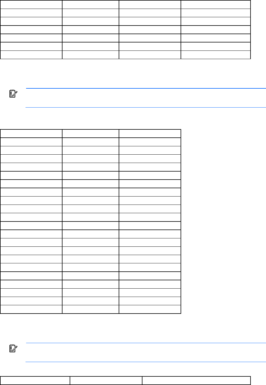
Time zone settings 212
Australia/Darwin
Indian/Kerguelen
Pacific/Honolulu
Pacific/Tongatapu
Australia/Eucla Indian/Mahe Pacific/Johnston Pacific/Truk
Australia/Hobart Indian/Maldives Pacific/Kiritimati Pacific/Wake
Australia/LHI Indian/Mauritius Pacific/Kosrae Pacific/Wallis
Australia/Lindeman Indian/Mayotte Pacific/Kwajalein Pacific/Yap
Australia/Lord_Howe Indian/Reunion Pacific/Majuro US/Hawaii
— — — US/Samoa
Europe time zone settings
IMPORTANT: Time zones must be entered exactly as they appear.
The following table provides the European time zone settings that are supported by the Onboard
Administrator.
Eire Europe/Kaliningrad Europe/Sarajevo
Europe/Amsterdam Europe/Kiev Europe/Simferopol
Europe/Andorra Europe/Lisbon Europe/Skopje
Europe/Athens Europe/Ljubljana Europe/Sofia
Europe/Belfast Europe/London Europe/Stockholm
Europe/Belgrade Europe/Luxembourg Europe/Tallinn
Europe/Berlin Europe/Madrid Europe/Tirane
Europe/Bratislava Europe/Malta Europe/Tiraspol
Europe/Brussels Europe/Mariehamn Europe/Uzhgorod
Europe/Bucharest Europe/Minsk Europe/Vaduz
Europe/Budapest Europe/Monaco Europe/Vatican
Europe/Busingen Europe/Moscow Europe/Vienna
Europe/Chisinau Europe/Nicosia Europe/Vilnius
Europe/Copenhagen Europe/Oslo Europe/Volgograd
Europe/Dublin Europe/Paris Europe/Warsaw
Europe/Gibraltar Europe/Podgorica Europe/Zagreb
Europe/Guernsey Europe/Prague Europe/Zaporozhye
Europe/Helsinki Europe/Riga Europe/Zurich
Europe/Isle_of_Man Europe/Rome GB
Europe/Istanbul
Europe/Samara
GB-Eire
Europe/Jersey Europe/San_Marino Poland
— — Portugal
Polar time zone settings
IMPORTANT: Time zones must be entered exactly as they appear.
The following table provides the Polar time zone settings that are supported by the Onboard Administrator.
Antarctica/Casey Antarctica/Mawson Antarctica/South_Pole

Time zone settings 213
Antarctica/Davis
Antarctica/McMurdo
Antarctica/Syowa
Antarctica/DumontDUrville Antarctica/Palmer Antarctica/Vostok
Antarctica/Macquarie Antarctica/Rothera Arctic/Longyearbyen

Acronyms and abbreviations 214
Acronyms and abbreviations
BLD
BladeSystem Location Device
CA
certificate authority
DDNS
Dynamic Domain Name System
DHCP
Dynamic Host Configuration Protocol
DN
distinguished name
DNS
domain name system
EBIPA
Enclosure Bay IP Addressing
EFM
Enclosure Firmware Management
FQDN
Fully Qualified Domain Name
FRU
field replaceable unit
GC
global catalog
HDD
hard drive
Acronyms and abbreviations 215
HP SIM
HP Systems Insight Manager
HTTPS
hypertext transfer protocol secure sockets
ICMP
Internet Control Message Protocol
iLO
Integrated Lights-Out
IPD
intelligent power discovery
LDAP
Lightweight Directory Access Protocol
MAC
Media Access Control
NTP
network time protocol
PDU
power distribution unit
PIC
peripheral interface controller
PKCS
Public-Key Cryptography Standards
PXE
preboot execution environment
RBSU
ROM-Based Setup Utility
RIBCL
Remote Insight Board Command Language
Acronyms and abbreviations 216
RSA
Rivest, Shamir, and Adelman public encryption key
SLAAC
stateless address autoconfiguration
SOAP
Simple Object Access Protocol
SSH
Secure Shell
SSO
single sign-on
TFTP
Trivial File Transfer Protocol
TPM
Trusted Platform Module
UEFI
Unified Extensible Firmware Interface
UID
unit identification
URB
utility ready blade
VC
Virtual Connect
VCM
Virtual Connect Manager
WWN
World Wide Name

Documentation feedback 217
Documentation feedback
HP is committed to providing documentation that meets your needs. To help us improve the documentation,
send any errors, suggestions, or comments to Documentation Feedback (mailto:docsfeedback@hp.com).
Include the document title and part number, version number, or the URL when submitting your feedback.

Index 218
A
accessing the CLI 13
account authentication 18
account level 16
ADD CA CERTIFICATE 34
ADD EBIPA 60
ADD EBIPAV6 60
ADD HPSIM CERTIFICATE 47
ADD LANGUAGE 111
ADD LDAP CERTIFICATE 39
ADD LDAP GROUP 39
ADD OA ADDRESS IPV6 75
ADD OA DNS 75
ADD OA DNS IPV6 76
ADD REMOTE_SUPPORT CERTIFICATE 194
ADD SNMP TRAPRECEIVER 77
ADD SNMP USER 78
ADD SSHKEY 76
ADD TRUSTED HOST 79
ADD USER 25
ADD VLAN 188
adding a user account 25
Africa time zone 208
Americas time zone 209
Asia time zone 210
ASSIGN 25
ASSIGN FOR LDAP 40
ASSIGN INTERCONNECT 168
ASSIGN OA 26
ASSIGN OA LDAP GROUP 40
authorized reseller 207
B
Blade management commands 151
C
CLEAR INTERCONNECT SESSION 168
CLEAR LOGIN_BANNER_TEXT 80
CLEAR NTP 80
CLEAR SCREEN 20
CLEAR SSHKEY 80
CLEAR SYSLOG 111
CLEAR VCMODE 80
CLI (Command Line Interface) 15
command line, Event messages 204
command, 169, 191
command, ADD CA CERTIFICATE 34
command, ADD EBIPA 60
command, ADD EBIPAV6 60
command, ADD HPSIM CERTIFICATE 47
command, ADD LANGUAGE 111
command, ADD LDAP CERTIFICATE 39
command, ADD LDAP GROUP 39
command, ADD OA ADDRESS IPV6 75
command, ADD OA DNS 75
command, ADD OA DNS IPV6 76
command, ADD REMOTE_SUPPORT
CERTIFICATE 194
command, ADD SNMP TRAPRECIEVER 77
command, ADD SNMP USER 78
command, ADD SSHKEY 76
command, ADD TRUSTED HOST 79
command, ADD USER 25
command, ADD VLAN 188
command, ASSIGN 25
command, ASSIGN for LDAP 40
command, ASSIGN INTERCONNECT 168
command, ASSIGN OA 26
command, ASSIGN OA LDAP GROUP 40
command, CLEAR INTERCONNECT SESSION 168
command, CLEAR LOGIN_BANNER_TEXT 80
command, CLEAR NTP 80
command, CLEAR SCREEN 20
command, CLEAR SSHKEY 80
command, CLEAR SYSLOG 111
command, CLEAR VCMODE 80
command, CONNECT ENCLOSURE 111
command, CONNECT INTERCONNECT 168
command, CONNECT SERVER 151
command, DISABLE ACTIVE HEALTH SYSTEM 179
command, DISABLE ALERTMAIL 81
command, DISABLE CRL 34
command, DISABLE DHCP_DOMAIN_NAME 112
command, DISABLE DHCPV6 81
command, DISABLE EBIPAV6 60
command, DISABLE ENCLOSURE_IP_MODE 82
Index
Index 219
command, DISABLE FIRMWARE
MANAGEMENT 141
command, DISABLE FQDN_LINK_SUPPORT 82
command, DISABLE GUI_LOGIN_DETAIL 112
command, DISABLE HTTPS 82
command, DISABLE IPV6 83
command, DISABLE IPV6DYNDNS 83
command, DISABLE LDAP 40
command, DISABLE LLF 112
command, DISABLE LOGIN_BANNER 83
command, DISABLE NTP 84
command, DISABLE REMOTE SUPPORT 197
command, DISABLE REMOTE SUPPORT
MAINTENANCE 197
command, DISABLE SECURESH 84
command, DISABLE SLAAC 84
command, DISABLE SNMP 85
command, DISABLE STRONG PASSWORDS 26
command, DISABLE SYSLOG REMOTE 182
command, DISABLE TELNET 85
command, DISABLE TRUSTED HOST 85
command, DISABLE TWOFACTOR 34
command, DISABLE URB 50
command, DISABLE USER 26
command, DISABLE VLAN 188
command, DISABLE XMLREPLY 86
command, DISCOVER FIRMWARE SERVER 141
command, DOWNLOAD CA CERTIFICATE 35
command, DOWNLOAD CONFIG 86
command, DOWNLOAD CONFIG using USB
key 185
command, DOWNLOAD HPSIM CERTIFICATE 47
command, DOWNLOAD LDAP CERTIFICATE 41
command, DOWNLOAD OA CERTIFICATE 50
command, DOWNLOAD REMOTE_SUPPORT
CERTIFICATE 194
command, DOWNLOAD SSHKEY 86
command, DOWNLOAD USER CERTIFICATE 35
command, EDIT VLAN 188
command, ENABLE ACTIVE HEALTH SYSTEM 179
command, ENABLE ALERTMAIL 87
command, ENABLE DHCPV6 87
command, ENABLE DISABLE
DHCP_DOMAIN_NAME 113
command, ENABLE EBIPAV6 61
command, ENABLE
ENCLOSURE_ILO_FEDERATION_SUPPORT 87
command, ENABLE ENCLOSURE_IP_MODE 88
command, ENABLE FIRMWARE
MANAGEMENT 141
command, ENABLE FQDN_LINK_SUPPORT 88
command, ENABLE GUI_LOGIN_DETAIL 113
command, ENABLE HTTPS 89
command, ENABLE IPV6 90
command, ENABLE IPV6DYNDNS 89
command, ENABLE LDAP 41
command, ENABLE LLF 113
command, ENABLE LOGIN_BANNER 89
command, ENABLE NTP 90
command, ENABLE REMOTE SUPPORT IRS 196
command, ENABLE REMOTE SUPPORT
MAINTENANCE 196
command, ENABLE REMOTE_SUPPORT DIRECT 195
command, ENABLE SECURESH 90
command, ENABLE SLAAC 91
command, ENABLE SNMP 91
command, ENABLE STRONG PASSWORDS 26
command, ENABLE SYSLOG REMOTE 182
command, ENABLE TELNET 91
command, ENABLE TRUSTED HOST 92
command, ENABLE URB 51
command, ENABLE USER 27
command, ENABLE VLAN 189
command, ENABLE XMLREPLY 92
command, EXIT 20
command, FORCE TAKEOVER 51
command, GENERATE CERTIFICATE 51
command, GENERATE KEY 53
command, HELP 20
command, HISTORY 27
command, HPONCFG 151
command, LOGOUT 20
command, PING 54
command, POWEROFF INTERCONNECT 169
command, POWEROFF SERVER 153
command, POWERON INTERCONNECT 169
command, POWERON SERVER 153
command, QUIT 21
command, REBOOT SERVER 154
command, REMOVE CA CERTIFICATE 36
command, REMOVE EBIPA 62
command, REMOVE EBIPAv6 62
command, REMOVE HPSIM CERTFICATE 48
command, REMOVE LDAP CERTIFICATE 41
command, REMOVE LDAP GROUP 42
command, REMOVE OA ADDRESS IPV6 92
command, REMOVE OA DNS 93
command, REMOVE OA DNS IPV6 93
command, REMOVE REMOTE_SUPPORT
CERTIFICATE 197
command, REMOVE SNMP TRAPRECEIVER 93, 94
command, REMOVE SNMP USER 94
Index 220
command, REMOVE TRUSTED HOST 94
command, REMOVE USER 28
command, REMOVE USER CERTIFICATE 36
command, REMOVE VLAN 189
command, RESTART OA 114
command, SAVE EBIPA 62
command, SAVE EBIPAV6 63
command, SAVE VLAN 189
command, SEND REMOTE SUPPORT
DATACOLLECTION 197
command, SET ALERTMAIL MAILBOX 95
command, SET ALERTMAIL SENDERDOMAIN 95
command, SET ALERTMAIL SENDERNAME 96
command, SET ALERTMAIL SMTP SERVER 96
command, SET DATE 114
command, SET
DEVICE_SERIAL_NUMBER_BLADE 54
command, SET DISPLAY EVENTS 115
command, SET EBIPA INTERCONNECT 63
command, SET EBIPA SERVER 64
command, SET EBIPAV6 INTERCONNECT 65
command, SET EBIPAV6 SERVER 66
command, SET ENCLOSURE ASSET 115
command, SET ENCLOSURE NAME 116
command, SET ENCLOSURE PART_NUMBER 116
command, SET ENCLOSURE PDU TYPE 116
command, SET ENCLOSURE POWER_CAP 202
command, SET ENCLOSURE
POWER_CAP_BAYS_TO_EXCLUDE 202
command, SET ENCLOSURE SERIAL_NUMBER 117
command, SET ENCLOSURE UID 117
command, SET FACTORY 55
command, SET FIPS MODE 96
command, SET FIRMWARE MANAGEMENT 141
command, SET FIRMWARE MANAGEMENT
BAYS_TO_INCLUDE SERVER 143
command, SET FIRMWARE MANAGEMENT FORCE
DOWNGRADE 144
command, SET FIRMWARE MANAGEMENT
POLICY 142
command, SET FIRMWARE MANAGEMENT
POWER 142
command, SET FIRMWARE MANAGEMENT
SCHEDULE 143
command, SET FIRMWARE MANAGEMENT
URL 142
command, SET HPSIM TRUST MODE 48
command, SET INTERCONNECT
ADMIN_PASSWORD FACTORY 170
command, SET INTERCONNECT
POWERDELAY 171
command, SET INTERCONNECT UID 171
command, SET IPCONFIG 97
command, SET LDAP GCPORT 43
command, SET LDAP GROUP ACCESS 42
command, SET LDAP GROUP DESCRIPTION 42
command, SET LDAP NAME 43
command, SET LDAP PORT 43
command, SET LDAP SERVER 44
command, SET LLF INTERVAL 117
command, SET LOGIN_BANNER_TEXT 97
command, SET MINIMUM PASSWORD LENGTH 28
command, SET NIC 154
command, SET NTP POLL 98
command, SET NTP PRIMARY 98
command, SET NTP SECONDARY 99
command, SET OA DOMAIN_NAME 118
command, SET OA GATEWAY 99
command, SET OA NAME 100
command, SET OA UID 100
command, SET OA USB 118
command, SET PASSWORD 28
command, SET POWER LIMIT 119
command, SET POWER MODE 119
command, SET POWER SAVINGS 119
command, SET RACK NAME 22
command, SET REMOTE SYSLOG PORT 182
command, SET REMOTE SYSLOG SERVER 183
command, SET REMOTE_SUPPORT DIRECT
ONLINE_REGISTRATION_COMPLETE 198
command, SET REMOTE_SUPPORT DIRECT
PROXY 198
command, SET SCRIPT MODE 55
command, SET SECURESH SERVER KEX DHG1 100
command, SET SERIAL BAUD 100
command, SET SERVER BOOT 154
command, SET SERVER BOOT FIRST 155
command, SET SERVER BOOT ONCE 155
command, SET SERVER DVD for USB key 185
command, SET SERVER POWERDELAY 156
command, SET SERVER UID 156
command, SET SESSION TIMEOUT 29
command, SET SNMP COMMUNITY 101
command, SET SNMP CONTACT 102
command, SET SNMP ENGINEID 101
command, SET SNMP LOCATION 102
command, SET TIME ZONE 120
command, SET URB 55
command, SET USER ACCESS 29
command, SET USER CERTIFICATE 36
command, SET USER CONTACT 29
command, SET USER FULLNAME 30
Index 221
command, SET USER PASSWORD 30
command, SET VLAN DEFAULT 189
command, SET VLAN FACTORY 190
command, SET VLAN INTERCONNECT 190
command, SET VLAN IPCONFIG SAVE 191
command, SET VLAN IPCONFIG STATIC 191
command, SET VLAN OA 192
command, SET VLAN REVERT 192
command, SET VLAN SERVER 192
command, SHOW ALL 56
command, SHOW CA CERTIFICATE 37
command, SHOW CONFIG 120
command, SHOW DATE 121
command, SHOW DEVICE SERIAL NUMBER
BLADE 58
command, SHOW DISPLAY EVENTS 121
command, SHOW EBIPA 68
command, SHOW EBIPAV6 70
command, SHOW ENCLOSURE FAN 122
command, SHOW ENCLOSURE INFO 122
command, SHOW ENCLOSURE LCD 123
command, SHOW ENCLOSURE POWER_CAP 203
command, SHOW ENCLOSURE
POWER_CAP_BAYS_TO_EXCLUDE 203
command, SHOW ENCLOSURE
POWER_SUMMARY 124
command, SHOW ENCLOSURE
POWERSUPPLY 125
command, SHOW ENCLOSURE STATUS 126
command, SHOW ENCLOSURE TEMP 126
command, SHOW FINGERPRINT 109
command, SHOW FIPS MODE 102
command, SHOW FIRMWARE 144
command, SHOW FIRMWARE LOG SERVER 148
command, SHOW FIRMWARE LOG SESSION 149
command, SHOW FIRMWARE
MANAGEMENT 144
command, SHOW FIRMWARE MANAGEMENT
LOG 145
command, SHOW FIRMWARE SUMMARY 145
command, SHOW FIRMWARE SUMMARY CSV 147
command, SHOW FRU 127
command, SHOW HEALTH 103
command, SHOW HPSIM INFO 48
command, SHOW INTERCONNECT 171
command, SHOW INTERCONNECT INFO 173
command, SHOW INTERCONNECT LIST 175
command, SHOW INTERCONNECT PORT
MAP 176
command, SHOW INTERCONNECT
POWERDELAY 176
command, SHOW INTERCONNECT SESSION 177
command, SHOW INTERCONNECT STATUS 177
command, SHOW LANGUAGES 129
command, SHOW LDAP CERTIFICATE 44
command, SHOW LDAP GROUP 45
command, SHOW LDAP INFO 45
command, SHOW LOGIN_BANNER 105
command, SHOW NETWORK 105
command, SHOW OA 130
command, SHOW OA CERTIFICATE 130
command, SHOW OA INFO 130
command, SHOW OA NETWORK 131
command, SHOW OA STATUS 132
command, SHOW OA UPTIME 133
command, SHOW OA USB 133
command, SHOW PASSWORD SETTINGS 30
command, SHOW RACK INFO 22
command, SHOW RACK NAME 23
command, SHOW REMOTE SUPPORT 198
command, SHOW REMOTE SUPPORT EVENTS 200
command, SHOW REMOTE_SUPPORT
CERTIFICATE 199
command, SHOW SERVER BOOT 157
command, SHOW SERVER DVD 180
command, SHOW SERVER FIRMWARE 149
command, SHOW SERVER INFO 157
command, SHOW SERVER LIST 159
command, SHOW SERVER NAMES 160
command, SHOW SERVER PORT MAP 160
command, SHOW SERVER POWERDELAY 162
command, SHOW SERVER STATUS 163
command, SHOW SERVER TEMP 164
command, SHOW SESSION TIMEOUT 31
command, SHOW SNMP 108
command, SHOW SNMP USER 108
command, SHOW SSHKEY 109
command, SHOW SYSLOG 134
command, SHOW SYSLOG HISTORY 136
command, SHOW SYSLOG OA 135
command, SHOW SYSLOG SERVER 166
command, SHOW SYSLOG SETTINGS 183
command, SHOW TOPOLOGY 23
command, SHOW TWOFACTOR INFO 37
command, SHOW URB 58
command, SHOW USBKEY 185
command, SHOW USER 31
command, SHOW VCMODE 109
command, SHOW VLAN 192
command, SLEEP 32
command, TEST ALERTMAIL 110
command, TEST LDAP 46
Index 222
command, TEST REMOTE_SUPPORT 200
command, TEST SNMP 110
command, TEST SYSLOG 183
command, TEST URB 59
command, UNASSIGN 32
command, UNASSIGN FOR LDAP 46
command, UNASSIGN OA 32
command, UNASSIGN OA LDAP GROUP 46
command, UNASSIGN SERVER 167
command, UPDATE 137
command, UPDATE FIRMWARE SERVER 150
command, UPDATE ILO 138
command, UPDATE IMAGE using USB key 186
command, UPLOAD CONFIG 139
command, UPLOAD CONFIG using USB key 187
command, UPLOAD SUPPORTDUMP 140
command, UPLOAD SYSLOG 140
commands, directory 39
commands, remote support 194
CONNECT ENCLOSURE 111
CONNECT INTERCONNECT 168
CONNECT SERVER 151
Current Default Gateway 99, 105, 131
D
default gateway 99, 105, 131
DHCP (Dynamic Host Configuration Protocol) 15
DHCP addresses 15
directory (LDAP) commands 39
DISABLE ACTIVE HEALTH SYSTEM 179
DISABLE ALERTMAIL 81
DISABLE CRL 34
DISABLE DHCP_DOMAIN_NAME 112
DISABLE DHCPv6 81
DISABLE EBIPAV6 60
DISABLE
ENCLOSURE_ILO_FEDERATION_SUPPORT 81
DISABLE ENCLOSURE_IP_MODE 82
DISABLE FIRMWARE MANAGEMENT 141
DISABLE FQDN_LINK_SUPPORT 82
DISABLE GUI_LOGIN_DETAIL 112
DISABLE HTTPS 82
DISABLE IPV6 83
DISABLE IPV6DYNDNS 83
DISABLE LDAP 40
DISABLE LLF 112
DISABLE LOGIN_BANNER 83
DISABLE NTP 84
DISABLE REMOTE SUPPORT 197
DISABLE REMOTE SUPPORT MAINTENANCE 197
DISABLE REMOTE_SUPPORT 197
DISABLE SECURESH 84
DISABLE SLAAC 84
DISABLE SNMP 85
DISABLE STRONG PASSWORDS 26
DISABLE SYSLOG REMOTE 182
disable telnet 85
DISABLE TRUSTED HOST 85
DISABLE TWOFACTOR 34
DISABLE URB 50
DISABLE USER 26
DISABLE VLAN 188
DISABLE XMLREPLY 86
DISCOVER FIRMWARE SERVER 141
documentation 217
DOWNLOAD CA CERTIFICATE 35
DOWNLOAD CONFIG 86
DOWNLOAD CONFIG using USB key 185
DOWNLOAD HPSIM CERTIFICATE 47
DOWNLOAD LDAP CERTIFICATE 41
DOWNLOAD OA CERTIFICATE 50
DOWNLOAD REMOTE_SUPPORT CERTIFICATE 194
DOWNLOAD SSHKEY 86
DOWNLOAD USER CERTIFICATE 35
E
EDIT VLAN 188
ENABLE ACTIVE HEALTH SYSTEM 179
ENABLE ALERTMAIL 87
ENABLE DHCPV6 87
ENABLE DISABLE DHCP_DOMAIN_NAME 113
ENABLE EBIPA 61
ENABLE EBIPAV6 61
ENABLE
ENCLOSURE_ILO_FEDERATION_SUPPORT 87
ENABLE ENCLOSURE_IP_MODE 88
ENABLE FIRMWARE MANAGEMENT 141
ENABLE FQDN_LINK_SUPPORT 88
ENABLE GUI_LOGIN_DETAIL 113
ENABLE HTTPS 89
ENABLE IPV6 90
ENABLE IPV6DYNDNS 89
ENABLE LDAP 41
ENABLE LLF 113
ENABLE LOGIN_BANNER 89
ENABLE NTP 90
ENABLE REMOTE SUPPORT IRS 196
ENABLE REMOTE SUPPORT MAINTENANCE 196
ENABLE REMOTE_SUPPORT DIRECT 195
ENABLE SECURESH 90
Index 223
ENABLE SLAAC 91
ENABLE SNMP 91
ENABLE STRONG PASSWORDS 26
ENABLE SYSLOG REMOTE 182
ENABLE TELNET 91
ENABLE TRUSTED HOST 92
ENABLE URB 51
ENABLE USER 27
ENABLE VLAN 189
ENABLE XMLPREPLY 92
Enclosure Bay IP Addressing (EBIPA) commands 60
enclosure DVD commands 180
Enclosure Firmware Management commands 141
enclosure management commands 111
Enclosure network configuration commands 75
Europe time zone 212
event notifications, defining 204
EXIT 20
F
force downgrades 138
FORCE TAKEOVER 51
FQDN link support 88
G
general commands 20
general management commands 50
Generat certificate prompts 52
GENERATE CERTIFICATE 51
GENERATE KEY 53
H
HELP 20
help resources 207
HISTORY 27
HP SIM commands 47
HPONCFG 151
I
iLO AutoLogin 18
Integrity blade restrictions 16
Interconnect management commands 168
IP addresses, setting up 15
L
Linux support 15
local access 13
LOGOUT 20
N
network settings 208
O
Oceanic time zone 211
P
PING 54
polar time zone 212
POWEROFF INTERCONNECT 169
POWEROFF SERVER 153
POWERON INTERCONNECT 169
POWERON SERVER 153
privilege levels 16, 18
Q
QUIT 21
R
rack commands 22
rack settings 22
REBOOT SERVER 154
remote access 13
Remote support commands 194
remote syslog commands 182
remote system logging 184
REMOVE CA CERTIFICATE 36
REMOVE EBIPA 62
REMOVE EBIPAv6 62
REMOVE HPSIM CERTIFICATE 48
REMOVE LDAP CERTIFICATE 41
REMOVE LDAP GROUP 42
REMOVE OA ADDRESS IPV6 92
REMOVE OA DNS 93
REMOVE OA DNS IPV6 93
REMOVE REMOTE_SUPPORT CERTIFICATE 197
REMOVE SNMP TRAPRECEIVER 93, 94
REMOVE SNMP USER 94
REMOVE TRUSTED HOST 94
REMOVE USER 28
REMOVE USER CERTIFICATE 36
REMOVE VLAN 189
reserved words 15
RESTART INTERCONNECT 169
RESTART OA 114
restrictions, Integrity blade 16
Index 224
S
SAVE EBIPA 62
SAVE EBIPA6 63
SAVE VLAN 189
SEND REMOTE SUPPORT DATACOLLECTION 197
serial port 13
SET ALERTMAIL MAILBOX 95
SET ALERTMAIL SENDERDOMAIN 95
SET ALERTMAIL SENDERNAME 96
SET ALERTMAIL SM 96
SET DATE 114
SET DEVICE SERIAL_NUMBER BLADE 54
SET DISPLAY 115
SET EBIPA INTERCONNECT 63
SET EBIPA SERVER 64
SET EBIPAV6 INTERCONNECT 65
SET EBIPAV6 SERVER 66
SET ENCLOSURE ASSET 115
SET ENCLOSURE NAME 116
SET ENCLOSURE PART NUMBER 116
SET ENCLOSURE PDU TYPE 116
SET ENCLOSURE POWER_CAP 202
SET ENCLOSURE
POWER_CAP_BAYS_TO_EXCLUDE 202
SET ENCLOSURE SERIAL_NUMBER 117
SET ENCLOSURE UID 117
SET FACTORY 55
SET FIPS MODE 96
SET FIRMWARE MANAGEMENT 141
SET FIRMWARE MANAGEMENT BAYS_TO_INCLUDE
SERVER 143
SET FIRMWARE MANAGEMENT FORCE
DOWNGRADE 144
SET FIRMWARE MANAGEMENT POLICY 142
SET FIRMWARE MANAGEMENT POWER 142
SET FIRMWARE MANAGEMENT SCHEDULE 143
DISABLE FQDN_LINK_SUPPORT 82
SET FIRMWARE MANAGEMENT URL 142
SET HPSIM TRUST MODE 48
SET INTERCONNECT ADMIN_PASSWORD
FACTORY 170
SET INTERCONNECT FACTORY 170
SET INTERCONNECT POWERDELAY 171
SET INTERCONNECT UID 171
SET IPCONFIG 97
SET LDAP GCPORT 43
SET LDAP GROUP ACCESS 42
SET LDAP GROUP DESCRIPTION 42
SET LDAP NAME MAP 43
SET LDAP PORT 43
SET LDAP SERVER 44
SET LLF INTERVAL 117
SET LOGIN_BANNER_TEXT 97
SET MINIMUM PASSWORD LENGTH 28
SET NIC 154
SET NTP POLL 98
SET NTP PRIMARY 98
SET NTP SECONDARY 99
SET OA DOMAIN_NAME 118
SET OA GATEWAY 99
SET OA NAME 100
SET OA UID 100
SET OA USB 118
SET PASSWORD 28
SET POWER LIMIT 119
SET POWER MODE 119
SET POWER SAVINGS 119
SET RACK NAME 22
SET REMOTE SYSLOG PORT 182
SET REMOTE SYSLOG SERVER 183
SET REMOTE_SUPPORT DIRECT
ONLINE_REGISTRATION_COMPLETE 198
SET REMOTE_SUPPORT DIRECT PROXY 198
SET SCRIPT MODE 55
SET SECURESH SERVER KEX DHG1 100
SET SERIAL BAUD 100
SET SERVER BOOT 154
SET SERVER BOOT FIRST 155
SET SERVER BOOT ONCE 155
SET SERVER DVD for USB key 185
SET SERVER POWERDELAY 156
SET SERVER UID 156
SET SESSION TIMEOUT 29
SET SNMP COMMUNITY 101
SET SNMP CONTACT 102
SET SNMP ENGINEID 101
SET SNMP LOCATION 102
SET TIME ZONE 120
SET URB 55
SET USER ACCESS 29
SET USER CERTIFICATE 36
SET USER CONTACT 29
SET USER FULLNAME 30
SET USER PASSWORD 30
SET VLAN DEFAULT 189
SET VLAN FACTORY 190
SET VLAN INTERCONNECT 190
SET VLAN IPCONFIG DHCP 191
SET VLAN IPCONFIG SAVE 191
SET VLAN IPCONFIG STATIC 191
SET VLAN OA 192
Index 225
SET VLAN REVERT 192
SET VLAN SERVER 192
SHOW ALL 56
SHOW CA CERTIFICATE 37
SHOW CONFIG 120
SHOW DATE 121
SHOW DEVICE SERIAL_NUMBER BLADE 58
SHOW DISPLAY EVENTS 121
SHOW EBIPA 68
SHOW EBIPAV6 70
SHOW ENCLOSURE FAN 122
SHOW ENCLOSURE INFO 122
SHOW ENCLOSURE LCD 123
SHOW ENCLOSURE POWER_CAP 203
SHOW ENCLOSURE
POWER_CAP_BAYS_TO_EXCLUDE 203
SHOW ENCLOSURE POWER_SUMMARY 124
SHOW ENCLOSURE POWERSUPPLY 125
SHOW ENCLOSURE STATUS 126
SHOW ENCLOSURE TEMP 126
SHOW FIPS MODE 102
SHOW FIRMWARE 144
SHOW FIRMWARE LOG SERVER 148
SHOW FIRMWARE LOG SESSSION 149
SHOW FIRMWARE MANAGEMENT 144
SHOW FIRMWARE MANAGEMENT LOG 145
SHOW FIRMWARE SUMMARY 145
SHOW FIRMWARE SUMMARY CSV 147
SHOW FRU 127
SHOW HEALTH 103
SHOW HPSIM INFO 48
SHOW INTERCONNECT 171
SHOW INTERCONNECT INFO 173
SHOW INTERCONNECT LIST 175
SHOW INTERCONNECT PORT MAP 176
SHOW INTERCONNECT POWERDELAY 176
SHOW INTERCONNECT SESSION 177
SHOW INTERCONNECT STATUS 177
SHOW LANGUAGES 129
SHOW LDAP CERTIFICATE 44
SHOW LDAP GROUP 45
SHOW LDAP INFO 45
SHOW LOGIN_BANNER 105
SHOW NETWORK 105
SHOW OA 130
SHOW OA CERTIFICATE 130
SHOW OA INFO 130
SHOW OA NETWORK 131
SHOW OA STATUS 132
SHOW OA UPTIME 133
SHOW OA USB 133
SHOW PASSWORD SETTINGS 30
SHOW RACK INFO 22
SHOW RACK NAME 23
SHOW REMOTE SUPPORT 198
SHOW REMOTE SUPPORT EVENTS 200
SHOW REMOTE_SUPPORT CERTIFICATE 199
SHOW SERVER BOOT 157
SHOW SERVER DVD 180
SHOW SERVER FIRMWARE 149
SHOW SERVER INFO 157
SHOW SERVER LIST 159
SHOW SERVER NAMES 160
SHOW SERVER PORT MAP 160
SHOW SERVER POWERDELAY 162
SHOW SERVER STATUS 163
SHOW SERVER TEMP 164
SHOW SESSION TIMEOUT 31
SHOW SNMP 108
SHOW SNMP USER 108
SHOW SSHFINGERPRINT 109
SHOW SSHKEY 109
SHOW SYSLOG 134
SHOW SYSLOG HISTORY 136
SHOW SYSLOG OA 135
SHOW SYSLOG SERVER 166
SHOW SYSLOG SETTINGS 183
SHOW TOPOLOGY 23
SHOW TWOFACTOR INFO 37
SHOW URB 58
SHOW USBKEY 185
SHOW USER 31
SHOW VCMODE 109
SHOW VLAN 192
SLEEP 32
SSH session 13
Static Default 99, 105, 131
T
technical support 207
telnet session 13
terminal emulator session 13
TEST ALERTMAIL 110
TEST LDAP 46
TEST REMOTE_SUPPORT 200
TEST SNMP 110
TEST SYSLOG 183
TEST URB 59
time zones 208
Two-Factor Authentication commands 34
Index 226
U
UNASSIGN 32
UNASSIGN FOR LDAP 46
UNASSIGN OA 32
UNASSIGN OA LDAP GROUP 46
UNASSIGN SERVER 167
universal time zone 208
UPDATE 137
UPDATE FIRMWARE SERVER 150
UPDATE ILO 138
UPDATE IMAGE 138
UPDATE IMAGE using USB key 186
UPLOAD CONFIG 139
UPLOAD CONFIG using USB key 187
UPLOAD SUPPORTDUMP 140
UPLOAD SYSLOG 140
USB key command 185, 187
User account commands 25
V
VLAN commands 188
W
what's new 11
