Hp Server Bl860C I2 Users Manual Integrity I2, BL870c & BL890c Blade User Service Guide
BL890C I2 to the manual d1f0b15b-e751-4252-b14b-a1030fa6f98d
2015-02-09
: Hp Hp-Server-Bl860C-I2-Users-Manual-549799 hp-server-bl860c-i2-users-manual-549799 hp pdf
Open the PDF directly: View PDF ![]() .
.
Page Count: 157 [warning: Documents this large are best viewed by clicking the View PDF Link!]
- HP Integrity BL860c i2, BL870c i2 & BL890c i2 Server Blade User Service Guide
- Contents
- 1 Overview
- 2 Site preparation
- 3 Installing the server blade into the enclosure
- Installation sequence and checklist
- Installing and powering on the server blade
- Installing the Blade Link for BL870c i2 or BL890c i2 configurations
- Using iLO 3
- Accessing UEFI or the OS from iLO 3 MP
- Installing the latest firmware using HP Smart Update Manager
- 4 Operating system procedures
- 5 Optional components
- Partner blades
- Hot-plug SAS disk drives
- Installing internal components
- Removing the access panel
- Processor and heatsink module
- DIMMs
- Mezzanine cards
- HP Smart Array P700m/512 Controller
- HP Smart Array P711m Controller
- Replacing the access panel
- Upgrading a conjoined configuration
- Procedure summary
- Upgrade kit contents
- Before getting started
- Upgrading the existing server blade
- Support
- Blade link and system information parameters
- Operating System Licenses
- Upgrade scenarios which do not require a reinstall of the operating system
- Possible changes due to VC profile mapping on the upgraded server blade
- Preserving VC-assigned MAC addresses in HP-UX by enabling Portable Image
- 6 Troubleshooting
- Methodology
- Troubleshooting tools
- Errors and error logs
- Troubleshooting processors
- Enclosure information
- Cooling subsystem
- Firmware
- Troubleshooting the server interface (system console)
- Troubleshooting the environment
- 7 Removing and replacing components
- 8 Support and other resources
- Standard terms, abbreviations, and acronyms
- A Utilities
- Index
- Index

HP Integrity BL860c i2, BL870c i2 & BL890c
i2 Server Blade User Service Guide
Abstract
This document contains specific information that is intended for users of this HP product.
HP Part Number: 5900-2661
Published: May 2013
Edition: 11

© Copyright 2010, 2013 Hewlett-Packard Development Company, L.P.
The information contained herein is subject to change without notice. The only warranties for HP products and services are set forth in the express
warranty statements accompanying such products and services. Nothing herein should be construed as constituting an additional warranty. HP shall
not be liable for technical or editorial errors or omissions contained herein.
Acknowledgments
Intel, Pentium, Itanium, Intel Inside, and the Intel Inside logo are trademarks or registered trademarks of Intel Corporation or its subsidiaries in the
United States and other countries. UNIX is a registered trademark of The Open Group. Microsoft and Windows are U.S. registered trademarks of
Microsoft Corporation.
Warranty
To get a copy of the warranty for this product see the warranty information website:
http://bizsupport2.austin.hp.com/bc/docs/support/SupportManual/c01865770/c01865770.pdf
Revision history
Publication DateEdition numberSupported product
versions
Operating systems
supported
Document manufacturing
part number
April 2010FirstBL860c i2, BL870c i2 &
BL890c i2
HP-UXAD399-9003A
September 2010SecondBL860c i2, BL870c i2 &
BL890c i2
HP-UX, OpenVMS,
Microsoft® Windows®
AD399-9003A_ed2
December 2010ThirdBL860c i2, BL870c i2 &
BL890c i2
HP-UX, OpenVMS,
Microsoft Windows
AD399-9003A_ed3
February 2011FourthBL860c i2, BL870c i2 &
BL890c i2
HP-UX, OpenVMS,
Microsoft Windows
AD399-9003A_ed4
May 2011FifthBL860c i2, BL870c i2 &
BL890c i2
HP-UX, OpenVMS,
Microsoft Windows
5992-1024
August 2011SixthBL860c i2, BL870c i2 &
BL890c i2
HP-UX, OpenVMS,
Microsoft Windows
5992-1050
November 2011SeventhBL860c i2, BL870c i2 &
BL890c i2
HP-UX, OpenVMS,
Microsoft Windows
5992-1076
February 2012EighthBL860c i2, BL870c i2 &
BL890c i2
HP-UX, OpenVMS,
Microsoft Windows
5992-1081
September 2012NinthBL860c i2, BL870c i2 &
BL890c i2
HP-UX, OpenVMS,
Microsoft Windows
5992-1089
February 2013TenthBL860c i2, BL870c i2 &
BL890c i2
HP-UX, OpenVMS,
Microsoft Windows
5900-2649
May 2013EleventhBL860c i2, BL870c i2 &
BL890c i2
HP-UX, OpenVMS,
Microsoft Windows
5900-2661

Contents
1 Overview..................................................................................................8
Server blade overview...............................................................................................................8
Server blade components..........................................................................................................9
2 Site preparation.......................................................................................10
Server blade dimensions and weight.........................................................................................10
Enclosure information..............................................................................................................10
Enclosure environmental specifications.......................................................................................10
Sample Site Inspection Checklist...............................................................................................11
Power subsystem.....................................................................................................................13
ESD handling information........................................................................................................13
Unpacking and inspecting the server blade................................................................................13
Verifying site preparation....................................................................................................14
Inspect the shipping containers for damage...........................................................................14
Unpacking the server blade................................................................................................14
Verifying the inventory........................................................................................................14
Returning damaged equipment............................................................................................14
3 Installing the server blade into the enclosure................................................15
Installation sequence and checklist............................................................................................15
Installing and powering on the server blade...............................................................................15
Preparing the enclosure......................................................................................................15
Removing a c7000 device bay divider.............................................................................16
Removing a c3000 device bay mini-divider or device bay divider........................................17
Installing interconnect modules........................................................................................18
Interconnect bay numbering and device mapping.........................................................19
Installing the server blade into the enclosure..........................................................................20
Server blade power states...................................................................................................21
Powering on the server blade..........................................................................................22
Powering off the server blade..........................................................................................22
Installing the Blade Link for BL870c i2 or BL890c i2 configurations................................................22
Conjoin checks..................................................................................................................25
Using iLO 3...........................................................................................................................25
Accessing UEFI or the OS from iLO 3 MP...................................................................................26
UEFI Front Page.................................................................................................................27
Saving UEFI configuration settings...................................................................................28
Booting and installing the operating system...........................................................................28
Operating system is loaded onto the server blade..................................................................29
Operating system is not loaded onto the server blade.............................................................29
OS login prompt................................................................................................................29
Installing the latest firmware using HP Smart Update Manager.....................................................29
4 Operating system procedures.....................................................................30
Operating systems supported on the server blade.......................................................................30
Installing the operating system onto the server blade...................................................................30
Installing the OS from an external USB DVD device or tape device...........................................30
Installing the OS using HP Ignite-UX.....................................................................................31
Installing the OS using vMedia............................................................................................31
Configuring system boot options...............................................................................................32
Booting and shutting down HP-UX.............................................................................................32
Adding HP-UX to the boot options list...................................................................................32
HP-UX standard boot..........................................................................................................33
Booting HP-UX from the UEFI Boot Manager.....................................................................33
Contents 3
Booting HP-UX from the UEFI Shell...................................................................................34
Booting HP-UX in single-user mode.......................................................................................34
Booting HP-UX in LVM-maintenance mode.............................................................................34
Shutting down HP-UX..........................................................................................................34
Booting and shutting down HP OpenVMS..................................................................................35
Adding OpenVMS to the Boot Options List............................................................................35
Booting OpenVMS.............................................................................................................36
Booting OpenVMS from the UEFI Boot Manager...............................................................36
Booting HP OpenVMS from the UEFI Shell........................................................................36
Shutting Down OpenVMS...................................................................................................37
Booting and shutting down Microsoft Windows..........................................................................37
Adding Microsoft Windows to the boot options list.................................................................37
Booting the Microsoft Windows operating system...................................................................39
Shutting down Microsoft Windows.......................................................................................39
Shutting down Windows from the command line...............................................................40
5 Optional components................................................................................41
Partner blades........................................................................................................................41
Hot-plug SAS disk drives..........................................................................................................42
Installing internal components..................................................................................................43
Removing the access panel.................................................................................................43
Processor and heatsink module............................................................................................44
DIMMs.............................................................................................................................49
Mezzanine cards...............................................................................................................52
HP Smart Array P700m/512 Controller.................................................................................53
Battery kit and other components....................................................................................53
Battery mounting bracket parts...................................................................................54
Installing the Controller Board.........................................................................................55
Upgrading or replacing controller options........................................................................56
Replacing the 512MB cache module...........................................................................56
Replacing the battery mounting bracket.......................................................................57
Replacing the BBWC battery......................................................................................58
Removing upgrade components......................................................................................60
Removing the 512MB cache module............................................................................60
Removing the battery mounting bracket.......................................................................60
Removing the BBWC battery......................................................................................61
HP Smart Array P711m Controller.........................................................................................62
Supercap pack mounting kit...........................................................................................62
Installing the Supercap mounting bracket..........................................................................63
Installing the P711m controller board................................................................................64
Installing the Supercap Pack...........................................................................................64
Replacing the access panel.................................................................................................65
Upgrading a conjoined configuration...................................................................................66
Procedure summary.......................................................................................................66
Upgrade kit contents......................................................................................................66
Before getting started.....................................................................................................67
Supported operating systems.....................................................................................67
Minimum firmware versions........................................................................................68
Determining your current firmware revisions..................................................................68
Rules for server blade internal components...................................................................72
Upgrading the existing server blade................................................................................73
Existing server blade check........................................................................................73
Adding resources.....................................................................................................73
Final hardware check................................................................................................78
Booting the operating system.....................................................................................79
4 Contents
Warranty registration................................................................................................79
Support.......................................................................................................................80
Blade link and system information parameters...................................................................80
Operating System Licenses.............................................................................................81
HP-UX.....................................................................................................................81
HP OpenVMS..........................................................................................................81
Windows Server 2008..............................................................................................81
Upgrade scenarios which do not require a reinstall of the operating system..........................82
Possible changes due to VC profile mapping on the upgraded server blade..........................82
Preserving VC-assigned MAC addresses in HP-UX by enabling Portable Image......................84
Pre-Upgrade Procedure for PI.....................................................................................85
Post-Upgrade Procedure for PI....................................................................................85
6 Troubleshooting........................................................................................87
Methodology.........................................................................................................................87
General troubleshooting methodology..................................................................................87
Executing recommended troubleshooting methodology ..........................................................88
Basic and advanced troubleshooting tables...........................................................................88
Troubleshooting tools..............................................................................................................91
Controls and ports.............................................................................................................92
Front panel view...........................................................................................................92
Rear panel view............................................................................................................93
Server blade LEDs..............................................................................................................93
Front panel LEDs...........................................................................................................93
SAS disk drive LEDs.......................................................................................................95
SAS hard drive LED combinations...............................................................................95
Blade Link LEDs.............................................................................................................96
Virtual Front Panel LEDs in the iLO 3 TUI................................................................................96
SUV Cable and Ports..........................................................................................................99
Connecting to the serial port...........................................................................................99
Diagnostics.....................................................................................................................100
Offline Diagnostics Environment.........................................................................................100
General diagnostic tools...................................................................................................100
Fault management overview..............................................................................................101
HP-UX Fault management..................................................................................................101
Errors and error logs.............................................................................................................101
Event log definitions.........................................................................................................101
Event log usage...............................................................................................................102
iLO 3 MP event logs.........................................................................................................102
SEL review......................................................................................................................104
Troubleshooting processors....................................................................................................105
Processor installation order................................................................................................105
Processor module behaviors..............................................................................................105
Enclosure information............................................................................................................105
Cooling subsystem................................................................................................................105
Firmware.............................................................................................................................105
Identifying and troubleshooting firmware issues....................................................................105
Verify and install the latest firmware...................................................................................106
Troubleshooting the server interface (system console).................................................................106
Troubleshooting the environment.............................................................................................106
7 Removing and replacing components........................................................108
Server blade components list..................................................................................................108
Preparing the server blade for servicing...................................................................................110
Powering off the server blade............................................................................................110
Blade Link for BL870c i2 or BL890c i2 configurations...........................................................110
Contents 5
Removing the Blade Link for BL870c i2 or BL890c i2 configurations...................................110
Replacing the Blade Link for BL870c i2 or BL890c i2 configurations...................................111
Blade Link for BL860c i2 configurations..............................................................................112
Server blade........................................................................................................................113
Access panel.......................................................................................................................113
Disk drive blanks..................................................................................................................114
Removing a disk drive blank..............................................................................................114
Disk drives...........................................................................................................................114
DIMM baffle........................................................................................................................115
DIMMs................................................................................................................................116
CPU baffle...........................................................................................................................117
CPU and heatsink module.....................................................................................................118
SAS backplane....................................................................................................................121
Server battery......................................................................................................................122
Mezzanine cards..................................................................................................................123
ICH mezzanine board...........................................................................................................124
System board.......................................................................................................................124
Blade Link............................................................................................................................125
8 Support and other resources....................................................................127
Contacting HP......................................................................................................................127
Before you contact HP......................................................................................................127
HP contact information.....................................................................................................127
Subscription service..........................................................................................................127
Documentation feedback..................................................................................................127
HP Insight Remote Support Software...................................................................................128
New and changed information in this edition...........................................................................128
Typographic conventions.......................................................................................................128
Standard terms, abbreviations, and acronyms...............................................130
A Utilities.................................................................................................133
Configuring a Smart Array Controller......................................................................................133
Using the saupdate command...........................................................................................133
get_mode..................................................................................................................133
set_mode...................................................................................................................134
Updating the firmware using saupdate...........................................................................134
Determining the Driver ID and CTRL ID................................................................................134
Configuring RAID volumes using the ORCA menu-driven interface...............................................135
Creating a logical drive....................................................................................................136
Deleting a logical drive....................................................................................................137
Useful UEFI command checks............................................................................................138
UEFI...................................................................................................................................139
UEFI Shell and HP POSSE commands.................................................................................139
Drive paths in UEFI...............................................................................................................142
Using the Boot Maintenance Manager....................................................................................142
Boot Options...................................................................................................................143
Add Boot Option........................................................................................................143
Delete Boot Option......................................................................................................144
Change Boot Order....................................................................................................145
Driver Options.................................................................................................................146
Add Driver Option......................................................................................................146
Delete Driver Option....................................................................................................147
Change Driver Order...................................................................................................147
Console Options..............................................................................................................147
Boot From File.................................................................................................................147
6 Contents
Set Boot Next Value.........................................................................................................148
Set Time Out Value..........................................................................................................148
Reset System....................................................................................................................149
iLO 3 MP.............................................................................................................................149
Index.......................................................................................................150
Index.......................................................................................................154
Contents 7

1 Overview
The HP Integrity BL860c i2 Server Blade is a dense, low-cost, Intel® Itanium® processor server
blade. Using a Blade Link hardware assembly, multiple BL860c i2 Server Blades can be conjoined
to create dual-blade, four socket and quad-blade, eight socket variants.
Number of Processor SocketsNumber of Conjoined Server BladesName
21BL860c i2
42BL870c i2
84BL890c i2
The three blade configurations support the HP-UX, HP OpenVMS, and Windows operating systems
and are designed for deployment in c-Class enclosures, specifically the 10U c7000 and the 6U
c3000 Enclosures.
NOTE: For purposes of this guide, make sure that the c-Class server blade enclosure is powered
on and running properly and that the OA iLO 3 is operational.
Server blade overview
SAS Hard Disk
Drives
PCIe I/O
Mezzanine card
capacitymax memoryDIMM slotsCPU cores (quad)Product
23384GB with
16GB DIMMs
248BL860c i2
46768GB with
16GB DIMMs
4816BL870c i2
8121.5TB with 16GB
DIMMs
9632BL890c i2
8 Overview
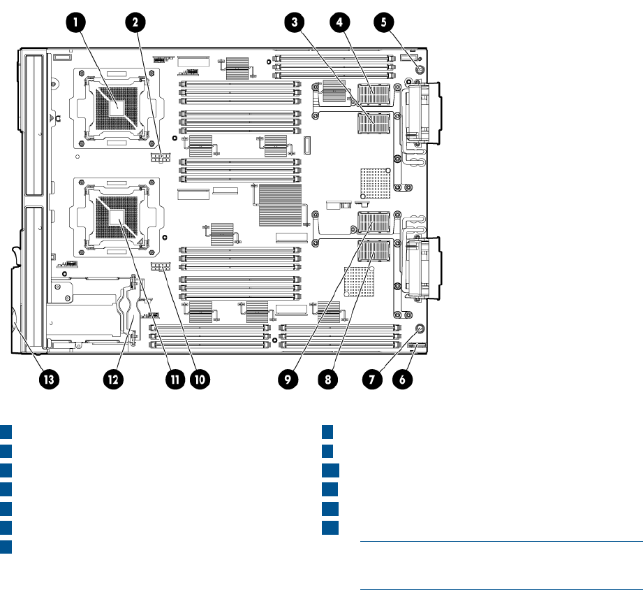
Server blade components
8ICH mezzanine connector
1CPU0
2CPU0 power connector 9Mezzanine connector 3 (type 1 or 2)
10 CPU1 power connector
3Mezzanine connector 1 (type 1)
4Mezzanine connector 2 (type 1 or 2) 11 CPU1
12 SAS backplane
5System board thumbscrew
6Battery (CR2032) 13 Pull tab
NOTE: The iLO 3 password is located on
the pull tab.
7System board thumbscrew
Server blade components 9
2 Site preparation
The HP Integrity BL860c i2 Server Blade does not have cooling or power systems. Cooling and
power is provided by the c-Class enclosure.
IMPORTANT: To avoid hardware damage, allow the thermal mass of the product to equalize to
the temperature and humidity of the installation facility after removing the shipping materials. A
minimum of one hour per 10°C (18°F) of temperature difference between the shipping facility and
installation facility is required
Server blade dimensions and weight
Table 1 Server blade dimensions and weight for the BL860c i2
valueDimensions
36.63 cm (14.42 in.)Height
5.14 cm (2.025 in.)Width
48.51 cm (19.1 in.)Depth
Unloaded: 8.6 kg (19 lb)
Fully loaded: 11.3 kg (25 lb)
Weight
Table 2 Blade Link dimensions and weight
WeightWidthHeightBlade Link type
.5 lb (.22 kg)51 mm (2 in)44 mm (1.73 in)SBL1 (BL860 i2)
1 lb (.45 kg)106 mm (4.17 in)44 mm (1.73 in)SBL2 (BL870 i2)
2 lb (.90 kg)212 mm (8.34 in)44 mm (1.73 in)SBL4 (BL890 i2)
Enclosure information
All three blade configurations are supported in c7000 and c3000 Enclosures.
For more enclosure information see:
http://h71028.www7.hp.com/enterprise/cache/316735-0-0-0-121.html.
Enclosure environmental specifications
NOTE: This information is for both c3000 and c7000 Enclosures.
ValueSpecification
Temperature range 1
10°C to 35°C (50°F to 95°F)Operating
-30°C to 60°C (-22°F to 140°F)Non-operating
Wet bulb temperature
28ºC (82.4ºF)Operating
38.7ºC (101.7ºF)Non-operating
Relative humidity (noncondensing)2
10 Site preparation

20% to 80%Operating
5% to 95%Non-operating
1All temperature ratings shown are for sea level. An altitude derating of 1°C per 304.8 m (1.8°F per 1000 ft) to 3048
m (10,000 ft) is applicable. No direct sunlight allowed. Upper operating limit is 3,048 m (10,000 ft) or 70 Kpa/10.1
psia. Upper non-operating limit is 9,144 m (30,000 ft) or 30.3 KPa/4.4 psia.
2Storage maximum humidity of 95% is based on a maximum temperature of 45°C (113°F). Altitude maximum for storage
corresponds to a pressure minimum of 70 KPa.
For more information on the c-Class enclosures, go to http://h71028.www7.hp.com/enterprise/
cache/316735-0-0-0-121.htmlf.
For more site preparation information, go to http://www.hp.com/go/Blades-docs, select HP
Integrity BL860c i2 Server Blade in the list of servers, and then select the Generalized Site Preparation
Guidelines.
Sample Site Inspection Checklist
Table 3 Customer and HP Information
Customer Information
Phone number:Name:
City or Town:Street address:
CountryState or province:
Zip or postal code:
Phone number:Primary customer contact:
Phone number:Secondary customer contact:
Phone number:Traffic coordinator:
HP information
Order number:Sales representative
Date:Representative making survey
Scheduled delivery date
Table 4 Site Inspection Checklist
Comment or DateCheck either Yes or No. If No, include comment number or date.
Computer Room
NoYesArea or conditionNumber
Is there a completed floor plan?1.
Is adequate space available for maintenance needs? Front 36
inches (91.4 cm) minimum and rear 36 inches (91.4 cm) minimum
are recommended clearances.
2.
Is access to the site or computer room restricted?3.
Is the computer room structurally complete? Expected date of
completion?
4.
Is a raised floor installed and in good condition?5.
Is the raised floor adequate for equipment loading?6.
Are channels or cutouts available for cable routing?7.
Sample Site Inspection Checklist 11

Table 4 Site Inspection Checklist (continued)
Comment or DateCheck either Yes or No. If No, include comment number or date.
Is a network line available?8.
Is a telephone line available?9.
Are customer-supplied peripheral cables and LAN cables available
and of the proper type?
10.
Are floor tiles in good condition and properly braced?11.
Is floor tile underside shiny or painted? If painted, judge the need
for particulate test.
12.
Power and Lighting
NoYesArea or ConditionNumber
Are lighting levels adequate for maintenance?13.
Are AC outlets available for servicing needs (for example, laptop)?14.
Does the input voltage correspond to equipment specifications?15.
Is dual source power used? If so, identify types and evaluate
grounding.
15a.
Does the input frequency correspond to equipment specifications?16.
Are lightning arrestors installed inside the building?17.
Is power conditioning equipment installed?18.
Is a dedicated branch circuit available for equipment?19.
Is the dedicated branch circuit less than 75 feet (22.86 m)?20.
Are the input circuit breakers adequate for equipment loads?21.
Safety
NoYesArea or ConditionNumber
Is an emergency power shutoff switch available?22.
Is a telephone available for emergency purposes?23.
Does the computer room have a fire protection system?24.
Does the computer room have antistatic flooring installed?25.
Do any equipment servicing hazards exist (loose ground wires,
poor lighting, and so on)?
26.
Cooling
NoYesArea or ConditionNumber
Can cooling be maintained between 5°C (41 °F) and 35°C (95
°F) (up to 1,525 m/5,000 ft)? Derate 1°C/305 m (34 °F/1,000
ft) above 1,525 m/5,000 ft and up to 3,048 m/10,000 ft.
27.
Can temperature changes be held to 5°C (9 °F) per hour with tape
media? Can temperature changes be held to 20°C (36 °F) per hour
without tape media?
28.
Can humidity level be maintained at 40% to 55% at 35°C (95 °F)
noncondensing?
29.
Are air-conditioning filters installed and clean?30.
Storage
12 Site preparation
Table 4 Site Inspection Checklist (continued)
Comment or DateCheck either Yes or No. If No, include comment number or date.
NoYesArea or ConditionNumber
Are cabinets available for tape and disc media?31.
Is shelving available for documentation?32.
Training
Area or ConditionNumber
Are personnel enrolled in the System Administrator’s Course?33.
Is on-site training required?34.
Power subsystem
The power subsystem is located on the system board. The BL860c i2 Server Blade receives 12
Volts directly from the enclosure. The voltage is immediately passed through an E-fuse circuit, which
will immediately cut power to the blade if a short circuit fault or over current condition is detected.
The E-fuse can also be intentionally power cycled through the manageability subsystem. The 12V
is distributed to various points on the blade and is converted to lower voltages through power
converters for use by integrated circuits and loads on the blade.
ESD handling information
CAUTION: Wear an ESD wrist strap when handling internal server components. Acceptable ESD
wrist straps include:
•The wrist strap that is included in the ESD kit with circuit checker (part number 9300-1609).
•The wrist strap that is included in the ESD kit without circuit checker (part number 9300-1608).
If the above options are unavailable, the throw away (one use only) strap that ships with some HP
memory products can also be used, with increased risk of electrostatic damage.
When removing and replacing server components, use care to prevent injury and equipment
damage. Many assemblies are sensitive to damage by electrostatic discharge.
Follow the safety precautions listed to ensure safe handling of components, to prevent injury, and
to prevent damage to the server blade:
•When removing or installing a server blade or server blade component, review the instructions
provided in this guide.
•Do not wear loose clothing that might snag or catch on the server or on other items.
•Do not wear clothing subject to static charge build-up, such as wool or synthetic materials.
•If installing an internal assembly, wear an antistatic wrist strap, and use a grounding mat such
as those included in the Electrically Conductive Field Service Grounding Kit.
•Handle components by the edges only. Do not touch any metal-edge connectors or electrical
components on accessory boards.
Unpacking and inspecting the server blade
Be sure that you have adequately prepared your environment for your new server blade, received
the components that you ordered, and verified that the server and the containers are in good
condition after shipment.
Power subsystem 13

Verifying site preparation
Verifying site preparation is an essential factor of a successful server blade installation, and includes
the following tasks:
•Gather LAN information. Determine the two IP addresses for the iLO 3 MP LAN and the server
blade LAN.
•Establish a method to connect to the server blade console. For more information on console
connection methods, see “Using iLO 3” (page 25) for more information.
•Verify electrical requirements. Be sure that grounding specifications and power requirements
are met.
•Confirm environmental requirements.
Inspect the shipping containers for damage
HP shipping containers protect their contents under normal shipping conditions. After the equipment
arrives, carefully inspect each carton for signs of shipping damage. Shipping damage constitutes
moderate to severe damage such as punctures in the corrugated carton, crushed boxes, or large
dents. Normal wear or slight damage to the carton is not considered shipping damage. If you find
shipping damage to the carton, contact your HP customer service representative immediately.
Unpacking the server blade
1. Use the instructions printed on the outside top flap of the carton.
2. Remove inner accessory cartons and the top foam cushions.
IMPORTANT: Inspect each carton for shipping damage as you unpack the server blade.
3. Place the server blade on an antistatic pad.
Verifying the inventory
The sales order packing slip lists the equipment shipped from HP. Use this packing slip to verify
that the equipment has arrived.
NOTE: To identify each item by part number, see the sales order packing slip.
Returning damaged equipment
If the equipment is damaged, immediately contact your HP customer service representative. The
service representative initiates appropriate action through the transport carrier or the factory and
assists you in returning the equipment.
14 Site preparation
3 Installing the server blade into the enclosure
Installation sequence and checklist
CompletedDescriptionStep
Perform site preparation (see “Site preparation” (page 10)for more information).1
Unpack and inspect the server shipping container and then inventory the contents using the
packing slip.
2
Install additional components shipped with the server.3
Install and power on the server blade.4
Configure iLO 3 MP access.5
Access iLO 3 MP.6
Access UEFI from iLO 3 MP.7
Download latest firmware using HP Smart Update Manager8
Install and boot the OS.9
NOTE: For more information regarding HP Integrity Server Blade upgrades, see “Upgrading a
conjoined configuration” (page 66)for more information.
Installing and powering on the server blade
Preparing the enclosure
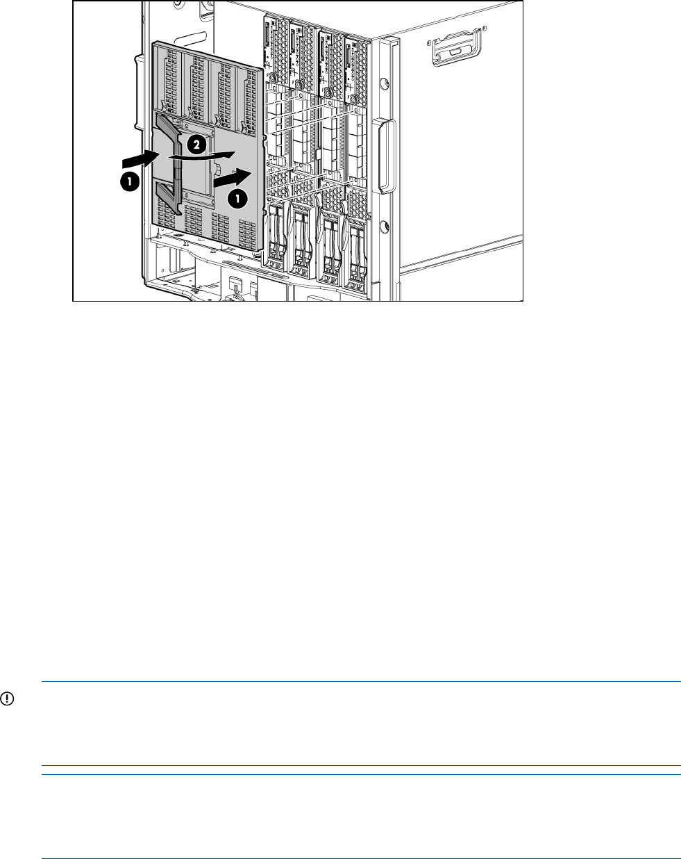
HP BladeSystem enclosures ship with device bay dividers to support half-height devices. To install
a full height device, remove the blanks and the corresponding device bay divider.
CAUTION: To prevent improper cooling and thermal damage, do not operate the server blade
or the enclosure unless all hard drive and device bays are populated with either a component or
a blank.
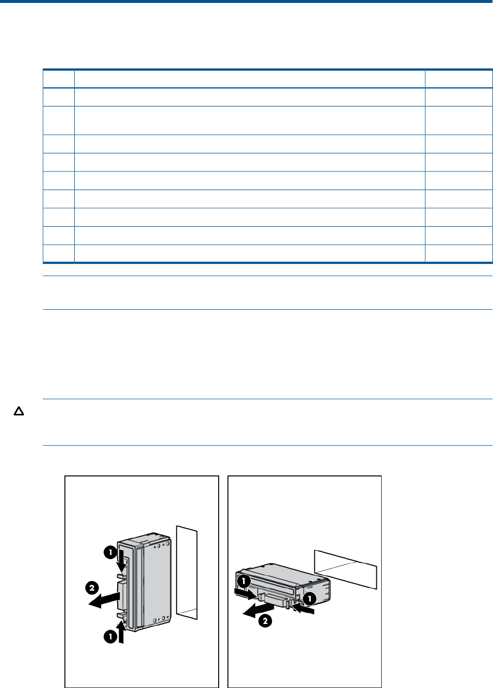
1. Remove the device bay blank.
Installation sequence and checklist 15
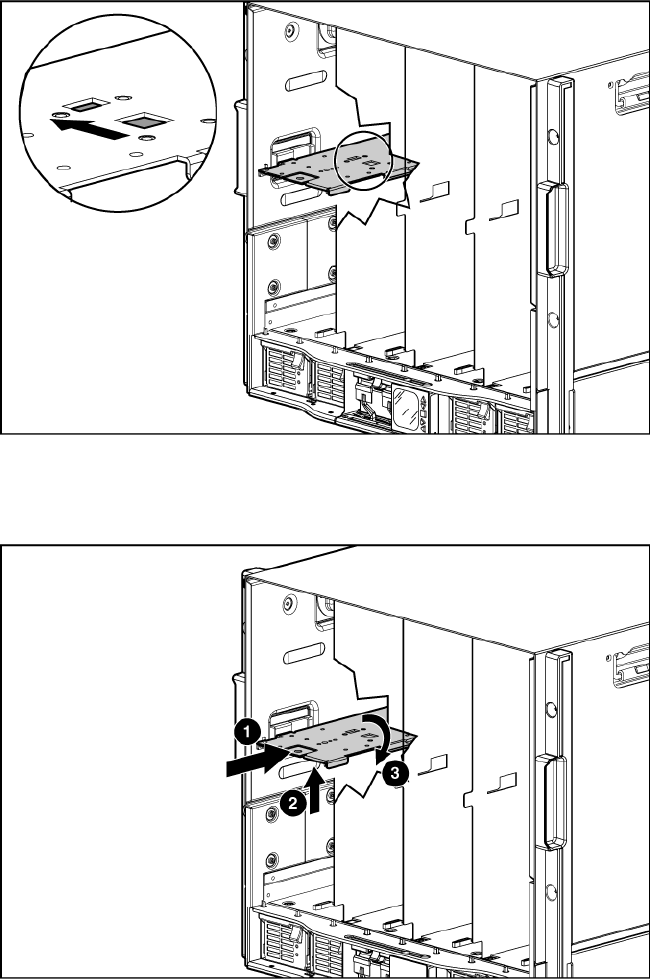
2. Remove the three adjacent blanks.
Removing a c7000 device bay divider
1. Slide the device bay shelf locking tab to the left to open it.
2. Push the device bay shelf back until it stops, lift the right side slightly to disengage the two
tabs from the divider wall, and then rotate the right edge downward (clockwise).
16 Installing the server blade into the enclosure
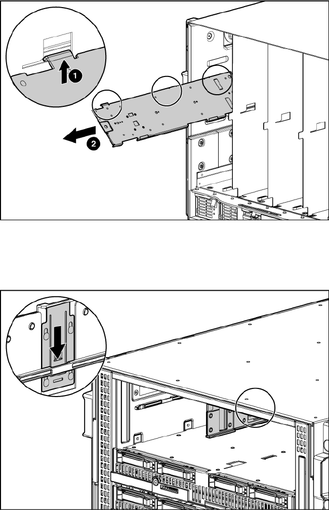
3. Lift the left side of the device bay shelf to disengage the three tabs from the divider wall, and
then remove it from the enclosure.
Removing a c3000 device bay mini-divider or device bay divider
1. Slide the locking tab down.
Installing and powering on the server blade 17
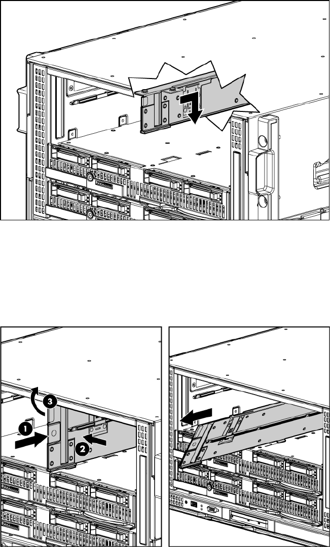
2. Remove the mini-divider or divider:
•c3000 mini-divider:
Push the divider toward the back of the enclosure until the divider drops out of the
enclosure.
•c3000 divider
a. Push the divider toward the back of the enclosure until it stops.
b. Slide the divider to the left to disengage the tabs from the wall.
c. Rotate the divider clockwise.
d. Remove the divider from the enclosure.
Installing interconnect modules
For specific steps to install interconnect modules, see the documentation that ships with the
interconnect module.
18 Installing the server blade into the enclosure
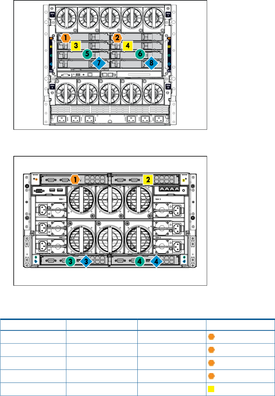
Interconnect bay numbering and device mapping
•HP BladeSystem c7000 Enclosure
•HP BladeSystem c3000 Enclosure
To support network connections for specific signals, install an interconnect module in the bay
corresponding to the embedded NIC or mezzanine signals.
Interconnect bay labelsc3000 interconnect bayc7000 interconnect bayServer blade signal
11NIC 1 (Embedded)
12NIC 2 (Embedded)
11NIC 3 (Embedded)
12NIC 4 (Embedded)
23 and 4Mezzanine 1
Installing and powering on the server blade 19
Interconnect bay labelsc3000 interconnect bayc7000 interconnect bayServer blade signal
3 and 45 and 6Mezzanine 2
3 and 47 and 8
3 and 45 and 6Mezzanine 3
3 and 47 and 8
For detailed port mapping information, see the HP BladeSystem enclosure installation poster or
the HP BladeSystem enclosure setup and installation guide for your product on the HP website
(http://www.hp.com/go/bladesystem/documentation).
Installing the server blade into the enclosure
NOTE: When installing additional blades into an enclosure, additional power supplies might
also be needed to meet power requirements. For more information, see the HP BladeSystem
enclosure setup and installation guide for your product on the HP website (http://www.hp.com/
go/bladesystem/documentation).
NOTE: Before installing and initializing the server blade, install any server blade options, such
as an additional processor, hard drive, or mezzanine card.
1. Remove the connector covers if they are present.
2. Prepare the server blade for installation.
20 Installing the server blade into the enclosure
3. Install the server blade.
The server blade should come up to standby power. The server blade is at standby power if the
blade power LED is amber.
Server blade power states
The server blade has three power states: standby power, full power, and off. Install the server
blade into the enclosure to achieve the standby power state. Server blades are set to power on to
standby power when installed in a server blade enclosure. Verify the power state by viewing the
LEDs on the front panel, and using Table 5.
For more front panel LED information, see “Front panel LEDs” (page 93).
Installing and powering on the server blade 21
Table 5 Power States
DC Power Applied?Standby Power
Applied?
Front Panel Power
Button Activated?
Server Blade Installed
in Enclosure?
Power States
NoYesNoYesStandby power
YesYesYesYesFull power
NoNoNoNoOff
Powering on the server blade
Use one of the following methods to power on the server blade:
NOTE: To power on blades in a conjoined configuration, only power on the Monarch blade.
•Use a virtual power button selection through iLO 3.
•Press and release the Monarch power button.
When the server blade goes from the standby mode to the full power mode, the blade power LED
changes from amber to green.
For more information about iLO 3, see “Using iLO 3” (page 25).
Powering off the server blade
Before powering down the server blade for any upgrade or maintenance procedures, perform a
backup of critical server data and programs.
Use one of the following methods to power off the server blade:
NOTE: To power off blades in a conjoined configuration, only power off the Monarch blade.
•Use a virtual power button selection through iLO 3 (Power Management, Power & Reset).
This method initiates a controlled remote shutdown of applications and the OS before the
server blade enter standby mode.
•Press and release the Monarch power button.
This method initiates a controlled shutdown of applications and the OS before the server blade
enter standby mode.
•Press and hold the Monarch power button for more than 4 seconds to force the server blade
to enter standby mode.
This method forces the server blade to enter standby mode without properly exiting applications
and the OS. It provides an emergency shutdown method in the event of a hung application.
Installing the Blade Link for BL870c i2 or BL890c i2 configurations
IMPORTANT: Without an attached Blade Link, the server blades will not power on.
22 Installing the server blade into the enclosure

NOTE: Before installing the Blade Link for BL870c i2 or BL890c i2, make sure the following
statements are true:
•All blades have the same CPU SKUs
•All blades have the same hardware revision (only use BL860c i2, BL870c i2, or BL890c i2
Server Blades)
•All blades have CPU0 installed
•All blades have the same firmware revision set
•All blades follow the memory loading rules for your configuration, see “DIMMs” (page 49)
•The enclosure OA firmware is compatible with the blade firmware
•The Monarch blade has an ICH mezzanine card installed
•The proper Blade Link is being used for your configuration
To check on the blade hardware revisions and CPU SKUs, go to the Command Menu in the iLO
3 TUI and enter the DF command. This dumps the FRU content of the blades.
NOTE: If you will be upgrading an initial installation, see “Upgrading a conjoined configuration”
(page 66) for more information on server blade upgrades.
Blade Link bay location rules
Partner blade half-height bay
number / Server blade
full-height bay number
Partner
blade
support?Blade location rules
Supported
enclosures
Number of
conjoined
blades
Blade Link
part numberClass
Bottom half-height adjacent
bay, paired with the server
YesNo specific bay
location rules for
blades
c70001 (standard for
BL860c i2)
AD399-67002BL1
blade in full-height bays 1&2,
3&4, 5&6, or 7&8
Half-height bay 8, paired with
the server blade in full-height
bay 3.
c3000
CAUTION: The bay
mini-divider must be installed
in the c3000 enclosure to
ensure the partner blade is
inserted correctly. Failure to
install the bay mini-divider
might result in damage to the
blade or enclosure when
installing the partner blade.1
N/ANoBays 1&2, 3&4,
5&6, or 7&8 with
c70002 (BL870c i2)AD399-67003BL2
Monarch blade in
odd bay
Bays 1&2, 3&4 with
Monarch blade in
odd bay
c3000
Bottom half-height bay 9
paired with full-height bays
YesBays 2&3, 4&5 or
6&7 with Monarch
c7000 only2 (BL870c i2)AD399-67010BL2E
2&3, bottom half-height bayblade in even bay
11 paired with full-height baysusing full-height
numbering 4&5, bottom half-height bay
13 paired with full-height bays
6&7
Installing the Blade Link for BL870c i2 or BL890c i2 configurations 23

Partner blade half-height bay
number / Server blade
full-height bay number
Partner
blade
support?Blade location rules
Supported
enclosures
Number of
conjoined
blades
Blade Link
part numberClass
N/ANoBays 2&3 with
Monarch blade in
c3000 only2 (BL870c i2)AD399-67011
even bay using
full-height numbering.
N/ANoBays 1&2&3&4 or
5&6&7&8, with
c7000 only4 (BL890c i2)AD399-67006BL4
Monarch blade
defaulting to slot 1 or
slot 5, respectively
N/ANoBays 1&2&3&4 with
Monarch blade
defaulting to slot 1
c3000 only4 (BL890c i2)AD399-67007
1For information on installing the c3000 bay mini-divider, see the HP BladeSystem c3000 Enclosure Setup and Installation
Guide.
CAUTION: Using the incorrect Blade Link can cause damage to the Blade Link and to the
connectors on both the Blade Link and the server blades.
IMPORTANT: Failure to follow bay location rules can prevent server blade power on.
NOTE: The manufacturing part numbers for the Blade Link is located on a sticker on the PCA.
“Upgrading a conjoined configuration” (page 66)
To install the Blade Link:
1. Log on to the OA.
2. Install the first blade into the lowest bay number, this blade becomes the Monarch blade
(“Installing the server blade into the enclosure”).
3. Wait 10 seconds. The IP address of the installed blade appears in the OA.
4. Insert each adjacent blade, waiting 10 seconds between blades.
NOTE: The blades will go into stand-by
5. Using the OA, verify that the rest of the blades that will be conjoined have an IP address and
are powered off.
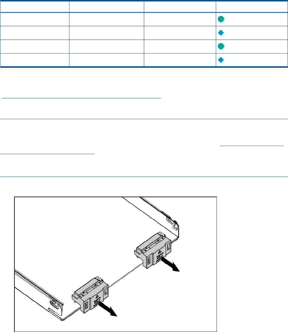
6. Remove the plastic protectors from the connectors on the back of the Blade Link.
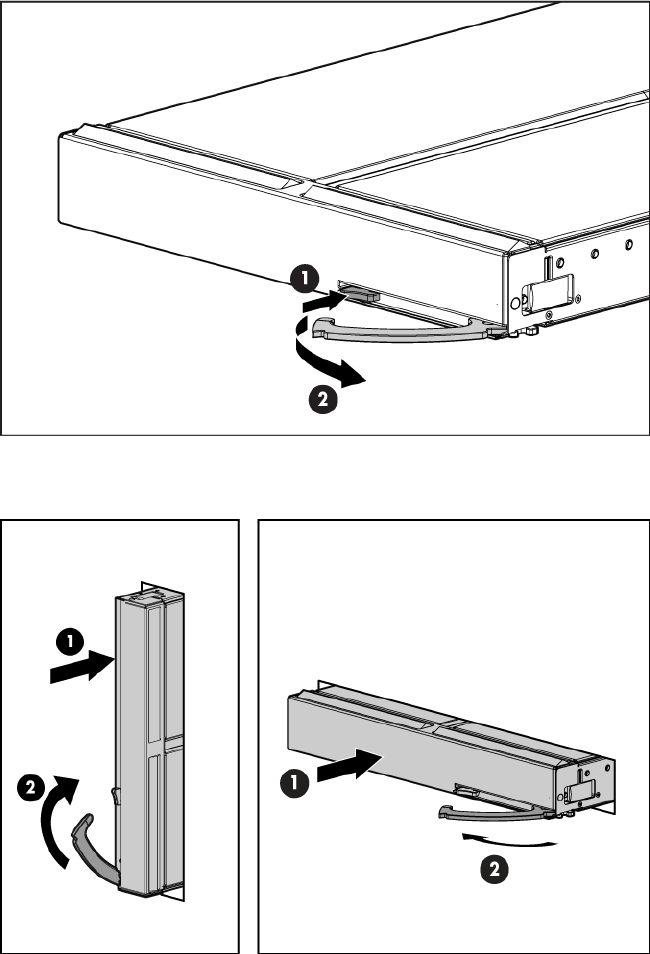
7. Push in the blue release latch on the handle to release the handle.
8. Pull the handle all the way out
9. Align the guide pins on the back of the Blade Link to the holes on the front of the server blades.
As you insert the pins into the holes, ensure the face on the Blade Link is evenly aligned parallel
to the face of the server blades.
10. Press firmly on the left and right sides of the Blade Link face until the handle naturally starts to
close.
CAUTION: If not properly aligned, you can damage the Blade Link
11. Close the handle when it has engaged.
24 Installing the server blade into the enclosure
12. Log into iLO 3 on the Monarch blade. For more information, see the HP Integrity iLO3
Operations Guide.
13. In iLO 3, go to the Command Menu and execute xd -r to reboot all of the iLO 3s in the
conjoined set.
14. Still in the iLO 3 Command Menu, power on the Monarch blade with the PC -on -nc
command. Powering on the Monarch blade will power the entire conjoined system on.
15. Boot the Monarch blade. Booting the Monarch blade boots the entire conjoined system.
Conjoin checks
Integrity BL870c i2 and BL890c i2 systems go through a process called “conjoining” when the
Blade Link is attached. The system cannot boot until that process is completed properly. The following
CM commands in the iLO 3 TUI show data from all blades, and can be used to determine if the
blades are successfully conjoined:
•DF— Lists the FRUs on all of the blades (2 or 4).
•SR — Shows a table of each blades firmware revisions.
•Blade— Shows information about the OA and the bays used.
The OA will also show a properly conjoined system from its GUI.
IMPORTANT: The secondary UUID and other system variables are stored on the Monarch blade.
If you do not put the Monarch blade in the leftmost slot, your system variables will not match. If
you ever change your iLO 3 configuration (such as adding users) that data is also stored on the
Monarch blade.
NOTE: Auxiliary blades are not slot dependent after being installed and configured, however
when the conjoined systems ship, they come with A, B, C, D stickers located under the Blade Links.
While auxiliary blades are not slot dependent after being installed and configured, HP recommends
using the shipped order to ensure proper auxiliary blade function.
Using iLO 3
The iLO 3 subsystem is a standard component of selected server blades that provides blade health
and remote server manageability. The iLO 3 subsystem includes an intelligent microprocessor,
secure memory, and a dedicated network interface. This design makes iLO 3 independent of the
host server and operating system. The iLO 3 subsystem provides remote access to any authorized
network client, sends alerts, and provides other server management functions.
Using iLO 3 25

Using iLO 3, you can:
•Remotely power on, power off, or reboot the host server.
•Send alerts from iLO 3 regardless of the state of the host server.
•Access advanced troubleshooting features through the iLO 3 interface.
For more information about iLO 3 basic features, see the iLO 3 documentation on the HP website
(http://www.hp.com/servers/lights-out).
Accessing UEFI or the OS from iLO 3 MP
UEFI is an architecture that provides an interface between the server blade OS and the server
blade firmware. UEFI provides a standard environment for booting an OS and running preboot
applications.
Use this procedure to access UEFI or the OS from the iLO 3 MP. Your security parameters were
set regarding remote access.
1. Retrieve the factory iLO 3 password from the iLO 3 Network pull tab located on the right side
of the Monarch blade.
2. From the MP Main Menu, enter co to access the Console.
NOTE: Terminal windows should be set to a window size of 80 columns x 25 rows for
optimal viewing of the console at UEFI.
3. After memory test and CPU late self test the following message appears:
Press Ctrl-C now to bypass loading option ROM UEFI drivers.
The prompt will timeout if Ctrl-C is not pressed within a few seconds. If Ctrl-C is pressed, you
will be presented with two options:
•Bypass loading from I/O slots.
•Bypass loading from I/O slots and core I/O.
The Bypass loading from I/O slots and core I/O option may be useful if a bad core I/O
UEFI driver is preventing system boot. USB drives can still be used at the UEFI shell to
update core I/O drivers.
CAUTION: Hitting Ctrl-C before the prompt will not work and may even disable this
feature, be sure wait for the prompt before hitting Ctrl-C.
NOTE: It can take several minutes for this prompt to appear, and the window of time
when Ctrl-C can be pressed is very short. For typical boots, HP recommends that you let
the prompt time out.
After selecting an option, boot will proceed.
NOTE: If no option is selected, normal boot will proceed after ten seconds.
4. Depending on how the server blade was configured from the factory, and if the OS is installed
at the time of purchase, you are taken to:
•UEFI shell prompt
•OS login prompt
If the server blade has a factory-installed OS, you can interrupt the boot process to configure
your specific UEFI parameters.
If you are at the UEFI shell prompt, go to “UEFI Front Page” (page 27).
If you are at the OS login prompt, go to “OS login prompt” (page 29).
26 Installing the server blade into the enclosure
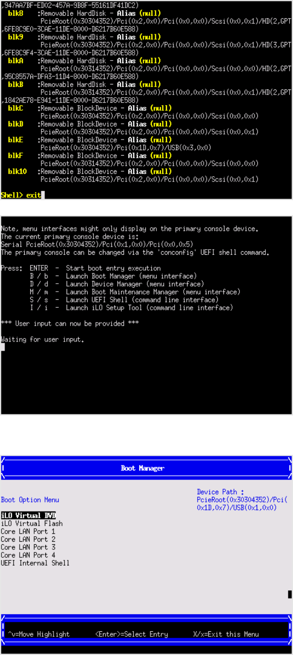
UEFI Front Page
If you are at the UEFI shell prompt, enter exit to get to the UEFI Front Page.
To view boot options, or launch a specific boot option, press Bor bto launch the Boot Manager.
Accessing UEFI or the OS from iLO 3 MP 27
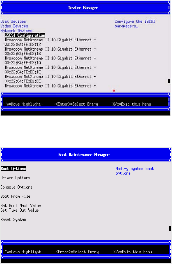
To configure specific devices, press Dor dto launch the Device Manager. This is an advanced
feature and should only be performed when directed.
To perform maintenance on the system such as adding, deleting, or reordering boot options, press
Mor mto launch the Boot Maintenance Manager.
To perform more advanced operations, press Sor sto launch the UEFI Shell.
To view the iLO 3 LAN configuration, press Ior ito launch the iLO 3 Setup Tool.
Saving UEFI configuration settings
There are other UEFI settings you can configure at this time. For more UEFI configuration options,
see Appendix A (page 133).
Booting and installing the operating system
From the UEFI Front Page prompt, you can boot and install in either of two manners:
•If your OS is loaded onto your server blade, see “Operating system is loaded onto the server
blade” (page 29).
•If the OS is not installed onto your server blade, see “Operating system is not loaded onto
the server blade” (page 29).
28 Installing the server blade into the enclosure

Operating system is loaded onto the server blade
If the OS is loaded on your server blade, normally UEFI will automatically boot to the OS. If the
UEFI Front Page is loaded, press ENTER to start auto boot, or Bor bto select a specific boot option
for your OS.
•Use your standard OS logon procedures, or see your OS documentation to log on to your
OS.
Operating system is not loaded onto the server blade
There are two options on how to load the OS if it is not loaded onto your server blade.
•To load the OS from a DVD, see “Installing the OS from an external USB DVD device or tape
device” (page 30).
•To load the OS using Ignite-UX, see “Installing the OS using HP Ignite-UX” (page 31).
OS login prompt
If your server blade is at the OS login prompt after you establish a connection to the server blade,
use your standard OS log in procedures, or see your OS documentation for the next steps.
Installing the latest firmware using HP Smart Update Manager
The HP Smart Update Manager utility enables you to deploy firmware components from either an
easy-to-use interface or a command line. It has an integrated hardware discovery engine that
discovers the installed hardware and the current versions of firmware in use on target servers. This
prevents extraneous network traffic by only sending the required components to the target. HP
Smart Update Manager also has logic to install updates in the correct order and ensure all
dependencies are met before deployment of a firmware update. It also contains logic to prevent
version-based dependencies from destroying an installation and ensures updates are handled in
a manner that reduces any downtime required for the update process. HP Smart Update Manager
does not require an agent for remote installations.
Key features of HP Smart Update Manager are:
•GUI and CLI–command line interface
•Dependency checking, which ensures appropriate installation order and dependency checking
between components
•Intelligent deployment deploys only required updates
•Improved deployment performance
•Remote command-line deployment
•Windows X86 or Linux X86 support
At this time, firmware updates on Integrity systems through HPSUM are done remotely. For example,
HP SUM runs on an x86 Linux or Windows management system and updates targeted Integrity
systems through the network. HP Smart Update Manager supports firmware updates on the BL860c
i2, BL870c i2, and BL890c i2 servers. Firmware bundles for these servers are available and can
be downloaded from the HP website at http://www.hp.com.
For more information about HP Smart Update Manager, see the HP Smart Update Manager User
Guide (http://www.hp.com/go/hpsum/documentation).
Installing the latest firmware using HP Smart Update Manager 29

4 Operating system procedures
Operating systems supported on the server blade
•HP-UX 11i v3 HWE 1003
•HP OpenVMS v8.4
•Microsoft Windows Server 2008 Itanium Edition R2
Installing the operating system onto the server blade
The following procedures describe generalized operating system installation. For more details, see
the operating system documentation.
Installing the OS from an external USB DVD device or tape device
NOTE: Tapeboot requires BL8x0c i2 system firmware bundle 26.11 or later and a partner tape
blade, or an additional 51378-B21 Integrity Smart Array P711m HBA running 6.22 firmware or
later to boot from an Ultrium 6250 tape drive.
1. If using an external USB DVD device:
a. Connect the Integrity SUV cable to the front of the Monarch server blade.
b. Connect the USB DVD cable to one of the USB ports on the SUV cable.
NOTE: Some DVD drives might also require a separate power connection.
c. Turn on the external USB DVD device.
2. Insert the OS media into the USB DVD device or tape device.
3. Power on the server blade and boot to UEFI. If the server blade is already powered on, then
reboot to UEFI using the reset command at the UEFI prompt.
4. From the UEFI Front Page, press Sor sto launch the UEFI Shell.
NOTE: If the device is already selected or you already know the device name, then skip the
following step.
If you are using a tape device, when the UEFI shell comes up, you should see a message
similar to the following on the console:
HP Smart Array P212 Controller (version 6.22)
Tape Drive(s) Detected:
Port: 1I, box:0, bay: 3 (SAS)
The message may also be similar to the following.
HP Smart Array P711m Controller (version 6.22) 0 Logical Drives
Tape Drive(s) Detected:
Port: 2E, box:1, bay: 9 (SAS)
NOTE: If you do not see a line starting with Port and ending with (SAS), the tape is not
connected correctly or it is not responding.
30 Operating system procedures

5. Locate the device you want to boot from.
a. For USB DVD, locate the device:
i. Use the map command to list all device names from the UEFI Shell prompt. The map
command displays the following:
fs2:\> map
Device mapping table
fs6 :Removable CDRom - Alias cd66d0a blk6
PcieRoot(0x30304352)/Pci(0x1D,0x7)/USB(0x3,0x0)/CDROM(0x0)
From the list generated by the map command, locate the device name (in this example,
fs6)
NOTE: Your DVD drive might not be named fs6. Make sure you verify the ID
appropriate to your DVD device.
ii. At the UEFI shell prompt, specify the device name for the DVD-ROM and then enter
the UEFI install command, as in the following example:
Shell> fs6:
fs6:\> install
b. For tape, locate the device:
• To boot from tape once you are at the UEFI shell:
Shell> tapeboot select
01
PcieRoot(0x30304352)/Pci(0x8,0x0)/Pci(0x0,0x0)/SAS(0x50060B00007F6FFC,0x0,0x1,NoTopology,0,0,0,0x0)
Select Desired Tape: 01 <<input 01
•If the correct media is installed, it will boot from tape when you enter the index
number.
•If there is no media in the SAS tape drive and you select 1, the following message
appears:
tapeboot: Could not load tapeboot image
6. The OS now starts loading onto the server blade. Follow the on-screen instructions to install
the OS fully.
7. Continue with “Configuring system boot options” (page 32)
Installing the OS using HP Ignite-UX
Ignite-UX is an HP-UX administration toolset that enables:
•Simultaneous installation of HP-UX on multiple clients
•The creation and use of custom installations
•The creation of recovery media
•The remote recovery of clients
To install the OS onto the server blade using Ignite-UX, go to www.hp.com/go/ignite-ux.
Installing the OS using vMedia
NOTE: Installing the OS using vMedia might be significantly slower than installing using other
methods.
vMedia enables connections of a DVD physical device or image file from the local client system
to the remote server. The virtual device or image file can be used to boot the server with an operating
system that supports USB devices.
vMedia depends on a reliable network with good bandwidth. This is especially important when
you are performing tasks such as large file transfers or OS installations.
Installing the operating system onto the server blade 31

For more information regarding loading the OS with vMedia, see the vMedia Chapter of the HP
Integrity Integrated Lights-Out Management Processor Operations Guide.
NOTE: After the OS is loaded, make sure to save your nonvolatile memory settings to preserve
boot entries in case of blade failure.
Configuring system boot options
•Boot Manager
Contains the list of boot options available. Ordinarily the boot options list includes the UEFI
Internal Shell and one or more operating system loaders.
To manage the boot options list for each server, use the UEFI Shell, the Boot Maintenance
Manager, or operating system utilities.
•Autoboot setting
The autoboot setting determines whether a server automatically loads the first item in the
boot options list or remains at the UEFI Front Page menu. With autoboot enabled, UEFI loads
the first item in the boot options list after a designated timeout period.
Configure the autoboot setting for an HP Integrity server using either the autoboot UEFI Shell
command or the Set Time Out Value menu item from the Boot Maintenance Manager.
Examples of autoboot commands for HP-UX:
◦Disable autoboot from the UEFI Shell by issuing autoboot off
◦Enable autoboot with the default timeout value by issuing autoboot on
◦Enable autoboot with a timeout of 60 seconds by issuing the autoboot 60
◦Set autoboot from HP-UX using setboot
◦Enable autoboot from HP-UX using setboot -b on
◦Disable autoboot from HP-UX using setboot -b off
For more information on the autoboot command, enter help autoboot.
Booting and shutting down HP-UX
To boot HP-UX, use one of the following procedures:
•To boot HP-UX normally, see “HP-UX standard boot” (page 33). HP-UX boots in multi-user
mode.
•To boot HP-UX in single-user mode, see “Booting HP-UX in single-user mode” (page 34).
•To boot HP-UX in LVM-maintenance mode, see“Booting HP-UX in LVM-maintenance mode”
(page 34).
Adding HP-UX to the boot options list
You can add the \EFI\HPUX\HPUX.EFI loader to the boot options list from the UEFI Shell or the
Boot Maintenance Manager.
NOTE: On HP Integrity server blades, the operating system installer automatically adds an entry
to the boot options list.
NOTE: To add an HP-UX boot option when logged in to HP-UX, use the setboot command.
For more information, see the setboot(1M) manpage.
To add HP-UX to the list:
32 Operating system procedures
1. Access the UEFI Shell environment.
a. Log in to iLO 3 for Integrity and enter CO to access the system console.
When accessing the console, confirm that you are at the UEFI Front Page.
If you are at another UEFI menu, then choose the Exit option or press Xor xto exit the
menu. Exit until you return to the screen that lists the keys that can be pressed to launch
various Managers.
b. Press Sor sto launch the UEFI shell.
2. Access the UEFI System Partition (fsX:where X is the file system number) for the device
from which you want to boot HP-UX.
For example, enter fs2: to access the UEFI System Partition for the bootable file system
number 2. The UEFI Shell prompt changes to reflect the file system currently accessed.
The full path for the HP-UX loader is \EFI\HPUX\HPUX.EFI and it should be on the device
you are accessing.
3. At the UEFI Shell environment, use the bcfg command to manage the boot options list.
The bcfg command includes the following options for managing the boot options list:
•bcfg boot dump – Display all items in the boot options list for the server.
•bcfg boot rm #– Remove the item number specified by #from the boot options list.
•bcfg boot mv #a #b – Move the item number specified by #a to the position specified
by #b in the boot options list.
•bcfg boot add # file.efi "Description"– Add a new boot option to the
position in the boot options list specified by #. The new boot option references file.efi
and is listed with the title specified by Description.
For example, bcfg boot add 1 \EFI\HPUX\HPUX.EFI "HP-UX 11i v3" adds
an HP-UX 11i v3 item as the first.
For more information, see the help bcfg command.
4. Exit the console and iLO 3 MP interfaces.
Press Ctrl–B to exit the system console and return to the iLO 3 MP Main Menu. To exit the MP,
press Xor xat the Main Menu.
HP-UX standard boot
Use either of the following procedures to boot HP-UX:
•“Booting HP-UX from the UEFI Boot Manager” (page 33)
•“Booting HP-UX from the UEFI Shell” (page 34)
Booting HP-UX from the UEFI Boot Manager
1. From the UEFI Boot Manager menu, choose an item from the boot options list to boot HP-UX.
2. Access the UEFI Boot Manager menu for the server on which you want to boot HP-UX.
3. Log in to iLO 3 MP and enter CO to choose the system console.
4. Confirm you are at the UEFI Front Page. If you are at another UEFI menu, then choose the Exit
option or press Xor xto exit the menu. Exit until you return to the screen that lists the keys
that can be pressed to launch various Managers. Press Bor bto launch the Boot Manager.
5. At the UEFI Boot Manager menu, choose an item from the boot options list.
Each item in the boot options list references a specific boot device and provides a specific set
of boot options or arguments you use when booting the device.
6. Press Enter to initiate booting using your chosen boot option.
Booting and shutting down HP-UX 33
7. Exit the console and iLO 3 MP interfaces.
8. Press Ctrl–B to exit the system console and return to the MP Main Menu. To exit the MP Main
Menu, press Xor x.
Booting HP-UX from the UEFI Shell
1. Access the UEFI Shell.
2. From the UEFI Front Page, press Sor sto launch the UEFI shell.
3. Use the map command to list the file systems (fs0, fs1, and so on) that are known and have
been mapped.
4. To select a file system to use, enter its mapped name followed by a colon (:). For example, to
operate with the boot device that is mapped as fs0, enter fs0: at the UEFI Shell prompt.
5. Enter HPUX at the UEFI Shell command prompt to launch the HPUX.EFI loader from the
currently selected boot device.
If needed, specify the full path of loader by entering \EFI\HPUX\HPUX at the UEFI Shell
command prompt.
6. Allow the HPUX.EFI loader to proceed with the boot command specified in the AUTO file,or
manually specify the boot command.
By default, the HPUX.EFI loader boots using the loader commands found in the
\EFI\HPUX\AUTO file on the UEFI System Partition of the selected boot device. The AUTO
file typically contains the boot vmunix command.
To interact with the HPUX.EFI loader, interrupt the boot process (for example, type a space)
within the time-out period provided by the loader. To exit the loader, use the exit command,
which returns you to UEFI.
Booting HP-UX in single-user mode
1. Use steps 1–5 from “Booting HP-UX from the UEFI Shell” (page 34) to access the UEFI shell
and launch the HPUX.EFI loader.
2. Access the HP-UX Boot Loader prompt (HPUX>) by pressing any key within the 10 seconds
given for interrupting the HP-UX boot process. Use the HPUX.EFI loader to boot HP-UX in
single-user mode in step 3
After you press a key, the HPUX.EFI interface (the HP-UX Boot Loader prompt, HPUX>)
launches. For help using the HPUX.EFI loader, enter the help command. To return to the UEFI
Shell, enter exit.
3. At the HPUX.EFI interface (the HP-UX Boot loader prompt, HPUX>) enter the boot -is
vmunix command to boot HP-UX (the /stand/vmunix kernel) in single-user (-is) mode.
Booting HP-UX in LVM-maintenance mode
The procedure for booting HP-UX into LVM Maintenance Mode is the same as for booting into
single user mode (“Booting HP-UX in single-user mode” (page 34)), except use the -lm boot option
instead of the -is boot option:
HPUX> boot -lm vmunix
Shutting down HP-UX
For more information, see the shutdown( 1M) manpage.
1. Log in to HP-UX running on the server that you want to shut down or log in to iLO 3 MP for
the server and use the Console menu to access the system console. Accessing the console
through iLO 3 MP enables you to maintain console access to the server after HP-UX has shut
down.
34 Operating system procedures

2. Issue the shutdown command with the appropriate command-line options.
The command-line options you specify determines the way in which HP-UX shuts down and
whether the server is rebooted.
Use the following list to choose an HP-UX shutdown option for your server:
•Shut down HP-UX and halt (power off) the server using the shutdown -h command.
Reboot a halted server by powering on the server using the PC command at the iLO 3
MP Command menu.
•Shut down HP-UX and reboot the server by issuing the shutdown -r command.
Booting and shutting down HP OpenVMS
Adding OpenVMS to the Boot Options List
NOTE: If OpenVMS is already installed on the server blade, add OpenVMS to the boot options
list by using the command procedure SYS$MANAGER:BOOT_OPTIONS.COM, then following the
on-screen instructions.
1. Access the UEFI Shell environment.
a. Log in to iLO 3 for Integrity and enter CO to access the system console.
When accessing the console, confirm that you are at the UEFI Front Page.
If you are at another UEFI menu, then choose the Exit option or press Xor xto exit the
menu. Exit until you return to the screen that lists the keys that can be pressed to launch
various Managers.
b. Press Sor sto launch the UEFI shell.
2. Access the UEFI System Partition (fsX: where X is the file system number) for the device from
which you want to boot OpenVMS.
For example, enter fs2: to access the UEFI System Partition for the bootable file system
number 2. The UEFI Shell prompt changes to reflect the file system currently accessed.
The full path for the loader is \EFI\VMS\VMS_LOADER.EFI and it should be on the device
you are accessing.
3. At the UEFI Shell environment, use the bcfg command to manage the boot options list.
The bcfg command includes the following options for managing the boot options list:
•bcfg boot dump – Display all items in the boot options list for the server.
•bcfg boot rm #– Remove the item number specified by #from the boot options list.
•bcfg boot mv #a #b – Move the item number specified by #a to the position specified
by #b in the boot options list.
•bcfg boot add # file.efi "Description"– Add a new boot option to the
position in the boot options list specified by #. The new boot option references file.efi
and is listed with the title specified by Description.
For example, bcfg boot add 1 \EFI\VMS\VMS_LOADER.EFI “OpenVMS V8.4”
adds an OpenVMS item as the first entry in the boot options list.
For more information, see the help bcfg command.
4. Exit the console and iLO 3 MP interfaces.
5. Press Ctrl–B to exit the system console and return to the MP Main Menu. To exit the MP Main
Menu, press Xor x.
For more details, see the HP OpenVMS 8.4 Upgrade and Installation Manual.
Booting and shutting down HP OpenVMS 35
Booting OpenVMS
To boot OpenVMS, use either of the following procedures:
•“Booting OpenVMS from the UEFI Boot Manager” (page 36)
•“Booting HP OpenVMS from the UEFI Shell” (page 36)
Booting OpenVMS from the UEFI Boot Manager
1. From the UEFI Boot Manager menu, choose an item from the boot options list to boot OpenVMS
using the chosen boot option.
2. Access the UEFI Boot Manager menu for the server on which you want to boot OpenVMS.
3. Log in to the iLO 3 MP and enter CO to choose the system console.
4. Confirm you are at the UEFI Front Page. If you are at another UEFI menu, then choose the Exit
option or press Xor xto exit the menu. Exit until you return to the screen that lists the keys
that can be pressed to launch various Managers. Press Bor bto launch the Boot Manager.
5. At the EFI Boot Manager menu, choose an item from the boot options list.
Each item in the boot options list references a specific boot device and provides a specific set
of boot options or arguments to use when booting the device.
6. Press Enter to initiate booting using the chosen boot option.
7. Exit the console and iLO 3 MP interfaces.
8. Press Ctrl–B to exit the system console and return to the MP Main Menu. To exit the MP Main
Menu, press Xor x.
Booting HP OpenVMS from the UEFI Shell
From the EFI Shell environment, to boot OpenVMS on a device, first access the bootable partition
(for example fs0:) for the root device and enter\efi\vms\vms_loader to initiate the OpenVMS
loader.
1. Access the UEFI Shell.
2. From the UEFI Front Page, press Sor sto launch the UEFI shell.
3. Use the map command to list the file systems (fs0, fs1, and so on) that are known and have
been mapped.
4. To select a file system to use, enter its mapped name followed by a colon (:). For example, to
operate with the boot device that is mapped as fs0, enter fs0: at the UEFI Shell prompt.
5. When accessing the bootable partition for the desired boot device, issue
the\efi\vms\vms_loader command to initiate the vms_loader.efi loader on the
device you are accessing.
fs5:> \efi\vms\vms_loader.efi
fs5:> \efi\vms\vms_loader.efi
HP OpenVMS Industry Standard 64 Operating System, Version V8.4
© Copyright 1976-2010 Hewlett-Packard Development Company, L.P.
%DECnet-I-LOADED, network base image loaded, version = 05.17.00
%DECnet-W-NOOPEN, could not open SYS$SYSROOT:[SYSEXE]NET$CONFIG.DAT
%SMP-I-CPUTRN, CPU #2 has joined the active set.
%SMP-I-CPUTRN, CPU #3 has joined the active set.
%SMP-I-CPUTRN, CPU #8 has joined the active set.
%SMP-I-CPUTRN, CPU #15 has joined the active set.
%SMP-I-CPUTRN, CPU #14 has joined the active set.
%SMP-I-CPUTRN, CPU #12 has joined the active set.
%SMP-I-CPUTRN, CPU #10 has joined the active set.
%SMP-I-CPUTRN, CPU #7 has joined the active set.
%SMP-I-CPUTRN, CPU #4 has joined the active set.
%SMP-I-CPUTRN, CPU #6 has joined the active set.
36 Operating system procedures

%SMP-I-CPUTRN, CPU #5 has joined the active set.
%SMP-I-CPUTRN, CPU #9 has joined the active set.
%SMP-I-CPUTRN, CPU #1 has joined the active set.
%SMP-I-CPUTRN, CPU #11 has joined the active set.
%SMP-I-CPUTRN, CPU #13 has joined the active set.
%STDRV-I-STARTUP, OpenVMS startup begun at 11-AUG-2010 06:15:29.21
6. Exit the console and iLO 3 MP interfaces.
7. Press Ctrl–B to exit the system console and return to the MP Main Menu. To exit the MP Main
Menu, press Xor x.
Shutting Down OpenVMS
1. Log in to OpenVMS running on the server that you want to shut down.
Log in to the iLO 3 MP for the server and use the Console menu to access the system console.
Accessing the console through the iLO 3 MP enables you to maintain console access to the
server after HP OpenVMS has shut down.
2. At the OpenVMS DCL prompt issue the @SYS$SYSTEM:SHUTDOWN command and specify
the shutdown options in response to the prompts given.
NOTE: Use the command in step 2 when you shut down OpenVMS the first time. If you have
shut down OpenVMS more than once, use the $ shutdown command.
$@sys$system:shutdown
SHUTDOWN -- Perform an Orderly System Shutdown
on node NODE1
How many minutes until final shutdown [0]:
Reason for shutdown [Standalone]:
Do you want to spin down the disk volumes [NO]?
Do you want to invoke the site-specific shutdown procedure [YES]?
Should an automatic system reboot be performed [NO]?
When will the system be rebooted [later]:
Shutdown options (enter as a comma-separated list):
REMOVE_NODE Remaining nodes in the cluster should adjust quorum
CLUSTER_SHUTDOWN Entire cluster is shutting down
REBOOT_CHECK Check existence of basic system files
SAVE_FEEDBACK Save AUTOGEN feedback information from this boot
DISABLE_AUTOSTART Disable autostart queues
POWER_OFF Request console to power-off the system
BIB_STATE Request console to reboot all CPUs to the Itanium BIB state
Shutdown options [NONE]: REBOOT_CHECK
%SHUTDOWN-I-BOOTCHECK, performing reboot consistency check...
%SHUTDOWN-I-CHECKOK, basic reboot consistency check completed
%SHUTDOWN-I-OPERATOR, this terminal is now an operator's console
%SHUTDOWN-I-DISLOGINS, interactive logins will now be disabled
%SET-I-INTSET, login interactive limit = 0, current interactive value = 1
%SHUTDOWN-I-SHUTNET, the DECnet network will now be shut down
Booting and shutting down Microsoft Windows
Adding Microsoft Windows to the boot options list
NOTE: On HP Integrity servers, the operating system installer automatically adds an entry to the
boot options list.
Booting and shutting down Microsoft Windows 37

1. Access the UEFI Shell environment.
a. Log on to iLO 3 for Integrity and enter CO to access the system console.
When accessing the console, confirm that you are at the UEFI Front Page.
If you are at another UEFI menu, then choose the Exit option or press Xor xto exit the
menu. Exit until you return to the screen that lists the keys that can be pressed to launch
various Managers.
b. Press Sor sto launch the UEFI shell.
2. Access the UEFI System Partition (fsX: where X is the file system number) for the device from
which you want to boot Windows.
For example, enter fs2: to access the UEFI System Partition for the bootable file system
number 2. The UEFI Shell prompt changes to reflect the file system currently accessed.
The full path for the Microsoft Windows loader is \efi\microsoft\winnt50\
ia64ldr.efi and it should be on the device you are accessing.
3. Use the ls command to list the contents of the \EFI\Microsoft\WINNT50directory to
identify the name of the Windows boot option file (Boot00nn) that you want to import into
the system boot options list.
fs0:\> ls EFI\Microsoft\WINNT50
Directory of: fs0:\EFI\Microsoft\WINNT50
09/18/03 11:58a <DIR> 1,024 .
09/18/03 11:58a <DIR> 1,024 ..
12/18/03 08:16a 354 Boot0001
1 File(s) 354 bytes
2 Dir(s)
fs0:\>
4. Use the \MSUtil\nvrboot.efi command to launch the Microsoft Windows boot options
utility.
fs0:\> msutil\nvrboot
NVRBOOT: OS Boot Options Maintenance Tool [Version 5.2.3683]
1. SUSE SLES 10
2. HP-UX Primary Boot: 0/0/1/0/0.2.0
* 3. Windows Server 2003, Datacenter
4. EFI Shell [Built-in]
* = Windows OS boot option
(D)isplay (M)odify (C)opy E(x)port (I)mport (E)rase (P)ush (H)elp (Q)uit
Select>
5. Use the Import command to import the Window boot option file.
Select> i
Enter IMPORT file path: \EFI\Microsoft\WINNT50\Boot0001
Imported Boot Options from file: \EFI\Microsoft\WINNT50\Boot0001
Press enter to continue
NOTE: Your output may not exactly match the output shown here.
6. Enter Qor qto quit the NVRBOOT utility.
7. Exit the console and iLO 3 MP interfaces.
Press Ctrl–B to exit the system console and return to the iLO 3 MP Main Menu. To exit the MP,
enter Xat the Main Menu.
38 Operating system procedures

Booting the Microsoft Windows operating system
Use UEFI Boot Manager menu to choose the appropriate Windows item from the boot options list.
See “Shutting down Microsoft Windows” (page 39) for more information on shutting down the
Windows operating system.
1. From the UEFI Boot Manager choose an item from the boot options list to boot Windows
2. Access the UEFI Boot Manager menu for the server on which you want to boot Windows.
3. Log into the iLO 3 MP and enter CO to choose the system console.
4. Confirm that you are at the UEFI Boot Manager menu (the main UEFI menu). If you are at
another UEFI menu, choose the Exit option from the submenus until you return to the screen
with the UEFI Boot Manager heading.
5. At the UEFI Boot Manager menu, choose an item from the boot options list.
Each item in the boot options list references a specific boot device and provides a specific set
of boot options or arguments to be used when booting the device.
6. Press Enter to initiate booting using the chosen boot option.
7. After Windows begins loading, wait for the SAC to become available.
The SAC interface provides a text-based administration tool that is available from the system
console. For more information, see the SAC online help (enter?at the SAC> prompt).
Loading.: Windows Server 2003, Datacenter
Starting: Windows Server 2003, Datacenter
Starting Windows...
********************************************************************************
Computer is booting, SAC started and initialized.
Use the "ch -?" command for information about using channels.
Use the "?" command for general help.
SAC>
NOTE: Your output may not exactly match the output shown here.
8. Exit the console and iLO 3 MP interfaces when finished using them.
Enter Ctrl-B to exit the console and return to the iLO 3 MP Main menu. To exit the iLO 3 MP,
enter xat the Main menu.
Shutting down Microsoft Windows
Shut down the Windows operating system on HP Integrity servers by using the Start menu or
theshutdown command.
CAUTION: Do not shut down Windows using SAC restart or shutdown commands under
normal circumstances.
Issuing restart or shutdown at the SAC> prompt causes the server to restart or shutdown
immediately and can result in the loss of data.
Instead use the Windows Start menu or the shutdown command to shut down gracefully.
To shut down Windows use either of the following methods.
•Choose Shut Down from the Start menu and choose either Restart or Shut down from the
pull-down menu.
The Restart menu item shuts down and restarts the server. The Shut down menu item shuts
down the server.
Booting and shutting down Microsoft Windows 39
You can use this method when using a graphical interface to the server.
•Issue the shutdown command from the Windows command line.
You can issue this command from a command prompt through the Special Administration
Console or from any other command line.
The Windows shutdown command includes the following options:
/s Shuts down and halts (power off) the server. This is the equivalent of Start—>Shut
Down, Shut down. To power on the server, use the iLO 3 MP PC command.
/r Shuts down and restarts the server. This is the equivalent of Start—>Shut Down,
Restart.
/a Aborts a server shutdown.
/t xxx Sets the timeout period before shutdown to xxx seconds. The timeout period ranges
from 0–600, with a default of 30.
Refer to the help shutdown Windows command for more information.
Shutting down Windows from the command line
From the Windows command line, issue the shutdown command to shut down the operating
system.
1. Log in to Windows running on the server that you want to shut down.
For example, access the system console and use the Windows Special Administration Console
interface to start a command prompt, from which you can issue Windows commands to shut
down the server.
2. Verify to see whether any users are logged in.
Use the query user or query session command.
3. Issue the shutdown command and the appropriate options to shut down the Windows Server
2003 on the server.
You have the following options when shutting down Windows:
•To shut down Windows and reboot: shutdown /r or choose the Start —> Shut Down
action and choose Restart from the pull-down menu.
•To shut down Windows and halt (power off server hardware): shutdown /s or choose
the Start —> Shut Down action and choose Shut down from the pull-down menu.
To reboot a halted server you must power on the server using the PCcommand at the iLO
3 MP Command menu.
•To abort a shutdown (stop a shutdown that has been initiated): shutdown /a
For example:
shutdown /r /t 60 /c "Shut down in one minute."
This command initiates a Windows system shutdown and reboot after a timeout period of 60
seconds. The /c option specifies a message that is broadcast to any other users of the
server.
40 Operating system procedures

5 Optional components
If your server blade has no additional components to install, go to “Installing and powering on the
server blade” (page 15).
Partner blades
The following partner blades are supported:
•Ultrium 448c Tape Blade
•SB920c Tape Blade
•SB1760c Tape Blade
•SB3000c Tape Blade
•SB40c Storage Blade
•D2200sb Storage Blade
•
IMPORTANT: In c7000 enclosures, partner blades are supported with BL860c i4 servers and
BL870c i4 servers with BL2E blade links.
In c3000 enclosures, partner blades are supported with BL860c i4 servers.
Partner blades are not supported with BL890c i4 servers.
Partner blade slotting rules are dependent on the conjoined blade configuration. For more
information on partner bay blade locations, see “Installing the Blade Link for BL870c i2 or BL890c
i2 configurations” (page 22).
NOTE: SAS tape boot is now supported with tape blades on HP Integrity BL860c i4, BL870 i4,
and BL980 i4 server blades.
NOTE: PCIe Gen-1 (driven from the ICH10 on the monarch blade’s ICH mezzanine card) provides
the interface to the partner blades. A separate mezzanine pass-thru card is not required.
Partner blades 41
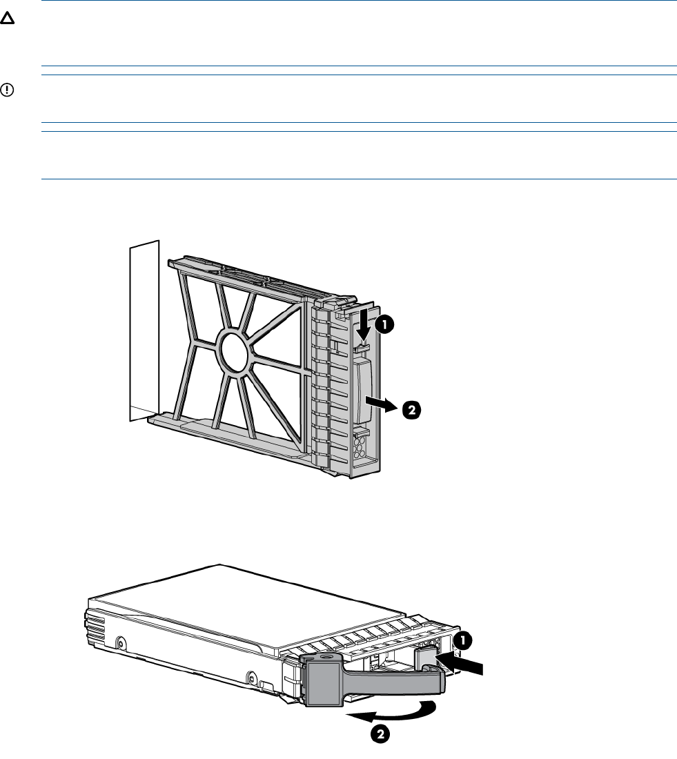
Hot-plug SAS disk drives
The server blade supports up to two hot-plug SAS drives.
CAUTION: To prevent improper cooling and thermal damage, do not operate the server blade
or the enclosure unless all hard drive and device bays are populated with either a component or
a blank.
IMPORTANT: The disk drive does not seat properly when 180° out of alignment. Verify the
orientation before insertion.
NOTE: For a list of supported disk drives for the server blade, see: “Server blade components
list” (page 108).
1. Remove the hard drive blank.
2. Prepare the hard drive.
3. Slide the drive into the cage until it is fully seated.
42 Optional components
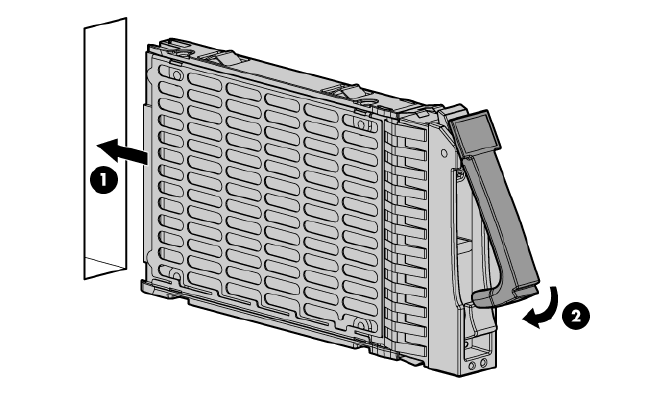
4. Close the lever to lock the drive into place.
Installing internal components
Removing the access panel
1. Lift the access panel latch.
2. Slide the access panel backwards approximately 2 cm (0.75 in).
3. Remove the access panel by lifting it straight up and off the server blade.
After the access panel is off, you can do the following:
•Add an additional processor (“Processor and heatsink module”).
•Add additional memory DIMMs (“DIMMs”).
•Add additional mezzanine cards (“Mezzanine cards”).
Installing internal components 43
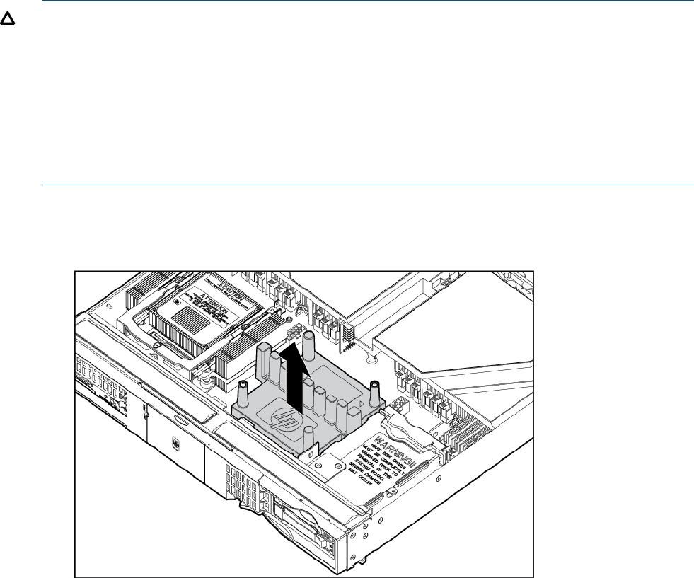
Processor and heatsink module
Processor load order
Observe the following guidelines when installing additional processors:
•In a BL860c i2, CPU0 is installed before CPU1.
•In a BL870c i2 or BL890c i2, each blade must have CPU0 installed.
•When adding additional CPUs in a conjoined configuration:
Load both CPU0 and CPU1 in the Monarch blade first◦
◦Load additional CPUs in sequence, from lowest slot-numbered blade to highest.
CAUTION: The pins on the processor socket are very fragile. Any damage to them might require
replacing the server blade base unit.
CAUTION: To avoid damage to the processor, verify that the plastic tabs on the processor are
pulled fully out before installation.
CAUTION: To avoid damage to the processor, handle the processor only by the edges. Do not
touch the bottom of the processor, especially the contact area.
CAUTION: To prevent possible server blade malfunction and damage to the equipment,
multiprocessor configurations must contain processors with the same part number.
The processor and heatsink ship as two separate units and are coupled together during installation
into the server blade.
1. Remove the CPU airflow baffle.
44 Optional components
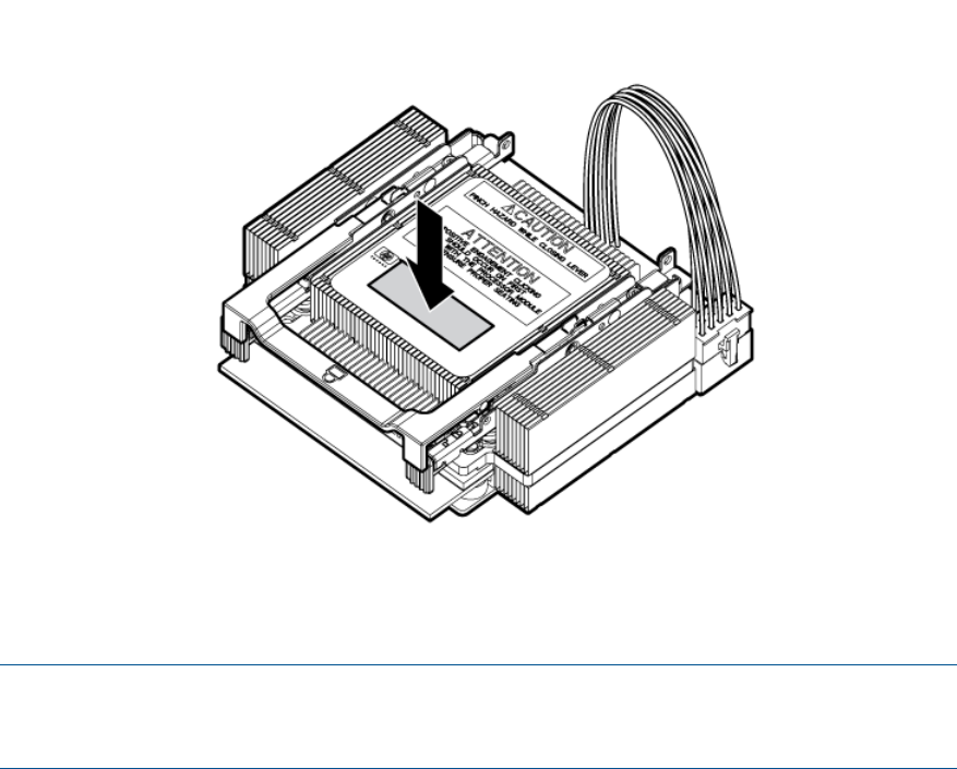
2. Transfer the duplicate part/serial numbers label from the processor module to the processor
heatsink.
a. Remove the duplicate tear-away label that lists the part and serial numbers from the
processor module.
b. Place the label on the top of the heatsink.
3. Install the processor over the load posts.
NOTE: Ensure pin 1, indicated on the empty socket with an embossed triangle, matches the
pin 1 marker on the processor module, the chamfered corner of its attached voltage regulator
heatsink.
4. Remove the heatsink cover.
Installing internal components 45
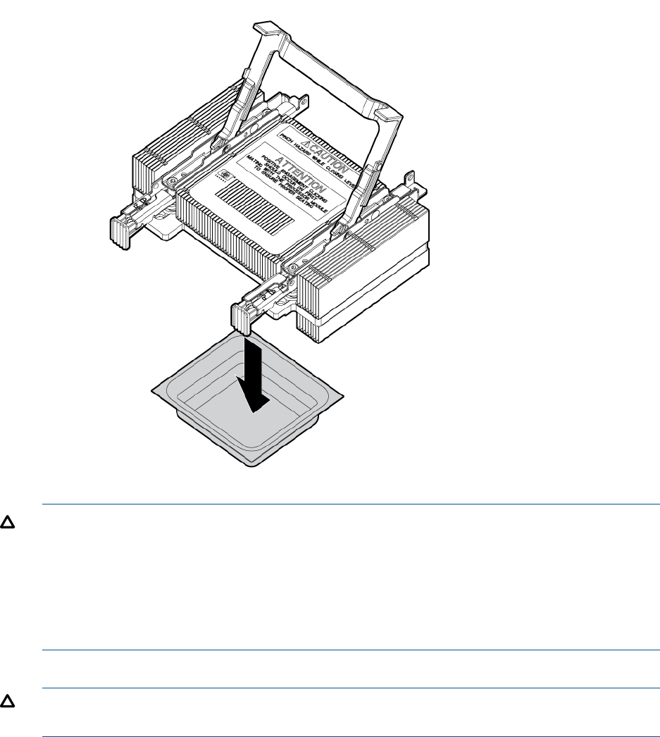
CAUTION: During installation, after removing the protective cover from the heatsink:
•Do not touch or come into contact with the thermal interface material.
•Immediately install the heatsink.
CAUTION: To avoid damage to the server blade and processor, ensure the processor heatsink
locking handle is fully back against the stops, rotated about 120° back. Also verify that the
plastic tabs on the processor heatsink are pulled fully out before installation.
5. Install the heatsink over the load posts.
CAUTION: Do not lower the heatsink locking handle before pushing the plastic locking tabs
into place.
46 Optional components
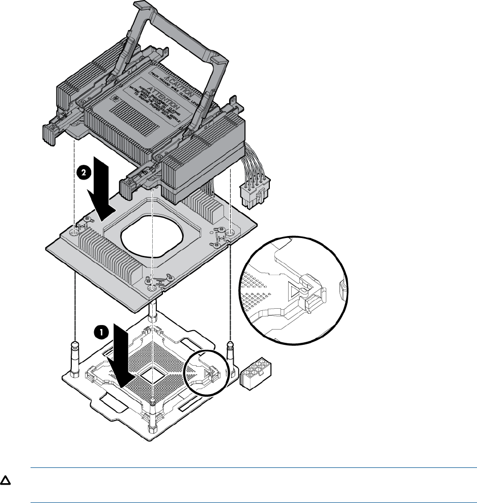
CAUTION: To prevent thermal instability and damage to the server blade, do not separate
the processor module from the processor's heatsink after they have been coupled.
Installing internal components 47
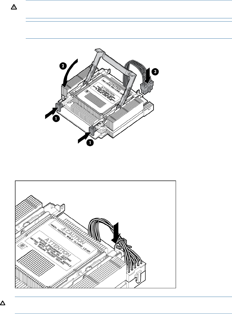
6. Secure the heatsink to the processor
a. Slide both plastic locking tabs into place. (See callout 1 in the following figure).
b. Grasp and rotate the latch downward. (See callout 2 in the following figure.)
WARNING! The heatsink locking lever can constitute a pinch hazard, keep your hands
on top of the lever during installation to avoid personal injury.
NOTE: Positive engagement clicking should occur during mating of the processor heat
sink and processor module onto the socket to ensure proper seating.
7. Connect the power cord. (See callout 3 in the previous figure).
8. Tie wrap the processor cable to the right tie point on the processor assembly.
CAUTION: When the CPU is installed, dress all slack in the power cable to the connector
end of the cable. Failure to do so could result in pinched or damaged CPU power cables.
48 Optional components
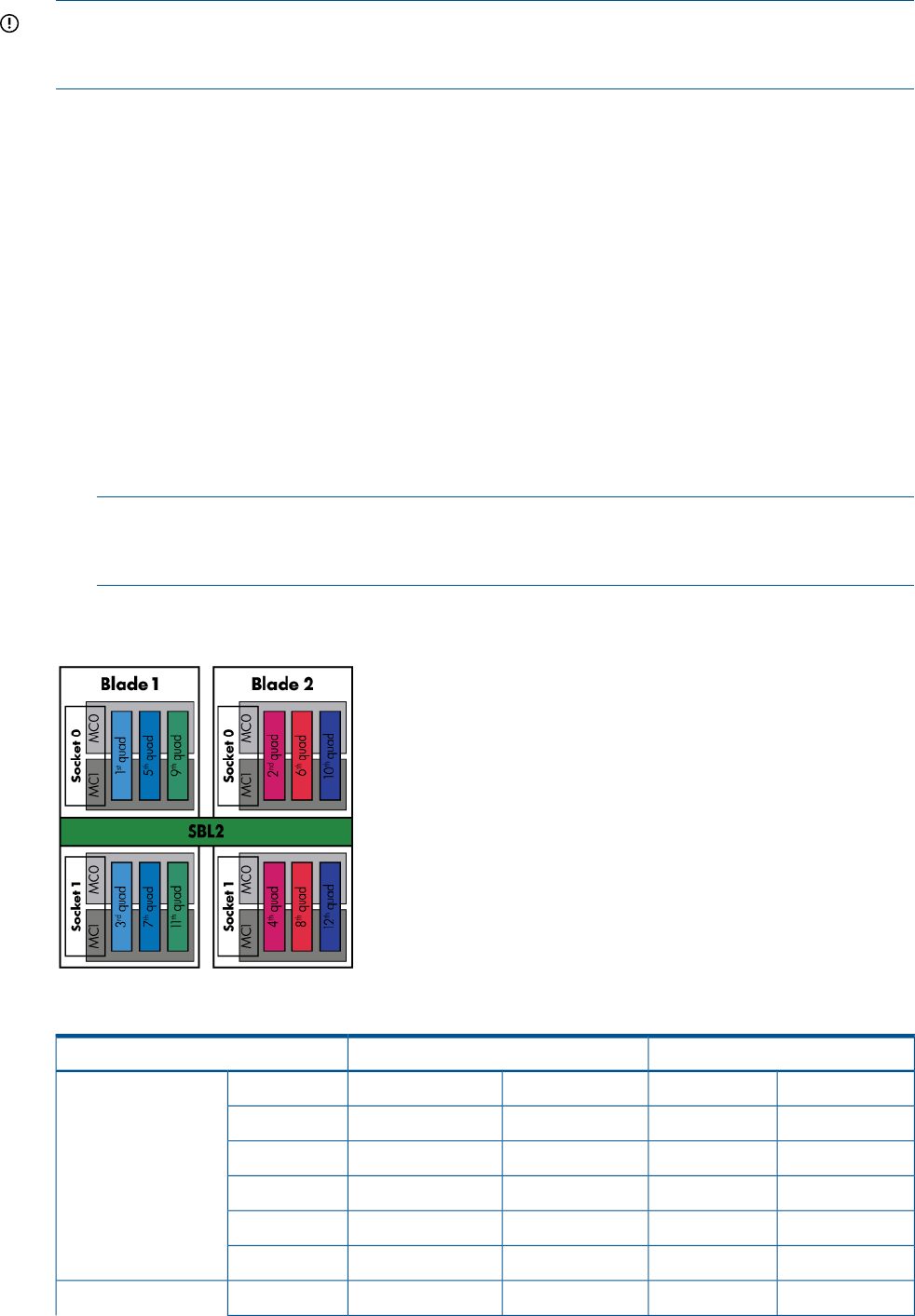
IMPORTANT: If you are adding an additional processor to your server blade, the DIMMs in the
server blade must be reconfigured to support both CPUs. For more information, see “DIMM pair
load order” (page 49).
DIMMs
DIMM installation guidelines
Observe the following guidelines when installing additional memory:
•In a BL860c i2 Server Blade, memory is loaded in pairs.
•In a BL870c i2 or BL890c i2 Server Blade, memory is loaded in quads that alternate between
blades.
•Only two DIMM sizes can be mixed in a BL870c i2 or BL890c i2 Server Blade.
In a BL870c i2 Server Blade, the two DIMM sizes must alternate between blades. Load
all of one DIMM size, then repeat with the second DIMM size.
◦
◦In a BL890c i2 Server Blade, blades 1 and 2 must have one DIMM size and blades 3
and 4 must have the other DIMM size. If only one DIMM size is used on BL980 i2,
alternate between all 4 blades.
NOTE: HP Integrity Server Blade upgrades follow the same DIMM loading rules.
See“Upgrading a conjoined configuration” (page 66) for more information on server blade
upgrades.
DIMM pair load order
Table 6 DIMM pair load order
CPU1CPU0
——4A3A1st
CPU0 only
——10B9B2nd
——6C1C3rd
——12D7D4th
——5E2E5th
——11F8F6th
——4A3A1stBoth CPUs loaded
Installing internal components 49
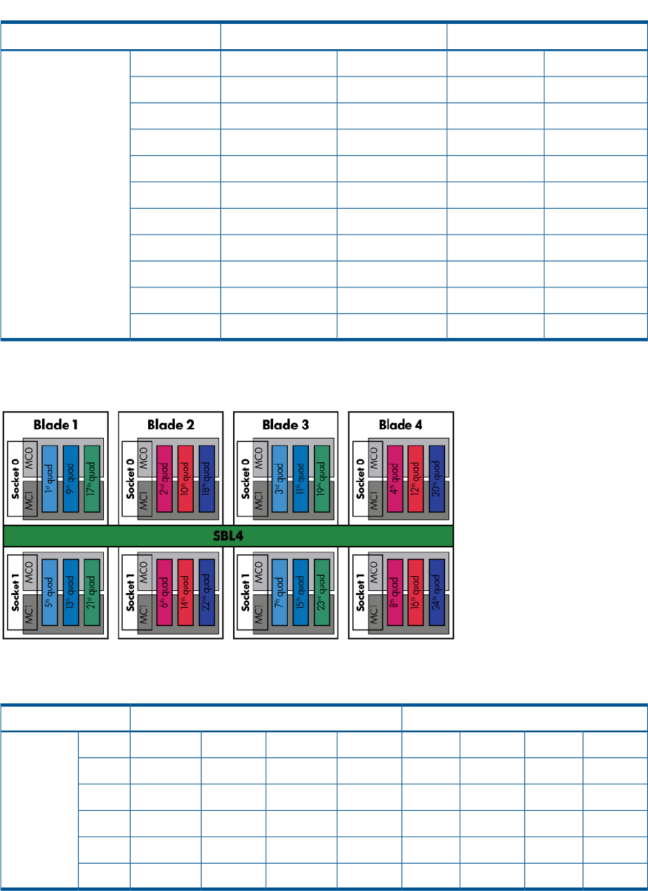
Table 6 DIMM pair load order (continued)
CPU1CPU0
7A1A——2nd
——10B9B3rd
10B6B——4th
——6C1C5th
9C3C——6th
——12D7D7th
12D4D——8th
——5E2E9th
8E2E——10th
——11F8F11th
11F5F——12th
DIMM quad load order rules
Table 7 DIMM quad load order
CPU1CPU0
————10B9B4A3A1st
Both CPUs
loaded
10B6B7A1A————2nd
————12D7D6C1C3rd
12D4D9C3C————4th
————11F8F5E2E5th
11F5F8E2E————6th
Installing DIMMS
1. Remove the DIMM baffle (“DIMM baffle” (page 115)).
2. Locate the DIMM slots on the server blade system board.
50 Optional components
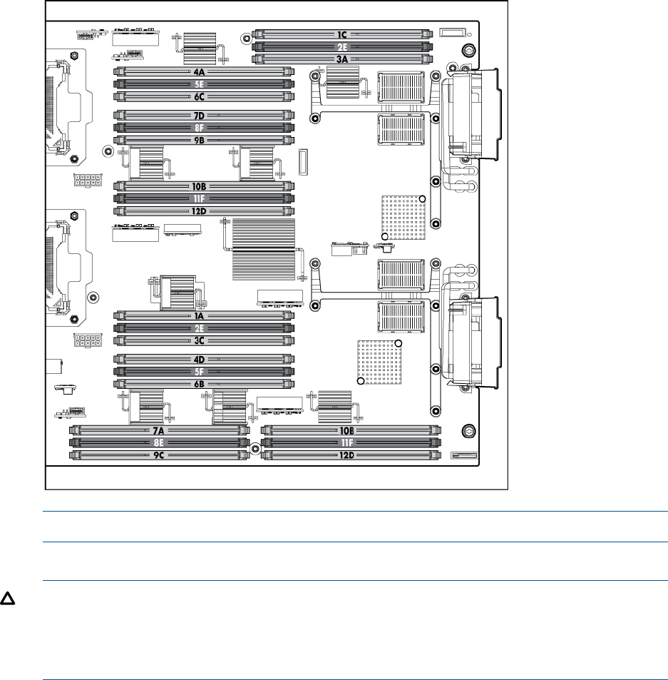
NOTE: The server blade ships with at least two DIMMs installed in slots 3A and 4A.
3. Ensure the DIMM slot latches are open.
CAUTION: Use only HP low profile DIMMs. DIMMs from other sources might adversely
affect data integrity.
DIMMs do not seat fully if turned the wrong way.
DIMMs in a pair or quad must be identical.
Installing internal components 51
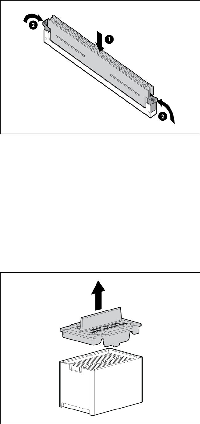
4. Insert a DIMM in a slot and push down firmly until the latches click shut.
Mezzanine cards
Optional mezzanine cards enable additional network connectivity and provide Fibre Channel
support. For mezzanine card locations, see “Server blade components” (page 9).
Optional mezzanine cards are classified as Type I mezzanine cards and Type II mezzanine cards.
The card type determines where it can be installed in the server blade:
•Install Type I mezzanine cards on any mezzanine connector.
•Install Type II mezzanine cards only on Mezzanine 2 connector or Mezzanine 3 connector.
To install a card:
1. Power off the server blade and remove it from the server blade enclosure (“Preparing the
server blade for servicing”).
2. Remove the access panel (“Access panel” (page 113)).
3. Remove the mezzanine connector cover.
52 Optional components
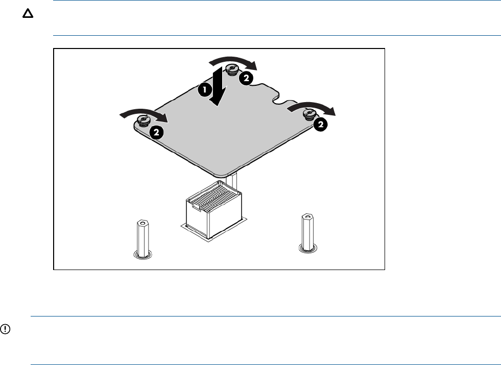
4. Align the mezzanine connector on the option card with the mezzanine connector on the system
board.
5. Press down on the connector to seat the card.
CAUTION: To prevent damage to the server blade, apply pressure over the mezzanine
connector when installing the mezzanine card. Do not apply pressure to the edges of the card.
HP Smart Array P700m/512 Controller
IMPORTANT: The HP Smart Array P700m Controller for HP ProLiant Servers User Guide includes
a battery replacement procedure that uses the two driveless HDD trays included in the kit. This
procedure is not supported on the BL860c i2, BL870c i2 or BL890c i2.
The HP Smart Array P700m/512 is a PCIe card supporting direct attach and shared SAS Storage.
It includes additional components that are covered in this section.
Battery kit and other components
The battery kit includes the following:
Installing internal components 53
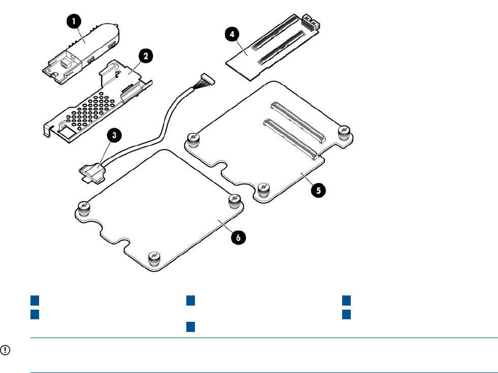
5P700m controller board
311.5 inch (29.2 cm) battery
cable
1BBWC battery
2 6
Battery mounting bracket Mezzanine card blank
4512 cache module
IMPORTANT: This product uses the 452348-B21 battery kit, also called the HP SA P-Series Low
Profile Battery. Do not order or use the 383280-B21 battery kit option.
Battery mounting bracket parts
The BBWC battery mounts on a black metal battery mounting bracket installed inside the server
blade. The mounting bracket clips onto a mezzanine card in slot 1. If no card is used in slot 1,
the mezzanine card blank option must be installed for the bracket to clip on.
For installing the bracket on to the server blade, the mounting bracket has:
•A mezzanine post loop that slides over the abutting mezzanine 2 post
•A thumbscrew clip that clips over the mezzanine 1 card or mezzanine blank thumbscrew
located at the rear of the blade
•A mezzanine foot that clips over the edge of the mezzanine 1 card or mezzanine blank that
is installed closest to the center of the blade
For installing the BBWC battery onto the bracket, the mounting bracket has:
•A C-hook to restrain the battery cable
•Two battery restraining clips to restrain the BBWC battery
54 Optional components
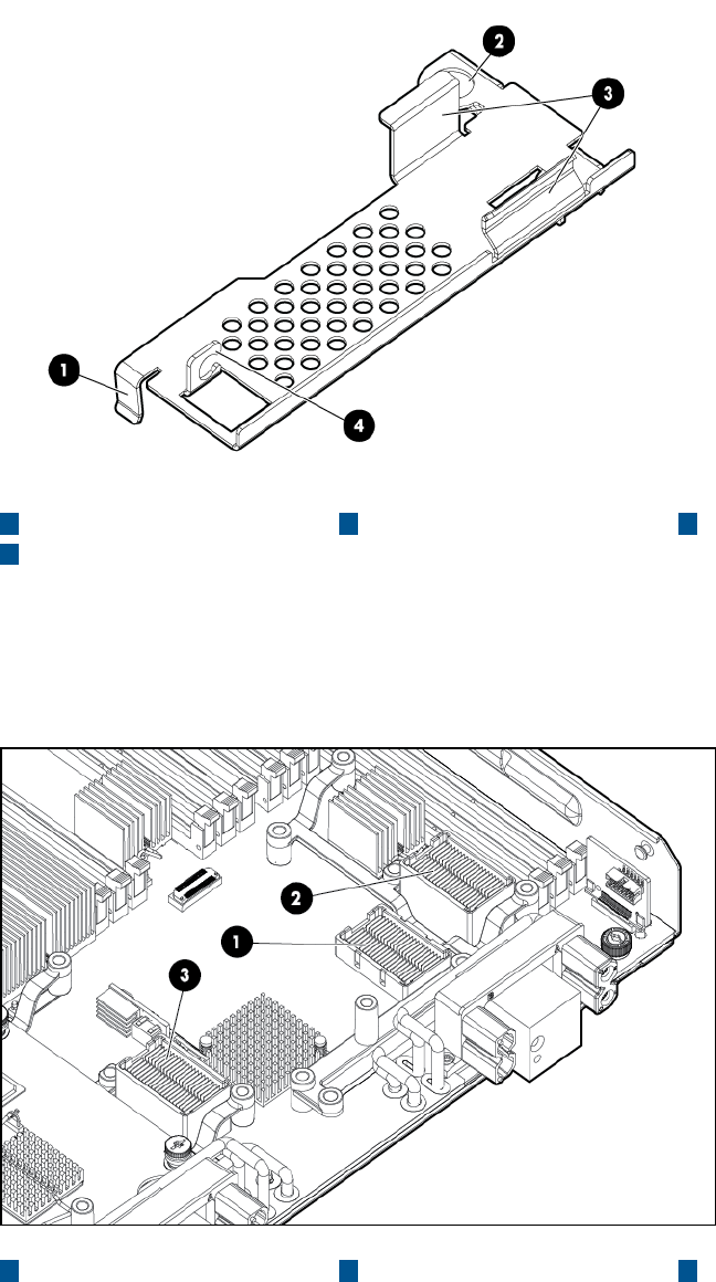
431 Mezzanine foot C-hookBattery restraining clips
2Mezzanine post loop
Installing the Controller Board
When used with the MSA2000sa G2 storage array (and therefore without the optional battery
kit) this card is supported in slots 1, 2, and 3 on the Integrity BL860c i2, BL870c i2, and BL890c
i2 server blades.
321 Slot 3Slot 2Slot 1
When used with the MDS600, the battery kit is required and this card is supported in slots 1 and
3 on the Integrity BL860c i2, BL870c i2, and BL890c i2 server blades. Mezzanine 2 installation
of this card is not supported on Integrity BL860c i2, BL870c i2, and BL890c i2 products for MDS600
configurations. If you must remove the cache module to transfer data, the BBWC battery must
remain connected so that the data is preserved. HP recommends installation into mezzanine slot
3, with a mezzanine blank or mezzanine card in slot 1 so the cache module and battery can be
removed together.
Installing internal components 55
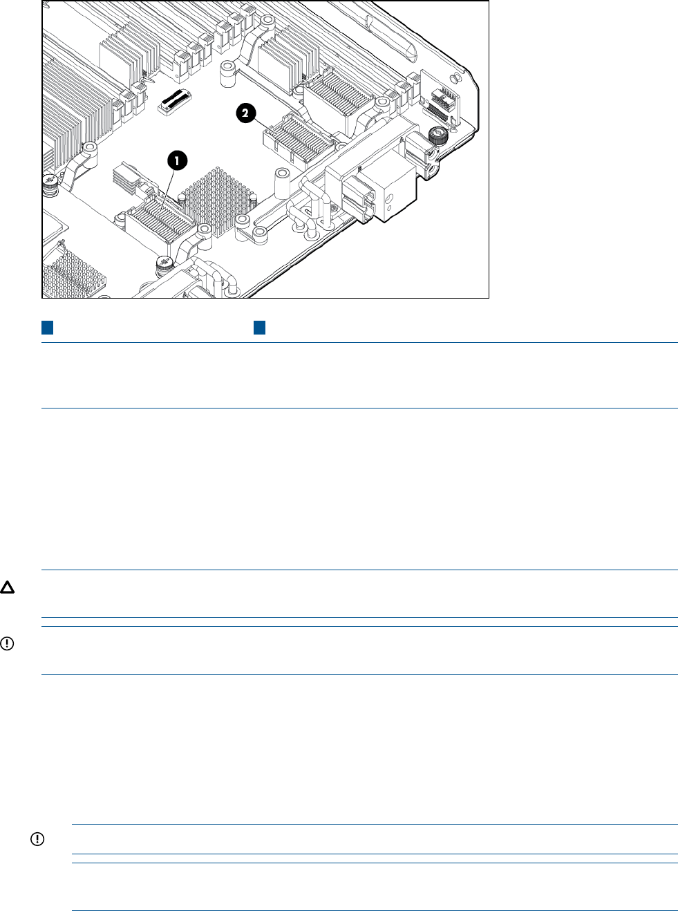
21 Slot 1Slot 3
NOTE: When a mixed configuration of BL860c i2, BL870c i2, and BL890c i2 blade(s) and other
c-Class server blades are in the same enclosure, the preferred location for the P700m cards is slot
3.
If you are unable to use mezzanine slot 3, you will have to remove the mezzanine card in slot 2,
BBWC battery, and battery mounting bracket to gain access to the cache module.
Use the procedure for installing standard mezzanine cards to install the SAS controller board, see
“Mezzanine cards” (page 52) for more information.
Upgrading or replacing controller options
Replacing the 512MB cache module
CAUTION: To avoid damage to the controller board, only install the cache module when the HP
Smart Array P700m/512 Controller is installed in the server blade.
IMPORTANT: If you must remove the cache module to transfer data, the BBWC battery must
remain connected to it so that the data is preserved.
1. power off the server blade and remove it from the server blade enclosure (“Preparing the
server blade for servicing”).
2. Remove the access panel (“Access panel” (page 113)).
3. Remove the DIMM baffle (“DIMM baffle” (page 115))
4. Remove any mezzanine cards blocking access to the HP Smart Array P700m/512 Controller
(“Mezzanine cards” (page 123)).
5. Plug the smaller battery cable plug into the cache module battery connector.
IMPORTANT: Only use the 11.5 inch (29.2 cm) battery cable (408658-001).
NOTE: The lip of the battery cable cache module plug has three tiny tabs that should face
down.
6. With the cache module battery connector pointing towards the 3A DIMM slot, line up the two
cache module connectors with the two corresponding slots on the P700m controller.
7. Press straight down on the cache module until it snaps into place.
56 Optional components
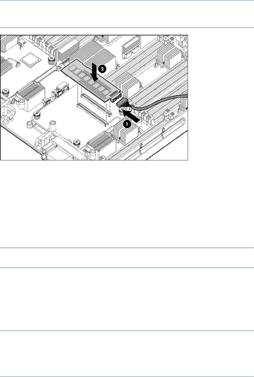
NOTE: If the P700m controller is in mezzanine 1, route the battery cable back over the card
and under the DIMM latches, doubling back towards slot 3, sliding the cable under the inner
mezzanine post for slot 3.
8. Replace the battery mounting bracket.
9. If the battery mounting bracket and BBWC were previously installed:
a. Replace the battery mounting bracket (“Replacing the battery mounting bracket”).
b. Position the battery with the print side down and push the end of the battery cable that
is plugged into the battery down under the battery mounting bracket's C-hook.
c. Route the cable so its battery end is on the side of the hook that is away from slot 3.
d. Push the other end of the battery down between the two restraining clips.
10. Replace any mezzanine cards that you had to remove from mezzanine slot 2 (“Mezzanine
cards” (page 123)).
NOTE: If the P700m controller is installed in mezzanine slot 3, tuck the cable between the
battery mounting bracket and slot 3.
Replacing the battery mounting bracket
1. power off the server blade and remove it from the server blade enclosure (“Preparing the
server blade for servicing”).
2. Remove the access panel (“Access panel” (page 113)).
3. Remove the DIMM baffle (“DIMM baffle” (page 115))
4. Temporarily remove any mezzanine card installed in slot 2 (“Mezzanine cards” (page 123)).
NOTE: If you will be installing the BBWC battery, be sure that the cache module is installed
and the battery cable is plugged into the cache module (“Replacing the 512MB cache
module”).
NOTE: If you are not installing the p700m into slot 1, slot 1 must contain either another
mezzanine card or mezzanine card blank.
5. Clip the mounting bracket onto the mezzanine card or mezzanine card blank.
Installing internal components 57
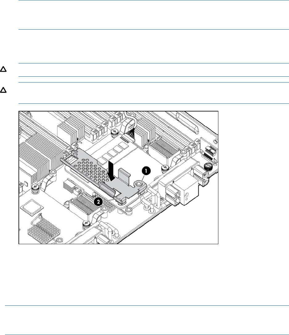
NOTE: If you are installing the p700m into slot 1, slide the bracket loop over the mezzanine
2 post that sticks up through the notch in the edge of the mezzanine card or mezzanine card
blank.
6. Press the bracket thumbscrew clip over the thumbscrew closest to the mezzanine post.
7. Push the remaining bracket foot over the other edge of the mezzanine card or mezzanine
card blank.
CAUTION: Push only enough to anchor the bracket, keeping the bracket level.
CAUTION: To avoid damage to the power cable ensure the battery bracket does not pinch
the power cable to the power connectors.
8. Replace any mezzanine cards that you had to remove from mezzanine slot 2 (“Mezzanine
cards” (page 123)).
Replacing the BBWC battery
The BBWC battery snaps onto the battery mounting bracket to secure the battery inside the server
blade.
NOTE: The battery mounting bracket is installed either on top of a mezzanine card in slot 1, or
the mezzanine blank in slot 1, depending upon the customer's configuration. If no card is used in
slot 1, the mezzanine card blank must be installed for the bracket to clip onto.
1. power off the server blade and remove it from the server blade enclosure (“Preparing the
server blade for servicing”).
2. Remove the access panel (“Access panel” (page 113)).
3. Remove the DIMM baffle (“DIMM baffle” (page 115)).
4. If the P700m controller is in mezzanine 1, and the battery cable is not already plugged into
the cache module:
a. Remove any mezzanine card installed in slot 2 so you can access the P700m cache
module (“Mezzanine cards” (page 123)).
b. Temporarily remove the cache module so you can access the module battery connector
(“Removing the 512MB cache module”).
58 Optional components
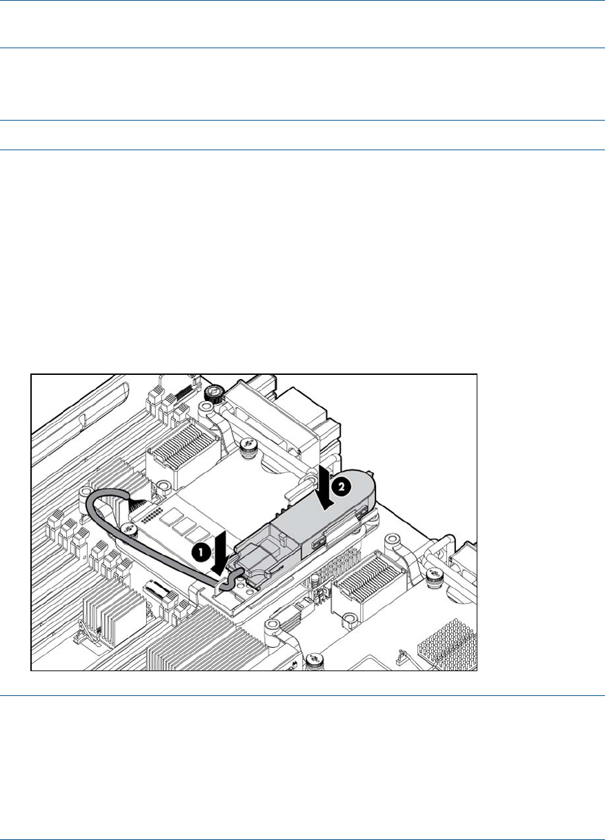
5. If it is not already connected, plug the battery cable cache module plug into the cache module
battery connector. Push the battery cable's plug into the battery connector until it snaps into
place.
NOTE: The lip of the battery cable's cache module plug has three tiny tabs that should face
down.
6. If you had to remove the cache module, reinstall it (“Replacing the 512MB cache module”).
7. With the battery cable plug label (contoured side) up line up the plug's thin edges with the
thin slits on the sides of the battery.
NOTE: The BBWC battery should be print side down.
8. Push the battery cable's plug, into the battery connector until it snaps into place.
9. Mount the battery onto the battery mounting bracket:
a. Position the battery with the print side down and push the end of the battery cable that
is plugged into the battery down under the battery mounting bracket's C-hook, routing
the cable so its battery end is on the side of the hook that is away from slot 3.
b. Push the other end of the battery down between the two restraining clips.
c. If the P700m is located in slot 1, route the battery cable over the P700m, under the DIMM
latches, doubling back towards slot 3, sliding it under the inner mezzanine post for slot
3.
If the P700m is located in slot 3, tuck the cable between the battery bracket and slot 3.
NOTE: After installing a BBWC battery, you might see a POST message during reboot
indicating the array accelerator is temporarily disabled. This is normal as the new BBWC
battery will have a low charge. The recharge process will begin automatically when the server
blade is installed in the enclosure.
The P700m controller will operate properly while the BBWC battery recharges, although the
performance advantage of the array accelerator will be absent. After the BBWC battery
charges up to a satisfactory level, the array accelerator is automatically enabled.
Installing internal components 59
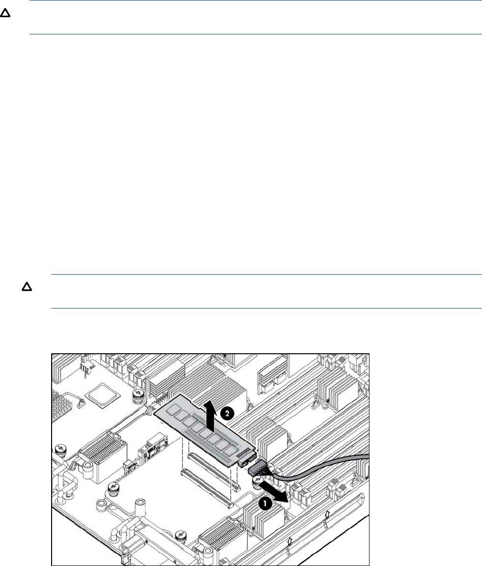
Removing upgrade components
Removing the 512MB cache module
CAUTION: Only remove/replace the cache module when it is installed in the blade, so as not
to bend the controller board.
1. If you are also going to be removing the BBWC battery:
a. Back up all data.
b. Close all applications
2. power off the server blade and remove it from the server blade enclosure (“Preparing the
server blade for servicing”).
3. Remove the access panel (“Access panel” (page 113)).
4. Remove the DIMM baffle (“DIMM baffle” (page 115))
5. Remove any mezzanine card installed in slot 2 (“Mezzanine cards” (page 123)).
6. Lift the BBWC battery straight up to remove it from the battery mounting bracket.
7. Pull straight up on the cache module to remove it from the controller.
8. Push the battery cable down and towards the rear of the server blade to push it out of the
battery bracket's C-hook.
9. If the controller is installed into slot 1, remove the battery mounting bracket from the mezzanine
card or mezzanine card blank by pulling straight up on the bracket and lifting it out of the
server.
10. Lift the cache module and the attached battery out of the server blade.
CAUTION: If you must remove the cache module to transfer data, the battery must remain
connected so that the data is preserved.
11. If you will be replacing the cache module, unplug the battery cable from the cache module
battery connector (“Replacing the 512MB cache module”).
Removing the battery mounting bracket
1. power off the server blade and remove it from the server blade enclosure (“Preparing the
server blade for servicing”).
2. Remove the access panel (“Access panel” (page 113)).
3. Remove the DIMM baffle (“DIMM baffle” (page 115))
60 Optional components
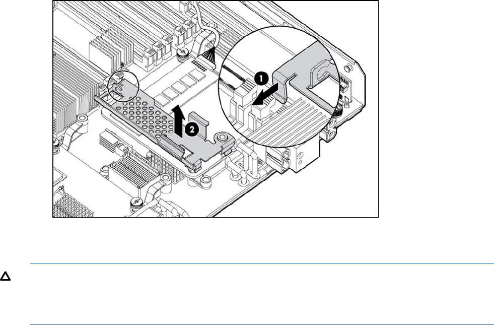
4. Remove any mezzanine card installed in slot 2 (“Mezzanine cards” (page 123)).
5. If installed, remove the BBWC battery (“Removing the BBWC battery”).
6. Remove the battery mounting bracket
Removing the BBWC battery
CAUTION: If you must remove the cache module to transfer data, the battery must remain
connected so that the data is preserved. If you must keep the battery connected to the cache module,
follow the steps for 512MB cache module removal (“Removing the 512MB cache module”) instead
of using this procedure.
1. Back up all data.
2. Close all applications.
3. power off the server blade and remove it from the server blade enclosure (“Preparing the
server blade for servicing”).
4. Remove the access panel (“Access panel” (page 113)).
5. Remove the DIMM baffle (“DIMM baffle” (page 115))
6. Lift up on the battery to remove it from the battery bracket.
7. Push the battery cable down and towards the rear of the server blade to push it out of the
battery bracket's C-hook.
Installing internal components 61
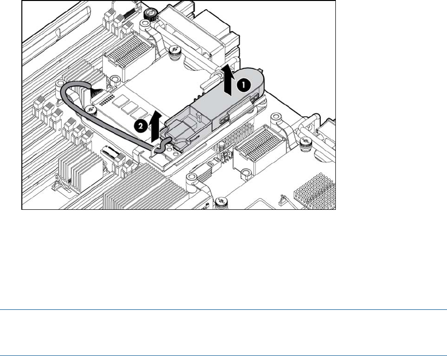
8. Push the battery plug out of the battery connector.
HP Smart Array P711m Controller
The HP Smart Array P711mis a PCIe card supporting direct attach and shared SAS Storage. This
card is supported in slots 1, 2, and 3 on the Integrity BL860c i2, BL870c i2, and BL890c i2 server
blades.
NOTE: When a mixed configuration of BL860c i2, BL870c i2, and BL890c i2 server blades and
other c-Class server blades is in the same enclosure, the preferred location for the P711m cards
is slot 3.
Supercap pack mounting kit
The HP Smart Array P711m Controller includes a cabled Supercap Pack which mounts inside the
server using the orderable AM341A Mounting Kit for Low profile battery (HP part number
AD399-2132A KIT, RAID BATTERY HOLDER). This kit contains a black metal mounting bracket
and a mezzanine card blank. The mounting bracket clips onto a mezzanine card in slot 1. If no
card is used in slot 1, the mezzanine card blank included in the kit must be installed to mount the
bracket.
For installing the bracket on to the server blade, the mounting bracket has:
•A mezzanine post loop that slides over the abutting mezzanine 2 post
•A thumbscrew clip that clips over the mezzanine 1 card or mezzanine blank thumbscrew
located at the rear of the blade
•• A mezzanine foot that clips over the edge of the mezzanine 1 card or mezzanine card
blank that is installed closest to the center of the blade
For installing the Supercap Pack onto the bracket, the mounting bracket has:
•A C-hook to restrain the cable
•Two restraining clips to restrain the Supercap Pack
62 Optional components
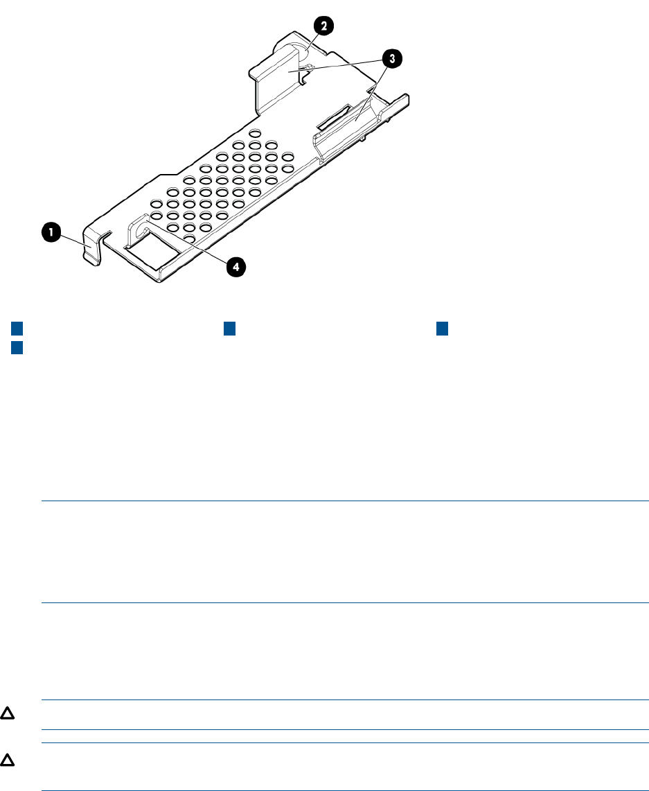
431 Mezzanine foot C-hookCable restraining clips
2Mezzanine post loop
Installing the Supercap mounting bracket
1. Power off the server blade and remove it from the server blade enclosure (“Preparing the
server blade for servicing”).
2. Remove the access panel (“Access panel” (page 113)).
3. Remove the DIMM baffle (“DIMM baffle” (page 115))
4. Temporarily remove any mezzanine card installed in slot 2 (“Mezzanine cards” (page 123)).
NOTE: Mezzanine slot 1 must contain the P711m Controller, another mezzanine card, or
the mezzanine card blank. If you are installing the P711m card in mezzanine slot 1, do so
now following the instructions “Installing the P711m Controller Board.” If you are not installing
the P711m card in mezzanine slot 1, and no other mezzanine card is present in slot 1, then
install the mezzanine card blank at this time.
5. Clip the mounting bracket onto the mezzanine card or mezzanine card blank.
6. Press the bracket thumbscrew clip over the thumbscrew closest to the mezzanine post.
7. Push the remaining bracket foot over the other edge of the mezzanine card or mezzanine
card blank.
CAUTION: Push only enough to anchor the bracket, keeping the bracket level.
CAUTION: To avoid damage to the power cable ensure the battery bracket does not pinch
the power cable to the power connectors.
Installing internal components 63
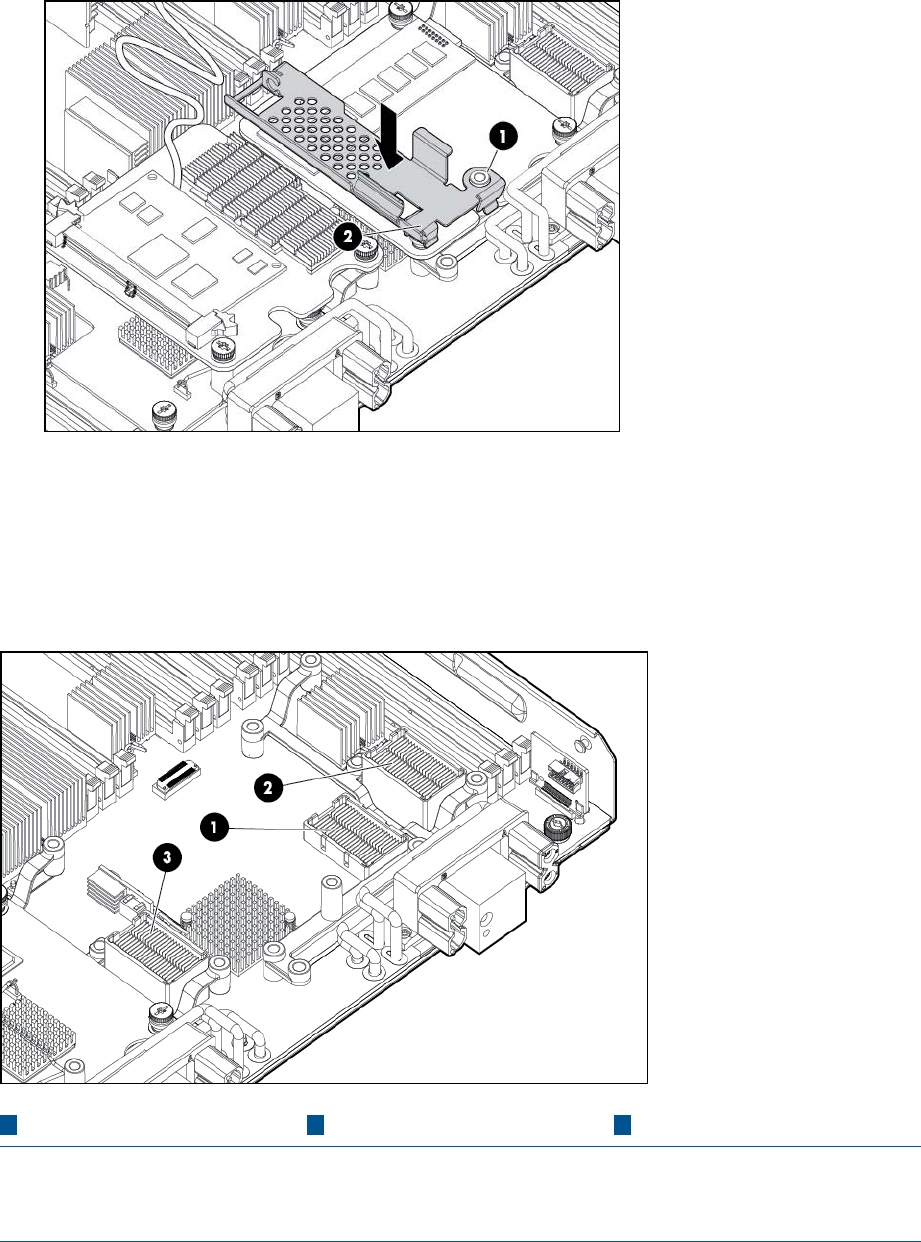
8. Replace any mezzanine cards that you had to remove from mezzanine slot 2 (“Mezzanine
cards” (page 123)).
Installing the P711m controller board
This card is supported in slots 1, 2, and 3 on the Integrity BL860c i2, BL870c i2, and BL890c i2
server blades.
321 Slot 3Slot 2Slot 1
NOTE: When a mixed configuration of BL860c i2, BL870c i2, and BL890c i2 server blades and
other c-Class server blades are in the same enclosure, the preferred location for the P711m cards
is slot 3.
Use the procedure for installing standard mezzanine cards to install the SAS controller board, see
“Mezzanine cards” (page 52) for more information.
Installing the Supercap Pack
The Supercap Pack snaps onto the mounting bracket to secure the Supercap Pack inside the server
blade.
64 Optional components
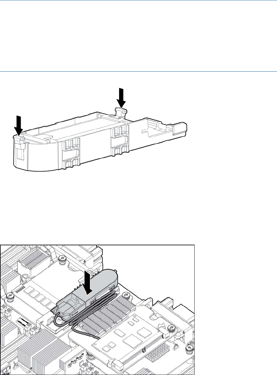
NOTE: The mounting bracket is installed either on top of a mezzanine card in slot 1, or the
mezzanine blank in slot 1, depending upon the customer's configuration. If no card is used in slot
1, the mezzanine card blank must be installed for the bracket to clip onto.
NOTE: The Supercap Pack includes two plastic tabs that must be removed for proper fit in the
BL860c i2, BL870c i2, and BL890c i2 server blades. One tab is located on the rounded end of
the Supercap Pack, the other tab is directly above the cable as it exits the plastic housing of the
Supercap Pack. To remove these tabs, squeeze them firmly toward each other (significant force is
required). Optionally, these two tabs can be clipped off even with the rest of the Supercap Pack.
1. Position the Supercap Pack with the print side down and push the end of the cable that is
connected to the Supercap Pack under the mounting bracket’s C-hook, routing the cable so
its supercap end is on the side of the hook that is away from slot 3
2. Push the other end of the Supercap Pack down between the two restraining clips.
3. Consolidate and secure remaining cable length using tie wrap or similar retention method.
Replacing the access panel
1. Place the access panel onto the server blade by lining up the keyways on the panel to the
posts on the server blade chassis.
2. Slide the access panel toward the front of the server blade until the panel lock button snaps
into place.
Installing internal components 65
Upgrading a conjoined configuration
This section contains information required to complete an upgrade of a BL860c i2, BL870c i2, or
BL890c i2 server blade. This document expands on the information provided in the Read This First
document which is included in the upgrade kit.
Procedure summary
1. Existing server blade check — The existing server blades that will be upgraded are checked
and their firmware level is updated to the minimum level if necessary. This must be completed
before the blades are combined for an upgrade and the upgrade Blade Link is applied.
2. Adding resources — The blades for the upgrade are placed together, internal component
changes are made if necessary, the Upgrade Blade Link is installed, and system information
parameters are exchanged between the server blade and the new Blade Link.
3. Final check — A final consistency check for firmware levels across each blade is completed,
the upgraded system is checked for normal operation at a low level, the Operating System
(OS) may need to be reinstalled, and finally the Operating Environment is booted and the
system checked for normal operation.
4. Warranty registration — Warranty and support are arranged to be transferred from the server
being upgraded to the upgraded server.
Upgrade kit contents
•The HP Integrity BL860c i2, BL870c i2 & BL890c i2 Server Blade Upgrades Read Me First
— part number 5991-8089
•One of the following:
AM358A HP Integrity Upgrade BL2 Blade Link (c3000 or c7000 enclosure)◦
◦AM364A HP Integrity Upgrade BL2-c 7E Blade Link (c7000 enclosure, Monarch in even
numbered bay)
◦AM365A HP Integrity Upgrade BL2-c 3E Blade Link (c3000 enclosure, Monarch in even
numbered bay)
◦AM359A HP Integrity Upgrade BL4 Blade Link (c7000 enclosure)
◦AM366A HP Integrity Upgrade BL4-c 3 Blade Link (c3000 enclosure)
Each Blade Link will include a new product number label to attach to the system label carrier;
the actual part number will depend on the type of upgrade ordered.
•AM360A HP Integrity BL860c i2 Upgrade Blade. One or more upgrade blades may be
included depending on the type of upgrade ordered. These should be pre-installed with ordered
processors, memory, and other components.
66 Optional components

Before getting started
IMPORTANT:
•Do not install or use the upgrade Blade Link until explicitly called for in the upgrade procedure.
For more information, see “Blade link and system information parameters” (page 80).
•The server blade firmware may need to be updated on the existing server blades as part of
the upgrade process, see “Determining your current firmware revisions” (page 68) for more
information.
•If the upgrade kit includes new Upgrade Blades, there are some situations which will require
a second firmware update.
•Processor and memory DIMM loading and distribution follows applicable rules across the
blades. For more information, see “Installing internal components” (page 43), and “Rules for
server blade internal components” (page 72).
•Adding new Upgrade Blades to an enclosure may require additional power supplies in the
enclosure to meet the new power requirements. This situation would be reported by the
enclosure Onboard Administrator. For more information, see the HP BladeSystem setup and
information guide for your enclosure at http://www.hp.com/go/bladesystem/documentation.
•If more than one existing server blade will be combined in the upgrade, one of them must be
designated as the “Monarch Server”. The Monarch blade from this server will become the
Monarch blade in the upgraded server blade.
•The UUID and serial number of the upgraded server blade will come from the Monarch Server.
•If the upgrade requires moving to a new enclosure, the configuration of the new enclosure
must match the mezzanine card I/O of the Monarch Server, so that LAN and SAN connections
can function correctly.
•A reinstallation of the OS may be required on the final upgrade system for certain upgrade
scenarios. You will use the section“Upgrade scenarios which do not require a reinstall of the
operating system” (page 82) to determine whether you must reinstall the OS. This will be
covered within the upgrade procedure steps.
•When the OS is not reinstalled, the boot disk must be attached to the designated Monarch
Server.
•When the OS is not reinstalled and VC is used, some rearrangement of the VC server profile
may be necessary. See “Possible changes due to VC profile mapping on the upgraded server
blade” (page 82).
•Depending on the type of upgrade and the OS used, a new OS license may be required.
•At the end of the upgrade, the Blade Links removed from the existing server blades cannot be
reused.
Supported operating systems
•HP-UX 11i v3 OE Update for March 2010
•HP-UX 11i v3 OE Update for September 2010
•HP-UX 11i v3 OE Update for March 2011
•HP OpenVMS Industry Standard 64 Operating System, Version V8.4 +
VMS84I_UPDATE-V0500
•Windows Server 2008 R2 7600 34N
Installing internal components 67

IMPORTANT: The Operating System may need to be reinstalled on the upgraded server. This
will be explained later.
IMPORTANT: If you will be using HP-UX, review the HP-UX errata documentation that is listed at
the following url:
http://bizsupport2.austin.hp.com/bc/docs/support/SupportManual/c02111059/c02111059.pdf
Minimum firmware versions
A minimum set of firmware is required for the blades and blade enclosures involved in the upgrade.
Firmware on the server blades, the enclosure HP Onboard Administrator, and the HP Virtual
Connect Manager (if Virtual Connect interconnect modules are installed) must be updated to at
least the minimum firmware level. Every blade in the upgrade must be at the same firmware level.
IMPORTANT: Any required updates must be checked for and completed during the upgrade
process.
Minimum Firmware LocationMinimum Firmware VersionProduct Name(s)
Go to hp.com —> Support & Drivers
—> enter product name —> select
21.08HP Integrity BL860c i2 Server Blade
HP Integrity BL870c i2 Server Blade
operating system —> “Cross operating
system”
HP Integrity BL890c i2 Server Blade
Go to hp.com —> Support & Drivers
—> enter product name
3.21HP BladeSystem Onboard
Administrator
Go to hp.com —> Support & Drivers
—> enter Interconnect Module product
name
3.15HP BladeSystem c-Class Virtual
Connect
Determining your current firmware revisions
Server blade
1. Log into the system iLO 3 MP.
2. From the Main Menu, enter cm to access the Command Menu
3. Enter sr to view the system FW revisions.
Hewlett-Packard Integrated Lights-Out 3 for Integrity
(C) Copyright 1999-2010 Hewlett-Packard Development Company, L.P.
MP Host Name: ilo002264fee2de
iLO MP Firmware Revision 01.41.01
*************************************************************************
MP ACCESS IS NOT SECURE
A default MP user Administrator/Admin is currently configured
and remote access is enabled. Modify the default password or
delete the default user (see UC command)
OR
Disable all types of remote access (see SA command)
*************************************************************************
MP MAIN MENU:
CO: Console
VFP: Virtual Front Panel
CM: Command Menu
CL: Console Log
SL: Show Event Logs
HE: Main Help Menu
68 Optional components
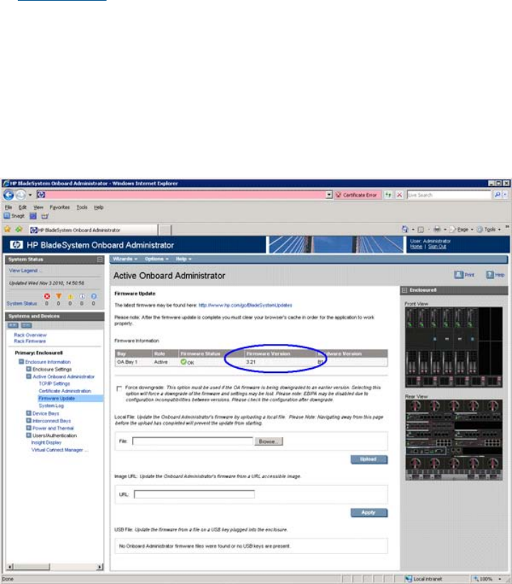
X: Exit Connection
[ilo002264fee2de] hpiLO-> cm
(Use Ctrl-B to return to MP main menu.)
[ilo002264fee2de] CM:hpiLO-> sr
SYSREV
Revisions Active Pending Bay 5 Bay 6
---------------------------------------------------------
iLO FW : 01.41.01 01.41.01 01.41.01
System FW : 01.80 01.80 01.80
MHW FPGA : 02.00 02.00 02.00
Power Mon FW : 03.04 03.04 03.04
Front Panel HW : 04.00 04.00 04.00
PRS HW : 02.07 02.07 02.07
IOH HW : 02.02 02.02 02.02
4. Compare the first four Revisions lines with the version information listed in the release notes
at www.hp.com for the current server blade, HP Smart Update Firmware bundle. If any of the
firmware revisions are less than those in the release notes, then the server firmware must be
updated.
OA
Use one of the following methods to determine the current OA firmware version:
•OA GUI — Connect to the OA GUI, expand the Active Onboard Administrator section of the
left sidebar menu, and select Firmware Update. The Firmware Version is listed under Firmware
Information.
•OA CLI — Log in to the OA CLI through the serial console port or LAN and enter show oa
info at the command prompt.
OA8> show oa info
Onboard Administrator #1 information:
Installing internal components 69
Product Name : BladeSystem c7000 Onboard Administrator
Part Number : 412142-B21
Spare Part No.: 414055-001
Serial Number : O985MP8457
UUID : 09O985MP8457
Manufacturer : HP
Firmware Ver. : 3.15
Hw Board Type : 0
Hw Version : B1
70 Optional components
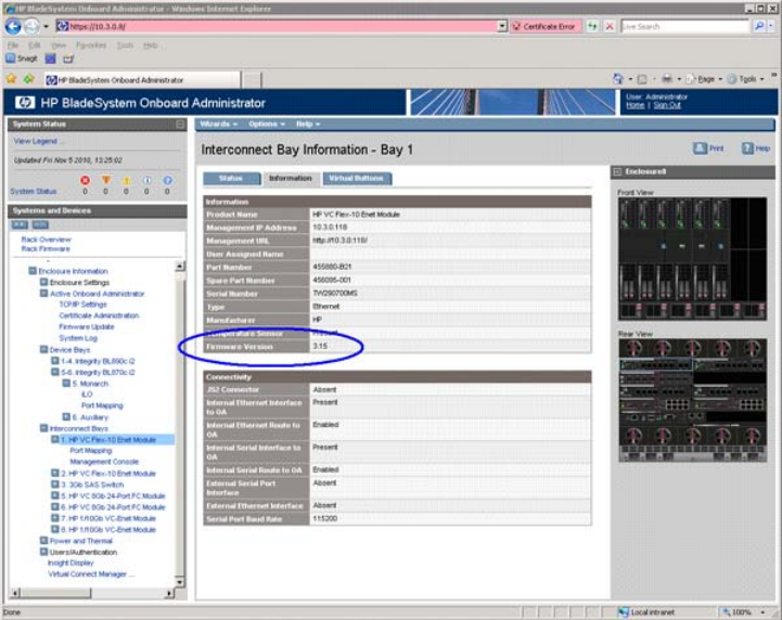
VCM
Use one of the following methods to determine the current VCM firmware version:
•OA GUI — Select the Interconnect Bay 1 device and then select the Information tab. Under
Information there is a Firmware Version line which indicates the current VC FW version installed
on the primary VC interconnect module.
Installing internal components 71
•VC Support Utility — Launch VC Support Utility – Interactive and enter version.
-------------------------------------------------------------------------------
HP BladeSystem c-Class Virtual Connect Support Utility
Version 1.6.0 (Build 95)
Build Date: Oct 13 2010 07:03:49
Copyright (C) 2007-2010 Hewlett-Packard Development Company, L.P.
All Rights Reserved
-------------------------------------------------------------------------------
Please enter action ("help" for list): version
Please enter Onboard Administrator IP Address: 10.3.0.8
Please enter Onboard Administrator Username: Administrator
Please enter Onboard Administrator Password: *****
The target configuration is integrated into a Virtual Connect Domain. Please
enter the Virtual Connect Domain administrative user credentials to continue.
User Name: Administrator
Password: *****
=======================================================================
Enclosure Bay Module Version
=======================================================================
USE827CYVC 1 HP VC Flex-10 Enet Module 3.15 2010-10-09T07:18:16Z
-----------------------------------------------------------------------
USE827CYVC 2 HP VC Flex-10 Enet Module 3.15 2010-10-09T07:18:16Z
-----------------------------------------------------------------------
USE827CYVC 3 3Gb SAS Switch
-----------------------------------------------------------------------
USE827CYVC 4 Module not present Not available
-----------------------------------------------------------------------
USE827CYVC 5 HP VC 8Gb 24-Port FC 1.03 v6.1.0_49
Module
-----------------------------------------------------------------------
USE827CYVC 6 HP VC 8Gb 24-Port FC 1.03 v6.1.0_49
Module
-----------------------------------------------------------------------
USE827CYVC 7 HP 1/10Gb VC-Enet Module 3.15 2010-10-09T07:18:16Z
-----------------------------------------------------------------------
USE827CYVC 8 HP 1/10Gb VC-Enet Module 3.15 2010-10-09T07:18:16Z
-----------------------------------------------------------------------
Total execution time: 00:01:31
Press Return/Enter to exit...
Rules for server blade internal components
You may make need to remove or redistribute internal components across server blades before
beginning the upgrade. The following section contains additional information required for upgrades.
Processor loading and matching rules
There are two processor sockets on each blade: socket 0 and socket 1. Socket 0 of each blade
in the server must be filled. Any additional processors must be loaded in socket 1 of the blade in
the lowest numbered enclosure bay which has an empty socket 1.
Every processor must be of the same type and must have the following:
•The same core count.
•The same core frequency.
•The same cache size.
This can be checked using the following methods:
•Examine the part number marked on each processor and each blade to make sure they are
the same on each component.
•Examine the core count, core frequency, and cache size of each processor to ensure that
every processor in the upgrade is the same. This can be done by logging into the Monarch
iLO 3 MP, choosing the Command Menu, then entering df to display FRU information. Each
72 Optional components

processor of each blade (by enclosure bay number) can be chosen individually and the
information displayed will include the information needed for comparison.
For more information, see “Processor and heatsink module” (page 44), and “ CPU and heatsink
module” (page 118).
DIMM matching and loading rules
The rules regarding DIMM load order change, especially when upgrading from a BL860c i2 to
either a BL870c i2 or BL890c i2. For more information on DIMM loading rules, see “DIMM quad
load order rules” (page 50).
There are also minimum system memory and performance guidelines must be followed. See the
Memory subsystem information for HP Integrity Server Blades (BL860c i2, BL870c i2, and BL890c
i2) Technical White Paper (http://h20195.www2.hp.com/v2/GetPDF.aspx/4AA1-1126ENW.pdf).
ICH mezzanine boards
If you will be combining existing server blades during upgrade, remove the ICH mezzanine board
from any server blades which are not the designated Monarch Blade for the upgrade
For more information on removing ICH mezzanine cards, see “ ICH mezzanine board” (page 124).
Optional mezzanine cards
The HP NC532m Dual Port 10GbE BL-c Adapter is restricted to two cards per blade on a BL890c
i2. There are no additional rules regarding the number of cards installed or the order of their
installation across the blades in an upgraded server blade. Ensure all mezzanine cards follow the
mezzanine port to interconnect module mapping detailed in “Installing interconnect modules”
(page 18).
Upgrading the existing server blade
Existing server blade check
IMPORTANT: All existing server blades to be combined in the upgrade should be installed in an
enclosure and functioning normally. Do not remove Blade Links or other components at this time.
Backup any important data on the existing servers before proceeding with the upgrade process.
1. If the Monarch Server is an HPVM host with active guests, then either stop those guests now
or migrate them to a temporary host server. Refer to the HP Integrity Virtual Machines
Installation, Configuration, and Administration document for information regarding guest
migration. If your upgrade scenario requires an OS reinstall, then the guests must be migrated
to a temporary host server before the upgrade or else they will be lost. See the section
“Upgrade scenarios which do not require a reinstall of the operating system” (page 82) to
determine whether your particular upgrade scenario requires an OS reinstall.
2. If the Monarch Server has HP-UX installed and Virtual Connect is used, you may wish to use
the Portable Image tool to assist in the upgrade. Refer to “Preserving VC-assigned MAC
addresses in HP-UX by enabling Portable Image” (page 84) and if you choose to use PI, then
execute the steps under “Pre-Upgrade Procedure for PI” in that section now.
3. If necessary, upgrade the firmware on the existing server blades, the OA, and VCM (if used).
Use the information in “Determining your current firmware revisions” (page 68) and “Minimum
firmware versions” (page 68) to determine if you will need to perform any firmware upgrades.
4. Verify that each existing server blade is able to boot to the UEFI shell without problems.
5. Verify that the designated Monarch Server is able to boot its OS. For information on launching
the OS from the UEFI shell, refer to “UEFI Front Page” (page 27)
Adding resources
1. Shutdown each existing server blade (“Powering off the server blade” (page 22)).
Installing internal components 73
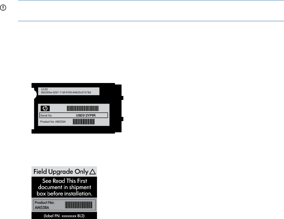
2. If a VC configuration is used and the upgrade requires moving to a new enclosure, then setup
the target VC server profile on the new enclosure now using the VCM domain and the
designated Monarch Server VC profile on the current system for guidance. Refer to “Possible
changes due to VC profile mapping on the upgraded server blade” (page 82) for important
information before starting this.
3. If the enclosure uses Virtual Connect, then unassign any VC server profiles assigned to enclosure
bays occupied by original servers and also those which will be occupied by upgrade server
blades. This must include profiles assigned to bays which will contain Monarch or auxiliary
blades. See the HP Virtual Connect for c-Class BladeSystem User Guide for more information
on VCM server profiles
4. If the Monarch Server or any other existing system to be added in the upgrade is using a
partner blade, remove it from the enclosure now. If the Monarch Server uses a partner blade
which will remain in the upgrade, it will be added back in a later step.
5. If necessary, move the Monarch Server. This step will be necessary for cases such as moving
from a c7000 to a c3000 enclosure or upgrading from a BL860c i2 or BL870c i2 in an odd
numbered enclosure bay to a BL870c i2 in an even numbered enclosure bay. See the table
“Blade Link bay location rules” in section “Installing the Blade Link for BL870c i2 or BL890c
i2 configurations” (page 22)
6. Place any other existing systems or upgrade blades to be combined in the upgrade into
enclosure bays adjacent to the Monarch Server.
IMPORTANT: Existing systems and new upgrade blades must be placed into enclosure bays
with higher numbers than those occupied by the Monarch Server.
7. Install any partner blades that will be used in the upgraded server blade. For positioning rules,
see“Installing the Blade Link for BL870c i2 or BL890c i2 configurations” (page 22)
8. Transfer the Monarch Server label carrier card to the Upgrade Blade Link:
a. Remove the label carrier card from behind the trap door of the Monarch Server Blade
Link. See “Blade Link” (page 125) for the trap door location. The label carrier card will
look like the image below:
b. Remove the product number portion of the Field Upgrade Only label on the Upgrade
Blade Link. This label will look similar to the image below:
Below is an example showing upgrade Blade Link sticker locations for the BL870c i2.
74 Optional components
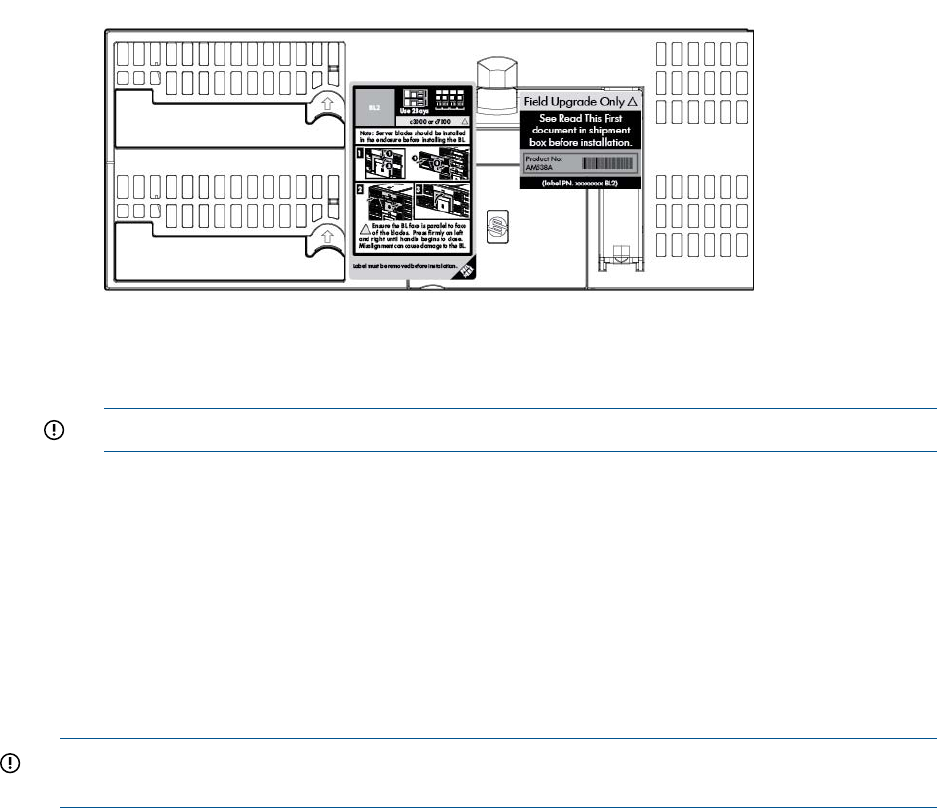
c. Place the product number portion from the Field Upgrade Only label on top of the old
product number and barcode on the label carrier card from the Monarch Server.
IMPORTANT: Do not cover the serial number on the label carrier card.
d. Remove the position information label (the left hand label in the above picture) from the
front of the upgrade Blade Link bezel.
Temporarily remove the “Field Upgrade Only” label if it blocks the Blade Link trap door.
e. Place the label carrier card behind the trap door of the Upgrade Blade Link, but do not
install the Upgrade Blade link at this time.
f. Reapply the “Field Upgrade Only” label to the upgrade Blade Link, making sure not to
cover the Blade Link handle.
9. Remove the Blade Links from the existing servers that will be included in the upgrade (“ Blade
Link for BL870c i2 or BL890c i2 configurations” (page 110)).
IMPORTANT: Mark the Monarch Server Blade Link and keep track of it until the upgrade is
successfully completed. Do not reuse the old Blade Links after the upgrade has been completed.
10. Make any necessary blade internal component changes. The following hardware components
have loading rules that can change after upgrading:
•processors
•DIMMs
•optional mezzanine cards
•ICH mezzanine boards
See “Rules for server blade internal components” (page 72) for more information.
11. Fully insert any unseated blades into the enclosure. Make sure all server blades that will be
included in the upgraded server are now fully seated into the enclosure with no Blade Links
installed.
12. Install the upgrade Blade Link by completing steps 1 through 11 in “Installing the Blade Link
for BL870c i2 or BL890c i2 configurations” (page 22)
13. Enter the show server list command at the Onboard Administrator command line
interface. The output should show a status of “OK” for each blade in the upgraded server, or
“OTHER” if there’s a current VC domain defined on the enclosure. The Monarch blade should
have an iLO 3 IP address assigned that would be the same one assigned to the Monarch
Server iLO 3.
14. Log into the iLO 3 MP interface and enter cm at the Main Menu to reach the Command Menu
prompt.
Installing internal components 75
15. Enter sr to view the system revision information. A sample output for a BL890c i2 is shown
below. The BL890c i2 will show four blades composing the serve blade, a BL870c i2 will
show two. If the output does not show all of the blades expected, then there is a problem
which must be resolved before proceeding. Reseating the Blade Link or individual blades may
correct server blade conjoining problems.
[ilo002264fed1da] CM:hpiLO-> sr
SYSREV
Revisions Active Pending Bay 5 Bay 6 Bay 7 Bay 8
----------------------------------------------------------------------------
iLO FW : 01.30.30 01.30.30 01.30.30 01.30.30 01.30.30
System FW : 01.24 01.24 01.24 01.24 01.24
MHW FPGA : 01.14 01.14 01.14 01.14 01.14
Power Mon FW : 03.04 03.04 03.04 03.04 03.04
Front Panel HW : 03.00 03.00 03.00 03.00 03.00
PRS HW : 02.07 02.07 02.07 02.07 02.07
IOH HW : 02.02 02.02 02.02 02.02 02.02
16. If the sr output indicates that the firmware is not consistent across all of the blades, which
should only be due to a new Upgrade Blade with different firmware version being added,
then complete a second server firmware update. Update the system to the same firmware
version used previously for the existing servers. An example of sr output indicating a firmware
inconsistency is shown below.
[ilo002264fee2de] CM:hpiLO-> sr
SYSREV
Revisions Active Pending Bay 5 Bay 6 Bay 7 Bay 8
----------------------------------------------------------------------------
iLO FW : --.--! 01.30.29 01.30.29 01.01.02 01.01.02
System FW : --.--! 01.24 01.24 01.08 01.08
MHW FPGA : --.--! 01.14 01.14 01.12 01.12
Power Mon FW : 03.04 03.04 03.04 03.04 03.04
Front Panel HW : 03.00 03.00 03.00 03.00 03.00
PRS HW : 02.07 02.07 02.07 02.07 02.07
IOH HW : 02.02 02.02 02.02 02.02 02.02
Note(s):
! = FW mismatch, update needed
If an update is required, it may need to be completed using the HPSUM Force Install option
for both the iLO 3 and system firmware bundles. When finished, log back into the iLO 3 MP
of the Monarch blade and enter sr from the Command Menu to verify that the firmware levels
on all conjoined blades are now consistent and up to date.
17. Exchange the System Information Parameters by following the steps below. For more information
regarding the information contained in the System Information Parameters, see “Blade link
and system information parameters” (page 80).
76 Optional components
a. Log into the Monarch iLO 3 MP, enter the Command Menu, and execute the command
sysset. This will list the system information parameters stored in the Upgrade Blade Link
(Primary) and those stored on the server blade (Secondary). Below is an example of the
output when upgrading from a BL860c i2 to a BL870c i2.
[ilo002264fee1be] CM:hpiLO-> sysset
SYSSET
Current System Information Parameters:
Manufacturer : HP
Product Name (prodname) : Integrity BL870c i2
Secondary Product Name : Integrity BL860c i2
Product Number (prodnum) : AM358A
Secondary Product Number : AD399A
Serial number (serial) : Uninitialized
Secondary Serial Number : USA0003
UUID (uuid) : FFFFFFFF-FFFF-FFFF-FFFF-FFFFFFFFFFFF
Secondary UUID : 89742B3C-AD78-11DF-BB2A-5ABBD7A51B74
Product ID : 0x702
An Upgrade Blade Link has been detected.
Primary and secondary system parameters values do not match.
Copy secondary UUID and serial number to primary? (Y/[N]):
The product name and product number from the Upgrade Blade Link reflect a BL870c
i2, while the Secondary product name and number (from the Monarch Server) reflect the
original BL860c i2.
b. The system detects the Upgrade Blade Link and prompts you to make the required system
information exchanges between Upgrade Blade Link and the server. Enter yto approve
the exchange. You will then be informed that a reset of the iLO 3 MP is necessary for the
changes to take effect.
Copy secondary UUID and serial number to primary? (Y/[N]): y
-> Secondary system parameters values have been copied to primary
system parameters.
->System Information parameters have been updated.
iLO MP needs to be reset in order for these changes to take effect
c. Reset the iLO 3 MP by entering xd –r –nc at the Command Menu prompt.
[ilo002264fee1be] CM:hpiLO-> xd -r -nc
XD -r -nc
-> MP reset requested
MP is now being reset...
-> Command successful.
Installing internal components 77

d. After the iLO 3 MP reset (less than one minute), log back into the iLO 3 MP, go to the
Command Menu, and enter sysset again to verify that the system information parameters
have been set for correctly for both Primary and Secondary. The values between Primary
and Secondary should now match.
[ilo002264fee1be] CM:hpiLO-> sysset
SYSSET
Current System Information Parameters:
Manufacturer : HP
Product Name (prodname) : Integrity BL870c i2
Secondary Product Name : Integrity BL870c i2
Product Number (prodnum) : AM358A
Secondary Product Number : AM358A
Serial number (serial) : USA0003
Secondary serial number : USA0003
UUID (uuid) : 89742B3C-AD78-11DF-BB2A-5ABBD7A51B74
Secondary UUID : 89742B3C-AD78-11DF-BB2A-5ABBD7A51B74
Product ID : 0x702
18. Remove the “Field Upgrade Only” sticker from the bezel of the Upgrade Blade Link. This is
no longer a Field Upgrade Blade Link because the serial number and UUID have now been
programmed.
19. If the enclosure uses Virtual Connect, then the Monarch Server VCM server profile should now
be assigned to the enclosure bays occupied by the upgraded server. The profile may need
some modifications after it is assigned to the upgrade so that network assignments and other
elements of the VC server profile match what is required. See “Possible changes due to VC
profile mapping on the upgraded server blade” (page 82) for more information. If the HP-UX
Portable Image tool is used (see “Preserving VC-assigned MAC addresses in HP-UX by enabling
Portable Image” (page 84)), then it’s best not to make changes until after the entire upgrade
is completed and any changes then should be made very carefully. Once assigned, verify
that there are no errors indicated by VCM or by the OA. Any VCM Domain Status or OA
System Status alerts or warnings should be resolved before proceeding. Sometimes, VCM
problems can be corrected by unassigning then reassigning the VC server profile.
Final hardware check
1. Log into the Monarch iLO 3 MP and power on the server by entering pc –on at the Command
Menu prompt or pressing the server power button.
2. Boot to the UEFI shell for a basic system check. Do not autoboot any currently installed operating
systems.
3. Complete the following checks to be sure that the upgraded server blade is functioning properly.
Any problems found in the steps immediately below should be resolved before proceeding.
a. Check the iLO 3 MP SEL for any problems. See “Errors and error logs” (page 101) for
more information on resolving any errors.
IMPORTANT: If any errors are found in the SEL, do not continue until resolving them.
b. Execute the UEFI shell command lanaddress and verify that the expected number of
LAN ports are shown and that there is a link indication for every port that is connected
to a network or network switch.
NOTE: You should see an Mon each applicable line.
NOTE: lanaddress and other EFI commands will only list 4 LAN ports for each blade's
embedded Flex-10 LOMs, regardless of the active VC profile configuration. If the profile
specifies additional Flex-10 LOM ports, those will become available while the operating
system runs.
78 Optional components

c. Execute the UEFI shell command map –rto make sure that all of the expected disks are
mapped.
d. Execute the UEFI shell command cpuconfig to make sure that all of the expected
processors are there and indicate active.
e. Execute the UEFI shell command info mem –dimms to make sure that all of the
expected DIMMs are there and indicate active.
4. If necessary, switch the onboard SmartArray SAS controller on new upgrade blades to RAID
mode (“Configuring a Smart Array Controller” (page 133)
NOTE: All new Upgrade Blades come with the onboard SmartArray SAS controller in HBA
mode.
5. If installed on the upgrade, configure the partner blade as necessary. See the specific partner
blade documentation for more information on configuration and setup. The documentation
can be located on www.hp.com by searching on the partner blade product name.
Booting the operating system
The server blade has now been physically upgraded and it may be ready to boot to the OS.
Certain upgrade scenarios require OS reinstallation:
1. See “Upgrade scenarios which do not require a reinstall of the operating system” (page 82)
to determine whether your particular server blade upgrade scenario requires a reinstallation
of the OS.
2. If a reinstallation of the OS is required, or you choose to reinstall the OS though it’s not
required, then complete it now. Refer to “Operating system procedures” (page 30) and the
OS specific installation documentation for more information. Any special configuration, such
as for an HPVM host server, must be redone after the OS is reinstalled.
3. Boot the OS. See “Operating system procedures” (page 30) for more information.
IMPORTANT: A new Operating System license may be required for the upgraded server.
See “Operating System Licenses” (page 81) for more information.
4. If you are using the HP-UX Portable Image tool, execute the steps under “Post-Upgrade
Procedure for PI” in the “Preserving VC-assigned MAC addresses in HP-UX by enabling Portable
Image” (page 84) section.
5. Verify that the system, especially networking and storage, function as expected.
NOTE: The Windows Server 2008 environment may require significant time for assimilating
new hardware after an upgrade with no OS reinstall. Check Device Manager carefully for
any problems. A restart of the OS will often correct problems with new hardware. It may be
necessary in some cases to manually install drivers for new devices.
6. If the Monarch Server is an HPVM host server, then the VM guests can now be migrated back
or started if they were stopped. Refer to the HP Integrity Virtual Machines Installation,
Configuration, and Administration document for information regarding guest migration. Test
each VM guest to make sure it’s functioning properly.
Warranty registration
After completing the upgrade, contact HP with the server serial number and new product number.
The warranty of the designated Monarch Server will be transferred to the upgraded server blade
and the service time will be reset. Proof of purchase must be provided and the HP warranty
organization must be notified.
Installing internal components 79

The proof of purchase should be a scanned copy or fax of a sales receipt or invoice from HP or
an authorized reseller. It can also be an order confirmation, shipping receipt, or reseller based
purchase/shipping confirmation that contains the following:
•The purchase or shipping date.
•The product number or product name/product description.
•The serial number, but it is not required (some invoices do not have serial numbers).
•The vendor’s name (the name of the business where the unit was purchased).
IMPORTANT: Be sure that all information is clearly readable.
More information regarding server blade warranties can be found at: http://
bizsupport2.austin.hp.com/bc/docs/support/SupportManual/c01865770/c01865770.pdf.
Support
A support Flex Care Pack with at least the same level of care as the server blade to be upgraded
(the Monarch Server) should have been purchased when the Upgrade Kit was ordered. Your HP
sales representative will apply the support package to the upgraded server blade and provide
credit for the unused portion of the package purchased for the original Monarch Server. The new
Flex Care Pack must be registered with the serial number of the original Monarch Server (now
attached to the upgraded server) included to ensure support entitlement. For more information, go
to www.hp.com/go/cpc. You can also contact your HP sales representative or contact HP sales
through the following link:
http://www.hp.com/large/contact/enterprise/index.html?key=1-57BVO&mcc=DRSR
Blade link and system information parameters
Every HP BL860c i2, BL870c i2 and BL890c i2 server blade has a set of information called the
System Information Parameters which helps to identify the server blade and is used for certain
applications and for the server blade warranty. This information includes:
•product name
•product number
•UUID
•serial number
This information is stored in nonvolatile memory onboard the Blade Link and server blades. The
system information parameters can be viewed from the iLO 3 MP interface Command Menu prompt
by entering sysset.
[ilo002264fed1da] CM:hpiLO-> sysset
SYSSET
Current System Information Parameters:
Manufacturer : HP
product name (prodname) : Integrity BL890c i2
Secondary Product Name : Integrity BL890c i2
Product Number (prodnum) : AH384A
Secondary Product Number : AH384A
Serial number (serial) : USA0000
Secondary Serial Number : USA0000
UUID (uuid) : E14F772A-AD78-11DF-85ED-1FC66668C7F5
Secondary UUID : E14F772A-AD78-11DF-85ED-1FC66668C7F5
Product ID : 0x704
80 Optional components

There are two sets of parameters shown:
•Primary values are stored on the Blade Link.
•Secondary values are those stored on the server blades.
When an existing server blade is upgraded, the system must retain the existing UUID and serial
number, but the product name and number will need to be changed to reflect the configuration of
the upgrade. The Upgrade Blade Link will come already installed with a product name and number
which reflects the upgrade configuration. This information will need to be copied to the server
blades, and the UUID and serial number of the server blades will need to be copied to the Upgrade
Blade Link. This exchange of system information parameters is done by firmware.
The server UUID, serial number, and product number are printed on the label carrier card behind
the Blade Link trapdoor which is described in “Blade Link” (page 125). The Upgrade Blade Link
does not ship with a label carrier card, but has a trap door for one. It also has a “Field Upgrade
Only” label on the front bezel which contains a peel-off sticker with the new product number.
Operating System Licenses
Some operating systems use tiered licensing levels based upon the maximum processor socket
count of the server it runs on. If the upgrade results in a higher tier for the system, then a new
software license will be required for using those operating systems. The tier level will rise when
the upgraded server contains more sockets than the original Monarch Server.
The “tiers” map to the server blades as follows:
•BL860c i2 – 2 Socket Tier
•BL870c i2 – 4 Socket Tier
•BL890c i2 – 8 Socket Tier
Your HP sales representative must be contacted to get this new license. Full credit will be received
when the original Monarch Server license is surrendered. The credit will reflect the current purchase
price of the original license, not the original purchase price, and the credit cannot exceed the
original license purchase price.
For more information contact your HP sales representative. HP sales can also be contacted by
following the link below:
http://www.hp.com/large/contact/enterprise/index.html?key=1-57BVO&mcc=DRSR.
The sections below provide specific information on licensing.
HP-UX
HP-UX uses tiered licensing and the license is delivered physically or electronically by certificate.
For more information regarding HP-UX 11i software licensing go to:
http://h71028.www7.hp.com/enterprise/us/en/os/hpux11i-oe-software-licensing.html?
jumpid=reg_R1002_USEN.
HP OpenVMS
OpenVMS uses tiered licensing and the license is delivered physically by certificate. For more
information regarding OpenVMS software licensing go to: http://h71000.www7.hp.com/
ovmslicensing/openvms_licensing_information.html.
Windows Server 2008
Windows does not use tiered licensing. No licensing changes or other extra steps are required
for the upgraded server blade.
Installing internal components 81

Upgrade scenarios which do not require a reinstall of the operating system
OS reinstall required?HP Virtual MachinesVirtual ConnectOperating
system
no HPVMHPVMno VCVC
NO1
XXHP-UX
NOXX
NO1
XX
NOXX
NO1
N/AN/AXOpenVMS
NOX
NO1
N/AN/AXWindows
Server 2008 NOX
1Note cautions in “Possible changes due to VC profile mapping on the upgraded server blade” (page 82)
Possible changes due to VC profile mapping on the upgraded server blade
Virtual Connect Manager supports assigning a VC server profile to each bladed server. Profiles
can include VC-assigned:
•UUID
•serial number
•Ethernet port MAC addresses with network assignments
•FC HBA connection WWNs with FC SAN assignments.
The VC-assigned MAC addresses, FC WWNs, UUID and serial number can come from blocks of
values supplied by VCM or from user-defined blocks of values. Alternatively, the factory-assigned
UUID, serial number, Ethernet port MAC addresses and FC HBA connection WWNs can be used.
The following information pertains to all of these options.
When performing an upgrade it is critical to understand how the server profile connection entries
will be mapped to ports on the upgrade server as this may impact the OS. What happens is
somewhat different for FC SAN assignments compared to Ethernet network assignments, so each
is described separately below.
The FC SAN connection entries in a profile should be thought of as sets of entries. If there are N
Virtual Connect FC Interconnect modules in an enclosure (where N is rounded up to an even
number) then there are N FC SAN connection entries per set. The first N entries are mapped to
the FC HBA ports on the Monarch blade, the second set of N entries are mapped to the FC HBA
ports on the first auxiliary blade, the next set of N entries to the next auxiliary blade, until all of
the FC connection entries have been mapped to ports or until there are no more FC HBA ports
available to map entries to. Below are a few examples of upgrading a BL860c i2 to a BL870c i2
in an enclosure with 4 Virtual Connect FC Interconnect modules where the BL860c i2 becomes the
Monarch blade in the upgrade server.
•If the profile assigned to the BL860c i2 server had 4 or fewer FC SAN connection entries then
those entries are still mapped to the FC HBA ports on the original BL860c i2 blade (since it
is the Monarch in the new server). There will be no FC SAN connection entries mapped to
any ports on the auxiliary blade in the upgraded server.
•If the profile assigned to the BL860c i2 server had more than 4 FC SAN connection entries
then the first 4 entries are still mapped to the FC HBA ports on the original BL860c i2 blade
(since it is the Monarch in the new server). The additional FC SAN connection entries (up to
82 Optional components

4), that had not been mapped to any ports prior to the upgrade, will be mapped to FC HBA
ports on the auxiliary blade in the upgraded server.
The Ethernet connection entries in a profile are handled differently from SAN entries in order to
balance the use of Flex-10 ports (even if no Flex-10 ports are used, the same balanced approach
is used). Virtual Connect manager distributes the Ethernet connection entries across all of the blades
in a server, and on each blade it distributes connection entries across all of the Ethernet physical
ports. This is done so that as few Flex-10 sub-ports are used as needed, which results in maximum
band-width available to each Flex-10 sub-port. This distribution of Ethernet connection entries across
all Ethernet ports is done for single-blade servers, too. The net result is that the mapping of Ethernet
connection entries in a profile assigned to a server will change when that server is upgraded.
Consider a the following examples.
•If the upgrade is from a BL860c i2 to a BL870c i2 then every other Ethernet connection entry
starting with the first entry (i.e., the first, third, fifth, etc. entries) will be mapped to ports on
the Monarch blade, and every other entry starting with the second entry (i.e., the second,
fourth, sixth, etc. entries) will be mapped to ports on the auxiliary blade.
•If the upgrade is from a BL860c i2 to a BL890c i2 then every fourth Ethernet connection entry
starting with the first entry (i.e., the first, fifth, ninth, etc. entries) will be mapped to ports on
the Monarch blade; every fourth entry starting with the second entry (i.e., the second, sixth,
tenth, etc. entries) will be mapped to the first auxiliary blade; every fourth entry starting with
the third entry (i.e., the third, seventh, eleventh, etc. entries) will be mapped to the second
auxiliary blade; and finally every fourth entry starting with the fourth entry will be mapped to
ports on the 3rd auxiliary blade.
For example, a profile with 8 Ethernet connection entries where each entry defines a connection
to a different network (this makes it easy to see what happens when an upgrade is done). Assume
that the profile is assigned to a BL860c i2 that is upgraded to a BL870c i2. Assume that VC Flex-10
Interconnection modules exist in bays 1 and 2, thus the Flex-10 LOMs on the blades are utilized.
The following table shows how these entries are mapped to ports on the original server and to the
blades in the upgraded server.
Mapping to BL870c i2
ports
Mapping to BL860c i2
ports
VCM assigned MAC
addressAssigned networkProfile entry
Monarch LOM1–aMonarch LOM1–a00-17-A4-77-90-10LAN-11
Auxiliary LOM1–aMonarch LOM2–a00-17-A4-77-90-12LAN-22
Monarch LOM2–aMonarch LOM3–a00-17-A4-77-90-14LAN-33
Auxiliary LOM2–aMonarch LOM4–a00-17-A4-77-90-16LAN-44
Monarch LOM3–aMonarch LOM1–b00-17-A4-77-90-18LAN-55
Auxiliary LOM3–aMonarch LOM2–b00-17-A4-77-90-1ALAN-66
Monarch LOM4–aMonarch LOM3–b00-17-A4-77-90-1CLAN-77
Auxiliary LOM4–aMonarch LOM4–b00-17-A4-77-90-1ELAN-88
If it is important that each of the networks be mapped to the same ports on the Monarch blade
after the upgrade, then the profile will need to be edited to add 7 Ethernet connection entries, and
then the entries must be edited to obtain the desired network connections aligned with the ports
Installing internal components 83

on the Monarch blade. The resulting set of Ethernet connection entries in the profile would be as
follows.
Mapping to BL870c i2 portsVCM assigned MAC addressAssigned networkProfile entry
Monarch LOM1–a00-17-A4-77-90-10LAN-11
Auxiliary LOM1–a00-17-A4-77-90-12unassigned2
Monarch LOM2–a00-17-A4-77-90-14LAN-23
Auxiliary LOM2–a00-17-A4-77-90-16unassigned4
Monarch LOM3–a00-17-A4-77-90-18LAN-35
Auxiliary LOM3–a00-17-A4-77-90-1Aunassigned6
Monarch LOM4–a00-17-A4-77-90-1CLAN-47
Auxiliary LOM4–a00-17-A4-77-90-1Eunassigned8
Monarch LOM1–b00-17-A4-77-90-20LAN-59
Auxiliary LOM1–b00-17-A4-77-90-22unassigned10
Monarch LOM2–b00-17-A4-77-90-24LAN-611
Auxiliary LOM2–b00-17-A4-77-90-26unassigned12
Monarch LOM3–b00-17-A4-77-90-28LAN-713
Auxiliary LOM3–b00-17-A4-77-90-2Aunassigned14
Monarch LOM4–b00-17-A4-77-90-2CLAN-815
NOTE: While the network mapping has been adjusted to preserve the original mapping of
networks to ports, it is not possible to adjust the MAC address assignment to preserve the same
mapping of MAC addresses to ports. If your OS is HP-UX, see the section “Preserving VC-assigned
MAC addresses in HP-UX by enabling Portable Image” (page 84) for a method which can be used
to preserve VC-assigned MAC addresses.
When moving a bladed server to a new enclosure as part of the upgrade where VC-assigned
MAC addresses or WWNs are used, the new enclosure VCM setup must use the same built-in
blocks of addresses. Even when this is done, it may be difficult to define a VC server profile where
the MAC addresses and WWNs are the same as those used on the original server before the
upgrade. If identical MAC addresses and WWNs are required and cannot be obtained using the
pre-defined blocks of addresses on the new enclosure, then the new enclosure will have to be set
for user-defined addresses with the addresses from the original enclosure profile moved into the
new enclosure VC domain. This caution also applies where VC-assigned UUID and serial numbers
are used, but it may not be possible to obtain the same VC-assigned UUID in a new enclosure. It’s
very important that setup for the new enclosure is done carefully so that there are no duplicate
MAC addresses or WWNs on a network. The values moved to a new enclosure should not remain
in use on the original enclosure.
The VC server profile should always be checked after being applied to the upgrade to make sure
that profile connection entries are mapped to ports as expected and to make sure there are no
profile errors or warnings which must be resolved. See the HP Virtual Connect for c-Class
BladeSystem User Guide for more information on VCM server profiles.
Preserving VC-assigned MAC addresses in HP-UX by enabling Portable Image
If your OS is HP-UX where the VC server profile does not use the hardware default MAC addresses
and it is important that Ethernet connections configured in the OS retain their VC-assigned MAC
addresses, then there is a package called “Portable Image” (PI) which can be used. The HP-UX
84 Optional components

Portable Image product is installed and enabled on the blade server before the upgrade. After the
upgrade, PI will automatically modify the HP-UX network instance numbers of the new hardware
environment so that they match the pre-upgrade environment. This takes advantage of the VCM
interconnect stacking links to allow all of the Monarch Server network connections to function
correctly with no corrections needed in the original VC server profile.
Portable Image can be used on VC configured systems where the VC domain has selected Virtual
Connect assigned MAC addresses instead of the static, factory-default MAC addresses. If you
choose to use PI to assist the upgrade, there will be a pre-upgrade step to follow on the designated
Monarch Server and then another step to follow after the upgrade. These two steps are detailed
below but they must not be executed until they’re explicitly called for in the upgrade procedure
which is found in the section “Upgrading the existing server blade” which is located in this section.
Pre-Upgrade Procedure for PI
These instructions are to be executed on the designated Monarch Server with the OS booted.
1. You need to obtain the PI package if it’s not already installed.
a. First, check for it being already installed by executing the following command:
swlist|grep HPPortableImage
b. If nothing is returned, then the package must be installed now. Go to
www.software.hp.com and search for “HP Portable Image”. Follow the link for HP-UX
Portable Image in the product list and follow the instructions there for installing the depot.
2. If your HP-UX 11i v3 release is September 2010 or earlier, then you must install the GIO
cumulative patch before proceeding.
a. Go to the HP Support Center web page at http://www.hp.com/go/hpsc. The site requires
a quick registration.
b. Search for “PHKL_41525” using the Search: HP Support Center box and download the
patch.
c. Follow the patch link and execute the installation instructions found there.
3. Enable PI by executing the following command:
kctune gio_portable_image=1
You should see the following:
Tunable Value Expression Changes
gio_portable_image (before) 0 Default Immed
(now) 1 1
4. The PI state must be saved before starting the upgrade. This is done by explicitly executing
the PI save command:
/opt/network/bin/hpuxpitool -s
5. Dump the saved PI state to a text file for possible use later. Obtain the dump by executing the
following command:
/opt/network/bin/hpuxpitool –g
This will list out each network instance along with its pre-upgrade MAC address.
6. Shutdown the OS using a shutdown command.
Post-Upgrade Procedure for PI
1. Dump the new PI state to a file for possible use later. Obtain the dump by executing the
following command:
/opt/network/bin/hpuxpitool –g
This will list out each network instance along with its post-upgrade MAC address.
2. Disable PI by executing the following command:
kctune gio_portable_image=0
Installing internal components 85
You should see the following:
Tunable Value Expression Changes
gio_portable_image (before) 1 1 Immed
(now) 0 0
3. The networking should be checked to make sure that the original system network instances
function correctly. If the HP-UX boot reports a LAN interface configuration failure, then check
the /etc/rc.log file for the failed instance number which may indicate something like the
following example:
ERROR: lan18 interface: ifconfig: no such interface
"/sbin/rc2.d/S340net start" FAILED
Get the MAC address for the failed instance number from the pre-upgrade PI dump and look
for that MAC address in the post-upgrade PI state dump. From that entry, note the new instance
number and edit the HP-UX networking configuration for the failed instance number so that it
uses the new instance number.
86 Optional components

6 Troubleshooting
This chapter provides strategies, procedures, and tools for troubleshooting server blade error and
fault conditions.
Methodology
General troubleshooting methodology
1. Review the following list of symptoms:
•Front Panel LED blinking
•System Alert present on system console
•Server blade will not power-up
•Server blade will not boot
•Error/Event Message received
•MCA occurred
2. Narrow down the observed issue to the specific troubleshooting procedure required. Isolate
the failure to a specific part of the server blade to perform more detailed troubleshooting. For
example:
•Issue - Front Panel LED blinking
NOTE: The front panel health LED flashes amber with a warning indication, or flashes
red with a fault indication.
◦Look for a system alert on the OA or system console.
◦Analyze the alert by using the SEL, to identify the last error logged by the server
blade. Use the iLO 3 MP commands to view the SEL, through the MP menu interface.
3. You should have a good idea about which area of the server blade requires further analysis.
For example, if the symptom was “server blade will not power-up”, the initial troubleshooting
procedure might have indicated a issue with the DC power rail not coming up after the power
was turned on.
4. Your goal is to identify the failed FRU and replace it. You must now perform the specific
removal and replacement procedure, and verification steps, see Chapter 7: “Removing and
replacing components” (page 108) for more details.
NOTE: If multiple FRUs are identified as part of the solution, fix all identified failed FRUs.
5. You might have to perform specific recovery procedures to finish the repair.
If a failure occurs the front panel LEDs and the SEL helps you identify the issue or FRU:
•The front panel LEDs and LAN LEDs of the server blade change color and blink to help identify
specific issues, and display LAN activity.
For information on LED locations and states, see “Front panel LEDs” (page 93).
•The SEL provides detailed information about the errors identified by the LEDs.
For server alerts of levels 3-5, the attention condition on the server LED can only be cleared by
cycling DC power.
If the LEDs and SEL do not give you enough information for you to identify the issue you are
experiencing, HP also provides diagnostic tools with each operating system (see “Troubleshooting
tools” (page 91) for more details).
Methodology 87

NOTE: Always examine the iLO 3 MP SEL in the case of a blinking yellow or red front panel
health LED, before replacing any hardware.
Executing recommended troubleshooting methodology
The recommended methodology for troubleshooting a server blade error or fault is as follows:
1. Consult the system console for any messages, emails, and so on, pertaining to a server blade
error or fault.
2. View the front panel LEDs (power and health), locally or remotely through the iLO 3 MP vfp
command.
3. Read the symptom/condition information in the left column of Table 9 (page 88).
4. Perform the actions specified in the Action column.
For more details, see the appropriate subsection of this chapter, where this information is provided
in the Action column. The Action you are directed to perform might be to access and read one or
more error logs (the event log and/or the FPL).
You can follow the recommended troubleshooting methodology, and use Table 9 and Table 10
(page 91) or go directly to the subsection of this chapter which corresponds to your own entry
point. Table 8 provides the corresponding subsection or location title for these different entry points
(for example, to start by examining the logs, go directly to “Errors and error logs” (page 101)).
Table 8 Troubleshooting Entry Points
Subsection or LocationEntry Point
See “Basic and advanced troubleshooting tables” (page 88) ,“Troubleshooting
tools” (page 91), and “Front panel LEDs” (page 93).
Front panel LEDs
See “Virtual Front Panel LEDs in the iLO 3 TUI” (page 96)Virtual Front Panel LEDs in the iLO
3 TUI
See “Errors and error logs” (page 101).SEL and
FPLs
See “Troubleshooting tools” (page 91).Offline and Online Diagnostics
See http://www.compaq.com/support/svctools/webes/ for more information
about this tool).
System Event Analyzer
Basic and advanced troubleshooting tables
Use the following troubleshooting tables to determine the symptoms or condition of a suspect server
blade. The state of the front panel LEDs can be viewed locally.
NOTE: Virtual front panel LEDs in the iLO 3 TUI are not the same as the front panel LEDs, see
“Virtual Front Panel LEDs in the iLO 3 TUI” (page 96) for more information about Virtual front panel
LED troubleshooting
Table 9 Basic Low End Troubleshooting
ActionConditionStep
Nothing is logged for this condition.Server blade appears “dead” -- no front panel
LEDs are on, and no fans are running. iLO 3 MP
is running.
1
1. For new server installations, review the installation
procedures.
2. Be sure that that the enclosure power cords are
connected to both the power supplies and to the AC
receptacles.
3. Be sure that that AC power, at the proper AC voltage
levels, is available to the receptacles.
88 Troubleshooting

Table 9 Basic Low End Troubleshooting (continued)
ActionConditionStep
4. If the power button’s integrated LED on front panel
remains off, then reseat the server blade.
5. As a last resort, replace the server blade. This issue is
fixed when the front panel LED states are as follows: blade
health is steady green.
A fatal fault has been detected and logged, attempting
to power on the server.
Server blade does not power on after front panel
power button is momentarily pressed (less than
four seconds).
2
1. Examine enclosure power supply LEDs. If they are not
steady green, then replace power supply.
2. If the enclosure power supply LED is green, then you
might need an additional power supply to supply sufficient
power to run the blades in the enclosure.
3. Examine the iLO 3 MP subsystem logs for events related
to DC power rails.
This issue is fixed when the front panel LEDs are as
follows: Health is steady green and power is steady
green.
A fatal fault has been detected and logged while booting
or running system firmware.
1. Cannot access the iLO 3 MP at this time.
Blade health LED is off and iLO 3 MP is not
running.
3a
2. Must reseat or replace the server blade. This issue is
fixed when the iLO 3 MP logs can be read and both front
panel health LED and server power LED states show:
Flashing green or steady green, and steady green,
respectively.
A warning or critical failure has been detected and
logged while booting or running system firmware.
Blade health LED is flashing amber or red and
iLO 3 MP is running.
3b
Examine the iLO 3 MP logs for events related to switched
DC power or cooling fans or configuration. This issue is
fixed when both front panel health LED and server power
LED states show: Flashing green or steady green, and
steady green, respectively.
Nothing can be logged for this condition. The blade
health LED state indicates that the server blade is either
booting or running system FW, or booting or running OS.
1. Look for loose, damaged, or disconnected signal cables
between the system console device, and serial port
connector on the front panel.
Cannot see iLO 3 MP prompt on system console
-- blade server power is on. iLO 3 MP is running.
4a
2. Be sure that that the RS232C configuration matches
between the server blade and the local console (see
“Troubleshooting the server interface (system console)”
(page 106) for more details).
3. As a last resort, replace the server blade. This issue is
fixed when the iLO 3 MP menu appears on the system
console.
Nothing can be logged for this condition.
1. Examine the iLO 3 MP logs for entries related to
processors, processor power modules, and shared
Cannot see UEFI prompt on system console. iLO
3 MP is running.
4b
memory, and core I/O devices (see “Errors and error
logs” (page 101) for more details).
2. As a last resort, replace the server blade. This issue is
fixed when the UEFI menu appears on the system console.
Nothing can be logged for this condition.
1. Reinsert the boot disk into the drive bay
Cannot find a boot disk. The iLO 3 MP is running.4c
Methodology 89

Table 9 Basic Low End Troubleshooting (continued)
ActionConditionStep
2. Search for the boot disk path using the UEFI shell
(map-r) command.
3. Examine the iLO 3 MP logs for entries related to
processors, processor power modules, and shared
memory, and core I/O devices (see “Errors and error
logs” (page 101) for more details).
4. As a last resort, replace the server blade. This issue is
fixed when all boot paths are found.
Nothing can be logged for this condition.Cannot see OS prompt on system console. iLO
3 MP is running.
5
1. Examine the iLO 3 MP logs for entries related to
processors, processor power modules, shared memory,
and core I/O devices (see “Errors and error logs”
(page 101) for more details). This issue is fixed when the
OS prompt appears on the system console.
NOTE: All events listed below are logged in both FPL and SEL unless otherwise noted. An event of alert level 2 or
greater will be logged in both places, alert level 1 or 0 is logged in FPL only.
1. Be sure that the Blade Link is properly installed and
fully seated.
“POWER_FAIL_NO_SBL” - Power command
failed because no Blade Link is installed
6a
2. Look for bent connector pins on the Blade Link
1. If the Blade Link was not removed, be sure that is
properly installed and fully seated.
“SBL_REMOVED “ - Blade Link was removed6b
2. Look for bent connector pins on the Blade Link.
1. Be sure that the Blade Link is properly installed and
fully seated.
“ILO_RST_REASON_SBL” - The iLO 3 was reset
because the Blade Link was installed (FPL only)
6c
2. Look for bent connector pins on the Blade Link.
1. Use the sysset command.“SYSVARS_MISMATCH” - The system variable
stored on the Blade Link does not match the
system variable stored on the blade.
6d
1. Be sure that the Blade Link installed in the correct slot
and enclosure, see “Installing the Blade Link for BL870c
i2 or BL890c i2 configurations” (page 22)
“SBL_DOMAIN_IMPROPER_SBL” - The Blade Link
currently installed is not appropriate for the blade
slot (even/odd) and enclosure (c7000/c3000)
being used
6e
2. Be sure that the Blade Link is properly installed and
fully seated.
3. Look for bent connector pins on the Blade Link.
1. Be sure that the Blade Link installed in the correct slot
and enclosure, see “Installing the Blade Link for BL870c
i2 or BL890c i2 configurations” (page 22)
“POWER_FAIL_IMPROPER_SBL” - Power
command failed because the Blade Link currently
installed is not appropriate for the blade slot
6f
2. Be sure that the Blade Link is properly installed and
fully seated.
(even/odd) and enclosure (c7000/c3000) being
used
3. Look for bent connector pins on the Blade Link.
1. Be sure that the Blade Link is properly installed and
fully seated.
Incorrect number of processors displayed for the
conjoined blades
6g
2. Look for bent connector pins on the Blade Link.
1. Be sure that the Blade Link is properly installed and
fully seated.
“QPI_CPU_LINK_DEGRADED”6h
90 Troubleshooting

Table 10 Advanced Low End Troubleshooting
ActionSymptom/ConditionStep
SEL logging has stopped (health is steady green and power is steady
green).
Cannot read SEL from the system
console.
6
1. Examine console messages for any UEFI errors or warnings about
operation or communications.
This issue is fixed when the SEL resumes logging.
Front panel LEDs indicate that the server blade power is turned on, and
it is either booting or running the OS (for example, health is steady
green and power is steady green).
OS is non-responsive (hung)7
Nothing can be logged for this condition.
1. Use the iLO 3 MP Command Menu to initial a ToC, using the tc
command.
2. Reboot the OS and escalate.
3. Obtain the system hardware status dump for root cause analysis.
4. Examine the iLO 3 MP logs for entries related to processors, processor
power modules, shared memory, and core I/O devices (see “Errors and
error logs” (page 101) for more details).
This issue is fixed when the root cause is determined.
Front panel LEDs indicate that the server blade detected a fatal error
that it cannot recover from through OS recovery routines (for example,
health is flashing red and power is steady green).
MCA occurs during server blade
operation. The server blade
reboots the OS.
8a
1. Capture the MCA dump with the UEFI command, errdump mca. If
the server blade can boot the OS, you can capture binary MCA dump
files online.
Note: The server blade reboots
OS if enabled.
2. Examine the iLO 3 MP logs for entries related to processors, processor
power modules, shared memory, and core I/O devices (See “Errors
and error logs” (page 101) for more details).
The issue is fixed when the MCA does not repeat or the source of the
MCA has been eliminated.
Front panel LEDs indicate that the server blade detected a fatal, front
side bus error.
MCA occurs during server blade
operation; server blade reboot of
OS is prevented.
8b
System firmware is running to gather and log all error data for this MCA
event.Note: The troubleshooting actions
for this step are identical to those 1. Examine the iLO 3 MP logs for entries related to processors, processor
power modules, shared memory, and core I/O devices (see “Errors and
error logs” (page 101)for more details).
in Step 8a, except that the server
blade in this step must be hard
reset to begin the booting
process. This issue is fixed when the MCA does not repeat.
You must hard reset the server
blade to clear the fatal condition
and boot the OS.
Troubleshooting tools
The HP Integrity BL860c i2 Server Blade uses LEDs and other tools to help troubleshoot problems
that occur in the server blade.
Troubleshooting tools 91
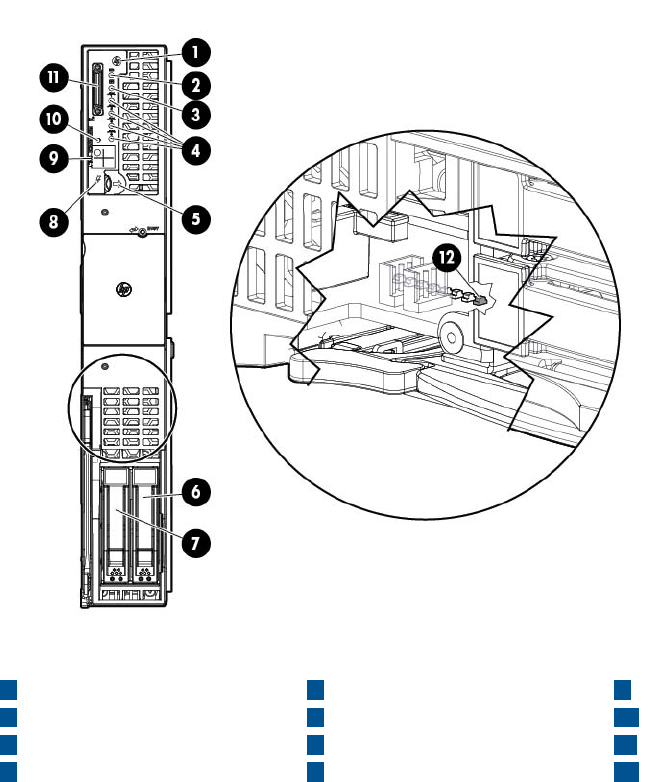
Controls and ports
Front panel view
9Partition Identifier
5Monarch power button
1Monarch blade indicator
2UID LED 10 Physical Presence Button
6HDD bay 1
7HDD bay 2
3Blade health LED 11 SUV connector
1284 iLO heartbeat LED (behind
grill)
Blade power LEDNICs 1, 2, 3, 4
92 Troubleshooting
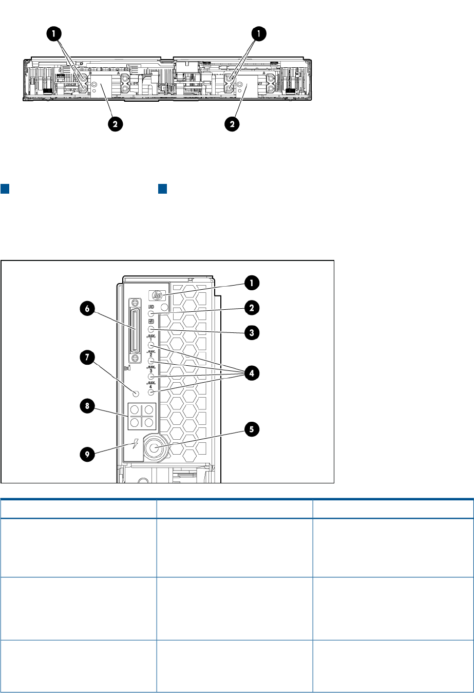
Rear panel view
21 GBX signal connectorsPower connectors
Server blade LEDs
Front panel LEDs
StatusDescriptionItem
Green = Blade is acting as Monarch
blade
Monarch blade indicator1
Off = Blade is not Monarch or is not
conjoined
Blue = IdentifiedUID LED2
Blue flashing = Active remote
management
Off = No active remote management
Green = Normal operationBlade health LED3
Amber flashing = Degraded condition
Red flashing = Critical condition
Troubleshooting tools 93
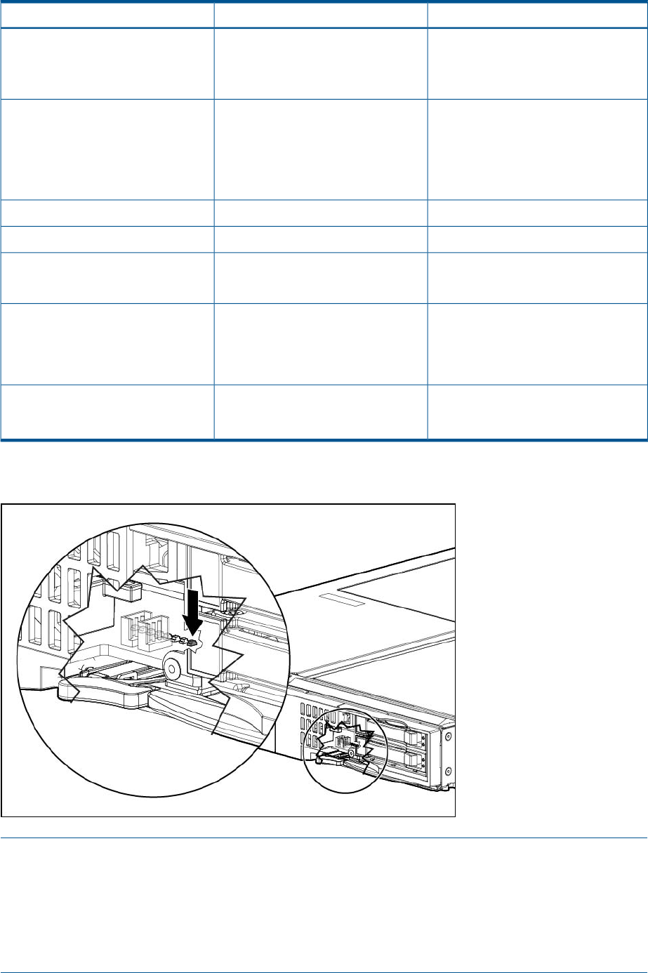
StatusDescriptionItem
Green = Network linkedNICs 1, 2, 3, 44
Green flashing = Network activity
Off = No link or activity
Green = Blade is acting as Monarch
and is powered on
Monarch power button / Monarch
power LED
5
Amber = Blade is acting as Monarch
and is in standby
Off = Blade is not Monarch
N/ASUV connector6
N/APhysical Presence Button7
Green = Blade is in a partitionPartition Identifier8
Off = Blade is not in a partition
Green = Server blade is powered onBlade power LED9
Amber = standby (auxiliary power
available) 1
Off = Off
Green flashing = iLO 3 Active
Solid green or off = iLO 3 failure or no
standby power
iLO 3 Heartbeat (behind grill)See Figure 1 (page 94)
1If the Onboard Administrator denies power to the server blade, the server blade returns to Standby mode.
Figure 1 iLO Heartbeat LED detail view
NOTE: The iLO heartbeat LED is visible when looking through the front grill of the Blade Link
nearest to the hard drive bays.
•If the blade is installed in a c7000 enclosure, then the LED is visible through the third and
fourth holes from the top of the blade in the leftmost row of holes.
•If the blade is installed in a c3000 enclosure, then the LED is visible through the third and
fourth holes from the left side of the blade in the bottommost row of holes.
94 Troubleshooting
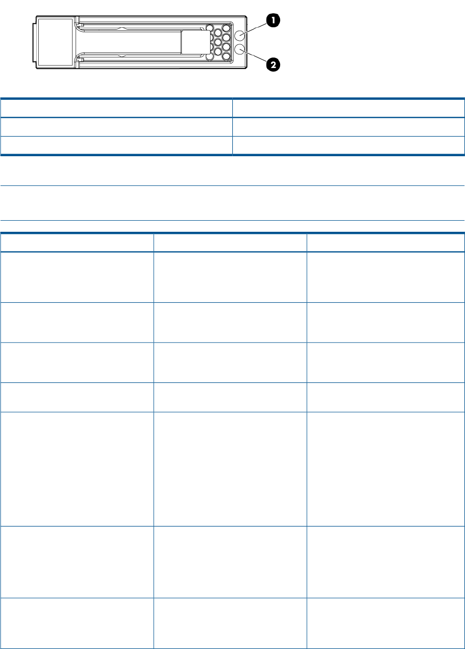
SAS disk drive LEDs
There are two disk drives on the BL860c i2 Server Blade. They have identical LEDs that display
the drive status.
DescriptionItem
Fault/UID LED (amber/blue)1
Online LED (green)2
SAS hard drive LED combinations
NOTE: Predictive failure alerts only occur when the hard drive is connected to a Smart Array
controller.
InterpretationFault/UID LED (amber/blue)Online/activity LED (green)
The drive has failed, or a predictive
failure alert has been received for this
Alternating amber and blueOn, off, or flashing
drive; it also has been selected by a
management application.
The drive is operating normally, and it
has been selected by a management
application.
Steadily blueOn, off, or flashing
A predictive failure alert has been
received for this drive. Replace the drive
as soon as possible.
Amber, flashing regularly (1 Hz)On
The drive is online, but it is not active
currently.
OffOn
Do not remove the drive. Removing a
drive might terminate the current
Amber, flashing regularly (1 Hz)Flashing regularly (1 Hz)
operation and cause data loss. The
drive is part of an array that is
undergoing capacity expansion or
stripe migration, but a predictive failure
alert has been received for this drive.
To minimize the risk of data loss, do
not replace the drive until the expansion
or migration is complete.
Do not remove the drive. Removing a
drive might terminate the current
OffFlashing regularly (1 Hz)
operation and cause data loss. The
drive is rebuilding, erasing, or it is part
of an array that is undergoing capacity
expansion or stripe migration.
The drive is active, but a predictive
failure alert has been received for this
Amber, flashing regularly (1 Hz)Flashing irregularly
drive. Replace the drive as soon as
possible.
Troubleshooting tools 95
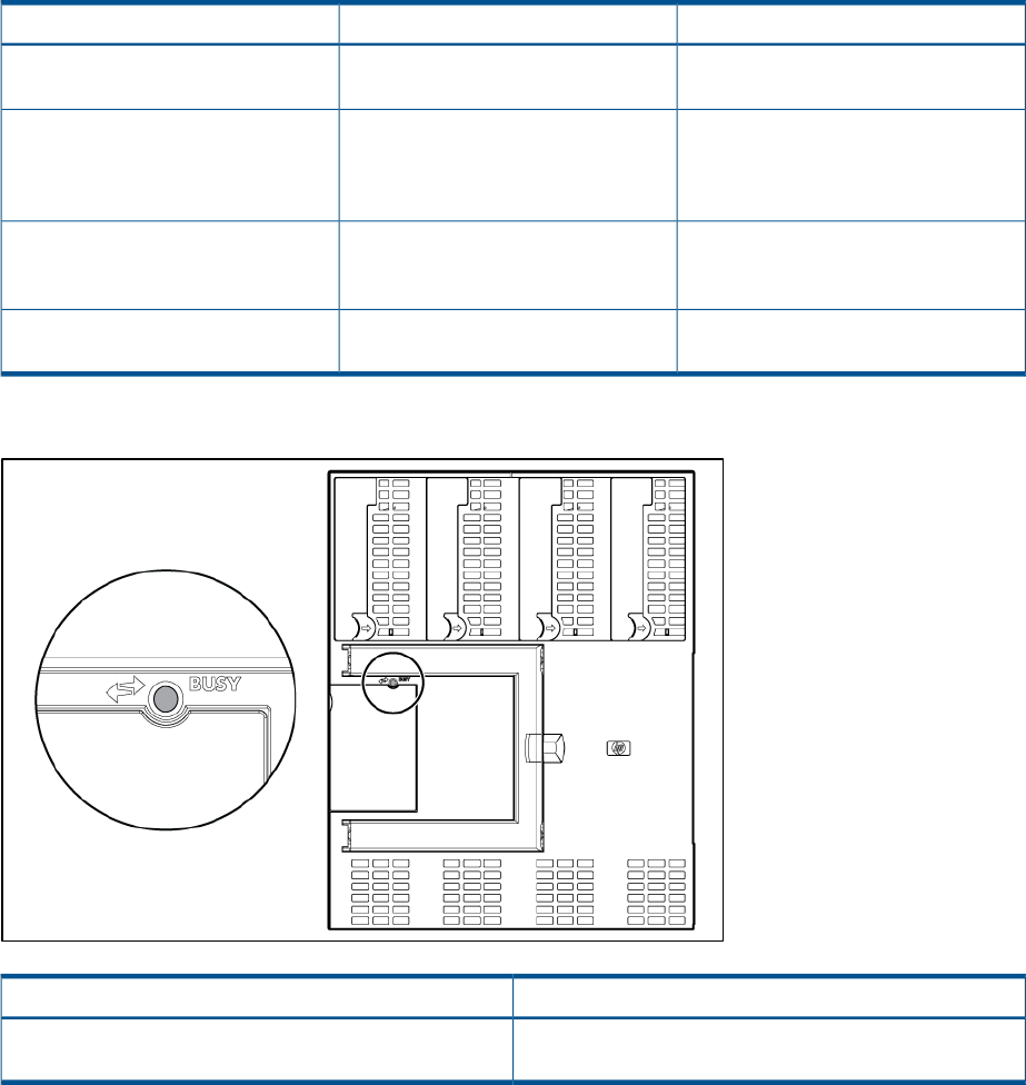
InterpretationFault/UID LED (amber/blue)Online/activity LED (green)
The drive is active, and it is operating
normally.
OffFlashing irregularly
A critical fault condition has been
identified for this drive, and the
Steadily amberOff
controller has placed it offline. Replace
the drive as soon as possible.
A predictive failure alert has been
received for this drive. Replace the drive
as soon as possible.
Amber, flashing regularly (1 Hz)Off
The drive is offline, a spare, or not
configured as part of an array.
OffOff
Blade Link LEDs
StatusDescription
Green = Blade Link is currently active. Do not remove.
Off = Blade Link is not currently active. Safe to remove.
Busy LED
Virtual Front Panel LEDs in the iLO 3 TUI
iLO 3 has no LED that equates to the Blade Health LED located on the front panel of each individual
BL860c i2 Server Blade. The Blade Health LED represents the health of the individual server blade.
The virtual LEDs in the iLO 3 GUI and TUI reflect system/partition health. The closest equivalency
to the Blade Health LED is a field called Bay [x] Health on the System Health page of the iLO 3
GUI.
The VFP, located in the iLO 3 TUI directly off the MP MAIN MENU, is a textual representation of
the system/partition state as well as the system’s status with respect to where it is in the boot process
(running non-OS code, etc).
The following virtual LEDs are located in the VFP:
•HEALTH
•SYSTEM
96 Troubleshooting

•LOCATOR
•POWER
Table 11 Indications for the iLO 3 TUI LEDs
ValueIndicationsEquivalentPurposeVFP LED
Health of the partition and the health of
one or more blades within the partition is
DEGRADED, meaning that:
Flashing
amber
System Health LED in the
iLO 3 GUI's Virtual Front
Panel
Represents the health of
the entire
system/partition. Shows
the worst health case of
HEALTH
•A FRU has failed
any blade that is part of
the partition. •A fatal event has been logged Level
seven alert events cause this indication
if there are no FRU failures.
NOTE: if the SYSTEM LED lights red,
this counts as a FRU failure for the
HEALTH LED.
Health of the partition is FATAL and the
health of one or more blades within the
partition are FATAL, meaning that:
•A FRU has failed and A fatal event has
been logged (Level seven events cause
this indication if there are FRU failures
on one of the blades in the partition.)
A reset will clear this LED of a fatal event,
but not a FRU failure. A power cycle will
clear both.
Flashing
red
All internal FRUs in the partition are
healthy, there are no fatal events, and the
system power is on.
Steady
green
Power to the system/partition is off and
there were no AMBER or RED HEALTH
indications on the last boot.
Off
There has been a FATAL event since the
last power on or system reset.
A reset or power on will clear this LED.
Flashing
red
•System Event Log
Health as displayed
on the System Health
page in the iLO 3
GUI
•There is no physical
LED on the blade's
front panel that
represents this state.
There is only one
SYSTEM LED per
partition. The state will
be the same for every
blade in the partition.
SYSTEM
System is beginning to boot the OSSteady
green
OS is not booting and there are no fatal
events.
Off
Troubleshooting tools 97

The system/partition is identified.OnIdentifies the
system/partition and will
LOCATOR UID LED on the front
panel of the
individual blade
•
System/partition is not identified and no
firmware update is actively writing to any
of the system ROMs
Off
blink while a firmware
update is in progress.
NOTE: All blades in a
partition show the same
LOCATOR status at all
times.
NOTE: You can toggle
the UID in software from
either the iLO 3 TUI or
web GUI. There is no
UID hardware button on
the server blade itself to
turn it on or off.
•Locator UID in iLO 3
•Virtual Indicator in
the Onboard
Administrator’s
interface
Power should not be interrupted; firmware
is actively burning a ROM.
NOTE: On ProLiant servers this LED
blinks to indicate remote management;
however this is not currently a supported
indication on Integrity servers.
Flashing
Toggles the current LED state to indicate
transitional mode states activated by a
push and hold of the Physical Presence
button.
If the Locator is off it will toggle on and
then off, but if the Locator is on, it will
ON/OFF
toggle
toggle off and then on. If the Locator is
flashing, no action will be taken.
System/partition is fully powered on.Steady
green
Identifies the
system/partition power
state.
POWER Monarch Power
button LED on the
front panel of the
Monarch blade
•
System/partition is in standby.Steady
amber
•System Power LED in
the iLO 3 GUI The system/partition is powered off.Off
98 Troubleshooting
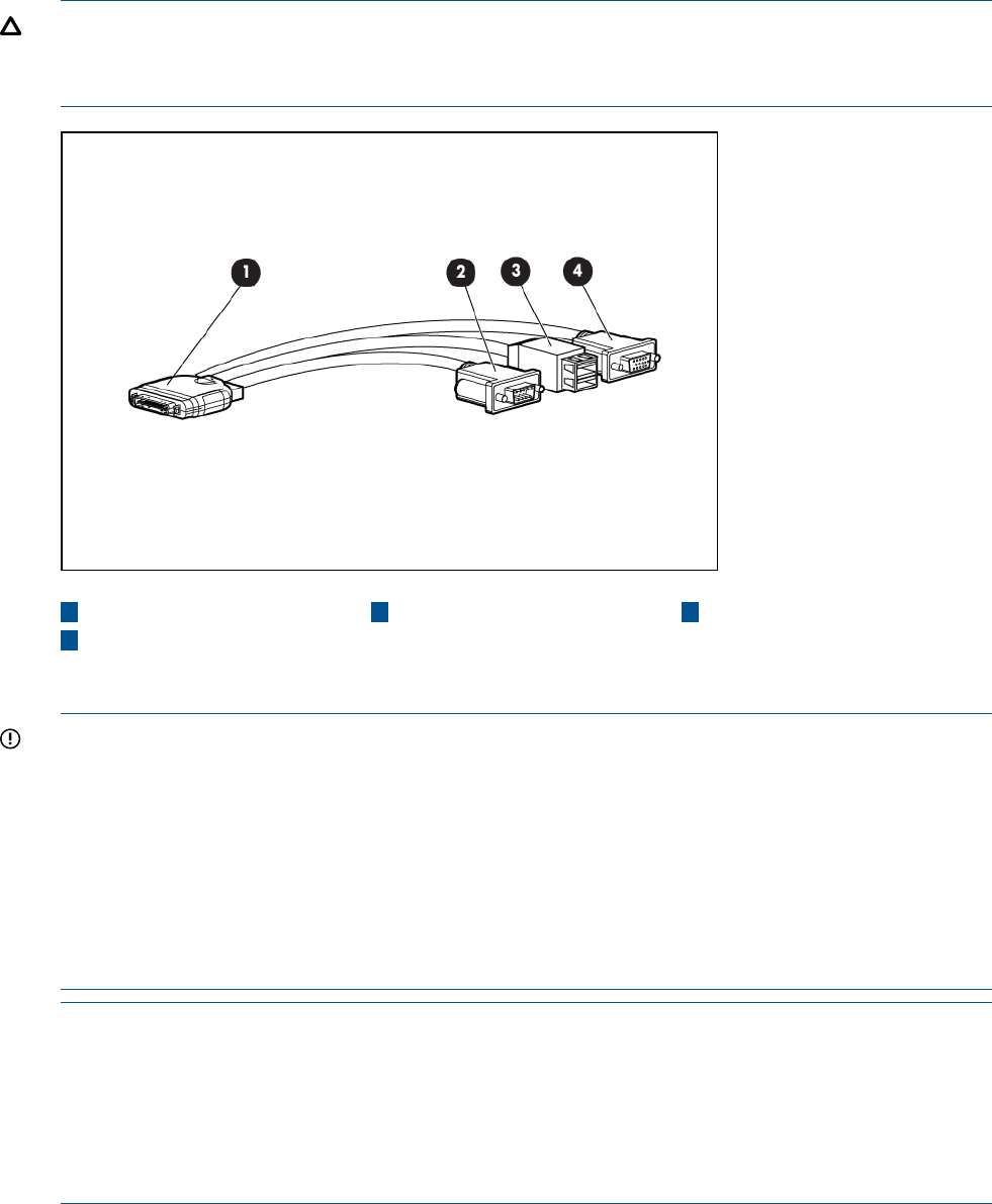
SUV Cable and Ports
The SUV port on the front of the server blade is used in conjunction with an SUV cable to connect
the server to external devices such as a terminal emulator or monitor. In a conjoined server, only
the SUV port on the Monarch Server is active.
CAUTION: The SUV cable is not designed to be used as a permanent connection.
Use caution when walking near the server blade when the SUV cable is installed. Hitting or bumping
the cable might cause the port on the server blade to break. This can damage the system board.
431 Server blade SerialUSB ports (2)
2Video
Connecting to the serial port
IMPORTANT: It is not necessary to physically connect to the Integrity iLO 3 via the serial port to
perform any management task. The intention is that the iLO LAN port should be used to communicate
with any iLO in the enclosure, as well as the Onboard Administrator. The LCD panel and the
Onboard Administrator can be used to configure and determine the iLO LAN address.
To physically connect to Integrity iLO 3 using the serial port:
1. 1. Connect the SUV cable to the SUV port (i.e., the diagnostic port).
2. 2. Connect an RS-232 cable to the RS-232 port on the SUV cable. This is the local connection
to the Integrity iLO 3 consoles.
3. 3. Connect the other end of the RS-232 cable to your terminal emulator.
NOTE: The terminal emulator is typically software that runs on a PC, such as Putty, Reflections,
or Hyper Terminal. This software enables a PC to communicate with the server using one of the
PC’s comm ports. If the PC has a RS-232 serial port then connect the cable to that port and then
configure the terminal emulator software to use that serial port. However, if the PC does NOT have
a serial port, then you will need a USB to Serial converter. These devices can be ordered from
SmartBuy and typically are in-expensive. The device has a USB connector that plugs into a USB
port on the PC, and it has a RS-232 port for connecting to the SUV serial port.
Troubleshooting tools 99
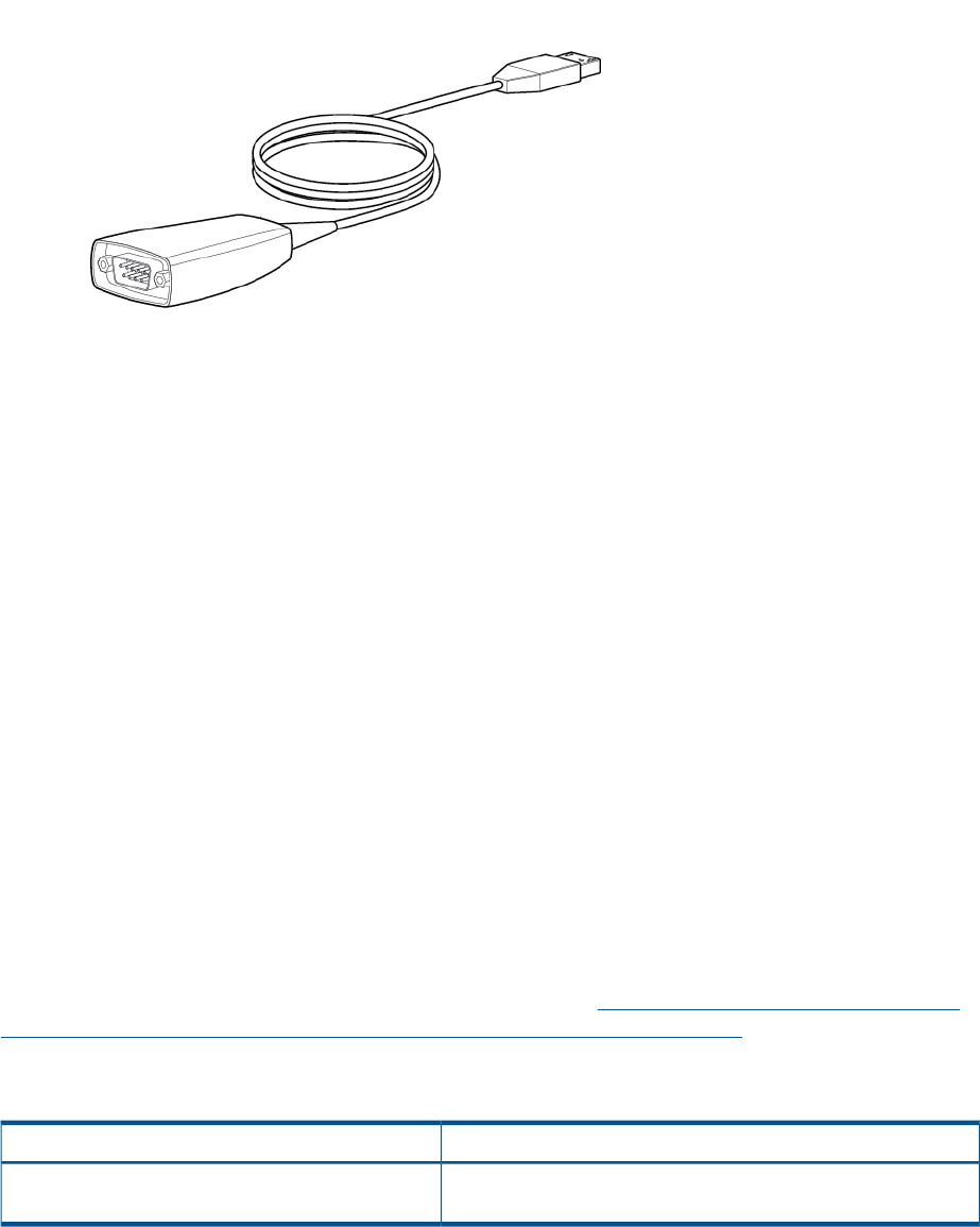
Diagnostics
A suite of offline and online support tools are available to enable troubleshooting server blade
issues. In general, if the operating system (HP-UX) is already running, HP does not recommend
shutting down the server blade. Use the online support tools.
If the OS cannot be booted, use the offline support tools to resolve the issue. The offline support
tools are available from the UEFI partition. after you resolve the issue preventing booting, boot
HP-UX, and use the online support tools for any further testing.
If it is not possible to reach the UEFI from either the main disk or from LAN, you must troubleshoot
using the visual fault indicators, console messages, and system error logs that are available.
Offline Diagnostics Environment
The Offline Diagnostics Environment provides a support tools platform that enables you to
troubleshoot a system that is running without an operating system. With Offline Diagnostics, you
can test systems that cannot be tested using the online tools.
The HP Integrity Servers and Itanium Workstations Offline Diagnostics and Utilities CD-ROM is
shipped with all Integrity systems and Itanium® workstations. This CD is updated quarterly, at
which time new functions and features can be added, new hardware diagnostics can be
incorporated, and performance can be improved.
For more information, regarding the use of the Offline Diagnostics Environment, see the Offline
Diagnostics Environment Administrator's and User's Guide (http://h20000.www2.hp.com/bc/
docs/support/SupportManual/c02628971/c02628971.pdf?HPBCMETA::).
General diagnostic tools
DescriptionDiagnostic Tool
Provides detailed information about the IPMI event (Issue
description, cause, action)
IPMI Event Decoder
100 Troubleshooting

Fault management overview
The goal of fault management and monitoring is to increase server blade availability, by moving
from a reactive fault detection, diagnosis, and repair strategy to a proactive fault detection,
diagnosis, and repair strategy. The objectives are:
•To detect issues automatically, as close as possible to the time of occurrence.
•To diagnose issues automatically, at the time of detection.
•To automatically report (in understandable text) a description of the issue, the likely causes of
the issue, the recommended actions to resolve the issue, and detailed information about the
issue.
•To be sure that tools are available to repair or recover from the fault.
HP-UX Fault management
Proactive fault prediction and notification is provided on HP-UX by SFM and WBEM indications.
WBEM is a collection of standards that aid large-scale systems management. WBEM allows
management applications to monitor systems in a network.
SFM and WBEM indication providers enable users to monitor the operation of a wide variety of
hardware products, and alert them immediately if any failure or other unusual event occurs. By
using hardware event monitoring, users can virtually eliminate undetected hardware failures that
could interrupt server blade operation or cause data loss.
HP SMH is the applications used to query information about monitored devices and view indications
and instances on WBEM. This WBEM-based network management application enables you to
create subscriptions and view indications.
SysMgmtPlus functionality displays the property pages of various devices and firmware on HP
SMH. SysMgmtPlus enables HP SMH to display improved property pages that contain dynamic
content, providing the user to view and hide details of devices and firmware. The Health Tests are
associated with components. The healthtest feature provides an option to perform health test on
all the device instances of the component.
For complete information on installing, administrating, and troubleshooting SFM software and its
components, see the System Fault Management Administrator's Guide (http://
h20000.www2.hp.com/bc/docs/support/SupportManual/c02677231/c02677231.pdf?
HPBCMETA::).
Errors and error logs
Event log definitions
Often the underlying root cause of an MCA event is captured by the server blade or firmware in
both the SEL and FPL logs. These errors are easily matched with MCA events by timestamps. For
example, the loss of a processor VRM might cause a processor fault. Decoding the MCA error
logs would only identify the failed processor as the most likely faulty FRU. Following are some
important points to remember about events and event logs:
•Event logs are the equivalent of the old chassis logs for status or error information output.
•Symbolic names are used in the source code; for example, MC_CACHE_CHECK.
•The hex code for each event log is 128 bits long with an architected format:
Some enumerated fields can be mapped to defined text strings.◦
◦All can be displayed in hex, keyword, or text mode.
Errors and error logs 101

•Events are created by firmware or the OS and are stored in either or both of the SEL and
forward progress event logs.
•The iLO 3 MP displays the SEL event logs.
Event log usage
To consult the event logs:
1. Connect to the system console.
2. Enter Ctrl–B to access the MP Main Menu.
3. To view event logs, enter the sl command:
[kauai20c] MFG! hpiLO-> sl
Event Log Viewer Menu:
Log Name Entries % Full Latest Timestamped Entry
---------------------------------------------------------------------------
E - System Event 206 40 % 04 Dec 2009 20:30:31
F - Forward Progress 4096 100 %
I - iLO Event 500 100 % 04 Dec 2009 20:50:57
C - Clear All Logs
L - Live Events
Enter menu item or [Ctrl-B] to Quit:
System Event (E) and Forward Progress (F) logs are useful to determine the context of an error.
iLO 3 MP event logs
The iLO 3 MP provides diagnostic and configuration capabilities. For more information on the iLO
3 MP commands, see the HP Integrity and HP 9000 Integrated Lights-Out Management Processor
Operations Guide To access the MP:
NOTE: The iLO 3 MP must be accessed from a terminal console which has access to the MP.
102 Troubleshooting
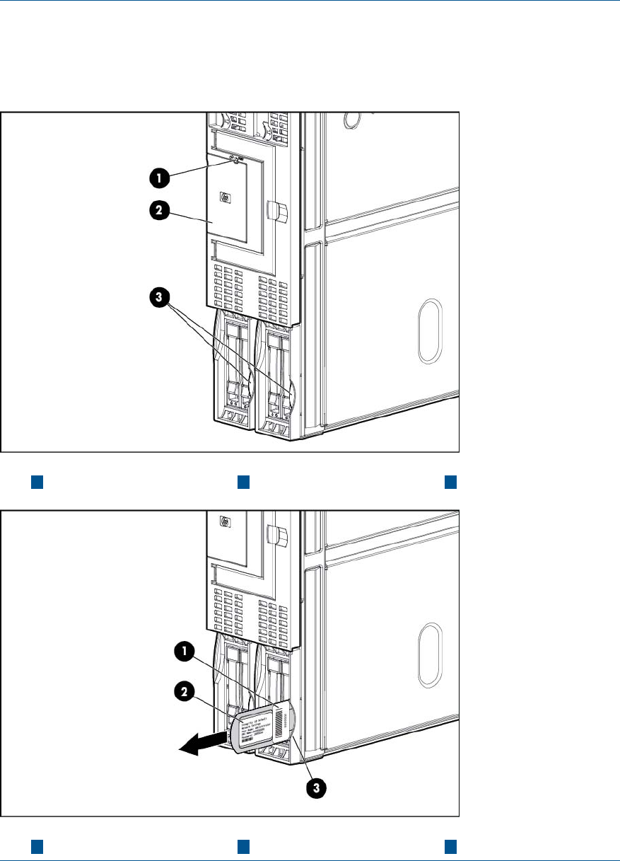
1. Log in with the proper username and password.
NOTE: the default login and password are:
login = Administrator
password = Randomly generated password found on the iLO 3 Network pull tab located on
the right side of the Monarch blade.
321 Pull tabLabel carrier doorBusy LED
321 Blade chassis endFactory tracking labelMP iLO 3 label
You are now at the MP Main Menu.
2. Enter cl to display the console history log. This log displays console history from oldest to
newest.
3. Enter Ctrl–B to return to the MP Main Menu.
Errors and error logs 103
4. Enter sl to display the status logs. The status logs consist of:
•System Event
•Forward Progress
•Current Boot
•Previous Boot
•Live Events
•Clear SELs
5. Enter Ctrl–B to return to the MP Main Menu.
SEL review
1. Access the iLO 3 MP command prompt.
2. Run the sl command. The Event Log Viewer menu displays:
[kauai20c] MFG! hpiLO-> sl
Event Log Viewer Menu:
Log Name Entries % Full Latest Timestamped Entry
---------------------------------------------------------------------------
E - System Event 206 40 % 04 Dec 2009 20:30:31
F - Forward Progress 4096 100 %
I - iLO Event 500 100 % 04 Dec 2009 20:50:57
C - Clear All Logs
L - Live Events
Enter menu item or [Ctrl-B] to Quit:
3. Select E to review the system events. The Event Log Navigation menu displays:
+ View next block (forward in time, e.g. from 3 to 4)
- View previous block (backward in time, e.g. from 3 to 2)
<CR> Continue to the next or previous block
D Dump the entire log
F First entry
L Last entry
J Jump to entry number
H View mode configuration - Hex
K View mode configuration - Keyword
T View mode configuration - Text
A Alert Level Filter options
U Alert Level Unfiltered
? Display this Help menu
Q Quit and return to the Event Log Viewer Menu
Ctrl-B Exit command, and return to the MP Main Menu
SL:hpiLO (+,-,<CR>,D,F,L,J,H,K,T,A,U,?,Q or Ctrl-B to Quit)->
# Location |Alert| Encoded Field | Data Field | Keyword/Timestamp
-------------------------------------------------------------------------------
10 ILO 1 2 408022E400E10012 0000000000000000 EXIT_MFG_MODE
07 Jan 2010 22:42:00
9 ILO 1 *3 6080253500E10010 0000000000000000 SYSVARS_MISMATCHED
07 Jan 2010 22:41:30
8 ILO 1 *3 608022E600E1000E 0000000000000000 ILO_SPECIAL_MODE
07 Jan 2010 22:41:27
7 ILO 1 2 408022E200E1000C 0000000000000000 ENTER_MFG_MODE
07 Jan 2010 22:41:27
6 ILO 1 2 408022AE00E1000A 0000000000000000 ILO_IS_BOOTING
07 Jan 2010 22:41:19
5 ILO 1 2 4080231200E10008 0000000000000000 FW_UPDATE_SUCCESS
07 Jan 2010 22:40:43
4 ILO 1 2 4080236800E10006 0000000000000000 FW_UPDATE_SIG_OVERRIDE
07 Jan 2010 22:33:05
104 Troubleshooting

3 ILO 1 2 4080230D00E10004 0000000000000000 FW_UPDATE_START
07 Jan 2010 22:31:23
2 ILO 1 2 408022E200E10002 0000000000000000 ENTER_MFG_MODE
4. Select a, then a threshold filter number to filter events to desired level.
MP:SL (+,-,<CR>,D, F, L, J, H, K, T, A, U, ? for Help, Q or Ctrl-B to Quit) >a
Alert Level Threshold Filter:
1 : Major Forward Progress
2 : Informational
3 : Warning
5 : Critical
7 : Fatal
Enter alert level threshold or [Q] to quit filter setup: 3
-> Alert threshold level 3 filter will be applied.
5. To decode the blinking state of a blade server LED, review the entire SEL and look at events
with alert level 2 and above.
Troubleshooting processors
Processor installation order
For a minimally loaded server blade, one processor must be installed in processor slot 0. Install a
processor of the same version into processor slot 1 (if purchased). See “ CPU and heatsink module”
(page 118) for more information on processor installation.
Processor module behaviors
All physical processors become functional after server power is applied.
Double-bit data cache errors in any physical processor core can cause a local MCA event, which
can have one of the following consequences:
•Can cause the entire system to crash.
•The failure is corrected and the processor is restarted.
•The failure is corrected, but the processor is disabled if it has experienced a local MCA before
within a certain time span.
Enclosure information
This installation document covers only the BL860c i2 server blade, and does not include any specific
server blade enclosure information. For server blade enclosure information, go to:
http://h71028.www7.hp.com/enterprise/cache/316735-0-0-0-121.html
Cooling subsystem
The server blade does not contain any fans. Cooling is handled by the enclosure.
Firmware
The server blade has two sets of firmware installed:
•Server blade firmware
•iLO 3 MP firmware
Identifying and troubleshooting firmware issues
Erratic server blade operation, or unsuccessful boot to the UEFI Boot Manager or UEFI Shell, are
symptoms of possible firmware issues.
NOTE: Firmware issues are relatively rare. Look for other problem causes first.
Troubleshooting processors 105

Probable firmware failure areas are:
•Unsupported firmware installation
•Corrupt firmware installation
To troubleshoot firmware issues:
1. Verify that all server blade firmware components are from the same release (use the MP
sysrev command).
2. Reinstall server blade firmware.
Verify and install the latest firmware
HP recommends that all firmware on all devices in your c-Class Ecosystem be updated to the latest
version anytime a new Integrity Server Blade or other hardware component is added.
To verify that you have the latest version of firmware for each component:
1. Go to http://www.hp.com.
2. Locate and click the Support & Drivers link on the main page.
3. Click the button next to Download drivers and software (and firmware).
4. Enter your product name (for example, BL860c i2) or number and click >>.
5. Choose the OS or Cross operating system (BIOS, Firmware, Diagnostics, etc.)
6. Refer to the Release Notes or Installation Instructions to verify the firmware version.
Troubleshooting the server interface (system console)
All system console connections (local RS-232 and iLO 3 MP LAN) are made through the port
connectors on the front of the server blade, through the SUV cable.
HP-UX uses the RS-232 serial text connection to a dumb terminal, or to terminal emulator software
running on a PC, to control server blade operations locally. All other connections are unsupported.
HP-UX alternatively uses the MP 10/100 BT LAN connection over a private network, to control
one or more server blade operations locally through telnet or SSH, or remotely over a public
network through a web GUI.
NOTE: RS-232 connection: If a dummy terminal/PC running terminal emulation software is
attached to the iLO 3 MP local port and does not respond to a Ctrl–B key sequence then it is
possible that the iLO 3 MP is not operational/functional.
Troubleshooting the environment
Ambient intake air temperature is often different from ambient room temperature; measure the
operating temperature and humidity directly in front of the cabinet cooling air intakes, rather than
measure only ambient room conditions.
Temperature sensors are found on:
•I/O baseboard, where the processors provide an integrated temperature sensor
•Status panel, where a thermal sensor detects the ambient room temperature. This sensor’s
reading is the main parameter used to regulate fan speed, under normal conditions.
106 Troubleshooting

Table 12 Server blade environmental specifications
Non-Operating RangeMaximum Rate of ChangeRecommended
Operating Range
Operating RangeParameter
-40°C to 60°C (-40°F
to 140°F)
10°C (50°F) / hr with
tape
20°C (68°F) / hr without
tape
20°C to 25°C (68°F
to 77°F) (up to 5000
feet)
5°C to 35°C (41°F to
95°F) (up to 5000 feet)
Temperature
90% at 65°C (149°F)
noncondensing
30% per hour
noncondensing
40-60% at 35 degrees
35°C (95°F)
noncondensing
15-80% at 35°C (95°F)
noncondensing
Relative Humidity
Troubleshooting the environment 107

7 Removing and replacing components
Server blade components list
NOTE: Part numbers are found by using the part nomenclature from this list to select the correct
part from HP Partsurfer (http://www.partsurfer.hp.com/search.aspx).
Table 13 CRU List
Spare Part NumberDescription with Part Number
Memory
AM326-690012 GB DDR3 PC3-10600R,128Mx8 memory (part number
500202-361)
AM327-690014 GB DDR3 PC3-10600R,256Mx4 memory (part number
591750-371)
AM328-690018 GB DDR3 PC3-10600R, 512Mx4 memory (part number
500205-371)
AM363-6900116GB PC3-8500R,512Mx4 memory (part number
500207-371)
Processors
AH339-6918AIntel Itanium Processor Quad Core 1.86GHz/24MB (DBS)
AH388A (Product) (part number AH339-2025A)
AH339-6917AIntel Itanium Processor Quad Core 1.73GHz/20MB (DBS)
AH387A (Product) (part number AH339-2024A)
AH339-6915AIntel Itanium Processor Quad Core 1.46GHz/16MB (No
DBS) AH386A (Product) (part number AH339-2022A)
AH339-6914AIntel Itanium Processor Dual Core 1.6GHz/12MB (No
DBS) AH385A (Product) (part number AH339-2021A)
612269-001CPU Heatsink1(part number 612269-001)
Internal Disks
507283-001HP 146GB 10K SAS 2.5" DP HDD (part number
507125-B21)
507284-001HP 300GB 10k SAS 2.5 HP DP HDD (part number
507127-B21)
512744-001HP 146GB 15k SAS 2.5" HP DP HDD (part number
512547-B21)
512743-001HP 72GB 15k SAS 2.5" HP DP HDD (part number
512545-B21)
581310-001HP 450GB 10k SAS 2.5" 6Gb HDD (part number
581285-B21)
581311-001HP 600GB 10k SAS 2.5" 6Gb HDD (part number
581287-B21)
653971-001HP 900GB 10k SAS 2.5" 6Gb HDD (part number
619291-B21)
632627-001HP 200GB SAS 2.5" SSD SLC Drive (part number
632492-B21)
632630-001HP 400GB SAS 2.5" SSD SLC Drive (part number
632494-B21)
108 Removing and replacing components

Table 13 CRU List (continued)
Boards and Cards
456978-001HP Dual Port 8Gbps Fibre Channel HBA Mezzanine Card
(Emulex) (part number 456972-B21)
455869-001HP Dual Port 8Gbps Fibre Channel HBA Mezzanine Card
(Q-Logic) (part number 451871-B21)
615316-001HP P700m PCIe Dual Port SAS HBA Mezzanine Card with
512MB Cache Memory (part number 508226-B21)
452348-B21Optional HP SA P-Series Low Profile Battery for SA P700m
card (part number 452348-B21)
519133-001HP 4x DDR Dual Port IB Mezzanine HCA Option Kit (part
number 492303-B21)
615318-001HP NC364m 4-port mezzanine adapter (part number
447883-B21)
445978-B21HP NC360m PCI Express Dual Port 1Gb (part number
445978-B21)
615317-001HP NCxxxm PCI Express Dual Port 10GbE (part number
467799-B21)
AD399-60013ICH Mezz Card with TPM (part number AD399-60013)
AD399-69014ICH Mezz Card without TPM (part number AD399-60014)
Blade Links
AD399-67002Blade Link - 1 blade (part number AD399-60002)
AD399-67003Blade Link - 2 blades (part number AD399-60003)
AD399-67006Blade Link- 4 blades, c7000 (part number AD399-60006
)
AD399-67007Blade Link- 4 blades, c3000 (part number AD399-60007
)
AD399-67010Blade Link - 2 Blades-E- c7000 (part number
AD399-60010)
AD399-67011Blade Link - 2 Blades-E-c3000 (part number AD399-60011)
Miscellaneous
AD399-2128BMemory Airflow Baffle (part number AD399-2128B)
AD399-2101BBlade Top Cover (part number AD399-2101B)
AD399-6901DBL860c i2 Base Unit (part number AD399-2001D)
AD399-67009SAS Disk backplane (part number AD399-60009)
234556-001NVRAM battery (part number 1420-0356)
AD399-2134AProcessor Airflow baffle (part number AD399-2134A)
Server blade components list 109

1The heatsink must be ordered along with the processor. You cannot replace a processor without also replacing the
heatsink.
Preparing the server blade for servicing
To service an internal server blade component, power off the server blade and remove it from the
server blade enclosure.
WARNING! Before proceeding with maintenance or service on a server blade that requires
physical contact with electrical or electronic components, be sure that power is removed or safety
precautions are followed to prevent electric shock and equipment damage. Observe all warning
and caution labels on equipment.
CAUTION: Electrostatic discharge can damage electronic components. Ensure you are properly
grounded before beginning an installation procedure. For more information, see the “ESD handling
information” (page 13).
Powering off the server blade
Before powering down the server blade for any upgrade or maintenance procedures, backup
critical server data and programs.
Use one of the following methods to power off the server blade:
NOTE: To power off blades in a conjoined configuration, only power off the Monarch blade.
•Use a virtual power button selection through iLO 3 (Power Management, Power & Reset).
This method initiates a controlled remote shutdown of applications and the OS before the
server blade enter standby mode.
•Press and release the Monarch power button.
This method initiates a controlled shutdown of applications and the OS before the server blade
enter standby mode.
•Press and hold the Monarch power button for more than 4 seconds to force the server blade
to enter standby mode.
This method forces the server blade to enter standby mode without properly exiting applications
and the OS. It provides an emergency shutdown in the event of a hung application.
Blade Link for BL870c i2 or BL890c i2 configurations
IMPORTANT: If you are replacing a faulty Blade Link, you must transfer the label with the blade
serial number from the failed Blade Link to the replacement.
Removing the Blade Link for BL870c i2 or BL890c i2 configurations
CAUTION: To prevent damage to the Blade Link, make sure that the activity light is off before
proceeding.
1. Power off the Monarch blade. (“Preparing the server blade for servicing”).
2. Push in the blue release latch on the handle to release it.
3. Pull the handle out to release the Blade Link.
4. Pull the Blade Link straight out, placing a free hand on the top right side of the bezel as you
pull to provide a counterbalance.
110 Removing and replacing components
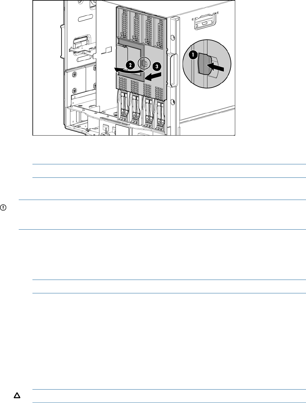
5. Place a plastic protector over the connector on the back of the Blade Link and place it in an
antistatic bag.
NOTE: Plastic protectors are only provided with replacement Blade Links.
Replacing the Blade Link for BL870c i2 or BL890c i2 configurations
IMPORTANT: If you are installing the Blade Link for the first time, see “Installing the Blade Link
for BL870c i2 or BL890c i2 configurations” (page 22) for more information regarding bay location
rules and other pre–installation requirements.
1. Log on to the OA.
2. Install the first blade into the lowest bay number, this blade becomes the Monarch blade
(“Installing the server blade into the enclosure”).
3. Wait 10 seconds. The IP address of the installed blade appears in the OA.
4. Insert each adjacent auxiliary blade, waiting 10 seconds between blades.
NOTE: The blades will go into stand-by
5. Using the OA, verify that the rest of the blades that will be conjoined have an IP address and
are powered off.
6. Remove the plastic protectors from the connectors on the back of the Blade Link.
7. Push in the blue release latch on the handle to release the handle.
8. Pull the handle all the way out
9. Align the guide pins on the back of the Blade Link to the holes on the front of the server blades.
As you insert the pins into the holes, ensure the face on the Blade Link is evenly aligned parallel
to the face of the server blades.
10. Press firmly on the left and right sides of the Blade Link face until the handle naturally starts to
close.
CAUTION: If not properly aligned, you can damage the Blade Link
11. Close the handle when it has engaged.
Preparing the server blade for servicing 111
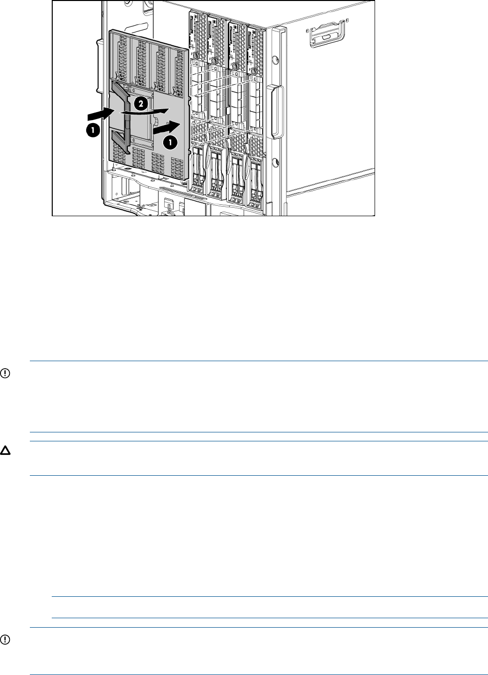
12. Log into iLO 3 on the Monarch blade. For more information, see the HP Integrity iLO3
Operations Guide.
13. In iLO 3, go to the Command Menu and execute xd -r to reboot all of the iLO 3s in the
conjoined set.
14. Still in the iLO 3 Command Menu, power on the Monarch blade with the PC -on -nc
command. Powering on the Monarch blade will power the entire conjoined system on.
15. Boot the Monarch blade. Booting the Monarch blade boots the entire conjoined system.
Blade Link for BL860c i2 configurations
IMPORTANT: Only remove a Blade Link from a BL860c i2 Server Blade in the following
circumstances:
•The Blade Link is faulty.
•You will be using the blade in a BL870c / BL890c i2 configuration.
CAUTION: To prevent damage to the Blade Link, make sure that the activity light is off before
proceeding.
1. Power off the server blade and remove it from the enclosure (“Preparing the server blade for
servicing”).
2. Place the blade on a flat, level, antistatic surface on its side, with the access panel facing up.
3. Squeeze the blue button on the side of the bezel.
4. While holding in the release button, pull the Blade Link off the blade while applying counter
pressure down on the blade to keep the blade from moving.
5. Place a plastic protector over the connector on the back of the Blade Link and place it in an
antistatic bag.
NOTE: Plastic protectors are only provided with replacement Blade Links.
IMPORTANT: If you are replacing a faulty Blade Link, take the label carrier card with the system
ID values out of the faulty Blade Link and place it inside the label carrier door of the new Blade
Link.
To replace the component, reverse the removal procedure.
112 Removing and replacing components
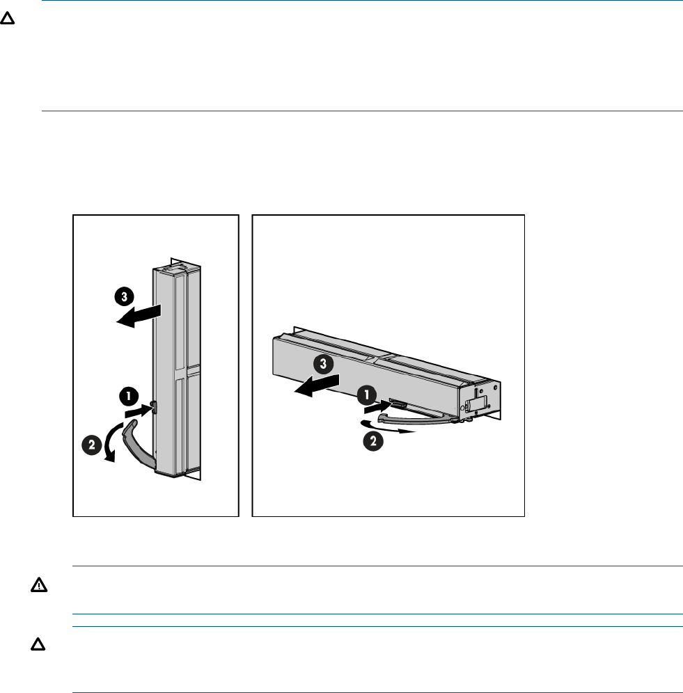
Server blade
CAUTION: After you press the release button, the server blade is unlocked from the enclosure.
Use both hands to support the server blade when you remove it from the rack. The server blade
weighs approximately 9 kg (20 lb).
CAUTION: The enclosure fans might still be running when the server blade is in standby mode.
Opening the lever removes all power from the server blade.
1. Power off the server blade. (“Powering off the server blade”)
2. If the blade is conjoined, then remove the Blade Link (“Removing the Blade Link for BL870c
i2 or BL890c i2 configurations”).
3. Remove the server blade.
4. Place the server blade on a flat, level, and antistatic surface.
WARNING! To reduce the risk of personal injury from hot surfaces, allow the drives and
the internal system components to cool before touching them.
CAUTION: Populate server blade enclosure bays with a server blade or server blade blank.
Operating the enclosure without a server blade or server blade blank causes improper airflow
and cooling which can lead to thermal damage.
To replace the component, reverse the removal procedure.
Access panel
The access panel is located on the right side of the server blade (when mounted in an enclosure).
1. Power off the server blade and remove it from the server blade enclosure. (“Preparing the
server blade for servicing”).
2. Lift the access panel latch.
3. Slide the access panel backwards approximately 2 cm (0.75 in).
4. Remove the access panel by lifting it straight up and off the server blade.
To replace the component, reverse the removal procedure.
Server blade 113
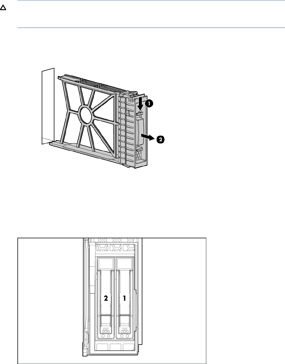
Disk drive blanks
The server blade has two disk drive bays. If you only purchased one hard disk, then your server
blade has a hard drive blank installed. Hard drive blanks maintain proper airflow throughout the
server blade.
CAUTION: Populate hard drive bays with a disk drive or a disk drive blank. Operating the server
blade without a disk drive or disk drive blank causes improper airflow and cooling, which can
lead to thermal damage.
Removing a disk drive blank
Remove the component as indicated:
To replace the hard drive blank, slide the blank into the bay until it locks into place. The hard drive
blank is keyed to fit only one way.
Disk drives
The BL860c i2 Server Blade has SAS disk drive slots on the BL860c i2 server blade. The SAS disk
drives have identical LEDs that display the drive status.
114 Removing and replacing components
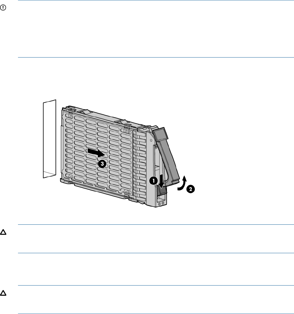
For the location of the SAS disk LEDs, see “SAS disk drive LEDs” (page 95).
To assess hard drive status, observe the SAS disk drive status LEDs. For an explanation of these
LEDs, see “Front panel LEDs” (page 93).
IMPORTANT: Before removing a SAS disk drive, perform a complete data backup.
If disk drive mirroring is enabled, you do not have to power off the server blade before removing
or replacing a SAS disk drive. If mirroring is not enabled, perform an OS shutdown before removing
a disk drive to protect data.
You are not required to remove the server blade from the enclosure to remove and replace a SAS
disk drive.
1. Press the release button.
2. Open the ejector lever.
3. Slide the disk drive out of the drive cage.
CAUTION: Populate hard drive bays with a SAS disk drive or a hard drive blank. Operating the
server blade without a SAS disk drive or disk drive blank causes improper airflow and cooling,
which can lead to thermal damage.
To replace the component, reverse the removal procedure.
DIMM baffle
CAUTION: To avoid damage to the server blade and the enclosure, install the DIMM baffle in
the proper location after adding or replacing DIMMs. DIMM baffles that are missing or installed
incorrectly can compromise server blade and enclosure cooling.
1. power off the server blade and remove it from the server blade enclosure (“Preparing the
server blade for servicing”).
2. Remove the access panel (“Access panel” (page 113)).
DIMM baffle 115
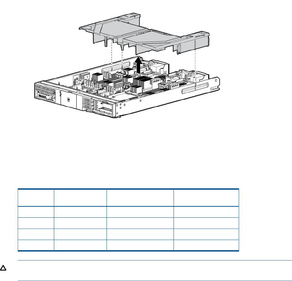
3. Pull the DIMM baffle straight up and out.
To replace the component, reverse the removal procedure.
DIMMs
The memory subsystem supports only DDR3 SDRAM technology using industry-standard 1.2” high
DIMMs.
BL890c i2 Min / Max
Memory size
BL870c i2 Min / Max
Memory size
BL860c i2 Min / Max
Memory size
Single DIMM
sizes
Not supportedNot supported8 GB / 48 GB2 GB
32 GB / 384 GB16 GB / 192 GB8 GB / 96 GB4 GB
32 GB / 768 GB32 GB / 384 GB16 GB / 192 GB8 GB
64 GB / 1.5 TB64 GB / 768 GB32 GB / 384 GB16 GB
CAUTION: When a single DIMM is removed it must either be replaced with a new matching
DIMM, or the DIMM load order must be adjusted.
1. Power off the server blade and remove it from the server blade enclosure (“Preparing the
server blade for servicing”).
2. Remove the access panel (“Access panel” (page 113)).
3. Locate the DIMM slots on the server blade system board (Step 2.
4. Remove the DIMM baffle (“DIMM baffle” (page 115)).
5. Open the DIMM slot latches.
116 Removing and replacing components
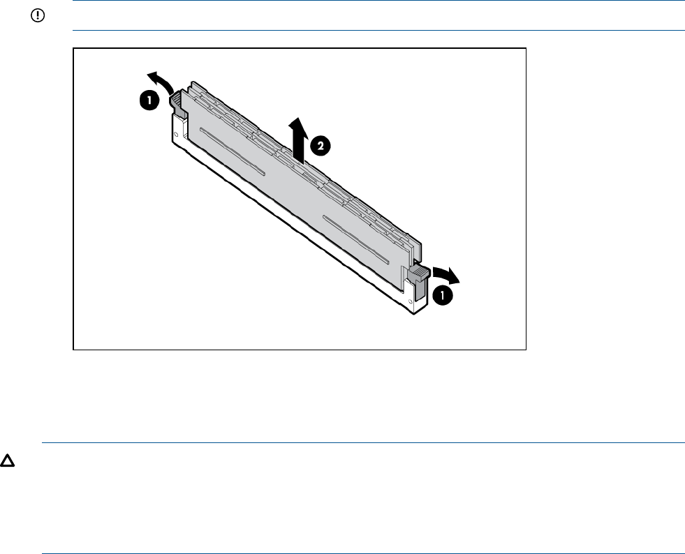
6. Remove the DIMM from the slot.
IMPORTANT: DIMMs do not seat fully if turned the wrong way.
To replace the component, reverse the removal procedure.
CPU baffle
CAUTION: To prevent damage to the server blade, never power on a server blade without a
CPU baffle or CPU in each CPU socket. The CPU baffle is needed for proper system cooling
CAUTION: Immediately install a CPU baffle in an empty CPU socket. To avoid damage to the
socket pins, the socket should never be uncovered for more than 5 seconds. If the socket is damaged,
the entire base blade must be replaced.
1. power off the server blade and remove it from the server blade enclosure (“Preparing the
server blade for servicing”).
2. Remove the access panel (“Access panel” (page 113)).
CPU baffle 117
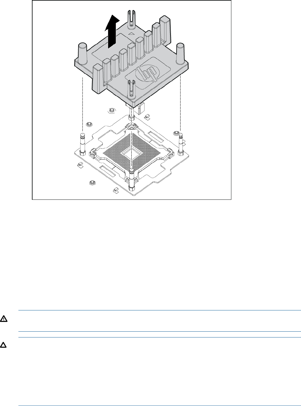
3. Pull the CPU baffle straight up and out.
To replace the component, reverse the removal procedure.
CPU and heatsink module
The BL860c i2 Server Blade contains a processor subsystem accommodating one or two Intel
Itanium processor modules.
Each processor module consists of the following:
•CPU chip, including CPU cores, QPI links for CPU-CPU and CPU-IO Hub chip connections,
and SMI links for CPU-Memory interface chip connections
•CPU power conversion module
•Heatsink, with mechanical attachment / assembly features
WARNING! To reduce the risk of personal injury from hot surfaces, allow the drives and the
internal system components to cool before touching them.
CAUTION: To prevent possible server malfunction, do not mix CPUs of different speeds or cache
sizes.
CAUTION: Removing a CPU will cause the DIMM loading rules to change. See “DIMMs”
(page 49) and use the loading rules for two CPUs. If you do not perform these procedures, then
any memory associated with the removed CPU will not be seen by the system.
CAUTION: To prevent thermal instability and damage to the server, do not separate the CPU
module from the heatsink.
1. Power off the server, and remove it from the enclosure (“Preparing the server blade for
servicing” (page 110)).
118 Removing and replacing components
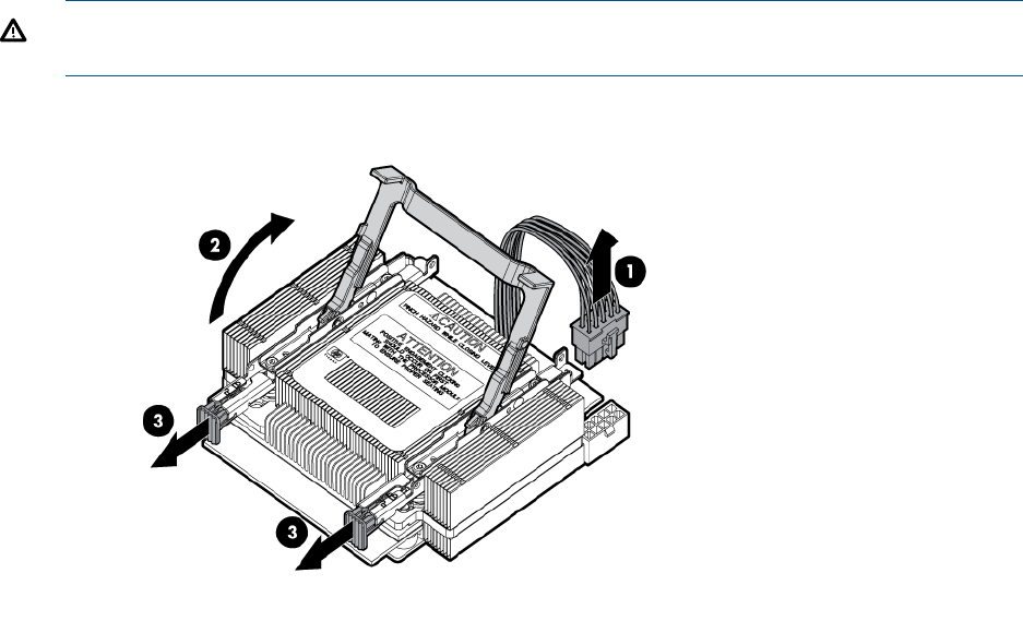
2. Remove the access panel (“Access panel” (page 113)).
3. Disconnect the power cord (see 1 below)
4. Rotate the CPU locking handle up and back until it reaches a hard stop (see 2 below)
WARNING! The heatsink locking lever can constitute a pinch hazard, keep your hands on
top of the lever during installation to avoid personal injury.
5. Pull both plastic tabs out (see 3 below).
6. Lift the CPU and heatsink off of the socket, pulling straight up.
CPU and heatsink module 119
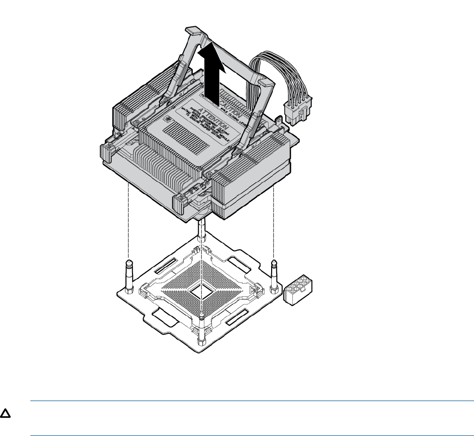
7. If the CPU is not being replaced, install a CPU baffle (“ CPU baffle” (page 117)).
CAUTION: To avoid damage to CPU socket pins and ensure proper system cooling, install
a CPU baffle in an empty CPU socket.
The replacement CPU module is shipped from HP without a heatsink. You will need to order and
attach a heatsink to the processor module before installing them for repair. See “Processor and
heatsink module” (page 44) for more information on the installation procedure.
120 Removing and replacing components
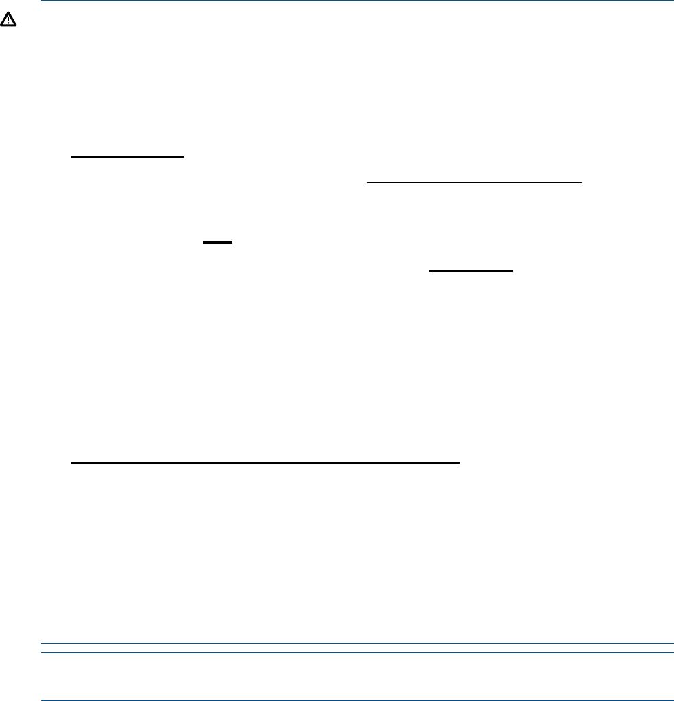
WARNING!
DO NOT SEPARATE THE HEATSINK FROM THE PROCESSOR MODULE.
Damage to the assembly will occur! Only Factory-Repair is authorized to separate assembly.
Return the assembly in the heatsink box using the processor's defective return label.
When the processor/heatsink assembly is removed from the server:
•Do NOT separate the heatsink from the processor.
•Place the intact processor/heatsink assembly, with the handle in the up position, into the extra
ESD bag provided in the heatsink box (if necessary re-use the ESD bag from the processor
box).
•To receive credit for both the processor and the heatsink:
◦Package the processor/heatsink assembly into the heatsink box.
◦Place the paper work originally shipped with the processor in the heatsink box.
◦Apply the processor defective return label to the heatsink box.
Global Customer Services and Support (GCSS) case coding recommendations:
•If the new processor/heatsink assembly is used – (solves the issue or is left in the server for
any reason) – return the defective assembly using the normal process; for example a part
failure code of 74, 75, etc…
•Once assembled, the parts cannot be returned as “Unused”.
In some scenarios assembled parts will not fix an issue, for example:
◦The new assembly is removed and the original is re-installed in the server.
◦The wrong speed processor or heatsink combination is assembled.
In these cases:
◦Use the defective label (B label) from the processor box and apply to the heatsink box.
◦Use a Parts Failure Code of “AI” on both parts.
NOTE: After replacing the processor and heatsink module use the cpuconfig from UEFI to
verify the that the processor socket has been reconfigured.
SAS backplane
The SAS disk backplane supports two small form factor hard disk drives. The backplane supports
hot-plugging a single SAS drive at a time. The activity LEDs and drive present LEDs are controlled
by a preprogrammed system-on-chip. The system board hosts the SAS controller and supplies 12
V, 5 V, and 3.3 V standby power to the backplane.
The SAS backplane is connected to the system board with a right angle connector. This connector
is specifically designed for high-speed differential applications, and supports server speeds
exceeding 5 Gigabits per second. Power, sense, and I2C signals are routed through this connector
as well as the SAS differential pairs and SGPIO signals.
1. Power off the server blade and remove it from the enclosure (“Preparing the server blade for
servicing”).
2. Remove the access panel (“Access panel” (page 113)).
SAS backplane 121
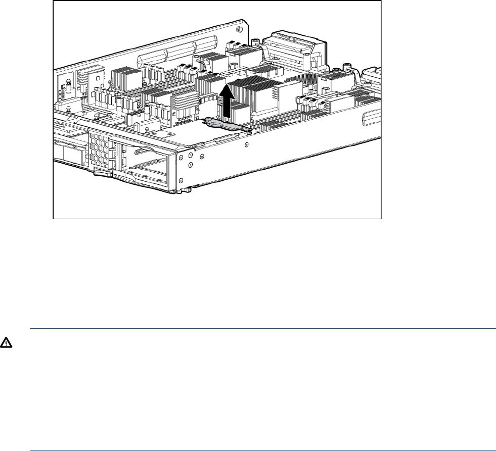
3. Remove the disk drives or disk drive blanks (“Disk drives” (page 114) or “Disk drive blanks”
(page 114)).
4. Lift the SAS back plane straight out of the server by the backplane handle.
To replace the component, reverse the removal procedure.
Server battery
If the server blade no longer automatically displays the correct date and time, you might have to
replace the battery that provides power to the real-time clock. Under normal use, battery life is 5
to 10 years.
WARNING! The computer contains an internal lithium manganese dioxide, a vanadium pentoxide,
or an alkaline battery pack. A risk of fire and burns exists if the battery pack is not properly handled.
To reduce the risk of personal injury:
•Do not attempt to recharge the battery.
•Do not expose the battery to temperatures higher than 60°C (140°F).
•Do not disassemble, crush, puncture, short external contacts, or dispose of in fire or water.
•Replace only with the spare designated for this product.
1. Power off the server and remove it from the enclosure (“Preparing the server blade for
servicing”).
2. Remove the access panel (“Access panel” (page 113)).
122 Removing and replacing components
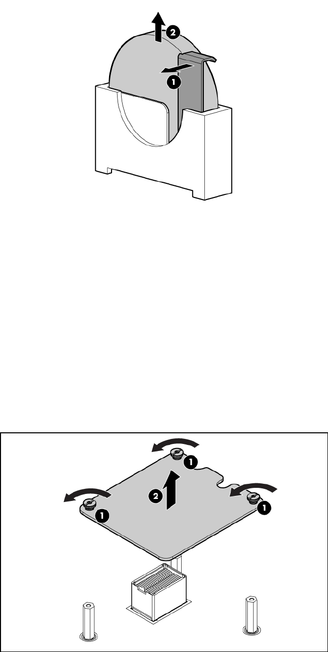
3. Remove the battery.
To replace the component, reverse the removal procedure.
Mezzanine cards
The I/O subsystem is composed of embedded core I/O and up to three mezzanine cards. The
server blade supports the following configurations:
•Up to three type I mezzanine cards using up to x8-PCIe Gen-2 links
•One type I and up to two type II mezzanine cards using up to x8-PCIe Gen-2 links
The server blade does not support PCI Hot Plug.
1. Power off the server and remove it from the enclosure (“Preparing the server blade for
servicing”).
2. Remove the access panel (“Access panel” (page 113)).
3. Remove the mezzanine card.
To replace the component, reverse the removal procedure.
Mezzanine cards 123
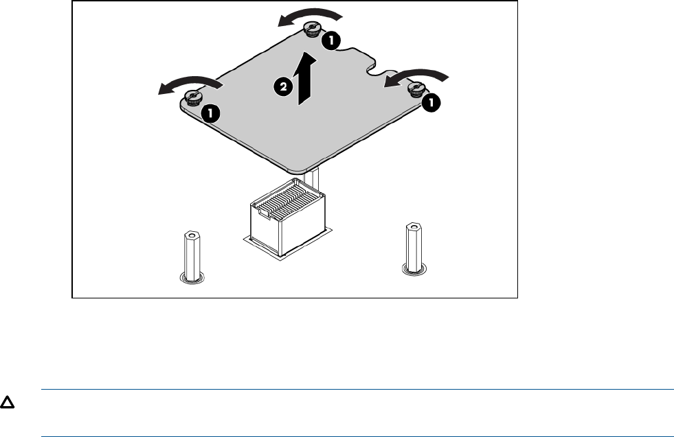
ICH mezzanine board
The ICH mezzanine card houses the following components:
•Intel ICH10 South Bridge
•ATI/AMD RN50/ES1000 Video Controller
•Embedded TPM 1.2
•Internal USB port — NOT SUPPORTED FOR USE
One ICH mezzanine board is required per system. The ICH mezzanine board is required in the
BL860c i2. In the BL870c i2 and BL890c i2, the ICH mezzanine board is only required in the
Monarch blade.
1. Power off the server and remove it from the enclosure (“Preparing the server blade for
servicing”).
2. Remove the access panel (“Access panel” (page 113)).
3. Remove the ICH mezzanine card:
To replace the component, reverse the removal procedure.
System board
CAUTION: To prevent damage to the system board, do not remove the system board from the
server blade.
In the event of a system board failure, both the system board and the server blade are replaced.
Before sending in the system board and server blade for replacement, remove the following
components:
•The processor and heatsink module (“ CPU and heatsink module” (page 118))
•The processor air baffle (“ CPU baffle” (page 117))
•The DIMMs (“DIMMs” (page 116))
•The DIMM baffle (“DIMM baffle” (page 115))
•The Smart Array battery (“Removing the BBWC battery” (page 61))
•The Mezzanine cards (“Mezzanine cards” (page 123))
124 Removing and replacing components
•The ICH mezzanine board (“ ICH mezzanine board” (page 124))
•The hard disk drives (“Disk drives” (page 114))
Remove these items from the replacement base unit and place them on the defective base unit for
protection during return shipment:
QuantityItem
2Protective processor covers
4Mezzanine covers
2Backplane connector covers
After replacing the system board and server blades:
IMPORTANT: Replacement server blades are shipped with the RAID controller in HBA mode by
default. If the server blade RAID controller was in RAID mode before replacement, you must change
the mode using the saupdate utility before booting the OS. See “Configuring a Smart Array
Controller” (page 133) for instructions on using the saupdate utility.
•Be sure that that the firmware on all conjoined blades matches (“Determining your current
firmware revisions” (page 68)).
•Be sure that the Stable storage info has transferred using the sysset command from the
MP/iLO 3 TUI (CLI).
Blade Link
Conjoining server blades using the Blade Link enables four (BL870c i2) and eight (BL890c i2)
socket server blade variants.
In a conjoined configuration, one of the BL860c i2 Server Blades becomes the master blade, also
referred to as the Monarch blade. The Monarch server blade is in the lowest numbered enclosure
bay, communication to the conjoined server blade is done through the Monarch blade.
Conjoined configurations can be upgraded after the initial installation, see “Upgrading a conjoined
configuration” (page 66) for more information on server blade upgrades.
Each Blade Link includes a trap door for the label carrier. To access the label carrier:
1. Locate the indentation on the upper-right corner of the access door.
Blade Link 125
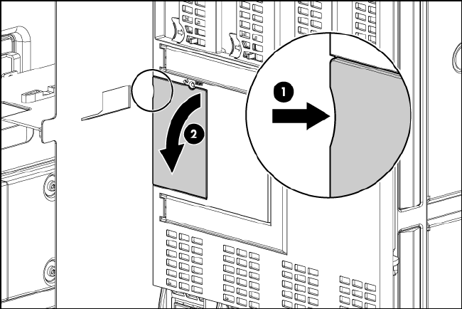

8 Support and other resources
Contacting HP
Before you contact HP
Be sure to have the following information available before you call contact HP:
•Technical support registration number (if applicable)
•Product serial number
•Product model name and number
•Product identification number
•Applicable error message
•Add-on boards or hardware
•Third-party hardware or software
•Operating system type and revision level
HP contact information
For the name of the nearest HP authorized reseller:
•In the United States, see the HP US service locator webpage (http://welcome.hp.com/country/
us/en/wwcontact.html.)
•In other locations, see the Contact HP worldwide (in English) webpage:
http://welcome.hp.com/country/us/en/wwcontact.html.
For HP technical support:
•In the United States, for contact options see the Contact HP United States webpage: (http://
welcome.hp.com/country/us/en/contact_us.html)
To contact HP by phone:
◦Call 1-800-HP-INVENT (1-800-474-6836). This service is available 24 hours a day, 7
days a week. For continuous quality improvement, calls may be recorded or monitored.
◦If you have purchased a Care Pack (service upgrade), call 1-800-633-3600. For more
information about Care Packs, refer to the HP website: (http://www.hp.com/hps).
•In other locations, see the Contact HP worldwide (in English) webpage (http://
welcome.hp.com/country/us/en/wwcontact.html)
Subscription service
HP recommends that you register your product at the Subscriber's Choice for Business website:
http://www.hp.com/country/us/en/contact_us.html.
Documentation feedback
HP welcomes your feedback. To make comments and suggestions about product documentation,
send a message to docsfeedback@hp.com.
Include the document title and manufacturing part number. All submissions become the property
of HP
Contacting HP 127

HP Insight Remote Support Software
HP strongly recommends that you install HP Insight Remote Support software to complete the
installation or upgrade of your product and to enable improved delivery of your HP Warranty, HP
Care Pack Service or HP contractual support agreement. HP Insight Remote Support supplements
your monitoring, 24x7 to ensure maximum system availability by providing intelligent event
diagnosis, and automatic, secure submission of hardware event notifications to HP, which will
initiate a fast and accurate resolution, based on your product’s service level. Notifications may be
sent to your authorized HP Channel Partner for on-site service, if configured and available in your
country. The software is available in two variants:
•HP Insight Remote Support Standard: This software supports server and storage devices and
is optimized for environments with 1-50 servers. Ideal for customers who can benefit from
proactive notification, but do not need proactive service delivery and integration with a
management platform.
•HP Insight Remote Support Advanced: This software provides comprehensive remote monitoring
and proactive service support for nearly all HP servers, storage, network, and SAN
environments, plus selected non-HP servers that have a support obligation with HP. It is
integrated with HP Systems Insight Manager. A dedicated server is recommended to host both
HP Systems Insight Manager and HP Insight Remote Support Advanced.
Details for both versions are available at:
http://www.hp.com/go/insightremotesupport
To download the software, go to Software Depot:
http://www.software.hp.com
Select Insight Remote Support from the menu on the right.
New and changed information in this edition
The following additions and changes have been made for this edition:
•The following information has been added:
◦Instructions for SAS tape boot in “Installing the OS from an external USB DVD device or
tape device” (page 30)
•The following information has been updated:
Supported partner blade configurations in “ Blade Link bay location rules” (page 23)◦
◦Supported partner blades and support for SAS tape boot in “Partner blades” (page 41)
◦Revised component descriptions in “Server blade components list” (page 108)
Typographic conventions
This document uses the following typographical conventions:
Command A command name or qualified command phrase.
Computer output Text displayed by the computer.
Ctrl-X A key sequence. A sequence such as Ctrl-X indicates that you
must hold down the key labeled Ctrl while you press another key
or mouse button.
ENVIRONMENT VARIABLE The name of an environment variable, for example, PATH.
ERROR NAME The name of an error, usually returned in the errno variable.
Key The name of a keyboard key. Return and Enter both refer to the
same key.
128 Support and other resources
User input Commands and other text that you type.
Variable The name of a placeholder in a command, function, or other
syntax display that you replace with an actual value.
WARNING A warning calls attention to important information that if not
understood or followed will result in personal injury or
nonrecoverable system issues.
CAUTION A caution calls attention to important information that if not
understood or followed will result in data loss, data corruption,
or damage to hardware or software.
IMPORTANT This alert provides essential information to explain a concept or
to complete a task
NOTE A note contains additional information to emphasize or supplement
important points of the main text.
Typographic conventions 129

Standard terms, abbreviations, and acronyms
A
ASIC Application-specific integrated circuit
Auxiliary Any blade in a conjoined server other than the lowest-numbered blade
B
BBRAM Battery-backed RAM
BBWC Battery Backed Write Cache
BCH Boot console handler
C
CE Customer engineer
CEC Core electronics complex
CMC Corrected machine check
CPE Corrected platform errors
CRU Customer replaceable unit
CSR Control status registers
D
DDNS Dynamic domain name system
DHCP Dynamic host configuration protocol
DLL Dynamic-link library
DMA Direct memory access
DMDC Data multiplexer/demultiplexer controller
DNS Domain name system
E
EFI Extensible Firmware Interface
See also UEFI.
EMS Event management service
ESD Electrostatic discharge
F
FC Fibre Channel
FPL Forward progress log
FRU Field replaceable unit
H
HBA Host bus adapter
HPSP HP service partition
I
iLO 3 Integrated Lights-Out
IPF Itanium processor family
130 Standard terms, abbreviations, and acronyms
L
LDAP Lightweight directory access protocol
LVM Logical volume manager
M
Monarch Designates a single-blade server, or lowest-numbered blade in a conjoined server
MP Management processor
MPS Maximum payload size
N
NIC Network interface card
NVRAM Non-Volatile RAM
O
OA Onboard Administrator
ORCA Option Rom Configuration for Arrays
P
PA-RISC Precision Architecture, Reduced Instruction Set Computing
PCA Printed circuit assembly
PCI Peripheral component interface
PCI-X Peripheral component interconnect extended
PCIe Peripheral component interconnect express
POL Point-of-load
POSSE Pre-OS system startup environment
POST Power-On Self-Test
Q
QPI Intel QuickPath Interconnect
S
SAL System abstraction layer
SAS Serial attached SCSI
SATA Serial ATA
SBA System bus adapter
SEL System event log
SFM System fault management
SGPIO Serial general purpose input/output
SMH System management homepage
SSH Secure Shell
STM Support Tool Manager
T
TLB Translation look-aside buffer
ToC Transfer of control
TPM Trusted platform module
131
TUI Text user interface
U
UART Universal asynchronous receiver-transmitter
UEFI Unified Extensible Firmware Interface, replaces EFI.
UID Unit identification
UPS Uninterruptible power supply
USB Universal serial bus
V
VCM Virtual Connect Manager
vMedia Virtual media
VRM Voltage regulator module
W
WBEM Web-Based enterprise management
132 Standard terms, abbreviations, and acronyms
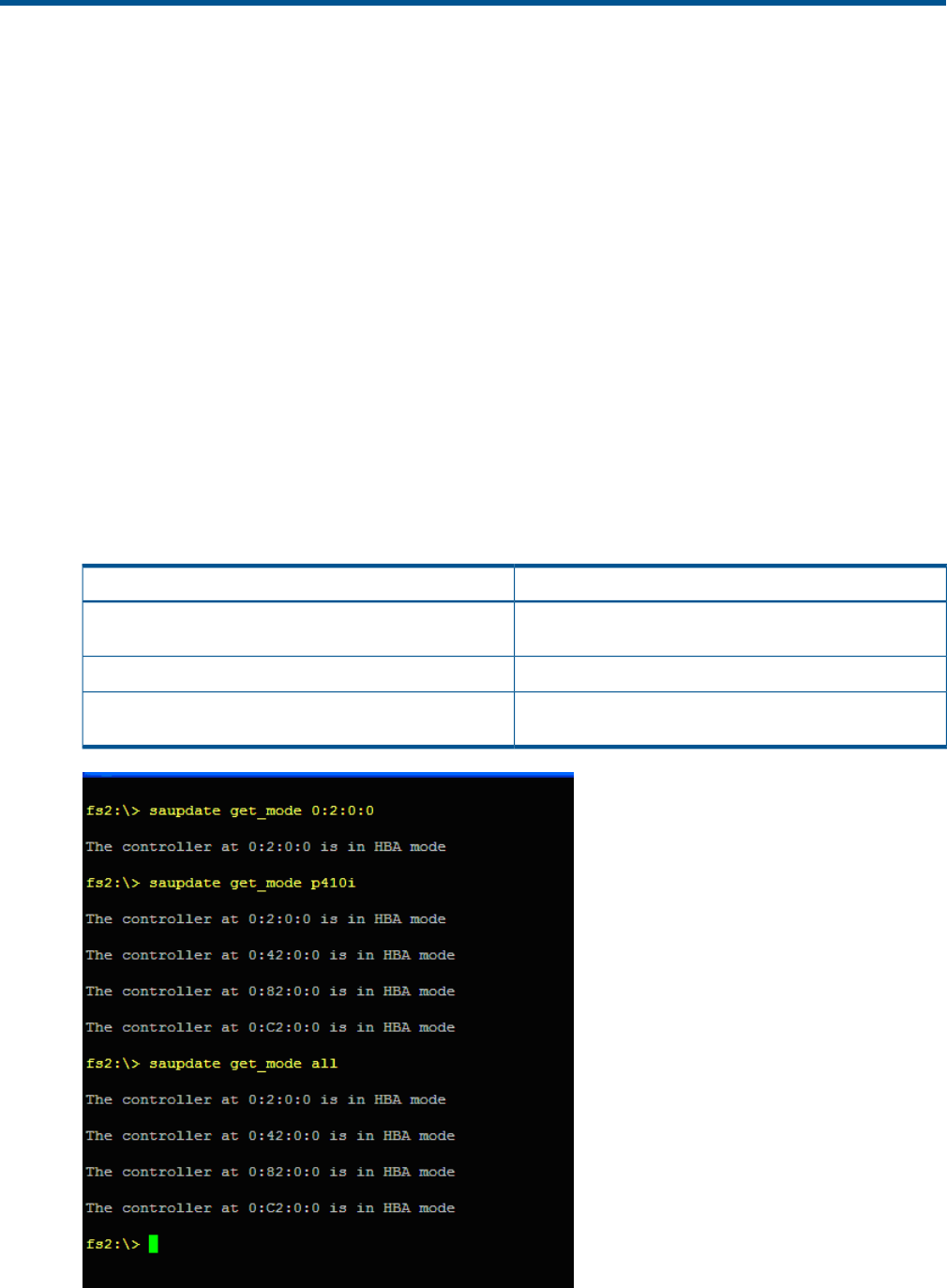
A Utilities
Configuring a Smart Array Controller
Using the saupdate command
The saupdate command is used to query or change the mode of the Smart Array P410i and
Smart Array P411 controllers to HBA or RAID. Querying or changing modes is not supported for
other controllers.
The following are the newly added commands to saupdate:
•get_mode
•set_mode
get_mode
This command displays the current mode of the controllers.
Syntax
saupdate get_mode <controller>
<controller> can be any one of the strings listed in Table 14.
Table 14 <controller> strings
Meaning
<controller>
A controller having the PCI segment id, bus id, device id
and function id is addressed
<seg:bus:dev:func>
Addresses all controllers in the systemall
Controllers of a particular type indicated by the <model>
string are addressed
<model>
Configuring a Smart Array Controller 133
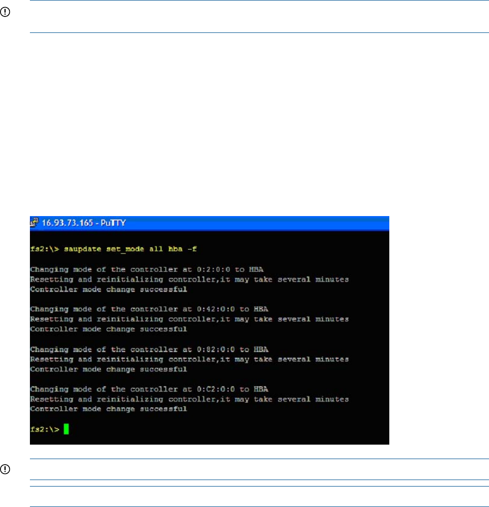
set_mode
IMPORTANT: If you are using HBA mode, do not install any disk that has previously been a part
of a RAID volume into the system.
Use set_mode to change the mode of the controller. If the controller is already in the required
mode the following message appears:
The controller at <seg:bus:dev:func> is already in HBA|RAID mode
Syntax
saupdate set_mode <controller> <hba|raid> [-f]
<controller> can be any one of the strings listed in Table 14 (page 133).
An alert message about the possible data loss is displayed when a mode change command is
issued. A confirmation is required before the actual mode change is made. This ensures unintentional
change of mode does not happen.
The –f option indicates the user is aware of the changes that are being made and there is not
need of a warning message or a confirmation regarding the mode change.
IMPORTANT: After changing the mode, perform a reconnect-r command at UEFI.
NOTE: Commands are not case-sensitive
Updating the firmware using saupdate
1. Download the firmware image file into the system's UEFI partition.
2. Boot the system to the UEFI Shell and change directories to the UEFI partition.
3. Use the saupdate list command to display all detected Smart Array controllers along
with the active firmware versions, the identification information from this list is used to designate
which controller is to be updated.
4. Use saupdate update <seg:bus:dev:func:index> <firmware image> to update
the firmware.
5. Restart the system.
Determining the Driver ID and CTRL ID
Use the drvcfg utility and UEFI shell commands to find the Driver ID corresponding Ctrl ID for the
SAS Host Bus Adapter.
134 Utilities
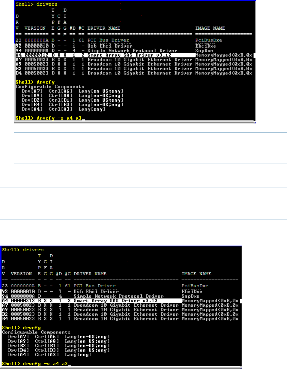
1. At the UEFI shell, use the drivers command.
2. Find the SAS Host Bus Adapter in the list of drivers, and make a note of the Driver ID from
the left column.
3. Use the drvcfg command.
4. Find the SAS Host Bus Adapter’s Driver ID in the list, and make a note of the corresponding
Ctrl ID.
NOTE: If the drivers listing shows Xunder CFG and DIAG, the drive is in RAID mode and
you can run drvcfg against it.
If the drivers listing shows -under CFG and DIAG, the drive is in HBA mode.
Configuring RAID volumes using the ORCA menu-driven interface
NOTE: The function keys cannot be used in ORCA if you are using a serial console. Substitute
ESC followed by the corresponding number key. For example, F3 would be Esc-3
NOTE: ORCA will not launch if there is no hard disk drive in the server blade.
From the UEFI Shell, enter drvcfg -s <Driver ID> <Ctrl ID>. To locate this information,
see “Determining the Driver ID and CTRL ID” (page 134).
The ORCA main menu will appear.
Configuring RAID volumes using the ORCA menu-driven interface 135
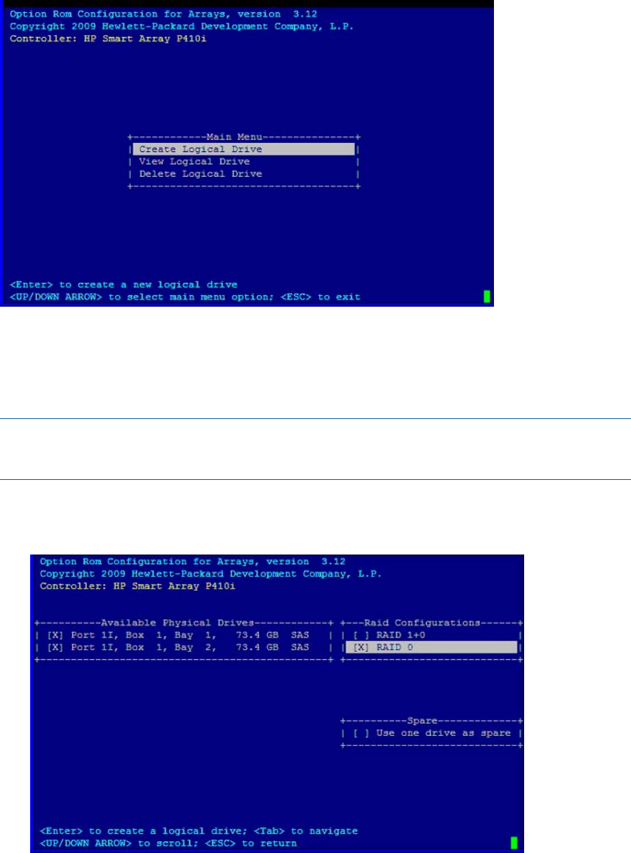
The ORCA main menu contains the following options:
•Create Logical Drive
•View Logical Drive
•Delete Logical Drive
NOTE: If you are configuring the HP Smart Array P700m/512 Controller or the HP StorageWorks
SB40c storage blade (P400 controller), then you can enter ORCA from POST by pressing the F8
key when prompted.
Creating a logical drive
1. At the ORCA main menu, select Create Logical Drive.
2. Select the physical disks to be included in the logical drive in the Available Physical Drives
section.
3. To select the Raid Configurations section and select the RAID type for the logical drive, press
Tab.
4. To select the Spare section and assign spare disks, as needed, press Tab.
5. To create the logical drive, press Enter. A summary of your choices appears.
136 Utilities
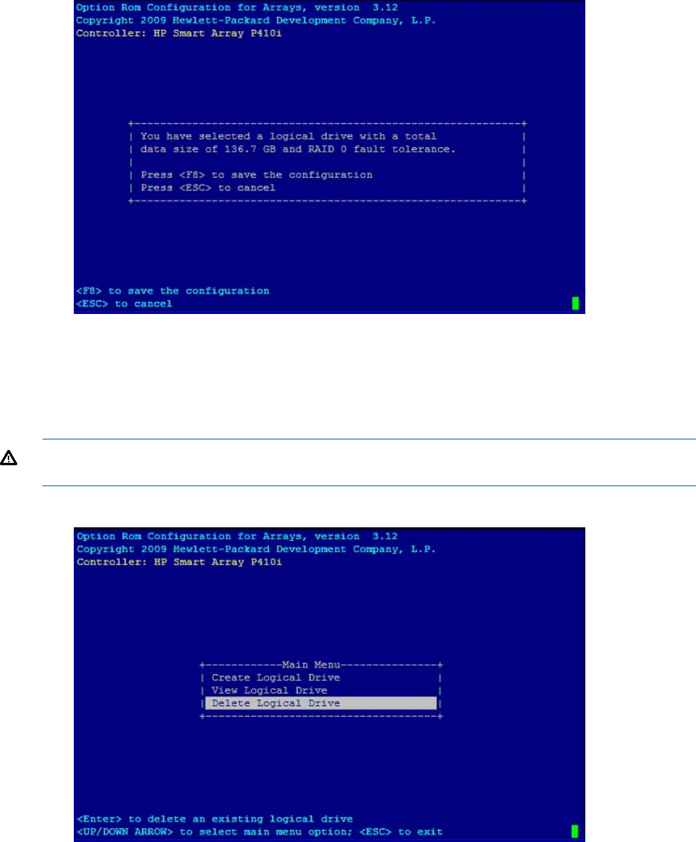
6. To save the configuration, press F8.
7. To acknowledge that the configuration was saved and return to the ORCA Main Menu, press
Enter.
Deleting a logical drive
WARNING! Back up all necessary data before deleting the logical drive. When you delete a
logical drive, data on the drive is not preserved.
1. At the ORCA main menu, select Delete Logical Drive.
2. Select a logical drive to be deleted.
Configuring RAID volumes using the ORCA menu-driven interface 137
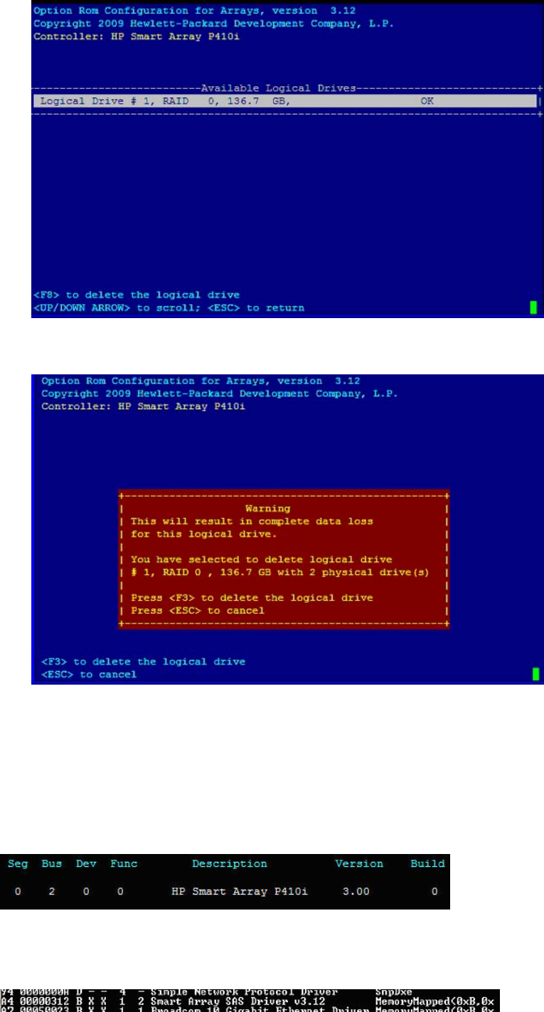
3. F3 to delete the logical drive.
4. To acknowledge that the configuration was saved and return to the ORCA Main Menu, press
Enter.
Useful UEFI command checks
saupdate.efi list
Use saupdate.efi list to list controller information such as the controller version.
drivers
Use drivers to find the driver version and DRV #.
138 Utilities

pci–i <path>
Use pci–i <path> to find vendor information.
UEFI
UEFI is an OS and platform-independent boot and preboot interface. UEFI resides between the OS
and platform firmware, allowing the OS to boot without having details about the underlying
hardware and firmware. UEFI supports boot devices, uses a flat memory model, and hides platform
and firmware details from the OS.
NOTE: Unified EFI Forum, Inc. defines the specification used to implement UEFI. POSSE is an HP
extension to UEFI, which provides a common user interface architecture to better serve HP customers,
service, and manufacturing.
UEFI consolidates boot utilities similar to those found in PA-RISC based servers, such as the BCH,
and platform firmware into a single platform firmware. UEFI allows the selection of any UEFI OS
loader from any boot medium that is supported by UEFI boot services. An UEFI OS loader supports
multiple options on the user interface.
UEFI supports booting from media that contain an UEFI OS loader or an UEFI-defined server
partition. An UEFI-defined system partition is required by UEFI to boot from a block device.
The UEFI boot manager loads UEFI applications (including the OS first stage loader) and UEFI
drivers from an UEFI-defined file system or image loading service. NVRAM variables point to the
file to be loaded. These variables contain application-specific data that is passed directly to the
UEFI application. UEFI variables provides system firmware a boot menu that points to all the
operating systems, even multiple versions of the same operating systems.
The UEFI boot manager allows you to control the server booting environment. Depending on how
you have configured the boot options, after the server is powered up the boot manager presents
you with different ways to bring up the server blade. For example, you can boot to the UEFI shell,
to an operating system located on the network or residing on media in the server, or the Boot
Maintenance Manager.
UEFI Shell and HP POSSE commands
For more information on these commands, enter help command at the UEFI Shell prompt.
Table 15 UEFI Shell Commands
DefinitionUEFI Shell Command
Displays the UEFI Shell command list or verbose command help?
Displays, creates, or deletes UEFI Shell aliasesalias
Displays or changes the attributes of files or directoriesattrib
Set/View autoboot timeout and retriesautoboot
Display/Modify the driver/boot configurationbcfg
Turn specific speedyboot bits on or offboottest
Displays or changes the current directorycd
Clears standard output and optionally changes background colorcls
Compares the contents of two filescomp
Configure consoles and set/view primary operating system consoleconconfig
Connects one or more UEFI drivers to a deviceconnect
UEFI 139

Table 15 UEFI Shell Commands (continued)
DefinitionUEFI Shell Command
Copies one or more files or directories to another locationcp
Deconfigure/Reconfigure processor sockets and threadscpuconfig
Displays or changes the current system datedate
Displays one or more blocks from a block devicedblk
Manage direct boot profilesdbprofile
Set default valuesdefault
Displays the list of devices managed by UEFI driversdevices
Displays the UEFI Driver Model compliant device treedevtree
Displays UEFI handle informationdh
Disconnects one or more UEFI drivers from a devicedisconnect
Displays the contents of memorydmem
Displays, saves, loads or deletes all UEFI NVRAM variablesdmpstore
Displays the UEFI driver listdrivers
Invokes the Driver Configuration Protocoldrvcfg
Invokes the Driver Diagnostics Protocoldrvdiag
Controls batch file command echoing or displays a messageecho
Full screen editor for ASCII or UNICODE filesedit
Compress a fileeficompress
Decompress a fileefidecompress
View/Clear logserrdump
Exits the UEFI Shell environmentexit
Executes commands for each item in a set of itemsfor
Perform FTP operationftp
Forces batch file execution to jump to specified locationgoto
Displays all registered UEFI GUIDsguid
Displays the UEFI Shell command list or verbose command helphelp
Full screen hex editorhexedit
Executes commands in specified conditionsif
Modify the default IP address of UEFI network stackifconfig
Display hardware informationinfo
Take user input and place in UEFI variableinput
Deconfigure/Reconfigure IO components or settingsioconfig
Display LAN deviceslanaddress
LAN bootlanboot
Loads and optionally connects one or more UEFI driversload
Loads a PCI Option ROMloadpcirom
140 Utilities

Table 15 UEFI Shell Commands (continued)
DefinitionUEFI Shell Command
Displays a list of files and subdirectories in a directoryls
Displays or defines mappingsmap
Set/View memory configuration settingsmemconfig
Displays the memory mapmemmap
Creates one or more directoriesmkdir
Displays or modifies MEM/MMIO/IO/PCI/PCIE address spacemm
Displays or changes the console output device modemode
Mounts a file system on a block devicemount
one or more files or directories to another locationmv
Displays the protocols and agents associated with a handleopeninfo
Make a PAL procedure callpalproc
Prints a message and waits for keyboard inputpause
Displays PCI device list or PCI function configuration spacepci
Ping a target machine with UEFI network stackping
Reconnects one or more UEFI drivers to a devicereconnect
Resets the systemreset
Deletes one or more files or directoriesrm
Make a SAL procedure callsalproc
View/configure system security featuressecconfig
Sets serial port attributessermode
Displays or modifies UEFI Shell environment variablesset
Set the size of a filesetsize
Shifts batch file input parameter positionsshift
Displays SMBIOS informationsmbiosview
Stalls the processor for the specified number of microsecondsstall
Boot from tapetapeboot
Perform TFTP operationtftp
Displays or changes the current system timetime
Displays or sets time zone informationtimezone
Updates filename timestamp with current system date and timetouch
Displays file contentstype
Unloads a UEFI driverunload
Displays UEFI Firmware version informationver
Displays or changes a file system volume labelvol
Turn on/off extended character featuresxchar
UEFI 141

Drive paths in UEFI
Devices in the server blade are represented by device paths in the UEFI shell. Each internal SAS
drive could be configured either as:
•RAID mode
•HBA (raw) mode
NOTE: A SAS drive in RAID mode is identified by "Scsi" in the device path A SAS drive in HBA
mode is identified by “SAS” in the device path.
NOTE: Unlike parallel SCSI, you cannot correlate UEFI device paths to internal SAS disk drive
bays with SAS regardless of RAID/HBA mode. The UEFI device paths currently do not contain any
information that could be used to determine the physical location of the drives.
Path examplePath formatDevice
PcieRoot(0x30304352)/Pci(0x2,0x0)/
Pci(0x0,0x0)/Scsi(0x0,0x0)
UIDPCIe root bridge device path
node
(RAID mode)
PcieRoot(0x30304352)/Pci(0x2,0x0)/Pci(0x0,0x0)
/SAS(0x5000C500037688B9,0x0,0x1,NoTopology,
0,0,0,0x0)
(HBA mode)
PcieRoot(0x30304352)/Pci(0x2,0x0)/Pci(0x0,0x0)/
Scsi(0x0,0x0)
/HD(1,GPT,27C34F01-9F1E-11DE-A0BB-AA000400FEFF)
HD
(Partition,Type,Signature)
Hard drive partition device
path
(RAID mode)
PcieRoot(0x30304352)/Pci(0x2,0x0)/Pci(0x0,0x0)/
SAS(0x5000C500037688B9,0x0,0x1,NoTopology,0,0,0,
0x0) )/HD
(1,GPT,27C34F01-9F1E-11DE-A0BB-AA000400FEFF)
(HBA mode)
PcieRoot(0x30304352)/Pci(0x1D,0x7)/
USB(0x3,0x0)/CDROM(0x1)
CDROM(Entry)CD-ROM / DVD-ROM
partition device path
NOTE: Everything after "Scsi" or "SAS" in the output can vary because each SAS drive/partition
is unique
Using the Boot Maintenance Manager
This menu allows you to change various boot options. The Boot Maintenance Manager Contains
the following submenus:
•Boot Options
•Driver Options
•Console Options
•Boot From File
•Set Boot Next Value
•Set Time Out Value
•Reset System
142 Utilities
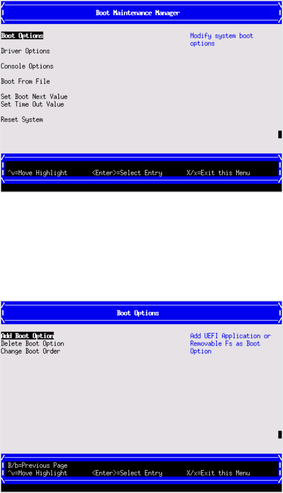
Boot Options
the Boot Options menu contains the following options:
•Add Boot Option
•Delete Boot Option
•Change Boot Order
Add Boot Option
Use this option to add items to the Boot Options list.
To add a boot option:
Using the Boot Maintenance Manager 143
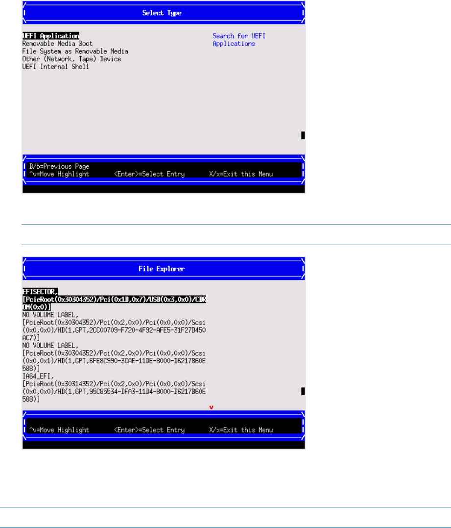
1. Select a boot device type.
2. Use the File Explorer menu to locate the correct boot device.
NOTE: File Explorer will load with the appropriate devices for the selected boot device.
Delete Boot Option
Use this option to remove boot options from the Boot Options list.
NOTE: This does not delete any files, applications or drivers from your server.
To remove items from the boot list:
144 Utilities
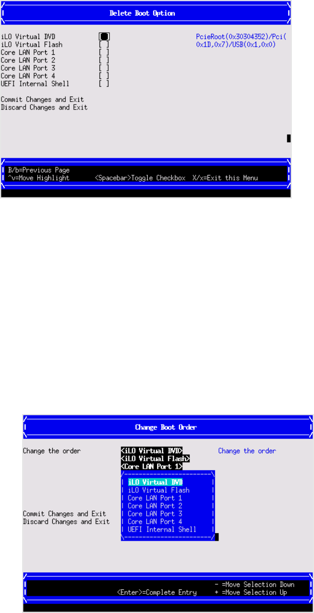
1. Press spacebar to toggle the checkbox for each boot options that you want to delete.
2. Select Commit Changes and Exit to save the new settings and return to the Boot Maintenance
Manager.
Change Boot Order
Use this option to change the order of boot options. If the first boot option fails, the server tries
booting the second, then the third, and so forth, until a boot option succeeds or until all options
have failed.
For example, if you normally boot using a configuration on your LAN but would like to boot from
a local hard drive if the LAN is unavailable, move the LAN boot option to the top of the list, followed
by the hard drive boot option.
To change the boot order:
1. Select an item on the boot order list.
2. Using the +and -keys, move the selection to the desired position in the book order list.
3. Press Enter when the item is in the desired position.
4. Select Commit Changes and Exit to save the new settings and return to the Boot Maintenance
Manager.
Using the Boot Maintenance Manager 145
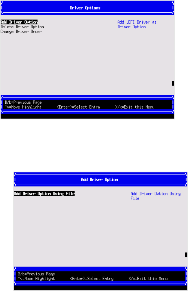
Driver Options
The Driver Options menu contains the following options:
•Add Driver Option
•Delete Driver Option
•Change Driver Order
Add Driver Option
Use this option to add driver options.
To add a driver option:
1. Select Add Driver Using File.
146 Utilities
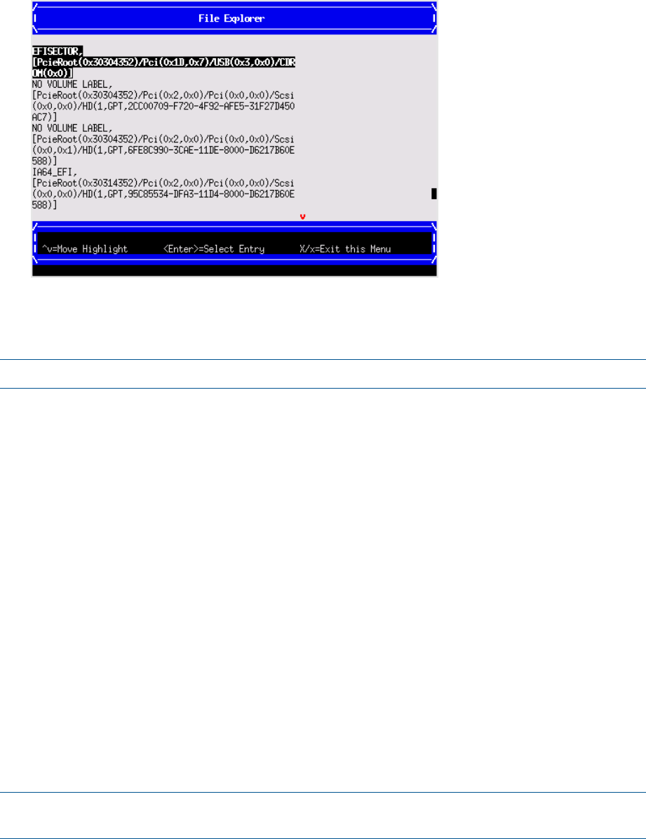
2. Use the File Explorer menu to locate the correct driver.
Delete Driver Option
Use this option to remove driver options.
NOTE: This does not delete any files, applications or drivers from your server.
To remove driver options:
1. Press spacebar to toggle the checkbox for each driver that you want to delete.
2. Select Commit Changes and Exit to save the new settings and return to the Boot Maintenance
Manager.
Change Driver Order
Use this option to change the load order of driver options.
To change the driver load order:
1. Select an item on the driver list.
2. Using the +and -keys, move the selection to the desired position in the book order list.
3. Press Enter when the item is in the desired position.
4. Select Commit Changes and Exit to save the new settings and return to the Boot Maintenance
Manager.
Console Options
The Console Options menu is not currently supported. Use the conconfig command from the
UEFI Shell to set console options.
Boot From File
Use this option to manually run a specific application or driver.
NOTE: This option boots the selected application or driver one time only. When you exit the
application, you return to this menu.
Using the Boot Maintenance Manager 147
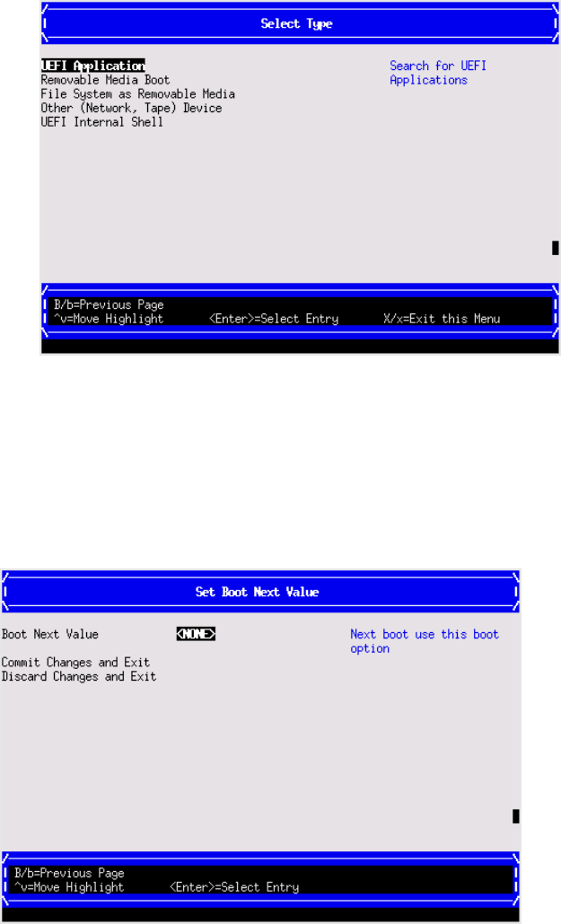
1. Select a boot device type.
2. Use the File Explorer menu to locate the correct driver or file.
Set Boot Next Value
Use this option to run the selected boot option immediately upon entering the main Boot Manager
menu. This option is useful for booting an option that only needs to be booted once, without
changing any other setting in the main Boot Manager menu. This is a one-time operation and does
not change the permanent server boot settings.
Set Time Out Value
Use this option to set the amount of time the server pauses before attempting to launch the first item
in the Boot Options list.
Interrupting the timeout during the countdown stops the Boot Manager from loading any boot
options automatically. If there is no countdown, boot options must be selected manually.
To set the auto boot timeout value, in seconds, select Set Timeout Value and enter the desired
value.
148 Utilities
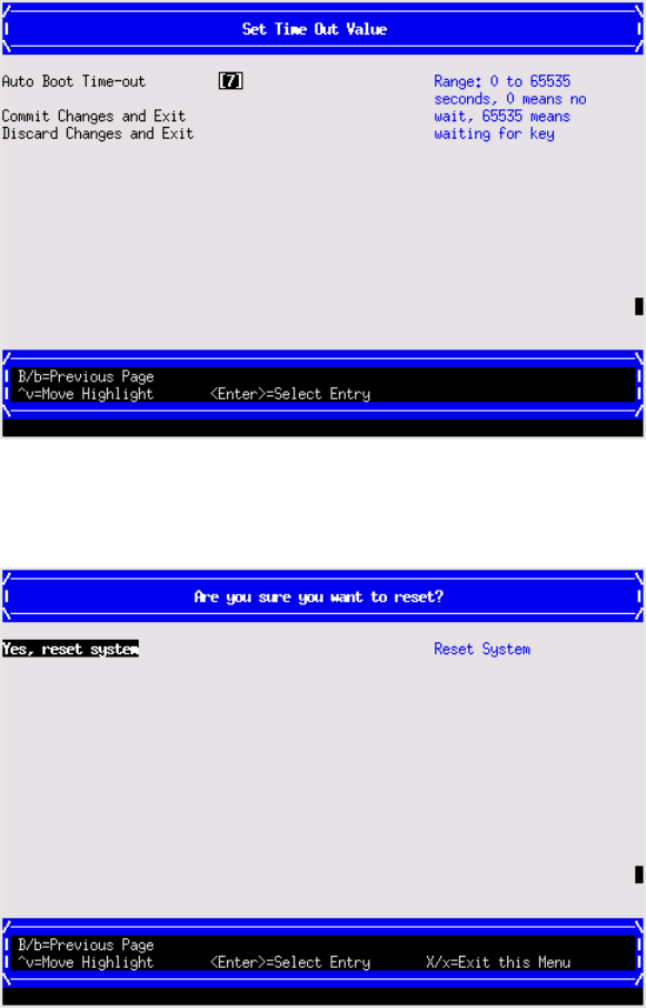
Reset System
Use this option to perform a system reset.
iLO 3 MP
The iLO 3 MP is an independent support system for the server. It provides a way for you to connect
to a server and perform administration or monitoring tasks for the server hardware.
The iLO 3 MP controls power, reset, ToC capabilities, provides console access, displays and
records system events, and displays detailed information about the various internal subsystems.
The iLO 3 MP also provides a virtual front panel used to monitor server status and the state of front
panel LEDs. All iLO 3 MP functions are available through the LAN and the local RS-232 port.
The iLO 3 MP is available whenever the server is connected to a power source, even if the server
main power switch is off.
Access to the iLO 3 MP can be restricted by user accounts. User accounts are password protected
and provide a specific level of access to the server and MP commands.
For more information regarding the iLO 3 MP, see the HP Integrity iLO 3 Operations Guide.
iLO 3 MP 149

Index
A
access panel
removing, 113
replacing, 65, 113
adding Windows to the boot options list, 37
antistatic wrist strap, 13
autoboot, 32
B
battery mounting bracket
parts, 54
Blade Link, 125
installing, 22
LEDs, 96
removing, 110
replacing, 111
boot option
add, 143
change boot order, 145
delete, 144
Set Boot Next Value, 148
boot option maintenance manager menu, 142
boot options list, 32
add HP-UX, 32
adding Windows, 37
booting
from file, 147
HP-UX (LVM maintenance mode), 34
HP-UX (UEFI boot manager), 33
HP-UX (UEFI Shell), 34
HP-UX in single-server mode, 34
OpenVMS, 36
OpenVMS (UEFI boot manager), 36
UEFI boot manager, 139
Windows, 39
C
c-Class enclosure see enclosure
checking the inventory, 14
commands
saupdate, 133
component locations, 9
configure system boot options, 32
configuring system boot options, 32
confirming the packing slip, 14
cooling subsystem, 105
CPU
removing, 118
customer replaceable unit (CRU), 108
D
damaged equipment, 14
diagnostics, 100
general diagnostic tools, 100
IPMI event decoder, 100
MCA analyzer, 100
offline, 100
dimensions of server blade, 10
DIMM baffle
removing, 115
replacing, 115
DIMMs
installation guidelines, 49
load order, 49
overview, 116
removing, 116
slot locations, 51, 116
disk drive backplane see SAS backplane
disk drive blank
removing, 114
replacing, 114
disk drives
removing, 115
drive paths, 142
driver option
add, 146
delete, 147
driver boot order, 147
drvcfg
CTRL ID, 134
Driver ID, 134
E
EFI see UEFI
enclosure, 10, 11, 105
general information, 10
interconnect mapping, 19
interconnect modules, 18
LAN ports, 18
error logs, 101–105
F
fault management, 101
field replaceable unit (FRU), 108
firmware
install, 106
MP, 105
OA, 69
server blade, 68
troubleshooting, 105
updates, 29
upgrades, 68
VCM, 71
verify, 106
forward progress log, 101
front panel
LEDs, 93
port, 92
H
hard disk drive see SAS disk drive
150 Index
HDD see SAS disk drive
HDD backplane see SAS backplane
heatsink module
installing, 44
removing, 118
HP Smart Array P700m/512 Controller, 53, 62
512MB cache module
removal, 60
replacment, 56
battery kit, 53
battery mounting bracket, 54
removal, 60
replacment, 57
BBWC battery
removal, 61
replacment, 58
controller board
installation, 55
HP Smart Update Manager, 29
HP-UX
booting in LVM maintenance mode, 34
booting in single-user mode, 34
Fault Management, 101
shutting down, 34
standard boot, 33
HP-UX Ignite, 29
HPSUM see HP Smart Update Manager
I
I/O subsystem, 123
ICH Mezzanine board
removing, 124
replacing, 124
iLO 3 MP, 149
accessing UEFI from, 26
event log, 102
inspecting the shipping container, 14
installation order
processors, 105
installing
Blade Link, 22
heatsink module, 44
operating system with Ignite-UX, 31
operating system with vMedia, 31
processor, 44
SAS backplane, 121
SAS disk drives, 42
server battery, 122
server blade into enclosure, 15, 20
installing components, 43
integrated Lights-Out Management Processor see iLO 3
MP
L
LEDs
front panel, 93, 95, 96
SAS disk drive, 95
load order
processors, 105
Logical drive
creating, 136
deleting, 137
M
MAC addresses
Portable Image, 84
Management Processor see iLO 3 MP
memory see DIMMs
N
NICs
locations on enclosure, 19
NVRAM configuration utility, 28
O
OpenVMS
booting (UEFI boot manager), 36
shutting down, 37
operating system
installation, 30
installing with Ignite-UX, 31
installing with vMedia, 31
supported, 30
ORCA, 135, 136, 137, 138
P
PI
Post-upgrade, 85
Pre-upgrade, 85
point-of-load voltage rails
specifications, 13
ports
front panel, 92
rear panel, 93
power button, 22, 110
power subsystem
specifications, 13
powering off, server blade, 22, 110
powering on
default, automatically, 21, 22
server blade, 21, 22
processor
installing, 44
load order, 105
R
RAID, 136, 137
configuration, 135
using ORCA, 135
rear panel
ports, 93
removing
access panel, 43
Blade Link, 110
CPU, 118
DIMM baffle, 115
DIMMs, 116
disk drive blank, 114
151
ICH Mezzanine board, 124
replacing, 111
SAS backplane, 121
SAS disk drive, 115
server battery, 122
server blade access panel, 113
server blade from enclosure, 113
replacing
access panel, 65
DIMM baffle, 115
disk drive blank, 114
ICH Mezzanine board, 124
removing, 118
SAS backplane, 121
server battery, 122
server blade access panel, 113
returning a damaged server blade, 14
S
safety information, 13
SAS backplane
removing, 121
replacing, 121
SAS disk drives
LEDs, 95
mirroring, 115
removing, 115
slot locations, 114
saupdate,133, 134
firmware updates, 134
get_mode,133
set_mode,134
server battery
removing, 122
replacing, 122
server blade
,22
access panel, 43, 65
components, 9
dimensions, 10
enclosure interconnect mapping, 19
front view, 92
LEDs, 95
overview, 8
powering off, 110
powering on, 21, 22
rear panel connectors, 93
rear view, 93
removing access panel, 113
removing from enclosure, 113
replacing the access panel, 113
returning a damaged server blade, 14
servicing, 110
unpacking, 14
weight, 10
servicing the server blade, 110
shipping damage, 14
shutting down
HP-UX, 34
OpenVMS, 37
Windows, 39
Windows from the command line, 40
site inspection checklist, 11
site preparation, 14
slot locations
DIMMs, 116
SAS disk drives, 114
Smart Array, 138
P700m/512 Controller, 53, 62
Smart Array Controller
firmware updates, 134
saupdate,133
status log, 104
support tools
offline, 100
SUV cable, 99
SUV cable port, 92
system boot options, 32
system event log, 87, 101, 104
T
troubleshooting
basic, 88
environment, 106
methodology, 88
MP firmware, 105
overview, 87
processors, 105
system console, 106
U
UEFI
accessing from iLO 3 MP, 26
commands, 138, 139
drive paths, 142
Front Page, 27
saving configuration settings, 28
Unified Extensible Firmware Interface see UEFI
unpacking the server blade, 14
upgrades, 66, 73
adding resources, 73
firmware, 68
firmware versions, 68
kit contents, 66
licenses, 81
OS reinstall, 82
procedure summary, 66
support, 80
supported operating systems, 67
warranty registration, 79
V
virtual power button, 22, 110
vMedia, 31
W
weight of server blade, 10
Windows
152 Index

Index
A
access panel
removing, 113
replacing, 65, 113
adding Windows to the boot options list, 37
antistatic wrist strap, 13
autoboot, 32
B
battery mounting bracket
parts, 54
Blade Link, 125
installing, 22
LEDs, 96
removing, 110
replacing, 111
boot option
add, 143
change boot order, 145
delete, 144
Set Boot Next Value, 148
boot option maintenance manager menu, 142
boot options list, 32
add HP-UX, 32
adding Windows, 37
booting
from file, 147
HP-UX (LVM maintenance mode), 34
HP-UX (UEFI boot manager), 33
HP-UX (UEFI Shell), 34
HP-UX in single-server mode, 34
OpenVMS, 36
OpenVMS (UEFI boot manager), 36
UEFI boot manager, 139
Windows, 39
C
c-Class enclosure see enclosure
checking the inventory, 14
commands
saupdate, 133
component locations, 9
configure system boot options, 32
configuring system boot options, 32
confirming the packing slip, 14
cooling subsystem, 105
CPU
removing, 118
customer replaceable unit (CRU), 108
D
damaged equipment, 14
diagnostics, 100
general diagnostic tools, 100
IPMI event decoder, 100
MCA analyzer, 100
offline, 100
dimensions of server blade, 10
DIMM baffle
removing, 115
replacing, 115
DIMMs
installation guidelines, 49
load order, 49
overview, 116
removing, 116
slot locations, 51, 116
disk drive backplane see SAS backplane
disk drive blank
removing, 114
replacing, 114
disk drives
removing, 115
drive paths, 142
driver option
add, 146
delete, 147
driver boot order, 147
drvcfg
CTRL ID, 134
Driver ID, 134
E
EFI see UEFI
enclosure, 10, 11, 105
general information, 10
interconnect mapping, 19
interconnect modules, 18
LAN ports, 18
error logs, 101–105
F
fault management, 101
field replaceable unit (FRU), 108
firmware
install, 106
MP, 105
OA, 69
server blade, 68
troubleshooting, 105
updates, 29
upgrades, 68
VCM, 71
verify, 106
forward progress log, 101
front panel
LEDs, 93
port, 92
H
hard disk drive see SAS disk drive
154 Index
HDD see SAS disk drive
HDD backplane see SAS backplane
heatsink module
installing, 44
removing, 118
HP Smart Array P700m/512 Controller, 53, 62
512MB cache module
removal, 60
replacment, 56
battery kit, 53
battery mounting bracket, 54
removal, 60
replacment, 57
BBWC battery
removal, 61
replacment, 58
controller board
installation, 55
HP Smart Update Manager, 29
HP-UX
booting in LVM maintenance mode, 34
booting in single-user mode, 34
Fault Management, 101
shutting down, 34
standard boot, 33
HP-UX Ignite, 29
HPSUM see HP Smart Update Manager
I
I/O subsystem, 123
ICH Mezzanine board
removing, 124
replacing, 124
iLO 3 MP, 149
accessing UEFI from, 26
event log, 102
inspecting the shipping container, 14
installation order
processors, 105
installing
Blade Link, 22
heatsink module, 44
operating system with Ignite-UX, 31
operating system with vMedia, 31
processor, 44
SAS backplane, 121
SAS disk drives, 42
server battery, 122
server blade into enclosure, 15, 20
installing components, 43
integrated Lights-Out Management Processor see iLO 3
MP
L
LEDs
front panel, 93, 95, 96
SAS disk drive, 95
load order
processors, 105
Logical drive
creating, 136
deleting, 137
M
MAC addresses
Portable Image, 84
Management Processor see iLO 3 MP
memory see DIMMs
N
NICs
locations on enclosure, 19
NVRAM configuration utility, 28
O
OpenVMS
booting (UEFI boot manager), 36
shutting down, 37
operating system
installation, 30
installing with Ignite-UX, 31
installing with vMedia, 31
supported, 30
ORCA, 135, 136, 137, 138
P
PI
Post-upgrade, 85
Pre-upgrade, 85
point-of-load voltage rails
specifications, 13
ports
front panel, 92
rear panel, 93
power button, 22, 110
power subsystem
specifications, 13
powering off, server blade, 22, 110
powering on
default, automatically, 21, 22
server blade, 21, 22
processor
installing, 44
load order, 105
R
RAID, 136, 137
configuration, 135
using ORCA, 135
rear panel
ports, 93
removing
access panel, 43
Blade Link, 110
CPU, 118
DIMM baffle, 115
DIMMs, 116
disk drive blank, 114
155
ICH Mezzanine board, 124
replacing, 111
SAS backplane, 121
SAS disk drive, 115
server battery, 122
server blade access panel, 113
server blade from enclosure, 113
replacing
access panel, 65
DIMM baffle, 115
disk drive blank, 114
ICH Mezzanine board, 124
removing, 118
SAS backplane, 121
server battery, 122
server blade access panel, 113
returning a damaged server blade, 14
S
safety information, 13
SAS backplane
removing, 121
replacing, 121
SAS disk drives
LEDs, 95
mirroring, 115
removing, 115
slot locations, 114
saupdate,133, 134
firmware updates, 134
get_mode,133
set_mode,134
server battery
removing, 122
replacing, 122
server blade
,22
access panel, 43, 65
components, 9
dimensions, 10
enclosure interconnect mapping, 19
front view, 92
LEDs, 95
overview, 8
powering off, 110
powering on, 21, 22
rear panel connectors, 93
rear view, 93
removing access panel, 113
removing from enclosure, 113
replacing the access panel, 113
returning a damaged server blade, 14
servicing, 110
unpacking, 14
weight, 10
servicing the server blade, 110
shipping damage, 14
shutting down
HP-UX, 34
OpenVMS, 37
Windows, 39
Windows from the command line, 40
site inspection checklist, 11
site preparation, 14
slot locations
DIMMs, 116
SAS disk drives, 114
Smart Array, 138
P700m/512 Controller, 53, 62
Smart Array Controller
firmware updates, 134
saupdate,133
status log, 104
support tools
offline, 100
SUV cable, 99
SUV cable port, 92
system boot options, 32
system event log, 87, 101, 104
T
troubleshooting
basic, 88
environment, 106
methodology, 88
MP firmware, 105
overview, 87
processors, 105
system console, 106
U
UEFI
accessing from iLO 3 MP, 26
commands, 138, 139
drive paths, 142
Front Page, 27
saving configuration settings, 28
Unified Extensible Firmware Interface see UEFI
unpacking the server blade, 14
upgrades, 66, 73
adding resources, 73
firmware, 68
firmware versions, 68
kit contents, 66
licenses, 81
OS reinstall, 82
procedure summary, 66
support, 80
supported operating systems, 67
warranty registration, 79
V
virtual power button, 22, 110
vMedia, 31
W
weight of server blade, 10
Windows
156 Index
