Hp Server Tc2110 Installation Sheet Install ShtA
2015-03-28
: Hp Hp-Server-Tc2110-Installation-Sheet-669534 hp-server-tc2110-installation-sheet-669534 hp pdf
Open the PDF directly: View PDF ![]() .
.
Page Count: 4
Setting Up the HP Server
HP Server
Installation Sheet
Notice
))))
tc2110
The information contained in this document is subject to change
without notice.
Hewlett-Packard makes no warranty of any kind with regard to this
material, including, but not limited to, the implied warranties of
merchantability and fitness for a particular purpose.
Hewlett-Packard shall not be liable for errors contained herein or for
incidental or consequential damages in connection with the
furnishing, performance, or use of this material.
Hewlett-Packard assumes no responsibility for the use or reliability
of its software on equipment that is not furnished by
Hewlett-Packard.
This document contains proprietary information that is protected by
copyright. All rights are reserved. No part of this document may be
photocopied, reproduced, or translated to another language without
the prior written consent of Hewlett-Packard Company.
Intel and Pentium are registered trademarks of Intel Corporation.
Microsoft , Windows NT , and Windows 2000 are registered
trademarks of Microsoft in the U.S. and other countries.
Torx is a registered trademark of CamCar/Textron, Incorporated.
Hewlett-Packard Company
Network Server Division
Technical Communications
10955 Tantau Avenue
Cupertino, California 95014 USA
Copyright 2002, Hewlett-Packard Company.
P5498-90005
Printed in February 2002 Printed on recycled paper
Audience Assumptions
This guide is for the person who installs, administers, and troubleshoots
LAN servers. Hewlett-Packard Company assumes you are qualified in the
servicing of computer equipment and trained in recognizing hazards in
products with hazardous energy levels. The instructions in this document
are provided in greater detail in the HP Server tc2110 Operation and
Maintenance Guide.
Configuring the HP Server
1. Check/set the Power Supply Input Voltage Switch:
❑ The input voltage switch is located above the power connector.
The default setting is 230 volts.
2. Connect all peripherals:
❑ Connect the keyboard, mouse, monitor, and UPS to the
HP Server.
3. Run Diagtools (Optional):
❑ Insert the HP Startup CD-ROM in the CD-ROM drive.
❑ Press F2 to continue, and then verify the hardware configuration.
❑ Verify the HP Server's BIOS version against the latest BIOS
version listed on HP's web site for this server at:
http:\\www.hp.com.
❑ If you do not have the latest BIOS, update the BIOS now. Refer
to the HP Server tc2110 Operations and Maintenance Guide
for instructions.
❑ Save the support ticket to a diskette for future reference.
4. Install the desired Network Operating System (NOS).
❑ Refer to the HP Server tc2110 NOS Installation Guide
for instructions on installing the NOS.
NOTE: If you are using an optional tape backup device, install and
configure the tape backup software now. Refer to the Tape
Backup Getting Started Guide for instructions.
5. Refer to the HP Server Documentation CD-ROM:
❑Use this CD-ROM for updated information about your HP Server,
and as a reference for any additional information not provided in
this Installation Sheet.
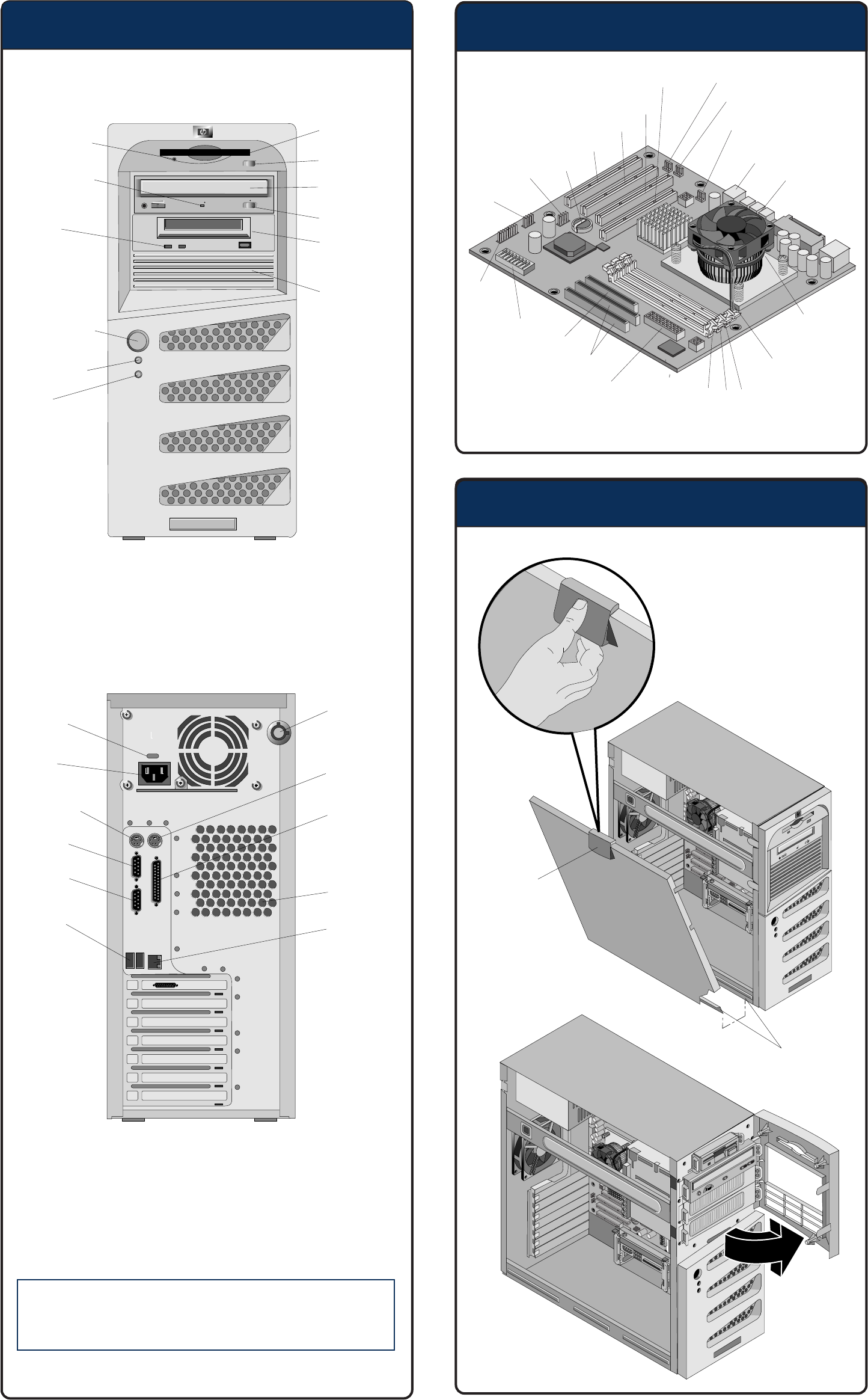
Familiarize Yourself (continued)
Opening the HP Server
Familiarize Yourself
CAUTION
s
The keyboard and mouse PS/2 ports are not
interchangeable. If a device is attached to the
incorrect port, the boot process will not complete.
FDD Activity
LED
Fexible Disk
Drive (FDD)
Eject Button
CD-ROM
Drive
Eject Button
Backup Tape
Drive
(optional)
3rd Hard
Drive
(optional)
Disk Activity
LED
Status
LEDs
Power On/Off
Sleep Switch
Power LED
Drive
Activity
LED
Power
Cover Lock
Latch
Hinge Tabs
Mouse
Parallel
System Fan
LAN
Input
Voltage
Switch
Keyboard
Serial A
Serial B
USB (2)
Processor,
Heat Sink
& Fan
CPU Fan
Connector
3 2 1
DIMM Slots
PSU
Connector 1
(labeled P1)
IDE
FDD
Switches
Status
Panel
USB
(not
used)
Battery
SCSI
Card
LED
PCI Slot 1
PCI Slot 2
PCI Slot 3
Internal
Speaker (not used)
CD Audio
USB (2)
PSU
Connector 2
(labeled PS3)
System Fan
Connector
(hidden by
heat sink)
AGP Card
Slot
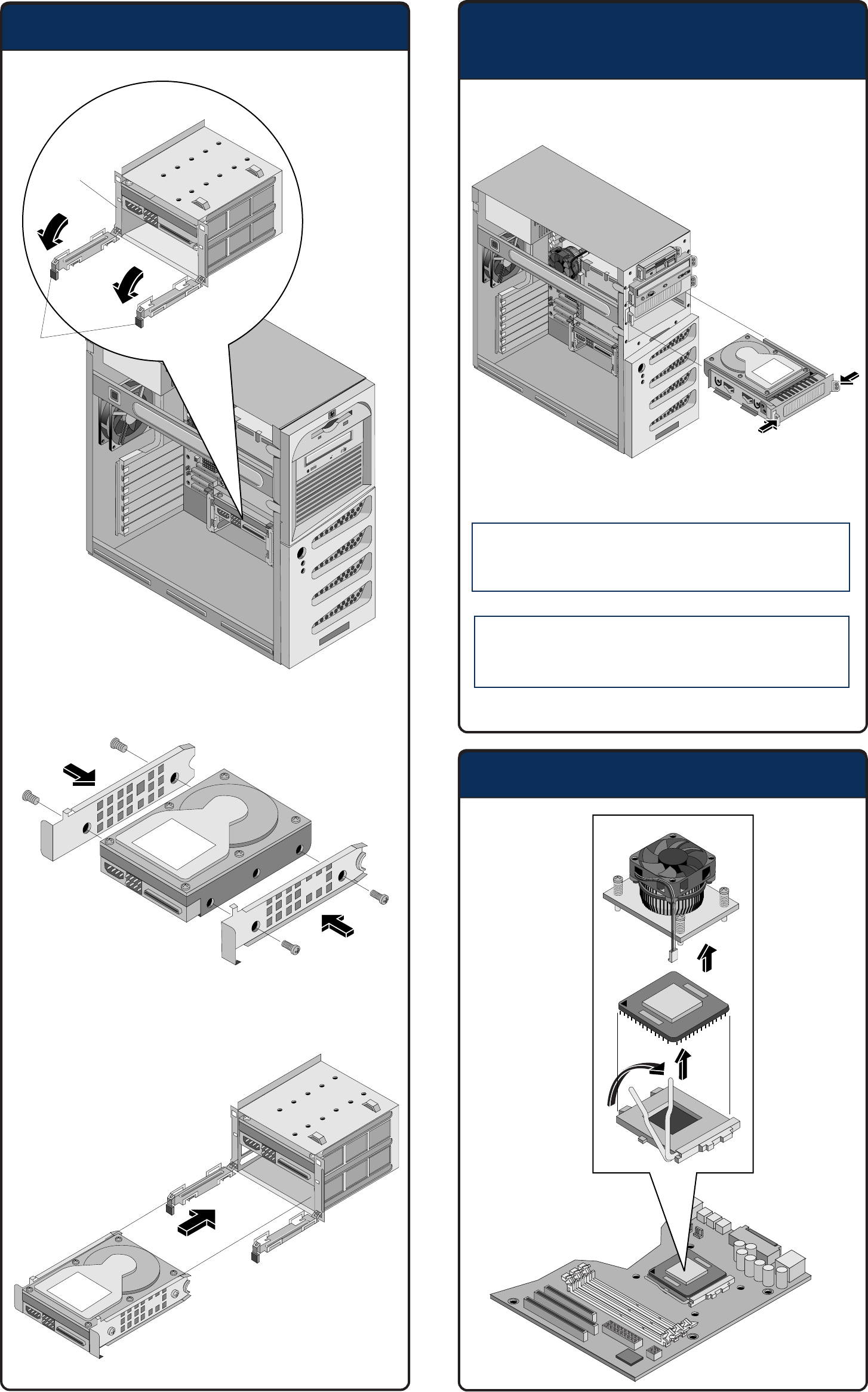
Installing Mass Storage Devices
Replacing the Processor
CAUTION Drives can be damaged by static electricity. Before
handling drives, touch an unpainted metal surface
to discharge static electricity.
CAUTION Always insert a filler panel into empty slots.
Operating with empty drive slots could cause
thermal damage to the HP server.
Installing Mass Storage Devices
(continued)
Drive
Side Rails
Retaining
Clips
Do not remove the
drive cage from
chassis
Do not remove the drive
cage from chassis
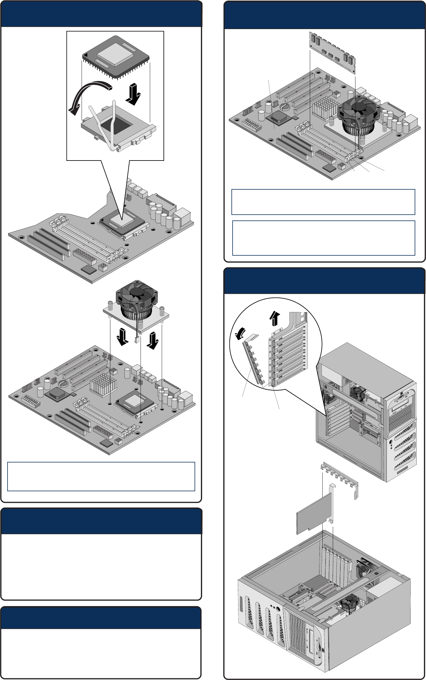
Replacing the Processor (continued)
Boot Priority
CAUTION Align pin 1 on the processor with pin 1 on the
processor socket, or pin damage will occur.
By default, the server searches for boot devices in this order:
1. Flexible disk drive
2. IDE CD-ROM drive
3. IDE hard drive
5. PCI slot 1
6. PCI slot 2
7. PCI slot 3
Installing Memory
CAUTION Use only HP PC133 MHz unbuffered, ECC,
SDRAM DIMMs.
CAUTION DDR DIMMs can be damaged by improper handling.
Always use an antistatic wrist strap and
grounding mat, and discharge static electricity
before touching DDR DIMMs.
Installing PCI Accessory Boards
System Board
3 2 1
DIMM Slots
Slot Cover
Latch
Latch
Retainer
For additional documentation refer to your HP Server Documentation
CD-ROM. You can also access additional information and documentation
from HP's external web site, either by connecting directly or through
your HP Server Documentation CD-ROM.
Obtaining Additional Documentation
