Hp Smart Storage Administrator Users Manual User Guide
2015-01-05
: Hp Hp-Smart-Storage-Administrator-Users-Manual-156159 hp-smart-storage-administrator-users-manual-156159 hp pdf
Open the PDF directly: View PDF ![]() .
.
Page Count: 137 [warning: Documents this large are best viewed by clicking the View PDF Link!]
- HP Smart Storage Administrator User Guide
- Abstract
- Notice
- Contents
- Overview
- Operations
- Accessing HP SSA in the offline environment
- Accessing HP SSA in the online environment
- Using the HP SSA GUI
- Icon and key stroke legend
- Navigating the GUI
- Configuration tasks
- Diagnostic tasks
- Using the HP SSA CLI
- Opening the CLI in Console mode
- Opening the CLI in Command mode
- CLI syntax
- Typical procedures
- Setting the boot controller
- Setting the boot volume
- Setting the target
- Identifying devices
- Deleting target devices
- Generating a diagnostic report
- Erasing a physical drive
- Rescanning the system
- Entering or deleting a license key
- Optimizing controller performance for video
- Creating a logical drive
- Moving a logical drive
- Viewing enclosure information
- Viewing SSD physical drives
- Viewing SSD information
- SmartCache in HPSSACLI
- Rapid Parity Initialization methods
- SSD Over Provisioning Optimization
- Assigning a chassis name to the controller
- Managing spare drives
- Setting the spare activation mode
- Spare Management Mode in HPSSACLI
- Expanding an array
- Shrinking an array
- Moving an array
- Replacing an array
- Setting Auto RAID 0
- Extending a logical drive
- Migrating a logical drive
- Setting the preferred path mode
- Disabling a redundant controller
- Changing the Rebuild Priority setting
- Changing the Expand Priority setting
- Setting the surface scan mode
- Changing the surface scan delay time
- Re-enabling a failed logical drive
- Changing the controller cache ratio
- Enabling or disabling the drive cache
- Enabling or disabling the array accelerator
- Enabling a script to exit on error
- Using the Split Mirror command
- Enabling SmartCache Write-back
- Managing FLS
- Managing modes
- Power mode
- Using HP SSA scripting
- Capturing a configuration
- Using an Input script
- Creating an HP SSA script file
- Script file options
- Control category
- Controller category
- Controller
- CacheState
- ClearConfigurationWithDataLoss
- DPOEnable
- DriveWriteCache
- ElevatorSortEnable
- FLS
- HBAmode
- IRPEnable
- LicenseKey, DeleteLicenseKey
- MNPDelay
- NoBatteryWriteCache
- Power modes
- PreferredPathMode
- QueueDepth
- RapidParityInitialization
- ReadCache, WriteCache
- RebuildPriority, ExpandPriority
- SurfaceScanDelay
- SurfaceScanDelayExtended
- SurfaceScanMode
- Video performance options
- Array category
- Logical Drive category
- Encryption support commands
- Encryption controller category
- AllowPlainText
- AcceptEULA
- ControllerPassword
- ControllerPasswordMode
- Encryption
- EncryptionClearConfig
- EncryptionCryptoPasswordSet
- EncryptionKeyManager
- EncryptionMasterKey
- EncryptionPassword
- EncryptionRecoveryQuestion
- EncryptionRecoveryAnswer
- EncryptionRekeyController
- EncryptionUser
- EncryptionUserPasswordSet
- FirmwareLock
- Encryption logical volume category
- Encryption controller category
- XML support
- HP SSA scripting warning messages
- HP SSA scripting error messages
- Troubleshooting
- HP Smart Storage Administrator Diagnostics Utility CLI
- 512e Physical drive support
- Drive arrays and fault-tolerance methods
- Diagnosing array problems
- Optional components
- HP Smart Array Advanced Pack
- Acronyms and abbreviations
- Documentation feedback
- Index

HP Smart Storage Administrator
User Guide
Abstract
This document identifies, and provides instructions for, the tools available for configuration, management, monitoring, and diagnosing of
HP ProLiant
controller and server products. This document is for the person who installs, administers, and troubleshoots servers and stor
age systems. HP assumes
you are qualified in the servicing of computer equipment and trained in recognizing hazards in products with hazardous energy levels.
Part Number: 742648-003
August 2014
Edition: 3
© Copyright 2013, 2014 Hewlett-Packard Development Company, L.P.
The information contained herein is subject to change without notice. The only warranties for HP products and services are set forth in the express
warranty statements accompanying such products and services. Nothing herein should be construed as constituting an additional warranty. HP shall
not be liable for technical or editorial errors or omissions contained herein.
Confidential computer software. Valid license from HP required for possession, use or copying. Consistent with FAR 12.211 and 12.212,
Commercial Computer Software, Computer Software Documentation, and Technical Data for Commercial Items are licensed to the U.S. Government
under vendor’s standard commercial license.
Microsoft®, Windows®, and Windows Server® are U.S. registered trademarks of Microsoft Corporation. Google™ is a trademark of Google Inc.

Contents 3
Contents
Overview ..................................................................................................................................... 5
About HP SSA ............................................................................................................................................. 5
Benefits of using HP SSA ............................................................................................................................... 5
Support for configuration tasks ............................................................................................................ 6
Array configuration ...................................................................................................................................... 8
Array configuration guidelines ............................................................................................................. 8
Minimum requirements ........................................................................................................................ 9
Native support for 64-bit and 32-bit operating systems .................................................................................... 9
Operations................................................................................................................................. 10
Accessing HP SSA in the offline environment ................................................................................................. 10
Launching HP SSA with HP Intelligent Provisioning (Gen8 or later) ........................................................ 10
Launching HP SSA during POST (Gen8 or later) .................................................................................. 10
Launching HP SSA from an ISO image (all generations) ....................................................................... 11
Accessing HP SSA in the online environment ................................................................................................. 14
Launching HP SSA on a local server ................................................................................................... 15
Launching HP SSA on a local server to configure a remote server.......................................................... 15
Launching HP SSA on a remote server to configure a local server.......................................................... 16
Using the HP SSA GUI ................................................................................................................................ 17
Icon and key stroke legend ............................................................................................................... 17
Navigating the GUI .......................................................................................................................... 18
Configuration tasks........................................................................................................................... 23
Diagnostic tasks ............................................................................................................................... 53
Using the HP SSA CLI ................................................................................................................................. 55
Opening the CLI in Console mode ..................................................................................................... 55
Opening the CLI in Command mode .................................................................................................. 56
CLI syntax ........................................................................................................................................ 56
Typical procedures ........................................................................................................................... 61
Using HP SSA scripting ............................................................................................................................... 80
Capturing a configuration ................................................................................................................. 81
Using an Input script ......................................................................................................................... 81
Creating an HP SSA script file ........................................................................................................... 81
Script file options ............................................................................................................................. 86
XML support .................................................................................................................................. 102
HP SSA scripting warning messages ................................................................................................ 105
HP SSA scripting error messages ..................................................................................................... 106
Troubleshooting ........................................................................................................................ 112
HP Smart Storage Administrator Diagnostics Utility CLI ................................................................................. 112
About the utility .............................................................................................................................. 112
Reported information ...................................................................................................................... 112
Installing the utility .......................................................................................................................... 114
Launching the utility in CLI mode ...................................................................................................... 115
Diagnostic report procedures ........................................................................................................... 115
SmartSSD Wear Gauge report procedures ....................................................................................... 115
512e Physical drive support ...................................................................................................................... 116
Drive arrays and fault-tolerance methods .................................................................................................... 116
Contents 4
Drive arrays ................................................................................................................................... 116
Effects of a hard drive failure on logical drives .................................................................................. 119
Fault-tolerance methods ................................................................................................................... 119
Diagnosing array problems ....................................................................................................................... 128
Diagnostic tools ............................................................................................................................. 128
Troubleshooting resources ............................................................................................................... 128
Optional components ................................................................................................................ 130
HP Secure Encryption ............................................................................................................................... 130
HP Smart Array Advanced Pack ................................................................................................. 131
About SAAP ............................................................................................................................................ 131
Acronyms and abbreviations ...................................................................................................... 132
Documentation feedback ........................................................................................................... 134
Index ....................................................................................................................................... 135

Overview 5
Overview
About HP SSA
HP SSA is the main tool for configuring arrays on HP Smart Array controllers. It exists in three interface
formats: the HP SSA GUI, the HP SSA CLI, and HP SSA Scripting. All formats provide support for
configuration tasks (on page 6). Some of the advanced tasks are available in only one format.
The diagnostic features in HP SSA are also available in the standalone software HP Smart Storage
Administrator Diagnostics Utility CLI (on page 112).
Starting with HP SSA and ProLiant Gen8 servers and server blades, HP SSA is accessible both offline and
online:
• Accessing HP SSA in the offline environment (on page 10)
Using one of multiple methods, you can run HP SSA before launching the host operating system. In
offline mode, users can configure or maintain detected and supported ProLiant devices, such as
optional Smart Array controllers and integrated Smart Array controllers. Some HP SSA features are only
available in the offline environment, such as setting the boot controller and boot volume.
• Accessing HP SSA in the online environment (on page 14)
This method requires an administrator to download the HP SSA executables and install them. You can
run HP SSA online after launching the host operating system.
Benefits of using HP SSA
HP Smart Storage Administrator is an advanced utility that enables you to perform many complex
configuration tasks. Previously, other HP configuration utilities, including Array Configuration Utility and
Option ROM Configuration for Arrays, were recommended for storage configuration.
Although ACU is still supported, HP SSA replaces it starting with HP ProLiant Gen8 servers.
There are many GUI differences between ACU and HP SSA. Some of the main differences include the
following:
• The tabs in ACU are integrated into the new HP SSA Configure menu.
• The 2-panel format in ACU is replaced with a 3-panel format in HP SSA.
• HP SSA includes a quick navigation menu, to access configuration or diagnostics options for a specific
controller.
• With an HP Smart Array Gen8 or later controller, most options do not require an SAAP license.
• HP SSA does not include a Wizards feature.
• HP SSA includes a stand-alone CLI diagnostics utility ("HP Smart Storage Administrator Diagnostics
Utility CLI" on page 112).
HP SSA provides full-range support for standard and advanced configuration tasks ("Support for
configuration tasks" on page 6). Some of these advanced tasks are not available in all HP SSA interface
formats (GUI, CLI, and Scripting).

Overview 6
Using HP SSA over other configuration utilities provides the following benefits:
• GUI, CLI, and Scripting interfaces are available.
• English, French, German, Italian, Japanese, Simplified Chinese, and Spanish languages are supported.
• Applications can be executed using the following tools:
o Any bootable media, such as a software CD
o Any supported Host operating system with a web browser (Microsoft Windows 2003 is not
supported. For a list of supported operating systems, see the HP website
(http://www.hp.com/go/ossupport).)
o Intelligent Provisioning, which is embedded in HP ProLiant Gen8 and later servers
• All formats can run in both online and offline environments.
• The utility can run on any machine that uses a supported browser.
Support for configuration tasks
The following table uses these symbols:
+ —The controller supports this task through HP SSA.
– —The controller supports this task through HP SSA only with a registered SAAP license key.
# —The controller supports this task through HP SSA only with a registered HP SmartCache license key.
To identify controller-specific feature support and SAAP requirements, see the controller user guide or the HP
website (http://www.hp.com/go/smartarray).
For more information, see "About SAAP (on page 131)."
Procedure HP Smart Array
G6 and G7
controllers
HP Smart Array
Gen8 controllers HP Smart Array
Gen9 controllers
(RAID mode)
HP Smart HBA Gen9
controllers
(HBA Mode)
Activate or delete
license keys
+ + + +
Assign a RAID level
to a logical drive
+ + + –
Assign spare drives
to an array
+ + + –
Configure multiple
systems identically
+1 +1 +1 +1
Configure a RAID 6
logical drive
– + P-Series only –
Configure a RAID
60 logical drive
– + P-Series only –
Configure RAID 1
(ADM) and RAID 10
(ADM)
– + P-Series only –
Copy the
configuration of one
system to multiple
systems
–1 +1 + +
Create multiple + + + –

Overview 7
Procedure HP Smart Array
G6 and G7
controllers
HP Smart Array
Gen8 controllers
HP Smart Array
Gen9 controllers
(RAID mode)
HP Smart HBA Gen9
controllers
(HBA Mode)
logical drives per
array
Create or delete
arrays and logical
drives
+ + + Clear config only
Enable or disable a
physical drive write
cache
+ + + –
Enable solid state
drives to be used as
caching devices,
using HP
SmartCache
n/a # #
P-Series only –
Enable optimized
data path to solid
state drives using HP
SSA Smart Path
+ + + –
Expand an array + + P-Series only –
Extend a logical
drive
+ + P-Series only –
Heal an array – + P-Series only –
HP Drive Erase
(replace the content
of a physical drive
with zeros or
random 0 and 1)
– + + –
Identify devices by
causing their LEDs to
flash
+ + + –
Migrate the RAID
level or stripe size
+ + P-Series only –
Move an array
(copy all array data
to a new array and
then delete the old
array)
–2 + P-Series only –
Move and delete
individual LUNs
– + P-series only for
move
–
Optimize the
controller
performance for
video
–2 + + –
Re-enable a failed
logical drive
+ + + –
Set the boot
controller
+ + + +
Set the expand
priority, migrate
+ + P-Series only –

Overview 8
Procedure HP Smart Array
G6 and G7
controllers
HP Smart Array
Gen8 controllers
HP Smart Array
Gen9 controllers
(RAID mode)
HP Smart HBA Gen9
controllers
(HBA Mode)
priority, and
accelerator ratio
Set the spare
activation mode
+ + + –
Set the stripe size + + + –
Set the surface scan
delay
+ + + –
Set the preferred
controller for a
logical drive (in
systems that support
redundant
controllers)
+2 + + –
Share a spare drive
among several
arrays
+ + + –
Removing a drive
from an array
(restripe the data on
an array to occupy
fewer physical
drives, then remove
the excess drives
from the array)
+/–2 + P-Series only –
Specify the size of
the logical drive
+ + + –
Split a RAID 1 array
or recombine a split
array (offline only)
+/– + + –
Split mirror backup
and rollback of RAID
1, 1+0, 1 (ADM)
and 10 (ADM)
mirrors
– + + –
1Scripting is the most efficient method for this task.
2The task is supported only from the Configuration screen.
Array configuration
Array configuration guidelines
Remember the following factors when you build an array:
• All drives grouped in a logical drive must be of the same type (for example, either all SAS or all SATA
and either all hard drives or all solid state drives).
• For the most efficient use of drive space, all drives within an array should have approximately the same
capacity. Each configuration utility treats every physical drive in an array as if it has the same capacity
Overview 9
as the smallest drive in the array. Any excess capacity of a particular drive cannot be used in the array
and is unavailable for data storage.
• The more physical drives configured in an array, the greater the probability that the array will
experience a drive failure during any given period.
• To guard against the data loss that occurs when a drive fails, configure all logical drives in an array with
a suitable fault-tolerance (RAID) method. For more information, see "Drive arrays and fault-tolerance
methods (on page 116)."
Minimum requirements
For minimum operating system requirements to run any HP SSA format, see the HP website
(http://www.hp.com/go/ossupport).
Minimum video requirements to run the HP SSA GUI include a minimum monitor resolution of 1024x768 and
16-bit color. The GUI supports the following browsers:
• Mozilla Firefox 9.0 or later
• Microsoft Internet Explorer 8.0 or later
• Google Chrome
For a list of supported controllers, see HP Smart Array RAID Controllers on the HP website
(http://www.hp.com/go/smartarray).
Native support for 64-bit and 32-bit operating
systems
HP SSA now offers a native 64-bit HP SSA application for supported 64-bit operating systems, eliminating
the need for compatibility libraries. A 32-bit HP SSA application is also available. Users can choose to install
the application that matches the OS installed on the server product.
The 64-bit HP SSA application is not a direct upgrade from 32-bit HP SSA. On 64-bit systems running 32-bit
HP SSA, you must uninstall the 32-bit application, and then install the 64-bit application.
Future versions of HP SSA will be available as native 32-bit or native 64-bit applications, as long as 32-bit
operating systems are supported.

Operations 10
Operations
Accessing HP SSA in the offline environment
To access and launch the HP SSA GUI in an offline environment, use one of the following methods:
• Launching HP SSA with HP Intelligent Provisioning (Gen8 or later) (on page 10)
• Launching HP SSA during POST (Gen8 or later) (on page 10)
• Launching HP SSA from an ISO image (all generations) (on page 11)
To access the HP SSA CLI or HP SSA Scripting in an offline environment, you must launch HP SSA from
an ISO image.
When offline HP SSA launches, an Execution Mode screen does not appear because HP SSA does not
support Remote Service Mode in an offline environment. For this functionality, use HP SSA in an online
environment ("Accessing HP SSA in the online environment" on page 14).
Launching HP SSA with HP Intelligent Provisioning (Gen8 or later)
1. Boot the server.
2. Press F10 to launch HP Intelligent Provisioning.
3. At the main screen, select Perform Maintenance.
4. At the Maintenance screen, select HP Smart Storage Administrator (HP SSA).
The system launches the HP SSA GUI.
Launching HP SSA during POST (Gen8 or later)
For Gen8 servers:
1. Boot the server.
During POST, the system recognizes devices.
2. When the system recognizes a Smart Array controller, press F5.
The system launches the HP SSA GUI, or if you are using Serial Console, the system launches the HP
SSA CLI.
For Gen9 and later servers:
1. Boot the server.
During POST, the system recognizes devices.
2. Press F10 to start Intelligent Provisioning.
A menu appears, listing the options for launching HP SSA.
3. Select a method to launch HP SSA.
The system launches the HP SSA GUI, or if you are using Serial Console, the system launches the HP
SSA CLI.

Operations 11
Launching HP SSA from an ISO image (all generations)
To launch HP SSA, you can also boot from an ISO image. To prepare the image, use one of the following
methods:
• Mounting the image through iLO (on page 11)
• Burning the image to a CD or DVD (on page 11)
• Flashing the image to a USB memory key or SD card on a UEFI bootable server (on page 11)
• Installing the image on a PXE server (on page 12)
Booting from the ISO image on a drive, on a key, or through iLO provides the same GUI interface. The user
can select to run Offline HP SSA GUI, HP SSA CLI, or HP SSA Scripting.
Mounting the image through iLO
This iLO functionality requires an iLO Advanced license.
To mount the image:
1. Download the HP ProLiant Offline Array Configuration Utility ISO image from the HP website
(http://www.hp.com/go/hpssa).
2. Browse to the server iLO page.
3. Start the remote console for the server.
4. On the remote console, use the iLO mount feature to browse to the location of the ISO image.
5. Select the ISO image to be mounted.
6. Reboot the server.
Burning the image to a CD or DVD
1. Download the HP ProLiant Offline HP Smart Storage Administrator ISO image from the HP website
(http://www.hp.com/go/hpssa).
2. Use third-party software to burn the ISO image to a CD or DVD.
3. Set the server to boot from the optical drive.
4. Insert the CD or DVD.
5. Reboot the server.
Flashing the image to a USB memory key or SD card on a UEFI bootable server
Booting from a USB key is supported only for UEFI mode.
1. Download the HP ProLiant Offline HP Smart Storage Administrator ISO image from the HP website
(http://www.hp.com/go/hpssa).
CAUTION: Before creating a bootable USB key from the Offline HP SSA ISO image, back up
any critical data stored on the key to a different location. The utility overwrites all data on the key.
2. Using ISO mounting software, mount the Offline HP SSA ISO image to a Windows drive.
For this example, use "E:."
3. Insert a USB key into a USB connector on the Windows system.
For this example, use "F:."
Operations 12
4. Format the USB key, and copy the contents of the mounted ISO to the USB key.
5. Insert the USB key into the server.
The USB key can now be used to boot to the Offline HP Smart Storage Administrator environment.
When booting from the USB key, a menu is presented. Select "USB BOOT: HP Smart Storage
Administrator (HPSSA)" to mount the correct device during the boot sequence.
Installing the image on a PXE server
To install the Offline HP SSA ISO image on a PXE server and boot from the image over a network, use the
following procedures:
1. Review the prerequisites (on page 12).
2. Set up PXELinux (on page 12).
3. Configure PXELinux (on page 13).
4. Specify the ISO image path (on page 13).
Depending on the network configuration, boot times might vary.
Prerequisites
Before proceeding with the configuration, you must have all the prerequisites:
• A good, working knowledge of PXE and TFTP
• A network with a DHCP server on it
• A TFTP server configured on the same network as the DHCP server
• A network file server that hosts the ISO images and is accessible by a PXE booted system
• PXELinux (http://syslinux.zytor.com/wiki/index.php/PXELINUX)
These instructions presume that you are using a Linux TFTP server and the TFTP package
(http://www.kernel.org/pub/software/network/tftp). Other TFTP servers should work similarly.
Set up PXELinux
Before proceeding with the configuration, ensure that your TFTP server and PXELinux configuration is set up
and configured properly.
To set up PXELinux:
1. Download the HP ProLiant Offline HP Smart Storage Administrator ISO image from the HP website
(http://www.hp.com/go/hpssa).
2. Copy the ISO image to the network file system, and note the location. NFS and Windows file shares are
supported.
For this example, use the following NFS and path to the ISO image:
192.168.0.99:/path/to/ahpssacd/image/hpssaoffline-1.60-16.0.iso
3. Before proceeding, test your network file system to ensure that it is accessible.
4. Access the /system directory of the CD in one of the following ways:
o Burn and mount the ISO image.
o Extract the ISO image using a third-party tool.
5. Copy all the files from the /system directory of the CD to your TFTP server so that it is accessible
by the TFTP software.
Operations 13
Configure PXELinux
1. Using the isolinux.cfg file from the /system/ directory of the CD as a guide, copy the labeled targets to
your PXELinux configuration file. You do not need to include the entire file:
label sos
MENU LABEL HP ProLiant Offline HP SSA Image
kernel hpboot_v.c32
append vmlinuz initrd=initrd.img media=net rw root=/dev/ram0
ramdisk_size=257144 init=/init loglevel=3 ide=nodma ide=noraid pnpbios=off
vga=791 splash=silent showopts TYPE=AUTOMATIC
label vsos
MENU LABEL HP ProLiant Offline HP SSA Image
kernel hpboot_v.c32
append vmlinuz initrd=initrd.img media=net rw root=/dev/ram0
ramdisk_size=257144 init=/init loglevel=3 ide=nodma ide=noraid pnpbios=off
vga=791 splash=silent showopts TYPE=MANUAL
2. Replace the lines kernel hpboot_v.c32 with kernel vmlinuz.
3. Remove vmlinuz from the append line.
The paths to the files on the TFTP server are vmlinuz and initrd.img. You must modify them to include
any directories or naming conventions you may have on your TFTP server.
Specify the ISO image path
For the PXE-booted server to find the ISO image, you must add the ISO image path to the append line in the
PXELinux configuration file.
Add the following arguments:
iso1=nfs://192.168.0.99/path/to/hpssacd/image/hpssaoffline-1.60-16.0.iso
iso1mnt=/mnt/bootdevice
The iso1 parameter helps the PXE-booted HP SSA Offline CD locate the ISO image. The iso1mnt parameter
tells the PXE-booted HP SSA CD where the iso1 image must be mounted.
Your final configuration must be similar to the following example:
label sos
MENU LABEL HP ProLiant Offline HPS SA Image
kernel vmlinuz
append initrd=initrd.img media=net rw root=/dev/ram0 ramdisk_size=257144
init=/init loglevel=3 ide=nodma ide=noraid pnpbios=off vga=791
splash=silent showopts TYPE=AUTOMATIC
iso1=nfs://192.168.0.99/path/to/hpssacd/image/hpssaoffline-1.60-16.0.iso
iso1mnt=/mnt/bootdevice
label vsos
MENU LABEL HP ProLiant Offline HP SSA Image
kernel vmlinuz
append initrd=initrd.img media=net rw root=/dev/ram0 ramdisk_size=257144
init=/init loglevel=3 ide=nodma ide=noraid pnpbios=off vga=791
splash=silent showopts TYPE=MANUAL
iso1=nfs://192.168.0.99/path/to/hpssacd/image/hpssaoffline-1.60-16.0.iso
iso1mnt=/mnt/bootdevice
Operations 14
You can add additional ISO images by specifying the additional iso# and iso#mnt arguments, for example,
iso2=/path/to/iso2.iso iso2mnt=/mnt/iso2.
Supported network file systems
The following network file systems are supported for use with PXE booting:
• NFS:
iso1=nfs://192.168.0.99/path/to/hpssacd/image/hpssaoffline-1.60-16.0.iso
iso1mnt=/mnt/bootdevice
NFS volumes are mounted with the following options:
o -o ro
o nolock
• Windows operating systems:
iso1=smbfs://192.168.0.99/share/path/to/hpssacd/image/hpssaoffline-1.60-
16.0.iso iso1mnt=/mnt/bootdevice
• Windows operating systems with logon credentials:
iso1=smbfs://user:password@192.168.0.99/share/path/to/hpssacd/image/hpss
aoffline-1.60-16.0.iso iso1mnt=/mnt/bootdevice
Accessing HP SSA in the online environment
To access, install, and launch HP SSA in the online environment, you must download the HP SSA
executables. All three formats have separate executables.
HP SSA Scripting is a standalone application that is distributed with the HP SSA CLI application.
Users familiar with ACU Scripting must now install the HP SSA CLI application to obtain the scripting
executable. The new HP SSA scripting executable (hpssascripting) replaces the former executable
(hpacuscripting) in all scripts.
For information about the minimum monitor settings and the version numbers of supported operating systems
and browsers, see the README.txt file provided with the executable.
To use HP SSA in the online environment:
1. Obtain the executable files from one of the following locations:
o The HP website (http://www8.hp.com/us/en/support.html), under Drivers & Downloads.
When prompted for product information, enter the appropriate server or server blade model name.
o The software CD that is provided with the controller
2. Follow the installation instructions provided with the executable.
3. After the executables are installed, launch each executable in the following manner:
o GUI—Click Start, and then select Programs>HP System Tools>HP Smart Storage
Administrator>Setup HP Smart Storage Administrator.
Depending on your configuration scenario, choose one of the following options:
— Launching HP SSA on a local server (on page 15)
— Launching HP SSA on a local server to configure a remote server (on page 15)
— Launching HP SSA on a remote server to configure a local server (on page 16)
Operations 15
o CLI—Click Start, and then select Programs>HP System Tools>HP Smart Storage Administrator CLI
o Scripting—Run hpssascripting.exe.
Launching HP SSA on a local server
Microsoft OS
1. Click Start, and then select Programs>HP System Tools>HP Smart Storage Administrator>HP Smart
Storage Administrator.
HP SSA launches in either a browser or application window (v1.50 and later). HP SSA then scans the
system and detects controllers. When controller detection is complete, the controllers are available on
the Controller/Device menu.
2. Configure a controller ("Configuring a controller" on page 24).
When configuration is complete, continue with the next step.
3. (Optional) To make newly created logical drives available for data storage, use the operating system
disk management tools to create partitions and format the drives.
Linux OS
1. From any command prompt, enter one of the following:
o For local mode, enter: hpssa– local
o For remote mode, enter: hpssa– start
HP SSA launches in a browser window.
2. For a list of options, enter the following:
hpssa- h
Launching HP SSA on a local server to configure a remote server
1. On the local server (host), click Start, and then select Programs>HP System Tools>HP Smart Storage
Administrator>HP Smart Storage Administrator Preferences.
The HP Smart Storage Administrator Preferences screen appears.
o Optional: Under HP System Management Homepage Integration, click Enable, or leave Disabled
(default).
o Optional: Under Preferred Language, select a language or leave as System Default.
o Click Exit.
2. On the remote server, open the browser.
3. Enter the following text into the address field of the remote browser (where servername is the name or
IP address of the host):
http://servername:2301
The login screen for the System Management Homepage opens.
4. Enter your login credentials:
o If you are using version 7.0.0 or later of the System Management Homepage, use your operating
system user name and password.
o If you are using an earlier version of the System Management Homepage, use your WBEM user
name and password.
The System Management Homepage opens.
Operations 16
For more information about the System Management Homepage, see the following:
o The HP System Management Homepage webpage (http://www.hp.com/go/smh)
o The HP System Management Homepage Installation Guide on the HP website
(http://www.hp.com/support/SMH_IG_en)
5. Click HP Smart Storage Administrator on the left side of the screen.
HP SSA opens, scans the remote server, and detects controllers. When controller detection is complete,
the controllers are available on the Controller/Device menu.
6. Configure a controller ("Configuring a controller" on page 24).
7. (Optional) To make newly created logical drives available for data storage, use the operating system
disk management tools to create partitions and format the drives.
Launching HP SSA on a remote server to configure a local server
1. On the local server (host), click Start, and then select Programs>HP System Tools>HP Smart Storage
Administrator>HP Smart Storage Administrator Preferences.
The HP Smart Storage Administrator Preferences screen appears.
o Optional: Under HP System Management Homepage Integration, click Enable, or leave Disabled
(default).
o Optional: Under Preferred Language, select a language or leave as System Default.
o Click Exit.
2. On the server that you want to configure, connect to the Systems Insight Manager server (port: 280),
and then log in.
3. Select Device Queries.
4. Under Device by Type, select All Servers.
5. Connect to the server that is running HP SSA.
6. Under Device Links, select System Management Homepage.
The login screen for the System Management Homepage opens.
7. Log in using your credentials:
o If you are using version 7.0.0 or later of the System Management Homepage, use your operating
system user name and password.
o If you are using an earlier version of the System Management Homepage, use your WBEM user
name and password.
The System Management Homepage opens.
For more information about the System Management Homepage, see the following:
— The HP System Management Homepage webpage
(http://h18013.www1.hp.com/products/servers/management/agents/index.html)
— The HP System Management Homepage Installation Guide on the HP website
(http://www.hp.com)
8. Click HP Smart Storage Administrator on the left side of the screen.
HP SSA opens, scans the remote server, and detects controllers. When controller detection is complete,
the controllers are available on the Controller/Device menu.
9. Configure a controller ("Configuring a controller" on page 24).
Operations 17
When configuration is complete, continue with the next step.
10. (Optional) To make newly created logical drives available for data storage, in a Windows OS, use the
operating system disk management tools to create partitions and format the drives.
Using the HP SSA GUI
Access HP SSA with one of the many methods available:
• Accessing HP SSA in the offline environment (on page 10)
• Accessing HP SSA in the online environment (on page 14)
When you launch the HP SSA GUI, the application opens and HP SSA scans the system and detects
controllers. This process can last up to 2 minutes. When controller detection is complete, the controllers are
available on the Devices/Tools menu.
After the GUI is open, tasks are distributed among categories. For more information, see "Navigating the
GUI (on page 18)."
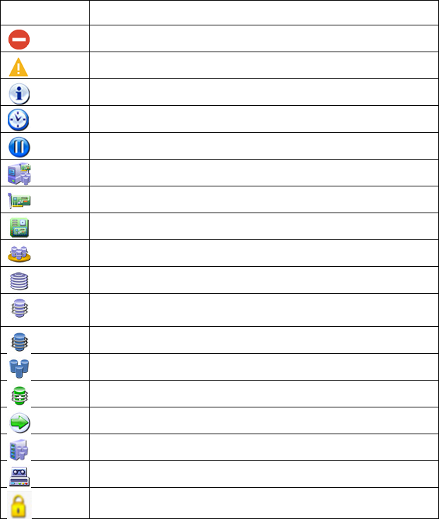
Icon and key stroke legend
The HP SSA GUI includes many icons (also defined in the Help file) to help with identification and
troubleshooting.
Image Description
Critical
Warning
Informational
Active Task(s)
Paused/Offline Drive
HP ProLiant Server
Array Controller
Array Controller (Embedded)
Array
Logical Drive
Assigned Physical Drive
Unassigned Physical Drive
Unassigned Drives
Spare Drive
Transient Drive
Cache Manager
Tape Drive
Locked
Operations 18
Image Description
License Manager
Keyboard functions and shortcuts can be used for navigating or performing actions in the GUI.
Key Description
Tab Cycle through selectable items on a page
Shift + Tab Cycle backwards through selectable items on a page
F5 Rescan system (equivalent to clicking the Rescan System
button)
B Browse main menu
H
Open HP SSA Help
X Exit HP SSA
Enter Perform the action of the currently selected link or button*
Escape Close non-action popups*
R Refresh selected controller*
* Local keyboard shortcuts are available only when the action that the key activates is accessible.
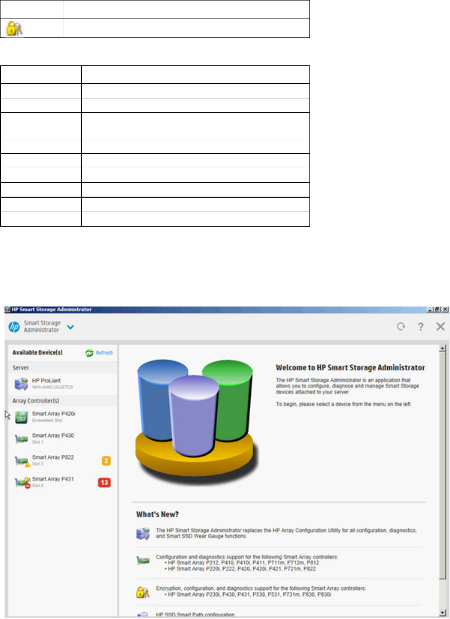
Navigating the GUI
When you open HP SSA, the Welcome screen appears.
The following elements are visible:
Operations 19
• The Smart Storage Administrator quick navigation menu is in the top, left-hand corner of the screen.
Clicking the down arrow displays the available devices, and clicking one of the available devices
displays additional information and options for the device. You can also return to a server Home screen,
or you can choose Configuration or Diagnostics for a device listed. For more information, see
"Configure screen (on page 19)" or "Diagnostics screen (on page 21)."
• Available device(s) are listed on the left-hand side of the screen. Clicking on a server or array controller
displays the available actions, alerts, and summary for that device. You can point to the status alerts to
see details on an alert.
• What's New? summarizes the changes since HP Array Configuration Utility became HP Smart Storage
Administrator, and since the previous versions of HP SSA.
• The Rescan System button is near the top right of the screen.
After adding or removing devices, click Rescan System to update the list of available devices.
• The Help button is near the top right of the screen.
To access help topics, press the H key or click Help. For more information, see "HP SSA Help (on page
22)."
• The Exit HP SSA button is near the top right of the screen.
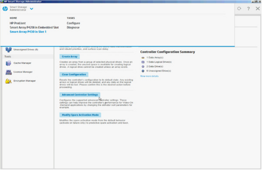
Configure screen
To access this screen, click either a device under Configuration in the quick navigation menu, or select an
available device from the Home screen, and then click Configure under the available options.

Operations 20
The Configure screen displays the GUI elements from the Welcome screen and lists available actions, status
messages, more detailed information, and a controller configuration summary for a selected controller.
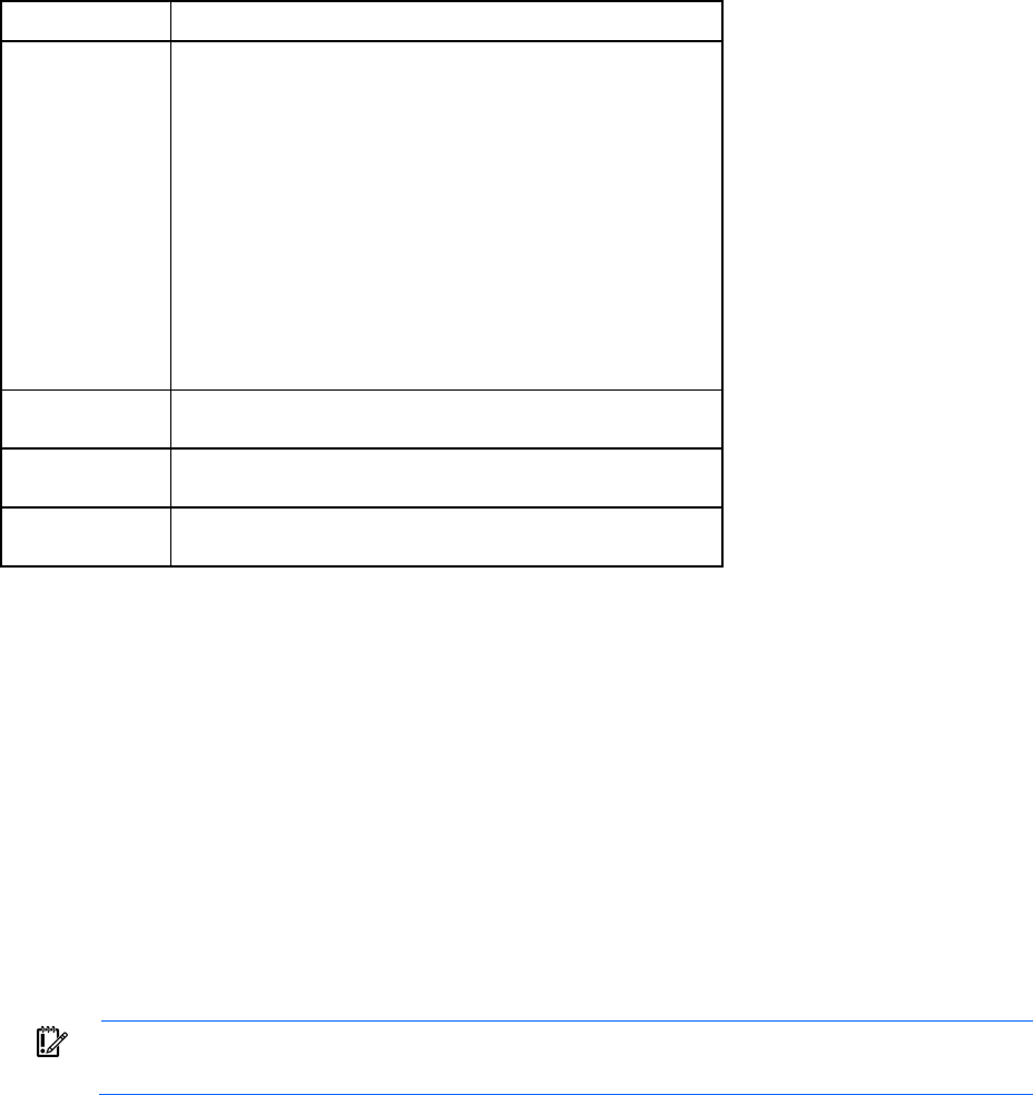
When a controller is selected, the following elements appear:
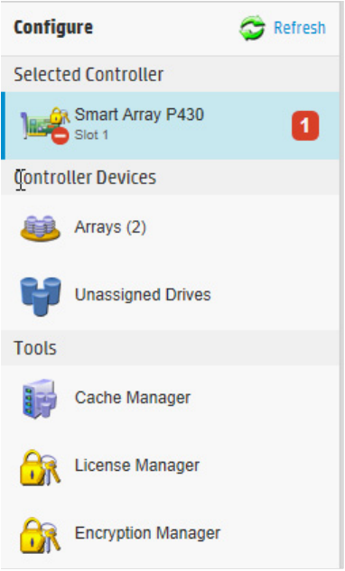
Operations 21
• Devices and Tools—This panel, at left, displays systems, controllers, arrays, physical drives, logical
drives, and a cache and license manager.
• Actions—This panel, in the middle, provides the following information and functionality:
o Tasks that are available for the selected device based on its current status and configuration
o Options and information pertinent to the task, after a task is selected
• Status Messages—This panel provides the following information and functionality:
o Status icons (critical, warning, and informational) with the number of individual alerts for each
category
o A view all status messages link that displays device-specific alerts in a pop-up window
• Controller Configuration Summary—This panel provides a summary of the following elements:
o Data arrays
o Data logical drives
o Data drives
o Unassigned drives
For a list of possible tasks that are available on the Configure screen, see "Configuration tasks (on page 23)."
Diagnostics screen
To access this screen, either click a device under Diagnostics in the quick navigation menu, or select an
available device from the Home screen, and then click Diagnose under the available options.
From the Diagnostics screen, you can run one of the following reports:
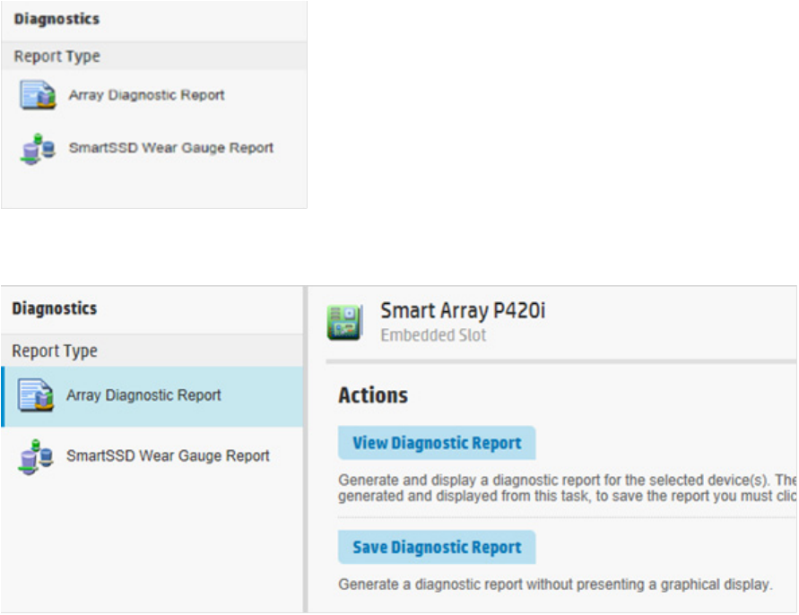
Operations 22
• Diagnostics Report
• SmartSSD Wear Gauge Report
When selecting either report, the available actions on the Actions panel include viewing the report or saving
the report.
For a list of possible tasks that are available on the Diagnostics screen, see "Diagnostic tasks (on page 53)."
HP SSA help
The Help button, at upper right, opens the embedded HP SSA help file. In addition to providing information
about the main screens and tabs, Help also provides several useful topics for new users, including the
following:
• Image Legend—A visual reference list defining the icons and graphical buttons used in HP SSA ("Icon
and key stroke legend" on page 17)
• Keyboard Controls—An explanation and list of keyboard functions for navigating the GUI ("Icon and
key stroke legend" on page 17)
• Keyboard Shortcuts—A list of keys and operations they perform within the GUI
To view these help topics and others, press the H key or click Help. When the Help window opens, expand
the topic "Getting Started with HP SSA."
The glossary in HP SSA help defines industry standard and HP terms as they relate to the HP SSA application.

Operations 23
Configuration tasks
From the Configure screen, you can perform tasks related to controllers, arrays, physical drives, and logical
drives.
For certain tasks, the controller must have SAAP activated by a registered license key. For more information,
see "About SAAP (on page 131)."
When a controller or device is selected, the tasks that appear are a subset of the total number of possible
tasks for the selected item. HP SSA lists or omits tasks based on the controller model and configuration.
For example, if the selected controller has no unassigned physical drives, Create Array is not an available
task.
The following table lists all the possible tasks for every type of item.
Item Tasks
Controller Accelerated I/O Path
Advanced Controller Settings* **
Array Accelerator Settings
Clear Configuration
Controller Settings
Create Array
Disable Standby Controller
Enable HBA/RAID/Smart Array Mode operations*
Enable HP SmartCache†
Manage Encryption
Manage License Keys*
Modify Power Modes*
More Information
Physical Drive Write Cache Settings
Redundancy Settings*
View Status Alerts
Array Bypass RAID components using HP SSA Smart Path
Create Array
Create Logical Drive
Create Split Mirror Backup
Convert Plaintext Data to Encrypted Data
Delete
Expand Array
Heal Array**
Manage Split Mirror Backup
More Information
Move Array**
Re-Mirror Array**
Replace Array**
Shrink Array**
Spare Management
Split Mirrored Array**
View Status Alerts
Volume Key Rekey
Operations 24
Item Tasks
Logical drive Create Logical Drive
Create SmartCache for Logical Drive
Convert Plaintext Data to Encrypted Data
Delete
Extend Logical Drive
Instant Secure Erase
Migrate RAID/Stripe Size
Modifying Cache Write Policy
Move Logical Drive* **
More Information
Re-enable Failed Logical Drive
View Status Alerts
Volume Key Rekey
Unused space Create Logical Drive
More Information
Physical drive Erase Drive**
View Status Alerts
Unassigned
drives
Create Array
More Information
*This task is not available on all controller models.
**If performed with an HP Smart Array G6 or G7 controller, this task requires a registered SAAP license key or a
controller where SAAP functionality is standard. See "About SAAP (on page 131)."
†If performed with a Gen8 or Gen9 controller, this task requires a registered HP SmartCache license key.
Configuring a controller
1. Open HP SSA.
For more information, see "Using the HP SSA GUI (on page 17)."
2. Open the Configure panel by doing one of the following:
o Choose a device and click Configure in the quick navigation menu.
o Select an available device from the Home screen, and then click Configure under the available
options.
The Configure panel appears.
IMPORTANT: Screens may have different options available, depending on the server
configuration.

Operations 25
3. Configure the controller. See "Performing a Configuration task (on page 25)."
4. When prompted, save the configuration.
5. Do one of the following:
o Configure an additional controller. Repeat steps 3 through 5.
o Click Exit HP SSA.
Performing a Configuration task
1. Open HP SSA.
For more information, see "Using the HP SSA GUI (on page 17)."
2. Open the Configure panel by doing one of the following:
o Choose a device and click Configure in the quick navigation menu.
o Select an available device from the Home screen, and then click Configure under the available
options.
3. Select a device from the Devices menu.
Operations 26
The Actions, Status Messages, and Controller Configuration Summary panels appear. The listed tasks
are available for this device in its current configuration. For more information, see "Configuration tasks
(on page 23)."
4. Click a task button.
A list of all possible options for that task appears on the right side of the screen, replacing the task list.
5. Select the settings or configuration options for the device.
6. Use the Next and Back buttons to navigate multiple screens of options.
7. Click Save or OK.
HP SSD Smart Path
HP SSD Smart Path enables an optimized data path to high performance solid state drives. The optimized
path bypasses the controller’s RAID processing components and sends I/O directly to the drives.
To enable or disable HP SSD Smart Path:
1. Open HP SSA.
For more information, see "Using the HP SSA GUI (on page 17)."
2. Open the Configure panel by doing one of the following:
o Choose a device and click Configure in the quick navigation menu.
o Select an available device from the Home screen, and then click Configure under the available
options.
3. Select a controller from the Devices menu.
The Actions panel appears.
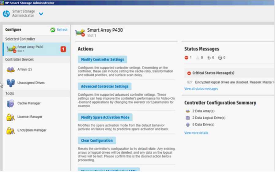
Create a logical drive:
1. Click Create Array.
Operations 27
2. Select SAS SSD or SATA SSD for the drive type.
3. Make selections for Internal Drive Cages.
4. Click Create Array.
5. Make selections for RAID Level, Strip Size/Full Stripe Size, Sectors/Track, and Size.
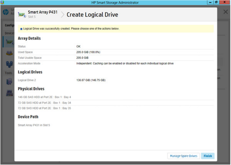
6. Click Create Logical Drive.
7. Click Finish.
By default, HP SSA Smart Path is enabled on SSD drives.
8. Under Configure>Devices, choose the array with the logical drive(s) you just created.
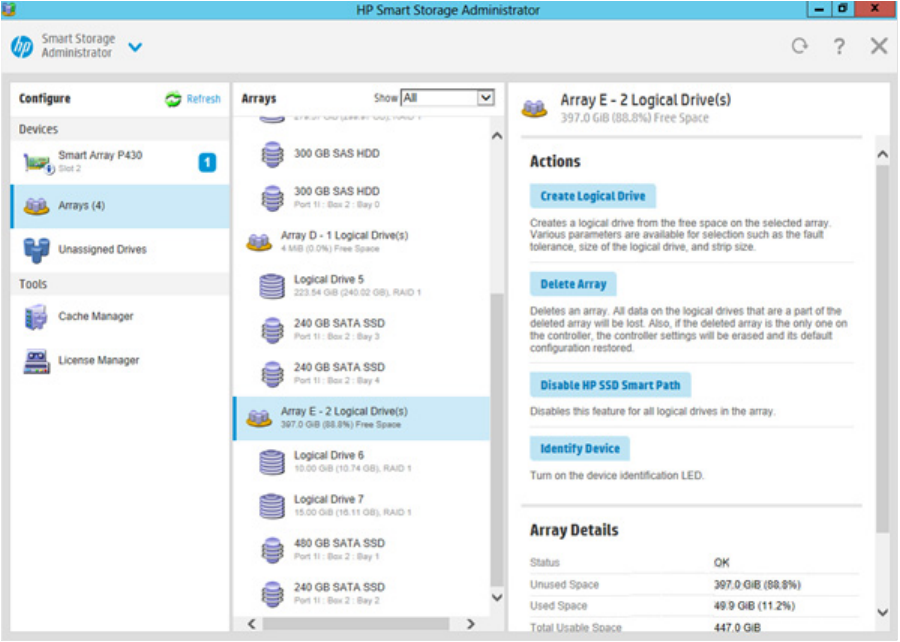
Operations 28
9. If you want to disable HP SSA Smart Path, click Disable HP SSD Smart Path.
10. Click Save.
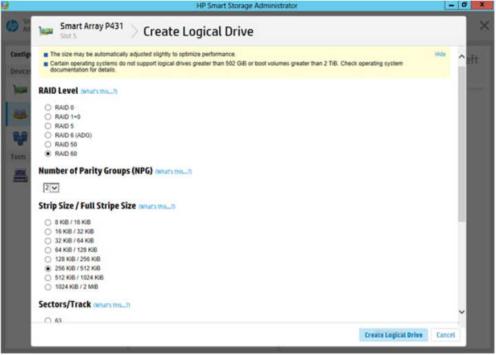
Rapid Parity Initialization
When you create a logical drive, you must initialize the parity using Rapid Parity Initialization.
RAID levels that use parity (RAID 5, RAID 6 (ADG), RAID 50, and RAID 60) require that the parity blocks be
initialized to valid values. Valid parity data is required to enable enhanced data protection through
background surface scan analysis and higher performance write operations. Two initialization methods are
available:
• Default – Initializes parity blocks in the background while the logical drive is available for access by the
operating system. A lower RAID level results in faster parity initialization.
• Rapid – Overwrites both the data and parity blocks in the foreground. The logical drive remains
invisible and unavailable to the operating system until the parity initialization process completes. All
parity groups are initialized in parallel, but initialization is faster for single parity groups (RAID 5 and
RAID 6). RAID level does not affect system performance during rapid initialization.
Rapid Parity Initialization is available only for supported controllers and in arrays composed of supported
physical drives.
To select the method for parity initialization:
1. Open HP SSA.
For more information, see "Using the HP SSA GUI (on page 17)."
2. Open the Configure panel by doing one of the following:
Operations 29
o Choose a device and click Configure in the quick navigation menu.
o Select an available device from the Home screen, and then click Configure under the available
options.
3. Select Arrays from the Devices menu.
A list of arrays appears.
4. Select an array, and select Create Logical Drive from the Actions menu.
5. Make selections for RAID Level, Number of Parity Groups (NPG), Strip Size/Full Strip Size,
Sectors/Track, Size, Parity Initialization Method, and Caching.
6. Click Create Logical Drive to continue.
SSD Over Provisioning Optimization
Solid state devices can be optimized by deallocating all used blocks before any data is written to the drive.
The optimization process is performed when the first logical drive in an array is created and when a physical
drive is used to replace a failed drive. Not all controllers support this option.
The SSD Over Provisioning Optimization feature allows the user to disable over provisioning optimization in
the GUI.
To disable Over Provisioning Optimization:
1. Open HP SSA.
For more information, see "Using the HP SSA GUI (on page 17)."
2. Select Unassigned Drives located under Controller Devices.
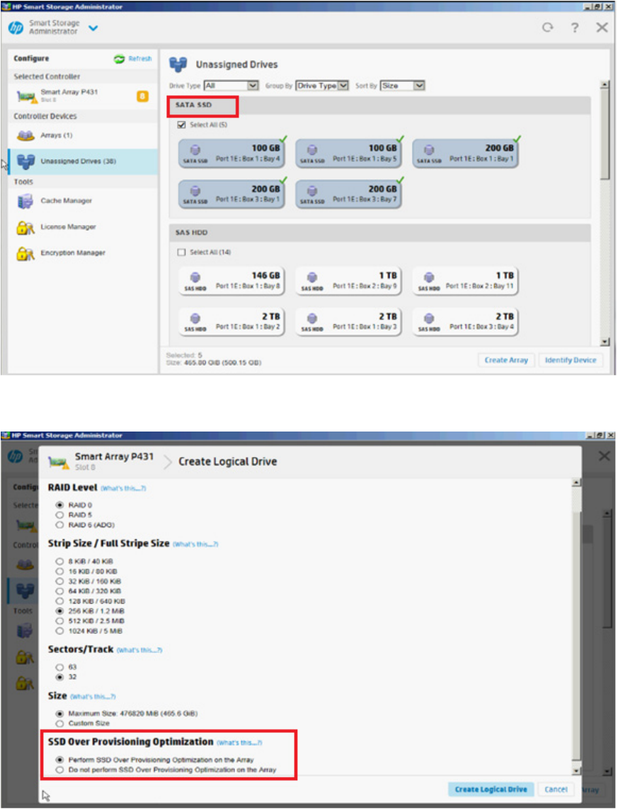
Operations 30
3. To create an array, select from the list of available SATA SSD drives listed. When finished, click Create
Array.
4. The Create Logical Drive window appears. Under the option SSD Over Provisioning Optimization,
select Do not perform SSD Over Provisioning Optimization on the Array.
5. Click Create Logical Drive.
Operations 31
Changing the Spare Activation Mode
The spare activation mode feature enables the controller firmware to activate a spare drive under the
following conditions:
• When a data drive reports a predictive failure (SMART) status
• When a data drive fails; this mode is the default.
In normal operations, and for older controllers, the firmware starts rebuilding a spare drive only when a data
drive fails. With the predictive failure activation mode, rebuilding can begin before the drive fails, reducing
the likelihood of data loss that could occur if an additional drive fails.
To change the Spare Activation Mode:
1. Open HP SSA.
For more information, see "Using the HP SSA GUI (on page 17)."
2. Open the Configure panel by doing one of the following:
o Choose a device and click Configure in the quick navigation menu.
o Select an available device from the Home screen, and then click Configure under the available
options.
3. Select a controller from the Devices menu.
The Actions panel appears.
4. In the Actions panel, click Modify Spare Activation Mode.
5. From the menu, select one of the following modes:
o Failure Spare Activation
o Predictive Spare Activation
6. Click Save.
Changing the Spare Management mode
The Spare Management feature provides multiple methods for handling spare behavior. You can choose
from the following options:
• Dedicated—When the failed data drive is replaced, it must be rebuilt from the data on the spare drive.
In Dedicated mode, one spare can be dedicated to multiple arrays.
• Auto-Replace Drives—The spare for the failed data drive automatically becomes the replacement data
drive. When the spare is replaced, the data drive does not need to be rebuilt. In Auto-replace mode,
spare drives cannot be shared between arrays.
If assigning Auto-Replace Drives mode to an array with a RAID 0 drive, Spare Activation Mode must be set
to Predictive Spare Activation mode.
To change the Spare Management mode:
1. Open HP SSA.
For more information, see "Using the HP SSA GUI (on page 17)."
2. Open the Configure panel by doing one of the following:
o Choose a device and click Configure in the quick navigation menu.
o Select an available device from the Home screen, and then click Configure under the available
options.

Operations 32
3. Select a controller from the Devices menu.
4. Select Create Array from the Actions panel.
The Array details screen appears.
5. Select a controller, drive type, and physical drives, and click Create Array.
6. Select settings for Create Plaintext Volume, RAID Level, Strip Size/Full Strip Size, Sectors/Track, Size,
and Caching. Click Create Logical Drive when complete.
7. Click Manage Spare Drives.
8. From the menu, select one of the following spare drive types:
o Dedicated Spare Drives
o Auto-Replace Drives
9. Select which drives will operate as spare drives in the array.
Operations 33
10. Click Save.
11. A confirmation screen appears. Click Yes to continue.
12. Click Manage Spare Drives to make additional selections, or click Finish.
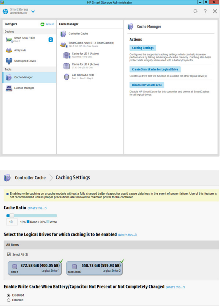
Cache Manager
Caching increases database performance by writing data to the cache memory, instead of directly to the
logical drives. Caching can be disabled to reserve the cache module for other logical drives on the array.
To configure the controller cache:
1. Open HP SSA.
For more information, see "Using the HP SSA GUI (on page 17)."
2. Open the Configure panel by doing one of the following:
o Choose a device and click Configure in the quick navigation menu.
o Select an available device from the Home screen, and then click Configure under the available
options.
3. Select Cache Manager from the Tools menu.
Operations 34
4. Click Controller Cache in the Cache Manager menu.
5. Click Caching Settings.
6. Select one or more logical drives to be cached.
Operations 35
7. Verify caching settings.
8. Click OK.
About HP SmartCache
HP SmartCache enables solid state drives to be used as caching devices for hard drive media. HP
SmartCache provides the following features:
• Accelerates application performance
• Provides lower latency for transactions in applications
• Supports all operating systems where HP Smart Array Gen9 controllers are supported, without the need
for changes to OS, driver, or applications
• Choice of write-through or write-back cache (Gen9 servers only)
HP SmartCache will be fully enabled after the first SmartCache is created on the controller.
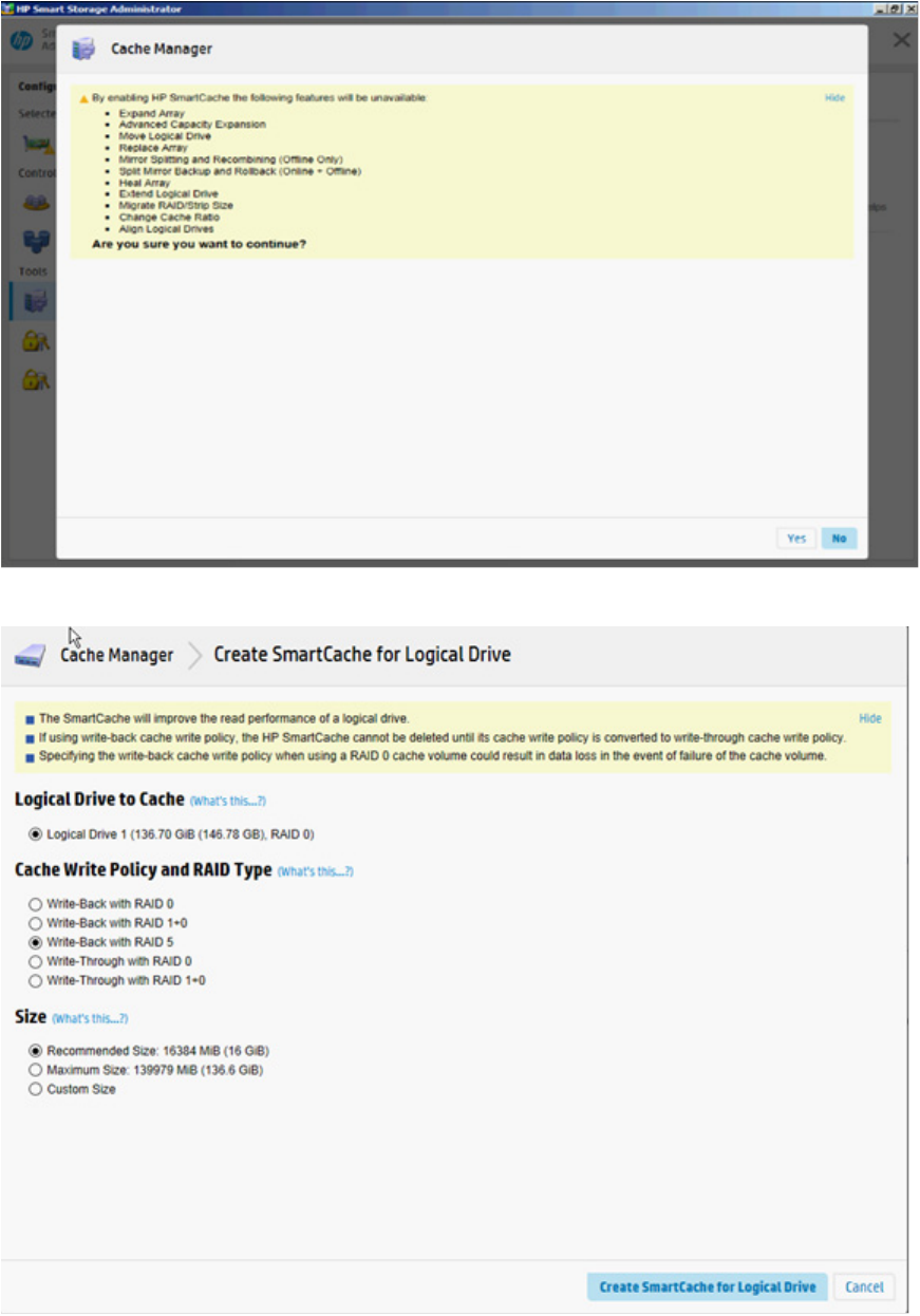
The following features cannot be performed unless HP SmartCache is disabled:
• Expand Array
• Advanced Capacity Expansion
• Move Logical Drive
• Replace Array
• Mirror Splitting and Recombining (offline only)
• Split Mirror Backup and Rollback (online and offline)
• Heal Array
• Extend Logical Drive
• Migrate RAID/Strip Size
• Change Cache Ratio
• Align Logical Drives
To support HP SmartCache, the Smart Array Controller firmware must meet the following version minimums:
• 6G controller: version 3.42 or later
• 12G controller: all releases
HP SmartCache requires an HP SmartCache license. For more information, see the HP website
(http://www.hp.com/go/smartcache).
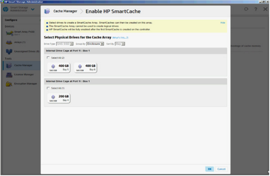
Enable HP SmartCache
Enabling HP SmartCache with an array will accelerate data input/output for the assigned logical drives. At
least one logical drive must be created on the controller prior to enabling HP SmartCache.
To enable HP SmartCache:
1. Open HP SSA.
For more information, see "Using the HP SSA GUI (on page 17)."
2. Open the Configure panel by doing one of the following:
o Choose a device and click Configure in the quick navigation menu.
Operations 36
o Select an available device from the Home screen, and then click Configure under the available
options.
3. Select Cache Manager from the Tools menu.
4. Click Enable HP SmartCache in the Actions menu.
5. Select one or more physical drives from the list of available drives.
6. Click OK.
Operations 37
7. A pop-up window appears, indicating certain features will not be available with HP SmartCache
enabled. If you want to continue, click Yes.
8. Create SmartCache for Logical Drive appears.
Operations 38
9. Select the following:
o Logical drive to cache
o Cache write policy and RAID type
o Size of the cache. HP recommends 10% of the drive size, and it must be a minimum of 16 GiB.
10. Click Create SmartCache for Logical Drive.
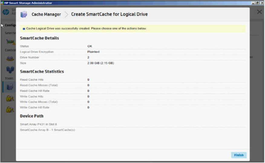
11. SmartCache Details, SmartCache Statistics, and Device Path appear. Click Finish to proceed.
The SmartCache is created for the Logical Drive.
Installing a license key with HP SmartCache
You can use HP SSA to install the license key and activate HP SmartCache functionality.
To install a license key:
1. Open HP SSA.
For more information, see "Using the HP SSA GUI (on page 17)."
2. Open the Configure panel by doing one of the following:
o Choose a device and click Configure in the quick navigation menu.
o Select an available device from the Home screen, and then click Configure under the available
options.
3. In the Tools menu, click License Manager.
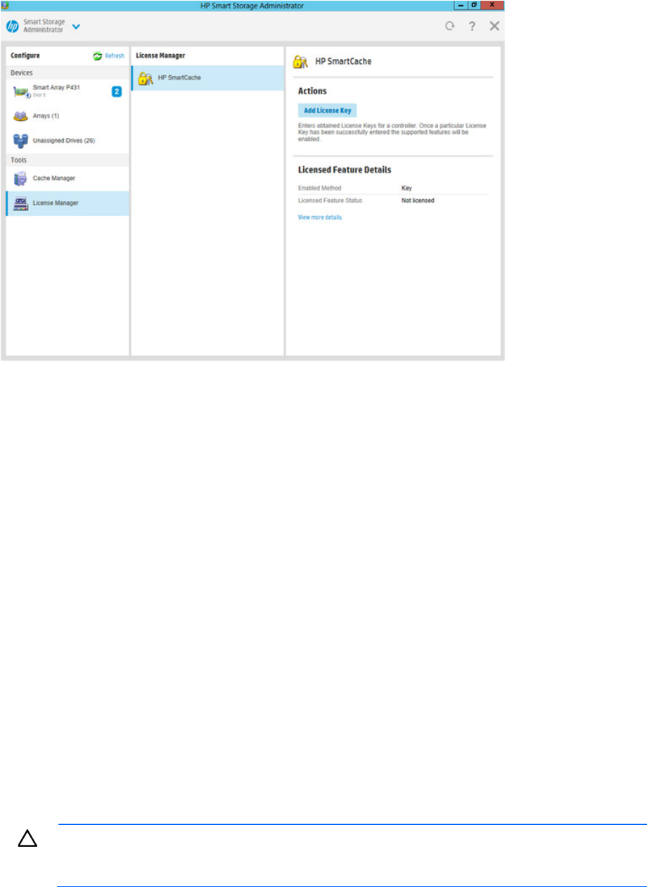
Operations 39
4. Under actions, click Add License Key.
5. Enter the license key number.
6. Click Save.
Enabling SmartCache Write-back
HP SSA contains two different policies for data writes when caching: write-back and write-through.
Write-back is a caching method where data is not copied to the data volume until absolutely necessary.
Write-back might accelerate performance in comparison to the write-through policy by reducing the number
of write operations to data volumes. The performance improvement can involve the risk of lost data if the
cache volume fails.
Write-through is a caching method where data is written to the cache and the data volumes simultaneously.
Write-through is the preferred write policy in applications where data loss cannot be tolerated, but has lower
performance compared to the write-back policy.
A write-back SmartCache cannot be deleted until it is converted to a write-through SmartCache using the
Modify Caching Write Policy button. This conversion forces user data to be flushed from the SmartCache
volume to the primary hard drive volume, to avoid data loss when the SmartCache is deleted. The time to
flush data from write-back SmartCache to hard drive volume varies, depending on several variables
including how much dirty data is held in the write-back SmartCache, host workload, and number of hard
drives in the primary volume.
SmartCache volumes must be deleted from newest to oldest, in reverse order from how they were created.
Some controllers might not support this option or might require a license key to enable this feature. The target
can be any valid SSD drive and existing non-cached logical drive for the data.
CAUTION: Specifying the write-back cache write policy could result in data loss in the event of
failure of the cache volume. When using a RAID 0 cache volume, a single SSD failure might result
in data loss.
Operations 40
IMPORTANT: If a demo license key expires, all SmartCache volumes configured with write-back
cache write policy are converted to write -through. When this happens, the logical drive details
show different values for Cache Write Policy and Cache Write Policy Requested. If the license is
reinstalled, the SmartCache volumes are restored to their original write-back cache write policy.
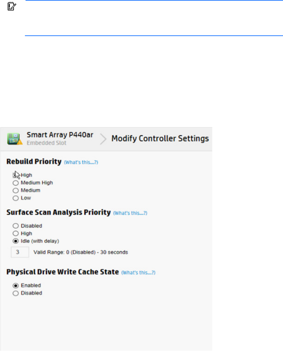
To modify the logical drive cache policy settings:
1. Open HP SSA.
For more information, see "Using the HP SSA GUI (on page 17)."
2. Select the controller.
3. Click Modify Controller Settings.
4. Under Physical Drive Write Cache State, select one of the following:
o Enabled
o Disabled
5. Click Save Settings.
6. A summary page appears. Click Finish to exit.
Operations 41
Working with mirrored arrays
Among the advanced tasks possible with the HP SSA GUI, you can split a mirrored array and then recombine
it. This process entails splitting a RAID 1 or RAID 1+0 mirror into two identical new arrays consisting of RAID
0 logical drives.
Support for these procedures requires the following:
• The HP SSA GUI must be run in offline mode.
• HP Smart Array G6 and G7 controller models must have a valid SAAP license ("About SAAP" on page
131).
• Mirrored arrays being split can have RAID 1, RAID 1+0, RAID 1 (ADM), or RAID 10 (ADM)
configurations. Arrays with other RAID configurations cannot be split.
Several reasons exist for splitting and recombining a mirrored array. For more information, see the "RAID
1(+0): breaking mirrors and rebuilding drives" how-to white paper on the HP website
(http://h20000.www2.hp.com/bc/docs/support/SupportManual/c00378986/c00378986.pdf).
Splitting a mirrored array
1. Run the HP SSA GUI in offline mode. See "Accessing HP SSA in the offline environment (on page 10)."
2. Open the Configure panel by doing one of the following:
o Choose a device and click Configure in the quick navigation menu.
o Select an available device from the Home screen, and then click Configure under the available
options.
3. Select Arrays from the Devices menu.
4. From the Arrays menu, select the appropriate array.
5. Select Manage Data Drives from the Actions panel.
6. Under Available Array Action(s), select Mirror Array.
7. Select a physical drive.
8. Click OK.
The mirrored array details are displayed.
9. Click Finish.
10. When HP SSA finishes splitting the array, two logical drives appear in the Arrays menu:
o When a RAID 1 or RAID 1+0 array splits, two RAID 0 logical drives are created.
o When an array that contains a RAID 1 (ADM) logical drive splits, a RAID 1 logical drive and a RAID
0 logical drive are created.
o When an array that contains a RAID 10 (ADM) logical drive splits, a RAID 1+0 logical drive and a
RAID 0 logical drive are created.
11. Shut down the OS.
12. Power down the server.
13. With power off, remove the physical drives that constitute one of the new arrays.
If you do not remove the physical drives for one of the arrays, the OS will be unable to distinguish
between the two arrays when the server is restarted because the arrays are identical.
14. Power up the server.
15. Restart the OS.
Operations 42
Recombining a split mirrored array
1. Run the HP SSA GUI in offline mode. See "Accessing HP SSA in the offline environment (on page 10)."
2. Open the Configure panel by doing one of the following:
o Choose a device and click Configure in the quick navigation menu.
o Select an available device from the Home screen, and then click Configure under the available
options.
3. Select Arrays from the Devices menu.
4. Select the appropriate array from the Arrays menu.
5. Select Manage Data Drives from the Actions panel.
6. In the Available Tasks panel, click Manage Split Mirror Backup.
7. Select the array to be mirrored to the source array.
This array is usually the array that was split from the original mirrored array. However, it can be any
other array of the correct size.
8. Click OK.
9. When HP SSA finishes re-mirroring the array, restart the OS.
The controller uses the rebuild process to synchronize the mirrored drives. The drive online LED flashes
during the rebuild process. Depending on the hard drive size and the server load, this process can take
up to 2 hours. You can boot the OS during this time, but the logical drive is not fault-tolerant until the
rebuild is complete.
Creating a split mirror backup
This task splits an array that consists of one or more RAID 1, RAID 1+0, RAID 1 (ADM), or RAID 10 (ADM)
logical drives, and then creates two arrays: a primary array and a backup array.
To create a split mirror backup:
1. Run the HP SSA GUI in offline mode. See "Accessing HP SSA in the offline environment (on page 10)."
2. Open the Configure panel by doing one of the following:
o Choose a device and click Configure in the quick navigation menu.
o Select an available device from the Home screen, and then click Configure under the available
options.
3. Select Arrays from the Devices menu.
4. Select the appropriate array from the Arrays menu.
5. In the Actions panel, click Create Split Mirror Backup.
A verification and message dialog box appears.
6. Click OK.
7. A details window appears. Click Finish.
HP SSA creates the array according to the following rules:
o If the original array contained RAID 1 or RAID 1+0 drives, then the primary array will contain RAID
0 drives.
o If the original array contained RAID 1 (ADM) drives, the primary array will contain RAID 1 drives.
o If the original array contained RAID 10 (ADM) drives, the primary array will contain RAID 1+0
drives.
Operations 43
o The backup array always contains RAID 0 logical drives.
o The primary array continues to be fully accessible to the operating system while the backup array is
hidden from the operating system.
8. When HP SSA finishes creating the split mirror backup, the new backup array appears in the Devices
menu:
The array includes the designation "Backup" at the beginning of the array name.
Re-mirroring, rolling back, or re-activating a split mirror backup
1. Run the HP SSA GUI in offline mode. See "Accessing HP SSA in the offline environment (on page 10)."
2. Open the Configure panel by doing one of the following:
o Choose a device and click Configure in the quick navigation menu.
o Select an available device from the Home screen, and then click Configure under the available
options.
3. Select Arrays from the Devices menu.
4. Select the appropriate array from the Arrays menu.
5. In the Available Tasks panel, click Manage Split Mirror Backup.
6. Select one of the following actions:
o Re-mirror the array and preserve the existing data. Discard the backup array.
This option re-creates the original mirrored array with the current contents of the primary array.
o Re-mirror the array and roll back to the contents of the backup array. Discard existing data.
This option re-creates the mirrored array but restores its original contents, which are in the backup
array. HP recommends that you do not perform this option under the following circumstances:
— In an online environment
— If the logical drive to be rolled back is mounted
— If the logical drive to be rolled back is in use by the operating system
o Activate the backup array.
This option makes the backup array fully accessible to the operating system. HP SSA removes the
designation "backup" from the name of the array.
Healing an array
The Heal Array operation enables you to enter a command to replace failed physical drives in the array with
healthy physical drives. After replacement, the original array and logical drive numbering is unaffected.
To use Heal Array, you must meet the following conditions:
• The array has at least one failed drive.
• The array is not transforming (for example, rebuilding to a spare).
• The array has a working cache, making it capable of transformation.
• The replacement physical drives and the original drives must be of the same interface type, such as SAS,
SATA, and so on.
• A sufficient number of unassigned physical drives of the correct size are available to replace each failed
physical drive in the array.

Operations 44
The correct size is defined as a drive as large as the smallest drive on the array, but no larger than the
smallest spare.
• If using an HP ProLiant Smart Array G6 or G7 controller, an SAAP 1.0 license is activated.
When you select Heal Array, and all conditions are met, one of the following actions occurs to the volume in
the array:
• If a volume has failed, HP SSA recreates the volume. This action occurs with a RAID 0 volume.
• If a volume is degraded, HP SSA rebuilds the volume.
Replacing an array
Some controllers may not support this option or might require a license key to enable the feature.
HP SSA enables you to transfer the contents of an array to an existing empty array or a new array. During
this operation, all logical drives transfer from the original array to the destination array. The original array is
deleted, and the drives that were being used are freed and listed as unassigned drives.
Replacing an array is a time-consuming process for two reasons: all data in each logical drive is copied to
the destination array, and the controller performs all data transformations while servicing IO requests to other
logical drives.
To perform the Replace Array operation, you must meet the following conditions:
• The destination array must have the same number of physical drives as the source or original array.
• Both the source and destination arrays must be in OK state.
• All existing logical drives in the source array must be in OK state.
• The destination array must have sufficient capacity to hold all logical drives present in the source array.
Setting Auto RAID 0
CAUTION: If you select this option for any logical drives, you will experience data loss for that
logical drive if one physical drive fails. Assign RAID 0 to drives that require large capacity and
high speed, but pose no data safety risk.
Auto Array RAID 0 creates a single RAID 0 volume on each physical drive specified, enabling the user to
select multiple drives and configure as RAID 0 simultaneously. Each array contains one physical drive and
one RAID 0 logical drive.
For more information about RAID 0, see "RAID 0—No fault tolerance (on page 120)."
To create an array with RAID 0:
1. Open HP SSA.
For more information, see "Using the HP SSA GUI (on page 17)."
2. Select the controller.
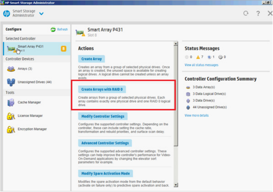
Operations 45
3. Click Create Arrays with RAID 0.
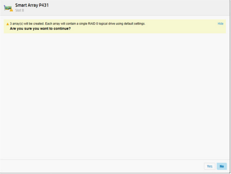
Operations 46
4. A new window appears, confirming each array will contain a single RAID 0 logical drive. Click Yes to
continue.
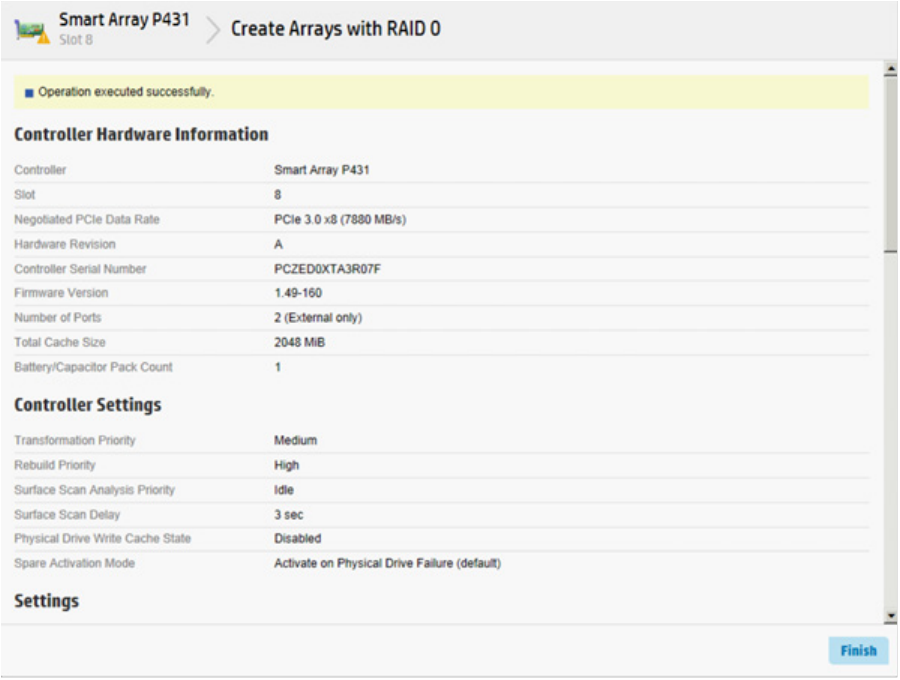
Operations 47
5. A new window appears, confirming RAID 0 configuration. Click Finish to complete.
Managing FLS
Flexible Latency Scheduler provides the ability to control drive latency while still providing the benefit of hard
drive optimization. It acts on a hard drive by inspecting a list of requests issued to a drive. FLS changes the
controller logic when submitting requests to a rotating drive based on the longest outstanding command
latency for a host request on that drive. FLS is a global option for the controller, to be applied to all drives in
effort to reduce the maximum observed latency from a host request.
The FLS attempts to put a cap on the high latency that can be experienced on some rotating disks (hard
drives) under highly random workloads. The low setting puts a latency cap of 250 ms on any request, after
which the controller schedules the request immediately.
The high setting uses a shorter latency cap of 50 ms. The target can be any valid individual controller target
that supports the flexible latency scheduler feature.
High settings result in generally lower maximum latencies for hard drive logical volumes, but lower
throughput for patterns that have improved latency.
FLS is currently available with the following controllers:
• HP Smart Array P440 Controller
• HP Smart Array P441 Controller
• HP Smart Array P840 Controller
FLS is available in the following settings.
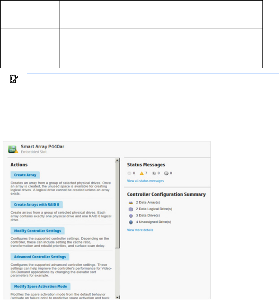
Operations 48
Setting Description
Disable Controller will allow drives to optimize for throughput, resulting in higher maximum
latencies for some workloads.
High Controller will attempt to compel disks to complete operations in a timely manner, but
still allow for some drive optimization. Doing so will lower the effective throughput for
some workloads.
Low Controller will compel a disk to complete operations at an earlier time compared to the
high setting, resulting in lower maximum latencies, but lower throughput.
IMPORTANT: Setting a higher level of FLS can result in a loss of throughput for some request
patterns.
To enable FLS:
1. Open HP SSA. For more information, see "Using the HP SSA GUI (on page 17)."
2. Select the controller.
3. Click Advanced Controller Settings.
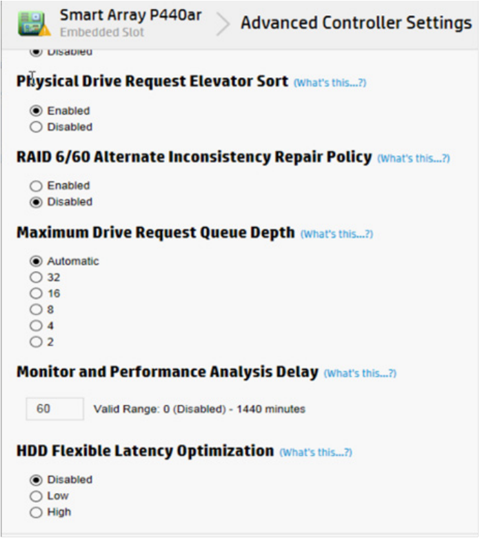
Operations 49
4. Scroll down to the option HDD Flexible Latency Optimization.
5. Select one of the following:
o Disabled
o Low
o High
6. Click OK.
7. A summary page appears. Click Finish to exit.
Managing modes
RAID mode or HBA mode
The controller operates in either RAID mode or HBA mode, but not both. Smart Array Controllers allowing
HBA mode can be configured to run in RAID mode. In HBA mode, all physical drives are presented directly
to the operating system and the hardware RAID engine is disabled.
When HBA mode is enabled, RAID mode is disabled. To enable RAID mode, disable HBA mode.
HBA mode

Operations 50
IMPORTANT: Enabling HBA Mode exposes the physical drives to the operating system. Smart
Array configuration is not allowed.
To enable HBA mode:
1. Open HP SSA. For more information, see "Using the HP SSA GUI (on page 17)."
2. Select the controller.
3. Click Configure.
4. Click Enable HBA mode.
5. A prompt appears warning you that entering HBA mode will disable any drives configured using a
Smart Array until the configuration is cleared. A reboot is required for HBA mode to be enabled.
If you want to continue, click OK.
6. A summary page appears. Click Finish to exit.
RAID mode
To enable RAID mode:
1. Open HP SSA. For more information, see "Using the HP SSA GUI (on page 17)."
2. Select the controller.
3. Click Configure.
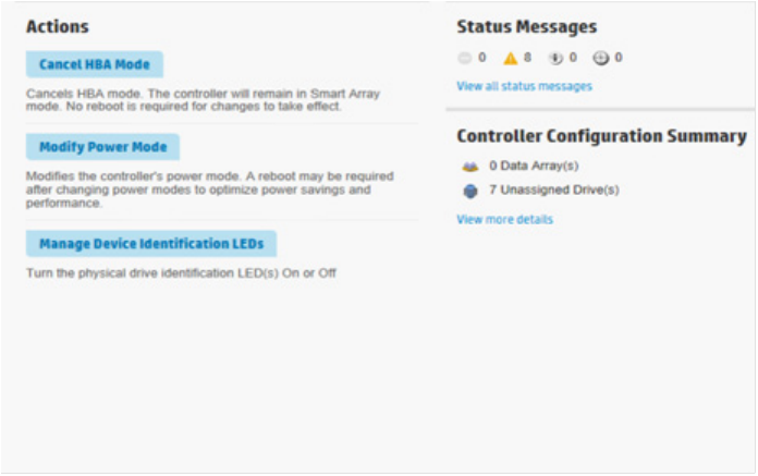
Operations 51
4. Click Cancel HBA mode.
5. A prompt appears indicating that the controller will remain in Smart Array mode and no reboot is
required. If you want to continue, click OK.
6. A summary page appears. Click Finish to exit.
Power modes
There are three available power modes:
• Maximum performance
• Minimum power
• Balanced
Maximum performance (default)
This is the default setting. All settings are selected based on maximum performance. Power savings options
that affect performance are disabled.
Balanced
You can use this setting to save power with minimal effects on performance. For large queue depths, this
setting affects throughput by 10% or less.
At lower queue depths or infrequent I/O, impacts on performance may be greater. This command is typically
useful in environments using only hard drives, and is not recommended when using SSDs.
Settings are based on the user configuration, such as the number or types of drives, the RAID level, storage
topology, and so forth. Significant changes to the configuration may require a reboot for optimal setting
selection. If a reboot is required to change settings, HP SSA generates a warning.
Minimum power
When settings are selected without regard to system performance, maximum power savings is achieved. HP
recommends this setting for very specific applications, but it is not appropriate for the majority of customers.
Most applications will suffer significant performance reduction.
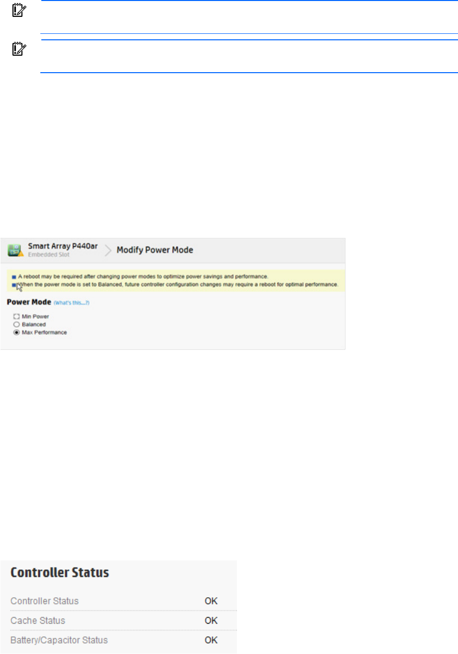
Operations 52
IMPORTANT: A reboot may be required after switching power modes in order to optimize
savings and performance.
IMPORTANT: When the power mode is set to Balanced, future controller configuration changes
may require a reboot for optimal performance.
To modify the power mode:
1. Open HP SSA. For more information, see "Using the HP SSA GUI (on page 17)."
2. Select the controller.
3. Click on Configure.
4. Click Modify Power Mode.
5. Select a power mode:
o Min Power
o Balanced
o Max Performance
6. Click OK.
7. A summary page appears. Click Finish to exit.
Viewing controller status
To view the controller status, including the status of the cache and an attached battery or capacitor, do the
following:
1. Open HP SSA. For more information, see "Using the HP SSA GUI (on page 17)."
2. Select a controller.
3. Click Configure.
4. Under Controller Configuration Summary, click View more details.
A new window appears.
5. Scroll down to Controller Status to view the status of the controller, cache, and battery or capacitor.
Operations 53
Diagnostic tasks
The HP SSA Diagnostics feature replaced the Array Diagnostic Utility supported by SmartStart v8.20 and
earlier.
HP SSA generates the following reports and logs:
• Array diagnostic report
This report contains information about all devices, such as array controllers, storage enclosures, drive
cages, as well as logical, physical, and tape drives. For supported solid state drives, this report also
contains SmartSSD Wear Gauge information.
• SmartSSD Wear Gauge report
This report contains information about the current usage level and remaining expected lifetime of solid
state drives attached to the system.
• Serial output logs
This log details the serial output for the selected controller.
For each controller, or for all of them, you can select the following tasks:
• View Diagnostic Report
• Save Diagnostic Report
• View SmartSSD Wear Gauge Report
• Save SmartSSD Wear Gauge Report
For the view tasks, HP SSA generates and displays the report or log. For the save tasks, HP SSA generates
a report without the graphical display.
For either task, you can save the report. In online and offline environments, HP SSA saves the diagnostic
report to a compressed folder, which contains an XML report, a plain text report, and a viewer file so you can
display and navigate the report through a web browser.
Each HP SSA Diagnostics report contains a consolidated view of any error or warning conditions
encountered. It also provides detailed information for every storage device, including the following:
• Device status
• Configuration flags
• Firmware version numbers
• Physical drive error logs
HP SSA Diagnostics never collects information about the data content of logical drives. The diagnostic report
does not collect or include the following:
• File system types, contents, or status
• Partition types, sizes, or layout
• Software RAID information
• Operating system device names or mount points
Performing a Diagnostics task
1. Open HP SSA.
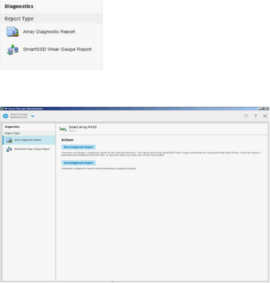
Operations 54
For more information, see "Using the HP SSA GUI (on page 17)."
2. Open the Diagnostics panel by doing one of the following:
o Choose a device and click Diagnose in the quick navigation menu
o Select an available device from the Home screen, and then click Diagnose under the available
options.
3. Choose a report type.
For this example, use the Array Diagnostic Reports selection.
4. Select Array Diagnostic Report.
The Actions panel for Array Diagnostic Report appears.
5. Click one of the task buttons:
o If you select View Diagnostic Report, the report appears. When you are finished viewing the current
report, click Close or Save.
6. If you select Save Diagnostic Report, wait for the report to generate, and then click Close Report or Save
Report.
Operations 55
For more information about reports and viewing them in a browser, see the following sections:
• "Reported information (on page 112)"
• "Identifying and viewing diagnostic report files (on page 115)"
• "Identifying and viewing SmartSSD Wear Gauge report files (on page 116)"
Using the HP SSA CLI
Access HP SSA with one of the many methods available:
• Accessing HP SSA in the offline environment (on page 10)
• Accessing HP SSA in the online environment (on page 14)
Some HP SSA CLI features are only available in the offline environment, such as setting the boot controller
and boot volume.
HP SSA CLI has two operating modes:
• Console mode ("Opening the CLI in Console mode" on page 55)
You can adjust several configuration parameters on several devices without having to restart HP SSA
each time.
• Command mode ("Opening the CLI in Command mode" on page 56)
You can make an isolated change of just one configuration parameter on one device.
For VMware ESXi 5.x, HP SSA CLI works similarly to the Command mode. However, slight differences exist,
requiring you to run HP SSA CLI through the VMware vSphere esxcli command-line utility. For more
information about using HP SSA CLI for ESXi 5.x, see the HP VMware Utilities User Guide.
For more information about using HP SSA CLI for Linux, see the following README.txt files:
• HP SSA: /opt/hp/hpssa/README.TXT
• HPSSACLI (32bit): /opt/hp/hpssacli/bld/hpssacli-1.XX-X.X.XXXX.txt
• HPSSACLI (64bit): /opt/hp/hpssacli/bld/hpssacli-1.XX-XX.XXXX_XX.txt
Opening the CLI in Console mode
The syntax of the command required to open the HP SSA CLI in Console mode depends on the operating
system that you are using.
• For Microsoft Windows, enter the following text:
C:\Program Files\hp\hpssacli\Bin\hpssacli.exe
Alternatively, click Start, and select Programs>HP System Tools>HP Smart Storage Administrator
CLI>HP Smart Storage Administrator CLI.
• For Linux, enter the following text:
[root@localhost root]# hpssacli
After you have entered Console mode in either operating system, the screen displays the following message
and console prompt:
HP Smart Storage Administrator CLI 1.XX.X.X
Detecting Controllers...Done.
Type "help" for a list of supported commands.
Type "exit" to close the console.
Operations 56
=>
The remaining examples in the HP SSA CLI section of this guide are described as if entered in Console mode.
Opening the CLI in Command mode
To use Command mode, identify the appropriate HP SSA CLI command ("The <command> variable" on
page 56). Then, add the command to the end of the text line that is used for opening the CLI in Console mode
(on page 55).
The following examples use help as the command:
• Using Microsoft Windows:
C:\Program Files\hp\Hpssacli\Bin\hpssacli.exe help
• Using Linux:
[root@localhost root]# hpssacli help
The remaining examples in the HP SSA CLI section of this guide are described as if entered in Console mode.
CLI syntax
Whether entered in Command mode or Console mode, a typical HP SSA CLI command line consists of three
parts: a target device, a command, and a parameter with values if necessary. Using angle brackets to denote
a required variable and plain brackets to denote an optional variable, the structure of a typical HP SSA CLI
command line is as follows:
<target> <command> [parameter=value]
The <target> variable
This variable provides the path to the device that you want to configure. The device can be a controller, an
array, a logical drive, or a physical drive. The syntax used is as follows:
controller all | slot=# | wwn=# | chassisname="AAA" | serialnumber=# |
chassisserialnumber=# | [array=all|<id>] [logicaldrive all|#]
[physicaldrive all|allunassigned|[#:]#:#,[#:]#:#...|[#:]#:#-[#:]#:#]
For example:
controller slot=3
controller wwn=500805F3000BAC11
controller slot=2 array A
controller chassisname="A" array B logicaldrive 2
controller chassisname="A" physicaldrive 1:0
controller all
controller slot=2 array all
controller slot=3 physicaldrive 1:2-1:5
The <command> variable
The <command> variable can be any of the following words or phrases, corresponding to typical
configuration tasks:
add
create
delete
modify
remove
set target
Operations 57
Nonconfiguration commands are also available:
diag ("Generating a diagnostic report" on page 63)
help ("The help command" on page 60)
rescan ("Rescanning the system" on page 64)
shorthand ("Keyword abbreviations" on page 58)
show ("The show command" on page 58)
version ("Displaying the current versions of the application layers" on page
60)
A command often requires a parameter, and some parameters require a value, but the specific parameters
and values that are valid for a given command depend on the target to which you apply the command.
To determine the valid parameters and values for a particular combination of target and command variables,
you can query the device ("Querying a device" on page 57). You can also inspect the example commands
in other sections of this guide.
Querying a device
If you do not know what values a parameter can have, you can sometimes query the device to find out by
entering a ? as the value of the parameter.
Example command:
=> ctrl ch="Lab4" ld 1 modify raid=0 ss=?
A typical screen response in this case could be:
Available options are:
8
16 (current value)
32
64
128 (default)
256
To determine which parameters can be queried, use the help feature of the CLI ("The help command" on
page 60).
Hiding warning prompts
When you enter a command for an operation that can potentially destroy user data, the CLI displays a
warning and prompts you for input (a y or an n) before continuing the operation. This situation is undesirable
when running batch file scripts. To prevent warning prompts from being displayed, use the term forced as
a parameter.
Example command:
ctrl ch="Lab4" ld 1 delete forced
Under VMware ESXi 5.x, the forced flag is required for any command that has the option for a forced flag.
If the forced parameter is not used, the system generates an error message notifying the user that the
command could not be completed without this flag.

Operations 58
Keyword abbreviations
Several commonly used keywords in the HP SSA CLI have acceptable abbreviations, as shown in the
following table. For a complete list of abbreviations, enter help shorthand in the HP SSA CLI.
Keyword Abbreviation in HP
SSA CLI
Keyword Abbreviation in HP
SSA CLI
adapterid
ai nobatterywritecache nbwc
allunassigned au numberparitygroups npg
arrayaccelerator aa parallelscsi ps
cacheratio cr physicaldrive pd
chassisname* ch* postprompttimeout ppto
chassisserialnumber
csn preferredpathmode ppm
chassisslot chs queuedepth qd
configurationmode cm raid1writebuffering r1wb
connectionname cn rebuildpriority rp
controller ctrl redundantcontroller rc
ctrlpath cp serialnumber sn
degradedperformancemode dpo spareactivationmode sam
drivetype dt ssdoverprovisioningoptimizat
ion ssdopo
drivewritecache dwc ssdphysicaldrive ssdpd
elevatorsort
es stripesize ss
enclosure enc surfaceanalysiseventnotify saen
exitonerror eoe surfacescandelay ssd
expandpriority ep surfacescanmode ssm
inconsistencyrepairpolicy irp sufacescanpriority sp
licensekey
lk tapedrive td
logicaldrive ld waitforcacheroom wfcr
mnpdelay mnpd — —
*The CLI also uses this keyword and abbreviation for the terms box name and RAID array ID.
The show command
The show command enables you to obtain information about a device.
Syntax:
<target> show [detail]|[status]
When you specify a target that consists of several devices, the information in the output is normally less
comprehensive than when you specify only one device as the target. You can use the [detail] parameter
in this case to retain all the information usually given for individual devices.
An extra parameter is available for controller targets: config. This parameter is used as follows:
<target controller> show config [detail]
If you use the config parameter, the output includes information about each device connected to the
controller.
Example 1:
=> ctrl slot=9 show
Operations 59
A typical output would be:
Smart Array P421 in Slot 9
Bus Interface: PCI
Slot: 9
Serial Number: PBKTV0XTAZZ005
RAID 6 (ADG) Status: Enabled
Controller Status: OK
Hardware Revision: A
Firmware Version: 0.02-106
Rebuild Priority: Medium
Expand Priority: Medium
Surface Scan Delay: 3 secs
Surface Scan Mode: Idle
Queue Depth: Automatic
Monitor and Performance Delay: 60 min
Elevator Sort: Enabled
Degraded Performance Optimization: Disabled
Inconsistency Repair Policy: Disabled
Wait for Cache Room: Disabled
Surface Analysis Inconsistency Notification: Disabled
Post Prompt Timeout: 15 secs
Cache Board Present: True
Cache Status: OK
Accelerator Ratio: 10% Read / 90% Write
Drive Write Cache: Disabled
Total Cache Size: 1024 MB
Total Cache Memory Available: 816 MB
No-Battery Write Cache: Disabled
Cache Backup Power Source: Capacitors
Battery/Capacitor Count: 1
Battery/Capacitor Status: OK
SATA NCQ Supported: True
Spare Activation Mode: Activate on drive failure
Controller Temperature (C): 40
Cache Module Temperature (C): 0
Capacitor Temperature (C): 0
Boot Controller: True
Primary Boot Volume: logicaldrive 1
Secondary Boot Volume: logicaldrive 1
Example 2:
=> ctrl all show
Because this target consists of several devices, the output will be brief. A typical output would be:
MSA1000 at dog (sn: P56350D9IP903J, csn: (9J3CJN71XDCH, wwn:
500805F3000BAC11)
Operations 60
Smart Array 5312 in Slot 3 (sn: P4AB5X9BFMLNTJ)
Smart Array 532 in Slot 2 (sn: P44940LDAORS4F)
Example 3:
=> ctrl ch="lab4" show config
The output in this case will have detailed information because the target consists of only one device. A typical
output would be:
MSA1000 at dog (sn: P56350D9IP903J, csn: (9J3CJN71XDCH, wwn:
500805F3000BAC11)
array A (SAS, Unused Space: 20091 MB)
logicaldrive 1 (219 MB, RAID 6(ADG), OK)
physicaldrive 1:1:3 (port 1:box 1:bay 3, SAS, 4.3 GB, OK)
physicaldrive 1:1:4 (port 1:box 1:bay 4, SAS, 9.1 GB, OK)
physicaldrive 1:1:5 (port 1:box 1:bay 5, SAS, 9.1 GB, OK)
physicaldrive 1:1:6 (port 1:box 1:bay 6, SAS, 9.1 GB, OK)
physicaldrive 1:1:7 (port 1:box 1:bay 7, SAS, 9.1 GB, OK)
physicaldrive 1:1:9 (port 1:box 1:bay 9, SAS, ??? GB, failed, spare)
unassigned
drive 1:1:1 (port 1:box 1:bay 1, SAS, 36 GB, OK)
physicaldrive 1:1:2 (port 1:box 1:bay 2, SAS, 36 GB, OK)
physicaldrive 1:1:8 (port 1:box 1:bay 8, SAS, 9.1 GB, OK)
physicaldrive 1:1:10 (port 1:box 1:bay 10, SAS, 9.1 GB, OK)
physical
physicaldrive 1:1:11 (port 1:box 1:bay 11, SAS, 9.1 GB, OK)
Displaying the current versions of the application layers
The version command displays the current versions of the application and other software layers.
Syntax:
version
Example command:
version
A typical output would be:
HP SSA CLI Version: 1.XX.X.X
SoulAPI Version: X.X.XX.X
InfoManager Version: X.0-XX.0
The help command
To get help with the CLI, enter help at the CLI prompt, and then enter one or more help items, as follows:
=> help <item1> [item2] [item3]
A help item can be any of the following:
• A CLI command ("The <command> variable" on page 56)
• An HP SSA CLI keyword or keyword abbreviation ("Keyword abbreviations" on page 58)
• A CLI parameter

Operations 61
• A term commonly used in HP SSA, such as migrate, extend, or cache
• The word shorthand (gives a list of abbreviations for keywords in the CLI)
The help feature of the HP SSA CLI behaves like a browser search engine in that each item that you add to
the help input string reduces the amount of help output text. For example, help controller produces
extensive information, while help controller remove restricts the help output to information about how
the remove command applies to controllers.
Typical procedures
The following sections describe some common HP SSA CLI procedures.
Setting the boot controller
This procedure is only available in the offline environment and only applies to booting in Legacy BIOS Boot
Mode.
The boot controller is the first controller that the system examines (after power up) to find a bootable logical
drive or volume. The controller boots from the first local drive by default. HP recommends leaving the default
setting, disable, in place in order to prevent an error when booting after replacing the boot volume or
controller. To assign a designated boot volume, see "Setting the boot volume (on page 61)."
Syntax:
<target> modify [bootcontroller=enable|disable]
where <target> is a controller with a volume that can be set as the boot volume.
Example command:
controller slot=1 modify bootcontroller=enable
Setting the boot volume
CAUTION: HP recommends setting the boot volume only in certain scenarios to prevent a system
boot error.
This procedure is only available in the offline environment and only applies to booting in Legacy BIOS Boot
Mode.
The boot volume is the volume that contains the OS and its support files. To work properly, the boot volume
must be accessible by the designated boot controller. See "Setting the boot controller (on page 61)."
Scenario: When the bootable volume is assigned Logical Drive 2 and a non-bootable local drive is assigned
as Logical Drive 1, a boot volume can be set without resulting in system error.
Syntax:
<target> modify [bootvolume=primary|secondary|none]
where <target> is a controller and a logical drive.
Example commands:
controller slot=1 ld 1 modify bootvolume=primary
controller slot=1 ld 2 modify bootvolume=secondary
controller slot=1 ld 1 modify bootvolume=none

Operations 62
Setting the target
If you must perform several operations on a given target device, you can simplify the required commands by
setting the device as the default <target> for the CLI operations.
After you have set the target, any command that you enter in the CLI without a specified <target> is
automatically applied to the set target. If you must also perform operations on other devices, you can still do
so at any time by specifying the <target> for each of those operations as usual. You can also change the
set target or clear it completely. The set target is automatically cleared when you close the CLI.
IMPORTANT: You cannot use the set target command in batch file scripts.
Syntax:
set target <target>
where <target> is a controller, array, or logical drive.
Example commands:
=> set target ctrl slot=3
=> clear target
Typical scenario
First, set a target as follows:
=> set target ctrl ch="Lab 4"
=> show target
controller chassisname="Lab 4"
As an example of how the set target command works, check the status of array A on this controller:
=> array A show
MSA1000 at Lab 4
array A
Interface Type: SAS
Unused Space: 7949 MB
Status: OK
The controller does not need to be specified because it is currently the set target.
Now clear the target, reset it, and enter a few commands for the new set target:
=> clear target
=> set target ctrl slot=3
=> array A add drives=1:7,1:8,1:9
=> array B add spares=1:10,1:11
=> ctrl slot=4 ld 3 modify ss=64
=> modify rp=high
This sequence includes a command for a different target (the controller in slot 4) as a demonstration. The next
command in the sequence (the one for modifying the rebuild priority) applies to the controller in slot 3, not the
one in slot 4. This is because the command does not specify a <target> for the rebuild priority, so the
default set target is used instead.
Identifying devices
You can enter a command that causes the LEDs on target devices to flash, enabling you to identify the
devices. After an hour, the LEDs stop flashing. You can also stop LED flashing by entering the off command.
Operations 63
Syntax:
<target> modify led=on|off
Example commands:
=> ctrl ch="Lab 4" modify led=on
=> ctrl ch="Lab 4" array A modify led=off
Deleting target devices
Syntax:
<target> delete [forced]
where <target> can be a controller, array, or logical drive. Except in the case of controllers, you can
delete several devices simultaneously if they are of similar type by using the all keyword.
Because deleting a target device can result in data loss, the screen displays a warning prompt unless you
include the forced parameter.
Example commands:
=> ctrl ch="Lab 4" delete forced
=> ctrl slot=3 ld all delete
Generating a diagnostic report
HP provides several ways for administrators to generate diagnostic information, including all three HP SSA
formats and the standalone HP Smart Storage Administrator Diagnostics Utility CLI (on page 112).
For VMware ESX 5.x, diagnostic reports are generated differently and require you to run another utility,
HPSSADUESXI, through the VMware vSphere CLI. For more information, see the HP VMware Utilities User
Guide.
In HP SSA CLI, the diag command outputs diagnostic information about a specified controller or all
controllers on the system. The ssdrpt option generates the SmartSSD Wear Gauge report.
Syntax
<target> diag <file=filename> [ris=on|off] [ssdrpt=on|off] [xml=on|off]
[zip=on|off]
where the following is designated:
• <target> is a controller or all controllers.
• <file=filename> designates the target file in which the diagnostic information is saved.
• [ris=on|off] determines whether RIS information is or is not included. The off value is provided for
backward compatibility and is ignored.
• [ssdrpt=on|off] specifies to generate or not generate the Smart SSD Wear Gauge report. The
default is off.
• [xml=on|off] outputs diagnostic information in formatted XML. The off value is provided for
backward compatibility and is ignored.
• [zip=on|off] compresses the output to a zipped file. Default behavior is uncompressed. The off
value is provided for backward compatibility and is ignored.
Example commands
ctrl all diag file=c:\allcontrollers.zip
ctrl slot=4 diag file=c:\ctrl_slot4.zip
ctrl ch="mybox" diag file=mybox.zip ssdrpt=on
Operations 64
Erasing a physical drive
Syntax:
<target> modify [erase erasepattern=zero|random_zero|random_random_zero]
where the target can be any valid physical drive.
To stop an erase process at any time, enter the stoperase command.
Example commands:
=> ctrl slot=3 ld 2 modify erase erasepattern=zero
=> ctrl slot=4 ld all modify erase erasepattern=random_zero
=> ctrl slot=3 ld 2 modify stoperase
Rescanning the system
A rescan detects devices that have been added to the system since the previous rescan or since the HP SSA
CLI was started, whichever is more recent.
Syntax:
Use the word rescan directly at the HP SSA CLI prompt, without any target device or parameters.
Example command:
=> rescan
Entering or deleting a license key
Some advanced configuration tasks (available only on certain controller models) can be performed only after
software is installed on the controller and a license key is registered to activate the software.
Syntax:
<target> add [lk=xxxxx-xxxxx-xxxxx-xxxxx-xxxxx]
where the target is any valid controller. The hyphens are optional.
To delete a license key, use a standard delete command but use the license key (not the controller) as the
target:
<target> delete
Example commands:
=> ctrl slot=5 lk=12345-65432-78787-43434-24680 delete
=> ctrl slot=4 add lk=9876543210222224444466666
Optimizing controller performance for video
On some controller models, you can optimize the controller performance for video.
To use this features on an HP Smart Array G6 or G7 controller, a registered SAAP ("About SAAP" on page
131) license key is required.
Syntax:
<target> modify dpo=enable elevatorsort=disable irp=enable
queuedepth=automatic mnpd=60
where the target is any valid controller.
The queuedepth parameter can also have a numerical value from 2 to 32, and the mnpd parameter can
have any value from 0 (disabled) to 60.

Operations 65
To disable the video performance optimization feature, reverse the disable and enable values noted above,
set the queue depth to automatic, and set mnpd to 0, as in the second example command.
Example commands:
=> ctrl slot=5 modify dpo=enable elevatorsort=disable irp=enable
queuedepth=16 mnpd=25
=> ctrl slot=3 modify dpo=disable elevatorsort=enable irp=disable
queuedepth=automatic mnpd=0
Creating a logical drive
Syntax:
<target> create type=ld [parameter=value]
<target> is usually a controller, but it can be an array if you are creating an additional logical drive on an
existing array.
If you want to create a logical drive on a group of physical drives that are not yet assigned to an array, you
do not have to build the array first. In the CLI, unlike in the GUI, the array is created automatically at the same
time as the logical drive.
The standard parameters used when creating a logical drive are described in the following table. If you do
not specify a particular parameter, the CLI uses the appropriate default value.
Parameter Acceptable values Comments
drives
[#:]#:#,[#:]#:#,...|[#:]#:#–[#:]#:#
|all|allunassigned
The default setting is all.
raid
0|1|1adm|1+0|1+0adm|5|50|6|60|?
The default setting is the highest RAID
level that the controller model and
number of drives can support, except
50 or 60 (which must be specified
deliberately).
numberparityg
roups
2|#
The default value is 2.
ss
8|16|32|64|128|256|512|1024|default
|? Units are KB.*
The default setting depends on the
RAID level.
size
#|min|max|maxmbr|?
This parameter determines the
desired size of the logical drive.
Units are MB.*
The default setting is
max.
sectors
32|63|default|?
The default setting depends on the
operating system.
aa
enable|disable|?
The default setting is
enable.
drivetype
sas|satalogical|sata|saslogical|par
allelscsi|ss_sas|ss_sata|?
—
*Use only these units. Do not enter any extra text in the command to specify the units.
If you specify an array as the target, you can omit the drives parameter, because the drives are already
implicitly defined by the array ID. This feature is useful if you are entering the command directly into the CLI
console because you do not need to remember which drives belong to the array. When you write a batch
file, however, it is often easier to specify every drive in the array than to parse out the array ID.
When you use the drives parameter you can list each drive individually, you can specify a drive range, or
you can specify both a range and some individual drives. A drive range can span ports, boxes, and bays.
Operations 66
If you specify individual drives, they do not have to form a continuous sequence. If you specify a range, the
CLI automatically excludes from the target any drive in the range that is unavailable (for example, a drive is
excluded if it already belongs to an array, is a spare, has too small a capacity, or has failed).
If you want to specify an existing array by its drives rather than by array ID, then all of the drives that you
specify must belong to the same array, and none of the drives in the array can be omitted.
Example commands:
ctrl slot=5 create type=ld drives=1:0,1:1,1:3 raid=adg
ctrl slot=5 create type=ld drives=1:1-1:3 raid=adg
ctrl slot=5 create type=ld drives=1:7,1:10-2:5,2:8-2:12 raid=adg
ctrl slot=5 array A create type=ld size=330 raid=adg
The following pair of commands demonstrates how the drives parameter can be used in a batch file to
create two logical drives on the same array, one of 330 MB and the other of 450 MB:
ctrl slot=2 create type=ld drives=1:1-1:6 size=330 raid=adg
ctrl slot=2 create type=ld drives=1:1-1:6 size=450 raid=5
Sample scenario
Consider a situation in which you want to create two arrays. One of these arrays needs two logical drives,
while the other needs only one.
First, determine what physical drives are available and what their properties are:
=> ctrl ch="Lab 4" pd all show
For this sample scenario, the screen response is:
MSA1000 at Lab 4
unassigned
physicaldrive 1:1:12 (port 1:box 1:bay12, SAS, 36.4 GB, OK)
physicaldrive 1:1:13 (port 1:box 1:bay13, SAS, 9.1 GB, OK)
physicaldrive 1:1:14 (port 1:box 1:bay14, SAS, 9.1 GB, OK)
Knowing this information, you can now create the first array with one logical drive:
=> ctrl ch="Lab 4" create type=ld drives=1:12
Now, verify that the array has been created:
=> ctrl ch="Lab 4" pd all show
In this case, the screen response is:
MSA1000 at Lab 4
array A
physicaldrive 1:1:12 (port 1:box 1:bay12, Parallel SCSI, 36.4 GB, OK)
unassigned
physicaldrive 1:1:13 (port 1:box 1:bay13, Parallel SCSI, 9.1 GB, OK)
physicaldrive 1:1:14 (port 1:box 1:bay14, Parallel SCSI, 9.1 GB, OK)
Create the second array on the two remaining physical drives. Before creating this array, determine what
RAID options are available for these drives:
=> ctrl ch="Lab 4" create type=ld drives=1:13,1:14 size=300 raid=?
The response in this case is:
Available options are:
0
1+0 (default value)
Now, create the new array:
Operations 67
=> ctrl ch="Lab 4" create type=ld drives=1:13,1:14 size=300 raid=1+0
It is not strictly necessary to specify the RAID level in this example because it is the highest possible level for
this scenario and will be used by default. However, it is included in the command as an example.
Now, verify that the array has been formed:
=> ctrl ch="Lab 4" pd all show
The screen response is:
MSA1000 at Lab 4
array A
physicaldrive 1:1:12 (port 1:box 1:bay12, SAS, 36.4 GB, OK)
array B
physicaldrive 1:1:13 (port 1:box 1:bay13, SAS, 9.1 GB, OK)
physicaldrive 1:1:14 (port 1:box 1:bay14, SAS, 9.1 GB, OK)
To create a second logical drive on array B, you can specify the array (method A) or you can specify every
physical drive in the array (method B).
=> ctrl ch="Lab 4" array B create type=ld size=900 (method A)
=> ctrl ch="Lab 4" create type=ld drives=1:13,1:14 size=900 (method B)
Finally, verify that the logical drives have all been created correctly:
=> ctrl ch="Lab 4" ld all show
MSA1000 at Lab 4
array A
logicaldrive 1 (33.9 GB, RAID 0, OK)
array B
logicaldrive 2 (298 MB, RAID 1+0, OK)
logicaldrive 3 (896 MB, RAID 1+0, OK)
Moving a logical drive
HP SSA now enables you to move a single logical drive from one array to another array. This feature is
available on HP Smart Array Gen8 and later controllers.
When moving the logical drive, you can choose one of the following destinations:
• An existing array
• A new array you create
To move a logical drive to an existing array, use the following information.
Syntax:
<target> modify [newarray=]
Command examples:
ctrl slot=1 ld 3 modify newarray=C
ctrl slot=1 ld 3 modify newarray=? // shows the available arrays
To move a logical drive and create a new array, use the following information.
Syntax:
<target> modify [drives=[#: ]#:#,[#: ]#:#,[#: ]#:#–[#: ]#:#,...]
Command examples:
ctrl slot=1 ld 3 modify drives=2e:1:1-2e:1:4
ctrl slot=1 ld 3 modify drives=? // shows the available drives
Operations 68
You can use the drivetype parameter to specify the drive interface type. When selecting all physical
drives, and multiple drive types exist, you must specify the drive interface type. Mixed drives are not allowed
on the same array or logical drives. If all drives on a controller are the same type, this parameter is not
needed.
For drivetype, use one of the following valid options:
[drivetype=sas | satalogical | sata | saslogical | parallelscsi | ss_sas |
ss_sata | ?]
Command examples:
controller slot=5 ld 1 modify drives=? drivetype=sas
controller slot=5 array A modify drives=? drivetype=ss_sas
Viewing enclosure information
The enclosure keyword is a valid target for the show command, and it outputs the storage enclosure
information.
Syntax:
enclosure [ all | port:box | serialnumber=xxx ] show [ detail | status ]
where the target can be any valid storage controller.
Example commands:
controller slot=5 enclosure all show
controller slot=5 enclosure 4E:1 show detail
controller slot=5 enclosure serialnumber=UAB123456 show status
Viewing SSD physical drives
The ssdphysicaldrive keyword is a valid target for the show command, and it outputs the solid state
physical drives on the specified controller.
Syntax:
<target> ssdpd all show [detail]
where the target is any valid controller.
Example commands:
controller slot=5 ssdpd all show
controller slot=5 ssdpd all show detail
Viewing SSD information
The ssdinfo keyword provides a summary for solid state drives for the specified controller.
Syntax:
<target> show ssdinfo [detail | summary]
Command examples:
controller slot=1 show ssdinfo
controller all show ssdinfo
controller all show ssdinfo detail
controller all show ssdinfo summary
SmartCache in HPSSACLI
HP SmartCache allows a caching logical drive to be created on a solid state physical drive, and to be
associated with an existing data logical drive to provide a performance increase.
Operations 69
Command Examples:
To create a new SmartCache array for existing data logical drive 1 using the solid state drive 1e:1:10:
=> ctrl slot=1 create type=ldcache drives=1e:1:10 datald=1
The command above creates a new SmartCache array, for example, "array B." Only one SmartCache array
may exist on a controller. This example creates an additional caching logical drive using the existing
SmartCache array for existing data logical drive 2:
=> ctrl slot=1 array B create type=ldcache datald=2
Rapid Parity Initialization methods
RAID levels that use parity (RAID 5, RAID 6 (ADG), RAID 50, and RAID 60) require that the parity blocks be
initialized to valid values. Valid parity data is required to enable enhanced data protection through
background surface scan analysis and higher performance write operations. Two initialization methods are
available:
• Default – Initializes parity blocks in the background while the logical drive is available for access by the
operating system. A lower RAID level results in faster parity initialization.
• Rapid – Overwrites both the data and parity blocks in the foreground. The logical drive remains
invisible and unavailable to the operating system until the parity initialization process completes. All
parity groups are initialized in parallel, but initialization is faster for single parity groups (RAID 5 and
RAID 6). RAID level does not affect system performance during rapid initialization.
Rapid Parity Initialization is available only for supported controllers and in arrays composed of supported
physical drives.
Example: of creating a logical drive with Rapid Parity Initialization:
=> ctrl slot=3 create type=ld drives=1e:1:1-1e:1:4
parityinitializationmethod=rapid
SSD Over Provisioning Optimization
Access to solid state devices can be optimized by deallocating all used blocks before any data is written to
the drive. The optimization process is performed when the first logical drive in an array is created, and when
a physical drive is used to replace a failed drive. Not all controllers support this option.
This feature is disabled by default in the CLI.
When creating the first logical drive in an array, the ssdoverprovisioningoptimization parameter
specifies to initialize solid state drives supporting the rapid parity initialization feature. The only valid option
is "on".
Example:
ctrl slot=1 create type=ld drives=1I:1:1 ssdoverprovisioningoptimization=on
ctrl slot=1 create type=ld drives=1I:1:2 ssdopo=on
Assigning a chassis name to the controller
If a controller is configured with at least one logical drive, you can give the controller a simplified name (the
chassis name) to make it easier to identify and enter the correct controller in a command.
Syntax:
<target> modify ch="new chassis name"
Operations 70
where <target> is a controller. If you change the chassis name of a controller that you have set as the
default target ("Setting the target" on page 62), you must reset the target.
Example commands:
=> ctrl sn=P56350D9IP903J modify ch="Lab 6"
=> ctrl ch="Lab 4" modify ch="Lab 6"
Managing spare drives
Assigning one or more online spare drives to an array enables you to postpone replacement of faulty drives.
However, it does not increase the fault-tolerance level of any logical drives in the array. For example, a
logical drive in a RAID 5 configuration suffers irretrievable data loss if two of its physical drives are
simultaneously in a failed state, regardless of the number of spare drives assigned to the array.
Any drive that you want to use as a spare must meet the following criteria:
• It must be an unassigned drive or a spare for another array.
• It must be of the same type as existing drives in the array (for example, SATA or SAS).
• It must have a capacity no less than that of the smallest drive in the array.
Syntax:
<target> add spares=[#:]#:#,[#:]#:#,[#:]#:#–[#:]#:#,...|allunassigned
[forced]
<target> remove spares=[#:]#:#,[#:]#:#,[#:]#:#–[#:]#:#,...|all
where <target> is an array (or logical drive, if the array contains only one logical drive). The forced
parameter represses any warning message prompts. If you specify a drive range, any drives in the range that
do not meet the previous criteria are not used.
Example commands:
=> ctrl slot=3 array B add spares=1:6
=> ctrl slot=4 array all add spares=1:5,1:7
=> ctrl slot=5 array A add spares=1:1–1:5
=> ctrl slot=5 array A remove spares=1:1–1:5
Setting the spare activation mode
The spare activation mode feature enables the controller firmware to activate a spare drive under the
following conditions:
• When a data drive reports a predictive failure (SMART) status
• When a data drive fails; this mode is the default.
In normal operations, and for older controllers, the firmware starts rebuilding a spare drive only when a data
drive fails. With the predictive failure activation mode, rebuilding can begin before the drive fails, reducing
the likelihood of data loss that could occur if an additional drive fails.
Use the spareactivationmode keyword to toggle the spare activation mode for the controller between
drive failure and drive predictive failure.
Syntax:
<target> modify spareactivationmode=[ failure | predictive ]
Example commands:
controller slot=1 modify spareactivationmode=predictive

Operations 71
controller slot=1 modify spareactivationmode=failure
Spare Management Mode in HPSSACLI
The sparetype keyword allows you to specify the spare type as "dedicated" (default) or "autoreplace." A
dedicated spare temporarily takes over for a failed drive and can be shared between arrays. An autoreplace
spare replaces a failed drive and cannot be shared between arrays.
Command example:
To add a spare with spare type of autoreplace:
=> ctrl slot=1 array A add spares=1e:1:5 sparetype=autoreplace
Expanding an array
You can increase the storage space on an array by adding physical drives. Any drive that you want to add
must meet the following criteria:
• It must be an unassigned drive.
• It must be of the same type as existing drives in the array (for example, SATA or SAS).
• It must have a capacity no less than that of the smallest drive in the array.
IMPORTANT: An array expansion, logical drive extension, or logical drive migration takes
about 15 minutes per gigabyte. While this process is occurring, no other expansion, extension,
or migration can occur simultaneously on the same controller. Controllers that do not support a
battery-backed write cache do not support this process.
Syntax:
<target> add drives=[#:]#:#,[#:]#:#,[#:]#:#–[#:]#:#,...|allunassigned
[forced]
where <target> is an array (or a logical drive, if the array contains only one logical drive). The forced
parameter represses any warning message prompts. If you specify a drive range, any drives in the range that
do not meet the previous criteria are not used.
If you add an odd number of drives to an array that contains a RAID 1+0 logical drive, you are prompted to
convert the RAID 1+0 logical drive to RAID 5 or RAID 6 (ADG). Adding the forced parameter to the
command prevents this prompt from appearing.
Example commands:
=> ctrl slot=3 array A add drives=1:0,1:1
=> ctrl slot=4 ld 1 add drives=allunassigned
=> ctrl slot=5 array A add drives=1:1–1:5
Shrinking an array
Some controllers may not support this option or may require a license key to enable this feature.
You can shrink the size of an array by removing a drive from an existing array. Observe the following
criteria:
• After the shrink, the array must have sufficient capacity to contain all of the configured logical volumes.
• You may not remove drives from the array if the resulting number of drives does not support the fault
tolerance (RAID level) of any existing logical drive. For example, if you have an array with four physical
drives and a RAID 5 logical drive, you can remove, at most, one drive, because RAID 5 requires at least
three physical drives.
Operations 72
• If the array contains a RAID 1+0 logical drive, you can remove only an even number of drives.
• If the array contains a compound RAID (RAID 50 or RAID 60) logical drive, you can remove drives only
in multiples of the number of parity groups. For example, an array with 10 physical drives and a RAID
50 logical drive can be shrunk by removing two or four drives only.
Syntax:
<target> remove drives=[#:]#:#-[#:]#:#
where <target> is an array, and the specified physical drives are being removed to shrink the array.
For example, in an existing array (array a), six drives (1e:1:4-1e:1:9) are in use. With all criteria met, you
can shrink the array to four drives by removing the last two drives with the command: <array a> remove
drives=1e:1:8-1e:1:9
Example commands:
=> array a remove drives=1e:1:12-1e:1:14
=> array b remove drives=1c:1:6-1c:1:7
Moving an array
Some controllers may not support this option or may require a license key to enable this feature.
You can move an array by designating different physical drives for the array. To move the array, each of the
physical drives where the array will reside must meet the following criteria:
• It must be an unassigned drive.
• It must be of the same type as the physical drives currently in the source array (for example, SATA or
SAS).
• The destination drives must have sufficient capacity to hold all the logical drives present in the source
array.
Like array creation and expansion, the useable space in all drives is reduced to the size of the smallest
physical drive in the destination disk set.
Moving an array automatically removes any previously assigned spare drives. If spares are assigned to the
existing array, they must be designated for the array when it is moved.
Syntax:
<target> modify drives=[#:]#:#-[#:]#:# spares=[#:]#:#-[#:]#:#
where <target> is an array, and the specified physical drives are the new destination for the array.
For example, in an existing array, three 72-GB SAS drives (1e:1:4-1e:1:6) are the source. Another drive of
the same size is the spare (1e:1:9). With all criteria met, you can move the array to three different 72-GB SAS
drives by specifying the new destination drives in the command (1e:1:12-1e:1:14). To maintain the same
spare drive, be sure to designate the spare drive for the moved array.
Example commands:
=> array a modify drives=1e:1:12-1e:1:14 spares=1e:1:9
=> array b modify drives=1c:1:6-1c:1:7
Replacing an array
Some controllers may not support this option or may require a license key to enable this feature.
You can replace an array by designating different physical drives for the array. To replace the array, each
of the physical drives where the array will reside must meet the following criteria:

Operations 73
• The destination drives must all be the same type (for example, SATA or SAS), but do not have to be
same type as the drives in the source array.
• A destination drive does not have to be an unassigned drive, but if it is assigned, it must be a drive
assigned to the array being replaced.
• The destination drives must have sufficient capacity to hold all the logical drives present in the source
array.
Like array creation and expansion, the useable space in all drives is reduced to the size of the smallest
physical drive in the destination disk set.
Replacing an array automatically removes any previously assigned spare drives. If spares are assigned to
the existing array, they must be designated for the array when it is moved.
Syntax:
<target> modify drives=[#:]#:#-[#:]#:# spares=[#:]#:#-[#:]#:#
where <target> is an array, and the specified physical drives are the new destination for the array.
For example, in an existing array, three 72-GB SAS drives (1e:1:4-1e:1:6) are the source. Another drive of
the same size is the spare (1e:1:9). With all criteria met, you can move the array to three different 72-GB SAS
or SATA drives by specifying the new destination drives in the command (1e:1:12-1e:1:14). To maintain the
same spare drive, be sure to designate the spare drive for the moved array.
Example commands:
=> array a modify drives=1e:1:12-1e:1:14 spares=1e:1:9
=> array b modify drives=1c:1:6-1c:1:7
Setting Auto RAID 0
Auto Array RAID 0 creates a single RAID 0 volume on each physical drive specified, enabling the user to
select multiple drives and configure as RAID 0 simultaneously. Each array contains one physical drive and
one RAID 0 logical drive. For more information about RAID 0, see "RAID 0—No fault tolerance (on page
120)."
Example command:
=> ctrl slot=1 create type=arrayr0 drives=allunassigned
Extending a logical drive
If the operating system supports logical drive extension, you can use any unassigned capacity on an array
to enlarge one or more of the logical drives on the array.
IMPORTANT: An array expansion, logical drive extension, or logical drive migration takes
about 15 minutes per gigabyte. While this process is occurring, no other expansion, extension,
or migration can occur simultaneously on the same controller. Controllers that do not support a
battery-backed write cache do not support this process.
Syntax:
<target> modify size=#|max|? [forced]
where <target> is a logical drive.
If the operating system does not support logical drive extension, carrying out this command makes data on
the logical drive unavailable. Therefore, the CLI displays a warning prompt as a safeguard in case you are
using such an operating system. To prevent the prompt from appearing, use the forced parameter.
Example commands:

Operations 74
=> ctrl slot=3 ld 1 modify size=max
=> ctrl slot=4 ld 1 modify size=?
=> ctrl slot=3 ld 2 modify size=500 forced
Migrating a logical drive
This command enables you to adjust the stripe size (data block size) or RAID level of a selected logical drive.
For more information, see "Selecting a RAID method (on page 127)."
Consider the following factors before performing a migration:
• For some RAID-level migrations to be possible, you might need to add one or more drives to the array.
• For migration to a larger stripe size to be possible, the array might need to contain unused drive space.
This extra space is necessary because some of the larger data stripes in the migrated array are likely to
be filled inefficiently.
IMPORTANT: An array expansion, logical drive extension, or logical drive migration takes
about 15 minutes per gigabyte. While this process is occurring, no other expansion, extension,
or migration can occur simultaneously on the same controller. Controllers that do not support a
battery-backed write cache do not support this process.
Syntax:
<target> modify [raid=0|1+0|1|5|6|adg|?] [ss=8|16|32|64|128|256|default|?]
where <target> is a logical drive.
The following limitations apply to this command:
• You cannot simultaneously query the RAID level and the stripe size of any given logical drive.
• If you do not specify a RAID level for a query or migration, the CLI uses the existing value by default.
• If you do not specify a stripe size, the CLI uses the default stripe size value for the RAID level that you
specify.
Example commands:
=> ctrl slot=3 ld 1 modify raid=1
=> ctrl slot=4 ld 2 modify ss=16
=> ctrl slot=2 ld 3 modify raid=5 ss=16
Setting the preferred path mode
The preferred path mode determines how I/O traffic to the logical drives is managed on controllers that are
in an active/active configuration.
• In Automatic mode, the storage system automatically selects a suitable path for I/O traffic to each
logical drive depending on the host I/O patterns at the time. Because the optimum path can vary with
time, I/O traffic for any given logical drive can be directed through either controller.
• In Manual mode, all I/O traffic to a given logical drive is directed through a designated controller. In
this case, you must also specify the preferred controller for each logical drive ("Assigning a redundant
controller to a logical drive" on page 75).
Syntax:
<target> modify [preferredpathmode=automatic|manual|?]
where <target> is a redundant controller.
Example command:
controller ch="lab 3" modify ppm=manual

Operations 75
Assigning a redundant controller to a logical drive
When you have set the preferred path mode ("Setting the preferred path mode" on page 74) in a redundant
system to Manual, you must use the chassisslot command to assign each logical drive in the system to
one of the redundant controllers.
Syntax:
<target> modify [chassisslot=#|?]
where <target> is a valid logical drive on a controller that is in an active/active configuration and #
denotes the chassis slot number of the redundant controller. (To obtain the chassis slot number, use the show
command on the controller.)
Example command:
controller ch="lab 3" ld 1 modify chs=2
Disabling a redundant controller
This command disables a redundant controller that is in an Active-Standby configuration.
IMPORTANT: The redundant controller cannot be re-enabled after you have disabled it.
Syntax:
<target> modify redundantcontroller=disable
where <target> is a controller that has an enabled redundant controller.
Example command:
=> ctrl ch="redundant Lab4" modify rc=disable
Changing the Rebuild Priority setting
The Rebuild Priority setting determines the urgency with which the controller treats an internal command to
rebuild a failed logical drive.
• At the low setting, normal system operations take priority over a rebuild.
• At the medium setting, rebuilding occurs for half of the time, and normal system operations occur for the
rest of the time.
• At the medium high setting, rebuilding is given a higher priority over normal system operations.
• At the high setting, the rebuild takes precedence over all other system operations.
If the logical drive is part of an array that has an online spare, rebuilding begins automatically when drive
failure occurs. If the array does not have an online spare, rebuilding begins when the failed physical drive
is replaced.
Syntax
<target> modify rp=high|mediumhigh|medium|low|?
where <target> is a controller.
Example command
=> ctrl slot=3 modify rp=high
Operations 76
Changing the Expand Priority setting
The Expand Priority setting determines the urgency with which the controller treats an internal command to
expand an array.
• At the low setting level, normal system operations take priority over an array expansion.
• At the medium setting, expansion occurs for half of the time, and normal system operations occur for the
rest of the time.
• At the high setting, the expansion takes precedence over all other system operations.
Syntax:
<target> modify ep=high|medium|low|?
where <target> is a controller.
Example command:
=> ctrl slot=3 modify ep=high
Setting the surface scan mode
The surfacescanmode keyword sets the surface mode for the controller. The available modes are disable,
high, or idle. If you specify the idle mode, you must also specify a surface scan delay value.
Syntax:
<target> modify [ surfacescanmode=disable | idle | high | ? ]
Example commands:
controller slot=1 modify surfacescanmode=high
controller slot=1 modify surfacescanmode=disable
controller slot=1 modify surfacescanmode=idle surfacescandelay=3
Changing the surface scan delay time
The setting for the surface scan delay determines the time interval for which a controller must be inactive
before a surface scan analysis is started on the physical drives that are connected to it.
Surface scan analysis is an automatic background process that ensures that you can recover data if a drive
failure occurs. The scanning process checks physical drives in fault-tolerant logical drives for bad sectors,
and in RAID 5 or RAID 6 (ADG) configurations, it also verifies the consistency of parity data.
Syntax:
<target> modify ssd=#
where <target> is a controller and # is a number between 1 and 30. This number determines the delay
time in seconds, but you do not need to include units with the command.
Example command:
=> ctrl sn=P56350D9IP903J modify ssd=3
Re-enabling a failed logical drive
If a logical drive has failed and the data on it is invalid or non-recoverable, you can re-enable the logical
drive so that it can be reused. This process preserves the structure of the logical drive and merely deletes
data, whereas a delete command applied to a logical drive deletes the logical drive structure as well as the
data.
Syntax:

Operations 77
<target> modify reenable [forced]
Example command:
=> ctrl slot=3 ld 1 modify reenable forced
Changing the controller cache ratio
The controller cache ratio setting determines the amount of memory allocated to read and write operations.
Different types of applications have different optimum settings. You can change the ratio only if the controller
has a battery-backed cache (because only battery-backed cache can be used for write cache) and if there
are logical drives configured on the controller.
Syntax:
<target> modify cr=#/#|?
where <target> is a controller, and #/# is the cache ratio in the format read percentage/write
percentage.
Example command:
=> ctrl slot=3 modify cr=25/75
Enabling or disabling the drive cache
On controllers and drives that support physical drive write cache, you can use this command to enable or
disable the write cache for all drives on the controller.
CAUTION: Because physical drive write cache is not battery-backed, you could lose data if a
power failure occurs during a write process. To minimize this possibility, use a backup power
supply.
Syntax:
<target> modify drivewritecache=enable|disable|? [forced]
where <target> is a controller that supports drive write cache.
Example command:
=> ctrl slot=5 modify dwc=enable
Enabling or disabling the array accelerator
If the controller has an array accelerator, you can disable or enable it for specified logical drives.
NOTE: Disabling the array accelerator for a logical drive reserves use of the accelerator cache
for other logical drives on the array. This feature is useful if you want the other logical drives to
have the maximum possible performance (for example, if the logical drives contain database
information).
Syntax:
<target> modify aa=enable|disable|?
where <target> is a logical drive.
Example command:
=> ctrl slot=3 ld 1 modify aa=enable
Operations 78
Enabling a script to exit on error
When a script encounters an error during execution, the exitonerror keyword enables the script to
decide whether to continue or to exit the application and return an exit code.
Syntax:
set [exitonerror=enable | disable]
Example commands:
set exitonerror=enable
set eoe=disable
show exitonerror
Using the Split Mirror command
The "splitmirror" command splits original RAID 1, RAID10 or ADM mirrored volumes into individual RAID0
volumes. The command will also split volumes into RAID1 or RAID10 volumes if ADM, and can be used to
recombine the volumes. Optionally, the command will hide the new volume from the OS.
Syntax
<target> splitmirror
action=[splitwithbackup|remirror|rollback|activatebackup]
where <target> is the array.
Actions
The "splitwithbackup" action splits an array consisting of one or more RAID 1, RAID 1+0, RAID 1 (ADM), or
RAID 10 (ADM) and creates two arrays: A primary array and a backup array. The new arrays have the
following characteristics:
• If the original array contained RAID 1 or RAID 1+0 drives, the primary array will contain RAID 0 drives.
• If the original array contained RAID 1 (ADM) drives, the primary array will contain RAID 1 drives.
• If the original array contained RAID 10 (ADM) drives, the primary array will contain RAID 1+0 drives.
The backup array always contains RAID 0 logical drives. The primary array continues to be fully accessible
to the OS while the backup array is hidden from the operating system.
The "remirror" action remirrors the array and preserves the existing data. Discard the backup array. This
option recreates the original mirrored array with the contents of the primary array.
The "rollback" action remirrors the array and rollback to the contents of the backup array. Discard existing
data. This option recreates the mirrored array but restores its contents to the point in time when the backup
array was created. It is not recommended that this option be performed online, or while the logical drive to
be rolled back is mounted or in use by the OS.
The "activatebackup" action activates the backup array. This option makes the backup array fully accessible
to the operating system. The target can be any valid individual array target.
Example command
=> ctrl slot= 5 array A splitmirror action=split with backup
=> ctrl slot= 5 array A splitmirror action=remirror
=> ctrl slot= 5 array A splitmirror action=rollback
=> ctrl slot= 5 array A splitmirror action=activatebackup
Enabling SmartCache Write-back

Operations 79
CAUTION: Specifying the write-back cache write policy could result in data loss in the event of
failure of the cache volume. When using a RAID 0 cache volume, a single SSD failure might result
in data loss.
IMPORTANT: If a demo license key expires, all SmartCache volumes configured with write-back
cache write policy are converted to write -through. When this happens, the logical drive details
show different values for Cache Write Policy and Cache Write Policy Requested. If the license is
reinstalled, the SmartCache volumes are restored to their original write-back cache write policy.
Syntax:
<target> create [type=ldcache][drives=#:#:#][datald]=#
[writepolicy=readonly|writethrough|writeback|?]
where <target> is any valid SSD drive and existing non-cached logical drive for the datald.
Example command:
ctrl slot=1 create type=ldcache drives=1i:1:1,1i:1:2 datald=1
ctrl slot=1 create type=ldcache drives=1i:1:1,1i:1:2 datald=1
writepolicy=writethrough
ctrl slot=1 create type=ldcache
drives=1i:1:1,1i:1:2 datald=1 writepolicy=writethrough raid=1
ctrl slot=1 create type=ldcache drives=1i:1:1,1i:1:2 datald=1
writepolicy=writeback
Managing FLS
IMPORTANT: Setting a higher level of FLS can result in a loss of throughput for some request
patterns.
This setting controls the flexible latency scheduler.
Syntax:
<target> modify [latency=low|high|disable|?]
Where the <target> is any valid individual controller target that supports the flexible latency scheduler
feature.
Example command:
<controller slot=5 modify latency=low>
Managing modes
HBA mode
IMPORTANT: Enabling HBA Mode exposes the physical drives to the operating system. Smart
Array configuration is not allowed.
Syntax:
<target> modify [hbamode=on|off|?]
Where <target> is any valid controller supporting this feature.
Example command:
controller slot=1 modify hbamode=on
ctrl slot=1 modify hbamode=off

Operations 80
RAID mode
Syntax:
<target> modify [raidmode=on|off|?]
Where <target> is any valid controller supporting this feature.
Example command:
controller slot=1 modify raidmode=on
ctrl slot=1 modify raidmode=off
Power mode
IMPORTANT: A reboot may be required after switching power modes in order to optimize
savings and performance.
IMPORTANT: When the power mode is set to Balanced, future controller configuration changes
may require a reboot for optimal performance.
Syntax:
<target> modify [powermode=minpower|balanced|maxperformance|?]
Where <target> is any valid controller supporting this feature.
This command sets the power for the controller.
• A value of minpower sets static settings to the lowest possible value and dynamically reduces power
based on the workload.
• A value of balanced sets statistic settings based on the configuration and dynamically reduces power
based on the workload (recommended).
• A value of maxperformance sets static settings to the highest possible value and does not dynamically
reduce power (default).
The target can be any valid individual controller target that supports the power mode feature.
Example command:
controller slot=5 modify powermode=balanced
Using HP SSA scripting
Access HP SSA with one of the many methods available:
• Accessing HP SSA in the offline environment (on page 10)
• Accessing HP SSA in the online environment (on page 14)
The HP SSA Scripting application has two scripting modes:
• Capture mode for capturing a configuration (on page 81)
HP SSA inspects the configuration of all internal and external array controllers connected to the server
and then writes a script file describing this configuration.
• Input mode for using an Input script (on page 81)
HP SSA reads the array configuration described in a specified script file. See "Creating an HP SSA
script file (on page 81)." HP SSA then applies this configuration to a target system.
Operations 81
Capturing a configuration
To capture the configuration of a system, enter the following command at the system command line prompt:
hpssascripting -c FILENAME [-internal | -external] -e FILENAME
The -c switch information, if provided, specifies the capture file name. The capture filename is optional. If no
capture file is specified, HP SSA names the default capture file acucapt.ini and places it in the HP SSA
working directory.
The -internal and -external switches limit capture to internal or external controllers.
The -e switch information is used only if HP SSA must generate an error file. The error filename is optional.
By default, HP SSA names the error file error.ini and places it in the HP SSA working directory.
Using an Input script
To use an Input script to configure or reconfigure a system, first locate a suitable HP SSA script or see
"Creating an HP SSA script file (on page 81)."
Then, enter the following command at the system command line prompt:
hpssascripting -i FILENAME [-internal | -external] [-reset] -e FILENAME
The -i switch information specifies the input file to use.
The -internal and -external switches limit configuration operations to internal or external controllers.
The -reset flag destroys any existing data and overwrites the current configuration with the configuration
specified in the script.
The -e switch information allows the user to rename an error file. By default, HP SSA names the error file
error.ini and places it in the HP SSA working directory.
Creating an HP SSA script file
To create a valid HP SSA script file, use one of the following methods:
• Modify the sample custom input script (on page 82).
• Create a Capture file for capturing a configuration (on page 81).
You can create a capture file from any server that has HP SSA loaded, and then modify the values of the
options in the file as necessary for the target system. This method is useful for applying a standard
configuration to several servers that have similar storage resources.
• Write an original script.
Each line of text in an HP SSA script file is in the format option=value and can be written in uppercase
or lowercase letters. For information about possible option values and the minimum configuration
information that a valid script must have, see the sample custom input script (on page 82).
You can add blank lines and comments to any script to make it easier to read and understand. To create a
comment, enter a semicolon, and then enter the comment text. HP SSA ignores all text on the same line after
a semicolon.
Operations 82
Script file requirements
The script file used by HP SSA Scripting is a text file that contains options and parameters required to
configure array controllers. In order to be successfully implemented, scripts must follow the guidelines below:
• Ordering of the options and parameters is important. Options need to be read in the sequence
Control>Controller>Array>Logical Drive.
• Lines of the script file are written in the form option=value or left blank.
• HP SSA Scripting does not distinguish between upper- and lowercase, except for the
"CHASSISNAME", "CONNECTIONNAME" and "HOSTMODE" options.
• Semicolons are used for comments within script files. If the first character in the line is a semicolon, HP
SSA Scripting ignores everything up to the next line.
• Some script options require the installation of a valid license key.
Sample custom input script
The sample script in this section gives all possible values for each option.
• If an option is shown in bold type, you must enter a value for that option when writing your own script.
• Default options are not universal across controllers and firmware.
You can use this script as a template for your own script.
Action = Configure|Reconfigure
Method = Custom
Controller = All|Slot [N][:N] | WWN [N] | First | SerialNumber [N] | IOCabinet
[N],IOBay [N],IOChassis [N],Slot [N],Cabinet [N],Cell [N]
ClearConfigurationWithDataLoss = Yes|No |Forced
LicenseKey = XXXXX-XXXXX-XXXXX-XXXXX-XXXXX
DeleteLicenseKey = XXXXX-XXXXX-XXXXX-XXXXX-XXXXX | * ; COMMENT: * is a wild
card that enables you to delete all license keys on the specified controller.
ReadCache = 0|10|20|25|30|40|50|60|70|75|80|90|100
WriteCache = 0|10|20|25|30|40|50|60|70|75|80|90|100
RebuildPriority = Low|Medium|Mediumhigh|High
ExpandPriority = Low|Medium|High
SurfaceScanDelay = N
SurfaceScanDelayExtended = N
SurfaceScanMode = Idle|High|Disabled
DriveWriteCache = Enable|Disable
MNPDelay = 0..60
IRPEnable = Enable|Disable
DOPEnable = Enable|Disable
ElevatorSortEnable = Enable|Disable
QueueDepth = 2|4|8|16|32|Automatic
DriveWriteCache = Enable | Disable
PreferredPathMode = Auto|Manual
; Array Options
Operations 83
; There can be multiple array specifications in the file
Array = A|B|C|D|E|F|G|...Z|AA|AB|AC... | NEXT
OnlineSpareMode = Dedicated | AutoReplace
OnlineSpare = Port:ID,... | Box:Bay,... | Port:Box:Bay | None | N
Drive = Port:ID... | Box:Bay... | Port:Box:Bay,... | N | *
; Caching Array Options
; There can be only one Caching Array specifications in the file
CachingArray = A|B|C|D|E|F|…Z|AA|AB|AC…
Drive = Port:ID,… | Box:Bay,… | Port:Box:Bay,...
; Logical Drive Options
; There can be multiple logical drive specifications in the file
; The maximum strip size depends on the number of drives in an array and the
size of the controller cache
LogicalDrive = 1|2|3… max Volumes | NEXT
Repeat = 0… max Volumes
RAID = 0|1|10|5|6|ADG|50|60
Size = N|Max|MAXMBR
Sizeblocks = N
ShrinkSize = N
NumberOfParityGroups = N
NPG (same as NumberOfParityGroups)
Sectors = 32|63
StripSize = 8|16|32|64|128|256|512|1024
ArrayAccelerator = Enable|Disable
; Caching Logical Drive Options
CachingLogicalDrive = 1|2|3… max Volumes/2
RAID = 0|1 ;FW and Controller dependent
Size = N
Sample custom capture script
Running HP SSA Scripting in capture mode captures the configuration of all array controllers on the server in
a capture file. The capture file can be used in input mode with minor edits to replicate the configuration to
other array controllers.
Use of the "–internal" or "–external" command line switches effectively filters the controllers captured. For
example, if the "–external" switch is used, then any controllers internal to the host computer are not captured
in the output file.
Example:
; Date captured: Wed Jan 15 15:33:14 2014
; Version: 1:60:0:5
Operations 84
Action= Configure
Method= Custom
; Controller Specifications
; Controller HP Smart Array P800, Firmware Version 5.20
Controller= Slot 9
ReadCache= 25
WriteCache= 75
RebuildPriority= Medium
ExpandPriority= Medium
SurfaceScanDelay= 3
DriveWriteCache= Disabled
MNPDelay= 60
IRPEnable= Disabled
DPOEnable= Disabled
ElevatorSortEnable= Enabled
QueueDepth= Automatic
; Unassigned Drives
; 2E:2:1 (300 GB), 2E:2:8 (146 GB), 2E:2:9 (146 GB), 2E:2:10 (146 GB), 2E:2:11
(300 GB), 2E:2:12 (300 GB), 2E:2:13 (146 GB), 2E:2:14 (146 GB), 2E:2:15 (146 GB),
2E:2:16 (146 GB), 2E:2:17 (146 GB), 2E:2:18 (146 GB)
; Array Specifications
Array= A
; Array Drive Type is SAS
; 2E:1:1 (146 GB)
Drive= 2E:1:1
OnlineSpare= No
; Logical Drive Specifications
LogicalDrive= 1
RAID= 0
Size= 139979
Sectors= 32
StripeSize= 128
ArrayAccelerator= Enabled
Sample encryption script
Initial encryption configuration
When the controller is new and unconfigured, or after the user has executed the "EncryptionClearConfig"
command to delete the encryption configuration, the user must initialize the encryption parameters before
first use of the controller.
Action= Configure
Method= Custom
Controller= SLOT 1
AcceptEULA=yes
EncryptionCryptoPasswordSet=Password.12345
EncryptionMasterKey= MyKeyName
EncryptionKeyManager= Local
AllowPlainText= True
Encryption= Enable
EncryptionUserPasswordSet= UPassword.9995 ; optional
Operations 85
ControllerPassword= MyBootTimePasswd ; optional
Firmwarelock= On ; optional
EncryptionRecoveryQuestion=This is my question ; optional
EncryptionRecoveryAnswer=This is my answer ; optional
Encryption configuration
When the controller encryption settings are configured, HP SSA Scripting can be used to change some
encryption parameters. The actual parameters to be changed vary based on the controller capabilities and
the version of controller firmware.
Action= Reconfigure
Method= Custom
Controller= SLOT 1
; first, log in
EncryptionUser= crypto
EncryptionPassword= Password.12345
; now change the parameters
FirmwareLock = Off
AllowPlainText= false
When creating volumes, you can set an additional volume option to determine whether the volume will be
encrypted or plaintext. You must first log in as the Crypto Officer user to use this feature. By default, volumes
are encrypted.
Action= Configure
Method= Custom
Controller= SLOT 1
EncryptionUser= crypto
EncryptionPassword= Password.12345
Array= A
Drives= 1
LogicalDrive= 1
RAID= 0
PlainText= Enable
This example converts an existing plaintext volume to cyphertext, without preserving data.
Action= Reconfigure
Method= Custom
Controller= SLOT 1
EncryptionUser= crypto
EncryptionPassword= Password.12345
Array= A
LogicalDrive= 1
Encode= DestroyData

Operations 86
Script file options
Options in HP SSA script files are divided into the following categories:
• Control category (on page 87)
• Controller category (on page 87)
• Array category (on page 92)
• Logical Drive category (on page 94)
Each category has several scripting options, but you do not always need to assign values to every option. HP
SSA can use default values in some instances, while in other instances, a listed option might not be relevant
for a particular configuration or scripting mode.
The options for each category are listed in the following table and described in more detail in the remainder
of this section.
Category Options Description
Control Action
Method These options define the overall behavior of HP SSA
when it processes scripts and creates configurations.
Control options can occur only once in a script file and
must be listed first.
Controller Controller
CacheState
ClearConfigurationWithDataLoss
DeleteLicenseKey
DPOEnable
DriveWriteCache
ElevatorSortEnable
ExpandPriority
IRPEnable
LicenseKey
MNPDelay
NoBatteryWriteCache
PreferredPathMode
QueueDepth
RaidArrayId
ReadCache
RebuildPriority
SurfaceScanDelay
SurfaceScanDelayExtended
SurfaceScanMode
WriteCache
Options in this category specify the controller that is to be
configured (or the controller that had its configuration
captured). Although the Controller option must begin this
section of the script, you can script other options in this
category in any order.
You can use one script file to configure all controllers in a
system, and you can configure the controllers identically
or individually. If you define each controller configuration
individually, enter the option values for one controller
and its arrays and logical drives before specifying the
option values for another controller.
Array Array
Drive
DriveType
Join
OnlineSpare
Split
These options describe an array that is to be configured
on the controller that was previously specified in the
script. (If no controller was previously specified, HP SSA
stops processing the script and creates an error file.)
Although the Array option must begin this section of the
script, you can script the other options in this category in
any order.

Operations 87
Category Options Description
Logical Drive ArrayAccelerator
LogicalDrive
NumberOfParityGroups
PreferredPath
RAID
Renumber
Repeat
ResourceVolumeOwner
Sectors
ShrinkSize
Size
SizeBlocks
StripSize
StripeSize
These options describe a logical drive that is to be
configured on an array that was previously specified in
the script. (If no array was previously specified, HP SSA
stops processing the script and creates an error file.)
Although the LogicalDrive option must begin this section
of the script, you can script the other options in this
category in any order.
Control category
The Control category has the following options:
• Action mode (on page 87)
• Method mode (on page 87)
Action mode
You must specify an Action mode:
• In Configure mode, you can create new arrays, but you cannot modify existing arrays. The controller
must be connected to unassigned physical drives for this mode to be available.
• In Reconfigure mode, you can modify existing arrays. For example, you can set up an array expansion,
a logical drive extension, or a migration. These procedures do not destroy data, unless you specifically
want the data to be deleted. In this mode, HP SSA does not change an existing option setting unless you
specifically script a different value for that option.
If you use the -reset command line switch, the existing controller configuration is cleared with data loss as
the first step in the configuration process. This command line switch is not compatible with Reconfigure mode.
Method mode
The default value for this option is Custom.
In Auto mode, HP SSA can perform an expansion, extension, or migration without user intervention if the
values that you set for other options imply that such an operation is necessary.
Controller category
The Controller category has the following options:
• Controller (on page 88)
• CacheState (on page 88)
• ClearConfigurationWithDataLoss (on page 88)
• DeleteLicenseKey ("LicenseKey, DeleteLicenseKey" on page 90)
Operations 88
• DPOEnable ("Video performance options" on page 91)
• DriveWriteCache (on page 89)
• ElevatorSortEnable ("Video performance options" on page 91)
• FLS (on page 89)
• HBAmode (on page 89)
• IRPEnable ("Video performance options" on page 91)
• LicenseKey ("LicenseKey, DeleteLicenseKey" on page 90)
• MNPDelay ("Video performance options" on page 91)
• NoBatteryWriteCache (on page 90)
• Power modes (on page 90)
• PreferredPathMode (on page 90)
• QueueDepth ("Video performance options" on page 91)
• RapidParityInitialization (on page 91)
• ReadCache ("ReadCache, WriteCache" on page 91)
• RebuildPriority ("RebuildPriority, ExpandPriority" on page 91)
• SurfaceScanDelay (on page 91)
• SurfaceScanDelayExtended (on page 91)
• Video performance options (on page 91)
Controller
You must enter a value for this option because it identifies the controller that you want to configure:
• All—Configure all detected internal and external controllers in the system.
• Slot N[:N]—Configure the internal controller in slot number N. External controllers can be identified
by appending the Port Number.
• WWN N—Configure the external controller that has the World Wide Name N.
• SerialNumber N—Configure the shared storage controller that has serial number N.
• IOCabinet[N],IOBay[N],IOChassis[N],Slot[N],Cabinet[N],Cell[N]—Configure the
controller in the Integrity server that has the slot path information defined by this sequence of identifiers.
CacheState
This option enables you to flush the cache or disable flushing of the cache. Values are FlushEnable and
FlushDisable.
You can use this option to prevent stale cache issues.
ClearConfigurationWithDataLoss
Clearing the configuration results in data loss because it deletes all logical volumes and arrays on the
controller. If you clear a configuration, you can write commands later in the script file to create a new
configuration from the liberated drive capacity.

Operations 89
The values for this option are as follows:
• Yes: The configuration will be cleared. All arrays and logical drives on the controller will be deleted.
This option will fail if there are mounted logical volumes in the OS.
• Forced: The configuration will be cleared. All arrays and logical drives on the controller will be
deleted.
• No: The configuration will not be cleared. This is the default option.
DPOEnable
The DPOEnable option controls the behavior of the controller Degraded Mode Performance Optimization.
This option is used to tune controller performance for video applications and requires the installation of a
valid license key. Command options are Enable or Disable.
DriveWriteCache
This option controls the settings of the write cache for all connected physical disks. For this option, the setting
is Enable or Disable. Not all physical disks or controllers support this option.
ElevatorSortEnable
The ElevatorSortEnable option controls the behavior of the controller cache write Elevator sort algorithm. This
option is used to tune controller performance for video applications and requires the installation of a valid
license key. Command options are Enable or Disable.
FLS
IMPORTANT: Setting a higher level of FLS can result in a loss of throughput for some request
patterns.
This command modifies the Flexible Latency Schedule feature. Command options are Low, High, or
Disable.
Example: Latency=[ Low | High | Disable]
HBAmode
IMPORTANT: Enabling HBA Mode exposes the physical drives to the operating system. Smart
Array configuration is not allowed.
This option enables HBA mode. Command options are Enabled or Disable.
Example: HBAMode=[ Enabled | Disable]
IRPEnable
The IRPEnable option controls the behavior of the controller Inconsistency Repair Policy. This option is used
to tune the controller performance for Video applications and requires the installation of a valid license key.
Command options are Enable or Disable.

Operations 90
LicenseKey, DeleteLicenseKey
These options enable you to enter a 25-character license key to activate or uninstall some controller features.
Hyphens can be entered, but are not required.
MNPDelay
The MNPDelay option controls the behavior of the controller Monitor and Performance Analysis Delay and
is expressed in values ranging from 0 to 60. This option is primarily used to tune controller performance for
video applications and requires the installation of a valid license key.
NoBatteryWriteCache
With this option, the controller can enable write cache when no battery is present or when the battery fails.
Values are Enable or Disable. The default is Disable.
Some controllers do not support this option.
Power modes
IMPORTANT: A reboot may be required after switching power modes in order to optimize
savings and performance.
IMPORTANT: When the power mode is set to Balanced, future controller configuration changes
may require a reboot for optimal performance.
This option modifies the controller power mode.
• A value of minpower sets static settings to the lowest possible value and dynamically reduces power
based on the workload.
• A value of balanced sets statistic settings based on the configuration and dynamically reduces power
based on the workload (recommended).
• A value of maxperformance sets static settings to the highest possible value and does not dynamically
reduce power (default).
Example: PowerMode= [ MinPower | Balanced | MaxPerformance ]
PreferredPathMode
The setting that you select for this option determines how the preferred I/O path to a particular logical drive
is set for a redundant array controller that is in an active/active configuration.
Not all controllers support this feature, and controllers in an active/standby configuration disregard this
option.
• Auto is the default setting for new configurations. In this case, the storage system automatically selects
the I/O path from the redundant controller to the logical drive and dynamically load balances all paths.
• Manual enables you to assign the logical drive to a specific redundant controller. If you select this
setting, use the PreferredPath (on page 96) command to specify the path.
If you are reconfiguring a controller and do not specify a setting for this option, the existing setting remains
unchanged.
Operations 91
QueueDepth
QueueDepth controls the behavior of the cache write queue. This option is used to tune controller
performance for video applications and requires the installation of a valid license key. Command values are
2, 4, 8, 16, 32, or Automatic.
RapidParityInitialization
This option enables Rapid Parity Initialization. The RPI command is not supported on all controllers and is
dependent on firmware and hard disk support. Command options are Enable or Disable.
ReadCache, WriteCache
Enter a number between 0 and 100 to specify the percentage of cache that is to be allocated to drive reads
or writes. The default values for both options are controller firmware-dependent.
The allowable cache ratios depend on the controller model and whether it has battery-backed write cache.
RebuildPriority, ExpandPriority
These options establish the priority for rebuild and expand functions. Rebuild has four possible values: Low,
Medium, MediumHigh, and High. MediumHigh is only available when Rapid Parity Initialization is enabled.
Expand has only three possible values: Low, Medium, and High.
These options are not required.
SurfaceScanDelay
Enter a number between 0 and 30 to specify the duration of the surface scan delay in seconds. This option
is not required. If you do not specify a value for this option, the delay remains unchanged. A value of 0
disables the scan.
SurfaceScanDelayExtended
Enter a number between 0 and 300 to specify the duration of the surface scan delay in tenths of seconds. This
option is not required. If you do not specify a value for this option, the delay remains unchanged. A value of
0 disables the scan.
If this parameter and SurfaceScanDelay are both in the input file, this parameter takes precedence.
SurfaceScanMode
This parameter specifies the Surface Scan Mode with the following values:
• Idle—The delay interval is set with the normal values from SurfaceScanDelay or
SurfaceScanDelayExtended.
• High—The surface scan enters a mode guaranteed to make progress despite the level of controller I/O.
• Disabled—No mode is selected.
Video performance options
To use this features on an HP Smart Array G6 or G7 controller, a registered SAAP ("About SAAP" on page
131) license key is required.
To optimize the controller performance for video, set values for the following options as indicated:
Operations 92
DPOEnable = No
ElevatorSortEnable = Yes
IRPEnable = No
In addition, do the following:
• Set the MNPDelay to any integer value from 1 to 60 (units are minutes). If you want to disable this
option, set a value of zero instead.
• Set the QueueDepth to one of the following values:
2|4|8|16|32|Automatic
Array category
The Array category has the following options:
• Array (on page 92)
• ArrayR0 (on page 92)
• CachingArray (on page 93)
• Drive (on page 93)
• DriveType (on page 93)
• OnlineSpareMode (on page 93)
• OnlineSpare (on page 94)
• SplitMirror (on page 94)
Array
Enter a letter or pair of letters to identify the array that is to be created or reconfigured, and observe these
additional limitations:
• In Configure mode, HP SSA creates a new array. The value that you specify for the array option must
be the next available letter or pair of letters in the sequence, according to the number of existing arrays
on the controller. AA follows Z, and BA follows AZ.
• In Reconfigure mode, HP SSA can either create a new array or reconfigure an existing array. In this
case, the value that you specify can identify an existing array, or it can correspond to the next available
array letter or pair of letters in the existing configuration.
ArrayR0
The option ArrayR0 creates a single drive array with a RAID0 volume for each argument. When ArrayR0 is
specified, DriveType is the only other valid command in the array section.
Command options:
• X:Y,...: Port: Id for controllers that use Port/Id drive numbering schemes. For Box/Bay numbering
schemes, use Box:Bay.
• X:Y:Z,...: Port:Box:Bay for SAS controllers
• N: N number of drives will be used
• *: Use all unconfigured drives

Operations 93
CachingArray
This option specifies the Caching Array ID.
• In Configure mode, HP SSA creates a new caching array. The value that you specify for the array option
must be the next available array letter in the existing configuration. AA follows Z, and BA follows AZ.
• In Reconfigure mode, the array letter identifies an existing array, or it can identify the next available
array letter in the existing configuration to create a new array.
Drive
You can use this option in the input file to specify new physical drives for the array. Use this option to build
a new array or to expand, shrink, or move an existing array.
Observe the following guidelines:
• If you are expanding an array, each drive that you add must have a capacity no less than that of the
smallest drive already in the array. The added drives and the existing drives in the array must all be the
same type (for example, SAS or SATA).
• If you are moving or shrinking an array, HP SSA Scripting compares the current drives with the
requested drives, and then determines whether you are moving or shrinking. Shrinking or moving an
array is supported only in Custom method mode.
• If the value of the ClearConfigurationWithDataLoss (on page 88) option is Yes, you can use
the Drive option to remove drives from an array.
Custom method mode—To specify the drives to be used in the array (different arrays on the same controller
can use different methods), choose one of the following methods:
• To specify individual drives, use the applicable convention (port:ID, box:bay, or port:box:bay).
• To specify only the number of drives to use (not which specific drive IDs to use), enter that number as the value for
this option. For example, if you enter drive=3, HP SSA uses the first three available drives to build or expand the
array that you define in the remainder of the script. HP SSA automatically determines which drives are suitable to
use.
• To use all available drives, enter an asterisk as the value for this option. An array that is configured using this method
cannot have a spare.
DriveType
This option specifies the interface type for drives that HP SSA must use to build the array.
Choose one of the valid drive types:
[SCSI | SAS | SATA | SATASSD | SASSSD]
The value is often used with the wildcard (*) or number argument for Drive.
OnlineSpareMode
The value for this option specifies the behavior of the spare drives when they are activated.
For controllers that support Auto Replace Drive, setting this value to AutoReplace enables a rebuilt spare drive
to become a data drive in the array. When the failed data drive is replaced, it assumes the role of the former
spare, eliminating the need for a second array rebuild.
Behavior Description
Dedicated Default value for spares

Operations 94
Behavior Description
AutoReplace The spare drive becomes a data drive
when the rebuild is complete.
AutoReplace spares cannot be shared
across arrays.
OnlineSpareMode is only supported on select HP Smart Array Px2x controllers and later.
OnlineSpare
The value for this option determines whether the array specified previously in the script will be configured
with spare drives.
The interface type for drives and spare drives must match, for example, all SAS or all SATA.
• X:Y,...: Port:Id for controllers that use Port/Id drive numbering schemes. For controllers using
Box/Bay numbering schemes, use Box:Bay.
• X:Y:Z,...: Port:Box:Bay for SAS controllers
• None: No spares will be added to the array and any existing spares on the array will be removed.
o Configure mode: if the OnlineSpare option is not specified, the default value is None.
o Reconfigure mode: If the OnlineSpare option is not specified, the spare state of the array will remain
unchanged.
• N: N number of spares will be added to the array. SSA Scripting will choose the best available, unused
physical drives for the spares.
SplitMirror
This option splits the original mirrored volumes into individual RAID0 volumes, optionally hiding the new
volume from the OS. SplitMirror also recombines volumes. The command will only execute if scripting is
started with the -offline command line option and the join target volumes are not in use by the OS.
SplitMirror operates on the following volumes:
• RAID1
• RAID10
• ADM
SplitMirror uses the following commands:
• SplitWithBackup: The mirrored array is split into two new arrays and the newly created array is
hidden from the OS.
• Rollback: The two arrays are recombined using the backup array as source data. Any changes made
to the online array are lost.
• Remirror: The two arrays are recombined using the online array as source data.
• ActivateBackup: The backup volume is made visible to the OS.
Logical Drive category
The Logical Drive category has the following options:
Operations 95
• ArrayAccelerator (on page 95)
• LogicalDrive (on page 95)
• CachingLogicalDrive (on page 95)
• CachedLogicalDrive (on page 96)
• NumberOfParityGroups (on page 96)
• PreferredPath (on page 96)
• RAID (on page 96)
• Renumber (on page 97)
• Repeat (on page 97)
• SetBootVolumePrimary (on page 97)
• SetBootVolumeSecondary (on page 97)
• Sectors (on page 97)
• Size (on page 98)
• SizeBlocks (on page 98)
• SmartCache Write-back (on page 98)
• SSDOPO (on page 98)
• StripSize (on page 98)
ArrayAccelerator
This option specifies whether the array accelerator is enabled or disabled for the specified logical drive. The
default value is Enabled.
LogicalDrive
The value that you enter for this option specifies the ID number of the logical drive that is to be created or
modified. The first logical drive on an array must have an ID of 1 (not 0), and logical drive numbering must
be contiguous.
• In Configure action mode, HP SSA accepts only the ID number of the next possible logical drive.
• In Reconfigure action mode, HP SSA also accepts the ID number of any existing logical drive.
CachingLogicalDrive
The value that you enter for this option specifies the ID number of the caching logical drive that is to be
created or modified. The first logical drive on an array must have an ID of 1 (not 0), and logical drive
numbering must be contiguous.
• In Configure mode, HP SSA accepts only the ID number of the next possible logical drive.
• In Reconfigure mode, HP SSA also accepts the ID number of any existing logical drive.
Caching logical drives and cached data drives must be on the same Array Controller.
Operations 96
CachedLogicalDrive
The value that you enter for this option specifies the data logical drive ID number to associate with the
Caching logical drive.
In Configure mode, HP SSA accepts the ID number of any existing logical drive.
Caching logical drives and cached data drives must be on the same Array Controller.
NumberOfParityGroups
When you create a RAID 50 or RAID 60 configuration, you must also set the number of parity groups.
You can use any integer value greater than 1 for this setting, with the restriction that the total number of
physical drives in the array must be exactly divisible by the number of parity groups.
The maximum number of parity groups possible for a particular number of physical drives is the total number
of drives divided by the minimum number of drives necessary for that RAID level (three for RAID 50, four for
RAID 60).
PreferredPath
If you select the Manual setting for PreferredPathMode (on page 90), use the PreferredPath
command to specify the path for I/O to the logical drive on a redundant controller in active/active mode.
The default setting for this option is 1. With this setting, the controller in chassis slot 1 is the preferred
controller for I/O to the logical drive. If you select 2, the controller in chassis slot 2 becomes the preferred
controller for the logical drive.
To determine the chassis slot numbers, use the show command on a controller that supports redundant
controllers.
RAID
The value that you enter for this option specifies the RAID level of the logical drive.
• When the Action mode is Configure, HP SSA automatically selects the highest RAID level that the
controller and drive configuration can support except RAID 50 or RAID 60. To specify RAID 50 or 60
for a controller that supports either of these RAID levels, use the Custom setting. In this case, you must
also specify the number of parity groups ("NumberOfParityGroups" on page 96).
• When the Action mode is Reconfigure, the default value is the existing RAID level for that logical drive.
If you specify a different RAID setting, then HP SSA either ignores the new setting, or attempts to migrate
the logical drive to the specified RAID level (when Method mode is Custom).
HP SSA supports the following values for RAID levels:
• 60—RAID 60
• 50—RAID 50
• ADG—RAID ADG is the equivalent of RAID 6
• 6—RAID 6
• 5—RAID 5
• 10ADM—RAID 1 with 3-way mirroring
• 10—RAID 10 (mirroring with 2 disks)
Operations 97
• 1ADM—RAID 1 with 3-way mirroring
• 1—RAID 1 (mirroring with 2 disks)
• 0—RAID 0
When using an HP Smart Array G6 or G7 controller, some RAID levels require SAAP ("About SAAP" on
page 131). RAID levels supported in a Caching Local Volume are limited by the firmware.
Renumber
This option renumbers the logical drive to N.
Typically used after a Join command, this option ensures the proper logical volume numbering is set, for
example, the boot volume is ID 1.
Do not mix Renumber and Join operations in the same script, because HP SSA Scripting does not update
its internal state after a renumber. If other commands are mixed with Renumber, commands targeting
specific volumes might target the incorrect volume.
Repeat
The value you enter for this option specifies the number of times that HP SSA is to repeat this logical drive
configuration.
Use one of the following values:
• N—In Configure mode, HP SSA creates N new logical drives.
• MAX—HP SSA creates the maximum number of logical drives possible. The number of drives created
depends on the number of existing drives and the maximum number of logical drives supported by the
controller.
You must specify the logical drive ID as Next. This Size option controls the size of each logical drive, or if
the size is set to MAX, the size of the volumes is set to consume all available space on the array.
SetBootVolumePrimary
This option sets the current logical volume to be the primary boot volume on the current controller through the
command Enable. This option is not supported on all array controllers.
SetBootVolumeSecondary
This option sets the current logical volume to be the secondary boot volume on the current controller through
the command Enable. This option is not supported on all array controllers.
Sectors
This option specifies the number of sectors that are to comprise each track. Enter 32 to disable MaxBoot or
63 to enable it.
• For new logical drives, the default setting is 63 if the logical drive is larger than 502 GB. Otherwise, the
default setting is 32.
• For an existing logical drive, the default setting is the existing setting.
Logical drive performance is likely to decrease with MaxBoot enabled.

Operations 98
Size
This parameter specifies the size of the logical drive.
Use the following values to set the size:
• N—The size in MB
• MAX—Uses all available unused space in the array for the logical drive. This value is the default.
• MAXMBR—Creates the largest size of volume supportable by a 32-bit MBR (2TiB)
In Reconfigure mode, the default setting is the existing size of the logical drive. If you enter a larger value, HP
SSA extends the logical drive to the new size if there is unused drive capacity on the same array, as long as
the operating system supports logical drive extension. You cannot reduce the size of the logical drive.
CAUTION: Back up all data before extending a logical drive.
SizeBlocks
This option specifies the size of the logical drive in 512-byte blocks. Use this option to set an exact size
without rounding.
When HP SSA Scripting captures a configuration, it reports volume sizes rounded down to the nearest MB.
When the capture is played back, the size is reduced to fit within the already rounded MB size. This option
prevents the loss of volume size over successive generations of captures.
However, if the size does not fit the geometry of the array, caused by different disks or RAID levels, the size
will be rounded down to fit the geometry.
SmartCache Write-back
CAUTION: Specifying the write-back cache write policy could result in data loss in the event of
failure of the cache volume. When using a RAID 0 cache volume, a single SSD failure might result
in data loss.
IMPORTANT: If a demo license key expires, all SmartCache volumes configured with write-back
cache write policy are converted to write -through. When this happens, the logical drive details
show different values for Cache Write Policy and Cache Write Policy Requested. If the license is
reinstalled, the SmartCache volumes are restored to their original write-back cache write policy.
This option enables write-back cache support. Command options are Writethrough or Writeback.
Example: CacheWritePolicy=[Writethrough | Writeback]
SSDOPO
This option sets the over provisioning optimization parameter at volume creation time through the command
Enable. This option is not supported on all array controllers, and only supported on some SSDs. This option
is not valid in reconfigure mode.
StripSize
Beginning with HP SSA, HP SSA CLI, and HP SSA Scripting, the StripSize option replaces the
StripeSize option. When distributing data across multiple physical drives (striping), the strip size is the
Operations 99
amount of data that is written to each physical drive. The full stripe size refers to the combined size of all the
strips across all physical drives, excluding parity-only drives.
You can enter a numerical value for this option to specify the size of the data strips (in kilobytes), or you can
leave this option blank and allow HP SSA to use a default value.
Strip sizes available for a RAID level vary based on the controller and the controller firmware level. The
maximum strip size changes dynamically and is reduced for arrays with a large number of data drives or
with smaller controller cache sizes. The controller must be able to read an entire strip of data at a time into
cache memory during transformation. Available memory is the limiting factor.
The following strip sizes are available:
• 8—8 KB
• 16—16 KB
• 32—32 KB
• 64—64 KB
• 128—128 KB
• 256—256 KB
• 512—512 KB
• 1024—1024 KB (supported starting with Gen8 controllers)
The default strip size value depends on the action mode:
• In Configure action mode, the default value is determined by the RAID level that you specified earlier in
the script.
• In Reconfigure action mode, the default value for this option is the strip size that is already configured
for the logical drive. If you enter a value that is different from the existing strip size, HP SSA attempts to
migrate the logical drive to the strip size that you specify. (If you intend to migrate the logical drive, back
up all data before starting the migration procedure.)
Encryption support commands
The following commands have been added to HP SSA Scripting versions 1.60.0.0 and later to support data
encryption features introduced with select Gen8+ controllers.
Encryption controller category
AllowPlainText
This command allows future plaintext volumes to be created when encryption is enabled. Existing volumes
are not modified. To toggle this command, use Yes or No values.
AcceptEULA
The command Yes accepts the Encryption End User License Agreement. The EULA must be accepted before
Encryption can be enabled.
ControllerPassword
This command sets the boot time controller password. Enter the password as the value.
Operations 100
ControllerPasswordMode
This command sets the boot password mode, allowing it to be suspended or deleted.
This command has the following values:
• Remove
• Suspend
• Resume
Encryption
This command enables or disables controller encryption through the values Enable or Disable. Before
encryption can be enabled, the following values must be set:
• Crypto user password ("EncryptionCryptoPasswordSet" on page 100)
• Key management mode ("EncryptionKeyManager" on page 100)
• Initial Master Encryption Key ("EncryptionMasterKey" on page 100)
• EULA ("AcceptEULA" on page 99) (accepted)
EncryptionClearConfig
This command deletes all secrets and Critical Security Parameters from the controller. This command does not
delete or modify any existing logical volumes. However, if the volumes are encrypted, they will be placed
into an offline state by the controller.
If any encrypted logical volumes exist on the controller, this command must be run offline.
To run this command, enter the value KeyName. The KeyName is required if encrypted logical volumes exist
on the controller. Otherwise, this argument can be omitted.
EncryptionCryptoPasswordSet
This command sets the encryption password for the Crypto user role. The command value is the password.
EncryptionKeyManager
This command sets the Key Manager mode to either Local or Remote. If set to Remote Key Manager mode,
ensure the external configuration is set up properly on the server's iLO configuration screens, and the system
configuration is added to the remote key manager.
Command values:
• Local key manager mode: Local
• Remote key manager mode: Remote
EncryptionMasterKey
This command sets the initial Master Encryption Key name. The command value is the key name.
EncryptionPassword
This command provides the encryption password for the role selected under EncryptionUser (on page 101).
The command value is the user password.
Operations 101
EncryptionRecoveryQuestion
This command sets the controller recovery question. The controller recovery question is used when the user
has forgotten the Crypto user password and wishes to change it. Enter the question as the value.
EncryptionRecoveryAnswer
This command sets the controller password recovery answer. This is the answer to the question set through the
EncryptionRecoveryQuestion command ("EncryptionRecoveryQuestion" on page 101). Enter the answer as
the command value.
EncryptionRekeyController
This command rekeys the controller when the value Yes is entered.
EncryptionUser
The commands User or Crypto set the encryption user role. The selected role determines which encryption
commands are available. Currently the only two roles supported are User and Crypto.
EncryptionUserPasswordSet
This command sets the encryption password for the User role. The command value is the password.
FirmwareLock
This command toggles the array controller firmware through the values Lock and Unlock. Firmware must
be unlocked prior being updated.
Encryption logical volume category
The following commands have been added to HP SSA Scripting versions 1.60.0.0 and later to support data
encryption features introduced with select Gen8+ controllers.
CryptoScramble
This command performs an instant cryptographic erase on the current logical volume. All user data is lost
upon entering the command value Yes.
Encode
This command converts a plaintext logical volume to an encrypted volume, optionally converting the existing
data or destroying it. The command values are PreserveData or DestroyData.
If PreserveData is entered, a volume transformation occurs.
EncryptionRekeyVolume
This command rekeys the logical volume when the value Yes is entered. This results in a volume
transformation.
Plaintext
This command specifies whether to create a new logical volume in either plaintext or encrypted form. To
create a plaintext volume when encryption is enabled, the AllowPlainText option must have been set
Operations 102
during initial configuration of the array controller. The command values are Enable or Disable, in reference
to whether encrypted forms are enabled. The default form is encrypted, or enabled.
XML support
HP SSA scripting supports an XML file format for input and output.
XML output
To create an XML output document, use an XML suffix with the output file name:
C:\hpssascripting -c out.xml
The following text is an example XML output file.
<?xml version="1.0"?>
<Config.document>
<!-- Date captured: Tue Jun 09 10:03:08 2009 -->
<!-- Version: 8:30:4 -->
<Action>Configure</Action>
<Method>Custom</Method>
<Controller ID="Slot 1">
<!-- Controller HP Smart Array P410, Firmware Version 1.99 -->
<ReadCache>25</ReadCache>
<WriteCache>75</WriteCache>
<RebuildPriority>Medium</RebuildPriority>
<ExpandPriority>Medium</ExpandPriority>
<SurfaceScanDelay>3</SurfaceScanDelay>
<DriveWriteCache>Disabled</DriveWriteCache>
<LicenseKey>35DRP-7RH6S-R89GR-4MX6N-8K48X</LicenseKey>
<!-- LicenseKeyType "Flex License" -->
<MNPDelay>60</MNPDelay>
<IRPEnable>Disabled</IRPEnable>
<DPOEnable>Disabled</DPOEnable>
<ElevatorSortEnable>Enabled</ElevatorSortEnable>
<QueueDepth>Automatic</QueueDepth>
<!-- Unassigned Drives 1I:4:5 (60.0 GB), 2I:2:1 (72 GB) -->
<Array ID="A">
<!-- Array Drive Type is Solid State SATA -->
<!-- Free space 0 GBytes -->
<!-- 1I:4:8 (120.0 GB),1I:4:7 (120.0 GB) -->
<Drive>1I:4:8, 1I:4:7</Drive>
<OnlineSpare>No</OnlineSpare>
<LogicalDrive ID="1">
<Raid>1</Raid>
<Size>114439</Size>
<Sectors>32</Sectors>
<StripeSize>128</StripeSize>
Operations 103
<ArrayAccelerator>Enabled</ArrayAccelerator>
</LogicalDrive>
</Array>
<Array ID="B">
<!-- Array Drive Type is SAS -->
<!-- Free space 0 GBytes -->
<!-- 1I:4:6 (72 GB),2I:2:4 (72 GB),2I:2:3 (72 GB),2I:2:2 (72 GB)-->
<Drive>1I:4:6, 2I:2:4, 2I:2:3, 2I:2:2</Drive>
<OnlineSpare>No</OnlineSpare>
<LogicalDrive ID="2">
<Raid>5</Raid>
<Size>52478</Size>
<Sectors>32</Sectors>
<StripeSize>64</StripeSize>
<ArrayAccelerator>Enabled</ArrayAccelerator>
</LogicalDrive>
<LogicalDrive ID="3">
<Raid>5</Raid>
<Size>52478</Size>
<Sectors>32</Sectors>
<StripeSize>64</StripeSize>
<ArrayAccelerator>Enabled</ArrayAccelerator>
</LogicalDrive>
<LogicalDrive ID="4">
<Raid>5</Raid>
<Size>52478</Size>
<Sectors>32</Sectors>
<StripeSize>64</StripeSize>
<ArrayAccelerator>Enabled</ArrayAccelerator>
</LogicalDrive>
<LogicalDrive ID="5">
<Raid>5</Raid>
<Size>52478</Size>
<Sectors>32</Sectors>
<StripeSize>64</StripeSize>
<ArrayAccelerator>Enabled</ArrayAccelerator>
</LogicalDrive>
</Array>
</Controller>
</Config.document>
XML input
XML input follows the same format as the document for XML output (on page 102). Use the same parameter
order as the standard input format.

Operations 104
The following example shows a simple input script in both standard and XML formats.
Standard format XML format
Action= Configure
Method= Custom
Controller= Slot 1
Array=A
Drive= 1I:4:8, 1I:4:7
LogicalDrive= 1
RAID= 0
Size= 100000
<?xml version="1.0"?>
<Config.document>
<Action>Configure</Action>
<Method>Custom</Method>
<Controller ID="Slot 1">
<Array ID="A">
<Drive>1I:4:8, 1I:4:7</Drive>
<LogicalDrive ID="1">
<Raid>0</Raid>
<Size>100000</Size>
</LogicalDrive>
</Array>
</Controller>
</Config.document>
XML input file DTD
The following DTD outlines the parameters for an HP SSA scripting XML input file.
<!DOCTYPE Config.document [
<!ELEMENT Config.document ( Action, Method, Controller+ ) >
<!ELEMENT Action ( Configure | Reconfigure ) >
<!ELEMENT Method ( Auto | Custom ) >
<!ELEMENT Controller, Array ) ChassisName? |
ClearConfigurationWithDataLoss | DPOEnable? | DriveWriteCache? |
ElevatorSortEnable? | ExpandPriority? | IRPEnable? | Initiator? |
LicenseKey? | MNPDelay? | PreferredPathMode? | QueueDepth? | ReadCache? |
RebuildPriority? | SurfaceScanDelay? | WriteCache? ) >
<!ATTLIST Controller ID PCDATA #REQUIRED >
<!ELEMENT ClearConfigurationWithDataLoss ( YES | NO ) NO >
<!ELEMENT DPOEnable ( YES | NO ) >
<!ELEMENT DriveWriteCache ( ENABLE | DISABLE ) >
<!ELEMENT ElevatorSortEnable ( YES | NO ) >
<!ELEMENT ExpandPriority ( HIGH | MEDIUM | LOW ) >
<!ELEMENT IRPEnable ( YES | NO ) >
<!ELEMENT LicenseKey ( #PCDATA ) >
<!ELEMENT MNPDelay ( #PCDATA ) >
<!ELEMENT PreferredPathMode ( AUTO | MANUAL ) >
<!ELEMENT ReadCache ( 0 | 10 | 20 | 30 | 40 | 50 | 60 | 70 | 80 | 90 | 100
) >
<!ELEMENT RebuildPriority ( HIGH | MEDIUM | LOW ) >
<!ELEMENT SurfaceScanDelay ( #PCDATA ) >
<!ELEMENT QueueDepth ( #PCDATA ) >
<!ELEMENT WriteCache ( 0 | 10 | 20 | 30 | 40 | 50 | 60 | 70 | 80 | 90 |
100 ) >
<!ELEMENT Array, LogicalDrive+ ( Drive, OnlineSpare ) >

Operations 105
<!ATTLIST Array ID PCDATA #REQUIRED >
<!ELEMENT Drive ( ALL | #PCDATA ) >
<!ELEMENT OnlineSpare ( YES | NO | #PCDATA ) >
<!ELEMENT LogicalDrive ( Raid, Repeat | Size, Sectors, StripeSize,
ArrayAccelerator? ) >
<!ATTLIST LogicalDrive ID PCDATA #REQUIRED >
<!ELEMENT ArrayAccelerator ( ENABLE | DISABLE ) ENABLE >
<!ELEMENT Raid (0 | 1 | 1ADM | 10 | 10ADM | 4 | 5 | 6 | ADG | 50 | 60)
>
<!ELEMENT Repeat ( MAX | #PCDATA ) >
<!ELEMENT Sectors ( 32 | 63 ) >
<!ELEMENT Size ( MAX | #PCDATA ) MAX >
<!ELEMENT StripeSize ( 8 | 16 | 32 | 64 | 128 | 256 | 512 ) >
]>
HP SSA scripting warning messages
Warning
code
Warning message Comment or clarification
4000 License key is already installed The input file specified a license key. However, a
license key is already installed on the controller.
4001 Clear configuration command failed -
configuration is already cleared The -reset option was used on a controller that
does not have a configuration.
4002 Chassis name is already set to this value The chassis name is already set to the supplied
value. The command is ignored.
4003 One or more controller commands were
skipped because the controller is not
configured
Certain commands require that the controller be
configured before they can be sent to the controller.
4004 Using Repeat function Some commands have been ignored because the
Repeat parameter has been specified in the input
file.
4005 The system must be rebooted for the firmware
flash to complete A controller has been flashed with new firmware.
The new firmware requires a reboot to take effect.
4006 Unable to set the array accelerator for this
volume. The cache board may be missing or
have a bad status, or the controller may not
support a cache
The controller may not support a cache (for
example, some Software RAID controllers) or the
cache may be missing or defective.
4007 The controller does not have a battery
attached The operation requested requires a battery and one
was not attached.
4008 The controller battery status is Failed The operation requires a battery and the attached
battery has failed.
4009 This parameter cannot be modified The input script attempted to modify a parameter
which is not modifiable.
4010 Rapid Parity Initialization is not available Rapid Parity Initialization is not available on the
selected volume; there may already be an RPI in
progress, or the firmware does not support RPI.
4011 The command is not available when
MODE=CONFIG
—

Operations 106
Warning
code
Warning message Comment or clarification
4012 The command is not availbale when
MODE=RECONFIG
—
HP SSA scripting error messages
Error code Error message Comment or clarification
0 — No error exists. The program completed
successfully.
2053
Too many coinciding expansion, migration,
or extension operations
The new configuration requires more
transformations than are possible at one time. For
example, you cannot expand a logical volume and
transform its RAID level at the same time.
2056 Controller does not support license keys The controller does not support license key entry or
deletion.
2059
Invalid license key The entered license key is not a valid license key.
2064 Controller does not support SSP The controller does not support SSP functions.
2817 Invalid Action The requested actions are invalid, for example,
combining
-reset
with capture mode.
2818 Invalid Method The method must be either Custom or Auto.
2819 Invalid Controller An invalid controller value was specified.
2821 No controllers detected No controllers were detected. This error applies to
Input mode only.
2823 Invalid Rebuild Priority The specified rebuild priority is not supported.
2824 Invalid Expand Priority The specified expand priority is not supported. This
error also occurs if the controller does not allow
expansion, and therefore does not support expand
priority.
2826 Array not specified The Array command is missing from the script file.
Some commands were found that require an Array
to be specified.
2827 New Array ID does not match the next
available Array ID
The array ID in the script file does not match the
array ID of the next available array. For example, if
the configuration has an Array A and the input file
specifies Array C (without Array B), then the script
generates this error.
2828 New Array ID already exists
The array ID specified in the script file (in Configure
mode) already exists in the configuration. Configure
mode can only create new arrays.
2829 Cannot create Array The controller will not allow a new array to be
created, either because the controller has no
unassigned physical drives attached or because the
maximum number of arrays or logical drives has
been reached already.
2830 Cannot expand Array The Array could not be expanded, either because
the controller does not support expansion, or the
current configuration does not allow expansion to
occur on the array.
2831 Cannot change Array Spare The spare state of the array could not be changed.

Operations 107
Error code Error message Comment or clarification
This error can occur when you attempt to add or
drop a spare and the current configuration does not
allow a spare state change for the array.
2832 Invalid physical drive. Possible reasons for
this include: a typing error, the drive already
exists in an array, the drive type does not
match, or it is a failed drive.
A specified physical drive is not a valid physical
drive, or it cannot be placed in the array.
2833 Invalid Spare A specified spare is not a valid spare drive, or it
cannot be placed in the array as a spare.
2834 Invalid logical drive The logical drive ID is not valid.
2836 New Logical Drive ID does not match the
next available logical drive ID.
If you are attempting to replicate a
configuration that has non-consecutive
logical drive numbers, then you must
change the script file so that the logical drive
numbers are consecutive.
The script file specifies a logical drive ID that is not
the first unused ID in the sequence. For example, this
message appears if the controller has only Logical
Drive 1 and the script file specifies creation of
Logical Drive 3 (omitting Logical Drive 2). A common
cause of this error is that the input file specifies
nonsequential logical drive numbers. In this case,
change the logical drive numbers in the input file so
that they are sequential.
2837 New Logical Drive ID already exists This error occurs in Configure mode when the logical
drive ID specified in the script file already exists in
the configuration. In Configure mode, you can
create new logical drives only.
2838 Cannot create Logical Drive The array has no free space, or the maximum
number of logical drives has been reached already.
2839 Cannot migrate Logical Drive RAID The controller does not support RAID migration, or
migration is not possible with the current controller
configuration.
2841 Cannot extend Logical Drive The controller does not support extension, or the
current controller configuration cannot be extended.
For example, extension is not possible if the array
has no free space.
2842 Invalid RAID The specified RAID level is invalid or is not possible
with the current physical disk and array
configuration.
2843 Invalid Size The specified size is invalid or is not possible with the
current configuration.
2844 Invalid Stripe Size
The specified stripe size is invalid, not supported by
the current RAID level, or not possible with the
current configuration.
2849 Invalid ClearConfigurationWithDataLoss
parameter
The valid parameters are Yes and No (default).
2850 Controller does not support Chassis Name The controller does not support setting a chassis
name.
2851 Invalid Chassis Name
The entered chassis name is invalid. Use characters
from the set a–z, A–Z, 0–9, !, @, #, *, (, ), ,, -, _, +,
:, ., /, and [space]. The name cannot end with a
space character or exceed the maximum number of
characters allowed by the controller.
2852 Invalid SSP State The requested SSP state is not a valid SSP state.
2853 Cannot change SSP settings The SSP settings cannot be changed for the controller

Operations 108
Error code Error message Comment or clarification
or logical drive.
2854 Invalid SSP Adapter ID The adapter ID is not a valid adapter ID that was
detected by the controller.
2857 Invalid Surface Scan Delay —
2861 Controller does not support redundancy
settings
The controller is not redundant or does not support
redundancy settings.
2864 Invalid Preferred Path Mode The specified value for the preferred path mode is
not valid, or the controller is not available.
2865 Invalid Preferred Path The specified preferred path is not a valid chassis
slot for an available, active controller, or the
controller is not available.
2866 Failure opening capture file —
2867 Failure opening input file —
2868 Failure opening error file —
2877 There are no suitable spares available
HP SSA found no drives that could be used as spares
for the specified array.
2880 Invalid Physical Disk Type Specified —
2882 Invalid MNP delay The specified value for MNP delay is invalid.
2883 Invalid Cache Logical Drive The specified caching logical drive ID is invalid.
2884 Invalid Caching Array The specified caching array ID is invalid.
2885 Error creating Caching Logical Drive —
2886 Error creating Caching Array —
2887 Error modifying Caching Volume —
2888 Unable to modify Caching Arrays Caching arrays cannot be modified once created.
2889 The requested Array modification is invalid Error specifying the list of drives when reconfiguring
an array
3000 Invalid Option The value of the option supplied to this parameter is
invalid.
3001 Invalid Command The command is invalid.
3002 Command Failed The controller returned an error for a command.
3003 License Key Delete Failed HP SSA is unable to delete the license key.
3004 Invalid Sector Size —
3005 Cannot delete Array —
3006 Invalid Number of Parity Groups —
3007 Chassis name is too long —
3008 Chassis name is already in use Another controller is already using the entered
chassis name.
3009 Auto Configure failed The Auto Configure mode was unable to complete
auto configuration.
3010 Cannot extend logical drive, not enough —

Operations 109
Error code Error message Comment or clarification
free space for the requested size
3011 Cannot extend logical drive, requested size
is too small
—
3012 Cannot specify both SIZE and SHRINKSIZE The input file cannot specify both a SIZE and
SHRINKSIZE parameter.
3013 Cannot shrink Array The array shrink operation was not successful.
3014 Cannot move Array The array move operation was not successful.
3015 Invalid operation - Advanced Pack support
required
The requested operation requires a valid license key
to be entered.
3016 Spare drives cannot be specified by a count
in Reconfigure mode
When in Reconfigure mode, the requested spare
drives must be specified by their addresses. A simple
count cannot be used.
3017 Disk drives cannot be specified by a count in
Reconfigure mode
When in Reconfigure mode, the requested data
drives must be specified by their addresses. A simple
count cannot be used.
3018 Invalid number of physical disks —
3019 Cannot create Array - no physical disks
specified HP SSA cannot create an array unless physical disks
are specified in the input file DRIVE parameter.
3020 SSP must be enabled in order to perform this
operation
For the specified operation, HP SSA requires SSP to
be supported and enabled.
3021 Invalid connection name —
3022 The connectionname cannot be removed
when the hostmode has a non-default
value.
—
3023 Invalid Host Mode —
3024 Invalid Adapter ID —
3025 This controller does not have host mode
modification capability
—
3026 You need to have administrator rights to
continue
—
3027 Another instance of HP SSA is already
running (possibly a service). Please
terminate the HP SSA application before
running HP SSA scripting.
—
3028 Invalid Drive Cache setting. Valid options
are ENABLE and DISABLE.
—
3029 Invalid or out of order Command Verify the ordering of the commands in the input
configuration file.
3030 Invalid or missing Array for Reconfigure Expecting a valid array in Reconfigure mode
3031 Invalid or missing Filename for Firmware
Update
The firmware filename supplied is not a valid
filename.
3032 Firmware Update Failed The firmware flash operation on the controller failed.
3033 This controller has been configured with a
more recent version of software. To prevent
data loss, configuration changes to this
controller are not allowed. Please upgrade
to the latest version to be able to continue to
configure this controller.
Some changes to SOULAPI are not
backward-compatible. This check prevents the use of
an older version of software on a controller
configured with a newer version, possibly overriding
changes and destroying data.

Operations 110
Error code Error message Comment or clarification
3034 Operations on this Array are temporarily
unavailable while the Array is transforming.
The user requested too many simultaneous changes.
For example, the user added new disks to an array
(expand array) and changed the size or RAID level
of logical volumes on the array. The solution is for the
user to wait until the array transformation is
complete.
3035 Invalid value for NoBatteryWriteCache A problem exists with the
NOBATTERYWRITECACHE command. Check the
supplied argument. Not all controllers support this
operation.
3036 Cannot delete Logical Drive
A problem occurred during the attempt to delete the
specified logical drive. The drive may be in use by
the OS, it may not exist, or it may not be the last
logical drive on the array.
3038 The SplitMirror command is not valid for the
specified Array
The operation is not available. Older array
controllers/firmware may not support this command.
3046 This command is only available when
running offline The operation requested cannot be performed
online. Boot to offline SSA Scripting and supply the
-offline parameter.
3047 Caching Volume parameters are not valid
for a data Volume The parameters supplied are not applicable or valid.
3048 Invalid Spare Mode —
3049 Encryption Login Failed —
3050 Encryption Login command is not available —
3051 The Encryption command is not available —
3052 The Zeroize command failed The controller firmware returned an error when
attempting to set zeroize the encryption
configuration.
3053 The Firmware Lock/Unlock failed The controller firmware returned an error when
attempting to lock or unlock the firmware.
3054 Unable to change the Key Manager Mode The controller firmware returned an error when
attempting to change the key manager mode.
3055 Unable to set the Key Encrypting Key The controller firmware returned an error when
attempting to set Key Encrypting Key name.
3056 Unable to set the boot password The controller firmware returned an error when
attempting to set the boot password.
3057 Unable to set the boot password state The controller firmware returned an error when
attempting to set the boot password state.
3058 The controller does not support encryption An attempt was made to execute an encryption
command on a controller which does not support
encryption.
3059 Controller Encryption is disabled An attempt was made to execute an encryption
command when encryption was disabled.
3060 Login required for this Encryption command
A login is required before the encryption command
can be attempted.
3061 Plaintext volumes are not allowed The option to create future plaintext volumes was not
selected when initially configuring the encryption
configuration.
3062 Rekey of the encrypted volume failed The controller firmware returned an error when
attempting to rekey the selected logical volume.

Operations 111
Error code Error message Comment or clarification
3063 Plaintext to Ciphertext conversion of the
volume failed
The controller firmware returned an error when
attempting to convert the logical volume from
plaintext to ciphertext.
3064 Instant Secure Erase failed The controller firmware returned an error when
attempting to perform an Instant Secure Erase
operation on the selected logical volume.
3065 Error changing the Controller Encryption
Mode
The controller firmware returned an error when
attempting to change the encryption mode (on/off).
3066 Error - you must indicate acceptance of the
End User License Agreement (EULA) using
ACCEPTEULA=YES
—
3067
Unable to set the password An attempt to set the encryption password failed.
3068 Unable to set the Recovery question/answer
An attempt to set the encryption recovery
question/answer pair failed.
3100
SSD Smart Path is not supported —
3101 The SSD Smart Path command failed —
3102 Unable to lock controller. Make sure other
instances of HPSSA, HPSSACLI, or
HPSSASCRIPTING are not configuring this
controller
—

Troubleshooting 112
Troubleshooting
HP Smart Storage Administrator Diagnostics Utility CLI
About the utility
Formerly known as the Array Diagnostics Utility, the HP Smart Storage Administrator Diagnostics Utility CLI
collects all possible information about storage devices in the system, detects all problems, and provides a
detailed configuration report in .zip format.
After downloading and installing the software, you can run the utility as a CLI in an online environment. The
functionality in this utility is mirrored in the diagnostics features of the HP Smart Storage Administrator, which
can be run in an offline environment.
The utility generates two types of reports:
• Array diagnostic report
This report contains information about all devices, such as array controllers, storage enclosures, drive
cages, as well as logical, physical, and tape drives. For supported solid state drives, this report also
contains SmartSSD Wear Gauge information.
• SmartSSD Wear Gauge report
This report contains information about the current usage level and remaining expected lifetime of solid
state drives attached to the system.
For more information, see "Reported information (on page 112)."
Reported information
The array diagnostic report provides detailed information about devices (array controllers, storage
enclosures, drive cages, physical drives, logical drives, and tape drives).
For example, device information on a typical embedded controller might include:
• Software versions
• Errors
• Controller information:
o Name
o Attached devices
o Description
o PCI bus
o PCI device
o PCI function
• Drive information:
Troubleshooting 113
o Interface
o WWID
o Drive model
o Serial number
o Firmware revision
o Total blocks
The SmartSSD Wear Gauge report contains information on the current usage level of and expected lifetime
remaining for solid state drives attached to the system.
For discovered SSDs, the report summary page provides the following calculated totals:
• Total Solid State Drives with Wearout Status
• Total Smart Array Solid State Drives
• Total Non Smart Array Solid State Drives
• Total Solid State SAS Drives
• Total Solid State SATA Drives
• Total Solid State Drives
In addition to these totals, the summary page also displays the following tables:
• Solid State Drives with Wearout Status
• Solid State Drives with Less Than an Estimated 56 Days of Life Remaining
• Solid State Drives with Less Than 2% Usage Remaining
• Solid State Drives with Less Than 5% Usage Remaining
• Smart Array Controllers
• Non Smart Array Controllers
When the generated report is viewed in a browser, the report page displays the following fields in the
SmartSSD Status table.

Troubleshooting 114
Field Description
SSD Wear Status Indicates the SSD's wear status with one of the following
messages:
•
OK
•
Not Supported
•
The SmartSSD Wear Gauge log is full. Wear
Gauge parameters are not available.
•
SSD has less than 5% usage remaining before
wearout.
•
SSD has less than 2% usage remaining before
wearout.
•
SSD has less than an estimated 56 days before it
reaches the maximum usage limit for writes
(wearout) and should be replaced as soon as
possible.
•
SSD has less than 5% of usage remaining before
wearout. It has less than an estimated 56 days
before it reaches the maximum usage limit and
should be replaced as soon as possible.
•
SSD has less than 2% of usage remaining before
wearout. It has less than an estimated 56 days
before it reaches the maximum usage limit and
should be replaced as soon as possible.
•
SSD has reached the maximum rated usage limit for
writes (wearout) and should be replaced
immediately.
Power Cycles Indicates the number of times the SSD has powered on
from the powered off state
Power On Hours Indicates the number of hours the SSD has been
powered on
Estimated Life
Remaining Based On
Workload To Date
Indicates an
estimate of the number of days the SSD has
before SSD Utilization reaches 100%. This field is not
displayed when the SSD Utilization is still at 0%.
Usage Remaining Indicates the percentage of the SSD that has not worn
out. Usage remaining is equal to the difference of 100
and the SSD Utilization percentage.
SSD Utilization Indicates the percentage of the SSD that has worn out
Installing the utility
1. Browse to the HP Smart Storage Administrator website (http://www.hp.com/go/hpssa).
2. Click Download software.
3. Select an OS.
4. Identify the preferred software and version, and then click Download.
5. Save, and then run, the executable file.
By default, the software installs at C:\Program Files\HP System Tools\.
Troubleshooting 115
Launching the utility in CLI mode
1. Click Start>All Programs>HP System Tools>HP Smart Storage Administrator Diagnostics Utility>Read
Me
2. Open a command prompt.
3. Change directory (cd) to the location where hpssaducli.exe is installed.
This directory is commonly C:\Program Files\hp\hpssaducli\bin.
4. Do one of the following:
o Generate a diagnostic report with the following command:
hpssaducli -f adu-report.zip
o Generate a SmartSSD Wear Gague report with the following command:
hpssaducli -ssd -f ssd-report.zip
For more options, use the following command:
hpssaducli -help
Diagnostic report procedures
Viewing the diagnostic report
1. Launch the utility ("Launching the utility in CLI mode" on page 115).
2. Browse to the .zip file you created using the utility.
3. Open the HTML file to view the report.
Identifying and viewing diagnostic report files
The diagnostic report output archive contains the following files:
• ADUReport.txt—Diagnostic report in text format
• ADUReport.xml—Diagnostic report in XML format
• ADUReportViewer.htm—HTML viewer for XML diagnostic report
• SlotX.txt (SlotX.old)—Controller serial output log
The serial output log file(s) are only available if the HP Smart Array SAS/SATA Event Notification
Service is installed and running.
To view the diagnostic report files in a browser:
1. Extract ADUReportViewer.htm to a directory.
2. Open ADUReportViewer.htm in the browser.
SmartSSD Wear Gauge report procedures
Viewing the SmartSSD Wear Gauge report
1. Launch the utility ("Launching the utility in CLI mode" on page 115).
2. Browse to the .zip file you created using the utility.
3. Open the HTML file to view the report.
Troubleshooting 116
Identifying and viewing SmartSSD Wear Gauge report files
The SmartSSD Wear Gauge report output archive contains the following files:
• SmartSSDWearGaugeReport.txt—SmartSSD wear gauge report in text format
• SmartSSDWearGaugeReport.json—SmartSSD wear gauge report in JSON format
• SmartSSDWearGaugeReport.htm—HTML viewer for the JSON wear gauge report
To view the SmartSSD Wear Gauge report files in a browser:
1. Extract the following files to a directory:
o SmartSSDWearGaugeReport.json
o SmartSSDWearGaugeReport.htm
All files must reside in the same directory.
2. Open SmartSSDWearGaugeReport.htm in the browser.
512e Physical drive support
HP Smart Storage Administrator is able to detect and correct performance issues caused by non-optimal
logical drive alignment for 512e physical drives.
The following scenarios indicate drive support is needed:
• Multiple logical drives exist in a single array.
• An array consists of one or more 512e physical drives.
• At least one of the logical drives in the array is not aligned on a native block boundary. For current
512e drives, the native block boundary is 4K.
As a response, HP SSA will display a warning indicating the logical drive is not optimally aligned and that
performance of the logical drive will not be optimal. Additionally, the array will present a "Re-align Local
Drive" button if the following scenario is met:
• There is enough free space in the array to move the logical drive to be aligned to the native 4K
boundary.
• The controller is capable of performing the transformation (requires a cache module with a
fully-charged battery or capacitor connected).
• The controller does NOT have HP SmartCache enabled.
Drive arrays and fault-tolerance methods
Drive arrays
The capacity and performance of a single physical (hard) drive is adequate for home users. However,
business users demand higher storage capacities, higher data transfer rates, and greater protection against
data loss when drives fail.
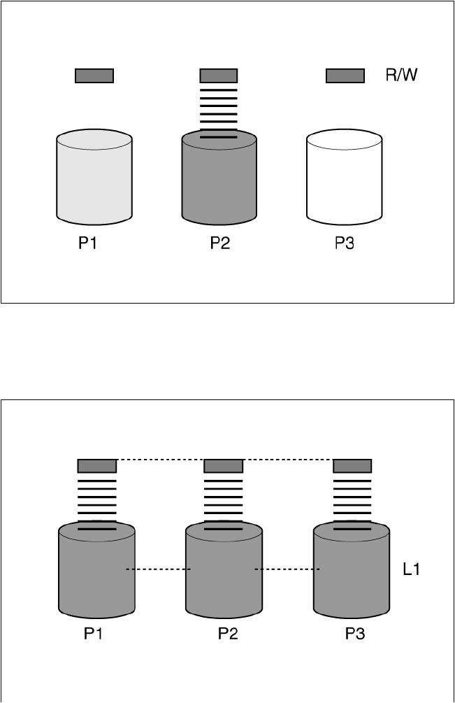
Troubleshooting 117
Connecting extra physical drives (Pn in the figure) to a system increases the total storage capacity but has no
effect on the efficiency of read/write (R/W) operations. Data can still be transferred to only one physical
drive at a time.
With an array controller installed in the system, the capacity of several physical drives can be combined into
one or more virtual units called logical drives (also called logical volumes and denoted by Ln in the figures in
this section). Then, the read/write heads of all the constituent physical drives are active simultaneously,
reducing the total time required for data transfer.
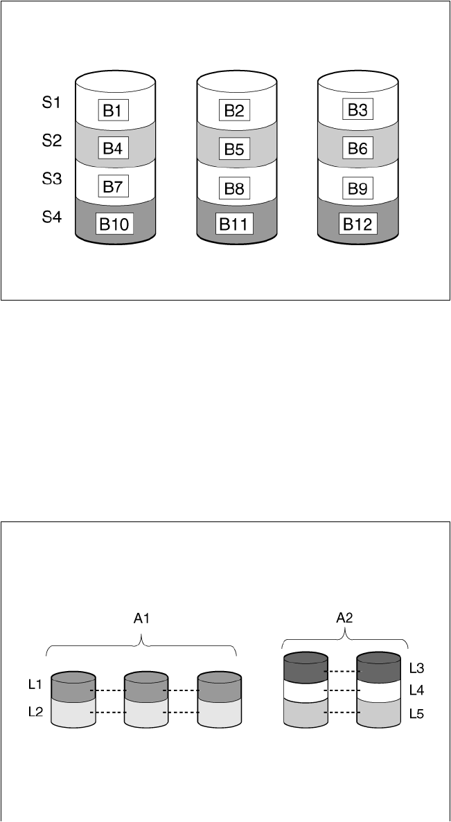
Troubleshooting 118
Because the read/write heads are active simultaneously, the same amount of data is written to each drive
during any given time interval. Each unit of data is called a block (denoted by Bn in the figure), and adjacent
blocks form a set of data stripes (Sn) across all the physical drives that comprise the logical drive.
For data in the logical drive to be readable, the data block sequence must be the same in every stripe. This
sequencing process is performed by the array controller, which sends the data blocks to the drive write heads
in the correct order.
A natural consequence of the striping process is that each physical drive in a given logical drive will contain
the same amount of data. If one physical drive has a larger capacity than other physical drives in the same
logical drive, the extra capacity is wasted because it cannot be used by the logical drive.
The group of physical drives containing the logical drive is called a drive array, or just array (denoted by An
in the figure). Because all the physical drives in an array are commonly configured into just one logical drive,
the term array is often used as a synonym for logical drive. However, an array can contain several logical
drives, each of a different size.
Troubleshooting 119
Each logical drive in an array is distributed across all of the physical drives within the array. A logical drive
can also extend across more than one port on the same controller, but it cannot extend across more than one
controller.
Drive failure, although rare, is potentially catastrophic. For arrays that are configured as shown in the
previous figure, failure of any physical drive in the array causes every logical drive in the array to suffer
irretrievable data loss. To protect against data loss due to physical drive failure, logical drives are configured
with fault tolerance ("Fault-tolerance methods" on page 119).
For any configuration except RAID 0, further protection against data loss can be achieved by assigning a
drive as an online spare (or hot spare). This drive contains no data and is connected to the same controller
as the array. When any other physical drive in the array fails, the controller automatically rebuilds
information that was originally on the failed drive to the online spare. The system is thus restored to full
RAID-level data protection, although it now no longer has an online spare. (However, in the unlikely event
that another drive in the array fails while data is being rewritten to the spare, the logical drive will still fail.)
When you configure an online spare, it is automatically assigned to all logical drives in the same array.
Additionally, you do not need to assign a separate online spare to each array. Instead, you can configure
one hard drive to be the online spare for several arrays if the arrays are all on the same controller.
Effects of a hard drive failure on logical drives
When a drive fails, all logical drives that are in the same array are affected. Each logical drive in an array
might be using a different fault-tolerance method, so each logical drive can be affected differently.
• RAID 0 configurations do not tolerate drive failure. If any physical drive in the array fails, all RAID 0
logical drives in the same array also fail.
• RAID 1 and RAID 10 configurations tolerate multiple drive failures if no failed drives are mirrored to one
another.
• RAID 5 configurations tolerate one drive failure.
• RAID 50 configurations tolerate one failed drive in each parity group.
• RAID 6 configurations tolerate two failed drives at a given time.
• RAID 60 configurations tolerate two failed drives in each parity group.
• RAID 1 (ADM) and RAID 10 (ADM) configurations tolerate multiple drive failures if no more than two
drives, mirrored to one another, fail.
Fault-tolerance methods
Several fault-tolerance methods exist. Those most often used with Smart Array controllers are
hardware-based RAID methods.
Two alternative fault-tolerance methods that are sometimes used are also described ("Alternative
fault-tolerance methods" on page 127). However, hardware-based RAID methods provide a much more
robust and controlled fault-tolerance environment, so these alternative methods are seldom used.
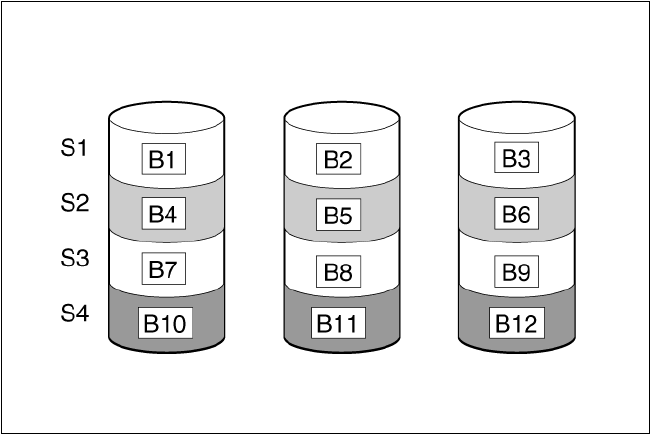
Troubleshooting 120
RAID 0—No fault tolerance
A RAID 0 configuration provides data striping, but there is no protection against data loss when a drive fails.
However, it is useful for rapid storage of large amounts of noncritical data (for printing or image editing, for
example) or when cost is the most important consideration.
Advantages:
• Has the highest write performance of all RAID methods.
• Has the lowest cost per unit of stored data of all RAID methods.
• All drive capacity is used to store data (none is needed for fault tolerance).
Disadvantages:
• All data on the logical drive is lost if a physical drive fails.
• Cannot use an online spare.
• Can only preserve data by backing it up to external drives.
RAID 1 and RAID 1+0 (RAID 10)
In RAID 1 and RAID 1+0 (RAID 10) configurations, data is duplicated to a second drive.
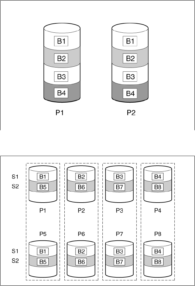
Troubleshooting 121
When the array contains only two physical drives, the fault-tolerance method is known as RAID 1.
When the array has more than two physical drives, drives are mirrored in pairs, and the fault-tolerance
method is known as RAID 1+0 or RAID 10.
In each mirrored pair, the physical drive that is not busy answering other requests answers any read requests
that are sent to the array. This behavior is called load balancing. If a physical drive fails, the remaining drive
in the mirrored pair can still provide all the necessary data. Several drives in the array can fail without
incurring data loss, as long as no two failed drives belong to the same mirrored pair.
This fault-tolerance method is useful when high performance and data protection are more important than the
cost of physical drives.
Advantages:
• This method has the second highest read performance of any fault-tolerant configuration.
• No data is lost when a drive fails, as long as no failed drive is mirrored to another failed drive.
• Up to half of the physical drives in the array can fail.
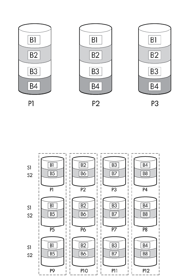
Troubleshooting 122
Disadvantages:
• This method is expensive, because many drives are needed for fault tolerance.
• Only half of the total drive capacity is usable for data storage.
RAID 1 (ADM) and RAID 10 (ADM)
In RAID 1 (ADM) and RAID 10 (ADM) configurations, data is duplicated to two additional drives.
When the array contains only three physical drives, the fault-tolerance method is known as RAID 1 (ADM).
When the array has more than three physical drives, drives are mirrored in trios, and the fault-tolerance
method is known as RAID 10 (ADM).
In each mirrored trio, the physical drives that are not busy answering other requests answer any read
requests that are sent to the array. This behavior is called load balancing. If a physical drive fails, the
remaining two drives in the mirrored trio can still provide all the necessary data. Several drives in the array
can fail without incurring data loss, as long as no three failed drives belong to the same mirrored trio.
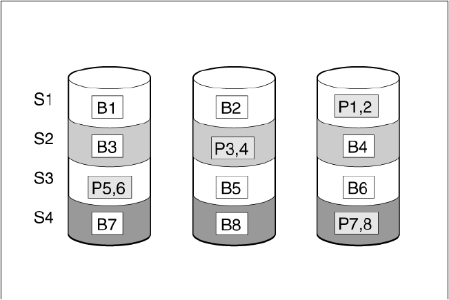
Troubleshooting 123
This fault-tolerance method is useful when high performance and data protection are more important than the
cost of physical drives.
Advantages:
• This method has the highest read performance of any fault-tolerant configuration.
• No data is lost when two drives fail, as long as no two failed drives are mirrored to another failed drive.
• Up to two-thirds of the physical drives in the array can fail.
Disadvantages:
• This method is expensive, because many drives are needed for fault tolerance.
• Only one-third of the total drive capacity is usable for data storage.
RAID 5—distributed data guarding
In a RAID 5 configuration, data protection is provided by parity data (denoted by Px,y in the figure). This
parity data is calculated stripe by stripe from the user data that is written to all other blocks within that stripe.
The blocks of parity data are distributed evenly over every physical drive within the logical drive.
When a physical drive fails, data that was on the failed drive can be calculated from the remaining parity
data and user data on the other drives in the array. This recovered data is usually written to an online spare
in a process called a rebuild.
This configuration is useful when cost, performance, and data availability are equally important.
Advantages:
• Has high read performance.
• Data is not lost if one physical drive fails.
• More drive capacity is usable than with RAID 1+0—parity information requires only the storage space
equivalent to one physical drive.
Disadvantages:
• Has relatively low write performance.
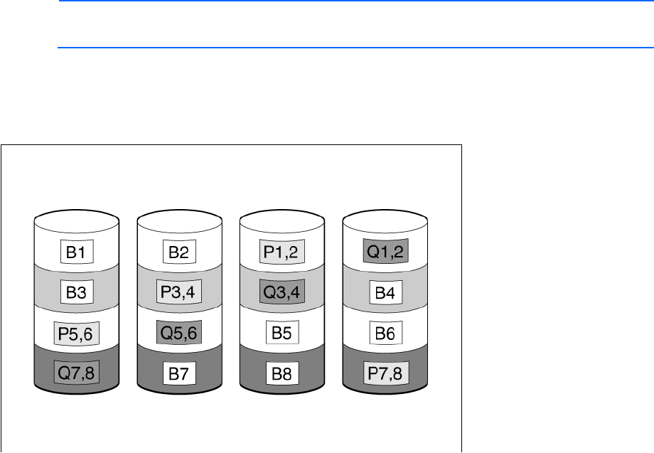
Troubleshooting 124
• Data is lost if a second drive fails before data from the first failed drive is rebuilt.
RAID 6 (ADG)—Advanced Data Guarding
NOTE: Not all controllers support RAID 6 (ADG).
RAID 6 (ADG), like RAID 5, generates and stores parity information to protect against data loss caused by
drive failure. With RAID 6 (ADG), however, two different sets of parity data are used (denoted by Px,y and
Qx,y in the figure), allowing data to still be preserved if two drives fail. Each set of parity data uses a
capacity equivalent to that of one of the constituent drives.
This method is most useful when data loss is unacceptable but cost is also an important factor. The probability
that data loss will occur when an array is configured with RAID 6 (ADG) is less than it would be if it was
configured with RAID 5.
Advantages:
• This method has a high read performance.
• This method allows high data availability—Any two drives can fail without loss of critical data.
• More drive capacity is usable than with RAID 1+0—Parity information requires only the storage space
equivalent to two physical drives.
Disadvantages:
The main disadvantage of RAID 6 (ADG) is a relatively low write performance (lower than RAID 5) because
of the need for two sets of parity data.
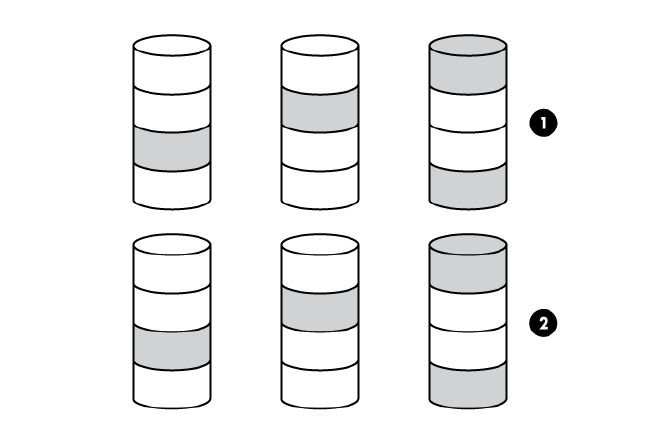
Troubleshooting 125
RAID 50
RAID 50 is a nested RAID method in which the constituent hard drives are organized into several identical
RAID 5 logical drive sets (parity groups). The smallest possible RAID 50 configuration has six drives
organized into two parity groups of three drives each.
For any given number of hard drives, data loss is least likely to occur when the drives are arranged into the
configuration that has the largest possible number of parity groups. For example, four parity groups of three
drives are more secure than three parity groups of four drives. However, less data can be stored on the array
with the larger number of parity groups.
RAID 50 is particularly useful for large databases, file servers, and application servers.
Advantages:
• Higher performance than for RAID 5, especially during writes.
• Better fault tolerance than either RAID 0 or RAID 5.
• Up to n physical drives can fail (where n is the number of parity groups) without loss of data, as long as
the failed drives are in different parity groups.
Disadvantages:
• All data is lost if a second drive fails in the same parity group before data from the first failed drive has
finished rebuilding.
• A greater percentage of array capacity is used to store redundant or parity data than with non-nested
RAID methods.
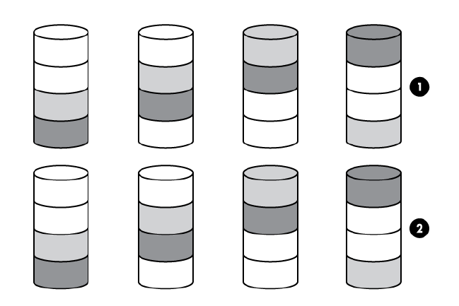
Troubleshooting 126
RAID 60
RAID 60 is a nested RAID method in which the constituent hard drives are organized into several identical
RAID 6 logical drive sets (parity groups). The smallest possible RAID 60 configuration has eight drives
organized into two parity groups of four drives each.
For any given number of hard drives, data loss is least likely to occur when the drives are arranged into the
configuration that has the largest possible number of parity groups. For example, five parity groups of four
drives are more secure than four parity groups of five drives. However, less data can be stored on the array
with the larger number of parity groups.
RAID 60 is particularly useful for data archives and high-availability solutions.
Advantages:
• Higher performance than for RAID 6, especially during writes.
• Better fault tolerance than either RAID 0 or RAID 6.
• Up to 2n physical drives can fail (where n is the number of parity groups) without loss of data, as long
as no more than two failed drives are in the same parity group.
Disadvantages:
• All data is lost if a third drive in a parity group fails before one of the other failed drives in the parity
group has finished rebuilding.
• A greater percentage of array capacity is used to store redundant or parity data than with non-nested
RAID methods.
Comparing the hardware-based RAID methods
Not all controllers support all RAID levels. To support some RAID levels, HP Smart Array G6 and G7
controllers require SAAP ("About SAAP" on page 131).

Troubleshooting 127
Item RAID 0 RAID 1+0 RAID 5 RAID 6
(ADG) RAID 1(0)
(ADM)
Alternative name Striping (no
fault
tolerance)
Mirroring Distributed
Data
Guarding
Advanced
Data
Guarding
Advanced
Data
Mirroring
Formula for number of drives usable
for data (n = total number of drives in
array)
n n/2 n-1 n-2 n/3
Percentage of drive space usable* 100% 50% 67% to 93% 50% to 96% 33%
Minimum number of physical drives
1 2 3 4 3
Tolerates failure of one physical drive
No Yes Yes Yes Yes
Tolerates simultaneous failure of
more than one physical drive
No Only if no
two failed
drives are in
the same
mirrored
pair
No Yes Only if no
three drives
are in the
same mirror
group**
Read performance
High High High High High
Write performance High Medium Low Low Medium
Relative cost Low High Medium Medium Very high
*Values for the percentage of drive space usable are calculated with these assumptions: (1) all physical drives in the
array have the same capacity; (2) online spares are not used; (3) no more than 14 physical drives are used per array for
RAID 5; and (4) no more than 56 drives are used with RAID 6 (ADG).
**Mirror groups include the physical drives in each mirror.
Selecting a RAID method
Not all controllers support all RAID levels. To determine the RAID capabilities of your controller, see the
model-specific information for your controller on the HP website
(http://www.hp.com/products/smartarray).
Most important criterion Also important Suggested RAID level
Fault tolerance Cost effectiveness
I/O performance RAID 6
RAID 10 (ADM), RAID 1+0, RAID 50, RAID 60
Cost effectiveness Fault tolerance
I/O performance
RAID 6
RAID 5 (RAID 0 if fault tolerance is not required)
I/O performance Cost effectiveness
Fault tolerance
RAID 5 (RAID 0 if fault tolerance is not required)
RAID 10 (ADM), RAID 1+0, RAID 50, RAID 60
Alternative fault-tolerance methods
Your operating system may also support software-based RAID or controller duplexing.
• Software-based RAID resembles hardware-based RAID, except that the operating system works with
logical drives as if they were physical drives. To protect against data loss caused by physical drive
failure, each logical drive must be in a different array from the others.
• Controller duplexing uses two identical controllers with independent, identical sets of drives containing
identical data. In the unlikely event of a controller failure, the remaining controller and drives will service
all requests.
Troubleshooting 128
Neither of these alternative fault-tolerance methods supports online spares or automatic data recovery, nor
do they support auto-reliability monitoring or interim data recovery.
If you decide to use one of these alternative methods, configure your arrays with RAID 0 for maximum storage
capacity and refer to your operating system documentation for further implementation details.
Diagnosing array problems
Diagnostic tools
To troubleshoot array problems and generate feedback about arrays, use the following diagnostic tools:
• Event Notification Service
This utility reports array events to the Microsoft® Windows® system event log and IML. You can obtain
the utility from the SmartStart CD or the HP website (http://www.hp.com/support). When prompted for
product information, enter the server model name.
• HP Insight Diagnostics
HP Insight Diagnostics is a tool that displays information about the system hardware configuration and
performs tests on the system and its components, including drives if they are connected to Smart Array
controllers. This utility is available on the SmartStart CD and also on the HP website
(http://www.hp.com/servers/diags).
• POST messages
Smart Array controllers produce diagnostic error messages (POST messages) at reboot. Many POST
messages suggest corrective actions. For more information about POST messages, see the HP ProLiant
Servers Troubleshooting Guide.
• HP Smart Storage Administrator
For more recent products, array diagnostics is available with HP SSA v9.0 and later. This utility is
available through HP Intelligent Provisioning on HP ProLiant Gen8 and later servers, and also on the HP
website (http://www.hp.com/support). For more information about HP SSA, see "About HP SSA (on
page 5)." For more information about error messages, see the HP ProLiant Servers Troubleshooting
Guide.
• HP Smart Storage Administrator Diagnostics Utility CLI
This standalone diagnostic utility provides configuration and error information about array controllers,
storage enclosures, drive cages, logical drives, physical drives, and tape drives. For any supported
SSDs, the utility provides current usage level and remaining expected lifetime. For more information,
see "HP Smart Storage Administrator Diagnostics Utility CLI (on page 112)."
Troubleshooting resources
HP ProLiant G7 (and earlier) products
The HP ProLiant Servers Troubleshooting Guide provides procedures for resolving common problems and
comprehensive courses of action for fault isolation and identification, error message interpretation, issue
resolution, and software maintenance on ProLiant servers and server blades. This guide includes
problem-specific flowcharts to help you navigate complex troubleshooting processes. To view the guide,
select a language:
• English (http://www.hp.com/support/ProLiant_TSG_en)
Troubleshooting 129
• French (http://www.hp.com/support/ProLiant_TSG_fr)
• Italian (http://www.hp.com/support/ProLiant_TSG_it)
• Spanish (http://www.hp.com/support/ProLiant_TSG_sp)
• German (http://www.hp.com/support/ProLiant_TSG_gr)
• Dutch (http://www.hp.com/support/ProLiant_TSG_nl)
• Japanese (http://www.hp.com/support/ProLiant_TSG_jp)
HP ProLiant Gen8 products
The HP ProLiant Gen8 Troubleshooting Guide, Volume I: Troubleshooting provides procedures for resolving
common problems and comprehensive courses of action for fault isolation and identification, issue resolution,
and software maintenance on ProLiant servers and server blades. To view the guide, select a language:
• English (http://www.hp.com/support/ProLiant_TSG_v1_en)
• French (http://www.hp.com/support/ProLiant_TSG_v1_fr)
• Spanish (http://www.hp.com/support/ProLiant_TSG_v1_sp)
• German (http://www.hp.com/support/ProLiant_TSG_v1_gr)
• Japanese (http://www.hp.com/support/ProLiant_TSG_v1_jp)
• Simplified Chinese (http://www.hp.com/support/ProLiant_TSG_v1_sc)
The HP ProLiant Gen8 Troubleshooting Guide, Volume II: Error Messages provides a list of error messages
and information to assist with interpreting and resolving error messages on ProLiant servers and server
blades. To view the guide, select a language:
• English (http://www.hp.com/support/ProLiant_EMG_v1_en)
• French (http://www.hp.com/support/ProLiant_EMG_v1_fr)
• Spanish (http://www.hp.com/support/ProLiant_EMG_v1_sp)
• German (http://www.hp.com/support/ProLiant_EMG_v1_gr)
• Japanese (http://www.hp.com/support/ProLiant_EMG_v1_jp)
• Simplified Chinese (http://www.hp.com/support/ProLiant_EMG_v1_sc)
HP ProLiant Gen9 products
The HP ProLiant Gen9 Troubleshooting Guide, Volume II: Error Messages provides a list of error messages
and information to assist with interpreting and resolving error messages on ProLiant servers and server
blades. To view the guide, select a language:
• English (http://www.hp.com/support/Gen9_EMG_en)
• French (http://www.hp.com/support/Gen9_EMG_fr)
• Spanish (http://www.hp.com/support/Gen9_EMG_es)
• German (http://www.hp.com/support/Gen9_EMG_de)
• Japanese (http://www.hp.com/support/Gen9_EMG_ja)
• Simplified Chinese (http://www.hp.com/support/Gen9_EMG_zh_cn)

Optional components 130
Optional components
HP Secure Encryption
HP Secure Encryption is a controller-based, enterprise-class data encryption solution that protects data at rest
on any bulk storage attached to the HP Smart Array controller. The solution is available for both local and
remote deployments, and works in conjunction with HP SmartCache.
HP Secure Encryption functions to secure sensitive data, for example all business data or data deemed
mission critical and requiring extra levels of protection. Protection is accomplished through the use of data
encryption keys and a simple deployment methodology. Many companies under government regulations
require that sensitive data must be secure and uncompromised. HP Secure Encryption has applied for
FIPS-140-2 (http://csrc.nist.gov/groups/STM/cmvp/documents/fips140-2/FIPS1402IG.pdf) level 2
regulatory data protection regulations established, with certification pending completion in 2014. Not only
is all data at rest protected, but any data that resides on the FBWC module, which is used as a write-caching
mechanism, is also encrypted.
Using the Encryption Manager, you can access HP Secure Encryption features to perform tasks such as key
management through the HP Enterprise Secure Key Manager and managing passwords. For more
information about optional encryption solutions for HP SSA, see the HP Secure Encryption Installation and
User Guide.
To access HP Secure Encryption features for Gen8 or later controllers, a separate license key must be
purchased from HP. To obtain a license key, see the Secure Encryption product page on the HP website
(http://www.hp.com).

HP Smart Array Advanced Pack 131
HP Smart Array Advanced Pack
About SAAP
SAAP is a collection of additional and advanced controller features embedded in the firmware of select
Smart Array controllers. For more information on the current features available through SAAP, see the HP
website (http://h18004.www1.hp.com/products/quickspecs/13200_div/13200_div.pdf).
To access SAAP features for HP Smart Array G6 or G7 controllers, you must purchase a license key from HP.
To obtain a license key, see the SAAP product page on the HP website (http://www.hp.com/go/SAAP). A
license key is not required to access SAAP features on HP Smart Array Gen8 controllers.
To install the license key and activate SAAP, use one of the following methods:
• Installing a license key with HP SSA CLI ("Entering or deleting a license key" on page 64)
• Installing a license key with HP SSA Scripting ("LicenseKey, DeleteLicenseKey" on page 90)
Some SAAP features are required for advanced configuration tasks in HP SSA. For a list of these tasks, see
"Support for configuration tasks (on page 6)."

Acronyms and abbreviations 132
Acronyms and abbreviations
ACU
Array Configuration Utility
ADG
Advanced Data Guarding (also known as RAID 6)
ADM
Advanced Data Mirroring
ADU
Array Diagnostics Utility
DHCP
Dynamic Host Configuration Protocol
FLS
Flexible Latency Scheduler
HP SSA
HP Smart Storage Administrator
iLO
Integrated Lights-Out
ISO
International Organization for Standardization
LUN
logical unit number
ORCA
Option ROM Configuration for Arrays
POST
Power-On Self Test
Acronyms and abbreviations 133
PXE
preboot execution environment
RIS
reserve information sector
SAAP
Smart Array Advanced Pack
SAS
serial attached SCSI
SATA
serial ATA
SMART
self-monitoring analysis and reporting technology
SSD
solid-state drive
SSP
Selective Storage Presentation
TFTP
Trivial File Transfer Protocol
WBEM
Web-Based Enterprise Management
WWN
World Wide Name

Documentation feedback 134
Documentation feedback
HP is committed to providing documentation that meets your needs. To help us improve the documentation,
send any errors, suggestions, or comments to Documentation Feedback (mailto:docsfeedback@hp.com).
Include the document title and part number, version number, or the URL when submitting your feedback.

Index 135
A
action mode, HPSSASCRIPTING 87
ACU scripting 92
ADG (advanced data guarding) 124
advanced data guarding (ADG) 124
array concepts 116
array configuration utilities, features 5
array configuration, copying 81
array, creating, HP SSA scripting 92, 93
array, expanding, HP SSA Scripting 93
array, healing 43
array, moving 72, 93
array, moving, HP SSA Scripting 93
array, replacing 44, 72
array, shrinking 25, 71, 93
array, shrinking, HP SSA Scripting 93
array, specifying and creating,
HPSSASCRIPTING 92
array, specifying, HP SSA scripting 92
ArrayAccelerator 95
C
CacheState 88
capturing configurations 81
choosing a RAID level 127
CLI (Command Line Interface) 55
CLI abbreviations 58
CLI syntax 56
CLI, accessing 10, 14, 115
Command Line Interface (CLI) 55
comparison of RAID features 126
configuration tasks, performing 25, 61, 81
configuration utilities, comparison of 5
configuration utilities, description of 8
configuration utility, choosing 8
console mode, opening ACU in 55
console mode, opening CLI in 55
controller duplexing 127
controller name 69
controller, specifying HPSSASCRIPTING 88
controller, specifying, HP SSA scripting 88
criteria for selecting a RAID level 127
D
data protection methods 119, 127
data striping 116, 120
default settings 82
DeleteLicenseKey 90
deleting a device 63
device information, obtaining 58
devices, discovering 18
devices, identifying 62
diagnostic report 53, 63, 115
diagnostic tools 128
diagnostics 21, 53, 63
disabling drive cache 77
disabling the redundant controller 75
distributed data guarding 123
DPOEnable 91
drive array concepts 116
drive cache, enabling or disabling 77, 89
drive information 68
drive mirroring 120, 122
drive type, HP SSA Scripting 93
DriveType 93
DriveWriteCache 89
duplexing 127
E
effects of a hard drive failure 119
ElevatorSortEnable 91
enabling drive cache 77
enclosure information 68
encryption 130
erase a drive 64
example CLI script, creating logical drive 66
exit on error 78
expanding an array 71, 93
expanding an array, HP SSA Scripting 93
ExpandPriority 91
extending logical drive capacity 73, 98
F
F5 prompt 10
failed logical drive, re-enabling 76
Index
Index 136
fault-tolerance methods 119
features of the utilities 5
G
GUI, accessing 10, 14
H
healing an array 43
help command 60
help resources 22
HP Smart Storage Administrator Diagnostics Utility
CLI 112, 128
HP SmartCaching 68
HP SSA GUI, methods for opening 17
HP SSA scripting error messages 106
I
I/O path, modifying 74, 75, 90
icons 17
identifying devices 62
information about devices, obtaining 58
Input script, using 81, 82
installing the utility 114
Intelligent Provisioning 10
IRPEnable 91
ISO image 11, 12
ISO image path, specifying 13
K
keystroke combinations 17
keyword abbreviations 58
L
languages 5
LEDs, activating 62
LicenseKey 90
local application, using HP SSA as 10, 11, 15
logical drive capacity extension 73, 98
logical drive, caching 95, 96
logical drive, description of 116
logical drive, failed, re-enabling 76
logical drive, migrating, HP SSA Scripting 96
M
MaxBoot setting 97
method mode, HP SSA scripting 87
methods for opening the HP SSA GUI 17
migrating stripe size or RAID level, HP SSA
Scripting 96
minimum requirements 9
mirrored arrays 41
mirrored drives 120, 122
MNPDelay 91
mounting virtual media 11, 12
moving an array 72, 93
N
navigating the interface 18
nested RAID 125, 126
NoBatteryWriteCache 90
Novell NetWare, configuration tool for 8
NumberOfParityGroups 96
O
offline deployment 10
online deployment 14
online spare, HP SSA Scripting 94
online spare, HPSSASCRIPTING 94
OnlineSpare 94
opening CLI in console mode 55
opening the HP SSA GUI 17
operating system support 9
options, scripting, list of 86
over provisioning optimization 29
overview of configuration utilities 8
P
parameters, in CLI, obtaining values of 57
parity groups 96, 125, 126
physical drive write cache, enabling or disabling 77
POST error messages 128
PreferredPath 96
PreferredPathMode 90
PXE-based deployment 12
PXELinux configuration 13
PXELinux setup 12
Q
querying a device 57
QueueDepth 91
R
RAID 44, 73, 96
RAID configuration 44, 73
RAID level migration 74, 96
Index 137
RAID level selection criteria 127
RAID levels 119, 120, 122, 123, 124, 125, 126
RAID levels, comparison of features 126
RAID, software-based 127
RAID-level migration, HP SSA Scripting 96
Rapid Parity Initialization 28, 69
RebuildPriority 75, 91
recombining a split mirrored array 42
redundant controller, disabling 75
redundant controller, modifying I/O path of 74, 75,
90, 96
redundant controller, preferred path settings for 74,
75, 90, 96
re-enabling a failed logical drive 76
registering a license key 38
re-mirroring a split mirror backup 43
remote server, configuring 15
remote service, using HP SSA as 16
renaming a controller 69
Renumber 97
Repeat 97
repeat configuration 97
replacing an array 44, 72
rescan 18, 64
running the HP SSA GUI 17
S
sample script 82
screen description 18, 19, 21, 22
script files 81
scripting modes 80
scripting options 86
scripting syntax 81
Sectors 97
selecting a RAID level 127
shorthand in CLI 58
show (CLI command) 58
shrinking an array 25, 71, 93
Size 98
SizeBlocks 98
Smart Array Advanced Pack (SAAP) 131
SmartCache 35
SmartSSD Wear Gauge report 115, 116
software-based RAID 127
spare activation mode 31, 70
spare drives, HP SSA Scripting 94
spare management 71
split mirror backup 42
splitting a mirrored array 41
SSD OPO 29
standby controller, disabling 75
striping data 116, 120
StripSize 98
surface scan delay 76, 91
surface scan mode 76
SurfaceScanDelay 91
SurfaceScanDelayExtended 91
SurfaceScanMode 91
syntax, CLI 56
T
target device, setting 62
tasks 23, 25, 53
troubleshooting 112, 128
U
utilities, description of 8
V
version command 60
video performance optimization 64, 91
W
warning messages 105
write cache, on physical drives, enabling or
disabling 77
X
XML DTD 104
XML input file 103
XML output file 102
XML support 102
