Hp Teemtalk Terminal Emulator 7 E License Users Manual DM_38
2015-01-05
: Hp Hp-Teemtalk-Terminal-Emulator-7-E-License-Users-Manual-201588 hp-teemtalk-terminal-emulator-7-e-license-users-manual-201588 hp pdf
Open the PDF directly: View PDF ![]() .
.
Page Count: 256 [warning: Documents this large are best viewed by clicking the View PDF Link!]
- Table of Contents
- CHAPTER 1 Introduction
- CHAPTER 2 Installing HP Device Manager
- CHAPTER 3 Getting Started
- CHAPTER 4 Using the HP Management Console
- Menu Item Overview
- Toolbar Overview
- Device Management
- Discovering Devices
- Grouping Devices
- Editing the Device Filter
- Searching for a Device in the Device Tree
- Checking Network Connection Status
- Printing Information About Devices & Tasks
- Shadowing Devices
- Power Management
- Task Template Management
- Task Management
- Device Status Tools
- CHAPTER 5 Common Tasks
- CHAPTER 6 Advanced Tasks
- CHAPTER 7 Configuration Management
- APPENDIX A Installing & Running JRE
- APPENDIX B Installing & Running MySQL
- APPENDIX C Error Code Reference
- Index

HP Device Manager 3.8
User Manual
ii
© Copyright 2008 Hewlett-Packard
Development Company, L.P. The
information contained herein is subject to
change without notice.
Microsoft and Windows are trademarks of
Microsoft Corporation in the U.S. and other
countries.
Pentium is a trademark of Intel Corporation
in the U.S. and other countries.
Java is a US trademark of Sun
Microsystems, Inc.
The only warranties for HP products and
services are set forth in the express warranty
statements accompanying such products
and services. Nothing herein should be
construed as constituting an additional
warranty. HP shall not be liable for technical
or editorial errors or omissions contained
herein.
This document contains proprietary
information that is protected by copyright. No
part of this document may be photocopied,
reproduced, or translated to another
language without the prior written consent of
Hewlett-Packard Company.
First Edition (April 2008)

iii
HP Device Manager User Manual
Table of Contents
CHAPTER 1
Introduction 1
What is HP Device Manager? 1
Overview 2
Concepts 4
The Device Pane 4
Device Tree 4
Element 4
Task Template 4
Managed Device 5
OS Tabs 5
PXE 5
Repository 5
Task 5
Task Pane & Summary Pane 6
Template Pane 6
Status Bar 6
EWF 6
Agent Mode 6
Getting More Information 7
The Internet 7
Technical Support 7

Table of Contents
iv
About This Manual 7
Overview of Contents 7
Terms & Conventions 9
CHAPTER 2
Installing HP Device Manager 11
Introduction 11
System Requirements 12
Management Console 12
Management Server 12
Management Gateway 13
Management Agent 13
Third Party Software 13
Network Requirements 14
Installing HP Device Manager 16
Configuring DHCP Servers 30
Management Server Installed Separately to the
DHCP Server 30
Management Server Installed on DHCP Server
Machine 30
Adding DHCP Option 60 and 201 to an ISC DHCP
Server 32
Configuring a Linux DHCP Server 33
Configuring Routers 33
Uninstalling Device Manager 34
CHAPTER 3
Getting Started 37
Logging in to the HP Management Console 37
Configuring the Repository 39
Creating an FTP Repository 39
Management Console Overview 43
Client Discovery 45
HP Management Agent Broadcast 45
Discover Agent 45
Discover by DHCP Tag 49

Table of Contents
v
Agent Configuration 49
Adding Elements to the Repository 51
Importing an Element into the Repository 52
CHAPTER 4
Using the HP Management Console 57
Menu Item Overview 57
Toolbar Overview 62
Device Management 64
Device Tree Icons 65
Displaying Device Properties 66
Deleting Devices 67
Discovering Devices 68
Grouping Devices 71
Dynamic Grouping 71
Manual Grouping 75
Naming Grouping Properties 78
Changing Grouping Properties 79
Pre-assigning Devices to Groups 80
Editing the Device Filter 81
Filter Security 85
Searching for a Device in the Device Tree 86
Checking Network Connection Status 87
Printing Information About Devices & Tasks 89
Printing Device Information 89
Printing a Device Task Report 90
Shadowing Devices 91
Power Management 93
Task Template Management 94
Task Template Categories 94
Creating & Editing Task Templates 95
Adding a Template to Favorites 96
Using Template Sequence Templates 96
Importing & Exporting Task Templates 97
Task Management 98

Table of Contents
vi
Task Pane Icons 98
Applying Tasks to Devices 99
Displaying Task Properties 102
Configuring Task Parameters 103
Pausing Tasks 105
Continuing Tasks 106
Resending Tasks 106
Deleting Tasks 107
Displaying Task Logs 107
Opening VNC Viewer for Shadowing 108
Opening a Result Template 108
Device Status Tools 109
Status Walker 109
Status Snapshot 114
CHAPTER 5
Common Tasks 117
Performing a Task 117
Changing Connection Settings 119
Changing Device Settings 122
Configuring Network Settings 122
Configuring Display Settings 123
Configuring Time Settings 124
Configuring Write Filter Settings 125
Using File and Registry Templates 127
Merging File and Registry Templates 130
Copying Files 131
Remote Command Execution 134
Remote Execution of Windows Scripts 136
CHAPTER 6
Advanced Tasks 137
Snapins 137
Introduction 137
Applying a Snapin to a Thin Client 138
Images 145

Table of Contents
vii
Introduction 145
Images & Repository Management 145
Client BIOS Settings for PXE 146
Pulling a PXE Image From a Client 147
Pushing a PXE Image to a Client 150
Preparing an XPe Client for Image Distribution 152
Cloning an XPe Image 153
Updating Images 157
Changing Registry Settings 159
Getting Registry Settings 159
Installing an XPe Software Component 166
Transferring an XPe Software Component to the FTP
Repository 166
Installing an XPe Software Component on Client
Devices 169
Performing a Persistent Write Operation on NeoLinux 4.x
Devices 170
Adding Devices Using MAC Addresses 173
Configuring Agents 175
Setting Agent Parameters 175
Updating the Agent Version 176
CHAPTER 7
Configuration Management 177
User Management 177
Working With Users 177
Working With Groups 180
FTP Repositories 183
Configuring an FTP Repository 183
Deleting a Repository 184
Exporting a Repository 184
Importing a Repository 185
FTP Repository Selection for Templates 185
FTP Mappings 186
Listing Devices & their FTP Servers 186
Listing Subnets & their FTPs Servers 187

Table of Contents
viii
Filtering Devices or Subnets 188
Grouping Property Name 190
Task Parameters 191
Valid Time and Timeout 191
Write Filter Policy Setting 192
Task Settings 193
Status Walker Configuration 194
Licensing 195
Importing a New License 195
Authentication Management 196
Key Management 196
Gateway Access Control 201
Report Management 202
Adding a Report Template 202
Importing a Report Plug-in File 206
Generating a Report Using a Report Template 207
Alias Management 209
Device Version Alias 209
Subnet Address Alias 211
Exporting an Alias 212
Importing an Alias 212
Template Plugin Management 213
Importing a Template Plugin 213
Removing a Template Plugin 214
APPENDIX A
Installing & Running JRE 215
Introduction 215
Windows-based Server Installation 215
Linux-based Server Installation 216
APPENDIX B
Installing & Running MySQL 217
Installing MySQL on Linux-based Servers 217
Running MySQL on Linux-based Servers 218


Table of Contents
x

1
HP Device Manager User Manual
CHAPTER 1 Introduction
This chapter introduces HP Device Manager and describes the
scope of this User Manual.
What is HP Device Manager?
HP Device Manager is a server-based application that provides
sophisticated centralized administration capabilities for thin client
devices running HP software. Features of HP Device Manager
include:
•Centralized management of software configuration and
upgrades.
•A central server-based database.
•The ability to easily create, store and update tasks.
•The ability to report on work done and task status.
•The ability to access any file or the system registry in thin client
devices.
•XML-based task file.
•Design tool for administrator to create tasks.
•User-friendly graphical user interface.
•Easy and powerful repository management.
•Support for WAN environment.
•Windows® XPe device management.
Introduction
2 What is HP Device Manager?
•Easy to change Enhanced Write Filter setting for XPe Agent.
•The ability to adjust the response time.
•Communicate with Data Encryption and Data Compression
between HP Management Server and HP Management Gateway.
•Easy to set the work mode of Agent.
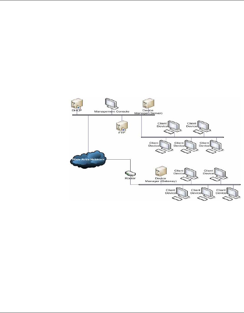
Overview HP Device Manager is structured as a Console - Server - Gateway
system.
HP Management Console
The HP Management Console is the user interface of HP Device
Manager. Several HP Management Consoles can interact with an HP
Management Server. The console allows system administrators to
view details for each controlled device, organize device trees, create
and maintain remote job definitions, and monitor tasks sent out to
devices.

Introduction
What is HP Device Manager? 3
HP Management Server
The HP Management Server controls agents through the HP Man-
agement Gateway. Tasks, stored as Task Templates on the server, can
be sent to each agent through each agent’s respective gateway to per-
form commands as required.
HP Management Gateway
The HP Management Gateway serves as the link between devices
and the HP Management Server. Devices register with the gateway
when they are started. The machine installed with the HP Manage-
ment Gateway also normally contains the PXE Server installed by
HP Device Manager.
Device Agent
The HP Management Agent is a software component installed on
thin client devices so that HP Device Manager can interact with
them. Agents are embedded into each HP operating system to enable
Device Manager to manage devices out-of-the-box (however, agents
on older devices may need to be upgraded). Agents get task
commands, execute the commands and report on their status.
FTP Server
The FTP server is where files are stored in a repository of compo-
nents, images, etc. that can be uploaded from or downloaded to the
agents at the request of the HP Management Server. You can create a
repository on more than one FTP server. The repository on an FTP
server is referred to as the "FTP Repository" in dialogs and in this
User Manual to distinguish it from the HP Management Server
Repository (the "Server Repository").

Introduction
4 Concepts
Concepts
The Device Pane The Device Pane is in the top-left of the Management Console’s
main screen. All thin clients of a selected product type that are
connected to the server are displayed in this pane.
This pane contains the Device Tree and the Grouping Scheme drop-
down menus.
Device Tree The Device Tree is the organized structure of all the managed
devices in the Management Console, displayed in the Device Pane,
on the top-left of the main screen.
The tree contains all the devices reported to the Management Server.
Devices can be automatically sorted and grouped according to their
attributes, or they can be dragged and dropped into arbitrary groups
when the devices are grouped by their customized extended
properties.
Tasks can be designated to groups of devices to meet their specific
needs.
Element An Element is a type of resource (such as a software component,
system image, diagnostic tool or agent file) stored in the Repository
which can be applied to a device using a particular template.
Task Template Task Templates are some of the tools administrators may use to
remotely control the devices. They are displayed in the Template
Pane. Each Task Template is an XML file that defines the configura-
tion change or software update that administrators want the remote
devices to do.
HP Device Manager provides a variety of built-in Task Templates
and many examples on how to manage remote devices, including
device name changes, network settings, home URL changes, ICA
connection clones, add/remove software components and so on.

Introduction
Concepts 5
Task Templates can be imported or exported by using tools on the
Management Console. New Task Templates can be downloaded
from HP’s FTP site, then imported to your HP Management Server.
Managed Device Managed device, client device, remote device, or device, as
mentioned in this manual, means a device managed by HP Device
Manager, such as a thin client.
OS Tabs OS Tabs enable you to select the different categories of Platform
Operating System that are controlled by HP Device Manager.
PXE PXE is a protocol defined on a foundation of industry-standard
Internet protocols and services that are widely deployed in the
industry (namely TCP/IP, DHCP, and TFTP).
HP Device Manager utilizes PXE to execute thin-client image
extraction and distribution.
Repository The Repository is a collection of elements which may consist of
software components, system images, diagnostic tools and agent
files stored on one or more FTP servers. The Repository actually
resides over several servers, these being the HP Management Server
Repository (the "Server Repository") and one or more FTP Server
Repositories (the "FTP Repository").
Task A task, or job, is the scheduled action to execute Task Templates to a
device or group of devices. To create a task, just drag and drop the
desired Task Template from the template pane to a device or a group
of devices in the device tree. Once executed, the details of the task
will be displayed in the Task Pane and the summaries will be
displayed in the Summary Pane.

Introduction
6 Concepts
Task Pane &
Summary Pane
The Task Pane and Summary Pane are in the bottom area of the
main Management Console window. They display the execution sta-
tus for each task. If there is more than one device for a listed task,
the status of each device will be listed.
Template Pane The Template Pane is in the top-right of the Management Console
main screen. The templates that are applicable to the listed client
devices are listed here.
Status Bar The Status Bar is shown at the very bottom of the main Management
Console window. Descriptions of various items in HP Device Man-
ager are displayed here when the mouse cursor moves over them; for
example, a description of each Device Pane icon is displayed when
the mouse cursor moves over each icon.
EWF Enhanced Write Filter (EWF) provides the ability to write-protect a
run-time image. By redirecting all write requests to either a separate
disk partition or RAM, EWF allows the run-time image to maintain
the appearance of a writeable run-time image. Additionally,
Enhanced Write Filter provides the ability to deploy a run-time
image onto read-only media, such as a CD-ROM.
Agent Mode Agent Mode is the mode of the Management Agent to acquire tasks
from the Management Gateway. Through configurations to the
Agent mode, the agent can work at the NAT network without Gate-
way. The Agent mode can be either Push mode or Pull mode. Push
mode means the gateway sends the available task to the agent, and
Pull mode means the agent would require the task from the gateway
at regular intervals.

Introduction
Getting More Information 7
Getting More Information
The Internet Current and archival information about HP products, including the
latest software updates, is available at:
http://www.hp.com
In addition, this user manual and other HP documentation are avail-
able at the HP web site for browsing or downloading.
Technical Support For technical support regarding HP products, call HP at +1-610-277-
8300 or request support using the form at:
http://www.hp.com/support/support_request.html
About This Manual
This manual explains how to use HP Device Manager version 3.8.
Occasionally it will refer to items displayed by client operating
systems. For a description of these items, please refer to the User
Manual for the type of client operating system being used.
Overview of
Contents
This manual is divided into the following chapters and appendices:
Chapter 1: Introduction
Introduces HP Device Manager and describes the scope
of this User Manual.
Chapter 2: Installing HP Device Manager
Describes the requirements for running HP Device
Manager and how to install it.
Chapter 3: Getting Started
Describes how to start using the HP Management
Console, set up a repository, and discover clients.

Introduction
8 About This Manual
Chapter 4: Using the HP Management Console
Covers the main functions of the Management Console,
including device management, task templates and task
management.
Chapter 5: Common Tasks
Describes how to use the Management Console to
change device settings, copy files and execute
commands.
Chapter 6: Advanced Tasks
Describes how to use snapins, images, change registry
settings, install XPe software components, and set the
agent mode.
Chapter 7: Configuration Management
Explains the administration of the console, working
with users, advanced server configuration, and
licensing.
Appendix A: Installing & Running JRE
Describes how to install and run the Java® Runtime
Environment.
Appendix B: Installing & Running MySQL
Describes how to install and run MySQL.
Appendix C: Error Code Reference
Explains the meaning of error codes which may be
generated by HP Device Manager.

Introduction
About This Manual 9
Terms &
Conventions
The following terms and conventions are used in this manual:
devices, clients and thin clients
The terms "devices", "clients", "thin clients" are interchangeable and
refer to any client devices that are running HP software.
keys to press
When you need to press two or more keys together at the same time,
such as the Ctrl key and the C key, this will be indicated by a plus
character inbetween the key names, which will be highlighted. For
example: Ctrl + C. The "+" character does not represent a key to be
pressed.
double-click
To "double-click" means to click the left mouse button twice in
quick succession when the mouse pointer is on a particular item on
the display, such as an icon. You should use the left mouse button
unless specifically told otherwise.
drag
To "drag" means to position the mouse pointer on an item on the dis-
play (such as the edge of a window), then hold down the left mouse
button and move the mouse while keeping the button held down.

Introduction
10 About This Manual

11
HP Device Manager User Manual
CHAPTER 2 Installing HP Device
Manager
This chapter describes the requirements for running HP Device
Manager and how to install it.
Introduction
HP Device Manager consists of four modules:
•Management Console
The graphical application used by administrators to access
the management system.
•Management Server
The central server which consolidates and controls all
management activities.
•Management Gateway
The gateway which serves as the link between Agents and the
Management Server.
•Management Agent
Software installed on the client to enable device management.
The Management Console, Management Server and Management
Gateway may be installed on the same machine, or on different
machines separately.

Installing HP Device Manager
12 System Requirements
System Requirements
Management
Console
The Management Console can be installed on any number of
machines. It has the following minimum system requirements:
•Operating System
Windows 2000 Professional (SP4)
Windows 2000 Server (SP4)
Windows XP Professional (SP2)
Windows 2003 Server
•Third-party Software
Java™ Runtime: SUN Java Runtime Environment version 1.4.2.
•Hardware
Pentium-III or greater
512MB RAM
256MB free disk space.
Management
Server
The Management Server should be installed on a single machine. It
has the following minimum system requirements:
•Operating System
Windows 2000 Server (SP4)
Windows 2003 Server
•Third-party Software
Java Runtime:
SUN Java Runtime Environment version 1.4.2.
DBMS - any of the following are supported:
Microsoft SQL Server 2000
MySQL 4.1
Microsoft Access 2000 or later.
•Hardware
Pentium® III or greater
512 MB RAM
512 MB free disk space.

Installing HP Device Manager
System Requirements 13
Management
Gateway
The Management Gateway may be installed on multiple machines.
However, only one Gateway should be present on a subnet. It has the
following minimum system requirements:
•Operating System
Windows 2000 Professional (SP4)
Windows 2000 Server (SP4)
Windows 2003 Server
•Third-party Software
N/A
•Hardware
Pentium-III or greater
512 MB RAM
512 MB free disk space.
Management Agent The Management Agent should be installed on each device that will
be managed by the system. It has the following minimum system
requirements:
•Operating System
NeoLinux 4.0.1
Neoware CE 8.1
Neoware XP embedded 1.4.2 or later
NeoLinux 3
•Hardware
Thin-client device supporting one of the operating systems listed
above.
2 MB free disk space.
Third Party
Software
The following FTP Servers are recommended for use with HP
Device Manager:
•FTP Server
Microsoft Internet Information Server (IIS) 5.0
Rhinosoft Serv-U FTP Server 4.0
SCO UNIX OpenServer FTP Server 5.0.4 or 5.0.6.

Installing HP Device Manager
14 System Requirements
Network
Requirements
The network should not contain any other running PXE servers. It
should permit free communication on ports used by HP Device Man-
ager. A number of UDP and TCP ports are required for client/server
communication. See Table 1 for a list of standard ports required, and
Table 2 for a list of custom ports required.
If you are using a Server behind a firewall, please add ports 1099 and
40002 to the exception ports in the firewall settings.
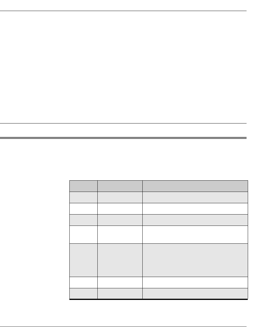
Table 1: Standard Ports Required
Port Protocol Purpose
67 & 68 UDP PXE - Bootstrap.
69 UDP TFTP (Trivial File Transfer Protocol).
4011 UDP DHCP Proxy Service (this is an alternative to ports
67 and 68 if those ports are not available).
20 & 21 TCP FTP (used for the Repository).
5900 TCP VNC Server.
Table 2: Custom HP Device Manager Ports Required
Receiver
Port
Sender Receiver Protocol Purpose
1099 Console Server TCP Console queries the RMI
Registry.
40000 Server/
Agent
Gateway UDP Server/Agent polls Gateway.
40001 Gateway Agent TCP Gateway sends task to Agent.
40002 Console Server TCP Console calls the remote
objects on Server by RMI.
40003 Server/
Agent
Gateway TCP Server sends task to
Gateway;
Agent sends report to
Gateway.

Installing HP Device Manager
System Requirements 15
40005 Gateway Server TCP Gateway sends report to
Server.
Table 2: Custom HP Device Manager Ports Required
Receiver
Port
Sender Receiver Protocol Purpose
Installing HP Device Manager
16 Installing HP Device Manager
Installing HP Device Manager
The installation program will determine if the software required to
run Device Manager is already installed.
Note: Different operating systems may have slightly different steps
and wording for the installation process.
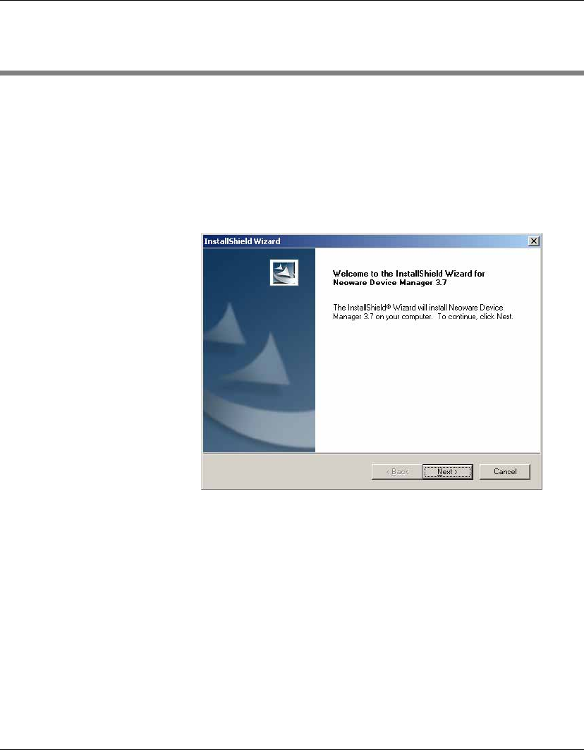
1Run the Device Manager InstallShield Wizard. The installa-
tion’s introductory dialog will be displayed.
2Click Next.
3Read then accept all the terms in the License Agreement dialog
by clicking Yes.
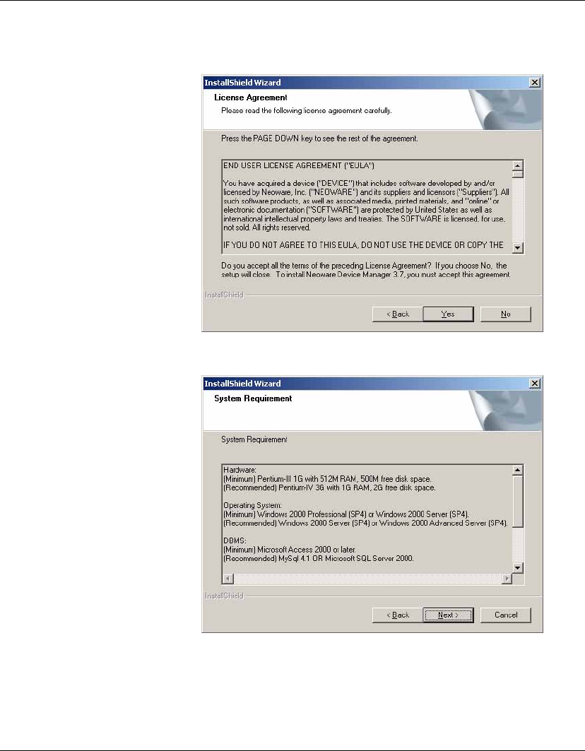
Installing HP Device Manager
Installing HP Device Manager 17
4Read the System Requirement then click Next.
5In the Choose Destination Location dialog, select the folder
where Device Manager will be installed. Accept the default
folder or click Browse and navigate to a specific location.
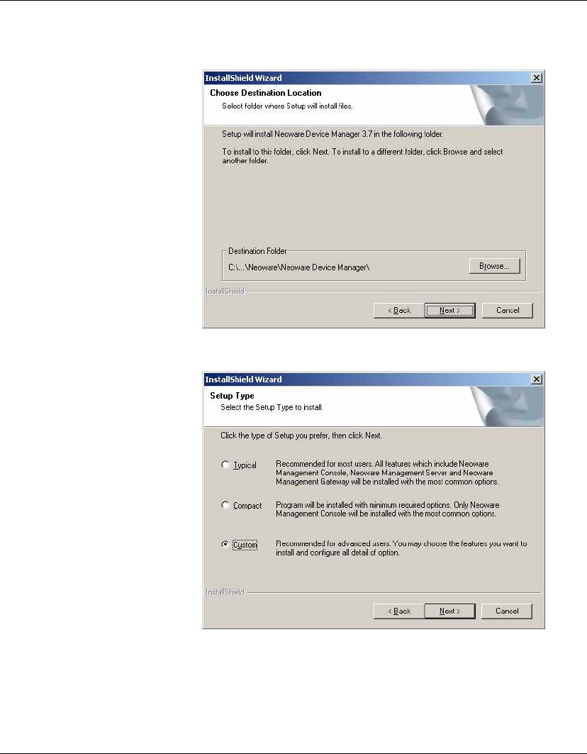
Installing HP Device Manager
18 Installing HP Device Manager
6Click Next and select a Setup Type.
Typical - The Management Console, Server and Gateway will be
installed with their default configurations. A Microsoft Access
database will be initialized as the Server’s database.
Compact - Only the Management Console will be installed.
Installing HP Device Manager
Installing HP Device Manager 19
Custom - Select the components to install and specify the con-
figuration of each one:
•Console - Does not require any configuration.
•Server - You can choose which database will be used for the
Server. The optional databases are Microsoft Access,
MySQL and Microsoft SQL Server.
•Gateway - You should configure DHCP and Gateway set-
tings. The DHCP server is used by the PXE boot ROM to get
an IP address as well as other basic networking information
(subnet mask, default gateway, etc.).
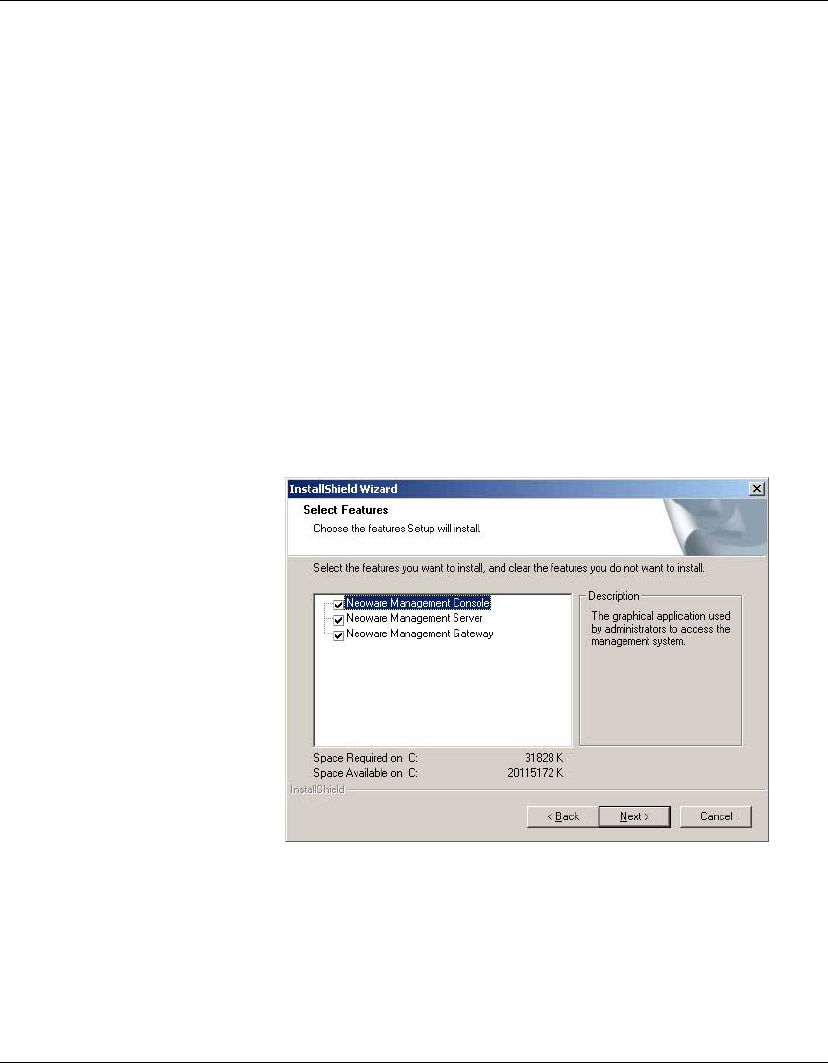
7Select Custom as an example, then click Next to continue.
8Select the Device Manager components that you wish to install
then click Next to continue.
Installing HP Device Manager
20 Installing HP Device Manager
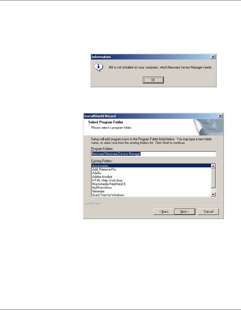
A Java Runtime Environment of version 1.4 or later, including
any Java2 platform system, is required to run Device Manager. If
JRE is not installed on your machine or its version is older than
1.4, the system will display the following dialog:
9In the Select Program Folder dialog, select the name of the
folder to store HP Device Manager.
Installing HP Device Manager
Installing HP Device Manager 21
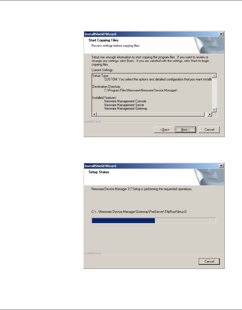
10 Click Next to preview the current installation settings.
11 Click Next to start installing the selected HP Device Manager
component(s).
Installing HP Device Manager
22 Installing HP Device Manager
12 Please wait until the file copying process is finished.
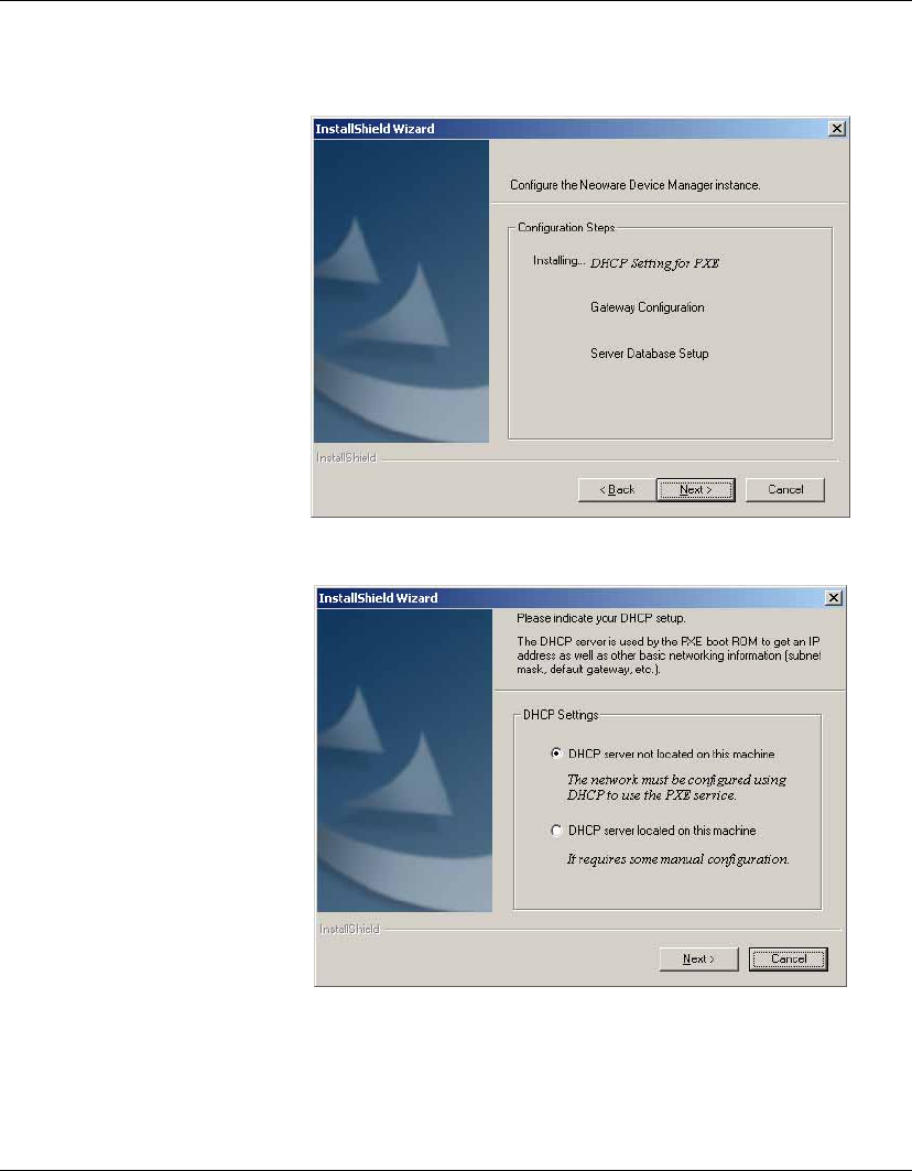
13 Click Next and the DHCP Configuration dialog will appear.
Specify whether the DHCP server is located on the machine you
are installing HP Device Manager.
Installing HP Device Manager
Installing HP Device Manager 23
Note: The DHCP server may need to be configured so that it can
be used with Device Manager, particularly if it is on the same
machine as Device Manager. See “Configuring DHCP Servers”
on page 30 for further information.
14 Click Next to install the Management Server and Management
Gateway services to your machine.
Installing HP Device Manager
24 Installing HP Device Manager
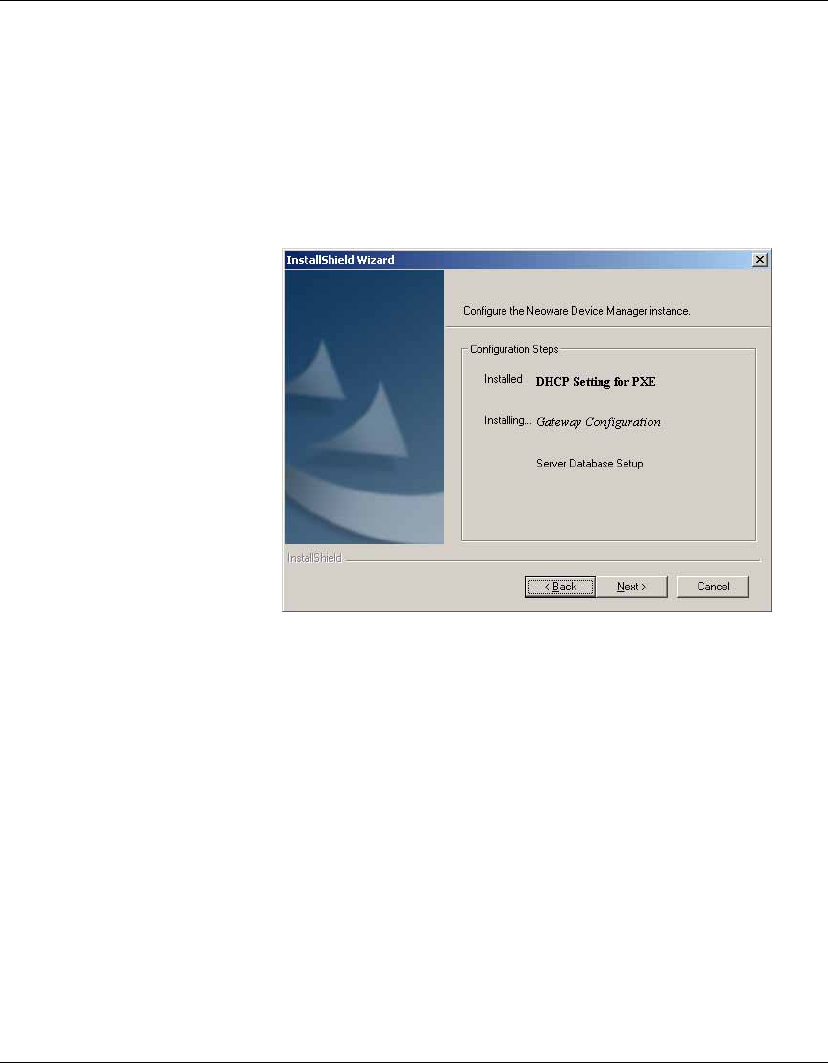
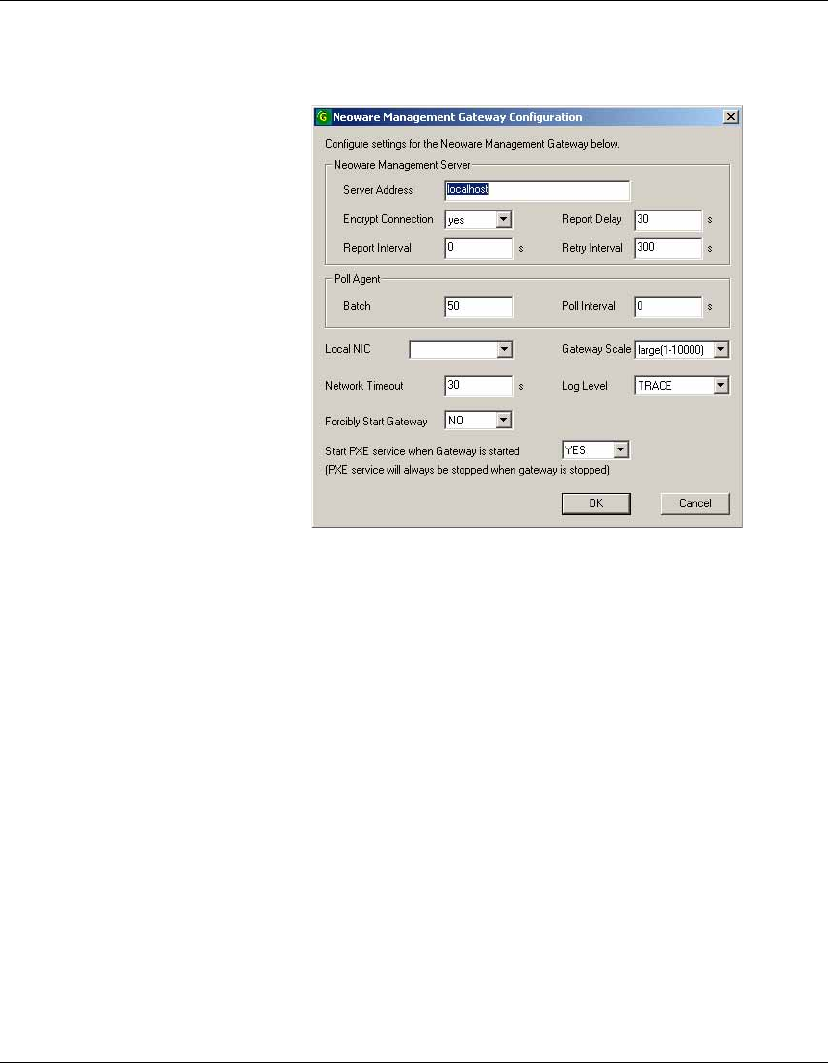
15 Click Next to display the Gateway Configuration dialog.
The Management Server Address is the address for the Manage-
ment Server that the Management Gateway will report to.
The Local NIC selects which NIC the gateway will receive agent
reports on. If there is only one NIC for the system, this field can
be left blank.
The Start PXE service when Gateway is started setting deter-
mines whether the PXE service will be started along with the
Management Gateway. The PXE service is always installed
along with the Gateway, but can be controlled independently of
the Gateway (by changing this setting to NO) if required. If this
is set to YES, when the Gateway is stopped, the PXE service
will also stop; when the Gateway is started, the PXE service will
also start.
Installing HP Device Manager
Installing HP Device Manager 25
16 Once you have set up the Gateway, click OK to save the settings
and continue.
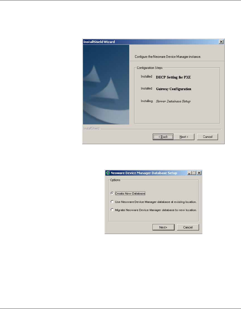
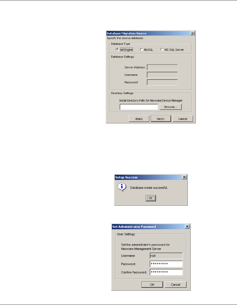
17 Click Next to start the Management Server Database configura-
tion.
18 Select one database installation option and click Next to start the
configuration.
Installing HP Device Manager
26 Installing HP Device Manager
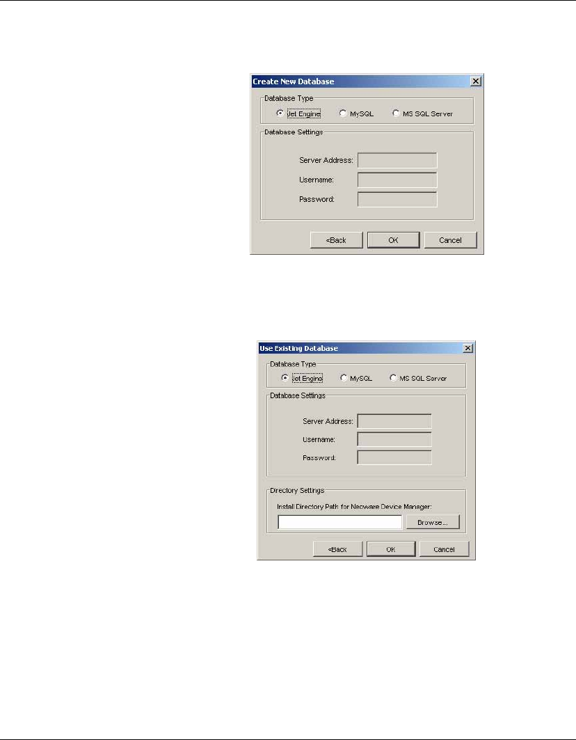
Create new database:
Note: If a Database named ndmdb already exists, it will be
overwritten without any warning!
Use Device Manager database at existing location:
Select the folder where Device Manager has been installed.
Input the path or click Browse and navigate to a specific location
in the Directory Settings box.
Installing HP Device Manager
Installing HP Device Manager 27
Migrate Device Manager database to new location:
Select the folder where Device Manager has been installed.
Input the path or click Browse and navigate to a specific location
in the Directory Settings box.
19 The following dialog will appear when the database has been
successfully created.
20 Click OK to set the Administrator password.
Installing HP Device Manager
28 Installing HP Device Manager
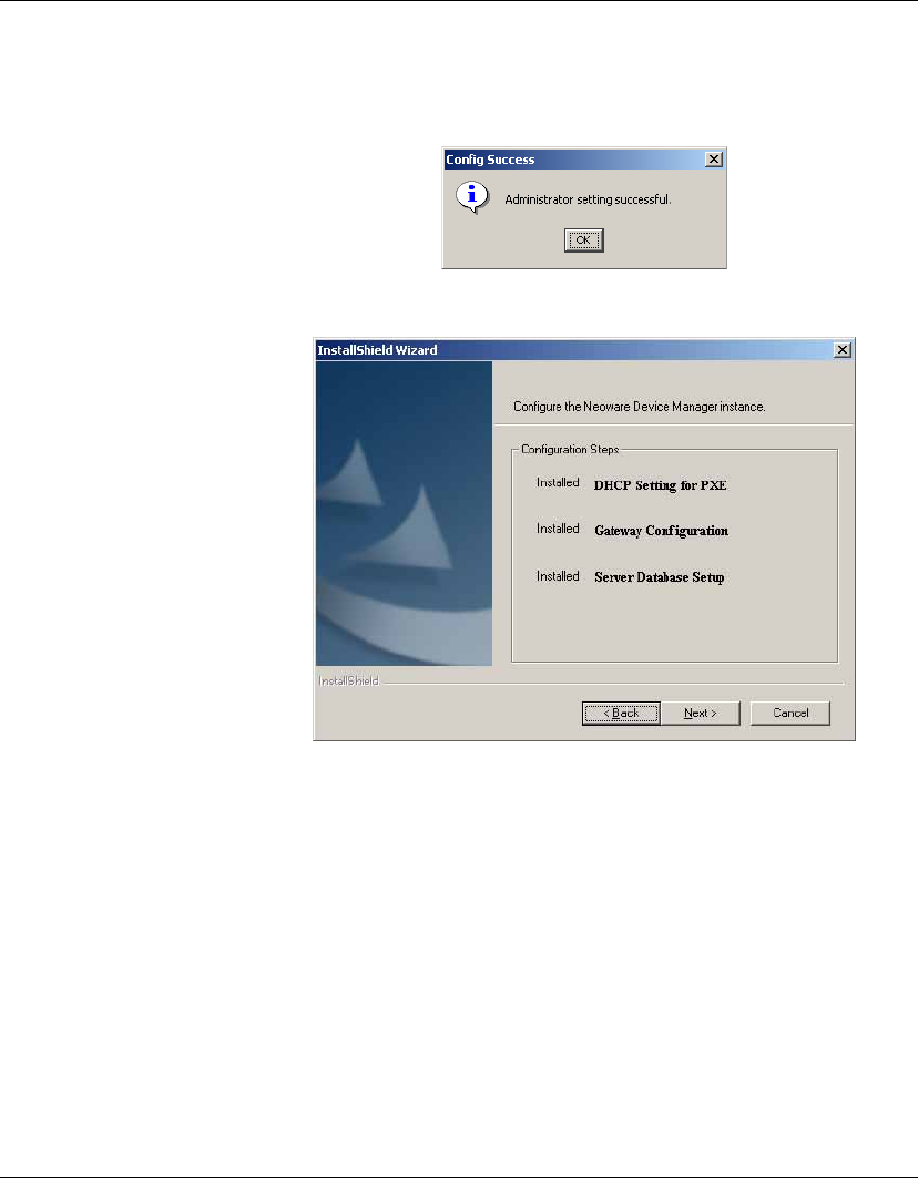
21 Click OK and you will be informed that the password has been
set successfully.
22 Click OK.
23 Click Next.
Installing HP Device Manager
Installing HP Device Manager 29
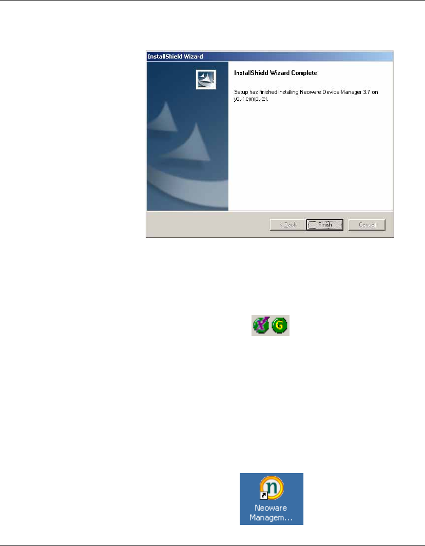
24 Click Finish to complete the installation process.
25 If the Management Console, Server and Gateway are setup
successfully, icons of the Server and Gateway will be displayed
in the Systray of your machine as shown below.
A green icon indicates the service is running, a yellow icon
indicates the service is starting up, and a red icon indicates the
service has stopped.
Note: You can start/stop services and configure the Gateway
server again by using the menu options displayed when you
right-click on the Systray icons.
An icon for the Management Console will be displayed on the
desktop.

Installing HP Device Manager
30 Configuring DHCP Servers
Configuring DHCP Servers
This section describes how to configure the DHCP server for use
with PXE.
Management
Server Installed
Separately to the
DHCP Server
Should problems occur when using PXE, the DHCP servers may
need to be checked for certain settings that may conflict with PXE.
However, on most networks, these issues should not occur.
The DHCP server is used by the PXE boot ROM to get an IP address
as well as other basic networking information (subnet mask, default
gateway, etc.).
Note: The network must be configured using DHCP to use the PXE
service.
Configuring the DHCP Server
1Ensure the DHCP server has not been previously configured for
a PXE bootstrap.
2If the DHCP options 43 & 60 are set, remove them.
Note: The Device Manager PXE service will detect the DHCP
packets sent by any PXE BootROMs and will offer PXE network
parameters without disturbing the standard DHCP negotiation
process. This is called DHCP Proxy.
The DHCP server should then be ready to be used with PXE.
Management
Server Installed on
DHCP Server
Machine
If Management Server is installed with a DHCP server on the same
machine, it requires some manual configuration.
The Management Server installation process installs the HP PXE
Service. This service provides the PXE remote-imaging function.
The service is automatically started and stopped with the operating
system.

Installing HP Device Manager
Configuring DHCP Servers 31
The DHCP server is used by the PXE boot ROM to get an IP address
as well as other basic networking information (subnet mask, default
gateway, etc.).
The following instructions assume that:
•The network is already configured using DHCP.
•The DHCP server has not been previously configured for a PXE
bootstrap.
•There are no other TFTP servers running on the same network.
Configuring the DHCP Server:
By default options 60 and 201 are not set under Windows 2000.
These options will have to be added in order to tell PXE clients
where to find the Management Server.
1If DHCP option 43 is set, remove it. (This is due to the fact that
Management Server is installed on the same machine as the
DHCP server.)
2Add option 60, and set value to “PXEClient”. If option 60 does
not exist, see the following instructions on setting this option.
Either:
•From the main Windows menu select Start > Run.
•Enter Cmd in the Open: field. A Command shell appears.
•Enter netsh then press the Enter key.
•Enter dhcp then press the Enter key.
•Enter server \\servername (using the UNC name for the
server).
Or:
•Enter server <ip_address> (using the IP address of the
server.). A “dhcp server >” prompt appears in the command
window.

Installing HP Device Manager
32 Configuring DHCP Servers
•Enter add optiondef 60 (name of your choice) STRING 0
then press the Enter key.
•Enter set optionvalue 60 STRING “PXEClient“ then press
the Enter key.
•To confirm that the settings are correct, enter show option-
value all then press the Enter key.
3Add option 201, and set the value to
“‘Management_Gateway_IP_Address’ ‘40003’“
•Type in add optiondef 201 (name of your choice) STRING
0 then press the Enter key.
•Type in set optionvalue 201 STRING
‘Management_Gateway_IP_Address’ ‘40003’ then press
the Enter key. (The Management_Gateway_IP_Address is
the address of the server running the Management Gateway
service.)
•To confirm that the settings are correct, type in show option-
value all then press the Enter key.
Note: When setting optionvalue 201, ‘Management_Gateway_
IP_Address’ ‘40003’ must be written exactly as shown above,
including the single quotes and separated by a single space, other-
wise errors will occur.
The DHCP server should then be ready to be used with PXE.
Adding DHCP
Option 60 and 201
to an ISC DHCP
Server
If ISC DHCP server 2.0 is in use, it must be updated to ISC DHCP
server 3.0 as version 2.0 does not support vendor specific informa-
tion. For more information, see HTTP://WWW.ISC.ORG.

Installing HP Device Manager
Configuring Routers 33
Configuring a Linux
DHCP Server
1Edit the DHCP server configuration file /etc/dhcpd.conf. Add
the following lines to the beginning of the file exactly as shown:
ddns-update-style ad-hoc;
Authoritative;
Option NDM code 201 =string;
Option vendor-class-identifier “PXEClient”;
Option NDM “‘Management_Gateway_IP_Address’ ‘40003’”;
2Restart dhcpd to use the new configuration.
3The HP Device Manager config string should be:
‘Management_Gateway_IP_Address’ ‘40003’
Configuring Routers
For PXE to function properly, any network that uses DHCP and has
multiple subnets should have an IP helper configured in the router
between any clients requiring a dynamic IP address and the DHCP
server. The router will need to be configured to have an additional IP
helper address to point to the Management Gateway.
Example (Cisco Router):
1Go to Global Configuration mode.
2Type ip forward-protocol udp 67 and press Enter.
3Type ip forward-protocol udp 68 and press Enter.
4Go to the LAN interface(s) that serves the PXE workstations.
5Type ip helper-address <DHCP Server IP address> and press
Enter.
6Type ip helper-address <Management Gateway IP address>
and press Enter.
Note: The above IP addresses should be entered without the < or >
characters.
Installing HP Device Manager
34 Uninstalling Device Manager
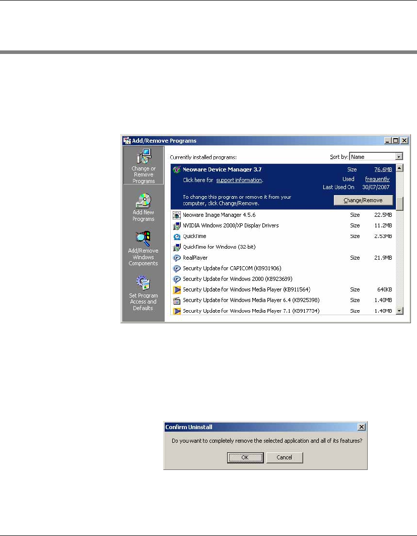
Uninstalling Device Manager
1Open the Microsoft Windows Control Panel (On a Windows
2000 system, select Start > Settings > Control Panel).
2Double-click Add/Remove Programs. The Add/Remove Pro-
grams window will appear.
3Select Neoware Device Manager from the list of currently
installed programs.
4Click Change/Remove to activate the Device Manager configu-
ration program.
5You will be asked to confirm your decision.
Click OK to continue.
Installing HP Device Manager
Uninstalling Device Manager 35
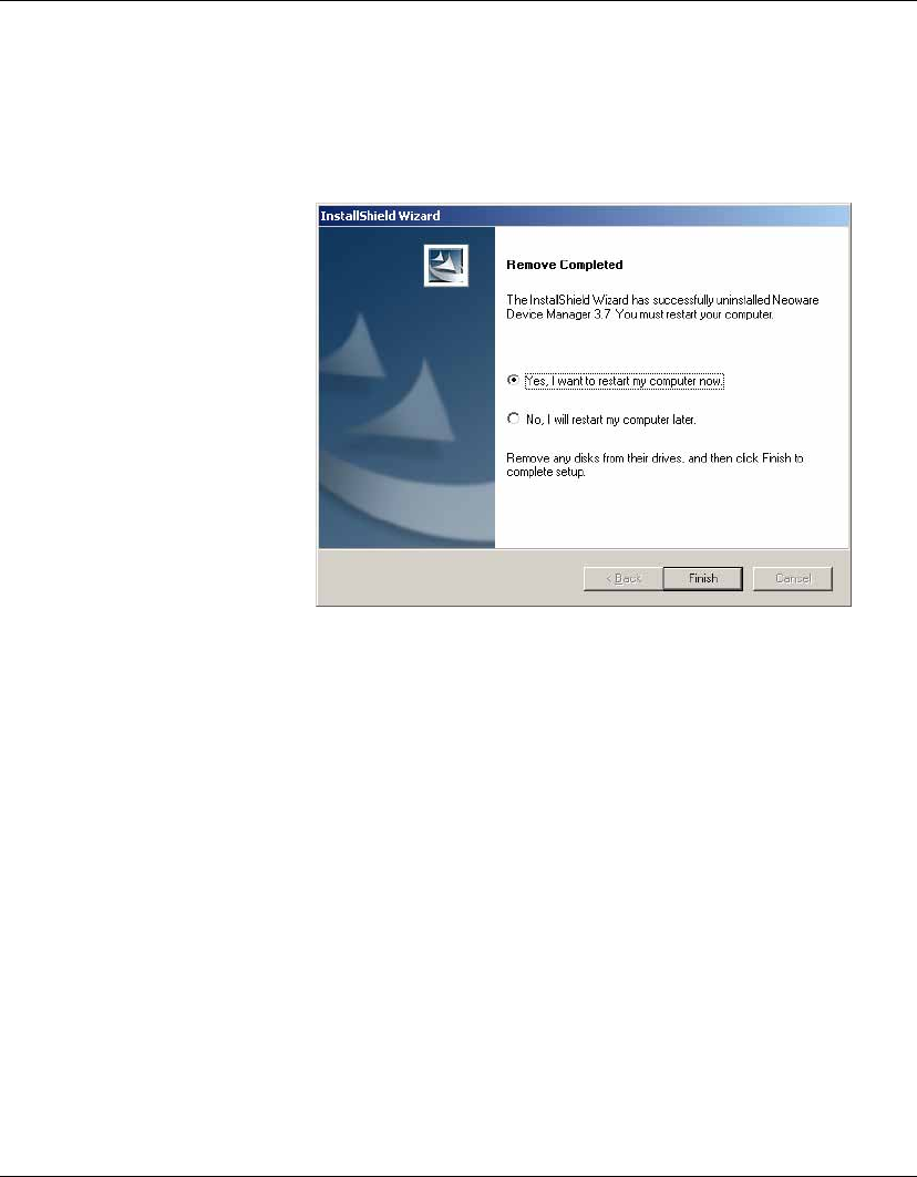
6Once Device Manager has been uninstalled, the computer
should be rebooted. Click Finish on the Remove Completed
dialog to reboot the computer, or select No before clicking
Finish if you intend to reboot the computer yourself later.
7HP Device Manager has now been uninstalled from your
system.

Installing HP Device Manager
36 Uninstalling Device Manager
37
HP Device Manager User Manual
CHAPTER 3 Getting Started
This chapter describes how to start using the HP Management
Console, set up a repository, and discover clients.
Logging in to the HP Management Console
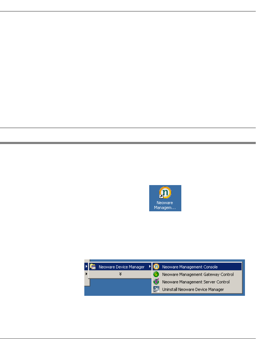
To launch the HP Management Console:
1Double-click the Neoware Management Console icon on the
Windows desktop.
OR
From the main Windows screen select:
Start > Programs > Neoware > Neoware Device Manager >
Neoware Management Console
Getting Started
38 Logging in to the HP Management Console
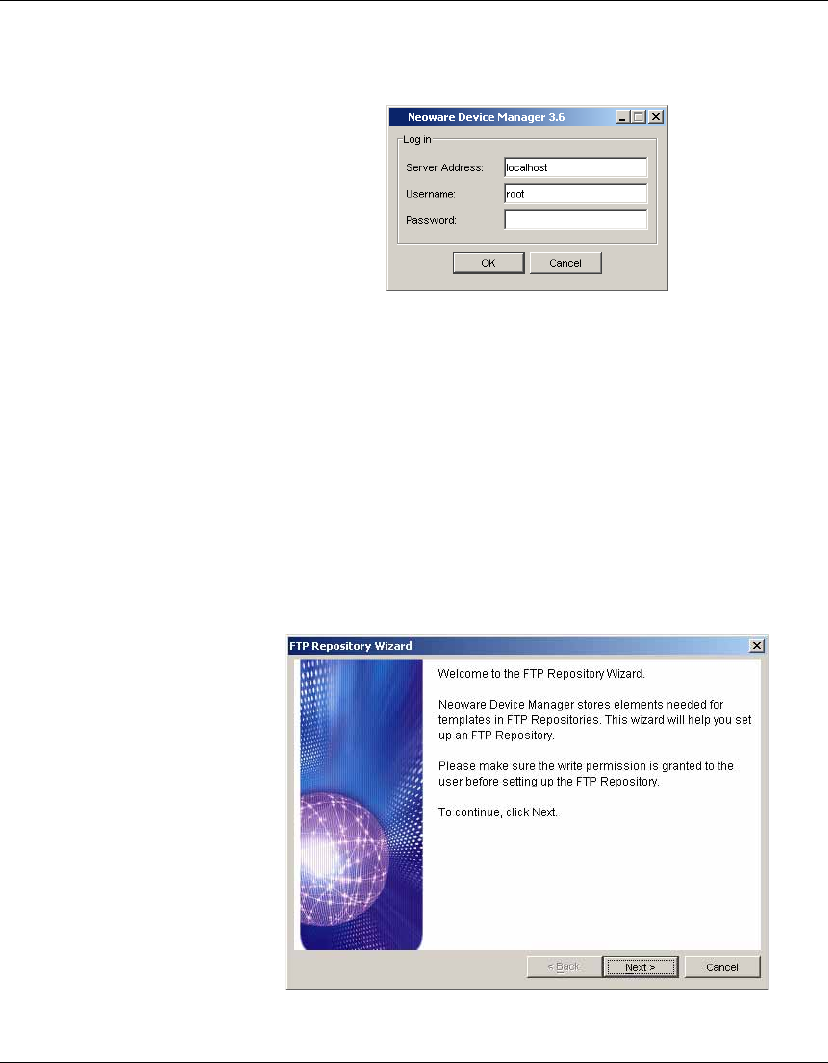
The Log in dialog will appear.
2Enter the Server Address of your network’s HP Management
Server. The address can be entered as an IP address or as a
machine name. If the console is on the same machine as the HP
Management Server, then enter “localhost”.
3Enter your Username and Password in their respective fields.
4Click OK to log in to the Console.
Once the username and password are verified, the main window
of the HP Management Console appears.
If this is the first time you have logged in the Management
Console, the FTP Repository Wizard will be displayed.

Getting Started
Configuring the Repository 39
Configuring the Repository
The HP Management Repository is used to store software
components, system images, diagnostic tools and agent files. Each
of the individual items stored in the Repository is referred to as an
element. Once elements are stored in the Repository, they can be
applied to client devices using templates.
The HP Management Repository actually resides over several
servers, these being the HP Management Server Repository (the
"Server Repository") and one or more FTP Server Repositories (the
"FTP Repository"). The Repository Management tool is used to
import elements into the Server Repository and then transfer them to
the relevant FTP Repository. An element must be transferred to an
FTP Repository before it can be applied to clients.
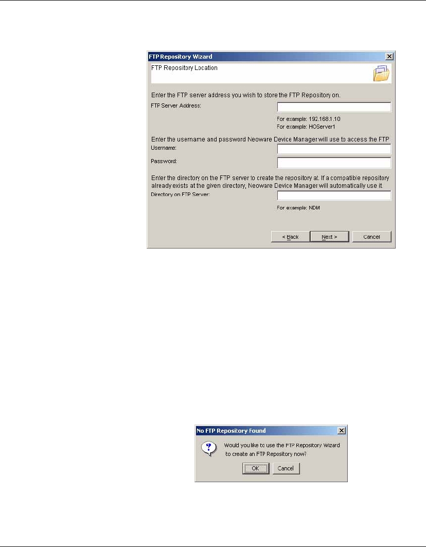
When you log in the HP Device Manager Console for the first time
you will be automatically prompted to create an FTP Repository
using the FTP Repository Wizard as described below. If you need to
create an additional FTP Repository later, you can run the FTP
Repository Wizard again by selecting Tools > Configuration from
the Console’s menu bar, selecting FTP Repositories in the left-hand
tree pane, then clicking the Launch FTP Wizard button in the top-
right corner.
Creating an FTP
Repository
To create an FTP Repository:
1If the FTP Repository Wizard is not displayed already, select
Tools > Configuration in the Console’s menu bar, select FTP
Repositories in the left-hand tree pane, then click the Launch
FTP Wizard button in the top-right corner.
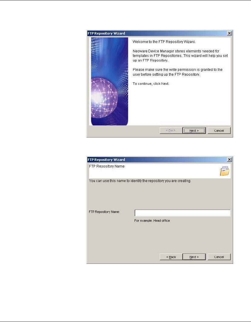
The Welcome screen will be displayed.
Getting Started
40 Configuring the Repository
2Click Next to display the FTP Repository Name screen.
3Enter a name to identify this FTP Repository in the FTP
Repository Name field.
4Click Next to display the FTP Repository Location screen.
Getting Started
Configuring the Repository 41
5In the FTP Server Address field, enter the IP address or host-
name of the server on which the FTP Repository is to be created.
Enter the User Name and Password for the server to enable HP
Device Manager to access it. The User Name and Password
must have write permissions for the server.
Enter a directory on the FTP server that will be used to store the
FTP Repository. When you click Next, the FTP Repository
Wizard will search for the directory, and if an existing FTP
Repository is found at that location, it will use it. If an existing
FTP Repository is not found, you will be asked if you want to
create the directory and FTP Repository as required.
Getting Started
42 Configuring the Repository
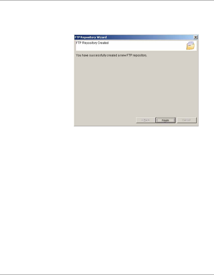
6When you have entered all of the details for the FTP Repository,
click Next to create it.
7Click Finish to close the FTP Repository Wizard.
The FTP Repository is now ready for you to add elements to it
using the Repository Management tool as described in the sec-
tion “Adding Elements to the Repository” on page 51.
Getting Started
Management Console Overview 43
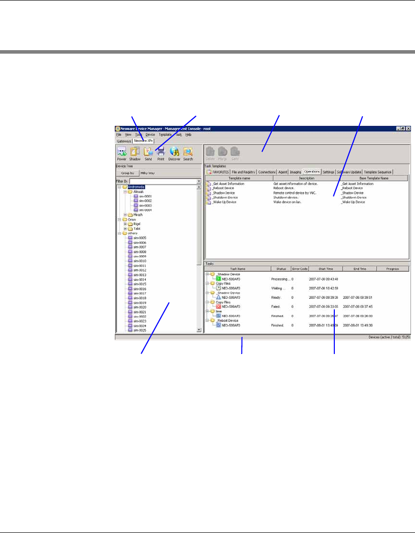
Management Console Overview
The Management Console window consists of three panes and a
series of tabs which determine their content.
•OS Tabs
Selects the different categories of terminal operating systems that
are controlled by HP Device Manager. Note that only the tabs for
the operating system types of the devices currently managed by
HP Device Manager will be displayed.
•Device Toolbar
Provides tools enabling you to power on/off the client devices,
shadow a remote client, send tasks, print device properties,
discover an agent, etc. Refer to the section “Toolbar Overview”
on page 62 for more information.
OS Tabs Device Toolbar Template Toolbar Template Pane
Device Pane Status Bar Task Pane

Getting Started
44 Management Console Overview
•Device Pane
All clients of the selected OS type that are connected to the server
are displayed in this window. This pane contains the Device Tree,
which is heirachical list of all the client devices, sorted with a
custom grouping scheme.
•Template Toolbar
Selects the different options to delete, merge or send templates.
•Template Pane
The templates that are applicable to the listed client devices are
listed here.
•Task Pane
Displays the execution status for each task in a hierachical
structure. If there is more than one device for a listed task, the
status of each device will be listed.
•Status Bar
Descriptions of various items in the HP Management Console are
displayed here when the cursor moves over them.

Getting Started
Client Discovery 45
Client Discovery
Clients which have the HP Management Agent installed must be
‘discovered’ by HP Device Manager before they can be used. There
are four approaches to client discovery:
•Through an HP Management Agent Broadcast (automatic)
•Server-side discovery using IP walking
•Discover Agent using DHCP Tag
•Agent Configuration
HP Management
Agent Broadcast
The HP Management Gateway will normally be able to detect most
HP Management Agents. The gateway functions by listening for a
network broadcast message sent when each agent starts up. How-
ever, to ensure that the gateway is able to detect all agents, it must be
running before each agent is started up.
If the gateway is unable to detect an agent, Discover Agent, IP
walking, DHCP Tag or Agent Configuration can be used instead.
Discover Agent HP Device Manager can search a range of IP addresses for agents
and gateways.
1Click on the Discover button in the Device Toolbar and select
Discover Device in the menu.
The Discover Device dialog will be displayed.
Getting Started
46 Client Discovery
Walking with IP Range
2Select the gateway in the Select Neoware Management Gate-
way list box, then select the Walking with IP Range option.
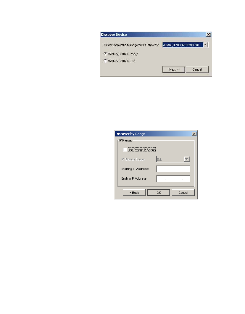
3Click Next to display the Discover by Range dialog.
4IP scopes define set ranges where HP Device Manager will
search for client agents. Select Use Preset IP Scope then select
an IP Search Scope, or deselect the box and enter a Starting IP
Address and an Ending IP Address. IP walking will search this
range of addresses for a reply.
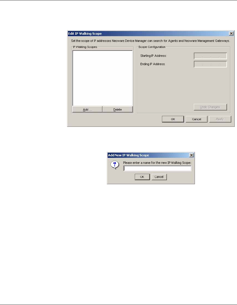
To configure an IP scope, select the Edit... option in the IP
Search Scope list box to display the Edit IP Walking Scope
dialog.
Getting Started
Client Discovery 47
Select an existing IP scope from the IP Walking Scopes list or
click Add to create a new one.
Enter a scope name to be used by HP Device Manager to refer to
the new search scope, then click OK.
Define the IP address range you want HP Device Manager to
search for client agents by filling in the Starting IP Address and
Ending IP Address. The IP address can be copied from another
location and pasted here. Click Apply to save the settings, then
OK to exit.
Getting Started
48 Client Discovery
Walking with IP List
2Select the gateway in the Select Neoware Management Gate-
way list box, then select the Walking with IP List option.
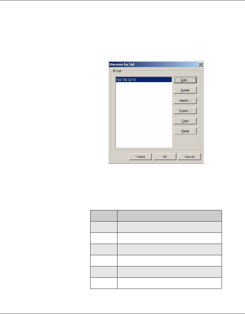
3Click Next to display the Discover by List dialog.
4The IP addresses in the IP List can be customized according to
your specific needs. Refer to the table below for descriptions of
each button in the dialog.
Table 3: Discover by List - Button Functions
Button Function
Add Add a new IP address to the IP list.
Delete Remove an existing IP address from the list.
Import... Import a *.txt or *.csv file to the IP list.
Export... Export the IP list as a *.txt file.
Copy Copy the current IP list.
Paste Paste a copied IP address.
Getting Started
Client Discovery 49
5Click on OK to search for agents or gateways. Once the search
has finished, a report will show the clients detected by HP
Device Manager.
6Click Close to automatically add the successful IP addresses to
the Device Pane.
Discover by DHCP
Tag
An agent can automatically register with a gateway based on the
content of a DHCP tag it receives during start-up. Add option 202 to
DHCP server and set the value to "<Server IP> <Gateway IP>".
(The Server IP and Gateway IP is the IP address of the server run-
ning the Management Server and Gateway respectively.) Please refer
to “Configuring DHCP Servers” on page 30 for details on how to
configure DHCP Server and add options.
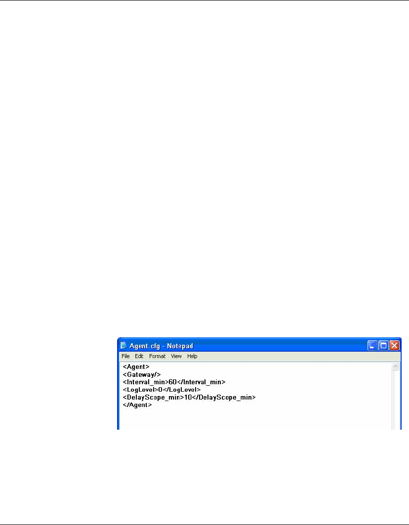
Agent
Configuration
You can manually add the IP address of the gateway to the agent's
configuration file so that the agent can search for the gateway auto-
matically.
To Configure Windows XP Embedded Agents:
1Open the directory of C:\WINDOWS\xpeagent.
2Open the Agent.cfg file with the Notepad application.
Getting Started
50 Client Discovery
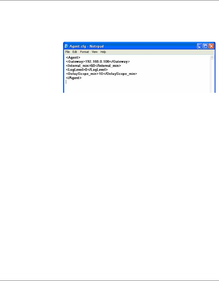
3Modify the gateway IP address in the second line. Please take
the format of the following illustration as an example (where
192.168.0.106 is the IP address of the gateway).
4Save your modifications and close this file.
When rebooted, the agent will search for the gateway according to
your specified IP address in the Agent.cfg file.
Note 1: The agents in the NAT environment must be configured as
described above.
Note 2: As for the agents that have successfully finished one task at
least, the IP address of the gateway has been added into the original
format of the Agent.cfg file on these agents. Hence you do not need
to manually configure these agents again.

Getting Started
Adding Elements to the Repository 51
Adding Elements to the Repository
This section describes how elements are added to the HP Manage-
ment Repository so that they are available for applying to client
devices. You must have configured an FTP Repository using the FTP
Repository Wizard before you can add elements to it (refer to the
section “Configuring the Repository” on page 39 for details).
The HP Management Repository actually resides over several serv-
ers, these being the HP Management Server Repository (the "Server
Repository") and one or more FTP Server Repositories (the "FTP
Repository"). The Repository Management tool is used to import
elements into the Server Repository and then transfer them to the
relevant FTP Repository. An element must be transferred to an FTP
Repository before it can be applied to clients.
Note: When importing an element into the HP Management
Repository, a relay FTP server must be selected to temporarily hold
the element, which is then automatically transferred to the Server
Repository.
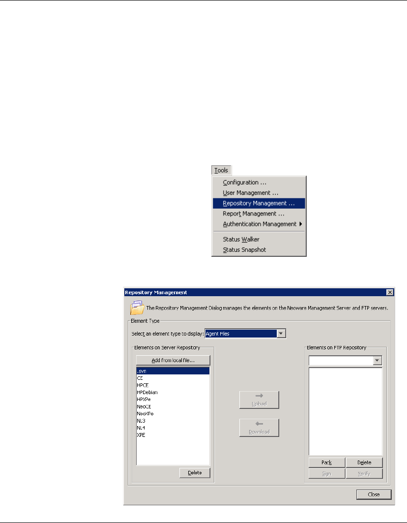
The Repository Management tool is displayed by selecting Tools >
Repository Management from the Management Console’s menu
bar. The following section describes how to use it to import an
element into the Server Repository, then transfer it to an FTP
Repository.
Elements created through the Console using a template (for exam-
ple, an image file), are placed in the FTP Repository specified in the
template. If you want the element to be available in another FTP
Repository, you first need to transfer it to the Server Repository
using the Repository Management tool’s Download button, then
transfer the element from the Server Repository to the other FTP
Repository using the Upload button.
Getting Started
52 Adding Elements to the Repository
Importing an
Element into the
Repository
The following procedure describes how to import an element into
the Repository. In this example we are importing a snapin which can
be used to add Adobe Reader to NeoLinux 4 clients.
1Copy the element to be imported to a temporary location on your
local drive. (In this case the element is a snapin downloaded
from the support section of the HP website.)
2Select Tools > Repository Management from the Management
Console’s menu bar to display the Repository Management
dialog.
Getting Started
Adding Elements to the Repository 53
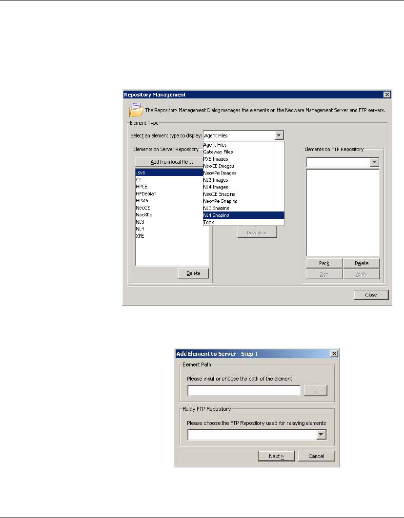
3In the Select an element type to display field, select the appro-
priate element option from the drop-down list. For this example
we will be using a NeoLinux 4 snapin to install Adobe Acrobat
Reader to NeoLinux 4 thin clients, so NL4 Snapins is selected.
4Click the Add from local file button to display the Add Element
to Server - Step 1 dialog.

Getting Started
54 Adding Elements to the Repository
5Click the ... button in the Element Path box to browse to the
directory containing the snapin you downloaded in step 1. Select
the folder containing the snapin files (in our example it is
Adobe_Acrobat_7.0.9-NL4.0.1-6002) then click Choose.
The Relay FTP Repository field will display the name of the FTP
Repository to use for relaying element files. You can change this
if required.
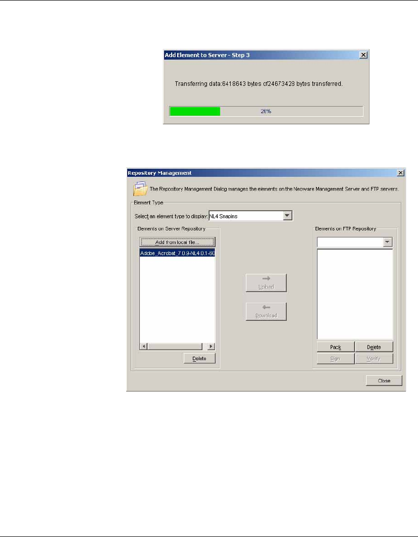
6Click Next to start copying the element files to the relay FTP
Repository.
A message box will be displayed once the element files have
been successfully uploaded to the relay FTP Repository.
7Click OK to automatically transfer the element files from the
relay FTP Repository to the Server Repository.
Getting Started
Adding Elements to the Repository 55
The Repository Management dialog should now display the
name of the element in the Elements on Server Repository field.
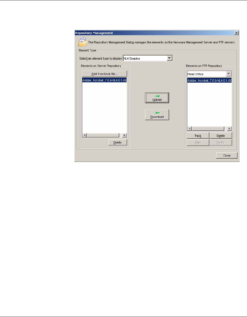
8Select the name of the FTP Repository to which you want to
transfer the element from the Elements on FTP Repository drop-
down list box.
9Select the element to transfer in the Elements on Server Reposi-
tory field, then click the Upload button.
Once the element has been transferred, it will be listed in both
the Server Repository and FTP Repository fields.
Getting Started
56 Adding Elements to the Repository
Now that the element is in the FTP Repository, it can be applied
to client devices using a template.
57
HP Device Manager User Manual
CHAPTER 4 Using the HP
Management Console
This chapter covers the main functions of the Console, including
device management, task templates and task management.
Menu Item Overview
The following table provides a brief description of the functions of
all the menu items available in the Management Console.
Table 4: Management Console - Menu Items
Menu Item Description
File Import License Import a new license for Device Manager.
Import Scheme Import a device grouping scheme.
Export Scheme Export a device grouping scheme.
Print Device
Information
Print information about the devices.
Print Device
Task Report
Displays and prints task information on all
users or a specific device.
See “Printing a Device Task Report” on
page 90 for more information.
Print Task Report Displays and prints information on tasks.
Exit Exit the Management Console.

Using the HP Management Console
58 Menu Item Overview
View Edit Grouping
Scheme
Sort the device list using customized proper-
ties according to the actual requirements.
See “Grouping Devices” on page 71 for more
information.
Search Device
Tree
Search for a device in the Device Tree accord-
ing to the IP address, host name and device
IDs. This option is very useful in a network
containing a large number of devices.
Device Filter Configure the device filters so as to filter the
devices when the Management Console is
sending tasks. As a result, only the required
devices can receive and perform the task.
Refresh Contact the Management Server to refresh the
status of the console.
Tools Configuration Configure settings related to FTP servers, IP
search scopes, system time-outs, shadowing,
gateway polling and extension properties.
See “Configuring the Repository” on page 39
for more details.
User
Management
Configure user accounts and user groups for
the console.
See “User Management” on page 177 for
more information.
Repository
Management
Control the elements (such as images and
software components) that are stored on the
Management Server repository and the FTP
server repositories.
See “Configuring the Repository” on page 39
for more details.
Report
Management
Manage the reports of the Devices and the
Tasks so that the user can get the required
reports according to the customized condi-
tions.
Table 4: Management Console - Menu Items
Menu Item Description

Using the HP Management Console
Menu Item Overview 59
Authentication
Management
Key Management - Manage the communica-
tion keys such as add, update, import and
export options, etc.
Gateway Access Control - Decide if a speci-
fied gateway is an authenticated gateway. If
not, the gateway will be banned and cannot
communicate with the Management Server.
Status Walker This tool makes a list of all the IPs available
and walks to them; taking back their status
information and displaying it.
See “Status Walker” on page 109 for details.
Status Snapshot This tool takes a snapshot, creates a report of
the devices’ status and stores it in the server
to be displayed when the tool is opened.
See “Status Snapshot” on page 114 for more
information.
Device Check
Connection
Status
Check the network connection status of the
agents via Ping and Trace Route.
Add Add a new device.
See “Adding Devices Using MAC
Addresses” on page 173 for more
information.
Delete Delete the selected device.
Manual Group Add Folder, Rename or Delete.
Send Task Send a Task Template task to the selected
device.
See “Applying Tasks to Devices” on page 99
for more information.
Shadow Attempts to shadow the selected device.
See “Shadowing Devices” on page 91 for
more information.
Table 4: Management Console - Menu Items
Menu Item Description

Using the HP Management Console
60 Menu Item Overview
Power
Management
Reboot - Sends a command to reboot the
selected device.
Wake on LAN - Sends a command to the
selected device to start it up.
Shutdown - Sends a command to shut down
the selected device.
See “Power Management” on page 93 for
more information.
Get Device Asset
Information
Get the specific information of the selected
device, such as General, Software, Hardware,
Hotfix, Network, Configuration and other
extended properties, etc.
Properties Displays the properties for the selected
device.
See “Displaying Device Properties” on
page 66 for more information.
Template
Delete Remove the selected template.
Merge Merge two or more selected composite tem-
plates.
See “Merging File and Registry Templates”
on page 130 for more information.
Send Task Send the selected template to the devices as a
task.
Properties Edit the selected template’s properties.
Add to Favorites Add the frequently used templates to the
Favorites tab in the Template Pane for more
convenient usage.
Import Import an XML template file into the cur-
rently selected template category.
See “Importing & Exporting Task Templates”
on page 97 for more information.
Table 4: Management Console - Menu Items
Menu Item Description

Using the HP Management Console
Menu Item Overview 61
Export Export an XML template file into the cur-
rently selected template category.
See “Importing & Exporting Task Templates”
on page 97 for more information.
Template Plugin
Management
Manage the plugin of the templates, such as
import or uninstall plugin, etc.
Task Pause Pause the selected task.
Continue Continue the selected task.
Resend Resend the selected task.
Cancel Cancel the selected task.
Cancel All Cancel all tasks.
Delete Delete the selected task.
Delete All Delete all tasks in the Task Pane.
Delete All
Finished
Delete all finished tasks in the Task Pane.
Open VNC
Viewer for
Shadowing
When a remote device has finished the
Shadow task, you can login the device via the
VNC viewer.
Open Result
Template
View the content of the result template, which
is created by certain types of templates on the
completion of their tasks.
View Task
Contents
View the specific content of the tasks.
View Task Log View the task status log.
Help About Display copyright and licensing information
for Device Manager.
Table 4: Management Console - Menu Items
Menu Item Description
Using the HP Management Console
62 Toolbar Overview
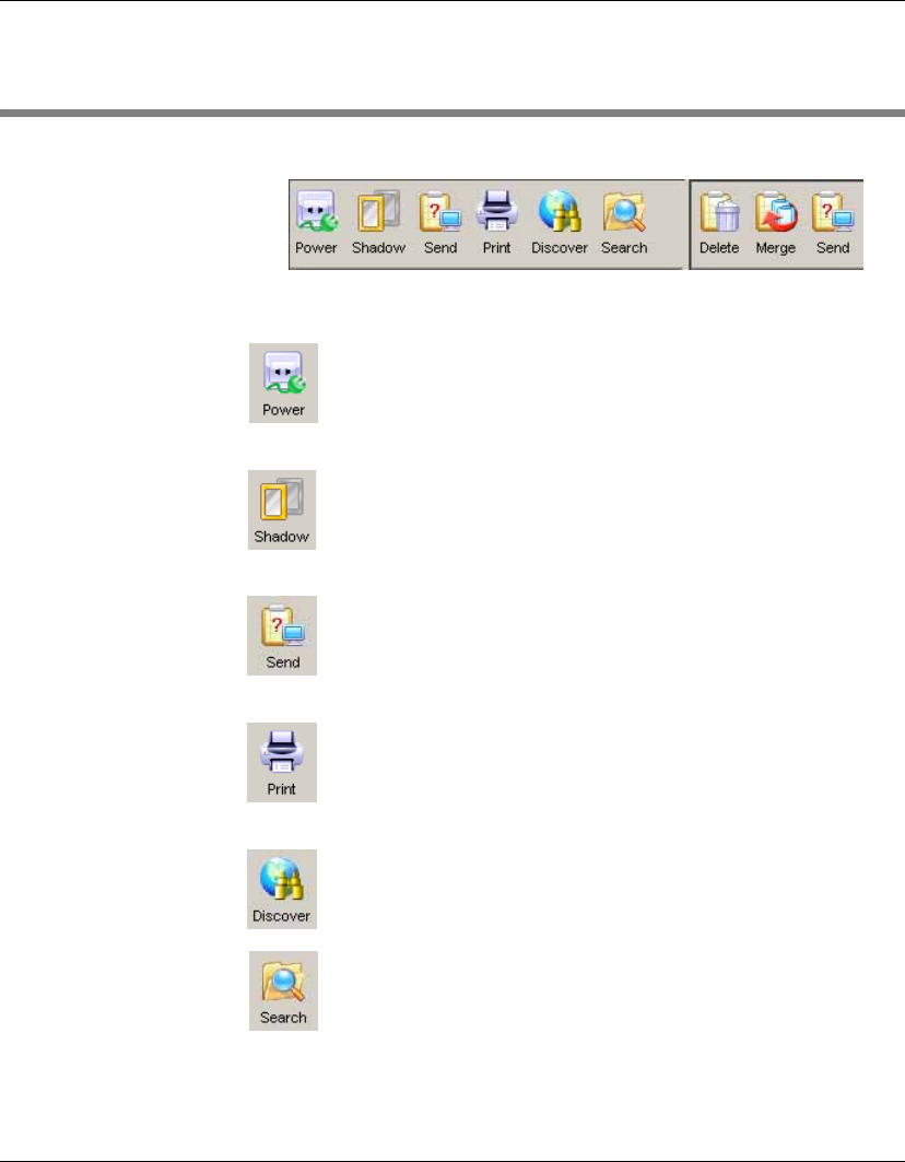
Toolbar Overview
The toolbar provides quick access to frequently used tools.
This enables you to Reboot, Wake on LAN or Shutdown
the currently selected device(s) in the device tree. Refer
to the section “Power Management” on page 93 for
details.
This enables you to shadow the selected device. The Task
Editor dialog will be displayed. Click OK to apply the
shadowing task to the device. Refer to the section “Shad-
owing Devices” on page 91 for details.
This will display the Template Chooser dialog enabling
you to send a template task to the currently selected
device(s). Refer to the section “Applying Tasks to
Devices” on page 99 for details.
This enables you to print information about the device(s)
currently selected in the device tree. Refer to the section
“Printing Information About Devices & Tasks” on
page 89 for details.
This enables you to discover client devices or gateways
on the network. Refer to the section “Discovering
Devices” on page 68 for details.
This enables you to find a specific device in the device
tree. Refer to the section “Searching for a Device in the
Device Tree” on page 86 for details.

Using the HP Management Console
Toolbar Overview 63
The following tools are available in the Template Pane:
This will delete the currently selected template. You will
be prompted to confirm the action before it is actually
deleted.
This will display the Merge Templates dialog enabling
you to merge two or more File and Registry templates.
Refer to the section “Merging File and Registry Tem-
plates” on page 130 for details.
This will display the Task Editor dialog enabling you to
send a template task to the currently selected device(s).
Refer to the section “Applying Tasks to Devices” on
page 99 for details.
Using the HP Management Console
64 Device Management
Device Management
All thin clients that connect to the server are displayed in the Device
Pane of the Management Console window. Selecting one of the OS
tabs below the menu bar will display all of the clients of the chosen
OS type in the Device Pane. Double-clicking an item in the Device
Pane or clicking on a folder icon will expand the device list.
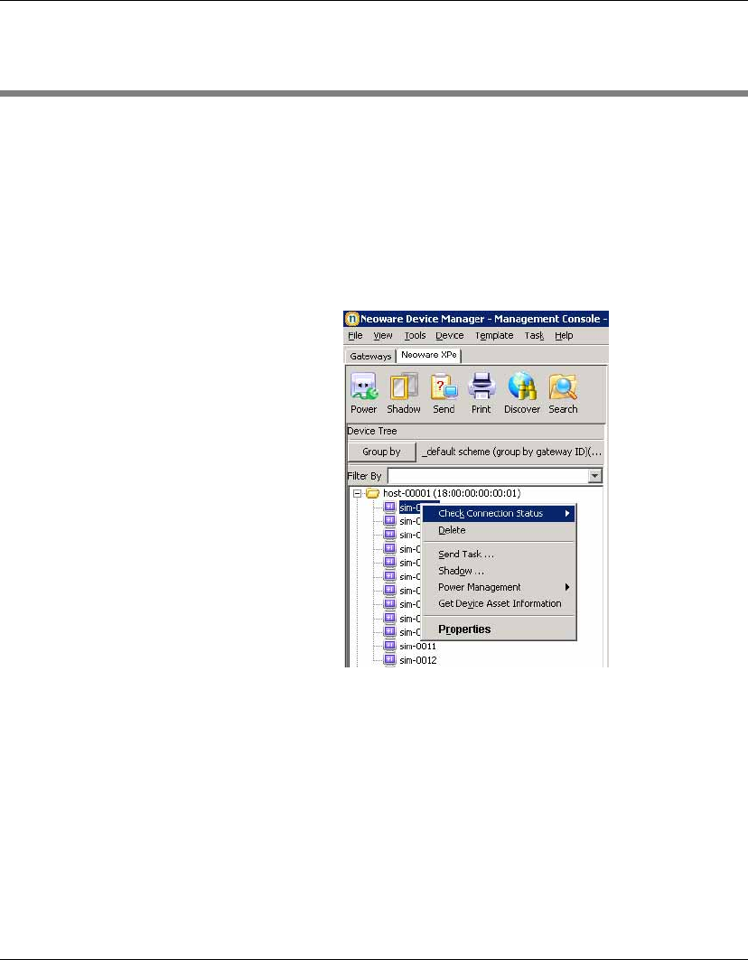
Select one or more devices and then right-click to see a menu of
applicable commands.
All of these commands are also available in the Device menu which
is displayed from the Console’s menu bar.

Using the HP Management Console
Device Management 65
Device Tree Icons On the Gateway tab, a G icon indicates a Management Gateway:
A green G icon represents a gateway that is currently active.
A greyed-out G icon represents a gateway that is currently
down or disconnected.
On the OS tabs, devices are represented by the following icons:
A folder represents a number of devices that have been
grouped together using the grouping schemes function.
A screen icon with a power symbol over it indicates that cur-
rently the status of this device cannot be confirmed because a
gateway to the device cannot be found.
A greyed-out screen icon with an exclamation mark over it
indicates the device is currently powered-off.
A screen icon with a curved arrow over it indicates the device
is currently in pull mode.
A screen icon with a curved arrow and padlock over it
indicates the device is currently in pull-lock mode (Enhanced
Write Filter is ON).
A screen icon with a straight arrow over it indicates the device
is currently in push mode.
A screen icon with a straight arrow and padlock over it
indicates the device is currently in push-lock mode.
Using the HP Management Console
66 Device Management
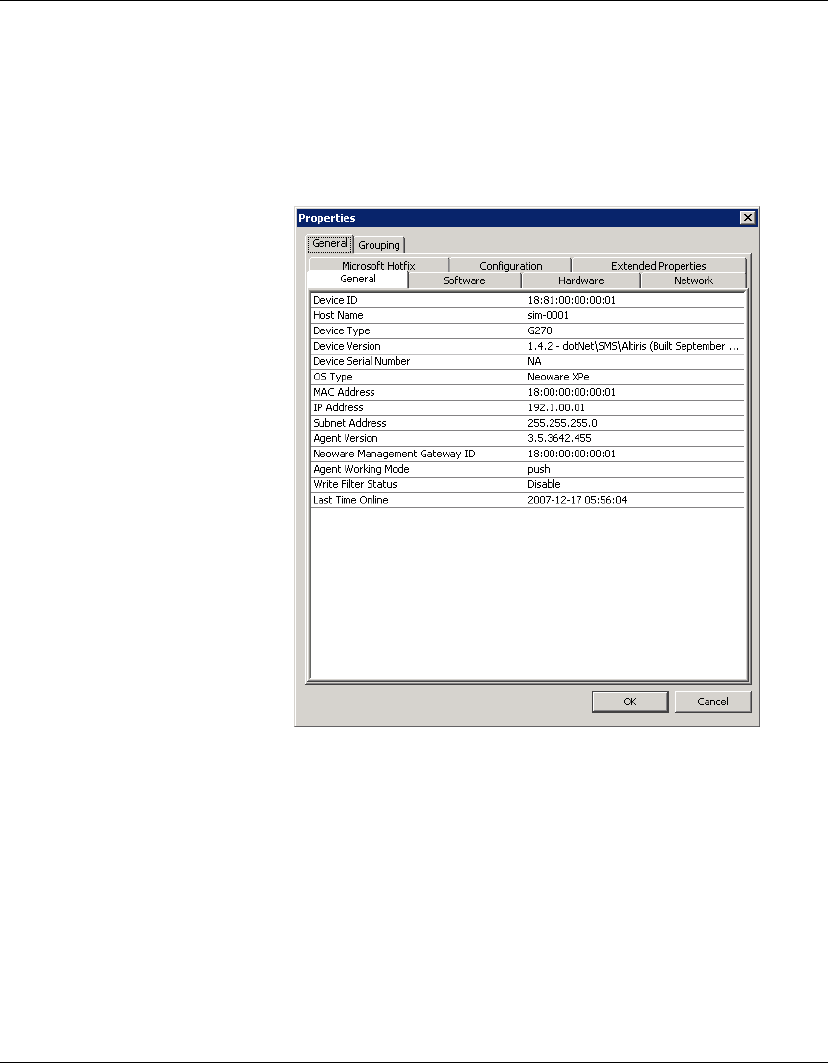
Displaying Device
Properties
To display the properties of a device:
1Right-click on the device in the Device Pane.
2Select Properties from the menu (or double-click any device) to
display the Device Properties dialog.
The Device Properties dialog displays the properties of the thin
client devices that are connected to the server. The dialog lets you
see different types of information.
Note: The IP address and MAC address in the device properties
dialog can be selected and copied. The selected address will be
highlighted, then you can right-click to copy the selected address.
Using the HP Management Console
Device Management 67
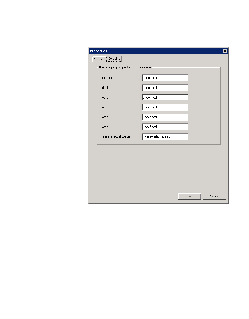
Click the Grouping tab to set grouping properties, which are used as
grouping criteria. See “Changing Grouping Properties” on page 79
for information on how to rename these grouping properties.
Note: To set the grouping properties, you can also right-click a
device in the
Task View
and select
Edit Device Properties
in the
menu.
Deleting Devices To delete a device:
1Right-click the device in the Device Pane.
2Select Delete from the menu.
The selected device is removed from the Device Pane.
Using the HP Management Console
68 Discovering Devices
Discovering Devices
The Discover Devices option allows Device Manager to search a
range of IP addresses for agents and gateways.
To use Discover Devices:
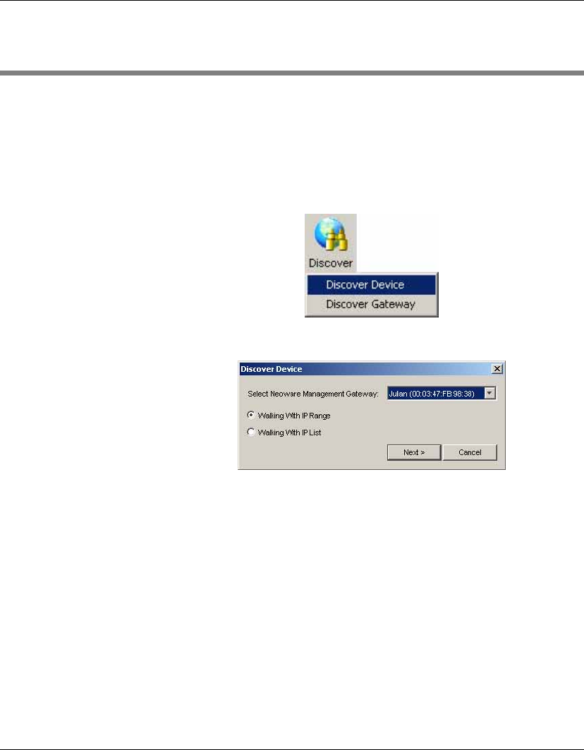
1Click on the Discover button in the Device Toolbar and select
Discover Device in the menu opened.
The Discover Device dialog will be displayed.
2Select the corresponding gateway in the Select Neoware Man-
agement Gateway drop-down menu, then select the Walking
with IP Range option.
Using the HP Management Console
Discovering Devices 69
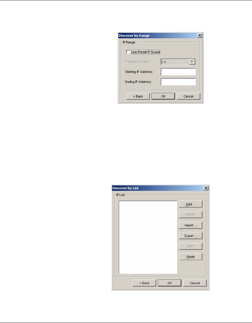
3Click Next to display the Discover by Range dialog.
4Check the Use Preset IP Scope box and select an IP Search
Scope, or deselect the box and enter a Starting IP Address and
an Ending IP Address. IP Walking will search this range of
addresses for a reply.
OR
You can select the corresponding gateway in the Select Gateway
drop-down menu, and then select the Walking with IP List
option. Click Next to display the Discover by List dialog.

Using the HP Management Console
70 Discovering Devices
In the Discover by List dialog, the IP addresses in the IP List can
be customized according to your specific needs. See the follow-
ing table for descriptions of each button in this dialog.
5Click OK to search for devices.
Table 5: Discover by List - Button Functions
Button Function
Add Add a new IP address to the IP list.
Delete Remove an existing IP address from the IP list.
Import... Import a *.txt or *.csv file to the IP list.
Export... Export the IP list as a *.txt file.
Copy Copy the current IP list.
Paste Paste a copied IP address.
Using the HP Management Console
Grouping Devices 71
Grouping Devices
Grouping devices according to specified criteria makes it easier for
administrators to manage them. Devices can be grouped automati-
cally according to any of their properties, or manually assigned to
groups in any way that is suitable for your requirements. Note that
you can also pre-assign the group to which a device belongs from the
device itself by editing its agent configuration settings.
Dynamic Grouping Dynamic grouping allows you to automatically group devices by
specific properties. For example, you could create a grouping
scheme that will group all devices by their CPU type or agent ver-
sion. You can specify more than one grouping property for a group,
and you can define up to six customizable grouping properties. Once
you have defined the properties associated with a dynamic grouping
scheme, all devices with matching properties will automatically be
assigned to the relevant group, including any devices added to
Device Manager in the future.
Defining a Dynamic Grouping Scheme
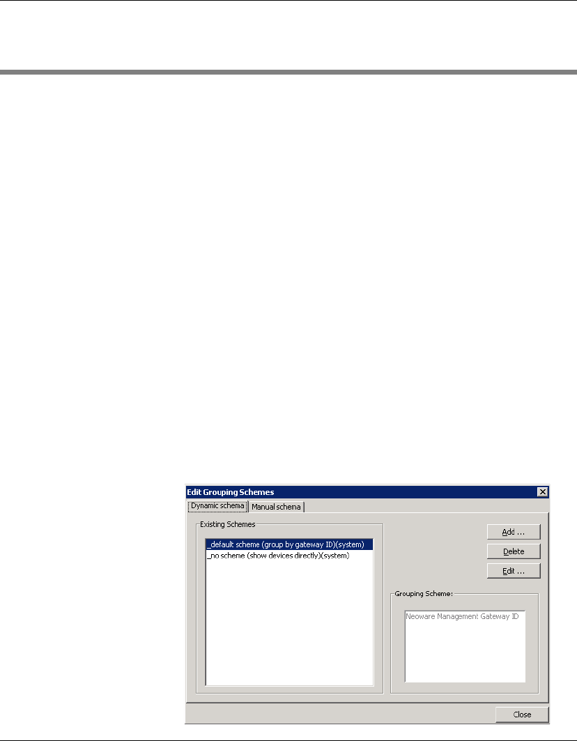
1Display the View menu from the Console’s menu bar and select
Edit Grouping Schemes.
Using the HP Management Console
72 Grouping Devices
The Dynamic schema tab lists existing dynamic grouping
schemes and enables you to create or edit a grouping scheme.
Two schemes are supplied by default: _default scheme will
group devices by gateway ID, whereas _no scheme will not
group devices but just list every device managed by Device
Manager.
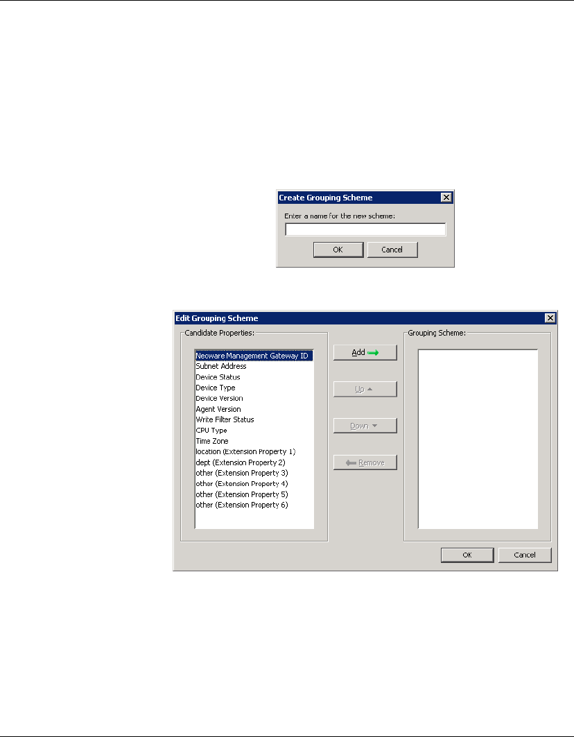
2To create a new dynamic grouping scheme, click Add.
3Enter a name for the new grouping scheme then click OK.
4Select a property by which you want to group devices in the
Candidate Properties list, then click Add to add it to the Group-
ing Scheme list. You can specify more than one property.

Using the HP Management Console
Grouping Devices 73
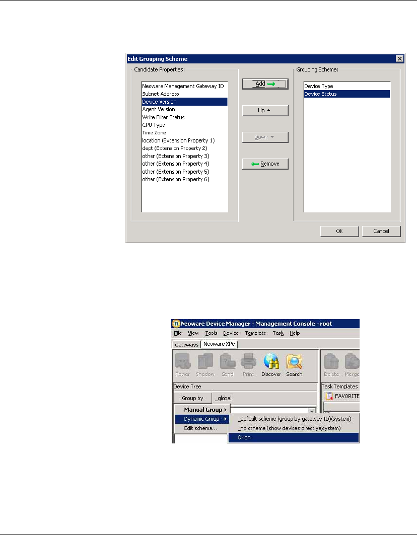
Note that there are six customizable grouping properties you can
use to group your devices as required.
5Once you have selected the properties to use, specify the priority
of those properties by clicking Up or Down to move the selected
property in the Grouping Scheme to a higher or lower grouping
priority. Device Manager will group devices using the property
with the highest priority in the order list. Other properties in the
order list are then considered in turn.
You can remove a selected property from the Grouping Scheme
list by clicking Delete.
Table 6: Candidate Properties
Properties Description
Gateway ID Group by gateway ID.
Subnet Address Group by subnet address.
Device Status Group by status (on/off).
Device Type Group by product type.
Device Version Group by device version.
Agent Version Group by agent version.
Write Filter Enabled Group by EWF status.
CPU Type Group by processor type.
Time Zone Group by time zone.
location (Extension
Property 1)
Customizable grouping property.
dept (Extension Prop-
erty 2)
Customizable grouping property.
other (Extension
Property 3 - 6)
Customizable grouping property.
Using the HP Management Console
74 Grouping Devices
6Click OK to create the new grouping scheme.
7Click the Group by button in the Device Tree panel and select
Dynamic Group. The new grouping scheme will be listed and
available for selection.
8Select the new grouping scheme to group all devices managed
by Device Manager accordingly.
Using the HP Management Console
Grouping Devices 75
Manual Grouping You can create grouping schemes in which you manually assign
devices to groups in whatever way you require.
Defining a Manual Grouping Scheme
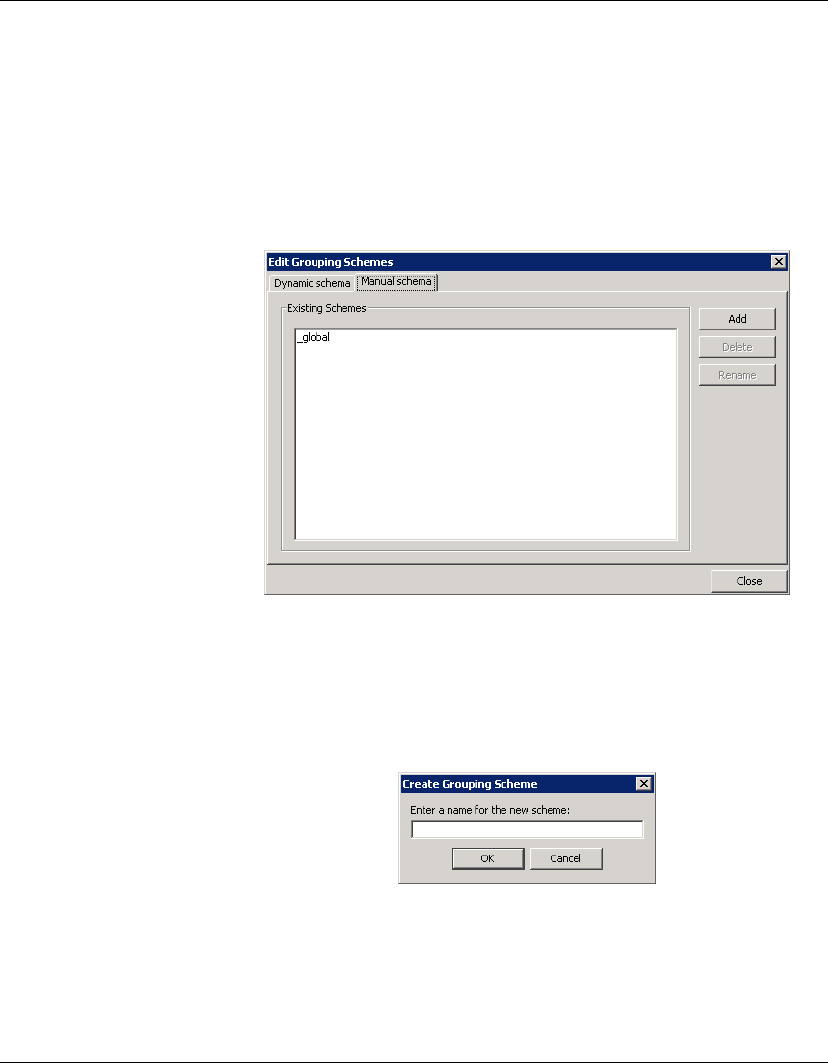
1Display the View menu from the Console’s menu bar, select Edit
Grouping Schemes, then click on the Manual schema tab.
The Manual schema tab lists existing manual grouping schemes
and enables you to create or edit a grouping scheme. One
scheme is supplied by default: _global will not group devices
but just list every device managed by Device Manager.
2To create a new manual grouping scheme, click Add.
3Enter a name for the new grouping scheme then click OK. The
name will appear in the Existing Schemes list.
Using the HP Management Console
76 Grouping Devices
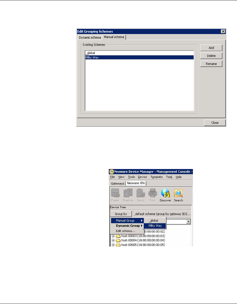
4Click Close.
5Click the Group by button in the Device Tree panel and select
Manual Group. The new grouping scheme will be listed and
available for selection.
6Select the new manual grouping scheme.
Any organisational changes you now make to the devices and
folders listed in the Device Tree panel will be saved to this
grouping scheme.
Using the HP Management Console
Grouping Devices 77
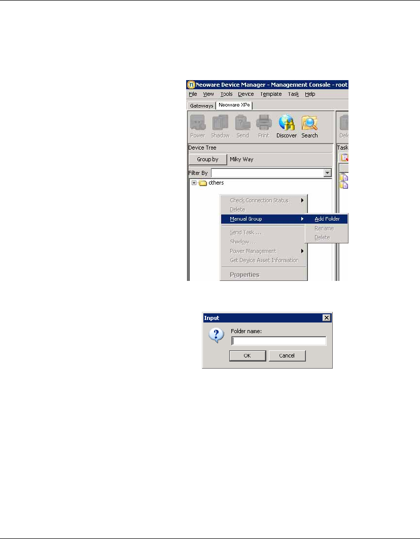
7To create a new folder in which to group devices, right-click in
the Device Tree pane and select Manual Group > Add Folder
from the pop-up menu.
8Enter a name for the group folder then click OK.
9You can now drag-and-drop the names of devices into this group
folder within the Device Tree panel.
Using the HP Management Console
78 Grouping Devices
Naming Grouping
Properties
Grouping properties are used to group devices into a customized
order suitable for your organization’s network configuration. These
groups provide simple management of devices over different depart-
ments or different locations. Each property name can be renamed as
required.
To rename grouping properties:
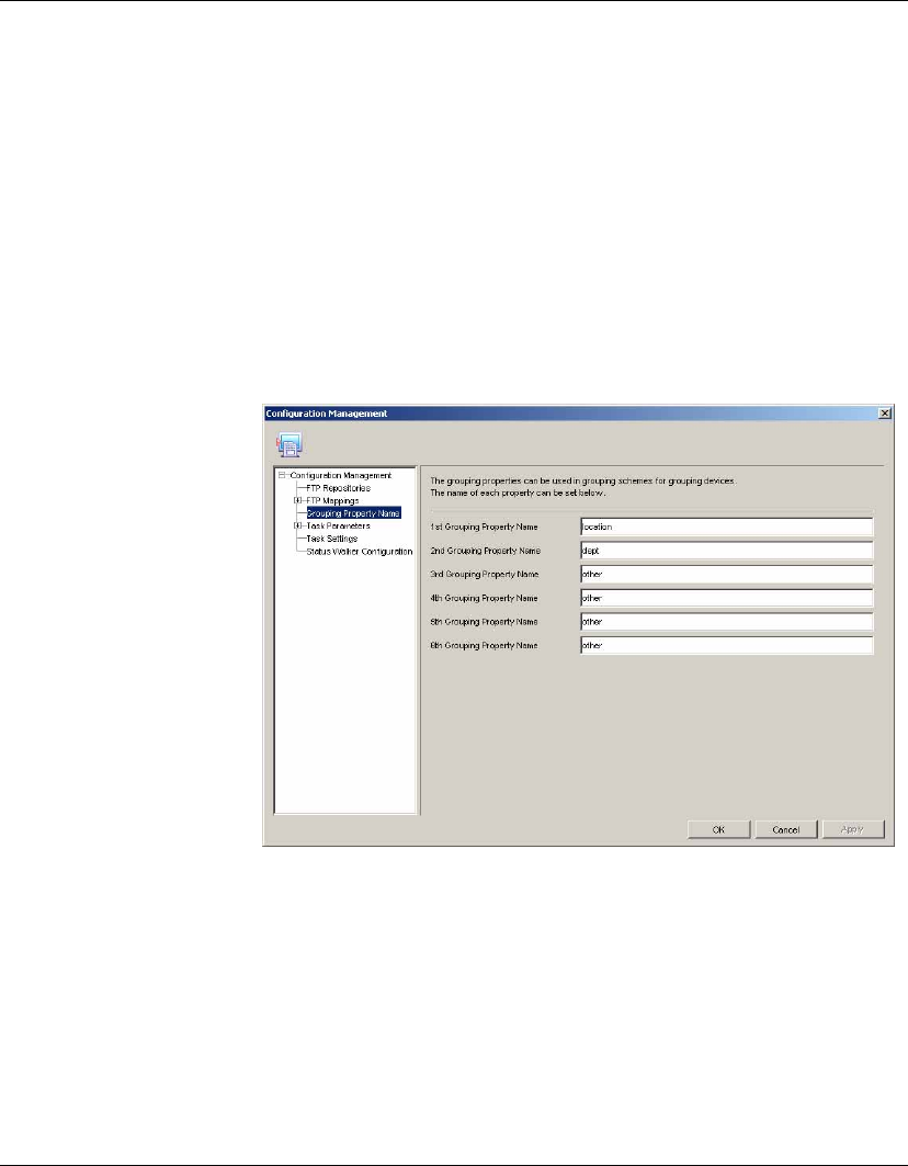
1Display the Tools menu from the Console’s menu bar and select
Configuration.
2Select the Grouping Property Name item in the left-hand tree
pane.
3Enter the names for the 1st, 2nd, 3rd, 4th, 5th and 6th grouping
properties as required.
Note: Changing the name of the properties does not alter the
data for each property. The 1st property always remains the 1st
property, the 2nd the 2nd, and so on.
4Click Apply to save the settings.
5Click OK to finish.
Using the HP Management Console
Grouping Devices 79
Changing Grouping
Properties
Grouping properties can be set by entering them into the properties
window for each device, or assigned by dragging and dropping
devices between property groups.
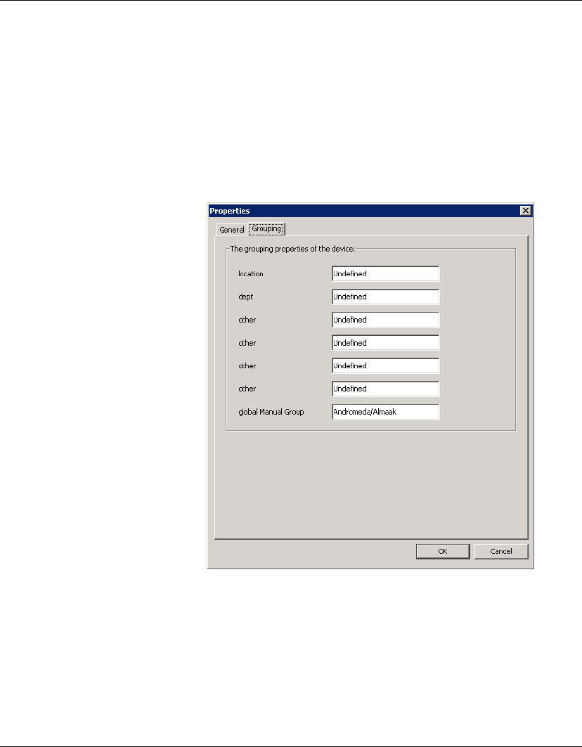
Setting grouping properties:
1Right-click the device whose properties you wish to view.
2Select the Grouping tab.
3Edit the data in each field as required.
4Click OK when done.
These properties can now be used to categorize your devices using
grouping schemes in the Device Pane.

Using the HP Management Console
80 Grouping Devices
Dragging and dropping devices:
1Ensure that the device tree has at least one grouping property
selected in the grouping scheme.
2Click on a device, hold down the mouse button then drag the
device to another group on the device tree.
Note: Devices can only be dragged between groups of the same
level on the device tree, and groups being dragged between must
have a grouping property.
3Release the mouse button and the grouping property for the
device will be set to that of the group being dropped into. The
device will then be re-grouped under the target group.
Pre-assigning
Devices to Groups
You can pre-assign a device to a specific group using the Agent Con-
figuration dialog on the device itself. On the Group tab, select Use
Static Custom Groups > Add Group Name "Manual Group" and
specify a value. Once the device agent has registered with the server,
you will see the device placed in the specified pre-assigned group
folder if you choose the global manual grouping scheme (click the
Group By button and select Manual Group > _global.)
Using the HP Management Console
Editing the Device Filter 81
Editing the Device Filter
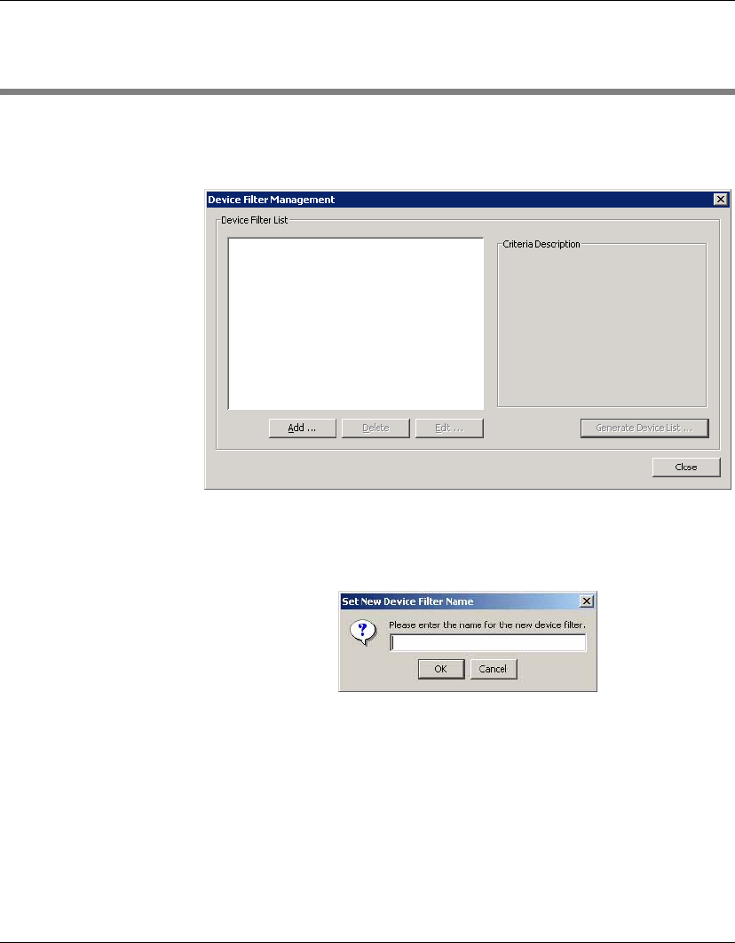
To edit the Device Filter:
1Select Device Filter... from the View menu.
2Click Add... to display the Set New Device Filter Name dialog.
You can also click Delete and Edit... to remove or modify the
existing Device Filters.
3Enter a name for the new device filter (e.g. XPe) and click OK to
display the Edit Device Filter dialog.
Using the HP Management Console
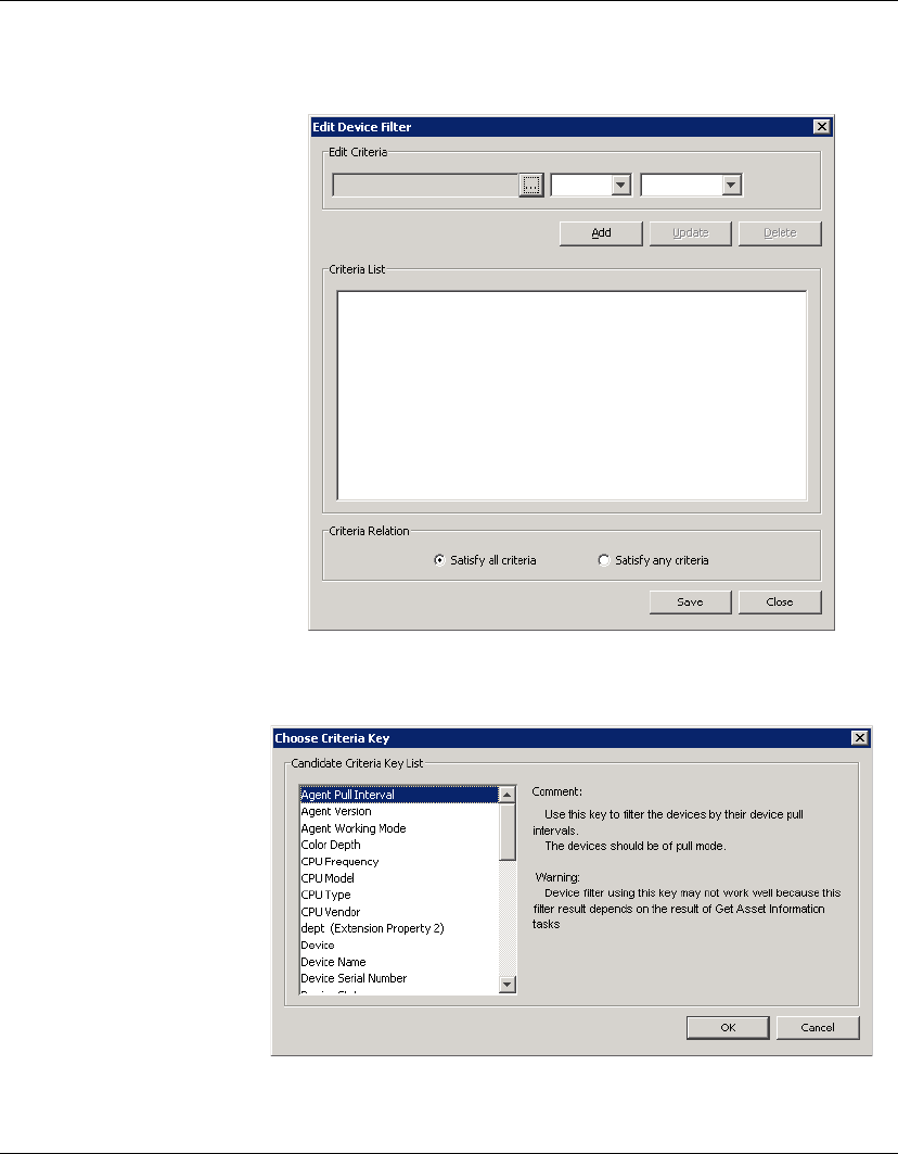
82 Editing the Device Filter
4Click the browse button in the Edit Criteria section to open the
Choose Criteria Key dialog.
Using the HP Management Console
Editing the Device Filter 83
5In the Candidate Criteria Key List, select the criteria according
to your needs. Click OK to return to the Edit Device Filter dialog.
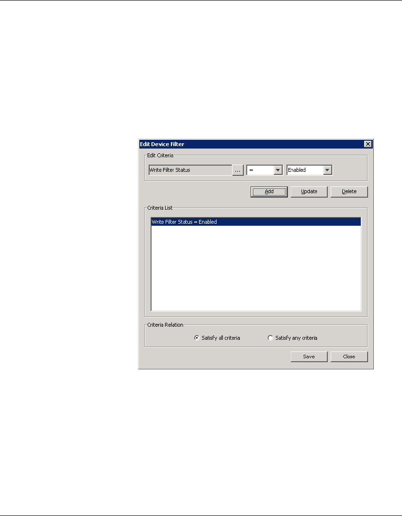
6Click the arrow button in the Edit Criteria section to select
conditions in the drop-down menus. For example: Write Filter
Status = Enabled.
7Click Add to add it to the Criteria List below. You also can select
one of the lists to modify or delete.
8If multiple filters exist in the Criteria List, you can select Satisfy
all criteria or Satisfy any criteria. Then click Save to return to
the Device Filter Management dialog.
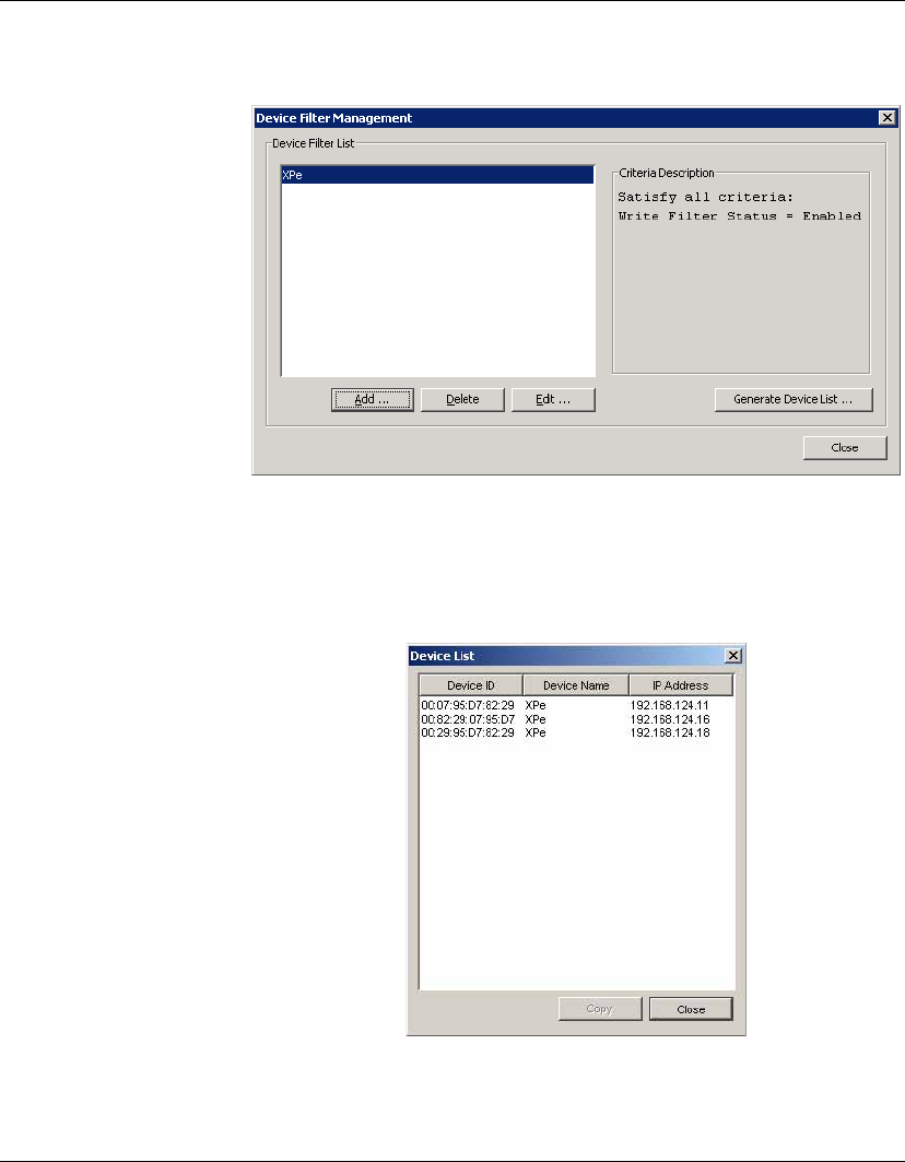
Using the HP Management Console
84 Editing the Device Filter
9In the Device Filter Management dialog you can edit or remove
the selected filter according to your requirements.
10 Click the Generate Device List... button to create the filtered
device list.
Now the administrator can use the device filters to manage the
devices in the network.
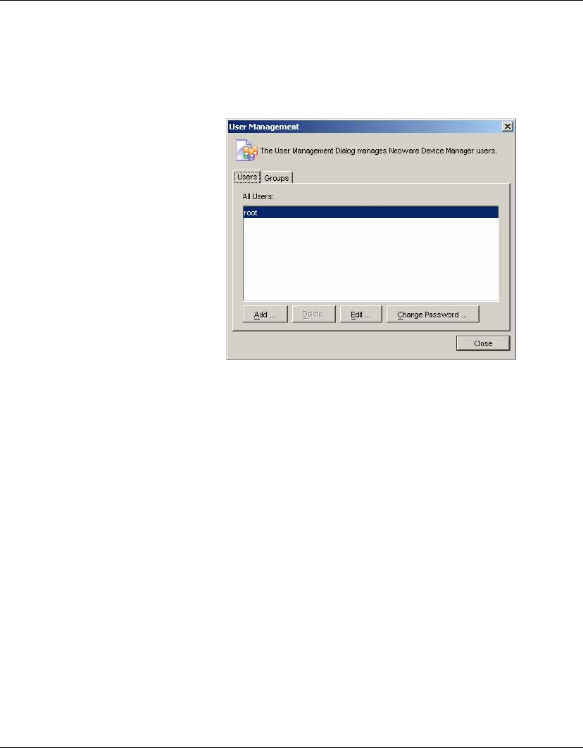
Using the HP Management Console
Editing the Device Filter 85
Filter Security You can limit the devices a user can see by assigning a filter to that
user as his security filter. The procedure is as follows:
1Display the Tools menu and select User Management....
2Select the name of the user on the Users tab, then click Edit.
3Display the Filter tab.
4Select the filter to use in the Enhanced Filter drop-down list.
When you log on as that user you will see that only the devices
allowed by the selected filter are displayed.
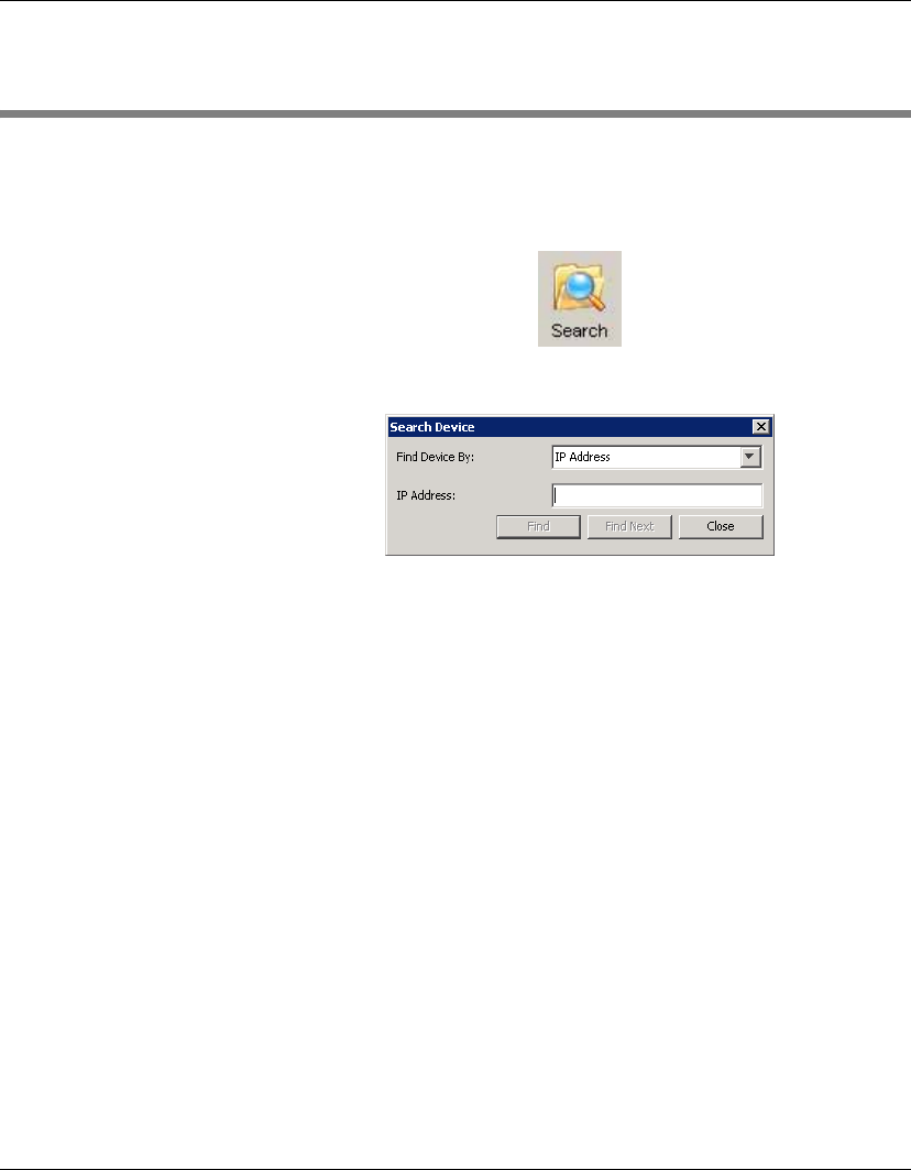
Using the HP Management Console
86 Searching for a Device in the Device Tree
Searching for a Device in the Device Tree
You can quickly display a particular device in the Console’s device
tree either by selecting Device > Search Device Tree from the menu
bar, or by clicking the Search button in the toolbar.
The Search Device dialog will be displayed.
You can find a device either by entering its IP Address, Host Name,
Device ID or Device Serial Number, as specified in the Find Device
By field. Enter the relevant information in the field below then click
Find. If the device is found, the console will automatically change
the display to show the device in the device tree.
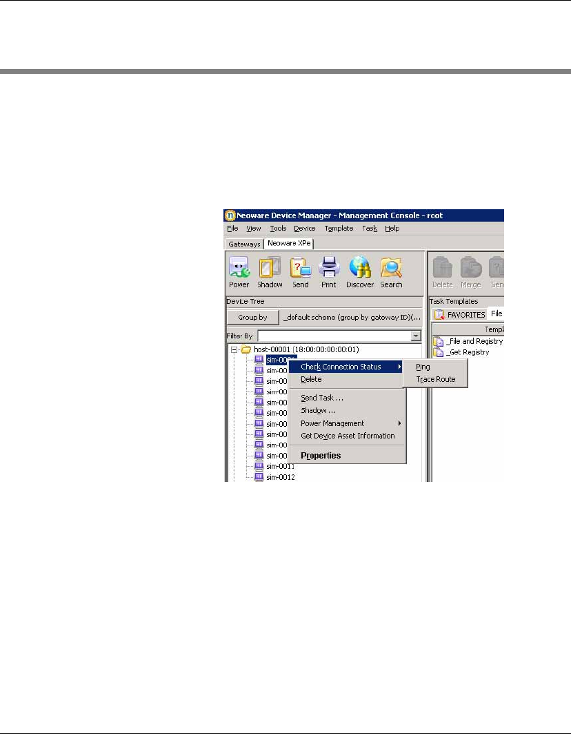
Using the HP Management Console
Checking Network Connection Status 87
Checking Network Connection Status
You can check the network connection status of a device (i.e.
whether it is connected to the network or not).
1In the Device Pane, select one or more devices and right-click
them to display a menu.
2Select Check Connection Status.
3Select the utility you want to use to check the connection status
of the device. You can choose from:
Ping - A basic Internet program that lets you verify that a partic-
ular Internet address exists and can accept requests. Pinging is
diagnostically used to ensure that a host computer, which you
are trying to reach, actually operates.
Trace Route - This diagnostic tool determines the path taken to a
destination by sending ICMP Echo Request messages with vary-
ing Time to Live (TTL) values to the destination. Each router
along the path is required to decrement the TTL in an IP packet
by at least 1 before forwarding it. Effectively, the TTL is a max-
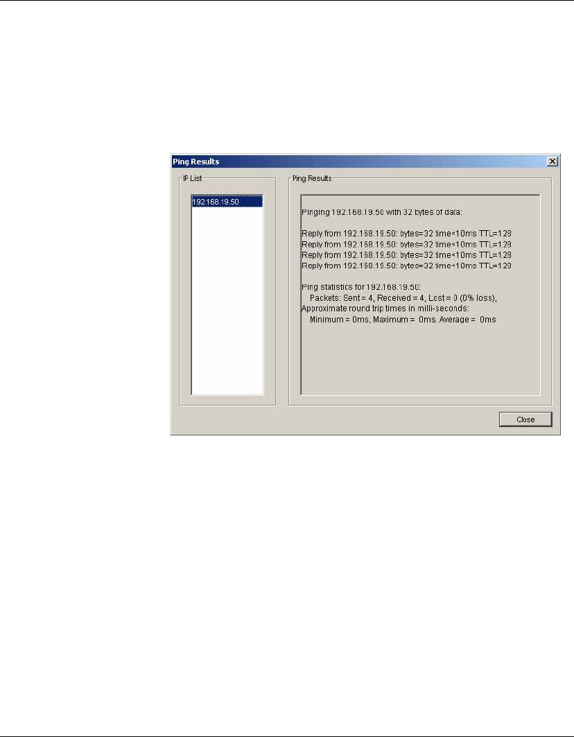
Using the HP Management Console
88 Checking Network Connection Status
imum link counter. When the TTL on a packet reaches 0, the
router is expected to return an ICMP Time Exceeded message to
the source computer.
A window displaying the network connection status of the
device will appear.
4Click Close.
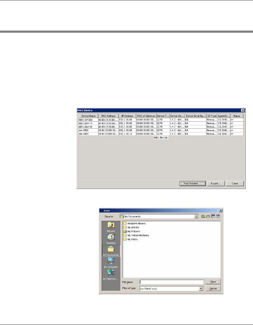
Using the HP Management Console
Printing Information About Devices & Tasks 89
Printing Information About Devices & Tasks
Printing Device
Information
To print information about any devices listed in the Console:
1In the Device Pane, select the devices you want to print (CTRL-
click and/or SHIFT-click them).
2Click the Print icon in the toolbar to display the Print Device
window. Information about all the selected devices is displayed
in the window.
3Either click Export to export the list to a *.csv file.
Enter a name and click Save.
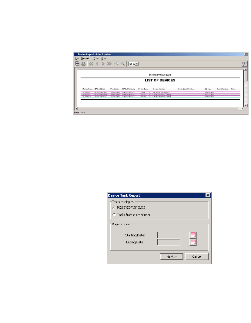
Using the HP Management Console
90 Printing Information About Devices & Tasks
OR
Click Print Preview to print the device report. The Print Preview
window opens.
4If you are satisfied with the preview, click the printer icon or dis-
play the File menu and select Print. Click OK if you accept the
printing settings.
Printing a Device
Task Report
To print information about tasks:
1In the Device Pane, select one device ONLY.
2Right-click on it and select Device Task Report from the menu.
3Tick Tasks from all users or Tasks from current users depend-
ing on what information you need to print.
4Define the period you want to get login information for by
clicking the buttons for both Starting Date and Ending Date.
5Click Next then Print.
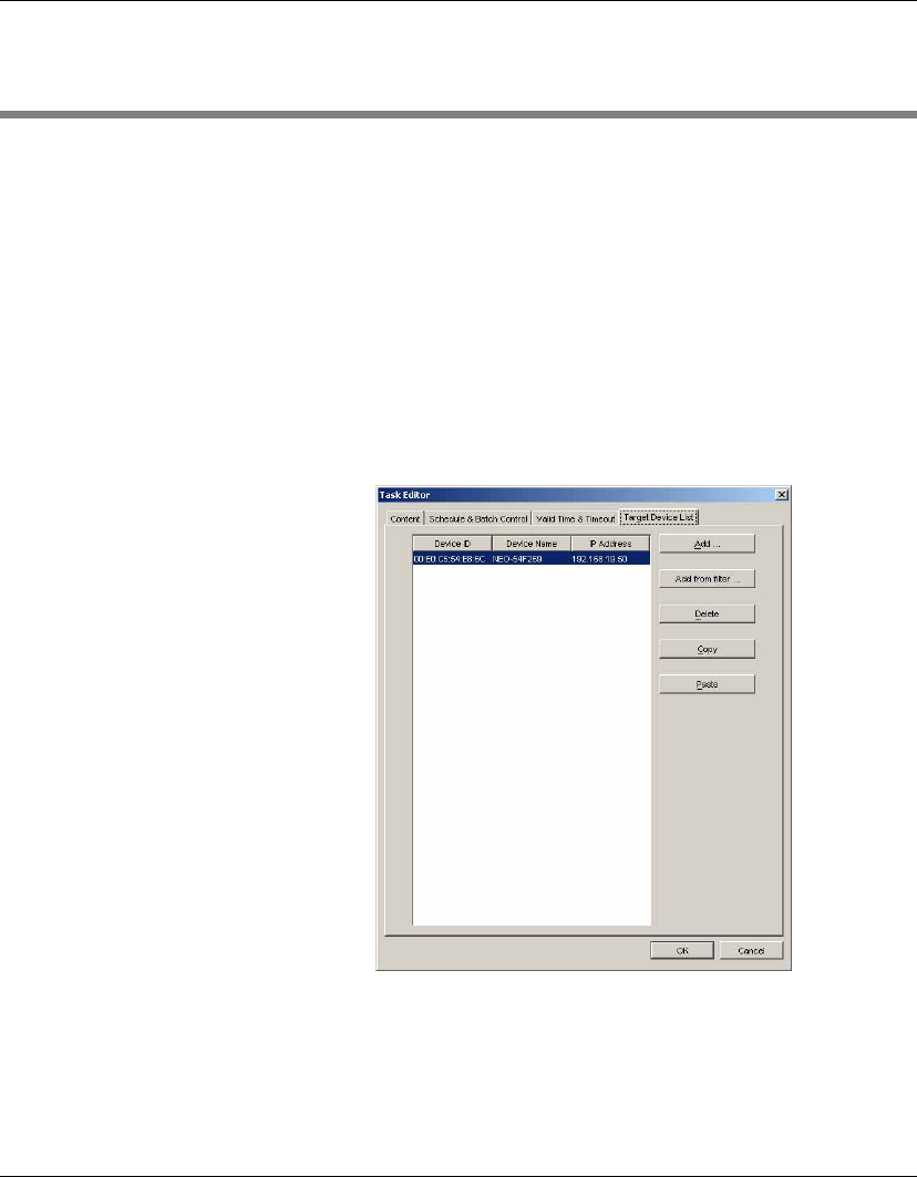
Using the HP Management Console
Shadowing Devices 91
Shadowing Devices
Shadowing enables you to connect to a remote thin client and view
and control that client from the HP Management Console. This can
be achieved either by using the _Shadow Device template available
on the Operations tab, or by selecting from the pop-up menu when
you right-click on a device as described below.
To shadow a device:
1Select a device or a group of devices in the Device Pane.
2Right-click and select Shadow from the pop-up menu. The Task
Editor dialog will be displayed.
3Click OK. When the Shadow processing task is complete, the
remote desktop of the terminal will be displayed in a separate
window.
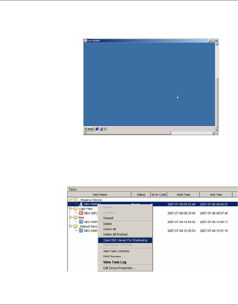
Using the HP Management Console
92 Shadowing Devices
Note: The session password of Shadow is the default password,
which can be set in Configuration.
To Open VNC Viewer for Shadowing:
1Select a completed Shadow Device task in the Task Pane.
2Right-click and select Open VNC Viewer for Shadowing, or dis-
play the Task menu and select Open VNC Viewer for Shadowing.
The remote desktop of the client will be displayed in a separate
window ready for your operations.
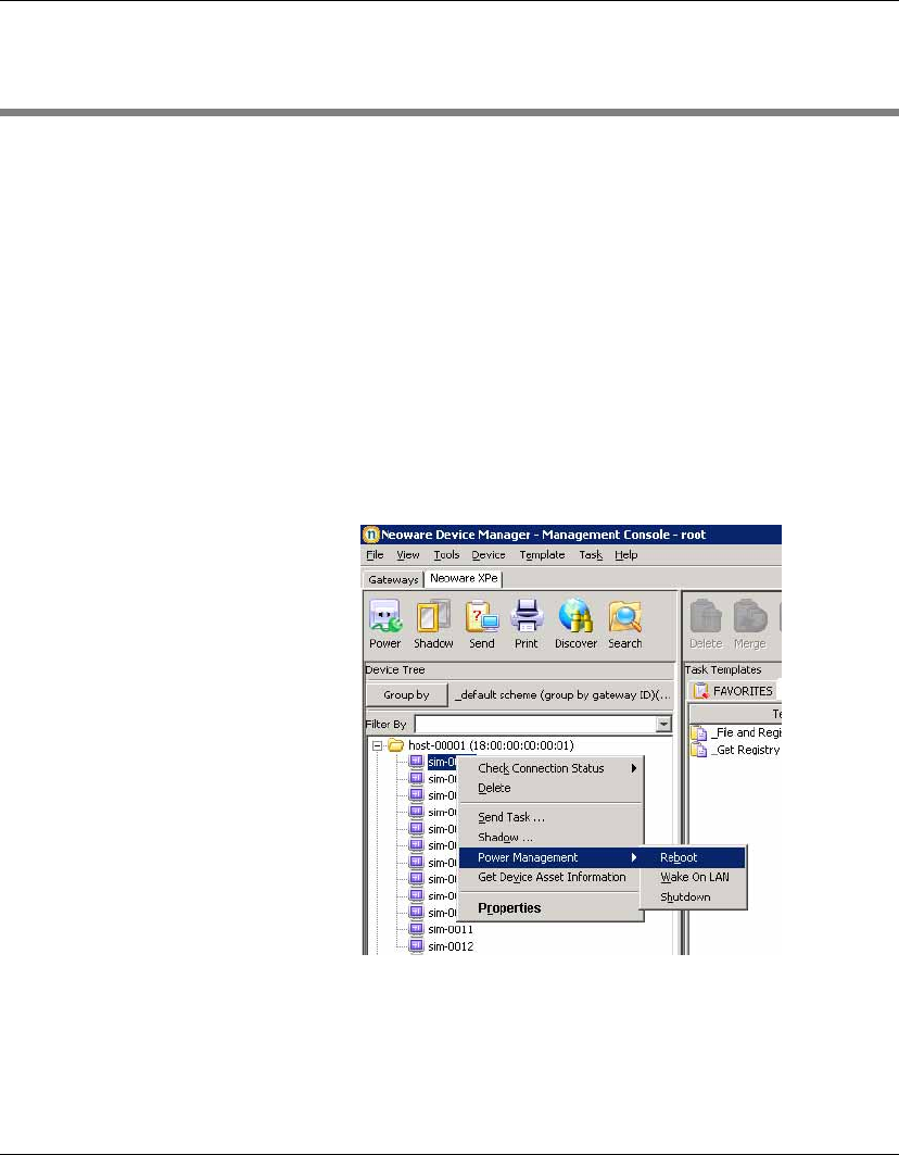
Using the HP Management Console
Power Management 93
Power Management
The Management Console enables you to reboot, shutdown and
wake a client remotely. This can be achieved either by using the tem-
plates available on the Operations tab, or by selecting from the pop-
up menu when you right-click on a device as described below.
Note: To wake a client, the Wake On LAN support of the client’s
BIOS must be enabled.
To shutdown, reboot, or wake a client:
1Select a device from the Device Pane in the main Console
window.
2Right-click and select Power Management > Reboot, Wake On
LAN or Shutdown from the pop-up menu.
3The Task Editor dialog will be displayed. Click OK to perform
the task.
When the client receives the task, a warning dialog will appear on
the screen of the client device to inform the user that the device will
be shutdown or restarted.
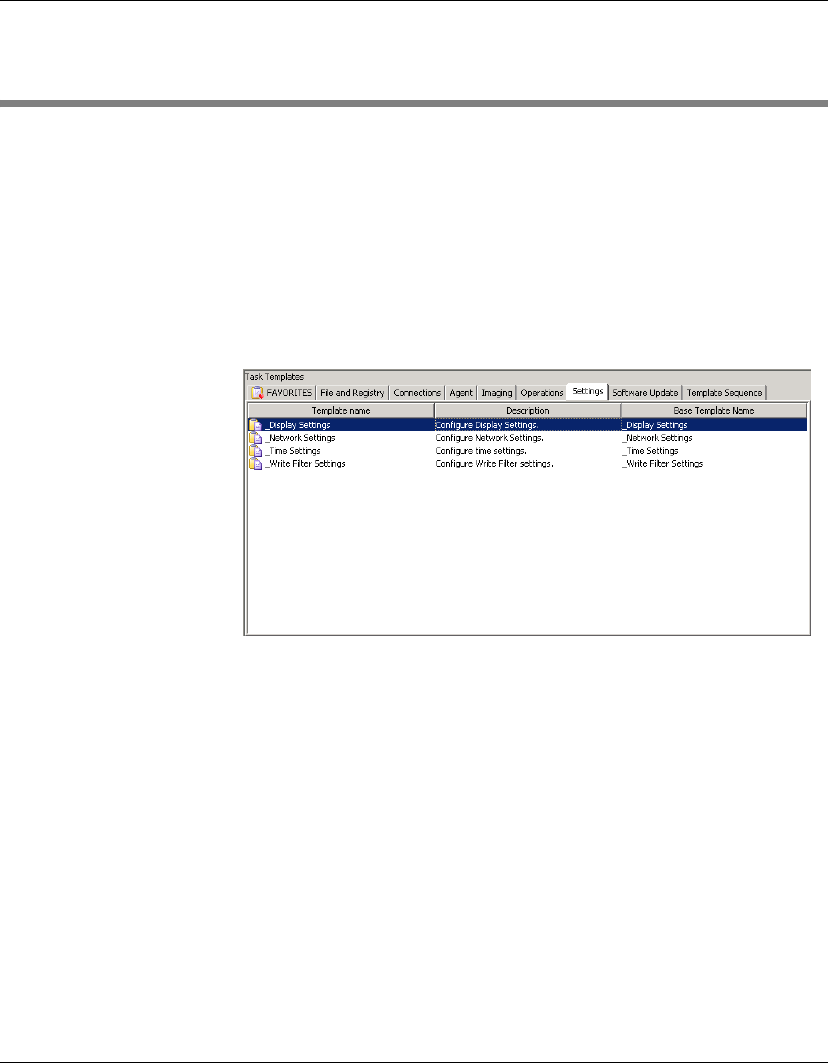
Using the HP Management Console
94 Task Template Management
Task Template Management
HP Device Manager uses Task Templates as the vehicle of commu-
nication between the server and agents residing on thin client
devices. A Task Template is an XML file that contains information
about a task. XML is a standard data format that can be shared easily
across applications and platforms - especially between those on sep-
arate operating systems that need to share data.
All the Task Templates in the system are displayed and managed in
the Template Pane.
Task Template
Categories
Task Templates are sorted into categories according to their function.
•Favorites
Used to store frequently used templates for convenient access.
•File and Registry
A generic template, consisting of a customizable combination of
copying files, deleting files, registry changes, running operating
system commands and pauses.
•Connections
Used to get the connection settings of a device.
•Agent
Used to define the work mode of the agent (push or pull), and
update the agent version.

Using the HP Management Console
Task Template Management 95
•Imaging
Used to push or pull flash-memory images of client devices.
•Operations
Used to perform various operations on a device such as reboot,
shadow, shutdown and wake up.
•Settings
Used to change various settings on the device such as display,
network, time and write filter.
•Software Update
Used to install or uninstall software components on client
devices.
•Template Sequence
Used to define sequences in which tasks are performed.
Personalized Task Templates, based upon these categories, can be
edited, deleted, imported or exported to create customized specific
tasks for devices.
Creating & Editing
Task Templates
A set of standard ’blank’ task templates are provided which are
listed under various categories according to their function in the
Template Pane. The names of standard templates begin with the "_"
(underscore) character, for example: _File and Registry.
To create or edit a task template:
1Double-click an existing template in the Template Pane, or
right-click a template then select Properties from the pop-up
menu.
2Specify your requirements for the template using the options
available. To clear a value of the target device, leave the
corresponding field for that value blank on the template.
3When you have finished defining a new template, click the Save
as button and enter a name for the new template.
4Click OK. The new template will be created and its name will
appear in the Template Pane.

Using the HP Management Console
96 Task Template Management
Adding a Template
to Favorites
To make it easier to locate templates that are used frequently, you
can add them to the Favorites tab as follows:
1Select a tab from the Template Pane.
2Right-click on the name of the template in the tab.
3Select Add to Favorites from the pop-up menu.
A copy of the selected template is added to Favorites.
Using Template
Sequence
Templates
You can specify two or more templates to be performed in a specific
order using Template Sequence templates. A Template Sequence
template can contain a maximum of 22 tasks.
1Select the Template Sequence tab in the Template Pane.
2Double-click the standard _Template Sequence template to
open the Template Editor.
3Click the Add button and select a template to add to the sequence
from the pop-up menu. The Template Editor for the selected
template will be displayed allowing you to edit it.
Note: You can define new templates to add to the sequence as
required, just select the blank template type from the menu.
4Click OK to add the template to the template sequence.
5Continue adding templates to the sequence as required. Note
that clicking Add after the first template has been added to the
sequence will display an additional menu for you to indicate
whether the next template will be actioned after the previous
template task has been successful, failed, or anyway (regardless
of the result).
6When you have finished defining the template sequence, click
Save as... to save the Template Sequence template for later use.

Using the HP Management Console
Task Template Management 97
Importing &
Exporting Task
Templates
You can import or export Task Templates so they can be shared
between HP Device Manager systems.
To import an XML file as a Task Template:
1Select the Product Type tab and the Category tab into which you
want to import the template.
2Display the Template menu from the menu bar and select
Import. The Open dialog will be displayed.
3Select the XML file that you want to import.
4Click Select Import Files. The file will be added to the selected
tab as a new template.
To export a Task Template as an XML file:
1Display the Template menu from the menu bar and select
Export.
2Enter the name of the template.
3Select the destination of the exported file.
4Click OK to export the template as an XML file.
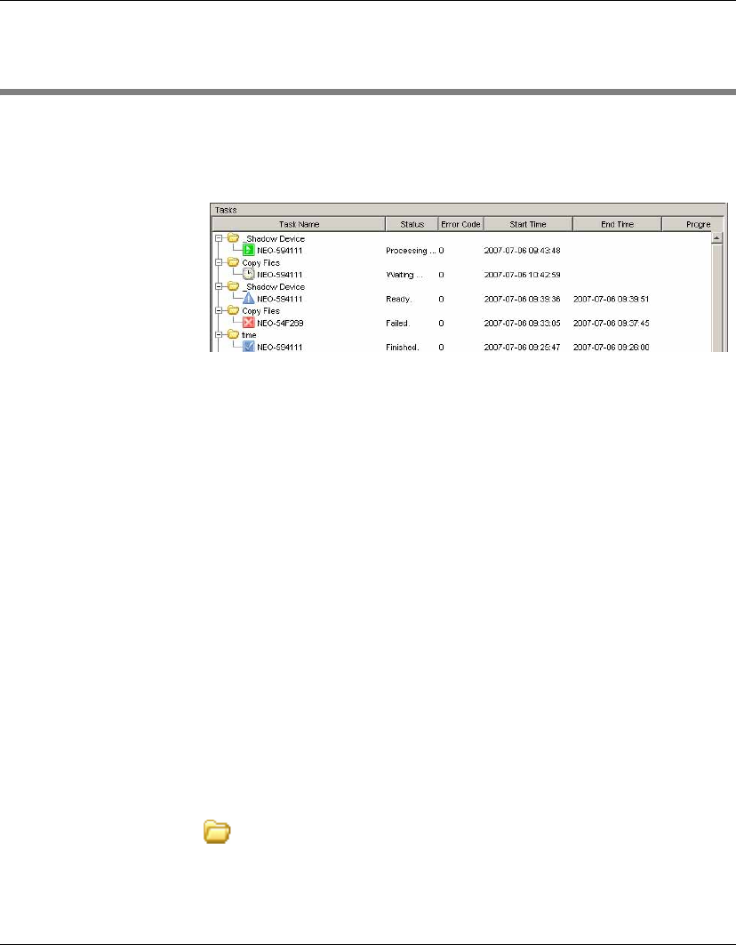
Using the HP Management Console
98 Task Management
Task Management
All the tasks that have been sent are monitored and the results are
displayed in the Task Pane. The Task Pane lists all the tasks that
have been sent to devices.
The task list consists of six columns:
•Task Name
Indicates how many devices that task was assigned to.
•Status
Indicates the status of the task in a particular device.
•Error Code
If the status is waiting and the server is retrying to send the task,
this indicates what the problem was.
•Start Time
Indicates when the task was begun.
•End Time
Indicates when the task ended.
•Progress
Indicates the progress of a task in a device.
Task Pane Icons The meaning of the icons displayed in the Task Pane are as follows:
Task Folder
This groups together a number of devices that have been sent
the same task.
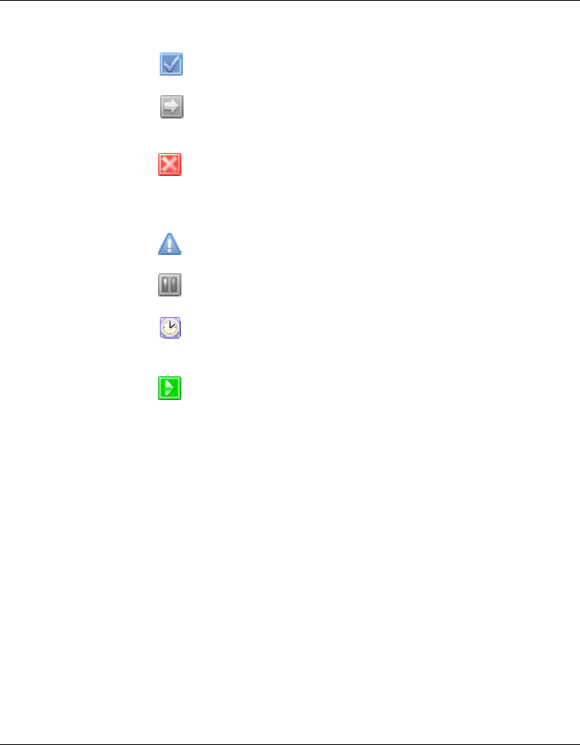
Using the HP Management Console
Task Management 99
Success
The task was executed successfully by the device.
Sending
The console has sent the task to the device and is waiting for
a reply.
Failed / Timeout
The task has failed or timed out. (If the task is not complete
after finite time, the status of the task will be displayed as
Timeout. The error code of the status is 0.)
Ready
The task is executed and waiting for the user’s operation.
Paused
The task has been paused.
Waiting
The task has been scheduled for sending at a later time, and
has not been sent yet.
Processing
The task has been accepted by the device and is being
processed.
Applying Tasks to
Devices
You can apply a task to a device from a defined template for the pur-
pose of remote configuration, monitoring, installing or restricting.
Assigning a PXE task will cause the thin client to either wake on
LAN or re-boot.
You can apply tasks by drag-and-drop or by manually selecting the
task.
1Drag a template from the Template Pane and drop it on to a
device,
OR
Right-click the device and select Send Task from the pop-up
menu to display the Template Chooser. Select a category then a
template from the templates list, then click Next.
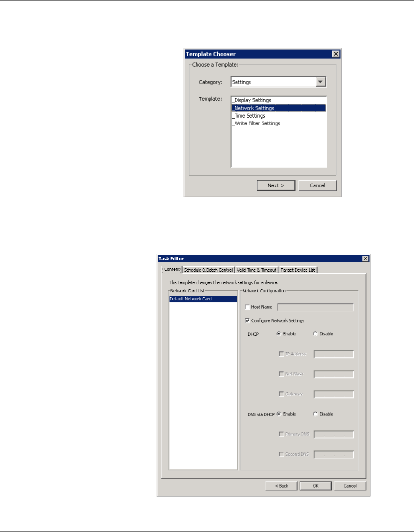
Using the HP Management Console
100 Task Management
2The Task Editor dialog will be displayed. This enables you to
make changes to the template and specify how and when the
task is to be performed.
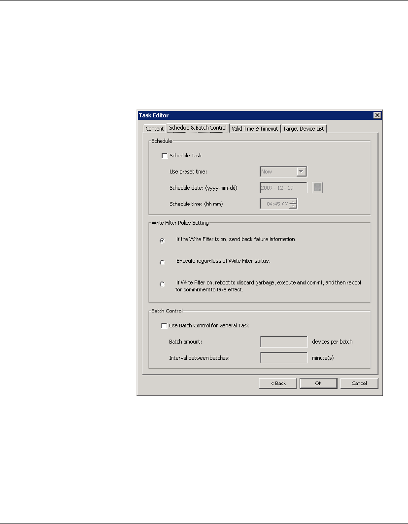
Using the HP Management Console
Task Management 101
3The Content tab allows you to change the properties of the task
as desired. (See “Creating & Editing Task Templates” on
page 95 for details.)
4Select the Schedule & Batch Control tab and specify when and
how the task is to be performed.
If you do not select the Schedule Task option and specify a time,
the task will be sent to the device as soon as you click the OK
button.
5Click OK to apply the task to the device.
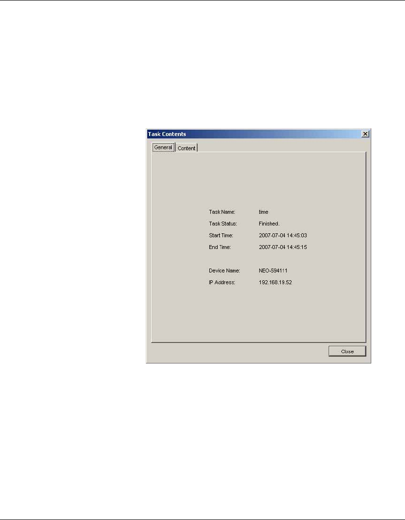
Using the HP Management Console
102 Task Management
Displaying Task
Properties
To display the properties of a task:
1In the Task Pane, click the + box next to the Task Name to list
the devices that the task is assigned to.
2Right-click a device and select View Task Contents in the pop-
up menu. A Task Contents window will be displayed showing
detailed information about the assigned task.
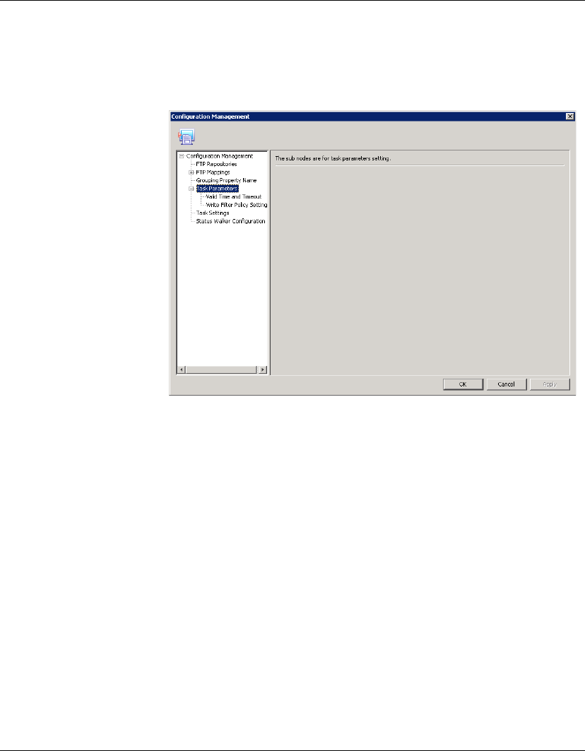
Using the HP Management Console
Task Management 103
Configuring Task
Parameters
Select Tools > Configuration from the Console’s menu bar to open
the Configuration Management dialog, then click the Task Parame-
ters option in the option tree pane to expand it.
The Task Parameters option consists of two sub-options: Valid Time
and Timeout and Write Filter Policy Setting. These are described in
the following sections.
Valid Time and Timeout
The Valid Time and Timeout options enable you to set the duration
HP Device Manager will wait for the execution of tasks. You can
also specify the start and end time of working hours during which
HP Device Manager will not execute tasks. Clicking in an option
field will cause the Description box to display a short description of
that option.
1Select Valid Time and Timeout in the option tree pane of the
Configuration Management dialog.
2Set the time, in minutes, for each category: Valid Time, General
Timeout, General Batch Interval, PXE Batch Interval and FTP
Batch Interval.
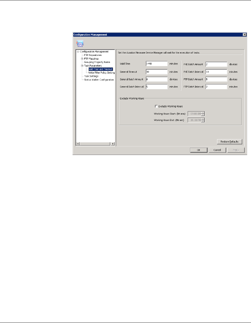
Using the HP Management Console
104 Task Management
Set the amount, in devices, for each category: General Batch
Amount, PXE, Batch Amount and FTP Batch Amount.
Check the Exclude Working Hours option box to input the start
and end time of working hours.
Clicking Restore defaults will reset the timeout settings to their
defaults and set the working hours to 9.00 start and 17.00 end..
3Click Apply to save the new settings.
4Click OK to exit.
Write Filter Policy Setting
The Write Filter Policy Setting options enable you to specify how
the Enhanced Write Filter on XPe devices affects tasks.
1Select Write Filter Policy Setting in the option tree pane of the
Configuration Management dialog.
2Choose one of the three policy items.
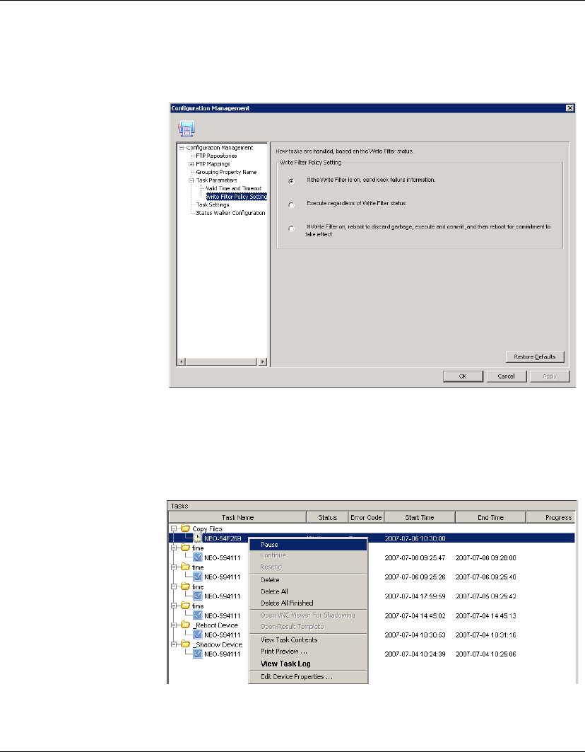
Using the HP Management Console
Task Management 105
3Click Apply to save the new settings.
4Click OK to exit.
Pausing Tasks To pause a waiting task:
1Select a waiting task in the Task Pane.
2Right-click and select Pause from the pop-up menu.
The status of the waiting task will be changed to Paused.
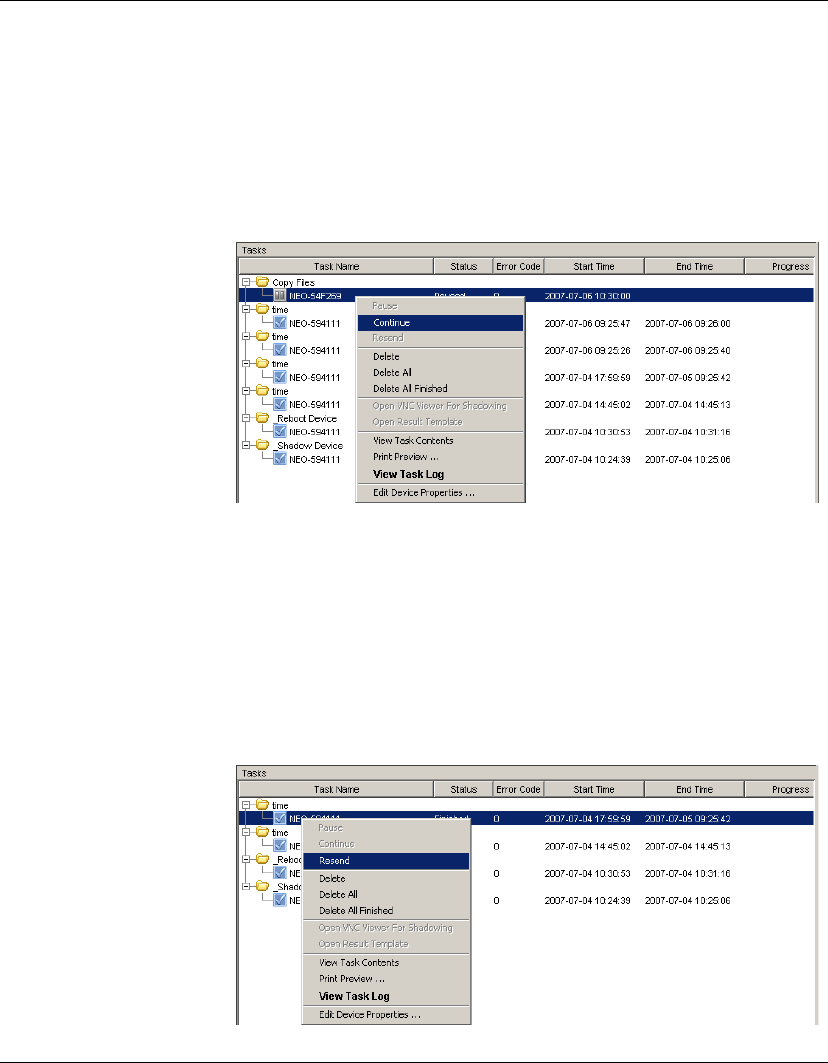
Using the HP Management Console
106 Task Management
Note: This operation only is available for waiting tasks.
Continuing Tasks To continue a paused task:
1Select a paused task in the Task Pane.
2Right-click and select Continue from the pop-up menu.
The status of the paused task will be changed to Waiting.
Note: Only paused tasks (tasks that have not been sent) can be
continued.
Resending Tasks If a task has finished, you can resend the task to the device.
1Select the finished task in the Task Pane.
2Right-click and select Resend from the pop-up menu.
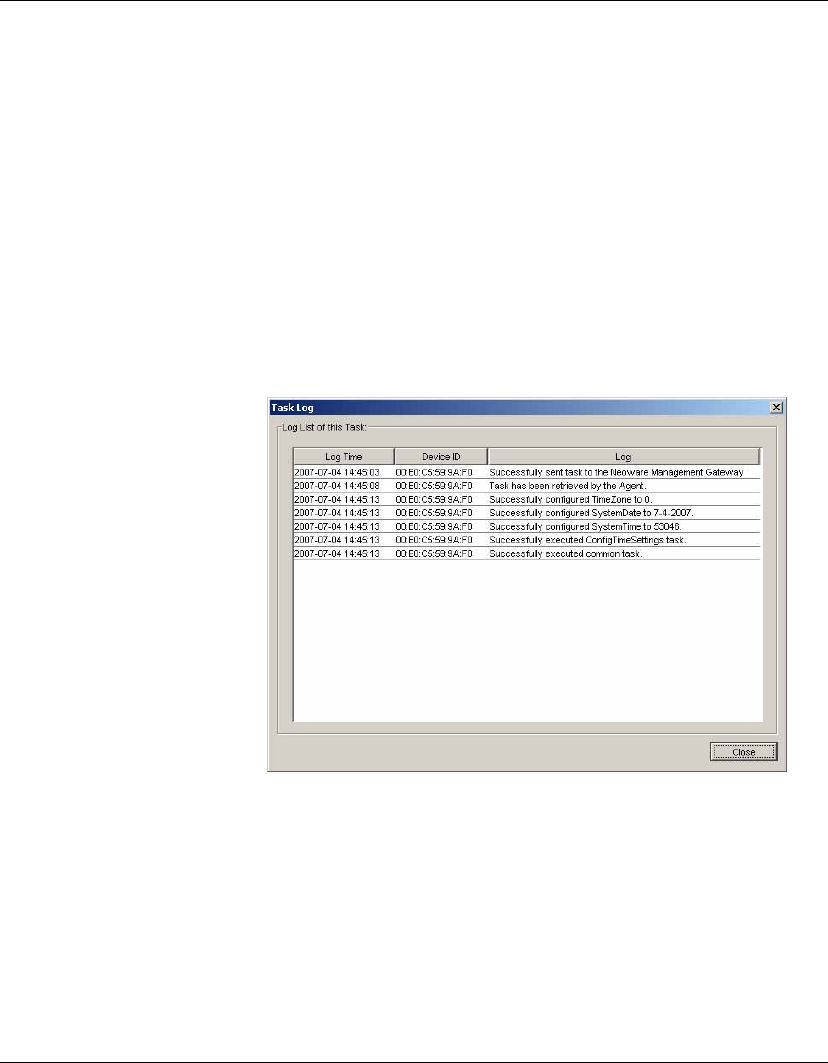
Using the HP Management Console
Task Management 107
Deleting Tasks To delete a selected task, right-click the task and select Delete from
the pop-up menu. If you select Delete All, all the tasks in the Task
Pane will be deleted. If you select Delete All Finished, all finished
tasks will be removed from the Task Pane.
Warning: Deleting a task that is in progress may damage the OS
image! For example, updating and upgrading tasks, pushing imag-
ing tasks, and so on.
Displaying Task
Logs
To display the log of a task:
1Right-click a task in the Task Pane and select View Task Log
from the pop-up menu. A Task Log window will be displayed.
2Click Close to close the log viewer when you have finished.
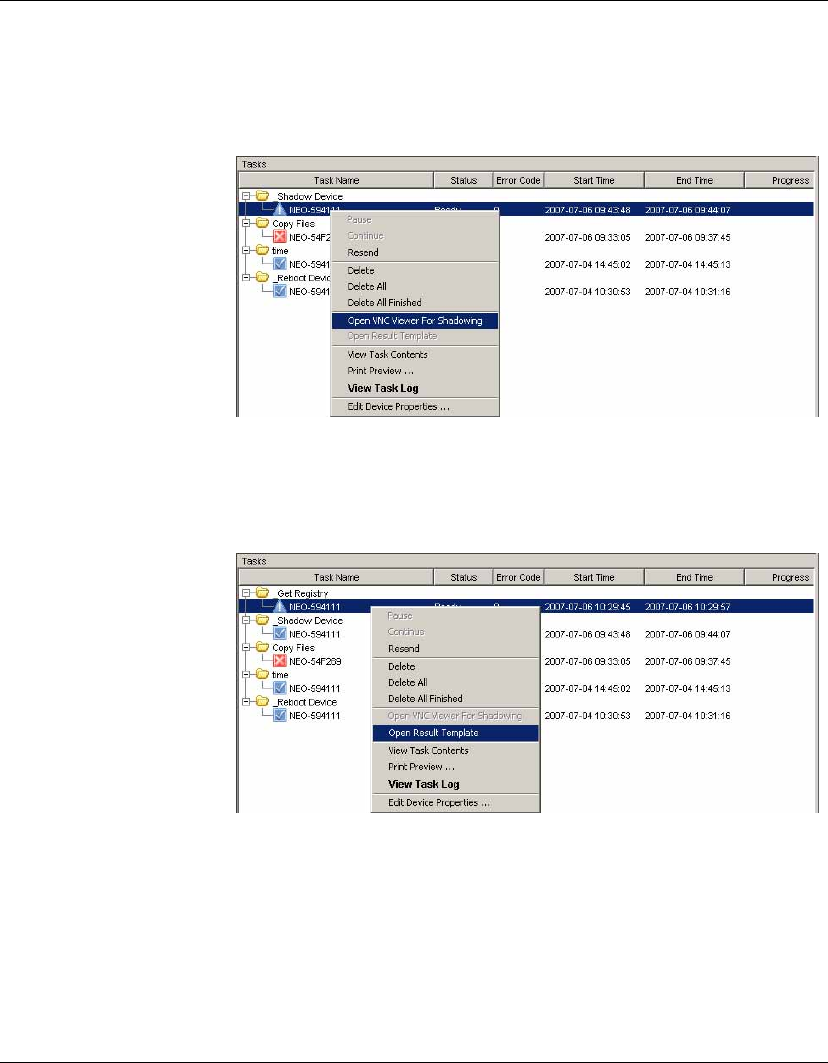
Using the HP Management Console
108 Task Management
Opening VNC
Viewer for
Shadowing
You can open a VNC Viewer for shadowing a device by right-click-
ing a ready or finished shadowing task and selecting Open VNC
Viewer for Shadowing from the pop-up menu.
Opening a Result
Template
Right-click a ready task and select Open Results Template from the
menu to open the results of some tasks such as Get Registry, Get
Connection Configuration and so on.
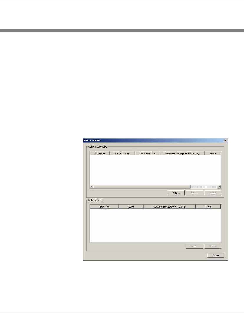
Using the HP Management Console
Device Status Tools 109
Device Status Tools
HP Device Manager has two integrated tools that monitor and record
the performance of the devices: Status Walker and Status Snapshot.
Status Walker The Status Walker tool makes a list of all the IPs available and
walks to them; it brings back their status information and displays it.
This status report is made in real time. The information is stored in a
database placed on the server.
Note: The
Status Walker
option is only available for Windows gate-
ways.
1Display the Tools menu from the Console’s menu bar and select
Status Walker to display the following dialog.
2Click Add to create a new walking schedule, or Edit to modify an
existing one. The Schedule Editor dialog will be displayed.
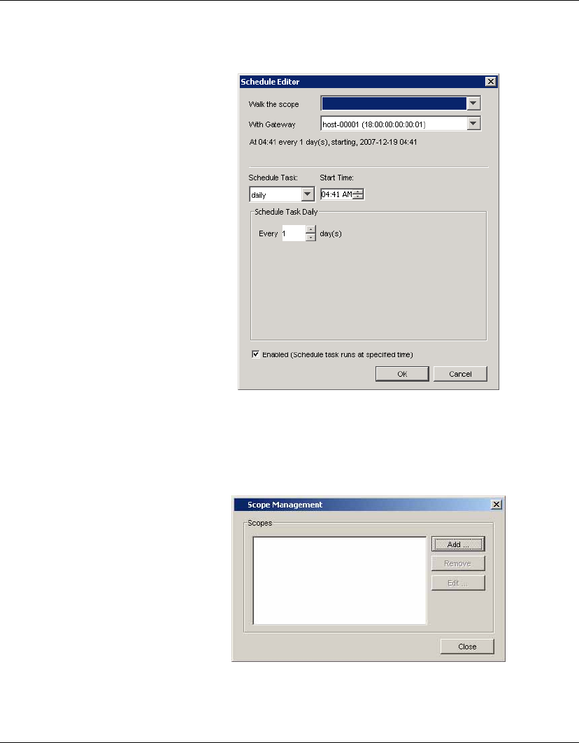
Using the HP Management Console
110 Device Status Tools
3Select the name of the scope to use in the Walk the Scope drop-
down menu, or select Edit... to define a new scope.
Selecting Edit... will display the Scope Management dialog
which enables you to add, edit or remove scopes..
Click the Add button and enter a name for the new scope.
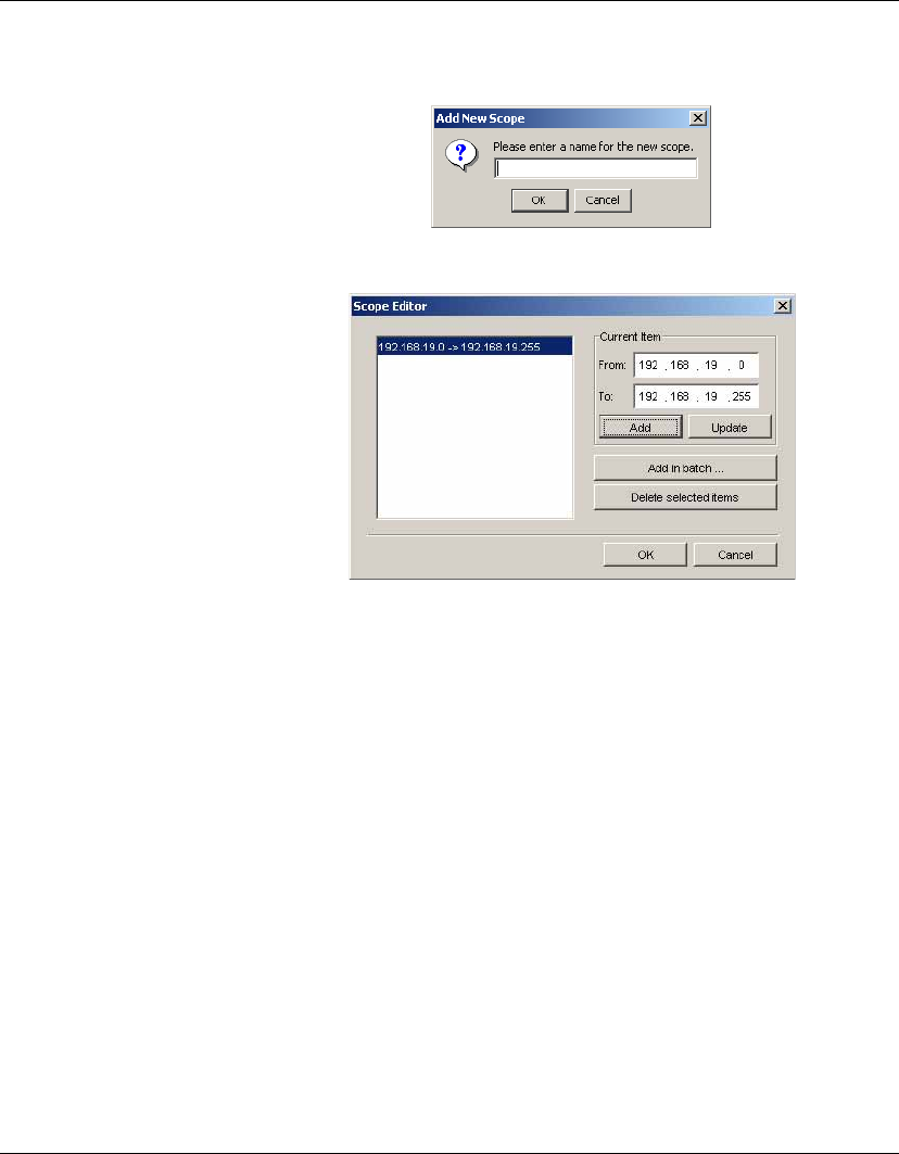
Using the HP Management Console
Device Status Tools 111
Click OK to display the Scope Editor dialog.
Specify the IP address range in the Current Item fields, then
click Add to add it to the list box on the left. Click OK when you
have finished defining scopes.
Click Close in the Scope Manager dialog to return to the Sched-
ule Editor. The scope(s) you defined will be listed in the Walk
the scope field ready for selection.
4Select the Gateway to use.
5Use the Schedule options to specify the time and frequency of
the task.
6Click OK.
The results of scheduled walking tasks will be displayed in the
Walking Tasks pane at the bottom of the Status Walker dialog.
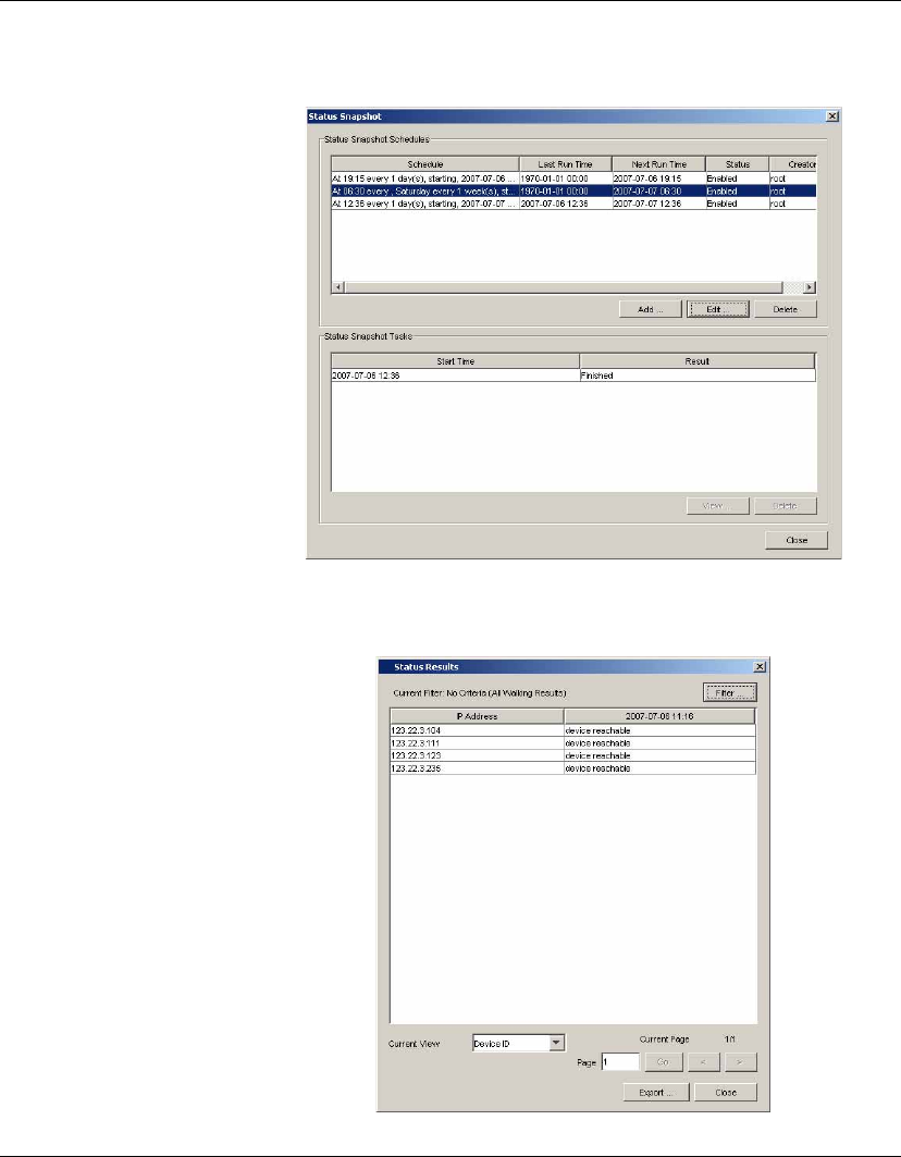
Using the HP Management Console
112 Device Status Tools
Selecting a Finished walking task then clicking the View button will
display the status of devices found.
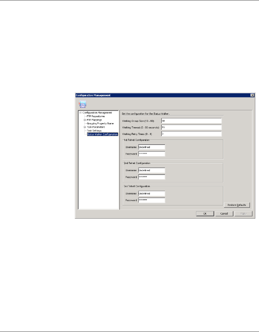
Using the HP Management Console
Device Status Tools 113
Configuring the Status Walker
You can configure the Status Walker to suit your requirements as
follows:
1Select Tools > Configuration from the Console’s menu bar to
open the Configuration Management window.
2Select the Status Walker Configuration item in the left-hand tree
pane.
Note: You can display a short description of each option by
clicking in the option field.
3Enter a value for the Walking Group Size.
4Define a value for Walking Timeout.
5Set the number of Walking Retry Times.
6Configure the 1st, 2nd and 3rd Telnet by typing in a Username
and Password for each one of them.
7Click Apply to save the settings.
8Click OK.
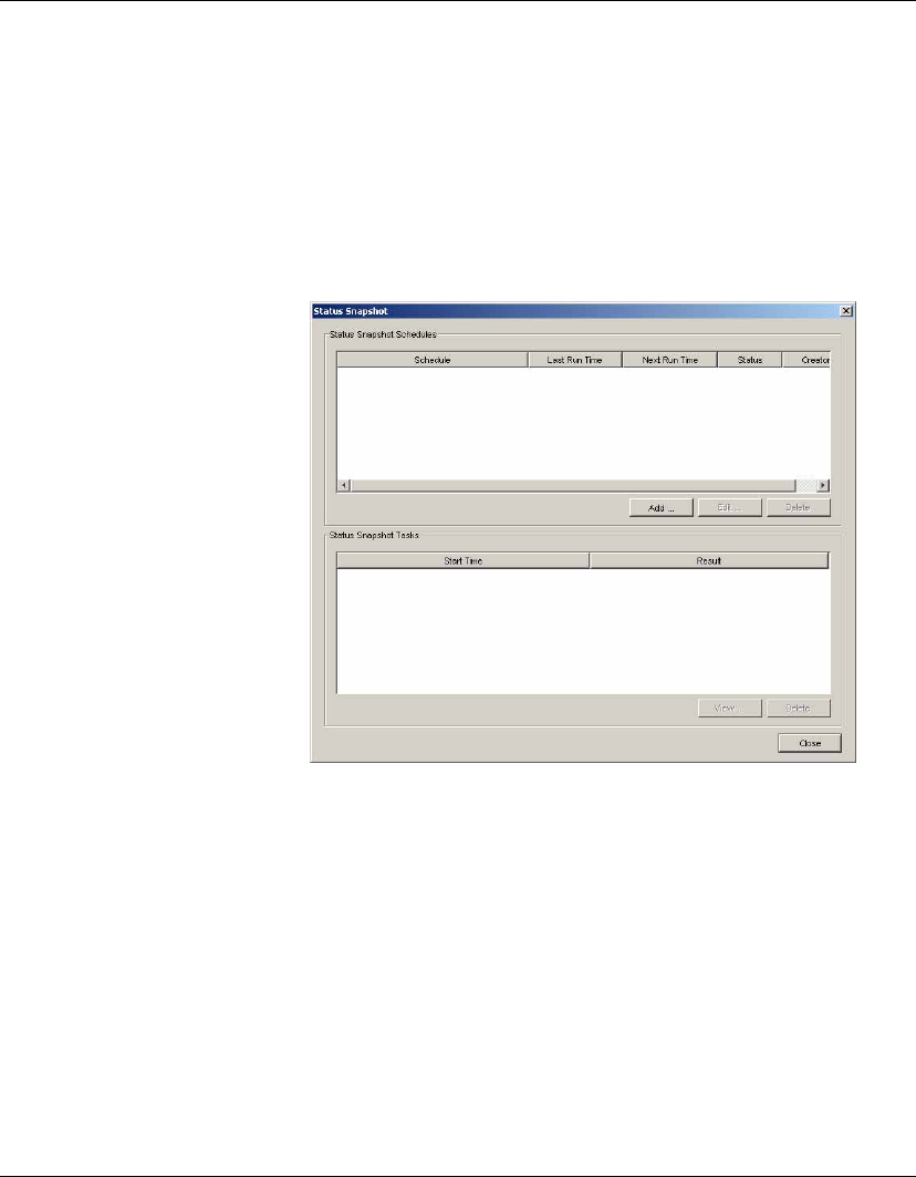
Using the HP Management Console
114 Device Status Tools
Status Snapshot The Status Snapshot tool takes a snapshot of the network, that is, it
creates a report of the devices’ status and stores it on the server to be
displayed when the tool is opened. This tool does not work in real
time. The Status Snapshot settings allow the administrator to sched-
ule the walk and set the frequency.
1Display the Tools menu from the Console’s menu bar and select
Status Snapshot. The Status Snapshot dialog will be displayed.
2Click Add to create a new status snapshot schedule, or Edit to
modify an existing one. The Schedule Editor dialog will be
displayed.
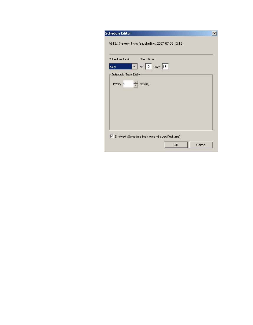
Using the HP Management Console
Device Status Tools 115
3Schedule the status snapshot task by specifying its Frequency
and the Start Time.
4Click OK.
5Click Close.
The results of the scheduled status snapshot tasks will be displayed
in the Status Snapshot Tasks pane at the bottom of the Status Snap-
shot dialog.
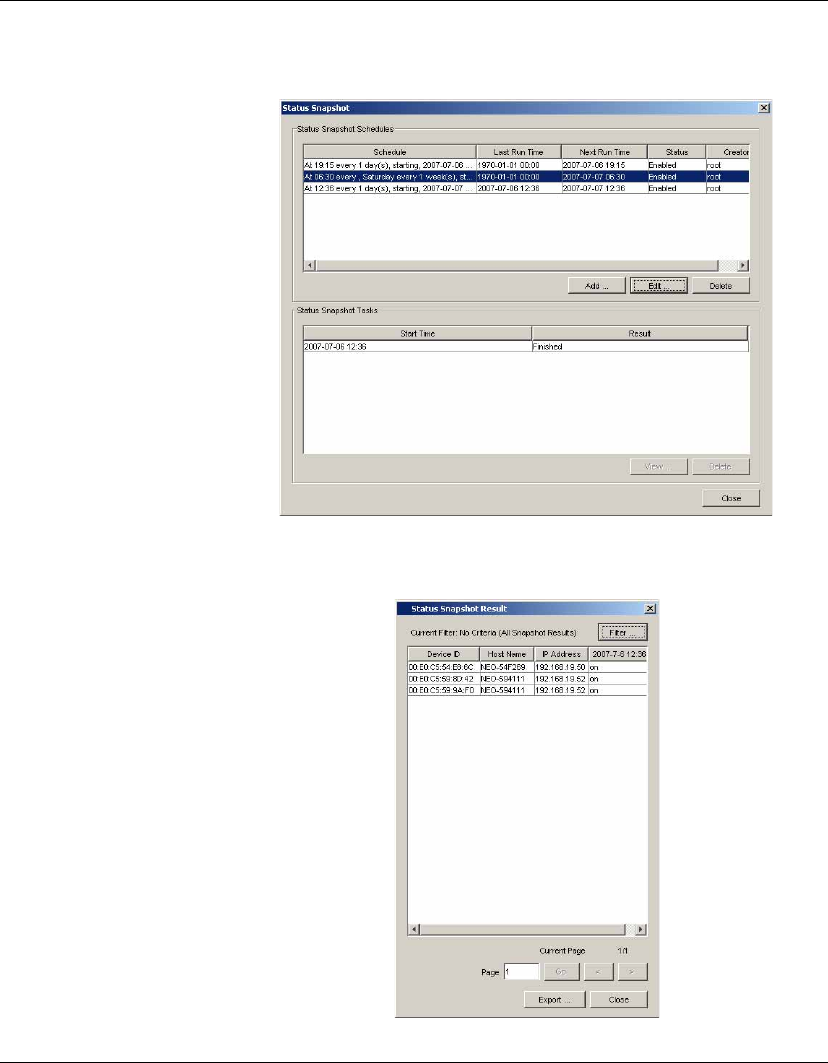
Using the HP Management Console
116 Device Status Tools
Selecting a Finished status snapshot task then clicking the View but-
ton will display information about the devices found.

117
HP Device Manager User Manual
CHAPTER 5 Common Tasks
This chapter describes how to use the Management Console to
change device settings, copy files and execute commands.
Performing a Task
In order to perform a task on a remote device you must first define
a template which provides the instructions to be executed or new
settings, then apply that template to the device. The basic proce-
dure is described below. For a more detailed explanation, please
refer to the sections “Task Template Management” on page 94 and
“Task Management” on page 98.
1To define a template, double-click an existing template in the
Template Pane, or right-click a template then select Properties
from the pop-up menu.
2Specify your requirements for the template using the options
available, then click the Save as button and enter a name for
the new template.
3To apply the template to a device or group of devices, either
drag the template from the Template Pane and drop it on to the
device or group,
or
right-click the device and select Send Task from the pop-up
menu to display the Template Chooser. Select a category then a
template from the templates list, then click Next.
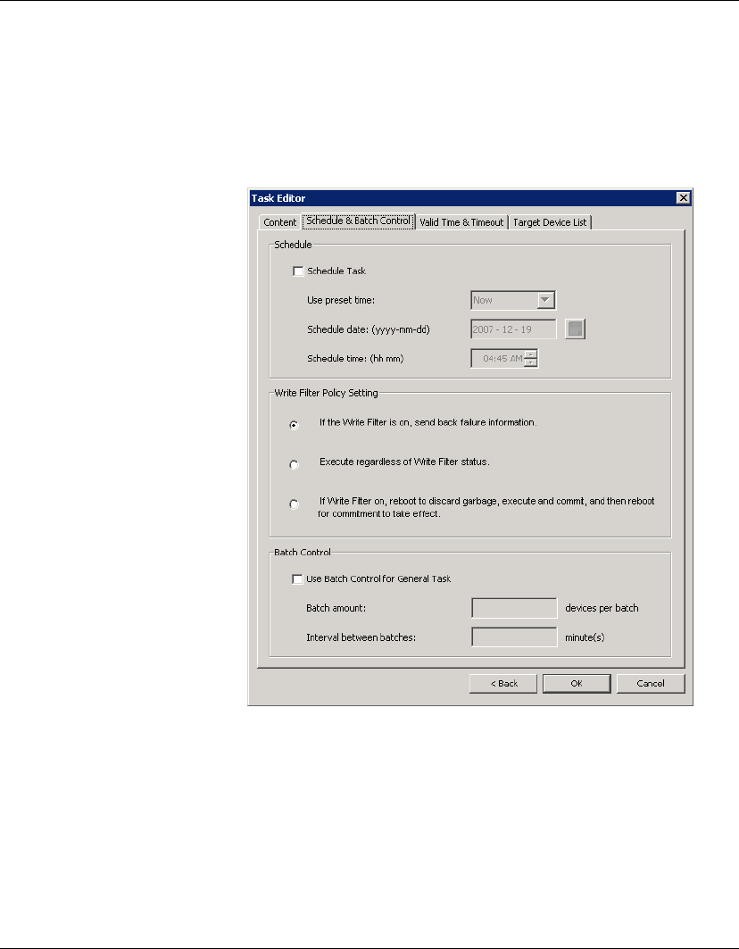
Common Tasks
118 Performing a Task
4The Task Editor dialog will be displayed. Select the Schedule &
Batch Control tab and specify when and how the task defined in
the template is to be performed. If you do not select the Sched-
ule Task option and specify a time, the task will be applied to the
device as soon as you click the OK button.
5Click OK to apply the task to the device.

Common Tasks
Changing Connection Settings 119
Changing Connection Settings
HP thin client devices are designed to access servers or applications
through pre-defined ICA, RDP, terminal emulation or Web browser
connections. HP Device Manager enables you to copy these pre-
defined connection settings from one thin client to others of the
same model and operating system type.
Important: Before copying the connection settings of a device, you
must make sure that each connection is properly configured and
tested on the network where the connections will be used.
1Configure a thin client device with the required connection
settings and ensure that the connections work on the network
where they will be used.
2Run the Management Console and display the name of the
device with the correct connections in the device tree.
3Select the Connections tab in the Template Pane, then double-
click on the _Get Connection Configuration template to display
the Template Editor.
4Use the check boxes to indicate which connection settings to
retrieve from the device.
5Enter a name for the template which will be created to store the
connection settings.
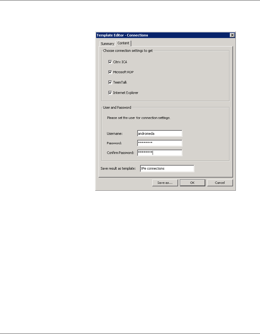
Common Tasks
120 Changing Connection Settings
6Click the Save as... button, enter a name for this template then
click OK.
7Drag and drop the template on the name of the device with the
correct connections in the device tree. The Task Editor will be
displayed.
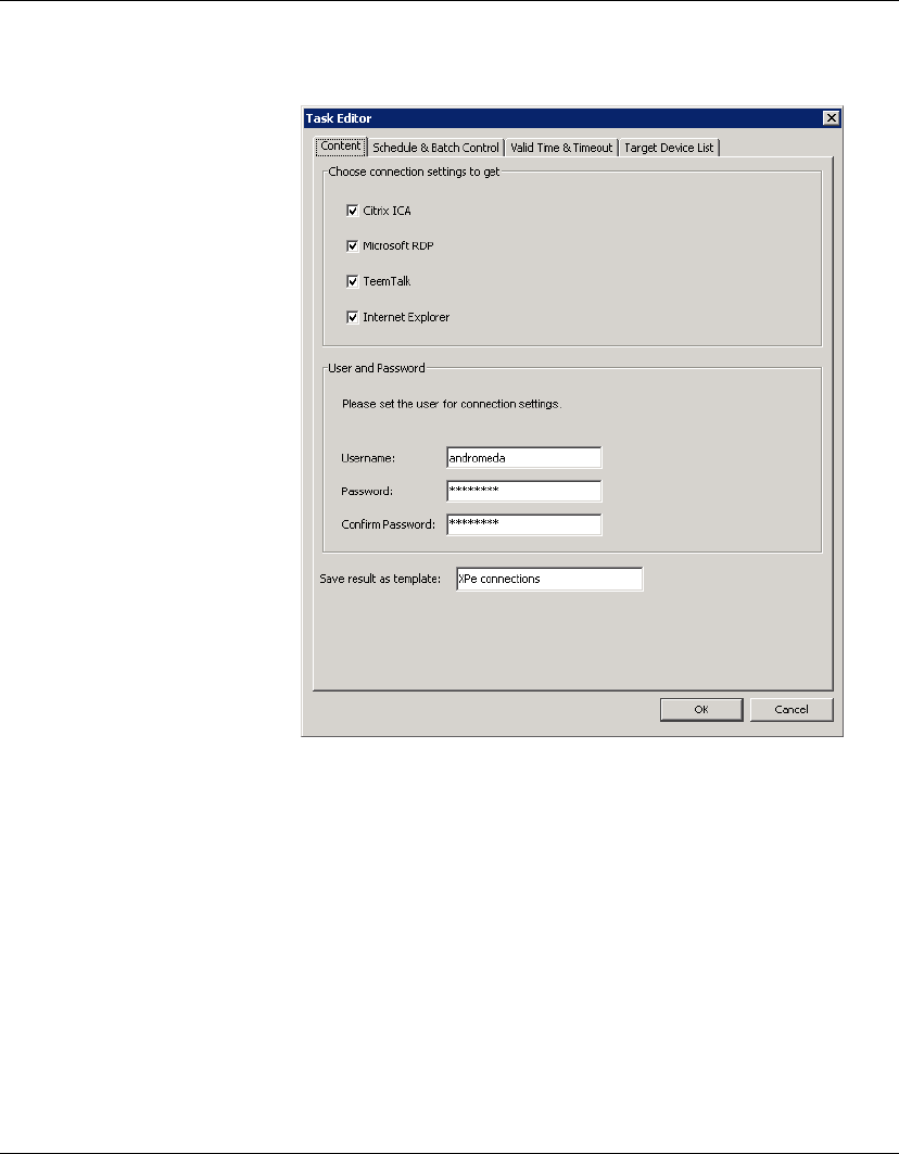
Common Tasks
Changing Connection Settings 121
8Click OK to apply the task to the client device.
9The connection settings will be copied from the device and
stored in a new template which will appear in the Templates
Pane with the name you specified in step 5.
10 You can now drag and drop this new template on devices in the
device tree to apply the connection settings to them.
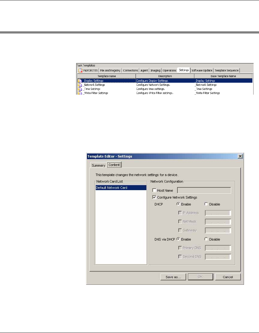
Common Tasks
122 Changing Device Settings
Changing Device Settings
The setup configuration of a device can be changed using templates
listed on the Settings tab in the Template Pane.
The following sections provide an overview of each template.
Configuring
Network Settings
1Select the Settings tab in the Template Pane.
2Double-click the _Network Settings template to display the
Template Editor.
3Enter the network settings as required.
Note: If
DHCP
is enabled (default), the device will not use static
IP information. If you want to use static IP, select
Disable
.
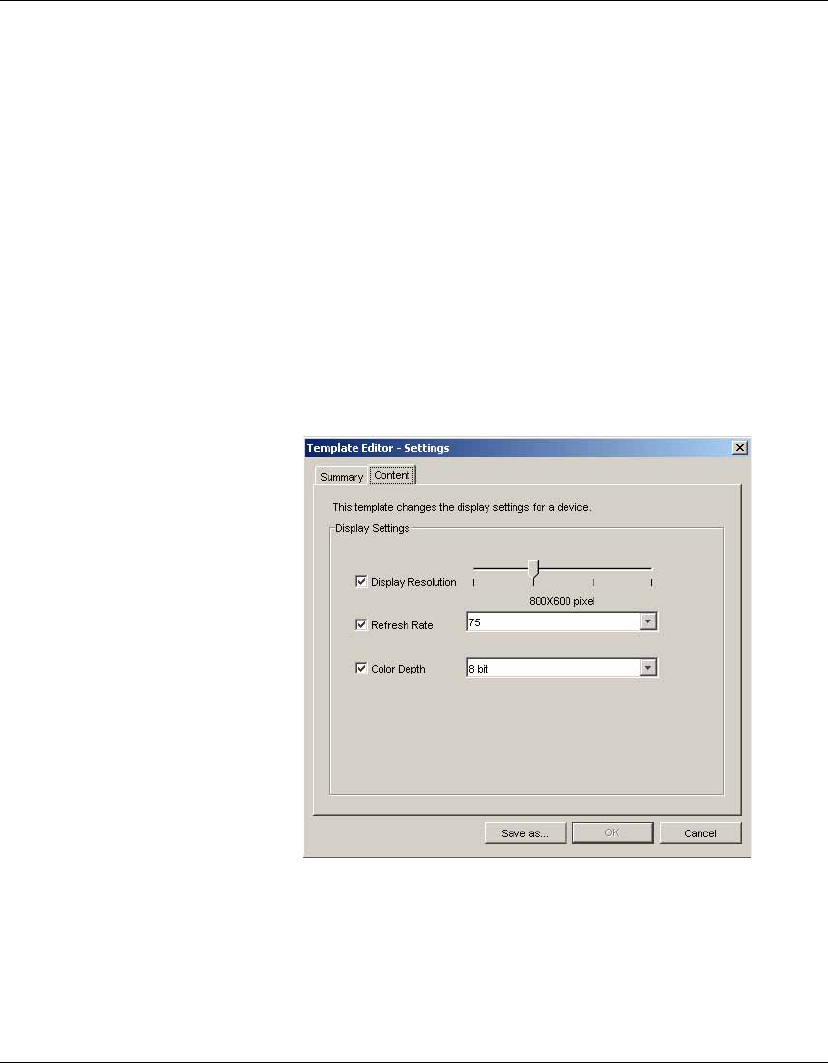
Common Tasks
Changing Device Settings 123
4Click Save As... to save the template with a new name.
5Drag and drop the template on the device(s) you want to
configure.
Note: Because changes made to device properties can be
applied to more than one device at a time, some settings are not
available if more than one device is selected. These include the
static IP information and device hostname - settings that must be
unique to each device.
Configuring Display
Settings
1Select the Settings tab in the Template Pane.
2Double-click the _Display Settings template to display the
Template Editor.
3Specify the Display Resolution (e.g. 800 x 600) using the slider,
and select the screen Refresh Rate and Color Depth from the
drop-down lists.
4Click Save as... to save the template with a new name.
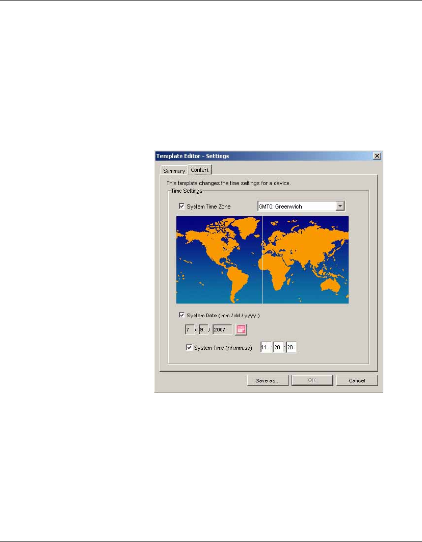
Common Tasks
124 Changing Device Settings
5Drag and drop the template on the device(s) you want to
configure.
Note: The
Color Depth
option is only available for XPe OS devices.
Configuring Time
Settings
1Select the Settings tab in the Template Pane.
2Double-click the _Time Settings template to display the
Template Editor.
3Specify the time settings you require.
4Click Save as... to save the template with a new name.
5Drag and drop the template on the device(s) you want to
configure.
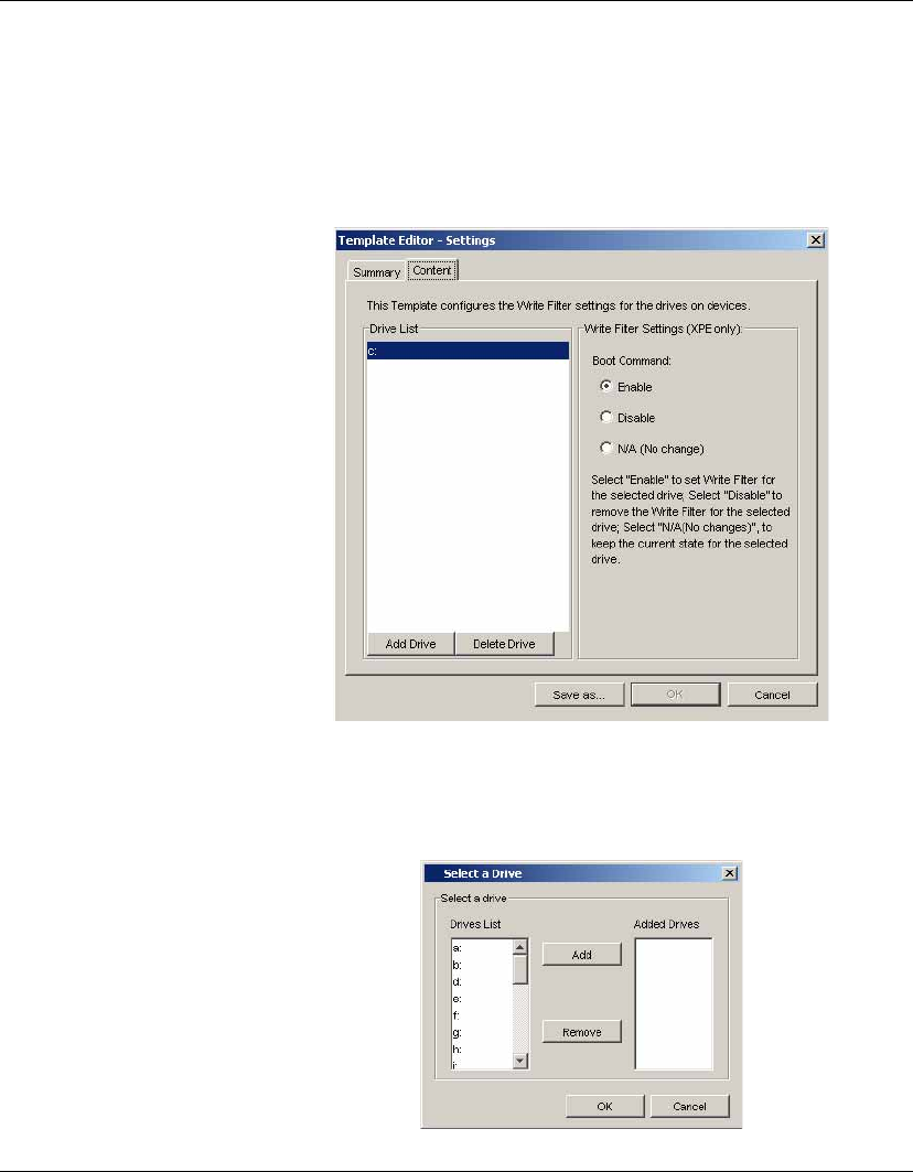
Common Tasks
Changing Device Settings 125
Configuring Write
Filter Settings
Note: Write Filter settings are only applicable to XPe OS devices.
1Select the Settings tab in the Template Pane.
2Double-click the _Write Filter Settings template to display the
Template Editor.
3Select the drive to configure in the Drive List box.
You can add one or more drives to the list by clicking the Add
Drive button to display the Select a Drive dialog.

Common Tasks
126 Changing Device Settings
Select a drive letter from the Drives List then click Add to add it
to the Added Drives list. Click OK to add the drives.
4Set the Boot Command to either Enable to set the Write Filter,
Disable to remove the Write Filter, or N/A (No change) to keep
the current state for the selected drive.
5Click Save as... to save the template with a new name.
6Drag and drop the template on the XPe OS device(s) you want to
configure.
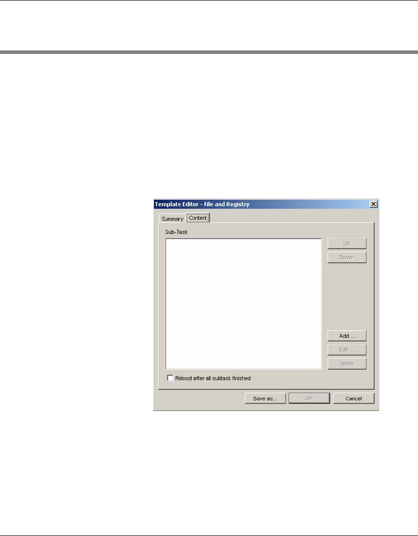
Common Tasks
Using File and Registry Templates 127
Using File and Registry Templates
The _File and Registry template is generic in that it consists of a
customizable combination of copying files, deleting files, registry
changes, running operating-system commands and pauses.
Customizing this template involves adding, deleting and re-arrang-
ing a variety of sub-tasks.
1Select the File and Registry tab in the Template Pane.
2Double-click the _File and Registry template to display the
Template Editor.
3Click Add to add a variety of sub-tasks. (Refer to the table below
for more information on each sub-task.)
Click Edit to edit a sub-task.
Click Delete to delete the selected sub-task.
Click Up and Down to re-arrange the sub-tasks as required.

Common Tasks
128 Using File and Registry Templates
4After modifying the template, click Save as to save the template
for later use.
Table 7: File and Registry Template Sub-Tasks
Sub-Task Item Description
Copy Files FTP Server Select an FTP repository to use.
Upload Upload files from the client device to the
selected FTP repository.
Download Download files from the selected FTP repos-
itory to the client device.
File Path On
Console
The path to the files to be copied.
File Name The name of the files to be copied.
Path On
Device
The path for the files to be copied to on the
device.
Copy Recur-
sively
Copy files matching the pattern in File Name
recursively in all subdirectories from the
given Path On Device.
Delete Files File Name The file name to be deleted.
Path On
Device
The location of the file.
Delete
Recursively
Delete files matching the pattern in File
Name recursively in all subdirectories from
the given Path On Device.
Registry Add Key... (Registry tree) Add a key at the selected
location on the tree.
Add Value... (Registry tree) Add a value on the selected
key.
Rename... (Registry tree) Rename the selected item.
Delete (Registry tree) Delete the selected item.

Common Tasks
Using File and Registry Templates 129
Action (Registry settings) The action to be applied
to the registry table. Set to add to add a key,
or delete key to delete a key.
Type (Registry settings) The type of registry key
value.
Value Name (Registry settings) Specify a name for the
registry key. Double-click on this field to
edit it.
Value Data (Registry settings) Specify the data to add to
the registry key value. Double-click on this
field to edit it.
Add Key (Key settings) If this is selected, even if the
selected key is empty, the key will still be
added to the registry.
Delete Key
and Value
(Key settings) If this is selected, the selected
key and all values under it will be deleted.
Note that there must be no values under the
given key.
Command Command The command on the client device to be exe-
cuted. Enter the full path name of the com-
mand on the client device.
If you are using a long file name that con-
tains a space, use quoted strings to indicate
where the file name ends and the arguments
begin. For example: "c:\program
files\file.exe".
Execute
After Reboot
Set to Yes if you want the system to reboot
and execute the command when it restarts, or
No if you want the command to be executed
immediately.
Wait Set to Yes if the given command has to wait
for the previous command to finish before
processing, or set to No for simultaneous
execution of commands.
Table 7: File and Registry Template Sub-Tasks
Sub-Task Item Description
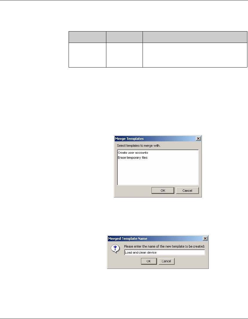
Common Tasks
130 Using File and Registry Templates
Merging File and
Registry Templates
Two or more File and Registry templates can be merged together to
form a new File and Registry template with the combined sub-tasks
of all of them.
1Select one of the File and Registry templates that you wish to
merge.
2Right-click on it and select Merge from the pop-up menu.
3Select another template to merge the selected template with,
then click OK to merge the templates.
4You will prompted to enter a name for the new template.
5Enter a name for the new template.
6A new File and Registry template will be created with all of the
sub-tasks of the original templates combined.
Pause Hours, Min-
utes, Seconds
The duration of time to pause processing of
the template, often in order to wait for certain
events, for example a system restart.
Table 7: File and Registry Template Sub-Tasks
Sub-Task Item Description
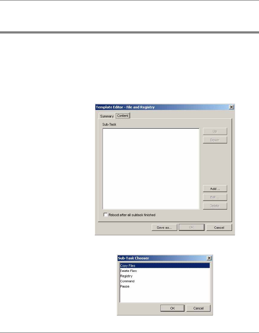
Common Tasks
Copying Files 131
Copying Files
You can copy files from a device to the FTP Repository, or download
files from the console to a device through the FTP Repository. Both
are achieved using the _File and Registry template.
1Select the File and Registry tab in the Template Pane.
2Double-click the _File and Registry template to display the
Template Editor.
3Click the Add button and select Copy Files.
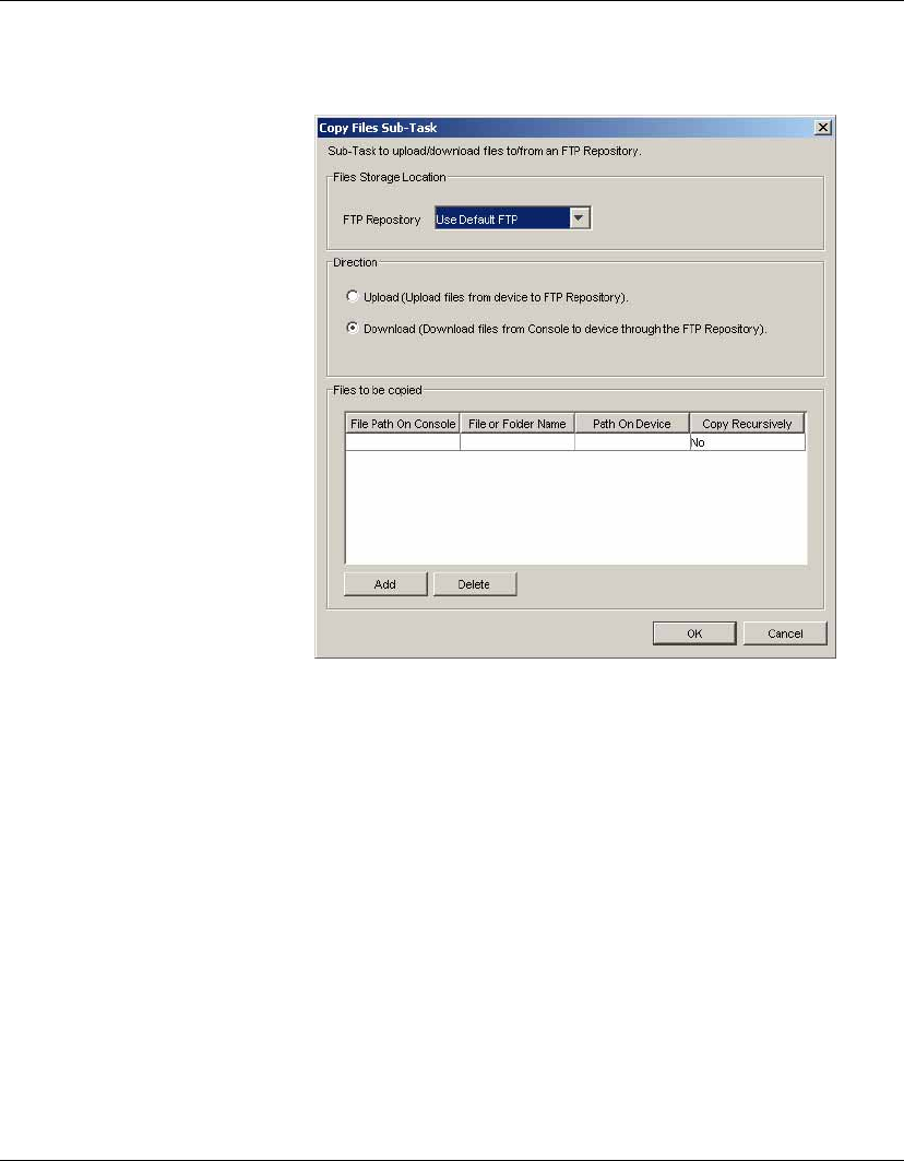
Common Tasks
132 Copying Files
4Click OK.
5Select the FTP Repository to use from the list box.
6Select the Direction of the copy files task: Upload files from
device to FTP Repository, or Download files from console to
device through the FTP Repository.
7Specify the Files to be copied by clicking in the fields and enter-
ing the relevant information. Additional lines can be added by
clicking the Add button.
The File Name field supports the use of the wildcards * and ?.
For example:
*means zero or more characters.
?means one character.
com.jar means the file is named com.jar.
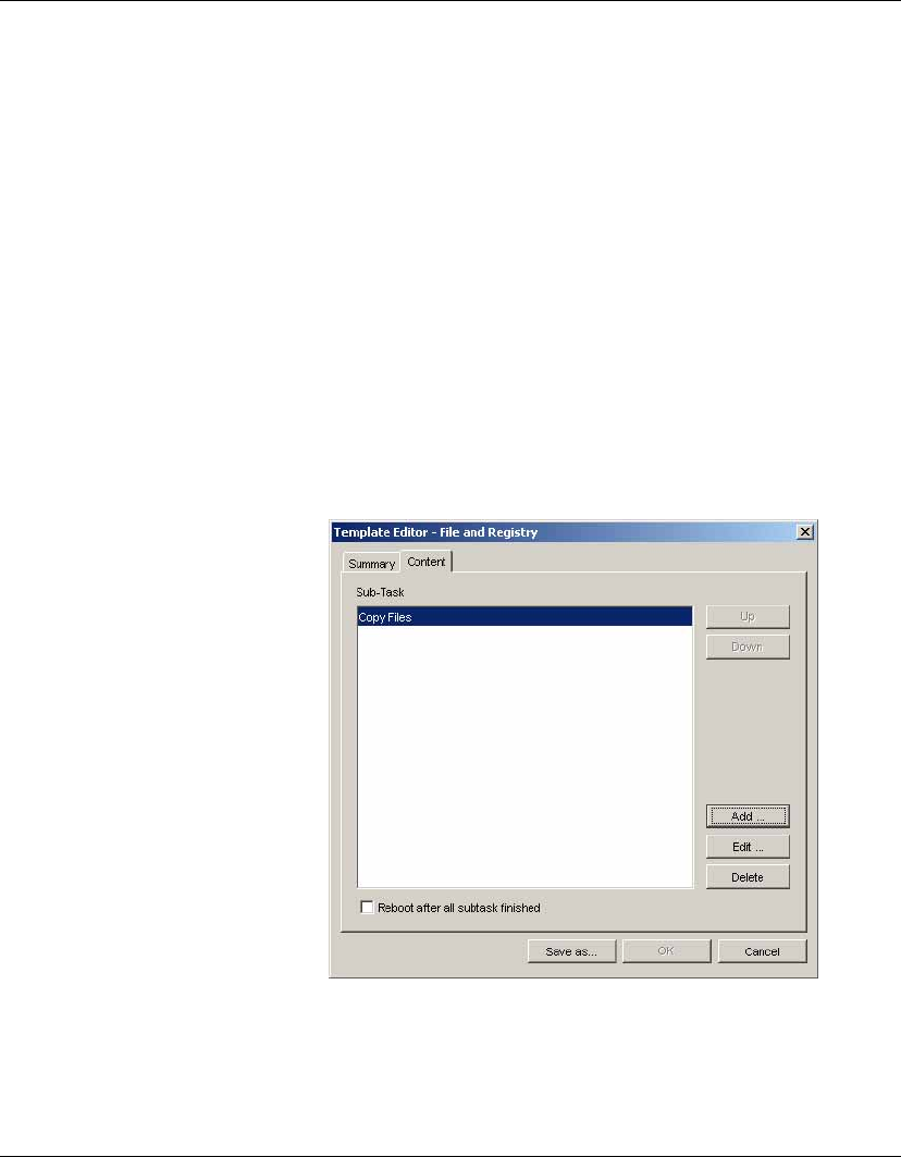
Common Tasks
Copying Files 133
c:\abc\*
c:\abc\
c:\abc all mean the same thing, that is, all the files under
directory c:\abc\.
a* means all the files that start with the letter a.
*a means all the files that end with the letter a.
If Copy Recursively is set to Yes, both files and sub-directories
matching the wildcard pattern defined in the File Name field will
be copied. If No is selected, only files in the given path will be
copied, but not sub-directories.
8Click OK when you have finished specifying files to be copied.
A Copy Files sub-task will be added to the Sub-Task list of the
template.
9Click Save as... to save the template with a new name.
10 Drag and drop the template on the device you want to copy files
to/from.
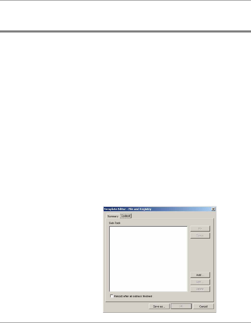
Common Tasks
134 Remote Command Execution
Remote Command Execution
HP Device Manager can remotely execute commands on a device
using File and Registry templates. In this context, a command is any-
thing executable on the device’s operating system. It can be applica-
tions, DOS batch files, Windows scripts, etc. You can enter any
command, however it is recommended that these commands are
tested on a client device first.
Note: DOS commands cannot be executed directly on a Windows XP
Embedded OS. To execute DOS commands you need to write them to
a batch file saved with the suffix “.bat”, then execute the batch file.
The Windows environment variable PATH may be different on each
device, so it is important to enter the full path to each command to
make sure it can be found on the device. For example, to execute an
executable file named xxx.exe in a directory named C:\Program
Files, enter the command as C:\Program Files\xxx.exe
To execute commands:
1Select the File and Registry tab in the Template Pane.
2Double-click the _File and Registry template to display the
Template Editor..
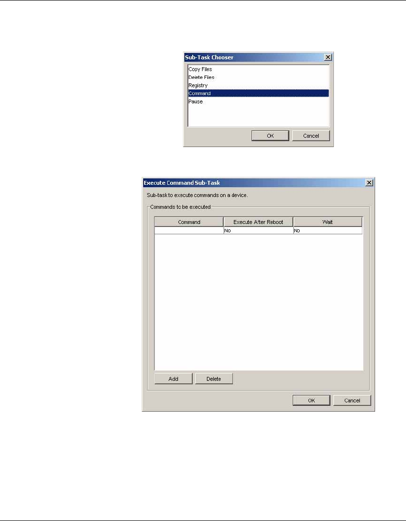
Common Tasks
Remote Command Execution 135
3Click the Add button and select Command.
4Click OK.
5Specify the command to be executed by clicking in the Com-
mand column and entering the appropriate information.
6In the Execute After Reboot column, select Yes if the device
should reboot before executing the command you specify. Select
No if you want the command to execute without the need to
reboot the device.

Common Tasks
136 Remote Command Execution
7In the Wait column, select Yes if the given command has to wait
for the previous command to finish before processing, or set to
No for simultaneous execution of commands.
8If you want to specify more commands, click Add to continue.
9Click OK when you have finished.
10 Click Save As... to save the template under a new name.
11 Drag and drop the template on the devices where you want the
commands to run.
Remote Execution
of Windows Scripts
Windows Scripting Host is a comprehensive scripting infrastructure
for the Microsoft Windows platform, provides script engines, Visual
Basic Scripting Edition and Microsoft JScript, which can be embed-
ded into Windows applications and an extensive array of supporting
technologies that make it easier for script users to script Windows
applications.
For more information on how to write Windows scripts, see:
http://www.msdn.microsoft.com
Enter “windows script” as search keywords.
To run windows scripts as a command from HP Device Manager,
you need to add “wscript” before the script name you want to run.
Wscript.exe is in the C:\windows\system32 directory.

137
HP Device Manager User Manual
CHAPTER 6 Advanced Tasks
This chapter describes how to use snapins, images, change registry
settings, install XPe software components, and set the agent mode.
Snapins
Introduction All of HP’s thin client operating systems utilize real filesystems in
Flash disk memory instead of monolithic Flash images. They also
use registry-based configuration mechanisms. The combination of
real filesystems and registry-based configuration allows HP cus-
tomers to add software or update software modules and device con-
figuration without having to replace the entire Flash image in the
thin client device.
Modular software additions and updates need only be as big as they
have to be (and in some cases may only be a few kilobytes of
information), and registry changes are similarly small. This speeds
the update process and helps alleviate bandwidth impact on busy
networks and low-bandwidth connections.
HP provides snapins to add software to thin clients, such as Adobe
Acrobat Reader. Snapins may also be provided by HP Technical
Support to help diagnose customer problems. Customers can
develop and use their own snapins, since the technology is based on
industry-standard protocols.
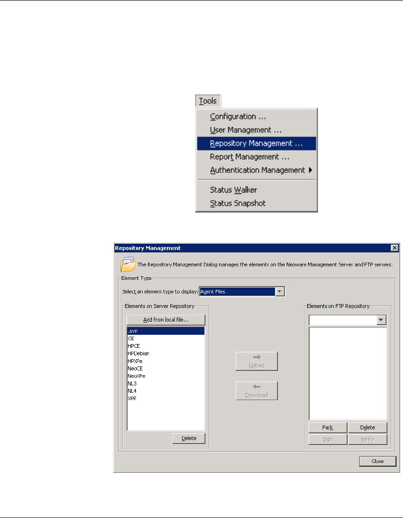
Advanced Tasks
138 Snapins
Applying a Snapin
to a Thin Client
1Download the required snapin from the support section of the
HP website to a temporary location on your local drive.
2Run the HP Management Console and select Tools > Repository
Management from the menu bar.
The Repository Management dialog will be displayed.
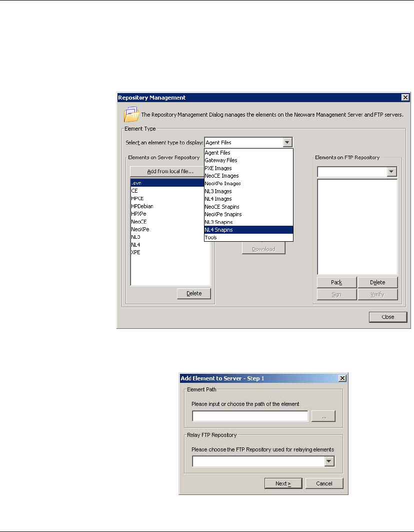
Advanced Tasks
Snapins 139
3In the Select an element type to display field, select the appro-
priate Snapins option from the drop-down list. For this example
we will be using a NeoLinux 4 snapin to install Adobe Acrobat
Reader to NeoLinux 4 thin clients, so NL4 Snapins is selected.
4Click the Add from local file button to display the Add Element
to Server - Step 1 dialog.
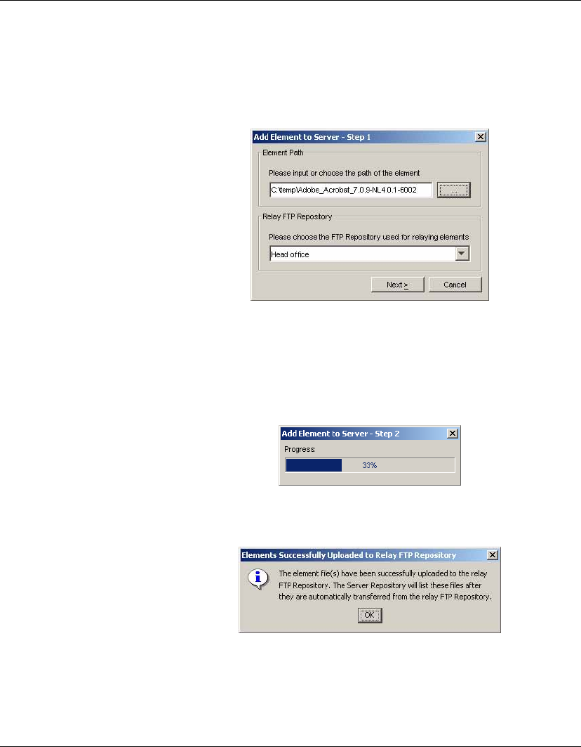
Advanced Tasks
140 Snapins
5Click the ... button in the Element Path box to browse to the
directory containing the snapin you downloaded in step 1. Select
the folder containing the snapin files (in our example it is
Adobe_Acrobat_7.0.9-NL4.0.1-6002) then click Choose.
The Relay FTP Repository field will display the name of the FTP
Repository to use for relaying files. You can change this if
required.
6Click Next to start copying the snapin files to the relay FTP
Repository.
A message box will be displayed once the snapin files have been
successfully uploaded to the relay FTP Repository.
7Click OK to automatically transfer the snapin files from the relay
FTP Repository to the Server Repository.
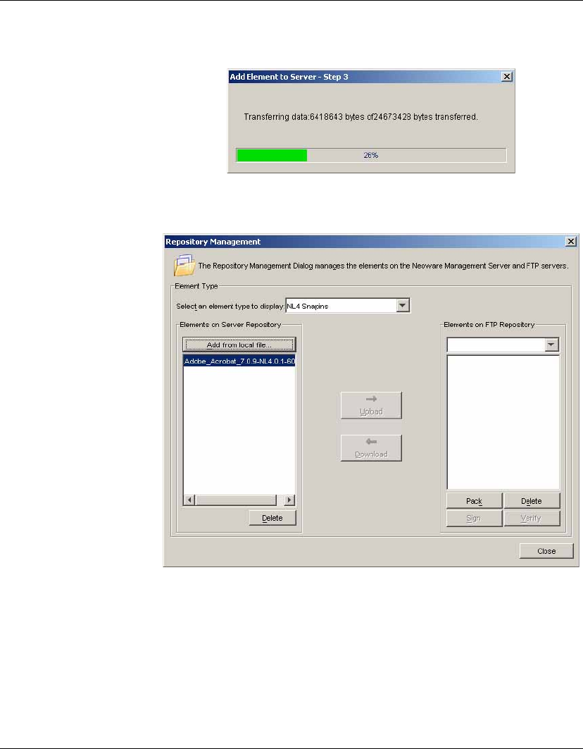
Advanced Tasks
Snapins 141
The Repository Management dialog should now display the
name of the snapin in the Elements on Server Repository field.
8Select the name of the FTP Repository to which you want to
transfer the snapin from the Elements on FTP Repository drop-
down list box.
9Select the snapin to transfer in the Elements on Server Reposi-
tory field, then click the Upload button.
Once the snapin has been transferred, it will be listed in both the
Server Repository and FTP Repository fields.
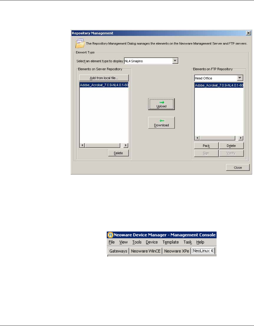
Advanced Tasks
142 Snapins
Now that the snapin is in the FTP Repository, it can be applied to
client devices using a template.
10 Click Close to exit Repository Management.
11 Click on the OS tab for the operating system supported by the
snapin. In our example it is the NeoLinux 4 OS tab.
12 In the Task Templates pane, click the Software Update tab then
double-click on the _Snapin template to display the Template
Editor.
13 Select the FTP Repository where the snapin resides in the FTP
Repository list box.
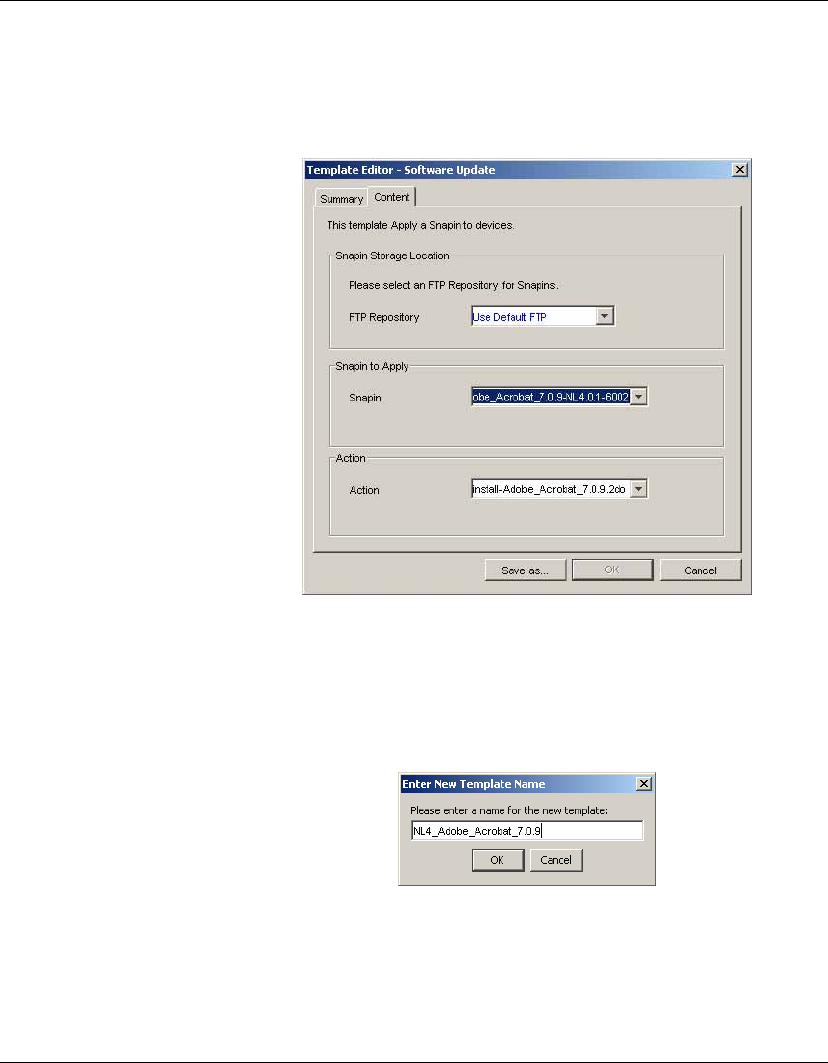
Advanced Tasks
Snapins 143
14 Select the name of the snapin in the Snapin list box. The Action
field will then display actions which can be performed using the
snapin. In this case the only action is Install.
Note: If the snapin is not displayed in the
Snapin
field, check
that you are displaying the
Task Templates
pane in the correct
OS tab (
NeoLinux 4
in our example).
15 Click the Save as... button and save the template using a name
that enables you to easily identify what it does.
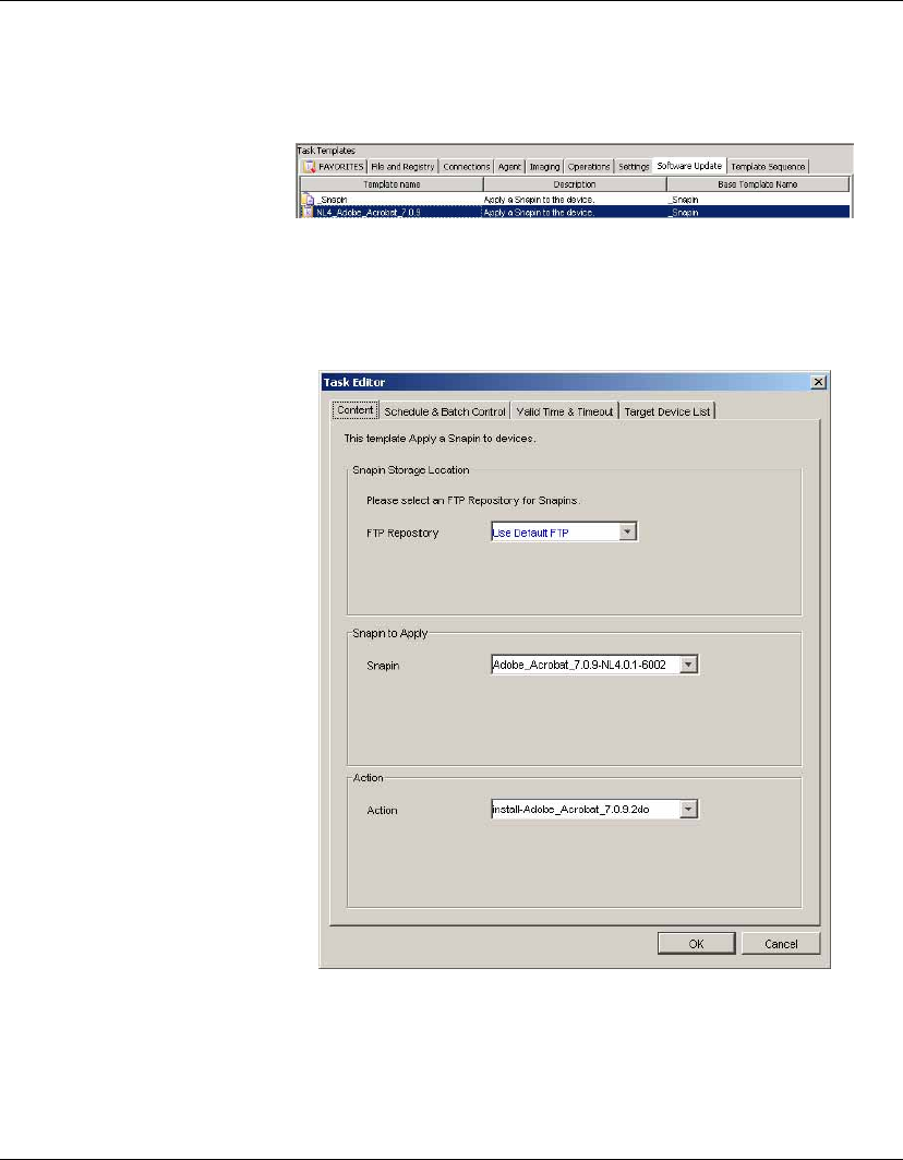
Advanced Tasks
144 Snapins
The Task Templates pane will now display the new snapin tem-
plate in the Software Update tab.
16 To apply the snapin to one or more thin client devices, select the
name of the snapin template then drag and drop it on the name of
the device(s) in the device tree panel. The Task Editor dialog
will be displayed.
17 If you want the snapin to be applied to the thin client(s) immedi-
ately, click OK. Otherwise you can schedule a time for the snapin
to be applied by clicking the Schedule & Batch Control tab.

Advanced Tasks
Images 145
Images
Introduction HP Device Manager can read and write images to and from
supported clients. An image file (.img) is a binary file containing all
the data on a thin client’s flash storage. HP Device Manager
manages images through the Repository Management tool, which
also provides utilities to verify image integrity.
The Imaging templates for each OS tab provide various means of
reading and writing images depending on whether or not a PXE
Server is being used. A PXE image can be pulled from a device and
pushed to other devices using the _PXE Imaging template (see
page 147 and page 150, respectively).
Note: Pushing and pulling images uses the PXE functions of HP
Device Manager and some DHCP server setups may conflict with
PXE. Should you experience problems with PXE, see “Configuring
DHCP Servers” on page 30.
The _Update Image template enables you to update a device using
an image from a specified FTP Repository without using a PXE
Server (see page 157). The Neoware XPe OS tab also includes a
_Clone XPe Image template (see page 153).
Images &
Repository
Management
The Repository Management tool enables you to import image files
into the Repository and transfer image files between FTP Reposito-
ries. It also enables you to sign and verify PXE images. The Reposi-
tory Management tool is displayed by selecting Tools > Repository
Management from the Console’s menu bar. Select the relevant
Images option from the Select an element type to display list.
Importing Images
Image files from an external source (i.e. not created from your local
HP Device Management System) can be imported into an FTP
Repository as described in the section “Importing an Element into
the Repository” on page 52.

Advanced Tasks
146 Images
Transferring Image Files Between Repositories
An image file must be stored in an FTP Repository in order for it to
be applied to clients using a template. Image files are initially placed
either in the Server Repository if they were imported, or in a specific
FTP Repository if created using a template. You can transfer image
files between repositories using the Upload and Download buttons in
the Repository Management dialog. In order to transfer an image
file from one FTP Repository to another, it must first be Downloaded
to the Server Repository, then Uploaded from there to the other FTP
Repository.
Signing & Verifying PXE Images
If the image file is a PXE image, it can be signed or verified by click-
ing the Sign or Verify buttons in the Repository Management dialog.
HP Device Manager will report a verification error if the MD5 sig-
nature file does not exist. Therefore, if the image is from a reliable
source, simply click Sign to re-create the digital signature.
Client BIOS Settings
for PXE
Before you can pull or push a PXE image, you must make sure that
the source and target client devices have their BIOS settings config-
ured correctly.
1Power-on the thin client device and hold down the Delete key to
display the CMOS Setup Utility screen.
2Select Advanced BIOS Features and set the following:
First Boot Device [LAN]
Second Boot Device [HDD-0]
3Press the ESC key to return to the initial screen, select
Integrated Peripherals then VIA OnChip PCI Device.
4Make sure Onboard Lan Boot ROM is set to [Enabled].
5Press the F10 key then Y and Return to save the settings.
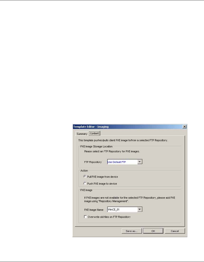
Advanced Tasks
Images 147
Pulling a PXE
Image From a Client
You can pull (copy) a PXE image from any client managed by HP
Device Manager and store it as a .img file in the Repository so that it
can be pushed (written) to other clients. This is achieved using the
_PXE Imaging template.
To pull a PXE image from a device:
1Make sure the BIOS settings of the client device from which you
want to pull an image are as described in the section “Client
BIOS Settings for PXE” on page 146.
2In the Management Console, display the OS tab containing the
name of the client in its Device Tree.
3Select the Imaging tab in the Task Templates pane then double-
click on the _PXE Imaging template.
4In the Template Editor - Imaging dialog, select the FTP Reposi-
tory where the image will be stored.
5Set the Action to Pull PXE image from device.
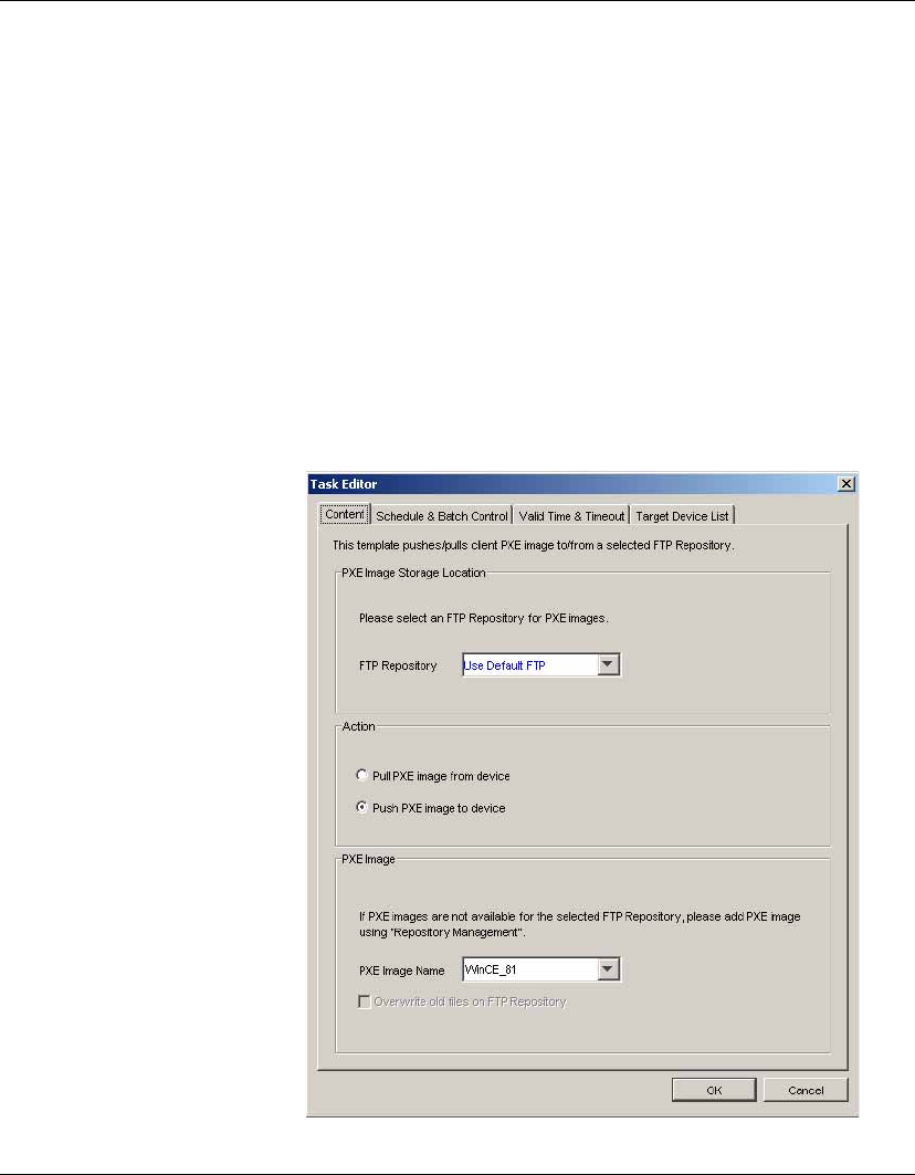
Advanced Tasks
148 Images
6Enter a name for the PXE Image so that you can easily identify it
once it is stored in the FTP Repository.
7If you need to overwrite any files that already exist in the FTP
Repository, select Overwrite old files on FTP Repository.
8Click the Save as... button, enter a name for this template, then
click OK.
The template will be created and listed in the Task Templates
pane ready for you to apply to devices.
9Select the template then drag and drop it on the name of the
client in the Device Tree from which you want to pull an image.
The Task Editor will be displayed.
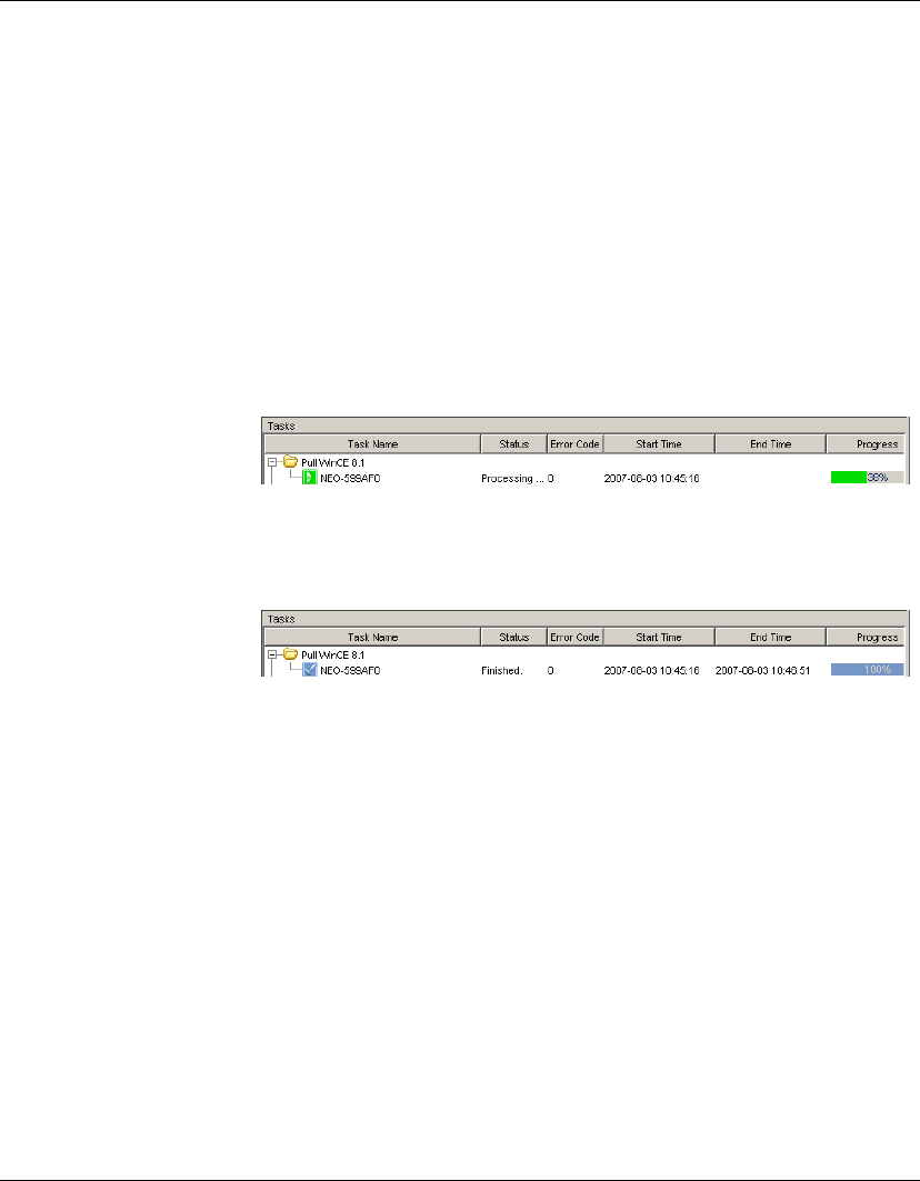
Advanced Tasks
Images 149
10 Click OK to apply the task to the device.
When the HP Management Agent on the client receives the task,
the client will display a warning message indicating that the
device will reboot in 15 seconds.
The client will shutdown then start-up in DOS mode and run the
utility which copies the contents of the flash storage to an .img
file in the FTP Repository. Note that this may take several
minutes.
The progress of the image creation task will be indicated in the
Tasks pane of the Console.
When the task has been completed successfully, the client will
reboot as normal and the Tasks pane will indicate the task has
finished.
An image file has now been created in the FTP Repository you
specified in step 4.
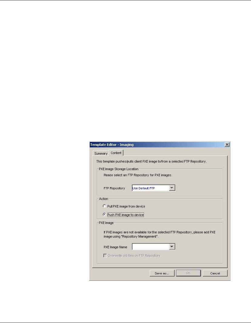
Advanced Tasks
150 Images
Pushing a PXE
Image to a Client
You can push (write) a PXE image stored in an FTP Repository to
any client managed by HP Device Manager, as long as it contains
enough Flash storage. This is achieved using the _PXE Imaging
template.
To push a PXE image to a device:
1Make sure the BIOS settings of the client device to which you
want to push an image are as described in the section “Client
BIOS Settings for PXE” on page 146.
2In the Management Console, display the OS tab containing the
name of the client in its Device Tree.
3Select the Imaging tab in the Task Templates pane, then double-
click on the _PXE Imaging template to display the Template
Editor.
4Select the FTP Repository where the PXE image file resides in
the FTP Repository list box.
5Select Push PXE image to device as the Action to perform.
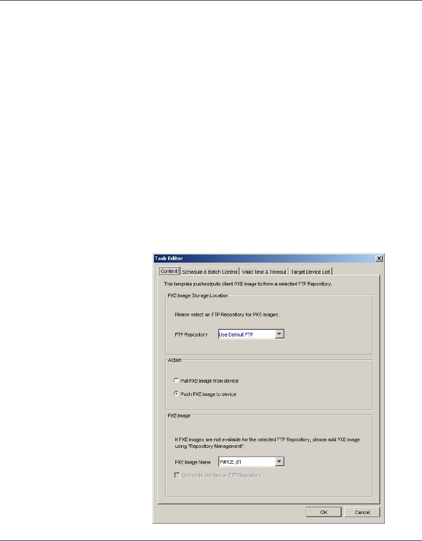
Advanced Tasks
Images 151
6Enter the name of the PXE image to push to the client in the PXE
Image Name field.
Note: The
PXE Image Name
field will only list the names of PXE
images if the image files have been transferred from the FTP
Repository to the Server Repository using the
Repository Man-
agement
tool. However, you can manually enter the name of the
image file in this field if it is not in the Server Repository, as long
as it is present in the
FTP Repository
you have selected in the
template.
7Click Save as... to save the template with a new name.
The template will be created and listed in the Task Templates
pane ready for you to apply to devices.
8Drag and drop the template on the device(s) to which you want
to apply the image. The Task Editor will be displayed.

Advanced Tasks
152 Images
9Click OK to apply the task to the device.
When the HP Management Agent on the client receives the task,
the client will display a warning message indicating that the
device will reboot in 15 seconds.
The client will shutdown then start-up in DOS mode and run the
utility which copies the image file from the FTP Repository to
its flash storage. Note that this may take some time.
The progress of the task will be indicated in the Tasks pane of
the Console.
When the task has been completed successfully, the client will
reboot with the new image and the Tasks pane will indicate the
task has finished.
Preparing an XPe
Client for Image
Distribution
The ChangeSID utility allows you to modify the computer SID
(Security ID) in the Microsoft NT/2000/XP operating system.
Note: Only the local administrator is authorized to run this utility.
SID information is kept in a registry file which is used for computer
and user identification in a workgroup or domain environment. The
ChangeSID utility creates a new random SID and replaces the old
one.
To use the ChangeSID utility, log on as a local administrator and
run ChangeSID.exe from a command line:
ChangeSID.exe <options>
where <options> can include the following:
-m Change the computer’s name to NEO- plus the last 6 digits of
its MAC address.
-n <new computername>
Assign a new computer name. Note that if -m is specified, this
option will be ignored.
-sid Change the computer SID.
-all Produces the same result as if you specified”-m -sid”.
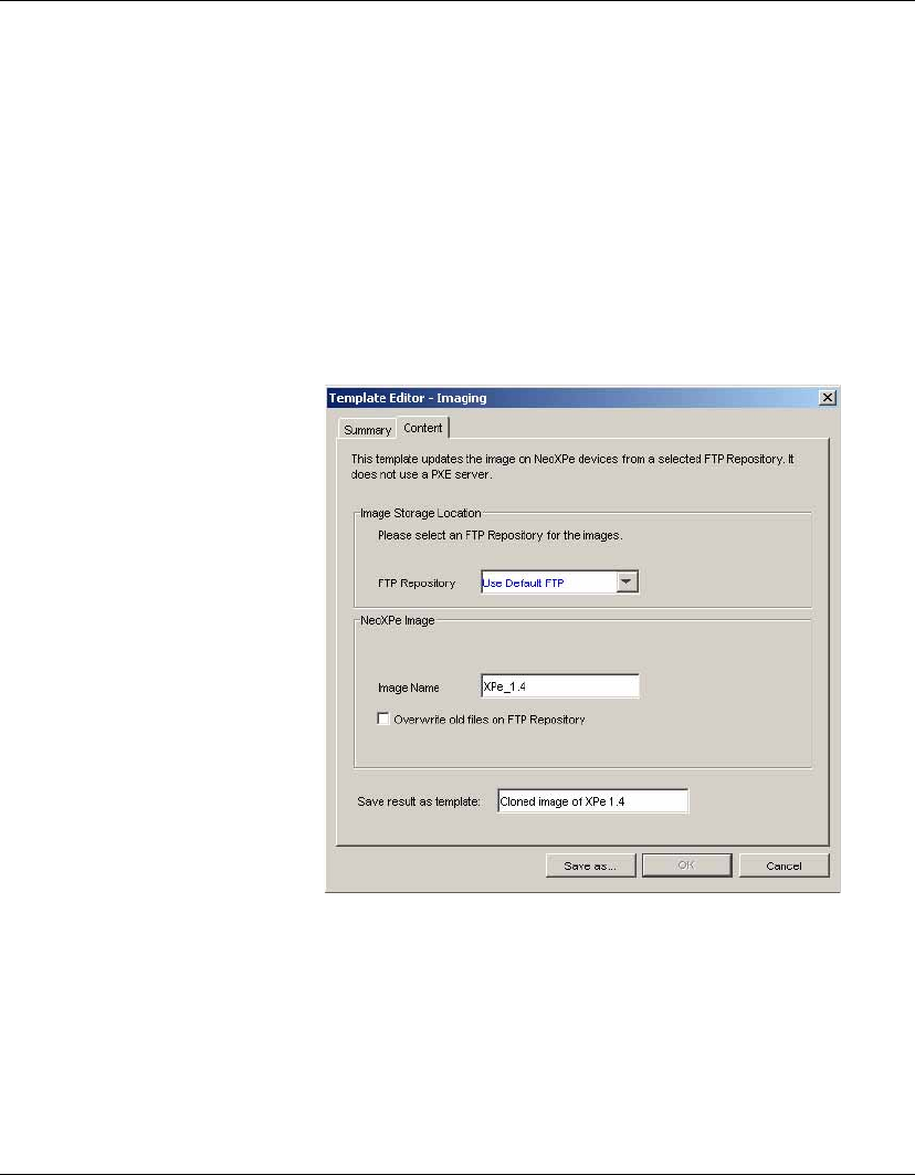
Advanced Tasks
Images 153
Cloning an XPe
Image
The _Clone XPe Image template enables you to clone the image of
an XPe device and either store the image for backup or apply it to
other XPe devices of the same model type and identical flash storage
size. This template does not use a PXE Server.
To clone an XPe image:
1Select the Imaging tab in the Task Templates pane then double-
click on the _Clone XPe Image template.
2In the Template Editor - Imaging dialog, select the FTP Reposi-
tory where the cloned image will be stored.
3In the Image Name field, enter a name for the cloned image that
will be stored in the FTP Repository.
4If you need to overwrite any files that already exist in the FTP
Repository, select Overwrite old files on FTP Repository.
5In the Save result as template field, enter a name for the result-
ing template which will be automatically created to enable you
to apply the cloned XPe image to other XPe clients.
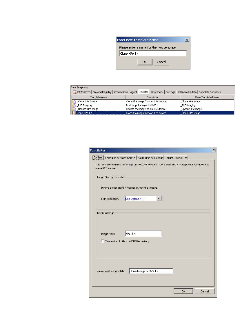
Advanced Tasks
154 Images
6Click the Save as... button, enter a name for this template, then
click OK.
A new template will appear in the Task Templates pane.
7Drag and drop this template on the XPe device whose image you
want to clone in the Device Tree. The Task Editor dialog will be
displayed.
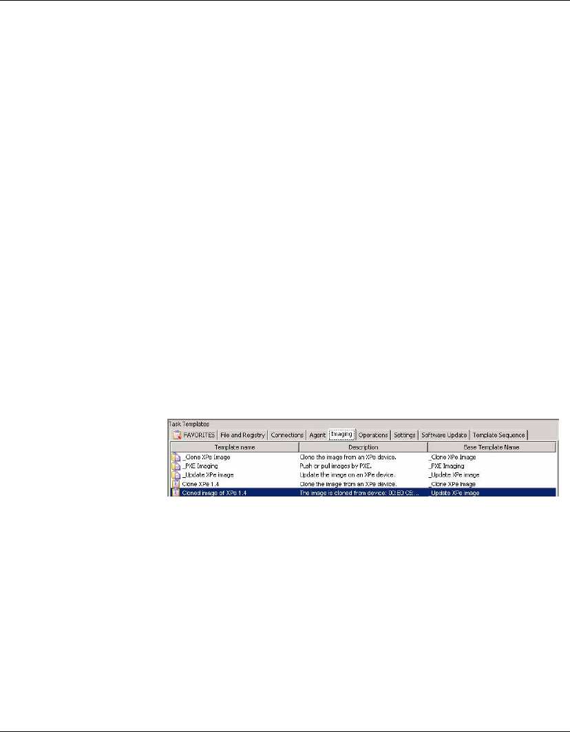
Advanced Tasks
Images 155
8Click OK to apply the task to the device immediately.
When the HP Management Agent on the client receives the task,
the client will display a warning message indicating that the
device will reboot in 15 seconds.
The client will shutdown then start-up in DOS mode and run the
clone utility which copies the contents of the flash storage to an
.img file on the FTP Repository. The last line on the client dis-
play will indicate progress in percentage completed. Note that
this may take several minutes.
The client will reboot after cloning has completed and enter
Maintenance Mode. DO NOT turn off the device during this pro-
cedure! The client will then reboot again.
The Tasks pane in the Management Console will continue to
indicate that the task is processing. The cloned image is being
compressed.
When the task has finished, a new template will appear in the
Task Templates pane with the name you specified in step 5 (the
result template).
You can now use this template to apply the cloned XPe image to
other XPe devices of the same model type and identical flash
storage size just by dragging and dropping it on the device(s) in
the Device Tree.
You can view information about the XPe image associated with
the template by double-clicking on the name of the template to
display the Template Editor dialog. This will display the name
of the image and the FTP Repository where it is stored, its OS
build number, original size, compressed size, and checksum.
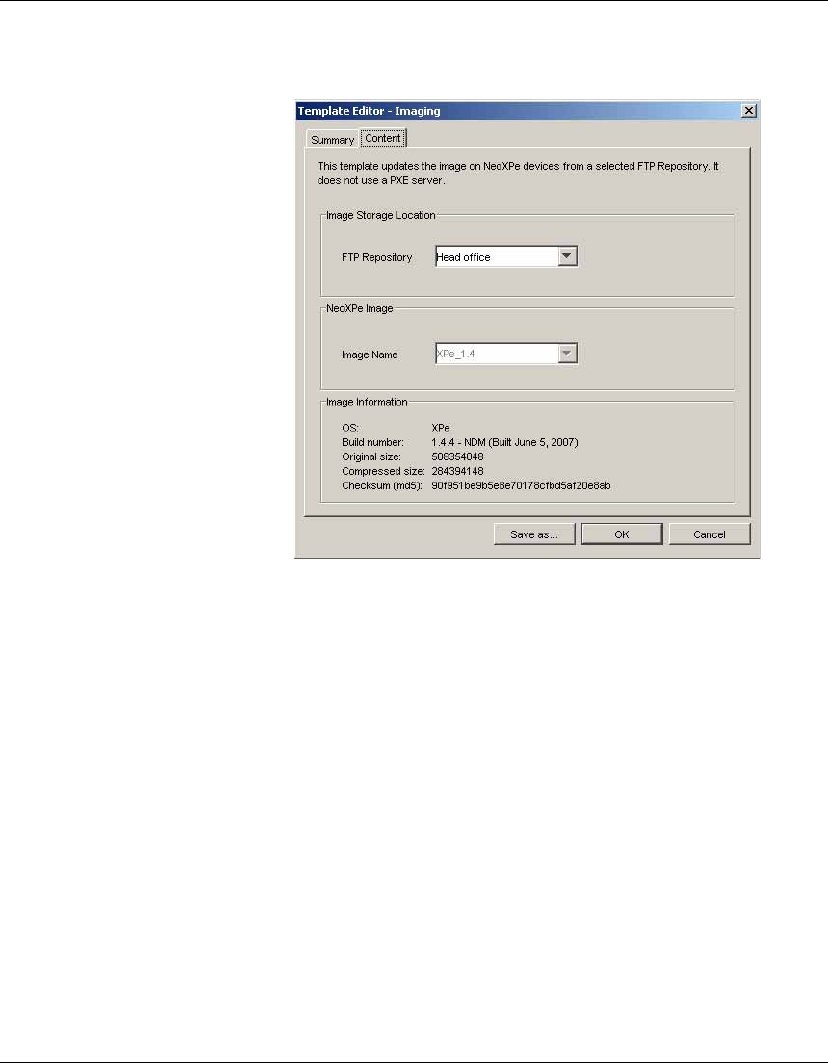
Advanced Tasks
156 Images
The cloned XPe image file will also be listed in Repository
Management ready for use in other templates. Select NeoXPe
Images as the element type, then select the FTP Repository
where it is stored.
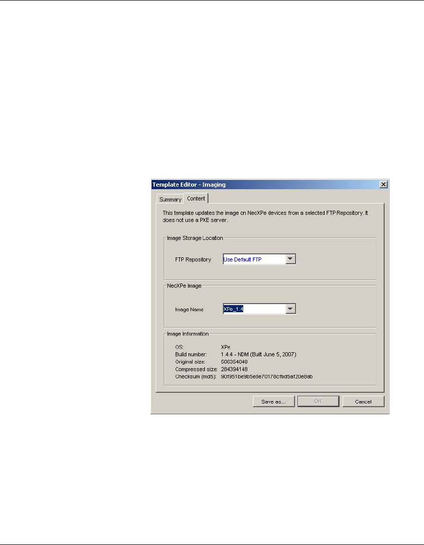
Advanced Tasks
Images 157
Updating Images The _Update Image template on each OS tab enables you to apply
images to devices without using a PXE Server.
To update the image on one or more devices:
1In the Management Console, display the OS tab containing the
name of the client(s) to be updated with the new image in the
Device Tree.
2Select the Imaging tab in the Task Templates pane, then double
click on the _Update Image template to display the Template
Editor.
3Select the FTP Repository where the image is stored.
4Enter the name of the image file in the Image Name field.
Note: The
Image Name
field will only list the names of images if
the image files have been transferred from the FTP Repository to
the Server Repository using the
Repository Management
tool.
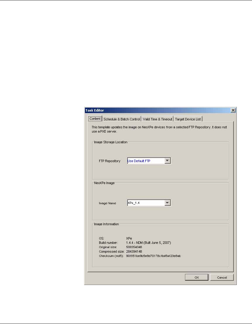
Advanced Tasks
158 Images
However, you can manually enter the name of the image file in
this field if it is not in the Server Repository, as long as it is
present in the
FTP Repository
you have selected in the template.
The Image Information box below will provide details of the
OS build version and image size for the image whose name is
currently displayed in the Image Name field.
5Click the Save as... button to save the template with a new name.
6Drag and drop the template on to the device(s) whose image is to
be updated. The Task Editor dialog will be displayed.
7Click OK to apply the image update task to the device(s).
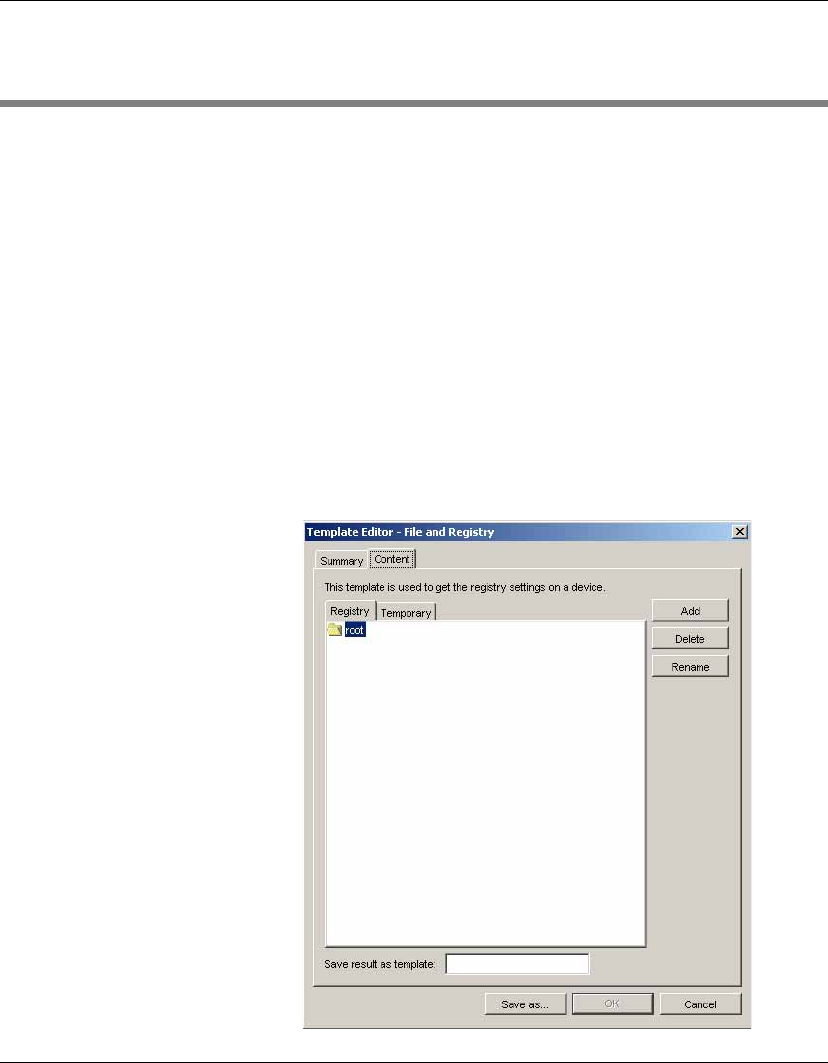
Advanced Tasks
Changing Registry Settings 159
Changing Registry Settings
HP Device Manager can add, delete and change registry keys and
their values on thin client devices using File and Registry templates.
Additionally, the existing settings can be cloned from a device using
the Get Registry template and then modified.
Getting Registry
Settings
HP Device Manager can clone the system registry of a thin client
device. The procedure is as follows:
1In the Console’s Management View, select the OS tab corre-
sponding to the operating system of the device from which you
want to get registry settings (e.g. NeoLinux 4).
2Select the File and Registry tab in the Task Templates pane,
then double-click on the _Get Registry template to display the
Template Editor.
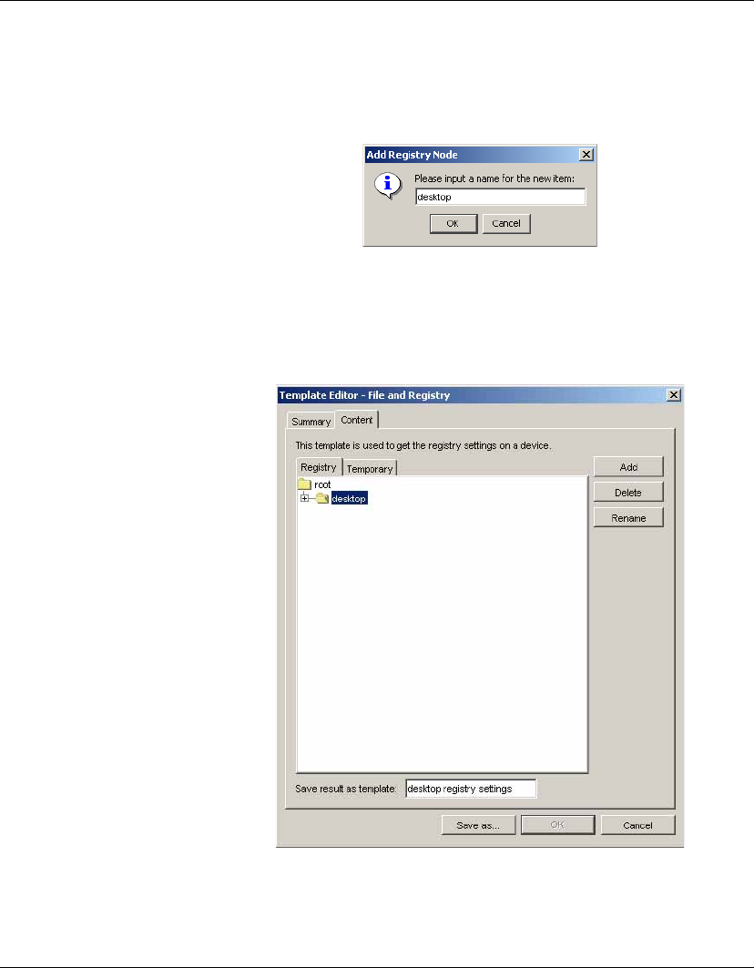
Advanced Tasks
160 Changing Registry Settings
3Click the Add button and enter the name of the registry node
from which you want to retrieve settings (e.g. desktop for desk-
top settings), then click OK.
The name of the new node will appear on the Registry tab of the
Template Editor.
4In the Save result as template field, enter a name for the tem-
plate which will be created to store the result.
5Click Save as... and enter a name which indicates the purpose of
this template (get desktop settings).
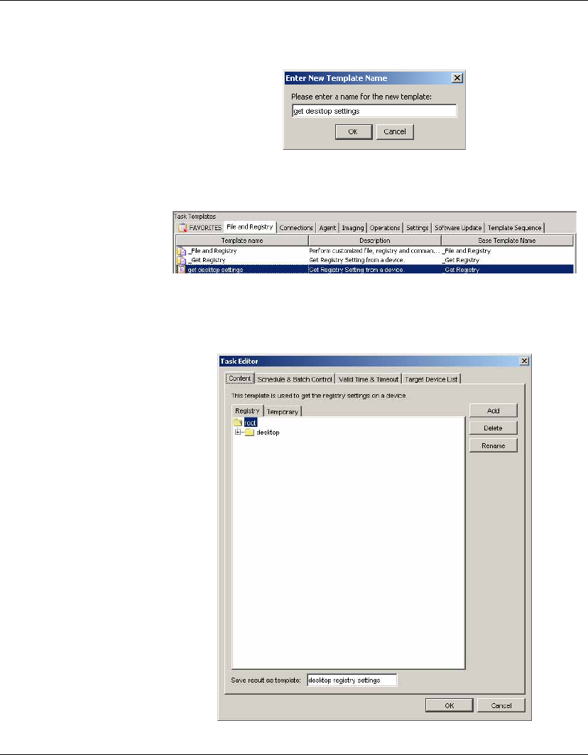
Advanced Tasks
Changing Registry Settings 161
6Click OK and the new template will appear in the Task Tem-
plates pane.
7Drag and drop this template on the device in the Device Tree
from which you want to get registry settings. The Task Editor
dialog will be displayed.
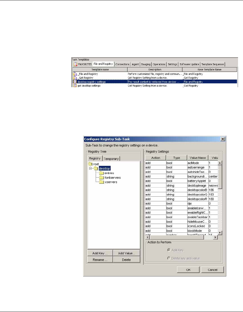
Advanced Tasks
162 Changing Registry Settings
8Click OK to apply the task to the device immediately.
The registry settings will be retrieved from the device and stored
in a new template in the Task Templates pane. Its name will be
the one which you specified in step 4.
9To view the retrieved registry settings, double-click on the result
template to display the Template Editor, double-click on the
Registry entry in the Sub-Task box to display the Configure
Registry Sub-Task dialog, then click on the registry node in the
Registry Tree panel to display the settings.
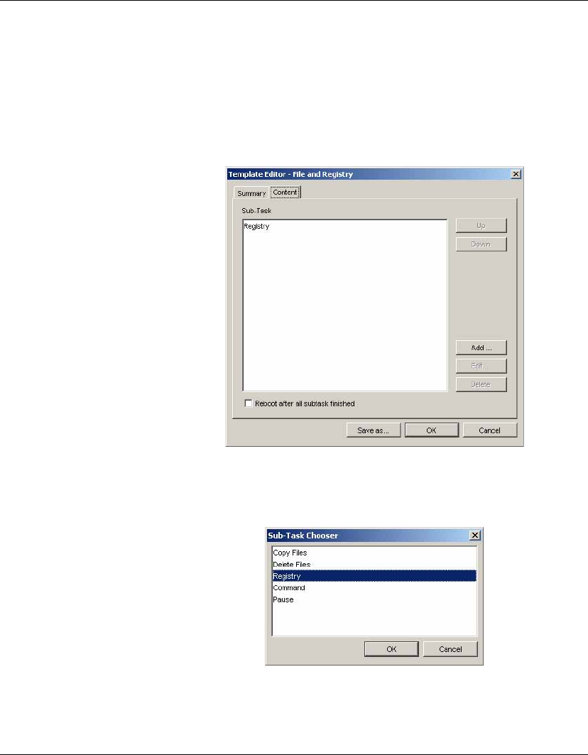
Advanced Tasks
Changing Registry Settings 163
Editing Registry Settings
1Select the File and Registry tab in the Template Pane.
2If you are editing a previously generated _Get Registry task
result template, double-click the name of that template, then
double-click Registry in the Sub-Task box.
If you need to create a new template, double-click the _File and
Registry template to display the Template Editor, then click the
Add button.
Select Registry in the Sub-Task Chooser, then click OK.
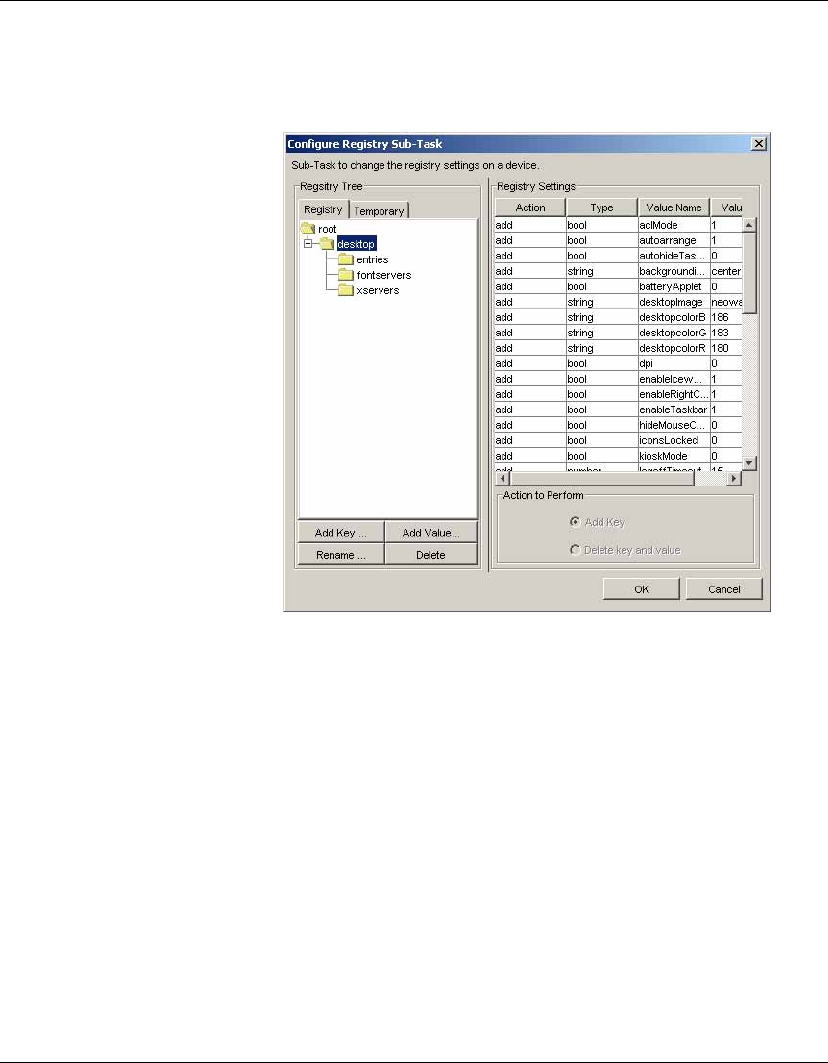
Advanced Tasks
164 Changing Registry Settings
3The Configure Registry Sub-Task dialog will be displayed
enabling you to edit registry settings.
You can edit the contents of the Registry Tree using the four but-
tons at the bottom of the box.
Add Key enables you to add a new key under the currently
selected item.
Add Value enables you to add a value to the selected key.
Rename enables you to rename the selected item.
Delete enables you to remove the selected item.
The Registry Settings box will display the current settings of the
key selected in the Registry Tree. It is divided into the following
columns:
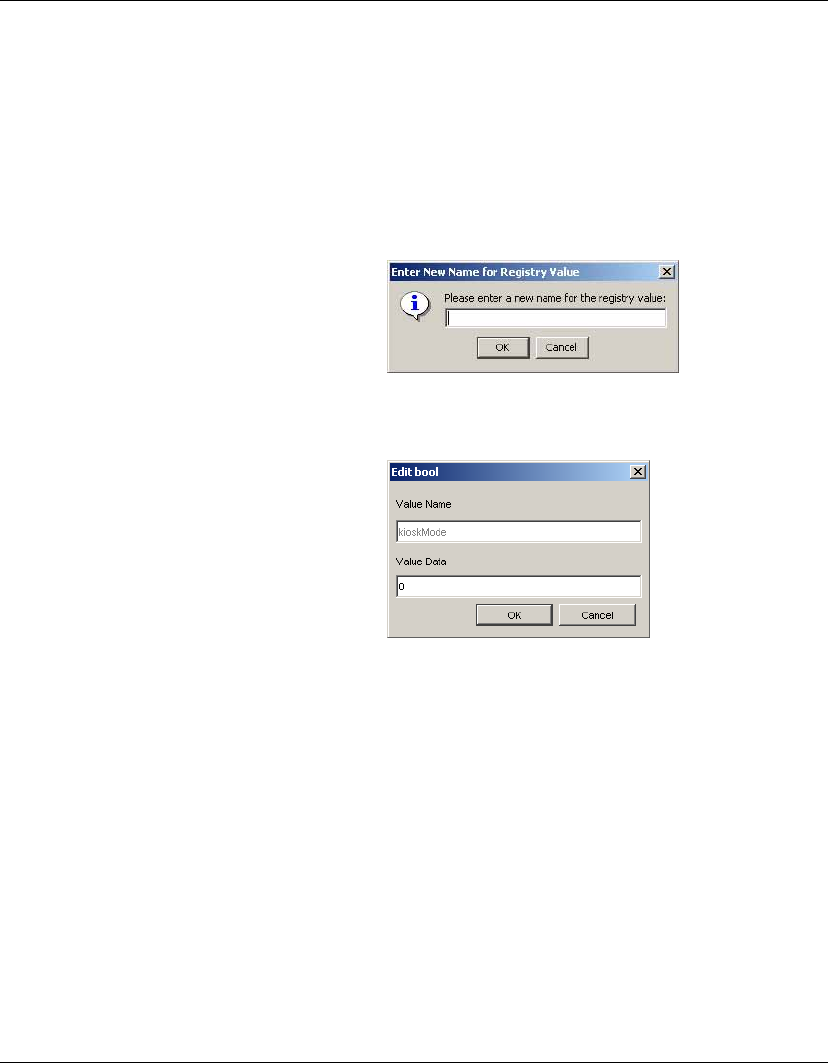
Advanced Tasks
Changing Registry Settings 165
Action Indicates the action to be applied to the registry
table: add or delete a key. Click in the field to
change the current setting.
Type Indicates the type of registry key value.
Value Name Displays the name of the registry key. Double-
click in this field to edit it.
Value Data Displays the data for the registry key value.
Double-click in this field to edit it.
The Action to Perform options determine whether the key is
added or deleted. If Add Key is selected, the selected key will be
added to the registry even if the key is empty. If Delete Key and
Value is selected, the selected key and all values under it will be
deleted. Note that there must not be any values under the speci-
fied key.
4When you have finished modifying the template, click the Save
as... button and enter a name for the new template.
5Click OK. The new template will be created and its name will
appear in the Template Pane.
6You can now apply the new registry settings to one or more
devices by dragging the template from the Template Pane and
dropping it on to the device(s) in the Device Tree.
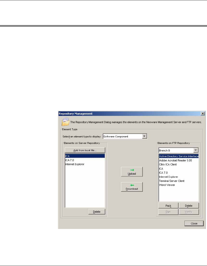
Advanced Tasks
166 Installing an XPe Software Component
Installing an XPe Software Component
Software components for XPe devices must be transferred to an FTP
Repository using Repository Management before they can be dis-
tributed to client devices.
Transferring an XPe
Software
Component to the
FTP Repository
1Download and unzip the XPe software components to a local
drive.
2Select Tools > Repository Management from the Console’s
menu bar.
3In the Select an element type to display field, select the Soft-
ware Component option from the drop-down list box.
4Click the Add from local file... button.
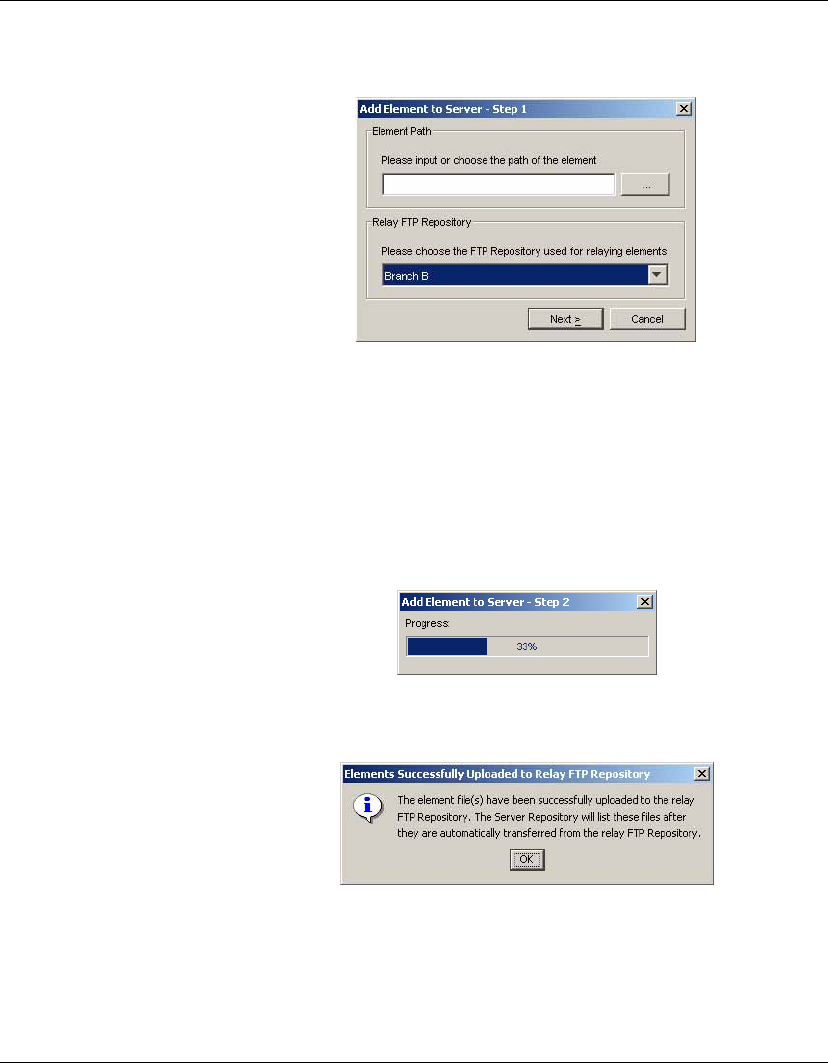
Advanced Tasks
Installing an XPe Software Component 167
5Enter the path of the software component you wish to add.
6Select a Relay FTP Repository in order to transfer the files to the
Server Repository.
The relay FTP Repository will receive the files from the Con-
sole, and temporarily hold them until they are automatically
transferred to the Server Repository.
7Click Next to start copying the files to the relay FTP Repository.
A message box will be displayed once the files have been suc-
cessfully uploaded to the relay FTP Repository.
8Click OK to automatically transfer the files from the relay FTP
Repository to the Server Repository.

Advanced Tasks
168 Installing an XPe Software Component
The Repository Management dialog should now display the
name of the software component in the Elements on Server
Repository field.
9Select the FTP Repository where you want the new software
component to be stored.
10 Select the software component then click Upload to upload it to
the FTP Repository.
Note: The username selected for the FTP server profile must
have write permission for the target folder.
11 Your software component is now ready to be installed using a
Software Component template.
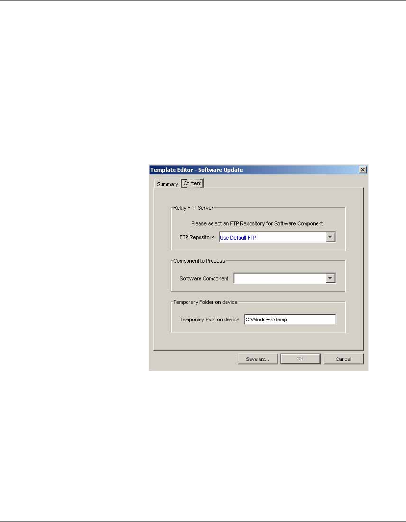
Advanced Tasks
Installing an XPe Software Component 169
Installing an XPe
Software
Component on
Client Devices
Software components can be installed on client devices once they
have been uploaded to the FTP Repository.
Note: The procedure for installing software components discussed in
this section is only applicable to Windows XPe clients.
To install a software component:
1Select the Software Update tab from the Template Pane.
2Double click _Software Component template to display the
Template Editor dialog.
3Select the FTP Repository containing the software component to
install.
4Select or enter the name of the Software Component to install
from the FTP Repository.
5Click Save as... to save the template with a new name.
6Drag and drop the template on the device(s) to which you want
to install the software component.

Advanced Tasks
170 Performing a Persistent Write Operation on NeoLinux 4.x Devices
Performing a Persistent Write Operation on NeoLinux 4.x Devices
NeoLinux 4.x devices use three related file systems which are
mounted as follows:
/
/writable
/.fs/org
Normally a user will perform all work under / or /writable, which
are mounted as readable and writable when the system starts up. The
file system of /writable is used for storing persistent data, where
files can be created, modified or removed, and the changes will not
be lost when the device reboots or shuts down.
However, the file system of / works in a different way. Any modifi-
cations made in this file system are temporary and will not be trans-
ferred to the actual disk, even though it is writable. When the device
reboots or shuts down the changes will be lost and the file system of
/ will revert to its original state.
Sometimes you may need to perform a persistent write to / in order
to run commands, utilities, scripts, etc. which require changes to be
saved. This can be achieved using the third file system /.fs/org,
which is mounted from the same source as /. It is possible to create,
modify or remove files persistently in /.fs/org, but as it is mounted as
read only you need to remount it to be writable before making any
changes to the file system, then reboot the device for the changes to
take effect.
The Command sub-task in the File and Registry template for
NeoLinux 4 devices includes options enabling you to change the
root directory to ./fs/org and mount it as writable.
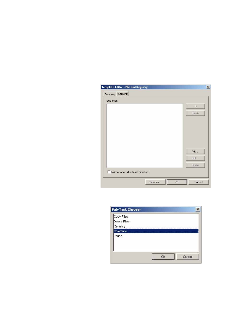
Advanced Tasks
Performing a Persistent Write Operation on NeoLinux 4.x Devices 171
The following procedure describes how to change the directory of a
NeoLinux 4.x device to /.fs/org and mount it as writable in order to
perform commands:
1With the NeoLinux 4 tab displayed, select the File and Registry
tab in the Template Pane.
2Double-click the _File and Registry template to display the
Template Editor.
3Click the Add button and select Command.
4Click OK to display the Execute Command Sub-Task dialog.
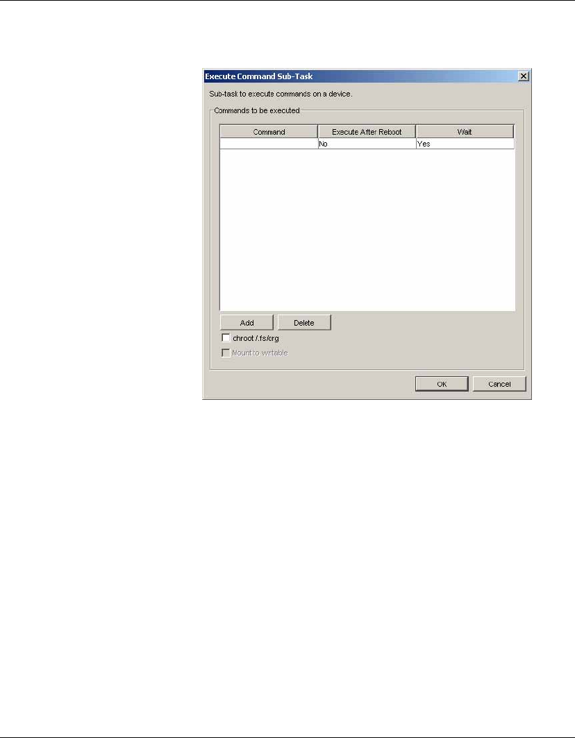
Advanced Tasks
172 Performing a Persistent Write Operation on NeoLinux 4.x Devices
5Check the chroot /.fs/org check box at the bottom of the dialog
in order to change the root directory to /.fs/org. The Mount to
writable option will then be available. Check this box as well.
Any commands you specify in this dialog will now be directed
to /.fs/org which will be mounted as writable.
6Specify the command(s) to execute, then click OK when you
have finished.
7Select the Reboot after all subtask finished option.
8Click Save As... to save the template under a new name.
9Drag and drop the template on the devices where you want the
commands to run.
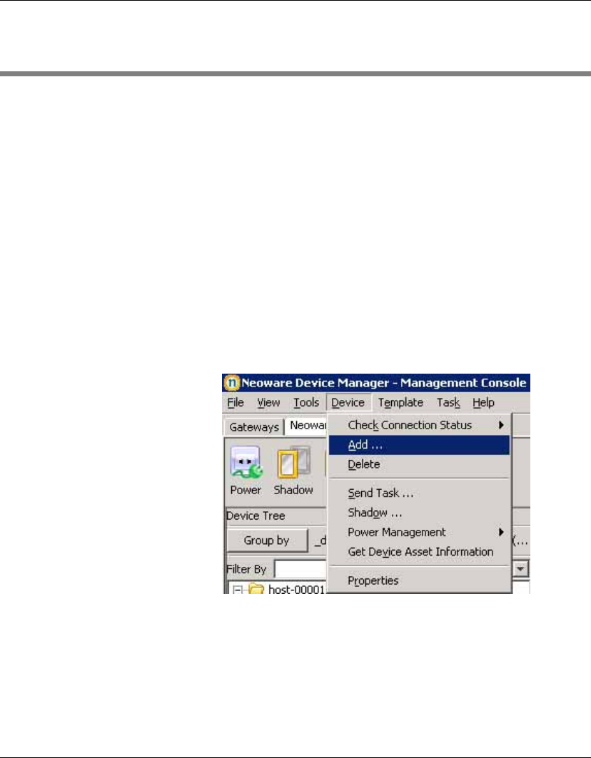
Advanced Tasks
Adding Devices Using MAC Addresses 173
Adding Devices Using MAC Addresses
Devices that are not working and need a new image, or that other-
wise have not been found by HP Device Manager, can be added to
the console using their MAC address. However, devices added to the
console in this manner cannot be fully managed by HP Device Man-
ager until the agent on the device reports to the HP Management
Server properly.
The primary use of this feature is if the device is not working and
needs a new image. An image can be pushed to the device using a
template. Another way to use this feature is to Wake On LAN a
device that has not previously been reported to the HP Management
Server and therefore is not displayed in the device tree.
To add a new device using its MAC address:
1Select Device > Add from the Management Console menu bar.
The Add Device dialog will be displayed.
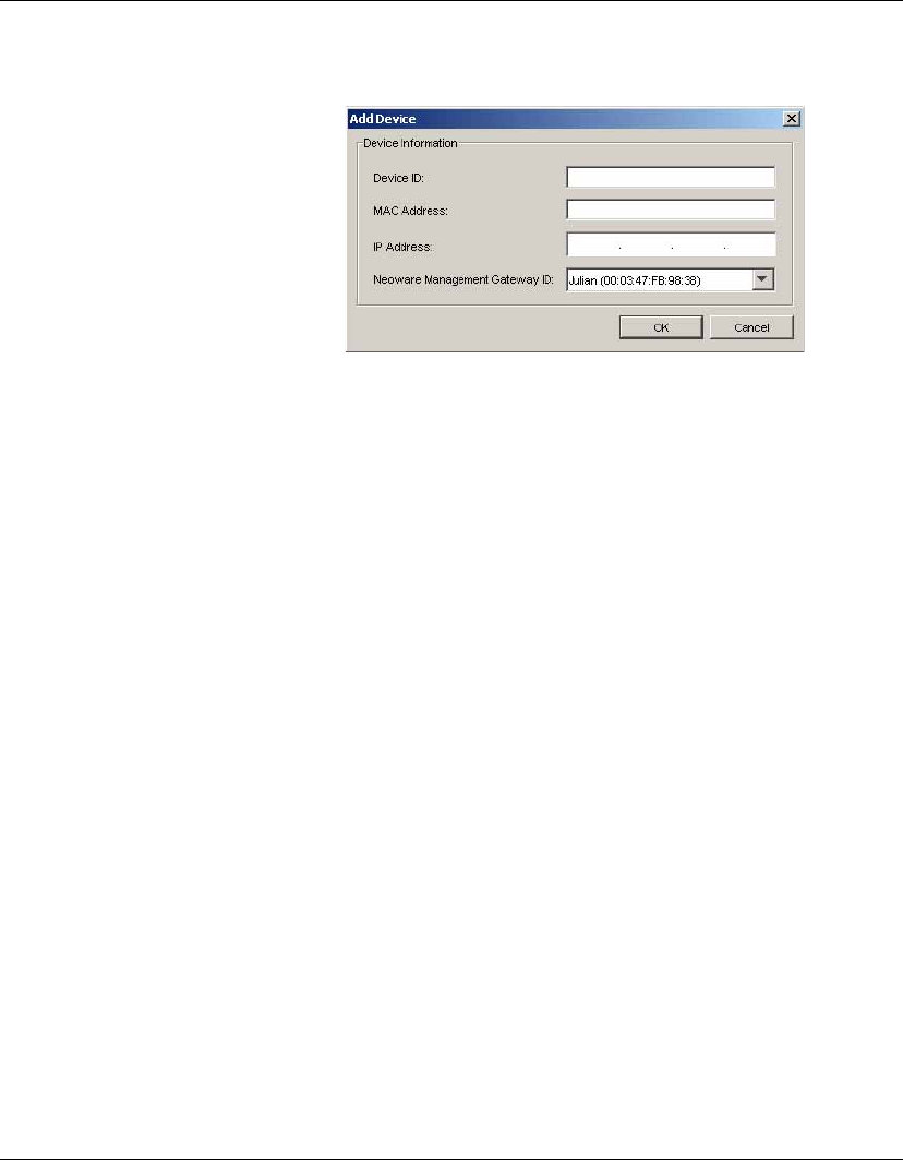
Advanced Tasks
174 Adding Devices Using MAC Addresses
2Enter the MAC Address of the device to be added.
3Select the Management Gateway that will connect with the
device from the Neoware Management Gateway ID drop-down
list.
4Click OK to add the device.
A new device will appear in the device tree with the name
deviceX, where X is a number. This device will appear as pow-
ered-off, but you can still interact with the device. For example,
you can use Send Task to send a new Imaging template to the
device, or Wake on LAN to attempt to start up the device.
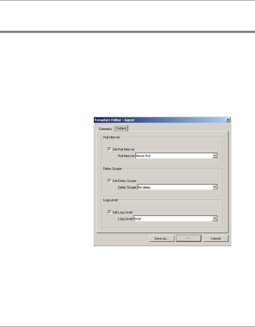
Advanced Tasks
Configuring Agents 175
Configuring Agents
The Agent templates enable you to set agent parameters and update
the agent version.
Setting Agent
Parameters
The _Configure Agent template enables you to specify how often it
pulls tasks from the Management Gateway, set the delay scope, and
specify the type of log information that will be generated.
1Double-click the _Configure Agent template on the Agent tab of
the Template Pane.
2Select the Pull Interval from the list.
3Select the Delay Scope from the list.
4Select the Log Level from the list.
5Click Save as... to save the template with a new name.
6Drag and drop the template on the device(s) you want to
configure.
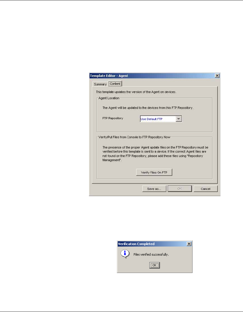
Advanced Tasks
176 Configuring Agents
Updating the Agent
Version
The _Update Agent template enables you to apply the latest version
of the Agent file to client devices. Agent update files must be added
to an FTP Repository using Repository Management before they
can be applied to client devices.
1Double-click the _Update Agent template on the Agent tab of
the Template Pane.
2Specify the location of the Agent update files by selecting from
the FTP Repository list.
3Click the Verify Files On FTP button to check whether the correct
Agent files are located on the specified FTP Repository.
4Click Save as... to save the template with a new name.
5Drag and drop the template on the device(s) you want to update.
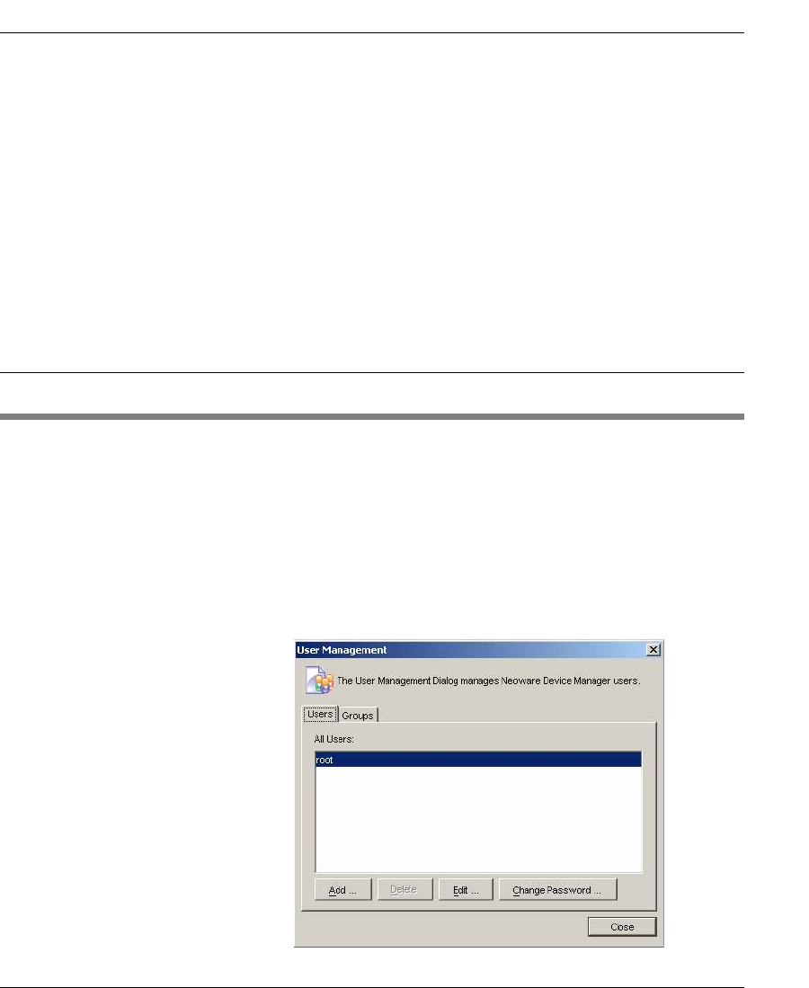
177
HP Device Manager User Manual
CHAPTER 7 Configuration
Management
This chapter explains the administration of the console, working
with users, advanced server configuration, and licensing.
User Management
Each user account can have customized permissions, according to
their level of need. These are assigned through the user groups
system.
Working With Users To add users:
1Display the Tools menu from the Console’s menu bar and
select User Management.
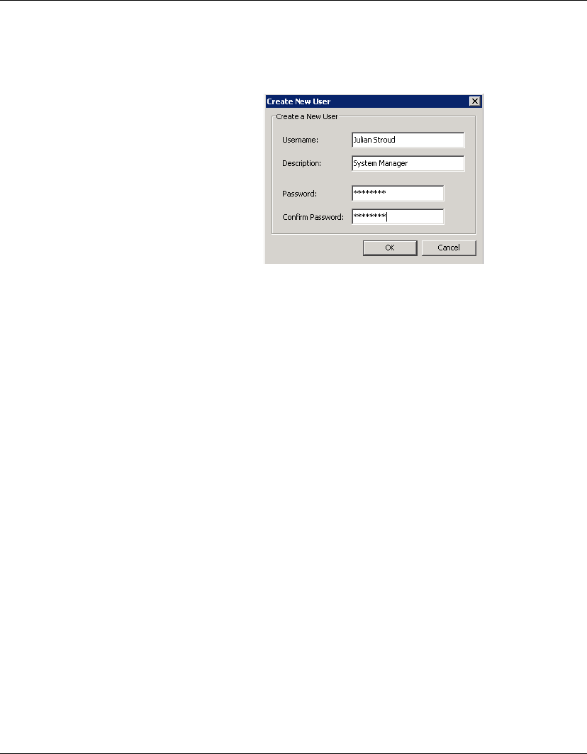
Configuration Management
178 User Management
2Click Add to add a new user. The Create New User dialog will
be displayed.
3Enter a Username for the new user and specify a Password.
Click OK to create the new user.
4Refer to the instructions below in order to add the new user to a
user group. Note that the user must be added to a group before it
has any permissions to use HP Device Manager.
This user name can be used to log in to the console the next time
the console starts.
To delete users:
1Display the Tools menu from the menu bar and select User
Management.
2Select a user in the User Management dialog.
3Click Delete then Yes to confirm that you want to delete the
selected user from the list.
To assign users to groups:
1In the User Management dialog, double-click a user name in the
Users list to edit the user.
2Select the Member Of tab.
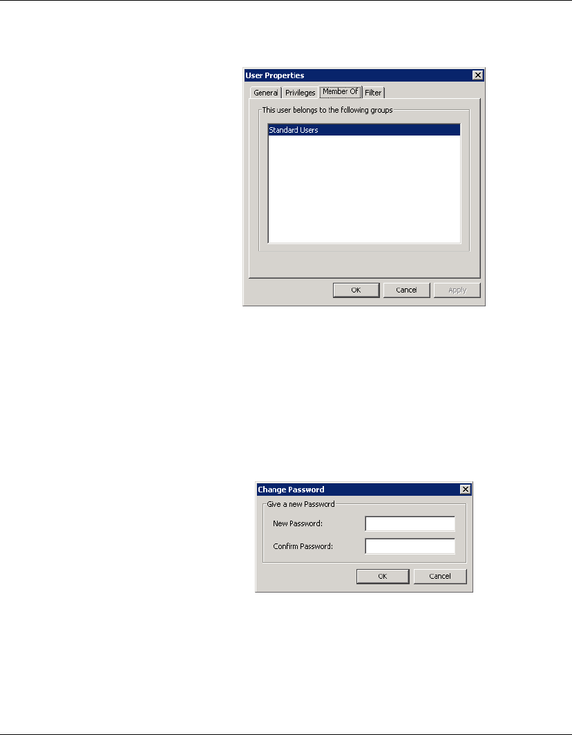
Configuration Management
User Management 179
3Click Add to add the user to a new group, or Delete to remove
the user from the selected group.
To change a user’s password:
1In the User Management dialog, right-click on the name of the
user whose password needs to be changed.
2Select Change Password from the pop-up menu.
3Enter the New Password for the user, then re-enter it in the Con-
firm Password field.
4Click OK to finish.
Note: When you log in as root for the first time, it is strongly rec-
ommended that you change the password from the default.
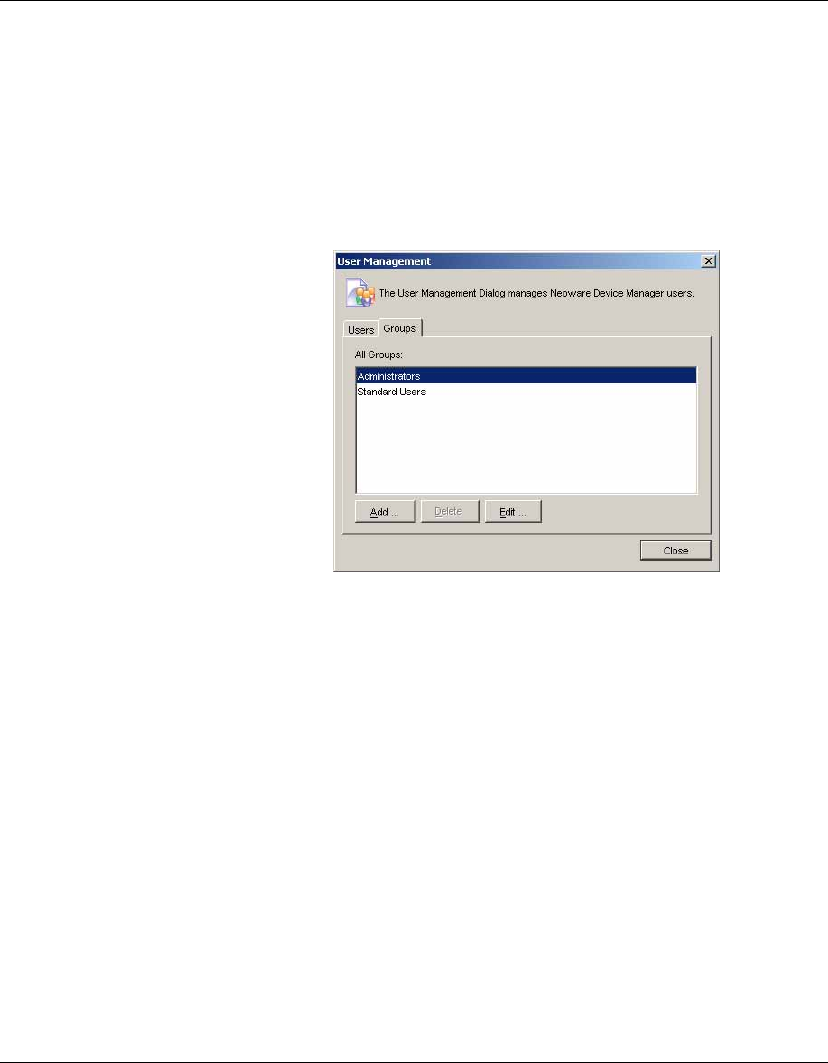
Configuration Management
180 User Management
Working With
Groups
Groups can be used to control user permissions in HP Device Man-
ager.
To add a group:
1Display the Tools menu from the Console’s menu bar and select
User Management. Select the Groups tab.
2Click Add to add a new group. This group can now be assigned a
set of permissions, and then users can be assigned to this group.
To assign permissions to groups:
1In the All Groups list, right-click the group you wish to modify.
2Select Properties in the pop-up menu.
3Select the Privileges tab.
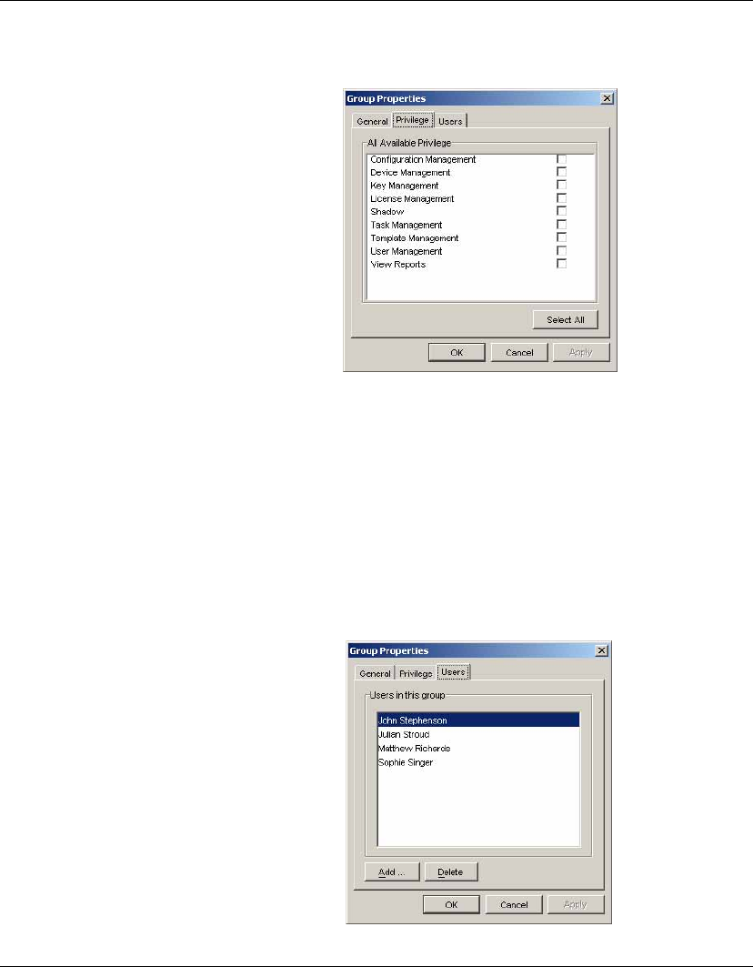
Configuration Management
User Management 181
4Select the permissions you wish to assign to the group.
5Click OK to finish.
To assign users to groups:
1Right-click the group you wish to modify in the Groups tab of
the User Management dialog.
2Select Properties in the pop-up menu.
3Select the Users tab.
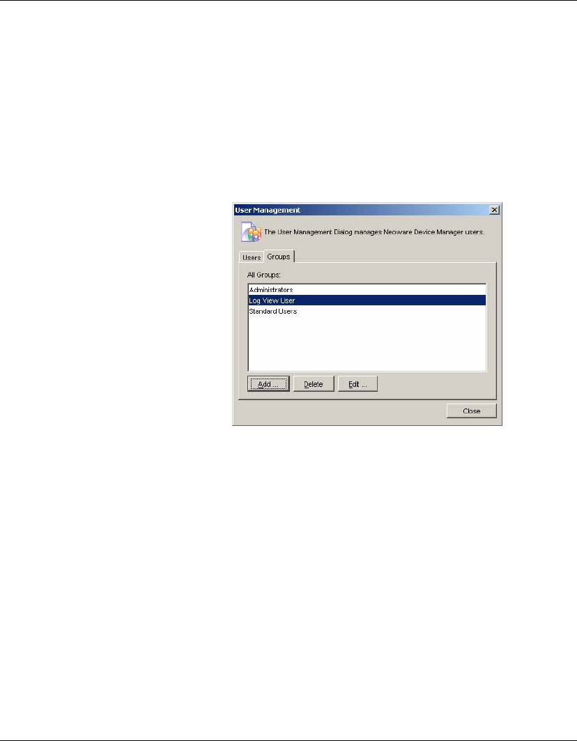
Configuration Management
182 User Management
4Use the Add and Delete buttons to modify the members of this
group.
5Click OK to finish.
To delete a group:
1Select the name of the group to be deleted in the All Groups list
on the Groups tab.
2Click the Delete button then Yes to confirm that you want to
delete the selected group from the list.
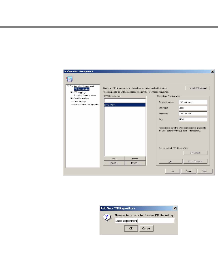
Configuration Management
FTP Repositories 183
FTP Repositories
Configuring an FTP
Repository
1Select Tools > Configuration from the Console’s menu bar.
2In the Configuration Management dialog, select the FTP Repos-
itories item in the left-hand tree pane.
3Different server profiles can be used to access different FTP
servers or different parts or accounts of the same FTP server.
Click Add to configure a new server.
4Enter a repository name to be used by HP Device Manager to
refer to the new repository, then click OK.

Configuration Management
184 FTP Repositories
5Fill in the Server Address, Username, Password and Path
settings. For example:
Server Address:192.168.88.7 (FTP server IP address)
Username:john
Password:dev1234 (input will appear hidden)
Path:./ndm
Note: You need to have write permissions for the given path.
The files will be stored at /home/john/ndm/ where /home/john
is the default login directory of user john.
6You can click Test if you want to try the connection to the
server. If there is a problem, click Undo Changes to recover the
last saved settings.
7If you want this Repository to be your default FTP server, click
Set Default.
8Click Apply to save the settings.
Deleting a
Repository
1Select Tools > Configuration from the Console’s menu bar.
2In the Configuration Management dialog, select the FTP Repos-
itories item in the left-hand tree pane.
3Select the repository you want to delete in the FTP Repositories
list, click Delete then Yes to confirm.
Exporting a
Repository
1Select Tools > Configuration from the Console’s menu bar.
2In the Configuration Management dialog, select the FTP Repos-
itories item in the left-hand tree pane.
3Select the repository you want to export in the FTP Repositories
list, then click Export.
4Browse to the location where you want to save it.
5Click Export FTP Repositories.

Configuration Management
FTP Repositories 185
Importing a
Repository
1Select Tools > Configuration from the Console’s menu bar.
2In the Configuration Management dialog, select the FTP Repos-
itories item in the left-hand tree pane.
3Click Import...
4Browse to the location where the FTP Repository you want to
import is located.
5Click Import FTP Repositories.
Note: The first FTP Repository imported will become the default
FTP Repository unless another has already been defined as
such.
FTP Repository
Selection for
Templates
Where applicable, each template allows you to define the method
used to find the required FTP Repository. The Content tab of the
Template Editor dialog will include an FTP Repository drop-down
list box providing the following three possibilities:
•Use Default
You preset a default server. To do this, select FTP Repositories in
the left-hand tree pane of the Configuration Management dialog,
select the name of the FTP Repository to use by default in the
FTP Repositories list, then click the Set Default button.
•Auto Mapping
The HP Management Server will find the corresponding FTP
server for each device according to the mapping defined in the
FTP Mappings definitions. (See “FTP Mappings” on page 186.)
•Use Specific FTP
You choose a specific FTP server for each template.
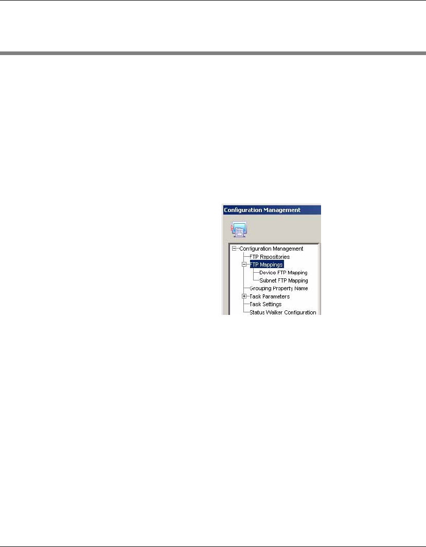
Configuration Management
186 FTP Mappings
FTP Mappings
The FTP Mappings tool automatically maps each and every client
device to the nearest and most convenient FTP server. This allows
the administrator to send tasks to a large number of agents, and have
the device connect automatically to an FTP server to find the infor-
mation or applications it may need to perform the task.
To configure the FTP Mappings tool, select Tools > Configuration
from the Console’s menu bar, expand the FTP Mappings item in the
left-hand tree pane of the Configuration Management dialog, then
select either Device FTP Mapping or Subnet FTP Mapping.
Listing Devices &
their FTP Servers
You can list devices and their FTP servers by selecting the Device
FTP Mapping item in the left-hand tree pane of the Configuration
Management dialog. A color code indicates how each device’s FTP
server was assigned:
•Blue
Automatic mapping (factory default settings). The HP Manage-
ment Server assigns an FTP server to each device depending on
which subnet it is connected to.
•Red
Uses a default FTP server, usually a server with highest broad-
band. The default FTP server can be changed at any time, so that
the devices assigned “default FTP” would connect to the new
FTP server.
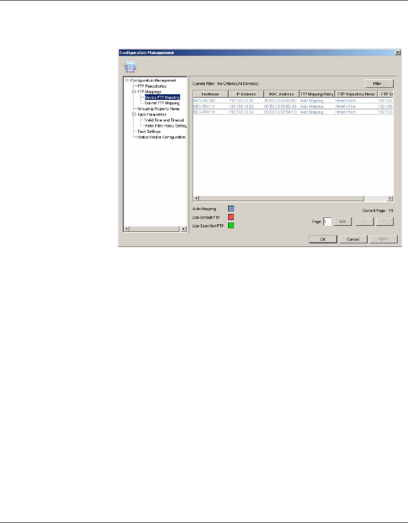
Configuration Management
FTP Mappings 187
•Green
Uses a static FTP server specified by the administrator.
Note: An administrator can change the FTP settings of a device or a
subnet at any time. The administrator can also change the default
FTP server and that will affect all the devices that use this option.
Note: HP Device Manager will automatically map any new device
added to the network.
Listing Subnets &
their FTPs Servers
You can list subnets and their FTP servers by selecting the Subnet
FTP Mapping item in the left-hand tree pane of the Configuration
Management dialog. A color code indicates how their FTP server
was assigned:
•Blue
Automatic mapping (factory default settings). The HP
Management Server assigns an FTP server to each subnet
according to its proximity. For example, a subnet that has an FTP
server will be using that server instead of another one in the
entire network.
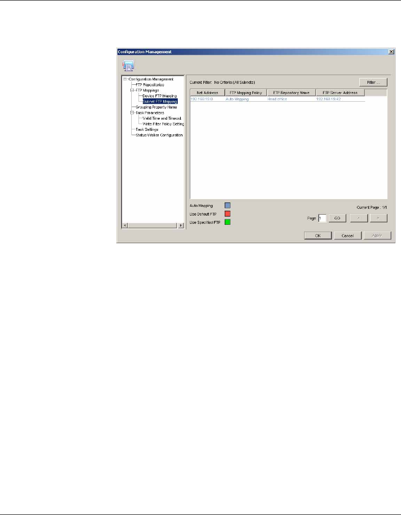
Configuration Management
188 FTP Mappings
•Red
Uses a default FTP server, usually a server with highest broad-
band. The default FTP server can be changed at any time, so that
the subnets assigned “default FTP” would connect to the new
FTP server.
•Green
Uses an FTP server specified by the administrator. For subnets
where this is the case, the administrator can change their FTP set-
tings to automatic mapping or default.
Filtering Devices or
Subnets
For companies with a large number of devices and/or subnets, the
Device FTP Mapping and Subnet FTP Mapping listings will be too
long for an administrator to easily find a particular device or to see
certain aspects. You can filter these mappings so that the administra-
tor can manage both the general and the specific aspects of each
device.
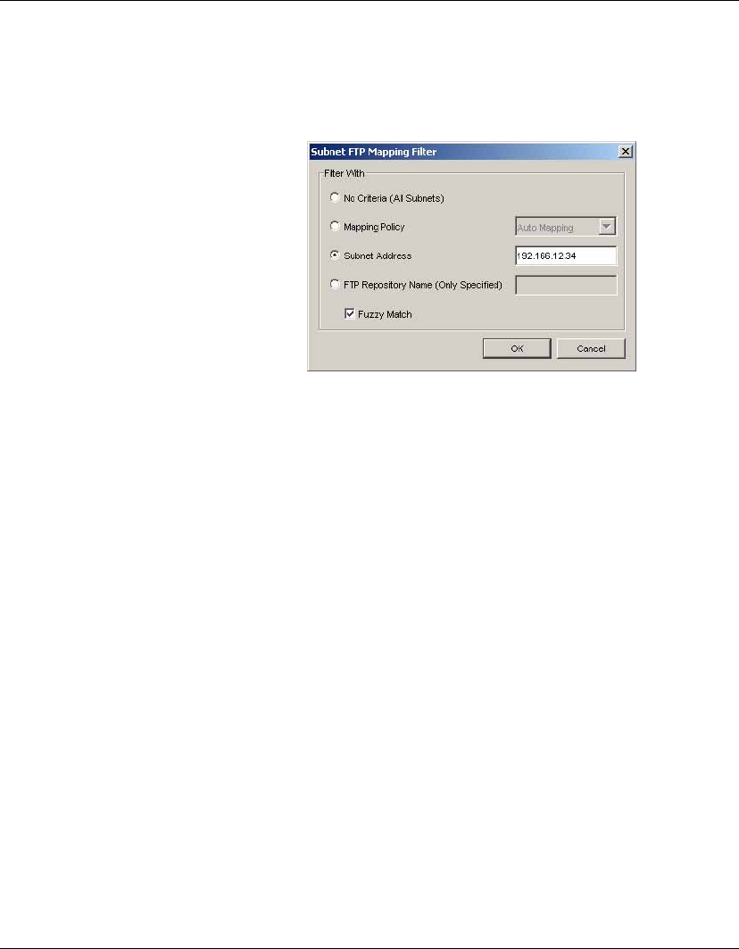
Configuration Management
FTP Mappings 189
On both the Device FTP Mapping and the Subnet FTP Mapping tabs,
click Filter to display a dialog which enables you to filter the listing
in various ways. Choose one of the filtering options then click OK.
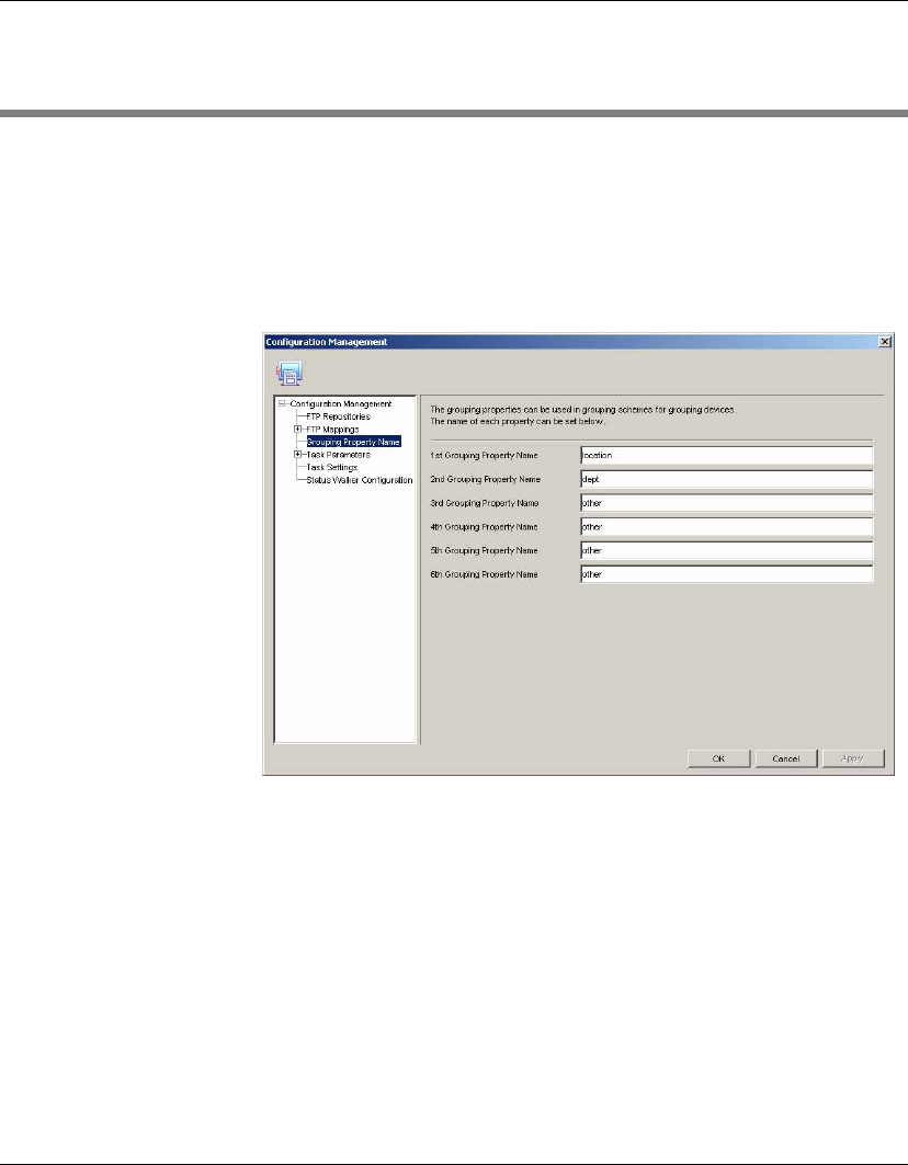
Configuration Management
190 Grouping Property Name
Grouping Property Name
Grouping properties can be used in grouping schemes for grouping
devices.
1Select Tools > Configuration from the Console’s menu bar.
2In the Configuration Management dialog, select the Grouping
Property Name item in the left-hand tree pane.
3Enter the name of the grouping property in the relevant
Grouping Property Name field.
4Click OK when you have finished.
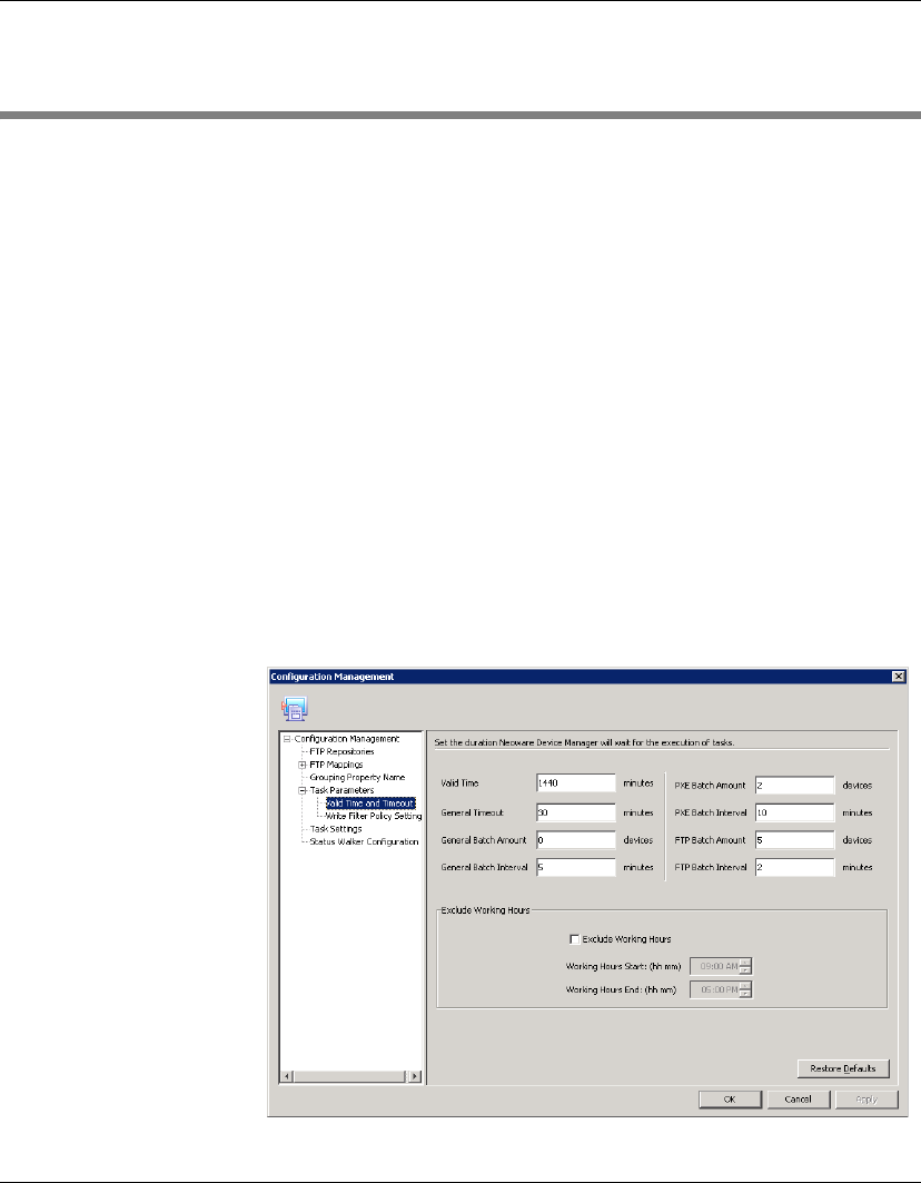
Configuration Management
Task Parameters 191
Task Parameters
You can set task parameters by selecting Tools > Configuration from
the Console’s menu bar to display the Configuration Management
dialog, then expanding the Task Parameters item in the left-hand
tree pane.
The Task Parameters item consists of two sub-items: Valid Time
and Timeout and Write Filter Policy Setting. These are described in
the following sections.
Valid Time and
Timeout
The Valid Time and Timeout options enable you to set the duration
HP Device Manager will wait for the execution of tasks. You can
also specify the start and end time of working hours during which
HP Device Manager will not execute tasks. Clicking in an option
field will cause the Description box to display a short description of
that option.
1Select Valid Time and Timeout in the left-hand tree pane of the
Configuration Management dialog.
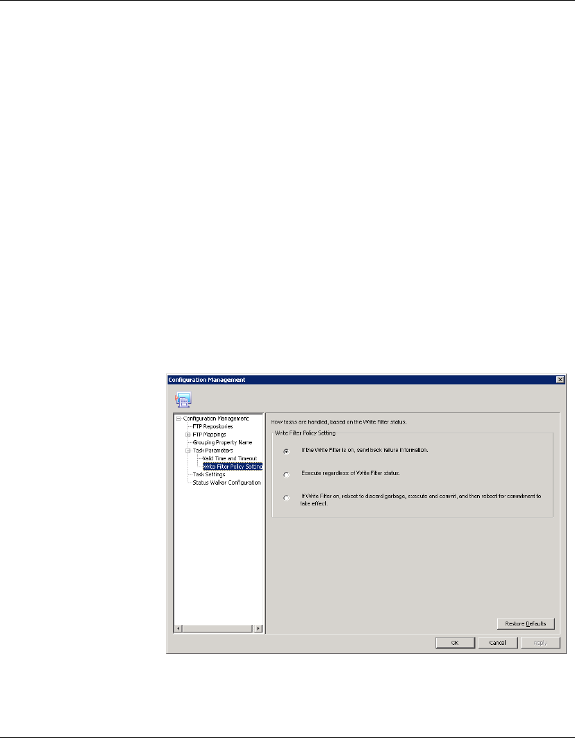
Configuration Management
192 Task Parameters
2Set the time, in minutes, for each category: Valid Time, General
Timeout, General Batch Interval, PXE Batch Interval and FTP
Batch Interval.
Set the amount, in devices, for each category: General Batch
Amount, PXE, Batch Amount and FTP Batch Amount.
Check the Exclude Working Hours option box to input the start
and end time of working hours.
Clicking Restore defaults will reset the timeout settings to their
defaults and set the working hours to 9.00 start and 17.00 end.
3Click Apply to save the new settings, then OK to exit.
Write Filter Policy
Setting
The Write Filter Policy Setting options enable you to specify how
the Enhanced Write Filter on XPe devices affects tasks.
1Select Write Filter Policy Setting in the left-hand tree pane of
the Configuration Management dialog.
2Choose one of the three policy options.
3Click Apply to save the new settings, then OK to exit.
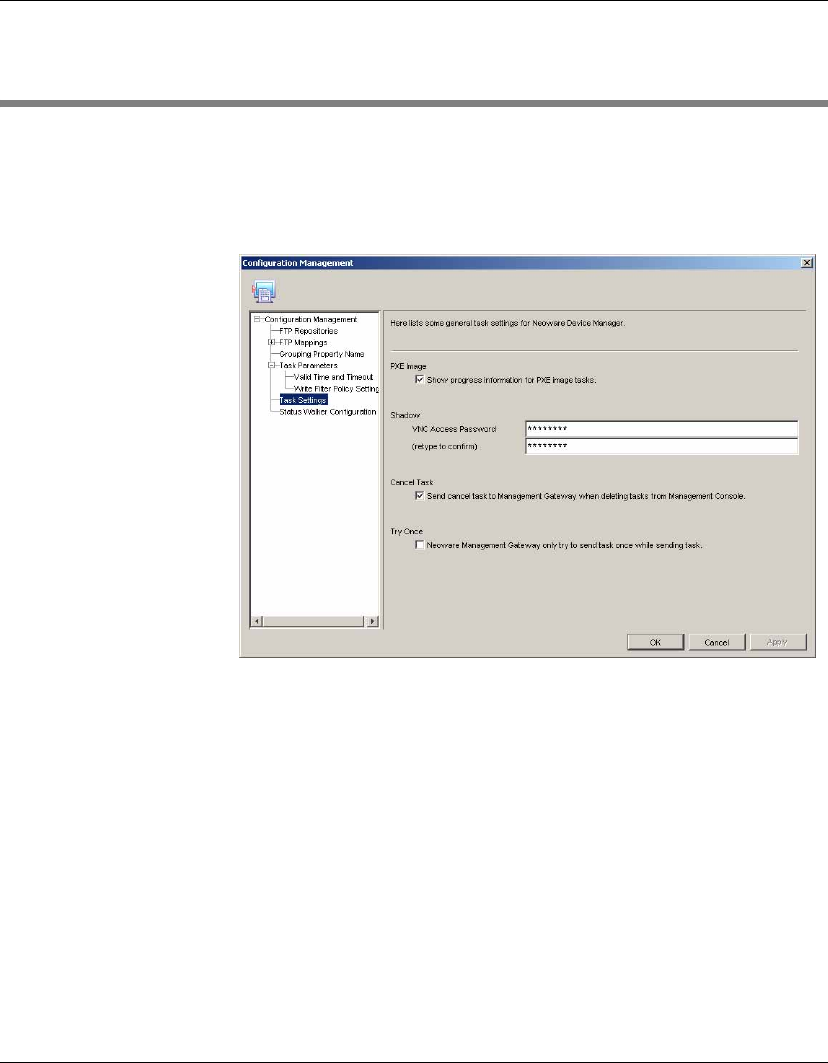
Configuration Management
Task Settings 193
Task Settings
You can specify general task settings by selecting Tools > Configu-
ration from the Console’s menu bar to display the Configuration
Management dialog, then selecting the Task Settings item in the
left-hand tree pane.
The PXE Image option enables you to show progress information for
PXE image tasks.
The VNC Access Password fields enable you to specify a password
that must be supplied to enable shadowing. Note that these fields
cannot be blank.
If the Cancel Task option is checked, a ’cancel task’ command will
be sent to the Management Gateway when deleting tasks from the
Console.
If the Try Once option is checked, the Management Gateway will
only attempt to send a task once.
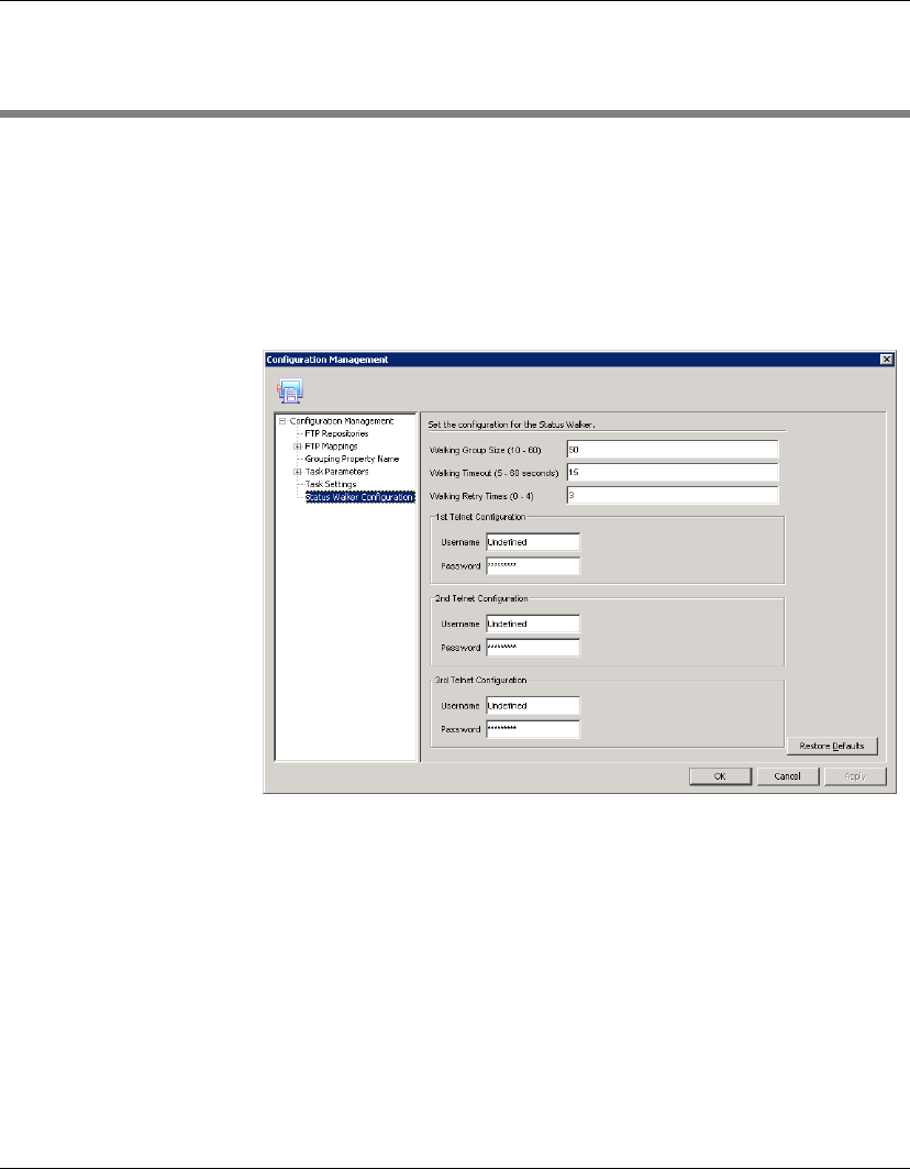
Configuration Management
194 Status Walker Configuration
Status Walker Configuration
The Status Walker configuration options enable you to specify the
walking group size, timeout and retry times, and specify the user
name and password for three telnet configurations.
Select Tools > Configuration from the Console’s menu bar to display
the Configuration Management dialog, then select the Status
Walker Configuration item in the left-hand tree pane.
Clicking in an option field will cause the Description box to display
a short description of that option.

Configuration Management
Licensing 195
Licensing
A license file contains information for the maximum number of
clients your HP Management Server can support concurrently and
the expiration date for the license. If more clients need to be
supported and the number is over the maximum in the license file,
HP can be contacted for another license file. Once this file has been
obtained it must be imported into HP Device Manager.
The HP Management Server icon in the Windows Systray will turn
red if the license expires. Consequently the HP Management Con-
sole will not connect to the Management Server until a new license
file is imported.
You can view information about your current license by selecting
Help > About from the Console’s menu bar.
Importing a New
License
You can only import a new license file through the Management
Console if the old license has already expired. Any invalid operation
to the license file when the Management Server is running will cause
the server to crash.
1Select File > Import License... from the Console’s menu bar to
display the Open dialog.
2Browse for the new license file and select it. (The license file has
the extension “.lic”.)
3Click Choose.
The Management Server will reboot automatically before the Con-
sole continues to work under the new license.
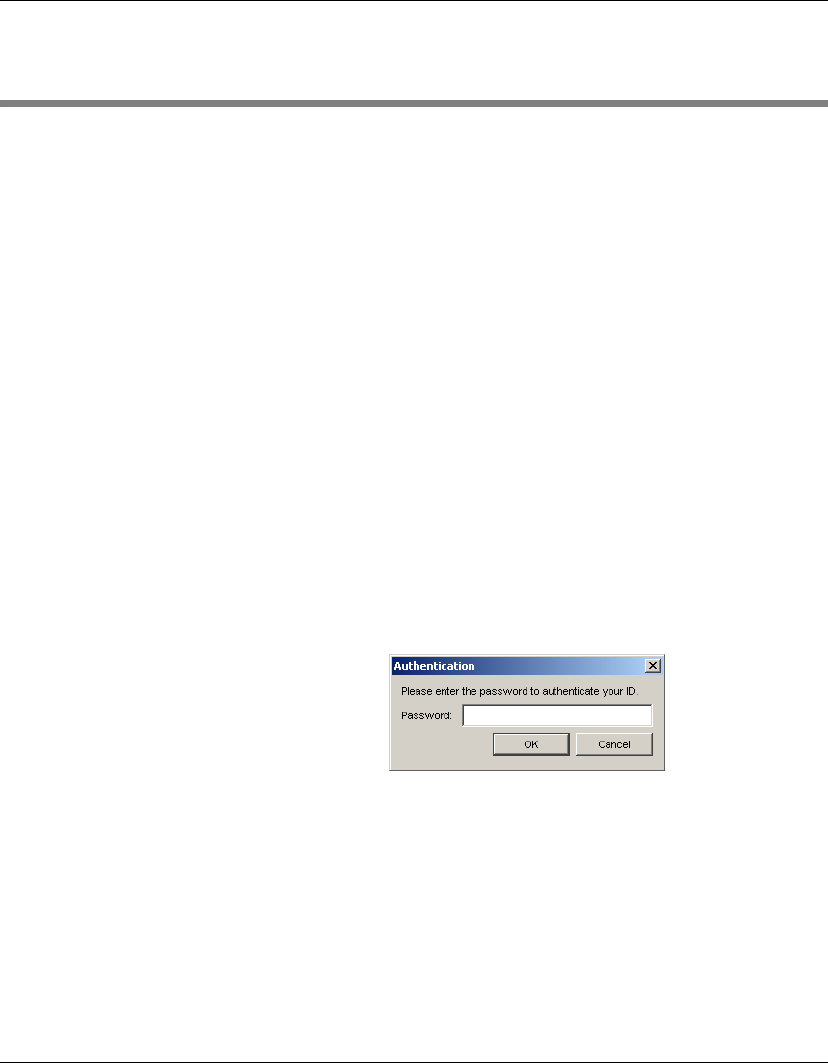
Configuration Management
196 Authentication Management
Authentication Management
Since the HP Management Server can discover and manage all HP
Device Manager gateways and agents on the network, a security
problem may occur due to the improper usage of the Management
Server. To overcome this, HP Device Manager provides an authenti-
cation capability for the gateways and the agents to recognize a
secure Management Server.
There are two tools for providing authentication: Key Management
and Gateway Access Control. These are accessed by selecting Tools
> Authentication Management in the Console’s menu bar.
Key Management An Authentication Key is a plain text password which is input on the
Management Console. The key will be passed to the devices during
the key update process. The devices will check the key passed by
Management Server when executing tasks.
To update the current Authentication Key:
1Select Tools > Authentication Management > Key Management
in the Console’s menu bar to display the Authentication dialog.
2Enter your user Password then click OK. The Key Management
window will be displayed.
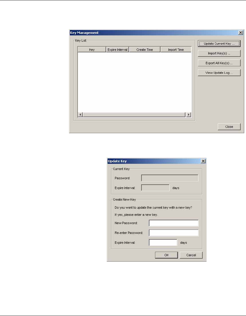
Configuration Management
Authentication Management 197
3Click the Update Current Key... button to display the Update
Key dialog.
4Enter the new Password (i.e. the Authentication Key) and
specify the Expire Interval (number of days).
5Click the OK button.
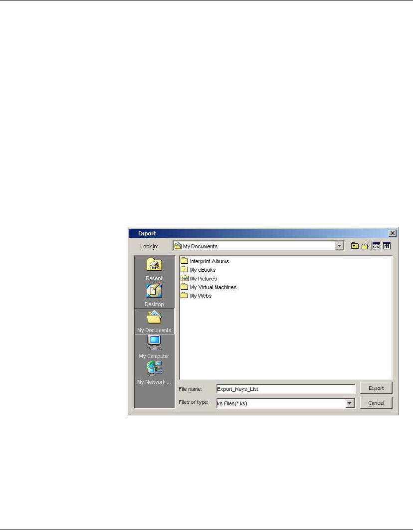
Configuration Management
198 Authentication Management
Note:
Expire Interval
is the time that the password (Key) keeps
valid. If an agent cannot contact a gateway for key information
before a specified time (Expiration Interval), the Key will expire,
(i.e., no longer in use) and the agent will revert to its initial key.
HP recommends that user passwords contain:
•at least eight characters
•letters of both upper and lower cases
•numbers and punctuations as well as letters
To export all Authentication Key(s):
1Click the Export All Key(s) button in the Key Management win-
dow to display the Export dialog.
2Browse for a folder to save the current authentication key(s) as a
*.ks file, then click the Export button.
3The system will prompt you to create and confirm the KeyStore
password.
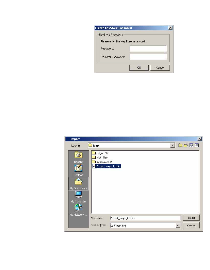
Configuration Management
Authentication Management 199
4In the Create KeyStore Password dialog, enter a KeyStore Pass-
word and confirm the password in the Re-enter Password field.
5Click the OK button.
To import Authentication Key(s):
1Click the Import Key(s) button in the Key Management window
to display the Import dialog.
2Browse for the exported *.ks file, then click the Import button.
3The system will prompt you to enter the KeyStore password.
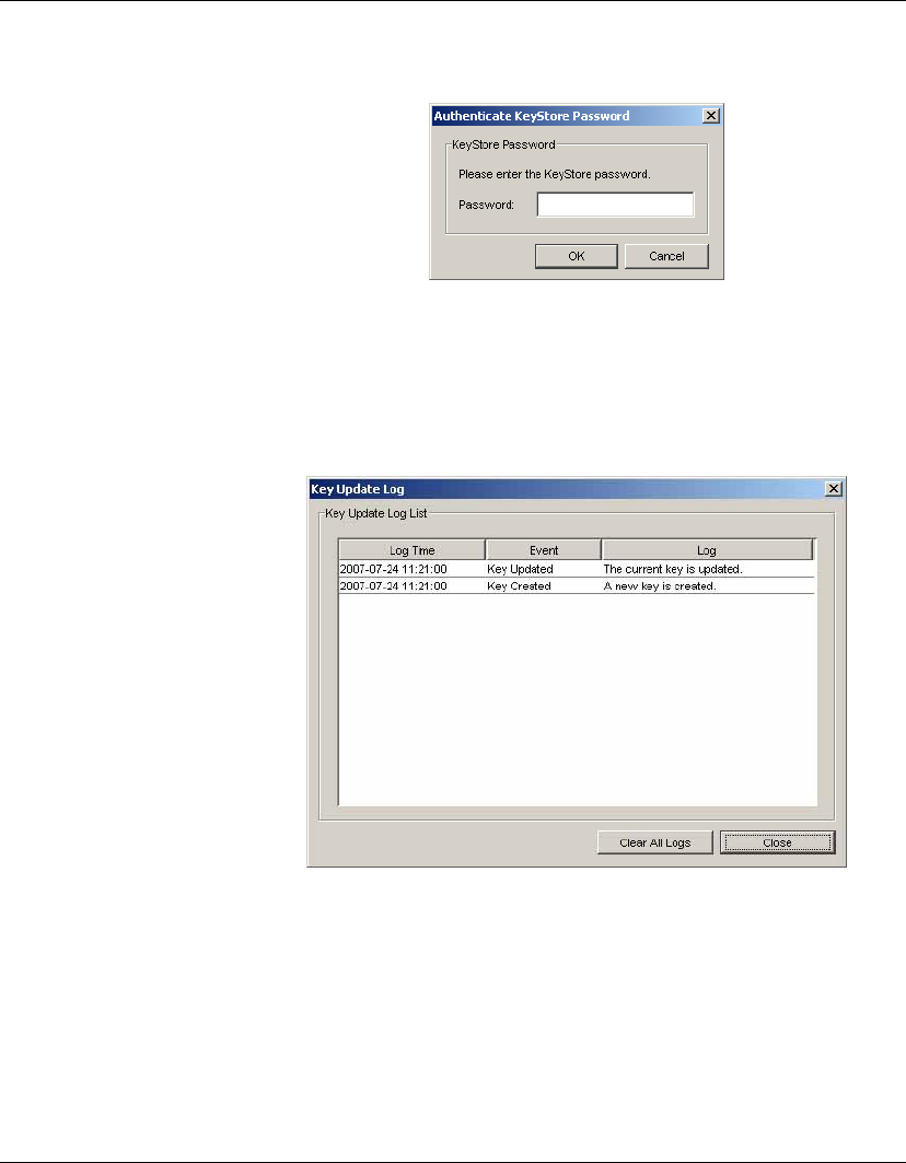
Configuration Management
200 Authentication Management
4Enter the KeyStore Password then click the OK button.
Viewing the Key Update Log
To view the Key Update Log, click the View Update Log... button in
the Key Management window.
In the Key Update Log List you can view all the log times and events.
You can remove all the logs by clicking the Clear All Logs button.
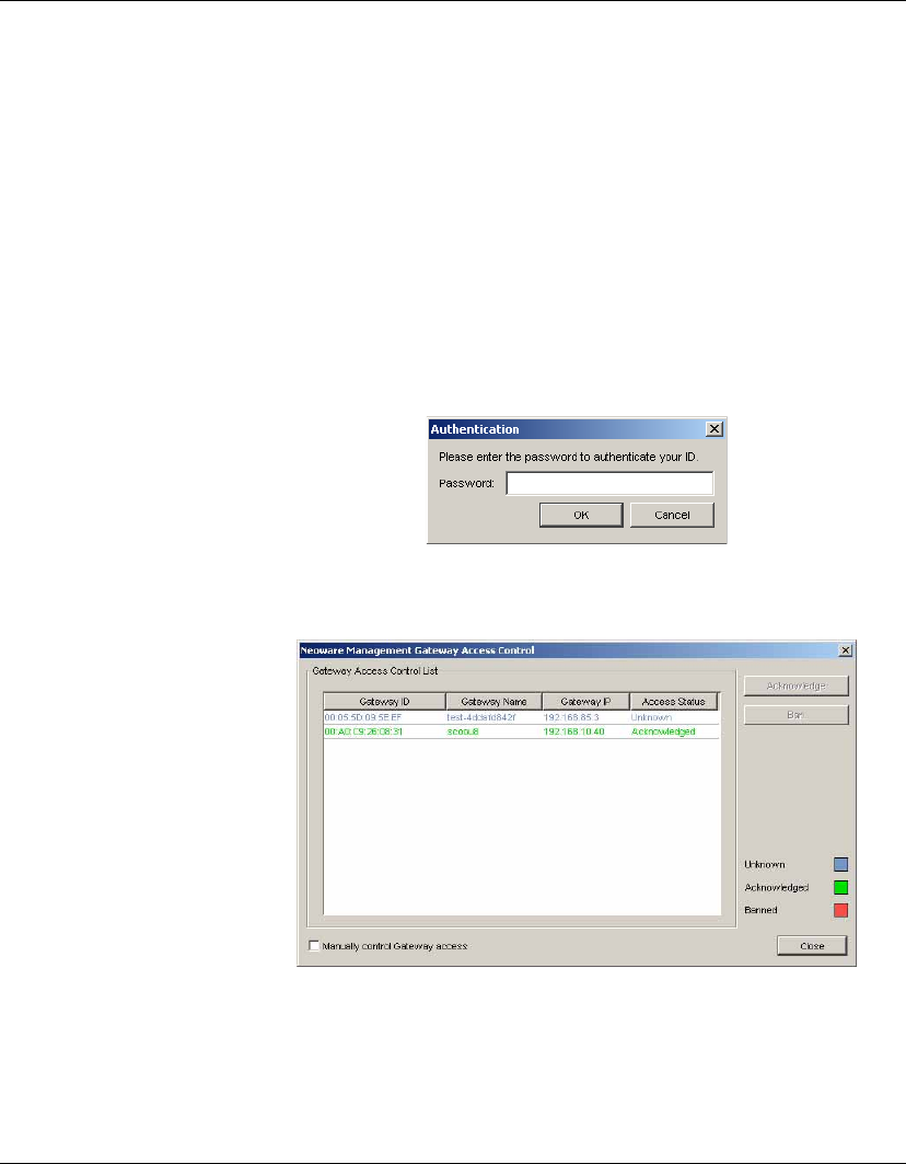
Configuration Management
Authentication Management 201
Gateway Access
Control
The Management Server will maintain the acknowledge status of a
gateway which is specified by the user from the Management Con-
sole. When a gateway is discovered by the Management Server, the
gateway is set as Unknown status. The Management Server will not
establish any connection with a gateway nor receive any messages
sent by the banned gateway unless the gateway is acknowledged.
To control Gateway access manually:
1Select Tools > Authentication Management > Neoware Man-
agement Gateway Access Control... from the Console’s menu
bar to display the Authentication dialog.
2Enter your password then click OK. The Neoware Management
Gateway Access Control window will be displayed.
3Select a gateway from the Gateway Access Control List, then
click the Acknowledge or Ban button to recognize or ban the
selected gateway.
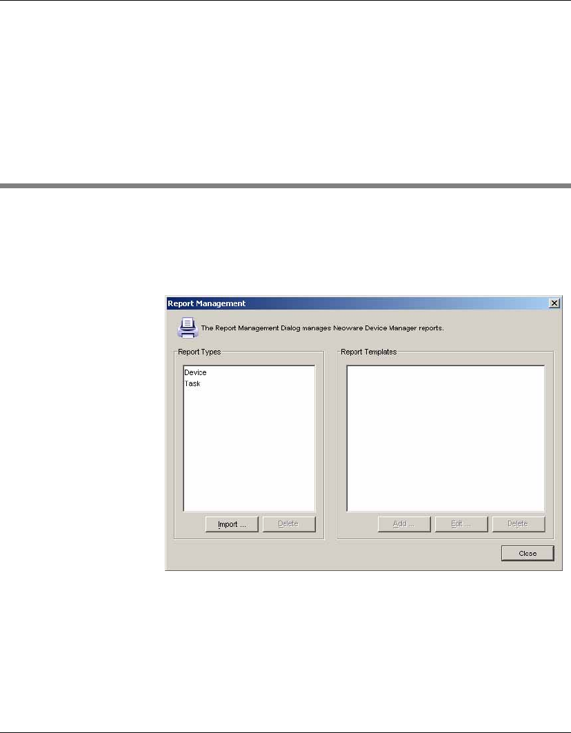
Configuration Management
202 Report Management
Note: If the
Manually control Gateway access
option is
unchecked, the gateway with the Unknown status is regarded as
Acknowledged. When this option is selected, the gateway with
the Unknown status is regarded as Banned and you need to
configure the status of the gateway manually.
Report Management
Adding a Report
Template
To add a report template:
1Select Tools > Report Management from the Console’s menu
bar to display the Report Management window.
2Select one report type from the Report Types list, then click the
Add button. A Set New Report Template Name dialog will
prompt you to input a report template name.
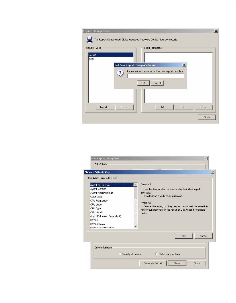
Configuration Management
Report Management 203
3Click OK to open the Edit Report Template window. In the Edit
Criteria field, click the ... button to open the Choose Criteria Key
window. Select a criteria key in the Candidate Criteria Key List.
After you have made the selection, click OK to return to the Edit
Report Template window.
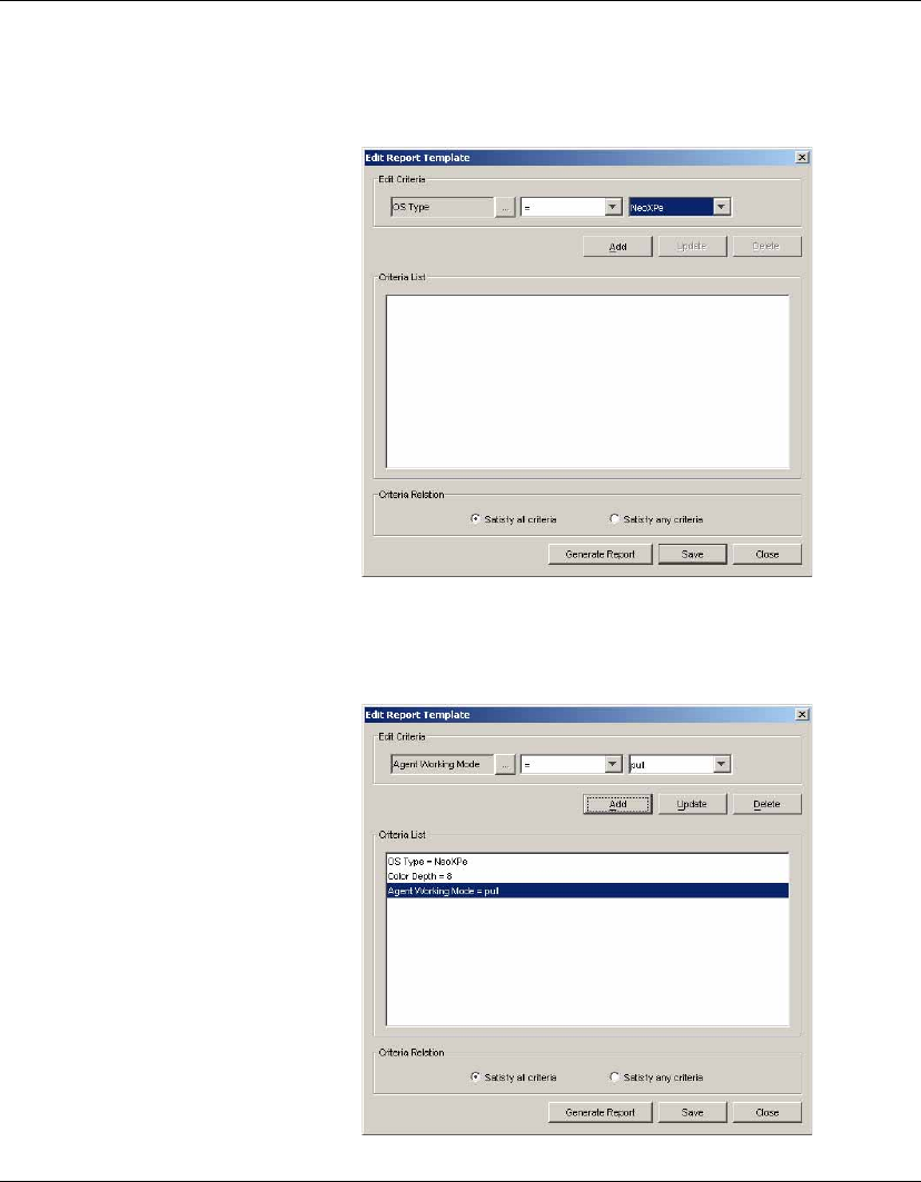
Configuration Management
204 Report Management
4In the Edit Criteria field, select or enter the criteria conditions in
the two drop-down lists.
Click Add to add the criteria into the Criteria List below, or you
can select an existing criteria then click Update to renew the
restricted condition.
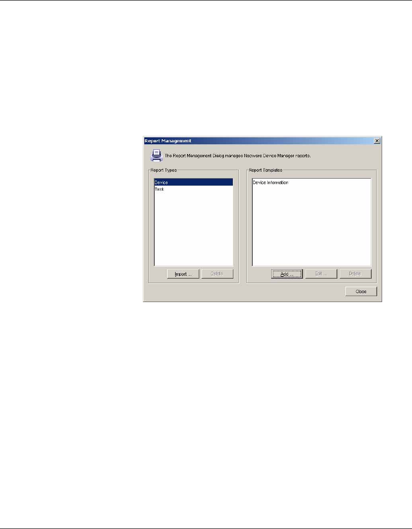
Configuration Management
Report Management 205
Note: The
Report Template
can contain several criteria and
each criteria could have one of two kinds of relationships:
Sat-
isfy All Criteria
or
Satisfy Any Criteria
. So you can select either
of them to generate reports.
5Click Generate Reports to generate the report according to the
current criteria, or click Save to add these criteria to the named
template.
Note: The modified criteria will not be saved in the template
after generating a report. You need to click the
Save
button to
save the modified criteria in the template.
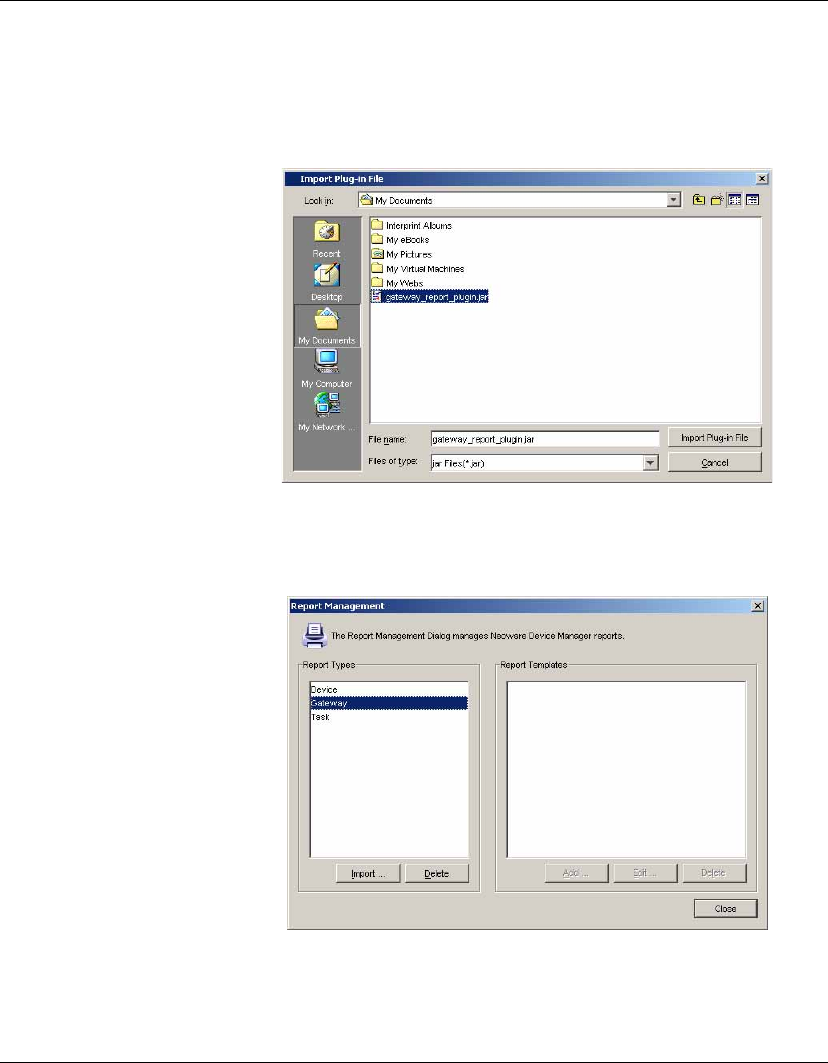
Configuration Management
206 Report Management
Importing a Report
Plug-in File
To import a report plug-in file:
1Click Import in the Report Management window, then select a
plug-in file (*.jar).
2Click Import Plug-in File to import the file and return to the
Report Management window. A new report type is added to the
Report Types list.
You can remove a report type from the list by selecting it then
clicking the Delete button. You will be prompted to confirm that
you want to delete it.
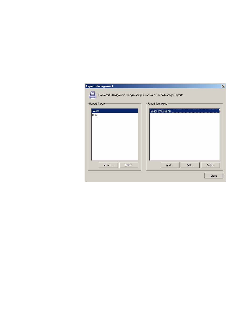
Configuration Management
Report Management 207
Note: The imported report types can be deleted only if there is
no template belonging to the reported type.
Generating a
Report Using a
Report Template
To generate report using a report template:
1In the Report Management window, select a report type from
the Report Types list and all the report templates belong to the
selected type will be displayed in the Report Templates list.
2Select a template from the list then click Edit, or double click on
the template to view the template's content.
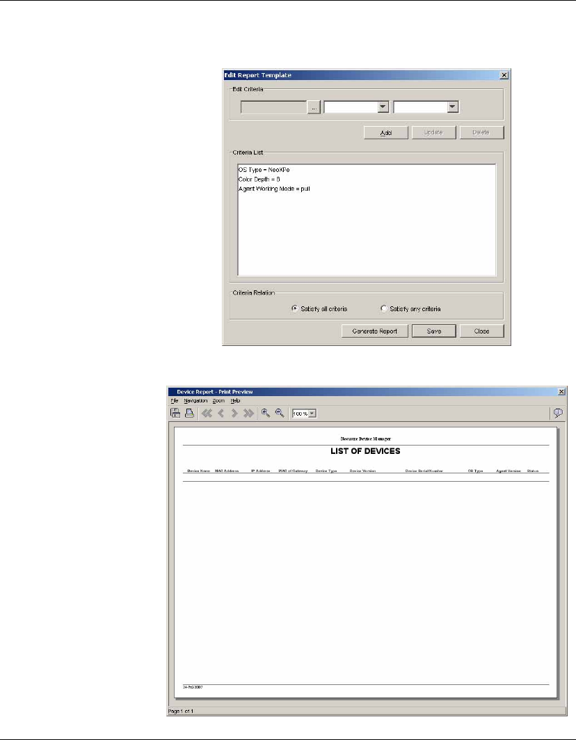
Configuration Management
208 Report Management
3Click Generate Report to preview the report.
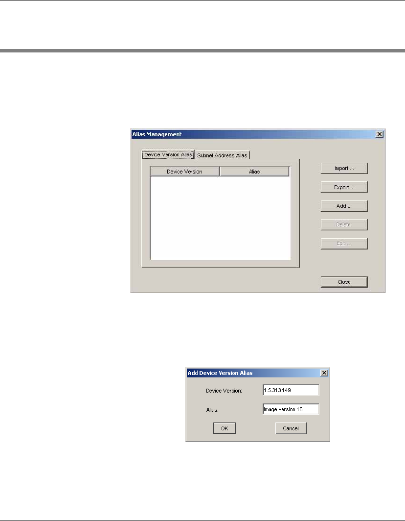
Configuration Management
Alias Management 209
Alias Management
Device Version
Alias
To add a device version alias:
1Select Tools > Alias Management from the Console’s menu bar
to display the Alias Management window.
2If necessary, click on the Device Version Alias tab to open the
corresponding panel.
3Click the Add... button to display the Add Device Version Alias
dialog, in which you can add a new record.
4Enter the device version and alias, then click OK. The new
record will be added to the Device Version Alias panel.
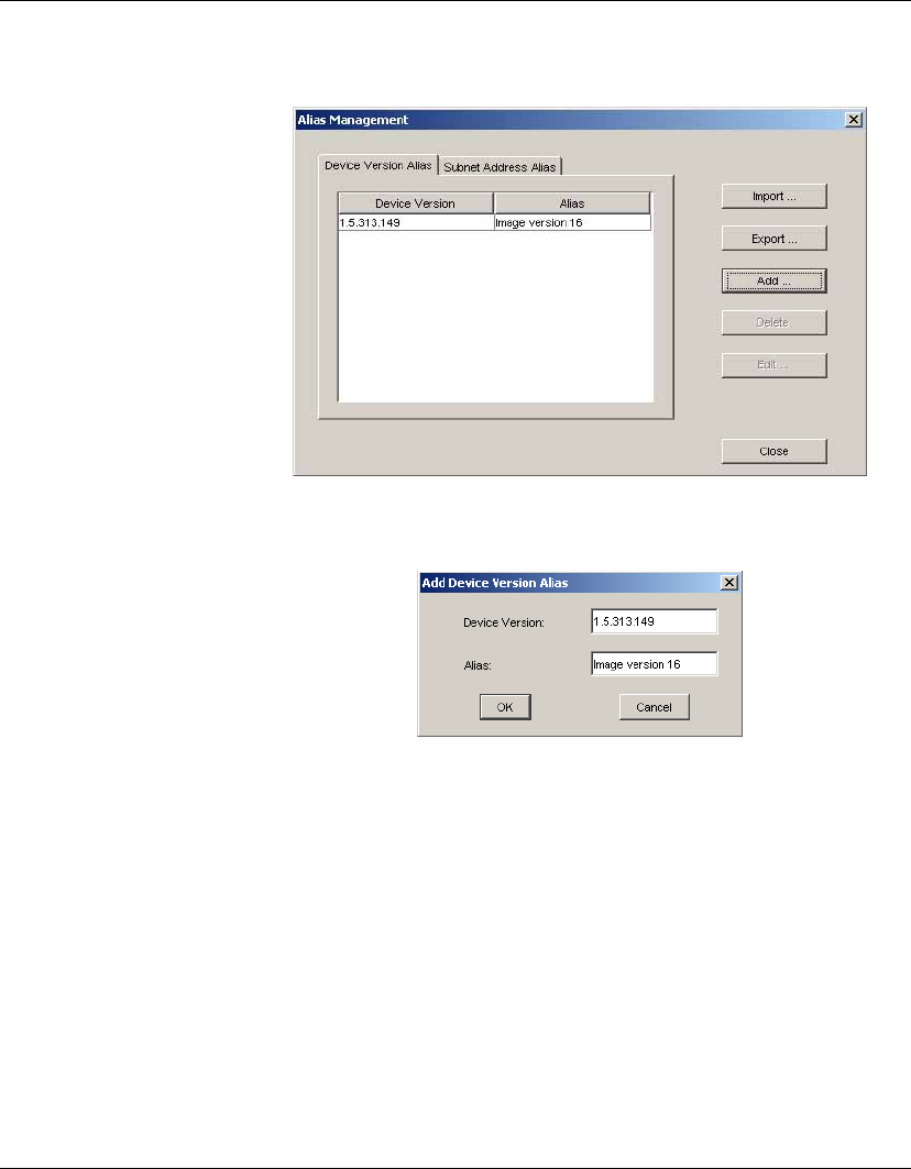
Configuration Management
210 Alias Management
To edit an existing device version alias, you need to select a record in
the Device Version Alias panel then click the Edit button.
In the Edit Device Version Alias dialog, change the alias then click
OK to save your modifications.
If you want to remove a record from the Device Version Alias panel,
just select a record and click the Delete button.
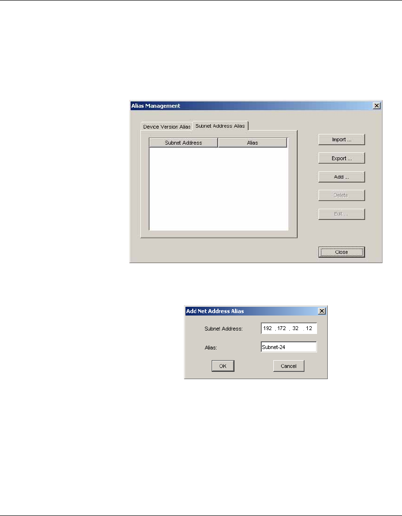
Configuration Management
Alias Management 211
Subnet Address
Alias
To add a subnet address alias:
1Select Tools > Alias Management from the Console’s menu bar
to display the Alias Management window.
2Click on the Subnet Address Alias tab.
3Click the Add... button to display the Add Net Address Alias
dialog, in which you can add a new record.
4Input the subnet address and alias, then click OK. The new
record will be added to the Subnet Address Alias panel.
To edit an existing subnet address alias, select a record in the Subnet
Address Alias panel then click the Edit button. In the Edit Subnet
Address Alias dialog you can change the alias then click OK to save
your modifications.
If you want to remove a record from the Subnet Address Alias panel,
just select a record and click the Delete button.
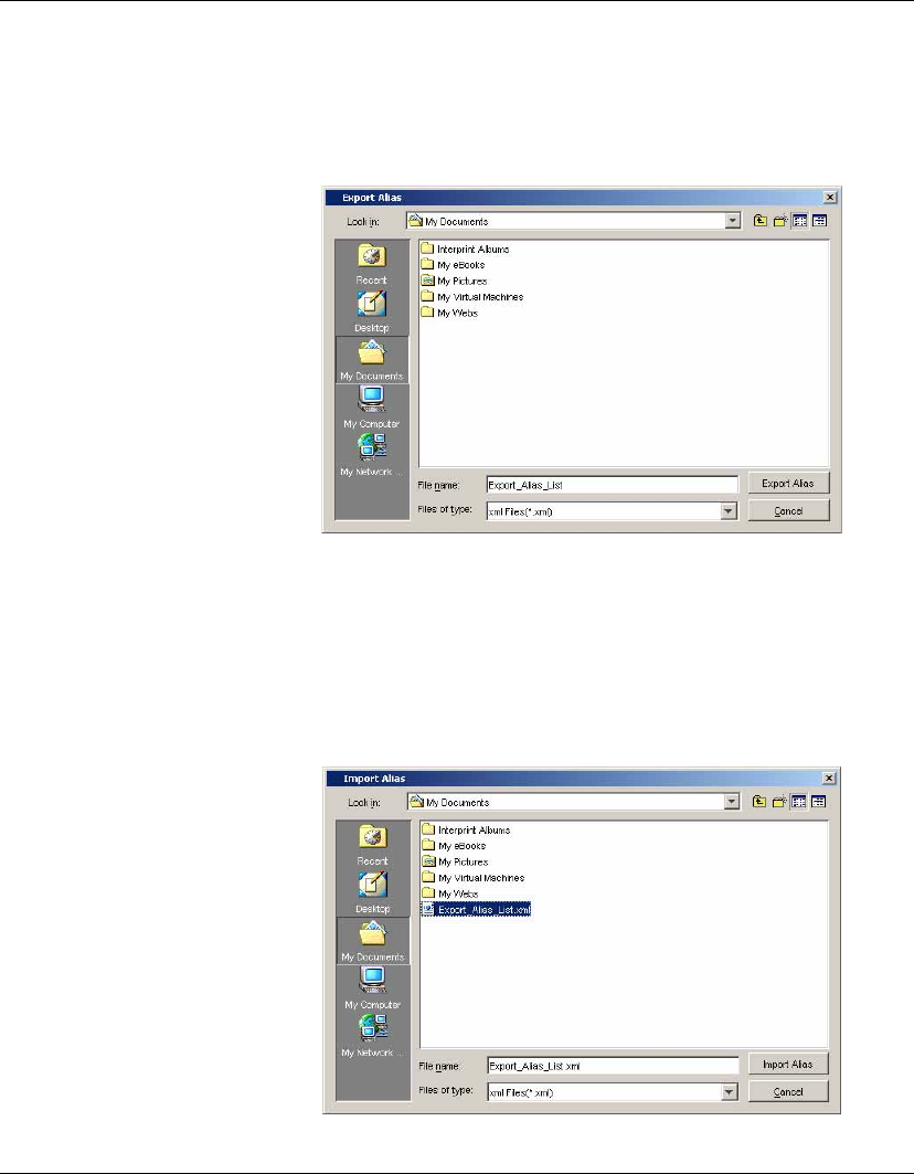
Configuration Management
212 Alias Management
Exporting an Alias To export an alias:
1In the Alias Management window, select a record and click the
Export button to open the Export Alias dialog.
2Browse for a folder to save the current alias as an *.xml file,
then click the Export Alias button.
Importing an Alias To import an alias:
1Click the Import button in the Alias Management window to
display the Import Alias dialog.
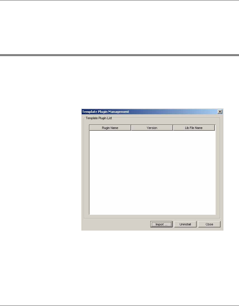
Configuration Management
Template Plugin Management 213
2Browse for the exported *.xml file then click the Import Alias
button. The imported alias will be added to the current list.
Template Plugin Management
Importing a
Template Plugin
To import a Template Plug-in:
1Select Template > Template Plugin Management from the Con-
sole’s menu bar to display the Template Plugin Management
window.
2Click the Import button to display the Select Import Files
dialog.
3Browse for the exported *.jar file, select it then click the OK but-
ton.
4The imported plugin will be displayed as a new tab with a new
template in the Template Pane.

Configuration Management
214 Template Plugin Management
Removing a
Template Plugin
To remove a Template Plugin:
1In the Template Plugin Management window, select a record
and click the Uninstall button.
2You will be prompted to confirm that you want to uninstall the
selected template. Click Yes to uninstall.
3The template tab associated with the uninstalled template plugin
will be deleted from the Template Pane.

215
HP Device Manager User Manual
APPENDIX A Installing &
Running JRE
This appendix describes how to install and run the Java Runtime
Environment.
Introduction
A Java Runtime Environment of version 1.41 or later, including
any Java2 platform system, is required to run HP Device Manager.
You can install the correct Java Runtime Environment from the HP
Device Manager installation CD.
Windows-based
Server Installation
To install the Java Runtime Environment for Windows based
servers:
1Navigate to the directory [CD]:\jre (where [cd]:\ is the drive
letter of your installation CD.)
2Double-click j2re-1_4_1_02-windows-i586-i.exe.
3Install the Java Runtime Environment following the on-screen
instructions.
The Java Runtime Environment is now ready for HP Device Man-
ager to be installed.

Installing & Running JRE
216 Introduction
Linux-based Server
Installation
To install the Java Runtime Environment for Linux based servers:
1Login as root.
2Enter the following commands:
shell> cd /usr/local
shell> cp /[CD]/j2re-1_4_1_02-linux-i586.bin /usr/local
(where [CD] is the path to the HP Device Manager CD).
shell> sh j2re-1_4_1_02-linux-i586.bin
shell> ln -s j2sdk1.4.1_02 j2sdk
3Set an environment variable JAVA_HOME to the pathname of
the directory into which you install the JDK:
shell> vi /etc/profile
Add the following lines just before "export PATH..."
PATH=/usr/local/j2sdk/bin:$PATH
JAVA_HOME=/usr/local/j2sdk
export PATH ... JAVA_HOME

217
HP Device Manager User Manual
APPENDIX B Installing &
Running MySQL
This appendix describes how to install and run MySQL.
Installing MySQL on Linux-based Servers
1Login as root.
2Enter the following commands:
shell> groupadd mysql
shell> useradd -g mysql mysql
shell> cd /usr/local
shell>
gunzip < /path/to/mysql-VERSION-OS.tar.gz | tar xvf -
shell> ln -s full-path-to-mysql-VERSION-OS mysql
shell> cd mysql
shell> scripts/mysql_install_db
shell> chown -R root
shell> chown -R mysql data
shell> chgrp -R mysql

Installing & Running MySQL
218 Running MySQL on Linux-based Servers
Running MySQL on Linux-based Servers
To run MySQL on Linux-based servers type the following:
shell> bin/safe_mysqld --user=mysql &
If you want to start MySQL automatically:
1Copy /support-files/mysql.server to the directory which
contains the startup files.
2Enter the following commands:
shell> chmod a+x mysql.server
shell> cp mysql.server /etc/rc.d/init.d/mysql
shell> ln -s /etc/rc.d/init.d/mysql /etc/rc.d/rc3.d/S99mysql
shell> ln -s /etc/rc.d/init.d/mysql /etc/rc.d/rc0.d/S01mysql
shell> chkconfig --add mysql
3Reboot the server.
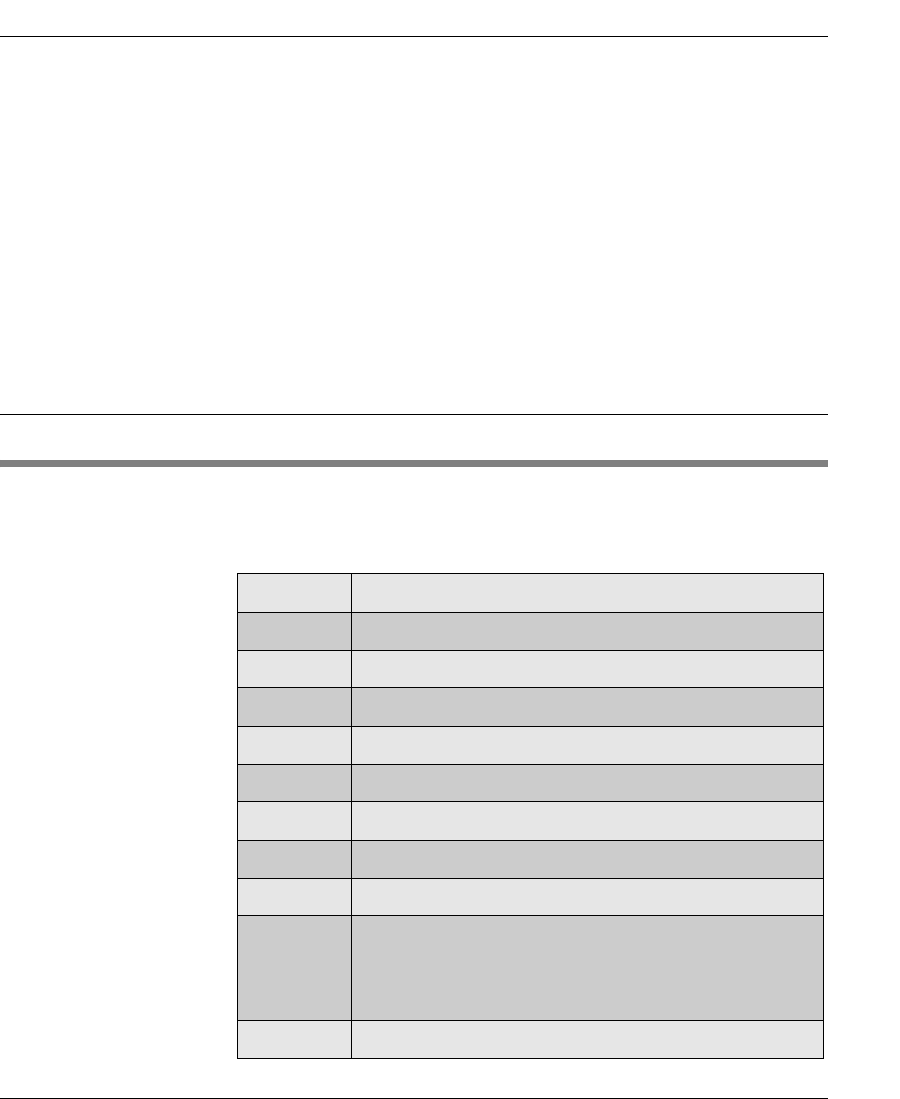
219
HP Device Manager User Manual
APPENDIX C Error Code
Reference
This appendix explains the meaning of error codes which may be
generated by HP Device Manager.
Error Codes
The following table lists the error codes which may be generated
by HP Device Manager and explains their meaning.
Error Code Description
0 Success.
1Could not connect with target Management Agent.
2The system cannot find the file specified.
3The system cannot find the path specified.
4The system cannot open the file.
5Access is denied.
7Report is received, but the report is corrupt or malformed.
8Task is not found in the Management Gateway.
9Management Agent information is lost in Management Gate-
way. Management Server is synchronizing Management
Agent information with Management Gateway. Please resend
the task another time.
10 Management Gateway failed to send task to Agent.

Error Code Reference
220 Error Codes
201 Image size larger than flash size.
202 Cannot connect to FTP Server.
203 Login error.
204 Image file does not exist.
205 Image file transfer failed.
206 MD5 file does not exist.
207 MD5 file transfer failed.
208 MD5 verification error.
209 Read flash error.
210 Write flash error.
211 Offset too large.
212 Get MAC address error.
213 Unknown command error.
214 MD5 file creation error.
215 FTP path error.
216 Cannot use BINARY mode in FTP transfer.
217 File already exists.
218 File and flash of different OS type.
220 Cannot connect to FTP Server.
221 Login FTP error.
222 Unknown command error.
223 Error with both PASV and PORT modes in FTP transfer.
300 Unknown error.
301 Failure connecting to PXE Server.
Error Code Description

Error Code Reference
Error Codes 221
302 Failure getting PXE task.
303 Invalid task format.
304 Failure pulling image (image file already exists).
305 Failure uploading file to FTP Server.
306 Failure executing PXE task (flash unsupported).
307 Failure uploading MD5 file.
308 Failure finding PXE server.
309 Failure pushing image file (file does not exist).
310 Failure pushing image MD5 file (file does not exist).
311 Failure downloading image file from FTP server.
312 Failure downloading MD5 file from FTP server.
313 Invalid image file size.
14000022 Unknown Error.
14000032 Time out.
14000042 Service terminated.
14000052 Unsupported task.
14000062 Allocate memory blocks error.
14000072 Child process crashed.
14001012 Registry path is empty.
14001022 Registry path is invalid.
14001032 Open HKEY_CURRENT_USER failure.
14001042 Registry task is empty.
14001052 Unknown registry type.
14001062 Open key failure.
Error Code Description

Error Code Reference
222 Error Codes
14001072 Enumerate value failure.
14001082 Delete registry item failure.
14001082 Delete registry value failure.
14002012 Invalid XML format.
14002022 Invalid version.
14002032 Unknown Clone or not.
14002042 Unknown task ID.
14002052 Unknown item parameter.
14002062 Unknown FTP parameter.
14002072 Unknown task content.
14002082 Attachment error.
14003012 Set display parameter failure.
14003022 Set DNS failure.
14003032 Set Gateway failure.
14003042 Set host name failure.
14003052 Set IP mask failure.
14003062 Set IP failure.
14003072 Set DHCP failure.
14003082 Get display parameter failure.
14003092 Get DNS failure.
14003102 Get IP failure.
14003112 Get IP mask failure.
14003122 Get host name failure.
14003132 Get Gateway failure.
Error Code Description

Error Code Reference
Error Codes 223
14003142 Get IP failure.
14003152 Not logged in.
14004012 Unknown registry parameter.
14004022 Command line error.
14004032 Unknown software component parameter.
14004042 Unknown VNC parameter.
14004052 Unknown pause parameter.
14004062 Cancelled by user.
14004072 Registry value is too long.
14004082 Get registry value failure.
14004092 Registry results overflowed.
14004102 No VNC password.
14004112 Set VNC password failure.
14004122 No element found.
14004132 Create VNC process failure.
14005002 Verify MD5 failure.
14006012 Connect FTP failure.
14006022 FTP error.
14006032 Could not find specified file or dir in FTP.
14006042 Invalid file.
14006052 No update file found.
14007012 Invalid Write Filter.
14007022 No Write Filter driver found.
14007032 Write Filter error.
Error Code Description

Error Code Reference
224 Error Codes
14007042 Write Filter enabled.
14008012 Retry update key.
14008022 Get new key failure.
14008032 Get current key failure.
14008042 Decrypt new key failure.
14008052 Update new key failure.
14009012 Get Write Filter persistent data failure.
14009022 Set Write Filter persistent data failure.
14010012 Delete dir or file failure.
14010022 Open file failure.
14010032 Read file failure.
14010042 Write file failure.
14010052 File content error.
14011012 No Linux config file group found.
14011022 No Linux config file item found.
14012012 Linux platform response error.
14013012 Platform interface enumerate task error.
14013022 Platform Interface BeginTask() exception.
14013030 Platform interface reboot.
14013042 Platform interface BeginTask() error.
14014012 Invalid or unmatched type of web browser.
14020022 Open description file error.
14020032 Cloning failed because of missing parameters from Linux
side.
14020042 Description file’s format is not correct.
Error Code Description

Error Code Reference
Error Codes 225
14020052 Create description file error.
14020062 Image info from task is different to info from description file
on FTP Server.
14020072 Image file already exists on FTP Server.
14020082 Prepare info for update.ini error.
14020092 Write info to update.ini error.
14020102 Execute SwitchOS.cmd error.
14020112 Not enough space available.
14020122 Copy menu.1st file from ’C:\Windows\system32\Grub’ to
’d:\Windows\System32\Grub’ error.
14020132 Copy menu_update.1st file from ’C:\Windows\system32\
Grub’ to ’d:\Windows\System32\Grub’ error.
14020142 Copy stage2 file from ’C:\Windows\system32\Grub’ to
’d:\Windows\System32\Grub’ error.
14020152 Create directory: ’d:\Windows’ error.
14020162 Create directory: ’d:\Windows\system32’ error.
14020172 Create directory: ’d:\Windows\system32\Grub’ error.
14020212 No suitable storage device found.
14020222 Cannot find partition on storage device.
14020232 Required file update.ini not found on writable.
14020242 Required parameters missing in update.ini.
14020252 None of the specified network interfaces could be configured.
14020262 Not enough space on the target partition.
14020272 The target partition is too large for the specified image.
14020282 Could not access the specified URL.
14020292 Streaming data to flash error.
Error Code Description

Error Code Reference
226 Error Codes
14020302 Cloning error.
14020312 Failed to obtain return code from returned update file from
cloning.
14020322 Failed to obtain return code from returned update file from
cloning.
14020402 FTPException unknown error.
14020412 File or directory not found.
14020422 Get file error.
14020432 Read reply error.
14020442 Set PASV error.
14020452 Init reply error.
14020462 Change directory error.
14020472 Delete file error.
14020482 List directory error.
14020492 Get resume error.
14020502 User not accepted.
14020512 Password not accepted.
14020522 Create directory error.
14020532 Finish put error.
14020542 TypeI error.
14020552 Put file error.
14020562 Get finish error.
14020572 Remove directory error.
14020582 FTP quit error.
14020592 PWD error.
Error Code Description

Error Code Reference
Error Codes 227
14020602 Connect error.
14020612 Put resume error.
14020622 Set port error.
14020632 Unknown.
14020712 FileException unknown Exception.
14020722 File does not exist.
14020732 No more free disk space.
14020742 Write forbidden.
14020752 Create forbidden.
14020762 Read forbidden.
14020772 Create directory forbidden.
14020782 File seek forbidden
14020792 Combine path error.
14020812 MFC initialization failed.
14020822 Invalid parameter number.
14020832 Failed to retrieve .2do file.
14020842 Failed to open .2do file.
14020852 Zero length for the .2do file.
14020862 Ack not received.
14020872 CMD failed.
14020882 Reboot requested.
14020892 The result file was not created or cannot be opened.
14021001 Bad command line.
14021002 Invalid file path name.
Error Code Description

Error Code Reference
228 Error Codes
14021003 Cannot create file.
14021004 Cannot run programs.
14021007 Cannot get platform type.
14021008 Cannot allocate memory.
14021009 Cannot get FTP address from registry.
14021010 Cannot set platform type.
14021011 Invalid parameter.
14021012 Cannot open existing file.
14021013 Time out to wait for a thread.
14021014 File size read does not match its actual size.
14021015 Cannot crack FTP URL.
14021016 Server not using FTP.
14021017 Connection open failed.
14021018 Cannot connect to server.
14021019 No file found on server.
14021020 No available space on storage media to copy a file.
14021021 There is an error when running NetCopy command.
14021022 There is an error when running SafeNetCopy command.
14021023 There is an error when running general command.
14021024 Cannot get an exit code of a process.
14021025 Get unexpected exit code of a thread.
14021026 Cannot get file size.
14021027 Cannot read content from file.
14021028 Failed to convert string from ASCII to Unicode.
Error Code Description

Error Code Reference
Error Codes 229
14021029 Cannot get file size.
14021030 Cannot rename file.
14021031 Cannot create directory.
14021099 RST file not found. Unknown error.
14022011 File corrupted (checksum error).
14022012 Failed to install firmware file.
14022013 Failed to install IPKG.
14022014 Failed to remove IPKG.
14022015 Unsupported format.
14022016 Not ready.
14022017 Not enough free disk space.
14022018 No such IPKG.
14022019 No such URL.
14022020 Failed to set registry.
14022021 Invalid parameter.
14022022 Remount error.
14022023 No such file.
14022024 No such path.
-2 Target agent timed out while executing task.
-100 Failed to get hostname.
-101 Hostname without domain part.
-102 Failed to set linger for socket.
-103 Reserved, no use.
-104 Reserved, no use.
Error Code Description

Error Code Reference
230 Error Codes
-105 Failed to get host address.
-106 Failed to create data socket.
-107 Failed to duplicate a socket.
-108 Failed to open file for read.
-109 Failed to open file for write.
-110 Failed to get socket name.
-111 Failed to bind data socket.
-112 Failed to bind data socket.
-113 Failed to listen on data socket.
-114 Server sent a invalid port number.
-115 Failed to connect to data socket.
-116 Failed to accept on data socket.
-117 Failed to set start point for file.
-118 Misc error for connection.
-119 Failed to retry connection.
-120 Connection is refused by peer.
-121 Bad transfer type.
-122 Invalid parameter for dir command.
-123 Failed to malloc memory.
-124 PWD command failed.
-125 CWD command failed.
-126 RMD command failed.
-127 Line list is bad.
-128 Option is not implemented.
Error Code Description

Error Code Reference
Error Codes 231
-129 Function is not implemented.
-130 LIST command failed.
-131 RETR command failed.
-132 STOR command failed.
-133 Failed to write file.
-134 Failed to read file.
-135 Failed to write to socket.
-136 Failed to read from socket.
-137 Failed to open file.
-138 Bad magic code.
-139 Bad parameter.
-140 Failed to create directory.
-141 Cannot go to previous directory.
-142 Failed to chmod.
-143 Failed to umask.
-144 DELETE command failed.
-145 SIZE command failed.
-146 MDTM command failed.
-147 TYPE command failed.
-148 SIZE command is not available.
-149 MDTM command is not available.
-150 Failed to rename.
-151 Glob is failed.
-152 Failed to set keepalive.
Error Code Description

Error Code Reference
232 Error Codes
-153 Disconnected by FTP server when login in.
-154 Invalid user.
-155 Invalid password.
-156 Failed to login.
-157 Invalid relay from server.
-158 Connection is closed by peer.
-159 Not connected.
-160 Cannot start data transfer.
-161 Failed to transfer data.
-162 PORT command failed.
-163 PASV command failed.
-164 UTIME command failed.
-165 UTIME command is not available.
-166 HELP command failed.
-167 Failed to delete local file.
-168 Failed to seek local file.
-169 Data transfer is aborted.
-170 Symbol link is failed.
-171 Symbol link is not available.
-172 Glob is not match.
-173 FEAT command is not available.
-174 Specified file is not found.
-175 No buffer.
-176 Local file is newer.
Error Code Description

Error Code Reference
Error Codes 233
-177 Remote file is newer.
-178 Local file is same as the remote file.
-179 LSD command failed.
-180 MLST command failed.
-181 Invalid response for MLST command.
-182 MLST command is not available.
-183 MLSD command is not available.
-184 STAT command failed.
-185 STAT for file command is not available.
-186 NLST command failed.
-187 NLST for file command is not available.
-188 No file or directory error.
-189 Cannot tell if file exists.
-190 File exists but cannot find the file type.
-191 Is not a directory.
-192 Recursion limit is reached.
-193 Control socket is timeout.
-194 Data socket is timeout.
-195 User canceled the FTP task.
-1000 Invalid XML format.
-1001 Invalid XML version.
-1002 Failure executing clone task.
-1003 Unknown task ID.
-1004 Unknown parameter.
Error Code Description

Error Code Reference
234 Error Codes
-1005 Unknown FTP parameter.
-1101 Failure setting display settings.
-1102 Failure setting DNS.
-1103 Failure setting default Gateway.
-1104 Failure setting host name.
-1105 Failure setting IP mask.
-1106 Failure setting IP address.
-1107 Failure setting DHCP server.
-1108 Failure getting display settings.
-1109 Failure getting DHCP server.
-1110 Failure getting IP address.
-1111 Failure getting IP mask.
-1112 Failure getting host name.
-1113 Failure getting default Gateway.
-1114 Failure getting DNS.
-1115 User not logged in.
-1229 Unknown registry parameter.
-1230 Failure executing task (command could not be executed).
-1231 Error in 'software' tag.
-1232 Unknown VNC parameter.
-1233 Unknown pause parameter.
-1234 Task canceled by user.
-1235 Error in registry value (registry value too long).
-1236 Failure getting registry value.
Error Code Description

Error Code Reference
Error Codes 235
-1237 Failure cloning registry (item too long).
-1301 Failure connecting to FTP Repository.
-1302 Unknown FTP error.
-1303 Failure looking for remote file or low space on local drive.
-1305 Failure looking for replace.exe.
-1401 Unknown FTP Error.
-1402 File or Directory not found.
-1403 Failed to get file.
-1404 Failed to receive reply from server.
-1405 Failed to set FTP mode PASV.
-1406 Server reply is invalid.
-1407 Failed to change current working directory.
-1408 Failed to delete file.
-1409 Failed to list directory.
-1410 Failed to resume getting a file.
-1411 User name error.
-1412 Password error.
-1413 Failed to create directory.
-1414 Failed to receive finish message about file is transferred.
-1415 Failed to set binary mode.
-1416 Failed to upload file.
-1417 No use.
-1418 Failed to remove directory.
-1419 Failed to receive QUIT reply from FTP server.
Error Code Description

Error Code Reference
236 Error Codes
-1420 Failed to receive PWD reply from FTP server.
-1421 Failed to connect to FTP server.
-1422 Failed to resume uploading a file.
-1501 Unknown FTP file error.
-1502 File does not exist.
-1503 No more disk space.
-1504 Failed to open a file for write.
-1505 Failed to create a new file.
-1506 Failed to open a file for read.
-1507 Failed to create a directory.
-1508 Failed to seek a resumption point.
-1509 Failed to combine file path.
-2001 Error in configuration file.
-2002 Error in configuration file (invalid format).
-2003 Error in configuration file (no group).
-2004 Error in configuration file (no item).
-2005 Invalid name format.
-2006 Invalid task content.
-2007 Failure executing file (error executing after reboot).
-2008 Failure opening VNC password file.
-2009 Failure setting VNC password.
-2010 Failure connecting to configuration daemon.
-2011 Failure sending task to configuration daemon.
-2012 Configuration daemon message timeout.
Error Code Description

Error Code Reference
Error Codes 237
-2013 Configuration daemon failure.
-2014 Update cannot be executed, an upgrade task is currently
running.
-2015 Failure getting update information from setup.conf.
-2016 Network connection failure.
-2017 Failure downloading *.hdr file.
-2018 Update cannot be executed, incorrect patch version.
-2019 Update successful. Caution: TO_VERSION info in .hdr file
differs from the /etc/.maxspeed.
-2020 Failure getting *.pch file or not enough disk space.
-5000 Failure accessing registry (blank path).
-5001 Failure accessing registry (invalid path).
-5002 Failure accessing registry (could not open current user).
-5003 Failure accessing registry (item does not exist).
-5004 Failure accessing registry (invalid value type).
-5005 Failure accessing registry (error opening key).
-5006 Failure accessing registry (error enumerating value).
-10001 The task type is unrecognized by the Gateway.
-10002 The task format is unrecognized by the Gateway.
-10003 The IP range is invalid.
-20001 Timed out while waiting for task result from target agent.
-20002 Task failed. Task became invalid before being sent.
Task failed. Management Gateway cannot be connected, and
no retry setting.
-20003 Could not connect with target Gateway.
-20004 Could not find target Gateway.
Error Code Description

Error Code Reference
238 Error Codes
-20005 A device with the same MAC address already exists.
-20006 A grouping scheme with the same alias already exists.
-20007 An IP walking scopes with the same name already exists.
-20008 A user with the same name already exists.
-20009 A user group with the same name already exists.
-20010 An FTP Repository with the same name already exists.
-20011 Fail to send task because Management Server cannot get
acknowledge from the Management Gateway.
-20012 The target Management Gateway is not authenticated by the
Management Server.
-20013 FTP setting is not correct for the FTP mapped by the device.
Error Code Description

239
HP Device Manager User Manual
Index
A
add
console user 177
device using MAC address 173
devices using Discover 45
agent templates
configure agent 175
update agent 176
agent.cfg configuration file 49
agents
configuration file 49
configure agent template 175
discovering 45
agent config file 49
by DHCP tag 49
walking with IP list 48
walking with IP range 46
gateway detection 45
overview 3
push/pull modes
concept 6
configuring 175
system requirements 13
update agent template 176
alias management
device version 209
exporting an alias 212
importing an alias 212
subnet address 211
authentication
export all keys 198
import key(s) 199
key management 196
key update 196
key update log 200
management 196
C
ChangeSID 152
clients
see devices
clone XPe image template 153
command sub-task 134
persistent write to / (NeoLinux 4.x) 170
concepts 4
configuration file
agent 49
configuration management
exclude working hours 104, 192
valid time and timeout 103, 191
write filter policy setting 104, 192
configure agent template 175
configure registry sub-task dialog 164
connection
check status 87
client settings 119
device network status 87
ping utility 87

Index
240
trace route utility 87
connection configuration template 119
console
see Management Console
conventions used in manual 9
copy files sub-task 131
D
delete files sub-task 128
deleting
console users 178
devices 67
repository 184
tasks 107
device filter 81
device management 64
Device Manager
installing 11
overview 1
system structure 2
uninstalling 34
device pane
concept 4
description 44
using 64
device status tools 109
status snapshot 114
status walker 109
device toolbar
overview 43
device tree
concept 4
icons displayed 65
overview 44
searching for a device 86
using 64
devices
adding using MAC address 173
agent overview 3
command execution 134
connection status 87
connections 119
deleting 67
discover by IP range 69
discover using IP list 69
discovering 68
displaying properties 66
grouping 71
pre-assign from device 80
grouping properties 67
limiting viewing by user 85
listing FTP servers 186
power management 93
pre-assigning to groups 80
printing properties 89
reboot 93
registry settings 159
remote commands 134
search for in device tree 86
security filter 85
shadowing 91
shutdown 93
status tools 109
status snapshot 114
status walker 109
task assignment 99
wake on LAN 93
DHCP server
configuration for PXE 30
installation 33
linux configuration 33
DHCP tag
agent discovery 49
discover
agents 45
devices 45, 68
gateway 68
display
settings template 123
task log 107
task properties 102
E
elements
concept 4
importing into repository 52
repository 39
Enhanced Write Filter

Index
241
see EWF
error codes 219
EWF
concept 6
policy setting 104, 192
exclude working hours 104, 192
executing commands remotely 134
export
alias 212
all authentication keys 198
F
favorite templates 96
file and registry template 127
command sub-task 134
NeoLinux 4.x devices 170
copy files sub-task 131
delete files sub-task 128
merging 130
pause sub-task 130
registry sub-task 159
file and registry templates
get registry 159
filters
editing device filter 81
limiting devices seen by user 85
security 85
firewall settings 14
frequently used templates 96
FTP mappings 186
FTP repository 51, 183, 184
adding elements to
elementsadding to repository 51
choosing 185
configuring 39
creating 39
description 39
importing element (snapin) 52
relay FTP server 51, 54
software components (XPe) 166
wizard 39
FTP repository wizard 39
FTP servers
listing
for devices 186
for subnets 187
overview 3
supported 13
G
gateway
see Management Gateway
get connection configuration 119
grouping
candidate properties 72
console users 178
devices 71
pre-assign from device itself 80
properties 67, 72
changing 79
naming 78
property name 190
groups
add users 177
adding 180, 182
assign users to 178
assigning permissions 180
properties 180
working with 180
I
icons
device tree 65
in systray
gateway 29
server 29
Management Console on desktop 29
task pane 98
toolbar 62
images
clone XPe device 153
importing & transferring in repository 145
introduction 145
pull PXE image from device 147
push PXE image to device 150
signing PXE images 146

Index
242
update image 157
using MAC address to push to client 173
verifying PXE images 146
XPe client preparation 152
images templates
clone XPe image 153
PXE imaging 147, 150
update image 157
import
alias 212
authentication key 199
license 195
template plugin 213
installation
administrator password 27
DHCP server 33
JRE (Java runtime environment) 215
MySQL 217
ports required 14
PXE 33
routers 33
system requirements 12
third-party software 13
Windows-based servers 16
installing XPe software components 166, 169
J
Java runtime environment (JRE)
installing & running 215
software requirement 12, 20
K
key management 196
key update log 200
L
licensing 195
import license 195
log-in 37
M
MAC address
using to add device 173
managed device
concept 5
Management Console
administration 177
device pane 4, 44
device toolbar
overview 43, 62
device tree 4, 44
icon on desktop 29
launching 37
logging in 37
menu item functions 57
OS tabs 5
overview 43
overview 2, 43
status bar 6
overview 44
summary pane 6
system requirements 12
task pane 6, 44, 98
icons 98
task templates
pane 94
template pane 6, 44
template toolbar 44
overview 63
users 177
adding 177
assigning to groups 178
deleting 178
password change 179
working with groups 180
Management Gateway
agent detection 45
automatic agent registration 49
controlling access 201
discovering 68
icon in systray 29
IP address
agent config file 49
overview 3
router configuration 33
system requirements 13
Management Server

Index
243
icon in systray 29
overview 3
system requirements 12
menu items in console 57
merging file and registry templates 130
MySQL 217
N
NeoLinux 4.x devices
file system 170
persistent write to / 170
network
connection status 87
ping utility 87
requirements 14
settings template 122
trace route utility 87
O
operations templates
reboot device 93
shadow device 91
shutdown device 93
wake up device 93
OS tabs
concept 5
overview 43
overview
agent 3
FTP server 3
Management Console 2, 43
Management Gateway 3
Management Server 3
P
password
changing 179
setting 178
setting during installation 27
pause sub-task 130
pausing tasks 105
ping utility 87
ports required
custom 14
standard 14
power management 93
pre-assigning devices to groups 80
printing
device information 89
task report 90
properties
device 66
grouping 67
printing 89
PXE
concept 5
configuring DHCP server for 30
image
signing 146
verifying 146
installation 33
PXE imaging template 147, 150
R
reboot device template 93
registry
changing settings 159
configure registry sub-task dialog 162, 164
editing key values 165
editing settings 163
file and registry template 163
get registry template 159
getting settings from a device 159
key values 165
task template 127
template editor 162
viewing settings 162, 164
registry sub-task 159
relay FTP server 51, 54
remote command execution 134
report
adding report template 202
generating 207
importing report plug-in file 206
management 202
repository
adding elements to 51
choosing 185

Index
244
concept 5
configuring 39, 183, 184
creating 39
deleting 184
description 39
exporting 184
FTP repository wizard 39
FTP server support 13
importing 185
importing an element (snapin) 52
listing FTP servers 186, 187
relay FTP server 51, 54
repository management 51
snapins 138
software components (XPe) 166
transferring elements 51
repository management 51
importing an element (snapin) 52
snapins 138
software components (XPe) 166
repository management tool 51
resending tasks 106
results template 108
router configuration 33
S
search
for device in device tree 86
toolbar button 86
search device dialog 86
security ID for XPe device 152
sequence template 96
server repository
description 39
settings templates
display 123
network 122
time 124
write filter 125
shadow device template 91
shadowing devices 91
VNC viewer 92
shutdown device 93
shutdown device template 93
snapins 137
applying to devices 138
importing into repository 52
introduction 137
obtaining 138
repository management 138
snapin template 142
software components (XPe)
adding to repository 166
installing 166, 169
software update templates
snapin 142
software component (XPe) 169
software updates 7
status bar
concept 6
overview 44
status snapshot 114
status walker 109, 194
subnet
address alias 211
listing FTP servers 187
summary pane 6
system requirements 12
agents 13
FTP server 13
Management Console 12
Management Gateway 13
Management Server 12
network 14
T
task pane
concept 6
overview 44
task parameters 191, 193
task report
printing 90
task settings 193
task templates
agent 175
configure agent 175
update agent 176
categories 94

Index
245
concept 4
connections
get connection configuration 119
creating 95
editing 95
exporting 97
favorites 96
file and registry
file and registry 163
get registry 159
using 127
frequently used 96
images
clone XPe image 153
PXE imaging 147, 150
update image 157
importing 97
managing 94
merging file and registry templates 130
operations
reboot device 93
shadow device 91
shutdown device 93
wake up device 93
overview 94
pane in console 94
sequence 96
settings
display 123
network 122
time 124
write filter 125
software component (XPe) 169
software update
snapin 142
software component (XPe) 169
template sequence 96
tasks
assign to devices 99
concept 5
continuing 106
deleting 107
display log 107
displaying properties 102
exclude working hours 104, 192
file and registry template 127
log display 107
management 98
parameters 103, 191, 193
pausing 105
properties 102
report
printing 90
resending 106
results template 108
sequence template 96
task pane 98
time and timeout 103, 191
VNC viewer 108
write filter policy setting 104, 192
TCP ports required 14
technical support 7
template pane
concept 6
overview 44
template plugin
importing 213
management 213
removing 214
template toolbar
overview 44
templates
see task templates
terms used in manual 9
third-party software required 13
time and timeout 103, 191
time settings template 124
toolbar
overview 62
search button 86
trace route utility 87
transferring elements 51
troubleshooting 7
U
UDP ports required 14

Index
246
update agent template 176
update image template 157
user management 177
V
valid time and timeout 103, 191
VNC viewer 92
task 108
W
wake on LAN 93
wake up device template 93
walking tool 109
walking with IP list 48
walking with IP range 46
Windows scripts 136
WOL 93
working hours 104, 192
write filter
settings template 125
write filter policy setting 104, 192
X
XML file 94
export task template as 97
import as task template 97
XPe devices
ChangeSID 152
cloning images 153
software components
adding to repository 166
installing 166
