Hp Work Light 85660B Users Manual Spectrum Analyzer RF Section
HP 85660B to the manual d3bdf083-6e3a-4db9-bb45-9aed08827968
2015-02-09
: Hp Hp-Work-Light-Hp-85660B-Users-Manual-550484 hp-work-light-hp-85660b-users-manual-550484 hp pdf
Open the PDF directly: View PDF ![]() .
.
Page Count: 570 [warning: Documents this large are best viewed by clicking the View PDF Link!]
- Back to Main Menu
- Title Page
- Table of Contents
- General Information
- Introduction
- Instruments Covered by This Manual
- Service Sheets
- Replacement Procedures
- Major Assembly and Component Locations
- Troubleshooting
- Printed Circuit Board Edge Connector Contact Cleaning
- HP-IB Address Selection
- Storage and Shipment
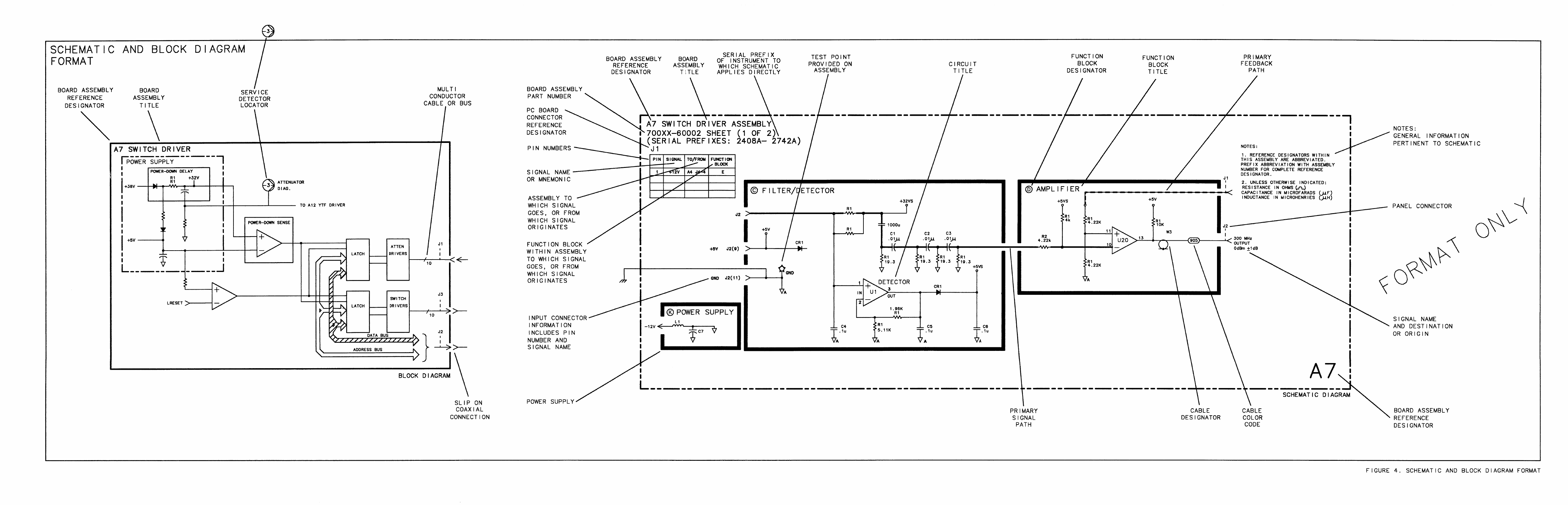
- Figure 4. Schematic and Block Diagram Format
- Schematic Symbols for Digital Integrated Circuits
- Overall Troubleshooting
- Analog Troubleshooting
- Digital Troubleshooting
- A5
- A6
- A6A3
- A6A7/A6A5/A6A8
- A6A7 YIG-Tuned Mixer (YTX) Current Driver, Circuit Description
- A6A8 YIG-Tuned Mixer (YTX), A6A5 Amplifier/Coupler/Load Unit (ACLU), Circuit Description
- A6A5 Amplifier/Coupler/Load Unit (ACLU) Replacement
- A6A7 YTX Current Driver Replacement
- A6A8 YTX Replacement
- A6A7 YTX Current Driver, Block Diagram
- A6A7 YTX Current Driver Component Locations, 85660-60128
- A6A7 YIG-Tuned Mixer (YTX) Current Driver, Schematic Diagram
- A6A9
- A6A10
- A6A10 Miscellaneous Bias/Relay Driver, Circuit Description
- A6A10 Miscellaneous Bias/Relay Driver, Block Diagram
- A6A10 Miscellaneous Bias/Relay Driver Component Locations,85660-60180
- A6A10 Miscellaneous Bias/Relay Driver Component Locations85660-60322
- A6A10 Miscellaneous Bias/Relay Driver,Schematic Diagram
- A6A10 Miscellaneous Bias/Relay Driver, Schematic Diagram
- A6A11
- A6A12
- A6A12 YIG-Tuned Mixer (YTX) Driver, Circuit Description
- A6A12 YTX Driver Component Locations, 85660-60366, 85660-60013, 85660-60235
- A6A12 YTX Driver, Block Diagram
- A6A12 YIG-Tuned Mixer (YTX) Driver, Schematic Diagram
- A6A12 YTX Driver, Schematic Diagram
- A6A12 YTX Driver, Schematic Diagram
- A6A13 RF Module Motherboard Component Locations, 85660-60014
- A6A13 RF Module Motherboard, Interconnect Diagram
- A7
- A7A1
- A7A2
- A7A3
- A7A4
- A7A4 M/N Output, Circuit Description
- A7A4 M/N Output, Troubleshooting
- A7A4A1A2 M/N VCO Board Component Locations, 85660-60018
- A7A4A2 M/N Output Board Component Locations, 85660-60192
- A7A4A2 M/N Output Board Component Locations, 85660-60239
- A7A4A2 M/N Output Board Component Locations, 85660-60266
- A7A4 M/N Output, Block Diagram
- A7A4 M/N Output, Schematic Diagram
- A7A4 M/N Output, Schematic Diagram
- A7A5 Reference Motherboard Component Locations, 85660-20020
- A7A5 M/N-Reference Motherboard, Interconnect Diagram
- A7A5 M/N-Reference Motherboard,Interconnect Diagram
- A8/A9
- A10
- A10A1
- A10A2
- A10A3
- A10A4
- A10A5
- A10A6
- A10A6 Phase Lock Loop 2 (PLL2) Phase Detector, Circuit Description
- A10A6 PLL2 Phase Detector Component Locations, 85660-60130, 85660-60229
- A10A6 PLL2 Phase Detector Component Locations, 85660-60254
- A10A6 PLL2 Phase Detector Component Locations, 85660-60276
- A10A6 PLL2 Phase Detector, Schematic Diagram
- A10A6 PLL2 Phase Detector, Schematic Diagram
- A10A6 PLL2 Phase Detector, Schematic Diagram
- A10A7
- A10A8
- A11
- A11A4
- A11A5
- A12
- A12 Front-Panel Interface, Circuit Description
- A12 Front-Panel Interface Extender Board, Schematic Diagram
- A23 Motherboard Instrument Bus, Interconnect Diagram
- A12 Front-Panel Interface, Schematic Diagram
- A12 Front-Panel Interface, Schematic Diagram
- A12 Front-Panel Interface Component Locations, 85660-60211, 85660-60246, 85660-60290
- A12 Front-Panel Interface, Schematic Diagram
- A12 Front-Panel Interface, Schematic Diagram
- A15
- A15 Controller,Circuit Description
- A15 Controller,Troubleshooting
- A15 Controller, Block Diagram
- A15 Controller Board Assembly, Component Locations: 85660-60209
- A15 Controller, Component Locations, 85660-60245
- A23 Motherboard Instrument Bus, Interconnect Diagram
- A15 Controller, Schematic Diagram (1 of 3)
- A15 Controller, Schematic Diagram (2 of 3)
- A15 Controller, Schematic Diagram (3 of 3)
- A15 Controller, Schematic Diagram (1 of 3)
- A15 Controller, Schematic Diagram (2 of 3)
- A15 Controller, Schematic Diagram (3 of 3)
- A16
- A16 Scan Generator, Circuit Description
- Scan Time Register and Sweep Time DAC
- Ramp Generator
- Ramp Control Logic, Switch Driver, Ramp Reset Switch, and Ramp Reset Amplifier
- Frequency Span Register and Span Width DAC
- Integer Number Attenuator, Band Decoder, Switch Drivers
- Aux Out Register, Aux Out Offset DAC, and Aux Out Amplifier
- Voltage Reference
- Scan Test Circuit
- Scan Reset Amplifier
- A16 Scan Generator, Simplified Block Diagram
- A16 Scan Generator, Block Diagram (1 of 2)
- A16 Scan Generator, Block Diagram (2 of 2)
- A16 Scan Generator Board Assembly, Component Location
- A16 Scan Generator Board Assembly, Component Locations
- A16 Scan Generator, Schematic Diagram
- A16 Scan Generator, Schematic Diagram
- A16 Scan Generator, Schematic Diagram
- A16 Scan Generator, Schematic Diagram
- A16 Scan Generator, Circuit Description
- A17
- A18
- A19
- A20
- A21
- A22
- A22 10 MHz Frequency Standard
- A22 10 MHz Frequency Standard Replacement
- A22A1 Frequency Standard Regulator Component Locations, 5062-1909, 5062-4837
- A22 10 MHz Frequency Standard Regulator, Schematic Diagram
- A23 Motherboard Component Locations, 85660-60041
- A23 Motherboard Component Locations, 85660-60368
- A23 Motherboard Instrument Bus, Interconnect Diagram
- A23 Motherboard, Interconnect Diagram
- A23 Motherboard, Interconnect Diagram
- A22 10 MHz Frequency Standard
- General Parts Listing
- Major Assembly and Component Locations

Troubleshooting
and
Repair
Manual
Volume 1
HP
85660B
Spectrum
Analyzer
RF
Section
ri!ia
HEWLETT
PACKARD
HP Part No. 85660-90210 Microfiche Part No. 85660-90211
Printed in USA December 1990
@Copyright Hewlett-Packard Company 1990
All Rights Reserved. Reproduction, adaptation, or translation without prior written
permission is prohibited, except as allowed under the copyright laws.
1212 Valley House Drive, Rohnert Park, CA 94928-4999, USA

Certification
Hewlett-Packard Company certifies that this product met its published specifications at the
time of shipment from the factory. Hewlett-Packard further certifies that its calibration
measurements are traceable to the United States National Institute of Standards and
Technology, to the extent allowed by the Institute’s calibration facility, and to the calibration
facilities of other International Standards Organization members.
Warranty
This Hewlett-Packard instrument product is warranted against defects in material and
workmanship for a period of one year from date of shipment. During the warranty period,
Hewlett-Packard Company will, at its option, either repair or replace products which prove to
be defective.
For warranty service or repair, this product must be returned to a service facility designated
by HP. Buyer shall prepay shipping charges to HP and HP shall pay shipping charges to
return the product to Buyer. However, Buyer shall pay all shipping charges, duties, and taxes
for products returned to HP from another country.
HP warrants that its software and firmware designated by HP for use with an instrument
will execute its programming instructions when properly installed on that instrument. HP
does not warrant that the operation of the instrument, or software, or firmware will be
uninterrupted or error-free.
Limitation of Warranty
The foregoing warranty shall not apply to defects resulting from improper or inadequate
maintenance by Buyer, Buyer-supplied software or interfacing, unauthorized modification or
misuse, operation outside of the environmental specifications for the product, or improper
site preparation or maintenance.
NO OTHER WARRANTY IS EXPRESSED OR IMPLIED. HP SPECIFICALLY
DISCLAIMS THE IMPLIED WARRANTIES OF MERCHANTABILITY AND FITNESS
FOR A PARTICULAR PURPOSE.
Exclusive Remedies
THE REMEDIES PROVIDED HEREIN ARE BUYER’S SOLE AND EXCLUSIVE
REMEDIES. HP SHALL NOT BE LIABLE FOR ANY DIRECT, INDIRECT, SPECIAL,
INCIDENTAL, OR CONSEQUENTIAL DAMAGES, WHETHER BASED ON
CONTRACT, TORT, OR ANY OTHER LEGAL THEORY.
Assistance
Product maintenance agreements and other customer assistance agreements are available for
Hewlett-Packard products.
For any assistance, contact your nearest Hewlett-Packard Sales and Service
Office.
. . .
iii
Safety Symbols
The following safety symbols are used throughout this manual. Familiarize yourself with each
of the symbols and its meaning before operating this instrument.
Caution
u
The caution sign denotes a hazard. It calls attention to a procedure which,
if not correctly performed or adhered to, could result in damage to or
destruction of the instrument. Do not proceed beyond a caution sign until the
indicated conditions are fully understood and met.
Warning
Q
The warning sign denotes a hazard. It calls attention to a procedure which,
if not correctly performed or adhered to, could result in injury or loss of life.
Do not proceed beyond a warning sign until the indicated conditions are fully
understood and met.
General Safety Considerations
Warning
Before this instrument is switched on, make sure it has been properly grounded
9
through the protective conductor of the ac power cable to a socket outlet
provided with protective earth contact.
Any interruption of the protective (grounding) conductor, inside or outside
the instrument, or disconnection of the protective earth terminal can result in
personal injury.
Warning
There are many points in the instrument which can, if contacted, cause personal
injury. Be extremely careful.
Any adjustments or service procedures that require operation of the instrument
with protective covers removed should be performed only by trained service
personnel.
Caution
Before this instrument is switched on, make sure its primary power circuitry
has been adapted to the voltage of the ac power source.
Failure to set the ac power input to the correct voltage could cause damage to
the instrument when the ac power cable is plugged in.
iv

Contents
Volume 1
General Information
Overall
Troubleshooting
Analog
Troubleshooting
Digital
Troubleshooting
A5 Front Panel
through A8
Rectifier/AS Power
Line Module
Volume 2
A10 20/30
Synthesizer through
A23 Motherboard
General Parts Listing
Major Assembly and
Comuonent Locations
General information on the contents of the manual, including storage,
shipment, and packaging.
Troubleshooting index, special messages, diagnostic functions, error
correction routine, sweep system block diagram and troubleshooting,
mnemonics listing, and spectrum analyzer overall block diagram.
Phase lock loop operation, start frequency tuning equations, and phase
lock troubleshooting.
Instrument preset checks, digital storage verification, and RF digital
troubleshooting block diagram.
Service sheets containing circuit descriptions, troubleshooting
information (if applicable), replacement procedures (if applicable),
replaceable parts lists, parts identification (if applicable), block
diagrams, component locations, and schematic diagrams.
Service sheets containing circuit descriptions, troubleshooting
information (if applicable), replacement procedures (if applicable),
replaceable parts lists, parts identification (if applicable), block
diagrams, component locations, and schematic diagrams.
Replaceable parts information, reference designations and
abbreviations, manufacturer’s code list, RF miscellaneous parts list,
RF assemblies parts list, and instrument parts identification.
RF section major assembly and component locations.
Contents 1

General
Information
Introduction
This volume of the Troubleshooting and Repair Manual contains information for the
troubleshooting and repair of the RF Section of the instrument. This information is combined
in service sheets and indexed with tabs for quick reference. Also contained in this volume
are overall troubleshooting information and illustrations of the instrument useful in isolating
failures to the RF or IF-Display Section
Instruments Covered by This Manual
This Troubleshooting and Repair manual contains information for the servicing of all
HP 85660B RF Sections with serial number prefixes of 2410A and above. The assemblies of
the HP 8566AB Retrofit Kit (HP 8566A to HP 8566B Retrofit Kit) are also covered in this
manual. The following HP 85660B RF Sections Options are covered in this manual.
n Option 001
(75fl
Input)
n Option 400 (400 Hz Operation)
n Option 462 (Impulse Bandwidths)
Changes that are made to the HP 85660B after the printing of this manual will be included in
an update supplement.
The HP 85660B RF Section is used with the HP 85662A IF-Display Section as the HP 8566B
Spectrum Analyzer. The HP 85660B RF Section is used with the HP 85662A Option 462
IF-Display Section as the HP 8566B Option 462 Spectrum Analyzer.
Service Sheets
The service sheets in this manual are organized in alphanumeric order and are indexed with
tabs to make it easy to locate a specific service sheet. Each of the service sheets contain the
following information:
w
Circuit Description (where practical)
n Replacement Procedure (where practical)
w
Troubleshooting Hints (where practical)
w
Replaceable Parts List
n Component Location Illustration
w
Parts Identification (where practical)
n Block Diagram (where practical)
General Information 1

n Schematic Diagram
Replacement Procedures
Replacement procedures are included for use in removing and replacing assemblies for repair.
They are located in the following sections:
w
A5 Front Panel
Front Panel Removal and Repair
w
A6 RF Module
A6 RF Module Replacement
A6Al
Coaxial Switch and A6A17 300 MHz BPF Replacement
A6A2 RF Attenuator Replacement
A6A4 Second Converter Replacement
A6A6 First Converter Replacement
A6A15 3.6 GHz BPF, A6A16 1.5 GHz
LPF, and A6A18 LPF Replacement
n A6A3 Last Converter
A6A3 Last Converter Replacement
H
A6A7 YTX Current
Driver/A6A5
ACLU/A6A8 YTX
A6A5 Amplifier/Coupler/Load Unit
(ACLU) Replacement
A6A7 YTX Current Driver Replacement
A6A8 YTX Replacement
w
A7M/N-Reference
A7 M/N-Reference Replacement
H
A8 Rectifier/A9 Power Line Module
RF Section Internal Fuse Replacement
Transformer Replacement
Power Transistor Replacement
n All YTO Loop
All YTO Loop and
AllA3
YTO
(2.0 to 6.2 GHz Oscillator) Replacement
n Al7 Positive Regulator
RF Section Internal Fuse Replacement
n Al8 Negative Regulator
RF Section Internal Fuse Replacement
2 General Information

Major Assembly and Component Locations
Major assembly and component location illustrations for the RF Section are located at the
rear of this manual.
Troubleshooting
Troubleshooting information for the RF Section is divided into three levels as follows:
W
Instrument Level
Spectrum Analyzer Overall Troubleshooting
w
Section Level
RF Section Analog Troubleshooting
RF Section Digital Troubleshooting
A6 RF Module
A7 M/N-Reference/A22 10 MHz Frequency Standard
A10
20/30
Synthesizer
All YTO Loop
n Assembly Level
Most assemblies have troubleshooting hints immediately following circuit descriptions.
Troubleshooting information is also located on assembly level block diagrams, notes, and
schematics.
All assemblies are indexed by tab except for the ones listed below. The index tab they can be
found under is also listed.
Table 1. Assembly Locations
Assembly Location
A24
I
General Parts Listing
I
Tl
A8 Rectifier/AS Power Line Module
Printed Circuit Board Edge Connector Contact Cleaning
Materials
w
Lint-free cloth or equivalent (HP Part Number 9310-0039, Check Digit 3).
w
Solution of 80% electronics-grade isopropyl alcohol and 20% water.
w
Static-free work station.
Procedure
1. Dampen the cloth with the alcohol and water solution and scrub the edge connector
contacts vigorously, using a circular motion. Polish one side of the board at a time until
the contacts shine, keeping the cloth damp to dissolve contaminants and reduce static
electricity.
General Information 3

2. Using a clean cloth, dry the contacts by wiping from their inside to outside edge. This
prevents particles from building up on the contact edges.
Caution
9
Do not use erasers to clean the edge connectors. They cause microscopic
damage to the contact surface, removing the thin gold plating and exposing
the nickel underplating, which eventually corrodes. Erasers also leave a film on
the contact and generate static electricity.
Do not use paper of any kind to clean the edge connector contacts. Paper or
lint particles left on the edge contact surface can cause intermittent electrical
connections.
Do not touch contact or trace surfaces with bare hands. Always handle the
board by its edges.
HP-IB Address Selection
The HP-IB address for the HP 8566B is preset at the factory by means of a five-segment
binary switch located on the Al5 Controller Assembly. This switch is set to the binary
number 11111 which corresponds to a decimal equivalent of 31. The number 31 is a special
instruction code that commands the instrument to use the last input address stored in
memory. This stored HP-IB address is ASCII 2R (d
ecimall
18) and determines the address to
be used on “power up.”
The HP-IB address may be changed to any of the addresses listed in Table 2 by resetting the
HP-IB
address
switch to correspond to the binary equivalent of the desired ASCII character
or decimal value as indicated in the table. The five-segment switch is illustrated in Figure 1
and is shown in its preset position (decimal 31).
4 General Information

Table 2. Cross-Reference Between ASCII, Decimal, and Binary Address
Codes
ASCII Character Decimal Value 5-Bit Binary Equivalent
@ SP
00
00000
A
!
01
00001
B
”
02
00010
C
#
03
00011
D
$
04 00100
E
%
05
00101
F &
06
00110
G
’
07 00111
H ( 08
01000
I
>
09
01001
J
*
10
01010
K +
11
01011
L
’
12
01100
M
-
13
01101
N
.
14
01110
0
/
15
01111
P
0
16
10000
Q
1
17
10001
R
2
18
10010
S
3
19
10011
T
4 20
10100
U
5
21
10101
V
6
22
10110
W
7
23
10111
X
8
24
11000
Y
9
25
11001
Z
26
11010
[
;
27
11011
\
< 28
11100
]
=
29
11101
?
>
30
11110
General Information 5
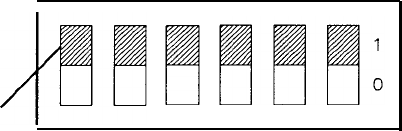
A6 A5 A4 A3 A2 Al
I
Switch in
Down Position
= Logic 1
Indicates Switch
in Down Position
Figure 1. HP-IB Address Switch (Shown in Factory Preset Position)
The HP-IB address may also be changed from the front panel or programmed via a controller
using a special shift key function (KSP). This address remains in effect as long as the
instrument memory has power from either the ac line or the internal battery. However, if
this stored address is lost, the default address is the factory preset decimal 18 (ASCII 2R).
For additional information on the HP-IB address, refer to the Operating and Programming
Manual.
Storage and Shipment
Environment
The instrument may be stored or shipped in environments within the following limits:
Temperature . . . . . . . . . . . . . . . . . . .
. . . . . . . . . . . . . . . . . . . . . . . . . . . . . . . . . .
-40°C to +75°c
Humidity. . . . . . . . . . . . . . . . . . . . . . . . . . . . . . . . . . . . . . . . . . . ...5% to 90% at 0°C to 40°C
Altitude . . . . . . . . . . . . . . . . . . . . . . . . . . . . . . . . . . . . . . . . . . . . . . . . . . . . . .Up to 15,240 meters
(50,000 feet)
The instrument should be protected from temperature extremes which might cause
condensation within the instrument.
Original Packaging
It is recommended that the original factory packaging materials be retained for use
when shipping the instrument. If original packaging material cannot be retained,
packaging materials identical to those used in factory packaging are available through the
Hewlett-Packard offices. Part numbers and descriptions of the packaging materials are listed
in Figure 2.
The combined weight of the two instrument sections is approximately 50 kg (112 lbs).
Because of the weight involved, do not package the instrument sections fastened together as
one unit. The instrument sections must be separated and packaged in separate containers.
The quantity of packaging materials in Figure 2 is for only one instrument section.
If the instrument is being returned to Hewlett-Packard for servicing, attach a tag to each
carton indicating the type of service required, return address, model number, and full serial
number. For your convenience, a supply of tags is included at the end of this section. Also,
mark each container FRAGILE to assure careful handling. In any correspondence, refer to the
instrument by model number and full serial number.
6 General Information
Other Packaging
If it is necessary to use packaging materials other than the type used in original factory
packaging, the following general instructions should be followed.
1. Separate the two instrument sections and wrap each in heavy paper or plastic.
2. Place the instrument sections in separate containers with 8 to 10 cm (3 to 4 inches) of
shock-absorbing material around all sides to provide firm cushioning and prevent movement
inside the container. Protect front panels with cardboard. Double-wall corrugated cartons
of 125 kg (275 lb) bursting strength are sufficient for shipping containers.
3. Seal each container securely and, if shipping to a Hewlett-Packard office or service center,
attach a tag to each container indicating the type of service required, return address, model
number and full serial number. For your convenience, a supply of tags is included at the
end of this section.
4. Mark each container FRAGILE to assure careful handling.
General Information 7
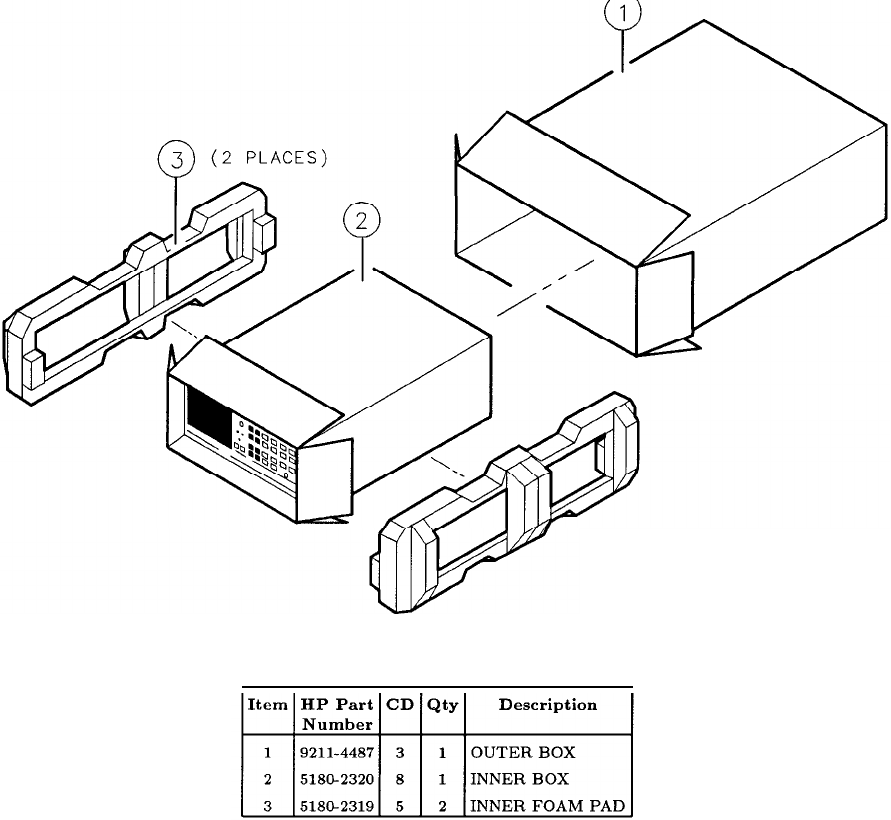
NOTE
Front handles must be
mounted for shipment.
Figure 2. Packaging for Shipment Using Factory Packaging Materials
Recommended Test Equipment
A list of recommended test equipment is contained in the HP 8566B Performance Tests
and Adjustments Manual (HP Part Number
08566-90148).
This list includes all of the
equipment that is necessary to perform the adjustments and tests of the HP 8566B. The List
of Recommended Test Equipment recommends a model number for each piece of equipment
needed and contains minimum specifications so that other equipment may be substituted for
the recommended model.
8 General Information
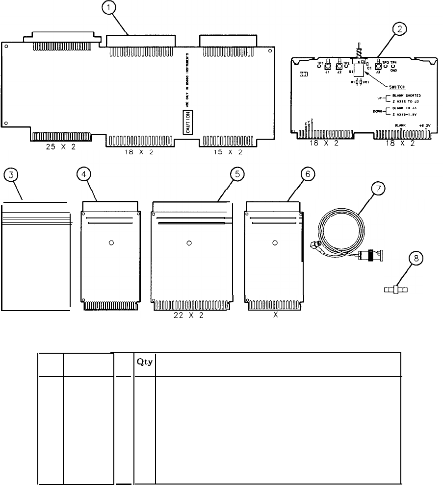
0
300000000000000000
18 X 2 25 X 2
Item HP Part
Number
1
85660-60114
2
85662-60088
3 08505-60042
485680-60034
5
08565-60107
6
08505-60041
7
85680-60093
8
1250-0669
CD
-
5
4
8
2
8
7
3
9
-
0
I
8
2
lj
~000000000000000~
15
x
2
Qty
Description
1
EXTENDER BOARD: Al2 RF SECTION INTERFACE
1
PC BOARD: DISPLAY ADJUSTMENT TEST
2
EXTENDERBOARD:
36
CONTACTS;
2
ROWS
OF
18
2
EXTENDERBOARD:
50
CONTACTS;
2
ROWS
OF
25
2
EXTENDERBOARD:
44
CONTACTS;
2
ROWSOF
22
1
EXTENDERBOARD:
30
CONTACTS;
2
ROWS
OF
15
2
CABLE: 4-FOOT LONG; BNC TO SMB SNAP-ON
1
ADAPTER: SMB SNAP-ON MALE TO SMB SNAP-ON MALE
Figure 3. Service Accessories, HP Part Number 08566-60001
General Information 9

This page intentionally left blank.
10
General Information
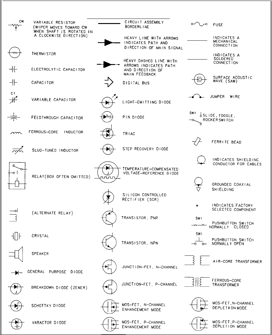
GRAPHIC SYMBOLS USED ON SCHEMATIC AND BLOCK DIAGRAMS
BASIC COMPONENT SYMBOLS
VARIABLE
RESISTOR
CIRCUIT
ASSEMBLY
(WIPER
Moves
TOWARD
cw BORDERLINE
‘=‘-b=
FUSE
WHEN
SHAFT
IS
ROTATED
IN
A
CLOCKWISE
DIRECTION)
HEAVY
LINE
WITH
ARROWS
INDICATES
A
INDICATES
PATH
AND
MECHANICAL
DIRECTION
OF
MAIN
SIGNAL CONNECTION
THERMISTOR
it
ELECTROLYTIC
CAPACITOR
-11
CAPACITOR
2
VARIABLE
CAPACITOR
I_
I-
FEEDTHROUGH
CAPACITOR
-
FERROUS-CORE
INDUCTOR
+
SLUG-TUNED
INDUCTOR
3
fr
-o-
-63
HEAVY
DASHED
LINE
WITH
ARROWS
INDICATES
PATH
AND
DIRECTION
OF
MAIN
FEEDBACK
DIGITAL
BUS
INDICATES
A
SOLDERED
CONNECTION
-@-
SURFACE
ACOUSTIC
WAVE
(SAW)
A
JUMPER
WIRE
LIGHT-EMITTING
DIODE
PIN
DIODE
SW1
<
;k;-:k
;c”,;‘,,
OR
TRIAC
-@
FERRITE
BEAD
STEP
RECOVERY
DIODE
@
TEMPERATURE-COMPENSATED
RELAY(BOX
OFTEN
OMITTED)
J
VOLTAGE-REFERENCE
DIODE
@
SILICON
CONTROLLED
RECTIFIER
(SCR)
-4
3
(ALTERNATE
RELAY)
@
TRANSISTOR.
PNP
-1rlt
CRYSTAL
TRANSISTOR,
NPN
4
SPEAKER
@
JUNCTION-FET.
N-CHANNEL
+
GENERAL
PURPOSE
DIODE
fa
e-
BREAKDOWN
DIODE
(ZENER)
63
JUNCTION-FET.
P-CHANNEL
J
49
SCHOTTKY
DIODE
@
MOS-FET.
N-CHANNEL
ENHANCEMENT
MODE
-B
VARACTOR
DIODE
it-
@
MOS-FET.
P-CHANNEL
ENHANCEMENT
MODE
Q
INDICATES
SHIELDING
CONDUCTOR
FOR
CABLES
8
GROUNDED
COAXIAL
SHIELDING
*
INDICATES
FACTORY
SELECTED
COMPONENT
SW1
PUSHBUTTON
SWITCH
4
c
NORMALLY
CLOSED
SW1
-L-
PUSHBUTTON
SWITCH
a*
NORMALLY
OPEN
Ix
AIR-CORE
TRANSFORMER
FERROUS-CORE
TRANSFORMER
MOS-FET,N-CHANNEL
DEPLET
I
ON MODE
MOS-FET.P-CHANNEL
DEPLETION
MODE
Figure 5. Graphic Symbols (1 of 2)
General Information 11
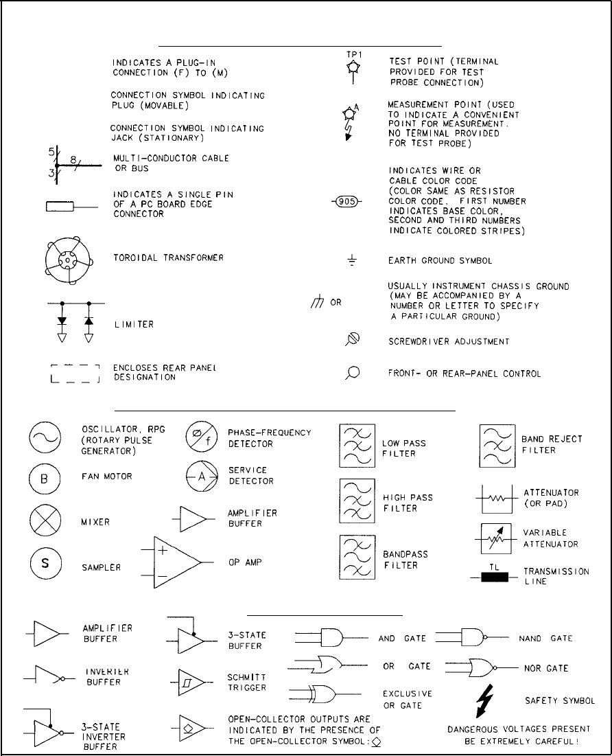
GRAPHIC SYMBOLS USED ON SCHEMATIC AND BLOCK DIAGRAMS
BASIC COMPONENT SYMBOLS (CONTINUED)
-c-c--
INDICATES
A
PLUG-IN
CONNECTION
(F)
TO
(M)
CONNECTION
SYMBOL
INDICATING
PLUG
(MOVABLE)
CONNECTION
SYMBOL
INDICATING
JACK
(STATIONARY)
MULTI-CONDUCTOR
CABLE
OR
BUS
INDICATES
A
SINGLE
PIN
OF
A
PC
BOARD
EDGE
I
CONNECTOR
TOROIDAL
TRANSFORMER
J-5
LIMITER
F--T
ENCLOSES
REAR
PANEL
L--J
DESIGNATION
0
0
B
63
0
S
TPl
48
A
B
I
:
/h
OR
6
PD
P
TEST
POINT
(TERMINAL
PROVIDED
FOR
TEST
PROBE
CONNECTION)
MEASUREMENT
POINT
(USED
TO
INDICATE
A
CONVENIENT
POINT
FOR
MEASUREMENT.
NO
TERMINAL
PROVIDED
FOR
TEST
PROBE)
INDICATES
WIRE
OR
CABLE
COLOR
CODE
(COLOR
SAME
AS
RESISTOR
COLOR
CODE.
FIRST
NUMBER
INDICATES
BASE
COLOR,
SECOND
AND
THIRD
NUMBERS
INDICATE
COLORED
STRIPES)
EARTH
GROUND
SYMBOL
USUALLY
INSTRUMENT
CHASSIS
GROUND
(MAY
BE
ACCOMPANIED
BY
A
NUMBER
OR
LETTER
TO
SPECIFY
A
PARTICULAR
GROUND)
SCREWDRIVER
ADJUSTMENT
FRONT-
OR
REAR-PANEL
CONTROL
COMMONLY USED ASSEMBLY AND CIRCUIT SYMBOLS
OSCILLATOR,
RPG
(ROTARY
PULSE
GENERATOR)
FAN
MOTOR
MIXER
SAMPLER
PHASE-FREQUENCY
DETECTOR
SERVICE
DETECTOR
AMPLIFIER
BUFFER
OP AMP
LOW
PASS
FILTER
HIGH
PASS
FILTER
BANDPASS
FILTER
BAND
REJECT
FILTER
ATTENUATOR
(OR
PAD)
fi!+
VARIABLE
ATTENUATOR
TL-
LINE
TRANSMISSION
BASIC LOGIC SYMBOLS
AMPLIFIER
BUFFER
3B;;;zE
>
AND
GATE
a
NAND
GATE
%
OR
GATE
B
NOR
GATE
INVtHltH
-
BUFFER
-D-
l7
SCHM
I
TT
SAFETY
SYMBOL
,I
TRlGGER
-a
;F;;;TE
u-
OPEN-COLLECTOR
OUTPUTS
ARE
3-STATE
-
INVERTER
Q
INDICATED
BY
THE
PRESENCE
OF
DANGEROUS
L
‘OLTAGES
PRESENT
RllFFFR
THE
OPEN-COLLECTOR
SYMBOL:G
BE
EXTREMELY
CAREFUL!
Figure 5. Graphic Symbols (2 of 2)
12 General Information
Schematic Symbols for Digital Integrated Circuits
The following is a guide to the symbols used for digital or logic ICs in this manual. The
symbology is based upon American National Standard ANSI Y32.14, Graphic Symbols for
Logic Diagrams (Two-State Devices), but does not strictly follow the standard. Figure 6
should be consulted for the explanation of digital IC symbols used in Sections VIII and IX.
Definitions
Logic Element. The part or parts of a logic device symbol having a well-defined logic function
(OR, AND, FLIP-FLOP, and so on) and one or more outputs. The inputs of a logic element
may be data or control inputs; the outputs are data outputs.
Control Block. The part of a logic device symbol to which all logic lines common to a group of
logic elements are connected. Lines connected to a control block are control lines.
Function Label. The notation within a logic device symbol that denotes its overall logic
function (counter, shift register, multiplexer, and so on)
Line Label. The symbol or abbreviation associated with an output or input line that defines
the action of the line.
Indicator Symbol. A symbol associated with an input or output line which defines the active
state or special characteristics of the line.
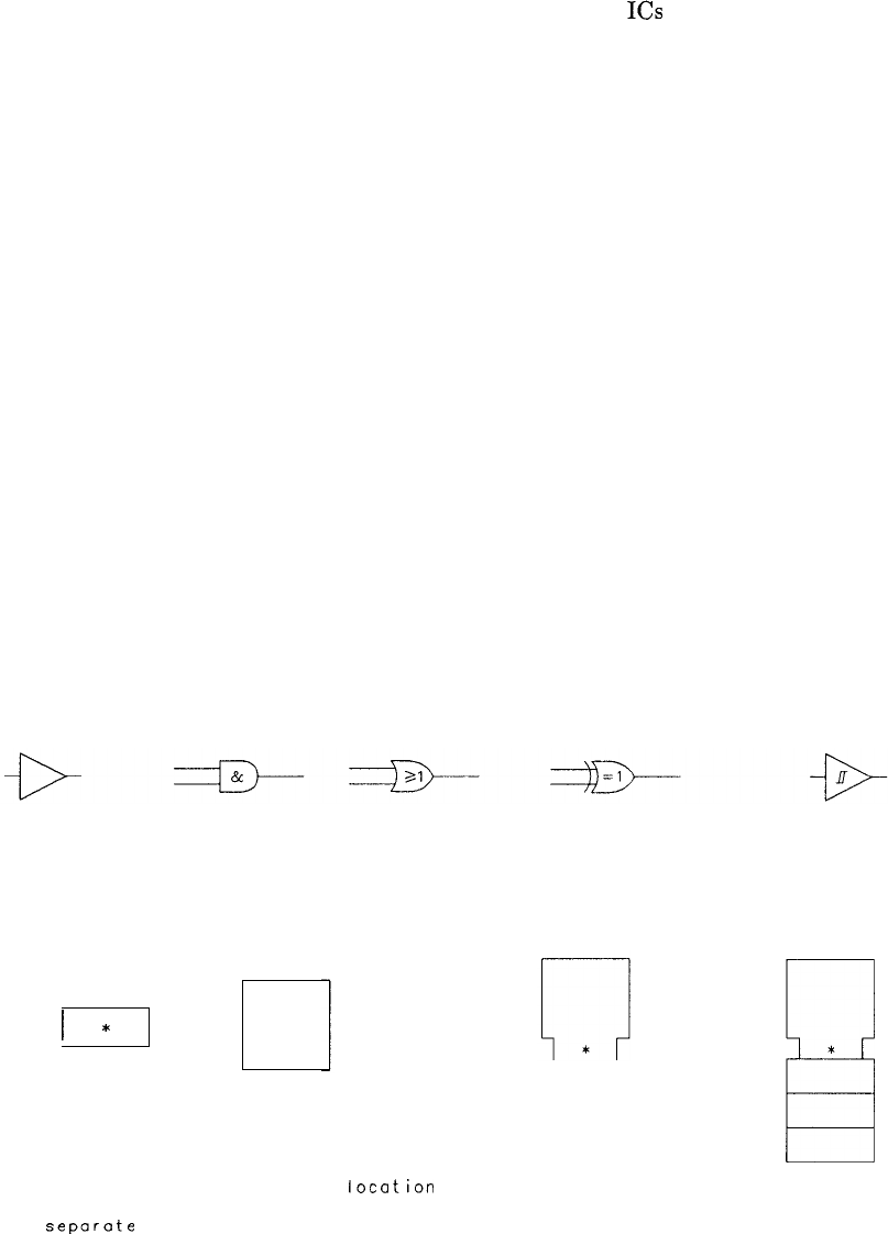
Basic Logic Symbols
Dist nctive-Shape Symbols
Amplifier/Buffer AND Gate OR Gate EXCLUSIVE OR Gate Schmitt Trigger
Rectangular Symbols
General Logic Element
I
I
*
1
*
Logic Elements with
Control Block Comnon Control Block
*
El
NOTE :
An asterisk indicates the
location
of the function label. If elements
sharing control lines are widely separated, each element will have a
separate
control block.
Figure 6. Schematic Symbols for Digital Integrated Circuits (1 of 7)
General Information 13
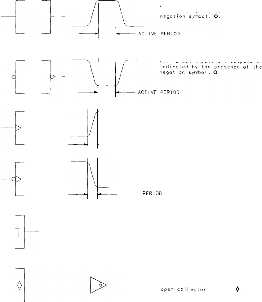
INDICATOR SYMBOLS (positive logic assumed)
ACTIVE-HIGH inputs and outputs are
indicated by the absence of the
ACTIVE-LOW inputs and outputs ore
d
zl
EDGE-SENSTIVE (Dynamic) inputs are
indicated by the presence of the
dynamic input symbol, D.
-ACTIVE PERIOD
;;-
:k
ACTIVE
PERIOD
1
I-
TRAILING-EDGE ACTIVATED outputs are
indicated by the output delay
symbol, 1. These outputs become
active when the signal thot
initiates the change returns to its
original state (example: the
outputs of a J-K master-slave
flip-flop).
OPEN-COLLECTOR outputs are
indicated by the presence of the
open-co1
I
ector
symbo I,
0.
Figure 6. Schematic Symbols for Digital Integrated Circuits (2 of 7)
14 General Information
Note:
The logic negation symbol (0) 1a one gives no information about the actual voltage levels used
in a digital cirucit. For this reason the type of logic system (positive or negative) must be
specified. In this manual, unless otherwise noted on the schematic, the logic system is positive;
that is, the more positive voltage level is the HIGH or l-state and the less positive level is the
LOW or O-state.
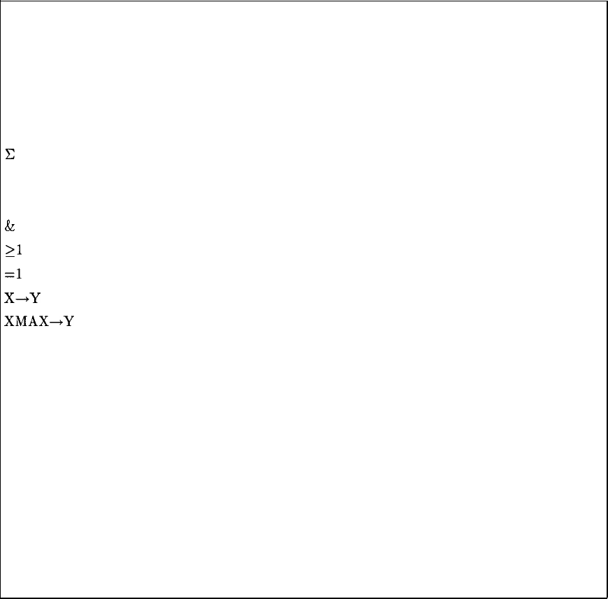
Function Labels
c
Adder
D Amplifier/Buffer
14 Monostable Multivibrator (One-Shot)
&
And Gate
21
Or Gate
=l
Exclusive or Gate
X-Y
Encoder, Decoder
XMAX+Y
Priority Encoder
greek symbol Schmitt Trigger
ALU Arithmetic and Logic Unit
CTR Counter
DEMUX Demultiplexer
FF Flip-Flop
MUX Multiplexer
RAM Random Access Memory
REG Register
ROM Read Only Memory
SAR Successive Approximation Register
SR Shift Register
Figure 6. Schematic Symbols for Digital Integrated Circuits (3 of 7)
General Information 15

Line Labels
+
+
+1
-1
=0,-l
=9,+1
=15,+1
An
c
D
Dn
EN
F
G
J
K
LD
PS
R
RD
S
SEL
SER
T
WR
Yn
3-ST
(placed by
function label)
Shift Left (or up)
Shift Right (or down)
Count Up
Count Down
Borrow Output
Carry Output (Decimal Counter)
Carry Output (Binary Counter)
nth Address Bit (ROM, RAM)
Clock Input
Data or Delay Input (Flip-Flop)
nth Data Bit Input
Enable
3-State Enable Input (See “Dependency”)
Gating Input (See “Dependency”)
J-K Flip-Flop J Input
J-K Flip-Flop K Input
Load Enable Input (Synchronous)
Preset Input (Asynchronous)
Reset or Clear Input
Read Enable Input (RAM, ROM)
Set Input
Line or Function Select Input
Serial Data Input (Shift Register)
Trigger Input (Monostable)
Write Enable Input (RAM)
nth Data Bit Output or I/O
3-State
Figure 6. Schematic Symbols for Digital Integrated Circuits (4 of 7)
16 General Information
Notes
1. The suffix or subscript 0 denotes the least significant bit (LSB) of a data or address word.
2. Letters may be used to identify a line or logic element without indicating a specific logic
function. For example:
---A
---B
-C
MUX
O-
7---
l A
O-
l+---
l B
0
l---
l c
Triple Z-Channel Multiplexer
Letters are used to relate control
inputs to logic elements. The
numerals 0 and 1 indicate O-state
and l-state,respectively, and
relate the position of a “switch”
to the logic state of the corres-
ponding control line.
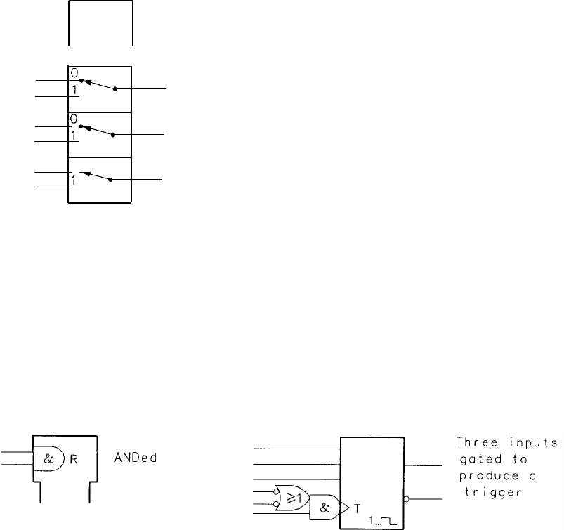
DEPENDENCY (G and F)
The dependency of inputs or outputs on an input is indicated with
gate symbols or the G line label. Gate symbols are often used when
the dependency exists between inputs. Two examples are:
1
Two inputs
ANDed
to
produce a
reset
Figure 6. Schematic Symbols for Digital Integrated Circuits (5 of 7)
General Information 17
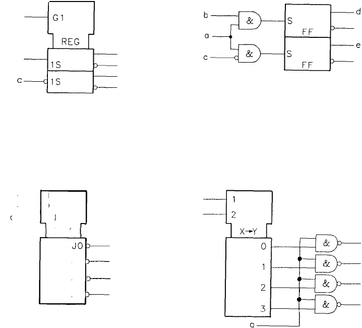
When the G label is used, the gating input is
labelled
with a G followed by a numeral or
letter. The line labels of the gated inputs or outputs are prefixed with the same numeral or
letter. Two examples are:
2-Bit Register
IC
Symbol Equivalent
a
Gl
REG
b
i
d
1s
C
IS
e
2-to-4 Line Decoder
-1
-2
a- GJ
X-Y
Jl
+
J2
h
J3
w
&
E
&
&
km-
I
-
I
I
Figure 6. Schematic Symbols for Digital Integrated Circuits (6 of 7)
18 General Information
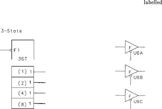
The F line label is used to indicate S-state logic. The S-state enable i:
F and numerals or letters are used as with the G label:
Counter with
3-State
Outputs 3-Stat
->c
4
Fl
-R
XT
CTR
(1)
l-
(2)
’
-
(4)
’
-
(8)
’
-
nput is
labelled
with an
e Buffers
F
I--i’-
U6A
Figure 6. Schematic Symbols for Digital Integrated Circuits (7 of 7)
Weighting of Input and Output Lines
The coding of multiplexers, demultiplexers, encoders, and decoders is shown by decimal
weighting. An example is the 2-to-4-line decoder shown on the previous page.
Weighting of Flip-Flops
When the position of a flip-flop in an array is significant (as in counters and shift registers),
the flip-flop is
labelled
with its decimal weight. An example is the “Counter with S-State
Outputs” shown above.
General Information 19

Overall
Troubleshooting
This chapter contains information that will help to identify the system of the spectrum
analyzer that is not operating correctly. Table 1, “Troubleshooting Index,” may be used to
locate troubleshooting information in the RF and IF Display Troubleshooting and Repair
Manuals. This chapter also describes the Special Messages that may be displayed on the CRT
and the Diagnostic Functions that are accessible from the front panel. The Error Correction
Routine and the Sweep System are also described in this chapter. The overall block diagram
of the HP 8566B is located at the end of this chapter.
Overall Troubleshooting 1

Table 1. Troubleshooting Index
Troubleshooting Information Tab Title or Location
Start Frequency Tuning Equations and RF Section Analog Troubleshooting
Phase Lock Block Diagram
Diagnostic Functions Spectrum Analyzer Overall
Troubleshooting
Digital Storage A3 Digital Storage Block Diagram
Display System Spectrum Analyzer Overall
Troubleshooting
Al Display Section Block Diagram
Error Correction Routine Spectrum Analyzer Overall
Troubleshooting
RF Section Digital (includes INSTR A3 Digital Storage Block Diagram
CHECK LEDs)
RF Section Digital Troubleshooting
Block Diagram
Al5 Controller
Special Messages Spectrum Analyzer Overall
Troubleshooting
Sweep System Spectrum Analyzer Overall
Troubleshooting
AlAl
Keyboard Al2 Front-Panel Interface
A3 Digital Storage Spectrum Analyzer Overall
Troubleshooting
A3 Digital Storage Block Diagram
A3Al
Trigger* Spectrum Analyzer Overall
Troubleshooting (Sweep System)
A3 Digital Storage Block Diagram
A3A2
Intensity Control* Al Display Section Block Diagram
A3 Digital Storage Block Diagram
A3A3
Line Generator* Al Display Section Block Diagram
A3 Digital Storage Block Diagram
A3A4
Memory Al Display Section Block Diagram
A3 Digital Storage Block Diagram
A3A5
Data Manipulator
A3A6
Main Control A3 Digital Storage Block Diagram
A3A7
Interface
* Troubleshooting information is also located behind the tab with this title.
Section
RF
RF
IF
RF
IF
RF
IF
RF
RF
RF
RF
RF
RF
IF
RF
IF
IF
IF
IF
IF
IF
IF
IF
2 Overall Troubleshooting

Table 1. Troubleshooting Index (continued)
Troubleshooting Information
A3A8
Analog-Digital-Converter*
A3A9
Track and Hold*
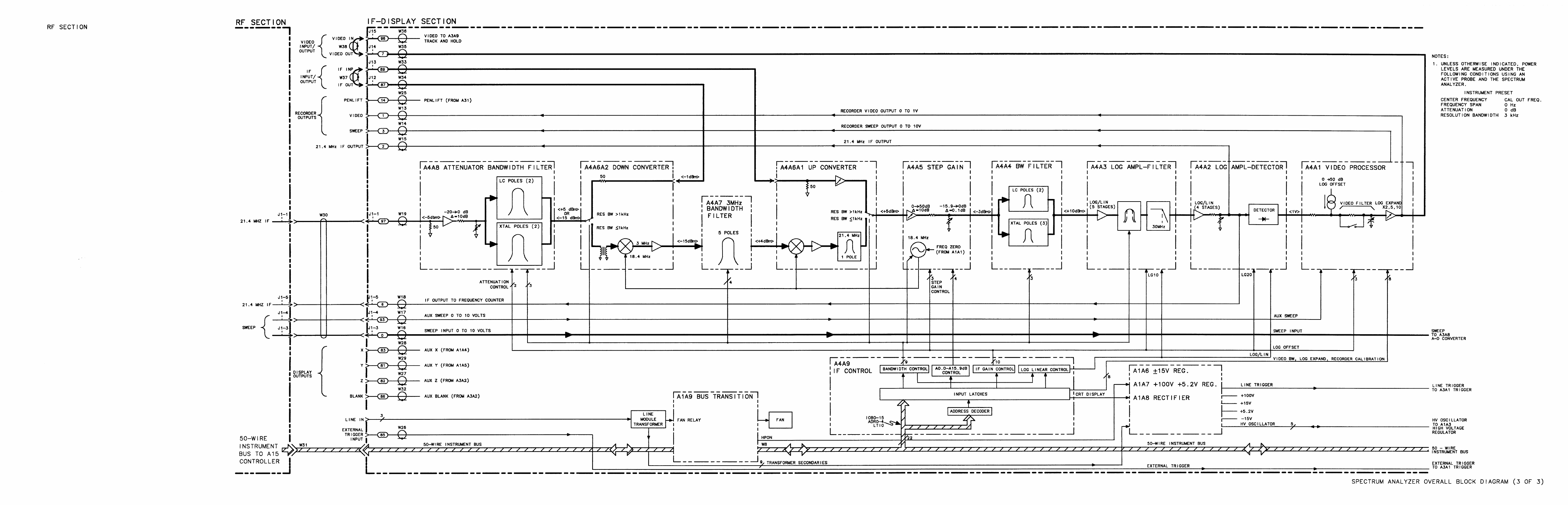
A4Al
Video Processor*
A4A2 Log Amplifier-Detector*
A4A3 Log Amplifier-Filter*
A4A4 Bandwidth Filter
A4A5 Step Gain*
A4A6 Down/Up Converter*
A4A7 3 MHz Bandwidth Filter
A4A8 Attenuator-Bandwidth Filter*
A4A9 IF Control*
Tab Title or Location
Spectrum Analyzer Overall
Troubleshooting (Sweep System)
Al Display Section Block Diagram
A3 Digital Storage Block Diagram
Spectrum Analyzer Overall
Troubleshooting
(Diagnostic Functions)
Al Display Section Block Diagram
A3 Digital Storage Block Diagram
Spectrum Analyzer Overall
Troubleshooting
(Error Correction Routine)
Section
RF
IF
IF
RF
IF
IF
RF
A5 Front Panel Al2 Front-Panel Interface
Al5 Controller
A6 RF Module
A7 M/N Loop Spectrum Analyzer Overall
Troubleshooting
A10
20/30
Synthesizer (Diagnostic Functions)
All YTO Loop
Al2 Front-Panel Interface* Spectrum Analyzer Overall
Troubleshooting (Sweep System)
Al5 Controller
Al5 Controller* Spectrum Analyzer Overall
Troubleshooting (Sweep System)
Al6 Scan Generator* Spectrum Analyzer Overall
Troubleshooting (Sweep System)
*
Troubleshooting information is also located behind the tab with this title.
RF
RF
RF
RF
RF
RF
RF
Overall Troubleshooting 3

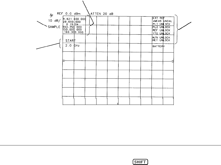
Special Messages
As a convenience to the operator and as an aid in servicing, eleven messages can appear in
the upper right corner of the CRT display. (Ten of these messages are shown in Figure 1.)
Five of the messages inform the operator of possible erroneous data from improper instrument
operation. The other six provide warnings of instrument malfunctions that must be repaired
for proper instrument operation.
A brief description of each message follows. The troubleshooting information listed is not
meant to be exhaustive. Refer to the appropriate Troubleshooting Block Diagram and
Troubleshooting Hints for more detailed information.
EXT REF
Indication to operator that the external frequency reference is selected.
MEAS
UNCAL
A warning to the operator that the amplitude/frequency data on the CRT is invalid because
the analyzer’s sweep speed is too fast for the selected bandwidth.
A warning to the operator that the analyzer settings displayed on the CRT have been changed
but the trace data has not been updated. This would occur, for example, when Trace A view
is selected and then Center Frequency is changed.
OVEN COLD
Indication that the frequency reference oven temperature is too low. There will be an oven
cold indication normally for about 10 minutes after the line power is initially applied to
the instrument. (The oven is powered and should stay warm as long as the instrument
is in STANDBY.) The time base HOVC (High = Oven Cold) signal is routed to the Al2
Front-Panel Interface for generation of this message.
BATTERY
A warning to the operator that the CMOS memory on the Al5 Controller has probably
lost the stored instrument states. The warning can only appear at instrument turn on. If it
appears, the instrument automatically reinitializes all the instrument states to the instrument
preset condition. The battery warning can be caused by a problem with the Al5 CMOS
memory power supply circuit. Performing the “long POP” instrument check (see RF Section
Digital Troubleshooting) erases the stored instrument states and causes a battery warning to
appear at instrument turn on. The HP-IB address is also lost. The battery warning can be
removed by pressing
[GHz’
and the HP-IB address restored by keying in
(jZiK)
(ZZKj
[desired address]
[jGiZi?Z).
4 Overall Troubleshooting

PLl
The
PLLl
Phase Lock Loop is unlocked. Items to check are:
n
AlOAl
-
Check signal out at
AlOAlJ3.
n AlOA2
-
Check signal in at AlOA2J2.
n
A10A3
-
Check signal out at AlOA3J3.
n AlOA4
-
Check signal out at AlOA4J2 and in at AlOA4J4.
PLL2
The PLL2 Phase Lock Loop is unlocked. Items to check are:
n AlOA5
-
Check signal out at AlOA5J3.
n AlOA6
-
Check
4
Det Out voltage at
AlOA6TP7.
n AlOA7
-
Check 500 kHz Reference at
AlOA7TP5
and divided output at
AlOA7TPl.
n AlOA8
-
Check VCO Tune output current at AlOA8J2.
REF UNLOCK
The 10 MHz Reference Loop is unlocked. Items to check are:
n OVEN COLD indicator on. This is normal operation.
n Cable W15 connected to rear-panel FREQ REFERENCE IN and OUT connectors.
w
Rear-Panel FREQ REFERENCE EXT/INT switch in proper position.
n
A7Al
and A7A2
-
Check 10 MHz out at
A7AlJ4.
YTO UNLOCK
The YTO Phase Lock Loop is unlocked. Items to check are:
1
A19
D/AConverter
n A20 Main Coil Driver
n A21 FM Coil Driver
n All YTO Loop
n Al6 Scan Generator
M/N UNLOCK
The M/N Phase Lock Loop is unlocked. Items to check are:
n A7A3
-
Check output at
A7A3Jl.
n A7A4
-
Check output at
A7A4Jl.
Overall Troubleshooting 5
HET UNLOCK
The RF Module Phase Lock Loop is unlocked. Items to check are:
n CAL OUTPUT
n A6A9
-
Check voltage at
A6A9J4.
n A6A4
-
Check 3.3 GHz output of A6A4.
FREQUENCY
DIAGNOSTICS BLOCK
TRACE
DETECT I ON
INDICATION
ACTIVE
FUNCTION
BLOCK
i/
SPECIAL
MESSAGES
BLOCK
I
I
START 2.0
GHz
STOP 22.0
GHz
RES BW 30
kHz
VBW
100
kHz
SWP
500
msec
Figure 1. CRT Locations of Special Messages and Diagnostic Function Indicators
Diagnostic Functions
The Diagnostic Functions are accessible through the blue
lsHlFTJ
key on the front panel.
Through their use it is possible to trace many instrument malfunctions back to the functional
block without removing any assemblies. They are also used in Performance Tests and
Adjustments as an aid in performing necessary adjustments. A summary of the Diagnostic
Functions follows. More information on their use can be found in the troubleshooting
procedures.
6 Overall Troubleshooting

Frequency Diagnostics
[SHIFT)
R1,~~b
REF
LVL)
(KM)
This function displays many of the internal frequency control parameters in the upper
left corner of the CRT display. (See Figure 1.) These parameters are the programmed
values determined by the Al5 Controller. For example, following an
C2-221,
a
@ZiJ
R
MKR~REF
LVL)
(KSR) might display the following values:
1.
2.321 400000
2.
30.000 000
3.
1 17 11
4.
184.545 455
5.
150.000 000
6.
160.300 000
Line 1 is the setting of the YTO Frequency for the selected START frequency.
Line 2 is the setting of the
20/30
SYNTHESIZER for the selected START frequency.
Line
3
contains three different numbers. The first is the band code number. The setting varies
from 0 for center frequencies below 2.5 GHz to 4 for center frequencies above 18.6 GHz. The
second number is the M number of the M/N loop. The third number is the N number of the
M/N Loop.
Line 4 indicates the frequency output of the M/N loop.
Line
5
indicates the frequency to which the PLL2 VCO has been tuned.
Line 6 shows the frequency to which the Controller has programmed the PLL3 VCO.
Lock Indicator Disable
A12TP2
Jumpered to
A12TP3
This function permits the analyzer to sweep at normal sweep rates ignoring any phase lock
flag indications. For example, if a YTO UNLOCK problem exists, the analyzer will sweep
slower since it spends most of its time trying to lock the YTO at center frequency during
retrace. By performing the phase lock inhibit, the analyzer does not waste time trying to lock
the YTO, so the front panel keys and display can be used as in normal operation. Note that
the displayed frequencies will probably not be accurate.
Trace Detection
Three different sampling modes are used by the analyzer in converting the video signal; these
are positive peak, negative peak, and sample. Normally the analyzer selects the proper mode
for each measurement, but these can be manually selected to verify proper operation. The
mode selected is indicated on the upper left side of the CRT display when under manual
control. (See Figure 1.) For example, a signal could be expanded to 2 dB/div to eliminate the
noise floor, and then by comparing a positive peak trace measurement, it can be determined
if the gains and offsets of the three modes are properly aligned. All three should appear the
same on a stable, noise-free signal. When in the noise, the positive peak should display the
highest noise peaks, negative peak mode should display the lowest noise levels, and sample
mode should display values between the positive and negative peaks.
[SHIFT)
Trace A
b[MAXHOLD)
(KSb)
displays positive peaks.
Overall Troubleshooting 7
@iZY) Trace A
dIVIEW)
(KSd)
displays negative peaks.
(SHIFT) Trace A
‘[B)
(KSe)
displays sampled data.
(S HIFT) Trace T Trace A(ksa)returns to the normal automatic detection modes and
removes the CRT indication.
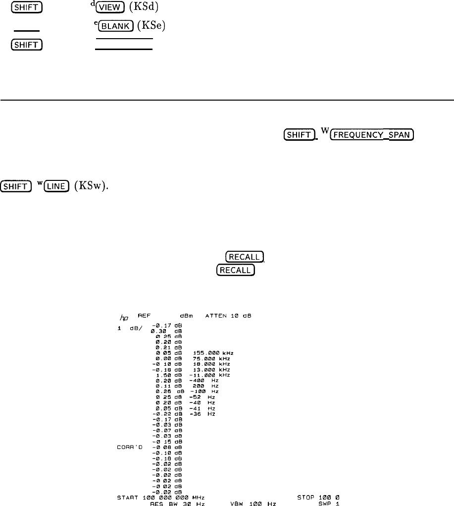
Error Correction Routine
The internal Error Correction Routine available by pressing
@iFi)
w[~~~~~~~~~
SPAN]
(KSW) is also useful as a diagnostic aid. If a malfunction causes the routine to stop, restart
it and note the control settings (RES BW,
ATTEN,
REF LEVEL,
LOG/LIN,
etc.) when
the failure occurred. If the routine runs, the correction factors can be displayed by pressing
(SHIFT]
“‘@
(KSw).
Figure 2 displays the data for a typical instrument. Table 2 gives the
parametric information, specifications and a place to start the troubleshooting procedure.
Caution must be exercised in interpreting the correction factor data. Wrong conclusions
can be reached by not understanding how the internal program runs. The program assumes
that the input signal level is -10.0
dBm.
Any error in this level translates to the correction
factors; therefore, the Amplitude Accuracy test
(RECALL]
8 should be performed first. The
internal program runs in the LIN mode while
[RECALL]
8 is in 1 dB/LOG mode. Large offsets
in LOG/LIN offset (lines 1 and 14) will cause errors in the data.
h7
REF
-7.0
dBnl
ATTEN
10
08
-0.17
ae
1
dB’
0.30
dB
0
25
dB
0.20
dB
0.21
ClB
0
05
dB
155.000
unr
0.00
dB
75.000
unz
-0
10
dB
18.000
KHZ
-O.lB
as
13.000
KHZ
L50
dB
-11.000
ltHZ
8.20
dB
-400
HZ
0.11
ClB
200
HZ
0.25
LiB
-1Eio
HZ
0
25
de
-52
HZ
0
20
ClB
-‘in
HZ
0.05
dB
-41
HZ
-0.22
dB
-36
HZ
-0.17
dB
-0.03
dB
-0.07
oe
-0.03
.3B
-0
15
dB
CORR’D
-0
08
OB
-0.18
dB
-D.IS
dB
-0.02
dB
-8.02
dB
-0.02
dB
-0
02
dB
-0
02 as
-0.02
dB
START
1Em
000 000
MHZ
STOP
ino
0
RES
BW
30
HZ “BW
188
HZ SWP
i
Figure 2. Error Correction Routine Data
8 Overall Troubleshooting
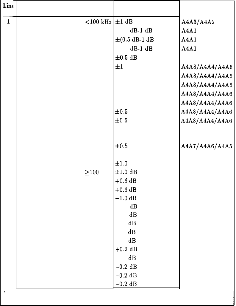
Table 2. Error Correction Routine Parameters
Liue
Parameter Specification
Troubleshooting
Information
1
2
3
4
5
6
7
8
9
10
11
12
13
14
15
16
17
18
19
20
21
22
23
24
25
26
27
28
29
30
31
LOG and LIN scale, BW
<lOO
kHz
LOG 10
db/
LOG 5
dB/
LOG 2
dB/
LOG 1
dB/
RES BW
=
3 MHz
1 MHz
300
kHz
100
kHz
30
kHz
10
kHz
3
kHz
1
kHz
300 Hz
100 Hz
30 Hz
10 Hz
LOG and LIN scale, BW
2100
kHz
A4A3/A4A2
Step
Gains
=
A20 A4A8
A10 A4A8
SG20-2 A4A5
SG20-1 A4A5
SGlO
A4A5
LG20
A4A3
LGlO A4A3
RF ATTENUATOR = 20 dB A6A10, A12U8
30
dB
A6A10, A12U8
40 dB A6A10, A12U8
50 dB A6A10, A12U8
60
dB
A6A10, A12U8
70 dB
A6Al0,
A12U8
’
Specifications for all Resolution Bandwidths are referenced to the 1 MHz Resolution
Bandwidth. The freauencv error terms are for error correction onlv.
fl
dB typical
f(0.5 dB-1 dB reading)
f(0.5
dB-1 dB reading)
f(0.5 dB-1 dB reading)
f0.5
dB
fl
dB*
f0.5 dB*
f0.5 dB*
f0.5 dB*
f0.5 dB*
~tO.5
dB*
f0.5
dB*
f0.5 dB*
f0.5 dB*
60.5
dB*
f0.5 dB*
61.0
dB*
&l.O
dB typical
f0.6
dB
to.6
dB
j-1.0 dB
fl.O
dB
fl.O dB
tl.O dB typical
fl.O dB typical
f0.2 dB typical
to.2
dB typical
f0.2 dB typical
to.2
dB
typical
to.2
dB typical
to.2
dB typical
A4A3/A4A2
A4Al
A4Al
A4Al
Overall Troubleshooting 9
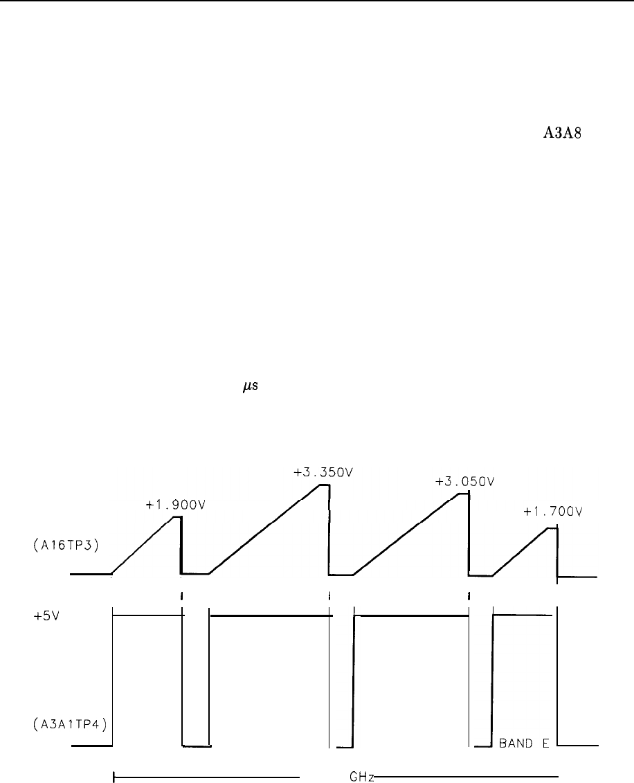
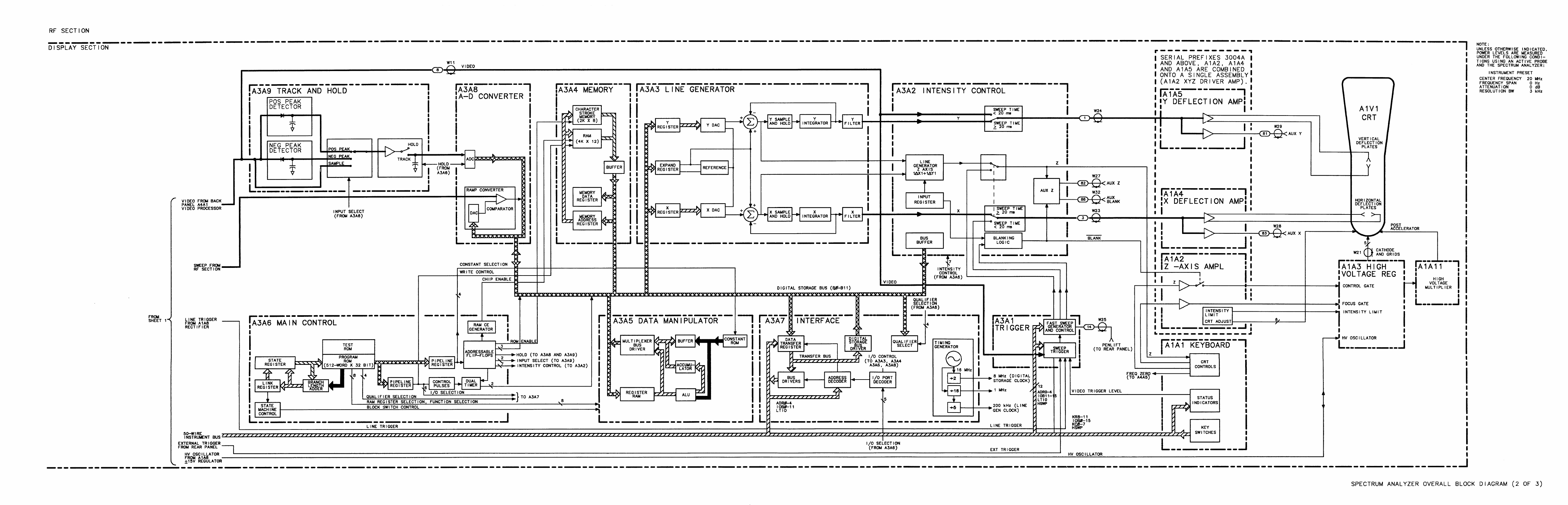
Sweep System Block Diagram Description
The HP 8566B Spectrum Analyzer sweep system consists of the following modes:
Continuous Sweep; Free Run Trigger
Several different assemblies are involved in the HP 8566B sweep system. The Al6
Scan Generator generates the 0 to 10 V sweep ramp. The ramp converter on the A3A8
Analog-Digital Converter and the Digital Storage Processor Section digitize this ramp into
a
10-bit
sweep address. When the sweep address reaches the marker address, the Digital
Storage Processor Section outputs a RSHS (Low = Reset High Sweep) pulse. This signal
resets the High Sweep flip-flop on the
A3Al
Trigger assembly. HSWP (High Sweep) goes low
and the current source charging the sweep capacitor on Al6 is shunted to ground, stopping
the sweep ramp at its present value. The negative transition on the HSWP line generates a
Service Request on Al2 Front-Panel Interface forcing LSRQ low which sets LSTP (Low Stop)
high. This “wakes up” the Al5 Controller. The Controller then reads the sweep address from
the Digital Storage Processor Section. If it corresponds to the end of the sweep, the Al5
Controller outputs a sweep reset command to the Al6 Scan Generator, resetting the sweep
ramp to 0 V. After all Service Requests have been handled (LSRQ is high), the Al5 Controller
starts the sweep by issuing a set HSWP command to the
A3Al
Trigger. The Al5 Controller
then issues a stop command to the Al2 Front-Panel Interface assembly that forces LSTP low,
stopping the Controller. After a 500 ps delay on
A3Al
Trigger, HSWP goes high, the sweep
ramp starts, the Digital Storage Processor Section starts digitizing the ramp, and the front
panel SWEEP LED lights indicating a sweep is in progress.
+1.9oov
+1
,700v
SCAN RAMP
(A16TP3)
ov
I
I I I I I I
II
I
I
I
I
I
I
+5v
HSWP
(A3AlTP4)
ov BAND B
-
BAND C
1
BAND D
r
BAND E
t
2-22 GHz
I
Figure 3. Sweep System Timing Example
10
Overall Troubleshooting

Triggered Sweep
The triggered sweep modes are very similar to free run operation except that instead of the
Al5 Controller outputting a set HSWP command to the
A3Al
Trigger assembly, it outputs a
trigger enable command. The output of the trigger select circuit (line, external, or video) then
clocks the HSWP line high.
Single Sweep
The single sweep mode is useful in troubleshooting the sweep system because it does not rely
on feedback from Digital Storage before resetting the sweep generator. Whenever the SWEEP
(ZiK$
key is pressed, the Al5 Controller resets the sweep generator and then sets HSWP
high through the
A3Al
Trigger assembly. Digital Storage then stops the sweep when it has
reached the end and the ramp resets to 0 V.
Fast Sweep
Fast sweep is enabled only for 0 Hz frequency spans and sweep times less than 20 ms. HSWP
is forced low, and the Al6 Sweep Generator is not used. See
A3Al
Trigger for a description of
the fast sweep operation.
Service Requests
Any of the Service Requests on the Al2 Front-Panel Interface will force LSRQ low which
forces HSWP low. For example, when a front-panel key is depressed, a keyboard Service
Request is generated. LSRQ goes low, LSTP goes high, and HSWP goes low stopping the
sweep. Depending on which key was pressed, the Al5 Controller will either continue the
sweep or reset it and start a new sweep. Note that the analyzer cannot sweep if any Service
Requests are present.
Sweep System Troubleshooting
The following procedure is an aid to rapidly isolate sweep system malfunctions. When the
malfunction has been traced to a single assembly, check the Service Sheets for that assembly
for a more thorough troubleshooting procedure.
Isolate the Scan Sweep
Disconnect the ramp from
A3A8Jl
and jumper
A3A8TPl
to
A3A8TP2.
This forces the ramp
comparator output high. The Digital Storage Processor Section should continue to process
data and increment the sweep address. The HSWP light should be flashing and HSWP should
have an approximately 16 ms pulse width. (Note that the instrument preset state may appear
to be functioning properly but will become distorted as the sweep time is slowed down.)
If this works, the Digital Storage Processor Section and Al5 Controller, Al2 Front-Panel
Interface, and
A3Al
Trigger assemblies are operating properly. Suspect the ramp generator
or Al6 Scan Generator or ramp converter on the A3A8 Analog-Digital Converter. To further
isolate the scan generator, reconnect the sweep ramp to
A3A8Jl
and remove the jumper. Set
the sweep time to 1 second and press the SWEEP
(ZiKZiY]
key. The ramp waveform will start
at greater than 10 V, go to 0 V when the SWEEP
[SINGLE]
key is pressed, and ramp back
Overall Troubleshooting
11
up to greater than 10 V. If the ramp waveform is correct, check the A3A8 ramp converter.
Otherwise check the ramp generator on A16.
Isolate Digital Storage Processor Section If HSWP Stays High (SWEEP LED ON)
With the sweep ramp disconnected from
A3A8Jl
and
A3A8TPl
jumpered
to
A3A8TP2,
check RSHS output for the presence of 60 ns low pulses. (The logic probe of the HP 5005A
Signature Analyzer can be used to detect them.) If present, check
A3Al
Trigger. If not, check
the Digital Storage Processor Section.
See
A3Al
Trigger Troubleshooting Procedure
Note that the
A3Al
Trigger assembly also generates and controls the fast sweep timing
(sweeps less than 10 ms).
12 Overall Troubleshooting

Table 3. Mnemonics Listing for RF Section
Mnemonic
ADRO-4
ATN*
BFC ON
DAV*
DIOl-8
EOI*
HLE2
HLEY
HOVH
HPON
HPUP
HSTD
HSWP
HULl
HUL2
HULH
HULM
HULR
HULY
HXRF
HYGH
IFC*
IOBO-15
KCO-7
KRO-11
LADR
LANR
LAOS
LB10
LDAS
LIPS
LLED
LMNE
LRMT
LROMl-3
LRTL
Active
State
LOW
LOW
LOW
LOW
HIGH
HIGH
HIGH
HIGH
HIGH
HIGH
HIGH
HIGH
HIGH
HIGH
HIGH
HIGH
HIGH
HIGH
HIGH
LOW
HIGH
LOW
LOW
LOW
LOW
LOW
LOW
LOW
LOW
LOW
LOW
LOW
Description
Address Bits 0 through
4
Attention True
Filter Capacitor IN
Data Valid
HP-IB Data Input/Output Bits
End or Identify
Phase Lock Loop 2 Lock Enable
YTO Lock Enable
Oven Cold
Power ON to IF-Display Section
Power Up
10 MHz Standard ON
Sweeping
Phase Lock Loop 1 or 3 Unlocked
Phase Lock Loop 2 Unlocked
Heterodyne Oscillator Unlocked
M/N Unlocked
REF Unlocked
YTO Unlocked
External Reference
YTO Loop Gain High
Interface
Clear
[nstrument
Bus Data Bits
Key Columns 0 through 7
Key Rows 0 through 11
-4ddress
LED ON
Analog Reset
Aux Out Strobe
RF Section I/O Strobe
DAC Strobe
Instrument Preset
LED Strobe
M/N Output Enable
Remove (High=Local)
Enable ROM 3-State Outputs
Local Button Pushed
Overall Troubleshooting 13

Table 3. Mnemonics Listing for RF Section (continued)
Mnemonic
LSAS
LSBY
LSRQ
LSTP
LSTS
LTGR
LTIO
LYSP
Ml-5
Nl-6
N DAC*
N RFD*
REN*
RPGl
RPG2
SAT1
SAT2
SRQ*
SW1
SW2
.I_
--- --
_
_
Active Description
State
LOW Scan Attenuator Strobe
HIGH
Standby
LOW Service Request
LOW
Stop Al5 Controller
LOW Scan Time Strobe
LOW
Tracking Generator Request
LOW
IF-Display Section I/O Strobe
LOW YTO Span
M/N Loop-M Inputs
M/N Loop-N Inputs
HIGH
Data Accepted
HIGH
Ready for Data
LOW Remote Enable
Rotary Pulse
Generator Lines
Scan Integer
Attenuator
LOW Service Request
Switch 1
(AlOA7)
Switch 2
(AlOA7)
14 Overall Troubleshooting
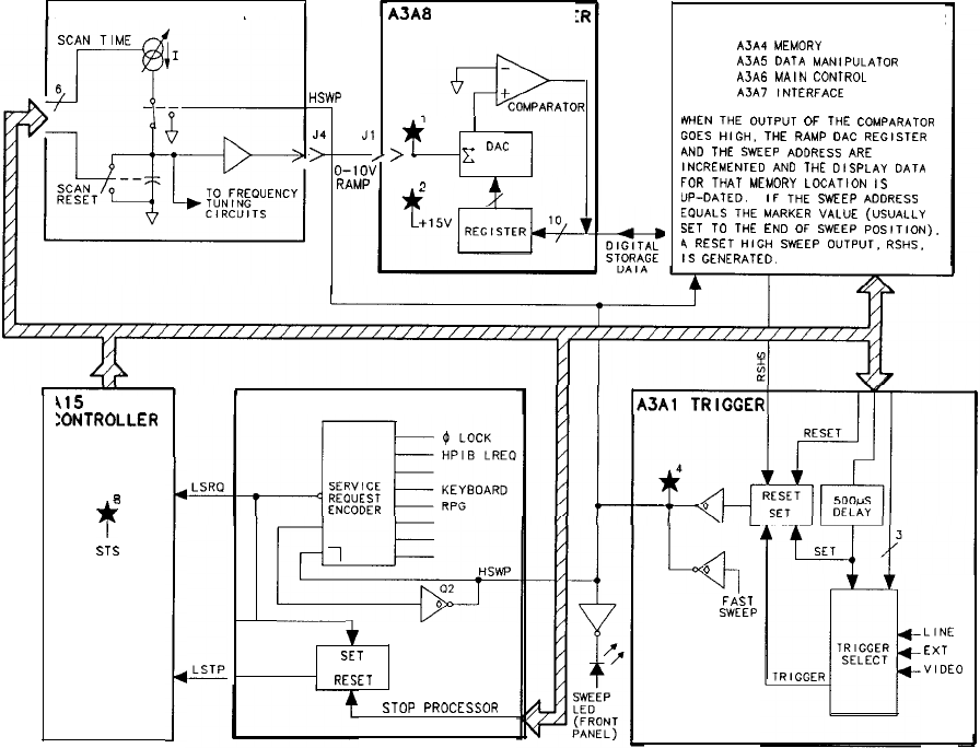
Al6 SCAN GENERATOR
HSWP
J4
J1
I
>
.
//-
c
DAC
o-1ov
RAMP
415
:ONTROLLER
8
f
ST-5
!
ASA
RAMP CONVERTE
412 FRONT-PANEL INTERFACE
v+
f
SET
RESET
STOP
PROCESSOR
DIGITAL STORAGE PROCESSOR
AJA4
MEMORY
A3A5
DATA
MANIPULATOR
A3A6
MAIN
CONTROL
A3A7
INTERFACE
rYHEN
THE
OUTPUT
OF
THE
COMPARATOR
GOES
HIGH.
THE
RAMP
OAC
REGISTER
AND
THE
SWEEP
ADDRESS
ARE
INCREMENTED
AN0
THE
DISPLAY
DATA
FOR
THAT
MEMORY
LOCATION
IS
“P-DATED. IF
THE
SWEEP
ADDRESS
EQUALS
THE
MARKER
VALUE
(USUALLY
SET
TO
THE
END
OF
SWEEP
POSITION).
4
RESET
HIGH
SWEEP
OUTPUT.
RSHS.
IS
GENERATED.
1
0
FAST
SWEEP
LINE
EXT
VIDEO
Figure 4. Sweep System Block Diagram
Overall Troubleshooting 15
Analog
Troubleshooting
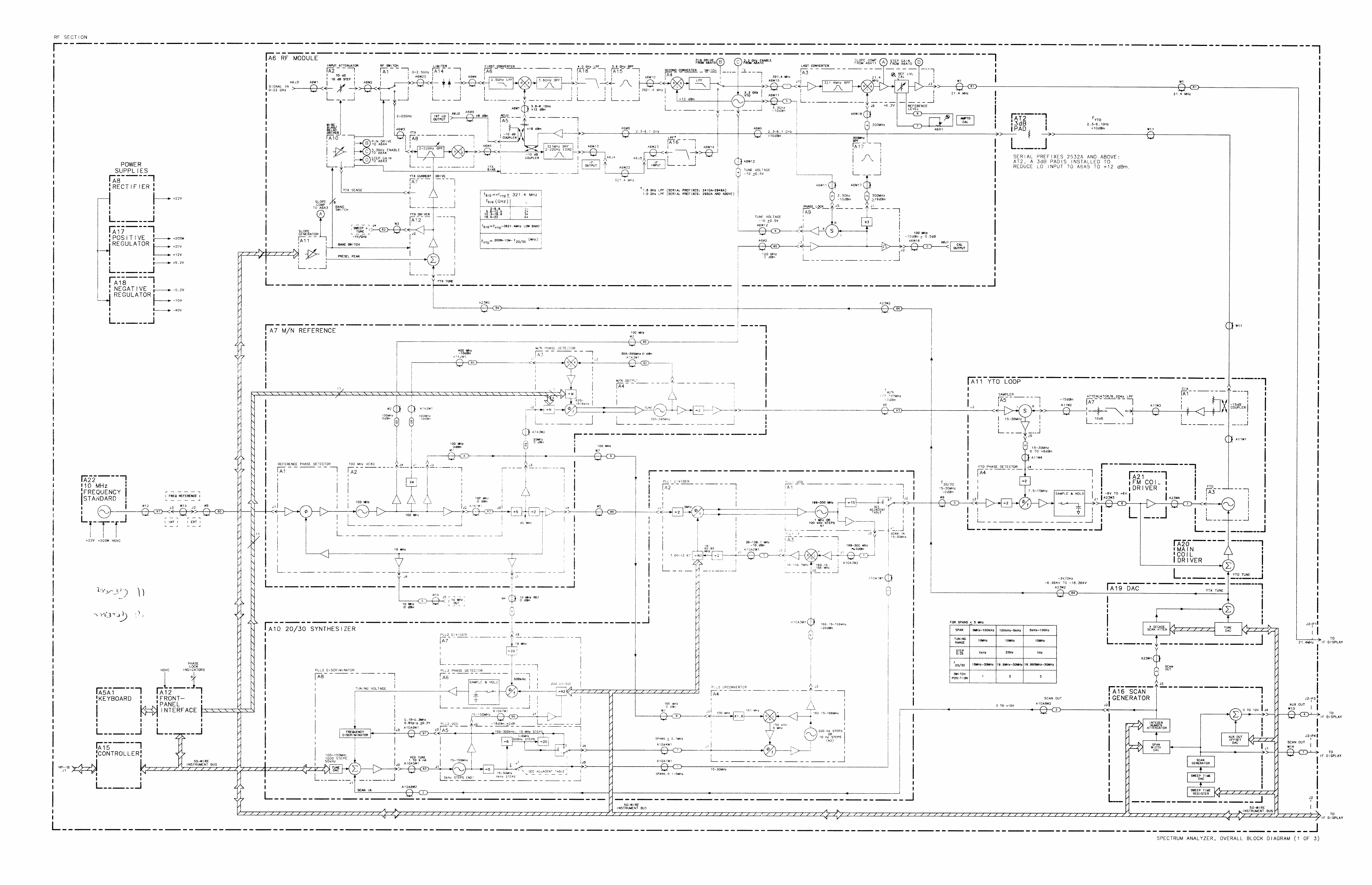
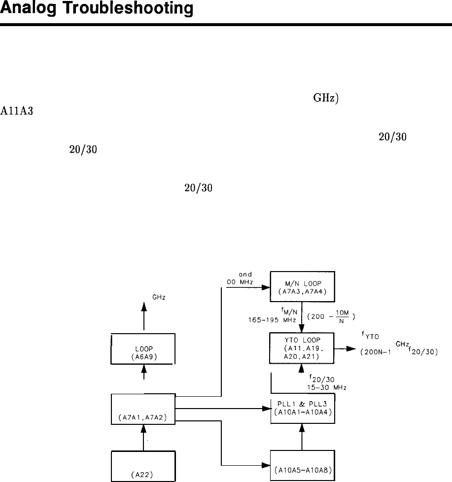
Phase Lock Loops Principles of Operation
General Description
The fundamental RF signal input to the A6 RF Module (2 to 6.2 GHz) is generated by the
AllA
YTO (YIG-Tuned Oscillator). This signal is phase-locked, through other phase-lock
loops, to the A22 10 MHz Standard (internal crystal oscillator). The YTO Loop pretunes and
locks the YTO signal to the output of the M/N Loop (part of A7) and the A10
20/30
Loop.
The M/N and
20/30
Loops serve two basic functions. First, they phase-lock the YTO Loop
to the 10 MHz Standard through the Reference Loop (part of A7). They also provide the
stepped tuning of the YTO output signal. The M/N Loop provides the larger steps (2000 to
6199 MHz in 10 MHz steps) while the
20/30
Loop provides the smaller (1 MHz to 1 Hz) steps.
All phase lock loops are referenced, either directly or indirectly, to the A22 10 MHz Standard.
Figure 1. shows the relationship between the various loops as well as defining the assemblies
associated with the loops.
4
3.3
GHz
t
HETERODYNE
100 MHz
1
lf:%fo;Hz
,
I
REFERENCE 10 MHz and 100 MHz
LOOP
PLLl
&
PLL3
(A7Al.A7AZ)
)
(AlOAl-AlOA4)
20 MHz
165-
10 MHz
10 MHz
STANDARD
(A2’J)
10 MHz PLL2
b
(AIOAS-~10~8)
fYTO
2.3-6.1
(200N-1
GHZ
OM-
f20/30)
Figure 1. Phase Lock Loops (Synthesizer), Block Diagram
Analog Troubleshooting 1
Reference Loop (Part of A7)
The Reference Loop is phase-locked to the A22 10 MHz Standard and its phase-locked
outputs (10, 20, 100, and 400 MHz) are used as references for the
20/30
Loop, the M/N
Loop, and the Heterodyne Loop (part of A6). The 10 MHz signal is also used as an auxiliary
rear-panel output.
The A7A2 100 MHz VCXO (Voltage-Controlled Crystal Oscillator) is the heart of this loop.
The 100 MHz output signal is 1) routed to the A6A9 Phase Lock assembly to be used as a
reference for the Heterodyne Loop and as the front-panel CAL OUTPUT signal, 2) routed
to the AlOA3 PLL3 Up Converter to be used as a reference for that phase-lock loop, 3)
multiplied by four to produce the reference signal for the M/N Loop (A7A3 M/N Phase
Detector), and 4) divided by five to produce a 20 MHz reference signal also used by the
M/
N Loop. The 20 MHz signal is divided by two to produce a 10 MHz signal which is used
as a reference for the
PLLl
and PLL2 phase-lock loops in the
20/30
Loop and also as the
rear-panel auxiliary output. The 10 MHz signal is also phase compared to the output of the
A22 10 MHz Standard. The resulting error signal is used to tune the 100 MHz VCXO to
phase-lock the Reference Loop.
M/N Loop (Part of A7)
The frequency output of the M/N Loop is dependent on the front-panel Start
Frequency/Center Frequency and in part, controls the YTO output frequency. This signal is
disabled during sweeps when the frequency span is greater than 5 MHz (fundamental mixing).
An encoded equivalent of the front-panel frequency’s most significant digits are input to the
M/N Loop as M and N numbers. The ratio of the M and N numbers determines the M/N
OUT
(fM,N)
frequency and are chosen such that the Nth harmonic (same as the divider
number) of
fM/N
tunes in exactly 10 MHz increments as M is changed. There is one 10 MHz
step for each valid
fM/N
frequency (M/N ratio) and Nth harmonic (N number). Refer to Table
2 for a complete list of M and N numbers and resulting
fM/N
frequencies. This 10 MHz step
complements the
20/30
Loop whose tuning range is 10 MHz and step size is 1 Hz. Together,
the M/N loop, YTO pretuning, and
20/30
Loop are able to tune the
AllA
YTO from
2000.000 000 to 6199.999 999 MHz in 1 Hz steps.
YTO Loop (All)
Whenever a change is made to the Start Frequency/Center Frequency (from the front panel
or remote controller), the YTO is pretuned near the desired new frequency. This is done
by encoded information being sent from the Al2 Front-Panel Interface to the A19 DAC
(Digital-to-Analog Converter) which generates and routes an analog voltage to the A20 Main
Coil Driver. The Main Coil Driver, in turn, generates a tuning current to tune the YTO. This
places the YTO frequency 20 to 30 MHz below the Nth harmonic of the M/N Loop output
(fM,N).
For frequency spans greater than 5 MHz, the YTO frequency is locked at the start
of each sweep with the M/N loop and the
20/30
loop to a 1 Hz resolution. The YTO signal
(fYTO)
and the M/N Loop output signal
(fM,N)
are mixed in the
AllA
Sampler (harmonic
mixer) to produce the YTO IF (f
YT~JIF)
signal. This 20 to 30 MHz signal is phase compared
to the
20/30
Loop output signal
(f2e,ao)
in the
AllA
YTO Phase Detector producing a dc
error voltage. It should be noted that
fYTC)IF
and
fze/se
are equal when the YTO Loop is
phase-locked. This error voltage is stored in a capacitor, the loop (YTO) opened, and a sweep
taken. The loop is relocked at the start of each sweep. If the frequency span is less than 5
MHz, the YTO Loop is always locked and is forced to sweep by following the swept oscillator
2 Analog Troubleshooting
reference (fzoise) from PLL2 in the
20/30
Loop which is either applied directly to the YTO or
divided down and summed into PLL2 and
PLLl
and then applied to the YTO.
When the frequency span is less than 25 kHz, the loop gain of the YTO Loop is increased
by approximately 10 dB to provide better performance. This is performed by control signal
HYGH (High = YTO Loop
G
ain
High) being placed in a High state.
20/30
Loop
(AlO)
The
20/30
Loop translates tuning data for the seven least significant digits of the YTO
frequency (2 to 6.2 GHz) into frequencies from 30 to 20.000 001 MHz. This translation is
quite straightforward and the resulting output frequency can be calculated by the following
equation:
f2c,/ao=
30
-
xxxx
xxx MHz
where
xxxx
xxx is the seven least significant digits of the YTO frequency.
This process of frequency translation is used to tune the YTO over a 10 MHz range in 1 Hz
steps (1 Hz steps in zero frequency span) and uses three complete phase-lock loops
(PLLl,
PLL2, and PLLS) to achieve this.
Phase Lock Loop 2 (PLL2)
p
rovides a low-frequency (20 to 30 MHz) reference (fze,se) to
the YTO Loop for frequency spans between approximately 100 kHz and 5 kHz. This loop is
locked at the start of each sweep, the error voltage stored in a capacitor, the loop unlocked,
and a sweep taken. For frequency spans of less than approximately 100 kHz and greater
than 5 kHz, the 20 to 30 MHz output is divided by 5 and applied as an input to Phase Lock
Loop 3
(PLLS)
and Phase Lock Loop 1
(PLLl).
The output of
PLLl/PLLS
then serves as
the reference input
(f20,30)
to the YTO Loop. If the frequency span is 5 kHz or smaller, the
output of PLL2 is divided by 100 and applied to PLL3.
Heterodyne Loop (Part of A6)
The Heterodyne Loop (A6A9) consists of a 3.3 GHz oscillator located in the A6A4 Second
Converter that is locked to the 100 MHz VCXO in the A7A2 assembly. The 100 MHz
signal drives the Sampler in the A6A9 Phase Lock assembly which produces a dc output
proportional to the phase difference between the 33rd harmonic of 100 MHz and the 3.3 GHz
oscillator output signal being sampled. This dc output is amplified and used to drive the 3.3
GHz oscillator to achieve phase lock. If the loop is unlocked, a search oscillator (in the A6A9)
turns on and sweeps the 3.3 GHz VCO until phase-lock is again achieved. The Heterodyne
loop is used only for start frequencies of less than 2 GHz.
Analog Troubleshooting 3
Troubleshooting Information
Troubleshooting Table
Table 1 correlates CRT phase-lock error messages with the probable faulty phase-lock loop
and associated assemblies. This is especially helpful in determining the faulty loop when more
than one phase-lock error message is displayed.
Table 1. Troubleshooting Using CRT Unlock Messages
Message
Probable Faulty Loop Associated Assemblies
(UNLOCK)
PLl
Phase Lock Loop 1
AlOAl
to
AlOA4
PL2 Phase Lock Loop 2
AlOA5
to
AlOA8
REF Reference Loop
A7A1,
A7A2,
A22
YTO YTO Loop A19, A20, A21, All
M/N
M/N Loop
A7A3,
A7A4
HET Heterodyne Loop
A6A9,
A6A4
PLl,
PL2 Phase Lock Loop 2
AlOA5
to
AlOA8
PLl,
YTO Phase Lock Loop 1
AlOAl
to
AlOA4
PLl,
PL2, YTO Phase Lock Loop 2
AlOA5
to
AlOA8
REF,
PLl,
PL2 Reference Loop
A7A1,
A7A2,
A22
REF, M/N, YTO Reference Loop
A7A1,
A7A2,
A22
M/N, YTO M/N Loop
A7A3,
A7A4
HET, REF Reference Loop
A7A1,
A7A2,
A22
Start Frequency Tuning Equations and Phase Lock Troubleshooting
General
Phase-lock loop troubleshooting is much easier if it is understood how the start frequency
is derived. The Diagnostic Functions of the spectrum analyzer can also be used to simplify
troubleshooting of the phase-lock loop.
The simplified block diagram at the back of this chapter shows the assemblies involved in
setting the start frequency. The HP 8566B has two tuning modes. For frequency spans
greater than 5 MHz, a method called lock and roll is used. This basically involves phase
locking the analyzer start frequency during the retrace period prior to the beginning of a new
scan. For frequency spans of 5 MHz and less, the YTO Loop is phase-locked during all of a
sweep, and the stable
20/30
Loop PLL2 is swept.
4 Analog Troubleshooting
The equation for start frequency is:
fSF
(B
W
X
fM/N
-
fm/m))
+ fIF
Where:
fsF
= Start Frequency
B
=
band number. KSR displays the value of B which varies from 0 to 4. When the
displayed value is 0 (low band), use 1 as a multiplier.
N
=
N number for M/N Loop. KSR displays the value of N which varies from 11 to 32.
fM,N
= M/N loop frequency in MHz. KSR displays the value which ranges from 177 to 197
MHz.
f20/30
= Synthesizer frequency in MHz. KSR displays the value which ranges from 20 to 30
MHz.
fIF
= Signal IF frequency. The value is -3621.4 MHz for band 0, -321.4 MHz for band 1,
and
+321.4
MHz for bands
2,
3,
and
4.
Note For a detailed explanation of the Frequency Diagnostic Function (KSR), see
Diagnostic Functions in the Spectrum Analyzer Overall Troubleshooting
Section of this manual.
As an example, these values are used following an INSTR PRESET
([a]
pressed) to
determine the start frequency.
B=l
N=13
fM/N
180.769231 MHz
f2elsu= 28.600000
fIF=
-321.4 MHz
Substitute these values into the equation.
fSF
= (1 x(13 x 180 x 769231 MHz)
-
28.600000 MHz)
-
321.4 MHz = 2000.0 MHz
M/N Loop Tuning
The frequency output of the M/N Loop is dependent on the ratio of M and N numbers. These
numbers are input in the form of digital tuning information to the M/N Loop Phase Detector.
The following equation shows the relationship between the output frequency and the M and N
numbers.
fM/N
= (200
-
lO(M/N))
MHz
Where:
fM/N
=
M/N output frequency
M = M number which varies from 8
-
27. KSR displays the value of M.
N = N number which varies from 11
-
32. KSR displays the value of N.
The M and N numbers are selected such that the M/N Loop output pretunes the YTO
frequency in 10 MHz steps. For a listing of the M and N numbers, M/N output frequencies
Analog Troubleshooting 5
(fM/N),
and the YTO frequencies, refer to Table 2, M and N Numbers and Resulting
Frequencies.
20/30
Synthesizer Tuning
When a start frequency change occurs, the YTO is pretuned near the new desired frequency
by the A19 Digital-Analog Converter and A20 Main Coil Driver. This places the YTO
frequency 20 to 30 MHz below the Nth harmonic of the M/N Loop output. (The Nth
harmonic is the same as the M/N Loop’s N number.) The YTO frequency and the M/N Loop
harmonic are mixed in the
AllA
Sampler. The YTO IF
(20-
30 MHz) is phase compared
with the
20/30
Synthesizer output. The
AllA
Phase Detector’s error voltage is then used
to tune the YTO through the A21 FM Coil Driver and the A20 Main Coil Driver to achieve
phase-lock.
The
20/30
Synthesizer is used to pretune the YTO in 1 Hz steps (in zero frequency span)
through a 10 MHz range. The following formula expresses the relationship between the
frequencies found in the YTO Loop.
&o/so
(N
x
fM/N)
-
f0
=
fYTOIF
Where:
f2u,su
=
20/30
Synthesizer frequency. (Displayed with KSR.)
N = N number, varies from 11
-
32. (KSR displays value of N.)
fM/N
=
M/N Loop frequency
fo = YTO frequency
fYToIF
= YTO IF frequency
The
20/30
Synthesizer frequency can also be determined by using the YTO frequency set.
This frequency is available by using KSR. In this case,
f2,,/s,,
= (30.000000
-
D7
D6
Ds
D4
Ds
Dz
Dr)
Where:
Dr to
Dr
is the YTO frequency displayed with Dr being the least significant digit (1 Hz).
Marker Mode
When the MARKER
@GG)
mode is selected, the analyzer does the following. First, the
center frequency is determined. Because the
@GGiJ
marker is a display marker, after the
center frequency is calculated, the position of the marker on the display is determined. By
knowing that the display consists of 1000 points and the programmed frequency span, the
processor calculates the offset between the center frequency and the marker. The frequency
span accuracy is the major cause of error in the readout accuracy of the MARKER
(NORMAL]
mode.
6 Analog Troubleshooting
Phase Lock Loop Troubleshooting
If one of the phase-lock error messages appears, a loop has failed. Start the troubleshooting
procedure by determining if the malfunction is dependent on Center Frequency, Frequency
Span, etc. Next, break the suspected loop and measure the power levels as indicated on the
RF Section Analog Block Diagram. Even with the oscillators at the extremes of their ranges,
the power levels must be within the limits indicated. The loop frequencies can be counted and
compared with the programmed frequencies listed by KSR by inserting a tee connector into
the loop.
The Lock Indicator Disable jumper
(A12TP2
to
A12TP3)
may be necessary if the keyboard
is locked out. Use the information from the Diagnostic Function and the Start Frequency
Tuning Equations to narrow the fault to a single assembly.
Analog Troubleshooting 7
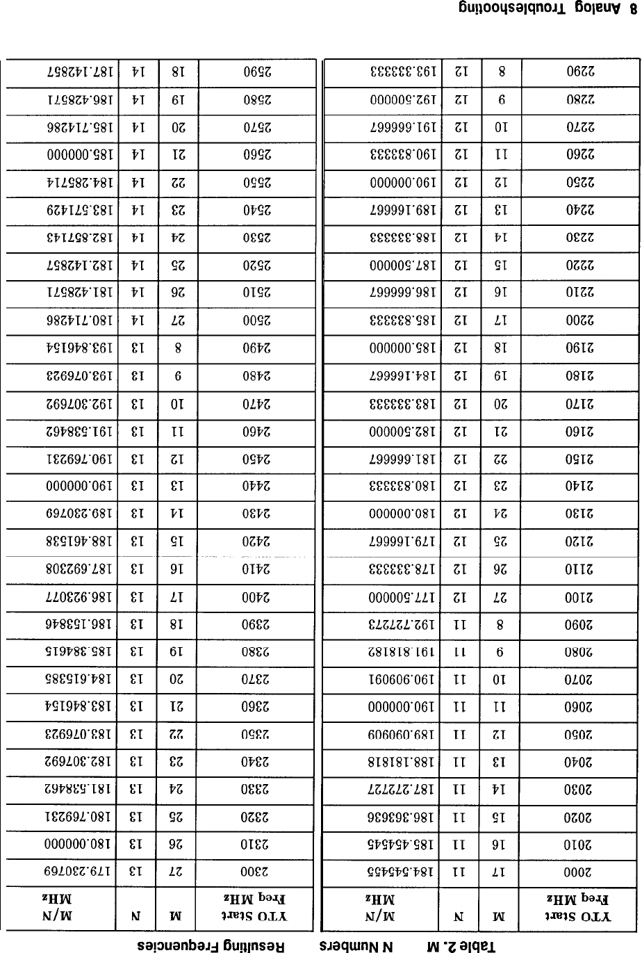
Gu!~ooqsalqnoJ~
f3oleuv
8
SapuanbaJj
Bugnsa+j
pue
SJaqWlN
N
pue
LN
‘Z
alqel

Table 2. M and N Numbers and Resulting Frequencies (continued)
2860
11 15
192.666667 3160
21
17
187.647059
2870
10
15
193.333333 3170
20 17
188.235294
2880
9
15
194.000000 3180
19
17
188.823529
2890
8
15
194.666667 3190
18 17
189.411765
Analog Troubleshooting 9
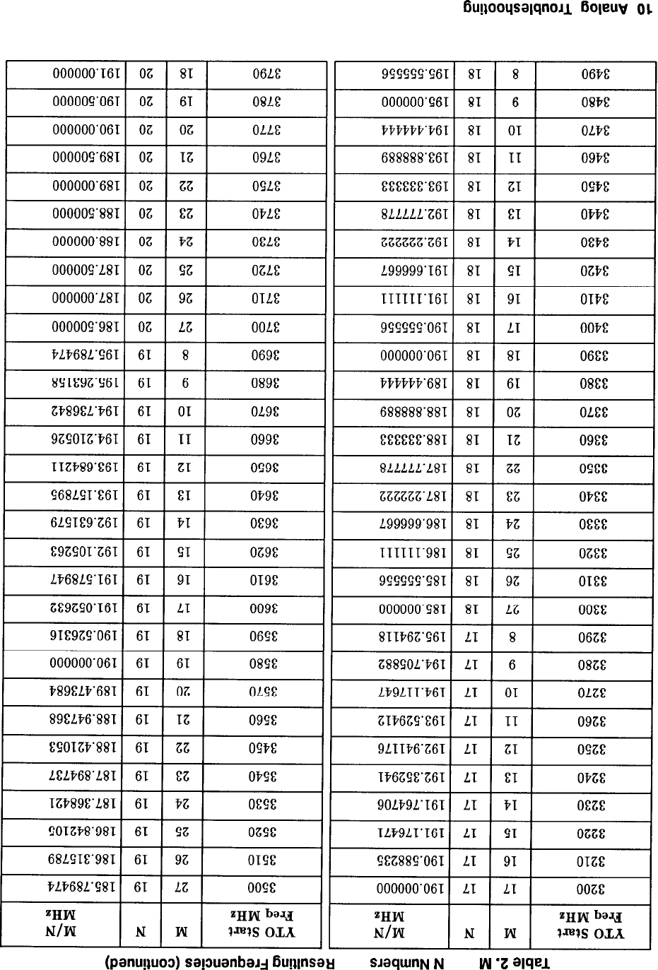
BugooqsalqnoJl
Boleuv
01
(panuguo3)
sa!manbaJj
Guglnsati
pue SJXjUIllN N pue w
‘I
alqel
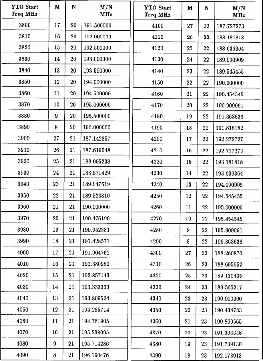
Table 2. M and N Numbers and Resulting Frequencies (continued)
Analog Troubleshooting 11
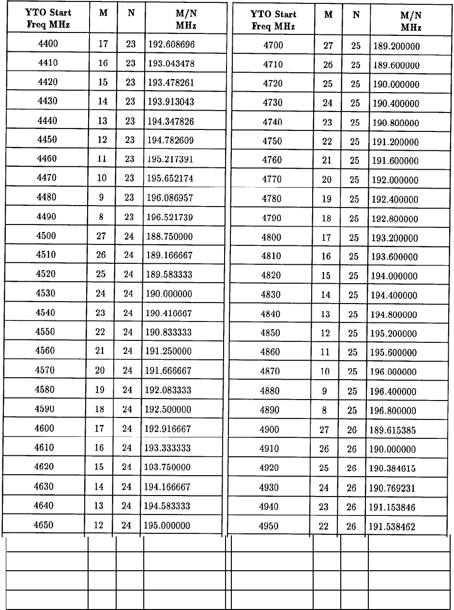
Table 2. M and N Numbers and Resulting Frequencies (continued)
4660
11
24 195.416667 4960
21 26
191.923077
4670
10
24 195.833333 4970
20 26
192.307692
4680
9
24 196.250000 4980
19 26
192.692308
4690
8
24
196.666667 4990
18
26
193.076923
12 Analog Troubleshooting
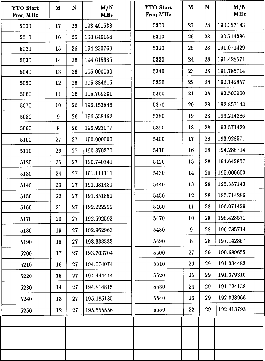
Table 2. M and N Numbers and Resulting Frequencies (continued)
5260
11
27 195.925926 5560
21
29 192.758621
5270
10
27
196.296296 5570
20 29
193.103448
5280
9
27
196.666667 5580
19
29
193.448276
5290
8
27
197.037037 5590
18
29
193.793103
Analog Troubleshooting 13
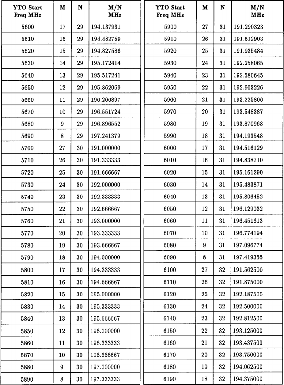
Table 2. M and N Numbers and Resulting Frequencies (continued)
14 Analog Troubleshooting
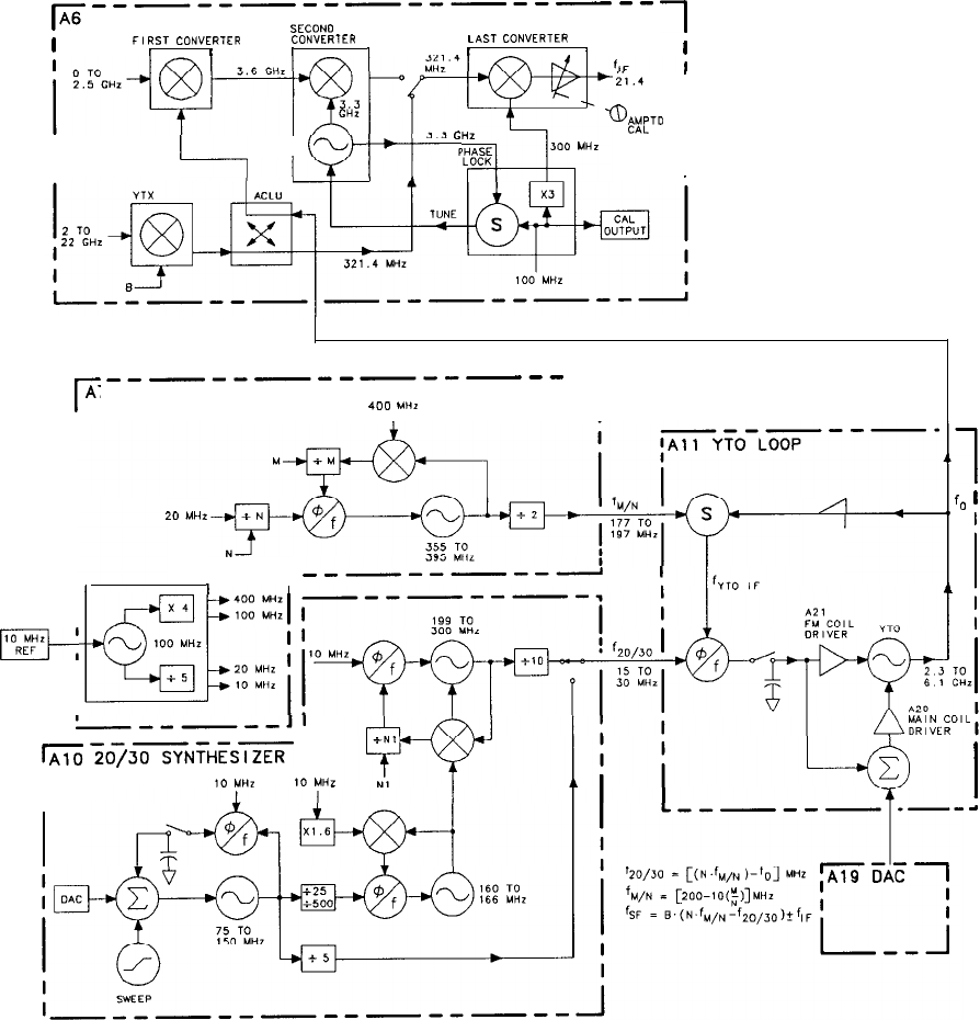
r
-----------P--P--
A6 RF MODULE
SECONO
1
I
FIRST
CONVERTER CONYERTER
LAST
CONVERTER
I I I I
I
I
I
I
L_,
I r-4-
I
Ef?i?
5.1.4
MHZ .
al
GHZ
&yo
I
‘FEE
300
MHZ
I
I
r
__----m---w---
A7 M/N REFERNCE
400
MHZ
1
I
I
I
I
I
I
I
I
RF
I
I
I
20 MHI
/I
I
r
__------A
------11
&
?073=?Hb=
I
I10
MHZ
10
MHZ
I
,l
fo
I
I
I
1
I
I
I
,d
Simplified RF Block Diagram
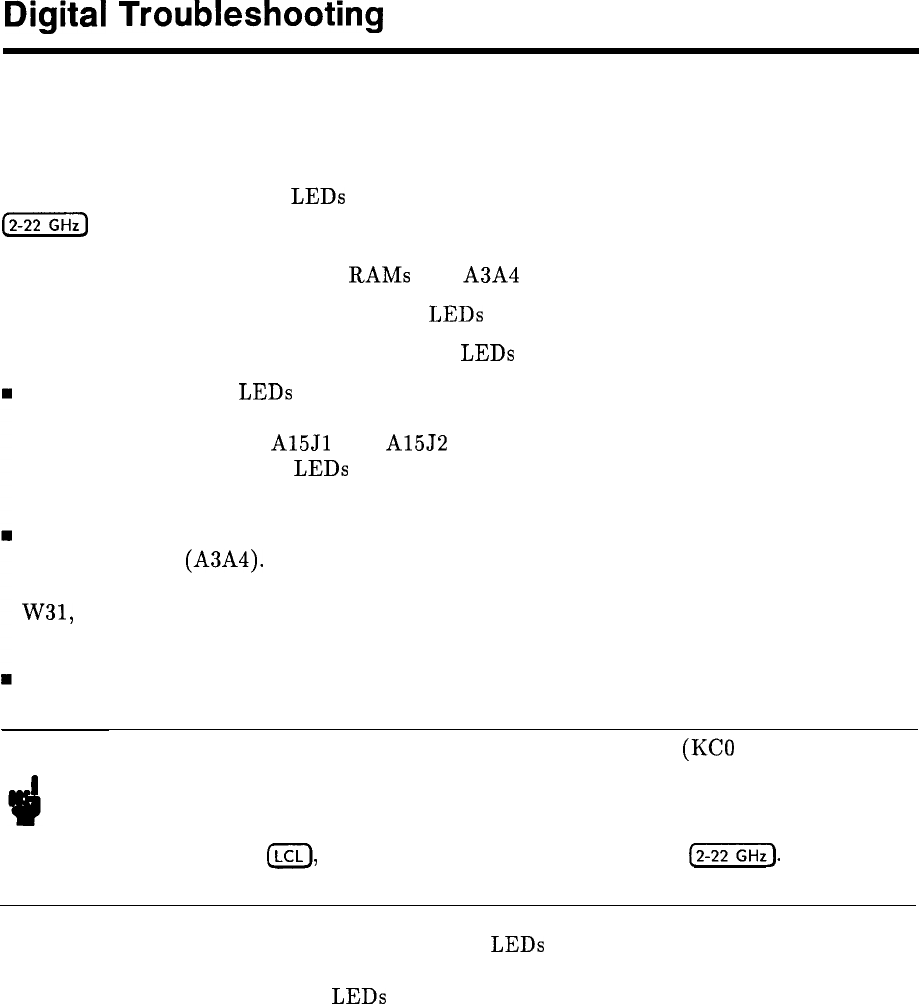
Digital
Troubleshooting
Preliminary Checks
Instrument Preset Check
The two red INSTR CHECK
LEDs
light whenever the instrument is turned on or when
@Z-Z@
is pushed. The main processor then performs a check of itself, a checksum
verification of all ROMs on the Al5 Controller, a partial check of the Instrument Bus (50-wire
bus), and a read-write check of the
RAMS
and A3A4 Memory in the IF-Display Section.
If all the checks pass, both INSTR CHECK LEDs turn off.
If any check fails, one or both INSTR CHECK LEDs remain on.
Both INSTR CHECK LEDs on indicates a problem with the Al5 Controller. First, remove
the Controller and make sure that the 50-wire ribbon cable and HP-IB ribbon cable are
pressed all the way onto
A15Jl
and A15J2 connectors. Reinstall the Al5 Controller. If both
front panel INSTR CHECK LEDs still remain on when the instrument is turned on, follow
procedure under Al5 Controller Self Test.
Left LED (INSTR CHECK I) on indicates a failure occurred when checking the Digital
Storage Memory (A3A4). First, check to ensure that a LINE power cord is connected to the
IF-Display Section. Also check to see that the rear-panel Analyzer Bus Interconnect Cable,
W31, is properly connected. If INSTR CHECK I still remains on when the instrument is
turned on, troubleshoot the A3 Digital Storage in the IF-Display Section.
Right LED (INSTR CHECK II) on indicates a failure occurred during the partial check of
the Instrument Bus.
Note The partial interface check reads the key column lines (KC0 through KC7)
from the Al and A5 front panels. If any front panel key is shorted or stuck
closed, INSTR CHECK II LED should remain on after the Self Test is
completed. This part of the Self Test can easily be verified by pushing any
key, except
CLCL),
and holding the key in while pushing
(2-22).
If the I/O
interface check routine is working, INSTR CHECK II LED will stay on.
n Suspected digital failure but no INSTR CHECK LEDs on may indicate a RAM or I/O bus
failure which is not checked in the normal Self Check or “POP” (Power-On Preset). If the
two front panel INSTR CHECK LEDs turn on when the LINE switch is set to ON, and
turn off again within a few seconds (indicating no digital problems), but symptoms persist
(such as improper CRT display or improper response to particular commands) indicating
that the problem is in the digital area, a “LONG POP” can be performed.
Digital Troubleshooting 1
“LONG
POP”
Instrument Preset Check
This check is very similar to the normal Instrument Preset Check: an additional processor
check is performed, all of the RAM locations in Digital Storage (A3A4 Memory) are checked,
and the RAM memory on the Al5 Controller is verified.
Since these more extensive checks require altering information that has been stored in RAM,
LONG POP requires an internal jumper on the Al5 Controller. To perform a LONG POP:
n Set the LINE switch to STANDBY.
w
Place a jumper between ST or STS to T3
q On Al5 Controller (HP part number 85660-60209) jumper
A15TP4
(STS) to
A15TPl-7
PO
q On Al5 Controller (HP part number 85660-60245) jumper
A15TPl-9
(ST) to
A15TPl-8
P-3).
q (Refer to Al5 Controller Component Location Diagrams for location of test points).
n Set the LINE switch to ON.
When LINE switch is set to ON, the two red INSTR CHECK
LEDs
are forced on and the
main processor steps through the Self Test routine, expanding the normal POP with the
additional tests mentioned above. The expected results for a LONG POP are exactly the
same as for the normal POP of Instrument Preset as described above in the Instrument Preset
Check.
Because LONG POP is a “destructive test” (it alters any information that has been stored in
RAM), it should be performed only as a last resort effort in troubleshooting what appears to
be a memory or processor related problem.
Digital Storage Verification
The Instrument Preset Check does a fairly complete verification of the Digital Storage
controller and memory. An additional check can be done, independent of the RF section, by
jumpering
A3A6TP3
to
A3A6TP6
and pushing
A3A7Sl
momentarily. A test pattern should
appear on the display. Refer to the A3 Digital Storage Troubleshooting Section in the HP
856628 IF-Display Section volume of the service manual for a more detailed description of
this procedure. Note that when the jumper is connected, the left check LED always stays
on following an INSTR PRESET, since in the test pattern mode, Digital Storage ignores all
instructions from the Al5 Controller.
2 Digital Troubleshooting
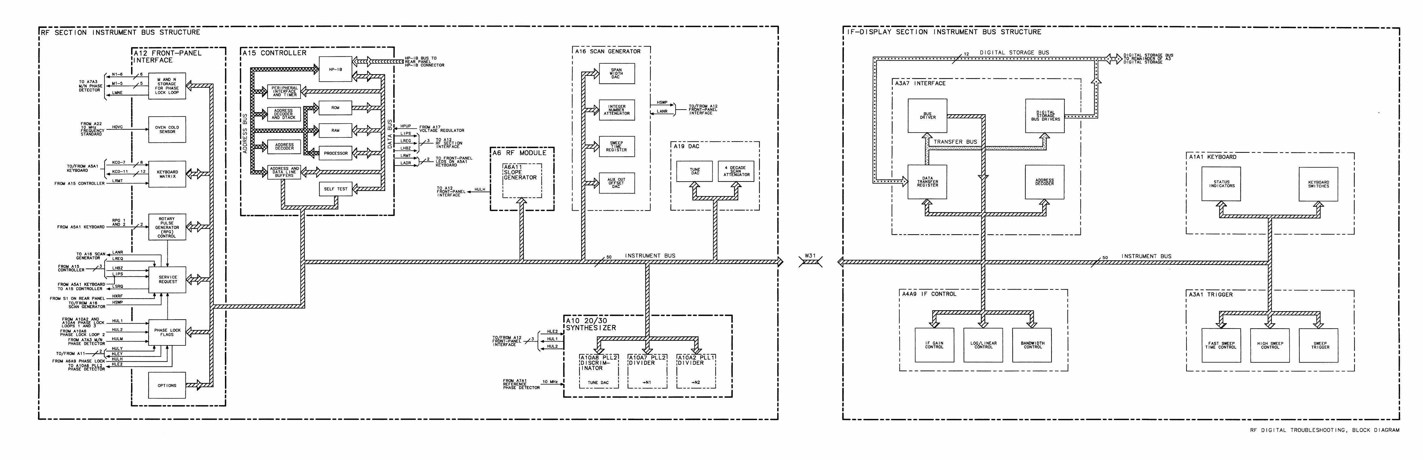
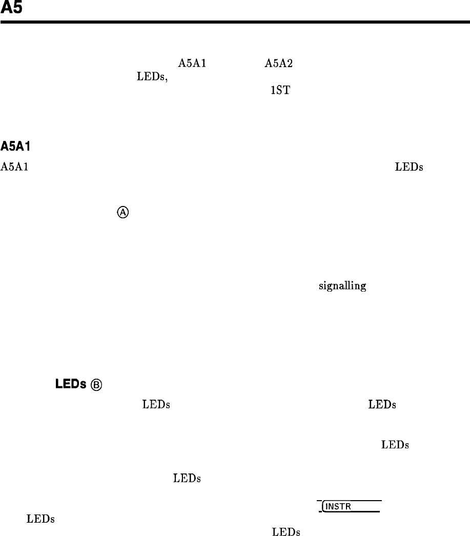
A5
A5 Front Panel, Circuit Description
The A5 Front Panel comprises the
A5Al
Keyboard, A5A2 Rotary Pulse Generator (RPG),
Instrument Check indicator
LEDs,
LINE power switch, STANDBY power indicator LED, and
CAL OUTPUT connector and cable. The RF INPUT, 1ST LO OUTPUT, and 321.4 MHz
IF INPUT and IF OUTPUT connectors are physically part of the A6 RF Module and are
described in detail in that section.
A5Al
Keyboard
A5Al
Keyboard includes the 49 pushbutton switches and 9 associated indicator
LEDs
on the
RF Section front panel.
Keyboard Switches
@
Each of the normally open SPST switches consists of a spring-loaded contact and a pair
of printed-circuit board contacts. All but two of the keyboard switches are organized in a
matrix of rows and columns. When a front-panel key is pressed, the corresponding SPST
switch is closed, connecting a normally grounded key row to a key column. The grounded
key column signal is detected on the Al2 Front Panel Interface,
signalling
the Al5 Controller
to immediately halt the sweep. Then, the Al5 Controller polls (grounds) each of the key
rows sequentially (starting with key row 0) to identify the particular front panel key that is
pressed. During normal operation, the front-panel SWEEP LED can be observed to blink off
momentarily as the Al5 Controller halts the sweep, polls both the IF Section keyboard and
the RF Section keyboard, and then reacquires phaselock before continuing on with the sweep.
Indicator
LEDs
@
The nine keyboard indicator LEDs and the two INSTR CHECK indicator LEDs are lighted
selectively by the Al5 Controller to indicate the state of coupled functions, SIGNAL TRACK
(on/off), DATA entry (enabled/disabled), HP-IB control status (remote and addressed), and
self-test. U2 and U3 latch the LED data from the Data Bus. All front-panel LEDs are lighted
momentarily during the turn-on self test for verification.
The two INSTR CHECK indicator LEDs are lighted selectively by the Al5 Controller to
indicate the overall results of the most recent instrument self test. An instrument self test is
performed each time the LINE switch is switched to ON or the
(INSTR
PRESET] key is pressed.
Both
LEDs
are lighted at the start of each self test, and both are turned off upon successful
test completion; if one or both of the INSTR CHECK LEDs remain on, an instrument fault
has been detected. Refer to the Al5 Controller section for detailed information about the self
test.
A5 1
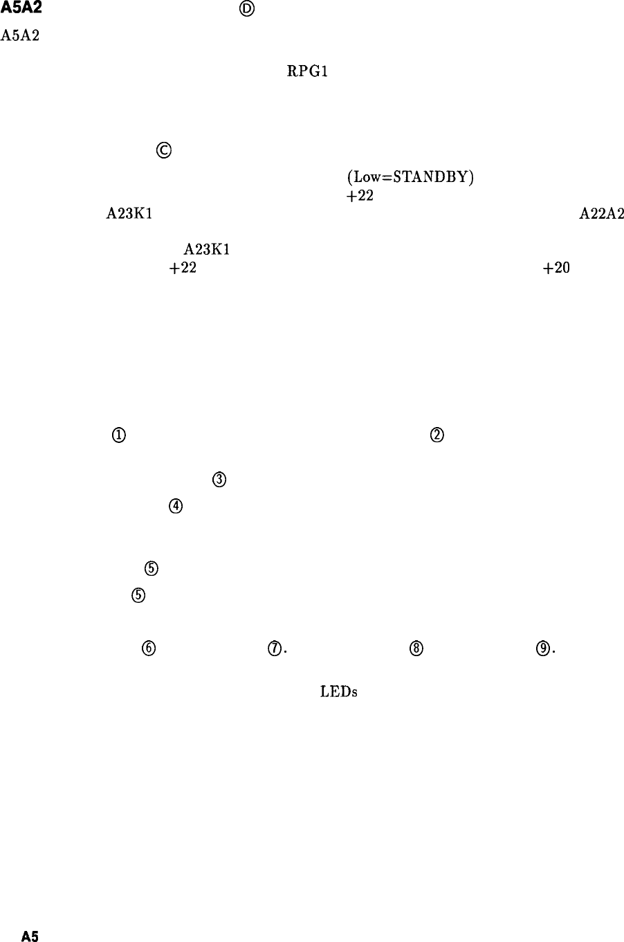
A5A2
Rotary Pulse Generator
@J
A5A2 Rotary Pulse Generator (RPG) is operated by turning the front-panel DATA knob
in either direction. The rate and direction of knob rotation are encoded in the number
and relative phase of output pulses on the
RPGl
and RPG2 lines. These two signals are
decoded on the Al2 Front Panel Interface, enabling the Al5 Controller to gradually change
appropriate instrument settings.
LINE Power Switch
@
When the LINE switch is in STANDBY, the LSBY
(Low=STANDBY)
line is grounded. If the
RF Section is connected to an ac power source, the
+22
V dc supply lights the STANDBY
LED, holds the
A23Kl
Fan Relay in the off state, and powers the heater circuit of the A22A2
10 MHz Quartz Crystal Oscillator; all other power supplies are turned off. When the LINE
switch is switched ON, the
A23Kl
Fan relay is released to the on state (switching on the fan)
and LSBY rises to about
+22
V dc (due to the Fan Relay coil). This enables the
+20
V dc
supply on the Al7 Positive Regulator, which causes all the power supplies to turn on.
Front Panel Removal and Repair
With ac line cords removed, proceed as follows.
1. Remove interconnecting cables between instruments.
2. Position instrument on right side as shown in view A of Figure 1.
3. Remove feet
@
from rear of RF Section by removing screws
@
shown in view A of Figure
1.
4. Loosen bottom cover screw
@
and remove cover.
5. Loosen thumbscrews
@
and separate instruments by holding IF-Display Section in place
while pushing the RF Section at the front panel.
6. After separating instruments, slide RF Section away from IF Display Section far enough
to remove screws
@
holding front panel to frame. Refer to view B of Figure 1.
7. Remove screws
@
from other side of instrument. Refer to view C of Figure 1.
8. Pull front panel out of frame as shown in view D of Figure 1.
9. Disconnect cable
@
from connector
0.
Disconnect cable
@J
from connector
8.
Refer to
view D of Figure 1.
10. To replace INSTR CHECK and STANDBY LEDs proceed as follows.
a. Unsolder the wires from the LED leads and push on the leads with a soldering aid to
force the LED out of the socket and through the front panel.
b. Insert a new LED and resolder as shown in Figure 2.
c. Trim excess lead length.
2
AS
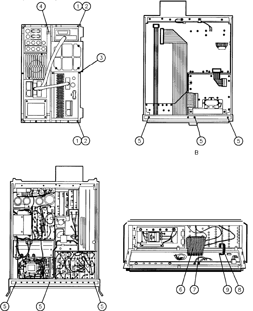
(2 PLACES)
VIEW A
b
5
VIEW 6
VIEW C VIEW D
Figure 1. Front Panel Removal and Repair
A5 3
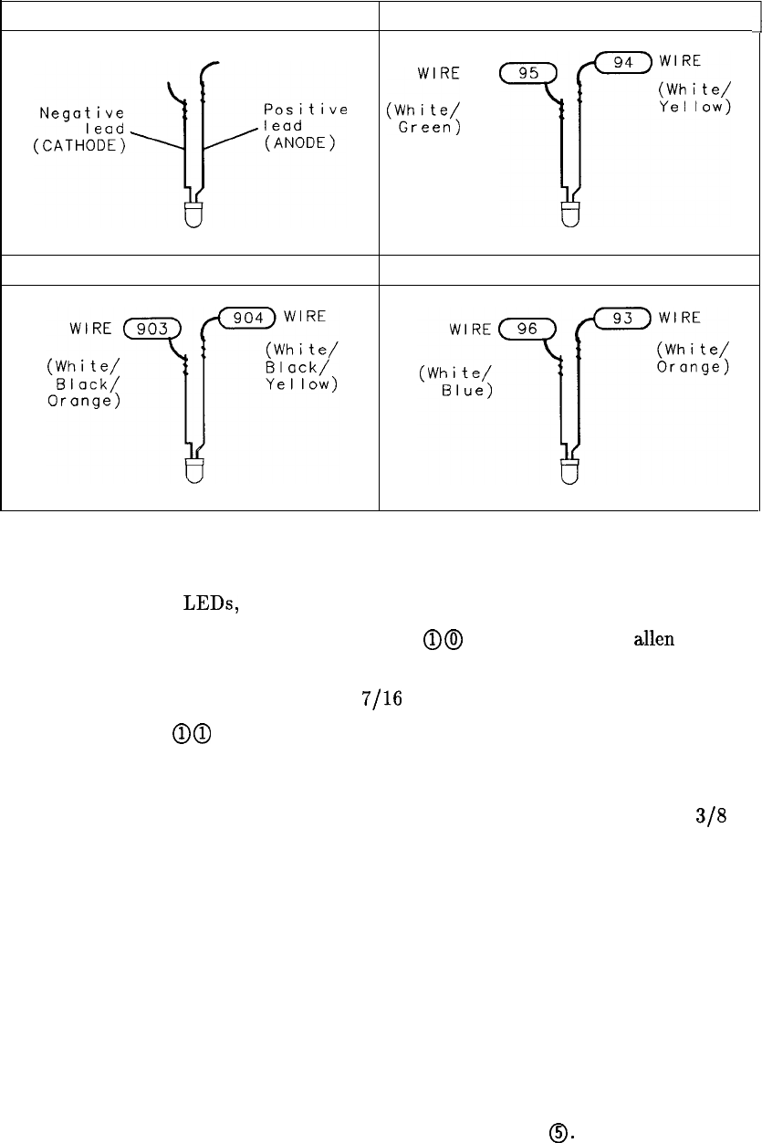
LED LEAD IDENTIFICATION INSTR CHECK I
..,I-:;;:;
*g;;;
~iz::~
STANDBY INSTR CHECK II
Figure 2. LED Removal and Repair
11. To replace signal input
LEDs,
switches, or keys, proceed as follows.
a. Loosen set screw in DATA control knob (RPG) @@ using a number 4
allen
wrench
(HP part number 8710-0857) and remove knob. Refer to Figure 3.
b. Remove nut from DATA control using a
7/16
inch wrench.
c. Remove 14 screws @@ and lift printed circuit board away from front panel. Refer to
Figure 3.
d. Pull defective LED out of socket with fingers (it may be necessary to pry slightly with
a pointed instrument such as a soldering aid), trim both leads on new LED to 3/B
inch (1 cm) and insert the new LED in the socket with negative (cathode) lead to the
square pad on the printed circuit board. Refer to LED lead identification below.
e. To remove the defective switch, remove the key from the switch, melt the plastic pins
holding the switch to the printed circuit board using a soldering iron, and remove the
switch from printed circuit board.
f. To replace the switch, insert the plastic pins of the new switch through the printed
circuit board and melt the pins with a soldering iron on the rear side of the printed
circuit board enough to secure the switch. Replace the key.
g. Reassemble the printed circuit board to the front panel and connect cables.
12. Reconnect the connectors removed in step 9.
13. Secure the front panel to the RF section by tightening six screws
0.
Refer to views B and
C of Figure 1.
1
4 A5
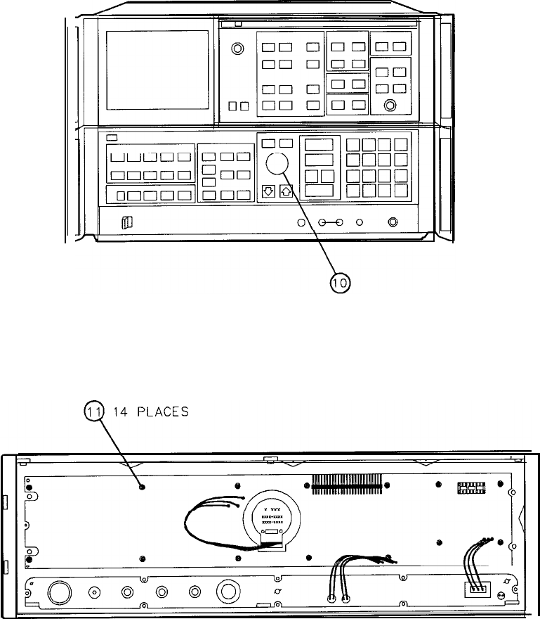
14. Secure IF Display Section to RF Section, replace bottom cover, and reconnect ac line
cords.
Figure 3. Keyboard Removal and Repair
AS 5
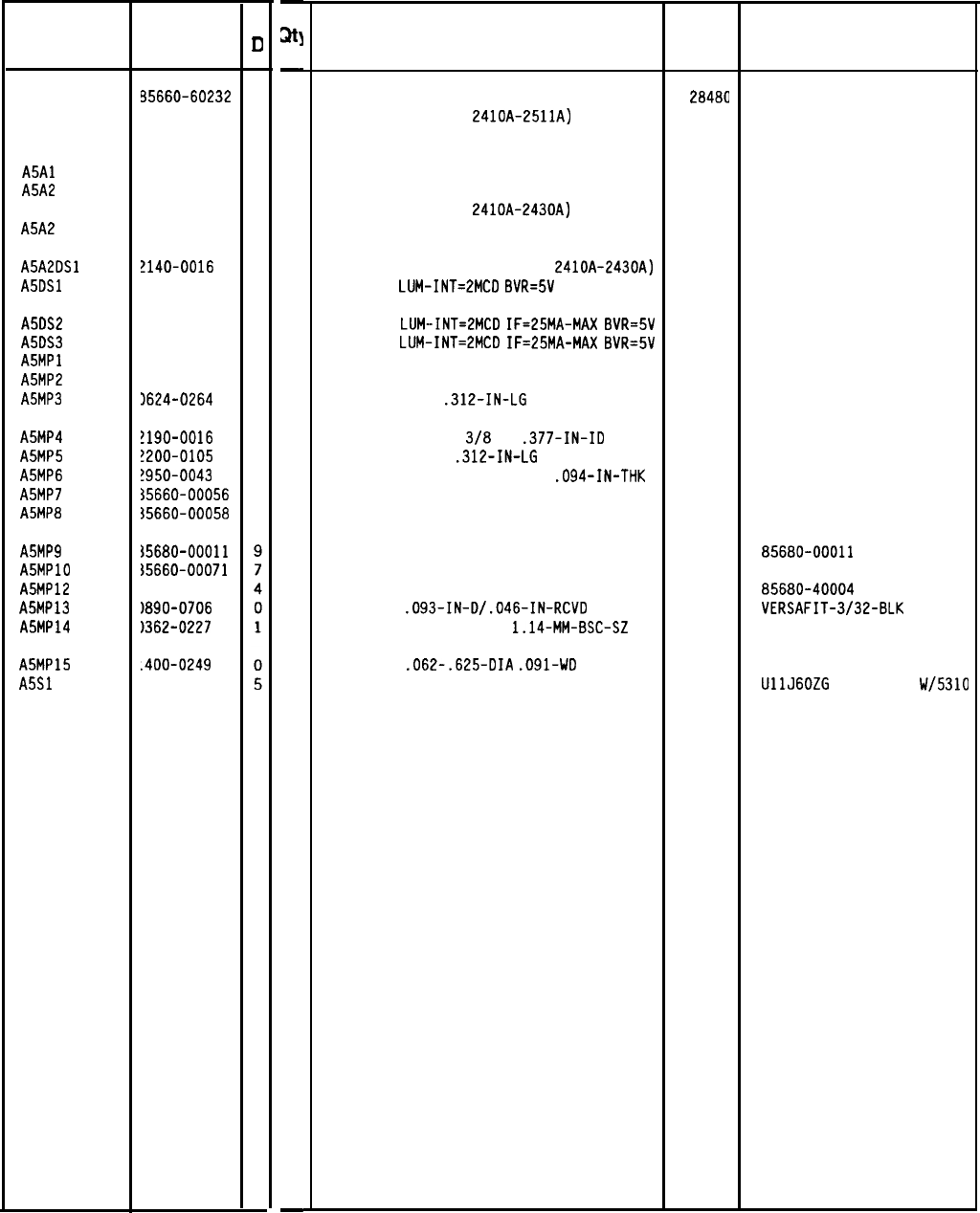
HP Part Number 85660-60232
A5 Front-Panel
Reference HP Part
C
Designation Number
II
A5 85660-60232
8
A5Al 35660-60210
2
A5A2 5060-0329
9
A5A2 3960-0684
2
A5A2DSl 2140-0016
a
A5DSl 1990-0487
7
A5DS2 1990-0486
6
A5DS3 1990-0486
6
A5MPl 1370-3069
2
A5MP2 1510-1148
2
A5MP3 3624-0264
2
A5MP4 !190-0016
3
A5MP5 !200-0105
4
A5MP6
!950-0043 8
A5MP7 35660-00056
a
A5MPB 35660-00058
0
A5MP9
A5MPlO
A5MP12
A5MP13
A5MP14
~5680-00011
%5660-00071
15680-40004
)890-0706
1362-0227
A5MP15
A5Sl
.400-0249
1101-2193
-
31
-
1
1
1
1
1
1
1
1
1
1
1
1
1
1
1
1
1
1
3
1
1
1
1
-
Description
FRONT PANEL ASSEMBLY
(SERIA
L PREFIXES
:
2410~-2511~)
(NOT AVAILABLE FOR FIELD REPLACEMENT)
28480
85660-60232
KEYBOARD ASSEMBLY
ROTARY PULSE GENERATOR
(SERIAL PREFIXES:
2410~-2430~)
ROTARY PULSE GENERATOR
(SERIAL PREFIXES: 2449A AND ABOVE)
LAMP, RPG (SERIAL PREFIXES:
2410~-2430~)
LED-LAMP
LUM-INT=ZMCD
BVR=5V
28480 85660-60210
28480 5060-0329
28480 0960-0684
28480 2140-0016
28480 HLMP-1401
LED-LAMP
LUM-INT=ZMCD
IF=25MA-MAX
BVR=5V 28480
LED-LAMP
LUM-INT=2MCD
IF=25MA-MAX
BVR=5V 28480
RPG TUNING KNOB 28480
RETAINER-PUSH-ON KB-TO-SHFT EXT
SCREW-TPG 4-40
.312-IN-LG
82 DEG
HLMP-1301
HLMP-1301
0370-3069
669
45722
WASHER-LK INTL T
3/B
IN
.377-IN-ID
SCREW-MACH 4-40
.312-IN-LG
PAN-HD-POZI
NUT-HEX-DBL-CHAM 3/B-32-THD
.094-IN-THK
LOWER SUB PANEL
78189
77250
73743
28480
28480
1920-02
LOWER SUB PANEL DRESS
28200-10-101
85660-00056
85660-00058
KEYBOARD SUB PANEL
KEYBOARD SUB PANEL DRESS
LED MOUNT
TUBING-HS
.093-IN-D/.046-IN-RCVD
CONNECTOR-SGL CONT SKT
1.14-MM-BSC-SZ
28480 856BO-00011
28480 85660-00071
28480 85680-40004
06090
VERSAFIT-3/32-BLK
27264 02-05-5216
CABLE TIE
.062-.625-DIA
.091-WD
NYL
59730 TY-23M-8
SWITCH-TGL PRI-SW SPDT 2A 250VAC SLDR-LU
09353 UllJGOZG
W/7868-14
W/5310
Mfr Mfr Part
Code Number
*Indicates factory-selected value
8566040232 Parts List
Page 1 of 1
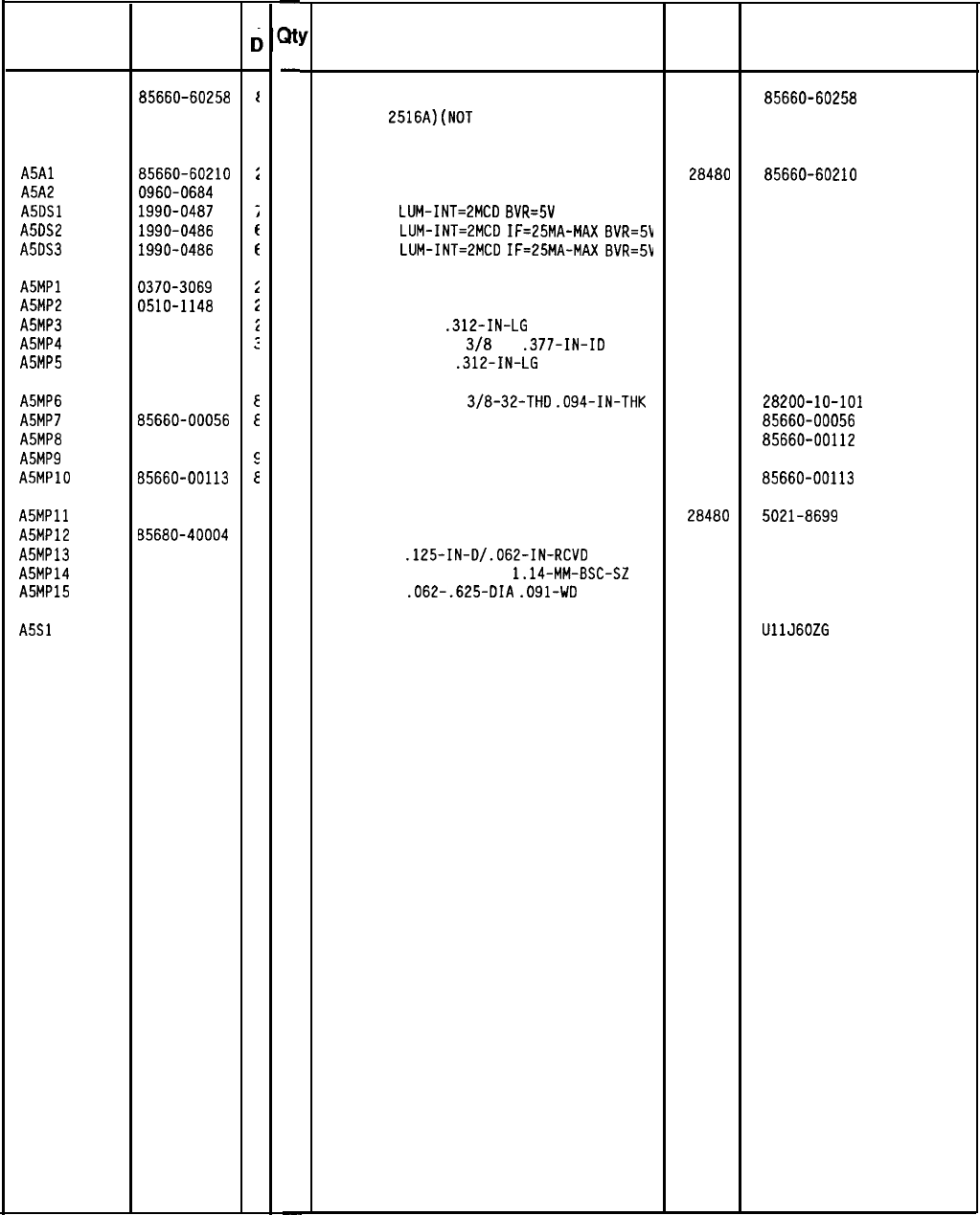
HP Part Number 85660-60258
A5 Front Panel
Reference HP Part
C
Designatior Number
c
A5 85660-60258
I
A5Al 85660-60210
;
A5A2 0960-0684
i
ASOSl 1990-0487
;
A5DS2 1990-0486
t
A5DS3 1990-0486
t
A5MPl 0370-3069
i
A5MP2 0510-1148
i
ASMP3 0624-0264
i
A5MP4 2190-0016
:
A5MP5 2200-0105
4
A5MP6
A5MP7
A5MPB
A5MP9
ASMPlO
2950-0043
E
85660-00056
E
85660-00112
7
85680-00011
E
85660-00113
E
A5MPll 5021-8699
C
A5MP12 65680-40004
4
A5MP13 0890-1186
2
A5MP14 0362-0227
1
A5MP15 1400-0249
a
A5Sl 3101-2193
5
-
zlt
-
1
1
1
1
1
1
1
1
1
1
1
1
1
1
1
1
1
3
1
1
1
1
-
Description
FRONT PANEL ASSEMBLY (SERIAL
PREFIX:
2516A)(NOT
AVAILABLE FOR
FIELD REPLACEMENT)
28480
85660-60258
KEYBOARD ASSEMBLY
ROTARY PULSE GENERATOR INPUT POWER: 5VDC
LED-LAMP
LUM-INT=2MCD
BVR=5V
LED-LAMP
LUM-INT=2MCD
IF=25MA-MAX
BVR=5V
LED-LAMP
LUM-INT=2MCD
IF=25MA-MAX
BVR=5\1
28480
85660-60210
28480 QEDS-8831
28480 HLMP-1401
28480 HLMP-1301
28480 HLMP-1301
RPG TUNING KNOB
28480
RETAINER-PUSH-ON KB-TO-SHFT EXT
SCREW-TPG 4-40
.312-IN-LG
82 DEG
WASHER-LK INTL T
3/B
IN
.377-IN-ID
SCREW-MACH 4-40
.312-IN-LG
PAN-HD-POZI
0370-3069
669
45722
78189
77250 1920-02
NUT-HEX-DBL-CHAM
3/8-32-THD
.094-IN-THK 73743 28200-10-101
LOWER SUB PANEL 28480
85660-00056
LOWER SUB PANEL DRESS 28480 8566D-00112
SUB PANEL KEY BOARD 28480 85680-00011
KEYBOARD PANEL DRESS 28480 85660-00113
KEYBOARD BEZEL
LED MOUNT
TUBING-HS
.125-IN-D/.062-IN-RCVD
CONNECTOR-SGL CONT SKT
1.14-MM-BSC-SZ
CABLE TIE
.062-.625-DIA
.091-WD
NYL
28480 5021-8699
28480 85680-40004
06090 VERSAFIT-l/B CLEAR
27264 02-05-5216
59730 TY-23M-8
SWITCH-TGL PRI-SW SPDT 2A 250VAC SLDR-LU 09353 UllJ6OZG
W/7868-14 W/531(
Mfr
Mfr Part
Code Number
*Indicates facto y-selected value
85660-60258 Parts List
Page 1 of 1
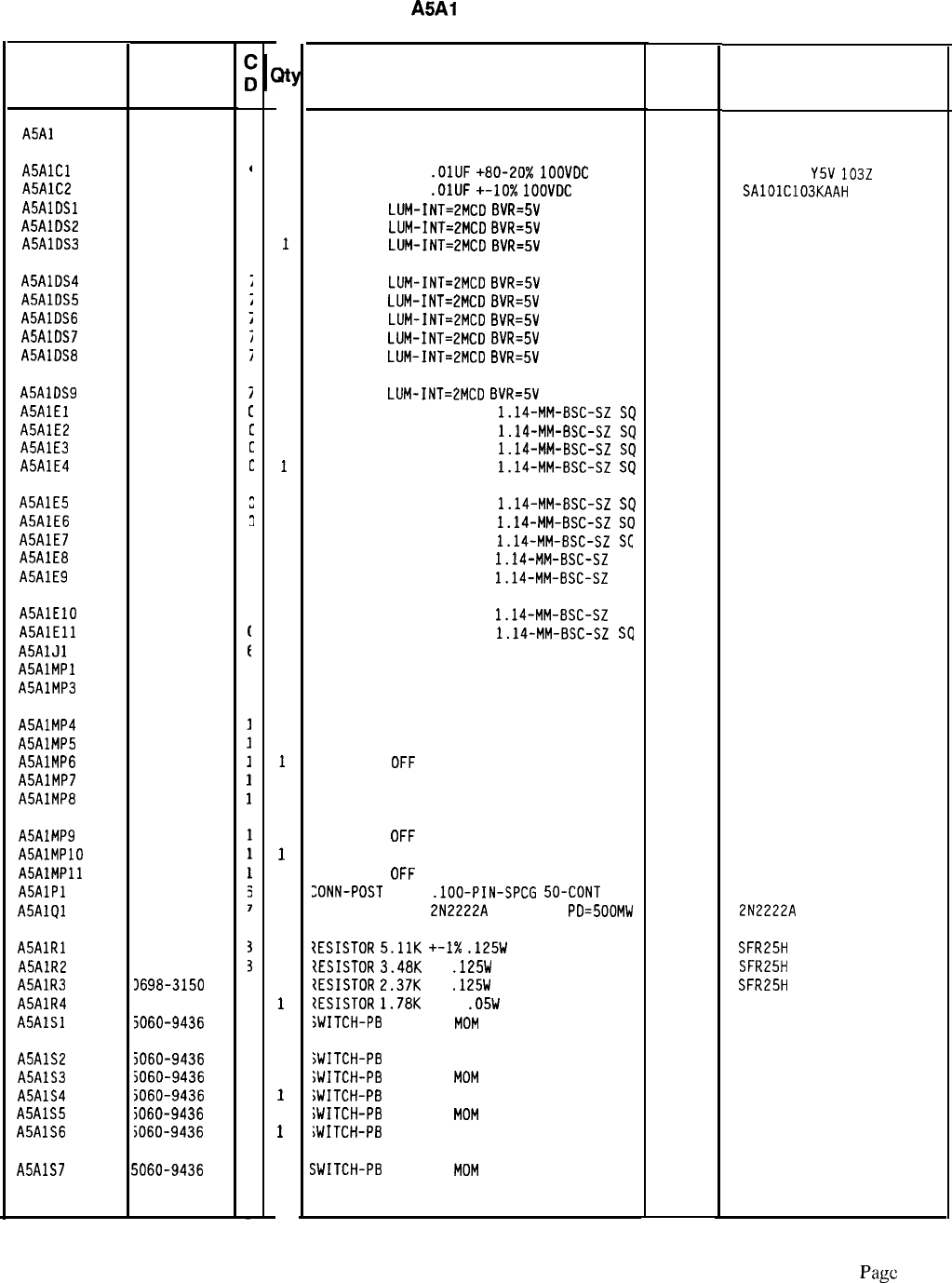
HP Part Number 85660-60210
Reference
Designatior
HP Part
Number
A5Al 85660-60210
A5AlCl 0160-2055
A5AlC2 0160-4832
A5AlDSl 1990-0487
A5AlDS2 1990-0487
A5AlDS3 1990-0487
,
A5AlDS4 1990-0487
;
A5AlDS5 1990-0487
;
A5AlDS6 1990-0487
;
A5AlDS7 1990-0487
;
A5AlDS8 1990-0487
i
A5AlDS9 1990-0487
i
A5AlEl 1251-0600
[
A5AlE2 1251-0600
[
A5AlE3 1251-0600
c
A5AlE4 1251-0600
c
A5AlE5 1251-0600
A5AlE6 1251-0600
A5AlE7 1251-0600
A5AlE8 1251-0600
A5AlE9 1251-0600
n
Y
3
A5AlElO
A5AlEll
A5AlJl
A5AlMPl
A5AlMP3
1251-0600
1251-0600
1200-1205
5041-3929
I
A5AlMP4
A5AlMP5
A5AlMP6
A5AlMP7
ASAlMP8
5041-3929
5041-3929
5041-3929
5041-3929
5041-3929
A5AlMP9 5041-3929
A5AlMPlO 5041-3929
A5AlMPll 5041-3929
A5AlPl 1251-5549
ASAlQl 1854-0477
A5AlRl 3757-0438
A5AlR2 3698-3152
A5AlR3 J698-3150
ASAlR4 3698-7242
A5AlSl 5060-9436
A5AlS2 5060-9436
A5AlS3 5060-9436
A5AlS4 5060-9436
A5AlS5
5060-9436
A5AlS6
5060-9436
A5AlS7 jO60-9436
1
1
1
1
1
1
1
1
1
1
1
1
1
1
1
1
1
1
1
1
1
1
1
1
1
1
1
1
1
1
1
1
1
1
1
1
1
1
1
1
1
1
1
1
1
1
A5Al Keyboard
Description Mfr
Mfr Par!
Code Number
KEYBOARD BOARD ASSEMBLY
2848C
85660-60210
CAPACITOR-FXD
.OlUF
+80-20X
1OOVDC
CER
CAPACITOR-FXD
.OlUF
+-10x
1OOVDC
CER
LED-LAMP
LUM-INT=2MCD
BVR=5V
LED-LAMP
LUM-INT=LMCD
BVR=5V
LED-LAMP
LUM-INT=2MCO
BVR=5V
04222
28480
28480
28480
805-504
Y5V
1032
SAlOlC103KAAH
HLMP-1401
HLMP-1401
HLMP-1401
LEO-LAMP
LUM-INT=EMCD
BVR=SV 28480 HLMP-1401
LED-LAMP
LUM-INT=2MCD
BVR=5V 28480 HLMP-1401
LED-LAMP
LUM-INT=2MCD
BVR=5V 28480 HLMP-1401
LED-LAMP
LUM-INT=ZMCD
BVR=5V 28480 HLMP-1401
LED-LAMP
LUM-INT=2MCD
BVR=5V 28480 HLMP-1401
LED-LAMP
LUM-INT=2MCD
BVR=5V 28480 HLMP-1401
CONNECTOR-SGL CONT PIN
1.14-MM-BSC-SZ
SQ
27264 16-06-0034
CONNECTOR-SGL CONT PIN
1.14-MM-BSC-SZ
SQ
27264 16-06-0034
CONNECTOR-SGL CONT PIN
1.14-MM-BSC-SZ
SQ
27264 16-06-0034
CONNECTOR-SGL CONT PIN
1.14-MM-BSC-SZ
SQ
27264 16-06-0034
CONNECTOR-SGL CONT PIN
1.14-MM-BSC-SZ
SQ
27264 16-06-0034
CONNECTOR-SGL CONT PIN
1.14-MM-BSC-SZ
SO
27264 16-06-0034
CONNECTOR-SGL CDNT PIN
1.14-MM-BSC-SZ
S(
27264 16-06-0034
CONNECTOR-SGL CDNT PIN
1.14-MM-BSC-SZ
SC
27264 16-06-0034
CONNECTOR-SGL CDNT PIN
1.14-MM-BSC-SZ
SC
27264 16-06-0034
CONNECTOR-SGL CDNT PIN
1.14-MM-BSC-SZ
SC
CONNECTOR-SGL CONT PIN
1.14-MM-BSC-SZ
SQ
SOCKET-IC 16-CONT DIP DIP-SLDR
NOT ASSIGNED
LED STAND OFF
27264 16-06-0034
27264 16-06-0034
00779 2-641610-z
28480 5041-3929
LED STAND OFF 28480 5041-3929
LED STAND OFF 28480 5041-3929
LED STAND
OFF 28480 5041-3929
LED STAND OFF 28480 5041-3929
LED STAND OFF 28480 5041-3929
LED STAND
OFF
LED STAND OFF
LED STAND
OFF
,DNN-POST
TYPE
.lOO-PIN-SPCG
50-CDNT
TRANSISTOR NPN
2N2222A
SI TO-18
PD=SOOMW
28480 5041-3929
28480 5041-3929
28480 5041-3929
18873
68025-650
04713 2N2222A
?ESISTOR
5.11K
+-I%
.125W
TF TC=O+-100
19701
SFR25H
tESISTDR
3.48K
1%
.125W
TF TC=O+-100
19701
SFR25H
IESISTOR
2.37K
1%
.125W
TF TC=O+-100
19701
SFR25H
lESISTOR
1.78K
+-1%
.05W
TF TC=O+-100
19701
50635
iWITCH-PB
SPST-NO
MOM 71468 5560-9436
SWITCH-P8
SPST-NO MOM
iWITCH-PB
SPST-NO
MOM
iWITCH-PB
SPST-NO MOM
iWITCH-PB
SPST-NO
MOM
iWITCH-PB
SPST-NO MOM
iWITCH-PB
SPST-NO
MOM
71468 5560-9436
71468 5560-9436
71468 5560-9436
71468 5560-9436
71468 5560-9436
71468 5560-9436
*Indicates factory-selected value
85660-60210 Parts List
Pap!
1 of 3
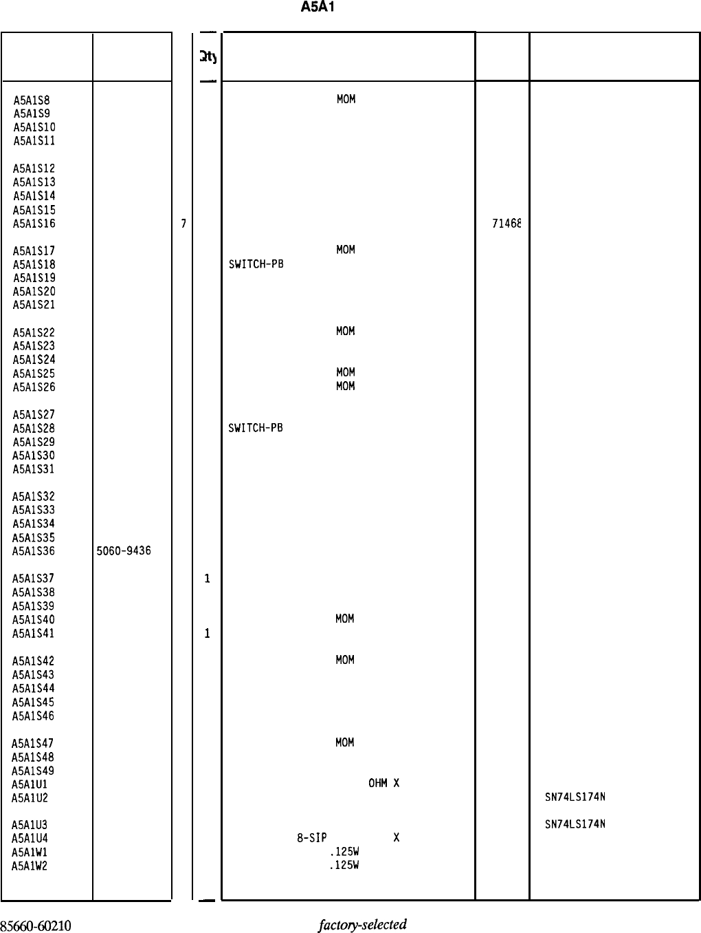
Reference
Designation
HP Part
Number
C
D
A5AlS8 5060-9436
7
A5AlS9 5060-9436
7
A5AlSlO 5060-9436
7
A5AlSll 5060-9436
7
A5AlS12 5060-9436
7
A5AlS13 5060-9436
7
A5AlS14 5060-9436
7
A5AlS15 5060-9436
7
A5AlS16 5060-9436
7
A5AlS17 5060-9436
7
A5AlS18 5060-9436
7
A5AlS19 5060-9436
7
A5AlS20 5060-9436
7
A5AlS21 5060-9436
7
A5AlS22 5060-9436
7
A5AlS23 5060-9436
7
A5AlS24 5060-9436
7
A5AlS25 5060-9436
7
A5AlS26 5060-9436
7
A5AlS27 5060-9436
7
A5AlS28 5060-9436
7
A5AlS29 5060-9436
7
A5AlS30 5060-9436
7
A5AlS31 5060-9436
7
A5AlS32 5060-9436
7
A5AlS33 5060-9436
7
A5AlS34 5060-9436
7
A5AlS35 5060-9436
7
A5AlS36 5060-9436
7
A5AlS37 5060-9436
7
A5AlS38 5060-9436
7
A5AlS39 5060-9436
7
A5AlS40 5060-9436
7
A5AlS41 5060-9436
7
A5AlS42 5060-9436
7
A5AlS43 5060-9436
7
A5AlS44 5060-9436
7
A5AlS45 5060-9436
7
A5AlS46 5060-9436
7
A5AlS47 5060-9436
7
A5AlS48 5060-9436
7
A5AlS49 5060-9436
7
A5AlUl 1810-0229
5
A5AlU2 1820-1196
8
A5AlU3
A5AlU4
ASAlWl
A5AlW2
1820-1196
8
1810-0229
5
0757-0346
2
0757-0346
2
85660-60210 Parts List
Page 2 of 3
-
m
-
1
1
1
1
1
1
1
1
1
1
1
1
1
1
1
1
1
1
1
1
1
1
1
1
1
1
1
1
1
1
1
1
1
1
1
1
1
1
1
1
1
1
1
1
1
1
1
1
-
HP Part Number 85660-60210
A5Al Keyboard
Description Mfr
Code Mfr Part
Number
SWITCH-PB SPST-NO
MOM 71468 5560-9436
SWITCH-P8 SPST-NO MOM 71468 5560-9436
SWITCH-P8 SPST-ND MOM 71468 5560-9436
SWITCH-PB SPST-NO MOM 71468 5560-9436
SWITCH-PB SPST-ND MOM
71468 5560-9436
SWITCH-PB SPST-NO MOM 71468 5560-9436
SWITCH-PB SPST-NO MOM
71468
5560-9436
SWITCH-PB SPST-NO MOM 71468 5560-9436
SWITCH-P8 SPST-NO MOM
71462
5560-9436
SWITCH-PB SPST-NO
MOM 71468 5560-9436
SWITCH-P6
SPST-NO MOM
71468 5560-9436
SWITCH-PB SPST-NO MOM 71468 5560-9436
SWITCH-PB SPST-NO MOM 71468 5560-9436
SWITCH-PB SPST-NO MOM 71468 5560-9436
SWITCH-PB SPST-NO
MOM 71468 5560-9436
SWITCH-PB SPST-NO MOM 71468 5560-9436
SWITCH-PB SPST-NO MOM 71468 5560-9436
SWITCH-PB SPST-NO
MOM 71468 5560-9436
SWITCH-PB SPST-NO
MOM 71468 5560-9436
SWITCH-PB SPST-NO MOM 71468 5560-9436
SWITCH-P6
SPST-NO MOM
71468 5560-9436
SWITCH-PB SPST-ND MOM 71468 5560-9436
SWITCH-P8 SPST-ND MOM 71468 5560-9436
SWITCH-PB SPST-NO MOM 71468 5560-9436
SWITCH-PB SPST-NO MOM 71468 5560-9436
SWITCH-PB SPST-ND MOM 71468 5560-9436
SWITCH-PB SPST-NO MOM 71468 5560-9436
SWITCH-PB SPST-NO MOM 71468 5560-9436
SWITCH-PB SPST-NO MOM 71468 5560-9436
SWITCH-PB SPST-NO MOM 71468 5560-9436
SWITCH-PB SPST-NO MOM 71468 5560-9436
SWITCH-PB SPST-NO MOM 71468 5560-9436
SWITCH-PB SPST-NO
MOM 71468 5560-9436
SWITCH-PB SPST-ND MOM 71468 5560-9436
SWITCH-PB SPST-NO
MOM 71468 5560-9436
SWITCH-PB SPST-NO MOM 71468 5560-9436
SWITCH-PB SPST-ND MOM 71468 5560-9436
SWITCH-PB SPST-NO MOM 71468 5560-9436
SWITCH-PB SPST-NO MOM 71468 5560-9436
SWITCH-PB SPST-NO
MOM 71468 5560-9436
SWITCH-PB SPST-NO MOM 71468 5560-9436
SWITCH-PB SPST-NO MOM 71468 5560-9436
NETWORK-RES B-SIP 330.0
OHM
X
7
11236 750-81
IC FF TTL LS D-TYPE POS-EDGE-TRIG CDM CL 01295 SN74LS174N
IC FF TTL LS D-TYPE PDS-EDGE-TRIG COM CL 01295 SN74LS174N
NETWORK-RES
a-SIP
330.0 OHM
X
7
11236 750-81
RESISTOR 10 +-1%
.125W
TF TC=O+-100
91637 CMF-55-1, T-l
RESISTOR 10 +-1%
.125W
TF TC=O+-100
91637 CMF-55-1, T-l
*Indicates
factoy-selected
value
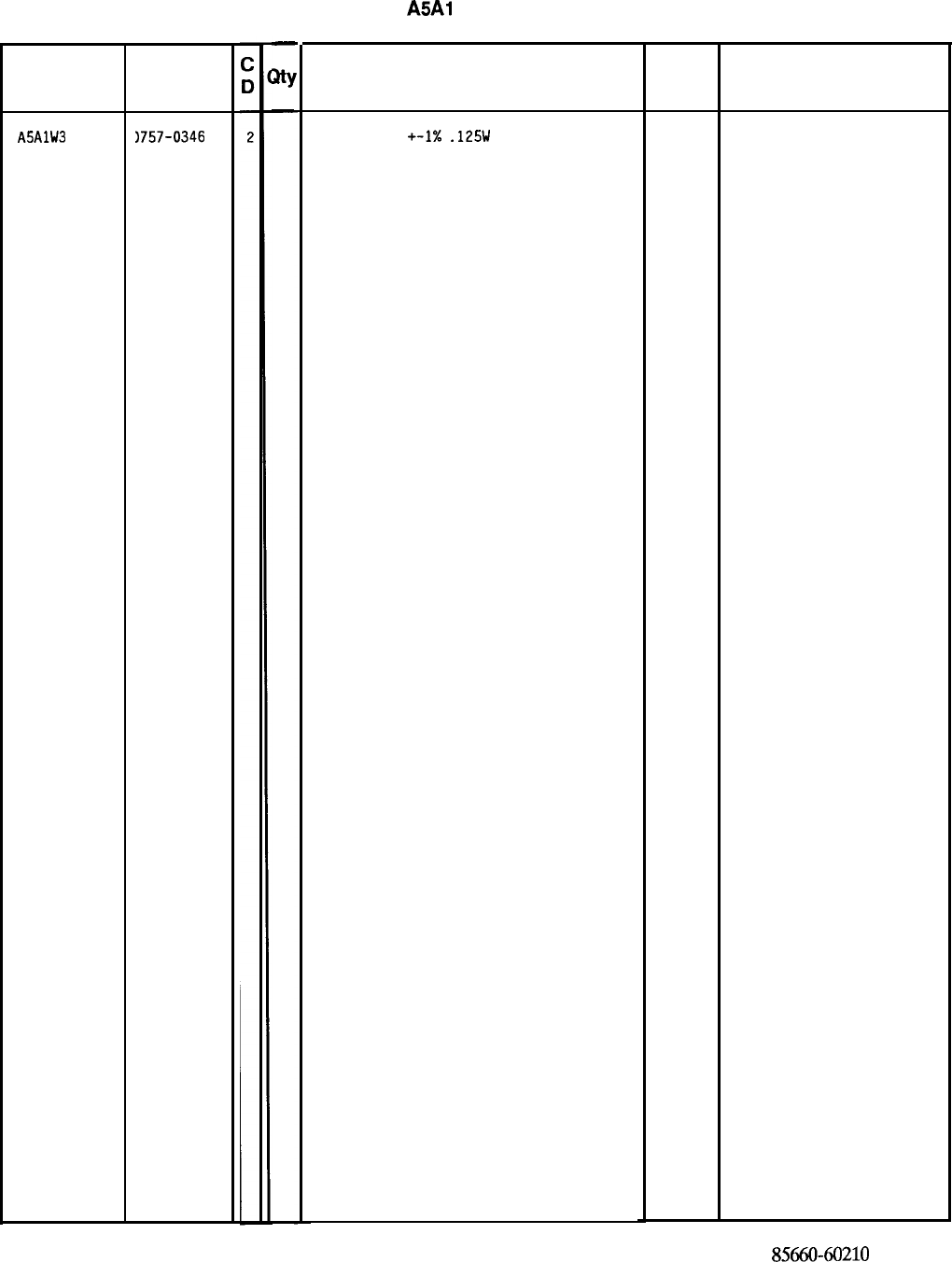
Reference
Designation
A5AlW3
HP Part
Number
1757-0346
-
sty
-
1
HP Part Number 85660-60210
ASAI
Keyboard
Description
RESISTOR 10 +-1X
.125W
TF TC=O+-100
*Indicates factory-selected value
Mfr
Code
91637
Mfr Part
Number
CMF-55-l. T-l
85660-60210 Parts List
Page 3 of 3
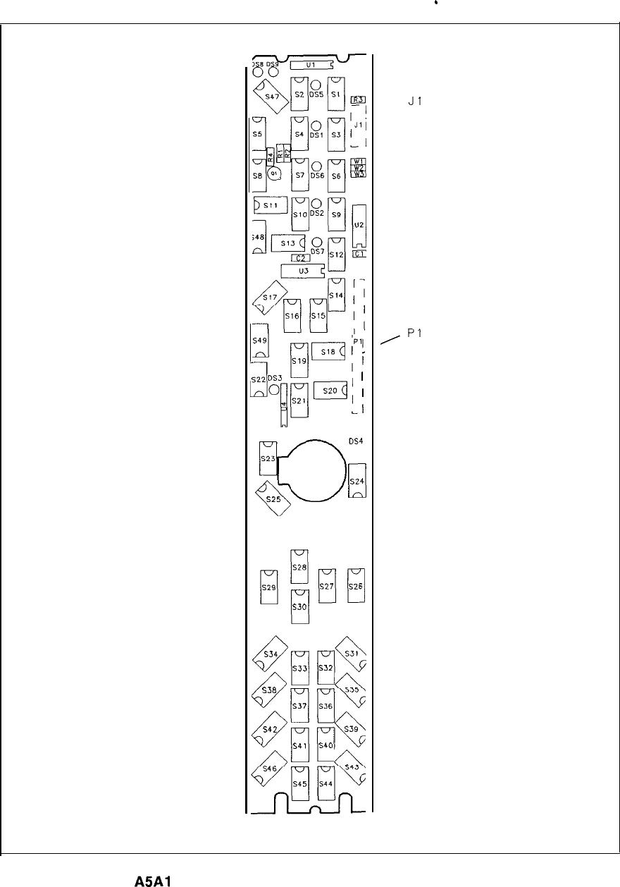
.
iI
rl
s,9
p-?J
/Il;
*T
s2,
I;
)
PI
-1
DS4
0
923
;Y)
a
Q
524
52s
S26
l$kl
527
S26
1
s30
0
s34
1
s33
8
938
rl
537
69
542
1
s41
47
546
545
J-
s31
1%
532
S36
Q
535
3.-,
rl
s39
SKI
$744
Q
543
L
Jl
I
p1
A5Al
Keyboard Component Locations, 85660-60210
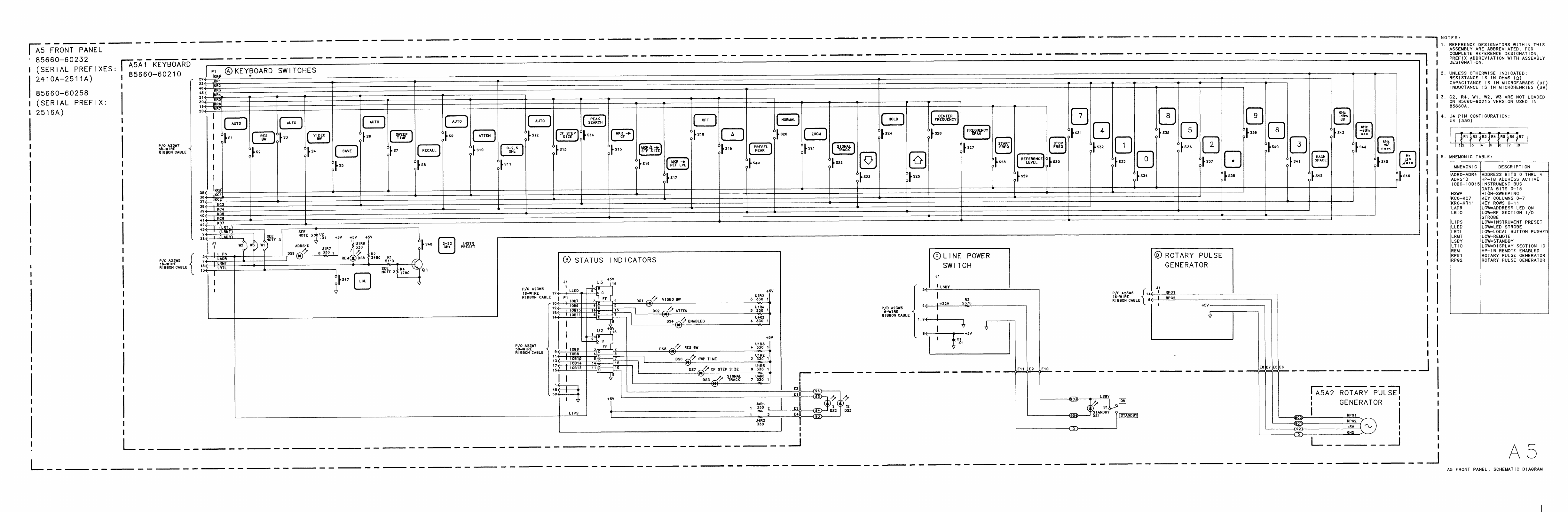
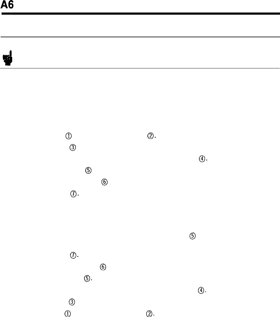
A6
A6 RF Module Replacement
Note For location of hardware and cables referred to in this procedure, see Figure 1.
Removal
1. Remove ac line cords, separate instrument sections, and remove top, bottom, and right
side covers from RF Section.
2. Remove RF front panel. (See A5 Front Panel Removal procedure in A5 Front Panel
section.)
3. Remove two clips
@)
by removing four screws
0.
4. Remove five cables
@
from A6 PC boards.
5. Remove A6 RF Module PC cover plate by removing six screws
0.
6. Disconnect coaxial cable
@
at point shown.
7. Disconnect two ribbon cables
@
from motherboard.
8. Remove five screws
0.
9. Slide the RF Module out from the mainframe.
Installation
10. Slide the RF Module into the mainframe; push coaxial cable
@
in slightly so that it does
not get caught on the mainframe.
11. Replace five screws
0.
12. Reconnect two ribbon cables
@
to motherboard.
13. Reconnect coaxial cable
0.
14. Replace A6 RF Module PC cover plate by replacing six screws
0.
15. Replace five cables
@
to A6 PC boards.
16. Replace two clips
@)
by replacing four screws
0.
17. Replace front panel.
18. Replace top, bottom, and side covers, reconnect IF and RF Sections, and reconnect ac line
cords.
A6 1
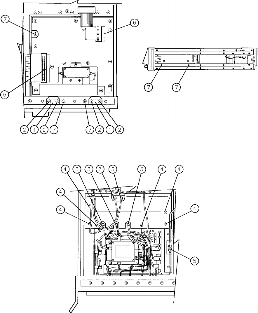
Figure 1. A6 RF Module Replacement
2 A6
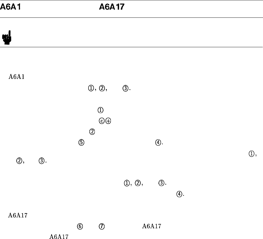
A6Al
Coaxial Switch and
A6A17
300 MHz BPF Replacement
Note For location of hardware and cables referred to in this procedure, see Figure 2.
1. Remove front panel from RF Section. (See A5 Front Panel Section for front panel removal
procedure.)
2.
A6Al
Replacement
a. Slightly loosen connectors
0,
0,
and
0.
b. Unsolder wires from the coaxial switch.
1 (brown) wire from input
Q)
3 (orange) wire from input @@
2 (red) wire from input
@
c. Release coaxial switch
@
by removing two screws
0.
d. Remove coaxial switch from three cables by completely disconnecting at connectors
0,
0,
and
0.
e. Resolder three wires to new coaxial switch.
f. Connect three cables to coaxial switch
0,
0,
and
0.
Do not tighten connectors.
g. Attach new coaxial switch to instrument with two screws
0.
h. Tighten connectors to coaxial switch.
3. A6A17 Replacement
a. Disconnect connectors
@
and
@)
and remove A6A17 BPF from mounting clips.
b. Install new A6A17 BPF in mounting clips and reconnect connectors.
4. Replace front panel. (See A5 Front Panel Section for front panel replacement procedure.)
A6 3
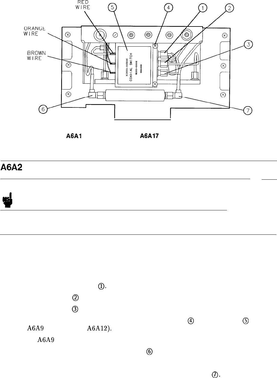
(2 PLACES)
Figure 2.
A6Al
Coaxial Switch and
A6A17
300 MHz BPF Replacement
A6A2 RF Attenuator Replacement
Note For location of hardware and cables referred to in this procedure, see Figure 3.
Removal
1. Remove front panel from RF Section. (See A5 Front Panel Section for front panel removal
procedure.)
2. Remove top and bottom covers from RF Section.
3. Disconnect attenuator cables
0.
4. Remove two screws
@
used to attach attenuator bracket to motherboard.
5. Remove two screws
@
used to attach attenuator bracket to “totem pole” assembly.
6. Remove RF Module PC board cover by removing six screws
@
and five cables
@
(three
from A6A9 and two from A6A12).
7. Remove A6A9 leaving remaining cables attached.
8. Disconnect attenuator ribbon cable connector
@
from motherboard.
9. Attenuator (attached to bracket) is now free. Remove from RF Module.
10. Remove attenuator bracket from attenuator by removing two screws
0.
4 A6
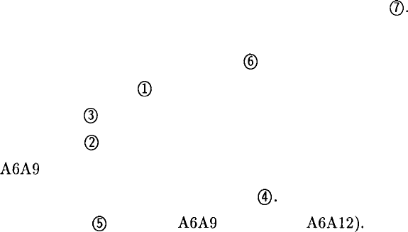
Installation
11. Attach attenuator bracket to attenuator by replacing two screws
0.
12. Place attenuator (attached to bracket) in RF Module.
13. Connect attenuator ribbon cable connector
@
to motherboard connector.
14. Align attenuator connectors
Q)
with cable connectors and tighten cable connectors.
15. Replace two screws
@
used to attach attenuator bracket to “totem pole” assembly.
16. Replace two screws
@
used to attach attenuator bracket to motherboard.
17. Replace A6A9 Phase Lock assembly.
18. Install PC board cover and replace six screws
0.
19. Reconnect five cables
@
(three to A6A9 and two to A6A12). Cables are color-coded and
color codes are marked on PC board cover.
20. Replace top and bottom covers on RF Section.
21. Replace front panel. (See A5 Front Panel Section for front panel replacement procedure.)
A6 5
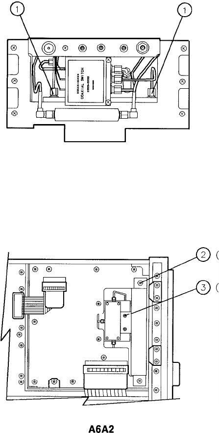
1
P
Figure 3. Replacement of
A6A2
RF Attenuator (1 of 2)
2 PLACES)
2 PLACES)
6 A6
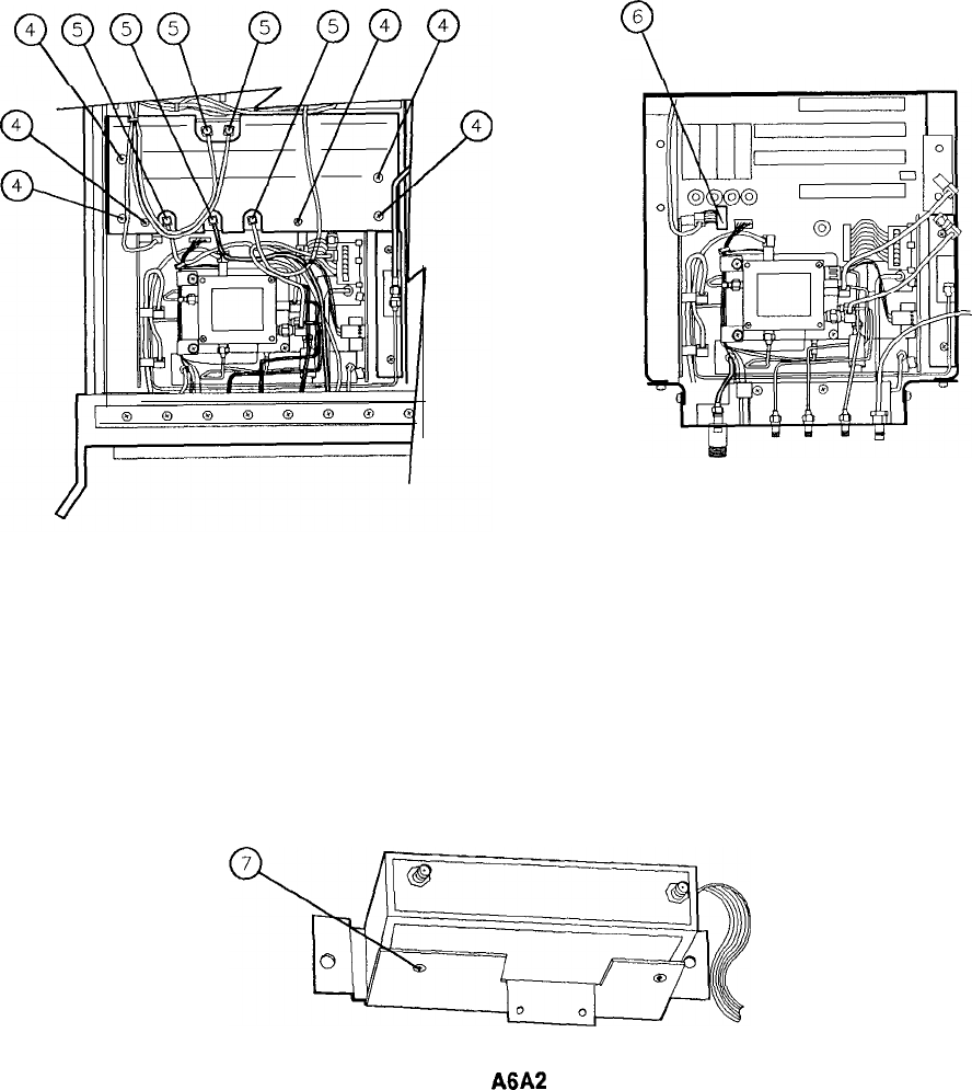
6
9
4
4
7
(2 PLACES)
Figure 3. Replacement of
A6A2
RF Attenuator (2 of 2)
A6 7
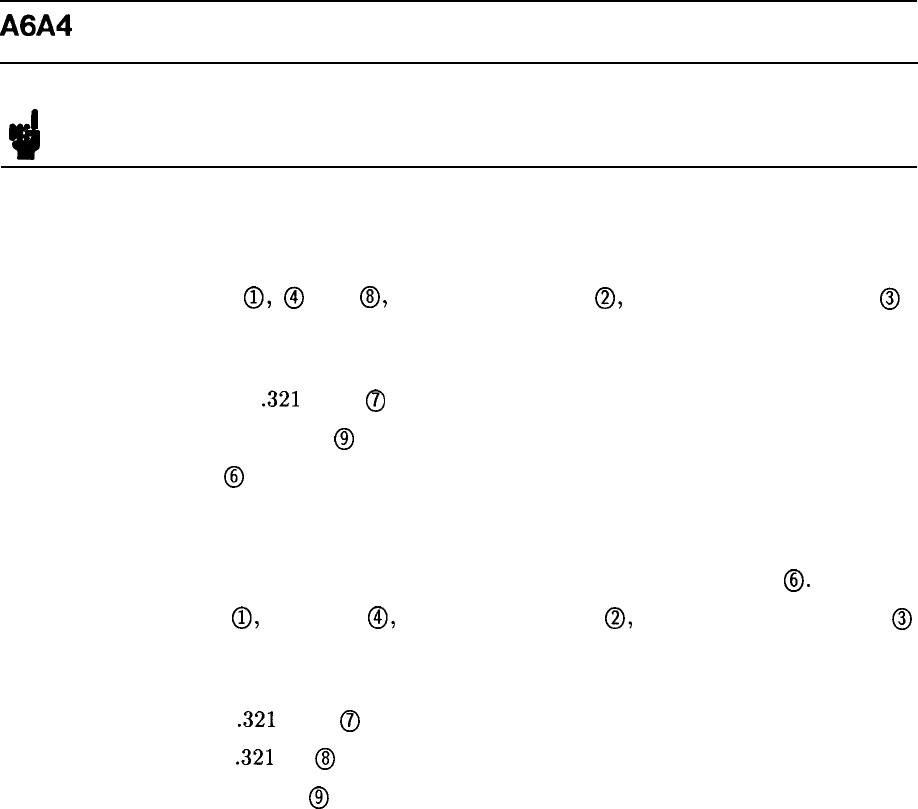
A6A4 Second Converter Replacement
Note For location of hardware and cables referred to in this procedure, see Figure 4.
Removal
1. Remove ac line cords and RF Section bottom cover.
2. Disconnect connectors
0,
@
and
0,
single-pin connector
0,
and double-pin connector
@
from Second Converter.
3. Disconnect the remaining cables from Second Converter
1 (brown) cable from
.321
OUT
(7J
4 (yellow) cable from TUNE
@
4. Remove two screws
@
to remove Second Converter from A6 RF Module.
Installation
5. Position new Second Converter on mounting bracket. Secure with two screws
0.
6. Reconnect connector
(ij,
connector
0,
single-pin connector
0,
and double-pin connector
@
to Second Converter.
7. Reconnect the following cables to Second Converter.
1 (brown) cable to
.321
OUT
0
1 (brown) cable to
.321
IN
@
4 (yellow) cable to TUNE
@
8. Replace bottom cover and ac line cords.
8 A6
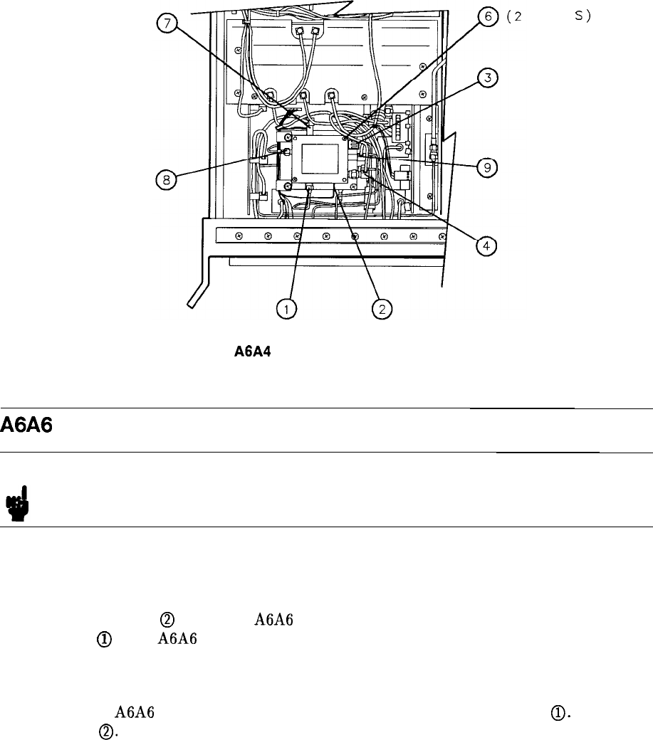
PL ACE
S)
Figure 4.
A6A4
Second Converter Replacement
A6A6 First Converter Replacement
Note For location of hardware and cables referred to in this procedure, see Figure 5.
Removal
1. Remove ac line cords, IF-Display Section, and RF Section top cover.
2. Remove two screws
@
to release A6A6 First Converter from A6 RF Module. Disconnect
connectors
@
from A6A6 First Converter.
Installation
3. Position new A6A6 First Converter in RF Module and reconnect connectors
0.
Reinstall
two screws
0.
4. Replace RF Section top cover. Attach IF-Display Section to RF Section. Reconnect ac line
cords.
A6 9
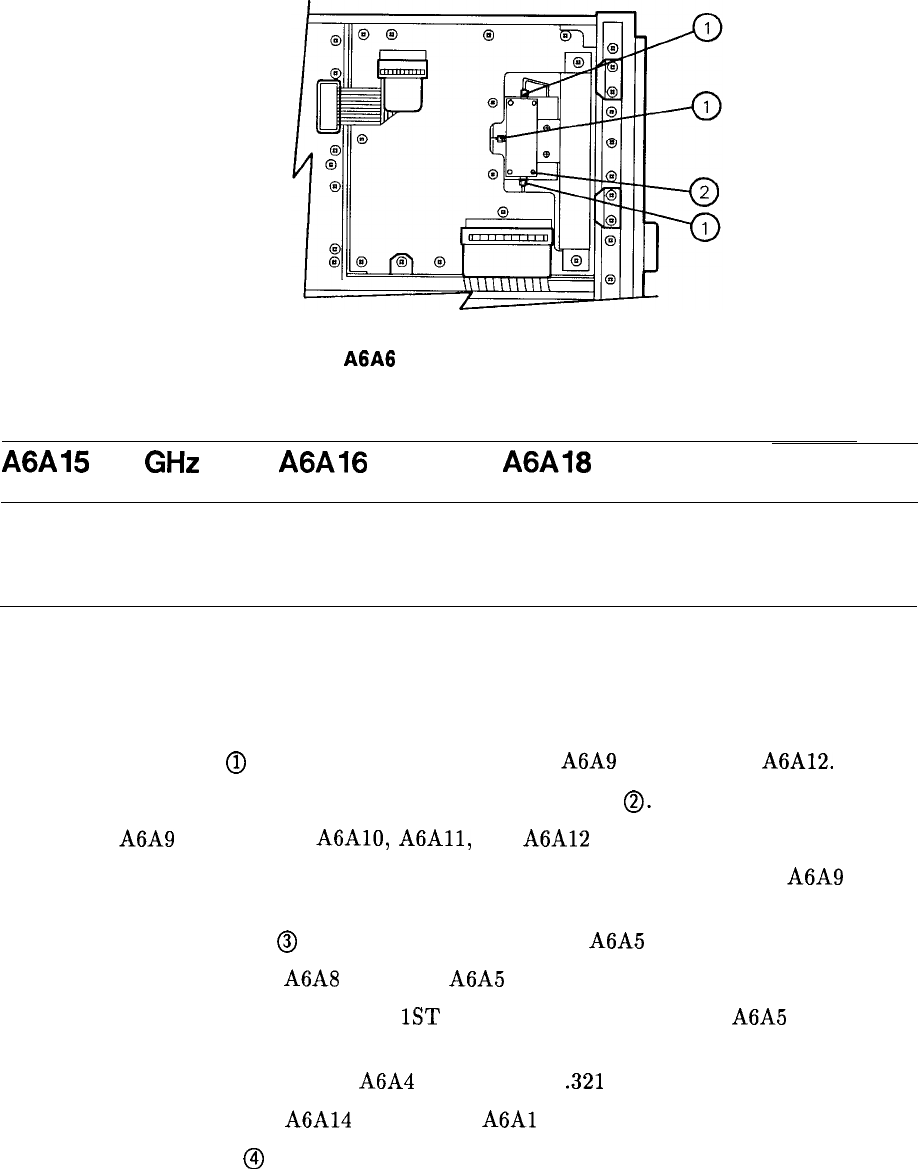
Figure 5.
A6A6
First Converter Replacement
(2 PLACES)
A6A15
3.6
GHz
BPF,
A6A16
LPF, and
A6A18
LPF Replacement
Note
3
For location of hardware and cables referred to in this procedure, see Figure 6.
Removal
1. Remove ac line cords, separate instrument sections, and remove top and bottom covers
from RF Section.
2. Remove five cables
Q)
from A6 PC boards; three from A6A9 and two from A6A12.
3. Remove RF Module PC board cover by removing six screws
0.
4. Remove A6A9 assembly and A6A10, A6A11, and A6A12 PC boards.
5. Disconnect 4 (yellow) cable and 5 (green) cable from 2nd converter to release A6A9
assembly.
6. Disconnect coaxial cable
@
between All YTO Loop and A6A5 ACLU at the ACLU.
7. Disconnect cable between A6A8 YTX and A6A5 ACLU at the YTX.
8. Disconnect cable between front-panel 1ST LO OUTPUT connector and A6A5 ACLU at
the ACLU.
9. Disconnect 1 (brown) cable from A6A4 2nd Converter
.321
OUT.
10. Disconnect cable between A6A14 Limiter and
A6Al
RF Switch at the RF Switch.
11. Remove three screws
@
used to attach ACLU cover plate one at a time, removing cable
clamp and reinstalling the screws.
12. Disconnect wire harness connectors from ACLU and 2nd Converter to release wire harness
from the “totem pole” assembly.
10 A6
13. Disconnect cable between front-panel IF OUTPUT connector and A6A5 ACLU at the
ACLU.
14. Disconnect cable between front-panel IF INPUT connector and A6A16 LPF at the LPF.
15. Disconnect wire harness plug from motherboard and position wire harness such that the
“totem pole” assembly can be removed.
16. Remove two screws
@
attaching the “totem pole” assembly to the motherboard and two
screws
@
attaching the “totem pole” assembly to the attenuator bracket.
17. Remove the “totem pole” assembly from RF Module.
18. A6A15, A6A16, OR A6A18 can now be replaced by disconnecting attached cables.
Installation
19. Replace A6A15, A6A16, or A6A18 in the “totem pole” assembly and reconnect cables.
20. Place the “totem pole” assembly in the RF Module.
21. Replace two screws
@
to attach the “totem pole” assembly to the motherboard and two
screws
@
to attach the “totem pole” assembly to the attenuator bracket.
Caution
9
The YIG-Tuned Mixer (YTX) contains an extremely small and sensitive
diode. A reverse voltage in excess of 3 volts may damage it. It is connected
directly to the center conductor of the LO/IF connector, and is especially
susceptible to blowout from electrostatic discharge. Before connecting any
cable to this connector, first discharge the cable by connecting the center
conductor to ground. It is recommended that the other end of the cable be
connected first. Once the cable is properly installed (from the YTX to the
ACLU), the BIAS pin of the ACLU is connected to the YTX diode and must
also be treated with caution. A general rule is to connect all devices to ground
before connecting them to the BIAS pin on the ACLU.
22. Reconnect cable to A6A8 YTX.
23. Reconnect cable to
A6Al
RF Switch.
24. Reconnect cable from front-panel 1ST LO OUTPUT to A6A5 ACLU.
25. Reconnect cable from front-panel IF OUTPUT to A6A5 ACLU.
26. Reconnect cable from front-panel IF INPUT to A6A16 LPF.
27. Reconnect cable
@
between All YTO Loop and A6A5 ACLU.
28. Reconnect 1 (brown) cable to and converter
.321
OUT.
29. Remove three screws
@
from A6A5 ACLU cover plate one at a time replacing cable
clamps then replacing screws.
A6 11
30. Reconnect all wire harness connectors to A6A5 ACLU and A6A4 2nd Converter as
follows.
n A6A4 2nd Converter
green
(5)
Wire
to
IE
white/brown (91) wire to
V,
white/black (90) wire to SW
n A6A5 ACLU
gray (8) wire to BIAS
white/red (92) wires to
+5
V dc (three pins)
31. Reconnect wire harness to motherboard.
32. Replace A6A9 assembly and A6A10,
A6Al1,
and A6A12 PC boards.
33. Replace PC board cover and install six screws
0.
34. Reconnect 4 (yellow) cable and 5 (green) cable to 2nd Converter.
35. Reconnect five cables
0
to A6 PC boards; three to A6A9 and two to A6A12.
36. Replace top and bottom covers on RF Section, recombine instrument sections, and
reconnect ac line cords.
12 A6
II’
I
d
5
0
6
(2 PLACES) (2 PLACES)
(3 PLACES)
TOTEM POLE
ASSEMBLY
A6A4
/
SECOND
CONVERTER
A6A5
ACLU
A6A16
1.5 GHz
LPF
A6A18
4.0 GHz
LPF
(CABLE)
A6i15
AiA6
3.6 GHz F I RST
BPF CONVERTER
Figure 6.
A6A15
BPF,
A6A16
LPF, and
A6A18
LPF Replacement
A6 13
A6W16
A6W17
WI
A6W15
A6W14
A6W18
A6A3
A6A4
A6W15
‘TOTEM POLE’
ASSEMBLY (SEE
SHEET 3 OF
THIS FIGURE)
A6All
A6AlO
A6W12
A6A9A
1
UNLOCK
INDICA
Wll
A6W19
A6W3
A6W12
-j----
A6A8
A6W6
A6A7
A6Wll
A6W2
A6A14
A6’i’l
A6i2
A6’ilO
A6W8
A6W13
A6W7
A6W23
A6W20
Figure 7. A6 RF Module, Parts Identification (1 of 6)
DSI
,TOR
14 A6
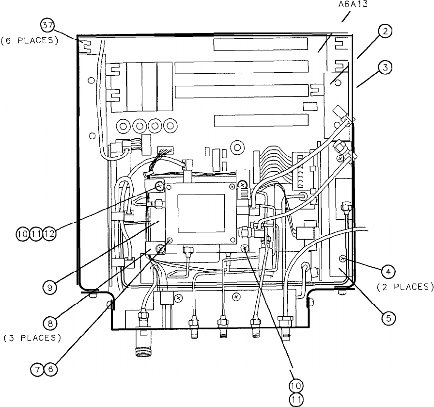
(3 PLACES)
A6A13
/
3
3
5
0
(2 PLACES)
$
10
11
Figure 7. A6 RF Module, Parts Identification (2 of 6)
2
P
3
/o
A6 15
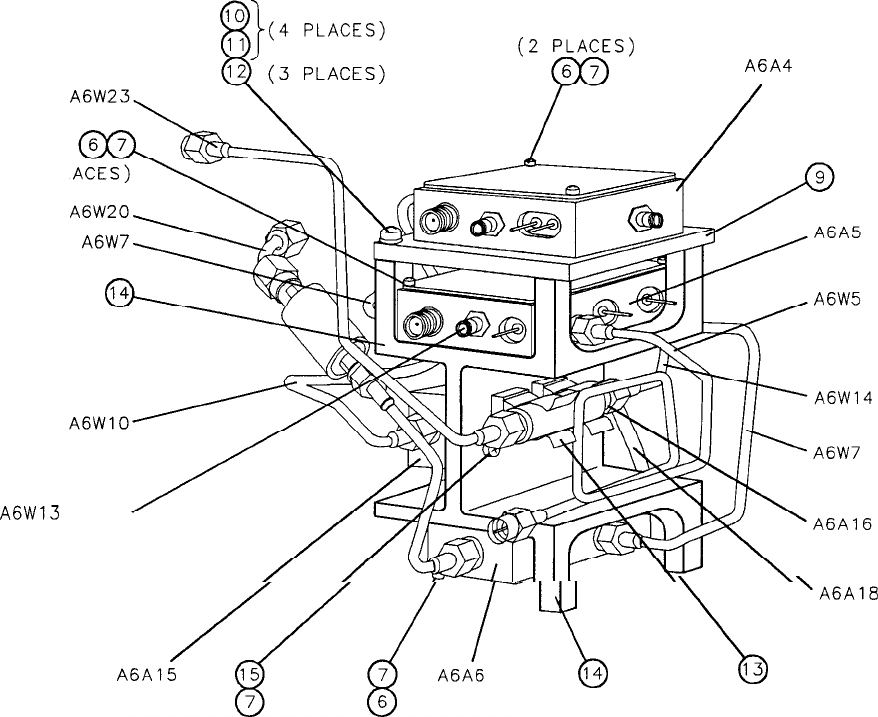
A6A4
(2 PL
A6W13
ROUTES TO
FRONT PANEL
A6Al5/[
,/.A/-
\
\
‘A6A18
76(2 PLACES)
(2 PLACES) (2 PLACES)
Figure 7. A6 RF Module, Parts Identification (3 of 6)
16 A6
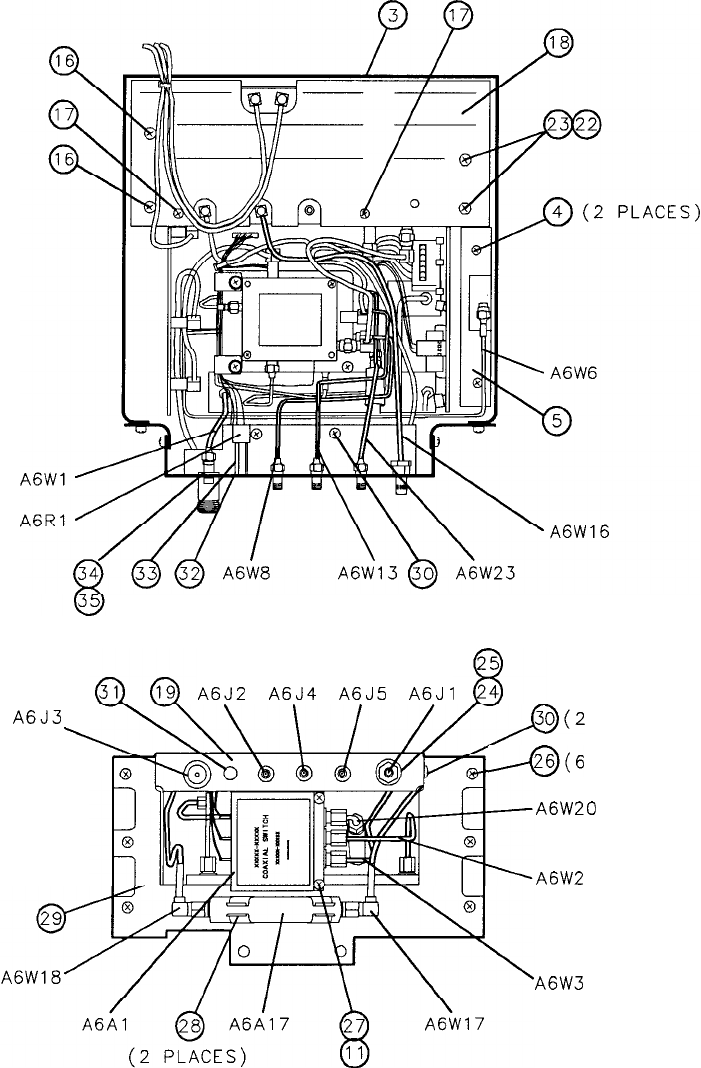
(2 PLACES)
A6J3
\
A6J2
A6J4
A6J.5
A6Jl
9(2
,@(6
A6W20
A6W2
A6W3
(2 PLACES)
PLACES)
PLACES)
Figure 7. A6 RF Module, Parts Identification (4 of 6)
A6 17
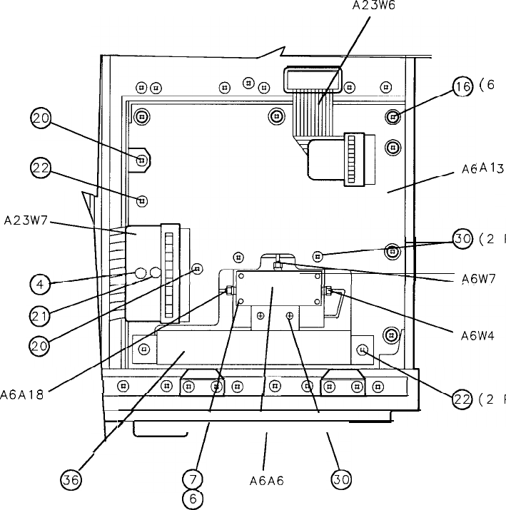
A23W6
0
v
w
A23W7
A
A6A18
/
0
36
(6 PLACES)
,A1
46W7
lo
/
7
1
I I
I I
I
\
-d
.!A6
i
w
(2 PLACES)
(2 PLACES)
PLACES)
PLACES)
Figure 7. A6 RF Module, Parts Identification (5 of 6)
18 A6
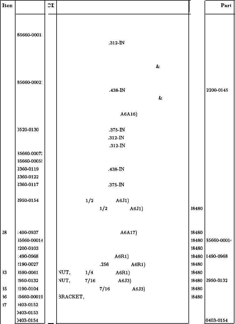
Iten
1
2
3
4
5
6
7
8
9
10
11
12
13
14
15
16
17
18
19
20
21
22
23
24
25
26
27
18
29
30
31
32
$3
34
$5
56
s7
HP Part
Number
0400-0009
8566900021
8566@0001,
2360-0116
856690002:
0520-0137
2190-0890
1400-0053
B566&0002:
2200-0145
2190-0003
3050-0105
1400-0942
356692007:
3520-0130
2360-0115
2200-0105
35660-0007:
35660-00051
1360-0119
2360-0122
1360-0117
3050-0010
1950-0154
1190-0054
1360-0113
1200-0151
L400-0937
$5660-00014
!200-0103
:490-0968
!190-0027
1590-0061
!950-0132
!190-0104
1566&00019
1403-0152
3403-0153
34030154
:I:
Description
-
9
6
9
5
9
8
1
4
7
2
8
6
0
0
1
4
4
0
1
8
3
6
2
2
9
2
0
3
8
2
9
6
4
6
0
3
9
0
1
-
GROMMET, RUBBER (FOR W2)
AIR DUCT, RF MODULE
BRACKET, MAIN, RF MODULE
SCREW, MACH, 632,
.312-IN
LG, FLAT HD
HEAT SINK, YTX CURRENT DRIVER
SCREW, MACH, 2-56, .75-IN LG, PAN HD
WASHER, SPLIT, 2-56 (FOR SCREWS (6)
&
(15))
CABLE CLAMP (FOR SCREW (10))
MOUNTING PLATE, 2ND CONVERTER
SCREW, MACH, 4-40,
.43&IN
LG, PAN HD
WASHER, SPLIT, 4-40 (FOR SCREWS (10)
&
(27))
WASHER, FLAT, 4-40 (FOR SCREWS (10))
COMPONENT CLIP (FOR A6A16)
MOUNT, MICROCIRCUIT, “TOTEM POLE”
SCREW, MACH, 2-56,
.375-IN
LG, PAN HD
SCREW, MACH, 632,
.312-IN
LG, PAN HD
SCREW, MACH, 4-40,
.312-IN
LG, PAN HD
COVER, RF MODULE PC BOARD
BRACKET, CONNECTOR, RF MODULE
SCREW, MACH, 632,
.438-IN
LG, PAN HD
SCREW, MACH, 632, .5-IN LG, FLAT HD
SCREW, MACH, 632,
.375-IN
LG, PAN HD
WASHER, FLAT, 632 (FOR SCREW (22))
NUT, HEX,
l/2
IN (FOR
A6Jl)
WASHER, LOCK,
l/2
IN (FOR
A6Jl)
SCREW, MACH, 632, .25-IN LG, PAN HD
SCREW, MACH, 4-40, .75-IN LG, PAN HD
COMPONENT CLIP (FOR A6A17)
BRACKET, FRONT, RF MODULE
SCREW, MACH, 4-40, .25-IN LG, PAN HD
PANEL BUSHING (FOR
A6Rl)
WASHER, LOCK,
.256
ID (FOR
A6Rl)
VUT,
HEX,
l/4
IN (FOR
A6Rl)
VUT,
HEX,
7/16
IN (FOR A6J3)
WASHER, LOCK,
7/16
IN (FOR A6J3)
3RACKET, ATTENUATOR, RF MODULE
30ARD GUIDE, BLACK
BOARD GUIDE, BROWN
BOARD GUIDE, RED
Mfr
Code
28480
28480
28480
28480
28480
28480
28480
28480
28480
28480
28480
28480
28480
28480
28480
28480
28480
28480
28480
28480
28480
28480
18480
18480
28480
18480
18480
!8480
!8480
!8480
!8480
!8480
!8480
!8480
!8480
!8480
18480
28480
28480
Mfr
Pari
Number
04004009
85660-0002
85660-0001
2360-0116
85660-0002
0520-0137
2190-0890
1400-0053
85660-0002
2200-0145
2190-0003
3050-0105
14009942
85660-2007
0520-0130
2360-0115
2200-0105
85660-0007:
85660-0005.
2360-0119
2360-0122
2360-0117
3050-0010
2950-0154
2190-0054
2360-0113
2200-0151
14009937
35660-0001~
2200-0103
14904968
2190-0027
1590-0061
2950-0132
2190-0104
35660-0001’
1403-0152
04030153
04030154
Figure 7. A6 RF Module, Parts Identification (6 of 6)
A6 19
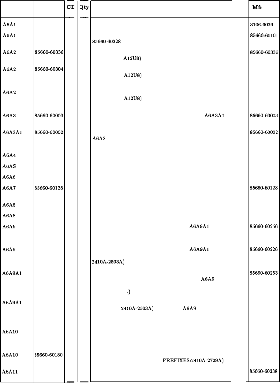
Reference
Designator
A6Al
31066029
A6Al
85660-60101
-
CE
-
2
0
A6A2 B5660-60336 3
A6A2
55660-60304
5
A6A2 55660-60121 4
A6A3
35660-60003
1
A6A3Al
35660-60002
0
A6A4 50867248
9
AGAS
50867133
1
A6A6 50867247 8
A6A7
35669-60128
1
A6A8 50867226 3
A6A8 50866226
1
A6A9 35660-60256 6
A6A9 35660-60226
A6A9Al
35660-60253
A6A9Al
35660-60202
A6AlO 35660-60322
A6AlO
35660-60180
A6All
35660-60238
0
3
2
7
5
4
-
HP Part
Number
-
Qty
-
1
1
1
1
1
1
1
1
1
1
1
1
1
1
1
1
1
1
1
1
-
RF Module
Description
RF SWITCH SPDT F SMA
RF SWITCH (OBSOLETE. ORDER HP PART NUMBER
8566@60228 FOR REPLACEMENT.)
RF ATTENUATOR/ERROR CORRECTION ROM
(INCLUDES A12U8)
RF ATTENUATOR/ERROR CORRECTION ROM
(INCLUDES A12U8) (OBSOLETE. ORDER HP PART
NUMBER 8566669336 FOR REPLACEMENT.)
RF ATTENUATOR/ERROR CORRECTION ROM
(INCLUDES A12U8) (OBSOLETE. ORDER HP PART
NUMBER 8566969336 FOR REPLACEMENT.)
LAST CONVERTER ASSEMBLY (INCLUDES
A6A3Al
LAST CONVERTER BOARD)
BOARD ASSEMBLY, LAST CONVERTER (PART OF
A6A3 LAST CONVERTER ASSEMBLY. MAY NOT BE
ORDERED SEPARATELY.)
SECOND CONVERTER
AMPLIFIER/COUPLER/LOAD UNIT (ACLU)
FIRST CONVERTER
BOARD ASSEMBLY, YIG-TUNED MIXER CURRENT
DRIVER
YIG-TUNED MIXER (YTX) (NEW)
YIG-TUNED MIXER (YTX) (RESTORED 5086-7226)
PHASE LOCK ASSEMBLY (INCLUDES
A6A9Al
PHASE
LOCK BOARD) (SERIAL NUMBER PREFIXES: 2504A
AND ABOVE)
PHASE LOCK ASSEMBLY (INCLUDES
A6A9Al
PHASE
LOCK BOARD) (SERIAL NUMBER PREFIXES:
2410A-2503A)
BOARD ASSEMBLY, PHASE LOCK (SERIAL NUMBER
PREFIXES: 2504A AND ABOVE) (PART OF A6A9
PHASE LOCK ASSEMBLY. MAY NOT BE ORDERED
SEPARATELY
.)
BOARD ASSEMBLY, PHASE LOCK (SERIAL NUMBER
PREFIXES: 2410A-2503A) (PART OF A6A9 PHASE
LOCK ASSEMBLY. MAY NOT BE ORDERED
SEPARATELY.)
BOARD ASSEMBLY, MISCELLANEOUS BIAS/RELAY
DRIVER (SERIAL NUMBER PREFIXES: 2747A AND
ABOVE)
BOARD ASSEMBLY, MISCELLANEOUS BIAS/RELAY
DRIVER (SERIAL NUMBER PREFIXES:2410A-2729A)
BOARD ASSEMBLY, SLOPE GENERATOR (SERIAL
NUMBER PREFIXES: 2613A AND ABOVE)
Mfr
MD
Part
Code Number
28480
3106-0029
28480
85660-60101
28480
85660-60336
28480 85660-60304
28480 85660-60121
28480
B5660-60003
28480
8566~60002
28480 50867248
28480 50867133
28480 50867247
28480
55660-60128
28480 5086-7226
28480 50866226
28480
55660-60256
28480
35660-60226
28480
35660-60253
28480 35660-60202
28480 35660-60322
28480 35660-60180
28480
35660-60238
20 A6
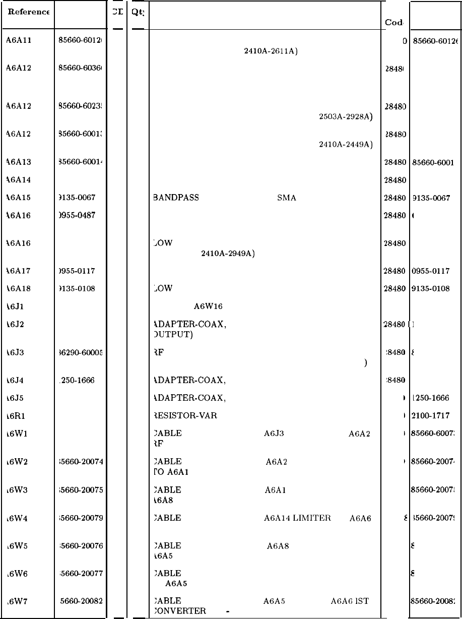
RF Module (continued)
Reference
Designato
A6All
HP Part
Number
85660-60121
-
ZL
-
9
A6A12
85660-60361 9
46A12
55660-6023!
1
46A12
!35660-6001:
3
46A13
35660-6001~ 4
\6A14 5086-7261
6
i6A15
2135-0067
5
\6A16 1955-0487
2
16A16 5086-7299 0
16A17
i6A18
k6Jl
16J2
3955-0117
)135-0108
5
5
1250-1666
8
k6J3 %6290-60005
7
L6J4
.250-1666
8
L6J5
250-1666 8
L6Rl
!lOO-1717 4
16Wl
15660-20073
7
k6W2
1566@20074
t6W3
;566G20075
~6W4
;5660-20079
~6W5
;5660-20076
16W6 ~5660-20077
,6W7
5660-20082
2
3
7
4
5
2
-
-
Qt:
-
1
1
1
1
1
1
1
1
1
1
1
1
1
1
1
1
1
1
1
1
1
1
1
-
Description
BOARD ASSEMBLY, SLOPE GENERATOR (SERIAL
NUMBER PREFIXES: 2410A-2611A)
BOARD ASSEMBLY, YIG-TUNED MIXER (YTX)
DRIVER (SERIAL NUMBER PREFIXES: 2936A AND
ABOVE)
BOARD ASSEMBLY, YIG-TUNED MIXER (YTX)
DRIVER (SERIAL NUMBER PREFIXES:
2503A-2928A
BOARD ASSEMBLY, YIG-TUNED MIXER (YTX)
DRIVER (SERIAL NUMBER PREFIXES: 2410A-2449A)
BOARD ASSEMBLY, RF MODULE MOTHERBOARD
LIMITER, 0-2.5 GHZ
BANDPASS
FILTER, 3.6 GHZ, SMA CONNECTORS
LOW PASS FILTER, 1.0 GHZ (SERIAL NUMBER
PREFIXES: 2950A AND ABOVE)
LOW
PASS FILTER, 1.5 GHZ (SERIAL NUMBER
‘REFIXES: 2410A-2949A)
3ANDPASS FILTER, 300 MHZ
,OW
PASS FILTER, 26 GHZ
‘ART OF A6W16 (CAL OUTPUT)
iDAPTER-COAX,
STR F-SMA F-SMA (FIRST LO
1UTPUT)
tF
INPUT CONNECTOR, TYPE N (INDIVIDUAL
‘ARTS ARE LISTED IN GENERAL PARTS LISTING
iDAPTER-COAX,
F-SMA F-SMR (IF OUTPUT)
iDAPTER-COAX,
F-SMA F-SMA (IF INPUT)
tESISTOR-VAR CONTROL CCP 50K 20% LIN
1
a
:
:
:
;
2
2
2
2
2
2
2
2
2
2
2
2
2
2
2
:ABLE ASSEMBLY, COAX A6J3 RF INPUT TO A6A2
tF ATTENUATOR (0-22 GHZ)
:ABLE ASSEMBLY, COAX A6A2 RF ATTENUATOR
r0
A6Al
RF SWITCH (O-22 GHZ)
:ABLE ASSEMBLY, COAX
A6Al
RF SWITCH TO
i6A8 YTX (2-22 GHZ)
:ABLE ASSEMBLY, COAX A6A14
LIR4ITER
TO A6A6
ST CONVERTER (O-2.5 GHZ)
:ABLE ASSEMBLY, COAX A6A8 YTX TO/FROM
L6A5
ACLU
:ABLE ASSEMBLY, COAX AT2 3DB ATTENUATOR
‘0 A6A5 ACLU (YTO LOOP OUT)
:ABLE ASSEMBLY, COAX A6A5 ACLU TO
AGA6
IST
:ONVERTER (3.6
-
6.1 GHZ)
,
Mfr
Cod’
28481
2848(
2848(
1848(
1848(
1848(
!848(
!848C
!848C
!848C
!848C
!848C
1848C
1848C
‘8480
‘8480
8480
8480
8480
8480
8480
8480
8480
e
cl
3
I
I
I
1
1
1!
1
I
1
!
I
I
)
!
)I
I
f
I
I
I
I
I
:
1
6
1
E
E
E
8
8
8
Mfr Part
Number
85660-6012e
85660-60366
85660-6023
85660-6001
65660-6001
5086-7261
9135-0067
39554487
5086-7299
1955-0117
>135-0108
1250-1666
36290-6000
1250-1666
L250-1666
!lOO-1717
15660-6007:
$5660-2007)
!5660-2007!
!5660-2007!
15660-20076
15660-2007:
;5660-2008:
A6 21
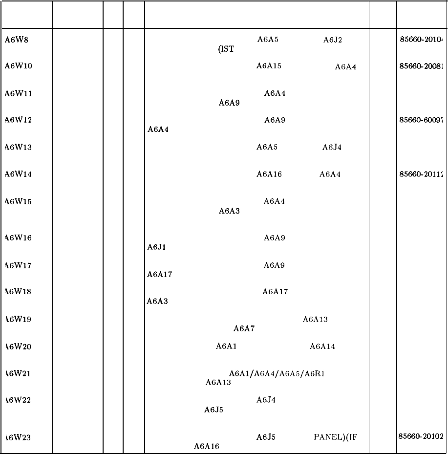
RF Module (continued)
Reference HP Part CD Qty Description Mfr Mfr Part
Designator Number Code Number
A6W8
85660-20104 9
1
CABLE ASSEMBLY, COAX A6A5 ACLU TO
A6J2 28480
85660-2010~
(FRONT PANEL)
(1ST
LO OUTPUT)
A6WlO
85660-20081
11
CABLE ASSEMBLY, COAX A6A15 3.6 GHZ TO
AFA4 28480 85660-20081
SECOND CONVERTER (3621.4 MHZ) BPF
A6Wll
85660-60055 3
1
CABLE ASSEMBLY, COAX 5 A6A4 SECOND
28480
856606005:
CONVERTER TO A6A9 PHASE LOCK (3.3 GHZ)
A6W12 85660-60097
3
1
CABLE ASSEMBLY, COAX 4 A6A9 PHASE LOCK TO
28480 85660~6009:
A6A4 SECOND CONVERTER (TUNE VOLTAGE)
A6W13
85660-20103
8
1
CABLE ASSEMBLY, COAX A6A5 ACLU TO
A6J4 28480
85660-2010:
(FRONT PANEL) (IF OUTPUT)
A6Wl4
85660-20112 9
1
CABLE ASSEMBLY, COAX A6A16 LPF TO A6A4
28480 85660-20112
SECOND CONVERTER (321.4 MHZ)
46W15 8566960057
5
1
CABLE ASSEMBLY, COAX 1 A6A4 SECOND
28480
8566060055
CONVERTER TO A6A3 LAST CONVERTER (321.4
MHZ)
46W16
85660-60058
6
1
CABLE ASSEMBLY, COAX 0 A6A9 PIIASE LOCK TO
28480
8566060058
A6Jl
(FRONT PANEL) (CAL OUTPUT)
46W17
85660-60056
4
1
CABLE ASSEMBLY, COAX 2 A6A9 PHASE LOCK TO
28480
8566060056
A6A17 300 MHZ BPF (300 MHZ)
16W18
85660-60054
2
1
CABLE ASSEMBLY, COAX 2 A6A17 300 MHZ BPF TO
28480
8566060054
A6A3 LAST CONVERTER (300 MHZ)
16W19 8120-2847
11
CABLE ASSEMBLY, 14 WIRE-RIBBON A6A13 RF
28480 8120-2847
MOTHERBOARD TO A6A7 YTX CURRENT DRIVER
i6W20
1250-1397
2
1
ADAPTER-COAX
A6Al
RF SWITCH TO A6A14
28480 1250-1397
LIMITER (O-2.5 GHZ)
i6W21 85660-60060
0
1
CABLE ASSEMBLY,
A6Al/A6A4/A6A5/AGRl
28480
8566060060
HARNESS TO A6A13 RF MOTIIERBOARD
\6W22 85660-20101 6
1
CABLE ASSEMBLY, COAX
A6J4
(FRONT PANEL) (IF
28480 85660-20101
OUTPUT) TO
A6J5
(FRONT PANEL)(IF INPUT)
(FRONT PANEL JUMPER)
i6W23
85660-20102
7
1
CABLE ASSEMBLY, COAX
A6J5
(FRONT PANEL)(IF
28480 85660-20102
INPUT) TO A6A16 LPF (321.4 MHZ)
22 A6
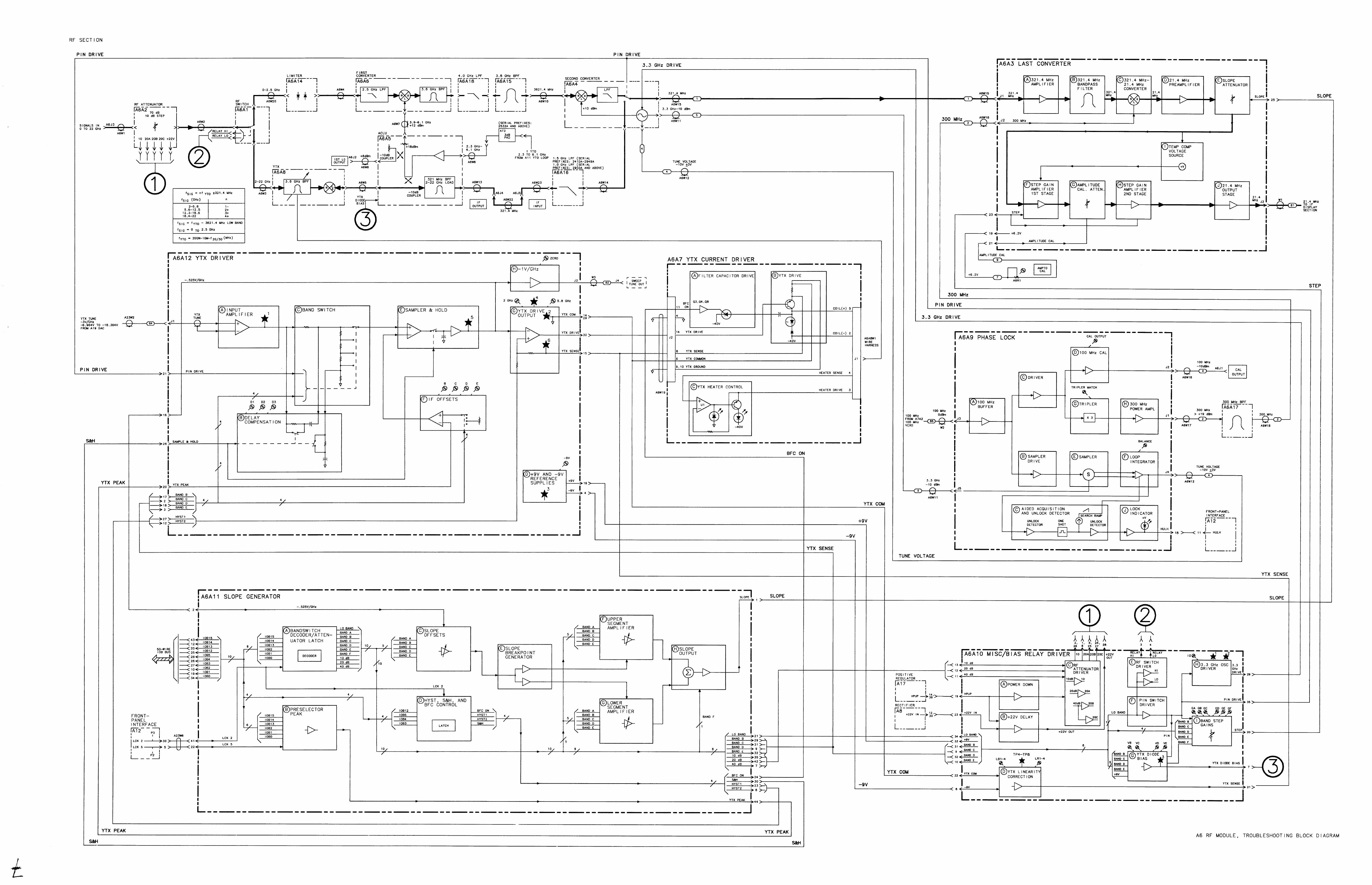
A6A3
A6A3 Last Converter, Circuit Description
The Last Converter has three main purposes:
1. Converting the 321.4 MHz IF signal from the A6 RF Module down to 21.4 MHz for
processing by the IF-Display Section.
2. Providing the means for correcting for variations in conversion loss versus frequency in the
input circuitry.
3. Filtering out 278.6 MHz image response.
The Last Converter consists of 11 basic elements. They are a 321.4 MHz amplifier, a 321.4
MHz
bandpass
filter, a 321.4 to 21.4 MHz converter a 21.4 MHz preamp, two pin diode
attenuators, two pin diode controlled variable gain amplifiers, an output stage, a temperature
compensation circuit, and power supply filtering.
Power Supplies
@
The power supply filtering consists of series inductors and shunt capacitors (L21 to L24
and C49 to C53). In addition to this, R38 and
VRl
provide a 6.2 V source used for biasing
transistors.
321.4 MHz Amplifier
@
The 321.4 MHz amplifier consists of Q8 and its associated circuitry. Q7 provides bias for
QS
by setting the base current.
321.4 MHz Bandpass Filter
@
The 321.4 MHz amplifier drives the 321.4 MHz
bandpass
filter which consists of L4 to L8
and C8 to C12. This filter is made up of five LC tank circuits coupled magnetically and
capacitively. Capacitive coupling occurs through PC board traces on the circuit side of the PC
board. Coupling into and out of the filter is done with tapped inductors L4 and L8. The filter
is tuned by means of C8 to C12. This filter rejects the 278.6 MHz image response.
321.4 to 21.4 MHz Converter
@
The 321.4 MHz filter drives the 321.4 to 21.4 MHz converter. This converter consists of a
packaged double-balanced mixer,
Ul.
The 300 MHz LO for this converter comes from the
A6A9 Phase Lock.
A6A3
1
21.4 MHz Preamplifier
0
The 321.4 to 21.4 MHz converter drives the 21.4 MHz preamp which consists of Q6 and
its associated components. Q5 provides bias for Q6 by setting the base current. LlO, C22,
and C23 form a series resonant circuit producing a notch in the frequency response of this
amplifier at 10.7 MHz. This is to prevent the second harmonic of 10.7 MHz from causing a
spurious response.
Slope Attenuator
@
The HP 8566 is a harmonic mixing spectrum analyzer, and as such has five bands of
frequencies to cover the range of 0 to 22 GHz. When changing from band to band, the
conversion loss of the input mixer changes. Also within each band there are variations of
conversion loss with frequency.
The variations of conversion loss within each band are compensated by pin diodes CR1 to
CR4 and associated circuitry. Pin diodes have a property of changing RF impedance as
their dc current is varied. Thus
CRl/CR2
and
CR3/CR4
form the two elements of a voltage
divider. The current through
CRl/CR2
is fixed by RlO and
Rll.
The current through
CR3/CR4
is determined by circuitry on the
A6All
Slope Generator. This forms a current
controlled variable attenuator. Pin diodes
CRl/CR2
are used in place of a fixed resistor to
provide temperature tracking with
CR3/CR4.
Step Gain Amplifier 1
@
and Step Gain Amplifier 2
@)
The variations of conversion loss from band to band are compensated for by two identical
variable gain amplifiers made up of Q3 and
QlO
and associated circuitry (Q4 and
Q9
are
emitter follower buffers). A simplified circuit of one of these stages is shown in Figure 1. The
gain of the amplifier is determined approximately by the following equation.
Gain
M
Impedance (CR8, CR9, and CRlO)
Impedance (CR5, CR6, and CR7)
The impedance of CR8, CR9, and CR10 is determined by R23 and temperature compensation
circuitry
(Ql).
The impedance of CR5, CR6, and CR7 is determined by the current from the step gain circuit
on the A6AlO Relay Driver.
2
A6A3
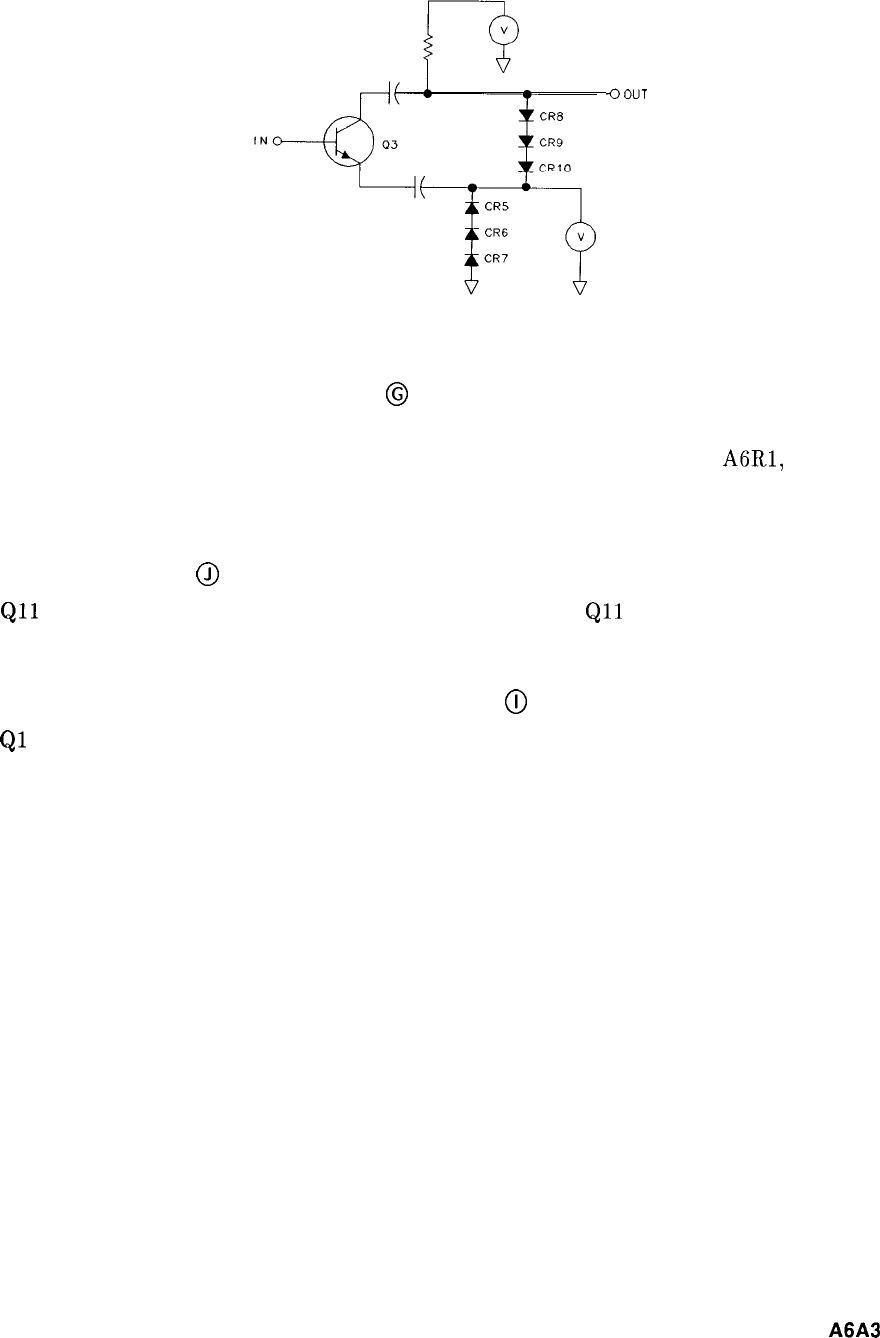
Q
OUT
Figure 1. Step Gain Amplifier, Simplified Schematic
Amplitude Calibration Attenuator
@
Q2 is an emitter follower buffer driving a second pin diode attenuator, CR11 to CR14. The
current through CR11 and CR12 is determined by the front-panel control A6R1, AMPTD
CAL. The current through CR13 and CR14 is fixed by R27. This circuit provides for
amplitude calibration of the instrument.
21.4 MHz Output
@
Qll
and Q12 form the output stage for the Last Converter.
Qll
is an emitter follower driving
a common emitter amplifier Q12.
Temperature Compensation Voltage Source
@
Ql
provides a voltage to set the current in CR8 to CR10 and CR15 to CR17. This voltage
varies with temperature, changing the gain of the two step-gain amplifiers to compensate for
gain changes with temperature elsewhere in the Last Converter.
A6A3
3
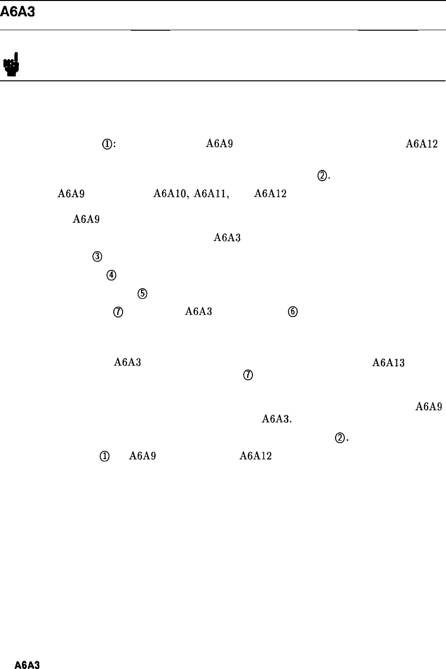
A6A3 Last Converter Replacement
Note For location of hardware and cables referred to in this procedure, see Figure 2.
Removal
1. Remove ac line cords and RF Section bottom and right side covers.
2. Disconnect cables @: three from top of A6A9 Phase Lock assembly and two from A6A12
YTX Driver board.
3. Remove A6 RF Module PC cover plate by removing six screws
0.
4. Remove A6A9 assembly and
A6Al0,
A6Al1,
and A6A12 PC boards from the A6 RF
Module. It is not necessary to disconnect the two cables (green and yellow) from the front
side of the A6A9 Phase Lock assembly.
5. Disconnect the following cables from the A6A3 Last Converter:
2 (red) cable
@
1 (brown) cable
@
81 (gray/brown) cable
@
6. Remove two screws
QJ
and remove A6A3 Last Converter
@
from RF Module.
Installation
7. When installing the A6A3 Last Converter, push Last Converter board into A6A13
Motherboard PC connector, replace two screws
0
and reconnect cables disconnected in
step 5.
8. Replace PC boards removed in step 4. Reconnect 5 (green) and 4 (yellow) cables to A6A9
Phase Lock if they were removed during removal of A6A3.
9. Replace and secure A6 RF Module PC board cover with six screws
0.
10. Reconnect cables
(iJ
to A6A9 Phase Lock and A6A12 YTX Driver. Cables are color-coded
and color codes are marked on PC board cover.
11. Replace bottom and right side covers on RF Section. Reconnect ac line cords.
4
A6A3
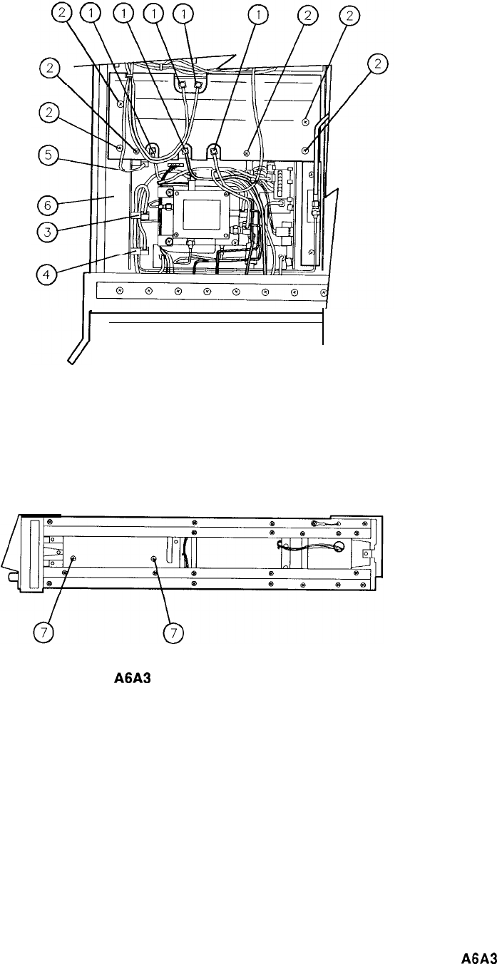
I
Figure 2.
A6A3
Last Converter ReplacementFigure 2.
A6A3
Last Converter Replacement
A6A3
5
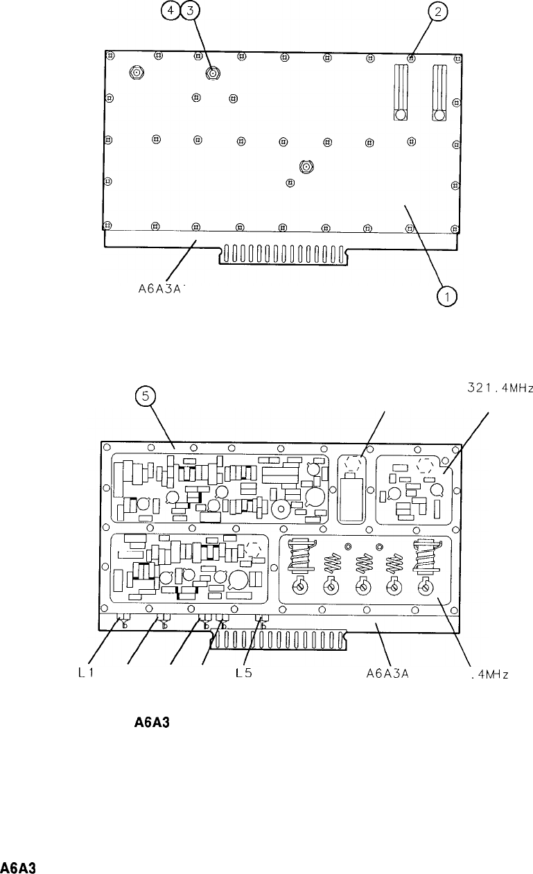
FRONT VIEW
(3 PLACES) (34 PLACES)
A6A3A
1
INTERNAL VIEW OF REAR
Q
5321.4-21.4 MHz
321.4MHz
CONVERTER AMPLIFIER
Ll
L2 L3 L4
L5 A6A3A
1
321
.4MI
BPF
iZ
Figure 3.
A6A3
Last Converter Assembly, Parts Identification (1 of 2)
6
A6A3
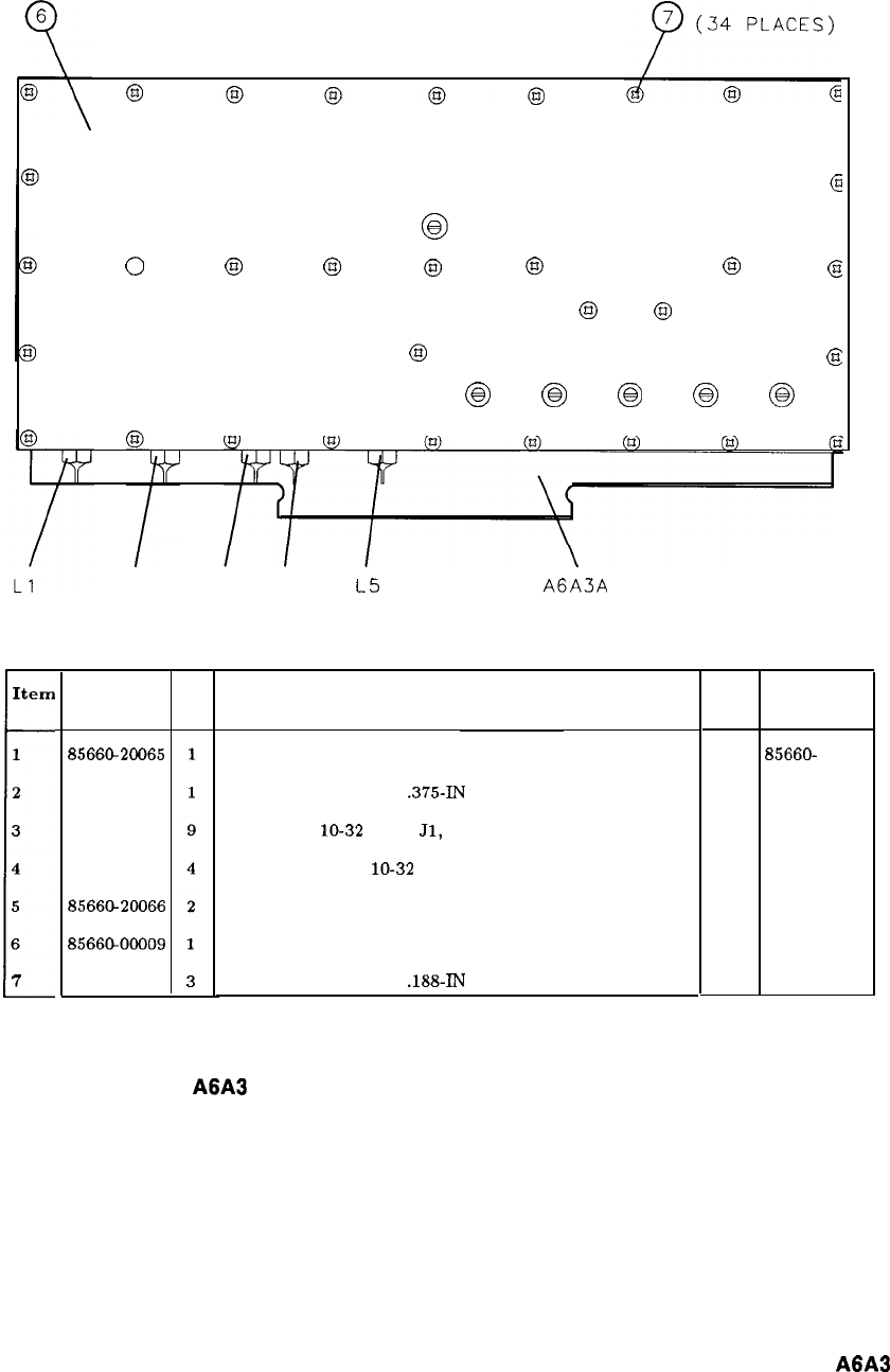
REAR VIEW
0
@
@
@
@
63
@0
@
@
@
63
@
@
63
@
63
@
@
Item
1
2
\
3
4
5
6
7
L2 L3 L4
L5 A6A3A
1
HP Part
Number
85660-20065
2200-0144
2950-0078
2190-0124
8566G20066
8566@00009
2200-0138
CD Description
COVER, BOTTOM, LAST CONVERTER
SCREW, MACH, 4-40,
.375-IN
LG, FLAT HD
NUT, HEX,
lo-32
(FOR
Jl,
J2, AND J3)
WASHER, LOCK,
lo-32
(FOR 61, J2, AND J3)
HOUSING, LAST CONVERTER
COVER, TOP, LAST CONVERTER
SCREW, MACH, 4-40,
.188-IN
LG, FLAT HD
Mfr Mfr Part
Code Number
28480 85660-
2006:
28480 2200-0144
28480
29504078
28480 2190-0124
28480 85660-20066
28480 85660-00009
28480 2200-0138
Figure 3.
A6A3
Last Converter Assembly, Parts Identification (2 of 2)
A6A3
7
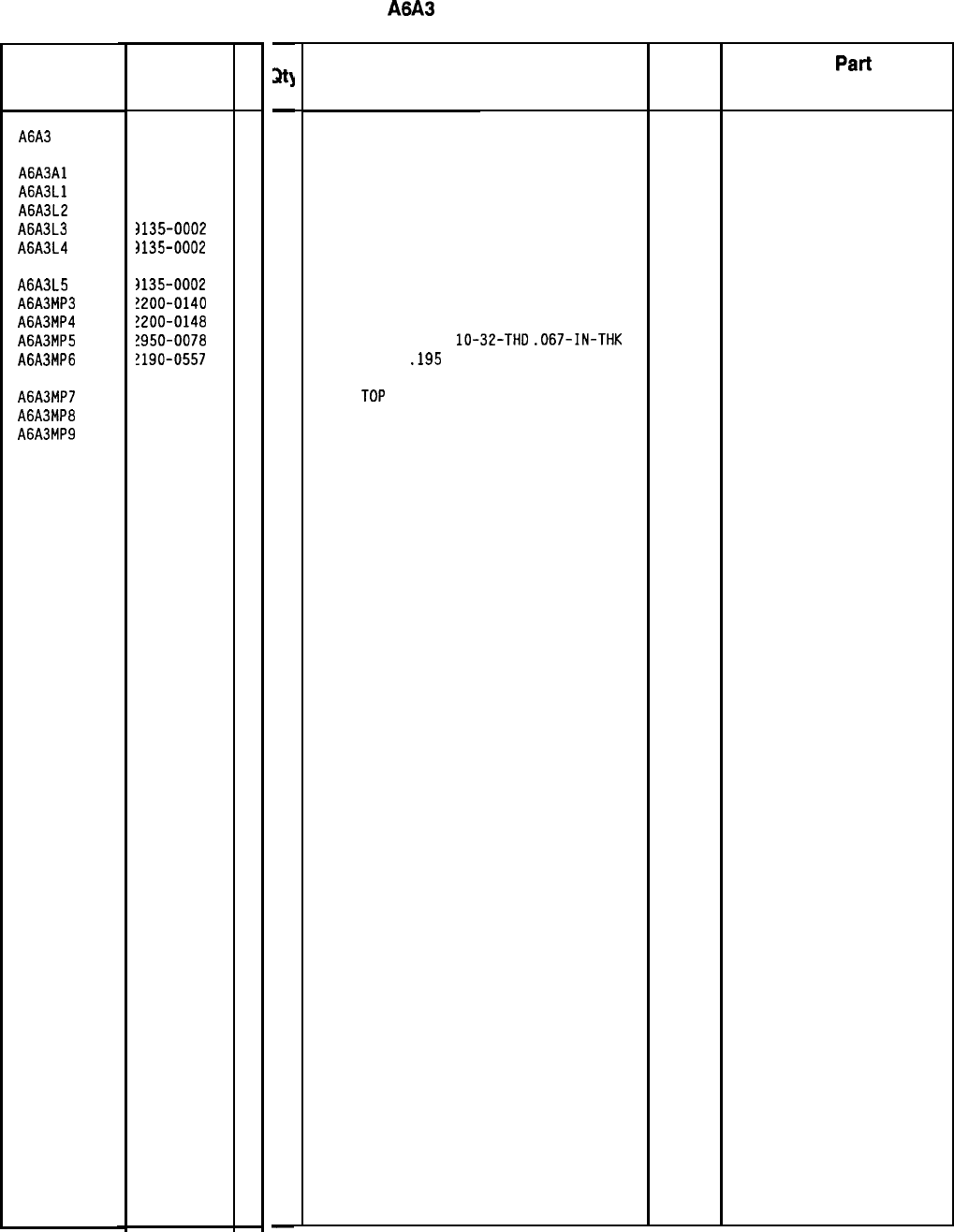
HP Part Number 85660-60003
A6A3
Last Converter
Reference HP Part
C
Designation Number
D
A6A3 35660-60003
1
A6A3Al 35660-60002
0
A6A3Ll 3135-0002
8
A6A3L2 3135-0002
8
A6A3L3 )135-0002
8
A6A3L4 )135-0002
8
A6A3L5
A6A3MP3
A6A3MP4
A6A3MP5
A6A3MP6
)135-0002
8
!200-0140
7
!200-0148
5
!950-0078
9
!190-0557
7
A6A3MP7 35660-00009
1
A6A3MP8 35660-20066
2
A6A3MP9 35660-20065
1
-
w
-
1
1
1
1
1
1
1
3
3
3
3
1
1
1
-
Description
LAST CONVERTER ASSEMBLY 28480 85660-60003
LAST CONVERTER BOARD ASSEMBLY 28480 85660-60002
FILTER-LOW PASS SOLDER-TERMS 33095 51-744-018
FILTER-LOW PASS SOLDER-TERMS 33095 51-744-018
FILTER-LOW PASS SOLDER-TERMS 33095 51-744-018
FILTER-LOW PASS SOLDER-TERMS 33095 51-744-018
FILTER-LOW PASS SOLDER-TERMS 33095
SCREW-MACH 4-40 .25-IN-LG 100 DEG
77250
SCREW-MACH 4-40 .5-IN-LG 100 DEG
77250
NUT-HEX-DBL-CHAM
lo-32-THD
.067-IN-THK 74163
STAR WASHER
.195
10
28480
51-744-018
500220
2190-0557
COVER
TOP 28480 85660-00009
HOUSING 28480 85660-20066
COVER BOTTOM 28480 85660-20065
Mfr Mfr
Part
Code Number
*Indicates factory-selected value
8566040003 Parts List
Page 1 of 1
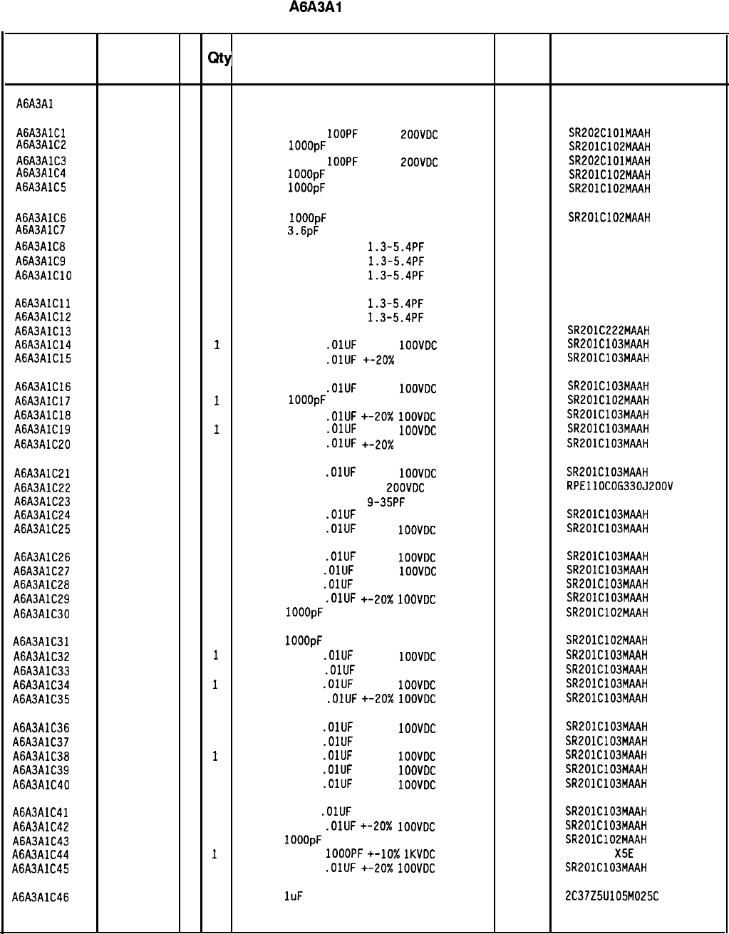
HP Part Number 85660-60002
A6A3Al Last Converter
Reference
HP Part C
Number D
Qty Description Mfr
Designation Mfr Part
Code Number
A6A3Al 85660-60002
0
1
BOARD ASSEMBLY LAST CONVERTER 28480 85660-60002
A6A3AlCl 0160-3877
5
1
CAPACITOR-FXD 1OOPF
+-20%
ZOOVDC
CER
04222
A6A3AlC2 SR202ClOlMAAH
0160-3878
6
1
CAP-FXD
1OOOpF
100 V
04222 SR201C102MAAH
A6A3AlC3 0160-3877
5
1
CAPACITOR-FXD 1OOPF
+-20%
ZOOVDC
CER
04222
A6A3AlC4 SR202ClOlMAAH
0160-3878
6
1
CAP-FXD
1OOOpF
100 V
04222
A6A3AlC5 SR201C102MAAH
0160-3878
6
1
CAP-FXD
1OOOpF
100 V
04222 SR201C102MAAH
A6A3AlC6 0160-3878
6
1
CAP-FXD IOOOpF
100 V
04222
A6A3AlC7
SR201C102MAAH
0160-2246
0
1
CAP-FXD
3.6pF
500 V
52763
A6A3AlC8
0121-0452
4
1
CAPACITOR-V
TRMR-AIR
1.3-5.4PF
175V PC-M
74970 187-0103-028
A6A3AlC9 0121-0452
4
1
CAPACITOR-V
TRMR-AIR
1.3-5.4PF
175V PC-M
74970 187-0103-028
A6A3AlClO
0121-0452
4
1
CAPACITOR-V
TRMR-AIR
1.3-5.4PF
175V PC-M
74970 187-0103-028
A6A3AlCll 0121-0452
4
1
CAPACITOR-V
TRMR-AIR
1.3-5.4PF
175V PC-M
74970 187-0103-028
A6A3AlC12 0121-0452
4
1
CAPACITOR-V
TRMR-AIR
1.3-5.4PF
175V PC-N
74970 187-0103-028
A6A3AlC13 0160-0572
1 1
CAPACITOR-FXD 2200PF +-20% IOOVDC CER 04222
SR201C222MAAH
A6A3AlC14 0160-3879
7
1
CAPACITOR-FXD
.OlUF
+-20%
1OOVDC
CER
04222 SR201C103MAAH
A6A3AlC15 0160-3879
7 1
CAPACITOR-FXD
.OlUF
+-20X
IOOVDC CER
04222 SR201C103MAAH
A6A3AlC16
0160-3879
7
1
CAPACITOR-FXD
.OlUF
+-20%
1OOVDC
CER
04222
SR201C103MAAH
A6A3AlC17 0160-3878
6
1
CAP-FXD
1OOOpF 100 V 04222 SR201C102MAAH
A6A3AlC18
0160-3879
7 1
CAPACITOR-FXD
.OlUF
+-20X
1OOVDC
CER
04222
SR201C103MAAH
A6A3AlC19 0160-3879
7
1
CAPACITOR-FXD
.OlUF
+-20%
1OOVDC
CER
04222 SR201C103MAAH
A6A3AlC20 0160-3879
7 1
CAPACITOR-FXD
.OlUF
+-20X IOOVDC CER
04222 SR201C103MAAH
A6A3AlC21 0160-3879
7 1
CAPACITOR-FXD
.OlUF
+-20%
1OOVDC
CER
04222 SR201C103MAAH
A6A3AlC22 0160-3653
5
1
CAPACITOR-FXD 33PF
+-5%
LOOVDC
CER 0+-30 RPEllOCOG330J200V
A6A3AlC23 0121-0046
2
1
CAPACITOR-V
TRMR-CER
9-35PF
200V PC-MTG
52763 304-322-573
A6A3AlC24 0160-3879
7
1
CAPACITOR-FXD
.OlUF
+-20% IOOVDC CER 04222 SR201C103MAAH
A6A3AlC25 0160-3879
7
1
CAPACITOR-FXD
.OlUF
+-20%
1OOVDC
CER
04222 SR201C103MAAH
A6A3AlC26 0160-3879
7
1
CAPACITOR-FXD
.OlUF
+-20%
1OOVDC
CER
04222 SR201C103MAAH
A6A3AlC27 0160-3879
7
1
CAPACITOR-FXD
.OlUF
+-20%
1OOVDC
CER
04222 SR201C103MAAH
A6A3AlC28 0160-3879
7
1
CAPACITOR-FXD
.OlUF
+-20%
IOOVDC CER 04222
SR201C103MAAH
A6A3AlC29 0160-3879
7
1
CAPACITOR-FXD
.OlUF
+-20X
1OOVDC
CER
04222 SR201C103MAAH
A6A3AlC30 0160-3878
6
1
CAP-FXD
IOOOpF
100 V
04222
SR201C102MAAH
A6A3AlC31 0160-3878
6
1
CAP-FXD
IOOOpF
100 V
04222 SR201C102MAAH
A6A3AlC32 0160-3879
7
1
CAPACITOR-FXD
.OlUF
+-20%
1OOVDC
CER
04222 SR201C103MAAH
A6A3AlC33 0160-3879
7
1
CAPACITOR-FXD
.OlUF
+-20% IOOVDC CER 04222 SR201C103MAAH
A6A3AlC34 0160-3879
7
1
CAPACITOR-FXD
.OlUF
+-20%
1OOVDC
CER
04222 SR201C103MAAH
A6A3AlC35 0160-3879
7
1
CAPACITOR-FXD
.OlUF
+-20x
1OOVDC CER 04222 SR201C103MAAH
A6A3AlC36
0160-3879
7
1
CAPACITOR-FXD
.DlUF
+-20%
1DOVDC
CER
04222 SR201ClD3MAAH
A6A3AlC37 0160-3879
7
1
CAPACITOR-FXD
.OlUF
+-20%
IOOVDC CER 04222
SR201C103MAAH
A6A3AlC38
0160-3879
7
1
CAPACITOR-FXD
.OlUF
+-20%
1OOVDC
CER
04222 SR201C103MAAH
A6A3AlC39 0160-3879
7
1
CAPACITOR-FXD
.OlUF
+-20%
1OOVDC
CER
04222
SR201C103MAAH
A6A3AlC40 0160-3879
7
1
CAPACITOR-FXD
.OlUF
+-20%
1OOVDC
CER
04222 SR201C103MAAH
A6A3AlC41 0160-3879
7
1
CAPACITOR-FXD
.OlUF
+-20% IOOVDC
CER 04222 SR201C103MAAH
A6A3AlC42 0160-3879
7
1
CAPACITOR-FXD
.OlUF
+-20X
1OOVDC
CER
04222 SR201C103MAAH
A6A3AlC43 0160-3878
6
1
CAP-FXD
1OOOpF
100 V
04222
SR201C102MAAH
A6A3AlC44 0160-3456
6
1
CAPACITOR-FXD
1OOOPF
+-lo%
1KVDC CER
808-542
X5E
102K
A6A3AlC45 0160-3879
7
1
CAPACITOR-FXD
.OlUF
+-20x
1OOVDC CER 04222 SR201C103MAAH
A6A3AlC46 0160-4892
6
1
CAP-FXD
1uF
25 V
56289 2C37Z5U105M025C
*Indicates facto y-selected value
8566060002 Parts List
Page 1 of 4
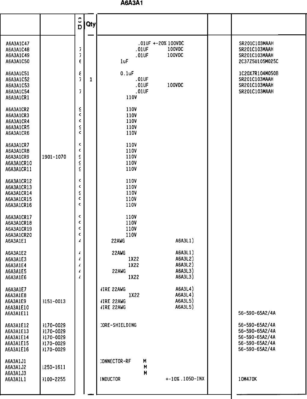
Reference
Designation HP Part
Number
A6A3AlC47 0160-3879
A6A3AlC48 0160-3879
A6A3AlC49 0160-3879
A6A3AlC50 0160-4892
A6A3AlC51 0160-4084
A6A3AlC52 0160-3879
A6A3AlC53 0160-3879
A6A3AlC54 0160-3879
AGA%AlCRl 1901-1070
A6A3AlCR2
A6A3AlCR3
A6A3AlCR4
A6A3AlCR5
A6A3AlCR6
1901-1070
1901-1070
1901-1070
1901-1070
1901-1070
A6A3AlCR7
A6A3AlCR8
A6A3AlCR9
A6A3AlCRlO
AGA3AlCRll
1901-1070
1901-1070
1901-1070
1901-1070
1901-1070
A6A3AlCR12 1901-1070
A6A3AlCR13 1901-1070
A6A3AlCR14 1901-1070
A6A3AlCR15 1901-1070
A6A3AlCR16 1901-1070
A6A3AlCR17 1901-1070
A6A3AlCR18 1901-1070
A6A3AlCR19 1901-1070
A6A3AlCR20 1901-1070
A6A3AlEl 8151-0013
A6A3AlE2 8151-0013
A6A3AlE3 8151-0013
A6A3AlE4 8151-0013
A6A3AlE5 8151-0013
A6A3AlE6 8151-0013
A6A3AlE7
A6A3AlE8
A6A3AlE9
A6A3AlElO
A6A3AlEll
3151-0013
3151-0013
~151-0013
3151-0013
3170-0029
A6A3AlE12 I170-0029
A6A3AlE13 1170-0029
A6A3AlE14 1170-0029
A6A3AlE15 I170-DO29
A6A3AlE16 I170-0029
A6A3AlJl
1250-1611
A6A3AlJ2
1250-1611
A6A3AlJ3
1250-1611
A6A3AlLl IlOO-2255
8566040002 Parts List
Page 2 of 4
c
0
7
I
I
E
E
I
7
I
c
E
C
c
c
C
c
c
E
c
5
C
C
5
c
C
C
C
C
C
1
1
1
1
1
1
4
4
4
4
3
3
3
3
3
3
3
3
3
4
-
at]
-
1
1
1
1
1
1
1
1
1
1
1
1
1
1
1
1
1
1
1
1
1
1
1
1
1
1
1
1
1
1
1
1
1
1
1
1
1
1
1
1
1
1
1
1
1
1
1
1
-
HP Part Number 85660-60002
A6A3Al Last Converter
Description
CAPACITOR-FXD
.OlUF
+-20x
1OOVDC
CER
CAPACITOR-FXD
.OlUF
+-20%
1OOVDC
CER
CAPACITOR-FXD
.OlUF
+-20%
1OOVDC
CER
CAP-FXD
1uF
25 V
Mfr
Code
04222
04222
04222
56289
CAP-FXD
O.luF
50 V
56289
CAPACITOR-FXD
.OlUF
+-20% IOOVDC CER
04222
CAPACITOR-FXD
.OlUF
+-20%
1OOVDC
CER
04222
CAPACITOR-FXD
.OlUF
+-20% IOOVDC CER
04222
DIODE-PIN
1lOV 28480
DIODE-PIN
1lOV 28480
DIODE-PIN
1lOV 28480
DIODE-PIN
1lOV 28480
DIODE-PIN
1lOV 28480
DIODE-PIN
1lOV 28480
DIODE-PIN
1lOV
28480
DIODE-PIN
1lOV 28480
DIODE-PIN
1lOV 28480
DIODE-PIN
1lOV 28480
DIODE-PIN
1lOV 28480
DIODE-PIN
1lOV 28480
DIODE-PIN
1lOV 28480
DIODE-PIN
1lOV
28480
DIODE-PIN
1lOV
28480
DIODE-PIN
1lOV
28480
DIODE-PIN
1lOV
DIODE-PIN
1lOV
DIODE-PIN
IlOV
DIODE-PIN
IlOV
WIRE
~~AWG
1x22 (
ATTACH
ED To
A6A3Ll)
28480
28480
28480
28480
92194
WIRE
~~AWG
1x22 (ATTACHED To
A6A3Ll) 92194
WIRE 22AWG
1X22
(ATTACHED TO
A6A3L2) 92194
WIRE 22AWG
1X22
(ATTACHED TO
A6A3L2) 92194
WIRE
~~AWG
1x22 (ATTACHED To
A6A3L3) 92194
WIRE 22AWG
1X22
(ATTACHED TO
A6A3L3) 92194
JIRE
~~AWG
1x22 (
A
TTACHED To
A6A3L4) 92194
JIRE 22AWG
1X22
(ATTACHED TO
A6A3L4) 92194
JIRE
~~AWG
1x22 (ATTACHED To
A6A3L5) 92194
JIRE
~~AWG
1x22 (ATTACHED To
A6A3L5) 92194
:ORE-SHIELDING BEAD 02114
:ORE-SHIELDING
BEAD
:ORE-SHIELDING BEAD
:ORE-SHIELDING BEAD
:ORE-SHIELDING BEAD
:ORE-SHIELDING BEAD
02114
02114
02114
02114
02114
:ONNECTOR-RF
SMB
M
PC 50-OHM
98291
:ONNECTOR-RF SMB
M
PC 50-OHM 98291
:ONNECTOR-RF SMB
M
PC 50-OHM 98291
LNDUCTOR
RF-CH-MLD 470NH
+-10x
.105D-INX 24226
*Indicates factory-selected value
Mfr Part
Number
SR201C103MAAH
SR201C103MAAH
SR201C103MAAH
2C37Z5U105M025C
lC20X7R104M050B
SR201C103MAAH
SR201C103MAAH
SR201C103MAAH
298
298
298
298
298
298
298
298
298
298
56-590-65A2/4A
56-59D-65A2/4A
56-590-65A2/4A
56-590-65A2/4A
56-590-65A2/4A
56-590-65A2/4A
51-051-0289
51-051-0289
51-051-0289
lOM470K
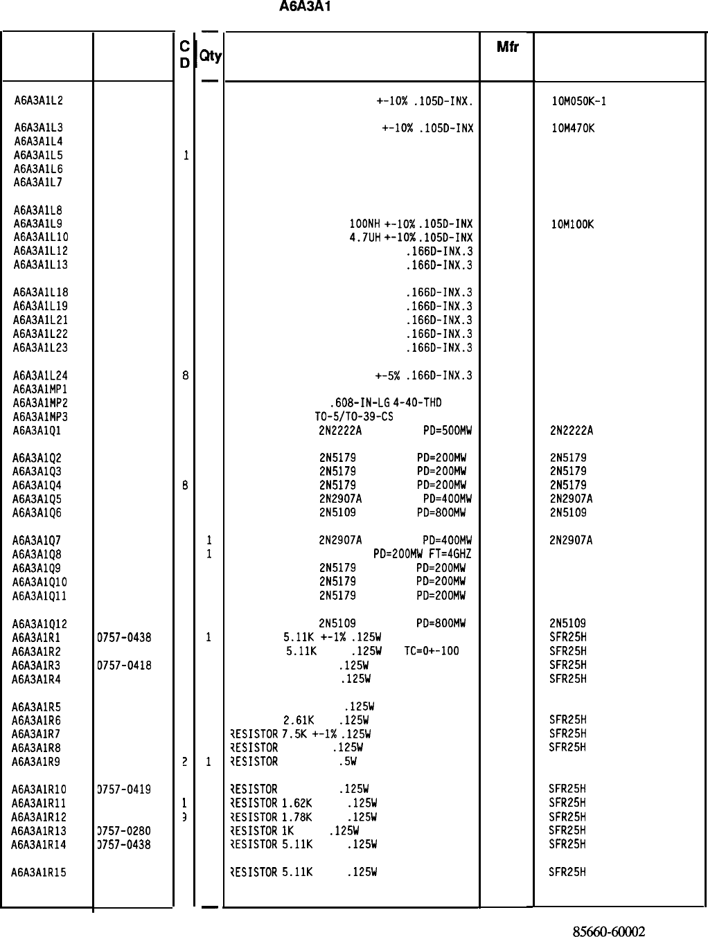
Reference
Designation
A6A3AlL2
HP Part
Number
9100-2891
4
A6A3AlL3 9100-2255
4
A6A3AlL4 85660-80002
2
A6A3AlL5
85660-80001
1
A6A3AlL6 85660-80001
1
A6A3AlL7 85660-80001
1
A6A3AlL8 85660-80002
2
A6A3AlL9 9100-2247
4
A6A3AlLlO 9140-0144
0
A6A3AlL12 9100-1623
8
A6A3AlL13 9100-1623
8
A6A3AlL18
9100-1623
8
A6A3AlL19 9100-1623
8
A6A3AlL21 9100-1623
8
A6A3AlL22 9100-1623
8
A6A3AlL23 9100-1623
8
A6A3AlL24
AGA3AlMPl
A6A3AlMP2
A6A3AlMP3
A6A3AlQl
9100-1623
8
0380-1672
0
1205-0226
9
1854-0477
7
A6A3AlQ2 1854-0345
8
A6A3AlQ3 1854-0345
8
A6A3AlQ4 1854-0345
6
A6A3AlQ5 1853-0281
9
A6A3AlQ6 1854-0378
7
A6A3AlQ7 1853-0281
A6A3AlQ8 1854-0686
A6A3AlQ9 1854-0345
A6A3AlQlO 1854-0345
A6A3AlQll 1854-0345
A6A3AlQ12 1854-0378
A6A3AlRl 0757-0438
A6A3AlR2 0757-0438
A6A3AlR3 0757-0418
A6A3AlR4 0698-3154
A6A3AlR5 0698-8818
A6A3AlR6 0698-0085
A6A3AlR7 0757-0440
A6A3AlR8 0698-3431
A6A3AlR9 0757-0198
A6A3AlRlO 3757-0419
A6A3AlRll 3757-0428
A6A3AlR12 3757-0278
A6A3AlR13 3757-0280
A6A3AlR14
3757-0438
A6A3AlR15
3757-0438
9
0
8
8
8
7
3
3
3
3
3
3
7
3
!
3
1
3
3
3
3
-
a
-
1
1
1
1
1
1
1
1
1
1
1
1
1
1
1
1
1
1
1
1
1
1
1
1
1
1
1
1
1
1
1
1
1
1
1
1
1
1
1
1
1
1
1
1
1
1
-
HP Part Number 85660-60002
A6A3Al
Last Converter
Description Mfr Mfr Part
Code Number
INDUCTOR RF-CH-MLD 50NH +-lo%
.105D-INX.
24226 lOMOSOK-1
INDUCTOR RF-CH-MLD 470NH +-lo%
.105D-INX 24226 lOM470K
COIL TAPPED 28480 85660-80002
COIL TAPPED 28480 85660-80001
COIL TAPPED 28480 85660-80001
COIL TAPPED 28480 85660-80001
COIL TAPPED
INDUCTOR RF-CH-MLD
1OONH
+-10x
.105D-INX
INDUCTOR RF-CH-MLD
4.7UH
+-lo%
.105D-INX
INDUCTOR RF-CH-MLD 27UH +-5%
.166D-INX.3
INDUCTOR RF-CH-MLD 27UH +-5%
.166D-INX.3
28480 85660-80002
24226 1OMlOOK
99800 1025-36
99800 1537-48
99800 1537-48
INDUCTOR RF-CH-MLD 27UH +-5%
.166D-INX.3 99800 1537-48
INDUCTOR RF-CH-MLD 27UH +-5%
.166D-INX.3 99800 1537-48
INDUCTOR RF-CH-MLD 27UH +-5%
.166D-INX.3 99800 1537-48
INDUCTOR RF-CH-MLD 27UH +-5%
.166D-INX.3 99800 1537-48
INDUCTOR RF-CH-MLD 27UH +-5%
.166D-INX.3 99800 1537-48
INDUCTOR RF-CH-MLD 27UH +-5x
.166D-INX.3
NOT ASSIGNED 99800 1537-48
STANDOFF-RVT-ON
.608-IN-LG
4-40-THD 06540
HEAT SINK SGL
TO-5/TO-39-CS 13103
TRANSISTOR NPN
2N2222A
SI TO-18
PD=50DMW 04713 11158
2N2222A
TRANSISTOR NPN
2N5179
SI TO-72
PD=200MW 04713 2N5179
TRANSISTOR NPN
2N5179
SI TO-72
PD=200MW 04713 2N5179
TRANSISTOR NPN
2N5179
SI TO-72
PD=EOOMW 04713 2N5179
TRANSISTOR PNP
2N2907A
SI TO-18
PD=400MW 04713 2N2907A
TRANSISTOR NPN
2N5109
SI TO-39
PD=800MW 04713 2N5109
TRANSISTOR PNP
2N2907A
SI TO-18
PD=400MW 04713
TRANSISTOR NPN SI TO-72
PD=200MW
FT=4GHZ 25403
TRANSISTOR NPN
2N5179
SI TO-72
PD=LOOMW 04713
TRANSISTOR NPN
2N5179
SI TO-72
PD=ZOOMW 04713
TRANSISTOR NPN
2N5179
SI TO-72 PD=ZOOMW
04713
2N2907A
215179
215179
215179
TRANSISTOR NPN
2N5109
SI TO-39
PD=800MW 04713 2N5109
RESISTOR
5.11K
+-I%
.125W
TF TC=O+-100
19701
SFR25H
RESISTOR
5.11K
+-1%
.125W
TF
TC=O+-100
19701
SFR25H
RESISTOR 619 +-1%
.125W
TF TC=O+-100
19701
SFR25H
RESISTOR 4.221: 1%
.125W
TF TC=O+-100
19701
SFR25H
RESISTOR 3.16 +-1%
.125W
TF TC=O+-100
91637 CMF-55-1
RESISTOR
2.61K
1%
.125W
TF TC=O+-100
19701
SFR25H
?ESISTOR
7.5K
+-I%
.125W
TF TC=O+-100
19701
SFR25H
?ESISTOR
23.7 1%
.125W
TF TC=O+-100
19701
SFR25H
7ESISTOR
100 +-1%
.5W
TF TC=O+-100
19701
5053R
?ESISTOR
681 +-1%
.125W
TF TC=O+-100
19701
SFR25H
?ESISTOR
1.62K
+-1%
.125W
TF TC=O+-100
19701
SFR25H
?ESISTOR
1.78K
+-1%
.125W
TF TC=O+-100
19701
SFR25H
7ESISTOR
1K
+-1%
.125W
TF TC=O+-100
19701
SFR25H
7ESISTOR
5.11K
+-1%
.125W
TF TC=O+-100
19701
SFR25H
?ESISTOR
5.11K
+-1%
.125W
TF TC=O+-100
19701
SFR25H
*Indicates factory-selected value
8566060002
Parts List
Page 3 of 4
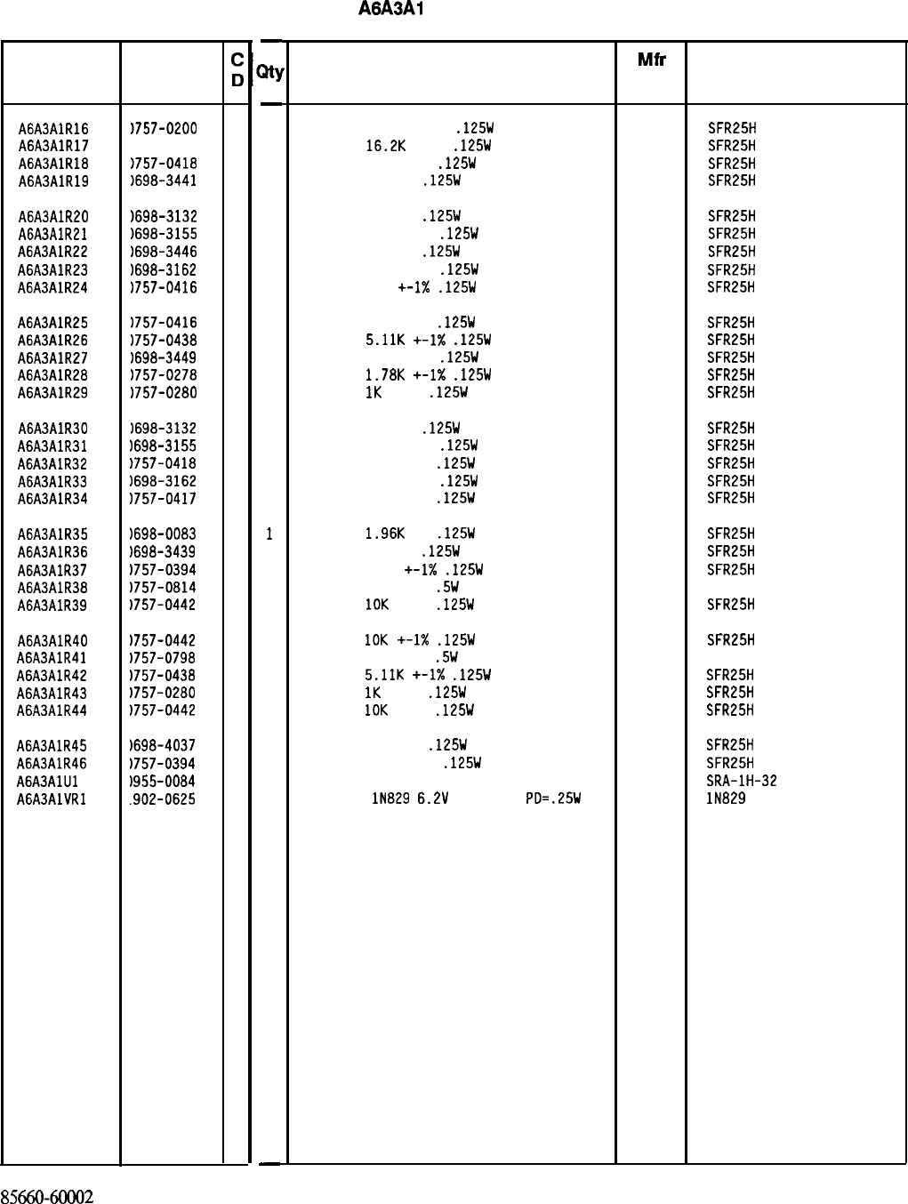
HP Part Number 85660-60002
A6A3Al Last Converter
Reference HP Part
Designation Number
A6A3AlR16
1757-0200
7
A6A3AlR17
1757-0447
4
A6A3AlR18
1757-0418
9
A6A3AlR19
1698-3441
8
A6A3AlR20
1698-3132
4
A6A3AlR21
1698-3155
1
A6A3AlR22
1698-3446
3
A6A3AlR23
1698-3162
0
A6A3AlR24
1757-0416
7
A6A3AlR25
1757-0416
7
A6A3AlR26
1757-0438
3
A6A3AlR27
1698-3449
6
A6A3AlR28
1757-0278
9
A6A3AlR29
1757-0280
3
A6A3AlR30
1698-3132
4
A6A3AlR31
1698-3155
1
A6A3AlR32
1757-0418
9
A6A3AlR33
1698-3162
0
A6A3AlR34
1757-0417 8
A6A3AlR35
1698-0083 8
A6A3AlR36
1698-3439
4
A6A3AlR37
1757-0394
0
A6A3AlR38
1757-0814
9
A6A3AlR39
1757-0442
9
A6A3AlR40
1757-0442
9
A6A3AlR41
1757-0798
8
A6A3AlR42
1757-0438
3
A6A3AlR43
1757-0280
3
A6A3AlR44
1757-0442
9
A6A3AlR45
1698-4037
0
A6A3AlR46
)757-0394
0
A6A3AlUl
1955-0084
5
AGA3AlVRl
.902-0625
0
-
XY
-
1
1
1
1
1
1
1
1
1
1
1
1
1
1
1
1
1
1
1
1
1
1
1
1
1
1
1
1
1
1
1
1
1
-
Description
RESISTOR 5.621: +-1%
.125W
TF TC=O+-100
19701
SFR25H
RESISTOR
16.2K
+-1%
.125W
TF TC=O+-100
19701
SFR25H
RESISTOR 619 +-1%
.125W
TF TC=O+-100
19701
SFR25H
RESISTOR 215 1%
.125W
TF TC=O+-100
19701
SFR25H
RESISTOR 261 1%
.125W
TF TC=O+-100
19701
SFR25H
RESISTOR 4.641: 1%
.125W
TF TC=O+-100
19701
SFR25H
RESISTOR 383 1%
.125W
TF TC=O+-100
19701
SFR25H
RESISTOR 46.41: 1% .125W TF TC=O+-100
19701
SFR25H
RESISTOR 511 +-I%
.125W
TF TC=O+-100
19701
SFR25H
RESISTOR 511 +-1%
.125W
TF TC=O+-100
19701
SFR25H
RESISTOR
5.11K
+-1X
.125W
TF TC=O+-100
19701
SFR25H
RESISTOR 28.71: 1%
.125W
TF TC=O+-100
19701
SFR25H
RESISTOR
1.78K
+-I%
.125W
TF TC=O+-100
19701
SFR25H
RESISTOR
1K
+-1%
.125W
TF TC=O+-100
19701
SFR25H
RESISTOR 261 1%
.125W
TF TC=O+-100
19701
SFR25H
RESISTOR 4.641: 1%
.125W
TF TC=O+-100
19701
SFR25H
RESISTOR 619 +-1%
.125W
TF TC=O+-100
19701
SFR25H
RESISTOR 46.41: 1%
.125W
TF TC=O+-100
19701
SFR25H
RESISTOR 562 +-1%
.125W
TF TC=O+-100
19701
SFR25H
RESISTOR
1.96K
1%
.125W
TF TC=O+-100
19701 SFR25H
RESISTOR 178 1%
.125W
TF TC=O+-100
19701
SFR25H
RESISTOR 51.1 +-1X
.125W
TF TC=O+-100
19701
SFR25H
RESISTOR 511 +-1%
.5W
TF TC=O+-100
19701
5053R
RESISTOR
10K
+-1%
.125W
TF TC=O+-100
19701
SFR25H
RESISTOR
10K
+-1X
.125W
TF TC=O+-100
19701
SFR25H
RESISTOR 110 +-1%
.5W
TF TC=O+-100
19701
5053R
RESISTOR
5.11K
+-1X
.125W
TF TC=O+-100
19701
SFR25H
RESISTOR
1K
+-1%
.125W
TF TC=O+-100
19701
SFR25H
RESISTOR
10K
+-1%
.125W
TF TC=O+-100
19701
SFR25H
RESISTOR 46.4 1%
.125W
TF TC=O+-100
19701
SFR25H
RESISTOR 51.1 +-1%
.125W
TF TC=O+-100
19701
SFR25H
U-WAVE MIXER 500 MHZ MAX 15542 SRA-lH-32
DIODE-ZNR
lN829
6.2V
5% DO-35
PD=.25W
TC
04713 lN829
8566060002
Parts List
Page 4 of 4
*Indicates facto y-selected value
Mfr Mfr Part
Code Number
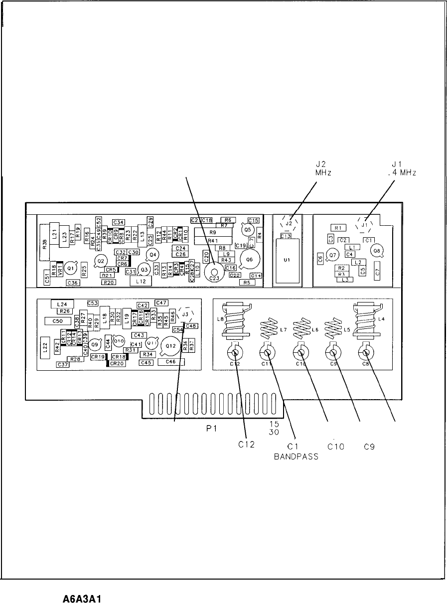
C23
10.7 MHz NOTCH
Jl
FILTER ADJUSTMENT 300
iii,
IN 321
.4
MHz IN
1
16 I
Pl
\ \ \
J3
Cl2
c.1 1
c.10
c9
C8
21.4 MHz OUT 321.4 MHz
BANDPASS
FILTER ADJUSTMENTS
A6A3Al
Last Converter Board Component Locations, 85660-60002
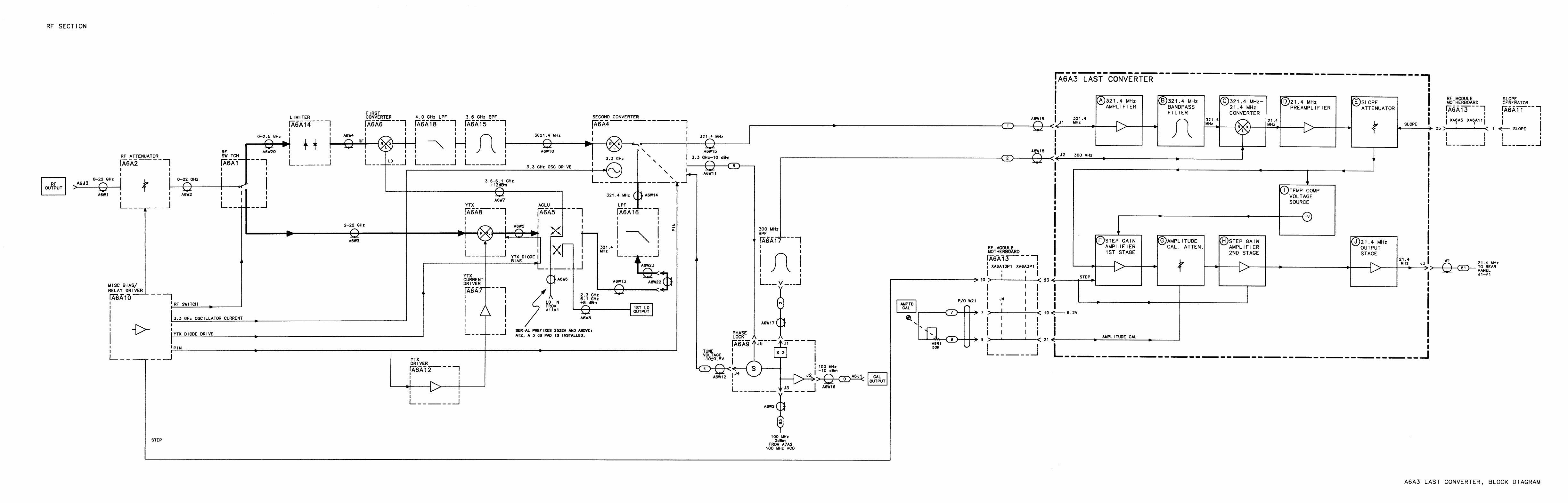
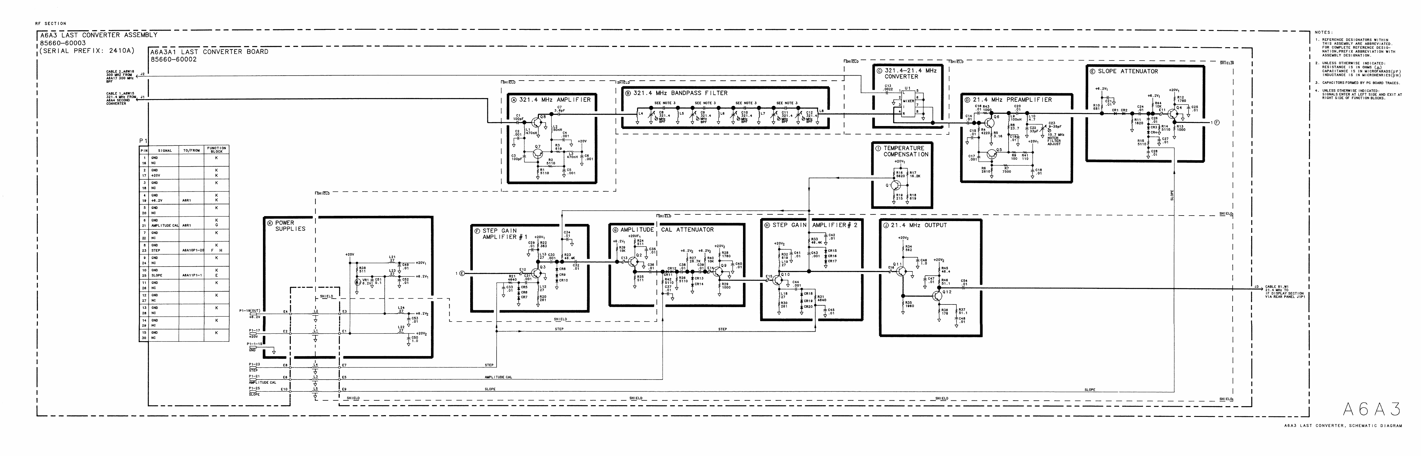
A6A7 YIG-Tuned Mixer (YTX) Current Driver, Circuit Description
The YTX Current Driver has three functions:
1. Provides the output stage for the A6A8 YTX coil.
2. Provides filter circuitry for the YTX.
3. Provides control circuitry for the YTX heater.
YTX Drive Output
@
The YTX drive output consists of Q5,
QS,
R14 to R17, VR4, and CR3. Q5 and Q6 form a
darlington transistor driven by the A6A12 YTX Driver. R14 to R17 are four 1000 ten-watt
resistors connected in parallel to form a 25R resistor which is used to sense the current in
the YTX coil. This sense signal is fed back to the YTX Driver. Four resistors are used for
power handling capability and temperature stability. VR4 and CR3 limit the flyback voltage
produced across the YTX coil during scan reset and prevent breakdown of Q5 and Q6.
Filter Capacitor Drive
@
When the spectrum analyzer is set to narrow spans and narrow resolution bandwidth, hum
and noise in the YTX drive circuitry which FMs the YTX can introduce phase noise and
line frequency sidebands onto a displayed signal. To prevent this occurrence, a large filter
capacitor, A6A7C1, is connected across the YTX coil by switch
QS
whenever the resolution
bandwidth is 100 Hz or less.
QS
is controlled from
A6All
Slope Generator through Q2, Q3, and Q4. When the resolution
bandwidth is 100 Hz or less, the filter capacitor is connected before the start of a scan and
disconnected at the end of a scan so that the scan reset and hysteresis correction can be
performed.
YTX Heater Control
@
The YTX heater control is a feedback circuit designed to maintain the center support of the
YTX at a constant 75”C, as the ambient temperature ranges from 0“ to 55°C. The green
LED,
DSl,
indicates that current is flowing properly in the heater. Red LED, DS2, indicates
the circuit is saturated, putting maximum power into the heater.
The heater ring of the YTX has a
4500
thin-film heater resistor, and a thermal sensor with
a positive temperature coefficient. The resistance versus temperature characteristics of the
thermal sensor are shown in Figure 1.
A6A7/A6Aii/A6A8
1
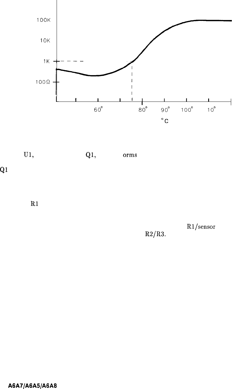
100K
--
IOK
--
RR
IK------
---- ---
L
I
I I
I
,
III
I
50”
60°
70”
80°
90’
loo0
1
loo
TEMP
“C
Figure 1. YTX Thermal Sensor Resistance versus Temperature Characteristics
Op-amp
Ul,
with R2, R3, R4,
Ql,
and Q7 f
arms
an amplifier with a gain of about 127. In
addition, R2 and R3 set a reference voltage at the negative input of the amplifier. Darlington
Ql
and Q7 is able to provide the large currents required to heat the heater resistor to 75°C.
VR2 and R5 offset the op-amp output voltage to be within range of the output stage (0 to
-40 V). CR1 protects the op-amp input.
The circuit operates as follows: If the heater ring is cool (such as at turn-on), the divider
formed by
Rl
and the sensor (described above) outputs a voltage that is less than the
reference at the minus input to the amplifier. This causes the amplifier output to swing
negative, thus drawing more current through the heater resistor, heating up the sensor,
causing it to increase its resistance. This raises the voltage at the
Rl/sensor
divider output
until it exactly equals that of the reference divider
R2/R3.
In general, small temperature
errors are manifested as a small voltage between pins 2 and 3 of the op-amp (its input). This
error is amplified and applied to the heater resistor with the appropriate sign to eliminate the
error.
2
A6A7/A6A5/A6A8
A6A8 YIG-Tuned Mixer (YTX),
A6A5 Amplifier/Coupler/Load Unit (ACLU), Circuit Description
The YTX consists of a three-pole tunable
bandpass
filter and a single-diode microwave
harmonic mixer. The 2 to 6 GHz local oscillator (LO) signal enters the ACLU, and is
amplified and coupled into the YTX to turn its diode on and off at the LO rate. The diode
conduction angle is adjusted with DC diode bias to be optimum for the harmonic of the LO
being used. The incoming microwave signal passes through the
bandpass
filter, through the
mixer diode, as the diode switches on and off, and into the precision
500
load of the ACLU.
The IF signal at 321.4 MHz travels down the same line as the higher frequency LO, but a
matching network couples the 321.4 MHz IF signal to the ACLU output while blocking the
LO.
The three-pole filter has two purposes:
1. To reject the image response of the mixer 642.8 MHz away from the desired signal.
2. To reject the LO signal that would otherwise come out of the mixer’s microwave input
port, and out of the instrument front panel.
Handling the YIG-Tuned Mixer
Caution
The YIG-Tuned Mixer (YTX) contains an extremely small and sensitive
diode. A reverse voltage in excess of 3 V may damage it. It is connected
directly to the center conductor of the LO/IF connector, and is especially
susceptible to blowout from electrostatic discharge. Before connecting any
coaxial cable to the YTX, connect the YTX BIAS pin to ground, discharge
the coaxial cable by connecting the center conductor to ground (YTX body),
then simultaneously touch both to chassis ground or the YTX package. It is
recommended that the other end of the cable be connected first before going
through this procedure.
Once the cable from the YTX to the ACLU is properly installed, the BIAS pin
of the ACLU is directly connected to the YTX diode. Therefore, treat the
BIAS pin with extreme caution, especially avoiding electrostatic discharge.
As a general rule, connect all devices to the chassis before connecting to or
touching the BIAS pin on the ACLU.
A6A7JA6A5/A6A8
3
A6A5 Amplifier/Coupler/Load Unit (ACLU) Replacement
Note
3
For location of hardware and cables referred to in this procedure, see Figure 2.
Removal
1. Remove ac line cords and RF Section bottom cover.
2. Disconnect connectors
0,
@
and
@J>,
single-pin connector
0,
and double-pin connector
@
from Second Converter.
3. Disconnect the remaining cables from Second Converter:
1 (brown) cable from
.321
OUT
0J
4 (yellow) cable from TUNE
@
4. Remove ACLU cover-plate by removing four screws
@
as shown in View A.
5. Disconnect five connectors a@>, three 92 (white/red) single-pin connectors
a@,
and one
8 (gray) single-pin connector
(iJo.
6. Release ACLU by removing two screws @@ shown in View B.
Installation
7. Secure new ACLU on mounting bracket with two screws
@@,
and reconnect the cables
and wires removed in step 5.
8. Replace ACLU cover-plate with four screws
@
shown in View A.
9. Reconnect the following cables to Second Converter: (Refer to View A.)
1 (brown) cable to
.321
OUT
0
1 (brown) cable to
.321
IN
@
4 (yellow) cable to TUNE
@
10.
Replace bottom cover and ac line cords.
4
A6A7/A6AS/A6A6
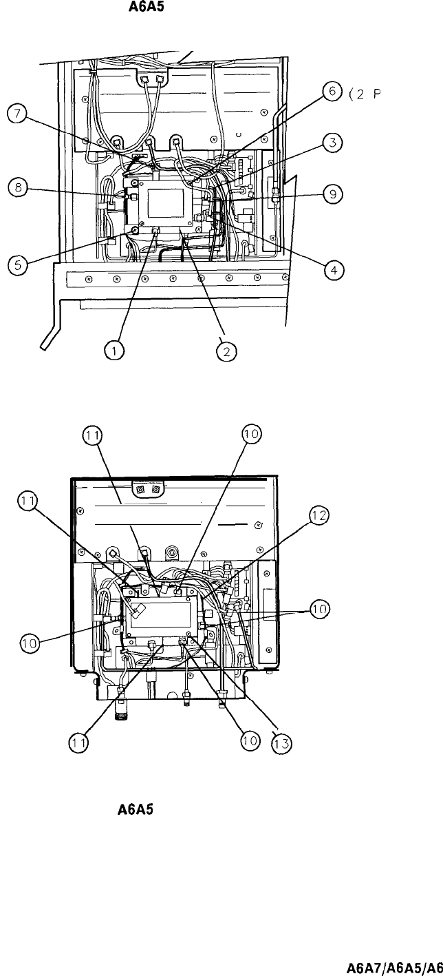
A6A5
Amplifier/Coupler/Load Unit (ACLU) Replacement
(2
p
(4 PLACES)
b
2
VIEW A
/
-
/
0
\
-
0
@
(2 PLACES)
VIEW B
Figure 2.
A6A5
ACLU Replacement
LACES)
A6A7/A6
A5/A6 A0
5
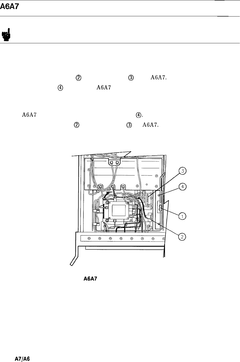
A6A7 YTX Current Driver Replacement
Note
!il
For location of hardware and cables referred to in this procedure, see Figure 3.
Removal
1. Remove ac line cords and RF Section bottom cover.
2. Disconnect 5-pin connector
@
and ribbon cable
@
from A6A7.
3. Remove two screws
@
and remove A6A7 from RF Module.
Installation
4. Place A6A7 in RF Module and replace two screws
0.
5. Reconnect 5-pin connector
@
and ribbon cable
@
to A6A7.
6. Replace bottom cover on RF Section and reconnect ac line cords.
(2 PLACES)
Figure 3.
A6A7
YTX Current Driver Replacement
6
A6
A7/A6
AS/A6 A8
A6A8
YTX Replacement
A6A8
YTX Replacement
Note
I
w
For location of hardware and cables referred to in this procedure, see Figure 4.
Removal
1. Remove ac line cords, separate instrument sections, and remove top and bottom covers
from RF Section.
2. Disconnect cable
@
between All YTO Loop and RF Module.
3. Remove five cables from RF Module PC boards; three from A6A9 Phase Lock and two
from A6A12 YTX Driver.
4. Remove RF Module PC board cover by removing six screws
0.
5. Remove A6A9 assembly and A6A10,
A6Al1,
and A6A12 PC boards.
6. Disconnect 4 (yellow) cable and 5 (green) cable from 2nd Converter to release A6A9
assembly.
7. Remove ribbon cable
@
between A6A7 YTX Current Driver and motherboard.
8. Disconnect 5-pin connector
@
from A6A7 and remove A6A7 by removing two screws
0.
Caution
The A6A8 YTX contains an extremely sensitive diode located inside the
LO/IF connector. This diode is highly susceptible to blow-out from static
discharge. Be very careful when handling the YTX to avoid damaging this
diode.
9. Disconnect all cables from A6A8 YTX.
10. Disconnect bus cable
@
from motherboard.
11. Remove two screws
Q)
holding YTX to motherboard.
12. Remove YTX from RF Module.
Installation
13. Place YTX in RF Module. Be sure insulator is properly installed between YTX and
motherboard.
14. Replace two screws
@)
to attach YTX to motherboard.
15. Reconnect bus cable
@
to motherboard.
Caution
The A6A8 YTX contains an extremely sensitive diode located inside the
LO/IF connector. This diode is highly susceptible to blow-out from static
discharge. Be very careful when connecting cables to the YTX to avoid
damaging this diode. Ground (discharge) all cables before connecting them
the YTX.
A6A7/A6A5/A6A8
7
A6A8
YTX Replacement
16. Reconnect coaxial cables to YTX.
17. Place A6A7 YTX Current Driver in RF Module and secure with two screws
0.
18. Reconnect 5-pin connector
@
to A6A7.
19. Replace ribbon cable
@
between A6A7 and motherboard.
20. Replace A6A9 assembly and A6A10,
A6Al1,
and A6A12 PC boards.
21. Reconnect 4 (yellow) cable and 5 (green) cable to 2nd Converter.
22. Replace RF Module PC board cover and secure with six screws
0.
23. Reconnect five cables to RF Module PC boards; three to A6A9 Phase Lock and two to
A6A12 YTX Driver. Cables are color-coded and color codes are labeled on PC board
cover.
24. Reconnect cable
@)
between All YTO Loop and RF Module.
25. Replace top and bottom covers on RF Section, recombine instrument sections, and
reconnect ac line cords.
8
A6A7/A6AS/A6A8
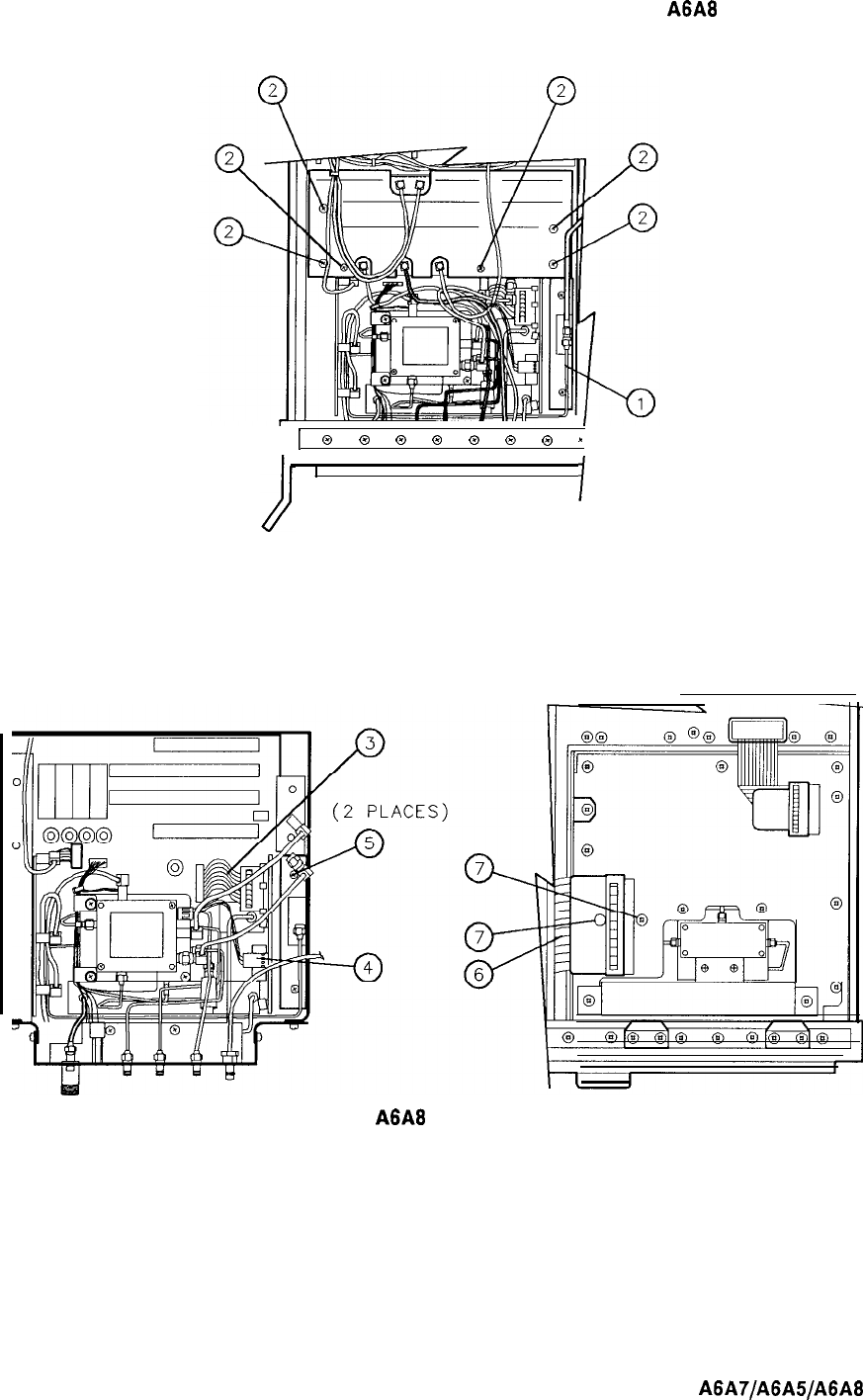
A6A8
YTX Replacement
I
1
0
0
0
0
Q
0
0
*
I
I
Figure 4.
A6A8
YTX Replacement
A6A7/A6A5/A6A8
9
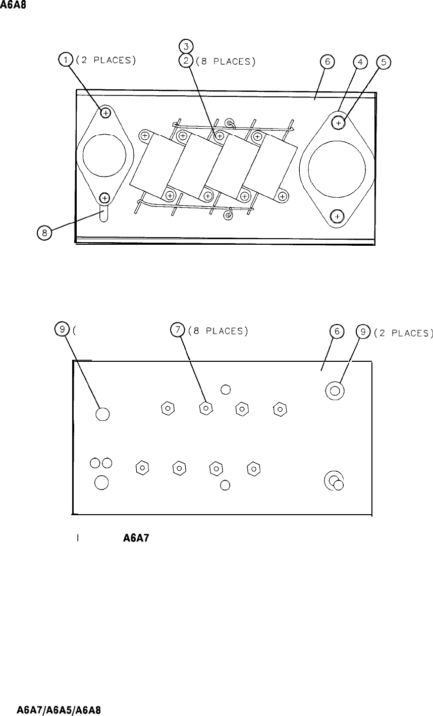
A6A8
YTX Replacement
0’
8
2 PLACES)
(2 PLACES)
\
I
I
O@
@
0 0
00
@
@
@
@
0
0
0
0
Figure 5.
A6A7
YTX Current Driver, Parts Identification (1 of 2)
10
A6A7/A6AS/A6A8
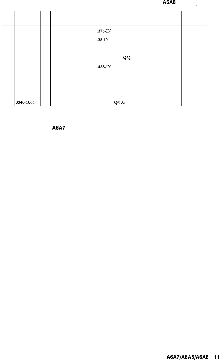
A6A8
YTX Replacement
Item HP Part CD Description Mfr Mfr Part
Number Code Number
1
2200-0107
6
SCREW, MACH, 4-40,
.375-IN
LG, PAN HD
28480 2200-0107
2
0520-0128
7
SCREW, MACH, 2-56,
.25-IN
LG, PAN HD
28480
0520-0128
3
2190-0014
1
WASHER, LOCK, 2-56, (FOR SCREW (2))
28480 2190-0014
4
1200-0043
8
INSULATOR, TRANSISTOR (FOR Q6)
28480 1200-0043
5
2200-0109 8
SCREW, MACH, 4-40,
.438-IN
LG, PAN HD
28480 2200-0109
6
85660-00023
9
HEAT SINK, YTX CURRENT DRIVER
28480 85660-00023
7
0610-0001
6
NUT, HEX, 2-56 (FOR SCREW (2))
28480 0610-0001
8
0340-0162
7
INSULATOR, TRANSISTOR (FOR Q7)
28480 0340-0162
9
0340-1064
0
INSULATOR, BUSHING (FOR
QS
&
Q7)
28480
0340-1064
Figure 5.
A6A7
YTX Current Driver, Parts Identification (2 of 2)
A6A7/A6AS/A6A8
11
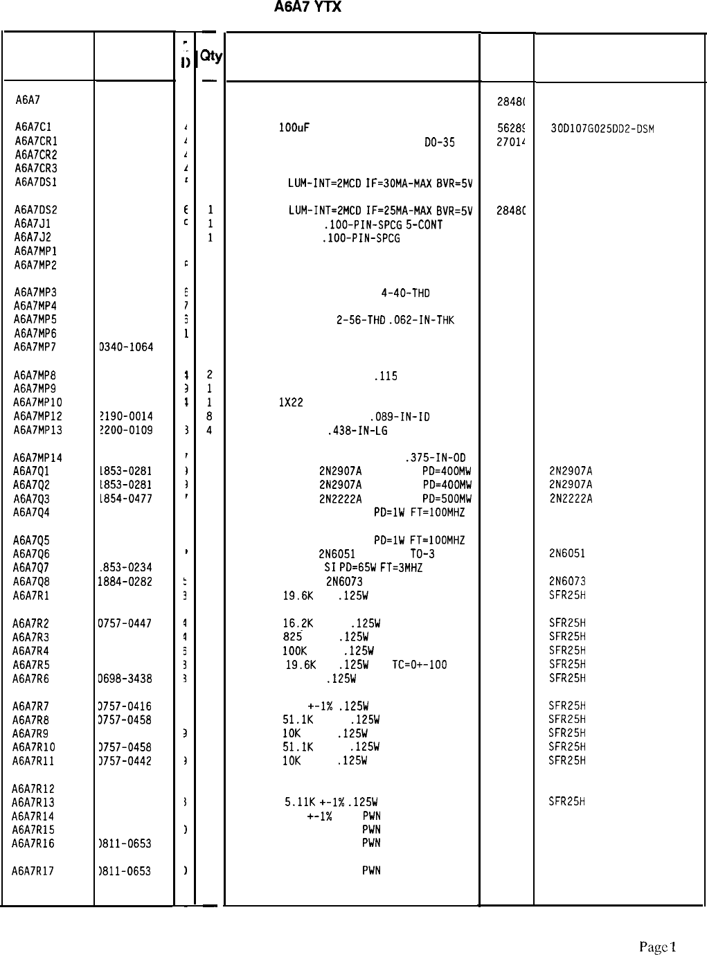
-
3t
HP Part Number 85660-60128
A6A7
YTX
Current Driver
Description Mfr
Mfr Part
Code
Number
-
1
BOARD ASSEMBLY, YTX CURRENT DRIVER
284BL
85660-60128
1
CAP-FXD
IOOuF
25 V AL-ELCTLT
5628s
300107G025DD2-DSM
1
DIODE-SWITCHING 125V 175MA 60NS
00-35
27011
FDH444
1
DIODE-SWITCHING 125V 175MA 60NS DO-35
27014
FDH444
1
DIODE-SWITCHING 125V 175MA 60NS DO-35
27014
FDH444
1
LED-LAMP
LUM-INT=2MCD
IF=30MA-MAX
BVR=SV
28481
HLMP-1503
LED-LAMP
LUM-INT=2MCD
IF=25MA-MAX
BVR=5V
CONN-POST TYPE
.lOO-PIN-SPCG
5-CDNT
CONN-POST TYPE
.lOO-PIN-SPCG
13-CDNT
NOT ASSIGNED
2848C
HLMP-1301
00779
87502-2
00779 87502-6
1
INSULATOR-XSTR THRM-CNDCT
18565
60-11-5791-1674
4
STANDOFF-RVT-ON .l-IN-LG
4-40-THD
8
SCREW-MACH 2-56 .25-IN-LG PAN-HD-POZI
8
NUT-HEX-DBL-CHAM
2-56-THD
.062-IN-THK
1
INSULATOR-XSTR THRM-CNDCT
4
INSULATOR-FLG-BSHG NYLON
05791
77250
73734
55285
BR 6905 B-0.100-43
K-4-05
INSULATOR-NYLON BUSHING
.115
ID
HEAT SINK CR OR
WIRE 22
1X22
WASHER-LK INTL T NO. 2
.089-IN-ID
SCREW-MACH 4-40
.438-IN-LG
PAN-HD-PDZI
28480
28480
28480
78189
77250
1200-0081
85660-00023
8151-0013
1902-00-00-2580
1
1
1
1
1
1
1
1
1
1
1
1
1
1
1
1
1
1
1
1
1
1
1
1
1
1
-
WASHER-FL NM NO. 8 .17-IN-ID
.375-IN-OD
TRANSISTOR PNP
2N2907A
SI TO-18
PD=400MW
TRANSISTOR PNP
2N2907A
SI TO-18
PD=400MW
TRANSISTOR NPN
2N2222A
SI TO-18
PD=500MW
TRANSISTOR PNP SI TO-39
PD=lW
FT=lOOMHZ
73734
04713
04713
04713
04713
33-112
2N2907A
2N2907A
2N2222A
TRANSISTOR PNP SI TO-39
PD=lW
FT=lOOMHZ 04713
TRANSISTOR PNP
2N6051
SI DARL
TO-3 04713
TRANSISTOR PNP
SI
PD=65W
FT=3MHZ 28480
THYRISTOR-TRIAC
2N6073 04713
RESISTOR
19.6K
1%
.125W
TF TC=O+-100
19701
2N6051
1853-0234
2N6073
SFR25H
RESISTOR
16.2K
+-1%
.125W
TF TC=O+-100
19701
SFR25H
RESISTOR 825 +-1%
.125W
TF TC=O+-100
19701
SFR25H
RESISTOR
1OOK
+-1%
.125W
TF TC=O+-100
19701
SFR25H
RESISTOR
19.6K
1%
.125W
TF
TC=O+-100
19701
SFR25H
RESISTOR 147 1%
.125W
TF TC=O+-100
19701
SFR25H
RESISTOR 511
+-1X
.125W
TF TC=O+-100
19701
SFR25H
RESISTOR
51.1K
+-1%
.125W
TF TC=O+-100
19701
SFR25H
RESISTOR
10K
+-1%
.125W
TF TC=O+-100
19701
SFR25H
RESISTOR
51.1K
+-1%
.125W
TF TC=O+-100
19701
SFR25H
RESISTOR
10K
+-1%
.125W
TF TC=O+-100
19701
SFR25H
RESISTOR 680 5% 2W MO TC=O+-200
RESISTOR
5.11K
+-1X
.125W
TF TC=O+-100
RESISTOR 100
+-1X
12W
PUN
TC=O+-5
RESISTOR 100 +-1% 12W
PUN
TC=O+-5
RESISTOR 100 +-1% 12W
PUN
TC=O+-5
RESISTOR 100 +-1% 12W
PUN
TC=O+-5
11502
GS-3
19701
SFR25H
01686 ALN-10
01686 ALN-10
01686 ALN-10
01686 ALN-10
*Indicates factory-selected value
85660-60128 Parts List
Page
1
of 2
Reference
Designatior
HP Part
Number
A6A7 85660-60128
A6A7Cl 0180-0094
A6A7CRl 1901-1067
A6A7CR2 1901-1067
A6A7CR3 1901-1067
A6A7DSl 1990-0485
A6A7DS2
A6A7Jl
A6A7J2
A6A7MPl
A6A7MP2
1990-0486
1251-5146
1251-5144
0340-0949
A6A7MP3 0380-1602
A6A7MP4 0520-0128
A6A7MP5 0610-0001
A6A7MP6 0340-1114
A6A7MP7 D340-1064
A6A7MP8 1200-0081
A6A7MP9 35660-00023
A6A7MPlO 3151-0013
A6A7MP12 !190-0014
A6A7MP13 !200-0109
A6A7MP14 3050-0239
A6A7Ql
L853-0281
A6A7Q2
1853-0281
A6A7Q3
1854-0477
A6A7Q4 1853-0038
A6A7Q5
1853-0038
A6A7Q6
1853-0391
A6A7Q7
.853-0234
A6A7Q8 1884-0282
A6A7Rl 0698-3157
A6A7R2 0757-0447
A6A7R3 0757-0421
A6A7R4 0757-0465
A6A7R5 0698-3157
A6A7R6 0698-3438
A6A7R7 3757-0416
A6A7RB 3757-0458
A6A7R9 3757-0442
A6A7RlO 3757-0458
A6A7Rll 3757-0442
A6A7R12 1698-3635
A6A7R13 1757-0438
A6A7R14 1811-0653
A6A7R15 1811-0653
A6A7R16 1811-0653
A6A7R17
1811-0653
v
.
.
.
1
1
1
1
c
E
c
7
E
E
7
5
1
3
1
3
1
I
3
r
1
1
I
I
I
1
,
3
1
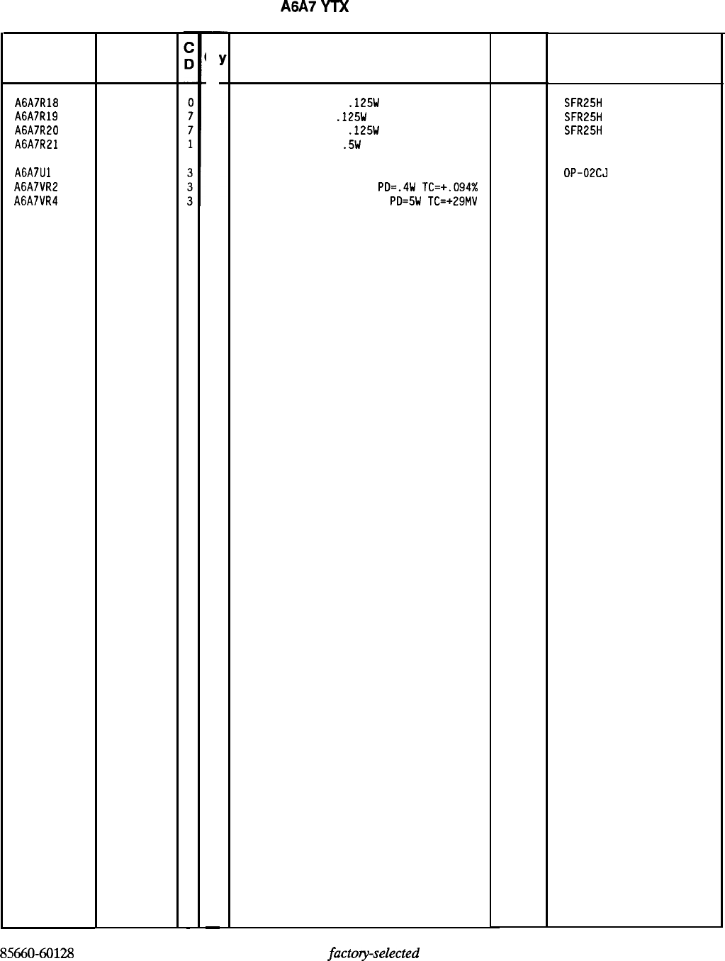
HP Part Number 85660-60128
A6A7
YTX
Current Driver
Reference HP Part
Designatior Number
A6A7R18 0757-0401
A6A7R19 0698-0082
A6A7R20 0757-0416
A6A7R21 0698-3395
A6A7Ul 1826-1058
A6A7VR2 1902-0967
A6A7VR4 1902-0644
-
Qt
1
1
1
1
1
1
1
-
Description
RESISTOR 100 +-1%
.125W
TF TC=O+-100
RESISTOR 464 1%
.125W
TF TC=O+-100
RESISTOR 511 +-1%
.125W
TF TC=O+-100
RESISTOR 34.8 1%
.5W
TF TC=O+-100
IC OP AMP GP a-TO-99 PKG
DIODE-ZNR 24V 5% DO-35
PD=.4W
TC=+.094%
DIODE-ZNR 1153638 30V 5%
PD=5W
TC=+29MV
85660-60128 Parts List
Page 2 of 2
*Indicates
factoy-selected
value
Mfr Mfr Part
Code Number
19701
19701
19701
19701
06665
04713
04713
SFR25H
SFR25H
SFR25H
5053R
OP-02CJ
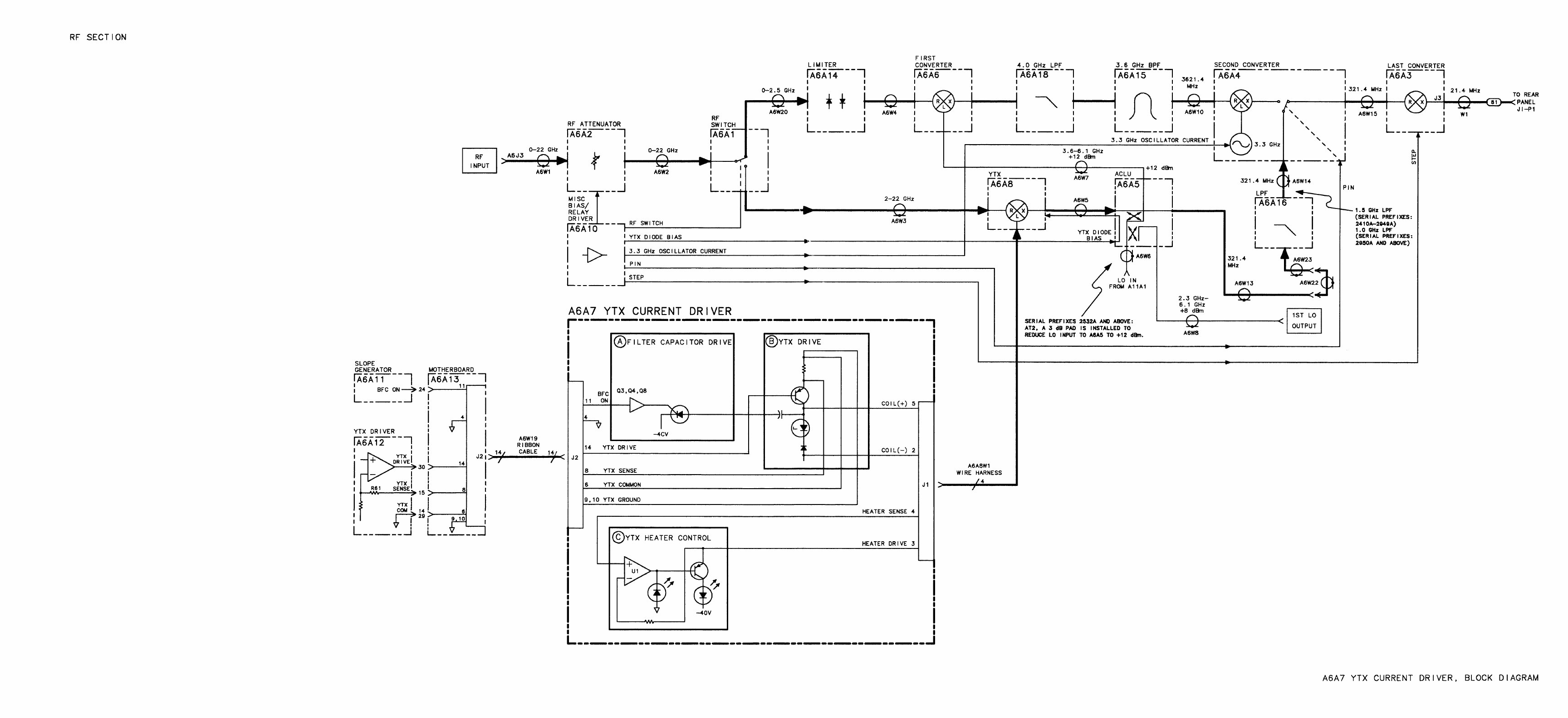

DS2
DSl
GREEN
ONIE9ER
ON=HEATER CONTROL SATURATED
\
PC BOARD SIDE
(SIGNAL
iD
HEATER
CONNECTIONS)
s
DSl
DS2
\;-
,/ig&#qg~
II
\
HEAT SINK SIDE
A6A7
YTX Current Driver Component Locations, 85660-60128
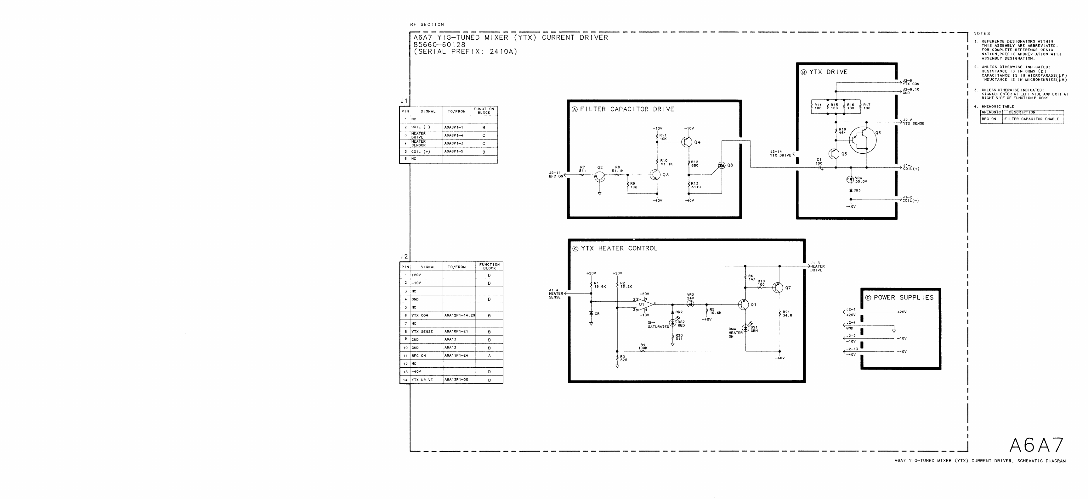
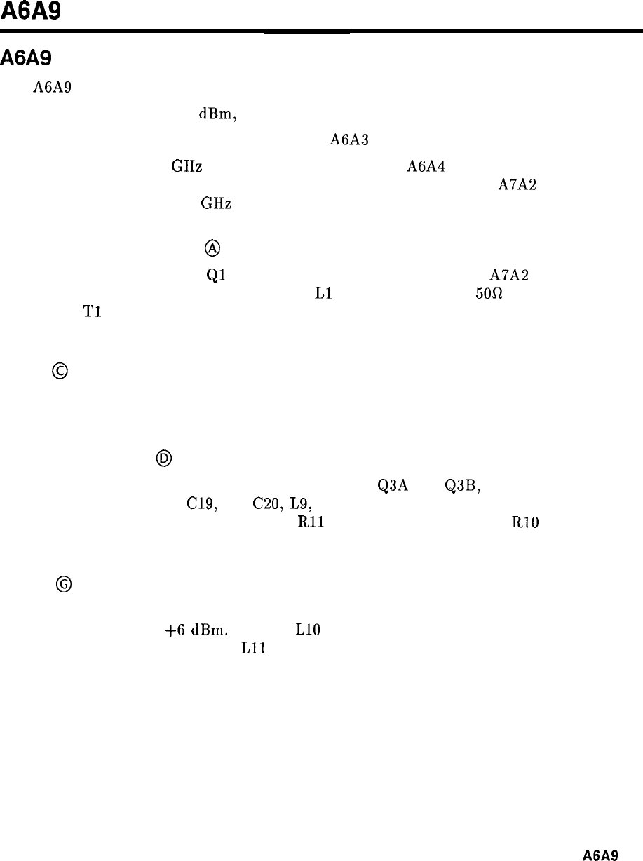
A6A9
A6A9
Phase Lock, Circuit Description
The A6A9 Phase Lock has three major functions:
1. To provide a stable -10.0
dBm,
100 MHz calibrator signal to the RF Section front panel.
2. To provide a 300 MHz local oscillator to the A6A3 Last Converter assembly.
3. To phase-lock the 3.3 GHz second local oscillator in the A6A4 Second Converter assembly
to the 33rd harmonic of the 100 MHz reference signal produced by the A7A2 100 MHz
VCXO assembly. This 3.3 GHz phase lock loop is called the Heterodyne Loop.
100 MHz Buffer Amplifier
@
The 100 MHz buffer amplifier
Ql
amplifies the reference signal from the A7A2 100 MHz
VCXO assembly. Low pass matching network,
Ll
and C4, provides a
5Ofl
input impedance.
Transformer
Tl
acts as a power divider, supplying the 100 MHz signal to both the Driver
circuit and the Phase Lock circuit.
Driver
@
Transistor Q2 amplifies the 100 MHz from the 100 MHz Buffer Amplifier. Power divider T2
drives both the 100 MHz Calibrator and the 300 MHz LO circuit.
100 MHz Calibrator
@
The Calibrator circuit consists of a differential amplifier, Q3A and Q3B, followed by a low
pass filter. Low pass filters C19, L8, C20,
L9,
and C22, reduce higher order harmonics on the
front panel calibrator output. Potentiometer
Rll
and factory-select resistor RlO set the gain
of Q3.
Tripler
@
With the 100 MHz input from the Driver circuit, the Tripler circuit produces a 300 MHz
output at approximately
+6
dBm.
Inductor
LlO
and C24 are used for impedance matching.
The output tank circuit, formed by
Lll
and the output capacitance of transistor Q4, resonates
at 300 MHz. Capacitor C29 adjusts the loading of the stage and couples the output to the
Power Amplifier.
A6A9
1
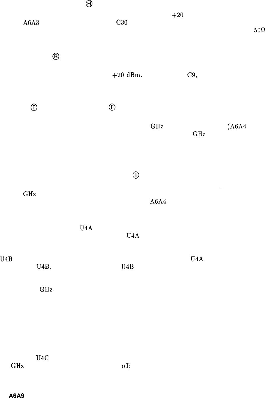
300 MHz Power Amplifier
@I
The output of the 300 MHz Power Amplifier, approximately
+20
dbm, is the local oscillator
for the A6A3 Last Converter. Capacitor
C30
reduces the sub-harmonic content of the output.
The output filter C52, L21, and C53, reduces higher order harmonics while maintaining a
500
output impedance.
Sampler Driver
@I
Amplifier U2 drives the Sampler step-recovery diode (function block E) with the 100
MHz signal at a level of approximately
+20
dBm.
Capacitors C8, C9, and L4 match the
forward-biased impedance of the diode to U2. Resistor R5 loads the output of U2 during the
diode’s reverse biased condition.
Sampler
@
and Loop Integrator
@
The output of the sampler is a dc voltage proportional to the phase difference between the
33rd harmonic of the 100 MHz reference and the 3.3 GHz second local oscillator (A6A4
Second Converter). Integrator U3 supplies a tune voltage to the 3.3 GHz second local
oscillator. This heterodyne loop phase locks the oscillator to the 100 MHz reference signal.
Potentiometer R38 adjusts the output balance of the sampler. Capacitor C46 is the integrator
capacitor for U3.
Aided Acquisition and Unlock Detector
@
The output tune voltage from the Loop Integrator (function block F) becomes
-
25 V when
the 3.3 GHz Heterodyne Loop is unlocked. The Aided Acquisition circuitry detects this
condition and retunes the 3.3 GHZ oscillator on the A6A4 Second Converter assembly within
the capture range of the phase-lock loop. The Aided Acquisition circuitry also controls the
Lock Indicator (function block J).
The Negative Rail Detector U4A is an inverting comparator. The threshold voltage at pin 5 is
set at -23.5 V. During unlock, the input of U4A becomes more negative than the threshold
voltage and the comparator output becomes positive. Resistor R21 provides positive feedback,
stabilizing the circuit. Resistors R25 and R26 form a voltage divider reducing the input to
U4B
below the value of the power supplies. The positive output of U4A triggers One Shot
multivibrator U4B. The negative output of U4B forward biases diodes CR1 and CR2. The
diodes become a constant current source for integrator capacitor C46 (function block F),
causing a positive direction search ramp of voltage at the output of U3. This search ramp
tunes the 3.3 GHz second local oscillator through the capture range of the phase-lock loop.
If the phase-lock loop does not phase-lock on the search ramp, the tune voltage will remain
positive until the One Shot recovers, reverse biasing CR1 and CR2. The output of U3 then
becomes negative (unlock condition), causing the Aided Acquisition circuitry to repeat the
search cycle until phase-lock occurs. This results in a sawtooth tune waveform with a period
of approximately 6 ms.
The One Shot pulse width of approximately 1 ms is controlled by R24 and C38. This is the
time it takes for the voltage on pin 7 to decay to -25 V to less the -20 V. During this time,
the input to U4C has become -20 V due to the positive tune voltage ramp. In high band the
3.3 GHz second local oscillator is switched
off;
the PIN signal goes negative, which disables
the search ramp and unlock detector through CR3.
2
A6A9
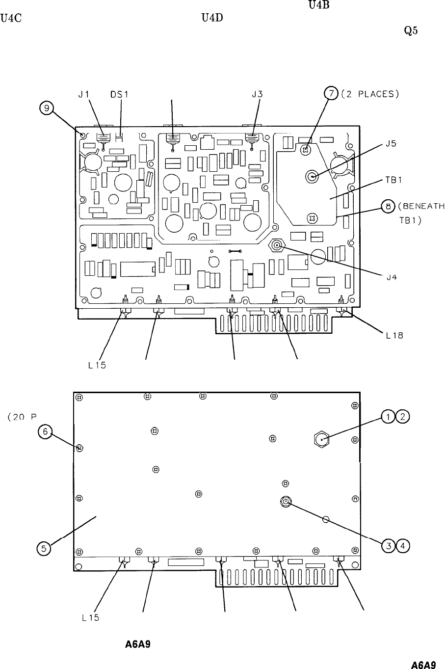
Switch and Unlock Detector: When unlock occurs, the output of U4B becomes low, causing
U4C to have a low output. The output of U4D becomes positive, turning off Q5. If no lock
occurs on the search ramp, the delay caused by resistor R27 and capacitor C37 keeps
Q5
off
until the next search cycle begins. This delay is different for an HP 85660A RF Section, and is
set by the value of R27.
Jl
DSI
J2
L1.5 L14 L17 L16
60
@
(gl
@
LACES)
@
0
@
L14 L17 L16 L18
Figure 1.
A6A9
Phase Lock Assembly, Internal and Front Views
A6A9
3
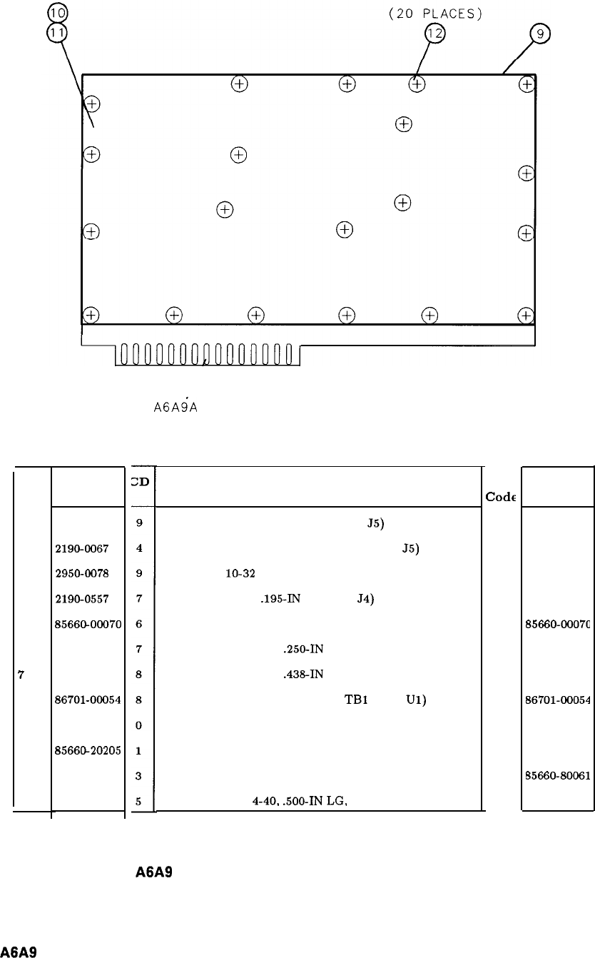
Item
1
2
3
4
5
6
7
8
9
10
11
12
HP Part
Number
2950-0177
2196-6067
2950-0078
2190-0557
8566CLOOO70
2200-0140
2200-0109
86701-06054
85660-20204
8566@20205
85660-80061
2200-0148
A6A9’A
1
Description
NUT, HEX, RF CONNECTOR (FOR
55)
WASHER, LOCK, RF CONNECTOR (FOR
55)
NUT, HEX,
lo-32
(FOR J4)
WASHER, LOCK,
.195-IN
ID (FOR
54)
COVER, FRONT, PHASE LOCK ASSEMBLY
SCREW, MACH, 4-40,
.250-IN
LG, FL HD
SCREW, MACH, 4-40,
.438-IN
LG, PAN HD
SPACER-SAMPLER (BETWEEN
TBl
AND
Ul)
HOUSING, PHASE LOCK ASSEMBLY
COVER, REAR, PHASE LOCK ASSEMBLY
INSULATING SHIELD, PLASTIC
SCREW, MACH. 4-40,
.500-IN
LG. FL HD
Mfr Mfr Part
Code
Number
28480 2950-0177
28480 2190-0067
28480 2950-0078
28480 2190-0557
28480
85660~0007C
28480 2200-0140
28480 2200-0109
28480 86701-00054
28480 85660-20204
28480 85660-20205
28480 85660-80061
28480 2200-0148
Figure 2.
A6A9
Phase Lock Assembly, Parts Identification, Rear View
4
A6A9
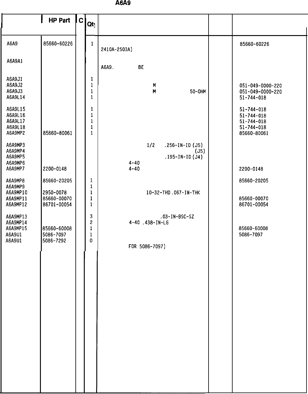
Reference
l
Designation
1
HPPa-
lC
Irt
II
I
I
Qtl
t
Description Mfr
Mfr Part
I
Number
D
Code Number
I
A6A9 85660-60226
0
1
PHASE LOCK ASSEMBLY (SERIAL PREFIX: 28480 85660-60226
2410A-2503A)
A6A9Al
A6A9Jl
A6A9J2
A6A9J3
A6A9L14
A6A9L15
A6A9L16
A6A9L17
A6A9L18
A6A9MP2
A6A9MP3 1250-1142
5
1
WASHER-LK INTL T
l/2
IN
.256-IN-ID
(55)
28480 1250-1142
A6A9MP4 1250-1143
6
1
NUT-RF CONNECTOR SERIES SMA HEX NUT
(55)
28480 1250-1143
A6A9MP5
2190-0559
7
1
WASHER-LK INTL T ND. 10
.195-IN-ID
(54)
28480 2190-0559
A6A9MP6 2200-0140
7
20
SCREW-MACH
4-40
.25-IN-LG 100 DEG
28480 2200-0140
A6A9MP7 2200-0148
5
20
SCREW-MACH
4-40
.5-IN-LG 100 DEG
28480 2200-0148
A6A9MP8
A6A9MP9
A6A9MPlO
A6A9MPll
A6A9MP12
A6A9MP13
A6A9MP14
A6A9MP15
A6A9Ul
A6A9Ul
85660-60202
2
I
1 PHASE LOCK BOARD ASSEMBLY (PART OF
28480 85660-60202
A6A9.
MAY NOT
BE
ORDERED SEPARATELY.)
(PARTS LIST INCLUDED IN THIS SECTION.)
1250-0544
9
CONNECTOR-RF SM-SNP M SGL-HOLE-FR SO-OHM
98291 051-049-0000-220
1250-0544
9
CONNECTOR-RF SM-SNP
M
SGL-HOLE-FR SO-OHM
98291 OSl-049-0000-220
1250-0544
9
CONNECTOR-RF SM-SNP
M
SGL-HOLE-FR
5D-OHM 98291 OSl-D49-0000-220
9135-0002
8
FILTER-LOW PASS SOLDER-TERMS 33095 51-744-018
9135-0002
8
FILTER-LOW PASS SOLDER-TERMS 33095 51-744-018
9135-0002
8
FILTER-LOW PASS SOLDER-TERMS 33095 51-744-018
9135-0002
8
FILTER-LOW PASS SOLDER-TERMS 33095 51-744-018
9135-0002
8
FILTER-LOW PASS SOLDER-TERMS 33095 51-744-018
85660-80061
3
INSULATOR, MYLAR, CLEAR 28480 85660-80061
85660-20205
1
COVER, BOTTOM 28480
85660-20205
85660-20204
0
HOUSING, PHASE LOCK 80X 28480 85660-20204
2950-0078
9
NUT-HEX-DBL-CHAM
lo-32-THD
.067-IN-THK 28480 2950-0078
85660-00070
6
COVER, PHASE LOCK 28480 8566D-DO070
86701-00054
8
SPACER, SAMPLER 28480
86701-DO054
1251-3172
7
2200-0107
8
85660-60008
6
5086-7097
6
5086-7292
3
CONNECTOR-SGL CONT SKT
.03-IN-BSC-SZ
RND
SCREW-MACH
4-40
.438-IN-LG
PAN-HD-POZI
BOARD ASSEMBLY. SAMPLER
SAMPLER 2-6.5 GHZ (PREFERRED)
SAMPLER 2-6.0 GHZ
(ALTERNATE
FOR
5086-7097)
28480
28480
28480
28480
28480
1251-3172
2200-0107
85660-60008
5086-7097
5086-7292
HP Part Number 85660-60226
A6A9
Phase Lock Assembly
*Indicates factory-selected value
8X560-60226 Parts List
Page 1 of 1
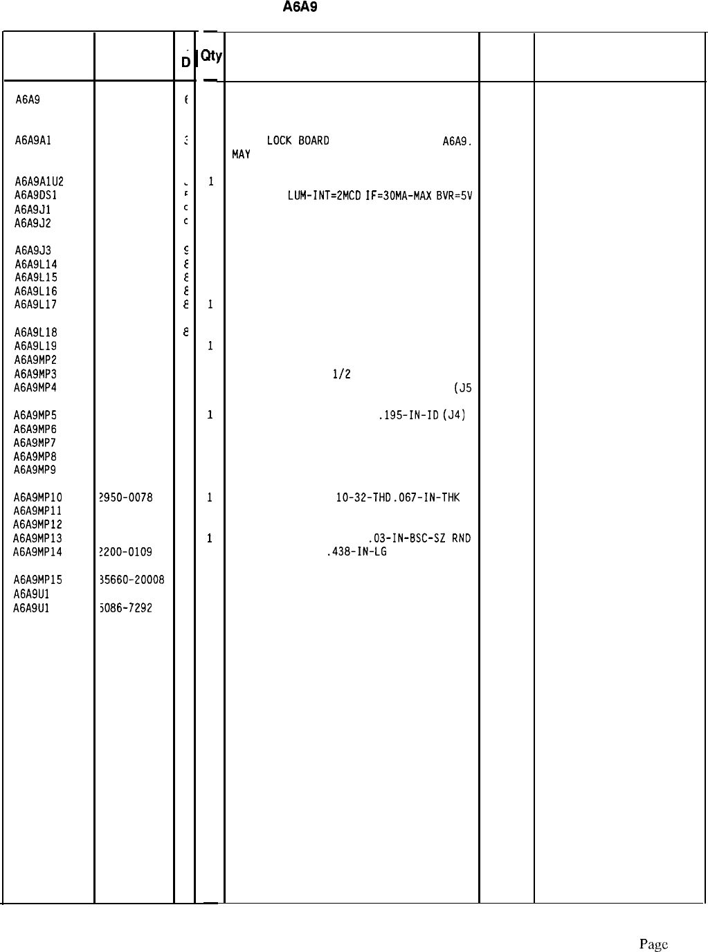
HP Part Number 85660-60256
A6A9
Phase Lock Box
Reference HP Part
Designation
Number
A6A9 85660-60256
A6A9Al 85660-60253
:
A6A9AlU2 1813-0213
A6A9OSl 1990-0485
A6A9Jl 1250-0544
A6A9J2 1250-0544
c
c
A6A9J3 1250-0544
s
A6A9L14 9135-0002
E
A6A9L15 9135-0002
E
A6A9L16 9135-0002
E
A6A9L17 9135-0002
a
A6A9L18
A6A9L19
A6A9MP2
A6A9MP3
A6A9MP4
9135-0002
a
9135-0002
8
85660-80061
3
1250-1142
5
1250-1143
6
A6A9MP5 2190-0557
7
A6A9MP6 2200-0140
7
A6A9MP7 2200-0148
5
A6A9MP8 35660-20226
6
A6A9MP9 35660-20225
5
A6A9MPlO !950-0078
9
A6A9MPll 35660-00089
7
A6A9MP12 36701-00054
a
A6A9MP13 1251-3172
7
A6A9MP14 !200-0109
8
A6A9MP15 35660-20008
2
A6A9Ul 5086-7097
6
A6A9Ul 5086-7292
3
C
c
-
;Itl
-
1
1
1
1
1
1
1
1
1
1
1
1
1
1
1
1
1
2c
2c
1
1
1
1
1
1
2
1
1
0
-
Description
PHASE LOCK ASSEMBLY
(SERIAL PREFIX: 2504A) 28480 85660-60256
PHASE
LOCK
BOARD
ASSEMBLY (PART OF
A6A9.
MAY
NOT BE ORDERED SEPARATELY.) (PARTS
LIST INCLUDED IN THIS SECTION.)
IC WIOEBANO AMPL TO-39 PKG
LEO-LAMP
LUM-INT=2MCO
IF=SOMA-MAX
BVR=5V
CONNECTOR-RF SM-SNP M SGL-HOLE-FR 50-OHM
CONNECTOR-RF SM-SNP M SGL-HOLE-FR 50-OHM
28480 85660-60253
04713 MWA130
28480 HLMP-1503
98291 051-049-0000-220
98291 051-049-0000-220
CONNECTOR-RF SM-SNP M SGL-HOLE-FR 50-OHM
98291 051-049-0000-220
FILTER-LOW PASS SOLDER-TERMS 33095 51-744-018
FILTER-LOW PASS SOLDER-TERMS 33095 51-744-018
FILTER-LOW PASS SOLDER-TERMS 33095 51-744-018
FILTER-LOW PASS SOLDER-TERMS 33095 51-744-018
FILTER-LOW PASS SOLDER-TERMS 33095 51-744-018
FILTER-LOW PASS SOLDER-TERMS 33095 51-744-018
INSULATOR MYLAR CLEAR 28480 85660-80061
WASHER-LK INTL T
l/2
IN .26-IN-IO (55)
16179
2098-5856-04
NUT-RF CONNECTOR SERIES SMA HEX NUT
(55 16179
2098-5862-00
WASHER-LK INTL T NO. 10
.195-IN-IO
(54)
SCREW-MACH 4-40 .25-IN-LG 100 OEG
SCREW-MACH 4-40 .5-IN-LG 100 OEG
COVER BOTTOM
1210-06-00-0551
HOUSING PHASE LOCK BOX
78189
77250
77250
28480
28480 85660-20226
85660-20225
NUT-HEX-DEL-CHAM
lo-32-THO
.067-IN-THK 74163
COVER PHASE LOCK 28480
SPACER SAMPLER 28480
CONNECTOR-SGL CONT SKT
.03-IN-BSC-SZ
RN0 00779
SCREW-MACH 4-40
.438-IN-LG
PAN-HO-POZI
77250
500220
85660-00089
86701-00054
2-331677-9
SAMPLER BOARD
SAMPLER 2-6.5 GHZ (PREFERRED)
SAMPLER 2-6.5 GHZ
(ALTERNATE FOR 5086-7097)
28480 85660-20008
28480 5086-7097
28480 5086-7292
Mfr
Mfr Part
Code Number
*Indicates factory-selected value
85660-60256 Parts List
Page
1 or
1
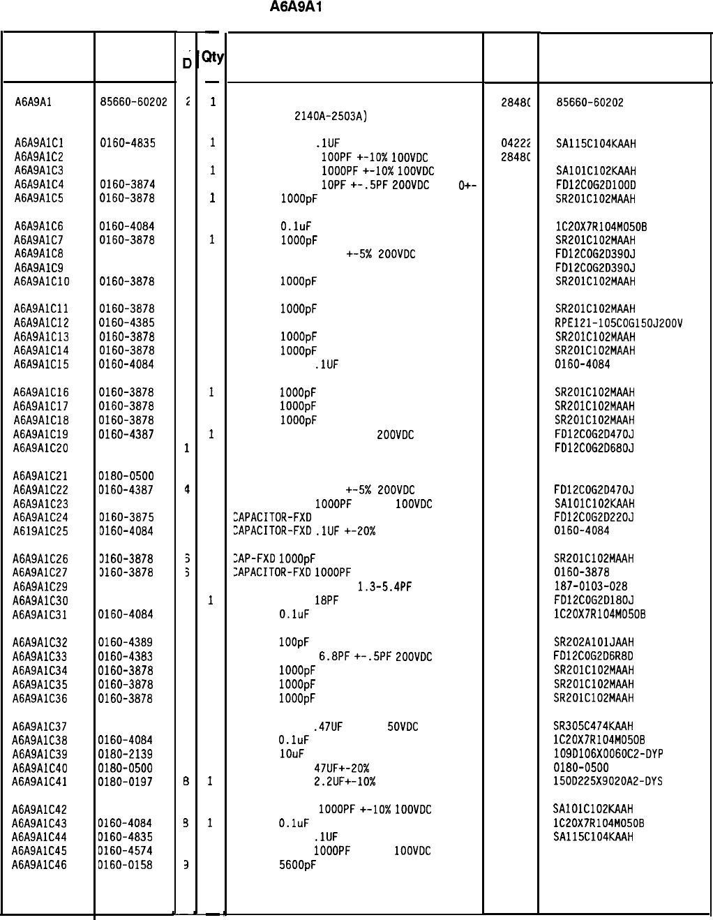
Reference
Designation
HP Part
Number
C
c
A6A9Al 85660-60202
i
A6A9AlCl 0160-4835
7
A6A9AlC2 0160-4574
1
A6A9AlC3 0160-4574
1
A6A9AlC4 0160-3874
2
A6A9AlC5 0160-3878
6
A6A9AlC6 0160-4084
a
A6A9AlC7 0160-3878
6
A6A9AlCB 0160-4494
4
A6A9AlC9 0160-4494
4
A6A9AlClO
0160-3878
6
A6A9AlCll 0160-3878
6
A6A9AlC12 0160-4385
2
A6A9AlC13 0160-3878
6
A6A9AlC14 0160-3878
6
A6A9AlC15
0160-4084
a
A6A9AlC16
0160-3878
6
A6A9AlC17 0160-3878
6
A6A9AlClB 0160-3878
6
A6A9AlC19 0160-4387
4
A6A9AlC20 0160-4350
1
A6A9AlC21 0180-0500
7
A6A9AlC22 0160-4387
4
A6A9AlC23 0160-4574
1
A6A9AlC24 0160-3875
3
A619AlC25
D160-4084
3
A6A9AlC26
3160-3878
5
A6A9AlC27 3160-3878
3
A6A9AlC29 0121-0452
4
A6A9AlC30
0160-4492
2
A6A9AlC31 0160-4084
a
A6A9AlC32 0160-4389
6
A6A9AlC33 0160-4383
0
A6A9AlC34 0160-3878
6
A6A9AlC35
0160-3878
6
A6A9AlC36
0160-3878
6
A6A9AlC37 0160-4441
1
A6A9AlC38
0160-4084
a
A6A9AlC39 0180-2139
2
A6A9AlC40 0180-0500
7
A6A9AlC41 0180-0197
6
A6A9AlC42 0160-4574
1
A6A9AlC43 0160-4084
3
A6A9AlC44 D160-4835
7
A6A9AlC45 0160-4574
1
A6A9AlC46
D160-0158
3
-
at!
-
1
1
5
1
1
1
1
1
1
1
1
1
1
1
1
1
1
1
1
1
1
1
1
1
1
1
1
1
1
1
1
1
1
1
1
1
1
1
1
1
1
1
1
1
-
HP Part Number 85660-60202
A6A9Al Phase Lock Board
Description
BOARD ASSEMBLY, PHASE LOCK (SERIAL
PREFIXES:
2140A-2503A)
CAPACITOR-FXO
.lUF
+-lo% 50VOC CER
CAPACITOR-FXO
1OOPF
+-lo%
1OOVOC
CER
CAPACITOR-FXO
1OOOPF
+-10X
1OOVOC
CER
CAPACITOR-FXO
1OPF
+-.5PF
LOOVOC
CER
O+-
CAP-FXO
1OOOpF
100 V
CAP-FXO
O.luF
50 V
CAP-FXO
1OOOpF
100 V
CAPACITOR-FXO 39PF +-5x
POOVOC
CER 0+-30
CAPACITOR-FXO 39PF +-5% 200VOC CER 0+-30
CAP-FXO
1OOOpF
100 V
CAP-FXO
1OOOpF
100 V
CAP-FXO 15pF 200 V
CAP-FXO
1OOOpF
100 V
CAP-FXO
1OOOpF
100 V
CAPACITOR-FXO
.lUF
+-20% 50VOC CER
CAP-FXO
1OOOpF
100 V
CAP-FXO
1OOOpF
100 V
CAP-FXO
IOOOpF
100 V
CAPACITOR-FXO 47PF +-5%
2OOVOC
CER 0+-30
CAP-FXO 68pF 200 V
CAP-FXO 47uF 20 V TA
CAPACITOR-FXO 47PF +-5x
ZOOVOC
CER 0+-30
CAPACITOR-FXO
1OOOPF
+-lo%
1OOVOC
CER
EAPACITOR-FXO
22PF +-5% 200VOC CER 0+-30
EAPACITOR-FXO
.lUF
+-20x
50VOC CER
ZAP-FXO
1OOOpF
100 V
ZAPACITOR-FXO
1OOOPF
+-20% 100 VOC CER
CAPACITOR-V TRMR-AIR
1.3-5.4PF
175V PC-M
CAPACITOR-FXO
18PF
+-5% 200VOC CER 0+-30
CAP-FXO
O.luF
50 V
CAP-FXO
1OOpF
200 V
CAPACITOR-FXO
6.8PF
+-.5PF
EOOVOC
CER 0+
CAP-FXO
1OOOpF
100 V
CAP-FXO
1OOOpF
100 V
CAP-FXO
1OOOpF
100 V
CAPACITOR-FXO
.47UF
+-lo%
SOVOC
CER
CAP-FXO
O.luF
50 V
CAP-FXO
1OuF
60 V UT-SLG-TA-ELCTLT
CAPACITOR-FXO
47UF+-20%
20VOC TA
CAPACITOR-FXO
2.2UF+-10%
20VOC TA
CAPACITOR-FXO
1OOOPF
+-lo%
IOOVOC
CER
CAP-FXO
O.luF
50 V
CAPACITOR-FXO
.lUF
+-lo% 50VOC CER
CAPACITOR-FXO
1OOOPF
+-lo%
1OOVOC
CER
CAP-FXO
56OOpF
200 V POLYE-FL
*Indicates factoyselected value
Mfr
Mfr Part
Code Number
28481
85660-60202
04222
284ac
04222
04222
SA115C104KAAH
1060-4574
SAlOlC102KAAH
F012C06201000
SR201C102MAAH
56289
04222
04222
1C20X7R104M0506
SR201C102MAAH
FO12COG20390J
FO12COG20390J
SR201C102MAAH
04222
04222
04222
28480
SR2OlC102MAAH
RPE121-105COG150J200V
SR201C102MAAH
SR201C102MAAH
0160-4084
04222
04222
04222
SR201C102MAAH
SR201C102MAAH
SR201C102MAAH
FO12COG2047OJ
F012C0620680J
56289
04222
28480
19901114
FO12COG20470J
SAlOlC102KAAH
FO12COG20220J
0160-4084
04222
28480
74970
56289
SR201C102MAAH
0160-3878
187-0103-028
FO12COG2O180J
1C20X7R104M0508
04222
04222
04222
04222
SR202AlOlJAAH
F012C0G206R80
SR201C102MAAH
SR201C102MAAH
SR201C102MAAH
04222 SR305C474KAAH
56289 lC20X7R104M0508
56289 1090106X0060C2-OYP
28480 0180-0500
56289 1500225X9020A2-OYS
04222
SAlOlC102KAAH
56289 lC20X7R104M0508
04222 SA115C104KAAH
28480 0160-4574
84411 HEW-238M
8X60-60202 Parts List
Page 1 of 3
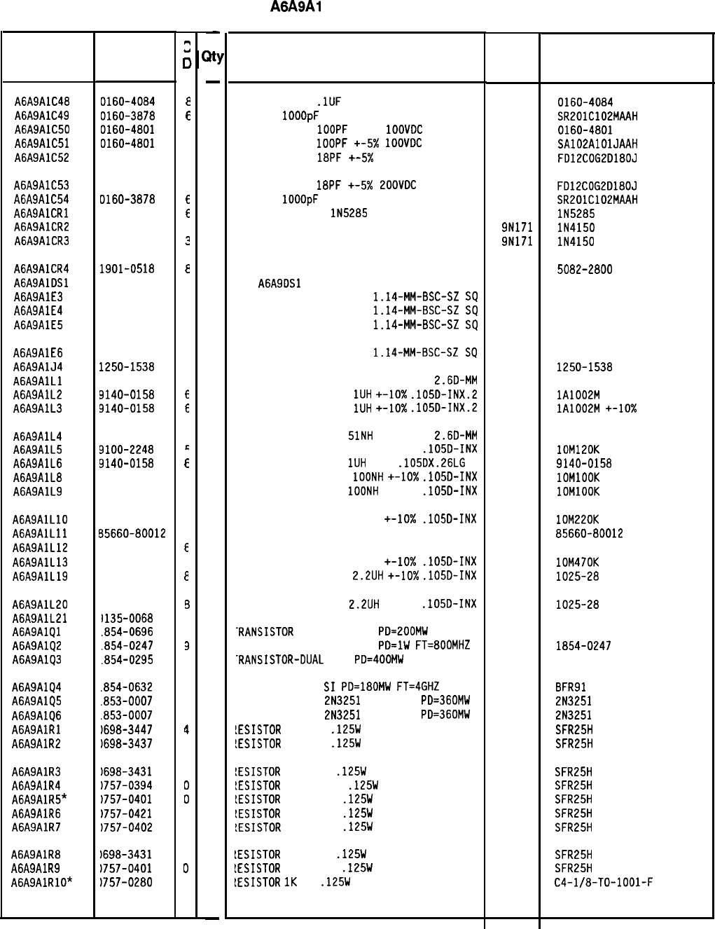
Reference
Designation
HP Part
Number
A6A9AlC48 0160-4084
A6A9AlC49 0160-3878
A6A9AlC50 0160-4801
A6A9AlC51 0160-4801
A6A9AlC52 0160-4492
A6A9AlC53 0160-4492
A6A9AlC54 0160-3878
AGASAlCRl 1901-0954
A6A9AlCR2 1901-0050
A6A9AlCR3 1901-0050
A6A9AlCR4
AGASAlOSl
A6A9AlE3
A6A9AlE4
A6A9AlE5
1901-0518
1251-0600
1251-0600
1251-0600
A6A9AlE6 1251-0600
A6A9AlJ4 1250-1538
A6A9AlLl 9135-0073
A6A9AlL2 9140-0158
A6A9AlL3 9140-0158
A6A9AlL4
A6A9AlL5
A6A9AlL6
A6A9AlLB
A6A9AlL9
9135-0073
9100-2248
9140-0158
9100-2247
9100-2247
A6A9AlLlO
A6A9AlLll
A6A9AlL12
A6A9AlL13
A6A9AlL19
9100-2251
85660-80012
9135-0068
9100-2255
9140-0142
A6A9AlL20
1140-0142
A6A9AlL21
l135-0068
A6A9AlQl
.854-0696
A6A9AlQ2
.854-0247
A6A9AlQ3
.854-0295
A6A9AlQ4
A6A9AlQ5
A6A9AlQ6
A6A9AlRl
A6A9AlR2
.854-0632
.853-0007
.853-0007
1698-3447
1698-3437
A6A9AlR3
1698-3431
A6A9AlR4
1757-0394
A6A9AlR5*
1757-0401
A6A9AlR6
1757-0421
A6A9AlR7
1757-0402
A6A9AlRB
A6A9AlR9
A6A9AlRlO*
1698-3431
1757-0401
)757-0280
8566040202 Parts List
Page 2 of 3
2
0
a
E
7
7
2
2
E
E
3
?
a
C
C
C
C
3
3
6
E
3
E
E
4
4
C
4
E
4
E
6
6
2
3
7
6
7
7
4
2
6
0
0
4
1
6
0
3
-
31
-
1
2
1
1
1
1
1
1
1
1
1
1
1
1
1
1
1
1
1
1
1
1
1
1
1
1
1
1
1
1
1
1
1
1
1
1
1
1
1
1
1
1
1
1
1
-
HP Part Number 85660-60202
A6A9Al Phase Lock Board
Description Mfr Part
Number
CAPACITOR-FXO
.lUF
+-20% 50VOC CER
CAP-FXO
IOOOpF
100 V
CAPACITOR-FXO
1OOPF
+-5%
1OOVOC
CER
CAPACITOR-FXO
1OOPF
+-5x
IOOVOC
CER 0+-3
CAPACITOR-FXO
18PF
+-5X 200VOC CER 0+-30
CAPACITOR-FXO
18PF
+-5x
LOOVOC
CER 0+-30
CAP-FXO
1OOOpF
100 V
DIODE-CUR RGLTR
lN5285
270UA DO-7
DIODE
-
SW
ITCHING aov 200MA 2Ns Do-35
DIODE
-
SWITCH
I
N
G aov 200MA 2Ns Do-35
Mfr
Code
28480
04222
28480
04222
0160-4084
SR201C102MAAH
0160-4801
SA102AlOlJAAH
F012COG2O180J
04222
04713
9N171
9N171
FO12COG20180J
SR201C102MAAH
lN5285
lN4150
lN4150
DIODE-SCHOTTKY SM SIG
SEE
A6A9OSl 5082-2800
CONNECTOR-SGL CONT PIN
1.14-MM-BSC-SZ
SQ
27264 16-06-0034
CONNECTOR-SGL CONT PIN
1.14-MM-BSC-SZ
SQ
27264 16-06-0034
CONNECTOR-SGL CONT PIN
1.14~MM-BSC-SZ
SQ
27264 16-06-0034
CONNECTOR-SGL CONT PIN
1.14~MM-BSC-SZ
SQ
27264
CONNECTOR-RF SMB M PC 50-OHM 28480
INDUCTOR RF-CH-ML0 51NH +-6.596%
2.60-MM 06560
INDUCTOR RF-CH-ML0
1UH
+-lo%
.1050-INX.2 32159
INDUCTOR RF-CH-ML0
1UH
+-lo%
.1050-INX.2 32159
16-06-0034
1250-1538
lA1002M
+-lo%
lA1002M
+-10X
INDUCTOR RF-CH-ML0
51NH
+-6.596%
2.60-MM 06560
INDUCTOR RF-CH-ML0 120NH +-lo%
.1050-INX 24226
INDUCTOR RF-CH-ML0
1UH
10%
.105OX.26LG 28480
INDUCTOR RF-CH-ML0
1OONH
+-lo%
.1050-INX 24226
INDUCTOR RF-CH-ML0
1OONH
+-lo%
.1050-INX 24226
lOM120K
9140-0158
1OMlOOK
1OMlOOK
INDUCTOR RF-CH-ML0 220NH +-lo%
.1050-INX
COIL 24NH
INDUCTOR RF-CH-ML0 33NH +-6.36%
INDUCTOR RF-CH-ML0 470NH +-lo%
.1050-INX
INDUCTOR RF-CH-ML0
2.2UH
+-10X
.1050-INX
24226
28480
06560
24226
99800
lOM220K
85660-80012
lOM470K
1025-28
:NOUCTOR RF-CH-ML0
2.2UH
+-lo%
.1050-INX 99800
:NOUCTOR RF-CH-ML0 33NH +-6.36% 06560
-RANSISTOR
NPN SI TO-72
PO=200MW 25403
'RANSISTOR NPN SI TO-39
PO=lW
FT=BOOMHZ 28480
-RANSISTOR-DUAL
NPN
PO=400MW 04713
1025-28
1854-0247
'RANSISTOR NPN
SI
PO=lBOMW
FT=4GHZ 25403 BFR91
'RANSISTOR PNP
2N3251
SI TO-18
PO=360MW 04713 2N3251
'RANSISTOR PNP
2N3251
SI TO-18
PO=360MW 04713 2N3251
!ESISTOR
422 1%
.125W
TF TC=O+-100
19701
SFR25H
!ESISTOR
133 1%
.125W
TF TC=O+-100
19701
SFR25H
!ESISTOR
23.7 1%
.125W
TF TC=O+-100
19701
SFR25H
!ESISTOR
51.1 +-1%
.125W
TF TC=O+-100
19701
SFR25H
IESISTOR
100 +-1%
.125W
TF TC=O+-100
19701
SFR25H
IESISTOR
825 +-1%
.125W
TF TC=O+-100
19701
SFR25H
!ESISTOR
110 +-1%
.125W
TF TC=O+-100
19701
SFR25H
IESISTOR
23.7 1%
.125W
TF TC=O+-100
19701
SFR25H
IESISTOR
100 +-1%
.125W
TF TC=O+-100
19701
SFR25H
IESISTOR
1K
1%
.125W
F TC=O+-100
24546
C4-l/B-TO-1001-F
*Indicates factory-selected value
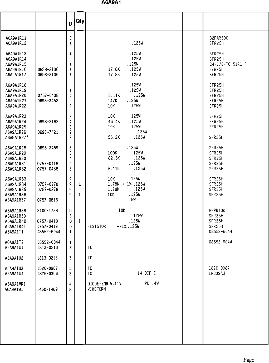
HP Part Number 85660-60202
A6A9Al Phase Lock Board
Reference HP Part
Designation Number
A6A9AlRll 2100-2574
:
A6A9AlR12 0757-0394
(
A6A9AlR13 0757-0401
(
A6A9AlR14 0757-0402
I
A6A9AlR15 0757-0394
(
A6A9AlR16 0698-3136
E
A6A9AlR17 0698-3136
I
A6A9AlRlB 0757-0416
i
A6A9AlR19 0757-0417
I
A6A9AlR20 0757-0438
:
A6A9AlR21 0698-3452
1
A6A9AlR22 0757-0442
c
A6A9AlR23 0757-0442
c
A6A9AlR24 0698-3162
(
A6A9AlR25 0757-0442
E
A6A9AlR26 0698-7421
i
A6A9AlR27* 0757-0459
E
A6A9AlR28 0698-3459
I
A6A9AlR29 0757-0465
t
A6A9AlR30 0757-0463
1
A6A9AlR31 0757-0418
c
A6A9AlR32 0757-0438
:
A6A9AlR33 0757-0442
c
A6A9AlR34 0757-0278
c
A6A9AlR35 0757-0278
c
A6A9AlR36 0757-0442
c
A6A9AlR37 0757-0816
1
A6A9AlR38
A6A9AlR39
A6A9AlR40
A6A9AlR41
A6A9AlTl
2100-1738
0757-0470
7757-0419
3757-0419
38552-6044
A6A9AlT2
A6A9AlUl 18552-6044
tai3-0213
A6A9AlU2 tal3-0213
A6A9AlU3 ta26-0987
A6A9AlU4 t826-0306
AGASAlVRl
A6A9AlWl
1902-0041
1460-1489
C
c
-
3Y
-
1
1
1
1
1
1
1
1
1
1
1
1
1
1
1
1
1
1
1
1
1
1
1
1
1
1
1
1
1
1
1
1
1
1
1
1
1
1
-
Description
RESISTOR-TRMR 500 lo% TKF SIDE-AOJ l-TRN 73138 82PAR500
RESISTOR 51.1 +-1%
.125W
TF TC=O+-100
19701
SFR25H
RESISTOR 100 +-1%
.125W
TF TC=O+-100
19701
RESISTOR 110 +-1%
.125W
TF TC=O+-100
19701
RESISTOR 51.1 1%
.125W
F TC=O+-100
24546
RESISTOR
17.8K
1%
.125W
TF TC=O+-100
19701
RESISTOR
17.8K
1%
.125W
TF TC=O+-100
19701
SFR25H
SFR25H
C4-l/B-TO-51Rl-F
SFR25H
SFR25H
RESISTOR 511 +-1%
.125W
TF TC=O+-100
19701
SFR25H
RESISTOR 562 +-1%
.125W
TF TC=O+-100
19701
SFR25H
RESISTOR
5.11K
+-1%
.125W
TF TC=O+-100
19701
SFR25H
RESISTOR
147K
1%
.125W
TF TC=O+-100
19701
SFR25H
RESISTOR
10K
+-1%
.125W
TF TC=O+-100
19701
SFR25H
RESISTOR
10K
+-1%
.125W
TF TC=O+-100
19701
SFR25H
RESISTOR
46.4K
1%
.125W
TF TC=O+-100
19701
SFR25H
RESISTOR
10K
+-1%
.125W
TF TC=O+-100
19701
SFR25H
RESISTOR 40K +-0.25%
.125W
TF TC=O+-100
19701
5033R
RESISTOR
56.2K
+-1%
.125W
TF TC=O+-100
19701
SFR25H
RESISTOR 383K 1%
.125W
TF TC=O+-100
19701
SFR25H
RESISTOR
1OOK
+-1%
.125W
TF TC=O+-100
19701
SFR25H
RESISTOR
82.5K
+-1%
.125W
TF TC=O+-100
19701
SFR25H
RESISTOR 619 +-1%
.125W
TF TC=O+-100
19701
SFR25H
RESISTOR
5.11K
+-1%
.125W
TF TC=O+-100
19701
SFR25H
RESISTOR
10K
+-1%
.125W
TF TC=O+-100
19701
SFR25H
RESISTOR
1.78K
+-I%
.125W
TF TC=O+-100
19701
SFR25H
RESISTOR
1.78K
+-1%
.125W
TF TC=O+-100
19701
SFR25H
RESISTOR
10K
+-1%
.125W
TF TC=O+-100
19701
SFR25H
RESISTOR 681 +-1%
.5W
TF TC=O+-100
19701
5053R
RESISTOR-TRMR
10K
lo% C TOP-AOJ I-TRN
73138 82PRlOK
RESISTOR 162K +-1%
.125W
TF TC=O+-100
19701
SFR25H
PESISTOR 681 +-1%
.125W
TF TC=O+-100
19701
SFR25H
{ESISTOR
681
+-I%
.125W
TF TC=O+-100
19701
SFR25H
TRANSFORMER, RF, 5-PIN 28480 08552-6044
TRANSFORMER, RF, 5-PIN
[C
WIOEBANO AMPLIFIER TO-39 PKG
(MUST BE ORDERED SEPARATELY)
[C
WIOEBANO AMPLIFIER TO-39 PKG
(MUST BE ORDERED SEPARATELY)
[C
OP AMP PRCN B-DIP-C PKG
[C
COMPARATOR GP QUAD
14-DIP-C
PKG
28480 08552-6044
04713 MWA130
04713 MWA130
28480 1826-0987
27014 LM339AJ
)IOOE-ZNR
5.11V
5% DO-35
PO=.4W 04713
dIREFORM
BE CU AG
17450
Mfr
Mfr Part
Code Number
*Indicates factory-selected value
85660-60202 Parts List
Page
3 or 3
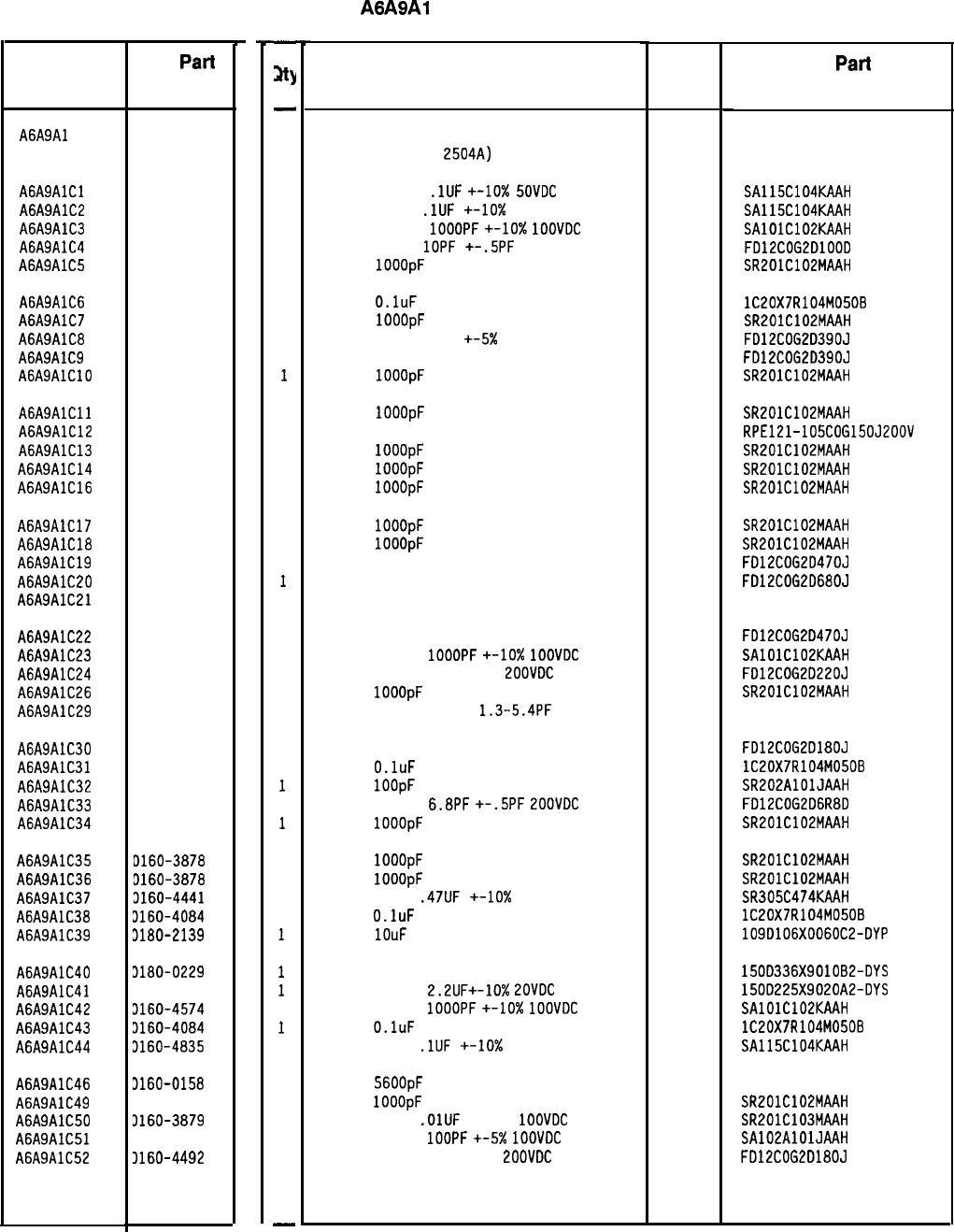
Reference
Designation
C
D
A6A9Al
HP
Part
Number
85660-60253
3
A6A9AlCl 0160-4835
7
A6A9AlC2 0160-4835
7
A6A9AlC3 0160-4574
1
A6A9AlC4 0160-3874
2
A6A9AlC5
0160-3878
6
A6A9AlC6 0160-4084
8
A6A9AlC7 0160-3878
6
A6A9AlC8 0160-4494
4
A6A9AlC9 0160-4494
4
A6A9AlClO 0160-3878
6
A6A9AlCll 0160-3878
6
A6A9AlC12 0160-4385
2
A6A9AlC13 0160-3878
6
A6A9AlC14 0160-3878
6
A6A9AlC16 0160-3878
6
A6A9AlC17 0160-3878
6
A6A9AlC18 0160-3878
6
A6A9AlC19 0160-4387
4
A6A9AlC20 0160-4350
1
A6A9AlC21 0180-0500
7
A6A9AlC22 0160-4387
4
A6A9AlC23 0160-4574
1
A6A9AlC24 0160-3875
3
A6A9AlC26 0160-3878
6
A6A9AlC29 0121-0452
4
A6A9AlC30 0160-4492
2
A6A9AlC31 0160-4084
8
A6A9AlC32 0160-4389
6
A6A9AlC33 0160-4383
0
A6A9AlC34 0160-3878
6
A6A9AlC35
D160-3878
6
A6A9AlC36 3160-3878
6
A6A9AlC37 3160-4441
1
A6A9AlC38 3160-4084
8
A6A9AlC39 3180-2139
2
A6A9AlC40 3180-0229
7
A6A9AlC41 3180-0197
8
A6A9AlC42 3160-4574
1
A6A9AlC43 3160-4084
8
A6A9AlC44 3160-4835
7
A6A9AlC46
3160-0158
9
A6A9AlC49 3160-3878
6
A6A9AlC50 3160-3879
7
A6A9AlC51 3160-4801
7
A6A9AlC52 3160-4492
2
-
31
-
1
1
1
1
1
1
1
1
1
1
1
1
1
1
1
1
1
1
1
1
1
1
1
1
1
1
1
1
1
1
1
1
1
1
1
1
1
1
1
1
1
1
1
1
1
1
-
HP Part Number 85660-60253
A6A9Al Phase Lock Board
Description Mfr Mfr
Part
Code Number
PHASE LOCK BOARD ASSEMBLY
(SERIAL PREFIX:
2504~) 28480 85660-60253
CAPACITOR-FXD
.lUF
+-lo%
SOVDC
CER
CAPACITOR-FXD
.lUF
+-lo%
50VDC CER
CAPACITOR-FXD
1OOOPF
+-10x
1OOVDC
CER
CAPACITOR-FXD
1OPF
+-.5PF
200VDC CER
CAP-FXD
1OOOpF
100 V
04222
04222
04222
04222
SA115C104KAAH
SA115C104KAAH
SAlOlC102KAAH
FD12COG2DlOOD
SR201C102MAAH
CAP-FXD
O.luF
50 V
CAP-FXD
1OOOpF
100 V
CAPACITOR-FXD 39PF
+-5x
200VDC CER O+-30
CAPACITOR-FXD 39PF +-5% 200VDC CER O+-30
CAP-FXD
1OOOpF
100 V
56289
04222
04222
lC20X7R104M0508
SR201C102MAAH
FD12COG2D390J
FD12COG2D390J
SR201C102MAAH
CAP-FXD
1OOOpF
100 V
CAP-FXD 15pF 200 V
CAP-FXD
1OOOpF
100 V
CAP-FXD
1OOOpF
100 V
CAP-FXD
IOOOpF
100 V
04222
04222
04222
04222
SR201C102MAAH
RPE121-105COG150J200V
SR201C102MAAH
SR201C102MAAH
SR201C102MAAH
CAP-FXD
1OOOpF
100 V
CAP-FXD
1OOOpF
100 V
CAPACITOR-FXD 47PF +-5% 2OOVDC CER O+-30
CAP-FXD 68pF 200 V
CAP-FXD 47uF 20 V TA
04222
04222
56289
SR201C102MAAH
SR201C102MAAH
FD12COG2047OJ
FD12COG2D680J
19901114
CAPACITOR-FXD 47PF +-5% 200VDC CER O+-30
CAPACITOR-FXD
1OOOPF
+-lo%
1OOVOC
CER
CAPACITOR-FXD 22PF +-5%
LOOVDC
CER O+-30
CAP-FXD
1OOOpF
100 V
CAPACITOR-V TRMR-AIR
1.3-5.4PF
175V PC-M
04222
04222
74970
FD12COG2D470J
SAlOlC102KAAH
FD12COG20220J
SR201C102MAAH
187-0103-028
CAPACITOR-FXD 18PF +-5% 200VDC CER O+-30
CAP-FXD
O.luF
50 V
CAP-FXD
1OOpF
200 V
CAPACITOR-FXD
6.8PF
+-.5PF
ZOOVDC
CER
CAP-FXD
1OOOpF
100 V
56289
04222
04222
FD12COG20180J
lC20X7R104M0506
SR202AlOlJAAH
FD12COG2D6R8D
SR201C102MAAH
CAP-FXD
1OOOpF
100 V
04222 SR201C102MAAH
CAP-FXD
1OOOpF
100 V
04222 SR201C102MAAH
CAPACITOR-FXD
.47UF
+-lo% 50VDC CER
04222 SR305C474KAAH
CAP-FXD
O.luF
50 V
56289 lC20X7R104M0508
CAP-FXD
1OuF
60 V UT-SLG-TA-ELCTLT
56289 109D106X0060C2-DYP
CAP-FXD 33uF 10 V TA
CAPACITOR-FXD
2.2lJF+-10%
EOVDC
TA
CAPACITOR-FXD
1OOOPF
+-lo%
1OOVDC
CER
CAP-FXD
O.luF
50 V
CAPACITOR-FXD
.lUF
+-IO% 50VDC CER
CAP-FXD
56OOpF
200 V POLYE-FL
CAP-FXD
1OOOpF
100 V
CAPACITOR-FXD
.OlUF
+-20%
1OOVDC
CER
CAPACITOR-FXD
1OOPF
+-5x
1OOVDC
CER
CAPACITOR-FXD 18PF +-5%
EOOVDC
CER O+-30
56289 150D336X901082-DYS
56289 150D225X9020A2-DYS
04222 SAlOlC102KAAH
56289 lC20X7R104M0508
04222 SA115C104KAAH
84411
04222
04222
04222
HEW-238M
SR201C102MAAH
SR201C103MAAH
SA102AlOlJAAH
FD12COG2D180J
*Indicates factory-selected value
8566040253
Parts List
Page 1 of 3
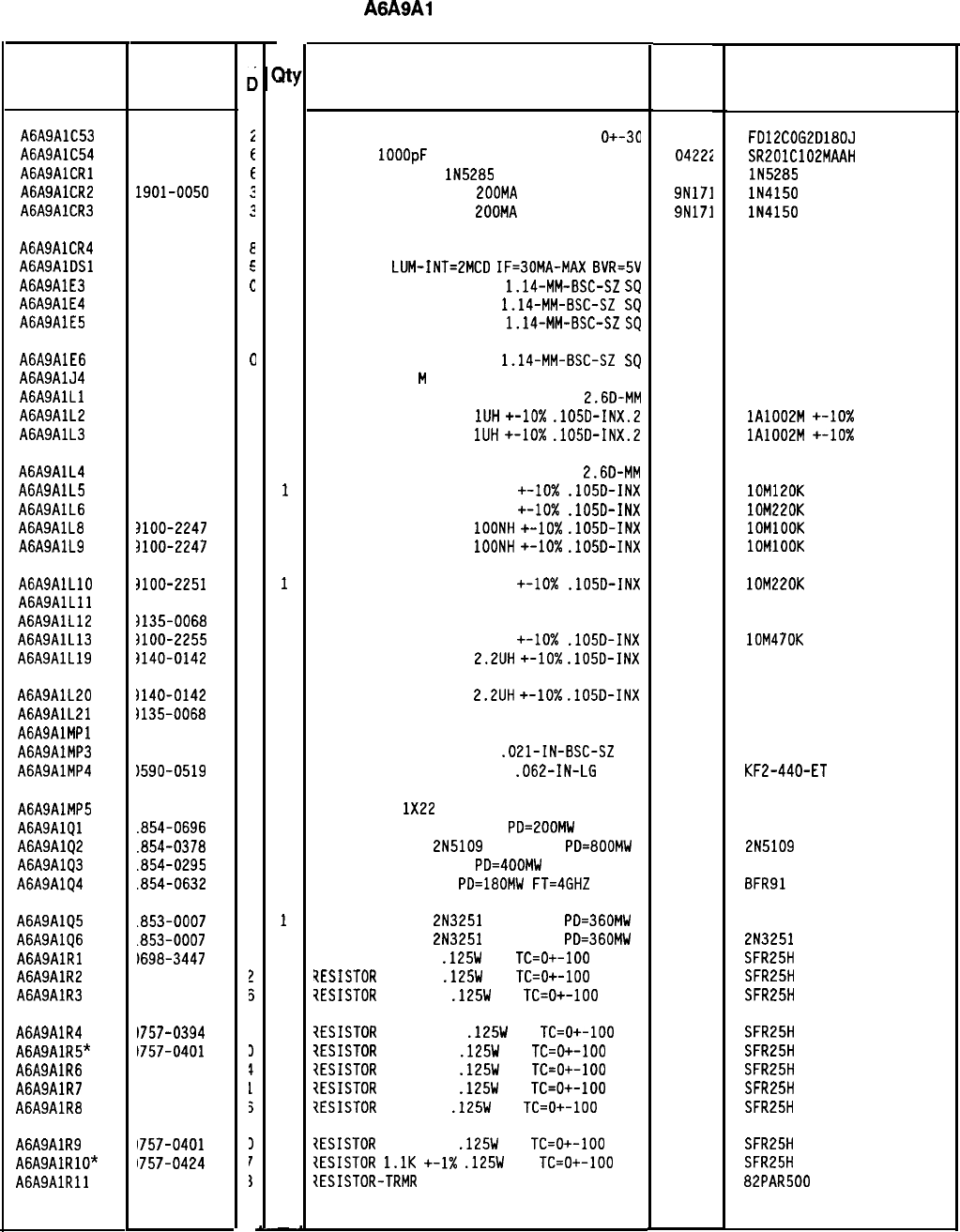
Reference
Designation
HP Part
Number
C
c
A6A9AlC53 0160-4492
i
A6A9AlC54 0160-3878
E
AGASAlCRl 1901-0954
E
A6A9AlCR2 1901-0050
2
A6A9AlCR3 1901-0050
2
A6A9AlCR4 1901-0518
E
AGASAlDSl 1990-0485
E
A6A9AlE3 1251-0600
c
A6A9AlE4 1251-0600
C
A6A9AlE5 1251-0600
C
A6A9AlE6 1251-0600
0
A6A9AlJ4 1250-2192
7
A6A9AlLl 3135-0073
3
A6A9AlL2 3140-0158
6
A6A9AlL3 3140-0158
6
A6A9AlL4 3135-0073
3
A6A9AlL5 3100-2248
5
A6A9AlL6 3100-2251
0
A6A9AlL8 3100-2247
4
A6A9AlL9 3100-2247
4
A6A9AlLlO
3100-2251
0
A6A9AlLll 35660-80012
4
A6A9AlL12 3135-0068
6
A6A9AlL13 3100-2255
4
A6A9AlL19
3140-0142
8
A6A9AlL20
A6A9AlL21
AGASAlMPl
A6A9AlMP3
A6A9AlMP4
3140-0142
8
1135-0068
6
1251-2194
1590-0519
1
7
A6A9AlMP5
1151-0013
4
A6A9AlQl
.854-0696
2
A6A9AlQ2
.854-0378
7
A6A9AlQ3
.854-0295
7
A6A9AlQ4
.854-0632
6
A6A9AlQ5
.853-0007
7
A6A9AlQ6
.853-0007
7
A6A9AlRl
1698-3447
4
A6A9AlR2
1698-3437
2
A6A9AlR3
1698-3431
?J
A6A9AlR4
1757-0394
3
A6A9AlR5*
1757-0401
1
A6A9AlR6
1757-0421
1
A6A9AlR7
1757-0402
1
A6A9AlR8
1698-3431
5
A6A9AlR9
1757-0401
I
A6A9AlRlO*
1757-0424
I
A6A9AlRll
'loo-2574
3
8566040253 Parts List
Page 2 of 3
a!
1
1
1
1
1
1
1
1
1
1
1
1
1
1
1
1
1
1
1
1
1
1
1
1
1
1
1
3
1
1
1
1
1
1
1
1
1
1
1
1
1
1
1
1
1
1
1
-
HP Part Number 85660-60253
A6A9Al Phase Lock Board
Description
CAPACITOR-FXD 18PF +-5% 200VDC CER
O+-30
CAP-FXD
1OOOpF
100 V
DIODE-CUR RGLTR
lN5285
270UA DO-7
DIODE-SWITCHING 80V
200MA
2NS DO-35
DIODE-SWITCHING 80V
200MA
2NS DO-35
Mfr
Code
04222
0471:
9N171
9N171
Mfr Part
Number
FD12COG2D180J
SR201C102MAAH
lN5285
lN4150
lN4150
DIODE-SCHOTTKY SM SIG
LED-LAMP
LUM-INT=EMCD
IF=30MA-MAX
BVR=5V
2848C
CONNECTOR-SGL CONT PIN
1.14-MM-BSC-SZ
SQ 27264
CONNECTOR-SGL CONT PIN
1.14-MM-BSC-SZ
SQ 27264
CONNECTOR-SGL CONT PIN
1.14-MM-BSC-SZ
SQ
27264
5082-2800
HLMP-1503
16-06-0034
16-06-0034
16-06-0034
CONNECTOR-SGL CONT PIN
1.14-MM-BSC-SZ
SQ
CONNECTOR-RF
M
SMB
INDUCTOR RF-CH-MLD 51NH +-6.596%
2.6D-MM
INDUCTOR RF-CH-MLD
1UH
+-10x
.105D-INX.2
INDUCTOR RF-CH-MLD
1UH
+-lo%
.105D-INX.2
27264
98291
06560
32159
32159
16-06-0034
051-051-0409-220
lA1002M
+-lo%
lA1002M
+-lo%
INDUCTOR RF-CH-MLD 51NH +-6.596%
2.60-MM 06560
INDUCTOR RF-CH-MLD 120NH +-IO%
.lOSD-INX 24226
INDUCTOR RF-CH-MLD 220NH +-lo%
.lOSD-INX 24226
INDUCTOR RF-CH-MLD
1OONH
+-lo%
.105D-INX 24226
INDUCTOR RF-CH-MLD
1OONH
+-10x
.105D-INX 24226
lOM120K
10M220K
IOMlOOK
1OMlOOK
INDUCTOR RF-CH-MLD 220NH +-lo%
.105D-INX
INDUCTOR 24NH
INDUCTOR RF-CH-MLD 33NH +-6.36%
INDUCTOR RF-CH-MLD 470NH +-IO%
.105D-INX
INDUCTOR RF-CH-MLD
2.2UH
+-10x
.lOSD-INX
24226
28480
06560
24226
99800
lOM220K
85660-80012
lOM470K
1025-28
INDUCTOR RF-CH-MLD
2.2UH
+-lo%
.105D-INX
INDUCTOR RF-CH-MLD 33NH +-6.36%
NOT ASSIGNED
99800
06560 1025-28
CONNECTOR-SGL CONT SKT
.OEl-IN-BSC-SZ 00779 3-331272-O
THREADED INSERT-NUT 4-40
.062-IN-LG
STL
46384 KF2-440-ET
WIRE 22AWG
1X22
298
TRANSISTOR NPN SI TO-72
PD=200MW
TRANSISTOR NPN
2N5109
SI TO-39
PD=800MW
TRANSISTOR-DUAL NPN
PD=400MW
TRANSISTOR NPN SI
PD=180MW
FT=4GHZ
92194
25403
04713
04713
25403
2N5109
BFR91
TRANSISTOR PNP
2N3251
SI TO-18
PD=360MW 04713 213251
TRANSISTOR PNP
2N3251
SI TO-18
PD=360MW 04713 2N3251
RESISTOR 422 1%
.125W
TF
TC=O+-100
19701
SFR25H
?ESISTOR
133 1%
.125W
TF
TC=O+-100
19701
SFR25H
?ESISTDR
23.7 1%
.125W
TF
TC=O+-100
19701
SFR25H
?ESISTOR
51.1 +-1%
.125W
TF
TC=O+-100
19701
SFR25H
?ESISTOR
100 +-1%
.125W
TF
TC=O+-100
19701
SFR25H
iESISTOR
825 +-1%
.125W
TF
TC=O+-100
19701
SFR25H
1ESISTOR
110 +-1%
.125W
TF
TC=O+-100
19701
SFR25H
?ESISTOR
23.7 1%
.125W
TF
TC=O+-100
19701
SFR25H
2ESISTOR
100 +-1%
.125W
TF
TC=O+-100
19701
SFR25H
tESISTOR
l.lK
+-1X
.125W
TF
TC=O+-100
19701
SFR25H
IESISTOR-TRMR
500 10% TKF SIDE-ADJ l-TRN
73138 82PAR500
*Indicates factory-selected value
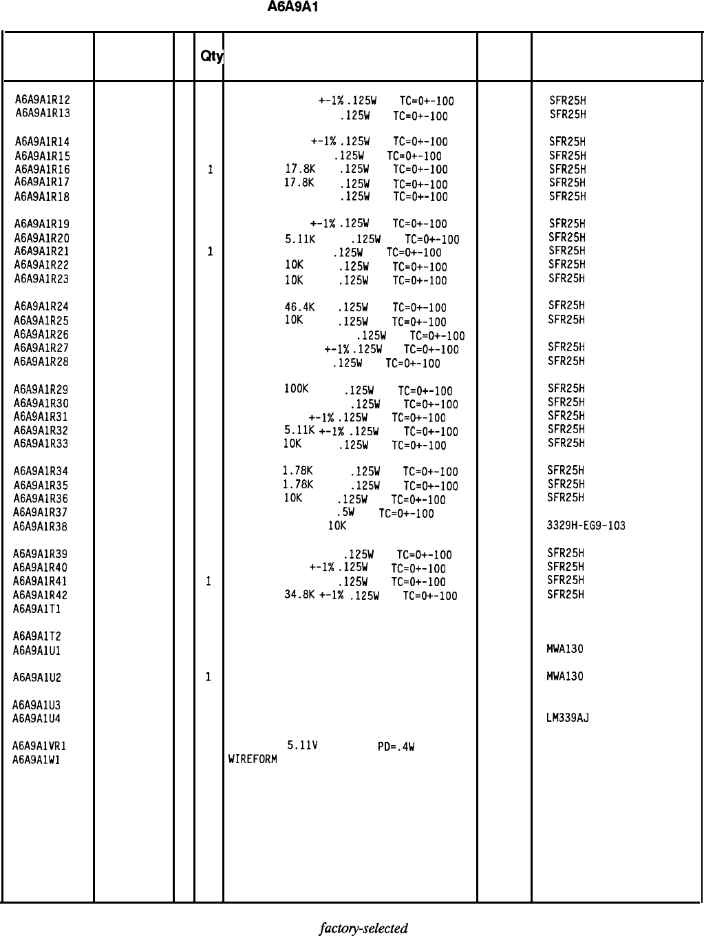
HP Part Number 85660-60253
A6A9Al Phase Lock Board
Reference
HP Part C
Designation
Number D
Qty Description Mfr Mfr Part
Code Number
A6A9AlR12 0757-0394
0
1
RESISTOR 51.1
+-1X
.125W
TF
TC=O+-100 19701
A6A9AlR13 SFR25H
0757-0401
0
1
RESISTOR 100 +-1%
.125W
TF
TC=O+-100
19701
SFR25H
A6A9AlR14 0757-0402
11
RESISTOR
110
+-1X
.125W
TF
TC=O+-100 19701 SFR25H
A6A9AlR15 0698-3435
0
1
RESISTOR
38.3 1%
.125W
TF
TC=O+-100
19701
SFR25H
A6A9AlR16
0698-3136
8
1
RESISTOR 17.8K
1%
.125W
TF
TC=O+-100
19701
A6A9AlR17 SFR25H
0698-3136
8
1
RESISTOR
17.8K
1%
.125W
TF
TC=O+-100
19701
SFR25H
A6A9AlR18 0757-0416
7
1
RESISTOR
511 +-1%
.125W
TF
TC=O+-100 19701 SFR25H
A6A9AlR19 0757-0417
8
1
RESISTOR
562
+-1X
.125W
TF
TC=O+-100
19701
SFR25H
A6A9AlR20 0757-0438
3
1
RESISTOR 5.11K
+-1%
.125W
TF
TC=O+-100 19701 SFR25H
A6A9AlR21 0698-3452
11
RESISTOR 147K
1%
.125W
TF
TC=O+-100
19701
SFR25H
A6A9AlR22 0757-0442
9
1
RESISTOR
10K
+-1%
.125W
TF
TC=O+-100
19701
SFR25H
A6A9AlR23 0757-0442
9
1
RESISTOR 10K
+-1%
.125W
TF
TC=O+-100
19701
SFR25H
A6A9AlR24 0698-3162
0
1
RESISTOR 46.4K
1%
.125W
TF
TC=O+-100
19701
SFR25H
A6A9AlR25
0757-0442
9
1
RESISTOR
10K
+-1%
.125W
TF
TC=O+-100
19701
SFR25H
A6A9AlR26 0698-7421
2
1
RESISTOR 40K
+-0.25%
.125W
TF
TC=O+-100 19701 5033R
A6A9AlR27 0757-0459
8
1
RESISTOR
56.21:
+-1X
.125W
TF
TC=O+-100
19701
SFR25H
A6A9AlR28 0698-3459
8
1
RESISTOR
383K 1%
.125W
TF
TC=O+-100
19701
SFR25H
A6A9AlR29 0757-0465
6
1
RESISTOR
1OOK
+-1%
.125W
TF
TC=O+-100
19701
SFR25H
A6A9AlR30
0757-0463
4
1
RESISTOR 82.51:
+-1%
.125W
TF
TC=O+-100
19701
SFR25H
A6A9AlR31 0757-0418
9
1
RESISTOR
619
+-1X
.125W
TF
TC=O+-100
19701
SFR25H
A6A9AlR32 0757-0438
3
1
RESISTOR
5.11K
+-1X
.125W
TF
TC=O+-100 19701 SFR25H
A6A9AlR33 0757-0442
9
1
RESISTOR
10K
+-1%
.125W
TF
TC=O+-100
19701
SFR25H
A6A9AlR34 0757-0278
9
1
RESISTOR
1.78K
+-1%
.125W
TF
TC=O+-100
19701
SFR25H
A6A9AlR35
0757-0278
9
1
RESISTOR
1.78K
+-1%
.125W
TF
TC=O+-100
19701
SFR25H
A6A9AlR36 0757-0442
9
1
RESISTOR
10K
+-1%
.125W
TF
TC=O+-100
19701
SFR25H
A6A9AlR37 0757-0816
1
1
RESISTOR 681 +-1%
.5W
TF
TC=O+-100
19701
5053R
A6A9AlR38 2100-4184
5
1
RESISTOR-TRMR
IOK
TKF
10% TOP-ADJ l-TRN
32997 3329H-EG9-103
A6A9AlR39 0757-0470
3
1
RESISTOR 162K +-1%
.125W
TF
TC=O+-100
19701
SFR25H
A6A9AlR40 0757-0419
0
1
RESISTOR 681
+-I%
.125W
TF
TC=O+-100 19701 SFR25H
A6A9AlR41 0757-0419
0
1
RESISTOR 681 +-1%
.125W
TF
TC=O+-100
19701
SFR25H
A6A9AlR42 0757-0123
3
1
RESISTOR
34.8K
+-1X
.125W
TF
TC=O+-100
19701
SFR25H
A6A9AlTl 08552-6044
11
TRANSFORMER RF 5-PIN 28480 08552-6044
A6A9AlT2 08552-6044
11
TRANSFORMER RF 5-PIN 28480 08552-6044
A6A9AlUl 1813-0213
3
1
IC WIDE BAND AMPLIFIER TO-39 PKG 04713 MWA130
(MUST BE ORDERED SEPARATELY)
A6A9AlU2 1813-0213
3
1
IC WIDE BAND AMPLIFIER TO-39 PKG 04713 MWA130
(MUST BE ORDERED SEPARATELY)
A6A9AlU3 1826-1049
2
1
IC OP AMP PRCN 8-DIP-C PKG 06665 OP-27GZ
A6A9AlU4 1826-0306
2
1
IC COMPARATOR GP QUAD 14-DIP-C PKG 27014 LM339AJ
AGASAlVRl 1902-0041
4
1
DIODE-ZNR
5.11V
5%
DO-35
PD=.4W 04713
A6A9AlWl 1460-1489 8
1
WIREFORM
BE CU AG
17450
*Indicates
factoyselected
value
8566040253 Parts List
Page 3 of 3
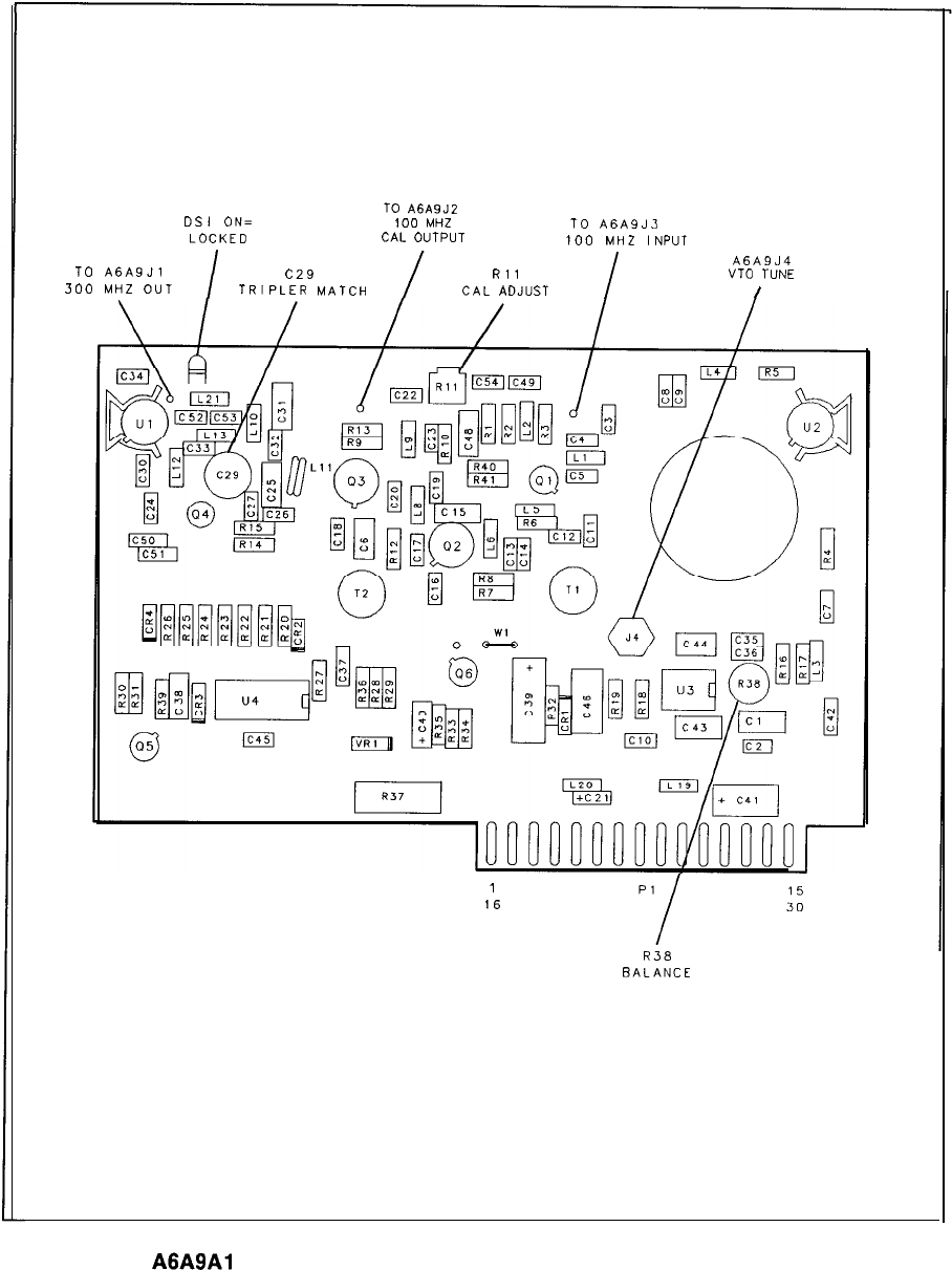
TO
A6A9J2
DSI
ON= 100
MHZ
TO
A6A9J3
LOCKED
CAL
OUTPUT
100
MHZ
INPUT
I
I
A6A9
J4
TO
A6A9Jl
c29
Rl
1
VT0
TUNE
300
MHZ
OUT
TRIPLER
MATCH CAL
ADJUST
I
1
16
R38
BALANCE
A6A9Al
Phase Lock Board Component Locations, 85660-60202
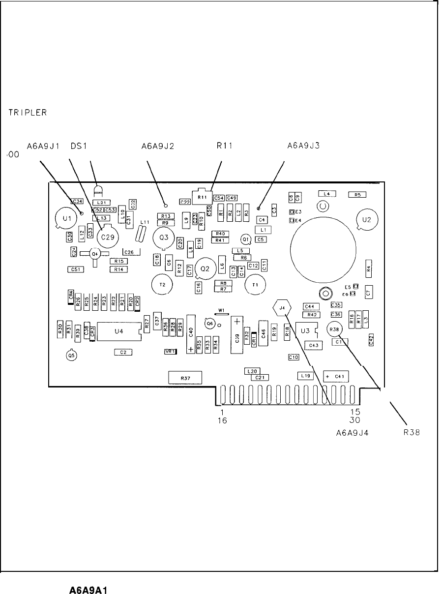
3
c29
TRIPLER
MATCH
\
TO
A6A9Jl
DSl
ON= TO
A6A9J2
Rll
TO
A6ASJ3
800 MHZ OUT LOCKED 100 MHZ OUT CAL OUTPUT 100 MHZ IN
\
\
s
=I+]
:al,,r;dii~~&
1’6
PI
2
TO
A6A9J4
TUNE VOLTAGE
OUT
\
R38
BALANCE
A6A9Al
Phase Lock Board Component Locations, 85660-60253
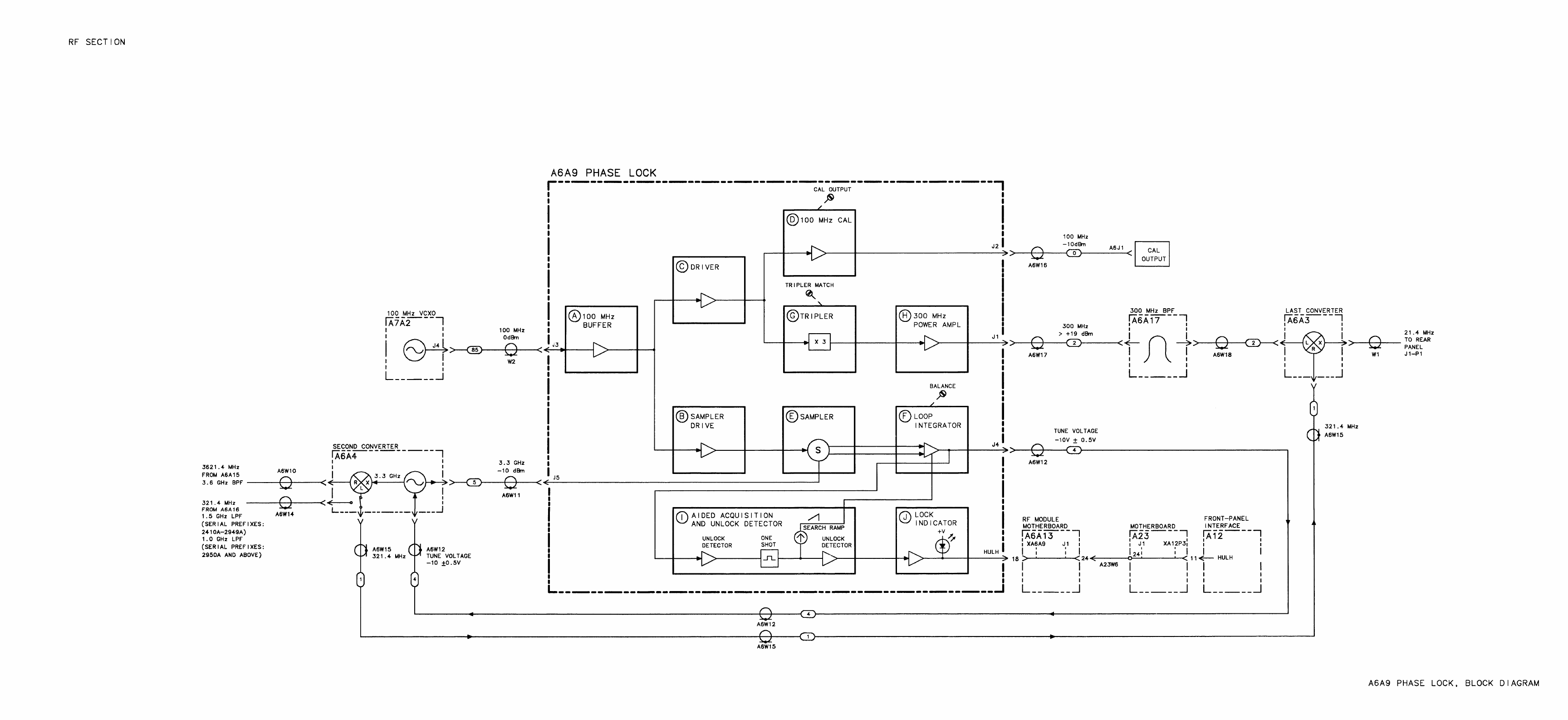
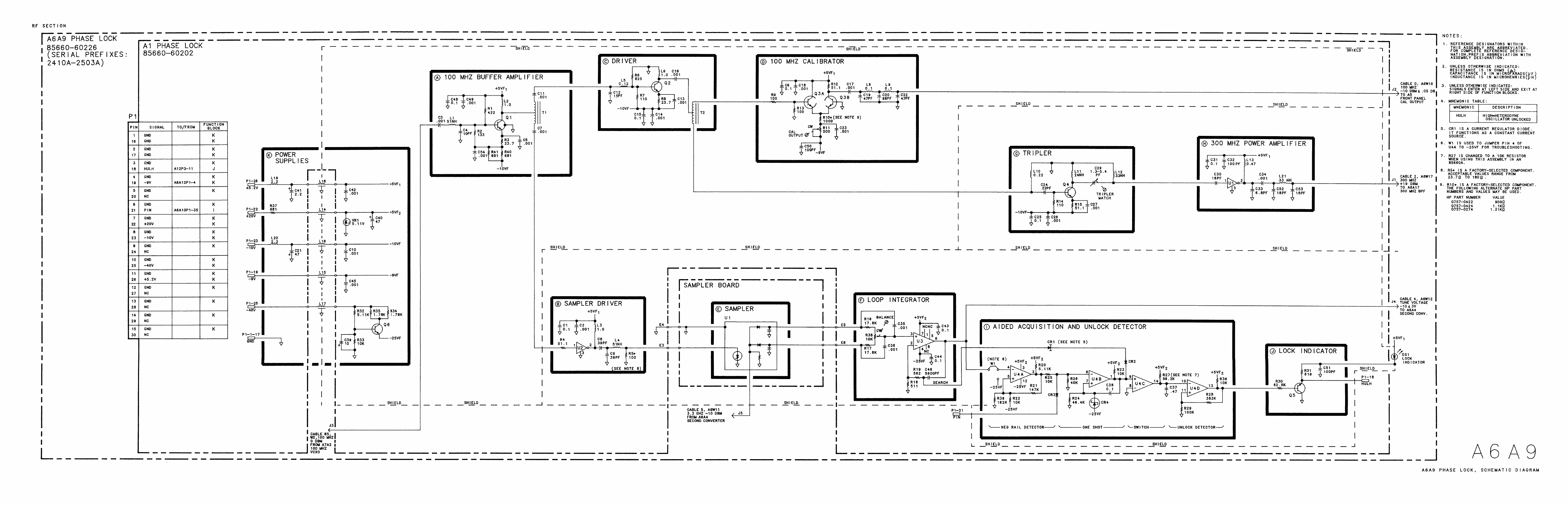
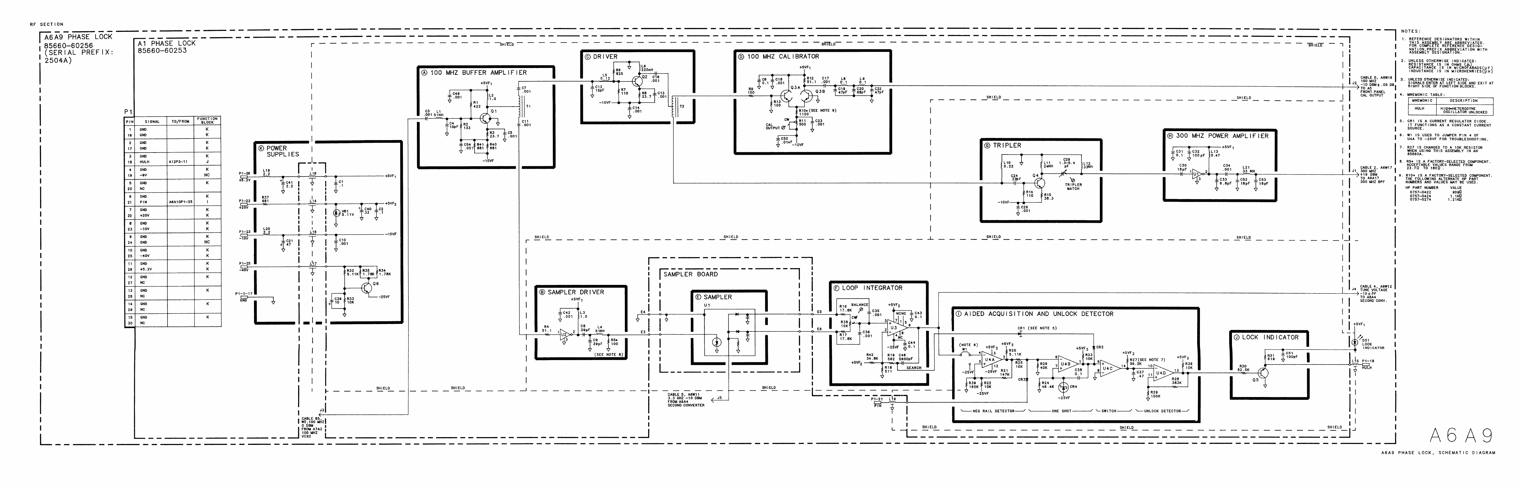
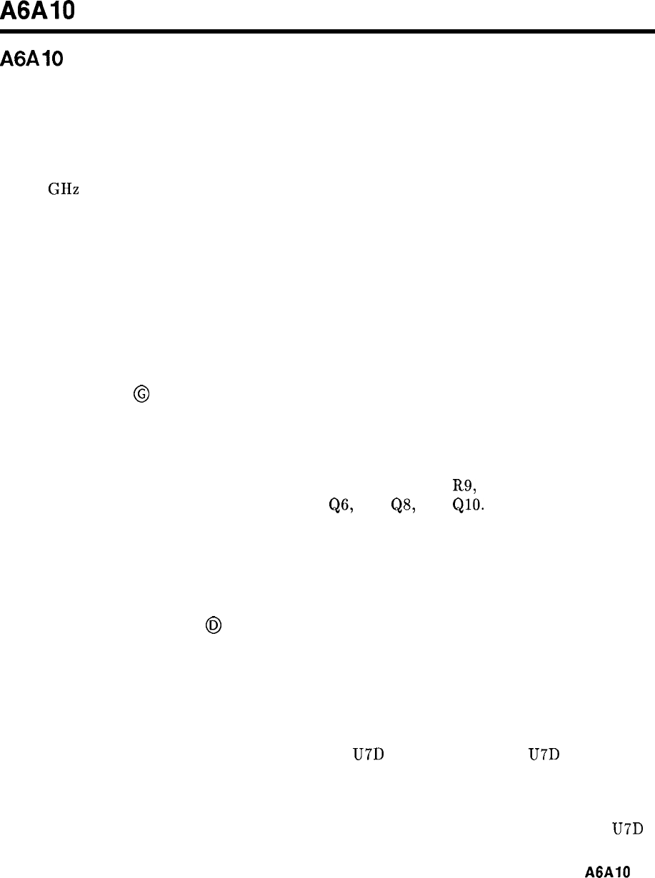
A6AlO
A6AlO
Miscellaneous Bias/Relay Driver, Circuit Description
This assembly is a collection of circuits necessary for proper operation of other assemblies in
the A6 RF Module. It contains nine circuits:
1. YTX Diode Bias
2. YTX Linearity Correction
3.
3.3 GHz Oscillator Driver
4. PIN Switch Driver
5. Band Step Gains
6. RF Switch Driver
7. RF Attenuator Driver
8. j-22 V Delay
9.
Power Down
YTX Diode Bias
@
To maintain the precise diode bias across the YTX mixer diode, the effects of series resistance
between the bias circuit and the diode must be eliminated. To do this, a negative impedance
voltage source U2 is used.
Voltage bias to the YTX diode is adjusted from band to band via R9, R12, R15, and R18.
This voltage is applied to U2 via FET switches
QS,
Q7,
QS,
and
&lo.
U2 has both positive
and negative feedback. The positive feedback is controlled by R43, R46, and R47, while the
negative feedback is via R45. The fact that the positive feedback and the negative feedback
are picked off across R44 causes a negative impedance at pin Pl-7 proportional to the
amplifier gain and R44.
YTX Linearity Correction
@I
Due to nonlinearities in the YTX magnet structure, some linearity correction must be made.
This is accomplished by placing resistors in parallel with the current-sense resistor in the
YTX coil driver circuit. These parallel resistors increase the coil current slightly. For current
compensation, both the point of compensation and the magnitude of compensation must be
varied.
This is accomplished in the following manner using U7D as a typical circuit: U7D is an ideal
zener circuit, that is, as long as the YTX linearity voltage is less negative than the voltage on
U7 pin 12 (the positive op amp input) diode CR5 is reverse biased. In this state, the YTX
linearity line sees a high impedance and no compensation occurs. When the YTX linearity
voltage goes more negative than the bias on U7 pin 12, diode CR5 is forward biased and U7D
A6AlO
1
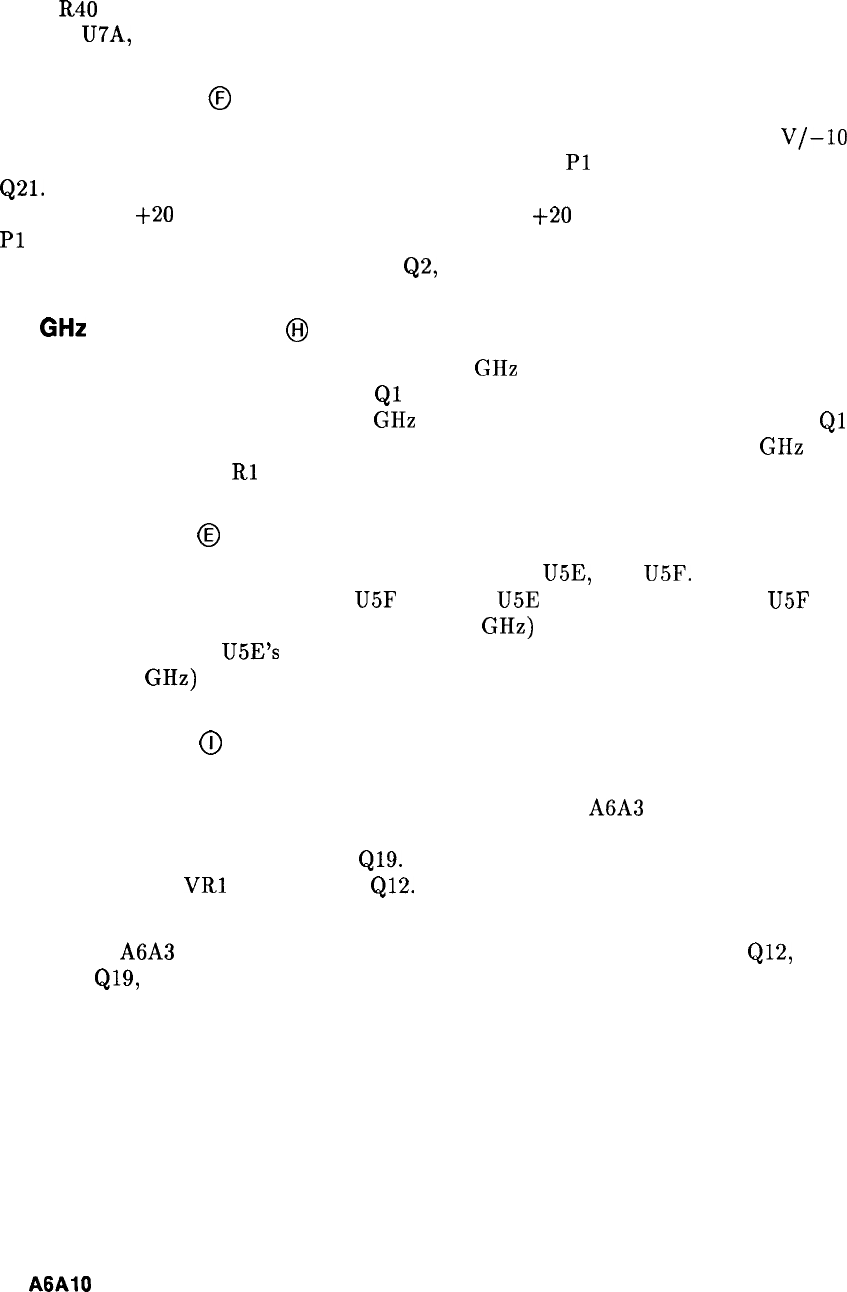
becomes a voltage follower maintaining the voltage at the cathode of CR5 at the same voltage
as on U7 pin 12. In this situation, R32 and R31 are effectively in parallel with the current
sense resistor of the coil driver circuit. R31 is used to adjust the magnitude of compensation,
while R40 is used to adjust the frequency at which the compensation occurs. In a similar
manner, U7A, B, C are used to correct for higher frequency nonlinearity.
PIN Switch Driver
@
The PIN switch driver converts the TTL logic level LO-BAND signal to the $20
V/-10
V
signal required by the Second Converter. The TTL level at
Pl
to 34 is input to the base of
Q21.
A high at the base of Q21 turns Q21 on, turning on Q4, which pulls the collector of Q4
approximately
+20
V. This turns on Q3, providing the
+20
V signal to the PIN drive output,
Pl
to 35. A low input on the LO-BAND TTL input turns Q21 off, which turns Q4 off. The
collector of Q4 then goes low, turning on Q2, and pulling the PIN drive line to -10 V.
3.3
GHz
Oscillator Driver
@I
The PIN drive signal is also used to turn the 3.3 GHz oscillator on in A-Band, and off in other
bands. When the PIN drive goes high,
Ql
is turned on which pulls its collector to -10 V. The
-10 V is the negative bias for the 3.3 GHz oscillator. When the PIN drive goes low,
Ql
is
turned off, dropping the oscillator bias current to zero, which turns off the 3.3 GHz oscillator.
In the on state, resistor
Rl
is used to adjust the oscillator bias current to 15 milliamps.
RF Switch Driver
@
The coaxial RF switch is driven by darlington amplifiers U5E, and U5F. A high input on the
LO-BAND line drives the outputs of U5F low, and U5E high. A low output at U5F drives the
Coaxial RF switch relay to the A-Band (0 to 2.5 GHz) position. The reverse occurs with a
low input which drives U5E’s output low, which forces the coaxial RF switch relay to the B-E
Band (2 to 22 GHz) position.
Band Step Gains
@
To correct for different input mixer conversion efficiencies and gains in the individual
frequency bands, the IF gain is changed. This is done in the A6A3 Last Converter by varying
the current through PIN attenuator diodes in the 21.4 MHz amplifier. This current is
controlled by Q12, Q14 to Q17, and
Q19.
In A-Band, the high output on the PIN drive line
breaks down zener
VRl
and turns on
Ql2.
This applies -40 V to the potentiometer R21.
Adjusting R21 varies the current in the step gain in A-Band.
The gain of A6A3 Last Converter is adjusted in each band as each transistor,
Ql2,
Q14 to
Q17, and Q19, is turned on for each individual band.
2
A6AlO
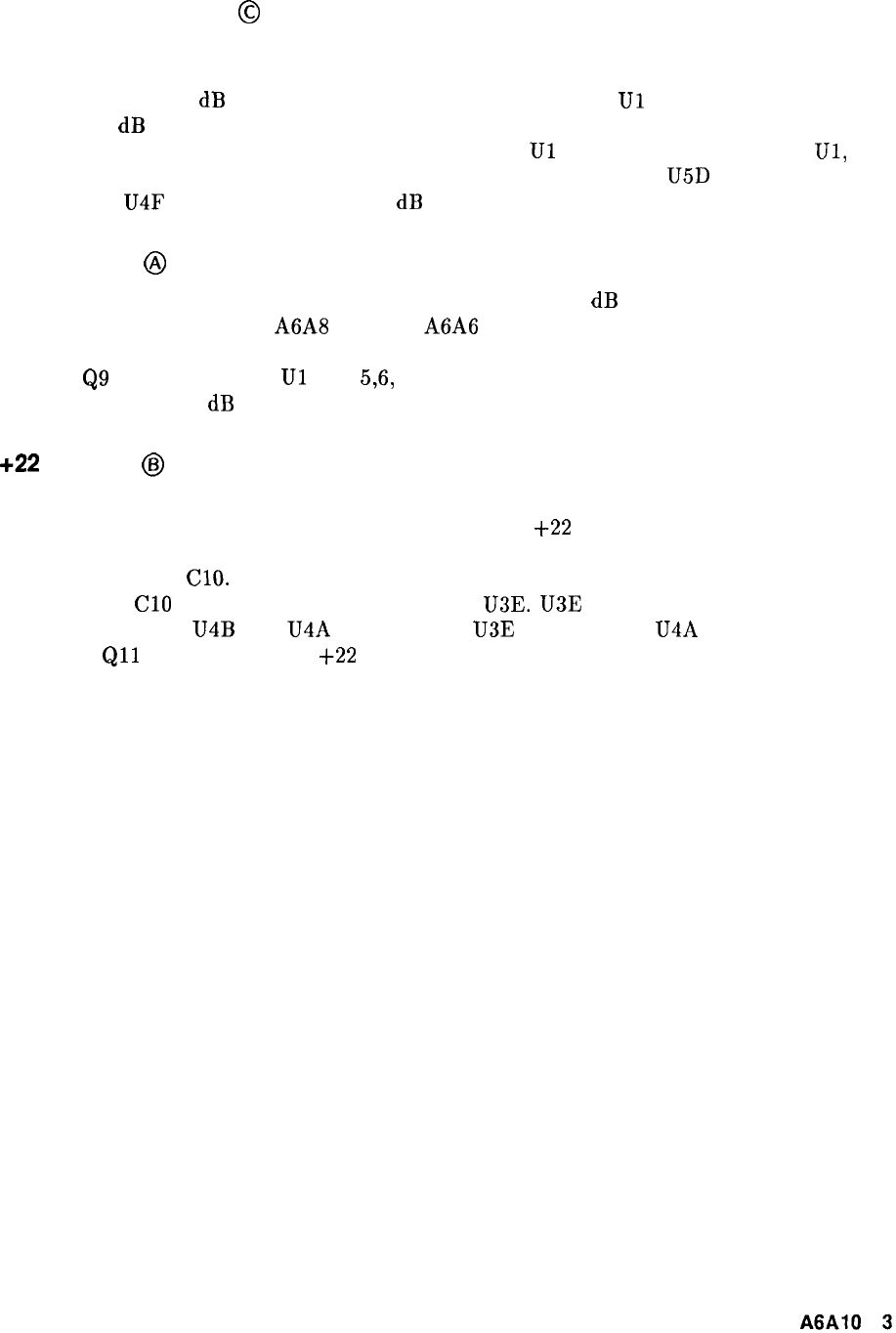
RF Attenuator Driver
@
The RF attenuator driver is similar to the RF Switch driver. The major difference is the logic
decoding to the inputs of the darlington switch drivers. The input to the logic circuit is the
standard 10, 20, 40, dB attenuation logic levels. The logic circuit
Ul
decodes this to the 10,
20, 20, 20, dB attenuation logic levels required to drive the RF attenuator. The output drivers
consist of darlington amplifiers driven by the outputs of
Ul
or the inverted outputs of
Ul,
via
U3. A low output of a darlington turns that line on. That is, a low at U5D pin 13, coupled
with high at U4F pin 11, enables the 10 dB attenuation position, and so forth.
Power Down
@
The power down circuit switches the RF attenuator into a 40 dB attenuation position to
prevent accidental damage to A6A8 YTX or A6A6 First Converter from an input signal when
the instrument is off. When the power up signal goes low, U3 pin 10 is driven high which
turns on
Q9
and Q13, forcing
Ul
pins 5,6, and 9, U4 pin 7, and U3 pin 5 high. This forces at
least the last two 20 dB attenuation stages in the attenuator on.
+22 V Delay
@I
On power up, the instrument goes through a self-check program. To prevent the RF relays
and the attenuator from chattering during this time, the
+22
V Bias to the attenuator and
RF switch is delayed for about 2.5 seconds after the power up signal goes high. This delay is
caused by R59 and ClO. When power up goes high, it takes approximately 2.5 seconds for the
voltage across
Cl0
to charge up enough to turn on U3E. U3E output is inverted twice by the
darlington amplifiers U4B and U4A so that when U3E output drops, U4A output also drops
turning on
Qll
which applies the
+22
V to the relay circuits.
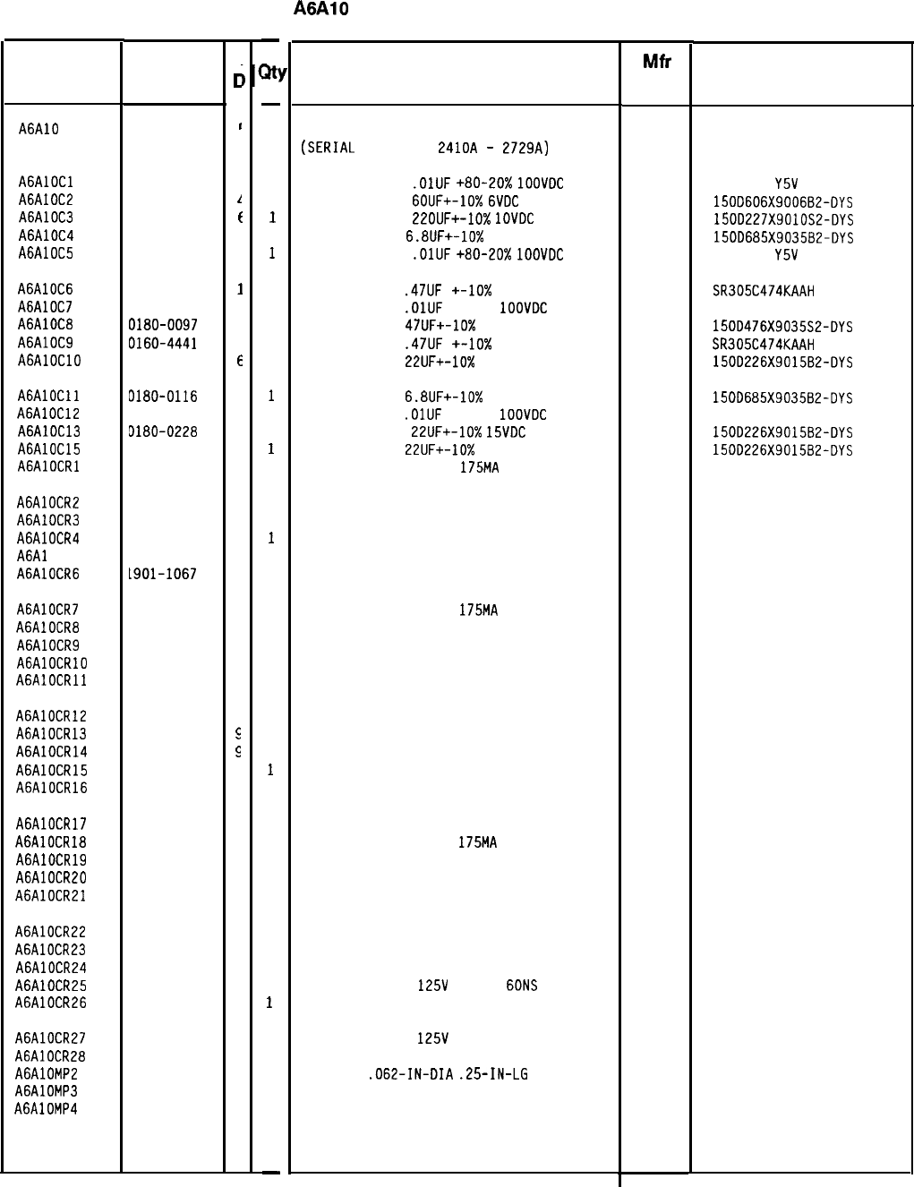
HP Part Number 85660-60180
A6AlO Miscellaneous Bias/Relay Driver
Description Mfr
Mfr Part
Code Number
BOARD ASSEMBLY, MISC BIAS/RELAY DRIVER
(SERIAL
PREFIXES:
2410~
-
2729A)
28480 85660-60180
CAPACITOR-FXD
.OlUF
+80-20%
1OOVDC
CER
CAPACITOR-FXD
6OUF+-10%
6VDC
TA
CAPACITOR-FXD
ZZOUF+-10%
1OVDC
TA
CAPACITOR-FXD
6.BUF+-10%
35VDC TA
CAPACITOR-FXD
.OlUF
+80-20%
1OOVDC
CER
56289
56289
56289
805-504
Y5V
1032
150D606X9006B2-DYS
150D227X9010S2-DYS
1500685X903582-DYS
805-504
Y5V
1032
CAPACITOR-FXD
.47UF
+-lo%
50VDC CER
04222 SR305C474KAAH
CAPACITOR-FXD
.OlUF
+-20%
1OOVDC
CER
28480 0160-3879
CAPACITOR-FXD
47UF+-10%
35VDC TA
56289 150D476X9035S2-DYS
CAPACITOR-FXD
.47UF
+-lo% 50VDC CER
04222 SR305C474KAAH
CAPACITOR-FXD
22UF+-10%
15VDC TA
56289 150D226X9015B2-DYS
CAPACITOR-FXD
6.8UF+-10%
35VDC TA
56289 150D685X903582-DYS
CAPACITOR-FXD
.OlUF
+-20%
1OOVDC
CER
28480 0160-3879
CAPACITOR-FXD
22UF+-10%
15VDC
TA
56289 150D226X9015B2-DYS
CAPACITOR-FXD
22UF+-10%
15VDC TA
56289 150D226X9015B2-OYS
DIODE-SWITCHING 125V
175MA
60NS DO-35
27014 FDH444
DIODE-SWITCHING 125V 175MA 60NS DO-35
27014 FDH444
DIODE-SWITCHING 125V 175MA 60NS DO-35
27014 FDH444
DIODE-SWITCHING 125V 175MA 60NS DO-35
27014 FDH444
DIODE-SWITCHING 125V 175MA 60NS DO-35
27014 FDH444
DIODE-SWITCHING 125V 175MA 60NS DO-35
27014 FDH444
DIODE-SWITCHING 125V
175MA
60NS DO-35
27014 FDH444
DIODE-SM SIG SCHOTTKY 28480 1901-0535
DIODE-SM SIG SCHOTTKY 28480 1901-0535
DIODE-SWITCHING 125V 175MA 60NS DO-35
27014 FDH444
DIODE-SM SIG SCHOTTKY 28480 1901-0535
DIODE-SM SIG SCHOTTKY
DIODE-SCHDTTKY SM SIG
DIODE-SCHOTTKY SM SIG
DIODE-SWITCHING 125V 175MA 60NS DO-35
DIODE-SM SIG SCHOTTKY
28480 1901-0535
27014 FDH444
28480 1901-0535
DIODE-SM SIG SCHDTTKY 28480 1901-0535
DIODE-SWITCHING 125V
175MA
60NS DO-35
27014 FDH444
DIODE-SWITCHING 125V 175MA 60NS DO-35
27014 FDH444
DIODE-SWITCHING 125V 175MA 60NS DO-35
27014 FDH444
DIODE-SWITCHING 125V 175MA 60NS DO-35
27014 FDH444
DIODE-SWITCHING 125V 175MA 60NS DO-35
27014 FDH444
DIODE-SWITCHING 125V 175MA 60NS DO-35
27014 FDH444
DIODE-SWITCHING 125V 175MA 60NS DO-35 27014 FDH444
DIODE-SWITCHING
125V
175MA
60NS
DO-35
27014 FDH444
DIODE-SWITCHING 125V 175MA 60NS DO-35
27014 FDH444
DIODE-SWITCHING
125V
175MA 60NS DO-35
27014 FDH444
DIODE-SWITCHING 125V 175MA 60NS DO-35
27014 FDH444
PIN-ROLL
.062-IN-DIA
.25-IN-LG
BE-CU
72962 99-012-062-0250
EXTR PC BD BLK 28480 4040-0748
EXTR PC BD BRN 28480 4040-0749
*Indicates factory-selected value
85660-60180 Parts List
Page 1 of 4
Reference
Designation HP Part
Number
C
c
A6AlO 85660-60180
I
AGAlOCl 0160-2055
c
A6AlOC2 0180-2206
1
A6AlOC3 0180-2208
f
A6AlOC4 0180-0116
I
A6AlOC5 0160-2055
C
A6AlOC6 0160-4441
I
A6AlOC7 0160-3879
7
A6AlOC8 0180-0097
7
A6AlOC9 0160-4441
1
AGAlOClO
0180-0228
6
AGAlOCll 0180-0116
1
A6AlOC12 0160-3879
7
A6AlDC13 D180-0228
6
A6AlOC15 3180-0228
6
AGAlOCRl 1901-1067
4
A6AlOCR2 1901-1067
4
A6AlOCR3 1901-1067
4
A6AlOCR4 1901-1067
4
A6Al OCR5 1901-1067
4
A6AlOCR6 L901-1067
4
A6AlOCR7
1901-1067
4
A6AlOCR8 1901-0535
9
A6AlOCR9 1901-0535
9
AGAlOCRlO 1901-1067
4
AGAlOCRll 1901-0535
c
A6AlOCR12 1901-0535
c
A6AlOCR13 1901-0535
5
A6AlOCR14 1901-0535
9
A6AlOCR15 1901-1067
4
A6AlOCR16
1901-0535
9
A6AlOCR17 1901-0535
9
A6AlOCR18
1901-1067
4
A6AlOCR19 1901-1067
4
A6AlOCR20 1901-1067
4
A6AlOCR21 1901-1067
4
A6AlOCR22 1901-1067
4
A6AlOCR23 1901-1067
4
A6AlOCR24 1901-1067
4
A6AlOCR25 1901-1067
4
A6AlOCR26 1901-1067
4
A6AlOCR27 1901-1067
4
A6AlOCR28 1901-1067
4
A6AlOMP2
1480-0073
6
A6AlOMP3 1040-0748
3
A6AlOMP4
1040-0749
4
-
w
-
1
1
1
1
1
1
1
1
1
1
1
1
1
1
1
1
1
1
1
1
1
1
1
1
1
1
1
1
1
1
1
1
1
1
1
1
1
1
1
1
1
1
1
2
1
1
-
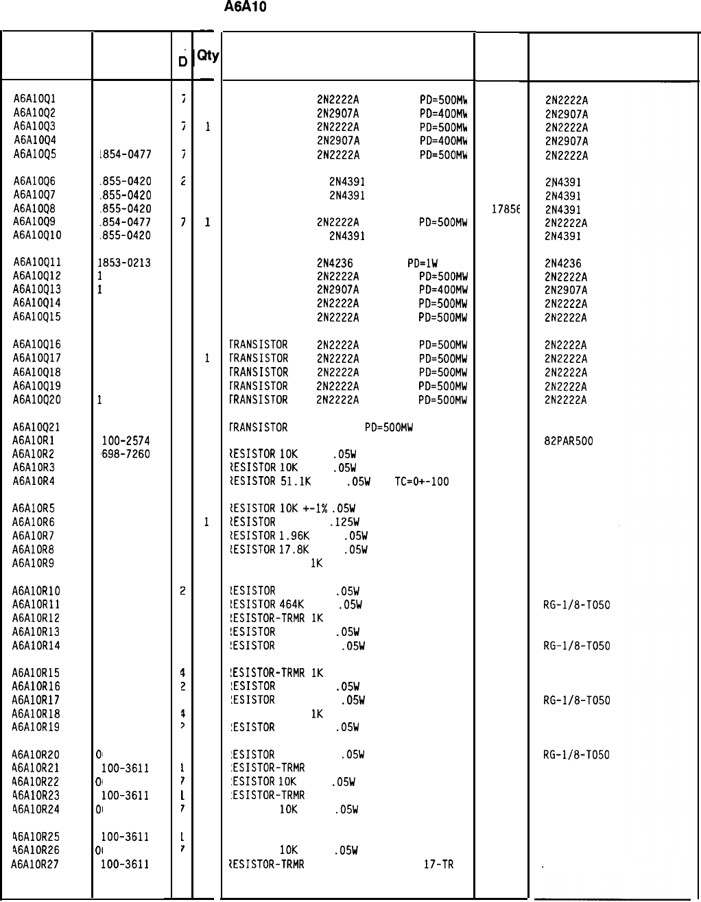
HP Part Number 85660-60180
A6AlO Miscellaneous Bias/Relay Driver
Description Mfr
Mfr Part
Code Number
TRANSISTOR NPN
2N2222A
SI TO-18
PD=SOOMk
TRANSISTOR PNP
2N2907A
SI TO-18
PD=400Mk
TRANSISTOR NPN
2N2222A
SI TO-18
PD=500Mk
TRANSISTOR PNP
2N2907A
SI TO-18
PD=400MW
TRANSISTOR NPN
2N2222A
SI TO-18
PD=500MW
0471:
0471:
0471:
0471:
0471:
TRANSISTOR J-FET
2N4391
N-CHAN D-MODE TO
17856
TRANSISTOR J-FET
2N4391
N-CHAN D-MODE TO
17856
TRANSISTOR J-FET 214391 N-CHAN D-MODE TO
17856
TRANSISTOR NPN
2N2222A
SI TO-18
PD=500MW
04713
TRANSISTOR J-FET
2N4391
N-CHAN D-MODE TO
17856
TRANSISTOR PNP
2N4236
SI TO-5
PD=lW
TRANSISTOR NPN
2N2222A
SI TO-18
PD=500MW
TRANSISTOR PNP
2N2907A
SI TO-18
PD=400MW
TRANSISTOR NPN
2N2222A
SI TO-18
PD=500MW
TRANSISTOR NPN
2N2222A
SI TO-18
PD=SOOMW
04713
04713
04713
04713
04713
[RANSISTOR
NPN
2N2222A
SI TO-18
PD=500MW
rRANSISTOR
NPN
2N2222A
SI TO-18
PD=500MW
rRANSISTOR
NPN
2N2222A
SI TO-18
PD=SOOMW
[RANSISTOR
NPN
2N2222A
SI TO-18
PD=500MW
[RANSISTOR
NPN
2N2222A
SI TO-18
PD=SOOMW
04713
04713
04713
04713
04713
[RANSISTOR
NPN SI DARL
PD=500MW
IESISTOR-TRMR 500 10% TKF SIDE-ADJ 1-TRN
tESISTOR
10K
+-1%
.05W
TF TC=O+-100
{ESISTOR
IOK
+-1%
.05W
TF TC=O+-100
tESISTOR
51.1K
+-1%
.05W
TF
TC=O+-100
04713
73138
19701
19701
19701
lESISTDR
10K
+-I%
.05W
TF TC=O+-100
lESISTDR
10 +-1%
.125W
TF TC=O+-100
[ESISTOR
1.96K
+-1%
.05W
TF TC=O+-100
lESISTOR
17.8K
+-1%
.05W
TF TC=O+-100
IESISTOR-TRMR
1K
10% TKF SIDE-ADJ 17-TRN
19701
91637
19701
19701
73138
lESISTDR
75K +-2%
.05W
TF TC=O+-100
lESISTOR
4641:
+-1%
.05W
TF TC=O+-100
!ESISTOR-TRMR
IK
10% TKF SIDE-ADJ 17-TRN
!ESISTOR
75K +-2%
.05W
TF TC=O+-100
!ESISTDR
464K +-1%
.05W
TF TC=O+-100
19701
11502
73138
19701
11502
LESISTOR-TRMR
IK
10% TKF SIDE-ADJ 17-TRN
!ESISTOR
75K +-2%
.05W
TF TC=O+-100
!ESISTOR
464K +-1%
.05W
TF TC=O+-100
IESISTOR-TRMR
1K
10% TKF SIDE-ADJ 17-TRN
!ESISTOR
75K +-2%
.05W
TF TC=O+-100
73138
19701
11502
73138
19701
:ESISTOR
464K +-1%
.05W
TF TC=O+-100
:ESISTOR-TRMR
50K 10% C SIDE-ADJ 17-TRN
:ESISTOR
10K
+-1%
.05W
TF TC=O+-100
:ESISTOR-TRMR
50K 10% C SIDE-ADJ 17-TRN
ESISTOR
10K
+-1%
.05W
TF TC=O+-100
11502
32997
19701
32997
19701
ESISTOR-TRMR 50K 10% C SIDE-ADJ 17-TR
ESISTOR
10K
+-1%
.05W
TF TC=O+-100
lESISTOR-TRMR
50K 10% C SIDE-ADJ
17-TR
32997
19701
32997
*Indicates factory-selected value
Reference
Designation
A6AlOQl
A6AlOQ2
A6AlOQ3
A6AlOQ4
A6AlOQ5
A6AlOQ6
A6AlOQ7
A6AlOQ8
A6AlOQ9
A6AlOQlO
A6AlOQll
A6AlOQ12
A6AlOQ13
A6AlOQ14
A6AlOQ15
A6AlOQ16
A6AlOQ17
A6AlOQl8
A6AlOQ19
A6AlOQ20
A6AlOQ21
AGAlORl
A6AlOR2
A6AlOR3
A6AlOR4
A6AlOR5
A6AlOR6
A6AlOR7
A6AlOR8
A6AlOR9
AGAlORlO
AGAlORll
A6AlOR12
A6AlOR13
A6AlOR14
A6AlOR15
A6AlOR16
A6AlOR17
A6AlOR18
A6AlOR19
A6AlOR20
A6AlOR21
A6AlOR22
46AlOR23
46AlOR24
46AlOR25
46AlOR26
A6AlOR27
I
1
1
1
1
I
I
I
I
I
I
1
1
1
1
1
1
1
1
1
1
1
2
0
0
0
0
0
0
0
2
0
0
2
0
0
2
0
0
2
0
01
2
Of
2
01
2
01
2
HP Part
Number
1854-0477
i
1853-0281
C
1854-0477
i
1853-0281
c
1854-0477
i
.855-0420
2
.855-0420
2
.855-0420
2
.854-0477
7
.855-0420
2
.853-0213
7
854-0477
7
853-0281
9
854-0477
7
854-0477
7
854-0477
7
854-0477
7
854-0477
7
854-0477
7
854-0477
7
854-0472
2
loo-2574
3
'698-7260
7
698-7260
7
698-7277
6
698-7260
7
757-0346
2
698-7243
6
698-7266
3
100-0545
4
698-7281
699-0127
100-0545
698-7281
699-0127
100-0545
698-7281
699-0127
100-0545
698-7281
699-0127
loo-3611
698-7260
loo-3611
698-7260
loo-3611
598-7260
loo-3611
85660-60180 Parts List
Page 2 of 4
c
c
2
3
4
2
3
4
z
3
4
7
3
1
I
1
I
1
I
1
-
a!
-
1
1
1
1
1
1
1
1
1
1
1
1
1
1
1
1
1
1
1
1
1
1
1
1
1
1
1
1
1
1
1
1
1
1
1
1
1
1
1
1
1
1
1
1
1
1
1
1
-
2N2222A
2N2907A
2N2222A
2N2907A
2N2222A
2N4391
2N4391
2N4391
2N2222A
2N4391
2N4236
2N2222A
2N2907A
2N2222A
2N2222A
2N2222A
2N2222A
2N2222A
2N2222A
2N2222A
MPS-A14
82PAR500
50635
50635
5023R
50635
CMF-55-1, T-l
50635
50635
67XR
5023R
RG-l/8-TO50
67XR
5023R
RG-l/8-TO50
67XR
5023R
RG-l/8-TO50
67XR
5023R
RG-l/8-TO50
3292x-1-503
50635
3292x-1-503
50635
3292x-1-503
50635
3292x-1-503
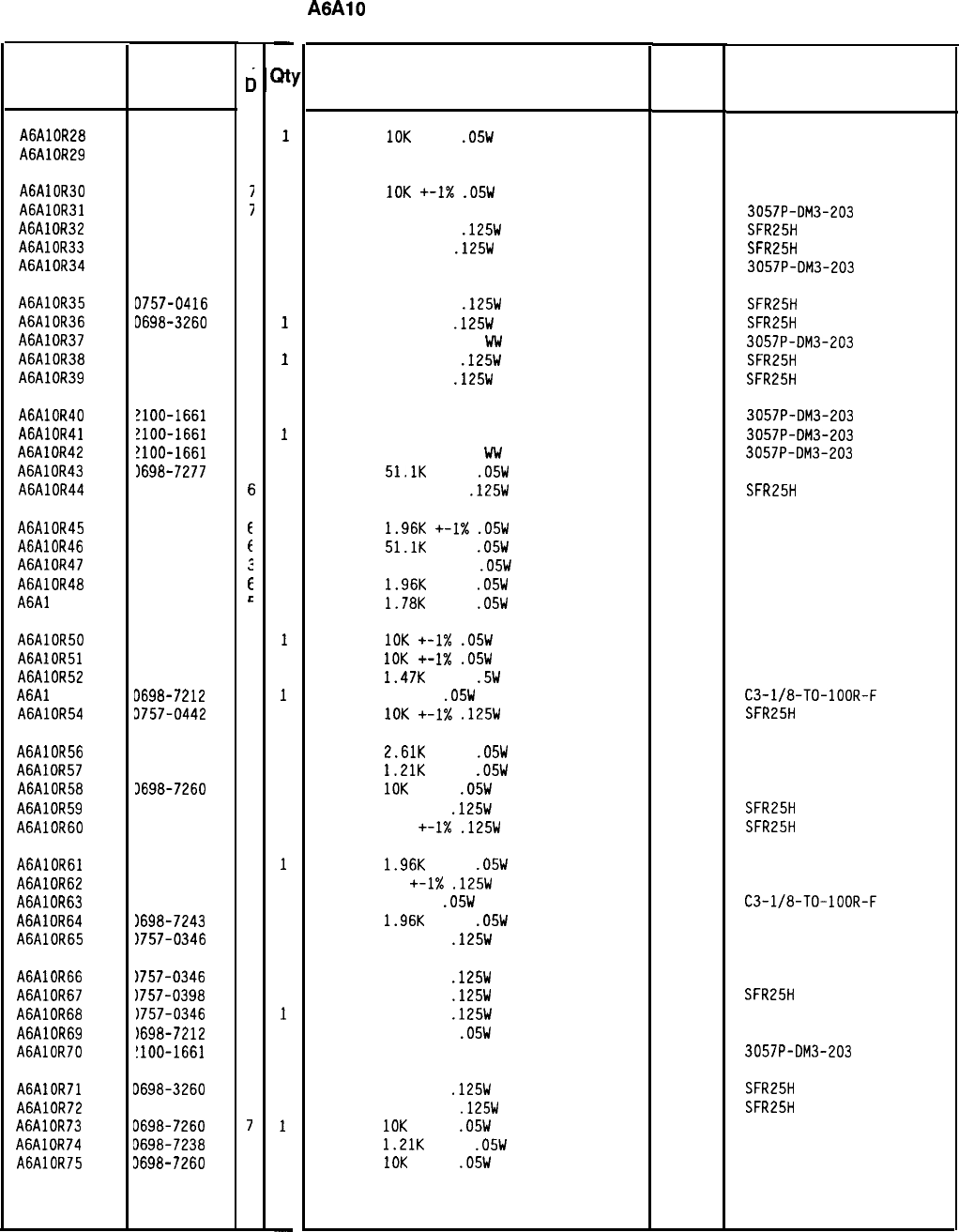
HP Part Number 85660-60180
A6AlO Miscellaneous Bias/Relay Driver
Reference
Designation
HP Part
Number
c
c
A6AlOR28
0698-7260
i
A6AlOR29 2100-3611
I
A6AlOR30 0698-7260
I
A6AlOR31 2100-1661
I
A6AlOR32 0757-0416
7
A6AlOR33 0698-3260
9
A6AlOR34 2100-1661
7
A6AlOR35 0757-0416
7
A6AlOR36 D698-3260
9
A6AlOR37 2100-1661
7
A6AlOR38 3757-0416
7
A6AlOR39 3698-3260
9
A6AlOR40 !lOO-1661
7
A6AlOR41
!lOO-1661
7
A6AlOR42
!lOO-1661
7
A6AlOR43 1698-7277
6
A6AlOR44 3757-0316
F
A6AlOR45 0698-7243
E
A6AlOR46 0698-7277
E
A6AlOR47 0698-7258
:
A6AlOR48 0698-7243
E
A6Al OR49
0698-7242
c
A6AlOR50 0698-7260
7
A6AlOR51 0698-7260
7
A6AlOR52 0757-1078
9
A6Al
OR53
D698-7212
9
A6AlOR54 3757-0442
9
A6AlOR56 3698-7246
9
A6AlOR57 3698-7238
9
A6AlOR58 3698-7260
7
A6AlOR59 3698-3454
3
A6AlOR60 1757-0416
7
A6AlOR61 1698-7243
6
A6AlOR62 1757-0346
2
A6AlOR63 1698-7212
9
A6AlOR64
1698-7243
6
A6AlOR65 1757-0346
2
A6AlOR66
1757-0346
A6AlOR67
1757-0398
A6AlOR68
1757-0346
A6AlOR69
1698-7212
A6AlOR70
!lOO-1661
A6AlOR71
A6AlOR72
A6AlOR73
A6AlOR74
A6AlOR75
J698-3260
0757-0416
0698-7260
D698-7238
3698-7260
2
4
2
3
7
3
7
7
9
7
-
;Itl
1
1
1
1
1
1
1
1
1
1
1
1
1
1
1
1
1
1
1
1
1
1
1
1
1
1
1
1
1
1
1
1
1
1
1
1
1
1
1
1
1
1
1
1
1
1
1
-
Description Mfr
Mfr Part
Code Number
RESISTOR
10K
+-1%
.05W
TF TC=O+-100
19701
50635
RESISTOR-TRMR 50K 10% C SIDE-ADJ 17-TRN
32997 3292x-1-503
RESISTOR
10K
+-I%
.05W
TF TC=O+-100
19701
50635
RESISTOR-TRMR 20K 5% WW SIDE-ADJ 22-TRN
32997 3057P-DM3-203
RESISTOR 511 +-1%
.125W
TF TC=O+-100
19701
SFR25H
RESISTOR 464K 1%
.125W
TF TC=O+-100
19701 SFR25H
RESISTOR-TRMR 20K 5% WW SIDE-ADJ 22-TRN
32997 3057P-DM3-203
RESISTOR 511 +-1%
.125W
TF TC=O+-100
19701
SFR25H
RESISTOR 464K 1%
.125W
TF TC=O+-100
19701
SFR25H
RESISTOR-TRMR 20K 5%
Ww
SIDE-ADJ 22-TRN
32997 3057P-DM3-203
RESISTOR 511 +-1%
.125W
TF TC=O+-100
19701
SFR25H
RESISTOR 464K 1%
.125W
TF TC=O+-100
19701
SFR25H
RESISTOR-TRMR 20K 5% WW SIDE-ADJ 22-TRN
32997 3057P-DM3-203
RESISTOR-TRMR 20K 5% WW SIDE-ADJ 22-TRN
32997 3057P-DM3-203
RESISTOR-TRMR 20K 5% Ww SIDE-ADJ 22-TRN
32997 3057P-DM3-203
RESISTOR
51.1K
+-1%
.05W
TF TC=O+-100
19701 5023R
RESISTOR 42.2 +-1%
.125W
TF TC=O+-100
19701
SFR25H
RESISTOR
1.96K
+-I%
.05W
TF TC=O+-100
19701
50635
RESISTOR
51.1K
+-1%
.05W
TF TC=O+-100
19701
5023R
RESISTOR 8.251: +-1%
.05W
TF TC=O+-100
19701
50635
RESISTOR
1.96K
+-1%
.05W
TF TC=O+-100
19701
50635
RESISTOR
1.78K
+-1%
.05W
TF TC=O+-100
19701
50635
RESISTOR
10K
+-1X
.05W
TF TC=O+-100
19701
50635
RESISTOR
10K
+-I%
.05W
TF TC=O+-100
19701
50635
RESISTOR
1.47K
+-1%
.5W
TF TC=O+-100
19701
5053R
RESISTOR 100 1%
.05W
F TC=O+-100
24546
C3-l/8-TO-lOOR-F
RESISTOR
10K
+-I%
.125W
TF TC=O+-100
19701
SFR25H
RESISTOR
2.61K
+-1%
.05W
TF TC=O+-100
19701
50635
RESISTOR
1.21K
+-1%
.05W
TF TC=O+-100
19701
50635
RESISTOR
10K
+-1%
.05W
TF TC=O+-100
19701
50635
RESISTOR 215K 1%
.125W
TF TC=O+-100
19701
SFR25H
RESISTOR 511 +-I%
.125W
TF TC=O+-100
19701
SFR25H
RESISTOR
1.96K
+-1%
.05W
TF TC=O+-100
19701
50635
RESISTOR 10 +-I%
.125W
TF TC=O+-100
91637 CMF-55-1, T-l
RESISTOR 100 1%
.05W
F TC=O+-100
24546
C3-l/8-TO-lOOR-F
RESISTOR
1.96K
+-1%
.05W
TF TC=O+-100
19701
50635
RESISTOR 10 +-1%
.125W
TF TC=O+-100
91637 CMF-55-1, T-l
RESISTOR 10 +-1%
.125W
TF TC=O+-100
91637 CMF-55-1, T-l
RESISTOR 75 +-1%
.125W
TF TC=O+-100
19701
SFR25H
RESISTOR 10 +-1%
.125W
TF TC=O+-100
91637 CMF-55-1, T-l
RESISTOR 100 +-1%
.05W
TF TC=O+-100
19701
50635
RESISTOR-TRMR 20K 5% WW SIDE-ADJ 22-TRN 32997 3057P-DM3-203
RESISTOR 464K 1%
.125W
TF TC=O+-100
19701
SFR25H
RESISTOR 511 +-1%
.125W
TF TC=O+-100
19701
SFR25H
RESISTOR
10K
+-1%
.05W
TF TC=O+-100
19701
50635
RESISTOR
1.21K
+-1%
.05W
TF TC=O+-100
19701
50635
RESISTOR
IOK
+-1%
.05W
TF TC=O+-100
19701
50635
*Indicates factory-selected value
85660-60180 Parts List
Page 3 of 4
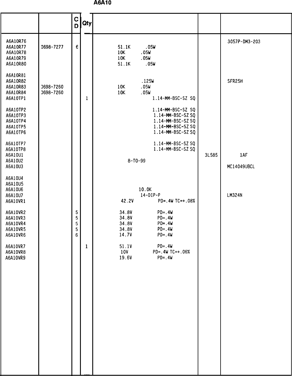
HP Part Number 85660-60180
A6AlO Miscellaneous Bias/Relay Driver
Reference HP Part
Designation Number
A6AlOR76 2100-1661
7
A6AlOR77 0698-7277
6
A6AlOR78 0698-7260
7
A6AlOR79 0698-7260
7
A6AlOR80 0698-7277
6
A6AlOR81 2100-3611
1
A6AlOR82 3698-3153
9
A6AlOR83 3698-7260
7
A6AlOR84 3698-7260
7
AGAlOTPl 1251-0600
0
A6AlOTP2 1251-0600
0
A6AlOTP3 1251-0600
0
A6AlOTP4 1251-0600
0
A6AlOTP5 1251-0600
0
A6AlOTP6 1251-0600
0
A6AlOTP7 1251-0600
0
A6AlOTP8 1251-0600
0
AGAlOUl 1820-1538
2
A6AlOU2 1826-1058
3
A6AlOU3 1820-1542
8
A6AlOU4 1858-0047
5
A6AlOU5 1858-0047
5
A6AlOU6 1810-0206
8
A6AlOU7 1826-0161
7
AGAlOVRl 1902-3323
1
A6AlOVR2
A6AlOVR3
A6AlOVR4
A6AlOVR5
A6AlOVR6
1902-3301
1902-3301
1902-3301
1902-3301
1902-3203
1902-3345
1902-0025
1902-3234
A6AlOVR7
A6AlOVR8
A6AlOVR9
7
4
3
21
-
1
1
1
1
1
1
1
1
1
1
1
1
1
1
1
1
1
1
1
1
1
1
1
1
1
1
1
1
1
1
1
1
1
-
Description
RESISTOR-TRMR 20K 5% WW SIDE-ADJ 22-TRN
32997 3057P-DM3-203
RESISTOR
51.1K
+-1%
.05W
TF TC=O+-100
19701
5023R
RESISTOR
10K
+-1%
.05W
TF TC=O+-100
19701
50635
RESISTOR
10K
+-1%
.05W
TF TC=O+-100
19701
50635
RESISTOR
51.1K
+-1%
.05W
TF TC=O+-100
19701
5023R
RESISTOR-TRMR 50K 10% C SIDE-ADJ 17-TRN
32997 3292x-1-503
RESISTOR 3.831: 1%
.125W
TF TC=O+-100
19701
SFR25H
RESISTOR
10K
+-1%
.05W
TF TC=O+-100
19701
50635
RESISTOR
10K
+-1%
.05W
TF TC=O+-100
19701
50635
CONNECTOR-SGL CONT PIN
1.14~MM-BSC-SZ
SQ
27264 16-06-0034
CONNECTOR-SGL CONT PIN
1.14-MM-BSC-SZ
SQ
27264 16-06-0034
CONNECTOR-SGL CONT PIN
1.14-MM-BSC-SZ
SQ
27264 16-06-0034
CONNECTOR-SGL CONT PIN
1.14-MM-BSC-SZ
SQ
27264 16-06-0034
CONNECTOR-SGL CONT PIN
1.14~MM-BSC-SZ
SQ
27264 16-06-0034
CONNECTOR-SGL CONT PIN
1.14-MM-BSC-SZ
SQ
27264 16-06-0034
CONNECTOR-SGL CONT PIN
1.14-MM-BSC-SZ
SQ
27264 16-06-0034
CONNECTOR-SGL CONT PIN
1.14-MM-BSC-SZ
SQ
27264 16-06-0034
IC GATE CMOS NAND QUAD 2-INP 3L585
CD401 1AF
IC OP AMP GP
8-TO-99
PKG
06665 OP-02CJ
IC BFR CMOS INV HEX l-INP 04713 MC14049UBCL
TRANSISTOR ARRAY 16-PIN PLSTC DIP 56289
TRANSISTOR ARRAY 16-PIN PLSTC DIP 56289
NETWORK-RES 8-SIP
lO.OK
OHM X 7
11236
IC OP AMP GP QUAD
14-DIP-P
PKG
27014
DIODE-ZNR
42.2V
5% DO-35
PD=.4W
TC=+.08% 04713
ULN-2003A
ULN-2003A
750-81
LM324N
DIODE-ZNR
34.8V
5% DO-35
PD=.4W
DIODE-ZNR
34.8V
5% DO-35
PD=.4W
DIODE-ZNR
34.8V
5% DO-35
PD=.4W
DIODE-ZNR
34.8V
5% DO-35
PD=.4W
DIODE-ZNR
14.7V
5% DO-35
PD=.4W
DIODE-ZNR
51.1V
5% DO-35
PD=.4W
DIODE-ZNR
1OV
5% DO-35
PD=.4W
TC=+.06%
DIODE-ZNR
19.6V
5% DO-35
PD=.4W
04713
04713
04713
04713
04713
04713
04713
04713
8X60-60180 Parts List
Page 4 of 4
*Indicates factory-selected value
Mfr
Mfr Part
Code Number
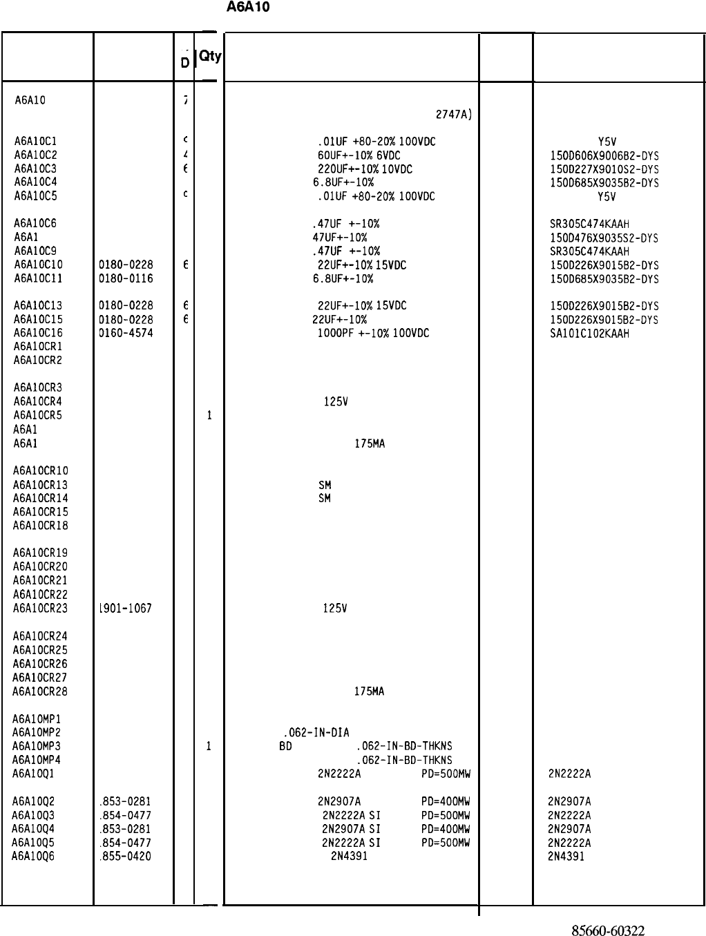
HP Part Number 85660-60322
A6AlO Miscellaneous Bias/Relay Driver
Description Mfr
Mfr Part
Code Number
BOARD ASSEMBLY, MISCELLANEOUS
BIAS/RELAY DRIVER (SERIAL PREFIX:
2747~)
28480 85660-60322
CAPACITOR-FXD
.OlUF
+80-20%
1OOVDC
CER
CAPACITOR-FXD
6OUF+-10%
6VDC
TA
CAPACITOR-FXD
22OUF+-10%
1OVDC
TA
CAPACITOR-FXD
6.8UF+-10%
35VDC TA
CAPACITOR-FXD
.OlUF
+80-20%
1OOVDC
CER
56289
56289
56289
805-504
Y5V
1032
150D606X9006B2-OYS
150D227X9010S2-DYS
150D685X9035B2-DYS
805-504
Y5V
1032
CAPACITOR-FXD
.47UF
+-lo% 50VDC CER
04222 SR305C474KAAH
CAPACITOR-FXD
47UF+-10%
35VDC TA
56289 150D476X9035S2-DYS
CAPACITOR-FXD
.47UF
+-lo% 50VDC CER
04222 SR305C474KAAH
CAPACITOR-FXD
22UF+-10%
15VDC
TA
56289 150D226X9015B2-DYS
CAPACITOR-FXD
6.8UF+-10%
35VDC TA
56289 150D685X9035B2-DYS
CAPACITOR-FXD
22UF+-10%
15VDC
TA
56289 150D226X901582-DYS
CAPACITOR-FXD
22UF+-10%
15VDC TA
56289 150D226X901582-DYS
CAPACITOR-FXD
1OOOPF
+-IO%
1OOVDC
CER
04222 SAlOlC102KAAH
DIODE-SWITCHING 125V 175MA 60NS DO-35
27014 FDH444
DIODE-SWITCHING 125V 175MA 60NS DO-35
27014 FOH444
DIODE-SWITCHING 125V 175MA 60NS DO-35
27014 FDH444
DIODE-SWITCHING
125V
175MA 60NS DO-35
27014 FDH444
DIODE-SWITCHING 125V 175MA 60NS DO-35
27014 FDH444
DIODE-SWITCHING 125V 175MA 60NS DO-35
27014 FDH444
DIODE-SWITCHING 125V
175MA
60NS DO-35
27014 FDH444
DIODE-SWITCHING 125V 175MA 60NS DO-35
DIODE-SCHOTTKY
SM
SIG
DIODE-SCHOTTKY
SM
SIG
27014 FDH444
DIODE-SWITCHING 125V 175MA 60NS DO-35
27014 FDH444
DIODE-SWITCHING 125V 175MA 60NS DO-35
27014 FDH444
DIODE-SWITCHING 125V 175MA 60NS DO-35
27014 FDH444
DIODE-SWITCHING 125V 175MA 60NS DO-35
27014 FOH444
DIODE-SWITCHING 125V 175MA 60NS DO-35
27014 FDH444
DIODE-SWITCHING 125V 175MA 60NS DO-35
27014 FDH444
DIODE-SWITCHING
125V
175MA 60NS DO-35
27014 FDH444
DIODE-SWITCHING 125V 175MA 60NS DO-35
27014 FDH444
DIODE-SWITCHING 125V 175MA 60NS DO-35
27014 FDH444
DIODE-SWITCHING 125V 175MA 60NS DO-35
27014 FDH444
DIODE-SWITCHING 125V 175MA 60NS DO-35
27014 FDH444
DIODE-SWITCHING 125V
175MA
60NS DO-35
27014 FDH444
NOT ASSIGNED
PIN-ROLL
.062-IN-DIA
.25-IN-LG BE-CU
EXTR-PC
BD
BLK POLYC
.062-IN-BD-THKNS
EXTR-PC BD BRN POLYC
.062-IN-BD-THKNS
TRANSISTOR NPN
2N2222A
SI TO-18
PD=SOOMW
72962 99-012-062-0250
04713
TRANSISTOR PNP
2N2907A
SI TO-18
PD=400MW 04713
TRANSISTOR NPN
2N2222A
SI
TO-18
PD=500MW 04713
TRANSISTOR PNP
2N2907A
SI
TO-18
PD=400MW 04713
TRANSISTOR NPN
2N2222A
SI
TO-18
PD=SOOMW 04713
TRANSISTOR J-FET
2N4391
N-CHAN D-MODE
17856
2N2222A
2N2907A
2N2222A
2N2907A
2N2222A
2N4391
*Indicates factory-selected value
8.5660-60322
Parts List
Page 1 of 4
Reference
Designation
HP Part
Number
c
c
A6AlO 85660-60322
i
AGAlOCl 0160-2055
c
A6AlOC2 0180-2206
1
A6AlOC3 0180-2208
E
A6AlOC4 0180-0116
I
A6AlOC5 0160-2055
c
A6AlOC6 0160-4441
I
A6Al OC8
0180-0097
7
A6AlOC9 0160-4441
1
AGAlOClO 0180-0228
f
AGAlOCll 0180-0116
1
A6AlOC13 0180-0228
6
A6AlOC15 D180-0228
6
A6AlOC16 0160-4574
1
AGAlOCRl 1901-1067
4
A6AlOCR2 1901-1067
4
A6AlOCR3 1901-1067
4
A6AlOCR4 1901-1067
4
A6AlOCR5 1901-1067
4
A6Al OCR6 1901-1067
4
A6Al OCR7
1901-1067
4
AGAlOCRlO 1901-1067
4
A6AlOCR13 1901-0535
9
A6AlOCR14 1901-0535
9
A6AlOCR15 1901-1067
4
A6AlOCR18 1901-1067
4
A6AlOCR19 1901-1067
4
A6AlOCR20 1901-1067
4
A6AlOCR21 1901-1067
4
A6AlOCR22 1901-1067
4
A6AlOCR23 L901-1067
4
A6AlOCR24
1901-1067
4
A6AlOCR25 1901-1067
4
A6AlOCR26
1901-1067
4
A6AlOCR27
1901-1067
4
A6AlOCR28
1901-1067
4
AGAlOMPl
A6AlOMP2
A6AlOMP3
A6AlOMP4
A6AlOQl
1480-0073
6
1040-0748
3
1040-0749
4
1854-0477
7
A6AlOQ2
A6AlOQ3
A6AlOQ4
A6AlOQ5
A6AlOQ6
.853-0281
9
.854-0477
7
.853-0281
9
.854-0477
7
.855-0420
2
-
at!
-
1
1
1
1
1
1
1
1
1
1
1
1
1
1
1
1
1
1
1
1
1
1
1
1
1
1
1
1
1
1
1
1
1
1
1
1
2
1
1
1
1
1
1
1
1
-
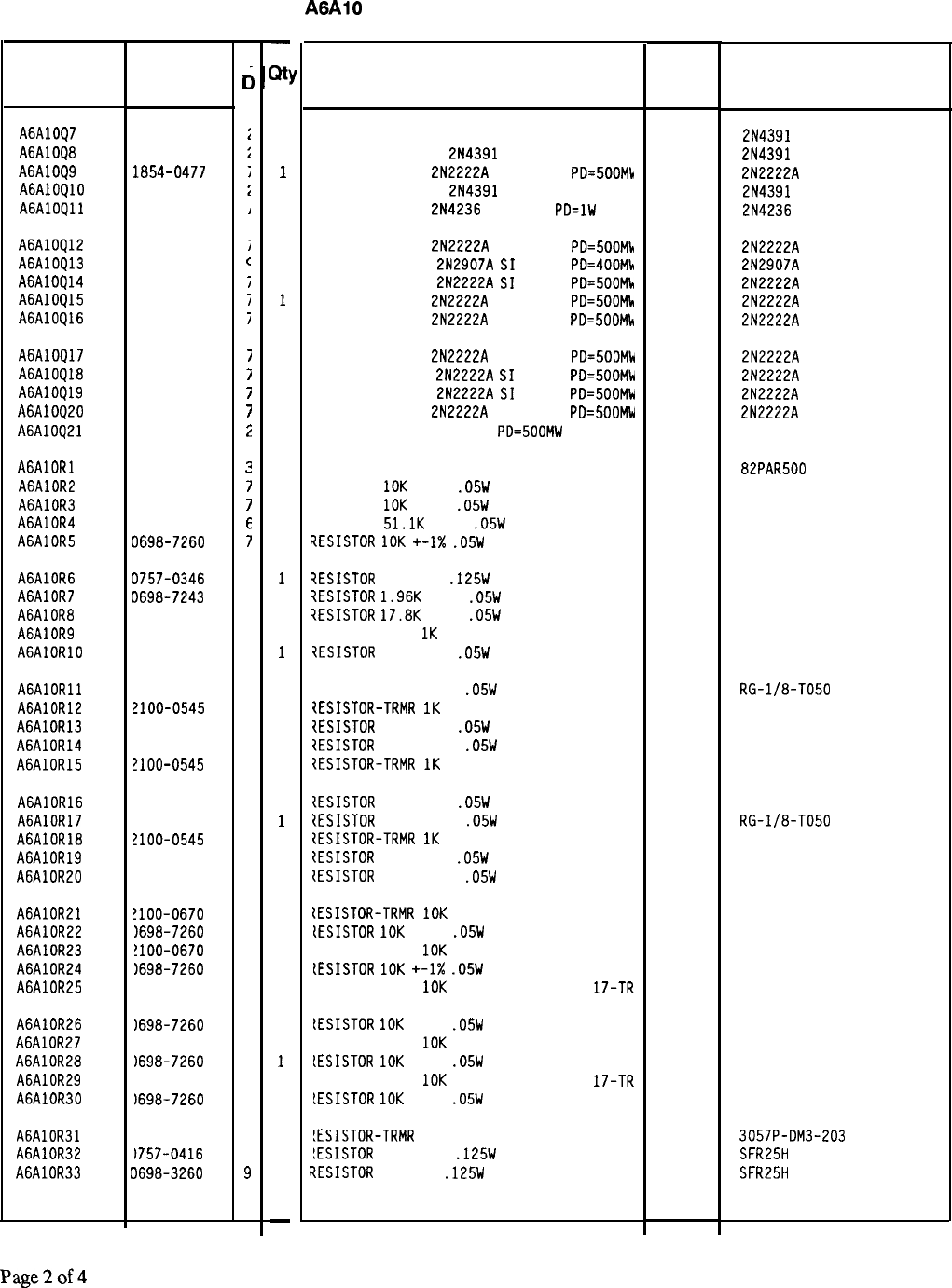
HP Part Number 85660-60322
A6AlO Miscellaneous Bias/Relay Driver
Description Mfr Mfr Part
Code Number
TRANSISTOR J-FET 214391 N-CHAN O-MODE
17856 2N4391
TRANSISTOR J-FET
2N4391
N-CHAN O-MODE
17856 2N4391
TRANSISTOR NPN
2N2222A
SI TO-18
PO=SOOMh 04713 2N2222A
TRANSISTOR J-FET
2N4391
N-CHAN O-MODE
17856 2N4391
TRANSISTOR PNP
2N4236
SI TO-5
PO=lW 04713 2N4236
TRANSISTOR NPN
2N2222A
SI TO-18
PO=SOOMh 04713 2N2222A
TRANSISTOR PNP
2N2907A
SI
TO-18
PO=400Mb 04713 2N2907A
TRANSISTOR NPN
2N2222A
SI
TO-18
PO=SOOMh 04713 2N2222A
TRANSISTOR NPN
2N2222A
SI TO-18
PO=500Mlr
04713 2N2222A
TRANSISTOR NPN
2N2222A
SI TO-18
PO=500MG(
04713 2N2222A
TRANSISTOR NPN
2N2222A
SI TO-18
PO=500Mk 04713 2N2222A
TRANSISTOR NPN
2N2222A
SI
TO-18
PO=SOOMW 04713 2N2222A
TRANSISTOR NPN
2N2222A
SI
TO-18
PO=500MW 04713 2N2222A
TRANSISTOR NPN
2N2222A
SI TO-18
PO=SOOMW 04713 2N2222A
TRANSISTOR NPN SI OARL
PO=500MW 04713 MPS-A14
RESISTOR-TRMR 500 10% TKF SIDE-AOJ l-TRN 73138 82PAR500
RESISTOR
10K
+-1%
.05W
TF TC=O+-100
19701
50635
RESISTOR
10K
+-1%
.05W
TF TC=O+-100
19701
50635
RESISTOR
51.1K
+-1%
.05W
TF TC=O+-100
19701
5023R
7ESISTOR
1OK
+-I%
.05W
TF TC=O+-100
19701
50635
7ESISTOR
10 +-1%
.125W
TF TC=O+-100
91637 CMF-55-l. T-l
?ESISTOR
1.96K
+-1%
.05W
TF TC=O+-100
19701
50635
iESISTOR
17.8K
+-1%
.05W
TF TC=O+-100
19701
50635
IESISTOR-TRMR
1K
10% TKF SIDE-AOJ 17-TRN
73138 67XR
7ESISTOR
75K +-2%
.05W
TF TC=O+-100
19701
5023R
7ESISTOR 464K +-1%
.05W
TF TC=O+-100
11502 RG-l/8-TO50
7ESISTOR-TRMR
1K
10% TKF SIDE-AOJ 17-TRN
73138 67XR
IESISTOR
75K +-2%
.05W
TF TC=O+-100
19701
5023R
2ESISTOR
464K +-1%
.05W
TF TC=O+-100
11502 RG-l/8-TO50
?ESISTOR-TRMR
1K
10% TKF SIDE-AOJ 17-TRN
73138 67XR
IESISTOR
75K +-2%
.05W
TF TC=O+-100
19701
5023R
{ESISTOR
464K +-1%
.05W
TF TC=O+-100
11502 RG-l/8-TO50
{ESISTOR-TRMR
1K
10% TKF SIDE-AOJ 17-TRN
73138 67XR
tESISTOR
75K +-2%
.05W
TF TC=O+-100
19701
5023R
{ESISTOR
464K +-1%
.05W
TF TC=O+-100
11502 RG-l/8-TO50
(ESISTOR-TRMR
10K
10% TKF SIDE-AOJ 17-TR
73138 67XR
lESISTOR
10K
+-1%
.05W
TF TC=O+-100
19701
50635
IESISTOR-TRMR
10K
10% TKF SIDE-AOJ 17-TR
73138 67XR
[ESISTOR
10K
+-1X
.05W
TF TC=O+-100
19701
50635
IESISTOR-TRMR
1OK
10% TKF SIDE-AOJ
17-TR 73138 67XR
iESISTOR
10K
+-1%
.05W
TF TC=O+-100
19701
50635
IESISTOR-TRMR
10K
10% TKF SIDE-AOJ 17-TR
73138 67XR
LESISTOR
10K
+-1%
.05W
TF TC=O+-100
19701
50635
IESISTOR-TRMR
10K
10% TKF SIDE-AOJ
17-TR 73138 67XR
!ESISTOR
10K
+-1%
.05W
TF TC=O+-100
19701
50635
!ESISTOR-TRMR
20K 5% WW SIOE-AOJ 22-TRN
32997 3057P-OM3-203
!ESISTOR
511 +-1%
.125W
TF TC=O+-100
19701
SFR25H
dESISTOR
464K 1%
.125W
TF TC=O+-100
19701
SFR25H
*Indicates factory-selected value
Reference
Designation
A6AlOQ7
A6AlOQ8
A6AlOQ9
A6AlOQlO
A6AlOQll
HP Part
Number
C
c
1855-0420
1855-0420
1854-0477
1855-0420
1853-0213
1
A6AlOQ12 1854-0477
i
A6AlOQ13 1853-0281
c
A6AlOQ14 1854-0477
i
A6AlOQ15 1854-0477
i
A6AlOQ16 1854-0477
i
A6AlOQ17 1854-0477
i
A6AlOQ18 1854-0477
i
A6AlOQ19 1854-0477
7
A6AlOQ20 1854-0477
7
A6AlOQ21 1854-0472
i
AGAlORl 2100-2574
2
A6AlOR2 0698-7260
7
A6AlOR3 0698-7260
7
A6AlOR4 0698-7277
6
A6AlOR5 0698-7260
7
A6AlOR6 D757-0346
2
A6AlOR7 D698-7243
6
A6AlOR8 3698-7266
3
A6AlOR9 2100-0545
4
AGAlORlO 3698-7281
2
AGAlORll 3699-0127
3
A6AlOR12 !lOO-0545
4
A6AlOR13 3698-7281
2
A6AlOR14 1699-0127
3
A6AlOR15 !lOO-0545
4
A6AlOR16
3698-7281
2
A6AlOR17 1699-0127
3
A6AlOR18 !lOO-0545
4
A6AlOR19
1698-7281
2
A6AlOR20 1699-0127
3
A6AlOR21 !lOO-0670
6
A6AlOR22 1698-7260
7
A6AlOR23 !lOO-0670
6
A6AlOR24 1698-7260
7
A6AlOR25 !lOO-0670
6
A6AlOR26
1698-7260
7
A6AlOR27
!lOO-0670
6
A6AlOR28
1698-7260
7
A6AlOR29
!lOO-0670
6
A6AlOR30
)698-7260
7
A6AlOR31
!lOO-1661
7
A6AlOR32
1757-0416
7
A6AlOR33 d698-3260
9
8566060322 Parts List
Page2of4
-
P
1
1
1
1
1
1
1
1
1
1
1
1
1
1
1
1
1
1
1
1
1
1
1
1
1
1
1
1
1
1
1
1
1
1
1
1
1
1
1
1
1
1
1
1
1
1
1
1
-
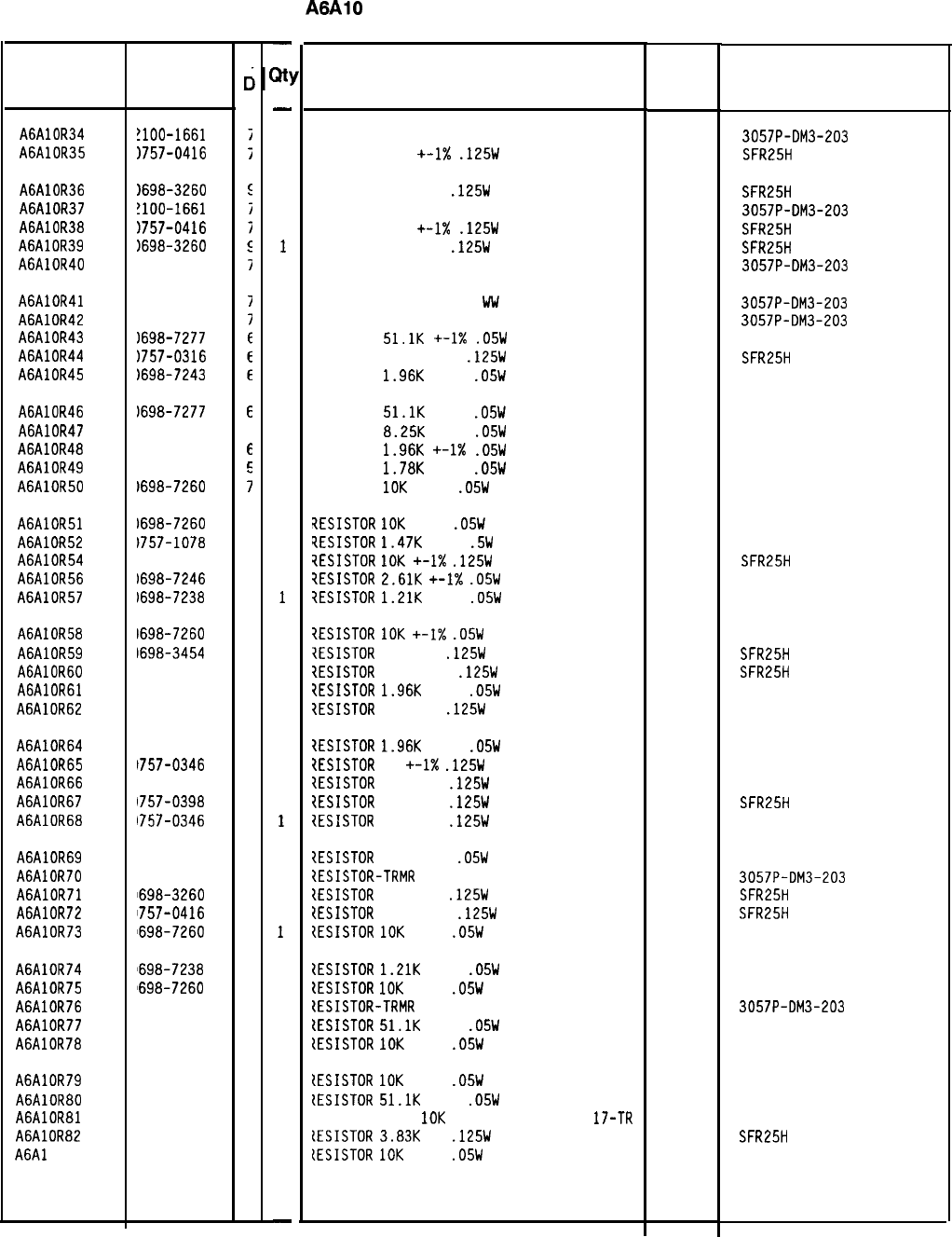
HP Part Number 85660-60322
A6AlO Miscellaneous Bias/Relay Driver
Description Mfr
Mfr Part
Code Number
RESISTOR-TRMR 20K 5% WW SIDE-AOJ 22-TRN
RESISTOR 511 +-1X
.125W
TF TC=O+-100
32997 3057P-OM3-203
19701
SFR25H
RESISTOR 464K 1%
.125W
TF TC=O+-100
RESISTOR-TRMR 20K 5% WW SIDE-AOJ 22-TRN
RESISTOR 511
+-I%
.125W
TF TC=O+-100
RESISTOR 464K 1%
.125W
TF TC=O+-100
RESISTOR-TRMR 20K 5% WW SIDE-AOJ 22-TRN
19701
SFR25H
32997 3057P-OM3-203
19701
SFR25H
19701
SFR25H
32997 3057P-OM3-203
RESISTOR-TRMR 20K 5% Ww SIDE-AOJ 22-TRN
RESISTOR-TRMR 20K 5% WW SIDE-AOJ 22-TRN
RESISTOR
51.1K
+-I%
.05W
TF TC=O+-100
RESISTOR 42.2 +-1%
.125W
TF TC=O+-100
RESISTOR
1.96K
+-1%
.05W
TF TC=O+-100
32997 3057P-OM3-203
32997 3057P-OM3-203
19701
5023R
19701
SFR25H
19701
50635
RESISTOR
51.1K
+-1%
.05W
TF TC=O+-100
19701
502317
RESISTOR
8.25K
+-1%
.05W
TF TC=O+-100
19701
50635
RESISTOR
1.96K
+-1X
.05W
TF TC=O+-100
19701
50635
RESISTOR
1.78K
+-1%
.05W
TF TC=O+-100
19701
50635
RESISTOR
10K
+-1%
.05W
TF TC=O+-100
19701
50635
?ESISTOR
10K
+-1%
.05W
TF TC=O+-100
?ESISTOR
1.47K
+-1%
.5W
TF TC=O+-100
?ESISTOR
10K
+-1X
.125W
TF TC=O+-100
?ESISTOR
2.61K
+-I%
.05W
TF TC=O+-100
?ESISTOR
1.21K
+-1%
.05W
TF TC=O+-100
19701
50635
19701
5053R
19701
SFR25H
19701
50635
19701
50635
?ESISTOR
10K
+-I%
.05W
TF TC=O+-100
7ESISTOR
215K 1%
.125W
TF TC=O+-100
1ESISTOR
511 +-1%
.125W
TF TC=O+-100
iESISTOR
1.96K
+-1%
.05W
TF TC=O+-100
7ESISTOR
10 +-1%
.125W
TF TC=O+-100
19701
50635
19701
SFR25H
19701
SFR25H
19701
50635
91637 CMF-55-1, T-l
?ESISTOR
1.96K
+-1%
.05W
TF TC=O+-100
7ESISTOR
10
+-1X
.125W
TF TC=O+-100
1ESISTOR
10 +-1%
.125W
TF TC=O+-100
1ESISTOR
75 +-1%
.125W
TF TC=O+-100
IESISTOR
10 +-1%
.125W
TF TC=O+-100
19701
50635
91637 CMF-55-1, T-l
91637 CMF-55-1. T-l
19701
SFR25H
91637 CMF-55-1, T-l
?ESISTOR
100 +-1%
.05W
TF TC=O+-100
IESISTOR-TRMR
20K 5% WW SIDE-AOJ 22-TRN
IESISTOR
464K 1%
.125W
TF TC=O+-100
{ESISTOR
511 +-1%
.125W
TF TC=O+-100
{ESISTOR
10K
+-1%
.05W
TF TC=O+-100
19701
50635
32997 3057P-OM3-203
19701
SFR25H
19701
SFR25H
19701
50635
ZESISTOR
1.21K
+-1%
.05W
TF TC=O+-100
tESISTOR
10K
+-1%
.05W
TF TC=O+-100
ZESISTOR-TRMR
20K 5% WW SIDE-AOJ 22-TRN
tESISTOR
51.1K
+-1%
.05W
TF TC=O+-100
{ESISTOR
10K
+-1%
.05W
TF TC=O+-100
19701
50635
19701
50635
32997 3057P-OM3-203
19701
5023R
19701
50635
(ESISTOR
10K
+-1%
.05W
TF TC=O+-100
19701
tESISTOR
51.1K
+-1%
.05W
TF TC=O+-100
19701
IESISTOR-TRMR
10K
10% TKF SIDE-AOJ
17-TR 73138
lESISTOR
3.83K
1%
.125W
TF TC=O+-100
19701
CESISTOR
10K
+-1%
.05W
TF TC=O+-100
19701
50635
5023R
67XR
SFR25H
50635
*Indicates factory-selected value
85660-60322 Parts List
Page 3 of 4
Reference
Designation
I
HP Part
Number
c
c
A6AlOR34
A6AlOR35
!lOO-1661
1757-0416
A6AlOR36
A6AlOR37
A6AlOR38
A6AlOR39
A6AlOR40
1698-3260
!lOO-1661
1757-0416
1698-3260
!lOO-1661
A6AlOR41
A6AlOR42
A6AlOR43
A6AlOR44
A6AlOR45
!lOO-1661
!lOO-1661
1698-7277
1757-0316
1698-7243
A6AlOR46
A6AlOR47
A6AlOR48
A6AlOR49
A6AlOR50
1698-7277
E
1698-7258
3
1698-7243
6
1698-7242
c
1698-7260
;
A6AlOR51
A6AlOR52
A6AlOR54
A6AlOR56
A6AlOR57
1698-7260
7
)757-1078
9
1757-0442
9
1698-7246
9
1698-7238
9
A6AlOR58
1698-7260
7
A6AlOR59
1698-3454
3
A6AlOR60
1757-0416
7
A6AlOR61
1698-7243
6
A6AlOR62
1757-0346
2
A6AlOR64
1698-7243
6
A6AlOR65
1757-0346
2
A6AlOR66
1757-0346
2
A6AlOR67
1757-0398
4
A6AlOR68
1757-0346
2
A6AlOR69
1698-7212
9
A6AlOR70 100-1661
7
A6AlOR71
1698-3260
9
A6AlOR72
1757-0416
7
A6AlOR73
1698-7260
7
A6AlOR74
1698-7238
9
A6AlOR75
1698-7260
7
A6AlOR76 100-1661
7
A6AlOR77 698-7277
6
A6AlOR78 698-7260
7
A6AlOR79 698-7260
7
A6AlOR80 698-7277
6
A6AlOR81 100-0670
6
A6AlOR82 698-3153
9
A6Al
OR83
698-7260
7
-
X!
-
1
1
1
1
1
1
1
1
1
1
1
1
1
1
1
1
1
1
1
1
1
1
1
1
1
1
1
1
1
1
1
1
1
1
1
1
1
1
1
1
1
1
1
1
1
1
1
-
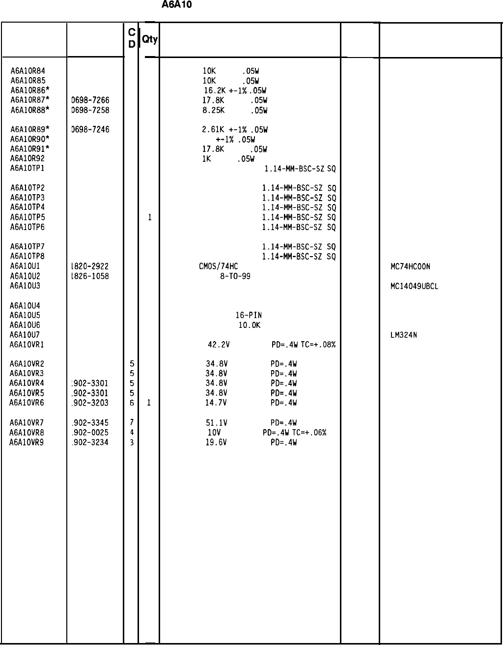
HP Part Number 85660-60322
A6AlO Miscellaneous Bias/Relay Driver
Reference HP Part
Designation Number
A6AlOR84 0698-7260
7
A6AlOR85 0698-7260
7
A6AlOR86* 0698-7265
2
A6AlOR87* D698-7266
3
A6AlOR88* 0698-7258
3
A6AlOR89* D698-7246
9
A6AlOR90" 3698-7188
a
A6AlOR91” 3698-7266
3
A6AlOR92 3698-7236
7
AGAlOTPl 1251-0600
0
A6AlOTP2 1251-0600
0
A6AlOTP3 1251-0600
0
A6AlOTP4 1251-0600
0
A6AlOTP5 1251-0600
0
A6AlOTP6 1251-0600
0
A6AlOTP7 1251-0600
0
A6AlOTP8 1251-0600
0
AGAlOUl 1820-2922
0
A6AlOU2 L826-1058
3
A6AlOU3 1820-1542
8
A6AlOU4
1858-0047
5
A6AlOU5
1858-0047
5
A6AlOU6 1810-0206
a
A6AlOU7
1826-0161
7
AGAlOVRl
1902-3323
1
A6AlOVR2
A6AlOVR3
A6AlOVR4
A6AlOVR5
A6AlOVR6
A6AlOVR7
A6AlOVR8
A6AlOVR9
1902-3301
1902-3301
.902-3301
.902-3301
.902-3203
.902-3345
.902-0025
.902-3234
-
%I
-
1
1
1
1
1
1
1
1
1
1
1
1
1
1
1
1
1
1
1
1
1
1
1
1
1
1
1
1
1
1
1
1
1
-
Description
RESISTOR
10K
+-1%
.05W
TF TC=O+-100
19701
50635
RESISTOR
10K
+-1%
.05W
TF TC=O+-100
19701
50635
RESISTOR
16.2K
+-1X
.05W
TF TC=O+-100
19701
50635
RESISTOR
17.8K
+-1%
.05W
TF TC=O+-100
19701
50635
RESISTOR
8.25K
+-1%
.05W
TF TC=O+-100
19701
50635
RESISTOR
2.61K
+-1X
.05W
TF TC=O+-100
19701
50635
RESISTOR 10
+-I%
.05W
TF TC=O+-100
19701
50635
RESISTOR
17.8K
+-1%
.05W
TF TC=O+-100
19701
50635
RESISTOR
1K
+-1%
.05W
TF TC=O+-100
19701
50635
CONNECTOR-SGL CONT PIN
1.14-MM-BSC-SZ
SQ
27264 16-06-0034
CONNECTOR-SGL CONT PIN
1.14-MM-BSC-SZ
SQ
27264 16-06-0034
CONNECTOR-SGL CONT PIN
1.14-MM-BSC-SZ
SQ
27264 16-06-0034
CONNECTOR-SGL CONT PIN
1.14-MM-BSC-SZ
SQ
27264 16-06-0034
CONNECTOR-SGL CONT PIN
1.14-MM-BSC-SZ
SQ
27264 16-06-0034
CONNECTOR-SGL CONT PIN
1.14-MM-BSC-SZ
SQ
27264 16-06-0034
CONNECTOR-SGL CONT PIN
1.14-MM-BSC-SZ
SQ
27264 16-06-0034
CONNECTOR-SGL CONT PIN
1.14-MM-BSC-SZ
SQ
27264 16-06-0034
IC GATE
CMOS/74HC
NAND QUAD 2-INP
04713 MC74HCOON
IC OP AMP GP
8-TO-99
PKG
06665 OP-OECJ
IC BFR CMOS INV HEX l-INP 04713 MC14049UBCL
TRANSISTOR ARRAY 16-PIN PLSTC DIP 56289
TRANSISTOR ARRAY
16-PIN
PLSTC DIP
56289
NETWORK-RES 8-SIP
lO.OK
OHM X 7
11236
IC OP AMP GP QUAD 14-DIP-P PKG 27014
DIODE-ZNR
42.2V
5% DO-35
PO=.4W
TC=+.08% 04713
ULN-2003A
ULN-2003A
750-81
LM324N
DIODE-ZNR
34.8V
5% DO-35
PO=.4W
DIODE-ZNR
34.8V
5% DO-35
PO=.4W
DIODE-ZNR
34.8V
5% DO-35
PO=.4W
DIODE-ZNR
34.8V
5% DO-35
PO=.4W
DIODE-ZNR
14.7V
5% DO-35
PO=.4W
DIODE-ZNR
51.1V
5% DO-35
PO=.4W
DIODE-ZNR
1OV
5% DO-35
PO=.4W
TC=+.06%
DIODE-ZNR
19.6V
5% DO-35
PO=.4W
04713
04713
04713
04713
04713
04713
04713
04713
8566060322 Parts List
Page 4 of 4
*Indicates factoy-selected value
Mfr
Mfr Part
Code Number
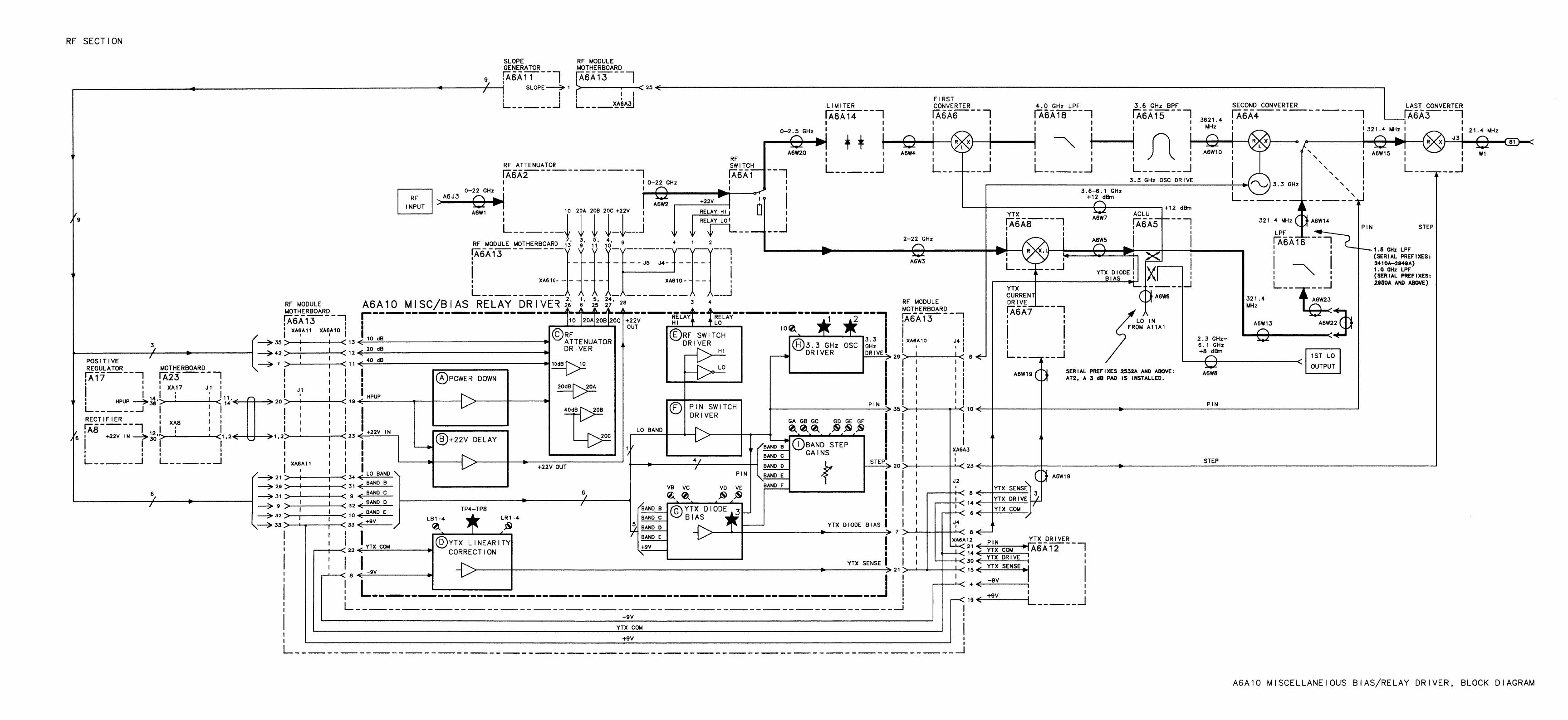
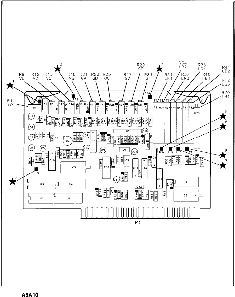
2’3
Pl
22
44
A6AlO Miscellaneous Bias/Relay Driver Component Locations, 85660-60180
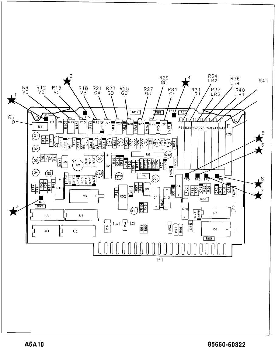
Rl
IO
R41
LB2
R42
LB3
--r-
n
~
“,
,~
u5
,
M
u
q
[l/ppF
;
gg
E
,,,,,~,,,:,,,~I),I.llli.i’::r
2’3
Pl
22
44
R70
, LB4
A6AlO Miscellaneous Bias/Relay Driver Component Locations, 85660-60322
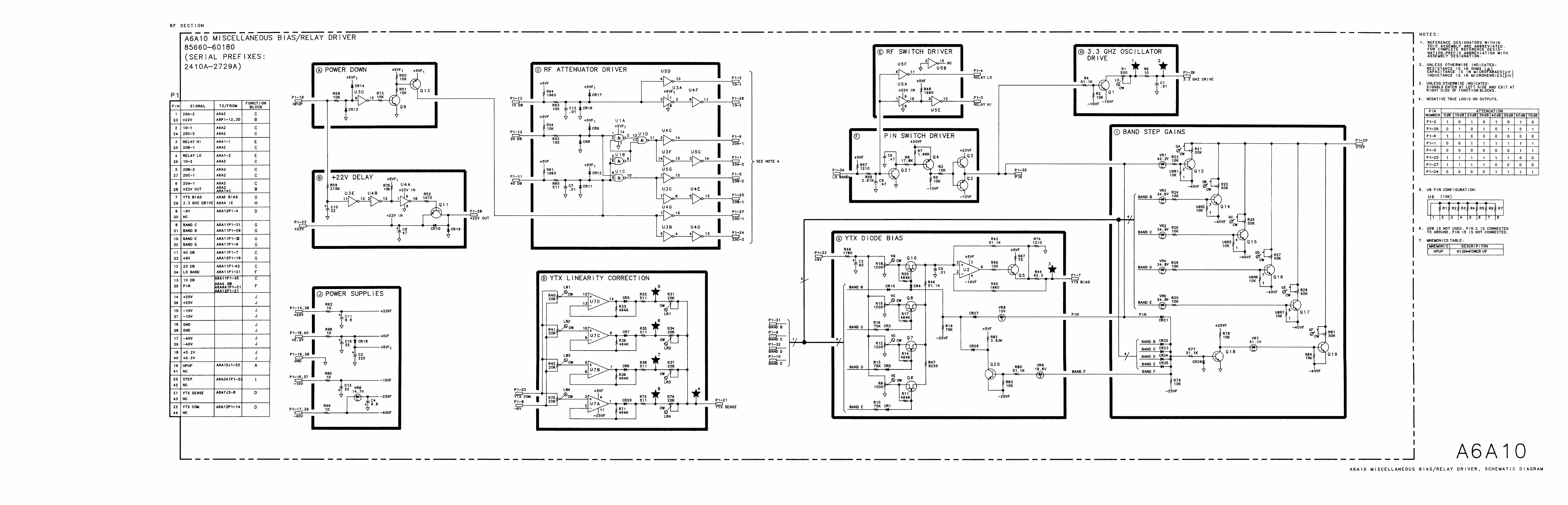
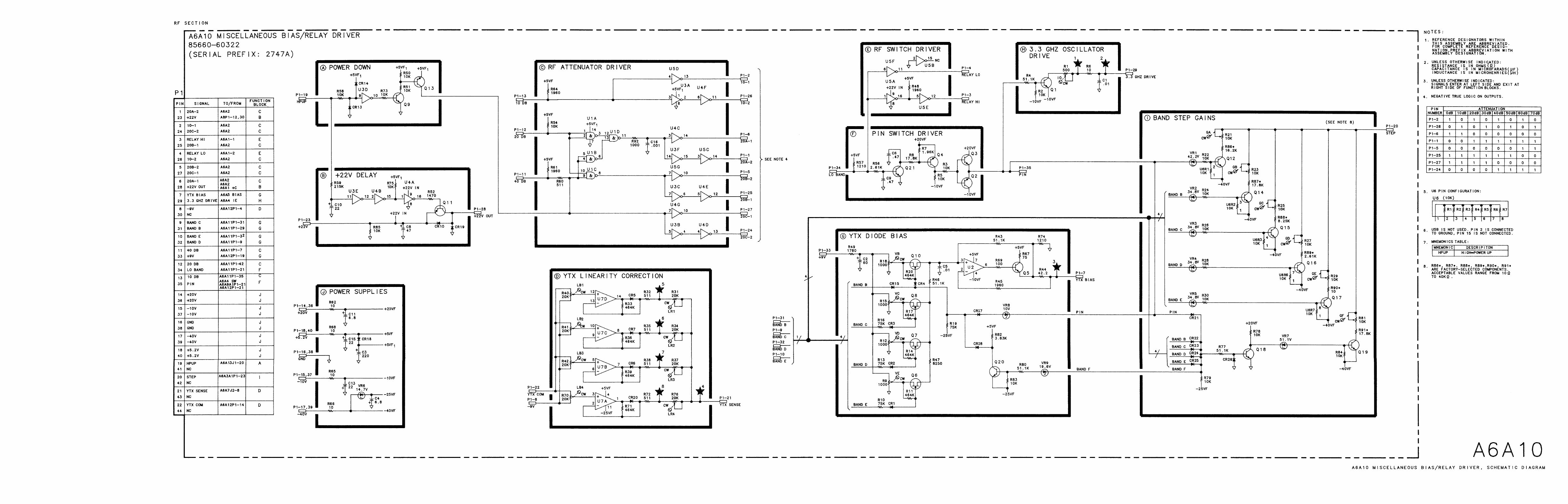
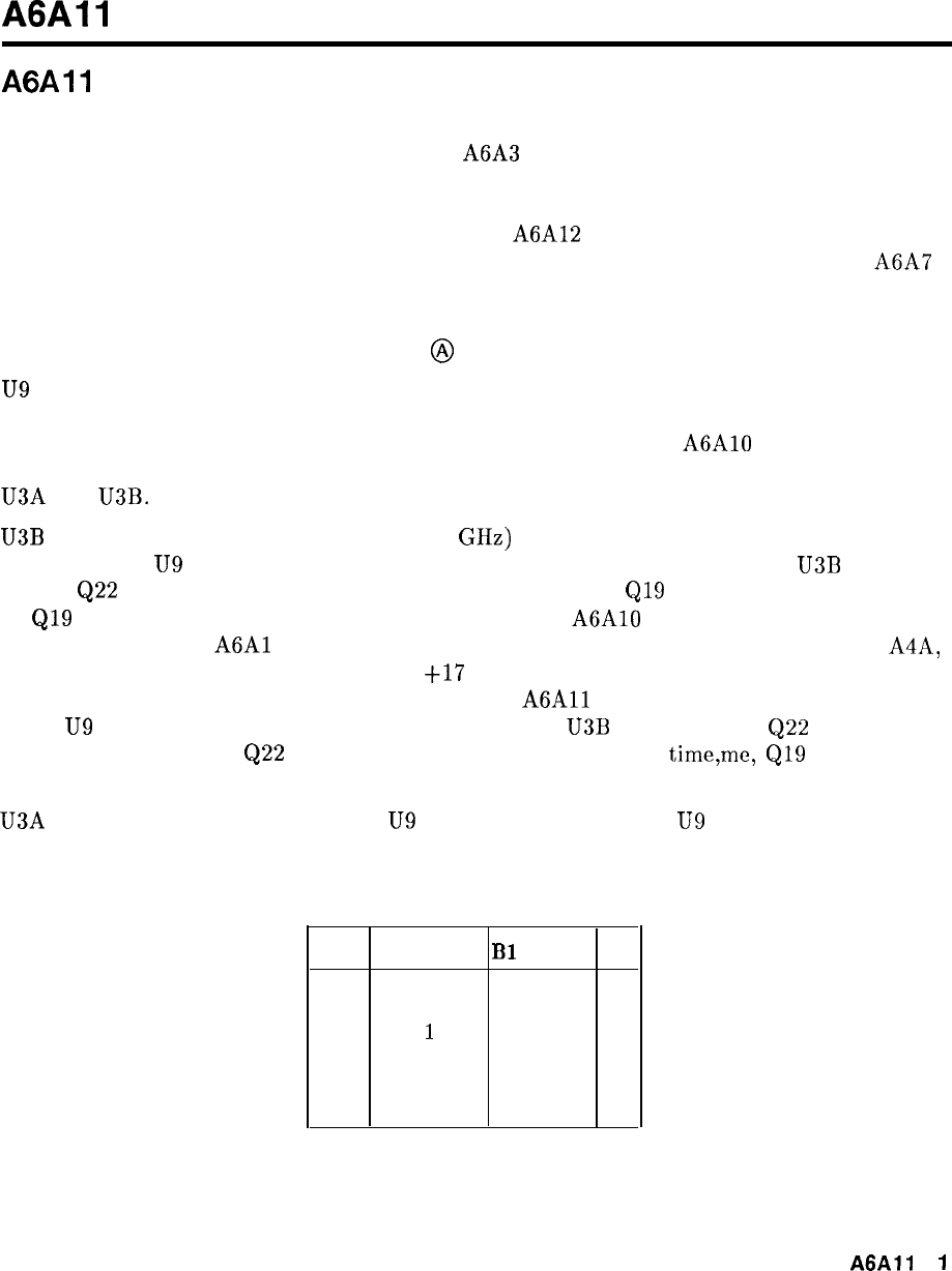
A6All
A6All
Slope Generator, Circuit Description
The slope generator takes a voltage which is proportional to YTX frequency and produces a
current to control the slope attenuator in the A6A3 Last Converter, which compensates for
conversion loss variations of the input mixer within each frequency band. The slope generator
also has circuitry which decodes bandswitch and attenuator settings, produces pulses for
the sample and hold, and hysteresis circuits in the A6A12 YTX Driver, produces the YTX
peaking signal for the YTX Driver, and a signal to switch in the filter capacitor on the A6A7
YTX Current Driver.
Bandswitch and Attenuator Decode
@
U9
is a hex latch which receives six lines from the 50-wire Instrument Bus and a strobe,
LCK2, which goes low when the six lines have valid A6 RF Module information. Three of
the latch outputs have attenuator setting information and go to the A6AlO Miscellaneous
Bias/Relay Driver. The other three lines have bandswitch information which is decoded by
U3A and U3B.
U3B
decodes the low band (Band A, 0 to 2.5 GHz) and the external mixer band (Band F).
When pin 2 of
U9
is high and pin 12 is low, Band A is selected. The output of
U3B
is high,
turning
Q22
on, bringing the collector of Q22 low. This turns
Q19
off, bringing the collector
of
Q19
(LO BAND) high. This information goes to the A6AlO Miscellaneous Bias/Relay
Driver to control the
A6Al
RF input switch. Q20 inverts the signal and drives amplifier A4A,
producing a signal which is approximately
+17
V when Band A is valid and approximately
-8 V otherwise. This signal is used throughout the
A6All
Slope Generator. When pins 2 and
12 of
U9
are both high, Band F is active. The output of
U3B
is low, turning
Q22
off, and
bringing the collector of
Q22
(and Band F line) high. At the same
time,me,
Q19
turns on,
bringing the LO BAND line low.
U3A decoder is enabled when pin 2 of
U9
is low. Pins 5 and 12 of
U9
have coded information
giving harmonic numbers as shown in Table 1.
Table 1. Bandswitch Decoding
Band B2 (pin 12)
Bl
(pin 5)
N
B
0
1
1
C
1
02
D
1 1
3
E
0 0 4
A6A11
1
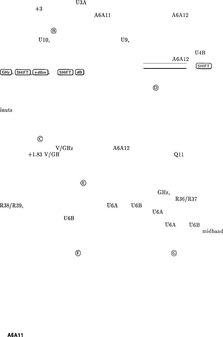
This information is decoded by U3A and amplified by U5. The outputs of U5 are
approximatley
+3
V when a band is valid and approximatley -22 V otherwise. These signals
are used to drive FET switches on the
A6All
Slope Generator and the A6A12 YTX Driver.
Preselector Peak
@J
A second latch, UlO, receives the same six lines a U9, but receives a different strobe, LCK5.
This strobe is valid when the six lines have preselector peaking information. The outputs
of this latch drive eight bits of a DAC which produces 0 to 10 V at the output of
U4B
corresponding to DAC values of 0.00 to 63.75. This voltage goes to the A6A12 YTX Driver.
This circuit is used to adjust the tacking of the YTX when [PRESELECTOR PEAK) or
(SHIFT)
a),
(K)
(+dBm),
or
(SHIFT)
Ide]
is keyed in.
Hysteresis, Sample-Hold Control, and Filter Capacitor
@
U8 is a Quad D-Latch which is used to decode information relating to Hysteresis, Sample and
Hold, and Filter Capacitor information. Four lines from the 50-wire Instrument Bus go to the
inuts
of the latch. The latch is strobed when these lines have valid RF Module information.
The instrument controller is able to connect the filter capacitor across the YTX, and control
the Hysteresis and Sample and Hold circuits on the YTX Driver.
Slope Offset
@
U7 receives the -0.525
V/GHz
signal from the A6A12 YTX Driver, amplifies and offsets it
such that a
t1.83
V/GH
z ramp centered about 6 V is produced at TP8.
Qll
to Q15 and
associated circuitry produce the offset for each band, and R2 varies the A-Band offset to
position the A-Band slope breakpoints.
Slope Breakpoint Generator
@
The signal at TP8 has a maximum range on Band C (5.8 to 12.5 GHz, second harmonic)
of approximately 0 to 12 V. This signal is applied to two voltage dividers
R36/R37
and
R38/R39,
which drive the positive inputs to U6A and
U6B
respectively. The voltage at the
inputs to these op amps is clamped by CR5 and CR6 such that U6A sees only the first half
of the full band ramp and
U6B
sees only the second half. In this manner, each full band
is divided into two segments with one breakpoint in the center. Both U6A and
U6B
are
configured for a gain of 2 and an offset of approximately -6.2 V, for a 0 V output at
midband
and unity gain overall.
Upper Segment Generator
@
and Lower Segment Generator
@
The outputs of U6 drive variable gain amplifiers as shown in Figure 1.
2
A6All
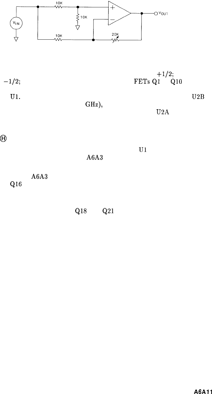
Figure 1. Variable Gain Amplifier, Simplified Schematic
When the 20 K potentiometer is set to zero, the amplifier has a gain of
+1/2;
when set to
20 K, the gain is
-l/2;
and when set to 10 K, the gain is zero.
FETs
Ql
to
QlO
switch in
different 20 K potentiometers for the five bands. The outputs for the two segments at U2 are
summed together in
Ul.
A waveform similar to Figure 2 is present at the output of
U2B
if
a full band is swept (for example, 5.8 to 12.5 GHz), and the oscilloscope horizontal input is
connected to the sweep output of the analyzer. Similarly, the output of U2A will appear as
shown in Figure 3.
Slope Output
@I
Both waveforms (Figure 2 and Figure 3) are summed together at
Ul
to form a current source
with Q16 to drive the slope attenuator in the A6A3 Last Converter. The average output
current is set by slope gain adjustment R84.
The slope attenuator in the A6A3 Last Converter varies the gain of the 21.4 MHz IF with the
collector current of
Ql6
providing gain correction that varies with frequency. Within each
band, there is independent control over two halves of the band, and IF gain that increases or
decreases with increasing frequency.
When Band F (external mixer) is selected,
QlS
and
Q21
provide additional gain to make up
for the conversion loss of the external mixer.
A6All
3
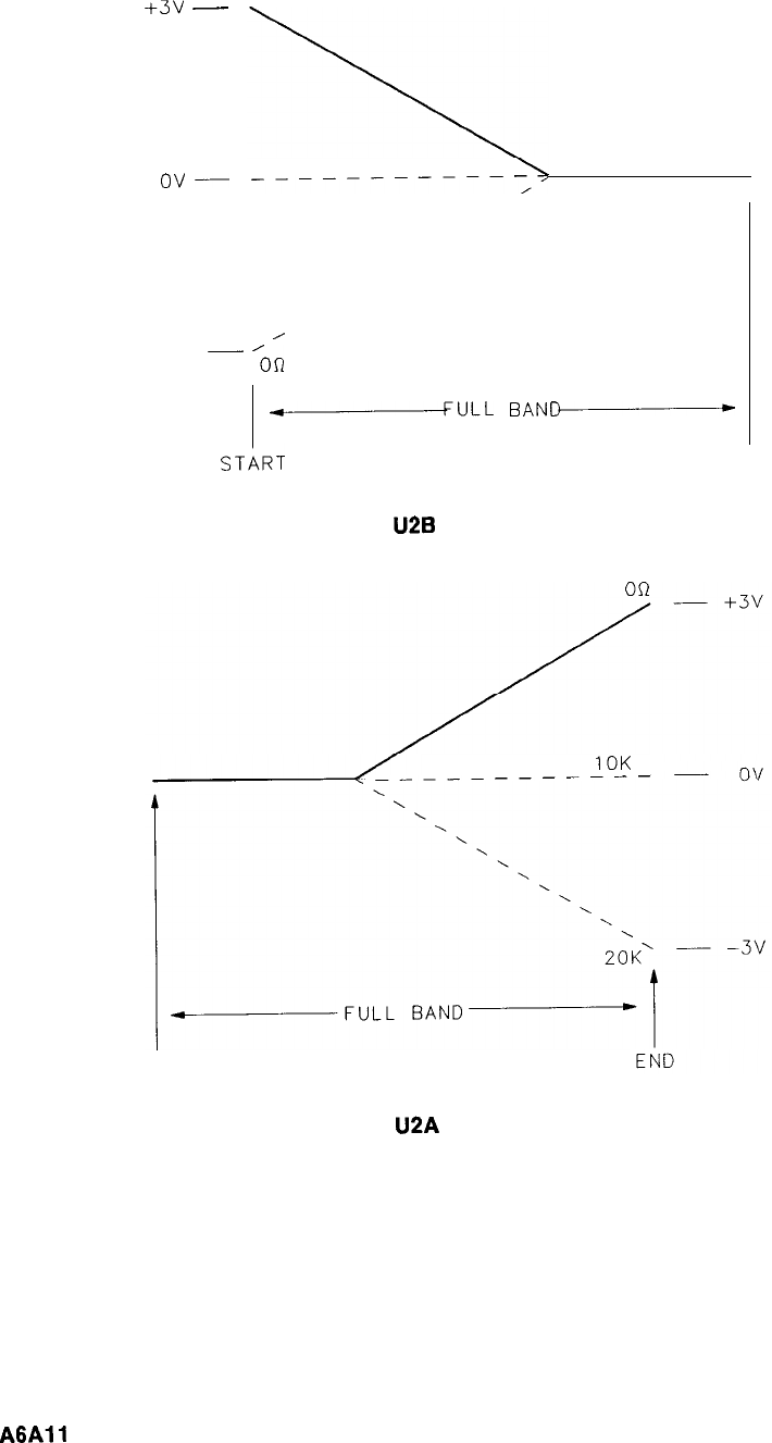
20K
+3v
__
1 OK
()v--
-----------;,
A
-3v
-
’
‘Obn
A
BULL
BAN-
STbRT
END
Figure 2.
U2B
Output Waveform
10K
-_-_--------
START
Figure 3.
U2A
Output Waveform
4
A6All
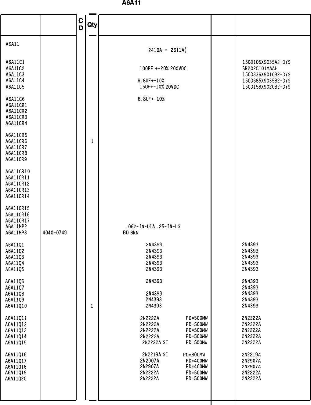
Reference
Designation
HP Part
Number
A6All 85660-60126
9
AGAllCl 0180-0291
3
A6A1
lC2
0160-3877
5
A6AllC3 0180-0229
7
A6AllC4 0180-0116
1
A6AllC5 0180-1746
5
A6AllC6 0180-0116
1
AGAllCRl 1901-1067
4
A6AllCR2 1901-1067
4
A6AllCR3 1901-1067
4
A6Al
lCR4
1901-1067
4
A6AllCR5 1901-1067
4
A6AllCR6 1901-1067
4
A6AllCR7 1901-1067
4
A6AllCR8 1901-1067
4
A6AllCR9 1901-1067
4
AGAllCRlO 1901-1067
4
AGAllCRll 1901-1067
4
A6AllCRlZ 1901-1067
4
A6AllCR13 1901-1067
4
A6AllCR14 1901-1067
4
A6AllCR15 1901-1067
4
A6AllCR16 1901-1067
4
A6AllCR17 1901-0518
8
A6AllMPZ 1480-0073
6
A6AllMP3 1040-0749
4
A6AllQl 1855-0414
A6AllQ2 1855-0414
A6Al
lQ3
1855-0414
A6Al
lQ4
1855-0414
A6AllQ5 1855-0414
A6AllQ6 1855-0414
A6AllQ7 1855-0414
A6AllQ8 1855-0414
A6AllQ9 1855-0414
A6AllQlO 1855-0414
A6AllQll 1854-0477
A6AllQ12 1854-0477
A6AllQ13 1854-0477
A6AllQ14 1854-0477
A6AllQ15 1854-0477
A6AllQl6 1854-0637
A6AllQ17 1853-0281
A6AllQl8
1853-0281
A6AllQ19 1854-0477
A6AllQ20 1854-0477
4
4
4
4
4
4
4
4
4
4
7
7
7
7
7
1
9
9
7
7
-
JtY
-
1
1
1
1
1
1
1
1
1
1
1
1
1
1
1
1
1
1
1
1
1
1
1
1
2
2
1
1
1
1
1
1
1
1
1
1
1
1
1
1
1
1
1
1
1
1
-
HP Part Number 85660-60126
A6All
Slope Generator
Description Mfr
Mfr Part
Code Number
BOARD ASSEMBLY, SLOPE GENERATOR
(SERIAL PREFIXES:
2410~
-
2611~) 28480 85660-60126
CAPACITOR-FXD lUF+-10% 35VDC TA
CAPACITOR-FXD
1OOPF
+-20X
ZOOVDC
CER
CAP-FXD 33uF 10 V TA
CAPACITOR-FXD
6.8UF+-10%
35VDC TA
CAPACITOR-FXD
15UF+-10%
LOVDC
TA
56289 150D105X9035A2-DYS
04222 SR202ClOlMAAH
56289 150D336X901082-DYS
56289 150D685X903582-DYS
56289 150D156X902082-DYS
CAPACITOR-FXD
6.8UF+-10%
35VDC TA
56289 1500685X903582-DYS
DIODE-SWITCHING 125V 175MA 60NS DO-35
27014 FDH444
DIODE-SWITCHING 125V 175MA 60NS DO-35
27014 FDH444
DIODE-SWITCHING 125V 175MA 60NS DO-35
27014 FDH444
DIODE-SWITCHING 125V 175MA 60NS DO-35
27014 FDH444
DIODE-SWITCHING 125V 175MA 60NS DO-35
27014 FDH444
DIODE-SWITCHING 125V 175MA 60NS DO-35
27014 FDH444
DIODE-SWITCHING 125V 175MA 60NS DO-35
27014 FDH444
DIODE-SWITCHING 125V 175MA 60NS DO-35
27014 FDH444
DIODE-SWITCHING 125V 175MA 60NS DO-35 27014 FDH444
DIODE-SWITCHING 125V 175MA 60NS DO-35 27014 FDH444
DIODE-SWITCHING 125V 175MA 60NS DO-35
27014 FDH444
DIODE-SWITCHING 125V 175MA 60NS DO-35
27014 FDH444
DIODE-SWITCHING 125V 175MA 60NS DO-35
27014 FDH444
DIODE-SWITCHING 125V 175MA 60NS DO-35
27014 FDH444
DIODE-SWITCHING 125V 175MA 60NS DO-35
DIODE-SWITCHING 125V 175MA 60NS DO-35
DIODE-SCHOTTKY SM SIG
27014
27014
PIN-ROLL
.062-IN-DIA
.25-IN-LG
BE-CU
72962
EXTR PC
8D
8RN
28480
FDH444
FDH444
5082-2800
99-012-062-0250
4040-0749
TRANSISTOR J-FET
2N4393
N-CHAN D-MODE TO
17856 2N4393
TRANSISTOR J-FET
2N4393
N-CHAN D-MODE TO
17856 2N4393
TRANSISTOR J-FET
2N4393
N-CHAN D-MODE TO
17856 2N4393
TRANSISTOR J-FET
2N4393
N-CHAN D-MODE TO
17856 2N4393
TRANSISTOR J-FET
2N4393
N-CHAN D-MODE TO
17856 2N4393
TRANSISTOR J-FET
2N4393
N-CHAN D-MODE TO
17856 2N4393
TRANSISTOR J-FET 214393 N-CHAN D-MODE TO
17856 2N4393
TRANSISTOR J-FET
2N4393
N-CHAN D-MODE TO
17856 2N4393
TRANSISTOR J-FET
2N4393
N-CHAN D-MODE TO
17856 2N4393
TRANSISTOR J-FET
2N4393
N-CHAN D-MODE TO
17856 2N4393
TRANSISTOR NPN
2N2222A
SI TO-18
PD=500MW
TRANSISTOR NPN
2N2222A
SI TO-18
PD=500MW
TRANSISTOR NPN
2N2222A
SI TO-18
PD=500MW
TRANSISTOR NPN
2N2222A
SI TO-18
PD=SOOMW
TRANSISTOR NPN
2N2222A
SI
TO-18
PD=SOOMW
TRANSISTOR NPN
2N2219A
SI
TO-5
PD=800MW
TRANSISTOR PNP
2N2907A
SI TO-18
PD=400MW
TRANSISTOR PNP
2N2907A
SI TO-18
PD=400MW
TRANSISTOR NPN
2N2222A
SI TO-18
PD=500MW
TRANSISTOR NPN
2N2222A
SI TO-18
PD=500MW
04713
04713
04713
04713
04713
04713
04713
04713
04713
04713
2N2222A
2N2222A
2N2222A
2N2222A
2N2222A
2N2219A
2N2907A
2N2907A
2N2222A
2N2222A
*Indicates factory-selected value
85660-60126 Parts List
Page 1 of 4
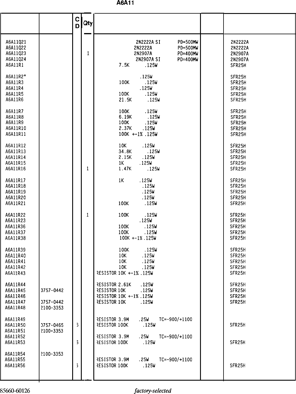
Reference
Designation
A6AllQ21
A6AllQ22
A6AllQ23
A6AllQ24
AGAllRl
HP Part
Number
1854-0477
7
1854-0477
7
1853-0281
9
1853-0281
9
0757-0440
7
A6AllR2" 0698-3453
2
A6AllR3 0757-0465
6
A6AllR4 0698-3260
9
A6AllR5 0757-0465
6
A6AllR6 0757-0199
3
A6AllR7 0757-0465
6
A6AllR8 0757-0290
5
A6AllR9 0757-0465
6
AGAllRlO 0698-3150
6
AGAllRll 0757-0465
6
A6AllR12 0757-0442
9
A6AllR13 0757-0123
3
A6AllR14 0698-0084
9
A6AllR15 0757-0280
3
A6AllR16 0757-1094
9
A6AllR17 0757-0280
3
A6AllR18 0757-0416
7
A6AllR19 0757-0416
7
A6AllR20 0757-0416
7
A6AllR21 0757-0465
6
A6AllR22 0757-0465
6
A6AllR23 0698-3260
3
A6AllR36 0757-0465
6
A6AllR37 0757-0465
6
A6Al
lR38
0757-0465
6
A6AllR39 0757-0465
6
A6AllR40 0757-0442
3
A6AllR41 0757-0442
3
A6AllR42 0757-0442
3
A6Al
lR43
0757-0442
3
A6AllR44 0698-0085
3
A6AllR45 D757-0442
3
A6AllR46 3757-0442
3
A6AllR47 3757-0442
3
A6AllR48 2100-3353
3
A6AllR49 3683-3955
3
A6AllR50 3757-0465
5
A6AllR51 2100-3353
3
A6AllR52 3683-3955
3
A6AllR53 3757-0465
5
A6AllR54 2100-3353
3
A6AllR55 1683-3955
3
A6AllR56 1757-0465
5
85660-60126 Parts List
Page 2 of 4
-
m
-
1
1
1
1
1
1
1
1
1
1
1
1
1
1
1
1
1
1
1
1
1
1
1
1
1
1
1
1
1
1
1
1
1
1
1
1
1
1
1
1
1
1
1
1
1
1
1
1
-
HP Part Number 85660-60126
A6A11
Slope Generator
Description
TRANSISTOR NPN
2N2222A
SI
TO-18
PD=500MW
TRANSISTOR NPN
2N2222A
SI TO-18
PD=500MW
TRANSISTOR PNP
2N2907A
SI TO-18
PD=400MW
TRANSISTOR PNP
2N2907A
SI
TO-18
PD=400MW
RESISTOR
7.5K
+-1%
.125W
TF TC=O+-100
RESISTOR 196K 1%
.125W
TF TC=O+-100
RESISTOR
1OOK
+-1%
.125W
TF TC=O+-100
RESISTOR 464K 1%
.125W
TF TC=O+-100
RESISTOR
1OOK
+-1%
.125W
TF TC=O+-100
RESISTOR
21.5K
+-1%
.125W
TF TC=O+-100
RESISTOR
IOOK
+-1%
.125W
TF TC=O+-100
RESISTOR
6.19K
+-1%
.125W
TF TC=O+-100
RESISTOR
1OOK
+-1%
.125W
TF TC=O+-100
RESISTOR
2.37K
1%
.125W
TF TC=O+-100
RESISTOR
1OOK
+-I%
.125W
TF TC=O+-100
RESISTOR
10K
+-1%
.125W
TF TC=O+-100
RESISTOR
34.8K
+-1%
.125W
TF TC=O+-100
RESISTOR
2.15K
1%
.125W
TF TC=O+-100
RESISTOR
1K
+-1%
.125W
TF TC=O+-100
RESISTOR
1.47K
+-1%
.125W
TF TC=O+-100
RESISTOR
1K
+-1%
.125W
TF TC=O+-100
RESISTOR 511 +-1%
.125W
TF TC=O+-100
RESISTOR 511 +-1%
.125W
TF TC=O+-100
RESISTOR 511 +-1%
.125W
TF TC=O+-100
RESISTOR
1OOK
+-1%
.125W
TF TC=O+-100
RESISTOR
IOOK
+-1%
.125W
TF TC=O+-100
RESISTOR 464K 1%
.125W
TF TC=O+-100
RESISTOR
1OOK
+-1%
.125W
TF TC=O+-100
RESISTOR
1OOK
+-1%
.125W
TF TC=O+-100
RESISTOR
1OOK
+-I%
.125W
TF TC=O+-100
RESISTOR
1OOK
+-1%
.125W
TF TC=O+-100
RESISTOR
10K
+-1%
.125W
TF TC=O+-100
RESISTOR
10K
+-1%
.125W
TF TC=O+-100
PESISTOR
10K
+-1%
.125W
TF TC=O+-100
?ESISTOR
10K
+-I%
.125W
TF TC=O+-100
7ESISTOR
2.61K
1%
.125W
TF TC=O+-100
?ESISTOR
10K
+-1%
.125W
TF TC=O+-100
?ESISTOR
10K
+-1X
.125W
TF TC=O+-100
?ESISTOR
10K
+-1%
.125W
TF TC=O+-100
IESISTOR-TRMR 20K 10% TKF SIDE-ADJ l-TRN
iESISTOR
3.9M
5%
.25W
CC
TC=-900/+1100
?ESISTOR
1OOK
+-1%
.125W
TF TC=O+-100
IESISTOR-TRMR 20K 10% TKF SIDE-ADJ l-TRN
?ESISTOR
3.9M
5%
.25W
CC
TC=-900/+1100
7ESISTOR
1OOK
+-1%
.125W
TF TC=O+-100
IESISTOR-TRMR 20K 10% TKF SIDE-ADJ l-TRN
?ESISTOR
3.9M
5%
.25W
CC
TC=-900/+1100
1ESISTOR
1OOK
+-1%
.125W
TF TC=O+-100
*Indicates
factoy-selected
value
Mfr
Code
04713
04713
04713
04713
19701
19701
19701
19701
19701
19701
19701
19701
19701
19701
19701
19701
19701
19701
19701
19701
19701
19701
19701
19701
19701
19701
19701
19701
19701
19701
19701
19701
19701
19701
19701
19701
19701
19701
19701
32997
01121
19701
32997
01121
19701
32997
01121
19701
Mfr Part
Number
2N2222A
2N2222A
2N2907A
2N2907A
SFR25H
SFR25H
SFR25H
SFR25H
SFR25H
SFR25H
SFR25H
SFR25H
SFR25H
SFR25H
SFR25H
SFR25H
SFR25H
SFR25H
SFR25H
SFR25H
SFR25H
SFR25H
SFR25H
SFR25H
SFR25H
SFR25H
SFR25H
SFR25H
SFR25H
SFR25H
SFR25H
SFR25H
SFR25H
SFR25H
SFR25H
SFR25H
SFR25H
SFR25H
SFR25H
3386X-Y46-203
C83955
SFR25H
3386X-Y46-203
C83955
SFR25H
3386X-146-203
C83955
SFR25H
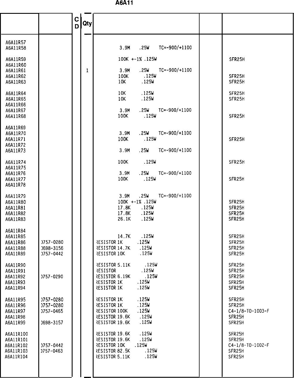
Reference
Designation
A6Al
lR57
A6AllR58
HP Part
Number
2100-3353
8
0683-3955
8
A6AllR59 0757-0465
6
A6AllR60 2100-3353
8
A6AllR61 0683-3955
8
A6AllR62 0757-0465
6
A6AllR63 0757-0442
9
A6AllR64 0757-0442
9
A6AllR65 0757-0442
9
A6AllR66 2100-3353
8
A6AllR67 0683-3955
8
A6AllR68 0757-0465
6
A6AllR69 2100-3353
8
A6AllR70 0683-3955
8
A6AllR71 0757-0465
6
A6AllR72 2100-3353
8
A6AllR73 0683-3955
8
A6AllR74 0757-0465
6
A6AllR75 2100-3353
8
A6AllR76 0683-3955
8
A6AllR77 0757-0465
6
A6AllR78 2100-3353
8
A6AllR79 0683-3955
8
A6AllR80 0757-0465
6
A6AllR81 0698-3136 8
A6AllR82 0698-3136
8
A6AllR83 0698-3159
5
A6AllR84 2100-3273
1
A6Al
lR85
0698-3156
2
A6Al
lR86
1757-0280
3
A6AllR88 1698-3156
2
A6AllR89 1757-0442
9
A6AllR90 1757-0438
3
A6AllR91 1757-0416
7
A6AllR92 1757-0290
5
A6AllR93 1757-0280
3
A6AllR94 1757-0280
3
A6AllR95 3757-0280
3
A6AllR96 1757-0280
3
A6AllR97 3757-0465
6
A6AllR98 3698-3157
3
A6AllR99 1698-3157
3
A6AllRlOO 1698-3157
3
AGAllRlOl 3698-3157
3
A6AllR102 1757-0442
9
A6AllR103 3757-0463
4
A6AllR104 1757-0438
3
-
3Y
-
1
1
1
1
1
1
1
1
1
1
1
1
1
1
1
1
1
1
1
1
1
1
1
1
1
1
1
1
1
1
1
1
1
1
1
1
1
1
1
1
1
1
1
1
1
1
1
-
HP Part Number 85660-60126
A6All
Slope Generator
Description Mfr
Mfr Part
Code Number
RESISTOR-TRMR 20K 10% TKF SIDE-ADJ l-TRN 32997 3386X-146-203
RESISTOR
3.9M
5%
.25W
CC
TC=-900/+1100 01121 CB3955
RESISTOR
1OOK
+-1X
.125W
TF TC=O+-100
19701
SFR25H
RESISTOR-TRMR 20K 10% TKF SIDE-ADJ l-TRN
32997 3386X-Y46-203
RESISTOR
3.9M
5%
.25W
CC
TC=-900/+1100 01121 CB3955
RESISTOR
1OOK
+-1%
.125W
TF TC=O+-100
19701
SFR25H
RESISTOR
10K
+-1%
.125W
TF TC=O+-100
19701
SFR25H
RESISTOR
10K
+-1%
.125W
TF TC=O+-100
19701
SFR25H
RESISTOR
10K
+-1%
.125W
TF TC=O+-100
19701
SFR25H
RESISTOR-TRMR 20K 10% TKF SIDE-ADJ l-TRN
32997 3386X-Y46-203
RESISTOR
3.9M
5%
.25W
CC
TC=-900/+1100
01121
CB3955
RESISTOR
1OOK
+-1%
.125W
TF TC=O+-100
19701
SFR25H
RESISTOR-TRMR 20K 10% TKF SIDE-ADJ l-TRN
32997 3386X-Y46-203
RESISTOR
3.9M
5%
.25W
CC
TC=-900/+1100 01121 CB3955
RESISTOR
1OOK
+-1%
.125W
TF TC=O+-100
19701 SFR25H
RESISTOR-TRMR 20K 10% TKF SIDE-ADJ l-TRN
32997 3386X-Y46-203
RESISTOR
3.9M
5%
.25W
CC
TC=-900/+1100 01121 C83955
RESISTOR
1OOK
+-1%
.125W
TF TC=O+-100
19701
SFR25H
RESISTOR-TRMR 20K 10% TKF SIDE-ADJ l-TRN
32997 3386X-Y46-203
RESISTOR
3.9M
5%
.25W
CC
TC=-900/+1100
01121
C83955
RESISTOR
1OOK
+-1%
.125W
TF TC=O+-100
19701
SFR25H
RESISTOR-TRMR 20K 10% TKF SIDE-ADJ l-TRN
32997 3386X-Y46-203
RESISTOR
3.9M
5%
.25W
CC
TC=-900/+1100 01121 C83955
RESISTOR
1OOK
+-1X
.125W
TF TC=O+-100
19701
SFR25H
RESISTOR
17.8K
1%
.125W
TF TC=O+-100
19701
SFR25H
RESISTOR
17.8K
1%
.125W
TF TC=O+-100
19701
SFR25H
RESISTOR
26.1K
1%
.125W
TF TC=O+-100
19701
SFR25H
RESISTOR-TRMR 2K 10% TKF SIDE-ADJ l-TRN
RESISTOR
14.7K
1%
.125W
TF TC=O+-100
tESISTOR
1K
+-1%
.125W
TF TC=O+-100
ZESISTOR
14.7K
1%
.125W
TF TC=O+-100
tESISTOR
10K
+-1%
.125W
TF TC=O+-100
32997
19701
19701
19701
19701
3386X-Y46-202
SFR25H
SFR25H
SFR25H
SFR25H
tESISTOR
5.11K
+-1%
.125W
TF TC=O+-100
19701
SFR25H
{ESISTOR
511 +-1%
.125W
TF TC=O+-100
19701
SFR25H
1ESISTOR
6.19K
+-1%
.125W
TF TC=O+-100
19701
SFR25H
tESISTOR
1K
+-1%
.125W
TF TC=O+-100
19701
SFR25H
{ESISTOR
1K
+-1%
.125W
TF TC=O+-100
19701
SFR25H
IESISTOR
1K
+-1%
.125W
TF TC=O+-100
19701
SFR25H
{ESISTOR
1K
+-1%
.125W
TF TC=O+-100
19701
SFR25H
IESISTOR
1OOK
1%
.125W
F TC=O+-100
24546
C4-l/8-TO-1003-F
{ESISTOR
19.6K
1%
.125W
TF TC=O+-100
19701
SFR25H
?ESISTOR
19.6K
1%
.125W
TF TC=O+-100
19701
SFR25H
1ESISTOR
19.6K
1%
.125W
TF TC=O+-100
19701
SFR25H
?ESISTOR
19.6K
1%
.125W
TF TC=O+-100
19701
SFR25H
1ESISTOR
10K
1%
.125W
F TC=O+-100
24546
C4-l/8-TO-1002-F
IESISTDR
82.5K
+-1%
.125W
TF TC=O+-100
19701
SFR25H
1ESISTOR
5.11K
+-1%
.125W
TF TC=O+-100
19701
SFR25H
*Indicates factory-selected value
85660-60126 Parts List
Page 3 of 4
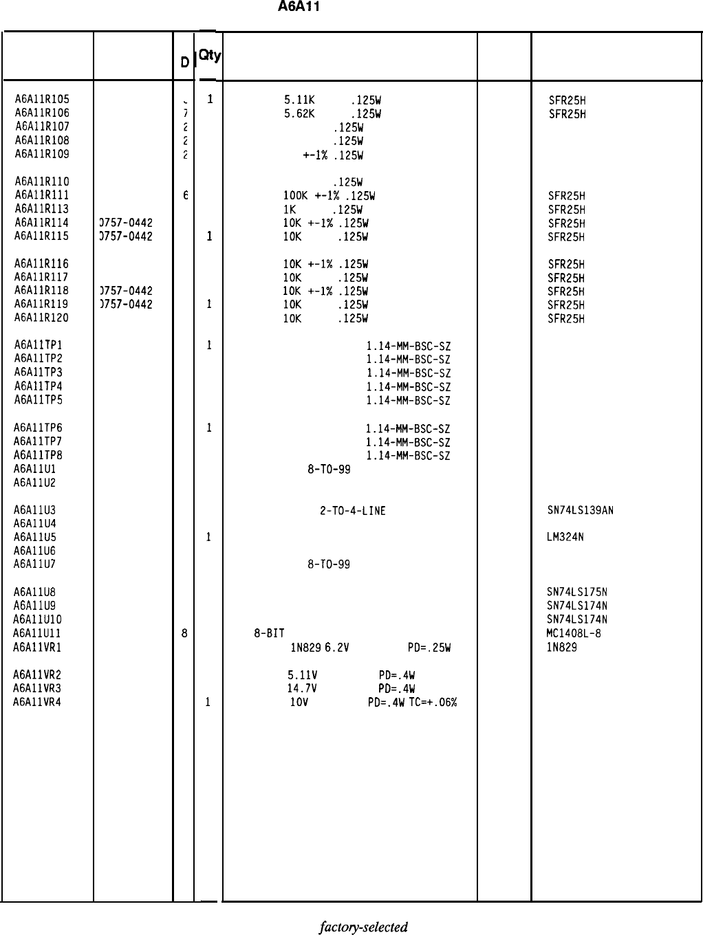
HP Part Number 85660-60126
A6All
Slope Generator
Reference HP Part
Designation Number
A6AllR105 0757-0438
A6AllR106 0757-0200
A6AllR107 0757-0346
A6AllR108 0757-0346
A6AllR109 0757-0346
AGAllRllO 0757-0346
2
AGAllRlll 0757-0465
E
A6AllR113 0757-0280
3
A6AllR114 3757-0442
9
A6AllR115 3757-0442
9
A6AllR116 3757-0442
9
A6AllR117 1757-0442
9
A6AllR118 3757-0442
9
A6AllR119 3757-0442
9
A6AllR120 1757-0442
9
AGAllTPl 1251-0600
0
A6AllTP2 1251-0600
0
A6Al
lTP3
1251-0600
0
A6Al
lTP4
1251-0600
0
A6AllTP5 1251-0600
0
A6AllTP6 1251-0600
c
A6AllTP7 1251-0600
C
A6AllTP8 1251-0600
C
AGAllUl 1826-1058
3
A6AllU2 5081-8117
3
A6AllU3 1820-1281
2
A6AllU4 5081-8117
3
A6AllU5 1826-0161
7
A6AllU6 5081-8117
3
A6AllU7 1826-1058
3
A6AllU8 1820-1195
7
A6AllU9 1820-1196
8
A6AllUlO 1820-1196
8
AGAllUll 1826-0188
8
AGAllVRl 1902-0625
0
A6AllVR2
1902-0041
4
A6AllVR3
1902-3203
6
A6AllVR4 1902-0025
4
85660-60126 Parts List
Page 4 of 4
c
c
-
Qt!
-
1
1
1
1
1
1
1
1
1
1
1
1
1
1
1
1
1
1
1
1
1
1
1
1
1
1
1
1
1
1
1
1
1
1
1
1
1
1
-
Description
RESISTOR
5.11K
+-1%
.125W
TF TC=O+-100
19701
SFR25H
RESISTOR
5.62K
+-1%
.125W
TF TC=O+-100
19701
SFR25H
RESISTOR 10 +-1%
.125W
TF TC=O+-100
91637 CMF-55-1, T-l
RESISTOR 10 +-1%
.125W
TF TC=O+-100
91637 CMF-55-1. T-l
RESISTOR 10 +-I%
.125W
TF TC=O+-100
91637 CMF-55-1, T-l
RESISTOR 10 +-1%
.125W
TF TC=O+-100
91637 CMF-55-1, T-l
RESISTOR
1OOK
+-1X
.125W
TF TC=O+-100
19701
SFR25H
RESISTOR
1K
+-1%
.125W
TF TC=O+-100
19701
SFR25H
RESISTOR
10K
+-1X
.125W
TF TC=O+-100
19701
SFR25H
RESISTOR
IOK
+-1%
.125W
TF TC=O+-100
19701
SFR25H
RESISTOR
IOK
+-1X
.125W
TF TC=O+-100
19701
SFR25H
RESISTOR
10K
+-1%
.125W
TF TC=O+-100
19701
SFR25H
RESISTOR
10K
+-1X
.125W
TF TC=O+-100
19701
SFR25H
RESISTOR
IOK
+-1%
.125W
TF TC=O+-100
19701 SFR25H
RESISTOR
10K
+-1%
.125W
TF TC=O+-100
19701
SFR25H
CONNECTOR-SGL CONT PIN
1.14-MM-BSC-SZ
SQ
27264 16-06-0034
CONNECTOR-SGL CONT PIN
1.14-MM-BSC-SZ
SQ
27264 16-06-0034
CONNECTOR-SGL CONT PIN
1.14-MM-BSC-SZ
SQ
27264 16-06-0034
CONNECTOR-SGL CONT PIN
1.14-MM-BSC-SZ
SQ
27264 16-06-0034
CONNECTOR-SGL CONT PIN
1.14-MM-BSC-SZ
SQ
27264 16-06-0034
CONNECTOR-SGL CONT PIN
1.14-MM-BSC-SZ
SQ
27264 16-06-0034
CONNECTOR-SGL CONT PIN
1.14-MM-BSC-SZ
SQ
27264 16-06-0034
CONNECTOR-SGL CONT PIN
1.14-MM-BSC-SZ
SQ
27264 16-06-0034
IC OP AMP GP
8-TO-99
PKG
06665 OP-02CJ
SCREEN 1826-0092 28480 5081-8117
IC DCDR TTL LS
2-TO-4-LINE
DUAL
SCREEN 1826-0092
IC OP AMP GP QUAD 14-DIP-P PKG
SCREEN 1826-0092
IC OP AMP GP
8-TO-99
PKG
01295 SN74LS139AN
28480 5081-8117
27014 LM324N
28480 5081-8117
06665 OP-02CJ
IC FF TTL LS D-TYPE POS-EDGE-TRIG COM CL
IC FF TTL LS D-TYPE POS-EDGE-TRIG COM CL
IC FF TTL LS D-TYPE POS-EDGE-TRIG COM CL
D/A
8-BIT
16-CERDIP BPLR
DIODE-ZNR
lN829
6.2V
5% DO-35
PD=.25W
TC
01295
01295
01295
04713
04713
04713
04713
04713
SN74LS175N
SN74LS174N
SN74LS174N
MC1408L-8
lN829
DIODE-ZNR
5.11V
5% DO-35
PD=.4W
DIODE-ZNR
14.7V
5% DO-35
PD=.4W
DIODE-ZNR
IOV
5% DO-35
PD=.4W
TC=+.06%
*Indicates
factoy-selected
value
Mfr Mfr Part
Code Number
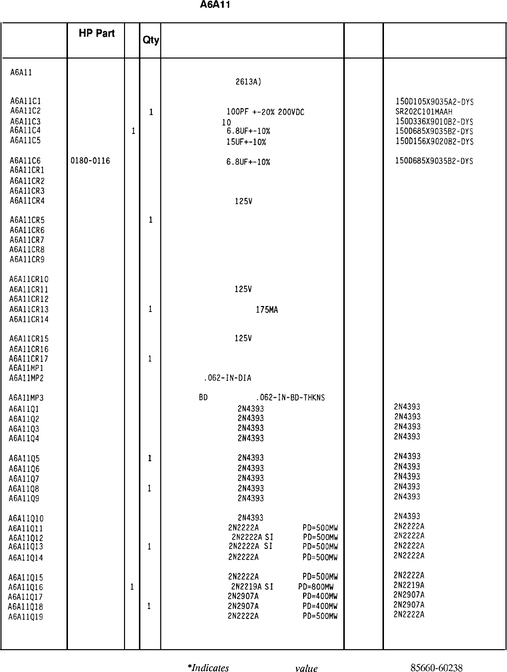
HP Part Number 85660-60238
A6All
Slope Generator
Reference
HPPart C
Designation Number
D
@’
Description Mfr
Mfr Part
Code Number
A6All 85660-60238
4
1
BOARD
ASSEMBLY, SLOPE GENERATOR
28480 85660-60238
(SERIA
L PRE
F
IX
:
2613~)
AGAllCl 0180-0291
3
1
CAPACITOR-FXD lUF+-10% 35VDC TA
56289
A6AllC2 1500105X9035A2-DYS
0160-3877
5
1
CAPACITOR-FXD
1OOPF +-20X
EOOVDC
CER
04222 SR202ClOlMAAH
A6Al
lC3
0180-0229
7
1
CAP-FXD
33uF
10
V TA
56289
A6AllC4 15OD336X901082-DYS
0180-0116
11
CAPACITOR-FXD
6.8UF+-10%
35VDC TA
56289
A6AllC5 150D685X903582-DYS
0180-1746
5
1
CAPACITOR-FXD 15UF+-10%
20VDC TA
56289 150D156X9020B2-DYS
A6AllC6 0180-0116
1 1
CAPACITOR-FXD 6.8UF+-10%
35VDC TA
56289
AGAllCRl 150D685X903582-DYS
1901-1067
4
1
DIODE-SWITCHING 125V 175MA 60NS DO-35 27014 FDH444
A6AllCR2 1901-1067
4
1
DIODE-SWITCHING 125V 175MA 60NS DO-35 27014 FDH444
A6Al
lCR3
1901-1067
4
1
DIODE-SWITCHING 125V 175MA 60NS DO-35 27014 FDH444
A6AllCR4 1901-1067
4
1
DIODE-SWITCHING
125V
175MA 60NS DO-35
27014 FDH444
A6AllCR5 1901-1067
4
1
DIODE-SWITCHING 125V 175MA 60NS DO-35 27014 FDH444
A6AllCR6 1901-1067
4
1
DIODE-SWITCHING 125V 175MA 60NS DO-35 27014 FDH444
A6AllCR7 1901-1067
4
1
DIODE-SWITCHING 125V 175MA 60NS DO-35 27014 FDH444
A6AllCR8 1901-1067
4
1
DIODE-SWITCHING 125V 175MA 60NS DO-35 27014 FDH444
A6AllCR9 1901-1067
4
1
DIODE-SWITCHING 125V 175MA 60NS DO-35 27014 FDH444
AGAllCRlO 1901-1067
4
1
DIODE-SWITCHING 125V 175MA 60NS DO-35 27014 FDH444
AGAllCRll 1901-1067
4
1
DIODE-SWITCHING
125V 175MA 60NS DO-35 27014 FOH444
A6AllCR12 1901-1067
4
1
DIODE-SWITCHING 125V 175MA 60NS DO-35 27014 FDH444
A6AllCR13 1901-1067
4
1
DIODE-SWITCHING 125V 175MA
60NS DO-35
27014 FDH444
A6AllCR14 1901-1067
4
1
DIODE-SWITCHING 125V 175MA 60NS DO-35 27014 FDH444
A6AllCR15 1901-1067
4
1
DIODE-SWITCHING
125V 175MA 60NS DO-35 27014 FDH444
A6AllCR16 1901-1067
4
1
DIODE-SWITCHING 125V 175MA 60NS DO-35 27014 FDH444
A6AllCR17 1901-0518
8
1
DIODE-SCHOTTKY SM SIG 5082-2800
AGAllMPl NOT ASSIGNED
A6AllMP2 1480-0073
6
2
PIN-ROLL
.062-IN-DIA
.25-IN-LG
BE-CU 72962 99-012-062-0250
A6Al
lMP3
4040-0749
4
2
EXTR-PC
8D
BRN POLYC
.062-IN-BD-THKNS
A6AllQl 1855-0414
4
1
TRANSISTOR J-FET
2N4393
N-CHAN D-MODE
17856 2N4393
A6AllQ2 1855-0414
4
1
TRANSISTOR J-FET
2N4393
N-CHAN D-MODE
17856 2N4393
A6AllQ3 1855-0414
4
1
TRANSISTOR J-FET
2N4393
N-CHAN D-MODE
17856 2N4393
A6AllQ4 1855-0414
4
1
TRANSISTOR J-FET
2N4393
N-CHAN D-MODE
17856 2N4393
A6AllQ5 1855-0414
4
1
TRANSISTOR J-FET
2N4393
N-CHAN D-MODE
17856 2N4393
A6AllQ6 1855-0414
4
1
TRANSISTOR J-FET
2N4393
N-CHAN D-MODE
17856 2N4393
A6AllQ7 1855-0414
4
1
TRANSISTOR J-FET
2N4393
N-CHAN D-MODE
17856 2N4393
A6AllQ8 1855-0414
4
1
TRANSISTOR J-FET
2N4393
N-CHAN D-MODE
17856 2N4393
A6AllQ9 1855-0414
4
1
TRANSISTOR J-FET
2N4393
N-CHAN D-MODE
17856 2N4393
A6AllQlO 1855-0414
4
1
TRANSISTOR J-FET
2N4393
N-CHAN D-MODE
17856 2N4393
A6AllQll 1854-0477
7
1
TRANSISTOR NPN
2N2222A
SI TO-18
PD=500MW 04713 2N2222A
A6AllQ12 1854-0477
7
1
TRANSISTOR NPN
2N2222A
SI
TO-18
PD=500MW 04713 2N2222A
A6Al
lQ13
1854-0477
7
1
TRANSISTOR NPN
2N2222A
SI
TO-18
PD=500MW 04713 2N2222A
A6AllQ14 1854-0477
7
1
TRANSISTOR NPN
2N2222A
SI TO-18
PD=500MW 04713 2N2222A
A6AllQ15 1854-0477
7
1
TRANSISTOR NPN
2N2222A
SI TO-18
PD=500MW 04713 2N2222A
A6AllQl6 1854-0637
11
TRANSISTOR NPN
2N2219A
SI
TO-5
PD=800MW 04713 2N2219A
A6AllQ17 1853-0281
9
1
TRANSISTOR PNP
2N2907A
SI TO-18
PD=400MW 04713 2N2907A
A6AllQ18 1853-0281
9
1
TRANSISTOR PNP
2N2907A
SI TO-18
PD=400MW 04713 2N2907A
A6AllQ19 1854-0477
7
1
TRANSISTOR NPN
2N2222A
SI TO-18
PD=500MW 04713 2N2222A
*Itzdicates
factory-selected
vahe
85660-60238 Parts List
Page 1 of 4
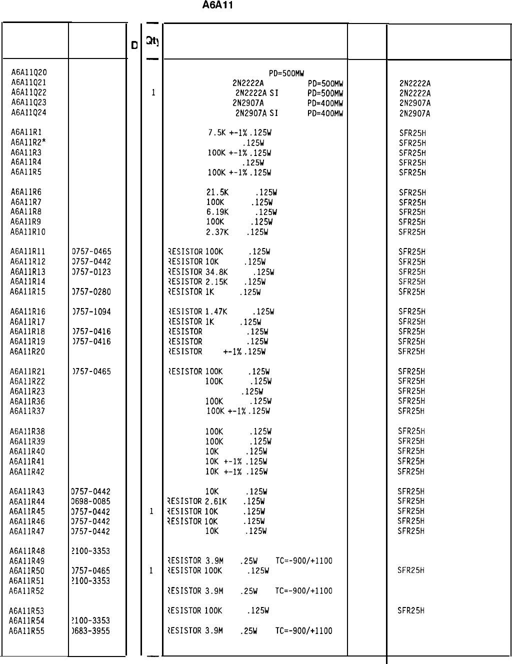
Reference
Designation
A6AllQ20 1854-0472
2
A6AllQ21 1854-0477
7
A6AllQ22 1854-0477
7
A6AllQ23 1853-0281
9
A6A1
IQ24
1853-0281
9
AGAllRl 0757-0440
7
A6AllR2” 0698-3453
2
A6AllR3 0757-0465
6
A6AllR4 0698-3260
9
A6AllR5 0757-0465
6
A6AllR6 0757-0199
3
A6AllR7 0757-0465
6
A6AllR8 0757-0290
5
A6Al
lR9
0757-0465
6
AGAllRlO 0698-3150
6
AGAllRll D757-0465
6
A6AllR12 3757-0442
9
A6AllR13 3757-0123
3
A6AllR14 3698-0084
9
A6AllR15 3757-0280
3
A6AllR16 3757-1094
9
A6AllR17 1757-0280
3
A6AllR18 1757-0416
7
A6AllR19 1757-0416
7
A6AllR20 1757-0416
7
A6AllR21 1757-0465
6
A6AllR22 0757-0465
6
A6AllR23 0698-3260
9
A6AllR36 0757-0465
6
A6AllR37 0757-0465
6
A6Al
lR38
0757-0465
6
A6AllR39 0757-0465
6
A6AllR40 0757-0442
9
A6AllR41 0757-0442
9
A6AllR42 0757-0442
9
A6AllR43 D757-0442
9
A6AllR44 3698-0085
0
A6AllR45 3757-0442
9
A6AllR46 3757-0442
9
A6AllR47 3757-0442
9
A6AllR48 !lOO-3353
8
A6AllR49 3683-3955
8
A6AllR50 1757-0465
6
A6AllR51 !lOO-3353
8
A6AllR52 1683-3955
8
A6AllR53 1757-0465
6
A6AllR54 !lOO-3353
8
A6AllR55 1683-3955
8
HP Part
Number
85660-60238 Parts List
Page 2 of 4
C
0
-
a)tJ
-
1
1
1
1
1
1
1
1
1
1
1
1
1
1
1
1
1
1
1
1
1
1
1
1
1
1
1
1
1
1
1
1
1
1
1
1
1
1
1
1
1
1
1
1
1
1
1
1
-
HP Part Number 85660-60238
A6All
Slope Generator
Description
TRANSISTOR NPN SI DARL
PD=SOOMW
TRANSISTOR NPN
2N2222A
SI TO-18
PD=500MW
TRANSISTOR NPN
2N2222A
SI
TO-18
PD=500MW
TRANSISTOR PNP
2N2907A
SI TO-18
PD=400MW
TRANSISTOR PNP
2N2907A
SI
TO-18
PD=400MW
RESISTOR
7.5K
+-I%
.125W
TF TC=O+-100
RESISTOR 196K 1%
.125W
TF TC=O+-100
RESISTOR
1OOK
+-I%
.125W
TF TC=O+-100
RESISTOR 464K 1%
.125W
TF TC=O+-100
RESISTOR
1OOK
+-1X
.125W
TF TC=O+-100
RESISTOR
21.5K
+-1%
.125W
TF TC=O+-100
RESISTOR
1OOK
+-1%
.125W
TF TC=O+-100
RESISTOR
6.19K
+-1%
.125W
TF TC=O+-100
RESISTOR
1OOK
+-1%
.125W
TF TC=O+-100
RESISTOR
2.37K
1%
.125W
TF TC=O+-100
iESISTOR
1OOK
+-1%
.125W
TF TC=O+-100
7ESISTDR
IOK
+-1%
.125W
TF TC=O+-100
?ESISTOR
34.8K
+-1%
.125W
TF TC=O+-100
?ESISTOR
2.15K
1%
.125W
TF TC=O+-100
?ESISTOR
1K
+-1%
.125W
TF TC=O+-100
?ESISTOR
1.47K
+-1%
.125W
TF TC=O+-100
1ESISTOR
IK
+-1%
.125W
TF TC=O+-100
ZESISTOR
511 +-1%
.125W
TF TC=O+-100
{ESISTOR
511 +-1%
.125W
TF TC=O+-100
{ESISTOR
511
+-I%
.125W
TF TC=O+-100
IESISTOR
1OOK
+-1%
.125W
TF TC=O+-100
RESISTOR
1OOK
+-1%
.125W
TF TC=O+-100
RESISTOR 464K 1%
.125W
TF TC=O+-100
RESISTOR
1OOK
+-1%
.125W
TF TC=O+-100
RESISTOR
IOOK
+-I%
.125W
TF TC=O+-100
RESISTOR
1OOK
+-1%
.125W
TF TC=O+-100
RESISTOR
1OOK
+-1%
.125W
TF TC=O+-100
RESISTOR
10K
+-1%
.125W
TF TC=O+-100
RESISTOR
10K
+-1X
.125W
TF TC=O+-100
RESISTOR
10K
+-I%
.125W
TF TC=O+-100
RESISTOR
10K
+-1%
.125W
TF TC=O+-100
?ESISTOR
2.61K
1%
.125W
TF TC=O+-100
?ESISTOR
10K
+-1%
.125W
TF TC=O+-100
7ESISTOR
10K
+-1%
.125W
TF TC=O+-100
7ESISTOR
10K
+-1%
.125W
TF TC=O+-100
IESISTOR-TRMR 20K 10% TKF SIDE-ADJ l-TRN
?ESISTOR
3.9M
5%
.25W
CC
TC=-900/+1100
7ESISTOR
1OOK
+-1%
.125W
TF TC=O+-100
IESISTOR-TRMR 20K 10% TKF SIDE-ADJ l-TRN
?ESISTOR
3.9M
5%
.25W
CC
TC=-900/+1100
IESISTOR
1OOK
+-1%
.125W
TF TC=O+-100
IESISTOR-TRMR 20K 10% TKF SIDE-ADJ I-TRN
{ESISTOR
3.9M
5%
.25W
CC
TC=-900/+1100
*Indicates facto y-selected value
Mfr
Mfr Part
Code Number
04713
04713
04713
04713
04713
19701
19701
19701
19701
19701
19701
19701
19701
19701
19701
19701
19701
19701
19701
19701
19701
19701
19701
19701
19701
19701
19701
19701
19701
19701
19701
19701
19701
19701
19701
19701
19701
19701
19701
19701
32997
01121
19701
32997
01121
19701
32997
01121
MPS-A14
2N2222A
2N2222A
2N2907A
2N2907A
SFR25H
SFR25H
SFR25H
SFR25H
SFR25H
SFR25H
SFR25H
SFR25H
SFR25H
SFR25H
SFR25H
SFR25H
SFR25H
SFR25H
SFR25H
SFR25H
SFR25H
SFR25H
SFR25H
SFR25H
SFR25H
SFR25H
SFR25H
SFR25H
SFR25H
SFR25H
SFR25H
SFR25H
SFR25H
SFR25H
SFR25H
SFR25H
SFR25H
SFR25H
SFR25H
3386X-Y46-203
C83955
SFR25H
3386X-146-203
C83955
SFR25H
3386X-Y46-203
C83955
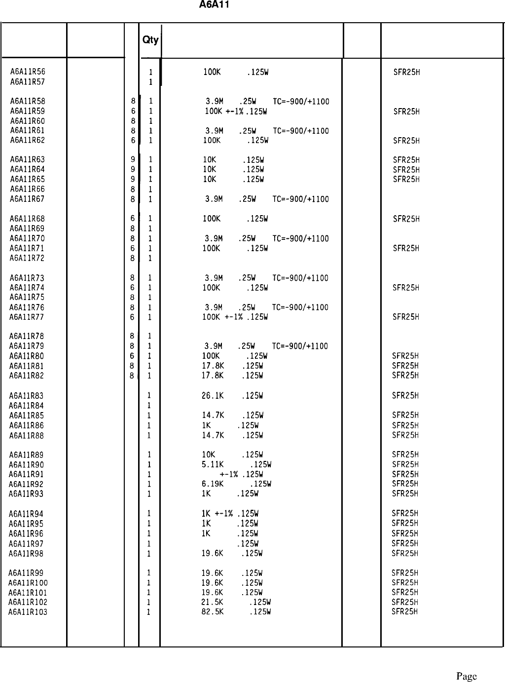
HP Part Number 85660-60238
A6A11
Slope Generator
Reference HP Part
C
Designation
Number
D
A6AllR56 0757-0465
A6AllR57 2100-3353
A6Al
lR58
0683-3955
A6AllR59 0757-0465
A6AllR60 2100-3353
A6AllR61 0683-3955
A6AllR62 0757-0465
A6AllR63 0757-0442
A6AllR64 0757-0442
A6AllR65 0757-0442
A6AllR66 2100-3353
A6AllR67 0683-3955
A6AllR68 0757-0465
A6AllR69 2100-3353
A6AllR70 0683-3955
A6AllR71 0757-0465
A6AllR72 2100-3353
6
8
A6Al
lR73
0683-3955
A6AllR74 0757-0465
A6AllR75 2100-3353
A6AllR76 0683-3955
A6AllR77 0757-0465
A6AllR78 2100-3353
A6AllR79 0683-3955
A6Al
lR80
0757-0465
A6AllR81 0698-3136
A6AllR82 0698-3136
A6A1
lR83
0698-3159
A6A1
lR84
2100-3273
A6AllR85 0698-3156
A6Al
lR86
0757-0280
A6AllR88 0698-3156
A6Al
lR89
0757-0442
A6AllR90 0757-0438
A6AllR91 0757-0416
A6AllR92 0757-0290
A6Al
lR93
0757-0280
A6Al
lR94
0757-0280
A6AllR95 0757-0280
A6AllR96 0757-0280
A6AllR97 0698-3260
A6Al
lR98
0698-3157
A6AllR99 0698-3157
A6AllRlOO 0698-3157
AGAllRlOl 0698-3157
A6AllR102 0757-0199
A6AllR103 0757-0463
5
1
2
3
2
9
3
7
5
3
3
3
3
9
3
3
3
3
3
4
Description Mfr
Mfr Part
Code Number
RESISTOR
1OOK
+-1%
.125W
TF TC=O+-100
19701
SFR25H
RESISTOR-TRMR 20K 10% TKF SIDE-ADJ l-TRN
32997 3386X-Y46-203
RESISTOR
3.9M
5%
.25W
CC
TC=-900/+1100 01121 CB3955
RESISTOR
1OOK
+-1X
.125W
TF TC=O+-100
19701
SFR25H
RESISTOR-TRMR 20K 10% TKF SIDE-ADJ l-TRN
32997 3386X-146-203
RESISTOR
3.9M
5%
.25W
CC
TC=-900/+1100 01121 CB3955
RESISTOR
IOOK
+-1%
.125W
TF TC=O+-100
19701
SFR25H
RESISTOR
10K
+-1%
.125W
TF TC=O+-100
19701
SFR25H
RESISTOR
10K
+-1%
.125W
TF TC=O+-100
19701
SFR25H
RESISTOR
IOK
+-1%
.125W
TF TC=O+-100
19701
SFR25H
RESISTOR-TRMR 20K 10% TKF SIDE-ADJ l-TRN
32997 3386X-Y46-203
RESISTOR
3.9M
5%
.25W
CC
TC=-900/+1100 01121 CB3955
RESISTOR
IOOK
+-1%
.125W
TF TC=O+-100
19701
SFR25H
RESISTOR-TRMR 20K 10% TKF SIDE-ADJ I-TRN
32997 3386X-146-203
RESISTOR
3.9M
5%
.25W
CC
TC=-900/+1100
01121 C83955
RESISTOR
1OOK
+-1%
.125W
TF TC=O+-100
19701
SFR25H
RESISTOR-TRMR 20K 10% TKF SIDE-ADJ l-TRN
32997 3386X-Y46-203
RESISTOR
3.9M
5%
.25W
CC
TC=-900/+1100 01121 CB3955
RESISTOR
1OOK
+-1%
.125W
TF TC=O+-100
19701
SFR25H
RESISTOR-TRMR 20K 10% TKF SIDE-ADJ l-TRN
32997 3386X-Y46-203
RESISTOR
3.9M
5%
.25W
CC
TC=-900/+1100
01121
C83955
RESISTOR
IOOK
+-I%
.125W
TF TC=O+-100
19701
SFR25H
RESISTOR-TRMR 20K 10% TKF SIDE-ADJ l-TRN
32997 3386X-Y46-203
RESISTOR
3.9M
5%
.25W
CC
TC=-900/+1100 01121 C83955
RESISTOR
1OOK
+-1%
.125W
TF TC=O+-100
19701
SFR25H
RESISTOR
17.8K
1%
.125W
TF TC=O+-100
19701
SFR25H
RESISTOR
17.8K
1%
.125W
TF TC=O+-100
19701
SFR25H
RESISTOR
26.1K
1%
.125W
TF TC=O+-100
19701
SFR25H
RESISTOR-TRMR 2K 10% TKF SIDE-ADJ l-TRN
32997 3386X-Y46-202
RESISTOR
14.7K
1%
.125W
TF TC=O+-100
19701
SFR25H
RESISTOR
1K
+-1%
.125W
TF TC=O+-100
19701
SFR25H
RESISTOR
14.7K
1%
.125W
TF TC=O+-100
19701
SFR25H
RESISTOR
10K
+-1%
.125W
TF TC=O+-100
19701
SFR25H
RESISTOR
5.11K
+-1%
.125W
TF TC=O+-100
19701
SFR25H
RESISTOR 511
+-1X
.125W
TF TC=O+-100
19701
SFR25H
RESISTOR
6.19K
+-1%
.125W
TF TC=O+-100
19701
SFR25H
RESISTOR
1K
+-1%
.125W
TF TC=O+-100
19701
SFR25H
RESISTOR
1K
+-1X
.125W
TF TC=O+-100
19701
SFR25H
RESISTOR
1K
+-1%
.125W
TF TC=O+-100
19701
SFR25H
RESISTOR
1K
+-1%
.125W
TF TC=O+-100
19701
SFR25H
RESISTOR 464K 1%
.125W
TF TC=O+-100
19701
SFR25H
RESISTOR
19.6K
1%
.125W
TF TC=O+-100
19701
SFR25H
RESISTOR
19.6K
1%
.125W
TF TC=O+-100
19701
SFR25H
RESISTOR
19.6K
1%
.125W
TF TC=O+-100
19701
SFR25H
RESISTOR
19.6K
1%
.125W
TF TC=O+-100
19701
SFR25H
RESISTOR
21.5K
+-1%
.125W
TF TC=O+-100
19701
SFR25H
RESISTOR
82.5K
+-1%
.125W
TF TC=O+-100
19701
SFR25H
*Indicates factoy-selected value
85660-60238 Parts List
Page
3 of 4
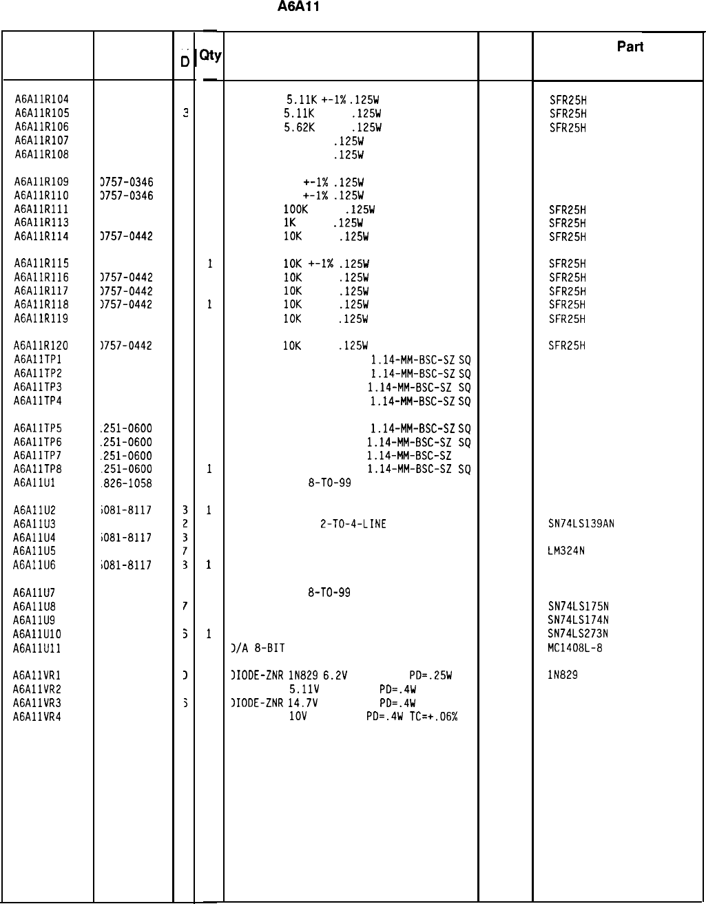
HP Part Number 85660-60238
A6All
Slope Generator
Reference HP Part
Designation Number
A6AllR104 0757-0438
3
A6AllR105 0757-0438
?
A6AllR106 0757-0200
7
A6AllR107 0757-0346
2
A6AllR108 0757-0346
2
A6AllR109 3757-0346
2
AGAllRllO 3757-0346
2
AGAllRlll 3757-0465
6
A6AllR113 3757-0280
3
A6AllR114 3757-0442
9
A6AllR115 1757-0442
9
A6AllR116 3757-0442
9
A6AllR117 3757-0442
9
A6AllR118 1757-0442
9
A6AllR119 1757-0442
9
A6AllRlZO 1757-0442
9
AGAllTPl 1251-0600
0
A6AllTP2 1251-0600
0
A6AllTP3 1251-0600
0
A6AllTP4 1251-0600
0
A6AllTP5
.251-0600
0
A6AllTP6
.251-0600
0
A6AllTP7
.251-0600
0
A6AllTP8
.251-0600
0
AGAllUl
.826-1058
3
A6AllU2
A6AllU3
A6AllU4
A6AllU5
A6AllU6
iO81-8117
820-1281
iO81-8117
826-0161
iO81-8117
A6Al
lU7
826-1058
3
A6AllU8 820-1195
r
A6AllU9 820-1196
3
AGAllUlO 820-1730
5
AGAllUll 826-0188
3
AGAllVRl 902-0625
1
A6AllVR2 902-0041
1
A6AllVR3 902-3203
5
A6AllVR4 902-0025
1
C
0
-
B!
-
1
1
1
1
1
1
1
1
1
1
1
1
1
1
1
1
1
1
1
1
1
1
1
1
1
1
1
1
1
1
1
1
1
1
1
1
1
1
1
-
Description
RESISTOR
5.11K
+-I%
.125W
TF TC=O+-100
19701
RESISTOR
5.11K
+-1%
.125W
TF TC=O+-100
19701
RESISTOR
5.62K
+-1%
.125W
TF TC=O+-100
19701
RESISTOR 10 +-1%
.125W
TF TC=O+-100
91637
RESISTOR 10 +-1%
.125W
TF TC=O+-100
91637
Mfr
Pat-l
Number
SFR25H
SFR25H
SFR25H
CMF-55-1, T-l
CMF-55-1, T-l
RESISTOR 10
+-1X
.125W
TF TC=O+-100
91637
CMF-55-1, T-l
RESISTOR 10 +-1X
.125W
TF TC=O+-100
91637 CMF-55-1, T-l
RESISTOR
1OOK
+-1%
.125W
TF TC=O+-100
19701
SFR25H
RESISTOR
1K
+-1%
.125W
TF TC=O+-100
19701
SFR25H
RESISTOR
10K
+-1%
.125W
TF TC=O+-100
19701
SFR25H
RESISTOR
10K
+-I%
.125W
TF TC=O+-100
19701
SFR25H
RESISTOR
IOK
+-1%
.125W
TF TC=O+-100
19701
SFR25H
RESISTOR
10K
+-1%
.125W
TF TC=O+-100
19701
SFR25H
RESISTOR
1OK
+-1%
.125W
TF TC=O+-100
19701
SFR25H
RESISTOR
IOK
+-1%
.125W
TF TC=O+-100
19701
SFR25H
RESISTOR
10K
+-1%
.125W
TF TC=O+-100
19701
SFR25H
CONNECTOR-SGL CONT PIN
1.14-MM-BSC-SZ
SQ
27264 16-06-0034
CONNECTOR-SGL CONT PIN
1.14-MM-BSC-SZ
SQ
27264 16-06-0034
CONNECTOR-SGL CONT PIN
1.14-MM-BSC-SZ
SQ
27264 16-06-0034
CONNECTOR-SGL CONT PIN
1.14-MM-BSC-SZ
SD
27264 16-06-0034
CONNECTOR-SGL CONT PIN
1.14-MM-BSC-SZ
SQ
27264 16-06-0034
CONNECTOR-SGL CONT PIN
1.14~MM-BSC-SZ
SQ
27264 16-06-0034
CONNECTOR-SGL CONT PIN
1.14-MM-BSC-SZ
SQ
27264 16-06-0034
CONNECTOR-SGL CONT PIN
1.14-MM-BSC-SZ
SQ
27264 16-06-0034
IC OP AMP GP
8-TO-99
PKG
06665 OP-02CJ
SCREENED 1826-0092
IC OCDR TTL LS
2-TO-4-LINE
DUAL
SCREENED 1826-0092
IC OP AMP GP QUAD 14-DIP-P PKG
SCREENED 1826-0092
28480 5081-8117
01295 SN74LS139AN
28480 5081-8117
27014 LM324N
28480 5081-8117
IC OP AMP GP
8-TO-99
PKG
06665 OP-02CJ
IC FF TTL LS D-TYPE POS-EDGE-TRIG COM CL 01295 SN74LS175N
IC FF TTL LS D-TYPE POS-EDGE-TRIG COM CL 01295 SN74LS174N
IC FF TTL LS D-TYPE POS-EDGE-TRIG COM CL 01295 SN74LS273N
1/A
8-BIT
16-CERDIP BPLR
04713 MC1408L-8
IIODE-ZNR
lN829
6.2V
5% DO-35
PD=.25W 04713
IIODE-ZNR
5.11V
5% DO-35
PD=.4W 04713
)IODE-ZNR
14.7V
5% DO-35
PD=.4W 04713
IIODE-ZNR
1OV
5% DO-35
PD=.4W
TC=+.06% 04713
IN829
85660-60238 Parts List
Page 4 of 4
*Indicates factory-selected value
Mfr
Code
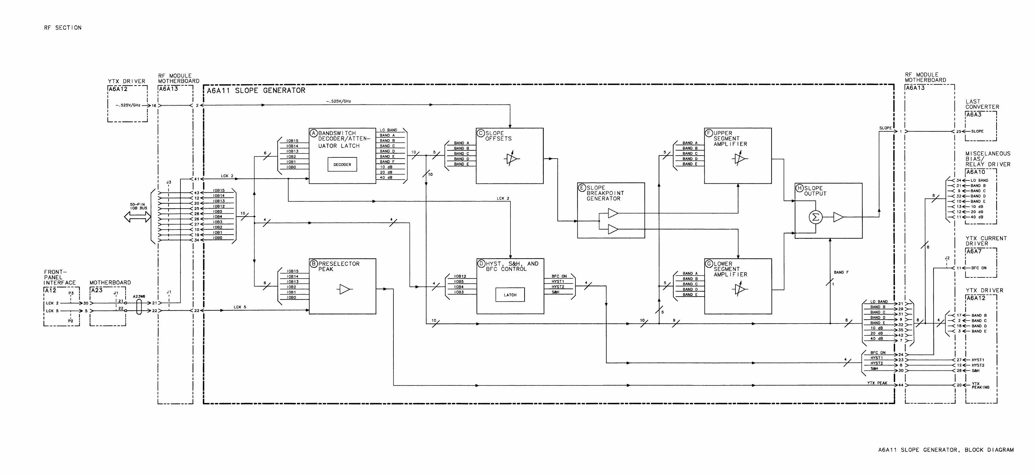
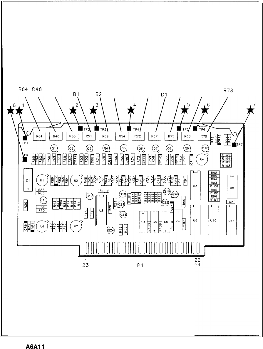
R84
R48
R66 R51 R69 R54 R72 R57 R75 R60
R78
GAIN Al A2
Bl
82
Cl C2
Dl
D2 El E2
2:
Pl
A6All
Slope Generator Component Locations, 85660-60126, 85660-60238

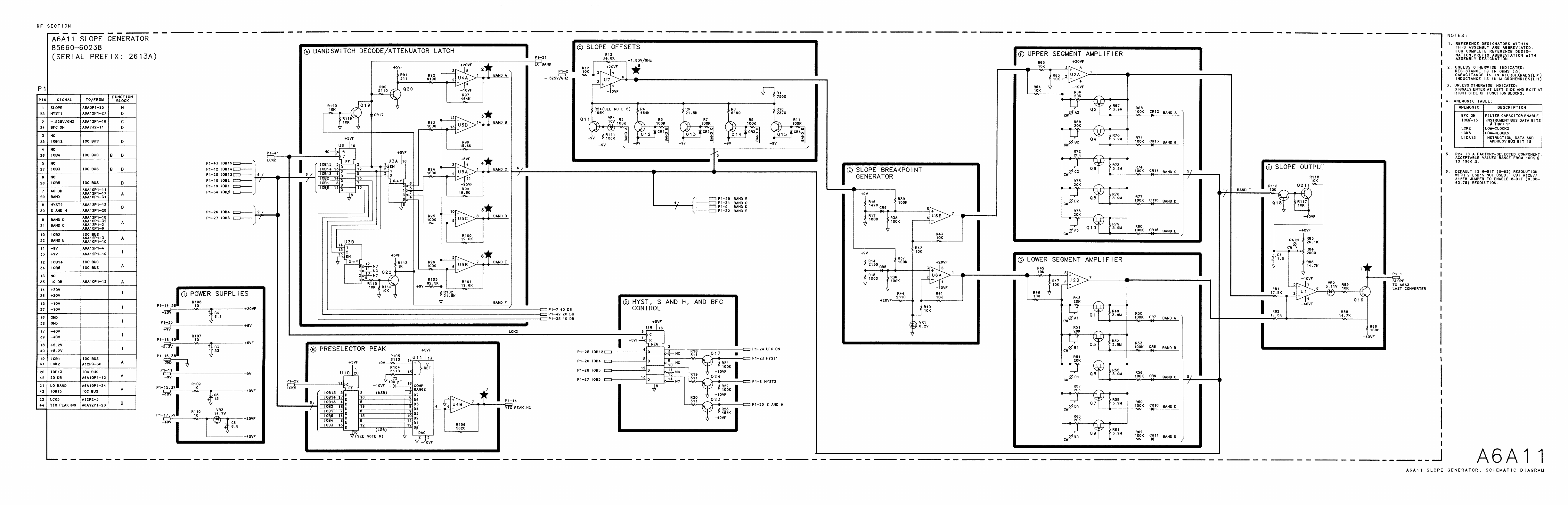
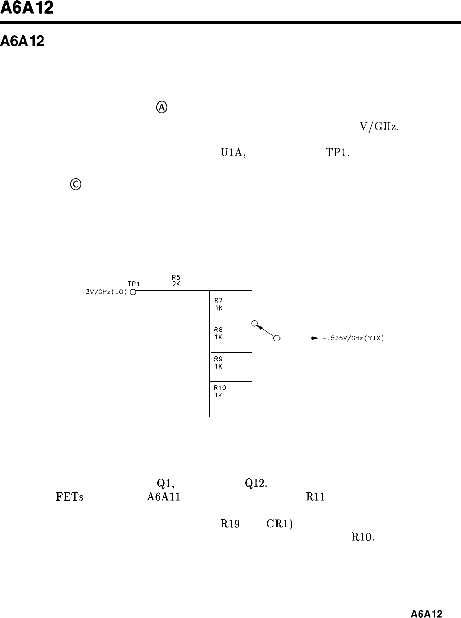
A6A12
A6A12 YIG-Tuned Mixer (YTX) Driver, Circuit Description
The YTX Driver receives a voltage proportional to the instrument LO frequency and produces
a signal to control current in the YTX coil.
Input Differential Amplifier
@
This input signal to the YTX Driver comes from the A19 DAC and is -3
V/GHz.
For
example, as the YTO Loop sweeps from 2 to 6 Ghz, this input signal sweeps from -6 to
-18 V. It is buffered by differential amplifier
UlA,
and appears at
TPl.
Bandswitch
@
The frequency that the YTX is tuned to must be made to follow the first, second, third,
or fourth harmonic of the YTO frequency, depending on the frequency band in which the
instrument is operating. This is done by attenuating the buffered input signal with a voltage
divider as shown in Figure 1.
R5
TPl
2K
-3V/GHz(LO)
0
0
R7
1K
R8
1K
*
-.525V/GHz(YTX)
0
R9
1K
0
RlO
1K
Figure 1. Bandwidth Voltage Divider
The position on the attenuator is determined by the harmonic number in use. The
bandswitching is done with FET
Ql,
Q2, Q3, and
Q12.
The bandswitch information used to
turn on the
FETs
comes from
A6All
Slope Generator. R6 and
Rll
to R14 form a second
voltage divider used as a gate return through R15 to R18. This prevents current through
bandswitch diodes and resistors (for example,
R19
and
CRl)
when the associated FET is
switched off from affecting the bandswitch voltage divider R5 and R7 to RlO.
A6A12
1
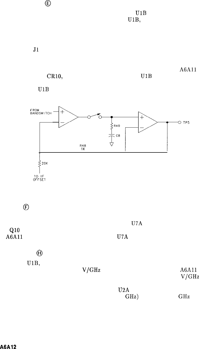
Sample and Hold
@
The output of the bandswitch drives preamp U5. U5 and
UlB
together form an op amp with
U5 a low-noise, low-temperature drift preamplifier. U5,
UlB,
and U6 are used in a sample and
hold circuit as shown in Figure 2.
Q15, a JFET, is used as the switch for the sample and hold. The switch is opened (that is,
the FET is turned off) whenever a bandcrossing occurs. When a bandcrossing occurs, the
input voltage at
Jl
changes as the YTO Loop resets its frequency to start a new band, and
the YTX bandswitch changes bands. At this time, the voltage at the input of U5 varies.
The sample and hold circuit is used to prevent these variations from reaching the YTX.
The sample and hold switch is controlled through Q14 by a signal from the
A6All
Slope
Generator. R44, R45, CRlO, and CR11 keep the output of
UlB
from saturating when the
feedback loop is opened by Q15 being off. This prevents a “glitch” at the output of U6 when
the loop closes if
UlB
suddenly had to recover from a saturated condition.
FROM
BANDSWITCH
R48
1K
TP5
i
20K
TO
IF
OFFSET
Figure 2. YTX Driver Sample and Hold, Simplified Schematic
IF Offsets
@
In addition to tracking a harmonic of the YTO, the YTX must be offset from this LO
harmonic by the first IF (321.4 MHz). This is done by U7A and its associated components.
Q7 to
QlO
switch in different IF offset adjustments for each band. The YTX peaking signal
from
A6All
Slope Generator is also summed into U7A through R77.
Sweep + Tune
@I
Since the U5,
UlB,
and U6 combination have a gain of 1.05 set by R48 and R75, the voltage
at TP5 has an sensitivity of -0.525
V/GHz
(YTX). Th
is
signal goes to the
A6All
Slope
Generator, to voltage divider R54 and R55, and to U8. U8 is set to give -1
V/GHz
at its
output which goes to J2. This signal is cabled to the rear panel of the instrument to provide
an analog voltage proportional to input frequency. U2A and its associated circuitry provide an
offset voltage for U8 to correct for the first IF (3.6214 GHz) in the 0 to 2.5 GHz band. R98 is
adjusted for 0 V at U2 with the spectrum analyzer tuned to 0 Hz.
2
A6A12
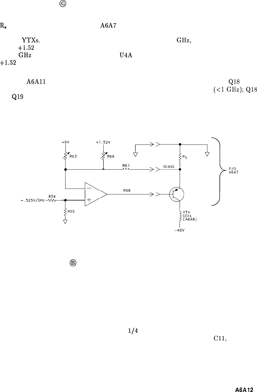
YTX Drive Output
@
Voltage divider R54 and R55 drive the output stage shown in Figure 3.
R,
and the output transistor are on A6A7 YTX Current Driver. The YTX has a nominal coil
sensitivity of 75 MHz/mA. R63 and R66 provide the means for compensating for variations
amount
YTXs.
When the YTX center frequency is tuned to 5.8 GHz, the voltage at pin 3 of
U3 is
+1.52
V. There is no voltage across R66 so it has no effect. R63 is adjusted for tracking
at 5.8 GHz and R66 is adjusted at 2 Ghz. U4A and voltage divider R68 and R69 provide the
t1.52
V source.
The YTX magnet exhibits hysteresis which must be corrected for. This is done by signals
from the
A6All
Slope Generator which is controlled by the instrument controller.
QlS
is
turned on for a short period of time to correct for hysteresis in narrow spans
(<l
GHz);
QlS
and
Q19
are both turned on for a short period of time in large spans and when making large
downward steps in frequency. The length of time that the transistors are on and the length of
time after they are off before the sweep starts is controlled by the instrument controller and
varies with start frequency, span, previous stop frequency, and so on.
+9v
+l
.52V
R63 R66
r
Rs
R61
a
*AA
,
,
SENSE
p/o
A6A7
R58
R54
-.
525V/GHz
+
-
::;
I
YTX
COIL
(ABAB)
-40v
Figure 3. Output Amplifier, Simplified Schematic
Delay Compensation
@I
The YTX and YTO (LO) are electromagnetically tuned devices. As such, they both exhibit a
delay in their response to changes in magnet current. When a change in coil current occurs,
there is a delay before the corresponding change in frequency occurs. When a ramp of current
is applied to a YTX or YTO magnet coil, there is a time delay between the ramp current
and the corresponding frequency. Since the YTX and YTO have different magnet structures,
they exhibit different amounts of delay. This causes tracking problems. These problems are
compounded by harmonic mixing and heating effects.
On the fourth harmonic, the YTO is sweeping
l/4
as much in frequency as the YTX. Thus
the YTO exhibits its least delay with respect to the YTX. R24, R25, Cl, C2,
Cll,
and C23
are used to “speed up” the YTX to track the YTO on fourth harmonic. On lower harmonics,
the YTO exhibits more delay compared to the YTX since it must now sweep further. The
YTX is then delayed to match the YTO under these conditions by R26 and C3.
A6A12
3
Since these RC combinations have long time constants, they cannot readily respond to the
transients produced at band crossings and scan resets. Therefore, whenever the sample and
hold circuit is holding, R24 to R26 are shorted by Q4 to
QS
respectively.
+9 V and -9 V Reference Supplies
@I
U2B and
U7B
and their associated circuitry form -9 V and
+9
V reference supplies used in
the YTX Driver, and elsewhere in the A6 RF Module.
4
A6A12
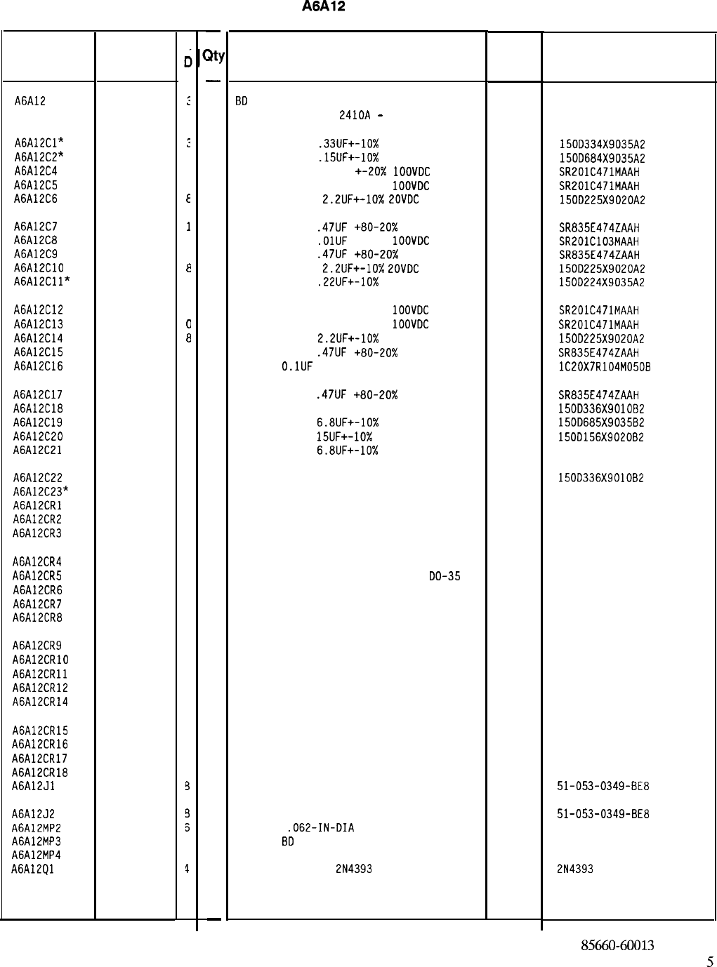
Reference
Designation
HP Part
Number
C
c
A6A12 85660-60013
:
A6AlZCl* 0180-2205
:
A6AlZC2" 0180-0218
4
A6AlZC4 0160-0571
C
A6AlZC5 0160-0571
C
A6AlZC6 0180-0197
E
A6AlZC7 0160-3097
1
A6A12C8 0160-3879
7
A6A12C9 0160-3097
1
A6A12ClO 0180-0197
8
A6A12Cll* 0180-1735
2
A6A12C12 0160-0571
0
A6A12C13 0160-0571
0
A6A12C14 0180-0197
8
A6A12C15 0160-3097
1
A6A12C16 0160-4084
8
A6A12C17 0160-3097
A6A12C18 0180-0229
A6A12C19 0180-0116
A6A12C20 0180-1746
A6A12C21 0180-0116
A6A12C22
A6A12C23*
A6A12CRl
A6A12CR2
A6A12CR3
0180-0229
1901-1067
1901-1067
1901-1067
A6A12CR4 1901-1067
A6A12CR5 1901-1067
A6A12CR6 1901-1067
A6A12CR7 1901-1067
A6A12CR8 1901-1067
A6A12CR9 1901-1067
A6A12CRlO 1901-1067
A6A12CRll 1901-1067
A6A12CR12 1901-1067
A6A12CR14 1901-1067
A6A12CR15 1901-1067
A6A12CR16 1901-1067
A6A12CR17 1901-1067
A6A12CR18 1901-1067
A6A12Jl 1250-0543
A6A12J2 1250-0543
A6A12MP2 1480-0173
A6A12MP3 4040-0749
A6A12MP4 4040-0750
A6A12Ql 1855-0414
1
7
1
5
1
7
4
4
4
4
4
4
4
4
4
4
4
4
4
4
4
4
4
3
3
s
4
7
4
-
at!
-
1
1
1
1
1
1
1
1
1
1
1
1
1
1
1
1
1
1
1
1
1
1
1
1
1
1
1
1
1
1
1
1
1
1
1
1
1
1
1
1
1
2
1
1
1
-
HP Part Number 85660-60013
A6A12
YTX Driver
Description
BD
ASSEMBLY, YIG-TUNED MIXER (YTX) DRIVE
(SERI
AL PREFIXES
:
2410~
-
2449A)
Mfr
Mfr Part
Code Number
28480 85660-60013
CAPACITOR-FXD
.33UF+-10%
35VDC TA
56289 150D334X9035A2
CAPACITOR-FXD
.15UF+-10%
35VDC TA
56289 150D684X9035A2
CAPACITOR-FXD 470PF +-20x
1OOVDC
CER
04222 SR201C471MAAH
CAPACITOR-FXD 470PF +-20%
1OOVDC
CER
04222 SR201C471MAAH
CAPACITOR-FXD
2.2UF+-10%
LOVDC
TA
56289 150D225X9020A2
CAPACITOR-FXD
.47UF
+80-20%
50VDC CER
04222 SR835E474ZAAH
CAPACITOR-FXD
.OlUF
+-20%
1OOVDC
CER
04222 SR201C103MAAH
CAPACITOR-FXD
.47UF
+80-20% 50VDC CER
04222 SR835E474ZAAH
CAPACITOR-FXD
2.2UF+-10%
ZOVDC
TA
56289 150D225X9020A2
CAPACITOR-FXD
.22UF+-10%
35VDC TA
56289 150D224X9035A2
CAPACITOR-FXD 470PF +-20%
1OOVDC
CER
04222 SR201C471MAAH
CAPACITOR-FXD 470PF +-20%
1OOVDC
CER
04222 SR201C471MAAH
CAPACITOR-FXD
2.2UF+-10%
20VDC TA
56289 150D225X9020A2
CAPACITOR-FXD
.47UF
+80-20%
50VDC CER
04222 SR835E474ZAAH
CAP-FXD
O.lUF
50 V
56289 lC20X7R104M0508
CAPACITOR-FXD
.47UF
+80-20% 50VDC CER
CAP-FXD 33UF 10 V TA
CAPACITOR-FXD
6.8UF+-10%
35VDC TA
CAPACITOR-FXD
15UF+-10%
20VDC TA
CAPACITOR-FXD
6.8UF+-10%
35VDC TA
04222 SR835E474ZAAH
56289 150D336X901082
56289 150D685X9035B2
56289 150D156X9020B2
56289 1500685X903582
CAP-FXD 33uF 10 V TA 56289 1500336X9OlOB2
SEE 85660-60013 SCHEMATIC DIAGRAM
DIODE-SWITCHING 125V 175MA 60NS DO-35
DIODE-SWITCHING 125V 175MA 60NS DO-35
DIODE-SWITCHING 125V 175MA 60NS DO-35
27014 FDH444
27014 FDH444
27014 FDH444
DIODE-SWITCHING 125V 175MA 60NS DO-35
27014 FDH444
DIODE-SWITCHING 125V 175MA 60NS
DO-35 27014 FDH444
DIODE-SWITCHING 125V 175MA 60NS DO-35
27014 FDH444
DIODE-SWITCHING 125V 175MA 60NS DO-35
27014 FDH444
DIODE-SWITCHING 125V 175MA 60NS DO-35
27014 FDH444
DIODE-SWITCHING 125V 175MA 60NS DO-35
27014 FDH444
DIODE-SWITCHING 125V 175MA 60NS DO-35 27014 FDH444
DIODE-SWITCHING 125V 175MA 60NS DO-35
27014 FDH444
DIODE-SWITCHING 125V 175MA 60NS DO-35
27014 FDH444
DIODE-SWITCHING 125V 175MA 60NS DO-35
27014 FDH444
DIODE-SWITCHING 125V 175MA 60NS DO-35 27014 FDH444
DIODE-SWITCHING 125V 175MA 60NS DO-35 27014 FDH444
DIODE-SWITCHING 125V 175MA 60NS DO-35 27014 FDH444
DIODE-SWITCHING 125V 175MA 60NS DO-35 27014 FDH444
CONNECTOR-RF SM-SNP M PC 50-OHM 98291 51-053-0349-BE8
CONNECTOR-RF SM-SNP M PC 50-OHM
PIN-ROLL
.062-IN-DIA
.25-IN-LG BE-CU
EXTR PC
BD
BRN
EXTR PC BD RED
TRANSISTOR J-FET
2N4393
N-CHAN D-MODE TO
98291 51-053-0349-BE8
72962 99-012-062-0250
28480 4040-0749
28480 4040-0750
17856 2N4393
*Indicates factory-selected value
85660-60013 Parts List
Page 1 of 5
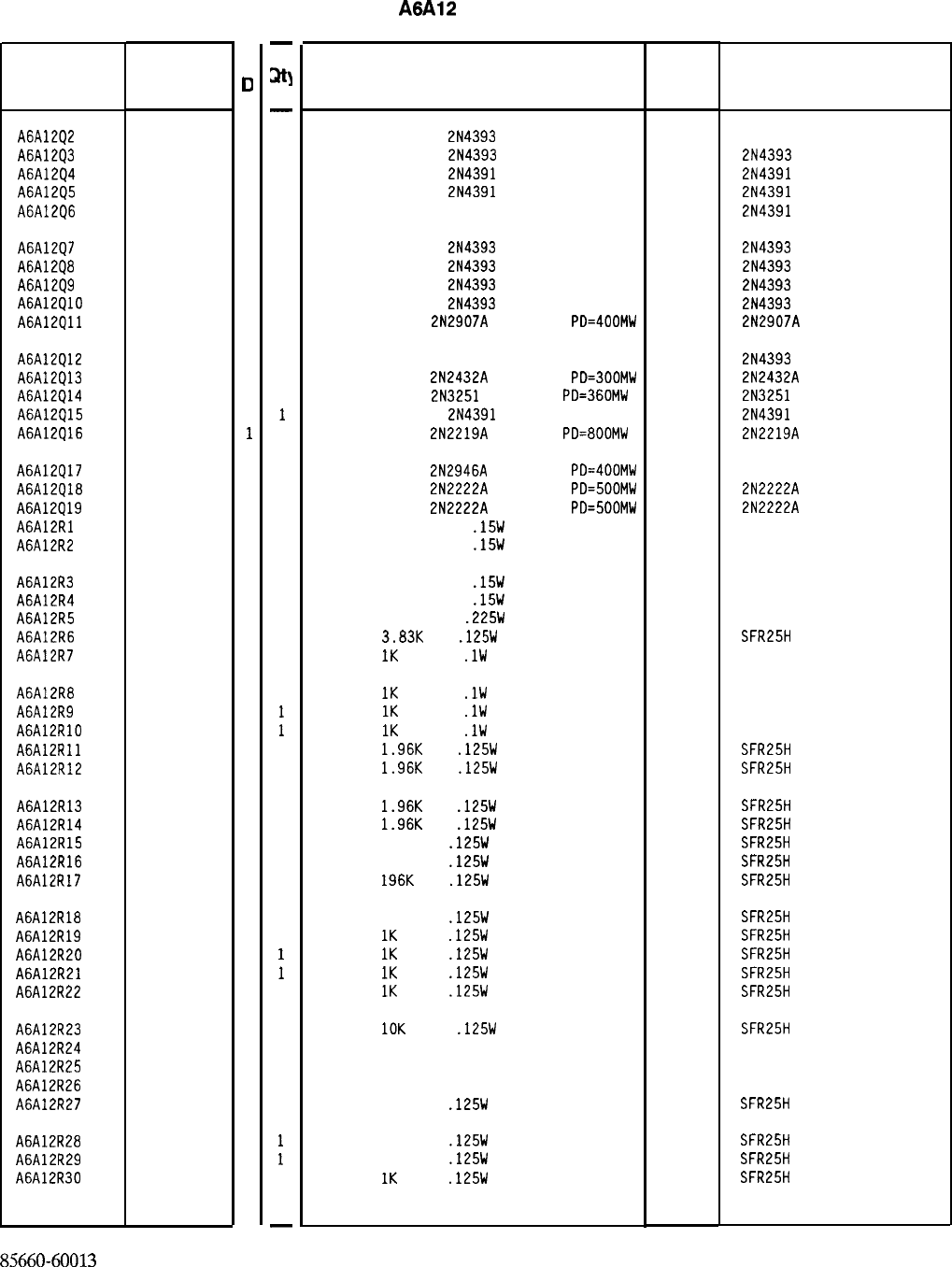
Reference
Designation
HP Part
Number
C
0
A6AlZQ2 1855-0414
4
A6AlZQ3 1855-0414
4
A6A12Q4 1855-0420
2
A6A12Q5 1855-0420
2
A6A12Q6 1855-0420
2
A6A12Q7 1855-0414
4
A6A12Q8 1855-0414
4
A6A12Q9 1855-0414
4
A6A12QlO 1855-0414
4
A6A12Qll 1853-0281
9
A6AlZQ12 1855-0414
4
A6AlZQ13 1854-0557
4
A6A12Q14 1853-0007
7
A6A12Q15 1855-0420
2
A6A12Q16 1854-0637
1
A6A12Q17 1853-0322
9
A6A12Q18 1854-0477
7
A6A12Q19 1854-0477
7
A6A12Rl 0698-8067
4
A6A12R2 0698-8067
4
A6A12R3
A6A12R4
A6A12R5
A6A12R6
A6A12R7
0698-8067
4
0698-8067
4
0699-0153
5
0698-3153
9
0698-8625
0
A6A12R8 0698-8625
0
A6A12R9 0698-8625
0
A6A12RlO 0698-8625
0
A6A12Rll 0698-0083
8
A6A12R12 0698-0083
8
A6A12R13 0698-0083
8
A6A12R14 0698-0083
8
A6A12R15 0698-3453
2
A6A12R16 0698-3453
2
A6A12R17 0698-3453
2
A6A12R18 0698-3453
2
A6A12R19 0757-0280
3
A6A12R20 0757-0280
3
A6A12R21 0757-0280
3
A6A12R22 0757-0280
3
A6A12R23 0757-0442
9
A6A12R24 2100-3353
8
A6A12R25 2100-3353
8
A6A12R26 2100-3357
2
A6AlZR27 0698-3453
2
A6A12R28 0698-3453
2
A6A12R29 0698-3453
2
A6A12R30 0757-0280
3
85660-60013 Parts List
Page 2 of 5
-
at]
-
1
1
1
1
1
1
1
1
1
1
1
1
1
1
1
1
1
1
1
1
1
1
1
1
1
1
1
1
1
1
1
1
1
1
1
1
1
1
1
1
1
1
1
1
1
1
1
1
-
HP Part Number 85660-60013
A6A12
YTX Driver
Description Mfr Mfr Part
Code Number
TRANSISTOR J-FET
2N4393
N-CHAN D-MODE TO
17856 214393
TRANSISTOR J-FET
2N4393
N-CHAN D-MODE TO
17856 2N4393
TRANSISTOR J-FET
2N4391
N-CHAN D-MODE TO
17856 2N4391
TRANSISTOR J-FET
2N4391
N-CHAN D-MODE TO
17856 2N4391
TRANSISTOR J-FET 214391 N-CHAN D-MODE TO
17856 2N4391
TRANSISTOR J-FET
2N4393
N-CHAN D-MODE TO
17856 2N4393
TRANSISTOR J-FET
2N4393
N-CHAN D-MODE TO
17856 2N4393
TRANSISTOR J-FET
2N4393
N-CHAN D-MODE TO
17856 2N4393
TRANSISTOR J-FET
2N4393
N-CHAN D-MODE TO
17856 2N4393
TRANSISTOR PNP
2N2907A
SI TO-18
PD=400MW 04713 2N2907A
TRANSISTOR J-FET 214393 N-CHAN D-MODE TO
17856 2N4393
TRANSISTOR NPN
2N2432A
SI TO-18
PD=BOOMW 01295 2N2432A
TRANSISTOR PNP
2N3251
SI TO-18
PD=360MW 04713 2N3251
TRANSISTOR J-FET
2N4391
N-CHAN D-MODE TO
17856 2N4391
TRANSISTOR NPN
2N2219A
SI TO-5
PD=800MW 04713 2N2219A
TRANSISTOR PNP
2N2946A
SI TO-46
PD=400MW 04713
TRANSISTOR NPN
2N2222A
SI TO-18
PD=500MW 04713
TRANSISTOR NPN
2N2222A
SI TO-18
PD=500MW 04713
RESISTOR 5K +-0.01%
.15W
MF TC=O+-1.3
18612
RESISTOR 5K +-0.01%
.15W
MF TC=O+-1.3
18612
2N2222A
2N2222A
301358
301358
RESISTOR 5K +-0.01%
.15W
MF TC=O+-1.3
18612
301358
RESISTOR 5K +-0.01%
.15W
MF TC=O+-1.3
18612
301358
RESISTOR 2K +-0.1%
.225W
MF TC=O+-1.3
18612 301358
RESISTOR
3.83K
1%
.125W
TF TC=O+-100
19701
SFR25H
RESISTOR
IK
+-0.1%
.lW
TF TC=O+-5
19701
50232
RESISTOR
IK
+-0.1%
.lW
TF TC=O+-5
19701
50232
RESISTOR
1K
+-0.1%
.lW
TF TC=O+-5
19701
50232
RESISTOR
1K
+-0.1%
.lW
TF TC=O+-5
19701
50232
RESISTOR
1.96K
1%
.125W
TF TC=O+-100
19701
SFR25H
RESISTOR
1.96K
1%
.125W
TF TC=O+-100
19701
SFR25H
RESISTOR
1.96K
1%
.125W
TF TC=O+-100
19701
SFR25H
RESISTOR
1.96K
1%
.125W
TF TC=O+-100
19701
SFR25H
RESISTOR 196K 1%
.125W
TF TC=O+-100
19701
SFR25H
RESISTOR 196K 1%
.125W
TF TC=O+-100
19701
SFR25H
RESISTOR
196K
1%
.125W
TF TC=O+-100
19701
SFR25H
RESISTOR 196K 1%
.125W
TF TC=O+-100
19701
SFR25H
RESISTOR
1K
+-1%
.125W
TF TC=O+-100
19701
SFR25H
RESISTOR
1K
+-1%
.125W
TF TC=O+-100
19701
SFR25H
RESISTOR
1K
+-1%
.125W
TF TC=O+-100
19701
SFR25H
RESISTOR
1K
+-1%
.125W
TF TC=O+-100
19701
SFR25H
RESISTOR
10K
+-1%
.125W
TF TC=O+-100
19701
SFR25H
RESISTOR-TRMR 20K 10% TKF SIDE-ADJ l-TRN
32997 3386X-Y46-203
RESISTOR-TRMR 20K 10% TKF SIDE-ADJ l-TRN
32997 3386X-Y46-203
RESISTOR-TRMR 500K 10% TKF SIDE-ADJ l-TR
32997 3386X-146-504
RESISTOR 196K 1%
.125W
TF TC=O+-100
19701
SFR25H
RESISTOR 196K 1%
.125W
TF TC=O+-100
19701
SFR25H
RESISTOR 196K 1%
.125W
TF TC=O+-100
19701
SFR25H
RESISTOR
IK
+-1%
.125W
TF TC=O+-100
19701
SFR25H
*Indicates factory-selected value
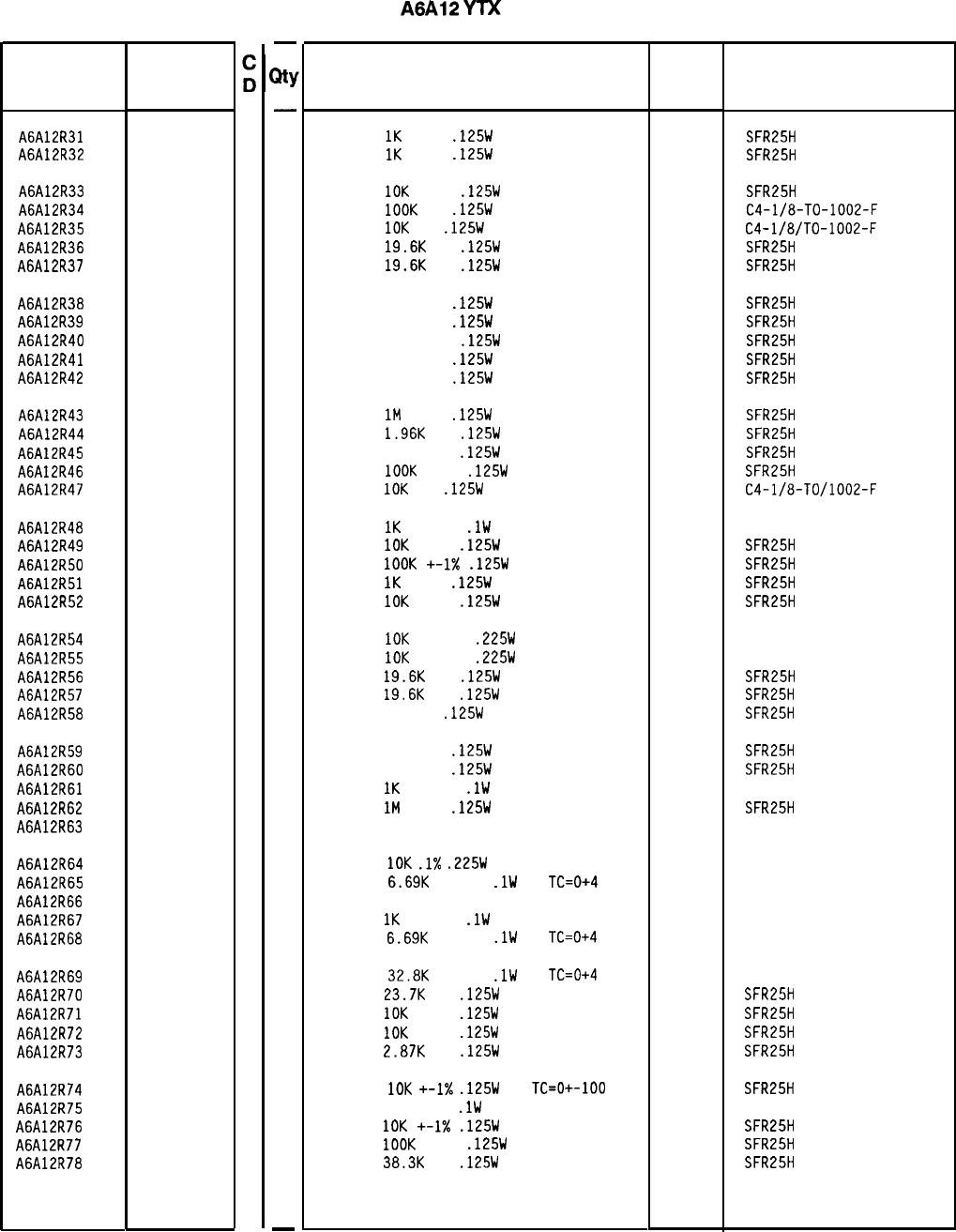
Reference
Designation
HP Part
Number
A6A12R31 0757-0280
3
A6A12R32 0757-0280
3
A6A12R33 0757-0442
9
A6A12R34 0757-0465
6
A6A12R35 0757-0442
9
A6A12R36 0698-3157
3
A6A12R37 0698-3157
3
A6A12R38 0698-4037
0
A6A12R39 0698-4037
0
A6A12R40 0757-0401
0
A6A12R41 0698-4037
0
A6A12R42 0698-4037
0
A6A12R43 0698-8827
4
A6A12R44 0698-0083
8
A6A12R45 0757-0401
0
A6A12R46 0757-0465
6
A6A12R47 0757-0442
9
A6A12R48 0698-8625
0
A6A12R49 0757-0442
9
A6A12R50 0757-0465
6
A6A12R51 0757-0280
3
A6A12R52 0757-0442
9
A6A12R54 0698-7479
0
A6A12R55 0698-7479
0
A6A12R56 0698-3157
3
A6A12R57 0698-3157
3
A6A12R58 0698-0082
7
A6A12R59 0698-4037
0
A6A12R60 0698-4037
0
A6A12R61 0698-8625
0
A6A12R62 0698-8827
4
A6A12R63 2100-4052
6
A6A12R64 0698-7479
0
A6A12R65 0698-8485
0
A6A12R66 2100-4052
6
A6A12R67 0698-8625
0
A6A12R68 0698-8485
0
A6A12R69 0698-6407
2
A6A12R70 0698-3158
4
A6A12R71 0757-0442
9
A6A12R72 0757-0442
9
A6A12R73 0698-3151
7
A6A12R74 0757-0442
9
A6A12R75 0698-8161
9
A6A12R76 0757-0442
9
A6A12R77 0757-0465
6
A6A12R78 0698-3161
9
-
JtY
-
1
1
1
1
1
1
1
1
1
1
1
1
1
1
1
1
1
1
1
1
1
1
1
1
1
1
1
1
1
1
1
1
1
1
1
1
1
1
1
1
1
1
1
1
1
1
1
-
HP Part Number 85660-60013
A6A12
YTX
Driver
Description Mfr
Mfr Part
Code Number
RESISTOR
1K
+-1%
.125W
TF TC=O+-100
19701
SFR25H
RESISTOR
1K
+-1%
.125W
TF TC=O+-100
19701
SFR25H
RESISTOR
10K
+-1%
.125W
TF TC=O+-100
19701
SFR25H
RESISTOR
1OOK
1%
.125W
F TC=O+-100
24546 C4-l/8-TO-1002-F
RESISTOR
10K
1%
.125W
F TC=O+-100
24546 C4-1/8/TO-1002-F
RESISTOR
19.6K
1%
.125W
TF TC=O+-100
19701
SFR25H
RESISTOR
19.6K
1%
.125W
TF TC=O+-100
19701
SFR25H
RESISTOR 46.4 1%
.125W
TF TC=O+-100
19701
SFR25H
RESISTOR 46.4 1%
.125W
TF TC=O+-100
19701
SFR25H
RESISTOR 100 +-1%
.125W
TF TC=O+-100
19701
SFR25H
RESISTOR 46.4 1%
.125W
TF TC=O+-100
19701
SFR25H
RESISTOR 46.4 1%
.125W
TF TC=O+-100
19701
SFR25H
RESISTOR
1M
+-1%
.125W
TF TC=O+-100
19701
SFR25H
RESISTOR
1.96K
1%
.125W
TF TC=O+-100
19701
SFR25H
RESISTOR 100 +-1%
.125W
TF TC=O+-100
19701 SFR25H
RESISTOR
1OOK
+-1%
.125W
TF TC=O+-100
19701
SFR25H
RESISTOR
10K
1%
.125W
F TC=O+-100
24546 C4-l/8-T0/1002-F
RESISTOR
1K
+-0.1%
.lW
TF TC=O+-5
19701
50232
RESISTOR
10K
+-1%
.125W
TF TC=O+-100
19701
SFR25H
RESISTOR
1OOK
+-1X
.125W
TF TC=O+-100
19701
SFR25H
RESISTOR
1K
+-1%
.125W
TF TC=O+-100
19701
SFR25H
RESISTOR
10K
+-1%
.125W
TF TC=O+-100
19701
SFR25H
RESISTOR
10K
+-0.1%
.225W
MF TC=O+-1.5
18612 301359
RESISTOR
10K
+-0.1%
.225W
MF TC=O+-1.5
18612 301359
RESISTOR
19.6K
1%
.125W
TF TC=O+-100
19701
SFR25H
RESISTOR
19.6K
1%
.125W
TF TC=O+-100
19701
SFR25H
RESISTOR 464 1%
.125W
TF TC=O+-100
19701
SFR25H
RESISTOR 46.4 1%
.125W
TF TC=O+-100
19701
SFR25H
RESISTOR 46.4 1%
.125W
TF TC=O+-100
19701
SFR25H
RESISTOR
IK
+-0.1%
.lW
TF TC=O+-5
19701
50232
RESISTOR
IM
+-1%
.125W
TF TC=O+-100
19701
SFR25H
RESISTOR-TRMR 20K 5% MF SIDE-ADJ 25-TRN
28480 2100-4052
RESISTOR
10K
.l%
.225W
F TC=O+-1
28480 0698-7479
RESISTOR
6.69K
+-0.1%
.lW
TF
TC=0+4
19701
50232
RESISTOR-TRMR 20K 5% MF SIDE-ADJ 25-TRN
28480 2100-4052
RESISTOR
1K
+-0.1%
.lW
TF TC=O+-5
19701
50232
RESISTOR
6.69K
+-0.1%
.lW
TF
TC=0+4
19701
50232
RESISTOR
32.8K
+-0.1%
.lW
TF
TC=0+4
RESISTOR
23.7K
1%
.125W
TF TC=O+-100
RESISTOR
10K
+-1%
.125W
TF TC=O+-100
RESISTOR
10K
+-1%
.125W
TF TC=O+-100
RESISTOR
2.87K
1%
.125W
TF TC=O+-100
19701
19701
19701
19701
19701
19701
19701
19701
19701
19701
50232
SFR25H
SFR25H
SFR25H
SFR25H
RESISTOR
1DK
+-I%
.125W
TF
TC=O+-100
RESISTOR 20K +-1%
.lW
TF TC=O+-5
RESISTOR
10K
+-1X
.125W
TF TC=O+-100
RESISTOR
1OOK
+-1%
.125W
TF TC=O+-100
RESISTOR
38.3K
1%
.125W
TF TC=O+-100
SFR25H
50232
SFR25H
SFR25H
SFR25H
*Indicates factory-selected value
85660-60013 Parts List
Page 3 of 5
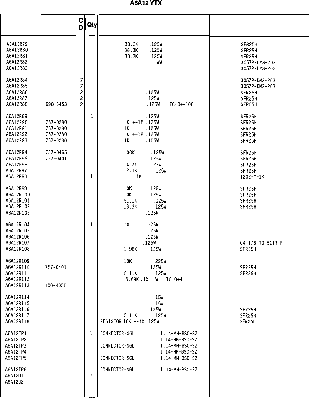
Reference
Designation
HP Part
Number
A6A12R79
1698-3161
9
A6A12R80
1698-3161
9
A6A12R81
1698-3161
9
A6A12R82
!lOO-1661
7
A6A12R83
1100-1661
7
A6A12R84
A6A12R85
A6A12R86
A6A12R87
A6A12R88
'100-1661
'100-1661
1698-3453
1698-3453
1698-3453
A6A12R89
1698-3453
2
A6A12R90
1757-0280
3
A6A12R91
1757-0280
3
A6A12R92
1757-0280
3
A6A12R93
1757-0280
3
A6A12R94
1757-0465
6
A6A12R95
'757-0401
0
A6A12R96 698-3156
2
A6A12R97 757-0444
1
A6A12R98 100-3390
3
A6A12R99 757-0442
A6A12RlOO 757-0442
A6A12RlOl 757-0458
A6A12R102 757-0289
A6A12R103 757-0346
A6A12R104 757-0346
A6A12R105 757-0346
A6A12R106 757-0346
A6A12R107 757-0416
A6A12R108 698-0083
A6A12R109 698-7479
A6A12RllO 757-0401
A6A12Rlll 757-0438
A6A12R112 698-8485
A6A12R113 loo-4052
A6A12R114 698-8067
A6A12R115 698-8067
A6A12R116 757-0401
A6A12R117 757-0438
A6A12R118 757-0442
A6A12TPl 251-0600
A6A12TP2 251-0600
A6A12TP3 251-0600
A6A12TP4 251-0600
A6A12TP5 251-0600
A6A12TP6 251-0600
A6A12Ul 081-8117
A6A12U2 081-8117
9
9
7
2
2
2
2
2
7
8
0
0
3
0
6
4
4
3
3
3
3
3
3
3
3
3
3
3
8566060013 Parts List
Page 4 of 5
-
21
-
1
1
1
1
1
1
1
1
1
1
1
1
1
1
1
1
1
1
1
1
1
1
1
1
1
1
1
1
1
1
1
1
1
1
1
1
1
1
1
1
1
1
1
1
1
1
1
1
-
HP Part Number 85660-60013
A6A12
YTX
Driver
Description Mfr
Mfr Part
Code Number
RESISTOR
38.3K
1%
.125W
TF TC=O+-100
19701
SFR25H
RESISTOR
38.3K
1%
.125W
TF TC=O+-100
19701
SFR25H
RESISTOR
38.3K
1%
.125W
TF TC=O+-100
19701
SFR25H
RESISTOR-TRMR 20K 5%
bib/
SIDE-ADJ 22-TRN
32997 3057P-DM3-203
RESISTOR-TRMR 20K 5% WW SIDE-ADJ 22-TRN
32997 3057P-DM3-203
RESISTOR-TRMR 20K 5% WW SIDE-ADJ 22-TRN
32997 3057P-DM3-203
RESISTOR-TRMR 20K 5% WW SIDE-ADJ 22-TRN
32997 3057P-DM3-203
RESISTOR 196K 1%
.125W
TF TC=O+-100
19701
SFR25H
RESISTOR 196K 1%
.125W
TF TC=O+-100
19701
SFR25H
RESISTOR 196K 1%
.125W
TF
TC=O+-100
19701
SFR25H
RESISTOR 196K 1%
.125W
TF TC=O+-100
19701
SFR25H
RESISTOR
1K
+-1X
.125W
TF TC=O+-100
19701
SFR25H
RESISTOR
1K
+-1%
.125W
TF TC=O+-100
19701
SFR25H
RESISTOR
1K
+-I%
.125W
TF TC=O+-100
19701
SFR25H
RESISTOR
1K
+-1%
.125W
TF TC=O+-100
19701
SFR25H
RESISTOR
1OOK
+-1%
.125W
TF TC=O+-100
19701
SFR25H
RESISTOR 100 +-1%
.125W
TF TC=O+-100
19701
SFR25H
RESISTOR
14.7K
1%
.125W
TF TC=O+-100
19701
SFR25H
RESISTOR
12.1K
+-1%
.125W
TF TC=O+-100
19701
SFR25H
RESISTOR-TRMR
1K
10% TF SIDE-ADJ 25-TRN
18612 1202-Y-1K
RESISTOR
10K
+-1%
.125W
TF TC=O+-100
19701
SFR25H
RESISTOR
10K
+-1%
.125W
TF TC=O+-100
19701
SFR25H
RESISTOR
51.1K
+-1%
.125W
TF TC=O+-100
19701
SFR25H
RESISTOR
13.3K
+-1%
.125W
TF TC=O+-100
19701
SFR25H
RESISTOR 10 +-1%
.125W
TF TC=O+-100
91637 CMF-55-1. T-l
RESISTOR
10
+-1%
.125W
TF TC=O+-100
91637 CMF-55-1, T-l
RESISTOR 10 +-1%
.125W
TF TC=O+-100
91637 CMF-55-1, T-l
RESISTOR 10 +-1%
.125W
TF TC=O+-100
91637 CMF-55-1. T-l
RESISTOR 511 1%
.125W
F TC=O+-100
24546
C4-l/8-TO-511R-F
RESISTOR
1.96K
1%
.125W
TF TC=O+-100
19701
SFR25H
RESISTOR
10K
+-0.1%
.225W
MF TC=O+-1.5
18612 301359
RESISTOR 100 +-1%
.125W
TF TC=O+-100
19701
SFR25H
RESISTOR
5.11K
+-1%
.125W
TF TC=O+-100
19701
SFR25H
RESISTOR
6.69K
.l%
.lW
F
TC=0+4 28480 0698-8485
RESISTOR-TRMR 20K 5% MF SIDE-ADJ 25-TRN 28480 2100-4052
RESISTOR 5K +-0.01%
.15W
MF TC=O+-1.3
18612 301358
RESISTOR 5K +-0.01%
.15W
MF TC=O+-1.3
18612 301358
RESISTOR 100 +-1%
.125W
TF TC=O+-100
19701
SFR25H
RESISTOR
5.11K
+-1%
.125W
TF TC=O+-100
19701
SFR25H
?ESISTOR
10K
+-I%
.125W
TF TC=O+-100
19701
SFR25H
LONNECTOR-SGL
CONT PIN
1.14-MM-BSC-SZ
SQ
27264 16-06-0034
"DNNECTOR-SGL CONT PIN
1.14-MM-BSC-SZ
SQ
27264 16-06-0034
ZONNECTOR-SGL
CONT PIN
1.14-MM-BSC-SZ
SQ
27264 16-06-0034
CONNECTOR-SGL CONT PIN
1.14-MM-BSC-SZ
SQ
27264 16-06-0034
LONNECTOR-SGL
CONT PIN
1.14-MM-BSC-SZ
SQ
27264 16-06-0034
ZONNECTOR-SGL
CONT PIN
1.14~MM-BSC-SZ
SQ
27264 16-06-0034
SCREEN 1826-0092 28480 5081-8117
SCREEN 1826-0092 28480 5081-8117
*Indicates factory-selected value
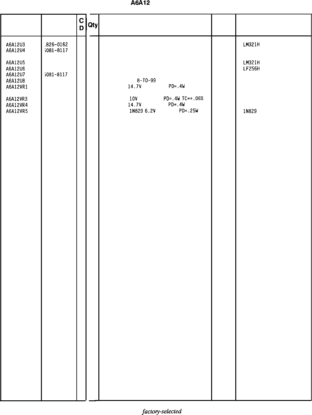
Reference HP Part
Designation
Number
A6A12U3
.B26-0162 8
A6A12U4
iO81-8117
3
A6A12U5
1826-0162
8
A6A12U6
1826-0371
1
A6A12U7
iO81-8117
3
A6A12U8
1826-1058
3
A6A12VRl
1902-3203
6
A6A12VR3 1902-0025
4
A6A12VR4
1902-3203
6
A6A12VR5 1902-0625
0
-
sty
-
1
1
1
1
1
1
1
1
1
1
-
HP Part Number 85660-60013
A6A12
YTX Driver
Description
IC PREAMPLIFIER TO-99 PKG 27014 LM321H
SCREEN 1826-0092 28480 5081-8117
IC PREAMPLIFIER TO-99 PKG
IC OP AMP LOW-BIAS-H-IMPD TO-99 PKG
SCREEN 1826-0092
IC DP AMP GP
8-TO-99
PKG
DIODE-ZNR
14.7V
5% DO-35
PD=.4W
27014
27014
28480
06665
04713
LM321H
LF256H
5081-8117
OP-02CJ
DIODE-ZNR
1OV
5% DO-35
PD=.4W
TC=+.06% 04713
DIODE-ZNR
14.7V
5% DO-35
PD=.4W 04713
DIODE-ZNR
lN829
6.2V
5% DO-7
PD=.25W 04713
Mfr
Mfr Part
Code Number
*Indicates
factoy-selected
value
85660-60013 Parts List
Page 5 of 5
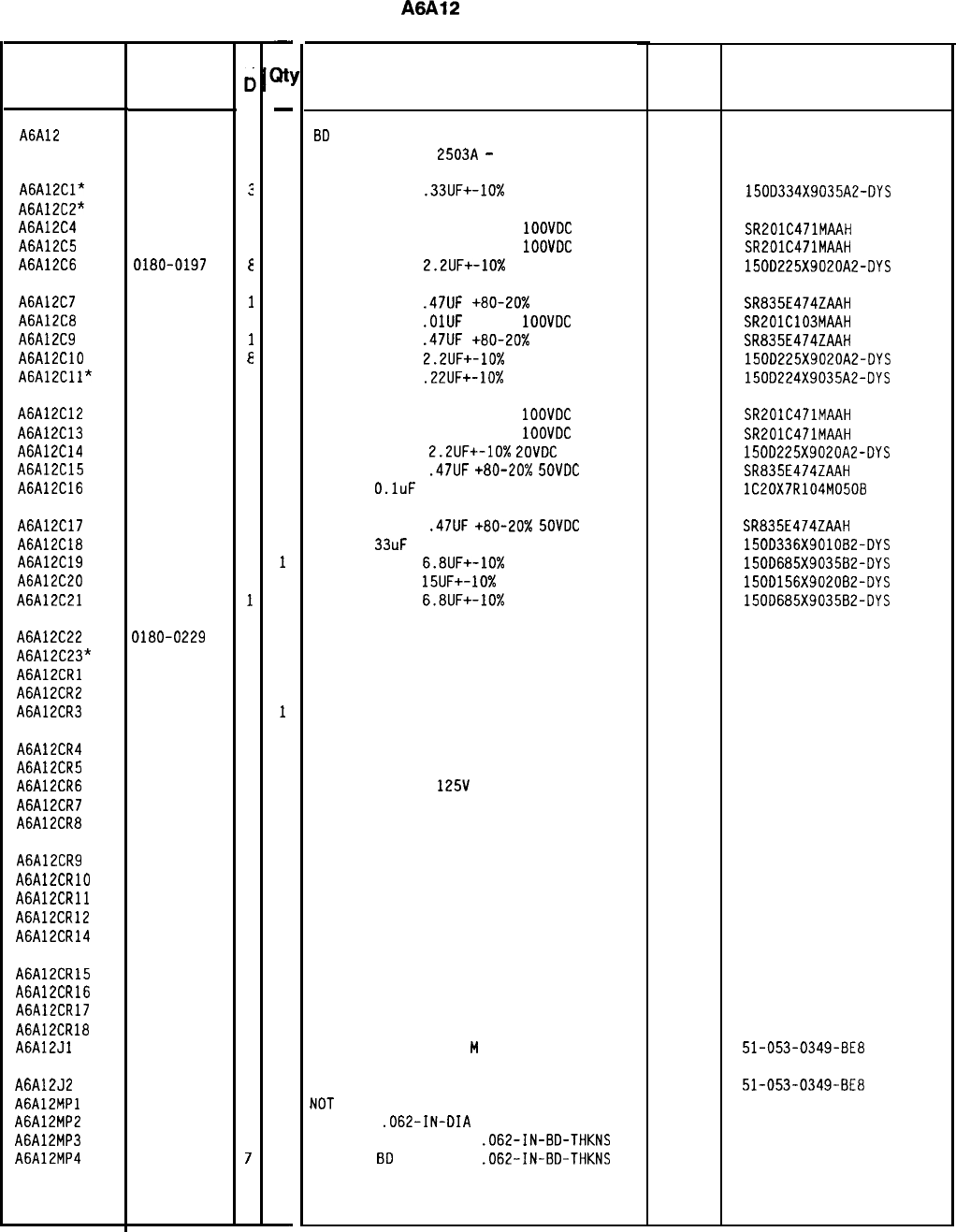
Reference
Designation
HP Part
Number
C
c
A6A12 85660-60235
I
A6A12Cl*
A6A12C2"
A6A12C4
A6A12C5
A6A12C6
0180-2205
:
0160-0571
c
0160-0571
C
0180-0197
E
A6A12C7 0160-3097
1
A6A12C8 0160-3879
7
A6A12C9 0160-3097
1
A6A12ClO 0180-0197
a
A6A12Cll" 0180-1735
2
A6A12C12 0160-0571
C
A6A12C13 0160-0571
C
A6A12C14 0180-0197
a
A6A12C15 0160-3097
1
A6A12C16 0160-4084
a
A6A12C17 0160-3097
1
A6A12C18 0180-0229
7
A6A12C19 0180-0116
1
A6A12C20 0180-1746
5
A6A12C21 0180-0116
1
A6A12C22
A6A12C23*
A6A12CRl
A6A12CR2
A6A12CR3
0180-0229
7
1901-1067
4
1901-1067
4
1901-1067
4
A6A12CR4 1901-1067
4
A6A12CR5 1901-1067
4
A6A12CR6 1901-1067
4
A6A12CR7 1901-1067
4
A6A12CR8 1901-1067
4
A6A12CR9 1901-1067
4
A6A12CRlO 1901-1067
4
A6A12CRll 1901-1067
4
A6A12CR12 1901-1067
4
A6A12CR14 1901-1067
4
A6A12CR15 1901-1067
4
A6A12CR16 1901-1067
4
A6A12CR17 1901-1067
4
A6A12CR18 1901-1067
4
A6A12Jl 1250-0543
8
A6A12J2
A6A12MPl
A6A12MP2
A6A12MP3
A6A12MP4
1250-0543
B
1480-0073
6
4040-0749
4
4040-0750
7
-
X!
-
1
1
1
1
1
1
1
1
1
1
1
1
1
1
1
1
1
1
1
1
1
1
1
1
1
1
1
1
1
1
1
1
1
1
1
1
1
1
1
1
2
1
1
-
HP Part Number 85660-60235
A6A12
YTX Driver
Description Mfr
Mfr Part
Code Number
8D
ASSEMBLY, YIG-TUNED MIXER (YTX) DRIVE
(SERIAL PREFIX:
2503~
-
2928A)
28480 85660-60235
CAPACITOR-FXD
.33UF+-10%
35VDC TA
SEE 85660-60235 SCHEMATIC DIAGRAM
CAPACITOR-FXD 470PF +-20%
1OOVDC
CER
CAPACITOR-FXD 470PF +-20%
1OOVDC
CER
CAPACITOR-FXD
2.2UF+-10%
20VDC TA
56289 1500334X9035A2-DYS
04222 SR201C471MAAH
04222 SR201C471MAAH
56289 150D225X9020A2-DYS
CAPACITOR-FXD
.47UF
+80-20% 50VDC CER
04222 SR835E474ZAAH
CAPACITOR-FXD
.OlUF
+-20%
1OOVDC
CER
04222 SR201C103MAAH
CAPACITOR-FXD
.47UF
+80-20x 50VDC CER
04222 SR835E474ZAAH
CAPACITOR-FXD
2.2UF+-10%
20VDC TA
56289 150D225X9020A2-DYS
CAPACITOR-FXD
.22UF+-10%
35VDC TA
56289 150D224X9035A2-OYS
CAPACITOR-FXD 470PF +-20%
1OOVDC
CER
04222 SR201C471MAAH
CAPACITOR-FXD 470PF +-20%
1OOVDC
CER
04222 SR201C471MAAH
CAPACITOR-FXD
2.2UF+-10%
ZOVDC
TA
56289 150D225X9020A2-DYS
CAPACITOR-FXD
.47UF
+80-20%
SOVDC
CER
04222 SR835E474ZAAH
CAP-FXD
O.luF
50 V
56289 lC20X7R104M0508
CAPACITOR-FXD
.47UF
+80-20%
SOVDC
CER
CAP-FXO
33uF
10 V TA
CAPACITOR-FXD
6.8UF+-10%
35VDC TA
CAPACITOR-FXD
15UF+-10%
20VDC TA
CAPACITOR-FXD
6.8UF+-10%
35VDC TA
04222 SR835E474ZAAH
56289 150D336X901082-DYS
56289 150D685X903582-DYS
56289 1500156X9020B2-DYS
56289 150D685X9035B2-DYS
CAP-FXD 33uF 10 V TA
56289 1500336X901082-DYS
SEE 85660-60235 SCHEMATIC DIAGRAM
DIODE-SWITCHING 125V 175MA 60NS DO-35
DIODE-SWITCHING 125V 175MA 60NS DO-35
DIODE-SWITCHING 125V 175MA 60NS DO-35
27014 FDH444
27014 FDH444
27014 FDH444
DIODE-SWITCHING 125V 175MA 60NS DO-35
27014 FDH444
DIODE-SWITCHING 125V 175MA 60NS DO-35
27014 FDH444
DIODE-SWITCHING
125V
175MA 60NS DO-35
27014 FDH444
DIODE-SWITCHING 125V 175MA 60NS DO-35
27014 FDH444
DIODE-SWITCHING 125V 175MA 60NS DO-35
27014 FDH444
DIODE-SWITCHING 125V 175MA 60NS DO-35
27014 FDH444
DIODE-SWITCHING 125V 175MA 60NS DO-35
27014 FDH444
DIODE-SWITCHING 125V 175MA 60NS DO-35
27014 FDH444
DIODE-SWITCHING 125V 175MA 60NS DO-35
27014 FDH444
DIODE-SWITCHING 125V 175MA 60NS DO-35
27014 FDH444
DIODE-SWITCHING 125V 175MA 60NS DO-35
27014 FDH444
DIODE-SWITCHING 125V 175MA 60NS DO-35 27014 FDH444
DIODE-SWITCHING 125V 175MA 60NS DO-35
27014 FDH444
DIODE-SWITCHING 125V 175MA 6DNS DO-35
27014 FDH444
CONNECTOR-RF SM-SNP
M
PC 50-OHM
98291 51-053-0349-BE8
CONNECTOR-RF SM-SNP M PC 50-OHM
NOT
ASSIGNED
PIN-ROLL
.062-IN-OIA
.25-IN-LG BE-CU
EXTR-PC BD BRN POLYC
.062-IN-BD-THKNS
EXTR-PC
80
RED POLYC
.062-IN-BD-THKNS
98291 51-053-0349-BE8
72962 99-012-062-0250
*Indicates factory-selected value
85660-60235 Parts List
Page
1
of 5
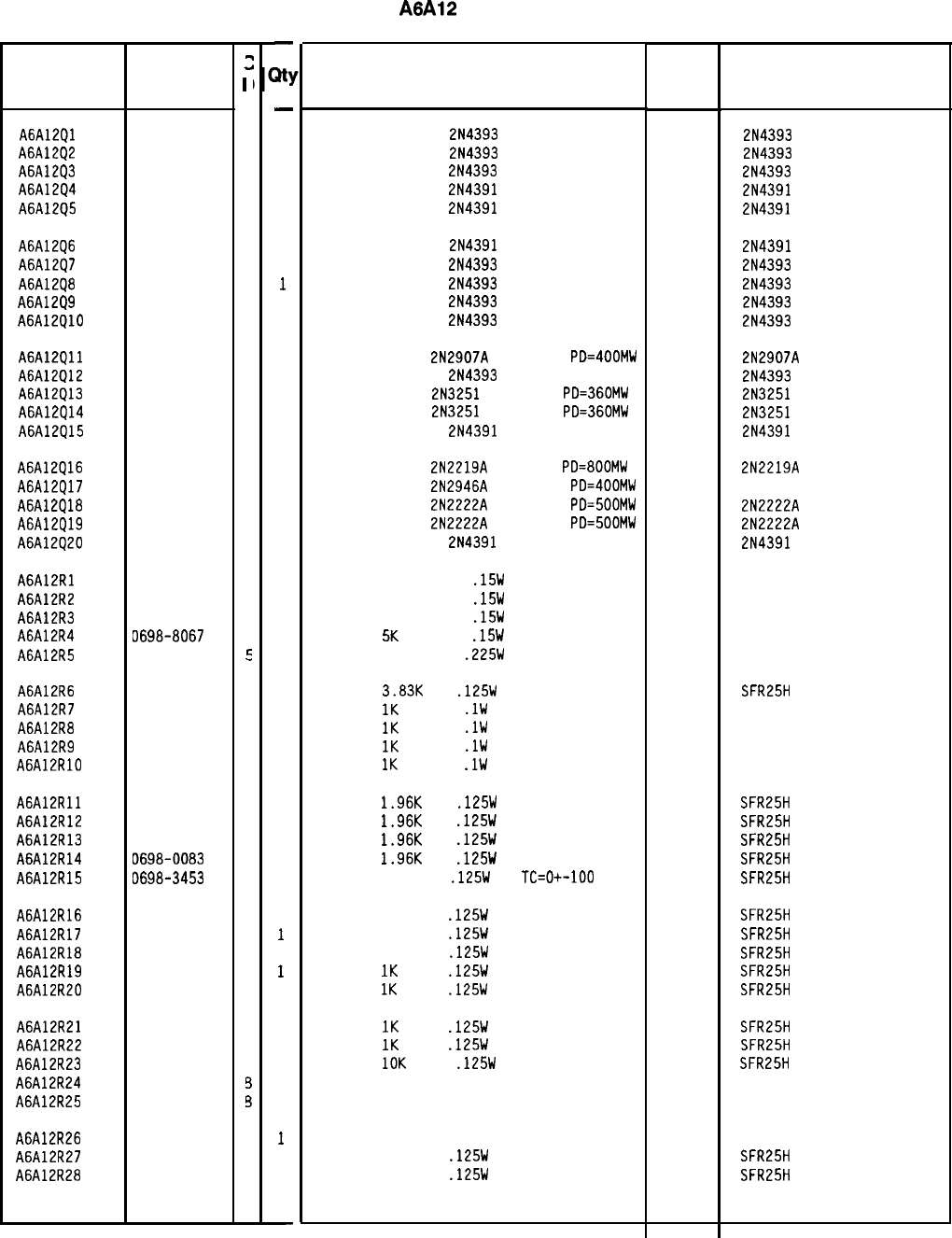
Reference
Designation
HP Part
Number
A6A12Ql 1855-0414
A6A12Q2 1855-0414
A6A12Q3 1855-0414
A6A12Q4 1855-0420
A6A12Q5 1855-0420
A6A12Q6 1855-0420
A6A12Q7 1855-0414
A6A12Q8 1855-0414
A6A12Q9 1855-0414
A6A12QlD 1855-0414
A6A12Qll 1853-0281
A6A12Q12 1855-0414
A6A12Q13 1853-0007
A6A12Q14 1853-0007
A6A12Q15 1855-0420
A6A12Q16 1854-0637
A6A12Q17 1853-0322
A6A12Q18 1854-0477
A6A12Q19 1854-0477
A6A12Q20 1855-0420
A6A12Rl 0698-8067
A6A12R2 0698-8067
A6A12R3 0698-8067
A6A12R4 0698-8067
A6A12R5 0699-0153
A6A12R6 0698-3153
A6A12R7 0698-8625
A6A12R8 0698-8625
A6A12R9 0698-8625
A6A12RlO 0698-8625
A6A12Rll 0698-0083
A6A12R12 0698-0083
A6A12R13 0698-0083
A6A12R14 0698-0083
A6A12R15 0698-3453
A6A12R16 0698-3453
A6A12R17 0698-3453
A6A12R18 0698-3453
A6A12R19 0757-0280
A6A12R20 0757-0280
A6A12R21
1757-0280
A6A12R22
1757-0280
A6A12R23
1757-0442
A6A12R24
1100-3353
A6A12R25
1100-3353
A6A12R26
1100-3357
A6A12R27
1698-3453
A6A12R28
1698-3453
8566040235 Parts List
Page 2 of 5
2
3
4
4
4
2
2
2
4
4
4
4
9
4
7
7
2
1
9
7
7
2
4
4
4
4
5
9
C
C
C
C
a
a
a
a
2
2
2
2
3
3
3
3
3
3
3
2
2
2
-
Jo
-
1
1
1
1
1
1
1
1
1
1
1
1
1
1
1
1
1
1
1
1
1
1
1
1
1
1
1
1
1
1
1
1
1
1
1
1
1
1
1
1
1
1
1
1
1
1
1
1
-
HP Part Number 85660-60235
A6A12
YTX Driver
Description
TRANSISTOR J-FET
2N4393
N-CHAN D-MODE
TRANSISTOR J-FET
2N4393
N-CHAN D-MODE
TRANSISTOR J-FET
2N4393
N-CHAN D-MODE
TRANSISTOR J-FET
2N4391
N-CHAN D-MODE
TRANSISTOR J-FET
2N4391
N-CHAN D-MODE
Mfr Mfr Part
Code Number
17856 2N4393
17856 2N4393
17856 2N4393
17856 2N4391
17856 2N4391
TRANSISTOR J-FET
2N4391
N-CHAN D-MODE
17856 2N4391
TRANSISTOR J-FET
2N4393
N-CHAN D-MODE
17856 2N4393
TRANSISTOR J-FET
2N4393
N-CHAN D-MODE
17856 2N4393
TRANSISTOR J-FET
2N4393
N-CHAN D-MODE
17856 2N4393
TRANSISTOR J-FET
2N4393
N-CHAN D-MODE
17856 2N4393
TRANSISTOR PNP
2N2907A
SI TO-18
PD=400MW 04713 2N2907A
TRANSISTOR J-FET
2N4393
N-CHAN D-MODE
17856 2N4393
TRANSISTOR PNP
2N3251
SI TO-18
PD=360MW 04713 2N3251
TRANSISTOR PNP
2N3251
SI TO-18
PD=360MW 04713 2N3251
TRANSISTOR J-FET
2N4391
N-CHAN D-MODE
17856 2N4391
TRANSISTOR NPN
2N2219A
SI TO-5
PD=800MW 04713
TRANSISTOR PNP
2N2946A
SI TO-46
PD=400MW
04713
TRANSISTOR NPN
2N2222A
SI TO-18
PD=500MW 04713
TRANSISTOR NPN
2N2222A
SI TO-18
PD=500MW 04713
TRANSISTOR J-FET
2N4391
N-CHAN D-MODE
17856
2N2219A
2N2222A
2N2222A
2N4391
RESISTOR 5K +-0.01%
.15W
MF TC=O+-1.3
18612 301358
RESISTOR 5K +-0.01%
.15W
MF TC=O+-1.3
18612 301358
RESISTOR 5K +-0.01%
.15W
MF TC=O+-1.3
18612 301358
RESISTOR
51:
+-0.01%
.15W
MF TC=O+-1.3
18612 301358
RESISTOR 2K +-0.1%
.225W
MF TC=O+-1.3
18612
301358
RESISTOR
3.83K
1%
.125W
TF TC=O+-100
RESISTOR
1K
+-0.1%
.lW
TF TC=O+-5
RESISTOR
1K
+-0.1%
.lW
TF TC=O+-5
RESISTOR
1K
+-0.1%
.lW
TF TC=O+-5
RESISTOR
1K
+-0.1%
.lW
TF TC=O+-5
RESISTOR
1.96K
1%
.125W
TF TC=O+-100
RESISTOR
1.96K
1%
.125W
TF TC=O+-100
RESISTOR
1.96K
1%
.125W
TF TC=O+-100
RESISTOR
1.96K
1%
.125W
TF TC=O+-100
RESISTOR 196K 1%
.125W
TF
TC=O+-100
RESISTOR 196K 1%
.125W
TF TC=O+-100
RESISTOR 196K 1%
.125W
TF TC=O+-100
RESISTOR 196K 1%
.125W
TF TC=O+-100
RESISTOR
1K
+-1%
.125W
TF TC=O+-100
RESISTOR
1K
+-1%
.125W
TF TC=O+-100
RESISTOR
1K
+-1%
.125W
TF TC=O+-100
RESISTOR
1K
+-1%
.125W
TF TC=O+-100
RESISTOR
10K
+-1%
.125W
TF TC=O+-100
RESISTOR-TRMR 20K 10% TKF SIDE-ADJ I-TRN
RESISTOR-TRMR 20K 10% TKF SIDE-ADJ l-TRN
RESISTOR-TRMR 500K 10% TKF SIDE-ADJ l-TR
RESISTOR 196K 1%
.125W
TF TC=O+-100
RESISTOR 196K 1%
.125W
TF TC=O+-100
19701
19701
19701
19701
19701
19701
19701
19701
19701
19701
19701
19701
19701
19701
19701
19701
19701
19701
32997
32997
32997
19701
19701
SFR25H
50232
50232
50232
50232
SFR25H
SFR25H
SFR25H
SFR25H
SFR25H
SFR25H
SFR25H
SFR25H
SFR25H
SFR25H
SFR25H
SFR25H
SFR25H
3386X-Y46-203
3386X-Y46-203
3386X-Y46-504
SFR25H
SFR25H
*Indicates factory-selected value
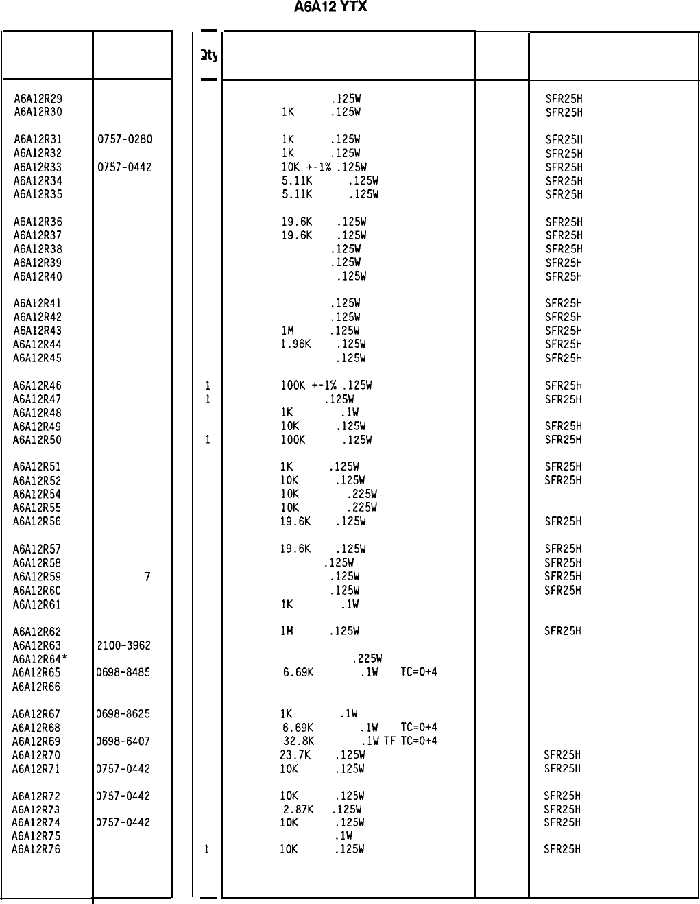
Reference
Designation
HP Part
Number
C
D
A6A12R29 0698-3453
2
A6A12R30 0757-0280
3
A6A12R31 0757-0280
3
A6A12R32 0757-0280
3
A6A12R33 0757-0442
9
A6A12R34 0757-0438
3
A6A12R35 0757-0438
3
A6A12R36 0698-3157
3
A6A12R37 0698-3157
3
A6A12R3B 0698-4037
0
A6A12R39 0698-4037
0
A6A12R40 0757-0401
0
A6A12R41 0698-4037
0
A6A12R42 0698-4037
0
A6A12R43 0698-8827
4
A6A12R44 0698-0083
8
A6A12R45 0757-0401
0
A6A12R46 0757-0465
6
A6A12R47 0698-0082
7
A6A12R48 0698-8625
0
A6A12R49 0757-0442
9
A6A12R50 0757-0465
6
A6A12R51 0757-0280
A6A12R52 0757-0442
A6A12R54 0698-7479
A6A12R55 0698-7479
A6A12R56 0698-3157
A6A12R57 0698-3157
A6A12R58 0698-0082
A6A12R59
0698-403
7
A6A12R60
0698-4037
A6A12R61
0698-8625
A6A12R62
0698-8827
A6A12R63 2100-3962
A6A12R64* 0698-7133
A6A12R65 D69B-8485
A6A12R66 2100-3962
A6A12R67 3698-8625
A6A12R6B 3698-8485
A6A12R69 3698-6407
A6A12R7D 3698-3158
A6A12R71 3757-0442
A6A12R72 3757-0442
A6A12R73 3698-3151
A6A12R74 3757-0442
A6A12R75 3698-8161
A6A12R76 3757-0442
3
9
0
0
3
3
7
0
0
0
4
5
3
0
5
0
0
2
4
9
9
7
9
9
9
-
sty
-
1
1
1
1
1
1
1
1
1
1
1
1
1
1
1
1
1
1
1
1
1
1
1
1
1
1
1
1
1
1
1
1
1
1
1
1
1
1
1
1
1
1
1
1
1
1
1
-
HP Part Number 85660-60235
A6A12
YTX
Driver
Description Mfr
Mfr Part
Code Number
RESISTOR 196K 1%
.125W
TF TC=D+-100
19701
SFR25H
RESISTOR
1K
+-1%
.125W
TF TC=O+-100
19701
SFR25H
RESISTOR
1K
+-1%
.125W
TF TC=O+-100
19701
SFR25H
RESISTOR
1K
+-1%
.125W
TF TC=O+-100
19701
SFR25H
RESISTOR
10K
+-1X
.125W
TF TC=O+-100
19701
SFR25H
RESISTOR
5.11K
+-1%
.125W
TF TC=O+-100
19701
SFR25H
RESISTOR
5.11K
+-1%
.125W
TF TC=O+-100
19701
SFR25H
RESISTOR
19.6K
1%
.125W
TF TC=O+-100
19701
SFR25H
RESISTOR
19.6K
1%
.125W
TF TC=O+-100
19701
SFR25H
RESISTOR 46.4 1%
.125W
TF TC=O+-100
19701
SFR25H
RESISTOR 46.4 1%
.125W
TF TC=O+-100
19701
SFR25H
RESISTOR 100 +-1%
.125W
TF TC=O+-100
19701
SFR25H
RESISTOR 46.4 1%
.125W
TF TC=O+-100
19701
SFR25H
RESISTOR 46.4 1%
.125W
TF TC=O+-100
19701
SFR25H
RESISTOR
1M
+-1%
.125W
TF TC=O+-100
19701
SFR25H
RESISTOR
1.96K
1%
.125W
TF TC=O+-100
19701
SFR25H
RESISTOR 100 +-1%
.125W
TF TC=O+-100
19701
SFR25H
RESISTOR
1OOK
+-1X
.125W
TF TC=O+-100
19701
SFR25H
RESISTOR 464 1%
.125W
TF TC=O+-100
19701
SFR25H
RESISTOR
1K
+-0.1%
.lW
TF TC=O+-5
19701
50232
RESISTOR
10K
+-1%
.125W
TF TC=O+-100
19701
SFR25H
RESISTOR
1OOK
+-1%
.125W
TF TC=O+-100
19701
SFR25H
RESISTOR
1K
+-1%
.125W
TF TC=O+-100
19701
SFR25H
RESISTOR
10K
+-1%
.125W
TF TC=O+-100
19701
SFR25H
RESISTOR
10K
+-0.1%
.225W
MF TC=O+-1.5
18612 301359
RESISTOR
10K
+-0.1%
.225W
MF TC=O+-1.5
18612
301359
RESISTOR
19.6K
1%
.125W
TF TC=O+-100
19701
SFR25H
RESISTOR
19.6K
1%
.125W
TF TC=O+-100
19701
SFR25H
RESISTOR 464 1%
.125W
TF TC=O+-100
19701
SFR25H
RESISTOR 46.4 1%
.125W
TF TC=O+-100
19701
SFR25H
RESISTOR 46.4 1%
.125W
TF TC=O+-100
19701
SFR25H
RESISTOR
IK
+-0.1%
.lW
TF TC=O+-5
19701
50232
RESISTOR
1M
+-1%
.125W
TF TC=O+-100
19701
SFR25H
RESISTOR-TRMR 5K 10% TF SIDE-ADJ 25-TRN
18612 1280
RESISTOR 15K +-0.05%
.225W
MF
18612 301358
RESISTOR
6.69K
+-0.1%
.lW
TF
TC=0+4
19701
50232
RESISTOR-TRMR 5K 10% TF SIDE-ADJ 25-TRN
18612 1280
RESISTOR
1K
+-0.1%
.lW
TF TC=O+-5
RESISTOR
6.69K
+-0.1%
.lW
TF
TC=0+4
RESISTOR
32.BK
+-0.1%
.lW
TF
TC=0+4
RESISTOR
23.7K
1%
.125W
TF TC=O+-100
RESISTOR
10K
+-1%
.125W
TF TC=O+-100
19701
19701
19701
19701
19701
19701
19701
19701
19701
19701
50232
50232
50232
SFR25H
SFR25H
RESISTOR
IOK
+-1%
.125W
TF TC=O+-100
RESISTOR
2.8JK
1%
.125W
TF TC=O+-100
RESISTOR
10K
+-1%
.125W
TF TC=O+-100
RESISTOR 20K +-1%
.lW
TF TC=O+-5
RESISTOR
10K
+-1%
.125W
TF TC=O+-100
SFR25H
SFR25H
SFR25H
50232
SFR25H
*Indicates factory-selected value
85660-60235 Parts List
Page 3 of 5
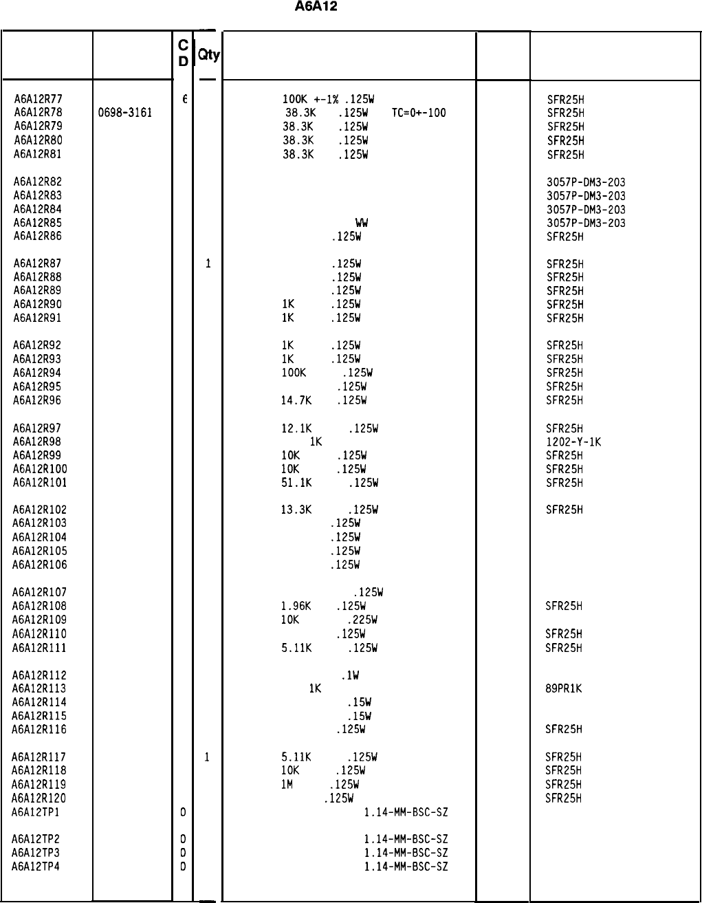
Reference
Designation
HP Part
Number
A6A12R77 0757-0465
E
A6A12R78 0698-3161
9
A6A12R79 0698-3161
9
A6A12R80 0698-3161
9
A6A12R81 0698-3161
9
A6A12R82 2100-1661
7
A6A12R83 2100-1661
7
A6A12R84 2100-1661
7
A6A12R85 2100-1661
7
A6A12R86 0698-3453
2
A6A12R87 0698-3453
2
A6A12R88 0698-3453
2
A6A12R89 0698-3453
2
A6A12R90 0757-0280
3
A6A12R91 0757-0280
3
A6A12R92 0757-0280
3
A6A12R93 0757-0280
3
A6A12R94 0757-0465
6
A6A12R95 0757-0401
0
A6A12R96 0698-3156
2
A6A12R97 0757-0444
1
A6A12R98 2100-3390
3
A6A12R99 0757-0442
9
A6A12RlOO 0757-0442
9
A6A12RlOl 0757-0458
7
A6A12R102 0757-0289
2
A6A12R103 0757-0346
2
A6A12R104 0757-0346
2
A6A12R105 0757-0346
2
A6A12R106 0757-0346
2
A6A12R107 0698-5667
4
A6A12R108 0698-0083
8
A6A12R109 0698-7479
0
A6A12RllO 0757-0401
0
A6A12Rlll 0757-0438
3
A6A12R112 0698-8547
A6A12R113 2100-3154
A6A12R114 0698-8067
A6A12R115 0698-8067
A6A12R116 0757-0401
A6A12RllJ 0757-0438
A6A12R118 0757-0442
A6A12R119 0698-8827
A6A12R120 0698-3437
A6A12TPl 1251-0600
A6A12TP2 1251-0600
A6A12TP3 1251-0600
A6A12TP4 1251-0600
5
7
4
4
0
3
3
4
2
0
0
0
0
85660-60235 Parts List
Page 4 of 5
-
Ml
-
1
1
1
1
1
1
1
1
1
1
1
1
1
1
1
1
1
1
1
1
1
1
1
1
1
1
1
1
1
1
1
1
1
1
1
1
1
1
1
1
1
1
1
1
1
1
1
1
-
HP Part Number 85660-60235
A6A12
YTX Driver
Description Mfr
Mfr Part
Code
Number
RESISTOR
1OOK
+-I%
.125W
TF TC=O+-100
19701
SFR25H
RESISTOR
38.3K
1%
.125W
TF
TC=D+-100
19701
SFR25H
RESISTOR
38.3K
1%
.125W
TF TC=O+-100
19701
SFR25H
RESISTOR
38.3K
1%
.125W
TF TC=O+-100
19701
SFR25H
RESISTOR
38.3K
1%
.125W
TF TC=O+-100
19701
SFR25H
RESISTOR-TRMR 20K 5% WW SIDE-ADJ 22-TRN
32997 3057P-DM3-203
RESISTOR-TRMR 20K 5% WW SIDE-ADJ 22-TRN
32997 3057P-DM3-203
RESISTOR-TRMR 20K 5% WW SIDE-ADJ 22-TRN
32997 3057P-DM3-203
RESISTOR-TRMR 20K 5%
WV
SIDE-ADJ 22-TRN
32997 3057P-DM3-203
RESISTOR 196K 1%
.125W
TF TC=O+-100
19701
SFR25H
RESISTOR 196K 1%
.125W
TF TC=O+-100
19701
SFR25H
RESISTOR 196K 1%
.125W
TF TC=O+-100
19701
SFR25H
RESISTOR 196K 1%
.125W
TF TC=O+-100
19701
SFR25H
RESISTOR
1K
+-1%
.125W
TF TC=O+-100
19701
SFR25H
RESISTOR
1K
+-1%
.125W
TF TC=O+-100
19701
SFR25H
RESISTOR
1K
+-1%
.125W
TF TC=D+-100
19701
SFR25H
RESISTOR
1K
+-1%
.125W
TF TC=O+-100
19701
SFR25H
RESISTOR
1OOK
+-1%
.125W
TF TC=O+-100
19701
SFR25H
RESISTOR 100 +-1%
.125W
TF TC=O+-100
19701
SFR25H
RESISTOR
14.7K
1%
.125W
TF TC=O+-100
19701
SFR25H
RESISTOR
12.1K
+-1%
.125W
TF TC=O+-100
19701
SFR25H
RESISTOR-TRMR
1K
10% TF SIDE-ADJ 25-TRN
18612 1202-Y-1K
RESISTOR
10K
+-1%
.125W
TF TC=O+-100
19701
SFR25H
RESISTOR
10K
+-1%
.125W
TF TC=O+-100
19701
SFR25H
RESISTOR
51.1K
+-1%
.125W
TF TC=O+-100
19701
SFR25H
RESISTOR
13.3K
+-1%
.125W
TF TC=O+-100
19701
SFR25H
RESISTOR 10 +-1%
.125W
TF TC=O+-100
91637 CMF-55-1, T-l
RESISTOR 10 +-1%
.125W
TF TC=O+-100
91637 CMF-55-1, T-l
RESISTOR 10 +-1%
.125W
TF TC=D+-100
91637 CMF-55-1, T-l
RESISTOR 10 +-1%
.125W
TF TC=O+-100
91637 CMF-55-1, T-l
RESISTOR 375 +-0.25%
.125W
TF TC=O+-25
19701
5033R
RESISTOR
1.96K
1%
.125W
TF TC=O+-100
19701
SFR25H
RESISTOR
10K
+-0.1%
.225W
MF TC=O+-1.5
18612
301359
RESISTOR 100 +-1%
.125W
TF TC=O+-100
19701
SFR25H
RESISTOR
5.11K
+-1%
.125W
TF TC=O+-100
19701
SFR25H
RESISTOR 4K +-0.5%
.lW
TF TC=O+-5
19701
50232
RESISTOR-TRMR
1K
10% TKF SIDE-ADJ 17-TRN
73138 89PRlK
RESISTOR 5K +-0.01%
.15W
MF TC=O+-1.3
18612 301358
RESISTOR 5K +-0.01%
.15W
MF TC=O+-1.3
18612 301358
RESISTOR 100 +-1%
.125W
TF TC=O+-100
19701
SFR25H
RESISTOR
5.11K
+-1%
.125W
TF TC=O+-100
19701
SFR25H
RESISTOR
10K
+-1%
.125W
TF TC=O+-100
19701
SFR25H
RESISTOR
1M
+-1%
.125W
TF TC=O+-100
19701
SFR25H
RESISTOR 133 1%
.125W
TF TC=O+-100
19701
SFR25H
CONNECTOR-SGL CONT PIN
1.14-MM-BSC-SZ
SQ
27264 16-06-0034
CONNECTOR-SGL CDNT PIN
1.14-MM-BSC-SZ
SQ
27264 16-06-0034
CONNECTOR-SGL CONT PIN
1.14-MM-BSC-SZ
SQ
27264 16-06-0034
CONNECTOR-SGL CONT PIN
1.14-MM-BSC-SZ
SQ
27264 16-06-0034
*Indicates facto y-selected value
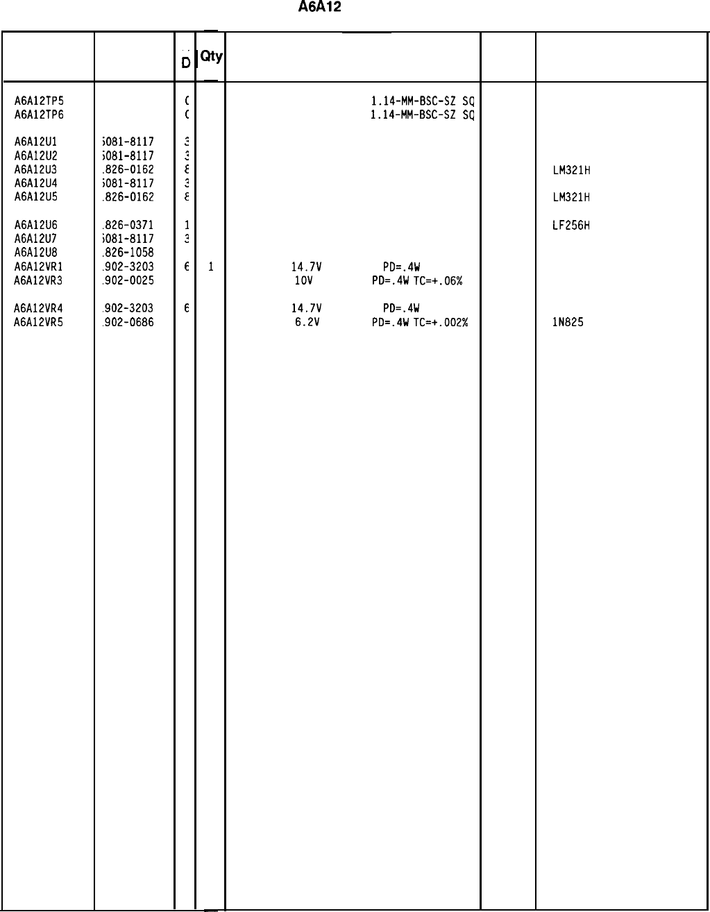
Reference HP Part
Designation Number
A6A12TP5
1251-0600
A6A12TP6
1251-0600
A6A12Ul
A6A12U2
A6A12U3
A6A12U4
A6A12U5
iO81-8117
iO81-8117
.826-0162
iO81-8117
.826-0162
A6A12U6
.826-0371
A6A12U7
iO81-8117
A6A12U8
.826-1058
A6A12VRl
.902-3203
A6A12VR3
.902-0025
A6A12VR4
.902-3203
A6A12VR5
.902-0686
C
c
c
c
:
:
E
3
E
1
3
3
E
4
E
3
-
at!
-
1
1
1
1
1
1
1
1
1
1
1
1
1
1
-
HP Part Number 85660-60235
A6A12
YTX Driver
Description
CONNECTOR-SGL CONT PIN
1.14-MM-BSC-SZ
SQ
27264 16-06-0034
CONNECTOR-SGL CONT PIN
1.14~MM-BSC-SZ
SQ
27264 16-06-0034
SCREENED 1826-0092 OP AMP 28480 5081-8117
SCREENED 1826-0092 OP AMP 28480 5081-8117
IC PREAMPLIFIER TO-99 PKG 27014 LM321H
SCREENED 1826-0092 DP AMP 28480 5081-8117
IC PREAMPLIFIER TO-99 PKG 27014 LM321H
IC OP AMP LOW-BIAS-H-IMPD TO-99 PKG 27014
SCREENED 1826-0092 OP AMP 28480
IC DP AMP GP 8-TD-99 PKG 06665
DIODE-ZNR
14.7V
5% DO-35
PD=.4W 04713
DIODE-ZNR
1OV
5% DO-35
PD=.4W
TC=+.OEi%
04713
LF256H
5081-8117
DP-OECJ
DIODE-ZNR
14.7V
5% DO-35
PD=.4W 04713
DIODE-ZNR
6.2V
2% DO-7
PD=.4W
TC=+.002% 04713 lN825
Mfr
Mfr Part
Code Number
*Indicates factoy-selected value
85660-60235 Parts List
Page 5 of 5
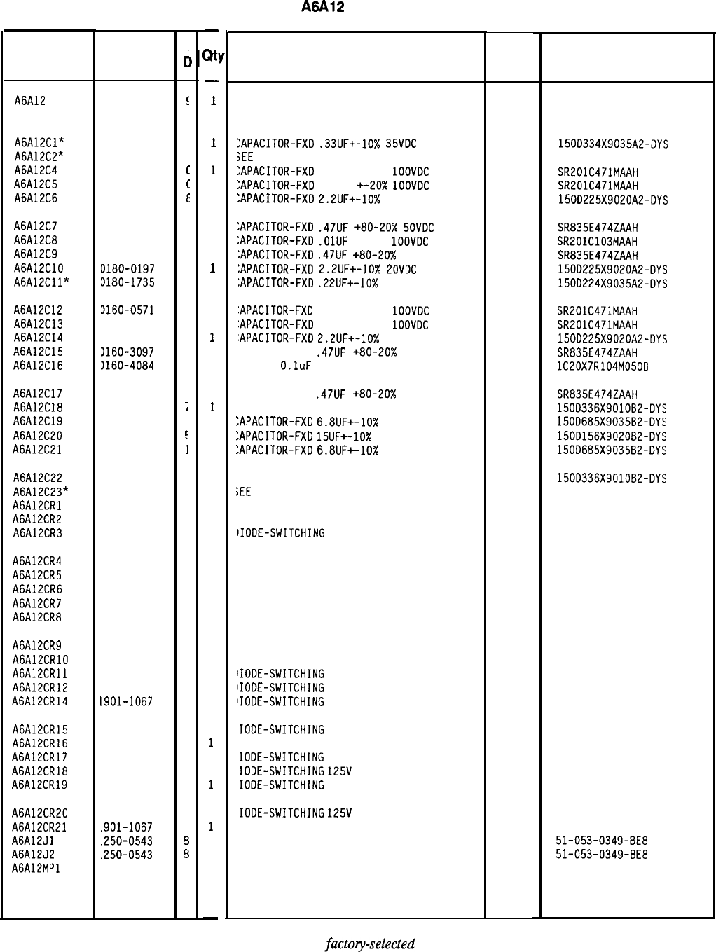
HP Part Number 85660-60366
Reference HP Part
C
Designation
Number
c
A6A12 85660-60366
!
A6A12Cl*
A6A12C2”
A6A12C4
A6A12C5
A6A12C6
0180-2205
0160-0571
(
0160-0571
(
0180-0197
E
A6A12C7 0160-3097
1
A6A12C8 0160-3879
7
A6A12C9 0160-3097
1
A6A12ClO
0180-0197
8
A6A12Cll* 3180-1735
2
A6A12C12 3160-0571
0
A6A12C13 3160-0571
0
A6A12C14 3180-0197
8
A6A12C15 3160-3097
1
A6A12C16 3160-4084
8
A6A12C17 1160-3097
A6A12C18
0180-0229
A6A12C19 0180-0116
A6A12C20 0180-1746
A6A12C21 0180-0116
A6A12C22
A6A12C23*
A6A12CRl
A6A12CR2
A6A12CR3
0180-0229
1901-1067
1901-1067
1901-1067
A6A12CR4 1901-1067
A6A12CR5 1901-1067
A6A12CR6 1901-1067
A6A12CR7 1901-1067
A6A12CR8 1901-1067
A6A12CR9 1901-1067
A6A12CRlO
1901-1067
A6A12CRll 1901-1067
A6A12CR12 1901-1067
A6A12CR14 L901-1067
A6A12CR15 1901-1067
A6A12CR16
1901-1067
A6A12CR17
1901-1067
A6A12CR18
1901-1067
A6A12CR19 1901-1067
A6A12CR20
A6A12CR21
A6A12Jl
A6A12J2
A6A12MPl
1901-1067
.901-1067
.250-0543
.250-0543
1
j
I
r:
;
7
4
4
4
4
4
4
4
4
4
4
4
4
4
4
4
4
4
4
4
4
6
3
-
;Itl
-
1
1
1
1
1
1
1
1
1
1
1
1
1
1
1
1
1
1
1
1
1
1
1
1
1
1
1
1
1
1
1
1
1
1
1
1
1
1
1
1
1
1
1
-
A6A12
YTX Driver
Description Mfr Mfr Part
Code Number
30 ASSEMBLY, YIG-TUNED MIXER (YTX) DRIVE
(SERI
AL PRE
F
IX
: 2936A)
28480 85660-60366
:APACITOR-FXD
.33UF+-10%
35VOC
TA
;EE
85660-60366 SCHEMATIC DIAGRAM
:APACITOR-FXD
470PF +-20%
1OOVDC
CER
:APACITOR-FXD
470PF
+-20x
1OOVDC
CER
:APACITOR-FXD
2.2lJF+-10%
20VDC TA
56289 150D334X9035A2-DYS
04222 SR201C471MAAH
04222 SR201C471MAAH
56289 150D225X9020A2-DYS
:APACITOR-FXD
.47lJF
+80-20x
SOVDC
CER
04222 SR835E474ZAAH
:APACITOR-FXD
.OlUF
+-20%
1OOVDC
CER
04222 SR201C103MAAH
:APACITOR-FXD
.47UF
+80-20%
50VDC CER
04222 SR835E474ZAAH
:APACITOR-FXD
2.2UF+-10%
LOVDC
TA
56289 150D225X9020A2-DYS
:APACITOR-FXD
.22UF+-10%
35VDC TA
56289 1500224X9035A2-DYS
:APACITOR-FXD
470PF +-20%
1OOVDC
CER
04222 SR201C471MAAH
:APACITOR-FXD
470PF +-20%
1OOVDC
CER
04222 SR201C471MAAH
.APACITOR-FXD
2.2UF+-10%
20VDC TA
56289 150D225X9020A2-DYS
APACITOR-FXD
.47UF
+80-20% 50VDC CER
04222 SR835E474ZAAH
AP-FXD
O.luF
50 V
56289 lC20X7R104M050B
APACITOR-FXD
.47UF
+80-20x
50VDC CER
:AP-FXD 33uF 10 V TA
:APACITOR-FXD
6.8UF+-10%
35VDC TA
:APACITOR-FXD
15UF+-10%
20VDC TA
:APACITOR-FXD
6.8UF+-10%
35VDC TA
04222 SR835E474ZAAH
56289 150D336X901082-DYS
56289 150D685X903582-DYS
56289 150D156X902082-DYS
56289 150D685X903582-DYS
:AP-FXD 33uF 10 V TA 56289 150D336X901082-DYS
;EE
85660-60366 SCHEMATIC DIAGRAM
IIODE-SWITCHING 125V 175MA 60NS DO-35
IIODE-SWITCHING 125V 175MA 60NS DO-35
)IODE-SWITCHING
125V 175MA 60NS DO-35
27014 FDH444
27014 FDH444
27014 FDH444
IIODE-SWITCHING 125V 175MA 60NS DO-35 27014 FDH444
IIODE-SWITCHING 125V 175MA 60NS DO-35 27014 FDH444
IIODE-SWITCHING 125V 175MA 60NS DO-35 27014 FDH444
IIODE-SWITCHING 125V 175MA 60NS DO-35 27014 FDH444
IIOOE-SWITCHING 125V 175MA 60NS DO-35 27014 FDH444
IIODE-SWITCHING 125V 175MA 60NS DO-35 27014 FDH444
IIODE-SWITCHING 125V 175MA 60NS DO-35 27014 FDH444
IIODE-SWITCHING
125V 175MA 60NS DO-35
27014 FDH444
lIODE-SWITCHING
125V 175MA 60NS DO-35
27014 FDH444
lIODE-SWITCHING
125V 175MA 60NS DO-35
27014 FDH444
IODE-SWITCHING
125V 175MA 60NS DO-35
27014 FDH444
IODE-SWITCHING 125V 175MA 60NS DO-35 27014 FDH444
IODE-SWITCHING
125V 175MA 60NS DO-35
27014 FDH444
IODE-SWITCHING
125V
175MA 60NS DO-35
27014 FDH444
IODE-SWITCHING
125V 175MA 60NS DO-35
27014 FDH444
IODE-SWITCHING
125V
175MA 60NS DO-35
IODE-SWITCHING 125V 175MA 60NS DO-35
ONNECTOR-RF SM-SNP M PC 50-OHM
ONNECTOR-RF SM-SNP M PC 50-OHM
OT ASSIGNED
27014 FDH444
27014 FDH444
98291 51-053-0349-8E8
98291 51-053-0349-8E8
*Indicates factory-selected value
85660-60366 Parts List
Page 1 of 5
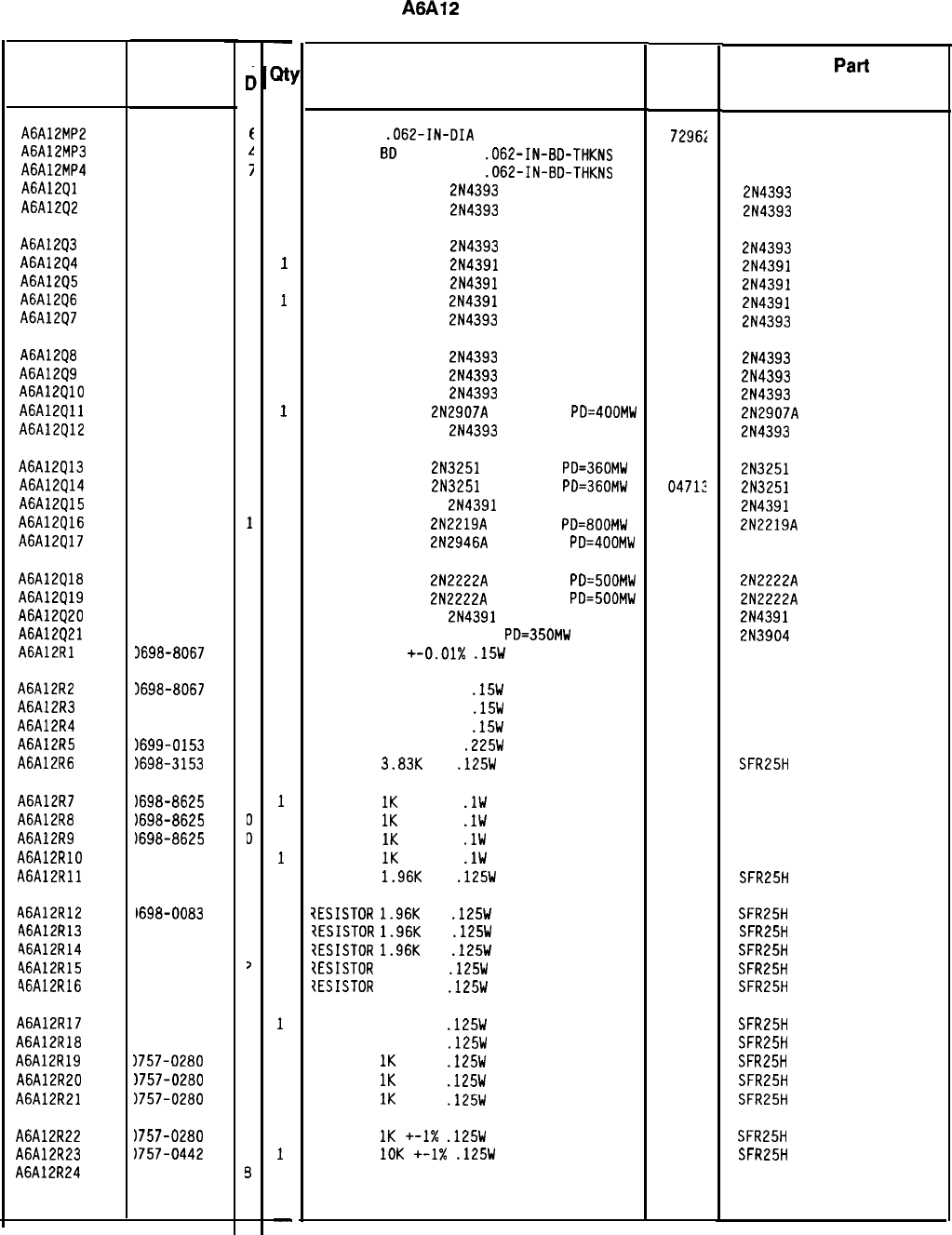
HP Part Number 85660-60366
A6A12
YTX Driver
Description Mfr Mfr
Part
Code Number
PIN-ROLL
.062-IN-DIA
.25-IN-LG BE-CU
EXTR-PC
8D
BRN POLYC
.062-IN-BD-THKNS
EXTR-PC BD RED POLYC
.062-IN-BD-THKNS
TRANSISTOR J-FET
2N4393
N-CHAN D-MODE
TRANSISTOR J-FET
2N4393
N-CHAN D-MODE
72962
99-012-062-0250
17856
2N4393
17856
2N4393
TRANSISTOR J-FET
2N4393
N-CHAN D-MODE
17856
2N4393
TRANSISTOR J-FET
2N4391
N-CHAN D-MODE
17856
2N4391
TRANSISTOR J-FET
2N4391
N-CHAN D-MODE
17856
2N4391
TRANSISTOR J-FET
2N4391
N-CHAN D-MODE
17856
2N4391
TRANSISTOR J-FET
2N4393
N-CHAN D-MODE
17856 2N4393
TRANSISTOR J-FET
2N4393
N-CHAN D-MODE
17856 2N4393
TRANSISTOR J-FET
2N4393
N-CHAN D-MODE
17856 2N4393
TRANSISTOR J-FET
2N4393
N-CHAN D-MODE
17856 2N4393
TRANSISTOR PNP
2N2907A
SI TO-18
PD=400MW 04713 2N2907A
TRANSISTOR J-FET
2N4393
N-CHAN D-MODE
17856 2N4393
TRANSISTOR PNP
2N3251
SI TO-18
PD=360MW
0471:
TRANSISTOR PNP
2N3251
SI TO-18
PD=360MW
04712
TRANSISTOR J-FET
2N4391
N-CHAN D-MODE
17856
TRANSISTOR NPN
2N2219A
SI TO-5
PD=800MW
04713
TRANSISTOR PNP
2N2946A
SI TO-46
PD=400MW 04713
2N3251
2N3251
2N4391
2N2219A
TRANSISTOR NPN
2N2222A
SI TO-18
PD=SOOMW 04713 2N2222A
TRANSISTOR NPN
2N2222A
SI TO-18
PD=500MW 04713 2N2222A
TRANSISTOR J-FET
2N4391
N-CHAN D-MODE
17856 2N4391
TRANSISTOR NPN SI TO-92
PD=350MW 04713 2N3904
RESISTOR 5K +-0.01X
.15W
MF TC=O+-1.3
18612 301358
RESISTOR 5K +-0.01%
.15W
MF TC=O+-1.3
18612 301358
RESISTOR 5K +-0.01%
.15W
MF TC=O+-1.3
18612 301358
RESISTOR 5K +-0.01%
.15W
MF TC=O+-1.3
18612 301358
RESISTOR 2K +-0.1%
.225W
MF TC=O+-1.3
18612 301358
RESISTOR
3.83K
1%
.125W
TF TC=O+-100
19701
SFR25H
RESISTOR
IK
+-0.1%
.lW
TF TC=O+-5
RESISTOR
1K
+-0.1%
.lW
TF TC=O+-5
RESISTOR
1K
+-0.1%
.lW
TF TC=O+-5
RESISTOR
IK
+-0.1%
.lW
TF TC=O+-5
PESISTOR
1.96K
1%
.125W
TF TC=O+-100
19701
19701
19701
19701
19701
19701
19701
19701
19701
19701
19701
19701
19701
19701
19701
19701
19701
32997
50232
50232
50232
50232
SFR25H
?ESISTOR
1.96K
1%
.125W
TF TC=O+-100
?ESISTOR
1.96K
1%
.125W
TF TC=O+-100
7ESISTOR
1.96K
1%
.125W
TF TC=O+-100
ZESISTOR
196K 1%
.125W
TF TC=O+-100
?ESISTDR
196K 1%
.125W
TF TC=O+-100
SFR25H
SFR25H
SFR25H
SFR25H
SFR25H
RESISTOR 196K 1%
.125W
TF TC=O+-100
RESISTOR 196K 1%
.125W
TF TC=O+-100
RESISTOR
1K
+-1%
.125W
TF TC=O+-100
RESISTOR
1K
+-1%
.125W
TF TC=O+-100
RESISTOR
1K
+-1%
.125W
TF TC=O+-100
SFR25H
SFR25H
SFR25H
SFR25H
SFR25H
RESISTOR
1K
+-1X
.125W
TF TC=O+-100
RESISTOR
IOK
+-1X
.125W
TF TC=O+-100
RESISTOR-TRMR 20K 10% TKF SIDE-ADJ l-TRN
SFR25H
SFR25H
3386X-Y46-203
*Indicates factory-selected value
Reference
Designation HP Part
Number
A6A12MP2 1480-0073
A6A12MP3 4040-0749
A6A12MP4 4040-0750
A6A12Ql 1855-0414
A6A12Q2 1855-0414
A6A12Q3 1855-0414
A6A12Q4 1855-0420
A6A12Q5 1855-0420
A6A12Q6 1855-0420
A6A12Q7 1855-0414
A6A12Q8 1855-0414
A6A12Q9 1855-0414
A6A12QlO 1855-0414
A6A12Qll
1853-0281
A6A12Q12 1855-0414
A6A12Q13 1853-0007
A6A12Q14 1853-0007
A6A12Q15 1855-0420
A6A12Q16 1854-0637
A6A12Q17 1853-0322
A6A12Q18 1854-0477
A6A12Q19 1854-0477
A6A12Q20 1855-0420
A6A12Q21 1854-0215
A6A12Rl 3698-8067
A6A12R2 1698-8067
A6A12R3 1698-8067
A6A12R4
1698-8067
A6A12R5
1699-0153
A6A12R6
1698-3153
A6A12R7
1698-8625
A6A12R8
1698-8625
A6A12R9
1698-8625
A6A12RlO
1698-8625
A6A12Rll
1698-0083
A6A12R12
1698-0083
A6A12R13
1698-0083
A6A12R14
1698-0083
46A12R15
1698-3453
46A12R16
1698-3453
A6A12R17 1698-3453
A6A12R18 1698-3453
A6A12R19 1757-0280
A6A12R20 1757-0280
A6A12R21 1757-0280
A6A12R22
1757-0280
A6A12R23
1757-0442
A6A12R24
1100-3353
8566040366 Parts List
Page 2 of 5
C
c
t
I!
i
4
4
4
2
2
2
4
4
4
4
9
4
7
7
2
1
9
7
7
2
1
4
4
4
4
5
9
0
0
0
3
3
3
3
3
>
,
2
2
3
3
3
3
9
9
-
3
1
1
1
1
1
1
1
1
1
1
1
1
1
1
1
1
1
1
1
1
1
1
1
1
1
1
1
1
1
1
1
1
1
1
1
1
1
1
1
1
1
1
1
1
1
1
1
1
-
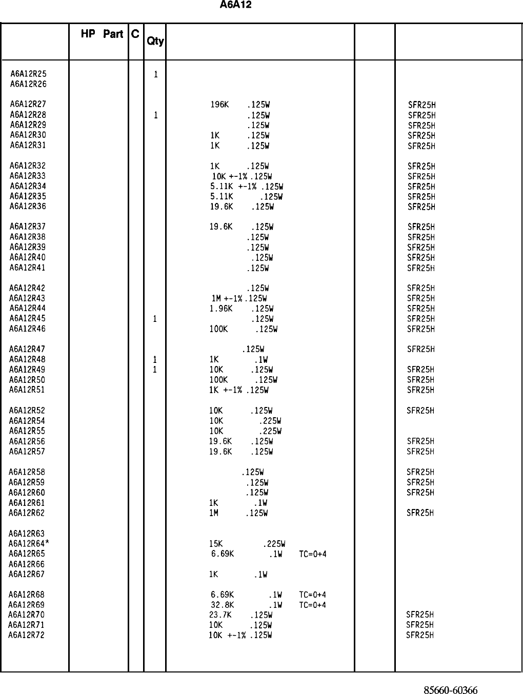
HP Part Number 85660-60366
A6A12
YTX Driver
Reference
HP
Part
c
QtY
Description Mfr
Mfr Part
Designation
Number D
Code Number
A6A12R25
2100-3353 8
1
RESISTOR-TRMR 20K 10% TKF SIDE-ADJ l-TRN
32997 3386X-Y46-203
A6A12R26
2100-3357 2 1
RESISTOR-TRMR 500K 10% TKF SIDE-ADJ l-TR
32997 3386X-Y46-504
A6A12R27
0698-3453 2 1
RESISTOR
196K
1%
.125W
TF TC=O+-100
19701
SFR25H
A6A12R28
0698-3453 2
1
RESISTOR 196K 1%
.125W
TF TC=O+-100
19701
SFR25H
A6A12R29
0698-3453 2 1
RESISTOR 196K 1%
.125W
TF TC=O+-100
19701
SFR25H
A6A12R30
0757-0280 3 1
RESISTOR
1K
+-1%
.125W
TF TC=O+-100
19701
SFR25H
A6A12R31
0757-0280 3 1
RESISTOR
1K
+-1%
.125W
TF TC=O+-100
19701
SFR25H
A6A12R32
0757-0280 3 1
RESISTOR
1K
+-1%
.125W
TF TC=O+-100
19701
SFR25H
A6A12R33
0757-0442 9 1
RESISTOR
10K
+-I%
.125W
TF TC=O+-100
19701
SFR25H
A6A12R34
0757-0438 3 1
RESISTOR
5.11K
+-1X
.125W
TF TC=O+-100
19701
SFR25H
A6A12R35
0757-0438 3 1
RESISTOR
5.11K
+-1%
.125W
TF TC=O+-100
19701
SFR25H
A6A12R36
0698-3157 3 1
RESISTOR
19.6K
1%
.125W
TF TC=O+-100
19701
SFR25H
A6A12R37
0698-3157 3 1
RESISTOR
19.6K
1%
.125W
TF TC=O+-100
19701
SFR25H
A6A12R38
0698-4037 0 1
RESISTOR 46.4 1%
.125W
TF TC=O+-100
19701
SFR25H
A6A12R39
0698-4037 0 1
RESISTOR 46.4 1%
.125W
TF TC=O+-100
19701
SFR25H
A6A12R40
0757-0401 0 1
RESISTOR 100 +-1%
.125W
TF TC=O+-100
19701
SFR25H
A6A12R41
0698-4037 0 1
RESISTOR 46.4 1%
.125W
TF TC=O+-100
19701
SFR25H
A6A12R42
0698-4037 0 1
RESISTOR 46.4 1%
.125W
TF TC=O+-100
19701
SFR25H
A6A12R43
0698-8827 4 1
RESISTOR
1M
+-1X
.125W
TF TC=O+-100
19701
SFR25H
A6A12R44
0698-0083 8 1
RESISTOR
1.96K
1%
.125W
TF TC=O+-100
19701
SFR25H
A6A12R45
0757-0401 0
1
RESISTOR 100 +-1%
.125W
TF TC=O+-100
19701
SFR25H
A6A12R46
0757-0465 6 1
RESISTOR
1OOK
+-1%
.125W
TF TC=O+-100
19701
SFR25H
A6A12R47
0698-0082 7 1
RESISTOR 464 1%
.125W
TF TC=O+-100
19701
SFR25H
A6A12R48
0698-8625 0
1
RESISTOR
1K
+-0.1%
.lW
TF TC=O+-5
19701
50232
A6A12R49
0757-0442 9
1
RESISTOR
10K
+-1%
.125W
TF TC=O+-100
19701
SFR25H
A6A12R50
0757-0465 6 1
RESISTOR
1OOK
+-1%
.125W
TF TC=O+-100
19701
SFR25H
A6A12R51
0757-0280 3 1
RESISTOR
1K
+-I%
.125W
TF TC=O+-100
19701
SFR25H
A6A12R52
0757-0442 9 1
RESISTOR
10K
+-1%
.125W
TF TC=O+-100
19701
SFR25H
A6A12R54
0698-7479 0 1
RESISTOR
10K
+-0.1%
.225W
MF TC=O+-1.5
18612 301359
A6A12R55
0698-7479 0 1
RESISTOR
10K
+-0.1%
.225W
MF TC=O+-1.5
18612 301359
A6A12R56
0698-3157 3 1
RESISTOR
19.6K
1%
.125W
TF TC=O+-100
19701
SFR25H
A6A12R57
0698-3157 3 1
RESISTOR
19.6K
1%
.125W
TF TC=O+-100
19701
SFR25H
A6A12R58
0698-0082 7 1
RESISTOR 464 1%
.125W
TF TC=O+-100
19701
SFR25H
A6A12R59
0698-4037 0 1
RESISTOR 46.4 1%
.125W
TF TC=O+-100
19701
SFR25H
A6A12R60
0698-4037 0 1
RESISTOR 46.4 1%
.125W
TF TC=O+-100
19701
SFR25H
A6A12R61
0698-8625 0 1
RESISTOR
1K
+-0.1%
.lW
TF TC=O+-5
19701
50232
A6A12R62
0698-8827 4 1
RESISTOR
1M
+-1%
.125W
TF TC=O+-100
19701
SFR25H
A6A12R63
2100-3962 5 1
RESISTOR-TRMR 5K 10% TF SIDE-ADJ 25-TRN
18612 1280
A6A12R64"
0698-7133 3 1
RESISTOR
15K
+-0.05%
.225W
MF TC=O+-1.3
18612
301358
A6A12R65
0698-8485 0 1
RESISTOR
6.69K
+-0.1%
.lW
TF
TC=0+4
19701
50232
A6A12R66
2100-3962 5 1
RESISTOR-TRMR 5K 10% TF SIDE-ADJ 25-TRN
18612 1280
A6A12R67
0698-8625 0 1
RESISTOR
1K
+-0.1%
.lW
TF TC=O+-5
19701
50232
A6A12R68
0698-8485 0 1
RESISTOR
6.69K
+-0.1%
.lW
TF
TC=0+4
19701
50232
A6A12R69
0698-6407 2 1
RESISTOR
32.8K
+-0.1%
.lW
TF
TC=0+4
19701
50232
A6A12R70
0698-3158 4 1
RESISTOR
23.7K
1%
.125W
TF TC=O+-100
19701
SFR25H
A6A12R71
0757-0442 9 1
RESISTOR
10K
+-1%
.125W
TF TC=O+-100
19701
SFR25H
A6A12R72
0757-0442 9 1
RESISTOR
10K
+-I%
.125W
TF TC=O+-100
19701
SFR25H
*Indicates factory-selected value
85660-60366 Parts List
Page 3 of 5
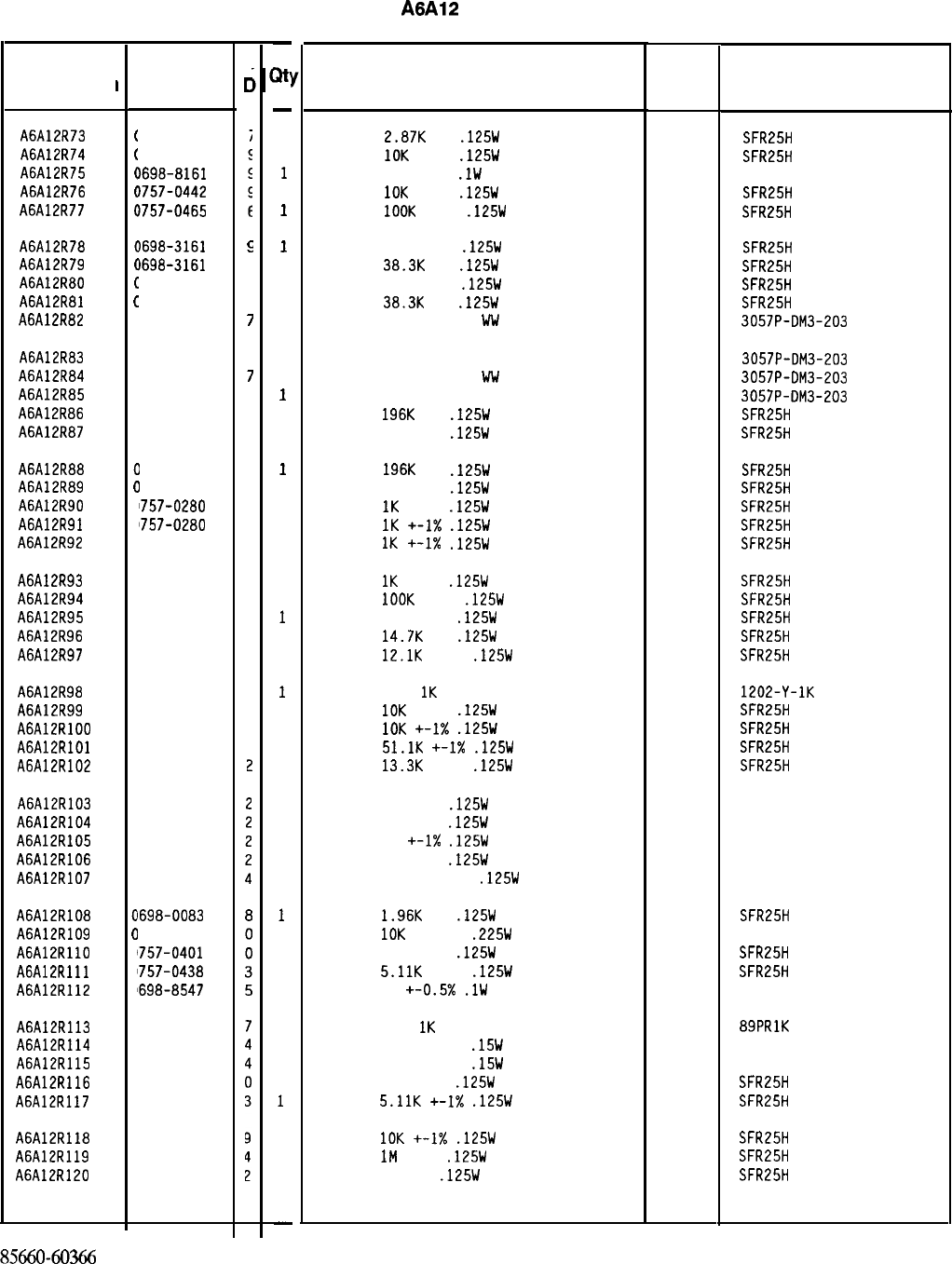
HP Part Number 85660-60366
A6A12
YTX Driver
Description Mfr Mfr Part
Code Number
RESISTOR
2.87K
1%
.125W
TF TC=O+-100
19701
SFR25H
RESISTOR
10K
+-1%
.125W
TF TC=O+-100
19701
SFR25H
RESISTOR 20K +-1%
.lW
TF TC=O+-5
19701
50232
RESISTOR
10K
+-1%
.125W
TF TC=O+-100
19701
SFR25H
RESISTOR
IOOK
+-1%
.125W
TF TC=O+-100
19701 SFR25H
RESISTOR 38.31: 1%
.125W
TF TC=O+-100
19701
SFR25H
RESISTOR
38.3K
1%
.125W
TF TC=O+-100
19701
SFR25H
RESISTOR 38.31: 1%
.125W
TF TC=O+-100
19701
SFR25H
RESISTOR
38.3K
1%
.125W
TF TC=O+-100
19701
SFR25H
RESISTOR-TRMR 20K 5% Ww SIDE-ADJ 22-TRN
32997 3057P-DM3-203
RESISTOR-TRMR 20K 5% WW SIDE-ADJ 22-TRN
32997 3057P-DM3-203
RESISTOR-TRMR 20K 5% Ww SIDE-ADJ 22-TRN
32997 3057P-DM3-203
RESISTOR-TRMR 20K 5% WW SIDE-AOJ 22-TRN
32997 3057P-DM3-203
RESISTOR
196K
1%
.125W
TF TC=O+-100
19701
SFR25H
RESISTOR 196K 1%
.125W
TF TC=O+-100
19701
SFR25H
RESISTOR
196K
1%
.125W
TF TC=O+-100
19701
SFR25H
RESISTOR 196K 1%
.125W
TF TC=O+-100
19701
SFR25H
RESISTOR
1K
+-1%
.125W
TF TC=O+-100
19701
SFR25H
RESISTOR
1K
+-1X
.125W
TF TC=O+-100
19701
SFR25H
RESISTOR
1K
+-I%
.125W
TF TC=O+-100
19701
SFR25H
RESISTOR
1K
+-1%
.125W
TF TC=O+-100
19701
SFR25H
RESISTOR
1OOK
+-1%
.125W
TF TC=O+-100
19701
SFR25H
RESISTOR 100 +-1%
.125W
TF TC=O+-100
19701
SFR25H
RESISTOR
14.7K
1%
.125W
TF TC=O+-100
19701
SFR25H
RESISTOR
12.1K
+-1%
.125W
TF TC=O+-100
19701
SFR25H
RESISTOR-TRMR
1K
10% TF SIDE-ADJ 25-TRN
18612 1202-Y-1K
RESISTOR
10K
+-1%
.125W
TF TC=O+-100
19701
SFR25H
RESISTOR
10K
+-I%
.125W
TF TC=O+-100
19701
SFR25H
RESISTOR
51.1K
+-I%
.125W
TF TC=O+-100
19701
SFR25H
RESISTOR
13.3K
+-1%
.125W
TF TC=O+-100
19701
SFR25H
RESISTOR 10 +-1%
.125W
TF TC=O+-100
91637 CMF-55-1. T-l
RESISTOR 10 +-1%
.125W
TF TC=O+-100
91637 CMF-55-1, T-l
RESISTOR 10
+-1X
.125W
TF TC=O+-100
91637 CMF-55-1, T-l
RESISTOR 10 +-1%
.125W
TF TC=O+-100
91637 CMF-55-1, T-l
RESISTOR 375 +-0.25%
.125W
TF TC=O+-25
19701
5033R
RESISTOR
1.96K
1%
.125W
TF TC=O+-100
19701
SFR25H
RESISTOR
10K
+-0.1%
.225W
MF TC=O+-1.5
18612 301359
RESISTOR 100 +-1%
.125W
TF TC=O+-100
19701
SFR25H
RESISTOR
5.11K
+-1%
.125W
TF TC=O+-100
19701
SFR25H
RESISTOR 4K +-0.5x
.lW
TF TC=O+-5
19701
50232
RESISTOR-TRMR
IK
10% TKF SIDE-ADJ 17-TRN
73138
89PRlK
RESISTOR 5K +-0.01%
.15W
MF TC=O+-1.3
18612 301358
RESISTOR 5K +-0.01%
.15W
MF TC=O+-1.3
18612 301358
RESISTOR 100 +-1%
.125W
TF TC=O+-100
19701
SFR25H
RESISTOR
5.11K
+-I%
.125W
TF TC=O+-100
19701
SFR25H
RESISTOR
10K
+-I%
.125W
TF TC=O+-100
19701
SFR25H
RESISTOR
IM
+-1%
.125W
TF TC=O+-100
19701
SFR25H
RESISTOR 133 1%
.125W
TF TC=O+-100
19701
SFR25H
*Indicates factory-selected value
Reference
Designation
A6A12R73
A6A12R74
A6A12R75
A6A12R76
A6A12R77
A6A12R78
A6A12R79
A6A12R80
A6A12R81
A6A12R82
A6A12R83
A6A12R84
A6A12R85
A6A12R86
A6A12R87
A6A12R88
A6A12R89
A6A12R90
A6A12R91
A6A12R92
A6A12R93
A6A12R94
A6A12R95
A6A12R96
A6A12R97
A6A12R98
A6A12R99
A6A12RlOO
A6A12RlOl
A6A12R102
A6A12R103
A6A12R104
A6A12R105
A6A12R106
A6A12R107
A6A12R108
A6A12R109
A6A12RllO
A6A12Rlll
A6A12R112
A6A12R113
A6A12R114
A6A12R115
A6A12R116
A6A12R117
A6A12R118
A6A12R119
A6A12R120
HP Part
Number
1698-3151
1757-0442
1698-8161
1757-0442
1757-0465
1698-3161
E
)698-3161
9
1698-3161
9
1698-3161
9
!lOO-1661
7
1100-1661
7
1100-1661
7
1100-1661
7
1698-3453
2
1698-3453
2
1698-3453
2
1698-3453
2
1757-0280
3
1757-0280
3
757-0280
3
I
(
(
(
(
1
(
(
c
c
2
2
2
2
a
a
a
II
0
0
0
0
0
0
0
0
2
0
0
0
0
C
C
C
C
a
a
a
0
0
0
2
0
0
0
0
0
0
0
757-0280
3
757-0465
6
757-0401
0
698-3156
2
757-0444
1
100-3390
3
757-0442
9
757-0442
9
757-0458
7
757-0289
2
1757-0346
1757-0346
1757-0346
1757-0346
1698-5667
1698-0083
1698-7479
1757-0401
1757-0438
1698-8547
100-3154
698-8067
698-8067
757-0401
757-0438
757-0442
698-8827
698-3437
85660-60366 Parts List
Page 4 of 5
C
c
-
;Itl
-
1
1
1
1
1
1
1
1
1
1
1
1
1
1
1
1
1
1
1
1
1
1
1
1
1
1
1
1
1
1
1
1
1
1
1
1
1
1
1
1
1
1
1
1
1
1
1
1
-
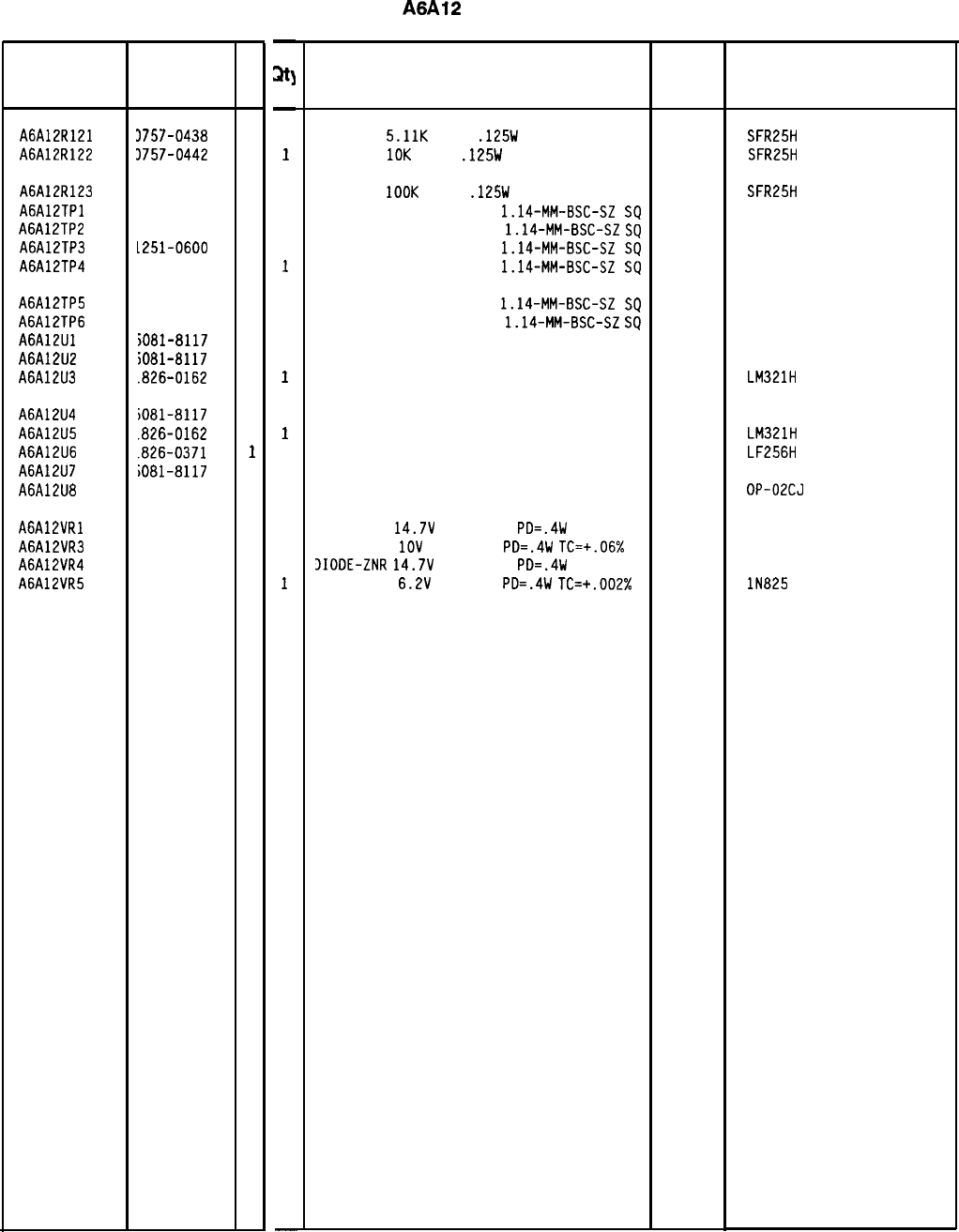
Reference HP Part
C
Designation Number
D
A6A12R121 3757-0438
3
A6A12R122 3757-0442
9
A6A12R123 1757-0465
6
A6A12TPl 1251-0600
0
A6A12TP2 1251-0600
0
A6A12TP3 L251-0600
0
A6A12TP4 1251-0600
0
A6A12TP5 1251-0600
0
A6A12TP6 1251-0600
0
A6A12Ul
iO81-8117
3
A6A12U2
iO81-8117
3
A6A12U3
.826-0162 8
A6A12U4
A6A12U5
A6A12U6
A6A12U7
A6A12U8
iO81-8117
3
.826-0162 8
.826-0371
1
iO81-8117
3
826-1058
3
A6A12VRl 902-3203
6
A6A12VR3 902-0025
4
A6A12VR4 902-3203
6
A6A12VR5 902-0686
3
-
31
-
1
1
1
1
1
1
1
1
1
1
1
1
1
1
1
1
1
1
1
1
1
-
HP Part Number 85660-60366
A6A12
YTX Driver
Description
RESISTOR
5.11K
+-1%
.125W
TF TC=O+-100
19701
SFR25H
RESISTOR
10K
+-1%
.125W
TF TC=O+-100
19701
SFR25H
RESISTOR
1OOK
+-1%
.125W
TF TC=O+-100
19701
SFR25H
CONNECTOR-SGL CONT PIN
1.14-MM-BSC-SZ
SQ
27264 16-06-0034
CONNECTOR-SGL CONT PIN
1.14-MM-BSC-SZ
SQ
27264 16-06-0034
CONNECTOR-SGL CONT PIN
1.14-MM-BSC-SZ
SQ
27264 16-06-0034
CONNECTOR-SGL CONT PIN
1.14-MM-BSC-SZ
SQ
27264 16-06-0034
CONNECTOR-SGL CONT PIN
1.14-MM-BSC-SZ
SQ
27264 16-06-0034
CONNECTOR-SGL CONT PIN
1.14-MM-BSC-SZ
SQ
27264 16-06-0034
SCREENED 1826-0092 OP AMP 28480 5081-8117
SCREENED 1826-0092 OP AMP 28480 5081-8117
IC PREAMPLIFIER TO-99 PKG 27014 LM321H
SCREENED 1826-0092 OP AMP 28480 5081-8117
IC PREAMPLIFIER TO-99 PKG 27014 LM321H
IC OP AMP LOW-BIAS-H-IMPD TO-99 PKG 27014 LF256H
SCREENED 1826-0092 OP AMP 28480 5081-8117
IC OP AMP GP a-TO-99 PKG 06665 OP-OLCJ
DIODE-ZNR
14.7V
5% DO-35
PD=.4W 04713
DIODE-ZNR
1OV
5% DO-35
PD=.4W
TC=+.06% 04713
IIODE-ZNR
14.7V
5% DO-35
PD=.4W 04713
IIODE-ZNR
6.2V
2% DO-7
PD=.4W
TC=+.002% 04713 lN825
*Indicates factoy-selected value
Mfr Mfr Part
Code Number
85660-60366 Parts List
Page 5 of 5
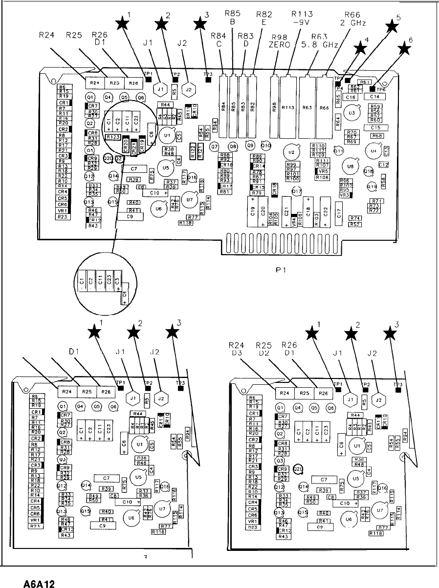
D3 D2
Dl
I
~00000000000000~l
1
15
16
Pl
30
C3 USED
+ +
+
+
+.
ONLY IN 8566A
R24 R’25 R26
D3 D2
Dl
-1
P/O 85660-60013
85660-60366
P/O 85660-60235
I
A6A12
YTX Driver Component Locations, 85660-60366, 85660-60013, 85660-60235
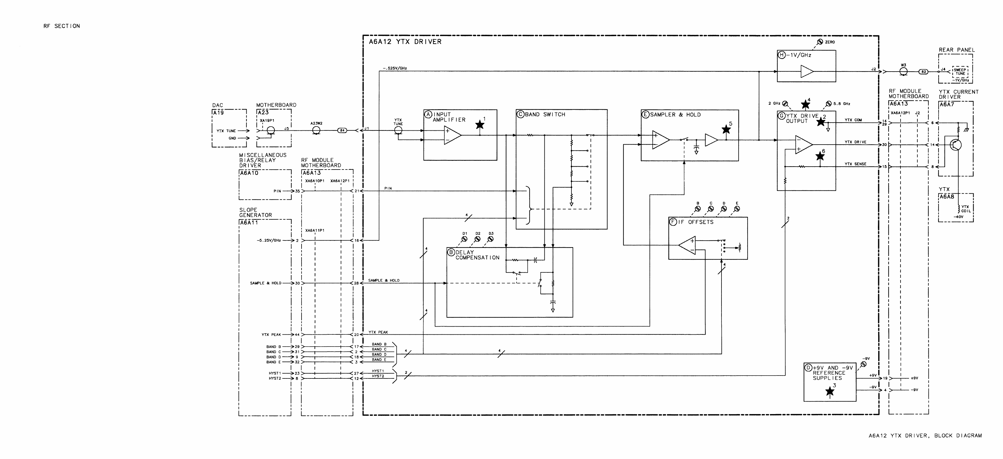
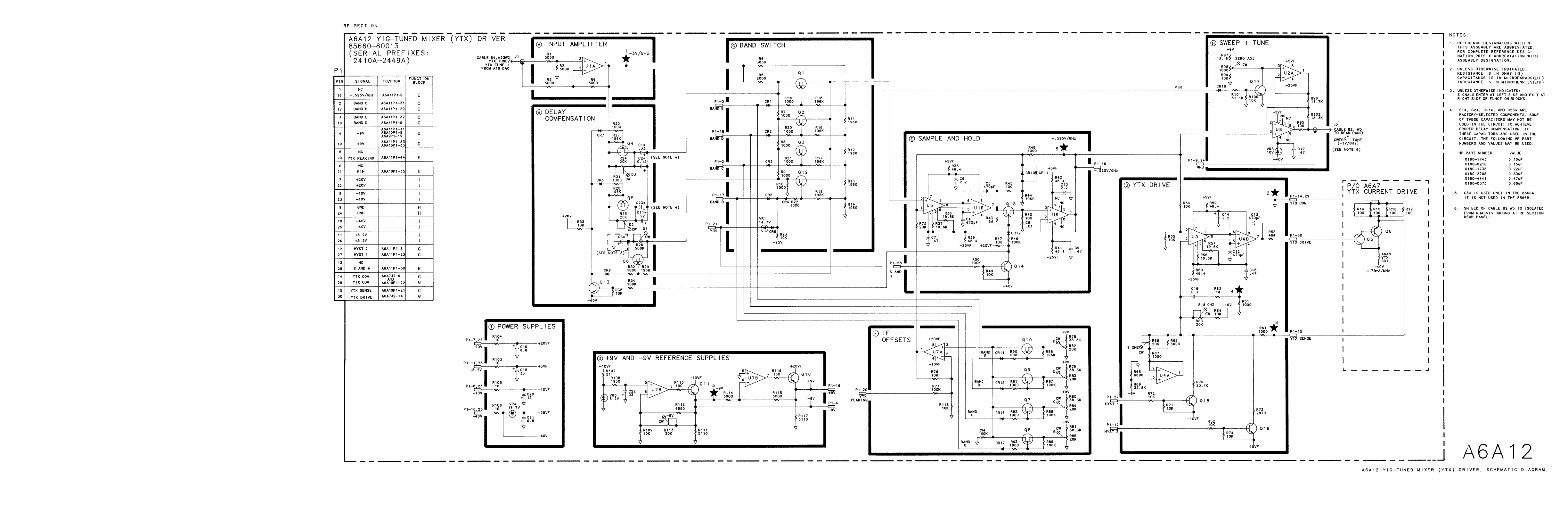
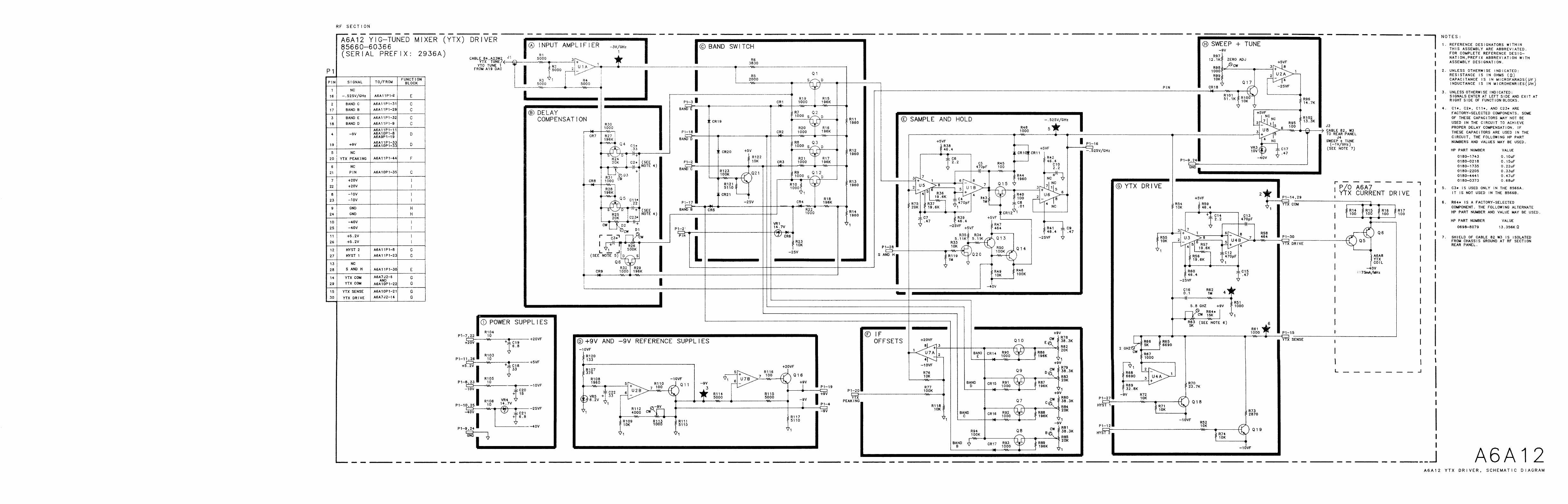
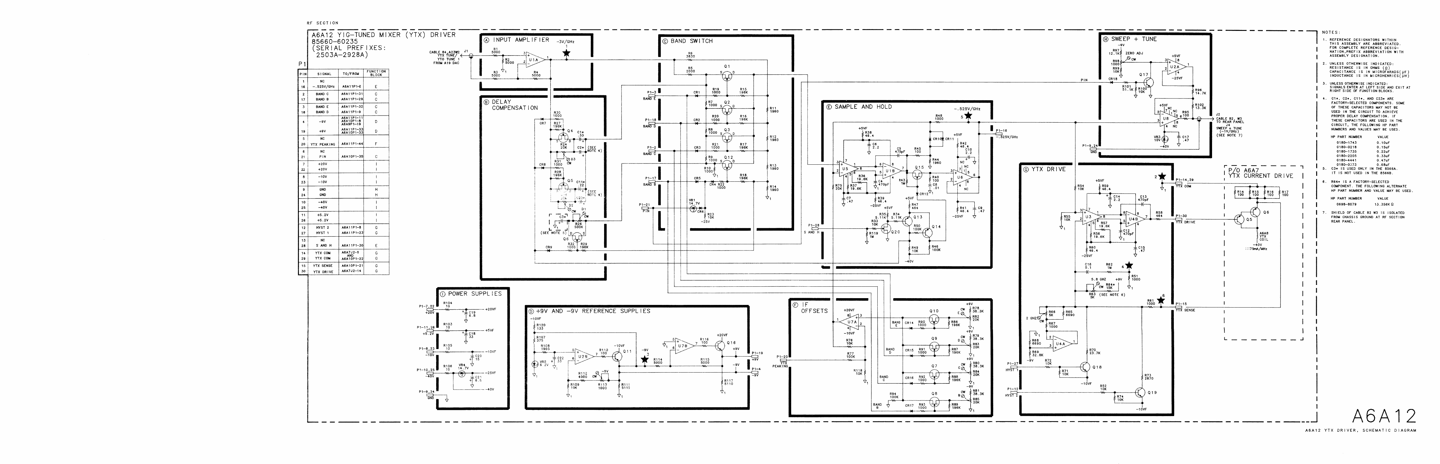
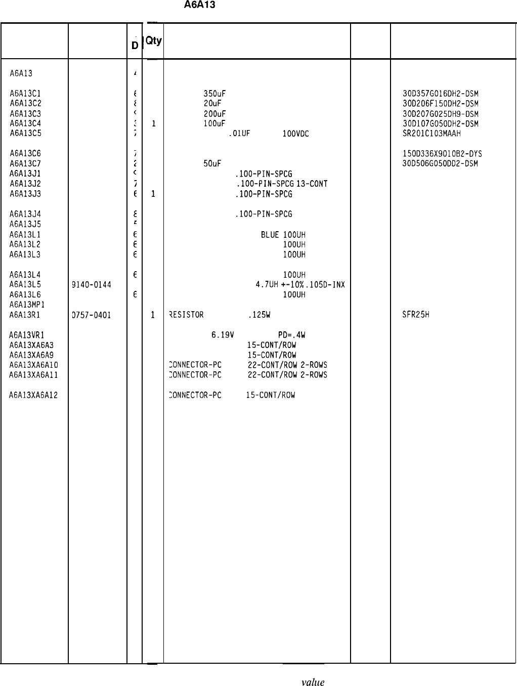
HP Part Number 85660-60014
A6A13
RF Module Motherboard
Reference HP Part
C
Designation
Number
c
A6A13 85660-60014
1
A6A13Cl 0180-2216
f
A6A13C2 0180-1997
t
A6A13C3 0180-2144
c
A6A13C4 0180-1819
:
A6A13C5 0160-3879
;
A6A13C6 0180-0229
i
A6A13C7 0180-0141
i
A6A13Jl 1251-5550
c
A6A13J2 1251-5144
i
A6A13J3 1251-5549
E
A6A13J4 1251-5145
E
A6A13J5 1200-1204
L
A6A13Ll 08558-80011
E
A6A13L2 08558-80011
E
A6A13L3 08558-80011
E
A6A13L4
A6A13L5
A6A13L6
A6A13MPl
A6A13Rl
08558-80011
E
9140-0144
C
08558-80011
E
3757-0401
C
A6A13VRl 1902-0049
2
A6A13XA6A3 1251-2035
9
A6A13XA6A9 1251-2035
9
A6A13XA6AlO 1251-1365
6
A6A13XA6All 1251-1365
6
A6A13XA6A12 1251-2035
9
-
zlt
-
1
1
1
1
1
1
1
1
1
1
1
1
1
1
1
1
1
1
1
1
1
1
1
1
1
1
-
Description
BOARD ASSEMBLY, RF MODULE MOTHERBOARD
28480 85660-60014
CAP-FXD
35OuF
16 V AL-ELCTLT
56289
30D357G016DH2-DSM
CAP-FXD
2OuF
150 V AL-ELCTLT
56289 30D206F150DH2-DSM
CAP-FXD
2OOuF
25 V AL-ELCTLT
56289 30D207G025DH9-DSM
CAP-FXD
1OOuF
50 V AL-ELCTLT
56289
30D107G050DH2-DSM
CAPACITOR-FXD
.OlUF
+-20%
1OOVDC
CER
04222 SR201C103MAAH
CAP-FXD 33uF 10 V TA
56289 150D336X901082-DYS
CAP-FXD
5OuF
50 V AL-ELCTLT
56289
30D506G050DD2-DSM
CONN-POST TYPE
.lOO-PIN-SPCG
26-CONT
18873 68025-626
CDNN-POST TYPE
.lOO-PIN-SPCG
13-CONT 00779 87502-6
CONN-POST TYPE
.lOO-PIN-SPCG
50-CONT
18873 68025-650
CDNN-POST TYPE
.lOO-PIN-SPCG
ll-CONT
00779 87502-5
SOCKET-IC 14-CDNT DIP DIP-SLDR 00779 2-641609-2
INDUCTOR FILTER COIL
BLUE
1OOUH 28480 08558-80011
INDUCTOR FILTER COIL BLUE
1OOUH 28480 08558-80011
INDUCTOR FILTER COIL BLUE
IOOUH 28480 08558-80011
INDUCTOR FILTER COIL BLUE
1OOUH
INDUCTOR RF-CH-MLD
4.7UH
+-lo%
.1050-INX
INDUCTOR FILTER COIL BLUE
1OOUH
NOT ASSIGNED
28480 08558-80011
99800 1025-36
28480 08558-80011
?ESISTOR
100 +-1%
.125W
TF TC=O+-100
19701
SFR25H
DIODE-ZNR
6.19V
5% DO-35
PD=.4W 04713
CONNECTOR-PC EDGE
15-CDNT/ROW
2-ROWS
26742
CONNECTOR-PC EDGE
15-CDNT/ROW
E-ROWS
26742
:ONNECTOR-PC
EDGE
22-CONT/RDW
2-ROWS 26742
:ONNECTDR-PC
EDGE
22-CDNT/ROW
2-ROWS 26742
220-624-03
220-624-03
220-626-03
220-626-03
:ONNECTOR-PC
EDGE
15-CDNT/ROW
2-ROWS
26742 220-624-03
*Indicates factory-selected
value
Mfr
Mfr Part
Code Number
85660-60014 Parts List
Page 1 of 1
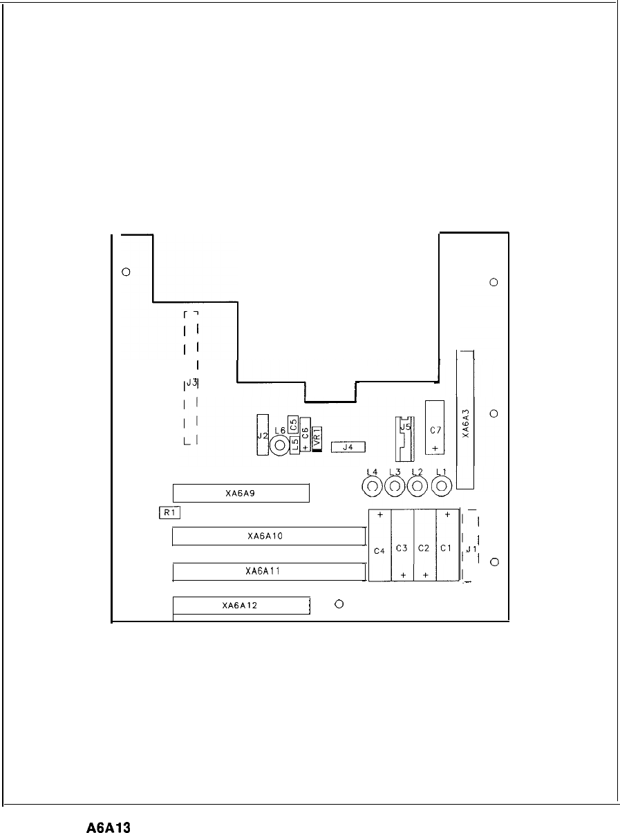
0
3
rl
I
1
I
1
I
1
00
1J31
0
r
0
0
XA6A9
m
0
XAGAlO
XA6All
0
XA6A12
1
0
-1
I
Jl
1
0
-
I
0
A6A13
RF Module Motherboard Component Locations, 85660-60014
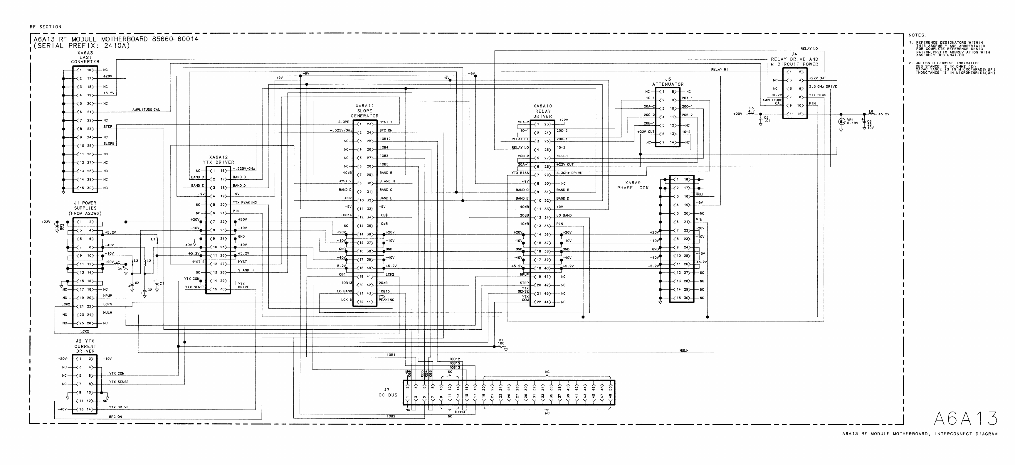
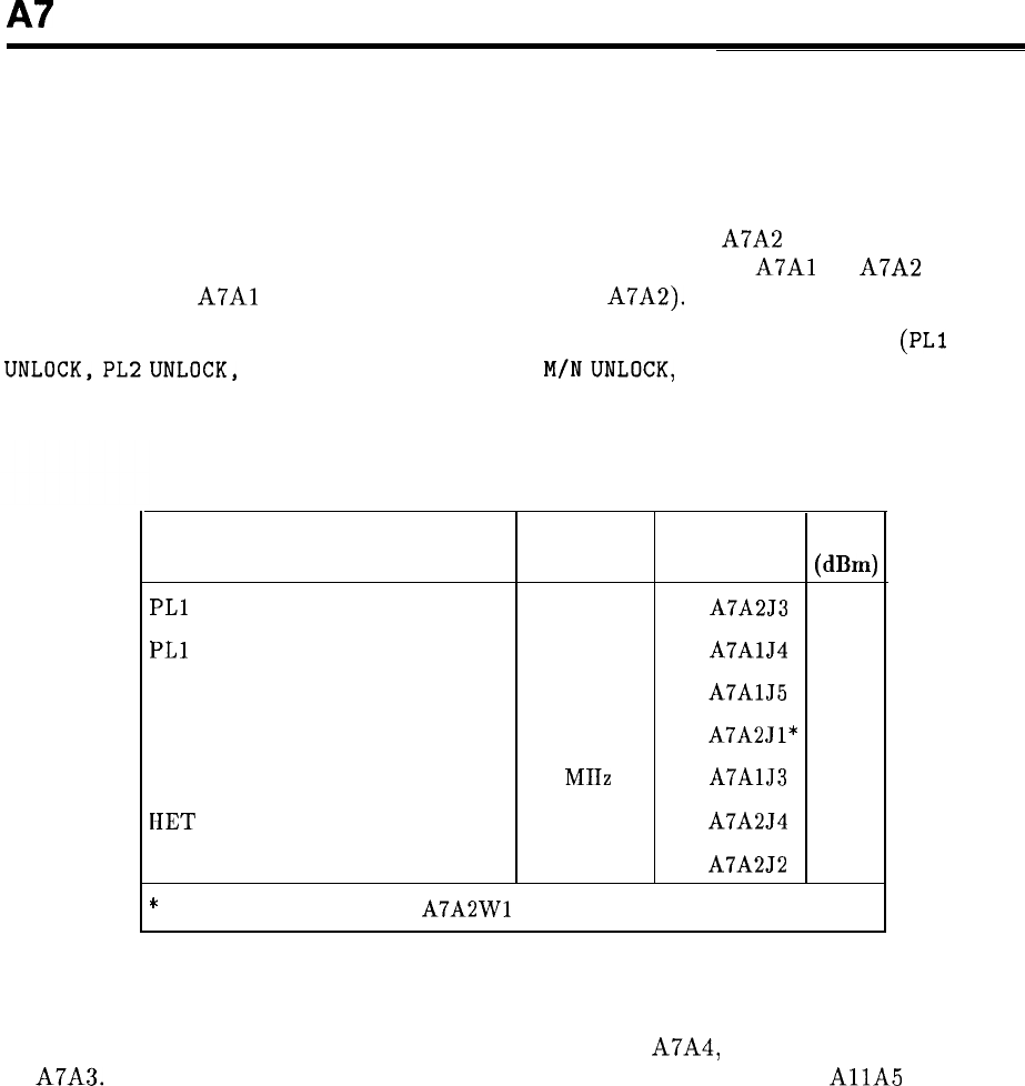
A7
A7 M/N Reference, Troubleshooting
Reference
All phase lock loops in the HP 8566B are referenced to the A22 10 MHz Frequency Standard.
The 10 MHz Frequency Standard is used to directly phase-lock the A7A2 100 MHz VCXO
only. All other phase lock loops receive their reference from either the
A7Al
or A7A2 (10 and
20 MHz from the
A7Al
and 100 and 400 MHz from the A7A2).
A malfunction of the 100 MHz VCXO is indicated by all phase lock error messages
(PLl
UNLOCK,PL2UNLOCK,
REFUNLOCK, YTO UNLOCK,
M/NUNLOCK,
and
HETUNLOCK)
being
displayed on the HP 8566B CRT. Table 1 lists the phase lock error messages, related
reference, location for measurement, and signal level.
Table 1. Phase Lock Error Messages
Phase Lock Error Message
Reference
output
Level
Frequency
Connector
(dB4
PLl
UNLOCK 100 MHz A7A2J3
0
PLl
UNLOCK 10 MHz
A7AlJ4
0
PL2 UNLOCK 10 MHz
A7AlJ5
0
YTO UNLOCK and M/N UNLOCK 400 MHz
A7A2Jl*
-10
YTO UNLOCK and M/N UNLOCK 20 MIIz
A7AlJ3
0
IIET UNLOCK 100 MHz A7A254
0
All Flags 100 MHz A7A2J2
0
*
Measure output at end of
A7A2Wl
96 cable.
M/N Loop
The M/N Loop consists of a 355 to 395 MHz VCO, part of A7A4, and a phase detector, part
of A7A3. The output of the VCO is divided by two and is used to drive the
AllA
Sampler
assembly. This divided signal is disabled by means of control line LMNE during sweeps when
the frequency span is greater than 5 MHz (fundamental mixing). The two divider numbers, M
and N, are selected by the Al5 Controller such that the Nth harmonic (same as the N divide
number) of the divided VCO output changes in exactly 10 MHz increments as M is changed.
A7 1
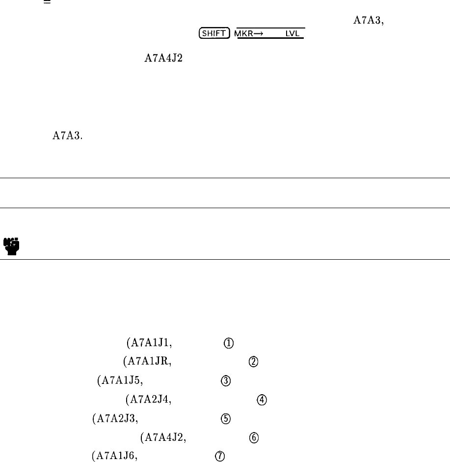
For example:
If M = 26,
N = 20,
and VCO Frequency = 187.0 MHz,
then M/N output frequency = N (VCO) = 20 x 187.0 = 3,740 MHz.
If M is changed to 25,
then the VCO frequency changes to 187.5 MHz,
and the M/N output frequency changes to 3,750 MHz (20 x 187.5).
Result
=
10 MHz change for M divider change of 1.
An incorrect M or N number, due to the main controller or a bad latch on A7A3, can be
easily detected. The frequency diagnostic
(SHIFT)
MKR+
REF
LVL
gives the M and N numbers
and the M/N output frequency (VCO divided by two) for the start frequency selected. A
frequency counter attached to A7A4J2 indicates the actual frequency output. Table 2, “M
and N Numbers and Resulting Frequencies,” of the RF Section Analog Troubleshooting tab,
lists all possible M/N output frequencies. By locating the M/N frequency measured by the
counter, the M and N numbers required to produce this frequency are obtained. The M and
N numbers can then be compared to those shown in the frequency diagnostic. The latch
and divider for the number in error can then be located using the troubleshooting procedure
outline for A7A3.
A7 M/N Reference Replacement
Note
I
w
For location of hardware and cables referred to in this procedure, see Figure 1.
Removal
1. Remove ac line cords, IF-Display Section, and RF Section top and bottom covers.
2. Remove the following cables from A7 M/N Reference:
80 (gray/black) cable
(A7AlJ1,
STD IN)
0
86 (gray/blue) cable
(A7AlJR,
10 MHz OUT)
@
9 (white) cable
(A7AlJ5,
10 MHz OUT)
@
85 (gray/green) cable
(A7A2J4,
100 MHz OUT)
@
8 (gray) cable
(A7A2J3,
100 MHz OUT)
@
93 (white/orange) cable
(A7A4J2,
M/N OUT)
@
6 (blue) cable
(A7AlJ6,
10 MHz OUT)
0
2 A7
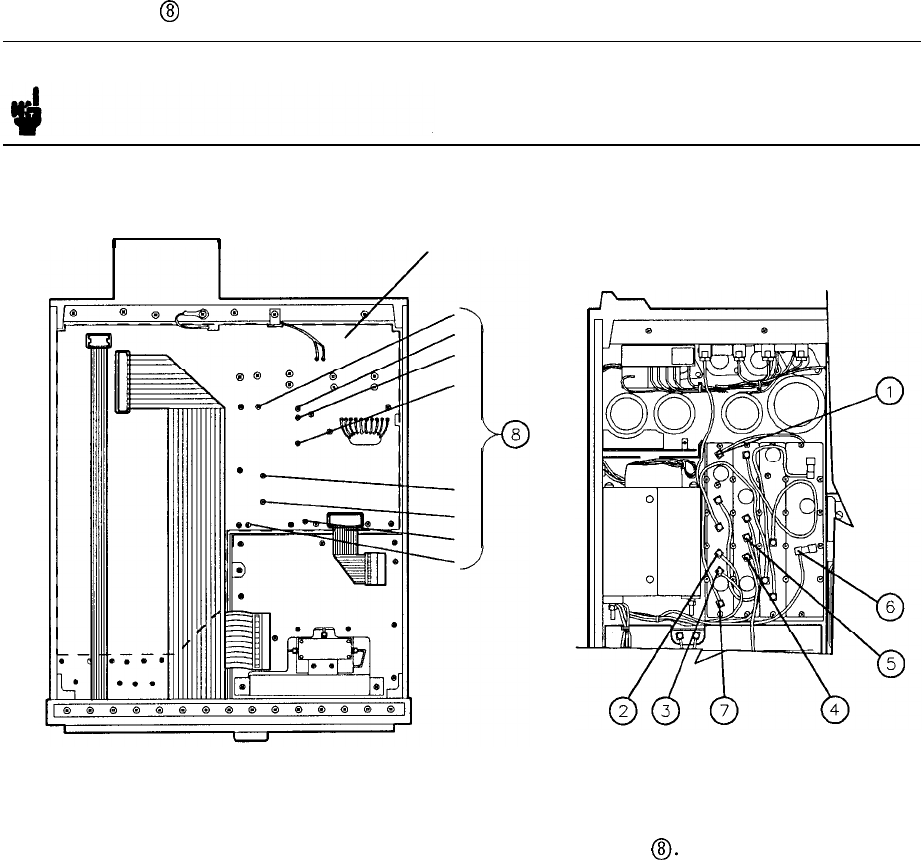
3. Remove clear plastic shield from motherboard (Figure 1) by removing all screws. Remove
eight screws
@
from the motherboard.
Note Screws are marked on motherboard with the letter B for easy identification.
II
CLEAR
PLASTIC
SHIELD
Figure 1. A7 M/N Reference Removal and Installation
4. Position A7 section in RF Section and secure with eight screws
0.
Replace clear plastic
shield over motherboard. Reconnect cables removed in step 2.
5. Replace RF Section top and bottom covers. Reassemble IF-Display Section to RF Section.
Reconnect ac line cords.
A7 3
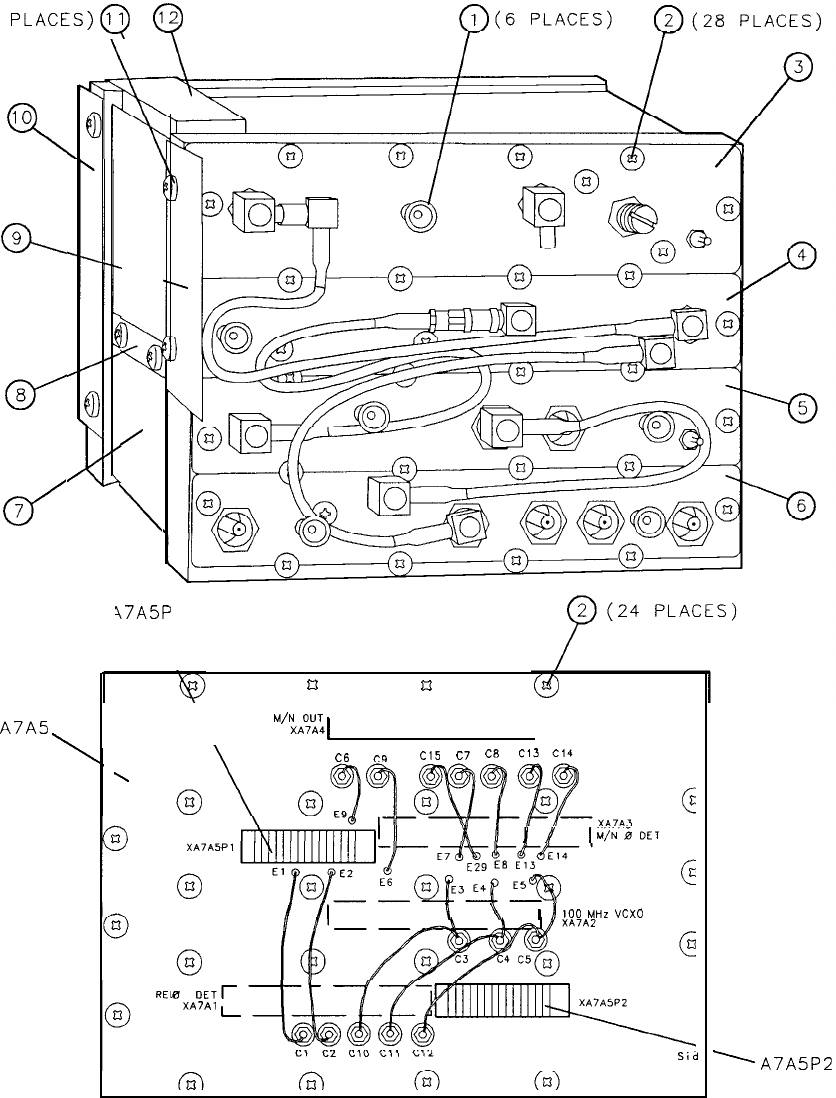
(6
PLACES)Q
Q
10
9
ck
0'
8
d
7
A7A5
\
n
I
3
/
\
47A5P
1
nu
\
\
-----
“‘ZE
1
I
\
C6
CQ
c15
c7
C8
j
/
Iiji’iDET
/
/I
\
\
,
j
100
MtiZ
“CXD
a
OETr
XA7A1
L
Circuit
Sid
’
A7A5P2
Figure 2. A7 M/N Reference, Parts Identification (1 of 2)
4 A7
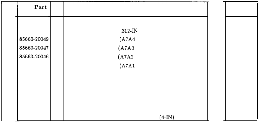
Item
1
2
3
4
5
6
7
8
9
10
11
12
HP
Part
Number
86701-40001
2200-0105
8566@20049
85660-20047
8566CL20046
85660-20045
5021-3208
86701-00024
86701-00029
86701-00030
2200-0103
0460-0778
CD
9
4
1
9
8
7
7
2
7
0
2
5
Description
EXTRACTOR, PC BOARD
SCREW, MACH, 4-40,
.312-IN
LG, PAN HD
COVER, PC BOARD (A7A4 M/N OUTPUT)
COVER, PC BOARD (A7A3 M/N 0 DET)
COVER, PC BOARD (A7A2 100 MHz VCXO)
COVER, PC BOARD,
(A7Al
REF 0 DET)
HOUSING, M/N-REFERENCE BLOCK
AIR SCOOP
AUR BAFFLE, TOP
AIR BAFFLE, BOTTOM
SCREW, MACH, 4-40, .25-IN LG, PAN HD
TAPE, ADHESIVE, FOAM CUSHION (4-IN)
Mfr
Code
48280
28480
28480
28480
28480
28480
22480
28480
28480
28480
28480
28480
Mfr Part
Number
86701-40001
2200-0105
85660-20049
85660-20047
85660-20046
85660-20045
5021-3208
86701-00024
86701-00029
86701-00030
2200-0103
0460-0778
Figure 2. A7 M/N Reference, Parts Identification (2 of 2)
A7 5
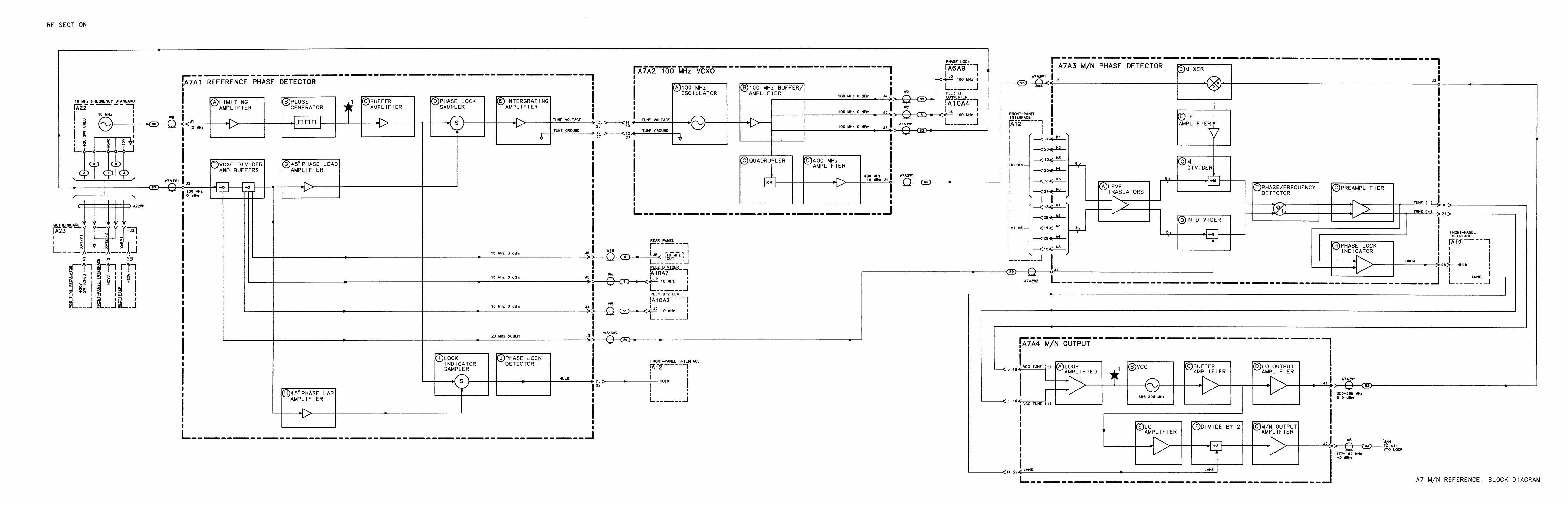
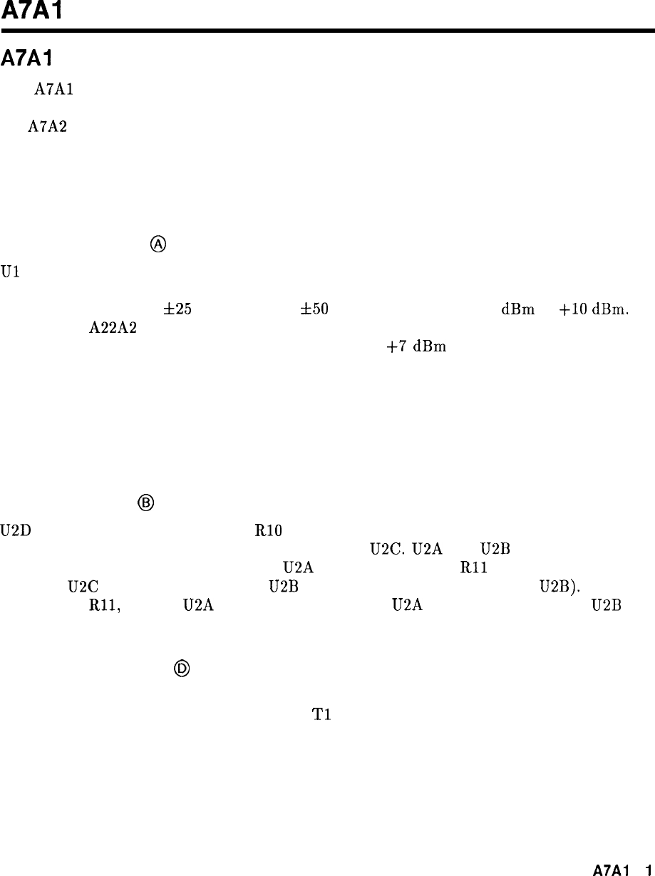
A7Al
A7Al
Reference Phase Detector, Circuit Description
The
A7Al
Reference Phase Detector contains the frequency divider, phase detector, and
integrating amplifier for the 100 MHz Reference phase-lock loop. Basically, 100 MHz from
the A7A2 VCXO is divided by 10 and compared to the 10 MHz frequency reference by the
phase detector. The error voltage from this comparison is fed back to the VCXO to keep its
frequency locked to 10 times that of the frequency reference. The bandwidth of the reference
phase-lock loop is 100 Hz; the 10 MHz derived from the 100 MHz VCXO must be within 100
Hz of the 10 MHz frequency reference for the loop to lock reliably.
Limiting Amplifier
@
Ul
amplifies and limits the amplitude of the reference signal from the rear panel FREQ
REFERENCE input. For proper operation of the 100 MHz Reference phase-lock loop, this
signal should be 5 MHz
f25
Hz or 10 MHz
f50
Hz at a power level of 0
dBm
to
+lO
dBm.
The internal A22A2 10 MHz Quartz Crystal Oscillator provides a stable, high spectral purity
10 MHz frequency reference at a power level of at least
+7
dBm
at the rear panel FREQ
REFERENCE output. A short BNC jumper cable is normally connected between the FREQ
REFERENCE input and output jacks to route the internal frequency reference signal to
the 100 MHz Reference phase-lock loop. The spectral purity of the FREQ REFERENCE
input signal directly affects the instrument phase noise performance. The internal frequency
reference remains off during instrument warmup (from a cold start) until it reaches thermal
equilibrium.
Pulse Generator
@
U2D is biased with feedback resistor RlO to further limit the 10 MHz to a well-shaped square
wave and set the proper logic levels for digital buffer U2C. U2A and
U2B
generate narrow
pulses, the width being the gate delay of U2A plus the delay from
Rll
and C5. When the
output of U2C goes low, the output of
U2B
goes high after one gate delay (of U2B). After a
delay due to
Rll,
C5 and U2A gate delay, the output of U2A goes high which causes
U2B
output to return low again, thus generating a narrow pulse.
Phase Lock Sampler
@
The phase lock sampler performs the function of phase detector. The 10 MHz pulses from the
buffer amplifier are applied to the primary of
Tl
which causes CR3 and CR4 to turn on for
the duration of the pulses. This samples the divided by 10 VCXO frequency and stores this
voltage on C36. When the loop is locked, the feedback due to the complete phase-lock loop
forces this voltage to be nearly zero. When the loop is unlocked, this voltage may be zero or
varying, depending on the reason for unlock.
A7A1
1
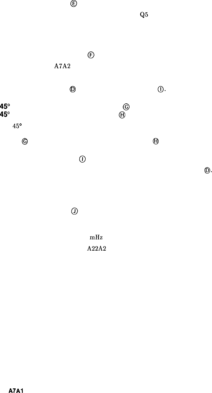
Integrating Amplifier
@
Q4 is a differential input pair which together with
Q5
and Q6 forms a high gain amplifier.
Feedback is added with C32 and R49 to make an integrating amplifier. C32 provides ac
feedback only, so for the amplifier to remain linear, dc feedback is accomplished by virtue of
the entire phase-lock loop.
VCXO Divider and Buffers
@
100 MHz from the A7A2 VXCO is applied to the counter U3 which divides by 5, then by
2. Its outputs are 10 MHz and 20 MHz which are buffered by U4 to be used as reference
frequencies by other assemblies in the instrument. The other 10 MHz output is used to drive
the Phase Lock Sampler
@J
and Lock Indicator Sampler
0.
45”
Phase Lead and Buffer Amplifier
@
and
45”
Phase Lag and Buffer Amplifier
@
The 45’ phase shift buffers are used to provide two 10 MHz signals which are 90” apart in
phase, the purpose of which is explained in Lock Indicator Sampler description. 45” phase
shift in
@
is accomplished with C35 and R53, while in
@)
it is done by R59 and C38.
Lock Indicator Sampler
(ij
The lock indicator sampler functions the same as the phase lock sampler
0.
The only
difference is that the 10 MHz is 90” shifted in phase. This causes the output of the lock
indicator sampler to be maximum negative voltage when the loop is locked, since in this state
the output of the phase-lock sampler is 0 V.
Phase Lock Detector
@
The output of the lock indicator sampler is compared to -0.5 V by U5. When the output
voltage becomes closer to 0 than to -0.5 V, U5 switches its output to TTL high to indicate to
the Al5 Controller that the 100 mHz Reference phase-lock loop is unlocked.
During instrument warmup, the A22A2 10 MHz Quartz Crystal Oscillator remains off for a
few minutes until thermal equilibrium is reached. It is normal for both an OVEN COLD and
REF UNLOCK indication to appear on the CRT during these first few minutes of instrument
operation after a cold start.
2
A7A1
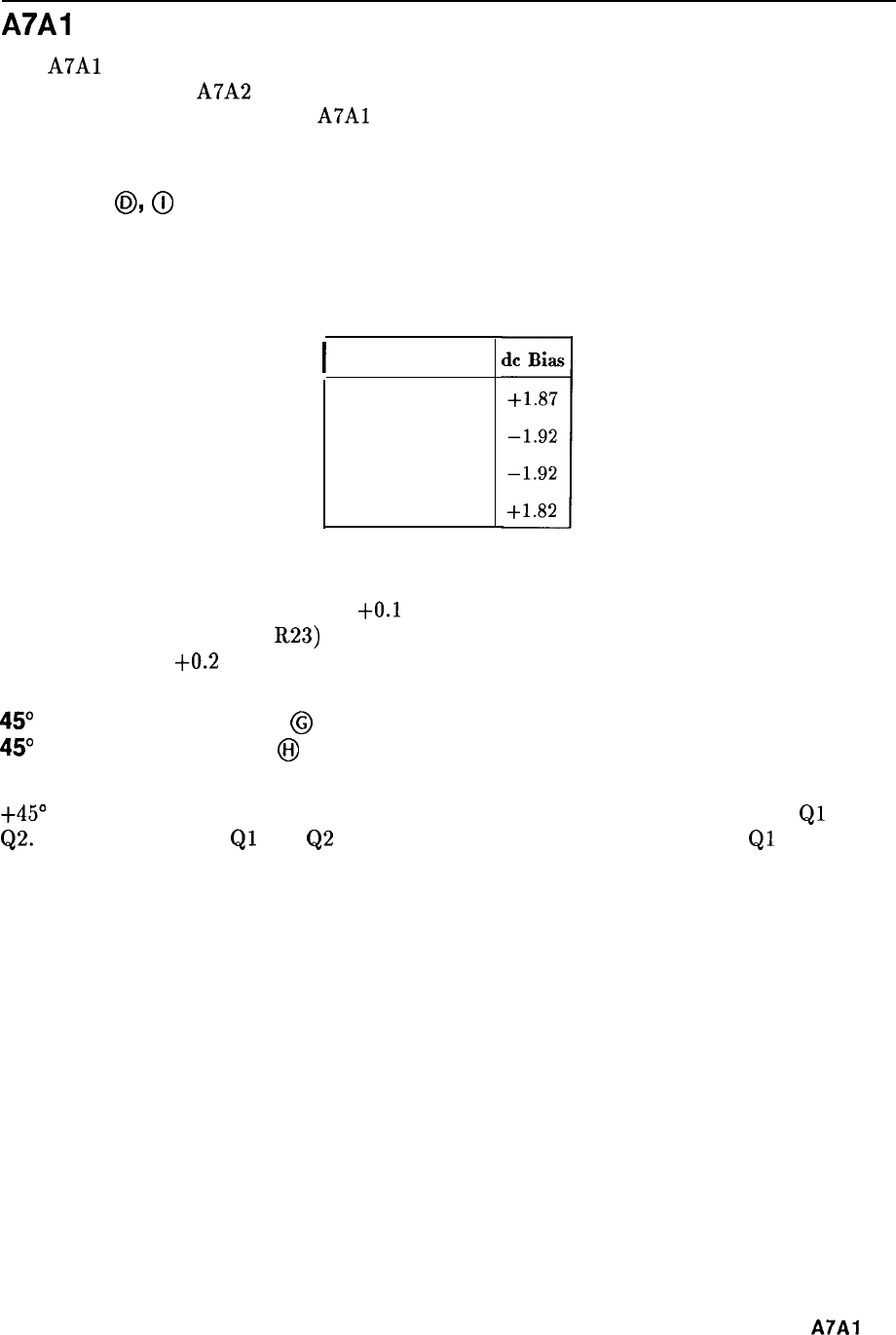
A7Al
Reference Phase Detector, Troubleshooting
The
A7Al
Reference Phase Detector compares the output of the 10 MHz Frequency Standard
to the output of the A7A2 100 MHz VCXO and provides the tuning drive voltage for the
VCXO. A phase lock detector in
A7Al
indicates to the main processor (A15) the state of the
Reference Phase Lock Loop.
Samplers
@,
@
The Phase Lock and Lock Indicator Samplers are identical. The diodes are biased to
approximately the same level in each. The dc bias on the diodes is as shown in Table 1.
Table 1. Sampler Diode Bias Voltage Levels
I
Diode
CR3 Anode
CR4 Cathode
CR5 Cathode
CR6 Anode
The Phase Lock Sampler output (junction of R32 and R34) is 0.0 V when locked or with no
10 MHz reference, and approximately
+O.l
V with no 100 MHz input. The Lock Indicator
output (junction of R25 and R23) is -1.5 V when locked, 0.0 V with no 10 MHz reference,
and approximately
+0.2
V with no 100 MHz input.
45’ Phase Lead Amplifier
@I
and
45”
Phase Lag Amplifier
@
The Phase Amplifiers shift the 100 MHz VCXO signal, which has been divided by 10 by U3,
+45” and -45” respectively. Figure 1 is typical of the waveforms at the collectors of
Ql
and
Q2.
The dc voltages for
Ql
and
Q2
are as shown in Table 2. The waveform of
Ql
leads the
waveform of Q2 by approximately 20 nanoseconds in Figure 1.
A7A7 3
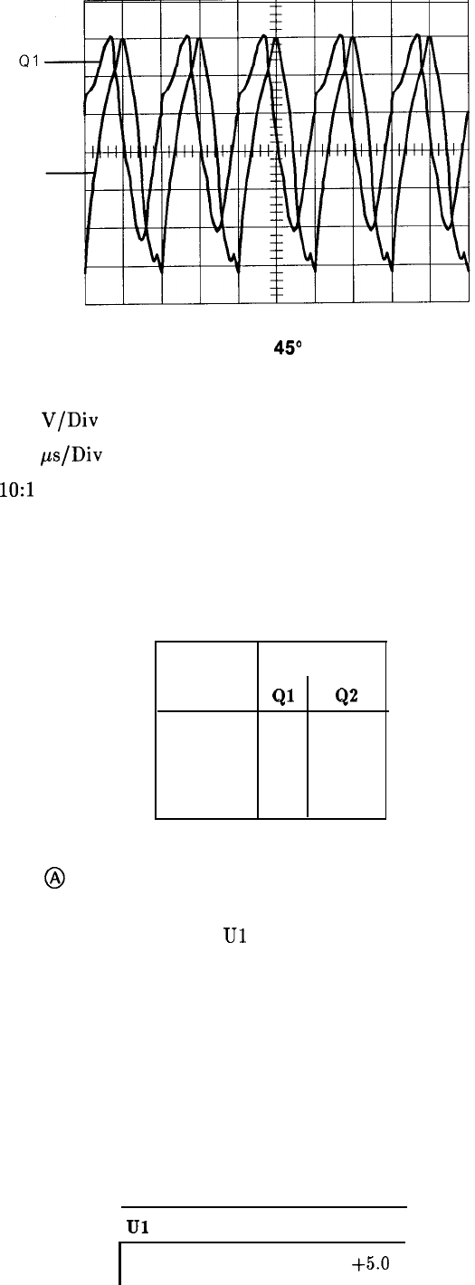
Q2
Figure 1. Outputs of
49
Phase Amplifiers
Oscilloscope Settings
Vertical 0.05
V/Div
AC
Horizontal 0.05
ps/Div
Probe
1O:l
Analyzer Settings
INSTR PRESET
Table 2. Phase Amplifier Voltage Levels
Voltage Levels
Ql
Q2
Emitter -8.0 -8.0
Base
-7.4 -7.4
Collector
-3.6 -3.6
Limiting Amplifier
@
The Limiting Amplifier shapes and amplifies the 10 MHz reference from the Frequency
Standard (A22). Typical voltage levels for
Ul
are shown in Table 3.
Table 3. Limiting Amplifier Voltage Levels
Ul Pin Number dc Voltage Level
I
I
1
I
+5.0
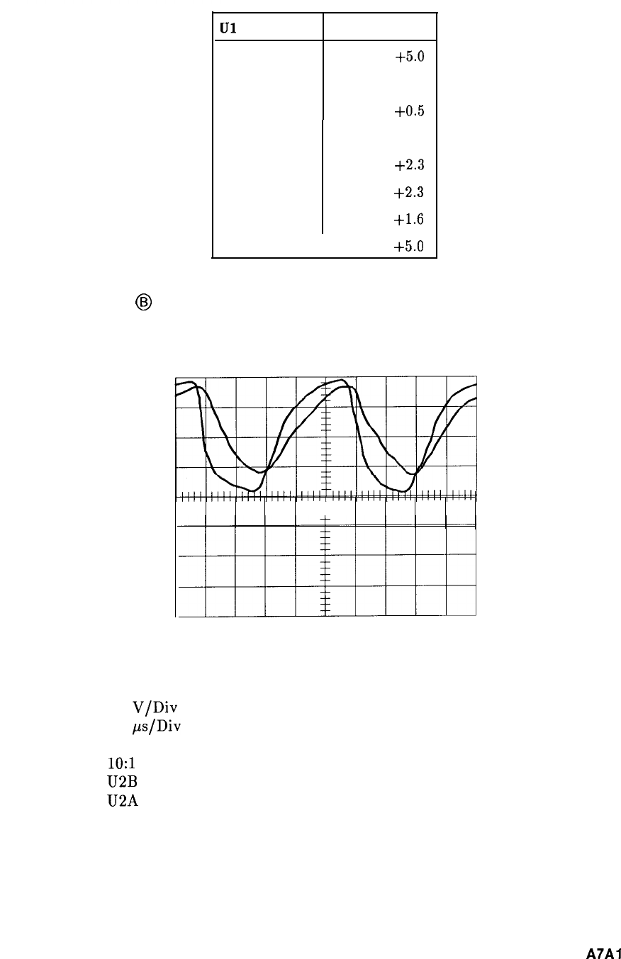
Table 3. Limiting Amplifier Voltage Levels
LJl
Pin Number dc Voltage Level
1
+5.0
2
0.0
3
+0.5
4
0.0
5
+2.3
6
+2.3
7
+1.6
8
I
t5.0
Pulse Generator
@
Typical input/output waveforms for the Pulse Generator are shown in Figure 2 and Figure 3.
Figure 2. Pulse Generator Input Waveforms
Oscilloscope Settings
Vertical 0.1
V/Div
Horizontal 0.2
ps/Div
X10 Magnifier
Probes
1O:l
Channel A U2B Pin 5
Channel B U2A Pin 2
Analyzer Settings
INSTR PRESET
A7A7
5
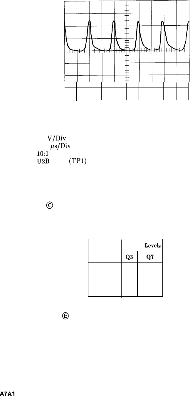
Figure 3. Pulse Generator Output Pulses
Oscilloscope Settings
Vertical 0.1
V/Div
Horizontal 0.05
ps/Div
Probe
1O:l
Channel A
U2B
Pin 4
(TPl)
Analyzer Settings
INSTR PRESET
Buffer Amplifier
@
Typical voltage levels for the Buffer Amplifier are shown in Table 4.
Integrating Amplifier
@
Typical voltage levels for the Integrating Amplifier are shown in Table 5.
Integrating Amplifier tune voltage output (junction of R75 and R51):
-8.6 V (locked)
-1.4 V (unlocked with no 100 MHz)
Table 4. Buffer Amplifier Voltage Levels
1
Voltage
Level:
Q3
Q7
Emitter -4.6 -4.6
Base
-4.5 -4.5
Collector
-0.3 -9.4
s
6
A7Al
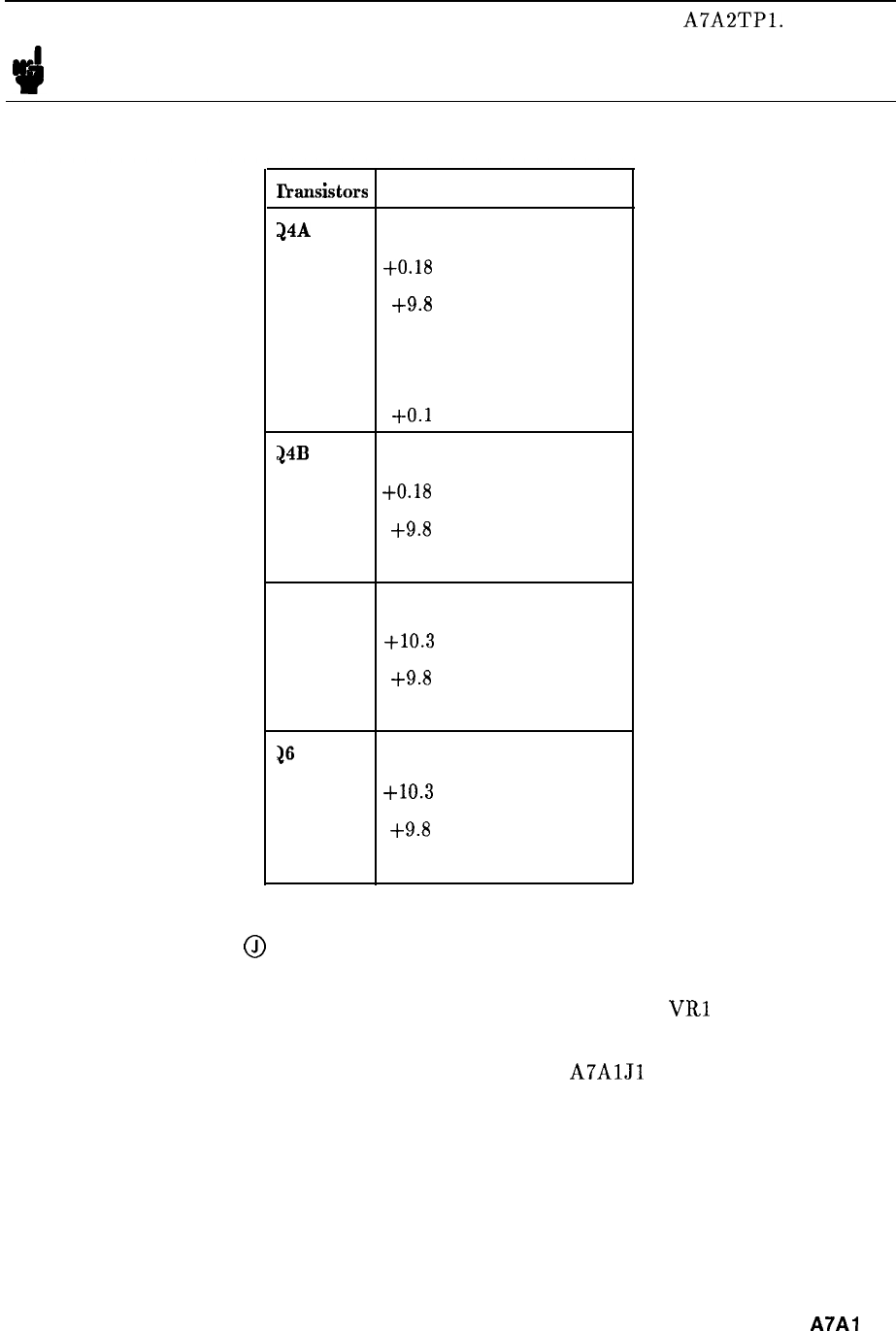
Note The 100 MHz VCXO Tune Voltage can be measured at
A7A2TPl.
However,
the voltage levels will be slightly lower than those listed above.
Table 5.
Integrating Amplifier Voltage Levels
lhnsistors
de Voltage Levels
24A
Pin 1
+0.18
Pin 2
+9.8
0.0
(locked)
Pin 3
0.0
(no 10 MHz)
Ref.
+O.l (no 100 MHz) VCXO
?4B
Pin 4
+0.18
Pin 5 +9.8
Pin 6 +o.o
25
Emitter
+10.3
Base
+9.8
Collector Gnd
26
Emitter
+10.3
Base
+9.8
Collector
-6.6
Phase Lock Detector
@I
The output of the Lock Indicator Sampler is compared to a reference of -0.4 V by
comparator U5. The output of U5 is high for any unlocked condition.
VRl
limits the output
voltage (HULR) to approximately 4.64 V.
This can be checked by disconnecting the 10 MHz input at
A7AlJl
(gray/white cable) and
measuring the output of U5. With the loop unlocked (10 MHz removed), this output should
be approximately 4.64 V.
A7A1
7
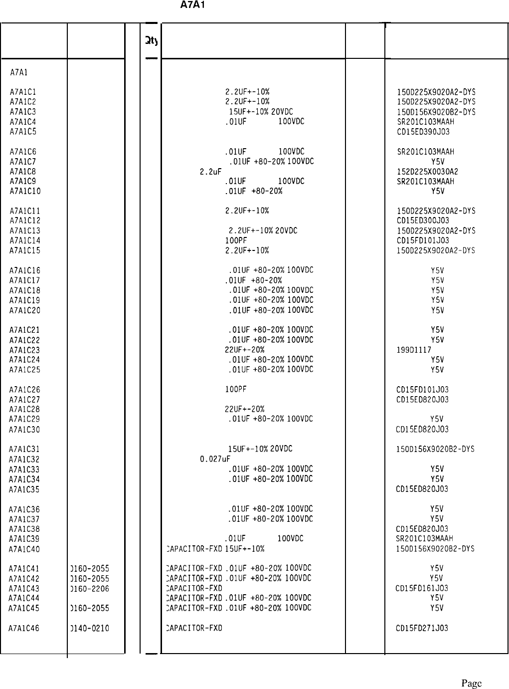
Reference
Designation
HP Part
Number
C
D
A7Al
85660-60015
5
A7AlCl
A7AlC2
A7AlC3
A7AlC4
A7AlC5
0180-0197
8
0180-0197
8
0180-1746
5
0160-3879
7
0140-0190
7
A7AlC6 0160-3879
7
A7AlC7 0160-2055
9
A7AlC8 0180-3073
5
A7AlC9 0160-3879
7
A7AlClO 0160-2055
9
A7AlCll 0180-0197
8
A7AlC12 0160-2199
2
A7AlC13 0180-0197
8
A7AlC14 0160-2204
0
A7AlC15 0180-0197
8
A7AlC16 0160-2055
A7AlC17 0160-2055
A7AlClB 0160-2055
A7AlC19 0160-2055
A7AlC20 0160-2055
A7AlC21 0160-2055
A7AlC22 0160-2055
A7AlC23 0180-0553
A7AlC24 0160-2055
A7AlC25 0160-2055
A7AlC26 0160-2204
A7AlC27 0140-0193
A7AlC28 0180-0553
A7AlC29 0160-2055
A7AlC30 0140-0193
A7AlC31 0180-1746
A7AlC32 0170-0066
A7AlC33 0160-2055
A7AlC34 0160-2055
A7AlC35 0140-0193
A7AlC36 0160-2055
A7AlC37 0160-2055
A7AlC38 0140-0193
A7AlC39 0160-3879
A7AlC40 1180-1746
A7AlC41 3160-2055
A7AlC42 3160-2055
A7AlC43 3160-2206
A7AlC44 1160-2055
A7AlC45 3160-2055
A7AlC46 3140-0210
9
9
9
9
9
9
9
0
9
9
0
0
0
9
0
5
9
9
9
0
9
9
0
7
5
9
9
2
9
9
2
-
m
-
1
1
1
1
1
1
1
1
1
1
1
1
1
1
1
1
1
1
1
1
1
1
1
1
1
1
1
1
1
1
1
1
1
1
1
1
1
1
1
1
1
1
1
1
1
1
1
-
HP Part Number 85660-60015
A7Al
Reference Phase Detector
Description Mfr
Code
Mfr Part
Number
BOARD ASSEMBLY, REFERENCE PHASE DETECTOR
28480
56289
56289
56289
04222
09023
04222
56289
04222
85660-60015
CAPACITOR-FXD
2.2UF+-10%
20VDC TA
CAPACITOR-FXD
2.2UF+-10%
20VDC TA
CAPACITOR-FXD
15UF+-10%
ZOVDC
TA
CAPACITOR-FXD
.OlUF
+-20%
1OOVDC
CER
CAPACITOR-FXD 39PF +-5% 300VDC MICA
150D225X9020A2-DYS
150D225X9020A2-DYS
150D156X9020B2-DYS
SR201C103MAAH
CD15ED390J03
CAPACITOR-FXD
.OlUF
+-20%
1OOVDC
CER
CAPACITOR-FXD
.OlUF
+80-20%
1OOVDC
CER
CAP-FXD
2.2uF
30 V TA
CAPACITOR-FXD
.OlUF
+-20%
1OOVDC
CER
CAPACITOR-FXD
.OlUF
+80-20%
IOOVDC CER
SR201C103MAAH
805-504
Y5V
1032
152D225X0030A2
SR201C103MAAH
805-504
Y5V
1032
CAPACITOR-FXD
2.2UF+-10%
20VDC TA
56289 1500225X9020A2-DYS
CAPACITOR-FXD 30PF +-5% 300VDC MICA
09023 CD15ED300J03
CAPACITOR-FXD
2.2UF+-10%
ZOVDC
TA
56289 150D225X9020A2-DYS
CAPACITOR-FXD
1OOPF
+-5% 300VDC MICA
09023 CD15FDlOlJ03
CAPACITOR-FXD
2.2UF+-10%
20VDC TA
56289 1500225X9020A2-DYS
CAPACITOR-FXD
.OlUF
+80-20%
1OOVDC
CER
805-504
Y5V
1032
CAPACITOR-FXD
.OlUF
+80-20%
IOOVDC CER 805-504
Y5V
1032
CAPACITOR-FXD
.OlUF
+80-20%
1OOVDC
CER
805-504
Y5V
1032
CAPACITOR-FXD
.OlUF
+80-20%
1OOVDC
CER
805-504
Y5V
1032
CAPACITOR-FXD
.OlUF
+80-20%
1OOVDC
CER
805-504
Y5V
1032
CAPACITOR-FXD
.OlUF
+80-20%
1OOVDC
CER
CAPACITOR-FXD
.OlUF
+80-20%
1OOVDC
CER
CAPACITOR-FXD
22UF+-20%
25VDC TA
CAPACITOR-FXD
.OlUF
+80-20%
1OOVDC
CER
CAPACITOR-FXD
.OlUF
+80-20%
1OOVDC
CER
56289
805-504
Y5V
1032
805-504
Y5V
1032
199D1117
805-504
Y5V
1032
805-504
Y5V
1032
CAPACITOR-FXD
1OOPF
+-5% 300VDC MICA
CAPACITOR-FXD 82PF +-5% 300VDC MICA
CAPACITOR-FXD
22UF+-20%
25VDC TA
CAPACITOR-FXD
.OlUF
+80-20%
1OOVDC
CER
CAPACITOR-FXD 82PF +-5% 300VDC MICA
CD15FDlOlJ03
CD15ED820J03
19901117
805-504
Y5V
1032
CD15ED820J03
CAPACITOR-FXD
15UF+-10%
POVDC
TA
CAP-FXD
0.027uF
200 V POLYE-FL
CAPACITOR-FXD
.OlUF
+80-20%
1OOVDC
CER
CAPACITOR-FXD
.OlUF
+80-20%
1OOVDC
CER
CAPACITOR-FXD 82PF +-5% 300VDC MICA
09023
09023
56289
09023
56289
84411
09023
150D156X902062-DYS
HEW-238M
805-504
Y5V
1032
805-504
Y5V
1032
CD15ED820J03
CAPACITOR-FXD
.OlUF
+80-20%
1OOVDC
CER
CAPACITOR-FXD
.OlUF
+80-20%
1OOVDC
CER
CAPACITOR-FXD 82PF +-5% 300VDC MICA
CAPACITOR-FXD
.OlUF
+-20%
1OOVDC
CER
:APACITOR-FXD
15UF+-10%
20VDC TA
09023
04222
56289
805-504
Y5V
1032
805-504
Y5V
1032
CD15ED820J03
SR201C103MAAH
150D156X9020B2-DYS
:APACITOR-FXD
.OlUF
+80-20%
1OOVDC
CER
:APACITOR-FXD
.OlUF
+80-20%
1OOVDC
CER
:APACITOR-FXD
160PF +-5% 300VDC MICA
:APACITOR-FXD
.OlUF
+80-20%
1OOVDC
CER
:APACITOR-FXD
.OlUF
+80-20%
1OOVDC
CER
805-504
Y5V
1032
805-504
Y5V
1032
CD15FD161JO3
805-504
Y5V
1032
805-504
Y5V
1032
:APACITOR-FXD
270PF +-5% 300VDC MICA
09023
09023 CD15FD271J03
*Indicates factory-selected value
85660-60015 Parts List
Page
1 of 5
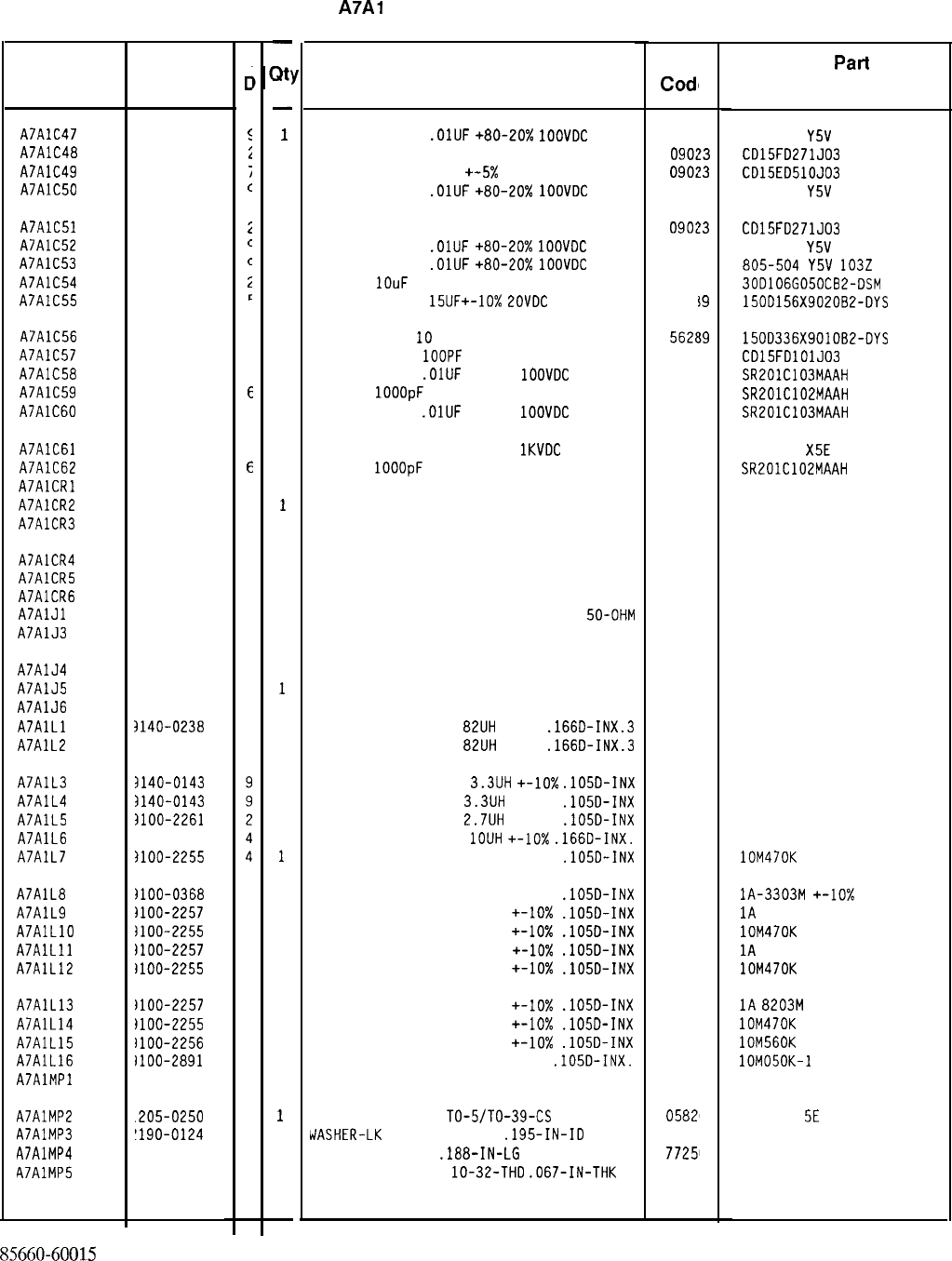
HP Part Number 85660-60015
A7Al
Reference Phase Detector
Description Mfr
Cod1
e
CAPACITOR-FXO
.OlUF
+80-20%
IOOVOC
CER
CAPACITOR-FXD 270PF +-5% 300VDC MICA
CAPACITOR-FXD 51PF
+-5%
300VDC MICA
CAPACITOR-FXD
.OlUF
+80-20%
1OOVDC
CER
0902
0902
!3
!3
Mfr
Pat-l
Number
805-504
Y5V
1032
CD15FD271J03
CD15ED510J03
805-504
Y5V
1032
CAPACITOR-FXD 270PF +-5% 300VDC MICA
CAPACITOR-FXD
.OlUF
+80-20%
1OOVDC
CER
CAPACITOR-FXD
.OlUF
+80-20%
1OOVOC
CER
CAP-FXD
1OuF
50 V AL-ELCTLT
CAPACITOR-FXD
15UF+-10%
ZOVDC
TA
0902
13
562E
19
562E
19
CD15FD271J03
805-504
Y5V
1032
805-504
Y~V
1032
30D106G050CB2-DSM
150D156X902082-DYS
CAP-FXD 33uF
10
V TA
CAPACITOR-FXD
1OOPF
+-5% 300VDC MICA
CAPACITOR-FXD
.OlUF
+-20%
1OOVDC
CER
CAP-FXD
1OOOpF
100 V
CAPACITOR-FXD
.OlUF
+-20%
1OOVDC
CER
5626
19
150D336X901062-DYS
0902
'3
CD15FDlOlJ03
0422
'2
SR201C103MAAH
0422
'2
SR201C102MAAH
0422
'2
SR201C103MAAH
CAPACITOR-FXD 220PF +-lo%
1KVDC
CER
CAP-FXD
1OOOpF
100 V
0422
'2
DIODE-SCHOTTKY SM SIG
DIODE-SCHOTTKY SM SIG
DIODE-SCHOTTKY SM SIG
838-546
X5E
221K
SR201C102MAAH
5082-2800
5082-2800
5082-2800
DIODE-SCHOTTKY SM SIG
DIODE-SCHOTTKY SM SIG
DIODE-SCHOTTKY SM SIG
CONNECTOR-RF SM-SNP M SGL-HOLE-FR
50-OHM 9829
1
CONNECTOR-RF SM-SNP M SGL-HOLE-FR 50-OHM
9829
1
5082-2800
5082-2800
5082-2800
051-049-0000-220
051-049-0000-220
CONNECTOR-RF SM-SNP M SGL-HOLE-FR 50-OHM
9829
1
051-049-0000-220
CONNECTOR-RF SM-SNP M SGL-HOLE-FR 50-OHM
9829
1
051-049-0000-220
CONNECTOR-RF SM-SNP M SGL-HOLE-FR 50-OHM
9829
1
051-049-0000-220
INDUCTOR RF-CH-MLD
82UH
+-5%
.166D-INX.3 9980
0
1537-72
INDUCTOR RF-CH-MLD
82UH
+-5%
.166D-INX.3 9980
0
1537-72
INDUCTOR RF-CH-MLD
3.3UH
+-lo%
.105D-INX 9980
0
1025-32
INDUCTOR RF-CH-MLD
3.3UH
+-lo%
.105D-INX 9980
0
1025-32
INDUCTOR RF-CH-MLD
2.7UH
+-lo%
.105D-INX 9980
0
1025-30
INDUCTOR RF-CH-MLD
1OUH
+-lo%
.166D-INX.
9980
0
1537-36
INDUCTOR RF-CH-MLD 470NH +-lo%
.105D-INX 2422
6
lOM470K
INDUCTOR RF-CH-MLD 330NH +-lo%
.105D-INX 3215
9
lA-3303M
+-lo%
INDUCTOR RF-CH-MLD 820NH +-IO%
.105D-INX 3215
9
1A
8203M +-lo%
INDUCTOR RF-CH-MLD 470NH +-10x
.lOSD-INX 2422
6
lOM470K
INDUCTOR RF-CH-MLD 820NH
+-lo%
.105D-INX 3215
9
1A
8203M +-lo%
INDUCTOR RF-CH-MLD 470NH +-lo%
.105D-INX 2422
6
lOM470K
INDUCTOR RF-CH-MLD 820NH +-IO%
.105D-INX
INDUCTOR RF-CH-MLD 470NH +-lo%
.lOSD-INX
INDUCTOR RF-CH-MLD 560NH
+-lo%
.105D-INX
INDUCTOR RF-CH-MLD 50NH +-lo%
.105D-INX.
NOT ASSIGNED
3215'
9
1A
8203M
+-lo%
2422
6
lOM470K
2422
6
lOM560K
2422
6
lOM050K-1
THERMAL LINK SGL
TO-5/TO-39-CS
05828
0
IJASHER-LK
INTL T NO. 10
.195-IN-ID 9829
1
SCREW-MACH 4-40
.188-IN-LG
PAN-HD-POZI
77251
0
NUT-HEX-DEL-CHAM
lo-32-THD
.067-IN-THK
7416.
3
2604 TH
SE
3002-26
500220
*Indicates factory-selected value
Reference
Designation HP Part
Number
C
c
A7AlC47 0160-2055
I
A7AlC48 0140-0210
L
A7AlC49 0160-2201
i
A7AlC50 0160-2055
c
A7AlC51 0140-0210
i
A7AlC52 0160-2055
c
A7AlC53 0160-2055
c
A7AlC54 0180-0183
i
A7AlC55 0180-1746
L
A7AlC56 0180-0229
7
A7AlC57 0160-2204
C
A7AlC58 0160-3879
7
A7AlC59 0160-3878
E
A7AlC60 0160-3879
7
A7AlC61 0160-3454
4
A7AlC62 0160-3878
E
A7AlCRl 1901-0518
a
A7AlCR2 1901-0518
a
A7AlCR3 1901-0518
a
A7AlCR4 1901-0518
a
A7AlCR5 1901-0518
a
A7AlCR6 1901-0518
a
A7AlJl 1250-0544
9
A7AlJ3 1250-0544
9
A7AlJ4
A7AlJ5
A7AlJ6
A7AlLl
A7AlL2
1250-0544
9
1250-0544
9
1250-0544
9
3140-0238
3
3140-0238
3
A7AlL3
A7AlL4
A7AlL5
A7AlL6
A7AlL7
)140-0143
a140-0143
3100-2261
3140-0114
3100-2255
A7AlL8
A7AlL9
A7AlLlO
A7AlLll
A7AlL12
)lOO-0368
6
1100-2257
6
3100-2255
4
1100-2257
6
1100-2255
4
A7AlL13
A7AlL14
A7AlL15
A7AlL16
A7AlMPl
1100-2257
6
1100-2255
4
1100-2256
5
IlOO-2891
4
A7AlMP2
A7AlMP3
A7AlMP4
A7AlMP5
.205-0250
3
1190-0124
4
1200-0101
3
‘950-0078
3
8.5660-60015
Parts List
Page 2 of 5
-
3t
-
1
1
1
1
1
1
1
1
1
1
1
1
1
1
1
1
1
1
1
1
1
1
1
1
1
1
1
1
1
1
1
1
1
1
1
1
1
1
1
1
1
1
1
1
1
1
1
-
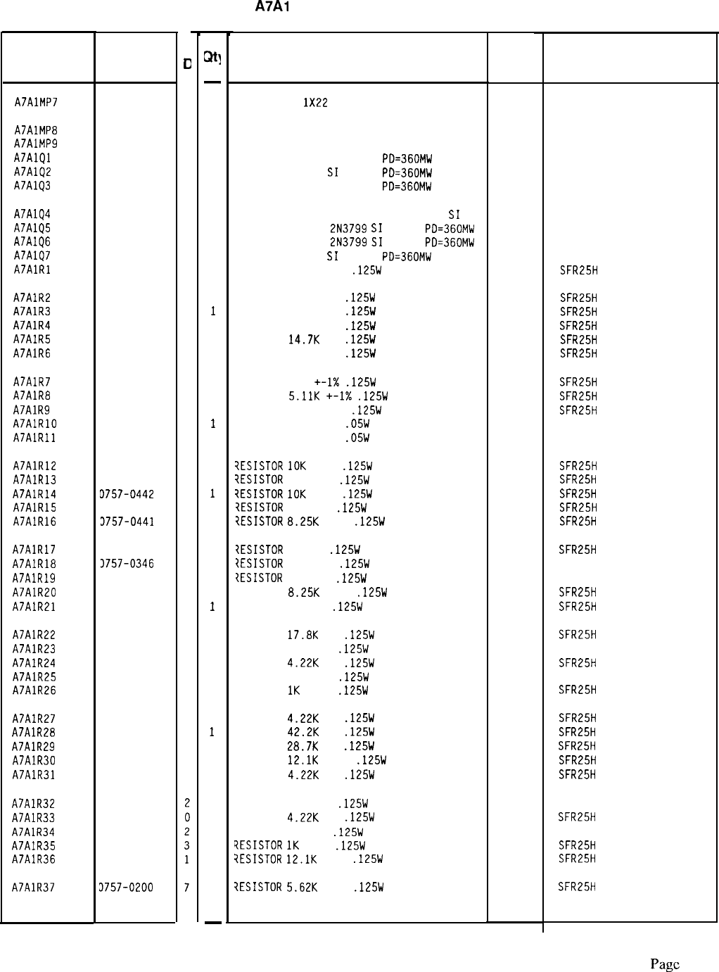
Reference
Designation
HP Part
Number
C
0
A7AlMP7 8151-0013
4
A7AlMP8 85660-20045
7
A7AlMP9 86701-40001
9
A7AlQl 1854-0019
3
A7AlQ2 1854-0019
3
A7AlQ3 1854-0019
3
A7AlQ4
A7AlQ5
A7AlQ6
A7AlQ7
A7AlRl
1855-0049
1
1853-0451
5
1853-0451
5
1853-0034
0
0757-0399
5
A7AlR2
A7AlR3
A7AlR4
A7AlR5
A7AlR6
0757-0417
8
0757-0416
7
0757-0401
0
0698-3156
2
0757-0401
0
A7AlR7
A7AlR8
A7AlR9
A7AlRlO
A7AlRll
0757-0420
3
0757-0438
3
0757-0399
5
0698-7222
1
0698-7219
6
A7AlR12
A7AlR13
A7AlR14
A7AlR15
A7AlR16
0757-0442
9
0698-3453
2
3757-0442
9
3698-3453
2
3757-0441
8
A7AlR17
A7AlR18
A7AlR19
A7AlR20
A7AlR21
3698-3438
3
3757-0346
2
1757-0346
2
0757-0441
8
0698-3438
3
A7AlR22
A7AlR23
A7AlR24
A7AlR25
A7AlR26
0698-3136
8
0757-0346
2
0698-3154
0
0757-0346
2
0757-0280
3
A7AlR27
A7AlR28
A7AlR29
A7AlR30
A7AlR31
0698-3154
0
0698-3450
9
0698-3449
6
0757-0444
1
0698-3154
0
A7AlR32 0757-0346
A7AlR33 0698-3154
A7AlR34 0757-0346
A7AlR35 0757-0280
A7AlR36 0757-0444
A7AlR37 3757-0200
-
w
-
1
1
1
1
1
1
1
1
1
1
1
1
1
1
1
1
1
1
1
1
1
1
1
1
1
1
1
1
1
1
1
1
1
1
1
1
1
1
1
1
1
1
1
1
1
1
1
-
HP Part Number 85660-60015
A7Al
Reference Phase Detector
Description
WIRE 22AWG
1X22
Mfr
Mfr Part
Code Number
92194 298
CASTING, COVER
PC EXTRACTOR
TRANSISTOR NPN SI TO-18
PD=360MW
TRANSISTOR NPN
SI
TO-18
PD=360MW
TRANSISTOR NPN SI TO-18
PD=360MW
2848C
2848C
04713
04713
04713
85660-20045
86701-40001
TRANSISTOR-JFET DUAL N-CHAN D-MODE
SI
PD
34677
TRANSISTOR PNP
2N3799
SI
TO-18
PO=360MW 04713
TRANSISTOR PNP
2N3799
SI
TO-18
PD=360MW 04713
TRANSISTOR PNP
SI
TO-18
PD=360MW 04713
RESISTOR 82.5 +-1%
.125W
TF TC=O+-100
19701
SFR25H
RESISTOR 562 +-1%
.125W
TF TC=O+-100
19701
SFR25H
RESISTOR 511 +-1%
.125W
TF TC=O+-100
19701
SFR25H
RESISTOR 100 +-1%
.125W
TF TC=O+-100
19701 SFR25H
RESISTOR
14.7K
1%
.125W
TF TC=O+-100
19701
SFR25H
RESISTOR 100 +-1%
.125W
TF TC=O+-100
19701
SFR25H
RESISTOR 750 +-I%
.125W
TF TC=O+-100
19701
SFR25H
RESISTOR
5.11K
+-I%
.125W
TF TC=O+-100
19701
SFR25H
RESISTOR 82.5 +-1%
.125W
TF TC=O+-100
19701
SFR25H
RESISTOR 261 +-1%
.05W
TF TC=O+-100
19701
50635
RESISTOR 196 +-1%
.05W
TF TC=O+-100
19701
50635
7ESISTOR
10K
+-1%
.125W
TF TC=O+-100
19701
SFR25H
iESISTOR
196K 1%
.125W
TF TC=O+-100
19701
SFR25H
?ESISTOR
10K
+-1%
.125W
TF TC=O+-100
19701
SFR25H
?ESISTOR
196K 1%
.125W
TF TC=O+-100
19701
SFR25H
?ESISTOR
8.25K
+-1%
.125W
TF TC=O+-100
19701
SFR25H
?ESISTOR
147 1%
.125W
TF TC=O+-100
19701
SFR25H
7ESISTOR
10 +-1%
.125W
TF TC=O+-100
91637 CMF-55-1, T-l
IESISTOR
10 +-1%
.125W
TF TC=O+-100
91637 CMF-55-1, T-l
RESISTOR
8.25K
+-1%
.125W
TF TC=O+-100
19701
SFR25H
RESISTOR 147 1%
.125W
TF TC=O+-100
19701
SFR25H
RESISTOR
17.8K
1%
.125W
TF TC=O+-100
19701
SFR25H
RESISTOR 10 +-1%
.125W
TF TC=O+-100
91637 CMF-55-1, T-l
RESISTOR
4.22K
1%
.125W
TF TC=O+-100
19701
SFR25H
RESISTOR 10 +-1%
.125W
TF TC=O+-100
91637 CMF-55-1, T-l
RESISTOR
1K
+-1%
.125W
TF TC=O+-100
19701
SFR25H
RESISTOR
4.22K
1%
.125W
TF TC=O+-100
19701
SFR25H
RESISTOR
42.2K
1%
.125W
TF TC=O+-100
19701
SFR25H
RESISTOR
28.7K
1%
.125W
TF TC=O+-100
19701 SFR25H
RESISTOR
12.1K
+-1%
.125W
TF TC=O+-100
19701
SFR25H
RESISTOR
4.22K
1%
.125W
TF TC=O+-100
19701
SFR25H
RESISTOR 10 +-1%
.125W
TF TC=O+-100
RESISTOR
4.22K
1%
.125W
TF TC=O+-100
RESISTOR
10 +-1%
.125W
TF TC=O+-100
?ESISTOR
1K
+-1%
.125W
TF TC=O+-100
?ESISTOR
12.1K
+-1%
.125W
TF TC=O+-100
?ESISTOR
5.62K
+-1%
.125W
TF TC=O+-100
91637 CMF-55-l. T-l
19701
SFR25H
91637 CMF-55-l. T-l
19701
SFR25H
19701
SFR25H
19701
SFR25H
*Indicates factory-selected value
85660-60015 Parts List
Page
3 of 5
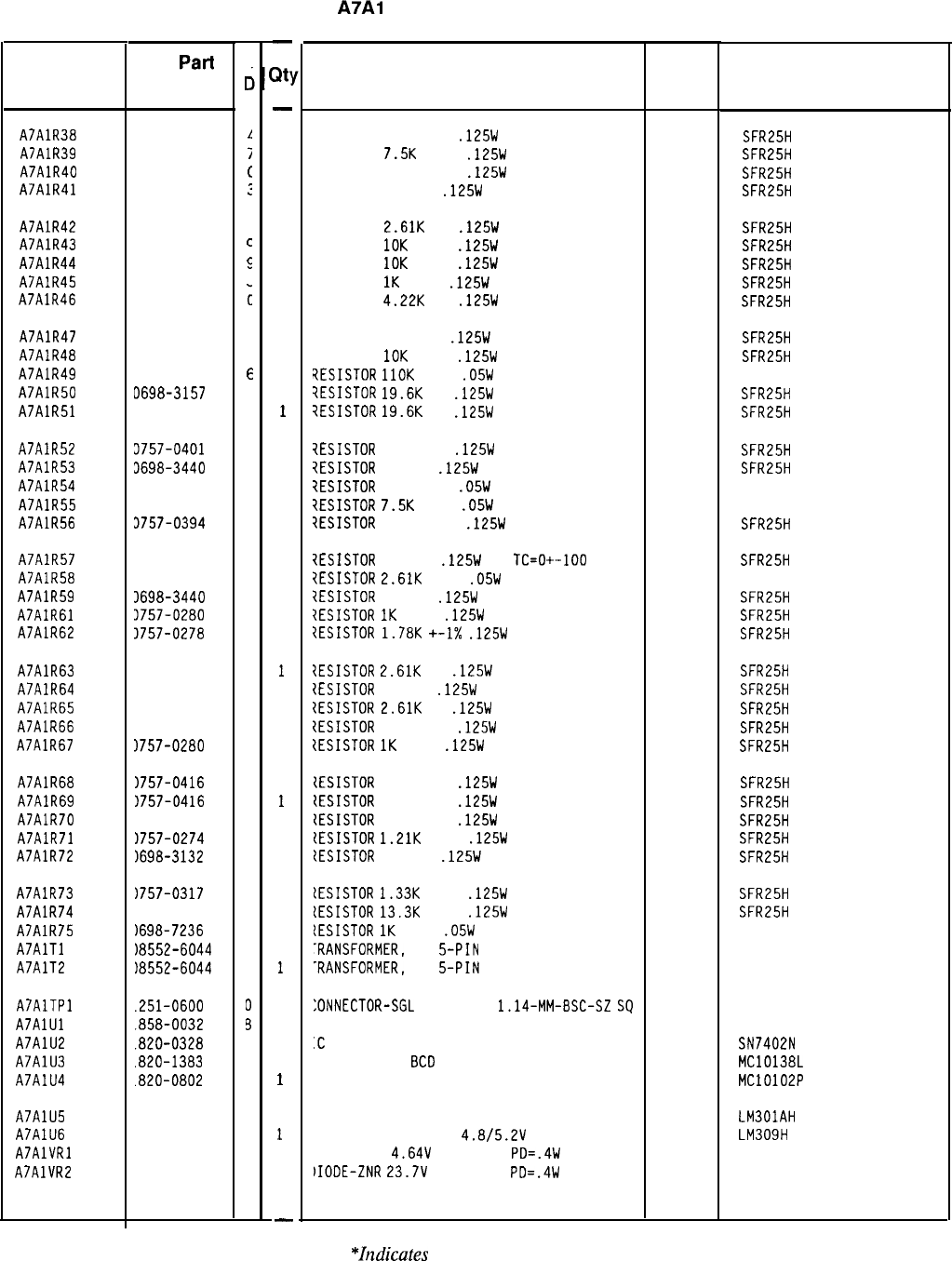
HP Part Number 85660-60015
Reference
Designation HP
Part
Number
A7AlR38 0757-0421
A7AlR39 0757-0440
A7AlR40 0757-0394
A7AlR41 0698-3446
A7AlR42 0698-0085
A7AlR43 0757-0442
A7AlR44 0757-0442
A7AlR45 0757-0280
A7AlR46 0698-3154
A7AlR47 0698-3453
A7AlR48 0757-0442
A7AlR49 0698-7285
A7AlR50 D698-3157
A7AlR51 3698-3157
A7AlR52 3757-0401
A7AlR53 3698-3440
A7AlR54 3698-7234
A7AlR55 3698-7257
A7AlR56 3757-0394
A7AlR57 3698-3446
A7AlR58 3698-7246
A7AlR59 3698-3440
A7AlR61 3757-0280
A7AlR62 3757-0278
A7AlR63 1698-0085
A7AlR64 1698-3132
A7AlR65 1698-0085
A7AlR66
1757-0421
A7AlR67 1757-0280
A7AlR68 1757-0416
A7AlR69 1757-0416
A7AlR70 1757-0416
A7AlR71 1757-0274
A7AlR72
1698-3132
A7AlR73
1757-0317
A7AlR74
1757-0289
A7AlR75
1698-7236
A7AlTl
18552-6044
A7AlT2
18552-6044
A7AlTPl
.251-0600
A7AlUl
.858-0032
A7AlU2
.820-0328
A7AlU3
.820-1383
A7AlU4
.820-0802
A7AlU5 820-0223
A7AlU6 820-0429
A7AlVRl 902-3082
A7AlVR2 902-3256
85660-60015 Parts List
Page 4 of 5
C
c
L
i
c
:
c
c
5
3
c
2
9
E
3
3
a
7
5
2
0
3
9
7
3
9
0
4
0
4
3
7
7
7
5
4
7
2
7
1
1
0
3
6
5
1
3
3
3
3
-
lit:
-
1
1
1
1
1
1
1
1
1
1
1
1
1
1
1
1
1
1
1
1
1
1
1
1
1
1
1
1
1
1
1
1
1
1
1
1
1
1
1
1
1
1
1
1
1
1
1
1
-
A7Al
Reference Phase Detector
Description
RESISTOR 825 +-1%
.125W
TF TC=O+-100
RESISTOR
7.5K
+-1%
.125W
TF TC=O+-100
RESISTOR 51.1 +-1%
.125W
TF TC=O+-100
RESISTOR 383 1%
.125W
TF TC=O+-100
Mfr
Code
19701
19701
19701
19701
Mfr Part
Number
SFR25H
SFR25H
SFR25H
SFR25H
RESISTOR
2.61K
1%
.125W
TF TC=O+-100
19701
SFR25H
RESISTOR
10K
+-1%
.125W
TF TC=O+-100
19701
SFR25H
RESISTOR
10K
+-1%
.125W
TF TC=O+-100
19701
SFR25H
RESISTOR
1K
+-1%
.125W
TF TC=O+-100
19701
SFR25H
RESISTOR
4.22K
1%
.125W
TF TC=O+-100
19701
SFR25H
RESISTOR 196K 1%
.125W
TF TC=O+-100
19701
SFR25H
RESISTOR
IOK
+-1%
.125W
TF TC=O+-100
19701
SFR25H
?ESISTOR
1lOK
+-1%
.05W
TF TC=O+-100
19701
5023R
?ESISTOR
19.6K
1%
.125W
TF TC=O+-100
19701
SFR25H
?ESISTOR
19.6K
1%
.125W
TF TC=O+-100
19701
SFR25H
?ESISTOR
100 +-1%
.125W
TF TC=O+-100
19701
SFR25H
7ESISTOR
196 1%
.125W
TF TC=O+-100
19701
SFR25H
ZESISTOR
825 +-1%
.05W
TF TC=O+-100
19701
50635
iESISTOR
7.5K
+-1%
.05W
TF TC=O+-100
19701
50635
?ESISTOR
51.1 +-1%
.125W
TF TC=O+-100
19701
SFR25H
?ESISTOR
383 1%
.125W
TF
TC=O+-100
19701
SFR25H
?ESISTOR
2.61K
+-1%
.05W
TF TC=O+-100
19701
50635
?ESISTOR
196 1%
.125W
TF TC=O+-100
19701
SFR25H
7ESISTOR
IK
+-1%
.125W
TF TC=O+-100
19701
SFR25H
{ESISTOR
1.78K
+-I%
.125W
TF TC=O+-100
19701
SFR25H
?ESISTOR
2.61K
1%
.125W
TF TC=O+-100
19701
SFR25H
IESISTOR
261 1%
.125W
TF TC=O+-100
19701
SFR25H
ZESISTOR
2.61K
1%
.125W
TF TC=O+-100
19701
SFR25H
{ESISTOR
825 +-1%
.125W
TF TC=O+-100
19701
SFR25H
{ESISTOR
1K
+-1%
.125W
TF TC=O+-100
19701
SFR25H
{ESISTOR
511 +-1%
.125W
TF TC=O+-100
19701
SFR25H
CESISTOR
511 +-1%
.125W
TF TC=O+-100
19701
SFR25H
(ESISTOR
511 +-1%
.125W
TF TC=O+-100
19701
SFR25H
tESISTOR
1.21K
+-1%
.125W
TF TC=O+-100
19701
SFR25H
CESISTOR
261 1%
.125W
TF TC=O+-100
19701
SFR25H
lESISTOR
1.33K
+-1%
.125W
TF TC=O+-100
19701
SFR25H
lESISTOR
13.3K
+-1%
.125W
TF TC=O+-100
19701
SFR25H
[ESISTOR
1K
+-1%
.05W
TF TC=O+-100
19701
50635
-RANSFORMER,
RF
5-PIN 28480 08552-6044
-RANSFORMER,
RF
5-PIN 28480 08552-6044
:ONNECTOR-SGL
CONT PIN
1.14-MM-BSC-SZ
SQ
27264 16-06-0034
'RANSISTOR ARRAY 14-PIN PLSTC DIP 27014 LM3146
:C
GATE TTL NOR QUAD 2-INP
01295 SN7402N
:C CNTR ECL BCD POS-EDGE-TRIG 04713 MC10138L
'C GATE ECL NOR QUAD 2-INP 04713 MC10102P
C OP AMP GP TO-99 PKG 27014
C V RGLTR-FXD-POS
4.8/5.2V
TO-39 PKG
27014
IIODE-ZNR
4.64V
5% DO-35
PD=.4W 04713
bIODE-ZNR
23.7V
5% DO-35
PD=.4W 04713
LM301AH
LM309H
*Zndicates
factory-selected value
Reference
Designation
A7AlWl
HP Part
Number
15660-60084
HP Part Number 85660-60015
A7Al
Reference Phase Detector
Description
CABLE ASSEMBLY, GRAY/ORANGE
(INCLUDES
52)
Mfr
Code
28480
Mfr Part
Number
85660-60084
*Indicates factory-selected
value
85660-60015 Parts List
Page 5 of 5
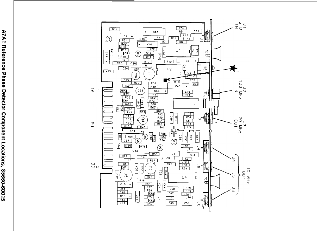
I-
E-l
l$j
fg
DEC
/
u3
c;
11
u
I
I
P.3
II
1::11::1-
-1
II
N
”
E,
-
I
’
u
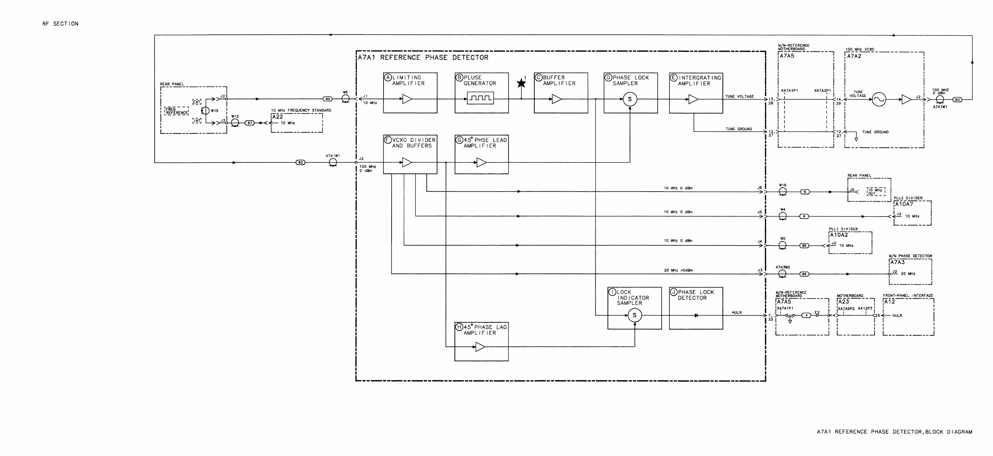
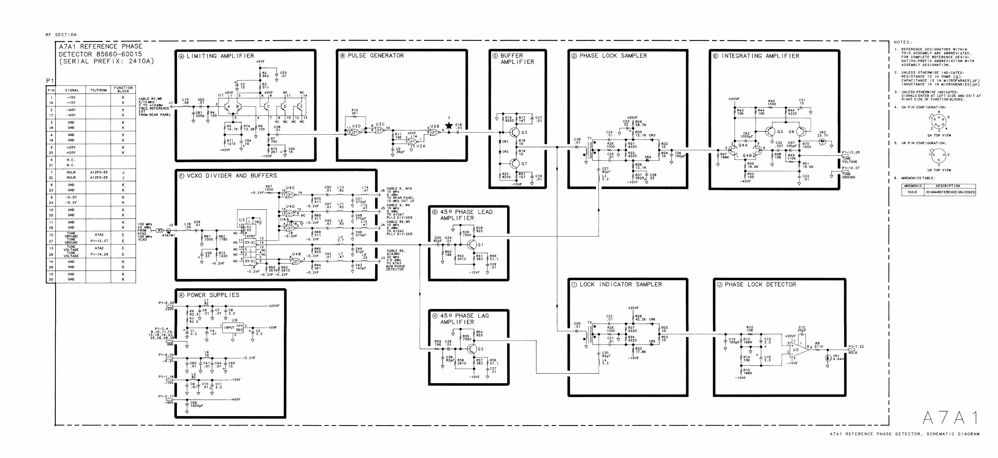
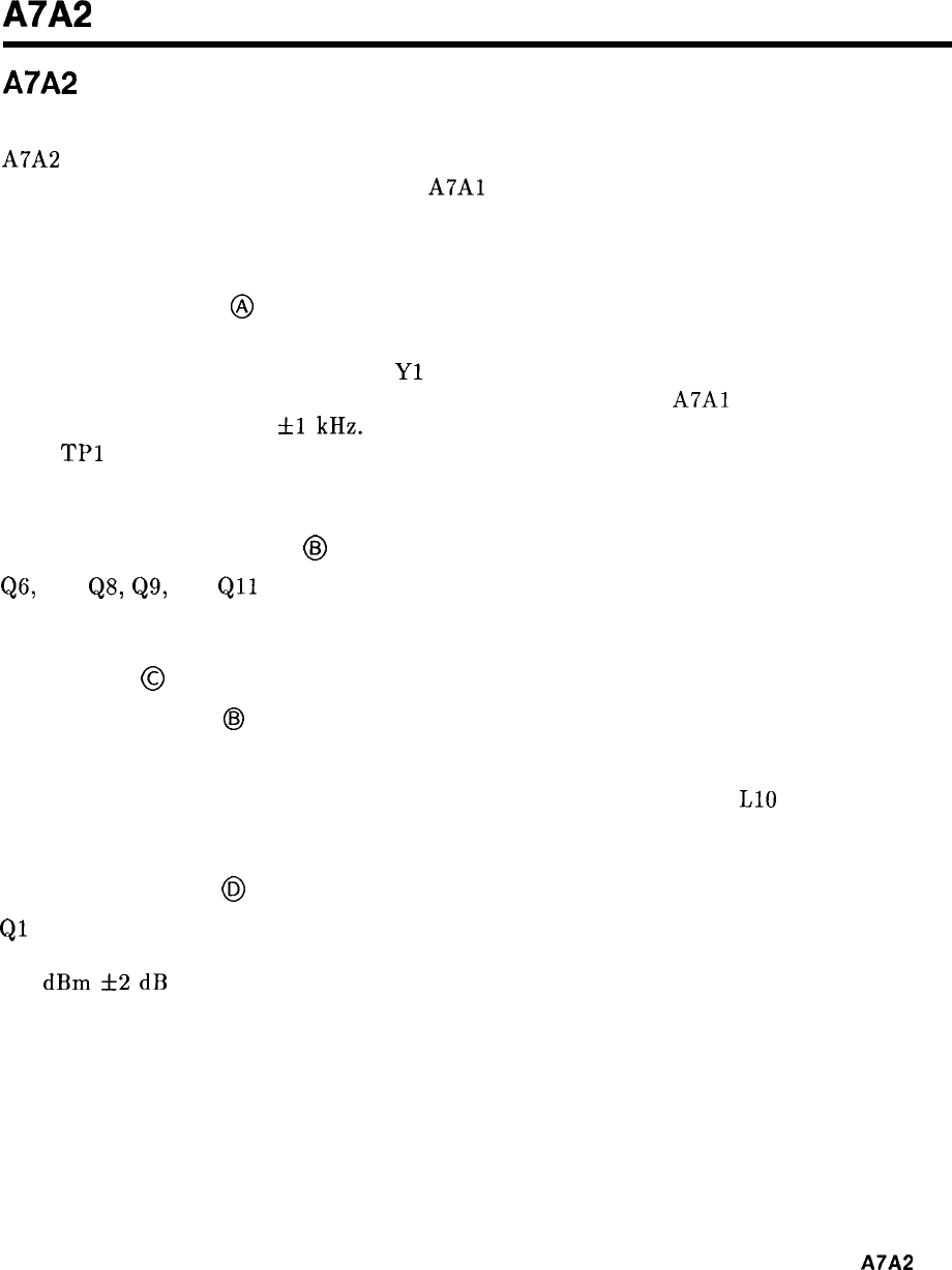
A7A2
A7A2 100 MHz Voltage-Controlled Crystal Oscillator (VCXO),
Circuit Description
A7A2 consists of a 100 MHz voltage-controlled crystal oscillator, buffer amplifiers, and a
frequency quadrupler. In conjunction with
A7Al
Reference Phase Detector, it forms the
reference phase-lock loop. Outputs of 100 MHz and 400 MHz are used as frequency references
by other assemblies in the instrument.
100 MHz Oscillator
@
Q5 functions as a common-base amplifier with feedback to form an oscillator. The
feedback includes the 100 MHz crystal
Yl
and varactor CR1 which are the principal
frequency-determining components. CR1 is tuned by the output of
A7Al
and can vary the
frequency by approximately
fl
kHz. The amplitude of the oscillations is limited by CR3 and
CR4.
TPl
is accessible from the top cover; the voltage should be near -8 V dc for proper
operation. The voltage is adjusted by tuning the oscillator with C4.
100 MHz Buffer Amplifier
@
QS,
Q7,
QS,
Q9,
and
Qll
form a series of 100 MHz amplifiers. They buffer the 100 MHz
outputs from each other as well as from the oscillator.
Quadrupler
@
100 MHz from Q7 in
@J
is applied to T3. The secondary of T3 is connected to Q3 and Q4 to
form a full-wave rectifier. Positive half cycles of 100 MHz to T3 turn on Q3 while negative
half cycles turn on Q4. The collectors are connected together to sum the currents and produce
even harmonics of 100 MHz. The output is tuned to 400 MHz by C3 and
LlO
to select
400
MHz.
400 MHz Amplifier
@
Ql
and Q2 are two common-emitter tuned amplifier stages which amplify 400 MHz and filter
undesired harmonics of 100 MHz. R67, R68, and R69 form a pad which is selected to give
-10
dBm
f2
dB output at 400 MHz.
A7A2
1
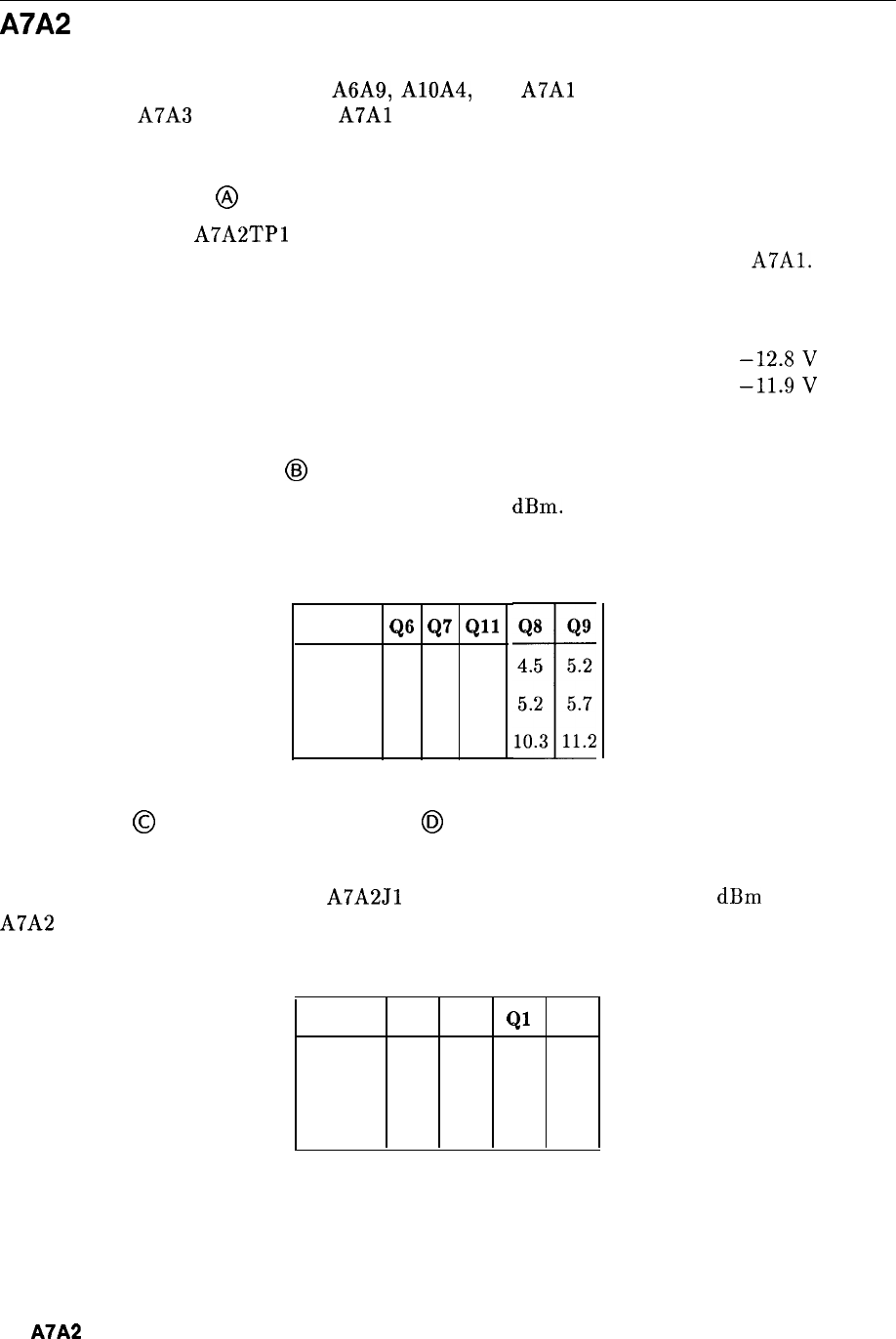
A7A2 100 MHz VCXO, Troubleshooting
The 100 MHz VCXO supplies all of the fixed reference frequencies for the HP 8566B. Separate
100 MHz outputs are routed to the A6A9, AlOA4, and
A7Al
assemblies. A 400 MHz signal is
applied to the A7A3 assembly. The
A7Al
assembly divides the 100 MHz input to provide 10
MHz and 20 MHz references.
100 MHz Oscillator
@
The tune voltage at
A7A2TPl
is nominally -8 V. If an unlocked condition exists, this voltage
is either -23 V or -1.3 V. If the level is -23 V, check the 10 MHz reference to
A7Al.
If the
level is -1.3 V, check the outputs of the 100 MHz Buffer/Amplifier.
Typical voltage levels for the oscillator transistor Q5 are:
Emitter ..........................................................
-12.8V
Base .............................................................
-11.9V
Collector .......................................................... ..O.O V
100 MHz Buffer/Amplifier
@I
All 100 MHz output levels should be approximately 0
dBm.
Typical voltage levels for each
transistor are as shown in Table 1.
Q6
Q7
Qll
Emitter
4.0
3.9
3.9
Base 4.7 4.7 4.6
Collector
9.3
9.4
9.4
Table 1. 100 MHz Buffer/Amplifier Voltage Levels
Quadrupler
@
and 400 MHz Amplifier
@I
Typical voltage levels for the Quadrupler and 400 MHz Amplifier are as shown in Table 2.
The 400 MHz Amplifier output at
A7A2Jl
(96 cable) is approximately -10
dBm
when the
A7A2 100 MHz board assembly is in the casting.
Table 2. Quadrupler and 400 MHz Amplifier Voltage Levels
Q3 Q4
Ql
Q3
Emitter -4.6 -5.1 -6.6 -6.6
Base
-5.9 -5.9 -5.9 -5.9
Collector
0.0
0.0
0.0 0.0
2
A7A2
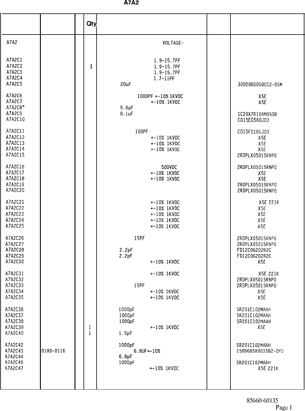
HP Part Number 85660-60135
A7A2
100 MHz VCXO
Reference
HP Part C
Mfr
Mfr Part
Designation
Number D
Qty Description Code Number
A7A2
85660-60135 0 1
BOARD ASSEMBLY, 100 MHZ
VOLTAGE- 28480 85660-60135
CONTROLLED CRYSTAL OSCILLATOR (VCXO)
A7A2Cl
0121-0495 5 1
CAPACITOR-V TRMR-AIR
1.9-15.7PF
175V
74970 187-0309-125
A7A2C2
0121-0495 5
1
CAPACITOR-V TRMR-AIR
1.9-15.7PF
175V
74970
A7A2C3 187-0309-125
0121-0495 5 1
CAPACITOR-V TRMR-AIR
1.9-15.7PF
175V
A7A2C4 74970 187-0309-125
0121-0493 3 1
CAPACITOR-V TRMR-AIR
1.7-1lPF
175V PC-MT
74970 187-0306-125
A7A2C5
0180-0049 9 1
CAP-FXD
2OuF
50 V AL-ELCTLT
56289
30D206G050CC2-DSM
A7A2C6
0160-3456 6 1
CAPACITOR-FXD
1OOOPF
+-lo%
IKVDC
CER
A7A2C7
0160-3454 4 1
808-542
X5E
102K
CAPACITOR-FXD 220PF +-lo%
1KVDC
CER 838-546
X5E
221K
A7A2C8*
0160-2251 7 1
CAP-FXD
5.6pF
500 V
52763
A7A2C9
0160-4084 8 1
CAP-FXD
O.luF
50 V
56289 lC20X7R104M050B
A7A2ClO
0140-0191 8 1
CAP-FXD 56pF 300 V MICA
09023 CD15ED560J03
A7A2Cll
0160-2204 0 1
CAPACITOR-FXD
1OOPF
+-5% 300VDC MICA
09023 CD15FDlOlJ03
A7A2C12
0160-3454 4 1
CAPACITOR-FXD 220PF +-lo%
1KVDC
CER 838-546
X5E
221K
A7A2C13
0160-3454 4 1
CAPACITOR-FXD 220PF
+-lo%
1KVDC
CER 838-546
XSE
221K
A7A2C14
0160-3454 4 1
CAPACITOR-FXD 220PF
+-lo%
1KVDC
CER 838-546
X5E
221K
A7A2C15 0160-2261
9 1
CAPACITOR-FXD 15PF +-5% 500VDC CER 0+-30
52763 2RDPLX05015RNPO
A7A2C16
0160-2261 9 1
CAPACITOR-FXD 15PF +-5%
SOOVDC
CER 0+-30
52763 2RDPLX05015RNPO
A7A2C17
0160-3454 4 1
CAPACITOR-FXD 220PF +-lo%
1KVDC
CER 838-546
X5E
221K
A7A2C18
0160-3454 4 1
CAPACITOR-FXD 220PF +-IO%
1KVDC
CER 838-546
X5E
221K
A7A2C19
0160-2261 9 1
CAPACITOR-FXD 15PF +-5% 500VDC CER 0+-30
52763 2RDPLX05015RNPO
A7A2C20 0160-2261
9 1
CAPACITOR-FXD 15PF +-5% 500VDC CER 0+-30
52763 2RDPLX05015RNPO
A7A2C21
0160-3454 4 1
CAPACITOR-FXD 220PF
+-10x
1KVDC
CER
838-546
X5E
221K
A7A2C22
0160-3454 4 1
CAPACITOR-FXD 220PF
+-lo%
1KVDC
CER 838-546
X5E
221K
A7A2C23
0160-3454 4 1
CAPACITOR-FXD 220PF +-IO%
1KVDC
CER 838-546
XSE
221K
A7A2C24
0160-3454 4 1
CAPACITOR-FXD 220PF
+-lo%
1KVDC
CER 838-546
X5E
221K
A7A2C25
0160-3454 4 1
CAPACITOR-FXD 220PF
+-lo%
1KVDC
CER 838-546
X5E
221K
A7A2C26
0160-2261 9 1
CAPACITOR-FXD
15PF
+-5% 500VDC CER 0+-30
52763 2RDPLX05015RNPO
A7A2C27
0160-2261 9 1
CAPACITOR-FXD 15PF +-5% 500VDC CER 0+-30
52763 2RDPLX05015RNPO
A7A2C28
0160-3872 0 1
CAP-FXD
2.2pF
200 V
FD12COG2D2R2C
A7A2C29
0160-3872 0 1
CAP-FXD
2.2pF
200 V
FD12COG202R2C
A7A2C30
0160-3454 4 1
CAPACITOR-FXD 220PF +-lo%
1KVDC
CER 838-546
X5E
221K
A7A2C31
0160-3454 4 1
CAPACITOR-FXD 220PF
+-lo%
1KVDC
CER
838-546
X5E
221K
A7A2C32 0160-2261
9 1
CAPACITOR-FXD 15PF +-5% 500VDC CER 0+-30
52763 2RDPLX05015RNPO
A7A2C33
0160-2261 9 1
CAPACITOR-FXD
15PF
+-5% 500VDC CER 0+-30
52763 2RDPLX05015RNPO
A7A2C34
0160-3454 4 1
CAPACITOR-FXD 220PF
+-lo%
1KVDC
CER 838-546
X5E
221K
A7A2C35
0160-3454 4 1
CAPACITOR-FXD 220PF
+-lo%
1KVDC
CER 838-546
X5E
221K
A7A2C36
0160-3878 6 1
CAP-FXD
1OOOpF
100 V
04222 SR201C102MAAH
A7A2C37
0160-3878 6 1
CAP-FXD
1OOOpF
100 V
04222 SR201C102MAAH
A7A2C38
0160-3878 6 1
CAP-FXD
1OOOpF
100 V
04222 SR201C102MAAH
A7A2C39
0160-3454 4
1
CAPACITOR-FXD 220PF
+-IO%
1KVDC
CER 838-546
X5E
221K
A7A2C40
0160-2238 0
1
CAP-FXD
1.5pF
500 V
52763
A7A2C42
0160-3878 6 1
CAP-FXD
1OOOpF
100 V
04222 SR201C102MAAH
A7A2C43 0180-0116
1 1
CAPACITOR-FXD
6.8UF+-10%
35VDC TA
56289 150D685X9035B2-DYS
A7A2C44
0160-2253 9 1
CAP-FXD
6.8pF
500 V
52763
47A2C46
0160-3878 6 1
CAP-FXD
1OOOpF
100 V
04222 SR201C102MAAH
47A2C47
0160-3454 4 1
CAPACITOR-FXD 220PF
+-lo%
1KVDC
CER
838-546
X5E
221K
*Indicates factory-selected value
85660-60135 Parts List
Page
1
of 4
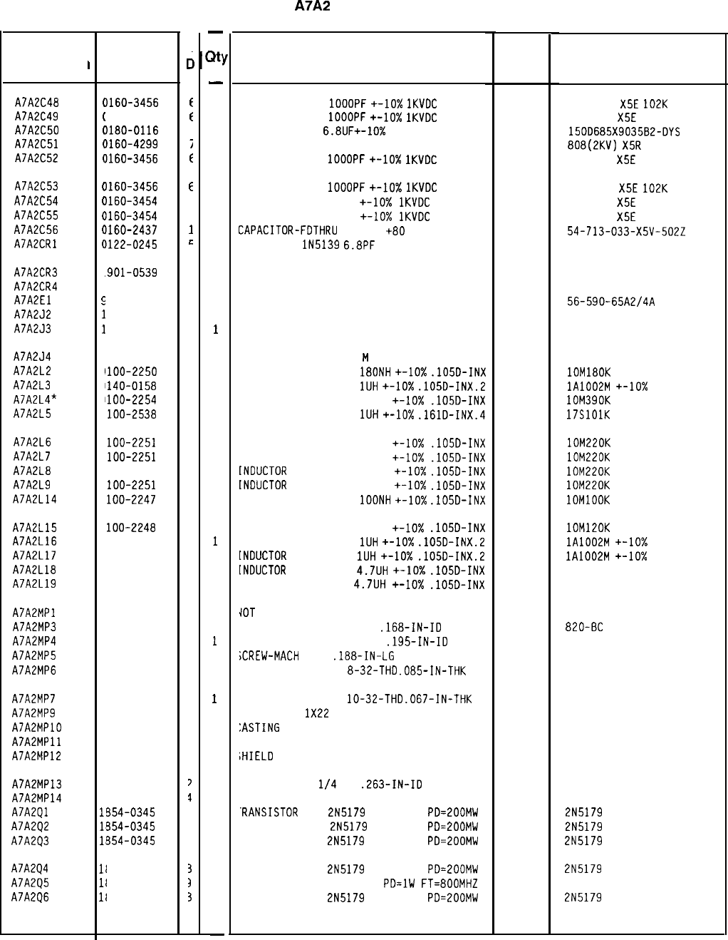
HP Part Number 85660-60135
A7A2
100 MHz VCXO
Description
CAPACITOR-FXD
1OOOPF
+-lo%
1KVDC
CER
CAPACITOR-FXD
1OOOPF
+-lo%
1KVDC
CER
CAPACITOR-FXD
6.8UF+-10%
35VDC TA
CAPACITOR-FXD 2200PF +-20% 250VDC CER
CAPACITOR-FXD
1OOOPF
+-lo%
1KVDC
CER
Mfr
Mfr Part
Code Number
56289
808-542
X5E
102K
808-542
X5E
102K
150D685X9035B2-DYS
808(2KV)
X5R
222M
808-542
X5E
102K
CAPACITOR-FXD
1OOOPF
+-IO%
1KVDC
CER
CAPACITOR-FXD 220PF +-lo%
1KVDC
CER
CAPACITOR-FXD 220PF +-IO%
1KVDC
CER
CAPACITOR-FDTHRIJ
5000PF
+80
-20% 200V
DIODE-VVC
lN5139
6.8PF
10%
33095
04713
808-542
X5E
102K
838-546
X5E
221K
838-546
X5E
221K
54-713-033-X5V-5022
IN5139
DIODE-SCHOTTKY SM SIG
DIODE-SCHOTTKY SM SIG
CORE-SHIELDING BEAD
CONNECTOR-RF SM-SNP M SGL-HOLE-FR 50-OHM
CONNECTOR-RF SM-SNP M SGL-HOLE-FR 50-OHM
02114 56-590-65A2/4A
98291 051-049-0000-220
98291 051-049-0000-220
CONNECTOR-RF SM-SNP
M
SGL-HOLE-FR 50-OHM
98291 051-049-0000-220
INDUCTOR RF-CH-MLD
180NH
+-lo%
.105D-INX 24226 lOM180K
INDUCTOR RF-CH-MLD
1UH
+-lo%
.105D-INX.2 32159 lA1002M
+-lo%
INDUCTOR RF-CH-ML0 390NH +-lo%
.105D-INX 24226 lOM390K
INDUCTOR RF-CH-MLD
1UH
+-lo%
.161D-INX.4 24226 17SlOlK
INDUCTOR RF-CH-MLD 220NH +-lo%
.105D-INX 24226 lOM220K
INDUCTOR RF-CH-MLD 220NH +-IO%
.105D-INX 24226 lOM220K
TNDUCTOR
RF-CH-MLD 220NH
+-lo%
.105D-INX 24226 lOM220K
INDUCTOR
RF-CH-MLD 220NH
+-lo%
.105D-INX 24226 lOM220K
[NDUCTOR RF-CH-MLD
1OONH
+-lo%
.105D-INX 24226 1OMlOOK
[NDUCTOR RF-CH-MLD 120NH +-lo%
.105D-INX 24226 lOM120K
[NDUCTOR RF-CH-MLD
1UH
+-10X
.105D-INX.2 32159 lA1002M
+-lo%
INDUCTOR
RF-CH-MLD
1UH
+-lo%
.105D-INX.2 32159 lA1002M
+-lo%
[NDUCTDR
RF-CH-MLD
4.7UH
+-10X
.105D-INX 99800 1025-36
[NDUCTOR RF-CH-MLD
4.7UH
+-IO%
.lOSD-INX 99800 1025-36
IOT
ASSIGNED
JASHER-LK INTL T NO. 8
.168-IN-ID OG791
JASHER-LK INTL T ND. 10
.195-IN-ID 98291
iCREW-MACH
4-40
.188-IN-LG
PAN-HD-POZI
77250
IUT-HEX-DEL-CHAM
8-32-THD
.085-IN-THK 80120
820-BC
3002-26
IUT-HEX-DBL-CHAM
lo-32-THD
.067-IN-THK 74163 500220
/IRE 22AWG
1X22
92194
298
:ASTING
COVER
28480 85660-20046
:XTRACTDR PC 28480 86701-40001
;HIELD
28480 86701-00045
IASHER-FL NM
l/4
IN
.263-IN-ID
NSULATOR-BSHG NYLON
.RANSISTOR
NPN
2N5179
SI TO-72
PD=ZOOMW
'RANSISTOR NPN
2N5179
SI TO-72
PD=200MW
RANSISTOR NPN
2N5179
SI TO-72
PD=200MW
RANSISTOR NPN
2N5179
SI TO-72
PD=200MW
RANSISTOR NPN SI TO-39
PD=lW
FT=800MHZ
RANSISTDR NPN
2N5179
SI TO-72
PD=200MW
86928
89663
04713
04713
04713
5610-72-10
2N5179
2N5179
2N5179
04713
04713
04713
2N5179
2N5179
*Indicates factory-selected value
I
Reference
Designation
A7A2C48
A7A2C49
A7A2C50
A7A2C51
A7A2C52
HP Part
Number
C
c
(
1160-3456
t
(
1160-3456
t
(
)180-0116
1
(
1160-4299
i
(
1160-3456
f
A7A2C53
(
1160-3456
E
A7A2C54
(
1160-3454
4
A7A2C55
(
1160-3454
4
A7A2C56
I
1160-2437
1
A7A2CRl
c
1122-0245
r:
A7A2CR3
1
.901-0539
3
A7A2CR4
1
901-0539
3
A7A2El
5
1170-0029
3
A7A2J2
1
250-0544
9
A7A2J3
1
250-0544
9
A7A2J4
1
250-0544
9
A7A2L2
9
1100-2250
9
A7A2L3
9
1140-0158
6
A7A2L4*
9
1100-2254
3
A7A2L5
9
loo-2538
6
A7A2L6
9
loo-2251
0
A7A2L7
9
loo-2251
0
A7A2L8
9
100-2251
0
A7A2L9
9
loo-2251
0
A7A2L14
9
loo-2247
4
A7A2L15
9
loo-2248
5
A7A2L16
9
140-0158
6
A7A2L17
9
140-0158
6
A7A2L18
9
140-0144
0
A7A2L19
9
140-0144
0
A7A2MPl
A7A2MP3
A7A2MP4
A7A2MP5
A7A2MP6
2
190-0009
2
190-0124
2
200-0101
2
580-0002
A7A2MP7
2
950-0078
A7A2MP9
8
151-0013
A7A2MPlO
8
5660-20046
A7A2MPll
8
6701-40001
A7A2MP12
8
6701-00045
A7A2MP13
A7A2MP14
A7A2Ql
A7A2Q2
A7A2Q3
A7A2Q4
A7A2Q5
A7A2Q6
3'
0.
1;
1;
1;
11
l(
II
050-0929
340-0177
354-0345
554-0345
354-0345
354-0345
354-0247
354-0345
4
4
0
4
3
4
3
3
7
7
1
3
3
3
3
3
3
85660-60135 Parts List
Page 2 of 4
-
3t:
-
1
1
1
1
1
1
1
1
1
1
1
1
1
1
1
1
1
1
1
1
1
1
1
1
1
1
1
1
1
1
1
1
1
1
1
1
1
1
1
1
1
1
1
1
1
1
1
-
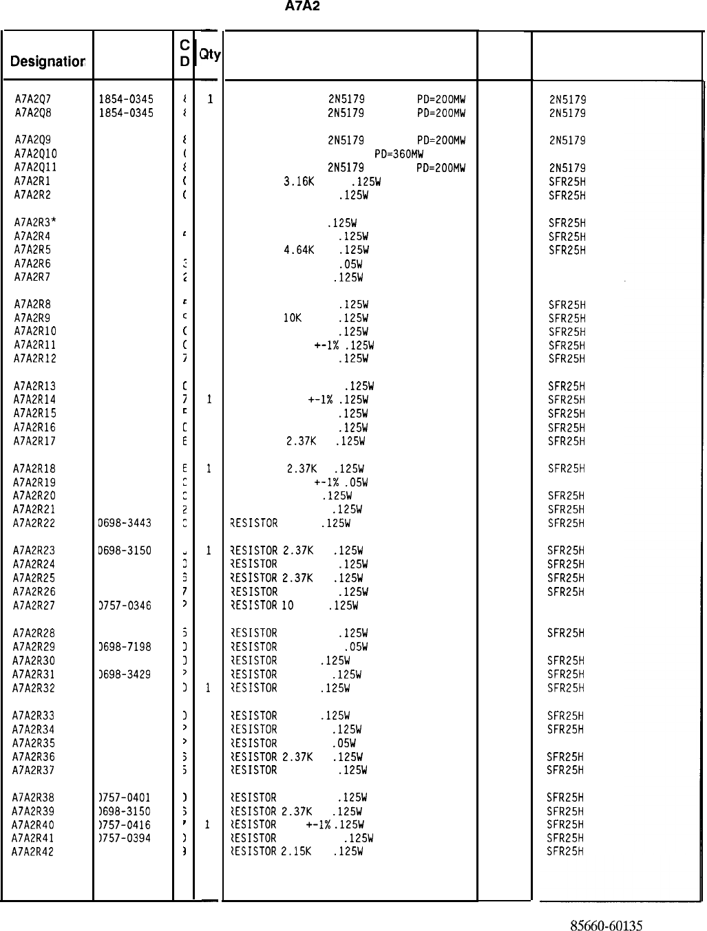
Reference
Designation:
AJA2QJ
AJA2Q8
HP Part
Number
1854-0345
1854-0345
AJA2Q9 1854-0345
I
AJA2QlO 1854-0404
(
AJA2Qll 1854-0345
t
AJA2Rl
0757-0279
(
AJA2R2
0757-0419
(
AJA2R3*
0698-3444
1
AJA2R4
0757-0422
r
AJA2R5 0698-3155
1
AJA2R6
0698-7224
:
AJA2RJ
0757-0346
i
AJA2R8
0757-0422
r
AJA2R9
0757-0442
c
AJA2RlO
0757-0401
t
AJA2Rll
0757-0394
t
AJA2R12
0757-0416
i
AJA2R13
0757-0394
[
AJA2R14
0757-0416
7
AJA2R15
0757-0422
c
AJA2R16
0757-0401
c
AJA2RlJ 0698-3150
E
AJA2R18 0698-3150
AJA2R19
0698-7198
AJA2R20
0698-3443
AJA2R21
0698-3429
AJA2R22
0698-3443
AJA2R23 D698-3150
I
AJA2R24
3757-0401
!
AJA2R25
3698-3150
3
AJA2R26
3757-0416
I
AJA2R27
3757-0346
?
AJA2R28
3757-0422
5
AJA2R29
3698-7198
3
AJA2R30
3698-3443
3
AJA2R31
1698-3429
>
AJA2R32
1698-3443
I
AJA2R33
AJA2R34
AJA2R35
AJA2R36
AJA2R37
1698-3443
I
1698-3429
,
1698-7223
>
1698-3150
5
1757-0422
i
AJA2R38
AJA2R39
AJA2R40
AJA2R41
AJA2R42
)?5?-0401
1
1698-3150
;
1757-0416
I
1757-0394
1
1698-0084
1
-
at]
-
1
1
1
1
1
1
1
1
1
1
1
1
1
1
1
1
1
1
1
1
1
1
1
1
1
1
1
1
1
1
1
1
1
1
1
1
1
1
1
1
1
1
1
1
1
1
1
-
HP Part Number 85660-60135
A7A2
100 MHz VCXO
Description Mfr
Mfr Part
Code Number
TRANSISTOR NPN
2N5179
SI
TO-72
PO=200MW
04713
TRANSISTOR NPN
2N5179
SI
TO-72
PO=200MW
04713
TRANSISTOR NPN
2N5179
SI
TO-72
PD=200MW
04713
TRANSISTOR NPN SI TO-18
PD=360MW
04713
TRANSISTOR NPN
2N5179
SI
TO-72
PD=EOOMW
04713
RESISTOR
3.16K
+-1%
.125W
TF TC=O+-100
19701
RESISTOR 681 +-1%
.125W
TF TC=O+-100
19701
RESISTOR 316 1%
.125W
TF TC=O+-100
RESISTOR 909 +-1%
.125W
TF TC=O+-100
RESISTOR
4.64K
1%
.125W
TF TC=O+-100
RESISTOR 316 +-1%
.05W
TF TC=O+-100
RESISTOR 10 +-1%
.125W
TF TC=O+-100
19701
19701
19701
19701
91637
RESISTOR 909 +-1%
.125W
TF TC=O+-100
19701
RESISTOR
10K
+-1%
.125W
TF TC=O+-100
19701
RESISTOR 100 +-1%
.125W
TF TC=O+-100
19701
RESISTOR 51.1 +-I%
.125W
TF TC=O+-100
19701
RESISTOR 511 +-1%
.125W
TF TC=O+-100
19701
RESISTOR 51.1 +-1%
.125W
TF TC=O+-100
19701
RESISTOR 511 +-I%
.125W
TF TC=O+-100
19701
RESISTOR 909 +-1%
.125W
TF TC=O+-100
19701
RESISTOR 100 +-1%
.125W
TF TC=O+-100
19701
RESISTOR
2.3JK
1%
.125W
TF TC=O+-100
19701
RESISTOR
2.3JK
1%
.125W
TF TC=O+-100
19701
RESISTOR 26.1
+-I%
.05W
TF TC=O+-100
19701
RESISTOR
287
1%
.125W
TF TC=O+-100
19701
RESISTOR 19.6 1%
.125W
TF TC=O+-100
19701
?ESISTOR
287
1%
.125W
TF TC=O+-100
19701
7ESISTOR
2.3JK
1%
.125W
TF TC=O+-100
7ESISTOR
100 +-1%
.125W
TF TC=O+-100
7ESISTOR
2.3JK
1%
.125W
TF TC=O+-100
?ESISTOR
511 +-1%
.125W
TF TC=O+-100
?ESISTOR
10
+-1%
.125W
TF TC=O+-100
19701
19701
19701
19701
91637
?ESISTOR
909 +-1%
.125W
TF TC=O+-100
7ESISTOR
26.1 +-1%
.05W
TF TC=O+-100
IESISTOR
287
1%
.125W
TF TC=O+-100
IESISTOR
19.6 1%
.125W
TF TC=O+-100
?ESISTOR
287
1%
.125W
TF TC=O+-100
?ESISTOR
287
1%
.125W
TF TC=O+-100
{ESISTOR
19.6 1%
.125W
TF TC=O+-100
IESISTOR
287
+-1%
.05W
TF TC=O+-100
{ESISTOR
2.3JK
1%
.125W
TF TC=O+-100
1ESISTOR
909 +-1%
.125W
TF TC=O+-100
{ESISTOR
100 +-1%
.125W
TF TC=O+-100
tESISTOR
2.3JK
1%
.125W
TF TC=O+-100
{ESISTOR
511
+-I%
.125W
TF TC=O+-100
{ESISTOR
51.1 +-1%
.125W
TF TC=O+-100
tESISTOR
2.15K
1%
.125W
TF TC=O+-100
19701
19701
19701
19701
19701
19701
19701
19701
19701
19701
19701
19701
19701
19701
19701
*Indicates factory-selected value
2N5179
2N5179
2N5179
2N5179
SFR25H
SFR25H
SFR25H
SFR25H
SFR25H
50635
CMF-55-1, T-l
SFR25H
SFR25H
SFR25H
SFR25H
SFR25H
SFR25H
SFR25H
SFR25H
SFR25H
SFR25H
SFR25H
50635
SFR25H
SFR25H
SFR25H
SFR25H
SFR25H
SFR25H
SFR25H
CMF-55-1, T-l
SFR25H
50635
SFR25H
SFR25H
SFR25H
SFR25H
SFR25H
50635
SFR25H
SFR25H
SFR25H
SFR25H
SFR25H
SFR25H
SFR25H
85660-6013.5
Parts List
Page 3 of 4
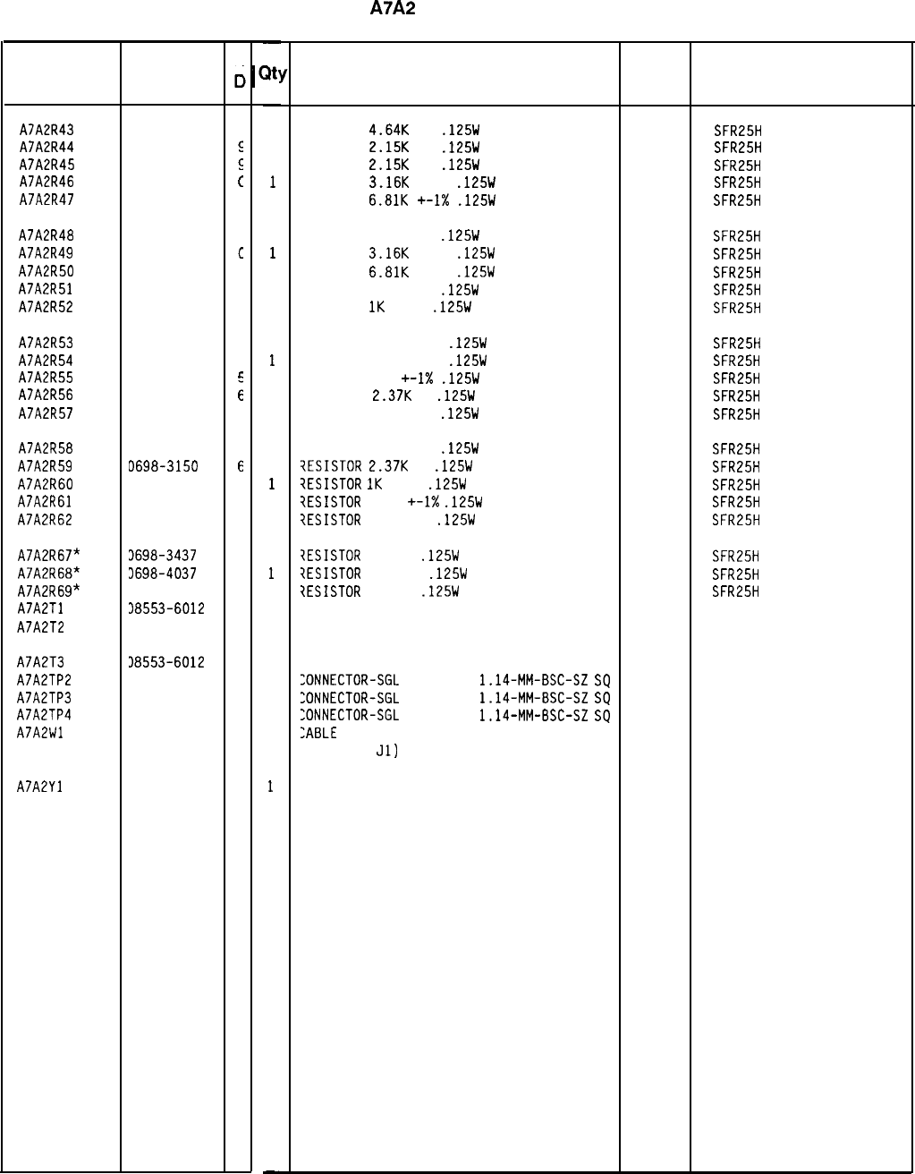
HP Part Number 85660-60135
A7A2
100 MHz VCXO
Reference HP Part
Designation Number
AJA2R43 0698-3155
I
AJA2R44 0698-0084
E
AJA2R45 0698-0084
s
AJA2R46
0757-0279
(
AJA2R47
0757-0439
4
AJA2R48
0757-0416
7
AJA2R49
0757-0279
c
AJA2R50
0757-0439
4
AJA2R51
0757-0416
7
AJA2R52
0757-0280
3
AJA2R53
0757-0394
C
AJA2R54
0757-0394
C
AJA2R55
0757-0422
E
AJA2R56 0698-3150
i
AJA2R57
0757-0401
C
AJA2R58
0757-0401
C
AJA2R59 D698-3150
6
AJA2R60
3757-0280
3
AJA2R61
3757-0397
3
AJA2R62
3757-0401
0
AJA2R6?*
3698-3437
2
AJA2R68*
3698-4037
0
AJA2R69”
3698-3437
2
AJA2Tl 38553-6012
5
AJA2T2 38553-6012
5
AJA2T3 38553-6012
5
AJA2TP2 1251-0600
0
AJA2TP3 1251-0600
0
AJA2TP4 1251-0600
0
AJA2Wl 35660-60082
6
AJA2Yl 1410-1086
5
C
c
-
;It:
-
1
1
1
1
1
1
1
1
1
1
1
1
1
1
1
1
1
1
1
1
1
1
1
1
1
1
1
1
1
1
1
-
Description
RESISTOR
4.64K
1%
.125W
TF TC=O+-100
19701
SFR25H
RESISTOR
2.15K
1%
.125W
TF TC=O+-100
19701
SFR25H
RESISTOR
2.15K
1%
.125W
TF TC=O+-100
19701
SFR25H
RESISTOR
3.16K
+-1%
.125W
TF TC=O+-100
19701
SFR25H
RESISTOR
6.81K
+-I%
.125W
TF TC=O+-100
19701
SFR25H
RESISTOR 511 +-1%
.125W
TF TC=O+-100
19701
SFR25H
RESISTOR
3.16K
+-1%
.125W
TF TC=O+-100
19701
SFR25H
RESISTOR
6.81K
+-1%
.125W
TF TC=O+-100
19701
SFR25H
RESISTOR 511 +-1%
.125W
TF TC=O+-100
19701
SFR25H
RESISTOR
1K
+-1%
.125W
TF TC=O+-100
19701
SFR25H
RESISTOR 51.1 +-1%
.125W
TF TC=O+-100
19701
SFR25H
RESISTOR 51.1 +-1%
.125W
TF TC=O+-100
19701
SFR25H
RESISTOR 909 +-I%
.125W
TF TC=O+-100
19701
SFR25H
RESISTOR
2.3JK
1%
.125W
TF TC=O+-100
19701
SFR25H
RESISTOR 100 +-1%
.125W
TF TC=O+-100
19701
SFR25H
RESISTOR 100 +-1%
.125W
TF TC=O+-100
19701
SFR25H
?ESISTOR
2.3JK
1%
.125W
TF TC=O+-100
19701
SFR25H
?ESISTOR
1K
+-1%
.125W
TF TC=O+-100
19701
SFR25H
?ESISTOR
68.1
+-I%
.125W
TF TC=O+-100
19701
SFR25H
?ESISTOR
100 +-1%
.125W
TF TC=O+-100
19701
SFR25H
7ESISTOR
133 1%
.125W
TF TC=O+-100
19701
SFR25H
?ESISTOR
46.4 1%
.125W
TF TC=O+-100
19701
SFR25H
7ESISTOR
133 1%
.125W
TF TC=O+-100
19701
SFR25H
TRANSFORMER 28480 08553-6012
TRANSFORMER 28480 08553-6012
TRANSFORMER
:ONNECTOR-SGL
CONT PIN
1.14-MM-BSC-SZ
SQ
:ONNECTOR-SGL
CONT PIN
1.14-MM-BSC-SZ
SQ
:ONNECTOR-SGL
CONT PIN
1.14-MM-BSC-SZ
SQ
:ABLE
ASSEMBLY, WHITE/BLUE
(INCLUDES
Jl)
28480 08553-6012
27264
16-06-0034
27264
16-06-0034
27264
16-06-0034
28480 85660-60082
:RYSTAL-QUARTZ 100 MHZ HC-35/U-HLDR 00809
85660-60135 Parts List
Page 4 of 4
*Indicates factory-selected value
Mfr
Mfr Part
Code Number
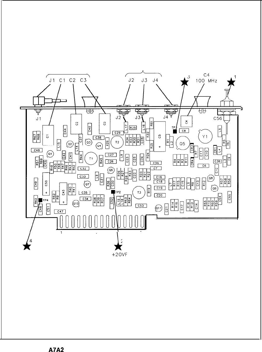
400 MHz 100 MHz
OUT OUT
ATUNE
/
-lOVF
16 PI
i(
15
230
+2ovF
1
A7A2
100 MHz VCXO Component Locations, 85660-60135
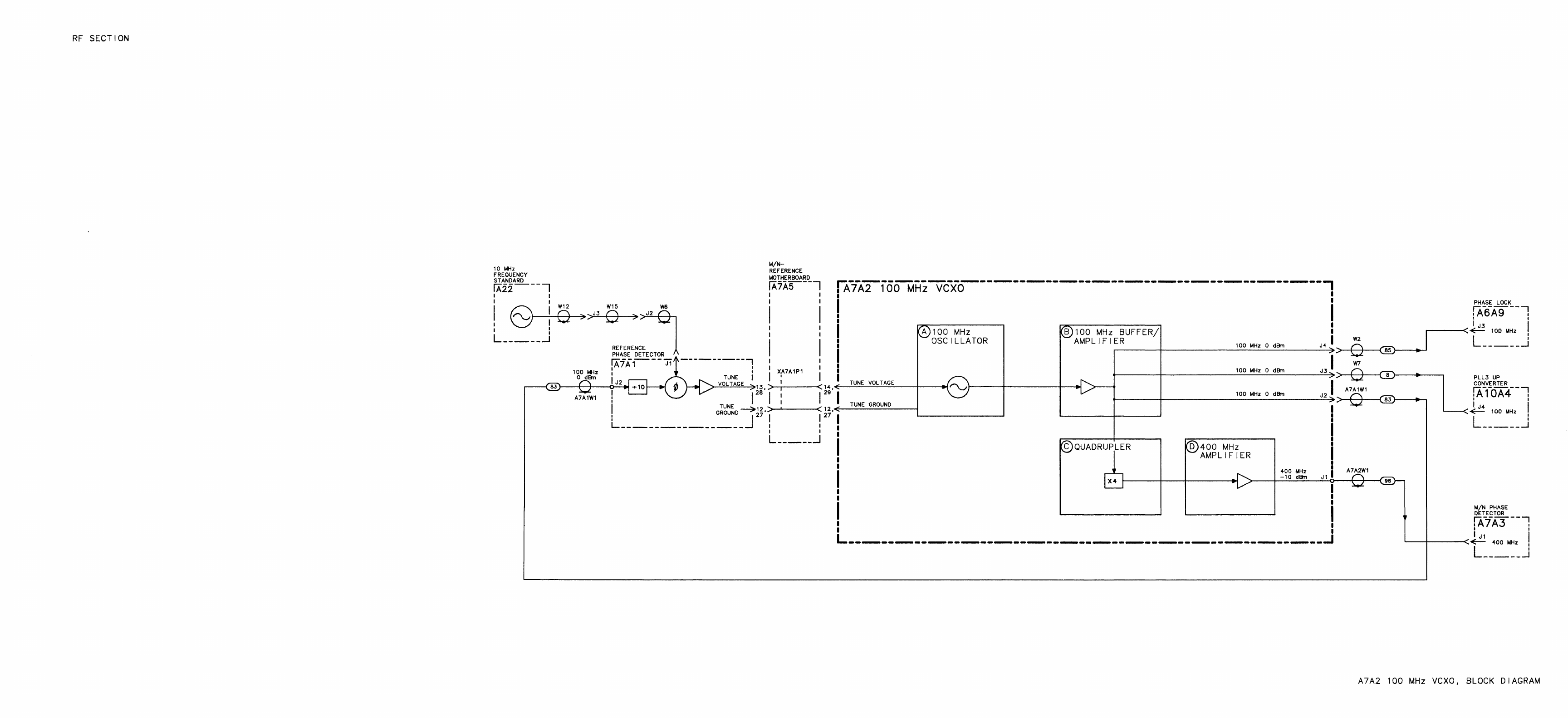
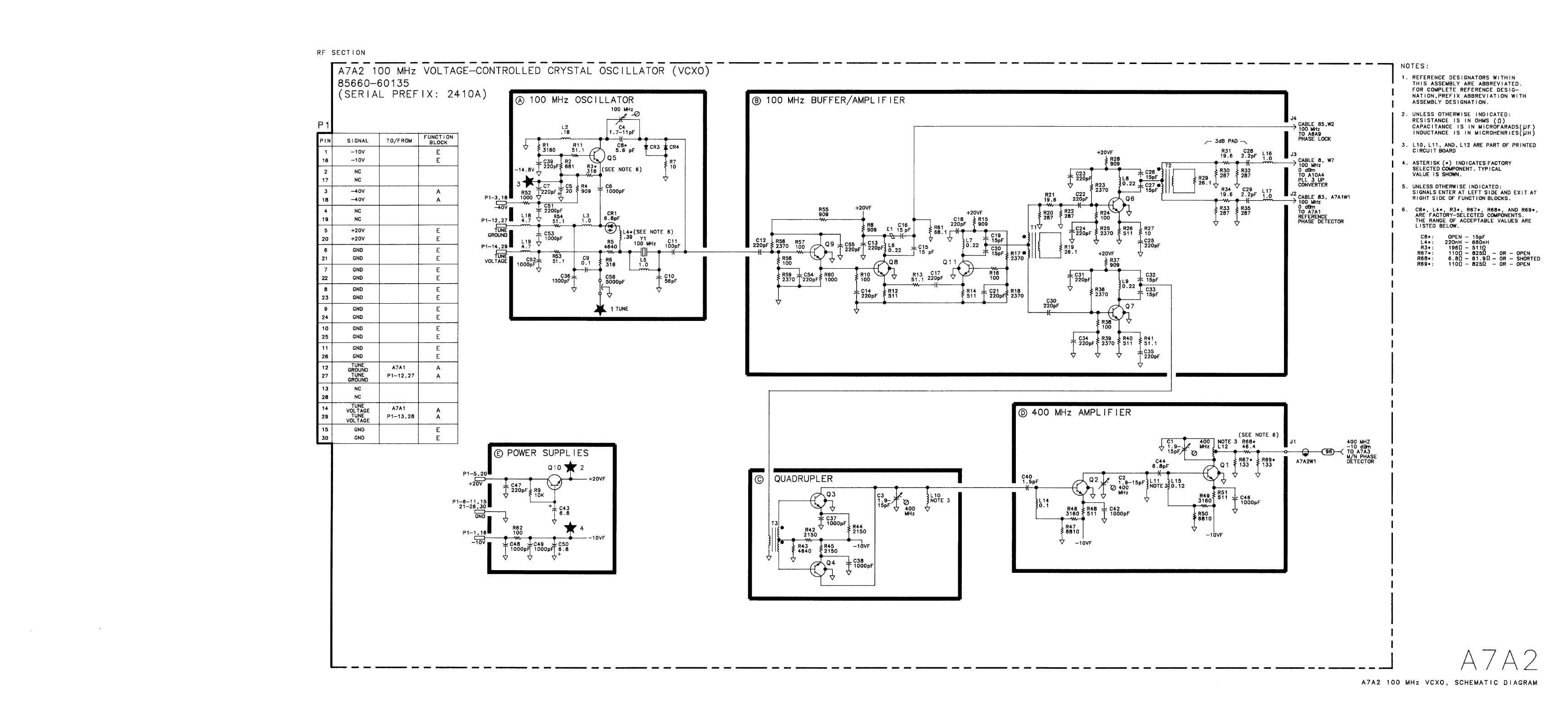
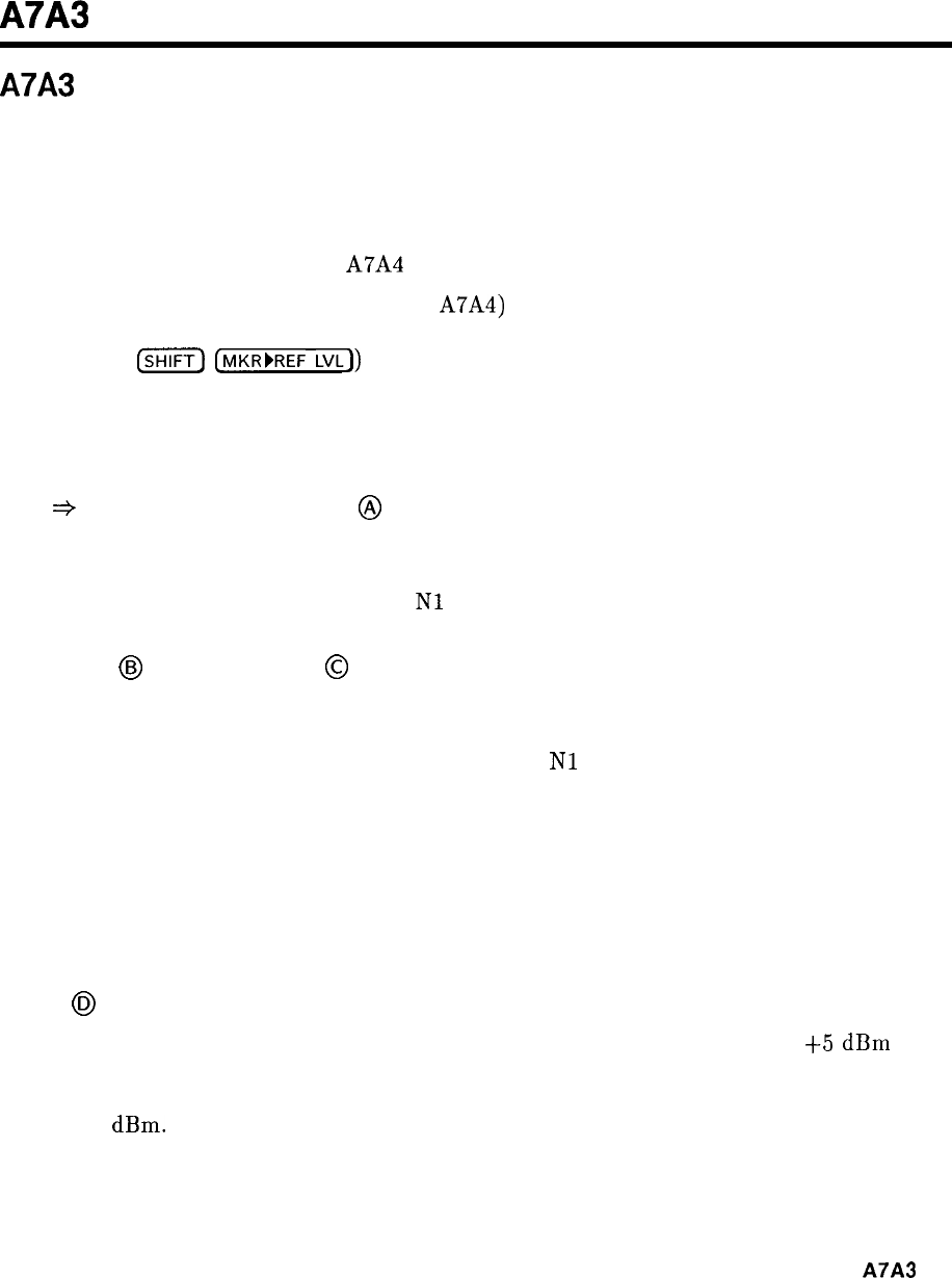
A7A3
A7A3 M/N Phase Detector, Circuit Description
The M/N phase detector has two programmable frequency dividers: an M divider and an
N divider. M and N are integer numbers which give the ratio of divider input frequency to
divider output frequency. This is the divide number. The input to the N divider is 20 MHz;
the M divider input is the difference frequency between the M/N VCO (355 to 395 MHz) and
400 MHz. The two divider outputs are compared in a phase/frequency detector. The detector
output is amplified and applied to A7A4 M/N Output where it is used to tune the M/N VCO.
In general, the M/N output frequency (from A7A4) is (200 to 10 M/N) MHz. The M/N VCO
frequency is twice the M/N output frequency. The spectrum analyzer frequency diagnostics
(displayed by
(SHIFT)
[MKR~REF LVL)) show the M number, N number, and M/N frequency.
The fifth line of diagnostics contains three integers; the second integer is the M number, and
the third integer is the N number. The next (sixth) diagnostic line gives the M/N output
frequency in MHz (177.5 MHz to 197.5 MHz).
TTL
+
ECL Level Translators
@
The numbers to program the frequency dividers come from Al2 Front-Panel Interface in
binary at TTL levels. U3, U13, and U17 shift these to ECL levels which are approximately
-0.9 V logic high and -1.7 V logic low.
Nl
and Ml designate the least significant bits.
N Divider
@
and M Divider
@
The M and N dividers are virtually identical. Basically, the four most significant bits of N
(three bits for M) N3, N4, N5, N6 load a counter U6. It counts down to two and is reloaded
on the next clock pulse. The two least significant bits,
Nl
and N2, control pulse swallowing
logic which causes the counter to count down to 1 instead of 2 before reloading. The logic
determines the proper number of extra pulses to be swallowed to effect the proper divide
number.
For troubleshooting, it is helpful to set the M and N numbers equal in a 1 MHz span using the
frequency diagnostics explained above. Waveforms at corresponding points in the two dividers
can then be compared to pinpoint the problem.
Mixer
@)
Q3 is an amplifier which drives the LO port of the mixer Q24. It supplies about
+5
dBm
over
the 355 to 395 MHz range. The output of the mixer is the difference between 400 MHz and
the M/N VCO frequency which gives an IF frequency between 5 and 45 MHz. The IF level is
about -17
dBm.
A7A3
1
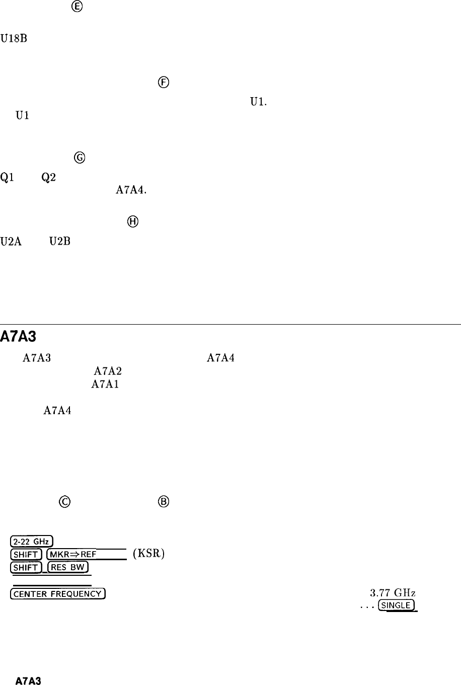
IF Amplifier
@
The 60 MHz low-pass filter rejects unwanted mixing products from the mixer. Q4 and
U18B
amplify and limit the IF signal and give it the proper levels to run the following ECL
circuitry.
Phase/Frequency Detector
@
The outputs of M and N dividers are compared in
Ul.
When they are in phase, the outputs
of
Ul
are narrow, coincident pulses. For unlock conditions, the output pulses are of varying
widths.
Preamplifier
@
Ql
and
Q2
are a low-noise differential pair preamplifier. Their outputs are combined in the
integrating amplifier of A7A4.
Phase Lock Indicator
@
U2A and
U2B
are voltage comparators which compare each tune line to the average plus a
small offset provided by R29. If the loop unlocks, one of the preamplifier outputs is higher
than the comparison voltage, and the phase lock indicator goes high, indicating the unlock
condition.
A7A3 M/N Phase Detector, Troubleshooting
The A7A3 M/N Phase Detector mixes the A7A4 M/N VCO output (355 to 395 MHz) with
400 MHz from the A7A2 100 MHz VCXO. The product of this mixing and the 20 MHz
reference from the
A7Al
are then divided by the M and N dividers respectively, and their
resultant outputs are compared by a phase/frequency detector. The phase error is used to
tune the A7A4 VCO.
The two dividers (M and N) are identical in operation and their waveforms can be compared
for troubleshooting purposes. The M and N numbers can be set to the same value and various
test points within each divider compared to reveal a malfunction, providing one of the dividers
is known to be operating properly.
M Divider
@
and N Divider
@
To display the M and N divide numbers on the HP 8566B CRT, key in the following settings:
@TGGGHz)
(Gii?Tj
(MKR*REF
LEVEL)
(KSR)
(-1
[BW)
(KSF)
[FREQUENCYSPAN) . . . . . . . . . . . . . . . . . . . . . . . . . . . . . . . . . . . . . . . . . . . . . . . . . . . . . 0 Hz
(CENTERFREQUENCY)
. . . . . . . . . . . . . . . . . . . . . . . . . . . . . . . . . . . . . . . . . . . . . . .
3.77GIIZ
SWEEP . . . . . . . . . . . . . . . . . . . . . . . . . . . . . . . . . . . . . . . . . . . . . . . . . . . . . . . .
...(~)
The third line of the diagnostic (KSR) should read as follows:
1 20 20
2
A7A3
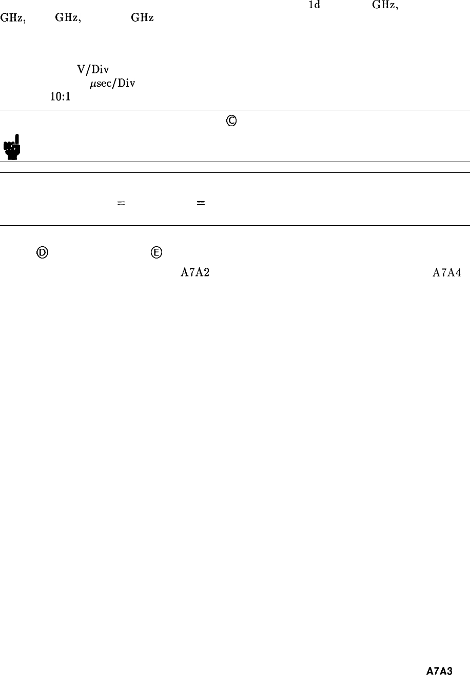
The second and third numbers are the M and N divide numbers respectively. The waveform
at test points 3 and 7, 5 and 6, and 1 and 2 should be as shown in Figures 1, 2, and 3
respectively. The Center Frequencies for Figure la, lb, lc, and
Id
are 3.77 GHz, 3.96
GHz, 4.15 GHz, and 4.34 GHz respectively. The M and N numbers are 20, 21, 22, and 23
respectively.
Oscilloscope control settings for Figure 1, Figure 2, and Figure 3 are:
Vertical: 0.1
V/Div
Horizontal: 0.2
psec/Div
Probe:
1O:l
Note
!iil
Waveforms on the M Divider
0
require the M/N VCO be phase-locked at 380
MHz. If the M/N VCO is not phase-locked, an external signal generator may
be used to locate the failure.
Note
3
All waveform voltage levels are emitter coupled logic (ECL) levels:
-0.9 V
=
high, -1.7 V
=
low.
Mixer
(EJ
and IF Amplifier
@
The Mixer inputs are 400 MHz from A7A2 100 MHz VCXO and 355 to 395 MHz from A7A4
M/N Output. When the M and N numbers are the same, the M/N output frequency is
380
MHz.
A7A3
3
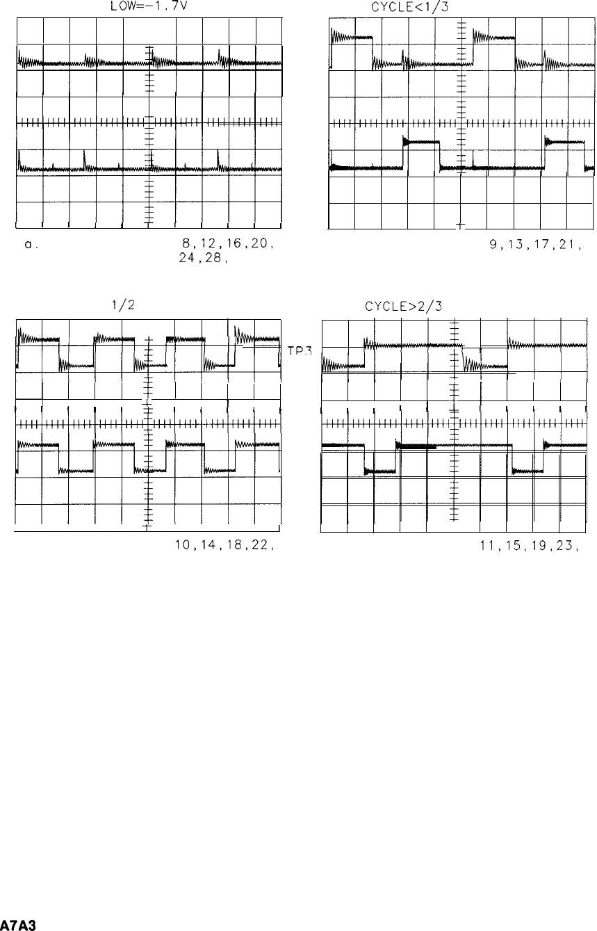
LEVELS=ECL
LOW=-1.7V
I
I
II I
T
I
I
I
I
I
a.
M or N Numbers
8,12,16,20,
24,28,
or 32
TP3
TP7
DUTY
CYCLE<1/3
T
b. M or N Numbers
9,13,17,21,
25, or 29
DUTY CYCLE
l/2
DUTY
CYCLE>2/3
111..
a.
TP3
I
I
I
I I + I
I
I
I
I
I
I
1
f
1
I
II
I
I
II I
+
I
II
II
I
I
II
I
I
I
III
I
I
I
II
I
t
I
I
I
I
I
I I
I
I
I + I
I
II
I
c. M or N Numbers
10,14,18,22,
d. M or N Numbers
11,15,19,23,
26, or 30 27, or 31
TP7
Figure 1. M and N Divider Waveforms for Test Points 3 and 7
4
A7A3
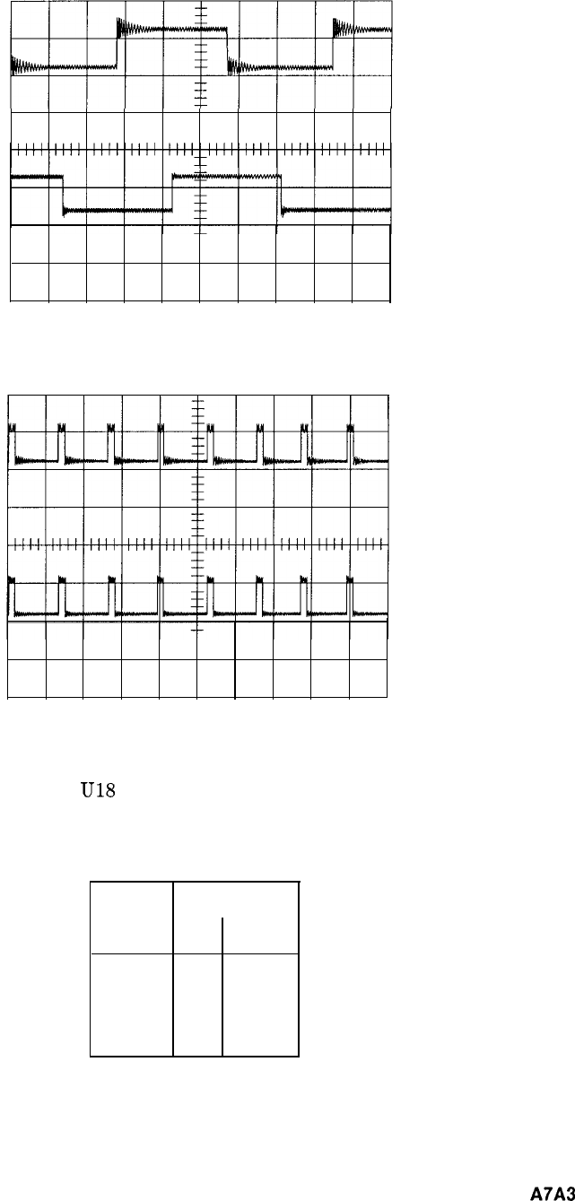
Figure 2. M and N Divider Waveforms for Test Points 5 and 6
Figure 3. M and N Divider Waveforms for Test Points 1 and 2
The output of the IF Amplifier at
U18
Pin 3 is at ECL logic levels: -0.9 V = high,
-1.7 V = low. Typical voltage levels for Q3 and Q4 are shown in Table 1.
Table 1. IF Amplifier Voltage Levels
Voltage Levels
Q3 Q4
Emitter -5.6 -7.4
Base
-4.8 -6.6
Collector
0
-1.9
A7A3
5
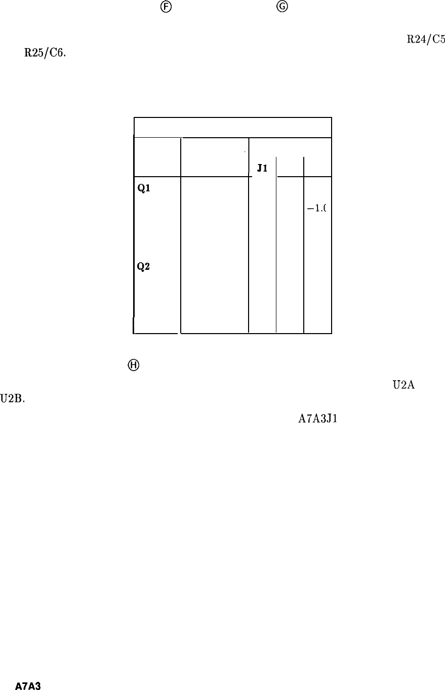
Phase Frequency Detector
@
and Preamplifier
@
The Phase/Frequency Detector outputs pulses whose width is proportional to the phase
difference of the two input signals. These pulses are filtered by the combination of
R24/C5
and
R25/C6.
The Preamplifier amplifies these pulses which are representative of the phase
difference of the two input signals. Typical voltage levels for the Preamplifier are shown in
Table 2.
Table 2. Typical Preamplifier Voltage Levels
Voltage Levels
1
Ql
Emitter
Base
Collector
Q2
Emitter
Base
1
Collector
Phase Locked
T
-0.2 -1.c -1.0
-1.t
-0.8 -0.8 -0.8 -1.6
-5.2 -7.9 -7.9 -1.9
-0.2 -1.0 -1.0 -1.0
-0.8 -1.7 -1.6 -0.8
-5.2 -1.8 -1.9 -7.9
No Input At
Jl
J2 J3
Phase Lock Indicator
@I
The outputs of the Preamplifier are compared to a reference voltage of -4 V by U2A and
U2B. The output (HULM) is high (active state) when the loop is unlocked.
This can be checked by disconnecting the 400 MHz input at
A7A3Jl
(96 cable) and measuring
the output of U2 (Pl-26). With the loop unlocked (400 MHz removed), this voltage should be
approximately 4.64 V.
6
A7A3
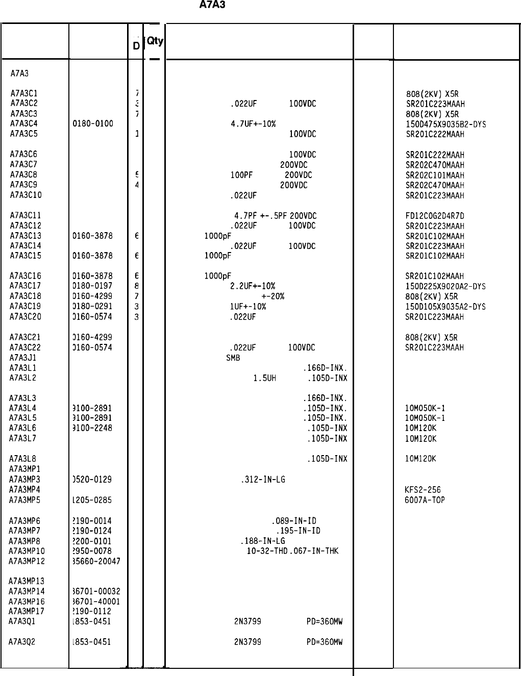
Reference
Designation
HP Part
Number
C
c
A7A3 85660-60136
I
A7A3Cl 0160-4299
A7A3C2 0160-0574
A7A3C3 0160-4299
A7A3C4 0180-0100
A7A3C5 0160-0572
I
A7A3C6 0160-0572
1
A7A3C7 0160-3876
4
A7A3Ca 0160-3877
E
A7A3C9 0160-3876
;1
A7A3ClO 0160-0574
2
A7A3Cll 0160-3873
1
A7A3C12 0160-0574
3
A7A3C13 0160-3878
E
A7A3C14 0160-0574
3
A7A3C15 0160-3878
E
A7A3C16
A7A3C17
A7A3Cla
A7A3C19
A7A3C20
0160-3878
olao-0197
D160-4299
3180-0291
3160-0574
A7A3C21
A7A3C22
A7A3Jl
A7A3Ll
A7A3L2
3160-4299
7
3160-0574
3
1250-2112
1
3100-1641
0
3100-2259
a
A7A3L3
A7A3L4
A7A3L5
A7A3L6
A7A3L7
3100-1641
0
3100-2891
4
3100-2891
4
3100-2248
5
3100-2248
5
A7A3La
A7A3MPl
A7A3MP3
A7A3MP4
A7A3MP5
3100-2248
5
3520-0129
1590-0533
1205-0285
a
5
0
A7A3MP6 !190-0014
A7A3MP7 !190-0124
A7A3MPa
!200-0101
A7A3MPlO !950-0078
A7A3MP12 35660-20047
A7A3MP13 35660-20068
A7A3MP14 36701-00032
A7A3MP16 36701-40001
A7A3MP17
!190-0112
A7A3Ql
1853-0451
A7A3Q2
1853-0451
1
4
0
9
9
4
2
9
0
5
5
-
a!
-
1
1
1
1
1
1
1
1
1
1
1
1
1
1
1
1
1
1
1
1
1
1
1
1
1
1
1
1
1
1
1
1
13
13
5
3
5
2
3
1
2
1
2
10
1
1
-
HP Part Number 85660-60136
A7A3
M/N Phase Detector
Description Mfr
Mfr Part
Code Number
BOARD ASSEMBLY, M/N PHASE DETECTOR 28480 85660-60136
CAPACITOR-FXD 2200PF +-20% 250VDC CER
CAPACITOR-FXD
.022UF
+-20%
1OOVOC
CER
CAPACITOR-FXD 2200PF +-20% 250VDC CER
CAPACITOR-FXD
4.7UF+-10%
35VDC TA
CAPACITOR-FXD 2200PF +-20%
1OOVDC
CER
04222
56289
04222
aoa(2Kv)
X5R
222M
SR201C223MAAH
aoa(2Kv)
X5R
222M
150D475X9035a2-DYS
SR201C222MAAH
CAPACITOR-FXD 2200PF +-20%
1OOVDC
CER
04222 SR201C222MAAH
CAPACITOR-FXD 47PF +-20%
ZOOVDC
CER
04222 SR202C470MAAH
CAPACITOR-FXD
1OOPF
+-20%
LOOVDC
CER
04222 SR202ClOlMAAH
CAPACITOR-FXD 47PF +-20%
EOOVDC
CER
04222 SR202C470MAAH
CAPACITOR-FXD
.022UF
+-20% IOOVDC CER
04222 SR201C223MAAH
CAPACITOR-FXD
4.7PF
+-.5PF
ZOOVDC
CER
CAPACITOR-FXD
.022UF
+-20%
1OOVDC
CER
CAP-FXD
1OOOpF
100 V
CAPACITOR-FXD
.022UF
+-20%
1OOVDC
CER
CAP-FXD
1OOOpF
100 V
04222
04222
04222
04222
FD12COG2D4R7D
SR201C223MAAH
SR201C102MAAH
SR201C223MAAH
SR201C102MAAH
CAP-FXD
1OOOpF
100 V
CAPACITOR-FXD
2.2UF+-10%
20VDC TA
CAPACITOR-FXD 2200PF +-20x 250VDC CER
CAPACITOR-FXD
lUF+-10%
35VOC TA
CAPACITOR-FXD
.022UF
+-20% IOOVDC CER
04222
56289
56289
04222
SR201C102MAAH
1500225X9020A2-DYS
aoa(2Kv)
X5R
222M
1500105X9035A2-DYS
SR201C223MAAH
CAPACITOR-FXD 2200PF +-20% 250VDC CER
CAPACITOR-FXD
.022UF
+-20%
1OOVOC
CER
CONNECTOR-RF
SMB
M SGL-HOLE-FR 50-OHM
INDUCTOR RF-CH-MLD 240UH +-5%
.166D-INX.
INDUCTOR RF-CH-MLD
1.5UH
+-lo%
.105D-INX
04222
98291
99800
99800
aoa(2Kv)
X5R
222M
SR201C223MAAH
051-047-0259-220
1537-94
1025-24
INDUCTOR RF-CH-MLD 240UH +-5%
.166D-INX.
99800 1537-94
INDUCTOR RF-CH-MLD 50NH +-lo%
.105D-INX.
24226 lOM050K-1
INDUCTOR RF-CH-MLD 50NH +-lo%
.105D-INX.
24226 lOM050K-1
INDUCTOR RF-CH-MLD 120NH +-lo%
.105D-INX 24226 lOM120K
INDUCTOR RF-CH-MLD 120NH +-lo%
.105D-INX 24226 lOM120K
INDUCTOR RF-CH-MLD 120NH +-lo%
.105D-INX
NOT ASSIGNED 24226 lOM120K
SCREW-MACH 2-56
.312-IN-LG
PAN-HD-POZI
77250
THREADED INSERT-NUT 2-56 .06-IN-LG SST
46384
HEAT SINK SGL DIP 13103 KFS2-256
6007A-TOP
WASHER-LK INTL T NO. 2
.Oa9-IN-ID 78189
WASHER-LK INTL T NO. 10
.195-IN-ID 98291
SCREW-MACH 4-40
.laa-IN-LG
PAN-HD-PDZI
77250
NUT-HEX-DBL-CHAM
lo-32-THD
.067-IN-THK 74163
COVER PC M/N DETECTOR 28480
1902-00-00-2580
3002-26
500220
85660-20047
GROUND LUG
HEAT SINK IC
EXTRACTOR PC
WASHER-LK SPLIT .Oaa-IN-ID
TRANSISTOR PNP
2N3799
SI TO-18
PD=360MW
TRANSISTOR PNP
2N3799
SI TO-la
PD=360MW
28480
28480
28480
28480
04713
85660-20068
86701-00032
86701-40001
2190-0112
04713
*Indicates facto y-selected value
8566040136 Parts List
Page 1 of 3
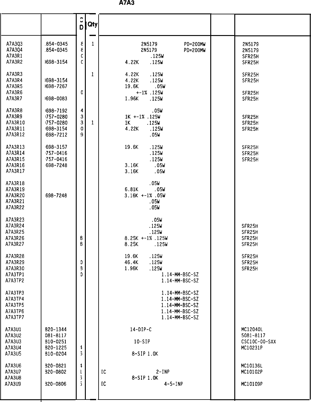
Reference
Designation
HP Part
Number
.854-0345
.854-0345
1698-3154
)698-3154
c
0
A7A3Q3
A7A3Q4
A7A3Rl
A7A3R2
A7A3R3
A7A3R4
A7A3R5
A7A3R6
A7A3R7
1698-3154
C
1698-3154
0
1698-7267
4
1757-0401
0
1698-0083
a
A7A3Ra
A7A3R9
A7A3RlO
A7A3Rll
A7A3R12
1698-7192
1757-0280
1757-0280
1698-3154
698-7212
A7A3R13
A7A3R14
A7A3R15
A7A3R16
A7A3R17
1698-3157
3
1757-0416
7
1757-0416
7
8698-7248
1
698-7248
1
A7A3R18
A7A3R19
A7A3R20
A7A3R21
A7A3R22
698-7223
2
698-7256
1
698-7248
1
698-7220
9
698-7220
9
A7A3R23
A7A3R24
A7A3R25
A7A3R26
A7A3R27
698-7192
4
757-0416
7
757-0416
7
757-0441
6
757-0441
3
A7A3R28
A7A3R29
A7A3R30
A7A3TPl
A7A3TP2
698-3157
3
698-3162
0
698-0083
3
251-0600
D
251-0600
3
A7A3TP3
A7A3TP4
A7A3TP5
A7A3TP6
A7A3TP7
251-0600
3
251-0600
3
251-0600
3
251-0600
3
251-0600
3
A7A3Ul 820-1344
3
A7A3U2 081-8117
3
A7A3U3 810-0251
3
A7A3U4 620-1225
$
A7A3U5 610-0204
5
A7A3U6
A7A3U7
A7A3U8
A7A3U9
320-0821
1
520-0802
L
310-0204
5
320-0806
j
8566040136 Parts List
Page 2 of 3
-
31
-
1
1
1
1
1
1
1
1
1
1
1
1
1
1
1
1
1
1
1
1
1
1
1
1
1
1
1
1
1
1
1
1
1
1
1
1
1
1
1
1
1
1
1
1
1
1
1
1
-
HP Part Number 85660-60136
A7A3
M/N Phase Detector
Description
TRANSISTOR NPN
2N5179
SI TO-72
PD=ZOOMW
TRANSISTOR NPN
2N5179
SI TO-72
PD=ZOOMW
RESISTOR 4.221: 1%
.125W
TF TC=O+-100
RESISTOR
4.22K
1%
.125W
TF TC=O+-100
Mfr Mfr Part
Code
Number
04713
2N5179
04713
2N5179
19701
SFR25H
19701
SFR25H
RESISTOR
4.22K
1%
.125W
TF TC=O+-100
19701
SFR25H
RESISTOR
4.22K
1%
.125W
TF TC=O+-100
19701
SFR25H
RESISTOR
19.6K
+-1%
.05W
TF TC=O+-100
19701
50635
RESISTOR 100 +-I%
.125W
TF TC=O+-100
19701
SFR25H
RESISTOR
1.96K
1%
.125W
TF TC=O+-100
19701
SFR25H
RESISTOR 14.7 +-1%
.05W
TF TC=O+-100
19701
50635
RESISTOR
1K
+-1X
.125W
TF TC=O+-100
19701
SFR25H
RESISTOR
IK
+-1%
.125W
TF TC=O+-100
19701
SFR25H
RESISTOR
4.22K
1%
.125W
TF TC=O+-100
19701
SFR25H
RESISTOR 100 +-1%
.05W
TF TC=O+-100
19701
50635
RESISTOR
19.6K
1%
.125W
TF TC=O+-100
19701
SFR25H
RESISTOR 511 +-1%
.125W
TF TC=O+-100
19701
SFR25H
RESISTOR 511 +-1%
.125W
TF TC=O+-100
19701
SFR25H
RESISTOR
3.16K
+-1%
.05W
TF TC=O+-100
19701
50635
RESISTOR
3.16K
+-1%
.05W
TF TC=O+-100
19701
50635
RESISTOR 287 +-1%
.05W
TF TC=O+-100
19701
50635
RESISTOR
6.81K
+-1%
.05W
TF TC=O+-100
19701
50635
RESISTOR
3.16K
+-1X
.05W
TF TC=O+-100
19701
50635
RESISTOR 215 +-1%
.05W
TF TC=O+-100
19701
50635
RESISTOR 215 +-1%
.05W
TF TC=O+-100
19701
50635
RESISTOR 14.7 +-1%
.05W
TF TC=O+-100
19701
50635
RESISTOR 511 +-1%
.125W
TF TC=O+-100
19701
SFR25H
RESISTOR 511 +-1%
.125W
TF TC=O+-100
19701
SFR25H
RESISTOR
8.25K
+-I%
.125W
TF TC=O+-100
19701
SFR25H
RESISTOR
8.25K
+-1%
.125W
TF TC=O+-100
19701
SFR25H
RESISTOR
19.6K
1%
.125W
TF TC=O+-100
19701
SFR25H
RESISTOR
46.4K
1%
.125W
TF TC=O+-100
19701
SFR25H
RESISTOR
1.96K
1%
.125W
TF TC=O+-100
19701
SFR25H
CONNECTOR-SGL CONT PIN
1.14-MM-BSC-SZ
SQ
27264 16-06-0034
CONNECTOR-SGL CONT PIN
1.14-MM-BSC-SZ
SQ
27264 16-06-0034
CONNECTOR-SGL CONT PIN
1.14-MM-BSC-SZ
SQ
27264 16-06-0034
CONNECTOR-SGL CONT PIN
1.14-MM-BSC-SZ
SQ
27264 16-06-0034
CONNECTOR-SGL CONT PIN
1.14~MM-BSC-SZ
SQ
27264 16-06-0034
CONNECTOR-SGL CONT PIN
1.14-MM-BSC-SZ
SQ
27264 16-06-0034
CONNECTOR-SGL CONT PIN
1.14-MM-BSC-SZ
SQ
27264 16-06-0034
IC PL LOOP
14-DIP-C
PKG
SCREEN 1826-0092
VETWORK-RES
lo-SIP
MULTI-VALUE
IC FF ECL D-M/S DUAL
UETWORK-RES
a-SIP
l.OK
OHM X 7
04713 MC12040L
28480 5081-8117
91637 CSClOC-oo-sxx
04713 MC10231P
11236 750-81
IC CNTR ECL BIN UP/DOWN SYNCHRO POS-EDGE 04713 MC10136L
IC
GATE ECL NOR QUAD
L-INP 04713 MC10102P
YETWORK-RES
&SIP
l.OK
OHM X 7
11236 750-81
tC
GATE ECL OR-NOR DUAL
4-5-INP 04713 MC10109P
*Indicates factory-selected value
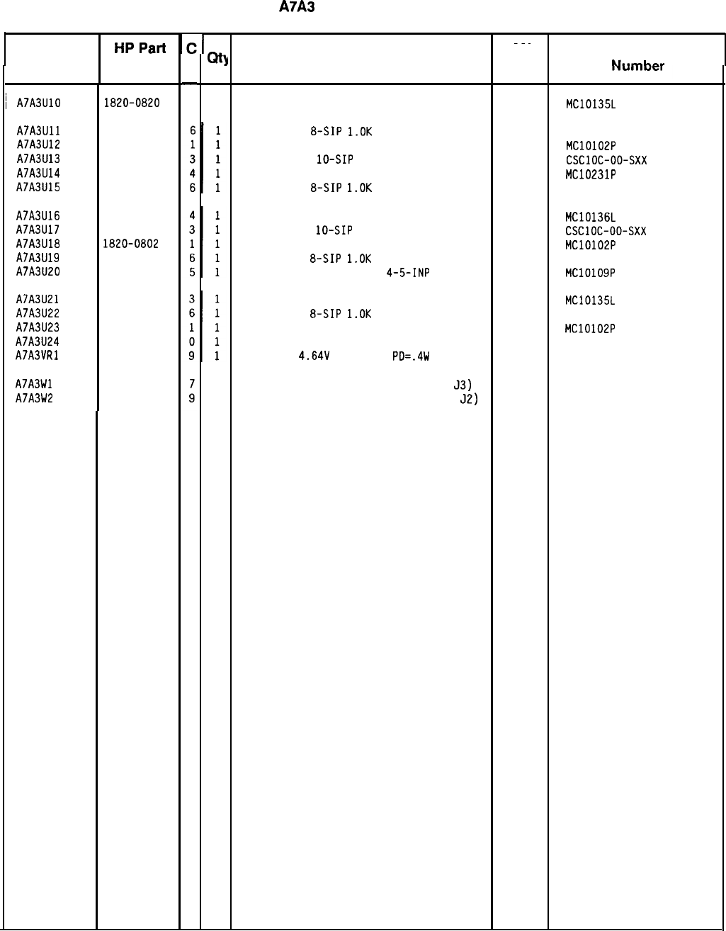
Reference
HPPart
‘C’
I
I
~~~
I
Number D
QtJ
Description Mfr
Mfr Part
Designation Code
kl..-I.,...
-
3
~
A7A3UlO 1820-0820
1
IC FF ECL J-BAR K-BAR COM CLOCK DUAL 04713 MC10135L
HP Part Number 85660-60136
A7A3
M/N Phase Detector
A7A3Ull 1810-0204
A7A3U12 1820-0802
A7A3U13 1810-0251
A7A3U14 1820-1225
A7A3U15 1810-0204
A7A3U16 1820-0821
A7A3U17 1810-0251
A7A3U18 1820-0802
A7A3U19 1810-0204
A7A3U20 1820-0806
A7A3U21 1820-0820
A7A3U22 1810-0204
A7A3U23 1820-0802
A7A3U24 0955-0063
A7A3VRl 1902-3082
A7A3Wl 85660-60083
A7A3W2 85660-60085
1
CABLE ASSEMBLY WHITE/RED (INCLUDES
53)
28480 85660-60083
1
CABLE ASSEMBLY GRAY/WHITE (INCLUDES
52)
28480 85660-60085
NETWORK-RES
&SIP
l.OK
OHM X 7
11236 750-81
IC GATE ECL NOR QUAD 2-INP 04713 MC10102P
NETWORK-RES
lo-SIP
MULTI-VALUE
91637 CSClOC-oo-sxx
IC FF ECL D-M/S DUAL 04713 MC10231P
NETWORK-RES
a-SIP
l.OK
OHM X 7
11236 750-81
IC CNTR ECL BIN UP/DOWN SYNCHRO POS-EDGE 04713 MC10136L
NETWORK-RES
lo-SIP
MULTI-VALUE
91637 CSClOC-oo-sxx
IC GATE ECL NOR QUAD 2-INP 04713 MC10102P
NETWORK-RES
a-SIP
l.OK
OHM X 7
11236 750-81
IC GATE ECL OR-NOR DUAL
4-5-INP 04713 MC10109P
IC FF ECL J-BAR K-BAR COM CLOCK DUAL 04713
NETWORK-RES
a-SIP
l.OK
OHM X 7
11236
IC GATE ECL NOR QUAD 2-INP 04713
U-WAVE MIXER 500 MHZ MAX
15542
DIODE-ZNR
4.64V
5% DO-35
PD=.4W 04713
MC10135L
750-81
MC10102P
SRA-1-32
*Indicates factory-selected value
85660-60136 Parts List
Page 3 of 3
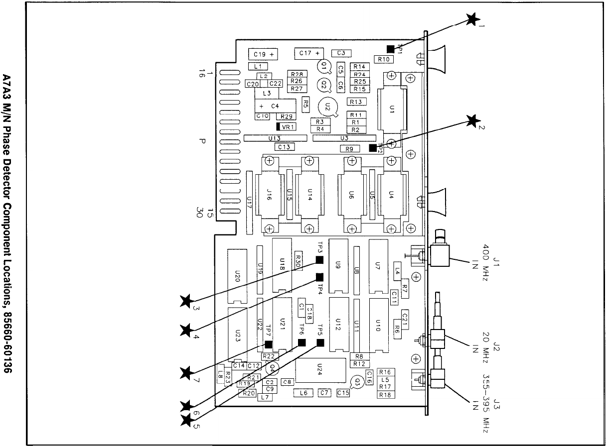
-0
id-
OU
c
w
w
>c/
0)
e
ul
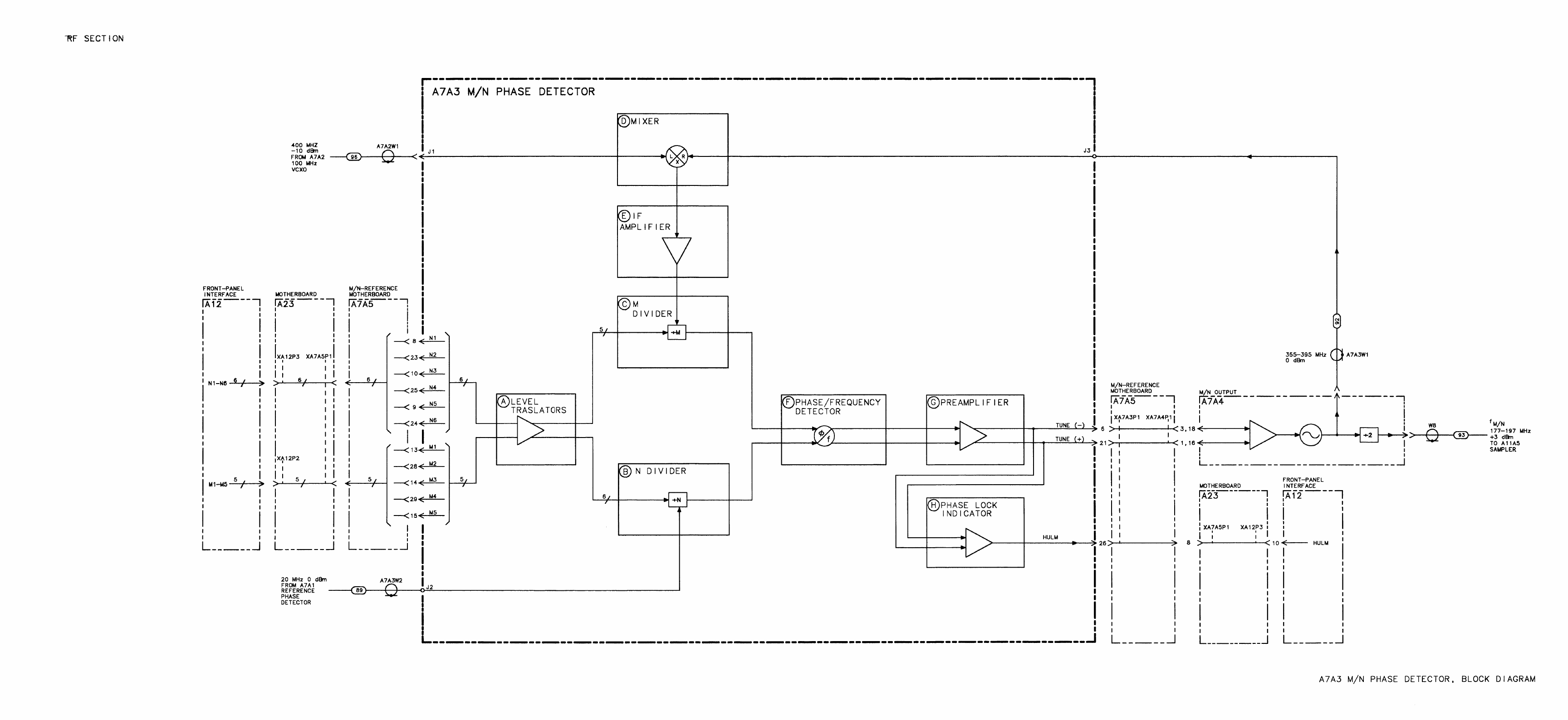
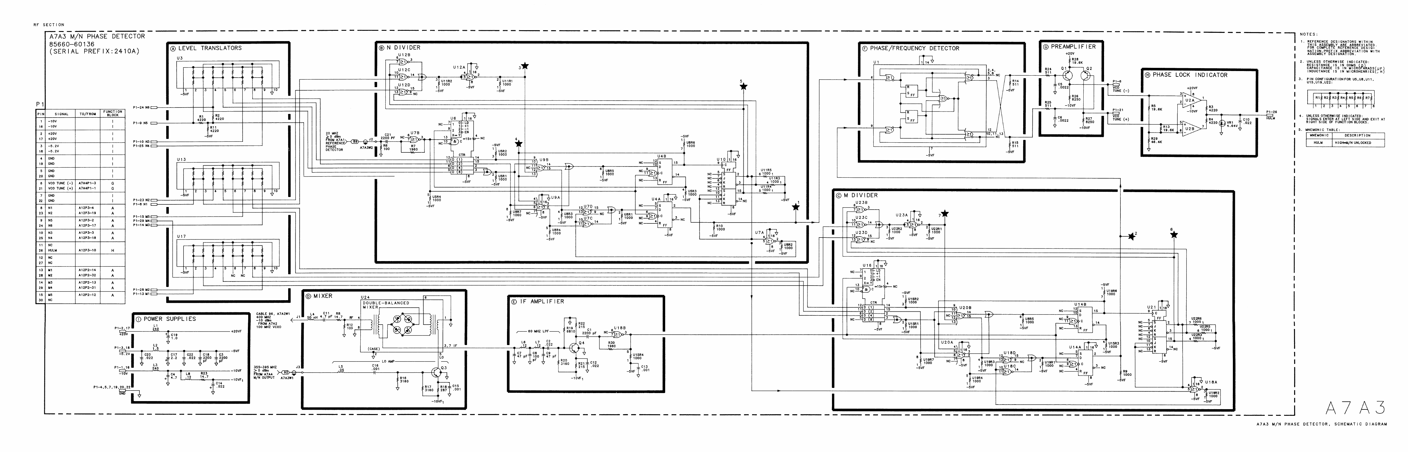
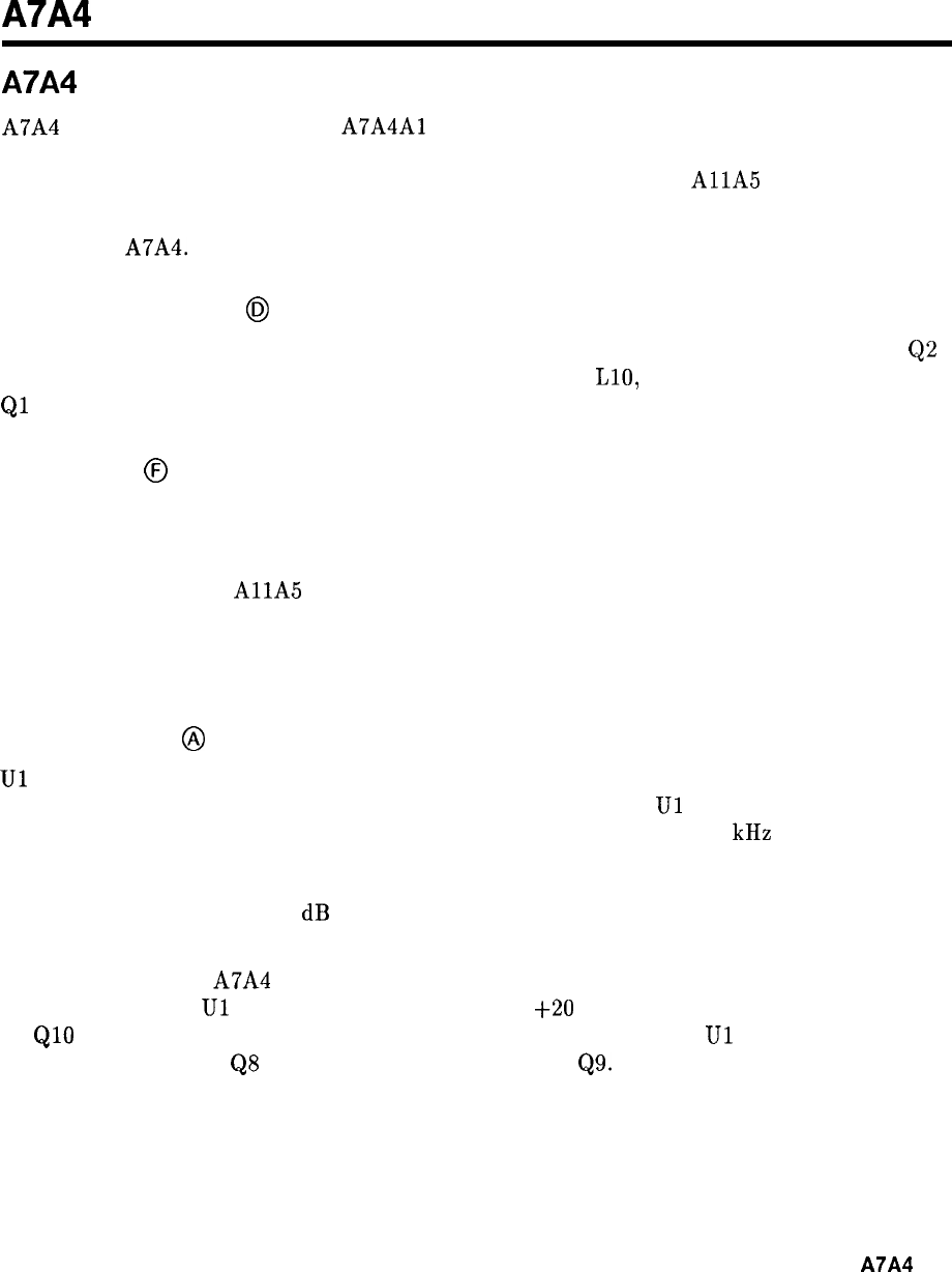
A7A4
A7A4 M/N Output, Circuit Description
A7A4 amplifies the output of the
A7A4Al
M/N VCO in two different paths. One path is
amplification and buffering to drive the mixer in the M/N phase-lock loop. The other path
drives a divide by two which, after further amplification, goes to the
AllA
Sampler.
The integrating loop amplifier which generates the tuning voltage for the M/N VCO is also
included on A7A4.
LO Output Amplifier
@J
Q5 is a common-emitter amplifier followed by a resistive pad to increase reverse isolation.
Q2
is a common-base amplifier which is broadly tuned by L2, LlO, and associated capacitances.
Ql
is another common-emitter amplifier which is followed by a 400 MHz low-pass filter.
Divide By 2
@
U2 is an ECL divide-by-2 Integrated Circuit. U2 generates the M/N output frequency which
is one-half that of the M/N VCO. For frequency spans of greater than 5 MHz, the M/N
control line (LMNE)
g
oes to a TTL high during the sweep. This disables U2, switching off
the M/N output to the
AllA
Sampler. At the beginning of each sweep, U2 is turned back
on and the M/N VCO is phase-locked to give the correct start frequency. During multi-band
sweeps, U2 is turned on at the beginning of each band, but is turned off during the actual
sweep.
Loop Amplifier
@
Ul
is connected as an integrating amplifier and generates -5 V to -35 V for tuning the M/N
VCO. Cl3 is the integrating capacitor; Cl2 and Cl5 compensate
Ul
to guarantee stability.
R33, R34, C14, and R15 compensate the entire phase-lock loop. The 200 kHz low pass filter
rejects the sampling frequency (20 MHz divided by N) and its harmonics which are generated
in the phase detector. CR6, R42, and R41 form an impedance breakpoint that increases the
loop gain by approximately 5 dB when the tune voltage goes below approximately -7 V. This
helps to make the varactor tuning curve linear.
For instruments with A7A4 M/N Output Assembly, part number 85660-60267, power for
integrating amplifier
Ul
is provided by an additional
+20
V connection (Pl-9, P24) and
by
QlO
which generates -15 V from the -40 V supply. The output of
Ul
is buffered by
common-base amplifier
QS
and by emitter-follower buffer
Q9.
A7A4
1
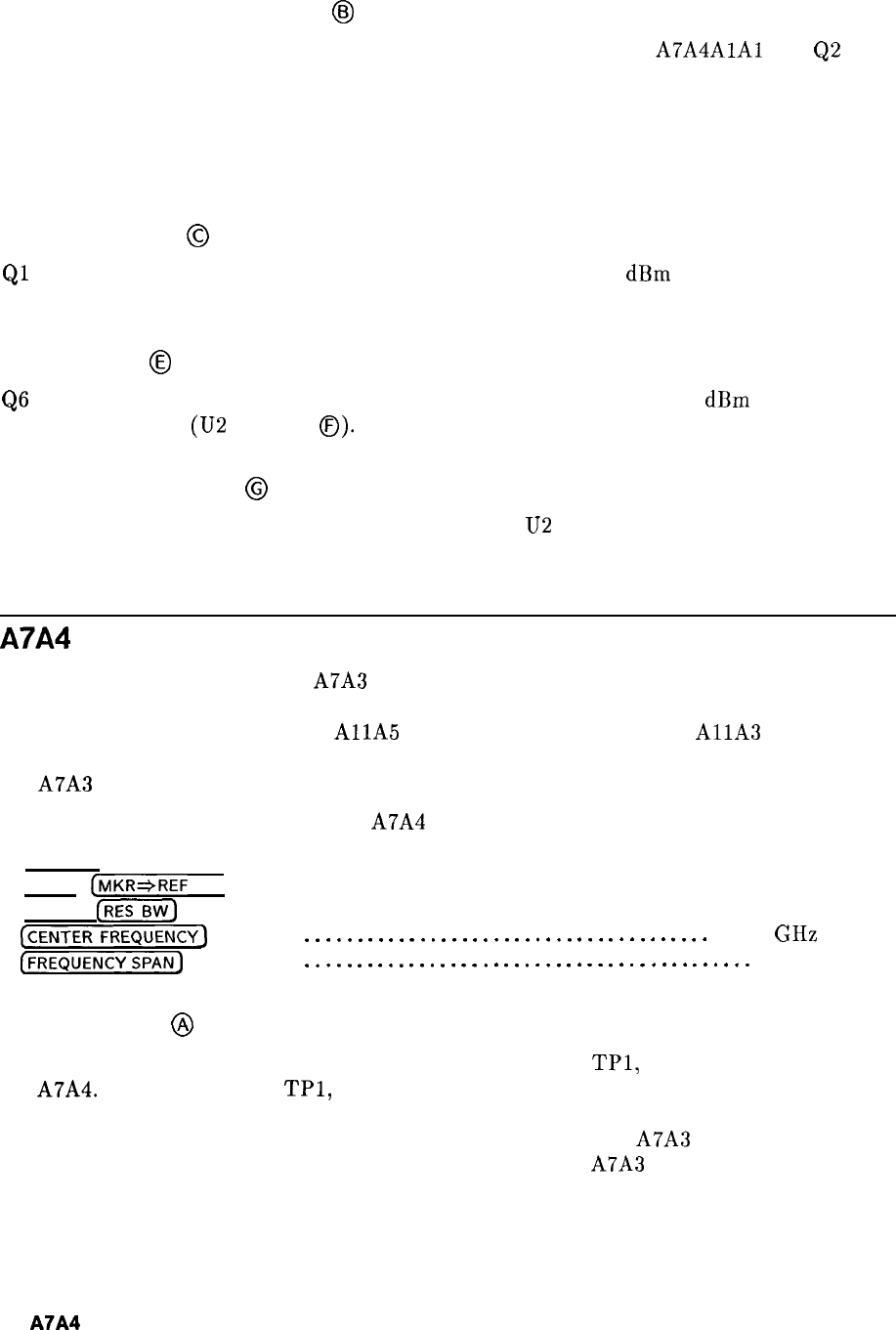
Voltage-Controlled Oscillator
6~
The M/N voltage-controlled oscillator (VCO) consists of a resonator
A7A4AlAl
and
Q2
with
its associated circuitry. The oscillation frequency is determined by the bias on the varactors
CR1 and CR2 which tunes the cavity resonator. Coarse tuning is provided by Cl, while
C5 is used to vary the output coupling to the cavity thereby varying the output power.
The impedance looking into the emitter of Q2 has a negative real part which provides the
conditions necessary for oscillation to occur.
Buffer Amplifier
@
Ql
is a common-emitter buffer amplifier which provides at least 0
dBm
output over the 355 to
395 MHz range of the VCO.
LO Amplifier
@
QS
and Q7 form a buffer amplifier to assure that there is approximately 0
dBm
to drive the
ECL divide-by-2 IC (U2 in block
0).
R24 and R25 set the proper dc level to drive U2.
M/N Output Amplifier
@
Q3 and Q4 provide buffering between the ECL divider
U2
and the output.
A7A4 M/N Output, Troubleshooting
The VCO tune voltage from the A7A3 M/N Phase Detector is amplified and applied to the
Voltage-Controlled Oscillator (VCO) by the loop amplifier. The VCO output is amplified,
divided by two, and applied to the
AllA
Sampler for phase locking the
AllA
YIG-Tuned
Oscillator (YTO) in 10 MHz increments. A portion of the VCO output provides feedback to
the A7A3 Phase Detector for phase locking of the M/N Loop.
Spectrum analyzer control settings for A7A4 troubleshooting:
(2-22)
(SHIFT)
(MKRJREF
LVL) (KSR)
(SHIFT)
(BW)
(KSF)
(CENTERFREQUENCY)
. . . . . . . .
[FREQUENCY SPAN) . . . . . . . . . .
.
.
.
.
.
.
.
.
.
.
.
.
.
.
.
.
.
.
.
.
.
.
.
.
.
.
.
.
.
.
.
.
.
.
.
.
.
.
.
3.77
.
.
.
.
.
.
.
.
.
.
.
.
.
.
.
.
.
.
.
.
.
.
.
.
.
.
.
.
.
.
.
.
.
.
.
.
.
.
.
.
.
.
.
GHz
0 Hz
Loop Amplifier
@
The tune voltage from the Loop Amplifier can be measured at
TPl,
located on the cover of
the A7A4. The dc voltage at
TPl,
with the front panel settings indicated above, shoud be
-14.2 V. If an unlocked condition exists, the voltage is approximately -0.5 V or -37.5 V.
If the level is -0.5 V, the probable cause is no VCO output to the A7A3 Phase Detector.
A level of -37.5 V indicates that the 20 MHz reference to the A7A3 Phase Detector is not
present.
2
A7A4
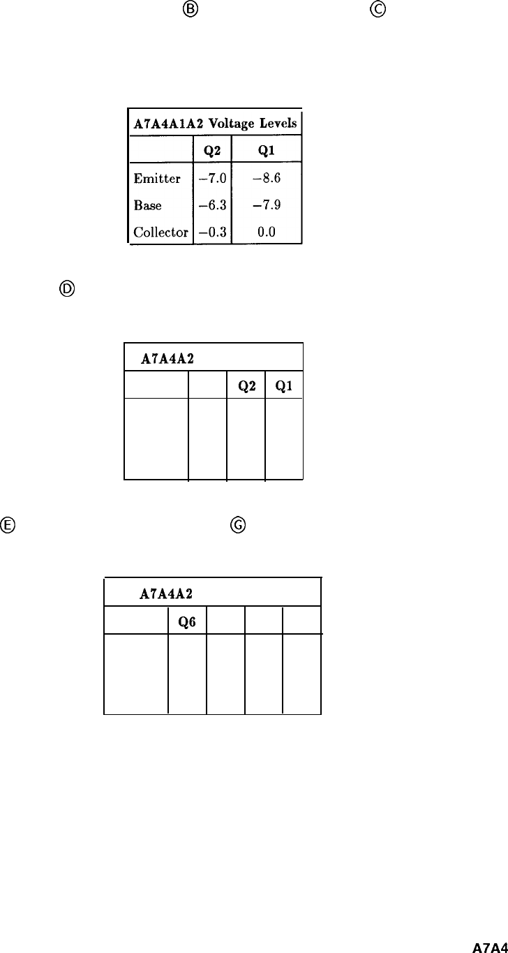
Voltage-Controlled Oscillator (VCO)
@j
and Buffer Amplifier
@
The VCO output frequency with the tuning voltage set to -14.2 V should be 380 MHz.
Typical voltage levels for the VCO are as shown in Table 1.
Table 1. Typical VCO Voltage Levels
LO Output Amplifier
@
Table 2. Typical LO Output Amplifier Voltage Levels
A7A4A2
Voltage Levels
Q5
Q2
Ql
Emitter -6.9 -6.7 -6.7
Base
-6.2 -6.2 -6.2
Collector
-0.5
0.0
0.0
LO Amplifier
@
and M/N Output Amplifier
@
Table 3. Typical LO and M/N Output Amplifier Voltage Levels
A7A4A2
Voltage Levels
Q6
Q7 Q3 Q4
Emitter -6.7 -3.1 -4.5 -5.2
Base
-6.2 -2.4 -3.8 -4.5
Collector -2.4 -1.1
0.0
-2.3
A7A4
3
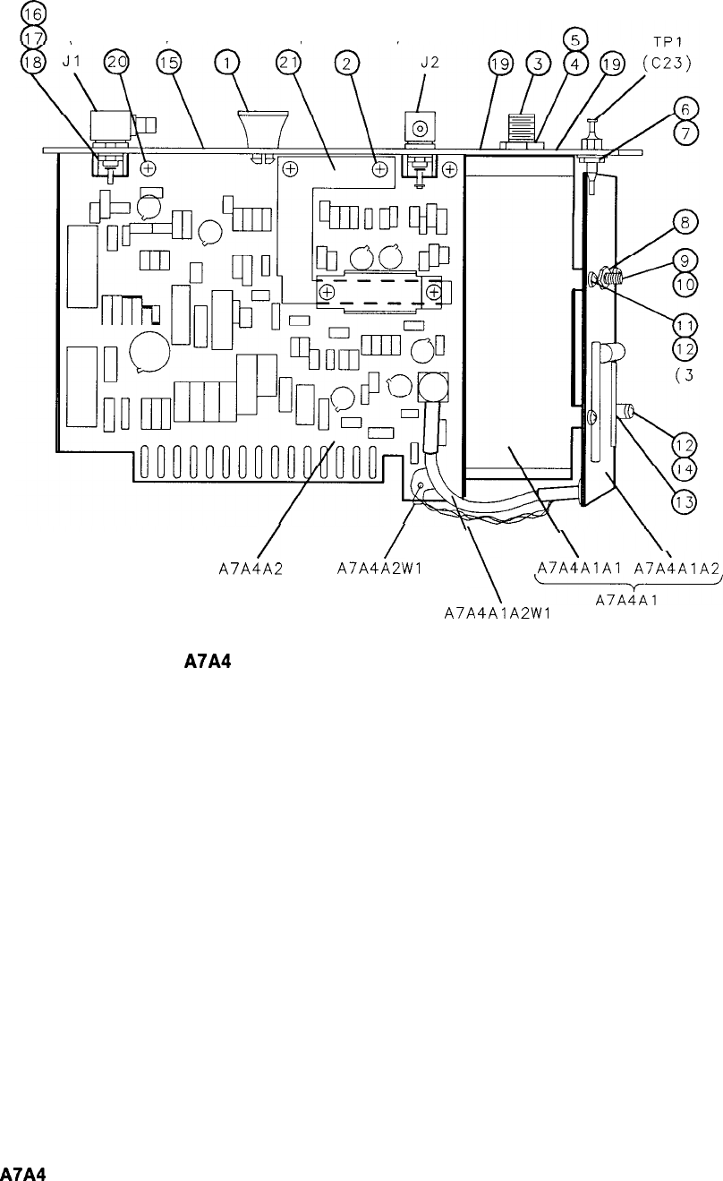
(2 PLACES)
Ga
(2 PLACES) (2 PLACES)
PLACES)
/
/
A7A4A2 A7A4A2Wl
\
\
A7A4AlAl
A7AiAlA2
a7a4’nr
A7A4AlA2Wl
Figure 1. A7A4 M/N Output Assembly, Parts Identification (1 of 2)
4
A7A4
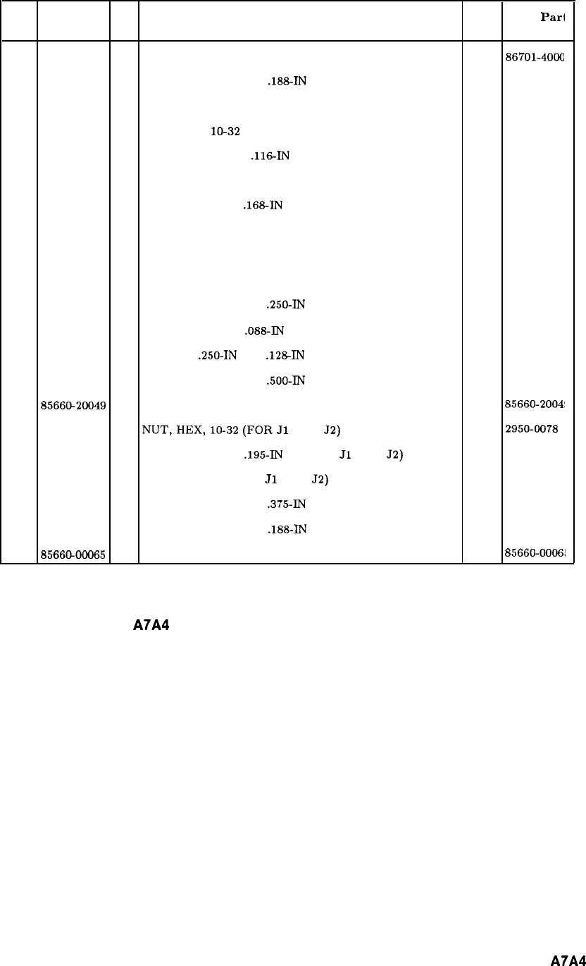
Item HP Part CD Description Mfr Mfr
Pari
Number Code Number
1
86701-40001
9
EXTRACTOR, PC BOARD 28480
86701-4000
22200-0101
0
SCREW, MACH, 4-40,
.188-IN
LG, PAN HD 28480 86701-2004
3
86701-20049
3
SCREW, TUNING, FREQ ADJUST 28480 86701-2004
4
2950-0078
9
NUT, HEX,
lo-32
(FOR FREQ ADJUST (3)) 28480
2950-0078
53050-0082 8WASHER, FL NM,
.116-IN
ID (FOR (3)) 28480 3050-0082
62580-0002 4NUT, HEX, 8-32 (FOR C23) 28480 2580-0002
7
2190-0009 4
WASHER, LOCK,
.168-IN
ID FOR C23) 28480
2190-0009
82260-0002 6NUT, HEX, 4-40 (FOR PWR ADJUST) 28480 2260-0002
9
86701-20046
0
PROBE, 4-40 THREAD (PWR ADJUST) 28480 86701-2004
10
86701-20047
1
SUPPORT-RESONATOR (FOR PROBE (9)) 28480 86701-2004
11
0520-0128
7
SCREW, MACH, 2-56,
.250-IN
LG, PAN HD 28480 0520-0128
12
2190-0045
8
WASHER, LOCK,
.088-IN
ID (FOR SCREW (11)) 28480
2190-0045
13
0380-0020
0
SPACER,
.250-IN
LG, .lZ%IN ID (FOR (14)) 28480 0380-0020
14 0520-0133 4SCREW, MACH, 2-56,
.500-IN
LG, PAN HD 28480 0520-0133
15 8566G20049
1
COVER, PC BOARD, (1714 M/N OUTPUT) 28480
85660-20041
16
2950-0078
9
NUT,HEX, lO-32(FOR
Jl
AND
52)
28480 29504078
17
2190-0124
4
WASHER, LOCK,
.195-IN
ID (FOR
Jl
AND
52)
28480
2190-0124
18
85660-20068
4
GROUND LUG (FOR
Jl
AND
52)
28480 85660-20061
19
2200-0167
8
SCREW, MACH, 4-40,
.375-IN
LG, FLAT HD 28480 2200-0167
20 2200-0101
0
SCREW, MACH, 4-40,
.188-IN
LG, APN HD POZI 28480 2200-0101
21
8566CbOOO65
9
IC HEAT SINK 28480
85660-0006!
Figure 1. A7A4 M/N Output Assembly, Parts Identification (2 of 2)
A7A4
5
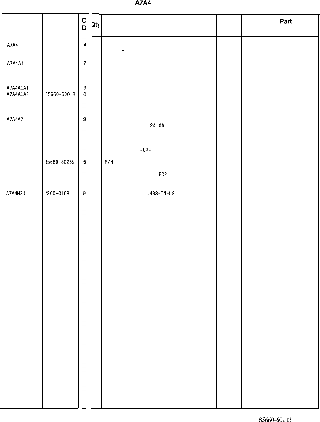
HP Part Number 85660-60113
A7A4
M/N Output
Reference HP Part
Designation Number
A7A4
A7A4Al
A7A4AlAl
A7A4AlA2
A7A4A2
A7A4MPl
35660-60113
35660-60096
35660-60112
~5660-60018
35660-60192
{5660-60239
!200-0168
-
m
-
1
1
1
1
1
1
2
-
Description
M/N OUTPUT ASSEMBLY (SERIAL PREFIXES:
2410A
-
2607A) 28480 85660-60113
M/N VOLTAGE CONTROLLED OSCILLATOR ASSY
(A COMPLETE PARTS LIST FOR THIS BOARD
ASSY IS INCLUDED IN THIS SECTION)
28480 85660-60096
M/N VOLTAGE CONTROLLED OSCILLATOR
M/N VCO BOARD ASSEMBLY
(A COMPLETE PARTS LIST FOR THIS BOARD
ASSY IS INCLUDED IN THIS SECTION)
28480 85660-60112
28480 85660-60018
M/N OUTPUT BOARD ASSEMBLY
(SERIAL PREFIXES
2410~
THROUGH 2449A)
(A COMPLETE PARTS LIST FOR THIS BOARD
ASSY IS INCLUDED IN THIS SECTION)
28480 85660-60192
-OR-
M/N
OUTPUT BOARD ASSEMBLY (SERIAL
PREFIXES 2503A THROUGH 2607A) (A
COMPLETE PARTS LIST
FOR
THIS BOARD ASSY
IS INCLUDED IN THIS SECTION)
28480 85660-60239
SCREW-MACH 4-40
.438-IN-LG
82 DEG
77250
Mfr Mfr
Part
Code Number
*Indicates factory-selected value
85660-60113 Parts List
Page 1 of 1
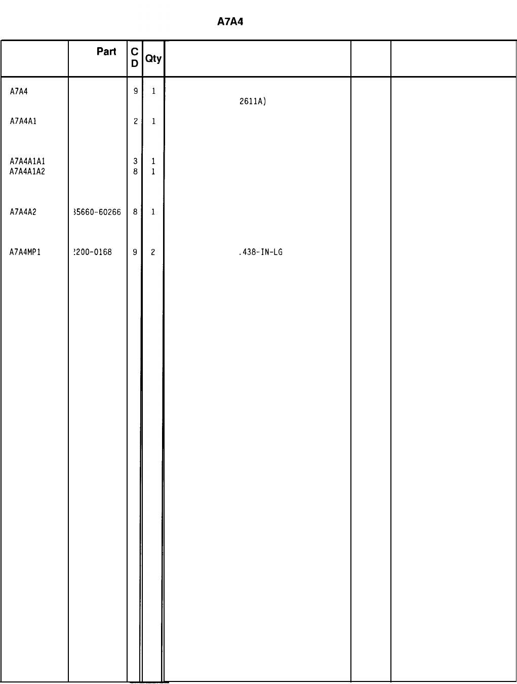
Reference
HP
Part
Designation Number
A7A4 35660-60267
A7A4Al 35660-60096
A7A4AlAl 35660-60112
A7A4AlA2 35660-60018
A7A4A2 35660-60266
A7A4MPl
!200-0168
HP Part Number 85660-60267
A7A4
M/N Output
Description
M/N OUTPUT ASSEMBLY
(SERIAL PREFIX:
2611~)
M/N VOLTAGE CONTROLLED OSCILLATOR ASSY
(A COMPLETE PARTS LIST FOR THIS BOARD
ASSY IS INCLUDED IN THIS SECTION)
M/N VOLTAGE CONTROLLED OSCILLATOR
M/N VCO BOARD ASSEMBLY
(A COMPLETE PARTS LIST FOR THIS BOARD
ASSY IS INCLUDED IN THIS SECTION)
M/N OUTPUT BOARD ASSEMBLY
(A COMPLETE PARTS LIST FOR THIS BOARD
ASSY IS INCLUDED IN THIS SECTION)
SCREW-MACH 4-40
.438-IN-LG
82 DEG
*Indicates factory-selected value
Mfr
Mfr Part
Code Number
28480 85660-60267
28480 85660-60096
28480 85660-60112
28480 85660-60018
28480 85660-60266
77250
85660-60267 Parts List
Page 1 of 1
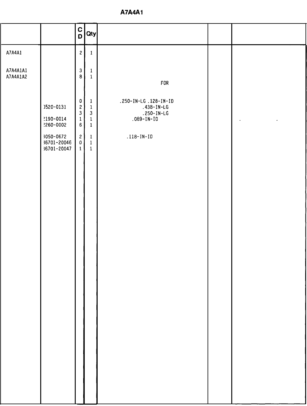
Reference HP Part
Designation Number
A7A4Al 35660-60096
A7A4AlAl 35660-60112
A7A4AlA2 35660-60018
1380-0020
1520-0131
1520-0174
!190-0014
!260-0002
iO50-0672
$6701-20046
i6701-20047
HP Part Number 85660-60096
A7A4Al VCO Assembly
Description
M/N VOLTAGE CONTROLLED OSCILLATOR
ASSEMBLY
M/N VOLTAGE CONTROLLED OSCILLATOR
M/N VCO BOARD ASSEMBLY
(A COMPLETE PARTS LIST
FOR
THIS BOARD
ASSY IS INCLUDED IN THIS SECTION)
SPACER
.250-IN-LG
.128-IN-ID
SCREW-MACH 2-56
.438-IN-LG
PAN-HD-POZI
SCREW-MACH 2-56
.250-IN-LG
PAN-HD-PDZI
LOCK WASHER
.089-IN-ID
NUT-HEX 4-40
WASHER SH
.118-IN-IO
PROBE
RESONATOR SUPPORT
Mfr
Mfr Part
Code Number
28480
28480
28480
77250
78189
85660-60096
85660-60112
85660-60018
1902-00-00-2580
*Indicates factory-selected value
85660-60096 Parts List
Page
1
of
1
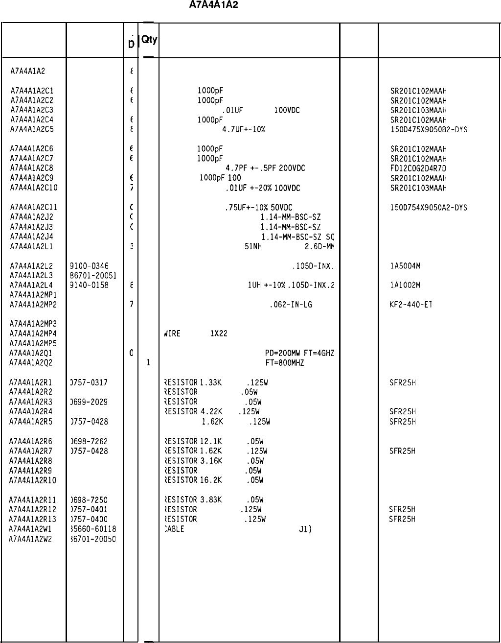
HP Part Number 85660-60018
A7A4AlA2
M/N VCO Board
Reference HP Part
Designation Number
A7A4AlA2 85660-60018
t
A7A4AlA2Cl 0160-3878
f
A7A4AlA2C2 0160-3878
t
A7A4AlA2C3 0160-3879
i
A7A4AlA2C4 0160-3878
t
A7A4AlA2CS
0180-1731
E
A7A4AlA2C6 0160-3878
e
A7A4AlA2C7 0160-3878
t
A7A4AlA2C8
0160-3873
1
A7A4AlA2C9 0160-3878
f
A7A4AlA2ClO
0160-3879
7
A7A4AlA2Cll 0180-2161
c
A7A4AlA2J2 1251-0600
c
A7A4AlA2J3 1251-0600
c
A7A4AlA2J4 1251-0600
C
A7A4AlA2Ll 9135-0073
?
A7A4AlA2L2
A7A4AlA2L3
A7A4AlA2L4
A7A4AlA2MPl
A7A4AlA2MP2
9100-0346
C
86701-20051
7
3140-0158
6
0590-0519
7
A7A4AlA2MP3 1251-2313
6
A7A4AlA2MP4 3151-0013
4
A7A4AlA2MPS 36701-20052
a
A7A4AlA2Ql 1854-0686
0
A7A4AlA2Q2 1854-0610
0
A7A4AlA2Rl 3757-0317
7
A7A4AlA2R2 3698-7219
6
A7A4AlA2R3 1699-2029
8
A7A4AlA2R4 3698-3154
0
A7A4AlA2R5 3757-0428
1
A7A4AlA2R6 1698-7262
9
A7A4AlA2R7 1757-0428
1
A7A4AlA2R8
1698-7248
1
A7A4AlA2R9 1699-1903
5
A7A4AlA2RlO 1698-7265
2
A7A4AlA2Rll 1698-7250
5
A7A4AlA2R12
1757-0401
0
A7A4AlA2R13 1757-0400
9
A7A4AlA2Wl 35660-60118
9
A7A4AlA2W2 36701-20050
6
C
c
-
*
-
1
1
1
1
1
1
1
1
1
1
1
1
1
1
1
1
1
1
1
1
1
1
2
1
1
1
1
1
1
1
1
1
1
1
1
1
1
1
1
1
-
Description
BOARD ASSEMBLY, M/N VCO 28480 85660-60018
CAP-FXD
1OOOpF
100 V
04222 SR201C102MAAH
CAP-FXD
1OOOpF
100 V
04222 SR201C102MAAH
CAPACITOR-FXD
.OlUF
+-20%
1OOVDC
CER
04222 SR201C103MAAH
CAP-FXO
1OOOpF
100 V
04222 SR201C102MAAH
CAPACITOR-FXD
4.7UF+-10%
50VDC TA
56289 150D475X9050B2-OYS
CAP-FXD
1OOOpF
100 V
CAP-FXD
1OOOpF
100 V
CAPACITOR-FXD
4.7PF
+-.5PF
POOVDC
CER
CAP-FXO
1OOOpF
100
V
CAPACITOR-FXD
.OlUF
+-20x
1OOVDC
CER
04222
04222
04222
04222
SR201C102MAAH
SR201C102MAAH
FD12COG2D4R7D
SR201C102MAAH
SR201C103MAAH
CAPACITOR-FXD
.75UF+-10%
SOVDC
TA
56289
CONNECTOR-SGL CONT PIN
1.14-MM-BSC-SZ
SC
27264
CONNECTOR-SGL CONT PIN
1.14-MM-BSC-SZ
SC
27264
CONNECTOR-SGL CONT PIN
1.14-MM-BSC-SZ
SQ
27264
INDUCTOR RF-CH-MLD
51NH
+-6.596%
2.60-MM 06560
150D754X9050A2-OYS
16-06-0034
16-06-0034
16-06-0034
INDUCTOR RF-CH-MLD 50NH +-20%
.105D-INX.
INDUCTOR
INDUCTOR RF-CH-MLD
1UH
+-lo%
.105D-INX.2
NOT ASSIGNED
32159 lA5004M
20%
28480 86701-20051
32159 lA1002M
+-lo%
THREADED INSERT-NUT 4-40
.062-IN-LG
STL
46384 KF2-440-El
CONNECTOR-SGL CONT SKT .04-IN-BSC-SZ RND
t/IRE
22AWG
1X22
SPACER, INSULATOR
TRANSISTOR NPN SI TO-72
PD=EOOMW
FT=4GHZ
TRANSISTOR NPN SI TO-46
FT=800MHZ
00779
92194
28480
25403
04713
3-332070-5
298
86701-20052
?ESISTOR
1.33K
+-1%
.125W
TF TC=O+-100
19701
SFR25H
?ESISTOR
196 +-1%
.05W
TF TC=O+-100
19701
50635
7ESISTOR
16.2 +-1%
.05W
TF TC=O+-100
91637 CMF-50-21
IESISTOR
4.22K
1%
.125W
TF TC=O+-100
19701
SFR25H
7ESISTOR
1.62K
+-1%
.125W
TF TC=O+-100
19701
SFR25H
?ESISTOR
12.1K
+-1%
.05W
TF TC=O+-100
19701
50635
IESISTOR
1.62K
+-1%
.125W
TF TC=O+-100
19701
SFR25H
IESISTOR
3.16K
+-1%
.05W
TF TC=O+-100
19701
50635
[ESISTOR
51.1 +-1%
.05W
TF TC=O+-100
91637 CMF-50-21
ZESISTOR
16.2K
+-1%
.05W
TF TC=D+-100
19701
50635
{ESISTOR
3.83K
+-1%
.05W
TF TC=O+-100
19701
50635
IESISTOR
100 +-1%
.125W
TF TC=O+-100
19701
SFR25H
(ESISTOR
90.9 +-1%
.125W
TF TC=O+-100
19701
SFR25H
:ABLE
ASSEMBLY, WHITE (INCLUDES
Jl)
28480 85660-60118
JUMPER CABLE 28480 86701-20050
Mfr
Mfr Part
Code Number
*Indicates factory-selected value
85660-60018 Parts List
Page 1 of 1
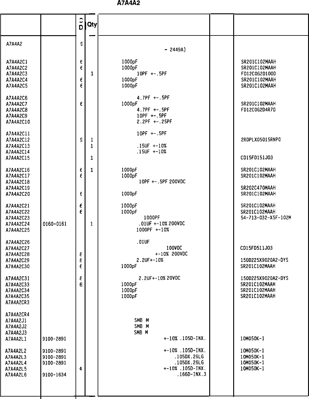
Reference
Designation
HP Part
Number
A7A4A2 85660-60192
A7A4A2Cl 0160-3878
A7A4A2C2 0160-3878
A7A4A2C3 0160-3874
A7A4A2C4 0160-3878
A7A4A2C5 0160-3878
A7A4A2C6 0160-3873
A7A4A2C7 0160-3878
A7A4A2C8 0160-3873
A7A4A2C9 0160-3874
A7A4A2ClO 0160-3872
A7A4A2Cll 0160-3874
A7A4A2C12 0160-2261
A7A4A2C13 0160-2290
A7A4A2C14 0160-2290
A7A4A2C15 0140-0196
A7A4A2C16 0160-3878
A7A4A2C17 0160-3878
A7A4A2C18 0160-3874
A7A4A2C19 0160-3876
A7A4A2C20
0160-3878
A7A4A2C21 0160-3878
A7A4A2C22 0160-3878
A7A4A2C23 0160-4351
A7A4A2C24 0160-0161
A7A4A2C25 0160-0153
A7A4A2C26 0160-0161
A7A4A2C27 0160-3534
A7A4A2C28 0160-0298
A7A4A2C29 0180-0197
A7A4A2C30
0160-3878
A7A4A2C31 0180-0197
A7A4A2C33 0160-3878
A7A4A2C34 0160-3878
A7A4A2C35 0160-3878
A7A4A2CR3 1901-0040
A7A4A2CR4 1901-0040
A7A4A2Jl 1250-0657
A7A4A2J2 1250-0657
A7A4A2J3 1250-0257
A7A4A2Ll 9100-2891
A7A4A2L2 9100-2891
A7A4A2L3 9100-2891
A7A4A2L4 9100-2891
A7A4A2L5 9100-2891
A7A4A2L6 9100-1634
::
0
9
E
f
2
E
E
1
f
1
2
C
2
9
4
4
3
E
E
2
4
E
E
E
2
4
4
4
1
e
e
f
e
E
6
6
1
1
5
5
1
4
4
4
4
4
1
-
a1
-
1
1
1
1
1
1
1
1
1
1
1
1
1
1
1
1
1
1
1
1
1
1
1
1
1
1
1
1
1
1
1
1
1
1
1
1
1
1
1
1
1
1
1
1
1
1
-
HP Part Number 85660-60192
ATA4A2
M/N Output Board
Description Mfr
Mfr Part
Code Number
BOARD ASSEMBLY, M/N OUTPUT
(SERIAL PREFIXES: 2410A
-
2449A) 28480 85660-60192
CAP-FXD
1OOOpF
100 V
CAP-FXD
1OOOpF
100 V
CAPACITOR-FXD
1OPF
+-.5PF
LOOVDC CER
CAP-FXD
1OOOpF
100 V
CAP-FXD
1OOOpF
100 V
04222
04222
04222
04222
SR201C102MAAH
SR201C102MAAH
F012COG2DlOOD
SR201C102MAAH
SR201C102MAAH
CAPACITOR-FXD
4.7PF
+-.5PF
LOOVDC CER
CAP-FXD
1OOOpF
100 V
CAPACITOR-FXD
4.7PF
+-.5PF
200VDC CER
CAPACITOR-FXD
1OPF
+-.5PF
200VDC CER
CAPACITOR-FXD
2.2PF
+-.25PF
LOOVDC CER
28480
04222
28480
28480
0160-3873
SR201C102MAAH
FD12COG2D4R7D
0160-3874
0160-3872
CAPACITOR-FXD
1OPF
+-.5PF
LOOVDC CER
28480 0160-3874
CAPACITOR-FXD 15PF +-5% 500VDC CER 0+-30
52763 2RDPLX05015RNPO
CAPACITOR-FXD
.15UF
+-lo% 80VDC POLYE
84411 HEW-238T
CAPACITOR-FXD
.15UF
+-lo% 8OVDC POLYE
84411 HEW-238T
CAPACITOR-FXD 150PF +-5% 300VDC MICA
09023 C015FD151J03
CAP-FXD
1OOOpF
100 V
04222 SR201C102MAAH
CAP-FXD
1OOOpF
100 V
04222 SR201C102MAAH
CAPACITOR-FXO
1OPF
+-.5PF
POOVDC
CER
28480 0160-3874
CAPACITOR-FXD 47PF +-20% LOOVDC CER 04222 SR202C470MAAH
CAP-FXD
1OOOpF
100 V
04222 SR201C102MAAH
CAP-FXD
1OOOpF
100 V
04222 SR201C102MAAH
CAP-FXD
1OOOpF
100 V
04222 SR201C102MAAH
CAPACITOR-FDTHRU
1OOOPF
20% 200V CER
33095 54-713-032-X5F-102M
CAPACITOR-FXD
.OlUF
+-lo%
ZOOVDC
POLYE
84411 HEW-238M
CAPACITOR-FXD
IOOOPF
+-lo%
EOOVDC POLYE
84411 HEW-238M
CAPACITOR-FXD
.OlUF
+-10% EOOVDC POLYE
84411 HEW-238M
CAPACITOR-FXD 510PF +-5%
1OOVDC
MICA
09023 CD15FD511J03
CAPACITOR-FXD 1500PF +-lo%
ZOOVDC
POLYE
84411 HEW-238M
CAPACITOR-FXD
2.2UF+-10%
2OVDC TA
56289 150D225X9020A2-DYS
CAP-FXD
1OOOpF
100 V
04222 SR201C102MAAH
CAPACITOR-FXD
2.2UF+-10%
ZOVDC
TA
CAP-FXD
1OOOpF
100 V
CAP-FXD
1OOOpF
100 V
CAP-FXD
1OOOpF
100 V
150D225X9020A2-DYS
SR201C102MAAH
SR201C102MAAH
SR201C102MAAH
DIODE-SWITCHING 30V 50MA 2NS DO-35
56289
04222
04222
04222
71468
DIODE-SWITCHING 30V 50MA 2NS DO-35 71468
CONNECTOR-RF
St48
M
SGL-HOLE-FR 50-OHM
28480
CONNECTOR-RF
SM8
M
SGL-HOLE-FR 50-OHM
28480
CONNECTOR-RF
SM8
M
PC 50-OHM
98291
INDUCTOR RF-CH-MLD 50NH +-lo%
.105D-INX.
24226
1250-0657
1250-0657
51-051-0169-226
lOMOSOK-1
INDUCTOR RF-CH-ML0 50NH +-lo%
.105D-INX.
24226 lOM050K-1
INDUCTOR RF-CH-MLD 50NH 10%
.105DX.26LG 24226 lOM050K-1
INDUCTOR RF-CH-MLD 50NH 10%
.105DX.26LG 24226 lOM050K-1
INDUCTOR RF-CH-ML0 50NH
+-lo%
.1050-INX.
24226 lOM050K-1
INDUCTOR RF-CH-ML0 75UH +-5%
.1660-INX.3 99800 1537-70
*Indicates factory-selected value
85660-60192 Parts List
Page 1 of 3
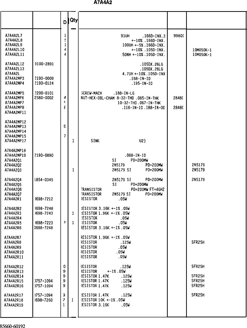
HP Part Number 85660-60192
A7A4A2
M/N Output Board
Description Mfr Mfr Part
Code Number
INDUCTOR RF-CH-MLD
91UH
+-5%
.166D-INX.3
998OC
1537-74
INDUCTOR RF-CH-MLD 15UH +-lo%
.166D-INX. 9980C
1537-40
INDUCTOR RF-CH-ML0
IOOUH
+-5X
.166D-INX. 9980C
1537-76
INDUCTOR RF-CH-MLD 50NH +-lo%
.105D-INX.
2422E lOM050K-1
INDUCTOR RF-CH-MLD
5ONH
+-lo%
.105D-INX. 24226
lOM050K-1
INDUCTOR RF-CH-MLD 50NH 10%
.105DX.26LG 28480 9100-2891
INDUCTOR RF-CH-MLD 50NH 10%
.105DX.26LG 28480 9100-2891
INDUCTOR RF-CH-MLD
4.7UH
+-lo%
.105D-INX 99800 1025-36
JASHER-LK INTL T NO. 8
.168-IN-ID 28480 2190-0009
JASHER-LK INTL T NO. 10
.195-IN-ID 28480 2190-0124
iCREW-MACH
4-40
.188-IN-LG
PAN-HD-POZI
00000 ORDER BY DESCRIPTION
dUT-HEX-DEL-CHAM
8-32-THD
.085-IN-THK
2848(
2580-0002
NUT-HEX-DBL-CHAM
lo-32-THD
.067-IN-THK
28481
2950-0078
WASHER-FL NM NO. 4
.116-IN-ID
.188-IN-00
2848C
3050-0082
COVER PC, M/N OUTPUT
2848C
85660-20049
GROUND LUG
EXTRACTOR PC 85660-20068
86701-40001
SCREW-MACH 4-40 .25-IN-LG PAN-HO-POZI
SCREW-MACH 2-56 .25-IN-LG PAN-HD-POZI
H
E
AT
SINK
SGL
DIP (
CO
VERI
NG
u2)
2848C
2848C
77250
77250
28480 1205-0285
I.C. HEAT SINK
JASHER-LK HLCL NO. 2
.088-IN-ID
TRANSISTOR NPN
SI
TO-72
PD=ZOOMW
TRANSISTOR NPN
2N5179
SI TO-72
PD=200MW
TRANSISTOR NPN
2N5179
SI
TO-72 PD=ZOOMW
28480 85660-00065
28480 2190-0890
28480 1854-0546
04713 2N5179
04713 2N5179
TRANSISTOR NPN
2N5179
SI
TO-72
PD=EOOMW 04713
TRANSISTOR NPN
SI
TO-72
PD=ZOOMW 28480
[RANSISTOR
NPN SI TO-72
PD=EOOMW
FT=4GHZ 25403
[RANSISTOR
NPN
2N5179
SI
TO-72
PD=200MW 04713
LESISTOR
100 +-1%
.05W
TF TC=O+-100
19701
2N5179
1854-0546
215179
50635
!ESISTOR
3.16K
+-I%
.05W
TF TC=O+-100
!ESISTOR
1.96K
+-1X
.05W
TF TC=O+-100
!ESISTOR
51.1 +-1%
.05W
TF TC=O+-100
!ESISTOR
287 +-1%
.05W
TF TC=O+-100
(ESISTOR
3.16K
+-I%
.05W
TF TC=O+-100
50635
50635
50635
50635
50635
7ESISTOR
1.96K
+-I%
.05W
TF TC=O+-100
XESISTOR
42.2 +-1%
.125W
TF TC=O+-100
IESISTOR
237 +-1%
.05W
TF TC=O+-100
1ESISTOR
10 +-1%
.05W
TF TC=O+-100
ZESISTOR
100 +-1%
.05W
TF TC=O+-100
50635
SFR25H
50635
50635
50635
[ESISTDR
51.1 +-1%
.125W
TF TC=O+-100
tESISTOR
100
+-I%
.05W
TF TC=O+-100
lESISTOR
1.47K
+-1%
.125W
TF TC=O+-100
lESISTOR
1.47K
+-1%
.125W
TF TC=O+-100
IESISTOR
1.47K
+-1%
.125W
TF TC=O+-100
SFR25H
50635
SFR25H
SFR25H
SFR25H
!ESISTOR
1.47K
+-1%
.125W
TF TC=O+-100
!ESISTOR
10K
+-1X
.05W
TF TC=O+-100
!ESISTOR
3.16K
+-1%
.05W
TF TC=O+-100
19701
19701
19701
19701
19701
19701
19701
19701
19701
19701
19701
19701
19701
19701
19701
19701
19701
19701
SFR25H
50635
50635
*Indicates factory-selected value
Reference
Designation HP Part
Number
9100-1635
9100-1620
9140-0210
9100-2891
9100-2891
c
c
A7A4A2L7
A7A4A2L8
A7A4A2L9
A7A4A2LlO
A7A4A2Lll
A7A4A2L12 9100-2891
4
A7A4A2L13 3100-2891
4
A7A4A2L 14 3140-0144
0
A7A4A2MP3 !190-0009
4
A7A4A2MP4 !190-0124
4
A7A4A2MP5
!200-0101
0
A7A4A2MP6 L580-0002
I
A7A4A2MP7 2950-0078
c
A7A4A2MP8 3050-0082
E
A7A4A2MPll 85660-20049
1
A7A4A2MP12 85660-20068
4
A7A4A2MP13 86701-40001
s
A7A4A2MP14 2200-0103
2
A7A4A2MP15 0520-0128
7
A7A4A2MP17 1205-0285
a
A7A4A2MP18 35660-00065
9
A7A4A2MP19 ?190-0890
1
A7A4A2Ql 1854-0546
1
A7A4A2Q2 1854-0345
8
A7A4A2Q3 1854-0345
8
A7A4A2Q4 1854-0345
8
A7A4A2Q5 1854-0546
1
A7A4A2Q6 1854-0686
0
A7A4A2Q7 1854-0345
8
A7A4A2Rl
1698-7212
3
A7A4A2R2
1698-7248
1
A7A4A2R3
)698-7243
6
A7A4A2R4
1698-7205
3
A7A4A2R5
)698-7223
7
A7A4A2R6 J698-7248
I
A7A4A2R7 3698-7243
6
A7A4A2R8 3757-0316
6
A7A4A2R9 3698-7221
0
A7A4A2RlO 3698-7188
8
A7A4A2Rll 1698-7212
9
A7A4A2R12 1757-0394
A7A4A2R13 1698-7212
A7A4A2R14 1757-1094
A7A4A2R15
1757-1094
A7A4A2R16
1757-1094
A7A4A2R17
1757-1094
A7A4A2R18
)698-7260
A7A4A2R19
1698-7248
85660-60192 Parts List
Page 2 of 3
-
a!
-
1
1
1
1
1
1
1
1
1
4
2
1
2
2
1
2
1
2
2
1
1
2
1
1
1
1
1
1
1
1
1
1
1
1
1
1
1
1
1
1
1
1
1
1
1
1
1
1
-
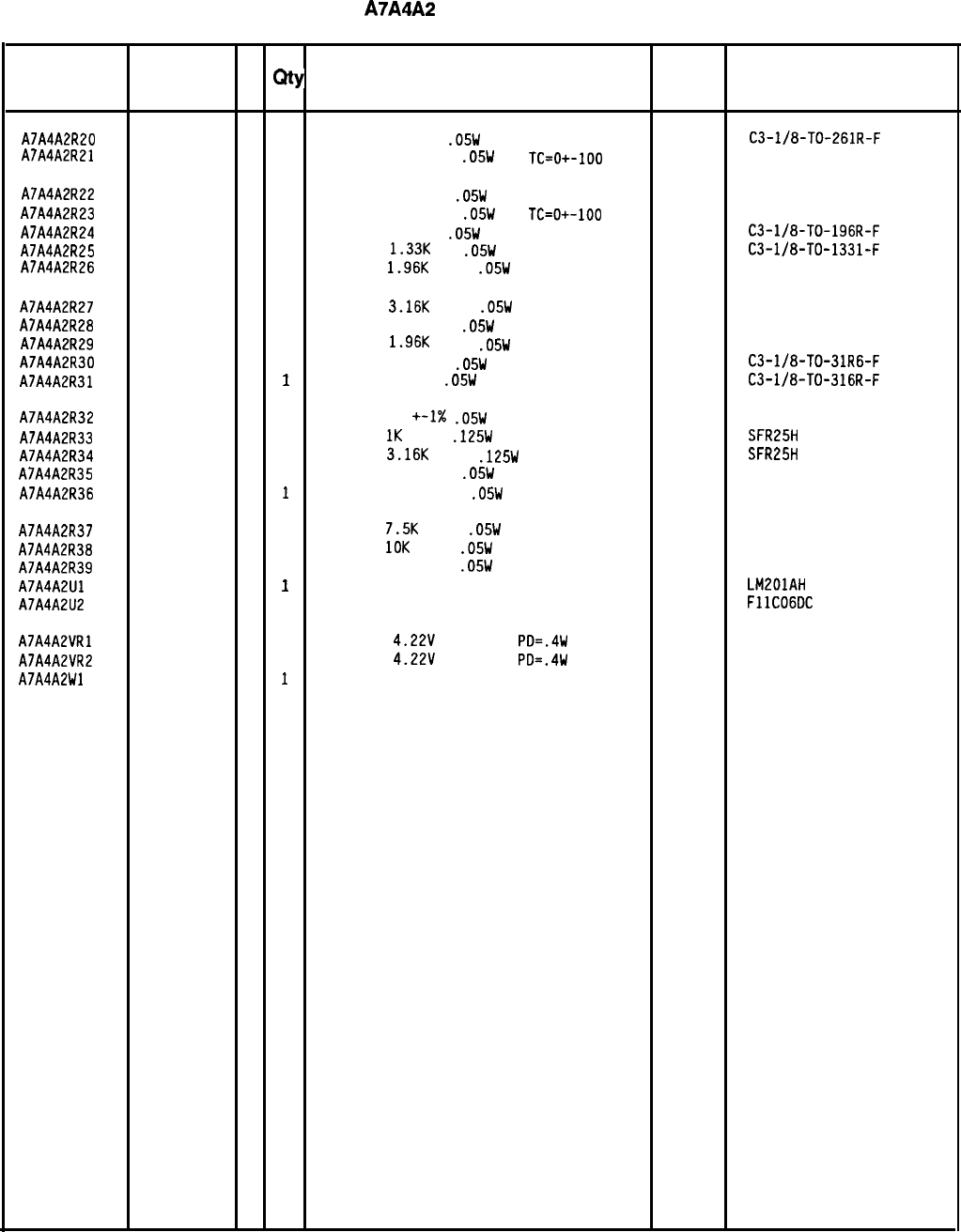
HP Part Number 85660-60192
A7A4A2
M/N Output Board
Reference
HP Part C
Number D
Qty Description Mfr
Mfr Part
Designation Code Number
A7A4A2R20 0698-7222
1 1
RESISTOR 261
1%
.05W
F TC=O+-100
24546
A7A4A2R21
C3-l/8-TO-261R-F
0698-7223
2 1
RESISTOR 287 +-1%
.05W
TF
TC=O+-100
19701
50635
A7A4A2R22 0698-7188
8
1
RESISTOR 10
+-1%
.05W
TF TC=O+-100
19701
50635
A7A4A2R23 0698-7229
8
1
RESISTOR 511
+-1%
.05W
TF
TC=O+-100
19701
50635
A7A4A2R24 0698-7219
6
1
RESISTOR
196 1%
.05W
F TC=O+-100
24546
C3-l/8-TO-196R-F
A7A4A2R25 0698-7239
0
1
RESISTOR
1.33K
1%
.05W
F TC=O+-100
24546
A7A4A2R26 C3-l/8-TO-1331-F
0698-7243
6
1
RESISTOR
1.96K
+-1%
.05W
TF
TC=O+-100
19701
50635
A7A4A2R27 0698-7248
1 1
RESISTOR 3.16K
+-1%
.05W
TF TC=O+-100
19701
50635
A7A4A2R28 0698-7229
8
1
RESISTOR 511
+-1%
.05W
TF TC=O+-100
19701
50635
A7A4A2R29 0698-7243
6
1
RESISTOR
1.96K
+-1%
.05W
TF TC=O+-100
19701
50635
A7A4A2R30
0698-7200
5
1
RESISTOR 31.6
1%
.05W
F TC=O+-100
24546
C3-l/8-TO-31R6-F
A7A4A2R31 0698-7224
3
1
RESISTOR 316 1%
.05W
F
TC=O+-100 24546
C3-l/8-TO-316R-F
A7A4A2R32 0698-7188
8
1
RESISTOR 10 +-1X
.05W
TF TC=O+-100
19701
50635
A7A4A2R33 0757-0280
3
1
RESISTOR
1K
+-1%
.125W
TF
TC=O+-100
19701
SFR25H
A7A4A2R34 0757-0279
0
1
RESISTOR
3.16K
+-1%
.125W
TF TC=O+-100
19701
SFR25H
A7A4A2R35 0698-7223
2
1
RESISTOR 287
.05W
+-1% TF TC=O+-100
19701
50635
A7A4A2R36 0698-7210
7
1
RESISTOR 82.5 +-1%
.05W
TF TC=O+-100
19701
50635
A7A4A2R37 0698-7257
2
1
RESISTOR
7.5K
+-1%
.05W
TF
TC=O+-100
19701
50635
A7A4A2R38 0698-7260
7
1
RESISTOR
10K
+-1%
.05W
TF
TC=O+-100 19701 50635
A7A4A2R39 0698-7229
8
1
RESISTOR 511 +-1%
.05W
TF
TC=O+-100
19701
50635
A7A4A2Ul 1826-0059
2
1
IC OP AMP GP TO-99 PKG 27014 LM201AH
A7A4A2U2 1820-2106
2
1
IC FF ECL D-M/S POS-EDGE-TRIG 07263 FllCOGDC
A7A4A2VRl 1902-3070
5
1
DIODE-ZNR
4.22V
5% DO-35
PD=.4W 04713
A7A4A2VR2 1902-3070
5
1
DIODE-ZNR
4.22V
5% DO-35
PD=.4W 04713
A7A4A2Wl 85660-60103
2
1
JUMPER ASSEBMLY 28480 85660-60103
*Indicates factory-selected value
8566040192 Parts List
Page 3 of 3
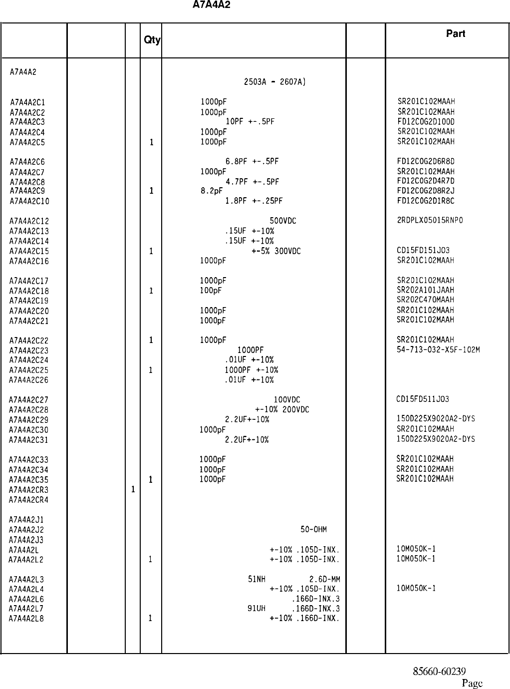
HP Part Number 85660-60239
A7A4A2
M/N Output Board
Reference
HP Part C
Designation
Number D
Qty Description Mfr Mfr
Part
Code Number
A7A4A2 85660-60239
5
1
BOARD ASSEMBLY, M/N OUTPUT 28480 85660-60239
(SERIAL PREFIXES:
2503~
-
2607~)
A7A4A2Cl 0160-3878
6
1
CAP-FXD
1OOOpF
100 V
04222 SR201C102MAAH
A7A4A2C2 0160-3878
6
1
CAP-FXD
1OOOpF
100 V
04222 SR201C102MAAH
A7A4A2C3 0160-3874
2
1
CAPACITOR-FXD
1OPF
+-.5PF
200VDC CER
FD12COG2DlOOD
A7A4A2C4 0160-3878
6
1
CAP-FXD
1OOOpF
100 V
04222 SR201C102MAAH
A7A4A2C5 0160-3878
6
1
CAP-FXD
IOOOpF
100 V
04222 SR201C102MAAH
A7A4A2C6 0160-4383
0
1
CAPACITOR-FXD
6.8PF
+-.5PF
200VDC CER
FD12COG2D6R80
A7A4A2C7 0160-3878
6
1
CAP-FXD
1OOOpF
100 V
04222 SR201C102MAAH
A7A4A2C8 0160-3873
1
1
CAPACITOR-FXD
4.7PF
+-.5PF
200VDC CER
FD12COG204R7D
A7A4A2C9 0160-4491
1
1
CAP-FXD
8.2pF
200 V
FD12COG2D8R2J
A7A4A2ClO 0160-4490
0
1
CAPACITOR-FXO
1.8PF
+-.25PF
2OOVDC CER
FD12COG2DlR8C
A7A4A2C12 0160-2261
9
1
CAPACITOR-FXD 15PF +-5%
SOOVDC
CER 0+-30
52763 2RDPLX05015RNPO
A7A4A2C13 0160-2290
4
1
CAPACITOR-FXD
.15UF
+-lo%
80VDC POLYE
84411 HEW-238T
A7A4A2C14 0160-2290
4
1
CAPACITOR-FXD
.15UF
+-lo%
80VDC POLYE
84411 HEW-238T
A7A4A2C15 0140-0196
3
1
CAPACITOR-FXD 150PF
+-5X
SOOVDC
MICA
09023 CD15FO151JO3
A7A4A2C16 0160-3878
6
1
CAP-FXD
1OOOpF
100 V
04222 SR201C102MAAH
A7A4A2C17 0160-3878
6
1
CAP-FXD
1OOOpF
100 V
04222 SR201C102MAAH
A7A4A2C18 0160-4389
6
1
CAP-FXD
IOOpF
200 V
04222 SR202AlOlJAAH
A7A4A2C19 0160-3876
4
1
CAPACITOR-FXD 47PF +-20% 2OOVOC CER
04222 SR202C470MAAH
A7A4A2C20 0160-3878
6
1
CAP-FXD
1OOOpF
100 V
04222 SR201C102MAAH
A7A4A2C21 0160-3878
6
1
CAP-FXD
1OOOpF
100 V
04222 SR201C102MAAH
A7A4A2C22 0160-3878
6
1
CAP-FXD
IOOOpF
100 V
04222 SR201C102MAAH
A7A4A2C23 0160-4351
2
1
CAPACITOR-FDTHRU
1OOOPF
20% 200V CER
33095 54-713-032-X5F-102M
A7A4A2C24 0160-0161
4
1
CAPACITOR-FXD
.OlUF
+-lo%
200VDC POLYE
84411 HEW-238M
A7A4A2C25 0160-0153
4
1
CAPACITOR-FXD
IOOOPF
+-lo%
200VDC POLYE
84411 HEW-238M
A7A4A2C26 0160-0161
4
1
CAPACITOR-FXD
.OlIJF
+-lo%
2OOVOC POLYE
84411 HEW-238M
A7A4A2C27 0160-3534
1 1
CAPACITOR-FXD 510PF +-5%
1OOVDC
MICA
09023 CD15FD511J03
A7A4A2C28 0160-0298
8
1
CAPACITOR-FXD 1500PF
+-lo%
POOVDC
POLYE
84411 HEW-238M
A7A4A2C29 0180-0197
8
1
CAPACITOR-FXD
2.2UF+-10%
20VDC TA
56289 150D225X9020A2-DYS
A7A4A2C30 0160-3878
6
1
CAP-FXD
1OOOpF
100 V
04222 SR201C102MAAH
A7A4A2C31 0180-0197
8
1
CAPACITOR-FXD
2.2UF+-10%
20VDC TA
56289 1500225X9020A2-DYS
A7A4A2C33 0160-3878
6
1
CAP-FXD
1OOOpF
100 V
04222 SR201C102MAAH
A7A4A2C34 0160-3878
6
1
CAP-FXD
1OOOpF
100 V
04222 SR201C102MAAH
A7A4A2C35 0160-3878
6
1
CAP-FXD
1OOOpF
100 V
04222 SR201C102MAAH
A7A4A2CR3 1901-0040
1
1
DIODE-SWITCHING 30V 50MA 2NS DO-35
71468
A7A4A2CR4 1901-0040
1
1
DIODE-SWITCHING 30V 50MA 2NS DO-35 71468
A7A4A2Jl 1250-0690
6
1
CONNECTOR-RF SMB M SGL-HOLE-FR 50-OHM
98291 51-047-4610
A7A4A2J2 1250-2112
1 1
CONNECTOR-RF SMB M SGL-HOLE-FR
50-OHM 98291 051-047-0259-220
A7A4A2J3 1250-0257
1 1
CONNECTOR-RF SMB M PC 50-OHM
98291 51-051-0169-226
A7A4A2L 1 9100-2891
4
1
INDUCTOR RF-CH-MLD 50NH
+-lo%
.1050-INX.
24226 lOM050K-1
A7A4A2L2 9100-2891
4
1
INDUCTOR RF-CH-MLD 50NH
+-lo%
.1050-INX.
24226 lOM050K-1
A7A4A2L3 9135-0073
3
1
INDUCTOR RF-CH-MLD
5lNH
+-6.596%
2.6D-MM 06560
A7A4A2L4 9100-2891
4
1
INDUCTOR RF-CH-MLD 50NH +-lo%
.lOSD-INX.
24226 lOM050K-1
A7A4A2L6 9100-1634
1 1
INDUCTOR RF-CH-MLD 75UH +-5%
.166D-INX.3 99800 1537-70
A7A4A2L7 9100-1635
2
1
INDUCTOR RF-CH-MLD
91UH
+-5%
.166D-INX.3 99800 1537-74
A7A4A2L8 9100-1620
5
1
INDUCTOR RF-CH-MLD 15UH
+-lo%
.166D-INX.
99800 1537-40
*Indicates factory-selected value
85660-60239 Parts List
Page
1 of 3
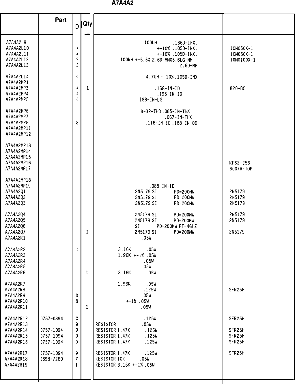
HP Part Number 85660-60239
A7A4A2
M/N Output Board
Description Mfr
Mfr Part
Code Number
INDUCTOR RF-CH-MLD
1OOUH
+-5%
.166D-INX.
99800
INDUCTOR RF-CH-MLD 50NH +-lo%
.105D-INX.
24226
INDUCTOR RF-CH-MLD 50NH
+-lo%
.105D-INX.
24226
INDUCTOR
IOONH
+-5.5x
2.6D-MMX6.6LG-MM 24226
INDUCTOR RF-CH-MLD 51NH +-6.596%
2.6D-MP 06560
INDUCTOR RF-CH-MLD
4.7UH
+-lo%
.105D-INX
NOT ASSIGNED 99800 1025-36
WASHER-LK INTL T NO. 8
.168-IN-ID OG791
WASHER-LK INTL T NO. 10
.195-IN-ID 98291
SCREW-MACH 4-40
.188-IN-LG
PAN-HD-POZI
77250
NUT-HEX-DBL-CHAM
8-32-THD
.085-IN-THK 80120
NUT-HEX-DBL-CHAM IO-32-THD
.067-IN-THK 74163
WASHER-FL NM NO. 4
.116-IN-ID
.188-IN-00 76854
COVER PC, M/N OUTPUT 28480
GROUND LUG 28480
EXTRACTOR PC
SCREW-MACH 4-40 .25-IN-LG PAN-HO-POZI
SCREW-MACH 2-56 .25-IN-LG PAN-HD-POZI
THREADED INSERT-NUT 2-56 .06-IN-LG SST
HEAT SINK SGL DIP-COVERING U2
28480
77250
77250
46384
13103
I.C. HEAT SINK
WASHER-LK HLCL NO. 2
.088-IN-ID
TRANSISTOR NPN
2N5179
SI
TO-72
PO=ZOOMW
TRANSISTOR NPN
2N5179
SI
TO-72
PD=200MW
TRANSISTOR NPN
2N5179
SI
TO-72
PD=200MW
28480
77339
04713
04713
04713
TRANSISTOR NPN
2N5179
SI
TO-72
PD=200MW 04713
TRANSISTOR NPN
2N5179
SI
TO-72
PD=200MW 04713
TRANSISTOR NPN
SI
TO-72
PD=ZOOMW
FT=4GHZ 25403
TRANSISTOR NPN
2N5179
SI
TO-72
PD=200MW 04713
RESISTOR 100 +-1%
.05W
TF TC=O+-100
19701
RESISTOR
3.16K
+-1%
.05W
TF TC=O+-100
RESISTOR
1.96K
+-I%
.05W
TF TC=O+-100
RESISTOR 51.1 +-1%
.05W
TF TC=O+-100
RESISTOR 287 +-1%
.05W
TF TC=O+-100
RESISTOR
3.16K
+-1%
.05W
TF TC=O+-100
RESISTOR
1.96K
+-1%
.05W
TF TC=O+-100
RESISTOR 42.2 +-1%
.125W
TF TC=O+-100
RESISTOR 237 +-1%
.05W
TF TC=O+-100
RESISTOR 10 +-I%
.05W
TF TC=O+-100
RESISTOR 100 +-1%
.05W
TF TC=O+-100
RESISTOR 51.1 +-1%
.125W
TF TC=O+-100
?ESISTOR
100 +-1%
.05W
TF TC=O+-100
iESISTOR
1.47K
+-1%
.125W
TF TC=O+-100
?ESISTOR
1.47K
+-1%
.125W
TF TC=O+-100
7ESISTDR
1.47K
+-1%
.125W
TF TC=O+-100
7ESISTOR
1.47K
+-1%
.125W
TF TC=O+-100
?ESISTOR
10K
+-1%
.05W
TF TC=O+-100
?ESISTOR
3.16K
+-I%
.05W
TF TC=O+-100
19701
19701
19701
19701
19701
19701
19701
19701
19701
19701
19701
19701
19701
19701
19701
19701
19701
19701
*Indicates factoy-selected value
Reference
Designation
A7A4A2L9
A7A4A2LlO
A7A4A2Lll
A7A4A2L12
A7A4A2L13
HP
Part
Number
c
c
9140-0210
1
9100-2891
1
9100-2891
L
9135-0079
c
9135-0073
:
A7A4A2L14
A7A4A2MPl
A7A4A2MP3
A7A4A2MP4
A7A4A2MP5
9140-0144
c
2190-0009
2190-0124
2200-0101
A7A4A2MP6 2580-0002
4
A7A4A2MP7 2950-0078
9
A7A4A2MP8 3050-0082
e
A7A4A2MPll 85660-20049
1
A7A4A2MP12 85660-20068
4
A7A4A2MP13 86701-40001
9
A7A4A2MP14 2200-0103
2
A7A4A2MP15 0520-0128
7
A7A4A2MP16 0590-0533
5
A7A4A2MP17 1205-0285
0
A7A4A2MP18 85660-00065
9
A7A4A2MP19 2190-0112
0
A7A4A2Ql 1854-0345
8
A7A4A2Q2 1854-0345
8
A7A4A2Q3 1854-0345
8
A7A4A2Q4 1854-0345
8
A7A4A2Q5 1854-0345
8
A7A4A2Q6 1854-0686
0
A7A4A2Q7 1854-0345
8
A7A4A2Rl 0698-7212
9
A7A4A2R2 0698-7248
1
A7A4A2R3 0698-7243
6
A7A4A2R4 0698-7205
0
A7A4A2R5 0698-7223
2
A7A4A2R6 0698-7248
1
A7A4A2R7 0698-7243
6
A7A4A2R8 0757-0316
6
A7A4A2R9 0698-7221
D
A7A4A2RlO 0698-7188
3
A7A4A2Rll 0698-7212
3
A7A4A2R12 D757-0394
A7A4A2R13 0698-7212
A7A4A2R14 3757-1094
A7A4A2R15 3757-1094
A7A4A2R16 3757-1094
A7A4A2Rl7 3757-1094
A7A4A2R18 3698-7260
A7A4A2R19 3698-7248
85660-60239 Parts List
Page 2 of 3
-
2:
-
1
1
1
1
1
1
1
1
2
1
2
1
1
2
1
2
2
2
1
1
2
1
1
1
1
1
1
1
1
1
1
1
1
1
1
1
1
1
1
1
1
1
1
1
1
1
1
-
1537-76
lOM050K-1
lOM050K-1
lOMOlOOX-1
820-BC
3002-26
500220
8942-3
85660-20049
85660-20068
86701-40001
KFS2-256
6007A-TOP
85660-00065
2N5179
2N5179
2N5179
2N5179
2N5179
2N5179
50635
50635
50635
50635
50635
50635
50635
SFR25H
50635
50635
50635
SFR25H
50635
SFR25H
SFR25H
SFR25H
SFR25H
50635
50635
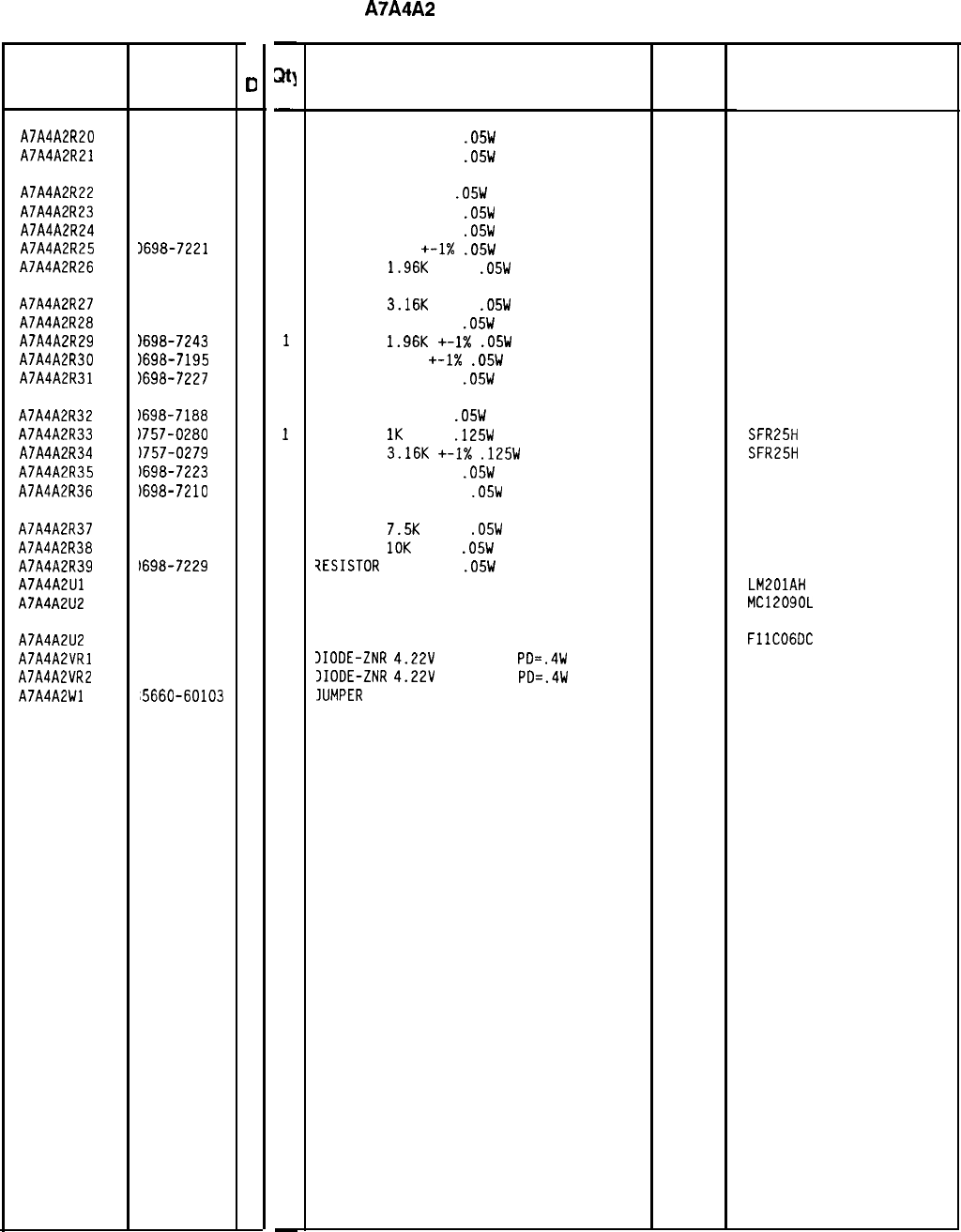
Reference HP Part
C
Designation Number
0
A7A4A2R20 3698-7223
2
A7A4A2R21 3698-7223
2
A7A4A2R22 3698-7188
8
A7A4A2R23 3698-7229
8
A7A4A2R24 3698-7212
9
A7A4A2R25
1698-7221
0
A7A4A2R26 1698-7243
6
A7A4A2R27 1698-7248
1
A7A4A2R28
1698-7229
8
A7A4A2R29
1698-7243
6
A7A4A2R30 1698-7195
7
A7A4A2R31
1698-7227
6
A7A4A2R32
1698-7188
8
A7A4A2R33
1757-0280
3
A7A4A2R34
1757-0279
0
A7A4A2R35
1698-7223
2
A7A4A2R36
)698-7210
7
A7A4A2R37
1698-7257
2
A7A4A2R38
1698-7260
7
A7A4A2R39
1698-7229
8
A7A4A2Ul 826-0059
2
A7A4A2U2 820-3485
2
A7A4A2U2 820-2106
2
A7A4A2VRl 902-3070
5
A7A4A2VR2 902-3070
5
A7A4A2Wl
'5660-60103
2
-
at]
-
1
1
1
1
1
1
1
1
1
1
1
1
1
1
1
1
1
1
1
1
1
1
0
1
1
1
-
HP Part Number 85660-60239
A7A4A2
M/N Output Board
Description
RESISTOR 287 +-1%
.05W
TF TC=O+-100
19701
50635
RESISTOR 287 +-1%
.05W
TF TC=O+-100
19701
50635
RESISTOR 10 +-1%
.05W
TF TC=O+-100
19701
50635
RESISTOR 511 +-1%
.05W
TF TC=O+-100
19701
50635
RESISTOR 100 +-1%
.05W
TF TC=O+-100
19701
50635
RESISTOR 237
+-1X
.05W
TF TC=O+-100
19701
50635
RESISTOR
1.96K
+-1%
.05W
TF TC=O+-100
19701
50635
RESISTOR
3.16K
+-1%
.05W
TF TC=O+-100
19701
50635
RESISTOR 511 +-1%
.05W
TF TC=O+-100
19701 50635
RESISTOR
1.96K
+-1X
.05W
TF TC=O+-100
19701
50635
RESISTOR 19.6
+-1X
.05W
TF TC=O+-100
19701
50635
RESISTOR 422 +-1%
.05W
TF TC=O+-100
19701
50635
RESISTOR 10 +-1%
.05W
TF TC=O+-100
19701
50635
RESISTOR
1K
+-1%
.125W
TF TC=O+-100
19701
SFR25H
RESISTOR
3.16K
+-I%
.125W
TF TC=O+-100
19701
SFR25H
RESISTOR 287 +-1%
.05W
TF TC=O+-100
19701
50635
RESISTOR 82.5 +-1%
.05W
TF TC=O+-100
19701
50635
RESISTOR
7.5K
+-1%
.05W
TF TC=O+-100
19701
50635
RESISTOR
10K
+-1%
.05W
TF TC=O+-100
19701
50635
7ESISTOR
511 +-1%
.05W
TF TC=O+-100
19701
50635
IC OP AMP GP TO-99 PKG 27014 LM201AH
IC PRESCR ECL 04713 MC12090L
ALTERNATE FOR 1820-3485 07263
)IODE-ZNR
4.22V
5% DO-35
PD=.4W 04713
IIODE-ZNR
4.22V
5% DO-35
PD=.4W 04713
IUMPER
ASSEBMLY
28480
FllCOGDC
85660-60103
Mfr
Mfr Part
Code Number
*Indicates factory-selected value
85660-60239 Parts List
Page 3 of 3
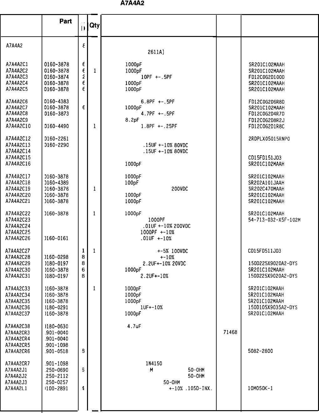
Reference
Designation HP
Part
Number
C
c
AJA4A2
85660-60266
E
AJA4A2Cl 0160-3878
E
AJA4A2C2 0160-3878
E
AJA4A2C3
0160-3674
2
AJA4A2C4 0160-3878
E
AJA4A2C5 0160-3878
E
AJA4A2C6 0160-4383
C
AJA4A2CJ
0160-3878
f
AJA4A2Ca
0160-3673
1
AJA4A2C9 0160-4491
1
AJA4A2ClO 0160-4490
c
AJA4A2C12 9160-2261
9
AJA4A2C13 3160-2290
4
AJA4A2Cl4 3160-2290
4
AJA4A2Cl5 3140-0196
3
AJA4A2C16 3160-3878
6
AJA4A2ClJ 3160-3878
6
AJA4A2Cla 3160-4389
6
AJA4A2C19
3160-3676
4
AJA4A2C20 3160-3878
6
AJA4A2C21 1160-3878
6
AJA4A2C22 1160-3878
6
AJA4A2C23
1160-4351
2
AJA4A2C24
1160-0161
4
AJA4A2C25 1160-0153
4
AJA4A2C26
)160-0161
4
AJA4A2C2
7
AJA4A2C28
AJA4A2C29
AJA4A2C30
AJA4A2C31
1160-3534
)160-0298
~180-0197
)160-3878
)lao-o197
AJA4A2C33
)160-3878
6
AJA4A2C34
)160-3878
6
AJA4A2C35
)160-3878
6
AJA4A2C36
uao-0291
3
AJA4A2C3
7
)160-3878
6
AJA4A2C38
AJA4A2CR3
AJA4A2CR4
AJA4A2CR5
AJA4A2CR6
Ilao-0630
.901-0040
.901-0040
.9oi-1098
.901-0518
AJA4A2CRJ
.901-1098
AJA4A2Jl
.250-0690
AJA4A2J2
.250-2112
AJA4A2J3
.250-0257
AJA4A2Ll
uoo-2891
4
1
1
1
3
1
5
1
1
1
-
a!
-
1
1
1
1
1
1
1
1
1
1
1
1
1
1
1
1
1
1
1
1
1
1
1
1
1
1
1
1
1
1
1
1
1
1
1
1
1
1
1
1
1
1
1
1
1
1
-
HP Part Number 85660-60266
A7A4A2
M/N Output Board
Description Mfr
Mfr Part
Code Number
BOARD ASSEMBLY, M/N OUTPUT
(SERIA
L
P
REFIX
:
2611~)
28480 85660-60266
CAP-FXD
1OOOpF
100 V
CAP-FXD
1OOOpF
100 V
CAPACITOR-FXD
1OPF
+-.5PF
200VDC CER
CAP-FXD
1OOOpF
100 V
CAP-FXD
IOOOpF
100 V
04222
04222
04222
04222
SR201C102MAAH
SR201C102MAAH
FD12COG2DlOOD
SR201C102MAAH
SR201C102MAAH
CAPACITOR-FXD
6.aPF
+-.5PF
200VDC CER
CAP-FXD
1OOOpF
100 V
CAPACITOR-FXD
4.JPF
+-.5PF
200VDC CER
CAP-FXD
8.2pF
200 V
CAPACITOR-FXD
l.aPF
+-.25PF
200VDC CER
04222
F012COG2D6RaD
SR201C102MAAH
FD12COG2D4RJD
FD12COG2DaR2J
FD12COG2DlRaC
CAPACITOR-FXD 15PF +-5% 5OOVDC CER 0+-30
52763
2RDPLX05015RNPO
CAPACITOR-FXD
.15UF
+-lo%
a0VDC
POLYE
a4411 HEW-23aT
CAPACITOR-FXD
.15UF
+-lo%
a0VDC
POLYE
a4411 HEW-23aT
CAPACITOR-FXD 150PF +-5% 300VDC MICA
09023 CD15FD151J03
CAP-FXD
1OOOpF
100 V
04222
SR201C102MAAH
CAP-FXD
1OOOpF
100 V
04222
SR201C102MAAH
CAP-FXD
1OOpF
200 V
04222
SR202AlOlJAAH
CAPACITOR-FXD 4JPF +-20%
ZOOVDC
CER
04222
SR202C4JOMAAH
CAP-FXD
1OOOpF
100 V
04222
SR201C102MAAH
CAP-FXD
IOOOpF
100 V
04222
SR201C102MAAH
CAP-FXD
1OOOpF
100 V
04222
SR201C102MAAH
CAPACITOR-FDTHRU
1OOOPF
20% 200V CER
33095
54-713-032-X5F-102M
CAPACITOR-FXD
.OlUF
+-lo%
LOOVDC
POLYE
a4411 HEW-23aM
CAPACITOR-FXD
1OOOPF
+-lo%
200VDC POLYE
a4411 HEW-23aM
CAPACITOR-FXD
.OlUF
+-10x
200VDC POLYE
a4411 HEW-23aM
CAPACITOR-FXD 510PF +-5x
1OOVDC
MICA
09023 CD15FD511J03
CAPACITOR-FXD 1500PF +-lo% 200VDC POLYE
84411 HEW-23aM
CAPACITOR-FXD
2.2UF+-10%
EOVDC
TA
56289 150D225X9020A2-DYS
CAP-FXD
1OOOpF
100 V
04222
SR201C102MAAH
CAPACITOR-FXD
2.2UF+-10%
20VDC TA
56289 150D225X9020A2-DYS
CAP-FXD
1OOOpF
100 V
04222
SR201C102MAAH
CAP-FXD
1OOOpF
100 V
04222
SR201C102MAAH
CAP-FXD
1OOOpF
100 V
04222
SR201C102MAAH
CAPACITOR-FXD
lUF+-10%
35VDC TA
56289 150D105X9035A2-DYS
CAP-FXD
1OOOpF
100 V
04222
SR201C102MAAH
CAP-FXD
4.JuF
50
V TA
DIODE-SWITCHING 30V 50MA 2NS DO-35
DIODE-SWITCHING 30V 50MA 2NS DO-35
DIODE-SWITCHING IN4150 50V 200MA 4NS
DIODE-SCHOTTKY SM SIG
56289
71466
71468
71466
19901123
5082-2800
DIODE-SWITCHING
lN4150
50V 200MA 4NS
71468
CONNECTOR-RF SMB
M
SGL-HOLE-FR
50-OHM 98291
CONNECTOR-RF SMB M SGL-HOLE-FR
50-OHM 98291
CONNECTOR-RF SMB M PC
50-OHM 98291
INDUCTOR RF-CH-MLD 50NH
+-lo%
.105D-INX.
24226
51-047-4610
051-047-0259-220
51-051-0169-226
lOM050K-1
*Indicates factory-selected value
85660-60266 Parts List
Page 1 of 3
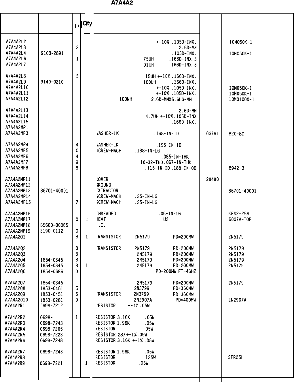
Reference
Designation
HP Part
Number
C
c
AJA4A2L2 9100-2891
4
AJA4A2L3
9135-0073
?
AJA4A2L4 9100-2891
4
AJA4A2L6 9100-1634
1
AJA4A2L
7
9100-1635
2
AJA4A2La 9100-1620
5
AJA4A2L9 9140-0210
1
AJA4A2LlO 9100-2891
4
AJA4A2Lll 9100-2891
4
AJA4A2L12
9135-0079
9
AJA4A2L13
AJA4A2L14
AJA4A2L15
AJA4A2MPl
AJA4A2MP3
9135-0073
3
9140-0144
0
9100-1641
0
2190-0009
4
AJA4A2MP4
AJA4A2MP5
AJA4A2MP6
AJA4A2MP
7
AJA4A2MPa
2190-0124
2200-0101
2580-0002
2950-0078
3050-0082
AJA4A2MPll 85660-20049
1
AJA4A2MP12 85660-20068
4
AJA4A2MP13 a6701-40001
9
AJA4A2MP14 2200-0103
2
AJA4A2MP15 0520-0128
7
AJA4A2MP16 0590-0533
5
AJA4A2MPlJ 1205-0285
0
AJA4A2MPla 85660-00065
3
AJA4A2MP19 2190-0112
0
AJA4A2Ql 1854-0345
3
AJA4A2Q2
AJA4A2Q3
AJA4A2Q4
AJA4A2Q5
AJA4A2Q6
1854-0345
1854-0345
1854-0345
1854-0345
1854-0686
AJA4A2QJ
1854-0345
3
AJA4A2Qa 1853-0451
5
AJA4A2Q9 1853-0451
3
AJA4A2QlO 1853-0281
3
AJA4A2Rl 3698-7212
3
AJA4A2R2 0698- 7248
1
AJA4A2R3
0696-7243
6
AJA4A2R4
0696-7205
0
AJA4A2R5
0698-7223
2
AJA4A2R6 0698-7248
1
AJA4A2R
7
0698-7243
6
AJA4A2Ra
0757-0316
6
AJA4A2R9
0698-7221
0
85660450266 Parts List
Page 2 of 3
a!
-
1
1
1
1
1
1
1
1
1
1
1
1
1
1
4
2
1
2
1
1
2
1
2
2
2
1
1
2
1
1
1
1
1
1
1
1
1
1
1
1
1
1
1
1
1
1
1
-
HP Part Number 85660-60266
A7A4A2
M/N Output Board
Description Mfr
Mfr Part
Code Number
INDUCTOR RF-CH-MLD 50NH
+-lo%
.105D-INX.
24226
INDUCTOR RF-CH-MLD 51NH +-6.596%
2.60-MM 06560
INDUCTOR RF-CH-MLD 50NH +-lo%
.lOSD-INX.
24226
INDUCTOR RF-CH-MLD
75UH
+-5%
.166D-INX.3 99800
INDUCTOR RF-CH-MLD
91UH
+-5%
.166D-INX.3 99800
lOM050K-1
lOM050K-1
1537-70
1537-74
INDUCTOR RF-CH-MLD
15UH
+-10x
.166D-INX.
99800
1537-40
INDUCTOR RF-CH-MLD
1OOUH
+-5%
.166D-INX.
99800
1537-76
INDUCTOR RF-CH-MLD 50NH +-lo%
.105D-INX.
24226 lOM050K-1
INDUCTOR RF-CH-MLD 50NH +-IO%
.lOSD-INX.
24226 lOM050K-1
INDUCTOR
1OONH
+-5.5%
2.6D-MMX6.6LG-MM 24226 lOMOlOOX-1
INDUCTOR RF-CH-MLD 51NH +-6.596%
2.6D-MM
INDUCTOR RF-CH-MLD
4.JUH
+-lo%
.105D-INX
INDUCTOR RF-CH-MLD 240UH +-5%
.166D-INX.
YOT ASSIGNED
06560
99800
99800 1025-36
1537-94
MASHER-LK
INTL T NO. a
.168-IN-IO
OGJ91
a20-BC
dASHER-LK
INTL T NO. 10
.195-IN-ID 98291
GCREW-MACH
4-40
.laa-IN-LG
PAN-HD-POZI
77250
IUT-HEX-DBL-CHAM a-32-THD
.085-IN-THK a0120
IUT-HEX-DBL-CHAM
lo-32-THD
.067-IN-THK
74163
JASHER-FL NM NO. 4
.116-IN-ID
.laa-IN-OD
76654
3002-26
500220
8942-3
:OVER
PC, M/N OUTPUT
iROUND
LUG
:XTRACTOR
PC
85660-20049
85660-20068
a6701-40001
iCREW-MACH
4-40
.25-IN-LG
PAN-HD-POZI
;CREW-MACH
2-56
.25-IN-LG
PAN-HD-POZI
28480
28480
28480
77250
77250
?HREADED
INSERT-NUT 2-56
.06-IN-LG
SST
iEAT
SINK SGL DIP-COVERING
U2
:.C.
HEAT SINK
IASHER-LK HLCL NO. 2 .Oaa-IN-ID
.RANSISTOR
NPN
2N5179
SI TO-72
PD=200MW
46384
13103
28480
77339
04713
KFS2-256
600JA-TOP
85660-00065
2N5179
.RANSISTOR
NPN
2N5179
SI TO-72
PD=200MW
04713
'RANSISTOR NPN
2N5179
SI
TO-72
PD=LOOMW
04713
'RANSISTOR NPN
2N5179
SI
TO-72
PD=ZOOMW
04713
'RANSISTOR NPN
2N5179
SI
TO-72
PD=ZOOMW
04713
'RANSISTOR NPN SI
TO-72
PD=200MW
FT=4GHZ 25403
2N5179
2N5179
2N5179
2N5179
'RANSISTOR NPN
2N5179
SI
TO-72
PD=ZOOMW
04713
'RANSISTOR PNP
2N3799
SI TO-la
PD=360MW
04713
.RANSISTOR
PNP
2N3799
SI TO-la
PD=360MW
04713
'RANSISTOR PNP
2N290JA
SI TO-la
PD=400MW
04713
.ESISTOR
100
+-I%
.05W
TF TC=O+-100
19701
2N5179
2N290JA
50635
lESISTOR
3.16K
+-1%
.05W
TF TC=O+-100
19701
50635
ZESISTOR
1.96K
+-1%
.05W
TF TC=O+-100
19701
50635
{ESISTOR
51.1 +-1%
.05W
TF TC=O+-100
19701
50635
IESISTOR
287
+-I%
.05W
TF TC=O+-100
19701
50635
ZESISTOR
3.16K
+-I%
.05W
TF TC=O+-100
19701
50635
{ESISTOR
1.96K
+-1%
.05W
TF TC=O+-100
19701
50635
{ESISTOR
42.2 +-1%
.125W
TF TC=O+-100
19701
SFR25H
ZESISTOR
237
+-1%
.05W
TF TC=O+-100
19701
50635
*Indicates factory-selected value
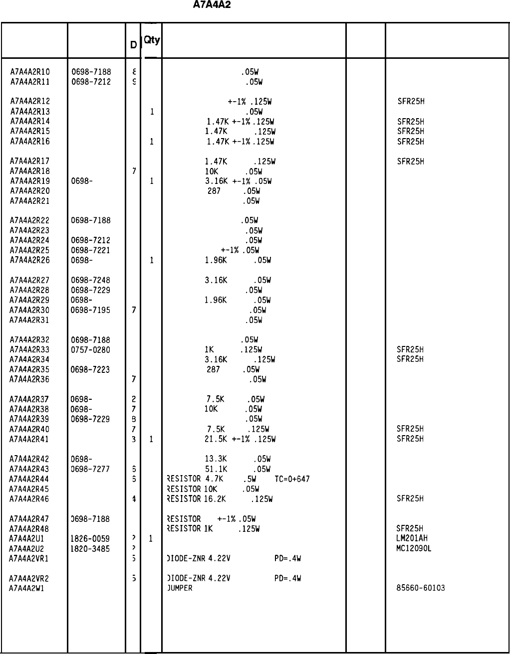
HP Part Number 85660-60266
A7A4A2
M/N Output Board
Reference HP Part
Designation Number
AJA4A2RlO 0698-7188
E
AJA4A2Rll
0698-7212
5
AJA4A2R12
0757-0394
C
AJA4A2Rl3
0698-7212
9
AJA4A2R14
0757-1094
9
AJA4A2R15
0757-1094
9
AJA4A2R16
0757-1094
9
AJA4A2RlJ
0757-1094
9
AJA4A2RlB
0698-7260
7
AJA4A2R19 0698-
7248
1
AJA4A2R20
0698-7223
2
AJA4A2R21
0698-7223
2
AJA4A2R22 0698-7188
a
AJA4A2R23
0698-7229
a
AJA4A2R24
0698-7212
9
AJA4A2R25
0698-7221
0
AJA4A2R26
0698-
7243
6
AJA4A2R27 0698-7248
1
AJA4A2R2B
0698-7229
a
AJA4A2R29
0698-
7243
6
AJA4A2R30
0698-7195
7
AJA4A2R31
0698-7227
6
AJA4A2R32 0698-7188
a
AJA4A2R33
0757-0280
3
AJA4A2R34
0757-0279
0
AJA4A2R35
0698-7223
2
AJA4A2R36
0698-7210
7
AJA4A2R3
7
AJA4A2R38
AJA4A2R39
AJA4A2R40
AJA4A2R41
069&
7257
0698-
7260
0698-7229
0757-0440
0757-0199
AJA4A2R42
0698-
7263
3
AJA4A2R43
0698-7277
3
AJA4A2R44
0687-4721
5
AJA4A2R45
0698-7260
7
AJA4A2R46
0757-0447
4
AJA4A2R47 3698-7188
3
AJA4A2R48
3757-0280
3
AJA4A2Ul 1826-0059
?
AJA4A2U2 1820-3485
>
AJA4A2VRl
1902-3070
5
AJA4A2VR2
1902-3070
5
AJA4A2Wl 35660-60103
,
C
0
-
Qt!
-
1
1
1
1
1
1
1
1
1
1
1
1
1
1
1
1
1
1
1
1
1
1
1
1
1
1
1
1
1
1
1
1
1
1
1
1
1
1
1
1
1
1
1
1
-
Description
RESISTOR 10 +-1%
.05W
TF TC=O+-100
19701
50635
RESISTOR 100 +-1%
.05W
TF TC=O+-100
19701
50635
RESISTOR 51.1
+-I%
.125W
TF TC=O+-100
19701
SFR25H
RESISTOR 100 +-1%
.05W
TF TC=O+-100
19701
50635
RESISTOR
1.4JK
+-1X
.125W
TF TC=O+-100
19701
SFR25H
RESISTOR
1.4JK
+-1%
.125W
TF TC=O+-100
19701
SFR25H
RESISTOR
1.4JK
+-I%
.125W
TF TC=O+-100
19701
SFR25H
RESISTOR
1.4JK
+-1%
.125W
TF TC=O+-100
19701
SFR25H
RESISTOR
10K
+-1%
.05W
TF TC=O+-100
19701
50635
RESISTOR
3.16K
+-I%
.05W
TF TC=O+-100
19701
50635
RESISTOR
287
+-1%
.05W
TF TC=O+-100
19701
50635
RESISTOR
287
+-1%
.05W
TF TC=O+-100
19701
50635
RESISTOR 10 +-1%
.05W
TF TC=O+-100
19701
50635
RESISTOR 511 +-1%
.05W
TF TC=O+-100
19701
50635
RESISTOR 100 +-1%
.05W
TF TC=O+-100
19701
50635
RESISTOR
237
+-1X
.05W
TF TC=O+-100
19701
50635
RESISTOR
1.96K
+-1%
.05W
TF TC=O+-100
19701
50635
RESISTOR
3.16K
+-1%
.05W
TF TC=O+-100
19701
50635
RESISTOR 511 +-1%
.05W
TF TC=O+-100
19701
50635
RESISTOR
1.96K
+-1%
.05W
TF TC=O+-100
19701
50635
RESISTOR 19.6 +-1%
.05W
TF TC=O+-100
19701
50635
RESISTOR 422 +-1%
.05W
TF TC=O+-100
19701
50635
RESISTOR 10 +-1%
.05W
TF TC=O+-100
19701
50635
RESISTOR
IK
+-1%
.125W
TF TC=O+-100
19701
SFR25H
RESISTOR
3.16K
+-1%
.125W
TF TC=O+-100
19701
SFR25H
RESISTOR
287
+-1%
.05W
TF TC=O+-100
19701
50635
RESISTOR 82.5 +-1%
.05W
TF TC=O+-100
19701
50635
RESISTOR
7.5K
+-1%
.05W
TF TC=O+-100
19701
50635
RESISTOR
10K
+-1%
.05W
TF TC=O+-100
19701
50635
RESISTOR 511 +-1%
.05W
TF TC=O+-100
19701
50635
RESISTOR
7.5K
+-1%
.125W
TF TC=O+-100
19701
SFR25H
RESISTOR
21.5K
+-I%
.125W
TF TC=O+-100
19701
SFR25H
RESISTOR
13.3K
+-1%
.05W
TF TC=O+-100
19701
50635
RESISTOR
51.1K
+-1%
.05W
TF TC=O+-100
19701
5023R
?ESISTOR
4.JK
10%
.5W
CC
TC=0+647
01121
EB4721
7ESISTOR
10K
+-1%
.05W
TF TC=O+-100
19701
50635
?ESISTOR
16.2K
+-1%
.125W
TF TC=O+-100
19701
SFR25H
1ESISTOR
10
+-1X
.05W
TF TC=O+-100
7ESISTOR
1K
+-1%
.125W
TF TC=O+-100
IC OP AMP GP TO-99 PKG
IC PRESCR ECL
IIODE-ZNR
4.22V
5% DO-35
PD=.4W
19701
19701
27014
04713
04713
50635
SFR25H
LM201AH
MC12090L
)IODE-ZNR
4.22V
5% DO-35
PD=.4W
04713
JUMPER
WIRE ASSEMBLY
28480 85660-60103
Mfr
Mfr Part
Code Number
*Indicates factory-selected value
85660-60266 Parts List
Page 3 of 3
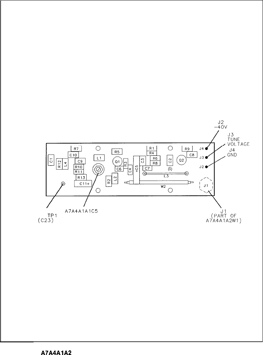
TUNE
A7A4AlAlC5
Jl
TO
TPI
PWR
c-3)
A!AP4AA:TAZ%l)
355-395 MHz
OUT
A7A4AlA2
M/N VCO Board Component Locations, 85660-60018
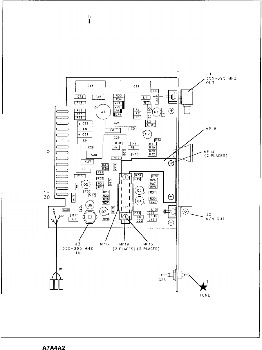
16
Pl
II
I
J3
MP17 MP19
MPl5
355-395
MHZ
(2
PLACES)(2
PLACES)
IN
Wl
Jl
355-395
MHZ
OUT
MP18
MP14
(2
PLACES)
%,;N
OUT
TUNE
A7A4A2 M/N Output Board Component Locations, 85660-60192
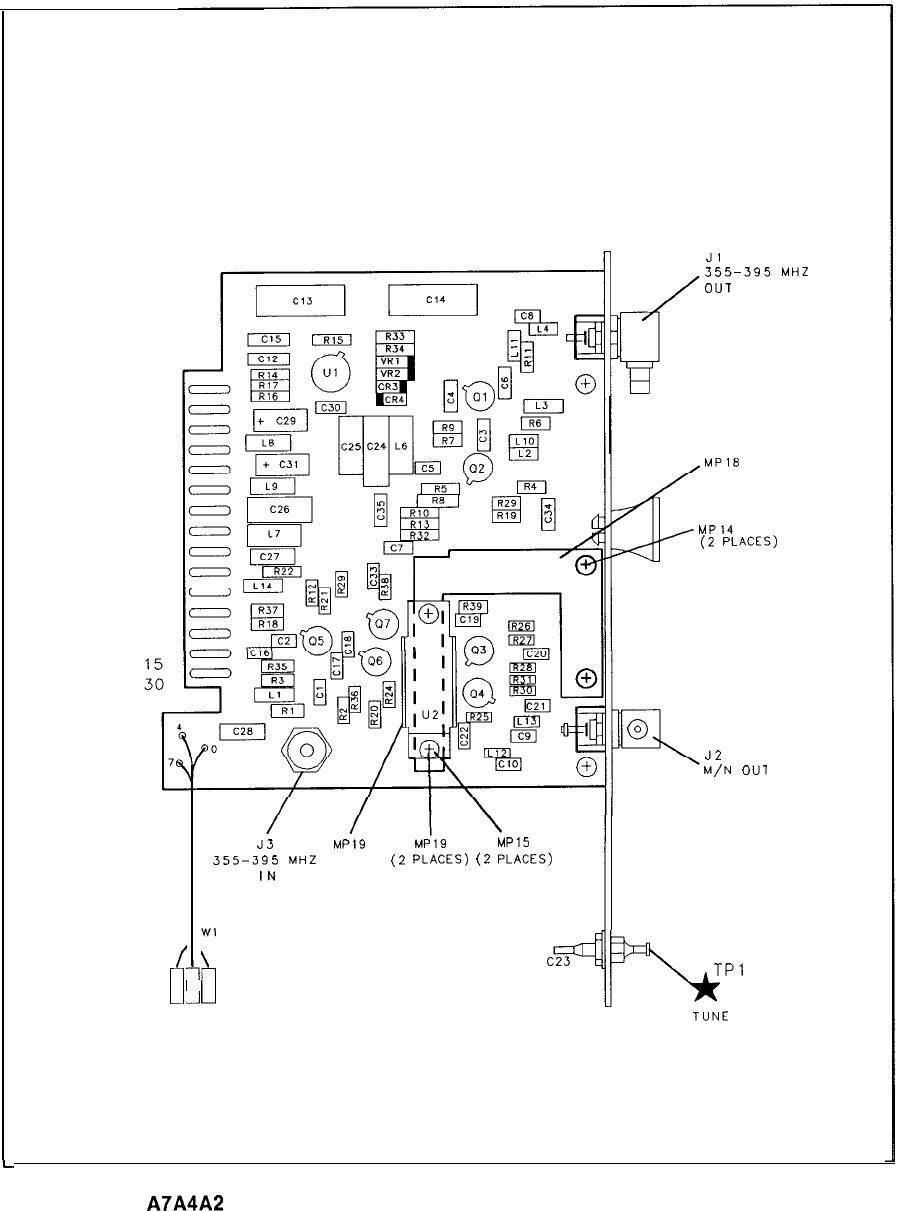
16
PI
6
4'
-1
L
J3 MPl9
MP19 MP15
355-395
MHZ
(2
PLACES)
(2
PLACES)
IN
c5F
Jl
355-395
MHZ
OUT
MP18
MP14
(2
PLACES)
J2
M/N
OUl
b
TPl
TUNE
A7A4A2 M/N Output Board Component Locations, 85660-60239
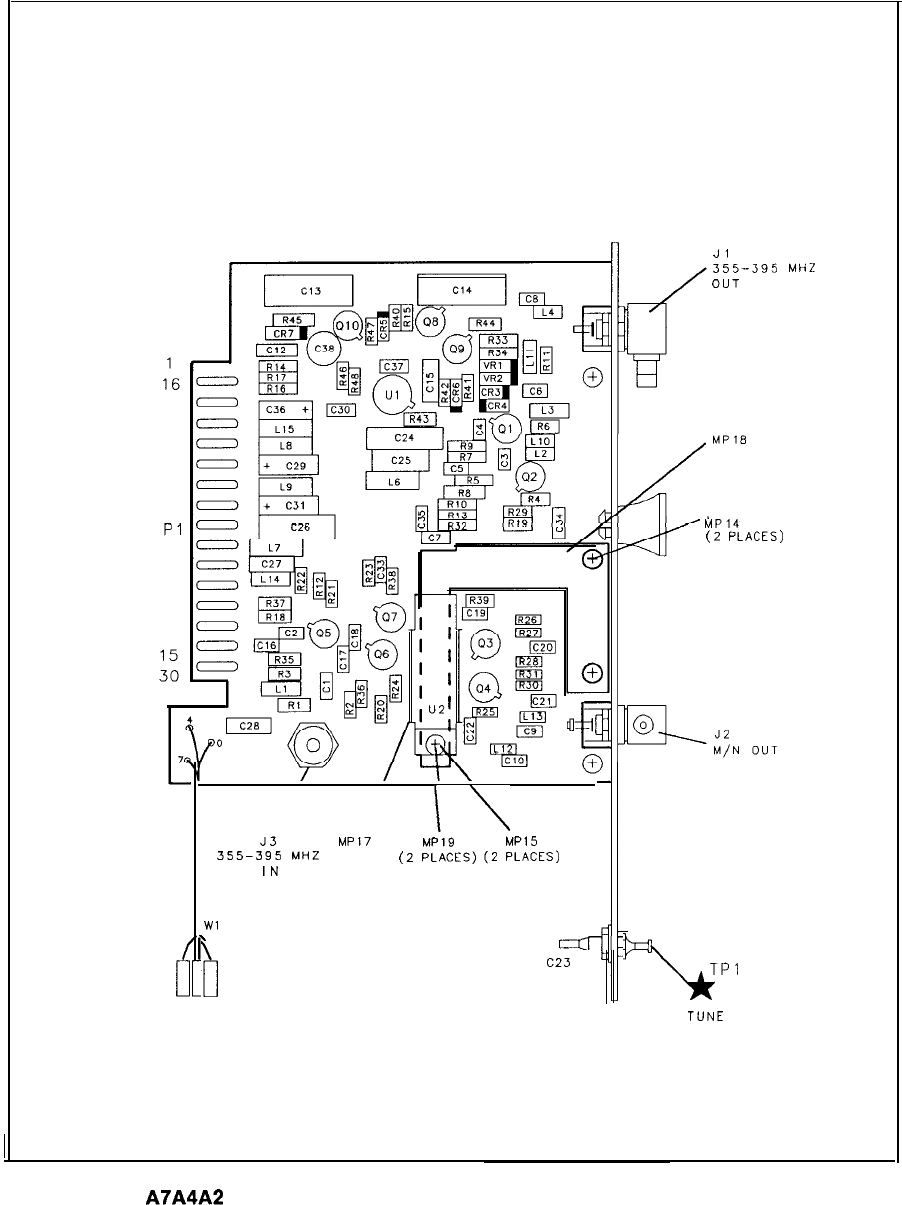
I\
J3
MP17 MP19 MP15
355-395
MHZ
(2
PLACES)(2
PLACES)
IN
Wl
a
C23
Jl
355-395
MHZ
OUT
MP14
(2
PLACES)
%
TPl
TUNE
A7A4A2 M/N Output Board Component Locations, 85660-60266
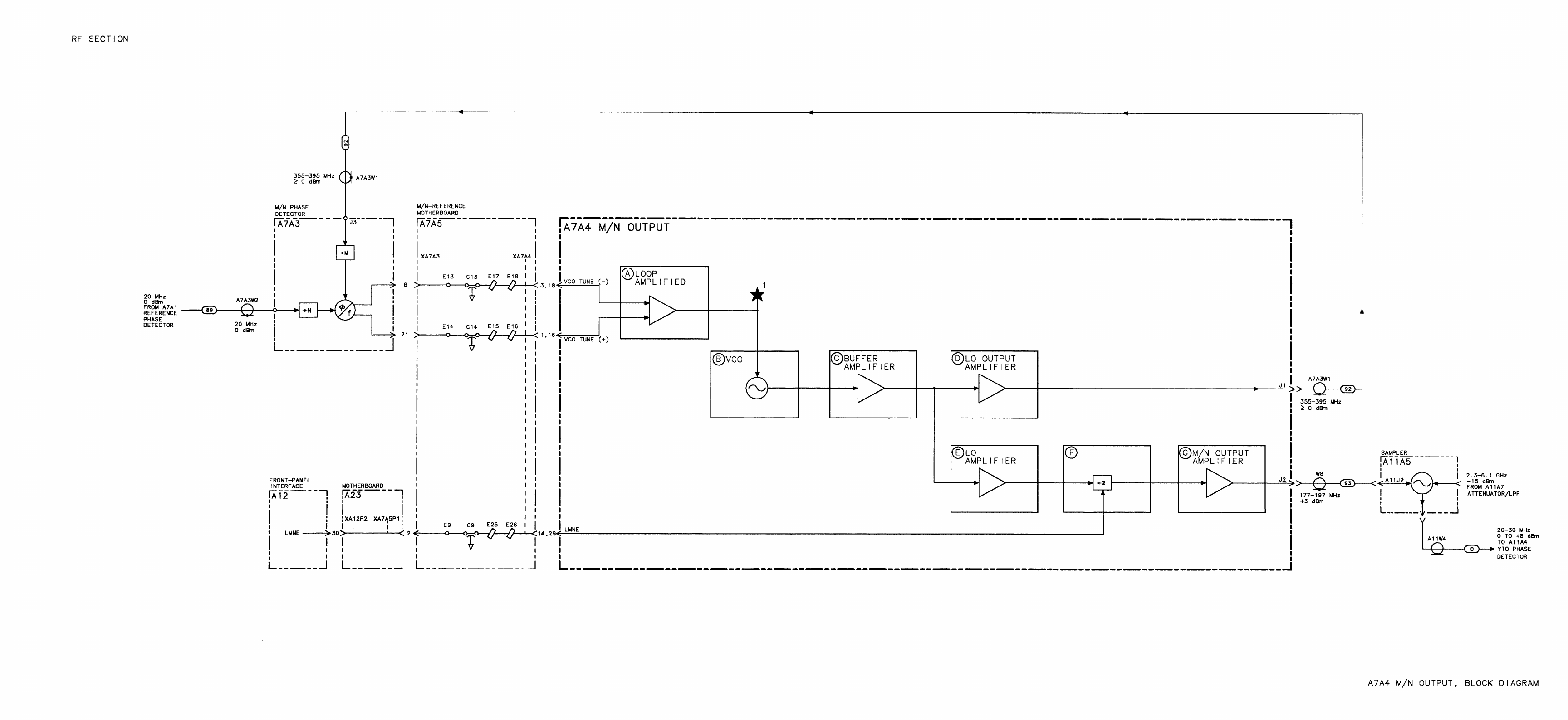
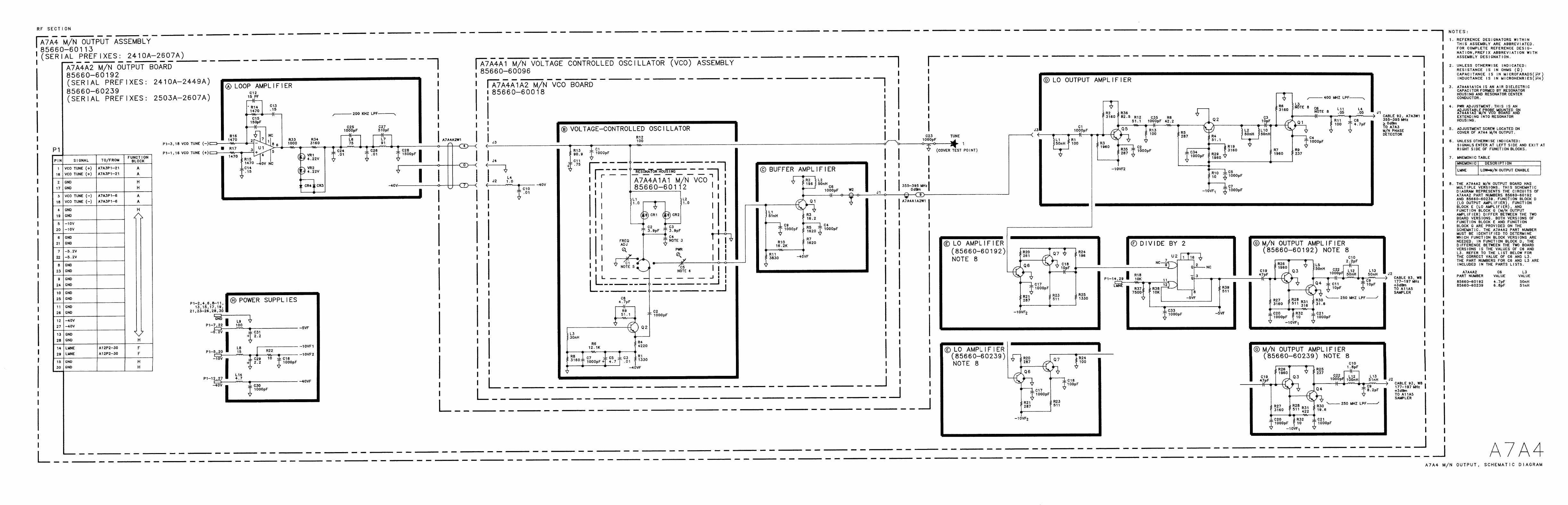
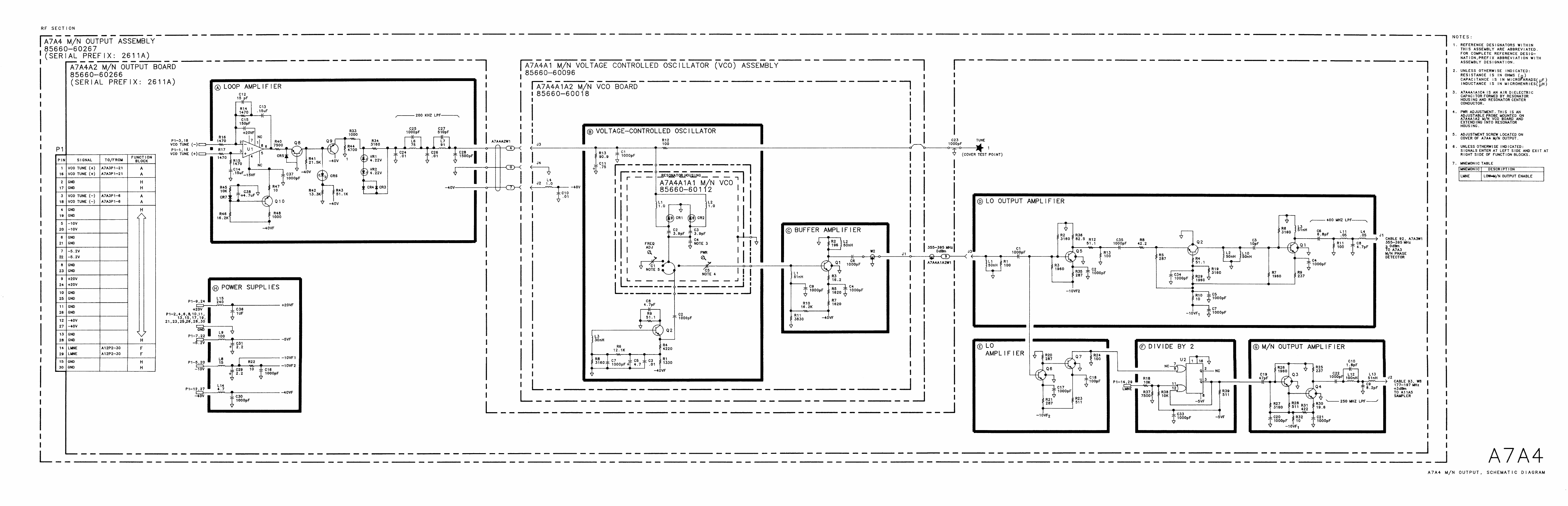
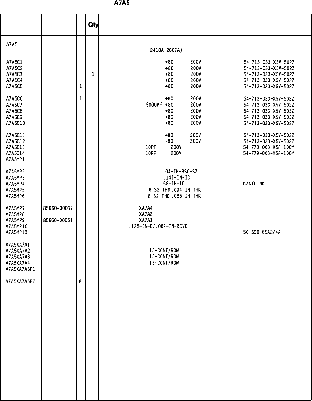
HP Part Number 85660-60020
A7A5
Reference Motherboard
Reference
HP Part C
Mfr
Mfr Part
Designation
Number D
Qty Description Code Number
A7A5
85660-60020 2 1
REFERENCE MOTHERBOARD
28480 85660-60020
(SERIAL PREFIXES:
Z~IOA-2607~)
A7A5Cl
0160-2437 1 1
CAPACITOR-FDTHRU 5000PF
+80
-20%
2OOV 33095 54-713-033-X5V-5022
A7A5C2
0160-2437 1 1
CAPACITOR-FDTHRU 5000PF
+80
-20%
2OOV 33095 54-713-033-X5V-5022
A7A5C3
0160-2437 1
1
CAPACITOR-FDTHRU 5000PF
+80
-20%
2OOV 33095 54-713-033-X5V-5022
A7A5C4
0160-2437 1 1
CAPACITOR-FDTHRU 5000PF
+80
-20%
2OOV 33095 54-713-033-X5V-5022
A7A5C5
0160-2437
1
1
CAPACITOR-FDTHRU 5000PF
+80
-20%
2OOV 33095 54-713-033-X5V-5022
A7A5C6
0160-2437
1
1
CAPACITOR-FDTHRU 5000PF
+80
-20%
2OOV 33095 54-713-033-X5V-5022
A7A5C7
0160-2437 1 1
CAPACITOR-FDTHRU
SOOOPF
+80
-20%
2OOV 33095 54-713-033-X5V-5022
A7A5C6
0160-2437 1 1
CAPACITOR-FDTHRU 5000PF
+60
-20%
2OOV 33095 54-713-033-X5V-5022
A7A5C9
0160-2437 1 1
CAPACITOR-FDTHRU 5000PF
+80
-20%
2OOV 33095 54-713-033-X5V-5022
A7A5ClO
0160-2437 1 1
CAPACITOR-FDTHRU 5000PF
+80
-20%
2OOV 33095 54-713-033-X5V-5022
A7A5Cll 0160-2437
1 1
CAPACITOR-FDTHRU 5000PF
+80
-20%
2OOV 33095 54-713-033-X5V-5022
A7ASC12
0160-2437 1 1
CAPACITOR-FDTHRU 5000PF
+80
-20%
2OOV 33095 54-713-033-X5V-5022
A7A5C13
0160-6211 7 1
CAPACITOR-FDTHRU
1OPF
20%
2OOV
CER
33095 54-779-003-X5F-100M
A7A5C14
0160-6211 7 1
CAPACITOR-FDTHRU
1OPF
20%
2OOV
CER
33095 54-779-003-X5F-100M
A7A5MPl NOT ASSIGNED
A7A5MP2
0360-0124 3 5
CONNECTOR-SGL CONT PIN
.04-IN-BSC-SZ
RND
97300
A7A5MP3
2190-0007 2 2
WASHER-LK INTL T NO. 6
.141-IN-ID 78189 1906-00-00-2580
A7A5MP4
2190-0087 8
12 WASHER-LK HLCL NO. 8
.168-IN-ID 78553 KANTLINK
A7A5MP5
2420-0003 7 2
NUT-HEX-OBL-CHAM
6-32-THD
.094-IN-THK 80120
A7A5MP6
2580-0002 4
12 NUT-HEX-DBL-CHAM
8-32-THD
.085-IN-THK 80120
A7A5MP7 85660-00037
5 1
INSULATOR FOR
XA7A4 28480 85660-00037
A7A5MP8
85660-00050 2 1
INSULATOR FOR
XA7A2 28480 85660-00050
A7A5MP9 85660-00051
3 1
INSULATOR FOR
XA7Al 28480 85660-00051
A7A5MPlO
0890-0983 5 1
TUBING-HS
.125-IN-D/.062-IN-RCVD 06090 VERSAFIT-l/8-BLK
A7A5MP18
9170-0029 3
12 CORE-SHIELDING BEAD
02114 56-590-65A2/4A
A7A5XA7Al
1251-4423 3 1
CONNECTOR-PC EDGE 26742 190-275-01
A7A5XA7A2
1251-4174 1 1
CONNECTOR-PC EDGE
15-CONT/ROW
l-ROW
26742
A7A5XA7A3
1251-2035 9 1
CONNECTOR-PC EDGE
15-CONT/ROW
Z-ROWS
26742 220-624-03
A7A5XA7A4
1251-5020 8 1
CONNECTOR-PC EDGE
15-CONT/ROW
l-ROW
26742 190-282-01
A7A5XA7A5Pl
5060-0112 8 1
CONNECTOR, 15-CONT DIP 28480 5060-0112
A7A5XA7A5P2
5060-0112
8
1
CONNECTOR, 15-CONT DIP 28480 5060-0112
*Indicates factory-selected value
85660-60020 Parts List
Page 1 of 1
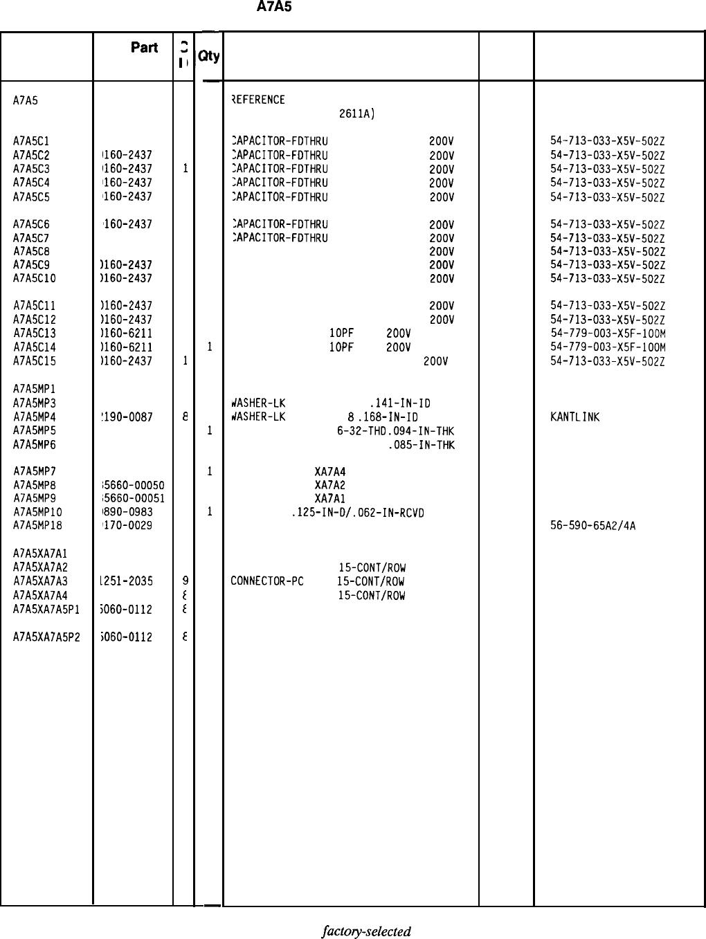
HP Part Number 85660-60265
A7A5
Reference Motherboard
Reference
HP
Part
Designation Number
A7A5
15660-60265
A7A5Cl
1160-2437
A7A5C2
1160-2437
A7A5C3
1160-2437
A7A5C4
1160-2437
A7A5C5
1160-2437
A7A5C6
'160-2437
A7A5C7 160-2437
A7A5CB
1160-2437
A7A5C9
1160-2437
A7A5ClO
1160-2437
A7A5Cll
A7A5C12
A7A5C13
A7ASC14
A7A5C15
1160-2437
1160-2437
1160-6211
)160-6211
)160-2437
A7A5MPl
A7A5MP3
A7A5MP4
A7A5MP5
A7A5MP6
1190-0007
1190-0087
1420-0003
1580-0002
A7A5MP7
15660-00037
A7A5MPB
15660-00050
A7A5MP9
;5660-00051
A7A5MPlO
1890-0983
A7A5MPlB
~170-0029
A7A5XA7Al 251-4423
A7A5XA7A2 251-4174
A7A5XA7A3 ,251-2035
A7A5XA7A4 1251-5020
A7A5XA7A5Pl
iO60-0112
A7A5XA7A5P2
iO60-0112
2
3
2
1
1
1
1
1
1
1
I
1
1
I
I
7
7
1
2
8
7
4
5
2
3
5
3
3
1
,o
E
E
E
-
JtY
-
1
1
1
1
1
1
1
1
1
1
1
1
1
1
1
1
1
1
1
1
1
1
1
1
1
1
1
1
1
1
1
-
Description
?EFERENCE
MOTHERBOARD
(SERIAL PREFIXES:
2611~)
28480 85660-60020
:APACITOR-FDTHRU
5000PF +BO -20%
2OOV 33095 54-713-033-X5V-5022
:APACITOR-FDTHRU
5000PF +BO -20%
2OOV 33095 54-713-033-X5V-5022
:APACITOR-FDTHRU
5000PF +BO -20%
2OOV 33095 54-713-033-X5V-5022
:APACITOR-FDTHRU
5000PF +BO -20%
2OOV 33095 54-713-033-X5V-5022
:APACITOR-FDTHRU
5000PF
+BO -20%
2OOV 33095 54-713-033-X5V-5022
:APACITOR-FDTHRU
5000PF +BO -20%
2OOV 33095 54-713-033-X5V-5022
:APACITOR-FDTHRU
5000PF +BO -20%
2OOV 33095 54-713-033-X5V-5022
CAPACITOR-FDTHRU 5000PF +BO -20%
2OOV 33095 54-713-033-X5V-5022
CAPACITOR-FDTHRU 5000PF +BO -20%
2OOV 33095 54-713-033-X5V-5022
CAPACITOR-FDTHRU 5000PF +BO -20%
2OOV 33095 54-713-033-X5V-5022
CAPACITOR-FDTHRU 5000PF +BO -20%
2OOV 33095 54-713-033-X5V-5022
CAPACITOR-FDTHRU 5000PF +BO -20%
2OOV 33095 54-713-033-X5V-5022
CAPACITOR-FDTHRU
1OPF
20%
2OOV
CER
33095 54-779-003-X5F-100M
CAPACITOR-FDTHRU
1OPF
20%
2OOV
CER
33095 54-779-003-X5F-100M
CAPACITOR-FDTHRU 500PF +BO -20%
2OOV 33095 54-713-033-x5v-5022
NOT ASSIGNED
VIASHER-LK
INTL T NO. 6
.141-IN-ID
rlASHER-LK
HLCL NO.
8
.168-IN-ID
NUT-HEX-DBL-CHAM
6-32-THD
.094-IN-THK
NUT-HEX-DBL-CHAM B-32-THD
.085-IN-THK
78189
78553
80120
80120
1906-00-00-2580
KANTLINK
INSULATOR FOR
XA7A4 28480 85660-00037
INSULATOR FOR
XA7A2 28480 85660-00050
INSULATOR FOR
XA7Al 28480 85660-00051
TUBING-HS
.125-IN-D/.062-IN-RCVD 06090 VERSAFIT-l/B-BLK
:ORE-SHIELDING BEAD 02114 56-590-65A2/4A
:ONNECTOR-PC EDGE 26742
:ONNECTOR-PC EDGE
15-CONT/ROW
l-ROW
26742
LONNECTOR-PC
EDGE
15-CONTIROW
Z-ROWS
26742
CONNECTOR-PC EDGE
15-CONT/ROW
I-ROW
26742
CONNECTOR, 15-CONT DIP 28480
190-275-01
220-624-03
190-282-01
5060-0112
CONNECTOR, 15-CONT DIP 28480 5060-0112
*Indicates factory-selected value
Mfr
Mfr Part
Code Number
85660-60265 Parts List
Page 1 of 1
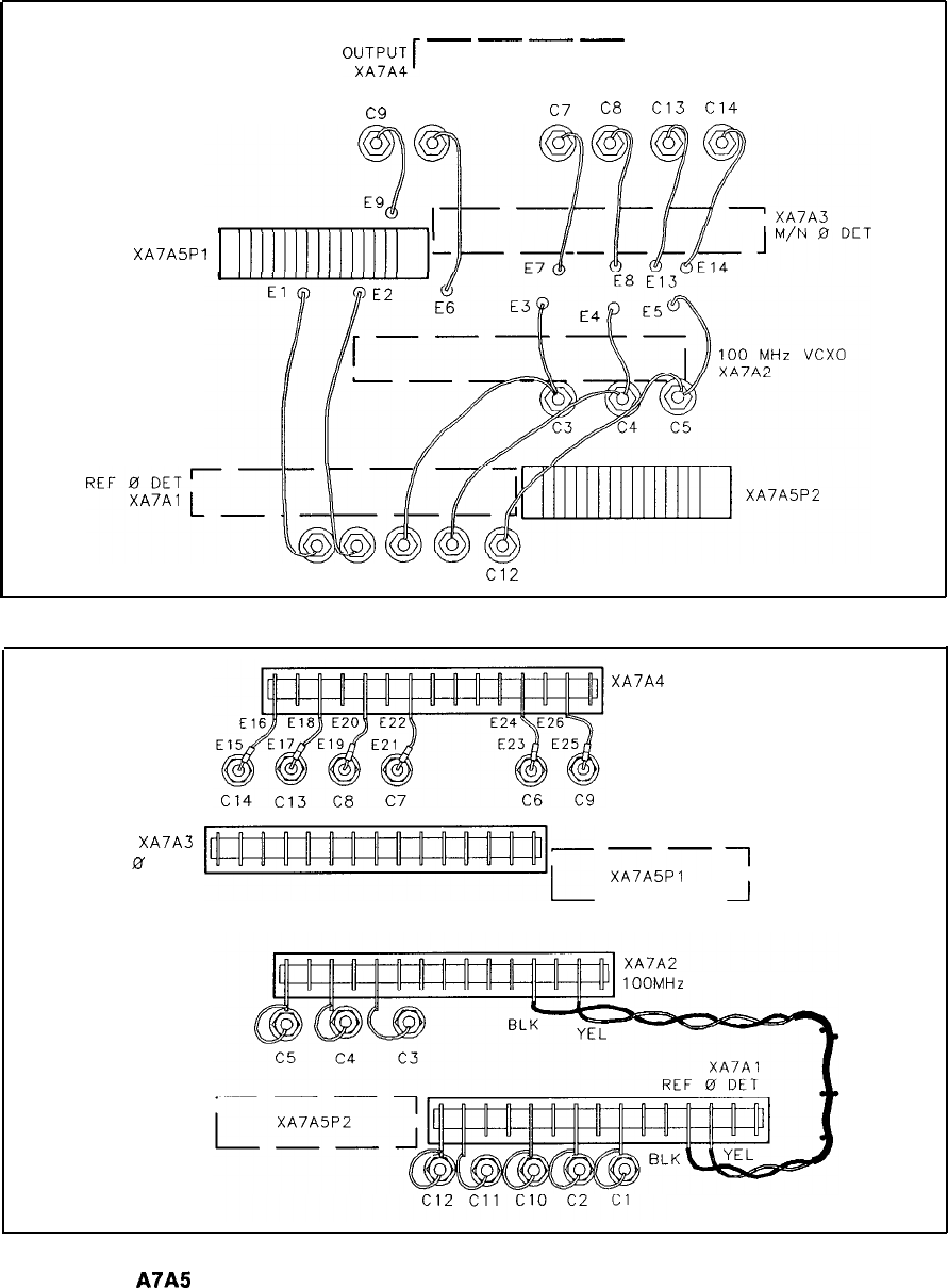
M/N
O;;‘,W[
-
-
-
-
-1
----
-I
c9
C6
c7
C8
Cl3
Cl4
XA7A5P
1
Cl c2 Cl0 Cl1
Cl2
Circuit Side
XA7A4
M/N OUTPUT
M/N
0’
DET
XA7A3
rc
XA7A5P1
1
--
1OOMHz
VCXO
Component Side
A7A5
Reference Motherboard Component Locations, 85660-20020
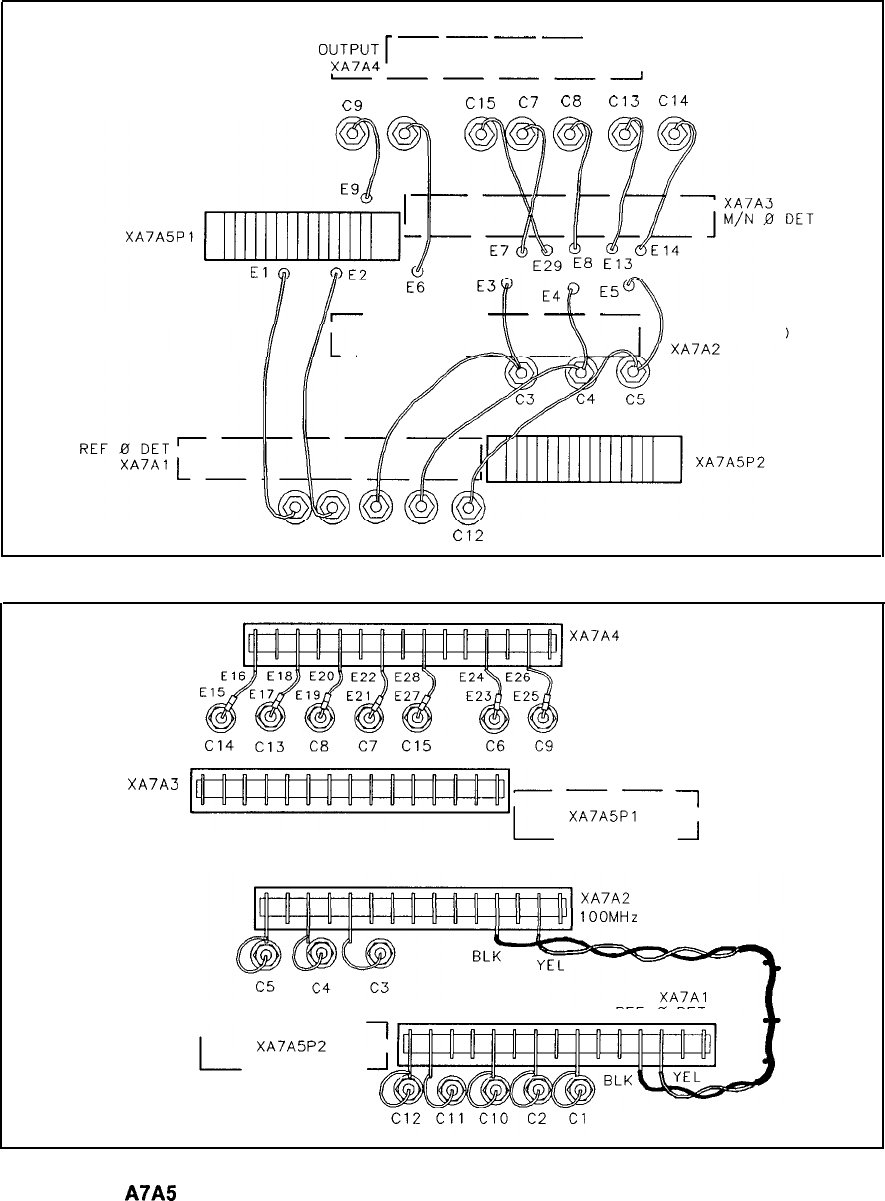
M/N
““,;‘,“A;[
-
-
-
-
-1
I----I
C9
C6
c15
c7
Ct3
Cl3
Cl4
-- 100 MHz VCXO
--
Cl c2 Cl0 Cl1
Cl2
Circuit Side
XA7A4
M/N OUTPUT
M/N 0 DET
XA7A3
>r
XA7A5r
1
--
1OOMHz
VCXO
REF 0 DET
---
--
Component Side
A7A5
Reference Motherboard Component Locations, 85660-60265
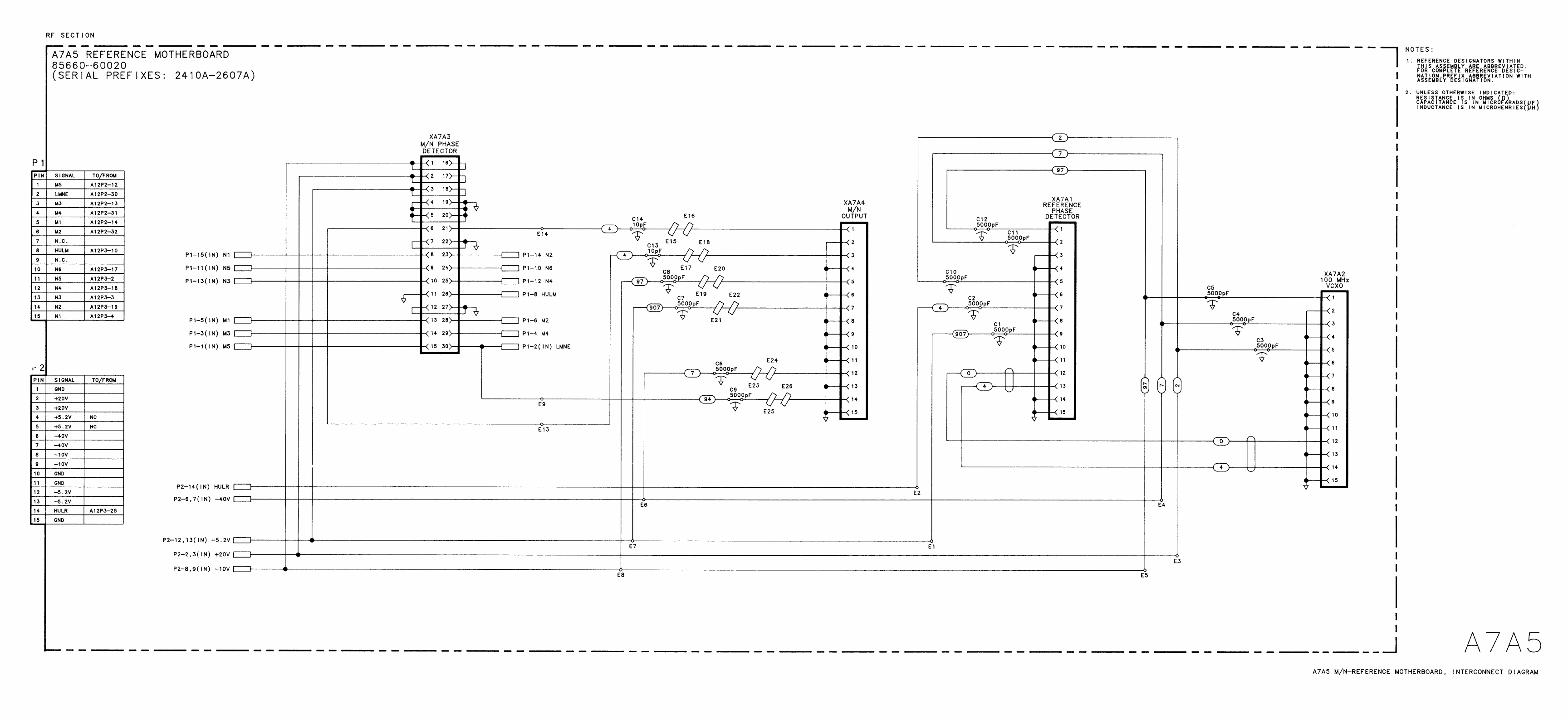
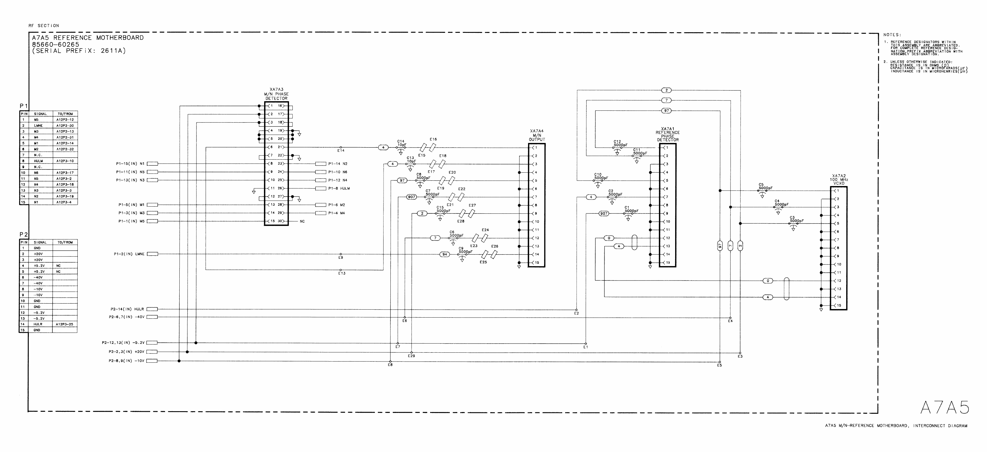
A8/A9
A8 Rectifier, Circuit Description
Power is supplied to the instrument through the A9 Power Line Module, which contains
the line voltage selector, to the primary of transformer
Tl.
Three bridge rectifiers and one
center-tapped secondary provide the rectified outputs.
Diodes CR1 through CR4 form a bridge rectifier that provides approximately 55 V for the
-40 V supply, part of the A18 Negative Regulator. CR5 through CR8 form a bridge rectifier
that provides about 20 V for the -10 V supply and the -5.2 V supply, also part of the Al8
Negative Regulator.
Diodes CR9 through CR12 form a bridge rectifier that provides approximately 30 V for the
i-22 V supply, part of the A8 Rectifier, and also the i-20 V and i-12 V supplies, part of the
Al7 Positive Regulator. Diodes CR13 and CR14 form a full-wave rectifier that provides about
12 V for the
i-5.2
V supply, part of the Al7 Positive Regulator.
The
+22
V (STANDBY) supply is an 18 V three-terminal regulator
Ul
which has its common
terminal biased at
+4
V by
Rl,
DSl,
and R2.
DSl
is an LED indicator that indicates the
presence of
+22
V.
VRl
and CR16 form a crowbar circuit for overvoltage protection. Fuse
Fl
provides overcurrent protection. The regulator
Ul
is also internally protected against short
circuits on its output. The
+22
V supply is on whenever the instrument is connected to an ac
line outlet.
The instrument is also protected against line overvoltages by an input crowbar circuit
consisting of VR2 and CR18. This crowbar causes the line fuse to blow if an overvoltage
condition occurs on the line.
Filter capacitors and bleeder resistors for all the switched power supplies are located on the
A23 Motherboard. The filter capacitors for the
+22
V (STANDBY) supply are A8C6 and
A6AlO C8. The location of fuses in the RF Section is shown in Figure 1.
A8JA9
1
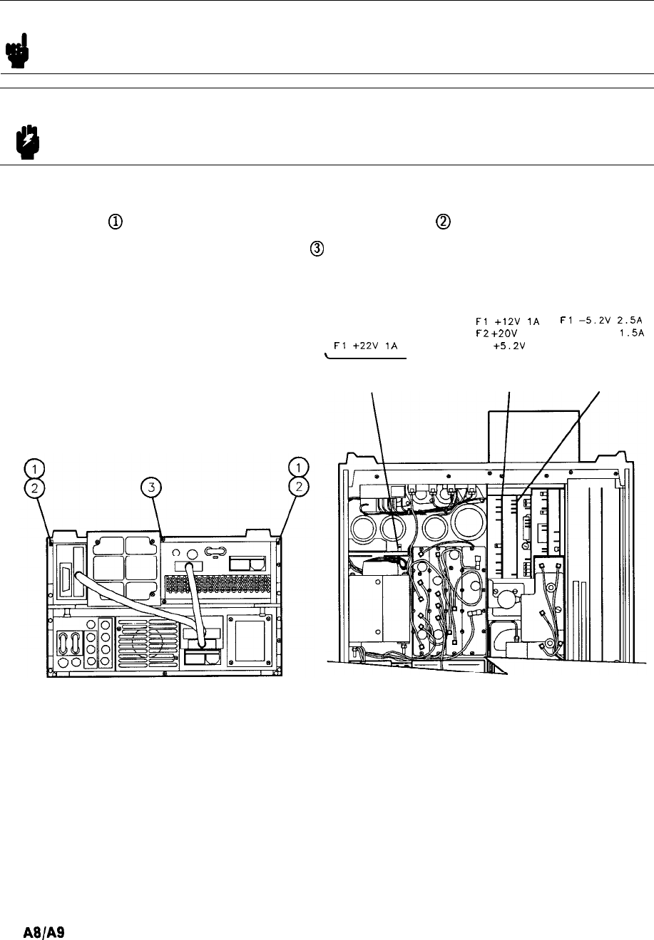
RF Section Internal Fuse Replacement
Note
d
For location of hardware and cables referred to in this procedure, see Figure 1.
Warning
Remove ac line cord from both instruments before proceeding with this
9
procedure.
1. Position instrument upside-down as shown in view A.
2. Remove feet
@
from rear of RF Section by removing screws
@
show in view A.
3. Remove bottom cover by loosening screw
@
and pulling cover toward rear of instrument.
4. Location of fuses is shown in view B.
Fl
+22V
1A
L,
,
A8
RECTIFIER
Fl
+12V
1A
Fl
-5.2V
2.5A
F2
+2OV
3A F2 -40V
1.5A
F3
+5.2V
6A F3 -lOV 5A
--
Al7 Al8
POS REG NEG REG
VIEW A VIEW B
Figure 1. Internal Fuse Replacement
2
A8/A9
Transformer Replacement
Note For location of hardware and cables referred to in the procedure, see Figure 2.
1. Remove ac line cords, IF-Display Section, and RF Section bottom cover, top cover, and
right side cover.
2. Remove front panel. (See A5 Front Panel section for A5 Front Panel Removal procedure.)
3. Remove A6 RF Module. (See A6 section for A6 RF Module removal procedure.)
4. Remove seven screws
Q).
5. To avoid losing washers and nuts from screws
@
into the interior of the RF Section, it is
recommended to do the following:
a. Set the RF Section on its right side with transformer on bottom.
b. Set the RF Section partially off the table so that a screwdriver can reach the remaining
four mounting screws.
c. For each screw
@
hold nut with needlenose pliers while removing screw. Mounting
screws on motherboard side can be accessed through small opening @ on motherboard.
d. When installing new transformer, set RF Section on its side as described in steps 5a and
5b. For each mounting screw, align nut and washers with hole, and while holding nut
with needlenose pliers, tighten screw.
e. Tighten remaining seven screws
(iJ
to secure Transformer to RF Section.
6. Replace RF Module.
7. Replace front panel.
8. Replace covers, attach IF-Display section to RF Section, and replace ac line cords.
AalA
3
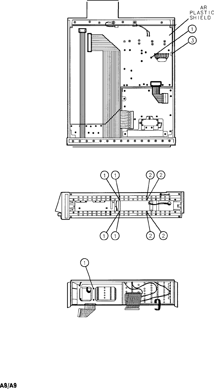
CLE
I
I
U
(2 PLACES)
Figure 2. Transformer Replacement
4
A8/A9

Power
Transistor Replacement (Rear
RF
Cover
Removal)
Note For location of hardware and cables referred to in this procedure, see Figure 3.
With ac line cords and RF Section bottom cover removed, proceed as follows:
1. Loosen rear cover by removing five screws
Q).
2. Power Transistors can now be easily replaced.
VIEW A VIEW
B
Figure 3. Power Transistor Replacement
A8fA9
5
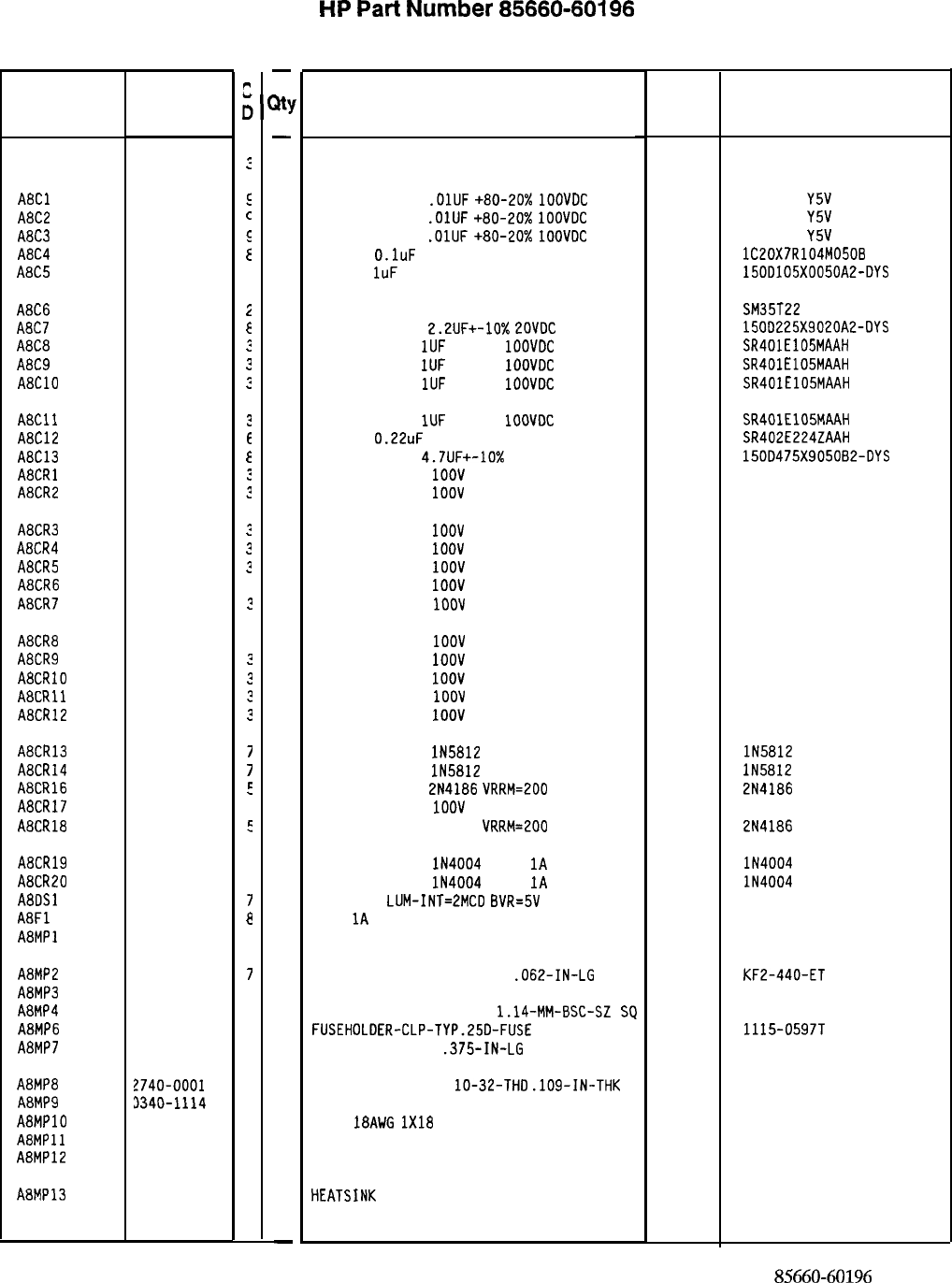
Reference
Designation
A8
ABC1
A8C2
A8C3
A8C4
A8C5
A8C6
A8C7
A8C8
A8C9
A8ClO
A8Cll
A8C12
A8C13
A8CRl
A8CR2
A8CR3
A8CR4
A8CR5
A8CR6
A8CR7
A8CR8
A8CR9
A8CRlO
A8CRll
A8CR12
A8CR13
A8CR14
A8CR16
A8CR17
A8CR18
A8CR19
A8CR20
A8DSl
A8Fl
A8MPl
A8MP2
A8MP3
A8MP4
A8MP6
A8MP7
A8MP8
A8MP9
A8MPlO
A8MPll
A8MP12
A8MP13
HP Part
Number
c
c
85660-60196
:
0160-2055
E
0160-2055
c
0160-2055
E
0160-4084
E
0180-0230
C
0180-3476
2
0180-0197
E
0160-4005
?
0160-4005
2
0160-4005
c
0160-4005
?
0160-3638
E
0180-1731
E
1901-0662
:
1901-0662
?
1901-0662
?
1901-0662
?
1901-0662
?
1901-0662
3
1901-0662
?
1901-0662
3
1901-0662
?
1901-0662
?
1901-0662
?
1901-0662
?
1901-0765
7
1901-0765
7
1884-0018
E
1901-0662
3
1884-0018
5
1901-0743
1
1901-0743
1
1990-0487
7
2110-0001
8
0590-0519
7
1200-0081
4
1251-0600
C
2110-0726
4
2200-0107
6
?740-0001
3
3340-1114
1
3151-0011
2
5000-9043
6
5040-6843
2
36701-00018
4
-
B!
-
1
1
1
1
1
1
1
1
1
1
1
1
1
1
1
1
1
1
1
1
1
1
1
1
1
1
1
1
1
1
1
1
1
1
1
2
2
1
2
2
2
1
1
1
1
1
-
HP
Part
Number 85660-60196
A8 Rectifier
Description Mfr
Mfr Part
Code Number
RECTIFIER BOARD ASSEMBLY 28480 85660-60196
CAPACITOR-FXD
.OlUF
+80-20%
1OOVDC
CER
CAPACITOR-FXD
.OlUF
+80-20%
1OOVDC
CER
CAPACITOR-FXD
.OlUF
+80-20%
1OOVDC
CER
CAP-FXD
O.luF
50 V
CAP-FXD
1uF
50 V TA
56289
56289
805-504
Y5V
1032
805-504
Y5V
1032
805-504
Y5V
1032
lC20X7R104M0508
150D105X0050A2-DYS
CAP-FXD 22uF 35 V AL-ELCTLT
CAPACITOR-FXD
2.2UF+-10%
LOVDC
TA
CAPACITOR-FXD
1UF
+-20%
1OOVDC
CER
CAPACITOR-FXD
1UF
+-20%
1OOVDC
CER
CAPACITOR-FXD
1UF
+-20%
1OOVDC
CER
56289
04222
04222
04222
SM35T22
1500225X9020A2-OYS
SR401E105MAAH
SR401E105MAAH
SR401E105MAAH
CAPACITOR-FXD
1UF
+-20%
1OOVDC
CER
04222 SR401E105MAAH
CAP-FXD
0.22uF
200 V
04222 SR402E224ZAAH
CAPACITOR-FXD 4.7UF+-10% 5OVDC TA
56289 150D475X905082-DYS
DIODE-PWR RECT
1OOV
6A
04713 MR751
DIODE-PWR RECT
1OOV
6A
04713 MR751
DIODE-PWR RECT
1OOV
6A
04713 MR751
DIODE-PWR RECT
1OOV
6A
04713 MR751
DIODE-PWR RECT
1OOV
6A
04713 MR751
DIODE-PWR RECT
1OOV
6A
04713 MR751
DIODE-PWR RECT
1OOV
6A
04713
MR751
DIODE-PWR RECT
1OOV
6A
04713 MR751
DIODE-PWR RECT
1OOV
6A
04713 MR751
DIODE-PWR RECT
1OOV
6A
04713 MR751
DIODE-PWR RECT
1OOV
6A
04713 MRJ51
DIODE-PWR RECT
1OOV
6A
04713 MR751
DIODE-PWR RECT
lN5812
50V 20A 35NS DO-4
30043 lN5812
DIODE-PWR RECT
lN5812
50V 20A 35NS DO-4
30043 lN5812
THYRISTOR-SCR
2N4186
VRRM=200 04713 2N4186
DIODE-PWR RECT
1OOV
6A
04713 MR751
THYRISTOR-SCR 214186 VRRM=200 04713 2N4186
DIODE-PWR RECT
lN4004
400V
1A
DO-41
DIODE-PWR RECT
IN4004
400V
1A
DO-41
LED-LAMP
LUM-INT=2MCD
BVR=5V
FUSE
1A
250V NTD FE UL
NOT ASSIGNED
71744 lN4004
71744 lN4004
28480 HLMP-1401
75915 312 001
THREADED INSERT-NUT 4-40
.062-IN-LG
STL
46384
INSULATOR-FLG-BSHG NYLON 26365
CONNECTOR-SGL CONT PIN
1.14-MM-BSC-SZ
SQ
27264
FUSEHOLDER-CLP-TYP.25D-FUSE 13060
SCREW-MACH 4-40
.375-IN-LG
PAN-HD-POZI
77250
KF2-440-ET
974 307
16-06-0034
1115-0597T
NUT-HEX-DBL-CHAM
lo-32-THD
.109-IN-THK 73734
INSULATOR-XSTR THRM-CNDCT TO-3 55285
WIRE
18AWG
1X18
92194
PIN
28480
EXTRACTOR 28480
HEATSINK
RECTIFIER
28480
K-4-05
296
5000-9043
5040-6843
86701-0018
*Indicates factory-selected value
85660-60196 Parts List
Page 1 of 2
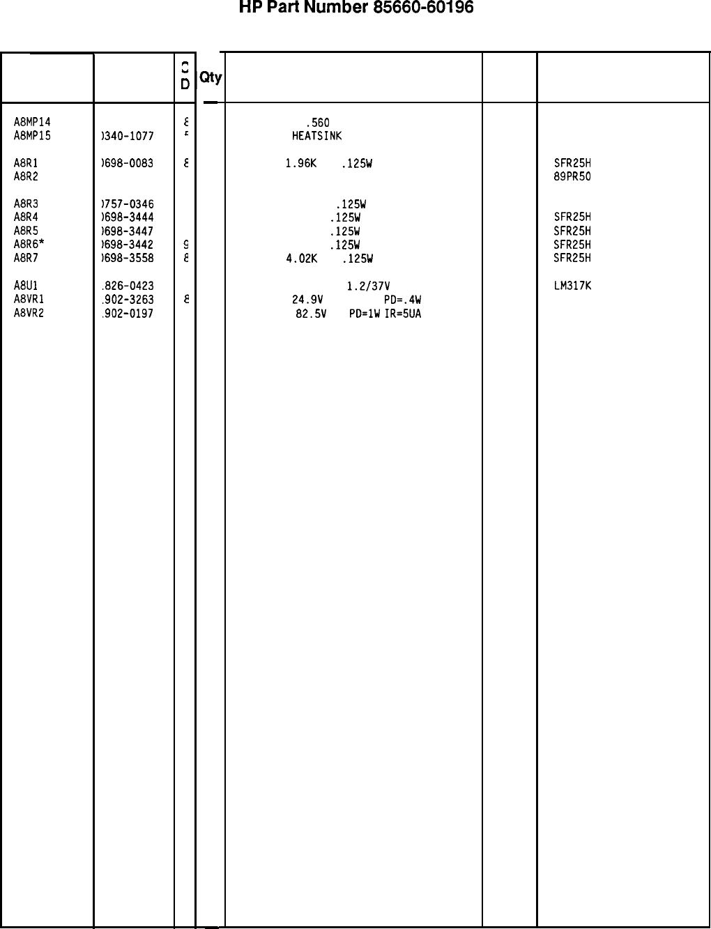
Reference HP Part
Designation Number
A8MP14
1050-0876
A8MP15
1340-1077
A8Rl
A8R2
1698-0083
!lOO-3052
A8R3
A8R4
A8R5
A8R6*
A8R7
1757-0346
)698-3444
1698-3447
)698-3442
1698-3558
A8Ul
.826-0423
A8VRl
.902-3263
A8VR2
.902-0197
c
0
E
c
E
4
2
1
4
9
e
4
e
1
21
-
2
2
1
1
1
1
1
1
1
1
1
1
-
HP
Part
Number 85660-60196
A8 Rectifier
Description
WASHER MICA
.560
IN-ID
INSULATOR
HEATSINK
660
86928 5624-53-5
RESISTOR
1.96K
1%
.125W
TF TC=O+-100
19701
SFR25H
RESISTOR-TRMR 50 10% TKF SIDE-ADJ 17-TRN 73138 89PR50
RESISTOR 10 +-1%
.125W
TF TC=O+-100
91637 CMF-55-1, T-l
RESISTOR 316 1%
.125W
TF TC=O+-100
19701
SFR25H
RESISTOR 422 1%
.125W
TF TC=O+-100
19701
SFR25H
RESISTOR 237 1%
.125W
TF TC=O+-100
19701
SFR25H
RESISTOR
4.02K
1%
.125W
TF TC=O+-100
19701
SFR25H
IC V RGLTR-ADJ-POS
1.2/37V
TO-3 PKG
27014
DIODE-ZNR
24.9V
2% DO-35
PD=.4W 04713
DIODE-ZNR
82.5V
5%
PD=lW
IR=5UA 04713
LM317K
85660-60196 Parts List
Page 2 of 2
*Indicates facto y-selected value
Mfr
Mfr Part
Code Number
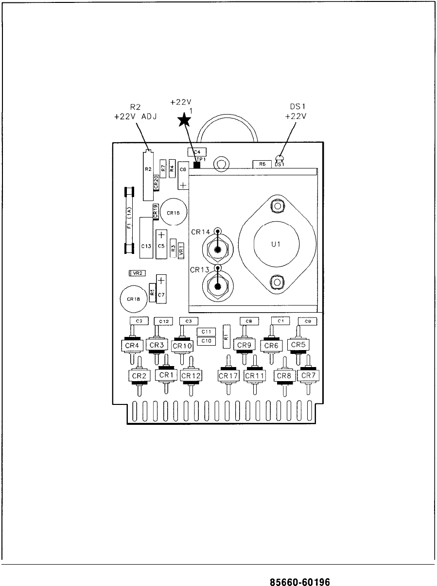
1
19 PI 18
36
A6 Rectifier Component Locations, 65660-60196
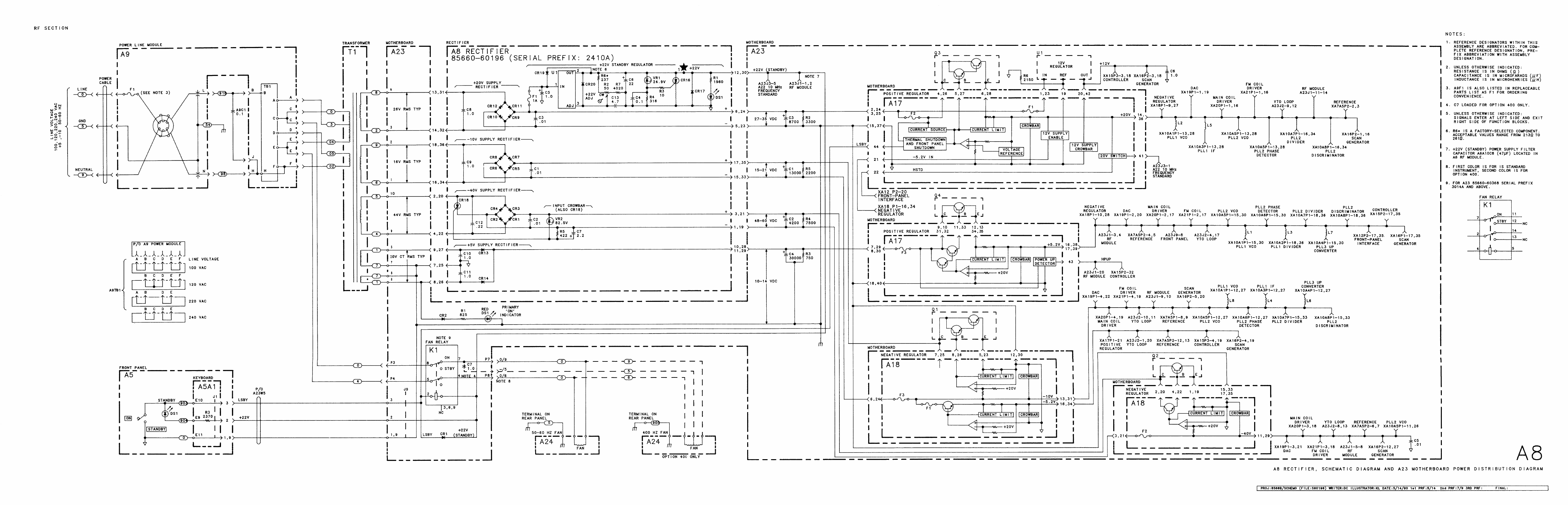
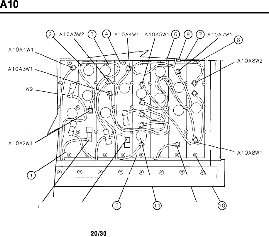
A10
AlOAlWl
AIOA
’
AlOA8Wl
I\\\ I
/
w5 w7 W4
1
2
AlOA8W2
(13 PLACES) (43 PLACES)
Figure 1. A10
20/30
Synthesizer, Parts Identification (1 of 3)
A10 1
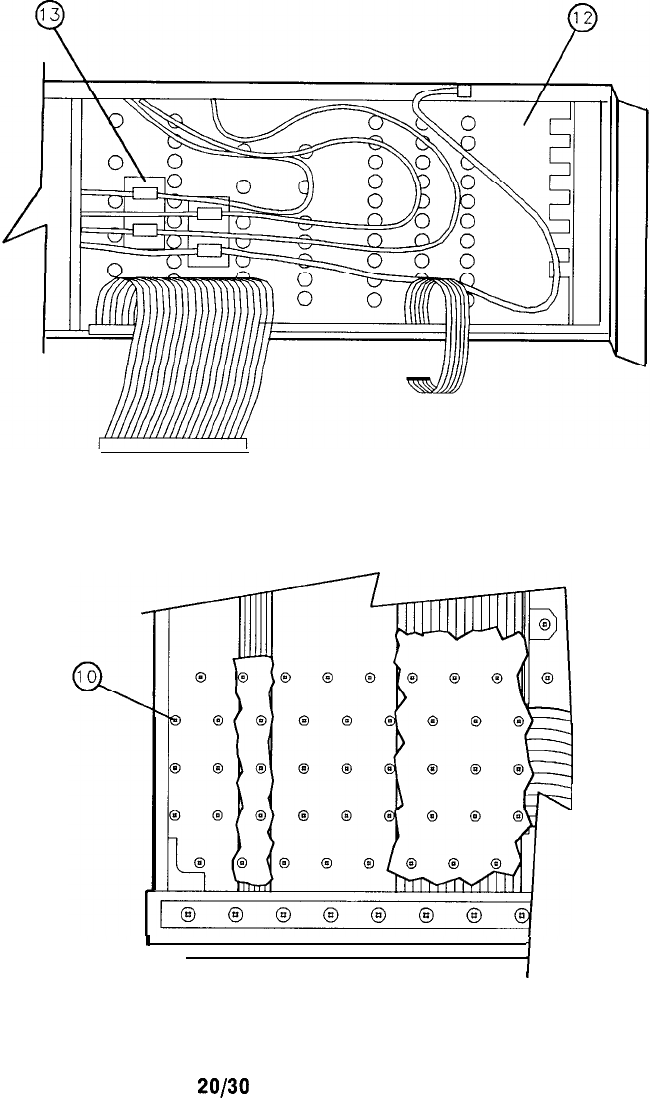
(2 PLACES)
(43 PLACES)
I
I
Figure 1. A10
20/30
Synthesizer, Parts identification (2 of 3)
2 A10
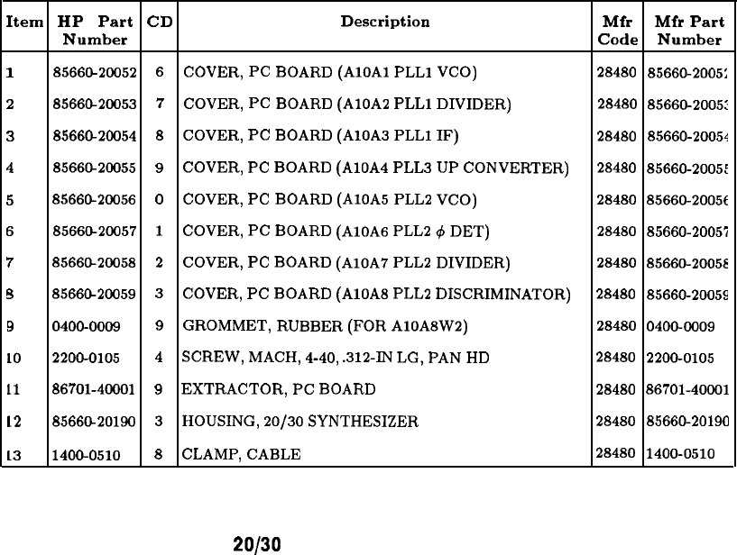
Item HP Part
CD
Description Mfr Mfr Part
Number Code Number
1
8566626052
6
COVER,
PC
BOARD
(AlOAl
PLLl
VCO)
28480
85660-2005:
2
8566@20053
7
COVER,
PC
BOARD
(AlOA2
PLLl
DIVIDER)
28480
85660-2005:
38566CL20054 8
COVER,
PC
BOARD
(AlOA3
PLLl
IF) 28480 85660-20054
4
8566CL20055
9
COVER,
PC
BOARD
(AlOA4
PLW
UP
CONVERTER)
28480
85660-2005:
5
85660-20056
0
COVER,
PC
BOARD
(AlOA5
PLL2
VCO)
28480 85660-20056
6
85660-20057
1
COVER,
PC
BOARD
(AlOA6
PLL2
,#I
DET)
28480 85660-20057
7
8566&20058
2
COVER,
PC
BOARD
(AlOA7
PLL2
DIVIDER)
28480 85660-20058
s
8566@20059
3
COVER,
PC
BOARD
(AlOA8
PLL2
DISCRIMINATOR)
28480 85660-20059
9
0400-0009
9
GROMMET,
RUBBER
(FOR
AlOASW2)
28480
0400-0009
LO
2200-0105
4
SCREW,
MACH,
4-40,
.312-IN
LG,
PAN
HD 28480 2200-0105
11
86701-46601 9
EXTRACTOR,
PC
BOARD
28480 86701-40001
12
8566CL20190 3
HOUSING,
20/30
SYNTHESIZER
28480 85666-20190
13
1400-0510 8
CLAMP,
CABLE
28480 1400-0510
Figure 1. A10
20/30
Synthesizer, Parts Identification (3 of 3)
A10 3
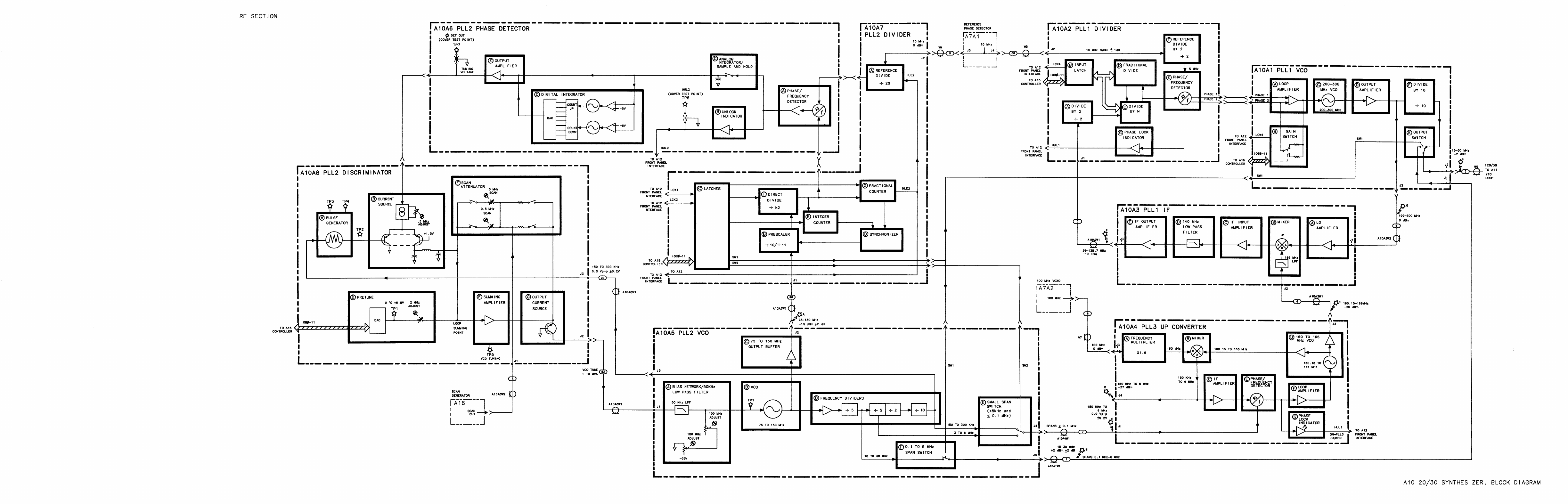
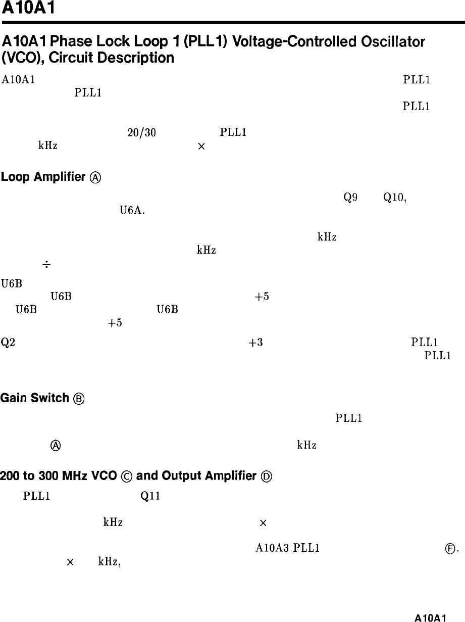
AIOAI
AIOAI
Phase
Lock
Loop
1
(PLLI)
Voltage-Controlled
Oscillator
(VCO),
Circuit
Description
AlOAl
contains the loop amplifier and voltage-controlled oscillator (VCO) for the
PLLl
phase
lock loop. The
PLLl
VCO tunes from 199.9 to 300 MHz (start frequencies of 200.000001
to 300.000000 MHz) for a range of about 4 V to 16 V tuning of the varactor. The
PLLl
VCO drives a counter which divides the frequency by 10. The counter output goes through a
switch and a filter to the
20/30
output. The
PLLl
VCO is turned off in spans greater than
n xl00 kHz but less than or equal to n
x
5 MHz to prevent spurious responses.
Loop
Amplifier
@
The loop amplifier consists of a low-noise differential pair input stage,
Q9
and
&lo,
and
an operational amplifier U6A. Feedback (ac is
)
p
rovided by C34 and R29. The output
of the amplifier goes through a programmable ac voltage divider consisting of R31, R32,
R33, R34, R35 with R36 and C36. The signal is filtered by a 40 kHz low-pass filter which
has two notches tuned to reject the 50 kHz subharmonics created by fractional-n division
(5 MHz
i
100).
U6B
compares the dc varactor tune voltage to about $17.5 V. If the tune voltage goes higher
than this, U6B switches and pulls it down to about
+5
V. Hysteresis in the switching point
of
U6B
provided by R24 keeps U6B from switching back to the original state until the tune
voltage reaches about
+5
V.
Q2
keeps the tune voltage from going below about
+3
V. This is to ensure that the
PLLl
VCO always oscillates and the varactors do not become forward biased in spans where
PLLl
is active.
Gain
Switch
@
U5 latches the four most significant bits of the programming of the
PLLl
fractional-n divider.
These are level translated by U4 which drives four FET switches. By changing the voltage
divider in
@
in this manner, a constant loop bandwidth of 5 kHz is achieved.
200
to
300
MHz
VCO
@
and
Output
Amplifier
@l
The
PLLl
VCO consists of
Qll
which operates in the grounded-base mode. The resonator is
principally CR3, CR4, and L4. Feedback is accomplished with L5, R16, and C17. In spans
greater than n x 100 kHz but less than or equal to n
x
5 MHz, the VCO is turned off by
forward biasing the varactors. Q5 is a common-base buffer amplifier. The output of the VCO
is applied to Q4 where it is amplified and applied to AlOA3
PLLl
IF and the Divide by 10
0.
In spans of n
x
100 kHz, the VCO is tuned as low as 199.000200 MHz.
AlOAl
1
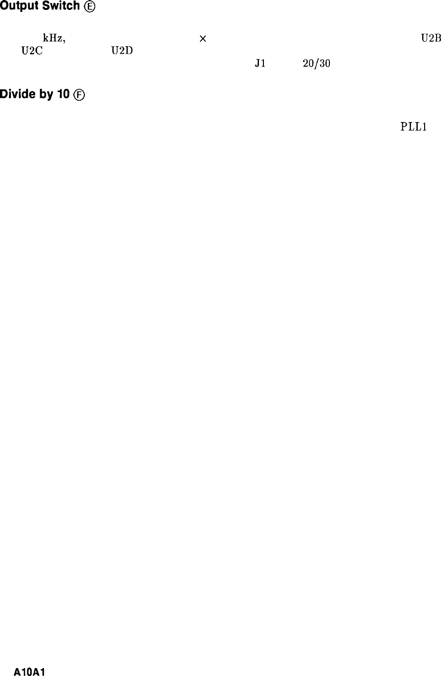
Output
Switch
@
The output switch is U2 which is a quad ECL NOR gate. For frequency spans greater than
n x 100 kHz, but less than or equal to n
x
5 MHz, the switch input to R3 is TTL low.
U2B
and U2C are on while U2D is off. For all other spans, the opposite states exist. This has the
effect of switching either the output of U3 divider or
Jl
to the
20/30
loop output J2.
Divide
by
IO
@
Q3 is a common-emitter amplifier which drives U3 through a high-pass filter. U3 is an ECL
divide by 10 counter which generates the necessary 19.99 MHz to 30 MHz from the
PLLl
vco output.
2
AlOAl
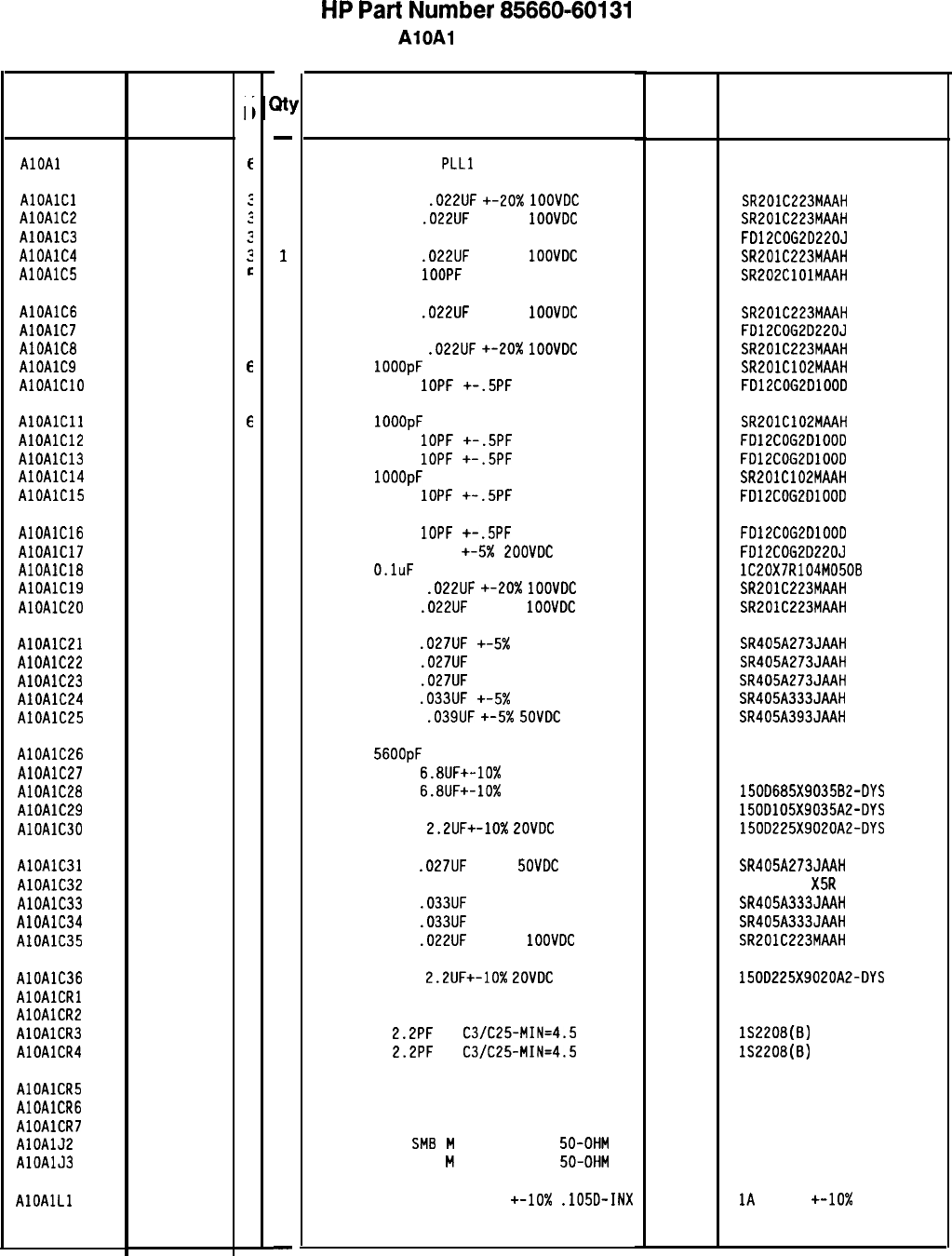
Reference
Designation
HP Part
Number
C
c
AlOAl 85660-60131
f
AlOAlCl 0160-0574
:
AlOAlC2 0160-0574
3
AlOAlC3 0160-3875
3
AlOAlC4 0160-0574
3
AlOAlCS 0160-3877
e
AlOAlC6 0160-0574
3
AlOAlC7 0160-3875
3
AlOAlCB 0160-0574
3
AlOAlC9 0160-3878
e
AlOAlClO 0160-3874
2
AlOAlCll 0160-3878
6
AlOAlCl2 0160-3874
2
AlOAlC13 0160-3874
2
AlOAlC14 0160-3878
6
AlOAlClS 0160-3874
2
AlOAlC16 0160-3874
2
AlOAlC17 0160-3875
3
AlOAlC18 0160-4084
8
AlOAlC19 0160-0574
3
AlOAlC20 0160-0574
3
AlOAlCEl 0160-4953
0
AlOAlC22 0160-4953
0
AlOAlC23 0160-4953
0
AlOAlC24 0160-4951
8
AlOAlC25 0160-4952
9
AlOAlC26 0160-0158
9
AlOAlC27 0180-0116
1
AlOAlC28 0180-0116
1
AlOAlC29 0180-0291
3
AlOAlC30 0180-0197
8
AlOAlC31 0160-4953
0
AlOAlC32 0160-4298
6
AlOAlC33 0160-4951
8
AlOAlC34 0160-4951
8
AlOAlC35 0160-0574
3
AlOAlC36 0180-0197
8
AlOAlCRl 1901-0040
1
AlOAlCRL 1901-0040
1
AlOAlCR3 0122-0085
1
AlOAlCR4 0122-0085
1
AlOAlCR5 1901-0040
1
AlOAlCR6 1901-0040
1
AlOAlCR7 1901-0040
1
AlOAlJ2 1250-2112
1
AlOAlJ3 1250-2112
1
AlOAlLl 9100-2257
6
a!
-
1
1
1
1
1
1
1
1
1
1
1
1
1
1
1
1
1
1
1
1
1
1
1
1
1
1
1
1
1
1
1
1
1
1
1
1
1
1
1
1
1
1
1
1
1
1
1
-
HP
Part
Number 85660-60131
AlOAl
PLL 1 VCO
Description Mfr
Mfr Part
Code Number
BOARD ASSEMBLY,
PLLl
VCO
28480 85660-60131
CAPACITOR-FXD
.022UF
+-20X
1OOVDC
CER
CAPACITOR-FXD
.022UF
+-20%
1OOVDC
CER
CAPACITOR-FXD 22PF +-5% LOOVDC CER 0+-30
CAPACITOR-FXD
.022UF
+-20%
1OOVDC
CER
CAPACITOR-FXD
1OOPF
+-20% LOOVDC CER
04222
04222
04222
04222
SR201C223MAAH
SR201C223MAAH
FD12COG2D220J
SR201C223MAAH
SR202ClOlMAAH
CAPACITOR-FXD
.022UF
+-20%
1OOVDC
CER
CAPACITOR-FXD 22PF +-5% 200VDC CER 0+-30
CAPACITOR-FXD
.022UF
+-20X
1OOVDC
CER
CAP-FXD
1OOOpF
100 V
04222
04222
04222
CAPACITOR-FXD
1OPF
+-.5PF
ZOOVDC CER
SR201C223MAAH
FD12COG2D220J
SR201C223MAAH
SR201ClD2MAAH
FD12COG2DlOOD
CAP-FXD
1OOOpF
100 V
04222
CAPACITOR-FXD
1OPF
+-.5PF
ZOOVDC CER
CAPACITOR-FXD
1OPF
+-.5PF
200VDC CER
CAP-FXD
1OOOpF
100 V
04222
CAPACITOR-FXD
1OPF
+-.5PF
200VDC CER
SR201C102MAAH
FD12COG2DlOOD
FD12COG2DlOOD
SR201C102MAAH
FD12COG2DlOOD
CAPACITOR-FXD
1OPF
+-.5PF
ZOOVDC CER
CAPACITOR-FXD 22PF +-5X
POOVDC
CER 0+-30
CAP-FXD
O.luF
50 V
CAPACITOR-FXD
.022UF
+-20X
1OOVDC
CER
CAPACITOR-FXD
.022UF
+-20%
1OOVDC
CER
56289
04222
04222
FD12COG2DlOOD
FD12COG2D220J
lC20X7R104M050B
SR201C223MAAH
SR201C223MAAH
CAPACITOR-FXD
.027UF
+-5X 50VDC CER
04222 SR405A273JAAH
CAPACITOR-FXD
.027UF
+-5% 50VDC CER
04222 SR405A273JAAH
CAPACITOR-FXD
.027UF
+-5% 50VDC CER
04222
SR405A273JAAH
CAPACITOR-FXD
.033UF
+-5X
50VDC CER
04222 SR405A333JAAH
CAPACITOR-FXD
.039UF
+-5x
SOVDC
CER
04222 SR405A393JAAH
CAP-FXD
56OOpF
200 V POLYE-FL
84411 HEW-238M
CAPACITOR-FXD
6.8UF+-10%
35VDC TA
56289 1500685X903582-DYS
CAPACITOR-FXD
6.8UF+-10%
35VDC TA
56289 150D685X903582-DYS
CAPACITOR-FXD lUF+-10% 35VDC TA
56289 150D105X9035A2-DYS
CAPACITOR-FXD
2.2UF+-10%
LOVDC
TA
56289 150D225X9020A2-DYS
CAPACITOR-FXD
.027UF
+-5%
SOVDC
CER
CAPACITOR-FXD 4700PF +-20% 250VDC CER
CAPACITOR-FXD
.033UF
+-5% 50VDC CER
CAPACITOR-FXD
.033UF
+-5% 50VDC CER
CAPACITOR-FXD
.022UF
+-20%
1OOVDC
CER
04222
04222
04222
04222
SR405A273JAAH
815-250V
X5R
472M
SR405A333JAAH
SR405A333JAAH
SR201C223MAAH
CAPACITOR-FXD
2.2UF+-10%
LOVDC
TA
56289
DIODE-SWITCHING 30V 50MA 2NS DO-35 71468
DIODE-SWITCHING 30V 50MA 2NS DO-35 71468
DIODE-VVC
2.2PF
7%
C3/C25-MIN=4.5 so545
DIODE-VVC
2.2PF
7%
C3/C25-MIN=4.5 so545
150D225X9020A2-DYS
152208(B)
lS2208(B)
DIODE-SWITCHING 30V 50MA 2NS DO-35
71468
DIODE-SWITCHING 30V 50MA 2NS DO-35
71468
DIODE-SWITCHING 30V 50MA 2NS DO-35 71468
CONNECTOR-RF
SM8
M
SGL-HOLE-FR
50-OHM 98291
CONNECTOR-RF SMB
M
SGL-HOLE-FR
50-OHM 98291 051-047-0259-220
051-047-0259-220
INDUCTOR RF-CH-MLD 820NH
+-lo%
.105D-INX 32159
1A
8203M
+-lo%
*Indicates factory-selected value
85660-60131 Parts List
Page 1 of 4
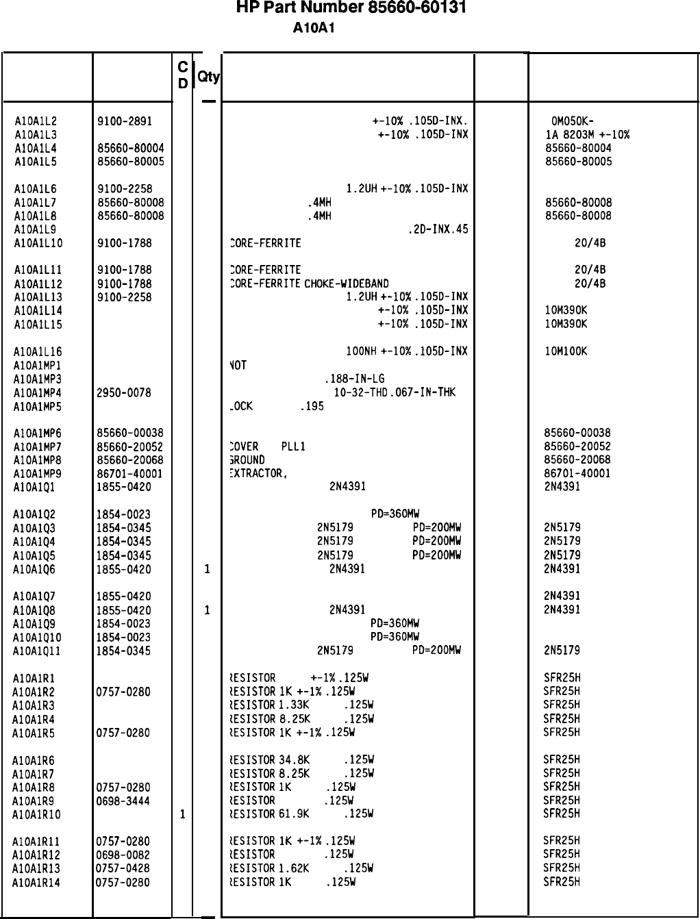
Reference
Designation
HP Part
Number Description Mfr Mfr Part
Code Number
-
AlOAlL2 9100-2891
4
1
INDUCTOR RF-CH-MLD 50NH +-lo%
.105D-INX.
24226
1
OMOSOK-
1
AlOAlL3 9100-2257
6
1
INDUCTOR RF-CH-MLD 820NH +-lo%
.105D-INX 32159
1A
8203M
+-lo%
AlOAlL4 85660-80004
4
1
INDUCTOR 30NH 28480 85660-80004
AlOAlL5 85660-80005
5
1
INDUCTOR 4NH 28480
85660-80005
AlOAlL6
9100-2258
7
1
AlOAlL7
85660-80008
a
1
AlOAlL8
85660-80008
a
1
AlOAlL9 9100-1647
6
1
AlOAlLlO 9100-1788
6
1
INDUCTOR RF-CH-MLD
1.2UH
+-IO%
.105D-INX
INDUCTOR-ADJ
.4MH
INDUCTOR-ADJ
.4MH
INDUCTOR RF-CH-MLD 470UH +-5%
.2D-INX.45
:ORE-FERRITE
CHOKE-WIDEBAND IMP:680
99800 1025-22
28480
85660-80008
28480 85660-80008
99800 2500-12
02114
VK200
20/48
AlOAlLll 9100-1788
6
1
:ORE-FERRITE
CHOKE-WIDEBAND IMP:680
02114
VK200
20/48
AlOAlLl2 9100-1788
6
1
:ORE-FERRITE
CHOKE-WIDEBAND
IMP:680
02114
VK200
20/48
AlOAlLl3 9100-2258
7
1
INDUCTOR RF-CH-MLD
1.2UH
+-lo%
.105D-INX 99800 1025-22
AlOAlL14 9100-2254
3
1
INDUCTOR RF-CH-MLD 390NH +-lo%
.105D-INX 24226 lOM390K
AlOAlL15 9100-2254
3
1
INDUCTOR RF-CH-MLD 390NH +-lo%
.1050-INX 24226 lOM390K
AlOAlL16
AlOAlMPl
AlOAlMP3
AlOAlMP4
AlOAlMP5
9100-2247
4
1
INDUCTOR RF-CH-MLD
1OONH
+-lo%
.105D-INX
VOT
ASSIGNED
24226 1OMlOOK
2200-0101
0
2
SCREW-MACH 4-40
.188-IN-LG
PAN-HD-POZI
77250
2950-0078
9
3
YUT-HEX-DBL-CHAM
lo-32-THD
.067-IN-THK 74163
2190-0124
4
6
-0CK
WASHER
.195
ID
28480 500220
2190-0124
AlOAlMP6 85660-00038
6
AlOAlMP7 85660-20052
6
AlOAlMP8
85660-20068
4
AlOAlMP9 86701-40001
9
AlOAlQl 1855-0420
2
1
1
3
1
1
1
1
1
1
1
1
1
1
1
1
1
1
1
1
1
1
1
1
1
1
1
1
1
1
-
SHIELDING CAN
:OVER
PC
PLLl
VCO
SROUND
LUG
:XTRACTOR,
PC
TRANSISTOR J-FET
2N4391
N-CHAN D-MODE TO
28480
85660-00038
28480 85660-20052
28480
85660-20068
28480 86701-40001
17856 2N4391
AlOAlQ2 1854-0023
9
AlOAlQ3 1854-0345
8
AlOAlQ4 1854-0345
8
AlOAlQ5 1854-0345
8
AlOAlQ6 1855-0420
2
TRANSISTOR NPN SI TO-18
PD=360MW 25403
TRANSISTOR NPN
2N5179
SI TO-72
PD=200MW 04713
TRANSISTOR NPN
2N5179
SI TO-72
PD=EOOMW 04713
TRANSISTOR NPN
2N5179
SI TO-72
PD=EOOMW 04713
TRANSISTOR J-FET
2N4391
N-CHAN D-MODE TO
17856
2N5179
2N5179
2N5179
2N4391
AlOAlQ7 1855-0420
2
AlOAlQ8 1855-0420
2
AlOAlQ9 1854-0023
9
AlOAlQlO 1854-0023
9
AlOAlQll 1854-0345
8
TRANSISTOR J-FET 214391 N-CHAN D-MODE TO 17856
TRANSISTOR J-FET
2N4391
N-CHAN D-MODE TO
17856
TRANSISTOR NPN SI TO-18
PD=360MW 25403
TRANSISTOR NPN SI TO-18
PD=360MW 25403
TRANSISTOR NPN
2N5179
SI TO-72
PD=ZOOMW 04713
2N4391
2N4391
2N5179
AlOAlRl 0757-0395
1
AlOAlRP 0757-0280
3
AlOAlR3 0757-0317
7
AlOAlR4 0757-0441
8
AlOAlR5 0757-0280
3
[ESISTOR
56.2
+-1X
.125W
TF TC=O+-100
tESISTOR
1K
+-1X
.125W
TF TC=O+-100
{ESISTOR
1.33K
+-1%
.125W
TF TC=O+-100
{ESISTOR
8.25K
+-1%
.125W
TF TC=O+-100
tESISTOR
1K
+-1X
.125W
TF TC=O+-100
19701
19701
19701
19701
19701
19701
19701
19701
19701
19701
19701
19701
19701
19701
SFR25H
SFR25H
SFR25H
SFR25H
SFR25H
AlOAlR6 0757-0123
3
AlOAlR7 0757-0441
8
AlOAlR8 0757-0280
3
AlOAlR9 0698-3444
1
AlOAlRlO 0757-0460
1
tESISTOR
34.8K
+-1%
.125W
TF TC=O+-100
tESISTOR
8.25K
+-1%
.125W
TF TC=O+-100
tESISTOR
1K
+-1%
.125W
TF TC=O+-100
tESISTOR
316 1%
.125W
TF TC=O+-100
lESISTOR
61.9K
+-1%
.125W
TF TC=O+-100
SFR25H
SFR25H
SFR25H
SFR25H
SFR25H
AlOAlRll 0757-0280
3
AlOAlRlE 0698-0082
7
AlOAlR13 0757-0428
1
AlOAlR14 0757-0280
3
lESISTOR
1K
+-I%
.125W
TF TC=O+-100
lESISTOR
464 1%
.125W
TF TC=O+-100
lESISTOR
1.62K
+-1%
.125W
TF TC=O+-100
lESISTOR
1K
+-1%
.125W
TF TC=O+-100
SFR25H
SFR25H
SFR25H
SFR25H
8566040131 Parts List
Page 2 of 4
HP
Part
Number 85660-60131
AlOAl
PLL 1 VCO
*Indicates factory-selected value
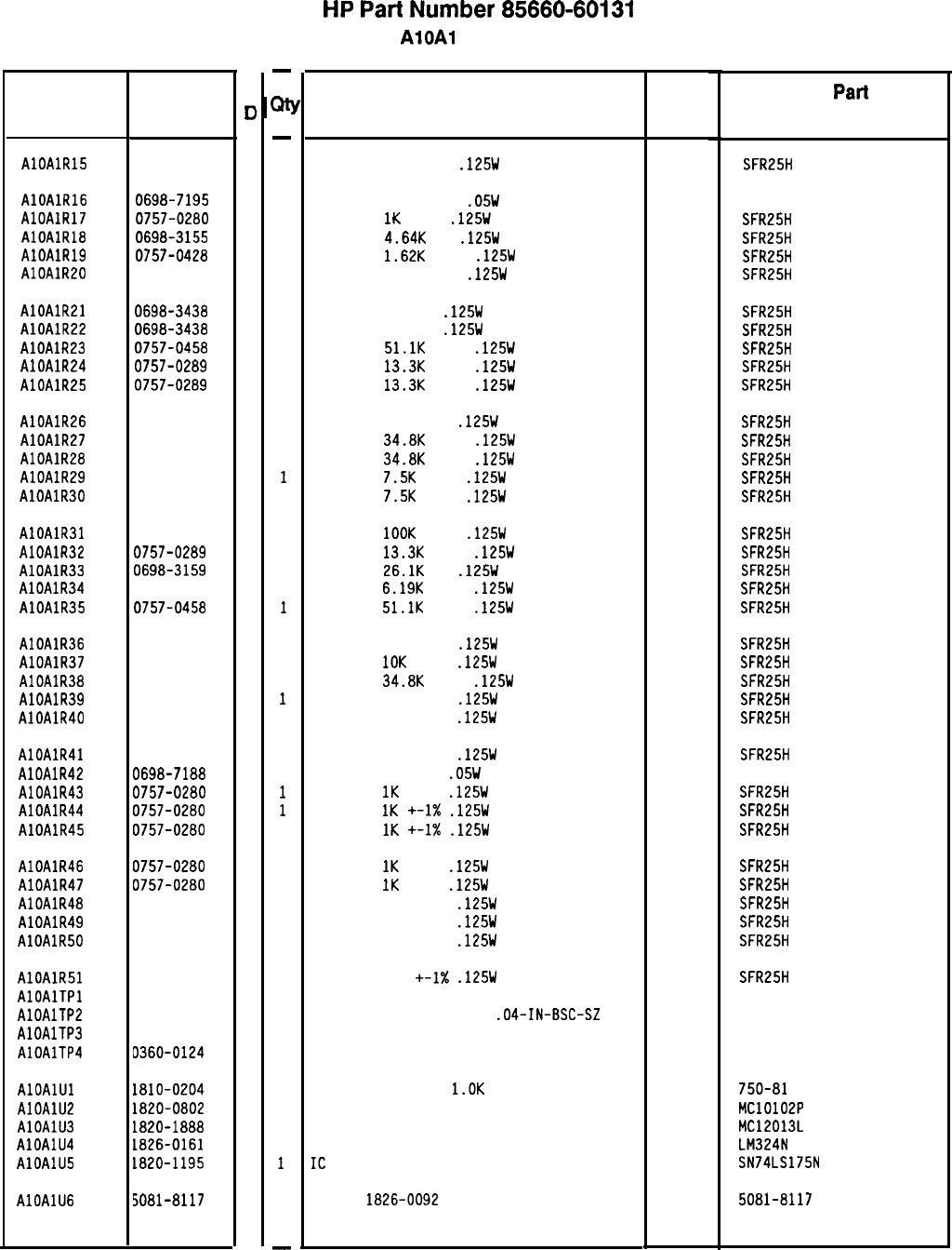
Reference
Designation
AlOAlR15
HP Part
Number
0757-0402
1
AlOAlR16 0698-7195
7
AlOAlR17 0757-0280
3
AlOAlR18 0698-3155
1
AlOAlR19 0757-0428
1
AlOAlR20 0757-0395
1
AlOAlR21 0698-3438
3
AlOAlR22 0698-3438
3
AlOAlR23 0757-0458
7
AlOAlR24 0757-0289
2
AlOAlR25 0757-0289
2
AlOAlR26 0757-0416
7
AlOAlR27 0757-0123
3
AlOAlR28 0757-0123
3
AlOAlR29 0757-0440
7
AlOAlR30
0757-0440
7
AlOAlR31 0757-0465
6
AlOAlR32 0757-0289
2
AlOAlR33 0698-3159
5
AlOAlR34 0757-0290
5
AlOAlR35
0757-0458
7
AlOAlR36 0757-0402
1
AlOAlR37 0757-0442
9
AlOAlR38 0757-0123
3
AlOAlR39 0757-0416
7
AlOAlR40 0757-0416
7
AlOAlR41 0757-0416
7
AlOAlR42 0698-7188
8
AlOAlR43 0757-0280
3
AlOAlR44 0757-0280
3
AlOAlR45
0757-0280
3
AlOAlR46 0757-0280
3
AlOAlR47 0757-0280
3
AlOAlR48 0757-0462
3
AlOAlR49 0757-0462
3
AlOAlR50
0757-0462
3
AlOAlR51 0757-0462
3
AlOAlTPl 0360-0124
3
AlOAlTPP 0360-0124
3
AlOAlTP3 0360-0124
3
AlOAlTP4 0360-0124
3
AlOAlUl 1810-0204
6
AlOAlUL 1820-0802
1
AlOAlU3 1820-1888
5
AlOAlU4 1826-0161
7
AlOAlU5 1820-1195
7
AlOAlU6 5081-8117
3
C
II
-
M
-
1
1
1
1
1
1
1
1
1
1
1
1
1
1
1
1
1
1
1
1
1
1
1
1
1
1
1
1
1
1
1
1
1
1
1
1
1
1
1
1
1
1
1
1
1
1
1
-
HP
Part
Number 85660-60131
AlOAl
PLL 1 VCO
Description Mfr Mfr
Part
Code Number
RESISTOR 110 +-1%
.125W
TF TC=O+-100
19701
SFR25H
RESISTOR 19.6 +-1%
.05W
TF TC=O+-100
19701
50635
RESISTOR
1K
+-1%
.125W
TF TC=O+-100
19701
SFR25H
RESISTOR
4.64K
1%
.125W
TF TC=O+-100
19701
SFR25H
RESISTOR
1.62K
+-1%
.125W
TF TC=O+-100
19701
SFR25H
RESISTOR 56.2 +-1%
.125W
TF TC=O+-100
19701
SFR25H
RESISTOR 147 1%
.125W
TF TC=O+-100
19701
SFR25H
RESISTOR 147 1%
.125W
TF TC=O+-100
19701
SFR25H
RESISTOR
51.1K
+-1%
.125W
TF TC=O+-100
19701
SFR25H
RESISTOR
13.3K
+-1%
.125W
TF TC=O+-100
19701
SFR25H
RESISTOR
13.3K
+-1%
.125W
TF TC=O+-100
19701
SFR25H
RESISTOR 511 +-1%
.125W
TF TC=O+-100
19701
SFR25H
RESISTOR
34.8K
+-1%
.125W
TF TC=O+-100
19701
SFR25H
RESISTOR
34.8K
+-1%
.125W
TF TC=O+-100
19701
SFR25H
RESISTOR
7.5K
+-1%
.125W
TF TC=O+-100
19701
SFR25H
RESISTOR
7.5K
+-1%
.125W
TF TC=O+-100
19701
SFR25H
RESISTOR
1OOK
+-1%
.125W
TF TC=O+-100
19701
SFR25H
RESISTOR
13.3K
+-1%
.125W
TF TC=O+-100
19701
SFR25H
RESISTOR
26.1K
1%
.125W
TF TC=O+-100
19701
SFR25H
RESISTOR
6.19K
+-1%
.125W
TF TC=O+-100
19701
SFR25H
RESISTOR
51.1K
+-1%
.125W
TF TC=O+-100
19701
SFR25H
RESISTOR 110 +-1%
.125W
TF TC=O+-100
19701
SFR25H
RESISTOR
10K
+-1%
.125W
TF TC=O+-100
19701
SFR25H
RESISTOR
34.8K
+-1%
.125W
TF TC=O+-100
19701
SFR25H
RESISTOR 511 +-1%
.125W
TF TC=O+-100
19701
SFR25H
RESISTOR 511 +-1%
.125W
TF TC=O+-100
19701
SFR25H
RESISTOR 511 +-1%
.125W
TF TC=O+-100
19701
SFR25H
RESISTOR 10 +-1%
.05W
TF TC=O+-100
19701
50635
RESISTOR
1K
+-1%
.125W
TF TC=O+-100
19701
SFR25H
RESISTOR
1K
+-1X
.125W
TF TC=O+-100
19701
SFR25H
RESISTOR
1K
+-I%
.125W
TF TC=O+-100
19701
SFR25H
RESISTOR
1K
+-1%
.125W
TF TC=O+-100
19701
SFR25H
RESISTOR
IK
+-1%
.125W
TF TC=O+-100
19701
SFR25H
RESISTOR 75K +-1%
.125W
TF TC=O+-100
19701
SFR25H
RESISTOR 75K +-1%
.125W
TF TC=O+-100
19701
SFR25H
RESISTOR 75K +-1%
.125W
TF TC=O+-100
19701
SFR25H
RESISTOR 75K +-1X
.125W
TF TC=O+-100
CONNECTOR-SGL CONT PIN .04-IN-BSC-SZ RND
CONNECTOR-SGL CONT PIN
.04-IN-BSC-SZ
RND
CONNECTOR-SGL CONT PIN .04-IN-BSC-SZ RND
CONNECTOR-SGL CONT PIN .04-IN-BSC-SZ RND
19701
97300
97300
97300
97300
SFR25H
NETWORK-RES 8-SIP
l.OK
OHM X 7
IC GATE ECL NOR QUAD 2-INP
IC PRESCR ECL
IC OP AMP GP QUAD 14-DIP-P PKG
IC
FF TTL LS D-TYPE POS-EDGE-TRIG COM CL
SCREEN
1826-0092
11236 750-81
04713 MC10102P
04713 MC12013L
27014 LM324N
01295 SN74LS175N
28480 5081-8117
*Indicates factory-selected value
85660-60131 Parts List
Page 3 of 4
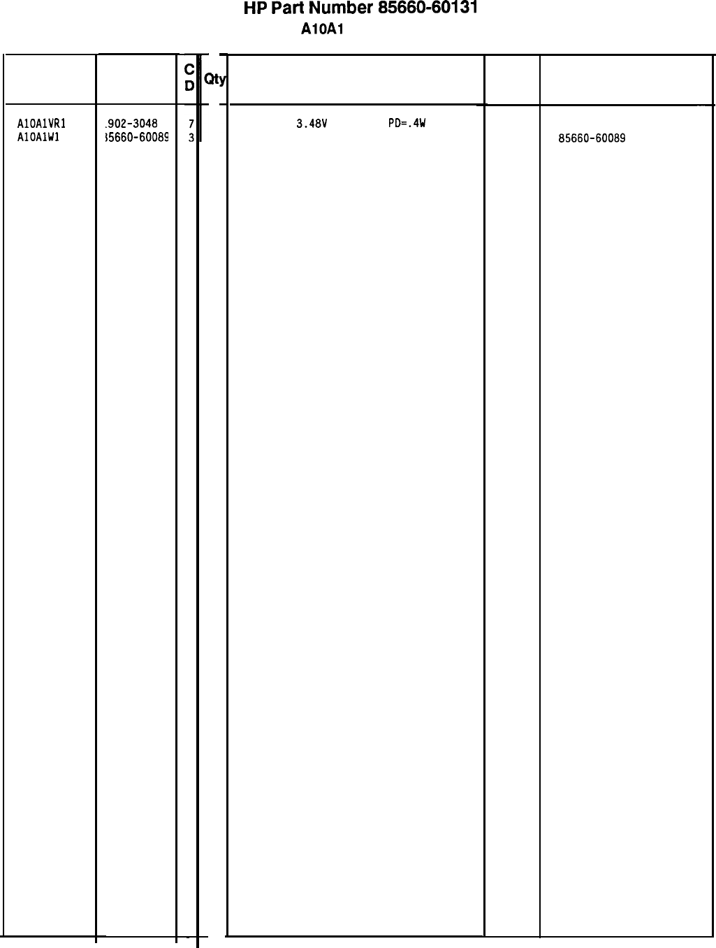
Reference
Designatior
AlOAlVRl
.902-3048
AlOAlWl
15660-60089
HP Part
Number
85660-60131 Parts List
Page 4 of 4
at
1
1
HP
Part
Number 85660-60131
AlOA1
PLL 1 VCO
Description Mfr
Code
DIODE-ZNR
3.48V
5% DO-35
PD=.4W 04713
CABLE ASSEMBLY, BROWN
2848C
*Indicates factoy-selected value
Mfr Part
Number
-
85660-60089
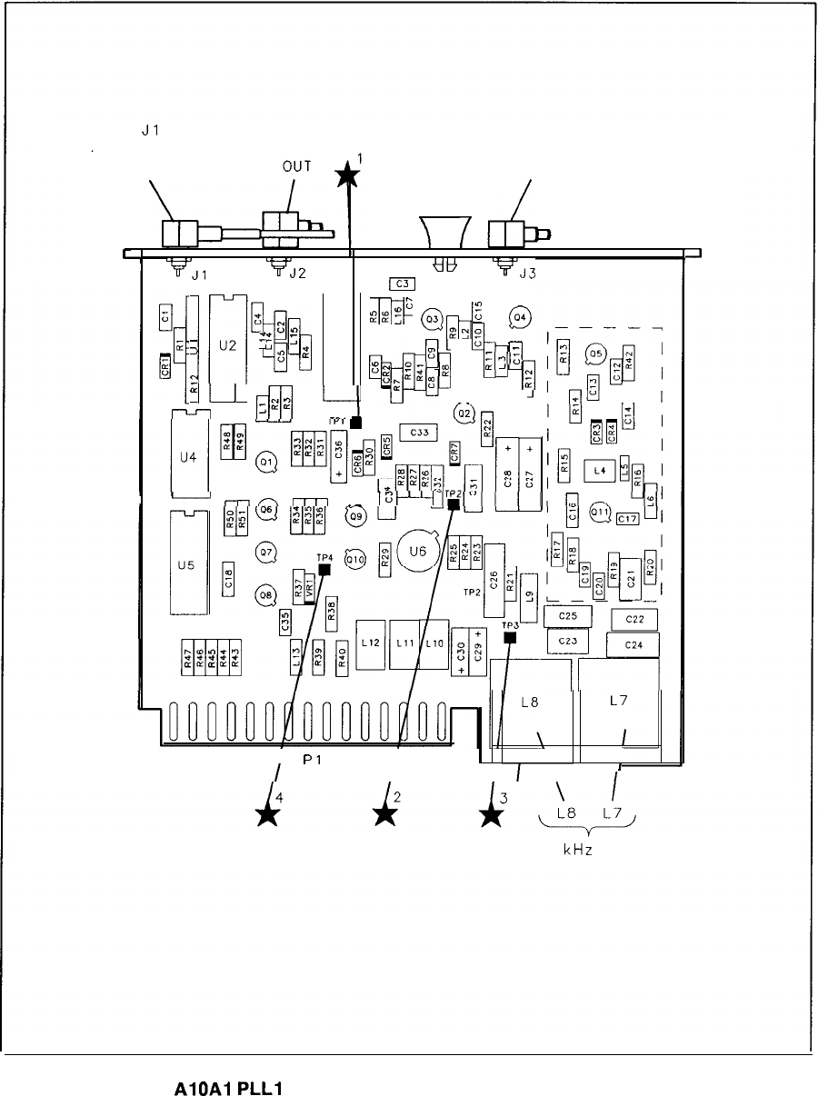
Jl
J2 J3
l-5 MHz SCAN 20-30 MHz OUT
IN 200-300 MHz
\
/
L
-I
VJl
VJ2
titt
m
7J3
5
zul
lrlQ0
--
@
-
3
u2
:
;g
:$?
@,;E
u3
;
8%9
E
a
91
0
z
zn,
g,“-B
aJ
f
11
1
;~‘::
VdE
r--J-
rm-
n
-
mnr-rn
.-
tat----
r.m”-l*n
ml
*e-**f
LLpL(L.xLLL
‘1
1
Pl
15
\
I
I
16 I30
-
50
kHz
NULL
AlOAl
PLLl
VCO Component Locations, 85660-60131
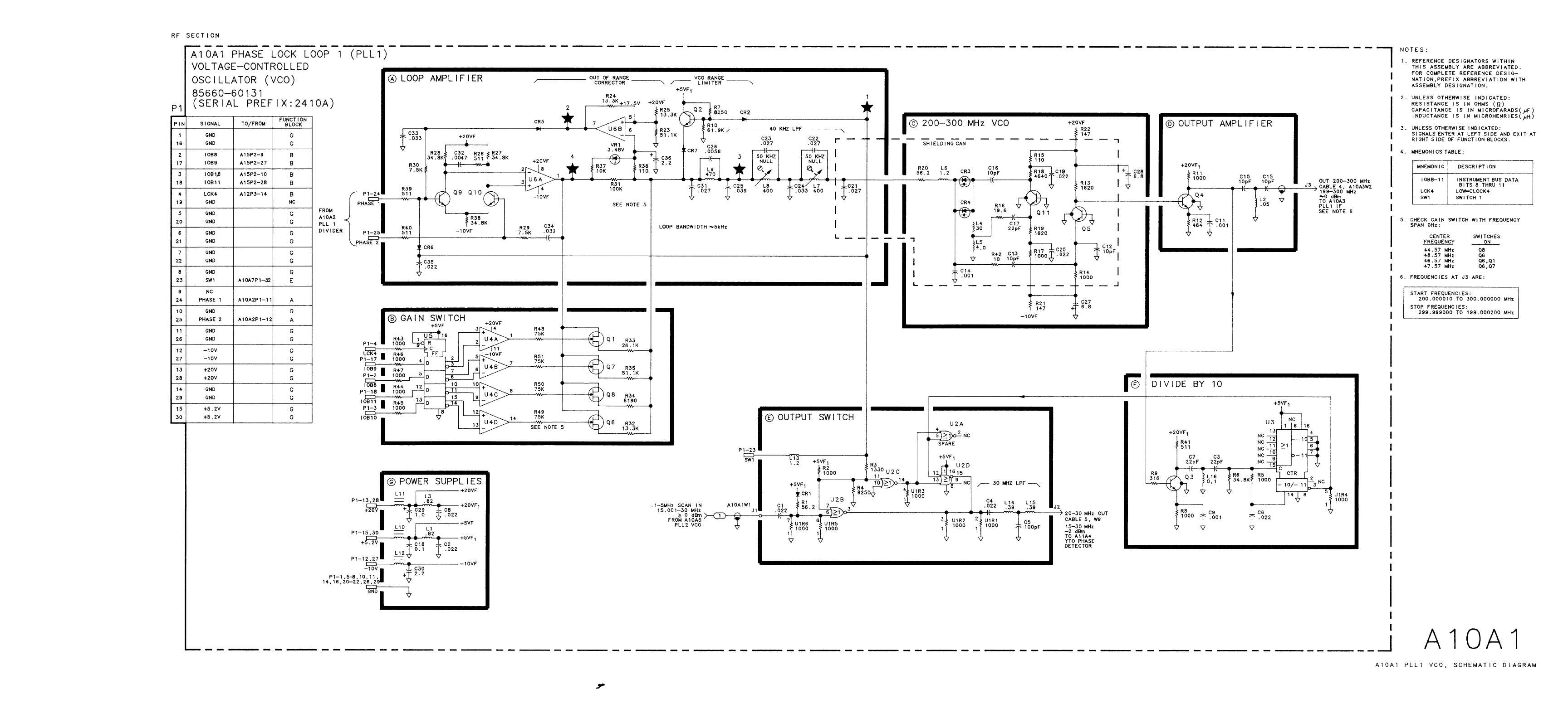
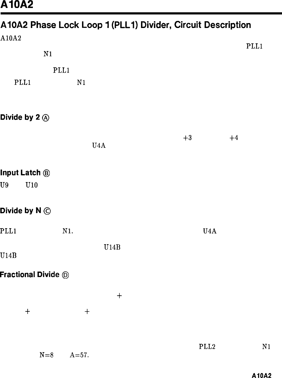
AlOA2
AlOA2
Phase
Lock
Loop
1
(PLLI)
Divider,
Circuit
Description
AlOA2 functions as a programmable frequency divider and a phase/frequency detector. The
divider is programmed by the Al5 Controller to divide the input frequency by the
PLLl
divide number
Nl
down to 5 MHz. This is then compared with a 5 MHz reference in the
phase/frequency detector. The detector output, after amplification and integration, tunes the
frequency of the
PLLl
voltage-controlled oscillator (VCO).
The
PLLl
divide number
Nl
always falls in the range between 3.60 and 13.97. The integer
part is coded in four binary bits while the fractional part (0.00 to 0.99) is coded in two 4-bit
BCD bytes.
Divide
by
2
@
U5 constitutes a 3-stage limiting amplifier. U5 is an ECL triple-line receiver which changes
the input to the proper amplitude and dc level (approximately
j-3
V low and
+4
V high) for
driving the subsequent divider. U4A is a D-type flip-flop which divides the limiting amplifier
output by 2.
Input
Latch
@
U9
and UlO are latches which store the divider programming number. The number is clocked
into the latches from the instrument bus with LCK4.
Divide
by
N
@
U12 is a 4-bit binary counter which is programmed with the integer part (3 to 13) of the
PLLl
divide number
Nl.
In operation it is clocked by the output of U4A and counts down to
1. On the next clock pulse, the programming number is loaded into the counter, and the cycle
repeats. Loading time is sensed by U14B when the count is at 2. The next clock pulse causes
U14B to change states which enables the loading of U12 on the subsequent clock pulse.
Fractional
Divide
6J
The fractional divide works on the pulse-swallowing principle. Consider a divider that divides
by N for P-A output pulses and by N
+
1 for A output pulses. Note that the total output
pulses is P. The number of input pulses to get P output pulses is
N(P-A)
+
(N + l)A = NP
+
A.
Therefore, the divide ratio is the number of input pulses divided by the number of output
pulses which is equal to N •l- A/P. In this case P is 100, so N represents the integer portion of
the divide number while A represents the fractional part times 100.
An example best illustrates how the fractional divide works. If the PLL2 divide number
Nl
is 8.57, then
N=8
and
A=57.
The integer divider normally divides by N each divide cycle.
AlOA2
1
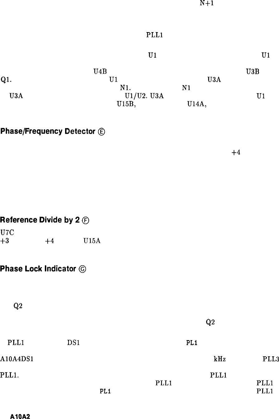
However, the Fractional Divide circuit can set the integer divider to a “hold” state every
N pulses, causing it to “swallow” a pulse and effectively divide by
N+l
for a cycle. In this
example, the Fractional Divide circuit selectively causes the integer divider to “swallow” a
pulse in 57 out of every 100 divide cycles. The integer divider thus divides by 8 for 43 out of
every 100 cycles and by 9 for 57 out of every 100 cycles, averaging out to the desired value of
8.57. Filtering in the phase-lock loop causes the
PLLl
VCO to lock steadily to this average
value.
The fractional divide number is programmed into
Ul
and U2 as two 4-bit BCD bytes.
Ul
and U2 are TTL decade rate multipliers connected in cascade. The input comes from the
integer divide counter U12 via U4B and the ECL to TTL translator consisting of U3B and
Ql.
For every 100 clock pulses into
Ul
and U2, there is output from U3A equal to 100 times
the fractional part of the divide number
Nl.
For example, if
Nl
= 8.57, then 57 pulses occur
at U3A output for every 100 pulses into
Ul/U2.
U3A translates the TTL outputs of
Ul
and
U2 to ECL, which then are latched by U15B, synchronized by U14A, and fed back to U12 to
control pulse “swallowing.”
Phase/Frequency Detector
@
The phase/frequency detector compares the divider output with a 5 MHz reference frequency.
When the two inputs are in phase, the outputs are ECL high, approximately
+4
V, with very
narrow pulses at a 5 MHz rate. When the inputs are the same frequency but different in
phase, one output line is a pulse with a width corresponding to the phase difference; the other
output is high with very narrow pulses. For a difference in input frequencies, the outputs
are pulses of varying widths, but with different average dc voltage levels. The sign of this dc
voltage is set by which frequency is higher and the magnitude is determined by the amount of
frequency difference.
Reference
Divide
by
2
@
U7C is an input buffer amplifier which generates the proper level for ECL (approximately
+3
V low and
+4
V high). U15A divides the 10 MHz input by 2 and applies this 5 MHz to
the phase/frequency detector.
Phase
Lock
Indicator
@
The input to the phase lock indicator is the wired OR Q outputs of the phase/frequency
detector. This input is ECL low (approximately 3 V) when the loop is locked; in this
condition, the dc voltage at the base of Q3 is lower than that at the base of Q2 so Q3 is on
and
Q2
is off. If the loop unlocks, the input to the phase lock indicator consists of varying
width pulses, the average dc value of which is about half way between a logic low and high.
The voltage divider consisting of R35 and R15 causes the voltage at
Q2
base to be lower than
that at Q3 base, so Q2 turns on indicating an unlock condition.
If
PLLl
unlocks, LED
DSl
will turn off, and the CRT message
PLl
UNLOCK will appear.
However, the CRT message PLI UNLOCK will also appear if PLL3 unlocks, as indicated when
AlOA4DSl
turns off. In spans above n x 5 MHz and spans of n x 100 kHz and below, PLL3
functions to shift the output of PLL2 up in frequency by 160 MHz for further division by
PLLl.
(n is the harmonic mixing number.) The two loops PLL3 and
PLLl
always operate
in conjunction; if PLL3 unlocks, then the output of
PLLl
is incorrect whether or not
PLLl
unlocks. The single CRT message
PLl
UNLOCK is used to indicate an unlock in either
PLLl
or
PLL3.
2
AIQA2
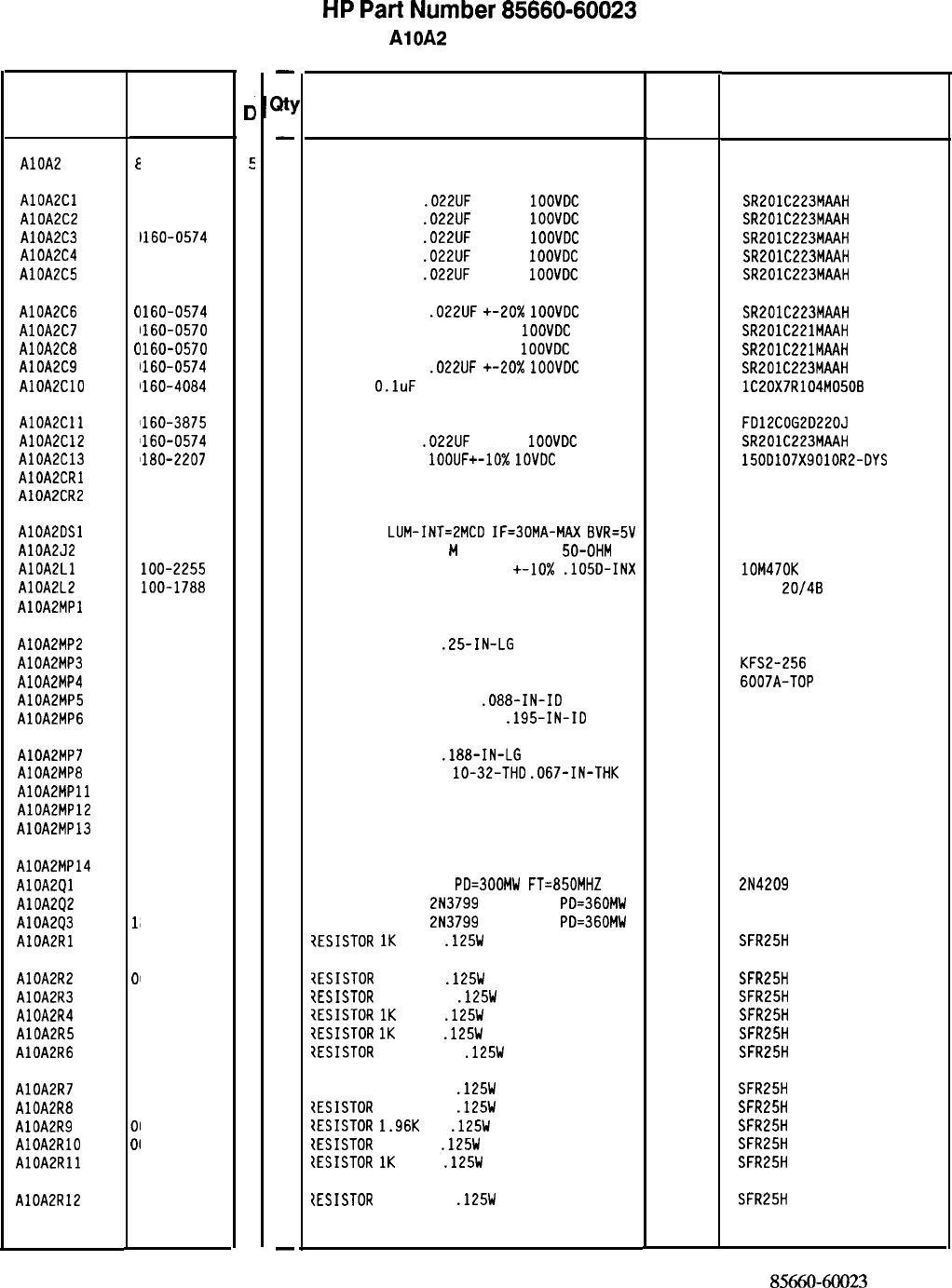
Reference HP Part
C
Designation Number
0
AlOA2
E
15660-60023
5
AlOAZCl
C
1160-0574
3
AlOA2C2
C
1160-0574
3
AlOA2C3
C
1160-0574
3
AlOA2C4
C
1160-0574
3
AlOA2C5
C
1160-0574
3
AlOA2C6
0
1160-0574
3
AlOA2C7
0
1160-0570
9
AlOA2C8
0
1160-0570
9
AlOA2C9
0
1160-0574
3
AlOALClO
0
1160-4084
8
AlOAZCll
0
1160-3875
3
AlOA2C12
0
1160-0574
3
AlOA2C13
0
1180-2207
5
AlOAPCRl
1
901-0040
1
AlOA2CR2
1
901-0040
1
AlOAEDSl
AlOA2J2
AlOAZLl
AlOA2L2
AlOA2MPl
1
990-0485
5
1
250-2112
1
9
loo-2255
4
9
loo-1788
6
AlOA2MP2
0
520-0128
7
AlOA2MP3
0
590-0533
5
AlOA2MP4
1
205-0285
0
AlOA2MP5
2
190-0112
0
AlOA2MP6
2
190-0124
4
AlOA2MP7
2
200-0101
0
AlOA2MP8
2
950-0078
9
AlOAZMPll
8
5660-00012
6
AlOA2MP12
8
5660-20053
7
AlOA2MP13
8
5660-20068
4
AlOA2MP14
8
6701-40001
9
AlOA2Ql
1'
853-0405
9
AlOA2Q2
1'
853-0451
5
AlOA2Q3
18
853-0451
5
AlOALRl
0
757-0280
3
AlOA2R2
AlOA2R3
AlOA2R4
AlOA2R5
AlOA2R6
698-3431
6
757-0403
2
757-0280
3
757-0280
3
757-0394
0
AlOA2R7
AlOA2R8
AlOA2R9
AlOAZRlO
AlOAERll
AlOA2R12
01
0
0
0
0
0
0’
01
01
0:
0:
757-0416
7
757-0416
7
698-0083
8
698-3440
7
757-0280
3
757-0416
7
-
w
-
1
1
1
1
1
1
1
1
1
1
1
1
1
1
1
1
1
1
1
1
2
2
1
2
4
2
2
1
1
2
2
1
1
1
1
1
1
1
1
1
1
1
1
1
1
1
-
HP
Part
Number 85660-60023
AlOA2 PLL 1 Divider
Description Mfr Mfr Part
Code Number
BOARD ASSEMBLY, PLL 1 DIVIDER
2848C
85660-60023
CAPACITOR-FXD
.022UF
+-20%
1OOVDC
CER
04222 SR201C223MAAH
CAPACITOR-FXD
.022UF
+-20%
1OOVDC
CER
04222 SR201C223MAAH
CAPACITOR-FXD
.022UF
+-20%
1OOVDC
CER
04222 SR201C223MAAH
CAPACITOR-FXD
.022UF
+-20%
1OOVDC
CER
04222 SR201C223MAAH
CAPACITOR-FXD
.022UF
+-20%
1OOVDC
CER
04222 SR201C223MAAH
CAPACITOR-FXD
.022UF
+-20x
1OOVDC
CER
04222 SR201C223MAAH
CAPACITOR-FXD 220PF +-20%
1OOVDC
CER
04222 SR201C221MAAH
CAPACITOR-FXD 220PF +-20%
1OOVDC
CER
04222 SR201C221MAAH
CAPACITOR-FXD
.022UF
+-20x
1OOVDC
CER
04222 SR201C223MAAH
CAP-FXD
O.luF
50 V
56289 lC20X7R104M0506
CAPACITOR-FXD 22PF +-5% 200VDC CER 0+-30
CAPACITOR-FXD
.022UF
+-20%
1OOVDC
CER
CAPACITOR-FXD
lOOUF+-10%
1OVDC
TA
DIODE-SWITCHING 30V 50MA 2NS DO-35
DIODE-SWITCHING 30V 50MA 2NS DO-35
04222
56289
71468
71468
FD12COG2D220J
SR201C223MAAH
150D107X9010R2-DYS
LED-LAMP
LUM-INT=EMCD
IF=30MA-MAX
BVR=5V
CONNECTOR-RF SMB
M
SGL-HOLE-FR
50-OHM
INDUCTOR RF-CH-MLD 470NH +-10x
.105D-INX
CORE-FERRITE CHOKE-WIDEBAND IMP:680
NOT ASSIGNED
28480 HLMP-1503
98291 051-047-0259-220
24226 lOM470K
02114
VK200
20/48
SCREW-MACH 2-56
.25-IN-LG
PAN-HD-POZI
THREADED INSERT-NUT 2-56 .06-IN-LG SST
HEAT SINK SGL DIP
WASHER-LK HLCL NO. 2
.088-IN-ID
WASHER-LK INTL T NO. 10
.195-IN-IO
77250
46384
13103
77339
98291
KFS2-256
6007A-TOP
3002-26
SCREW-MACH 4-40
.188-IN-LG
PAN-HD-POZI
NUT-HEX-DEL-CHAM
lo-32-THD
.067-IN-THK
HEAT SINK BOTTOM
PC COVER, PLL 1 DIVIDER
GROUND LUG
77250
74163
28480
28480
28480
500220
85660-00012
85660-20053
85660-20068
EXTRACTOR PC
TRANSISTOR PNP SI
PD=300MW
FT=850MHZ
TRANSISTOR PNP
2N3799
SI TO-18
PD=360MW
TRANSISTOR PNP
2N3799
SI TO-18
PD=360MW
7ESISTOR
1K
+-1%
.125W
TF TC=O+-100
28480
04713
04713
04713
19701
86701-40001
2N4209
SFR25H
7ESISTOR
23.7 1%
.125W
TF TC=O+-100
iESISTOR
121 +-1%
.125W
TF TC=O+-100
?ESISTOR
1K
+-1%
.125W
TF TC=O+-100
?ESISTOR
1K
+-1%
.125W
TF TC=O+-100
?ESISTOR
51.1 +-1%
.125W
TF TC=O+-100
SFR25H
SFR25H
SFR25H
SFR25H
SFR25H
7ESISTOR 511 +-1%
.125W
TF TC=O+-100
tESISTOR
511 +-1%
.125W
TF TC=O+-100
?ESISTOR
1.96K
1%
.125W
TF TC=O+-100
IESISTOR
196 1%
.125W
TF TC=O+-100
{ESISTOR
1K
+-1%
.125W
TF TC=O+-100
SFR25H
SFR25H
SFR25H
SFR25H
SFR25H
tESISTOR
511 +-1%
.125W
TF TC=O+-100
19701
19701
19701
19701
19701
19701
19701
19701
19701
19701
19701
SFR25H
*Indicates factory-selected value
85660-60023 Parts List
Page 1 of 3
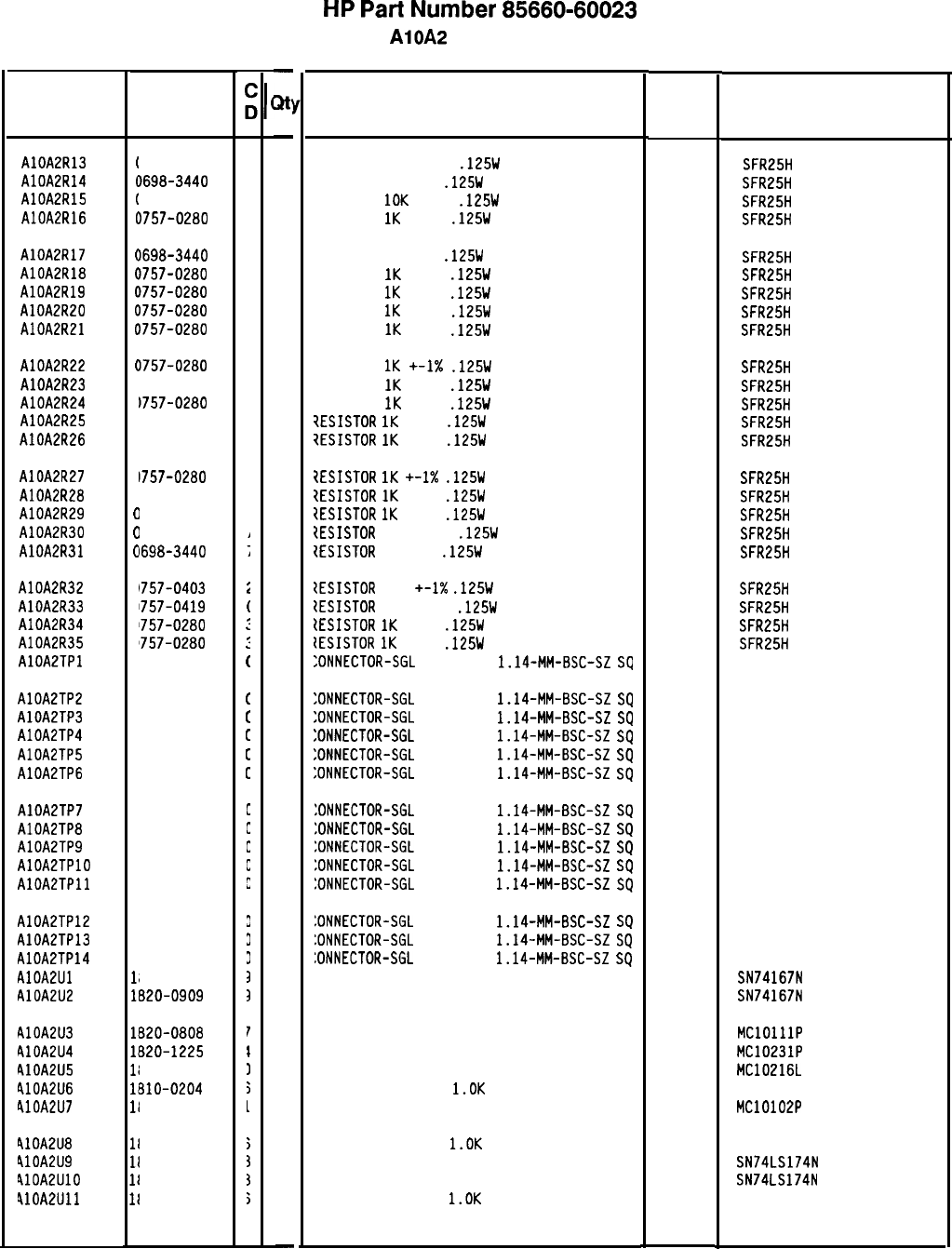
HP
Part
Number 85660-60023
AlOA2 PLL 1 Divider
Description Mfr Mfr Part
Code Number
RESISTOR 511 +-1%
.125W
TF TC=O+-100
19701
SFR25H
RESISTOR 196 1%
.125W
TF TC=O+-100
19701
SFR25H
RESISTOR
10K
+-1%
.125W
TF TC=O+-100
19701
SFR25H
RESISTOR
1K
+-1%
.125W
TF TC=O+-100
19701
SFR25H
RESISTOR 196 1%
.125W
TF TC=O+-100
19701
SFR25H
RESISTOR
1K
+-1%
.125W
TF TC=O+-100
19701
SFR25H
RESISTOR
1K
+-1%
.125W
TF TC=O+-100
19701
SFR25H
RESISTOR
1K
+-1%
.125W
TF TC=O+-100
19701
SFR25H
RESISTOR
1K
+-1%
.125W
TF TC=O+-100
19701
SFR25H
RESISTOR
1K
+-1X
.125W
TF TC=O+-100
19701
SFR25H
RESISTOR
1K
+-1%
.125W
TF TC=O+-100
19701
SFR25H
RESISTOR
1K
+-1%
.125W
TF TC=O+-100
19701
SFR25H
?ESISTOR
1K
+-1%
.125W
TF TC=O+-100
19701
SFR25H
7ESISTOR
1K
+-1%
.125W
TF TC=O+-100
19701
SFR25H
?ESISTOR
1K
+-1X
.125W
TF TC=O+-100
19701
SFR25H
tESISTOR
1K
+-1%
.125W
TF TC=O+-100
19701
SFR25H
?ESISTOR
1K
+-1%
.125W
TF TC=O+-100
19701
SFR25H
tESISTOR
511 +-1%
.125W
TF TC=O+-100
19701
SFR25H
1ESISTOR
196 1%
.125W
TF TC=O+-100
19701
SFR25H
1ESISTOR
121
+-1X
.125W
TF TC=O+-100
19701
SFR25H
tESISTOR
681 +-1%
.125W
TF TC=O+-100
19701
SFR25H
IESISTOR
1K
+-1%
.125W
TF TC=O+-100
19701
SFR25H
ZESISTOR
1K
+-1%
.125W
TF TC=O+-100
19701
SFR25H
:ONNECTOR-SGL
CONT PIN
1.14-MM-BSC-SZ
SQ
27264 16-06-0034
:ONNECTOR-SGL
CONT PIN
1.14-MM-BSC-SZ
SQ
27264 16-06-0034
:ONNECTOR-SGL
CONT PIN
1.14-MM-BSC-SZ
SQ
27264 16-06-0034
:ONNECTOR-SGL
CONT PIN
1.14-MM-BSC-SZ
SQ
27264 16-06-0034
:ONNECTOR-SGL
CONT PIN
1.14~MM-BSC-SZ
SQ
27264 16-06-0034
:ONNECTOR-SGL
CONT PIN
1.14-MM-BSC-SZ
SQ
27264 16-06-0034
:ONNECTOR-SGL
CONT PIN
1.14-MM-BSC-SZ
SQ
27264 16-06-0034
:ONNECTOR-SGL
CONT PIN
1.14-MM-BSC-SZ
SQ
27264 16-06-0034
:ONNECTOR-SGL
CONT PIN
1.14-MM-BSC-SZ
SQ
27264 16-06-0034
:ONNECTOR-SGL
CONT PIN
1.14-MM-BSC-SZ
SQ
27264 16-06-0034
:ONNECTOR-SGL
CONT PIN
1.14-MM-BSC-SZ
SQ
27264 16-06-0034
:ONNECTOR-SGL
CONT PIN
1.14-MM-BSC-SZ
SQ
27264 16-06-0034
:ONNECTOR-SGL
CONT PIN
1.14-MM-BSC-SZ
SQ
27264 16-06-0034
:ONNECTOR-SGL
CONT PIN
1.14-MM-BSC-SZ
SQ
27264 16-06-0034
C MULTR TTL 01295 SN74167N
C MULTR TTL 01295 SN74167N
C GATE ECL NOR DUAL 3-INP 04713 MClOlllP
C FF ECL D-M/S DUAL 04713 MC10231P
C RCVR ECL LINE RCVR TPL 2-INP 04713 MC10216L
IETWORK-RES 8-SIP l.OK OHM X 7 11236 750-81
C GATE ECL NOR QUAD 2-INP 04713 MC10102P
ETWORK-RES 8-SIP
l.OK
OHM X 7
11236 750-81
C FF TTL LS D-TYPE POS-EDGE-TRIG COM CL
01295 SN74LS174N
C FF TTL LS D-TYPE POS-EDGE-TRIG COM CL
01295 SN74LS174N
ETWORK-RES 8-SIP
l.OK
OHM X 7
11236 750-81
*Indicates factory-selected value
Reference
Designation
AlOA2R13
AlOA2R14
AlOA2R15
AlOA2R16
AlOA2R17
AlOA2R18
AlOA2R19
AlOA2R20
AlOA2R21
AlOA2R22
AlOA2R23
AlOA2R24
AlOA2R25
AlOA2R26
AlOA2R27
AlOA2R28
AlOA2R29
AlOA2R30
AlOA2R31
AlOA2R32
AlOA2R33
AlOA2R34
AlOA2R35
AlOA2TPl
AlOA2TP2
AlOA2TP3
AlOA2TP4
AlOA2TP5
AlOA2TP6
AlOA2TP7
AlOA2TP8
AlOA2TP9
AlOALTPlO
AlOA2TPll
AlOA2TP12
AlOA2TP13
AlOA2TP14
AlOA2Ul
AlOA2U2
AlOA2U3
AlOA2U4
RlOA2U5
410A2U6
410A2U7
410A2U8
410A2U9
410A2UlO
410A2Ull
I
I
(
(
(
(
1
(
C
t
I
c
C
C
C
C
C
0
0
0
0
0
0
0
1
1
1
1
1
1
1
1
1
1
1
1
1
1
1,
1,
1;
11
1;
II
II
II
II
11
11
HP Part
Number
1757-0416
1698-3440
1757-0442
1757-0280
1698-3440
1757-0280
1757-0280
1757-0280
1757-0280
1757-0280
1757-0280
)757-0280
1757-0280
1757-0280
1757-0280
1757-0280
1757-0280
1757-0416
1698-3440
1757-0403
i
1757-0419
(
1757-0280
:
‘757-0280
:
251-0600
(
251-0600
c
251-0600
c
251-0600
[
251-0600
c
251-0600
C
251-0600
c
251-0600
c
251-0600
c
251-0600
c
251-0600
c
251-0600
2
251-0600
3
251-0600
3
820-0909
3
820-0909
3
620-0808
I
820-1225
1
620-1320
I
510-0204
5
320-0802
L
310-0204
5
320-1196
3
320-1196
3
310-0204
j
85660-60023 Parts List
Page 2 of 3
-
;)tl
-
1
1
1
1
1
1
1
1
1
1
1
1
1
1
1
1
1
1
1
1
1
1
1
1
1
1
1
1
1
1
1
1
1
1
1
1
1
1
1
1
1
1
1
1
1
1
1
1
-
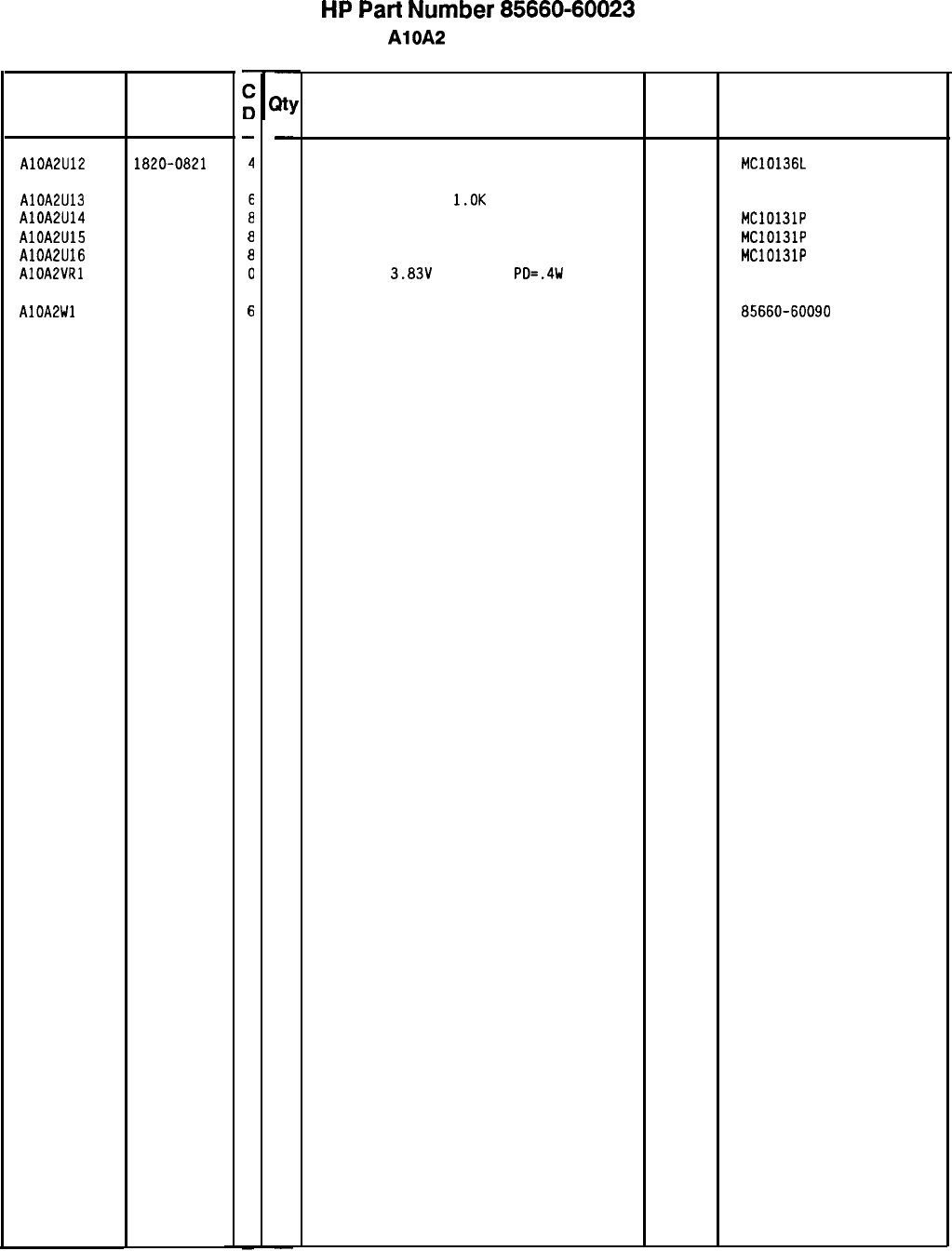
HP
Part
Number 85660-60023
AlOA2 PLL 1 Divider
Reference
Designation
HP Part
Number
AlOA2U12 1820-0821
AlOA2U13 1810-0204
AlOA2U14 1820-0817
AlOA2U15 1820-0817
AlOA2U16
1820-0817
AlOAPVRl 1902-3059
AlOALWl 35660-60090
-
m
-
1
1
1
1
1
1
1
-
Description
IC CNTR ECL BIN UP/DOWN SYNCHRO POS-EDGE 04713 MC10136L
NETWORK-RES 8-SIP
l.OK
OHM X 7
11236
IC FF ECL O-M/S DUAL 04713
IC FF ECL O-M/S DUAL 04713
IC FF ECL O-M/S DUAL 04713
DIODE-ZNR
3.83V
5% DO-35
PO=.4W 04713
750-81
MC10131P
MC10131P
MC10131P
CABLE ASSEMBLY, ORANGE 28480 85660-60090
Mfr
Mfr Part
Code Number
*Indicates factory-selected value
85660-60023 Parts List
Page 3 of 3
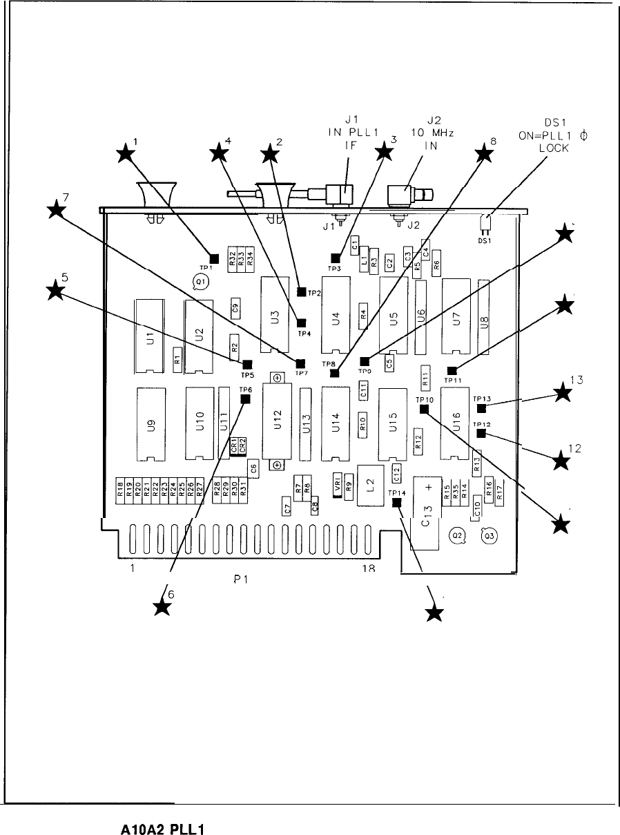
~H~~O~noolmJ3OOO~~
au@
1
18
19
Pl
36 \
i
14
9
2
11
F
/--A3
Yc*
b
10
AlOA2
PLLl
Divider Component Locations, 85660-60023
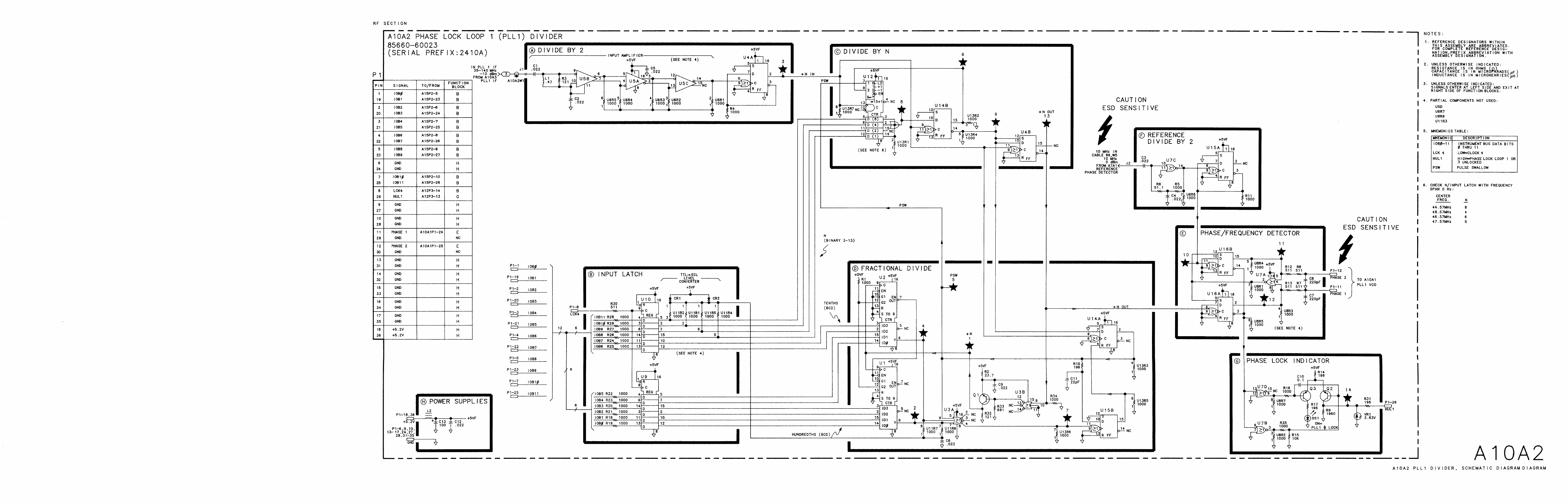
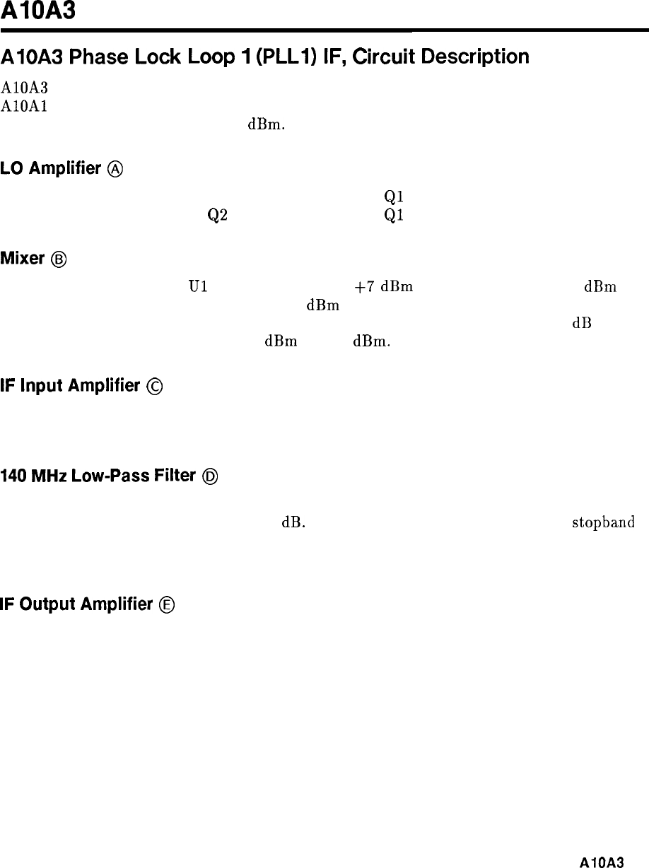
AlOA3
AlOA3
Phase
Lock
Loop
1
(PLLI)
IF,
Circuit
Description
AlOA3 functions to mix the output of A10A4 (160.15 to 166 MHz) with the LO output from
AlOAl
(200 to 300 MHz). Theoutput of this assembly is the difference frequency suitably
filtered and amplified to about -10
dBm.
LO
Amplifier
@
The LO amplifier consists of common-emitter amplifiers
Ql
and Q2. CR1 and CR2 provide
limiting to prevent overdriving
Q2
near 200 MHz where
Ql
has more gain.
Mixer
@I
The double-balanced mixer
Ul
operates with about
+7
dBm
LO drive and with -30
dBm
RF signal input. The IF output is about -36
dBm
and covers 30 MHz to 140 MHz. The
185 MHz Low-Pass Filter attenuates the harmonics of the RF signal input. The 10 dB pad
reduces the RF signal input from -20
dBm
to -30
dBm.
IF
Input
Amplifier
@
The IF input amplifier has an input filter to partially filter the RF and LO signals from the
mixer. The amplifier Q3 has emitter degeneration R17 to reduce distortion.
140
MHz
Low-Pass
Filter
@I
The 140 MHz Low-Pass Filter is a modified elliptic filter which must pass 140 MHz while
rejecting 160 to 166 MHz by at least 60 dB. The three adjustable coils optimize the
stopband
by providing nulls at the frequencies shown on the schematic. This filter also rejects the LO
frequencies (200 to 300 MHz).
IF
Output
Amplifier
@
The IF output amplifier consists of two common-emitter stages and an output low-pass filter.
The two stages are coupled by Cl4 and L17 which provide high frequency peaking.
AlOA3
1
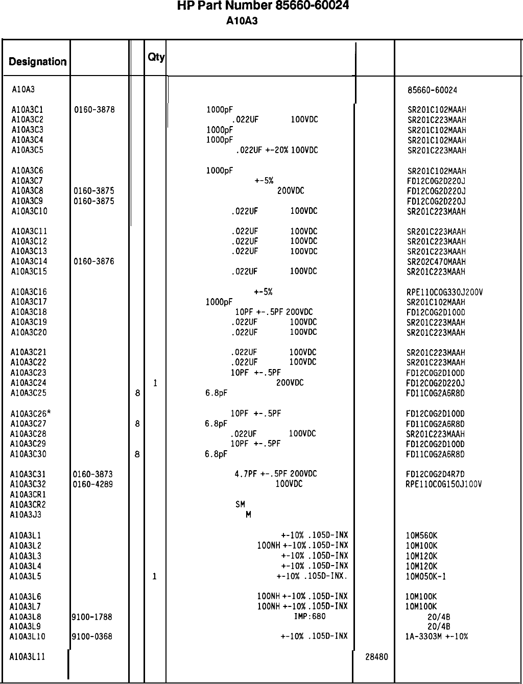
HP
Part
Number 85660-60024
AlOA3 PLL 1 IF
Reference HP Part C
Designation
n
Number
D
Qty
AlOA3 85660-60024
6 1
AlOA3Cl 0160-3878
6 1
AlOA3C2 0160-0574
3 1
AlOA3C3 0160-3878
6 1
AlOA3C4 0160-3878
6 1
AlOA3C5 0160-0574
3 1
AlOA3C6 0160-3878
6 1
AlOA3C7 0160-3875
3 1
AlOA3CB 0160-3875
3 1
AlOA3C9 0160-3875
3 1
AlOA3ClO 0160-0574
3 1
AlOA3C11 0160-0574
3 1
CAPACITOR-FXD
.022UF
+-20%
1OOVDC
CER
04222 SR201C223MAAH
AlOA3C12 0160-0574
3 1
CAPACITOR-FXD
.022UF
+-20%
1OOVDC
CER
04222 SR201C223MAAH
AlOA3C13 0160-0574
3 1
CAPACITOR-FXD
.022UF
+-20%
1OOVDC
CER
04222 SR201C223MAAH
AlOA3C14 0160-3876
4 1
CAPACITOR-FXD 47PF +-20% 2OOVDC CER
04222 SR202C470MAAH
AlOA3C15 0160-0574
3 1
CAPACITOR-FXD
.022UF
+-20%
1OOVDC
CER
04222 SR201C223MAAH
AlOA3C16 0160-3653
5 1
AlOA3C17 0160-3878
6 1
AlOA3ClB 0160-3874
2 1
AlOA3C19 0160-0574
3 1
AlOA3C20 0160-0574
3 1
AlOA3C21 0160-0574
3 1
CAPACITOR-FXD
.022UF
+-20%
1OOVDC
CER
AlOA3C22 0160-0574
3 1
CAPACITOR-FXD
.022UF
+-20%
1OOVDC
CER
AlOA3C23 0160-3874
2 1
CAPACITOR-FXO
1OPF
+-.5PF
LOOVDC CER
AlOA3C24 0160-3875
3
1
CAPACITOR-FXD 22PF +-5%
LOOVDC
CER 0+-30
AlOA3C25 0160-3565
8
1
CAP-FXD
6.BpF
100 V
AlOA3C26* 0160-3874
2 1
AlOA3C27 0160-3565
8
1
AlOA3C28 0160-0574
3 1
AlOA3C29 0160-3874
2 1
AlOA3C30 0160-3565
8
1
AlOA3C31 0160-3873
1 1
CAPACITOR-FXD
4.7PF
+-.5PF
ZOOVDC
CER
AlOA3C32 0160-4289
5 1
CAPACITOR-FXD 15PF +-5%
1OOVDC
CER 0+-30
AlOA3CRl 1901-0535
9 1
DIODE-SCHOTTKY SM SIG
AlOA3CR2 1901-0535
9 1
DIODE-SCHOTTKY
SM
SIG
AlOA3J3 1250-0690
6 1
CONNECTOR-RF SMB
M
SGL-HOLE-FR SO-OHM
AlOA3Ll 9100-2256
5 1
INDUCTOR RF-CH-MLD 560NH
+-lo%
.1050-INX 24226 lOM560K
AlOA3L2 9100-2247
4 1
INDUCTOR RF-CH-MLD
1OONH
+-lo%
.1050-INX 24226 1OMlOOK
AlOA3L3 9100-2248
5 1
INDUCTOR RF-CH-MLD 120NH +-10x
.105D-INX 24226 lOM120K
AlOA3L4 9100-2248
5 1
INDUCTOR RF-CH-MLD 120NH +-lo%
.105D-INX 24226 lOM120K
AlOA3L5 9100-2891
4
1
INDUCTOR RF-CH-MLD 50NH +-lo%
.105D-INX.
24226 lOM050K-1
AlOA3L6 9100-2247
4 1
INDUCTOR RF-CH-MLD
1OONH
+-lo%
.105D-INX 24226 1OMlOOK
AlOA3L7 9100-2247
4 1
INDUCTOR RF-CH-MLD
1OONH
+-lo%
.105D-INX 24226 1OMlOOK
AlOA3LB 9100-1788
6 1
CORE-FERRITE CHOKE-WIDEBANO
IMP:680 02114
VK200
20/4B
AlOA3L9 9100-1788
6 1
CORE-FERRITE CHOKE-WIDEBAND IMP:680
02114
VK200
20/4B
AlOA3LlO 9100-0368
6 1
INDUCTOR RF-CH-MLD 330NH +-lo%
.105D-INX 32159 lA-3303M
+-lo%
AlOA3Lll
I
85660-80006
Description
BOARD ASSEMBLY, PLL 1 IF
CAP-FXD
1OOOpF
100 V
CAPACITOR-FXD
.022UF
+-20%
1OOVDC
CER
CAP-FXD
1OOOpF
100 V
CAP-FXD
1OOOpF
100 V
CAPACITOR-FXD
.022UF
+-20x
1OOVDC
CER
CAP-FXD
1OOOpF
100 V
04222
CAPACITOR-FXD 22PF +-5X 200VDC CER 0+-30
CAPACITOR-FXD 22PF +-5%
EOOVDC
CER 0+-30
CAPACITOR-FXD 22PF +-5% 200VDC CER 0+-30
CAPACITOR-FXD
.022UF
+-20%
1OOVDC
CER
CAPACITOR-FXD 33PF
+-5x
200VDC CER 0+-30
CAP-FXD
1OOOpF
100 V
CAPACITOR-FXD
1OPF
+-.5PF
ZOOVDC
CER
CAPACITOR-FXD
.022UF
+-20%
1OOVDC
CER
CAPACITOR-FXD
.022UF
+-20%
1OOVDC
CER
CAPACITOR-FXD
1OPF
+-.5PF
200VDC CER
CAP-FXD
6.BpF
100 V
CAPACITOR-FXD
.022UF
+-20%
1OOVDC
CER
CAPACITOR-FXD
1OPF
+-.5PF
200VDC CER
CAP-FXD
6.BpF
100 V
6 1
INDUCTOR 120NH
Mfr
Mfr Part
Code Number
28480 85660-60024
04222 SR201C102MAAH
04222 SR201C223MAAH
04222 SR201C102MAAH
04222 SR201C102MAAH
04222 SR201C223MAAH
04222
04222
04222
04222
04222
04222
04222
98291 51-047-4610
SR201C102MAAH
FD12COG2D220J
FD12COG2D220J
FD12COG2022OJ
SR201C223MAAH
RPEllOCOG330J200V
SR201C102MAAH
FD12COG2DlOOD
SR201C223MAAH
SR201C223MAAH
SR201C223MAAH
SR201C223MAAH
FD12COG2DlOOD
FD12COG2022OJ
FDllCOGLAGRBD
FD12COG2DlOOD
FDllCOG2A6RBD
SR201C223MAAH
FD12COG2DlOOD
FDllCOG2AGRBD
FD12COG204R7D
RPEllOCOG150J100V
85660-80006
*Indicates factory-selected value
85660-60024 Parts List
Page 1 of 3
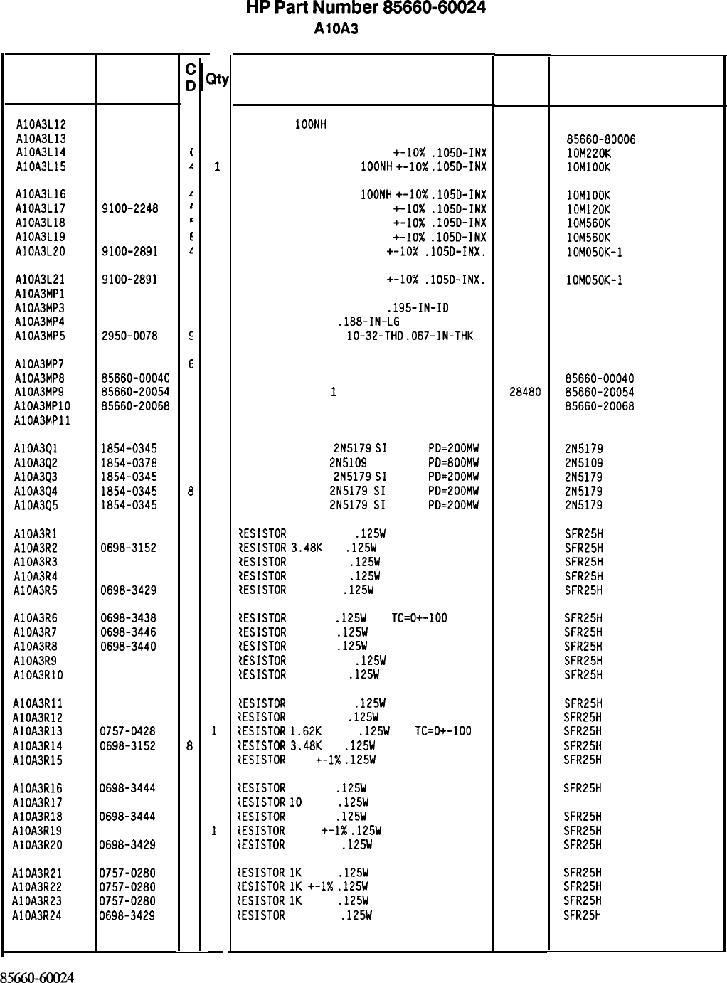
Reference
Designation HP Part
Number
AlOA3L12 85660-80009
C
1
AlOA3L13 85660-80006
f
1
AlOA3L14 9100-2251
(
1
AlOA3L15 9100-2247
1
1
AlOA3L16
AlOA3L17
AlOA3LlB
AlOA3L19
AlOA3L20
9100-2247
I!
1
INDUCTOR RF-CH-MLD
1OONH
+-IO%
.lOSD-INX
9100-2248
c
1
INDUCTOR RF-CH-ML0 120NH +-lo%
.105D-INX
9100-2256
L
1
INDUCTOR RF-CH-MLD 560NH +-lo%
.105D-INX
9100-2256
r
i
1
INDUCTOR RF-CH-MLD 560NH +-lo%
.105D-INX
9100-2891
1
INDUCTOR RF-CH-MLD 50NH
+-lo%
.105D-INX.
AlOA3L21
AlOA3MPl
AlOA3MP3
AlOA3MP4
AlOA3MP5
9100-2891
4 1
2190-0124
4
6
WASHER-LK INTL T NO. 10
.195-IN-ID 98291
2200-0101
C
2
SCREW-MACH 4-40
.lBB-IN-LG
PAN-HD-POZI
77250
2950-0078
9
3
NUT-HEX-DBL-CHAM
lo-32-THD
.067-IN-THK 74163
AlOA3MP7 85660-00038
E
AlOA3MPB 85660-00040
C
AlOA3MP9 85660-20054
a
AlOA3MPlO 85660-20068
4
AlOA3MPll 86701-40001
9
AlOA3Ql 1854-0345
8
AlOA3Q2 1854-0378
7
AlOA3Q3 1854-0345
a
AlOA3Q4 1854-0345
a
AlOA3Q5 1854-0345
a
AlOA3Rl 0757-0394
0
AlOA3R2 0698-3152
a
AlOA3R3 0757-0421
4
AlOA3R4 0757-0401
0
AlOA3R5 0698-3429
2
AlOA3R6 0698-3438
AlOA3R7 0698-3446
AlOA3RB 0698-3440
AlOA3R9 0757-0394
AlOA3RlO 0757-0401
AlOA3Rll 0757-0397
AlOA3R12 0757-0401
AlOA3R13 0757-0428
AlOA3R14 0698-3152
AlOA3R15 0757-0416
AlOA3R16 0698-3444
AlOA3R17 0757-0346
AlOA3RlB 0698-3444
AlOA3R19 0757-0394
AlOA3R20 0698-3429
AlOA3R21 0757-0280
AlOA3R22 0757-0280
AlOA3R23 0757-0280
AlOA3R24 0698-3429
3
3
7
0
0
3
0
1
8
7
1
2
1
0
2
3
3
3
2
2
1
1
3
2
1
1
1
1
1
1
1
1
1
1
1
1
1
1
1
1
1
1
1
1
1
1
1
1
1
1
1
1
1
-
85660-60024 Parts List
Page 2 of 3
HP
Part
Number 85660-60024
AlOA3 PLL 1 IF
Description
INDUCTOR
1OONH
INDUCTOR 120NH
INDUCTOR RF-CH-MLD 220NH +-lo%
.1050-INX
INDUCTOR RF-CH-MLD
1OONH
+-lo%
.105D-INX
Mfr
Code
28480
28480
24226
24226
Mfr Part
Number
85660-80009
85660-80006
lOM220K
1OMlOOK
24226 1OMlOOK
24226 lOM120K
24226 lOM560K
24226 lOM560K
24226 lOM050K-1
INDUCTOR RF-CH-MLD 50NH +-lo%
.105D-INX.
NOT ASSIGNED 24226 lOM050K-1
3002-26
500220
SHIELDING CAN 28480
85660-00038
SHIELDING CAN 28480
85660-00040
COVER, PC, PLL
1
IF
28480 85660-20054
GROUND LUG 28480 85660-20068
EXTRACTOR PC 28480 86701-40001
TRANSISTOR NPN
2N5179
SI
TO-72
PD=200MW 04713 2N5179
TRANSISTOR NPN
2N5109
SI TO-39
PD=BOOMW 04713 2N5109
TRANSISTOR NPN
2N5179
SI
TO-72
PD=200MW 04713 2N5179
TRANSISTOR NPN
2N5179
SI
TO-72
PD=EOOMW 04713 2N5179
TRANSISTOR NPN
2N5179
SI
TO-72
PD=200MW 04713 2N5179
7ESISTOR
51.1 +-1%
.125W
TF TC=O+-100
19701
SFR25H
7ESISTOR
3.4BK
1%
.125W
TF TC=O+-100
19701
SFR25H
7ESISTOR
825 +-1%
.125W
TF TC=O+-100
19701
SFR25H
7ESISTOR
100 +-1%
.125W
TF TC=O+-100
19701
SFR25H
7ESISTOR
19.6 1%
.125W
TF TC=O+-100
19701
SFR25H
1ESISTOR
147 1%
.125W
TF
TC=O+-100
19701
SFR25H
1ESISTOR
383 1%
.125W
TF TC=O+-100
19701
SFR25H
tESISTOR
196 1%
.125W
TF TC=O+-100
19701
SFR25H
IESISTOR
51.1 +-1%
.125W
TF TC=O+-100
19701
SFR25H
{ESISTOR
100 +-1%
.125W
TF TC=O+-100
19701
SFR25H
tESISTOR
68.1 +-1%
.125W
TF TC=O+-100
19701
SFR25H
ZESISTOR
100 +-1%
.125W
TF TC=O+-100
19701
SFR25H
ZESISTOR
1.62K
+-1%
.125W
TF
TC=O+-100
19701
SFR25H
IESISTOR
3.4BK
1%
.125W
TF TC=O+-100
19701
SFR25H
tESISTOR
511
+-I%
.125W
TF TC=O+-100
19701
SFR25H
tESISTOR
316 1%
.125W
TF TC=O+-100
19701
SFR25H
IESISTOR
10
+-1%
.125W
TF TC=O+-100
91637 CMF-55-1. T-l
{ESISTOR
316 1%
.125W
TF TC=O+-100
19701
SFR25H
lESISTOR
51.1
+-1X
.125W
TF TC=O+-100
19701
SFR25H
tESISTOR
19.6 1%
.125W
TF TC=O+-100
19701
SFR25H
lESISTOR
1K
+-1%
.125W
TF TC=O+-100
19701
SFR25H
lESISTOR
1K
+-1X
.125W
TF TC=O+-100
19701
SFR25H
[ESISTOR
IK
+-1%
.125W
TF TC=O+-100
19701
SFR25H
lESISTOR
19.6 1%
.125W
TF TC=O+-100
19701
SFR25H
*Indicates factory-selected value
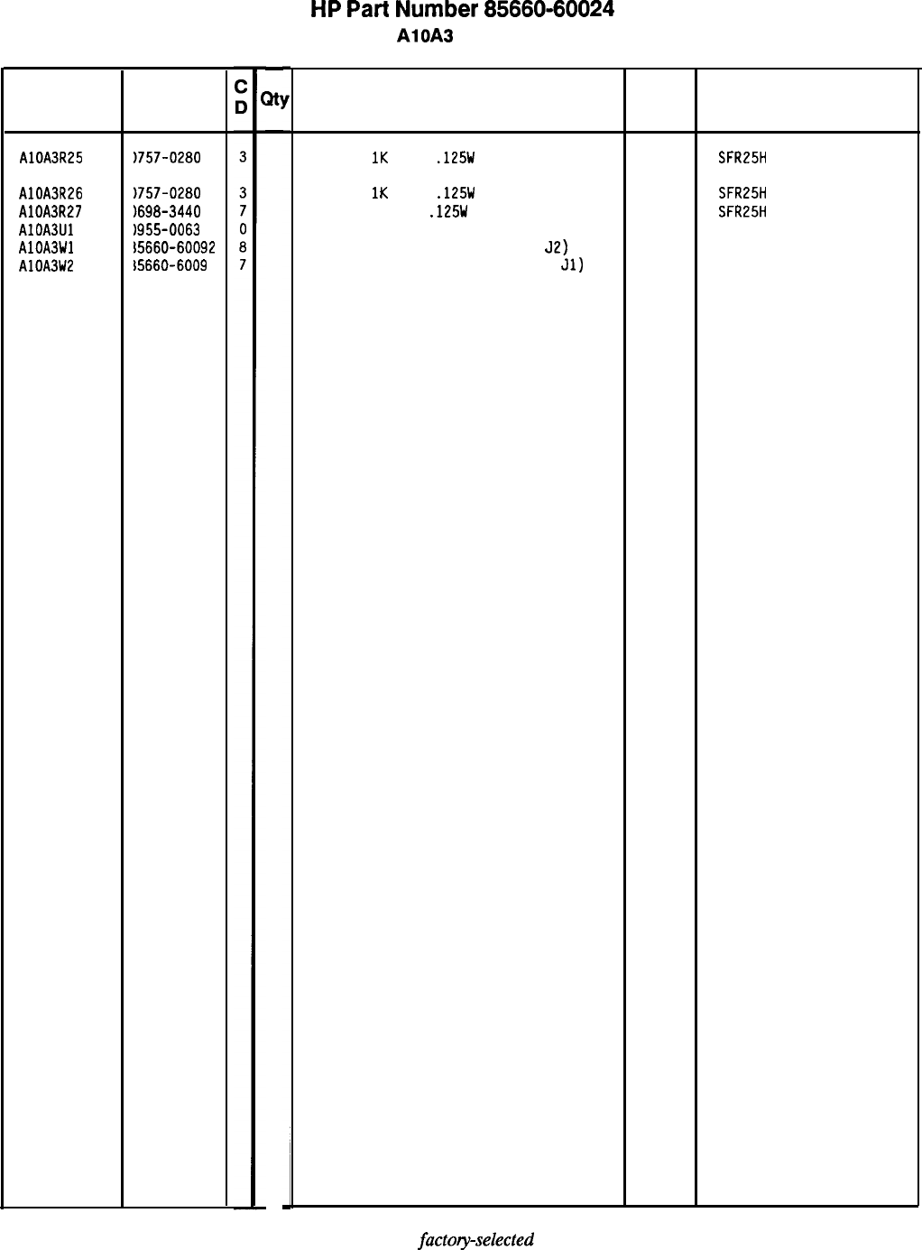
Reference
Designation
AlOA3R25
AlOA3R26
AlOA3R27
AlOAJLJl
AlOA3Wl
AlOA3W2
HP Part
Number
1757-0280
)757-0280
1698-3440
1955-0063
i5660-60092
15660-6009
-
w
-
1
1
1
1
1
1
HP
Part
Number 85660-60024
AlOA3 PLL 1 IF
Description
RESISTOR
1K
+-1%
.125W
TF TC=O+-100
RESISTOR
1K
+-1%
.125W
TF TC=O+-100
RESISTOR 196 1%
.125W
TF TC=O+-100
U-WAVE MIXER 500 MHZ MAX
CABLE ASSEMBLY, BLUE (INCLUDES
52)
CABLE ASSEMBLY, YELLOW (INCLUDES
Jl)
Mfr
Mfr Part
Code Number
19701
SFR25H
19701
SFR25H
19701
SFR25H
15542 SRA-1-32
28480 85660-60092
28480 85660-60091
*Indicates
factoyselected
value
85660-60024 Parts List
Page 3 of 3
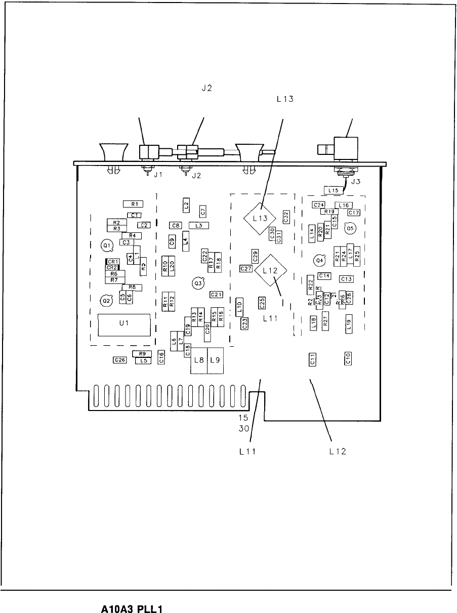
Jl
J2
J3
IN IN
L13
OUT
ZOO-300 MHz 160-166 MHz 170 MHz NULL PLL 1 IF
1
piTJ=
’
00
85
EkeI
i,
Q
“E:
G,
ILJ
ZN
;$I
63
m
(L(L
In-
2;
.&
1
0:
w
‘”
Y?
‘1
t
L8
L9
rrzl
Q~iyJggj
I
:
nA
ll
t&;;
Ic271
LIZ
cml
I,
a4
Y
I,pm
;
0
0
‘I
IL.+
00
D
to:
;
m
1,
EG
-0
;
Lll
1
‘@~,
--A
IL----’
1
B
I
I
m
R2
R3
Ic2
35
I
@
c3R4
I
CR1
CR2
RS
%
;I
z
?I7
R7
j
@
G”
”
1
16 PI
Lll
L12
165 MHz NULL 160 MHz NULL
AlOA3
PLLl
IF Component Locations, 85660-60024
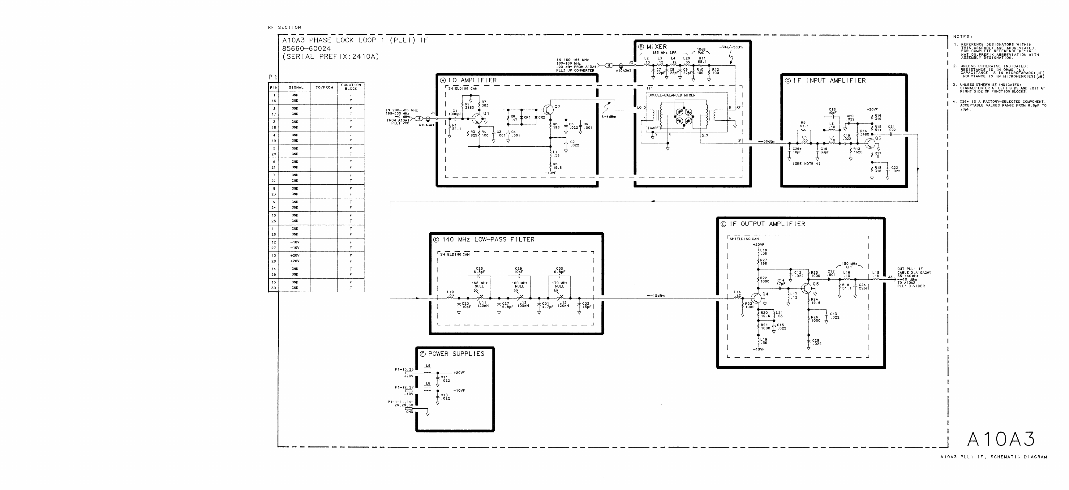
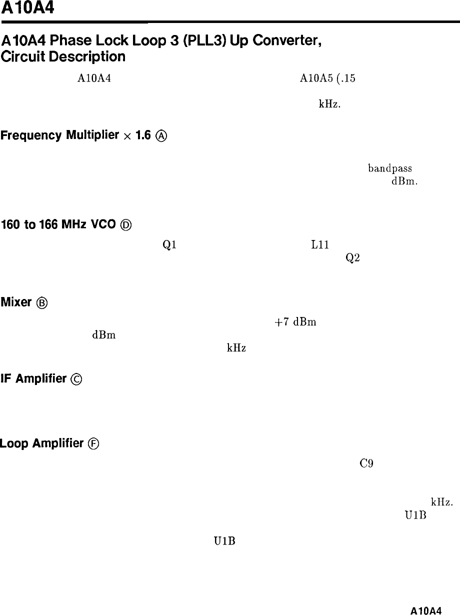
AlOA4
AlOA4
Phase
Lock
Loop
3
(PLL3)
Up
Converter,
Circuit
Description
The function of AlOA4 is to mix 160 MHz with the output of AlOA5 (.15 to 6 MHz),
up-converting that output by 160 MHz. The two frequencies are mixed together in a phase
lock loop which has a closed loop bandwidth of approximately 10 kHz.
Frequency
Multiplier
x
1.6
@
The frequency multiplier generates 160 MHz from the 100 MHz at the input. U3 divides the
input by 5 and produces harmonics of the resulting 20 MHz. The 160 MHz
bandpass
filter
selects 160 MHz, which is then amplified by Q5 and buffered with a pad to -20
dBm.
All
three adjustments are set by peaking the 160 MHz signal.
160
to
166
MHz
VCO
@
The 160 to 166 MHz VCO uses
Ql
in a Colpitts configuration.
Lll
centers the frequency
range of the VCO while CR3 is the varactor which tunes the oscillator.
Q2
and Q4 are buffer
amplifiers.
Mixer
@
U7 is a double-balanced mixer which operates with about
f7
dBm
of LO power at 160 to
166 MHz and -20
dBm
of RF signal power at 160 MHz. The desired output is the difference
frequency which falls in the range between 150 kHz and 6 MHz.
IF
Amplifier
@
The output of the mixer U7 is filtered by an 8-section elliptic filter which must reject
14 to 20 MHz, and other higher frequencies. The filter output is amplified by Q3.
Loop
Amplifier
@
The phase detector outputs are connected to the differential inputs of U2.
C9
and R16
provide ac feedback around U2 while dc feedback is provided by the entire phase lock loop.
CR4 and CR5 lessen the charging time of C7 when the input frequency is changed abruptly.
R14, R15, and C7 form an ac voltage divider which sets the loop bandwidth to about 10
kIIz.
The output of the divider goes to the varactor in the oscillator and tunes the VCO.
UlB
prevents this tune voltage from latching at a positive value by sensing when the voltage goes
above 0 V. When this occurs, the output of
UlB
pulls the tune voltage down to the proper
lock range. R13 provides hysteresis to allow time for the loop to lock.
AlOA4
1
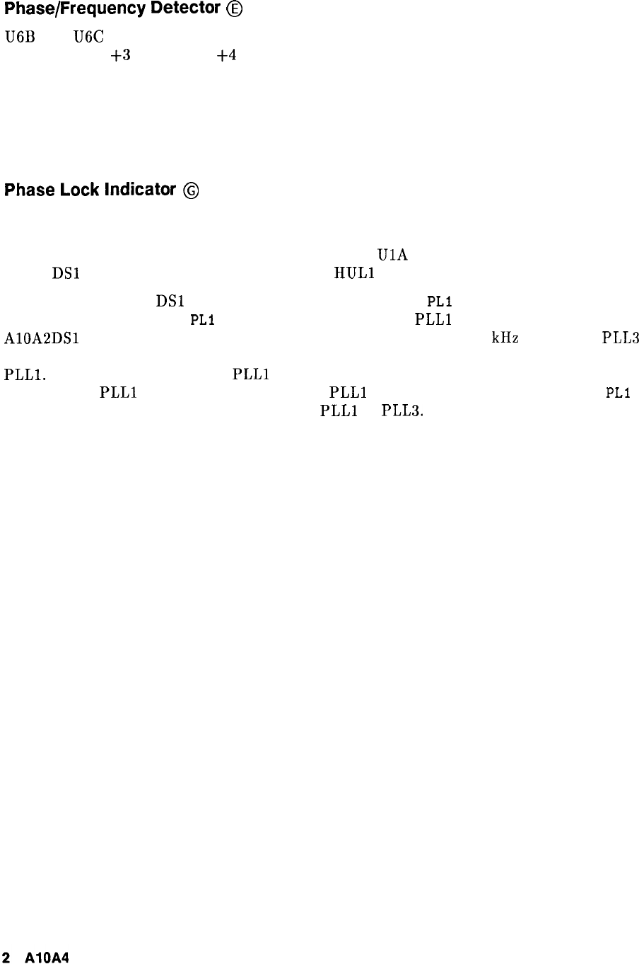
Phase/Frequency Detector
@
U6B and U6C are ECL buffer amplifiers which have the proper output amplitude and dc level
(approximately
+3
V low and
+4
V high) to drive the phase/frequency detector. When the
phase detector inputs have the same phase, the outputs are ECL high with narrow negative
coincident pulses. If there is a phase offset, the pulse widens on one of the outputs depending
on which signal is leading in phase. When the input frequencies are different, the outputs
consist of varying width pulses; the dc or average value of the outputs are different depending
on which frequency is higher and by how much.
Phase
Lock
Indicator
@
The phase lock indicator senses the outputs of the phase detector which are ECL logic high
when the loop is locked. When the loop is not locked, the average phase detector output level
drops to half way between a logic low and logic high.
UlA
switches when this occurs and
causes
DSl
to go out and the phase lock output
HULl
to go to TTL high.
If PLL3 unlocks, LED
DSl
will turn off, and the CRT message
PLl
UNLOCK will appear.
However, the CRT message
PLl
UNLOCK will also appear if
PLLl
unlocks, as indicated when
AlOA2DSl
turns off. In spans above n x 5 MHz and spans of n x 100 kHz and below, PLL3
functions to shift the output of PLL2 up in frequency by 160 MHz for further division by
PLLl.
The two loops PLL3 and
PLLl
always operate in conjunction; if PLL3 unlocks, then
the output of
PLLl
is incorrect whether or not
PLLl
unlocks. The single CRT message
PLl
UNLOCK is used to indicate an unlock in either
PLLl
or PLLS.

Reference
Designation
HP Part
Number
AlOA4 85660-60025
7
AlOA4Cl 0160-0574
3
AlOA4C2 0160-0572
1
AlOA4C3 0160-0572
1
AlOA4C4 0160-0574
3
AlOA4C5 0160-4084
a
AlOA4C6 0160-4084
a
AlOA4C7 0180-0291
3
AlOA4C8 0160-0161
4
AlOA4C9 0160-0161
4
AlOA4ClO 0160-0574
3
AlOA4Cll 0160-0574
3
AlOA4C12 0180-0228
6
AlOA4C13 0180-0291
3
AlOA4C14 0160-0574
3
AlOA4C15 0160-0574
3
AlOA4C16 0160-0574
3
AlOA4C17 0160-4084
a
AlOA4C18 0160-3749
0
AlOA4C19 0160-3877
5
AlOA4C20 0160-3749
0
AlOA4C21 0180-0228
6
AlOA4C22 0160-3876
4
AlOA4C23 0180-0228
6
AlOA4C24 0160-3877
5
AlOA4C25 0160-0571
0
AlOA4C26 0160-3877
5
AlOA4C27 0160-0574
3
AlOA4C28 0160-0571
0
AlOA4C29 0160-3878
6
AlOA4C30 0160-0574
3
AlOA4C31 0160-0574
3
AlOA4C32 0160-0574
3
AlOA4C33 0160-3875
3
AlOA4C34 0160-0574
3
AlOA4C35 0160-3872
0
AlOA4C36 0160-3872
0
AlOA4C37 0160-3565
8
AlOA4C38 0160-0574
3
AlOA4C39 0160-3874
2
AlOA4C40 0160-0574
3
AlOA4C41 0160-0574
AlOA4C42 0160-0574
AlOA4C43 0160-3873
AlOA4C44 0160-3875
AlOA4C45 0160-3874
AlOA4C46 0160-3874
-
%Y
-
1
1
1
1
1
1
1
1
1
1
1
1
1
1
1
1
1
1
1
1
1
1
1
1
1
1
1
1
1
1
1
1
1
1
1
1
1
1
1
1
1
1
1
1
1
1
1
-
HP
Part
Number 85660-60025
Al OA4 PLL 3 Up Converter
Description Mfr
Code
BOARD ASSEMBLY, PLL 3 UP CONVERTER 28480
Mfr Part
Number
85660-60025
CAPACITOR-FXD
.022UF
+-20%
1OOVDC
CER
04222 SR201C223MAAH
CAPACITOR-FXD 2200PF +-20%
1OOVDC
CER
04222 SR201C222MAAH
CAPACITOR-FXD 2200PF +-20%
IOOVDC
CER
04222 SR201C222MAAH
CAPACITOR-FXD
.022UF
+-20%
1OOVDC
CER
04222 SR201C223MAAH
CAP-FXD
O.luF
50 V
56289 lC20X7R104M050B
CAP-FXD
O.luF
50 V
CAPACITOR-FXD lUF+-10% 35VDC TA
CAPACITOR-FXD
.OlUF
+-lo%
EOOVDC POLYE
CAPACITOR-FXD
.OlUF
+-10x
200VDC POLYE
CAPACITOR-FXD
.022UF
+-20X
1OOVDC
CER
56289 lC20X7R104M050B
56289 15DD105X9035A2-DYS
84411 HEW-238M
84411 HEW-238M
04222 SR201C223MAAH
CAPACITOR-FXD
.022UF
+-20%
1OOVDC
CER
04222 SR201C223MAAH
CAPACITOR-FXD
22UF+-10%
15VDC TA
56289 150D226X901582-DYS
CAPACITOR-FXD
lUF+-10%
35VDC TA
56289
150D105X9035A2DYS
CAPACITOR-FXD
.022UF
+-20%
1OOVDC
CER
04222 SR201C223MAAH
CAPACITOR-FXD
.022UF
+-20%
1OOVDC
CER
04222 SR201C223MAAH
CAPACITOR-FXD
.022UF
+-20%
1OOVDC
CER
04222
CAP-FXD
O.luF
50 V
56289
CAPACITOR-FXD 330PF +-lo% 50VDC CER
CAPACITOR-FXD
1OOPF
+-20%
ZODVDC
CER
CAPACITOR-FXD 330PF
+-lo%
50VDC CER
04222
SR201C223MAAH
lC20X7R104M050B
RPEllO-401X7R331K50V
SR202ClOlMAAH
RPEllO-401X7R331K50V
CAPACITOR-FXD
22UF+-10%
15VDC
TA
56289 150D226X9015B2-DYS
CAPACITOR-FXD 47PF +-20% 200VDC CER
04222 SR202C470MAAH
CAPACITOR-FXD
22UF+-10%
15VDC TA
56289 150D226X9015B2-DYS
CAPACITOR-FXD
1OOPF
+-20%
LOOVDC
CER
04222 SR202ClOlMAAH
CAPACITOR-FXD 470PF +-20%
1OOVDC
CER
04222 SR201C471MAAH
CAPACITOR-FXD
1OOPF
+-20%
ZODVDC
CER
CAPACITOR-FXD
.022UF
+-20%
1OOVDC
CER
CAPACITOR-FXD 470PF +-20%
1ODVDC
CER
CAP-FXD
1OOOpF
100 V
CAPACITOR-FXD
.022UF
+-20%
1OOVDC
CER
04222 SR202ClOlMAAH
04222 SR201C223MAAH
04222 SR201C471MAAH
04222 SR201C102MAAH
04222 SR201C223MAAH
CAPACITOR-FXD
.022UF
+-20x
1OOVDC
CER
CAPACITOR-FXD
.022UF
+-20%
1OOVDC
CER
CAPACITOR-FXD 22PF +-5% EOOVDC CER
0+-30
CAPACITOR-FXD
.022UF
+-20%
1OOVDC
CER
CAP-FXD
2.2pF
200 V
04222
04222
04222
SR201C223MAAH
SR201C223MAAH
FD12COG2D220J
SR2DlC223MAAH
FD12COG2D2R2C
CAP-FXD
2.2pF
200 V
CAP-FXD
6.8pF
100 V
CAPACITOR-FXD
.022UF
+-20%
1OOVDC
CER
CAPACITOR-FXD
1OPF
+-.5PF
LOOVDC CER
CAPACITOR-FXD
.022UF
+-20%
1OOVDC
CER
04222
04222
FD12COG2D2R2C
FDllCOG2A6R8D
SR201C223MAAH
FD12CDG2DlOOD
SR201C223MAAH
CAPACITOR-FXD
.022UF
+-20%
1OOVDC
CER
CAPACITOR-FXD
.022UF
+-20%
1DDVDC
CER
CAPACITOR-FXD
4.7PF
+-.5PF
ZOOVDC
CER
CAPACITOR-FXD 22PF
+-5x
200VDC CER 0+-30
CAPACITOR-FXD
1OPF
+-.5PF
200VDC CER
04222
04222 SR201C223MAAH
SR201C223MAAH
FD12COG2D4R7D
FD12COG2D220J
FD12COG2DlOOD
CAPACITOR-FXD
1OPF
+-.5PF
EOOVDC CER
FD12COG2DlOOD
*Indicates factory-selected value
85660-60025 Parts List
Page 1 of 4
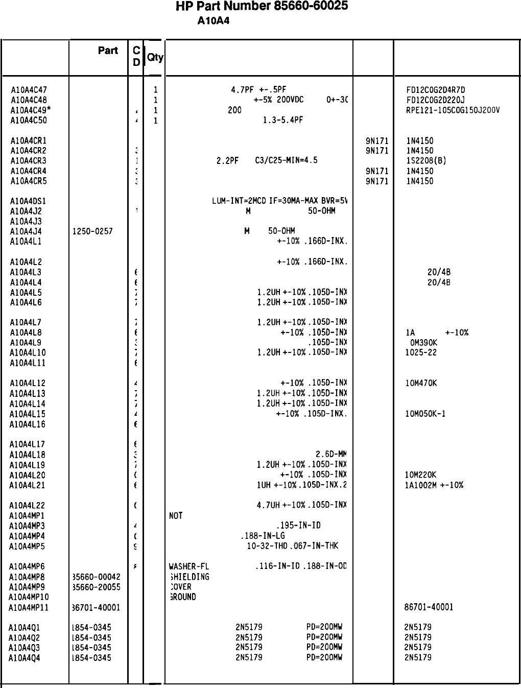
Reference
Designation HP
Part
Number
-
AlOA4C47 0160-3873
AlOA4C48 0160-3875
AlOA4C49* 0160-4385
AlOA4C50 0121-0452
Description
CAPACITOR-FXD
4.7PF
+-.5PF
200VDC CER
CAPACITOR-FXD 22PF +-5X
EOOVDC
CER
0+-3C
CAP-FXD 15pF
200
V
Mfr
Mfr Part
Code Number
CAPACITOR-V TRMR-AIR
1.3-5.4PF
175V
74970
FD12COG2D4R7D
FD12COG2D220J
RPE121-105COG150J200V
187-0103-028
AlOA4CRl 1901-0050
AlOA4CR2 1901-0050
AlOA4CR3 0122-0085
AlOA4CR4 1901-0050
AlOA4CR5 1901-0050
1
DIODE-SWITCHING 80V 200MA 2NS DO-35 9N171 lN4150
1
DIODE-SWITCHING 80V 200MA 2NS DO-35 9N171 lN4150
1
DIODE-VVC
2.2PF
7%
C3/C25-MIN=4.5
so545 132208(8)
1
DIODE-SWITCHING 80V 200MA 2NS DO-35 9N171 lN4150
1
DIODE-SWITCHING 80V 200MA 2NS DO-35 9N171 lN4150
AlOA4DSl 1990-0485
I
1
LED-LAMP
LUM-INT=2MCO
IF=30MA-MAX
BVR=5V
28480 HLMP-1503
AlOA4J2 1250-2112
1
1
CONNECTOR-RF SMB
M
SGL-HOLE-FR
50-OHM 98291 051-047-0259-220
AlOA4J3 1250-2112
,
1
CONNECTOR-RF SMB M SGL-HOLE-FR 50-OHM
98291 051-047-0259-220
AlOA4J4 1250-0257
1
1
CONNECTOR-RF SMB
M
PC
50-OHM 98291 51-051-0169-226
AlOA4Ll 9140-0179
1
1
INDUCTOR RF-CH-MLD 22UH
+-lo%
.166D-INX.
99800 1537-44
AlOA4L2 9140-0179
1
1
INDUCTOR RF-CH-MLD 22UH
+-lo%
.166D-INX.
99800 1537-44
AlOA4L3 9100-1788
t
1
CORE-FERRITE CHOKE-WIDEBAND IMP:680
02114
VK200
20/4B
AlOA4L4 9100-1788
t
1
CORE-FERRITE CHOKE-WIDEBAND IMP:680
02114
VK200
20/4B
AlOA4L5 9100-2258
;
1
INDUCTOR RF-CH-MLD
1.2UH
+-10X
.105D-INX
99800 1025-22
AlOA4L6 9100-2258
;
1
INDUCTOR RF-CH-MLD
1.2UH
+-lo%
.105D-INX
99800 1025-22
AlOA4L7 9100-2258
;
1
INDUCTOR RF-CH-MLD
1.2UH
+-10x
.lOSD-INX
99800 1025-22
AlOA4L8 9100-2257
t
1
INDUCTOR RF-CH-MLD 820NH
+-lo%
.105D-INX
32159
1A
8203M
+-lo%
AlOA4L9 9100-2254
:
1
INDUCTOR RF-CH-MLD 390NH +-10%
.lOSD-INX
24226
1
OM390K
AlOA4LlO 9100-2258
;
1
INDUCTOR RF-CH-MLD
1.2UH
+-10x
.105D-INX
99800 1025-22
AlOA4Lll 85660-80006
t
1
INDUCTOR 120NH 28480 85660-80006
AlOA4L12 9100-2255
I
1
INDUCTOR RF-CH-MLD 470NH
+-lo%
.lOSD-INX
24226 lOM470K
AlOA4L13 9100-2258
;
1
INDUCTOR RF-CH-MLD
1.2UH
+-lo%
.105D-INX 99800 1025-22
AlOA4L14 9100-2258
i
1
INDUCTOR RF-CH-MLD
1.2UH
+-lo%
.105D-INX 99800 1025-22
AlOA4L15 9100-2891
I
1
INDUCTOR RF-CH-MLD 50NH +-lo%
.105D-INX.
24226 lOM05DK-1
AlOA4L16 85660-80006
t
1
INDUCTOR 120NH 28480 85660-80006
AlOA4L17 85660-80006
f
1
AlOA4L18 9135-0073
:
1
AlOA4L19 9100-2258
j
1
AlOA4L20 9100-2251
(
1
AlOA4L21 9140-0158
t
1
INDUCTOR 120NH 28480
06560
99800
24226
32159
85660-80006
1025-22
lOM220K
lA1002M
+-lo%
AlOA4L22
AlOA4MPl
AlOA4MP3
AlOA4MP4
AlOA4MP5
9140-0144
INDUCTOR RF-CH-MLD 51NH +-6.596%
2.60-MM
INDUCTOR RF-CH-MLD
1.2UH
+-lo%
.lD5D-INX
INDUCTOR RF-CH-MLD 220NH +-lo%
.105D-INX
INDUCTOR RF-CH-MLD
1UH
+-lo%
.105D-INX.2
INDUCTOR RF-CH-MLD
4.7UH
+-lo%
.105D-INX
NOT
ASSIGNED
99800 1025-36
2190-0124
2200-0101
2950-0078
1
6
WASHER-LK INTL T ND. 10
.195-IN-ID 98291
2
SCREW-MACH 4-40
.188-IN-LG
PAN-HD-POZI
77250
3
NUT-HEX-DBL-CHAM
lo-32-THD
.067-IN-THK 74163
3002-26
500220
AlOA4MP6 3050-0082
AlOA4MP8 35660-00042
AlOA4MP9 35660-20055
AlOA4MPlO 35660-20068
AlOA4MPll 367Dl-40001
1
1
1
3
1
1
1
1
1
-
IJASHER-FL
NM NO. 4
.116-IN-ID
.188-IN-00
jHIELDING
CAN
:OVER
PC, PLL3 UP CONVERTER
iROUND
LUG
IXTRACTOR PC
76854 8942-3
28480 85660-00042
28480 85660-20055
28480
85660-20068
28480 86701-40001
AlOA4Ql 1854-0345
AlOA4Q2 1854-0345
AlOA4Q3 1854-0345
AlOA4Q4 1854-0345
TRANSISTOR NPN
2N5179
SI TO-72
PD=ZODMW 04713 2N5179
TRANSISTOR NPN
2N5179
SI TO-72
PD=LOOMW 04713 2N5179
TRANSISTOR NPN
2N5179
SI TO-72
PD=ZOOMW 04713 2N5179
TRANSISTOR NPN
2N5179
SI TO-72
PD=POOMW 04713 2N5179
85660-60025 Parts List
Page 2 of 4
-
HP
Part
Number 85660-60025
AloA4
PLL 3 Up Converter
*Indicates factory-selected value
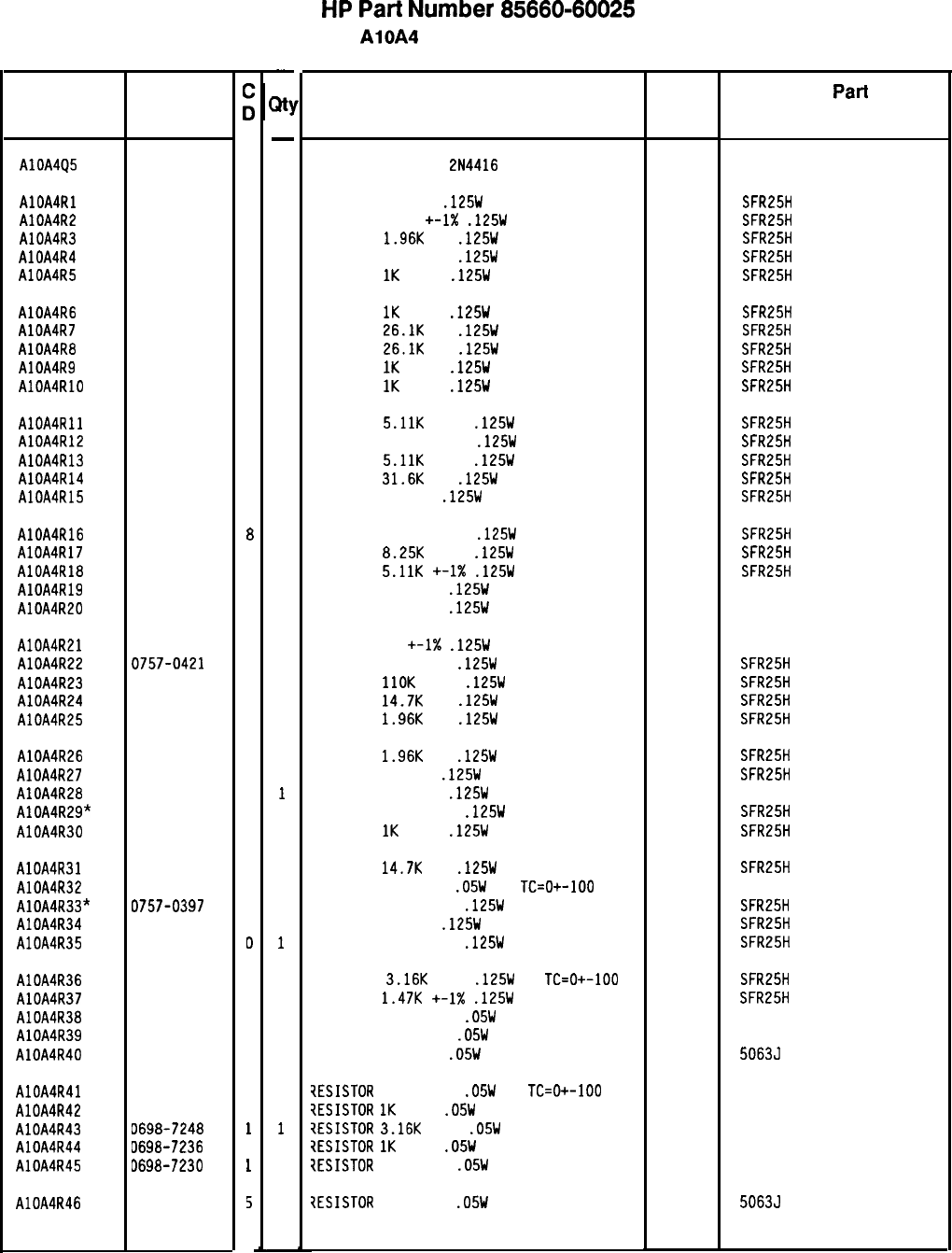
Reference
Designation
HP Part
Number
AlOA4Q5 1855-0327
B
AlOA4Rl 0698-3440
7
AlOA4R2 0757-0394
0
AlOA4R3 0698-0083
8
AlOA4R4 0757-0418
9
AlOA4R5 0757-0280
3
AlOA4R6 0757-0280
3
AlOA4R7 0698-3159
5
AlOA4R8 0698-3159
5
AlOA4R9 0757-0280
3
AlOA4RlD 0757-0280
3
AlOA4Rll 0757-0438
3
AlDA4R12 0757-0441
8
AlOA4R13 0757-0438
3
AlOA4R14 0698-3160
8
AlOA4R15 0698-3447
4
AlOA4R16 0757-0441
8
AlOA4R17 0757-0441
8
AlOA4R18 0757-0438
3
AlOA4R19 0757-0346
2
AlOA4R20 0757-0346
2
AlOA4R21 0757-0346
AlOA4R22 0757-0421
AlOA4R23 0757-0466
AlOA4R24 0698-3156
AlOA4R25 0698-0083
AlOA4R26 0698-0083
AlOA4R27 0698-3440
AlOA4R28 0757-0346
AlOA4R29* 0757-0397
AlOA4R30 0757-0280
AlDA4R31 0698-3156
AlOA4R32 0698-7219
AlOA4R33* 0757-0397
AlOA4R34 0698-3440
AlOA4R35 0757-0394
AlOA4R36 0757-0279
AlOA4R37 0757-1094
AlOA4R38 0698-7192
AlOA4R39 0698-7230
AlOA4R40
0698-7188
AlOA4R41
AlOA4R42
AlOA4R43
AlOA4R44
AlOA4R45
0698-7200
0698-7236
0698-7248
D698-7236
D698-7230
AlOA4R46 3698-7218
2
4
7
2
B
B
7
2
3
3
2
6
3
7
D
D
3
4
1
3
5
7
1
7
1
i
-
JI
-
1
1
1
1
1
1
1
1
1
1
1
1
1
1
1
1
1
1
1
1
1
1
1
1
1
1
1
1
1
1
1
1
1
1
1
1
1
1
1
1
1
1
1
1
1
1
1
-
HP
Part
Number 85660-60025
AlOA4 PLL 3 Up Converter
Description Mfr
Code
TRANSISTOR J-FET
2N4416
N-CHAN D-MODE
34677
RESISTOR 196 1%
.125W
TF TC=O+-100
RESISTOR 51.1
+-1X
.125W
TF TC=O+-100
RESISTOR
1.96K
1%
.125W
TF TC=O+-100
RESISTOR 619 +-1%
.125W
TF TC=D+-100
RESISTOR
1K
+-1%
.125W
TF TC=O+-100
19701
19701
19701
19701
19701
Mfr
Part
Number
SFR25H
SFR25H
SFR25H
SFR25H
SFR25H
RESISTOR
1K
+-1%
.125W
TF TC=O+-100
19701
SFR25H
RESISTOR
26.1K
1%
.125W
TF TC=O+-100
19701
SFR25H
RESISTOR
26.1K
1%
.125W
TF TC=O+-100
19701
SFR25H
RESISTOR
1K
+-1%
.125W
TF TC=O+-100
19701
SFR25H
RESISTOR
1K
+-1%
.125W
TF TC=O+-100
19701
SFR25H
RESISTOR
5.11K
+-1%
.125W
TF TC=O+-100
19701
SFR25H
RESISTOR 8.251: +-1%
.125W
TF TC=O+-100
19701
SFR25H
RESISTOR
5.11K
+-1%
.125W
TF TC=O+-100
19701
SFR25H
RESISTOR
31.6K
1%
.125W
TF TC=O+-100
19701
SFR25H
RESISTOR 422 1%
.125W
TF TC=O+-100
19701
SFR25H
RESISTOR 8.251: +-1%
.125W
TF TC=O+-100
19701
SFR25H
RESISTOR
8.25K
+-1%
.125W
TF TC=O+-100
19701
SFR25H
RESISTOR
5.11K
+-I%
.125W
TF TC=D+-100
19701
SFR25H
RESISTOR 10 +-1%
.125W
TF TC=O+-100
91637 CMF-55-1, T-l
RESISTOR 10 +-1%
.125W
TF TC=O+-100
91637 CMF-55-1, T-l
RESISTOR 10 +-1X
.125W
TF TC=O+-100
91637 CMF-55-1, T-l
RESISTOR 825 +-1%
.125W
TF TC=D+-100
19701
SFR25H
RESISTOR
1lOK
+-1%
.125W
TF TC=O+-100
19701
SFR25H
RESISTOR
14.7K
1%
.125W
TF TC=O+-100
19701
SFR25H
RESISTOR
1.96K
1%
.125W
TF TC=O+-100
19701
SFR25H
RESISTOR
1.96K
1%
.125W
TF TC=O+-100
19701
SFR25H
RESISTOR 196 1%
.125W
TF TC=O+-100
19701
SFR25H
RESISTOR 10 +-1%
.125W
TF TC=D+-100
91637 CMF-55-1, T-l
RESISTOR 68.1 +-1%
.125W
TF TC=O+-100
19701
SFR25H
RESISTOR
1K
+-1%
.125W
TF TC=O+-100
19701
SFR25H
RESISTOR
14.7K
1%
.125W
TF TC=O+-100
RESISTOR 196 +-1%
.05W
TF
TC=O+-100
RESISTOR 68.1 +-1%
.125W
TF TC=O+-100
RESISTOR 196 1%
.125W
TF TC=O+-100
RESISTOR 51.1 +-1%
.125W
TF TC=O+-100
SFR25H
50635
SFR25H
SFR25H
SFR25H
RESISTOR
3.16K
+-1%
.125W
TF
TC=O+-100
RESISTOR
1.47K
+-1X
.125W
TF TC=O+-100
RESISTOR 14.7 +-1%
.05W
TF TC=O+-100
RESISTOR 562 +-1%
.05W
TF TC=O+-100
RESISTOR 10 +-1%
.05W
TF TC=O+-100
SFR25H
SFR25H
50635
50635
50635
?ESISTOR
31.6 +-1%
.05W
TF
TC=O+-100
?ESISTDR
1K
+-1%
.05W
TF TC=O+-100
?ESISTOR
3.16K
+-1%
.05W
TF TC=O+-100
7ESISTOR
1K
+-1%
.05W
TF TC=O+-100
?ESISTDR
562 +-1%
.05W
TF TC=O+-100
7ESISTOR
178 +-1%
.05W
TF TC=O+-100
19701
19701
19701
19701
19701
19701
19701
19701
19701
19701
19701
19701
19701
19701
19701
19701
50635
50635
50635
50635
50635
50635
*Indicates factory-selected value
85660-60025 Parts List
Page 3 of 4
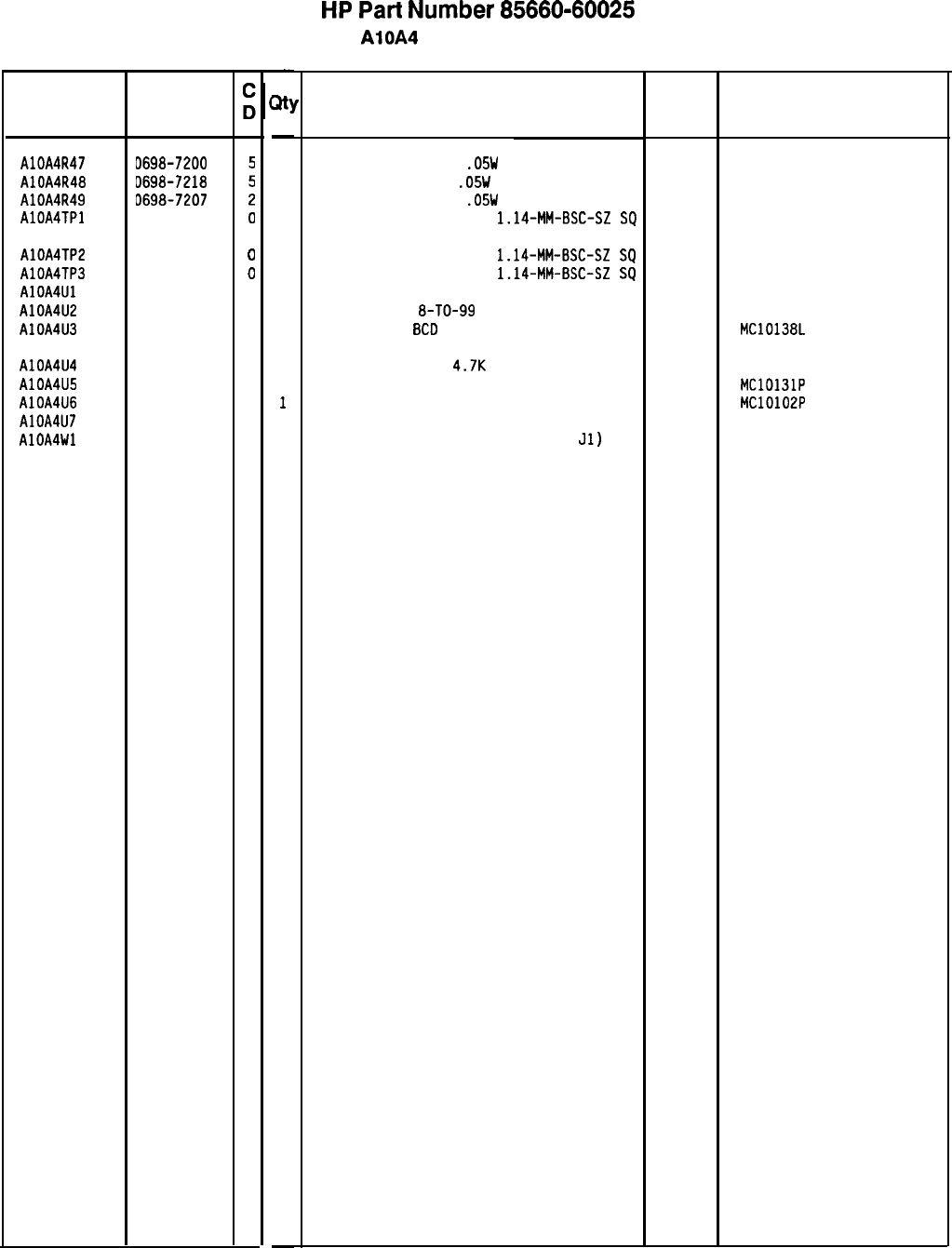
Reference HP Part
Designation Number
AlOA4R47
AlOA4R48
AlOA4R49
AlOA4TPl
D698-7200
0698-7218
D698-7207
1251-0600
AlOA4TP2 1251-0600
0
AlOA4TP3 1251-0600
0
AlOA4Ul 5081-8117
3
AlOA4U2 1826-1058
3
AlOA4U3 1820-1383
5
AlOA4U4
AlOA4U5
AlOA4U6
AlOA4U7
AlOA4Wl
1810-0205
7
1820-0817
8
1820-0802
1
1955-0063
0
35660-60093
9
-
31
-
1
1
1
1
1
1
1
1
1
1
1
1
1
1
-
HP
Part
Number 85660-60025
AlOA4 PLL 3 Up Converter
Description
RESISTOR 31.6 +-1%
.05W
TF TC=O+-100
19701
50635
RESISTOR 178 +-1%
.05W
TF TC=O+-100
19701
50635
RESISTOR 61.9 +-1%
.05W
TF TC=O+-100
19701
50635
CONNECTOR-SGL CONT PIN
1.14~MM-BSC-SZ
SQ
27264 16-06-0034
CONNECTOR-SGL CONT PIN
1.14~MM-BSC-SZ
SQ
CONNECTOR-SGL CONT PIN
1.14~MM-BSC-SZ
SQ
SCREEN 1826-0092
IC OP AMP GP
8-TO-99
PKG
IC CNTR ECL
8CD
POS-EDGE-TRIG
27264 16-06-0034
27264 16-06-0034
28480 5081-8117
06665 OP-02CJ
04713 MC10138L
NETWORK-RES 8-SIP
4.7K
OHM X 7
11236 750-81
IC FF ECL D-M/S DUAL 04713 MC10131P
IC GATE ECL NOR QUAD 2-INP 04713 MC10102P
U-WAVE MIXER 500 MHZ MAX 15542 SRA-1-32
CABLE ASSEMBLY, VIOLET (INCLUDES
Jl)
28480 85660-60093
8566040025 Parts List
Page 4 of 4
*Indicates factory-selected value
Mfr
Mfr Part
Code Number
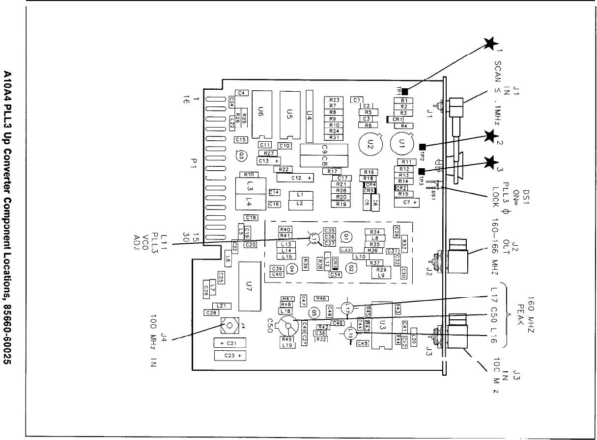
/f
I
r-&y
II
u
\
-
\Z
KS
?J
I
N
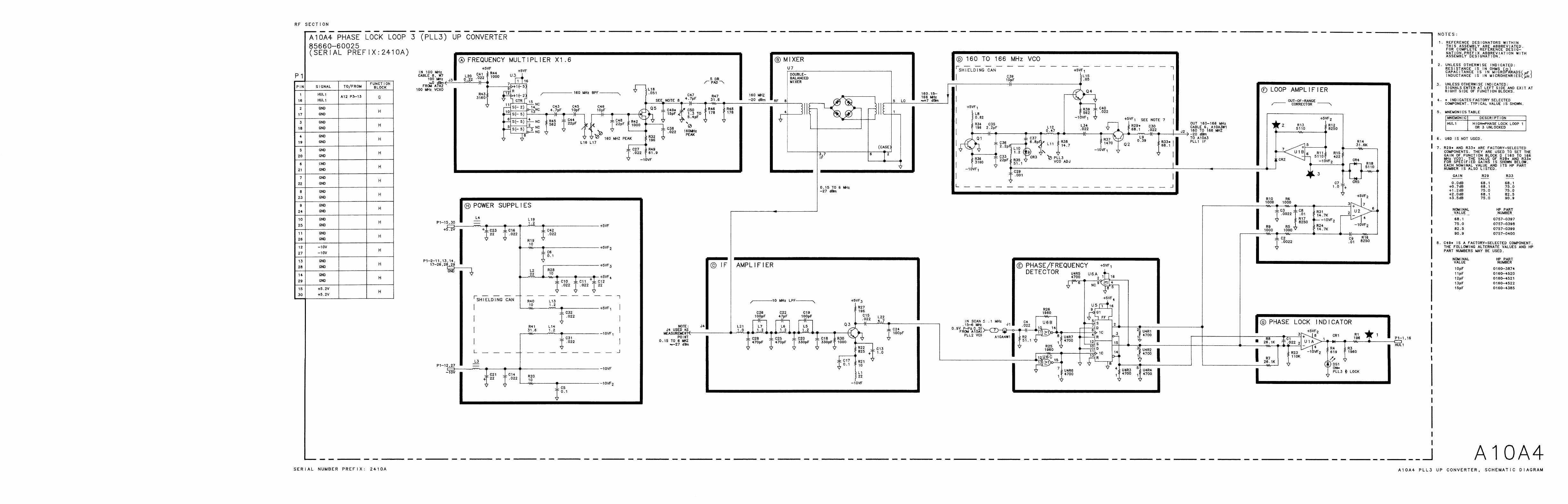

AlOA5
AlOA5
Phase
Lock
Loop
2
(PLL2)
Voltage
Controlled
Oscillator
(VCO),
Circuit
Description
75
to
150
MHz
VCO
@
The VCO is a varactor tuned oscillator which tunes 75 to 150 MHz. Varactors
CRl,
CR2,
CR3, and CR4 form a series-tuned resonant circuit with L4 and L5. This series circuit
connects the emitters of
Ql
and
Q2.
Q2 is a common-base amplifier whose load impedance is
made up primarily of L9, R14, and R15. The voltage across the load is coupled to the base of
emitter-follower
Ql,
which drives the series resonant circuit.
Bias
Network/50
kHz
Low-Pass
Filter
@
Transistors Q5 and Q6 and associated components form a filtered -32 V source to bias the
varactor tuning diodes. In the absence of tuning current, the varactor bias is set by R2 to
approximately -17 V. Tuning current from the AlOA8 PLL2 Discriminator passes through
the 50 kHz low-pass filter and acts to pull this bias voltage in a positive direction. Tuning
sensitivity is set by R4, to -10
Mhz/mA.
75
to
150
MHz
Output
Buffer
@
Q4 is a grounded-base amplifier to isolate the VCO from the load circuits. The output of Q4
is filtered, attenuated, and used to drive the AlOA7 PLL2 Divider.
Frequency
Dividers
@
Q3 isolates the VCO from the dividers and develops the required drive voltage. Note that all
of the dividers and gates are ECL with
Vcc
hooked to
+5
V and
VEE
grounded. U3 divides
the VCO frequency by 5; to the range of 15 to 30 MHz. U6C provides isolation. U2 divides
the output by 5; to the range of 3 to 6 MHz. U2 then further divides by 2 and
Ul
divides
the output by 10, to the range of is 0.15 to 0.30 MHz. The output of
Ul
is fed to the
AlOh
PLL2 Discriminator.
Small
Span
Switch
@
U5 functions as a single-pole double-throw switch, controlled by SW2. For frequency spans
greater than n x 5 kHz up to n x 100 kHz, SW2 is TTL high, routing the 3 to 6 MHz signal
from U2 through U5C, U5B, and U5D to the AlOA4 PLL3 Up Converter (n is the harmonic
mixing number). When the frequency span is n x 5 kHz or less, or greater than n x 5 MHz,
SW2 is low, routing the 0.15 to 0.30 MHz signal from
Ul
through U5A and U5D to the PLL3
Up Converter. R33 and R34 shift the TTL levels to ECL levels.
AlOA5
1
0.1
to
5
MHz
Span
Switch
@
For frequency spans of greater than n x 100 kHz up to n x 5 MHz, SW1 is TTL low, routing
the 15 to 30 MHz signal from U3 through U6D, U7D, and
Tl
to the
AlOAl
PLLl
VCO.
When SW1 is high, the circuit provides 90 dB of isolation. R35 and R36 shift the TTL levels
to ECL levels.
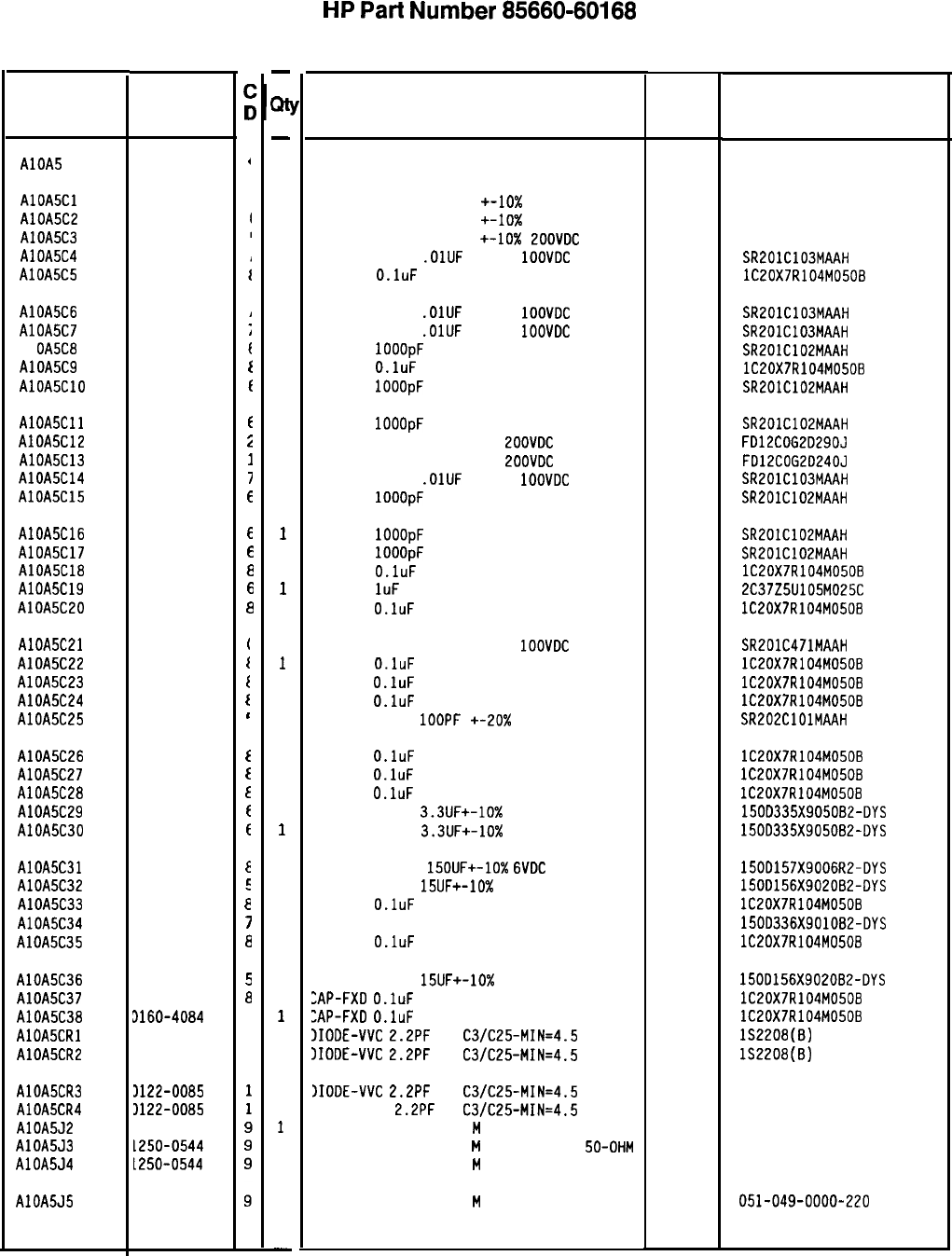
HP
Part
Number 85660-60168
Reference
Designatior
HP Part
Number
t
AlOA5 85660-60168
,
AlOA5Cl 0160-0300
AlOA5C2 0160-0155
AlOA5C3 0160-0154
AlOA5C4 0160-3879
AlOA5C5 0160-4084
AlOASC6 0160-3879
1
AlOA5C7 0160-3879
;
Al
OA5C8 0160-3878
f
AlOA5C9 0160-4084
f
AlOA5ClO 0160-3878
f
AlOA5Cll 0160-3878
t
AlOASC12 0160-4525
i
AlOA5C13 0160-4524
I
AlOA5C14 0160-3879
I
AlOA5C15 0160-3878
6
AlOA5C16 0160-3878
6
AlOA5C17 0160-3878
6
AlOA5C18 0160-4084
a
AlOA5C19 0160-4892
6
AlOA5C20
0160-4084
I-
AlOA5C21 0160-0571
i
AlOA5C22 0160-4084
I
AlOA5C23 0160-4084
t
AlOA5C24 0160-4084
t
AlOA5C25 0160-3877
I
AlOA5C26 0160-4084
f
AlOA5C27 0160-4084
t
AlOA5C28 0160-4084
f
AlOA5C29 0180-2141
f
AlOA5C30 0180-2141
f
AlOA5C31 0180-1715
E
AlOA5C32 0180-1746
E
AlOA5C33 0160-4084
i
AlOA5C34 0180-0229
7
AlOA5C35
0160-4084
a
AlOASC36 0180-1746
5
AlOASC37 0160-4084
a
AlOA5C38 3160-4084
8
AlOA5CRl 3122-0085
1
AlOA5CR2 3122-0085
1
AlOA5CR3 3122-0085
AlOA5CR4 3122-0085
AlOA5J2 1250-0544
AlOA5J3 1250-0544
AlOASJ4 L250-0544
AlOA5J5
1250-0544
-
Qt
-
1
1
1
1
1
1
1
1
1
1
1
1
1
1
1
1
1
1
1
1
1
1
1
1
1
1
1
1
1
1
1
1
1
1
1
1
1
1
1
1
1
1
1
1
1
1
1
-
Al OA5 PLL 2 VCO
Description Mfr
Mfr Part
Code Number
BOARD ASSEMBLY. PLL2 VCD
2848C
85660-60168
CAPACITOR-FXD 2700PF +-lo% 200VDC POLYE
84411 HEW-238M
CAPACITOR-FXD 3300PF +-lo% 200VDC PDLYE
84411 HEW-238M
CAPACITOR-FXD 2200PF +-lo%
LOOVDC
POLYE
84411 HEW-238M
CAPACITOR-FXD
.OlUF
+-20%
1OOVDC
CER
04222 SR201C103MAAH
CAP-FXD
O.luF
50 V
56289 lC2OX7R104M0508
CAPACITOR-FXD
.OlUF
+-20%
1OOVDC
CER
04222 SR2OlC103MAAH
CAPACITOR-FXD
.OlUF
+-20%
1OOVDC
CER
04222 SR201C103MAAH
CAP-FXD
1OOOpF
100 V
04222 SR2OlC102MAAH
CAP-FXD
O.luF
50 V
56289 lC20X7R104MO50B
CAP-FXD
1OOOpF
100 V
04222 SR201C102MAAH
CAP-FXD
1OOOpF
100 V
CAPACITOR-FXD 29PF +-5%
LOOVDC
CER 0+-30
CAPACITOR-FXD 24PF +-5%
ZOOVDC
CER 0+-30
CAPACITOR-FXD
.OlUF
+-20%
1OOVDC
CER
CAP-FXD
1OOOpF
100 V
04222
04222
04222
SR201C102MAAH
FD12COG2029OJ
FD12COG2D24OJ
SR201C103MAAH
SR2OlC102MAAH
CAP-FXD
1OOOpF
100 V
CAP-FXD
IOOOpF
100 V
CAP-FXD
O.luF
50 V
"AP-FXD
1uF
25 V
CAP-FXD
O.luF
50 V
04222 SR201C102MAAH
04222 SR2OlC102MAAH
56289 lC20X7R104M05OB
56289 2C37Z5UlD5M025C
56289 lC20X7R104M0508
CAPACITOR-FXD 470PF +-20%
1OOVDC
CER
04222 SR201C471MAAH
CAP-FXD
O.luF
50 V
56289 lC20X7R104M0508
CAP-FXD
O.luF
50 V
56289 lC20X7R104MO508
CAP-FXD
O.luF
50 V
56289 lC20X7R104M0508
CAPACITOR-FXD
1OOPF
+-20X
200VDC CER
04222 SR202ClOlMAAH
CAP-FXD
O.luF
50 V
56289 lC20X7R104M0508
CAP-FXD
O.luF
50 V
56289 lC2OX7R104M050B
CAP-FXD
O.luF
50 V
56289 lC20X7R104MO5OB
CAPACITOR-FXD 3.3UF+-10% 50VDC TA
56289 1500335X905OB2-DYS
CAPACITOR-FXD
3.3UF+-10%
50VDC TA
56289 15OD335X905082-DYS
CAPACITOR-FXD
15OUF+-10%
6VDC
TA
CAPACITOR-FXD
15UF+-10%
20VDC TA
CAP-FXD
O.luF
50 V
CAP-FXD 33uF 10 V TA
CAP-FXD
O.luF
50 V
56289 150D157X9006R2-DYS
56289 1500156X902OB2-DYS
56289 lC20X7R104M0508
56289 150D336X901082-DYS
56289 lC2DX7R104M050B
CAPACITOR-FXD
15UF+-10%
20VDC TA
ZAP-FXD
O.luF
50 V
:AP-FXD
O.luF
50 V
1IDDE-VVC
2.2PF
7%
C3/C25-MIN=4.5
IIDDE-VVC
2.2PF
7%
C3/C25-MIN=4.5
)IODE-VVC
2.2PF
7%
C3/C25-MIN=4.5
IIDDE-VVC
2.2PF
7%
C3/C25-MIN=4.5
:ONNECTOR-RF SM-SNP
M
SGL-HOLE-FR 50-OHM
:ONNECTOR-RF SM-SNP
M
SGL-HOLE-FR
50-OHM
:ONNECTOR-RF SM-SNP
M
SGL-HOLE-FR 50-OHM
56289 1500156X9020B2-DYS
56289 lC20X7R104MO508
56289 lC20X7R104M0508
so545 lS2208(B)
so545 lS2208(8)
so545 132208(B)
so545 152208(B)
98291 051-049-0000-220
98291 051-049-0000-220
98291 051-049-0000-220
:ONNECTOR-RF SM-SNP
M
SGL-HOLE-FR 50-OHM 98291 051-049-0000-220
*Indicates factory-selected value
85660-60168 Parts List
Page 1 of 3
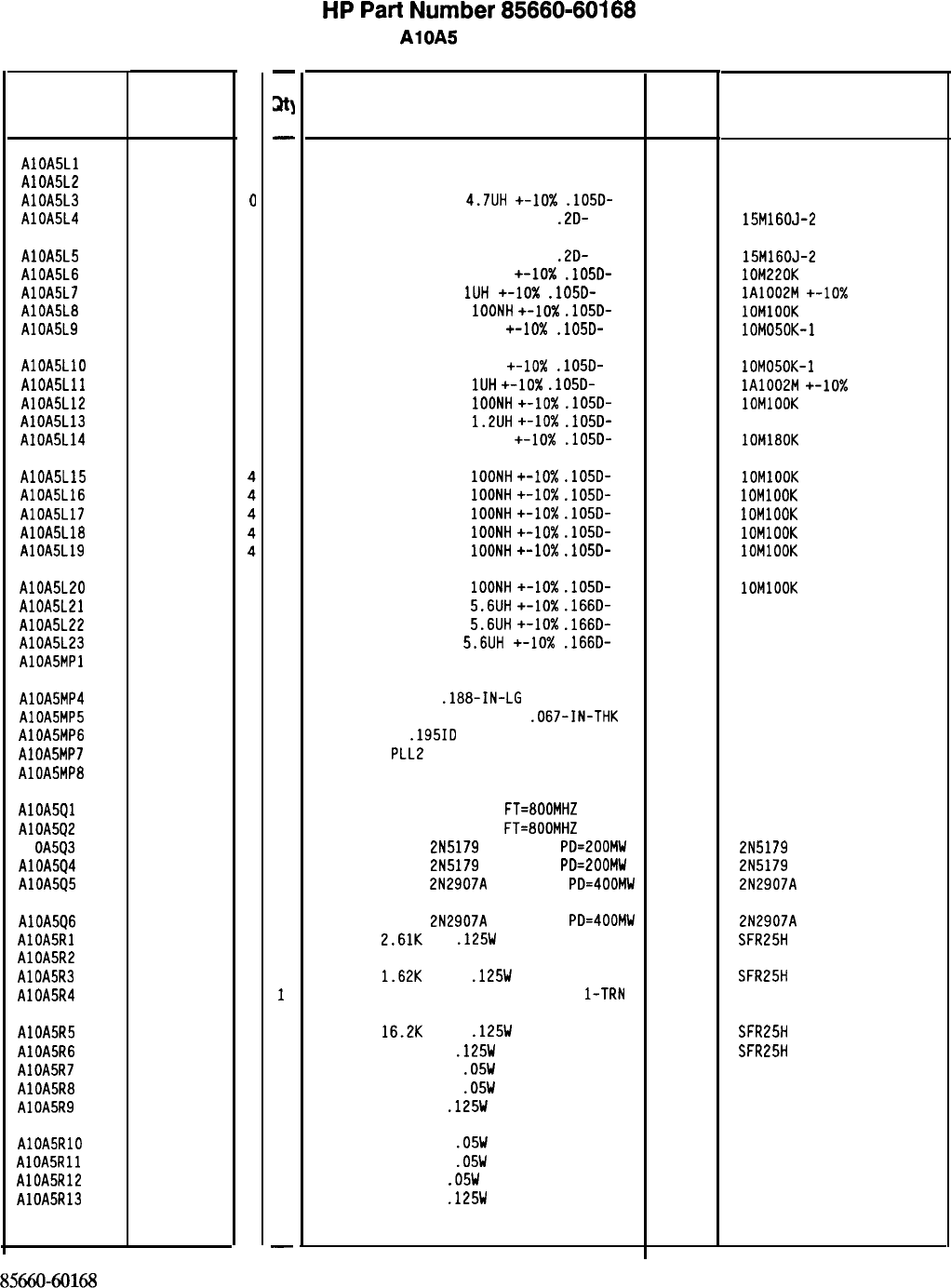
Reference
Designation
HP Part
Number
C
D
AlOA5Ll 85660-80031
7
AlOA5L2 85660-80031
7
AlOA5L3 9140-0144
a
AlOA5L4 9100-3358
a
AlOA5L5 9100-3358
0
AlOA5L6 9100-2251
0
AlOA5L7 9140-0158
6
AlOA5L8 9100-2247
4
AlOA5L9 9100-2891
4
AlOA5LlO 9100-2891
4
AlOA5Lll 9140-0158
6
AlOA5L12 9100-2247
4
AlOA5L13 9100-2258
7
AlOA5L14 9100-2250
9
AlOA5L15
AlOA5L16
AlOA5L17
AlOA5L18
AlOA5L19
9100-2247
9100-2247
9100-2247
9100-2247
9100-2247
AlOA5L20
AlOA5L21
AlOA5L22
AlOA5L23
AlOA5MPl
9100-2247
4
9100-1618
1
9100-1618
1
9100-1618
1
AlOA5MP4 2200-0101
0
AlOA5MP5 2950-0078
9
AlOA5MP6 2190-0124
4
AlOA5MP7 85660-20056
0
AlOA5MP8 86701-40001
9
AlOA5Ql
AlOA5Q2
Al
OA5Q3
AlOA5Q4
AlOA5Q5
1854-0610
0
1854-0610
0
1854-0345
8
1854-0345
8
1853-0281
9
AlOA5Q6 1853-0281
9
AlOASRl 0698-0085
0
AlOA5R2 2100-3273
1
AlOA5R3 0757-0428
1
AlOA5R4 2100-3273
1
AlOA5R5 0757-0447
4
AlOA5R6 0757-0401
0
AlOA5R7 0698-7205
0
AlOA5R8 0698-7205
0
AlOA5R9 0757-0346
2
AlOA5RlO 0698-7228
7
AlOA5Rll 0698-7228
7
AlOA5R12 0698-7188
8
AlOA5R13 0757-0346
2
85660-60168
Parts List
Page 2 of 3
-
at]
-
1
1
1
1
1
1
1
1
1
1
1
1
1
1
1
1
1
1
1
1
1
1
1
1
1
1
1
2
1
1
1
1
1
1
1
1
1
1
1
1
1
1
1
1
1
1
1
-
HP
Part
Number 85660-60168
AlOA5 PLL 2 VCO
Description Mfr
Mfr Part
Code Number
I NOUCTOR
INDUCTOR
INDUCTOR RF-CH-MLD
4.7UH
+-lo%
.105D-
INDUCTOR RF-CH-MLD 162NH +-5%
.2D-
28480 85660-80031
28480 85660-80031
99800 1025-36
24226 15M160J-2
INDUCTOR RF-CH-ML0 162NH +-5%
.2D-
24226 15M160J-2
INDUCTOR RF-CH-ML0 220NH +-lo%
.105D-
24226 lOM220K
INDUCTOR RF-CH-MLD
1UH
+-lo%
.105D-
32159 lA1002M
+-10x
INDUCTOR RF-CH-MLD
1OONH
+-lo%
.105D-
24226 1OMlOOK
INDUCTOR RF-CH-MLD 50NH +-lo%
.105D-
24226 lOM050K-1
INDUCTOR RF-CH-MLD 50NH
+-lo%
.105D-
24226 lOM050K-1
INDUCTOR RF-CH-MLD
1UH
+-lo%
.1050-
32159 lA1002M
+-10X
INDUCTOR RF-CH-ML0
1OONH
+-10X
.105D-
24226 1OMlOOK
INDUCTOR RF-CH-ML0
1.2UH
+-lo%
.105D-
99800 1025-22
INDUCTOR RF-CH-MLD 180NH +-lo%
.105D-
24226 lOM180K
INDUCTOR RF-CH-MLD
1OONH
+-lo%
.105D-
24226 1OMlOOK
INDUCTOR RF-CH-MLD
1OONH
+-IO%
.105D-
24226 1OMlOOK
INDUCTOR RF-CH-ML0
1OONH
+-lo%
.1050-
24226 1OMlOOK
INDUCTOR RF-CH-MLD
1OONH
+-lo%
.1050-
24226 1OMlOOK
INDUCTOR RF-CH-MLD
1OONH
+-10X
.1050-
24226 1OMlOOK
INDUCTOR RF-CH-ML0
1OONH
+-lo%
.105D-
24226 1OMlOOK
INDUCTOR RF-CH-MLD
5.6UH
+-lo%
.1660-
99800 1537-30
INDUCTOR RF-CH-MLD
5.6UH
+-lo%
.166D-
99800 1537-30
INDUCTOR RF-CH-MLD
5.6UH
+-10x
.166D-
99800 1537-30
NOT ASSIGNED 28480 85660-20168
SCREW-MACH 4-40
.188-IN-LG
PAN-HD-POZI
NUT-HEX-DBL-CHAM IO-32-THD
.067-IN-THK
WASHER LOCK
.195ID
COVER PC,
PLL2
VCO
EXTRACTOR PC
77250
74163 500220
28480 85660-20056
28480 86701-40001
TRANSISTOR NPN SI TO-46
FT=800MHZ 04713
TRANSISTOR NPN SI TO-46
FT=BOOMHZ 04713
TRANSISTOR NPN
2N5179
SI TO-72
PD=200MW 04713
TRANSISTOR NPN
2N5179
SI TO-72
PD=200MW 04713
TRANSISTOR PNP
2N2907A
SI TO-18
PD=400MW 04713
2N5179
2N5179
2N2907A
TRANSISTOR PNP
2N2907A
SI TO-18
PD=400MW 04713 2N2907A
RESISTOR
2.61K
1%
.125W
TF TC=O+-100
19701 SFR25H
RESISTOR-TRMR 2K 10% TKF SIDE-ADJ l-TRN 32997 3386X-Y46-202
RESISTOR
1.62K
+-1%
.125W
TF TC=O+-100
19701
SFR25H
RESISTOR-TRMR 2K 10% TKF SIDE-ADJ
l-TRN 32997 3386X-146-202
RESISTOR
16.2K
+-1%
.125W
TF TC=O+-100
19701
SFR25H
RESISTOR 100 +-1%
.125W
TF TC=O+-100
19701
SFR25H
RESISTOR 51.1 +-1%
.05W
TF TC=O+-100
19701
50635
RESISTOR 51.1 +-1%
.05W
TF TC=O+-100
19701
50635
RESISTOR 10 +-1%
.125W
TF TC=O+-100
91637 CMF-55-1, T-l
RESISTOR 464 +-1%
.05W
TF TC=O+-100
19701
50635
RESISTOR 464 +-1%
.05W
TF TC=O+-100
19701
50635
RESISTOR 10 +-1%
.05W
TF TC=O+-100
19701
50635
RESISTOR 10 +-1%
.125W
TF TC=O+-100
91637 CMF-55-1, T-l
*Indicates factory-selected value
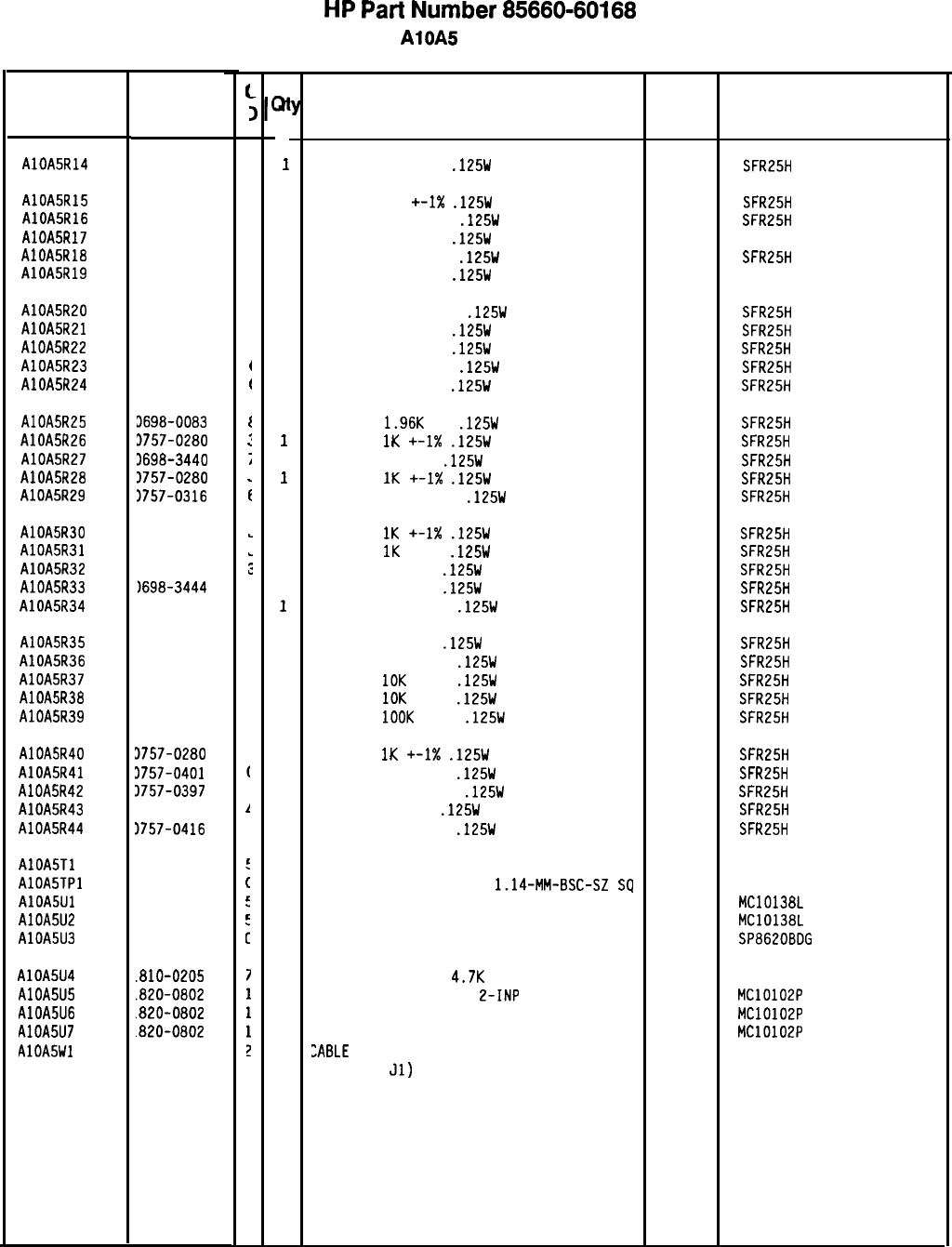
HP
Part
Number 85660-60168
AlOA5 PLL 2 VCO
Reference
Designation
AlOA5R14 0757-0398
AlOA5R15 0757-0398
AlOA5R16 0757-0418
AlOA5R17 0757-0346
AlOA5R18 0757-0419
AlOA5R19 0757-0346
AlOA5R20
0757-0400
AlOA5R21 0757-0398
AlOA5R22 0757-0398
AlOA5R23 0757-0401
AlOA5R24 0698-4037
AlOA5R25 3698-0083
AlOA5R26 3757-0280
AlOA5R27 3698-3440
AlOA5R2B 3757-0280
AlOA5R29 1757-0316
AlOA5R30 1757-0280
AlOA5R31 1757-0280
AlOA5R32 1698-3446
AlOA5R33
1698-3444
AlOA5R34 0757-0419
AlOA5R35 0698-3444
AlOA5R36 0757-0419
AlOA5R37 0757-0442
AlOA5R38 0757-0442
AlOA5R39 0757-0465
AlOASR40 3757-0280
AlOA5R41 3757-0401
AlOASR42 3757-0397
AlOA5R43 3698-3132
AlOA5R44 1757-0416
AlOA5Tl 18553-6012
AlOA5TPl 1251-0600
AlOA5Ul
1820-1383
AlOA5U2
1820-1383
AlOA5U3
1820-2047
AlOA5U4
.810-0205
AlOA5U5
.820-0802
AlOA5U6
.820-0802
AlOA5U7
.820-0802
AlOA5Wl
15660-60088
HP Part
Number
f
I
,
(
(
I
:
;
;
L
L
:
L
I
ai
1
1
1
1
1
1
1
1
1
1
1
1
1
1
1
1
1
1
1
1
1
1
1
1
1
1
1
1
1
1
1
1
1
1
1
1
1
1
1
1
1
Description
RESISTOR 75 +-1%
.125W
TF TC=O+-100
RESISTOR 75
+-I%
.125W
TF TC=O+-100
RESISTOR 619 +-1%
.125W
TF TC=O+-100
RESISTOR 10 +-1%
.125W
TF TC=O+-100
RESISTOR 681 +-1%
.125W
TF TC=O+-100
RESISTOR 10 +-1%
.125W
TF TC=O+-100
RESISTOR 90.9 +-1%
.125W
TF TC=O+-100
RESISTOR 75 +-1%
.125W
TF TC=O+-100
RESISTOR 75 +-1%
.125W
TF TC=O+-100
RESISTOR 100 +-1%
.125W
TF TC=O+-100
RESISTOR 46.4 1%
.125W
TF TC=O+-100
RESISTOR
1.96K
1%
.125W
TF TC=O+-100
RESISTOR
1K
+-I%
.125W
TF TC=O+-100
RESISTOR 196 1%
.125W
TF TC=O+-100
RESISTOR
1K
+-I%
.125W
TF TC=O+-100
RESISTOR 42.2 +-1%
.125W
TF TC=O+-100
RESISTOR
1K
+-1X
.125W
TF TC=O+-100
RESISTOR
1K
+-1%
.125W
TF TC=O+-100
RESISTOR 383 1%
.125W
TF TC=O+-100
RESISTOR 316 1%
.125W
TF TC=O+-100
RESISTOR 681 +-1%
.125W
TF TC=O+-100
RESISTOR 316 1%
.125W
TF TC=O+-100
RESISTOR 681 +-1%
.125W
TF TC=O+-100
RESISTOR
10K
+-1%
.125W
TF TC=O+-100
RESISTOR
10K
+-1%
.125W
TF TC=O+-100
RESISTOR
1OOK
+-1%
.125W
TF TC=O+-100
RESISTOR
1K
+-1X
.125W
TF TC=O+-100
RESISTOR 100 +-1%
.125W
TF TC=O+-100
RESISTOR 68.1 +-1%
.125W
TF TC=O+-100
RESISTOR 261 1%
.125W
TF TC=O+-100
RESISTOR 511 +-1%
.125W
TF TC=O+-100
TRANSFORMER, RF BLUE
CONNECTOR-SGL CONT PIN
1.14~MM-BSC-SZ
SQ
IC CNTR ECL BCD POS-EDGE-TRIG
IC CNTR ECL BCD POS-EDGE-TRIG
IC DIVR ECL QUINARY
NETWORK-RES 8-SIP
4.7K
OHM X 7
IC GATE ECL NOR QUAD
2-INP
IC GATE ECL NOR QUAD 2-INP
IC GATE ECL NOR QUAD 2-INP
:ABLE
ASSEMBLY, GRAY/ORANGE
(INCLUDES
~1)
Mfr
Mfr Part
Code
Number
19701
SFR25H
19701
SFR25H
19701
SFR25H
91637
CMF-55-1, T-l
19701
SFR25H
91637
CMF-55-1, T-l
19701
SFR25H
19701
SFR25H
19701
SFR25H
19701
SFR25H
19701
SFR25H
19701
SFR25H
19701
SFR25H
19701
SFR25H
19701
SFR25H
19701
SFR25H
19701 SFR25H
19701
SFR25H
19701
SFR25H
19701
SFR25H
19701
SFR25H
19701
SFR25H
19701
SFR25H
19701
SFR25H
19701
SFR25H
19701
SFR25H
19701
SFR25H
19701
SFR25H
19701
SFR25H
19701
SFR25H
19701
SFR25H
28480 08553-6012
27264 16-06-0034
04713 MC10138L
04713 MC10138L
52648 SP8620BDG
11236 750-81
04713 MC10102P
04713 MC10102P
04713 MC10102P
28480 85660-60088
*Indicates factory-selected value
8X60-60168 Parts List
Page 3 of 3
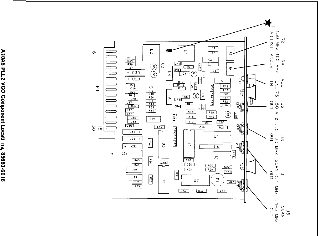
P
;5
%
;I!
K
s
0
2
2
2
2
;:
%
=f.
0
z
I
z
z
?
zi
s
W
-- 0
0,
u
LO
I’
gvl-
I
I+
c32
1
+
c31
-I<
;a
tf
gk.5
L
I
N
VI
G1k
cl
z
N
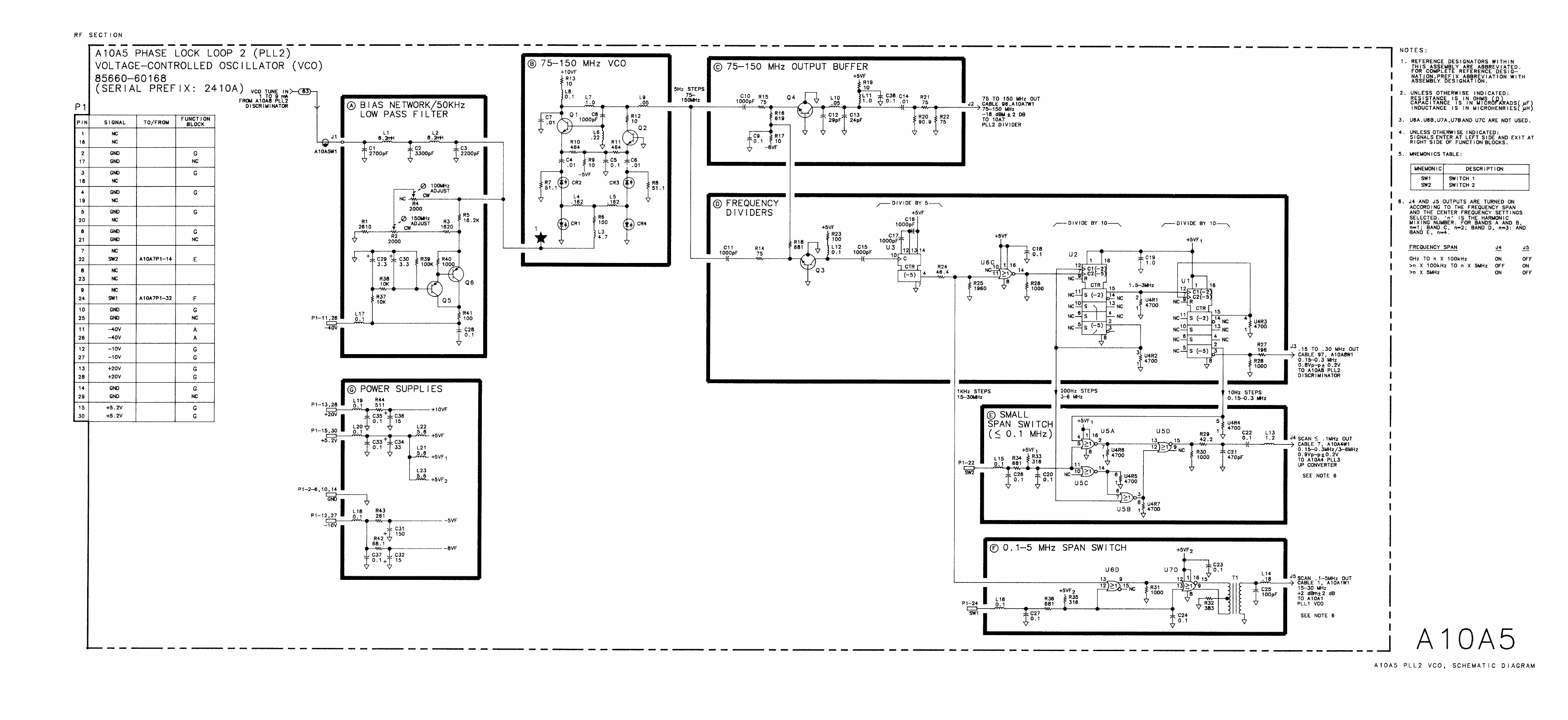
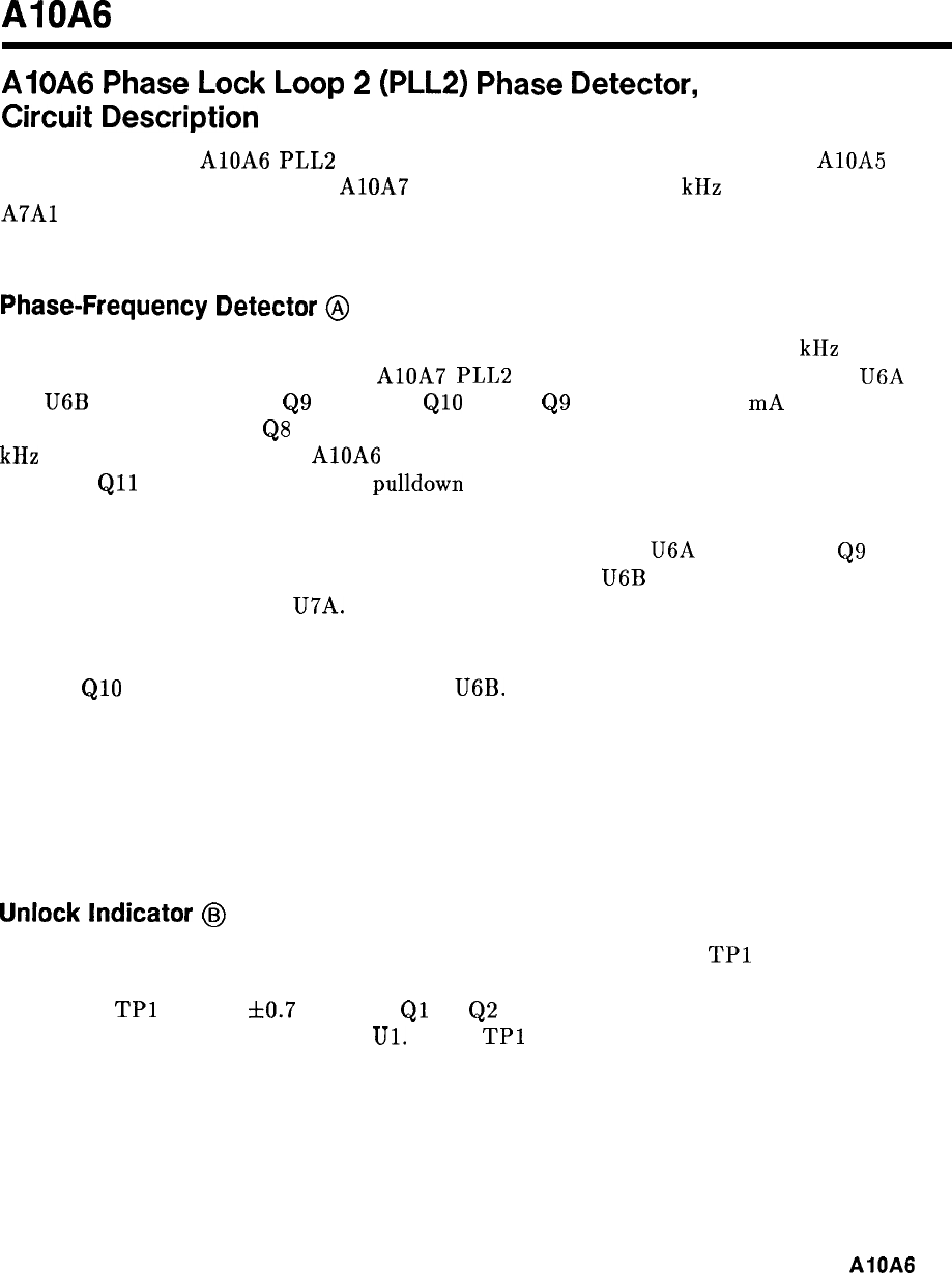
AIOAG
AlOA6
Phase
Lock
Loop
2
(PLL2)
Phase
Detector,
Circuit
Description
The purpose of the AlOA6 PLL2 Phase Detector is to compare the output of the AlOA5
PLL2 VCO (after division by the AlOA7 PLL2 Divider) to the 500 kHz Reference from the
A7Al
Reference Phase Detector. The phase difference is converted to an error voltage used to
correct the PLL2 VCO frequency.
Phase-Frequency Detector
@
The phase-frequency detector responds to the phase difference between the 500 kHz reference
input and the divided input from the AlOA7 PLL2 Divider. Assuming both flip-flops U6A
and
U6B
have been cleared,
Q9
is on and
QlO
is off.
Q9
supplies about 3
mA
current which
is sunk by current source
QS
resulting in approximately zero current flow through the 50
kHz low-pass filter to U3. On AlOA6 PLL2 Phase Detector, HP part number 85660-60276,
transistor
Qll
is added as an active
pulldown
to reduce glitches that could cause momentary
false unlocks.
A pulse from the PLL2 Divider on Pl-19 clocks the Q output of U6A high, turning
Q9
off. A
subsequent reference pulse on Pl-20 clocks the Q output of
U6B
high, which will immediately
reset both flip- flops through U7A. Thus the effect of a pulse at Pl-19 leading one at Pl-20 is
to momentarily reduce the output current. Therefore, if the divided output leads the reference
in phase, the current decreases. Similarly, if the reference phase leads, the current increases
because
QlO
is connected to the Q output of U6B.
If the two inputs have different frequencies, the pulse relationships become complicated, but
the net effect is positive output current if the reference frequency is high.
U3 serves as an amplifier to provide the high currents necessary to rapidly charge the
integrating capacitor C7 in the following stage. VR2 and VR3 serve as clamps, limiting the
output swing to f5.8 V.
Unlock
Indicator
0%~
When the phase lock loop is in a steady state condition, the voltage at
TPl
is zero. If
unlocked, the voltage will be non-zero except for transients passing through zero. When
the voltage
TPl
exceeds
f0.7
V, either
Ql
or
Q2
is turned on, discharging Cl5 or Cl4
respectively and tripping comparator
Ul.
When
TPl
voltage settles to less than f0.7 V, Cl4
and Cl5 must recharge before the comparator is reset. This takes 5 ms. The comparator
output is TTL high for an unlock condition and remains there for 5 ms after a lock condition
is established.
AlOA6
1
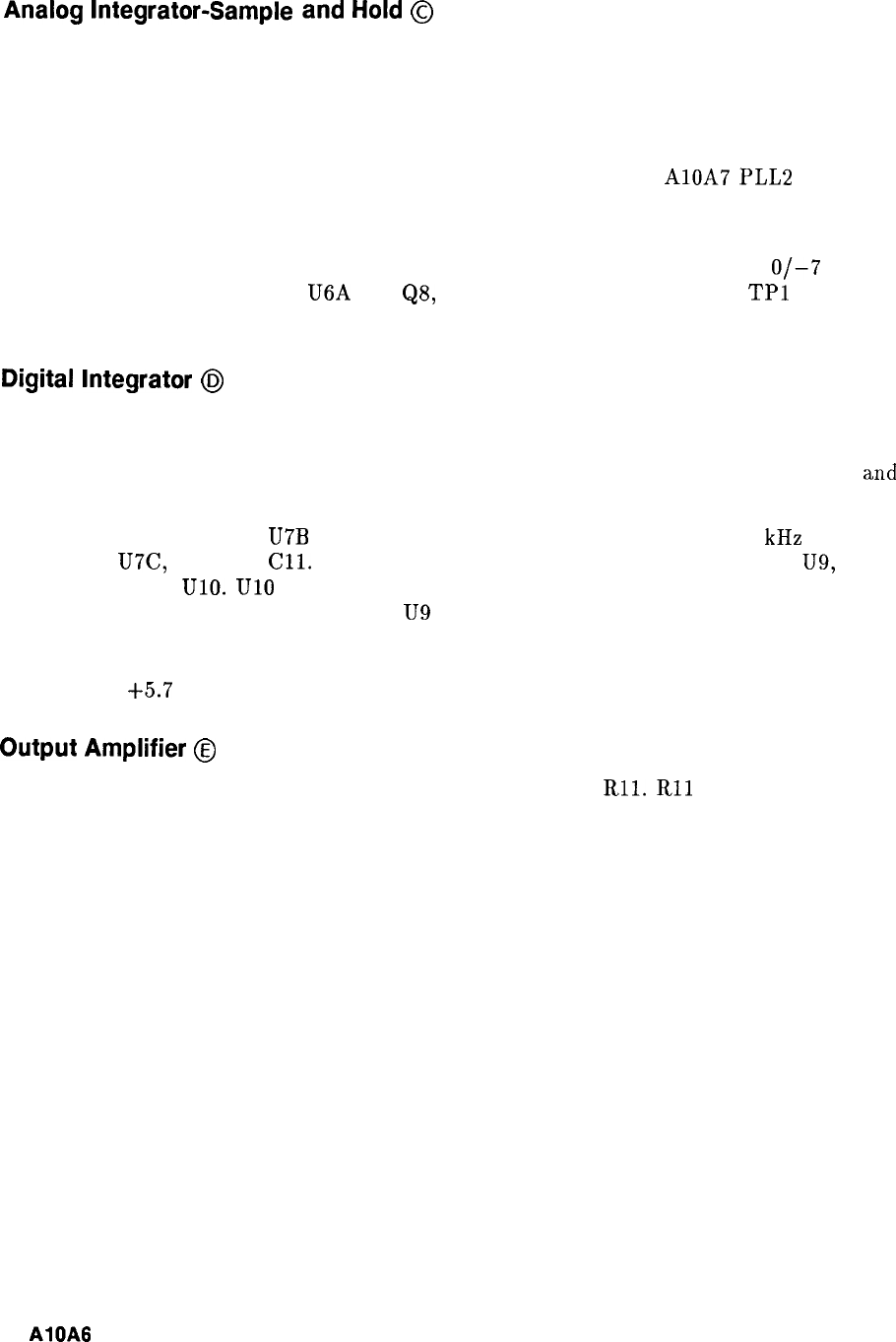
Analog
Integrator-Sample
and
Hold
@
U2 and C7 form an integrator which integrates current flowing from U3 through R8. The
output of the integrator is summed with other signals in U4 and ultimately controls the VCO
frequency. In steady state conditions, TP3 will settle to a constant voltage which tunes the
VCO to the correct frequency. If the voltage at TP3 is constant, the input current must be
zero, so opening FET switch Q3 will not change the voltage at TP3. When PLL2 is being
used in its swept mode, the loop is locked to a start frequency set by AlOA7 PLL2 Divider,
then Q3 is opened. This breaks the lock loop, permitting a sweep to be executed.
Q3 is closed with zero gate voltage, and open with -7 V gate voltage. The gate drive comes
from Q6 and Q7, which translate the TTL level lock-sweep signal on Pl-2 to the
O/-7
V
levels. Pl-2 is also connected to U6A and
QS,
which results in zero voltage at
TPl
during a
sweep. A negative voltage may turn on Q3, changing the charge stored on C7.
Digital
Integrator
@
The analog integrator does not have sufficient control range to correct initial warm-up drift
and long term aging. If TP3 goes below -4.7 V, Q5 is turned on and its collector voltage is
pulled down to -1.4 V. At this point, CR4 and CR3 become forward biased, clamping U2
and
preventing further negative movement of TP3.
Simultaneously, the input of
U7B
will have been pulled low, which turns on a 2 kHz oscillator
made up of U7C, R20, and
Cll.
This clocks the count up input of counters U8 and U9,
which drives DAC UlO. UlO sources negative current to the summing junction of U4 and this
current increases in magnitude as U8 and
U9
count up. When the current reaches a value
which tunes the VCO to the proper frequency, TP3 moves positive, shutting off the oscillator
and returning control to the analog integrator. An analogous sequence occurs when TP3 tries
to rise above
+5.7
V.
Output
Amplifier
@
U4 serves to sum signals from the analog integrator, DAC, and
Rll.
Rll
is a high frequency
signal path shunting the integrators.
2
AlOA6
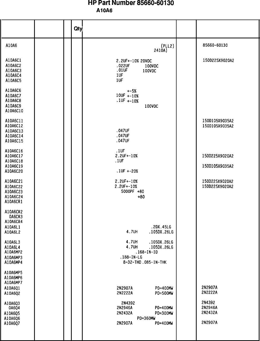
HP
Part
Number 85660-60130
AlOA6 PLL 2 Phase Detector
Reference
HP Part C
Number D
Qty Description Mfr Mfr Part
Designation Code Number
AlOA6 85660-60130
5
1
BOARD
ASSEMBLY, PHASE LOCK LOOP 2
(PLL2)
28480 85660-60130
PHASE DETECTOR (SERIAL PREFIX:
2410~)
AlOAGCl 0180-0197
B
1
CAPACITOR-FXD 2.2UF+-10%
20VDC
TA
56289 150D225X9020A2
AlOA6C2 0160-0574
3
1
CAPACITOR-FXD
.022UF
+-20%
IOOVDC
CER
28480 0160-0574
AlOA6C3 0160-3879
7
1
CAPACITOR-FXD
.OlUF
+-20%
1OOVDC
CER
28480 0160-3879
AlOA6C4 0160-4892
6
1
CAPACITOR-FXD
1UF
+-20% 25VDC CER 28480 0160-4892
AlOA6C5 0160-4892
6
1
CAPACITOR-FXD
1UF
+-20% 25VDC CER 28480 0160-4892
AlOA6C6 0160-2199
2
1
CAPACITOR-FXD 30PF
+-5X 300VDC MICA
28480 0160-2199
AlOA6C7 0160-5609
5
1
CAPACITOR-FXD
IOUF +-lo%
50VDC MET-POLYC
28480 0160-5609
AlOA6C8 0160-4084
8
1
CAPACITOR-FXD
.lUF
+-lo% 50VDC CER
28480 0160-4084
AlOA6C9 0160-0573
2
1
CAPACITOR-FXD 4700PF
+-20%
1OOVDC
CER
28480 0160-0573
AlOAGClO 0160-2199
2
1
CAPACITOR-FXD 30PF
+-5% 300VDC MICA
28480 0160-2199
AlOAGCll 0180-0291
3
1
CAPACITOR-FXD lUF+-10%
35VDC TA 56289 1500105X9035A2
AlOA6C12 0180-0291
3
1
CAPACITOR-FXD lUF+-10% 35VDC TA 56289 1500105X9035A2
AlOA6C13 0160-0575
4
1
CAPACITOR-FXD
.047UF
28480 0160-0575
AlOA6C14 0160-0575
4
1
CAPACITOR-FXD
.047UF
28480 0160-0575
AlOA6C15 0160-0575
4
1
CAPACITOR-FXD
.047UF
28480 0160-0575
AlOA6C16 0160-4084
8
1
CAPACITOR-FXD
.lUF
+-20% 50VDC CER 28480 0160-4084
AlOA6C17 0180-0197
8
1
CAPACITOR-FXD
2.2UF+-10%
20VDC
TA 56289 150D225X9020A2
AlOA6ClB 0160-4084
8
1
CAPACITOR-FXD
.lUF
+-20% 50VDC
CER 28480 0160-4084
AlOA6C19 0180-0291
3
1
CAPACITOR-FXD lUF+-10% 35VOC TA
56289 1500105X9035A2
AlOA6C20
0160-4084
8
1
CAPACITOR-FXD
.lUF
+-20x 50VDC CER 28480 0160-4084
AlOA6C21 0180-0197
8
1
CAPACITOR-FXD
2.2UF+-10%
EOVDC
TA 56289 150D225X9020A2
AlOA6C22 0180-0197
8
1
CAPACITOR-FXD
2.2UF+-10%
EOVDC TA
56289 150D225X9020A2
AlOA6C23 0160-2437
11
CAPACITOR-FDTHRU
SOOOPF
+80
-20% 200V
28480 0160-2437
AlOA6C24 0160-2437
11
CAPACITOR-FDTHRU 5000PF +80
-20% 200V
28480 0160-2437
AlOAGCRl 1901-0033
2
1
DIODE-GEN PRP 180V 200MA DO-7 28480 1901-0033
AlOA6CR2 1901-0376
6
1
DIODE-GEN PRP 35V 50MA DO-35 28480 1901-0376
Al OA6CR3 1901-0376
6
1
DIODE-GEN PRP 35V 50MA DO-35 28480 1901-0376
AlOA6CR4 1901-0033
2
1
DIODE-GEN PRP 180V 200MA DO-7 28480 1901-0033
AlOAGLl 9100-1651
2
1
INDUCTOR RF-CH-MLD 750UH +-5%
.2DX.45LG 28480 9100-1651
AlOA6L2 9140-0144
0
1
INDUCTOR RF-CH-MLD
4.7UH
10%
.105DX.26LG 28480 9140-0144
AlOA6L3 9140-0144
0
1
INDUCTOR RF-CH-MLD
4.7UH
10%
.105DX.26LG 28480 9140-0144
AlOA6L4 9140-0144
0
1
INDUCTOR RF-CH-MLD
4.7UH
10%
.105OX.26LG 28480 9140-0144
AlOA6MP2 2190-0009
4
2
WASHER-LK INTL T NO. 8
.168-IN-ID 28480 2190-0009
AlOA6MP3 2200-0101
02
SCREW-MACH 4-40
.188-IN-LG
PAN-HO-POZI
00000 ORDER BY DESCRIPTION
AlOA6MP4 2580-0002
4
2
NUT-HEX-DBL-CHAM
8-32-THD
.085-IN-THK 28480 2580-0002
AlOA6MP5 8150-0013
4
1
WIRE, 22 AWG 1x22 92194 298
AlOA6MP6 85660-20057
11
CVR PC 2 PHSDETC 28480 85660-20057
AlOA6MP7 86701-40001
9
2
EXTRACTOR PC 28480 86701-40001
AlOAGQl 1853-0281
9
1
TRANSISTOR PNP
2N2907A
SI TO-18
PD=400MW 04713 2N2907A
AlOA6Q2 1854-0477
7
1
TRANSISTOR NPN
2N2222A
SI TO-18
PD=500MW 04713 2N2222A
AlOA6Q3 1855-0386
9
1
TRANSISTOR J-FET
2N4392
N-CHAN D-MODE TO
04713 2N4392
Al
OA6Q4 1853-0322
9
1
TRANSISTOR PNP
2N2946A
SI TO-46
PD=400MW 01275 2N2946A
AlOA6Q5 1854-0557
4
1
TRANSISTOR NPN
2N2432A
SI TO-18
PD=300MW 01295 2N2432A
AlOA6Q6
1854-0404
0
1
TRANSISTOR NPN SI TO-18
PD=360MW 28480 1854-0404
AlOA6Q7 1853-0281
9
1
TRANSISTOR PNP
2N2907A
SI TO-18
PD=400MW 04713 2N2907A
*Indicates factory-selected value
85660-60130 Parts List
Page 1 of 3
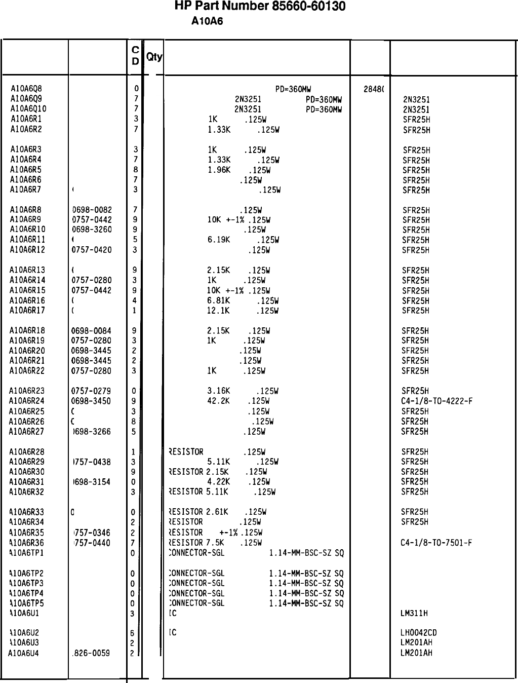
HP
Part
Number 85660-60130
AlOA6 PLL 2 Phase Detector
Description Mfr
Mfr Part
Code Number
TRANSISTOR NPN SI TO-18
PD=360MW
28481
1854-0404
TRANSISTOR PNP
2N3251
SI TO-18
PD=360MW
0471:
2N3251
TRANSISTOR PNP
2N3251
SI TO-18
PD=360MW
0471:
2N3251
RESISTOR
1K
+-1%
.125W
TF TC=O+-100
19701
SFR25H
RESISTOR
1.33K
+-1%
.125W
TF TC=O+-100
19701
SFR25H
RESISTOR
1K
+-1%
.125W
TF TC=O+-100
19701
SFR25H
RESISTOR
1.33K
+-1%
.125W
TF TC=O+-100
19701
SFR25H
RESISTOR
1.96K
1%
.125W
TF TC=O+-100
19701
SFR25H
RESISTOR 196 1%
.125W
TF TC=O+-100
19701
SFR25H
RESISTOR 34.81: +-1%
.125W
TF TC=O+-100
19701
SFR25H
RESISTOR 464 1%
.125W
TF TC=O+-100
19701
SFR25H
RESISTOR
10K
+-1X
.125W
TF TC=O+-100
19701
SFR25H
RESISTOR 464K 1%
.125W
TF TC=O+-100
19701
SFR25H
RESISTOR
6.19K
+-1%
.125W
TF TC=O+-100
19701
SFR25H
RESISTOR 750 +-1%
.125W
TF TC=O+-100
19701
SFR25H
RESISTOR
2.15K
1%
.125W
TF TC=O+-100
19701 SFR25H
RESISTOR
1K
+-1%
.125W
TF TC=O+-100
19701
SFR25H
RESISTOR
10K
+-1X
.125W
TF TC=O+-100
19701
SFR25H
RESISTOR
6.81K
+-1%
.125W
TF TC=O+-100
19701
SFR25H
RESISTOR
12.1K
+-1%
.125W
TF TC=O+-100
19701
SFR25H
RESISTOR
2.15K
1%
.125W
TF TC=O+-100
19701
SFR25H
RESISTOR
1K
+-1%
.125W
TF TC=O+-100
19701
SFR25H
RESISTOR 348 1%
.125W
TF TC=O+-100
19701 SFR25H
RESISTOR 348 1%
.125W
TF TC=O+-100
19701
SFR25H
RESISTOR
1K
+-1%
.125W
TF TC=O+-100
19701
SFR25H
RESISTOR
3.16K
+-1%
.125W
TF TC=O+-100
19701
SFR25H
RESISTOR
42.2K
1%
.125W
F TC=O+-100
24546
C4-l/8-TO-4222-F
RESISTOR 75K +-1%
.125W
TF TC=O+-100
19701
SFR25H
RESISTOR 121K +-1%
.125W
TF TC=O+-100
19701
SFR25H
RESISTOR 237K 1%
.125W
TF TC=O+-100
19701
SFR25H
7ESISTOR
422K 1%
.125W
TF TC=O+-100
19701
SFR25H
7ESISTOR
5.11K
+-1%
.125W
TF TC=O+-100
19701
SFR25H
1ESISTOR
2.15K
1%
.125W
TF TC=O+-100
19701
SFR25H
7ESISTOR
4.22K
1%
.125W
TF TC=O+-100
19701
SFR25H
7ESISTOR
5.11K
+-1%
.125W
TF TC=O+-100
19701
SFR25H
IESISTOR
2.61K
1%
.125W
TF TC=O+-100
19701 SFR25H
{ESISTOR
348 1%
.125W
TF TC=O+-100
19701
SFR25H
IESISTOR
10
+-1X
.125W
TF TC=O+-100
91637 CMF-55-1, T-l
IESISTOR
7.5K
1%
.125W
TF TC=O+-100
24546
C4-l/8-TO-7501-F
:ONNECTOR-SGL
CONT PIN
1.14-MM-BSC-SZ
SQ
27264 16-06-0034
:ONNECTOR-SGL
CONT PIN
1.14-MM-BSC-SZ
SQ
27264 16-06-0034
:ONNECTOR-SGL
CONT PIN
1.14-MM-BSC-SZ
SQ
27264 16-06-0034
XNNECTOR-SGL
CONT PIN
1.14-MM-BSC-SZ
SQ
27264 16-06-0034
:ONNECTOR-SGL
CONT PIN
1.14~MM-BSC-SZ
SQ
27264 16-06-0034
[C
COMPARATOR PRCN TO-99 PKG
27014 LM311H
IC
OP AMP 14-DIP-C PKG
27014 LH0042CD
:C OP AMP GP TO-99 PKG 27014 LM201AH
IC OP AMP GP TO-99 PKG 27014 LM201AH
*Indicates factory-selected value
Reference
Designatior
1
HP Part
Number
AlOA6Q8 1854-0404
AlOA6Q9 1853-0007
AlOA6QlO 1853-0007
AlOAGRl 0757-0280
AlOA6R2 0757-0317
AlOA6R3
AlOA6R4
AlOA6R5
AlOA6R6
AlOA6R7
0757-0280
0757-0317
0698-0083
0698-3440
0757-0123
AlOA6R8
AlOA6R9
AlOAGRlO
AlOAGRll
AlOA6R12
0698-0082
3757-0442
3698-3260
3757-0290
3757-0420
AlOA6R13
AlOA6R14
AlOA6R15
AlOA6R16
AlOA6R17
1698-0084
3757-0280
1757-0442
1757-0439
1757-0444
AlOA6R18
AlOA6R19
AlOA6R20
AlOA6R21
AlOA6R22
1698-0084
1757-0280
1698-3445
1698-3445
1757-0280
AlOA6R23
AlOA6R24
AlOA6R25
AlOA6R26
AlOA6R27
1757-0279
)698-3450
1757-0462
1757-0467
1698-3266
AlOA6R28
AlOA6R29
AlOA6R30
AlOA6R31
AlOA6R32
1698-3460
1757-0438
1698-0084
1698-3154
1757-0438
RlOA6R33
410A6R34
410A6R35
410A6R36
410A6TPl
I
I
I
I
(
(
I
i
(
(
(
(
(
(
(
(
(
c
c
c
C
C
C
C
C
C
0
0
0
0
1
1
1
1
1
1
1
1
I
1698-0085
1698-3445
1757-0346
1757-0440
251-0600
410A6TP2
410A6TP3
410A6TP4
llOA6TP5
410A6Ul
251-0600
251-0600
251-0600
251-0600
826-0026
ilOA6U2
ilOA6U3
AlOA6U4
826-0459
826-0059
.826-0059
85660-60130 Parts List
Page 2 of 3
31
1
1
1
1
1
1
1
1
1
1
1
1
1
1
1
1
1
1
1
1
1
1
1
1
1
1
1
1
1
1
1
1
1
1
1
1
1
1
1
1
1
1
1
1
1
1
1
1
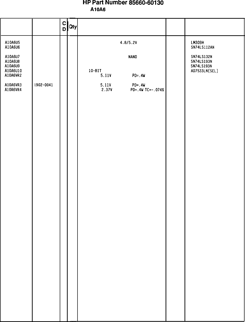
Reference HP Part
Designation Number
AlOA6U5 1820-0429
8
AlOA6U6 1820-1212
9
AlOA6U7 1820-1425
6
AlOA6U8 1820-1194
6
AlOA6U9 1820-1194
6
AlOAGUlO
1826-0448
3
AlOA6VR2 1902-0041
4
AlOA6VR3
AlOA6VR4
L902-0041
1902-3002
4
3
-
31
-
1
1
1
1
1
1
1
1
1
-
HP
Part
Number 85660-60130
AlOA6 PLL 2 Phase Detector
Description
IC V RGLTR-FXD-POS
4.8/5.2V
TO-39 PKG
27014 LM309H
IC FF TTL LS J-K NEG-EDGE-TRIG PRESET/CL 01295 SN74LS112AN
IC SCHMITT-TRIG TTL LS
NAN0
QUAD 2-INP
01295
IC CNTR TTL LS BIN UP/DOWN SYNCHRO POS-E 01295
IC CNTR TTL LS BIN UP/DOWN SYNCHRO POS-E 01295
D/A
lo-BIT
16-PLASTIC CMOS
24355
DIODE-ZNR
5.11V
5% DO-35
PD=.4W 04713
SN74LS132N
SN74LS193N
SN74LS193N
AD7533LN(SEL)
DIODE-ZNR
5.11V
5% DO-35
PD=.4W 04713
DIODE-ZNR
2.37V
5% DO-7
PO=.4W
TC=-.074%
04713
Mfr Mfr Part
Code Number
*Indicates factory-selected value
8X60-60130 Parts List
Page 3 of 3
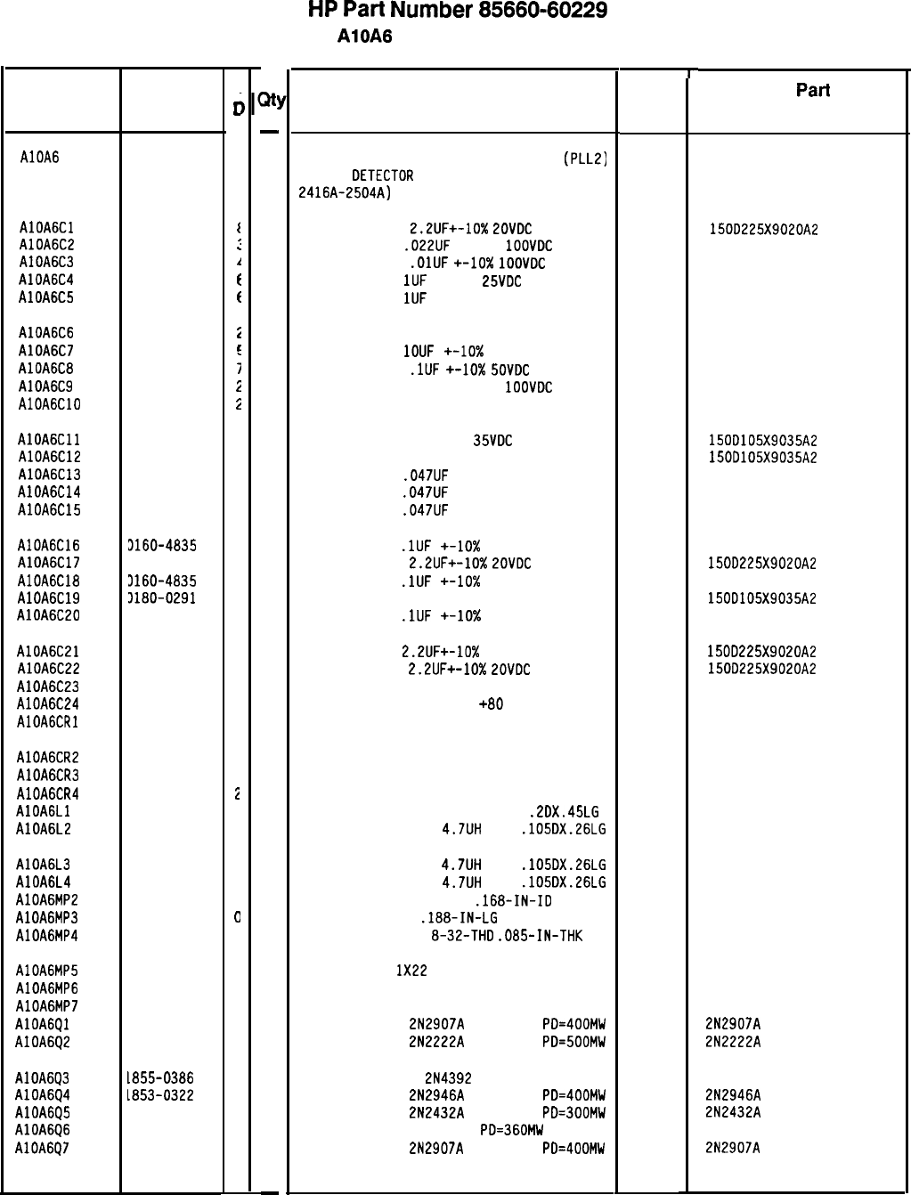
HP
Part
Number 85660-60229
AlOA6 PLL 2 Phase Detector
l-
Description Mfr Mfr
Part
Code Number
BOARD ASSEMBLY, PHASE LOCK LOOP 2
(PLLZ)
PHASE
DETECTOR
(
SERIAL
PREF
IXES
:
2416A-2504A)
28480 85660-60229
CAPACITOR-FXD
2.2UF+-10%
LOVDC
TA
56289 150D225X9020A2
CAPACITOR-FXD
.022UF
+-20%
1OOVDC
CER
28480 0160-0574
CAPACITOR-FXO
.OlUF
+-lo%
1OOVDC
CER
28480 0160-4832
CAPACITOR-FXD
1UF
+-20%
25VDC
CER
28480 0160-4892
CAPACITOR-FXD
1UF
+-20% 25VDC CER
28480 0160-4892
CAPACITOR-FXD 30PF +-5% 300VDC MICA
28480 0160-2199
CAPACITOR-FXD
1OUF
+-lo% 50VDC MET-POLYC
28480 0160-5609
CAPACITOR-FXD
.lUF
+-lo%
SOVDC
CER
28480 0160-4835
CAPACITOR-FXD 4700PF +-20%
1OOVDC
CER
28480 0160-0573
CAPACITOR-FXD 30PF +-5% 300VDC MICA
28480 0160-2199
CAPACITOR-FXD lUF+-10%
35VDC
TA
56289 150D105X9035A2
CAPACITOR-FXD lUF+-10% 35VDC TA
56289 150D105X9035A2
CAPACITOR-FXD
.047UF
+-20% 50VDC CER
28480 0160-0575
CAPACITOR-FXD
.047UF
+-20% 50VDC CER
28480 0160-0575
CAPACITOR-FXD
.047UF
+-20% 50VDC CER
28480 0160-0575
CAPACITOR-FXD
.lUF
+-lo% 50VDC CER
28480 0160-4835
CAPACITOR-FXD
2.2UF+-10%
ZOVDC
TA
56289 150D225X9020A2
CAPACITOR-FXD
.lUF
+-10x
50VOC CER
28480 0160-4835
CAPACITOR-FXO lUF+-10% 35VDC TA
56289 150D105X9035A2
CAPACITOR-FXD
.lUF
+-lo% 50VDC CER
28480 0160-4835
CAPACITOR-FXD
2.2UF+-10%
20VDC TA
56289 150D225X9020A2
CAPACITOR-FXD
2.2UF+-10%
ZOVDC
TA
56289 1500225X9020A2
CAPACITOR-FDTHRU 5000PF +BO -20% 200V
28480 0160-2437
CAPACITOR-FDTHRU 5000PF
+80
-20% 200V
28480 0160-2437
DIODE-GEN PRP 180V 200MA DO-7 28480 1901-0033
DIODE-GEN PRP 35V 50MA DO-35 28480 1901-0376
DIODE-GEN PRP 35V 50MA DO-35 28480 1901-0376
DIODE-GEN PRP 180V 200MA DO-7 28480 1901-0033
INDUCTOR RF-CH-MLD 750UH +-5%
.2DX.45LG 28480 9100-1651
INDUCTOR RF-CH-MLD
4.7UH
10%
.105DX.26LG 28480 9140-0144
INDUCTOR RF-CH-MLD
4.7UH
10%
.105DX.26LG 28480
INDUCTOR RF-CH-MLD
4.7UH
10%
.105DX.26LG 28480
WASHER-LK INTL T NO. 8
.168-IN-IO 28480
SCREW-MACH 4-40
.188-IN-LG
PAN-HD-POZI
00000
NUT-HEX-DBL-CHAM
8-32-THD
.085-IN-THK 28480
9140-0144
9140-0144
2190-0009
ORDER BY DESCRIPTION
2580-0002
WIRE, 22 AWG
1X22
CVR PC 2 PHSDETC
EXTRACTOR PC
298
85660-20057
TRANSISTOR PNP
2N2907A
SI TO-18
PD=400MW
TRANSISTOR NPN
2N2222A
SI TO-18
PD=SOOMW
92194
28480
28480
04713
04713
86701-40001
2N2907A
2N2222A
TRANSISTOR J-FET
2N4392
N-CHAN D-MODE TO
04713 214392
TRANSISTOR PNP
2N2946A
SI TO-46
PD=400MW 01275 2N2946A
TRANSISTOR NPN
2N2432A
SI TO-18
PD900MW
01295 2N2432A
TRANSISTOR NPN SI TO-18
PD=360MW 28480 1854-0404
TRANSISTOR PNP
2N2907A
SI TO-18
PD=400MW 04713 2N2907A
*Indicates factory-selected value
85660-60229 Parts List
Page 1 of 3
Reference
Designatior
C
c
AlOA6
HP Part
Number
85660-60229
AlOAGCl 0180-0197
I
AlOA6C2 0160-0574
:
AlOA6C3 0160-4832
1
AlOA6C4 0160-4892
t
AlOA6C5 0160-4892
f
AlOA6C6 0160-2199
i
AlOA6C7 0160-5609
c
AlOA6C8 0160-4835
;
AlOA6C9 0160-0573
i
AlOAGClO 0160-2199
2
AlOAGCll 0180-0291
3
AlOA6C12 0180-0291
3
AlOA6C13 0160-0575
4
AlOA6C14 0160-0575
4
AlOA6C15
0160-0575
4
AlOA6C16 3160-4835
7
AlOA6C17 3180-0197
8
AlOA6C18 3160-4835
7
AlOA6C19 3180-0291
3
AlOA6C20 1160-4835
7
AlOA6C21 1180-0197
B
AlOA6C22 1180-0197
8
AlOA6C23 1160-2437
1
AlOA6C24 1160-2437
1
AlOAGCRl
1901-0033
2
AlOA6CR2
1901-0376
6
AlOA6CR3 1901-0376
6
AlOA6CR4 1901-0033
2
AlOAGLl 9100-1651
2
AlOA6L2 9140-0144
C
AlOA6L3 9140-0144
AlOA6L4 9140-0144
AlOA6MP2 2190-0009
AlOA6MP3 2200-0101
AlOA6MP4 2580-0002
AlOA6MP5 3150-0013
AlOA6MP6 35660-20057
AlOA6MP7 36701-40001
AlOA6Ql 1853-0281
AlOA6Q2 1854-0477
AlOA6Q3 1855-0386
AlOA6Q4 L853-0322
AlOA6Q5
1854-0557
AlOA6Q6 1854-0404
AlOA6Q7
1853-0281
C
a
4
0
4
4
1
9
9
7
9
9
4
0
9
at
-
1
1
1
1
1
1
1
1
1
1
1
1
1
1
1
1
1
1
1
1
1
1
1
1
1
1
1
1
1
1
1
1
1
2
2
2
1
1
2
1
1
1
1
1
1
1
-
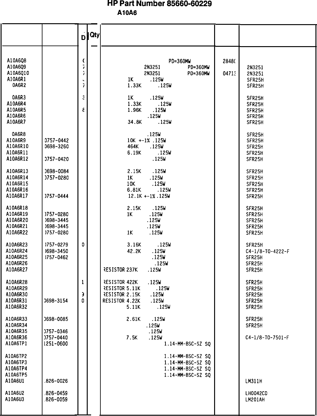
HP
Part
Number 85660-60229
AlOA6 PLL 2 Phase Detector
Description Mfr
Mfr Part
Code Number
TRANSISTOR NPN SI TO-18
PO=360MW
TRANSISTOR PNP
2N3251
SI TO-18
PO=360MW
TRANSISTOR PNP
2N3251
SI TO-18
PO=360MW
RESISTOR
1K
+-1%
.125W
TF TC=O+-100
RESISTOR
1.33K
+-1%
.125W
TF TC=O+-100
2848(
1854-0404
0471:
2N3251
0471:
2N3251
19701
SFR25H
19701
SFR25H
RESISTOR
1K
+-1%
.125W
TF TC=O+-100
RESISTOR
1.33K
+-1%
.125W
TF TC=O+-100
RESISTOR
1.96K
1%
.125W
TF TC=O+-100
RESISTOR 196 1%
.125W
TF TC=O+-100
RESISTOR
34.8K
+-1%
.125W
TF TC=O+-100
19701
SFR25H
19701
SFR25H
19701
SFR25H
19701
SFR25H
19701
SFR25H
RESISTOR 464 1%
.125W
TF TC=O+-100
RESISTOR
10K
+-1X
.125W
TF TC=O+-100
RESISTOR
4641:
1%
.125W
TF TC=O+-100
RESISTOR
6.19K
+-1%
.125W
TF TC=O+-100
RESISTOR 750 +-1%
.125W
TF TC=O+-100
19701
SFR25H
19701
SFR25H
19701
SFR25H
19701
SFR25H
19701
SFR25H
RESISTOR
2.15K
1%
.125W
TF TC=O+-100
RESISTOR
1K
+-1%
.125W
TF TC=O+-100
RESISTOR
10K
+-1%
.125W
TF TC=O+-100
RESISTOR
6.81K
+-1%
.125W
TF TC=O+-100
RESISTOR
12.1K
+-1X
.125W
TF TC=O+-100
19701
SFR25H
19701
SFR25H
19701
SFR25H
19701
SFR25H
19701
SFR25H
RESISTOR
2.15K
1%
.125W
TF TC=O+-100
RESISTOR
1K
+-1%
.125W
TF TC=O+-100
RESISTOR 348 1%
.125W
TF TC=O+-100
RESISTOR 348 1%
.125W
TF TC=O+-100
RESISTOR
1K
+-1%
.125W
TF TC=O+-100
19701
SFR25H
19701 SFR25H
19701
SFR25H
19701
SFR25H
19701
SFR25H
RESISTOR
3.16K
+-1%
.125W
TF TC=O+-100
RESISTOR
42.2K
1%
.125W
F TC=O+-100
RESISTOR 75K +-1%
.125W
TF TC=O+-100
RESISTOR 121K +-1%
.125W
TF TC=O+-100
7ESISTOR
2371:
1%
.125W
TF TC=O+-100
19701
SFR25H
24546 C4-l/8-TO-4222-F
19701
SFR25H
19701 SFR25H
19701
SFR25H
iESISTOR
4221:
1%
.125W
TF TC=O+-100
?ESISTOR
5.11K
+-1%
.125W
TF TC=O+-100
?ESISTOR
2.15K
1%
.125W
TF TC=O+-100
.7ESISTOR
4.22K
1%
.125W
TF TC=O+-100
RESISTOR
5.11K
+-1%
.125W
TF TC=O+-100
19701
SFR25H
19701
SFR25H
19701
SFR25H
19701
SFR25H
19701
SFR25H
RESISTOR
2.61K
1%
.125W
TF TC=O+-100
RESISTOR 348 1%
.125W
TF TC=O+-100
RESISTOR 10 +-1%
.125W
TF TC=O+-100
RESISTOR
7.5K
1%
.125W
TF TC=O+-100
CONNECTOR-SGL CONT PIN
1.14~MM-BSC-SZ
SQ
19701
SFR25H
19701
SFR25H
91637 CMF-55-1, T-l
24546
C4-l/8-TO-7501-F
27264 16-06-0034
CONNECTOR-SGL CONT PIN
1.14~MM-BSC-SZ
SQ
27264 16-06-0034
CONNECTOR-SGL CONT PIN
1.14-MM-BSC-SZ
SQ
27264 16-06-0034
CONNECTOR-SGL CONT PIN
1.14~MM-BSC-SZ
SQ
27264 16-06-0034
CONNECTOR-SGL CONT PIN
1.14-MM-BSC-SZ
SQ
27264 16-06-0034
IC COMPARATOR PRCN TO-99 PKG 27014 LM3llH
IC OP AMP 14-DIP-C PKG
IC OP AMP GP TO-99 PKG 27014 LH0042CO
27014 LMEOlAH
*Indicates factory-selected value
Reference HP Part
Designation
Number
AlOA6Q8 1854-0404
AlOA6Q9 1853-0007
AlOA6QlO 1853-0007
AlOAGRl 0757-0280
Al
OA6R2 0757-0317
Al
OA6R3 0757-0280
AlOA6R4 0757-0317
AlOA6R5 0698-0083
AlOA6R6 0698-3440
AlOA6R7 0757-0123
Al
OA6R8
AlOA6R9
AlOAGRlO
AlOAGRll
AlOA6R12
0698-0082
D757-0442
D698-3260
3757-0290
3757-0420
AlOA6R13 3698-0084
AlOA6R14 3757-0280
AlOA6R15 1757-0442
AlOA6R16 1757-0439
AlOA6R17 1757-0444
AlOA6R18 1698-0084
AlOA6R19 1757-0280
AlOA6R20 1698-3445
AlOA6R21 1698-3445
AlOA6R22
1757-0280
AlOA6R23
1757-0279
AlOA6R24
1698-3450
AlOA6R25
1757-0462
AlOA6R26
1757-0467
AlOA6R27
1698-3266
AlOA6R28
1698-3460
AlOA6R29
1757-0438
AlOA6R30
1698-0084
AlOA6R31 J698-3154
AlOA6R32 3757-0438
AlOA6R33 3698-0085
AlOA6R34 3698-3445
AlOA6R35 3757-0346
AlOA6R36 1757-0440
AlOAGTPl 1251-0600
AlOA6TP2 1251-0600
AlOA6TP3 1251-0600
AlOA6TP4 1251-0600
AlOA6TP5
1251-0600
AlOAGUl
.826-0026
AlOA6U2
AlOA6U3
.826-0459
.B26-0059
8X60-60229 Parts List
Page 2 of 3
C
c
(
7
i
;
?
7
E
7
3
7
9
9
5
3
9
3
9
4
1
9
3
2
2
3
0
3
3
3
5
1
3
3
3
3
0
2
2
7
0
0
0
0
0
3
6
2
-
w
-
1
1
1
1
1
1
1
1
1
1
1
1
1
1
1
1
1
1
1
1
1
1
1
1
1
1
1
1
1
1
1
1
1
1
1
1
1
1
1
1
1
1
1
1
1
1
1
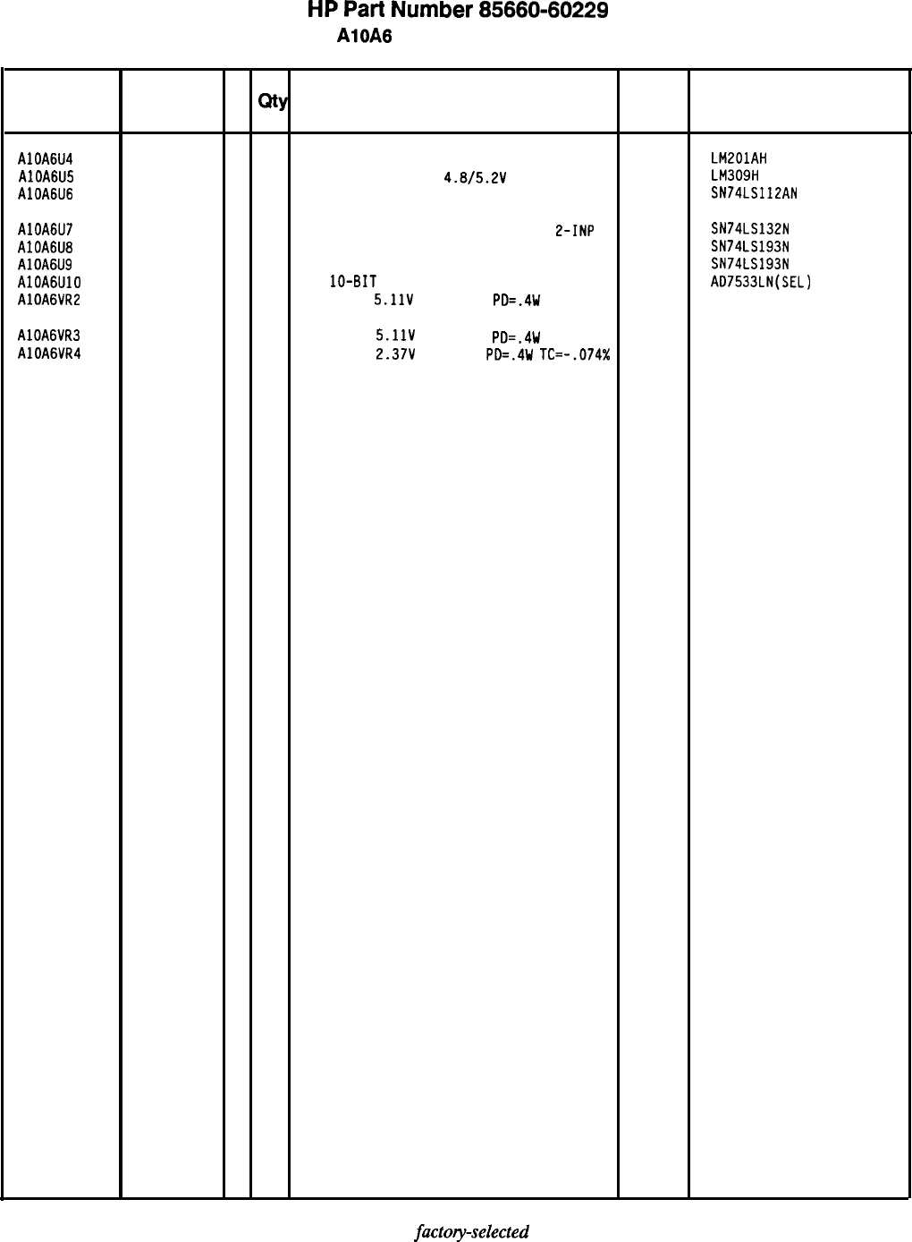
HP
Part
Number 85660-60229
AlOA6 PLL 2 Phase Detector
Reference
HP Part C
Number D
Qty Description
Mfr
Mfr Part
Designation Code Number
AlOA6U4
AlOA6U5
AlOA6U6
AlOA6U7
AlOA6U8
AlOA6U9
AlOAGUlO
AlOA6VR2
AlOA6VR3
AlOA6VR4
1826-0059
2
1
IC OP AMP GP TO-99 PKG 27014 LM201AH
1820-0429
8
1
IC V
RGLTR-FXO-POS
4.8/5.2V
TO-39 PKG
27014 LM309H
1820-1212
9
1
IC FF TTL LS J-K NEG-EDGE-TRIG PRESET/CL 01295 SN74LS112AN
1820-1425
6
1
IC SCHMITT-TRIG
TTL LS NAND QUAD
L-INP 01295 SN74LS132N
1820-1194
6
1
IC CNTR TTL UP/DOWN
LS BIN SYNCHRO POS-E
01295 SN74LS193N
1820-1194
6
1
IC CNTR TTL UP/DOWN
LS BIN SYNCHRO POS-E
01295 SN74LS193N
1826-0448
3
1
O/A
lo-BIT 16-PLASTIC CMOS 24355
1902-0041 AO7533LN(SEL)
4
1
DIODE-ZNR
5.11V
5% DO-35
PO=.4W 04713
1902-0041
4
1
DIODE-ZNR
5.11V
5% DO-35
PO=.4W 04713
1902-3002
3
1
DIODE-ZNR 2.37V
5% DO-7
PO=.4W
TC=-.074% 04713
*Indicates
factoy-selected
value
85660-60229 Parts List
Page 3 of 3
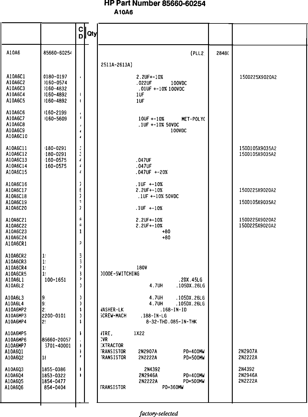
HP
Part
Number 85660-60254
AlOA6 PLL 2 Phase Detector
Description Mfr
Mfr Part
Code Number
BOARD ASSEMBLY, PHASE LOCK LOOP 2
(PLLZ,
PHASE DETECTOR (SERIAL PREFIXES:
2511A-2613A)
2848t
85660-60254
CAPACITOR-FXO
2.2UF+-10%
20VOC TA
56288
1500225X9020A2
CAPACITOR-FXO
.022UF
+-20%
1OOVOC
CER
2848C
0160-0574
CAPACITOR-FXO
.OlUF
+-lo%
1OOVOC
CER
2848C
0160-4832
CAPACITOR-FXO
1UF
+-20% 25VOC CER
2848C 0160-4892
CAPACITOR-FXO
1UF
+-20% 25VOC CER
28480 0160-4892
CAPACITOR-FXO 30PF +-5% 300VOC MICA
28480 0160-2199
CAPACITOR-FXO
1OUF
+-lo%
50VOC
MET-POLYC 28480 0160-5609
CAPACITOR-FXO
.lUF
+-lo%
SOVOC
CER
28480 0160-4835
CAPACITOR-FXO 4700PF +-20%
1OOVOC
CER
28480 0160-0573
CAPACITOR-FXO 30PF +-5% 300VOC MICA
28480 0160-2199
CAPACITOR-FXO lUF+-10% 35VOC TA
56289 1500105X9035A2
CAPACITOR-FXO lUF+-10% 35VOC TA
56289 1500105X9035A2
CAPACITOR-FXO
.047UF
+-20% 50VOC CER
28480 0160-0575
CAPACITOR-FXO
.047UF
+-20% 50VOC CER
28480 0160-0575
CAPACITOR-FXO
.047UF
+-20X
50VOC CER
28480 0160-0575
CAPACITOR-FXO
.lUF
+-lo% 50VOC CER
28480 0160-4835
CAPACITOR-FXO
2.2UF+-10%
20VOC TA
56289 1500225X9020A2
CAPACITOR-FXO
.lUF
+-10x
SOVOC
CER
28480 0160-4835
CAPACITOR-FXO lUF+-10% 35VOC TA 56289 1500105X9035A2
CAPACITOR-FXO
.lUF
+-lo% 50VOC CER
28480 0160-4835
CAPACITOR-FXO
2.2UF+-10%
20VOC TA
56289 1500225X9020A2
CAPACITOR-FXO
2.2UF+-10%
20VOC TA
56289 1500225X9020A2
CAPACITOR-FOTHRU 5000PF
+80
-20% 200V
28480 0160-2437
CAPACITOR-FOTHRU 5000PF
+80
-20% 200V
28480 0160-2437
DIODE-GEN PRP 180V 200MA DO-7 28480 1901-0033
DIODE-GEN PRP 35V 50MA 00-35 28480 1901-0376
DIODE-GEN PRP 35V 50MA DO-35 28480 1901-0376
DIODE-GEN PRP
1BOV
200MA DO-7
28480 1901-0033
IIOOE-SWITCHING
80V 200MA 2NS DO-35
28480 1901-0050
INDUCTOR RF-CH-ML0 750UH +-5%
.2OX.45LG 28480 9100-1651
INDUCTOR RF-CH-ML0
4.7UH
10%
.105OX.26LG 28480 9140-0144
LNOUCTOR RF-CH-ML0
4.7UH
10%
.105OX.26LG 28480 9140-0144
LNOUCTOR RF-CH-ML0
4.7UH
10%
.105OX.26LG 28480 9140-0144
JASHER-LK
INTL T NO. 8
.168-IN-IO 28480 2190-0009
iCREW-MACH
4-40
.188-IN-LG
PAN-HO-POZI
00000 ORDER BY DESCRIPTION
IUT-HEX-OBL-CHAM
8-32-THO
.085-IN-THK 28480 2580-0002
/IRE,
22 AWG
1X22
:VR
PC 2 PHSOETC
:XTRACTOR
PC
rRANSISTOR
PNP
2N2907A
SI TO-18
PO=400MW
[RANSISTOR
NPN
2N2222A
SI TO-18
PO=500MW
'RANSISTOR J-FET
2N4392
N-CHAN O-MODE TO
'RANSISTOR PNP
2N2946A
SI TO-46
PO=400MW
'RANSISTOR NPN
2N2222A
SI TO-18 PO=500MW
iRANSISTOR
NPN SI TO-18
PO=360MW
92194 298
28480 85660-20057
28480 86701-40001
04713 2N2907A
04713 2N2222A
04713 2N4392
01275 2N2946A
04713 2N2222A
28480 1854-0404
*Indicates
factoryselected
value
85660-60254 Parts List
Page 1 of 3
Reference
Designatior
1
HP Part
Number
AlOA6
t
35660-60254
AlOAGCl
(
1180-0197
AlOA6C2
c
1160-0574
AlOA6C3
c
1160-4832
AlOA6C4
C
1160-4892
AlOA6C5
C
1160-4892
,
AlOA6C6
C
1160-2199
,
AlOA6C7
C
1160-5609
I
AlOA6C8
C
1160-4835
/
AlOA6C9
a
1160-0573
I
AlOAGClO
a
1160-2199
I
AlOAGCll
0
1180-0291
:
AlOA6C12
0
1180-0291
:
AlOA6C13
0
1160-0575
1
AlOA6C14
0
‘160-0575
1
AlOA6C15
0
160-0575
1
AlOA6C16
0
160-4835
i
AlOA6C17
0
180-0197
E
AlOA6C18
0
160-4835
i
AlOA6C19
0
180-0291
?
AlOA6C20
0
160-4835
I
AlOA6C21
0
180-0197
t
AlOA6C22
0
180-0197
P
AlOA6C23
0
160-2437
1
AlOA6C24
0
160-2437
1
AlOAGCRl
1'
901-0033
7
AlOA6CR2
I!
901-0376
5
AlOA6CR3
I!
901-0376
5
AlOA6CR4
I!
901-0033
7
AlOA6CR5
l!
901-0050
3
AlOAGLl
9
loo-1651
?
AlOA6L2
9
140-0144
I
AlOA6L3
AlOA6L4
AlOA6MP2
AlOA6MP3
AlOA6MP4
140-0144
140-0144
190-0009
zoo-0101
580-0002
AlOA6MP5
8:
150-0013
AlOA6MP6
8!
5660-20057
AlOA6MP7
81
j701-40001
AlOA6Ql
11
353-0281
AlOA6Q2
II
354-0477
AlOA6Q3
1t
355-0386
AlOA6Q4
lf
353-0322
AlOA6Q5
1t
354-0477
AlOA6Q6
1’
854-0404
I
I
I
1
I
I
;
I
I
I
I
at
1
1
1
1
1
1
1
1
1
1
1
1
1
1
1
1
1
1
1
1
1
1
1
1
1
1
1
1
1
1
1
1
1
1
2
2
2
1
1
2
1
1
1
1
1
1
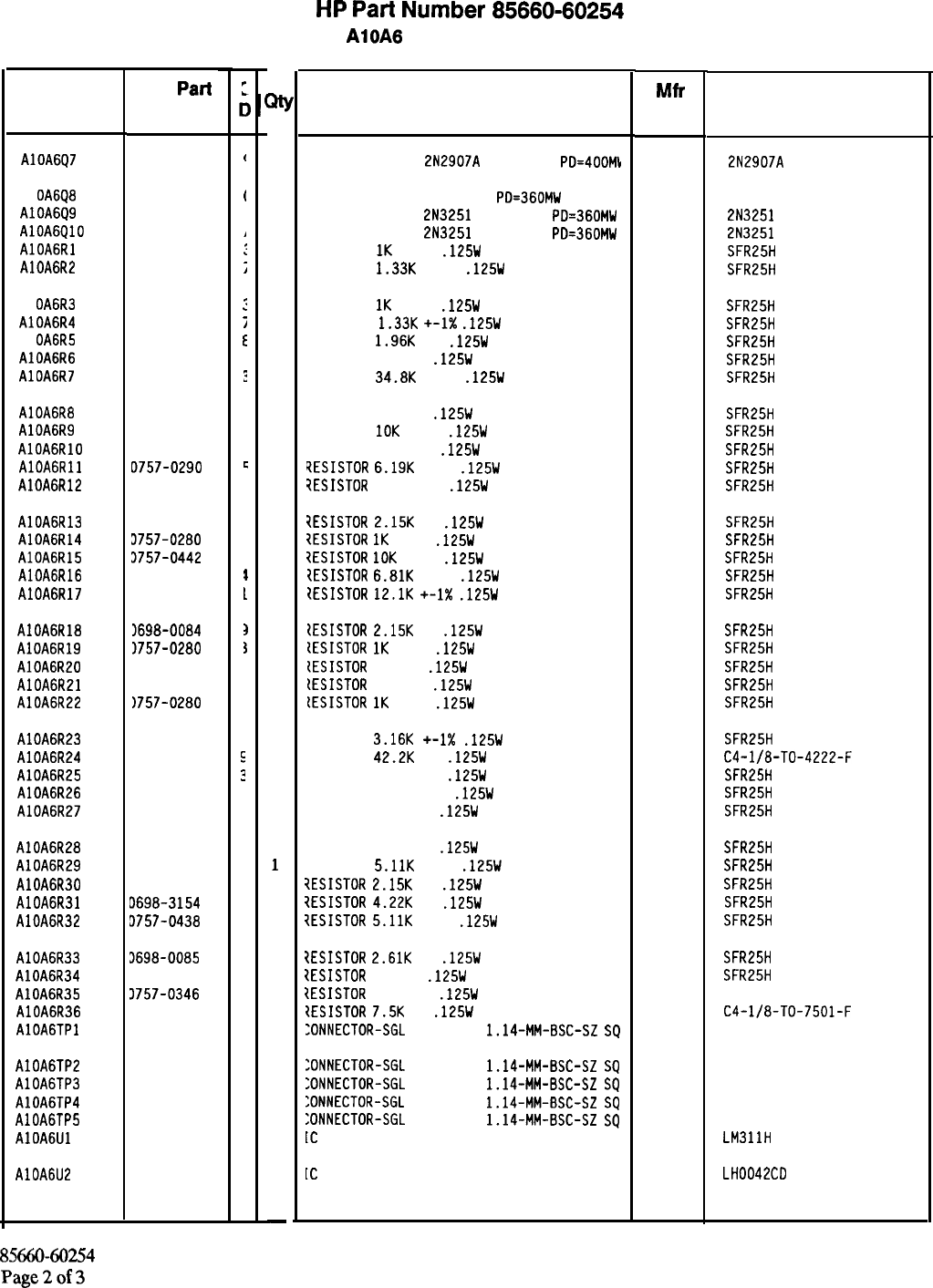
HP
Part
Number 85660-60254
AlOA6 PLL 2 Phase Detector
Description Mfr
Mfr Part
Code Number
TRANSISTOR PNP
2N2907A
SI TO-18
PO=400M\I
04713 2N2907A
TRANSISTOR NPN SI TO-18
PO=360MW
TRANSISTOR PNP
2N3251
SI TO-18
PO=360MW
TRANSISTOR PNP
2N3251
SI TO-18
PO=360MW
RESISTOR
1K
+-1%
.125W
TF TC=O+-100
RESISTOR
1.33K
+-1%
.125W
TF TC=O+-100
28480 1854-0404
04713 2N3251
04713 2N3251
19701
SFR25H
19701
SFR25H
RESISTOR
1K
+-1%
.125W
TF TC=O+-100
RESISTOR
1.33K
+-1X
.125W
TF TC=O+-100
RESISTOR
1.96K
1%
.125W
TF TC=O+-100
RESISTOR 196 1%
.125W
TF TC=O+-100
RESISTOR
34.8K
+-1%
.125W
TF TC=O+-100
19701
SFR25H
19701
SFR25H
19701
SFR25H
19701
SFR25H
19701
SFR25H
RESISTOR 464 1%
.125W
TF TC=O+-100
RESISTOR
10K
+-1%
.125W
TF TC=O+-100
RESISTOR 464K 1%
.125W
TF TC=O+-100
tESISTOR
6.19K
+-1%
.125W
TF TC=O+-100
7ESISTOR
750 +-1%
.125W
TF TC=O+-100
19701
SFR25H
19701
SFR25H
19701 SFR25H
19701
SFR25H
19701
SFR25H
1ESISTOR
2.15K
1%
.125W
TF TC=O+-100
7ESISTOR
1K
+-1%
.125W
TF TC=O+-100
7ESISTOR
10K
+-1%
.125W
TF TC=O+-100
tESISTOR
6.81K
+-1%
.125W
TF TC=O+-100
tESISTOR
12.1K
+-1X
.125W
TF TC=O+-100
19701
SFR25H
19701
SFR25H
19701 SFR25H
19701
SFR25H
19701
SFR25H
tESISTOR
2.15K
1%
.125W
TF TC=O+-100
tESISTOR
1K
+-1%
.125W
TF TC=O+-100
{ESISTOR
348 1%
.125W
TF TC=O+-100
[ESISTOR
348 1%
.125W
TF TC=O+-100
lESISTOR
1K
+-1%
.125W
TF TC=O+-100
19701
SFR25H
19701
SFR25H
19701 SFR25H
19701
SFR25H
19701
SFR25H
RESISTOR
3.16K
+-1X
.125W
TF TC=O+-100
RESISTOR
42.2K
1%
.125W
F TC=O+-100
RESISTOR 75K +-1%
.125W
TF TC=O+-100
RESISTOR 121K +-1%
.125W
TF TC=O+-100
RESISTOR 237K 1%
.125W
TF TC=O+-100
19701
SFR25H
24546
C4-l/8-TO-4222-F
19701
SFR25H
19701
SFR25H
19701
SFR25H
RESISTOR 422K 1%
.125W
TF TC=O+-100
RESISTOR
5.11K
+-1%
.125W
TF TC=O+-100
iESISTOR
2.15K
1%
.125W
TF TC=O+-100
?ESISTOR
4.22K
1%
.125W
TF TC=O+-100
iESISTOR
5.11K
+-1%
.125W
TF TC=O+-100
19701
SFR25H
19701
SFR25H
19701 SFR25H
19701
SFR25H
19701
SFR25H
7ESISTOR
2.61K
1%
.125W
TF TC=O+-100
19701
1ESISTOR
348 1%
.125W
TF TC=O+-100
19701
tESISTOR
10 +-1%
.125W
TF TC=O+-100
91637
IESISTOR
7.5K
1%
.125W
TF TC=O+-100
24546
:ONNECTOR-SGL
CONT PIN
1.14-MM-BSC-SZ
SQ
27264
SFR25H
SFR25H
CMF-55-1, T-l
C4-l/8-TO-7501-F
16-06-0034
:ONNECTOR-SGL
CONT PIN
1.14-MM-BSC-SZ
SQ
27264 16-06-0034
:ONNECTOR-SGL
CONT PIN
1.14-MM-BSC-SZ
SQ
27264 16-06-0034
:ONNECTOR-SGL
CONT PIN
1.14-MM-BSC-SZ
SQ
27264 16-06-0034
:ONNECTOR-SGL
CONT PIN
1.14-MM-BSC-SZ
SQ
27264 16-06-0034
[C
COMPARATOR PRCN TO-99 PKG
27014 LM3llH
[C
OP AMP 14-DIP-C PKG
27014 LH0042CO
*Indicates factory-selected value
Reference
Designatior HP
Part
Number
AlOA6Q7 1853-0281
Al
OA6Q8 1854-0404
AlOA6Q9 1853-0007
AlOAGQlO 1853-0007
AlOAGRl 0757-0280
AlOA6R2 0757-0317
Al
OA6R3 0757-0280
AlOA6R4 0757-0317
Al OA6R5 0698-0083
AlOA6R6 0698-3440
AlOA6R7 0757-0123
AlOA6R8 0698-0082
AlOA6R9 0757-0442
AlOAGRlO 0698-3260
AlOAGRll D757-0290
AlOA6R12 0757-0420
AlOA6R13 0698-0084
AlOA6R14 3757-0280
AlOA6R15 3757-0442
AlOA6R16 3757-0439
AlOA6R17 3757-0444
AlOA6R18 1698-0084
AlOA6R19 1757-0280
AlOA6R20 1698-3445
AlOA6R21 1698-3445
AlOA6R22 1757-0280
AlOA6R23 0757-0279
AlOA6R24 0698-3450
AlOA6R25 0757-0462
AlOA6R26 0757-0467
AlOA6R27 0698-3266
AlOA6R28 0698-3460
AlOA6R29 0757-0438
AlOA6R30 0698-0084
AlOA6R31 0698-3154
AlOA6R32 3757-0438
AlOA6R33 3698-0085
AlOA6R34 3698-3445
AlOA6R35 3757-0346
AlOA6R36 3757-0440
AlOAGTPl 1251-0600
AlOA6TP2 1251-0600
AlOA6TP3 1251-0600
AlOA6TP4 1251-0600
AlOA6TP5 1251-0600
AlOAGUl 1826-0026
AlOA6U2
1826-0459
8566060254
Parts List
Page2of3
:
t
t
I
1
:
;
:
i
E
i
?
7
3
3
c
3
3
3
3
I
1
3
1
,
,
I
M
1
1
1
1
1
1
1
1
1
1
1
1
1
1
1
1
1
1
1
1
1
1
1
1
1
1
1
1
1
1
1
1
1
1
1
1
1
1
1
1
1
1
1
1
1
1
1
-
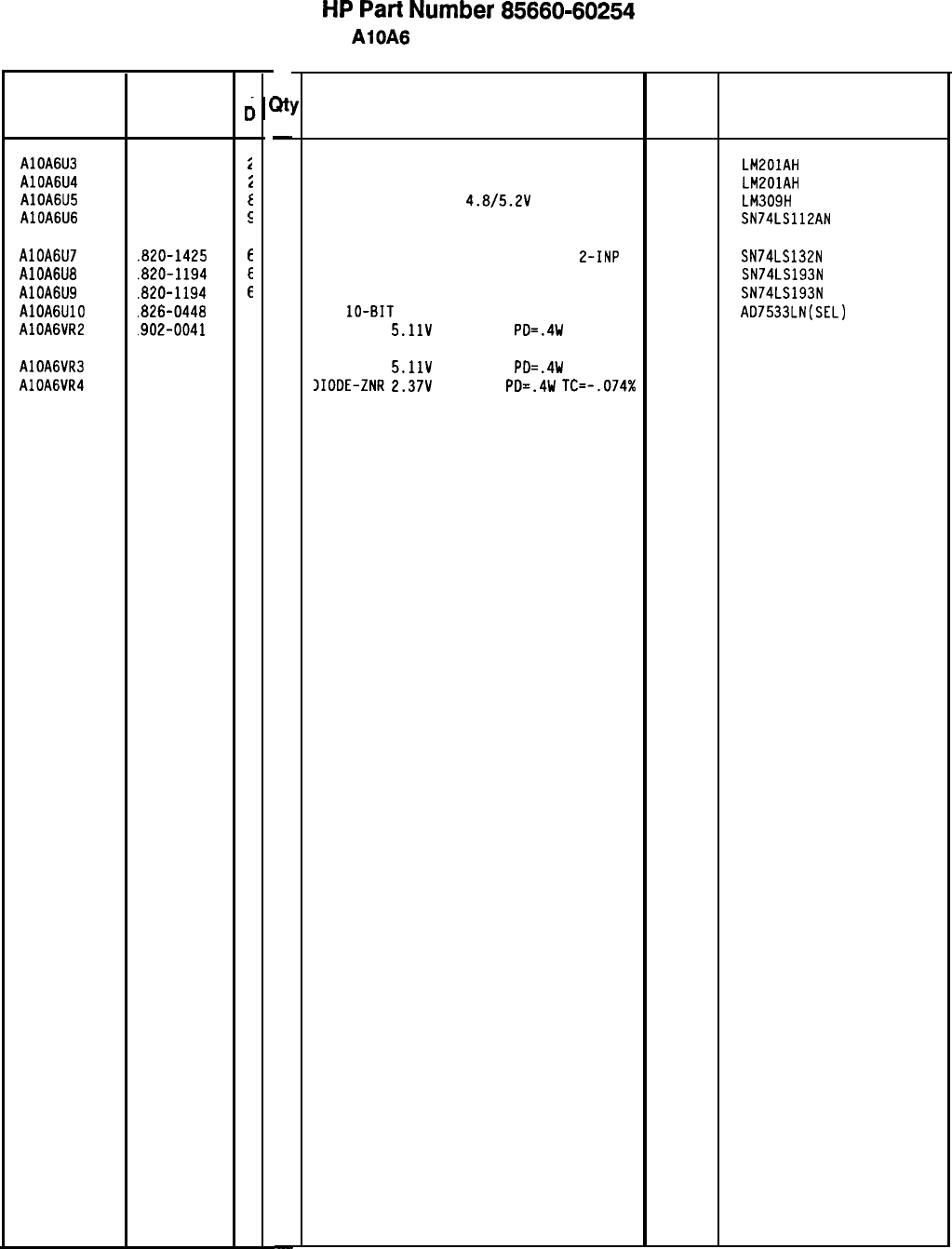
HP
Part
Number 85660-60254
Reference HP Part
Designation
Number
AlOA6U3 1826-0059
AlOA6U4 1826-0059
AlOA6U5
1820-0429
AlOA6U6
1820-1212
AlOA6U7
.B20-1425
AlOA6U8
.820-1194
AlOA6U9
.820-1194
AlOAGUlO
.826-0448
AlOA6VR2
.902-0041
AlOA6VR3
AlOA6VR4 902-0041
902-3002
c
c
i
i
t
E
E
E
E
3
4
4
3
3tl
-
1
1
1
1
1
1
1
1
1
1
1
-
AlOA6 PLL 2 Phase Detector
Description
IC OP AMP GP TO-99 PKG 27014 LMEOlAH
IC OP AMP GP TO-99 PKG 27014 LMZOlAH
IC V RGLTR-FXO-POS
4.8/5.2V
TO-39 PKG
27014 LM309H
IC FF TTL LS J-K NEG-EDGE-TRIG PRESET/CL 01295 SN74LS112AN
IC SCHMITT-TRIG TTL LS NAND QUAD
E-INP 01295
IC CNTR TTL LS BIN UP/DOWN SYNCHRO POS-E 01295
IC CNTR TTL LS BIN UP/DOWN SYNCHRO POS-E 01295
O/A
lo-BIT
16-PLASTIC CMOS
24355
DIODE-ZNR
5.11V
5% DO-35
PO=.4W 04713
SN74LS132N
SN74LS193N
SN74LS193N
AO7533LN(SEL)
DIODE-ZNR
5.11V
5% DO-35
PO=.4W 04713
JIOOE-ZNR
2.37V
5% DO-7
PO=.4W
TC=-.074%
04713
Mfr
Mfr Part
Code Number
*Indicates factory-selected value
85660-60254 Parts List
Page 3 of 3
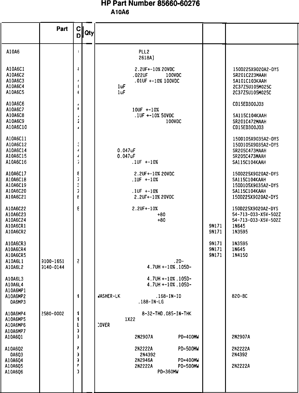
Reference
Designatior HP Pati
Number
AlOA6 85660-60276
AlOAGCl 0180-0197
AlOA6C2 0160-0574
AlOA6C3 0160-4832
AlOA6C4 0160-4892
AlOA6C5 0160-4892
I
AlOA6C6 0160-2199
1
AlOA6C7 0160-5609
I
AlOA6C8 0160-4835
/
AlOA6C9 0160-0573
i
AlOAGClO 0160-2199
‘
AlOAGCll 0180-0291
AlOA6C12 0180-0291
AlOA6C14 0160-0575
AlOA6C15 0160-0575
AlOA6C16 0160-4835
AlOA6C17 0180-0197
AlOA6C18 0160-4835
AlOA6C19 0180-0291
AlOA6C20 0160-4835
AlOA6C21 0180-0197
AlOA6C22 0180-0197
AlOA6C23 0160-2437
AlOA6C24 0160-2437
AlOAGCRl 1901-0033
AlOA6CR2 1901-0376
AlOA6CR3 1901-0376
AlOA6CR4 1901-0033
AlOA6CR5 1901-0050
AlOAGLl 9100-1651
AlOA6L2 3140-0144
AlOA6L3
AlOA6L4
AlOAGMPl
AlOA6MP2
Al OA6MP3
3140-0144
3140-0144
2190-0009
2200-0101
AlOA6MP4 2580-0002
AlOA6MP5 3151-0013
AlOA6MP6 35660-20057
AlOA6MP7 36701-40001
AlOAGQl 1853-0281
AlOA6Q2 1854-0477
Al OA6Q3 1855-0386
AlOA6Q4 1853-0322
AlOA6Q5 1854-0477
AlOA6Q6 1854-0404
E
1
1
2
E
E
2
3
2
3
3
3
1
3
$
1
1
3
3
1
3
3
I
1
-
at]
-
1
1
1
1
1
1
1
1
1
1
1
1
1
1
1
1
1
1
1
1
1
1
1
1
1
1
1
1
1
1
1
1
1
2
2
2
2
1
2
1
1
1
1
1
1
-
HP
Part
Number 85660-60276
AlOA6 PLL 2 Phase Detector
Description Mfr
Mfr Part
Code Number
BOARD ASSEMBLY,
PLLL
PHASE DETECTOR
(SERIAL PREFIX:
2618~) 2848C
85660-60276
CAPACITOR-FXO
2.2UF+-10%
ZOVOC
TA
56289
1500225X9020A2-OYS
CAPACITOR-FXO
.022UF
+-20%
1OOVOC
CER
04222 SR201C223MAAH
CAPACITOR-FXO
.OlUF
+-lo%
1OOVOC
CER
04222 SAlOlC103KAAH
CAP-FXO
1uF
25 V
56289 2C37Z5U105M025C
CAP-FXO
1uF
25 V
56289 2C37Z5U105M025C
CAPACITOR-FXO 30PF +-5% 300VOC MICA
09023 CO15EO300J03
CAPACITOR-FXO
1OUF
+-lo%
50VOC MET-POLYC
84411 HEW-687
CAPACITOR-FXO
.lUF
+-lo%
SOVOC
CER
04222 SA115C104KAAH
CAPACITOR-FXO 4700PF +-20%
1OOVOC
CER
04222 SR201C472MAAH
CAPACITOR-FXO 30PF +-5% 300VOC MICA
09023 CO15E0300J03
CAPACITOR-FXO lUF+-10% 35VOC TA
56289 1500105X9035A2-OYS
CAPACITOR-FXO lUF+-10% 35VOC TA
56289 1500105X9035A2-OYS
CAP-FXO
0.047uF
50 V CER
04222 SR205C473MAAH
CAP-FXO
0.047uF
50 V CER
04222 SR205C473MAAH
CAPACITOR-FXO
.lUF
+-lo% 50VOC CER
04222 SA115C104KAAH
CAPACITOR-FXO
2.2UF+-10%
LOVOC
TA
56289 1500225X9020A2-OYS
CAPACITOR-FXO
.lUF
+-lo%
50VOC CER
04222 SA115C104KAAH
CAPACITOR-FXO lUF+-10% 35VOC TA
56289 1500105X9035A2-OYS
CAPACITOR-FXO
.lUF
+-lo% 50VOC CER
04222 SA115C104KAAH
CAPACITOR-FXO
2.2UF+-10%
POVOC
TA
56289 1500225X9020A2-OYS
CAPACITOR-FXO
2.2UF+-10%
20VOC TA
56289 1500225X9020A2-OYS
CAPACITOR-FOTHRU 5000PF
+80
-20% 200V
33095 54-713-033-X5V-5022
CAPACITOR-FOTHRU 5000PF
+80
-20% 200V
33095 54-713-033-X5V-5022
DIODE-GEN PRP 180V 200MA DO-35 9N171 lN645
DIODE-GEN PRP 35V 50MA DO-35 9N171 lN3595
DIODE-GEN PRP 35V 50MA DO-35 9N171 lN3595
DIODE-GEN PRP 180V 200MA DO-35 9N171 lN645
DIODE-SWITCHING BOV 200MA 2NS DO-35 9N171 lN4150
INDUCTOR RF-CH-ML0 750UH +-5%
.20-
99800 2500-22
INDUCTOR RF-CH-ML0
4.7UH
+-lo%
.1050-
99800 1025-36
INDUCTOR RF-CH-ML0
4.7UH
+-10X
.1050-
INDUCTOR RF-CH-ML0
4.7UH
+-10X
.1050-
YOT ASSIGNED
99800 1025-36
99800 1025-36
dASHER-LK
INTL T NO. 8
.168-IN-IO 06791
SCREW-MACH 4-40
.188-IN-LG
PAN-HO-POZI
77250 820-BC
VUT-HEX-OBL-CHAM
8-32-THO
.085-IN-THK
JIRE 22AWG
1X22
:OVER
PC, PLL2 PHASE DETECTOR
EXTRACTOR, PC
TRANSISTOR PNP
2N2907A
SI TO-18
PO=400MW
TRANSISTOR NPN
2N2222A
SI TO-18 PO=500MW
TRANSISTOR J-FET
2N4392
N-CHAN O-MODE TO
TRANSISTOR PNP
2N2946A
SI TO-46
PO=400MW
TRANSISTOR NPN
2N2222A
SI TO-18
PO=500MW
TRANSISTOR NPN SI TO-18
PO=360MW
80120
92194
28480
28480
04713
298
85660-20057
86701-40001
2N2907A
04713
04713
04713
04713
04713
2N2222A
2N4392
2N2222A
*Indicates factoryselected value
85660-60276 Parts List
Page 1 of 3
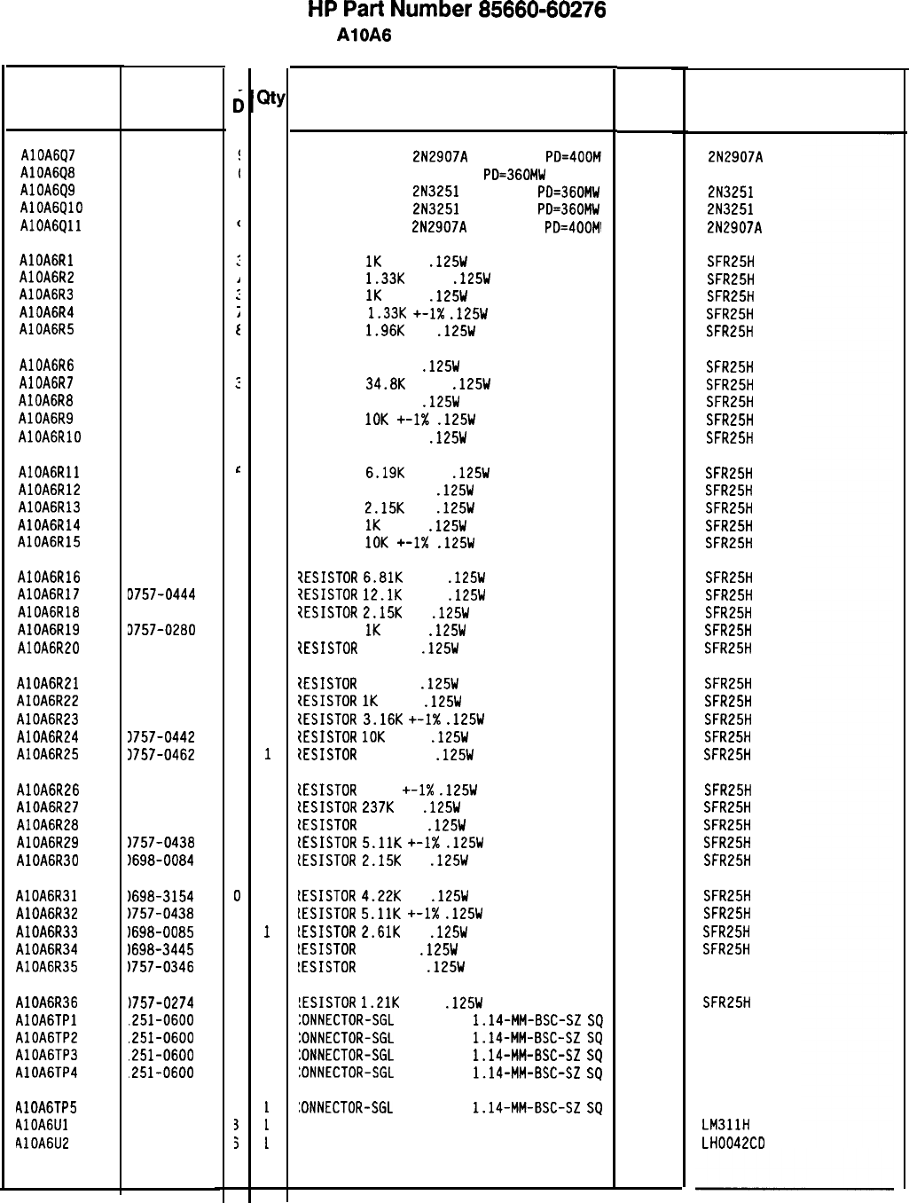
HP
Part
Number 85660-60276
Reference
Designatior
AlOA6Q7
AlOA6Q8
AlOA6Q9
AlOA6QlO
AlOAGQll
HP Part
Number
C
c
1853-0281
1854-0404
1853-0007
1853-0007
1853-0281
AlOAGRl 0757-0280
:
AlOA6R2 0757-0317
1
AlOA6R3 0757-0280
:
AlOA6R4 0757-0317
;
AlOA6R5 0698-0083
t
AlOA6R6 0698-3440
i
AlOA6R7 0757-0123
:
AlOA6R8 0698-0082
7
AlOA6R9 0757-0442
C
AlOAGRlO 0698-3260
C
AlOAGRll 0757-0290
e
AlOA6R12 0757-0420
3
AlOA6R13 0698-0084
9
AlOA6R14 0757-0280
3
AlOA6R15 0757-0442
9
AlOA6R16 0757-0439
4
AlOA6R17 D757-0444
1
AlOA6R18 3698-0084
9
AlOA6R19 3757-0280
3
AlOA6R20 3698-3445
2
AlOA6R21 3698-3445
2
AlOA6R22 3757-0280
3
AlOA6R23 3757-0279
0
AlOA6R24 3757-0442
9
AlOA6R25 3757-0462
3
AlOA6R26 1757-0467
8
AlOA6R27 1698-3266
5
AlOA6R28 1698-3460
1
AlOA6R29 1757-0438
3
AlOA6R30
1698-0084
9
AlOA6R31
1698-3154
0
AlOA6R32
1757-0438
3
AlOA6R33
1698-0085
0
AlOA6R34
1698-3445
2
AlOA6R35
1757-0346
2
AlOA6R36
)757-0274
5
AlOAGTPl
.251-0600
3
AlOA6TP2
.251-0600
3
AlOA6TP3
.251-0600
3
AlOA6TP4
.251-0600
3
AlOA6TP5 251-0600
3
AlOAGUl 826-0026
3
AlOA6U2 826-0459
5
85660-60276 Parts List
Page 2 of 3
It
1
1
1
1
1
1
1
1
1
1
1
1
1
1
1
1
1
1
1
1
1
1
1
1
1
1
1
1
1
1
1
1
1
1
1
1
1
1
1
1
1
1
1
1
1
1
1
1
AlOA6 PLL 2 Phase Detector
Description
TRANSISTOR PNP
2N2907A
SI TO-18
PD=4OOM'
TRANSISTOR NPN SI TO-18
PD=360MW
TRANSISTOR PNP
2N3251
SI TO-18
PD=360MW
TRANSISTOR PNP
2N3251
SI TO-18
PD=360MW
TRANSISTOR PNP
2N2907A
SI TO-18
PD=400Ml
Mfr Mfr Part
Code
Number
0471:
0471:
0471:
0471:
0471:
RESISTOR
1K
+-1%
.125W
TF TC=O+-100
19701
RESISTOR
1.33K
+-1%
.125W
TF TC=O+-100
19701
RESISTOR
1K
+-1%
.125W
TF TC=O+-100
19701
RESISTOR
1.33K
+-1X
.125W
TF TC=O+-100
19701
RESISTOR
1.96K
1%
.125W
TF TC=O+-100
19701
RESISTOR 196 1%
.125W
TF TC=O+-100
19701
RESISTOR
34.8K
+-1%
.125W
TF TC=O+-100
19701
RESISTOR 464 1%
.125W
TF TC=O+-100
19701
RESISTOR
10K
+-I%
.125W
TF TC=O+-100
19701
RESISTOR 464K 1%
.125W
TF TC=O+-100
19701
RESISTOR
6.19K
+-1%
.125W
TF TC=O+-100
19701
RESISTOR 750 +-1%
.125W
TF TC=O+-100
19701
RESISTOR
2.15K
1%
.125W
TF TC=O+-100
19701
RESISTOR
1K
+-1%
.125W
TF TC=O+-100
19701
RESISTOR
10K
+-I%
.125W
TF TC=O+-100
19701
7ESISTOR
6.81K
+-1%
.125W
TF TC=O+-100
19701
?ESISTOR
12.1K
+-1%
.125W
TF TC=O+-100
19701
7ESISTOR
2.15K
1%
.125W
TF TC=O+-100
19701
7ESISTOR
1K
+-1%
.125W
TF TC=O+-100
19701
7ESISTOR
348 1%
.125W
TF TC=O+-100
19701
tESISTOR
348 1%
.125W
TF TC=O+-100
19701
IESISTOR
1K
+-1%
.125W
TF TC=O+-100
19701
IESISTOR
3.16K
+-I%
.125W
TF TC=O+-100
19701
ZESISTOR
10K
+-1%
.125W
TF TC=O+-100
19701
ZESISTOR
75K +-1%
.125W
TF TC=O+-100
19701
tESISTOR
121K
+-1X
.125W
TF TC=O+-100
19701
tESISTOR
2371:
1%
.125W
TF TC=O+-100
19701
lESISTOR
422K 1%
.125W
TF TC=O+-100
19701
lESISTOR
5.11K
+-I%
.125W
TF TC=O+-100
19701
lESISTOR
2.15K
1%
.125W
TF TC=O+-100
19701
lESISTOR
4.22K
1%
.125W
TF TC=O+-100
19701
LESISTOR
5.11K
+-1X
.125W
TF TC=O+-100
19701
IESISTOR
2.61K
1%
.125W
TF TC=O+-100
19701
LESISTOR
348 1%
.125W
TF TC=O+-100
19701
!ESISTOR
10 +-1%
.125W
TF TC=O+-100
91637
!ESISTOR
1.21K
+-1%
.125W
TF TC=O+-100
19701
:ONNECTOR-SGL
CONT PIN
1.14-MM-BSC-SZ
SQ
27264
:ONNECTOR-SGL
CONT PIN
1.14~MM-BSC-SZ
SQ
27264
:ONNECTOR-SGL
CONT PIN
1.14-MM-BSC-SZ
SQ
27264
:ONNECTOR-SGL
CONT PIN
1.14-MM-BSC-SZ
SQ
27264
:ONNECTOR-SGL
CONT PIN
1.14-MM-BSC-SZ
SQ
27264
C COMPARATOR PRCN TO-99 PKG 27014
C OP AMP 14-DIP-C PKG 27014
*Indicates factory-selected value
2N2907A
2N3251
2N3251
2N2907A
SFR25H
SFR25H
SFR25H
SFR25H
SFR25H
SFR25H
SFR25H
SFR25H
SFR25H
SFR25H
SFR25H
SFR25H
SFR25H
SFR25H
SFR25H
SFR25H
SFR25H
SFR25H
SFR25H
SFR25H
SFR25H
SFR25H
SFR25H
SFR25H
SFR25H
SFR25H
SFR25H
SFR25H
SFR25H
SFR25H
SFR25H
SFR25H
SFR25H
SFR25H
CMF-55-1, T-l
SFR25H
16-06-0034
16-06-0034
16-06-0034
16-06-0034
16-06-0034
LM311H
LH0042CD
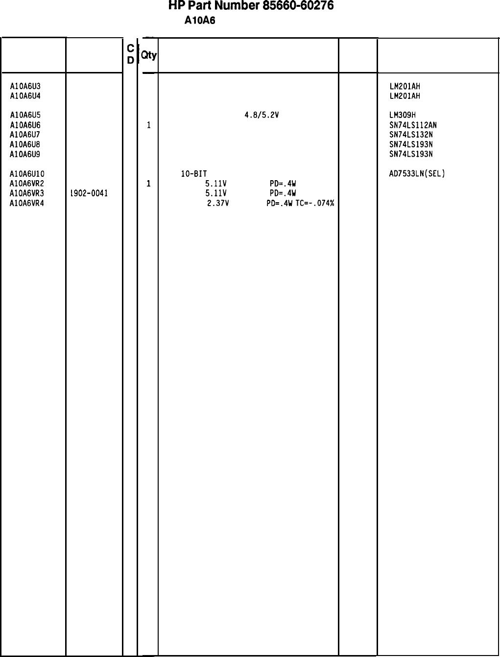
HP
Part
Number 85660-60276
AlOA6 PLL 2 Phase Detector
Reference
Designation
HP Part
Number
AlOA6U3 1826-0059
2
AlOA6U4 1826-0059
2
AlOA6U5 1820-0429
8
AlOA6U6 1820-1212
9
AlOA6U7 1820-1425
6
AlOA6U8 1820-1194
6
AlOA6U9 1820-1194
6
AlOAGUlO 1826-0448
3
AlOA6VR2 1902-0041
4
AlOA6VR3 1902-0041
4
AlOA6VR4 1902-3002
3
-
31
-
1
1
1
1
1
1
1
1
1
1
1
-
Description
IC OP AMP GP TO-99 PKG 27014 LM201AH
IC OP AMP GP TO-99 PKG 27014 LMLOIAH
IC V RGLTR-FXD-POS
4.8/5.2V
TO-39 PKG
27014 LM309H
IC FF TTL LS J-K NEG-EDGE-TRIG PRESET/CL 01295 SN74LS112AN
IC SCHMITT-TRIG TTL LS NAND QUAD 2-INP 01295 SN74LS132N
IC CNTR TTL LS BIN UP/DOWN SYNCHRO POS-E 01295 SN74LS193N
IC CNTR TTL LS BIN UP/DOWN SYNCHRO POS-E 01295 SN74LS193N
D/A
lo-BIT
16-PLASTIC CMOS
24355
DIODE-ZNR
5.11V
5% DO-35
PD=.4W 04713
DIODE-ZNR
5.11V
5% DO-35
PD=.4W 04713
DIODE-ZNR
2.37V
5% DO-7
PD=.4W
TC=-.074% 04713
AD7533LN(SEL)
Mfr
Mfr Part
Code
Number
*Indicates factory-selected value
85660-60276 Parts List
Page 3 of 3
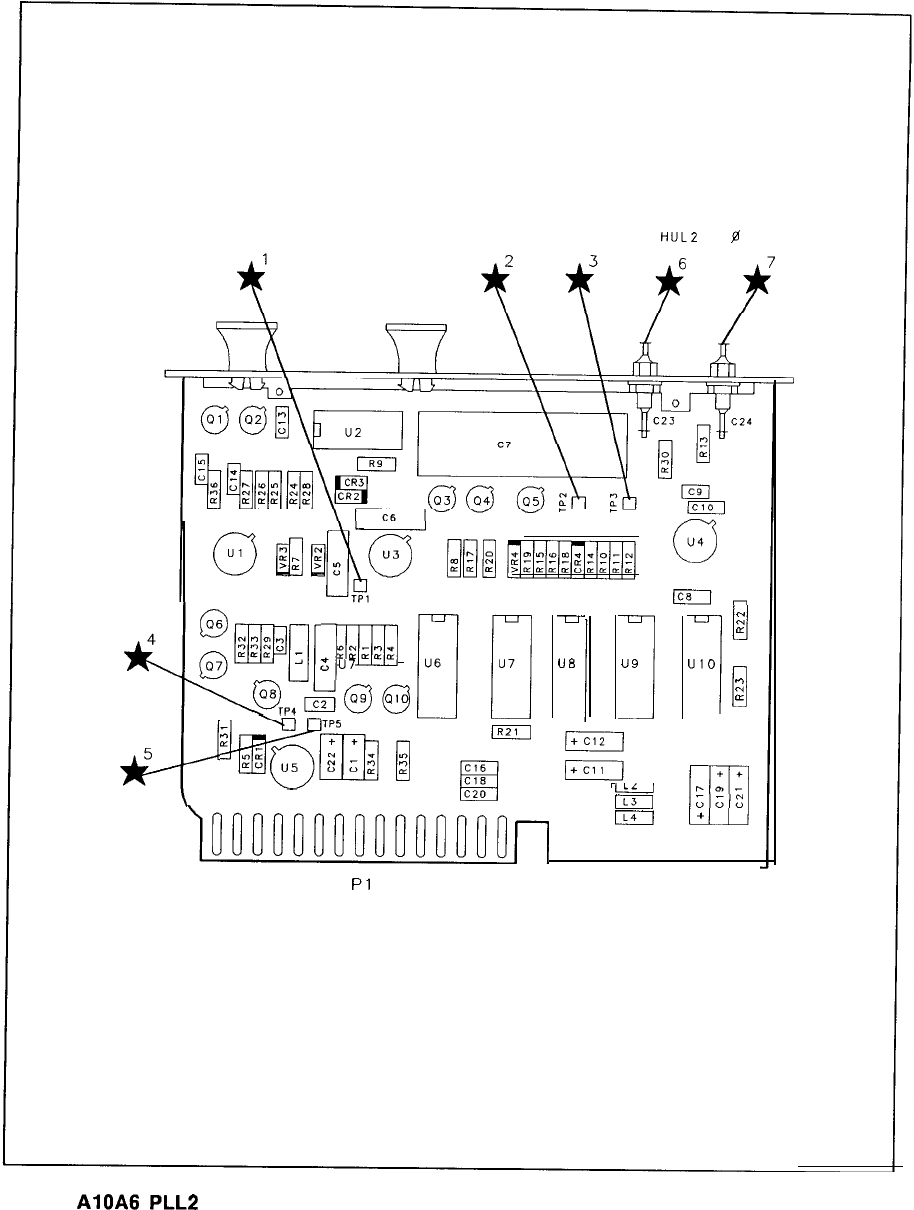
HULZ fl
DET OUT
4
@@iJ;
,mi
“6
Q
m
:I
“7
Q,,&g@
rm
5
::i@~[
g
-
UE
1
u9
I
)onnnnocscocooon~
IL3
I
c3
u4
Ic8m
I
I;
::
LL
UIO
n
::
Lr
1
16
Pl
15
30
+
+
r.
0)
-
ull
;;c:
+
AlOA6
PLL2
Phase Detector Component Locations, 85660-60130, 85660-60229
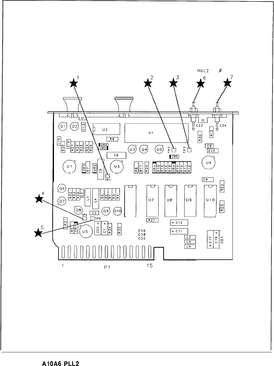
HULZ g
DET OUT
77
U6
lli
U7
m
Cl6
El
Cl8
c20
r:
U6
I
u9
Ic9
m
0
u4
Ic8
1
n
c:
LL
UIO
0
::
a
16 30
+
r.
m
UI
;;
+
+
;;
1
0
AlOA6
PLL2
Phase Detector Component Locations, 85660-60254
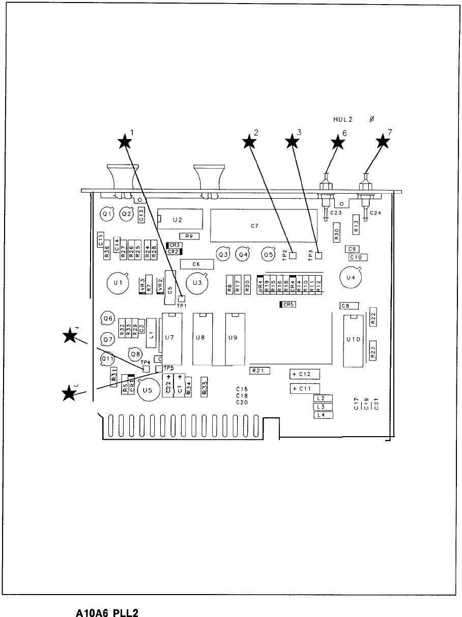
HULZ
$8
DET OUT
4
Jk
5
jc,
@$Yj
TP5
n
e
-
2:
(J!j
0
[-I-j[
+
+
-
(,,1,]
z
-:,
2
U”cc
n
Cl6
q
cl*
pT--
c20
IL2
(L3
)ooonnnnnnonnnnn~
I
1
16 PI 15
30
+ +
h
0)
-
q
;;z
+
AlOA8
PLL2
Phase Detector Component Locations, 85660-60276

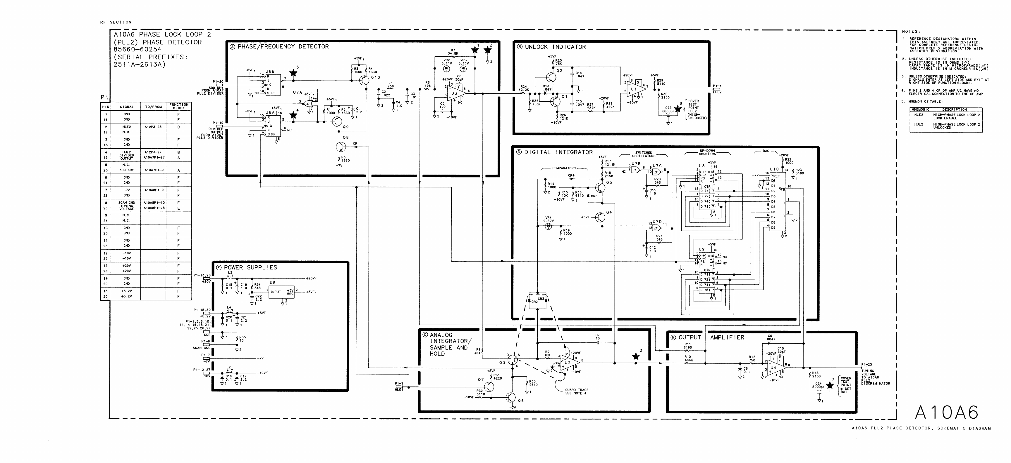
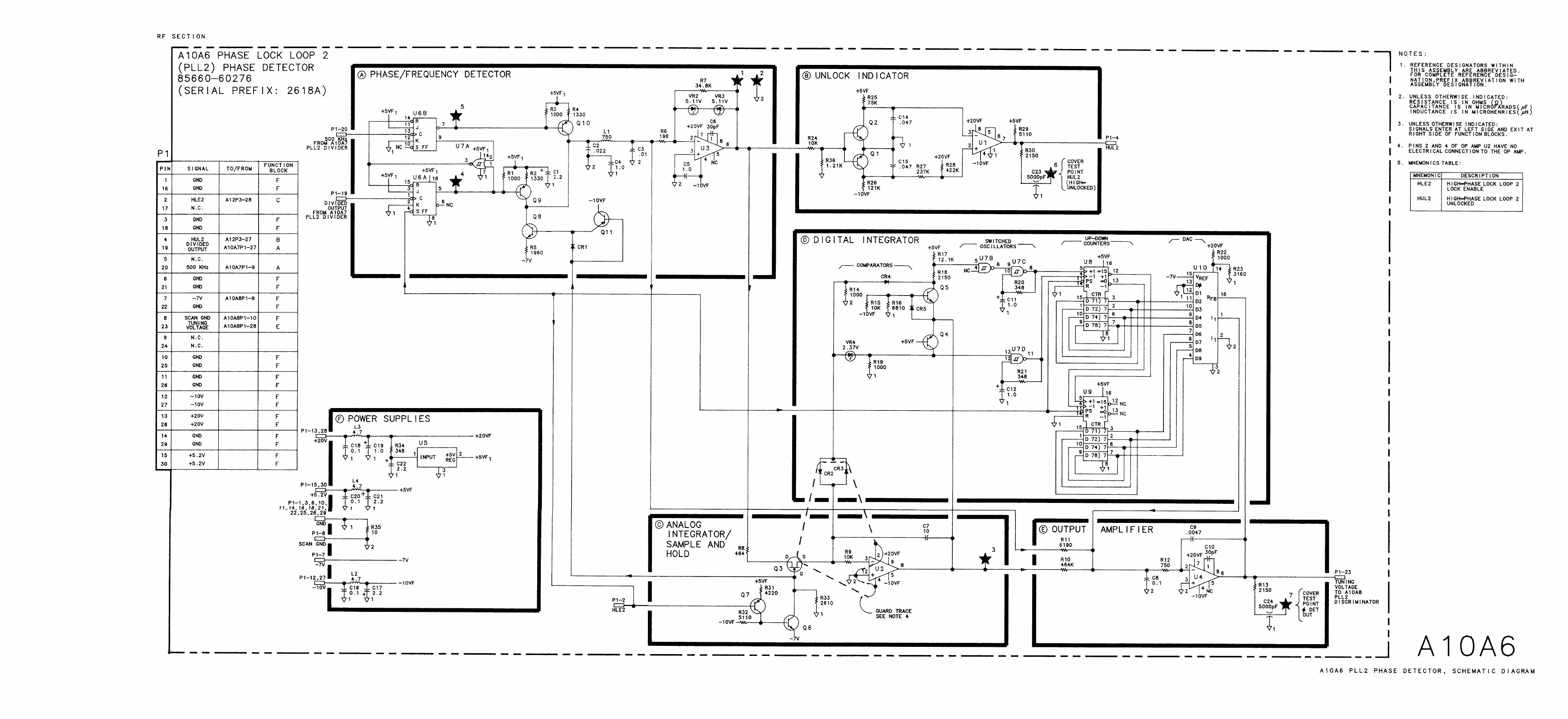
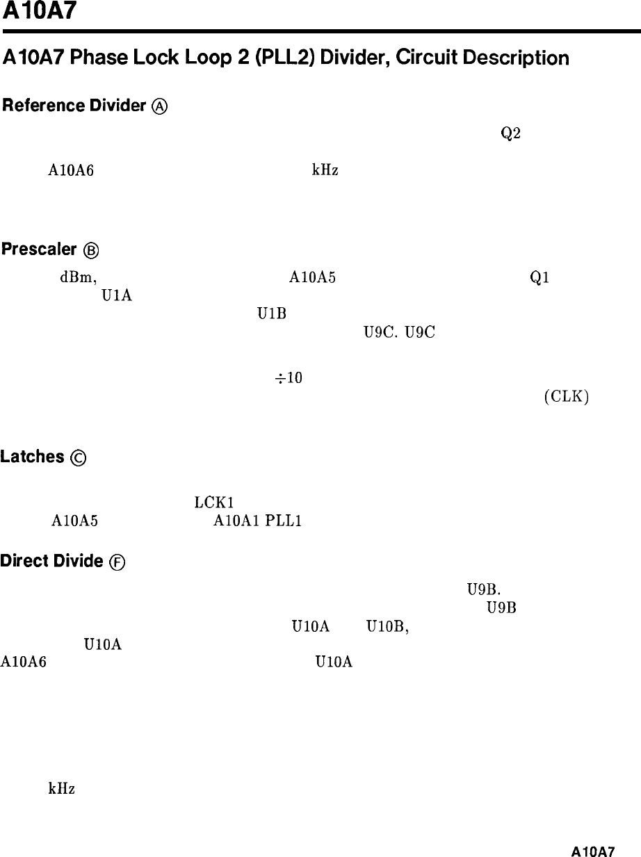
AlOA7
AlOA7
Phase
Lock
Loop
2
(PLL2)
Divider,
Circuit
Description
Reference
Divider
@
A 10 MHz signal derived from the quartz crystal reference is amplified by
Q2
and used to
drive divider U4. The divide by 10 output of U4 drives U16, whose divide by 2 output goes
to the AlOA6 PLL2 Phase Detector. This 500 kHz signal is used as a reference to which
the programmable divide output of the PLL2 Divider is compared. The TTL input on Pl-2
disables the reference divider during sweeps.
Prescaler
GJ
The -18
dBm,
75 to 150 MHz input from AlOA5 PLL2 VCO, is amplified by
Ql
and used to
drive prescaler
UlA
which is a variable-module divider. It divides by 10 if pin 9, “PSW” is
high; it divides by 11 if pin 9 is low.
UlB
is an ECL circuit which contains an ECL to TTL
translator. Pin 7 is the TTL output, which drives gate U9C. U9C is used as a buffer to drive
the multiple of loads on its output; the “CLK” line.
The prescaler should be thought of as a
~10
with the ability to “swallow” input pulses. If
the PSW line is low, in effect one input pulse is lost (swallowed) for each output
(CL10
pulse
produced.
Latches
@
U12, U13, and U14 are latches which store the divider programming number. The number is
clocked into the latches with
LCKl
and LCK2. U14 also latches in SW1 and SW2, which are
sent to AlOA5 PLL2 VCO and
AlOAl
PLLl
VCO.
Direct
Divide
@
U8 and U15 are cascaded dividers whose state outputs are sensed by U9B. The CLK line
from the prescaler clocks U8. When the count reaches 25, the output of
U9B
goes high. This
initiates a divide sequence by J-K flip-flops UlOA and UlOB, which are clocked by CLK. The
Q output of UlOA goes high on a count of 27 and low on 29. This signal is output to the
AlOA6 PLL2 Phase Detector. The Q output of UlOA goes low on a count of 27, resetting U8
and U15. When it returns high on 29, the sequence resumes.
U15 is preset to a count of zero and U8 to a count of 0 to 9 depending on input data. Thus, if
U8 is preset to 0, the circuit divides by 29. If preset to 9, the circuit divides by 20.
Since the prescaler has already divided by 10, the 75 to 150 MHz input is divided by numbers
200, 210, . . . 290 according to the BCD digit programming U8. Since the output is locked
to 500 kHz by the phase lock loop, the VCO is programmed from 100 to 145 MHz in 5 MHz
steps.
AlOA7
1
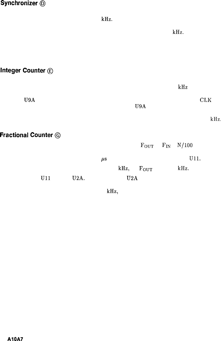
Synchronizer
0
Other divide numbers are provided through the pulse swallowing technique. The output
frequency is held by the lock loop to 500 kHz. If N input pulses per second are swallowed,
the input frequency must rise by N Hz to keep the output constant. If N input pulses are
swallowed for each output pulse, input frequency must rise by N x 500 kHz.
The pulse swallow synchronizer accepts pulses from the fractional counter and integer counter,
and at the proper time, as determined by the CLK line, drops the PSW line to swallow input
pulses.
Integer
Counter
@
U7 is a presettable counter which is preset to an externally programmable count by the RST
line. RST pulses come from the direct divide output, and occur at a 500 kHz rate. After
each RST pulse, U7 counts CLK pulses until a count of 9 is reached. A count of 9 causes the
output of U9A to go high. The pulse swallow synchronizer drops the PSW line on CLK pulse
after the RST pulse, and raises it two CLK pulses after U9A goes high. PSW therefore is low
one CLK pulse longer than the count time. If U7 is preset to N, (9-N) + 1 input pulses will
be swallowed for each CLK pulse, forcing the input frequency to rise by (10-N) x 500 kHz.
Fractional
Counter
@
U5 and U6 are rate multipliers. They provide the function
FOUT
=
FIN
x
N/100
where N is a
two digit BCD number (8 bits). The least significant digit goes to U5, the other to U6. The
output comes from U5 and triggers a 1.6 ps pulse from one-shot multivibrator
Ull.
The input frequency to the rate multipliers is 500 kHz, so
FOUT
= N x 5 kHz.
The output from
Ull
goes to U2A. A high input at U2A causes the synchronizer to swallow
one less pulse per RST pulse than it would have other wise. The fractional counter therefore
causes the input frequency to drop by N x 5 kHz, where N ranges from 0 to 99.
2
AlQA7
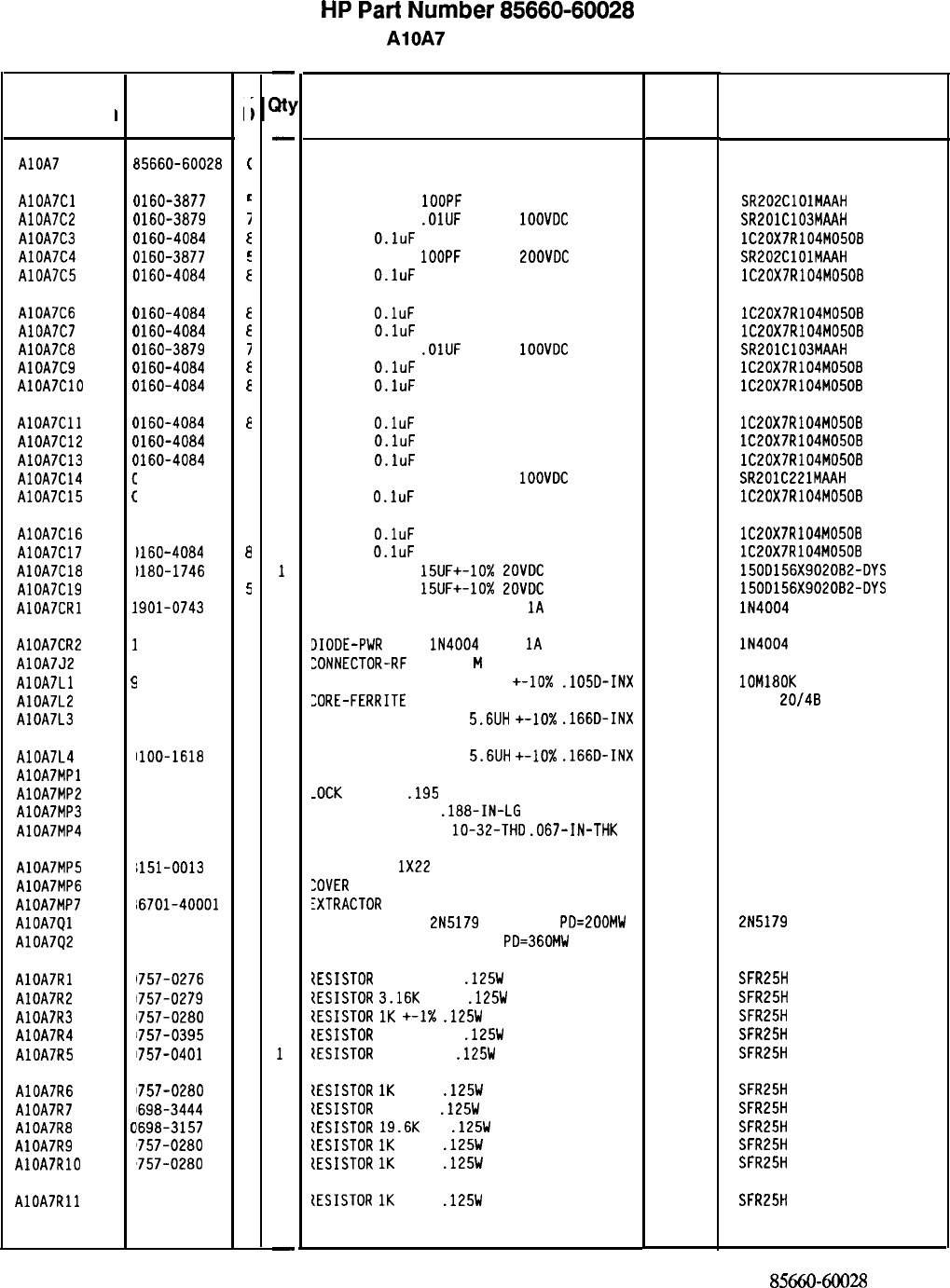
Reference
Designation
I
AlOA7
HP Part
Number
35660-60028
c
c
I
(
AlOA7Cl
(
1160-3877
t
AlOA7C2
(
1160-3879
i
AlOA7C3
(
1160-4084
E
AlOA7C4
(
1160-3877
c
AlOA7C5
(
1160-4084
i
AlOA7C6
(
1160-4084
E
AlOA7C7
(
1160-4084
E
AlOA7C8
(
1160-3879
7
AlOA7C9
(
1160-4084
E
AlOA7ClO
t
1160-4084
E
AlOA7Cll
c
1160-4084
a
AlOA7C12
c
1160-4084
a
AlOA7C13
c
1160-4084
a
AlOA7C14
c
1160-0570
9
AlOA7C15
c
1160-4084
a
AlOA7C16
C
1160-4084
a
AlOA7C17
C
1160-4084
a
AlOA7C18
C
1180-1746
5
AlOA7C19
C
1180-1746
5
AlOA7CRl
1
.901-0743
1
AlOA7CR2
1
901-0743
1
AlOA7J2
1
250-0544
9
AlOA7Ll
9
1100-2250
9
AlOA7L2
9
1100-1788
6
AlOA7L3
9
1100-1618
1
AlOA7L4
AlOA7MPl
AlOA7MP2
AlOA7MP3
AlOA7MP4
9
1100-1618
1
2
‘190-0124
4
2
‘200-0101
0
2
‘950-0078
9
AlOA7MP5
8
~151-0013
4
AlOA7MP6
a
15660-20058
2
AlOA7MP7
8
!6701-40001
9
AlOA7Ql
1
854-0345
8
AlOA7Q2
1
854-0019
3
AlOA7Rl
AlOA7R2
AlOA7R3
AlOA7R4
AlOA7R5
1757-0276
1757-0279
1757-0280
1757-0395
1757-0401
AlOA7R6
AlOA7R7
AlOA7R8
AlOA7R9
AlOA7RlO
AlOA7Rll
0
0
0
0
0
0
0
0
0
0
0
1757-0280
1698-3444
1698-3157
‘757-0280
‘757-0280
757-0280
7
0
3
1
0
3
1
3
3
3
3
-
31
-
1
1
1
1
1
1
1
1
1
1
1
1
1
1
1
1
1
1
1
1
1
1
1
1
1
1
1
1
2
1
1
1
2
1
1
1
1
1
1
1
1
1
1
1
1
1
-
HP
Part
Number 85660-60028
AlOA7 PLL 2 Divider
Description Mfr
Code
BOARD ASSEMBLY, PLL 2 DIVIDER 28480
Mfr Part
Number
85660-60028
CAPACITOR-FXD
1OOPF
+-20% 200VDC CER
04222 SR202ClOlMAAH
CAPACITOR-FXD
.OlUF
+-20%
1OOVDC
CER
04222 SR201C103MAAH
CAP-FXD
O.luF
50 V
56289 lC20X7R104M0508
CAPACITOR-FXD
1OOPF
+-20%
EOOVDC
CER
04222 SR202ClOlMAAH
CAP-FXD
O.luF
50 V
56289 lC20X7R104M050B
CAP-FXD
O.luF
50 V
56289 lC20X7R104M050B
CAP-FXD
O.luF
50 V
56289 lC20X7R104M050B
CAPACITOR-FXD
.OlUF
+-20%
1OOVDC
CER
04222 SR201C103MAAH
CAP-FXD
O.luF
50 V
56289 lC20X7R104M050B
CAP-FXD
O.luF
50 V
56289 lC20X7R104M050B
CAP-FXD
O.luF
50 V
CAP-FXD
O.luF
50 V
CAP-FXD
O.luF
50 V
CAPACITOR-FXD 220PF +-20%
1OOVDC
CER
CAP-FXD
O.luF
50 V
56289 lC20X7R104M050B
56289 lC20X7R104M050B
56289 lC20X7R104M050B
04222 SR201C221MAAH
56289 lC20X7R104M050B
CAP-FXD
O.luF
50 V
CAP-FXD
O.luF
50 V
CAPACITOR-FXD
15UF+-10%
ZOVDC
TA
CAPACITOR-FXD
15UF+-10%
LOVDC
TA
DIODE-PWR RECT IN4004 400V
1A
DO-41
56289 lC20X7R104M050B
56289 lC20X7R104M050B
56289 150D156X9020B2-DYS
56289 150D156X9020B2-DYS
71744 lN4004
3IODE-PWR
RECT
lN4004
400V
1A
DO-41
71744 lN4004
ZONNECTOR-RF
SM-SNP
M
SGL-HOLE-FR 50-OHM
98291 051-049-0000-220
INDUCTOR RF-CH-MLD 180NH
+-lo%
.lOSD-INX 24226 lOM180K
,ORE-FERRITE
CHOKE-WIDEBAND IMP:680
02114
VK200
20/4B
INDUCTOR RF-CH-MLD
5.6UH
+-lo%
.166D-INX 99800 1537-30
INDUCTOR RF-CH-ML0
5.6UH
+-lo%
.166D-INX
YOT ASSIGNED
-0CK
WASHER
.195
IO
99800 1537-30
28480
77250
74163
2190-0124
SCREW-MACH 4-40
.188-IN-LG
PAN-HD-POZI
YUT-HEX-OBL-CHAM
lo-32-THD
.067-IN-THK 500220
JIRE 22AWG
1X22
:OVER
PC, PLL 2 DIVIDER
fXTRACTOR
PC
TRANSISTOR NPN
2N5179
SI TO-72
PD=ZOOMW
TRANSISTOR NPN SI TO-18
PD=360MW
92194
28480
28480
04713
04713
298
85660-20058
86701-40001
2N5179
1ESISTOR
61.9 +-1%
.125W
TF TC=O+-100
tESISTOR
3.16K
+-1%
.125W
TF TC=O+-100
{ESISTOR
1K
+-1X
.125W
TF TC=O+-100
CESISTOR
56.2 +-1%
.125W
TF TC=O+-100
ZESISTOR
100 +-1%
.125W
TF TC=O+-100
tESISTOR
1K
+-1%
.125W
TF TC=O+-100
IESISTOR
316 1%
.125W
TF TC=O+-100
lESISTOR
19.6K
1%
.125W
TF TC=O+-100
{ESISTOR
IK
+-1%
.125W
TF TC=O+-100
[ESISTOR
1K
+-1%
.125W
TF TC=O+-100
tESISTOR
1K
+-1%
.125W
TF TC=O+-100
19701
19701
19701
19701
19701
19701
19701
19701
19701
19701
19701
SFR25H
SFR25H
SFR25H
SFR25H
SFR25H
SFR25H
SFR25H
SFR25H
SFR25H
SFR25H
SFR25H
*Indicates factory-selected value
85660-60028 Parts List
Page 1 of 2
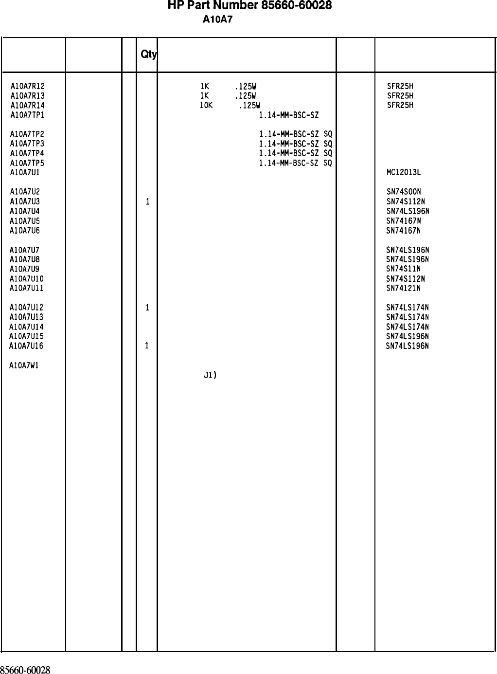
HP
Part
Number 85660-60028
AlOA7 PLL 2 Divider
Reference
HP Part C
Number D
Qty Description Mfr
Mfr Part
Designation Code Number
AlOA7R12 0757-0280
3
1
RESISTOR
1K
+-1%
.125W
TF TC=O+-100
19701
SFR25H
AlOA7R13 0757-0280
3
1
RESISTOR
IK
+-1%
.125W
TF TC=O+-100
19701
SFR25H
AlOA7R14 0757-0442
9
1
RESISTOR
10K
+-1%
.125W
TF TC=O+-100
19701
SFR25H
AlOA7TPl 1251-0600
0
1
CONNECTOR-SGL CONT PIN
1.14-MM-BSC-SZ
SQ
27264 16-06-0034
AlOA7TP2 1251-0600
0
1
CONNECTOR-SGL CONT PIN
1.14~MM-BSC-SZ
SQ
27264 16-06-0034
AlOA7TP3 1251-0600
0
1
CONNECTOR-SGL CONT PIN
1.14~MM-BSC-SZ
SQ
27264 16-06-0034
AlOA7TP4 1251-0600
0
1
CONNECTOR-SGL CONT PIN
1.14-MM-BSC-SZ
SQ
27264 16-06-0034
AlOA7TP5 1251-0600
0
1
CONNECTOR-SGL CONT PIN
1.14-MM-BSC-SZ
SQ
27264 16-06-0034
AlOA7Ul 1820-1888
5
1
IC PRESCR ECL 04713 MC12013L
AlOA7U2 1820-0681
4
1
IC GATE TTL S NAND QUAD 2-INP 01295 SN74SOON
AlOA7U3 1820-0629
0
1
IC FF TTL S J-K NEG-EDGE-TRIG PRESET/CLE 01295 SN74S112N
AlOA7U4 1820-1251
6
1
IC CNTR TTL LS DECD ASYNCHRO NEG-EDGE-TR 01295 SN74LS196N
AlOA7U5 1820-0909
9
1
IC MULTR TTL 01295 SN74167N
AlOA7U6 1820-0909
9
1
IC MULTR TTL 01295 SN74167N
AlOA7U7 1820-1251
6
1
IC CNTR TTL LS OECD ASYNCHRO NEG-EDGE-TR 01295 SN74LS196N
AlOA7U8 1820-1251
6
1
IC CNTR TTL LS DECD ASYNCHRO NEG-EDGE-TR 01295 SN74LS196N
AlOA7U9 1820-0686
9
1
IC GATE TTL S AND TPL 3-INP 01295 SN74SllN
AlOA7UlO 1820-0629
0
1
IC FF TTL S J-K NEG-EDGE-TRIG PRESET/CLE 01295 SN74S112N
AlOA7Ull 1820-0261
6
1
IC MV TTL MONOSTBL 01295 SN74121N
AlOA7U12 1820-1196
8
1
IC FF TTL LS O-TYPE POS-EDGE-TRIG COM CL 01295 SN74LS174N
AlOA7U13 1820-1196
8
1
IC FF TTL LS D-TYPE PDS-EDGE-TRIG COM CL 01295 SN74LS174N
AlOA7U14 1820-1196
8
1
IC FF TTL LS D-TYPE POS-EDGE-TRIG COM CL 01295 SN74LS174N
AlOA7U15 1820-1251
6
1
IC CNTR TTL LS DECD ASYNCHRO NEG-EDGE-TR 01295 SN74LS196N
AlOA7U16 1820-1251
6
1
IC CNTR TTL LS DECD ASYNCHRO NEG-EDGE-TR 01295 SN74LS196N
AlOA7Wl 85660-60087
1
1
CABLE ASSEMBLY, WHITE/BLUE 28480 85660-60087
(INCLUDES
~1)
8566040028
Parts List
Page 2 of 2
*Indicates factory-selected value
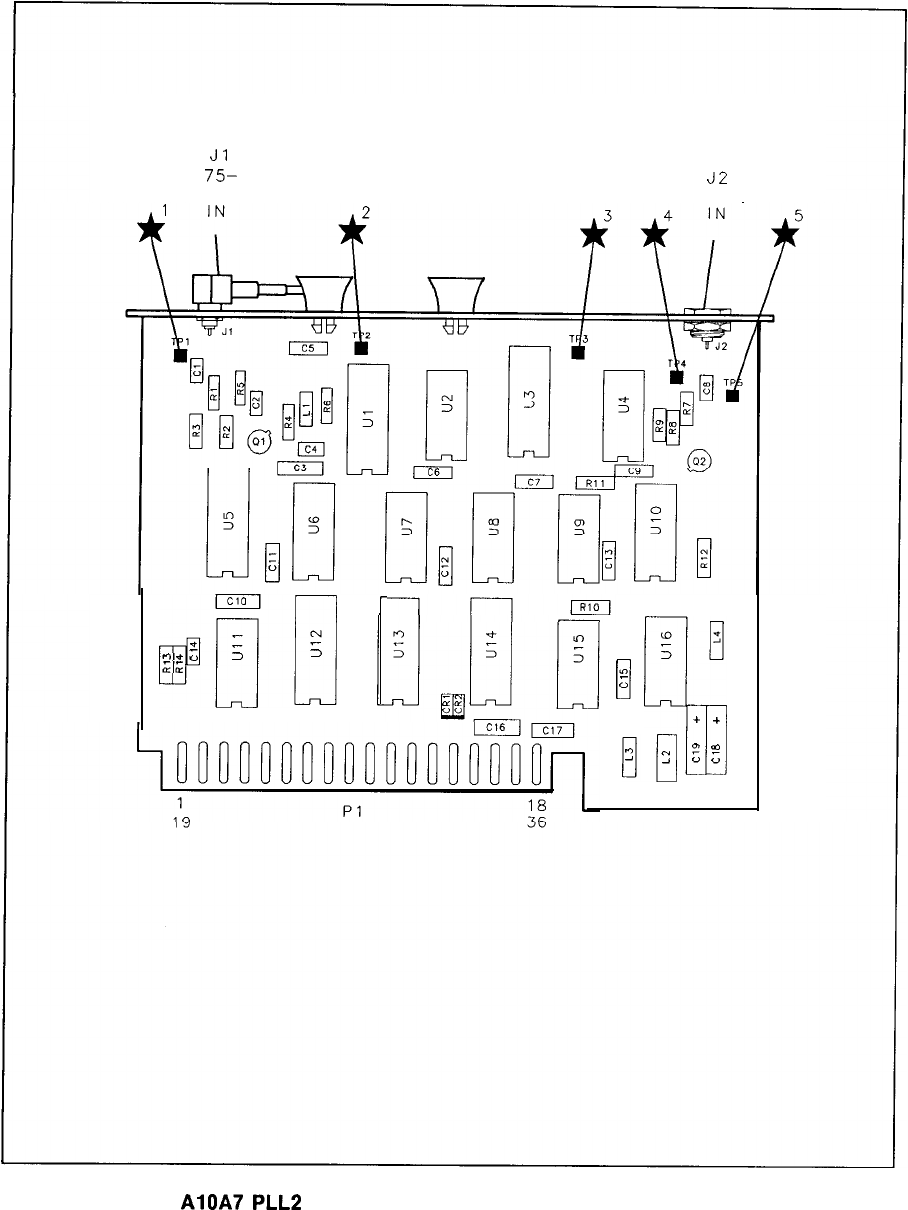
JlJl
75-75-
J2J2
150 MHz
150 MHz 10 MHz
10 MHz
(
d
z
r-4
a,’
me
;
33
&L
r
0
*
-
A
3
0
tn
0
;
%
+
+
ul
3
y
z
-=I
0
;
AlOA7
PLL2
Divider Component Locations, 85660-60028
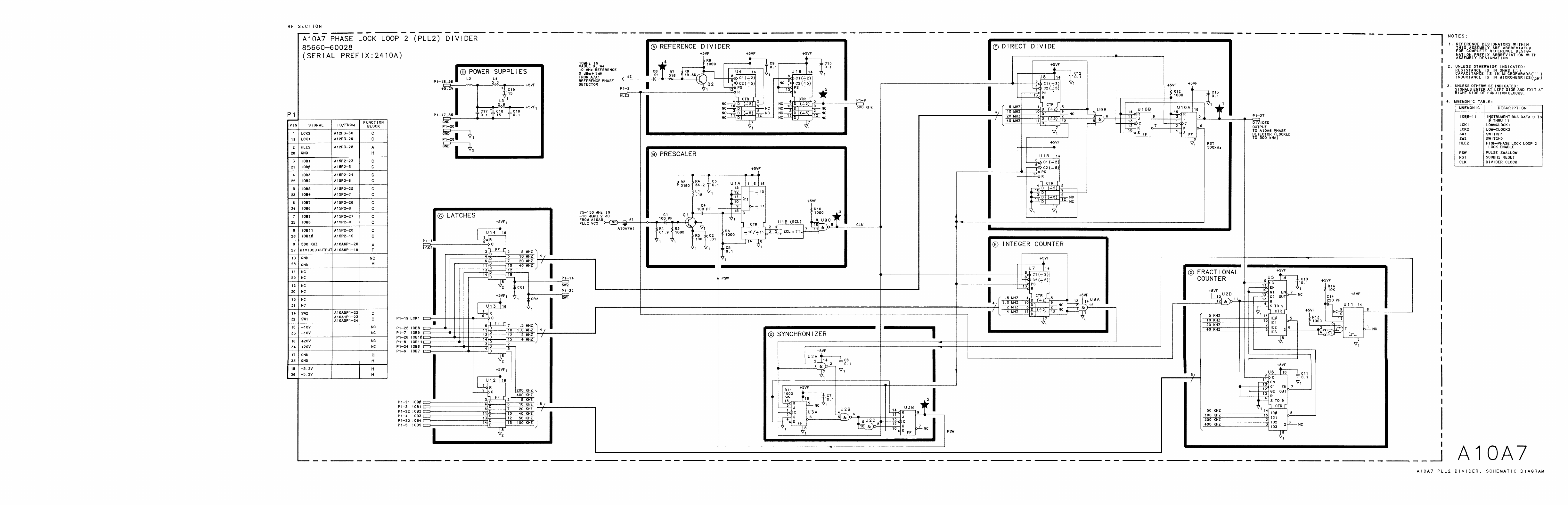
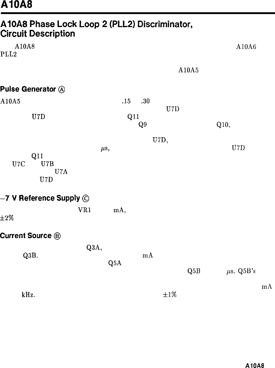
AlOA8
AlOA8
Phase
Lock
Loop
2
(PLL2)
Discriminator,
Circuit
Description
The AlOA8 PLL2 Discriminator combines the error voltage information from the AlOA6
PLL2 Phase Detector, the attenuated scan information (SCAN DAC IN) from the Al6 Scan
Generator, and the tuning information from the Al2 Front-Panel Interface (via the Instrument
Bus) to produce a tuning current to tune the oscillator in the AlOA5 PLL2 VCO.
Pulse
Generator
@
AlOA5 PLL2 VCO provides an ECL level
.15
to
.30
MHz input which is amplified by Q6
and Q7. At the beginning of a cycle, both inputs of gate U7D are low. When Q7 collector
goes high, U7D output goes low, saturating
Qll
and causing resonator L4, C15, Cl6 to ring
at 5.2 MHz. This damped oscillation appears at
Q9
collector, is clipped by
&lo,
and used to
drive counter U6. U6 is preset to a count of 6. When the count reaches 8, the (8) output of
U6 goes high. This is fed back to the other input of U7D, holding its output low after the
input from Q7 goes low. After 1.6
ps,
the count reaches 16, (8) goes low again,
U7D
output
goes high,
Qll
is turned off, resulting in the resonance being damped by R17. At the count of
16, U7C and U7B reset the counter to 5. Before the oscillation is fully damped, the counter
gets clocked to 6. U7A prevents a latch-up condition by clearing the counter in the event that
the output of U7D remains low for a long period of time.
-7
V
Reference
Supply
@
U13 biases reference diode
VRl
at 7.5
mA,
and provides a low impedance source at -7.0 V
dza%
Current
Source
@
The -7 V source, via R6 and Q3A, provides current which develops a stable 7 V drop across
R7 and Q3B. This acts as the reference for a 3.2 mA current source comprised of U4 and Q4.
This current flows to ground through Q5A when the (8) output of U6 is low. If an input pulse
has triggered the pulse generator, the current is switched through
Q5B
for 1.6
ps.
Q5B’s
collector current goes through a low-pass filter to the summing point of the discriminator loop.
The average value of this current is directly proportional to the input frequency, being 1.5 mA
at 300 kHz. The current to frequency ratio is adjustable
*l%
by the phase lock input on
PI-28.
AiOA8
1
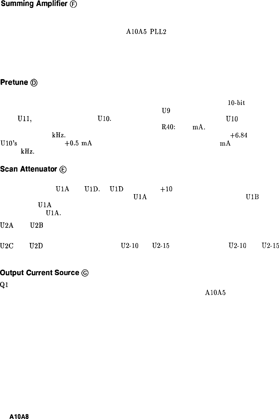
Summing
Amplifier
@
U3 is a noninverting integrator which responds to the voltage at the loop summing point,
the junction of C22 and R43. The output of U3 is connected through R45 to the output
summing network, whose output tunes the AlOA5 PLL2 VCO. Non-zero voltages at the loop
summing point will therefore cause the VCO frequency to change, until the current from the
discriminator reaches a level which cancels the other input, returning the summing point
voltage to zero. In this way, the VCO frequency is forced to be exactly proportional to the net
current fed to the summing point.
Pretune
@J
The pretune circuit tunes the discriminator loop approximately to the desired frequency. The
phase lock loop then applies small corrections to get the frequency exact. A
lo-bit
binary
word representing the pretune frequency is latched by
U9
and U12. The data programs
DAC
Ull,
whose output goes to UlO. If the input is all zeros, the output of UlO is zero.
The pretune current is then that which flows through R40: -1.5
mA.
This tunes the input
frequency to 300 kHz. A binary word representing decimal 1000 will result in
+6.84
V at
UlO’s
output, adding
+0.5
mA
to the summing point. The resulting -1.0
mA
tunes the loop
to 200 kHz.
Scan
Attenuator
@
The attenuated scan ramp is fed to the loop summing point via the range resistors selected
by analog switches
UlA
and
UlD.
If
UlD
is closed, a
+lO
V ramp causes a 0.5 MHz span
(referred to the 15 to 30 MHz VCO output).
UlA
closed results in a 5 MHz span.
UlB
is
closed when
UlA
is, feeding a current to the summing point which compensates for drift and
nonlinearity in
UlA.
U2A and U2B direct the scan ramp directly to the VCO. This “forward feed” helps
compensate for the rather slow response of the discriminator loop.
U2C and U2D perform a logic function:
U2-10
HI,
U2-15
LO for wide scans;
U2-10
LO,
U2-15
HI for narrow scans, and both HI for scan disabled.
Output
Current
Source
@
Ql
and Q2 form a low-noise current summing point for error signals from U3 and forward feed
from the scan and phase lock inputs. The output current goes to the AlOA5 PLL2 VCO.
2
AlOA8
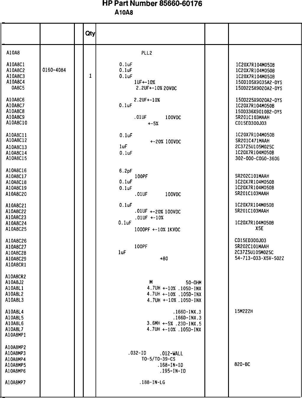
HP
Part
Number 85660-60176
AlOA8 PLL 2 Discriminator
Reference
HP Part C
Mfr
Designation
D
Qty Description Mfr Part
Number Code Number
AlOAt?
85660-60176
9
1
BOARD ASSEMBLY,
PLL2
DISCRIMINATOR
28480 85660-60176
AlOA8Cl 0160-4084
8
1
CAP-FXD
O.luF
50 V
56289
AlOA8C2 0160-4084 lC20X7R104M050B
8
1
CAP-FXD
O.luF
50 V
56289
AlOA8C3 0160-4084 lC20X7R104M0508
8
1
CAP-FXD
O.luF
50 V
56289
AlOA8C4 0180-0291 lC20X7R104M0508
3
1
CAPACITOR-FXD
lUF+-10%
35VDC TA
56289
Al OA8C5 0180-0197 15DD105X9035A2-DYS
8
1
CAPACITOR-FXD
2.2UF+-10%
EOVDC
TA
56289 150D225X9020A2-DYS
AlOABC6 0180-0197
8
1
CAPACITOR-FXD
2.2UF+-10%
20VDC TA
56289
AlOA8C7 0160-4084 150D225X9020A2-DYS
8
1
CAP-FXD
O.luF
50 V
56289
AlOA8C8 0180-0229 lC20X7R104M050B
7
1
CAP-FXD 33uF 10 V TA 56289
AlOA8C9 0160-3879 150D336X901082-OYS
7
1
CAPACITOR-FXD
.OlUF
+-20%
1OOVDC
CER
04222
AlOABClO SR201C103MAAH
0160-2199
2
1
CAPACITOR-FXD 30PF
+-5x 300VDC MICA
09023 CD15ED300J03
AlOA8Cll 0160-4084
8
1
CAP-FXD O.luF
50 V
56289
AlOA8C12 lC20X7R104M050B
0160-0571
0
1
CAPACITOR-FXD 470PF
+-20x
1OOVDC
CER
04222 SR201C471MAAH
AlOA8C13 0160-4892
6
1
CAP-FXD
1uF
25 V 56289 2C37Z5U105M025C
AlOA8C14 0160-4084 8
1
CAP-FXD O.luF
50 V
56289
AlDA8C15 lC20X7R104M050B
0160-4605
9
1
CAP-FXD 36pF 500 V
302-000-COGO-3606
AlOA8C16 0160-2252
8
1
CAP-FXD 6.2pF
500 V
52763
AlOA8C17 0160-3877
5
1
CAPACITOR-FXD 1OOPF
+-20% 200VDC CER
04222 SR202ClOlMAAH
AlOA8C18 0160-4084
8
1
CAP-FXO
O.luF 50 V 56289 lC20X7R104M0508
AlOA8C19 0160-4084
8
1
CAP-FXD O.luF
50 V
56289 lC20X7R104M050B
AlOA8C20 0160-3879
7
1
CAPACITOR-FXD
.OlUF
+-20%
1OOVDC
CER
04222 SR201C103MAAH
AlOA8C21 0160-4084
8
1
CAP-FXD
O.luF 50 V 56289 lC20X7R104M0508
AlOA8C22 0160-3879
7
1
CAPACITOR-FXD
.OlUF
+-20X
1OOVDC
CER
04222 SR201C103MAAH
AlOA8C23 0160-0161
4
1
CAPACITOR-FXD
.OlUF
+-lo%
200VDC POLYE
84411 HEW-238M
AlOA8C24 0160-4084
8
1
CAP-FXD
O.luF
50 V
56289 lC20X7R104M0508
AlOA8C25 0160-3456
6
1
CAPACITOR-FXD 1OOOPF
+-lo%
1KVDC
CER
808-542 X5E
102K
AlOA8C26 0160-2199
2
1
CAPACITOR-FXD 30PF +-5% 300VDC MICA 09023 CD15ED300JD3
AlOA8C27 0160-3877
5
1
CAPACITOR-FXD
1OOPF +-20% 200VDC CER 04222 SR202ClOlMAAH
AlOA8C28 0160-4892
6
1
CAP-FXD
1uF
25 V
56289 2C37Z5U105M025C
AlOA8C29 0160-2437
11
CAPACITOR-FDTHRU 5000PF +80
-20% 200V
33095 54-713-033-X5V-502Z
AlOA8CRl 1901-0539
3
1
DIODE-SCHOTTKY SM SIG
AlOA8CR2 1901-0539
3
1
DIODE-SCHOTTKY SM SIG
AlOA8J2 1250-0544
9
1
CONNECTOR-RF SM-SNP
M
SGL-HOLE-FR
50-OHM 98291 051-049-0000-220
AlOA8Ll 9140-0144
0
1
INDUCTOR RF-CH-MLD
4.7UH +-lo%
.105D-INX 99800 1025-36
AlOABL2 9140-0144
0
1
INDUCTOR RF-CH-MLD
4.7UH
+-lo%
.105D-INX 99800 1025-36
AlOA8L3 9140-0144
0
1
INDUCTOR RF-CH-MLD 4.7UH
+-lo%
.105D-INX 99800 1025-36
AlOA8L4 9140-0392
0
1
INDUCTOR RF-CH-MLD 22UH
+-3%
.166D-INX.3 24226 15M222H
AlOA8L5 9100-1629
4
1
INDUCTOR RF-CH-MLD 47UH
+-5%
.166D-INX.3 99800 1537-60
AlOA8L6 9100-1666
9
1
INDUCTOR RF-CH-MLD
3.6MH +-5X
.23D-INX.5 99800 2500-54
AlOA8L7 9140-0144
0
1
INDUCTOR RF-CH-MLD
4.7UH +-lo%
.105D-INX 99800 1025-36
AlOABMPl NOT ASSIGNED
AlOA8MP2 0360-0270
0
1
TERMINAL-SLDR LUG LK-MTG FOR-X10-SCR 79963 807-196
AlOA8MP3 0890-0324
8
1
TUBING-FLEX
.032-ID
TFE
.012-WALL 09795 II-TW,FR-1
AlOA8MP4 1205-0250
9
1
THERMAL LINK SGL
TO-5/TO-39-CS 05820 2604 TH 5E
AlOA8MP5 2190-0009
4
1
WASHER-LK INTL T NO. 8
.168-IN-ID 06791 820-BC
AlOA8MP6 2190-0124
4
1
WASHER-LK INTL T NO. 10
.195-IN-ID 98291 3002-26
AlOA8MP7 2200-0101
0
5
SCREW-MACH 4-40
.188-IN-LG PAN-HD-POZI 77250
*Indicates factory-selected value
8X60-60176 Parts List
Page 1 of 4
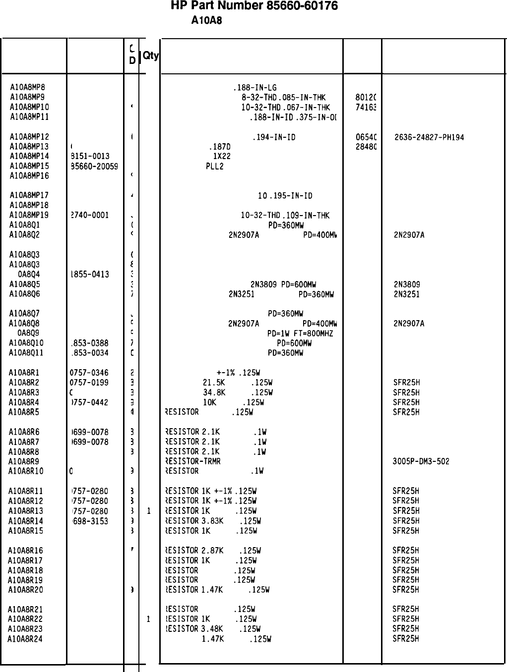
Reference
Designatior
1
HP Part
Number
AlOA8MP8 2200-0164
AlOA8MP9 2580-0002
AlOA8MPlO 2950-0078
AlOABMPll 3050-0021
AlOA8MP12
AlOABMP13
AlOA8MP14
AlOA8MP15
AlOA8MP16
3050-0907
6960-0059
5151-0013
35660-20059
36701-40001
AlOA8MP17
AlOABMP18
AlOA8MP19
AlOA8Ql
AlOA8Q2
2190-0124
35660-00059
!740-0001
1854-0404
1853-0281
AlOA8Q3
AlOA8Q3
Al
OA8Q4
AlOA8Q5
AlOA8Q6
1854-1030
1854-0957
1855-0413
1853-0269
1853-0007
AlOA8Q7
AlOA8Q8
Al
OA8Q9
AlOA8QlO
AlOA8Qll
1854-0019
1853-0281
1854-0247
.853-0388
.853-0034
AlOABRl
AlOA8R2
AlOA8R3
AlOA8R4
AlOA8R5
I
I
I
I
I
,
1
1
I
1
I
I
1
I
t
I
c
C
C
C
C
C
2
0
0
0
0
0
0
0
0
0
0
0
0
0
0
C
1757-0346
)757-0199
1757-0123
1757-0442
1698-3132
AlOA8R6
AlOA8R7
AlOA8R8
AlOA8R9
AlOA8RlO
1699-0078
1699-0078
1699-0078
‘100-1739
1699-0082
AlOA8Rll
AlOA8R12
AlOA8R13
AlOA8R14
AlOA8R15
1757-0280
1757-0280
1757-0280
1698-3153
757-0280
AlOA8R16
AlOA8R17
AlOA8R18
AlOA8R19
AlOA8R20
698-3151
757-0280
698-3445
698-3447
757-1094
AlOABR21
AlOA8R22
AlOA8R23
AlOA8R24
698-3444
757-0280
698-3152
1757-1094
85660-60176 Parts List
Page 2 of 4
t
t
,
I
c
1
i
C
(
t
:
:
i
L
c
C
I
c
2
3
3
3
0
3
3
I
1
3
I
I
1
1
1
r
I
,
I
)
I
I
1
1
1
1
1
1
1
1
1
1
1
1
1
1
1
0
1
1
1
1
1
1
1
1
1
1
1
1
1
1
1
1
1
1
1
1
1
1
1
1
1
1
1
1
1
1
1
1
AlOA8 PLL 2 Discriminator
Description Mfr Mfr Part
Code Number
SCREW-MACH 4-40
.188-IN-LG
UNCT 82 DEG
7725C
NUT-HEX-DEL-CHAM
8-32-THD
.085-IN-THK
8012C
NUT-HEX-DBL-CHAM
lo-32-THD
.067-IN-THK
74163
WASHER-FL NM NO. 8
.188-IN-ID
.375-IN-OL 73734
500220
WASHER-SHLDR NO. 10
.194-IN-ID
PLUG HOLE
.187D
WIRE 22AWG
1X22
COVER PC
PLLE
DISCRIMINATOR
EXTRACTOR PC
0654C
2636-24827-PH194
2848G
6960-0059
92194 298
28480 85660-20059
28480 86701-40001
WASHER-LK INTL T NO.
10
.195-IN-ID
SHIELD 3002-26
85660-00059
NUT-HEX-DBL-CHAM
lo-32-THD
.109-IN-THK
TRANSISTOR NPN SI TO-18
PD=360MW
TRANSISTOR PNP
2N2907A
SI TO-18
PD=400Mh
98291
28480
73734
04713
04713 2N2907A
DUAL TRANSISTOR X-N D SD3303 78
ALTERNATE PART FOR 1854-1030
TRANSISTOR J-FET P-CHAN D-MODE TO-18 SI
TRANSISTOR-DUAL PNP
2N3809
PD=GOOMW
TRANSISTOR PNP
2N3251
SI TO-18
PD=360MW
17856
04713
04713 2N3809
2N3251
TRANSISTOR NPN SI TO-18
PD=360MW 04713
TRANSISTOR PNP
2N2907A
SI TO-18
PD=400MW 04713
TRANSISTOR NPN SI TO-39
PD=lW
FT=BOOMHZ 04713
TRANSISTOR-DUAL PNP TO-78
PD=GOOMW 04713
TRANSISTOR PNP SI TO-18
PD=360MW 04713
2N2907A
RESISTOR 10 +-1X
.125W
TF TC=O+-100
91637 CMF-55-1, T-l
RESISTOR
21.5K
+-1%
.125W
TF TC=O+-100
19701
SFR25H
RESISTOR
34.8K
+-1%
.125W
TF TC=O+-100
19701
SFR25H
RESISTOR
10K
+-1%
.125W
TF TC=O+-100
19701
SFR25H
7ESISTOR
261 1%
.125W
TF TC=O+-100
19701
SFR25H
iESISTOR
2.1K
+-0.1%
.lW
TF TC=O+-10
1ESISTOR
2.1K
+-0.1%
.lW
TF TC=O+-10
7ESISTOR
2.1K
+-0.1%
.lW
TF TC=O+-10
?ESISTOR-TRMR
5K 10% WW SIDE-ADJ 20-TRN
tESISTOR
215 +-0.1%
.lW
TF TC=O+-10
50232
50232
50232
3005P-DM3-502
50232
IESISTOR
1K
+-1X
.125W
TF TC=O+-100
tESISTOR
1K
+-1X
.125W
TF TC=O+-100
ZESISTOR
1K
+-1%
.125W
TF TC=O+-100
ZESISTOR
3.83K
1%
.125W
TF TC=O+-100
{ESISTOR
1K
+-1%
.125W
TF TC=O+-100
SFR25H
SFR25H
SFR25H
SFR25H
SFR25H
tESISTOR
2.87K
1%
.125W
TF TC=O+-100
tESISTOR
1K
+-1%
.125W
TF TC=O+-100
lESISTOR
348 1%
.125W
TF TC=O+-100
lESISTOR
422 1%
.125W
TF TC=O+-100
[ESISTOR
1.47K
+-1%
.125W
TF TC=O+-100
SFR25H
SFR25H
SFR25H
SFR25H
SFR25H
LESISTOR
316 1%
.125W
TF TC=O+-100
LESISTOR
IK
+-1%
.125W
TF TC=O+-100
lESISTOR
3.48K
1%
.125W
TF TC=O+-100
RESISTOR
1.47K
+-1%
.125W
TF TC=O+-100
19701
19701
19701
32997
19701
19701
19701
19701
19701
19701
19701
19701
19701
19701
19701
19701
19701
19701
19701
SFR25H
SFR25H
SFR25H
SFR25H
*Indicates factory-selected value
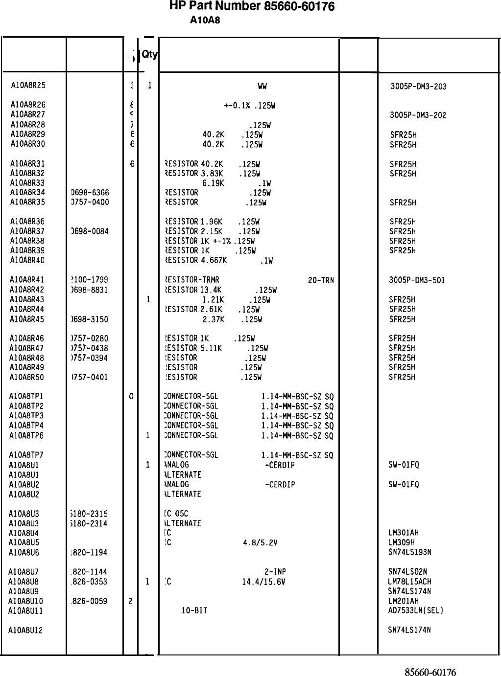
HP
Part
Number 85660-60176
AlOA8 PLL 2 Discriminator
Description Mfr
Mfr Part
Code Number
RESISTOR-TRMR 20K 10% WU SIDE-ADJ PO-TRN
32991
3005P-DM3-203
RESISTOR 390K +-0.1X
.125W
TF TC=O+-10
19701
50332
RESISTOR-TRMR 2K 10% WW SIDE-ADJ 20-TRN
32997
3005P-DM3-202
RESISTOR 39K +-0.1%
.125W
TF TC=O+-10
19701
50332
RESISTOR
40.2K
1%
.125W
TF TC=O+-100
19701
SFR25H
RESISTOR
40.2K
1%
.125W
TF TC=O+-100
19701
SFR25H
?ESISTOR
40.2K
1%
.125W
TF TC=O+-100
19701
SFR25H
7ESISTOR
3.83K
1%
.125W
TF TC=O+-100
19701
SFR25H
7ESISTOR
6.19K
+-0.1%
.lW
TF TC=O+-10
19701 50232
7ESISTOR
800 +-0.1%
.125W
TF TC=O+-25
19701
5033R
7ESISTOR
90.9 +-1%
.125W
TF TC=O+-100
19701
SFR25H
ZESISTOR
1.96K
1%
.125W
TF TC=O+-100
19701
SFR25H
1ESISTOR
2.15K
1%
.125W
TF TC=O+-100
19701
SFR25H
tESISTOR
1K
+-1X
.125W
TF TC=O+-100
19701
SFR25H
tESISTOR
1K
+-1%
.125W
TF TC=O+-100
19701
SFR25H
{ESISTOR
4.667K
+-0.1%
.lW
TF TC=O+-10
19701
50232
IESISTOR-TRMR
500 10% WW SIDE-ADJ
EO-TRN 32997 3005P-DM3-501
lESISTOR
13.4K
+-0.1%
.125W
TF TC=O+-10
19701
50332
LESISTOR
1.21K
+-1%
.125W
TF TC=O+-100
19701
SFR25H
LESISTOR
2.61K
1%
.125W
TF TC=O+-100
19701
SFR25H
LESISTOR
2.37K
1%
.125W
TF TC=O+-100
19701
SFR25H
lESISTOR
1K
+-1%
.125W
TF TC=O+-100
19701
SFR25H
!ESISTOR
5.11K
+-1%
.125W
TF TC=O+-100
19701
SFR25H
!ESISTOR
51.1 +-1%
.125W
TF TC=O+-100
19701
SFR25H
!ESISTOR
100 +-1%
.125W
TF TC=O+-100
19701
SFR25H
!ESISTOR
100 +-1%
.125W
TF TC=O+-100
19701
SFR25H
ZONNECTOR-SGL
CONT PIN
1.14-MM-BSC-SZ
SQ
27264 16-06-0034
:ONNECTOR-SGL
CONT PIN
1.14~MM-BSC-SZ
SQ
27264 16-06-0034
:ONNECTOR-SGL
CONT PIN
1.14~MM-BSC-SZ
SQ
27264 16-06-0034
:ONNECTOR-SGL
CONT PIN
1.14-MM-BSC-SZ
SQ
27264 16-06-0034
:ONNECTOR-SGL
CONT PIN
1.14-MM-BSC-SZ
SQ
27264 16-06-0034
:ONNECTOR-SGL
CONT PIN
1.14-MM-BSC-SZ
SQ
\NALOG
SWITCH 4 SPST 16
-CERDIP
\LTERNATE
PART FOR 1826-0811
\NALOG
SWITCH 4 SPST 16
-CERDIP
\LTERNATE
PART FOR 1826-0811
27264 16-06-0034
06665 SW-OlFQ
06665 SW-OlFQ
[C
05C
Ml OP AMP
28480 5180-2315
\LTERNATE
PART FOR 5180-2315
[C
OP AMP GP TO-99 PKG
!C
V RGLTR-FXD-POS
4.8/5.2V
TO-39 PKG
:C CNTR TTL LS BIN UP/DOWN SYNCHRO POS-E
27014 LM301AH
27014 LM309H
01295 SN74LS193N
:C GATE TTL LS NOR QUAD
L-INP 01295 SN74LS02N
'C
V RGLTR-FXD-POS
14.4/15.6\1
TO-39 PKG
27014 LM78L15ACH
C FF TTL LS D-TYPE POS-EDGE-TRIG COM CL
01295 SN74LS174N
C OP AMP GP TO-99 PKG 27014 LMZOlAH
l/A
lo-BIT
16-PLASTIC CMOS
24355 AD7533LN(SEL)
C FF TTL LS D-TYPE POS-EDGE-TRIG COM CL
01295 SN74LS174N
*Indicates factory-selected value 8.5660-60176
Parts List
Page 3 of 4
Reference
Designation HP Part
Number
C
c
AlOA8R25 2100-1972
:
AlOA8R26 0699-0081
E
AlOA8R27 2100-2851
C
AlOA8R28 0699-0080
7
AlOA8R29 0698-3499
E
AlOA8R30 0698-3499
E
AlOABR31 0698-3499
6
AlOA8R32 0698-3153
9
AlOA8R33 0699-0084
1
AlOA8R34 D698-6366
2
AlOA8R35 3757-0400
9
AlOA8R36 3698-0083
8
AlOA8R37 3698-0084
9
AlOA8R38 1757-0280
3
AlOA8R39 3757-0280
3
AlOA8R40 1699-0079
4
AlOA8R41 !lOO-1799
2
AlOA8R42
1698-8831
0
AlOA8R43
1757-0274
5
AlOA8R44
1698-0085
0
AlOA8R45
1698-3150
6
AlOA8R46
1757-0280
3
AlOA8R47
1757-0438
3
AlOA8R48
1757-0394
D
AlOA8R49
1757-0401
3
AlOA8R50
1757-0401
3
AlOA8TPl 1251-0600
0
AlOABTP2 1251-0600
0
AlOA8TP3 1251-0600
0
AlOA8TP4 1251-0600
0
AlOA8TP6 1251-0600
0
AlOA8TP7 1251-0600
0
AlOA8Ul
1826-0811
4
AlOA8Ul 1826-0582
6
AlOABU2
1826-0811
4
AlOA8U2 1826-0582
6
AlOA8U3 5180-2315
AlOA8U3
5180-2314
AlOA8U4
1820-0223
AlOA8U5
1820-0429
AlOA8U6
1820-1194
AlOA8U7
.820-1144
AlOA8U8
.826-0353
AlOA8U9 820-1196
AlOA8UlO
.826-0059
AlOA8Ull 826-0448
AlOA8U12 820-1196
1
0
0
B
6
6
3
3
2
3
3
-
a!
1
1
1
1
1
1
1
1
1
1
1
1
1
1
1
1
1
1
1
1
1
1
1
1
1
1
1
1
1
1
1
1
1
0
1
0
1
0
1
1
1
1
1
1
1
1
1
-
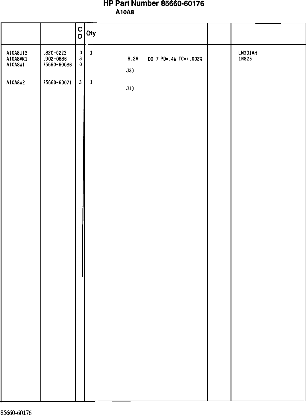
HP
Part
Number 85660-60176
AlOA8 PLL 2 Discriminator
Reference
Designation
AlOA8U13
AlOA8VRl
AlOA8Wl
AlOA8W2
HP Part
Number
L820-0223
L902-0686
15660-60086
i5660-60071
85660-60176
Parts List
Page 4 of 4
-
w
-
1
1
1
1
-
Description
IC OP AMP GP TO-99 PKG
DIODE-ZNR
6.2V
2%
DO-7
PD=.4W
TC=+.002%
CABLE ASSEMBLY, WHITE/VIOLET
(I
NCLU
DES
53)
CABLE ASSEMBLY, RED
(INCLUDES
Jl)
*Indicates factory-selected value
Mfr
Code
27014 LM301AH
04713 lN825
28480 85660-60086
28480 85660-60071
Mfr Part
Number
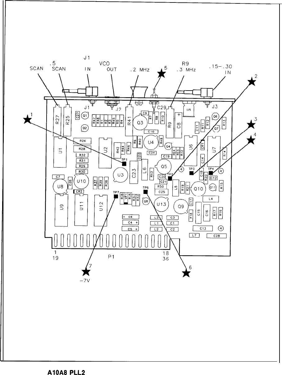
R27 R25
Jl
J2 vco
5 MHz
.5
MHz J3
SCAN
VCO
TUNE R41 TUNE
Rg
15-.30
MHz
AlOA8
PLLP
Discriminator Component Location, 85660-60176
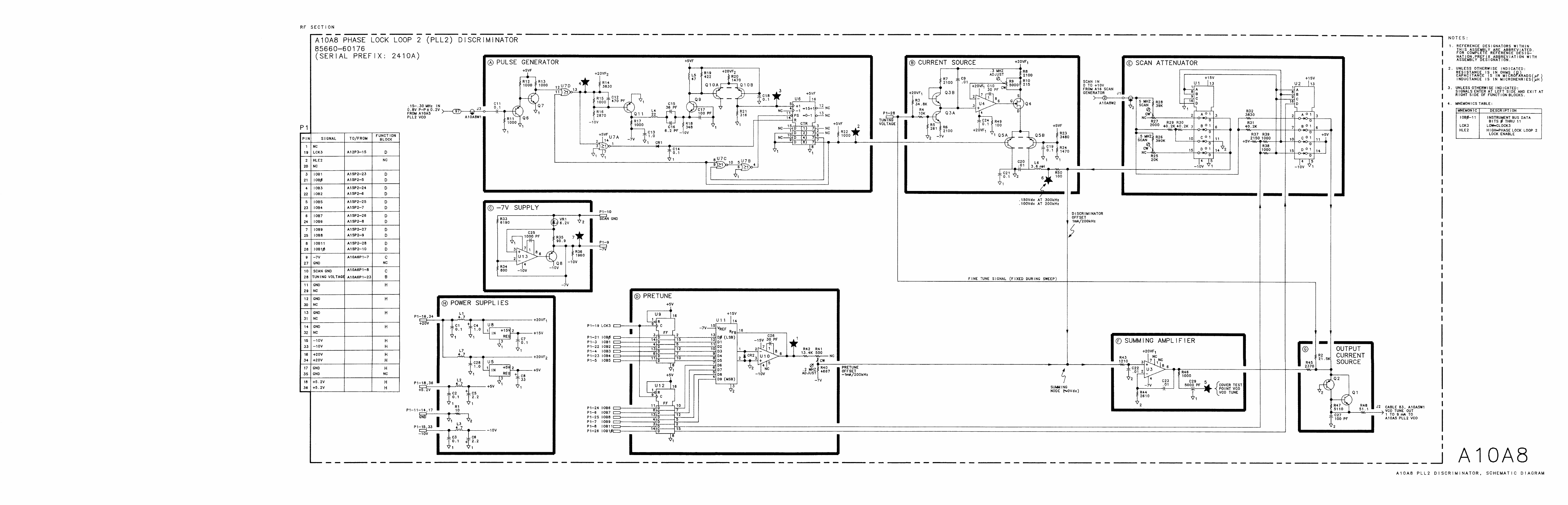
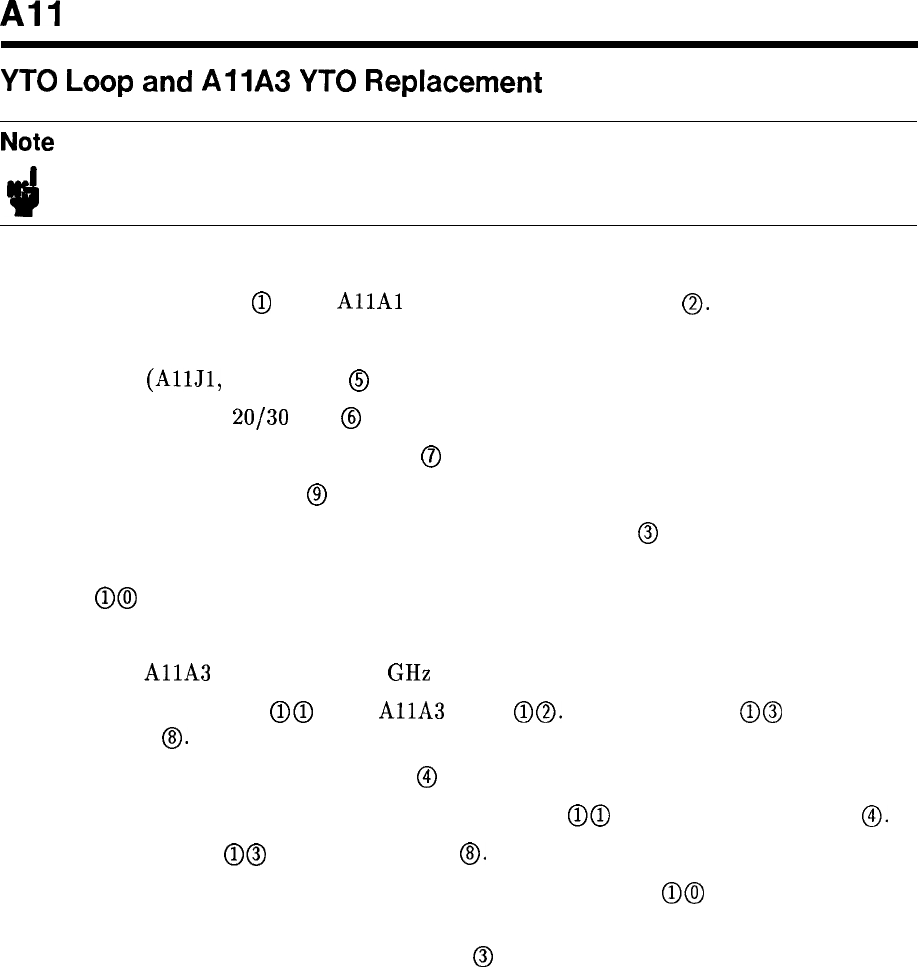
All
YTO
Loop
and
AllA
YTO
Replacement
Note For location of hardware and cables referred to in this procedure, see Figure 1.
With the ac line cords and RF Section bottom cover removed, proceed as follows:
1. Disconnect connector
@
from
AllAl
(Coupler/Isolator/Amplifier)
0.
Refer to view A.
2. Remove the following cables from All YTO Loop. Refer to view A.
8 (gray)
(AllJl,
DET OUT)
@
5 (green) (AllJ3,
20/30
IN)
@
93 (white/orange) (AllJ2, M/N IN)
0
0 (black) (AllJ4, IF IN)
@
3. Release YTO Loop from RF Section by removing three screws
@
as shown in view A.
4. Partially slide YTO Loop out from RF Section. Reach behind YTO Loop and disconnect
cable @@ from motherboard connector. Note position of cable. Refer to view B.
5. Remove All YTO Loop from RF Section.
6. To replace
AllA
YTO (2.0 to 6.2 GHz OSCILLATOR), proceed as follows.
a. Disconnect connector @@ from
AllA
YTO
a@.
Disconnect cable @@ from YTO
connector @. Refer to view B.
b. To remove YTO, remove two screws
@
as shown in view A.
c. When installing the new YTO, reconnect connector
a@
before tightening screws
0.
d. Reconnect cable
a@
to YTO connector @. Refer to view B.
7. When installing All YTO Loop in RF Section, reconnect cable @@ to motherboard
before completely sliding All into RF Section. Refer to view B.
8. Secure YTO Loop to RF Section with screws
@
as shown in view A.
9. Reconnect cables and connectors to YTO Loop as removed in steps 1 and 2.
10. Replace bottom cover and ac line cords.
All 1
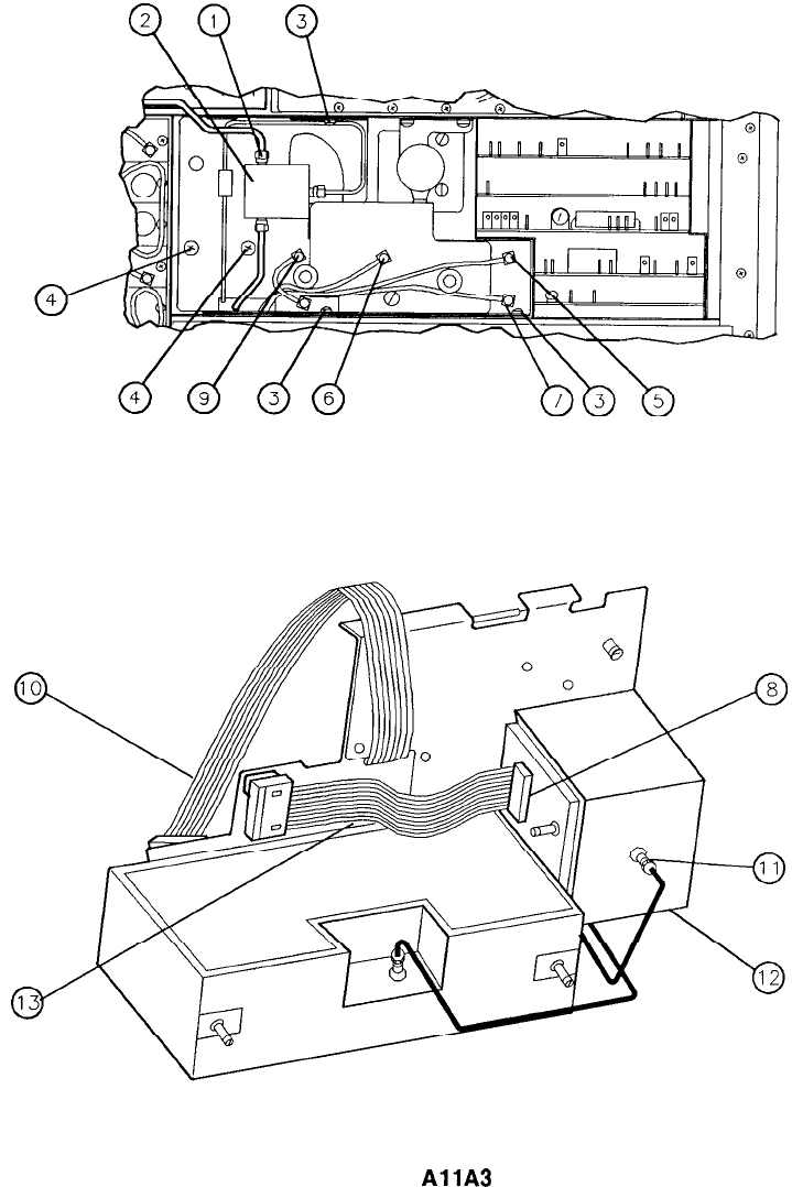
REAR
VIEW A
VIEW B
Figure 1. Ail YTO Loop and
AllA
YTO Replacement
2 All
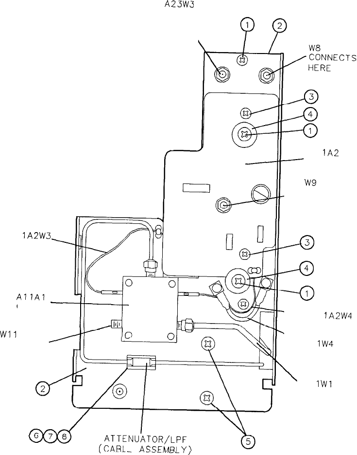
A23W3
CIA
-
WI
1
ln
CONNECTS
HERE
HERE
\
CONNECTS
Al
lA2W3
Al
IA2
-
INTERCONNECT
w9
/CONNECTS
HERE
ATTENUATOR/LPF
fC,ARl
F
ASSFLARI
VI
a
-49
-@
-Al
lA2W4
\Al
lW4
Al
IWl
Figure 2. All YTO Loop Assembly, Parts Identification (1 of 4)
All 3
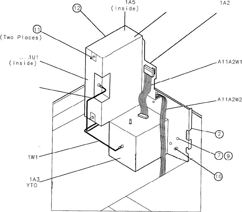
Q
12 Al
IA5
Al IA4 Al
lA2
(Ins,ide)
(Inside) INTERCONNECT
’
Y/
Al
1Ul
Al IA7
Al
IWl
L
I
Al
lA3
YTO-
1
Figure 2. All YTO Loop Assembly, Parts Identification (2 of 4)
4 All
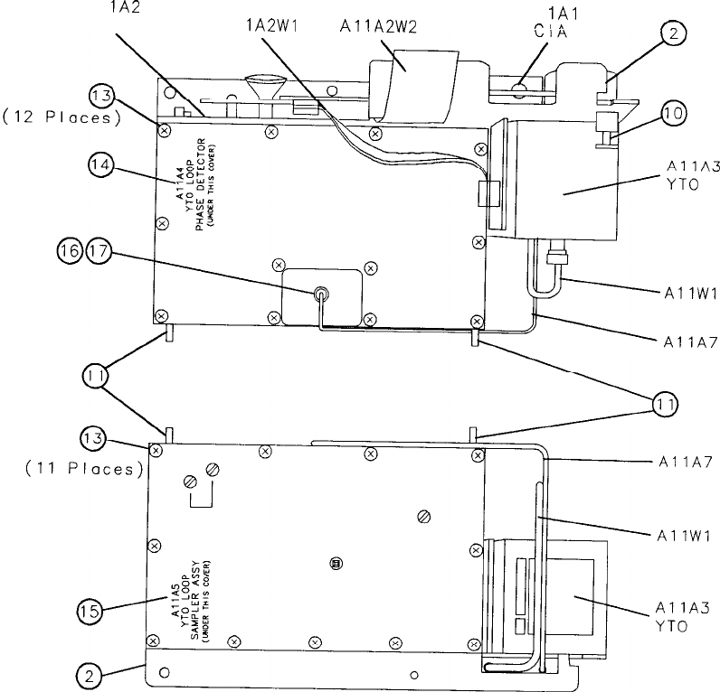
Al
lA2
INTERCONNECT Al
lA2Wl
Al
lA3W3
Al
1Al
,-Y
*
Figure 2. Al 1 YTO Loop Assembly, Parts Identification (3 of 4)
All 5
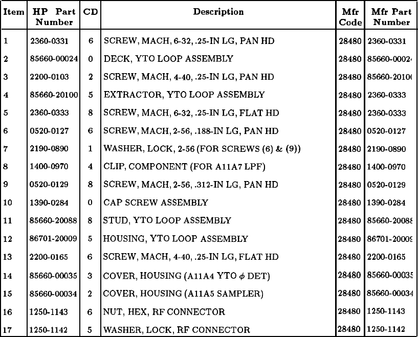
Item HP Part
CD
Description Mfr Mfr Part
Number Code Number
1
2360-0331 6
SCREW,
MACH,
632,
.25-IN
LG,
PAN
HD 28480 2360-0331
28566C~OOO24
0
DECK,
YTO
LOOP
ASSEMBLY
28480 85660-0002~
3
2200-0103
2
SCREW,
MACH,
4-40,
.25-IN
LG,
PAN
HD 28480 85660-2010(
4
85660-20100
5
EXTRACTOR, YTO
LOOP
ASSEMBLY
28480 2360-0333
5
2360-0333
8
SCREW,
MACH,
632,
.25-IN
LG,
FLAT
HD 28480 2360-0333
6
0520-0127
6
SCREW,
MACH,
2-56,
.188-IN
LG,
PAN
HD 28480
0520-0127
7
2190-0890
1
WASHER,
LOCK,
2-56
(FOR
SCREWS
(6)
&
(9))
28480 2190-0890
8
1400-0970 4CLIP,
COMPONENT
(FOR
AllA
LPF) 28480 1400-0970
9
0520-0129
8
SCREW,
MACH,
2-56,
.312-IN
LG,
PAN
HD 28480 0520-0129
10
1390-0284
0
CAP
SCREW
ASSEMBLY
28480 1390-0284
11
8566@20088
8
STUD,
YTO
LOOP
ASSEMBLY
28480 85660-20088
12
86701-20009
5
HOUSING,
YTO
LOOP
ASSEMBLY
28480 86701-2000s
13
2200-0165
6
SCREW,
MACH,
4-40,
.25-IN
LG,
FLAT
HD 28480 2200-0165
14 8566CLOOO35
3
COVER,
HOUSING
(AllA
YTO
c$
DET)
28480 85660-00035
15
85660-00034
2
COVER,
HOUSING
(AllA
SAMPLER)
28480 85660-00034
16
1250-1143
6
NUT,
HEX,
RF
CONNECTOR
28480 1250-1143
17
1250-1142
5
WASHER,
LOCK,
RF
CONNECTOR
28480 1250-1142
Figure 2. All YTO Loop Assembly, Parts Identification (4 of 4)
6 All
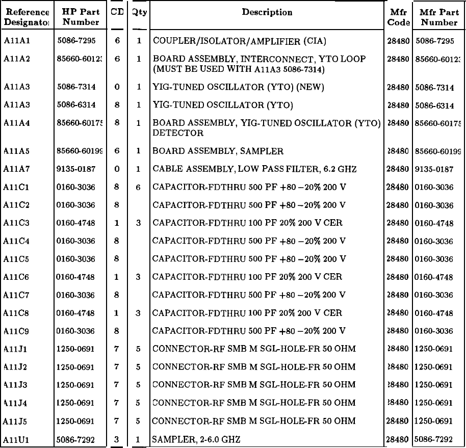
RF Section Assemblies
Reference
Designatol
AllAl
AllA
HP Part
Number
50867295
8566&6012:
-
CD
-
6
6
-
3tY
-
1
1
AllA
50867314
0
1
AllA
50866314
8
1
AllA
85660-60175
8
1
AllA
85660-60195
AllA
9135-0187
AllCl
0160-3036
AllC2
0160-3036
AllC3
0160-4748
AllC4
0160-3036
AllC5
0160-3036
AllC6
0160-4748
AllC7
0160-3036
AllC8
0160-4748
AllCS
0160-3036
AllJl
1250-0691
41152
1250-0691
41153
1250-0691
41154
1250-0691
AllJ5
1250-0691
AllUl
50867292
6
0
8
8
1
8
8
1
8
1
8
7
7
7
7
7
3
-
3
3
3
5
5
5
5
5
1
-
Description
COUPLER/ISOLATOR/AMPLIFIER
(CIA)
BOARD
ASSEMBLY,
INTERCONNECT,
YTO
LOOP
(MUST
BE
USED
WITH
AllA
50867314)
YIG-TUNED
OSCILLATOR
(YTO)
(NEW)
YIG-TUNED
OSCILLATOR
(YTO)
BOARD
ASSEMBLY,
YIG-TUNED
OSCILLATOR
(YTO)
DETECTOR
BOARD
ASSEMBLY,
SAMPLER
CABLE
ASSEMBLY,
LOW
PASS
FILTER,
6.2
GHZ
CAPACITOR-FDTHRU
500
PF
+80
-20%
200
V
CAPACITOR-FDTHRU
500
PF
+SO
-20%
200
V
CAPACITOR-FDTHRU
100
PF
20%
200
V
CER
CAPACITOR-FDTHRU
500
PF
+80
-20%
200
V
CAPACITOR-FDTHRU
500
PF
+80
-20%
200
V
CAPACITOR-FDTHRU
100
PF
20%
200
V
CER
CAPACITOR-FDTHRU
500
PF
+80
-20%
200
V
CAPACITOR-FDTHRU
100
PF
20%
200
V
CER
CAPACITOR-FDTHRU
500
PF
+80
-20%
200
V
CONNECTOR-RF
SMB
M
SGL-HOLEFR
50
OHM
CONNECTOR-RF
SMB
M
SGL-HOLEFR
50
OHM
CONNECTOR-RF
SMB
M
SGL-HOLEFR
50
OHM
CONNECTOR-RF
SMB
M
SGLHOLEFR
50
OHM
CONNECTOR-RF
SMB
M
SGLHOLEFR
50
OHM
SAMPLER,
2-6.0
GHZ
Mfr
Code
2848(
2848(
2848C
2848C
2848C
28480
2848(
2848(
2848(
2848f
2848(
2848C
2848C
2848C
28480
28480
18480
18480
18480
18480
2848f
2848C
a
1
I
1
1
I
,
I
1
1
1
1
I
1
I
I
I
I
/
1
1
85660-60199
9135-0187
01603036
01603036
0160-4748
01603036
01603036
0160-4748
01603036
0160-4748
01603036
1250-0691
1250-0691
12504691
1250-0691
1250-0691
50867292
Mfr Part
Number
50867295
85660-6012:
50867314
50866314
85660-60175
All 7
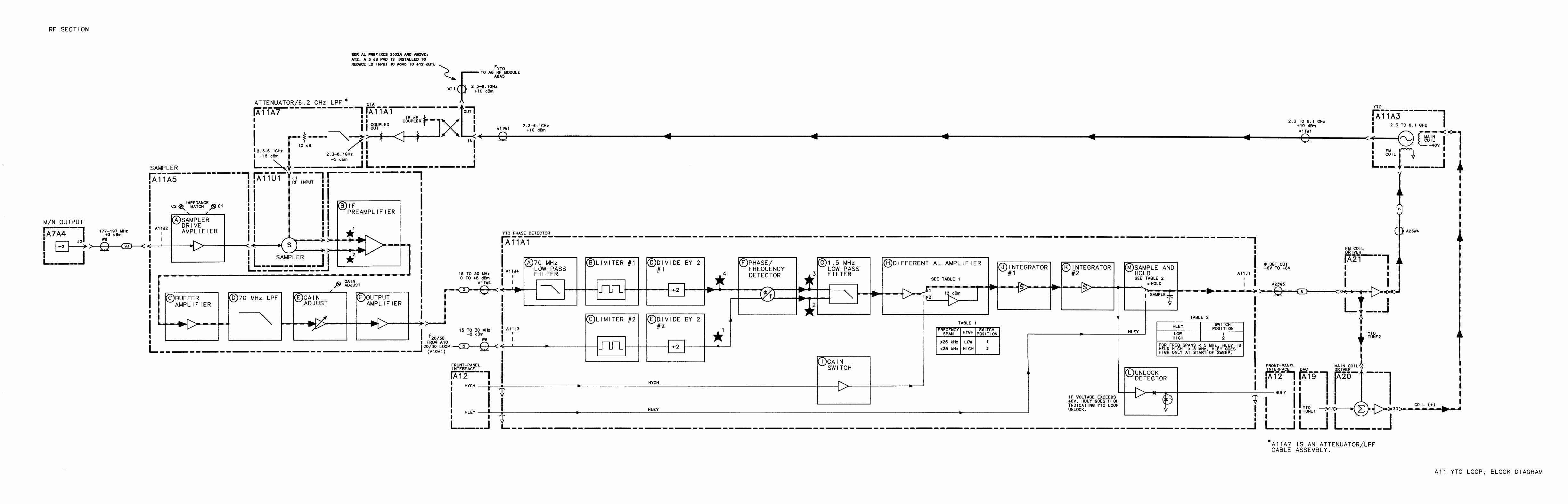
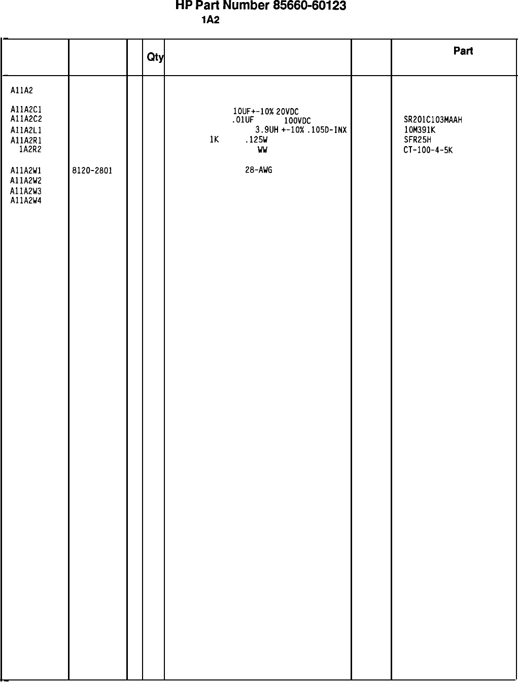
HP
Part
Number 85660-60123
Al
lA2
YTO Loop Interconnect
Reference
HP Part C
Number D
QtY
Description Mfr
Designation
Mfr
Part
Code Number
AllA
85660-60123
6
1
BOARD
ASSEMBLY. YTO LOOP INTERCONNECT
28480 85660-60123
AllA2Cl 0180-0374
3
1
CAPACITOR-FXD
lOUF+-10%
ZOVDC
TA
56289
AllA2C2 1500106X902082-DYS
0160-3879
7
1
CAPACITOR-FXD
.OlUF
+-20%
1OOVDC
CER
04222 SR201C103MAAH
AllALL
9100-2262
3
1
INDUCTOR
RF-CH-MLD
3.9UH
+-lo%
.105D-INX 24226 lOM391K
AllA2Rl 0757-0280
3
1
RESISTOR
1K
+-1%
.125W
TF TC=O+-100
19701
SFR25H
Al lA2R2
2100-1775 4 1
RESISTOR-TRMR 5K 5% Ww TOP-ADJ l-TRN CT-lOO-4-5K
AllA2Wl 8120-2801
7
1
FLAT
RIBBON ASSY
2B-AWG
14-COND
28480 8120-2801
AllA2W2 8120-2803
9
1
FLAT RIBBON ASSY 28-AWG 20-COND 28480 8120-2803
AllA2W3 85660-60108
7
1
WIRE ASSEMBLY, WHITE/RED 28480 85660-60108
AllA2W4 85660-60109
8
1
WIRE ASSEMBLY, WHITE/BLUE 28480 85660-60109
*Indicates factory-selected value
8566040123 Parts List
Page 1 of 1
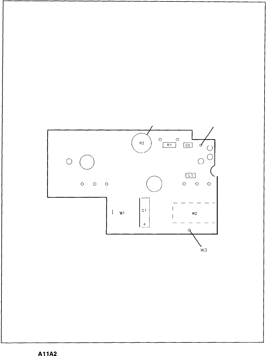
R2
GATE BIAS ADJ
w4
o”
0
(c1
c
0
0
0
---
lI
1
Wl
I
I
I
L--
Cl
1
EI
w2
+
AllA
YTO Loop Interconnect Component Locations, 85660-60123
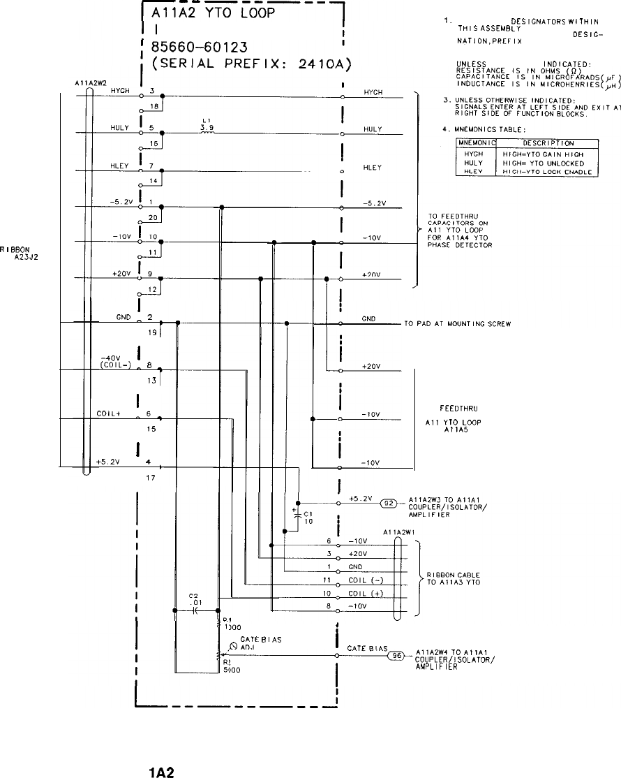
RF SECTION
R
I
BBON CABLE
TO
A23JZ
-m--m---
INTERCONNECT
I
GND
^
2
19
-40”
I
(COIL-)
^
8
_
13
COIL+
!6_
15
I
+5.2v
4
17
NOTES:
1.
REFERENCE
DESlCNATORS
WlTHlN
THIS
ASSEMBLY
ARE ABBREVIATED.
FOR COMPLETE REFERENCE
DES,&
NATION,PREFIX
ABBREVIATION WITH
ASSEMBLY DESIGNATION.
2.
UNLESS
OTHERWISE
INDICATED:
TO
FEEDTHRU
CAPACITORS ON
AIT
YTD
LOOP
FOR
A11A5
SAMPLER
500
;
GATE
B
I
AS
!s
ADJ I
GATE
BIAS
~AllA2W4
TO
AIlAl
im
I
COUPLER/ISOLATOR/
AMPLIFIER
Al
lA2
YTO Loop Interconnect, Interconnect Diagram
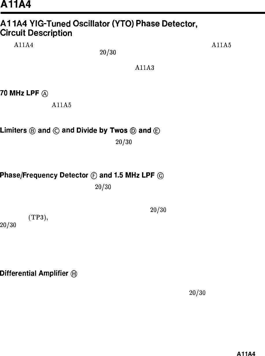
Al
IA4
Al
lA4
YIG-Tuned
Oscillator
(YTO)
Phase
Detector,
Circuit
Description
The
AllA
YTO Phase Detector compares the frequency and phase of the
AllA
Sampler
IF signal to the output of the A10
20/30
Synthesizer Loop. The resultant error signal is
integrated, amplified, and applied to the A21 FM Coil Driver where it is routed to either the
main coil (dc path) or FM coil (ac path) of the
AllA
YTO. This tunes the YTO frequency
the proper amount in the proper direction to maintain phase lock.
70
MHz
LPF
@
The output of the
AllA
Sampler (IF IN) is passed through a 70 MHz LPF to remove any
unwanted frequencies which may have been introduced during the sampling process.
Limiters
@
and
@
and
Divide
by
Twos
@
and
@
Each of the two input signals (IF IN and
20/30
IN) are passed through a limiter to
establish ECL signal levels. Each signal is then divided by two before being applied to the
phase/frequency detector. This lowers the frequency at which the detector must operate.
Phase/Frequency Detector
0
and
1.5
MHz
LPF
@
The two input signals (IF IN and
20/30
IN), after being divided by two, are applied to Phase
Frequency Detector U3. The function of U3 is to output a pulse which is related to the phase
difference of the two input signals. The width of this pulse is directly proportional to the
amount of phase difference. If the IF signal leads the
20/30
signal, a negative pulse appears at
U3 pin 3
(TP3),
the width of which is proportional to the amount of phase difference. If the
20/30
signal leads the IF signal, a negative pulse appears at U3 pin 12 (TP2). In each case,
the other output is an ECL high (approximately -0.6 V). If the inputs are in phase, one of
the detector outputs is an ECL high (approximately -0.6 V) with narrow negative spikes and
the other just an ECL high. The detector outputs are averaged in the 1.5 MHz LPF before
being applied to the differential amplifier.
Differential
Amplifier
GiJ
The detector outputs are applied to Differential Amplifier Q4. The output of this differential
amplifier is directly related to the phase difference of the IF IN and
20/30
IN signals.
AllA
1
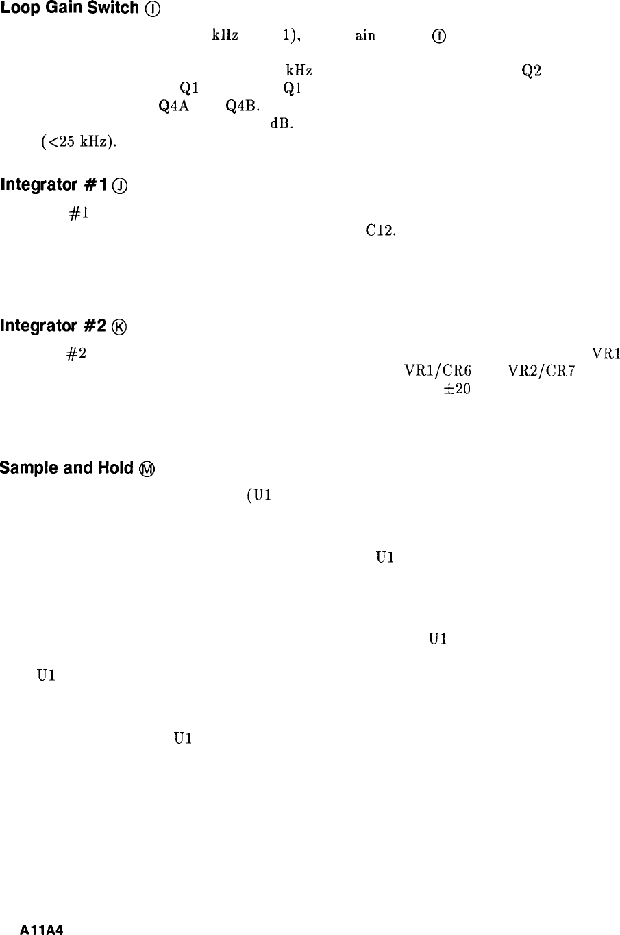
Loop
Gain
Switch
(ij
In frequency spans less than 25 kHz (N =
l),
Loop
G
ain
Switch
@
is enabled. The enable
signal HYGH (High = YTO Gain High) is from the Al2 Front-Panel Interface and is high
whenever a frequency span of less than 25 kHz is selected. This high turns on
Q2
which
turns on Q3 which causes
Ql
to saturate.
Ql
then effectively becomes a short, placing R14
between the emitters of Q4A and Q4B. This lowers the emitter resistance by a factor of four,
increasing the gain by approximately 12 dB. This improves phase noise at narrow frequency
spans
(<25
kHz).
Integrator
#l
@
Integrator
#l
produces a ramp output proportional to the amplitude and period of the input.
This integrating action is performed by R16, R21, and
Cl2.
Diodes CR2 and CR3 limit the
upper and lower ramp voltages to one diode drop (approximately 0.6 V). This ramp may be in
either a positive or negative direction depending on the input. When the loop is locked and
the instrument is in zero frequency span, the output is a dc level.
Integrator
#2
@
Integrator
#2
also produces a ramp output but of greater amplitude due to zener diodes
VRl
and CR2. The upper and lower ramp voltages are limited by VRl/C!RG and
VR2/CR7
to
approximately 6.8 V. This corresponds to a capture range of about
&20
MHz, since YTO
sensitivity is -3 MHz/V. Integrating action is performed by R24, R25, and C16. In zero
frequency span, when the loop is locked, the output is a dc level.
Sample
and
Hold
@I
The purpose of the sample and hold
(Ul
and associated circuitry) is to sample the ramp
voltage output of the integrators to tune the YTO frequency, then hold this dc value to
prevent the YTO loop from affecting the YTO Sweep.
For frequency spans less than 5 MHz (including ZERO),
Ul
is held in the sample mode. This
means that the YTO is phase locked during the entire sweep for frequency spans less than 5
MHz.
For frequency spans greater than 5 MHz (fundamental mixing only), phase lock is performed
only at the start of each sweep as follows. Just prior to a sweep,
Ul
is placed in the sample
mode, the sampled output is applied to YTO to correct its frequency, and phase lock occurs.
Then
Ul
is placed in the hold mode, which stores the sampled output voltage across Cl. This
voltage keeps the YTO tuned to the correct frequency. The sweep occurs, and the sequence is
repeated.
The mode of operation of
Ul
is determined by control signal HLEY (High = YTO Lock
enable) from the Al2 Front-Panel Interface. The duration of the sample mode is determined
by HLEY which varies with frequency span selected.
2
AllA

Unlock
Detector
@
Phase lock is obtained by use of the YTO (FM coil for ac corrections and main coil dc
corrections) which has a frequency tuning range of approximately
f20
MHz at 3 MHz/V
sensitivity.
Unlock detector U2 and associated circuitry is used to determine when the error voltage is
too large for the YTO Loop to respond. This detection is performed for both positive and
negative error voltages by U2A and U2B respectively.
If the error voltage (ramp output of Integrator
#2)
exceeds f6.1 V, control signal HULY
(High = YTO Unlocked) is generated and routed to the Al2 Front-Panel Interface where it
causes a service request to be generated. Coded information corresponding to this request is
placed on the Instrument Bus and is detected by the Al5 Controller which turns on the YTO
UNLOCK annotation on the CRT.
AllA
3
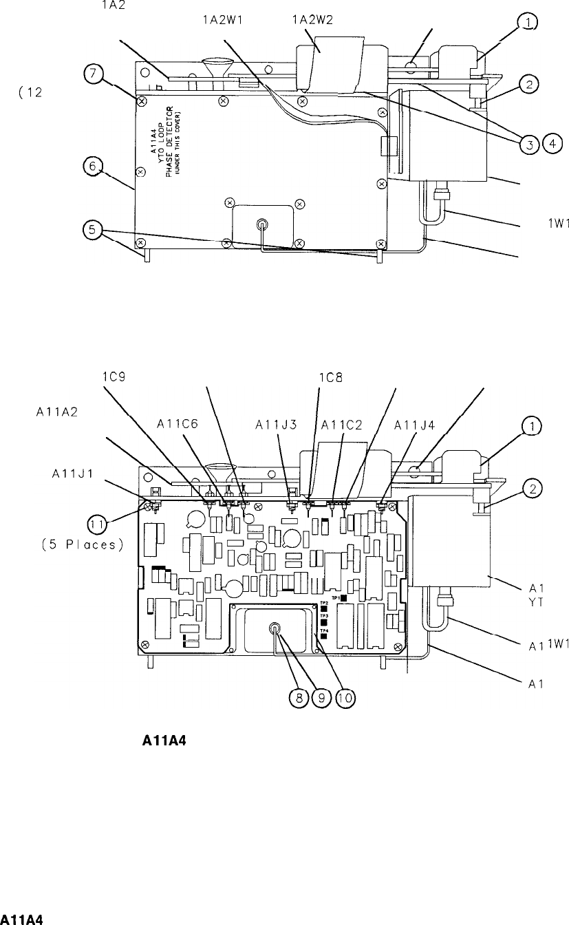
(12
Al
lA2
Al IA1
INTERCONNECT Al
lA2Wl
Al
lA2W2
CIA
\\
\-
/
/--
Places)
-
x
x
UT
-==g==
0
4
Al IA3
YTO
Al
IWl
Al IA7
Al IA1
Al
lC9
Al lC3 Al
lC8
Al ICI CIA
INTERCONNECT
lA3
0
lW1
IA7
Figure 1.
AllA
YTO Phase Detector, Parts Identification (1 of 2)
4
AllA
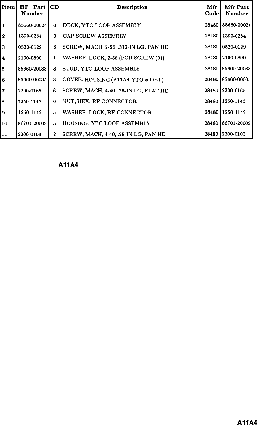
Item HP Part CD Description Mfr Mfr Part
Number Code Number
1
85660-00024 0
DECK,
YTO
LOOP
ASSEMBLY
28480 85660-00024
2
1390-0284
0
CAP
SCREW
ASSEMBLY
28480 1390-0284
3
0520-0129
8
SCREW,
MACH,
2-56,
.312-IN
LG,
PAN
HD 28480
0520-0129
4
2190-0890
1
WASHER,
LOCK,
2-56
(FOR
SCREW
(3)) 28480
2190-0890
5
8566&20088
8
STUD,
YTO
LOOP
ASSEMBLY
28480 85660-20088
6
8566600035
3
COVER,
HOUSING
(AllA
YTO
c$
DET)
28480
8566600035
7
2200-0165
6
SCREW,
MACH,
4-40,
.25-IN
LG,
FLAT
HD 28480 2200-0165
8
1250-1143
6
NUT,
HEX,
RF
CONNECTOR
28480 1250-1143
9
1250-1142
5
WASHER,
LOCK,
RF
CONNECTOR
28480 1250-1142
10
86701-20009
5
HOUSING,
YTO
LOOP
ASSEMBLY
28480
86701-20009
11
2200-0103
2
SCREW,
MACH,
4-40,
.25-IN
LG,
PAN
HD 28480 2200-0103
Figure 1.
AllA
YTO Phase Detector, Parts Identification (2 of 2)
AllA
5
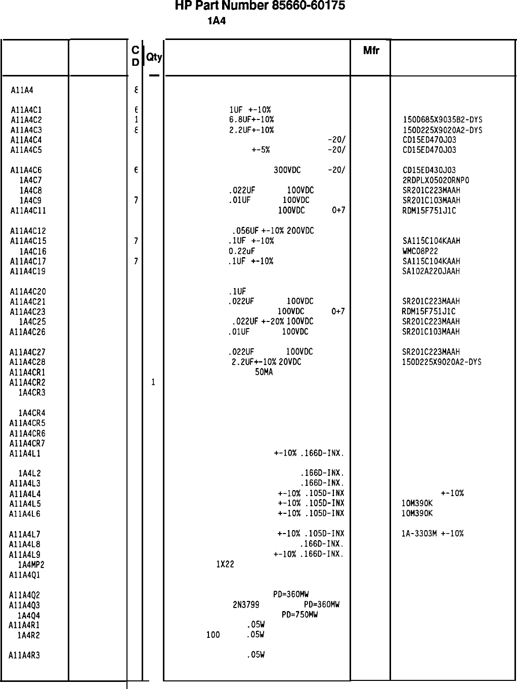
Reference
Designation
HP Part
Number
85660-60175
AllA
E
AllA4Cl 0160-3787
E
AllA4C2 0180-0116
1
AllA4C3 0180-0197
E
AllA4C4 0160-2307
4
AllA4C5 0160-2307
4
AllA4C6 0160-2200
E
Al lA4C7 0160-2264
2
Al lA4C8 0160-0574
3
Al lA4C9 0160-3879
7
AllA4Cll 0160-3538
5
AllA4C12 0160-0165
8
AllA4C15
0160-4835
7
Al lA4C16 0160-2453
1
AllA4C17 0160-4835
7
AllA4C19 0160-4787
a
AllA4C20 0160-3661
5
AllA4C21 0160-0574
3
AllA4C23 0160-3538
5
Al lA4C25 0160-0574
3
AllA4C26 0160-3879
7
AllA4C27 0160-0574
3
AllA4C28 0180-0197
8
AllA4CRl 1901-0040
1
AllA4CR2 1901-0518
8
Al lA4CR3 1901-0518
8
Al lA4CR4 1901-0040
1
AllA4CR5 1901-0040
1
AllA4CR6 1901-0040
1
AllA4CR7 1901-0040
1
AllA4Ll 9100-1620
5
Al lA4L2 9100-1641
0
AllA4L3 9100-1641
0
AllA4L4 9100-0368
6
AllA4L5 9100-2254
3
AllA4L6 9100-2254
3
AllA4L7 9100-0368
6
AllA4L8 9100-1620
5
AllA4L9 9100-1620
5
Al lA4MP2 8151-0013
4
AllA4Ql 1855-0395
0
AllA4Q2 1854-0404
0
AllA4Q3 1853-0451
5
Al lA4Q4 1854-1030
0
AllA4Rl 0698-7212
9
Al
lA4R2
0698-7212
9
AllA4R3 0698-7219
6
Xl
-
1
1
1
1
1
1
1
1
1
1
1
1
1
1
1
1
1
1
1
1
1
1
1
1
1
1
1
1
1
1
1
1
1
1
1
1
1
1
1
1
1
1
1
1
1
1
1
HP
Part
Number 85660-60175
Al
lA4
YTO Phase Detector
Description Mfr
Mfr Part
Code Number
BOARD ASSEMBLY. YTO PHASE DETECTOR 28480 85660-60175
CAPACITOR-FXO
1UF
+-lo% 50VOC MET-POLYC
84411 HEW-249
CAPACITOR-FXO
6.8lJF+-10%
35VOC TA
56289 150D685X903582-DYS
CAPACITOR-FXO
2.2lJF+-10%
20VDC TA
56289 15DD225X9020A2-DYS
CAPACITOR-FXD 47PF +-5% 30DVDC MICA
-2O/ 09023 CD15ED470JD3
CAPACITOR-FXD 47PF
+-5x
3DOVDC MICA
-2O/ 09023 CD15ED470J03
CAPACITOR-FXO 43PF +-5%
JOOVDC
MICA
-201 09023 CD15ED430J03
CAPACITOR-FXD 20PF +-5% 500VDC CER 0+-30
52763 2RDPLX05020RNPO
CAPACITOR-FXD
.D22UF
+-20%
1OOVDC
CER
04222 SR201C223MAAH
CAPACITOR-FXD
.OlUF
+-20%
1OOVDC
CER
04222 SR201C103MAAH
CAPACITOR-FXD 75DPF +-5%
1DDVDC
MICA
0+7
09023
RDM15F751JlC
CAPACITOR-FXD
.056UF
+-lo%
ZDOVDC
POLYE
84411 HEW-238M
CAPACITOR-FXD
.lUF
+-10x 50VDC CER
04222 SAllSC104KAAH
CAPACITOR-FXD
0.22uF
80 V PDLYE-FL
09023 WMC08P22
CAPACITOR-FXD
.lUF
+-lo%
50VDC CER
04222 SA115C104KAAH
CAPACITOR-FXD 22pF 100 V 04222 SA102A220JAAH
CAPACITOR-FXD
.lUF
+-5% 50VDC MET-PDLYC
84411 HEW-249
CAPACITOR-FXD
.022UF
+-20%
1DOVDC
CER
04222 SR201C223MAAH
CAPACITOR-FXD 750PF +-5%
1ODVDC
MICA
0+7
09023
RDM15F751JlC
CAPACITOR-FXD
.022UF
+-20x
IODVDC
CER
04222 SR201C223MAAH
CAPACITOR-FXD
.OlUF
+-20%
1OOVDC
CER
04222 SR201C103MAAH
CAPACITOR-FXD
.D22UF
+-20%
1OOVDC
CER
CAPACITOR-FXD
2.2UF+-10%
POVDC
TA
DIODE-SWITCHING 30V
50MA
2NS DO-35
DIODE-SCHOTTKY SM SIG
DIODE-SCHOTTKY SM SIG
04222
56289
71468
SR2DlC223MAAH
150D225X9020A2-DYS
5082-2800
5082-2800
DIODE-SWITCHING 30V 50MA 2NS DO-35 71468
DIODE-SWITCHING 30V 5DMA 2NS DO-35 71468
DIODE-SWITCHING 30V 5DMA 2NS DO-35
71468
DIODE-SWITCHING 30V 50MA 2NS DO-35 71468
INDUCTOR RF-CH-MLD 15UH +-lo%
.166D-INX.
99800 1537-40
INDUCTOR RF-CH-MLD 240UH +-5%
.166D-INX.
99800 1537-94
INDUCTOR RF-CH-MLD 24DUH +-5%
.166D-INX.
99800 1537-94
INDUCTOR RF-CH-MLD 33DNH +-lo%
.105D-INX 32159
IA-3303M +-IO%
INDUCTOR RF-CH-MLD 39DNH
+-10x
.lOSD-INX 24226 lOM390K
INDUCTOR RF-CH-MLD 390NH
+-10x
.lD5D-INX 24226 lOM390K
INDUCTOR RF-CH-MLD 330NH
+-10x
.105D-INX
INDUCTOR RF-CH-MLD 15UH +-10%
.166D-INX.
INDUCTOR RF-CH-MLD 15UH +-lo%
.166D-INX.
WIRE 22AWG
1X22
TRANSISTOR J-FET N-CHAN D-MODE TO-52 SI
TRANSISTOR NPN SI TO-18
PD=360MW
TRANSISTOR PNP
2N3799
SI TO-18
PD=360MW
TRANSISTOR-DUAL NPN TO-78
PD=750MW
RESISTOR 100 +-1%
.05W
TF TC=O+-100
RESISTOR
100
+-1%
.05W
TF TC=D+-100
RESISTOR 196 +-1%
.D5W
TF TC=D+-100
32159 lA-3303M
+-lo%
99800 1537-40
99800 1537-40
92194 298
17856 FN2645
04713
04713
04713
19701
19701
50635
50635
19701
50635
*Indicates factory-selected value
85660-60175 Parts List
Page 1 of 2
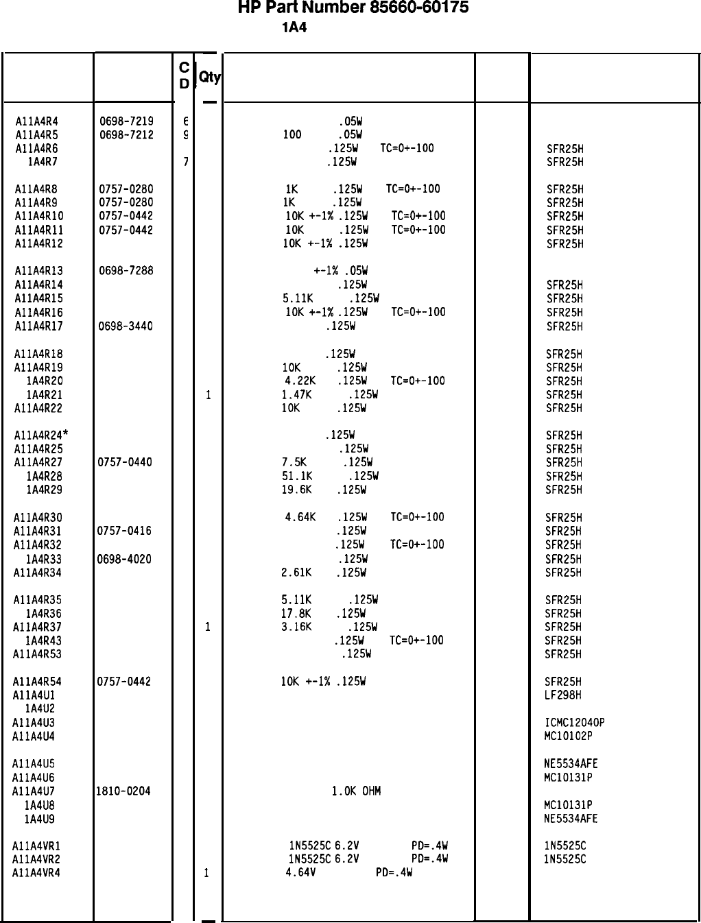
Reference
Designation
HP Part
Number
AllA4R4 0698-7219
E
AllA4R5 0698-7212
9
AllA4R6 0698-3132
4
Al
lA4R7
0698-3440
7
AllA4R8 0757-0280
3
AllA4R9 0757-0280
3
AllA4RlD 0757-0442
9
AllA4Rll 0757-0442
9
AllA4R12 0757-0442
9
AllA4R13 0698-7288
9
AllA4R14 0757-0418
9
AllA4R15 0757-0438
3
AllA4R16 0757-0442
9
AllA4R17 0698-3440
7
AllA4R18 0698-3132
4
AllA4R19 0757-0442
9
Al lA4R20 0698-3154
0
Al
lA4R21
0757-1094
9
AllA4R22 0757-0442
9
AllA4R24* 0698-0082
7
AllA4R25 0698-3152
a
AllA4R27 0757-0440
7
Al lA4R28 0757-0458
7
Al lA4R29 0698-3157
3
AllA4R30 0698-3155
1
AllA4R31 0757-0416
7
AllA4R32 0757-0416
7
Al lA4R33 0698-4020
1
AllA4R34 0698-0085
0
AllA4R35 0757-0438
3
Al lA4R36 0698-3136
8
AllA4R37 0757-0279
0
Al lA4R43 0757-0421
4
AllA4R53 0757-0394
0
AllA4R54 0757-0442
9
AllA4Ul 1826-0422
3
Al
lA4U2
5081-8117
3
AllA4U3 1820-1344
8
AllA4U4 1820-0802
1
AllA4U5 1826-0783
9
AllA4U6 1820-0817
8
AllA4U7 1810-0204
6
Al lA4U8 1820-0817
8
Al
lA4U9
1826-0783
9
AllA4VRl 1902-1260
1
AllA4VR2 1902-1260
1
AllA4VR4 1902-3082
9
8566040175 Parts List
Page 2 of 2
-
31
-
1
1
1
1
1
1
1
1
1
1
1
1
1
1
1
1
1
1
1
1
1
1
1
1
1
1
1
1
1
1
1
1
1
1
1
1
1
1
1
1
1
1
1
1
1
1
1
-
HP
Part
Number 85660-60175
Al
lA4
YTO Phase Detector
Description Mfr Mfr Part
Code Number
RESISTOR 196 +-1%
.05W
TF TC=D+-100
19701
50635
RESISTOR
100
+-1%
.D5W
TF TC=O+-100
19701
50635
RESISTOR 261 1%
.125W
TF
TC=O+-100
19701
SFR25H
RESISTOR 196 1%
.125W
TF TC=O+-100
19701
SFR25H
RESISTOR
1K
+-1%
.125W
TF
TC=O+-100
19701
SFR25H
RESISTOR
1K
+-1%
.125W
TF TC=O+-100
19701
SFR25H
RESISTOR
10K
+-1X
.125W
TF
TC=O+-100
19701
SFR25H
RESISTOR
10K
+-1%
.125W
TF
TC=O+-ID0
19701
SFR25H
RESISTOR
1DK
+-1X
.125W
TF TC=O+-100
19701
SFR25H
RESISTOR 147K +-1X
.D5W
TF TC=D+-100
19701
5023R
RESISTOR 619 +-1%
.125W
TF TC=O+-100
19701
SFR25H
RESISTOR
5.11K
+-1%
.125W
TF TC=O+-100
19701
SFR25H
RESISTOR
10K
+-1X
.125W
TF
TC=O+-100
19701
SFR25H
RESISTOR 196 1%
.125W
TF TC=D+-100
19701
SFR25H
RESISTOR 261 1%
.125W
TF TC=O+-100
19701 SFR25H
RESISTOR
10K
+-1%
.125W
TF TC=O+-100
19701
SFR25H
RESISTOR
4.22K
1%
.125W
TF
TC=O+-100
19701
SFR25H
RESISTOR
1.47K
+-1%
.125W
TF TC=O+-100
19701
SFR25H
RESISTOR
10K
+-1%
.125W
TF TC=O+-100
19701
SFR25H
RESISTOR 464 1%
.125W
TF TC=D+-100
19701
SFR25H
RESISTOR 3.481: 1%
.125W
TF TC=D+-100
19701
SFR25H
RESISTOR
7.5K
+-1%
.125W
TF TC=O+-100
19701
SFR25H
RESISTOR
51.1K
+-1%
.125W
TF TC=D+-100
19701
SFR25H
RESISTOR
19.6K
1%
.125W
TF TC=O+-100
19701
SFR25H
RESISTOR
4.64K
1%
.125W
TF
TC=O+-100
19701
SFR25H
RESISTOR 511 +-1%
.125W
TF TC=O+-100
19701
SFR25H
RESISTOR 511 +-1%
.125W
TF
TC=O+-100
19701
SFR25H
RESISTOR 9.531: 1%
.125W
TF TC=D+-100
19701
SFR25H
RESISTOR
2.61K
1%
.125W
TF TC=D+-100
19701
SFR25H
RESISTOR
5.11K
+-1%
.125W
TF TC=D+-100
19701
SFR25H
RESISTOR
17.8K
1%
.125W
TF TC=O+-100
19701
SFR25H
RESISTOR
3.16K
+-1%
.125W
TF TC=O+-100
19701
SFR25H
RESISTOR 825 +-1%
.125W
TF
TC=O+-100
19701
SFR25H
RESISTOR 51.1 +-1%
.125W
TF TC=O+-100
19701
SFR25H
RESISTOR
10K
+-1X
.125W
TF TC=D+-100
SAMPLE AND HOLD 8 -METAL
SCREENED 1826-0092
PHASE DETECTOR
19701
27014
28480
IC ECL QUAD 2 NOR GATE
IC DP AMP LOW-NOISE 8-DIP-C PKG
IC FF ECL D-M/S DUAL
NETWORK-RES 8-SIP
l.OK
OHM
X 7
IC FF ECL D-M/S DUAL
IC OP AMP LOW-NOISE 8-DIP-C PKG
DIODE-ZNR
lN5525C
6.2V
2% DO-7
PD=.4W
IR
DIODE-ZNR
lN5525C
6.2V
2% DO-7
PD=.4W
IR
DIODE-ZNR
4.64V
5% DO-35
PD=.4W
SFR25H
LF298H
5081-8117
ICMC12040P
MC10102P
18324 NE5534AFE
04713 MC10131P
11236 750-81
04713 MC10131P
18324 NE5534AFE
04713
04713
04713
lN5525C
lN5525C
*Indicates factory-selected value
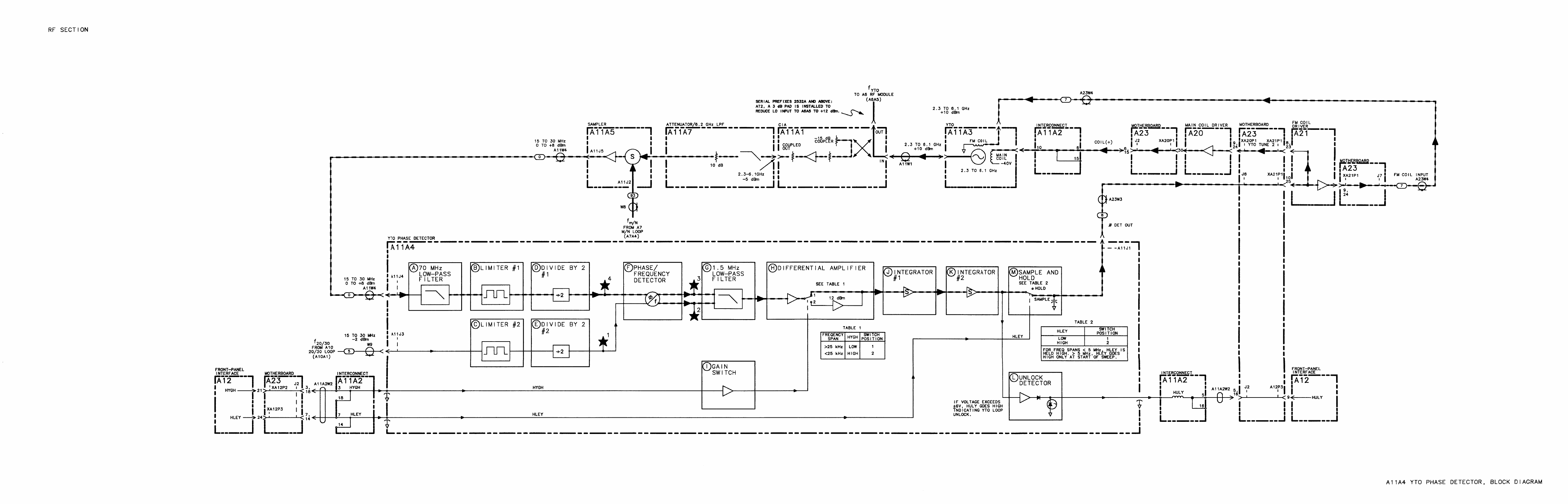
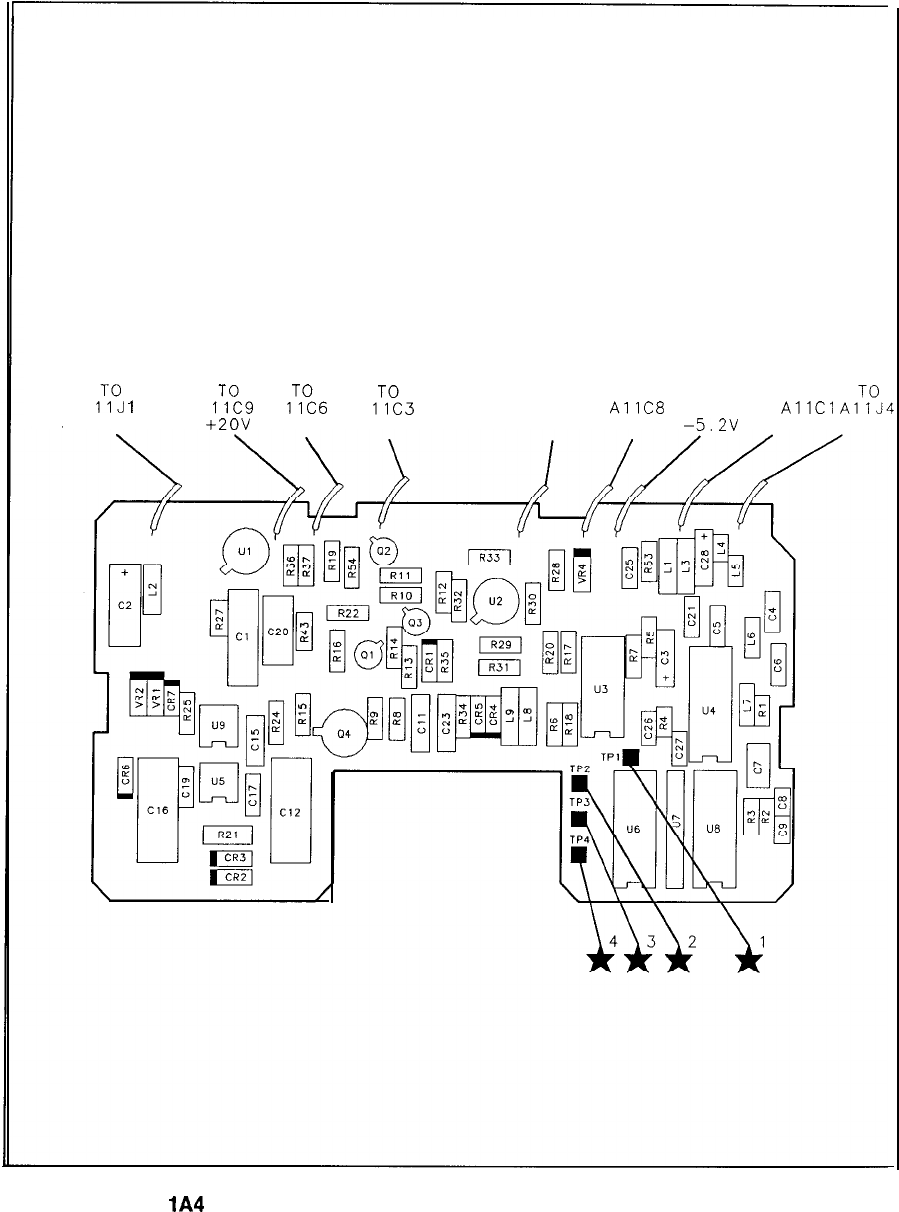
A
,:“J
I
A
1%
A
I:%
A
ITI:3
TO TO TO TO
AllJ3
AllC8
AllC2
AllCl
A,:“,,
0 DET OUT
+2ov
HYGH HLEY 20-30 IN HULY
-5.2v
-lov IF IN
Al
lA4
YTO Phase Detector Component Locations, 85660-60175
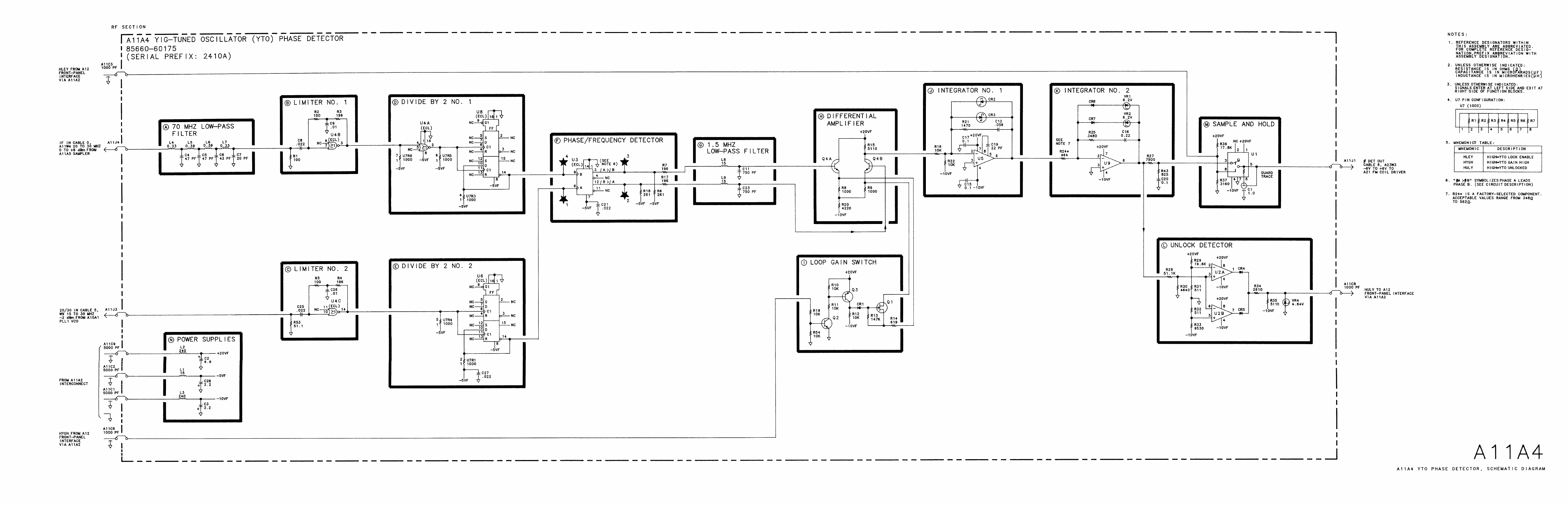
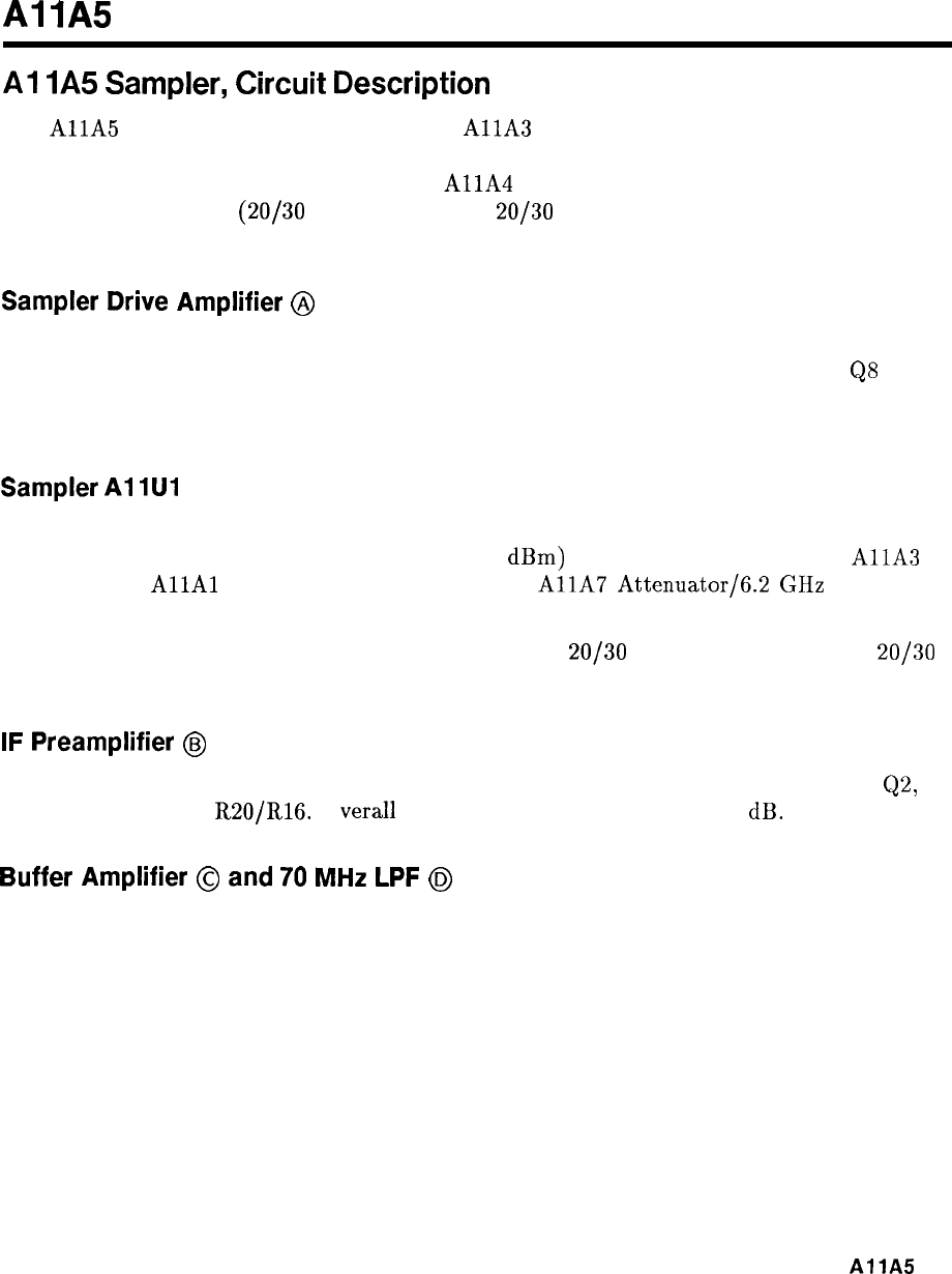
Al
lA5
Al
IA5
Sampler,
Circuit
Description
The
AllA
Sampler mixes the output of the
AllA
YTO (RF INPUT) with the Nth
harmonic of the output of the A7 M/N Reference Loop (M/N IN). The 20 to 30 MHz
difference signal (IF OUT) is output to the
AllA
YTO Phase Detector to be compared
with the 20 to 30 MHz
(20/30
IN) from the A10
20/30
Synthesizer for the purpose of phase
locking.
Sampler
Drive
Amplifier
@
The output of the A7 M/N Reference Loop (M/N IN) is applied to common-base amplifier
Q3. The output of Q3 is ac coupled to common-emitter amplifier QS. The output of
QS
is
passed through an impedance matching network which provides maximum drive power to
AllUl Sampler. Adjustments Cl and C2 optimize this impedance match.
Sampler
Al
1Ul
AllUl Sampler contains a step recovery diode (SRD) circuit to create harmonics of the M/N
IN signal which are mixed with the low-level (-15
dBm)
RF INPUT signal from the
AllA
YTO (via the
AllAl
Coupler/Isolator/Amplifier and
AllA
Attenuator/6.2
GHz LPF).
When the YTO Loop is phase locked, the mixing product of the Nth harmonic of the M/N IN
signal and the RF INPUT signal is precisely equal to the
20/30
IN signal from the A10
20/30
Synthesizer.
IF
Preamplifier
@
The IF Preamplifier consists of common-source amplifier Q4, common-emitter amplifier
Q2,
and feedback divider
R20/R16.
0
Vera11
gain provided is approximately 14 dB.
Buffer
Amplifier
@
and
70
MHz
LPF
@
The AllUl Sampler output, after being amplified, is buffered by emitter-follower Q7 and
applied to a 70 MHz low-pass filter. This filtering is done to remove any unwanted mixing
products produced by the mixing action of the sampler.
AllA
1
Gain
Adjust
@
After being filtered, the IF signal is applied to common-emitter amplifier Q6 which has
adjustable gain. IF Gain adjustment
Rl
can be adjusted to provide from 5 dB to 20 dB of
gain. This is used to adjust the level of the IF signal to the proper level for comparison to the
20/30
signal in the
AllA
YTO Phase Detector.
Output
Amplifier
@
The IF signal is further amplified by output amplifier Q5 and
Ql.
Gain is approximately
21 dB. This provides the proper level signal to drive the
AllA
YTO Phase Detector.
2
AllA
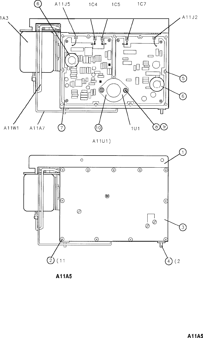
0
6
AllJ5
Al
lC4
Al
lC5
Al
lC7
Al
lA3
YTO \
AllJ2
00
Al
IUI
w
(6 PLACES) (BENEATH SAMPLER (2 PLACES)
AllUl)
w(11
PLACES) PL ACES)
Figure 1.
AllA
Sampler, Parts Identification (1 of 2)
AllA
3
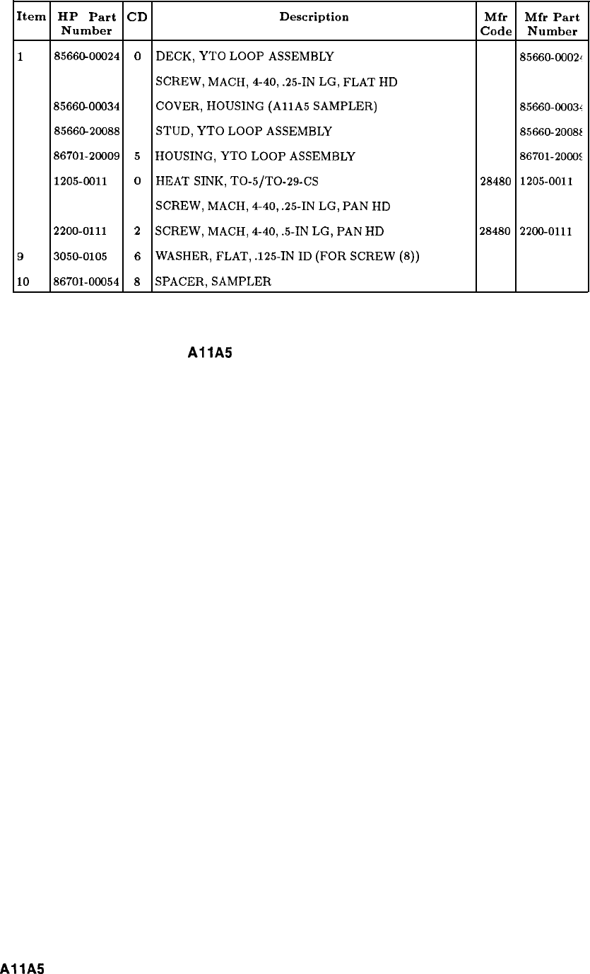
Item HP Part CD Description Mfr Mfr Part
Number Code Number
1
8566@00024
0
DECK,
YTO
LOOP
ASSEMBLY
28480
85660-0002~
2
2200-0165 6
SCREW,
MACH,
4-40,
.25-IN
LG,
FLAT
HD
28480
2200-0165
3
8566GOOO34
2
COVER,
HOUSING
(AllA
SAMPLER)
28480
85660~0003~
4
8566&20088
8
STUD,
YTO
LOOP
ASSEMBLY
28480
85660-20086
5
86701-20009
5
HOUSING,
YTO
LOOP
ASSEMBLY
28480
86701-2000:
6
1205-0011
0
HEAT
SINK,
TO-5/TO-29-CS
28480 1205-0011
7
2200-0103
2
SCREW,
MACH,
4-40,
.25-IN
LG,
PAN
HD
28480
2200-0103
B
2200-0111
2
SCREW,
MACH,
4-40,
.5-IN
LG,
PAN
HD 28480 2200-0111
9
3050-0105 6
WASHER,
FLAT,
.125-IN
ID
(FOR
SCREW
(8))
28480 3050-0105
10
86701-00054
8
SPACER,
SAMPLER
28480
86701-00054
Figure 1.
AllA
Sampler, Parts Identification (2 of 2)
4
AllA
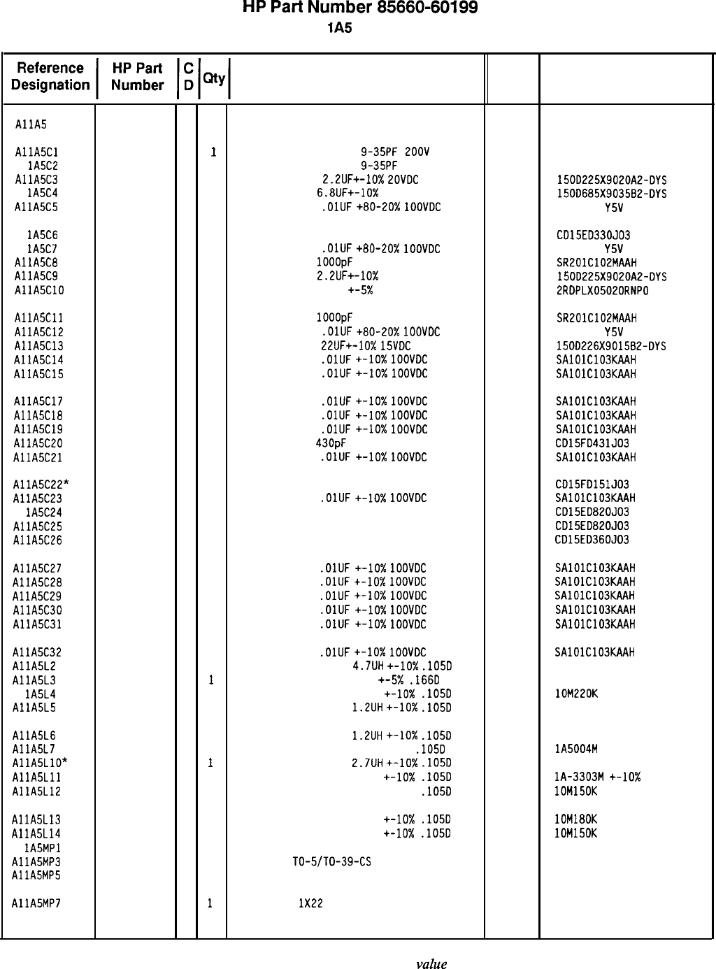
HP
Part
Number 85660-60199
Al
lA5
Sampler
Description
AllA
AllA5Cl
Al
lA5C2
AllA5C3
Al lA5C4
AllA5C5
85660-60199
6
1
BOARD ASSEMBLY, SAMPLER
0121-0046
2
1
CAPACITOR-V TRMR-CER
9-35PF
ZOOV
PC-MTG
0121-0046
2
1
CAPACITOR-V TRMR-CER
9-35PF
200V PC-MTG
0180-0197
8
1
CAPACITOR-FXD
2.2lJF+-10%
POVDC
TA
0180-0116
1 1
CAPACITOR-FXD
6.8lJF+-10%
35VDC TA
0160-2055
9
1
CAPACITOR-FXD
.OlUF
+80-20x
1OOVDC
CER
28480 85660-60199
52763
52763
56289
56289
304-322-573
304-322-573
150D225X9020A2-DYS
150D685X903582-DYS
805-504
Y5V
1032
Al lA5C6
Al
lA5C7
AllA5C8
AllA5C9
AllA5ClO
0160-2150
5
1
CAPACITOR-FXD 33PF +-5% 300VDC MICA
0160-2055
9
1
CAPACITOR-FXD
.OlUF
+80-20%
1OOVDC
CER
0160-3878
6
1
CAPACITOR-FXD
1OOOpF
100 V
0180-0197
8
1
CAPACITOR-FXD
2.2UF+-10%
20VDC TA
0160-2264
2
1
CAPACITOR-FXD 20PF
+-5X
500VDC CER
09023
04222
56289
52763
CD15ED330JD3
805-504
Y5V
1032
SR201C102MAAH
150D225X9020A2-DYS
2RDPLX05020RNPO
AllASCll
AllA5C12
AllA5C13
AllA5C14
AllA5C15
0160-3878
6
1
CAPACITOR-FXD
1OOOpF
100 V
0160-2055
9
1
CAPACITOR-FXD
.OlUF
+80-20%
1OOVDC
CER
0180-0228
6
1
CAPACITOR-FXD
22UF+-10%
15VDC
TA
0160-4832
4
1
CAPACITOR-FXD
.OlUF
+-lo%
1OOVDC
CER
0160-4832
4
1
CAPACITOR-FXD
.OlUF
+-10x
1OOVDC
CER
04222
56289
04222
04222
SR201C102MAAH
805-504
Y5V
1032
1500226X9015B2-DYS
SAlOlC103KAAH
SAlOlC103KAAH
AllA5C17 0160-4832
4
1
CAPACITOR-FXD
.OlUF
+-lo%
1OOVDC
CER
AllA5C18 0160-4832
4
1
CAPACITOR-FXD
.OlUF
+-lo%
1OOVDC
CER
AllA5C19 0160-4832
4
1
CAPACITOR-FXD
.OlUF
+-lo%
1OOVDC
CER
AllA5C20 0160-0939
4
1
CAPACITOR-FXD
43OpF
300 V MICA
AllASC21 0160-4832
4
1
CAPACITOR-FXD
.OlUF
+-lo%
1OOVDC
CER
AllA5C22* 0140-0196
3
1
CAPACITOR-FXD 150PF +-5% 300VDC MICA
AllA5C23 0160-4832
4
1
CAPACITOR-FXD
.OlUF
+-10x
1OOVDC
CER
Al lA5C24 0140-0193
0
1
CAPACITOR-FXD 82PF +-5% 300VDC MICA
AllA5C25 0140-0193
0
1
CAPACITOR-FXD 82PF +-5% 300VDC MICA
AllA5C26 0160-2308
5
1
CAPACITOR-FXD 36PF +-5% 300VDC MICA
04222 SAlOlC103KAAH
04222 SAlOlC103KAAH
04222 SAlOlC103KAAH
09023 CD15FD431JD3
04222 SAlOlC103KAAH
09023 CD15FD151J03
04222 SAlOlC103KAAH
09023 CD15EDB20JD3
09023 CD15ED820J03
09023 CD15ED360JD3
AllA5C27 0160-4832
4
1
CAPACITOR-FXD
.OlUF
+-lo%
1OOVDC
CER
04222 SAlOlC103KAAH
AllA5C28 0160-4832
4
1
CAPACITOR-FXD
.OlUF
+-lo%
IOOVDC
CER
04222
SAlOlC103KAAH
AllA5C29 0160-4832
4
1
CAPACITOR-FXD
.OlUF
+-lo%
1OOVDC
CER
04222 SAlOlC103KAAH
AllA5C30 0160-4832
4
1
CAPACITOR-FXD
.OlUF
+-lo%
1OOVDC
CER
04222 SAlOlC103KAAH
AllA5C31 0160-4832
4
1
CAPACITOR-FXD
.OlUF
+-lo%
1OOVDC
CER
04222 SAlDlC103KAAH
AllA5C32 0160-4832
4
1
CAPACITOR-FXD
.OlUF
+-lo%
1OOVOC
CER
AllA5L2 9140-0144
0
1
INDUCTOR RF-CH-MLD
4.7UH
+-lo%
.105D
AllA5L3 9100-1623
8
1
INDUCTOR RF-CH-MLD 27UH
+-5x
.166D
Al lA5L4 9100-2251
0
1
INDUCTOR RF-CH-MLD 220NH
+-lo%
.105D
AllA5L5 9100-2258
7
1
INDUCTOR RF-CH-MLD
1.2UH
+-lo%
.105D
04222 SAlOlC103KAAH
99800 1025-36
99800 1537-48
24226 lOM220K
99800 1025-22
AllA5L6 9100-2258
7
1
INDUCTOR RF-CH-MLD
1.2UH
+-lo%
.105D
AllA5L7 9100-0346
0
1
INDUCTOR RF-CH-MLD 50NH +-20%
.105D
AllA5LlO* 9100-2261
2
1
INDUCTOR RF-CH-MLD
2.7UH
+-lo%
.105D
AllASLll 9100-0368
6
1
INDUCTOR RF-CH-MLD 330NH
+-lo%
.105D
AllA5L12 9100-2249
6
1
INDUCTOR RF-CH-MLD 150NH +-10%
.105D
99800 1025-22
32159 lA5004M
20%
99800 1025-30
32159 lA-3303M
+-lo%
24226 lOM150K
AllA5L13
AllA5L14
Al
lA5MPl
AllA5MP3
AllA5MP5
9100-2250
9
1
INDUCTOR RF-CH-MLD 180NH +-lo%
.105D
9100-2249
6
1
INDUCTOR RF-CH-MLD 150NH
+-lo%
.105D
NOT ASSIGNED
1205-0011
0
1
HEAT SINK
TO-5/TO-39-CS
1251-3172
7
1
CONNECTOR-SGL CONT SKT .03-IN-BSC-SZ RND
24226 lDM180K
24226 lDM15DK
98978 TXBF-032-025B
00779 2-331677-9
AllA5MP7 8151-0013
4
1
WIRE 22AWG
1X22
92194 298
Mfr Mfr Part
Code Number
*Indicates factory-selected
vahe 8X60-60199 Parts List
Page 1 of 3

HP
Part
Number 85660-60199
Al
lA5
Sampler
Description Mfr
Mfr Part
Code Number
INSULATOR-XSTR DAP-GL
TRANSISTOR NPN SI TO-39
PD=lW
FT=BOOMHZ
TRANSISTOR NPN
2N5179
SI TO-72
PD=200MW
TRANSISTOR NPN SI TO-39
PD=lW
FT=800MHZ
07047
04712
04713
04713
-
A-10001 DAP
2N5179
TRANSISTOR J-FET N-CHAN D-MODE TO-52 SI
TRANSISTOR PNP SI
PD=200MW
FT=500MHZ
TRANSISTOR NPN
2N5179
SI TO-72
PD=EOOMW
TRANSISTOR NPN
2N5179
SI TO-72
PD=200MW
TRANSISTOR NPN SI TO-39
PD=lW
FT=800MHZ
17856
04713
04713
04713
04713
2N5179
2N5179
RESISTOR-TRMR 50 10% TKF TOP-ADJ I-TRN
32997
3386P-Y46-500
RESISTOR 51.1 +-1%
.125W
TF TC=O+-100
19701
SFR25H
RESISTOR 196 1%
.125W
TF TC=O+-100
19701
SFR25H
RESISTOR
2.61K
1%
.125W
TF TC=O+-100
19701
SFR25H
RESISTOR
l.lK
+-1%
.125W
TF TC=O+-100
19701
SFR25H
RESISTOR
1K
+-1%
.125W
TF TC=O+-100
19701
SFR25H
RESISTOR
1.78K
+-1%
.125W
TF TC=O+-100
19701
SFR25H
RESISTOR 82.5 +-1%
.5W
TF TC=O+-100
19701
5053R
RESISTOR 82.5
+-1X
.125W
TF TC=O+-100
19701
SFR25H
RESISTOR 316K 1%
.125W
TF TC=O+-100
19701
SFR25H
7ESISTOR
162K +-1%
.125W
TF TC=O+-100
19701
SFR25H
7ESISTOR
147 +-1%
.05W
TF TC=O+-100
19701
50635
7ESISTOR
1.1K
+-1X
.125W
TF TC=O+-100
19701
SFR25H
7ESISTOR
75 +-1%
.125W
TF TC=O+-100
19701
SFR25H
IESISTOR
l.lK
+-1%
.125W
TF TC=O+-100
19701
SFR25H
IESISTOR
681
+-1X
.125W
TF TC=O+-100
19701
SFR25H
ZESISTOR
825
+-1%
.125W
TF TC=O+-100
19701
SFR25H
RESISTOR 316 +-1%
.05W
TF TC=O+-100
19701
50635
RESISTOR 51.1
+-I%
.05W
TF TC=D+-100
19701
50635
RESISTOR 19.6 +-1%
.05W
TF TC=O+-100
19701
50635
RESISTOR
1.96K
1%
.125W
TF TC=O+-100
19701
SFR25H
RESISTOR
2.15K
1%
.125W
TF TC=O+-100
19701
SFR25H
RESISTOR 464 1%
.125W
TF TC=O+-100
19701
SFR25H
RESISTOR
1K
+-1X
.125W
TF TC=O+-100
19701
SFR25H
RESISTOR 51.1 +-1%
.125W
TF TC=O+-100
19701
SFR25H
RESISTOR 464 1%
.125W
TF TC=O+-100
19701
SFR25H
PESISTOR 100 +-I%
.05W
TF TC=O+-100
19701
50635
7ESISTOR
10
+-1%
.125W
TF TC=O+-100
91637 CMF-55-1. T-l
7ESISTOR
750 +-1%
.125W
TF TC=O+-100
19701
SFR25H
7ESISTOR
178 1%
.125W
TF TC=D+-100
19701
SFR25H
1ESISTDR
10 +-1%
.125W
TF TC=O+-100
91637 CMF-55-1. T-l
IESISTOR
IK
+-1%
.125W
TF TC=O+-100
19701
SFR25H
1ESISTOR
178 1%
.125W
TF TC=O+-100
19701
SFR25H
{ESISTDR
51.1
+-I%
.125W
TF TC=O+-100
19701
SFR25H
ZESISTOR
51.1 +-1%
.125W
TF TC=O+-100
19701
SFR25H
{ESISTOR
31.6
+-I%
.125W
TF TC=O+-100
19701
SFR25H
tESISTOR
31.6
+-1X
.125W
TF TC=O+-100
19701
SFR25H
[ESISTOR
51.1 +-1%
.125W
TF TC=O+-100
19701
SFR25H
!ESISTDR
21.5 +-1%
.05W
TF TC=O+-100
19701
50635
*Indicates factory-selected value
Reference
Designatior
AllA5MP8
Al
lA5Ql
Al 1A5Q2
AllA5Q3
AllA5Q4
AllA5Q5
AllA5Q6
AllA5Q7
AllA5Q8
AllA5Rl
AllA5R2
Al
lA5R3
AllA5R4
AllA5R5
Al lA5R6
AllA5R7
Al lA5R8
AllA5R9
AllA5RlO
AllASRll
AllA5R13
AllA5R15
AllA5R16
AllA5R17
AllA5R18
AllA5R19
AllA5R20
AllA5R21
Al lA5R22"
AllA5R23
AllA5R24
AllA5R25
AllASR26
AllA5R27
Al lA5R28
AllA5R29
Al lA5R30
AllA5R31
AllA5R32
Al lA5R33
Al lA5R34
AllA5R35
Al lA5R36
AllA5R37
AllA5R38
Al lA5R39
AllA5R40
AllA5R41
1
1
I
I
I
1
1
1
1
1
2
0
0
0
0
0
0
0
0
0
0
01
0
0
0
0'
0:
0
0
0
0
0
0
0
0
0
0
0
0
01
0'
0
01
0:
0:
0;
0;
0;
01
HP Part
Number
1200-0173
‘
1854-0247
c
.854-0345
E
.854-0247
9
855-0235
7
853-0015
7
854-0345
a
854-0345
a
854-0247
9
loo-3383
1757-0394
698-3440
698-0085
757-0424
757-0280
757-0278
757-0796
757-0399
698-3457
757-0470
698-7216
757-0424
757-0398
757-0424
757-0419
757-0421
8698-7224
698-7205
698-7195
698-0083
698-0084
698-0082
757-0280
757-0394
698-0082
698-7212
757-0346
757-0420
698-3439
757-0346
757-0280
698-3439
757-0394
757-0394
757-0180
757-0180
757-0394
598-7196
8X60-60199 Parts List
Page 2 of 3
c
c
4
0
7
0
7
3
9
6
5
6
3
3
7
1
I
1
I
3
0
7
B
9
7
3
0
7
3
!
3
1
>
3
I
1
1
,
>
1
!
Jt
1
1
1
1
1
1
1
1
1
1
1
1
1
1
1
1
1
1
1
1
1
1
1
1
1
1
1
1
1
1
1
1
1
1
1
1
1
1
1
1
1
1
1
1
1
1
1
1
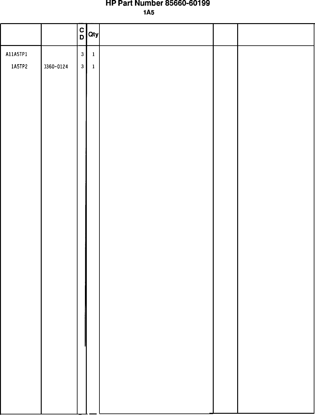
HP
Part
Number 85660-60199
Al
lA5
Sampler
Reference HP Part
Designation Number
AllA5TPl 1360-0124
Al lA5TP2 3360-0124
-
Description
CONNECTOR-SGL CONT PIN .04-IN-BSC-SZ RNC
CONNECTOR-SGL CONT PIN .04-IN-BSC-SZ RNC
*Indicates factory-selected value
Mfr
Code
Mfr Part
Number
97300
97300
8X60-60199 Parts List
Page 3 of 3
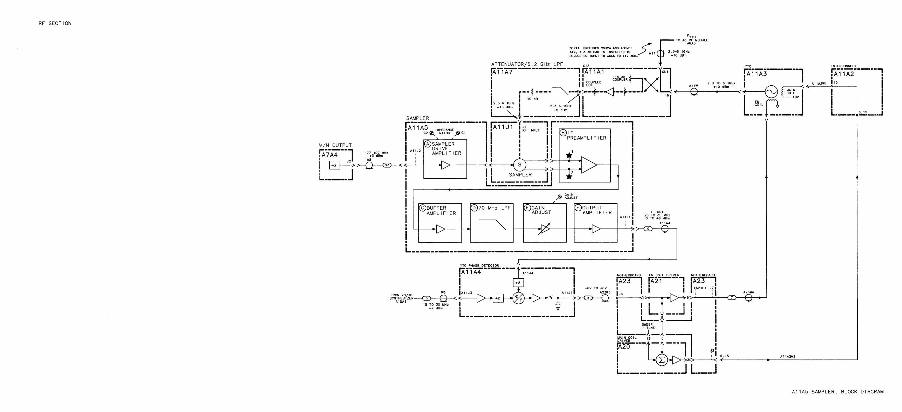
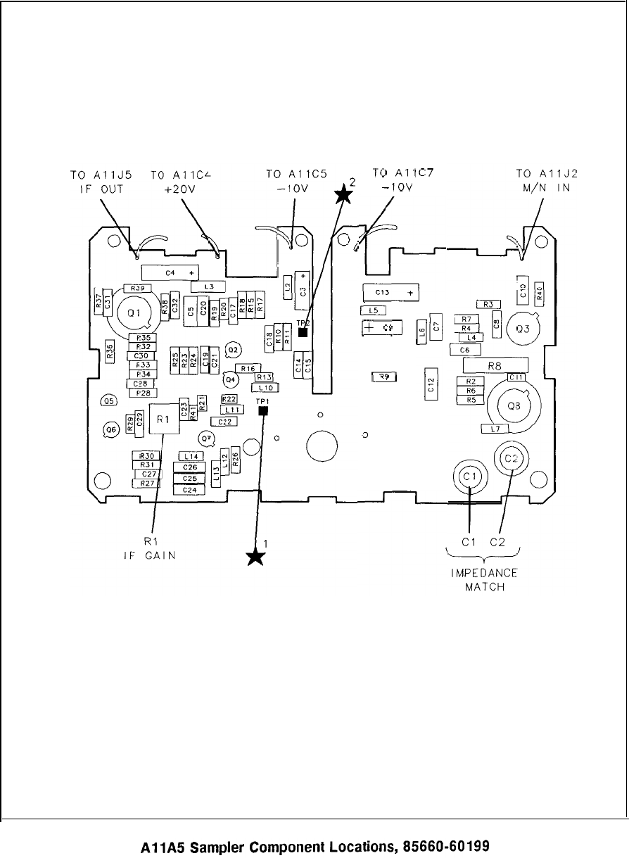
0
fL
0
u
0
0
1
g
p-c12
0
z
I$”
I
;:
+
$2
”
\1
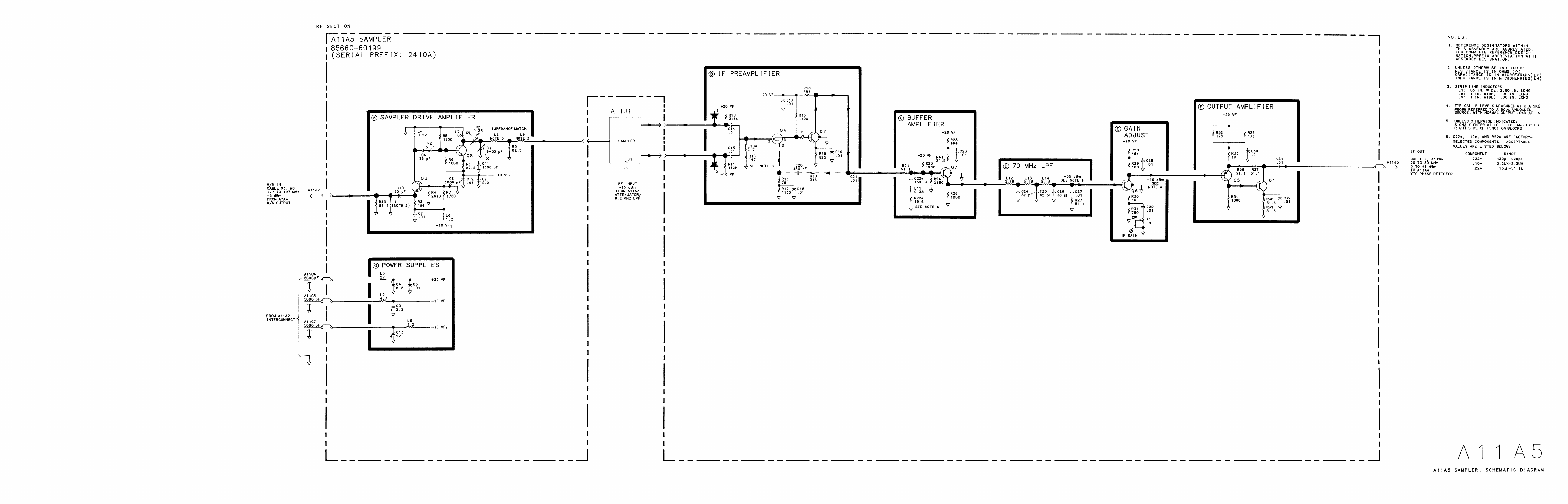
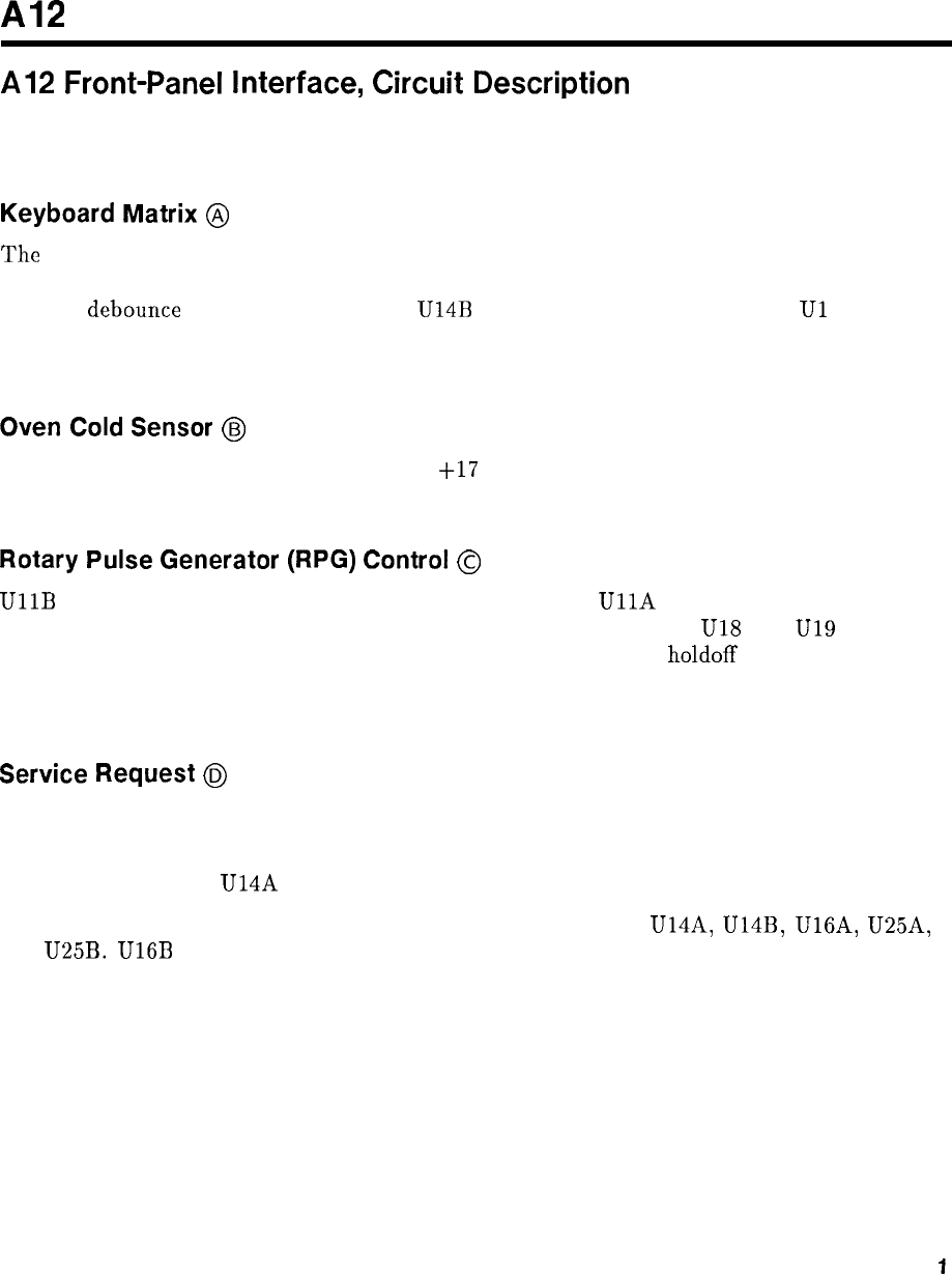
A12
Al2
Front-Panel
Interface,
Circuit
Description
Al2 Front-Panel Interface contains the miscellaneous digital functions for interfacing with the
Al5 Controller.
Keyboard Matrix
@
The
keyboard is organized as a matrix (rows and columns) of normally open SPST switches.
The rows are driven by U2 and U3. U6 functions as a key-down detector. Q2 and associated
circuitry
debounce
the key switches, and
U14B
latches the key-down condition.
Ul
and U4
gate the key columns onto the Data Bus. By selectively enabling the key rows, Al5 Controller
can poll the keyboard.
Oven
Cold
Sensor
@
When U22 senses the oven line is less than
+17
V, it tells the Controller that the oven is no
longer cold.
Rotary
Pulse
Generator
(RPG)
Control
@
UllB
enables the RPG, allowing the pulses to be counted.
UllA
detects the direction of
rotation of the RPG (rotation of the DATA knob on the front panel).
U18
and
U19
count the
number of RPG pulses since the last RPG RESET. U28 provides a
holdoff
of about 200 ms,
until service is requested, giving the instrument time to respond to the last request and to
continue to sweep before the next request occurs; that is, to give the operator visual feedback.
Service
Request
@
This circuit encodes the various requests for service for the Al5 Controller.
U24 encodes the service request. U27 is a change detector (HXRF or LRMT), and U25
latches these changes. U14A detects and latches the falling edge of HSWP.
U13 also provides the reset pulses for clearing the request latches U14A, U14B, U16A, U25A,
and U25B.
U16B
is cleared by any pending request (that is, it restarts Al5 Controller) by
U24.
Q3 pulls HSWP low whenever a request is pending.
U12 gates the encoded request and also places HXRF or LHBZ on the Data Bus.
Al2
1
M/N
Storage
@
Each flag can be enabled (interrogated), or all flags can be enabled.
U30
and U32 provide the
logic, and
U20
stores the state of the enabled flags.
Address Decoder
@
U7, UlO, and U33 decode the address lines, enabling the appropriate ICs to gate or store data
for the Data Bus.
Attenuator
Correction
Rom
@
U8 is a PROM (programmable read-only memory) that contains the attenuation errors
(calibration data) of the RF attenuator.
Control
Lines
@
U9
controls certain mainframe functions, such as turning off the internal reference oscillator
(IISTD).
Options
@
U21
gates the Options jumpers onto the Data Bus.
2 A12
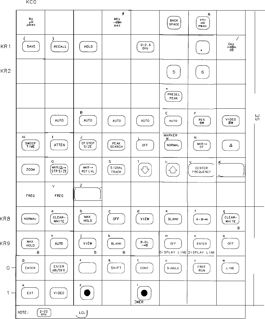
KC0
I
KC1 KC2 KC4 KC5 KC6 KC7
KC3
I
#
MHZ
0
-dml
see
SPACE
Hz
0
PV
gsec
KRO
KRl
KR2
KR3
KR4
KR5
KR6
KR7
KR8
KR9
)
0
RECALL
0
HOLD
D-2.5
0
GHZ
(
0
SAVE
0
0
/
GH2
0
+d&r
dB
0
1
0
2
0
3
0
40
7
0
a
0
9
AB
0
AUTO
0
AUTO
G
VIDEO
0
BW
I
0
ATTEN
a
MKR/A-
0
STPSIZE
C
0
AUTO
D
0
AUTO
MARKER
t:
H
SWEEP
0
TIME
J
CF
STEP
0
SIZE
K
PEAK
0
SEARCH
0
0
A
P
0
ZOOM
R
MKR-r
0
REF LYL
s
SIGNAL
0
TRACK
A
FREQUENCY
SPAN
L-
X
START
0
FREO
Y
STOP
0
FREO
2
7
REFERENCE
LEVEL
0
NORMAL
b
MAX
0
HOLD
c
d
0
OFF
0
VIEW
A-B TRACE A
9
CLEAR-
0
WHITE
TRACE B
(zGJ&
TRACE A
0
CLEAR-
0
WnTE
TRACE A
I
0
AZ?!?
TRACE A
h
MAX
0
HOLD
TRACE B
j
k
0
VIEW
0
BLANK
TRACE BTRACE B
I
B-OL
0
-8
t
0
CONT
3WER
RIGHT
0
0
OFF
THRESHOLD
w
0
LINE
P
0
ENTER
THRESHOLD
4
ENTER
0
dB/O
I”
r
LIN
0
5
0
SHIFT
KR
KR
x
0
EXT
Y
0
VIDEO
=@
LOWER LEFT
IOTE:
(2G;1:2)
AND
I
LcL
I
ARE NOT PART OF THE MATRIX
Figure 1. HP 8566 Keyboard Matrix
Al2 3
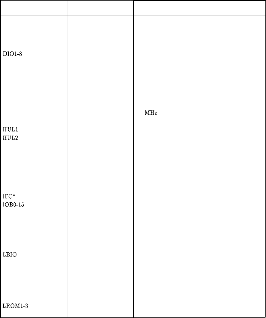
Table 1. Mnemonics Listing for RF Section
Mnemonic
ADRO-4
ATN*
BFC ON
DAV*
DIOl-8
EOI*
HLE2
HLEY
HOVH
HPON
HPUP
HSTD
HSWP
HULl
HUL2
HULH
HULM
EIULR
HULY
HXRF
HYGH
[FC*
[OBO-15
KCO-7
KRO-11
LADR
LANR
LAOS
LB10
LDAS
LIPS
LLED
LMNE
LRMT
LROMl-3
LRTL
Active
State
LOW
LOW
LOW
LOW
HIGH
HIGH
IIIGH
HIGH
HIGH
HIGH
HIGH
HIGH
HIGH
HIGH
HIGH
HIGH
HIGH
HIGH
AIGII
LOW
HIGII
LOW
LOW
LOW
LOW
LOW
LOW
LOW
LOW
LOW
LOW
LOW
Description
Address Bits 0 through 4
Attention True
Filter Capacitor IN
Data Valid
HP-IB Data Input/Output Bits
End or Identify
Phase Lock Loop 2 Lock Enable
YTO Lock Enable
Oven Cold
Power ON to IF-Display Section
Power Up
10 MIIz Standard ON
Sweeping
Phase Lock Loop 1 or 3 Unlocked
Phase Lock Loop 2 Unlocked
Heterodyne Oscillator Unlocked
M/N Unlocked
REF Unlocked
YTO Unlocked
External Reference
YTO Loop Gain High
Interface Clear
Instrument Bus Data Bits
Key Columns 0 through 7
Key Rows 0 through 11
Address LED ON
Analog Reset
Aux Out Strobe
RF Section I/O Strobe
DAC Strobe
Instrument Preset
LED Strobe
M/N Output Enable
Remove (High=Local)
Enable ROM 3-State Outputs
Local Button Pushed
4 A12
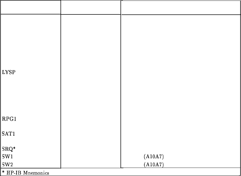
Table 1. Mnemonics Listing for RF Section (continued)
Mnemonic
LSAS
LSBY
LSRQ
LSTP
LSTS
LTGR
LTIO
LYSP
Ml-5
Nl-6
N DAC*
N RFD*
REN*
RPGl
RPG2
SAT1
SAT2
SRQ*
SW1
SW2
Active
State
LOW
HIGH
LOW
LOW
LOW
LOW
LOW
LOW
HIGH
HIGH
LOW
LOW
Description
Scan Attenuator Strobe
Standby
Service Request
Stop Al5 Controller
Scan Time Strobe
Tracking Generator Request
[F-Display Section I/O Strobe
YTO Span
M/N Loop-M Inputs
M/N Loop-N Inputs
Data Accepted
Ready for Data
Remote Enable
Rotary Pulse
Generator Lines
Scan Integer
Attenuator
Service Request
Switch 1 (AlOA7)
Switch 2 (AlOA7)
J
Al2 5
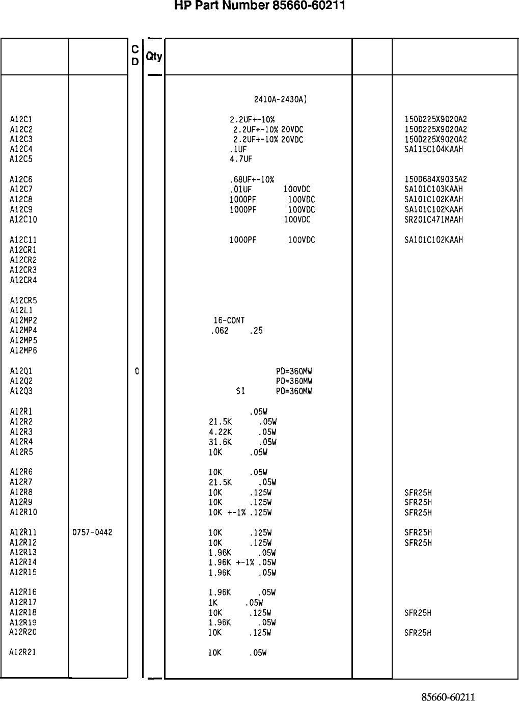
Reference
Designation
Al.2
85660-60211
3
A12Cl
AlZC2
A12C3
A12C4
A12C5
0180-0197
8
0180-0197
a
0180-0197
8
0160-4835
7
0180-2683
1
A12C6
AlZC7
A12C8
A12C9
A12ClO
0180-0373
2
0160-4832
4
0160-4574
1
0160-4574
1
0160-0571
0
A12Cll
A12CRl
A12CR2
A12CR3
A12CR4
0160-4574
1
1901-0040
1
1901-0040
1
1901-0040
1
1901-0518
8
A12CR5 1901-0518
8
A12Ll 08558-80011
6
A12MP2 1200-0812
9
A12MP4 1480-0073
6
A12MP5 4040-0749
4
A12MP6 4040-0750
7
A12Ql
A1202
A1293
1854-0404
0
1854-0404
0
1854-0404
0
A12Rl
A12R2
A12R3
A12R4
AlZR5
0698-7281
2
0698-7268
5
0698-7251
6
0698-7272
1
0698-7260
7
A12R6
A12R7
A12R8
A12R9
A12RlO
0698-7260
7
0698-7268
5
0757-0442
9
0757-0442
9
0757-0442
9
A12Rll
A12R12
A12R13
A12R14
AlZR15
0757-0442
9
0757-0442
9
0698-7243
6
0698-7243
6
0698-7243
6
A12R16 0698-7243
6
A12R17 0698-7236
7
A12R18 0757-0442
9
AlZR19 0698-7243
6
A12R20 0757-0442
9
AlZR21 0698-7260
7
HP Part
Number
-
3Y
-
1
1
1
1
1
1
1
1
1
1
1
1
1
1
1
1
1
1
1
2
1
1
1
1
1
1
1
1
1
1
1
1
1
1
1
1
1
1
1
1
1
1
1
1
1
1
-
HP
Part
Number 85660-60211
Al2 Front Panel Interface
Description Mfr Mfr Part
Code Number
BOARD ASSEMBLY, FRONT PANEL INTERFACE
(SERIAL PREFIXES:
2410~-2430~) 28480 85660-60211
CAPACITOR-FXD
2.2UF+-10%
20VDC TA
56289 150D225X9020A2
CAPACITOR-FXD
2.2UF+-10%
2OVDC
TA
56289 150D225X9020A2
CAPACITOR-FXO
2.2UF+-10%
EOVDC
TA
56289 1500225X9020A2
CAPACITOR-FXD
.lUF
+-lo% 50VDC CER
04222 SA115C104KAAH
CAPACITOR-FXD
4.7UF
35VDC TA
28480 0180-2683
CAPACITOR-FXD
.68UF+-10%
35VDC TA
56289 150D684X9035A2
CAPACITOR-FXD
.OlUF
+-lo%
1OOVDC
CER
04222 SAlOlC103KAAH
CAPACITOR-FXD
1OOOPF
+-lo%
1OOVDC
CER
04222 SAlOlC102KAAH
CAPACITOR-FXD
1OOOPF
+-lo%
1OOVDC
CER
04222 SAlOlC102KAAH
CAPACITOR-FXD 470PF +-20%
1OOVDC
CER
04222 SR201C471MAAH
CAPACITOR-FXD
1OOOPF
+-lo%
1OOVDC
CER
DIODE-SWITCHING 30V 50MA 2NS DO-35
DIODE-SWITCHING 30V 50MA 2NS DO-35
DIODE-SWITCHING 30V 50MA 2NS DO-35
DIODE-SCHOTTKY SM SIG
04222
71468
71468
71468
SAlOlC102KAAH
5082-2800
DIODE-SCHOTTKY SM SIG
FILTER COIL BLUE
SOCKET-IC
16-CONT
DIP DIP-SLDR
PIN-ROLL
.062
DIA
.25
IN LG
EXTR PC BD BRN
EXTR PC BD RED
28480
28480
72962
28480
28480
5082-2800
08558-80011
1200-0812
99-012-062-0250
4040-0749
4040-0750
TRANSISTOR NPN SI TO-18
PD=360MW
TRANSISTOR NPN SI TO-18
PD=360MW
TRANSISTOR NPN
SI
TO-18
PD=360MW
RESISTOR 75K +-2%
.05W
TF TC=O+-100
RESISTOR
21.5K
+-1%
.05W
TF TC=O+-100
RESISTOR
4.22K
+-1%
.05W
TF TC=O+-100
RESISTOR
31.6K
+-1%
.05W
TF TC=O+-100
RESISTOR
10K
+-1%
.05W
TF TC=O+-100
5023R
50635
50635
50635
50635
RESISTOR
10K
+-1%
.05W
TF TC=O+-100
RESISTOR
21.5K
+-1%
.05W
TF TC=O+-100
RESISTOR
10K
+-1%
.125W
TF TC=O+-100
RESISTOR
1OK
+-1%
.125W
TF TC=O+-100
RESISTOR
10K
+-1X
.125W
TF TC=O+-100
50635
50635
SFR25H
SFR25H
SFR25H
RESISTOR
1DK
+-1%
.125W
TF TC=O+-100
RESISTOR
10K
+-1%
.125W
TF TC=O+-100
RESISTOR
1.96K
+-1%
.05W
TF TC=O+-100
RESISTOR
1.96K
+-1X
.05W
TF TC=O+-100
RESISTOR
1.96K
+-1%
.05W
TF TC=O+-100
SFR25H
SFR25H
50633
50635
50635
RESISTOR
1.96K
+-1%
.05W
TF TC=O+-100
RESISTOR
1K
+-1%
.05W
TF TC=O+-100
RESISTOR
10K
+-1%
.125W
TF TC=O+-100
RESISTOR
1.96K
+-1%
.05W
TF TC=O+-100
RESISTOR
10K
+-1%
.125W
TF TC=O+-100
RESISTOR
10K
+-1%
.05W
TF TC=O+-100
04713
04713
04713
19701
19701
19701
19701
19701
19701
19701
19701
19701
19701
19701
19701
19701
19701
19701
19701
19701
19701
19701
19701
19701
50635
50635
SFR25H
50635
SFR25H
50635
*Indicates factory-selected value
85660-60211 Parts List
Page 1 of 3
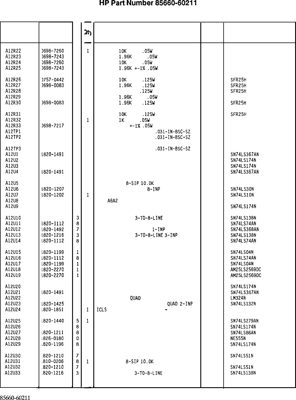
Reference
Designation
AlZR22
A12R23
A12R24
A12R25
A12R26
A12R27
A12R28
A12R29
A12R30
A12R31
A12R32
A12R33
AlZTPl
A12TP2
A12TP3
A12Ul
A12U2
A12U3
A12U4
A12U5
A12U6
A12U7
A12U8
A12U9
A12UlO
A12Ull
A12U12
A12U13
A12U14
A12U15
A12U16
A12U17
A12U18
A12U19
A12U20
A12U21
A12U22
A12U23
A12U24
A12U25
A12U26
A12U27
A12U28
A12U29
A12U30
A12U31
A12U32
A12U33
HP Part
Number
C
D
3698-7260
7
3698-7243
6
3698-7260
7
3698-7243
6
1757-0442
9
1698-0083
a
1698-3454
3
1698-7243
6
1698-0083
a
1757-0442
9
1698-7236
7
1698-7217
4
1251-5177
6
1251-5177
6
1251-5177
6
La20-1491
6
1820-1196
a
1820-1196
a
ia20-1491
6
1810-0206
ia20-1207
ia20-1202
a
2
7
1820-1196
a
1820-1216
ia20-1112
La20-1492
1820-1216
1820-1112
La20-1199
La20-1112
La20-1199
1820-2270
La20-2270
1820-1196 a
1820-1491
6
1826-0161
7
La20-1425
6
1820-1851
2
1820-1440
1820-1196
~820-1211
1826-0180
1820-1196
.820-1210
.810-0206
.a20-1210
.820-1216
85660-60211
Parts List
Page 2 of 3
-
3)
-
1
1
1
1
1
1
1
1
1
1
1
1
1
1
1
1
1
1
1
1
1
1
1
1
1
1
1
1
1
1
1
1
1
1
1
1
1
1
1
1
1
1
1
1
1
1
1
-
HP
Part
Number 85660-60211
Al2 Front Panel Interface
Description Mfr
Mfr Part
Code Number
RESISTOR
10K
+-1%
.05W
TF TC=O+-100
19701
50635
RESISTOR
1.96K
+-1%
.05W
TF TC=O+-100
19701
50635
RESISTOR
10K
+-1%
.05W
TF TC=O+-100
19701
50635
RESISTOR
1.96K
+-I%
.05W
TF TC=O+-100
19701
50635
RESISTOR
10K
+-1%
.125W
TF TC=O+-100
19701
SFR25H
RESISTOR
1.96K
1%
.125W
TF TC=O+-100
19701
SFR25H
RESISTOR 215K 1%
.125W
TF TC=O+-100
19701
SFR25H
RESISTOR
1.96K
+-1%
.05W
TF TC=O+-100
19701
50635
RESISTOR
1.96K
1%
.125W
TF TC=O+-100
19701
SFR25H
RESISTOR
10K
+-1%
.125W
TF TC=O+-100
RESISTOR
1K
+-1%
.05W
TF TC=O+-100
RESISTOR 162 +-I%
.05W
TF TC=O+-100
CONNECTOR-SGL CONT PIN
.031-IN-BSC-SZ
CONNECTOR-SGL CONT PIN
.031-IN-BSC-SZ
19701
19701
19701
SFR25H
50635
50635
460-2984-02-03-00
460-2984-02-03-00
CONNECTOR-SGL CONT PIN
.031-IN-BSC-SZ
IC BFR TTL LS NON-INV HEX l-INP
IC FF TTL LS O-TYPE POS-EDGE-TRIG COM CL
IC FF TTL LS O-TYPE POS-EDGE-TRIG COM CL
IC BFR TTL LS NON-INV HEX l-INP
01295
01295
01295
01295
460-2984-02-03-00
SN74LS367AN
SN74LS174N
SN74LS174N
SN74LS367AN
NETWORK-RES
&SIP
lO.OK
OHM X 7
IC GATE TTL LS NAND
8-INP
IC GATE TTL LS NAND TPL 3-INP
P/O
A6A2
NOT SEPARATELY REPLACEABLE
IC FF TTL LS O-TYPE POS-EDGE-TRIG COM CL
11236 750-81
01295 SN74LS30N
01295 SN74LSlON
01295 SN74LS174N
IC OCOR TTL LS
3-TO-a-LINE
3-INP
01295 SN74LS138N
IC FF TTL LS O-TYPE POS-EDGE-TRIG PRESET 01295 SN74LS74AN
IC BFR TTL LS INV HEX
l-INP 01295 SN74LS368AN
IC OCOR TTL LS
3-TO-a-LINE
3-INP 01295 SN74LS138N
IC FF TTL LS O-TYPE POS-EDGE-TRIG PRESET 01295 SN74LS74AN
IC INV TTL LS HEX l-INP 01295 SN74LS04N
IC FF TTL LS O-TYPE POS-EDGE-TRIG PRESET 01295 SN74LS74AN
IC INV TTL LS HEX l-INP 01295 SN74LS04N
IC CNTR TTL LS BIN UP/DOWN SYNCHRO POS-E 34335 AM25LS2569OC
IC CNTR TTL LS BIN UP/DOWN SYNCHRO POS-E 34335
AM25LS2569OC
IC FF TTL LS O-TYPE POS-EDGE-TRIG COM CL
IC BFR TTL LS NON-INV HEX l-INP
IC OP AMP GP
QUA0
14-DIP-P PKG
IC SCHMITT-TRIG TTL LS NAND
QUA0
2-INP
ICLS
148 P ENCODER a INPUT
-
3 OUTPUT
01295 SN74LS174N
01295 SN74LS367AN
27014 LM324N
01295 SN74LS132N
IC LCH TTL LS QUAD
IC FF TTL LS O-TYPE POS-EDGE-TRIG COM CL
IC GATE TTL LS EXCL-OR QUAD E-INP
IC TIMER TTL MONO/ASTBL
IC FF TTL LS O-TYPE POS-EDGE-TRIG COM CL
01295 SN74LS279AN
01295 SN74LS174N
01295 SN74LS86AN
la324 NE555N
01295 SN74LS174N
IC GATE TTL LS AND-OR-INV DUAL 2-INP 01295 SN74LS51N
NETWORK-RES
&SIP
lO.OK
OHM X 7
11236 750-81
IC GATE TTL LS AND-OR-INV DUAL E-INP 01295 SN74LS51N
IC OCOR TTL LS
3-TO-a-LINE
3-INP
01295 SN74LS138N
*Indicates factory-selected value
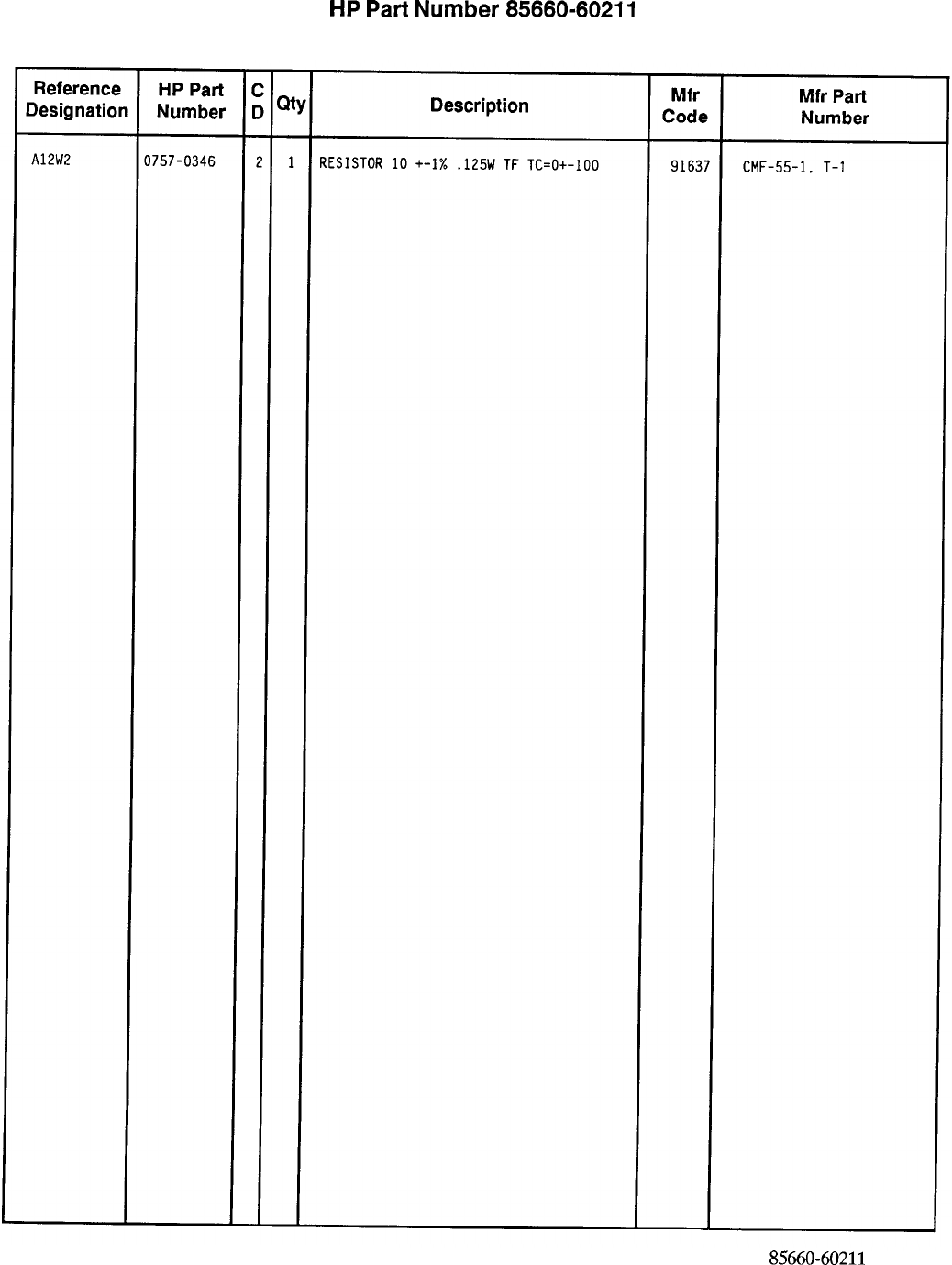
HP
Part
Number 85660-60211
Al2 Front Panel interface
*Indicates factoy-selected value
85660-60211 Parts List
Page 3 of 3
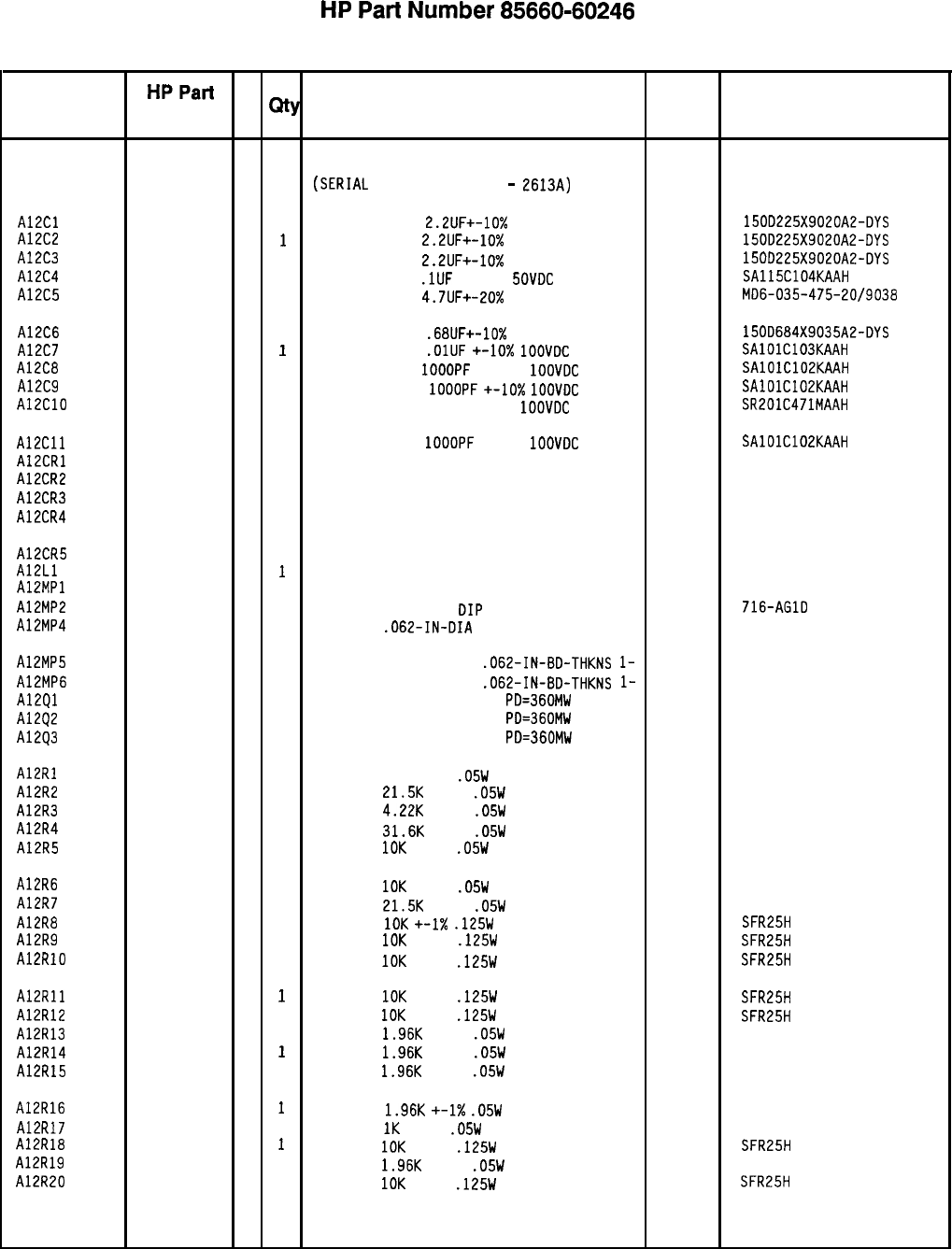
HP
Part
Number 85660-60246
Al2 Front Panel Interface
Reference
HPPart C
Designation
Number D
Qty Description Mfr
Mfr Part
Code Number
Al2 85660-60246
4
1
BOARD
ASSEMBLY, FRONT PANEL INTERFACE
28480 85660-60246
(SERIAL
PREFIXES: 2449A
-
2613~)
A12Cl 0180-0197
a
1
CAPACITOR-FXO 2.2UF+-10%
20VOC TA
56289 1500225X9020A2-OYS
A12C2
0180-0197 a
i
CAPACITOR-FXO
2.2UF+-10%
20VOC TA
56289 1500225X9020A2-OYS
A12C3 0180-0197
a
1
CAPACITOR-FXO
2.2UF+-10%
20VOC TA
56289 1500225X9020A2-OYS
A12C4 0160-4835
7
1
CAPACITOR-FXO
.lUF
+-lo%
SOVOC
CER
04222 SA115C104KAAH
A12C5 0180-2683
1 1
CAPACITOR-FXO
4.7UF+-20%
35VOC TA
04222 MO6-035-475-20/9038
A12C6 0180-0373
2
1
CAPACITOR-FXO .68UF+-10%
35VOC TA
56289 1500684X9035AZ-OYS
A12C7 0160-4832
4
1
CAPACITOR-FXO
.OlUF
+-lo%
1OOVOC
CER
04222 SAlOlC103KAAH
A12C8 0160-4574
1 1
CAPACITOR-FXO
IOOOPF
+-lo%
1OOVOC
CER
04222 SAlOlC102KAAH
A12C9 0160-4574
1 1
CAPACITOR-FXO
1OOOPF
+-10X
1OOVOC
CER
04222 SAlOlC102KAAH
A12ClO 0160-0571
0
1
CAPACITOR-FXO 470PF +-20%
1OOVOC
CER
04222 SR201C471MAAH
A12Cll 0160-4574
1 1
CAPACITOR-FXO 1OOOPF
+-lo%
1OOVOC
CER
04222 SAlOlC102KAAH
A12CRl 1901-0040
1 1
DIODE-SWITCHING 30V 50MA 2NS DO-35 71468
A12CR2 1901-0040
1 1
DIODE-SWITCHING 30V 50MA 2NS DO-35
71468
A12CR3 1901-0040
1
1
DIODE-SWITCHING 30V 50MA 2NS DO-35 71468
A12CR4 1901-0518 a
1
DIODE-SCHOTTKY SM SIG 5082-2800
A12CR5 1901-0518
a
1
DIODE-SCHOTTKY SM SIG 5082-2800
A12Ll 08558-80011
6
I
INDUCTOR BLUE COIL 28480 08558-80011
A12MPl NOT ASSIGNED
A12MP2 1200-0812
9
1
SOCKET-IC
16-CONT
DIP
DIP-SLOR
91506 716-AGlO
A12MP4 1480-0073
6
1
PIN-ROLL
.062-IN-OIA
.25-IN-LG BE-CU
72962 99-012-062-0250
A12MP5 4040-0749
4
1
EXTR-PC BO BRN POLYC
.062-IN-BO-THKNS
l-
28480 4040-0749
A12MP6 4040-0750
7
1
EXTR-PC
BO RED POLYC
.062-IN-BO-THKNS
l-
28480 4040-0750
A12Ql 1854-0404
0
1
TRANSISTOR NPN SI TO-18
PO=360MW 04713
A12Q2 1854-0404
0
1
TRANSISTOR NPN SI TO-18
PO=360MW 04713
A12Q3 1854-0404
0
1
TRANSISTOR NPN SI TO-18
PO=360MW 04713
A12Rl 0698-7281
2
1
RESISTOR 75K +-2%
.05W
TF TC=O+-100
19701
5023R
A12R2 0698-7268
5
1
RESISTOR
21.5K
+-1%
.05W
TF TC=O+-100
19701
50635
A12R3 0698-7251
6
1
RESISTOR
4.22K
+-1%
.05W
TF TC=O+-100
19701 50635
A12R4 0698-7272
1 1
RESISTOR
31.6K
+-1%
.05W
TF TC=O+-100
19701
50635
A12R5 0698-7260
7
1
RESISTOR
10K
+-1%
.05W
TF TC=O+-100
19701
50635
A12R6 0698-7260
7
1
RESISTOR
10K
+-1%
.05W
TF TC=O+-100
19701 50633
A12R7 0698-7268
5
1
RESISTOR
21.5K
+-1%
.05W
TF TC=O+-100
19701
50635
A12R8 0757-0442
9
1
RESISTOR 10K
+-I%
.125W
TF TC=O+-100
19701
SFR25H
A12R9 0757-0442
9
1
RESISTOR
IOK
+-1%
.125W
TF TC=O+-100
19701
SFR25H
A12RlO 0757-0442
9
1
RESISTOR
10K
+-1%
.125W
TF TC=O+-100
19701 SFR25H
A12Rll 0757-0442
9
1
RESISTOR
10K
+-1%
.125W
TF TC=O+-100
19701
SFR25H
A12R12 0757-0442
9
1
RESISTOR
10K
+-1%
.125W
TF TC=O+-100
19701
SFR25H
A12R13 0698-7243
6
1
RESISTOR
1.96K
+-1%
.05W
TF TC=O+-100
19701 50635
A12R14 0698-7243
6
1
RESISTOR
1.96K
+-1%
.05W
TF TC=O+-100
19701
50635
A12R15 0698-7243
6
1
RESISTOR
1.96K
+-1%
.05W
TF TC=O+-100
19701
50635
A12R16 0698-7243
6
1
RESISTOR
1.96K
+-1X
.05W
TF TC=O+-100
19701
50635
A12R17 0698-7236
7
1
RESISTOR
1K
+-1%
.05W
TF TC=O+-100
19701
50635
A12R18 0757-0442
9
1
RESISTOR
10K
+-1%
.125W
TF TC=O+-100
19701
SFR25H
A12R19 0698-7243
6
1
RESISTOR
1.96K
+-1%
.05W
TF TC=O+-100
19701
50635
A12R20 0757-0442
9
1
RESISTOR
10K
+-1%
.125W
TF TC=O+-100
19701
SFR25H
*Indicates factoy-selected value
85660-60246 Parts List
Page 1 of 3
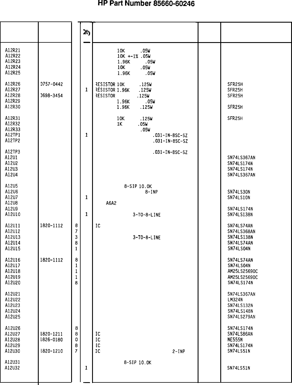
Reference
Designation
A12R21
A12R22
A12R23
A12R24
A12R25
A12R26
A12R27
A12R28
A12R29
A12R30
A12R31
A12R32
A12R33
AlETPl
A12TP2
A12TP3
A12Ul
A12U2
A12U3
A12U4
A12U5
A12U6
A12U7
A12U8
A12U9
A12UlO
A12Ull
A12U12
A12U13
A12U14
A12U15
A12U16
A12U17
A12U18
A12U19
A12U20
A12U21
A12U22
A12U23
A12U24
A12U25
A12U26
A12U27
A12U28
A12U29
A12U30
A12U31
A12U32
HP Part
Number
C
D
0698-7260
7
0698-7260
7
0698-7243
6
0698-7260
7
0698-7243
6
9757-0442
9
3698-0083
a
3698-3454
3
0698-7243
6
0698-0083
a
0757-0442
9
0698-7236
7
0698-7217
4
1251-5177
6
1251-5177
6
1251-5177
6
1820-1491
6
1820-1196
a
1820-1196
a
1820-1491
6
1810-0206
1820-1207
1820-1202
a
2
7
1820-1196
1820-1216
a
3
1820-1112
1820-1492
1820-1216
1820-1112
1820-1199
1820-ii12
1820-1199
1820-2270
1820-2270
1820-1196
1820-1491
6
1826-0161
7
1820-1425
6
1820-1851
2
1820-1440
5
1820-1196
1820-1211
la26-0180
1820-1196
La20-1210
1810-0206
1820-1210
a
7
8566040246 Parts List
Page 2 of 3
-
sty
-
1
1
1
1
1
1
1
1
1
1
1
1
1
1
1
1
1
1
1
1
1
1
1
1
1
1
1
1
1
1
1
1
1
1
1
1
1
1
1
1
1
1
1
1
1
1
1
-
HP
Part
Number 85660-60246
Al2 Front Panel Interface
Description Mfr Mfr Part
Code Number
RESISTOR
10K
+-1%
.05W
TF TC=O+-100
19701
50635
RESISTOR
10K
+-I%
.05W
TF TC=O+-100
19701
50635
RESISTOR
1.96K
+-1%
.05W
TF TC=O+-100
19701 50635
RESISTOR
10K
+-1%
.05W
TF TC=O+-100
19701
50635
RESISTOR
1.96K
+-1%
.05W
TF TC=O+-100
19701
50635
?ESISTOR
10K
+-1%
.125W
TF TC=O+-100
19701
SFR25H
iESISTOR
1.96K
1%
.125W
TF TC=O+-100
19701
SFR25H
7ESISTOR
215K 1%
.125W
TF TC=O+-100
19701
SFR25H
RESISTOR
1.96K
+-1%
.05W
TF TC=O+-100
19701
50635
RESISTOR
1.96K
1%
.125W
TF TC=O+-100
19701
SFR25H
RESISTOR
10K
+-1%
.125W
TF TC=O+-100
RESISTOR
1K
+-1%
.05W
TF TC=O+-100
RESISTOR 162 +-1%
.05W
TF TC=O+-100
CONNECTOR-SGL CONT PIN
.031-IN-BSC-SZ
CONNECTOR-SGL CONT PIN
.031-IN-BSC-SZ
19701
19701
19701
SFR25H
50635
50635
460-2984-02-03-00
460-2984-02-03-00
CONNECTOR-SGL CONT PIN
.O%l-IN-BSC-SZ
IC BFR TTL LS NON-INV HEX I-INP
IC FF TTL LS O-TYPE POS-EDGE-TRIG COM CL
IC FF TTL LS O-TYPE POS-EDGE-TRIG COM CL
IC BFR TTL LS NON-INV HEX l-INP
01295
01295
01295
01295
460-2984-02-03-00
SN74LS367AN
SN74LS174N
SN74LS174N
SN74LS367AN
NETWORK-RES
&SIP
lO.OK
OHM X 7
IC GATE TTL LS NAND
8-INP
IC GATE TTL LS NAND TPL 3-INP
P/O
A6A2
NOT SEPARATELY REPLACEABLE
IC FF TTL LS O-TYPE POS-EDGE-TRIG COM CL
IC OCOR TTL LS
3-TO-a-LINE
3-INP
11236 750-81
01295 SN74LS30N
01295 SN74LSlON
01295 SN74LS174N
01295 SN74LS138N
IC
FF TTL LS O-TYPE POS-EDGE-TRIG PRESET
01295 SN74LS74AN
IC BFR TTL LS INV HEX I-INP 01295 SN74LS368AN
IC OCOR TTL LS
3-TO-a-LINE
3-INP
01295 SN74LS138N
IC FF TTL LS O-TYPE POS-EDGE-TRIG PRESET 01295 SN74LS74AN
IC INV TTL LS HEX l-INP 01295 SN74LS04N
IC FF TTL LS O-TYPE POS-EDGE-TRIG PRESET 01295 SN74LS74AN
IC INV TTL LS HEX l-INP 01295 SN74LS04N
IC CNTR TTL LS BIN UP/DOWN SYNCHRO POS-E 34335
AM25LS2569OC
IC CNTR TTL LS BIN UP/DOWN SYNCHRO POS-E 34335
AM25LS2569OC
IC FF TTL LS O-TYPE POS-EDGE-TRIG COM CL 01295 SN74LS174N
IC BFR TTL LS NON-INV HEX I-INP 01295 SN74LS367AN
IC OP AMP GP QUAD 14-DIP-P PKG 27014 LM324N
IC SCHMITT-TRIG TTL LS NAND QUAD 2-INP 01295 SN74LS132N
IC ENCOR TTL LS 01295 SN74LS148N
IC LCH TTL LS QUAD 01295 SN74LS279AN
IC FF TTL LS O-TYPE POS-EDGE-TRIG COM CL 01295 SN74LS174N
IC
GATE TTL LS EXCL-OR QUAD 2-INP
01295 SN74LS86AN
IC
TIMER TTL MONO/ASTBL
la324 NE555N
[C
FF TTL LS O-TYPE POS-EDGE-TRIG COM CL
01295 SN74LS174N
IC
GATE TTL LS AND-OR-INV DUAL
L-INP 01295 SN74LS51N
NETWORK-RES
a-SIP
lO.OK
OHM X 7
11236 750-81
IC GATE TTL LS AND-OR-INV DUAL 2-INP 01295 SN74LS51N
*Indicates factory-selected value
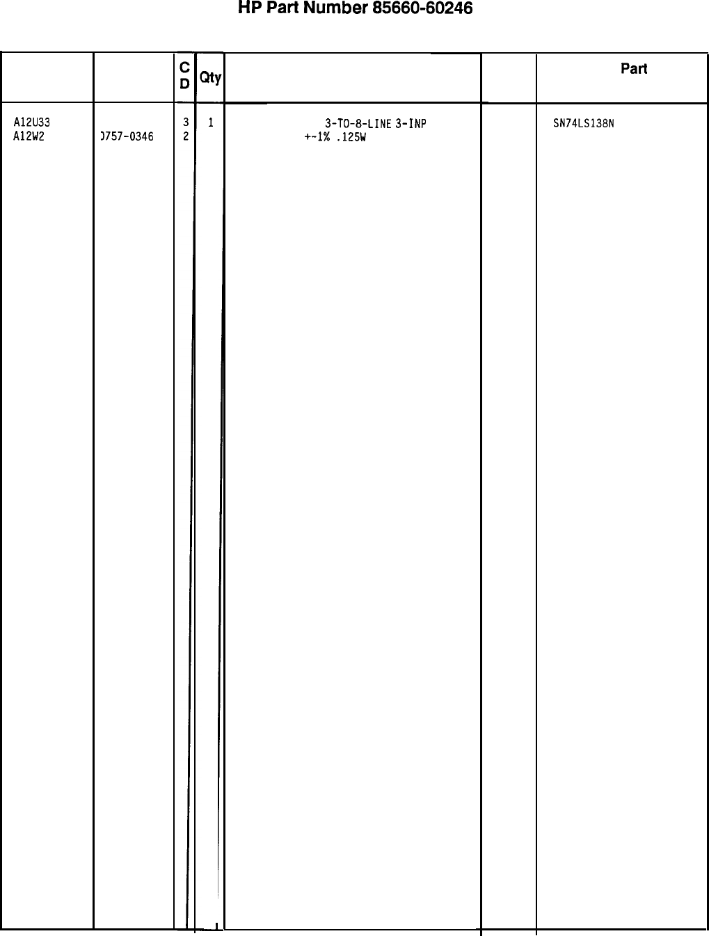
Reference
Designation
HP Part
Number
A12U33 1820-1216
A12W2 3757-0346
-
m
-
1
1
HP
Part
Number 85660-60246
Al2 Front Panel Interface
Description
IC OCOR TTL LS
3-TO-a-LINE
3-INP 01295
RESISTOR 10 +-I%
.125W
TF TC=O+-100
91637
*Indicates factory-selected value
Mfr
Code Mfr
Part
Number
SN74LS138N
CMF-55-1, T-l
85660-60246 Parts List
Page 3 of 3
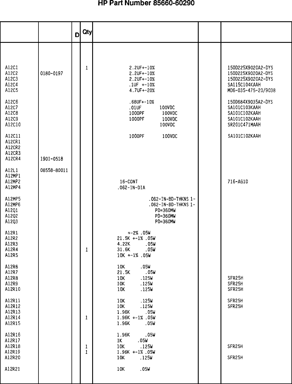
HP
Part
Number 85660-60290
Al2 Front Panel Interface
Reference
HP Part C
Mfr Mfr Part
Designation
Number
D
Qty Description Code Number
Al2
85660-60290 4 1
BOARD ASSEMBLY, FRONT PANEL INTERFACE 28480 85660-60290
(SERIAL PREFIX: 2618A)
A12Cl
0180-0197 a
I
CAPACITOR-FXO
2.2UF+-10%
20VOC TA
56289 1500225X9020A2-OYS
A12C2 0180-0197
a 1
CAPACITOR-FXO
2.2UF+-10%
20VOC TA
56289 1500225X9020A2-OYS
A12C3
0180-0197 a 1
CAPACITOR-FXO
2.2UF+-10%
20VOC TA
56289 1500225X9020A2-OYS
A12C4
0160-4835 7 1
CAPACITOR-FXO
.lUF
+-lo% 50VOC CER
04222 SA115C104KAAH
A12C5
0180-2683 1 1
CAPACITOR-FXO
4.7UF+-20%
35VOC TA
04222
MO6-035-475-20/9038
A12C6
0180-0373 2 1
CAPACITOR-FXO
.68UF+-10x
35VOC TA
56289 1500684X9035A2-OYS
A12C7
0160-4832 4 1
CAPACITOR-FXO
.OlUF
+-lo%
1OOVOC
CER
04222 SAlOlC103KAAH
A12C8
0160-4574 1 1
CAPACITOR-FXO
1OOOPF
+-lo%
IOOVOC
CER
04222 SAlOlC102KAAH
A12C9
0160-4574 1 1
CAPACITOR-FXO
1OOOPF
+-lo%
1OOVOC
CER
04222 SAlOlC102KAAH
A12ClO
0160-0571 0 1
CAPACITOR-FXO 470PF +-20%
IOOVOC
CER
04222 SR201C471MAAH
A12Cll
0160-4574 1 1
CAPACITOR-FXO
IOOOPF
+-lo%
1OOVOC
CER
04222 SAlOlC102KAAH
AlECRl
1901-0040 1 1
DIODE-SWITCHING 30V 50MA 2NS DO-35
71468
A12CR2
1901-0040 1 1
DIODE-SWITCHING 30V 50MA 2NS DO-35
71468
A12CR3
1901-0040 1 1
DIODE-SWITCHING 30V 50MA 2NS DO-35
71468
A12CR4 1901-0518
a 1
DIODE-SCHOTTKY SM SIG 5082-2800
A12Ll 08558-80011
6 1
INDUCTOR BLUE COIL 28480 08558-80011
AlZMPl NOT ASSIGNED
A12MP2
1200-0812 9 1
SOCKET-IC
16-CONT
DIP DIP-SLOR
91506 716-AGlO
A12MP4
1480-0073 6 1
PIN-ROLL
.062-IN-OIA
.25-IN-LG BE-CU
72962 99-012-062-0250
A12MP5
4040-0749 4 1
EXTR-PC BO BRN POLYC
.062-IN-BO-THKNS
l-
28480 4040-0749
A12MP6
4040-0750 7 1
EXTR-PC BO RED POLYC
.062-IN-BO-THKNS
l-
28480 4040-0750
A12Ql
1854-0404 0 1
TRANSISTOR NPN SI TO-18
PO=360MW 04713
A12Q2
1854-0404 0 1
TRANSISTOR NPN SI TO-18
PO=360MW 04713
A1293
1854-0404 0 1
TRANSISTOR NPN SI TO-18
PO=360MW 04713
A12Rl
0698-7281 2 1
RESISTOR 75K
+-2X
.05W
TF TC=O+-100
19701
5023R
A12R2
0698-7268 5 1
RESISTOR
21.5K
+-1X
.05W
TF TC=O+-100
19701
50635
A12R3
0698-7251 6 1
RESISTOR
4.22K
+-1%
.05W
TF TC=O+-100
19701 50635
A12R4
0698-7272 1
1
RESISTOR
31.6K
+-1%
.05W
TF TC=O+-100
19701
50635
A12R5
0698-7260 7 1
RESISTOR
10K
+-1X
.05W
TF TC=O+-100
19701
50635
A12R6
0698-7260 7 1
RESISTOR
10K
+-1%
.05W
TF TC=O+-100
19701 50635
A12R7
0698-7268 5 1
RESISTOR
21.5K
+-1%
.05W
TF TC=O+-100
19701
50635
A12R8
0757-0442 9 1
RESISTOR
10K
+-1%
.125W
TF TC=O+-100
19701
SFR25H
A12R9
0757-0442 9 1
RESISTOR
IOK
+-1%
.125W
TF TC=O+-100
19701
SFR25H
A12RlO
0757-0442 9 1
RESISTOR
10K
+-1%
.125W
TF TC=O+-100
19701
SFR25H
A12Rll
0757-0442 9 1
RESISTOR
10K
+-1%
.125W
TF TC=O+-100
19701
SFR25H
A12R12
0757-0442 9 1
RESISTOR
10K
+-1%
.125W
TF TC=O+-100
19701
SFR25H
A12R13
0698-7243 6 1
RESISTOR
1.96K
+-1%
.05W
TF TC=O+-100
19701
50635
A12R14
0698-7243 6
1
RESISTOR
1.96K
+-1X
.05W
TF TC=O+-100
19701
50635
A12R15
0698-7243 6 1
RESISTOR
1.96K
+-1%
.05W
TF TC=O+-100
19701
50635
A12R16
0698-7243 6 1
RESISTOR
1.96K
+-1%
.05W
TF TC=O+-100
19701
50635
A12R17
0698-7236 7 1
RESISTOR
1K
+-1%
.05W
TF TC=O+-100
19701
50635
A12R18
0757-0442 9
1
RESISTOR
10K
+-1%
.125W
TF TC=O+-100
19701
SFR25H
A12R19
0698-7243 6
1
RESISTOR
1.96K
+-1X
.05W
TF TC=O+-100
19701
50635
A12R20
0757-0442 9 1
RESISTOR
10K
+-1%
.125W
TF TC=O+-100
19701
SFR25H
A12R21
0698-7260 7 1
RESISTOR
IOK
+-1%
.05W
TF TC=O+-100
19701
50635
*Indicates factory-selected value
85660-60290 Parts List
Page 1 of 3
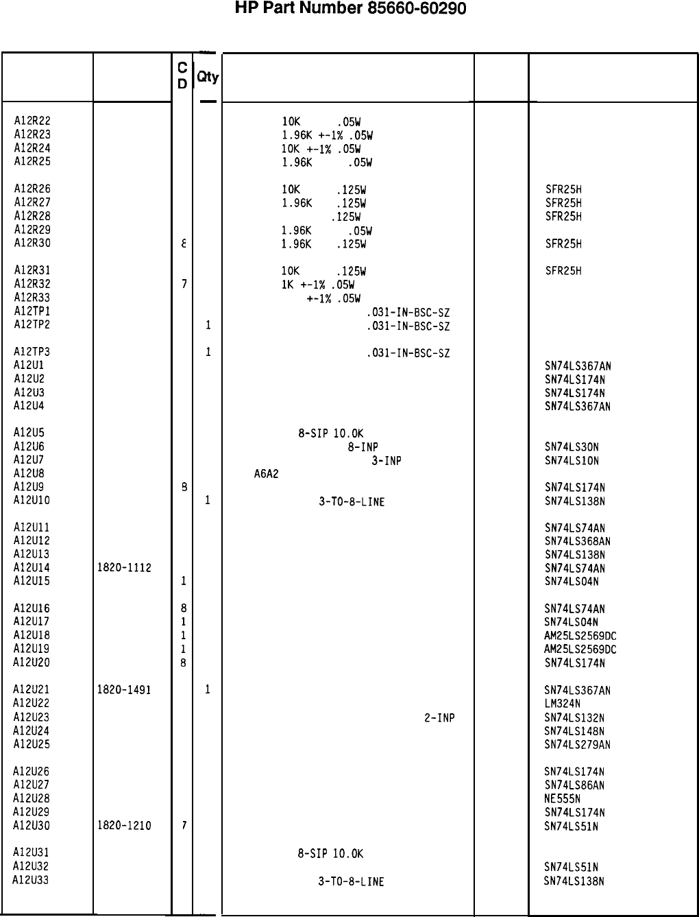
Reference
Designation
A12R22 0698-7260
7
A12R23 0698-7243
6
A12R24 0698-7260
7
A12R25 0698-7243
6
A12R26
A12R27
A12R28
A12R29
A12R30
0757-0442
9
0698-0083
a
0698-3454
3
0698-7243
6
0698-0083
E
A12R31
A12R32
A12R33
AlETPl
A12TP2
0757-0442
9
0698-7236
7
0698-7217
4
1251-5177
6
1251-5177
6
A12TP3
A12Ul
A12U2
A12U3
A12U4
1251-5177
6
1820-1491
6
1820-1196
a
1820-1196
a
1820-1491
6
A12U5
A12U6
A12U7
A12U8
A12U9
A12UlO
1810-0206
8
1820-1207
2
1820-1202
7
1820-1196
1820-1216
3
3
A12Ull
A12U12
A12U13
A12U14
A12U15
1820-1112
3
1820-1492
7
1820-1216
3
1820-iii2
a
1820-1199
1
A12U16
A12U17
A12U18
A12U19
A12U20
1820-1112
1820-1199
1820-2270
1820-2270
1820-1196
A12U21
A12U22
A12U23
A12U24
A12U25
1820-1491
6
1826-0161
7
1820-1425
6
1820-1851
2
1820-1440
5
A12U26
A12U27
A12U28
A12U29
A12U30
1820-1196
3
1820-1211
3
1826-0180
3
1820-1196
3
ia20-1210
7
A12U31
A12U32
A12U33
1810-0206
1820-1210
1820-1216
a
7
3
HP Part
Number
85660-60290 Parts List
Page 2 of 3
-
m
-
1
1
1
1
1
1
1
1
1
1
1
1
1
1
1
1
1
1
1
1
1
1
1
1
1
1
1
1
1
1
1
1
1
1
1
1
1
1
1
1
1
1
1
1
1
1
1
-
HP
Part
Number 85660-60290
Al2 Front Panel Interface
Description
RESISTOR
10K
+-1%
.05W
TF TC=O+-100
RESISTOR
1.96K
+-1X
.05W
TF TC=O+-100
RESISTOR
10K
+-I%
.05W
TF TC=O+-100
RESISTOR
1.96K
+-1%
.05W
TF TC=O+-100
Mfr Mfr Part
Code Number
19701
50635
19701
50635
19701
50635
19701
50635
RESISTOR
IOK
+-1%
.125W
TF TC=O+-100
19701
SFR25H
RESISTOR
1.96K
1%
.125W
TF TC=O+-100
19701
SFR25H
RESISTOR 215K 1%
.125W
TF TC=O+-100
19701 SFR25H
RESISTOR
1.96K
+-1%
.05W
TF TC=O+-100
19701
50635
RESISTOR
1.96K
1%
.125W
TF TC=O+-100
19701
SFR25H
RESISTOR
10K
+-1%
.125W
TF TC=O+-100
RESISTOR
1K
+-1X
.05W
TF TC=O+-100
RESISTOR 162 +-1X
.05W
TF TC=O+-100
CONNECTOR-SGL CONT PIN
.031-IN-BSC-SZ
CONNECTOR-SGL CONT PIN
.031-IN-BSC-SZ
19701
19701
19701
SFR25H
50635
50635
460-2984-02-03-00
460-2984-02-03-00
CONNECTOR-SGL CONT PIN
.031-IN-BSC-SZ
IC BFR TTL LS NON-INV HEX l-INP
IC FF TTL LS O-TYPE POS-EDGE-TRIG COM CL
IC FF TTL LS O-TYPE POS-EDGE-TRIG COM CL
IC BFR TTL LS NON-INV HEX l-INP
01295
01295
01295
01295
460-2984-02-03-00
SN74LS367AN
SN74LS174N
SN74LS174N
SN74LS367AN
NETWORK-RES
&SIP
lO.OK
OHM X 7
IC GATE TTL LS NAND
8-INP
IC GATE TTL LS NAND TPL
3-INP
P/O
A6A2
NOT SEPARATELY REPLACEABLE
IC FF TTL LS O-TYPE POS-EDGE-TRIG COM CL
IC OCOR TTL LS
3-TO-a-LINE
3-INP
11236 750-81
01295 SN74LS30N
01295 SN74LSlON
01295 SN74LS174N
01295 SN74LS138N
IC FF TTL LS O-TYPE POS-EDGE-TRIG PRESET 01295 SN74LS74AN
IC BFR TTL LS INV HEX l-INP 01295 SN74LS368AN
IC OCOR TTL LS 3-TO-&LINE 3-INP
01295 SN74LS138N
IC FF TTL LS O-TYPE POS-EDGE-TRIG PRESET 01295 SN74LS74AN
IC INV TTL LS HEX l-INP 01295 SN74LS04N
IC FF TTL LS O-TYPE POS-EDGE-TRIG PRESET 01295 SN74LS74AN
IC INV TTL LS HEX l-INP 01295 SN74LS04N
IC CNTR TTL LS BIN UP/DOWN SYNCHRO POS-E
34335
AM25LS2569OC
IC CNTR TTL LS BIN UP/DOWN SYNCHRO POS-E
34335
AM25LS2569OC
IC FF TTL LS O-TYPE POS-EDGE-TRIG COM CL 01295 SN74LS174N
IC BFR TTL LS NON-INV HEX l-INP 01295 SN74LS367AN
IC OP AMP GP QUAD 14-DIP-P PKG 27014 LM324N
IC SCHMITT-TRIG TTL LS NAND QUAD
L-INP 01295 SN74LS132N
IC ENCOR TTL LS 01295 SN74LS148N
IC LCH TTL LS QUAD 01295 SN74LS279AN
IC FF TTL LS O-TYPE POS-EDGE-TRIG COM CL 01295 SN74LS174N
IC GATE TTL LS EXCL-OR QUAD 2-INP 01295 SN74LS86AN
IC TIMER TTL MONO/ASTBL la324 NE555N
IC FF TTL LS O-TYPE POS-EDGE-TRIG COM CL 01295 SN74LS174N
IC GATE TTL LS AND-OR-INV DUAL 2-INP 01295 SN74LS51N
NETWORK-RES
&SIP
10.OK
OHM X 7
11236 750-81
IC GATE TTL LS AND-OR-INV DUAL 2-INP 01295 SN74LS51N
IC OCOR TTL LS
3-TO-a-LINE
3-INP
01295 SN74LS138N
*Indicates factoy-selected value
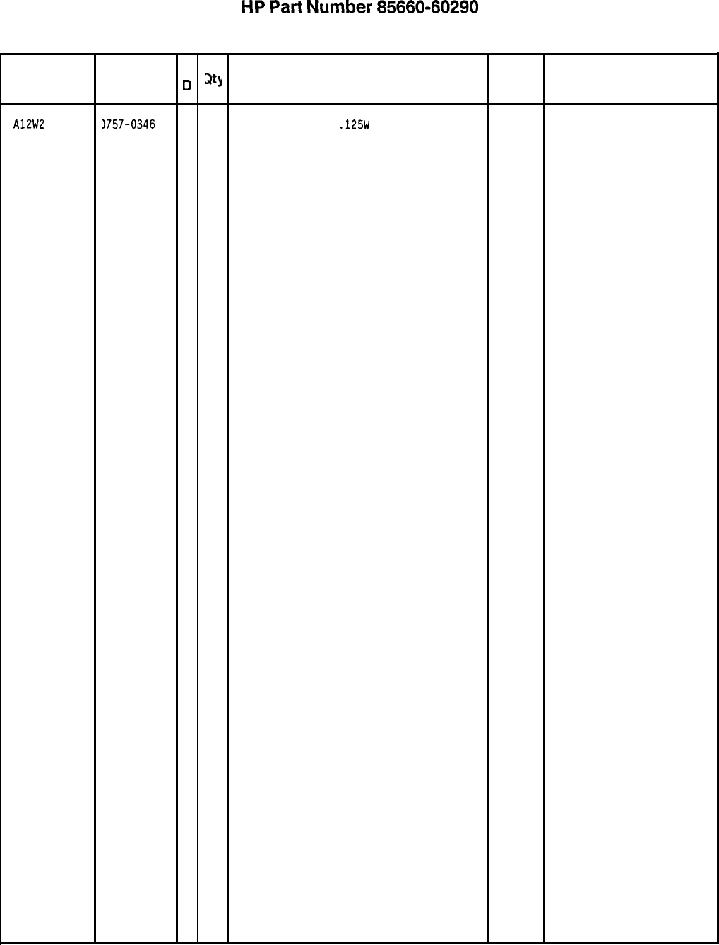
Reference
Designation
A12W2
HP Part
Number
3757-0346
C
D
2
1
HP
Part
Number 85660-60290
Al2 Front Panel Interface
Description
RESISTOR 10 +-1%
.125W
TF TC=O+-100
Mfr
Code
91637
Mfr Part
Number
CMF-55-l. T-l
*Indicates factory-selected value
85660-60290 Parts List
Page 3 of 3
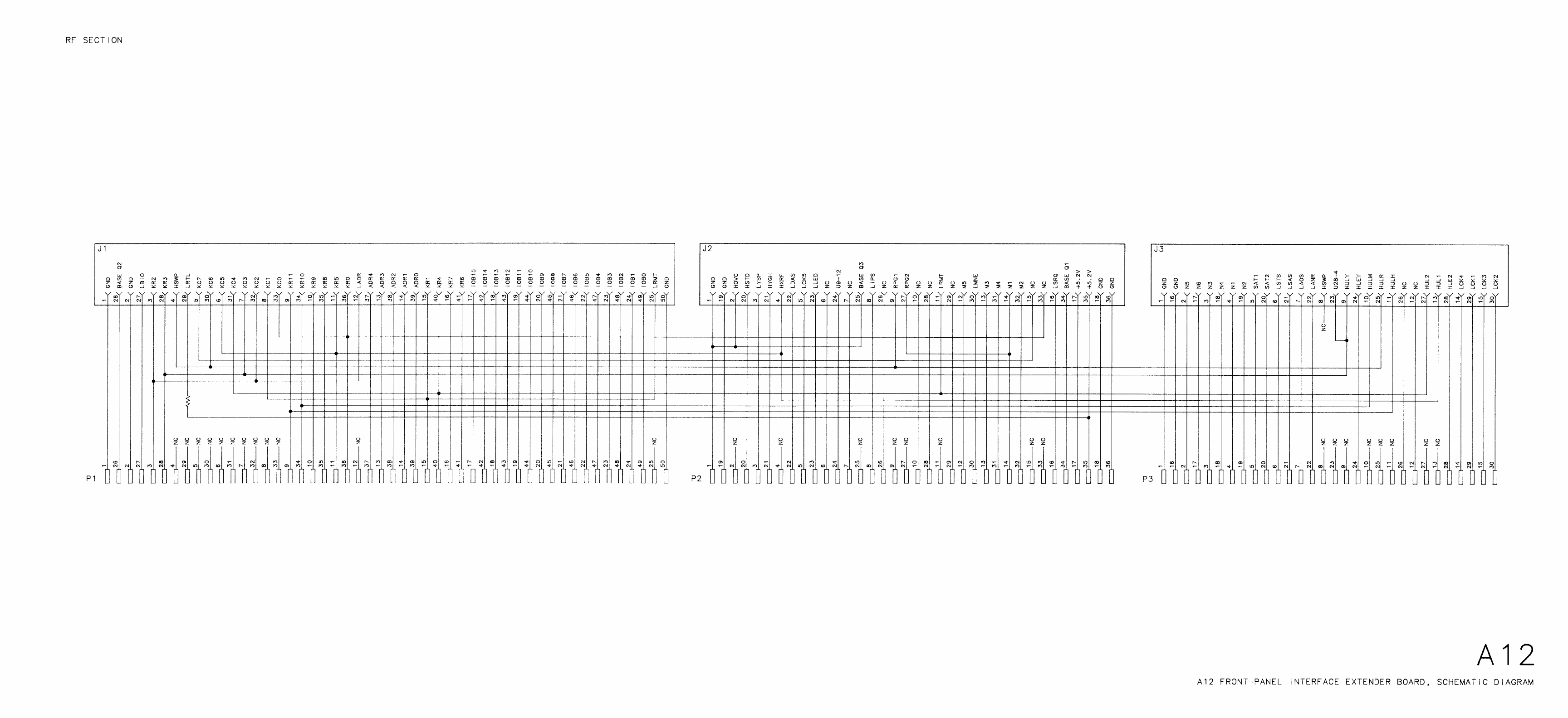
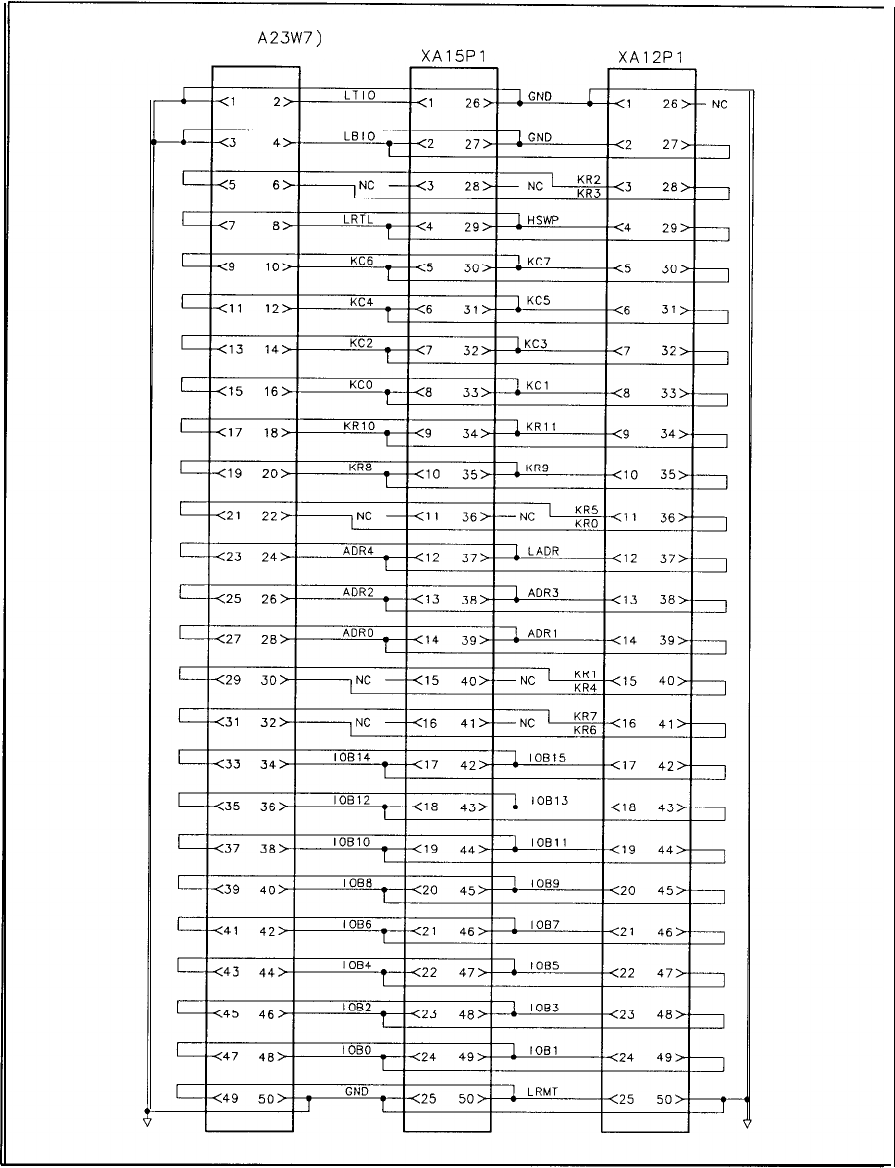
(P/O
A23W7)
J8
XA15Pl XA12Pl
A23 Motherboard Instrument Bus, Interconnect Diagram
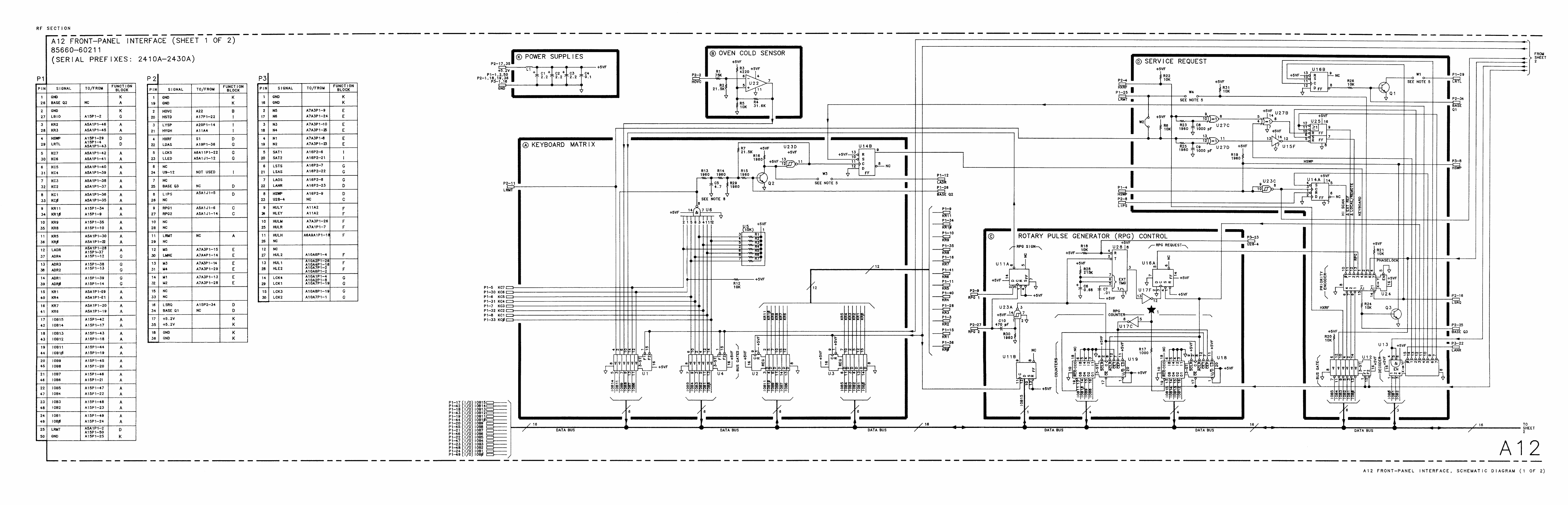
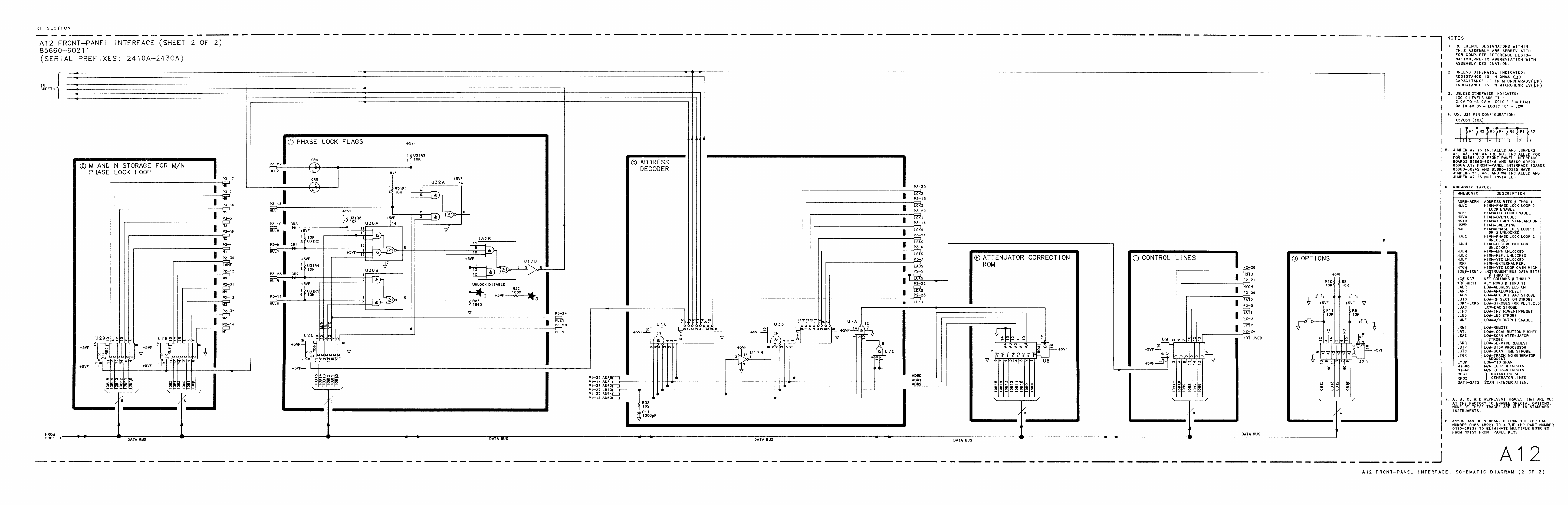
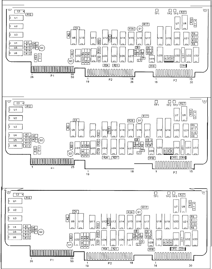
85660-60290
85660-60246
0
w
TPI
TR
%I
nion
[pz-
ml
F
000000000000000000,
m
Ml
pq
t25
26
PI
50
~nnnnnnnnnnnnnnn
1
P2
18
1
15
19
36
P3
16 30
85660-60211
0
TPI
TEA,,,,,
k
II
Eel
m
164
--
IA2663
rlri
I
tIzEL rxzq
1~211
(R18
pRT
pi71
nononnnnnnnnonnnnnJ
1
nnnnnnnnnnnnnnn
I
18
P2
1
15
19
36
16
P3
30
Al2 Front-Panel Interface Component Locations, 85660-60211, 85660-60246, 85660-60290
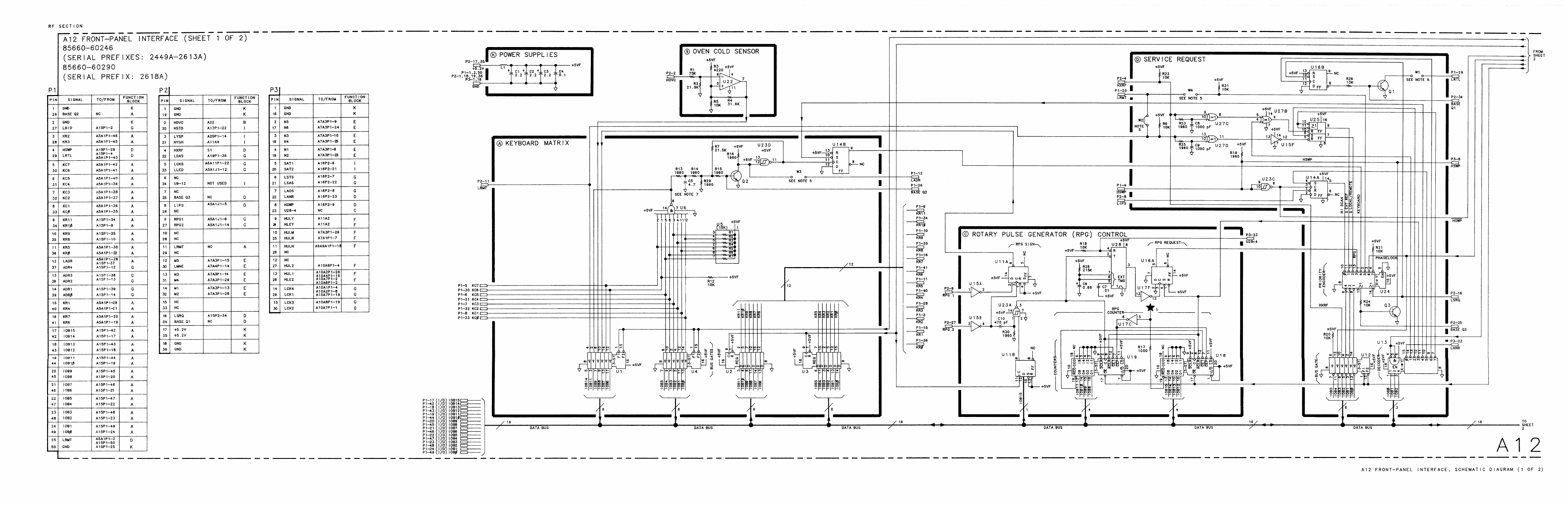
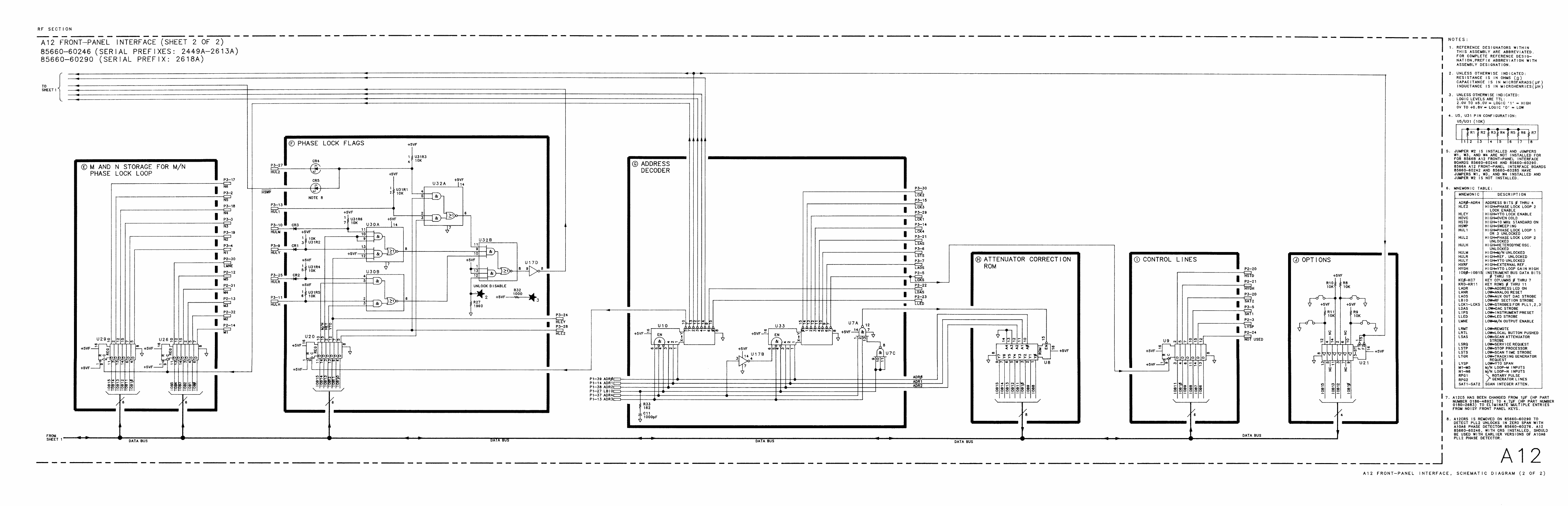
Al5
Al5
Controller,
Circuit
Description
The Al5 controller performs the main control functions of the spectrum analyzer. The
board includes a 16-bit microprocessor (the instrument’s main processor), read-only memory
(ROMs), random-access memory (RAMS), and HP-IB circuitry.
The schematic shows how the main processor, memory, HP-IB, and other circuits on the A15
Controller are interconnected via the microprocessor’s 23-bit address bus and the 16-bit data
bus. To control signal flow on these buses, various signals must be derived from the address
bus signals and the microprocessor’s remaining output signals. These control signals are
generated by two programmable-array-logic integrated circuits (PALS) and other discrete
logic (R/W DECODE, ADDRESS DECODER AND DTACK, ADDRESS DECODE, and
LTIO/LBIO blocks). The signals are used by the microprocessor to control data flow and
address decoding on the Al5 Controller and to control signal flow over the Instrument Bus.
The 16-bit, 8 MHz MC68000 microprocessor receives input through the front panel keyboard
or from HP-IB, performs the necessary decoding and calculations, and outputs the proper
control signals to execute a specific spectrum analyzer operation. Typical main processor
tasks include phase-locking the YTO, selecting the correct sweep time and frequency span,
setting the IF-Display Section resolution bandwidth and sensitivity, and displaying the current
control settings on the CRT through the A3 Digital Storage Section. Instructions that tell the
microprocessor how to accomplish these tasks, the firmware, are stored in ROMs located on
the Al5 Controller. In addition, custom commands and programming can be downloaded into
RAM, permitting specialized operation without requiring a dedicated controller.
The microprocessor performs a brief power-on pretest (POP) at instrument turn-on, verifying
operation of critical circuits and lighting front-panel check LEDs I and II. In addition, LEDs
located on the top edge of the Al5 Controller provide information to help identify particular
faulty circuit components in case a failure occurs.
The instrument’s main memory consists of read-only memory (ROM) and random-access
memory (RAM)
h’
h
w
rc
are located on the Al5 controller. Each 16-bit word in memory is
composed of two 8-bit bytes. The ROM, used to provide permanent storage of the firmware,
is composed of four 32 Kbyte erasable programmable read-only memory (EPROMS). This
provides a total of 64 K-words of ROM. The RAM, used for erasable storage of custom
instructions and programs, is composed of four 8 Kbyte static CMOS memory-integrated
circuits for a total of 16 K-words of RAM. A lithium battery located on the Al5 Controller
provides battery backup power to the CMOS RAM to preserve the contents of memory
when power is removed from the instrument. The typical in-circuit life expectancy of the
non-rechargeable battery is at least three years.
The HP-IB allows the spectrum analyzer to communicate with external devices. It is
implemented using four ICs: a data latch, an HP-IB processor, and two bus transceivers.
The Al5 Controller clock circuit generates an
~-MHZ
clock signal for the 16-bit microprocessor
and a synchronous
~-MHZ
clock signal for the HP-IB processor. The appropriate clock
A15 1
frequency is derived from division of the output signal of a 14.7456 MHz hybrid crystal clock
oscillator.
The Al5 Controller firmware includes extensive diagnostics which are executed whenever the
instrument is powered up or the INSTRUMENT PRESET key is pressed.
The microprocessor executes a self-test routine and indicates the results via LEDs. A memory
failure, microprocessor failure, or Instrument Bus failure can usually be pinpointed to the
failed component using these indicators.
HP-IB
Address
Switch
The position of the address switch on the Al5 Controller
(A15SWl)
determines which HP-IB
address is used by the analyzer when the line power is turned on.
The address switch is preset to 31 (switches Al through A5 pressed up) at the factory. If the
CMOS backup battery has not been discharged, the last HP-IB address used by the analyzer
is active at instrument power-up. If the backup battery is discharged, the analyzer will default
to an HP-IB address of 18 at instrument power-up.
If the address switch is set to any address from 0 to 30, this address will be used as the
read/write address by the analyzer with power on.
Switch A6 is also set in the “up” position (logic 1) at the factory. A6 in this position does a
checksum verification of the two pairs of ROMs on the Al5 Controller as part of the self-test
routine with power.
HP-IB
Signal
Ground
(A25)
The A25 HP-IB Signal Ground assembly provides chassis ground for the HP-IB shield. Pins
12 and 18 through 24 of the HP-IB connector J2 are immediately grounded to the chassis
upon entering the instrument.
Firmware
The firmware for the HP 8566B has been changed several times since its origin. These changes
of firmware have required that U37, U38, U39, and
U40
EPROMs be changed. The following
table lists each of the HP 8566B firmware changes, the firmware date (displayed when the HP
8566B is powered on), the HP part numbers for the EPROMs, and the serial number prefixes
of the HP 8566B that the firmware revision was originally manufactured with.
2
A15

Revision
Revision Firmware EPROM Part SerialFirmware EPROM Part Serial
CodeCode
DateDate NumbersNumbers
PrefixesPrefixes
A
A85660-8005385660-80053
2410A2410A
85660-8005485660-80054
through
through
85660-8005585660-80055 2421A
2421A
85660-8005685660-80056
B
B
17.7.8417.7.84 85660-80071
85660-80071 2430A
2430A
85660-80072
85660-80072 throughthrough
85660-80073 2449A
85660-80073 2449A
85660-8007485660-80074
cc
14.1.85
14.1.85 85660-80080
85660-80080 2503A2503A
85660-80081
85660-80081 throughthrough
85660-80082
85660-80082 2516A
2516A
85660-8008385660-80083
DD
5.5.85
5.5.85
85660-80092
85660-80092 2526A
2526A
85660-8009385660-80093
85660-8009485660-80094
85660-8009585660-80095
E
E
16.7.85
16.7.85 85660-80104
85660-80104 2526A2526A
85660-80105
85660-80105 throughthrough
85660-80106
85660-80106 2627A2627A
85660-8010785660-80107
F
F
13.9.86
13.9.86 85660-80123
85660-80123 2635A
2635A
85660-8012485660-80124
85660-8012585660-80125
85660-8012685660-80126
G
G29.9.86
29.9.86
85660-80148
85660-80148 2635A
2635A
85660-80149
85660-80149 throughthrough
85660-80150
85660-80150 2937A2937A
85660-8015185660-80151
H
H
10.10.89
10.10.89 85660-80185 2949A
85660-80185 2949A
85660-80186
85660-80186
andand
85660-80187
85660-80187 AboveAbove
85660-8018885660-80188
Al5 3
Al5
Controller,
Troubleshooting
Troubleshooting the Al5 Controller is divided into two levels:
Level 1 is Self Test which uses the built-in diagnostics of the spectrum analyzer to isolate
the failure. No external test equipment is required.
Level 2 is Manual Tests which require the use of general troubleshooting equipment such as
a digital voltmeter and oscilloscope. This level is required when the Self Test can’t isolate
the failure.
Level
1
Self
Test
The Self Test is run on power-up and after pushing the [INSTRUMENT PRESET) key. Two
front panel
LEDs,
INSTR CHECK I and II, give an indication of Self Test results (without
removing any covers from the instrument). There are also 15 LEDs on the Al5 Controller
(DSl
through DS15) that will help isolate a problem.
Front
Panel
INSTR
CHECK
I
and
II
LEDs
The two red INSTR CHECK LEDs are forced on whenever the instrument is turned on or
the (INSTRUMENT PRESET) key is pushed. The main processor then performs a check of itself, a
checksum verification of all ROMs on the Al5 Controller, a partial check of the Instrument
Bus (50-wire bus), and a read/write check of the
RAMS
and A3A4 Memory in the IF-Display
Section.
If all the checks pass, both INSTR CHECK LEDs are turned off. If the check fails, one or
both INSTR CHECK
LEDs
remain on.
a. Both INSTR CHECK LEDs on indicates a problem on the Al5 Controller. First remove
the Al5 Controller and make sure that the 50-wire ribbon cable and HP-IB ribbon cable
are pressed all the way onto
A15Jl
and A15J2 connectors. Reinstall the Al5 Controller. If
both front panel INSTR CHECK LEDs still remain on when the instrument is turned on,
follow procedure under Al5 Controller Self Test.
b. Left LED (INSTR CHECK I) on indicates a failure occurred when checking Digital Storage
Memory (A3A4). First check to ensure that a LINE power cord is connected to the
IF-Display Section. Also check to se that the rear-panel Analyzer Bus Interconnect Cable,
W31, is properly connected. If INSTR CHECK I still remains on when the instrument is
turned on, troubleshoot the A3 Digital Storage in the IF-Display Section.
c. Right LED (INSTR CHECK II) on indicates a failure occurred during the partial check of
the Instrument Bus.
Note The partial interface check reads the key column lines
(KC0
through
KC7) from the Al and A5 front panels. If any front panel key is shorted
or stuck closed, INSTR CHECK II LED should remain on after the Self
Test is completed. This part of the Self Test can easily be verified by
pushing any key, except
ILCL),
and holding the key in while pushing the
[INSTRUMENT PRESET) key. If the I/O interface check routine is working, INSTR
CHECK II LED will stay on.
d. Suspected Digital Failure but no INSTR CHECK LEDs on may indicate a RAM or I/O
bus failure which is not checked in the normal Self Test or “POP” (Power On Preset). If
4 Al5
the two front panel INSTR CHECK LEDs turn on when the LINE switch is set to ON
and within a few seconds turn off (indicating no digital problems), but symptoms (such as
improper CRT display or improper response to particular commands) indicate that the
problem is in the digital area, a “LONG POP” can be performed. LONG POP is very
similar to the normal POP except an additional processor check is performed, all of the
RAM locations in Digital Storage (A3A4 Memory) are checked, and the memory (RAM) on
the Al5 Controller is verified.
Since these more extensive checks require altering information that has been stored in
RAM, LONG POP requires an internal jumper on the Al5 Controller. To perform a LONG
POP:
n Set the LINE Switch to STANDBY.
n Place a jumper between ST or STS to T3
q On Al5 Controller (HP part number 85660-60209) jumper
A15TP4
(STS) to
A15TPl-7
(TV
c7
On Al5 Controller (HP part number 85660-60245) jumper
A15TPl-9
(ST) to
A15TPl-8
(T3).
q (Refer to Al5 Controller Component Location Diagrams for location of test points).
n Set the LINE switch to ON.
When LINE switch is then set to ON, the two red INSTR CHECK LEDs are forced on and
the main processor steps through the Self Test routine, expanding the normal POP by the
additional tests mentioned. The expected results for a LONG POP are exactly the same as
for the normal POP of INSTR PRESET as described above under “Front Panel INSTR
CHECK I and II
LED?.
Because LONG POP is a “destructive test” (it alters any information that has been stored
in RAM), it should be performed only as a last resort effort in troubleshooting what
appears to be a memory or processor-related problem.
Al5
Controller
Self
Test
The Al5 Controller Self Test is run on power-up and after pushing the (INSTRUMENT PRESET]
key. Fourteen
LEDs
(A15DSl
through A15DS14) on the Al5 Controller give an indication of
the Self Test results. All 14 LEDs are forced on whenever the instrument is turned on or the
(INSTRUMENT PRESET) key is pushed. The main processor (A15U26) then performs a check of
itself, a check of the Peripheral Interface and Timer chip, a checksum verification of all the
ROMs on the Al5 Controller, a read/write check of the
RAMS
on the Al5 Controller, and an
Instrument Bus check that checks the I/O Bus, Address Bus, and Data Bus for stuck lines.
If
all
the checks pass, the 14 LEDs are turned off serially as each check is completed. If the
checks fail, one or more LEDs remain on. Refer to Table 1, “A15 Controller Self Test Fail
Indicators,” at the end of this troubleshooting section.
Other failure modes to look for are:
a. If the 14
LEDs
turn on but are all turned off at the same time (instead of sequentially), the
Peripheral Interface and Timer chip has most likely failed.
b. When an I/O failure is indicated (DS3, DS4, or a combination of these LEDs remain on), it
may become necessary to use an oscilloscope to locate a stuck line.
A15
5
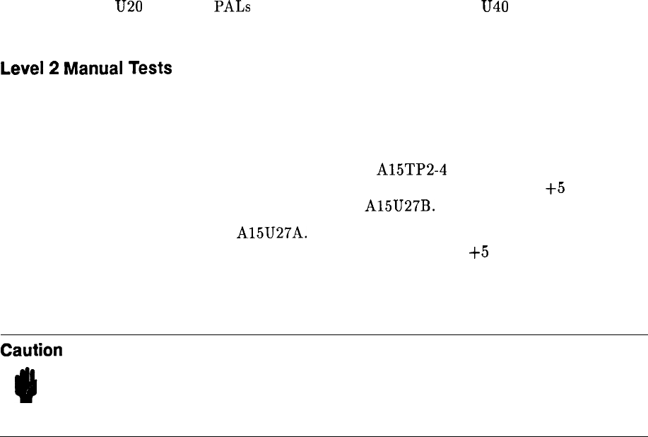
Try replacing
U20
and U42
PALS
first, then try replacing U39 and
U40
ROMs. If I/O
failure still occurs, probe I/O lines with oscilloscope.
Level
2
Manual
Tests
If the Self Test doesn’t lead to a failed component, it will be necessary to use a DVM or an
oscilloscope. The following procedure may help locate the failed component:
a. Check all power supply voltages that supply power to the Al5 Controller.
b. Check processor clock by connecting oscilloscope to
A15TP2-4
(CK). The clock frequency
should be approximately 7.36 MHz. The amplitude should be approximately
+5
V (HIGH)
and 0 V (LOW). Al
so
check for LCLK at pin 7 of A15U27B.
c. Check HP-IB clock at pin 5 of A15U27A. The HP-IB clock frequency should be
approximately 3.68 MHz. The amplitude should be approximately
+5
V (HIGH) and 0 V
(LOW).
d. Some intermittent failures may require the use of heat (hair dryer) or cold (freeze mist) to
isolate the failure.
Caution
Care should be exercised to avoid getting components too hot. Excessive heat
may cause permanent damage of good components. Also, avoid spraying freeze
mist directly on PC boards. Failures due to high-resistance paths between
traces on PC boards have been caused by spraying the boards with freeze
mist.
6 Al5
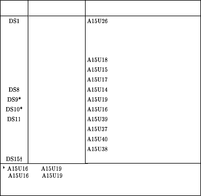
Table l-l. Al5 Controller Self Test Fail Indicators
Al5 LED
On
DSl
DS2
DS3
DS4
DS5
DS6
DS7
DSB
DS9*
DSlO*
DSll
DS12
DS13
DS14
DS15t
Affected
Circuitry
Processor
Top Box Address
Bottom Box Address
I/O, Data Bus
RAM
RAM
RAM
RAM
ROM
ROM
ROM
ROM
ROM
ROM
RAM
Probable Failure
Al5U26
Use oscilloscope to isolate failure.
Use oscilloscope to isolate failure
Use oscilloscope to isolate failure.
A15U18
A15U15
A15U17
A15U14
A15U19
A15U16
A15U39
A15U37
A15U40
A15U38
Power Supply (VRAM)
k
A15U16 and A15U19 are loaded when 128K ROMs (set of 6) are installed.
A15U16 and A15U19 are not loaded when 256K ROMs (set of 4) are used.
. DS15 should normally stay on. If DS15 is not on, suspect the
power supply that supplies VRAM.
1
Al5 7
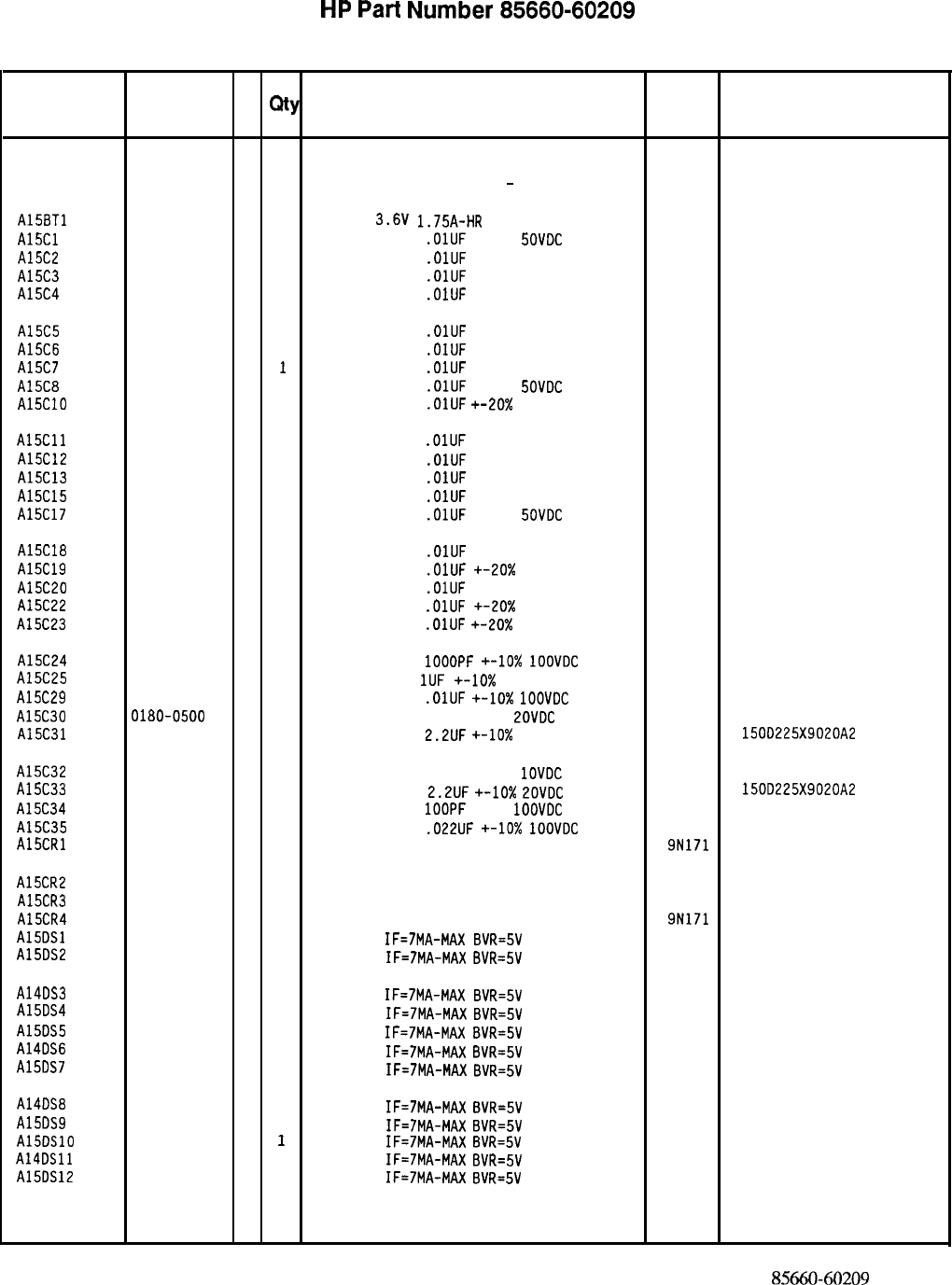
HP
Part
Number 85660-60209
Al5 Controller
Reference
HP Part C
Designation
Number D
Qty Description Mfr
Mfr Part
Code Number
Al5 85660-60209
9
1
BOARD ASSEMBLY, CONTROLLER 28480 85660-60209
(SERIAL PREFIXES: 2410A
-
2449A)
A15BTl
A15Cl
A15C2
A15C3
A15C4
A15C5
A15C6
A15C7
A15C8
A15ClO
A15Cll
A15C12
A15C13
A15C15
A15C17
A15C18
A15C19
A15C20
A15C22
A15C23
A15C24
A15C25
A15C29
A15C30
A15C31
A15C32
A15C33
A15C34
A15C35
A15CRl
A15CR2
A15CR3
A15CR4
A15DSl
A15DS2
A14DS3
A15DS4
A15DS5
A14DS6
A15DS7
A14DS8
A15DS9
AlSDSlO
A14DSll
A15DS12
1420-0331
3
1
BATTERY
3.6V 1.75A-HR
LITHIUM THIONYL
15-51-04-410-000
0160-4554
7
1
CAPACITOR-FXD
.OlUF
+-20%
SOVDC
CER
28480 0160-4554
0160-4554
7
1
CAPACITOR-FXD
.OlUF
+-20% 50VDC CER
28480 0160-4554
0160-4554
7
1
CAPACITOR-FXD
.OlUF
+-20% 50VDC CER
28480 0160-4554
0160-4554
7
1
CAPACITOR-FXD
.OlUF
+-20% 50VDC CER
28480 0160-4554
0160-4554
7
1
CAPACITOR-FXD
.OlUF
+-20% 50VDC CER
28480 0160-4554
0160-4554
7
1
CAPACITOR-FXD
.OlUF
+-20% 50VDC CER
28480 0160-4554
0160-4554
7
1
CAPACITOR-FXD
.OlUF
+-20% 50VDC CER
28480 0160-4554
0160-4554
7
1
CAPACITOR-FXD
.OlUF
+-20%
SOVDC
CER
28480 0160-4554
0160-4554
7
1
CAPACITOR-FXD
.OlUF
+-20x
50VDC CER
28480 0160-4554
0160-4554
7
1
CAPACITOR-FXD
.OlUF
+-20% 50VDC CER
28480 0160-4554
0160-4554
7
1
CAPACITOR-FXD
.OlUF
+-20% 50VDC CER
28480 0160-4554
0160-4554
7 1
CAPACITOR-FXD
.OlUF
+-20% 50VDC CER
28480 0160-4554
0160-4554
7
1
CAPACITOR-FXD
.OlUF
+-20% 50VDC CER
28480 0160-4554
0160-4554
7
1
CAPACITOR-FXD
.OlUF
+-20%
SOVDC
CER
28480 0160-4554
0160-4554
7
1
CAPACITOR-FXD
.OlUF
+-20% 50VDC CER
28480 0160-4554
0160-4554
7
1
CAPACITOR-FXD
.OlUF
+-20X
50VDC CER
28480 0160-4554
0160-4554
7
1
CAPACITOR-FXD
.OlUF
+-20% 50VDC CER
28480 0160-4554
0160-4554
7
1
CAPACITOR-FXD
.OlUF
+-20x 50VDC CER
28480 0160-4554
0160-4554
7
1
CAPACITOR-FXD
.OlUF
+-20x
50VDC CER
28480 0160-4554
0160-4574
1
1
CAPACITOR-FXD 1OOOPF
+-IO%
1OOVDC
CER
28480 0160-4574
0160-4535
4
1
CAPACITOR-FXD
1UF
+-lo% 50VDC CER
28480 0160-4554
0160-4832
4
1
CAPACITOR-FXD
.OlUF
+-lo%
1OOVDC
CER
28480 0160-4832
0180-0500
7
1
CAPACITOR-FXD
47UF +-20%
ZOVDC
TA
28480 0180-0500
0180-0197
8
2
CAPACITOR-FXD 2.2UF
+-lo%
20VDC TA
56289 150D225X9020A2
0180-0552
9
1
CAPACITOR-FXD
220UF +-20%
1OVDC
TA
28480 0180-0552
0180-0197
,
8
1
CAPACITOR-FXD
2.2UF
+-lo%
EOVDC
TA
56289 150D225X9020A2
0160-4801
7
1
CAPACITOR-FXD 1OOPF
+-5%
1OOVDC
CER
28480 0160-4801
0160-4833
5
1
CAPACITOR-FXD
.022UF
+-lo%
IOOVDC
CER
28480 0160-4833
1901-0620
3
1
DIODE-SWITCHING 60V 400MA DO-35
9N171 NDP250
1901-0050
3
1
DIODE-SWITCHING 80V 200MA 2NS DO-35 28480 1901-0050
1901-0518
8
1
DIODE-SM SIG SCHOTTKY 28480 1901-0518
1901-0620
3
1
DIODE-SWITCHING 60V 400MA DO-35 9N171 NDP250
1990-0958
7
1
LED-LAMP IF=7MA-MAX
BVR=5V 28480 1990-0958
1990-0958
7
1
LED-LAMP
IF=7MA-MAX
BVR=5V 28480 1990-0958
1990-0958
7
1
LED-LAMP IF=7MA-MAX
BVR=5V 28480 1990-0958
1990-0958
7
1
LED-LAMP
IF=7MA-MAX
BVR=5V 28480 1990-0958
1990-0958
7
1
LED-LAMP IF=7MA-MAX
BVR=SV 28480 1990-0958
1990-0958
7
1
LED-LAMP
IF=7MA-MAX
BVR=5V 28480 1990-0958
1990-0958
7
1
LED-LAMP
IF=7MA-MAX
BVR=5V 28480 1990-0958
1990-0958
7
1
LED-LAMP
IF=7MA-MAX
BVR=5V 28480 1990-0958
1990-0958
7
1
LED-LAMP
IF=7MA-MAX
BVR=5V 28480 1990-0958
1990-0958
7
1
LED-LAMP
IF=7MA-MAX
8VR=5V 28480 1990-0958
1990-0958
7
1
LED-LAMP
IF=7MA+iAX
BVR=5V 28480 1990-0958
1990-0958
7
1
LED-LAMP
IF=7MA-MAX
8VR=5V 28480 1990-0958
*Indicates factoy-selected value 8.5660-60209
Parts List
Page 1 of 4
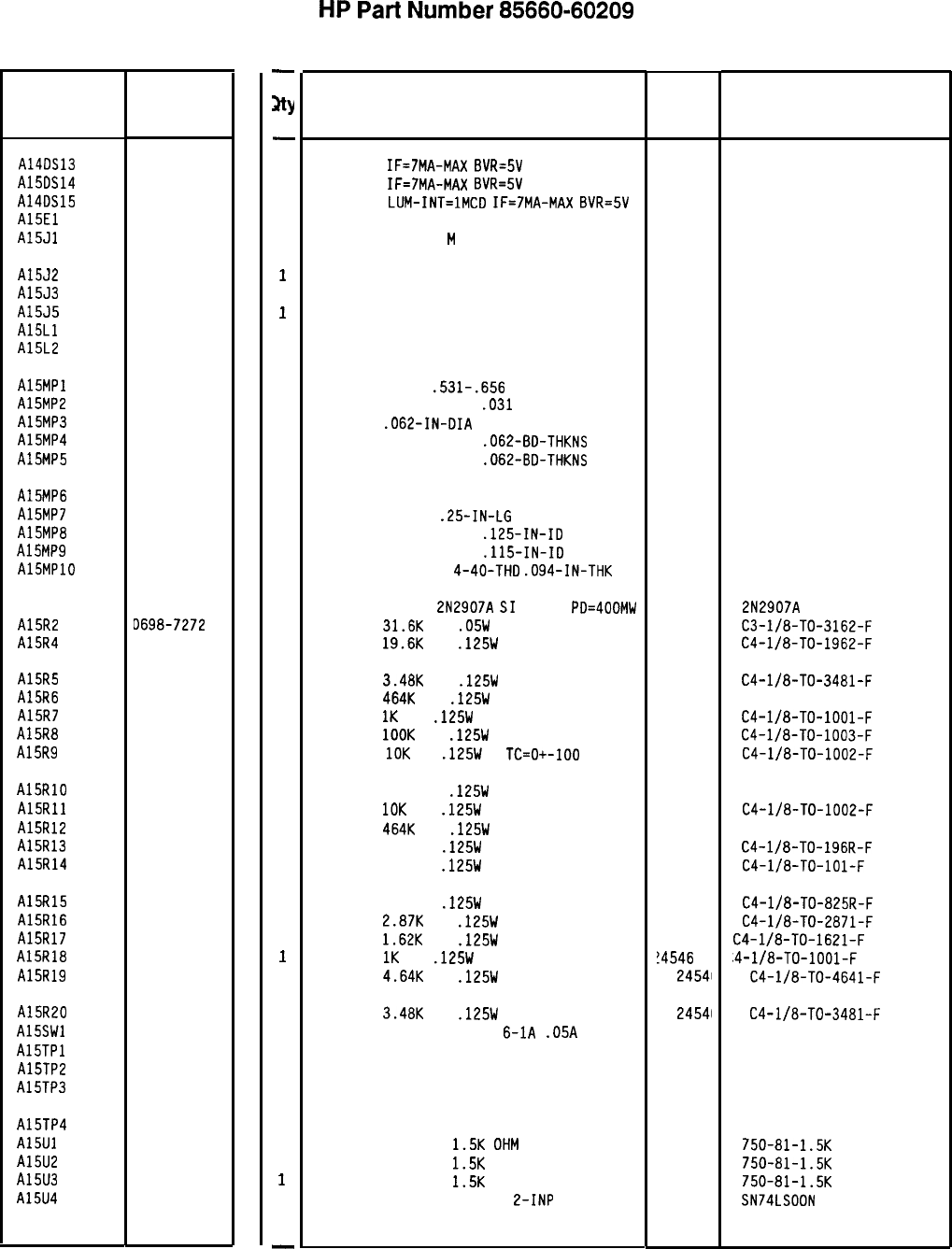
Reference
Designation HP Part
Number
C
D
A14DS13 1990-0958
7
A15DS14 1990-0958
7
A14DS15 1990-0957
6
A15El 1251-4787
2
A15Jl 1251-5926
3
A15J2 1251-5905
8
A15J3 1200-0607
0
A15J5 1251-5619
1
A15Ll 9140-0864
1
A15L2 08558-80011
6
A15MPl 1400-1267
4
A15MP2 1251-5177
6
A15MP3 1480-0073
6
A15MP4 4040-0749
4
A15MP5 4040-0753
0
A15MP6
A15MP7
A15MP8
A15MP9
AlSMPlO
2200-0139
4
3050-0105
6
2190-0003 8
2260-0001
5
A1591 1853-0281
9
A15R2 D698-7272
1
A15R4 3698-3157
3
A15R5 3698-3152
8
A15R6 0698-3260
9
A15R7 0757-0280
3
A15R8 0757-0465
6
A15R9 0757-0442
9
A15RlO 0698-3260
9
A15Rll 0757-0442
9
A15R12 0698-3260
9
A15R13 0698-3440
7
A15R14 0757-0401
0
A15R15 0757-0421
4
A15R16 0698-3151
7
A15R17 0757-0428
1
A15R18 0757-0280
3
A15R19 0698-3155
1
A15R20 3698-3152
8
A15SWl 3101-2197
9
A15TPl 1251-8096
4
A15TP2 1251-8616
4
A15TP3 3360-1682
0
A15TP4 0360-1682
0
A15Ul 1810-0446 8
A15U2 1810-0446
8
A15U3 1810-0446
8
A15U4 1820-1197
9
8X60-60209 Parts List
Page 2 of 4
-
Jtty
-
1
1
1
1
1
1
1
1
1
1
1
2
2
1
1
1
1
1
1
1
1
1
1
1
1
1
1
1
1
1
1
1
1
1
1
1
1
1
1
1
1
1
1
1
1
1
1
-
HP
Part
Number 85660-60209
A15 Controller
Description
LED-LAMP
IF=7MA-MAX
BVR=5V
LED-LAMP
IF=7MA-MAX
BVR=5V
LED-LAMP
LUM-INT=lMCD
IF=7MA-MAX
BVR=5V
SHUNT-DIP 8-POSITION
CONNECTOR 50-PIN
M
POST TYPE
Mfr
Code
28480
28480
28480
28480
28480
Mfr Part
Number
1990-0958
1990-0958
1990-0957
1251-4787
1251-5926
CONNECTOR 24-PIN M POST TYPE
16-PIN IC SOCKET
CONNECTOR 4-PIN M POST TYPE
COIL 120UH 20%
INDUCTOR BLUE COIL
28480 1251-5905
28480 1200-0607
28480 1251-5619
28480 9140-0864
28480 08558-80011
HOLDER BATTERY
.531-.656
DIA
91833
91
CONNECTOR SINGLE PIN
.031
IN
28480 1251-5177
PIN-ROLL
.062-IN-DIA
.25-IN-LG BE-CU
28480 1480-0073
EXTR-PC BD BRN POLYC
.062-BD-THKNS 28480 4040-0749
EXTR-PC BD GRN PDLYC
.062-BD-THKNS 28480 4040-0753
NOT ASSIGNED
SCREW-MACH 4-40
.25-IN-LG
PAN-HD POZI
28480 2200-0139
WASHER-FL MTLC NO. 4
.125-IN-ID 28480 3050-0105
WASHER-LK HLCL ND. 4
.115-IN-ID 28480 2190-0003
NUT-HEX-DBL-CHAM
4-40-THD
.094-IN-THK 28480 2260-0001
TRANSISTOR PNP
2N2907A
$1
TO-18
PD=4OOMW 04713 2N2907A
RESISTOR
31.6K
1%
.05W
F TC=O+-100
24546
C3-l/8-TO-3162-F
RESISTOR
19.6K
1%
.125W
F TC=O+-100
24546
C4-l/8-TO-1962-F
RESISTOR
3.48K
1%
.125W
F TC=O+-100
24546
C4-l/8-TO-3481-F
RESISTOR
4641:
1%
.125W
F TC=O+-100
28480 0698-3260
RESISTOR
1K
1%
.125W
F TC=O+-100
24546
C4-l/8-TO-1001-F
RESISTOR
1OOK
1%
.125W
F TC=O+-100
24546
C4-l/8-TO-1003-F
RESISTOR
10K
1%
.125W
F
TC=O+-ID0 24546
C4-l/8-TO-1002-F
RESISTOR 464K 1%
.125W
F TC=O+-100
28480 0698-3260
RESISTOR
10K
1%
.125W
F TC=O+-100
24546
C4-l/8-TO-1002-F
RESISTOR
4641:
1%
.125W
F TC=O+-100
28480 0698-3260
RESISTOR 196 1%
.125W
F TC=O+-100
24546
C4-l/8-TO-196R-F
RESISTOR 100 1%
.125W
F TC=O+-100
24546
C4-l/8-TO-101-F
RESISTOR 825 1%
.125W
F TC=O+-100
24546
C4-l/8-TO-825R-F
RESISTOR
2.87K
1%
.125W
F TC=O+-100
24546
C4-l/8-TO-2871-F
RESISTOR
1.62K
1%
.125W
F TC=O+-100
24546
C4-l/8-TO-1621-F
RESISTOR
1K
1%
.125W
F TC=O+-100
!4546
,4-l/8-TO-1001-F
RESISTOR
4.64K
1%
.125W
F TC=O+-100
24541
C4-l/8-TO-4641-F
RESISTOR
3.48K
1%
.125W
F TC=O+-100
SWITCH-RKR DIP-RKR-ASSY
6-1A
.05A
30VDC
HEADER ASSY 7PIN
HEADER ASSY 4PIN
TERMINAL-STUD SGL-TUR PRESS-MTG
TERMINAL-STUD SGL-TUR PRESS-MTG
NETWORK-RES 8-SIP
1.5K
OHM
X 7
NETWORK-RES 8-SIP
1.5K
OHM X 7
NETWORK-RES 8-SIP
1.5K
OHM X 7
IC GATE TTL LS NAND QUAD
2-INP
24541
C4-l/8-TO-3481-F
28480 3101-2197
28480 1251-8096
28480 1251-8616
28480 0360-1682
28480 0360-1682
11236 750-81-1.5K
11236 750-81-1.5K
11236 750-81-1.5K
01295 SN74LSDON
*Indicates facto y-selected value
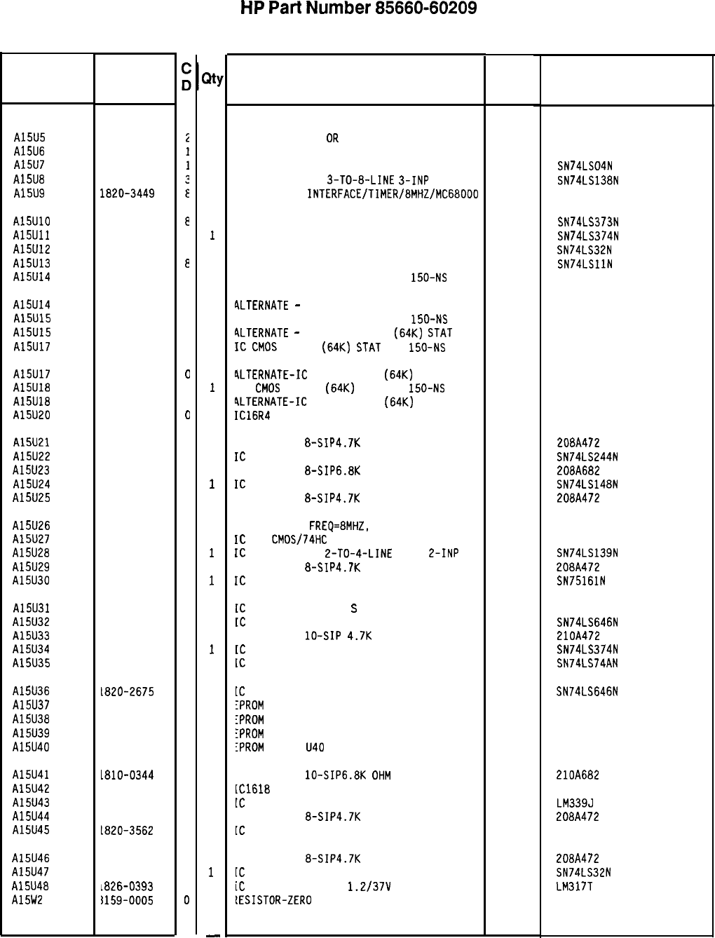
Reference
Designation
HP Part
Number
1820-3401
1820-2551
1820-1199
1820-1216
1820-3449
A15U5
A15U6
A15U7
A15U8
A15U9
A15UlO
A15Ull
A15U12
A15U13
A15U14
1820-2102
8
1820-1997
7
1820-1208
3
1820-1203
e
1818-3183
2
A15U14
A15U15
A15U15
A15U17
1818-3305
C
1818-3183
2
1818-3305
C
1818-3183
2
A15U17
A15U18
A15U18
A15U20
1818-3305
0
1818-3183
2
1818-3305
0
5180-2330
0
A15U21 1810-0205
7
A15U22 1820-2024
3
A15U23 1810-0394
5
A15U24 1820-1851
2
A15U25 1810-0205
7
A15U26
A15U27
A15U28
A15U29
A15U30
1820-2505
5
1820-3173
5
1820-1281
2
1810-0205
7
1820-2483
8
A15U31
A15U32
A15U33
A15U34
A15U35
1820-3431
8
1820-2675
0
1810-0279
5
1820-1997
7
1820-1112
8
A15U36
A15U37
A15U38
A15U39
A15U40
1820-2675
0
35660-80053
3
35660-80055
5
35660-80054
4
35660-80056
6
A15U41 L810-0344
5
A15U42 35660-80070
4
A15U43 1826-0759
9
A15U44 1810-0205
7
A15U45 L820-3562
6
A15U46
A15U47
A15U48
A15W2
1810-0205
7
1820-1208
3
1826-0393
7
~159-0005
D
31
1
1
1
1
1
1
1
1
1
1
0
1
0
1
0
1
0
1
1
1
1
1
1
1
1
1
1
1
1
1
1
1
1
1
1
1
1
1
1
1
1
1
1
1
1
1
1
-
HP
Part
Number 85660-60209
Al5 Controller
Description
IC BFR TTL ALS
OR
QUAD 2-INP
IC-GENERAL PURPOSE INTERFACE BUS ADAPTER
IC INV TTL LS HEX I-INP
IC DCDR TTL LS
3-TO-8-LINE
3-INP
IC-PARALLEL
INTERFACE/TIMER/8MHZ/MC68ODO
Mfr
Mfr Part
Code Number
28480 1820-3401
28480 1820-2551
01295 SN74LS04N
01295 SN74LS138N
28480 1820-3449
IC LCH TTL LS D-TYPE OCTL 01295 SN74LS373N
IC FF TTL LS D-TYPE POS-EDGE-TRIG PRL-IN 01295 SN74LS374N
IC GATE TTL LS OR QUAD 2-INP 01295 SN74LS32N
IC GATE TTL LS AND TPL 3-INP 01295 SN74LSllN
IC CMOS 65536 (64K) STAT RAM
150-NS
3-S
28480 1818-3183
4LTERNATE
-
IC CMOS 65536 (64K) STAT RAM
28480 1818-3305
IC CMOS 65536 (64K) STAT RAM
150-N'S
3-S
28480 1818-3183
ALTERNATE
-
Ic CMOS 65536
(64~)
STAT
RAM
28480 1818-3305
Ic
CMOS
65536
(64~)
STAT
R
AM
150-NS
3-s
28480 1818-3183
ALTERNATE-Ic
CMOS 65536
(64~)
STAT RAM
28480 1818-3305
Ic
CMOS
65536
(64~)
STAT RAM
150-NS
3-s
28480 1818-3183
ALTERNATE-IC
CMOS 65536
(64~)
STAT
RAM
28480 1818-3305
IC16R4
PAL PRGMD
28480 5180-2330
VETWORK-RES 8-SIP4.7K OHM X 7
IC
DRVR TTL LS LINE DRVR OCTL
VETWORK-RES 8-SIP6.8K OHM X 7
IC
ENCDR TTL LS
YETWORK-RES
8-SIP4.7K
OHM X 7
01121 208A472
01295 SN74LS244N
01121 208A682
01295 SN74LS148N
01121
208A472
IC-MPU; CLK
FREQ=8MHZ,
INSTRUCTION
28480 1820-2505
IC
FF
CMDS/74HC
J-K NEG-EDGE-TRIG
28480 1820-3173
IC
DCDR TTL LS
2-TO-4-LINE
DUAL
L-INP 01295 SN74LS139N
VETWORK-RES 8-SIP4.7K OHM X 7
01121 208A472
IC
RCVR TTL LS BUS OCTL
01295 SN75161N
[C
TRANSCEIVER TTL
S
INSTR-BUS IEEE-488
28480 1820-3431
[C
RCVR TTL LS BUS OCTL
01295 SN74LS646N
IETWORK-RES
lo-SIP
4.7K
OHM X 9
01121 210A472
[C
FF TTL LS D-TYPE POS-EDGE-TRIG PRL-IN
01295 SN74LS374N
IC
FF TTL LS D-TYPE POS-EDGE-TRIG
01295 SN74LS74AN
[C
RCVR TTL LS BUS OCTL
01295 SN74LS646N
IPROM
PRGMD U37
28480 85660-80053
IPROM
PRGMD U38
28480 85660-80055
lPRDM
PROG U39
28480 85660-80054
iPROM
PRGMD
U40 28480 85660-80056
IETWORK-RES
lo-SIP6.8K
OHM
X 9
[Cl618
PAL PRGMD
[C
COMPARATOR GP QUAD 14-DIP-C PKG
IETWORK-RES
8-SIP4.7K
OHM X 7
[C
BFR TTL ALS INV HEX
01121 210A682
28480 85660-80070
04713 LM339J
01121 208A472
28480 1820-3562
IETWORK-RES
8-SIP4.7K
OHM X 7
01121 208A472
[C
GATE TTL L8 OR QUAD 2-INP
01295 SN74LS32N
iC
V RGLTR-ADJ-PDS
1.2/37V
TO-220 PKG
27014 LM317T
[ESISTOR-ZERO
OHMS 22 AWG LEAD DIA
28480 8159-0005
*Indicates factoy-selected value
8X60-60209 Parts List
Page 3 of 4
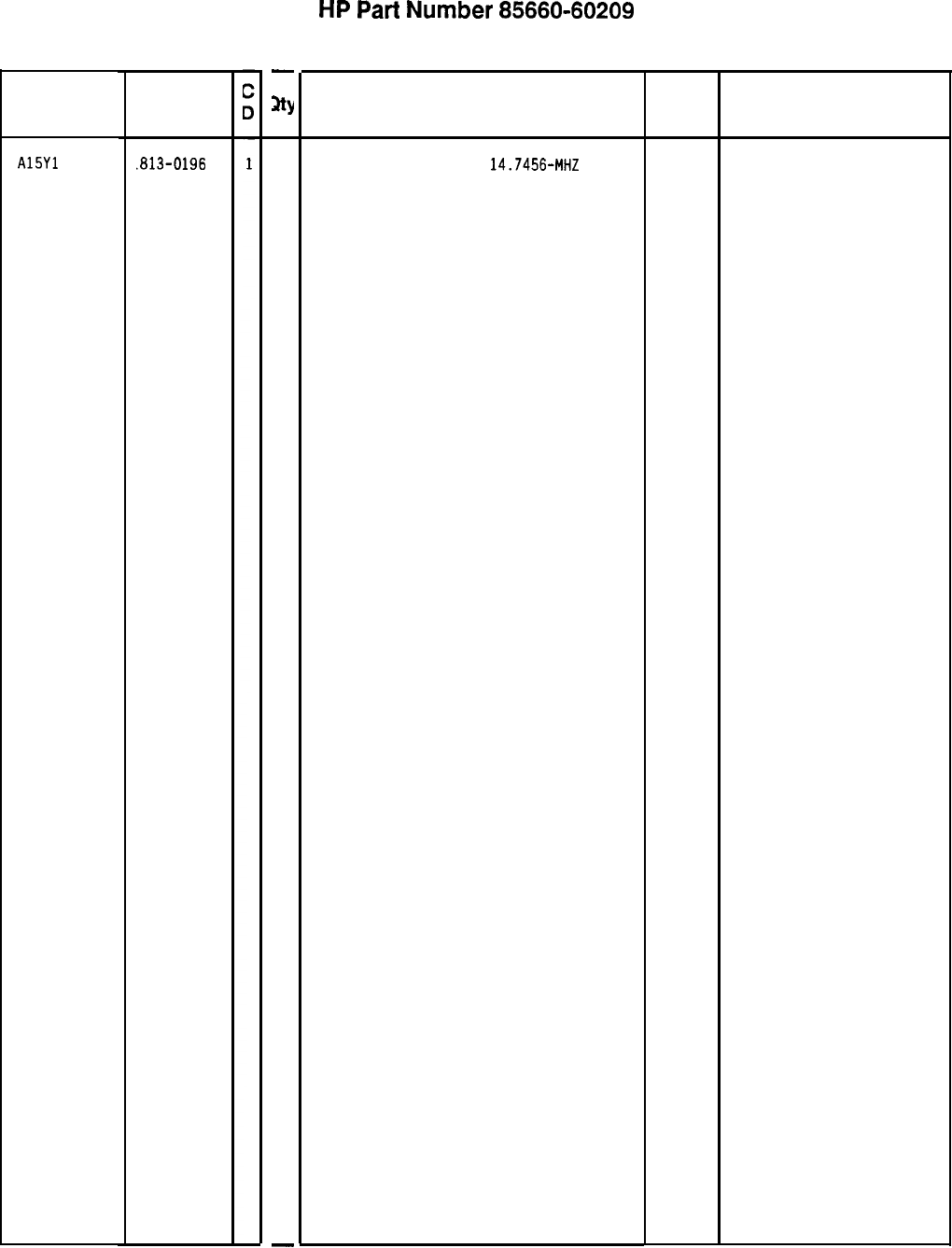
Reference
Designation
A15Yl
HP Part
Number
.813-0196
85660-60209 Parts List
Page 4 of 4
-
3Y
1
-
HP
Part
Number 85660-60209
Al5 Controller
Description
XTAL-CLOCK-OSCILLATOR
14.7456-MHZ
*Indicates factoy-selected value
Mfr
Code
28480
Mfr Part
Number
1813-0196
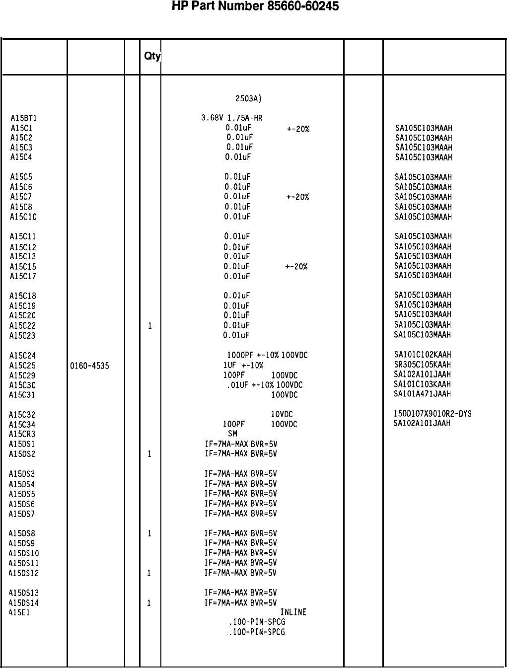
HP
Part
Number 85660-60245
Al 5 Controller
Reference
HP Part C
Number D
Qty Description Mfr
Mfr Part
Designation Code Number
Al5 85660-60245
3
1
BOARD ASSEMBLY, CONTROLLER 28480 85660-60245
(SERIAL PREFIX:
2503~)
A15BTl 1420-0331
3
1
BATTERY
3.68V
1.75A-HR
LITHIUM
THIONYL 15-51-04-410-000
A15Cl 0160-4554
7
1
CAPACITOR-FXD
O.OluF
50 VDC +-20x CER
04222 SA105C103MAAH
A15C2 0160-4554
7
1
CAPACITOR-FXD
O.OluF 50 VDC +-20% CER 04222 SA105C103MAAH
A15C3 0160-4554
7
1
CAPACITOR-FXD
O.OluF 50 VDC +-20% CER 04222 SA105C103MAAH
A15C4 0160-4554
7
1
CAPACITOR-FXD
O.OluF
50
VDC +-20% CER 04222 SA105C103MAAH
A15C5 0160-4554
7
1
CAPACITOR-FXD
O.OluF
50 VDC +-20%
CER 04222 SA105C103MAAH
A15C6 0160-4554
7
1
CAPACITOR-FXD
O.OluF
50 VDC +-20%
CER 04222
SA105C103MAAH
A15C7 0160-4554
7
1
CAPACITOR-FXD
O.OluF
50 VDC +-20x
CER 04222 SA105C103MAAH
A15C8 0160-4554
7
1
CAPACITOR-FXD
O.OluF
50 VDC +-20%
CER 04222 SA105C103MAAH
A15ClO 0160-4554
7
1
CAPACITOR-FXD
O.OluF
50 VDC +-20% CER
04222 SA105C103MAAH
A15Cll 0160-4554
7
1
CAPACITOR-FXD
O.OluF
50 VDC +-20% CER
04222 SA105C103MAAH
A15C12 0160-4554
7
1
CAPACITOR-FXD
O.OluF
50 VDC +-20% CER
04222 SA105C103MAAH
A15C13 0160-4554
7
1
CAPACITOR-FXD
O.OluF
50 VDC +-20% CER
04222 SA105C103MAAH
A15C15 0160-4554
7
1
CAPACITOR-FXD
O.OluF
50 VDC +-20x CER
04222 SA105C103MAAH
A15C17 0160-4554
7
1
CAPACITOR-FXD
O.OluF
50 VDC +-20% CER
04222 SAlOSClOSMAAH
A15C18 0160-4554
7
1
CAPACITOR-FXD
O.OluF
50 VDC +-20% CER
04222 SA105C103MAAH
A15C19 0160-4554
7
1
CAPACITOR-FXD
O.OluF
50 VDC +-20% CER
04222 SA105C103MAAH
A15C20 0160-4554
7
1
CAPACITOR-FXD
O.OluF
50 VDC +-20% CER
04222 SA105C103MAAH
A15C22 0160-4554
7
1
CAPACITOR-FXD
O.OluF
50 VDC +-20% CER
04222 SA105C103MAAH
A15C23 0160-4554
7
1
CAPACITOR-FXD
O.OluF
50 VDC +-20% CER
04222 SAlD5C103MAAH
A15C24 0160-4574
1
1
CAPACITOR-FXD
1OOOPF
+-IO%
1OOVDC
CER
04222 SAlOlC102KAAH
A15C25 0160-4535
4
1
CAPACITOR-FXD
1UF
+-10x
50VDC CER
04222 SR305C105KAAH
A15C29 0160-4801
7
1
CAPACITOR-FXD
1OOPF
+-5%
1OOVDC
CER 0+-3
04222 SA102AlOlJAAH
A15C30 0160-4832
4
1
CAPACITOR-FXD
.OlUF
+-lo%
1OOVDC
CER
04222 SAlOlC103KAAH
A15C31 0160-4808
4
1
CAPACITOR-FXD 470PF +-5%
1OOVDC
CER 0+-3
04222 SAlOlA471JAAH
A15C32 0180-2207
5
1
CAPACITOR-FXD lOOUF+-10%
1OVDC
TA
56289 150D107X901DR2-DYS
A15C34 0160-4801
7
1
CAPACITOR-FXD
1OOPF
+-5%
1OOVDC
CER 0+-3
04222 SA102AlDlJAAH
A15CR3 1901-0518
8
1
DIODE-SCHOTTKY
SM
SIG
28480
AlSDSl 1990-0958
7
1
LED-LAMP
IF=7MA-MAX
BVR=5V 28480 HLMP-1700
A15DS2 1990-0958
7
1
LED-LAMP
IF=7MA-MAX
BVR=5V 28480 HLMP-1700
A15DS3
A15DS4
A15DS5
A15DS6
A15DS7
1990-0958
7
1
LED-LAMP
IF=7MA-MAX
8VR=5V 28480 HLMP-1700
1990-0958
7
1
LED-LAMP
IF=7MA-MAX
BVR=5V 28480 HLMP-1700
1990-0958
7
1
LED-LAMP
IF=7MA-MAX
BVR=5V 28480 HLMP-1700
1990-0958
7
1
LED-LAMP
IF=7MA-MAX
BVR=SV 28480 HLMP-1700
1990-0958
7
1
LED-LAMP
IF=7MA-MAX
BVR=5V 28480 HLMP-1700
A15DS8
A15DS9
A15DSlO
A15DSll
A15DS12
1990-0958
7
1
LED-LAMP
IF=7MA-MAX
BVR=5V 28480 HLMP-1700
1990-0958
7
1
LED-LAMP
IF=7MA-MAX
BVR=5V 28480 HLMP-1700
1990-0958
7
1
LED-LAMP
IF=7MA-MAX
BVR=SV 28480 HLMP-1700
1990-0958
7
1
LED-LAMP
IF=7MA-MAX
BVR=5V 28480 HLMP-1700
1990-0958
7
1
LED-LAMP
IF=7MA-MAX
BVR=5V 28480 HLMP-1700
415DS13
415DS14
415El
41551
41552
1990-0958
7
1
LED-LAMP
IF=7MA-MAX
BVR=5V 28480 HLMP-1700
1990-0958
7
1
LED-LAMP
IF=7MA-MAX
8VR=5V 28480 HLMP-1700
1251-4787
2
1
SHUNT-DIP 8 POSITION DUAL
INLINE
PKG
00779 435704-8
1251-5926
3
1
CONN-POST TYPE
.lOO-PIN-SPCG
50-CONT
18873 67997-650
1251-5905
8
1
CONN-POST TYPE
.lOO-PIN-SPCG
24-CONT
18873 67997-624
*Indicates factoy-selected value
8566060245 Parts List
Page 1 of 3
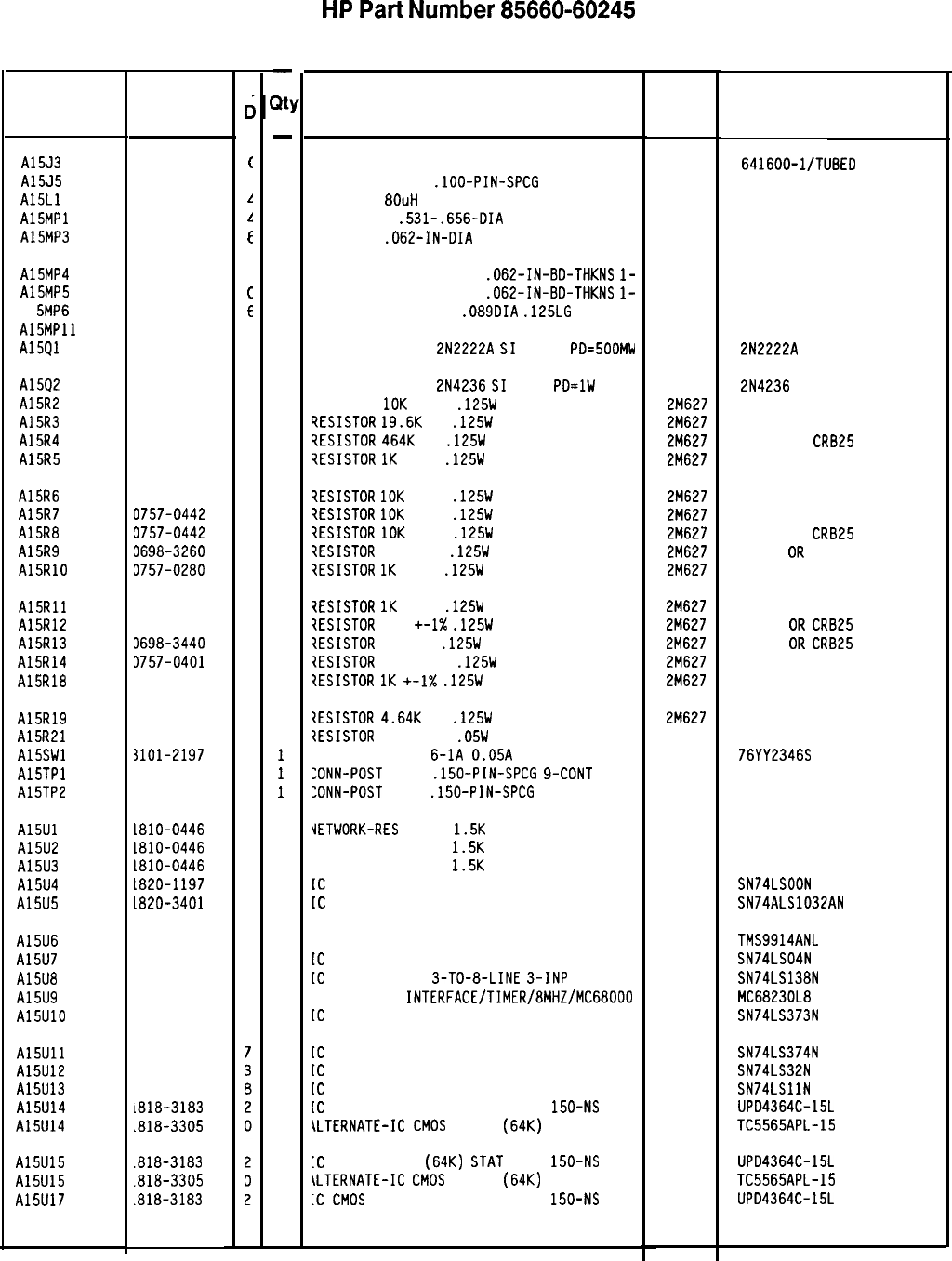
Reference
Designation HP Part
Number
c
c
A15J3 1200-0607
(
A15J5 1251-5619
I
A15Ll 9140-0875
.!
Al5MPl 1400-1267
1
A15MP3 1480-0073
E
A15MP4 4040-0749
4
A15MP5 4040-0753
c
Al
5MP6 0361-0026
E
A15MPll 1200-0567
1
Al5Ql 1854-0477
7
A1592
A15R2
A15R3
A15R4
A15R5
1853-0213
7
0757-0442
9
0698-3157
3
0698-3260
9
0757-0280
3
A15R6
A15R7
A15R8
A15R9
A15RlO
0757-0442
9
D757-0442
9
3757-0442
9
3698-3260
9
3757-0280
3
A15Rll
A15R12
A15R13
A15R14
A15R18
3757-0280
3
3757-0401
0
3698-3440
7
3757-0401
0
1757-0280
3
A15R19
A15R21
A15SWl
A15TPl
A15TP2
1698-3155
1
1698-7212
9
SlOl-2197
9
1252-0569
2
1251-8427
5
A15Ul
A15U2
A15U3
A15U4
A15U5
1810-0446
8
1810-0446
8
L810-0446
8
L820-1197
9
1820-3401
2
A15U6
A15U7
A15U8
A15U9
A15UlO
1820-2548
6
1820-1199
1
1820-1216
3
1820-3449
8
1820-2102
8
A15Ull
1820-1997
A15U12
1820-1208
A15U13
1820-1203
A15U14
~818-3183
A15U14
.818-3305
A15U15
.818-3183
A15U15
.818-3305
A15U17
.818-3183
8566060245 Parts List
Page 2 of 3
-
a!
-
1
1
1
1
2
1
1
1
1
1
1
1
1
1
1
1
1
1
1
1
1
1
1
1
1
1
1
1
1
1
1
1
1
1
1
1
1
1
1
1
1
1
1
1
0
1
0
1
-
HP
Part
Number 85660-60245
A15 Controller
Description Mfr Mfr Part
Code Number
16-PIN IC SOCKET
CONN-POST TYPE
.lOO-PIN-SPCG
4-CONT
INDUCTOR
80uH
10%
HOLDER-BAT
.531-.656-DIA
FOR AA CELLS
PIN-ROLL
.062-IN-DIA
.25-IN-LG BE-CU
00779 641600-l/TUBED
2-641600
18873 68000-604
28480 9140-0875
91833
91
72962
99-012-062-0250
EXTR-PC BD BRN POLYC
.062-IN-BD-THKNS
l-
EXTR-PC BD GRN POLYC
.D62-IN-BD-THKNS
l-
RIVET-SEMITUB DVH
.089DIA
.125LG
SOCKET-IC 28-CONT DIP DIP-SLDR
TRANSISTOR NPN
2N2222A
$1
TO-18
PD=500MW
12014 R-4008-1/8
00779 2-641605-l
04713 2N2222A
TRANSISTOR PNP
2N4236
$1
TO-5
PD=lW 04713 2N4236
RESISTOR
10K
+-1%
.125W
TF TC=O+-100
2M627 CRB14 OR CRB25
?ESISTOR
19.6K
1%
.125W
TF TC=O+-100
2M627 CR814 OR CRB25
?ESISTOR
4641:
1%
.125W
TF TC=O+-100
2M627
CRB14 OR
CR825
iESISTDR
1K
+-1%
.125W
TF TC=O+-100
2M627 CRB14 OR CRB25
7ESISTOR
10K
+-1%
.125W
TF TC=O+-100
2M627 CRB14 OR CRB25
7ESISTOR
10K
+-1%
.125W
TF TC=O+-100
2M627 CRB14 OR CR825
1ESISTOR
10K
+-1%
.125W
TF TC=O+-100
2M627
CR814 OR
CR825
7ESISTDR
464K 1%
.125W
TF TC=O+-100
2M627
CRB14
OR
CR825
7ESISTOR
1K
+-1%
.125W
TF TC=O+-100
2M627
CRB14 OR CRB25
7ESISTOR
1K
+-1%
.125W
TF TC=O+-100
2M627 CRB14 OR CRB25
7ESISTOR
100
+-I%
.125W
TF TC=O+-100
2M627
CRB14
OR
CR825
IESISTDR
196 1%
.125W
TF TC=O+-100
2M627
CRB14
OR
CR825
1ESISTOR
100 +-1%
.125W
TF TC=O+-100
2M627 CRB14 OR CRB25
?ESISTOR
1K
+-1X
.125W
TF TC=O+-100
2M627 CRB14 OR CRB25
IESISTOR
4.64K
1%
.125W
TF TC=O+-100
2M627
CRB14 OR CRB25
2ESISTOR
100 +-1%
.05W
TF TC=O+-100
19701
50635
SWITCH-DIP RKR
6-1A
0.05A
30VDC
81073 76YY2346S
:DNN-POST
TYPE
.150-PIN-SPCG
9-CDNT 00779 87221-8
:DNN-POST
TYPE
.150-PIN-SPCG
5-CONT
00779 87221-4
IETWORK-RES
8-SIP
1.5K
OHM X 7
11236 750-81
JETWORK-RES 8-SIP
1.5K
OHM X 7
11236 750-81
JETWORK-RES 8-SIP
1.5K
OHM X 7
11236 750-81
[C
GATE TTL LS NAND QUAD 2-INP
01295 SN74LSOON
[C
BFR TTL ALS OR QUAD 2-INP
01295 SN74ALSlD32AN
[C-GENERAL PURPOSE INTERFACE BUS ADAPTER 01295 TMS9914ANL
[C
INV TTL LS HEX l-INP
01295 SN74LS04N
[C
DCDR TTL LS
3-TO-8-LINE
3-INP 01295 SN74LS138N
[C-PARALLEL
INTERFACE/TIMER/8MHZ/MC68000 04713
MC68230L8
[C
LCH TTL LS D-TYPE OCTL
01295 SN74LS373N
[C
FF TTL LS D-TYPE POS-EDGE-TRIG PRL-IN
01295 SN74LS374N
01295 SN74LS32N
01295 SN74LSllN
SD545 UPD4364C-15L
SO562
TC5565APL-15
[C
GATE TTL LS OR QUAD 2-INP
IC
GATE TTL LS AND TPL 3-INP
IC
CMOS 65536 (64K) STAT RAM
ALTERNATE-Ic
CMOS
65536
(64~)
150-NS
3-S
STAT RAM
:c
CMOS 65536
(64~)
STAT
RAM
150-NS
3-S
so545 UPD4364C-15L
ALTERNATE-Ic
CMOS
65536
(64~)
STAT RAM SO562
TC5565APL-15
.C
CMOS
65536 (64K) STAT RAM
150-NS
3-S
so545 UPD4364C-15L
*Indicates facto y-selected value
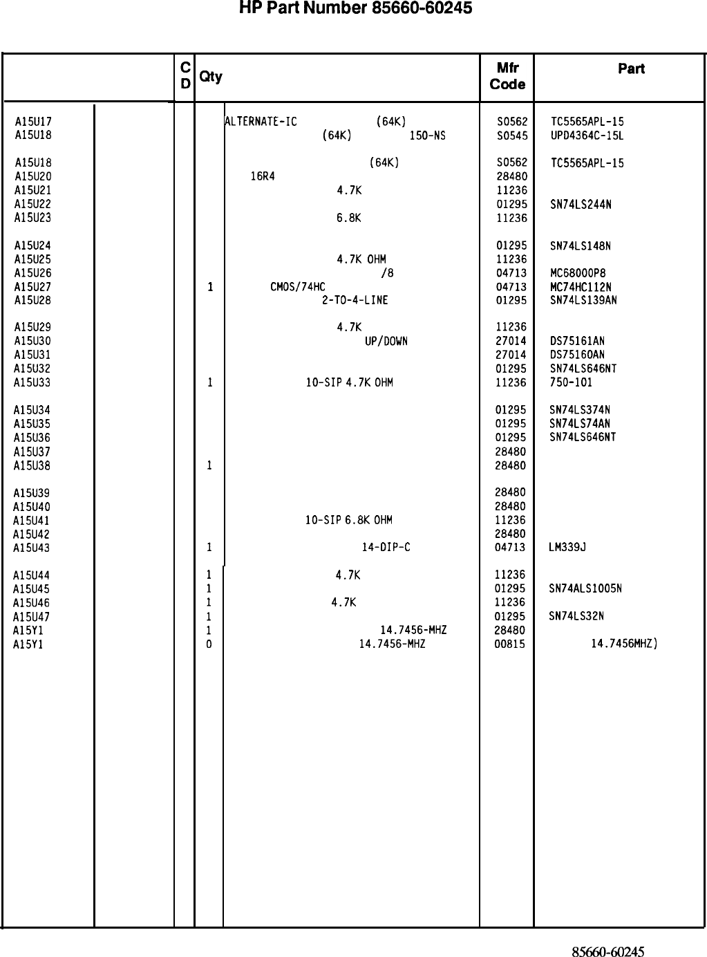
HP
Part
Number 85660-60245
Al 5 Controller
Reference
I
HP Part
Designation Number
I
I
A15U17 1818-3305
A15U18 1818-3183
A15U18 1818-3305
A15U20 5180-2330
A15U21 1810-0205
A15U22 1820-2024
A15U23 1810-0394
0
ALTERNATE-IC
CMOS 65536
(64~)
STAT RAM
1
Ic CMOS 65536
(64~)
STAT RAM
150-NS
3-s
0 ALTERNATE-IC CMOS 65536
(64~)
STAT RAM
1
IC
16R4
PAL PRGMD
1
NETWORK-RES 8-SIP
4.7K
OHM X 7
1
IC DRVR TTL LS LINE DRVR OCTL
1
NETWORK-RES 8-SIP
6.8K
OHM X 7
A15U24 1820-1851
1
IC ENCDR TTL LS
A15U25 1810-0205
1
NETWORK-RES 8-SIP
4.7K
OHM
X 7
A15U26 1820-3532
1
IC-16 BIT MICROPROCESSOR
/8
MHZ
A15U27 1820-3173
1
IC FF
CMOS/74HC
J-K NEG-EDGE-TRIG PRESET
A15U28 1820-1281
1
IC DCDR TTL LS
2-TO-4-LINE
DUAL
A15U29 1810-0205
1
NETWORK-RES 8-SIP
4.7K
OHM X 7
A15U30 1820-3513
1
IC-INTERFACE XCVR BCD
UP/DOWN
INSTRUMENT
A15U31 1820-3431
1
IC-INTERFACE XCVR BCD UP/DOWN INSTRUMENT
A15U32 1820-2675
1
IC TRANSCEIVER TTL LS BUS OCTL
A15U33 1810-0279
1
NETWORK-RES
lo-SIP
4.7K
OHM
X 9
A15U34 1820-1997
A15U35 1820-1112
A15U36 1820-2675
A15U37 85660-80185
A15U38 85660-80187
A15U39 85660-80186
A15U40 85660-80188
A15U41 1810-0344
A15U42 85660-80070
A15U43 1826-0759
1
IC FF TTL LS D-TYPE PDS-EDGE-TRIG PRL-IN
1
IC FF TTL LS D-TYPE PDS-EDGE-TRIG PRESET
1
IC TRANSCEIVER TTL LS BUS OCTL
1
EPROM PRGMD
1
EPROM PRGMD
1
EPROM PRGMD
1
EPROM PRGMD
1
NETWORK-RES
lo-SIP
6.8K
OHM
X 9
1
IC1618 PAL PRGMD
1
IC COMPARATOR GP QUAD
14-DIP-C
PKG
A15U44 1810-0205
A15U45 1820-3562
A15U46 1810-0205
A15U47 1820-1208
A15Yl 1813-0196
A15Yl 1813-0129
NETWORK-RES 8-SIP
4.7K
OHM X 7
IC BFR TTL ALS INV HEX
NETWORK-RES 8-SIP
4.7K
OHM X 7
IC GATE TTL LS OR QUAD 2-INP
CLOCK-OSCILLATOR-CRYSTAL
14.7456-MHZ
CLOCK-OSCILLATOR-XTAL
14.7456-MHZ
0.01%
(
AL
T
ERNA
T
E PART
F
OR
1813-0196)
I
QtY
Description Mfr
Part
Number
TC5565APL-15
UPD4364C-15L
TC5565APL-15
5180-2330
750-81
SN74LS244N
750-81
SN74LS148N
750-81
MC68000P8
MC74HC112N
SN74LS139AN
750-81
DS75161AN
DS75160AN
SN74LS646NT
750-101
SN74LS374N
SN74LS74AN
SN74LS646NT
85660-80185
85660-80187
85660-80186
85660-80188
750-101
85660-80070
LM339J
750-81
SN74ALS1005N
750-81
SN74LS32N
1813-0196
HS-lOO(
14.7456MHZ)
*Indicates factoy-selected value
8566060245
Parts List
Page 3 of 3
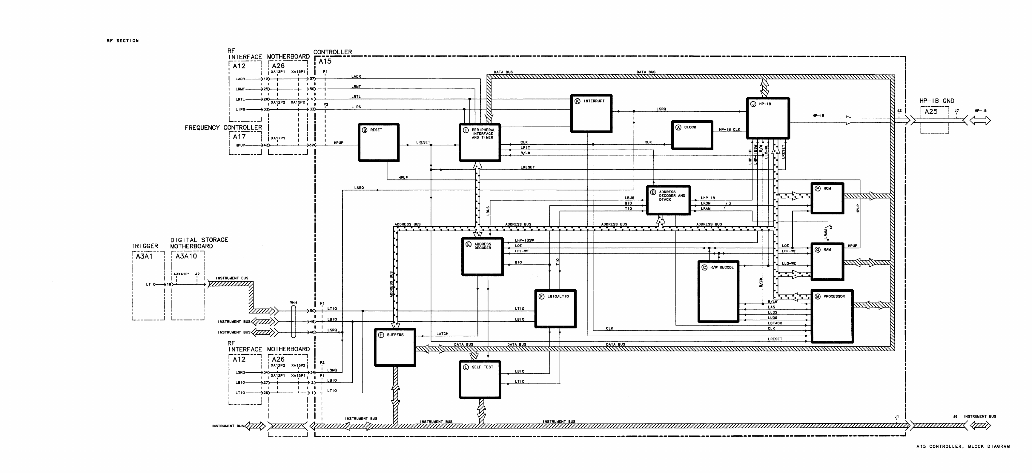
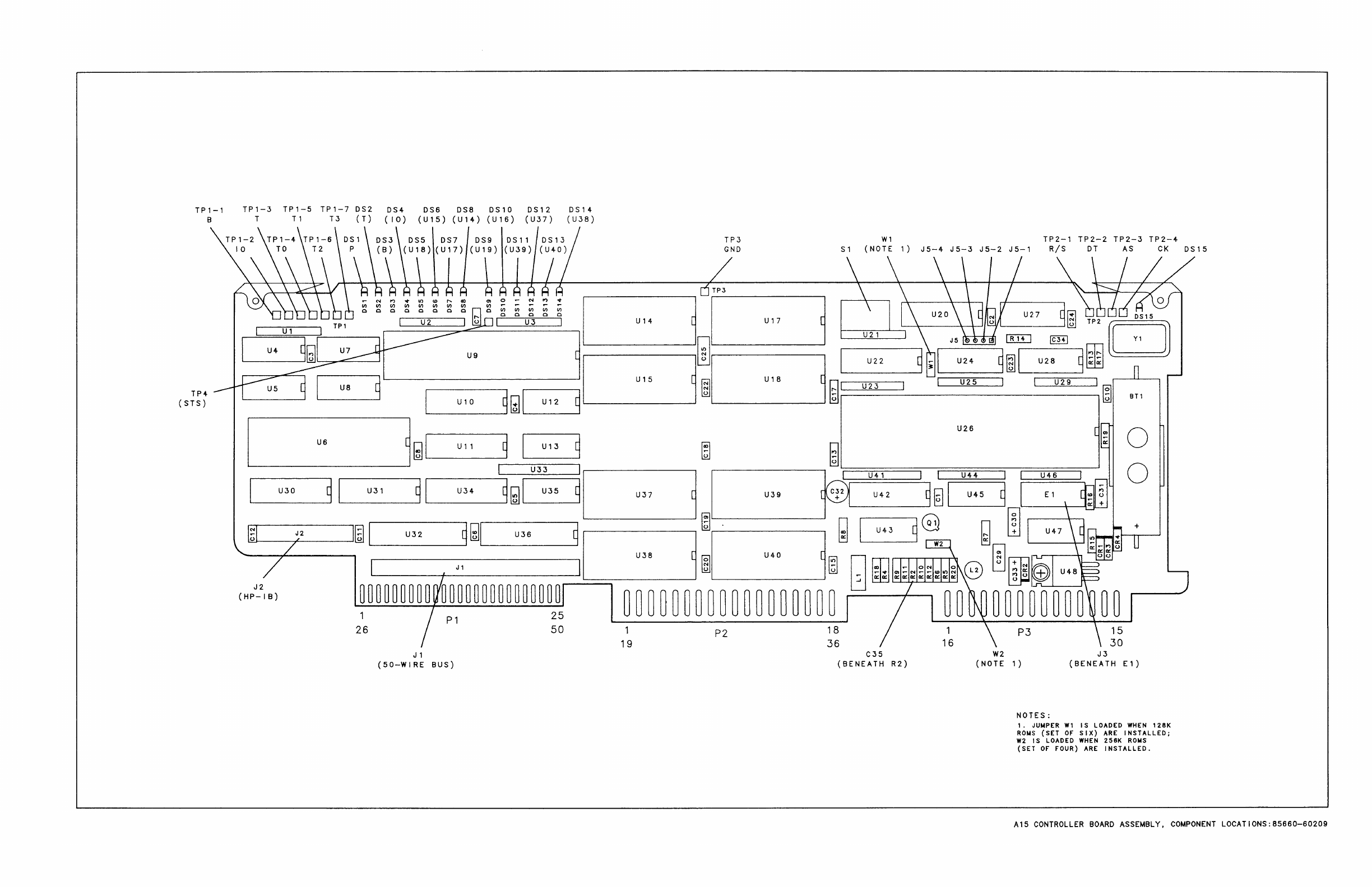
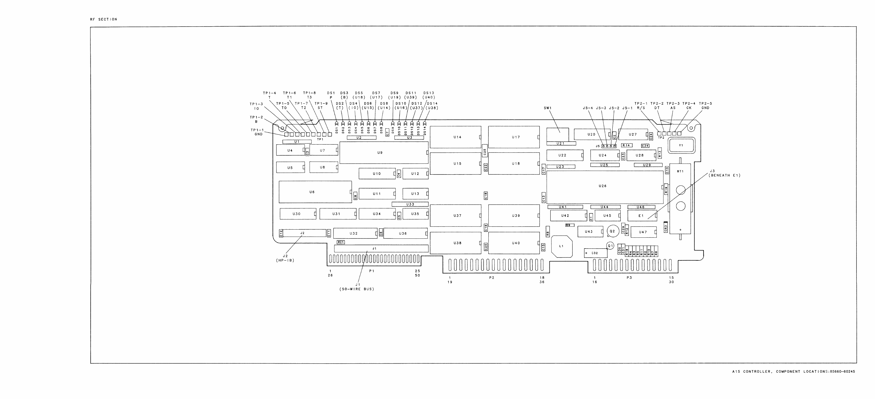
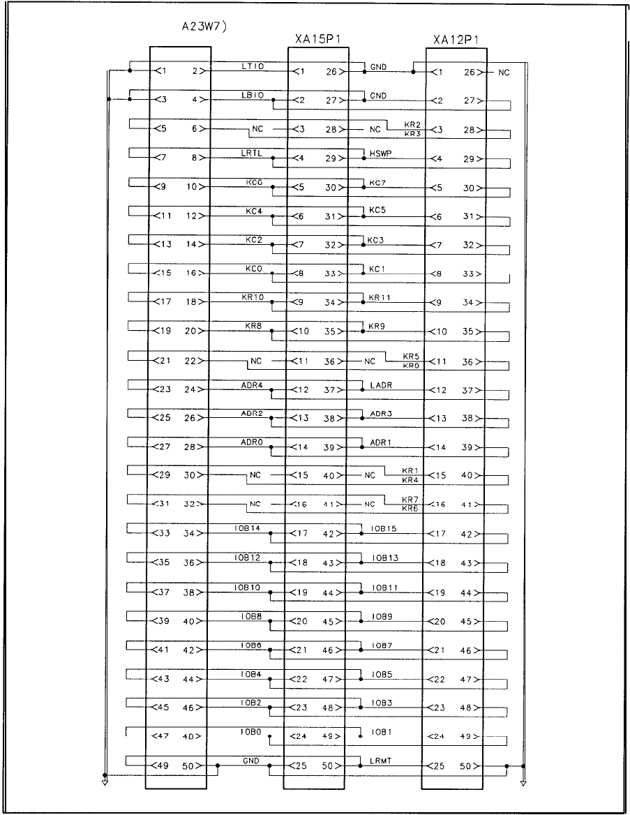
(P/O
A23W7)
J8
XA15Pl XA12Pl
A23 Motherboard Instrument Bus, Interconnect Diagram
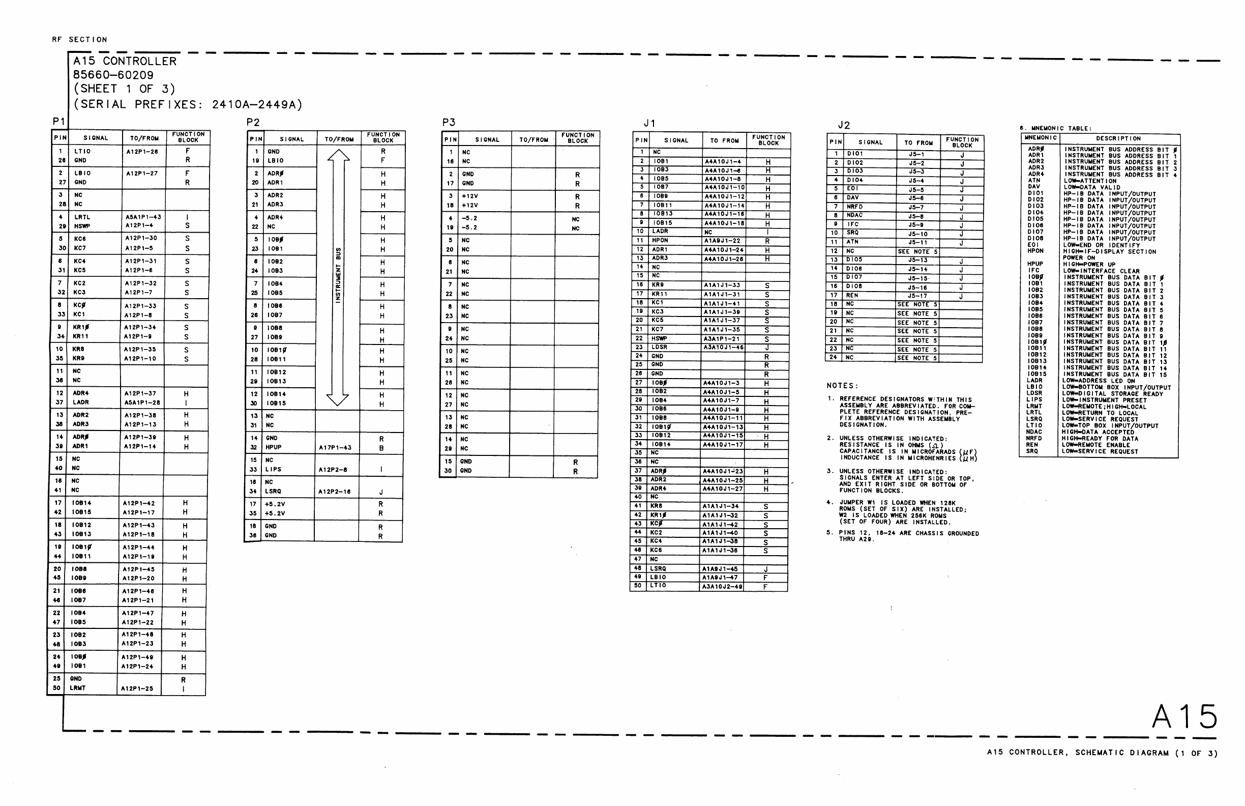
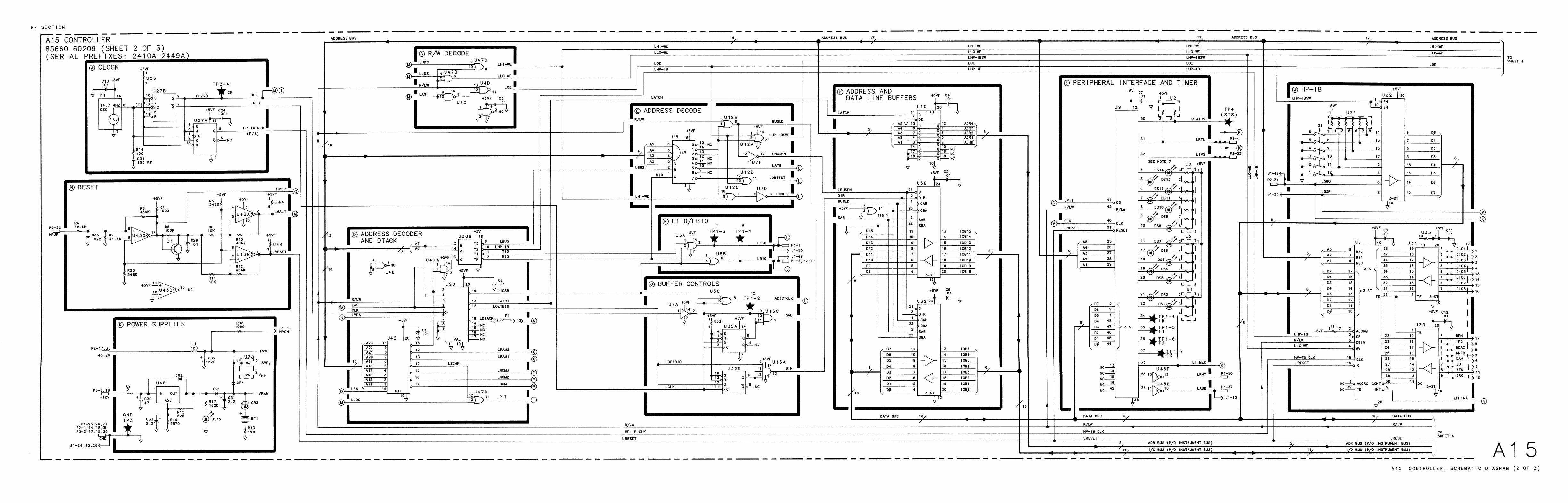
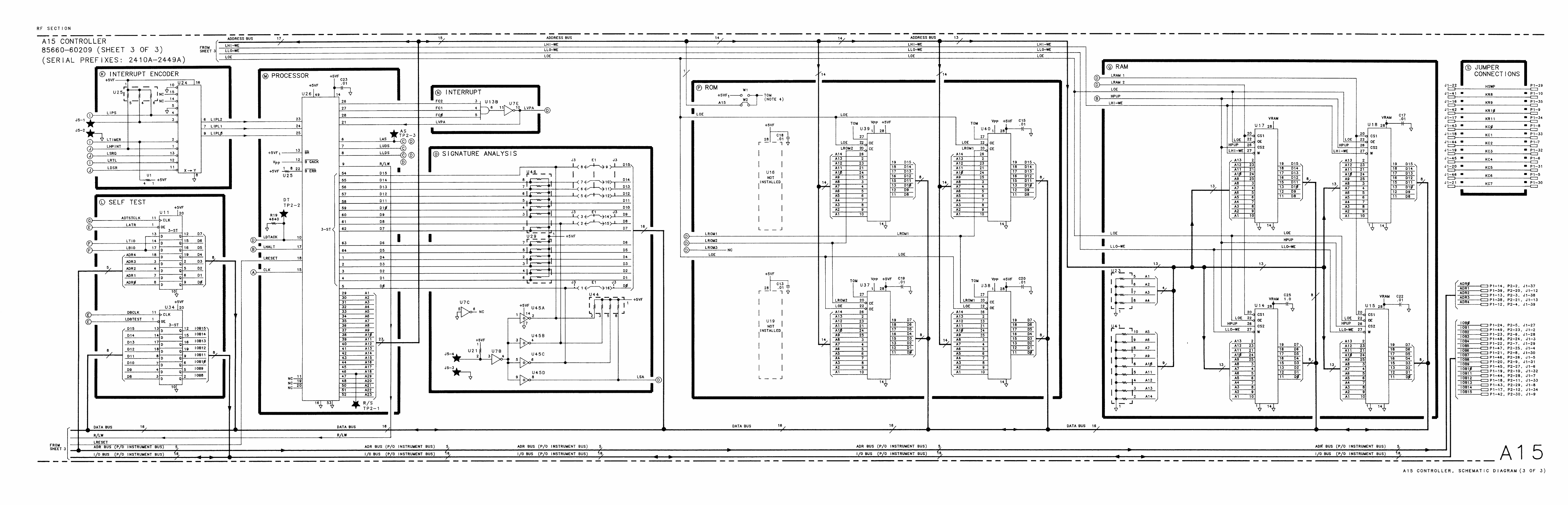
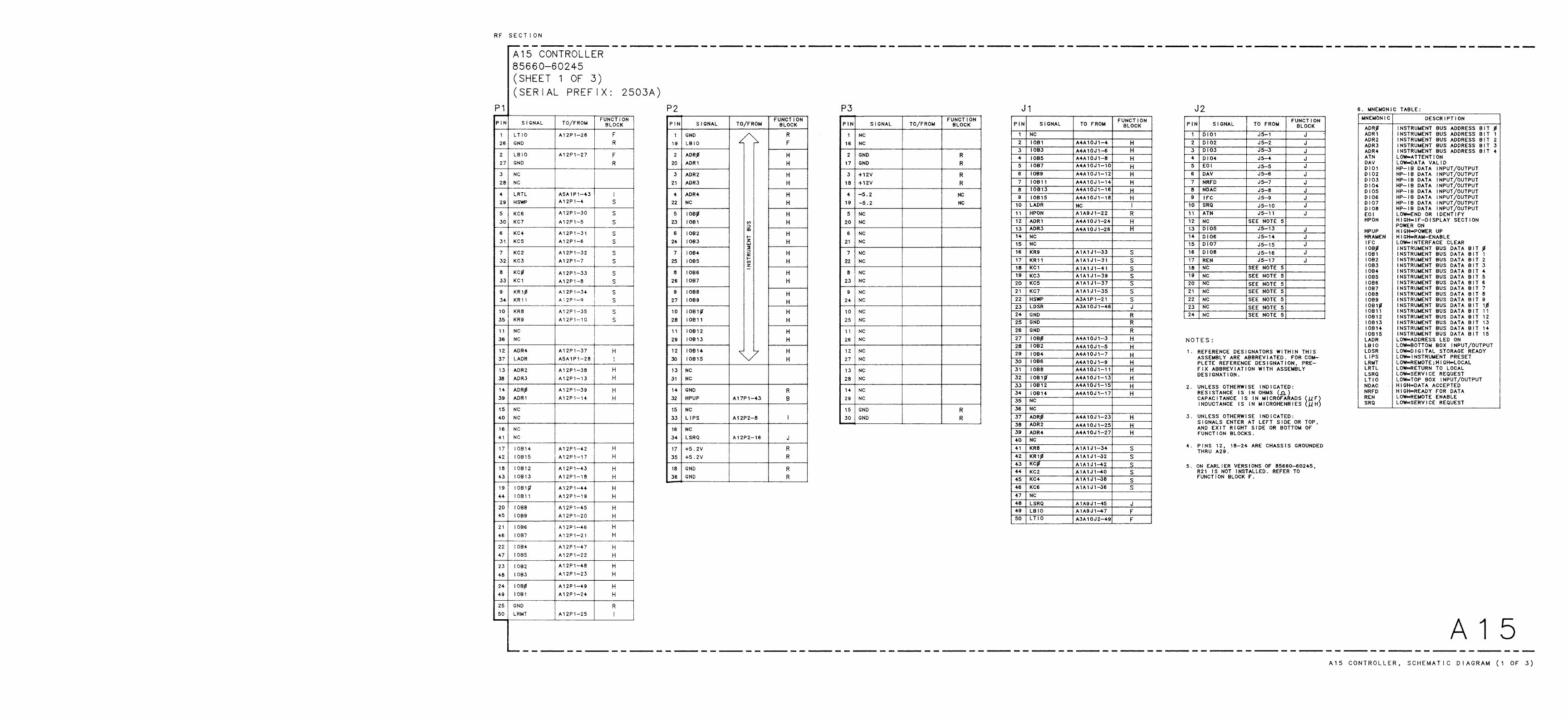
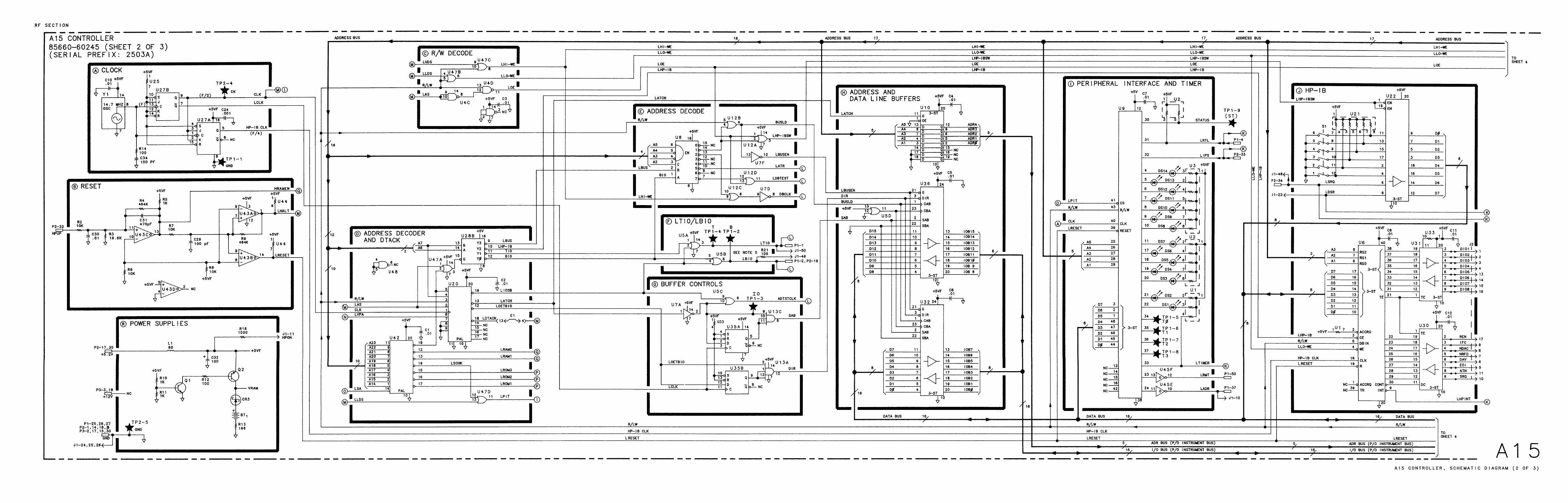
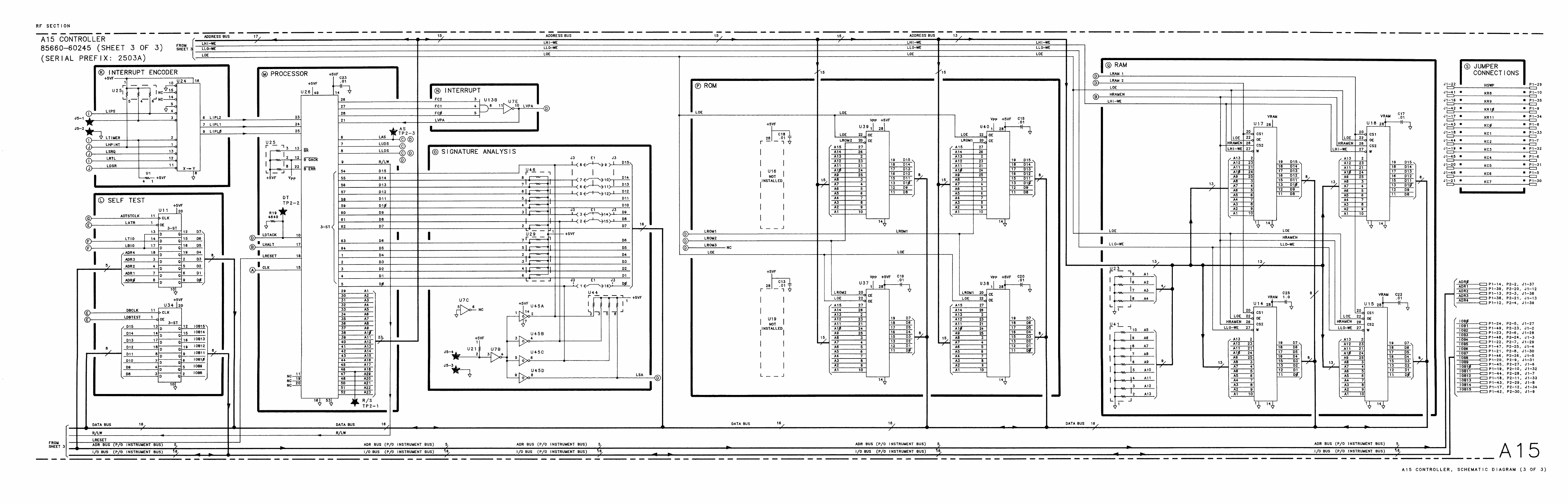
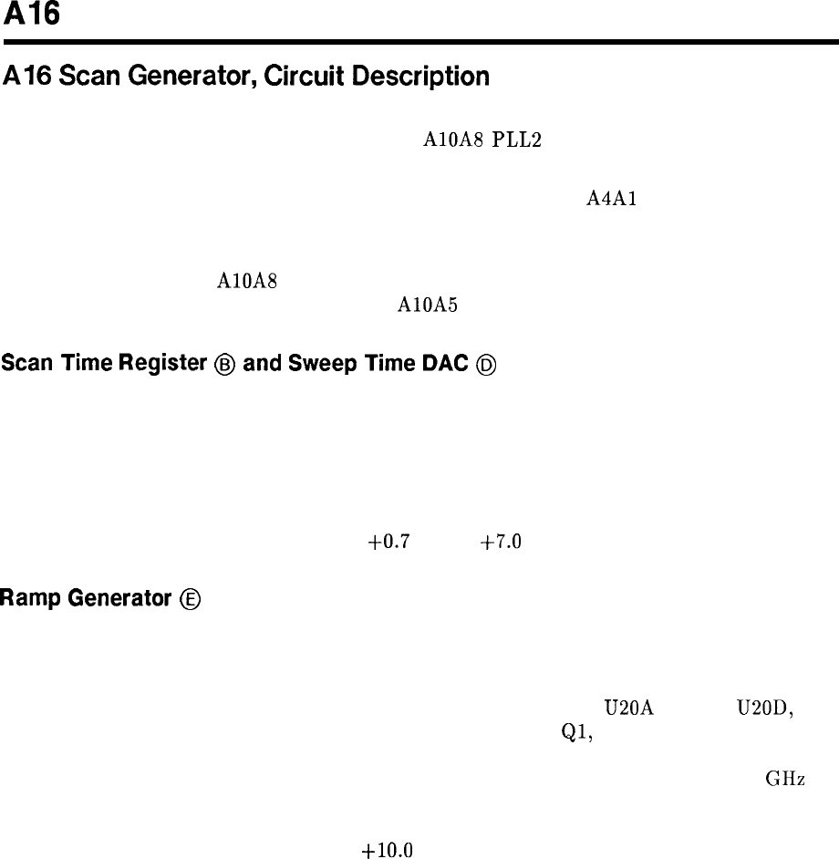
Al6
Al6
Scan
Generator,
Circuit
Description
The Al6 Scan Generator provides tuning voltage ramps to the IF-Display Section (SCAN
OUT and AUX OUT) andscaled ramps to the AlOA8 PLL2 Discriminator and A19 DAC.
The SCAN OUT ramp to the IF-Display Section is used for the horizontal sweep signal for
the CRT display update, and the AUX OUT ramp is used by the
A4Al
Video Processor to
maintain video information in proper correlation with the horizontal sweep and frequency
tuning.
The scaled ramp to the AlOA8 PLL2 Discriminator is used to scale the tuning current ramp
(VCO TUNE) used to tune the VCO on the AlOA5 PLL2 VCO.
Scan
Time Register
@
and
Sweep
Time
DAC
@
Scan time information is placed in the scan time registers U26, U27, and U29. This
information comes from the front panel via the Instrument Bus. Processing of this
information is done on the Al2 Front-Panel Interface and Al5 Controller. The information is
clocked into the Scan Time Register by control signal LSTS (Low = Scan Time Strobe). This
control signal becomes active (low) whenever the selected scan time is changed. A positive dc
voltage is developed by U8 corresponding to the programmed sweep time information applied
to the DAC U28. This voltage is between
+0.7
V and
+7.0
V.
Ramp
Generator
@
The dc voltage level provided by U8 causes a constant current to flow through the proper
scaling resistor, through Virtual Ground and Q5 to the Ramp Capacitor Cl. The scaling
resistor is selected by the programmed sweep information from the front panel the same as is
the sweep time. This information turns on one of the switch drivers U20A through U20D,
which turns on one and only one of the scaling resistor switches
Ql,
Q2, Q3, or Q4, to place
the proper scaling resistors in the charging current path for Cl. If the selected sweep time
is slower than 200 seconds, none of the scaling resistors are switched in. For 0.0 to 2.5 GHz
frequency span, the waveform on Ramp Capacitor Cl is a positive going ramp from -5.0 Vdc
to -2.0 Vdc with a 3 ms reset time. Ramp Buffer U3 amplifies and shifts the level of the
ramp so that the SCAN OUT is a 0.0 to
+lO.O
V dc ramp.
Al6 1
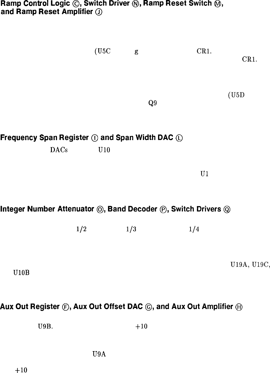
Ramp
Control
Logic
0,
Switch
Driver
@,
Ramp
Reset
Switch
@I,
and
Ramp Reset
Amplifier
@
The sweep ramp is formed by alternately charging and discharging Cl, according to the
following cycle.
Control line HSWP resets the sweep (High = Sweeping). When HSWP goes low (determined
by IF-Display Section), LHOLD (U5C pin 8)
g
oes low, turning on
CRl.
When CR1 is on,
charging current bypasses ramping capacitor Cl and instead passes to ground via
CRl.
Ramping capacitor Cl stops charging.
Ramping capacitor Cl holds its charge until LANR, from Front-Panel Interface Assembly
A12, goes low (Low = Analog Reset). When LANR goes low, LHOLD goes high, turning
CR1 off, removing the current bypass for ramping capacitor Cl. RESET/GO (U5D pin 11)
also goes high when LANR goes low, which turns
Q9
off. Q7 and Q6 then turn on, providing
a discharge path for Cl through Ramp Reset Amplifier U2. Test point 3 remains at ground
potential until HSWP again goes high, starting the cycle again.
Frequency
Span
Register
(ij
and
Span
Width
DAC
@
The Span Width DACs U17 and
UlO
provide a negative scan ramp to be scaled by the
Integer Number Attenuator. The output of this negative-going ramp is between 0 and -10
V. The amplitude of the ramp is dependent on the span of the instrument. Frequency span
information arrives on the Instrument Bus and is stored in registers
Ul
and U18. This
information is clocked into Frequency Span registers U16 and U18 whenever control line LSAS
(Low = Scan Attenuator Strobe) goes low.
Integer Number Attenuator
@,
Band
Decoder
@,
Switch
Drivers
@I
The Integer Number Attenuator scales the negative ramp at TP5 to the harmonic band being
swept. This division is by
l/2
for Band C,
l/3
for Band D, and
l/4
for Band E. In Band B,
the ramp is not scaled so it remains unchanged.
The division is performed by R48 through R50. If in Band B, only R80 is in the circuit. In
Band C, R81 is added. In Band D, R82 is added. In Band E, R83 is added. These resistors
are switched in by transistors Q15, Q13, and Q14, which are driven by drivers U19A, U19C,
and UlOB respectively. The information necessary to determine when and which resistors to
switch in comes form the Al2 Front-Panel Interface (SAT 1 and SAT 2) and is decided by
Band Decoder P.
Aux
Out
Register
0,
Aux
Out
Offset
DAC
0,
and
Aux
Out
Amplifier
@I
The AUX OUT signal is a positive-going ramp voltage from the scan generator which is
amplified by U9B. This output is always 0 to
+lO
V regardless of the selected frequency span.
If more than one harmonic band is swept, there is a small ramp output from the ramp
generator E (TP3) for each band with each ramp resetting to 0 V. To combine these ramps,
Aux Out Offset DAC U22 and U9A provide a voltage to hold the Aux Out Amplifier input at
a dc level at the end of each ramp. The output therefore is a continuous ramp voltage from
0 to
+lO
V. This voltage is programmed into the DAC U22 by the span information from
the Instrument Bus. This information is stored in Aux Out Register U23 and U21, being
clocked in by control line LAOS (Low = Aux Out Strobe). This control line is from the Al2
2 Al6
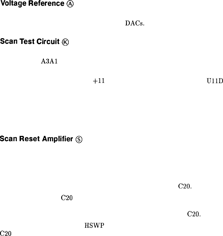
Front-Panel Interface and is enabled (pulled low) whenever front-panel key selections indicate
that more than one harmonic board is being swept.
Voltage
Reference
@
Voltage Reference U7 and associated circuitry provide a stable -7 V dc reference voltage for
both the Sweep Time and Aux Out Offset DACs.
Scan
Test
Circuit
@
The control signal HSWP (High = Sweeping) is normally pulled low indicating the end of a
sweep by the
A3Al
Trigger in the IF-Display Section. This signal can also be pulled low by
the Scan Test Circuit for the purpose of testing the scan circuitry.
If the scan ramp should exceed
+ll
V, this overvoltage is detected by
UllD
which triggers
one-shot multivibrator U6. U6 generates a 50 ms pulse on the HSWP line. When this pulse
goes low, the Al5 Controller “thinks” that the sweep has ended and performs its update
functions. When the pulse goes high again (after 50 ms), the Al5 Controller “thinks” a new
sweep has begun. This enables the sweep circuitry to function without the IF-Display Section,
or when a circuit malfunction exists, thus aiding troubleshooting.
Scan
Reset
Amplifier
@
The Scan Reset Amplifier supplies negative feedback that holds SCAN OUT (Q12 emitter) at
ground potential during retrace.
For Scan Generator (HP part number 85660-60198): Fixed-gain amplifier U13 amplifies
any potential at its noninverting input, pin 3. During retrace, LSAMPLE is low, and
sample-and-hold device U14 tracks the U13 output, charging C20.
This error voltage at
C20
is divided by R64, R65, and R66, and is summed with the Span
Width DAC output at U12 pin 2. The amplified and inverted output of U12 cancels the
potential at SCAN OUT that produced the error voltage across C20.
When the sweep commences,
HSWP
and LSAMPLE are high. The input to U14 is held on
C20
for the duration of the sweep.
Al6 3
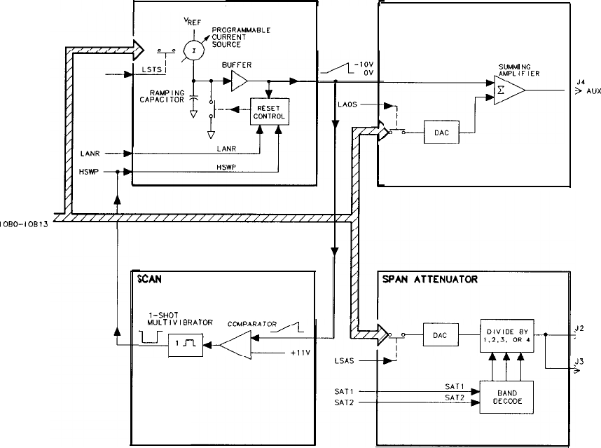
RAW GENERATOR
INSTRUMENT
BUS
1oEm-1cr313
SCAN
TEST
T-SHOT
MULTlVlBRATOR
q
1J-L
AUX GUT
S”MM
I
NG
cFL
;‘A”,
OUT
J2
l SCAN OUT
J3
3
SCAN OUT
Figure 1. Al6 Scan Generator, Simplified Block Diagram
4 Al6
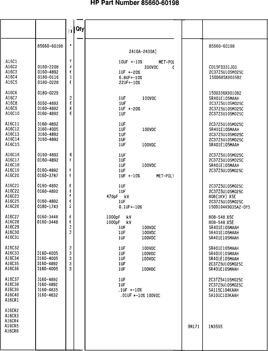
Reference
Designation
HP Part
Number
Al6 85660-60198
A16Cl 0160-5609
A16C2 0160-2208
A16C3 0160-4892
A16C4 0180-0116
A16C5 0180-0228
A16C6
A16C7
A16C8
A16C9
A16ClO
0180-0229
7
0160-4005
3
0160-4892
E
0160-4892
E
0160-4892
E
A16Cll
A16C12
A16C13
A16C14
A16C15
0160-4892
6
0160-4005
3
D160-4892
6
3160-4892
6
3160-4005
3
A16C16 0160-4892
A16C17 0160-4892
A16C18 0160-4005
A16C19 0160-4892
A16C20 0160-3787
A16C21
A16C22
A16C23
A16C25
A16C26
0160-4892
f
0160-4892
f
0160-3447
6
0160-4892
E
0180-1743
i
A16C27
A16C28
A16C29
A16C30
A16C31
0160-3448
E
0160-3448
E
0160-4005
3
0160-4005
3
0160-4005
3
A16C32
A16C33
A16C34
A16C35
A16C36
0160-4005
0160-4005
D160-4005
D160-4892
3160-4005
A16C37
A16C38
A16C39
A16C40
A16CRl
3160-4892
6
3160-4892
6
3160-4835
7
3160-4832
4
1901-0539
3
A16CR2
A16CR3
A16CR4
A16CR5
A16CR6
1901-0539
3
1901-0539
3
1901-0539
3
1901-0376
6
1901-0040
1
c
c
r
F
t
-
a
-
1
1
1
1
1
1
1
1
1
1
1
1
1
1
1
1
1
1
1
1
1
1
1
1
1
1
1
1
1
1
1
1
1
1
1
1
1
1
1
1
1
1
1
1
1
1
-
Al 6 Scan Generator
Description
Mfr Part
Number
BOARD ASSEMBLY, SCAN GENERATOR
(SERIAL PREFIXES:
2410~-2430~)
Mfr
Code
28480 85660-60198
CAPACITOR-FXD
1OUF
+-lo%
50VDC
MET-PO1 84411 HEW-687
CAPACITOR-FXD 330PF +-5%
SOOVDC
MICA
C
09023 CD15FD331JO3
CAPACITOR-FXD
1IJF
+-20x 25VDC CER
56289 2C37Z5U105M025C
CAPACITOR-FXD
6.8UF+-10%
35VDC TA
56289 150D685X903582
CAPACITOR-FXD
22UF+-10%
15VDC TA
56289 1500226X901582
CAP-FXD 33uF 10 V TA 56289 1500336X9OlOB2
CAPACITOR-FXD
1UF
+-20%
1OOVDC
CER
04222 SR401E105MAAH
CAPACITOR-FXD
1UF
+-20% 25VDC CER
56289 2C37Z5U105M025C
CAPACITOR-FXD
1UF
+-20x 25VDC CER
56289 2C37Z5U105M025C
CAPACITOR-FXD
1UF
+-20% 25VDC CER
56289 2C37Z5U105M025C
CAPACITOR-FXD
1UF
+-20% 25VDC CER
56289 2C37Z5U105M025C
CAPACITOR-FXD
1UF
+-20%
1OOVDC
CER
04222 SR401E105MAAH
CAPACITOR-FXD
1UF
+-20% 25VDC CER
56289 2C37Z5U105M025C
CAPACITOR-FXD
1UF
+-20% 25VDC CER
56289 2C37Z5U105M025C
CAPACITOR-FXD
1UF
+-20%
1OOVDC
CER
04222 SR401E105MAAH
CAPACITOR-FXD
1UF
+-20% 25VDC CER
56289 2C37Z5U105M025C
CAPACITOR-FXD
1UF
+-20% 25VDC CER
56289 2C37Z5U105M025C
CAPACITOR-FXD
1UF
+-20%
1OOVDC
CER
04222 SR401E105MAAH
CAPACITOR-FXD
1UF
+-20% 25VDC CER
56289 2C37Z5U105M025C
CAPACITOR-FXD
1UF
+-lo%
50VDC
MET-POL'I
84411 HEW-249
CAPACITOR-FXD
1UF
+-20% 25VDC CER
CAPACITOR-FXD
1UF
+-20% 25VDC CER
CAP-FXD
47OpF
1
kV
CAPACITOR-FXD
1UF
+-20% 25VDC CER
CAPACITOR-FXD
O.lUF+-10%
35VDC TA
56289
56289
56289
56289
2C37Z5U105M025C
2C37Z5U105M025C
808(1KV)
X5E
471K
2C37Z5U105M025C
1500104X9035A2-DYS
CAP-FXD
1OOOpF
1
kV
CAP-FXD
1OOOpF
1
kV
CAPACITOR-FXD
1UF
+-20%
1OOVDC
CER
CAPACITOR-FXD
1UF
+-20%
1OOVDC
CER
CAPACITOR-FXD
1UF
+-20%
1OOVDC
CER
04222
04222
04222
808-548
X5E
102K
808-548
X5E
102K
SR401E105MAAH
SR401E105MAAH
SR401E105MAAH
CAPACITOR-FXD
1UF
+-20%
1OOVDC
CER
04222 SR401E105MAAH
CAPACITOR-FXD
1UF
+-20%
1OOVDC
CER
04222 SR401E105MAAH
CAPACITOR-FXD
1UF
+-20%
1OOVDC
CER
04222 SR401E105MAAH
CAPACITOR-FXD
1UF
+-20% 25VDC CER
56289 2C37Z5U105M025C
CAPACITOR-FXD
1UF
+-20%
1OOVDC
CER
04222 SR401E105MAAH
CAPACITOR-FXD
1UF
+-20% 25VDC CER
56289 2C37Z54105M025C
CAPACITOR-FXD
1UF
+-20% 25VDC CER
56289 2C37Z5U105M025C
CAPACITOR-FXD
.lUF
+-lo%
50VDC CER
04222 SA115C104KAAH
CAPACITOR-FXD
.OlUF
+-lo%
1OOVDC
CER
04222 SAlOlC103KAAH
DIODE-SCHDTTKY SM SIG 28480 1901-0539
DIODE-SCHOTTKY SM SIG 28480
DIODE-SCHDTTKY SM SIG 28480
DIODE-SCHOTTKY SM SIG 28480
DIODE-GEN PRP 35V 50MA DO-35
9N171
DIODE-SWITCHING 30V 50MA 2NS DO-35 71468
1901-0539
1901-0539
1901-0539
lN3595
*Indicates factory-selected value
8566060198 Parts List
Page 1 of 4
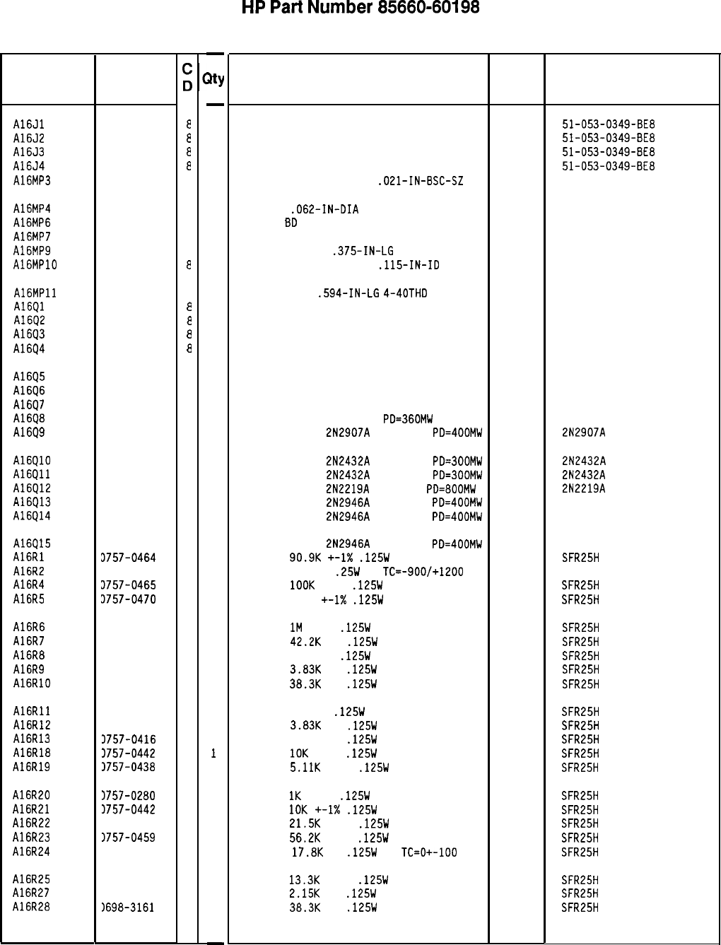
Reference
Designation
HP Part
Number
A16Jl
A16J2
A16J3
A16J4
A16MP3
1250-0543
a
1250-0543
a
1250-0543
a
1250-0543
a
1251-2194
1
A16MP4 1480-0073
1
A16MP6 4040-0749
4
A16MP7 4040-0754
1
A16MP9 2200-0143
C
AlGMPlO 2190-0003
a
A16MPll
Al6Ql
A1602
A16Q3
A1694
0380-1194
1
1855-0020
a
1855-0020
a
1855-0020
a
1855-0020
a
A1605
Al6Q6
A1697
Al6Q8
A1699
1855-0082
2
1855-0082
2
1855-0082
2
1854-0404
C
1853-0281
9
A16QlO
Al6Qll
A16Q12
A16Q13
A16914
1854-0557
4
1854-0557
4
1854-0637
1
1853-0322
9
1853-0322
9
A16915
A16Rl
A16R2
A16R4
A16R5
1853-0322
9
3757-0464
5
3683-2265
1
3757-0465
6
3757-0470
3
A16R6
A16R7
A16R8
A16R9
A16RlO
3698-8827
4
3698-3450
9
3698-3459
8
3698-3153
9
3698-3161
9
A16Rll
A16R12
A16R13
A16R18
A16R19
3698-3446
3
3698-3153
9
3757-0416
7
1757-0442
9
1757-0438
3
A16R20
A16R21
A16R22
A16R23
A16R24
3757-0280
3
3757-0442
9
1757-0199
3
1757-0459
8
3698-3136
8
A16R25
A16R27
A16R28
1757-0289
2
1698-0084
9
1698-3161
9
85660-60198 Parts List
Page 2 of 4
-
BY
-
1
1
1
1
2
2
1
1
2
2
2
1
1
1
1
1
1
1
1
1
1
1
1
1
1
1
1
1
1
1
1
1
1
1
1
1
1
1
1
1
1
1
1
1
1
1
1
1
-
HP
Part
Number 85660-60198
Al6 Scan Generator
Description
CONNECTOR-RF SM-SNP M PC 50-OHM
CONNECTOR-RF SM-SNP M PC 50-OHM
CONNECTOR-RF SM-SNP M PC 50-OHM
CONNECTOR-RF SM-SNP M PC 50-OHM
CONNECTOR-SGL CONT SKT
.OEl-IN-BSC-SZ
PIN-ROLL
.062-IN-DIA
.25-IN-LG
EXTR PC
BD
BRN
EXTR PC BD BLU
SCREW-MACH 4-40
.375-IN-LG
PAN-HD POZI
WASHER LOCK, HLCL NO.4
.115-IN-ID
STANDOFF-RND
.594-IN-LG
4-40THD
TRANSISTOR J-FET N-CHAN D-MODE TO-18 SI
TRANSISTOR J-FET N-CHAN D-MODE TO-18 SI
TRANSISTOR J-FET N-CHAN D-MODE TO-18 SI
TRANSISTOR J-FET N-CHAN D-MODE TO-18 SI
TRANSISTOR J-FET P-CHAN D-MODE SI
TRANSISTOR J-FET P-CHAN D-MODE SI
TRANSISTOR J-FET P-CHAN D-MODE SI
TRANSISTOR NPN SI TO-18
PD=360MW
TRANSISTOR PNP
2N2907A
SI TO-18
PD=400MW
TRANSISTOR NPN
2N2432A
SI TO-18
PD=300MW
TRANSISTOR NPN
2N2432A
SI TO-18
PD=300MW
TRANSISTOR NPN
2N2219A
SI TO-5
PD=800MW
TRANSISTOR PNP
2N2946A
SI TO-46
PD=400MW
TRANSISTOR PNP
2N2946A
SI TO-46
PD=400MW
TRANSISTOR PNP
2N2946A
SI TO-46
PD=400MW
RESISTOR
90.9K
+-1X
.125W
TF TC=O+-100
RESISTOR 22M 5%
.25W
CC
TC=-900/+1200
RESISTOR
1OOK
+-1%
.125W
TF TC=O+-100
RESISTOR 162K +-1X
.125W
TF TC=O+-100
RESISTOR
1M
+-1%
.125W
TF TC=O+-100
RESISTOR
42.2K
1%
.125W
TF TC=O+-100
RESISTOR 383K 1%
.125W
TF TC=O+-100
RESISTOR
3.83K
1%
.125W
TF TC=O+-100
RESISTOR
38.3K
1%
.125W
TF TC=O+-100
RESISTOR 383 1%
.125W
TF TC=O+-100
RESISTOR
3.83K
1%
.125W
TF TC=O+-100
RESISTOR 511 +-1%
.125W
TF TC=O+-100
RESISTOR
IOK
+-1%
.125W
TF TC=O+-100
RESISTOR
5.11K
+-1%
.125W
TF TC=O+-100
RESISTOR
1K
+-1%
.125W
TF TC=O+-100
RESISTOR
10K
+-I%
.125W
TF TC=O+-100
RESISTOR
21.5K
+-1%
.125W
TF TC=O+-100
RESISTOR
56.2K
+-1%
.125W
TF TC=O+-100
RESISTOR
17.8K
1%
.125W
TF
TC=O+-100
RESISTOR
13.3K
+-1%
.125W
TF TC=O+-100
RESISTOR
2.15K
1%
.125W
TF TC=O+-100
RESISTOR
38.3K
1%
.125W
TF TC=O+-100
*Indicates factory-selected value
Mfr
Code
98291
98291
98291
98291
00779
72962
28480
28480
77250
80120
00000
04713
04713
04713
04713
04713
04713
04713
04713
04713
01295
01295
04713
04713
04713
04713
19701
01121
19701
19701
19701
19701
19701
19701
19701
19701
19701
19701
19701
19701
19701
19701
19701
19701
19701
19701
19701
19701
Mfr Part
Number
51-053-0349-BE8
51-053-0349-BE8
51-053-0349-BE8
51-053-0349-BE8
3-331272-O
99-012-062-0250
4040-0749
4040-0754
ORDER BY DESCRIPTION
SFE793
SFE793
SFE793
SFE793
2N2907A
2N2432A
2N2432A
2N2219A
SFR25H
CB2265
SFR25H
SFR25H
SFR25H
SFR25H
SFR25H
SFR25H
SFR25H
SFR25H
SFR25H
SFR25H
SFR25H
SFR25H
SFR25H
SFR25H
SFR25H
SFR25H
SFR25H
SFR25H
SFR25H
SFR25H
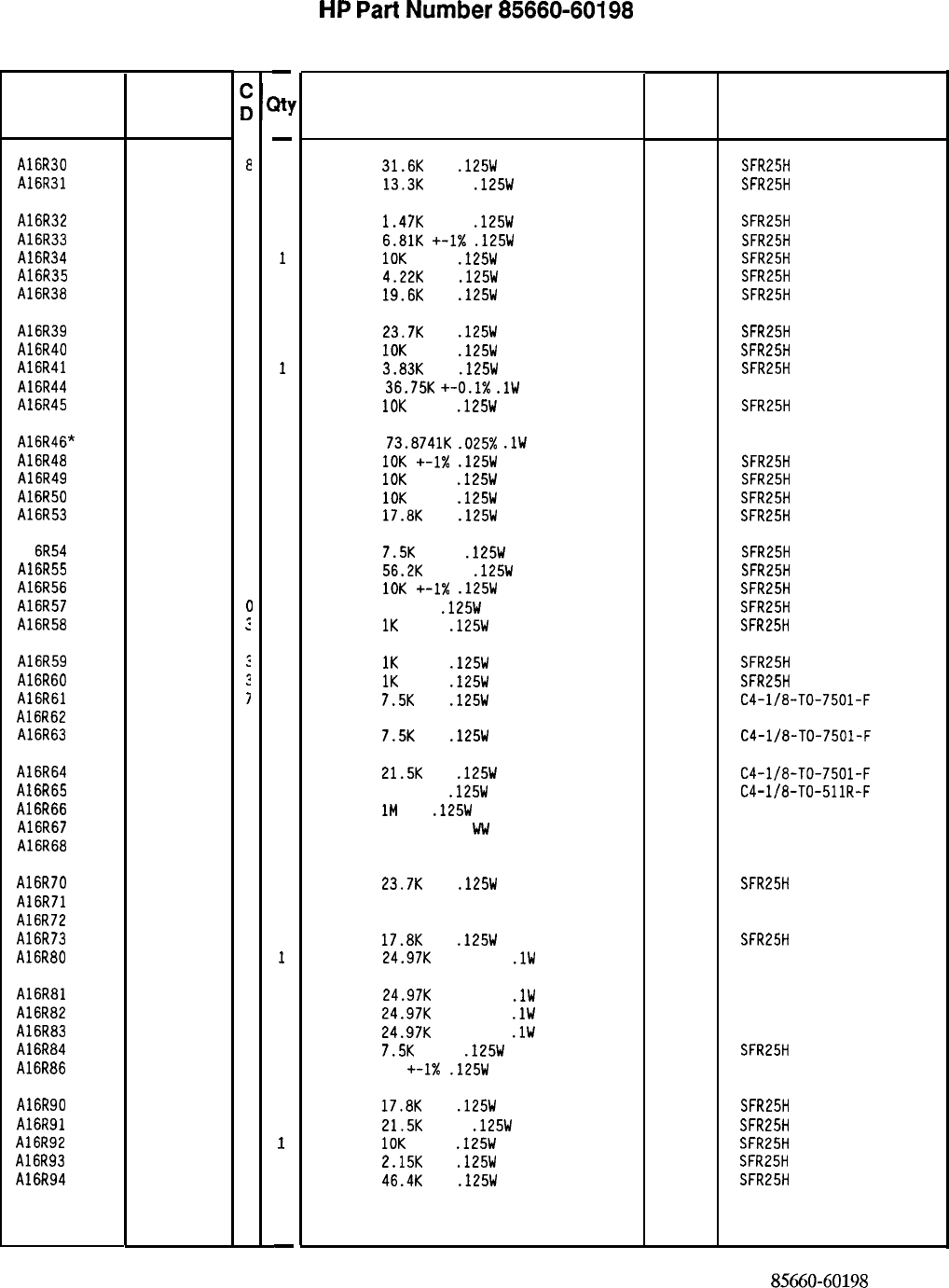
Reference
Designation
A16R30
A16R31
A16R32
A16R33
A16R34
A16R35
A16R38
A16R39
A16R40
A16R41
A16R44
A16R45
A16R46"
A16R48
A16R49
A16R50
A16R53
Al
6R54
A16R55
A16R56
A16R57
A16R58
A16R59
A16R60
A16R61
A16R62
A16R63
A16R64
A16R65
A16R66
A16R67
A16R68
A16R70
A16R71
A16R72
A16R73
A16R80
A16R81
A16R82
A16R83
A16R84
A16R86
A16R90
A16R91
A16R92
A16R93
A16R94
HP Part
Number
0698-3160
a
0757-0289
2
0757-1094
9
0757-0439
4
0757-0442
9
0698-3154
0
0698-3157
3
0698-3158
4
0757-0442
9
0698-3153
9
0699-0307
1
0757-0442
9
0699-0380
0
0757-0442
9
0757-0442
9
0757-0442
9
0698-3136
8
0757-0440
7
0757-0459
8
0757-0442
9
0698-3443
r
0757-0280
:
0757-0280
:
0757-0280
?
0757-0440
I
2100-1760
7
0757-0440
7
0757-0199
3
0757-0416
7
0698-8827
4
2100-1760
7
2100-1759
4
0698-3158
4
2100-1759
4
2100-1759
4
0698-3136
8
0699-0308
2
0699-0308
2
0699-0308
2
0699-0308
2
0757-0440
7
0757-0346
2
0698-3136
8
0757-0199
3
0757-0442
9
0698-0084
9
0698-3162
0
-
w
-
1
1
1
1
1
1
1
1
1
1
1
1
1
1
1
1
1
1
1
1
1
1
1
1
2
1
1
1
1
1
1
1
1
1
1
1
1
1
1
1
1
1
-
HP
Part
Number 85660-60198
Al 6 Scan Generator
Description
RESISTOR
31.6K
1%
.125W
TF TC=O+-100
RESISTOR
13.3K
+-1%
.125W
TF TC=O+-100
Mfr Mfr Part
Code Number
19701
SFR25H
19701
SFR25H
RESISTOR
1.47K
+-1%
.125W
TF TC=O+-100
19701
SFR25H
RESISTOR
6.81K
+-1X
.125W
TF TC=O+-100
19701
SFR25H
RESISTOR
10K
+-1%
.125W
TF TC=O+-100
19701
SFR25H
RESISTOR
4.22K
1%
.125W
TF TC=O+-100
19701
SFR25H
RESISTOR
19.6K
1%
.125W
TF TC=O+-100
19701
SFR25H
RESISTOR
23.7K
1%
.125W
TF TC=O+-100
19701
SFR25H
RESISTOR
IOK
+-1%
.125W
TF TC=O+-100
19701 SFR25H
RESISTOR
3.83K
1%
.125W
TF TC=O+-100
19701
SFR25H
RESISTOR
36.75K
+-0.1X
.lW
TF TC=O+-10
19701
50232
RESISTOR
10K
+-1%
.125W
TF TC=O+-100
19701
SFR25H
RESISTOR
73.8741K
.025%
.lW
F TC=O+-5
28480 0699-0380
RESISTOR
10K
+-1X
.125W
TF TC=O+-100
19701
SFR25H
RESISTOR
10K
+-1%
.125W
TF TC=O+-100
19701
SFR25H
RESISTOR
10K
+-1%
.125W
TF TC=O+-100
19701
SFR25H
RESISTOR
17.8K
1%
.125W
TF TC=O+-100
19701
SFR25H
RESISTOR
7.5K
+-1%
.125W
TF TC=O+-100
19701
SFR25H
RESISTOR
56.2K
+-1%
.125W
TF TC=O+-100
19701
SFR25H
RESISTOR
10K
+-I%
.125W
TF TC=O+-100
19701
SFR25H
RESISTOR 287 1%
.125W
TF TC=O+-100
19701
SFR25H
RESISTOR
1K
+-1%
.125W
TF TC=O+-100
19701
SFR25H
RESISTOR
1K
+-1%
.125W
TF TC=O+-100
19701
SFR25H
RESISTOR
1K
+-1%
.125W
TF TC=O+-100
19701
SFR25H
RESISTOR
7.5K
1%
.125W
F TC=O+-100
24546 C4-l/8-TO-7501-F
RESISTOR-TRMR 5K 5% WW SIDE-ADJ l-TRN
28480 2100-1760
RESISTOR
7.5K
1%
.125W
F TC=O+-100
24546
C4-l/8-TO-7501-F
RESISTOR
21.5K
1%
.125W
F TC=O+-100
RESISTOR 511K 1%
.125W
F TC=O+-100
RESISTOR
1M
1%
.125W
F TC=O+-100
RESISTOR-TRMR 5K 5% kW SIDE-ADJ l-TRN
RESISTOR-TRMR 2K 5% WW SIDE-ADJ l-TRN
RESISTOR
23.7K
1%
.125W
TF TC=O+-100
RESISTOR-TRMR 2K 5% WW SIDE-ADJ l-TRN
RESISTOR-TRMR 2K 5% WW SIDE-ADJ l-TRN
RESISTOR
17.8K
1%
.125W
TF TC=O+-100
RESISTOR
24.97K
+-0.025%
.lW
TF TC=O+-5
24546
24546
24546
C4-l/8-TO-7501-F
C4-l/8-TO-511R-F
0698-8827
CT-106-4-5K
CT-106-4-2K
19701
19701
19701
SFR25H
CT-106-4-2K
CT-106-4-2K
SFR25H
50232
RESISTOR
24.97K
+-0.025%
.lW
TF TC=O+-5
19701
50232
RESISTOR
24.97K
+-0.025%
.lW
TF TC=O+-5
19701
50232
RESISTOR
24.97K
+-0.025%
.lW
TF TC=O+-5
19701
50232
RESISTOR
7.5K
+-1%
.125W
TF TC=O+-100
19701
SFR25H
RESISTOR 10 +-I%
.125W
TF TC=O+-100
91637 CMF-55-1, T-l
RESISTOR
17.8K
1%
.125W
TF TC=O+-100
19701
SFR25H
RESISTOR
21.5K
+-1%
.125W
TF TC=O+-100
19701
SFR25H
RESISTOR
10K
+-1%
.125W
TF TC=O+-100
19701
SFR25H
RESISTOR
2.15K
1%
.125W
TF TC=O+-100
19701 SFR25H
RESISTOR
46.4K
1%
.125W
TF TC=O+-100
19701
SFR25H
*Indicates facto y-selected value
85660-60198 Parts List
Page 3 of 4
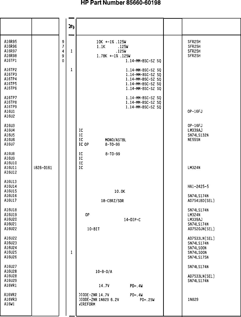
Reference
Designation
A16R95
A16R96
A16R97
A16R98
A16TPl
A16TP2
A16TP3
A16TP4
A16TP5
A16TP6
A16TP7
A16TP8
A16TP9
A16Ul
A16U2
A16U3
A16U4
A16U5
A16U6
A16U7
A16U8
A16U9
A16UlO
A16Ull
A16U12
A16U13
A16U14
A16U15
A16U16
A16U17
A16U18
A16U19
A16U20
A16U21
A16U22
A16U22
A16U23
A16U24
A16U25
A16U26
A16U27
A16U28
A16U28
A16U29
A16VRl
A16VR2
A16VR3
A16Wl
HP Part
Number
0757-0442
0757-0424
0757-0405
0757-0278
1251-0600
C
D
1251-0600
0
1251-0600
0
1251-0600
0
1251-0600
0
1251-0600
0
1251-0600
0
1251-0600
0
1251-0600
0
1826-0601
0
1826-0471
2
1826-0601
0
1826-0306
2
1820-1425
6
1826-0180
0
1826-1058
3
1826-1058
3
1826-0092
3
1826-0229
8
1826-0161
7
1826-0229
8
1826-0471
2
1826-0840
9
1810-0206
8
1820-1196
8
1826-0684
9
1820-1196
8
1826-0161
7
1826-0306
2
1820-1196
8
1826-0541
7
1826-0448
3
1820-1196
8
1820-1197
9
1820-1197
9
1820-1195
7
1820-1196
8
1826-0541
7
1826-0448
3
1820-1196
8
1902-3203
6
1902-3203
6
1902-0625
0
1460-1489
8
85660-60198 Parts List
Page 4 of 4
-
3Y
-
1
1
1
1
1
1
1
1
1
1
1
1
1
1
1
1
1
1
1
1
1
1
1
1
1
1
1
1
1
1
1
1
1
1
0
1
1
1
1
1
0
1
1
1
1
1
-
HP
Part
Number 85660-60198
Al6 Scan Generator
Description Mfr Mfr Part
Code Number
RESISTOR
10K
+-1X
.125W
TF TC=D+-100
19701
SFR25H
RESISTOR
l.lK
+-1%
.125W
TF TC=O+-100
19701
SFR25H
RESISTOR 162 +-1%
.125W
TF TC=O+-100
19701
SFR25H
RESISTOR
1.78K
+-1X
.125W
TF TC=O+-100
19701
SFR25H
CONNECTOR-SGL CONT PIN
1.14-MM-BSC-SZ
SQ
27264 16-06-0034
CONNECTOR-SGL CONT PIN
1.14-MM-BSC-SZ
SQ
27264 16-06-0034
CONNECTOR-SGL CONT PIN
1.14-MM-BSC-SZ
SQ
27264 16-06-0034
CONNECTOR-SGL CONT PIN
1.14-MM-BSC-SZ
SQ
27264 16-06-0034
CONNECTOR-SGL CONT PIN
1.14-MM-BSC-SZ
SQ
27264 16-06-0034
CONNECTOR-SGL CONT PIN
1.14-MM-BSC-SZ
SQ
27264 16-06-0034
CONNECTOR-SGL CONT PIN
1.14-MM-BSC-SZ
SQ
27264 16-06-0034
CONNECTOR-SGL CONT PIN
1.14-MM-BSC-SZ
SQ
27264 16-06-0034
CONNECTOR-SGL CONT PIN
1.14-MM-BSC-SZ
SQ
27264 16-06-0034
IC OP AMP PRCN TO-99 PKG 06665 OP-16FJ
IC OP AMP LOW-DRIFT TO-99 PKG 06665 DP-07CJ SELECTED
IC OP AMP PRCN TO-99 PKG 06665 DP-16FJ
IC
COMPARATOR GP QUAD 14-DIP-C PKG
27014 LM339AJ
IC
SCHMITT-TRIG TTL LS NAND QUAD 2-INP
01295 SN74LS132N
IC
TIMER TTL
MOND/ASTBL 18324 NE555N
IC
DP
AMP GP
8-TO-99
PKG
06665 DP-02CJ
[C
OP AMP GP
8-TO-99
PKG
06665
(C
OP AMP GP DUAL TO-99 PKG
04713
[C
OP AMP LOW-DRIFT TO-99 PKG
06665
IC
OP AMP GP QUAD 14-DIP-P PKG
27014
IC OP AMP LOW-DRIFT TO-99 PKG 06665
OP-02CJ
OP-05CJ
LM324N
OP-05CJ
IC OP AMP LOW-DRIFT TO -99 PKG 28480 1826-0471
SAMPLE AND HOLD 14 -CERDIP 34371 HAl-2425-5
NETWORK-RES 8-SIP
lO.OK
OHM X 7
11236 750-81
IC FF TTL LS D-TYPE POS-EDGE-TRIG COM CL 01295 SN74LS174N
D/A 12-BIT
18-CBRZ/SDR
CMOS
24355 AD7541BD(SEL)
IC FF TTL LS D-TYPE POS-EDGE-TRIG COM CL 01295 SN74LS174N
IC
DP
AMP GP QUAD 14-DIP-P PKG
27014 LM324N
IC COMPARATOR GP QUAD
14-DIP-C
PKG
27014 LM339AJ
IC FF TTL LS D-TYPE POS-EDGE-TRIG CDM CL 01295 SN74LS174N
D/A
lo-BIT
16-PLASTIC CMOS
24355 AD7520JN(SEL)
ALTERNATE FOR 1826-0541 24355 AD7533LN(SEL)
IC FF TTL LS D-TYPE PDS-EDGE-TRIG CDM CL 01295 SN74LS174N
IC GATE TTL LS NAND QUAD 2-INP 01295 SN74LSOON
IC GATE TTL LS NAND QUAD 2-INP 01295 SN74LSOON
IC FF TTL LS D-TYPE POS-EDGE-TRIG COM CL 01295 SN74LS175N
IC FF TTL LS D-TYPE POS-EDGE-TRIG CDM CL 01295
IC CDNV
lo-B-D/A
16-DIP-P PKG
28480
ALTERNATE FOR 1826-0541 24355
IC FF TTL LS D-TYPE POS-EDGE-TRIG CDM CL 01295
DIODE-ZNR
14.7V
5% DO-35
PD=.4W 04713
SN74LS174N
1826-0541
AD7533LN(SEL)
SN74LS174N
)IODE-ZNR
14.7V
5% DO-35
PD=.4W 04713
3IODE-ZNR
lN829
6.2V
5% DO-35
PD=.25W
TC
04713
dIREFORM
BE CU AG
17450 lN829
*Indicates factory-selected value
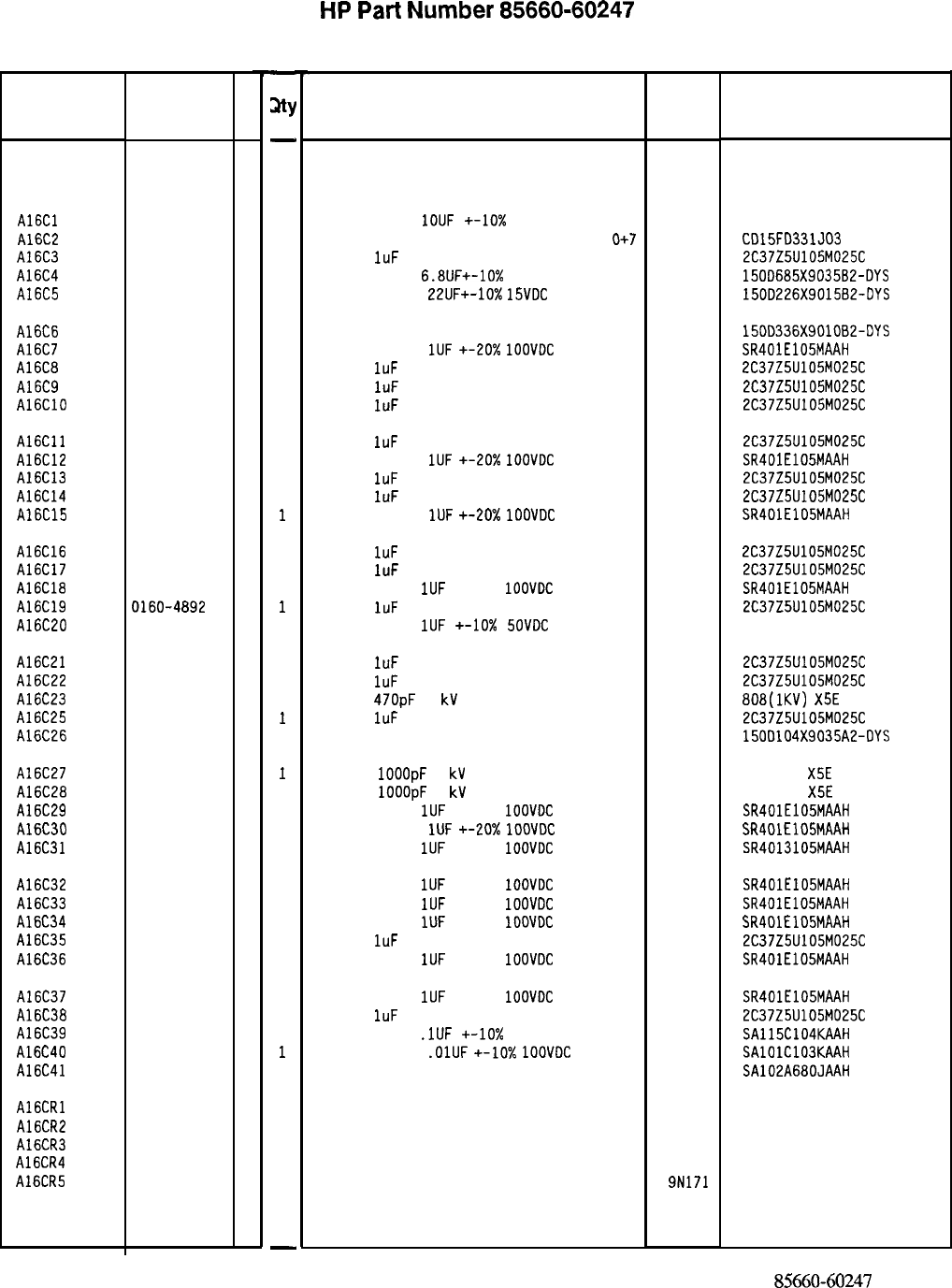
Reference
Designation
HP Part C
Number D
Al6
85660-60247 5
A16Cl
A16C2
A16C3
A16C4
A16C5
0160-5609 5
0160-2208 4
0160-4892 6
0180-0116 1
0180-0228 6
A16C6
A16C7
A16C8
A16C9
A16ClO
0180-0229 7
0160-4005 3
0160-4892 6
0160-4892 6
0160-4892 6
A16Cll
A16C12
A16C13
A16C14
A16C15
0160-4892 6
0160-4005 3
0160-4892 6
0160-4892 6
0160-4005 3
A16C16
A16C17
A16C18
A16C19
A16C20
0160-4892 6
0160-4892 6
0160-4005 3
0160-4892
6
0160-3787 6
A16C21
A16C22
A16C23
A16C25
A16C26
0160-4892 6
0160-4892 6
0160-3447 5
0160-4892 6
0180-1743 2
A16C27
A16C28
A16C29
A16C30
A16C31
0160-3448 6
0160-3448 6
0160-4005 3
0160-4005 3
0160-4005 3
A16C32
0160-4005 3
A16C33
0160-4005 3
A16C34
0160-4005 3
A16C35
0160-4892 6
A16C36
0160-4005 3
A16C37
A16C38
A16C39
A16C40
A16C41
0160-4005 3
0160-4892 6
0160-4835 7
0160-4832 4
0160-4803 9
A16CRl
A16CR2
A16CR3
A16CR4
A16CR5
1901-0539 3
1901-0539 3
1901-0539 3
1901-0539 3
1901-0376 6
-
sty
-
1
1
1
1
1
1
1
1
1
1
1
1
1
1
1
1
1
1
1
1
1
1
1
1
1
1
1
1
1
1
1
1
1
1
1
1
1
1
1
1
1
1
1
1
1
1
-
HP
Part
Number 85660-60247
Al 6 Scan Generator
Description
BOARD ASSEMBLY SCAN GENERATOR
(
SER
I
AL P
RE
FIX
: 2449A)
Mfr
Code
28480
Mfr Part
Number
85660-60247
CAPACITOR-FXD
1OUF
+-lo% 50VDC MET-POLYC
84411 HEW-687
CAPACITOR-FXD 330PF +-5% 300VDC MICA
0+7
09023 CD15FD331J03
CAP-FXD
1uF
25 V
56289 2C37Z5U105M025C
CAPACITOR-FXD
6.8UF+-10%
35VDC TA
56289 150D685X9035B2-DYS
CAPACITOR-FXD
22UF+-10%
15VDC
TA
56289 150D226X901582-OYS
CAP-FXD 33uF 10 V TA
56289 15DD336X9010B2-DYS
CAPACITOR-FXD
1UF
+-20x
1OOVDC
CER
04222 SR401E105MAAH
CAP-FXD
1uF
25 V
56289 2C37Z5U105M025C
CAP-FXD
1uF
25 V
56289 2C37Z5U105M025C
CAP-FXD
IuF
25 V
56289 2C37Z5U105M025C
CAP-FXD
1uF
25 V
56289 2C37Z5U105M025C
CAPACITOR-FXD
1UF
+-20x
IOOVDC
CER
04222 SR401E105MAAH
CAP-FXD
1uF
25 V
56289 2C37Z5U105M025C
CAP-FXD
IuF
25 V
56289 2C37Z5U105M025C
CAPACITOR-FXD
1UF
+-20x
1OOVDC
CER
04222
SR401E105MAAH
CAP-FXD
1uF
25 V
56289 2C37Z5U105M025C
CAP-FXD
1uF
25 V
56289 2C37Z5U105M025C
CAPACITOR-FXD
1UF
+-20%
1OOVDC
CER
04222 SR401E105MAAH
CAP-FXD
1uF
25 V
56289 2C37Z5U105M025C
CAPACITOR-FXD
1UF
+-lo%
SOVDC
MET-POLYC
84411 HEW-249
CAP-FXD
IuF
25 V
CAP-FXD
1uF
25 V
CAP-FXD
47OpF
1
kV
CAP-FXD
1uF
25 V
CAPACITOR-FXD .lUF+-10% 35VDC TA
56289
56289
56289
56289
2C37Z5U105M025C
2C37Z5U105M025C
808(1KV)
X5E
471K
2C37Z5U105M025C
150D104X9035A2-DYS
CAP-FXD
1OOOpF
1
kV
CAP-FXD
1OOOpF
1
kV
CAPACITOR-FXD
1UF
+-20%
1OOVDC
CER
CAPACITOR-FXD
1UF
~-20%
1OOVDC
CER
CAPACITOR-FXD
1UF
+-20%
1OOVDC
CER
04222
04222
04222
808-548
X5E
102K
808-548
X5E
102K
SR401E105MAAH
SR401E105MAAH
SR4013105MAAH
CAPACITOR-FXD
1UF
+-20%
IOOVDC
CER
CAPACITOR-FXD
1UF
+-20%
1OOVDC
CER
CAPACITOR-FXD
1UF
+-20%
1DDVDC
CER
CAP-FXD
1uF
25 V
CAPACITOR-FXD
1UF
+-20%
1OOVDC
CER
04222 SR401E105MAAH
04222 SR401E105MAAH
04222
SR401E105MAAH
56289 2C37Z5UlOSM025C
04222 SR401E105MAAH
CAPACITOR-FXD
1UF
+-20%
1OOVDC
CER
04222 SR401E105MAAH
CAP-FXD
1uF
25 V
56289 2C37Z5U105M025C
CAPACITOR-FXD
.lUF
+-lo%
50VDC CER
04222 SA115C104KAAH
CAPACITOR-FXD
.OlUF
+-lo%
1OOVOC
CER
04222 SAlOlC103KAAH
CAP-FXD 68pF 100 V 04222 SA102A680JAAH
DIODE-SCHOTTKY SM SIG 28480 1901-0539
DIODE-SCHOTTKY SM SIG 28480 1901-0539
DIODE-SCHOTTKY SM SIG 28480 1901-0539
DIODE-SCHDTTKY SM SIG 28480 1901-0539
DIODE-GEN PRP 35V 50MA DO-35 9N171 IN3595
*Indicates factoy-selected value
85660-60247 Parts List
Page 1 of 4
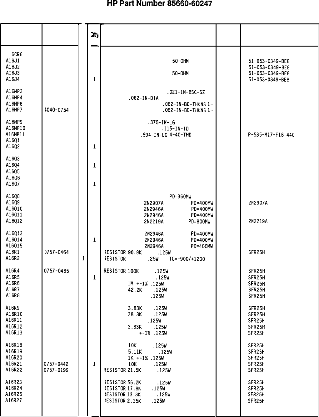
Reference
Designation
HP Part
Number
C
D
Al
6CR6
A16Jl
A16J2
A16J3
A16J4
1901-0040
1
1250-0543 8
1250-0543
8
1250-0543
8
1250-0543 8
A16MP3
A16MP4
A16MP6
A16MP7
1251-2194
1
1480-0073
6
4040-0749
4
4040-0754
1
A16MP9 2200-0143
0
AlGMPlO 2190-0003
8
AlGMPll 0380-1194
1
A16Ql 1855-0020
8
A16Q2 1855-0020
8
A1693
A16Q4
A16Q5
Al6Q6
A16Q7
1855-0020
8
1855-0020
8
1855-0082
2
1855-0082
2
1855-0082
2
A16Q8
A16Q9
Al6QlO
A16Qll
A16Q12
1854-0404
0
1853-0281
9
1853-0322
9
1853-0322
9
1854-0637
1
A16Q13
A16Q14
A16915
A16Rl
A16R2
1853-0322
9
1853-0322
9
1853-0322
9
3757-0464
5
3683-2265
1
A16R4
A16R5
A16R6
A16R7
A16R8
3757-0465
6
0757-0470
3
0698-8827
4
0698-3450
9
0698-3459
8
A16R9
A16RlO
A16Rll
A16R12
A16R13
0698-3153
9
0698-3161
9
0698-3446
3
0698-3153
9
0757-0416
7
A16R18
A16R19
A16R20
A16R21
A16R22
0757-0442
9
0757-0438
3
0757-0280
3
D757-0442
9
0757-0199
3
A16R23
A16R24
A16R25
A16R27
3757-0459
8
3698-3136
8
1757-0289
2
1698-0084
9
8X60-60247 Parts List
Page 2 of 4
-
3Y
-
1
1
1
1
1
2
2
1
1
2
2
2
1
1
1
1
1
1
1
1
1
1
1
1
1
1
1
1
1
1
1
1
1
1
1
1
1
1
1
1
1
1
1
1
1
1
1
1
-
HP
Part
Number 85660-60247
A16 Scan Generator
Description Mfr
Mfr Part
Code Number
DIODE-SWITCHING 30V 50MA 2NS DO-35
71468
CONNECTOR-RF SM-SNP M PC
50-OHM 98291
CONNECTOR-RF SM-SNP M PC 50-OHM 98291
CONNECTOR-RF SM-SNP M PC
50-OHM 98291
CONNECTOR-RF SM-SNP M PC 50-OHM 98291
CONNECTOR-SGL CONT SKT
.021-IN-BSC-SZ
PIN-ROLL
.062-IN-DIA
.25-IN-LG BE-CU
EXTR-PC BD BRN PDLYC
.062-IN-BD-THKNS
l-
EXTR-PC BD BLU POLYC
.062-IN-BD-THKNS
l-
00779 3-331272-O
72962
99-012-062-0250
SCREW-MACH 4-40
.375-IN-LG
PAN-HD-POZI
77250
WASHER-LK HLCL NO. 4
.115-IN-ID 80120
STANDOFF-RND
.594-IN-LG
4-40-THD 04729
TRANSISTOR J-FET N-CHAN D-MODE TO-18 SI 04713
TRANSISTOR J-FET N-CHAN D-MODE TO-18 SI 04713
TRANSISTOR J-FET N-CHAN D-MODE TO-18 SI
TRANSISTOR J-FET N-CHAN D-MODE TO-18 SI
TRANSISTOR J-FET P-CHAN D-MODE SI
TRANSISTOR J-FET P-CHAN D-MODE SI
TRANSISTOR J-FET P-CHAN D-MODE SI
04713
04713
04713
04713
04713
TRANSISTOR NPN SI TO-18
PD=360MW
TRANSISTOR PNP
2N2907A
SI TO-18
PD=400MW
TRANSISTOR PNP
2N2946A
SI TO-46
PD=400MW
TRANSISTOR PNP
2N2946A
SI TO-46
PD=400MW
TRANSISTOR NPN
2N2219A
SI TO-5
PD=800MW
04713
04713
04713
04713
04713
TRANSISTOR PNP
2N2946A
SI TO-46
PD=400MW 04713
TRANSISTOR PNP
2N2946A
SI TO-46
PD=400MW 04713
TRANSISTOR PNP
2N2946A
SI TO-46
PD=400MW 04713
7ESISTDR
90.9K
+-1%
.125W
TF TC=O+-100
19701
?ESISTOR
22M 5%
.25W
CC
TC=-900/+1200 01121
m1ESISTOR
1OOK
+-1%
.125W
TF TC=O+-100
RESISTOR 162K +-1%
.125W
TF TC=O+-100
RESISTOR
1M
+-1X
.125W
TF TC=O+-100
RESISTOR
42.2K
1%
.125W
TF TC=O+-100
RESISTOR 383K 1%
.125W
TF TC=O+-100
RESISTOR
3.83K
1%
.125W
TF TC=O+-100
RESISTOR
38.3K
1%
.125W
TF TC=O+-100
RESISTOR 383 1%
.125W
TF TC=O+-100
RESISTOR
3.83K
1%
.125W
TF TC=O+-100
RESISTOR 511 +-I%
.125W
TF TC=O+-100
RESISTOR
10K
+-1%
.125W
TF TC=O+-100
RESISTOR
5.11K
+-1%
.125W
TF TC=O+-100
RESISTOR
1K
+-I%
.125W
TF TC=O+-100
RESISTOR
10K
+-1%
.125W
TF TC=O+-100
iESISTOR
21.5K
+-1%
.125W
TF TC=O+-100
?ESISTOR
56.2K
+-1%
.125W
TF TC=O+-100
{ESISTOR
17.8K
1%
.125W
TF TC=O+-100
{ESISTOR
13.3K
+-1%
.125W
TF TC=O+-100
ZESISTOR
2.15K
1%
.125W
TF TC=O+-100
19701
19701
19701
19701
19701
19701
19701
19701
19701
19701
19701
19701
19701
19701
19701
19701
19701
19701
19701
*Indicates factory-selected value
51-053-0349-BE8
51-053-0349-BE8
51-053-0349-BE8
51-053-0349-BE8
P-535-M17-F16-440
SFE793
SFE793
SFE793
SFE793
2N2907A
2N2219A
SFR25H
CB2265
SFR25H
SFR25H
SFR25H
SFR25H
SFR25H
SFR25H
SFR25H
SFR25H
SFR25H
SFR25H
SFR25H
SFR25H
SFR25H
SFR25H
SFR25H
SFR25H
SFR25H
SFR25H
SFR25H
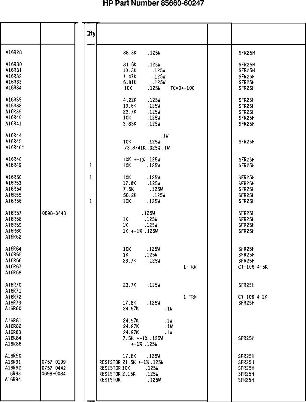
Reference
Designation
HP Part
Number
C
D
A16R28 0698-3161
9
A16R30
A16R31
A16R32
A16R33
A16R34
0698-3160
8
0757-0289
2
0757-1094
9
0757-0439
4
0757-0442
9
A16R35
A16R38
A16R39
A16R40
A16R41
0698-3154
0
0698-3157
3
0698-3158
4
0757-0442
9
0698-3153
9
A16R44 0699-0307
1
A16R45 0757-0442
9
A16R46* 0699-0380
0
A16R48
A16R49 0757-0442
9
0757-0442
9
A16R50
A16R53
A16R54
A16R55
A16R56
0757-0442
9
0698-3136
8
0757-0440
7
0757-0459
8
0757-0442
9
A16R57
A16R58
A16R59
A16R60
A16R62
0698-3443
0
0757-0280
3
0757-0280
3
0757-0280
3
2100-1762
9
A16R64
A16R65
A16R66
A16R67
A16R68
0757-0442
9
0757-0280
3
0698-3158
4
2100-1760
7
2100-1759
4
A16R70
A16R71
A16R72
A16R73
A16R80
0698-3158
4
2100-1759
4
2100-1759
4
0698-3136
8
0699-0308
2
A16R81
A16R82
A16R83
A16R84
A16R86
0699-0308
2
0699-0308
2
0699-0308
2
0757-0440
7
0757-0346
2
A16R90
A16R91
A16R92
Al 6R93
A16R94
0698-3136
8
0757-0199
3
D757-0442
9
3698-0084
9
3698-3162
0
-
3Y
-
1
1
1
1
1
1
1
1
1
1
1
1
1
1
1
1
1
1
1
1
1
1
1
1
1
1
1
1
1
1
1
1
1
1
1
1
1
1
1
1
1
1
1
1
1
1
-
HP
Part
Number 85660-60247
Al6 Scan Generator
Description Mfr
Mfr Part
Code Number
RESISTOR
38.3K
1%
.125W
TF TC=O+-100
19701
SFR25H
RESISTOR
31.6K
1%
.125W
TF TC=O+-100
19701
SFR25H
RESISTOR
13.3K
+-1%
.125W
TF TC=O+-100
19701 SFR25H
RESISTOR
1.47K
+-1%
.125W
TF TC=O+-100
19701
SFR25H
RESISTOR
6.81K
+-1%
.125W
TF TC=O+-100
19701
SFR25H
RESISTOR
10K
+-1%
.125W
TF
TC=O+-100
19701
SFR25H
RESISTOR
4.22K
1%
.125W
TF TC=O+-100
19701
SFR25H
RESISTOR
19.6K
1%
.125W
TF TC=O+-100
19701
SFR25H
RESISTOR
23.7K
1%
.125W
TF TC=O+-100
19701
SFR25H
RESISTOR
10K
+-1%
.125W
TF TC=O+-100
19701
SFR25H
RESISTOR
3.83K
1%
.125W
TF TC=O+-100
19701
SFR25H
RESISTOR 36.751: +-0.1%
.lW
TF TC=O+-10
19701
50232
RESISTOR
10K
+-1%
.125W
TF TC=O+-100
19701 SFR25H
RESISTOR
73.8741K
.025%
.lW
F TC=O+-5
2848 0699-0380
RESISTOR
10K
+-I%
.125W
TF TC=O+-100
19701
SFR25H
RESISTOR
IOK
+-1%
.125W
TF TC=O+-100
19701
SFR25H
RESISTOR
10K
+-1%
.125W
TF TC=O+-100
19701
SFR25H
RESISTOR
17.8K
1%
.125W
TF TC=O+-100
19701
SFR25H
RESISTOR
7.5K
+-1%
.125W
TF TC=O+-100
19701
SFR25H
RESISTOR
56.2K
+-1%
.125W
TF TC=O+-100
19701
SFR25H
RESISTOR
10K
+-1%
.125W
TF TC=O+-100
19701
SFR25H
RESISTDR 287 1%
.125W
TF TC=O+-100
RESISTOR
1K
+-1%
.125W
TF TC=O+-100
RESISTOR
1K
+-1%
.125W
TF TC=O+-100
RESISTOR
1K
+-1X
.125W
TF TC=O+-100
RESISTOR-TRMR 20K 5% WW SIDE-ADJ I-TRN
19701
19701
19701
19701
SFR25H
SFR25H
SFR25H
SFR25H
CT-106-4-20K
RESISTOR
10K
+-1%
.125W
TF TC=O+-100
RESISTOR
1K
+-1%
.125W
TF TC=O+-100
RESISTOR
23.7K
1%
.125W
TF TC=O+-100
RESISTOR-TRMR 5K 5% WW SIDE-ADJ
l-TRN
RESISTOR-TRMR 2K 5% WW SIDE-ADJ I-TRN
19701
19701
19701
SFR25H
SFR25H
SFR25H
CT-106-4-5K
CT-106-4-2K
RESISTOR
23.7K
1%
.125W
TF TC=O+-100
RESISTOR-TRMR 2K 5% WW SIDE-ADJ I-TRN
RESISTOR-TRMR 2K 5% WW SIDE-ADJ
l-TRN
RESISTOR
17.8K
1%
.125W
TF TC=O+-100
RESISTOR
24.97K
+-0.025%
.lW
TF TC=O+-5
19701
19701
19701
SFR25H
CT-106-4-2K
CT-106-4-2K
SFR25H
50232
RESISTOR
24.97K
+-0.025%
.lW
TF TC=O+-5
19701
50232
RESISTOR
24.97K
+-0.025%
.lW
TF TC=O+-5
19701
50232
RESISTOR
24.97K
+-0.025%
.lW
TF TC=O+-5
19701
50232
RESISTOR
7.5K
+-1X
.125W
TF TC=O+-100
19701
SFR25H
RESISTOR 10 +-1X
.125W
TF TC=O+-100
91637 CMF-55-1, T-l
RESISTOR
17.8K
1%
.125W
TF TC=O+-100
19701
SFR25H
?ESISTDR
21.5K
+-I%
.125W
TF TC=O+-100
19701
SFR25H
XESISTDR
IOK
+-1%
.125W
TF TC=O+-100
19701
SFR25H
XESISTOR
2.15K
1%
.125W
TF TC=O+-100
19701
SFR25H
7ESISTOR
46.41: 1%
.125W
TF TC=O+-100
19701 SFR25H
*Indicates factory-selected value
85660-60247 Parts List
Page 3 of 4
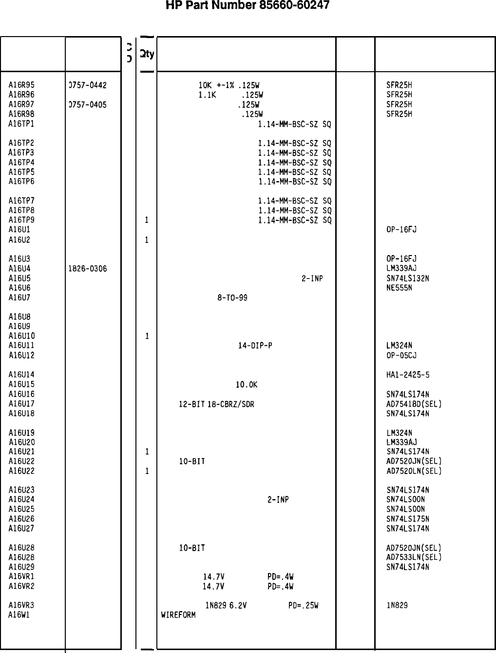
Reference
Designation
HP Part
Number
A16R95
A16R96
A16R97
A16R98
A16TPl
3757-0442
9
0757-0424
7
3757-0405
4
5757-3439
9
1251-0600
0
A16TP2
A16TP3
A16TP4
A16TP5
A16TP6
1251-0600
0
1251-0600
0
1251-0600
0
1251-0600
0
1251-0600
0
A16TP7
A16TP8
A16TP9
A16Ul
A16U2
1251-0600
0
1251-0600
0
1251-0600
0
1826-0601
0
1826-0471
2
A16U3
A16U4
A16U5
A16U6
A16U7
1826-0601
0
1826-0306
2
1820-1425
6
1826-0180
0
1826-1058
3
A16U8
A16U9
A16UlO
A16Ull
A16U12
1826-1058
3
1826-0092
3
1826-0229
8
1826-0161
7
1826-0229
8
Al6U14
A16U15
A16U16
A16U17
A16U18
1826-0840
9
1810-0206
8
1820-1196
8
1826-0684
9
1820-1196
8
A16U19
A16U20
A16U21
A16U22
A16U22
1826-0161
7
1826-0306
2
1820-1196
8
1826-0541
7
1826-0448
3
A16U23
A16U24
A16U25
A16U26
A16U27
1820-1196
8
1820-1197
9
1820-1197
9
1820-1195
7
1820-1196
8
A16U28 1826-0541
7
A16U28 1826-0448
3
A16U29 1820-1196
8
A16VRl 1902-3203
6
A16VR2 1902-3203
6
A16VR3 1902-0625
0
A16Wl 1460-1489
8
8566060247 Parts List
Page 4 of 4
-
sty
-
1
1
1
1
1
1
1
1
1
1
1
1
1
1
1
1
1
1
1
1
1
1
1
1
1
1
1
1
1
1
1
1
1
1
1
1
1
1
1
1
1
1
1
1
1
1
1
-
HP
Part
Number 85660-60247
Al 6 Scan Generator
Description Mfr Mfr Part
Code Number
RESISTOR
10K
+-1X
.125W
TF TC=O+-100
19701
SFR25H
RESISTOR
l.lK
+-1%
.125W
TF TC=O+-100
19701
SFR25H
RESISTOR 162 +-1%
.125W
TF TC=O+-100
19701
SFR25H
RESISTOR 178K +-1%
.125W
TF TC=O+-100
19701 SFR25H
CONNECTOR-SGL CDNT PIN
1.14-MM-BSC-SZ
SQ
27264 16-06-0034
CONNECTOR-SGL CONT PIN
1.14-MM-BSC-SZ
SQ
27264 16-06-0034
CONNECTOR-SGL CDNT PIN
1.14-MM-BSC-SZ
SQ
27264 16-06-0034
CONNECTOR-SGL CONT PIN
1.14-MM-BSC-SZ
SQ
27264 16-06-0034
CONNECTOR-SGL CONT PIN
1.14-MM-BSC-SZ
SQ
27264 16-06-0034
CONNECTOR-SGL CDNT PIN
1.14-MM-BSC-SZ
SQ
27264 16-06-0034
CONNECTOR-SGL CONT PIN
1.14-MM-BSC-SZ
SQ 27264 16-06-0034
CONNECTOR-SGL CONT PIN
1.14-MM-BSC-SZ
SQ
27264 16-06-0034
CONNECTOR-SGL CONT PIN
1.14-MM-BSC-SZ
SQ
27264 16-06-0034
IC OP AMP PRCN TO-99 PKG 06665 OP-16FJ
IC OP AMP LOW-DRIFT TO-99 PKG 06665 DP-07CJ SELECTED
IC OP AMP PRCN TO-99 PKG 06665 OP-16FJ
IC COMPARATOR GP QUAD 14-DIP-C PKG 27014 LM339AJ
IC SCHMITT-TRIG TTL LS NAND QUAD
L-INP 01295 SN74LS132N
IC TIMER TTL MONO/ASTBL 18324 NE555N
IC OP AMP GP
8-TO-99
PKG
06665 DP-02CJ
IC OP AMP GP 8-TD-99 PKG 06665
IC OP AMP GP DUAL TO-99 PKG 04713
IC OP AMP LOW-DRIFT TO-99 PKG 06665
IC OP AMP GP QUAD
14-DIP-P
PKG
27014
IC OP AMP LOW-DRIFT TO-99 PKG 06665
OP-OECJ
OP-05CJ
LM324N
OP-OSCJ
SAMPLE AND HOLD 14 -CEROIP 34371 HAl-2425-5
NETWORK-RES 8-SIP
lO.OK
OHM X 7
11236 750-81
IC FF TTL LS D-TYPE POS-EDGE-TRIG COM CL 01295 SN74LS174N
D/A
12-BIT
18-CBRZ/SDR
CMOS
24355 AD75418D(SEL)
IC FF TTL LS D-TYPE POS-EDGE-TRIG COM CL 01295 SN74LS174N
IC OP AMP GP QUAD 14-DIP-P PKG 27014 LM324N
IC COMPARATOR GP QUAD 14-DIP-C PKG 27014 LM339AJ
IC FF TTL LS D-TYPE POS-EDGE-TRIG COM CL 01295 SN74LS174N
D/A
lo-BIT
16-PLASTIC CMOS
24355 AD7520JN(SEL)
ALTERNATE FOR 1826-0541 24355 AD7520LN(SEL)
IC FF TTL LS D-TYPE POS-EDGE-TRIG COM CL 01295 SN74LS174N
IC GATE TTL LS NAND QUAD
E-INP 01295 SN74LSOON
IC GATE TTL LS NAND QUAD 2-INP 01295 SN74LSOON
IC FF TTL LS D-TYPE POS-EDGE-TRIG COM CL 01295 SN74LS175N
IC FF TTL LS D-TYPE POS-EDGE-TRIG COM CL 01295 SN74LS174N
D/A
lo-BIT
16-PLASTIC CMOS
ALTERNATE FOR 1826-0541
IC FF TTL LS D-TYPE POS-EDGE-TRIG CDM CL
DIODE-ZNR
14.7V
5% DO-35
PD=.4W
DIODE-ZNR
14.7V
5% DO-35
PD=.4W
DIODE-ZNR
lN829
6.2V
5% DO-35
PD=.25W
TC
WIREFORM BE CU AG
24355
24355
01295
04713
04713
AD7520JN(SEL)
AD7533LN(SEL)
SN74LS174N
04713
17450 lN829
*Indicates factory-selected value
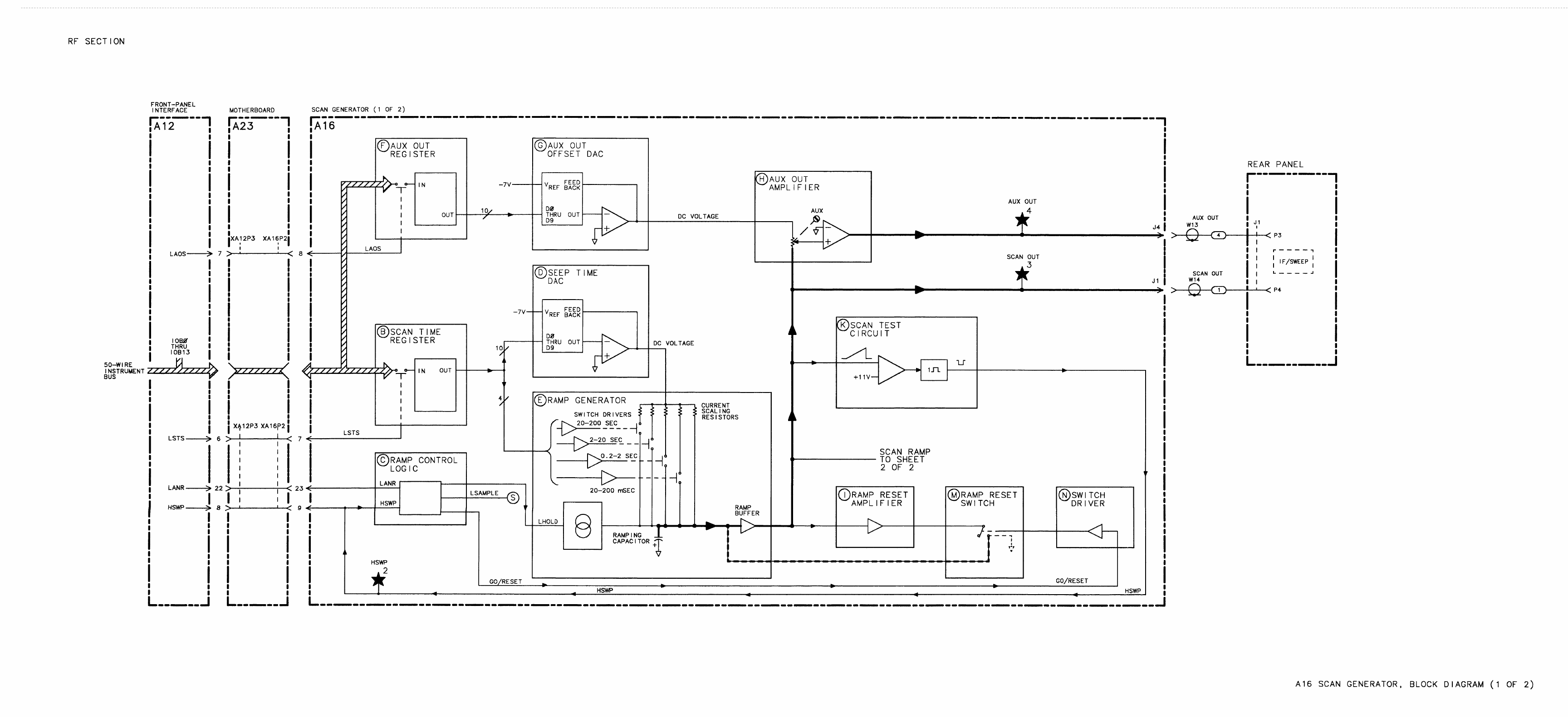
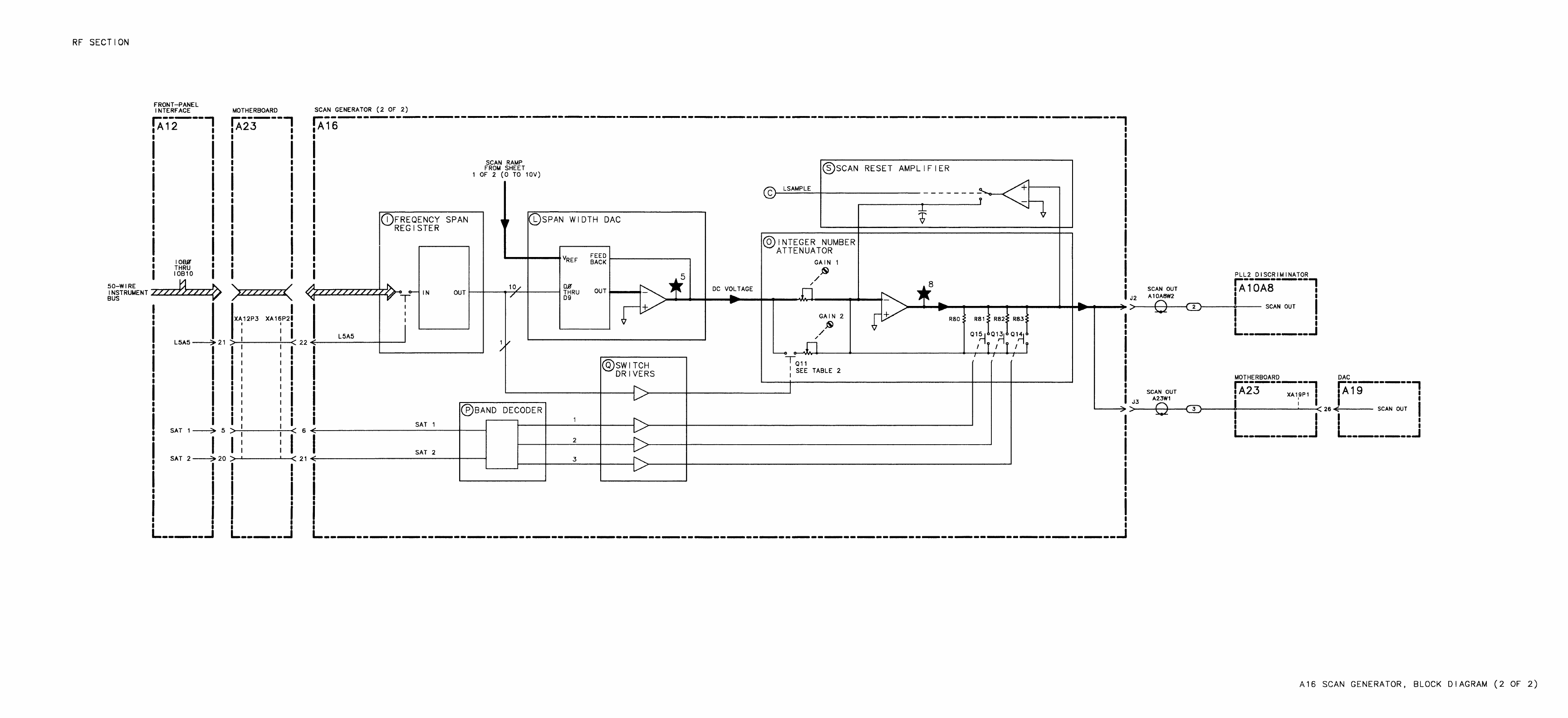
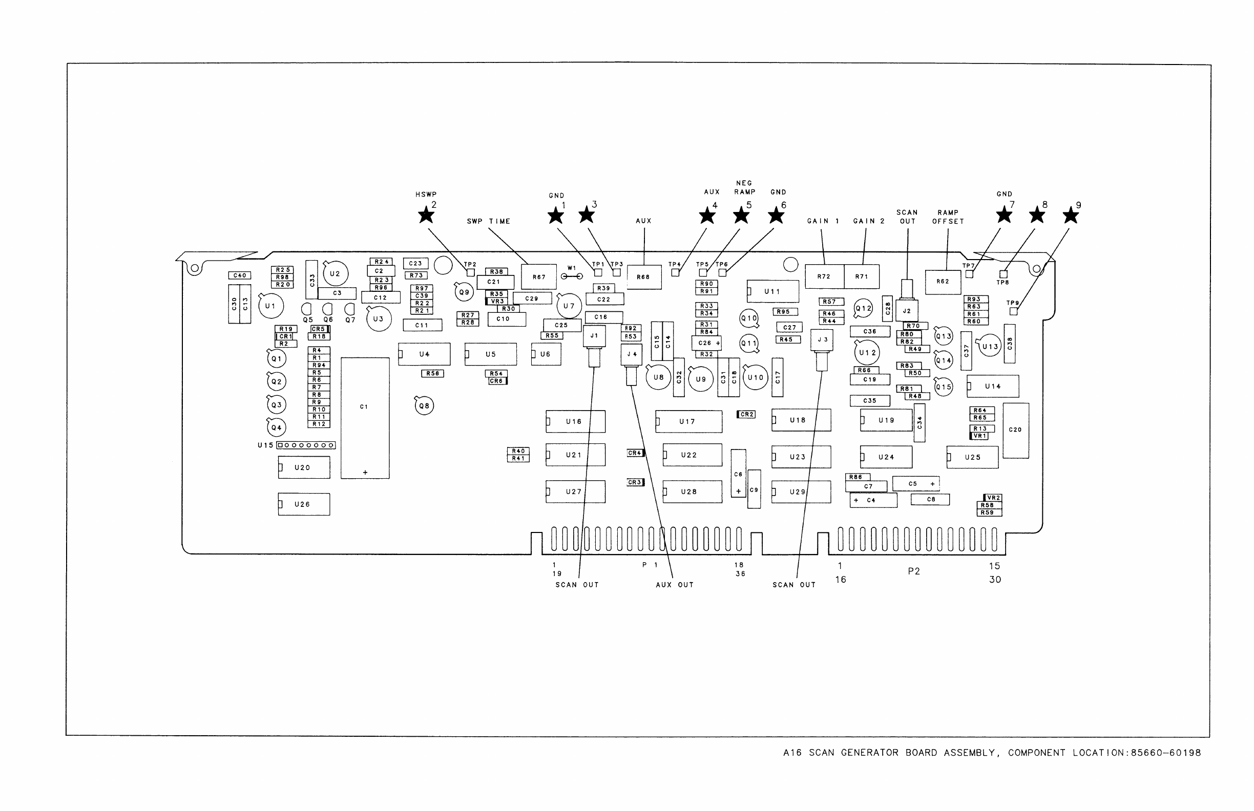
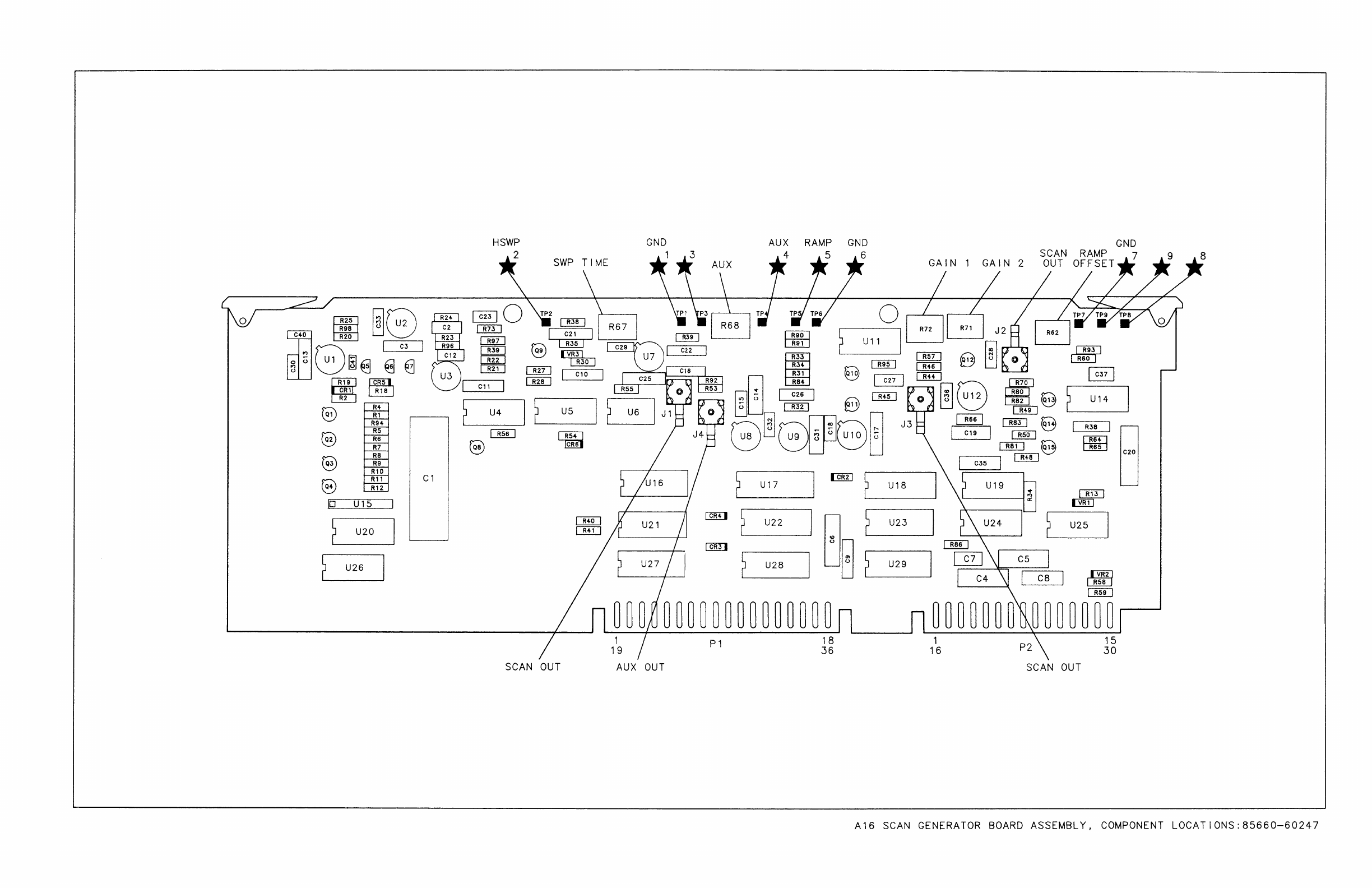

RF SECTION
-------------------------,,
Al6 SCAN GENERATOR
85660-60198 (1 OF 2)
(SERIAL PREFIXES:
2410~-2430~)
4
4LlRP
AIW-2
NC
4OR1
AISPZ-20
NC
CAPAClTANCE
IS IN
l.ICROFARAOS(~F)
INDUCTANCE
IS
IN
YICROHENRIES(,,H)
3.
UNLESS OTHERWISE
INDICATED:
SIGNALS ENTER AT LEFT
SIDE
OR
TOP
AN0
EXIT AT
RIGHT
SIDE OR
BOTTOM OF
FVNCTION
BLOCKS.
4“15 PIN
CONFlG”RATION:
,082
A15P2-6
a
OS3
AlSP2-24
E
OR4
A15P2-7
E
,095
AIWZ-25
E
086
A
15P2-8
E
007 A15P2-26
E
088
AIWZ-9
B
OS9
AISPZ-27
B
08
1p
AISPZ-10
B
OB,
1
A15P2-28
E
0812 A15P2-11
I3
0813
AlSP2-29
E
0814
AISPZ-I2
NC
0815 A15P2-JO
NC
IC
4
-5.m
AIW-16.34
NC
19
-5.2”
AlW-16.34
NC
5 -10”
AIW-13.31
R
20 -10”
Al*Pl-I3.3I
R
6
SAT,
Ala=-5
P
21
SAT2
AIF-20
P
7
LSTS
A
12P3-6
B
22
LSAS
AIZPJ-21
I
8
LAOS
AlZP3-7
F
23
LANR
AIZPS-22
C
9
“SW
A
1
W-8
C
5.
MNEMONlC
TABLE.
MNEMONIC DESCRIPTION
LSAS
LOW SC
STROBEA
N ATTENUATOR
LSTS
LOW-SCAN
TlME
STROBE
LAOS
LOW-AUX
OUT STROBE
Hsw
HIGH=SWEEPING
SAT
1
:gg”
INTEGER ATTENUATOR
12
-40”
AIW-11.29
R
27
-40”
Al*Pl-I1.29
R
13 NC
28 NC
SAT2
SCAN INTEGER ATTENUATOR
MSB
LANR LCW=ANALCGRESET
6. ACCEPTABLE
VALVES
FOR
R46.
ARE:
VALUE
1
PART NUMBER
74.2%
0699-0311
(CO-7)
73.874K
0699-0380
(CO=O,
THE FOLLOWING COMPONENTS ARE NOT USED:
UIC.
“40
“IIB.
“110
"15R5.
"15R6.
"15R7
"190
NO NC
,NO
NC
“24A.
“240
8.
czs
HAS BEEN CHANCED FROM 1p)F (HP PART
NUMBER
0180-0291)
TO
O.l!.lF
(HP PART
NUMBER
0180-1743)
TO SUPPRESS
YOLTAGE
SPIKES ON THE
A”X
OUT SIGNAL.
I
I
I
I
I
I
I
I
I
I
I
I
I
I
I
I
I
I
I
I
I
I
I
I
I
I
I
I
I
I
I
I
I
I
I
Al6
-------------------------
-J
Al6 Scan Generator, Schematic Diagram
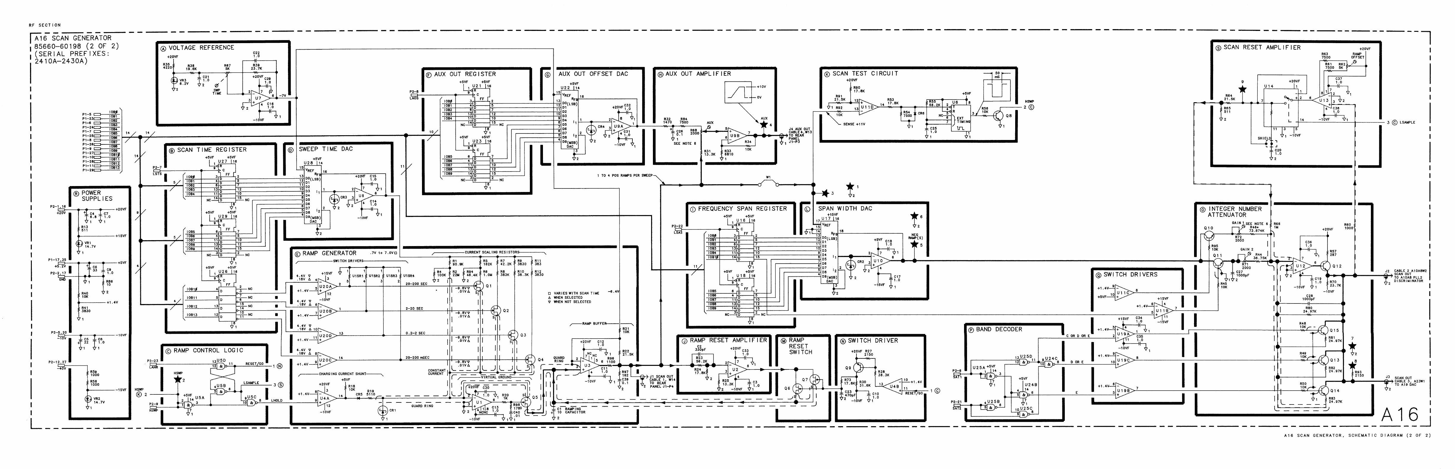
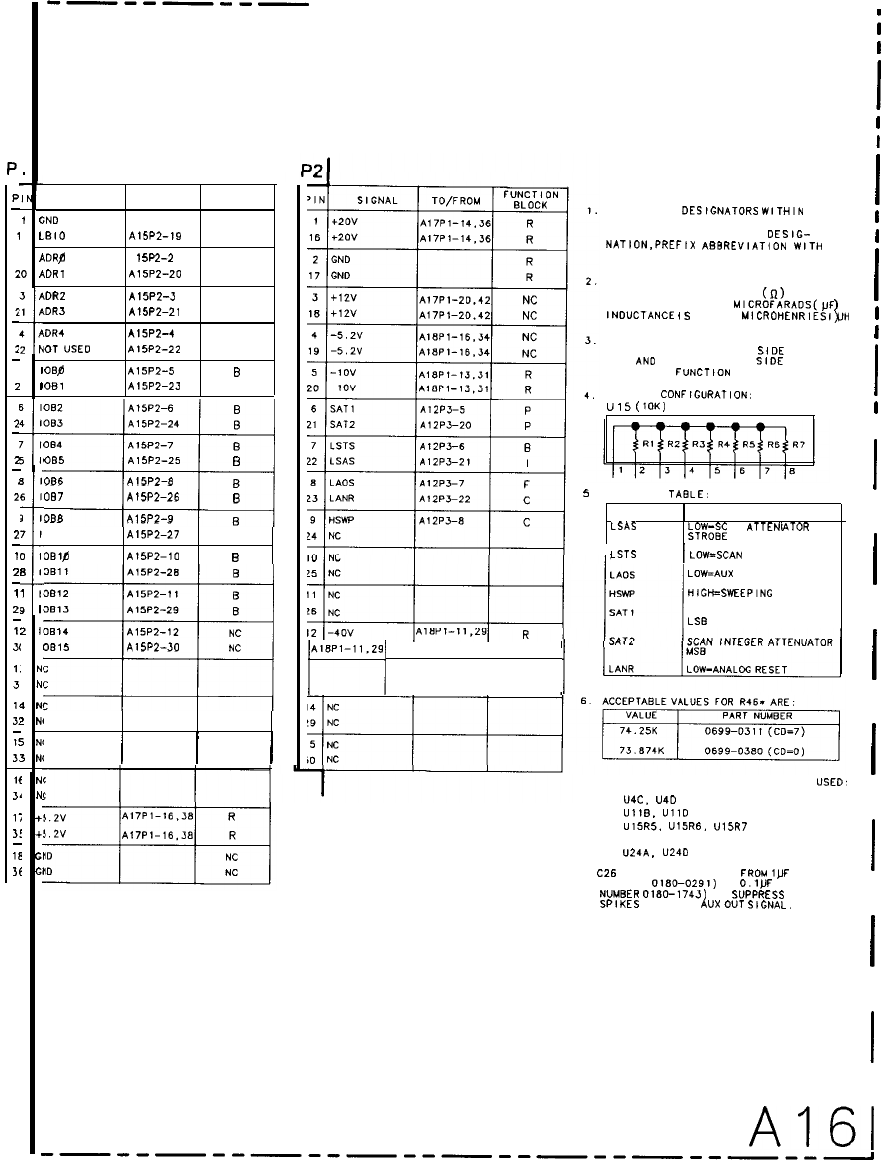
RF SECTION
----P--P
Al6 SCAN GENERATOR -----P--P---------
85660-60247 (1 OF 2)
(SERIAL PREFIX: 2449A)
SIGNAL TO/FROM FUNCTION
BLOCK
;No
NC
.BIO
AISW-19
NC
\ob?p A
1
SW-2
NC
,DR,
A15P2-20
NC
\DRZ
AlW2-3
NC
IORO
A15P2-21
NC
DR4
A15P2-4
NC
LOT
“SE0
AISW-22
NC
OW
h15P2-5
B
081
A15P2-23
B
REFERENCE
OESlGNATORS
WITHIN
THIS ASSEMBLY ARE ABBREVIATED.
FOR COMPLETE REFERENCE
DES,&
NATION,PREFIX
ABBREYIATION
WlTH
ASSEMBLY DESIGNATION.
UNLESS OTHERWISE INDICATED!
RESISTANCE IS IN OHMS
(fl)
CAPACITANCE IS IN
MICROFARACS(,,F
INOUCTANCE
IS
IN
MICROHENRIES(~H
)
‘)
UNLESS OTHERWISE INDICATED.
SIGNALS ENTER AT LEFT
SIDE
OR
TOP AND EXIT AT RIGHT
SIDE
OR
BOTTOM OF
FVNCTICN
BLOCKS.
082 A15PZ-6
B
083
AlW-24
B
084 A15P2-7
B
3&i
005
A,W2-25
6
086
AlW2-8
B
087
Am--26
B
OBB
A15P2-9
B
“15 PIN
CONFlG”RAT,ON.
UlS(10K)
5
089
A15P2-27
B
091p A15P2-10
B
0011 A15P2-28
B
0812 A15P2-11
B
0013 A15P2-29
B
0014 A15P2-12
NC
:
0015 A15P2-30
NC
c
MNEMONIC
TABLE:
MNEMONIC DESCRIPTION
LSAS
0 SCAN
ATTENU
G&
ATOR
LSTS
1
LOWG3.N
TIME STROBE
LOW=A”X
OUT STROBE
HIw=SwEEPING
SCAN INTEGER ATTENUATOR
LSB
ib
i,1”’
~~Pl-ll.Zli
R /
I I I
THE FOLLOWING COMPONENTS ARE NOT
USED’
“4C.
U40
“11B.
“110
“15R5.
U15R6.
“I%7
“190
U24A.
“240
8.
C26
HAS BEEN CHANGE0 FROM
l,,F
(HP PART
NUMBER
0180-0291)
TO
O.l!,F
(HP PART
NUMBER
0180-1743)
TO
SVPPRESS
VOLTAGE
SPlKES
ON THE
A”X
OUT
SIGNAL.
;
I
I
I
I
I
I
I
I
I
I
I
I
I
I
I
I
I
I
I
I
I
I
I
I
I
I
I
I
I
I
I
I
I
I
1
P
-
1
2
2
-
2
-
2
-
2
-
2
-
/
2
2
-
1
2
-
1
2’
-
1
3,
1.
3
11
3:
-
1:
3.
16
5
Ii
3!
-
1E
Jf
1
c
9
L
2
/
‘0
/
3
!
1
P
t
4 8
2
h
5
I
3
I
6
I
4
I
i
7 I
5 I
3
I
6
I
2
I
7
1
T
0 I
8
I
1
I
9
I
2 I’
, I’
3
N'
I
NI
t
1
NI
!
NI
5
NC
J
N(
NC
NC
+!
+:
G,
c,
A161
Al6 Scan Generator, Schematic Diagram
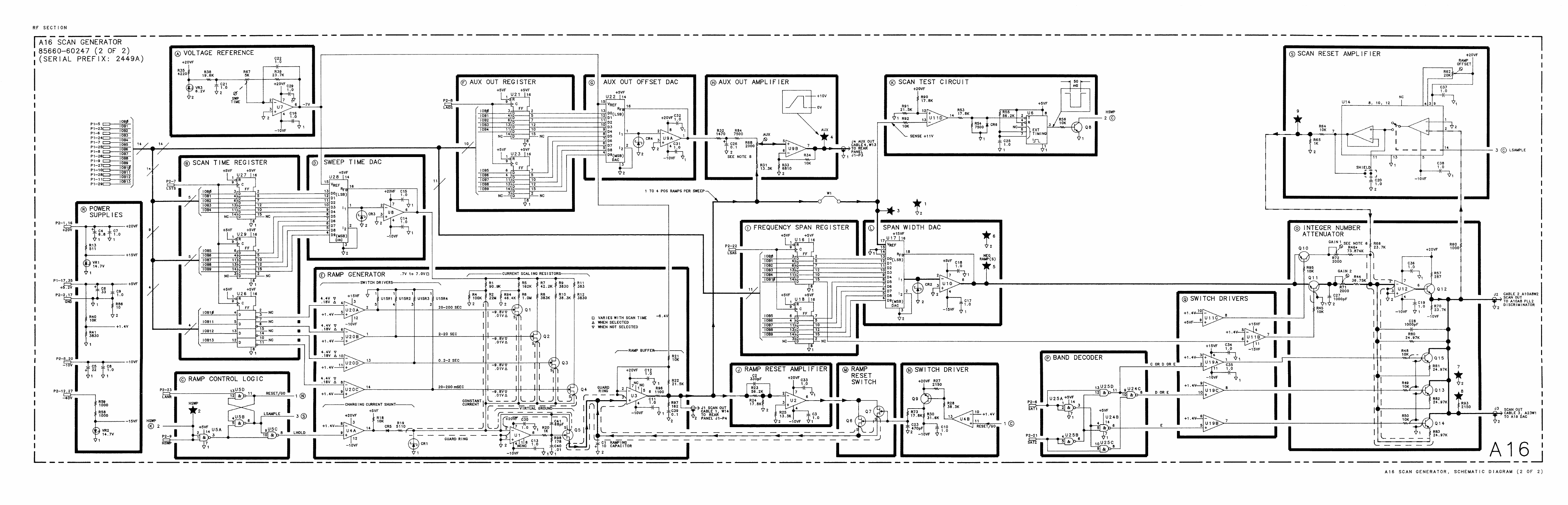
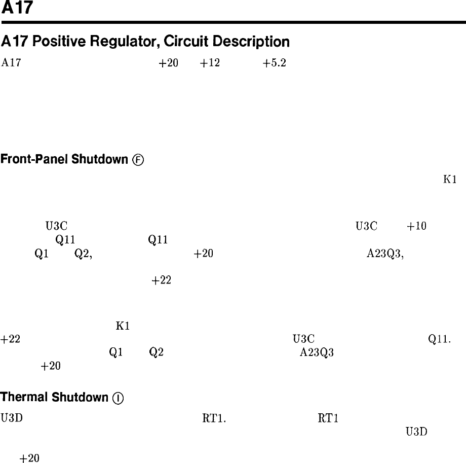
Al7
Al7
Positive
Regulator,
Circuit
Description
Al?
Positive Regulator provides
+20
V,
+12
V, and
+5.2
V regulated voltages to the
instrument. It also provides for thermal shutdown at temperatures above 85°C or if the fan
fails, controls power to the oscillator in the A22 10 MHz Frequency Standard and ensures
power-up and power-down operation that will not invalidate data in Al5 Controller. The
relationship of Al7 to A8 Rectifier, A23 Motherboard, and Al8 Negative Regulator is shown
on the A8 Rectifier schematic.
Front-Panel
Shutdown
@
When the front-panel LINE switch is in STANDBY, the LSBY line is grounded, fan relay
Kl
on the A23 Motherboard is energized turning the fan off, and the STANDBY LED is turned
on.
Pin 9 of U3C is also at ground when LSBY is grounded so the output of U3C is at i-10 V,
turning on
Qll
through R41.
Qll
sinks all of the current supplied by the compound current
source
Ql
and Q2, which turns off the i-20 V supply series-pass transistor A23Q3, located on
the A23 Motherboard. All other supplies are referenced to the output of the $20 V Regulator,
so they are also disabled. (The
+22
V supply is an exception. It is always on as long as the
instrument has ac power from the line.)
When the front-panel LINE switch is switched to the ON position, the LSBY line is no longer
grounded, the fan relay
Kl
is no longer energized, and the fan turns on. LSBY rises to about
+22
V through the fan relay coil. This causes the output of U3C to go low, turning off
Qll.
The current source of
Ql
and
Q2
can now supply current to A23Q3 on the A23 Motherboard,
and the
-j-20
V supply will turn on.
Thermal
Shutdown
@
U3D senses the voltage across thermistor
RTl.
The resistance of
RTl
is nominally 1000 ohms
at 25°C and drops to 107 ohms at 85°C. When the resistance drops, the output of U3D rises,
turning on the thermal shutdown LED DS3 and also Q12, which disables the current source in
the
+20
V supply, shutting the supply off. CR5 and R52 provide hysteresis so the instrument
will not turn on again until the temperature drops to 55°C.
Al7 1
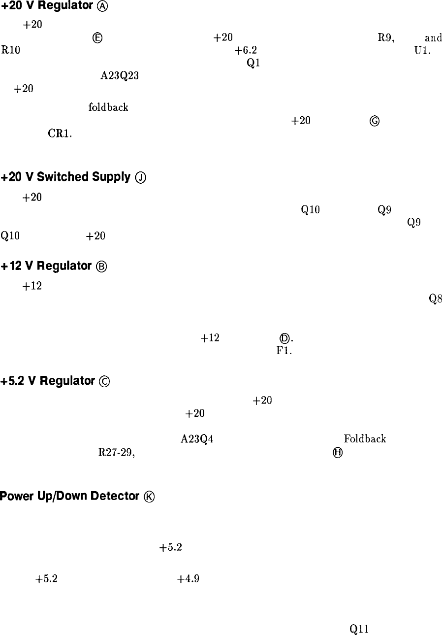
+20
V
Regulator
@
The
+20
V supply has as its reference a 6.2 V zener diode VR2 biased from the output of
the j-20 V supply,
@
on the schematic. The
+20
V output is divided down by R9, R50,
and
RlO to 6.2 V. This voltage is compared with the
t6.2
V reference voltage by amplifier
Ul.
This amplifier sinks current from the current source
Ql
so that the voltage at the base of the
series-pass transistor A23Q23 (on A23 Motherboard) is such that the output of the supply is
at
+20
V.
A simple form of
foldback
current limiting is provided by the current sensing resistor R3, R4,
R5, CR4, and Q3. 0vervoltage protection is provided by the
+20
V crowbar
@
consisting of
VR3 and
CRl.
DS2 is an LED which indicates the presence of an output voltage. Fuse F2
provides further protection for the supply.
+20
V
Switched
Supply
@
The
+20
V switched supply provides power to the oscillator circuits of the A22 10 MHz
Frequency Standard. If the Reference Disable line HSTD is low,
QlO
is off, and
Q9
is off, so
no power is supplied to the internal 10 MHz oscillator. When HSTD goes high, both
Q9
and
QlO
turn on, and i-20 V is supplied to the internal 10 MHz oscillator.
+12
V
Regulator
@
The i-12 V supply is a 12 V floating regulator with its reference terminal biased at 11 V by
R24 and VR8. This supply is enabled by the presence of the -5.2 V supply, which causes
QS
to turn off, allowing the zener diode VR8 to be biased by the current flowing from the output
of the supply through R24. LED DS4 provides a visible indication of an output voltage.
Overvoltage protection is provided by the
-l-12
V crowbar
0.
The regulator itself is internally
protected, but further protection is provided by CR3 and
Fl.
+5.2
V
Regulator
@
The operation of this supply is similar to that of the
+20
V supply. Its reference is from the
voltage divider R36 and R49 from the i-20 V supply. This voltage is compared with the
divided down output voltage by U2, which drives the Darlington-connected transistors Q6
and Q4 and the series-pass transistor A23Q4 on the A23 Motherboard.
Foldback
current
limit is provided by R27-29, R31, R32, and Q5. The output crowbar
@
provides overvoltage
protection. Further protection is provided by F3.
Power
Up/Down
Detector
@
A power-up indication HPUP is provided to allow the instrument to turn on and off in an
orderly manner. The HPUP line goes high when all of the following conditions are met:
1. The rectified dc voltage of the
+5.2
V Unreg supply is above 8.6 V (provides an indication
that the Line Voltage is present).
2. The
t5.2
V output is higher than
t4.9
V.
3. The front-panel shutdown and thermal shutdown circuits allow the instrument to be turned
on.
If both the front-panel shutdown and thermal shutdown transistors
Qll
and Q12 are
off, CR11 is reverse biased. If the output of the i-5.2 V supply is greater than i-4.9 V,
2 Al7
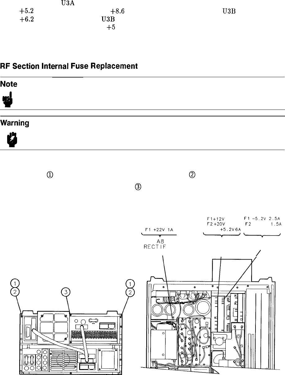
the output of U3A is high, and CR12 is reverse biased. If the dc input voltage to the
+5.2
V supply is greater than
+8.6
V, then the voltage at pin 5 of
U3B
is greater than
+6.2
V, and the output of
U3B
is high. This turns on transistors Q13 and Q7, pulling
the collector of Q7 to about
+5
V. This provides the HPUP signal.
If any of the above conditions are not met, HPUP remains low. R59 and Cl4 provide an
additional time delay at turn-on to allow the supplies to settle down.
RF
Section
Internal
Fuse
Replacement
Note For location of hardware and cables referred to in this procedure, see Figure 1.
3
Warning
Remove ac line cord from both instruments before proceeding with this
9
procedure.
1. Position instrument upside-down as show in view A.
2. Remove feet
@
from rear of RF Section by removing screws
@
show in view A.
3. Remove bottom cover by loosening screw
@
and pulling cover toward rear of instrument.
4. Location of fuses is shown in view B.
Fl
+22V
1A
L
7
,
RE&
I ER
\
Fl
+12V
IA
Fl
-5.2V
2.5A
F2
+ZOV
3A
F2
-40V
1.5A
F3
t5.2V
6A
F3 -lOV 5A
w-
Al7 Al8
POS REG NEG REG
I
/
VIEW A
Figure 1. Internal Fuse Placement
VIEW B
Al7 3
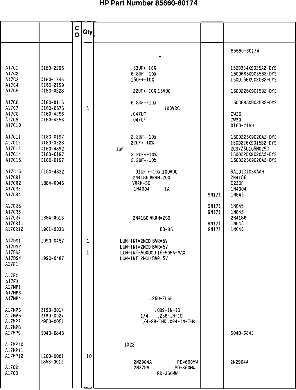
Reference
Designation
HP Part
Number
HP
Part
Number 85660-60174
Al7 Positive Regulator
Description Mfr
Mfr Part
Code Number
-
Al7 95660-60174
7
1
BOARD ASSEMBLY, POSITIVE REGULATOR
(SERIAL PREFIXES: 2410A
-
2532A)
28480 85660-60174
A17Cl 3180-2205
3
1
CAPACITOR-FXD
.33UF+-10%
35VOC TA
56289 150D334X9035A2-DYS
A17C2 3180-0116
11
CAPACITOR-FXD
6.8UF+-10%
35VDC TA
56289 150D685X9035B2-DYS
A17C3 3180-1746
5
1
CAPACITOR-FXD
15UF+-10%
2OVDC TA
56289 1500156X9020B2-DYS
A17C4 3160-2199
2
1
CAPACITOR-FXD 30PF +-5% 300VDC MICA
28480 0160-2199
A17C5 3180-0228
6
1
CAPACITOR-FXD
22UF+-10%
15VDC
TA
56289 150D226X9015B2-DYS
A17C6 3180-0116
11
CAPACITOR-FXD
6.8UF+-10%
35VDC TA
56289 150D685X9035B2-DYS
A17C7 3160-0573
2
1
CAPACITOR-FXD 4700PF +-20%
1OOVDC
CER
28480 0160-0573
A17CB 3160-4256
6
1
CAPACITOR-FXD
.047UF
+-20% 200VDC CER
16546 CW30
B 473M
A17C9 3160-4256
6
1
CAPACITOR-FXD
.047UF
+-20% 2OOVDC CER
16546 CW30
B 473M
A17ClO 3160-2199
2
1
CAPACITOR-FXD 30PF +-5% 300VDC MICA
28480 0160-2199
A17Cll 3180-0197
8
1
A17C12 3180-0228
6
1
A17C13 3160-4892
6
1
A17C14 3180-0197
8
1
A17C15 3180-0197
8
1
CAPACITOR-FXD
2.2UF+-10%
20VDC TA
CAPACITOR-FXD
22UF+-10%
15VDC TA
CAP-FXD
1uF
25 V
CAPACITOR-FXD
2.2UF+-10%
20VDC TA
CAPACITOR-FXD
2.2UF+-10%
20VDC TA
56289 1500225X9020A2-DYS
56289 150D226X9015B2-OYS
56289 2C37Z5U105M025C
56289 150D225X9020A2-DYS
56289 150D225X9020A2-DYS
A17C16 0160-4832
4
1
CAPACITOR-FXD
.OlUF
+-lo%
1OOVDC
CER
A17CRl 1884-0018
5
1
THYRISTOR-SCR
2N4186
VRRM=EOO
A17CR2 1884-0046
9
1
THYRISTOR-SCR
VRRM=50
A17CR3 1901-0743
11
DIODE-PWR RECT
lN4004
400V
1A
DO-41
A17CR4 1901-0033
2
1
DIODE-GEN PRP 180V 200MA DO-35
04222
04713
71744
9N171
SAlOlC103KAAH
2N4186
C23OF
lN4004
lN645
A17CR5 1901-0033
2
1
DIODE-GEN PRP 180V 200MA DO-35 9N171 lN645
A17CR6 1901-0033
2 1
DIODE-GEN PRP 180V 200MA DO-35 9N171 lN645
Al7CR7 1884-0018
5
1
THYRISTOR-SCR
2N4186
VRRM=200 04713 2N4186
A17CRll 1901-0033
2
1
DIODE-GEN PRP 180V 200MA DO-35 9N171 lN645
A17CR12 1901-0033
2
1
DIODE-GEN PRP 180V 200MA
DO-35 9N171 lN645
A17DSl 1990-0487
7
1
LED-LAMP
LUM-INT=2MCD
BVR=SV 28480 HLMP-1401
A17DS2 1990-0487
71
LED-LAMP
LUM-INT=2MCD
BVR=5V 28480 HLMP-1401
A17DS3 1990-0404
8
1
LED-LAMP
LUM-INT=SOOUCD
IF=50MA-MAX 28480 HLMP-1000
A17DS4 1990-0487
7
1
LED-LAMP
LUM-INT=2MCD
BVR=SV 28480 HLMP-1401
A17Fl 2110-0001
8
1
FUSE IA 250V NTD FE UL 75915 312 001
A17F2
A17F3
A17MPl
A17MP3
A17MP4
2110-0003
0
1
2110-0056
3
1
FUSE 3A 250V NTD FE UL
FUSE 6A 250V NTD FE UL
NOT ASSIGNED
75915 312 003
75915 312 006
3520-0128
7
2
SCREW-MACH 2-56 .25-IN-LG PAN-HD-POZI 77250
2110-0269
0
6
FUSEHOLDER-CLIP TYPE
.25D-FUSE 28480 2110-0269
A17MP5 ?190-0014
1
A17MP6 !190-0027
6
A17MP7 !950-0051
8
A17MP8 5000-9043
6
A17MP9 5040-6843
2
A17MPlO 3151-0013
4
A17MPll 36701-20036
8
A17MP12 1200-0081
4
A1791 1853-0012
4
A17Q2 1853-0451
5
A17Q3 1854-0404
0
2
1
1
1
1
1
1
10
1
1
1
-
WASHER-LK INTL T NO. 2
.089-IN-ID
WASHER-LK INTL T
l/4
IN
.256-IN-ID
NUT-HEX-DBL-CHAM
l/4-28-THD
.094-IN-THK
EXTRACTOR PIN
78189
78189
73743
28480
28480
1902-00-00-2580
1914-00
PC BOARD EXTRACTOR 5000-9043
5040-6843
WIRE 22AWG
1X22
DIODE MOUNTING BLOCK
INSULATOR-FLG-BSHG NYLON
TRANSISTOR PNP
2N2904A
SI TO-39
PD=GOOMW
TRANSISTOR PNP
2N3799
SI TO-18
PD=360MW
TRANSISTOR NPN SI TO-18
PO=360MW
92194
28480
26365
04713
04713
04713
298
86701-20036
974 307
2N2904A
-
*Indicates factory-selected value
85660-60174 Parts List
Page 1 of 4
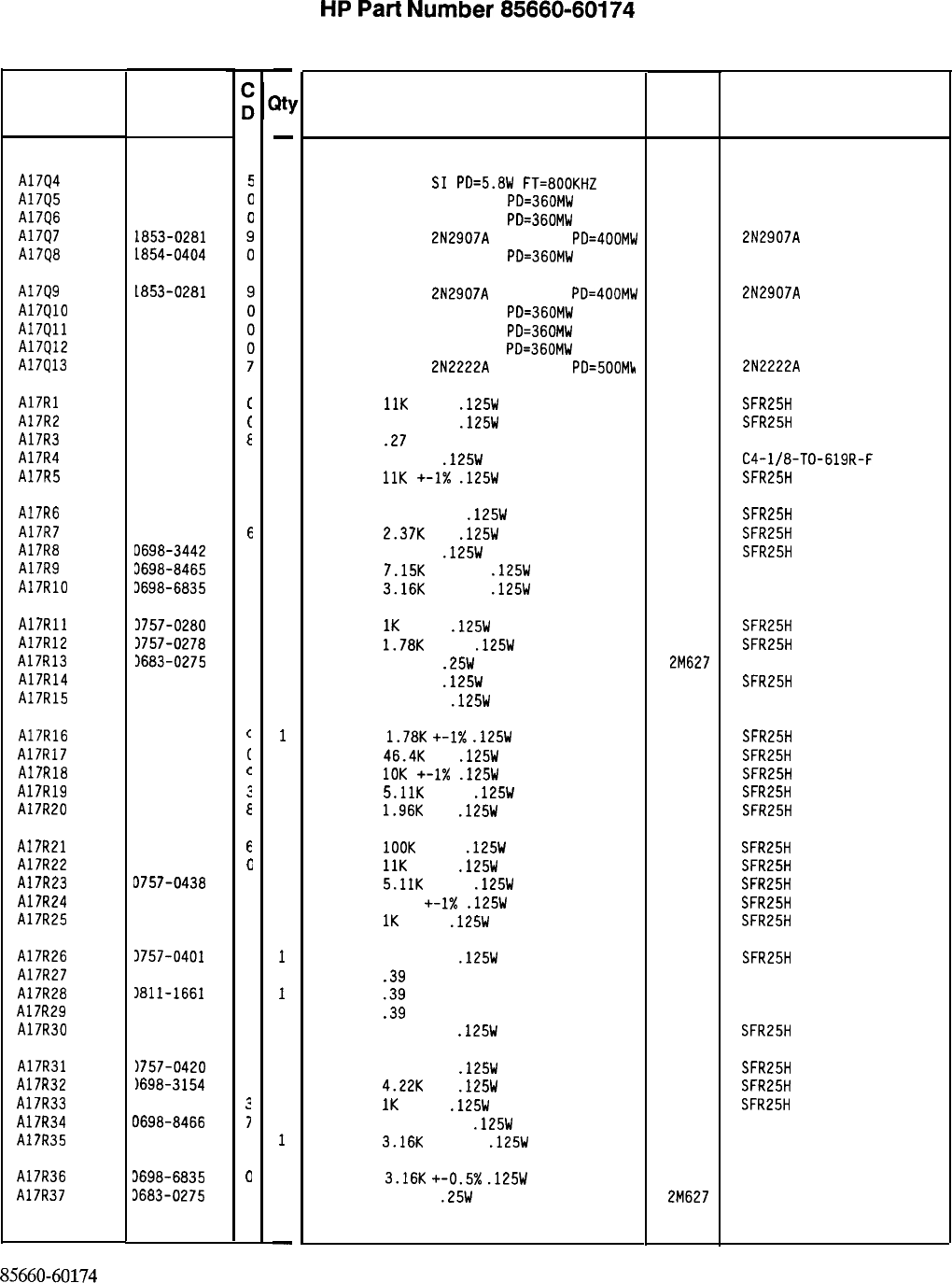
Reference
Designation
A17Q4
A17Q5
A17Q6
A17Q7
A17Q8
HP Part
Number
1854-0441
1854-0404
1854-0404
1853-0281
1854-0404
A17Q9
A17QlO
A17Qll
A17Q12
A17Q13
1853-0281
1854-0404
1854-0404
1854-0404
1854-0477
A17Rl
A17R2
A17R3
A17R4
A17R5
0757-0443
0757-0401
0811-1659
0757-041s
0757-0443
A17R6
A17R7
A17R8
A17RS
A17RlO
0757-0394
0698-3150
D698-3442
3698-8465
3698-6835
A17Rll 3757-0280
A17R12 1757-0278
A17R13 1683-0275
A17R14 1698-3444
A17R15 3757-0346
A17R16 0757-0278
A17R17 0698-3162
A17R18 0757-0442
A17RlS 0757-0438
A17R20 0698-0083
A17R21 0757-0465
A17R22 0757-0443
A17R23 D757-0438
A17R24 3757-039s
A17R25 3757-0280
A17R26 3757-0401
Al7R27 1811-1661
A17R28
1811-1661
A17R29 1811-1661
A17R30 1757-041s
A17R31 1757-0420
A17R32
1698-3154
A17R33 0757-0280
A17R34 0698-8466
Al7R35 0698-6835
A17R36
A17R37 3698-6835
3683-0275
85660-60174 Parts List
Page 2 of 4
t
(
E
C
C
C
E
9
6
0
3
9
9
1
?
c
t
c
?
E
6
c
3
5
3
0
2
2
2
0
3
0
:
7
C
0
9
-
Xl
-
1
1
1
1
1
1
1
1
1
1
1
1
1
1
1
1
1
1
1
1
1
1
1
1
1
1
1
1
1
1
1
1
1
1
1
1
1
1
1
1
1
1
1
1
1
1
1
-
HP
Part
Number 85660-60174
Al7 Positive Regulator
Description
TRANSISTOR NPN
SI
m=5.aw
FT=aooKtiz
TRANSISTOR NPN SI TO-18
PD=360MW
TRANSISTOR NPN SI TO-18
PD=360MW
TRANSISTOR PNP
2N2907A
SI TO-18
PD=400MW
TRANSISTOR NPN SI TO-18
PD=360MW
Mfr
Mfr Par!
Code Number
28480
04713
04713
04713
04713
1845-0441
2N2907A
TRANSISTOR PNP
2N2907A
SI TO-18
PD=400MW 04713
TRANSISTOR NPN SI TO-18
PD=360MW 04713
TRANSISTOR NPN SI TO-18
PD=360MW 04713
TRANSISTOR NPN SI TO-18
PD=360MW 04713
TRANSISTOR NPN
2N2222A
SI TO-18
PD=500Mk 04713
2N2907A
2N2222A
RESISTOR
11K
+-1%
.125W
TF TC=O+-100
19701 SFR25H
RESISTOR 100 +-1%
.125W
TF TC=O+-100
19701
SFR25H
RESISTOR
.27
+-5% 2W PWI TC=O+-800
11502 SPH
RESISTOR 681 1%
.125W
F TC=O+-100
24546
C4-l/8-TO-619R-F
RESISTOR
11K
+-1X
.125W
TF TC=O+-100
19701
SFR25H
RESISTOR 51.1 +-1%
.125W
TF TC=O+-100
19701
SFR25H
RESISTOR
2.37K
1%
.125W
TF TC=O+-100
19701
SFR25H
RESISTOR 237 1%
.125W
TF TC=O+-100
19701 SFR25H
RESISTOR
7.15K
+-0.5%
.125W
TF TC=O+-50
19701
5033R
RESISTOR
3.16K
+-0.5%
.125W
TF TC=O+-50
19701
5033R
RESISTOR
1K
+-1%
.125W
TF TC=O+-100
19701
SFR25H
RESISTOR
1.78K
+-1%
.125W
TF TC=O+-100
19701
SFR25H
RESISTOR 2.7 5%
.25W
CF TC=O-400
2M627 R-25J
RESISTOR 316 1%
.125W
TF TC=O+-100
19701
SFR25H
RESISTOR 10 +-1%
.125W
TF TC=O+-100
91637 CMF-55-1. T-l
RESISTOR
1.78K
+-I%
.125W
TF TC=O+-100
19701
SFR25H
RESISTOR
46.4K
1%
.125W
TF TC=O+-100
19701 SFR25H
RESISTOR
10K
+-1X
.125W
TF TC=O+-100
19701
SFR25H
RESISTOR
5.11K
+-1%
.125W
TF TC=O+-100
19701
SFR25H
RESISTOR
1.96K
1%
.125W
TF TC=O+-100
19701
SFR25H
RESISTOR
1OOK
+-1%
.125W
TF TC=O+-100
19701 SFR25H
RESISTOR
11K
+-1%
.125W
TF TC=O+-100
19701
SFR25H
RESISTOR
5.11K
+-1%
.125W
TF TC=O+-100
19701
SFR25H
RESISTOR 82.5 +-I%
.125W
TF TC=O+-100
19701 SFR25H
RESISTOR
1K
+-1%
.125W
TF TC=O+-100
19701
SFR25H
RESISTOR 100 +-1%
.125W
TF TC=O+-100
19701
SFR25H
RESISTOR
.39
+-5% 2W PWI TC=O+-800
11502 SPH
RESISTOR
.39
+-5% 2W PWI TC=O+-800
11502 SPH
RESISTOR
.39
+-5% 2W PWI TC=O+-800
11502 SPH
RESISTOR 681 +-1%
.125W
TF TC=O+-100
19701
SFR25H
RESISTOR 750 +-1%
.125W
TF TC=O+-100
19701
SFR25H
RESISTOR
4.22K
1%
.125W
TF TC=O+-100
19701
SFR25H
RESISTOR
1K
+-1%
.125W
TF TC=O+-100
19701 SFR25H
RESISTOR 942 +-0.5%
.125W
TF TC=O+-50
19701
50338
RESISTOR
3.16K
+-0.5%
.125W
TF TC=O+-50
19701
5033R
RESISTOR
3.16K
+-0.5x
.125W
TF TC=O+-50
19701
5033R
RESISTOR 2.7 5%
.25W
CF TC=O-400
2M627 R-25J
*Indicates facto y-selected value
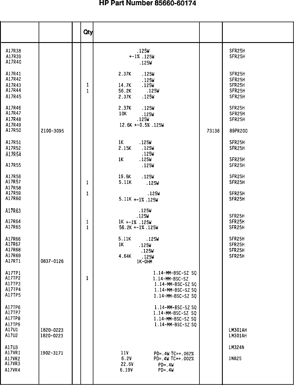
HP
Part
Number 85660-60174
Al7 Positive Regulator
Reference
HP Part C
Number D
Qty Description Mfr
Designation Mfr Part
Code Number
A17R38
A17R39
A17R40
A17R41
A17R42
A17R43
A17R44
A17R45
A17R46
A17R47
A17R48
A17R49
A17R50
A17R51
A17R52
A17R53
A17R54
A17R55
A17R56
A17R57
A17R58
A17R59
A17R60
A17R62
A17R63
A17R64
A17R65
A17R66
A17R67
Al7R68
A17R69
A17RTl
A17TPl
A17TP2
A17TP3
A17TP4
A17TP5
A17TP6
A17TP7
A17TP8
A17TPS
A17Ul
A17U2
A17U3
A17VRl
A17VR2
A17VR3
A17VR4
0698-3444
11
RESISTOR 316 1%
.125W
TF TC=O+-100
19701
SFR25H
0757-0401
0
1
RESISTOR 100 +-1X
.125W
TF TC=O+-100
19701
SFR25H
0757-0346
2
1
RESISTOR 10 +-1%
.125W
TF TC=O+-100
91637 CMF-55-1,
T-l
0698-3150
6
1
RESISTOR
2.37K
1%
.125W
TF TC=O+-100
19701
SFR25H
0757-0418
9
1
RESISTOR 619 +-1%
.125W
TF TC=O+-100
19701
SFR25H
0698-3156
2
1
RESISTOR
14.7K
1%
.125W
TF TC=O+-100
19701
SFR25H
0757-0459 a
i
RESISTOR
56.2K
+-1%
.125W
TF TC=O+-100
19701
SFR25H
0698-3150
6
1
RESISTOR
2.37K
1%
.125W
TF TC=O+-100
19701
SFR25H
0698-3150
6
1
RESISTOR
2.37K
1%
.125W
TF TC=O+-100
19701 SFR25H
0757-0442
9
1
RESISTOR
10K
+-1%
.125W
TF TC=O+-100
19701
SFR25H
0698-3444
1
1
RESISTOR 316 1%
.125W
TF TC=O+-100
19701
SFR25H
0698-8464
5
1
RESISTOR
12.6K
+-0.5X
.125W
TF
TC=O+-50
19701
5033R
2100-3095
5
1
RESISTOR-TRMR 200 10% TKF SIDE-ADJ 17-TR 73138 89PR200
0757-0280
3
1
RESISTOR
1K
+-1%
.125W
TF TC=O+-100
19701
SFR25H
0698-0084
9
1
RESISTOR
2.15K
1%
.125W
TF TC=O+-100
19701 SFR25H
0698-4405
6
1
RESISTOR 107 +-1%
.125W
TF TC=O+-100
91637
T-l
0757-0280
3
CMF-55-1,
1
RESISTOR
1K
+-1%
.125W
TF TC=O+-100
19701
SFR25H
0757-0401
0
1
RESISTOR 100 +-1%
.125W
TF TC=O+-100
19701 SFR25H
0698-3157
3
1
RESISTOR
19.6K
1%
.125W
TF TC=O+-100
19701
SFR25H
0757-0438
3
i
RESISTOR
5.11K
+-1%
.125W
TF TC=O+-100
19701
SFR25H
0698-3634
11
RESISTOR 470 5% 2W MO TC=O+-200
11502 GS-3
0757-045s a
I
RESISTOR 56.21: +-1%
.125W
TF TC=O+-100
19701
SFR25H
0757-0438
3
1
RESISTOR
5.11K
+-1X
.125W
TF TC=O+-100
19701
SFR25H
0757-0346
21
RESISTOR 10 +-1%
.125W
TF TC=O+-100
91637 CMF-55-1,
T-l
0698-3444
1
1
RESISTOR 316 1%
.125W
TF TC=O+-100
19701
SFR25H
0757-0280
3
i
RESISTOR
1K
+-I%
.125W
TF TC=O+-100
19701
SFR25H
0757-045s a
i
RESISTOR
56.2K
+-1X
.125W
TF TC=O+-100
19701 SFR25H
0757-0438
3
1
RESISTOR
5.11K
+-1%
.125W
TF TC=O+-100
19701
SFR25H
0757-0280
3
1
RESISTOR
1K
+-1%
.125W
TF TC=O+-100
19701 SFR25H
0757-0416
7
1
RESISTOR 511
+-1%
.125W
TF TC=O+-100
19701
SFR25H
0698-3155
11
RESISTOR
4.64K
1%
.125W
TF TC=O+-100
19701
SFR25H
0'337-0126
6 1
THERMISTOR DISC
lK-OHM
TC=-4.4%/C-DEG
STD-0163
1251-0600
0
1
CONNECTOR-SGL CONT PIN
1.14-MM-BSC-SZ
SQ
27264 16-06-0034
1251-0600
0
1
CONNECTOR-SGL CONT PIN
1.14-MM-BSC-SZ
SQ
27264 16-06-0034
1251-0600
0
1
CONNECTOR-SGL CONT PIN
1.14-MM-BSC-SZ
SQ
27264 16-06-0034
1251-0600
0
1
27264
CONNECTOR-SGL CONT PIN
1.14-MM-BSC-SZ
SQ
16-06-0034
1251-0600
0
1
CONNECTOR-SGL CONT
PIN
1.14-MM-BSC-SZ
SQ
27264 16-06-0034
1251-0600
0
1
CONNECTOR-SGL CONT PIN
1.14-MM-BSC-SZ
SQ
27264 16-06-0034
1251-0600
0
1
27264
CONNECTOR-SGL CONT PIN
1.14-MM-BSC-SZ
SQ
16-06-0034
1251-0600
0
1
CONNECTOR-SGL CONT
PIN
1.14-MM-BSC-SZ
SQ
27264 16-06-0034
1251-0600
0
1
CONNECTOR-SGL CONT PIN
1.14-MM-BSC-SZ
SQ
27264 16-06-0034
1820-0223
0
1
IC OP AMP GP TO-99 PKG 27014 LM301AH
1820-0223
0
1
IC OP AMP GP TO-99 PKG 27014 LM301AH
1826-0161
7
1
IC OP AMP GP QUAD 14-DIP-P PKG 27014 LM324N
1902-3171
7
1
DIODE-ZNR
11V
5% DO-35
PD=.4W
TC=+.062% 04713
1902-0686
3
1
DIODE-ZNR
6.2V
2% DO-7
PD=.4W
TC=+.002% 04713 lN825
1902-3252
5
1
DIODE-ZNR
22.6V
2% DO-35
PD=.4W 04713
1902-0049
2
1
DIODE-ZNR
6.19V
5% DO-35
PD=.4W 04713
*Indicates factory-selected value
85660-60174 Parts List
Page 3 of 4
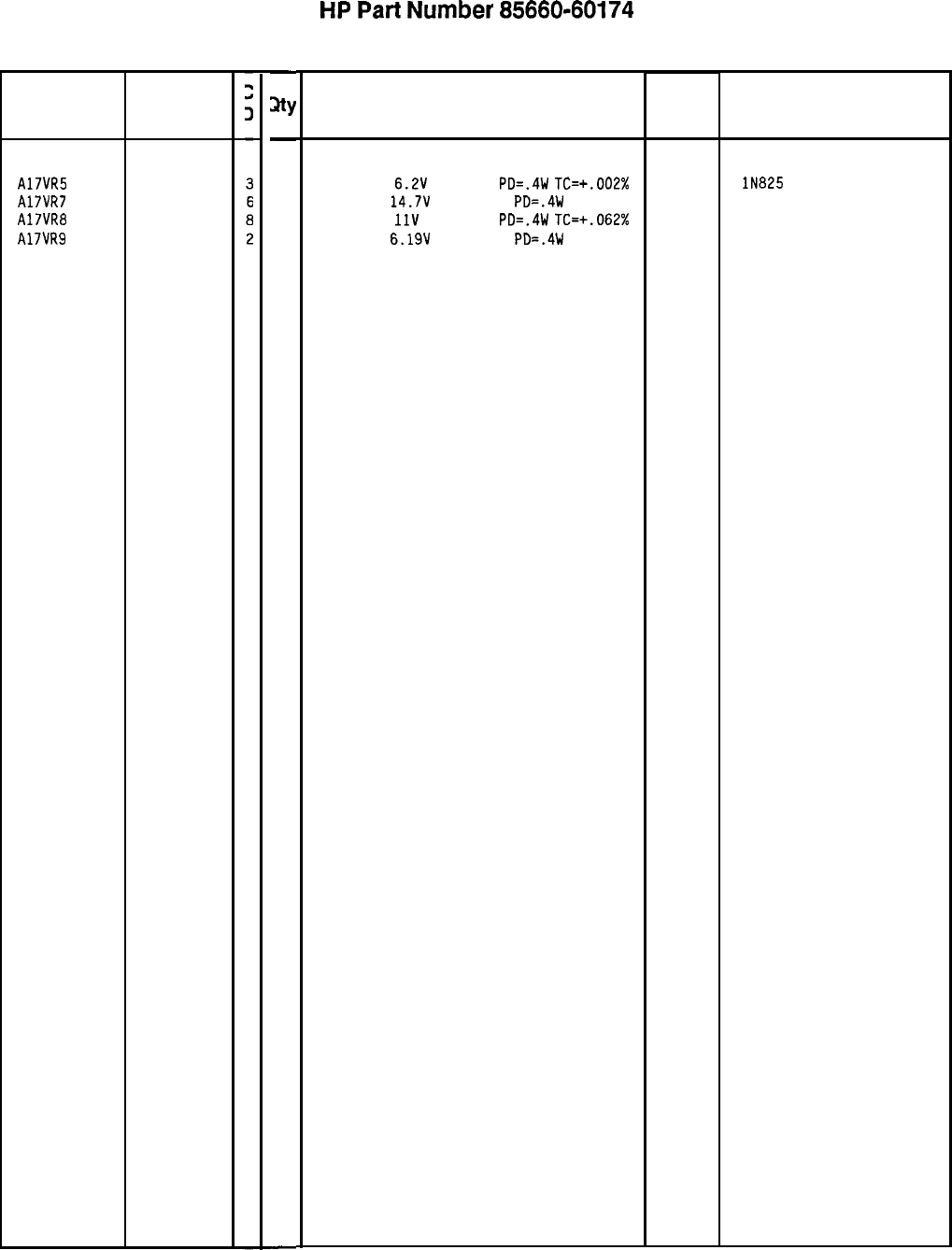
Reference
Designation
A17VR5 1902-0686
A17VR7 1902-3203
A17VR8 1902-3172
A17VR9 1902-0049
HP Part
Number
-
sty
-
1
1
1
1
-
HP
Part
Number 85660-60174
Al7 Positive Regulator
Description
DIODE-ZNR
6.2V
2% DO-7
PD=.4W
TC=+.002%
DIODE-ZNR
14.7V
5% DO-35
PD=.4W
DIODE-ZNR
11V
2% DO-35
PD=.IW
TC=+.062%
DIODE-ZNR
6.19V
5% DO-35
PD=.4W
85660-60174 Parts List
Page 4 of 4
*Indicates facto y-selected value
Mfr Mfr Part
Code Number
04713
04713
04713
04713
lN825
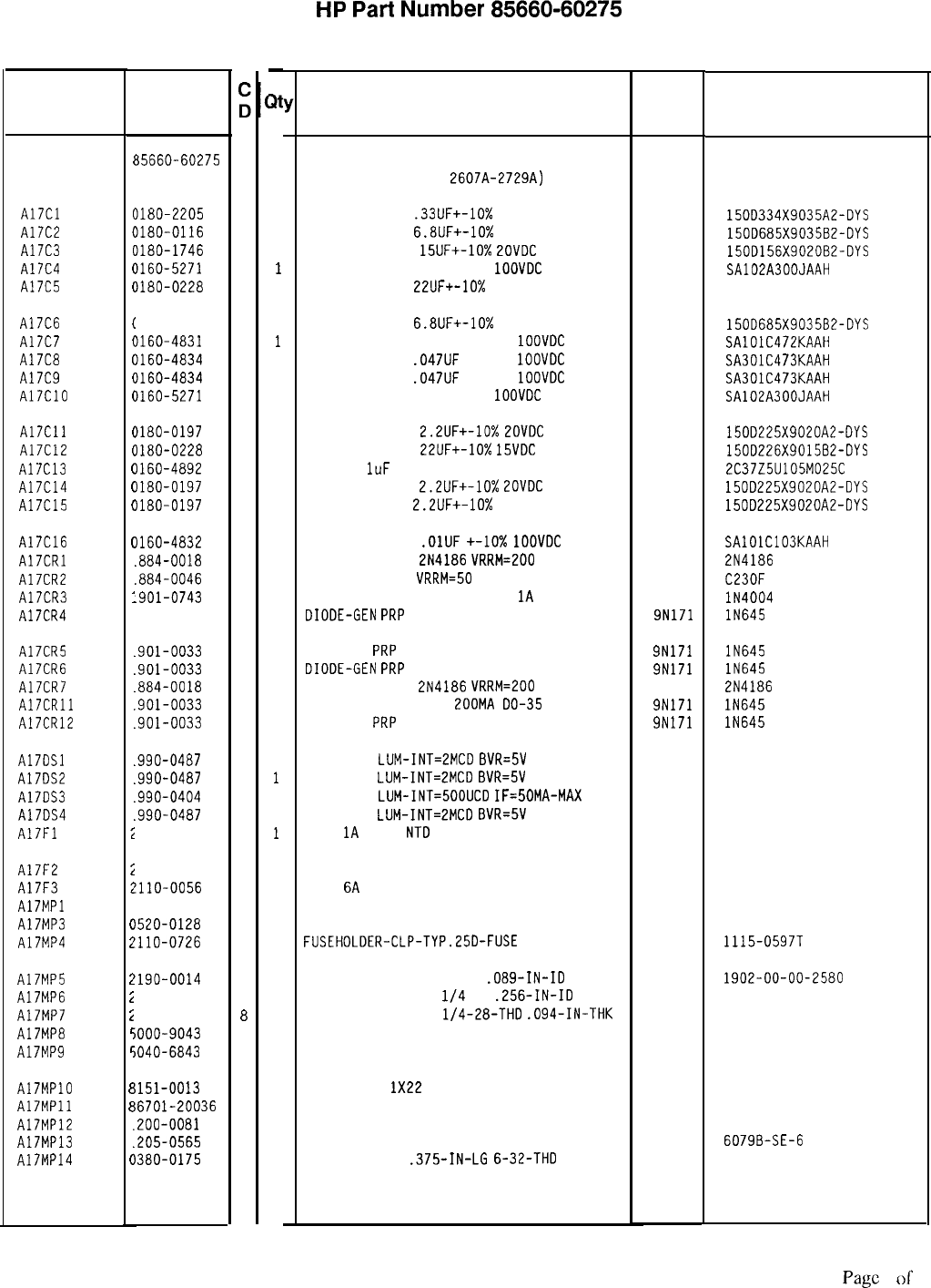
HP
Part
Number 85660-60275
Al7 Positive Regulator
Reference
Designation
Al7
A17Cl
A17C2
A17C3
A17C4
A17C5
A17C6
A17C7
A17C8
A17C9
A17ClO
A17Cll
A17C12
A17C13
A17C14
A17C15
A17C16
A17CRl
A17CR2
A17CR3
A17CR4
A17CR5
A17CR6
A17CR7
A17CRll
A17CR12
A17DSl
A17DS2
A17DS3
A17DS4
A17Fl
A17F2
A17F3
A17MPl
A17MP3
A17MP4
A17MP5
A17MP6
A17MP7
A17MPB
A17MPS
A17MPlO
A17MPll
A17MP12
A17MP13
A17MP14
t
(
(
(
(
(
(
(
(
(
(
(
(
(
(
(
(
1
1
I
1
1
1
1
1
I
1
1
1
1
i
i
i
(
i
i
i
i
r:
r
E
E
1
1
(
HP Part
Number
;)t
Description Mfr
Mfr Part
Code Number
35660-60275
9
1
BOARD ASSEMBLY, POSITIVE REGULATOR
(SERIAL PREFIXES:
2607A-2729A) 28480 85660-60275
)iao-2205
3
1
CAPACITOR-FXO
.33UF+-10%
35VDC TA
56289 150D334X9035A2-DYS
Ilao-0116
1
1
CAPACITOR-FXD
6.8UF+-10%
35VDC TA
56289 150D685X9035B2-DYS
1180-1746
5
1
CAPACITOR-FXD
15UF+-10%
ZOVDC
TA
56289 150D156X9020B2-DYS
1160-5271
7
1
CAPACITOR-FXD 30PF +-5%
1OOVDC
CER 0+-30
04222 SA102A300JAAH
nao-0228
6
1
CAPACITOR-FXD
22UF+-10%
15VDC TA
56289 1500226X901562-DYS
1180-0116
1 1
CAPACITOR-FXD
6.8UF+-10%
35VDC TA
56289 150D685X9035B2-DYS
1160-4831
3
1
CAPACITOR-FXD 4700PF +-lo%
1OOVDC
CER
04222 SAlOlC472KAAH
1160-4834
6
1
CAPACITOR-FXD
.047UF
+-lo%
1OOVDC
CER
04222 SA301C473KAAH
1160-4834
6
1
CAPACITOR-FXD
.047UF
+-lo%
1OOVDC
CER
04222 SA301C473KAAH
1160-5271
7
1
CAPACITOR-FXD 30PF +-5%
1OOVDC
CER 0+-30
04222 SA102A300JAAH
uao-0197
a
1
)iao-0228
6
1
1160-4892
6
1
Ilao-0197
a
1
1180-0197
a
1
CAPACITOR-FXD
2.2UF+-10%
LOVDC
TA
CAPACITOR-FXD
22UF+-10%
15VDC
TA
CAP-FXD
1uF
25 V
CAPACITOR-FXD
2.2UF+-10%
ZOVDC
TA
CAPACITOR-FXD
2.2UF+-10%
20VDC TA
56289 150D225X9020A2-DYS
56289 150D226X901582-OYS
56289 2C37Z5U105M025C
56289 150D225X9020A2-DYS
56289 150D225X9020A2-DYS
1160-4832
4
1
CAPACITOR-FXD
.OlUF
+-lo%
1OOVDC
CER
.aa4-0018
5
1
THYRISTOR-SCR
2N4186
VRRM=200
.884-0046
9
1
THYRISTOR-SCR
VRRM=50
.901-0743
1 1
DIODE-PWR RECT IN4004 400V
1A
DO-41
.SOl-0033
2
1
DIODE-GEN
PRP
iaov 200MA Do-35
04222
04713
71744
9N171
SAlOlC103KAAH
2N4186
C23OF
lN4004
IN645
.901-0033
2
1
DIODE
-
GEN
PRP
laov 200MA Do-35
SN171 lN645
.901-0033
2
1
DIODE-GEN
PRP
laov 200MA Do-35
9N171 lN645
.884-0018
5
1
THYRISTOR-SCR
2N4186
VRRM=200 04713 2N4186
.901-0033
2
1
DIODE-GEN PRP iaov
200M~
00-35 SN171 lN645
.901-0033
2
1
DIODE
-
GEN
PRP
iaov 200MA Do-35
9N171 lN645
990-0487
7
1
LED-LAMP
LUM-INT=EMCD
BVR=5V 28480 HLMP-1401
.990-0487
7
1
LED-LAMP
LUM-INT=LMCD
BVR=5V 28480 HLMP-1401
.sso-0404
a
1
LED-LAMP
LUM-INT=500UCD
IF=50MA-MAX 28480 HLMP-1000
.990-0487
7
1
LED-LAMP
LUM-INT=2MCD
BVR=5V 28480 HLMP-1401
1110-0001
a
1
FUSE
1A
250V
NT0
FE UL
75915 312 001
‘110-0003
0
1
ZllO-0056
3
1
FUSE 3A 250V NTD FE UL
FUSE
6A
250V NTD FE UL
NOT ASSIGNED
75915 312 003
75915 312 006
)520-0128
7 2
SCREW-MACH 2-56 .25-IN-LG PAN-HD-POZI 77250
1110-0726
4 6
FUSEHOLDER-CLP-TYP.25D-FUSE 13060 1115-0597T
!190-0014
1
1190-0027
6
1950-0051
8
iOOO-9043
6
iO40-6843
2
1151-0013
4
%6701-20036
a
.200-0081
4
.205-0565
9
)3ao-0175
6
2
1
1
1
1
1
1
1
1
1
WASHER-LK INTL T NO. 2
.089-IN-ID
WASHER-LK INTL T
l/4
IN
.256-IN-ID
NUT-HEX-DBL-CHAM
l/4-28-THD
.094-IN-THK
EXTRACTOR
PIN
i902-00-00-2580
1914-00
PC BOARD EXTRACTOR
78189
78189
73743
28480
28480 5000-9043
5040-6843
WIRE 22AWG
1X22
92194
298
DIODE MOUNTING BLOCK 28480 86701-20036
INSULATOR-FLG-BSHG NYLON 26365 974 307
HEAT SINK SGL PLSTC-PWR-CS
13103
6079B-SE-6
STANDOFF-HEX
.375-IN-LG
6-32-THD 83330
2321
-
*Indicates factory-selected value
85660-60275 Parts List
Page
1 of 4
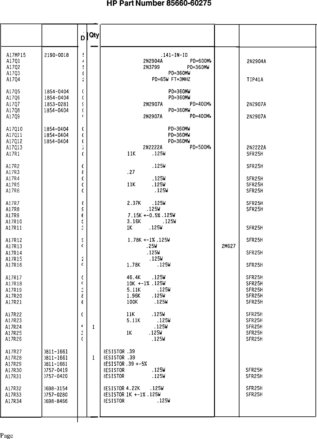
Reference
Designation
A17MP15
A17Ql
A17Q2
A17Q3
A17Q4
HP Part
Number
2190-0018
1853-0012
1853-0451
1854-0404
1854-0456
A17Q5
A17Q6
A17Q7
A17Q8
A17QS
1854-0404
1854-0404
1853-0281
1854-0404
1853-0281
A17QlO
A17Qll
A17Q12
A17Q13
A17Rl
1854-0404
1854-0404
1854-0404
1854-0477
0757-0443
A17R2
A17R3
A17R4
A17R5
A17R6
0757-0401
0811-1659
0757-041s
0757-0443
0757-0394
A17R7
A17R8
A17RS
A17RlO
A17Rll
0698-3150
0698-3442
0698-8465
0698-6835
0757-0280
A17R12 0757-0278
A17R13 0683-0275
A17R14 0698-3444
A17R15 0757-0346
A17R16 0757-0278
A17R17 0698-3162
A17R18 0757-0442
A17RlS 0757-0438
A17R20 0698-0083
A17R21 0757-0465
A17R22
A17R23
A17R24
A17R25
A17R26
0757-0443
0757-0438
0757-039s
0757-0280
0757-0401
A17R27
1811-1661
A17R28
)811-1661
A17R29
1811-1661
A17R30
1757-0419
A17R31 1757-0420
A17R32 1698-3154
A17R33 1757-0280
A17R34
16984466
85660-60275 Parts List
Page 2 of 4
c
c
(
t
(
(
(
c
z
f
(
:
I
c
1
2
c
(
c
:
I
t
(
c
:
(
2
2
2
0
3
0
3
7
-
31
-
1
1
1
1
1
1
1
1
1
1
1
1
1
1
1
1
1
1
1
1
1
1
1
1
1
1
1
1
1
1
1
1
1
1
1
1
1
1
1
1
1
1
1
1
1
1
1
1
-
HP
Part
Number 85660-60275
Al7 Positive Regulator
Description
WASHER-LK HLCL NO. 6
.141-IN-ID
TRANSISTOR PNP
2N2904A
SI TO-39
PD=GOOMk
TRANSISTOR PNP
2N3799
SI TO-18
PD=360MW
TRANSISTOR NPN SI TO-18
PD=360MW
TRANSISTOR NPN SI
PD=65W
FT=3MHZ
Mfr
Mfr Part
Code Number
73734
04713
04713
04713
01295
2N2904A
TIP41A
TRANSISTOR NPN SI TO-18
PD=360MW 04713
TRANSISTOR NPN SI TO-18
PD=360MW 04713
TRANSISTOR PNP
2N2907A
SI TO-18
PD=400Mb 04713
TRANSISTOR NPN SI TO-18
PD=360MW 04713
TRANSISTOR PNP
2N2907A
SI TO-18
PD=400M!+
04713
2N2907A
2N2907A
TRANSISTOR NPN SI TO-18
PD=360MW 04713
TRANSISTOR NPN SI TO-18
PD=360MW 04713
TRANSISTOR NPN SI TO-18
PD=360MW 04713
TRANSISTOR NPN
2N2222A
SI TO-18
PD=500Mh 04713
RESISTOR
11K
+-1%
.125W
TF TC=O+-100
19701
2N2222A
SFR25H
RESISTOR 100 +-1%
.125W
TF TC=O+-100
19701
SFR25H
RESISTOR
.27
+-5% 2W PWI TC=O+-800
11502
SPH
RESISTOR 681 +-1%
.125W
TF TC=O+-100
19701
SFR25H
RESISTOR
11K
+-1%
.125W
TF TC=O+-100
19701
SFR25H
RESISTOR 51.1 +-1%
.125W
TF TC=O+-100
19701
SFR25H
RESISTOR
2.37K
1%
.125W
TF TC=O+-100
19701
SFR25H
RESISTOR 237 1%
.125W
TF TC=O+-100
19701
SFR25H
RESISTOR
7.15K
+-0.5x
.125W
TF TC=O+-50
19701
5033R
RESISTOR
3.16K
+-0.5%
.125W
TF TC=O+-50
19701
5033R
RESISTOR
IK
+-1%
.125W
TF TC=O+-100
19701
SFR25H
RESISTOR
1.78K
+-I%
.125W
TF TC=O+-100
19701
SFR25H
RESISTOR 2.7 5%
.25W
CF TC=O-400
2M627 R-25J
RESISTOR 316 1%
.125W
TF TC=O+-100
19701
SFR25H
RESISTOR 10 +-1%
.125W
TF TC=O+-100
91637 CMF-55-1, T-l
RESISTOR
1.78K
+-1%
.125W
TF TC=O+-100
19701
SFR25H
RESISTOR
46.4K
1%
.125W
TF TC=O+-100
19701
SFR25H
RESISTOR
10K
+-1X
.125W
TF TC=O+-100
19701
SFR25H
RESISTOR
5.11K
+-1%
.125W
TF TC=O+-100
19701
SFR25H
RESISTOR
1.96K
1%
.125W
TF TC=O+-100
19701
SFR25H
RESISTOR
1OOK
+-1%
.125W
TF TC=O+-100
19701
SFR25H
RESISTOR
11K
+-1%
.125W
TF TC=O+-100
19701
SFR25H
RESISTOR
5.11K
+-1%
.125W
TF TC=O+-100
19701
SFR25H
RESISTOR 82.5 +-1%
.125W
TF TC=O+-100
19701
SFR25H
RESISTOR
1K
+-1%
.125W
TF TC=O+-100
19701
SFR25H
RESISTOR 100 +-1%
.125W
TF TC=O+-100
19701
SFR25H
tESISTOR
.39
+-5% 2W PWI TC=O+-800
11502 SPH
tESISTOR
.39
+-5% 2W PWI TC=O+-800
11502 SPH
{ESISTOR
.39
+-5x
2W PWI TC=O+-800
11502 SPH
tESISTOR
681 +-1%
.125W
TF TC=O+-100
19701
SFR25H
{ESISTOR
750 +-1%
.125W
TF TC=O+-100
19701
SFR25H
tESISTOR
4.22K
1%
.125W
TF TC=O+-100
19701
SFR25H
tESISTOR
IK
+-1X
.125W
TF TC=O+-100
19701
SFR25H
CESISTOR
942 +-0.5%
.125W
TF TC=O+-50
19701
5033R
*Indicates factory-selected value
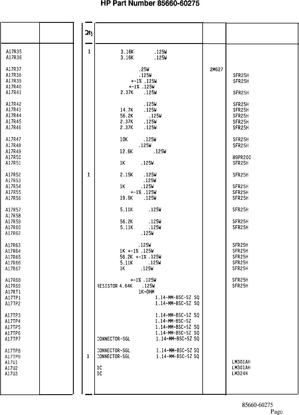
Reference
Designatior
A17R35
A17R36
HP Part
Number
0698-6835
0
0698-6835
0
A17R37
A17R38
A17R39
A17R40
A17R41
0683-0275
9
0698-3444
1
0757-0401
0
0757-0346
2
0698-3150
6
A17R42
A17R43
A17R44
A17R45
A17R46
0757-0418
9
0698-3156
2
0757-0459
8
0698-3150
6
0698-3150
6
A17R47
A17R48
A17R49
A17R50
A17R51
0757-0442
9
0698-3444
1
0698-8464
5
2100-3095
5
0757-0280
3
A17R52
A17R53
A17R54
A17R55
A17R56
0698-0084
9
0698-4405
6
0757-0280
3
0757-0401
0
0698-3157
3
A17R57
A17R58
A17R59
A17R60
A17R62
0757-0438
3
0698-3634
1
0757-0459
8
0757-0438
3
0757-0346
2
A17R63
A17R64
A17R65
A17R66
A17R67
0698-3444
1
0757-0280
3
0757-0459
8
0757-0438
3
0757-0280
3
A17R68
A17R69
A17RTl
A17TPl
A17TP2
0757-0416
7
0698-3155
1
0837-0126
6
1251-0600
0
1251-0600
0
A17TP3 1251-0600
A17TP4 1251-0600
A17TP5 1251-0600
A17TP6 1251-0600
A17TP7 1251-0600
A17TP8 1251-0600
A17TP9 1251-0600
A17Ul 1820-0223
A17U2 1820-0223
A17U3 1826-0161
C
D
0
0
0
0
0
0
0
0
0
7
-
a;ltl
-
1
1
1
1
1
1
1
1
1
1
1
1
1
1
1
1
1
1
1
1
1
1
1
1
1
1
1
1
1
1
1
1
1
1
1
1
1
1
1
1
1
1
1
1
1
1
1
-
HP
Part
Number 85660-60275
Al7 Positive Regulator
Description Mfr
Mfr Part
Code Number
RESISTOR
3.16K
+-0.5%
.125W
TF TC=O+-50
19701
5033R
RESISTOR 3.16K +-0.5%
.125W
TF TC=O+-50
19701
5033R
RESISTOR 2.7 5%
.25W
CF TC=O-400
2M627 R-25J
RESISTOR 316 1%
.125W
TF TC=O+-100
19701
SFR25H
RESISTOR 100
+-1X
.125W
TF TC=O+-100
19701
SFR25H
RESISTOR 10 +-1X
.125W
TF TC=O+-100
91637 CMF-55-1, T-l
RESISTOR
2.37K
1%
.125W
TF TC=O+-100
19701
SFR25H
RESISTOR 619 +-1%
.125W
TF TC=O+-100
19701
SFR25H
RESISTOR
14.7K
1%
.125W
TF TC=O+-100
19701
SFR25H
RESISTOR
56.2K
+-1%
.125W
TF TC=O+-100
19701
SFR25H
RESISTOR
2.37K
1%
.125W
TF TC=O+-100
19701
SFR25H
RESISTOR
2.37K
1%
.125W
TF TC=O+-100
19701
SFR25H
RESISTOR
10K
+-1%
.125W
TF TC=O+-100
19701
SFR25H
RESISTOR 316 1%
.125W
TF TC=O+-100
19701
SFR25H
RESISTOR
12.6K
+-0.5%
.125W
TF TC=O+-50
19701
5033R
RESISTOR-TRMR 200 10% TKF SIDE-ADJ 17-TR
73138 89PR200
RESISTOR
1K
+-1%
.125W
TF TC=O+-100
19701
SFR25H
RESISTOR
2.15K
1%
.125W
TF TC=O+-100
19701
SFR25H
RESISTOR 107 +-1%
.125W
TF TC=O+-100
91637 CMF-55-1. T-l
RESISTOR
1K
+-1%
.125W
TF TC=O+-100
19701
SFR25H
RESISTOR 100 +-1X
.125W
TF TC=O+-100
19701
SFR25H
RESISTOR
19.6K
1%
.125W
TF TC=O+-100
19701
SFR25H
RESISTOR
5.11K
+-1%
.125W
TF TC=O+-100
19701
SFR25H
RESISTOR 470 5% 2W MO TC=O+-200 11502 GS-3
RESISTOR
56.2K
+-1%
.125W
TF TC=O+-100
19701
SFR25H
RESISTOR
5.11K
+-1%
.125W
TF TC=O+-100
19701
SFR25H
RESISTOR 10 +-1%
.125W
TF TC=O+-100
91637 CMF-55-1, T-l
RESISTOR 316 1%
.125W
TF TC=O+-100
19701
SFR25H
RESISTOR
1K
+-1X
.125W
TF TC=O+-100
19701
SFR25H
RESISTOR
56.2K
+-1X
.125W
TF TC=O+-100
19701
SFR25H
RESISTOR
5.11K
+-1%
.125W
TF TC=O+-100
19701
SFR25H
RESISTOR
1K
+-1%
.125W
TF TC=O+-100
19701
SFR25H
RESISTOR 511 +-1X
.125W
TF TC=O+-100
?ESISTOR
4.64K
1%
.125W
TF TC=O+-100
THERMISTOR DISC
lK-OHM
TC=-4.4%/C-DEG
CONNECTOR-SGL CDNT PIN
1.14-MM-BSC-SZ
SQ
CONNECTOR-SGL CONT PIN
1.14-MM-BSC-SZ
SQ
19701
19701
27264
27264
SFR25H
SFR25H
STD-0163
16-06-0034
16-06-0034
CONNECTOR-SGL CONT PIN
1.14-MM-BSC-SZ
SQ
27264 16-06-0034
"ONNECTOR-SGL CONT PIN
1.14-MM-BSC-SZ
SQ
27264 16-06-0034
CONNECTOR-SGL CONT PIN
1.14-MM-BSC-SZ
SQ
27264 16-06-0034
CONNECTOR-SGL CONT PIN
1.14-MM-BSC-SZ
SQ
27264 16-06-0034
EONNECTOR-SGL
CONT PIN
1.14-MM-BSC-SZ
SQ
27264 16-06-0034
:ONNECTOR-SGL
CONT PIN
1.14-MM-BSC-SZ
SQ
27264 16-06-0034
:ONNECTOR-SGL
CONT PIN
1.14-MM-BSC-SZ
SQ
27264 16-06-0034
IC OP AMP GP TO-99 PKG 27014 LM301AH
IC
OP AMP GP TO-99 PKG
27014 LM301AH
IC
OP AMP GP QUAD 14-DIP-P PKG
27014 LM324N
*Indicates factory-selected value
85660-60275 Parts List
Page
3 of 4
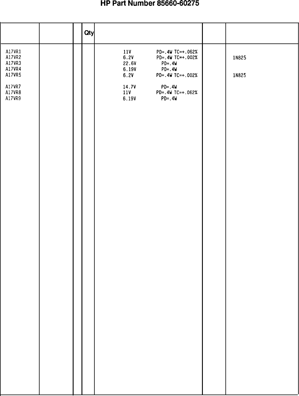
HP
Part
Number 85660-60275
Al7 Positive Regulator
Reference
HP Part C
Designation
Number D
Qty Description Mfr
Mfr Part
Code Number
A17VRl 1902-3171
7
1
DIODE-ZNR
11V
5% DO-35
PD=.4W
TC=+.062% 04713
A17VR2 1902-0686
3
1
DIODE-ZNR 6.2V
2% DO-7
PD=.4W
TC=+.002% 04713 lN825
A17VR3 1902-3252
5
1
DIODE-ZNR 22.6V
2% DO-35
PD=.4W 04713
A17VR4 1902-0049
2
1
DIODE-ZNR 6.19V
5% DO-35
PD=.4W 04713
A17VR5 1902-0686
3
1
DIODE-ZNR 6.2V
2% DO-7
PD=.4W
TC=+.002%
04713 lN825
A17VR7 1902-3203
6
1
DIODE-ZNR 14.7V
5% DO-35
PD=.4W 04713
A17VR8 1902-3172
8
1
DIODE-ZNR
11V
2% DO-35
PD=.4W
TC=+.062%
04713
A17VR9 1902-0049
2
1
DIODE-ZNR 6.19V
5% DO-35
PD=.4W 04713
85660-60275 Parts List
Page 4 of 4
*Indicates factory-selected value
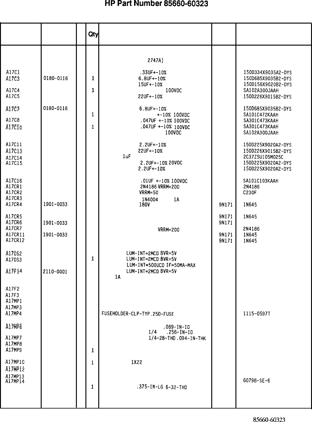
HP
Part
Number 85660-60323
Al7 Positive Regulator
Reference
HP Part C
Designation
Number D
Qty Description Mfr
Mfr Part
Code Number
Al7 85660-60323
8
1
BOARD ASSEMBLY, POSITIVE REGULATOR 28480 85660-60323
(SERIAL PREFIX:
2747~)
A17Cl
A17C2
A17C3
A17C4
A17C5
A17C6
A17C7
A17C8
A17C9
A17ClO
A17Cll
A17C12
A17C13
A17C14
A17C15
A17C16
A17CRl
A17CR2
A17CR3
A17CR4
A17CR5
A17CR6
A17CR7
A17CRll
A17CR12
A17DSl
A17DS2
A17DS3
A17DS4
A17Fl
A17F2
A17F3
A17MPl
A17MP3
A17MP4
A17MP5
A17MP6
A17MP7
A17MP8
A17MP9
A17MPlO
A17MPll
A17MP12
A17MP13
A17MP14
0180-2205
3
1
CAPACITOR-FXD
.33UF+-10% 35VDC TA 56289
0180-0116 1500334X9035A2-DYS
11
CAPACITOR-FXD
6.8UF+-10%
35VDC TA
56289
0180-1746 150D685X9035B2-DYS
5
1
CAPACITOR-FXD
15UF+-10%
EOVDC TA
56289
0160-5271 150D156X9020B2-DYS
7
1
CAPACITOR-FXD 30PF +-5%
1OOVDC
CER 0+-30
04222
0180-0228 SA102A300JAAH
6
1
CAPACITOR-FXD
22UF+-10%
15VDC TA
56289 150D226X9015B2-DYS
0180-0116
1 1
CAPACITOR-FXD
6.8UF+-10% 35VDC TA 56289
0160-4831 150D685X9035B2-DYS
3
1
CAPACITOR-FXD 4700PF +-lo%
1OOVOC
CER
04222
0160-4834 SAlOlC472KAAH
6
1
CAPACITOR-FXD
.047UF
+-lo%
1OOVDC
CER
04222 SA301C473KAAH
0160-4834
6
1
CAPACITOR-FXD
.047UF
+-lo%
1OOVDC
CER
04222
0160-5271 SA301C473KAAH
7
1
CAPACITOR-FXD 30PF +-5%
1OOVDC
CER 0+-30
04222 SA102A300JAAH
0180-0197
8
1
CAPACITOR-FXD
2.2UF+-10% EOVDC TA 56289
0180-0228 1500225X9020A2-DYS
6
1
CAPACITOR-FXD
22UF+-10%
15VDC TA
56289
0160-4892 150D226X901582-DYS
6
1
CAP-FXD
1uF
25 V
56289
0180-0197 2C37Z5U105M025C
8
1
CAPACITOR-FXD
2.2UF+-10%
ZOVDC
TA
56289
0180-0197 150D225X9020A2-DYS
8
1
CAPACITOR-FXD
2.2UF+-10%
EOVDC TA
56289 150D225X9020A2-DYS
0160-4832
4
1
CAPACITOR-FXO
.OlUF
+-10X
1OOVDC CER 04222
1884-0018 SAlOlC103KAAH
5
1
THYRISTOR-SCR
2N4186
VRRM=200 04713 2N4186
1884-0046
9
1
THYRISTOR-SCR
VRRM=50 C23OF
1901-0743
1 1
DIODE-PWR RECT lN4004
400V
1A
DO-41
71744 IN4004
1901-0033
2
1
DIODE-GEN PRP
18OV
200MA
DO-35 9N171 lN645
1901-0033
2
1
DIODE-GEN PRP 180V 200MA DO-35 9N171 lN645
1901-0033
2
1
DIODE-GEN PRP 180V 200MA DO-35 9N171
1884-0018 IN645
5
1
THYRISTOR-SCR
214186
VRRM=200 04713
1901-0033 2N4186
21
DIODE-GEN PRP 180V 200MA DO-35 9N171 lN645
1901-0033
2
1
DIODE-GEN PRP 180V 200MA DO-35 9N171 IN645
1990-0487
7
1
LED-LAMP
LUM-INT=2MCD
BVR=5V 28480
1990-0487 HLMP-1401
7
1
LED-LAMP
LUM-INT=EMCD
8VR=5V 28480
1990-0404 HLMP-1401
8
1
LED-LAMP
LUM-INT=500UCD
IF=50MA-MAX 28480
1990-0487 HLMP-1000
7
1
LED-LAMP
LUM-INT=EMCD
BVR=5V 28480
2110-0001 HLMP-1401
8
1
FUSE
1A
250V NTD FE UL
75915 312 001
2110-0003
0
1
FUSE 3A 250V NTD FE
UL
75915
2110-0056 312 003
3
1
FUSE 6A 250V NTD FE UL 75915 312 006
NOT ASSIGNED
0520-0128
7
2
SCREW-MACH 2-56 .25-IN-LG PAN-HD-POZI 77250
2110-0726
4
6
FUSEHDLDER-CLP-TYP.25D-FUSE 13060 1115-0597T
2190-0014
1
2
WASHER-LK INTL T NO. 2 .089-IN-ID 78189
2190-0027 1902-00-00-2580
6
1
WASHER-LK INTL T
l/4
IN
.256-IN-ID 78189
2950-0051 1914-00
8
1
NUT-HEX-DBL-CHAM
l/4-28-THD
.094-IN-THK 73743
5000-9043
6
1
EXTRACTOR PIN 28480
5040-6843 5000-9043
2
1
PC BOARD EXTRACTOR 28480 5040-6843
8151-0013
4
1
WIRE 22AWG
1X22
92194 298
86701-20036
8
1
DIODE MOUNTING BLOCK 28480
1200-0081 86701-20036
410
INSULATOR-FLG-BSHG NYLON
1205-0565 26365 974 307
9
1
HEAT SINK SGL PLSTC-PWR-CS 13103
0380-0175 6079B-SE-6
6
1
STANDOFF-HEX
.375-IN-LG 6-32-THD 83330
2321
*Indicates factoy-selected value
85660-60323 Parts List
Page 1 of 4
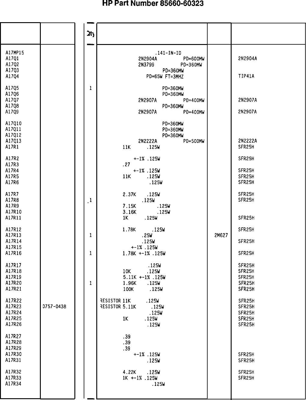
Reference
Designation HP Part
Number
A17MP15
A17Ql
A1792
A17Q3
A17Q4
2190-0018
5
1853-0012
4
1853-0451
5
1854-0404
0
1854-0456
2
A17Q5
A17Q6
Al7Q7
A1798
A17Q9
1854-0404
0
1854-0404
0
1853-0281
9
1854-0404
0
1853-0281
9
A17QlO
A17Qll
A17Q12
A17913
A17Rl
1854-0404
0
1854-0404
0
1854-0404
0
1854-0477
7
0757-0443
0
A17R2
A17R3
A17R4
A17R5
A17R6
0757-0401
0
0811-1659
8
0757-0419
0
0757-0443
0
0757-0394
0
A17R7
Al7R8
A17R9
A17RlO
A17Rll
0698-3150
6
0698-3442
9
0698-8465
6
0698-6835
0
0757-0280
3
A17R12
A17R13
A17R14
A17R15
A17R16
0757-0278
9
0683-0275
9
0698-3444
1
0757-0346
2
0757-0278
9
A17R17
A17R18
A17R19
A17R20
A17R21
0698-3162
0
0757-0442
9
0757-0438
3
0698-0083
8
0757-0465
6
Al7R22 0757-0443
A17R23 0757-0438
A17R24 0757-0399
A17R25 0757-0280
A17R26 0757-0401
A17R27 0811-1661
A17R28 0811-1661
A17R29 0811-1661
A17R30 0757-0419
A17R31 0757-0420
A17R32 0698-3154
A17R33 0757-0280
A17R34 0698-8466
8566060323 Parts List
Page 2 of 4
C
D
0
3
5
3
0
2
2
2
0
3
0
3
7
-
a
-
1
1
1
1
1
1
1
1
1
1
1
1
1
1
1
1
1
1
1
1
1
.l
1
1
1
1
1
1
1
1
1
1
1
1
1
1
1
1
1
1
1
1
1
1
1
1
1
1
-
HP
Part
Number 85660-60323
Al7 Positive Regulator
Description Mfr Mfr Part
Code Number
WASHER-LK HLCL NO. 6
.141-IN-ID 73734
TRANSISTOR PNP
2N2904A
SI TO-39
PD=GOOMW 04713
TRANSISTOR PNP
2N3799
SI TO-18
PO=360MW 04713
TRANSISTOR NPN SI TO-18
PD=360MW 04713
TRANSISTOR NPN SI
PD=65W
FT=3MHZ 01295
2N2904A
TIP4lA
TRANSISTOR NPN SI TO-18
PD=360MW 04713
TRANSISTOR NPN SI TO-18
PD=360MW 04713
TRANSISTOR PNP
2N2907A
SI TO-18
PD=400MW 04713
TRANSISTOR NPN SI TO-18
PD=360MW 04713
TRANSISTOR PNP
2N2907A
SI TO-18
PD=400MW 04713
2N2907A
2N2907A
TRANSISTOR NPN SI TO-18
PD=360MW 04713
TRANSISTOR NPN SI TO-18
PD=360MW 04713
TRANSISTOR NPN SI TO-18
PD=360MW 04713
TRANSISTOR NPN
2N2222A
SI TO-18
PD=500MW 04713
RESISTOR
11K
+-1%
.125W
TF TC=O+-100
19701
2N2222A
SFR25H
RESISTOR 100 +-I%
.125W
TF TC=O+-100
19701
SFR25H
RESISTOR
.27
+-5% 2W PWI TC=O+-800
11502 SPH
RESISTOR 681 +-1X
.125W
TF TC=O+-100
19701
SFR25H
RESISTOR
11K
+-1%
.125W
TF TC=O+-100
19701
SFR25H
RESISTOR 51.1 +-1%
.125W
TF TC=O+-100
19701
SFR25H
RESISTOR
2.37K
1%
.125W
TF TC=O+-100
19701 SFR25H
RESISTOR 237 1%
.125W
TF TC=O+-100
19701
SFR25H
RESISTOR
7.15K
+-0.5%
.125W
TF TC=O+-50
19701
5033R
RESISTOR
3.16K
+-0.5%
.125W
TF TC=O+-50
19701
5033R
RESISTOR
1K
+-1%
.125W
TF TC=O+-100
19701
SFR25H
RESISTOR
1.78K
+-1%
.125W
TF TC=O+-100
19701
SFR25H
RESISTOR 2.7 5%
.25W
CF TC=O-400
2M627 R-25J
RESISTOR 316 1%
.125W
TF TC=O+-100
19701
SFR25H
RESISTOR 10
+-I%
.125W
TF TC=O+-100
91637 CMF-55-l. T-l
RESISTOR
1.78K
+-I%
.125W
TF TC=O+-100
19701
SFR25H
RESISTOR 46.41: 1%
.125W
TF TC=O+-100
19701
SFR25H
RESISTOR
10K
+-1%
.125W
TF TC=O+-100
19701
SFR25H
RESISTOR
5.11K
+-1X
.125W
TF TC=O+-100
19701 SFR25H
RESISTOR
1.96K
1%
.125W
TF TC=O+-100
19701
SFR25H
RESISTOR
1OOK
+-1%
.125W
TF TC=O+-100
19701
SFR25H
?ESISTOR
11K
+-1%
.125W
TF TC=O+-100
19701
SFR25H
XESISTOR
5.11K
+-1%
.125W
TF TC=O+-100
19701
SFR25H
RESISTOR 82.5 +-1%
.125W
TF TC=O+-100
19701
SFR25H
RESISTOR
1K
+-1%
.125W
TF TC=O+-100
19701 SFR25H
RESISTOR 100 +-1%
.125W
TF TC=O+-100
19701
SFR25H
RESISTOR
.39
+-5% 2W PWI TC=O+-800
11502 SPH
RESISTOR
.39
+-5% 2W PWI TC=O+-800
11502 SPH
RESISTOR
.39
+-5% 2W PWI TC=O+-800
11502 SPH
RESISTOR 681 +-I%
.125W
TF TC=O+-100
19701
SFR25H
RESISTOR 750 +-1%
.125W
TF TC=O+-100
19701
SFR25H
RESISTOR
4.22K
1%
.125W
TF TC=O+-100
19701
SFR25H
RESISTOR
1K
+-1X
.125W
TF TC=O+-100
19701
SFR25H
RESISTOR 942 +-0.5%
.125W
TF TC=O+-50
19701
5033R
*Indicates factory-selected value
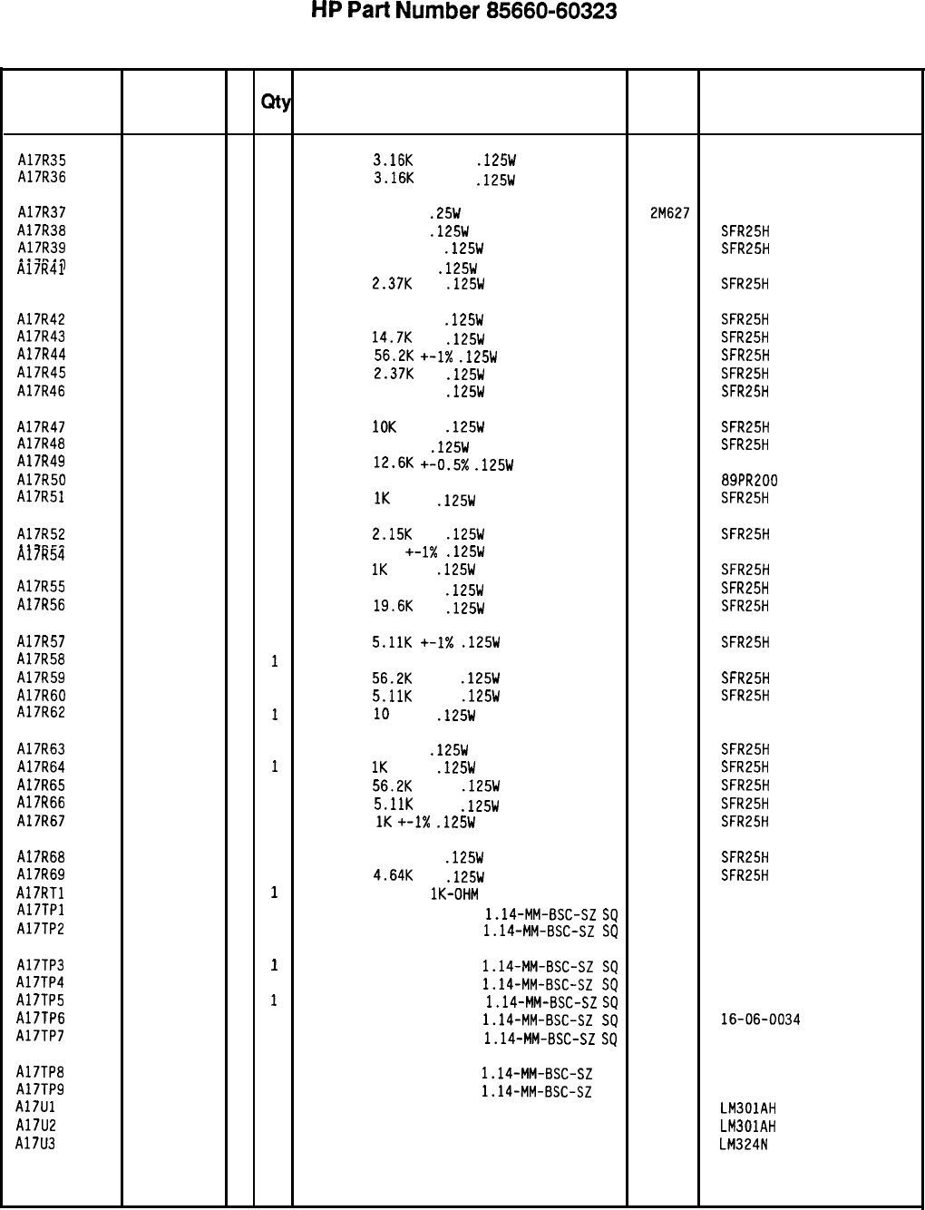
HP
Part
Number 85660-60323
Al7 Positive Regulator
Reference
HP Part C
Number D
Qty Description Mfr
Designation
Mfr Part
Code Number
A17R35
A17R36
A17R37
A17R38
A17R39
A17R40
A17R41
A17R42
A17R43
Al7R44
A17R45
A17R46
A17R47
A17R48
A17R49
A17R50
A17R51
A17R52
A17R53
Al7R54
A17R55
A17R56
A17R57
A17R58
A17R59
A17R60
A17R62
A17R63
A17R64
A17R65
A17R66
A17R67
A17R68
A17R69
A17RTl
A17TPl
A17TP2
A17TP3
A17TP4
A17TP5
A17TP6
A17TP7
A17TP8
A17TP9
A17Ul
A17U2
A17U3
0698-6835
0
1
RESISTOR
3.16K
+-0.5%
.125W
TF TC=O+-50
19701
5033R
0698-6835
0
1
RESISTOR
3.16K
+-0.5%
.125W
TF TC=O+-50
19701
5033R
0683-0275
9
1
RESISTOR 2.7 5%
.25W
CF TC=O-400
2M627 R-25J
0698-3444
11
RESISTOR 316 1%
.125W
TF TC=O+-100
19701 SFR25H
0757-0401
0
1
RESISTOR 100 +-1%
.125W
TF
TC=O+-100
19701
SFR25H
0757-0346
2
1
RESISTOR 10 +-1%
.125W
TF TC=O+-100
91637
0698-3150 CMF-55-1,
T-l
6
1
RESISTOR
2.37K
1%
.125W
TF TC=O+-100
19701 SFR25H
0757-0418
9
1
RESISTOR 619 +-1%
.125W
TF
TC=O+-100
19701
SFR25H
0698-3156
2
1
RESISTOR
14.7K
1%
.125W
TF TC=O+-100
19701 SFR25H
0757-0459
8
1
RESISTOR
56.2K +-1X
.125W
TF TC=O+-100
19701
SFR25H
0698-3150
6
1
RESISTOR
2.37K
1%
.125W
TF TC=O+-100
19701
SFR25H
0698-3150
6
1
RESISTOR 2.371: 1%
.125W
TF TC=O+-100 19701 SFR25H
0757-0442
9
1
RESISTOR
10K
+-1%
.125W
TF TC=O+-100
19701
SFR25H
0698-3444
1
1
RESISTOR 316
1%
.125W
TF TC=O+-100
19701 SFR25H
0698-8464
5
1
RESISTOR
12.6K
+-0.5x
.125W
TF TC=O+-50
19701
5033R
2100-3095
5
1
RESISTOR-TRMR 200 10% TKF
SIDE-ADJ 17-TR 73138 89PR200
0757-0280
3
1
RESISTOR
1K
+-1%
.125W
TF TC=O+-100
19701
SFR25H
0698-0084
9
1
RESISTOR
2.15K
1%
.125W
TF TC=O+-100
19701
SFR25H
0698-4405
6
1
RESISTOR 107 +-1X
.125W
TF TC=O+-100
91637 CMF-55-l.
T-l
0757-0280
3
1
RESISTOR
1K
+-1%
.125W
TF TC=O+-100
19701
SFR25H
0757-0401
0
1
RESISTOR 100
+-1%
.125W
TF TC=O+-100
19701
SFR25H
0698-3157
3
1
RESISTOR
19.6K
1%
.125W
TF TC=O+-100
19701
SFR25H
0757-0438
3
1
RESISTOR
5.11K
+-I%
.125W
TF TC=O+-100
19701
SFR25H
0698-3634
11
RESISTOR 470 5% 2W MO TC=O+-200 11502 GS-3
0757-0459
8
1
RESISTOR
56.2K
+-1%
.125W
TF TC=O+-100
19701
SFR25H
0757-0438
3
1
RESISTOR
5.11K
+-1%
.125W
TF TC=O+-100
19701
SFR25H
0757-0346
2
1
RESISTOR
10
+-1%
.125W
TF TC=O+-100
91637 CMF-55-l.
T-l
0698-3444
1
1
RESISTOR 316 1%
.125W
TF TC=O+-100
19701
SFR25H
0757-0280
3
1
RESISTOR
1K
+-1%
.125W
TF TC=O+-100
19701
SFR25H
0757-0459
8
1
RESISTOR
56.2K
+-1%
.125W
TF TC=O+-100
19701
SFR25H
0757-0438
3
1
RESISTOR
5.11K
+-1%
.125W
TF TC=O+-100
19701
SFR25H
0757-0280
3
1
RESISTOR
1K
+-1X
.125W
TF
TC=O+-100
19701
SFR25H
0757-0416
7
1
RESISTOR 511 +-1%
.125W
TF TC=O+-100
19701
SFR25H
0698-3155
1
1
RESISTOR
4.64K
1%
.125W
TF TC=O+-100
19701
SFR25H
0837-0126
6
1
THERMISTOR DISC
lK-OHM
TC=-4.4%/C-DEG
STD-0163
1251-0600
0
1
CONNECTOR-SGL 27264
1251-0600
CONT PIN
1.14-MM-BSC-SZ
SQ
16-06-0034
0
1
CONNECTOR-SGL CONT PIN 1.14-MM-BSC-SZ
SQ
27264 16-06-0034
1251-0600
0
1
27264 16-06-0034
1251-0600
CONNECTOR-SGL CONT PIN
1.14-MM-BSC-SZ
SQ
0
1
1251-0600
CONNECTOR-SGL CONT PIN
1.14-MM-BSC-SZ
SQ
27264 16-06-0034
0
1
27264
CONNECTOR-SGL CONT PIN
1.14-MM-BSC-SZ
SQ
16-06-0034
1251-0600
0
1
CONNECTOR-SGL CONT PIN
1.14-MM-BSC-SZ
SQ
27264 16-06-0034
1251-0600
0
1
CONNECTOR-SGL CONT
PIN
1.14-MM-BSC-SZ
SQ
27264 16-06-0034
1251-0600
0
1
CONNECTOR-SGL CONT PIN
1.14-MM-BSC-SZ
SQ
27264 16-06-0034
1251-0600
0
1
1820-0223
CONNECTOR-SGL CONT PIN
1.14-MM-BSC-SZ
SQ
27264 16-06-0034
0
1
IC OP AMP GP TO-99 PKG 27014 LM301AH
1820-0223
0
1
IC OP AMP GP TO-99 PKG 27014 LM301AH
1826-0161
7
1
IC OP AMP GP QUAD 14-DIP-P PKG 27014 LM324N
*Indicates factoy-selected value
8566060323 Parts List
Page 3 of 4
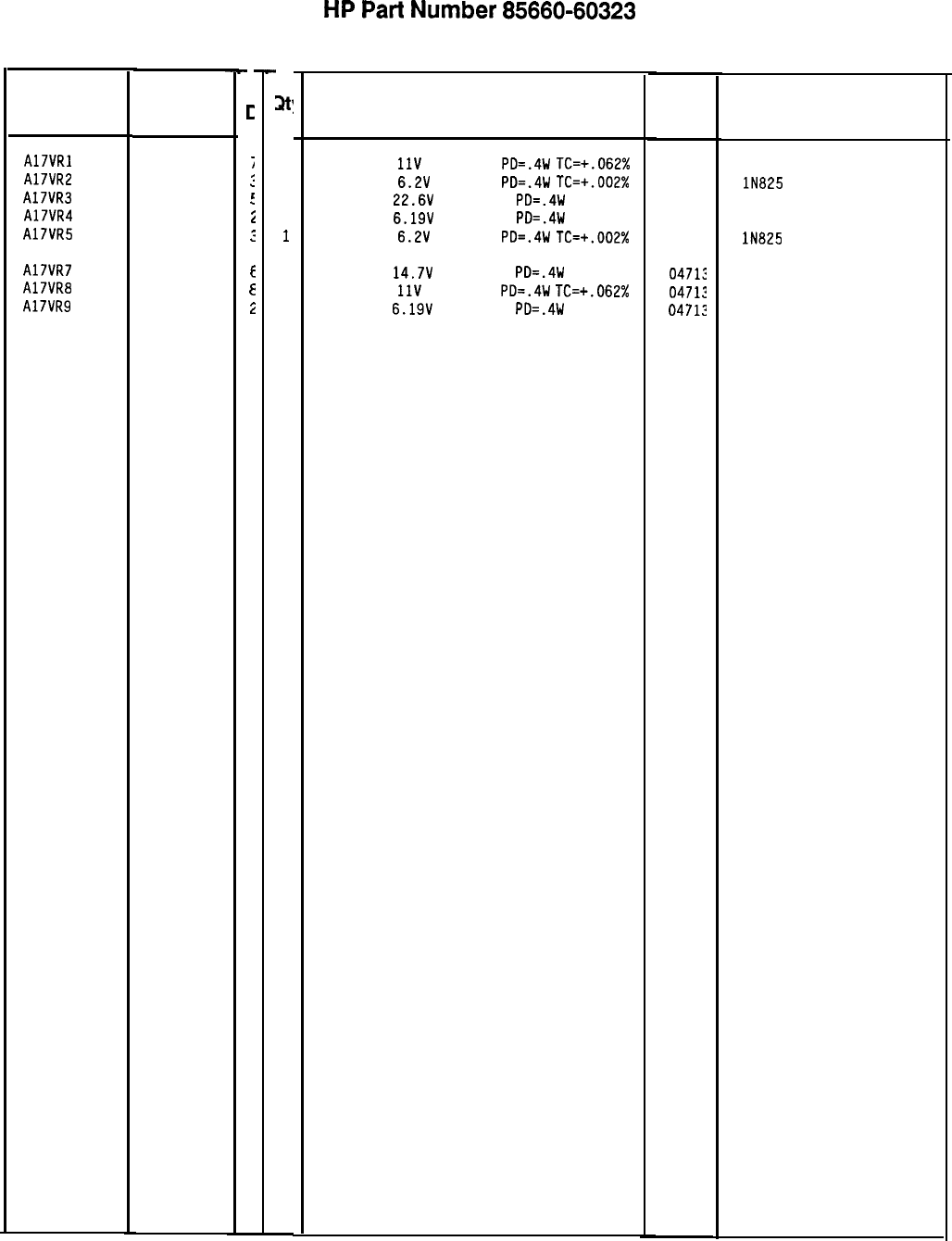
HP
Part
Number 85660-60323
Al7 Positive Regulator
Reference HP Part
Designation
Number
A17VRl 1902-3171
A17VR2 1902-0686
A17VR3 1902-3252
A17VR4 1902-0049
A17VR5 1902-0686
Al7VR7 1902-3203
A17VR8 1902-3172
A17VR9 1902-0049
85660-60323 Parts List
Page 4 of 4
C
c
j
:
t
i
:
E
E
i
3
1
1
1
1
1
1
1
1
-
Description
DIODE-ZNR
11V
5% DO-35
PD=.4W
TC=+.062%
DIODE-ZNR
6.2V
2% DO-7
PD=.4W
TC=+.002%
DIODE-ZNR
22.6V
2% DO-35
PD=.4W
DIODE-ZNR
6.19V
5% DO-35
PD=.4W
DIODE-ZNR
6.2V
2% DO-7
PD=.4W
TC=+.002%
DIODE-ZNR
14.7V
5% DO-35
PD=.4W
DIODE-ZNR
11V
2% DO-35
PD=.4W
TC=+.062%
DIODE-ZNR
6.19V
5% DO-35
PD=.4W
*Indicates factoy-selected value
Mfr
Mfr Part
Code
Number
0471:
0471:
0471:
0471:
0471:
0471;
04712
04712
lN825
lN825
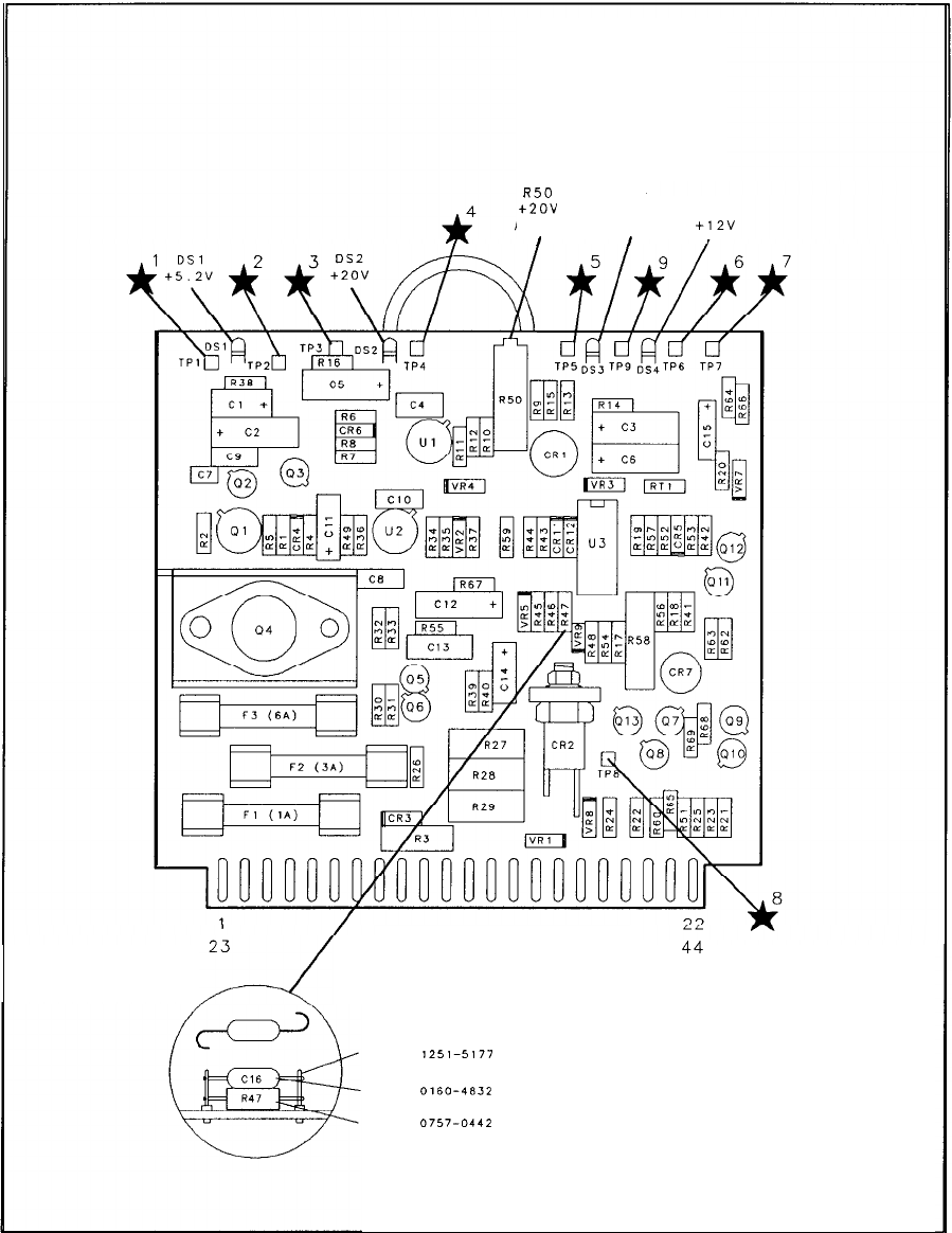
8750
OS3
+2ov
THERMAL OS4
ADJUST SHUT DOWN
f12V
I I
,
PI
23
Y---4
44
HP P/N
1251-5177
HP P/N
0160-4832
HP P/N
0757-0442
Al7 Positive Regulator Component Locations, 85660-60174
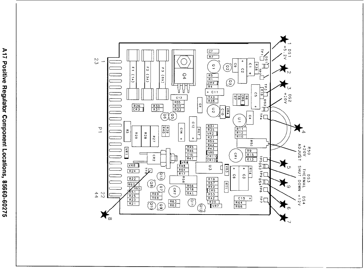
;
zc
d
”
a
,*n!T
+
5
+ +
a
I7
Em
;
2
t:
:4
Pm
:q
Cl5
+
F3
R64
Q
R65
27
P
Z+a
:zg
In
<
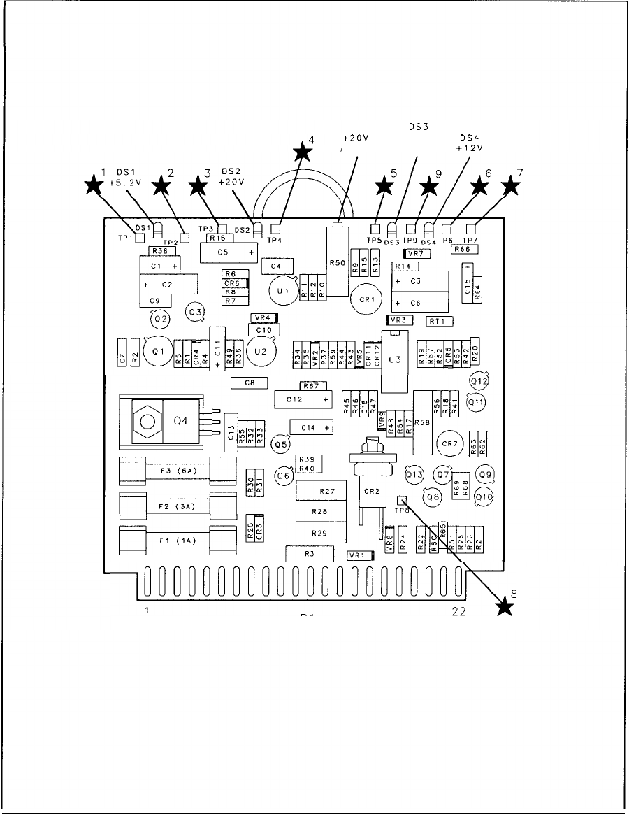
R50
OS3
THERMAL
DS4
ADJUST SHUT DOWN
+12”
CB
p$;
”
u?NW
oaz;:
F.3
(6A)
iFTGi$$
pqp4
~~oocouc~oc~nr~uu~ou:o~~~
1
PI 22
23 44
Al7 Positive Regulator Component Locations, 85660-60323
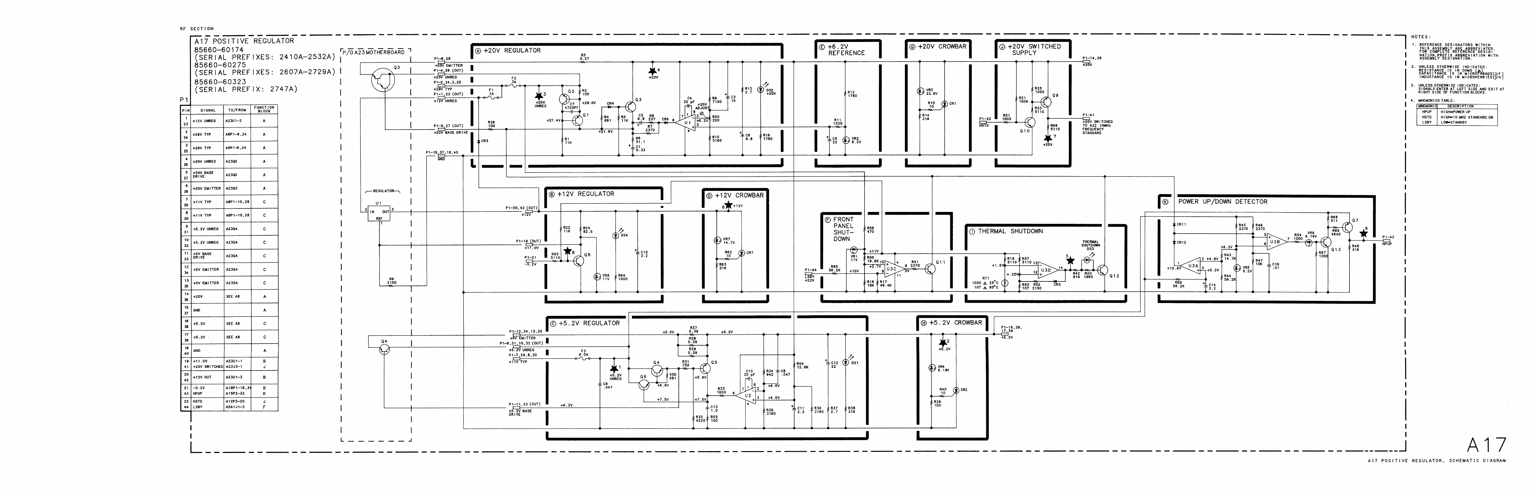
Al8
Al8
Negative
Regulator,
Circuit
Description
Al8 Negative Regulator provides -5.2 V, -10 V, and -40 V regulated voltages to the
instrument. All three supplies derive their reference from the
+20
V supply on the Al7
Positive Regulator. The relationship of Al8 to A8 Rectifier, Al7 Positive Regulator, and A23
Motherboard is shown on the A8 schematic.
-10
V
Regulator
@
The -10 V supply is referenced to the
+20
V supply by a resistor divider consisting of R5,
R6, and R7 connected between the two supplies. The voltage at the junction of R5 and R6 is
nominally 0 V. Any error is amplified by U2 to drive the series-pass transistor
A23Ql.
The
entire unregulated portion of the supply, including the rectifier diodes and filter capacitor, is
floating; thus the collector of
A23Ql
is typically i-15 V. Current-sensing resistors Rl and R23
are connected between the emitter of
A23Ql
and ground. These resistors, along with R2, R3,
CRl,
and
Ql,
form a current
foldback
protection network.
Overvoltage protection is provided by the -10 V crowbar
BJ
consisting of VR2 and CR26.
Further protection is provided by fuse F3. LED DS2 indicates the presence of an output
voltage.
-5.2
V
Regulator
@
The -5.2 V supply is also referenced to the
+20
V supply by a resistor divider consisting of
R37, R38, and R39 connected between the two supplies. This supply is a double-regulated
supply, as its input is in the regulated output from the -10 V supply. Error amplifier
Ul
drives the pass transistor Q2 via Q3. R32 and R33 are dropping resistors, so the power
dissipation in
Q2
is not excessive. R34, R12, R32, and Q4 provide current
foldback
protection.
Further protection is provided by
Fl.
Overvoltage protection is provided by the -5.2 V
crowbar
@I
consisting of VR4 and CR27. LED DS3 indicates the presence of an output
voltage.
-40
V
Regulator
The -40 V supply is referenced to the
+2OV
supply by the voltage divider consisting of R24,
R25, and R26, designed so that the input to the error amplifier U3 is at 0 V. The output
of the error amplifier drives the Darlington connection of
Q5
and the series-pass transistor
A23Q2. The input to the supply is floating, so the collector of A23Q2 is typically at
+lO
V.
Foldback
current protection is provided by R17, R18, R19, and Q6. Further current protection
is provided by the -40 V crowbar
@
consisting of VR3 and CR25. The presence of an output
voltage is indicated by LED
DSl.
A18 1
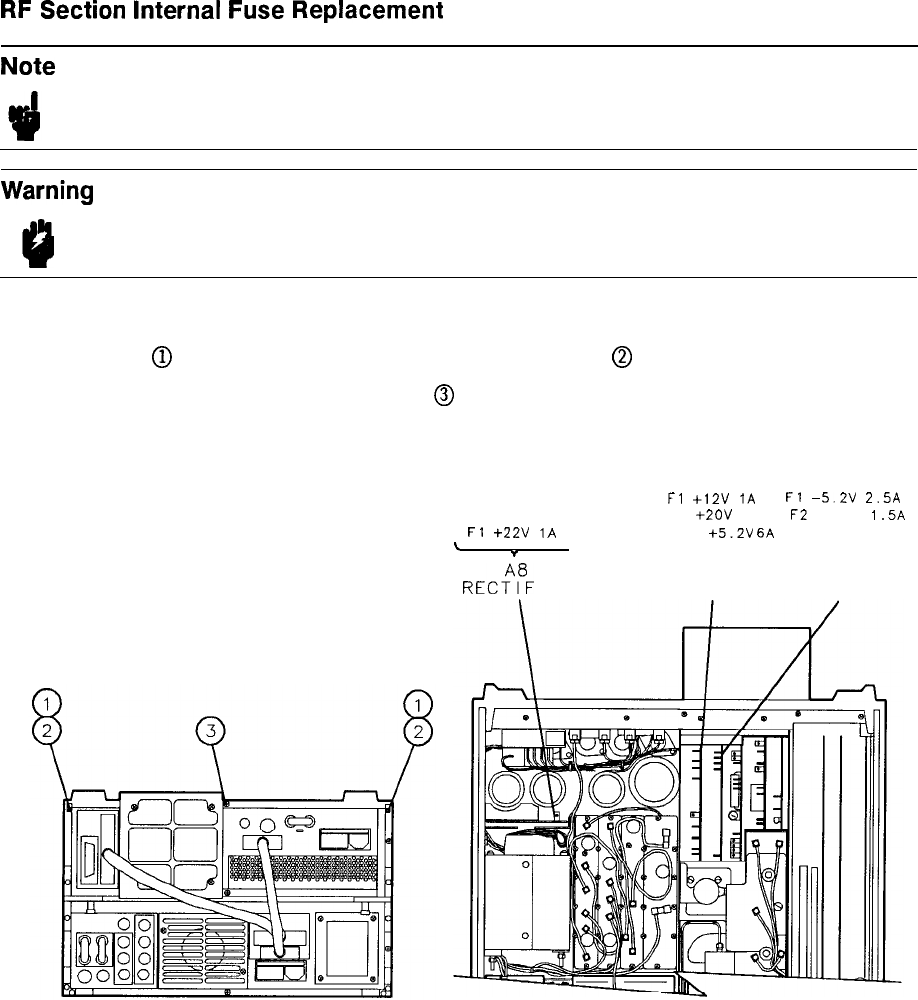
RF
Section
Internal
Fuse
Replacement
Note For location of hardware and cables referred to in this procedure, see Figure 1.
Warning
Remove ac line cord from both instruments before proceeding with this
procedure.
1. Position instrument upside-down as shown in view A.
2. Remove feet
@
from rear of RF Section by removing screws
@
shown in view A.
3. Remove bottom cover by loosening screw
@
and pulling cover toward rear of instrument.
4. Location of fuses is shown in view B.
Fl
+22V
1A
\
*
,
RE&
I ER
Fl
+12V
1A
Fl
-5.2V
2.5A
F2
+2OV
3A
F2
-40V
1.5A
F3
t5.2V
6A
F3 -lOV 5A
--
Al7 Al8
POS REG NEG REG
VIEW A VIEW B
Figure 1. Internal Fuse Replacement
2 A18
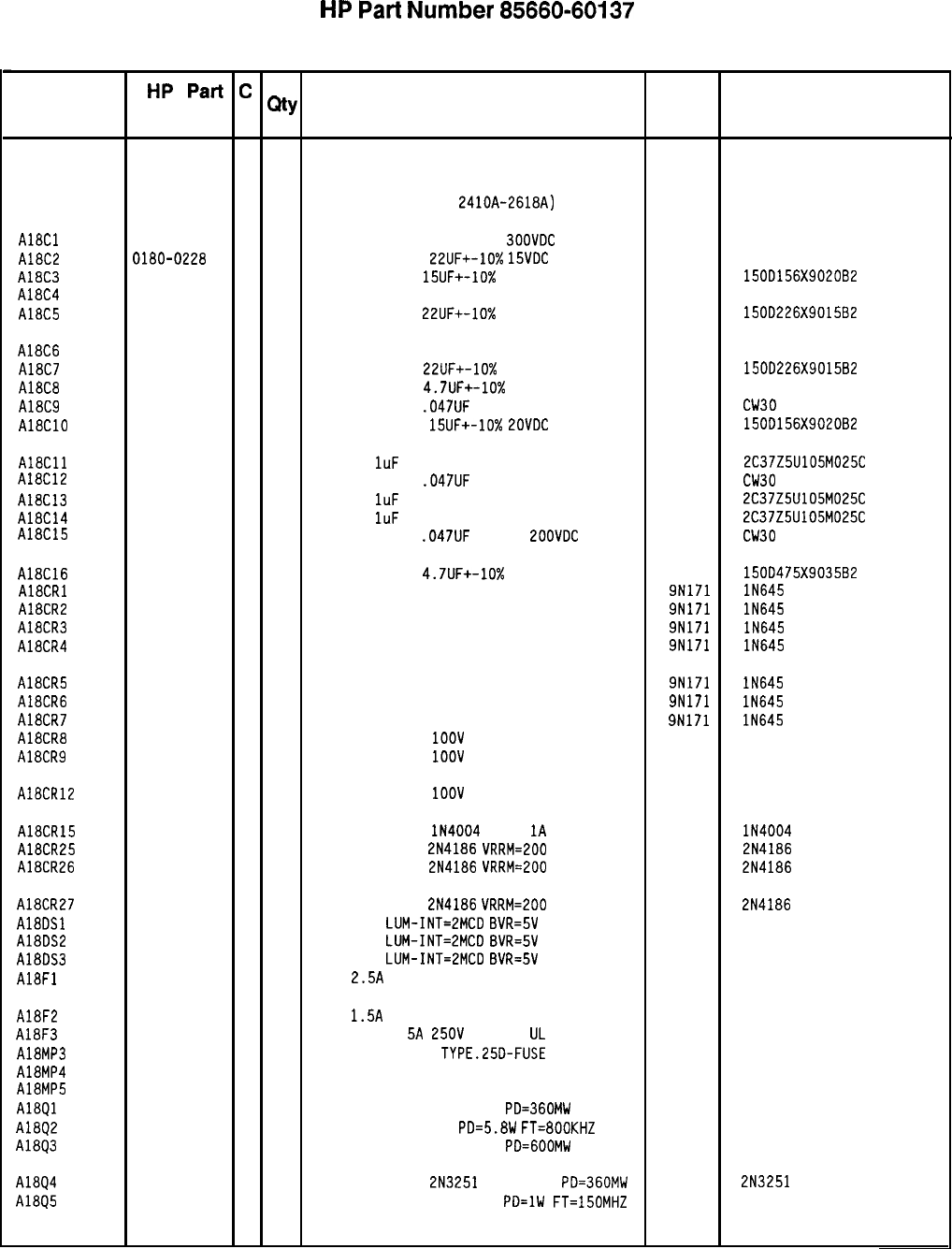
HP
Part
Number 85660-60137
A18 Negative Regulator
Reference
Mfr
Mfr Part
Designation
HP
Part
c
QtY
Number D
Description Code Number
Al8 85660-60137
2
1
BOARD ASSEMBLY, NEGATIVE REGULATOR 28480 85660-60137
(SERIAL PREFIXES:
2410~-2618~)
A18Cl 0160-2199
2
3
CAPACITOR-FXO 30PF +-5%
300VDC
MICA
28480 0160-2199
A18C2 0180-0228
6
1
CAPACITOR-FXD
22UF+-10%
15VDC
TA
56289 1500226X901582
A18C3 0180-1746
5
1
CAPACITOR-FXD
15UF+-10%
20VDC TA
56289 150D156X9020B2
A18C4 0160-2199
2
CAPACITOR-FXD 30PF +-5% 300VDC MICA
28480 0160-2199
A18C5 0180-0228
6
1
CAPACITOR-FXD
22UF+-10%
15VDC TA
56289 1500226X9015B2
A18C6 0160-2199
2
1
CAPACITOR-FXD 30PF +-5% 300VDC MICA
28480 0160-2199
A18C7 0180-0228
6
1
CAPACITOR-FXD
22UF+-10%
15VDC TA
56289 150D226X9015B2
A18C8 0180-1731
8
1
CAPACITOR-FXD
4.7UF+-10%
50VDC TA
56289 1500475X905082
A18C9 0160-4256
6
3
CAPACITOR-FXD
.047UF
+-20% 200VDC CER
16546 CW30
8
473M
A18ClO 0180-1746
5
1
CAPACITOR-FXD
15UF+-10%
ZOVDC
TA
56289 150D156X9020B2
A18Cll 0160-4892
6
1
CAP-FXD
1uF
25 V
56289 2C37Z5U105M025C
A18C12
0160-4256 6
CAPACITOR-FXD
.047UF
+-20% 200VDC CER
16546 CW30
B 473M
A18C13 0160-4892
6
1
CAP-FXO
1uF
25 V
56289 2C37Z5U105M025C
A18C14 0160-4892
6
1
CAP-FXD
1uF
25 V
56289 2C37Z5U105M025C
A18C15
0160-4256 6
CAPACITOR-FXD
.047UF
+-20%
ZOOVDC
CER
16546 CW30
B 473M
A18C16 0180-0100
3
1
CAPACITOR-FXD
4.7UF+-10%
35VDC TA
56289 150D475X903582
A18CRl 1901-0033
2
1
DIODE-GEN PRP 180V 200MA DO-35 9N171 lN645
A18CR2 1901-0033
2 1
DIODE-GEN PRP 180V 200MA DO-35 9N171 lN645
A18CR3 1901-0033
2
1
DIODE-GEN PRP 180V 200MA DO-35 9N171 lN645
A18CR4 1901-0033
2
1
DIODE-GEN PRP 180V 200MA DO-35 9N171 lN645
A18CR5
A18CR6
A18CR7
A18CR8
A18CR9
1901-0033
2
1
DIODE-GEN PRP 180V 200MA DO-35 9N171 lN645
1901-0033
2
1
DIODE-GEN PRP 180V 200MA DO-35 9N171 lN645
1901-0033
2
1
DIODE-GEN PRP 180V 200MA DO-35 9N171 lN645
1901-0662
3
1
DIODE-PWR RECT
1OOV
6A
04713 MR751
1901-0662
3
1
DIODE-PWR RECT
1OOV
6A
04713 MR751
A18CR12 1901-0662
3
1
DIODE-PWR RECT
1OOV
6A
04713 MR751
A18CR15 1901-0743
1 1
DIODE-PWR RECT
lN4004
400V
1A
DO-41
71744 lN4004
A18CR25 1884-0018
5
1
THYRISTOR-SCR
2N4186
VRRM=200 04713 2N4186
A18CR26 1884-0018
5
1
THYRISTOR-SCR
2N4186
VRRM=EOO 04713 2N4186
A18CR27
A18DSl
A18DS2
A18DS3
A18Fl
1884-0018
5
1
THYRISTOR-SCR
2N4186
VRRM=200 04713 2N4186
1990-0487
7
1
LED-LAMP
LUM-INT=2MCD
BVR=5V 28480 HLMP-1401
1990-0487
7
1
LED-LAMP
LUM-INT=2MCD
BVR=5V 28480 HLMP-1401
1990-0487
7
1
LED-LAMP
LUM-INT=ZMCD
BVR=5V 28480 HLMP-1401
2110-0083
6
1
FUSE
2.5A
250V NTD FE UL
75915 312 02.5
A18F2 2110-0043
8
1
FUSE
1.5A
250V NTD FE UL
75915
312
01.5
A18F3 2110-0010
9
1
FUSE (INCH)
5~
250~
NTD FE
UL
75915 312 005
A18MP3 2110-0269
0 6
FUSEHOLDER-CLIP
TYPE.Z5D-FUSE 28480 2100-0269
A18MP4 5000-9043
6
1
EXTRACTOR PIN 28480 5000-9043
A18MP5 5040-6843
2
1
EXTRACTOR 28480 5040-6843
A18Ql 1854-0404
0
1
TRANSISTOR NPN SI TO-18
PD=360MW 04713
A1802 1854-0441
5
1
TRANSISTOR NPN SI
PD=5.8W
FT=800KHZ 28480 1854-0441
A18Q3 1853-0001
1
1
TRANSISTOR PNP SI TO-39
PD=GOOMW 27014
A18Q4 1853-0007
7
1
TRANSISTOR PNP
2N3251
SI TO-18
PD=360MW 04713 2N3251
A18Q5 1854-0271
9
1
TRANSISTOR NPN SI TO-39
PO=lW
FT=150MHZ 04713
*Indicates factory-selected value
85660-60137 Parts List
Page 1 of 3
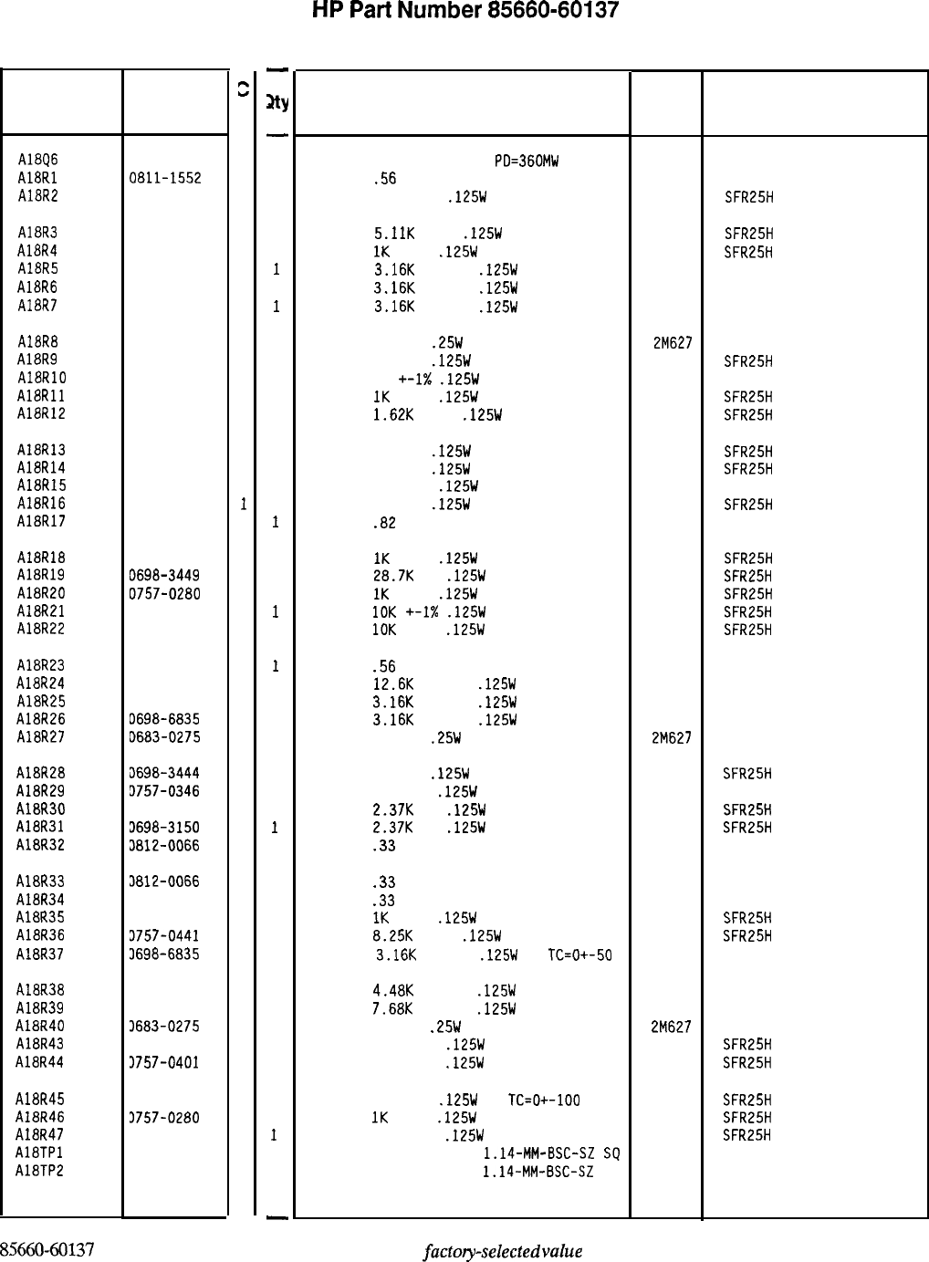
Reference
Designation
HP Part
Number
A18Q6
A18Rl
A18R2
1854-0404
0
0811-1552
0
0757-0421
4
A18R3
A18R4
A18R5
A18R6
A18R7
0757-0438
3
0757-0280
3
0698-6835
0
0698-6835
0
0698-6835
0
A18R8
A18R9
AlaRlO
A18Rll
A18R12
0683-0275
9
0698-3444
1
0757-0346
2
0757-0280
3
0757-0428
1
A18R13
A18R14
A18R15
A18R16
A18R17
0698-3447
4
0698-3444
1
0757-0346
2
0698-3444
1
0811-1665
6
A18R18
A18R19
A18R20
A18R21
A18R22
0757-0280
3
0698-3449
6
0757-0280
3
0757-0442
9
0757-0442
9
A18R23
A18R24
A18R25
A18R26
A18R27
0811-1552
0
0698-8464
5
0698-6835
0
0698-6835
0
D683-0275
9
AlBR28
A18R29
A18R30
A18R31
A18R32
il698-3444
1
3757-0346
2
3698-3150
6
3698-3150
6
3812-0066
1
A18R33
A18R34
A18R35
A18R36
A18R37
3812-0066
1
3812-0066
1
3757-0280
3
3757-0441
a
3698-6835
0
A18R38 3698-7050
A18R39 3698-6853
A18R40 3683-0275
A18R43 3757-0401
A18R44 3757-0401
A18R45 3698-3435
A18R46 3757-0280
A18R47
1757-0401
A18TPl 1251-0600
A18TP2 1251-0600
85660-60137 Parts List
Page 2 of 3
c
D
3
2
9
0
0
0
3
0
0
0
-
JtY
-
1
1
1
1
1
1
1
1
1
1
1
1
1
1
1
1
1
1
1
1
1
1
1
1
1
1
1
1
1
1
1
1
1
1
1
1
1
1
1
1
1
1
1
1
1
1
1
1
-
HP
Part
Number 85660-60137
A18 Negative Regulator
Description Mfr
Mfr Part
Code Number
TRANSISTOR NPN SI TO-18
PO=360MW 04713
RESISTOR
.56
+-5% 2W PWI TC=O+-800
11502
RESISTOR 825 +-1%
.125W
TF TC=O+-100
19701
SPH
SFR25H
RESISTOR
5.11K
+-1%
.125W
TF TC=O+-100
19701
SFR25H
RESISTOR
1K
+-1%
.125W
TF TC=O+-100
19701
SFR25H
RESISTOR
3.16K
+-0.5%
.125W
TF TC=O+-50
19701
5033R
RESISTOR 3.16K +-0.5%
.125W
TF TC=O+-50
19701
5033R
RESISTOR
3.16K
+-0.5%
.125W
TF TC=O+-50
19701
5033R
RESISTOR 2.7 5%
.25W
CF TC=O-400
2M627 R-25J
RESISTOR 316 1%
.125W
TF TC=O+-100
19701
SFR25H
RESISTOR 10 +-I%
.125W
TF TC=O+-100
91637 CMF-55-1, T-l
RESISTOR
IK
+-1%
.125W
TF TC=O+-100
19701
SFR25H
RESISTOR
1.62K
+-1%
.125W
TF TC=O+-100
19701
SFR25H
RESISTOR 422 1%
.125W
TF TC=O+-100
19701
SFR25H
RESISTOR 316 1%
.125W
TF TC=O+-100
19701
SFR25H
RESISTOR 10 +-1%
.125W
TF TC=O+-100
91637 CMF-55-1. T-l
RESISTOR 316 1%
.125W
TF TC=O+-100
19701
SFR25H
RESISTOR
.82
+-5% 2W PWI TC=O+-800
11502 SPH
RESISTOR
1K
+-1%
.125W
TF TC=O+-100
19701
SFR25H
RESISTOR
28.7K
1%
.125W
TF TC=O+-100
19701
SFR25H
RESISTOR
1K
+-1%
.125W
TF TC=O+-100
19701
SFR25H
RESISTOR
10K
+-I%
.125W
TF TC=O+-100
19701
SFR25H
RESISTOR
10K
+-1%
.125W
TF TC=O+-100
19701
SFR25H
RESISTOR
.56
+-5% 2W PWI TC=O+-800
11502 SPH
RESISTOR
12.6K
+-0.5%
.125W
TF TC=O+-50
19701
5033R
RESISTOR
3.16K
+-0.5%
.125W
TF TC=O+-50
19701
5033R
RESISTOR
3.16K
+-0.5%
.125W
TF TC=O+-50
19701
5033R
RESISTOR 2.7 5%
.25W
CF TC=O-400
2M627 R-25J
RESISTOR 316 1%
.125W
TF TC=O+-100
19701
SFR25H
RESISTOR 10 +-1%
.125W
TF TC=O+-100
91637 CMF-55-1, T-l
RESISTOR
2.37K
1%
.125W
TF TC=O+-100
19701 SFR25H
RESISTOR
2.37K
1%
.125W
TF TC=O+-100
19701
SFR25H
RESISTOR
.33
+-5% 2W PWI TC=O+-800
11502 SPH
RESISTOR
.33
+-5% 2W PWI TC=O+-800
11502 SPH
RESISTOR
.33
+-5% 2W PWI TC=O+-800
11502
SPH
RESISTOR
1K
+-1%
.125W
TF TC=O+-100
19701
SFR25H
RESISTOR
8.25K
+-1%
.125W
TF TC=O+-100
19701
SFR25H
RESISTOR
3.16K
+-0.5%
.125W
TF
TC=O+-50
19701
5033R
RESISTOR
4.48K
+-0.5%
.125W
TF TC=O+-50
19701
5033R
RESISTOR
7.68K
+-0.5%
.125W
TF TC=O+-50
19701
5033R
RESISTOR 2.7 5%
.25W
CF TC=O-400
2M627 R-25J
RESISTOR 100 +-1%
.125W
TF TC=O+-100
19701
SFR25H
RESISTOR 100 +-1%
.125W
TF TC=O+-100
19701 SFR25H
R
ES
IST
OR
38.3 1%
,125~
TF
Tc=o+-100
19701
SFR25H
RESISTOR
1K
+-1%
.125W
TF TC=O+-100
19701
SFR25H
RESISTOR 100 +-1%
.125W
TF TC=O+-100
19701
SFR25H
CONNECTOR-SGL CONT PIN
1.14-MM-BSC-SZ
SQ
27264 16-06-0034
CONNECTOR-SGL CONT PIN
1.14-MM-BSC-SZ
SQ
27264 16-06-0034
*Indicates factory-selected
value

HP
Part
Number 85660-60137
Al8 Negative Regulator
Reference
HP Part C
Designation
Number D
Qty Description Mfr
Mfr Part
Code Number
AlETP3 1251-0600
0
1
CONNECTOR-SGL
CONT PIN
1.14-MM-BSC-SZ
SQ
27264 16-06-0034
AlETP4 1251-0600
0
1
CONNECTOR-SGL CONT
PIN
1.14-MM-BSC-SZ
SQ
27264 16-06-0034
A18TP5 1251-0600
0
1
CONNECTOR-SGL CONT
PIN
1.14-MM-BSC-SZ
SQ
27264 16-06-0034
AlEUl 1820-0223
0
1
IC OP AMP GP TO-99 PKG 27014 LM301AH
AlEU2 1820-0223
0
I
IC OP AMP GP TO-99 PKG 27014 LM301AH
AlEU3 1820-0223
0
i
IC OP AMP GP TO-99 PKG 27014 LM301AH
A18VRl 1902-0025
4
1
DIODE-ZNR
IOV
5% DO-35
PO=.4W
TC=+.06% 04713
AlEVR2 1902-3171
7
1
DIODE-ZNR
11V
5%
DO-35
PO=.4W
TC=+.062% 04713
A18VR3 1902-3330
0
1
DIODE-ZNR
44.2V
2% DO-35
PO=.4W 04713
A18VR4 1902-0049
2
1
DIODE-ZNR 6.19V
5% DO-35
PO=.4W 04713
*Indicates factory-selected value
85660-60137 Parts List
Page 3 of 3
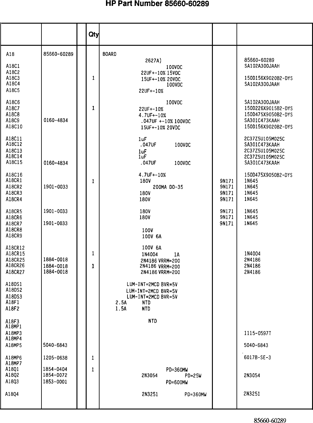
HP
Part
Number 85660-60289
A18 Negative Regulator
Reference
HP Part C
Designation
Number D
Qty Description Mfr Mfr Part
Code Number
A18
AlECl
A18C2
AlEC3
A18C4
A18C5
AlEC6
A18C7
Alaca
AlEC9
A18ClO
AlECll
AlEC12
A18C13
AlEC14
AlEC15
AlEC16
A18CR1
AlECR2
AlECR3
AlBCR4
AlECR5
AlECR6
AlECR7
AlaCRE
AlECR9
A18CR12
AlECR15
AlECR25
A18CR26
A18CR27
A18OSl
AlEOS2
AlEOS3
AlBFl
A18F2
AlEF3
Ali3MPl
AlEMP3
AlEMP4
AlEMP5
AlEMP6
A18MP7
AlEQl
AlEQ2
A1893
A18Q4
85660-60289
5
1
BOARD
ASSEMBLY NEGATIVE REGULATOR
(SERIAL PREFIX:
2627~)
28480 85660-60289
0160-5271
7
1
CAPACITOR-FXO 30PF +-5%
1OOVOC
CER 0+-30
04222 SA102A300JAAH
0180-0228
6
1
CAPACITOR-FXO
22UF+-10x
15VOC
TA
56289 1500226X901582-OYS
0180-1746
5
1
CAPACITOR-FXO
15UF+-10%
LOVOC
TA
56289 1500156X9020B2-OYS
0160-5271
7
1
CAPACITOR-FXO 30PF
+-5%
1OOVOC
CER 0+-30
04222 SA102A300JAAH
0180-0228
6
1
CAPACITOR-FXO
22UF+-10%
15VOC TA
56289 1500226X901582-OYS
0160-5271
7
1
CAPACITOR-FXO 30PF +-5%
IOOVOC
CER 0+-30
04222 SA102A300JAAH
0180-0228
6
I
CAPACITOR-FXO
22UF+-10%
15VOC TA
56289 1500226X9015B2-OYS
0180-1731
a
1
CAPACITOR-FXO 4.7UF+-10% 50VOC TA
56289 1500475x905082-0Ys
0160-4834
6
1
CAPACITOR-FXO
.047UF
+-lo%
1OOVOC
CER
04222 SA301C473KAAH
0180-1746
5
1
CAPACITOR-FXO
15UF+-10%
ZOVOC
TA
56289 1500156X9020B2-OYS
0160-4892
6
1
CAPACITOR-FXO
1uF
25 V
56289 2C37Z5U105M025C
0160-4834
6
1
CAPACITOR-FXO
.047UF
+-lo%
1OOVOC
CER
04222 SA301C473KAAH
0160-4892
6
1
CAPACITOR-FXO
1uF
25 V
56289 2C37Z5U105M025C
0160-4892
6
1
CAPACITOR-FXO
IuF
25 V
56289 2C37Z5U105M025C
0160-4834
6
1
CAPACITOR-FXO
.047UF
+-lo%
1OOVOC
CER
04222 SA301C473KAAH
0180-1731
a
1
CAPACITOR-FXO
4.7UF+-10%
50VOC TA
56289 1500475X9050B2-OYS
1901-0033
2
1
DIODE-GEN PRP
18OV
200MA DO-35 9N171 lN645
1901-0033
2
1
DIODE-GEN PRP laov
200~~
00-35 9N171 lN645
1901-0033
2
1
DIODE-GEN PRP
18OV
200MA DO-35
9N171 lN645
1901-0033
2
1
DIODE-GEN PRP
18OV
200MA DO-35
9N171 lN645
1901-0033
2
1
DIODE-GEN PRP
18OV
200MA DO-35
9N171 lN645
1901-0033
2
1
DIODE-GEN PRP
18OV
200MA DO-35
9N171 lN645
1901-0033
2
1
DIODE
-
GEN
PRP laov 200MA DO-35
9N171 lN645
1901-0662
3
1
DIODE-PWR RECT
1OOV
6A
04713 MR751
1901-0662
3
1
DIODE-PWR RECT
1OOV
6A
04713 MR751
1901-0662
3
1
DIODE-PWR RECT
1OOV
6A 04713 MR751
1901-0743
11
DIODE-PWR RECT
lN4004
400V
1A
DO-41
71744 lN4004
1884-0018
5
1
THYRISTOR-SCR
2N4186
VRRM=LOO 04713 2N4186
1884-0018
5
I
THYRISTOR-SCR
2N4186 VRRM=POO 04713 2N4186
iaa4-0018
5
1
THYRISTOR-SCR
2N4186
VRRM=200 04713 2N4186
1990-0487
7
1
LEO-LAMP
LUM-INT=2MCO
BVR=5V 28480 HLMP-1401
1990-0487
7
1
LEO-LAMP LUM-INT=2MCO
BVR=SV 28480 HLMP-1401
1990-0487
7
1
LEO-LAMP
LUM-INT=ZMCO
BVR=5V 28480 HLMP-1401
2110-0083
6
1
FUSE
2.5A
250V
NT0
FE UL 75915 312 02.5
2110-0043
8
1
FUSE
1.5A
250V
NT0
FE UL
75915 312 01.5
2110-0010
9
1
FUSE 5A 250V
NT0
FE UL
(INCH)
75915 312 005
NOT ASSIGNED
2110-0726
4
6
FUSEHOLDER-CLP-TYP.250-FUSE 13060 1115-0597T
5000-9043
6
1
EXTRACTOR PIN 28480 5000-9043
5040-6843
2
1
PC BOARD EXTRACTOR 28480 5040-6843
1205-0638
7
1
HEAT SINK SGL TO-66-CS 13103 -6017B-SE-3
1200-0081
412
INSULATOR-FLG-BSHG NYLON 26365 974 307
1854-0404
0
I
TRANSISTOR NPN SI TO-18
PO=360MW 04713
1854-0072
a 1
TRANSISTOR NPN
2N3054
SI TO-66
PO=25W 04713 2N3054
1853-0001
1
1
TRANSISTOR PNP
SI TO-39
PO=GOOMW 27014
1853-0007
7
1
TRANSISTOR PNP 2N3251
SI TO-18
PO=360MW 04713 2N3251
*Indicates factory-selected value
85660-60289 Parts List
Page 1 of 3
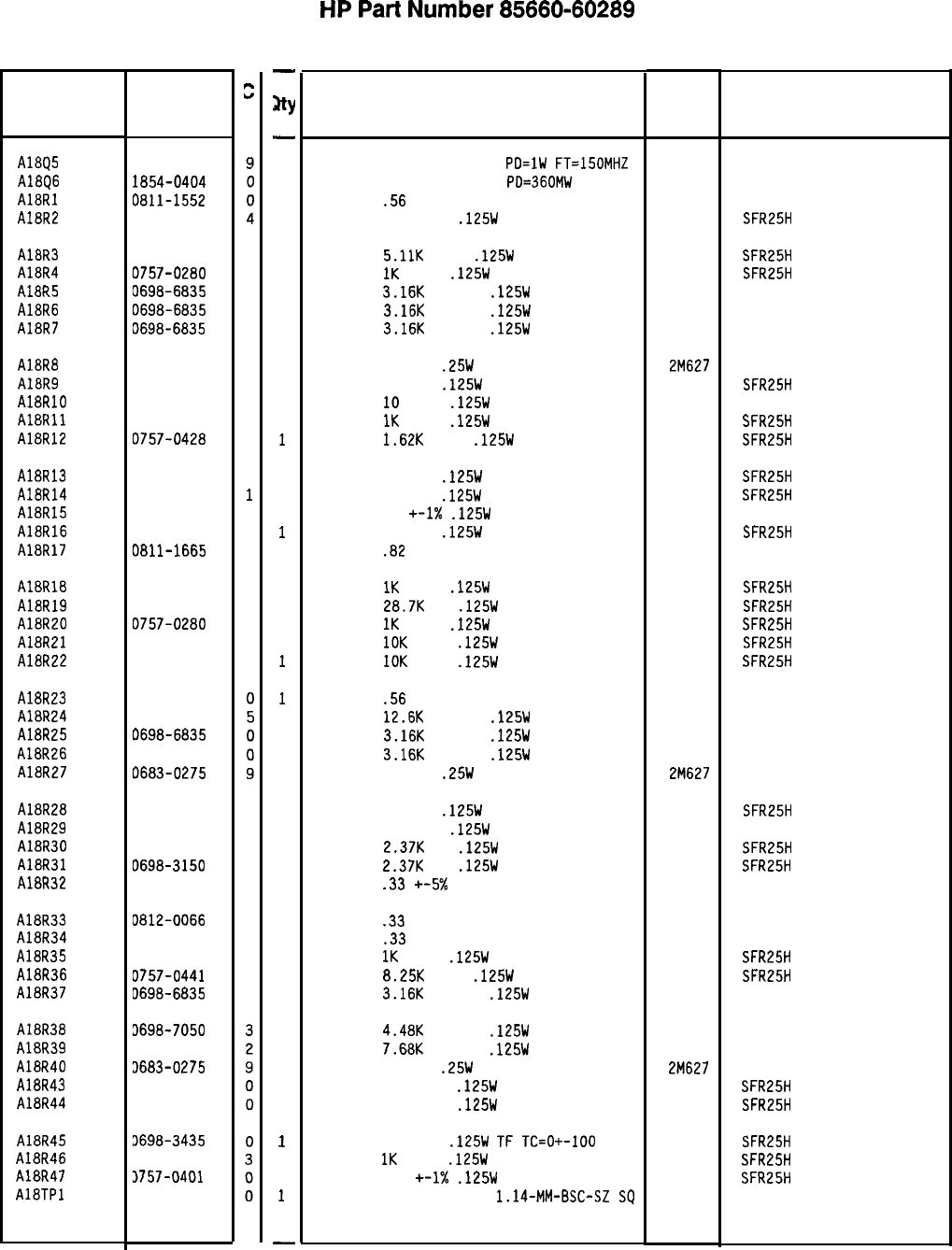
Reference
Designation
AlEQ5
AlEQ6
AlaRI
AlER2
HP Part
Number
1854-0271
1854-0404
0811-1552
0757-0421
AlER3
AlER4
AlER5
AlER6
AlER7
0757-0438
3
0757-0280
3
0698-6835
0
0698-6835
0
0698-6835
0
AlaRa
A18R9
AlaRlO
A18Rll
AlER12
0683-0275
9
0698-3444
1
0757-0346
2
0757-0280
3
0757-0428
1
A18R13
AlER14
AlER15
AlER16
AlER17
0698-3447
4
0698-3444
1
0757-0346
2
0698-3444
1
0811-1665
6
A18R18
AlER19
A18R20
AlER21
AlER22
0757-0280
3
0698-3449
6
0757-0280
3
0757-0442
9
0757-0442
9
A18R23
A18R24
AlER25
A18R26
AlER27
0811-1552
0698-8464
0698-6835
0698-6835
0683-0275
AlER28
AlER29
AlER30
A18R31
A18R32
0698-3444
1
0757-0346
2
0698-3150
6
0698-3150
6
0812-0066
1
A18R33
AlER34
AlER35
A18R36
AlER37
0812-0066
1
0812-0066
1
0757-0280
3
0757-0441
a
D698-6835
0
AlER38
AlER39
A18R40
A18R43
AlER44
3698-7050
3698-6853
3683-0275
3757-0401
3757-0401
AlER45 3698-3435
A18R46 3757-0280
A18R47 3757-0401
AlETPl 1251-0600
8X60-60289 Parts List
Page 2 of 3
s
D
-
JtY
-
1
1
1
1
1
1
1
1
1
1
1
1
1
1
1
1
1
1
1
1
1
1
1
1
1
1
1
1
1
1
1
1
1
1
1
1
1
1
1
1
1
1
1
1
1
1
1
1
-
HP
Part
Number 85660-60289
Al8 Negative Regulator
Description Mfr Mfr Part
Code Number
TRANSISTOR NPN SI TO-39
PO=lW
FT=lSOMHZ 04713
TRANSISTOR NPN SI TO-18
PO=360MW 04713
RESISTOR
.56
+-5% 2W PWI TC=O+-800
11502
RESISTOR 825 +-1%
.125W
TF TC=O+-100
19701
SPH
SFR25H
RESISTOR
5.11K
+-1%
.125W
TF TC=O+-100
19701
SFR25H
RESISTOR
IK
+-1%
.125W
TF TC=O+-100
19701
SFR25H
RESISTOR
3.16K
+-0.5%
.125W
TF TC=O+-50
19701
5033R
RESISTOR
3.16K
+-0.5%
.125W
TF TC=O+-50
19701
5033R
RESISTOR
3.16K
+-0.5%
.125W
TF TC=O+-50
19701
5033R
RESISTOR 2.7 5%
.25W
CF TC=O-400
2M627 R-25J
RESISTOR 316 1%
.125W
TF TC=O+-100
19701
SFR25H
RESISTOR
10
+-1%
.125W
TF TC=O+-100
91637 CMF-55-1, T-l
RESISTOR
1K
+-1%
.125W
TF TC=O+-100
19701
SFR25H
RESISTOR
1.62K
+-1%
.125W
TF TC=O+-100
19701
SFR25H
RESISTOR 422 1%
.125W
TF TC=O+-100
19701
SFR25H
RESISTOR 316 1%
.125W
TF TC=O+-100
19701
SFR25H
RESISTOR 10
+-1X
.125W
TF TC=O+-100
91637 CMF-55-1, T-l
RESISTOR 316 1%
.125W
TF TC=O+-100
19701
SFR25H
RESISTOR
.82
+-5% 2W PWI TC=O+-800
11502 SPH
RESISTOR
1K
+-1%
.125W
TF TC=O+-100
19701 SFR25H
RESISTOR
28.7K
1%
.125W
TF TC=O+-100
19701
SFR25H
RESISTOR
IK
+-1%
.125W
TF TC=O+-100
19701
SFR25H
RESISTOR
10K
+-1%
.125W
TF TC=O+-100
19701
SFR25H
RESISTOR
IOK
+-1%
.125W
TF TC=O+-100
19701
SFR25H
RESISTOR
.56
+-5% 2W PWI TC=O+-800
11502 SPH
RESISTOR
12.6K
+-0.5%
.125W
TF TC=O+-50
19701
5033R
RESISTOR
3.16K
+-0.5%
.125W
TF TC=O+-50
19701
5033R
RESISTOR
3.16K
+-0.5%
.125W
TF TC=O+-50
19701
5033R
RESISTOR 2.7 5%
.25W
CF TC=O-400
2M627 R-25J
RESISTOR 316 1%
.125W
TF TC=O+-100
19701
SFR25H
RESISTOR 10 +-1%
.125W
TF TC=O+-100
91637 CMF-55-1, T-l
RESISTOR
2.37K
1%
.125W
TF TC=O+-100
19701
SFR25H
RESISTOR
2.37K
1%
.125W
TF TC=O+-100
19701
SFR25H
RESISTOR
.33
~-5%
2W PWI TC=O+-800
11502 SPH
RESISTOR
.33
+-5% 2W PWI TC=O+-800
11502 SPH
RESISTOR
.33
+-5% 2W PWI TC=O+-800
11502 SPH
RESISTOR
1K
+-1%
.125W
TF TC=O+-100
19701
SFR25H
RESISTOR
8.25K
+-1%
.125W
TF TC=O+-100
19701
SFR25H
RESISTOR
3.16K
+-0.5%
.125W
TF TC=O+-50
19701
50338
RESISTOR
4.48K
+-0.5%
.125W
TF TC=O+-50
19701
5033R
RESISTOR
7.68K
+-0.5%
.125W
TF TC=O+-50
19701
5033R
RESISTOR 2.7 5%
.25W
CF TC=O-400
2M627 R-25J
RESISTOR 100 +-1%
.125W
TF TC=O+-100
19701
SFR25H
RESISTOR 100 +-1%
.125W
TF TC=O+-100
19701
SFR25H
RE
SI
ST
OR
38.3 1%
.125w
TF
~c=o+-100
19701
SFR25H
RESISTOR
1K
+-1%
.125W
TF TC=O+-100
19701
SFR25H
RESISTOR 100
+-1X
.125W
TF TC=O+-100
19701
SFR25H
CONNECTOR-SGL CONT PIN
1.14-MM-BSC-SZ
SQ
27264 16-06-0034
*Indicates factory-selected value
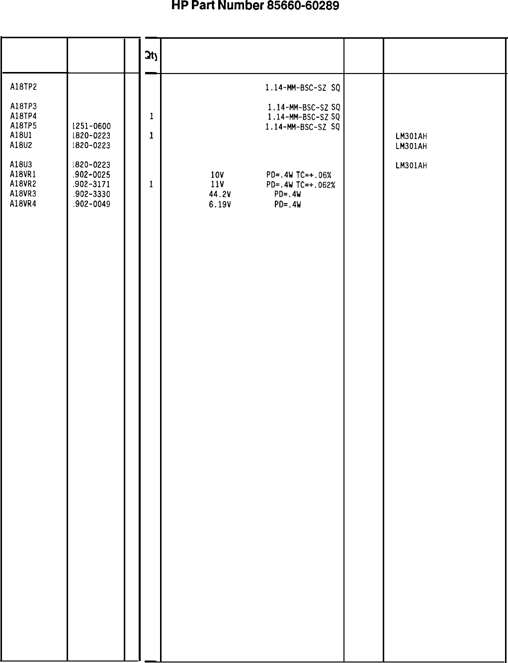
Reference HP Part
Designation
Number
A18TP2 1251-0600
AlETP3 1251-0600
AlETP4 1251-0600
A18TP5 L251-0600
A18Ul
1820-0223
AlEU2
1820-0223
AlEU3
AlEVRl
A18VR2
AlEVR3
AlEVR4
1820-0223
.902-0025
.902-3171
.902-3330
.902-0049
C
D
0
0
0
0
0
0
0
4
7
0
2
-
at]
-
1
1
1
1
1
1
1
1
1
1
1
-
HP
Part
Number 85660-60289
Al8 Negative Regulator
Description
CONNECTOR-SGL CONT PIN
1.14-MM-BSC-SZ
SQ
27264 16-06-0034
CONNECTOR-SGL CONT PIN
1.14-MM-BSC-SZ
SQ
27264 16-06-0034
CONNECTOR-SGL CONT PIN
1.14-MM-BSC-SZ
SQ
27264 16-06-0034
CONNECTOR-SGL CONT PIN
1.14-MM-BSC-SZ
SQ
27264 16-06-0034
IC OP AMP GP TO-99 PKG 27014 LM301AH
IC OP AMP GP TO-99 PKG 27014 LM301AH
IC OP AMP GP TO-99 PKG 27014
DIODE-ZNR
1OV
5% DO-35
PO=.4W
TC=+.06% 04713
DIODE-ZNR
11V
5% DO-35
PO=.4W
TC=+.062% 04713
DIODE-ZNR
44.2V
2% DO-35
PO=.4W 04713
DIODE-ZNR
6.19V
5% DO-35
PO=.4W 04713
LM301AH
Mfr
Mfr Part
Code Number
*Indicates factory-selected value
85660450289 Parts List
Page 3 of 3
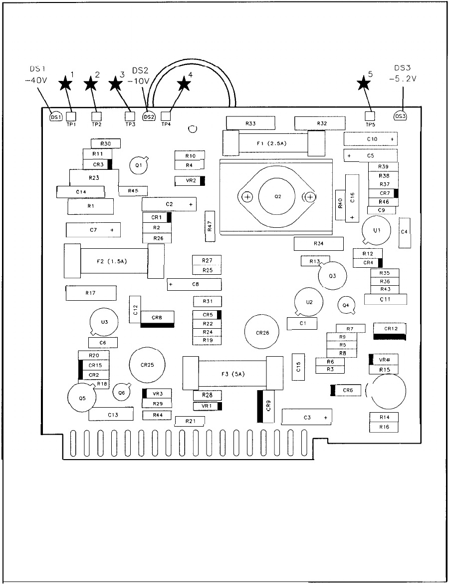
u
rR30
R
“,i:
(g
pi
~~~
R23
I
I
I
I
,-*a
L
*_I
II
‘d’
-+---LJ
’
-~~
0
O2
0
s:
0
LL
n
+
z
RS9
H
R38
L--FL
L----z-
-1
El
nyrj
,’
FEZ+-
RI2
RI3
CR4
R37
CR7
B
R46
c9
:_:I
U,
-eY
IR17I
(J
@Eg
r--q
CR5
R22
u
-
Ia.4
I
0
CR26
RI9
‘:l:;r,
i_;yfTg,
u2
04
P
Cl7
R5
t-3
(5A)
&r_-
R8
R6
RJ
RI5
R28
I
\
-
‘LY-
L
‘-a
g
I
r---rT
g
I
Vf+l
I
[CR61
(
CR27
)
1
19
PI 18
36
Al8 Negative Regulator Component Locations, 85660-60137
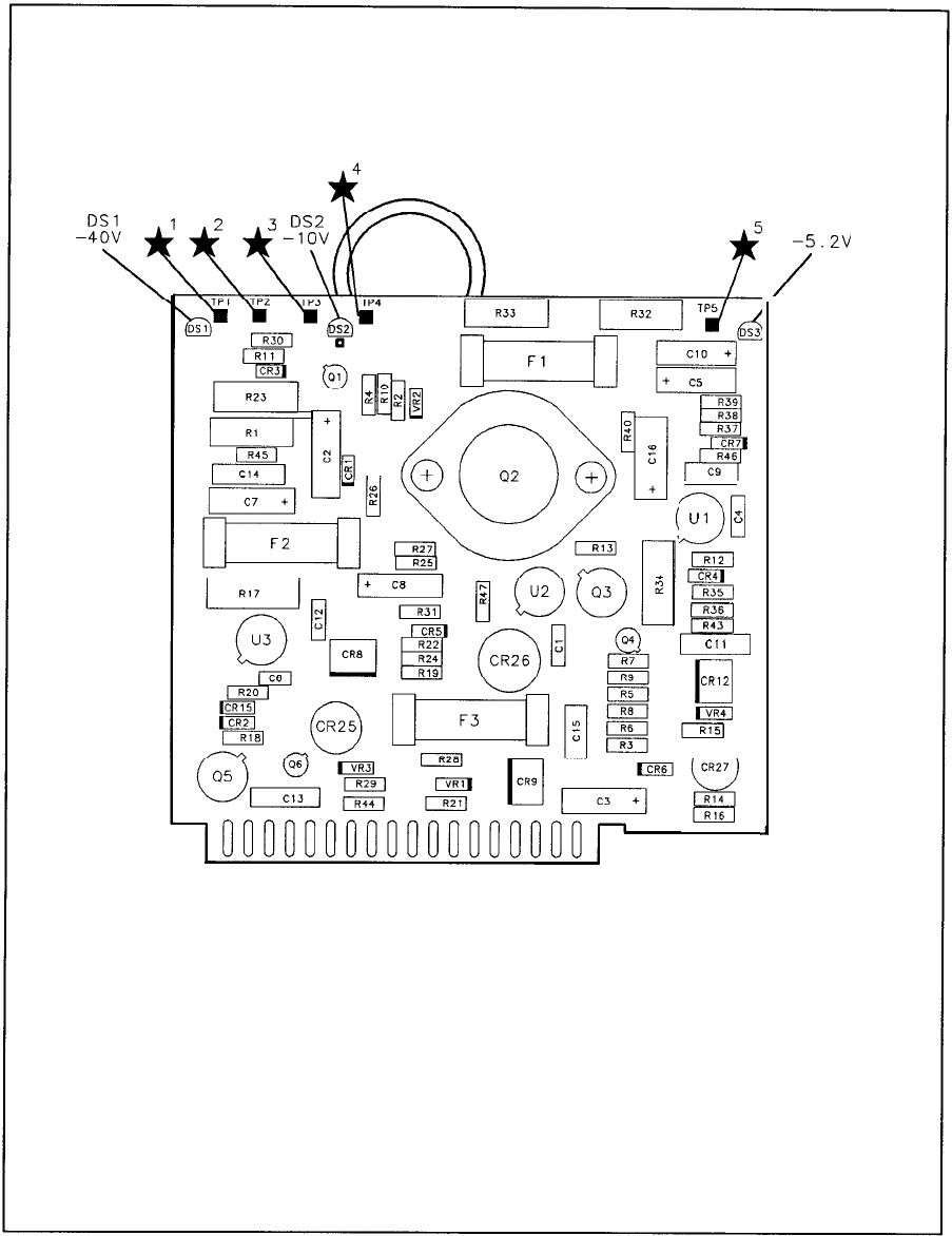
30
Ul
t
m
m
m
j
R43
r?
c,,
II
CR12
m
m
,
DS3
-5.2V
/
Al8 Negative Regulator Component Locations, 85660-60289
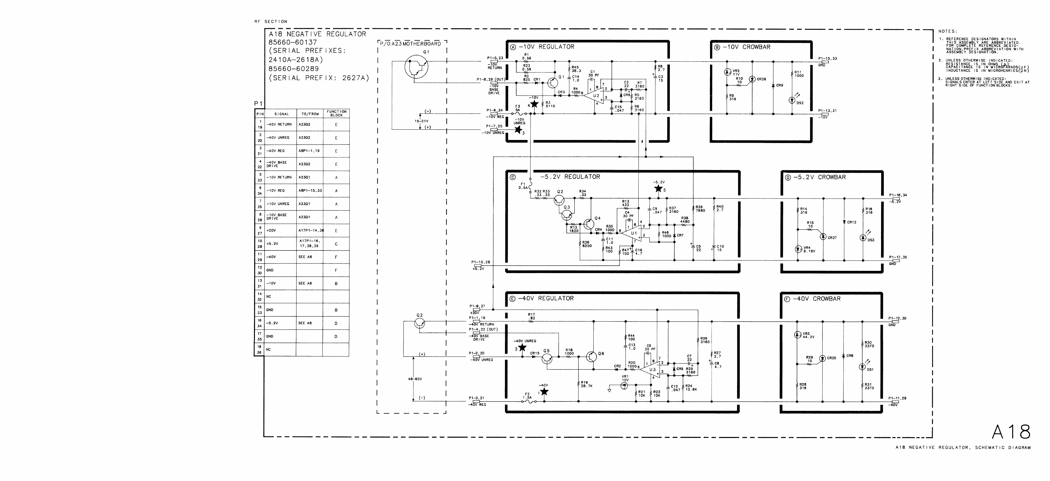

A19
A19
Digital-to-Analog
Converter
(DAC),
Circuit
Description
The A19 DAC provides the tuning voltage to the A20 YTO Main Coil Driver used to coarse
tune the YTO Start Frequency and set the proper amount of sweep. This occurs at the
beginning of each sweep and at the beginning of each harmonic band within a sweep.
YTO
Pretune Register
@
and
Pretune
DAC
@
Frequency information is loaded into pretune registers U5 and U6 from the Instrument Bus.
This is coded information from the Instrument Bus. This information is clocked into the
registers by LDAS (Low
=
DAC Strobe). The Pretune DAC, in conjunction with U2, provides
an output of 0.0 to
i-12.6
V dc in approximately 3
mV
increments. The exact voltage is
dependent on the coded information input. This voltage is applied to Summing Amplifier U4
through R3.
Frequency
Span
Register
and
Switch
Driver
@I
and
Span
Scaling
@
Coded span information from the Al2 Front-Panel Interface is loaded into register U7 from
the Instrument Bus and clocked out to switch drivers U8 and
U9
by LSAS (Low = Scan
Attenuator Strobe). These switch drivers turn on (close) switches
Q2
through Q6 according to
the coded information input. The SCAN DAC IN signal (attenuated sweep ramp) from the
Al6 Scan Generator is then applied to the proper scaling resistors R26 through R30, R38, and
R58, to provide the sweep for the YTO. This output current is applied to Summing Amplifier
u4.
Summing
Amplifier
@
The fixed dc current from the Pretune DAC, corresponding to the desired YTO Start
Frequency, and the ramp current from the Scaling Resistors, corresponding to the desired
Frequency Span, are summed at the input of U4. U4 amplifies this combined signal and
applies it to both the YTO and YTX at a sensitivity of -3
V/GHz
to coarse tune the
analyzer to the selected Start Frequency and Frequency Span.
Negative
Voltage
Reference
@
and
Positive
Voltage
Reference
@
U3 and associated circuitry
0
provide a nominal -12.6 V reference for U3, the pretune DAC
in function block
0.
UlO
and associated circuitry
$J
provide a nominal
+lO
V reference for
summing amplifier U4 in function block
0.
A19 1
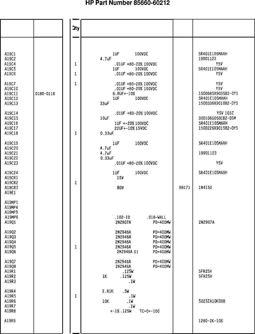
Reference
Designation
HP Part
Number
C
D
A19 85660-60212
4
A19Cl
A19C2
A19C4
A19C5
A19C6
0160-4005
3
0180-0630
4
0160-2055
9
0160-4005
3
0160-2055
9
A19C7
A19ClO
A19Cll
A19C12
A19C13
0160-2055
9
0160-2055
9
0180-0116
1
0160-4005
3
0180-0229
7
A19C14
A19C15
A19C16
A19C17
A19C18
0160-2055
9
0180-0183
2
0160-4005
3
0180-0228
6
0160-4745
8
A19C19
A19C20
A19C21
A19C22
A19C23
0160-4005
3
0180-0630
4
0180-0630
4
0160-4745
8
0160-2055
9
A19C24
A19CRl
A19CR2
A19CR3
A19El
0160-4005
3
1901-0179
7
1901-0539
3
1901-0050
3
0340-0060
4
A19MPl
A19MP4
A19MP5
A19MP6
A19Ql
5000-9043
6
5040-6843
2
0890-0644
5
1853-0281
9
A1992
A19Q3
A1994
A1995
A1996
1853-0322
9
1853-0322
9
1853-0322
9
1853-0322
9
1853-0322
9
A19Q7
A19Q8
A19Rl
A19R2
A19R3
1853-0322
9
1853-0322
9
0698-8590
8
0757-0280
3
0699-0306
0
A19R4 0698-0024
7
A19R5 0699-0306
0
A19R6 0699-0642
7
A19R7 0699-0306
0
A19R8 0757-0346
2
A19R9 2100-4020 8
-
%Y
-
1
1
1
1
1
1
1
1
1
1
1
1
1
1
1
1
1
1
1
1
1
1
1
1
1
1
1
1
1
1
1
1
1
1
1
1
1
1
1
1
1
1
1
1
1
1
-
HP
Part
Number 85660-60212
A19 DAC
Description
BOARD ASSEMBLY. DIGITAL-TO-ANALOG
CONVERTER (DAC)
CAPACITOR-FXD
1UF
+-20%
1OOVDC
CER
CAP-FXD
4.7uF
50 V TA
CAPACITOR-FXD
.OlUF
+80-20%
IOOVDC
CER
CAPACITOR-FXD
1UF
+-20%
1OOVDC
CER
CAPACITOR-FXD
.OlUF
+80-20%
1OOVDC
CER
CAPACITOR-FXD
.OlUF
+80-20%
1OOVDC
CER
CAPACITOR-FXD
.OlUF
+80-20X
1OOVDC
CER
CAPACITOR-FXD
6.8UF+-10%
35VDC TA
CAPACITOR-FXD
1UF
+-20%
1OOVDC
CER
CAP-FXD
33uF
10 V TA
CAPACITOR-FXD
.OlUF
+80-20%
1OOVDC
CER
CAP-FXD
1OuF
50 V AL-ELCTLT
CAPACITOR-FXD
1UF
+-20x
1OOVDC
CER
CAPACITOR-FXD
22UF+-10%
15VDC
TA
CAP-FXD
0.33uF
100 V POLYP-FL
CAPACITOR-FXD
1UF
+-20%
1OOVDC
CER
CAP-FXD
4.7uF
50 V TA
CAP-FXD
4.7uF
50 V TA
CAP-FXD
0.33uF
100 V POLYP-FL
CAPACITOR-FXD
.OlUF
+80-20%
1OOVDC
CER
CAPACITOR-FXD
1UF
+-20%
1OOVDC
CER
DIODE-SWITCHING
15V
50MA 750PS DO-7
DIODE-SCHOTTKY SM SIG
DIODE-SWITCHING
8OV
200MA 2NS DO-35
TERMINAL-STUD SPCL-FDTHRU PRESS-MTG
NOT ASSIGNED
PIN
EXTRACTOR, PC
SLEEVING-FLEX
.102-ID
NEMA-3
.018-WALL
TRANSISTOR PNP
2N2907A
SI TO-18
PD=400MW
TRANSISTOR PNP
2N2946A
SI TO-46
PD=400MW
TRANSISTOR PNP
2N2946A
SI TO-46
PD=4OOMW
TRANSISTOR PNP
2N2946A
SI TO-46
PD=400MW
TRANSISTOR PNP
2N2946A
SI TO-46
PD=4OOMW
TRANSISTOR PNP
2N2946A
SI
TO-46
PD=400MW
TRANSISTOR PNP
2N2946A
SI TO-46
PD=400MW
TRANSISTOR PNP
2N2946A
SI TO-46
PD=400MW
RESISTOR 853 +-1%
.125W
TF TC=O+-100
RESISTOR
1K
+-1%
.125W
TF TC=O+-100
RESISTOR 6K +-0.025%
.lW
TF TC=O+-5
RESISTOR
2.61K
1%
.5W
TF TC=O+-100
RESISTOR 6K +-0.025%
.lW
TF TC=O+-5
RESISTOR
10K
+-0.1%
.lW
TF TC=O+-5
RESISTOR 6K +-0.025%
.lW
TF TC=O+-5
RESISTOR 10
+-1X
.125W
TF
TC=O+-100
RESISTOR-TRMR 2K 10% TF SIDE-ADJ 26-TRN
*Indicates factoyselected value
Mfr
Mfr Part
Code Number
28480 85660-60212
04222
56289
04222
SR401E105MAAH
199D1123
805-504
Y5V
1032
SR401E105MAAH
805-504
Y5V
1032
56289
04222
56289
805-504
Y5V
1032
805-504
Y5V
1032
150D685X903582-DYS
SR401E105MAAH
150D336X901082-DYS
56289
04222
56289
84411
805-504
Y5V
1032
30D106G050CB2-DSM
SR401E105MAAH
150D226X901582-DYS
HEW-446
04222
56289
56289
84411
SR401E105MAAH
199111123
199D1123
HEW-446
805-504
Y5V
1032
04222 SR401E105MAAH
27014 FD777
9N171 lN4150
98291 011-6809-00-0-209
28480 5000-9043
28480 5040-6843
79074 VARFIL B-A-l
04713 2N2907A
04713
04713
04713
04713
04713
04713
04713
19701
19701
19701
SFR25H
SFR25H
50232
19701
5053R
19701
50232
19701
5023ZAlOKOOB
19701
50232
91637 CMF-55-1, T-l
18612 1280-2K-10%
85660-60212 Parts List
Page 1 of 3
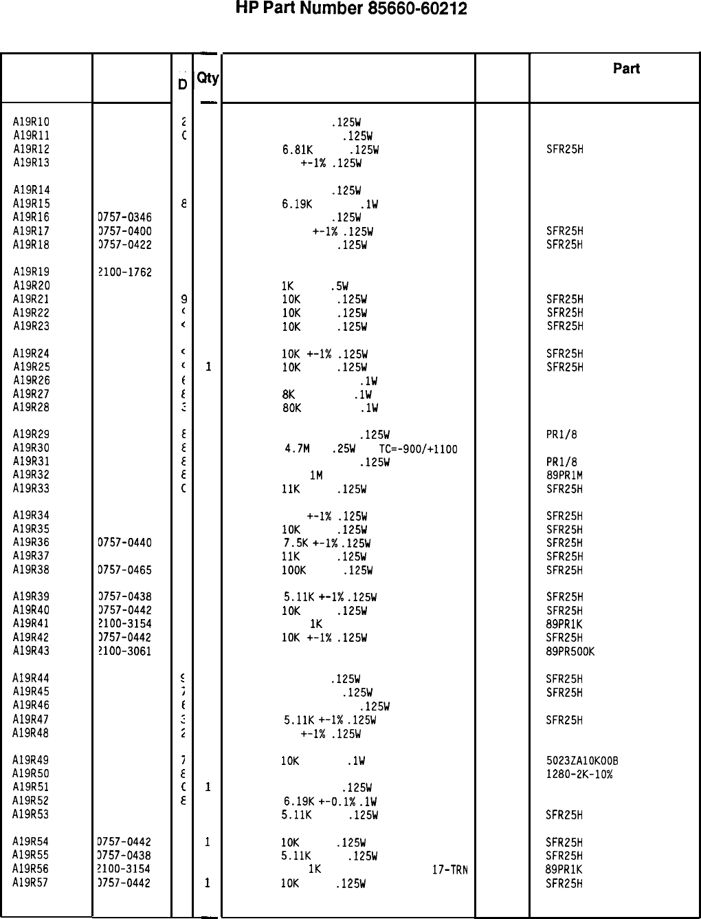
Reference
Designation HP Part
Number
A19RlO 0757-0346
A19Rll 0698-6348
A19R12 0757-0439
A19R13 0757-0346
A19R14 0757-0346
A19R15 0699-0156
A19R16 D757-0346
A19R17 3757-0400
A19R18 3757-0422
A19R19 2100-1762
A19R20 3757-0159
A19R21 3757-0442
A19R22 0757-0442
A19R23 0757-0442
A19R24 0757-0442
A19R25 0757-0442
A19R26 0699-0302
A19R27 0699-0304
A19R28 0699-0309
A19R29 0699-0643
A19R30 0683-4755
A19R31 0699-0643
A19R32 2100-3163
A19R33 0757-0443
A19R34 0757-0416
A19R35 0757-0442
A19R36 0757-0440
A19R37 0757-0443
A19R38 0757-0465
A19R39
A19R40
A19R41
A19R42
A19R43
3757-0438
3757-0442
?lOO-3154
3757-0442
!lOO-3061
A19R44 0698-3260
A19R45 0757-0276
A19R46 0698-8572
A19R47 0757-0438
A19R48 0757-0346
A19R49 0699-0642
A19R50 2100-4020
A19R51 0698-6348
A19R52 0699-0156
A19R53 0757-0438
A19R54 D757-0442
A19R55 3757-0438
A19R56 2100-3154
A19R57 3757-0442
85660-60212 Parts List
Page 2 of 3
C
0
i
c
4
2
2
6
2
9
5
9
5
P
(
(
(
(
t
t
:
E
E
E
E
c
7
9
7
C
6
3
9
7
9
5
E
;
f
:
i
i
E
c
E
3
9
3
7
9
-
Jtty
-
1
1
1
1
1
1
1
1
1
1
1
1
1
1
1
1
1
1
1
1
1
1
1
1
1
1
1
1
1
1
1
1
1
1
1
1
1
1
1
1
1
1
1
1
1
1
1
1
-
HP
Part
Number 85660-60212
A19 DAC
Description
RESISTOR 10 +-1%
.125W
TF TC=O+-100
RESISTOR 3K +-0.1%
.125W
TF TC=O+-25
RESISTOR
6.81K
+-1%
.125W
TF TC=O+-100
RESISTOR 10 +-I%
.125W
TF TC=O+-100
Mfr
Code
91637
19701
19701
91637
Mfr
Part
Number
CMF-55-1, T-l
5033R
SFR25H
CMF-55-1, T-l
RESISTOR 10 +-1%
.125W
TF TC=O+-100
91637 CMF-55-1, T-l
RESISTOR
6.19K
+-0.1%
.lW
TF TC=O+-5
19701 50232
RESISTOR 10 +-1%
.125W
TF TC=O+-100
91637 CMF-55-1, T-l
RESISTOR 90.9 +-1X
.125W
TF TC=O+-100
19701
SFR25H
RESISTOR 909 +-1%
.125W
TF TC=O+-100
19701
SFR25H
RESISTOR-TRMR 20K 5% WW SIDE-ADJ I-TRN
RESISTOR
1K
+-1%
.5W
TF TC=O+-100
RESISTOR
10K
+-1%
.125W
TF TC=O+-100
RESISTOR
10K
+-1%
.125W
TF TC=O+-100
RESISTOR
IOK
+-1%
.125W
TF TC=O+-100
19701
19701
19701
19701
CT-106-4-20K
5053R
SFR25H
SFR25H
SFR25H
RESISTOR
10K
+-1X
.125W
TF TC=O+-100
19701 SFR25H
RESISTOR
10K
+-1%
.125W
TF TC=O+-100
19701
SFR25H
RESISTOR 800 +-0.025%
.lW
TF TC=O+-5
19701
50232
RESISTOR
8K
+-0.025%
.lW
TF TC=O+-5
19701
50232
RESISTOR
80K
+-0.025%
.lW
TF TC=O+-5
19701
50232
RESISTOR 400K +-0.02%
.125W
TF TC=O+-5
RESISTOR
4.7M
5%
.25W
CC
TC=-900/+1100
RESISTOR 400K +-0.02%
.125W
TF TC=O+-5
RESISTOR-TRMR
1M
20% TKF SIDE-ADJ 17-TRN
RESISTOR
11K
+-1%
.125W
TF TC=O+-100
01121
73138
19701
PR1/8
CB4755
PRY8
89PRlM
SFR25H
RESISTOR 511 +-I%
.125W
TF TC=O+-100
19701
SFR25H
RESISTOR
10K
+-1%
.125W
TF TC=O+-100
19701
SFR25H
RESISTOR
7.5K
+-1X
.125W
TF TC=O+-100
19701
SFR25H
RESISTOR
11K
+-1%
.125W
TF TC=O+-100
19701
SFR25H
RESISTOR
1OOK
+-1%
.125W
TF TC=O+-100
19701
SFR25H
RESISTOR
5.11K
+-1X
.125W
TF TC=O+-100
19701
SFR25H
RESISTOR
10K
+-1%
.125W
TF TC=O+-100
19701
SFR25H
RESISTOR-TRMR
1K
10% TKF SIDE-ADJ 17-TRN
73138 89PRlK
RESISTOR
1DK
+-I%
.125W
TF TC=O+-100
19701 SFR25H
RESISTOR-TRMR 500K 10% TKF SIDE-ADJ 17-T
73138
89PR500K
RESISTOR 464K 1%
.125W
TF TC=O+-100
19701 SFR25H
RESISTOR 61.9 +-1%
.125W
TF TC=O+-100
19701
SFR25H
RESISTOR 508.7 +-0.1%
.125W
TF TC=O+-25
19701
5033R
RESISTOR
5.11K
+-I%
.125W
TF TC=O+-100
19701
SFR25H
RESISTOR 10 +-I%
.125W
TF TC=O+-100
91637 CMF-55-1, T-l
RESISTOR
10K
+-0.1%
.lW
TF TC=O+-5
19701
5023ZAlOKOOB
RESISTOR-TRMR 2K 10% TF SIDE-ADJ 26-TRN
18612 1280-2K-10%
RESISTOR 3K +-0.1%
.125W
TF TC=O+-25
19701
5033R
RESISTOR
6.19K
+-0.1X
.lW
TF TC=O+-5
19701
50232
RESISTOR
5.11K
+-1%
.125W
TF TC=O+-100
19701
SFR25H
RESISTOR
10K
+-1%
.125W
TF TC=O+-100
19701
SFR25H
RESISTOR
5.11K
+-1%
.125W
TF TC=O+-100
19701
SFR25H
RESISTOR-TRMR
1K
10% TKF SIDE-ADJ
17-TRN 73138 89PRlK
RESISTOR
10K
+-1%
.125W
TF TC=O+-100
19701
SFR25H
*Indicates factory-selected value
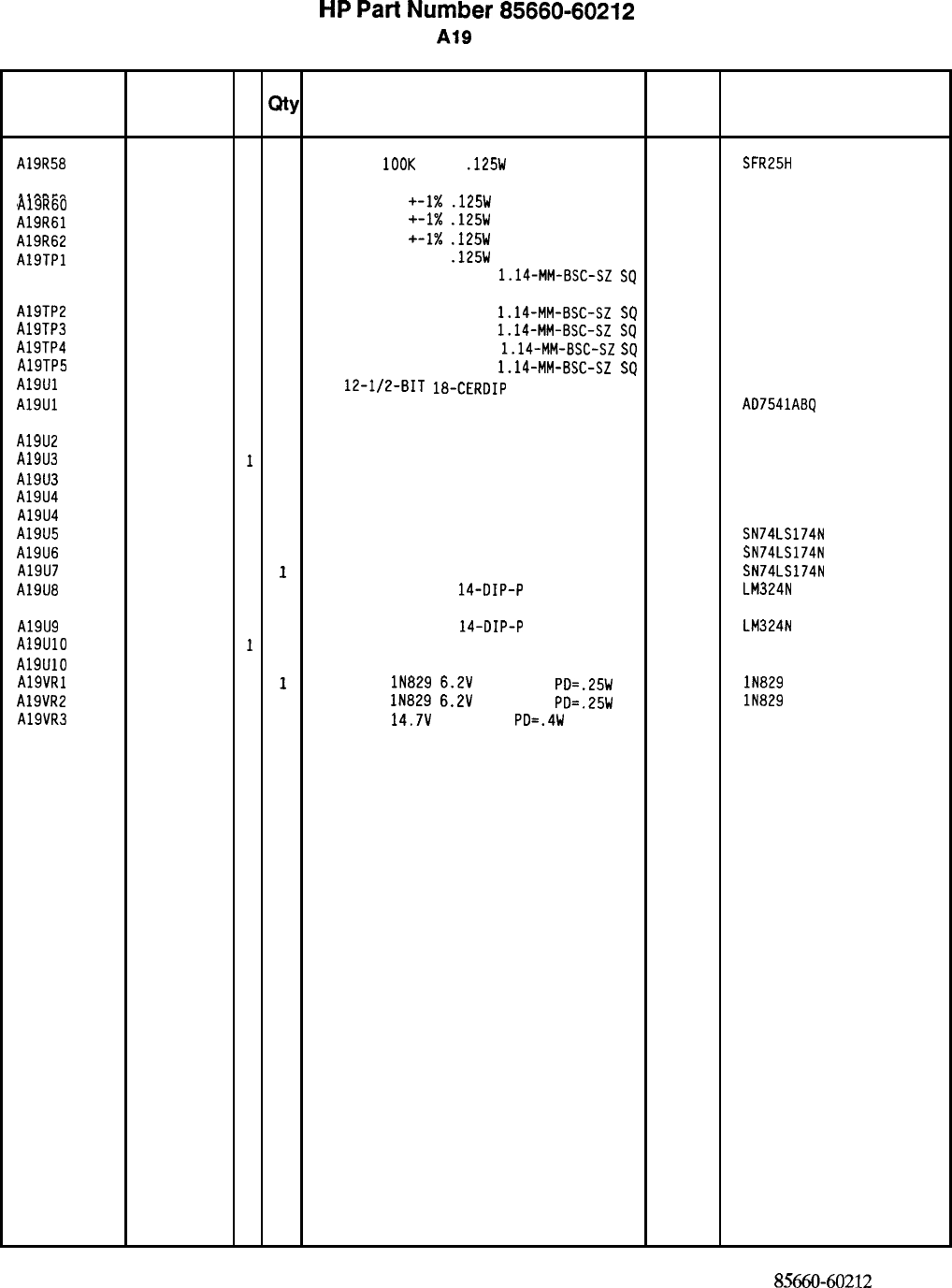
HP
Part
Number 85660-60212
A19
DAC
Reference
HP Part C
Number D
Qty Description Mfr
Designation
Mfr Part
Code Number
A19R58
A19R59
A19R60
A19R61
A19R62
A19TPl
A19TP2
A19TP3
A19TP4
A19TP5
A19Ul
A19Ul
A19U2
A19U3
A19U3
A19U4
A19U4
A19U5
A19U6
A19U7
A19U8
A19U9
A19UlO
A19UlO
AlSVRl
A19VR2
A19VR3
0757-0465
6
1
RESISTOR
1OOK
+-1%
.125W
TF TC=O+-100
19701
SFR25H
0757-0346
2
1
RESISTOR 10 +-1X
.125W
TF TC=O+-100
91637
0757-0346
2
CMF-55-1.
T-l
1
RESISTOR 10
+-1X
.125W
TF TC=O+-100
91637 CMF-55-1,
T-l
0757-0346
2
1
RESISTOR 10
+-1X
.125W
TF TC=O+-100
91637 CMF-55-1,
T-l
0757-0346
2
1
RESISTOR 10 +-1%
.125W
TF TC=O+-100
91637
1251-0600
0
CMF-55-1,
T-l
1
CONNECTOR-SGL CONT PIN
1.14~MM-BSC-SZ
SQ
27264 16-06-0034
1251-0600
0
1
CONNECTOR-SGL CONT PIN
1.14-MM-BSC-SZ
SQ
27264 16-06-0034
1251-0600
0
1
CONNECTOR-SGL CONT PIN
1.14-MM-BSC-SZ
SQ
27264 16-06-0034
1251-0600
0
1
CONNECTOR-SGL CONT PIN
1.14-MM-BSC-SZ
SQ
27264 16-06-0034
1251-0600
0
1
CONNECTOR-SGL CONT PIN
1.14-MM-BSC-SZ
SQ
27264 16-06-0034
1826-1190
4
1
D/A
12-l/2-BIT 18-CERDIP
CMOS
28480
1826-1169 1826-1190
70
ALTERNATE FOR 1826-1190
24355
AD7541ABQ
1826-0471
2
1
IC OP AMP LOW-DRIFT TO-99 PKG 06665 OP-07CJ SELECTED
5180-2315
1
1
IC OP AMP LOW-DRIFT TO-99 PKG 28480
5180-2314 5180-2315
0
0
ALTERNATE FOR 5180-2315
28480 5180-2314
5180-2315
1
1
IC OP AMP LOW-DRIFT TO-99
PKG
28480 5180-2315
5180-2314
0
0
ALTERNATE FOR 5180-2315
28480 5180-2314
1820-1196
8
1
IC FF TTL LS D-TYPE POS-EDGE-TRIG COM
CL
01295 SN74LS174N
1820-1196
8
1
IC FF TTL LS D-TYPE POS-EDGE-TRIG COM
CL
01295 SN74LS174N
1820-1196
8
1
IC FF TTL LS D-TYPE POS-EDGE-TRIG COM
CL
01295 SN74LS174N
1826-0161
7
1
IC OP AMP GP QUAD
14-DIP-P
PKG
27014 LM324N
1826-0161
7
1
IC OP AMP GP QUAD
14-DIP-P
PKG
27014 LM324N
5180-2315
11
IC OP AMP LOW-DRIFT TO-99 PKG 28480 5180-2315
5180-2314
0
0
ALTERNATE FOR 5180-2315
28480 5180-2314
1902-0625
0
1
DIODE-ZNR
lN829
6.2V
5% DO-35
PD=.25W
TC
04713 lN829
1902-0625
0
1
DIODE-ZNR
lN829
6.2V
5% DO-35
PD=.25W TC 04713 lN829
1902-3203
6
1
DIODE-ZNR
14.7V
5% DO-35
PD=.4W 04713
*Indicates factory-selected value
8X60-60212
Parts List
Page 3 of3
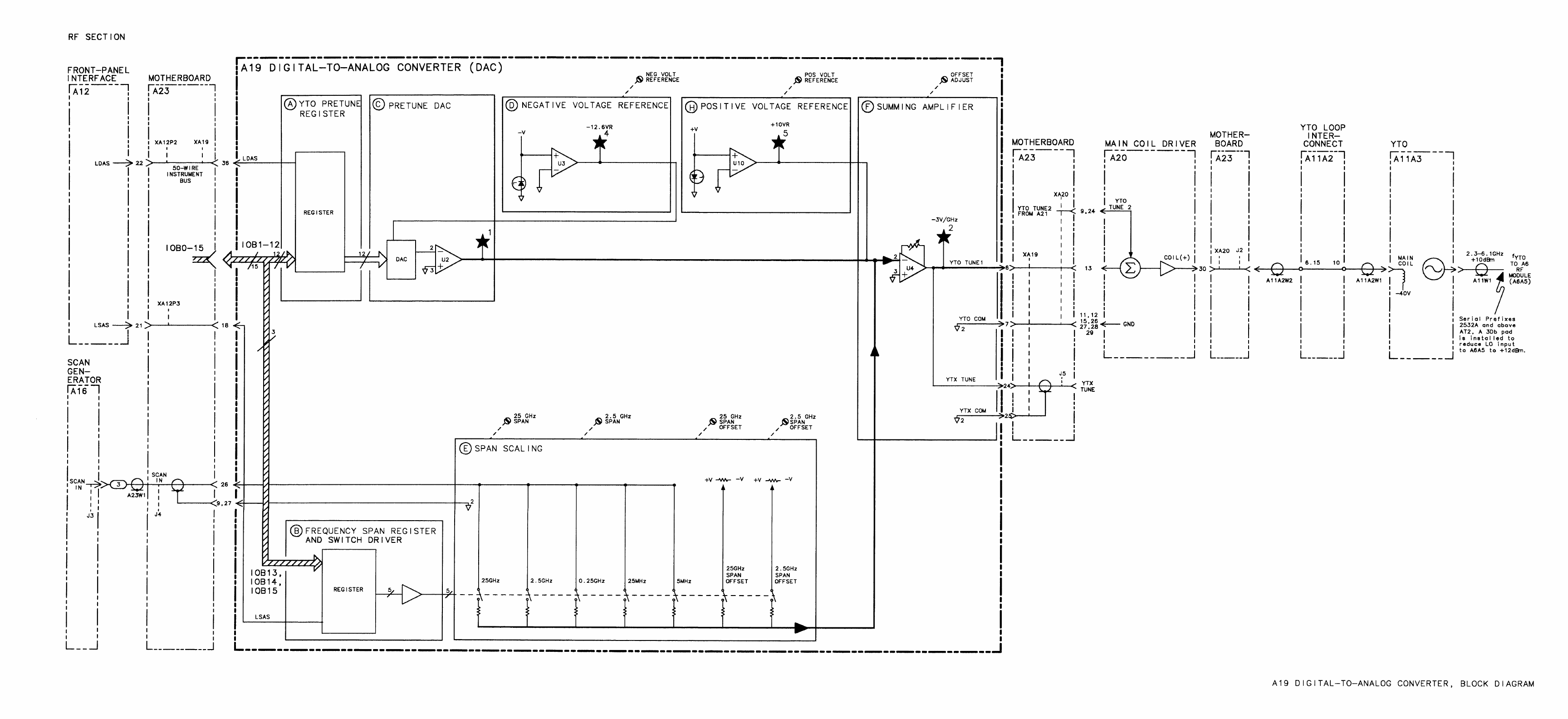
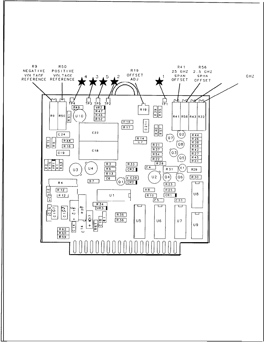
R43 R32
25 GHZ 2.5
GHL
SPAN SPAN
pm--
0+
yI
::
-,..
:,
-
El
an
N
0
o-
-
u
=
”
0
w
+
r.
orcr
m
0
-
R60
0
0
0
c
‘I)0
-
IR36
+
;o
RSZ
H
:
a:
R
59
1
PI 18
19 36
A19 Digital-to-Analog Converter Component Locations, 85660-60212
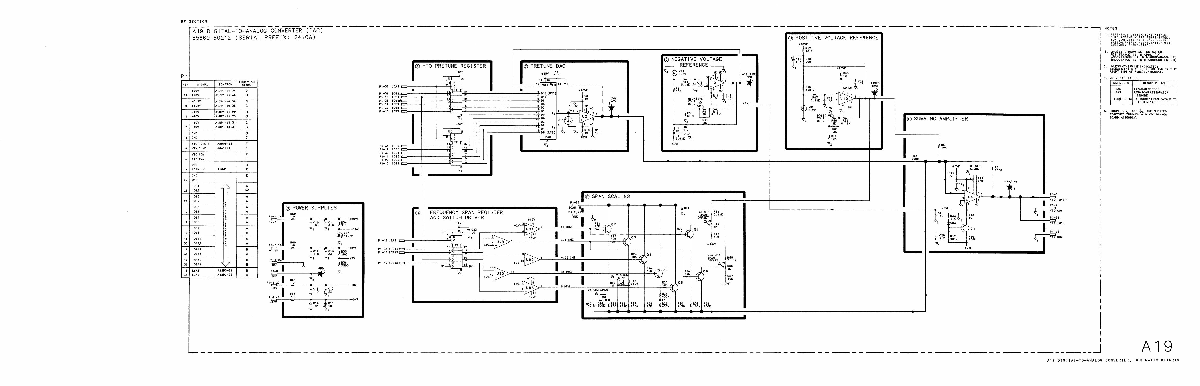
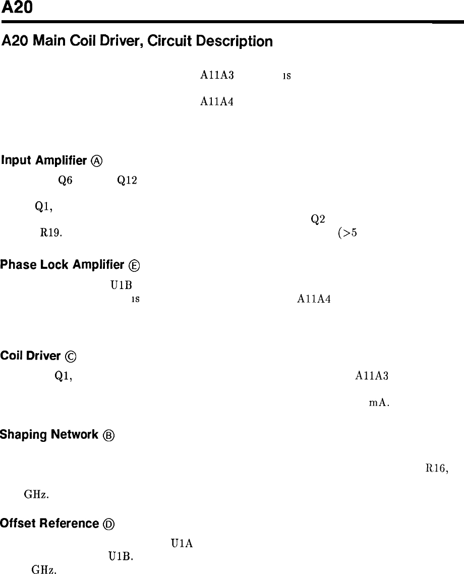
A20
A20
Main
Coil
Driver,
Circuit
Description
The A20 Main Coil Driver produces a tuning current proportional to the tuning voltage input
from the A19 DAC and applies it to the
AllA
YTO. Th’
is
provides coarse tuning of the
YTO frequency and sweep. Fine tuning is performed by summing a current proportional to
the low-frequency error voltage from the
AllA
YTO Phase Detector (via the A21 FM Coil
Driver) with the tuning current from the A19 DAC. Additional fine tuning is done by the A21
FM Coil Driver using the current proportional to the high-frequency error voltage component.
Input
Amplifier
@
Transistors
QS
through
Ql2
form a discrete noninverting operational amplifier whose output
is proportional to the tuning voltage input (YTO TUNE 1). This output is applied to Coil
Driver
Ql,
Q4, and Q5 which supply the YTO Main Coil current. For frequency spans greater
than 5 MHz, LYSP
(1
ow
= YTO span) turns on (closes) switch
Q2
allowing a current flow
through R19. This is done to improve sweep linearity for wide spans
(>5
MHz).
Phase
Lock
Amplifier
@
Phase Lock Amplifier
UlB
provides a current proportional to the low-frequency error voltage
input (YTO TUNE 2). Th’
is
error voltage input is from the
AllA
YTO Phase Detector and
is indicative of the YTO frequency error. The current output of the Phase Lock Amplifier is
summed with the current output controlled by the Input Amplifier in the Coil Driver.
Coil
Driver
@
Transistors
Ql,
Q4, and Q5 provide drive current to the main coil of the
AllA
YTO to set
the frequency and amount of sweep of the YTO. YTO main coil sensitivity is approximately
25 mA/GHz. The Coil Driver output is between approximately 50 and 150 mA.
Shaping
Network
@J
Compensation network U2 provides linearity shaping of the current output of the Coil Driver.
The components of the network are factory selected to match the YTO. Resistors R24,
Rl6,
and R25 sense the current output of the Coil Driver. R25 is used to fine tune the YTO to
6.15 GHz.
Offset Reference
6~
The Offset Reference composed of
UlA
and associated circuitry provides a fixed voltage to
Phase Lock Amplifier
UlB.
This voltage provides the current necessary to fine tune the YTO
to 2.3 GHz.
A20 1
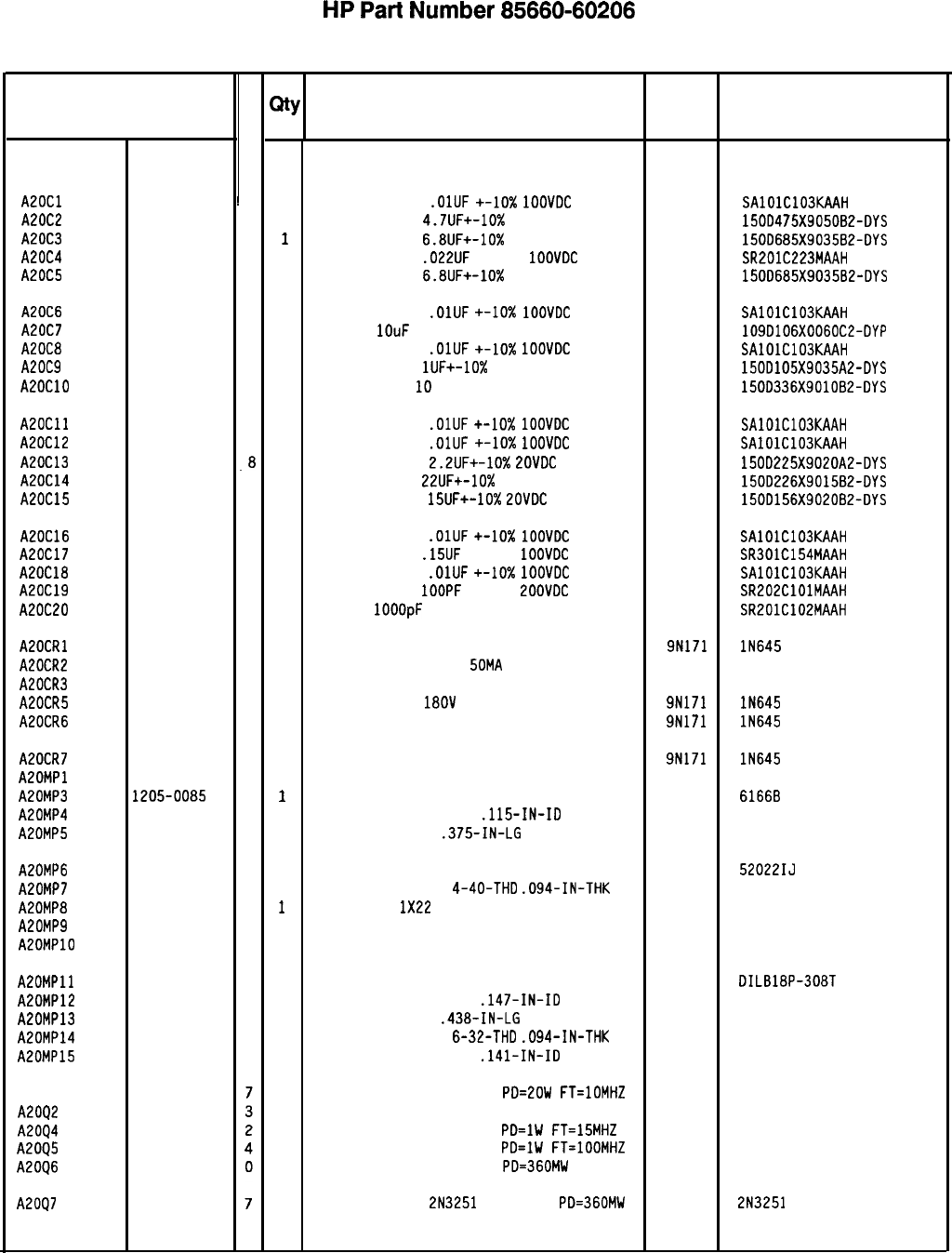
HP
Part
Number 85660-60206
A20 Main Coil Driver
Reference
I
HP Part
Designation Number
A20 85660-60206
6
AZOCl 0160-4832
~
4
AZOC2 0180-1731
8
A20C3 0180-0116
1
A20C4 0160-0574
3
A20C5 0180-0116
1
A20C6 0160-4832
4
A20C7 0180-2139
2
A20C8 0160-4832
4
A20C9 0180-0291
3
A20ClO 0180-0229
7
A20Cll 0160-4832
A20C12 0160-4832
A20C13 0180-0197
A20C14 0180-0228
A20C15 0180-1746
A20C16 0160-4832
4
A20C17 0160-4442
2
A20C18 0160-4832
4
A20C19 0160-3877
5
A20C20 0160-3878
6
AEOCRl 1901-0033
2
A20CR2 1901-0040
1
A20CR3 1901-0040
1
A20CR5 1901-0033
2
A20CR6 1901-0033
2
A20CR7
AEOMPl
A20MP3
A20MP4
A20MP5
A20MP6 6040-0454
0
A20MP7 2260-0001
5
A20MP8 8151-0013
4
A20MP9 5000-9043
6
A20MPlO 5040-6843
2
AEOMPll 1200-0539
7
A20MP12 3050-0010
2
A20MP13 2360-0119
8
A20MP14 2420-0003
7
A20MP15 2190-0018
5
A2091 1854-0237
A2002 1855-0413
A2004 1854-0232
A2095 1853-0038
A2006 1854-0404
A2097 1853-0007
4
4
.8
6
5
1901-0033
2
1205-0085
8
2190-0003
8
2200-0107
6
C
D
QtY
Description
1
1
1
1
1
1
1
1
1
1
1
1
1
1
1
1
1
1
1
1
1
1
1
1
1
1
1
1
2
2
1
2
1
1
1
1
1
2
2
2
1
1
1
1
1
1
BOARD ASSEMBLY, MAIN COIL DRIVER 28480 85660-60206
CAPACITOR-FXD
.OlUF
+-lo%
1OOVDC
CER
04222 SAlOlC103KAAH
CAPACITOR-FXD 4.7UF+-10% 5OVDC TA
56289 150D475X9050B2-DYS
CAPACITOR-FXD
6.8UF+-10%
35VDC TA
56289 1500685X9035B2-DYS
CAPACITOR-FXD
.022UF
+-20%
IOOVDC
CER
04222 SR201C223MAAH
CAPACITOR-FXD
6.8UF+-10%
35VDC TA
56289 15OD685X9035B2-DYS
CAPACITOR-FXD
.OlUF
+-IO%
1OOVDC
CER
04222 SAlOlC103KAAH
CAP-FXD
1OuF
60 V WT-SLG-TA-ELCTLT
56289 109D106X0060C2-DYP
CAPACITOR-FXD
.OlUF
+-lo%
1OOVDC
CER
04222 SAlOlC103KAAH
CAPACITOR-FXD
lUF+-10%
35VDC TA
56289 150D105X9035A2-DYS
CAP-FXD 33uF
10
V TA
56289 1500336X9010B2-DYS
CAPACITOR-FXD
.OlUF
+-10x
1OOVDC
CER
04222 SAlOlC103KAAH
CAPACITOR-FXD
.OlUF
+-lo%
1OOVOC
CER
04222 SAlOlC103KAAH
CAPACITOR-FXD
2.2UF+-10%
ZOVDC
TA
56289 150D225X9020A2-DYS
CAPACITOR-FXD
22UF+-10%
15VDC TA
56289 150D226X9015B2-DYS
CAPACITOR-FXD
15UF+-10%
ZOVDC
TA
56289 150D156X9020B2-DYS
CAPACITOR-FXD
.OlUF
+-lo%
1OOVDC
CER
04222 SAlOlC103KAAH
CAPACITOR-FXD
.15UF
+-20%
1OOVDC
CER
04222 SR301C154MAAH
CAPACITOR-FXD
.OlUF
+-10X
1OOVDC
CER
04222 SAlOlC103KAAH
CAPACITOR-FXD
IOOPF
+-20%
EOOVDC
CER
04222 SR202ClOlMAAH
CAP-FXD
1OOOpF
100 V
04222 SR201C102MAAH
DIODE-GEN PRP 180V 200MA DO-35 9N171
DIODE-SWITCHING 30V
SOMA
2NS DO-35
71468
DIODE-SWITCHING 30V 50MA 2NS DO-35
71468
DIODE-GEN PRP
1BOV
200MA DO-35
9N171
DIODE-GEN PRP 180V 200MA DO-35 9N171
DIODE-GEN PRP 180V 200MA DO-35
NOT ASSIGNED 9N171 lN645
HEAT SINK TO-66-CS 13103
WASHER-LK HLCL NO. 4
.115-IN-ID 80120
SCREW-MACH 4-40
.375-IN-LG
PAN-HD-POZI
77250
HEAT SINK COMPOUND SYNTH/REFRC 92895
NUT-HEX-DBL-CHAM
4-40-THD
.094-IN-THK 80120
WIRE 22AWG
1X22
92194
EXTRACTOR PIN 28480
PC BOARD EXTRACTOR 28480
SOCKET-IC 18-CONT DIP DIP-SLDR 09922
WASHER-FL MTLC NO. 6
.147-IN-ID 76210
SCREW-MACH 6-32
.438-IN-LG
PAN-HD-POZI
93907
NUT-HEX-DBL-CHAM
6-32-THD
.094-IN-THK 80120
WASHER-LK HLCL NO. 6
.141-IN-ID 73734
TRANSISTOR NPN SI TO-66
PD=EOW
FT=lOMHZ 04713
TRANSISTOR J-FET P-CHAN D-MODE TO-18 SI 17856
TRANSISTOR NPN SI TO-39
PD=lW
FT=15MHZ 04713
TRANSISTOR PNP SI TO-39
PD=lW
FT=lOOMHZ 04713
TRANSISTOR NPN SI TO-18
PD=360MW 04713
TRANSISTOR PNP
2N3251
SI TO-18
PD=360MW 04713
2N3251
Mfr Mfr Part
Code Number
lN645
IN645
lN645
61668
BASE ONLY
52022IJ
298
5000-9043
5040-6843
DILB18P-308T
65
*Indicates factory-selected value
85660450206 Parts List
Page 1 of 3
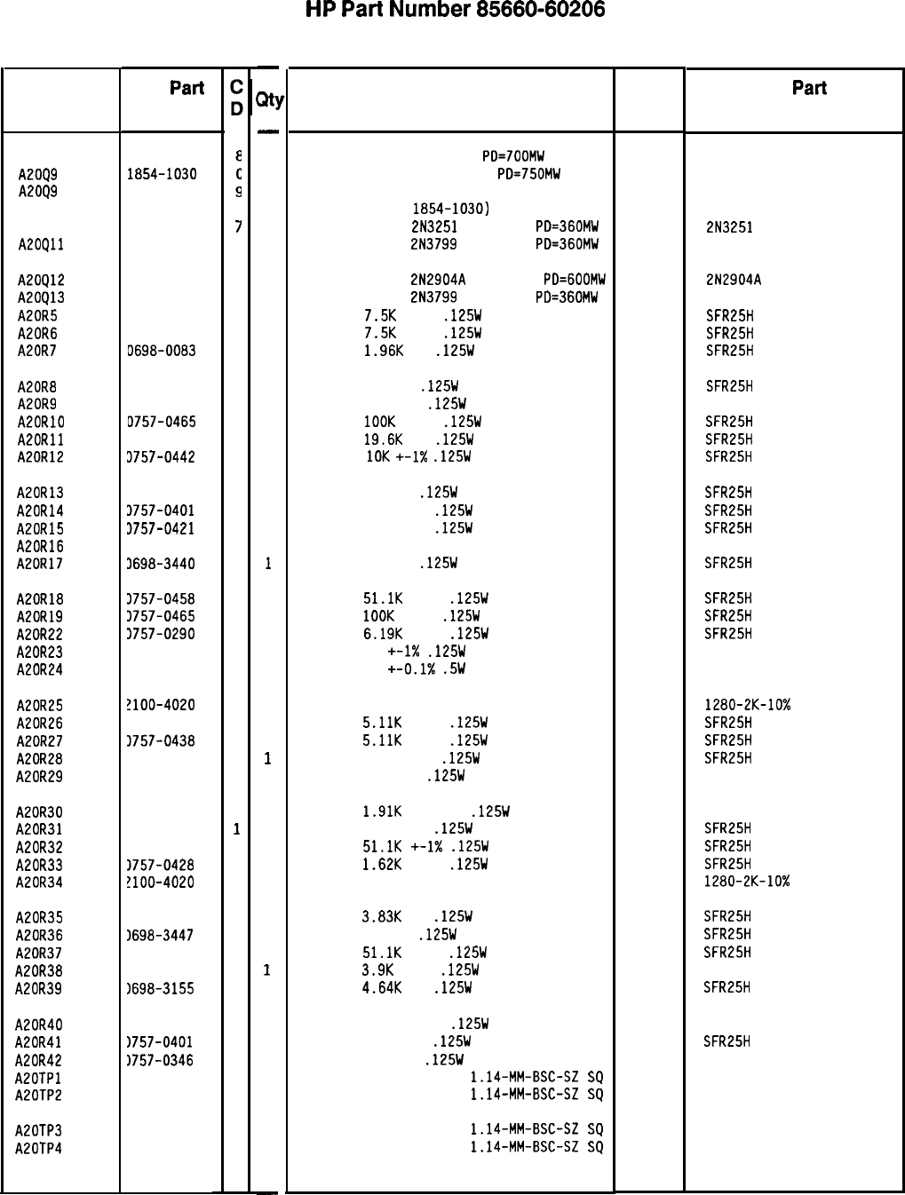
Reference
Designation
A2098
A.2009
A2099
HP
Par-l
Number
1854-0022
1854-1030
1854-0221
A20910 1853-0007
7
A20Qll 1853-0451
5
A20Q12
A20Q13
A20R5
A20R6
A20R7
1853-0012
4
1853-0451
5
0757-0440
7
0757-0440
7
D698-0083
a
A20R8
A20R9
A20RlO
A20Rll
A20R12
0698-3440
7
0757-0346
2
D757-0465
6
3698-3157
3
3757-0442
9
A20R13
A20R14
A20R15
A20R16
A20R17
3698-3440
7
3757-0401
0
3757-0421
4
3811-3440
9
3698-3440
7
A20R18
A20R19
A20R22
A20R23
A20R24
3757-0458
7
3757-0465
6
3757-0290
5
3757-0346
2
3811-2936
6
A20R25
A20R26
A20R27
A20R28
A20R29
!lOO-4020
8
1757-0438
3
3757-0438
3
1757-0467
8
1757-0346
2
A20R30
A20R31
A20R32
A20R33
A20R34
1698-8025
4
1757-0402
1
1757-0458
7
1757-0428
1
!lOO-4020
8
A20R35 1698-3153
A20R36 1698-3447
A20R37 1757-0458
A20R38 1698-5673
A20R39 1698-3155
A20R40 1698-8420
A20R41
1757-0401
A20R42 1757-0346
A20TPl 1251-0600
A20TP2 1251-0600
A20TP3 1251-0600
A20TP4 1251-0600
9
4
7
2
1
3
0
2
0
0
0
0
85660-60206 Parts List
Page 2 of 3
-
Ml
-
1
1
0
1
1
1
1
1
1
1
1
1
1
1
1
1
1
1
1
1
1
1
1
1
1
1
1
1
1
1
1
1
1
1
1
1
1
1
1
1
1
1
1
1
1
1
1
-
HP
Part
Number 85660-60206
A20 Main Coil Driver
Description Mfr Mfr
Part
Code Number
TRANSISTOR NPN SI TO-39
PO=700MW 28480
TRANSISTOR-DUAL NPN TO-78
PD=750MW 04713
TRANSISTOR-DUAL NPN 28480
1854-0022
1854-0221
(ALTERNATE FOR
1854-1030)
TRANSISTOR PNP
2N3251
SI TO-18
PD=360MW
TRANSISTOR PNP
2N3799
SI TO-18
PD=360MW 04713
04713 2N3251
TRANSISTOR PNP
2N2904A
SI TO-39
PD=GOOMW 04713
TRANSISTOR PNP
2N3799
SI TO-18
PD=360MW 04713
RESISTOR
7.5K
+-1%
.125W
TF TC=O+-100
19701
RESISTOR
7.5K
+-1%
.125W
TF TC=O+-100
19701
RESISTOR
1.96K
1%
.125W
TF TC=O+-100
19701
2N2904A
SFR25H
SFR25H
SFR25H
RESISTOR 196 1%
.125W
TF TC=O+-100
19701
SFR25H
RESISTOR 10 +-1%
.125W
TF TC=O+-100
91637 CMF-55-1, T-l
RESISTOR
1OOK
+-1%
.125W
TF TC=O+-100
19701
SFR25H
RESISTOR
19.6K
1%
.125W
TF TC=O+-100
19701
SFR25H
RESISTOR
10K
+-I%
.125W
TF TC=O+-100
19701
SFR25H
RESISTOR 196 1%
.125W
TF TC=O+-100
19701
SFR25H
RESISTOR 100 +-1%
.125W
TF TC=O+-100
19701
SFR25H
RESISTOR 825 +-1%
.125W
TF TC=O+-100
19701
SFR25H
RESISTOR 125 +-1% 25W PWN TC=O+-2 01686 ALN-25
RESISTOR 196 1%
.125W
TF TC=O+-100
19701
SFR25H
RESISTOR
51.1K
+-1%
.125W
TF TC=O+-100
19701
SFR25H
RESISTOR
1OOK
+-1%
.125W
TF TC=O+-100
19701
SFR25H
RESISTOR
6.19K
+-1%
.125W
TF TC=O+-100
19701
SFR25H
RESISTOR 10
+-1X
.125W
TF TC=O+-100
91637 CMF-55-1, T-l
RESISTOR 15 +-0.1X
.5W
PN TC=O+-5
01686 R348
RESISTOR-TRMR 2K 10% TF SIDE-ADJ 26-TRN
18612 1280-2K-10%
RESISTOR
5.11K
+-1%
.125W
TF TC=O+-100
19701
SFR25H
RESISTOR
5.11K
+-1%
.125W
TF TC=O+-100
19701
SFR25H
RESISTOR 121K +-1%
.125W
TF TC=O+-100
19701
SFR25H
RESISTOR 10 +-1%
.125W
TF TC=O+-100
91637 CMF-55-1, T-l
RESISTOR
1.91K
+-0.25%
.125W
TF TC=O+-50
19701
5033R
RESISTOR 110 +-1%
.125W
TF TC=O+-100
19701
SFR25H
RESISTOR
51.1K
+-1X
.125W
TF TC=O+-100
19701
SFR25H
RESISTOR
1.62K
+-1%
.125W
TF TC=O+-100
19701
SFR25H
RESISTOR-TRMR 2K 10% TF SIDE-ADJ 26-TRN
18612 1280-2K-10%
RESISTOR
3.83K
1%
.125W
TF TC=O+-100
19701
SFR25H
RESISTOR 422 1%
.125W
TF TC=O+-100
19701
SFR25H
RESISTOR
51.1K
+-1%
.125W
TF TC=O+-100
19701
SFR25H
RESISTOR
3.9K
+-1%
.125W
TF TC=O+-25
91637 CMF-55-1, T-9
RESISTOR
4.64K
1%
.125W
TF TC=O+-100
19701
SFR25H
RESISTOR 4.221: +-1%
.125W
TF TC=O+-25
19701
50331
RESISTOR 100 +-1%
.125W
TF TC=O+-100
19701
SFR25H
RESISTOR 10 +-1%
.125W
TF TC=O+-100
91637 CMF-55-l. T-l
CONNECTOR-SGL CONT PIN
1.14-MM-BSC-SZ
SQ
27264 16-06-0034
CONNECTOR-SGL CONT PIN
1.14-MM-BSC-SZ
SQ
27264 16-06-0034
CONNECTOR-SGL CONT PIN
1.14-MM-BSC-SZ
SQ
27264 16-06-0034
CONNECTOR-SGL CONT PIN
1.14-MM-BSC-SZ
SQ
27264 16-06-0034
*Indicates factory-selected value

Reference
Designation
A20TP5
A20TP6
A20Ul
HP Part
Number
L251-0600
1251-0600
5081-8117
A2OVRl 1902-0680
A20VR2 1902-3404
-
31
-
1
1
1
1
1
HP
Part
Number 85660-60206
A20 Main Coil Driver
Description
CONNECTOR-SGL CONT PIN
1.14-MM-BSC-SZ
SC
27264 16-06-0034
CONNECTOR-SGL CONT PIN
1.14-MM-BSC-SZ
SC
27264 16-06-0034
SCREEN 1826-0092 IC OPAMP 28480 5081-8117
DIODE-ZNR
lN827
6.2V
5% DO-7
PD=.4W
TC=+
04713
DIODE-ZNR
82.5V
5% DO-7
PD=.4W
TC=+.082% 04713 lN827
Mfr
Mfr Part
Code Number
*Indicates factory-selected value
85660-60206 Parts List
Page 3 of 3
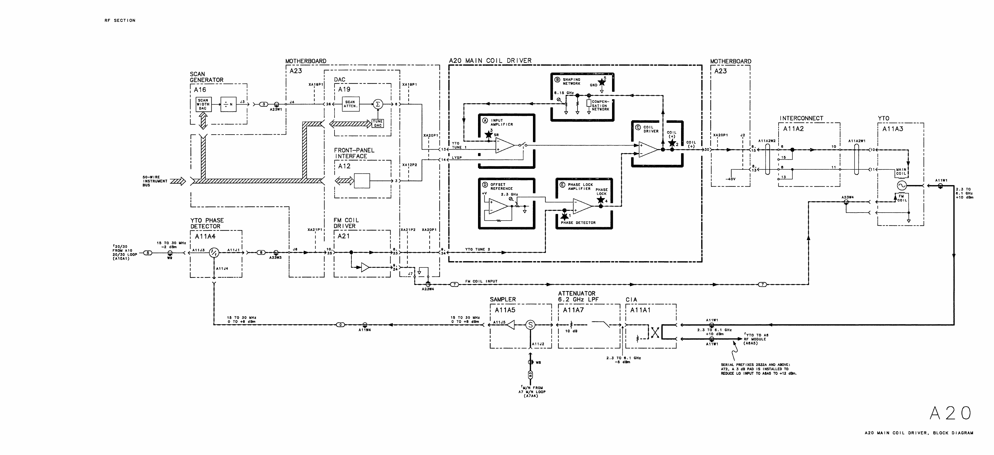
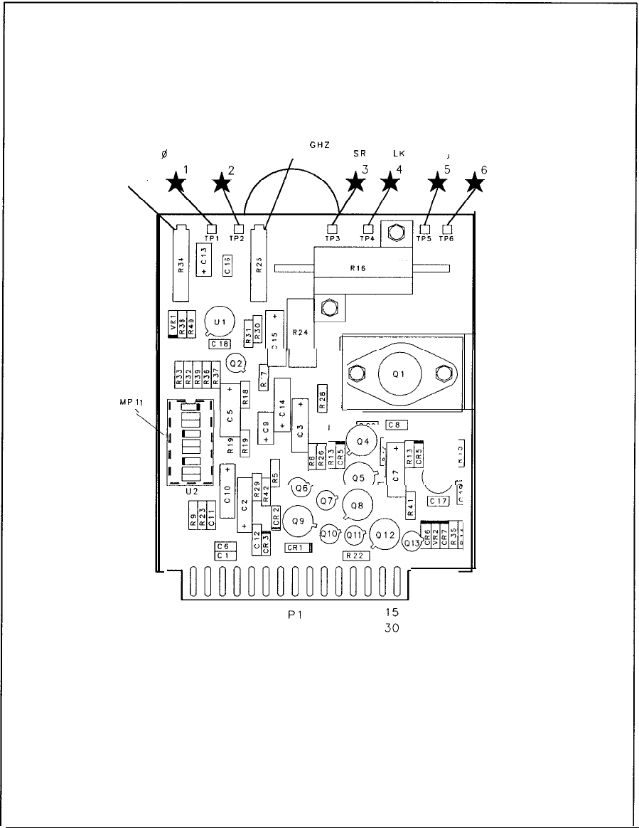
MPl
\
R25
6.15
GHZ
0
DET COIL I
SR
0
LK
GND
R34
2.3 GHZ
ON.n‘nf-
OllFlR”
@,
L---J
(LLLcrcccQe
+
m
w
II
ii
d’
:
s
z+
n
?It
4
IElI
g’:
r
0
;\I
$
+
T:
em
I~~_1
+
qua;
zf$k
ft2
@
o7
T
L
uii
E
:
pg~g@&
Q!
,drilDrrccoo~or,
1
16
Pl
A20 Main Coil Driver Component Locations, 85660-60206
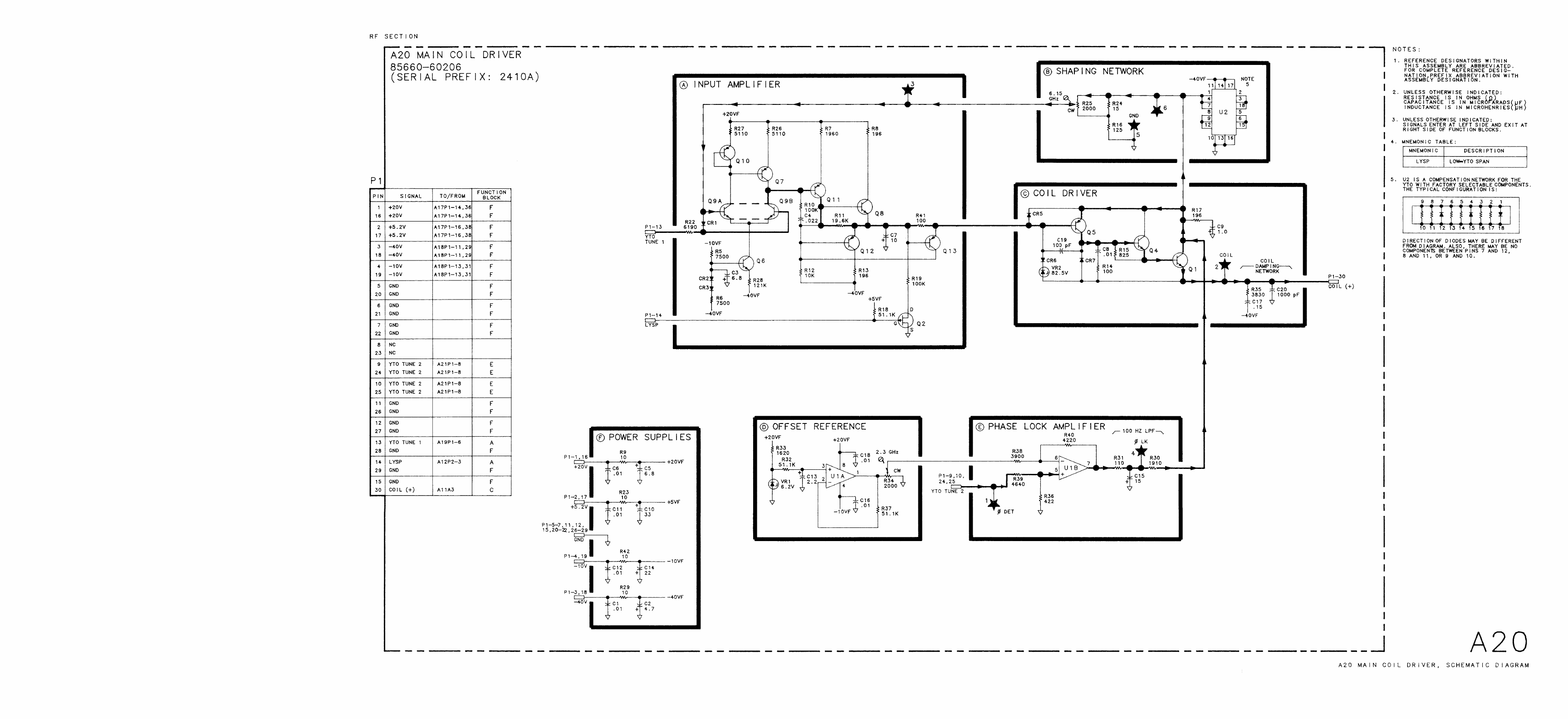
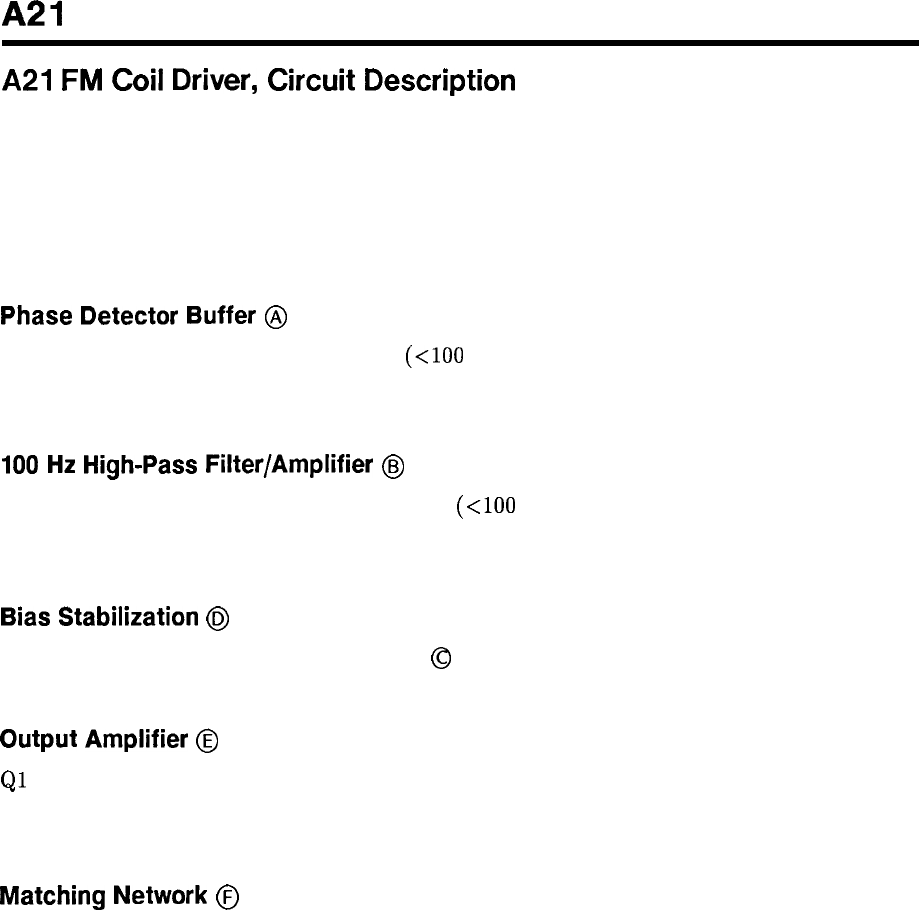
A21
A21
FM
Coil
Driver,
Circuit
Description
The A21 FM Coil Driver performs two functions.
1. Separates the low-frequency component from the error voltage input (DET IN) and directs
it to the A20 Main Coil Driver.
2. Provides drive current to the FM Coil of the YTO proportional to the high-frequency
component of the error voltage input (DET IN).
Phase Detector Buffer
@
This buffer drives both the low-frequency
(<lOO
Hz) portion of the error voltage input (DET
IN) to be applied to the A20 Main Coil Driver and the high-frequency portion to be applied
to the FM coil of the YTO.
100
Hz
High-Pass
Filter/Amplifier
@
This filter/amplifier separates the low-frequency (<lOO Hz) signals from the input to be
applied to the main coil of the YTO and amplifies the high-frequency signals to be applied to
the FM Coil of the YTO.
Bias
Stabilization
@
This circuit adjusts the dc current in Buffer
@
to ensure there is not quiescent current applied
to the YTO FM Coil.
Output
Amplifier
@
Ql
and Q4 form a push-pull amplifier to provide drive current to the YTO FM Coil
porportional to the high-frequency error voltage input (DET IN). This is done to tune the
YTO frequency to a corrected output determined by the YTO Phase Lock Loop.
Matching
Network
@
Provides impedance matching between the Output Amplifier and the YTO FM Coil to assure
accurate tuning of the YTO frequency.
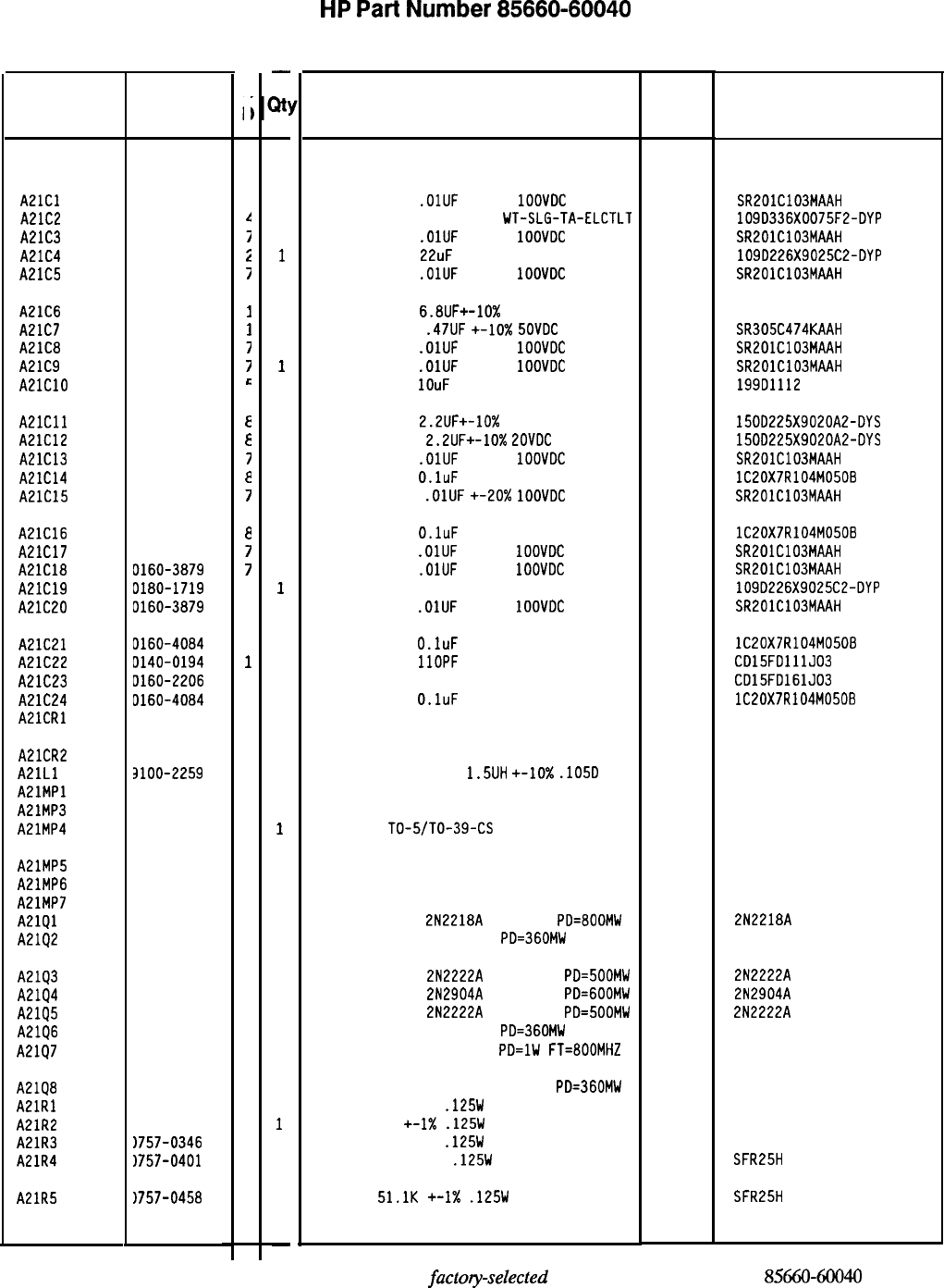
Reference
Designation HP Part
Number
C
c
A21
85660-60040
f
A21Cl
A21C2
A21C3
A21C4
A21C5
0160-3879
i
0180-0234
1
0160-3879
i
0180-1719
i
0160-3879
I
A21C6
A21C7
A21C8
A21C9
A21ClO
0180-0116
I
0160-4441
I
0160-3879
7
0160-3879
I
0180-0491
c
A21Cll
A21C12
A21C13
A21C14
A21C15
0180-0197
a
0180-0197
E
0160-3879
7
0160-4084
a
0160-3879
7
A21C16
A21C17
A21C18
A21C19
A21C20
0160-4084
a
0160-3879
7
D160-3879
7
0180-1719
2
0160-3879
7
A21C21
A21C22
A21C23
A21C24
A2lCRl
0160-4084
a
0140-0194
1
D160-2206
2
0160-4084
a
1901-0040
1
A21CR2
A21Ll
AElMPl
A21MP3
A21MP4
1901-0040
3100-2259
1
a
1200-0173
5
1205-0011
0
A21MP5 1205-0037
0
A21MP6 5000-9043
6
A21MP7 5040-6843
2
A21Ql 1854-0013
7
A2102 1854-0404
0
A21Q3 1854-0477
A2194 1853-0012
A2195 1854-0477
A21Q6 1854-0023
A21Q7 1854-0247
A21Q8
1853-0451
A21Rl 1757-0346
A21R2 1757-0346
A21R3 1757-0346
A21R4
1757-0401
A21R5 1757-0458
7
4
7
9
9
5
2
2
2
0
7
-
a!
-
1
1
1
1
1
1
1
1
1
1
1
1
1
1
1
1
1
1
1
1
1
1
1
1
1
1
1
1
1
1
1
1
1
1
1
1
1
1
1
1
1
1
1
1
1
1
-
HP
Part
Number 85660-60040
A21 FM Coil Driver
Description Mfr Mfr Part
Code Number
BOARD ASSEMBLY, FM COIL DRIVER 28480 85660-60040
CAPACITOR-FXD
.OlUF
+-20%
1OOVDC
CER
04222 SR201C103MAAH
CAPACITOR-FXD 33uF 75 V
UT-SLG-TA-ELCTLT 56289 109D336X0075F2-DYP
CAPACITOR-FXD
.OlUF
+-20%
1OOVDC
CER
04222 SR201C103MAAH
CAPACITOR-FXD
22uF
25 V WT-SLG-TA-ELCTLT
56289 109D226X9025C2-OYP
CAPACITOR-FXD
.OlUF
+-20%
1OOVDC
CER
04222 SR201C103MAAH
CAPACITOR-FXD
6.8UF+-10%
35VDC TA
56289 1500685X903582-DYS
CAPACITOR-FXD
.47UF
+-lo%
5OVDC
CER
04222 SR305C474KAAH
CAPACITOR-FXD
.OlUF
+-20%
1OOVDC
CER
04222 SR201C103MAAH
CAPACITOR-FXD
.OlUF
+-20%
1OOVDC
CER
04222 SR201C103MAAH
CAPACITOR-FXD
IOuF
25 V TA
56289 199D1112
CAPACITOR-FXD
2.2UF+-10%
20VDC TA
56289 1500225X9020A2-DYS
CAPACITOR-FXD
2.2UF+-10%
EOVDC
TA
56289 150D225X9020A2-DYS
CAPACITOR-FXD
.OlUF
+-20%
1OOVDC
CER
04222 SR201C103MAAH
CAPACITOR-FXD
O.luF
50 V
56289 lC20X7R104M050B
CAPACITOR-FXD
.OlUF
+-20x
1OOVDC
CER
04222 SR201C103MAAH
CAPACITOR-FXD
O.luF
50 V
56289 lC20X7R104M050B
CAPACITOR-FXD
.OlUF
+-20%
1OOVDC
CER
04222 SR201C103MAAH
CAPACITOR-FXD
.OlUF
+-20%
1OOVDC
CER
04222 SR201C103MAAH
CAPACITOR-FXD 22uF 25 V WT-SLG-TA-ELCTLT
56289 109D226X9025C2-DYP
CAPACITOR-FXD
.OlUF
+-20%
1OOVDC
CER
04222 SR201C103MAAH
CAPACITOR-FXD
O.luF
50 V
56289
CAPACITOR-FXD
1lOPF
+-5% 300VDC MICA
09023
CAPACITOR-FXD 160PF +-5% 300VDC MICA
09023
CAPACITOR-FXD
O.luF
50 V
56289
DIODE-SWITCHING 30V 50MA 2NS DO-35 71468
lC20X7R104M050B
CD15FDlllJ03
CD15FD161J03
lC20X7R104M050B
DIODE-SWITCHING 30V 50MA 2NS DO-35
INDUCTOR RF-CH-MLD
1.5UH
+-lo%
.105D
NOT ASSIGNED
71468
99800 1025-24
INSULATOR-XSTR DAP-GL 07047 A-10001 DAP
HEAT SINK
TO-5/TO-39-CS 98978 TXBF-032-025B
HEAT SINK TO-18-CS
EXTRACTOR PIN
PC BOARD EXTRACTOR
TRANSISTOR NPN
2N2218A
SI TO-5
PD=800MW
TRANSISTOR NPN SI TO-18
PD=360MW
98978
28480
28480
27014
04713
TXBF-019-0258
5000-9043
5040-6843
2N2218A
TRANSISTOR NPN
2N2222A
SI TO-18
PD=500MW 04713
TRANSISTOR PNP
2N2904A
SI TO-39
PD=GOOMW 04713
TRANSISTOR NPN
2N2222A
SI TO-18
PD=500MW 04713
TRANSISTOR NPN SI TO-18
PD=360MW 25403
TRANSISTOR NPN SI TO-39
PD=lW
FT=800MHZ 04713
2N2222A
2N2904A
2N2222A
TRANSISTOR PNP 213799 SI TO-18
PD=360MW
RESISTOR 10 +-1%
.125W
TF TC=O+-100
RESISTOR 10 +-I%
.125W
TF TC=O+-100
RESISTOR 10 +-1%
.125W
TF TC=O+-100
RESISTOR 100 +-1%
.125W
TF TC=O+-100
RESISTOR
51.1K
+-I%
.125W
TF TC=O+-100
04713
91637
91637
91637
19701
CMF-55-1, T-l
CMF-55-1, T-l
CMF-55-l. T-l
SFR25H
19701
SFR25H
*Indicates
factoryselected
value 85660430040
Parts List
Page 1 of 2
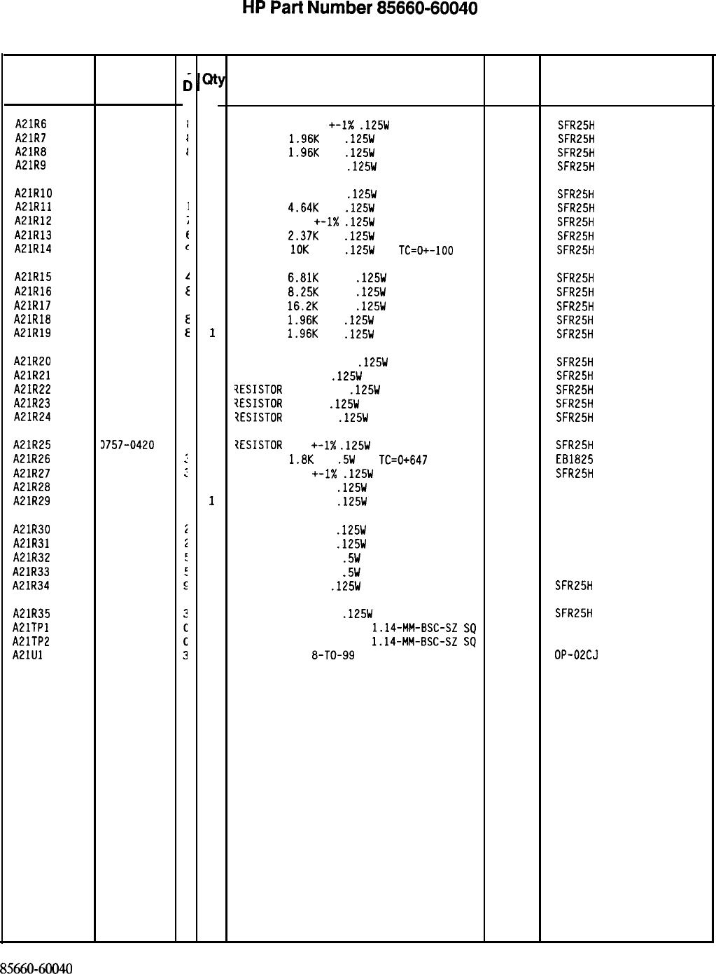
HP
Part
Number 85660-60040
A21 FM Coil Driver
Reference
Designatior
A21R6 0757-0441
A21R7 0698-0083
A21R8 0698-0083
A21R9 0698-3155
A21RlO 0698-3155
A21Rll 0698-3155
A21R12 0757-0416
A21R13 0698-3150
A21R14 0757-0442
A21R15
A21R16
A21R17
A21R18
A21R19
0757-0439
1
0757-0441
f
0757-0447
4
0698-0083
E
0698-0083
E
A21R20
A21R21
A21R22
A21R23
A21R24
0757-0441
a
0698-3438
3
0757-0394
C
0698-3447
4
0698-3429
2
A21R25
A21R26
A21R27
A21R28
A21R29
3757-0420
3
0686-1825
:
0757-0420
:
0757-0346
i
0757-0346
i
A21R30 0757-0346
A21R31 0757-0346
A21R32 0757-0802
A21R33 0757-0802
A21R34 0698-3442
A21R35 0757-0420
AElTPl 1251-0600
A21TP2 1251-0600
A21Ul 1826-1058
HP Part
Number
C
c
1
1
1
1
1
1
1
1
1
1
1
1
1
1
1
1
1
1
1
1
1
1
1
1
1
1
1
1
1
1
1
1
1
Description
RESISTOR 8.251: +-1X
.125W
TF TC=O+-100
RESISTOR
1.96K
1%
.125W
TF TC=O+-100
RESISTOR
1.96K
1%
.125W
TF TC=O+-100
RESISTOR 4.641: 1%
.125W
TF TC=O+-100
19701
SFR25H
19701
SFR25H
19701
SFR25H
19701
SFR25H
RESISTOR 4.641: 1%
.125W
TF TC=O+-100
RESISTOR
4.64K
1%
.125W
TF TC=O+-100
RESISTOR 511
+-I%
.125W
TF TC=O+-100
RESISTOR
2.37K
1%
.125W
TF TC=O+-100
RESISTOR
10K
+-1%
.125W
TF
TC=O+-100
19701
SFR25H
19701
SFR25H
19701
SFR25H
19701
SFR25H
19701
SFR25H
RESISTOR
6.81K
+-1%
.125W
TF TC=O+-100
RESISTOR
B.25K
+-1%
.125W
TF TC=O+-100
RESISTOR
16.2K
+-1%
.125W
TF TC=O+-100
RESISTOR
1.96K
1%
.125W
TF TC=O+-100
RESISTOR
1.96K
1%
.125W
TF TC=O+-100
19701
SFR25H
19701
SFR25H
19701
SFR25H
19701
SFR25H
19701
SFR25H
RESISTOR 8.251: +-1%
.125W
TF TC=O+-100
RESISTOR 147 1%
.125W
TF TC=O+-100
?ESISTOR
51.1 +-1%
.125W
TF TC=O+-100
?ESISTOR
422 1%
.125W
TF TC=O+-100
?ESISTOR
19.6 1%
.125W
TF TC=O+-100
19701
SFR25H
19701
SFR25H
19701
SFR25H
19701
SFR25H
19701
SFR25H
7ESISTOR
750
+-1X
.125W
TF TC=O+-100
RESISTOR
1.8K
5%
.5W
CC
TC=0+647
RESISTOR 750
+-1X
.125W
TF TC=O+-100
RESISTOR 10 +-1%
.125W
TF TC=O+-100
RESISTOR 10 +-1%
.125W
TF TC=O+-100
19701
SFR25H
01121
E81825
19701
SFR25H
91637 CMF-55-1. T-l
91637 CMF-55-1, T-l
RESISTOR 10 +-1%
.125W
TF TC=O+-100
RESISTOR 10 +-1%
.125W
TF TC=O+-100
RESISTOR 162 +-1%
.5W
TF TC=O+-100
RESISTOR 162 +-1%
.5W
TF TC=O+-100
RESISTOR 237 1%
.125W
TF TC=O+-100
91637 CMF-55-1, T-l
91637 CMF-55-1. T-l
19701
5053R
19701
5053R
19701
SFR25H
RESISTOR 750 +-1%
.125W
TF TC=O+-100
19701
CONNECTOR-SGL CONT PIN
1.14~MM-BSC-SZ
SQ
27264
CONNECTOR-SGL CONT PIN
1.14-MM-BSC-SZ
SQ
27264
IC OP AMP GP
8-TO-99
PKG
06665
85660-6oo4o
Parts List
Page 2 of 2
*Indicates factory-selected value
Mfr Mfr Part
Code Number
SFR25H
16-06-0034
16-06-0034
OP-02c.J
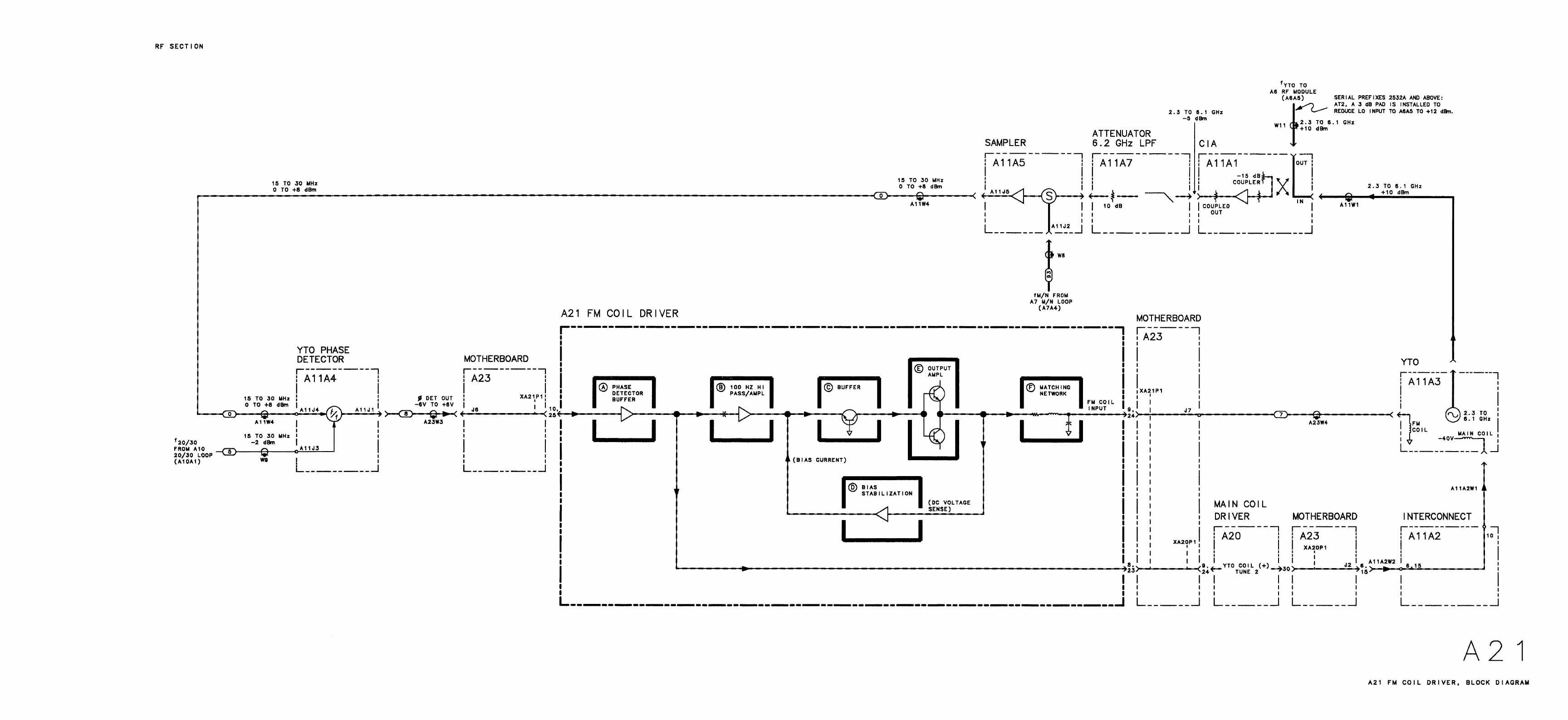
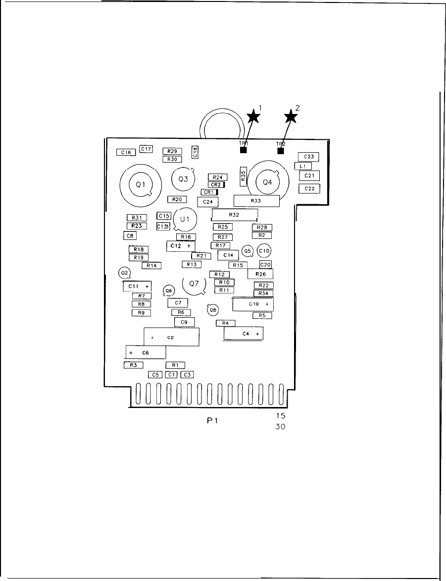
FT
E
“’
R-23
C13
w
El
RI6
m
B
Cl2
+
I
(
El
I
m
I
I
mm
m
I
,=f?q
@
+
c20
m
m
d
I326
mm
m
1
16
Pl
A21 FM Coil Driver Component Locations, 85660-60040
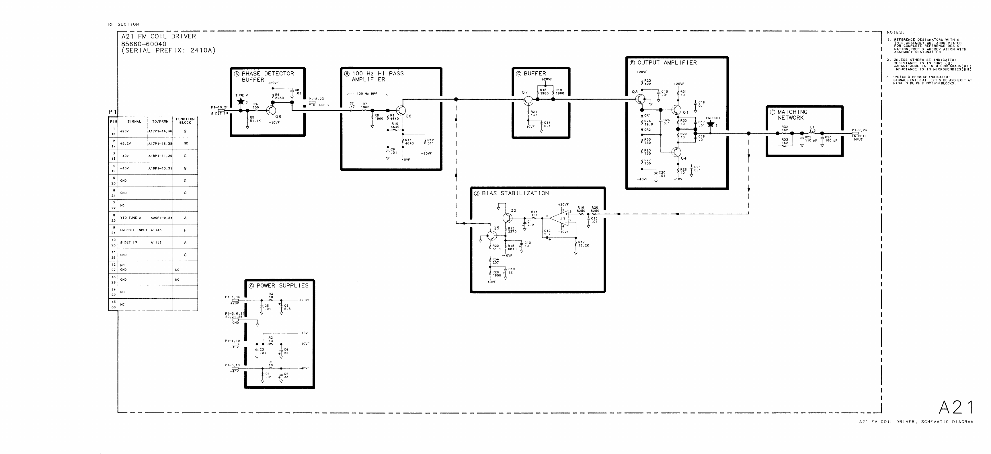
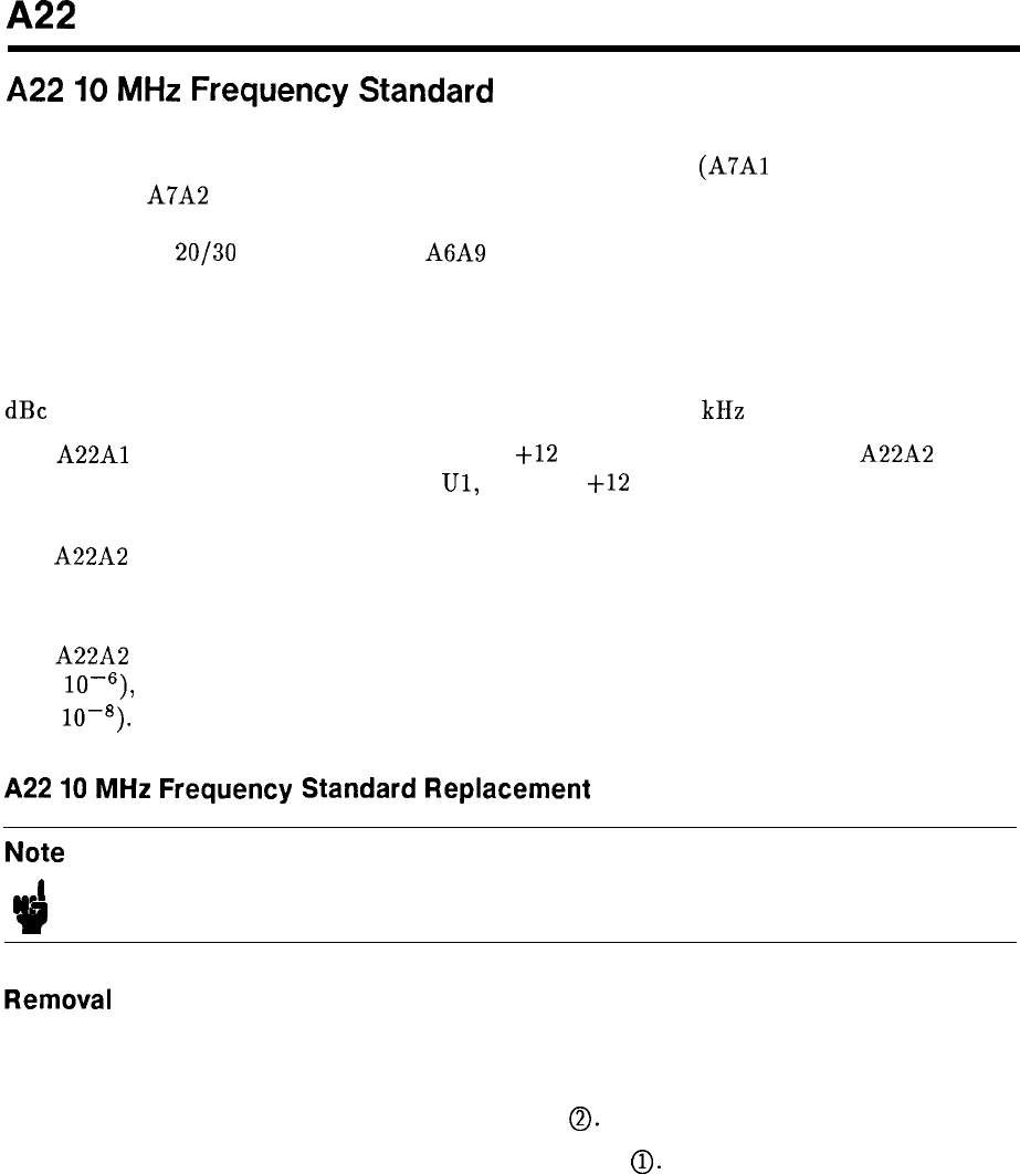
A22
A22
IO
MHz
Frequency
Standard
The 10 MHz Frequency Standard provides a stable frequency reference signal for the 100 MHz
Reference Loop to phase lock to. The 100 MHz Reference Loop
(A7Al
Reference Phase
Detector and A7A2 100 MHz VCXO) in turn provides stable frequency reference signals
of 10 MHz, 20 MHz, and 100 MHz to lock the remaining phased locked loops-A7 M/N
Reference, A10
20/30
Synthesizer, and A6A9 Phase Lock.
Alternately, the rear-panel FREQ REFERENCE jumper cable can be removed and
an external 5 Mhz or 10 MHz reference signal can be connected to the EXTERNAL
FREQUENCY REFERENCE INPUT. The performance of the spectrum analyzer will be
degraded unless the frequency reference phase noise and spurious signals are less than -140
dBc single sideband (1 Hz) referred to 10 MHz at a 100 Hz to 10 kHz offset.
The
A22Al
Regulator Board assembly provides
+12
V regulated voltage to the A22A2 Quartz
Crystal Oscillator. Voltage Regulator IC,
Ul,
provides
+12
V resolution with Cl and C3
providing compensation and CR1 providing reverse-bias protection.
The A22A2
Q
uartz Crystal Oscillator is an extremely stable, compact, low-power source of
10 MHz. It has a very fast warm-up time, exhibits excellent temperature characteristics, and
has low phase noise and power consumption.
The A22A2 Quartz Crystal Oscillator has the ability to be adjusted over a range of 20 Hz
(2 x 10w6), yet the control is sensitive enough to allow adjustment to better than 0.1 Hz
(1 x
10-8).
A22
10
MHz
Frequency
Standard
Replacement
Note
.I
rp
For location of hardware and cables referred to in this procedure, see Figure 1.
1. Remove ac line cords and RF Section bottom cover.
2. Remove All YTO Loop by removing three screws as indicated by instructions on top of
YTO Loop assembly. Disconnect cable connector
0.
3. Release A22 10 MHz Standard by removing two screws
0.
4. When removing 10 MHz Standard, disconnect 87 (gray/violet) cable and 6-pin connector
from behind.
A22 1
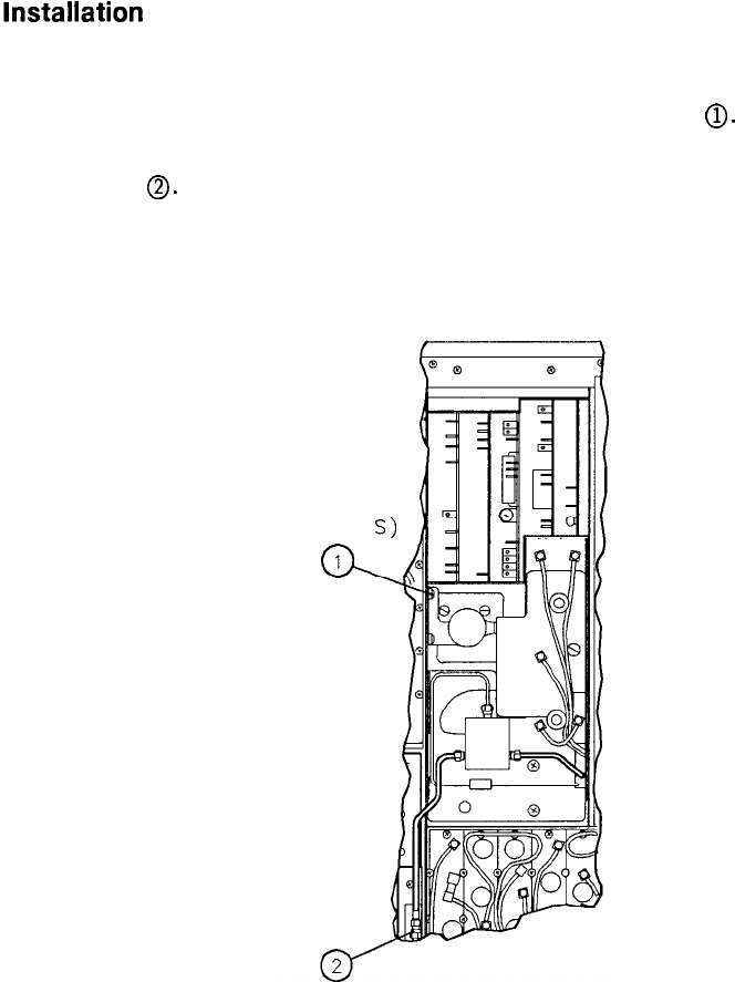
5.
6.
7.
When installing new 10 MHz Standard, check that rear studs are supported by both rear
rubber mounts and reconnect 87 (gray/violet) cable and 6-pin connector (red wire to rear
pin). Fasten 10 MHz Standard to RF Section with two screws
0.
Replace All YTO Loop. Replace three screws removed in step 2 and reconnect cable
connector
0.
Replace RF Section bottom cover and reconnect ac line cords.Replace RF Section bottom cover and reconnect ac line cords.
REARREAR
(2 PLACE
a
1
Figure 1. A22 10 MHz Standard Replacement
2 A22
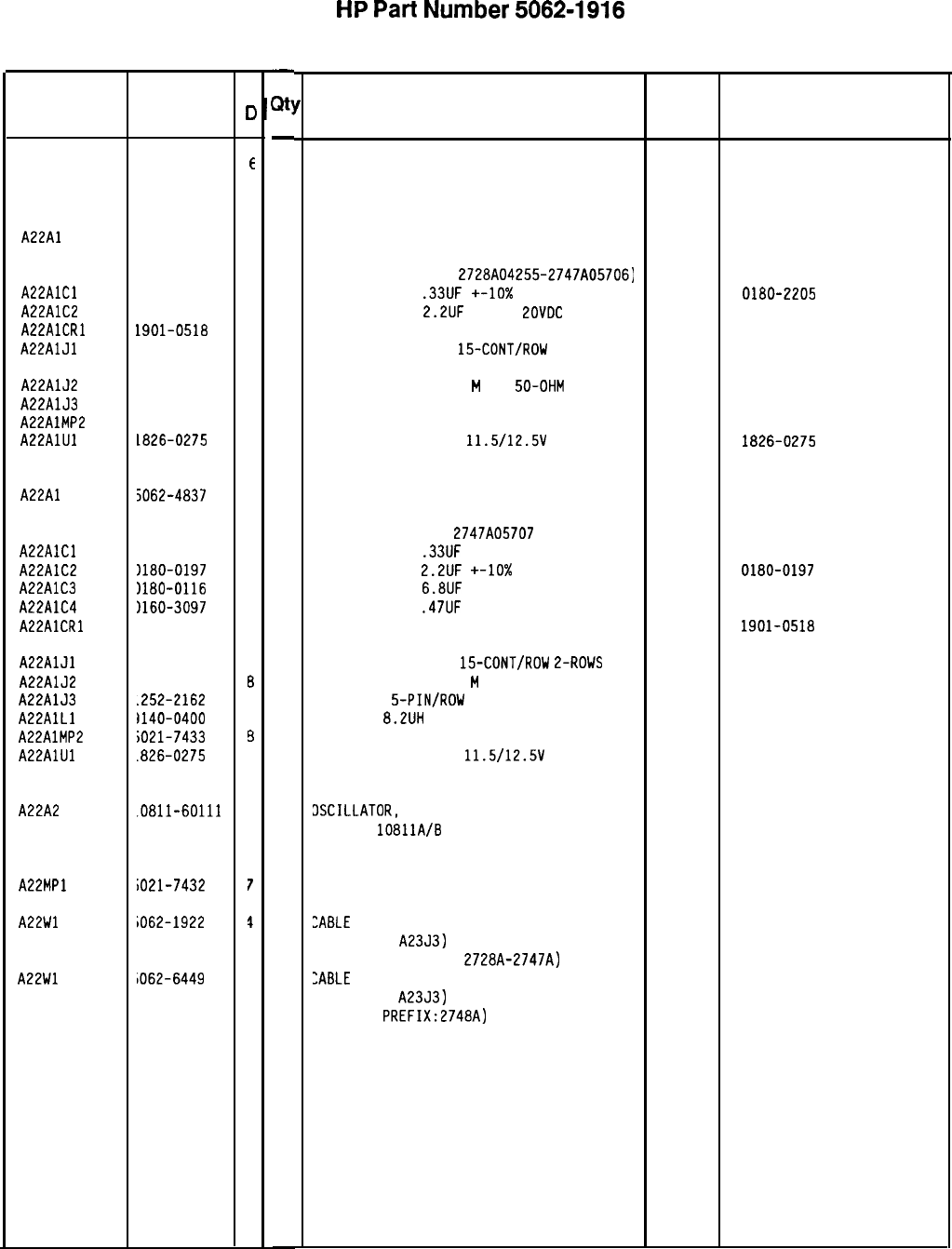
HP
Part
Number
50624916
A22 10 MHz Frequency Standard
Reference HP Part
Designation Number
A22 5062-1916
E
A22Al 5062-1909
7
A22AlCl 0180-2205
3
A22AlC2 0180-0197
a
A22AlCRl 1901-0518
a
A22AlJl 1251-2035
9
A22AlJ2 1250-0543
a
A22AlJ3 1252-2162
5
A22AlMP2 5021-7433
a
A22AlUl 1826-0275
4
A22Al 5062-4837
6
A22AlCl 1180-2205
A22AlC2
1180-0197
A22AlC3 )lBO-0116
A22AlC4
1160-3097
A22AlCRl 1901-0518
A22AlJl
1251-2035
A22AlJ2
1250-0543
A22AlJ3
.252-2162
A22AlLl
1140-0400
A22AlMP2
iO21-7433
A22AlUl
.826-0275
A22A2
.OBll-60111
A22MPl
A22Wl
iO21-7432
iO62-1922
A22Wl
1062-6449
3
a
1
1
8
9
a
5
1
9
4
3
7
4
3
C
c
-
Qt!
-
1
1
1
1
1
1
1
1
1
1
1
1
1
1
1
1
1
1
1
1
1
1
1
1
1
1
-
Description
10 MHz FREQUENCY STANDARD ASSEMBLY
(SE
RIAL PREFIX
: 2728~)
BOARD ASSEMBLY, 10 MHz FREQUENCY
STANDARD REGULATOR
(SERIA
L NUMBERS
:
2728~04255-2747~05706)
CAPACITOR-FXD
.33UF
+-lo%
35VDC TA
CAPACITOR-FXD
2.2UF
+-10%
LOVDC
TA
DIODE-SCHOTTKY SM SIG
CONNECTOR-PC EDGE
15-CONT/ROW
2-ROWS
CONNECTOR-RF SM-SNP
M
PC
50-OHM 28480 1250-0543
CONNECTOR 5-PIN/ROW l-ROW
28480 1252-2162
SHOCK-MOUNT STANDOFF 28480 5021-7433
IC V RGLTR-FXD-POS
11.5/12.5\1
TO-92 PKG
28480 1826-0275
BOARD ASSEMBLY, 10 MHz FREQUENCY
STANDARD REGULATOR
(SERIAL NUMBERS:
2747A05707
AND ABOVE)
CAPACITOR-FXD
.33UF
+-lo% 35VDC TA
CAPACITOR-FXD
2.2UF
+-lo%
20VDC TA
CAPACITOR-FXD
6.8UF
35V TA
CAPACITOR-FXD
.47UF
50V CER
DIODE-SCHDTTKY SM SIG
CONNECTOR-PC EDGE
15-CONT/RDW
2-ROWS 28480 1251-2035
CONNECTOR-RF SM-SNP
M
PC 50-OHM
28480 1250-0543
CONNECTOR
5-PIN/ROW
l-ROW
28480 1252-2162
INDUCTOR
8.2UH
5%
28480 9140-0400
SHOCK-MOUNT STANDOFF 28480 5021-7433
IC V RGLTR-FXD-POS
11.5/12.5\1
TO-92 PKG
28480 1826-0275
DSCILLATOR,
10 MHZ QUARTZ CRYSTAL
SEE HP
lOBllA/B
QUARTZ CRYSTAL
OSCILLATOR OPERATING AND SERVICE
MANUAL, PART NUMBER 10811-90002.
TOP COVER/BRACKET
:ABLE
ASSEMBLY, WIRE HARNESS, 5-WIRE
(A2253 TO
A2353)
(SERIAL PREFIXES:
2728~-2747~)
:ABLE
ASSEMBLY, WIRE HARNESS, 5-WIRE
(A2253 TO
A2353)
(SERIAL
PREFIX:2748A)
Mfr Mfr Part
Code Number
2848C
5062-1916
28480 5062-1909
28480 0180-2205
28480 0180-0197
28480 1901-0518
28480 1251-2035
28480 5062-4837
28480 0180-2205
28480 0180-0197
28480 0180-0116
28480 0160-3097
28480 1901-0518
28480 10811-60111
28480 5021-7432
28480 5062-1922
28480 5062-6449
*Indicates factory-selected value
5062-1916 Parts List
Page 1 of 1
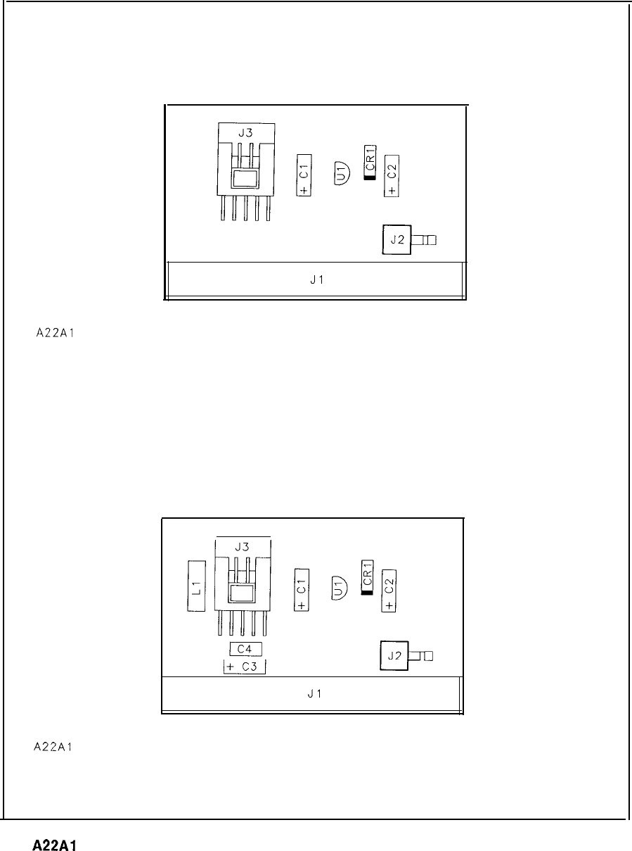
Jl
A22Al
10 MHz FREQUENCY STANDARD REGULATOR, COMPONENT LOCATION
Jl
A22Al
10 MHz FREQUENCY STANDARD REGULATOR, COMPONENT LOCATION
5062-l 909
5062-4837
A22Al
Frequency Standard Regulator Component Locations, 5062-1909, 5062-4837
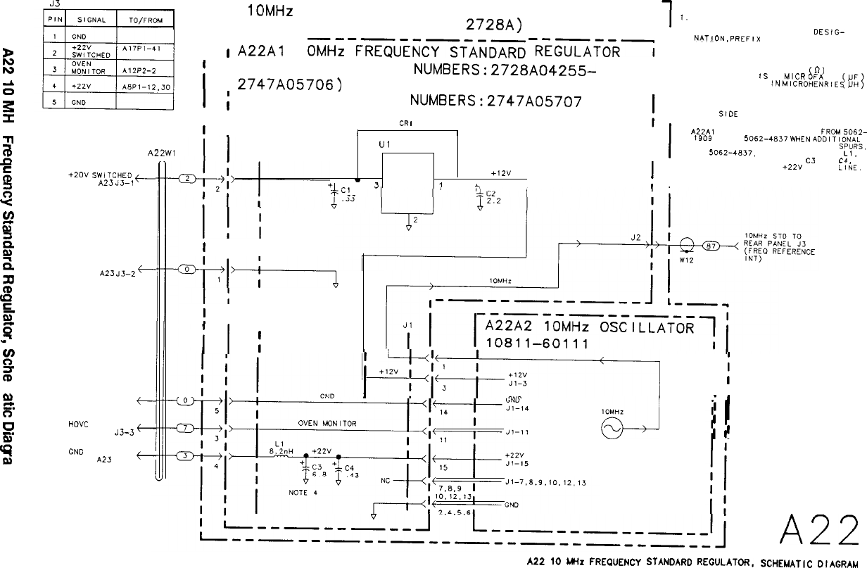
RF SECTION
>
Is
s
E
N
7
B
s
2
Y
cn
c
is
z.
z
z
E
0”
“Z
ff
s
3
a
c.
c)
0
-.
fE
i;
3
A22Wl
+2ov
SW,
TCHED
+
FROM
AZ3
33-1
GND
FROM
AZ3
J3-2
+-
GND
FROM A23 JJ-4
+-
HOVC
FROM A23
J3-3
+-
GND
FROM
A23
JJ-5
+
y-d-----,------
-----m
I
A22
1OMHz
FREQUENCY STANDARD ASSEMBLY
5062-1916 (SERIAL PREFIX:
2728~)
I---
l
I
A22Al
i
I
1
OMHi
-F~U:iCYfiiD~
-RiG?O:i
5062-1909 (SERIAL
NUMBERS:2728A04255-
2747A05706)
i
I
;
5062-4837 (SERIAL
NUMBERS:2747A05707
I
, AND ABOVE)
-^.
’
I Ln
I
I
I
I
Ul
J3
+,2v
I
‘;-C!-
3
1
-
1
I
1
I
II’
I
’
I
7-1
I
“+-r---i
I
’
I
’
.
I
il
I
7
NOTES:
REFERENCE DESIGNATORS WITHIN
THIS ASSEMBLY ARE ABBREVIATED.
I
FOR COMPLETE REFERENCE
DESIG-
NATIDN.PREFIX
ABBREVIATION WITH
I
ASSEMBLY DESIGNATION.
I
2. UNLESS OTHERWISE INDICATED:
CAPACITANCE
iS
IN
MICR
FARADS
RESISTANCE IS IN OHMS
60)
INDUCTANCE IS
IN
MICROHENRiES
, 3. UNLESS OTHERWISE INDICATED:
I
SIGNALS ENTER AT LEFT SIDE AND EXIT AT
RIGHT
SIDE
OF FUNCTION BLOCKS.
I
4.
A22Al
PART NUMBER CHANGED FROM
5062-
1909
TO
50624837
WHEN
ADDITIONAL
FILTERING WAS ADDED TO REDUCE
SPURS.
ON
50624837,
SERIES INDUCTOR,
L,.
I
AND BYPASS CAPACITORS.
CJ
AND
C4
WERE ADDED TO THE
+22”
SUPPLY
Llk
I
!
+lTr!Tl
j
i
I
IOMHZ
d
i
I
I
!
A22
SCHEMATIC DIAGRAM
A22
10 MHz FREQUENCY
STANDARD
REGULATOR.
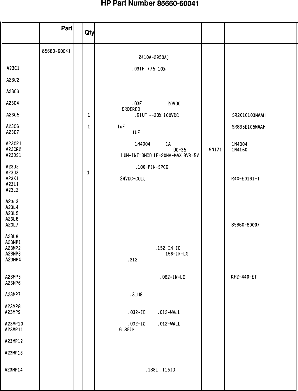
HP
Part
Number 85660-60041
A23 Motherboard
Reference
HP
Part
C
Mfr Mfr Part
Designation
Number D
Qty Description
Code
Number
A23 85660-60041
7 1
BOARD ASSEMBLY, MOTHERBOARD 28480 85660-60041
(SERI
AL PREFIX
:
2410A-2950A)
A23Cl
0180-0452 8 1
CAPACITOR-FXD
.031F
+75-10x 25VDC AL
28480 0180-0452
(MUST BE ORDERED SEPARATELY)
A23C2
0180-0454 0 1
CAPACITOR-FXD 4200UF +75-10% 75VDC AL
28480 0180-0454
(MUST BE ORDERED SEPARATELY)
A23C3
0180-0453 9 1
CAPACITOR-FXD 8700UF +75-10% 40VDC AL
28480 0180-0453
(MUST BE ORDERED SEPARATELY)
A23C4
0180-2798 9 1
CAPACITOR-FXD
.03F
+lOO-10%
ZOVDC
AL
28480 0180-2798
(MUST BE
ORDERED
SEPARATELY)
A23C5
0160-3879 7
1
CAPACITOR-FXD
.OlUF
+-20X
1OOVDC
CER
04222 SR201C103MAAH
A23C6
0160-0127 2
1
CAP-FXD
1uF
50 V
04222 SR835E105MAAH
A23C7
0170-0073 8 1
CAPACITOR-FXD
1UF
600V
28480
(400HZ OPTION ONLY)
A23CRl
1901-0743 1 1
DIODE-PWR RECT
lN4004
400V
1A
DO-41
71744 lN4004
A23CR2
1901-0050 3 1
DIODE-SWITCHING 80V 200MA 2NS
DO-35 9N171 lN4150
A23DSl
1990-0517 4 1
LED-LAMP
LUM-INT=3MCD
IF=20MA-MAX
BVR=SV 28480 5082-4655
A2352
1251-5799 8 1
CONN-POST TYPE
.lOO-PIN-SPCG
20-CONT
76381 3428-2303
A2353
1252-2689 1
1
CONN-HEADER, VERTICAL, 6-PIN 28480 1252-2689
A23Kl
0490-0618 5 1
RELAY 2C
24VDC-COIL
5A 115VAC
77342 R40-E0161-1
A23Ll
85660-80007 7 1
INDUCTOR P/S FILTER 28480 85660-80007
A23L2
85660-80007 7 1
INDUCTOR P/S FILTER 28480 85660-80007
A23L3
85660-80007 7 1
INDUCTOR P/S FILTER 28480 85660-80007
A23L4
85660-80007 7 1
INDUCTOR P/S FILTER 28480 85660-80007
A23L5
85660-80007 7 1
INDUCTOR P/S FILTER 28480 85660-80007
A23L6
85660-80007 7 1
INDUCTOR P/S FILTER 28480 85660-80007
A23L7
85660-80007 7 1
INDUCTOR P/S FILTER 28480 85660-80007
A23L8
85660-80007 7 1
INDUCTOR P/S FILTER 28480 85660-80007
A23MPl NOT ASSIGNED
A23MP2
0380-0076 6 4
SPACER-RVT-ON .5-IN-LG
.152-IN-ID 00866
A23MP3
0590-1491 6
11 THREADED INSERT-STDF 4-40
.156-IN-LG 46384 KFE-440-5-ET
A23MP4
2200-0105 4 2
SCREW SM440
.312
28480 2200-0105
(MUST BE ORDERED SEPARATELY)
A23MP5
0590-0519 7
14 THREADED INSERT-NUT 4-40
.062-IN-LG
STL
46384
KF2-440-ET
A23MP6
85660-00026 2 1
SHOCK-MOUNT, BOTTOM 28480 85660-00026
(MUST BE ORDERED SEPARATELY)
A23MP7
1520-0205 2 2
SHOCK-MOUNT.
.31HG
28480 1520-0205
(MUST BE ORDERED SEPARATELY)
A23MP8
85660-20093 5 2
STANDOFF-YTO CASTING SUPPORT 28480 85660-20093
A23MP9
0890-0324 8 1
TUBING-FLEX
.032-ID
TFE
.012-WALL 09795 II-TW,FR-1
A23MPlO
0890-0324 8 1
TUBING-FLEX
.032-ID
TFE
.012-WALL 09795 II-TW,FR-1
A23MPll
0460-0778 5 1
TAPE PC,
6.85IN 28480 0460-0778
(MUST BE ORDERED SEPARATELY)
A23MP12
85660-00027 3 1
HEAT SINK INSULATOR 28480 85660-00027
(MUST BE ORDERED SEPARATELY)
A23MP13
85660-20061 7 1
TRANSISTOR HEAT SINK 28480 85660-20061
(MUST BE ORDERED SEPARATELY)
A23MP14
0340-0923 8
10 INSULATOR, SPACER,
.188L
.115ID
28480 0340-0923
(MUST BE ORDERED SEPARATELY)
*Indicates factory-selected value
8566040041 Parts List
Page 1 of 3

Reference
Designation
HP Part
Number
C
D
A23MP15 2200-0111
2
A23MP16 0340-1114
1
A23MP17 2680-0129
8
A23Pl
A23P2
A23P3
A23P4
A23P7
1251-0600
0
1251-0600
0
1251-0600
0
1251-0600
0
0360-1788
7
A23P8 0360-1788
7
A23P9 0360-1788
7
A2391 1854-0618
8
A23Q2 1854-0294
0
A23Q3 1854-0618
8
A2394 1854-0679
1
A23Rl 0757-0421
4
A23R2 0687-3321
0
A23R3
A23R4
A23R5
A23R6
A23R7
0683-7515
4
0686-7525
2
0683-2225
3
0698-0084
9
0698-7229
8
A23R8
A23R9
A23RlO
A23Rll
A23R12
0698-7229
8
0698-7229
8
0698-7229
8
3698-7229
8
3698-7229
8
A23R13 3698-7229
8
A23Ul 1826-0423
8
A23Wl 35660-60070
2
A23W2 35660-60068
8
A23W3 35660-60069
9
A23W4 35660-60124
7
A23W5 3120-2800
6
A23W6 3120-2804
0
A23W7 3120-2802
8
8.5660-60041
Parts List
Page 2 of 3
-
31
-
1c
5
8
1
1
1
1
1
1
1
1
1
1
1
1
1
1
1
1
1
1
1
1
1
1
1
1
1
1
1
1
1
1
1
1
-
HP
Part
Number 85660-60041
A23 Motherboard
Description Mfr Mfr Part
Code Number
SCREW SM440
.500
PNPD
(MUST BE ORDERED SEPARATELY)
INSULATOR, TRANSISTOR TO-3ADH
(MUST BE ORDERED SEPARATELY)
SCREW SM1032
.312
PNPD
(MUST BE ORDERED SEPARATELY)
28480
28480
28480
2200-0111
0340-1114
2680-0129
CONNECTOR-SGL CONT PIN
1.14-MM-BSC-SZ
SQ
27264
CONNECTOR-SGL CONT PIN
1.14-MM-BSC-SZ
SQ
27264
CONNECTOR-SGL CDNT PIN
1.14-MM-BSC-SZ
SQ
27264
CONNECTOR-SGL CONT PIN
1.14-MM-BSC-SZ
SQ
27264
CONNECTOR-SGL CONT PIN
.045-IN-BSC-SZ
SQ
04574
16-06-0034
16-06-0034
16-06-0034
16-06-0034
CONNECTOR-SGL CDNT PIN
.045-IN-BSC-SZ
SQ
CONNECTOR, SINGLE MALE
SQ.045
(400HZ OPTION ONLY)
TRANSISTOR NPN SI DARL TO-3
PD=15OW
(MUST BE ORDERED SEPARATELY)
04574
28480
04713 MJ3000
TRANSISTOR NPN SI
TO-3
PD=llSW
FT=500KHZ
(MUST BE ORDERED SEPARATELY)
TRANSISTOR NPN SI DARL TO-3
PD=150W
(MUST BE ORDERED SEPARATELY)
TRANSISTOR NPN
2N5885
SI TO-8
PO=EOOW
(MUST BE ORDERED SEPARATELY)
RESISTOR 825 +-1%
.125W
TF TC=O+-100
RESISTOR
3.3K
10%
.5W
CC
TC=0+647
28480 1854-0294
04713 MJ3000
28480 1854-0679
19701
SFR25H
01121 EB3321
RESISTOR 750 5%
.25W
CF TC=O-400
2M627 R-25J
RESISTOR
7.5K
5%
.5W
CC
TC=0+647 01121 EB7525
RESISTOR
2.2K
5%
.25W
CF TC=O-400
2M627 R-25J
RESISTOR
2.15K
1%
.125W
TF TC=O+-100
19701
SFR25H
RESISTOR 511
+-1X
.05W
TF TC=O+-100
19701
50635
?ESISTOR
511 +-1%
.05W
TF TC=O+-100
19701
50635
7ESISTDR
511
+-I%
.05W
TF TC=O+-100
19701
50635
iESISTDR
511 +-1%
.05W
TF TC=O+-100
19701
50635
1ESISTOR
511 +-1%
.05W
TF
TC=O+-100
19701
50635
7ESISTDR
511 +-1%
.05W
TF
TC=O+-100
19701
50635
7ESISTOR 511 +-1%
.05W
TF TC=O+-100
IC REGULATOR TO-3
(MUST BE ORDERED SEPARATELY)
:ABLE
ASSEMBLY, COAX 3 (A19 TO
A26)
(MUST BE ORDERED SEPARATELY)
:ABLE
ASSEMBLY, COAX 84 (A19 TO
A6A12)
(MUST BE ORDERED SEPARATELY)
:ABLE
ASSEMBLY,
COAX
8 (A21
TO
AllJl)
(MUST BE ORDERED SEPARATELY)
19701
50635
27014 LM317K
28480 85660-60070
28480 85660-60068
28480 85660-60069
:ABLE
ASSEMBLY, COAX 7 (A21 TO
AllA3)
(
MUS
T
B
E
OR
DERED
SEPARATELY
)
16-PIN
CABLE ASSEMBLY
[MUST BE ORDERED SEPARATELY)
!6-PIN
CABLE ASSEMBLY
[MUST BE ORDERED SEPARATELY)
SO-PIN CABLE ASSEMBLY
28480 85660-60124
28480 8120-2800
28480 8120-2804
28480 8120-2802
*Indicates factory-selected value
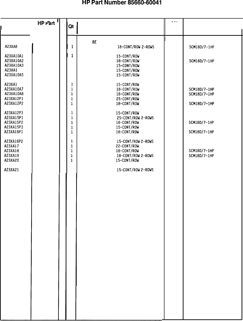
HP
Part
Number 85660-60041
A23 Motherboard
Reference
*‘-
-
-
’
C
nr
raft
I
I
--.
I
1
Designation Number
t
D
Qt
Mfr
Y
C
I
Description
Mfr Part
I
Code Number
I
A23XA8
I
1251-2026
8
I
1
SCM18D/7-1HP
(MUST
BE
ORDERED SEPARATELY)
CONNECTOR-PC EDGE
18-CONT/ROW
2-ROWS
A23XAlOAl
A23XAlOA2
A23XAlOA3
A23XAl OA4
A23XAlOA5
A23XAl OA6
A23XAlOA7
A23XAlOA8
A23XA12Pl
A23XA12P2
A23XA12P3
A23XA15Pl
A23XA15P2
A23XA15P3
A23XA16Pl
A23XA16P2
A23XA17
A23XA18
A23XA19
A23XA20
A23XA21
1251-2035
9
~
1
26742 220-624-03
1251-2026
8
1
SCM18D/7-1HP
1251-2035
9
1
26742 220-624-03
1251-2035
9
1
26742 220-624-03
1251-2035
9
1
26742 220-624-03
CONNECTOR-PC EDGE
15-CONT/ROW
2-ROWS
CONNECTOR-PC EDGE
18-CDNT/ROW
2-ROWS
CONNECTOR-PC EDGE
15-CONT/ROW
2-ROWS
CONNECTOR-PC EDGE
15-CDNT/ROW
2-ROWS
CONNECTOR-PC EDGE
15-CDNT/ROW
2-ROWS
1251-2035
9
26742 220-624-03
1251-2026
8
SCM18D/7-IHP
1251-2026
8
SCM18D/7-1HP
1251-7312
5
00779 l-530843-6
1251-2026
8
SCM18D/7-IHP
CONNECTOR-PC EDGE
15-CDNT/ROW
E-ROWS
CONNECTOR-PC EDGE
18-CDNT/RDW
L-ROWS
CONNECTOR-PC EDGE
18-CONT/RDW
2-ROWS
CONNECTOR-PC EDGE
25-CDNT/ROW
2-ROWS
CONNECTOR-PC EDGE
18-CDNT/RDW
2-ROWS
1251-2035
9
26742 220-624-03
1251-7312
5
00779 l-530843-6
1251-2026
8
SCM18D/7-1HP
1251-2035
9
26742 220-624-03
1251-2026
8
SCM18D/7-1HP
CONNECTOR-PC EDGE
15-CONT/ROW
2-ROWS
CONNECTOR-PC EDGE
25-CDNT/ROW
2-ROWS
CONNECTOR-PC EDGE
18-CONT/ROW
2-ROWS
CONNECTOR-PC EDGE
15-CONT/RDW
2-ROWS
CONNECTOR-PC EDGE
18-CONT/ROW
2-ROWS
1251-2035
9
26742 220-624-03
1251-1365
6
26742 220-626-03
1251-2026
8
SCM18D/7-1HP
1251-2026
8
SCM18D/7-1HP
1251-2035
9
220-624-03
CONNECTOR-PC EDGE
15-CONT/RDW
2-ROWS
CONNECTOR-PC EDGE
22-CONT/ROW
2-ROWS
CONNECTOR-PC EDGE
18-CDNT/ROW
2-ROWS
CONNECTOR-PC EDGE
18-CONT/ROW
2-ROWS
CONNECTOR-PC EDGE
15-CONT/ROW
E-ROWS
26742
1251-2035
9
CONNECTOR-PC EDGE
15-CONT/ROW
2-ROWS 26742 220-624-03
*Indicates factory-selected value
8566040041 Parts List
Page 3 of 3
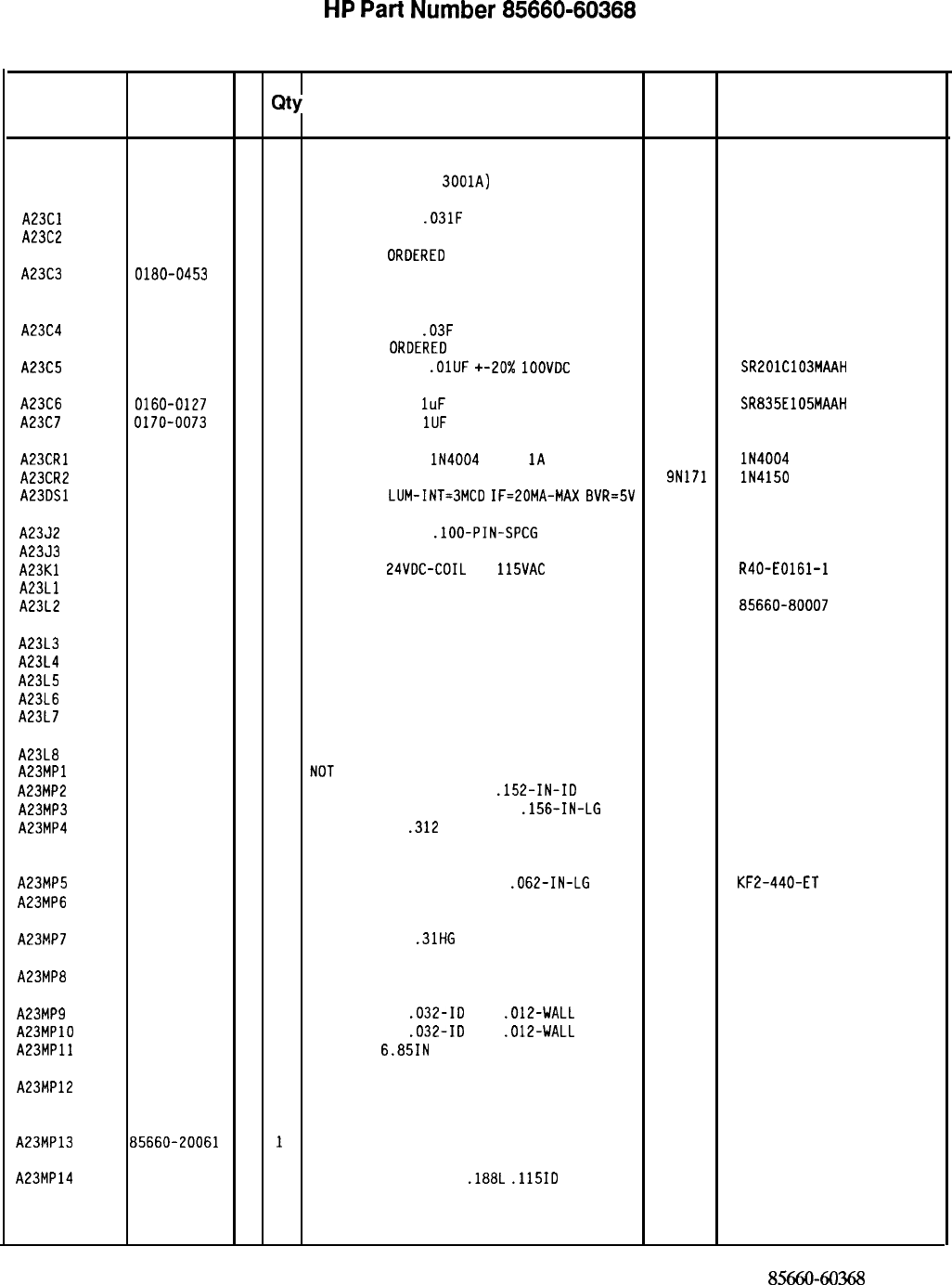
HP
Part
Number 85660-60368
A23 Motherboard
Reference
HP Part C
Designation
Number D
Qty Description Mfr
Mfr Part
Code Number
A23 85660-60368
1
1
BOARD ASSEMBLY, MOTHERBOARD 28480 85660-60368
(SERI
AL PREFIX
:
3001~)
A23Cl 0180-0452
8
1
CAPACITOR-FXD
.031F
+75-10% 25VDC AL
28480 0180-0452
A23C2 0180-0454
0
1
CAPACITOR-FXD 4200UF +75-10% 75VDC AL
28480 0180-0454
(
MUST
BE
ORDERED
SEPAR
ATELY
)
A23C3 0180-0453
9
1
CAPACITOR-FXD 8700UF +75-10% 40VDC AL
28480 0180-0453
(MUST BE ORDERED SEPARATELY)
A23C4 0180-2798
9
1
CAPACITOR-FXD
.03F
+lOO-10% 20VDC AL
28480 0180-2798
(MUST BE
ORDERED
SEPARATELY)
A23C5 0160-3879
7
1
CAPACITOR-FXD
.OlUF
+-20x
1OOVDC
CER
04222 SR201C103MAAH
A23C6 0160-0127
2
1
CAPACITOR-FXD
1uF
50 V
04222 SR835E105MAAH
A23C7 0170-0073
8
1
CAPACITOR-FXD
1UF
600V
28480 0170-0073
(400HZ OPTION ONLY)
A23CRl 1901-0743
1
1
DIODE-PWR RECT
lN4004
400V
1A
DO-41
71744 lN4004
A23CR2 1901-0050
3
1
DIODE-SWITCHING 80V 200MA 2NS DO-35
9N171 lN4150
A23DSl 1990-0517
4
1
LED-LAMP
LUM-INT=3MCD
IF=20MA-MAX
BVR=SV 28480 5082-4655
A2352 1251-5799
8
1
CONN-POST TYPE
.lOO-PIN-SPCG
20-CONT
76381 3428-2303
A2353 1252-2689
1
1
CONN-HEADER. VERTICAL, 6-PIN 28480 1252-2689
A23Kl 0490-1647
2
1
RELAY 2C
24VDC-COIL
5A
115VAC 77342 R40-E0161-1
A23Ll 85660-80007
7
1
INDUCTOR P/S FILTER 28480 85660-80007
A23L2 85660-80007
7
1
INDUCTOR P/S FILTER 28480 85660-80007
A23L3 85660-80007
7
1
INDUCTOR P/S FILTER 28480 85660-80007
A23L4 85660-80007
7
1
INDUCTOR P/S FILTER 28480 85660-80007
A23L5 85660-80007
7
1
INDUCTOR P/S FILTER 28480 85660-80007
A23L6 85660-80007
7
1
INDUCTOR P/S FILTER 28480 85660-80007
A23L7 85660-80007
7
1
INDUCTOR P/S FILTER 28480 85660-80007
A23L8
A23MPl
A23MP2
A23MP3
A23MP4
85660-80007
7
1
INDUCTOR P/S FILTER 28480 85660-80007
NOT
ASSIGNED
0380-0076
6 4
SPACER-RVT-ON .5-IN-LG
.152-IN-ID 00866
0590-1491
6
11
THREADED INSERT-STDF 4-40
.156-IN-LG 46384 KFE-440-5-ET
2200-0105
4
2
SCREW SM440
.312
28480 2200-0105
(MUST BE ORDERED SEPARATELY)
A23MP5 0590-0519
7
14
THREADED INSERT-NUT 4-40
.062-IN-LG
STL
46384 KF2-440-ET
A23MP6 85660-00026
2
1
SHOCK-MOUNT, BOTTOM 28480 85660-00026
(MUST BE ORDERED SEPARATELY)
A23MP7 1520-0205
2 2
SHOCK-MOUNT,
.31HG
28480 1520-0205
(MUST BE ORDERED SEPARATELY)
A23MP8 85660-20093
5
2
STANDOFF-YTD CASTING SUPPORT 28480 85660-20093
A23MP9 0890-0324
8
1
TUBING-FLEX
.032-ID
TFE
.OlL-WALL 09795 II-TW.FR-1
A23MPlO 0890-0324
8
1
TUBING-FLEX
.032-ID
TFE
.012-WALL 09795 II-TW,FR-1
A23MPll 0460-0778
5
1
TAPE PC,
6.85IN 28480 0460-0778
(MUST BE ORDERED SEPARATELY)
A23MP12 85660-00027
3
1
HEAT SINK INSULATOR 28480 85660-00027
(MUST BE ORDERED SEPARATELY)
A23MP13 85660-20061
7
1
TRANSISTOR HEAT SINK 28480 85660-20061
(MUST BE ORDERED SEPARATELY)
A23MP14 0340-0923
810
INSULATOR, SPACER,
.188L
.115ID
28480 0340-0923
(MUST BE ORDERED SEPARATELY)
*Indicates factory-selected value
85660-60368 Parts List
Page 1 of 3
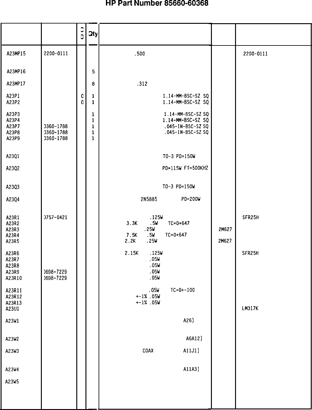
Reference HP Part
2
Designation Number
0
A23MP15 2200-0111
2
A23MP16 0340-1114
1
A23MP17 2680-0129
8
A23Pl 1251-0600
0
A23P2 1251-0600
0
A23P3 1251-0600
0
A23P4 1251-0600
0
A23P7 3360-1788
7
A23P8 3360-1788
7
A23P9 3360-1788
7
A23Ql
A2342
1854-0618
8
1854-0294
0
A23Q3 1854-0618
8
A2394 1854-0679
1
A23Rl 3757-0421
4
A23R2 1687-3321
0
A23R3 3683-7515
4
A23R4 3686-7525
2
A23R5 3683-2225
3
A23R6 1698-0084
9
A23R7 1698-7229
8
A23R8 3698-7229
8
A23R9 1698-7229
8
A23RlO 1698-7229
8
A23Rll 1698-7229
8
A23R12 1698-7229
8
A23R13 3698-7229
8
A23Ul 1826-0423
8
A23Wl 35660-60070
2
A23W2 35660-60068
8
A23W3 35660-60069
9
A23W4 35660-60124
7
A23W5 3120-2800
6
8566040368 Parts List
Page 2 of 3
-
mY
-
10
1
1
1
1
1
1
1
1
1
1
1
1
1
1
1
1
1
1
1
1
1
1
1
-
HP
Part
Number 85660-60368
A23 Motherboard
Description
SCREW SM440
.500
PNPD
(MUST BE ORDERED SEPARATELY)
Mfr Mfr Part
Code Number
28480 2200-0111
INSULATOR, TRANSISTOR TO-3ADH
(MUST BE ORDERED SEPARATELY)
SCREW SM1032
.312
PNPD
(MUST BE ORDERED SEPARATELY)
CONNECTOR-SGL CDNT PIN
1.14-MM-BSC-SZ
SQ
CONNECTOR-SGL CONT PIN
1.14-MM-BSC-SZ
SQ
28480 0340-1114
28480 2680-0129
27264 16-06-0034
27264 16-06-0034
CONNECTOR-SGL CONT PIN
1.14-MM-BSC-SZ
SQ
CONNECTOR-SGL CONT PIN
1.14~MM-BSC-SZ
SQ
CONNECTOR-SGL CONT PIN
.045-IN-BSC-SZ
SQ
CONNECTOR-SGL CONT PIN
.045-IN-BSC-SZ
SQ
CONNECTOR, SINGLE MALE SQ.045
(400HZ OPTION ONLY)
27264
27264
04574
04574
16-06-0034
16-06-0034
TRANSISTOR NPN SI DARL
TO-3
PD=15OW
(MUST BE ORDERED SEPARATELY)
TRANSISTOR NPN SI TO-3
PD=115W
FT=SOOKHZ
(MUST BE ORDERED SEPARATELY)
04713 MJ3000
28480 1854-0294
TRANSISTOR NPN SI DARL
TO-3
PD=lSOW
(MUST BE ORDERED SEPARATELY)
TRANSISTOR NPN
2N5885
SI TO-8
PD=2OOW
(MUST BE ORDERED SEPARATELY)
04713 MJ3000
28480 1854-0679
RESISTOR 825 +-1%
.125W
TF TC=O+-100
19701
SFR25H
RESISTOR
3.3K
10%
.5W
CC
TC=0+647 01121 EB3321
RESISTOR 750 5%
.25W
CF TC=O-400
2M627 R-25J
RESISTOR
7.5K
5%
.5W
CC
TC=0+647 01121 EB7525
RESISTOR
2.2K
5%
.25W
CF TC=O-400
2M627 R-25J
RESISTOR
2.15K
1%
.125W
TF TC=O+-100
19701
SFR25H
RESISTOR 511 +-1%
.05W
TF TC=O+-100
19701
50635
RESISTOR 511 +-1%
.05W
TF TC=O+-100
19701
50635
RESISTOR 511 +-1%
.05W
TF TC=O+-100
19701
50635
RESISTOR 511 +-1%
.05W
TF TC=O+-100
19701
50635
RESISTOR 511 +-1%
.05W
TF
TC=O+-100
RESISTOR 511
+-1X
.05W
TF TC=O+-100
RESISTOR 511
+-1X
.05W
TF TC=O+-100
IC REGULATOR TO-3
(MUST BE ORDERED SEPARATELY)
CABLE ASSEMBLY, COAX 3 (A19 TO
A26)
(MUST BE ORDERED SEPARATELY)
19701
19701
19701
27014
28480
50635
50635
50635
LM317K
85660-60070
CABLE ASSEMBLY, COAX 84 (A19 TO
A6A12)
(MUST BE ORDERED SEPARATELY)
CABLE ASSEMBLY,
COAX
8 (A21 TO
AllJl)
(MUST BE ORDERED SEPARATELY)
28480
28480
85660-60068
85660-60069
CABLE ASSEMBLY, COAX 7 (A21 TO
AllA3)
(MUST BE ORDERED SEPARATELY)
16-PIN CABLE ASSEMBLY
(MUST BE ORDERED SEPARATELY)
28480 85660-60124
28480 8120-2800
*Indicates factory-selected value
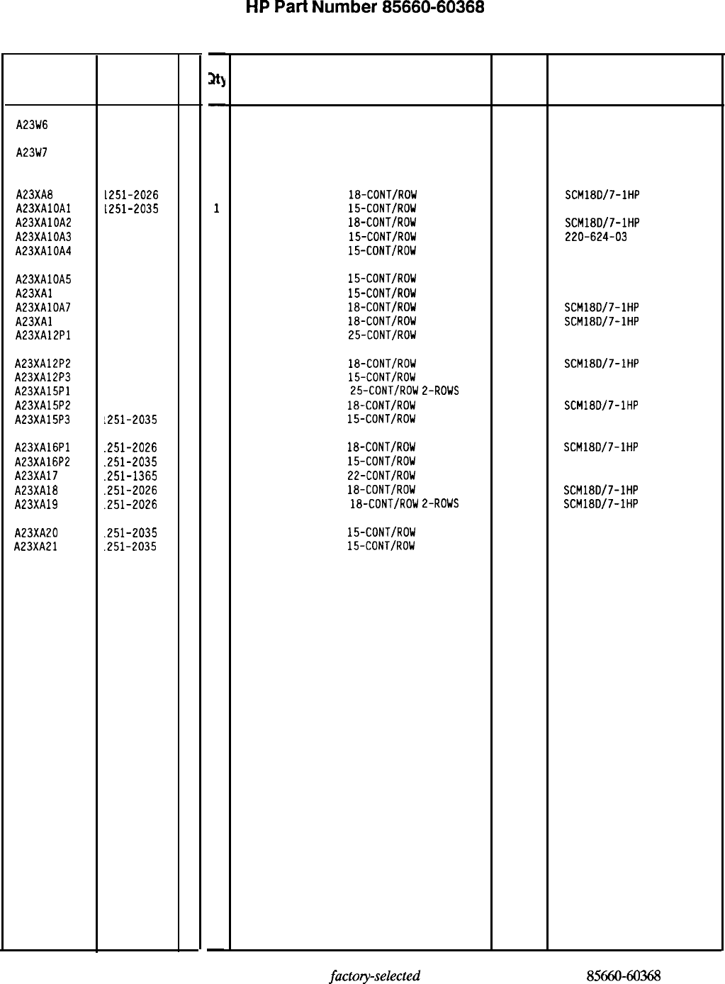
HP
Part
Number 85660-60368
A23 Motherboard
Reference HP Part
C
Designation Number
D
A23W6 3120-2804
0
A23W7 3120-2802
8
A23XA8 1251-2026
8
A23XAlOAl L251-2035
9
A23XAlDA2 1251-2026
8
A23XAlOA3 1251-2035
9
A23XAlOA4 1251-2035
9
A23XAlOA5
1251-2035
9
A23XAl OA6 1251-2035
9
A23XAlOA7 1251-2026
8
A23XAl OA8
1251-2026
8
A23XA12Pl
1251-7312
5
A23XA12P2 1251-2026
8
A23XA12P3
1251-2035
9
A23XA15Pl
1251-7312
5
A23XA15P2
1251-2026
8
A23XA15P3
1251-2035
9
A23XA16Pl
.251-2026 8
A23XA16P2
.251-2035
9
A23XAl7
.251-1365
6
A23XA18
.251-2026
8
A23XA19
.251-2026
8
A23XA20
.251-2035
9
A23XA21
.251-2035
9
-
at)
-
1
1
1
1
1
1
1
1
1
1
1
1
1
1
1
1
1
1
1
1
1
1
1
1
-
Description
26-PIN CABLE ASSEMBLY
(MUST BE ORDERED SEPARATELY)
50-PIN CABLE ASSEMBLY
(MUST BE ORDERED SEPARATELY)
28480
28480
8120-2804
8120-2802
CONNECTOR-PC EDGE
18-CONT/ROW
2-ROWS
CONNECTOR-PC EDGE
15-CONT/ROW
2-ROWS
CONNECTOR-PC EDGE
18-CONT/RDW
L-ROWS
CONNECTOR-PC EDGE
15-CONT/ROW
E-ROWS
CONNECTOR-PC EDGE
15-CONT/RDW
2-ROWS
CONNECTOR-PC EDGE
15-CONT/ROW
L-ROWS
CONNECTOR-PC EDGE
15-CONT/ROW
2-ROWS
CONNECTOR-PC EDGE
18-CDNT/ROW
2-ROWS
CONNECTOR-PC EDGE
18-CDNT/ROW
2-ROWS
CONNECTOR-PC EDGE
25-CDNT/ROW
2-ROWS
26742
26742
26742
26742
26742
SCM180/7-1HP
220-624-03
SCM18D/7-1HP
220-624-03
220-624-03
00779
220-624-03
220-624-03
SCM18D/7-1HP
SCM18D/7-1HP
l-530843-6
CONNECTOR-PC EDGE
18-CDNT/ROW
2-ROWS
CONNECTOR-PC EDGE
15-CONT/ROW
E-ROWS
CONNECTOR-PC EDGE
25-CONT/ROW
2-ROWS
CONNECTOR-PC EDGE
18-CONT/ROW
2-ROWS
CONNECTOR-PC EDGE
15-CONT/ROW
2-ROWS
26742
00779
26742
SCM18D/7-IHP
220-624-03
l-530843-6
SCM18D/7-1HP
220-624-03
CONNECTOR-PC EDGE
18-CDNT/ROW
2-ROWS
CONNECTOR-PC EDGE
15-CDNT/ROW
2-ROWS
CONNECTOR-PC EDGE
22-CONT/RDW
L-ROWS
CONNECTOR-PC EDGE
18-CDNT/ROW
L-ROWS
CONNECTOR-PC EDGE
18-CDNT/RDW
2-ROWS
26742
26742
SCM18D/7-1HP
220-624-03
220-626-03
SCM18D/7-1HP
SCM18D/7-IHP
CONNECTOR-PC EDGE
15-CONT/ROW
2-ROWS
26742 220-624-03
CONNECTOR-PC EDGE
15-CONT/ROW
2-ROWS
26742 220-624-03
Mfr
Mfr Part
Code Number
*Indicates factory-selected value
8566040368
Parts List
Page 3 of 3
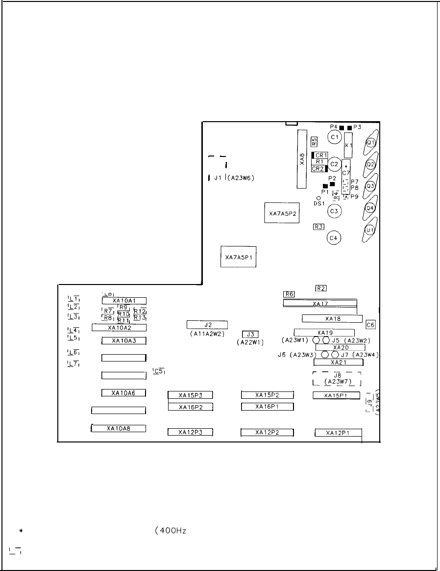
FRONT
1
XAlOA3
1
1
XA10A4
1
1
XA10A5
j
1
XAIOAG
1
)
XAlOA7
1
c-
I
1
1
J1
I(A23~6)
I I
--
I
(AllA2W2)
[J31
(A22Wl)
XAl8
J4
(A:+3:;
J’S
(A23W3)
00J7
(A23W4)
1
XA21
1
25
r-Js-7
L
@23w72_
J
[
XA15P3
1
1
XA15P2
1
XAl6P2
11
XAl6Pl
1
1
XAIOAB
]
1
XAlZP3
)
1
XAlZP2
](
XAlZPl
REAR
* LOADED FOR OPTION 400
(400Hz
) ONLY
L7
INDICATES COMPONENT ON REVERSE SIDE
A23 Motherboard Component Locations, 85660-60041
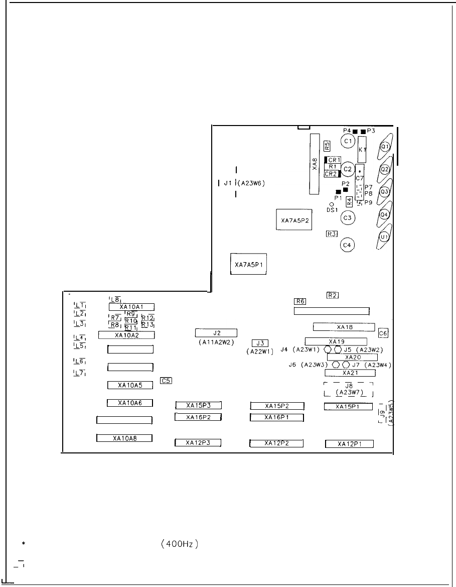
FRONT
1
XA10A3
]
(
XA10A4
1
[
XAlOA5
1
1
XAlOA6
1
1
XAlOA7
1
1
XAlOAB
]
m
I
1
1
Jl
i(A23W6)
I
1
--
r-l
XA7A5P
1
I
’
I
mm
XA17
II
I
(A22Wl)
r-j7-7
L
@23w7)
J
1
XA15P3
j
1
XA15P2
1
L
XA16PZ
1
1
XAIGPI
1
[
XA12P3
]j
XA12P2
11
XAlZPl
1
I
* LOADED FOR OPTION 400
(400Hz)
ONLY
-7
INDICATES COMPONENT ON REVERSE SIDE
REAR
A23 Motherboard Component Locations, 85660-60368
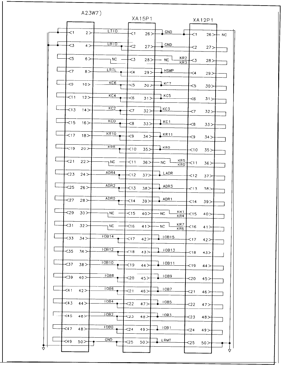
(P/O
A23W7)
J8
XAlSPl
A23 Motherboard Instrument B
US
, Interconnect Diagram
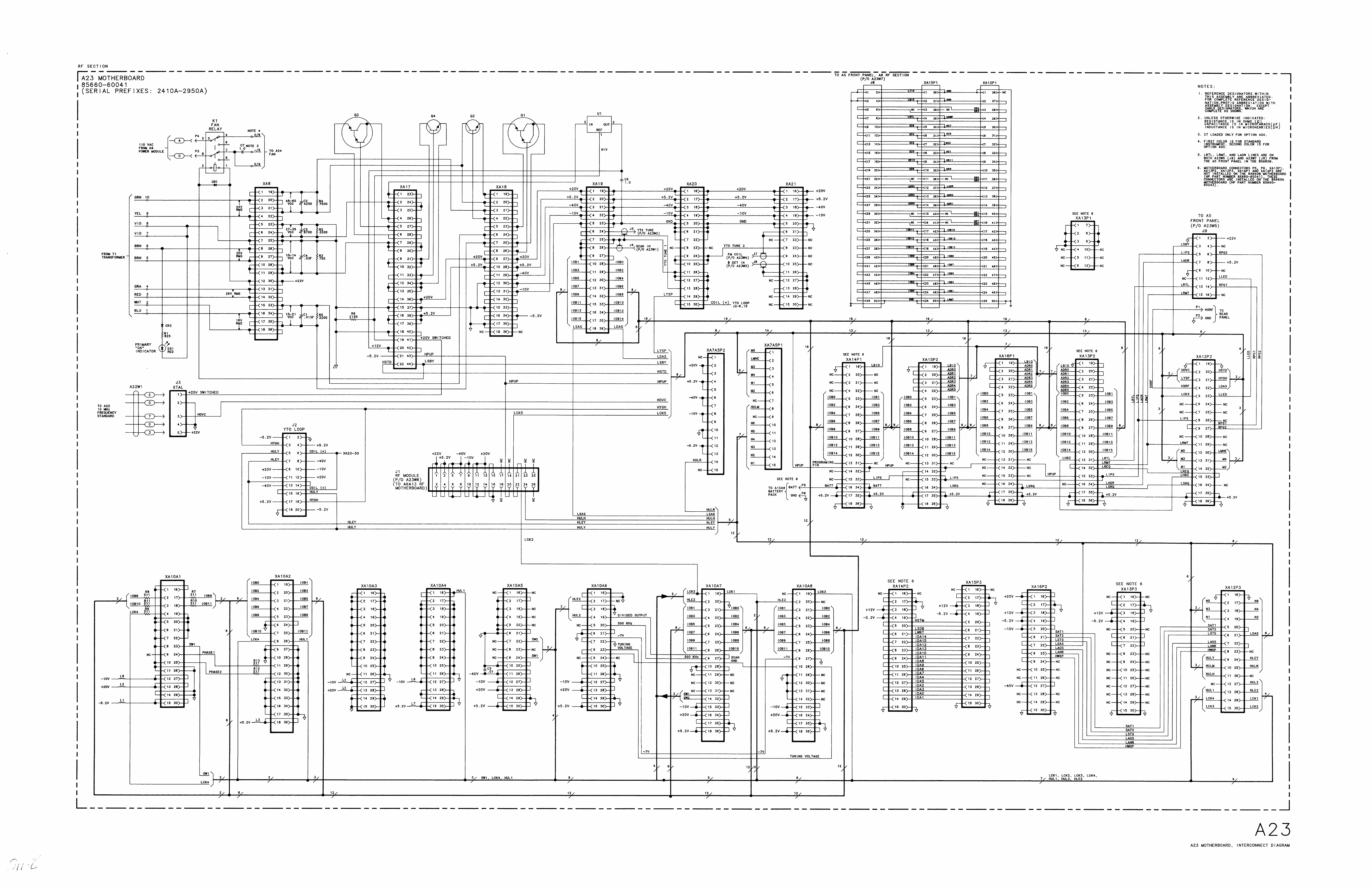
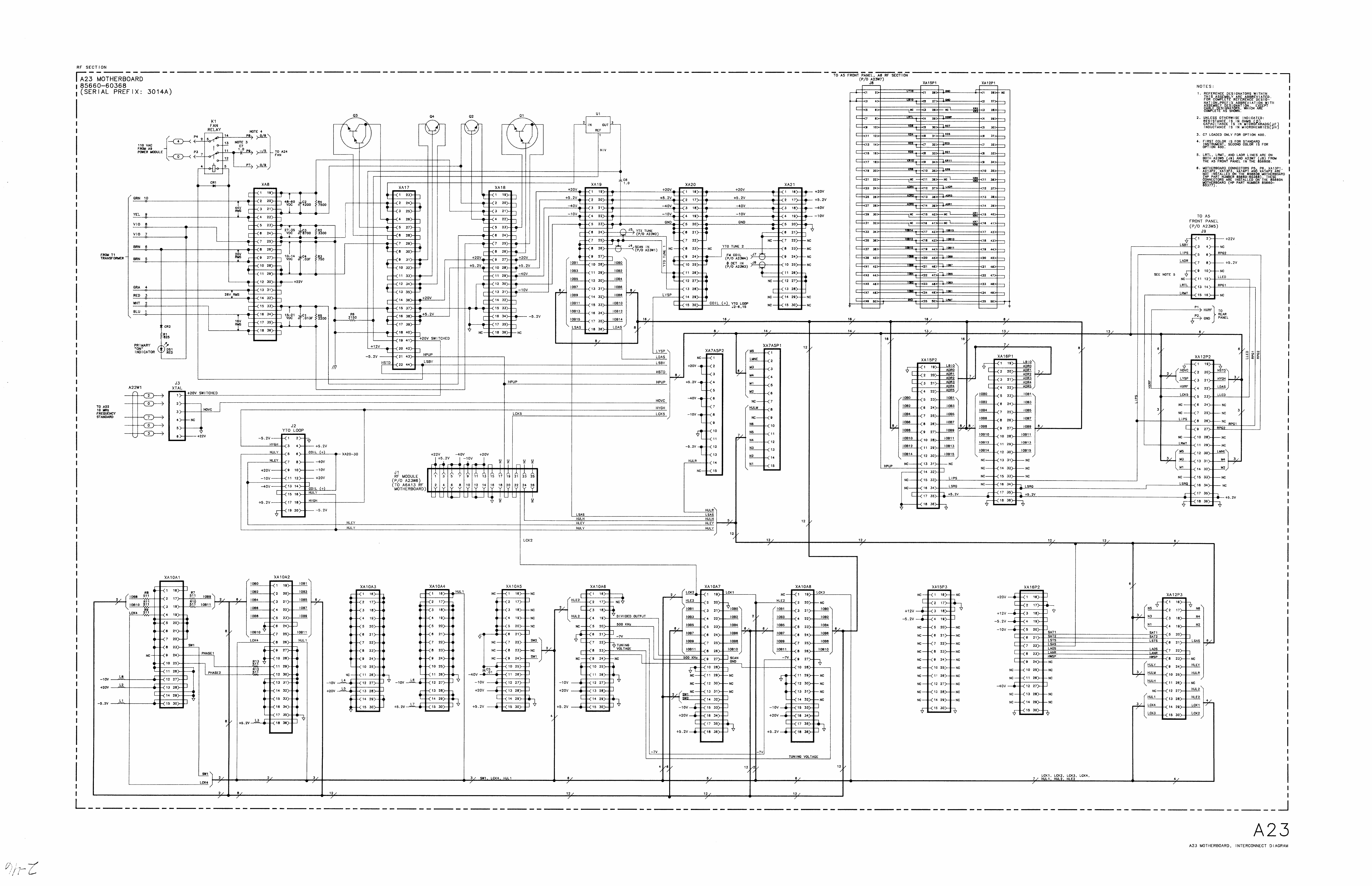
General
Parts
Listing
Introduction
This chapter contains information on ordering replacement parts and assemblies. The parts
lists document all assembly versions up to the time that the manual is printed.
Table 1 lists reference designations, abbreviations, and value multipliers used in the parts lists.
Table 2 lists the names and addresses that correspond to the manufacturer code numbers in
the parts lists.
Table 3 lists the various types of AC power cables that are available, their description, and
part numbers.
Table 4 lists all major assemblies, part numbers, and descriptions of the assemblies.
Table 5 lists cables, part numbers, and descriptions of the cables .
Table 6 lists miscellaneous parts, part numbers, and descriptions of the parts.
Figures 1 through 9 illustrate the locations of instrument assemblies and hardware with the
part numbers listed.
General
Parts
List
Format
The following information is listed for each part:
1. The Hewlett-Packard part number.
2. The part number check digit (CD).
3. The total quantity (Qty) in the assembly. (This number is stated once and only at the first
mention of the part.)
4. The description of the part.
5. A five-digit code indicating a typical manufacturer of the part.
6. The manufacturer part number.
Ordering
Information
To order a part listed in the general parts table, quote the HP part number, include the check
digit, and indicate the quantity required. Address and mail the order to the Hewlett-Packard
Sales and Service Office nearest you. The check digit ensures accurate and timely processing
of your order.
To order a part that is not listed in the general parts table, include the function and
description of the part, and the number of parts required. Address and mail the order to the
Hewlett-Packard Sales and Service Office nearest you.
General Parts Listing 1

Direct Mail-Order
System
Within the USA, Hewlett-Packard can supply parts through a direct mail-order system.
Advantages of using the system are as follows:
1. Direct ordering and shipment from the Hewlett-Packard Parts Center in Mountain View,
California.
2. No maximum or minimum quantity requirement on any mail order. (There is a
minimum-order quantity imposed on orders made through the Hewlett-Packard Sales and
Service Offices when the orders require billing and invoicing.)
3. Prepaid transportation. (There is a handling charge added to each order.)
4. No invoices.
A check or money order must accompany direct-mail orders. Mail-order forms and specific
ordering information are available from Hewlett-Packard Sales and Service Offices.
Direct
Phone-Order
System
A phone-order system is available within the USA for regular and hotline replacement parts
service. Hewlett-Packard has provided a toll-free phone number, and accepts Mastercard or
Visa for orders.
Regular Orders
The toll-free phone number is (800) 227-8164. It is available 6 am to 5 pm (Pacific time),
Monday through Friday. Regular orders require a four-day delivery time.
Hotline Orders
The hotline service for ordering emergency parts is available 24 hours a day, 365 days a
year. There is an additional charge on hotline orders to cover the cost of freight and special
handling.
The toll-free hotline phone number is (800) 227-8164, available 6 am to 5 pm (Pacific time),
Monday through Friday. The phone number for after-hours, weekends, and holidays is (415)
968-2347. Hotline orders are normally delivered the following business day.
2 General Parts Listing
Table 1. Reference Designations, Abbreviations, and Multipliers (1 of 4)
REFERENCE DESIGNATIONS
A
Assembly FFuse RT Thermistor
AT Attenuator, Isolator, FL Filter
S
Switch
Limiter, Termination HY Circulator TTransformer
B
Fan, Motor JElectrical Connector TB Terminal Board
BT Battery (Stationary Portion), TC Thermocouple
CCapacitor Jack TP Test Point
CP
Coupler KRelay
U
Integrated Circuit,
CR Diode, Diode
L
Coil, Inductor Microcircuit
Thyristor, Step
M
Meter
V
Electron Tube
Recovery Diode, MP Miscellaneous VR Breakdown Diode
Varactor Mechanical Part (Zener),
DC Directional Coupler PElectrical Connector Voltage Regulator
DL Delay Line (Movable Portion), W Cable, Wire, Jumper
DS
Annunciator, Lamp, Plug
X
Socket
Light Emitting
Q
Silicon Controlled YCrystal Unit
Diode (LED), Rectifier (SCR), (Piezoelectric,
Signaling Device Transistor, Quartz)
(Visible) Triode Thyristor Z Tuned Cavity,
E
Miscellaneous Electrical Part R Resistor Tuned Circuit
ABBREVIATIONS
ABSC Basic CNDCT Conducting,
BTN Button Conductive,
A
Across Flats, Acrylic, Conductivity,
Air (Dry Method),
C
Conductor
Ampere CONT Contact,
4DJ Adjust, Adjustment
C
Capacitance, Continuous,
4NSI American National Capacitor, Control,
Standards Institute Center Tapped, Controller
(formerly Cermet, Cold, CONV Converter
USASI-ASA) Compression CPRSN Co mpression
4SSY Assembly
CCP
Carbon Composition CUP-PT Cup Point
4WG American Wire Gage Plastic cw Clockwise,
CD Cadmium, Card, Continuous Wave
B
Cord
CER Ceramic
BCD Binary Coded CHAM Chamfer
Decimal CIIAR Character,
D
BD
Board, Bundle Characteristic,
BE-CU Beryllium Copper Charcoal
D
Deep, Depletion,
BNC
Type of Connector CMOS Complementary Depth, Diameter,
BRG Bearing, Boring Metal Oxide Direct Current
BRS
Brass Semiconductor
DA
Da.rlington
General Parts Listing 3
Table 1. Reference Designations, Abbreviations, and Multipliers (2 of 4)
DAP-GL Diallyl Phthalate
Glass
DBL Double
DCDR Decoder
DEG Degree
D-HOLE D-Shaped Hole
DIA Diameter
DIP Dual In-Line
Package
DIP-SLDR Dip Solder
D-MODE Depletion Mode
DO
DP
DPST
DPDT
DWL
E-R
EXT
F
FC
FDTHRU
FEM
FIL-HD
FL
Package Type
Designation
Deep, Depth, Dia-
metric Pitch, Dip
Double Pole Three
Throw
Double Pole Double
Throw
Dowel1
E
E-Ring
Extended, Extension:
External, Extinguish
F
Fahrenheit, Farad,
Female, Film
(Resistor), Fixed,
Flange, Frequency
Carbon Film/
Composition, Edge
of Cutoff Frequency,
Face
Feedthrough
Female
Fillister Head
Flash, Flat, Fluid
?LAT-PT
Flat Point
?R
Front
?REQ
Frequency
ABBREVIATIONS
FT Current Gain
Bandwidth Product
(Transition
Frequency), Feet,
Foot
FXD Fixed
G
GEN General, Generator
GND Ground
GP General Purpose,
Group
H
H
Henry, High
HDW Hardware
IIEX
IIexadecimal,
Hexagon,
Hexagonal
HLCL Helical
HP Hewlett-Packard
Company, High
Pass
I
[C
Collector Current,
Integrated Circuit
1D
Identification,
Inside Diameter
1F
Forward Current,
Intermediate
Frequency
[N
Inch
[NCL
Including
[NT
Integral, Intensity,
Internal
J
I-FET Junction Field
Effect Transistor
1
JFET Junction Field
Effect Transistor
K
KKelvin, Key,
Kilo, Potassium
KNRLD Knurled
KVDC Kilovolts
Direct Current
LED
LG
LIN
LK
LKG
LUM
M
MA
MACH
MAX
MC
MET
MHZ
L
Light Emitting
Diode
Length, Long
Linear, Linearity
Link, Lock
Leakage, Locking
Luminous
M
Male, Maximum,
Mega, Mil, Milli,
Mode
Milliampere
Machined
Maximum
Molded Carbon
Composition
Metal, Metallized
Megahertz
MINTR Miniature
MIT Miter
MLD
Mold, Molded
MM
Magnetized Material,
Millimeter
MOM
Momentary
MTG Mounting
MTLC Metallic
MW
Milliwatt
4 General Parts Listing
Table 1. Reference Designations, Abbreviations, and Multipliers (3 of 4)
N
N
Nano, None
N-CHAN N-Channel
NH
NM
NO
NOM
NPN
NS
NUM
NYL
Nanohenry
Nanometer,
Nonmetallic
Normally Open,
Number
Nominal
Negative Positive
Negative (Transistor)
Nanosecond,
Non-Shorting, Nose
Numeric
Nylon (Polyamide)
0
OA Over-All
OD Outside Diameter
OP AMP Operational
Amplifier
OPT Optical, Option,
Optional
P
PA
PAN-HD
PAR
PB
PC
PCB
P-CHAN
PD
PF
PKG
Picoampere, Power
Amplifier
Pan Head
Parallel, Parity
Lead (Metal),
Pushbutton
Printed Circuit
Printed Circuit
Board
P-Channel
Pad, Power
Dissipation
Picofarad, Power
Factor
Package
ABBREVIATIONS
PLSTC Plastic
PNL Panel
PNP Positive Negative
Positive (Transistor
POLYC Polycarbonate
POLYE Polyester
POT
POZI
PREC
PRP
PSTN
PT
PW
3
R
REF
RES
RF
XGD
IND
IR
2VT
;AWR
;EG
;GL
;I
;L
Potentiometer
Pozidriv Recess
Precision
Purple, Purpose
Piston
Part, Point,
Pulse Time
Pulse Width
Q
Figure of Merit
R
Range, Red,
Resistance, Resistor
Right, Ring
Reference
Resistance, Resistor
Radio Frequency
Rigid
Round
Rear
Rivet, Riveted
S
Surface Acoustic
Wave Resonator
Segment
Single
Silicon,
Square Inch
Slide, Slow
;LT Slot. Slotted
SMA Subminiature,
A Type
(Threadec
Connector)
SMB Subminiature,
B Type (Slip-on
Connector)
SMC Submi niature,
C-Type (Threaded
Connector)
SPCG Spacing
SPDT Single Pole
Double Throw
SPST Single Pole
Single Throw
SQ
Square
SST Stainless Steel
STL Steel
SUBMIN Subminiature
sz
T
TA
TC
THD
THK
TO
TPG
I’R-HD
I’RMR
TRN
Size
T
Teeth,
Temperatu re,
Thickness, Time,
Timed, Tooth,
Typical
Ambient
Temperature,
Tantalum
Temperature
Coeffi
cient
Thread, Threaded
Thick
Package Type
Designation
Tapping
Truss Head
Trimmer
Turn, Turns
I’RSN Torsion
General Parts Listing 5

Table 1. Reference Designations, Abbreviations, and Multipliers (4 of 4)
U
UCD Microcandela
UF Microfarad
UH
Microhenry
UL Microliter,
Underwriters’
Laboratories, Inc.
UNHDND Unhardened
V
V
VAC
Variable, Violet,
Volt, Voltage
Vacuum,
Volts-
Alternating Current
ABBREVIATIONS
VAR Variable
VDC Volts-Direct Current
w
WWatt, Wattage,
White, Wide, Width
W/SW With Switch
ww Wire Wound
X
X
By (Used with
Dimensions),
Reactance
Y
YIG
Yttrium-Iron-
Garnet
Z
ZNR Zener
Abbreviation
Prefix
MULTI
Multble
T
G
M
k
da
d
C
tera
gig
a
mega
kilo
deka
deci
centi
10’2
log
lo6
lo3
lo2
10-r
10-Z
‘LIERS
Abbreviation Prefix Multiple
m
milli
10-s
P
micro
lo+
nnano 10-s
P
pica 10-12
ffemto 10-15
a
atto 10-l”
6 General Parts Listing
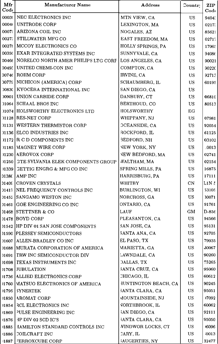
Table 2. Manufacturers Code List
Mfr
Code
0003!
0004t
0007:
0027:
0027t
0035(
0046C
0049:
0074t
3077s
3083C
30901
11064
11074
11128
11131
11136
11172
11185
)1230
11250
11339
0138C
3140s
31415
11452
11461
31468
11478
11542
11590
11607
11688
11691
11698
11708
11736
)1760
)1795
11850
U854
11869
11876
11885
11886
11887
Manufacturer Name Address
Countr:
V
NEC
ELECTRONICS
INC
MTN
VIEW,
CA
us
UNITRODE
CORP LEXINGTON,
MA
us
ARIZONA
COIL
INC
NOGALES,
AZ
us
STILLWATER
MFG
CO
EAST
FREEDOM,
MA
us
MCCOY
ELECTRONICS
CO HOLLY
SPRINGS,
PA
us
EXAR
INTEGRATED
SYSTEMS
INC
SUNNYVALE,
CA
us
NORELCO
NORTH
AMER
PHILIPS
LTG
CORF LOS
ANGELES,
CA
us
UNITED
CHEMI-CON
INC
COMPTON,
CA
us
ROHM
CORP
IRVINE,
CA
us
NICHICON
(AMERICA)
CORP SCHAUMBERG,
IL
us
KYOCERA
INTERNATIONAL
INC SAN
DIEGO,
CA
us
UNION
CARBIDE
CORP DANBURY,
CT
us
SCHAAL
BROS
INC
BERTHOUD,
CO
us
HOLSWORTHY
ELECTRONICS
LTD
HOLSWORTHY
EG
RES-NET
CORP WHIPPANY,
NJ
us
WESTERN
THERMISTOR
CORP 3CEANSIDE,
CA
us
ELCO
INDUSTRIES
INC
ROCKFORD,
IL
us
R
C
D
COMPONENTS
INC
3EDFORD,
NH
us
MAGNET
WIRE
CORP
VEW
YORK, NY us
AEROVOX
CORP
\TEW
BEDFORD,
MA
us
GTE
SYLVANIA
ELEK
COMPONENTS
GROUP
UlrALTHAM,
MA
us
3ETTIG
ENGRG
&
MFG
CO
INC
jPRING
MILLS,
PA
us
AMP
INC
HARRISBURG,
PA
us
CROVEN
CRYSTALS WHITBY
CN
NEL
FREQUENCY
CONTROLS
INC
BURLINGTON,
WI us
SANGAMO
WESTON
INC
NORCROSS,
GA
us
GOE
ENGINEERING
CO
INC
ONTARIO,
CA
us
STETTNER
&
CO LAUF
GM
BOYD
CORP PLEASANTON,
CA
us
HP
DIV
01
SAN
JOSE
COMPONENTS
SAN
JOSE,
CA
us
PLESSEY
SEMICONDUCTORS
SANTA
ANA,
CA
us
ALLEN-BRADLEY
CO
INC
EL
PASO,
TX
us
MURATA
CORPORATION
OF
AMERICA MARIETTA,
GA
us
TRW
INC
SEMICONDUCTOR
DIV LAWNDALE,
CA
us
TEXAS
INSTRUMENTS
INC
3ALLAS,
TX
us
JUBULATION SANTA
CRUZ,
CA
us
ALLIED
ELECTRONICS
CORP
?HICAGO,
IL
us
MATSUO
ELECTRONICS
OF
AMERICA RJNTINGTON
BEACH,
CA
us
SYNERTEK SANTA
CLARA,
CA
us
4ROMAT
CORP tiOUNTAINSIDE,
NJ
us
ICL
ELECTRONICS
INC
JORTHBROOK,
IL
us
‘ULSE
ENGINEERING
INC
;AN
DIEGO,
CA
us
IP
DIV
02
SCD
IC’S
SANTA
CLARA,
CA
us
3AMILTON
STANDARD
CONTROLS
INC
NINDWOR
LOCKS,
CT
us
=OILCRAFT
INC
:ARY,
IL
us
“ERROXCUBE
CORP
SAUGERTIES,
NY
us
ZIP
Code
9404:
0217:
85621
0271;
1706:
94086
90021
9022c
92712
50195
16810
30513
1
I
I
(
c
f
(
I
C
c
1
1
,
!
1
!
s
!
7
I
I
i
E
c
E
s
C
E
s
s
C
6
1
17981
32054
$1125
13102
.0013
)2741
)2154
-6875
17111
,lN
:
53105
30071
31761
l-858
34566
35131
32705
79935
30067
)0260
‘5265
$5060
iO612
bO245
b5051
)7092
LOO62
12111
15050
16096
ioo13
2477
General Parts Listing 7
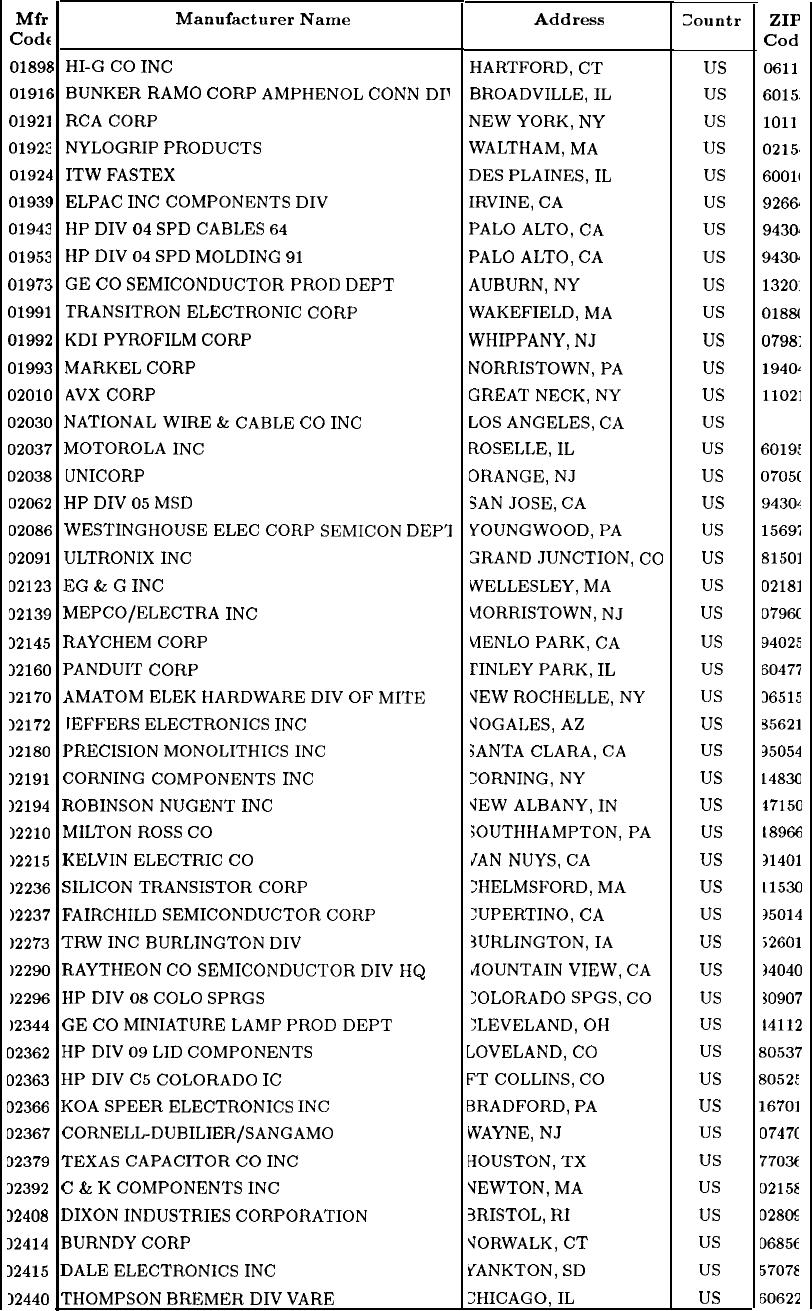
Mfr
Code
0189E
0191e
01921
0192:
01924
0193S
01943
01953
01973
01991
01992
01993
02010
02030
02037
02038
02062
02086
02091
02123
32139
32145
32160
12170
12172
12180
12191
12194
12210
12215
12236
12237
12273
12290
12296
12344
J2362
02363
02366
02367
02379
32392
32408
12414
12415
12440
NATIONAL
WIRE
&
CABLE
CO
INC
MOTOROLA
INC
UNICORP
HP
DIV
05
MSD
5
i
I
1
I
I
1
1
1
1
1
7
1
I
I
I
I
1
I
(
I
D
E
:
E
Tl
F
F
c
F
1
I
(
I
(
I
I
I
r
HI-G
CO
INC
BUNKER
RAM0
CORP
AMPHENOL
CONN
DI’
RCA
CORP
NYLOGRIP
PRODUCTS
ITW
FASTEX
ELPAC
INC
COMPONENTS
DIV
HP
DIV
04
SPD
CABLES
64
HP
DIV
04
SPD
MOLDING
91
GE
CO
SEMICONDUCTOR
PROD
DEPT
TRANSITRON
ELECTRONIC
CORP
KDI
PYROFILM
CORP
MARKEL
CORP
AVX
CORP
WESTINGHOUSE
ELEC
CORP
SEMICON
DEP’I
ULTRONIX
INC
3G
&
G
INC
MEPCO/ELECTRA
INC
iAYCHEM
CORP
‘ANDUIT
CORP
\MATOM
ELEK
HARDWARE
DIV
OF
MITE
IEFFERS
ELECTRONICS
INC
‘RECISION
MONOLITHICS
INC
:ORNING
COMPONENTS
INC
tOBINSON
NUGENT
INC
dILTON
ROSS
CO
<ELVIN
ELECTRIC
CO
iILICON
TRANSISTOR
CORP
;‘AIRCHILD
SEMICONDUCTOR
CORP
TRW
INC
BURLINGTON
DIV
lAYTHEON
CO
SEMICONDUCTOR
DIV
HQ
IP
DIV
08
COLO
SPRGS
:E
CO
MINIATURE
LAMP
PROD
DEPT
LIP
DIV
09
LID
COMPONENTS
HP
DIV
C5
COLORADO
IC
KOA
SPEER
ELECTRONICS
INC
ZORNELL-DUBILIER/SANGAMO
rEXAS
CAPACITOR
CO
INC
?
&
K
COMPONENTS
INC
1IXON
INDUSTRIES
CORPORATION
3URNDY
CORP
1ALE
ELECTRONICS
INC
THOMPSON
BREMER
DIV
VARE
Table 2. Manufacturers Code List (continued)
Manufacturer Name Address Zountr
HARTFORD,
CT
us
BROADVILLE,
IL
us
NEW YORK, NY
us
WALTHAM,
MA
us
DES
PLAINES,
IL
us
IRVINE,
CA
us
PALO
ALTO,
CA
us
PALO
ALTO,
CA
us
AUBURN,
NY
us
WAKEFIELD,
MA
us
WHIPPANY,
NJ
us
NORRISTOWN,
PA
us
GREAT
NECK,
NY
us
LOS
ANGELES,
CA
us
ROSELLE,
IL
us
ORANGE,
NJ
us
SAN
JOSE,
CA
us
YOUNGWOOD,
PA
us
GRAND
JUNCTION,
CO
us
WELLESLEY,
MA
us
\?ORRISTOWN,
NJ
us
MENLO
PARK,
CA
us
TINLEY
PARK,
IL
us
VEW
ROCHELLE,
NY us
VOGALES,
AZ
us
SANTA
CLARA,
CA
us
:ORNING, NY
us
\IEW
ALBANY,
IN
us
:OUTHHAMPTON,
PA
us
JAN
NUYS,
CA
us
:HELMSFORD,
MA
us
:UPERTINO,
CA
us
SURLINGTON,
IA
us
dOUNTAIN
VIEW,
CA
us
:OLORADO
SPGS,
CO
us
:LEVELAND,
OH
us
UOVELAND,
CO
us
FT
COLLINS,
CO
us
BRADFORD,
PA
us
WAYNE,
NJ
us
kIOUSTON,
TX
us
VEWTON,
MA
us
3RISTOL,
RI
us
VORWALK,
CT
us
YANKTON,
SD
us
ZHICAGO,
IL
us
ZIP
Cod
0611
6015.
1011
0215.
60011
92662
9430‘
9430.
1320:
0188(
0798:
194oz
11021
90031
60191
0705(
94301
15695
81501
02181
0796c
94025
6047i
36515
95621
35054
14830
17150
18966
a1401
11530
a5014
52601
34040
30907
14112
d0537
8052:
16701
0747C
770X
02158
028%
06856
57078
60622
8 General Parts Listing
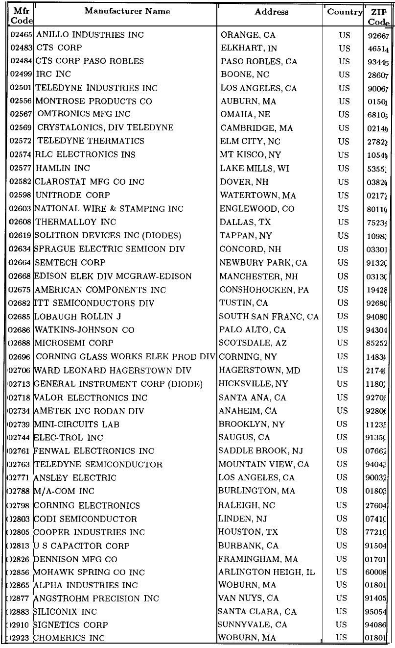
Table 2. Manufacturers Code List (continued)
Mfr Manufacturer Name Address Couutry
ZIP
Code Cod
02465
ANILLO
INDUSTRIES
INC
ORANGE,
CA
us
9266
02483
CTS
CORP ELKHART,
IN
us
4651
02484
CTS
CORP
PASO
ROBLES PASO
ROBLES,
CA
us
93441
02499
IRC
INC
BOONE,
NC
us
2860
02501
TELEDYNE
INDUSTRIES
INC LOS
ANGELES,
CA
us
9006’
02556
MONTROSE
PRODUCTS
CO
AUBURN,
MA
us
0150
02567
OMTRONICS
MFG
INC
OMAHA,
NE
us
6810!
02569
CRYSTALONICS,
DIV
TELEDYNE CAMBRIDGE,
MA
us
0214(
02572
TELEDYNE
THERMATICS
ELM
CITY,
NC
us
2782:
02574
RLC
ELECTRONICS
INS
MT
KISCO,
NY us
1054:
02577
HAMLIN
INC
LAKE
MILLS,
WI
us
53551
02582
CLAROSTAT
MFG
CO
INC
DOVER,
NH
us
0382(
02598
UNITRODE
CORP WATERTOWN,
MA
us
0217:
02603
NATIONAL
WIRE
&
STAMPING
INC
ENGLEWOOD,
CO
us
8011(
02608
THERMALLOY
INC
DALLAS,
TX us
75234
02619
SOLITRON
DEVICES
INC
(DIODES) TAPPAN,
NY
us
1098;:
32634
SPRAGUE
ELECTRIC
SEMICON
DIV CONCORD,
NH
us
03301
32664
SEMTECH
CORP NEWBURY
PARK,
CA
us
9132c
32668
EDISON
ELEK
DIV
MCGRAW-EDISON MANCHESTER,
NH
us
031x
12675
AMERICAN
COMPONENTS
INC
CONSHOHOCKEN,
PA
us
19425
12682
ITT
SEMICONDUCTORS
DIV TUSTIN,
CA
us
9268C
12685
LOBAUGH
ROLLIN
J
SOUTH
SAN
FRANC,
CA
US
94080
12686
WATKINS-JOHNSON
CO PALO
ALTO,
CA
us
94304
12688
MICROSEMI
CORP SCOTSDALE,
AZ
us
85252
02696
CORNING
GLASS
WORKS
ELEK
PROD
DIV
CORNING,
NY
us
1483
02796
WARD
LEONARD
HAGERSTOWN
DIV HAGERSTOWN,
MD
us
2174(
02713
GENERAL
INSTRUMENT
CORP
(DIODE)
HICKSVILLE,
NY
us
1180:
02718
VALOR
ELECTRONICS
INC
SANTA
ANA,
CA
us
9270:
02734
AMETEK
INC
RODAN
DIV
ANAHEIM,
CA
us
92806
02739
MINI-CIRCUITS
LAB
BROOKLYN,
NY us
1123:
02744
ELEC-TROL
INC
SAUGUS,
CA
us
9135c
02761
FENWAL
ELECTRONICS
INC
SADDLE
BROOK,
NJ
us
07662
32763
TELEDYNE
SEMICONDUCTOR MOUNTAIN
VIEW,
CA
us
94042
32771
ANSLEY
ELECTRIC
LOS
ANGELES,
CA
us
90032
12788
M/A-COM
INC
BURLINGTON,
MA
us
01803
12798
CORNING
ELECTRONICS RALEIGH,
NC
us
27604
12803
COD1
SEMICONDUCTOR LINDEN,
NJ
us
07410
12805
COOPER
INDUSTRIES
INC
HOUSTON,
TX
us
77210
12813
U
S
CAPACITOR
CORP BURBANK,
CA
us
91504
12826
DENNISON
MFG
CO
FRAMINGHAM,
MA
us
01701
12856
MOHAWK
SPRING
CO
INC
ARLINGTON
HEIGH,
IL
us
60008
12865
ALPHA
INDUSTRIES
INC
WOBURN,
MA
us
01801
12877
ANGSTROHM
PRECISION
INC VAN
NUYS,
CA
us
91405
12883
SILICONIX
INC
SANTA
CLARA,
CA
us
95054
12910
SIGNETICS
CORP SUNNYVALE,
CA
us
94086
12923
CHOMERICS
INC
WOBURN,
MA
, us
01801
General Parts Listing
9
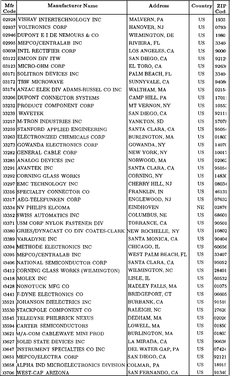
Table 2. Manufacturers Code List (continued)
Mfr Manufacturer Name Address Country ZIP
Code
Code
02928
VISHAY
INTERTECHNOLOGY
INC
MALVERN,
PA
us
1935
02937
VOLTRONICS
CORP HANOVER,
NJ
us
07931
02946
DUPONT
E
I
DE
NEMOURS
&
CO
WILMINGTON,
DE
us
1986
02995
MEPCO/CENTRALAB
INC
RIVIERA,
FL
us
3340.
03038
INTL
RECTIFIER
CORP
LOS
ANGELES,
CA
us
9006!
03122
EMCON
DIV
ITW
SAN
DIEGO,
CA
us
9212!
03123
MICRO-OHM
CORP
EL
TORO,
CA
us
92631
03171
SOLITRON
DEVICES
INC PALM
BEACH,
FL
us
334oi
03172
TRW
MICROWAVE SUNNYVALE,
CA
us
9408t
03174
ANZAC
ELEK
DIV
ADAMS-RUSSEL
CO
INC
WALTHAM,
MA
us
0215~
03206
DUPONT
CONNECTOR
SYSTEMS CAMP
HILL,
PA
us
17011
03232
PRODUCT
COMPONENT
CORP MT
VERNON,
NY
us
1055:
03239
WAVETEK
SAN
DIEGO,
CA
us
92111
03257
M-TRON
INDUSTRIES
INC
YANKTON,
SD
us
5707i
33259
STANFORD
APPLIED
ENGINEERING SANTA
CLARA,
CA
us
95054
33263
ELECTRONIZED
CHEMICALS
CORP BURLINGTON,
MA
us
0180:
33273
GOWANDA
ELECTRONICS
CORP
GOWANDA,
NY
us
1407c
13282
GENERAL
CABLE
CORP
NEW YORK, NY
us
1OOli
13285
ANALOG
DEVICES
INC
NORWOOD,
MA
us
02062
13291
AVANTEK
INC
SANTA
CLARA,
CA
us
95054
13292
CORNING
GLASS
WORKS CORNING,
NY
us
1483c
13297
EMC
TECHNOLOGY
INC
CHERRY
HILL,
NJ
us
08034
13316
SPECIALTY
CONNECTOR
CO
FRANKLIN,
IN
us
46131
13317
AEG-TELEFUNKEN
CORP ENGLEWOOD,
NJ
us
07632
13334
NV
PHILIPS
ELCOMA EINDHOVEN
NE 02876
13352
SWISS
AUTOMATICS
INC
COLUMBUS,
NE
us
68661
13371
USM
CORP
NYLOK
FASTENER
DIV TORRANCE,
CA
us
90501
13380
GRIESIDYNACAST
CO
DIV
COATES-CLARK
NEW
ROCHELLE,
NY us
10802
)3389
VARADYNE
INC
SANTA
MONICA,
CA
us
90404
13394
METHODE
ELECTRONICS
INC
CHICAGO,
IL
us
60656
13395
MEPCO/CENTRALAB
INC
WEST
PALM
BEACH,
FL
US
33407
)3406
NATIONAL
SEMICONDUCTOR
CORP SANTA
CLARA,
CA
us
95052
13412
CORNING
GLASS
WORKS
(WILMINGTON) WILMINGTON,
NC
us
28401
13418
MOLEX
INC LISLE,
IL
us
60532
13428
NONOTUCK
MFG
CO
HADLEY
FALLS,
MA
us
01075
13441
F-DYNE
ELECTRONICS
CO
BRIDGEPORT,
CT
us
06605
33521
JOHANSON
DIELECTRICS
INC
BURBANK,
CA
us
9151(
33530
STACKPOLE
COMPONENT
CO
RALEIGH,
NC
us
2762C
13545
TELEDYNE
PHILBRICK
NEXUS DEDHAM,
MA
us
0202t
13594
CARTER
SEMICONDUCTORS LOWELL,
MA
us
0185C
13621
M/A-COM
CABLEWAVE
MINI
PROD BURLINGTON,
MA
us
0180:
13627
SOLID
STATE
DEVICES
INC LA
MIRADA,
CA
us
9063E
13647
INSTRUMENT
SPECIALTIES
CO
INC DEL
WATER
GAP,
PA
us
07424
13651
MEPCO/ELECTRA
CORP
SAN
DIEGO,
CA
us
92121
13658
ALPHA
IND
MICROELECTRONICS
DIVISION
COLMAR,
PA
us
18915
13706
WEST-CAP
ARIZONA SAN
FERNANDO,
CA
us
9134c
10
General Parts Listing
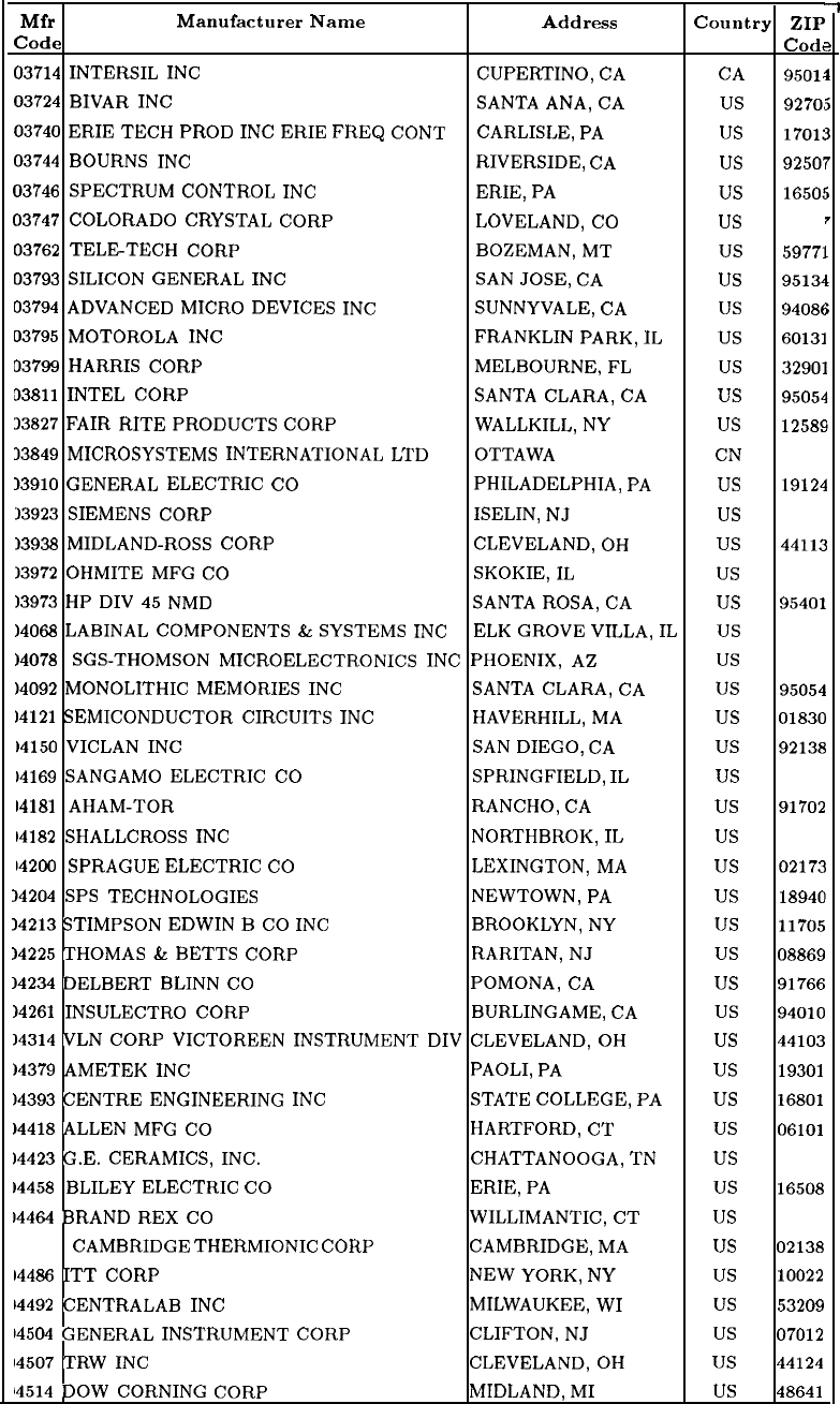
Table 2. Manufacturers Code List (continued)
Mfr Manufacturer Name Address Country ZIP
Code
Code
03714
INTERSIL
INC
CUPERTINO,
CA CA
95Olz
03724
BIVAR
INC
SANTA
ANA,
CA
us
9270!
03740
ERIE
TECH
PROD
INC
ERIE
FREQ
CONT CARLISLE,
PA
us
1701:
03744
BOURNS
INC
RIVERSIDE,
CA
us
9250;
03746
SPECTRUM
CONTROL
INC ERIE,
PA
us
1650:
03747
COLORADO
CRYSTAL
CORP LOVELAND,
CO
us
80535
03762
TELETECH
CORP BOZEMAN,
MT
us
59771
03793
SILICON
GENERAL
INC SAN
JOSE,
CA
us
95134
03794
ADVANCED
MICRO
DEVICES
INC
SUNNYVALE,
CA
us
94086
03795
MOTOROLA
INC
FRANKLIN
PARK,
IL
us
60131
03799
HARRIS
CORP MELBOURNE,
FL
us
32901
93811
INTEL
CORP SANTA
CLARA,
CA
us
95054
33827
FAIR
RITE
PRODUCTS
CORP WALLKILL,
NY
us
12589
33849
MICROSYSTEMS
INTERNATIONAL
LTD
OTTAWA
CN
13910
GENERAL
ELECTRIC
CO
PHILADELPHIA,
PA
us
19124
13923
SIEMENS
CORP
ISELIN,
NJ
us
08830
13938
MIDLAND-ROSS
CORP CLEVELAND,
OH
us
44113
13972
OHMITE
MFG
CO
SKOKIE,
IL
us
60076
13973
HP
DIV
45
NMD SANTA
ROSA,
CA
us
95401
14068
LABINAL
COMPONENTS
&
SYSTEMS
INC ELK
GROVE
VILLA,
IL US
60007
14078
SGS-THOMSON
MICROELECTRONICS
INC
PHOENIX,
AZ
us
85022
)4092
MONOLITHIC
MEMORIES
INC
SANTA
CLARA,
CA
us
95054
14121
SEMICONDUCTOR
CIRCUITS
INC HAVERHILL,
MA
us
01830
)4150
VICLAN
INC
SAN
DIEGO,
CA
us
92138
14169
SANGAMO
ELECTRIC
CO
SPRINGFIELD,
IL
us
62702
I4181
AHAM-TOR
RANCHO,
CA
us
91702
14182
SHALLCROSS
INC
NORTHBROK,
IL
us
60062
14200
SPRAGUE
ELECTRIC
CO
LEXINGTON,
MA
us
02173
14204
SPS
TECHNOLOGIES
NEWTOWN,
PA
us
18940
14213
STIMPSON
EDWIN
B
CO
INC
BROOKLYN,
NY us
11705
14225
THOMAS
&
BETTS
CORP RARITAN,
NJ
us
08869
14234
DELBERT
BLINN
CO
POMONA,
CA
us
91766
14261
INSULECTRO
CORP BURLINGAME,
CA
us
94010
14314
VLN
CORP
VICTOREEN
INSTRUMENT
DIV
CLEVELAND,
OH
us
44103
)4379
AMETEK
INC PAOLI,
PA
us
19301
14393
CENTRE
ENGINEERING
INC STATE
COLLEGE,
PA
us
16801
14418
ALLEN
MFG
CO
HARTFORD,
CT
us
06101
14423
G.E.
CERAMICS,
INC.
CHATTANOOGA,
TN
us
37405
)4458
BLILEY
ELECTRIC
CO ERIE,
PA
us
16508
14464
BRAND
REX
CO
WILLIMANTIC,
CT
us
06226
14475
CAMBRIDGE THERMIONIC CORP CAMBRIDGE,
MA
us
02138
14486
ITT
CORP
NEW YORK, NY us
10022
I4492
CENTRALAB
INC
MILWAUKEE,
WI
us
53209
14504
GENERAL
INSTRUMENT
CORP CLIFTON,
NJ
us
07012
14507
TRW
INC
CLEVELAND,
OH
us
44124
‘4514
DOW
CORNING
CORP MIDLAND,
MI
us
48641
General Parts
Listing
1
a
1
5
3
7
i
,
I
L
i
11
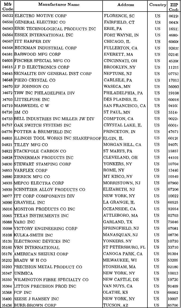
Table 2. Manufacturers Code List (continued)
Mfr Manufacturer Name Address
Code Country ZIP
Code
04522
ELECTRO
MOTIVE
CORP
FLORENCE,
SC
us
06226
04550
GENERAL
ELECTRIC
CO FAIRFIELD,
CT
us
0643(
04563
ERIE
TECHNOLOGICAL
PRODUCTS
INC ERIE,
PA
us
1651:
04564
ESSEX
INTERNATIONAL
INC FORT
WAYNE,
IN
us
46804
04567
ITT
HARPER
DIV CHICAGO,
IL
us
6060(
04568
BECKMAN
INDUSTRIAL
CORP
FULLERTON,
CA
us
9263:
04581
BARWOOD
MFG
CORP EVERETT,
MA
us
0214s
04605
FISCHER
SPECIAL
MFG
CO
CINCINNATI,
OH
us
452OC
04615
J
F
D
ELECTRONICS
CORP
BROOKLYN,
NY us
11219
04645
SIGNALITE
DIV
GENERAL
INST
CORP NEPTUNE,
NJ
us
07753
04648
PIEZO
CRYSTAL
CO CARLSILE,
PA
us
17013
04670
EF
JOHNSON
CO
WASECA,
MN
us
56093
34672
TRW
INC
PHILADELPHIA
DIV
PHILADELPHIA,
PA
us
19108
34703
LITTELFUSE
INC DES
PLAINES,
IL
us
60016
54719
MARWEDEL
C
W
SAN
FRANCISCO,
CA
US
9410:
04726
3M
CO ST
PAUL,
MN
us
5514L
04733
BELL
INDUSTRIES
INC
MILLER
JW
DIV
COMPTON,
CA
us
90224
04757
OAK
SWITCH
SYSTEMS
INC
CRYSTAL
LAKE,
IL
us
60014
04776
POTTER
&
BRUMFIELD
INC
PRINCETON,
IN
us
47671
04805
ILLINOIS
TOOL
WORKS
INC
SHAKEPROOF
ELGIN,
IL
us
60126
04821
TILLEY
MFG
CO
MORGAN
HILL,
CA
us
9407c
04822
STACKPOLE
CARBON
CO ST
MARY&
PA
us
15857
04828
TINNERMAN
PRODUCTS
INC
CLEVELAND,
OH
us
44101
04830
STEWART
STAMPING
CORP YONKERS,
NY
us
10704
04853
VARFLEX
CORP ROME,
NY
us
13440
34880
ZIERICK
MFG
CO
MT
KISCO,
NY
us
10549
34935
MEPCO
ELECTRA
CORP MORRISTOWN,
NJ
us
07960
34939
SCHNITZER
ALLOY
PRODUCTS
CO
ELIZABETH,
NJ
us
07206
14977
ITT
CORP
COMPONENTS
DIV
NEW YORK,
NY
us
10022
14990
GRAYHILL
INC LA
GRANGE,
IL
us
60525
15016
MONITOR
PRODUCTS
CO
INC
OCEANSIDE,
CA
us
92054
15065
TEXAS
INSTRUMENTS
INC
ATTLEBORO,
MA
us
02703
15088
VARO
INC
GARLAND,
TX us
75046
15098
VICTORY
ENGINEERING
CORP SPRINGFIELD,
NJ
us
07081
15108
KULKA-SMITH
INC
MANASQUAN,
NJ
us
08736
15131
ELECTRONIC
DEVICES
INC
YONKERS,
NY
us
10710
35160
VRN
INTERNATIONAL
ST
PETERSBURG,
FL
US
33710
05176
AMERICAN
SHIZUKI
CORP
CANOGA
PARK,
CA
us
91304
05232
BRADY
W
H
CO
MILWAUKEE,
WI us
53209
05293
PRECISION
METAL
PRODUCT
CO
STONEHAM,
MA
us
02180
35347
UNIMICA
NEW YORK,
NY
us
10013
35350
WILMINGTON
FIBRE
SPECIALTY
CO
NEW
CASTLE,
DE
us
19720
35364
LITTON
PRECISION
PROD
INC VAN
NUYS,
CA
us
91409
15368
FCP
INC
OLATHE,
KS
us
66062
15400
REESE
J
RAMSEY
INC
NEW YORK, NY
us
10007
15436
BURR-BROWN
CORP
TUCSON,
AZ
us
85706
12
General Parts Listing
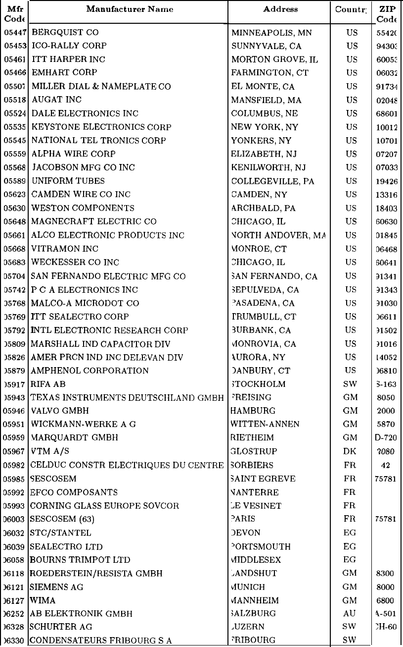
Table 2. Manufacturers Code List (continued)
Mfr
Code
0544;
0545:
05461
05466
055Oi
0551E
05524
05535
05545
05559
05568
05589
05623
05630
05648
05661
05668
05683
05704
05742
35768
35769
35792
15809
15826
15879
15917
15943
05946
05951
05959
05967
05982
05985
05992
05993
06003
36032
36039
36058
36118
16121
36127
16252
16328
16330
,
)
i
I
I
)
1
1
(
1
I
1
1
1
!
I
I
I
I
1
I
I
F
1
1
(
(
1
(
!
:
5
I
I
s
\
1
s
(
BERGQUIST
CO
ICO-RALLY
CORP
ITT
HARPER
INC
EMHART
CORP
MILLER
DIAL
&
NAMEPLATE
CO
AUGAT
INC
DALE
ELECTRONICS
INC
KEYSTONE
ELECTRONICS
CORP
NATIONAL
TEL
TRONICS
CORP
ALPHA
WIRE
CORP
JACOBSON
MFG
CO
INC
UNIFORM
TUBES
CAMDEN
WIRE
CO
INC
WESTON
COMPONENTS
MAGNECRAFT
ELECTRIC
CO
4LC0
ELECTRONIC
PRODUCTS
INC
VITRAMON
INC
WECKESSER
CO
INC
3AN
FERNANDO
ELECTRIC
MFG
CO
’
C
A
ELECTRONICS
INC
tiALCO-A
MICRODOT
CO
TT
SEALECTRO
CORP
NTL
ELECTRONIC
RESEARCH
CORP
vlARSHALL
IND
CAPACITOR
DIV
4MER
PRCN
IND
INC
DELEVAN
DIV
4MPHENOL
CORPORATION
tIFA
AB
CEXAS
INSTRUMENTS
DEUTSCIILAND
GMBH
VALVO
GMBH
WICKMANN-WERKE
A
G
MARQUARDT
GMBH
VTM
A/S
CELDUC
CONSTR
ELECTRIQUES
DU
CENTRE
3ESCOSEM
XFCO
COMPOSANTS
ZORNING
GLASS
EUROPE
SOVCOR
3ESCOSEM
(63)
;TC/STANTEL
3EALECTRO
LTD
30URNS
TRIMPOT
LTD
tOEDERSTEIN/RESISTA
GMBH
;IEMENS
AG
NIMA
iB
ELEKTRONIK
GMBH
;CHURTER
AC
:ONDENSATEURS
FRIBOURG
S
A
Manufacturer Name Address County
MINNEAPOLIS,
MN
SUNNYVALE,
CA
MORTON
GROVE,
IL
FARMINGTON,
CT
EL
MONTE,
CA
MANSFIELD,
MA
COLUMBUS,
NE
NEW
YORK, NY
YONKERS,
NY
ELIZABETH,
NJ
KENILWORTH,
NJ
COLLEGEVILLE,
PA
CAMDEN,
NY
ARCHBALD,
PA
CHICAGO,
IL
VORTH
ANDOVER,
MA
MONROE,
CT
ZHICAGO,
IL
SAN
FERNANDO,
CA
SEPULVEDA,
CA
‘ASADENA,
CA
TRUMBULL,
CT
3URBANK,
CA
VIONROVIA,
CA
4URORA,
NY
IANBURY,
CT
STOCKHOLM
:REISING
HAMBURG
WITTEN-ANNEN
RIETHEIM
GLOSTRUP
3ORBIERS
3AINT
EGREVE
VANTERRE
;E
VESINET
‘ARIS
1EVON
‘ORTSMOUTH
tiIDDLESEX
JANDSHUT
i4UNICH
tiANNHEIM
;ALZBURG
.UZERN
PRIBOURG
us
us
us
us
us
us
us
us
us
us
us
us
us
us
us
us
us
us
us
us
us
us
us
us
us
us
SW
GM
GM
GM
GM
DK
FR
FR
FR
FR
FR
EG
EG
EG
GM
GM
GM
AU
SW
SW
ZIP
Codr
5542C
9430:
6005:
06032
91734
02048
68601
10012
10701
07207
07033
19426
13316
18403
60630
01845
06468
60641
91341
31343
31030
16611
31502
31016
14052
16810
S-163
8050
2000
5870
D-720
42
75781
75781
8300
8000
6800
4-501
:H-60
General Parts Listing 13
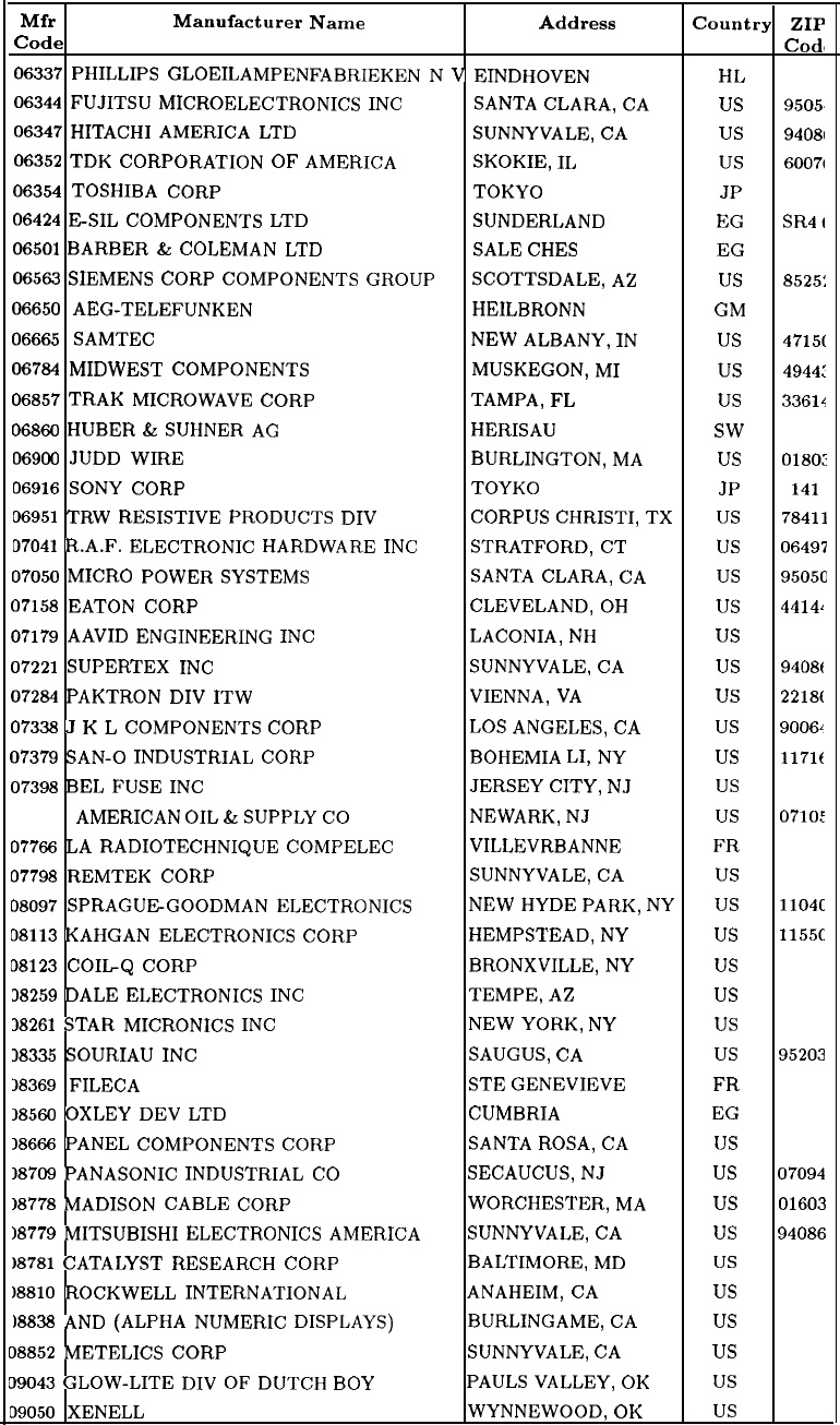
Table 2. Manufacturers Code List (continued)
Mfr Manufacturer Name Address
Code Country ZIP
Cod,
06337
PHILLIPS
GLOEILAMPENFABRIEKEN
N
V
EINDHOVEN
HL
06344
FUJITSU
MICROELECTRONICS
INC
SANTA
CLARA,
CA
us
9505,
06347
HITACHI
AMERICA
LTD
SUNNYVALE,
CA
us
94081
06352
TDK
CORPORATION
OF
AMERICA SKOKIE,
IL
us
6007t
06354
TOSHIBA
CORP
TOKYO
JP
06424
ESIL
COMPONENTS
LTD
SUNDERLAND
EG SR4
I
06501
BARBER
&
COLEMAN
LTD SALE
CHES
EG
06563
SIEMENS
CORP
COMPONENTS
GROUP SCOTTSDALE,
AZ
us
8525:
06650
AEG-TELEFUNKEN
HEILBRONN
GM
7100
06665
SAMTEC
NEW ALBANY,
IN
us
4715(
06784
MIDWEST
COMPONENTS MUSKEGON,
MI
us
4944:
06857
TRAK
MICROWAVE
CORP TAMPA,
FL
us
33614
06866
HUBER
&
SUHNER
AG
HERISAU
SW
06906
JUDD
WIRE BURLINGTON,
MA
us
0180:
06916
SONY
CORP TOYKO
JP 141
06951
TRW
RESISTIVE
PRODUCTS
DIV
CORPUS
CHRISTI,
TX
US 78411
07041
R.A.F.
ELECTRONIC
HARDWARE
INC
STRATFORD,
CT
us
06497
37050
MICRO
POWER
SYSTEMS SANTA
CLARA,
CA
us
9505c
07158
EATON
CORP CLEVELAND,
OH
us
44141
07179
AAVID
ENGINEERING
INC
LACONIA,
NH
us
0324:
07221
SUPERTEX
INC
SUNNYVALE,
CA
us
9408t
07284
PAKTRON
DIV
ITW
VIENNA,
VA
us
2218(
07338
J
K
L
COMPONENTS
CORP LOS
ANGELES,
CA
us
9006L
07379
SAN-O
INDUSTRIAL
CORP BOHEMIA
LI,
NY
us
1171c
07398
BEL
FUSE
INC
JERSEY
CITY,
NJ
us
0730:
07477
AMERICAN
OIL
&
SUPPLY
CO
NEWARK,
NJ
us
0710:
07766
LA
RADIOTECHNIQUE
COMPELEC VILLEVRBANNE FR
07798
REMTEK
CORP SUNNYVALE,
CA
us
08097
SPRAGUEGOODMAN
ELECTRONICS
NEW
HYDE
PARK,
NY
US
1104c
08113
KAHGAN
ELECTRONICS
CORP HEMPSTEAD,
NY us
1155c
08123
COIL-Q
CORP BRONXVILLE,
NY
us
38259
DALE
ELECTRONICS
INC
TEMPE,
AZ
us
85252
38261
STAR
MICRONICS
INC
NEW
YORK,
NY
us
18335
SOURIAU
INC
SAUGUS,
CA
us
95203
18369
FILECA STE
GENEVIEVE FR
18560
OXLEY
DEV
LTD
CUMBRIA
EG
18666
PANEL
COMPONENTS
CORP
SANTA
ROSA,
CA
us
18709
PANASONIC
INDUSTRIAL
CO
SECAUCUS,
NJ
us
07094
18778
MADISON
CABLE
CORP WORCHESTER,
MA
us
01603
18779
MITSUBISHI
ELECTRONICS
AMERICA SUNNYVALE,
CA
us
94086
18781
CATALYST
RESEARCH
CORP BALTIMORE,
MD
us
)8810
ROCKWELL
INTERNATIONAL ANAHEIM,
CA
us
18838
AND
(ALPHA
NUMERIC
DISPLAYS) BURLINGAME,
CA
us
08852
METELICS
CORP SUNNYVALE,
CA
us
09043
GLOW-LITE
DIV
OF
DUTCH
BOY
PAULS
VALLEY,
OK
us
09050
XENELL
WYNNEWOOD,
OK
us
14
General Parts Listing
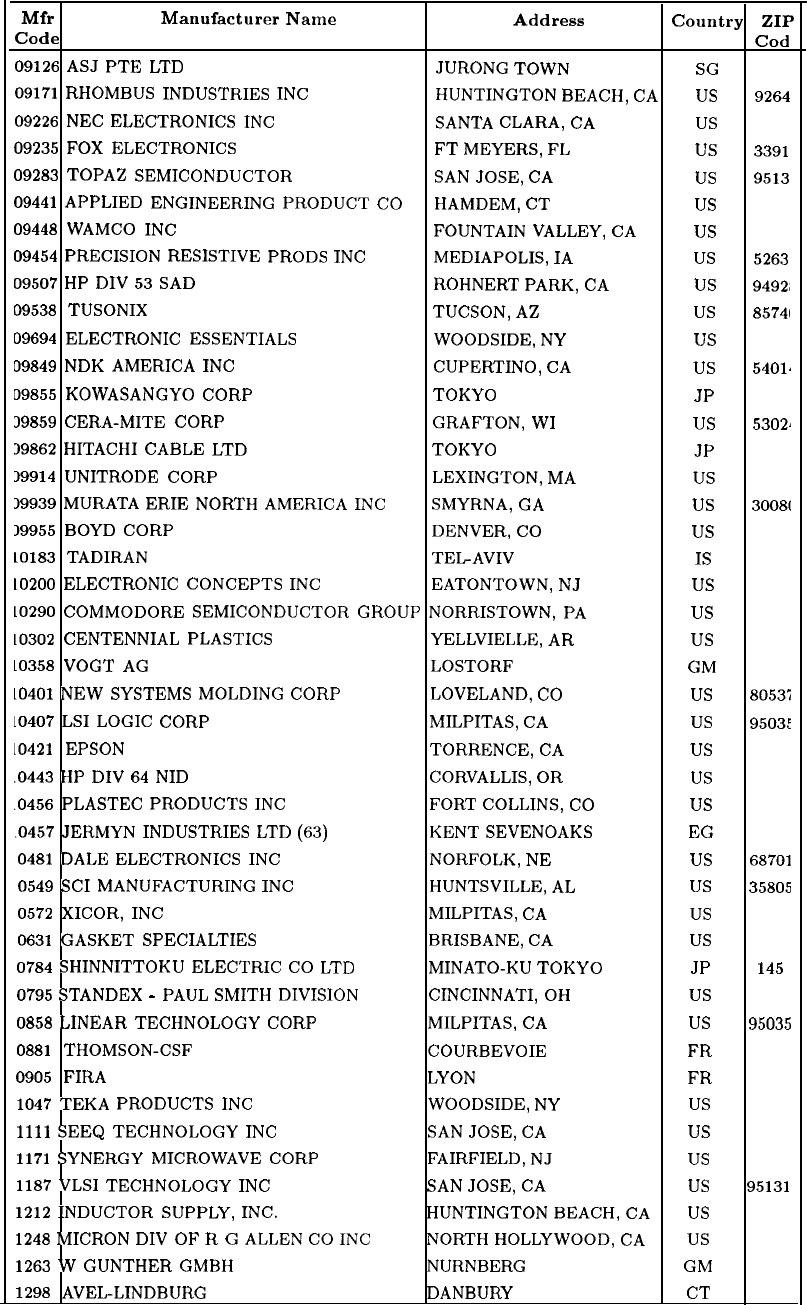
Table 2. Manufacturers Code List (continued)
Mfr Manufacturer Name Address Country ZIP
Code Cod
09126
ASJ
PTE
LTD
JURONG
TOWN
SG
09171
RHOMBUS
INDUSTRIES
INC
HUNTINGTON
BEACH,
CA
US
9264
09226
NEC
ELECTRONICS
INC
SANTA
CLARA,
CA
us
09235
FOX
ELECTRONICS FT
MEYERS,
FL
us
3391
09283
TOPAZ
SEMICONDUCTOR
SAN
JOSE,
CA
us
9513
09441
APPLIED
ENGINEERING
PRODUCT
CO
HAMDEM,
CT
us
09448
WAMCO
INC
FOUNTAIN
VALLEY,
CA
us
09454
PRECISION
RESISTIVE
PRODS
INC
MEDIAPOLIS,
IA
us
5263
09507
HP
DIV
53
SAD
ROHNERT
PARK,
CA
us
9492;
09538
TUSONIX TUCSON,
AZ
us
85741
09694
ELECTRONIC
ESSENTIALS WOODSIDE,
NY
us
09849
NDK
AMERICA
INC
CUPERTINO,
CA
us
54012
09855
KOWASANGYO
CORP
TOKYO
JP
39859
CERA-MITE
CORP GRAFTON,
WI
us
5302.
39862
HITACHI
CABLE
LTD
TOKYO
JP
19914
UNITRODE
CORP LEXINGTON,
MA
us
59939
MURATA
ERIE
NORTH
AMERICA
INC
SMYRNA,
GA
us
3008(
19955
BOYD
CORP DENVER,
CO
us
10183
TADIRAN TEL-AVIV
IS
10200
ELECTRONIC
CONCEPTS
INC
EATONTOWN,
NJ
us
10290
COMMODORE
SEMICONDUCTOR
GROUP
NORRISTOWN,
PA
us
10302
CENTENNIAL
PLASTICS YELLVIELLE,
AR
us
10358
VOGT
AG LOSTORF GM
LO401
NEW
SYSTEMS
MOLDING
CORP LOVELAND,
CO
us
8053:
10407
LSI
LOGIC
CORP MILPITAS,
CA
us
95031
10421
EPSON TORRENCE,
CA
us
.0443
HP
DIV
64
NID CORVALLIS,
OR
us
.0456
PLASTEC
PRODUCTS
INC FORT
COLLINS,
CO
us
.0457
JERMYN
INDUSTRIES
LTD
(63)
KENT
SEVENOAKS
EG
0481
DALE
ELECTRONICS
INC
NORFOLK,
NE
us
68701
0549
SC1
MANUFACTURING
INC
HUNTSVILLE,
AL
us
35805
0572
XICOR,
INC
MILPITAS,
CA
us
0631
GASKET
SPECIALTIES
BRISBANE,
CA
us
0784
SHINNITTOKU
ELECTRIC
CO
LTD
MINATO-KU
TOKYO
JP 145
0795
STANDEX
-
PAUL
SMITH
DIVISION CINCINNATI,
OH
us
0858
LINEAR
TECHNOLOGY
CORP
MILPITAS,
CA
us
95035
0881
THOMSON-CSF COURBEVOIE FR
0905
FIRA
LYON FR
1047
TEKA
PRODUCTS
INC
WOODSIDE,
NY
us
1111
SEEQ
TECHNOLOGY
INC SAN
JOSE,
CA
us
1171
SYNERGY
MICROWAVE
CORP FAIRFIELD,
NJ
us
1187
VLSI
TECHNOLOGY
INC SAN
JOSE,
CA
us
95131
1212
INDUCTOR
SUPPLY,
INC.
HUNTINGTON
BEACH,
CA
US
1248
MICRON
DIV
OF
R
G
ALLEN
CO
INC NORTH
HOLLYWOOD,
CA
US
1263
W
GUNTHER
GMBH NURNBERG GM
1298
AVEL-LINDBURG DANBURY
CT
General Parts Listing
15
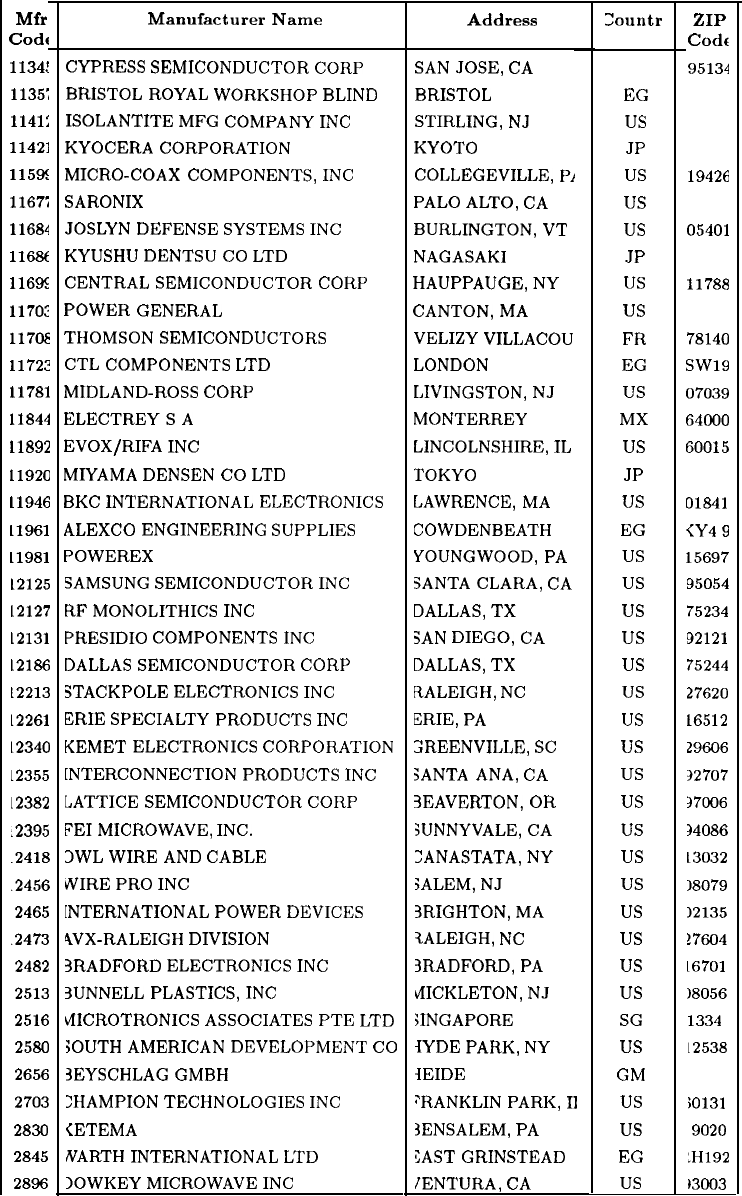
Table 2. Manufacturers Code List (continued)
Mfr
Code
1134:
1135;
1141:
11421
115%
1167;
11684
116%
116X
1170:
117(x
11722
11781
11844
11892
11920
11946
11961
11981
12125
12127
12131
12186
12213
L2261
L2340
L2355
12382
.2395
.2418
.2456
2465
.2473
2482
2513
2516
2580
2656
2703
2830
2845
2896
Manufacturer Name Address zountr
CYPRESS
SEMICONDUCTOR
CORP
BRISTOL
ROYAL
WORKSHOP
BLIND
ISOLANTITE
MFG
COMPANY
INC
KYOCERA
CORPORATION
MICRO-COAX
COMPONENTS,
INC
SARONIX
JOSLYN
DEFENSE
SYSTEMS
INC
KYUSHU
DENTSU
CO
LTD
CENTRAL
SEMICONDUCTOR
CORP
POWER
GENERAL
THOMSON
SEMICONDUCTORS
CTL
COMPONENTS
LTD
MIDLAND-ROSS
CORP
ELECTREYSA
EVOX/RIFA
INC
MIYAMA
DENSEN
CO
LTD
BKC
INTERNATIONAL
ELECTRONICS
ALEXCO
ENGINEERING
SUPPLIES
POWEREX
SAMSUNG
SEMICONDUCTOR
INC
RF
MONOLITHICS
INC
PRESIDIO
COMPONENTS
INC
DALLAS
SEMICONDUCTOR
CORP
3TACKPOLE
ELECTRONICS
INC
ERIE
SPECIALTY
PRODUCTS
INC
KEMET
ELECTRONICS
CORPORATION
[NTERCONNECTION
PRODUCTS
INC
LATTICE
SEMICONDUCTOR
CORP
FE1
MICROWAVE,
INC.
3WL
WIRE
AND
CABLE
WIRE
PRO
INC
[NTERNATIONAL
POWER
DEVICES
4VX-RALEIGH
DIVISION
3RADFORD
ELECTRONICS
INC
3UNNELL
PLASTICS,
INC
bfICROTRONICS
ASSOCIATES
PTE
LTD
SOUTH
AMERICAN
DEVELOPMENT
CO
3EYSCHLAG
GMBH
:HAMPION
TECHNOLOGIES
INC
<ETEMA
NARTH
INTERNATIONAL
LTD
lOWKEY
MICROWAVE
INC
SAN
JOSE,
CA
BRISTOL
STIRLING,
NJ
KYOTO
COLLEGEVILLE,
Pi
PALO
ALTO,
CA
BURLINGTON,
VT
NAGASAKI
HAUPPAUGE,
NY
CANTON,
MA
VELIZY
VILLACOU
LONDON
LIVINGSTON,
NJ
MONTERREY
LINCOLNSHIRE,
IL
TOKYO
LAWRENCE,
MA
COWDENBEATH
YOUNGWOOD,
PA
SANTA
CLARA,
CA
DALLAS,
TX
SAN
DIEGO,
CA
DALLAS,
TX
RALEIGH,
NC
ERIE,
PA
ZREENVILLE,
SC
SANTA
ANA,
CA
3EAVERTON,
OR
SUNNYVALE,
CA
ZANASTATA,
NY
SALEM,
NJ
3RIGHTON,
MA
tALEIGH,
NC
3RADFORD,
PA
fiICKLETON,
NJ
SINGAPORE
lYDE
PARK,
NY
lEIDE
;‘RANKLIN
PARK,
II
3ENSALEM,
PA
CAST
GRINSTEAD
IENTURA,
CA
us
EG
us
JP
us
us
us
JP
us
us
FR
EG
us
MX
us
JP
us
EG
us
us
us
us
us
us
us
us
us
us
us
us
us
us
us
us
us
SG
us
GM
us
us
EG
us
ZIP
Code
95134
19426
05401
11788
78140
SW19
07039
64000
60015
01841
<Y4
9
15697
95054
75234
92121
75244
27620
16512
29606
92707
97006
94086
13032
18079
12135
17604
L6701
18056
1334
12538
$0131
9020
1H192
b3003
16 General Parts Listing
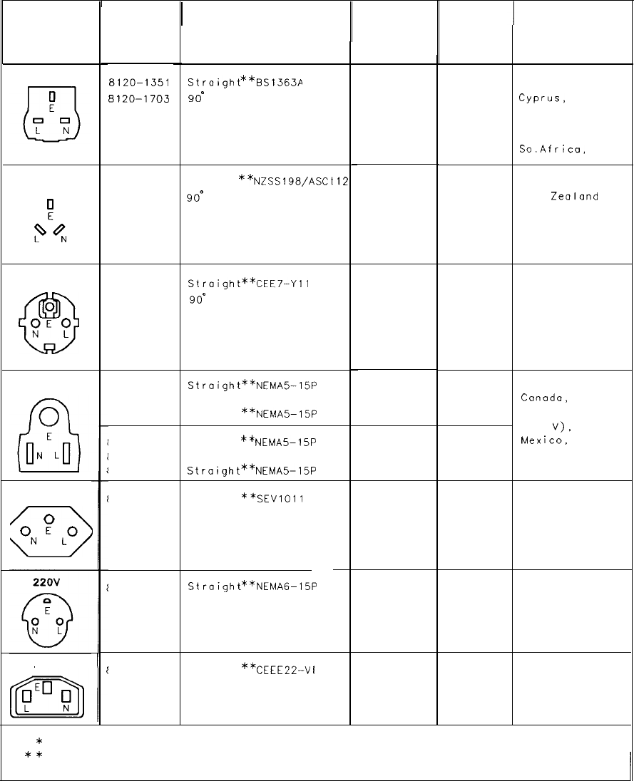
I
I
CABLE
HP PART
NUMBER
I
CABLE
LENGTH
CM (INCHES)
CABLE
COLOR
PLUG
DESCRIPTION
FOR USE
IN COUNTRY
PLUG TYPE *
250V
Stroight**BS1363A
90”
229 (90)
229 (90)
Mint Gray
Mint Gray
Great Britain,
Cyprus,
Nigeria
Rhodesia,
Singapore,
So.Africa,
lndi
8120-1351
8120-1703
250V 8120-1369 Straight
**NZSSl98/ASC’
8120-0696 go0
Gray Australia,
Gray New
Zealand
201 (79)
221 (87)
Ii2
0
0
PE%
8120-1689
Stroight**CEE7-Yll
8120-1692 go0
201 (79) Mint Gray
201 (79) Mint Gray
East and West
Europe, Saudi
Arabia, United
Arab Republic
(unpolarized in
many nations)
250V
0
a
t?‘?
125V
8120-1348
Stroight**NEMA%15P
8120-1398 90’
8120-1754 Straight
**NEMA5-15P
United States
Canada,
Japan (100 V or
200
V),
Mex
ice,
Phillipines,
Taiwan
203 (80) Black
203 (80) Black
91 (36) B I ock
3120-1378 Straight
**NEMA5-15P
3120-1521 90’
3120-1676
Stroight**NEMA5-15P
203 (80) Jade Gray
203 (80) Jade Gray
91 (36) Jade Gray
250v 3120-2104 Straight
**SEVlOll
1959-24507
Type 12
201 (79) Gray Switzerland
c3
ON
p
Lo
3 120-0698
Straight**NEMAG-15P
250V 3120-1860 Straight
**CEEE22-V
I
*
E = Earth Ground; L = Line; N = Neutral
**
Part number for plug is industry identifier for plug only. Number shown for cable is
HP Part Number for complete cable, including plug.
i
Table 3. AC Power Cables Available
General Parts Listing 17
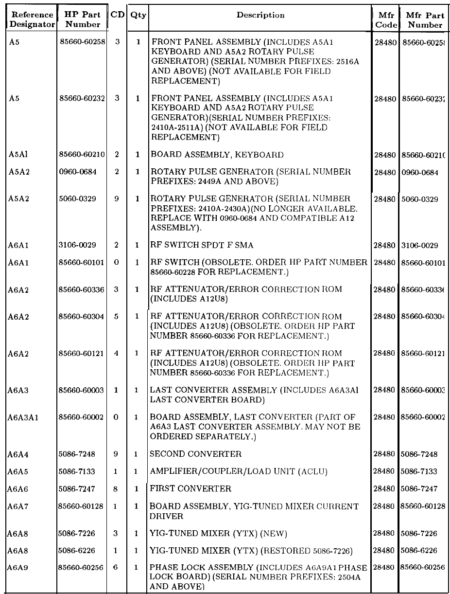
RF Section Assemblies
Reference HP Part
Designator Number
A5
A5
85660-6025885660-60258
CD
Qty
Description
3
A5
A5 85660-6023285660-60232
3
A5Al
A5Al 85660-6021085660-60210
A5A2
A5A2
0960468409604684
A5A2
A5A2 5060-03295060-0329
2
2
9
A6Al
A6Al
3106-00293106-0029
A6Al
A6Al
85660-6010185660-60101
A6A2
A6A2 85660-6033685660-60336
A6A2
A6A2
85660-6030485660-60304
2
0
3
5
A6A2
A6A2
85660-6012185660-60121
4
A6A3A6A3 85660-6000385660-60003
A6A3AlA6A3Al
85660-6000285660-60002
1
0
A6A4A6A4
5086724850867248
A6A5A6A5 5086-71335086-7133
A6A6A6A6 5086-72475086-7247
A6A7A6A7 85660-6012885660-60128
A6A8A6A8 5086-72265086-7226
A6A8A6A8 5086-62265086-6226
A6A9A6A9 85660-6025685660-60256
3
1
6
1
FRONT
PANEL
ASSEMBLY
(INCLUDES
A5Al
KEYBOARD
AND
A5A2
ROTARY
PULSE
GENERATOR)
(SERIAL
NUMBER
PREFIXES:
2516A
AND
ABOVE)
(NOT
AVAILABLE
FOR
FIELD
REPLACEMENT)
1
FRONT
PANEL
ASSEMBLY
(INCLUDES
A5Al
KEYBOARD
AND
A5A2
ROTARY
PULSE
GENERATOR)(SERIAL
NUMBER
PREFIXES:
2410~-25llA)
(NOT
AVAILABLE
FOR
FIELD
REPLACEMENT)
1
BOARD
ASSEMBLY,
KEYBOARD
1
ROTARY
PULSE
GENERATOR
(SERIAL
NUMBER
PREFIXES:
2449A
AND
ABOVE)
1
ROTARY
PULSE
GENERATOR
(SERIAL
NUMBER
PREFIXES:
2410A-2430A)(NO
LONGER
AVAILABLE.
REPLACE
WITH
0960-0684
AND
COMPATIBLE
Al2
ASSEMBLY).
1
RF
SWITCH
SPDT
F
SMA
1
RF
SWITCH
(OBSOLETE.
ORDER
IIP
PART
NUMBER
8566C~60228
FOR
REPLACEMENT.)
1
RF
ATTENUATOR/ERROR
CORRECTION
ROM
(INCLUDES
A12U8)
RF
ATTENUATOR/ERROR
CORRECTION
IiOM
(INCLUDES
A12U8)
(OBSOLETE.
ORDER
IIP
PART
NUMBER
8566960336
FOR
REPLACEMENT.)
RF
ATTENUATOR/ERROR
CORRECTION
ROM
(INCLUDES
A12U8)
(OBSOLETE.
ORDER
III’
PART
NUMBER
8566060336
FOR
REPLACEMENT.)
LAST
CONVERTER
ASSEMBLY
(INCLUDES
A6A3Al
LAST
CONVERTER
BOARD)
BOARD
ASSEMBLY,
LAST
CONVERTER
(PART
OF
A6A3
LAST
CONVERTER
ASSEMBLY.
MAY
NOT
BE
ORDERED
SEPARATELY.)
SECOND
CONVERTER
AMPLIFIER/COUPLER/LOAD
UNIT
(ACLU)
1
FIRST
CONVERTER
1
BOARD
ASSEMBLY,
YIG-TUNED
MIXER
CURRENT
DRIVER
1
YIG-TUNED
MIXER
(YTX)
(NEW)
1
YIG-TUNED
MIXER
(YTX)
(RESTORED
5086-7226)
1
PHASE
LOCK
ASSEMBLY
(INCLUDES
AGAB.
PHASE
LOCK
BOARD)
(SERIAL
NUMBER
PREFIXES:
2504A
AND
ABOVE)
Mfr Mfr Part
Code Number
2848028480
85660-60251
85660-60251
2848028480
85660-6023:
85660-6023:
2848028480
85660~fX121C
85660~fX121C
2848028480
0960-0684
0960-0684
28480
5060-032928480
5060-0329
28480
3106-0029
28480
3106-0029
28480
85660-6010128480
85660-60101
28480
85660~6033t28480
85660~6033t
28480
85660-6030428480
85660-60304
28480
85660-6012128480
85660-60121
28480
85660~6000?28480
85660~6000?
28480
85660-6000228480
85660-60002
28480
5086-724828480
5086-7248
28480
5086-713328480
5086-7133
28480
5086-724728480
5086-7247
28480
85660-6012828480
85660-60128
28480
5086-722628480
5086-7226
28480
5086-622628480
5086-6226
28480
8566060256
28480
8566060256
18 General Parts Listing
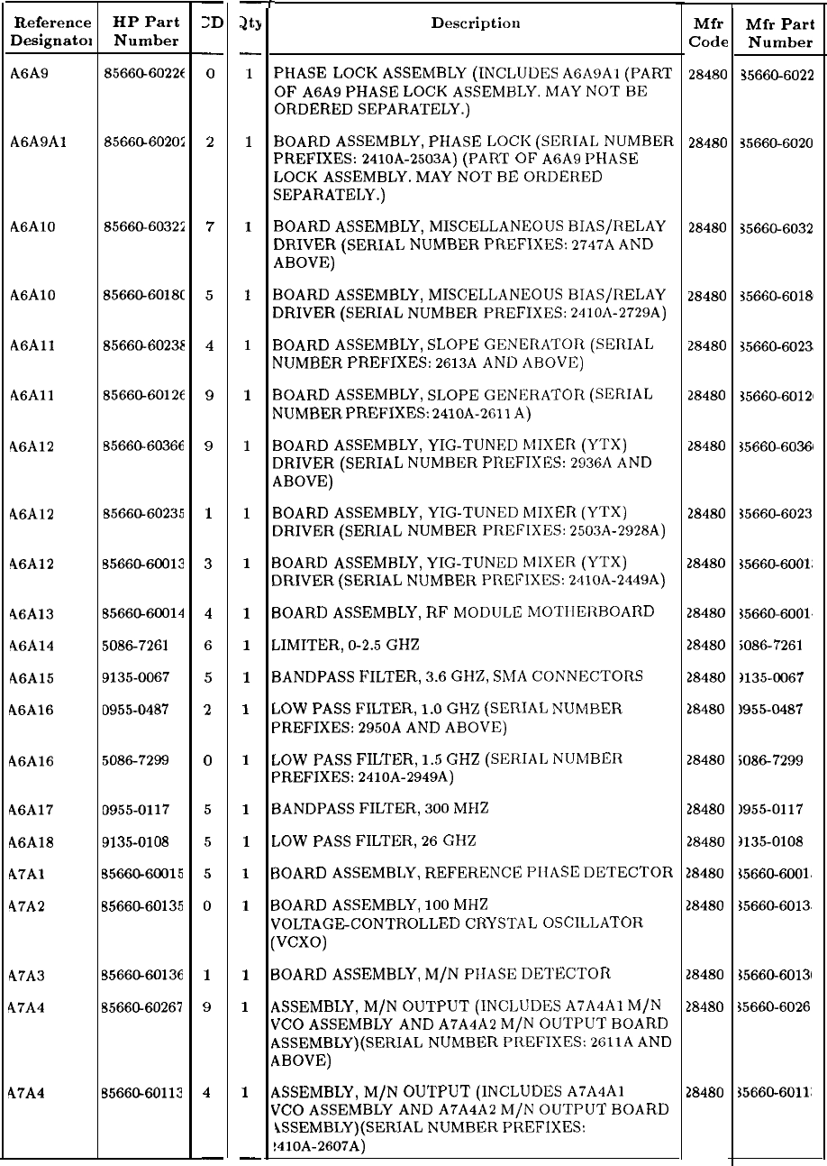
RF Section Assemblies (continued)
Reference
Designatol
A6A9
HP Part
Number
-
ZD
8566CL60226
-
0
A6A9Al
8566CL6020;
2
A6AlO 85660-60324
7
A6AlO
8566CL6018C
5
A6All
85660-60238
4
A6All
8566G60126
9
46A12
65660-60366
9
A6A12 65660-60235
1
46A12
55660-60013
3
46A13 6566~60014
4
46Al4
50867261
6
A6A15 9135-0067
5
A6A16 D955-0487
2
A6A16
50867299
A6A17
A6A18
A7Al
47A2
0955-0117
9135-0108
B5660-60015
8566Ch60135
A7A3
47A4
B5660-60136
85660-60267
47A4
6566CL60113
0
5
5
5
0
1
9
4
-
-r
-
at>
-
1
1
1
1
1
1
1
1
1
1
1
1
1
1
1
1
1
1
1
1
1
-
Descriptiou
PHASE
LOCK
ASSEMBLY
(INCLUDES
A6A9Al
(PART
OF
A6A9
PHASE
LOCK
ASSEMBLY.
MAY
NOT
BE
ORDERED
SEPARATELY.)
BOARD
ASSEMBLY,
PHASE
LOCK
(SERIAL
NUMBER
PREFIXES:
241oA-2503A)
(PART
OF
A6A9
PHASE
LOCK
ASSEMBLY.
MAY
NOT
BE
ORDERED
SEPARATELY.)
BOARD
ASSEMBLY,
MISCELLANEOUS
BIAS/RELAY
DRIVER
(SERIAL
NUMBER
PREFIXES:
2747A
AND
ABOVE)
BOARD
ASSEMBLY,
MISCELLANEOUS
BIAS/RELAY
DRIVER
(SERIAL
NUMBER
PREFIXES:
2410A-2729A)
BOARD
ASSEMBLY,
SLOPE
GENERATOR
(SERIAL
NUMBER
PREFIXES:
2613A
AND
ABOVE)
BOARD
ASSEMBLY,
SLOPE
GENERATOR
(SERIAL
NUMBER
PREFIXES:
2410A-2611
A)
BOARD
ASSEMBLY,
YIG-TUNED
h4IXER
(YTX)
DRIVER
(SERIAL
NUMBER
PREFIXES:
2936A
AND
ABOVE)
BOARD
ASSEMBLY,
YIG-TUNED
MIXER
(YTX)
DRIVER
(SERIAL
NUMBER
PREFIXES:
2503A-2928A)
BOARD
ASSEMBLY,
YIG-TUNED
MIXER
(YTX)
DRIVER
(SERIAL
NUMBER
PREFIXES:
241oA-2449A)
BOARD
ASSEMBLY,
RF
MODULE
MOTIIERBOARD
LIMITER,
O-2.5
GHZ
BANDPASS
FILTER,
3.6
GHZ,
SMA
CONNECTORS
LOW
PASS
FILTER,
1.0
GHZ
(SERIAL
NUMBER
PREFIXES:
2950A
AND
ABOVE)
LOW
PASS
FILTER,
1.5
GHZ
(SERIAL
NUMBER
PREFIXES:
2410A-2949A)
BANDPASS
FILTER,
300
MHZ
LOW
PASS
FILTER,
26
GHZ
BOARD
ASSEMBLY,
REFERENCE
PIIASE
DETECTOR
BOARD
ASSEMBLY,
100
MHZ
VOLTAGECONTROLLED
CRYSTAL
OSCILLATOR
(VCXO)
BOARD
ASSEMBLY,
M/N
PIIASE
DETECTOR
ASSEMBLY,
M/N
OUTPUT
(INCLUDES
A7A4Al
M/N
VCO
ASSEMBLY
AND
A7A4A2
M/N
OUTPUT
BOARD
ASSEMBLY)(SERIAL
NUMBER
PREFIXES:
2611A
AND
ABOVE)
ASSEMBLY,
M/N
OUTPUT
(INCLUDES
A7A4Al M/N
VCO
ASSEMBLY
AND
A7A4A2
M/N
OUTPUT
BOARD
iSSEMBLY)(SERIAL
NUMBER
PREFIXES:
!410A-2607A)
Mfr Mfr
Part
Code Number
28480 35660-6022
28480 35660-6020
28480 35660-6032
28480
35660-60181
28480
35660-6023s
28480
35660-60121
28480
35660-60361
28480 35660-6023
28480
35660-6001:
28480
35660-6001.
28480
5086-7261
28480
)135X067
28480 1955-0487
28480
50867299
28480 1955-0117
28480 3135-0108
28480 %5660-6001.
28480 $5660-6013,
28480
%5660-60131
28480 $5660-6026
28480
35660-6011:
General Parts Listing 19
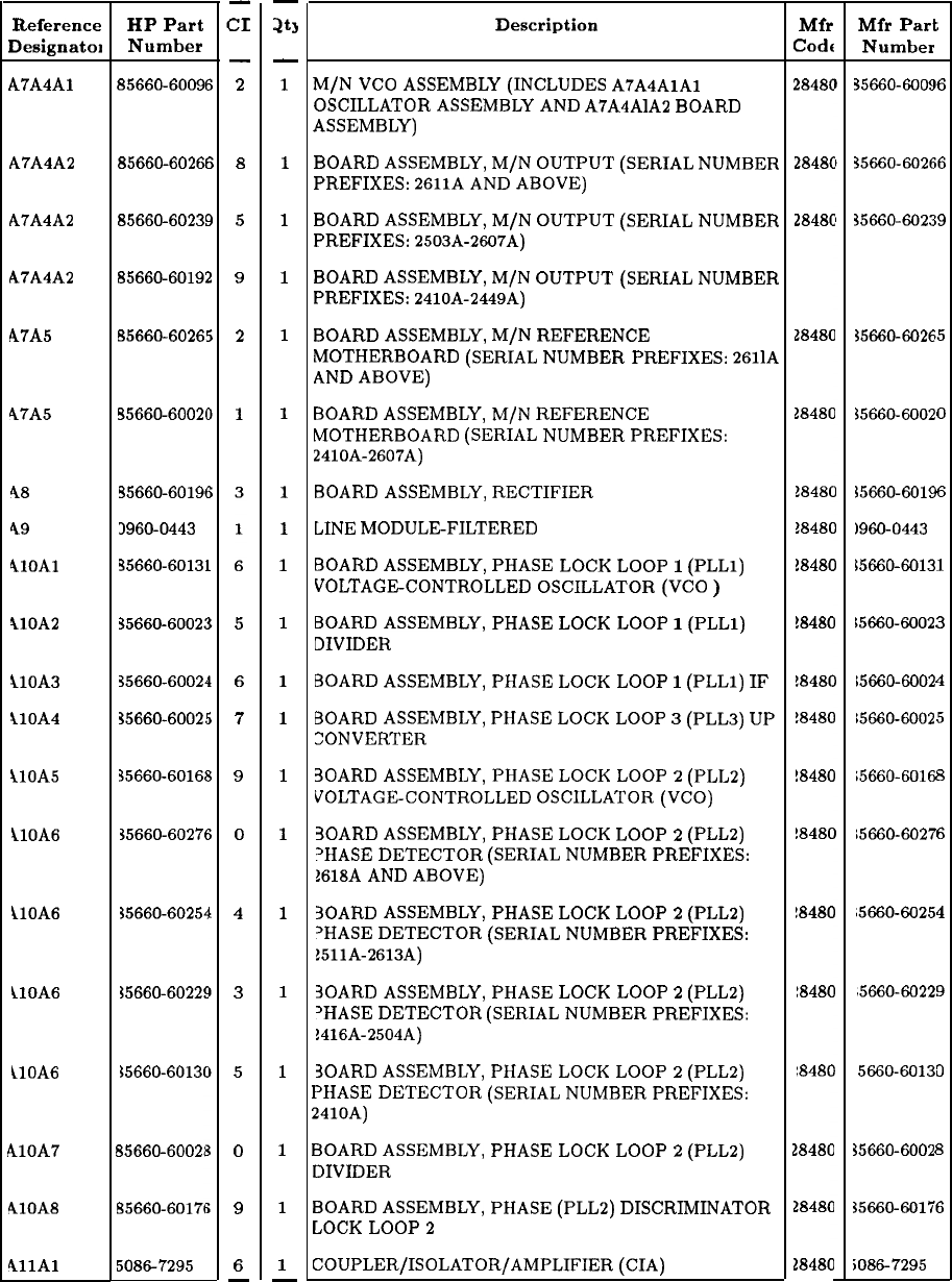
RF Section Assemblies (continued)
-
as
-
1
1
1
1
1
1
1
1
1
1
1
1
1
1
1
1
1
1
1
1
-
Description
M/N
VCO
ASSEMBLY
(INCLUDES
A7A4AlAl
OSCILLATOR
ASSEMBLY
AND
A7A4AlA2
BOARD
ASSEMBLY)
BOARD
ASSEMBLY,
M/N
OUTPUT
(SERIAL
NUMBER
PREFIXES:
2611A
AND
ABOVE)
BOARD
ASSEMBLY,
M/N
OUTPUT
(SERIAL
NUMBER
PREFIXES:
2503A-2607A)
BOARD
ASSEMBLY,
M/N
OUTPUT
(SERIAL
NUMBER
PREFIXES:
2410A-2449A)
BOARD
ASSEMBLY,
M/N
REFERENCE
MOTHERBOARD
(SERIAL
NUMBER
PREFIXES:
2611A
AND
ABOVE)
BOARD
ASSEMBLY,
M/N
REFERENCE
MOTHERBOARD
(SERIAL
NUMBER
PREFIXES:
2410A-2607A)
BOARD
ASSEMBLY,
RECTIFIER
LINE
MODULEFILTERED
BOARD
ASSEMBLY,
PHASE
LOCK
LOOP
1
(PLLl)
VOLTAGE-CONTROLLED
OSCILLATOR
(VCO
)
BOARD
ASSEMBLY,
PHASE
LOCK
LOOP
1
(PLLl)
DIVIDER
BOARD
ASSEMBLY,
PHASE
LOCK
LOOP
1
(PLLl)
IF
BOARD
ASSEMBLY,
PHASE
LOCK
LOOP
3
(PLL3)
UP
ZONVERTER
30ARD
ASSEMBLY,
PHASE
LOCK
LOOP
2
(PLL2)
VOLTAGE-CONTROLLED
OSCILLATOR
(VCO)
30ARD
ASSEMBLY,
PHASE
LOCK
LOOP
2
(PLL2)
‘HASE DETECTOR
(SERIAL
NUMBER
PREFIXES:
1618A
AND
ABOVE)
30ARD
ASSEMBLY,
PHASE
LOCK
LOOP
2
(PLL2)
‘HASE
DETECTOR
(SERIAL
NUMBER
PREFIXES:
1511A-2613A)
30ARD
ASSEMBLY,
PHASE
LOCK
LOOP
2
(PLL2)
‘HASE
DETECTOR
(SERIAL
NUMBER
PREFIXES:
1416A-2504A)
30ARD
ASSEMBLY,
PHASE
LOCK
LOOP
2
(PLLI)
PHASE
DETECTOR
(SERIAL
NUMBER
PREFIXES:
2410A)
BOARD
ASSEMBLY,
PHASE
LOCK
LOOP
2
(PLL2)
DIVIDER
BOARD
ASSEMBLY,
PHASE
(PLL2)
DISCRIMINATOR
LOCK
LOOP
2
COUPLER/ISOLATOR/AMPLIFIER
(CIA)
Reference
Designatol
A7A4A1
HP Part
Number
85660-60091
-
3
6
-
2
A7A4A2
85660-60261
6
8
A7A4A2
85660-6023!
9
5
A7A4A2
85660-6019:
2
9
A7A5 85660-6026!
5
2
47A5
55660-6002t
1
48
35660-60196
49 3960-0443
410Al
35660-60131
1
AlOA2
35660-6002:
5
llOA3
35660-6002~
4
6
ilOA4
35660-6002:
i
7
110A5
35660-60162
I
9
klOA6 35660-6027f
j
0
ilOA6
35660-60254 4
ilOA6
35660-6022C 3
ilOA6
35660-6013C
5
b10A7
65660-6002;
0
410A8
85660-60171 9
411Al
50867295
6
-
Mfr Mfr
Pari
Codf
Number
2848C
2848C
2848C
28480
28480
18480
18480
38480
!8480
!8480
!8480
!8480
!8480
!8480
18480
18480
28480
28480
28480
35660-6005
I6
35660-6026
i6
35660-6023
19
35660-6026
85
$5660-6002 0
15660-6019
)960-0443
6
~56606913
1
15660-6002 3
15660-6002 4
15660-6002
5
15660-6016
8
;5660-60278
6
~5660-6025,
4
,5660-6022’
9
5660-60131
D
35660-6002 8
35660-6017
‘6
iO867295
t
20 General Parts Listing
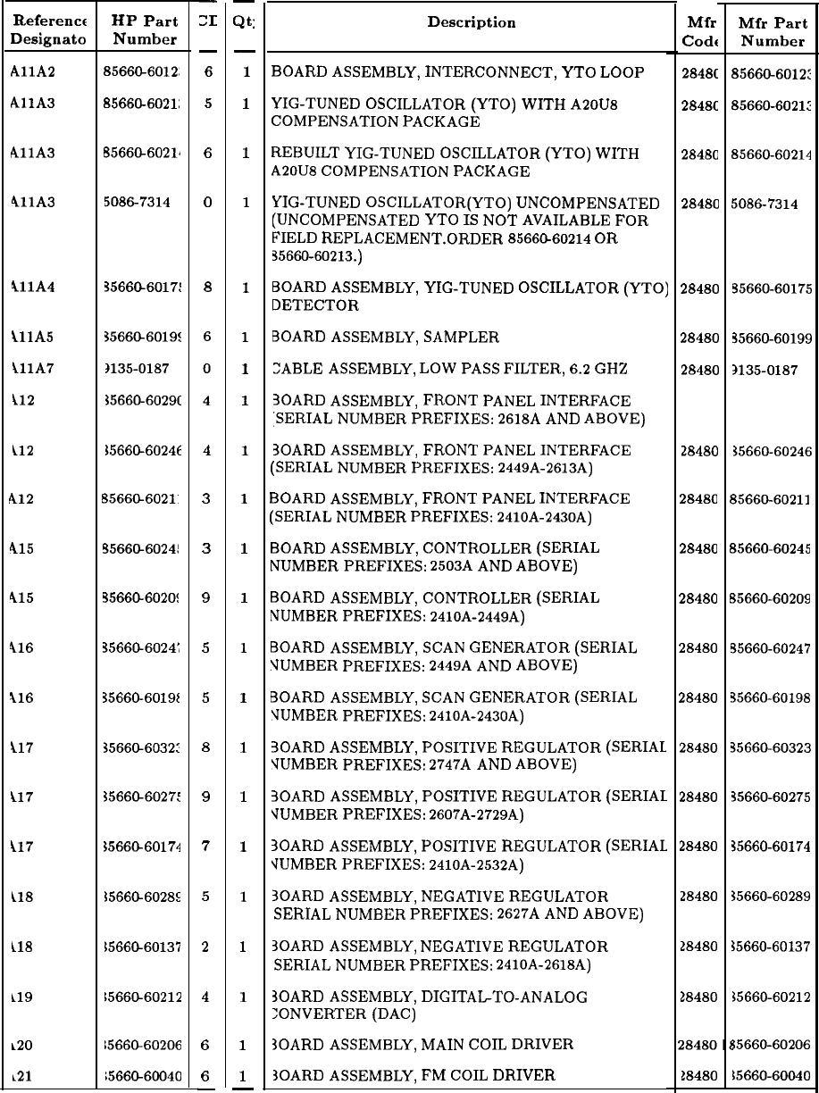
RF Section Assemblies (continued)
Description Mfr Mfr Part
Codt
Number
BOARD
ASSEMBLY,
INTERCONNECT,
YTO
LOOP
YIG-TUNED
OSCILLATOR
(YTO) WITH
A20U8
COMPENSATION
PACKAGE
2848C
85660-6012:
2848C
85660-6021:
REBUILT
YIG-TUNED
OSCILLATOR
(YTO)
WITH
A20U8
COMPENSATION
PACKAGE
28480 85660-60214
YIG-TUNED
OSCILLATOR(YT0)
UNCOMPENSATED
(UNCOMPENSATED
YTO
IS
NOT
AVAILABLE
FOR
FIELD
REPLACEMENT.ORDER
8566&60214
OR
3566960213.)
28480 5086-7314
BOARD
ASSEMBLY,
YIG-TUNED
OSCILLATOR
(YTO)
DETECTOR
28480 55660-60175
BOARD
ASSEMBLY,
SAMPLER
:ABLE
ASSEMBLY,
LOW
PASS
FILTER,
6.2
GHZ
28480 35660-60199
28480 3135-0187
30ARD
ASSEMBLY,
FRONT
PANEL
INTERFACE
SERIAL
NUMBER
PREFIXES:
2618A
AND
ABOVE)
30ARD
ASSEMBLY,
FRONT
PANEL
INTERFACE
(SERIAL
NUMBER
PREFIXES:
2449A-2613A)
28480 35660-60246
BOARD
ASSEMBLY,
FRONT
PANEL
INTERFACE
(SERIAL
NUMBER
PREFIXES:
2410A-2430A)
28480 85660-60211
BOARD
ASSEMBLY,
CONTROLLER
(SERIAL
NUMBER
PREFIXES:
2503A
AND
ABOVE)
28480 85660-60245
BOARD
ASSEMBLY,
CONTROLLER
(SERIAL
NUMBER
PREFIXES:
2410A-2449A)
28480 85660-60209
BOARD
ASSEMBLY,
SCAN
GENERATOR
(SERIAL
‘JUMBER
PREFIXES:
2449A
AND
ABOVE)
28480 55660-60247
BOARD
ASSEMBLY,
SCAN
GENERATOR
(SERIAL
VUMBER
PREFIXES:
2410A-2430A)
28480 35660-60198
HOARD
ASSEMBLY,
POSITIVE
REGULATOR
(SERIAL
VUMBER
PREFIXES:
2747A
AND
ABOVE)
28480 35660-60323
30ARD
ASSEMBLY,
POSITIVE
REGULATOR
(SERIAL
VUMBER
PREFIXES:
2607A-2729A)
28480 35660-60275
30ARD
ASSEMBLY,
POSITIVE
REGULATOR
(SERIAL
‘JUMBER
PREFIXES:
2410A-2532A)
28480 35660-60174
30ARD
ASSEMBLY,
NEGATIVE
REGULATOR
SERIAL
NUMBER
PREFIXES:
2627A
AND
ABOVE)
30ARD
ASSEMBLY,
NEGATIVE
REGULATOR
SERIAL
NUMBER
PREFIXES:
2410A-2618A)
28480 35660-60289
28480
$5660-60137
30ARD
ASSEMBLY,
DIGITAL-TO-ANALOG
:ONVERTER
(DAC)
28480
$5660-60212
30ARD
ASSEMBLY,
MAIN
COIL
DRIVER
$5660-60206
30ARD
ASSEMBLY,
FM
COIL
DRIVER
28480
!5660-60040
Reference
Designato
AllA
AllA
HP Part
Number
8566@6012<
85660-6021:
-
x
-
6
5
AllA
6566CL6021‘ 6
411A3 50867314
0
4llA4
35660-6017:
8
LllA5
illA
i12
3566&6019%
3135-0187
35660-6029C
L12
35660-60246
4
A12
6566G6021
3
415 85660-6024! 3
415
S5660-6020s 9
416 35660-6024:
5
\16
35660-6019f
5
117 35660-6032:
8
117
%566@6027:
9
i17
15660-60174 7
i18
3566S6028S
5
L18
!5660-60137
2
L19
L20
L21
15660-60212 4
1566CL60206
6
15660-60040 6
-
-
Qt:
-
1
1
1
1
1
1
1
1
1
1
1
1
1
1
1
1
1
1
1
1
1
1
-
General Parts Listing 21
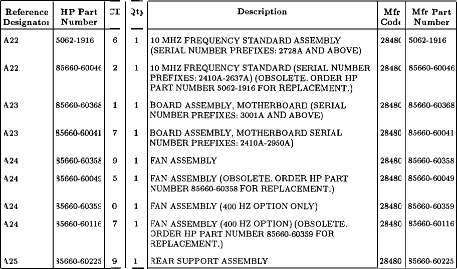
RF Section Assemblies (continued)
-
20
-
1
1
1
1
1
1
1
1
1
-
Description
10
MHZ
FREQUENCY
STANDARD
ASSEMBLY
(SERIAL
NUMBER
PREFIXES:
2728A
AND
ABOVE)
10
MHZ
FREQUENCY
STANDARD
(SERIAL
NUMBER
PREFIXES:
2410A-2637A)
(OBSOLETE.
ORDER
HP
PART
NUMBER
5062-1916
FOR
REPLACEMENT.)
BOARD
ASSEMBLY,
MOTHERBOARD
(SERIAL
NUMBER
PREFIXES:
3001A
AND
ABOVE)
BOARD
ASSEMBLY,
MOTHERBOARD
SERIAL
NUMBER
PREFIXES:
2410A-2950A)
FAN
ASSEMBLY
FAN
ASSEMBLY
(OBSOLETE.
ORDER
HP
PART
NUMBER
8566060358
FOR
REPLACEMENT.)
FAN
ASSEMBLY
(400
HZ
OPTION
ONLY)
FAN
ASSEMBLY
(400
HZ
OPTION)
(OBSOLETE.
ORDER
HP
PART
NUMBER
85660-66359
FOR
REPLACEMENT.)
REAR
SUPPORT
ASSEMBLY
28480 85660-60225
Reference HP Part
Designatol Number
A22
5062-1916
A22 85660-60046
A23 85660-60368
A23
65660-60041
424
55660-60358
424
55660-60049
424 S5660-60359
424 35660-60116
425 35660-60225
-
x
-
6
2
1
7
9
5
0
7
9
-
Mfr
Codt
2848C
Mfr Part
Number
5062-1916
2848C
85660-60046
2848C
85660X.0368
28480 85660-60041
28480 85660-60358
28480
8566040049
28480
8566040359
28480 85660-60116
22 General Parts Listing
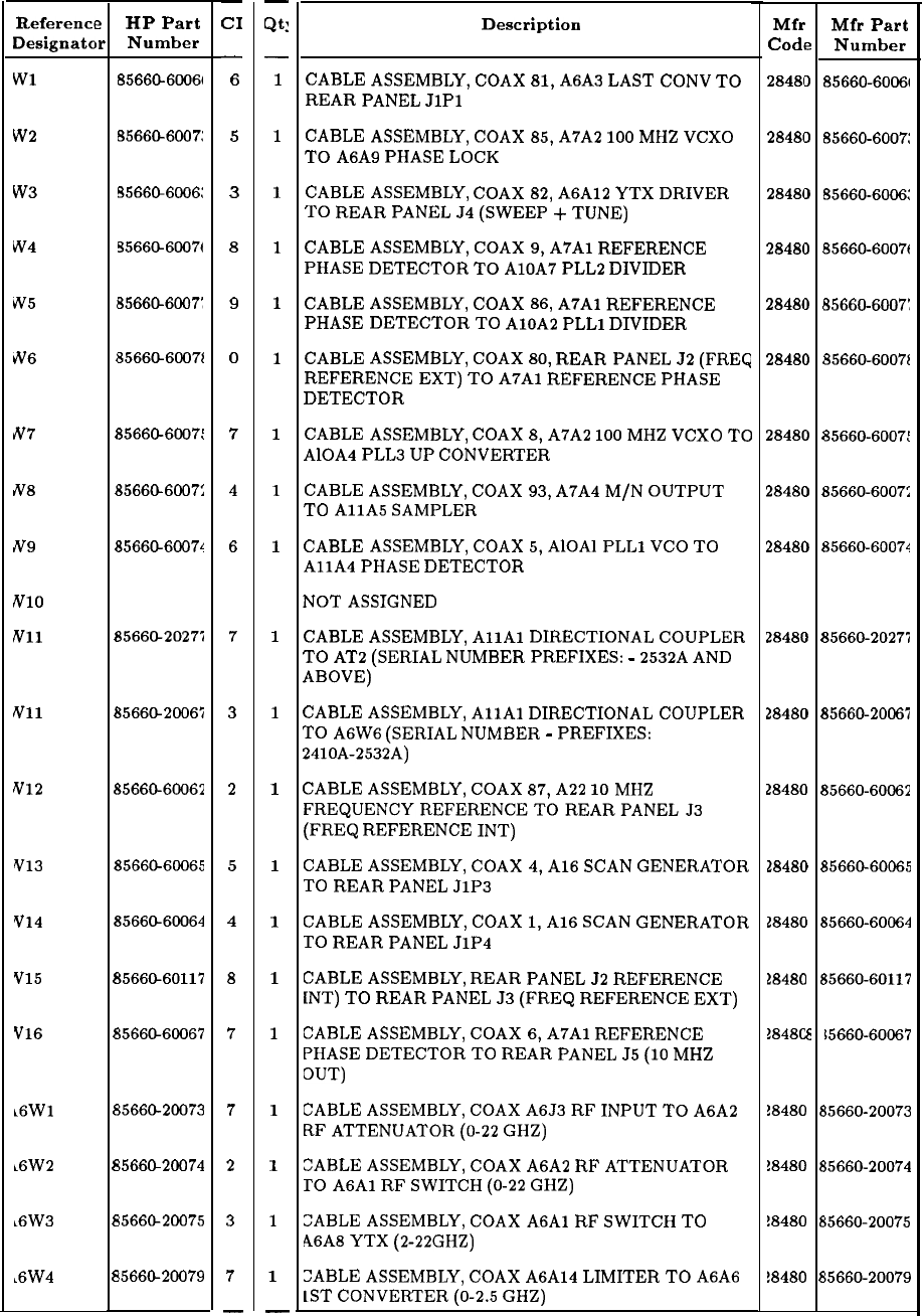
Reference
Designata
Wl
w2
w3
w4
w5
b'6
N8
N9
IV10
Nil
Nil
N12
v13
Y14
Y15
Y16
i6Wl
~6W2
~6W3
,6W4
e
HP Part
w
Number
85660-6006t
8566@6007:
95661X6006:
5566G6007t
55660-6007:
1
35660-60072
1
35660-6007:
1
35660-6007:
1
35660-60074
35660-20277
1
S5660-20067
~5660-60062
t5660-60065
15660-60064
E
15660-60117
E
I566660067
e
15660-20073
8
i566CL20074
8
;566@20075
8
,5660-20079
-
CI
-
6
5
3
8
9
0
7
4
6
7
3
2
5
4
8
7
7
2
3
7
-
-
Qt:
-
1
1
1
1
1
1
1
1
1
1
1
1
1
1
1
1
1
1
1
1
-
RF Section Cables
Description
CABLE
ASSEMBLY,
COAX
81,
A6A3
LAST
CONV
TO
REAR
PANEL
JlPl
CABLE
ASSEMBLY,
COAX
85,
A7A2
100
MHZ
VCXO
TO
A6A9
PHASE
LOCK
CABLE
ASSEMBLY,
COAX
82,
A6A12
YTX
DRIVER
TO
REAR
PANEL
J4
(SWEEP
+
TUNE)
CABLE
ASSEMBLY,
COAX
9,
A7Al
REFERENCE
PHASE
DETECTOR
TO
AlOA7
PLL2
DIVIDER
CABLE
ASSEMBLY,
COAX
86,
A7Al
REFERENCE
PHASE
DETECTOR
TO
AlOA2
PLLl
DIVIDER
CABLE
ASSEMBLY,
COAX
80,
REAR
PANEL
J2
(FREQ
REFERENCE
EXT)
TO
A7Al
REFERENCE
PHASE
DETECTOR
CABLE
ASSEMBLY,
COAX
8,
A7A2
100
MHZ
VCXO
TO
AlOA4
PLL3
UP
CONVERTER
CABLE
ASSEMBLY,
COAX
93,
A7A4
M/N
OUTPUT
TO
AllA
SAMPLER
CABLE
ASSEMBLY,
COAX
5,
AlOAl
PLLl
VCO
TO
AllA
PHASE
DETECTOR
NOT
ASSIGNED
CABLE
ASSEMBLY,
AllAl
DIRECTIONAL
COUPLER
TO
AT2
(SERIAL
NUMBER
PREFIXES:
-
2532A
AND
ABOVE)
CABLE
ASSEMBLY,
AllAl
DIRECTIONAL
COUPLER
TO
A6W6
(SERIAL
NUMBER
-
PREFIXES:
2410A-2532A)
CABLE
ASSEMBLY,
COAX
87,
A22
10
MHZ
FREQUENCYREFERENCETOREARPANELJ3
(FREQ
REFERENCE
INT)
CABLE
ASSEMBLY,
COAX
4,
Al6
SCAN
GENERATOR
TO
REAR
PANEL
J1P3
CABLE
ASSEMBLY,
COAX
1,
Al6
SCAN
GENERATOR
TO
REAR
PANEL
J1P4
CABLE
ASSEMBLY,
REAR
PANEL
52
REFERENCE
[NT)
TO
REAR
PANEL
53
(FREQ
REFERENCE
EXT)
CABLE
ASSEMBLY,
COAX
6,
A7Al
REFERENCE
PHASE
DETECTOR
TO
REAR
PANEL
J5
(10
MHZ
OUT)
CABLE
ASSEMBLY,
COAX
A6J3
RF
INPUT
TO
A6A2
RF
ATTENUATOR
(O-22
GHZ)
CIABLE
ASSEMBLY,
COAX
A6A2
RF
ATTENUATOR
TO
A6Al
RF
SWITCH
(O-22
GHZ)
CABLE
ASSEMBLY,
COAX
A6Al
RF
SWITCH
TO
46A8
YTX
(2-22GHZ)
:ABLE
ASSEMBLY,
COAX
A6A14
LIMITER
TO
A6A6
LST
CONVERTER
(O-2.5
GHZ)
Mfr
Codq
2848f
2848(
2848(
2848(
2848(
2848(
2848C
2848C
2848C
2848C
2848C
28480
28480
18480
18480
18480
38480
!8480
!8480
!8480
e
1
I
I
I
i
1
I
)
1
)
1
1 1
I 1
I
1
I
1
I
f
I
t
1
6
6
E
I
8
8
8
Mfr Part
Number
85660-6006f
85660-6007:
85660-6006:
B5660-6007t
85660-6007:
95660-60072
35660-6007:
35660-6007:
35660-60074
35660-20275
~5660-20067
$5660-60065
15660-60064
55660-60117
15660-60067
15660-20073
15660-20074
i5660-20075
15660-20079
General Parts Listing 23
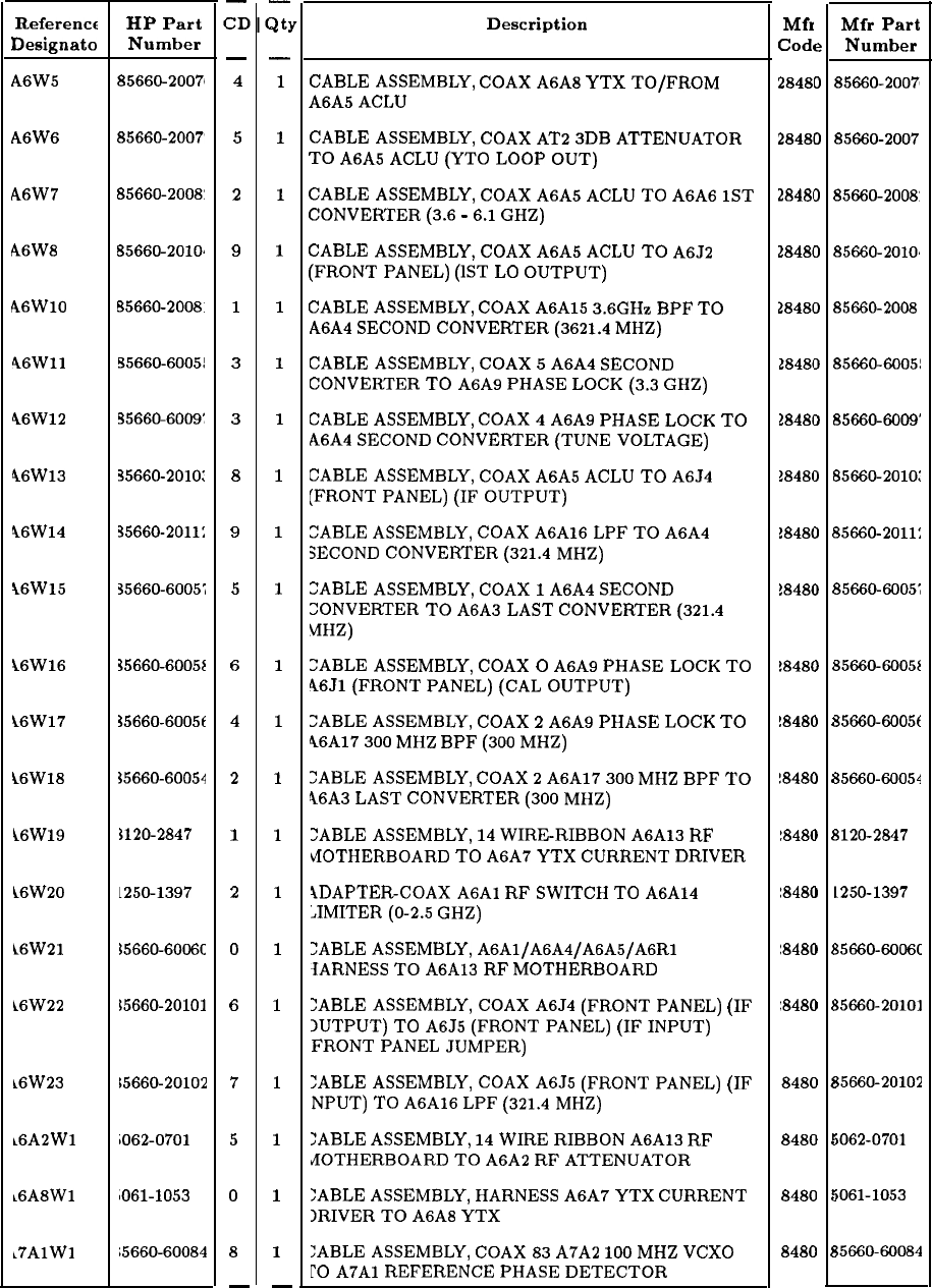
Referencr
Designato
A6W5
A6W6
A6W7
A6W8
A6WlO
46Wll
46W12
46W13
46W14
\6W15
i6W16
16W17
i6W18
i6W19
L6W20
L6W21
L6W22
i6W23
~6A2Wl
L6A8Wl
~7AlWl
HP Part
Number
85660-20071
85660-2007'
85660-2008:
B5660-2008.
95660-6005!
!?5660-6009:
35660-2010:
35660-2011:
35660-6005;
35660-6005E
35660-6005t
35660-60054
3120-2847
L250-1397
35660-6006C
L5660-20101
15660-20102
iO62-0701
1061-1053
;5660-60084
-
z’r
-
4
5
2
9
1
3
3
8
9
5
6
4
2
1
2
0
6
7
5
0
8
-
-
a:
-
1
1
1
1
1
1
1
1
1
1
1
1
1
1
1
1
1
1
1
1
1
-
RF Section Cables (continued)
Description
CABLE
ASSEMBLY,
COAX
A6A8
YTX
TO/FROM
A6A5
ACLU
CABLE
ASSEMBLY,
COAX
AT2
3DB
ATTENUATOR
TO
A6A5
ACLU
(YTO
LOOP
OUT)
CABLE
ASSEMBLY,
COAX
A6A5
ACLU
TO
A6A6
1ST
CONVERTER
(3.6
-
6.1
GHZ)
CABLE
ASSEMBLY,
COAX
A6A5
ACLU
TO
A6J2
(FRONT
PANEL)
(1ST
LO
OUTPUT)
CABLE
ASSEMBLY,
COAX
A6A15
3.6GHz
BPF
TO
A6A4
SECOND
CONVERTER
(3621.4
MHZ)
CABLE
ASSEMBLY,
COAX
5
A6A4
SECOND
CONVERTER
TO
A6A9
PHASE
LOCK
(3.3
GHZ)
CABLE
ASSEMBLY,
COAX
4
A6A9
PHASE
LOCK
TO
A6A4
SECOND
CONVERTER
(TUNE
VOLTAGE)
CABLE
ASSEMBLY,
COAX
A6A5
ACLU
TO
A6J4
[FRONT
PANEL)
(IF
OUTPUT)
CABLE
ASSEMBLY,
COAX
A6A16
LPF
TO
A6A4
SECOND
CONVERTER
(321.4
MHZ)
CABLE
ASSEMBLY,
COAX
1
A6A4
SECOND
CONVERTER
TO
A6A3
LAST
CONVERTER
(321.4
MHZ)
:ABLE
ASSEMBLY,
COAX
0
A6A9
PHASE
LOCK
TO
46Jl
(FRONT
PANEL)
(CAL
OUTPUT)
:ABLE
ASSEMBLY,
COAX
2
A6A9
PHASE
LOCK
TO
46A17
300
MHZ
BPF
(300
MHZ)
?ABLE
ASSEMBLY,
COAX
2
A6A17
300
MHZ
BPF
TO
46A3
LAST
CONVERTER
(300
MHZ)
>ABLE
ASSEMBLY,
14
WIRERIBBON
A6A13
RF
bfOTHERBOARD
TO
A6A7
YTX
CURRENT
DRIVER
YDAPTER-COAX
A6Al
RF
SWITCH
TO
A6A14
JIMITER
(O-2.5
GHZ)
:ABLE
ASSEMBLY,
A6Al/A6A4/A6AS/A6Rl
SARNESS
TO
A6A13
RF
MOTHERBOARD
:ABLE
ASSEMBLY,
COAX
A6J4
(FRONT
PANEL)
(IF
IUTPUT)
TO
A6J5
(FRONT
PANEL)
(IF
INPUT)
FRONT
PANEL
JUMPER)
:ABLE
ASSEMBLY,
COAX
A6J5
(FRONT
PANEL)
(IF
NPUT)
TO
A6A16
LPF
(321.4
MHZ)
TABLE
ASSEMBLY,
14
WIRE
RIBBON
A6A13
RF
JOTHERBOARD
TO
A6A2
RF
ATTENUATOR
:ABLE
ASSEMBLY,
HARNESS
A6A7
YTX
CURRENT
IRIVER
TO
A6A8
YTX
:ABLE
ASSEMBLY,
COAX
83
A7A2
100
MHZ
VCXO
r0 A7Al
REFERENCE
PHASE
DETECTOR
Mfr
Cod
28481
28481
28481
2848f
2848t
2848(
1848(
1848(
1848(
!848(
!848C
!848C
!848C
1848C
1848C
1848C
18480
8480
8480
8480
8480
e
0
0
3
3
1
I
1
I
I
;
1
i
I
I
)
1
I
1
I1
I
1
I
1
I
1
I
1
/
r
c
c
c
8
Mfr
Part
Number
85660-2007s
85660-2007
85660-2008'
85660-2008
85660-60051
85660-6009'
85660-2010:
65660-2011:
55660-6005;
35660-6005~
35660-6005~
35660-60054
3120-2847
1250-1397
35660~6006c
35660-20101
35660-20102
iO62-0701
iO61-1053
i5660-60084
24 General Parts Listing
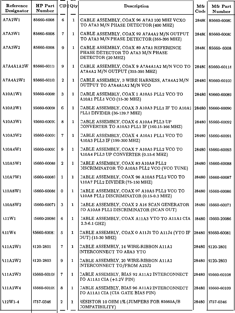
Reference
Designator
A7A2Wl
A7A3Wl
A7A3W2
A7A4A2Wl
AlOAlWl
AlOA2Wl
410A3Wl
410A3W2
410A4Wl
210ASWl
ilOA7Wl
ilOA8Wl
ilOA8W2
lllW1
AllW4
411A2Wl
411A2W2
911A2W3
211A2W4
i12Wl-4
HP Part
Number
8566CL6008
8566&6008.
85660-6008.
8566CL60111
5566CL6010:
35660-6008:
35660-6009(
35660-6009:
35660-60091
3566CL6009:
35660-60088
$5660-60087
15660-60086
1566@60071
1566G20086
35660-60081
3120-2801
3120-2803
35660-6OlOE
15660-6010:
)757-0346
-
x
-
6
7
9
9
2
3
6
8
7
9
2
1
0
3
6
5
7
9
7
8
2
-
-
3:
-
1
1
1
1
1
1
1
1
1
1
1
1
1
1
1
1
1
1
1
1
1
-
RF Section Cables (continued)
Description
CABLE
ASSEMBLY,
COAX
96
A7A2
lo0
MHZ
VCXO
TO
A7A3
M/N
PHASE
DETECTOR
(400
MHZ)
CABLE
ASSEMBLY,
COAX
92
A7A4A2
M/N
OUTPUT
TO
A7A3
M/N
PHASE
DETECTOR
(355-395
MHZ)
CABLE
ASSEMBLY,
COAX
89
A7Al
REFERENCE
PHASE
DETECTOR
TO
A7A3
M/N
PHASE
DETECTOR
(20
MHZ)
CABLE
ASSEMBLY,
COAX
9
A7A4AlA2
M/N
VCO
TO
A7A4A2
M/N
OUTPUT
(355-395
MHZ)
CABLE
ASSEMBLY,
3
WIRE
HARNESS,
A7A4A2
M/N
OUTPUT
TO
A7A4AlA2
M/N
VCO
CABLE
ASSEMBLY,
COAX
1
AlOA5
PLL2
VCO
TO
AlOAl
PLLl
VCO
(15-30
MHZ)
CABLE
ASSEMBLY,
COAX
3
AlOA3
PLLl
IF
TO
AlOA2
PLLl
DIVIDER
(36-139.7
MHZ)
CABLE
ASSEMBLY,
COAX
6
AlOA4
PLL3
UP
CONVERTER
TO
AlOA3
PLLl
IF
(160.15-166
MHZ)
:ABLE
ASSEMBLY,
COAX
4
AlOAl
PLLl
VCO
TO
410A3
PLL3
IF
(199-300
MHZ)
>ABLE
ASSEMBLY,
COAX
7
AlOA5
PLL2
VCO
TO
410A4
PLL3
UP
CONVERTER
(0.15-6
MHZ)
?ABLE
ASSEMBLY,
COAX
83
AlOA8
PLL2
IISCRIMINATOR
TO
AlOA5
PLL2
VCO
(VCO
TUNE)
:ABLE
ASSEMBLY,
COAX
96
AlOA5
PLL2
VCO
TO
ilOA7
PLL2
DIVIDER
(75-150
MHZ)
:ABLE
ASSEMBLY,
COAX
97
AlOA5
PLL2
VCO
TO
tlOA8
PLL2
DISCRIMINATOR
(0.x-0.3
MHZ)
:ABLE
ASSEMBLY,
COAX
2
Al6
SCAN
GENERATOR
l’0
AlOA8
PLL2
DISCRIMINATOR
(SCAN
OUT)
:ABLE
ASSEMBLY,
COAX
AllA
YTO
TO
AllAl
CIA
2.3-6.1
GHZ)
CABLE
ASSEMBLY,
COAX
0
AllJ5
TO
AllJ4
(YTO
IF
OUT)
(15-30
MHZ)
CABLE
ASSEMBLY,
14
WIRERIBBON
AllA
[NTERCONNECT
TO
AllA
YTO
:ABLE
ASSEMBLY,
20
WIRE-RIBBON
AllA
[NTERCONNECT
TO/FROM
A23J2
:ABLE
ASSEMBLY,
BIAS
92
AllA
INTERCONNECT
TO
AllAl
CIA
(+5.2V
PIN)
>ABLE
ASSEMBLY,
BIAS
96
AllA
INTERCONNECT
TO
AllAl
CIA
(CIA
GATE
BIAS
PIN)
tESISTOR
10
OHM
1%
(JUMPERS
FOR
85660A/B
:OMPATIBILITY)
Mfr
Code
2848C
2848C
2848C
28480
28480
28480
28480
28480
28480
28480
28480
28480
28480
18480
18480
28480
28480
28480
28480
28480
28480
Mfr Part
Number
85660-6008:
85660-6008:
85660-
6008
85660-60118
85660-60103
55660-60089
35660-60090
35660-60092
35660-60091
35660-60093
35660-60088
35660-60087
S5660-60086
)5660-60071
15660-20086
35660-60081
3120-2801
3120-2803
35660-60108
35660-60109
1757-0346
General Parts Listing 25
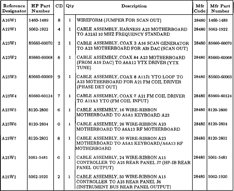
RF Section Cables (continued)
ReferenceReference HP PartHP Part
Designator NumberDesignator Number
A16WlA16Wl
1460-14891460-1489
A22WlA22Wl
5062-19225062-1922
A23Wl
A23Wl
85660-6007085660-60070
A23W2A23W2
85660-6006885660-60068
A23W4
A23W4
85660-6012485660-60124
A23W5A23W5
8120-28008120-2800
A23W6
A23W6
8120-28048120-2804
A23W7A23W7
8120-28028120-2802
7
6
0
8
A25WlA25Wl
5061-54815061-5481
6
A25W2
A25W2 5062-19205062-1920
2
A23W3A23W3
85660-6006985660-60069
CD
8
4
2
8
9
Qty
I
Description
1
1
1
Mfr
I
I
Mfr Part
Code Number
Mfr Mfr Part
Code Number
28480
1460-148928480
1460-1489
28480
5062-192228480
5062-1922
28480
85660-6007028480
85660-60070
28480
85660-6006828480
85660-60068
WIREFORM
(JUMPER
FOR
SCAN
OUT)
CABLE
ASSEMBLY,
HARNESS
A23
MOTHERBOARD
TO
A22AllO
MHZ
FREQUENCY
STANDARD
CABLE
ASSEMBLY,
COAX
3
Al6
SCAN
GENERATOR
TO
A23
MOTHERBOARD
FOR
A19
DAC
(SCAN
OUT)
1
CABLE
ASSEMBLY,
COAX
84
A23
MOTHERBOARD
(FROM
A19
DAC)
TO
A6A12
YTX
DRIVER
(YTX
TUNE)
CABLE
ASSEMBLY,
COAX
8
AllJl
YTO
LOOP
TO
A23
MOTHERBOARD
FOR
A21
FM
COIL
DRIVER
(PHASE
DET
OUT)
CABLE
ASSEMBLY,
COAX
7
A21
FM
COIL
DRIVER
TO
AllA
YTO
(FM
COIL
INPUT)
CABLE
ASSEMBLY,
16
WIRERIBBON
MOTHERBOARD
TO
A5Al
KEYBOARD
A23
CABLE
ASSEMBLY,
26
WIRERIBBON
A23
MOTHERBOARD
TO
A6A13
RF
MOTHERBOARD
CABLE
ASSEMBLY,
50
WIRE-RIBBON
A23
MOTHERBOARD
TO
A5Al KEYBOARD/AGAlS
RF
MOTHERBOARD
CABLE
ASSEMBLY,
24
WIRE-RIBBON
A15
CONTROLLER
TO
A25
REAR
PANEL
57
(HP-IB
REAR
PANEL
OUTPUT)
CABLE
ASSEMBLY,
50
WIRERIBBON
A15
CONTROLLER
TO
A25
REAR
PANEL
J6
(INSTRUMENT
BUS
REAR
PANEL
OUTPUT)
28480
85660-6006928480
85660-60069
28480
85660-6012428480
85660-60124
28480
8120-280028480
8120-2800
28480
8120-280428480
8120-2804
28480
8120-280228480
8120-2802
28480
5061-548128480
5061-5481
28480
5062-192028480
5062-1920
26 General Parts Listing
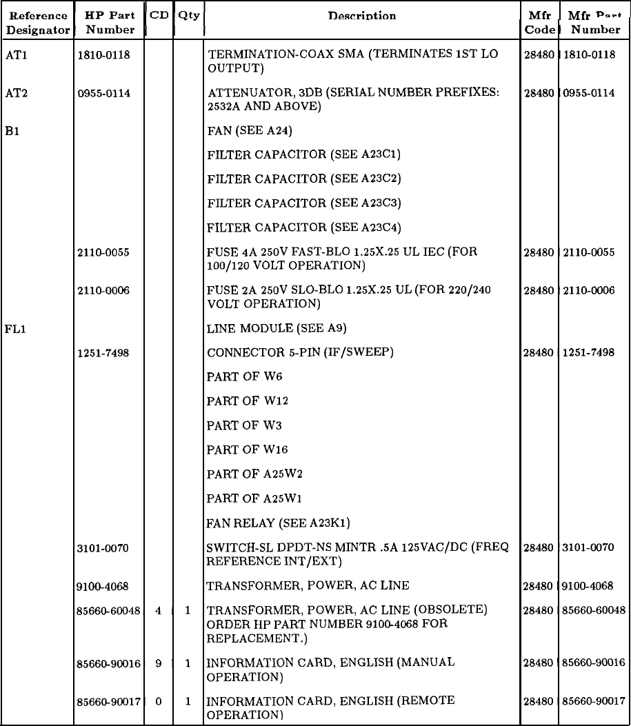
RF Section Miscellaneous Parts
nescrintion Mfr
“F”
Pn.4
TERMINATION-COAX
SMA
(TERMINATES
1ST
LO
OUTPUT)
ATTENUATOR,
3DB
(SERIAL
NUMBER
PREFIXES:
2532A
AND
ABOVE)
FAN
(SEE
A24)
FILTER
CAPACITOR
(SEE
A23Cl)
FILTER
CAPACITOR
(SEE
A23C2)
FILTER
CAPACITOR
(SEE
A23C3)
FILTER
CAPACITOR
(SEE
A23C4)
FUSE
4A
250V
FAST-BLO
1.25X.25
UL
IEC
(FOR
100/120
VOLT
OPERATION)
FUSE
2A
250V
SLO-BLO
1.25X.25
UL
(FOR
220/240
VOLT
OPERATION)
LINE
MODULE
(SEE
A9)
CONNECTOR
S-PIN
(IF/SWEEP)
PART
OF
W6
PART
OF
W12
PART
OF
W3
PART
OF
W16
PART
OF
A25W2
PART
OF
A25Wl
FAN
RELAY
(SEE
A23Kl)
SWITCH-SL
DPDT-NS
MINTR
.5A
125VAC/DC
(FREQ
REFERENCE
INT/EXT)
TRANSFORMER,
POWER,
AC
LINE
TRANSFORMER,
POWER,
AC
LINE
(OBSOLETE)
ORDER
HP
PART
NUMBER
9100-4068
FOR
REPLACEMENT.)
INFORMATION
CARD,
ENGLISH
(MANUAL
OPERATION)
INFORMATION
CARD,
ENGLISH
(REMOTE
OPERATION)
General Parts Listing 27
This page intentionally left blank.
28 General Parts Listing
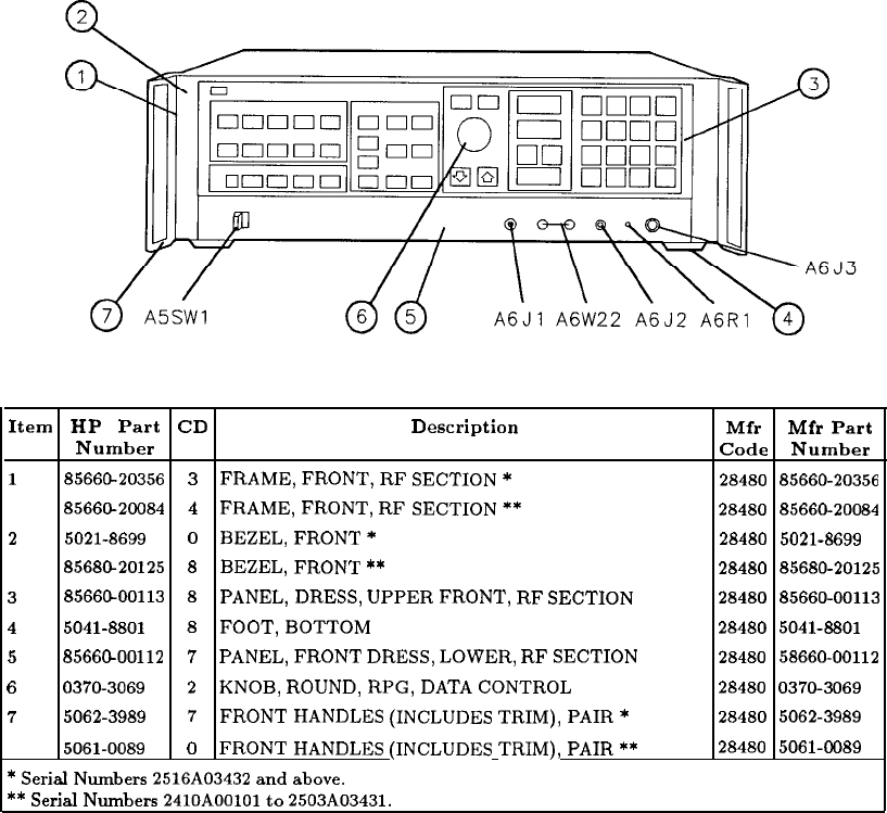
Item HP Part CD Description
Number
1
85660-20356
3
FRAME,
FRONT,
RF
SECTION
*
85660-20084 4
FRAME,
FRONT,
RF
SECTION
**
2
5021-8699
0
BEZEL,
FRONT
*
8568620125
8
BEZEL,
FRONT
**
3
8566&00113
8
PANEL,
DRESS,
UPPER
FRONT,
RF
SECTION
4
5041-8801
8
FOOT,
BOTTOM
5
8566@00112
7
PANEL,
FRONT
DRESS,
LOWER,
RF
SECTION
6
0370-3069
2
KNOB,
ROUND,
RPG,
DATA
CONTROL
7
5062-3989
7
FRONT
HANDLES
(INCLUDES
TRIM),
PAIR
*
5061-0089
0
FRONT
HANDLES
(INCLUDES
TRIM),
PAIR
**
*
Serial
Numbers
2516A03432
and
above.
**
Serial
Numbers
2410AOOlOl
to
2503A03431.
Mfr Mfr Part
Code Number
28480 85660-20356
28480 85660-20084
28480 5021-8699
28480 85680-20125
28480 85660-00113
28480 5041-8801
28480 58660-00112
28480
0370-3069
28480
5062-3989
28480 5061-0689
Figure 1. Instrument Parts Identification, Front View
General Parts Listing 29
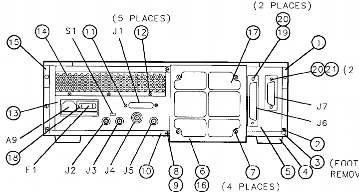
PLACES)
‘ED)
30 General Parts Listing
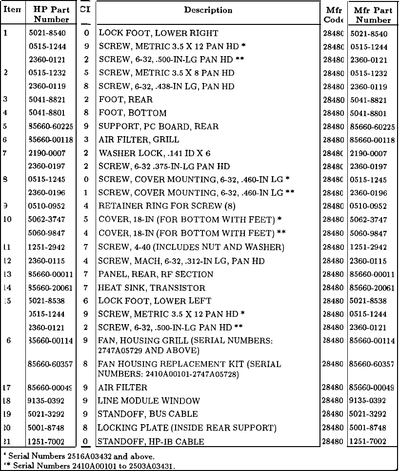
Iten
1
2
s
3
LO
11
12
13
L4
15
6
HP Part
Number
5021-8540
0515-1244
2360-0121
0515-1232
2360-0119
5041-8821
5041-8801
55660-60225
3566CkOO118
2190-0007
2360-0197
0515-1245
2360-0196
0510-0952
5062-3747
5060-9847
1251-2942
2360-0115
55660-00011
5566@20061
5021-8538
1515-1244
2360-0121
35660-00114
d5660-60357
8
17
85660-00045
18
9135-0392
19
5021-3292
10
5001-8748
11
1251-7002
-
CI
-
0
9
2
5
8
2
8
9
3
2
2
0
1
4
5
4
7
4
7
7
6
9
2
9
9
9
9
8
0
-
Description
LOCK
FOOT,
LOWER
RIGHT
SCREW,
METRIC
3.5
X
12
PAN
HD
*
SCREW,
632,
.500-IN-LG
PAN
HD
**
SCREW,
METRIC
3.5
X
8
PAN
HD
SCREW,
6-32,
.438-IN
LG,
PAN
HD
FOOT,
REAR
FOOT,
BOTTOM
SUPPORT,
PC
BOARD,
REAR
AIR
FILTER,
GRILL
WASHER
LOCK,
.141
ID
X
6
SCREW,
632
.375-IN-LG
PAN
HD
SCREW,
COVER
MOUNTING,
632,
.460-IN
LG
*
SCREW,
COVER
MOUNTING,
6-32,
.460-IN
LG
**
RETAINER
RING
FOR
SCREW
(8)
COVER,
18-IN
(FOR
BOTTOM
WITH
FEET)
*
COVER,
18-IN
(FOR
BOTTOM
WITH
FEET)
**
SCREW,
4-40
(INCLUDES
NUT
AND
WASHER)
SCREW,
MACH,
6-32,
.312-W
LG,
PAN
HD
PANEL,
REAR,
RF
SECTION
HEAT
SINK,
TRANSISTOR
LOCK
FOOT,
LOWER
LEFT
SCREW,
METRIC
3.5
X
12
PAN
HD
*
SCREW,
632,
.500-IN-LG
PAN
HD
**
FAN,
HOUSING
GRILL
(SERIAL
NUMBERS:
2747AO5729
AND
ABOVE)
FAN
HOUSING
REPLACEMENT
KIT
(SERIAL
NUMBERS:
2410AOOlOl-2747A05728)
AIR
FILTER
LINE
MODULE
WINDOW
STANDOFF,
BUS
CABLE
LOCKING
PLATE
(INSIDE
REAR
SUPPORT)
STANDOFF,
HP-IB
CABLE
’
Serial
Numbers
2516A03432
and
above.
‘*
Serial
Numbers
2410AOOlOl
to
2503A03431.
Mfr Mfr Part
Code
Number
28480
5021-8540
28480
0515-1244
28480 2360-0121
28480 0515-1232
28480 2360-0119
28480 5041-8821
28480 5041-8801
28480 85660-60225
28480
85660-00118
2848C
2190-0007
2848C
2360-0197
28480 0515-1245
28480 2360-0196
28480
0510-0952
28480 5062-3747
28480
5060-9847
28480 1251-2942
28480 2360-0115
28480 85660-00011
28480 85660-20061
28480 5021-8538
28480
0515-1244
28480 2360-0121
28480
85660-00114
28480 85660-60357
28480 85660-00049
28480 9135-0392
28480 5021-3292
28480 5001-8748
28480 1251-7002
Figure 2. RF Section Parts Identification
General Parts Listing 31
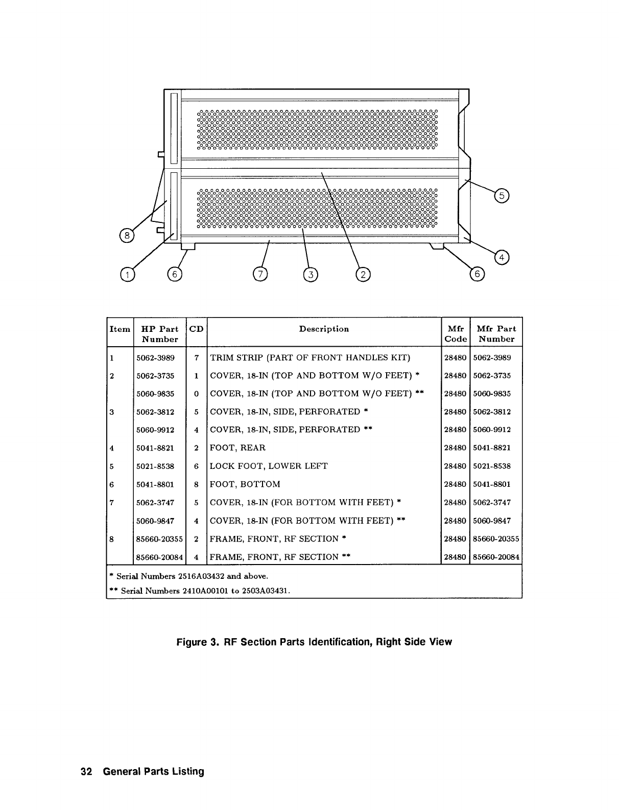
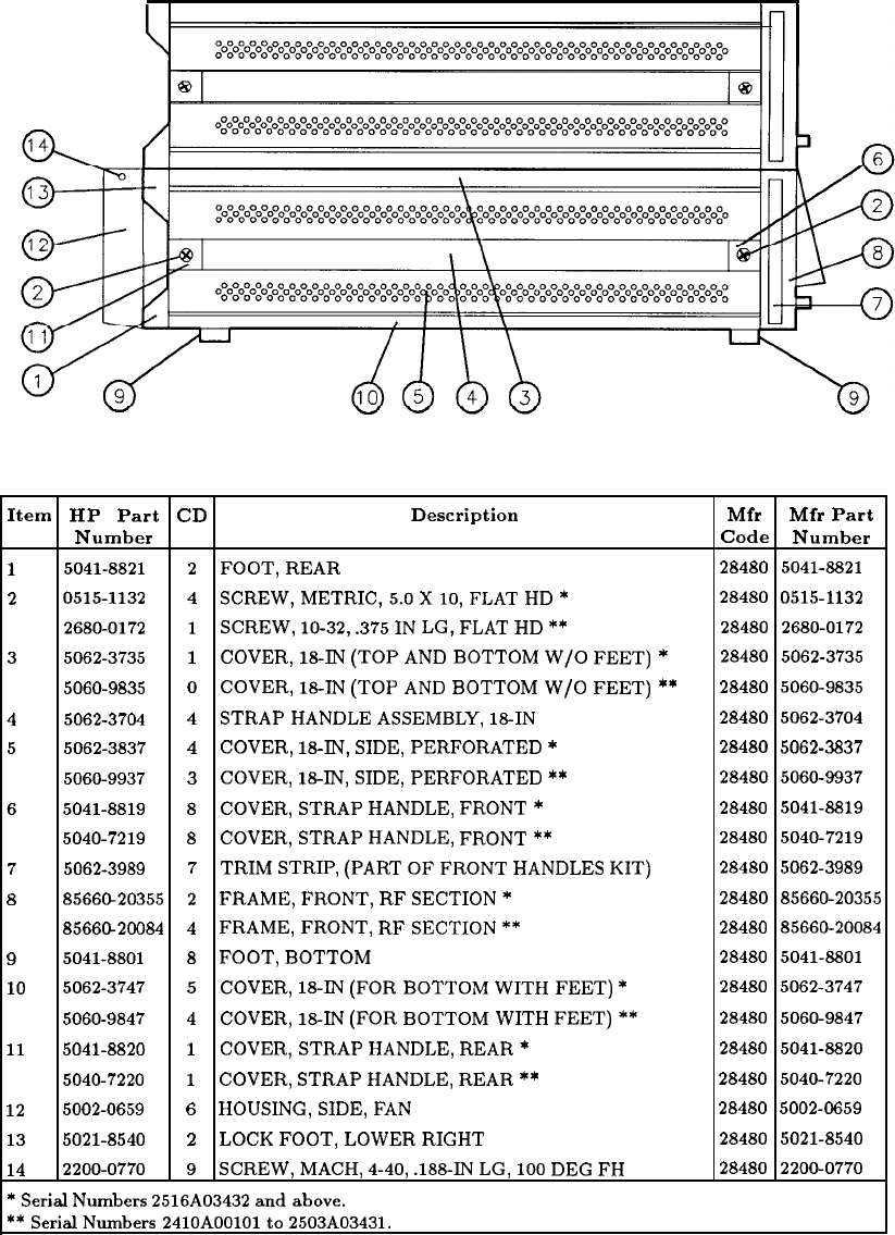
Item HP Part CD Description Mfr Mfr Part
Number Code Number
1
5041-8821
2
FOOT,
REAR
28480 5041-8821
2
0515-1132
4
SCREW,METRIC,5.0XlO,FLAT
HD
*
28480 0515-1132
2680-0172
1
SCREW,
10-32,
.375
IN
LG,
FLAT
HD
**
28480 2680-0172
3
5062-3735
1
COVER,
18-W
(TOP
AND
BOTTOM
W/O
FEET)
*
28480 5062-3735
5060-9835 0
COVER,
18-IN
(TOP
AND
BOTTOM
W/O
FEET) **
28480 5060-9835
4
5062-3704 4
STRAP
HANDLE
ASSEMBLY,
18-IN 28480
5062-3704
5
5062-3837
4
COVER,
18-W,
SIDE,
PERFORATED
*
28480
5062-3837
5060-9937 3
COVER,
18-IN,
SIDE,
PERFORATED
**
28480
5060-9937
65041-8819
8
COVER,
STRAP
HANDLE,
FRONT
*
28480
5041-8819
5040-7219
8
COVER,
STRAP
HANDLE,
FRONT
**
28480
5040-7219
7
5062-3989
7
TRIM
STRIP,
(PART
OF
FRONT
HANDLES
KIT)
28480
5062-3989
8
85660-20355
2
FRAME,
FRONT,
RF
SECTION
*
28480 85660-20355
8566G20084
4
FRAME,
FRONT,
RF
SECTION
**
28480 85660-20084
9
5041-8801
8
FOOT,
BOTTOM
28480 5041-8801
10
5062-3747
5
COVER,
18-IN
(FOR
BOTTOM
WITH
FEET)
*
28480
5062-3747
5060-9847
4
COVER,
18-IN
(FOR
BOTTOM
WITH
FEET)
**
28480
5060-9847
11
5041-8820
1
COVER,
STRAP
HANDLE,
REAR
*
28480
5041-8820
5040-7220
1
COVER,
STRAP
HANDLE,
REAR
**
28480 5040-7220
12
5002-0659
6
HOUSING,
SIDE,
FAN 28480
5002-0659
13
5021-8540
2
LOCK
FOOT,
LOWER
RIGHT
28480
5021-8540
14
2200-0770
9
SCREW,
MACH,
4-40,
.188-IN
LG,
100
DEG
FH 28480
2200-0770
*
Serial
Numbers
2516AO3432
and
above.
**
SerialNumbers
2410AOOlOlto
2503A03431.
Figure 4. RF Section Parts Identification, Left Side View
General Parts Listing 33
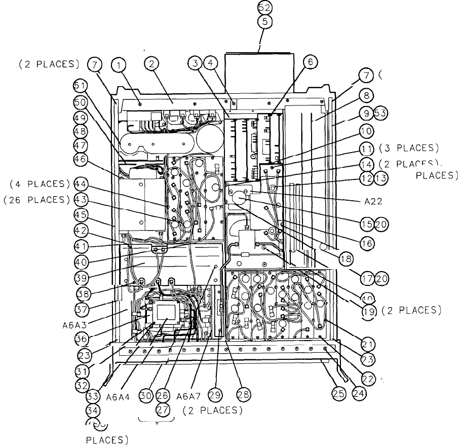
2
?
5
(8 PLACES)
(2
PLACES)
@
Q
(2 PLACES)
w
(2 PLACES)
wm
D
7 (2 PLACES)
(2
PLACiS)
;uI
1
w---/@
(2 PLACES)
-%i
(2
PLACES)
(6 PLACES)
(2 PLACES)
(37 PLACES)
(2
PEES)
(2 PLACES)
Figure 5. RF Section Parts Identification, Bottom View (1 of 3)
34 General Parts Listing
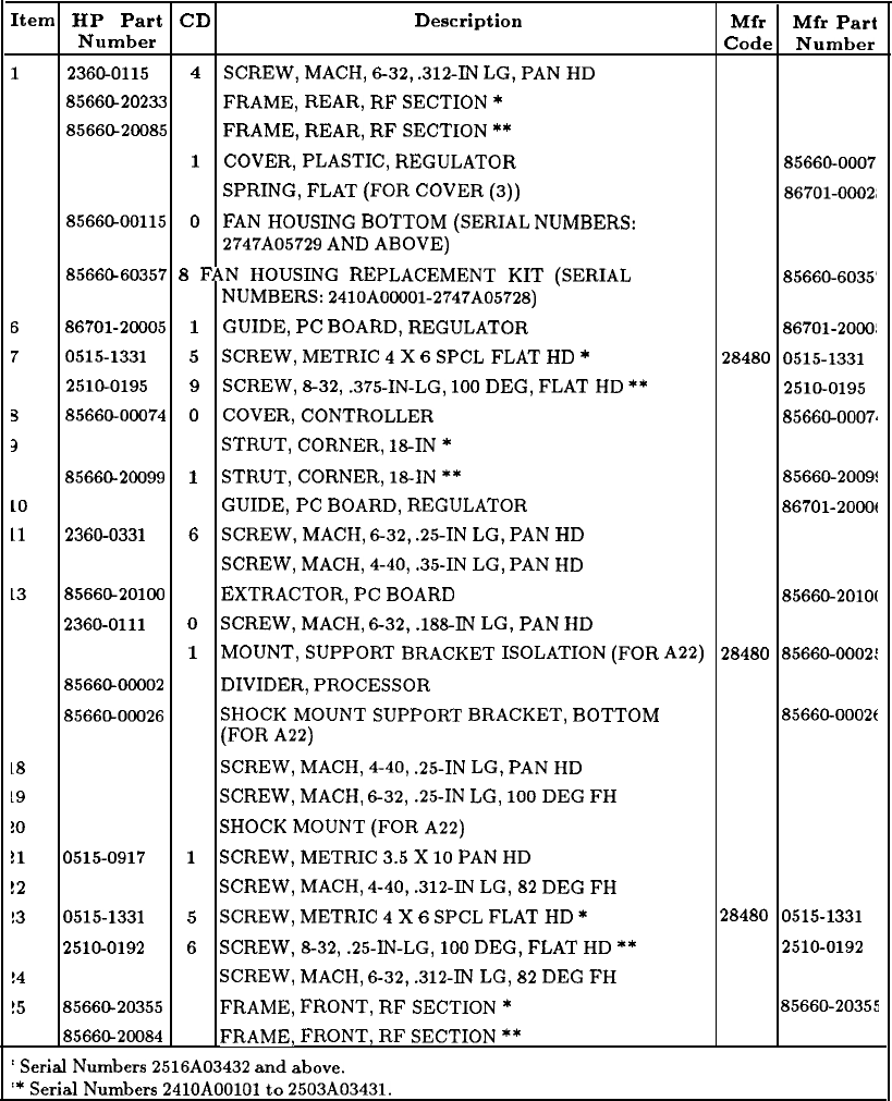
Item HP Part
CD
Description Mfr Mfr
Part
Number Code Number
1
2360-0115
4
SCREW,
MACH,
632,
.312-W
LG,
PAN
HD
28480 2360-0115
2
8566G20233
5
FRAME,
REAR,
RF
SECTION
*
28480 85660-2023
8566C20085
5
FRAME,
REAR,
RF
SECTION
**
28480 85660-2008
3
85660-00075
1
COVER,
PLASTIC,
REGULATOR
28480 85660-0007
4
86701-00028
6
SPRING,
FLAT
(FOR
COVER
(3))
28480
86701-0002,
5
8566&00115
0
FAN
HOUSING
BOTTOM
(SERIAL
NUMBERS:
28480
85660-0011.
2747AO5729
AND
ABOVE)
8566@60357
8
FAN
HOUSING
REPLACEMENT
KIT
(SERIAL
28480
85660-6035'
NUMBERS:
2410AOOOOl-2747A05728)
6
86701-20005
1
GUIDE,
PC
BOARD,
REGULATOR
28480
86701-2000:
7
0515-1331
5
SCREW,
METRIC
4
X
6
SPCL
FLAT
HD
*
28480 0515-1331
2510-0195 9
SCREW,
8-32,
.375-IN-LG,
100
DEG,
FLAT
HD
**
28480
2510-0195
3
85660-00074
0
COVER,
CONTROLLER
28480
85660-0007.
3
5021-5837
2
STRUT,
CORNER,
18-IN
*
28480 5021-5837
85660-20099
1
STRUT,
CORNER,
18IN
**
28480
85660-2009:
LO
86701-20006
2
GUIDE,
PC
BOARD,
REGULATOR
28480
86701-2OOOf
11
2360-0331 6
SCREW,
MACH,
632,
.25-IN
LG,
PAN
HD
28480
2360-0331
12
2200-0103
2
SCREW,
MACH,
4-40,
.35-IN
LG,
PAN
HD
28480 2200-0103
13
8566CL20100
5
EXTRACTOR,
PC
BOARD
28480
85660-2OlOC
14
2360-0111 0
SCREW,
MACH,
632,
.188-W
LG,
PAN
HD
28480
2360-0111
15
85660-00025
1
MOUNT,
SUPPORT
BRACKET
ISOLATION
(FOR A22)
28480
85660-0002:
16
8566@00002
4
DIVIDER,
PROCESSOR
28480
85660-0000:
17
8566CLOOO26
2
SHOCK
MOUNT
SUPPORT
BRACKET,
BOTTOM
28480
85660-0002t
(FOR
A22)
L8
2200-0103
2
SCREW,
MACH,
4-40,
.25-IN
LG,
PAN
HD
28480 2200-0103
19
2360-0333 8
SCREW,
MACH,
632,
.25-IN
LG,
100
DEG
FH
28480 2360-0333
!O
1520-0205
2
SHOCK
MOUNT
(FOR
A22)
28480
1520-0205
!l
0515-0917
1
SCREW,
METRIC
3.5
X
10
PAN
HD
28480 0515-0917
!2
2200-0105
4
SCREW,
MACH,
4-40,
.312-IN
LG,
82
DEG
FH
28480 2200-0105
!3
0515-1331
5
SCREW,
METRIC
4
X
6
SPCL
FLAT
HD
*28480 0515-1331
2510-0192
6
SCREW,
8-32,
.25-IN-LG,
100
DEG,
FLAT
HD
**
28480
2510-0192
!4
2360-0116
5
SCREW,
MACH,
632,
.312-W
LG,
82
DEG
FH
28480 2360-0116
!5
85660-20355
2
FRAME,
FRONT,
RF
SECTION
*
28480
85660-20355
8566CL20084
2
FRAME,
FRONT,
RF
SECTION
**
28480
85660-20084
’
Serial
Numbers
2516A03432
and
above.
‘*
Serial
Numbers
2410AOOlOl
to
2503A03431.
Figure 5. RF Section Parts Identification, Bottom View (2 of 3)
General Parts Listing 35
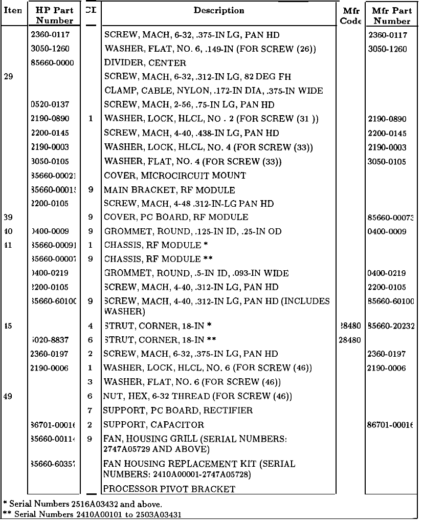
Iten
HP Part
Number
26
2360-0117
27
3050-1260
28
8566CLOOOO
29
2360-0116
30
1400-0053
31 D520-0137
32
2190-0890
33
2200-0145
34
2190-0003
35
3050-0105
36 3566CLOOO21
37 3566CLOOOl:
38
2200-0105
39
35660-0007:
10
140~0009
11
35660-00091
~5660-00005
12
1400-0219
13
!200-0105
14
55660-601OC
L5
1566620232
iO20-8837
46
2360-0197
47
2190-0096
48 3050-0227
49
2420-0002
50 35660-0001:
51
36701-OOOlf
52
35660-0011~
3566Cb6035;
-
6
6
3
5
4
3
1
2
8
6
7
9
4
9
9
1
9
3
4
9
SCREW,
MACH,
632,
.375-IN
LG,
PAN
HD
WASHER,
FLAT,
NO.
6,
.149-IN
(FOR
SCREW
(26))
DIVIDER,
CENTER
8
SCREW,
MACH,
632,
.312-IN
LG,
82
DEG
FH
CLAMP,
CABLE,
NYLON,
.172-IN
DIA,
.375-IN
WIDE
SCREW,
MACH,
2-56,
.75-IN
LG,
PAN
HD
WASHER,
LOCK,
HLCL,
NO
.2
(FOR
SCREW
(31))
SCREW,
MACH,
4-40,
.438-IN
LG,
PAN
HD
WASHER,
LOCK,
HLCL,
NO.
4
(FOR
SCREW
(33))
WASHER,
FLAT,
NO.
4
(FOR
SCREW
(33))
COVER,
MICROCIRCUIT
MOUNT
MAIN
BRACKET,
RF
MODULE
SCREW,
MACH,
4-48
.312-IN-LG
PAN
HD
COVER,
PC
BOARD,
RF
MODULE
GROMMET,
ROUND,
.125IN
ID,
.25-IN
OD
CHASSIS,
RF
MODULE
*
CHASSIS,
RF
MODULE
**
GROMMET,
ROUND,
.5-IN
ID,
.093-IN
WIDE
SCREW,
MACH,
4-40,
.312-IN
LG,
PAN
HD
SCREW,
MACH,
4-40,
.312-IN
LG,
PAN
HD
(INCLUDES
WASHER)
STRUT,
CORNER,
18-IN
*
STRUT,
CORNER,
18-IN
**
SCREW,
MACH,
632,
.375-IN
LG,
PAN
HD
WASHER,
LOCK,
HLCL,
NO.
6
(FOR
SCREW
(46))
WASHER,
FLAT,
NO.
6
(FOR
SCREW
(46))
NUT,
HEX,
632
THREAD
(FOR
SCREW
(46))
SUPPORT,
PC
BOARD,
RECTIFIER
SUPPORT,
CAPACITOR
FAN,
HOUSING
GRILL
(SERIAL
NUMBERS:
2747A05729
AND
ABOVE)
FAN
HOUSING
REPLACEMENT
KIT
(SERIAL
NUMBERS:
2410AOOC91-2747A05728)
PROCESSOR
PIVOT
BRACKET
53
35660-00004 6
-
*
Serial
Numbers
2516A03432
and
above.
-
:I:
Description Mfr
MD
Part
Code
Number
28480
2360-0117
28480
3050-1260
28480
85660-0000:
28480 2360-0116
28480
1400-0053
28480 0520-0137
28480
2190-0890
28480
2200-0145
28480
2190-0003
28480
3050-0105
28480 85660-00021
28480 85660-0001:
28480 2200-0105
28480 85660~00072
18480
0400-0009
18480 85660-00091
18480 85660-00007
18480
0400-0219
38480
2200-0105
18480 85660-60100
!8480
95660-20232
,848O 5020-8837
28480
2360-0197
28480
2190-0006
28480 3050-0227
28480
2420-0002
28480 85660-0001:
28480 86701-0001~
28480 85660-00114
28480 85660-60357
18480 85660-00004
Figure 5. RF Section Parts Identification, Bottom View (3 of 3)
36 General Parts Listing
This page intentionally left blank
General Parts Listing 37
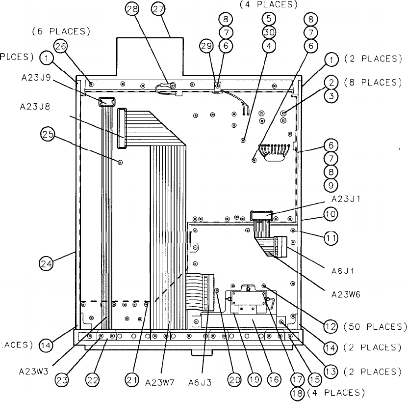
(2
PI
A23J8
( 11 PLACES)
@,
0’
24
(2 PL
(8 PLACES (4 PLACES)
“ill,@
(4 PLACES)
!!&yj-j;im
(6 PLACES)
(2 PLACES)
Figure 6. RF Section Parts Identification, Top View (1 of 2)
38 General Parts Listing
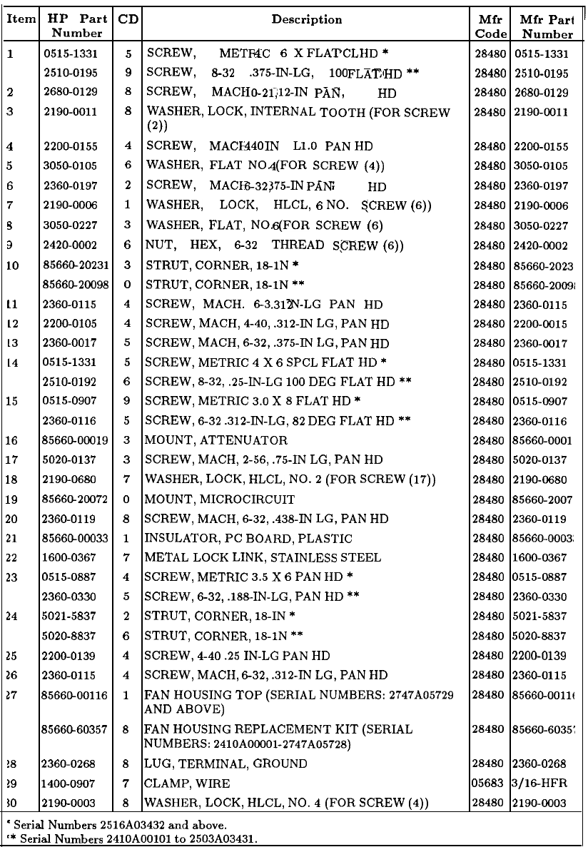
Item HP Part CD Description
Mfr
Mfr
Part
Number Code Number
1
0515-1331
5
SCREW,
METRIC
X
SPCL
*
4
6
FLAT
HD 28480 0515-1331
2510-0195
9
SCREW,
8-32
.375-IN-LG,
100
DEG
**
FLAT
HD 28480 2510-0195
2
2680-0129 8
SCREW,
MACH,
.312-IN
LG,
10-21,
PAN
HD 28480 2680-0129
3
2190-0011
8
WASHER,
LOCK,
INTERNAL
TOOTH
(FOR
SCREW
28480 2190-0011
(2))
4
2200-0155
4
SCREW,
MACH.
IN
LG
PAN
440
1.0
HD 28480 2200-0155
5
3050-0105 6
WASHER,
FLAT
NO.
(FOR
SCREW
(4))
4
28480
3050-0105
6
2360-0197
2
SCREW,
MACH,
.375-IN
LG
632,
PAN
HD 28480
2360-0197
7
2190-0006
1
WASHER,
LOCK,
HLCL,
NO.
(FOR
(6))
6
SCREW
28480
2190-0006
s
3050-0227
3
WASHER,
FLAT,
NO.
(FOR
SCREW
(6)
6
28480
3050-0227
3
2420-0002
6
NUT,
HEX,
632
THREAD
(FOR
(6))
SCREW
28480 2420-0002
LO
8566@20231
3
STRUT,
CORNER,
18-1N
*
28480
85660-2023
8566@20098
0
STRUT,
CORNER,
18-1N
**
28480 85660-20091
11
2360-0115
4
SCREW,
MACH.
632
IN-LG
PAN
HD
.312 28480 2360-0115
12
2200-0105
4
SCREW,
MACH,
4-40,
.312-IN
LG,
PAN HD 28480 2200-0015
13
2360-0017
5
SCREW,
MACH,
6-32,
.375-W
LG,
PAN HD 28480
2360-0017
14
0515-1331
5
SCREW,
METRIC
4
X
6
SPCL
FLAT
HD
*
28480 0515-1331
2510-0192
6
SCREW,
8-32,
.25-IN-LG
100
DEG
FLAT
HD
**
28480 2510-0192
15
0515-0907
9
SCREW,
METRIC
3.0
X
8
FLAT
HD
*
28480
0515-0907
2360-0116
5
SCREW,
6-32
.312-IN-LG,
82
DEG
FLAT
HD
**
28480
2360-0116
16
8566C-00019 3
MOUNT,
ATTENUATOR
28480 85660-0001
17
5020-0137
3
SCREW,
MACH,
2-56,
.75-IN
LG,
PAN
HD 28480
5020-0137
18
2190-0680
7
WASHER,
LOCK,
HLCL,
NO.
2
(FOR
SCREW
(17))
28480
2190-0680
19
8566&20072
0
MOUNT,
MICROCIRCUIT
28480
85660-2007
20
2360-0119
8
SCREW,
MACH,
632,
.438-IN
LG,
PAN
HD 28480 2360-0119
21
8566GOOO33
1
INSULATOR,
PC
BOARD,
PLASTIC
28480 85660-0003:
22
1600-0367
7
METAL
LOCK
LINK,
STAINLESS
STEEL
28480 1600-0367
23
0515-0887
4
SCREW,
METRIC
3.5
X
6
PAN
HD
*
28480
0515-0887
2360-0330
5
SCREW,
632,
.188-IN-LG,
PAN
HD
**
28480
2360-0330
24
5021-5837
2
STRUT,
CORNER,
18-IN
*
28480
5021-5837
5020-8837
6
STRUT,
CORNER,
18-1N
**
28480
5020-8837
25
2200-0139
4
SCREW,
4-40
.25
IN-LG
PAN
HD 28480 2200-0139
16
2360-0115
4
SCREW,
MACH,
632,
.312-IN
LG,
PAN
HD 28480 2360-0115
17
8566CkOO116
1
FAN
HOUSING
TOP
(SERIAL
NUMBERS:
2747A05729
28480 85660-OOllt
AND
ABOVE)
8566&60357
8
FAN
HOUSING
REPLACEMENT
KIT
(SERIAL
28480
85660-6035:
NUMBERS:
2410A00001-2747A05728)
!8 2360-0268
8
LUG,
TERMINAL,
GROUND
28480
2360-0268
19
1400-0907
7
CLAMP,
WIRE
05683
3/16HFR
!O
2190-0003
8
WASHER,
LOCK,
HLCL,
NO.
4
(FOR
SCREW
(4)) 28480
2190-0003
'
SerialNumbers
2516A03432
andabove.
‘*
Serial
Numbers
2410AOOlOl
to
2503A03431.
Figure 6. RF Section Parts Identification, Top View (2 of 2)
General Parts Listing
39
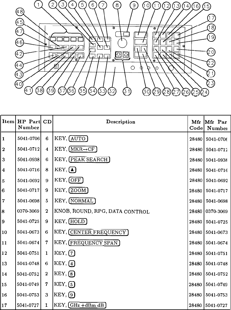
Item HP Part CD Description Mfr Mfr
Par
Number Code Number
1
5041-0706
6
KEY,
Czj
28480 5041-07Of
2
5041-0712
4
KEY,
k-j
28480 5041-0711
35041-0938
6
KEY,
CPEAK
SEARCH)
28480 5041-0931
4
5041-0716
8
KEY,
@
28480 5041-0716
5
5041-0692
9
KEY,
loFF)
28480 5041-0692
6
5041-0717
9
KEY,
m
28480 5041-0717
7
5041-0698
5
KEY,
(j-1
28480 5041-0698
8
0370-3069
2
KNOB,
ROUND,
RPG,
DATA CONTROL
28480 0370-3069
9
5041-0725
9
KEY,
[jj
28480 5041-0725
10
5041-0673
6
KEY,
[CENTER
FREQUENCY)
28480 5041-0673
11
5041-0674
7
KEY,
@RE$UENCy
SPAN]
28480 5041-0674
12
5041-0751
1
KEY,
@
28480 5041-0751
13
5041-0748
6
KEY,
@
28480 5041-0748
14
5041-0752
2
KEY,
@
28480 5041-0752
15
5041-0749
7
KEY,
@
28480 5041-0749
16
5041-0753
3
KEY,
@
28480 5041-0753
17
5041-0727
1
KEY,
[GHz
+dBm dB]
28480 5041-0727
Figure 7. RF Section Parts Identification, Front Panel, Front View (1 of 2)
40 General Parts Listing
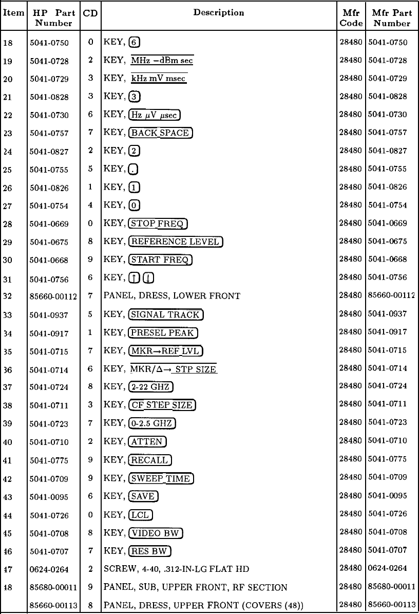
Item HP Part CD Description
Number
18
5041-0750
0
KEY,@
19
5041-0728
2
KEY,
MHz
-dBm
set
20
5041-0729
3
KEY,
kHz
mV
msec
21
5041-0828
3
KEY,
@
22
5041-0730
6
KEY,
[Hz]
23
5041-0757
7
KEY,
(BACK
SPACE_)
14
5041-0827
2
KEY,
@
25
5041-0755
5
KEY,
0
26
5041-0826
1
KEY,@
27 5041-0754 4
KEY,@
28
5041-0669
0
KEY,
(STOP
FREQ)
29
5041-0675
8
KEY, (REFERENCELEVEL)
30
5041-0668
9
KEY,[sTARTFREQJ
31
5041-0756
6
KEY,@0
32
85660-00112
7
PANEL,DRESS,LOWERFRONT
33
5041-0937
5
KEY,@IGNALTRAcK_)
34
5041-0917
i
KEY,
[PRESELPEAKJ
35
5041-0715
7
KEY,[MKR-+REF
LVL_)
36
5041-0714
6
KEY,
MKR/A+
STPSIZE
37 5041-0724
8
KEY,[w)
38 5041-0711
3
KEY,
&F
STEP
SIZE_)
39 5041-0723
7
KEY,
(O-2.5)
40
5041-0710
2
KEY,
cm-
41
5041-0775
9
KEY,
Cm)
42
5041-0709
9
KEY,@wmP
TIME_)
43
5041-0095
6
KEY,-
44
5041-0726
0
KEY,(LCL)
15
5041-0708
8
KEY,
C-1
16
5041-0707
7
KEY,
cm-
17
0624-0264
2
SCREW,4-40,.312-IN-LG
FLAT
HD
18
8568GOOOll
9
PANEL,SUB,UPPERFRONT,RFSECTION
85660-00113
8
PANEL,DRESS,UPPER
FRONT
(COVERS
(48))
Mfr Mfr Part
Code Number
28480 5041-0750
28480 5041-0728
28480 5041-0729
28480 5041-0828
28480
5041-0730
28480
5041-0757
28480 5041-0827
28480 5041-0755
28480
5041-0826
28480 5041-0754
28480 5041-0669
28480 5041-0675
28480 5041-0668
28480 5041-0756
28480 85660-00112
28480
5041-0937
28480 5041-0917
28480 5041-0715
28480 5041-0714
28480 5041-0724
28480 5041-0711
28480 5041-0723
28480 5041-0710
28480 5041-0775
28480 5041-0709
28480 5041-0095
28480 5041-0726
28480 5041-0708
28480
5041-0707
28480
0624-0264
28480 85680-00011
28480 85660-00113
Figure 7. RF Section Parts Identification, Front Panel, Front View (2 of 2)
General Parts Listing 41
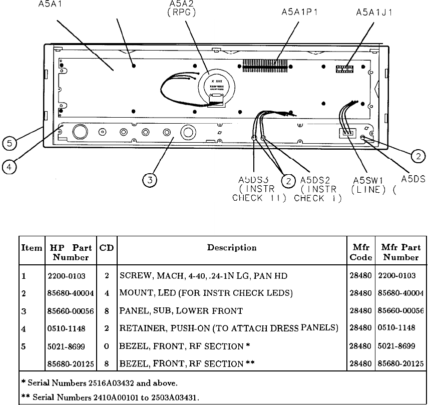
A5Al
(14 PLACES)
KEYBOARD 0
A5A2
1
(RPG)
ASAlP
A5AlJl
(3 PLACES)
A5DS
1
STANDBY)
Item HP Part CD Description Mfr Mfr Part
Number Code Number
1
2200-0103
2
SCREW,
MACH,
4-40,
.24-1N
LG,
PAN
HD 28480 2200-0103
2
85680-40004
4
MOUNT,
LED
(FOR
INSTR
CHECK
LEDS) 28480 85680-40004
3
8566&00056
8
PANEL,
SUB,
LOWER
FRONT
28480 85660-00056
4
0510-1148
2
RETAINER,
PUSH-ON
(TO
ATTACH
DRESS
PANELS) 28480 0510-1148
5
5021-8699
0
BEZEL,
FRONT,
RF
SECTION
*
28480 5021-8699
8568@20125
8
BEZEL,
FRONT,
RF
SECTION
**
28480 85680-20125
*
Serial
Numbers
2516A03432
and
above.
**
Serial
Numbers
2410AOOlOl
to
2503A03431.
Figure 8. RF Section Parts Identification, Front Panel
42 General Parts Listing
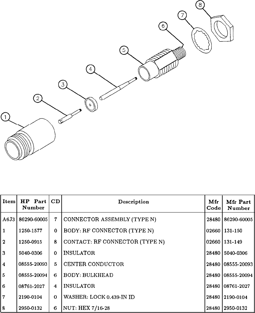
Item HP Part CD Description Mfr Mfr Part
Number Code Number
A6J3
8629&60005
7
CONNECTOR
ASSEMBLY
(TYPE
N) 28480 86290-60005
1
1250-1577 0
BODY:
RF
CONNECTOR
(TYPE
N) 02660 131-150
2
1250-0915
8
CONTACT:
RF
CONNECTOR
(TYPE
N) 02660 131-149
3
5040-0306
0
INSULATOR
28480
5040-0306
4
0855520093
5
CENTER
CONDUCTOR
28480 08555-20093
5
08555-20094
6
BODY:
BULKHEAD
28480
08555-20094
6
08761-2027
4
INSULATOR
28480 08761-2027
7
2190-0104
0
WASHER:
LOCK
0.439-IN
ID
28480
2190-0104
8
2950-0132
6
NUT:
HEX
7/16-28
28480 2950-0132
Figure 9. RF Input Connector, Parts Identification
General Parts Listing 43
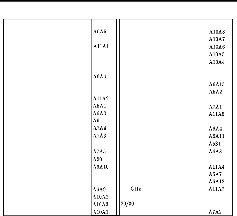
Major Assembly and Component Locations
Major Assembly and Component Locations
Assembly
ACLU
Controller
Coupler/Isolator/Amplifier (CIA)
Digital Analog Converter (DAC)
FM Coil Driver
Fan
First Converter
Front Panel
Front Panel Interface
Interconnect
Keyboard
Last Converter
Line Module
M/N Output
M/N Phase Detector
M/N Reference
M/N Reference Motherboard
Main Coil Driver
Miscellaneous Bias/Relay Driver
Motherboard
Negative Regulator
Phase Lock
Phase Lock Loop 1 Divider
Phase Lock Loop 1 IF
Phase Lock Loop 1 VCO
Location
A6A5
Al5
AllAl
A19
A21
A24
A6A6
A5
Al2
AllA
A5Al
A6A3
A9
h7A4
h7A3
A7
A7A5
420
46AlO
423
418
46A9
410A2
410A3
4lOAl
Assembly Location
Phase Lock Loop 2 Discriminator AlOA8
Phase Lock Loop 2 Divider AlOA7
Phase Lock Loop 2 Phase Detector AlOA6
Phase Lock Loop 2 VCO AlOA5
Phase Lock Loop 3 Up Converter AlOA4
Positive Regulator Al7
RF Module A6
RF Module Motherboard A6A13
Rotary Pulse Generator (RPG) A5A2
Rectifier A8
Reference Phase Detector
A7Al
Sampler
AllA
Scan Generator Al6
Second Converter A6A4
Slope Generator
A6All
STANDBY/ON Switch
A5Sl
YIG-TUNED MIXER (YTX) A6A8
YTO Loop All
YTO Phase Detector
AllA
YTX Current Driver A6A7
YTX Driver A6A12
6.2 GHz Low-Pass Filter
AllA
10 MHz Frequency Standard A22
20130
Synthesizer A10
100 MHz VCXO A7A2
Major Assembly and Component Locations
1
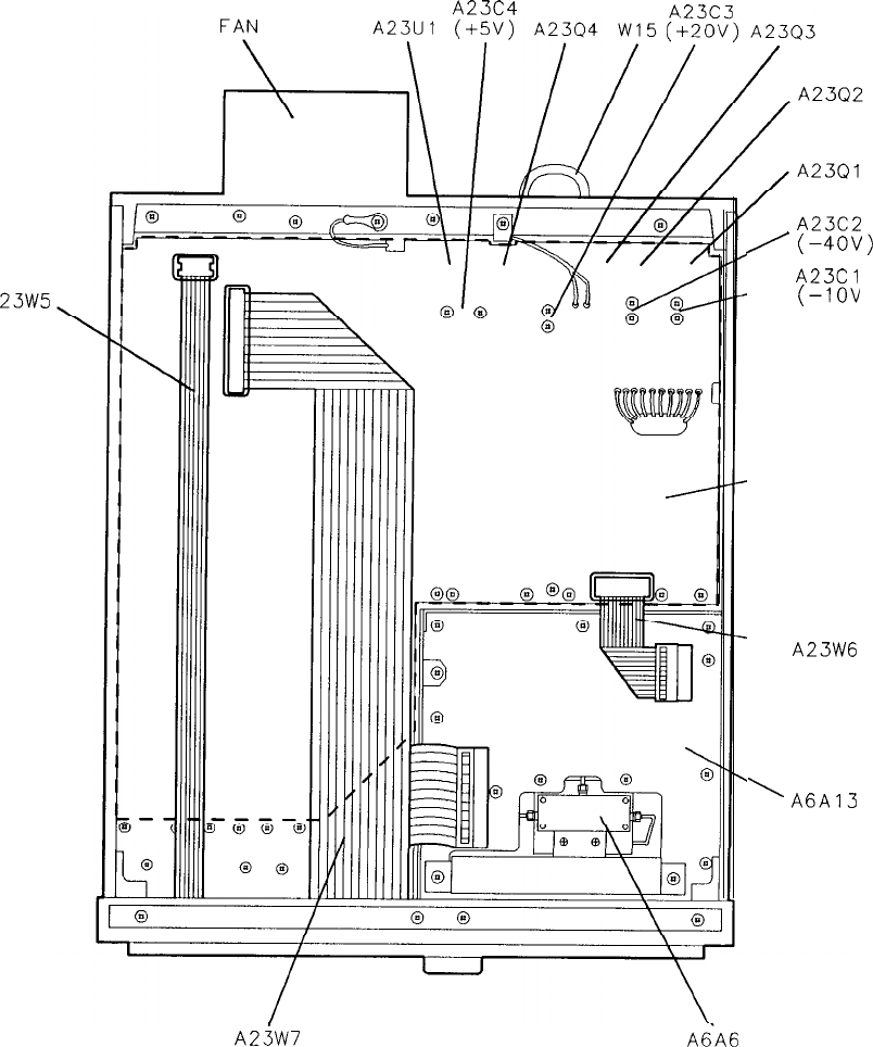
A
23W5
A24
A23C4
A23C2
/
(-4OV)
,
A23Cl
(-1ov
A23
‘MOTHERBOARD
.
A23W6
\
A6A13
RF MODULE
MOTHERBOARD
A23W7
AiA6
FIRST CONVERTER
Figure 1. Major Assembly and Component Locations, Bottom View
2
Major Assembly and Component Locations
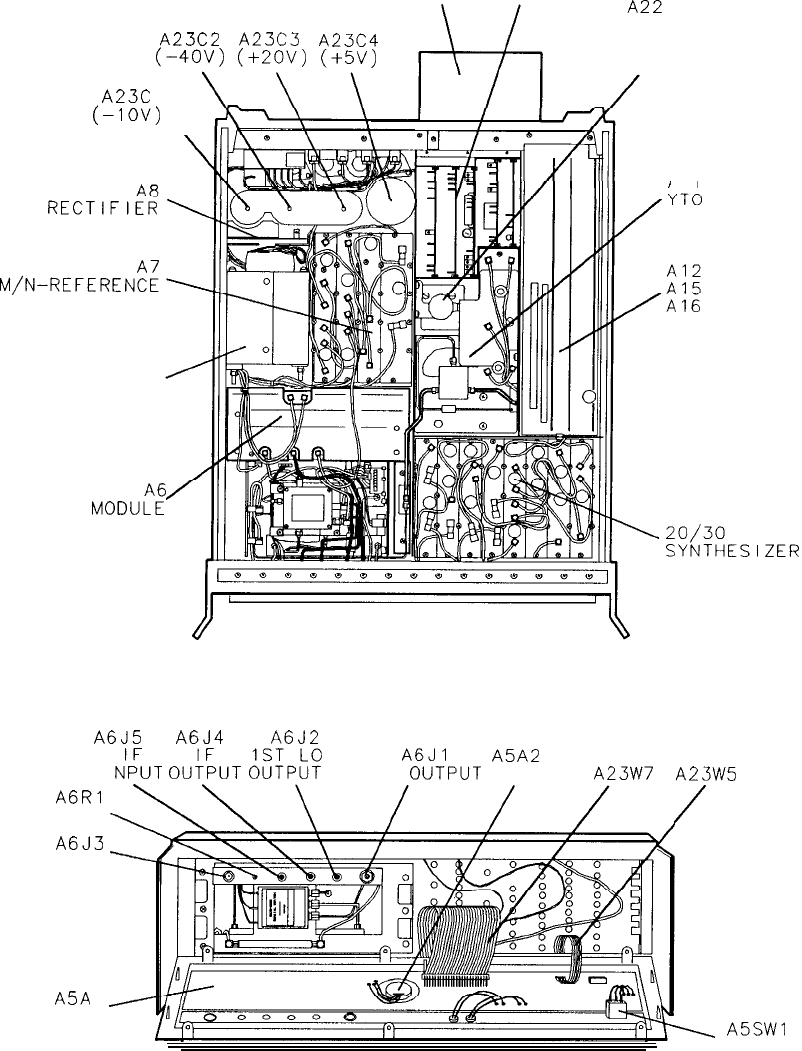
Al7
THROUGH
A24 A21
10 MHz
A23C2
A23C3
A23C4
(-4OV)
(+ZOv)
(+5v)
FREQUENCY
STANDARD
A23C
1
(-IOV)
\
RECTlFlEd
M/N-REFEREN;;
TRANSFORM:;
RF
MOD”;:
Al 1
A6J5 A6J4 A6J2
I
N’:“T
0”t;“T
;uSfP:?
CAL
A%PUT
A5A2
RPG
A23W7
A6Rl
AMPTD CAL
A6J3
RF INPUT
A5A
1
KEYBOARD
A23W5
/
\
ASSWI
STANDBY/ON
Figure 2. Major Assembly and Component Locations, Top and Front Views
Major Assembly and Component Locations
3
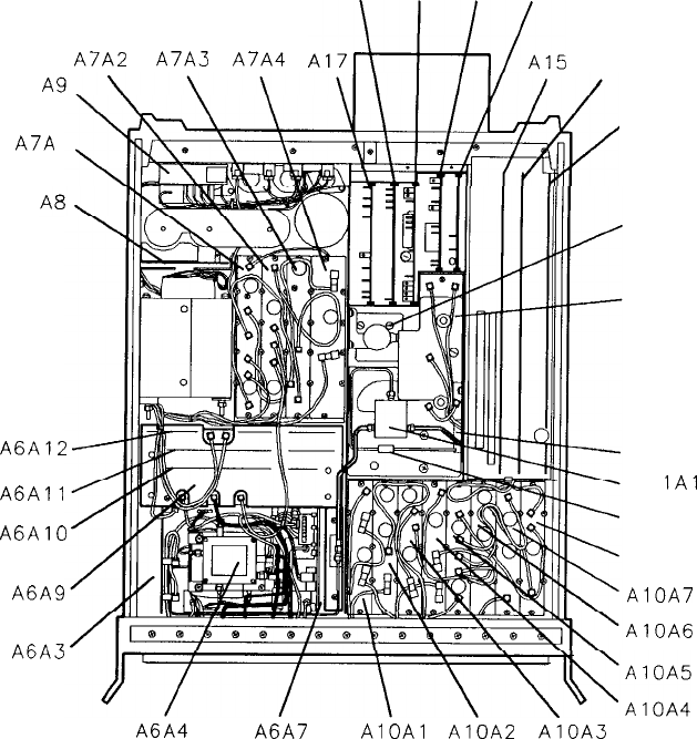
Al8 A19 A20 A21
A7A2 A7A3
A7A4
.i,!j&!-,~li
Al6
A7A
1
A6A12
A6All
A6AlO
A6A9
A6A3
,A12
A22
Al IA2
Al 1
Al
1Al
Al IA7
A10A8
AlOA7
AlOA6
A6A4 A6A7
AlOAl
AlOA2
AlOA3
Figure 3. Major Assemby and Component Locations, Top View
4
Major Assembly and Component Locations
Table 1-2. Hewlett-Packard Sales and Service Offices
I
I
,
I
1
1
(
t
1
1
(
t
1
:
1
(
1
1
t
1
1
1
1
1
I
I
!
1
US FIELD OPERATIONS
HEADQUARTERS
Kewlett-Packard Company
19320 Pruneridge Avenue
Cupertino, CA 95014, USA
(408) 973-1919
California
Hewlett-Packard Co.
1421 South Manhattan Ave.
Fullerton, CA 92631
(714)
999-6700
Hewlett-Packard Co.
301 E. Evelyn
Mountain View, CA 94041
:415)
694-2000
Colorado
Hewlett-Packard Co.
24 Inverness Place, East
Englewood, CO 80112
:303)
649-5000
Georgia
Hewlett-Packard Co.
1000 South Park Place
4tlanta,
GA 30339
:404)
955- 1500
UliIlOiS
Hewlett-Packard Co.
j201
Tollview Drive
Rolling Meadows, IL 60008
:708)
255-9800
Yew
Jersey
Hewlett-Packard Co.
120 W. Century Road
Paramus, NJ 07653
1201)
599-5000
rexas
Hewlett-Packard Co.
)30
E. Campbell Rd.
Richardson, TX 75081
1214)
231-6101
EUROPEAN OPERATION
HEADQUARTERS
Hewlett-Packard S.A.
150, Route du Nant-d’Avri1
1217 Meyrin
2/Geneva
Switzerland
(41 22) 780.8111
France
Hewlett-Packard France
1 Avenue Du Canada
Zone
D’Activite
De Courtaboeuf
F-91947 Les Ulis Cedex
France
(33 1) 69 82 60 60
Germany
Hewlett-Packard
GmbH
Berner Strasse 117
6000 Frankfurt 56
West Germany
(49 69) 500006-O
Great Britain
Hewlett-Packard Ltd.
Eskdale Road, Winnersh Triangle
Wokingham, Berkshire
RGll
5DZ
England
(44 734) 696622
INTERCON OPERATIONS
HEADQUARTERS
Hewlett-Packard Company
3495 Deer Creek Rd.
Palo Alto, California 94304-1316
(415) 857-5027
Australia
Hewlett-Packard Australia Ltd.
31-41 Joseph Street
Blackburn, Victoria 3130
(61 3) 895-2895
Canada
Hewlett-Packard (Canada) Ltd.
17500 South Service Road
Trans-Canada Highway
Kirkland, Quebec H9J
2X8
Canada
(514) 697-4232
Japan
Yokogawa-Hewlett-Packard Ltd.
1-27-15 Yabe, Sagamihara
Kanagawa 229, Japan
(81 427) 59-1311
People’s Republic
of China
China Hewlett-Packard, Ltd.
38 Bei San Huan Xl Road
Shuang Yu Shu
Hai Dian District
Beijing, China
(86 1) 256-6888
Singapore
Hewlett-Packard Singapore
Pte. Ltd.
1150 Depot Road
Singapore 0410
(65) 273 7388
Taiwan
Hewlett-Packard Taiwan
8th Floor, H-P Building
337 Fu Hsing North Road
Taipei, Taiwan
(886 2) 712-0404
Major Assembly and Component Locations
5

HEWLETT
PACKARD
HP Part No.
65660-90210
Printed in USA
