Hp Xp P9500 Disk Array Owners Manual Owner Guide
2015-01-05
: Hp Hp-Xp-P9500-Disk-Array-Owners-Manual-157626 hp-xp-p9500-disk-array-owners-manual-157626 hp pdf
Open the PDF directly: View PDF ![]() .
.
Page Count: 104 [warning: Documents this large are best viewed by clicking the View PDF Link!]
- HP XP P9500 Owner Guide
- Contents
- 1 Introduction
- 2 Functional and operational characteristics
- 3 System components
- 4 Power On/Off procedures
- 5 Troubleshooting
- 6 Support and other resources
- A Comparing the XP24000/XP20000 Disk Array and P9500
- B Specifications
- C Regulatory compliance notices
- Regulatory compliance identification numbers
- Federal Communications Commission notice
- Canadian notice (Avis Canadien)
- European Union notice
- Japanese notices
- Korean notices
- Taiwanese notices
- Turkish recycling notice
- Laser compliance notices
- Recycling notices
- English recycling notice
- Bulgarian recycling notice
- Czech recycling notice
- Danish recycling notice
- Dutch recycling notice
- Estonian recycling notice
- Finnish recycling notice
- French recycling notice
- German recycling notice
- Greek recycling notice
- Hungarian recycling notice
- Italian recycling notice
- Latvian recycling notice
- Lithuanian recycling notice
- Polish recycling notice
- Portuguese recycling notice
- Romanian recycling notice
- Slovak recycling notice
- Spanish recycling notice
- Swedish recycling notice
- Battery replacement notices
- Glossary
- Index

HP XP P9500 Owner Guide
Abstract
This guide describes the operation of the HP XP P9500 disk array. Topics include a description of the disk array hardware,
instructions on how to manage the disk array, descriptions of the disk array control panel and LED indicators, troubleshooting,
and regulatory statements. The intended audience is a storage system administrator or authorized service provider with
independent knowledge of the HP XP P9500 disk array and the HP Remote Web Console.
HP Part Number: AV400-96608
Published: January 2014
Edition: Tenth

© Copyright 2010, 2014 Hewlett-Packard Development Company, L.P.
The information contained herein is subject to change without notice. The only warranties for HP products and services are set forth in the express
warranty statements accompanying such products and services. Nothing herein should be construed as constituting an additional warranty. HP shall
not be liable for technical or editorial errors or omissions contained herein.
Acknowledgements
Microsoft®, Windows®, Windows® XP, and Windows NT® are U.S. registered trademarks of Microsoft Corporation.
Java and Oracle are registered trademarks of Oracle and/or its affiliates.
Export Requirements
You may not export or re-export this document or any copy or adaptation in violation of export laws or regulations.
Without limiting the foregoing, this document may not be exported, re-exported, transferred or downloaded to or within (or to a national resident
of) countries under U.S. economic embargo, including Cuba, Iran, North Korea, Sudan, and Syria. This list is subject to change.
This document may not be exported, re-exported, transferred, or downloaded to persons or entities listed on the U.S. Department of Commerce
Denied Persons List, Entity List of proliferation concern or on any U.S. Treasury Department Designated Nationals exclusion list, or to parties directly
or indirectly involved in the development or production of nuclear, chemical, biological weapons, or in missile technology programs as specified
in the U.S. Export Administration Regulations (15 CFR 744).
Warranty
WARRANTY STATEMENT: To obtain a copy of the warranty for this product, see the warranty information website:
http://www.hp.com/go/storagewarranty

Contents
1 Introduction...............................................................................................6
P9500 overview.......................................................................................................................6
Hardware overview...................................................................................................................6
Controller chassis.................................................................................................................7
Drive chassis.......................................................................................................................8
Features..................................................................................................................................9
Scalability...........................................................................................................................9
High performance..............................................................................................................10
High capacity...................................................................................................................10
Connectivity......................................................................................................................11
P9500.........................................................................................................................11
Remote Web Console....................................................................................................11
High reliability...................................................................................................................11
Non disruptive service and upgrades....................................................................................11
Economical and quiet.........................................................................................................11
Specifications.........................................................................................................................12
Software features and functions................................................................................................13
2 Functional and operational characteristics....................................................17
System architecture overview....................................................................................................17
Hardware architecture.............................................................................................................17
RAID implementation overview.................................................................................................17
Array groups and RAID levels..............................................................................................17
Sequential data striping......................................................................................................19
LDEV striping across array groups........................................................................................19
CU Images, LVIs, and Logical Units...........................................................................................20
CU images.......................................................................................................................20
Logical Volume images.......................................................................................................21
Logical Units.....................................................................................................................21
Mainframe operations.............................................................................................................21
Mainframe compatibility and functionality.............................................................................21
Mainframe operating system support....................................................................................22
Mainframe configuration.....................................................................................................22
System option modes, host modes, and host mode options...........................................................22
System option modes..........................................................................................................22
Host modes and host mode options......................................................................................51
Open systems operations.........................................................................................................51
Open systems compatibility and functionality.........................................................................52
Open systems host platform support.....................................................................................52
Open systems configuration.................................................................................................52
Remote Web Console.............................................................................................................53
3 System components..................................................................................54
Controller chassis...................................................................................................................54
System control panel...............................................................................................................56
Drive chassis..........................................................................................................................57
Cache memory......................................................................................................................59
Memory operation..................................................................................................................60
Data protection......................................................................................................................60
Shared memory......................................................................................................................61
Flash storage chassis...............................................................................................................61
P9000 flash module...........................................................................................................61
Contents 3
Flash module unit...................................................................................................................62
Flash storage chassis...............................................................................................................63
Cache memory......................................................................................................................64
System capacities with smart flash modules................................................................................64
4 Power On/Off procedures.........................................................................66
Safety and environmental information........................................................................................66
Standby mode.......................................................................................................................66
Power On/Off procedures.......................................................................................................66
Power On procedures.........................................................................................................66
Power Off procedures.........................................................................................................67
Battery backup operations.......................................................................................................67
Cache destage batteries.....................................................................................................68
Battery life .......................................................................................................................68
Long term array storage......................................................................................................68
5 Troubleshooting........................................................................................70
Solving problems....................................................................................................................70
Service information messages...................................................................................................70
C-Track..................................................................................................................................71
Insight Remote Support............................................................................................................71
Failure detection and reporting process.....................................................................................72
6 Support and other resources......................................................................74
Contacting HP........................................................................................................................74
Subscription service............................................................................................................74
Documentation feedback....................................................................................................74
Related information.................................................................................................................74
HP websites......................................................................................................................74
Conventions for storage capacity values....................................................................................75
Typographic conventions.........................................................................................................75
Rack stability..........................................................................................................................76
A Comparing the XP24000/XP20000 Disk Array and P9500 .........................77
Comparison of the XP24000/XP20000 Disk Array and P9500....................................................77
B Specifications...........................................................................................80
Mechanical specifications........................................................................................................80
Electrical specifications............................................................................................................80
System heat and power specifications........................................................................................80
System components heat and power specifications .....................................................................81
AC power - PDU options..........................................................................................................82
Environmental specifications.....................................................................................................83
C Regulatory compliance notices...................................................................85
Regulatory compliance identification numbers............................................................................85
Federal Communications Commission notice..............................................................................85
FCC rating label................................................................................................................85
Class A equipment........................................................................................................85
Class B equipment........................................................................................................85
Declaration of Conformity for products marked with the FCC logo, United States only.................86
Modification.....................................................................................................................86
Cables.............................................................................................................................86
Canadian notice (Avis Canadien).............................................................................................86
Class A equipment.............................................................................................................86
Class B equipment.............................................................................................................86
European Union notice............................................................................................................86
Japanese notices....................................................................................................................87
4 Contents
Japanese VCCI-A notice......................................................................................................87
Japanese VCCI-B notice......................................................................................................87
Japanese VCCI marking.....................................................................................................87
Japanese power cord statement...........................................................................................87
Korean notices.......................................................................................................................87
Class A equipment.............................................................................................................87
Class B equipment.............................................................................................................88
Taiwanese notices...................................................................................................................88
BSMI Class A notice...........................................................................................................88
Taiwan battery recycle statement..........................................................................................88
Turkish recycling notice............................................................................................................88
Laser compliance notices.........................................................................................................89
English laser notice............................................................................................................89
Dutch laser notice..............................................................................................................89
French laser notice.............................................................................................................89
German laser notice...........................................................................................................90
Italian laser notice..............................................................................................................90
Japanese laser notice.........................................................................................................90
Spanish laser notice...........................................................................................................91
Recycling notices....................................................................................................................91
English recycling notice......................................................................................................91
Bulgarian recycling notice...................................................................................................92
Czech recycling notice........................................................................................................92
Danish recycling notice.......................................................................................................92
Dutch recycling notice.........................................................................................................92
Estonian recycling notice.....................................................................................................93
Finnish recycling notice.......................................................................................................93
French recycling notice.......................................................................................................93
German recycling notice.....................................................................................................93
Greek recycling notice........................................................................................................94
Hungarian recycling notice.................................................................................................94
Italian recycling notice........................................................................................................94
Latvian recycling notice.......................................................................................................94
Lithuanian recycling notice..................................................................................................95
Polish recycling notice.........................................................................................................95
Portuguese recycling notice.................................................................................................95
Romanian recycling notice..................................................................................................95
Slovak recycling notice.......................................................................................................96
Spanish recycling notice.....................................................................................................96
Swedish recycling notice.....................................................................................................96
Battery replacement notices.....................................................................................................96
Dutch battery notice...........................................................................................................96
French battery notice..........................................................................................................97
German battery notice........................................................................................................97
Italian battery notice..........................................................................................................98
Japanese battery notice......................................................................................................98
Spanish battery notice........................................................................................................99
Glossary..................................................................................................100
Index.......................................................................................................103
Contents 5

1 Introduction
P9500 overview
The P9500 is a high capacity, high performance disk array that offers a wide range of storage
and data services, software, logical partitioning, and simplified and unified data replication across
heterogeneous disk arrays. Its large scale, enterprise class virtualization layer combined with Smart
Tiers and Thin Provisioning software, delivers virtualization of internal and external storage into
one pool.
Using this system, you can deploy applications within a new framework, leverage and add value
to current investments, and more closely align IT with business objectives. P9500 disk arrays provide
the foundation for matching application requirements to different classes of storage and deliver
critical services including:
•Business continuity services
•Content management services (search, indexing)
•Non disruptive data migration
•Thin Provisioning
•Smart Tiers
•High availability
•Security services
•I/O load balancing
•Data classification
•File management services
New technological advances improve reliability, serviceability and access to disk drives and other
components when maintenance is needed. Each component contains a set of LEDs that indicate
the operational status of the component. The system includes new and upgraded software features,
including Smart Tiers, and a significantly improved, task oriented version of Remote Web Console
that is designed for ease of use and includes context sensitive online help. The system documentation
has been changed to a task oriented format that is designed to help you find information quickly
and complete tasks easily.
Hardware overview
The P9500 disk arrays contain significant new technology that was not available in previous HP
disk arrays. The system can be configured in many ways, starting with a small (one rack) to a large
(six rack) system that includes two controller chassis, up to 2048 HDD drives which include up to
256 solid state drives, and a total of 1024 GB cache. The system provides a highly granular
upgrade path, allowing the addition of disk drives to the drive chassis, and Processors Blades and
other components to the controller chassis in an existing system as storage needs increase. The
controller chassis (or DKU) of the P9500 disk array can be combined so that what would previously
have been two separate disk arrays are now a single disk array with homogeneous logic control,
cache, and front end and back end interfaces, all mounted in custom HP 19 inch racks.
A basic P9500 disk array is a control rack (Rack- 00) that contains a controller chassis and two
drive chassis (factory designation DKU). The fully configured P9500 disk array consists of two
controller chassis and sixteen drive chassis for fully configured system. The controller chassis contains
the control logic, processors, memory, and interfaces to the drive chassis and the host servers. A
drive chassis consists of disks or SSD drives, power supplies, and the interface circuitry connecting
it to the controller chassis. The remaining racks (Rack-01, Rack-02, Rack-10 and Rack-11) contain
from one to three drive chassis.
6 Introduction
The following sections provide descriptions and illustrations of the P9500 disk array and its
components.
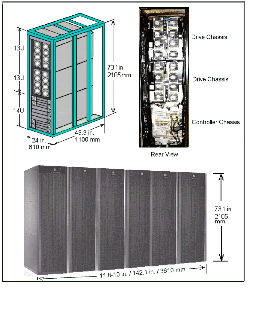
Figure 1 P9500 disk array
NOTE: Each Rack is 600mm wide without side covers. Add 5mm to each end of entire assembly
for each side cover.
Controller chassis
The controller chassis (factory designation DKC) includes the logical components, memory, disk
drive interfaces, and host interfaces. It can be expanded with a high degree of granularity to a
system offering up to twice the number of processors, cache capacity, host interfaces and disk
storage capacity.
The controller chassis includes the following maximum number of components: two service
processors, 512 GB cache memory, four grid switches, four redundant power supplies, eight
channel adapters, four disk adapters, and ten dual fan assemblies. It is mounted at the bottom of
Hardware overview 7
the rack because it is the heavier of the two units. If a system has two SVPs, both SVPs are mounted
in controller chassis #0.
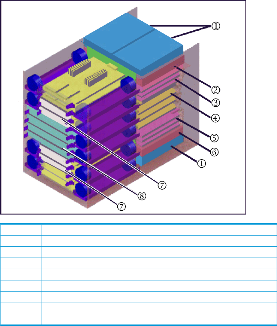
The following illustration shows the locations of the components in the controller chassis. The
controller chassis is described in more detail in “System components” (page 54).
Figure 2 Controller chassis
DescriptionItem
AC/DC: Power Supply 2 or 4 per controller1
Service Processor: One or two units in the #0 controller chassis2
CHA3
Grid switches4
CHA (up to 7) and DKA (up to 4)5
Service Processor: One or two units in the #0 controller chassis6
Cache: 2 to 8 cache boards in pairs (2, 4, 6, 8)7
P9500: 2 to 4 microprocessor boards8
Drive chassis
The drive chassis (factory designation DKU) consists of SAS switches, slots for 2 1/2 inch HDD or
SSD drives, and four 4 fan door assemblies that can be easily opened to allow access to the drives.
Each drive chassis can hold 128 2 1/2 inch HDD or SSD drives. The maximum number of 2 1/2
inch drives in a P9500 system is 2048.
8 Introduction
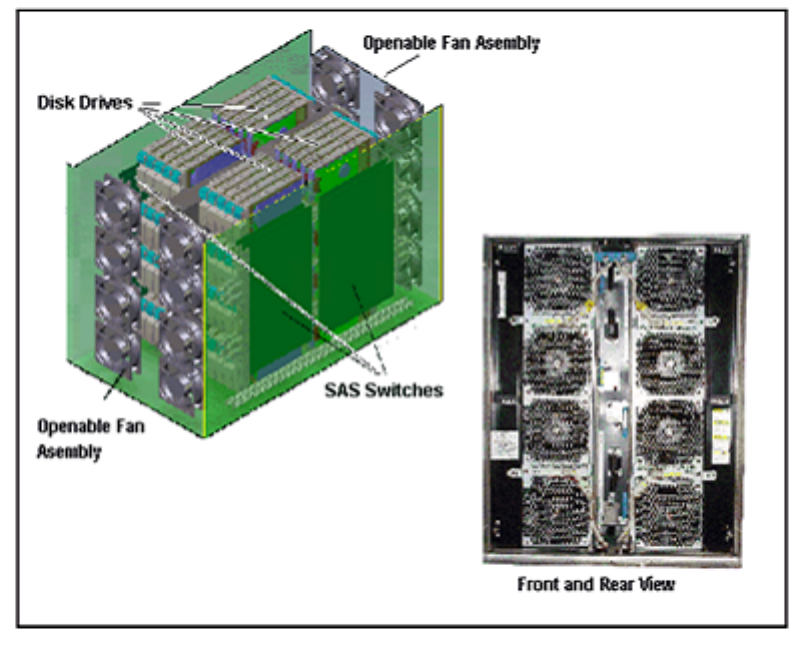
Figure 3 Disk Unit
Features
This section describes the main features of the P9500 disk array.
Scalability
The P9500 disk array is highly scalable and can be configured in several ways as needed to meet
customer requirements:
•The minimum configuration is a single rack containing one controller chassis and two drive
chassis.
•One to three racks containing one controller chassis and up to eight drive chassis. A drive
chassis can contain up to 128 2 1/2 disk drives or 128 SSDs. Drives can be intermixed. See
Table 2 (page 13) for details.
•The maximum configuration is a six rack twin version of the above that contains two controller
chassis and up to 16 drive chassis containing up to 2048 2 1/2 inch disk drives. The total
internal raw physical storage space of this configuration is approximately 2458 TB (based
on 1.2 TB HDDs).
Features 9
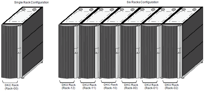
Figure 4 Example P9500 disk array configurations
In addition to the number of disk drives, the system can be configured with disk drives of different
capacities and speeds, varying numbers of CHAs and DKAs, and varying cache capacities, as
follows:
•Two to six CHAs (each is a pair of boards). This provides a total of 12 when all of the CHA
slots are used and there are no DKAs installed, as in a diskless system. The maximum total
number of CHAs and DKAs is 12.
•Two to four DKAs (each is a pair of boards). This provides a total of 8 when all of the DKA
slots are used. When all 4 DKA pairs are installed , then up to 8 CHA pairs can be installed
•Cache memory capacity: 256 GB (1 module / 3-rack system) and 512 GB (two modules /
6-rack system)
•Disk drive capacities of 146 GB, 200 GB (SSD), 300 GB, 400 GB (SSD), 500 GB, 600 GB,
800 GB (SSD), 900 GB, and 1.2 TB.
•Channel ports: 80 for one module, 176 for two modules.
High performance
The P9500 includes several new features that improve the performance over previous models.
These include:
•8 GBps only Fibre Channel for CHAs without the limitation of microprocessors on each board.
•SSD flash drives with ultra high speed response.
•High speed data transfer between the DKA and HDDs at a rate of 6 GBps with the SAS
interface.
•High speed quad core CPUs that provide three times the performance of an XP24000/XP20000
Disk Array.
High capacity
The P9500 supports the following high capacity features:
•HDD (disk) drives with capacities of 146 GB, 300 GB, 500 GB, 600 GB 900 GB, and 1.2
TB. See Table 2 (page 13).
•SSD (flash) drives with capacity of 200 GB, 400 GB, and 800 GB. See Table 2 (page 13).
•Controls up to 65,280 logical volumes and up to 2,048 disk drives, and provides a maximum
raw physical disk capacity of approximately 1229 TB using 1.2 TB drives.
10 Introduction
Connectivity
P9500
The P9500 Disk Array supports most major IBM Mainframe operating systems and Open System
operating systems, such as Microsoft Windows, Oracle Solaris, IBM AIX, Linux, HP-UX, and
VMware. For more complete information on the supported operating systems, contact HP Technical
Support.
P9500 supports the following host interfaces. They can mix within the disk array.
•Mainframe: Fibre Channel (FICON)
•Open system: Fibre Channel
Remote Web Console
The required features for the Remote Web Console computer include operating system, available
disk space, screen resolution, CD drive, network connection, USB port, CPU, memory, browser,
Flash, and Java environment. These features are described in Chapter 1 of the HP XP P9000
Remote Web Console User Guide.
High reliability
The P9500 disk array includes the following features that make the system extremely reliable:
•Support for RAID6 (6D+2P), RAID5 (3D+1P/7D+1P), and RAID1 (2D+2D/4D+4D) See
“Functional and operational characteristics” (page 17) for more information on RAID levels.
•All main system components are configured in redundant pairs. If one of the components in
a pair fails, the other component performs the function alone until the failed component is
replaced. Meanwhile, the disk array continues normal operation.
•The P9500 is designed so that it cannot lose data or configuration information if the power
fails. This is explained in “Battery backup operations” (page 67).
Non disruptive service and upgrades
The P9500 disk array is designed so that service and upgrades can be performed without
interrupting normal operations. These features include:
•Main components can be “hot swapped” — added, removed, and replaced without any
disruption — while the disk array is in operation. The front and rear fan assemblies can be
moved out of the way to enable access to disk drives and other components, but not both at
the same time. There is no time limit on changing disk drives because either the front or rear
fans cool the unit while the other fan assembly is turned off and moved out of the way.
•A Service Processor mounted on the controller chassis monitors the running condition of the
disk array. Connecting the SVP with a service center enables remote maintenance.
•The firmware (microcode) can be upgraded without disrupting the operation of the disk array.
The firmware is stored in shared memory (part of the cache memory module) and transferred
in a batch, reducing the number of transfers from the SVP to the controller chassis via the LAN.
This increases the speed of replacing the firmware online because it works with two or more
processors at the same time.
•The P9500 is designed so that it cannot lose data or configuration information if the power
fails (see “Battery backup operations” (page 67)).
Economical and quiet
The three speed fans in the control and drive chassis are thermostatically controlled. Sensors in
the units measure the temperature of the exhaust air and set the speed of the fans only as high as
necessary to maintain the unit temperature within a preset range. When the system is not busy and
Features 11

generates less heat, the fan speed is reduced, saving energy and reducing the noise level of the
system.
When the disk array is in standby mode, the disk drives spin down and the controller and drive
chassis use significantly less power. For example, a system that consumes 100 amps during normal
operation, uses only 70 amps while in standby mode.
Specifications
The following tables provide general specifications of the P9500. Additional specifications are
located in “Specifications” (page 80).
Table 1 P9500 specifications
Dual ModuleSingle ModuleSizeItem
2458 TB1229 TBInternalMaximum raw drive
capacity (based on 1.2 TB
HDDs) 247 PB247 PBExternal
64k64k-Maximum number of
volumes
See Table 2 (page 13).Supported drives
Min 128 GBMin 64 GB.Cache memory capacity
Max 1024 GBMax 512 GB
Min 64 GB.Cache flash memory
capacity Max 1028 GB
RAID1, RAID5, RAID6.RAID Level
2D+2D, 4D+4DRAID1RAID GroupConfiguration
3D+1P, 7D+1PRAID5
6D+2PRAID6
Hierarchical Star NetArchitectureInternal Path
Cache Path = 128 GB/sMaximum Bandwidth
Control Path = 64 GB/s
64 (2WL*32)32 (2WL*6)SAS 6GBack-end Path
160/16,880 /16,8FC 2/4/8GNumber of ports per
installation unit
SAS/Dual PortController chassisDevice I/F
drive chassis
Interface
Max. 6 GBpsData transfer rate
256 (2.5 inch HDD)Maximum number
of HDD per SAS I/F
8 if drives installed4 if drives installedMaximum number of CHAs
12 if diskless6 if diskless
1/2/4 GBps Fibre Channel: 16MFS/16MFLMainframeChannel I/F
2/4/8 GBps Fibre Channel: 16MUS/16MUL
2/4/8 GBps Fibre Shortwave:Open systems
12 Introduction

Table 1 P9500 specifications (continued)
Dual ModuleSingle ModuleSizeItem
8UFC/16UFC
32 cores16 coresQuantityManagement Processor
Cores
61
61
CHAsMicro Processor Blade
configuration 2 / 80 or 2 / 42DKAs
Minimum/maximum
2 / 162 / 8Cache
4 / 82 / 4Switches /CSW
Notes:
1. All CHA configuration, no DKAs (diskless system).
Table 2 Drive specifications
Speed (RPM)Drive CapacitySizeDrive Type
15,000300 GB2 1/2 inchHDD (SAS)
10,000300, 600, and 900 GB
7,200500 GB, 1 TB, and 1.2 TB
n/a200, 400, and 800 GB2 1/2 inchSSD (Flash)
Dual ModuleSingle ModuleDrive ChassisDrive Type
(6 rack system)(3 rack system)
20481024128HDD, 2 1/2 inch
2562
1282
1281
SSD (Flash)
Notes.
1. SSD drives can be mounted all in one drive chassis or spread out among all of the chassis in the storage system.
2. Recommended maximum number.
The drives must be added four at a time to create RAID groups, unless they are spare drives.
Software features and functions
The P9500 disk array provides advanced software features and functions that increase data
accessibility and deliver enterprise wide coverage of online data copy/relocation, data
access/protection, and storage resource management. HP software products and solutions provide
a full set of industry leading copy, availability, resource management, and exchange software to
support business continuity, database backup and restore, application testing, and data mining.
The following tables describe the software that is available on the P9500 disk array.
Table 3 Virtualization features and functions
DescriptionFeature
Provides logical partitioning of the cache which allows you to divide the cache
into multiple virtual cache memories to reduce I/O contention.
Cache Partition
Supports the virtualization of external disk arrays. Users can connect other disk
arrays to the P9500 disk array and access the data on the external disk array via
Cache Residency
virtual devices created on the P9500 disk array. Functions such as Continuous
Access Synchronous and Cache Residency can be performed on external data
through the virtual devices.
Software features and functions 13

Table 4 Performance management features and functions
DescriptionFeature
Cache Residency locks and unlocks data into the cache to optimize access to the most
frequently used data. It makes data from specific logical units resident in a cache, making
Cache Residency
all data accesses become cache hits. When the function is applied to a logic unit,
frequently accessed, throughput increases because all reads become cache hits.
Performs detailed monitoring of the disk array and volume activity. This is a short term
function and does not provide historical data.
Performance Monitor
Enables the mainframe host to issue multiple I/O requests in parallel to the same
LDEV/UCB/device address in the P9500. Parallel Access Volumes provides compatibility
Parallel Access Volumes
with the IBM Workload Manager (WLM) host software function and supports both static
and dynamic PAV functionality.
Table 5 Provisioning features and functions for Open systems
DescriptionFeature
Provides automated movement of sub LUN data for a multi tiered Thin Provisioning pool.
The most accessed pages within the pool is dynamically relocated onto a faster tier in
Smart Tiers
the pool. This improves performance of the most frequently accessed pages while giving
the remaining data sufficient response times on a lower cost storage.
The LUN Manager feature configures the fibre channel ports and devices (logical units)
for operational environments.
LUN Manager
The LUN Expansion feature expands the size of a logical unit (volume) to which an open
system host computer accesses by combining multiple logical units (volumes) internally.
LUN Expansion
The Thin Provisioning feature virtualizes some or all of the system's physical storage. This
simplifies administration and addition of storage, eliminates application service
Thin Provisioning
interruptions, and reduces costs. It also improves the capacity and efficiency of disk
drives by assigning physical capacity on demand at the time of the write command
receipt without assigning the physical capacity to logical units.
Converts single volumes (logical volume images or logical units) into multiple smaller
volumes to improve data access performance.
Virtual LVI
Protects data in logical units / volumes / LDEVs from I/O operations illegally performed
by host systems. Users can assign an access attribute to each volume to restrict read
and/or write operations, preventing unauthorized access to data.
Data Retention
Table 6 Provisioning features and functions for Mainframe
DescriptionFeature
Converts single volumes (logical volume images or logical units) into multiple smaller
volumes to improve data access performance.
Virtual LVI
Restricts host access to data on the P9500. Open system users can restrict host access
to LUNs based on the host's world wide name (WWN). Mainframe users can restrict
host access to volumes based on node IDs and logical partition (LPAR) numbers.
Volume Security for
Mainframe
Protects data from I/O operations performed by hosts. Users can assign an access
attribute to each logical volume to restrict read and/or write operations, preventing
unauthorized access to data.
Volume Retention
Table 7 Data replication features and functions
DescriptionFeature
Performs remote copy operations between disk arrays at different locations.
Continuous Access Synchronous provides the synchronous copy mode for open
Continuous Access Synchronous
and
14 Introduction

Table 7 Data replication features and functions (continued)
DescriptionFeature
Continuous Access Synchronous
Zsystems. Continuous Access Synchronous Z provides synchronous copy for mainframe
systems.
Creates internal copies of volumes for purposes such as application testing and
offline backup. Can be used in conjunction with True Copy or Continuous Access
Journal to maintain multiple copies of data at primary and secondary sites.
Business Copy and
Business Copy Z
Snapshot creates a virtual, point- in- time copy of a data volume. Since only changed
data blocks are stored in the Snapshot storage pool, storage capacity is substantially
Snapshot (open systems only)
less than the source volume. This results in significant savings compared with full
cloning methods. With Snapshot, you create virtual copies of a data volume in the
Virtual Storage Platform
This feature provides a RAID storage based hardware solution for disaster recovery
which enables fast and accurate system recovery, particularly for large amounts of
Continuous Access Journal and
Continuous Access Journal Z data which span multiple volumes. Using Continuous Access Journal, you can
configure and manage highly reliable data replication systems using journal volumes
to reduce chances of suspension of copy operations.
This feature provides compatibility with IBM Extended Remote Copy (XRC)
asynchronous remote copy operations for data backup and recovery in the event
of a disaster.
Compatible FlashCopy
Table 8 Security features and functions
DescriptionFeature
This feature implements encryption for both open systems and mainframe data
using the encrypting disk adapter. It includes enhanced key support up to 32
DKA Encryption
separate encryption keys allows encryption to be used as access control for multi
tenant environments. It also provides enhanced data security for the AES-XTS mode
of operations.
Storage management users of P9500 systems can be authenticated and authorized
for storage management operations using existing customer infrastructure such as
Microsoft Active Directory, LDAP, and RADIUS based systems.
External Authentication and
Authorization
Provides greater granularity and access control for P9500 storage administration.
This new RBAC model separates storage, security, and maintenance functions
Role Based Access Control (RBAC)
within the array. Storage Management users can receive their “role” assignments
based on their group memberships in external authorization sources such as
Microsoft Active Directory and LDAP. This RBAC model will also align with the
RBAC implementation in HCS 7.
Successor to the XP24000/XP20000 Disk Array Storage Logical Partition (SLPR).
It allows for additional granularity and flexibility of the management of storage
resources.
Resource Groups
Table 9 System maintenance features and functions
DescriptionFeature
The Audit Log function monitors all operations performed using Remote Web
Console (and the SVP), generates a syslog, and outputs the syslog to the Remote
Web Console computer.
Audit Log Function
Provides support for SNMP monitoring and management. Includes HP specific MIBs
and enables SNMP based reporting on status and alerts. SNMP agent on the SVP
SNMP Agent
gathers usage and error information and transfers the information to the SNMP
manager on the host.
Software features and functions 15

Table 10 Host server based features and functions
DescriptionFeature
On open systems, performs various functions, including data replication and data
protection operations by issuing commands from the host to the HP disk arrays.
RAID Manager
The RAID Manager software supports scripting and provides failover and mutual
hot standby functionality in cooperation with host failover products.
Transfers data between mainframe and open system platforms using the FICON
channels for high speed data transfer without requiring network communication
links or tape.
Data Exchange
Operates with the Business Copy feature. Rewrites the OS management information
(VTOC, VVDS, and VTOCIX) and dataset name and creates a user catalog for a
Dataset Replication for Mainframe
Business Copy/Snapshot target volume after a split operation. Provides the prepare,
volume divide, volume unify, and volume backup functions to enable use of a
Business Copy target volume.
16 Introduction
2 Functional and operational characteristics
System architecture overview
This section briefly describes the architecture of the P9500 disk array.
Hardware architecture
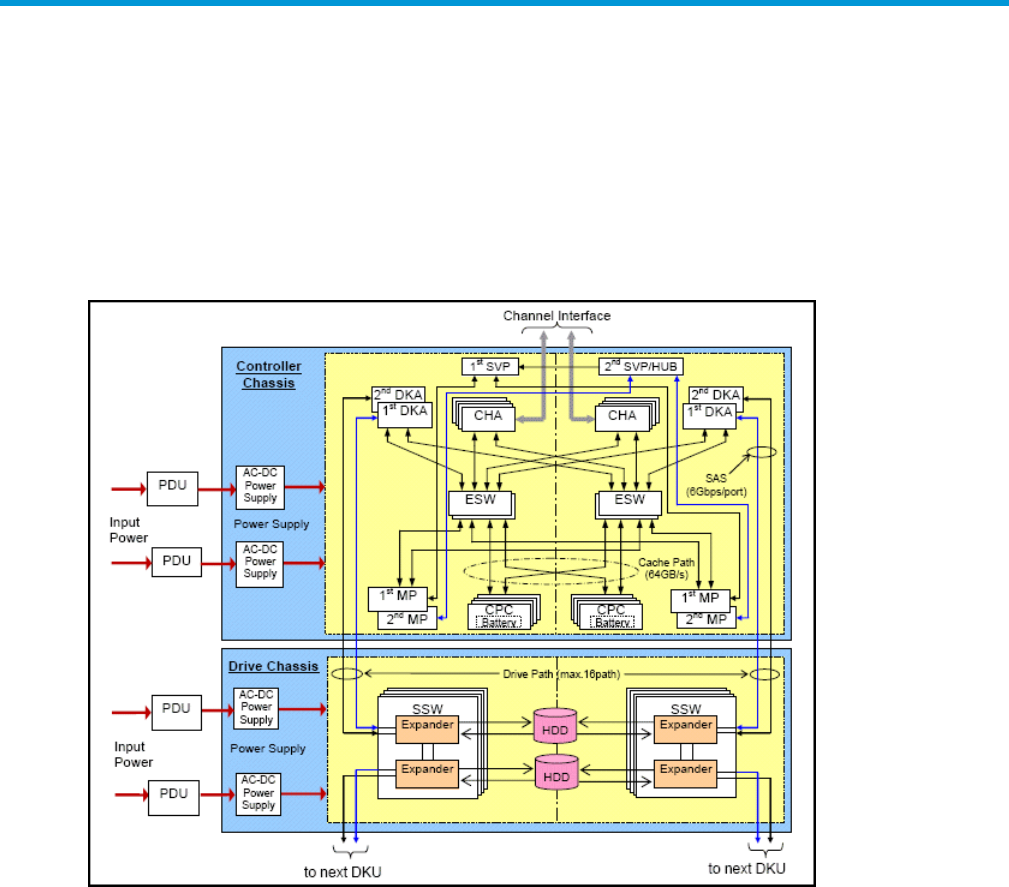
The basic system architecture is shown in the following diagram.
Figure 5 P9500 architecture overview
The system consists of two main hardware assemblies:
•A controller chassis that contains the logic and processing components
•A drive chassis that contains the disk drives or solid state drives.
These assemblies are explained briefly in “Introduction” (page 6), and in detail in “System
components” (page 54).
RAID implementation overview
This section provides an overview of the implementation of RAID technology on the P9500 disk
array.
Array groups and RAID levels
The array group (also called parity group) is the basic unit of storage capacity for the P9500 disk
array. Each array group is attached to both boards of a DKA pair over 2 SAS paths, which enables
all data drives in the array group to be accessed simultaneously by a DKA pair. Each controller
rack has two drive chassis (factory designation DKU), and each drive chassis can have up to 128
physical data drives.
System architecture overview 17
The P9500 supports the following RAID levels: RAID1, RAID5, RAID6. RAID0 is not supported on
the P9500. When configured in four drive RAID5 parity groups (3D+1P), ¾ of the raw capacity
is available to store user data, and ¼ of the raw capacity is used for parity data.
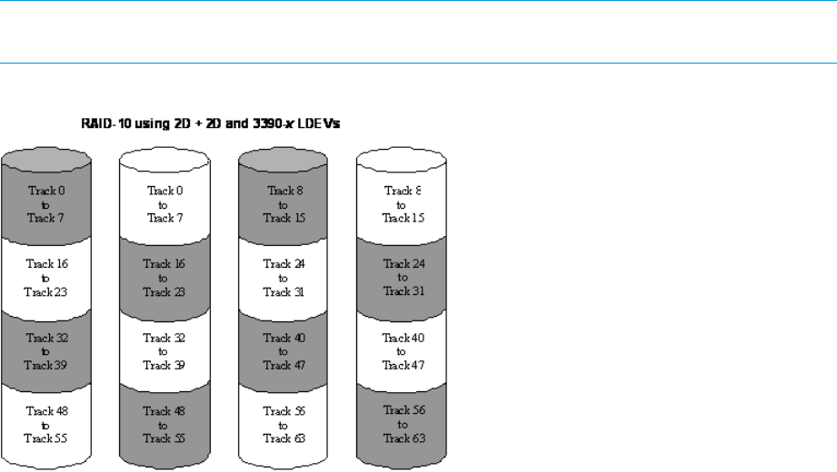
RAID1.Figure 6 (page 18) illustrates a sample RAID1 (2D+2D) layout. A RAID1 (2D+2D) array
group consists of two pairs of data drives in a mirrored configuration, regardless of data drive
capacity. A RAID1 (4D+4D) group combines two RAID1 (2D+2D) groups. Data is striped to two
drives and mirrored to the other two drives. The stripe consists of two data chunks. The primary
and secondary stripes are toggled back and forth across the physical data drives for high
performance. Each data chunk consists of either eight logical tracks (mainframe) or 768 logical
blocks (open systems). A failure in a drive causes the corresponding mirrored drive to take over
for the failed drive. Although the RAID5 implementation is appropriate for many applications, the
RAID1 option can be ideal for workloads with low cache hit ratios.
NOTE: When configuring RAID1 (4D+4D), HP recommends that both RAID1 (2D+2D) groups
within a RAID1 (4D+4D) group be configured under the same DKA pair.
Figure 6 Sample RAID1 2D + 2D layout
RAID5. A RAID5 array group consists of four or eight data drives, (3D+1P) or (7D+1P). The data
is written across the four (or eight) drives in a stripe that has three (or seven) data chunks and one
parity chunk. Each chunk contains either eight logical tracks (mainframe) or 768 logical blocks
(open). The enhanced RAID5+ implementation in the P9500 minimizes the write penalty incurred
by standard RAID5 implementations by keeping write data in cache until an entire stripe can be
built and then writing the entire data stripe to the drives. The 7D+1P RAID5 increases usable
capacity and improves performance.
Figure 7 (page 19) illustrates RAID5 data stripes mapped over four physical drives. Data and
parity are striped across each of the data drives in the array group (hence the term “parity group”).
The logical devices (LDEVs) are evenly dispersed in the array group, so that the performance of
each LDEV within the array group is the same. This figure also shows the parity chunks that are
the Exclusive OR (EOR) of the data chunks. The parity and data chunks rotate after each stripe.
The total data in each stripe is either 24 logical tracks (eight tracks per chunk) for mainframe data,
or 2304 blocks (768 blocks per chunk) for open systems data. Each of these array groups can be
configured as either 3390-x or OPEN-x logical devices. All LDEVs in the array group must be the
same format (3390-x or OPEN-x). For open systems, each LDEV is mapped to a SCSI address, so
that it has a TID and logical unit number (LUN).
18 Functional and operational characteristics
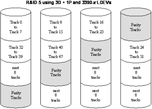
Figure 7 Sample RAID5 3D + 1P layout (data plus parity stripe)
RAID6. A RAID6 array group consists of eight data drives (6D+2P). The data is written across the
eight drives in a stripe that has six data chunks and two parity chunks. Each chunk contains either
eight logical tracks (mainframe) or 768 logical blocks (open).
In the case of RAID6, data can be assured when up to two drives in an array group fail. Therefore,
RAID6 is the most reliable of the RAID levels.
Sequential data striping
The P9500’s enhanced RAID5 implementation attempts to keep write data in cache until parity
can be generated without referencing old parity or data. This capability to write entire data stripes,
which is usually achieved only in sequential processing environments, minimizes the write penalty
incurred by standard RAID5 implementations. The device data and parity tracks are mapped to
specific physical drive locations within each array group. Therefore, each track of an LDEV occupies
the same relative physical location within each array group in the disk array.
In a RAID6 (dual parity) configuration, two parity drives are used to prevent loss of data in the
unlikely event of a second failure during a rebuild of a previous failure.
LDEV striping across array groups
In addition to the conventional concatenation of RAID1 array groups (4D+4D), the P9500 supports
LDEV striping across multiple RAID5 array groups for improved logical unit performance in open
system environments. The advantages of LDEV striping are:
•Improved performance, especially of an individual logical unit, due to an increase in the
number of data drives that constitute an array group.
•Better workload distribution: in the case where the workload of one array group is higher
than another array group, you can distribute the workload by combining the array groups,
thereby reducing the total workload concentrated on each specific array group.
The supported LDEV striping configurations are:
•LDEV striping across two RAID 5 (7D+1P) array groups. The maximum number of LDEVs in
this configuration is 1000. See Figure 8 (page 20)).
•LDEV striping across four RAID 5 (7D+1P) array groups. The maximum number of LDEVs in
this configuration is 2000. See Figure 9 (page 20).
RAID implementation overview 19
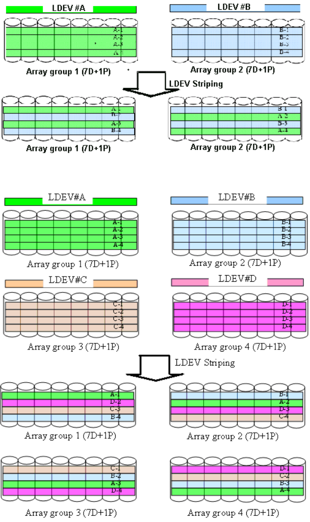
Figure 8 LDEV striping across 2 RAID5 (7D+1P) array groups
Figure 9 LDEV striping across 4 RAID5 (7D+1P) array groups
All data drives and device emulation types are supported for LDEV striping. LDEV striping can be
used in combination with all P9500 data management functions.
CU Images, LVIs, and Logical Units
This section provides information about control unit images, logical volume images, and logical
units.
CU images
The P9500 is configured with one control unit image for each 256 devices (one SSID for each 64
or 256 LDEVs) and supports a maximum of 510 CU images (255 in each logical disk controller,
or LDKC).
The P9500 supports 2105 and 2107control unit (CU) emulation types.
20 Functional and operational characteristics
The mainframe data management features of the P9500 may have restrictions on CU image
compatibility.
For further information on CU image support, see the Mainframe Host Attachment and Operations
Guide, or contact HP.
Logical Volume images
The P9500 supports the following mainframe LVI types:
•3390-3, -3R, -9, L, and -M. The 3390-3 and 3390-3R LVIs cannot be intermixed in the same
disk array.
•3380-3, -F, -K.
The LVI configuration of the P9500 disk array depends on the RAID implementation and physical
data drive capacities. The LDEVs are accessed using a combination of logical disk controller number
(00-01), CU number (00-FE), and device number (00-FF). All control unit images can support an
installed LVI range of 00 to FF.
Logical Units
The P9500 disk array is configured with OPEN-V logical unit types. The OPEN-V logical unit can
vary in size from 48.1 MB to 4 TB. For information on other logical unit types (e.g., OPEN-9),
contact HP support.
For maximum flexibility in logical unit configuration, the P9500 provides the VLL and LUN Expansion
(LUSE) features. Using VLL, users can configure multiple logical units under a single LDEV. Using
Virtual LVI or LUSE, users can concatenate multiple logical units into large volumes. For further
information on VLL and Virtual LVI, see the HP XP P9000 Performance for Open and Mainframe
Systems User Guide and the HP XP P9000 Provisioning for Open Systems User Guide
Mainframe operations
This section provides high level descriptions of mainframe compatibility, support, and configuration.
Mainframe compatibility and functionality
In addition to full System Managed Storage (SMS) compatibility, the P9500 disk array provides
the following functions and support in the mainframe environment:
•Sequential data striping
•Cache fast write (CFW) and DASD fast write (DFW)
•Enhanced dynamic cache management
•Extended count key data (ECKD) commands
•Multiple Allegiance
•Concurrent Copy (CC)
•Peer-to-Peer Remote Copy (PPRC)
•Compatible FlashCopy
•Parallel Access Volume (PAV)
•Enhanced CCW
•Priority I/O queuing
•Red Hat Linux for IBM S/390 and zSeries
Mainframe operations 21

Mainframe operating system support
The P9500 disk array supports most major IBM Mainframe operating systems and Open System
operating systems, such as Microsoft Windows, Oracle Solaris, IBM AIX, Linux, HP-UX, and
VMware. For more complete information on the supported operating systems, go to: http://
www.hp.com
Mainframe configuration
After a P9500 disk array has been installed, users can configure the disk array for mainframe
operations.
See the following user documents for information and instructions on configuring your P9500 disk
array for mainframe operations:
•The HP XP P9000 Mainframe Host Attachment and Operations Guide describes and provides
instructions for configuring the P9500 for mainframe operations, including FICON attachment,
hardware definition, cache operations, and device operations.
For detailed information on FICON connectivity, FICON/Open intermix configurations, and
supported HBAs, switches, and directors for P9500, please contact HP support.
•The HP XP P9000 Remote Web Console User Guide provides instructions for installing,
configuring, and using Remote Web Console to perform resource and data management
operations on the P9500 disk arrays.
•The HP XP P9000 Provisioning for Mainframe Systems User Guide and HP XP P9000 Volume
Shredder for Open and Mainframe Systems User Guide provides instructions for converting
single volumes (LVIs) into multiple smaller volumes to improve data access performance.
System option modes, host modes, and host mode options
This section provides detailed information about system option modes. Host modes and host mode
options are also discussed.
System option modes
To provide greater flexibility and enable the P9500 disk array to be tailored to unique customer
operating requirements, additional operational parameters, or system option modes, are available.
At installation, the modes are set to their default values, as shown in the following table. Be sure
to discuss these settings with HP Technical Support. The system option modes can only be changed
by HP.
The following tables provide information about system option modes and SVP operations:
•Table 11 (page 23) lists the system option mode information for the P9500.
•Table 12 (page 51) specifies the details for mode 269 for Remote Web Console operations.
•Table 13 (page 51) specifies the details of mode 269 for SVP operations.
The system option mode information may change in future firmware releases. Contact HP for the
latest information on the P9500 system option modes.
The system option mode information includes:
•Mode: Specifies the system option mode number.
•Category: Indicates the functions to which the mode applies.
•Description: Describes the action or function that the mode provides.
•Default: Specifies the default setting (ON or OFF) for the mode.
•MCU/RCU: For remote functions, indicates whether the mode applies to the main control unit
(MCU) and/or the remote control unit (RCU).
22 Functional and operational characteristics

Table 11 System option modes
MCU/RCUDefaultDescriptionCategoryMode
MCUOFFR-VOL read only function.Public20
(Optional)
OFFRegarding the correction copy or the drive copy, in case
ECCs/LRC PINs are set on the track of copy source HDD, mode
Common22
22 can be used to interrupt the copy processing (default) or to
create ECCs/LRC PINs on the track of copy target HDD to
continue the processing.
Mode 22 = ON:
If ECCs/LRC PINs (up to 16) have been set on the track of copy
source HDD, ECCs/LRC PINs (up to 16) will be created on the
track of copy target HDD so that the copy processing will
continue.
If 17 or more ECCs/LRC PINs are created, the corresponding
copy processing will be interrupted.
Mode 22 = OFF (default)
If ECCs/LRC PINs have been set on the track of copy source HDD,
the copy processing will be interrupted. (first recover ECCs/LRC
PINs by using the PIN recovery flow, and then perform the
correction copy or the drive copy again)
One of the controlling option for correction/drive copy.
MCUOFFSets default function (CRIT=Y) option for SVP panel (HRC).HRC36
Mode 64 = ON:Continuous Access
Synchronous Z
64
•When receiving the Freeze command, in the subsystem, pair
volumes that fulfill the conditions below are suspended and
the status change pending (SCP) that holds write I/Os from
the host is set. The path between MCU and RCU is not deleted.
Query is displayed only but unusable.
•When receiving the RUN command, the SCP status of the pairs
that fulfill the conditions below is released.
•When a Failure Suspend occurs when Freeze Option Enable
is set, except the pair in which the Failure Suspend occurs,
other pairs that fulfill conditions below go into SCP state:
- Continuous Access Synchronous Sync M-VOL
- Mainframe Volume
- Pair status: Duplex/Pending
Mode 64 = OFF (default):
•When receiving the Freeze command, pairs that fulfill the
conditions below are suspended and the SCP is set. In the
case of CU emulation type 2105/2017, the path between
MCU and RCU is deleted, while the path is not deleted but
unusable with Query displayed only in the case of CU
emulation type 3990.
•When receiving the RUN command, the SCP status of the pairs
that fulfill the conditions below is released.
•When a Failure Suspend occurs while the Freeze Option
Enable is set, except the pair in which the Failure Suspend
occurs, other pairs that fulfill the conditions below go into SCP
state.
Conditions:
•Continuous Access Synchronous Sync M-VOL
•Mainframe Volume
System option modes, host modes, and host mode options 23

Table 11 System option modes (continued)
MCU/RCUDefaultDescriptionCategoryMode
•Pair status: Duplex/Pending
•A pair whose RCU# is identical to the RCU for which the
Freeze command is specified.
MCU/RCU.Notes:Continuous Access
Synchronous Z
64
(cont) 1. When all the following conditions are met, set Mode 64=ON.
2. When all the following conditions are met, set Mode 64=ON.
- Customer requests to stop the update I/O operation to the
RCU of a Continuous Access Synchronous Z pair for the whole
subsystem.
- Disaster Recovery function such as GDPS, HyperSwap, or
Fail Over/ Fail Back, which requires compatibility with IBM
storage, is not used as this Mode 64 operates without having
compatibility with IBM storage.
- Only Peer-to-Peer-Remote-Copy operation. (Do not use it in
combination with Business Continuity Manager.)
3. Even though the Failover command is not an applicable
criterion, when executing the Failover command while Mode
114 is ON, since ports are not automatically switched, the
Failover command fails.
4. With increase of Sync pairs in subsystem, the time period to
report the completion of Freeze command and RUN command
gets longer (estimate of time to report completion: 1 second
per 1000 pairs), and MIH may occur.
-OFFBusiness Copy Z80 •For RAID 300/400/450 (SI for OPEN or Mainframe) In
response to the Restore instruction from the host or Storage
Navigator, the following operation is performed regardless
of specifying Quick or Normal.
•For RAID 500/600/700 (SI for OPEN) In response to the
Restore instruction from the host, if neither Quick nor Normal
is specified, the following operation is performed
Mode 80 = ON: Normal Restore / Reverse Copy is performed.
Mode 80 = OFF: Quick Restore is performed.
Notes.
1. This mode is applied when the specification for Restore of SI
is switched between Quick (default) and Normal.
2. The performance of Restore differs depending on the Normal
or Quick specification.
-OFFDetermines whether NormalCopy or QuickResync, if not specified,
is performed at the execution of pairresync by CCI.
Business Copy87
Mode 87 = ON: QuickResync is performed.
Mode 87 = OFF: NormalCopy is performed.
MCUOFFChanges the default CGROUP Freeze option.HRC104
MCUOFFThis mode enables or disables the LCP/RCP port to be
automatically switched over when the PPRC command
ESTPATH/DELPATH is executed.
HRC114
Mode 114 = ON:
Automatic port switching during ESTPATH/DELPATH is enabled.
Mode 114 = OFF (default):
Automatic port switching during ESTPATH/DELPATH is disabled.
Notes:
24 Functional and operational characteristics

Table 11 System option modes (continued)
MCU/RCUDefaultDescriptionCategoryMode
1. If you select an incorrect port while the mode is set to ON,
and if ESTPATH is executed when no logic path exists, the
port is switched to RCP..
2. Set this mode to OFF before using TPC-R (IBM software for
disaster recovery).
-OFFFor Split or Resync request from the Mainframe host and Storage
Navigator,
Business Copy122
Mode 122 = ON:
•By specifying Split or Resync, Steady/Quick Split or
Normal/Quick Resync is respectively executed in accordance
with Normal/Quick setting
Mode 122 = OFF (default)?
•By specifying Split or Resync, Steady/Quick Split or
Normal/Quick Resync is respectively executed in accordance
with Normal/Quick setting. For details, see "SOM 122" sheet
Note:
(1) For RAID500 and later models, this mode is applied to use
scripts etc that are used on RAID400 and 450 (2) In the case of
RAID500 and later models, executing the pairresync command
from RAID Manager may be related to the SOM 087 setting.
(3) When performing At-Time Split from RAID Manager
- Set this mode to OFF in the case of RAID450
- Set this mode to OFF or specify the environment variable
HORCC_SPLT for Quick in the case of RAID500 and
later.Otherwise, Pairsplit may turn timeout.
(4) The mode becomes effective after specifying Split/Resync
following the mode setting. The mode function does not work if
it is set during the Split/Resync operation
-OFFYellow Light Option (only for XP product)Common187
RCUOFFCnt Ac-S Z – Allows you to update the VOLSER and VTOC of the
R-VOL while the pair is suspended if both mode 20 and 190 are
ON
HRC190
MCU/RCUOFFHigh Speed Format for CVS (Available for all dku emulation type)Common269
(1) High Speed Format support
When redefining all LDEVs included in an ECC group using
Volume Initialize or Make Volume on CVS setting panel, LDEV
format, as the last process, will be performed in high speed.
(2) Make Volume feature enhancement
In addition, with supporting the feature, the Make Volume feature
(recreating new CVs after deleting all volumes in a VDEV), which
so far was supported for OPEN-V only, is available for all
emulation types.
Mode 269 = ON:
The High Speed format is available when performing CVS
operations on Storage Navigator or performing LDEV formats on
the Maintenance window of the SVP for all LDEVs in a parity
group.
Mode 269 = OFF (default):
As usual, only the low speed format is available when performing
CVS operations on Storage Navigator. In addition, the LDEV
specifying format on the Maintenance window of the SVP is in
low speed as well.
System option modes, host modes, and host mode options 25

Table 11 System option modes (continued)
MCU/RCUDefaultDescriptionCategoryMode
Notes:
1. For more details about mode 269, see worksheet "Mode269
detail for RAID700".
2. Mode 269 is effective only when using the SVP to format the
CVS.
-OFFTru64 (Host Mode 07) and OpenVMS (Host Mode 05)Open278
Caution: Host offline: Required
MCU/RCUOFFIssuing OLS when Switching PortHRC292
In case the mainframe host (FICON) is connected with the
CNT-made FC switch (FC9000 etc.), and is using along with the
TrueCopy S/390 with Open Fibre connection, the occurrence of
Link Incident Report for the mainframe host from the FC switch
will be deterred when switching the CHT port attribute (including
automatic switching when executing CESTPATH and CDELPATH
in case of Mode 114=ON).
Mode 292=ON:
When switching the port attribute, issue the OLS (100ms) first,
and then reset the Chip.
Mode 292=OFF (default):
When switching the port attribute, reset the Chip without issuing
the OLS.
MCU/RCUOFFThis mode enables the pre-label function (creation of VTOC
including VOLSER).
Mainframe305
Mode 305 = ON:
Pre-label function is enabled
Note:
1. Set SOM 305 to ON before performing LDEV Format for a
mainframe volume if you want to perform OS IPL (volume
online) without fully initializing the volume after the LDEV
Format. However, full initialization is required in actual
operation.
2. Processing time of LDEV format increases by as much as full
initialization takes.
3. The following functions and conditions are not supported.
•Quick format
•3390-A (Dynamic Provisioning attribute)
•Volume Shredder
4. Full initialization is required in actual operation.
MCUOFFSIM RC=2180 optionContinuous Access
Synchronous Z
308
<Description>
Continuous Access
Journal Z SIM RC=2180 (RIO path failure between MCU and RCU) was
not reported to host. DKC reports SSB with F/M=F5 instead of
reporting SIM RC=2180 in the case. Micro-program has been
modified to report SIM RC=2180 with newly assigned system
option Mode as individual function for specific customer.
Usage:
Mode 308 = ON
SIM RC 2180 is reported which is compatible with older Hitachi
specification
Mode 308 = OFF
Reporting is compatible with IBM - Sense Status report of F5.
26 Functional and operational characteristics

Table 11 System option modes (continued)
MCU/RCUDefaultDescriptionCategoryMode
OFFMode 448 = ON: (Enabled)Continuous Access
Journal
448
If the SVP detects a blocked path, the SVP assumes that an error
occurred, and then immediately splits (suspends) the mirror.Continuous Access
Journal Z Mode 448 = OFF: (Disabled)
If the SVP detects a blocked path and the path does not recover
within the specified period of time, the SVP assumes that an error
occurred, and then splits (suspends) the mirror.
Note:
The mode 448 setting takes effect only when mode 449 is set to
OFF.
Detecting and monitoring path blockade between MCU and RCU
of Universal Replicator/Universal Replicator for z/OS
Continuous Access
Journal
449
<Functionality>Continuous Access
Journal Z - Mode 449 on: Detecting and monitoring of path blockade will
NOT be performed.
- Mode 449 off (default *) : Detecting and monitoring of the path
blockade will be performed.
* Newly shipped DKC will have Mode 449 = ON as default.
Note: The mode status will not be changed by the microcode
exchange.
OFFCLPR (Function of Virtual Partition Manager) partitions the cache
memory in the disk subsystem into multiple virtual cache and
Cache Partition454
assigns the partitioned virtual cache for each use. If a large
amount of cache is required for a specific use, it can minimize
the impact on other uses. The CLPR function works as follows
depending on whether SOM 454 is set to ON or OFF.
Mode 454 = OFF (default):
The amount of the entire destage processing is periodically
determined by using the highest workload of all CLPRs (*a). (The
larger the workload is, the larger the amount of the entire destage
processing becomes.)
*a: (Write Pending capacity of CLPR#x) ÷ (Cache capacity of
CLPR#x), x=0 to 31
CLPR whose value above is the highest of all CLPRs
Because the destage processing would be accelerated depending
on CLPR with high workload, when the workload in a specific
CLPR increases, the risk of host I/O halt would be reduced.
Therefore, set Mode 454 to OFF in most cases.
Mode 454 = ON:
The amount of the entire destage processing is periodically
determined by using the workload of the entire system (*b). (The
larger the workload is, the larger the amount of the entire destage
processing becomes.)
*b: (Write Pending capacity of the entire system) ÷ (Cache
capacity of the entire system)
Because the destage processing would not be accelerated even
if CLPR has high workload, when the workload in a specific CLPR
increases, the risk of host I/O halt would be increased. Therefore,
it is limited to set Mode 454 to ON only when a CLPR has
constant high workload and it gives priority to I/O
System option modes, host modes, and host mode options 27

Table 11 System option modes (continued)
MCU/RCUDefaultDescriptionCategoryMode
MCU/RCUOFFExternal Storage457 1. High Speed LDEV Format for External Volumes
Mode 457 = ON: The high speed LDEV format for external
volumes is available by setting system option mode 457 to
ON. When System Option Mode 457 is ON, when selecting
the external volume group and performing the LDEV format,
any Write processing on the external logical units will be
skipped. However, if the emulation type of the external LDEV
is a mainframe system, the Write processing for mainframe
control information only will be performed after the write skip.
2. Support for Mainframe Control Block Write GUIMode 457 =
ON: The high speed LDEV format for external volumes is
supported. Control Block Write of the external LDEVs in
Mainframe emulation is supported by Remote Web Console
(GUI).
Notes:
1. If the LDEV is not written with data “0” before performing the
function, the LDEV format may fail.
2. After the format processing, make sure to set system option
mode 457 to OFF.
-OFFWhen the secondary volume of an BC/BC Z pair is an external
volume, the transaction to change the status from SP-PEND to
SPLIT is as follows:
Business Copy Z,
Business Copy
459
1. Mode 459 = ON when creating an BC/BC Z pair: The copy
data is created in cache memory. When the write processing
on the external storage completes and the data is fixed, the
pair status will change to SPLIT.
2. Mode 459 = OFF when creating an BC/BC Z pair Once the
copy data has been created in cache memory, the pair status
will change to SPLIT. The external storage data is not fixed
(current spec).
MCUOFFSIM Report without Inflow LimitContinuous Access
Synchronous Z
464
For Cnt Ac-S, the SIM report for the volume without inflow limit
is available when mode 464 is set to ON.
SIM: RC=490x-yy (x=CU#, yy=LDEV#)
OFFFor Cnt Ac-J/Cnt Ac-J Z operations it is strongly recommended
that the path between main and remote storage systems have a
Continuous Access
Journal, Continuous
Access Journal Z
466
minimum data transfer speed of 100 Mbps. If the data transfer
speed falls to 10 Mbps or lower, Cnt Ac-J operations cannot be
properly processed. As a result, many retries occur and Cnt Ac-J
pairs may be suspended. Mode 466 is provided to ensure proper
system operation for data transfer speeds of at least 10 Mbps.
Mode 466 = ON: Data transfer speeds of 10 Mbps and higher
are supported. The JNL read is performed with 4-multiplexed read
size of 256 KB.
Mode 466 = OFF: For conventional operations. Data transfer
speeds of 100 Mbps and higher are supported. The JNL read is
performed with 32-multiplexed read size of 1 MB by default.
Note: The data transfer speed can be changed using the Change
JNL Group options.
ONFor the following features, the current copy processing slows
down when the percentage of “dirty” data is 60% or higher, and
Business
Copy/Snapshot,
467
it stops when the percentage is 75% or higher. Mode 467 isBusiness Copy provided to prevent the percentage from exceeding 60%, so that
the host performance is not affected.
Z,Compatible
FlashCopy,
28 Functional and operational characteristics

Table 11 System option modes (continued)
MCU/RCUDefaultDescriptionCategoryMode
Business Copy, Business Copy Z, Compatible FlashCopy,
Snapshot, Auto LUN, External Storage
Snapshot, Auto
LUN, External
Storage Mode 467 = ON: Copy overload prevention. Copy processing
stops when the percentage of “dirty” data reaches 60% or higher.
When the percentage falls below 60%, copy processing restarts.
Mode 467 = OFF: Normal operation. The copy processing slows
down if the dirty percentage is 60% or larger, and it stops if the
dirty percentage is 75% or larger.
Caution: This mode must always be set to ON when using an
external volume as the secondary volume of any of the
above-mentioned replication products.
Note: It takes longer to finish the copy processing because it stops
for prioritizing the host I/O performance.
OFFSince the SIM-RC 601xxx that are generated when the usage
rate of Pool used by Snapshot exceeds the threshold value can
Snapshot
(Earlier than
70-05-0x-00/00)
471
be resolved by users, basically they are not reported to the
maintenance personnel.This option is used to inform maintenance
Snapshot, Fast
Snap personnel of these SIMs that are basically not reported to
maintenance personnel in case these SIMs must be reported to
them.
(70-05-0x-00/00
or higher) SIMs reported by setting the mode to ON are:
•SIM-RC 601xxx (Pool utilization threshold excess) (Earlier than
70-05-0x-00/00)
•SIM-RC 601xxx (Pool utilization threshold excess)/ 603000
(SM Space Warning) (70-05-0x-00/00 or higher:)
Mode 471 = ON:This kind of SIMs is reported to maintenance
personnel.Mode 471 = OFF (default):This kind of SIMs is not
reported to maintenance personnel.Note:Set this mode to ON
when it is required to inform maintenance personnel of the SIM-RC
(*)
SIMs reported by setting the mode to ON are:
•SIM-RC 601xxx (Pool utilization threshold excess) (Earlier than
70-05-0x-00/00)
•SIM-RC 601xxx (Pool utilization threshold excess)/ 603000
(SM Space Warning) (70-05-0x-00/00 or higher:)
MCU/RCUOFFUR initial copy performance can be improved by issuing a
command from Raid Manager/BC Manager to execute a
Continuous Access
Journal, Continuous
Access Journal Z
474
dedicated script consists of UR initial copy (Nocopy), UR suspend,
TC (Sync) initial copy, TC (Sync) delete, and UR resync.
Mode 474 = ON:
For a suspended UR pair, a TC-Sync pair can be created with
the same P-VOL/S-VOL so that UR initial copy time can be reduced
by using the dedicated script.
Mode 474 = OFF (default):
For a suspended UR pair, a TC-Sync pair cannot be created with
the same P-VOL/S-VOL. For this, the dedicated script cannot be
used.
Note:
1. Set this mode for both MCU and RCU.
2. When the mode is set to ON;
- Execute all of pair operations from Raid Manager/ BCM.
- Use a dedicated script.
System option modes, host modes, and host mode options 29

Table 11 System option modes (continued)
MCU/RCUDefaultDescriptionCategoryMode
- Initial copy operation is prioritized over update I/O. Therefore,
the processing speed of the update I/O slows down by about
15?s per command.
3. If this mode is set to ON, the processing speed of update I/O
slows down by about 15?s per command, version downgrade
is disabled, and Take Over is not available.
4. If the mode is not set to ON for both or either sides, the
behavior is as follows.
- Without setting on both sides: Normal UR initial copy
performance.
- With setting on MCU/without setting on RCU: TC Sync pair
creation fails.
- Without setting on MCU/with setting on RCU: The update data
for P-VOL is copied to the S-VOL in synchronous manner.
- While the mode is set to ON, micro-program downgrade is
disabled.
- While the mode is set to ON, Take Over function is disabled.
- The mode cannot be applied to a UR pair that is the 2nd mirror
in URxUR multi-target configuration or URxUR cascade
configuration. If applied, TC pair creation is rejected with
SSB=CBEE output.
MCU/RCUOFFThe IBM-compatible PPRC FC path interface has been supported
with RAID500 50-06-11-00/00. As the specification of QUERY
Continuous Access
Synchronous Z
484
display using this interface (hereinafter called New Spec) is
Business Copy Z different from the current specification (hereinafter called Previous
Spec), this mode enables to display the PPRC path QUERY with
the New Spec or Previous Spec.
Mode 484 = ON:
PPRC path QUERY is displayed with the New Spec.
Mode 484 = OFF (default):
PPRC path QUERY is displayed with the Previous Spec
(ESCON interface).
Note:
(1) Set this mode to ON when you want to maintain compatibility
with the Previous Spec for PPRC path QUERY display under the
environment where IBM host function (such as PPRC and GDPS)
is used.
(2) When an old model or a RAID500 that doesn’t support this
mode is connected using Cnt Ac-S Z, set this mode to OFF.
(3) If the display specification is different between MCU and RCU,
it may cause malfunction of host.
(4) When TPC-R is used, which is IBM software for disaster
recovery, set this mode to ON.
.OFFMode 491 is used for improving the performance of Business
Copy/ Business Copy Z/ ShadowImage FCv1.
Business Copy
Business Copy Z
491
Mode ON: The option (Reserve05) of Business Copy/ Business
Copy Z is available. If the option is set to ON, the copy of
Business Copy/ Business Copy Z/ ShadowImage FCv1 will be
performed from 64 processes to 128 processes so that the
performance will be improved.
Mode OFF (default): The option (Reserve05) of Business Copy/
Business Copy Z is unavailable. The copy ofBusiness Copy/
Business Copy Z/ ShadowImage FCv1 is performed with 64
processes.
30 Functional and operational characteristics

Table 11 System option modes (continued)
MCU/RCUDefaultDescriptionCategoryMode
Note:
1. Make sure to apply mode 491 when the performance of
Business Copy/ Business Copy Z/ ShadowImage FCv1 is
considered to be important.
2. Make sure not to apply the mode when the host I/O
performance is considered to be important.
3. The mode will be noneffective if 3 or more pairs of DKAs are
not mounted.
4. Make sure to set mode 467 to OFF when using mode 491,
since the performance may not improve.
5. The mode is noneffective for the NSC model.
OFFFunction:NAS495
That the secondary volume where S-VOL Disable is set means the
NAS file system information is imported in the secondary volume.
If the user has to take a step to release the S-VOL Disable attribute
in order to perform the restore operation, it is against the policy
for the guard purpose and the guard logic to have the user
uninvolved. In this case, in the NAS environment, Mode 495 can
be used to enable the restore operation.
Mode 495 = ON:
The restore operation ?Reverse Copy, Quick Restore) is allowed
on the secondary volume where S-VOL Disable is set.
Mode 495 = OFF (default):
The restore operation ?Reverse Copy, Quick Restore) is not
allowed on the secondary volume where S-VOL Disable is set.
MCU/RCUOFFThis option is used to enable Delta Resync with no host update
I/O by copying only differential JNL instead of copying all data.
Continuous Access
Journal, Continuous
Access Journal Z
506
The HUR Differential Resync configuration is required.
Mode 506 = ON:
Without update I/O: Delta Resync is enabled.
With update I/O: Delta Resync is enabled.
Mode 506 = OFF (default):
Without update I/O: Total data copy of Delta Resync is
performed.
With update I/O: Delta Resync is enabled.
Note:
Even when mode 506 is set to ON, the Delta Resync may fail
and only the total data copy of the Delta Resync function is
allowed if the necessary journal data does not exist on the primary
subsystem used for the Delta Resync operation.
RCUOFFWhen aContinuous Access Journal Z pair is in the Duplex state,
this option switches the display of Consistency Time (C/T) between
the values at JNL restore completion and at JNL copy completion.
Continuous Access
Journal Z
530
Mode 530 = ON:
- C/T displays the value of when JNL copy is completed.
Mode 530 = OFF (default):
C/T displays the value of when JNL restore is completed.
Note:
At the time of Purge suspend or RCU failure suspend, the C/T of
Continuous Access Journal Z displayed by Business Continuity
System option modes, host modes, and host mode options 31

Table 11 System option modes (continued)
MCU/RCUDefaultDescriptionCategoryMode
Manager or Storage Navigator may show earlier time than the
time showed when the pair was in the Duplex state.
MCU/RCUOFFWhen PIN data is generated, the SIM currently stored in SVP is
reported to the host.
Open and
Mainframe
531
Mode 531 = ON:
The SIM for PIN data generation is stored in SVP and reported
to the host.
Mode 531 = OFF:
The SIM for PIN data generation is stored in SVP only, not
reported to the host, the same as the current specification.
This option prevents pair operations of TCz, URz, or SIz via
Command Device online.
Continuous Access
Synchronous Z,
548
Mode 548 = ON:
Continuous Access
Journal Z, or Pair operations of TC for z/OS, UR for z/OS, or SI for z/OS via
online Command Device are not available. SSB=0x64fb is output.
ShadowImage for
Mainframe from
BCM Mode 548 = OFF:
Pair operations of TC for z/OS, UR for z/OS, or SI for z/OS via
online Command Device are available. SIM is output.
Note:
1. When Command Device is used online, if a script containing
an operation via Command Device has been executed, the
script may stop if this option is set to ON. As described in the
BCM user’s guide, the script must be performed with Command
Device offline.
2. This option is applied to operations from BCM that is operated
on MVS.
MCU/RCUOFFPrevents an error code from being set in the 8 - 11th bytes in the
standard 16-byte sense byte.
Open556
Mode 556 = ON:
An error code is not set in the 8 - 11th bytes in the standard
16-byte sense byte.
Mode 556 = OFF (default):
An error code is set in the 8 - 11th bytes in the standard 16-byte
sense byte.
MCU/RCUOFFAllows Quick Restore for external volumes with different Cache
Mode settings.
Business Copy,
External Storage
561
Mode 561 = ON:
Quick Restore for external volumes with different Cache Mode
settings is prevented.
Mode 561 = OFF (default):
Quick Restore for external volumes with different Cache Mode
settings is allowed.
MCU/RCUOFFFor the DKU emulation type 2105/2107, specifying the
CASCADE option for the ICKDSF ESTPAIR command is allowed.
Continuous Access
Synchronous Z
573
The unit where
Cnt Ac-S Z andMode 573 = ON:Business Copy Z BC Z in a
The ESTPAIR CASCADE option is allowed. cascading
Mode 573 = OFF (default): configuration use
the same volume
The ESTPAIR CASCADE option is not allowed. (When specified,
the option is rejected.)
32 Functional and operational characteristics

Table 11 System option modes (continued)
MCU/RCUDefaultDescriptionCategoryMode
Notes:
1. When DKC emulation type is 2105/2107, this mode is
applied in the case where pair creation in Cnt Ac-S Z – BC Z
cascading configuration in the ICKDSF environment fails with the
following message output.
Message: ICK30111I DEVICE SPECIFIED IS THE SECONDARY
OF A DUPLEX OR PPRC PAIR
2. The CASCADE option can be specified in the TSO environment
also.
3. Although the CASCADE option can be specified for the
ESTPAIR command, the PPRC-XD function is not supported.
4. Perform thorough pre-check for any influence on GDPS/PPRC.
5. The SOM must be enabled only when the CASCADE option
is specified for the ESTPAIR command for the DKC emulation type
2105/2107.
.OFFTurning this option ON changes the frequency of progress updates
when disconnecting an external volume. of disconnection is
changed.
External Storage589
improvement in destaging to the pool by achieving efficient HDD
access.
Mode 589 = ON: For each external volume, progress is updated
only when the progress rate is 100%
Mode 589 = OFF (default): Progress is updated when the progress
rate exceeds the previous level.
Notes:
1. Set this option to ON when disconnecting an external volume
while the specific host IO operation is online and its
performance requirement is severe.
2. Whether the disconnecting status for each external volume is
progressed or not cannot be confirmed on Remote Web
Console (It indicates “-“ until just before the completion and
at the last it changes to 100%).
.ONThis mode is used to report SIMs (RC=DCE0 to DCE3) to a
Mainframe host to warn that a URz journal is full.
Continuous Access
Journal Z
598
Mode 598 = ON:
SIMs (RC=DCE0 to DEC3) to warn that a JNL is full are reported
to SVP and the host.
Mode 598= OFF (default):
SIMs (RC=DCE0 to DEC3) to warn that a JNL is full are reported
to SVP only.
Notes:
1. This mode is applied if SIMs (RC=DCE0 to DCE3) need to be
reported to a Mainframe host.
2. The SIMs are not reported to the Open server.
3. SIMs for JNL full (RC=DCE0 and DCE1) on MCU are reported
to the host connected with MCU.
4. SIMs for JNL full (RC=DCE2 and DCE3) on RCU are reported
to the host connected with RCU.
.OFFThis option is used to set whether an audit log is to be stored onto
the system disk or not.
Audit Log676
Mode 676 = ON:
An audit log is stored onto the system disk.
System option modes, host modes, and host mode options 33

Table 11 System option modes (continued)
MCU/RCUDefaultDescriptionCategoryMode
Mode 676 = OFF (default):
An audit log is not stored onto the system disk.
This mode is also enabled/disabled by enabling/disabling Audit
Log Buffer on the [Audit Log Setting...] window, which can be
opened by selecting [Settings] -> [Security] -> [Audit Log Setting...]
on Storage Navigator.
Notes:
1. 1. This option is applied to the sites where the level of
importance of an audit log is high.
2. A system disk with available space of more than 130 MB (185
cylinders when the track format is 3380/6586/NF80, and
154 cylinders when the track format is 3390/6588) must
exist. (Otherwise, audit log is not stored even this option is
ON).
3. Make sure to turn this option on after preparing a normal
system disk that meets the condition in (2). If Define
Configuration & Install is performed, turn this option on after
formatting the system disk.
.OFFThis option is used to slow down the initial copy and resync copy
operations when the Write Pending rate on RCU exceeds 60%.
Continuous Access
Synchronous Z
689
Mode 689 = ON:Business Copy Z
The initial copy and resync copy operations are slowed down
when the Write Pending rate on RCU exceeds 60%.
*: From RAID700, if the Write Pending rate of CLPR where the
initial copy target secondary volume belongs to is not over 60%
but that of MP PCB where the S-VOL belongs to is over 60%, the
initial copy operation is slowed down.
Mode 689 = OFF (default):
The initial copy and resync copy operations are not slowed down
when the Write Pending rate on RCU exceeds 60% (the same as
before).
Note:
1. 1. This mode can be set online.
2. 2. The micro-programs on both MCU and RCU must support
this mode.
3. 3. This mode should be set per customer’s requests.
4. 4. If the Write Pending status long keeps 60% or more on
RCU, it takes extra time for the initial copy and resync copy
to be completed by making up for the slowed down copy
operation.
5. 5.From RAID700, if the Write Pending rate of CLPR where the
initial copy target secondary volume belongs to is not over
60% but that of MP PCB where the S-VOL belongs to is over
60%, the initial copy operation is slowed down.
.OFFThis option is used to prevent Read JNL or JNL Restore when the
Write Pending rate on RCU exceeds 60% as follows:
Continuous Access
Journal, Continuous
Access Journal Z
690
•When CLPR of JNL-Volume exceeds 60%, Read JNL is
prevented.
•When CLPR of Data (secondary)-Volume exceeds 60%, JNL
Restore is prevented.
Mode 690 = ON:
Read JNL or JNL Restore is prevented when the Write Pending
rate on RCU exceeds 60%.
Mode 690 = OFF (default):
34 Functional and operational characteristics

Table 11 System option modes (continued)
MCU/RCUDefaultDescriptionCategoryMode
Read JNL or JNL Restore is not prevented when the Write Pending
rate on RCU exceeds 60% (the same as before).
Notes:
1. This mode can be set online.
2. This mode should be set per customer’s requests.
3. If the Write Pending status long keeps 60% or more on RCU,
it takes extra time for the initial copy to be completed by
making up for the prevented copy operation.
4. If the Write Pending status long keeps 60% or more on RCU,
the pair status may become Suspend due to the JNL-Vol being
full.
.OFFThis mode is available to enable or disable the QoS function.Open696
Mode 696 = ON:
QoS is enabled. (In accordance with the Share value set to SM,
I/Os are scheduled. The Share value setting from RMLIB is
accepted)
Mode 696 = OFF (default):
QoS is disabled. (The Share value set to SM is cleared. I/O
scheduling is stopped. The Share value setting from host is
rejected)
Note:
1. Set this mode to ON when you want to enable the QoS
function.
.OFFIssues the Read command at the logical unit discovery operation
using Ext Stor.
External Storage701
Mode 701 = ON:
The Read command is issued at the logical unit discovery
operation.
Mode 701 = OFF:
The Read command is not issued at the logical unit discovery
operation.
Notes:
1. When the Open LDEV Guard attribute (VMA) is defined on
an external device, set the system option to ON.
2. When this option is set to ON, it takes longer time to complete
the logical unit discovery. The amount of time depends on
external storages.
3. With this system option OFF, if searching for external devices
with VMA set, the VMA information cannot be read.
4. When the mode is set to ON while the following conditions
are met, the external volume is blocked.
a. RAID700 70-03-3x-00/00 or higher version is used on the
storage system.
b. An external volume to which Nondisruptive Migration
(NDM) attribute is set exists.
c. The external volume is reserved by the host
5. As the VMA information is USP/NSC specific, this mode does
not need to be ON when the external storage is other than
USP/NSC.
6. Set the mode to OFF when the following conditions are met.
a. RAID700 70-03-3x-00/00 or higher version is used on the
storage system
System option modes, host modes, and host mode options 35

Table 11 System option modes (continued)
MCU/RCUDefaultDescriptionCategoryMode
b. An external volume to which Nondisruptive Migration
(NDM) attribute is set exists.
.OFFTo reduce the chance of MIH, this option can reduce the priority
of BC, VM, CoW Snapshot, Flash Copy or Resync copy internal
Open and
Mainframe
704
IO requests so that host IO has a higher priority. This mode
creates new work queues where these jobs can be assigned with
a lower priority.
Mode 704 = ON:
Copy processing requested is registered into a newly created
queue so that the processing is scheduled with lower priority than
host I/O.
Mode 704 = OFF: (Default)
Copy processing requested is not registered into a newly created
queue. Only the existing queue is used.
Note:
If the PDEV is highly loaded, the priority of Read/Write processing
made by BC, VM, Snapshot, Compatible FlashCopy or Resync
may become lower. As a consequence the copy speed may be
slower.
.OFFSupports the Active Path Load Balancing (APLB) mode.External Storage
(Mainframe and
Open)
720
Mode 720 = ON:
The alternate path of EVA (A/A) is used in the APLB mode.
Mode 720 = OFF (default):
The alternate path of EVA (A/A) is used in the Single mode.
Note:
Though online setting is available, the setting will not be enabled
until Check Paths is performed for the mapped external device.
.OFFWhen a parity group is uninsulated or installed, the following
operation is performed according to the setting of mode 721.
Open and
Mainframe
721
Mode 721 = ON:
When a parity group is uninstalled or installed, the LED of the
drive for uninstallation is not illuminated, and the instruction
message for removing the drive does not appear. Also, the
windows other than that of parity group, such as DKA or DKU,
are unavailable to select.
Mode 721 = OFF (default):
When a parity group is uninstalled or installed, the operation is
as before: the LED of the drive is illuminated, and the drive must
be unmounted and remounted.
Notes:
1. When the RAID level or emulation type is changed for the
existing parity group, this option should be applied only if the
drive mounted position remains the same at the time of the
parity group uninstallation or installation.
2. After the operation using this option is completed, the mode
must be set back to OFF; otherwise, the LED of the drive to be
removed will not be illuminated at subsequent parity group
uninstalling operations.
.OFFThis option determines the action that will be taken when the
status of an external volume is Not Ready
External Storage725
part 1 of
2Mode 725 = ON:
36 Functional and operational characteristics

Table 11 System option modes (continued)
MCU/RCUDefaultDescriptionCategoryMode
When Not Ready is returned, the external path is blocked and
the path status can be automatically recovered (Not Ready
blockade). Note that the two behaviors, automatic recovery and
block, may be repeated.
For version 60-05-06-00/00 and later, when the status of a
device is Not Ready blockade, Device Health Check is executed
after 30 seconds.
Mode 725 = OFF (default):
When Not Ready is returned three times in three minutes, the
path is blocked and the path status cannot be automatically
recovered (Response error blockade).
Notes:
1. For R700 70-01-62-00/00 and lower (within 70-01-xx range)
•Applying this SOM is prohibited when USP V/VM is used
as an external subsystem and its external volume is DP-VOL.
•Applying this SOM is recommended when the above
condition (1) is not met and SUN storage is used as an
external storage.
•Applying this SOM is recommended if the above condition
(1) is not met and a maintenance operation such as
firmware update causing controller reboot is executed on
the external storage side while a storage system other than
Hitachi product is used as an external subsystem.
2. For R700 70-02-xx-00/00 and higher
•Applying this SOM is prohibited when USP V/VM is used
as an external subsystem and its external volume is DP-VOL.
•Applying this SOM is recommended when the above
condition (1) is not met and SUN storage is used as an
external storage.
•Applying this SOM is recommended when the above
condition (1) is not met and EMC CX series or Fujitsu Fibre
CAT CX series is used as an external storage.
•Applying this SOM is recommended if the above condition
(1) is not met and a maintenance operation such as
firmware update causing controller reboot is executed on
the external storage side while a storage system other than
Hitachi product is used as an external subsystem.
(Continued below)
.OFFNotes: (continued)External Storage725
3. While USP V/VM is used as an external subsystem and its
volume is DP-VOL, if SOM e Pool-VOLs constituting the DP-VOL
part 2 of
2are blocked, external path blockade and recovery occurs
repeatedly.
4. When a virtual volume mapped by UVM is set to pool-VOL
and used as DP-VOL in local subsystem, this SOM can be applied
without problem.
.OFFTo set the Protect attribute for the target DP-VOL using Data
Retention (Data Ret), when any write operation is requested to
Thin Provisioning
Data Retention
729
the area where the page allocation is not provided at a time
when the HDP Pool is full.
Mode 729 = ON:
To set the Protect attribute for the target DP-VOL using Data Ret,
when any write operation is requested to the area where the
System option modes, host modes, and host mode options 37

Table 11 System option modes (continued)
MCU/RCUDefaultDescriptionCategoryMode
page allocation is not provided at a time when the HDP pool is
full. (Not to set in the case of Read request.)
Mode 729 = OFF (default):
Not to set the Protect attribute for the target DP-VOL using Data
Ret, when any write operation is requested to the area where the
page allocation is not provided at a time when HDP pool is full.
Notes:
1. This SOM is applied when:
- The threshold of pool is high (e.g., 95%) and the pool may
be full.
- File system is used.
- Data Retention is installed.
2. Since the Protect attribute is set for V-VOL, the Read operation
cannot be allowed as well.
3. When Data Retention is not installed, the desired effect is not
achieved.
4. Protect attribute can be released from the Data Retention
window of Remote Web Console after releasing the full status
of the pool by adding a Pool-VOL.
.OFFThis option enables to suspend Volume Migration or Quick Restore
operation during LDEV-related maintenance.
Auto LUN V2,
Business Copy,
733
Mode 733 = ON:
Business Copy Z Auto LUN V2 or Quick Restore operation during LDEV-related
maintenance is not suspended
Mode 733 = OFF (default):
Auto LUN V2 or Quick Restore operation during LDEV-related
maintenance is suspended
Notes:
1. This option should be applied when Auto LUN V2or Quick
Restore operation can be suspended during LDEV-related
maintenance.
2. Set mode 733 to ON if you want to perform any LDEV-related
maintenance activities and you do not want these operations to
fail when Volume Migration or Quick Restore is active.
3. This option is recommended as functional improvement to
avoid maintenance failures. In SOM e cases of a failure in
LDEV-related maintenance without setting the option, Storage
Navigator operations may be unavailable.
4. There is the potential for LDEV-related maintenance activities
to fail when Auto LUN V2 and Quick Restore is active without
setting the option.
.OFFWhen exceeding the pool threshold, the SIM is reported as
follows:
Mcrocode
verwsion V02 and
lower:
734
Mode 734 = ON: The SIM is reported at the time when exceeding
the pool threshold. If the pool usage rate continues to exceed theThin Provisioning pool threshold, the SIM is repeatedly reported every eight (8)
Mcrocode
verwsion V02 +1
and higher:
hours. Once the pool usage rate falls below the pool threshold,
and then exceeds again, the SIM is reported.
Mode 734 = OFF (default): The SIM is reported at the time when
exceeding the pool threshold. The SIM is not reported while the
Thin Provisioning
Dynamic
Provisioning for
Mainframe
pool usage rate continues to exceed the pool threshold. Once
the pool usage rate falls below the pool threshold and then
exceeds again, the SIM is reported.
Notes:
38 Functional and operational characteristics

Table 11 System option modes (continued)
MCU/RCUDefaultDescriptionCategoryMode
1. This option is turned ON to prevent the write I/O operation
from being unavailable due to pool full.
2. If the exceeding pool threshold SIM occurs frequently, other
SIMs may not be reported.
3. Though turning on this option can increase the warning effect,
if measures such as adding a pool fail to be done in time so
that the pool becomes full, MODE 729 can be used to prevent
file systems from being destroyed.
4. Turning on MODE 741 can provide the SIM report to not only
the users but also the service personnel.
-OFFThe option enables to switch over whether to report the following
SIM for users to the service personnel:
Mcrocode
verwsion V02 and
lower:
741
SIM-RC 625000 (THP pool usage rate continues to exceed the
threshold)Thin Provisioning
Mode 741 = ON: SIM is reported to the service personnelMcrocode
verwsion V02 +1
and higher: Mode 741 = OFF (default): SIM is not reported to the service
personnel
Thin Provisioning,
Dynamic Note:
1. This option is set to ON to have SIM for users reported to the
service personnel:
- For the system where SNMP and E-mail notification are not
set.
Provisioning for
Mainframe
- If Remote Web Console is not periodically activated.
2. When MODE 734 is turned OFF, SIM-RC625000 is not
reported; accordingly the SIM is not reported to the service
personnel even though this option is ON.
-OFFEnables to change the area where the information is obtained as
the Characteristic1 item from SYMMETRIX.
External Storage745
Mode 745 = ON:
•The area where the information is obtained as the
Characteristic1 item from SYMMETRIX is changed.
•When CheckPaths or Device Health Check (1/hour) is
performed, the information of an already-mapped external
volume is updated to the one after change.
Mode 745 = OFF (default):
•The area where the information is obtained as the
Characteristic1 item from SYMMTRIX is set to the default.
•When CheckPaths or Device Health Check (1/hour) is
performed, the information of an already-mapped external
volume is updated to the default.
Notes:
1. This option is applied when the Characteristic1 item is
displayed in symbols while the EMC SYMMETRIX is connected
using UVM.
2. Enable the setting of EMC SCSI Flag SC3 for the port of the
SYMMETRIX connected with P9500. If the setting of EMC SCSI
Flag SC3 is not enabled, the effect of this mode may not be
achieved.
3. If you want to enable this mode immediately after setting,
perform Check Paths on each path one by one for all the
external ports connected to the SYMMETRIX. Without doing
Check Paths, the display of Characteristic1 can be changed
automatically by the Device Health Check performed once
System option modes, host modes, and host mode options 39

Table 11 System option modes (continued)
MCU/RCUDefaultDescriptionCategoryMode
per hour. If SSB=AD02 occurs and a path is blocked, perform
Check Paths on this path again.
4. If Check Paths is performed while Business Copy Z pair and
Compatible FlashCopy Mirror pair are defined in the specified
volume, the Check Paths operation is rejected with a message
“605 2518”. If Business Copy Z pair and Compatible
FlashCopy Mirror pair are defined in the specified volume,
do not perform Check Paths and wait until the display is
automatically changed.
.OFFDisables the Thin Provisioning Rebalance function that allows the
HDDs of all ECC Groups in the pool to share the load.
Mcrocode
verwsion V02 and
lower:
749
Mode 749 = ON:
Thin Provisioning,
Smart Tiers The Thin Provisioning Rebalance function is disabled.
Mode 749 = OFF (default):
Mcrocode version
V02_ICS or
V02+1:
The Thin Provisioning Rebalance function is activated.
Notes:
Thin Provisioning 1. This option is applied when no change in performance
characteristic is desired.
Dynamic
Provisioning for
Mainframe
2. All THP pools are subject to the THP Rebalance function.
3. When a pool is newly installed, the load may be concentrated
on the installed pool volumes.
Smart Tiers 4. When 0 data discarding is executed, load may be unbalanced
among pool volumes.
Mcrocode version
V03 and higher:
Thin Provisioning
Dynamic
Provisioning for
Mainframe
Smart Tiers
Smart Tiers Z
MCU/RCUOFFEnables/disables output of in-band audit logs.Open and
Mainframe
757
Mode 757 = ON:
Output is disabled.
Mode 776 = OFF (default):
Output is enabled.
Notes:
1. Mode 757 applies to the sites where outputting the In-band
audit logs is not needed.
2. When this option is set to ON
- There is no access to SM for the In-band audit logs, which
can avoid the corresponding performance degradation.
- SM is not used for the In-band audit logs.
3. If outputting the In-band audit log is desired, set this mode to
OFF.
RCUOFFThis mode enables to settle the data to RCU according to the time
stamp specified in the command when a Flush suspension for an
EXCTG is performed from BCM.
Continuous Access
Journal Z
762
(On RCU side,
consideration in
Mode762 = ON: Takeover is
required for
setting)
The data is settled to RCU according to the time stamp specified
in the command.
Mode 762 = OFF (default):
40 Functional and operational characteristics

Table 11 System option modes (continued)
MCU/RCUDefaultDescriptionCategoryMode
The data is settled to RCU according to the time stamp that RCU
has received.
Notes:
1. This mode is applied under the following conditions.
(1)Continuous Access Journal Z.
(2) EXCTG configuration.
(3) Flush suspension with an EXCTG specified is executed.
(4) BCM is installed on the host where the time stamping function
is available.
(In the case of multiple-host configuration, SYSPLEX timer is
available on the system)
2. If this mode is set to ON while the BCM does not exist in the
environment where the time stamping function is available (In the
case of multiple-host configuration, SYSPLEX timer is available on
the system), the pair status may not become Suspend after Flush
suspension for an EXCTG.
3. Do not set this mode to ON if the BCM does not exist in the
environment where the time stamping function is available (In the
case of multiple-host configuration, SYSPLEX timer is available on
the system).
MCU and RCUOFFThis mode controls whether the retry operation is executed or not
when a path creation operation is executed.
Continuous Access
Synchronous
769
(The function applies to both of CU FREE path and CU single path
for Open and Mainframe).
Continuous Access
Synchronous Z
Mode 769 = ON:Continuous Access
Journal The retry operation is disabled when the path creation operation
is executed (retry operation is not executed).Continuous Access
Journal Z Mode 769 = OFF (default):
The retry operation is enabled when the path creation operation
is executed (retry operation is executed).
Notes:
1. This mode is applied when the three conditions below are
met:
•SOM 114 is set to OFF (operation of automatically
switching the port is disabled).
•HMO 49 and HMO 50 are set to OFF (70-02-31-00/00
and higher).
•TPC-R is used (it is not applied in normal operation).
2. When SOM 769 is set to ON, SOM 114, HMO 49 and HMO
50 must not be set to ON.
3. In either of the following cases, the path creating operation
may fail after automatic port switching is executed.
•SOM 114 is set to ON.
•HMO 49 and HMO 50 are set to ON.
.OFFThis mode enables/disables to output the F/M=FB message to
the host when the status of P-VOL changes to Suspend during a
TC/TCA S-VOL pair suspend or deletion operation from BCM.
Continuous Access
Synchronous Z,
Business Continuity
Manager
776
Mode 776 = ON:
When the status of P-VOL changes to Suspend during a TC/TCA
S-VOL pair suspend or deletion operation from BCM, the F/M=FB
message is not output to the host.
System option modes, host modes, and host mode options 41

Table 11 System option modes (continued)
MCU/RCUDefaultDescriptionCategoryMode
Mode 776 = OFF (default):
When the status of P-VOL changes to Suspend during a TC/TCA
S-VOL pair suspend or deletion operation from BCM, the F/M=FB
message is output to the host.
Notes:
1. Set this mode to ON in the environment where TC/TCA for
z/OS is used from BCM and the MCU host does not need the
F/M=FB message output during an S-VOL pair suspend or deletion
operation from BCM.
2. If this mode is set to ON, the F/M=FB message is not output
to the host when the status of P-VOL changes to Suspend during
a TC/TCA S-VOL pair suspend or deletion operation from BCM
3. If the PPRC item of CU option is set to NO, the F/M=FB
message is not output to the host regardless of setting of this
mode.
4. If the function switch#07 is set to “enable”, the F/M=FB
message is not output to the host regardless of setting of this
mode.
MCU/RCUOFFThis mode can reduce the MIH watch time of RI/O for a
Continuous Access Synchronous for MainframeS or Continuous
Continuous Access
Synchronous
784
1 of 2 Access Synchronous pair internally so that update I/Os can
Continuous Access
Synchronous for
Mainframe
continue by using an alternate path without MIH or time-out
occurrence in the environment where Mainframe host MIH is set
to 15 seconds, or Open host time-out time is short (15 seconds
or less). The mode is effective at initial pair creation or Resync
operation for Continuous Access Synchronous Z or Continuous
Access Synchronous. (Not effective by just setting this mode to
ON)
Mode 784 = OFF (default):
The operation is processed in accordance with the TC Sync for
z/OS or TC Sync specification.
Special Direction
•(1) The mode is applied to the environment where Mainframe
host MIH time is set to 15 seconds.
•(2) The mode is applied to the environment where OPEN host
time-out time is set to 15 seconds or less.
•(3) The mode is applied to reduce RI/O MIH time to 5
seconds.
•(4) The mode is effective for the entire system.
Notes:
1. This function is available for all the TC Sync for z/OS and TC
Sync pairs on the subsystem, unable to specify the pairs that
are using this function or not.
2. RAID700) To apply the mode to TC Sync, both MCU and RCU
must be RAID700 and micro-program must be the support
version on both sides. If either one of MCU or RCU is
RAID600, the function cannot be applied.
3. For a TC Sync for z/OS or TC Sync pair with the mode
effective (RI/O MIH time is 5 seconds), the setting of RI/O
MIH time made at RCU registration (default is 15 seconds,
which can be changed within range from 10 to 100 seconds)
is invalid. However, RI/O MIH time displayed on Storage
Navigator and CCI is not "5 seconds" but is what set at RI/O
registration.
42 Functional and operational characteristics

Table 11 System option modes (continued)
MCU/RCUDefaultDescriptionCategoryMode
4. To apply the mode to TC Sync for z/OS, MCU and RCU must
be RAID600 or RAID700 and micro-program must be the
support version on both sides.
5. If a failure occurs on the switched path between DKCs,
Mainframe host MIH or Open server time-out may occur.
(Continued below)
MCU/RCUOFFNotes: (continued)Continuous Access
Synchronous
784
2 of 2 6. If an MP to which the path between DKCs belongs is
overloaded, switching to an alternate path delays and host MIH
or time-out may occur.
Continuous Access
Synchronous for
Mainframe 7. If an RI/O retry occurs due to other factors than RI/O MIH (5
sec), such as a check condition report issued from RCU to MCU,
the RI/O retry is performed on the same path instead of an
alternate path. If a response delay to the RI/O occurs constantly
on this path due to path failure or link delay, host MIH or time-out
may occur due to response time accumulation for each RI/O
retried within 5 seconds.
8. Even though the mode is set to ON, if Mainframe host MIH
time or Open host time-out time is set to 10 seconds or less, host
MIH or time-out may occur due to a path failure between DKCs.
9. Operation commands are not available for promptly
switching to an alternate path.
10. The mode works for the pair for which initial pair creation
or Resync operation is executed.
11. Micro-program downgrade to an unsupported version cannot
be executed unless all the TC Sync for z/OS or TC Sync pairs
are suspended or deleted.
12. See the appendix of the SOM for operational specifications
in each combination of MCU and RCU.
..OFFThis mode enables the batch prefetch copy.Compatible
FlashCopy
787
Mode 787 = ON:
The batch prefetch copy is executed for an FC Z pair and a
Preserve Mirror pair
Mode 787 = OFF (default):
The batch prefetch copy is not executed.
Notes:
1. When the mode is set to ON, the performance characteristic
regarding sequential I/Os to the FCv2target VOL changes.
2. The mode is applied only when SOM 577 is set to OFF
3. The mode is applied if response performance for a host I/O
issued to the FCv2 target VOL is prioritized
..OFFWhile a THP pool VOL is blocked, if a read or write I/O is issued
to the blocked pool VOL, this mode can enable the Protect
attribute of DRU for the target DP-VOL.
Dynamic
Provisioning,
Data Retention
Utility
803
Mode 803 = ON:
While a THP pool VOL is blocked, if a read or write I/O is issued
to the blocked pool VOL, the DRU attribute is set to Protect.
Mode 803 = OFF (default):
While a THP pool VOL is blocked, if a read or write I/O is issued
to the blocked pool VOL, the DRU attribute is not set to Protect.
Notes:
System option modes, host modes, and host mode options 43

Table 11 System option modes (continued)
MCU/RCUDefaultDescriptionCategoryMode
1. 1. This mode is applied when
•- a file system using THP pool VOLs is used.
•- Data Retention Utility is installed.
2. 2. Because the DRU attribute is set to Protect for the V-VOL, a
read I/O is also disabled.
3. 3. If Data Retention Utility is not installed, the expected effect
cannot be achieved.
4. 4. The Protect attribute of DRU for the HDP V-VOL can be
released on the Data Retention window of Storage Navigator
after recovering the blocked pool VOL.
By switching the mode to ON/OFF when Business
Copy/Snapshot is used with SOM 467 set to ON, copy
processing is continued or stopped as follows.
Business
Copy/Snapshot,
ShadowImage for
855
Mode 855 = ON:
Mainframe, Auto
LUN V2 When the amount of dirty data is within the range from 58% to
63%, the next copy processing is continued after the dirty data
created in the previous copy is cleared to prevent the amount of
dirty data from increasing (copy after destaging). If the amount
of dirty data exceeds 63%, the copy processing is stopped.
Mode 855 = OFF (default):
The copy processing is stopped when the amount of dirty data
is over 60%.
Notes:
1. This mode is applied when all the following conditions are
met
•ShadowImage is used with SOM 467 set to ON.
•Write pending rate of an MP blade that has LDEV
ownership of the copy target is high
•Usage rate of a parity group to which the copy target LDEV
belongs is low.
•ShadowImage copy progress is delayed.
2. This mode is available only when SOM 467 is set to ON.
3. If the workload of the copy target parity group is high, the
copy processing may not be improved even if this mode is set
to ON
-OFFThis mode enables or disables to limit the cache allocation
capacity per MPB to within 128 GB except for cache residency.
OPEN and
Mainframe
857
Mode 857 = ON:
The cache allocation capacity is limited to within 128 GB.
Mode 857 = OFF (default):
The cache allocation capacity is not limited to within 128 GB.
Note:
This mode is used with P9500 microcode version -04
(70-04-0x-00/00) and earlier. It is also applied when
downgrading the microprogram from V02 (70-02-02-00/00) or
higher to a version earlier than V02 (70-02-02-00/00) while
over 128 GB is allocated.
..OFFAll-page reclamation (discarding all mapping information between
THP pool and THP volumes) is executed in DP-VOL LDEV format.
Dynamic
Provisioning
867
This new method is enabled or disabled by setting the mode to
ON or OFF.
Mode 867 = ON:
44 Functional and operational characteristics

Table 11 System option modes (continued)
MCU/RCUDefaultDescriptionCategoryMode
LDEV format of the DP-VOL is performed with page reclamation.
Mode 867 = OFF (default):LDEV format of the HDP-VOL is
performed with 0 data writing.
Notes:
1. 1. This mode is applied at recovery after a pool failure.
2. 2. Do not change the setting of the mode during DP-VOL
format.
3. 3. If the setting of the mode is changed during DP-VOL format,
the change is not reflected to the format of the DP-VOL being
executed but the format continues in the same method.
..OFFWhen the mode is applied, the order of data transfer slots is
guaranteed at the destaging from P9500 to an external storage.
External Storage872
Mode 872 = ON:
The order of data transfer slots from P9500 to an external storage
is guaranteed.
Mode 872 = OFF (default):
The order of data transfer slots from P9500 to an external storage
is not guaranteed.
In V03 and later versions, the mode is set to ON before shipment.
If the micro-program is exchanged to a supported version (V03
or later), the setting is OFF as default and needs to be set to ON
manually.
Note:
1. This mode is applied when performance improvement at
sequential write in UVM configuration is required.
OFFBy disabling context switch during data transfer, response time
in low I/O load is improved.
Mainframe894
Mode 894 = ON:
When all the following conditions are met, the context switch is
disabled during data transfer.
1. The average MP operating rate of MP PCB is less than 40 %,
or the MP operating rate is less than 50%.
2. Write pending rate is less than 35 %.
3. Data transfer length is within 8 KB.
4. The time from job initiation is within 1600 ?s
Mode 894 = OFF (default):
The context switch is enabled during data transfer.
Notes:
1. This mode is applied when improvement of I/O response
performance in low workload is required.
2. Because the processing on the Mainframe target port is
prioritized, other processing may take longer time compared
to that when the mode is set to OFF.
..OFFSetting the mode to ON or OFF, the link type with transfer speed
of 8 GBps or 4 GBps is reported respectively.
Continuous Access
Synchronous Z
895
Mode 895 = ON:
When the FICON/FC link up speed is 8 GBps, the link type with
transfer speed of 8 GBps is reported.
Mode 895 = OFF (default):
The link type with transfer speed of up to 4 GBps is reported ,
even when the actual transfer speed is 8 GBps.
System option modes, host modes, and host mode options 45

Table 11 System option modes (continued)
MCU/RCUDefaultDescriptionCategoryMode
Notes:
1. To apply the mode, set the RMF version of mainframe to be
connected to 1.12 or higher.
2. If the OS does not use a supported version, the transfer speed
cannot be displayed correctly.
..OFFThe mode enables or disables the background format function
performed on an unformatted area of a THP/Smart pool.
Thin Provisioning
Thin Provisioning
Z,
896
For the information of operating conditions, refer to Provisioning
Guide for Open Systems or Provisioning Guide for Mainframe
Systems.
Smart Tiers
Smart Tiers Z, Fast
Snap Mode 896 = ON:
The background format function is enabled.
Mode 896 = OFF (default):
The background format function is disabled.
Note:
1. The mode is applied when a customer requires the background
format for a DP/Smart pool in the environment where new
page allocation (for example, when system files are created
from a host for newly created multiple THP VOLs), frequently
occurs and the write performance degrades because of an
increase in write pending rate.
2. When the mode is set to ON, because up to 42MB/s of ECCG
performance is used, local copy performance may degrade
by about 10%. Therefore, confirm whether the 10%
performance degradation is acceptable or not before setting
the mode to ON.
3. When a Dynamic Provisioning VOL that is used as an external
VOL is used as a pool VOL, if the external pool becomes full
due to the background format, the external VOL may be
blocked.
If the external pool capacity is smaller than the external VOL
(Dynamic Provisioning VOL), do not set the mode to ON.
..OFFBy the combination of SOM 897 and 898 setting, the expansion
width of Tier Range upper I/O value (IOPH) can be changed as
follows.
Smart Tiers, Smart
Tiers Z
897
Mode 897 = ON:
SOM 898 is OFF: 110%+0IO
SOM 898 is ON: 110%+2IO
Mode 897 = OFF (Default)
SOM 898 is OFF: 110%+5IO (Default)
SOM 898 is ON: 110%+1IO
By setting the SOM s to ON to lower the upper limit for each tier,
the gray zone between other tiers becomes narrow and the
frequency of page allocation increases.
Notes:
1. Apply the mode when the usage of upper tier is low and that
of lower tier is high.
2. The mode must be used with SOM 898.
3. Narrowing the gray zone increases the number of pages to
migrate between tiers per relocation.
4. When Tier1 is SSD while SOM 901 is set to ON, the effect
of SOM 897 and 898 to the gray zone of Tire1 and Tier2 is
disabled and the SOM 901 setting is enabled instead. In
46 Functional and operational characteristics

Table 11 System option modes (continued)
MCU/RCUDefaultDescriptionCategoryMode
addition, the settings of SOM 897 and 898 are effective for
Tire2 and Tier3.
Please also see spreadsheet "SOM 897_898_901" for more
details about the relations between SOM 897, 898 and 901.
..OFFI/O value (IOPH) can be changed as follows.Smart Tiers, Smart
Tiers Z
898
Mode 898 = ON:
SOM 897 is OFF: 110%+1IO
SOM 897 is ON: 110%+2IO
Mode 898 = OFF (default):
SOM 897 is OFF: 110%+5IO (Default)
SOM 897 is ON: 110%+0IO
By setting the SOM s to ON to lower the upper limit for each tier,
the gray zone between other tiers becomes narrow and the
frequency of page allocation increases.
Notes:
1. Apply the mode when the usage of upper tier is low and that
of lower tier is high.
2. The mode must be used with SOM 897.
3. Narrowing the gray zone increases the number of pages to
migrate between tiers per relocation.
4. When Tier1 is SSD while SOM 901 is set to ON, the effect
of SOM 897 and 898 to the gray zone of Tire1 and Tier2 is
disabled and the SOM 901 setting is enabled instead. In
addition, the settings of SOM 897 and 898 are effective for
Tire2 and Tier3.
Please also see spreadsheet "SOM 897_898_901" for more
details about the relations between SOM 897, 898 and 901.
..OFFIn combination with the SOM 900 setting, whether to execute
and when to start the I/O synchronous copy change as follows.
Volume Migration899
Mode 899 = ON:
SOM 900 is ON: I/O synchronous copy starts without retrying
Volume Migration.
SOM 900 is OFF: I/O synchronous copy starts when the
threshold of Volume Migration retry is exceeded.
(Recommended)
Mode 899 = OFF (default):
asSOM 900 is ON: I/O synchronous copy starts when the
number of retries reaches half of the threshold of Volume
Migration retry.
SOM 900 is OFF: Volume Migration is retired and I/O
synchronous copy is not executed.
Notes:
1. This mode is applied when improvement of Volume Migration
success rate is desired under the condition that there are many
updates to a migration source volume of Volume Migration.
2. During I/O synchronous copy, host I/O performance degrades.
OFFIn combination with SOM899 setting, whether to execute and
when to start the I/O synchronous copy change as follows.
Auto LUN900
Mode 900 = ON:
SOM899 is ON: I/O synchronous copy starts when the threshold
of Auto LUN retry is exceeded.
System option modes, host modes, and host mode options 47

Table 11 System option modes (continued)
MCU/RCUDefaultDescriptionCategoryMode
SOM899 is OFF: I/O synchronous copy starts when the number
of retries reaches half of the threshold of Auto LUN retry.
Mode 900 = OFF (default):
SOM899 is ON: I/O synchronous copy starts when the threshold
of Volume Migration retry is exceeded. (Recommended)
SOM899 is OFF: Volume Migration is retired and I/O
synchronous copy is not executed.
Note:
1. This mode is applied when improvement of Auto LUN success
rate is desired under the condition that there are many updates
to a migration source volume of Auto LUN.
2. During I/O synchronous copy, host I/O performance
degrades.
OFFBy setting the mode to ON or OFF, the page allocation method
of Tier Level ALL when the drive type of tier1 is SSD changes as
follows.
Smart Tiers
Smart Tiers Z
901
Mode 901 = ON:
For tier1 (drive type is SSD), pages are allocated until the capacity
reaches the limit. Without consideration of performance limitation
exceedance, allocation is done from highly loaded pages until
reaching the capacity limit
When the capacity of the tier1 reaches the threshold value, the
minimum value of the tier range is set to the starting value of the
lower IOPH zone, and the maximum value of the lower tier range
is set to the boundary value.
Mode 901 = OFF (default):
For tier1 (drive type is SSD), page allocation is performed based
on performance potential limitation. With consideration of
performance limitation exceedance, allocation is done from highly
loaded pages but at the point when the performance limitation
is reached, pages are not allocated any more even there is free
space.
When the capacity of the tier1 reaches the threshold value, the
minimum value of the tier range is set to the boundary value, and
the maximum value of the lower tier range is set to a value of
boundary value x 110% + 5 [IOPH].
.OFFBy setting the mode to ON or OFF, the number of pages to be
migrated per unit time at tier relocation is changed.
Smart Tiers
Smart Tiers Z
904
Mode 904 = ON:
The number of pages to be migrated at tier relocation is set to
up to one page per second. Mode 904 = OFF (default):
No restriction on the number of pages to be migrated at tier
relocation (existing specification).
Notes:
1. This mode is applied when:
•Smart Tiers Z is used (including multi platforms
configuration).
•the requirement for response time is severe.
2. The number of pages to be migrated per unit time at tier
relocation decreases.
.OFFThe mode can change CM capacity allocated to MPBs with
different workloads.
Continuous Access
Journal
908
Mode 908 = ON:
48 Functional and operational characteristics

Table 11 System option modes (continued)
MCU/RCUDefaultDescriptionCategoryMode
Continuous Access
Journal Z The difference in CM allocation capacity among MPBs with
different workload is large.
Mode 908 = OFF (default):
The difference in CM allocation capacity among MPBs with
different workload is small (existing operation)
Notes:
1. 1. The mode is applied to a CLPR only used for UR JNLGs.
2. 2. Since CM capacity allocated to MPBs with low load is
small, the performance is affected by a sudden increase in
load.
When the mode is set to ON, Smart monitoring information of a
THP pool containing a THP VOL to which the per-page policy
setting is made is discarded
Smart Tiers
Smart Tiers Z
912
One hour or more is required from the time when the mode is set
to on to the time when the discarding processing is completed.
In addition, the per-page policy setting is prevented while the
mode is ON.
Mode 912 = ON:
Smart monitoring information of a THP pool containing a THP
VOL to which the per-page policy setting is made is discarded.
The following restrictions are applied to the THP pool.
1. When execution mode is Auto, monitoring the target THP pool
is disabled.
2. When execution mode is Manual, a request to start monitoring
the target THP pool is not accepted.
3. Monitoring information (weighted average information) of the
target THP pool is discarded.
Mode 912 = OFF (default):
Smart monitoring information of a THP pool containing a THP
VOL to which the per-page policy setting is made is not discarded.
Notes:
1. The mode is applied when the micro-program is downgraded
from V04 or higher to earlier than V04 while the per-page
policy setting has been made once. (including a case that the
per-page policy setting is once made and then released.)
2. After setting the mode to ON, wait for one hour or more until
the discarding processing is completed.
ONThe mode is used to switch the method to migrate data at
rebalancing.
Thin Provisioning
Thin Provisioning Z
917
Mode 917 = ON (default):
Smart Tiers Page usage rate is averaged among parity groups or external
volume groups where pool volumes are defined.
Smart Tiers Z
Mode 917 = OFF:
Page usage rate is averaged among pool volumes without
considering parity groups or external volume groups.
Notes:
1. The mode is applied when multiple LDEVs are created in a
parity group or external volume group.
2. If the mode setting is changed during pool shrink, the shrink
processing may fail.
3. When the mode is set to OFF, the processing to average page
usage rate among pool volumes in a parity group or external
volume group works; therefore, the drive workload becomes
System option modes, host modes, and host mode options 49

Table 11 System option modes (continued)
MCU/RCUDefaultDescriptionCategoryMode
high because the migration source and target are in the same
parity group or external volume group.
4. When pool shrink is performed per pool VOL from a parity
group with multiple pool VOLs defined (or from an external
volume group) while the mode is set to ON, the pool shrink
takes longer time compared to when the mode is set to OFF.
When the mode is set to ON, all of the zero data page
reclamation operations in processing are stopped. (Also the zero
data page reclamation cannot be started.)
Thin Provisioning
Fast Snap
930
* Zero data page reclamation by WriteSame and UNMAP
functions, and IO synchronous page reclamation are not disabled.
Mode 930 = ON:
All of the zero data page reclamation operations in processing
are stopped at once. (Also the zero data reclamation cannot be
newly started.)
Mode 930 = OFF (default):
The zero data page reclamation is performed.
See sheet "SOM 930" for relationship with SOM 755 and SOM
859.
Notes:
1. The mode is applied when stopping or disabling zero data
page reclamation by user request is required.
2. When the mode is set to ON, the zero data page reclamation
does not work at all.
•Zero data page reclamation by Write Same and UNMAP,
and IO synchronous page reclamation can work.
3. When downgrading micro-program to a version that does not
support the mode while the mode is set to ON, set the mode
to OFF after the downgrade
•Because the zero data page reclamation does not work at
all while the mode is set to ON.
4. The mode is related to SOM 755 and SOM 859.
By setting the mode to ON, Smart monitoring data is collected
even if the pool is a THP pool.
Thin Provisioning
Thin Provisioning Z
937
Mode 937 = ON:
Smart Tiers Smart monitoring data is collected even if the pool is a THP pool.
Smart Tiers Z Only Manual execution mode and Period mode are supported.
Mode 937 = OFF (default):
Smart monitoring data is not collected if the pool is a THP pool
Notes:
1. The mode is applied when Smart monitoring data collection
is required in THP environment.
2. When Smart is already used, do not set the mode to ON.
3. For Smart monitoring data collection, shared memory for Smart
must be installed.
4. If monitoring data collection is performed without shared
memory for Smart installed, an error is reported and the
monitoring data collection fails.
5. Before removeing the shared memory for Smart, set the mode
to OFF and wait for 30 minutes.
50 Functional and operational characteristics

Table 11 System option modes (continued)
MCU/RCUDefaultDescriptionCategoryMode
6. Tier relocation with monitoring data collected when the mode
is set to ON is disabled.
7. When THP is converted into Smart (after purchase of PP
license), the collected monitoring data is discarded.
Table 12 Mode 269: Remote Web Console operations
Mode 269 OFFMode 269 ONTarget of OperationOperation
No formatNo formatAll LDEVs in a PGVLL (CVS)
No formatNo formatSome LDEVs in a PGVLL (CVS)
No operationNo operationPG is specifiedFormat
Low speedLow speedAll LDEVs in a PGFormat
Low speedLow speedSome LDEVs in a PGFormat
Table 13 Mode 269: SVP operations
Mode 269 OFFMode 269 ONTarget of OperationOperation
High speedHigh speed-PDEV Addition
No formatNo formatAll LDEVs in a PGVLL (CVS)
No formatNo formatSome LDEVs in a PGVLL (CVS)
High speedHigh speedPG is specifiedFormat
Low speedHigh speedAll LDEVs in a PGFormat
Low speedLow speedSome LDEVs in a PGFormat
High speedHigh speed-PDEV Addition
Host modes and host mode options
The P9500 supports connection of multiple server hosts of different platforms to each of its ports.
When your system is configured, the hosts connected to each port are grouped by host group or
by target. For example, if Solaris and Windows hosts are connected to a fibre port, a host group
is created for the Solaris hosts, another host group is created for the Windows hosts, and the
appropriate host mode and host mode options are assigned to each host group. The host modes
and host mode options provide enhanced compatibility with supported platforms and environments.
The host groups, host modes, and host mode options are configured using the LUN Manager
software on Remote Web Console. For further information on host groups, host modes, and host
mode options, see the HP XP P9000 Provisioning for Open Systems User Guide.
Open systems operations
This section provides high-level descriptions of OPEN systems compatibility, support, and
configuration.
Open systems operations 51

Open systems compatibility and functionality
The P9500 supports and offers many features and functions for the open-systems environment,
including:
•Multi-initiator I/O configurations in which multiple host systems are attached to the same
fibre-channel interface
•Fibre-channel arbitrated-loop (FC-AL) and fabric topologies
•Command tag queuing
•Industry-standard failover and logical volume management software
•SNMP remote disk array management
The P9500’s global cache enables any fibre-channel port to have access to any logical unit in the
disk array. In the P9500, each logical unit can be assigned to multiple fibre-channel ports to
provide I/O path failover and/or load balancing (with the appropriate middleware support) without
sacrificing cache coherency.
The user should plan for path failover (alternate pathing) to ensure the highest data availability.
The logical units can be mapped for access from multiple ports and/or multiple target IDs. The
number of connected hosts is limited only by the number of FC ports installed and the requirement
for alternate pathing within each host. If possible, the primary path and alternate paths should be
attached to different channel cards.
Open systems host platform support
The P9500 disk array supports most major open-system operating systems, such as Microsoft
Windows, Oracle Solaris, IBM AIX, Linux, HP-UX, and VMware. For more complete information
on the supported operating systems, go to: http://www.hp.com. Each supported platform has a
user guide that is included in the P9500 documentation set. See the HP XP P9000 Documentation
Roadmap for a complete list of P9500 user guides, including the host configuration guides.
Open systems configuration
After physical installation of the P9500 disk array has been completed, the user configures the
disk array for open-systems operations with assistance as needed from the HP representative.
Please see the following documents for information and instructions on configuring your P9500
disk array for open-systems operations:
•The host configuration guides provide information and instructions on configuring the P9500
disk array and disk devices for attachment to the open-systems hosts.
NOTE: Queue depth and other parameters may need to be adjusted for the disk array. See
the appropriate configuration guide for queue depth and other requirements.
•The HP XP P9000 Remote Web Console User Guide provides instructions for installing,
configuring, and using Remote Web Console to perform resource and data management
operations on the P9500 disk array.
•The HP XP P9000 Provisioning for Open Systems User Guide describes and provides instructions
for configuring the P9500 for host operations, including FC port configuration, LUN mapping,
host groups, host modes and host mode options, and LUN Security.
Each fibre-channel port on the P9500 disk array provides addressing capabilities for up to
2,048 LUNs across as many as 255 host groups, each with its own LUN 0, host mode, and
host mode options. Multiple host groups are supported using LUN Security.
52 Functional and operational characteristics
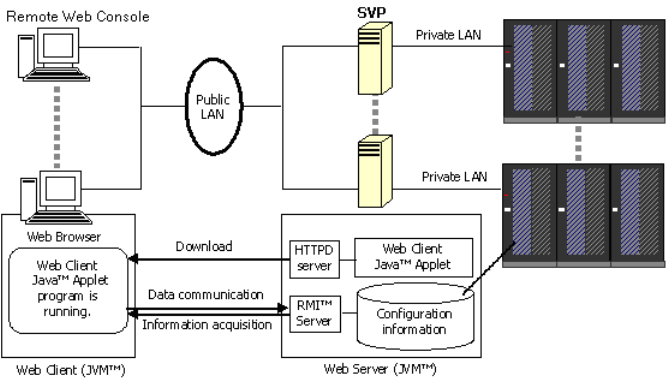
•The HP XP P9000 SNMP Agent User Guide describes the SNMP API interface for the P9500
disk array and provides instructions for configuring and performing SNMP operations.
•The HP XP P9000 Provisioning for Open Systems User Guide and HP XP P9000 Volume
Shredder for Open and Mainframe Systems User Guide provide instructions for configuring
multiple custom volumes (logical units) under single LDEVs on the P9500 disk array. The HP
XP P9000 Provisioning for Open Systems User Guide also provides instructions for configuring
size-expanded logical units by concatenating multiple logical units to form individual large
logical units.
Remote Web Console
Remote Web Console is installed on a PC, laptop, or workstation. It communicates via a LAN to
the SVP in the P9500 disk array. The SVP obtains disk array configuration and status information
and sends user initiated commands to the disk array. The Remote Web Console GUI displays
detailed disk array information and allows users to configure and perform storage operations on
the system.
Remote Web Console is provided as a Java applet program that can be executed on any machine
that supports a Java Virtual Machine (JVM). A PC hosting the Remote Web Console software is
called a remote console. Each time a remote console accesses and logs into the SVP of the desired
disk array, the Remote Web Console applet is downloaded from the SVP to the remote console.
Figure 10 (page 53) illustrates remote console and SVP configuration for Remote Web Console.
For further information about Remote Web Console, see the HP XP P9000 Remote Web Console
User Guide.
Figure 10 Remote Web Console and SVP configuration
Remote Web Console 53

3 System components
Controller chassis
The controller chassis provides system logic, control, memory, and monitoring, as well as the
interfaces and connections to the disk drives and the host servers. The controller chassis consists
of the following components:
Table 14 Controller chassis
DescriptionItem
.MaxMinName
A CHA is an interface board that provides connection to
the host servers. It provides the channel interface control
8 if 4 DKAs installed.
12 if no DKAs
installed.
2CHA
functions and intercache data transfer functions between the
disk array and the host servers. It converts the data format
between CKD and FBA. The CHA contains an internal
processor and 128 bytes of edit buffer memory.
A DKA is an interface board that provides connection to the
disk drives and SSDs. Provides the control functions for data
40 with no drives2
with drives
DKA
transfer between drives and cache. The DKA contains DRR
(Data Recover and Reconstruct), a parity generator circuit.
It supports eight FIBRE path and offers 32 KB of buffer for
each FIBRE path.
The full duplex switches serve as the data interconnection
between the CHAs, DKAs, and cache memory. They also
42Switches
connect the control signals between the Micro Processor
Blade (microprocessors) and the cache memory.
A custom PC that implements system configuration settings
and monitors the system operational status. Connecting the
21Service
processor
(SVP) SVP to service center enables the storage system to be
remotely monitored and maintained by the HP support team.
This significantly increases the level of support that HP can
provide to its customers.
NOTE: The SVP also provides a communication hub for
the 3rd and 4th Processor blade in Module-0. The SVP is
installed only in Module-0 only (system 0).
In a system with two SVPs, both are installed in the controller
chassis in system 0
Connects the switches, adapters, and service processor.
NOTE: The Hub provides communication connection for
3rd and 4th Processor blade in Module-0. The Hub is
installed in Module-1 only.
21Hub
The full duplex switches serve as the data interconnection
between the CHAs, DKAs, and CMs. They also connect the
42ESW
control signals between the P9500s (microprocessors) and
the CM boards.
Quad core, 2.33 GHz processors are independent of the
CHAs and DKAs and can be shared across CHAs and DKAs
42Processor
Blades
The cache is an intermediate buffer between the channels
and drives. Each cache memory adapter has a maximum
42Cache memory
adapter (CPC) capacity of 32 GB. An environmentally friendly nickel
hydride battery and up to two Cache Backup Memory Solid
States Disk drives are installed on each Cache Memory
Adapter board. In the event of a power failure, the cache
54 System components
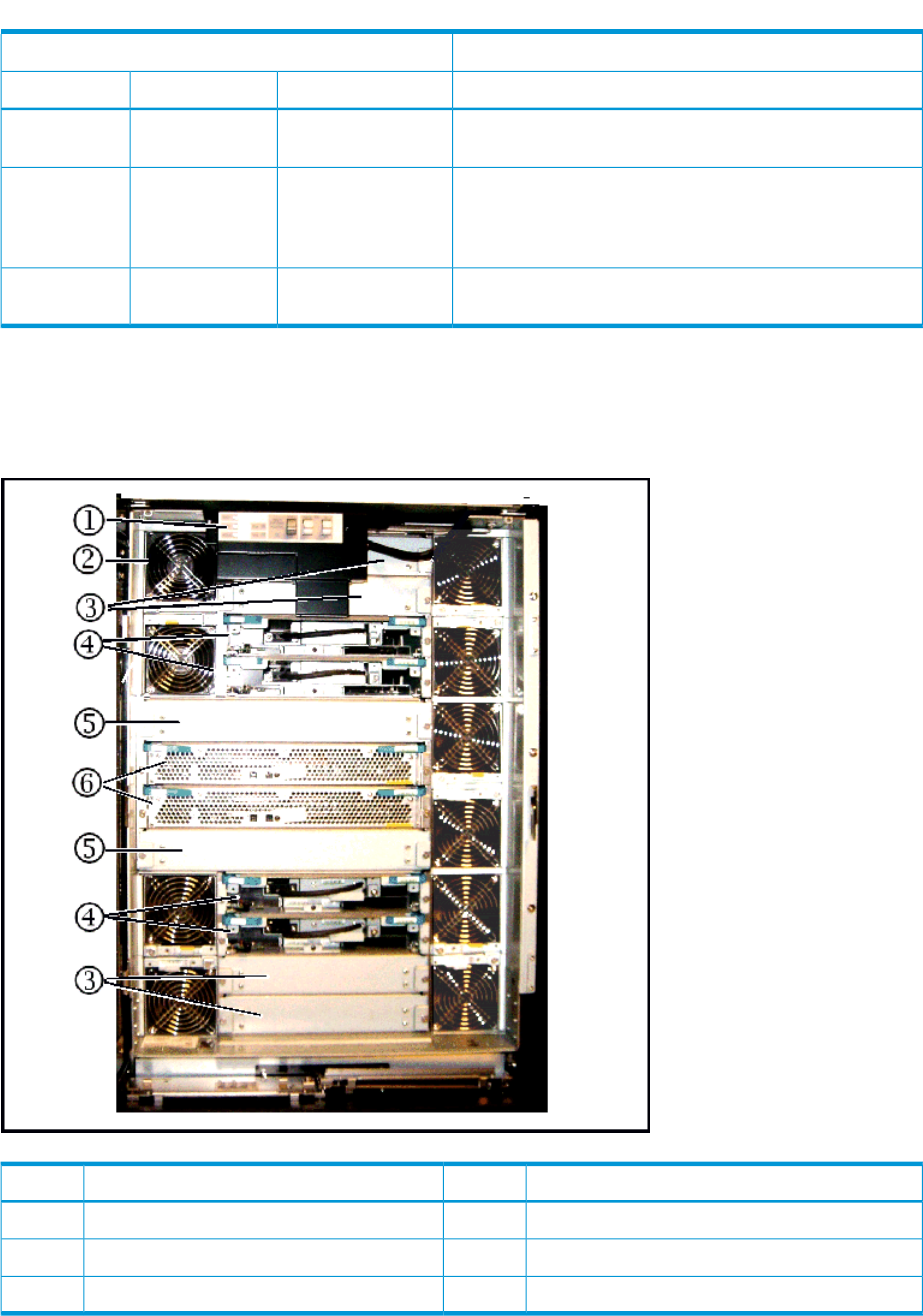
Table 14 Controller chassis (continued)
DescriptionItem
.MaxMinName
data will not be lost and will remain protected on the Cache
Backup Memory Solid States Disk drive.
200–220 VAC input. Provides power to the DKC in a
redundant configuration to prevent system failure. Up to four
42AC-DC power
supply power supplies can be used as needed to provide power
to additional components.
Each fan unit contains two fans to ensure adequate cooling
in case one of the fans fails.
1010Cooling fan
The following illustrations show the front and rear views of a controller chassis that is configured
with the minimum number of components. The system control panel (#1 in the front view) is described
in the next section.
Figure 11 Controller chassis front view (minimum configuration)
DescriptionItemDescriptionItem
Fan (10 total)2Control Panel1
Cache Memory Adapter4Slots for optional Cache Memory Adapter.3
Processor blades6Slots for additional Processor blades5
Controller chassis 55
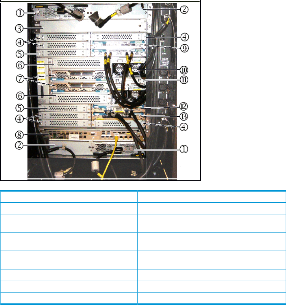
Figure 12 Controller chassis rear view (minimum configuration)
DescriptionItemDescriptionItem
Slots for optional Power Supply.2Power Supply (2 min, 4 max)1
Slots for Channel Adapter board.42nd Service Processor (optional for Module-0)
or Hub (optional for Module-1)
3
Slots for optional Express Switch Adapter.6Slots for optional Disk Control Adapter or
Channel Adapter board.
5
1st Service Processor for Module-0 or 1st Hub for
Module-1
8Express Switch Adapter7
Fan10Channel Adapter board9
Disk Control Adapter12SSVPMN11
--Channel Adapter board13
System control panel
The following illustration shows the P9500 system control panel. The table following the illustration
explains the purpose of each of the controls and LEDs on the panel.
56 System components
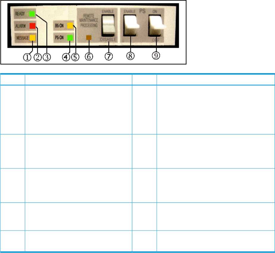
Figure 13 P9500 system control panel
DescriptionItemDescriptionItem
ALARM - Red LED2MESSAGE - Amber LED1
Indicates DC under voltage of any DKC part, DC
over current, abnormally high temperature, or that
an unrecoverable failure occurred.
ON: indicates that a SIM (Message) was
generated from either of the clusters. Applied
to both storage clusters.
Blinking: Indicates that a SVP failure has
occurred.
PS ON - Green LED4READY - Green LED Indicates that input/output
operation on the channel interface is enabled.
3
Indicates that the system is powered on, that the
POST is complete, and that the system has booted
up and is ready for use.
REMOTE MAINTENANCE PROCESSING - Amber
LED
6BS ON - Amber LED
Indicates that the Sub Power supply is on. (CL
1 or CL 2)
5
Indicates that the system is being remotely
maintained.
PS SW ENABLE - switch8REMOTE MAINTENANCE ENABLE/DISABLE -
switch
7
Used to enable the PS ON/PS OFF switch.
When ON, permits remote maintenance.
--PS ON/PS OFF - switch9
Turns the system power on or off.
Drive chassis
The drive chassis includes two back-to-back disk drive assemblies. Each assembly includes HDDs,
SSW boards, HDD PWR boards, eight cooling fans, and two AC-DC power supplies. All components
are configured in redundant pairs to prevent system failure. All the components can be added or
replaced while the disk array is in operation.
The following illustration shows the rear view of the drive chassis. The table following the illustration
describes the drive chassis components.
Drive chassis 57
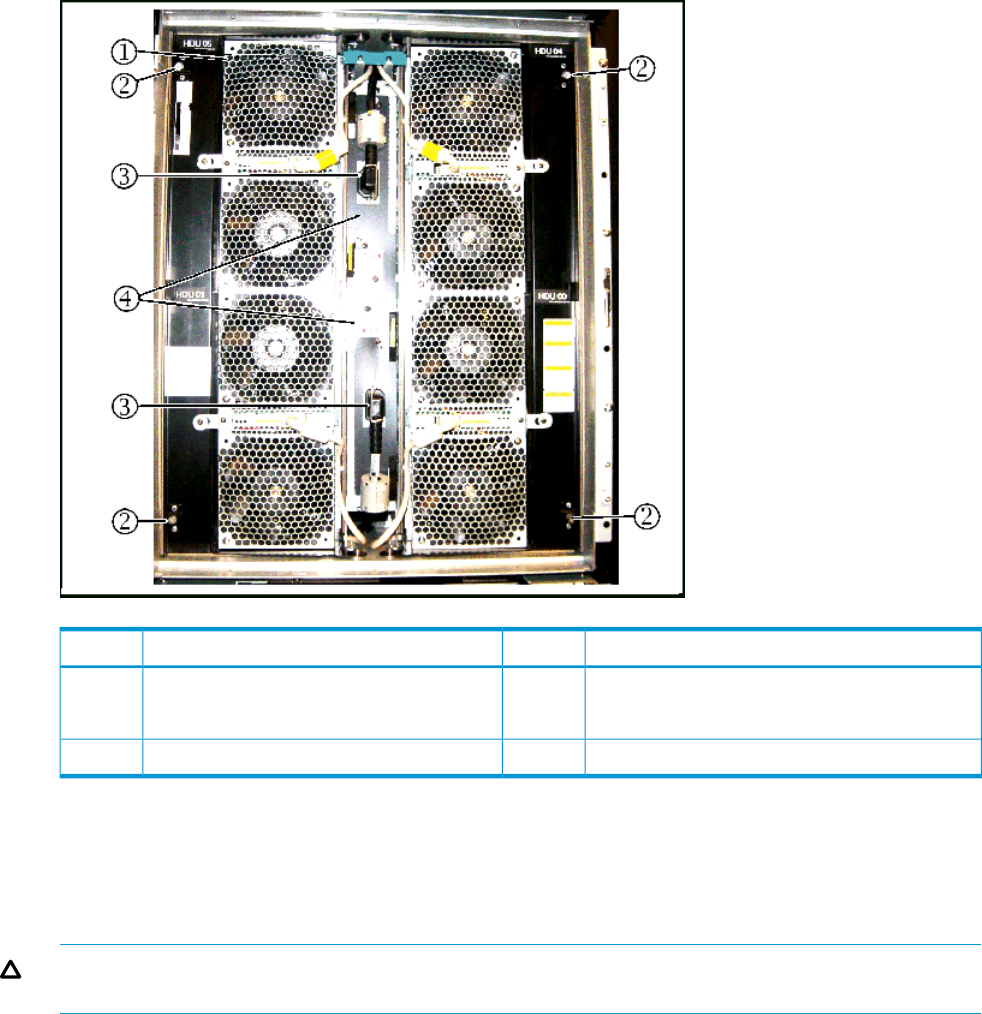
Figure 14 Drive chassis
DescriptionItemDescriptionItem
Fan assembly lock screw2Fan (8 total)1
(Loosen screw to open fan door.)
HDD Power Supply4Power Cable3
The fans on the front of the unit are intake fans that pull ambient air into the unit. The fans on the
rear assembly are exhaust fans that blow hot air out of the unit. The two sets of fans work together
to create a large airflow through the unit. Either fan assembly is sufficient to cool the unit. Therefore
there is no time limit when changing disk drives, as long as either the front or the rear fan assembly
is in place.
CAUTION: To prevent the unit from overheating, both the front and rear fan assemblies should
never be opened at the same time while the system is running.
58 System components
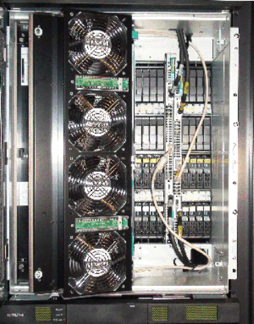
Figure 15 Disk chassis (fan door open)
As shown in Figure 15 (page 59), the fan assemblies on both the front and rear sides of the drive
chassis fold out and away from the unit to allow access to the disk drives. The three speed fans in
the drive chassis are thermostatically controlled by a temperature sensor (thermistor) in the unit.
The sensor measures the temperature of the exhaust air from the unit and sets the fan speed as
needed to maintain the unit temperature within a preset range. When the unit is not busy and cools
down, the fan speed is reduced, saving energy and reducing the noise level of the unit.
When the fan assemblies are opened, the power to the fans is automatically switched off and the
fans stop rotating. This helps prevent possible injury because there is no protective screen on the
back side of the fans.
Cache memory
The P9500 can be configured with up to 512 GB of cache memory per controller chassis (1024
GB for a two-module system). The cache is nonvolatile and is protected from data loss with onboard
batteries to backup cache data into the onboard Cache Backup Memory Solid States Disk drive.
Each controller chassis can contain from two to eight cache memory adapter boards. Each board
contains from 8 GB to 64 GB.
Cache memory adaptor boards are installed in pairs and work together to provide cache and
shared memory for the system. In addition to the memory on the cache boards, 4 GB of cache
memory is also located on each Micro Processor Blade board. See the following illustration.
Cache memory 59
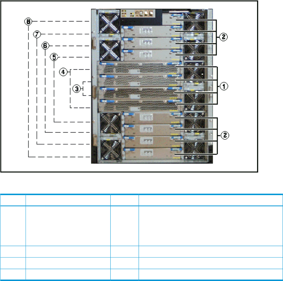
Figure 16 Cache memory
Table 15 Cache memory
DescriptionItemDescriptionItem
Cache Memory Adapter:2Micro Processor Blade1
8, 16, or 24 GB standardIncludes 4 GB cache
32 GB SSD drives optional
1 or 2 16 GB SSD drives
Micro Processor Blade cluster 14Micro Processor Blade cluster 03
Cache cluster 16Cache cluster 05
Cache cluster 38Cache cluster 27
Memory operation
The P9500 places all read and write data in the cache. The amount of fast-write data in cache is
dynamically managed by the cache control algorithms to provide the optimum amount of read
and write cache, depending on the workload read and write I/O characteristics.
Mainframe hosts can specify special attributes (for example, cache fast write command) to write
data (typically sort work data) without write duplexing. This data is not duplexed and is usually
given a discard command at the end of the sort, so that the data will not be destaged to the drives.
Data protection
The P9500 is designed so that it cannot lose data or configuration information from the cache if
the power fails. The cache is protected from data loss up for up to ten minutes by the cache destage
batteries while the data is copied to the cache SSD (flash memory) on the cache boards (see
“Battery backup operations” (page 67)).
60 System components

Shared memory
The P9500 shared memory is not on a separate memory module as it was in the previous hardware
systems. Shared memory resides by default on the first pair of cache boards in controller chassis
#0.
When you install software features such as Snapshot or Continuous Access Journal, the shared
memory usage increases as software features are installed. Shared memory can use up to 56 GB.
Depending on how much cache memory is installed, it may be necessary to install more cache
memory as more software features are installed in the system. Up to 32 GB can be installed on
each cache board. When 32 GB of cache is installed, it is also necessary to install a second SSD
(cache flash memory) on the cache board to back up the cache in case of power failure. Additional
cache backup SSD memory comes in 32 and 64 GB capacities.
In addition to cache, the shared memory on each cache board contains a 1/2 GB cache directory
to safeguard write pending data in the cache in the unlikely case of double failure of the shared
memory cache area. The cache directory has mapping tables for the Micro Processor Blade LDEVs
and the allocated cache slots in each Micro Processor Blade cache partition.
NOTE: Shared Memory in the P9000 is not a separate memory module as it was in the HP
XP24000/20000 disk arrays.
Flash storage chassis
This section includes information on the flash module drive (FMD), flash storage unit (FSU), and
flash storage chassis (FSX).
P9000 flash module
The P9000 flash module is a custom-designed and manufactured enterprise class solid state storage
module. It uses a high performance, custom ASIC flash controller and standard flash memory chips
in an implementation that exceeds the performance of expensive SLC SSDs, but costs less than less
expensive MLC SSDs. The FMD greatly improves the performance and solid state storage capacity
of the VSP system, while significantly reducing the cost per TB of storage.
Even in the initial capacity of 1.6 TB per FMD, the FMD outperforms both MLC and SLC flash
drives, has a longer service life, requires less power, and generates less heat per TB than SSDs.
FMDs can be used instead of, or in addition to, disk and flash drives, but they are installed in a
flash storage “chassis” composed of a cluster four flash module units (FMU). The next section
describes the FMU.
Shared memory 61
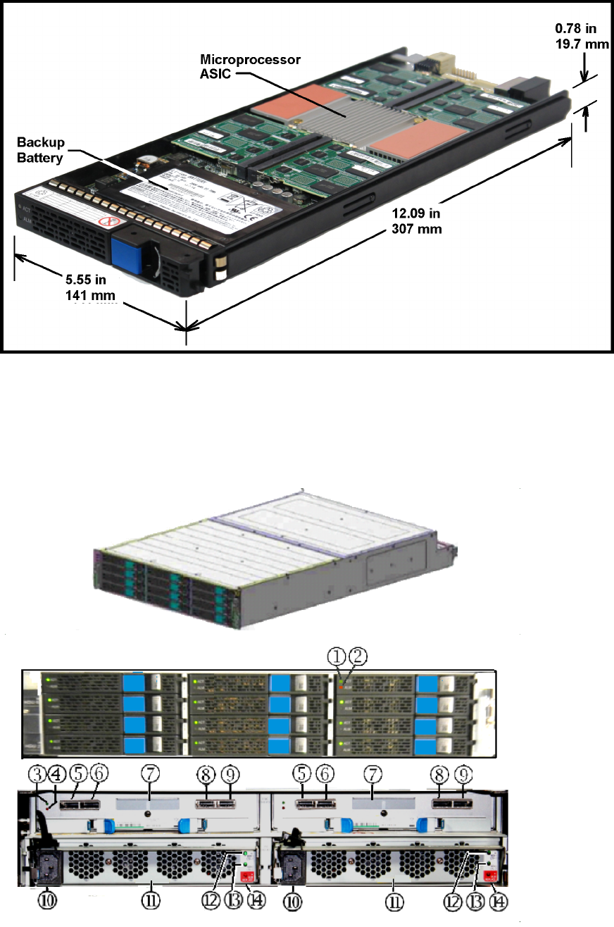
Figure 17 Flash Module Drive
Flash module unit
The flash module box (FMU) is a 2U high chassis that contains up to 12 FMDs, plus two redundant
power supplies and two redundant SSW adapters.
Figure 18 Flash Module Unit
62 System components
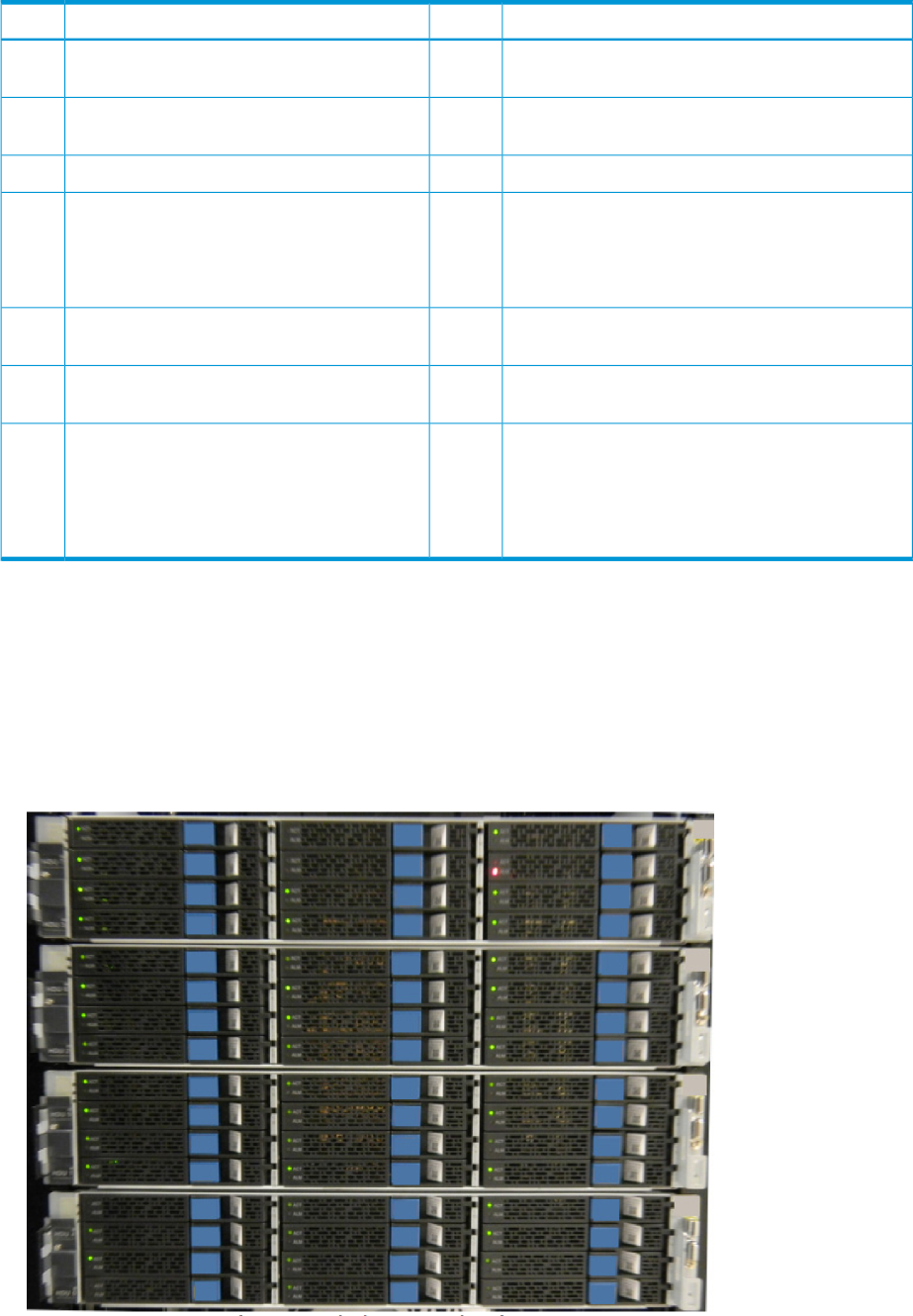
Table 16 Flash Module Unit
DescriptionItemDescriptionItem
SAS / SSW standard OUT connector.8FMD Active LED - lights when FMD is activated.
Blinks at drive access.
1
SAS / SSW high performance OUT connector.9FMD Alarm LED - lights when FMD has an error
and should be replaced.
2
Power cord receptacle.10SAS / SSW Module Power LED.3
Power Supply - 220 VAC input, draws approximately
265 watts.
NOTE: The power supply occupy the lower half of
the FM box (the SSW occupies the upper half).
11SAS / SSW Module Alarm LED - indicates fatal
error condition.
4
Power Supply Ready 1 LED - lights when 12 VDC
power#1 is ready.
12SAS / SSW standard IN connector.5
Power Supply Ready 2 LED - lights when 12 VDC
power #2 is ready.
13SAS / SSW high performance IN connector.6
Power Supply alarm LED - lights when power supply
has an error.
14SAS / SSW adapter - connects the FMDs to
the BEDs in the controller via SSW cables.
NOTE: Be sure to use the same SSW jumper
settings when replacing an SSW. Contact HP
Technical Support before replacing a SSW.
7
Flash storage chassis
The flash storage chsssis (FBX) is a cluster of four FMUs as shown in the following illustration. There
is not an actual chassis or enclosure surrounding the four FSBs, but since it takes the place of a
DKU drive chassis, the cluster is referred to as a chassis for consistency. FMDs can be added to
the FBX in increments of four, eight, or sixteen, depending on the desired RAID configuration.
Figure 19 Flash storage chassis
Flash storage chassis 63

Cache memory
Your P9000 can be configured with up to 512 GB of cache memory per controller chassis (1 TB
for a two-module system). Each controller chassis can contain from two to eight cache memory
adapter boards. Each board contains from 8 GB to 64 GB.
Cache memory adaptor boards are installed in pairs and work together to provide cache and
shared memory for the system. Each pair is called a cluster. From one to four cache clusters can
be installed in a controller.
Table 17 Drive Specifications
Speed (RPM)Drive Capacity
Size (inches)1
Drive Type
15,000300 GB2-1/2HDD (SAS)
10,000300 GB, 600 GB, 900 GB
7,200500 GB
7,2001 TB
n/a200 GB, 400 GB, 800 GB2-1/2SSD (Flash)1
n/a1.6, 3.2 TB5.55 x 12.09 x 0.78FDM (flash module)
1Each drive size requires its own chassis.
Minimum number of drives - Four HDDs or SSDs per controller chassis (two in upper half, two in
lower half). HDDs or SSDs must be added four at a time to create RAID groups, unless they are
spare drives. The minimum number of operating FMD drives is four, one in each FMU in the FBX
chassis. Spares are additional.
Table 18 Maximum Number of Drives
Dual Module (6-rack system)
Single Module (3-rack
system)Drive ChassisDrive Type (inches)
20481024128HDD, 2-1/2
2563
1283
1282
SSD, 2-1/21
19296448FMD4
1Each drive size requires its own chassis.
2SSD drives can be mounted all in one drive chassis or spread out among all of the chassis in the
storage system.
3Recommended maximum number.
4FMD drives are not the same form factor as HDDs or SSDs and require an FBX chassis. See
“P9000 flash module” (page 61).
System capacities with smart flash modules
The following table lists the P9000 system storage capacities when using FMDs.
Table 19 System capacities with smart flash modules
Considering hot sparing requirements
R6R5R1
14+2P6D+2P7D+1P3D+1P4D+4P2D+2P
Single flash chassis, max. capacity
51.264.064.070.464.070.4Raw1.6 GB
64 System components

Table 19 System capacities with smart flash modules (continued)
Considering hot sparing requirements
R6R5R1
14+2P6D+2P7D+1P3D+1P4D+4P2D+2P
44.848.056.052.832.035.2Usable
102.4128.0128.0140.8128.0140.8Raw3.2 GB
89.696.0112.0105.664.070.4Usable
Flash chassis pair max. capacity
128.0140.8140.8147.2140.8147.2Raw1.6 GB
112.0105.6123.2110.470.473.6Usable
256.0281.6281.6254.4281.6254.4Raw3.2 GB
224.0211.2246.4220.8140.8147.2Usable
Total P9500 max. capacity
256.0281.6281.6294.4281.6294.4Raw1.6 GB
224.0211.2246.4220.8140.8147.2Usable
512.0563.2563.2588.8563.2588.8Raw3.2 GB
448.0422.4492.8441.6281.6294.4Usable
Considering hot sparing requirements, number of flash modules
Single flash chassis max. capacity - add two hot spares
324040444044Count1.6 GB
6480808880883.2 GB
Flash chassis pair max. capacity - add four hot spares
808888928892Count1.6 GB
1601761761841761843.2 GB
Total VSP max. capacity - add eight hot spares
160176176184176184Count1.6 GB
3203523523683523683.2 GB
System capacities with smart flash modules 65

4 Power On/Off procedures
Safety and environmental information
CAUTION: Before operating or working on the P9500 disk array, read the safety section in the
HP XP P9000 Site Preparation Guide and the environmental information in “Regulatory compliance
notices” (page 85).
Standby mode
When the disk array power cables are plugged into the PDUs and the PDU breakers are ON, the
disk array is in standby mode. When the disk array is in standby mode:
•The Basic Supply (BS) LED on the control panel is ON. This indicates that power is applied to
the power supplies.
•The READY LED is OFF. This indicates that the controller and drive chassis are not operational.
•The fans in both the controller and drive chassis are running.
•The cache destage batteries are being charged.
•The disk array consumes significantly less power than it does in operating mode. For example,
a disk array that draws 100 amps while operating draws only about 70 amps in standby
mode (see “Electrical specifications” (page 80) for power consumption specifications.
To put the disk array into standby mode from the OFF condition:
1. Ensure that power is available to the AC input boxes and PDUs in all racks in which the P9500
disk array is installed.
2. Turn all PDU power switches/breakers ON.
To put the disk array into standby mode from a power on condition, complete the power off
procedures in this chapter. See “Power Off procedures” (page 67).
To completely power down the disk array, complete the power off procedures in this chapter, then
turn off all PDU circuit breakers.
CAUTION: Make certain that the disk array is powered off normally and in standby mode before
turning off the PDU circuit breakers. Otherwise, turning off the PDU circuit breakers can leave the
disk array in an abnormal condition.
Power On/Off procedures
This section provides general information about power on/off procedures for the P9500 disk array.
If needed, consult HP Technical Support for assistance.
Power On procedures
CAUTION: Only a trained HP support representative can restore power to the disk array.
Prerequisites
•Ensure that the disk array is in standby mode. See “Standby mode” (page 66).
NOTE: The control panel includes a safety feature to prevent the storage system power from
accidentally being turned on or off. The PS power ON/OFF switch does not work unless the
ENABLE switch is moved to and held in the ENABLE position while the power switch is moved to
the ON or OFF positions.
66 Power On/Off procedures
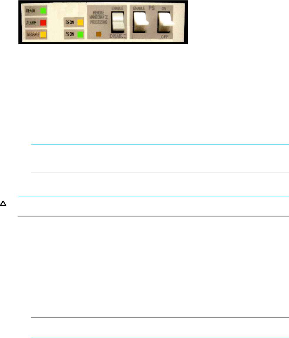
Follow this procedure exactly when powering the disk array on. Refer to the illustration of the
control panel as needed.
1. On the control panel, check the amber BS LED and make sure it is lit. It indicates that the disk
array is in standby mode.
2. In the PS area on the control panel, move the Enable switch to the ENABLED position. Hold
the switch in the Enabled position and move the PS ON switch to the ON position. Then release
the ENABLE switch.
3. Wait for the disk array to complete its power-on self-test and boot-up processes. Depending
on the disk array configuration, this may take several minutes.
4. When the Ready LED is ON, the disk array boot up operations are complete and the disk
array is ready for use.
NOTE: If the Alarm LED is also on, or if the Ready LED is not ON after 20 minutes, please
contact HP Technical Support. The disk array generates a SIM that provides the status of the
battery charge (see “Cache destage batteries” (page 68)).
Power Off procedures
CAUTION: Only a trained HP support representative can shut down and power off the disk array.
Do not attempt to power down the disk array other than during an emergency.
Prerequisites:
•Ensure that all software specific shutdown procedures have been completed. Please see the
applicable user manuals for details.
•Ensure that all I/O activity to the disk array has stopped. You can vary paths offline and/or
shut down the attached hosts.
Follow this procedure exactly when powering the disk array off.
1. In the PS area on the power panel, move the Enable switch to the Enabled position. Hold the
switch in the Enabled position and press the PS OFF switch on the Operator Panel.
2. Wait for the disk array to complete its shutdown routines. Depending on the disk array
configuration and certain MODE settings, it can take up to 20 minutes for the disk array to
copy data from cache to the disk drives and for the disk drives to spin down.
NOTE: If the Ready and PS LEDs do not turn OFF after 20 minutes, contact HP Technical
Support.
Battery backup operations
The P9500 is designed so that it cannot lose data or configuration information if the power fails.
The battery system is designed to provide enough power to completely destage all data in the
cache if two consecutive power failures occur and the batteries are fully charged. If the batteries
do not contain enough charge to provide sufficient time to destage the cache when a power failure
occurs, the cache operates in write through mode. This synchronously writes to HDDs to prevent
slow data throughput in the cache. When the battery charge is 50% or more, the cache write
protect mode operates normally.
Battery backup operations 67
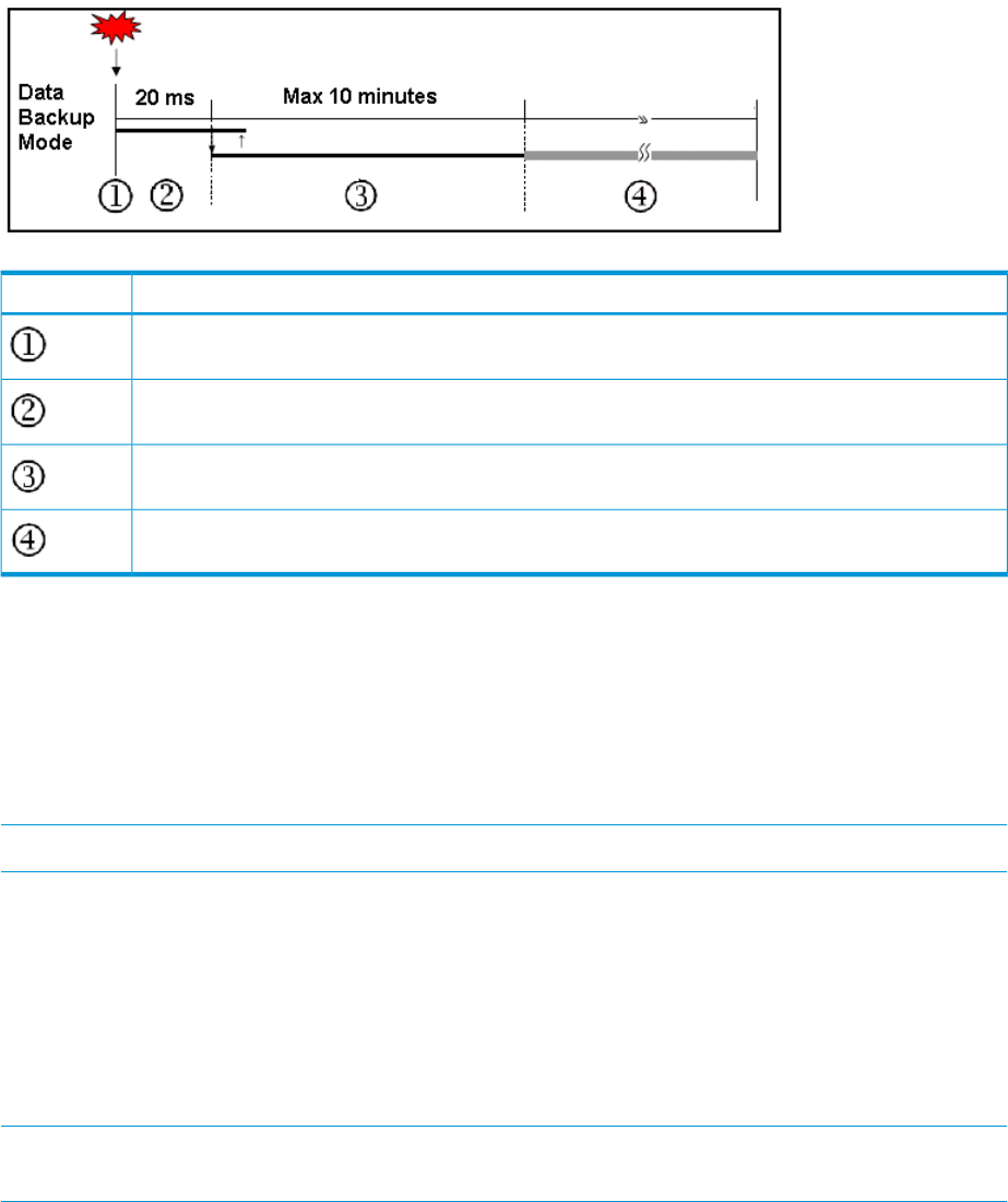
When a power failure occurs and continues for 20 milliseconds or less, the disk array continues
normal operation. If the power failure exceeds 20 milliseconds, the disk array uses power from
the batteries to back up the cache memory data and disk array configuration data to the cache
flash memory on each cache board. This continues for up to ten minutes. The flash memory does
not require power to retain the data. The following illustration shows the timing in the event of a
power failure.
Figure 20 Battery backup operations
DescriptionItem
Power failure occurs
The storage system continues to operate for 20 milliseconds and detects the power failure.
The cache memory data and the storage system configuration are backed up to the cache flash memory
on the cache boards. The backup continues even if power is restored during the backup.
Unrestricted data backup. Data is continuously backed up to the cache flash memory.
Cache destage batteries
The environmentally friendly nickel hydride cache destage batteries are used to save disk array
configuration and data in the cache in the event of a power failure. The batteries are located on
the cache memory boards and are fully charged at the distribution center where the disk array is
assembled and tested. Before the system is shipped to a customer site, the batteries are disconnected
by a jumper on the cache board. This prevents them from discharging during shipping and storage
until the system is installed. At that time, HP Technical Support representative connects the batteries.
NOTE: The disk array generates a SIM when the cache destage batteries are not connected.
Battery life
The batteries have a lifespan of three years, and will hold the charge when connected. When the
batteries are connected and power is on, they are charged continuously. This occurs during both
normal system operation and while the system is in standby mode.
When the batteries are connected and the power is off, the batteries slowly discharge. They will
have a charge of less than 50% after two weeks without power. When fully discharged, the batteries
must be connected to power for three hours to fully recharge.
NOTE: The disk array generates a SIM when the cache destage batteries are not charged to at
least 50%. The LEDs on the front panel of the cache boards also show the status of the batteries.
Long term array storage
While connected, the cache destage batteries will completely discharge in two to three weeks
without power applied. If you do not use a P9500 for two weeks or more, contact HP Technical
68 Power On/Off procedures
Support to move the batteries to a disk array that is being used, or turn the disk array on to standby
mode for at least 3 hours once every two weeks.
If you store the system for more than two weeks and do not disconnect the cache destage batteries,
when you restart the system, the batteries will need to charge for at least 90 minutes before the
cache will be protected. To prevent the batteries from discharging during long term storage, contact
HP Technical Support and ask them to disconnect the battery jumpers on the cache boards.
Battery backup operations 69

5 Troubleshooting
Solving problems
The P9500 disk array is highly reliable and is not expected to fail in any way that would prevent
access to user data. The READY LED on the control panel must be ON when the disk array is
operating online.
The following table lists possible error conditions and provides recommended actions for resolving
each condition. If you are unable to resolve an error condition, contact your HP representative, or
call the support center for assistance.
Table 20 Troubleshooting
Recommended ActionError Condition
Determine the type of error (see the SIM codes section. If possible, remove the cause of
the error. If you cannot correct the error condition, call the support center for assistance.
Error message displayed.
Turn off all PDU switches and breakers. After the facility power comes back on steady,
turn them back on and power the system up. See Chapter 4 for instructions. If needed,
call HP support for assistance.
General power failure
Determine if there is a failed storage path. If so, toggle the RESTART switch, and retry
the operation. If the fence message is displayed again, call the support center for
assistance.
Fence message is displayed
on the console.
Call the support center for assistance. WARNING: Do not open the P9500 control
frame/controller or touch any of the controls.
READY LED does not go on,
or there is no power
supplied.
If there is a temperature problem in the area, power down the disk array, lower the room
temperature to the specified operating range, and power on the storage system. Call
ALARM LED is on.
the support center if needed for assistance with power off/on operations. If the area
temperature is not the cause of the alarm, call the support center for assistance.
Service information messages
The P9500 disk array generates SIMs to identify normal operations. For example, Continuous
Access Synchronous pair status change as well as service requirements and errors or failures. For
assistance with SIMs, please call the support center.
SIMs can be generated by the channel adapters and disk adapters and by the SVP. All SIMs
generated by the P9500 are stored on the SVP for use by HP personnel, logged in the
SYS1.LOGREC dataset of the mainframe host system, displayed by the Remote Web Console
software, and reported over SNMP to the open system host. The SIM display on Remote Web
Console enables users to remotely view the SIMs reported by the attached disk array. Each time
a SIM is generated, the amber Message LED on the control panel turns on. The C-Track remote
maintenance tool also reports all SIMs to the support center
SIMs are classified according to severity. There are four levels: service, moderate, serious, or acute.
The service and moderate SIMs (lowest severity) do not require immediate attention and are
addressed during routine maintenance. The serious and acute SIMs (highest severity) are reported
to the mainframe host (s) once every eight hours.
NOTE: If a serious or acute level SIM is reported, call the support center immediately to ensure
that the problem is being addressed.
The following figure illustrates a typical 32 byte SIM from the P9500 disk array. SIMs are displayed
by reference code (RC) and severity. The six digit RC, which is composed of bytes 22, 23, and
13, identifies the possible error and determines the severity. The SIM type, located in byte 28,
indicates which component experienced the error.
70 Troubleshooting
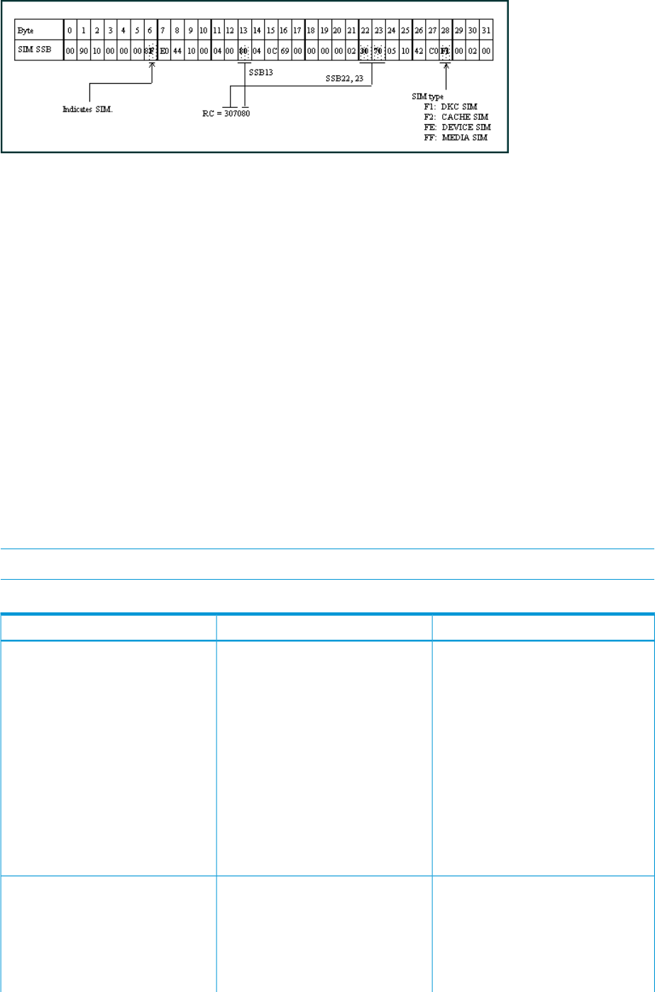
Figure 21 Service Information Message
C-Track
The C-Track remote support solution detects and reports events to the HP Support Service. C-Track
transmits heartbeats, SIMs, and configuration information for remote data collection and monitoring
purposes. C-Track also enables the HP Support Service to remotely diagnose issues and perform
maintenance (if the customer allows the remote maintenance). The C-Track solution offers Internet
connectivity only. If you choose the Internet-based remote support solution, additional infrastructure
and site preparation are required. Additional preparation may include server and router
requirements, which you and HP may be responsible for implementing.
Insight Remote Support
HP strongly recommends that you install HP Insight Remote Support software to complete the
installation or upgrade of your product and to enable enhanced delivery of your HP Warranty,
HP Care Pack Service or HP contractual support agreement. HP Insight Remote Support supplements
your monitoring, 24x7 to ensure maximum system availability by providing intelligent event
diagnosis, and automatic, secure submission of hardware event notifications to HP, which will
initiate a fast and accurate resolution, based on your product’s service level. Notifications may be
sent to your authorized HP Channel Partner for on-site service, if configured and available in your
country. The HP Insite Remote Support products available for the P9500 disk arrays are described
in “P9500 disk array remote support products” (page 71).
NOTE: HP Insight Remote Support Standard is not supported on XP and P9500 Disk Arrays.
Table 21 P9500 disk array remote support products
ApplicationDescriptionHP Product
For customers that fully commit to use
HP Remote Support. It uses HP Insight
HP XP/P9500 Remote Device Access
Support
AE241A
Remote Support for P9500 Remote
Device Monitoring utilizing
LAN/Internet connectivity and Remote
Device Access Support. This
configuration is required to meet the
objectives of XP disk array’s Internet
connectivity with Remote Device Access
initiative and prerequisites for Critical
Support contracts. HP recommends that
the AE241A product with Internet
connectivity should be utilized for all
new P9500 installations, to ensure the
optimal support model and highest TCE.
For customers that commit to utilize
Internet and Insight Remote Support
HP XP/P9500 no Remote Device
Access Support
AE242A
connectivity for P9500 Remote Device
Monitoring but will not allow for Remote
Device Access to the P9500 array from
HP for proactive and critical support
processes.With no Remote Device
C-Track 71

Table 21 P9500 disk array remote support products (continued)
ApplicationDescriptionHP Product
Access, Critical Support contract
prerequisites cannot be met.
For a customer whose strict security
protocols specifically prohibit inbound/
HP XP/P9500 Mission Critical No
LAN Support
AE244A
outbound traffic to/from the data center
and thus will not allow Remote Support
connection by either modem or
LAN/internet connectivity; but does
have Mission Critical Services with
Customer Engineer onsite included in
the terms of the support contract.
Factory Authorization will be required
to order this product. Proof of valid
Customer Engineer onsite Mission
Critical support contract must be
provided for Factory Authorization
approval.
For a customer whose strict security
protocols specifically prohibit
HP XP/P9500 No Mission Critical
LAN Support
AE245A
inbound/outbound traffic to/from the
data center and thus will not allow
Remote Support connection by either
modem or LAN and does not have a
Mission Critical Services on-site
contract. The added cost of this
configuration only covers the additional
warranty support cost to HP during
warranty period. Other additional costs
can also be incurred for support
contracts for customers who do not have
remote support configured.
Details are available at:
http://www.hp.com/go/insightremotesupport
To download the software, go to Software Depot:
http://www.software.hp.com
Select Insight Remote Support from the menu on the right.
Failure detection and reporting process
If a failure occurs in the system, the failure is detected and reported to the system log, the SIM log,
and HP technical support, as shown in “Failure reporting process” (page 73).
72 Troubleshooting
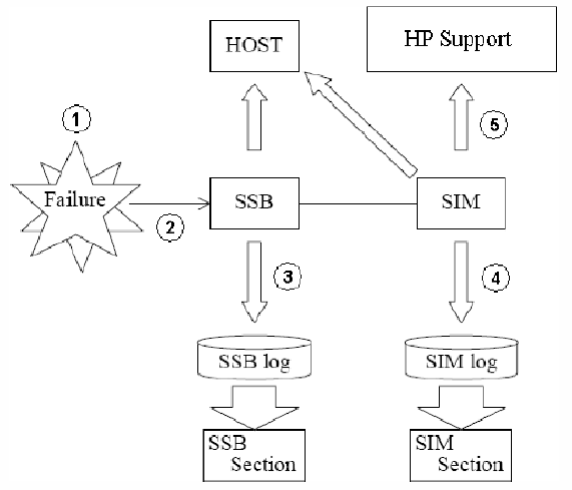
Figure 22 Failure reporting process
Failure detection and reporting process 73

6 Support and other resources
Contacting HP
For worldwide technical support information, see the HP support website:
http://www.hp.com/support
Before contacting HP, collect the following information:
•Product model names and numbers
•Technical support registration number (if applicable)
•Product serial numbers
•Error messages
•Operating system type and revision level
•Detailed questions
Subscription service
Receive, by email, support alerts announcing product support communications, driver updates,
software releases, firmware updates, and customer-replaceable component information by signing
up at http://www.hp.com/go/myadvisory.
To change options for support alerts you already receive, click the Sign in link on the right.
Documentation feedback
HP welcomes your feedback.
To make comments and suggestions about product documentation, please send a message to
storagedocsfeedback@hp.com. Include the document title and manufacturing part number. All
submissions become the property of HP.
Related information
The following documents [and websites] provide related information:
•HP XP P9000 External Storage for Open and Mainframe Systems User Guide
•HP XP P9000 Provisioning for Open Systems User Guide
•HP XP P9000 Remote Web Console Messages
•HP XP P9000 RemoteWeb Console User Guide
•HP XP P9000 SNMP Agent User Guide
You can find these documents on the Manuals page of the HP Business Support Center website:
http://www.hp.com/support/manuals
In the Storage section, click Disk Storage Systems for hardware or Storage Software for software,
and then select your product.
HP websites
For additional information, see the following HP websites:
•http://www.hp.com
•http://www.hp.com/go/storage
•http://www.hp.com/service_locator
74 Support and other resources

•http://www.hp.com/support/manuals
•http://www.hp.com/support/downloads
•http://www.hp.com/storage/whitepapers
Conventions for storage capacity values
P9000 disk arrays use the following values to calculate physical storage capacity values (hard
disk drives):
•1 KB (kilobyte) = 1,000 bytes
•1 MB (megabyte) = 1,0002bytes
•1 GB (gigabyte) = 1,0003bytes
•1 TB (terabyte) = 1,0004bytes
•1 PB (petabyte) = 1,0005bytes
•1 EB (exabyte) = 1,0006bytes
P9000 disk arrays use the following values to calculate logical storage capacity values (logical
devices):
•1 KB (kilobyte) = 1,024 bytes
•1 MB (megabyte) = 1,0242bytes
•1 GB (gigabyte) = 1,0243bytes
•1 TB (terabyte) = 1,0244bytes
•1 PB (petabyte) = 1,0245bytes
•1 EB (exabyte) = 1,0246bytes
Typographic conventions
Table 22 Document conventions
ElementConvention
Blue text: Table 22 (page 75) •Cross-reference links and e-mail addresses
•A cross reference to the glossary definition of the term
in blue text
email addressesBlue, bold, underlined text
Website addressesBlue, underlined text: http://www.hp.com
Bold text •Keys that are pressed
•Text typed into a GUI element, such as a box
•GUI elements that are clicked or selected, such as menu
and list items, buttons, tabs, and check boxes
Text emphasisItalic text
Conventions for storage capacity values 75

Table 22 Document conventions (continued)
ElementConvention
Monospace text •File and directory names
•System output
•Code
•Commands, their arguments, and argument values
Monospace, italic text •Code variables
•Command variables
Emphasized monospace textMonospace, bold text
WARNING! Indicates that failure to follow directions could result in bodily harm or death.
CAUTION: Indicates that failure to follow directions could result in damage to equipment or data.
IMPORTANT: Provides clarifying information or specific instructions.
NOTE: Provides additional information.
TIP: Provides helpful hints and shortcuts.
Rack stability
Rack stability protects personnel and equipment.
WARNING! To reduce the risk of personal injury or damage to equipment:
•Extend leveling jacks to the floor.
•Ensure that the full weight of the rack rests on the leveling jacks.
•Install stabilizing feet on the rack.
•In multiple-rack installations, fasten racks together securely.
•Extend only one rack component at a time. Racks can become unstable if more than one
component is extended.
76 Support and other resources

A Comparing the XP24000/XP20000 Disk Array and
P9500
Comparison of the XP24000/XP20000 Disk Array and P9500
The P9500 includes several upgrades from the XP24000/XP20000 Disk Array as well as a number
of new features. These include:
•High scalability. The system supports configurations of 2 1/2 disk drives in either a single or
dual DKC configuration
•Shared processors. In the P9500, the processor and interface cards are separate. This allows
either or both to be configured separately, and allows each processor to share resources
across multiple interface cards.
•Load balancing. The P9500 disk array allows workloads to be better balanced across
management processor and breaks the affinity between specific front end and back end ports
with specific processors.
•High performance. The system uses shared high performance quad core processors instead
of single core. This significantly increases system total processing speed and distributes
processing across the CHAs and DKAs as needed.
•Faster access to system control information through the use of on board memory.
•Storage management usability improvements. The new version includes a user friendly, task
based GUI that reduces the number of operations needed to complete a task and includes
wizards to assist users in new or repetitive tasks. This version of Remote Web Console also
includes context sensitive online help.
The following tables show the main differences between the XP24000/XP20000 Disk Array and
the P9500.
Table 23 Storage management improvements
XP24000/XP20000 Disk ArrayP9500
Architecture OrientedUse Case Oriented Operation
Many steps and clicks for operationFewer steps and clicks
Slow performance impressionFaster operation and higher performance
Many user interfacesUnified User interface (GUI/CLI)
Table 24 Basic Mainframe functional differences
XP24000/XP20000 Disk ArrayP9500Feature
SupportedNot supported (Only FC V2)FlashCopy Version 1
3380-33380-3Drive Emulation Type
3390-1/2/3/3R/9/L/M3390-1/2/3/3R/9/L/M/V
3990/2105/21072105/2107DKC Emulation Type
1616The number of multi relations
10485751048575The maximum relations in system
10001000The maximum relations for each VOL
Source : Supported (V07 or higher)Source : SupportedExternal VOL
Target : Supported
Save to SVPSave to SVPSaving Differential Bitmap
Comparison of the XP24000/XP20000 Disk Array and P9500 77

Table 24 Basic Mainframe functional differences (continued)
XP24000/XP20000 Disk ArrayP9500Feature
OS/390 V2/R10 or higherOS/390 V2/R10 or higherSupported OS
z/OS V1R0 or higher/OS V1R0 or higher
z/VM V5R3 or higherz/VM V5R3 or higher
z/VSE V4R1 or higherz/VSE V4R1 or higher
TSOTSOOperation Interface
ICKDSFICKDSF
DFSMSdssDFSMSdss
ANTRQSANTRQS
Table 25 Functional differences - Business Copy Z
XP24000/XP20000 Disk ArrayP9500Feature.
39902105DKC Emulation TypeBasic
Functions 21052107
2107
3380-33380-3Drive Emulation Type
3390-1/2/3/3R/9/L/M3390-1/2/3/3R/9/L/M
3390-M3390-MThe biggest size of pair creatable
volume.
16k16kMaximum number of pairs in
system
256256Maximum number of CTGs in
system
81928192Maximum number of pairs in one
CTG
Save to SVPSave to SSDSaving Differential Bitmap
Save to SYSTEM DISK
Remote Web ConsoleRemote Web ConsoleInterface
PPRCPPRC
Business Copy ZBusiness Copy Z
1:11:N (N<=3)1:11:N (N<=3)Pair configurationExpanded
Function SupportedSupportedAt-Time Split Function
Table 26 Functional differences - Business Copy for Open Systems
XP24000/XP20000 Disk ArrayP9500Feature.
Open-3, Open-8,Open-9Open-3, Open-8,Open-9Drive Emulation Type
Open-E, Open-L, Open-VOpen-E, Open-L, Open-V
FibreFibreHost I/F
Open-V 4 TBOpen-V 4 TBMaximum size of pair creatable
volume.
16k Pair16k PairMaximum number of pairs in
system
78 Comparing the XP24000/XP20000 Disk Array and P9500

Table 26 Functional differences - Business Copy for Open Systems (continued)
XP24000/XP20000 Disk ArrayP9500Feature.
256CTG256CTGMaximum number of CTG in
system
8192 Pair8192 PairMaximum number of pair in one
CTG
Save to SVPSave to SYSTEM DISKSave to SSDSaving differential bitmap
Remote Web ConsoleRemote Web ConsoleOperation interface
RAID Manager (Inband)RAID Manager (Inband)
RAID Manager (Outband)
1:11:1Pair configurationExpanded
Function Cascade pairCascade pair
1:N (N <= 3)1:N (N <= 3)
Comparison of the XP24000/XP20000 Disk Array and P9500 79

B Specifications
Mechanical specifications
The following table lists the mechanical specifications of the P9500 disk array.
Table 27 P9500 mechanical specifications
Dual ModuleSingle ModuleSingle RackDimension
(6 racks)(3 racks)
142 / 361071.3 / 181024.0 / 610Width (inches / mm)
45 / 114545 / 114545 / 1145Depth (inches / mm)
79 / 200679 / 200679 / 2006Height (inches / mm)
7500 / 34023750 / 17011120 / 508 (Diskless)Min (lbs / kg)System
Weight 8560 / 38834319 / 19591558 / 707Max (lbs / kg)
Rack Weight is included in system weight292.6 / 133(lbs / kg)Rack
Weight
Electrical specifications
The P9500 supports single-phase and three-phase power. Power consumption and heat dissipation
is independent of input power.
“System heat and power specifications” (page 80) lists system heat and power specifications.
“System components heat and power specifications ” (page 81) lists component heat and power
specifications.
“AC power - PDU options” (page 82) lists the PDU specifications for both single phase and three
phase power.
System heat and power specifications
Table 28 System heat and power specifications
Full Array (DKC-0
plus DKC-1 plus
DKU x4)DKU RackDKC Module-1DKC Module-0
Parameter 1, 2
33.15.455.425.87Max Power
consumption (kVA)
Heat Dissipation
and Power
Consumption 31.45.175.155.57Max Heat
dissipation (kW)
Specifications
(Maximum
configuration) 107155176431757119012Max BTUs per
hour
27002444644284791Max Kcal per hour
1Heat (KW, BTU, Kcal) and Power (kVA) values are for determining load for site planning. Actual heat generation
and power demand may be less.
2Calculated values with drives at a typical I/O condition. (Random Read and Write, 50 IOPSs for HDD, 2500 IOPSs
for SSD, Data Length: 8Kbytes). These values may increase for future compatible drives.
80 Specifications

System components heat and power specifications
Table 29 System components heat and power specifications
Power Consumption
(kVA)1
Heat Output (kW)1
HP XP P9500 Disk Array ComponentComponent Product Number
0.6404
0.6004
Flash Module ChassisAV375A
0.0183
0.0173
Flash ModuleAV392A, AV393A
1.971.88Disk Array DKC Module-0 RackAV400A
1.931.83DKC Module-1 RackAV401A, AV401B
1.541.47DKU Disk Unit RackAV402A,AV402B
see note 5see note 5Base 2.5in Drive ChassisAV411B
0.6000.57Complete 2.5in Drive ChassisAV412B
0.1030.120Drive Chassis SAS Switch KitAV413A
0.0760.0728-port 2-8 Gbps FC CHAAV423A, AV423B
0.0760.07216-port 2-8 Gbps FC CHAAV424A, AV424B
0.1240.11816p 1-4 Gbps SW FICON CHAAV425A
0.1240.11816p 1-4 Gbps LW FICON CHAAV426A
0.0760.07216p 2-8 Gbps SW FICON CHAAV427A, AV427B
0.0760.07216p 2-8 Gbps LW FICON CHAAV428A
0.0760.072P9500 8-port 10 Gbps FCoE CHAAV429A
0.2000.19Processor BladeAV440A, AV440B
0.0100.010DKC Hub KitAV442A
0.0550.0522nd SVP High Reliability KitAV443A
0.0720.068Cache Memory AdapterAV444A
0.0200.01916GB Cache Memory ModuleAV447A, AV447B
0.0200.01932GB Cache Memory ModuleAV448A, AV448B
0.0052
0.0052
64GB Cache Backup Memory ModuleAV451A
0.0052
0.0052
128GB Cache Backup Memory ModuleAV452A
0.0840.08SAS DKA Drive AdapterAV455A
0.0740.07Express Switch AdapterAV458A
0.00743
0.00703
500GB 6G SAS 7.2K 2.5in DP HDDAV467A
0.00873
0.00823
1TB SAS 7.2K 2.5in DP HDDAV468A
0.00833
0.00793
300GB SAS 10K 2.5in DP HDDAV474A
0.00853
0.00803
600GB SAS 10K 2.5in DP HDDAV475A
0.00953
0.00903
900GB SAS 10K 2.5in DP HDDAV476A
0.00873
0.00833
1.2 TB SAS 10K 2.5in DP HDDAV477A
0.00843
0.00803
146GB SAS 15K 2.5in DP HDDAV482A
0.00903
0.00863
300GB SAS 15K 2.5in DP HDDAV483A
0.01343
0.01273
200GB SAS 2.5in DP SLC SSDAV490A
System components heat and power specifications 81

Table 29 System components heat and power specifications (continued)
Power Consumption
(kVA)1
Heat Output (kW)1
HP XP P9500 Disk Array ComponentComponent Product Number
0.00243
0.00233
400GB SAS 2.5in DP SLC SSDAV491A
0.00283
0.00263
200GB SAS 2.5in DP MLC SSDAV492A
0.00283
0.00263
400GB SAS 2.5in DP MLC SSDAV493A
0.00713
0.00673
800GB SAS 2.5in DP MLC SSDAV494A
1Heat (KW, BTU, Kcal) and Power (kVA) values are for determining rated load for site planning. Actual heat generation
and power demand may be less.
2Power is consumed during the battery back-up time only.
3Actual values at a typical I/O condition. (Random Read and Write, 50 IOPSs for HDD, 2500 IOPSs for SSD, Data
Length: 8Kbytes). These values may increase for future compatible drives.
4Maximum values with all fans rotate at maximum.
5AV411B Base 2.5in Drive Chassis does not include power supplies consequenly demands zero (0) kVA and geneates
no (0) kW heat.
AC power - PDU options
P9500 is configured for input power using separate rackmount PDU products. PDUs are available
for three phase or single phase power for NEMA and IEC compliance applications.
Table 30 P9500 AC PDU options
Notes
Facility
receptacle
neededPlug Type
Branch circuit
requirements
per PDU
Number of
PDU per Rack1
Local Power
Product
Number
For customers
with, 208 - 240
NEMA
L15-30R
NEMA
L15-30P
208-240V, 3Ø,
4-wire, 30A
23 phase (4
wire)
AV404A
AV404AU VAC, 3-Phase,
4-Wire Power
Distribution
System
For customers
with 380 - 415
IEC60309 4
pole, 5-wire,
IEC60309 4
pole, 5-wire
380-415V, 3Ø,
5-wire, 16A
23 phase (5
wire)
AV405A
AV405AU VAC,380-415 VAC,
16A
380-415VAC,
16A
Category D
Breaker Three-Phase,
5-Wire Wye
Power
Distribution
System
For customers
with single
NEMA L6-30RNEMA L6-30P200-240V, 1Ø,
3-wire, 30A
4single phase
NEMA
AV406A
AV406AU phase power
and need
NEMA L6-30P
plug
For customers
with single
IEC60309 2
pole, 3-wire,
240VAC, 32A
IEC60309 2
pole, 3-wire,
240VAC, 32A
200-240V, 1Ø,
3-wire, 32A
Category D
Breaker
4single phase
IEC
AV407A
AV407AU phase power
and need
IEC60309 32A
plug
Notes:
1. Each PDU has one fixed power cord with attached plug. Power cord is not removable.
82 Specifications
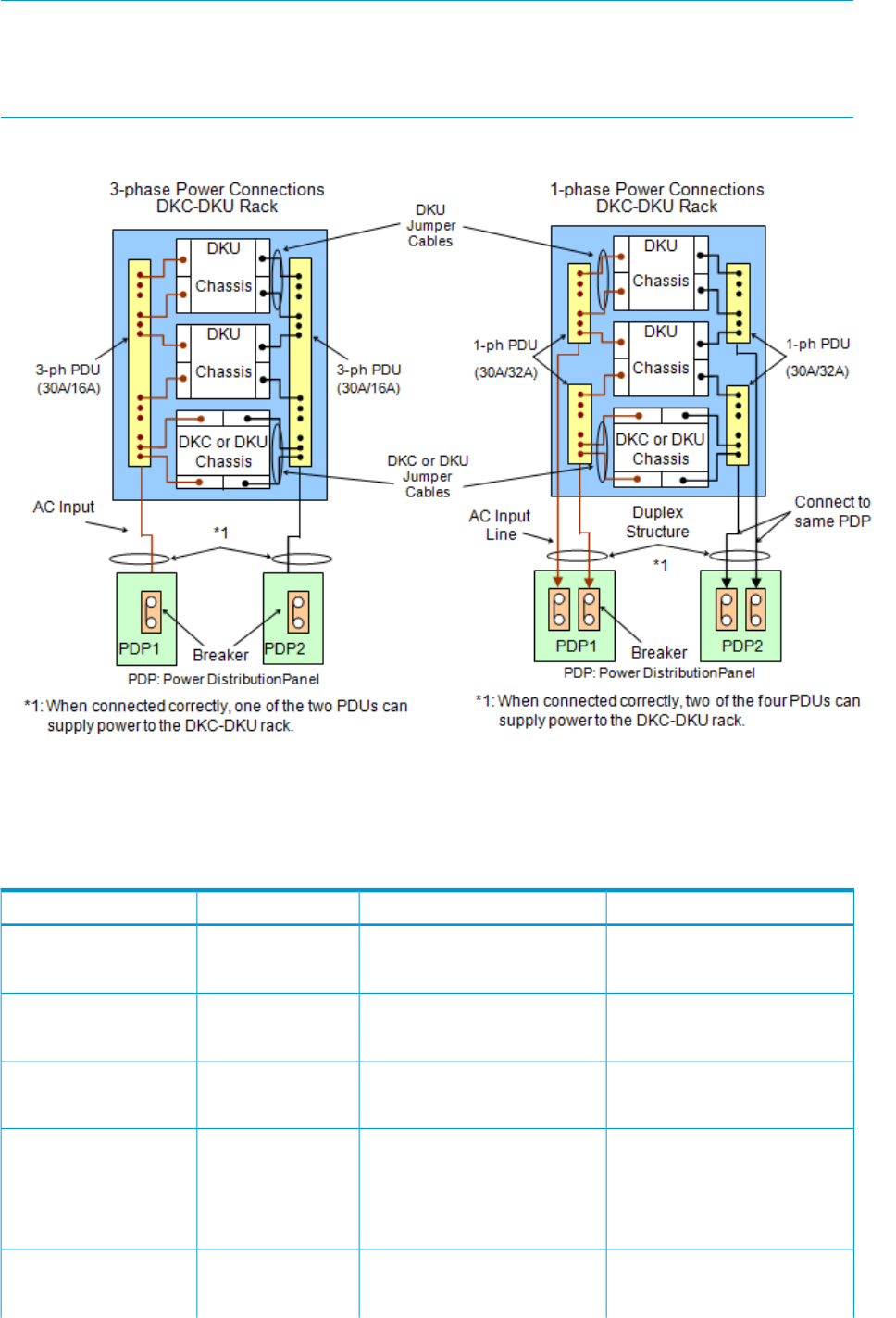
NOTE: PDU models can be changed in the field using offline maintenance procedures.
NOTE: When ordering systems, HP does not allow mixtures of different phase PDUs in a system
(even though there are no technical issues). Only upgrade orders can ship with difference phase
PDUs in a system.
Figure 23 P9500 AC power configuration diagram
Environmental specifications
The following table lists the environmental specifications of the P9500 storage system.
Table 31 P9500 environmental specifications
In StorageNot OperatingOperatingItem
-45 - 140-18 - 109.4 / -10 to 4360.8 - 80.9 /Temperature
-25 to 60-18 to 95 / -10 to 358
16 to 32(ºF / ºC)
5 to 958 to 9020 to 80Relative Humidity
(%)2
84.2 / 2980.6 / 2778.8 / 26Max. Wet Bulb
(ºF / ºC)
68 / 2050 / 1050 / 10Temperature
Deviation
per hour)
(ºF / ºC)
Sine Vibration:5 to 10 Hz: 2.5 mm10 to 300 HzVibration
4.9 m/s1, 5 min.10 to 70 Hz: 4.9 m/s1
0.49 m/s1
to 10Hz: 0.25 mm
Environmental specifications 83

Table 31 P9500 environmental specifications (continued)
In StorageNot OperatingOperatingItem
At the resonant frequency with
the highest displacement found
between 3 to 100 Hz 3
70 to 99 Hz: 0.05 mm
99 to 300 Hz: 9.8 m/s1
Random Vibration:
0.147 m2/s3
30 min, 5 to 100 Hz 4
--Up to 2.5 7
Earthquake
resistance (m/s2)
Horizontal:78.4 m/s1, 15 ms-Shock
Incline Impact 1.22 m/s
5
Vertical:
Rotational Edge 0.15 m
6
--60 m to 3,000 mAltitude
Notes:
1. Recommended temperature range is 21 to 24°C
2. On shipping/storage condition, the product should be packed with factory packing
3. The above specifications of vibration are applied to all three axes
4. See ASTM D999-01 The Methods for Vibration Testing of Shipping Containers.
5. See ASTM D5277-92 Test Method for Performing Programmed Horizontal Impacts Using an Inclined Impact Tester.
6. See ASTM D6055-96 Test Methods for Mechanical Handling of Unitized Loads and Large Shipping Cases and
Crates.
7. Time is 5 seconds or less in case of the testing with device resonance point (6 to 7Hz).
8. When flash modules are installed in the system.
84 Specifications

C Regulatory compliance notices
This section contains regulatory notices for the HP HP P9500 Disk Array.
Regulatory compliance identification numbers
For the purpose of regulatory compliance certifications and identification, this product has been
assigned a unique regulatory model number. The regulatory model number can be found on the
product nameplate label, along with all required approval markings and information. When
requesting compliance information for this product, always refer to this regulatory model number.
The regulatory model number is not the marketing name or model number of the product.
Product specific information:
HP P9500 Disk Array
Regulatory model number: CSPRA-0390
FCC and CISPR classification: Class A
These products contain laser components. See Class 1 laser statement in the Laser compliance
notices section.
Federal Communications Commission notice
Part 15 of the Federal Communications Commission (FCC) Rules and Regulations has established
Radio Frequency (RF) emission limits to provide an interference-free radio frequency spectrum.
Many electronic devices, including computers, generate RF energy incidental to their intended
function and are, therefore, covered by these rules. These rules place computers and related
peripheral devices into two classes, A and B, depending upon their intended installation. Class A
devices are those that may reasonably be expected to be installed in a business or commercial
environment. Class B devices are those that may reasonably be expected to be installed in a
residential environment (for example, personal computers). The FCC requires devices in both classes
to bear a label indicating the interference potential of the device as well as additional operating
instructions for the user.
FCC rating label
The FCC rating label on the device shows the classification (A or B) of the equipment. Class B
devices have an FCC logo or ID on the label. Class A devices do not have an FCC logo or ID on
the label. After you determine the class of the device, refer to the corresponding statement.
Class A equipment
This equipment has been tested and found to comply with the limits for a Class A digital device,
pursuant to Part 15 of the FCC rules. These limits are designed to provide reasonable protection
against harmful interference when the equipment is operated in a commercial environment. This
equipment generates, uses, and can radiate radio frequency energy and, if not installed and used
in accordance with the instructions, may cause harmful interference to radio communications.
Operation of this equipment in a residential area is likely to cause harmful interference, in which
case the user will be required to correct the interference at personal expense.
Class B equipment
This equipment has been tested and found to comply with the limits for a Class B digital device,
pursuant to Part 15 of the FCC Rules. These limits are designed to provide reasonable protection
against harmful interference in a residential installation. This equipment generates, uses, and can
radiate radio frequency energy and, if not installed and used in accordance with the instructions,
may cause harmful interference to radio communications. However, there is no guarantee that
interference will not occur in a particular installation. If this equipment does cause harmful
interference to radio or television reception, which can be determined by turning the equipment
Regulatory compliance identification numbers 85
off and on, the user is encouraged to try to correct the interference by one or more of the following
measures:
•Reorient or relocate the receiving antenna.
•Increase the separation between the equipment and receiver.
•Connect the equipment into an outlet on a circuit that is different from that to which the receiver
is connected.
•Consult the dealer or an experienced radio or television technician for help.
Declaration of Conformity for products marked with the FCC logo, United States only
This device complies with Part 15 of the FCC Rules. Operation is subject to the following two
conditions: (1) this device may not cause harmful interference, and (2) this device must accept any
interference received, including interference that may cause undesired operation.
For questions regarding this FCC declaration, contact us by mail or telephone:
•Hewlett-Packard Company P.O. Box 692000, Mail Stop 510101 Houston, Texas 77269-2000
•Or call 1-281-514-3333
Modification
The FCC requires the user to be notified that any changes or modifications made to this device
that are not expressly approved by Hewlett-Packard Company may void the user's authority to
operate the equipment.
Cables
When provided, connections to this device must be made with shielded cables with metallic RFI/EMI
connector hoods in order to maintain compliance with FCC Rules and Regulations.
Canadian notice (Avis Canadien)
Class A equipment
This Class A digital apparatus meets all requirements of the Canadian Interference-Causing
Equipment Regulations.
Cet appareil numérique de la class A respecte toutes les exigences du Règlement sur le matériel
brouilleur du Canada.
Class B equipment
This Class B digital apparatus meets all requirements of the Canadian Interference-Causing
Equipment Regulations.
Cet appareil numérique de la class B respecte toutes les exigences du Règlement sur le matériel
brouilleur du Canada.
European Union notice
This product complies with the following EU directives:
•Low Voltage Directive 2006/95/EC
•EMC Directive 2004/108/EC
Compliance with these directives implies conformity to applicable harmonized European standards
(European Norms) which are listed on the EU Declaration of Conformity issued by Hewlett-Packard
for this product or product family.
86 Regulatory compliance notices
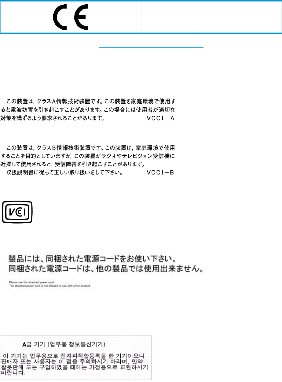
This compliance is indicated by the following conformity marking placed on the product:
This marking is valid for non-Telecom products and EU
harmonized Telecom products (e.g., Bluetooth).
Certificates can be obtained from http://www.hp.com/go/certificates.
Hewlett-Packard GmbH, HQ-TRE, Herrenberger Strasse 140, 71034 Boeblingen, Germany
Japanese notices
Japanese VCCI-A notice
Japanese VCCI-B notice
Japanese VCCI marking
Japanese power cord statement
Korean notices
Class A equipment
Japanese notices 87
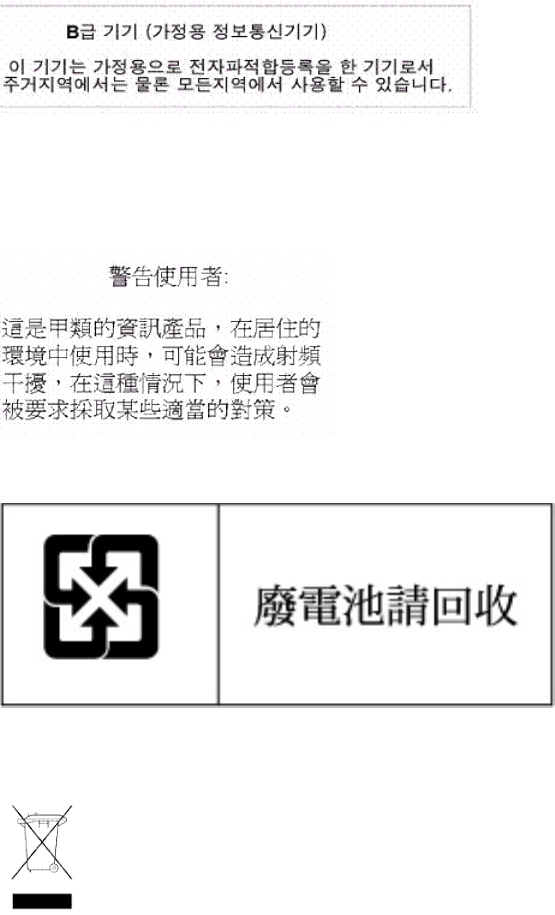
Class B equipment
Taiwanese notices
BSMI Class A notice
Taiwan battery recycle statement
Turkish recycling notice
Türkiye Cumhuriyeti: EEE Yönetmeliğine Uygundur
88 Regulatory compliance notices
Laser compliance notices
English laser notice
This device may contain a laser that is classified as a Class 1 Laser Product in accordance with
U.S. FDA regulations and the IEC 60825-1. The product does not emit hazardous laser radiation.
WARNING! Use of controls or adjustments or performance of procedures other than those
specified herein or in the laser product's installation guide may result in hazardous radiation
exposure. To reduce the risk of exposure to hazardous radiation:
•Do not try to open the module enclosure. There are no user-serviceable components inside.
•Do not operate controls, make adjustments, or perform procedures to the laser device other
than those specified herein.
•Allow only HP Authorized Service technicians to repair the unit.
The Center for Devices and Radiological Health (CDRH) of the U.S. Food and Drug Administration
implemented regulations for laser products on August 2, 1976. These regulations apply to laser
products manufactured from August 1, 1976. Compliance is mandatory for products marketed in
the United States.
Dutch laser notice
French laser notice
Laser compliance notices 89
German laser notice
Italian laser notice
Japanese laser notice
90 Regulatory compliance notices
Spanish laser notice
Recycling notices
English recycling notice
Disposal of waste equipment by users in private household in the European Union
This symbol means do not dispose of your product with your other household waste. Instead, you should
protect human health and the environment by handing over your waste equipment to a designated
collection point for the recycling of waste electrical and electronic equipment. For more information,
please contact your household waste disposal service
Recycling notices 91

Bulgarian recycling notice
Изхвърляне на отпадъчно оборудване от потребители в частни домакинства в Европейския
съюз
Този символ върху продукта или опаковката му показва, че продуктът не трябва да се изхвърля заедно
с другите битови отпадъци. Вместо това, трябва да предпазите човешкото здраве и околната среда,
като предадете отпадъчното оборудване в предназначен за събирането му пункт за рециклиране на
неизползваемо електрическо и електронно борудване. За допълнителна информация се свържете с
фирмата по чистота, чиито услуги използвате.
Czech recycling notice
Likvidace zařízení v domácnostech v Evropské unii
Tento symbol znamená, že nesmíte tento produkt likvidovat spolu s jiným domovním odpadem. Místo
toho byste měli chránit lidské zdraví a životní prostředí tím, že jej předáte na k tomu určené sběrné
pracoviště, kde se zabývají recyklací elektrického a elektronického vybavení. Pro více informací kontaktujte
společnost zabývající se sběrem a svozem domovního odpadu.
Danish recycling notice
Bortskaffelse af brugt udstyr hos brugere i private hjem i EU
Dette symbol betyder, at produktet ikke må bortskaffes sammen med andet husholdningsaffald. Du skal
i stedet den menneskelige sundhed og miljøet ved at afl evere dit brugte udstyr på et dertil beregnet
indsamlingssted for af brugt, elektrisk og elektronisk udstyr. Kontakt nærmeste renovationsafdeling for
yderligere oplysninger.
Dutch recycling notice
Inzameling van afgedankte apparatuur van particuliere huishoudens in de Europese Unie
Dit symbool betekent dat het product niet mag worden gedeponeerd bij het overige huishoudelijke afval.
Bescherm de gezondheid en het milieu door afgedankte apparatuur in te leveren bij een hiervoor bestemd
inzamelpunt voor recycling van afgedankte elektrische en elektronische apparatuur. Neem voor meer
informatie contact op met uw gemeentereinigingsdienst.
92 Regulatory compliance notices

Estonian recycling notice
Äravisatavate seadmete likvideerimine Euroopa Liidu eramajapidamistes
See märk näitab, et seadet ei tohi visata olmeprügi hulka. Inimeste tervise ja keskkonna säästmise nimel
tuleb äravisatav toode tuua elektriliste ja elektrooniliste seadmete käitlemisega egelevasse kogumispunkti.
Küsimuste korral pöörduge kohaliku prügikäitlusettevõtte poole.
Finnish recycling notice
Kotitalousjätteiden hävittäminen Euroopan unionin alueella
Tämä symboli merkitsee, että laitetta ei saa hävittää muiden kotitalousjätteiden mukana. Sen sijaan sinun
on suojattava ihmisten terveyttä ja ympäristöä toimittamalla käytöstä poistettu laite sähkö- tai
elektroniikkajätteen kierrätyspisteeseen. Lisätietoja saat jätehuoltoyhtiöltä.
French recycling notice
Mise au rebut d'équipement par les utilisateurs privés dans l'Union Européenne
Ce symbole indique que vous ne devez pas jeter votre produit avec les ordures ménagères. Il est de
votre responsabilité de protéger la santé et l'environnement et de vous débarrasser de votre équipement
en le remettant à une déchetterie effectuant le recyclage des équipements électriques et électroniques.
Pour de plus amples informations, prenez contact avec votre service d'élimination des ordures ménagères.
German recycling notice
Entsorgung von Altgeräten von Benutzern in privaten Haushalten in der EU
Dieses Symbol besagt, dass dieses Produkt nicht mit dem Haushaltsmüll entsorgt werden darf. Zum
Schutze der Gesundheit und der Umwelt sollten Sie stattdessen Ihre Altgeräte zur Entsorgung einer dafür
vorgesehenen Recyclingstelle für elektrische und elektronische Geräte übergeben. Weitere Informationen
erhalten Sie von Ihrem Entsorgungsunternehmen für Hausmüll.
Recycling notices 93

Greek recycling notice
Απόρριψη άχρηοτου εξοπλισμού από ιδιώτες χρήστες στην Ευρωπαϊκή Ένωση
Αυτό το σύμβολο σημαίνει ότι δεν πρέπει να απορρίψετε το προϊόν με τα λοιπά οικιακά απορρίμματα.
Αντίθετα, πρέπει να προστατέψετε την ανθρώπινη υγεία και το περιβάλλον παραδίδοντας τον άχρηστο
εξοπλισμό σας σε εξουσιοδοτημένο σημείο συλλογής για την ανακύκλωση άχρηστου ηλεκτρικού και
ηλεκτρονικού εξοπλισμού. Για περισσότερες πληροφορίες, επικοινωνήστε με την υπηρεσία απόρριψης
απορριμμάτων της περιοχής σας.
Hungarian recycling notice
A hulladék anyagok megsemmisítése az Európai Unió háztartásaiban
Ez a szimbólum azt jelzi, hogy a készüléket nem szabad a háztartási hulladékkal együtt kidobni. Ehelyett
a leselejtezett berendezéseknek az elektromos vagy elektronikus hulladék átvételére kijelölt helyen történő
beszolgáltatásával megóvja az emberi egészséget és a környezetet.További információt a helyi
köztisztasági vállalattól kaphat.
Italian recycling notice
Smaltimento di apparecchiature usate da parte di utenti privati nell'Unione Europea
Questo simbolo avvisa di non smaltire il prodotto con i normali rifi uti domestici. Rispettare la salute
umana e l'ambiente conferendo l'apparecchiatura dismessa a un centro di raccolta designato per il
riciclo di apparecchiature elettroniche ed elettriche. Per ulteriori informazioni, rivolgersi al servizio per
lo smaltimento dei rifi uti domestici.
Latvian recycling notice
Europos Sąjungos namų ūkio vartotojų įrangos atliekų šalinimas
Šis simbolis nurodo, kad gaminio negalima išmesti kartu su kitomis buitinėmis atliekomis. Kad
apsaugotumėte žmonių sveikatą ir aplinką, pasenusią nenaudojamą įrangą turite nuvežti į elektrinių ir
elektroninių atliekų surinkimo punktą. Daugiau informacijos teiraukitės buitinių atliekų surinkimo tarnybos.
94 Regulatory compliance notices

Lithuanian recycling notice
Nolietotu iekārtu iznīcināšanas noteikumi lietotājiem Eiropas Savienības privātajās mājsaimniecībās
Šis simbols norāda, ka ierīci nedrīkst utilizēt kopā ar citiem mājsaimniecības atkritumiem. Jums jārūpējas
par cilvēku veselības un vides aizsardzību, nododot lietoto aprīkojumu otrreizējai pārstrādei īpašā lietotu
elektrisko un elektronisko ierīču savākšanas punktā. Lai iegūtu plašāku informāciju, lūdzu, sazinieties ar
savu mājsaimniecības atkritumu likvidēšanas dienestu.
Polish recycling notice
Utylizacja zużytego sprzętu przez użytkowników w prywatnych gospodarstwach domowych w
krajach Unii Europejskiej
Ten symbol oznacza, że nie wolno wyrzucać produktu wraz z innymi domowymi odpadkami.
Obowiązkiem użytkownika jest ochrona zdrowa ludzkiego i środowiska przez przekazanie zużytego
sprzętu do wyznaczonego punktu zajmującego się recyklingiem odpadów powstałych ze sprzętu
elektrycznego i elektronicznego. Więcej informacji można uzyskać od lokalnej firmy zajmującej wywozem
nieczystości.
Portuguese recycling notice
Descarte de equipamentos usados por utilizadores domésticos na União Europeia
Este símbolo indica que não deve descartar o seu produto juntamente com os outros lixos domiciliares.
Ao invés disso, deve proteger a saúde humana e o meio ambiente levando o seu equipamento para
descarte em um ponto de recolha destinado à reciclagem de resíduos de equipamentos eléctricos e
electrónicos. Para obter mais informações, contacte o seu serviço de tratamento de resíduos domésticos.
Romanian recycling notice
Casarea echipamentului uzat de către utilizatorii casnici din Uniunea Europeană
Acest simbol înseamnă să nu se arunce produsul cu alte deşeuri menajere. În schimb, trebuie să protejaţi
sănătatea umană şi mediul predând echipamentul uzat la un punct de colectare desemnat pentru reciclarea
echipamentelor electrice şi electronice uzate. Pentru informaţii suplimentare, vă rugăm să contactaţi
serviciul de eliminare a deşeurilor menajere local.
Recycling notices 95
Slovak recycling notice
Likvidácia vyradených zariadení používateľmi v domácnostiach v Európskej únii
Tento symbol znamená, že tento produkt sa nemá likvidovať s ostatným domovým odpadom. Namiesto
toho by ste mali chrániť ľudské zdravie a životné prostredie odovzdaním odpadového zariadenia na
zbernom mieste, ktoré je určené na recykláciu odpadových elektrických a elektronických zariadení.
Ďalšie informácie získate od spoločnosti zaoberajúcej sa likvidáciou domového odpadu.
Spanish recycling notice
Eliminación de los equipos que ya no se utilizan en entornos domésticos de la Unión Europea
Este símbolo indica que este producto no debe eliminarse con los residuos domésticos. En lugar de ello,
debe evitar causar daños a la salud de las personas y al medio ambiente llevando los equipos que no
utilice a un punto de recogida designado para el reciclaje de equipos eléctricos y electrónicos que ya
no se utilizan. Para obtener más información, póngase en contacto con el servicio de recogida de
residuos domésticos.
Swedish recycling notice
Hantering av elektroniskt avfall för hemanvändare inom EU
Den här symbolen innebär att du inte ska kasta din produkt i hushållsavfallet. Värna i stället om natur
och miljö genom att lämna in uttjänt utrustning på anvisad insamlingsplats. Allt elektriskt och elektroniskt
avfall går sedan vidare till återvinning. Kontakta ditt återvinningsföretag för mer information.
Battery replacement notices
Dutch battery notice
96 Regulatory compliance notices
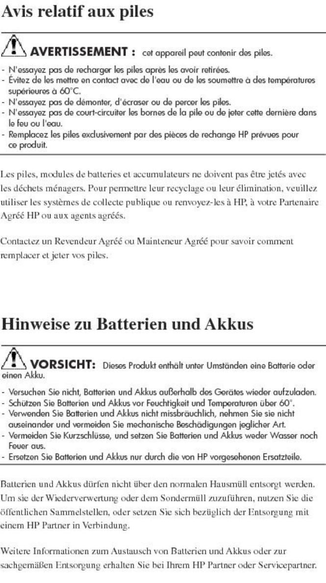
French battery notice
German battery notice
Battery replacement notices 97
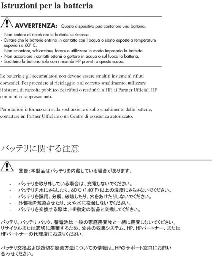
Italian battery notice
Japanese battery notice
98 Regulatory compliance notices
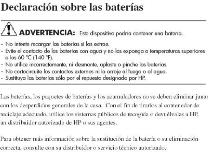
Spanish battery notice
Battery replacement notices 99

Glossary
access method An IBM-specific term for software that moves data between main storage and I/O devices to
create channel programs and manage system buffers.
AL Arbitrated loop.
allocation The ratio of allocated storage capacity versus total capacity as a percentage. Allocated storage
refers to those logical devices (LDEVs) that have paths assigned to them. Allocated storage capacity
is the sum of the storage of these LDEVs. Total capacity is the sum of the capacity of all LDEVs
on the disk array.
ambient
temperature The air temperature in the area where a system is installed. Also called intake temperature or
room temperature.
array group A group of four or eight physical hard disk drives (HDDs) installed in a P9000 or XP disk array
and assigned a common RAID level. RAID1 array groups consist of four (2D+2D) or eight HDDs
(4D+4D). RAID5 array groups include a parity disk, but also consist of four (3D+1P) or eight
HDDs (7D+1P). All RAID6 array groups are made up of eight HDDs (6D+2P). This is also known
as a parity group or a RAID group.
BC P9000 or XP Business Copy. An HP application that provides volume-level, point-in-time copies
in the disk array.
BC Z The version of Business Copy that supports mainframe volumes.
CB Circuit Breaker.
CHA Channel adapter. A device that provides the interface between the array and the external host
system. Occasionally, this term is used synonymously with the term channel host interface processor
(CHIP).
CLI Command-line interface. An interface comprised of various commands which are used to control
operating system responses.
Cnt Ac-J P9000 or XP Continuous Access Journal software.
Cnt Ac-J Z The version of Continuous Access Journal that supports mainframe volumes.
Cnt Ac-S P9000 or XP Continuous Access Synchronous software.
Cnt Ac-S Z The version of Continuous Access Synchronous that supports mainframe volumes.
CU Control Unit. Used to organize the storage space attached to the disk controller (DKC). You can
group similarly configured logical devices (LDEVs) with unique control unit images (CUs). CUs
are numbered sequentially. The disk array supports a certain number of CUs, depending on the
disk array model. Each CU can manage multiple LDEVs; therefore, both the CU number and the
LDEV number are required to identify an LDEV.
CVS CVS devices (OPEN-x CVS or 3390-x CVS) are custom volumes configured using array
management software to be smaller or larger than normal fixed-size OPEN or mainframe system
volumes. Synonymous with volume size customization (VSC). OPEN-V is a CVS-based volume.
C-Track Continuous Track. An HP software program that detects internal hardware component problems
on an array and automatically reports them to HP Support Services.
DFSMS Data Facility Storage Management Subsystem.
DKA Disk adapter.
DKC Disk controller.
DKU Disk Unit.
emulation mode The LDEVs associated with each RAID group are assigned an emulation mode that makes them
operate like OPEN system disk drives. The emulation mode determines the size of an LDEV or
volume.
OPEN-V: User-defined custom size
3390-3/3R: 2.838 GB
3390-9: 8.514 GB
3390-L: 27.844 GB
100 Glossary
3390-M: 55.689 GB
3380-3 2.377 GB
ESW Express switch adapter.
failover The process that occurs when one device assumes the workload of a failed companion device.
Failovers can be planned or unplanned.
FBA Fixed-block architecture.
FC-AL Fibre Channel Arbitrated Loop.
fence level A method of setting rejection of P9000 or XP Continuous Access write I/O requests from the host
according to the condition of mirroring consistency.
Fibre Channel A data transfer architecture designed for mass storage devices and other peripheral devices that
require high bandwidth.
Fibre Channel Loop An enclosure that provides twelve-port central interconnect for Fibre Channel Arbitrated Loops
following the ANSI Fibre Channel drive enclosure standard.
FICON Fibre connectivity. An FC layer 4 protocol used to map mainframe channel command and data
I/O operations onto standard FC infrastructure, protocol, and FC services.
HBA Host bus adapter.
HCD Hardware Configuration Definition.
HDD Hard disk drive.
LDKC Logical disk controller.
LUN Logical unit number. A LUN results from mapping a logical unit number, port ID, and LDEV ID to
a RAID group. The size of the LUN is determined by the emulation mode of the LDEV and the
number of LDEVs associated with the LUN.
LUSE Logical Unit Size Expansion. The LUSE feature is available when the HP StorageWorks LUN
Manager product is installed, and allows a LUN, normally associated with only a single LDEV,
to be associated with 1 to 36 LDEVs. Essentially, LUSE makes it possible for applications to access
a single large pool of storage.
M-VOL Main volume.
MCU Main control unit.
OPEN-
x
A general term describing any of the supported OPEN emulation modes (for example, OPEN-E).
There are two types of OPEN-x devices: legacy OPEN-x devices with a fixed size (such as OPEN-3,
OPEN-8, OPEN-9, and OPEN-E), and OPEN-V, which has a variable size and is a CVS-based
volume.
P-VOL Primary volume.
parity group A set of hard disk drives that have the same capacity and that are treated as one group. A parity
group contains both user data and parity information, which enables user data to be accessed
if one or more drives in the group is not available.
path A path is created by associating a port, a target, and a LUN ID with one or more LDEVs. Also
known as a LUN.
PAV Parallel access volume.
PCB Printed circuit board.
PDEV Physical device.
PDP Power Distribution Panels.
PDU Power distribution unit. The rack device that distributes conditioned AC or DC power within a
rack.
port A physical connection that allows data to pass between a host and the disk array. The number
of ports on a disk array depends on the number of supported I/O slots and the number of ports
available per I/O adapter. The P9000 and XP family of disk arrays supports Fibre Channel (FC)
ports and other port types. Ports are named by port group and port letter, such as CL1-A. CL1 is
the group; A is the port letter.
101
RAID group A group of disks configured to provide enhanced redundancy, performance, or both. Specifically,
four or eight physical hard disk drives (HDDs) installed in a P9000 or XP disk array and assigned
a common RAID level. In an XP disk array this is also referred to as an array group or parity
group.
RAID level A configuration of disk drives that uses striping, mirroring, and parity to improve performance
and data availability and reliability.
RAID Manager The CLI configuration and replication tool for the P9000 or XP disk array that system administrators
can use to enter RAID Manager commands from open-system hosts to perform Continuous Access,
Business Copy, Database Validator, and Data Retention operations, as well as provisioning
commands on logical devices.
RAID1-level data
storage A RAID that consists of at least two drives that use mirroring (100 percent duplication of the
storage of data). There is no striping. Read performance is improved since either disk can be
read at the same time. Write performance is the same as for single disk storage.
RAID1/5 Specific RAID architectures.
RAID5-level data
storage A RAID that provides data striping at the byte level and also stripe error correction information.
RAID5 configurations can tolerate one drive failure. Even with a failed drive, the data in a RAID5
volume can still be accessed normally.
RAID6-level data
storage A RAID that provides data striping at the byte level and also stripe error correction information.
RAID6 configurations can tolerate two drive failures. Even with two failed drives, the data in a
RAID6 volume can still be accessed normally. RAID6 read performance is similar to RAID5, since
all drives can service read operations, but the write performance is lower than that of RAID5
because the parity data must be updated on multiple drives.
RCU Remote control unit.
Remote Web
Console A browser-based program installed on the SVP that allows you to configure and manage the disk
array.
RM HP StorageWorks RAID Manager.
SAS Serial Attached SCSI.
SCP State-change-pending.
SIM Service information message.
SMPL Simplex.
SSB Sense byte.
SSD Solid state disk. A high-performance storage device that contains no moving parts. An SSD
contains DRAM or EEPROM memory boards, a memory bus board, a CPU, and a battery card.
SSVPMN Sub Service Processor Monitor.
SVP Service processor. A computer built into a disk array. The SVP, used only by an HP service
representative, provides a direct interface to the disk array.
synchronous Describes computing models that perform tasks in chronological order without interruption. In
synchronous replication, the source waits for data to be copied at the destination before
acknowledging that it has been written at the source.
TID Target ID.
UID Unit identification.
V-VOL Virtual Volume.
VOL, vol Volume.
volume Volume on disk. An accessible storage area on disk, either physical or virtual.
WLM Workload manager.
WWN World Wide Name. A unique identifier assigned to a Fibre Channel device.
102 Glossary

Index
A
architecture
system, 17
B
basic configuration;configuration
basic, 6
battery replacement notices, 96
C
cache, 54
Canadian notice, 86
capacity
cache, 10
disk drive, 10
chassis
controller, 54
controller, components, 54
drive, 57
components
controller chassis, 54
drive chassis, 57
configuration
maximum, 9
minimum, 9
contacting HP, 74
controller chassis, 7, 9
controller, components, 8, 54
controls
description, 56
system, 56
conventions
document, 75
storage capacity values, 75
text symbols, 76
cooling fans, 58
D
Declaration of Conformity, 86
Disposal of waste equipment, European Union, 91
document
conventions, 75
related information, 74
documentation
HP website, 74
providing feedback, 74
drive chassis components, 57
E
European Union notice, 86
F
fans
controller chassis, 55
cooling, 58
drive chassis, 59
features
hardware, 6
software, 13
Federal Communications Commission notice, 85
H
hardware description, 6
help
obtaining, 74
host modes, 51, 52
HPsubscription service, 74
technical support, 74
hub, 54
J
Japanese notices, 87
K
Korean notices, 87
L
laser compliance notices, 89
logical units, 20, 21
M
mainframe, 21, 22
memory
cache, 59
shared, 61
microprocessor, 54
N
new features, 6
O
operations
battery backup, 67
option modes
system, 22
P
power supply, 55
procedures
power off, 67
power on, 66
R
rack stability
warning, 76
RAID groups, 17
RAID implementation, 17
recycling notices, 91
regulatory compliance
Canadian notice, 86
103
European Union notice, 86
identification numbers, 85
Japanese notices, 87
Korean notices, 87
laser, 89
recycling notices, 91
Taiwanese notices, 88
related documentation, 74
S
safety, 66
service processor, 54
specifications
drive, 10, 13
electrical, 80
environmental, 83
general, 12
mechanical, 80
storage capacity values
conventions, 75
subscription service, HP, 74
SVP, 54
switches
control, 56
ESW, 54
power, 67
symbols in text, 76
system reliability, 6
T
Taiwanese notices, 88
technical support
HP, 74
service locator website, 74
technological advances, 6
text symbols, 76
typographic conventions, 75
V
virtualization, 6
W
warning
rack stability, 76
web sites
HP subscription service, 74
websites
HP , 74
product manuals, 74
104 Index
