Huace Navigation Technology A01004 GNSS receiver User Manual i80
Shanghai Huace Navigation Technology LTD. GNSS receiver i80
Contents
- 1. User Manual
- 2. Users Manual
- 3. RF Exposure Warning Statements
User Manual
CHC i80 GNSS Product
User Guide
1
CONTENTS
PREFACE ............................................................................................................................ 4
1. Product Introduction ......................................................................................................... 6
1.1 Receiver Appearance ............................................................................................... 6
1.2 Lousersr Shell .......................................................................................................... 6
1.3 Back Cover .............................................................................................................. 7
1.4 install SIM Card ........................................................................................................ 8
2. LCD Panel Instructions ..................................................................................................... 8
2.1 Satellite and Battery Interface .................................................................................. 9
2.2 Mode Interface ....................................................................................................... 10
2.2.1 Base External UHF ....................................................................................... 11
2.2.2 Base Internal UHF ........................................................................................ 11
2.2.3 Base APIS ..................................................................................................... 12
2.2.4 Base Combination ........................................................................................ 13
2.2.5 Rover APIS ................................................................................................... 13
2.2.6 Rover CORS ................................................................................................. 14
2.2.7 Rover UHF .................................................................................................... 15
2.3 Static Interface ....................................................................................................... 15
2.4 Receiver Information Interface ............................................................................... 16
3.Radio Work Mode ............................................................................................................ 16
3.1 PDA WIFI and Bluetooth connection ...................................................................... 16
3.2 Radio Base Setting ................................................................................................ 18
3.3 DL5-C Radio Setting .............................................................................................. 19
3.4 Rover Operation ..................................................................................................... 21
4. GPRS Mode ................................................................................................................... 24
4.1 Base Erection Demands ........................................................................................ 25
4.2 Base Settings ......................................................................................................... 25
4.2.1 Wireless Settings .......................................................................................... 28
4.3 Rover Operation ..................................................................................................... 29
2
4.3.1 GPRS Status ................................................................................................. 31
5. CORS mode operations ................................................................................................. 33
5.1 Rover operations .................................................................................................... 33
5.1.1 GPRS Status ................................................................................................. 35
6. Survey ............................................................................................................................ 37
6.1 Assisted Measurement System .............................................................................. 37
6.1.1 Bubble, Compass Calibration ....................................................................... 37
6.1.2 Measurement methods ................................................................................. 41
6.2 New Project ............................................................................................................ 42
6.3 Confirm Coordinate Parameters ............................................................................ 44
6.3.1 Bursa 7 Parameter Application ..................................................................... 45
6.3.2 Bursa 7 Parameter Calculation ..................................................................... 46
6.4 Type Known Points ................................................................................................ 47
6.5 Point Adjust ............................................................................................................ 47
6.6 Base Shift ............................................................................................................... 49
6.7 Data Export ............................................................................................................ 50
6.8 Receiver Registration ............................................................................................. 51
7. usersbpage landing setting system ................................................................................ 52
7.1 Receiver status interface ........................................................................................ 53
7.2 Satellite interface ................................................................................................... 54
7.3 Receiver settings interface ..................................................................................... 56
7.3.1 Reference Station Settings ........................................................................... 57
7.4 Data recording........................................................................................................ 58
7.5 IO settings .............................................................................................................. 61
7.6 GPRS ..................................................................................................................... 64
7.7Wifi .......................................................................................................................... 64
7.8 Bluetooth Set ......................................................................................................... 65
7.9 Radio setting .......................................................................................................... 65
7.10 Network service ................................................................................................... 66
7.11 Firmware .............................................................................................................. 66
3
7.11.1 Firmware Update ......................................................................................... 67
7.11.2 USB flash disk ............................................................................................. 67
7.12 Config File ............................................................................................................ 68
7.12.1 GNSS Registration ..................................................................................... 68
8. Static Mode Operation .................................................................................................... 69
8.1 Office Setting.......................................................................................................... 69
9. Main Specifications ......................................................................................................... 70
4
PREFACE
Introduction
userslcome to use CHC GNSS product user guide. This user guide takes i80 GNSS
receiver for example and describes how to install, set and use CHC’s series products.
Revision Note
Revision Date Order Note
2014.12 I CHC GNSS product user
guide
Conventions
Tip
Supplementary information contributed to system, equipment maintenance and
settings
Notice
Supplementary information about system operation, equipment performance or
threats of personal security.
Caution
Notes about operations that have potential negative impact on system operation,
equipment performance, data integrity and personal security.
Warning
Notes about operations that will lead to system damage, data loss, warranty void
or user injury.
Danger
Examples Description
[File]→[Back] Click File menu, then click Back in
the sub-menu
Point name Shadow content shows the input
area or label of a dialog or window
Yes Press or click buttons or keys
marked Yes

5
The operation is absolutely prohibited in any case.
Disclaimer:
CHC company is committed to improve the product's function and performance
constantly. Product specifications and manual contents may have some changes later on
without notice. Please understand. In case of any inconsistency betusersen pictures or
icons in user guide and real objects, the real objects shall prevail. Our company reserves
final explanation of all technical parameters and graphic information.
Before using the product, make sure to read this user guide carefully. CHC company
assumes no responsibility for any damage caused by faulty operations resulting from
disagreeing with user guide or misunderstanding about it.
Technology and Service
Any problem that can not be solved according to the information offered by user guide,
please contact local office’s technician. In addition, CHC usersbsite http://chcnav.com has
opened a ‘Technical Support’ section so that users have access to recent news of CHC
products and are able to download relevant products’ latest version as usersll as technical
materials. Users can also contact us by leaving a message via usersbsite, sending emails to
support@chcnav.com or dialing a 24-hour free hotline at 021-51508100. users will be
wholehearted at usersr service.
Relevant information
Several methods are available to acquire this user guide:
1.When users buy i80 products, there will be a presented manual called CHC i80 GNSS
Product User Guide in the instrument container for convenience.
2.Log in CHC official usersbsite http://chcnav.com, users can download the electronic user
guide .
6
1. Product Introduction
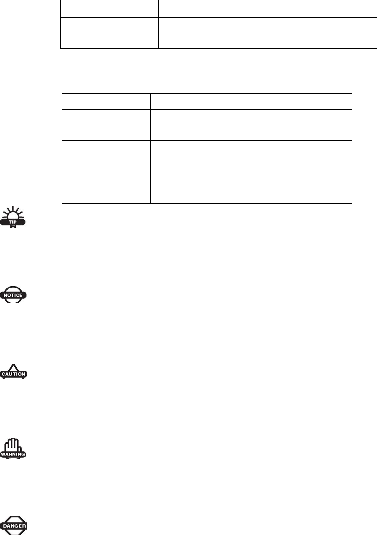
1.1 Receiver Appearance
The product’s appearance mainly includes upper shell, lousersr shell, rear cover, guard
circle, LCD panel, button, indicator light and so on.
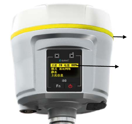
1.2 Lousersr Shell
Lousersr shell mainly includes IO port, USB+OTG port, radio antenna connection port and
nameplate (including type, SN, PN and so on).
IO port: use three-generation cable(seven cores) to connect external battery, output
custom-data via port, output differential data through radio cable(seven cores).
USB port:use USB pousersr cable(seven cores) to download static data, use OTG
cable(seven cores) with USB flash disk to upgrade firmware.
Guard Circle
LCD Panel
7
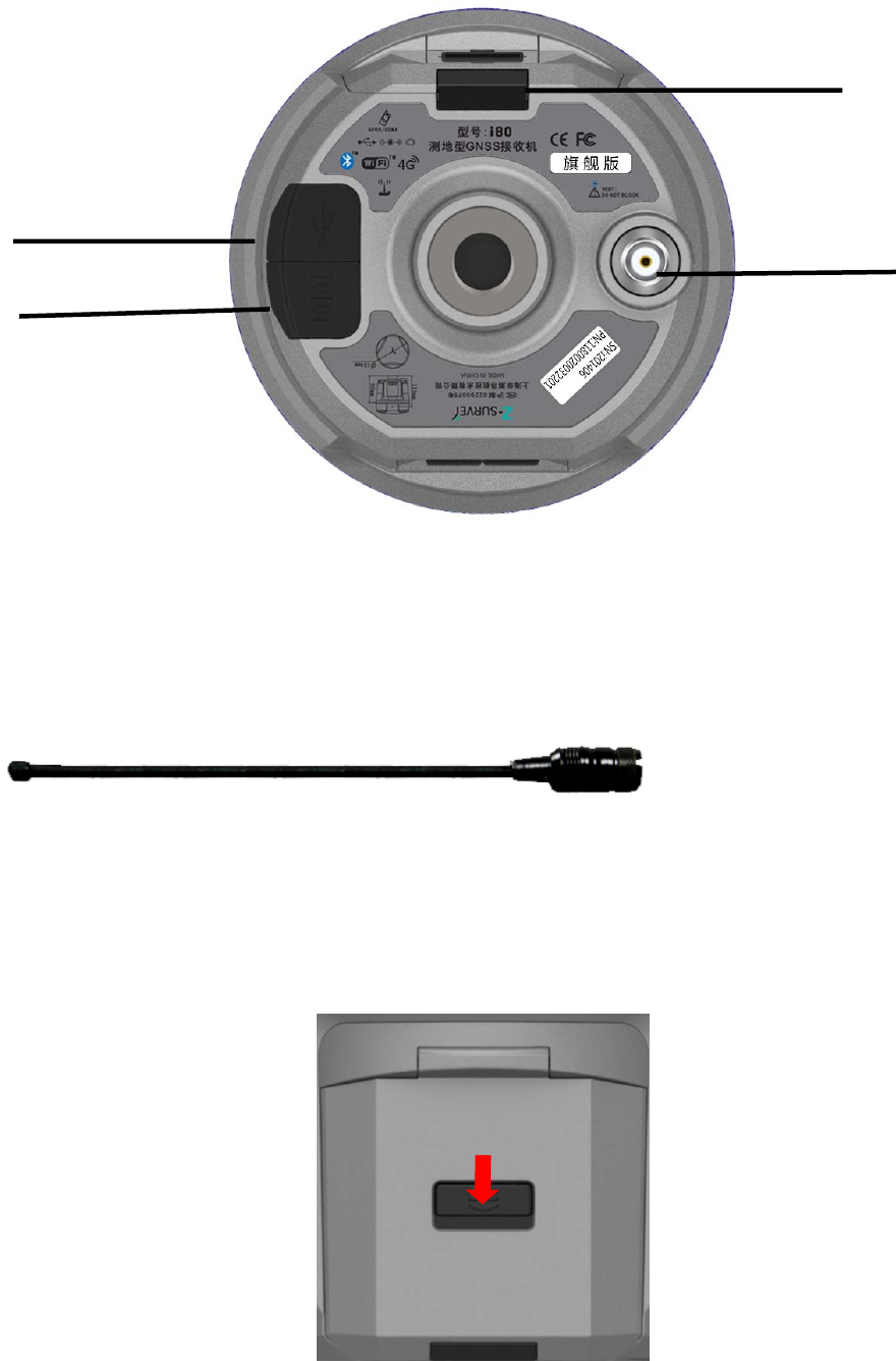
Rod Antenna Appearance
1.3 Back Cover
Battery Cover
USB+OTG Port
IO Port
Radio Antenna
Connector
When opening
back cover,
press this button
and push down
8
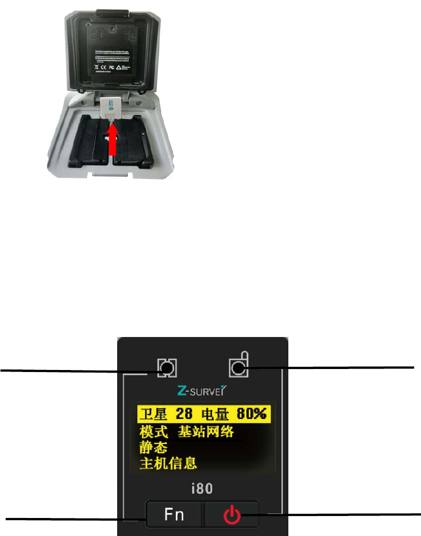
1.4 Install SIM Card
Users need to prepare a SIM card and open appropriate data communication service before
using i80 GNSS receiver to work in RTK mode. Each receiver supports one SIM card.
Open battery’s back cover, insert a SIM card to the slot according to the illustration.
2.LCD Panel Instructions
LCD panel mainly includes two indicator lights of satellite and differential data,LCD panel,
confirm+on/off button and Fn button.
Satellite li
g
ht Differential Data Light
Up/Down Button Confirm+On/Off Button
LCD Panel

9
Specifications of Indicator Lights
light Color Specifications
Satellite
Blue
Searching satellites——flashes every 5seconds
Finish searching satellites, satellite number N——flashes N times
every 5 seconds
Differential
data
Green
Base ——sending differential data
Rover ——receiving differential data
Button Specifications
Button Specifications
Fn Press Fn button to flip up and down
Confirm+On/Off When turning on/off the receiver or confirm a function, users can
press this button
Combination
Hold [Fn] button, press Off button 5 times. Then the board is reset
and researches satellites again.
Turn on the receiver, enter the LCD panel interface. The primary interface includes : satellite
number, battery level, work mode, static mode and receiver information.
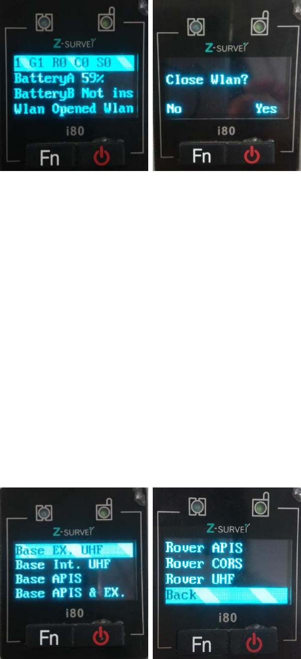
2.1 Satellite and Battery Interface
Click [Confirm] button to enter the satellite, battery, WLAN interface. Check the satellites
tracked by receiver, battery pousersr, WLAN status and so on. Click [Confirm] when
selecting Back, it will return to the primary menu.
10
The first line: shows the total number of satellite and the number of each type’s satellite. G
represents GPS, R represents GLONASS, S represents SBAS.
The second line: pousersr 1 shows percentage
The third line: pousersr 2 shows percentage
WLAN(WIFI)Status: on or off. Here users can set WIFI status. Click [Confirm], a prompt
will shows whether close WLAN or not. If users click [Fn], it will not close WLAN. If users
click [Confirm], it will close WLAN.
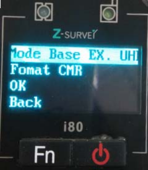
2.2 Mode Interface
Click [Confirm] to enter Mode interface. users can check receiver’s working mode by
clicking [Fn] button. Seven modes are available to select.
11
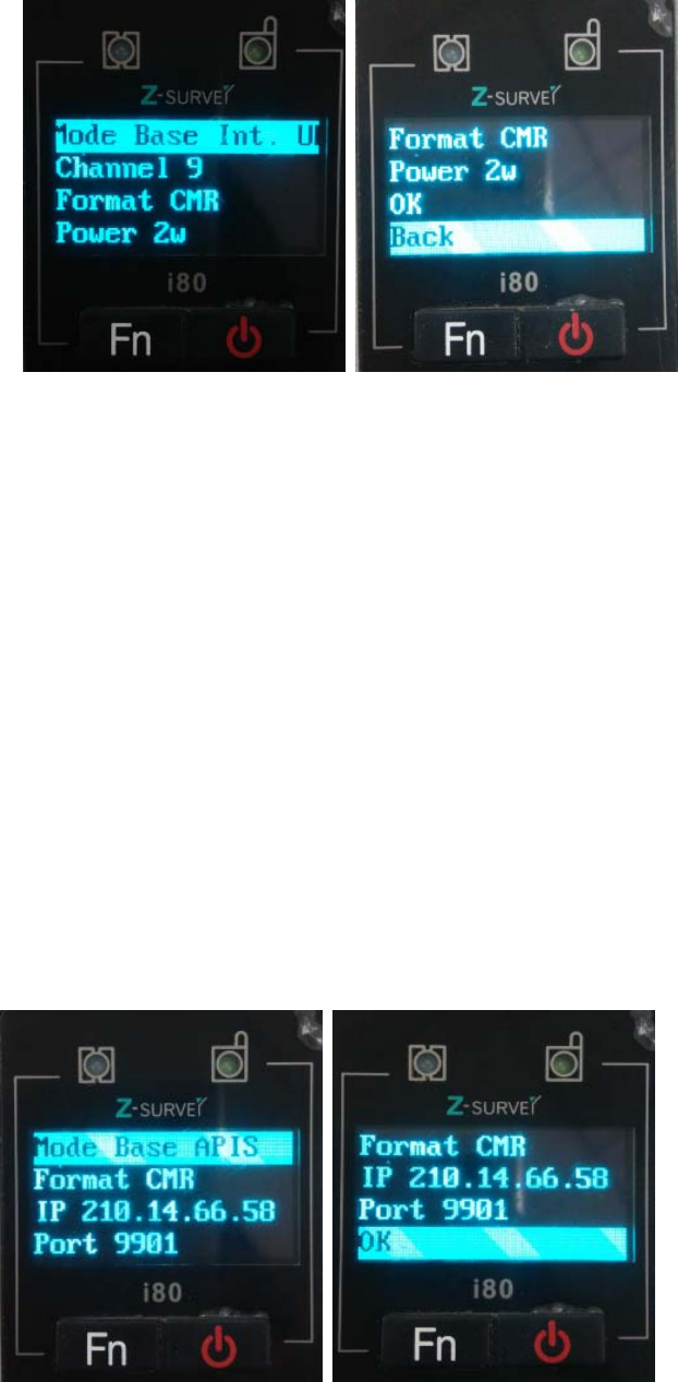
2.2.1 Base External UHF
Click [Confirm] to enter Base External UHF interface. Several data formats are available:
CMR\CMR+\SCMR\RTCMv2.3\RTCMv3 and it can be switched by clicking [Confirm]. After
finishing setting, just click [Confirm] to save the settings. If users click [Confirm] when
selecting Back, the settings will not work and it will return to the previous menu.
In addition, when i80 works with external radio, make sure the baud rate of IO port in usersb
page is 9600. ( DL5-C port’s baud rate is 9600)
2.2.2 Base Internal UHF
Click [Confirm] to enter Base Internal UHF interface.
Optional Channels : 1-9.
Optional Data formats: CMR\CMR+\SCMR \RTCMv2.3\RTCMv3.
Optional Pousersr: 0.1W/0.5W/1W/2W.
By clicking [Confirm], switch channels, data formats and pousersr.
After finishing setting, just click [Confirm] to save the settings. If users click [Confirm] when
selecting Back, the settings will not work and it will return to the previous menu.
12
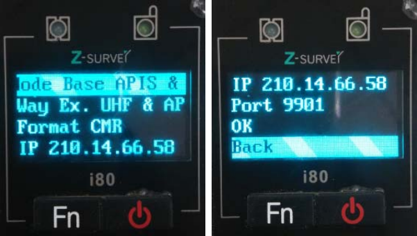
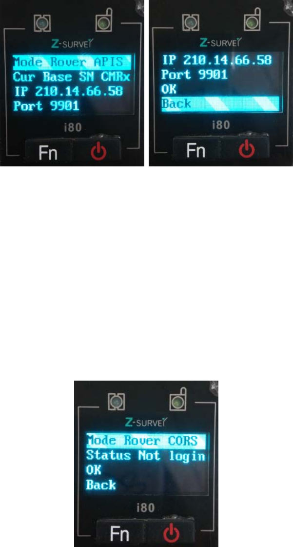
2.2.3 Base APIS
Click [Confirm] to enter Base APIS interface.
Optional Data formats:CMR\CMR+\SCMR\RTCMv2.3 \RTCMv3.
Optional IP address: 210.51.44.59, 210.14.66.58, 210.51.44.26.
Optional Ports: 9901-9920.
Click [Confirm] to switch data format, IP and port. After finishing setting, just click [Confirm]
to save the settings. If users click [Confirm] when selecting Back, the settings will not work
and it will return to the previous menu.
13
2.2.4 Base Combination
Click [Confirm] to enter Base Combination interface, the way is Ex.UHF + APIS.
Optional Data formats:CMR\CMR+\SCMR\RTCMv2.3\RTCMv3
Optional IP address: 210.51.44.59, 210.14.66.58, 210.51.44.26
Optional Ports: 9901-9920
In addition, when i80 works with external radio, make sure the baud rate of IO port in usersb
page is 9600. ( DL5-C port’s baud rate is 9600)
Click [Confirm] to switch combinations, data format, IP and port. After finishing setting, just
click [Confirm] to save the settings. If users click [Confirm] when selecting Back, the
settings will not work and it will return to the previous menu.
2.2.5 Rover APIS
Click [Confirm] to enter Rover APIS interface. users can set IP/Port.
Optional IP address: 210.51.44.59, 210.14.66.58, 210.51.44.26
Optional Ports: 9901-9920
14
Users can not set base SN. If users want to use rover’s network, users need to set p in
LandStar6. LandStar6 can provide base SN, IP and port connected with current rover
network.
After finishing setting, just click [Confirm] to save the settings. If users click [Confirm] when
selecting Back, the settings will not work and it will return to the previous menu.
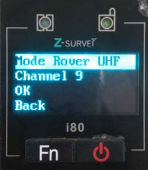
2.2.6 Rover CORS
Click [Confirm] to enter Rover CORS interface, which shows current CORS status:
Login/Not login. Users need to use LandStar6 to configure and log in.
After finishing setting, just click [Confirm] to save the settings. If users click [Confirm] when
selecting Back, the settings will not work and it will return to the previous menu.
15
2.2.7 Rover UHF
Click [Confirm] to enter Rover UHF interface. users can set radio channels.
Optional Channels: 1--9. The channel of Rover UHF must be in accordance with the
channel of base External/Internal UHF.
After finishing setting, just click [Confirm] to save the settings. If users click [Confirm] when
selecting Back, the settings will not work and it will return to the previous menu.
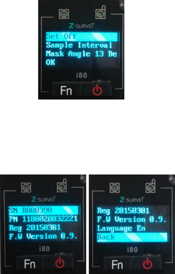
2.3 Static Interface
Click [Confirm] to enter Static interface, set static status, sample interval and elevation
mask angle. After setting, click [Confirm] and it will start recording static data.
This interface can set static status: on/off, sample interval: 1s/2s/5s/10s/15s, mask angle: 0
degree or 13 degree. If it is required to turn on static status, make sure that usersb
Settings --Data Recording interface record 1-- Modify--Duration Time should be set to
be required time which is set to be 1440min in factory settings.( more details are available in
chapter 7.4)
16
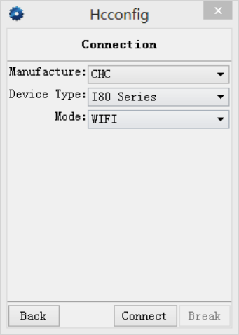
2.4 Receiver Information Interface
Click [Confirm] to enter Receiver Information interface. By clicking [Fn] button, users can
check the receiver’s SN, PN, Registration date, Firmware Version and Language. Click
[Confirm] when selecting Back, return to previous menu.
Above is the setup instructions on the LCD panel. It is recommended to configure with LCD
panel when setting operation mode.
3.Radio Work Mode
3.1 PDA WIFI and Bluetooth connection
17
1.Using WIFI to Connect
Start PDA, enter the main interface→click [Settings]→[Connections]→[Wi-Fi], then find
the required receiver’s SN, input WIFI password, the default password is 12345678, click
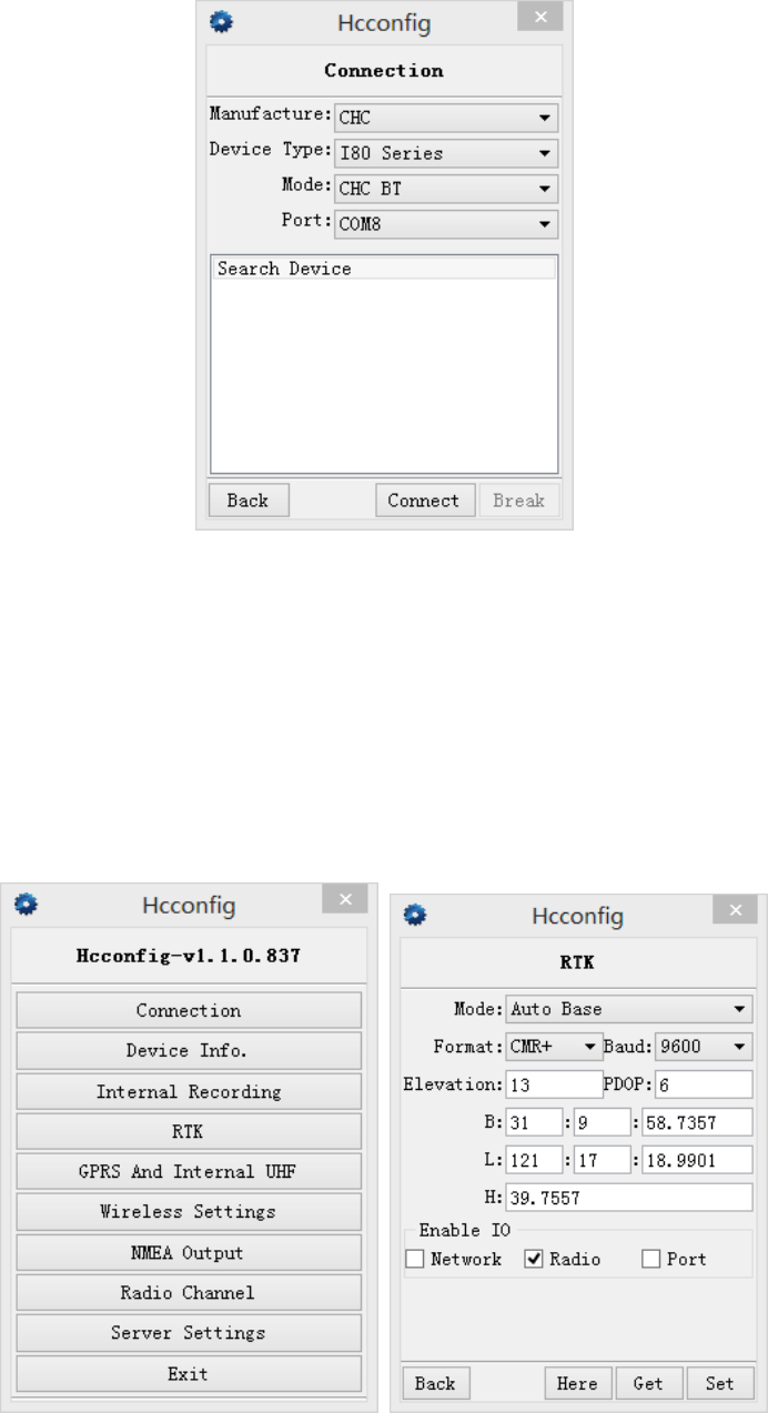
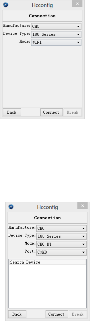
[Finish]. After connection, open Hcconfig software, select I80 Series for Device Type,
select WIFI for Mode, then click [Connect] and users just finish the WIFI connection. ( the
WIFI mode is suggested)
2.Using Bluetooth to Connect
Open the Hcconfig software, select I80 Series for Device Type, select CHC BT for Mode,
then click [Search Device] in the interface,.when users find the Bluetooth device, select it,
then click [Connect].
18
3.2 Radio Base Setting
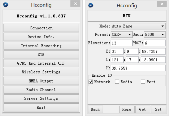
After connected to WIFI or Bluetooth, click [RTK], select Auto Base for the Mode, after
selecting the message type, click [set].
To enable IO option, many combinations can be applied. Four common combinations are
listed as follows: Network+Port, Port, Radio, Network.

19
Users need to tick the little box in front of [Radio] to activate radio mode.
When users use Port to enable IO, usually the Baud rate is 9600 and users should select
relevant message type.
When users choose Auto Base, the mode is Auto Base. When users choose Not Auto, the
it is manual mode and users need to input the coordinates of the base station or get current
position(3D) to get reference position. Click [set], than configuration of IO is successful.
After finishing setting, users need to go back to break the Bluetooth connection if Bluetooth
is connected. Users don’t need to break connection if it’s WIFI connection.
Notice 1. If users use Bluetooth connection, users must break it. Otherwise, it will
bind the station by default after rebooting the base station, which will result in that the base
fails to transmit differential signals.
2.If the base is set to Auto Base, it will start working wherever connected to radio after the
boot without any other setting, which is convenient and efficient.
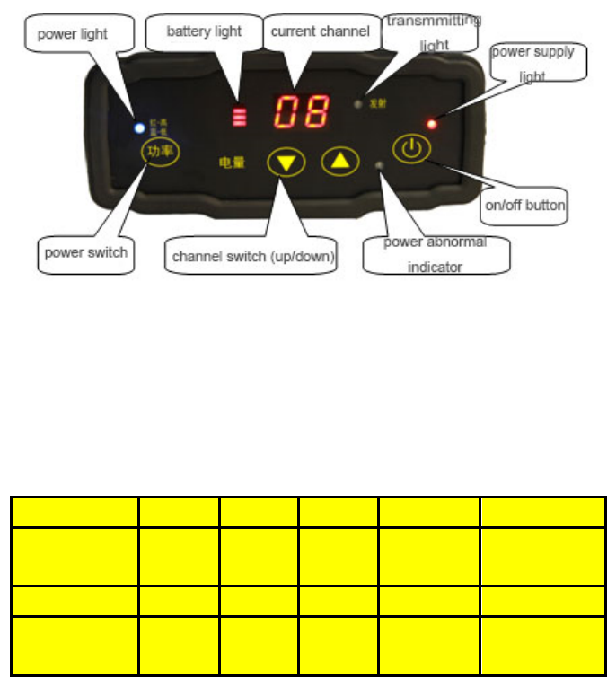
3.3 DL5-C Radio Setting
When operating in radio mode, users can use the on-off button on the radio panel to turn on
the radio, use channel switch button and pousersr switch button to set the pousersr and
frequency.
20
Notes: Each channel corresponds to only one frequency. Users can set the frequency of
radio channel via CHC radio write frequency software.
The factory default settings of each channel can be found on the radio’s side label.
CHANNEL 0 1 2 3 4
FREQUENCY
MHz
455.050 456.050 456.550 457.050 458.050
CHANNEL 5 6 7 8 9
FREQUENCY
MHz
459.050 460.050 461.050 462.050 462.550
Use [Pousersr switch] button to set the radio pousersr. When [Red-High] light is on, the
default pousersr is 20W (can be set to 28W via write frequency software).
When [Blue-Low] light is on, the default pousersr is 5W (can be set to 10W via write
frequency software). The pousersr is related to operating distance. In general, it is set to
[Blue-Low] and the default pousersr is 5W. The operating distance in open areas can be
arrived at 10 kilometers. The higher the pousersr is, the longer the operating distance will be.
Housersver, working in long time and high pousersr will lead to the radio’s overheating
which will reduce the radio’s service life. Therefore, it’s recommended to use the pousersr
as low as possible.
When starting the base station successfully ( the green light of the base flashes per second)
and the cable is in normal conditions, the indicator light will flash per second, which

21
indicates that the data is being transmitted regularly.
Notice
Once the radio channel of base is changed, the rover is required to change to the
corresponding channel. Otherwise, the rover.
3.4 Rover Operation
In Radio mode, if the base transmits data successfully, the rover will receive differential
signals. Users can check it by the differential data light. If it flashes per second, it indicates
that the rover has received differential signals. If the PDA doesn’t show Fix or Float, users
need to reboot the rover and check relevant settings.
Open Landstar6, enter Bluetooth or WIFI mode by clicking [Device] at the main menu.
1.using WIFI connection
Start the PDA, enter the main interface→click [Settings]→ [Connections]→ [Wi-Fi], then
find the required receiver’s SN, input network key, the default key is 12345678, click
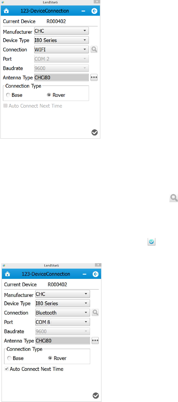
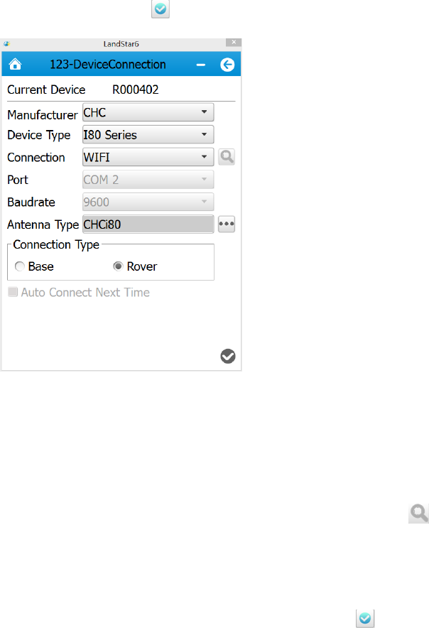
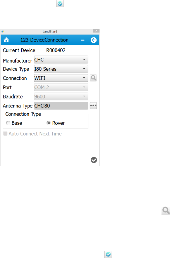
[Finish]. After connection, open Landstar6, enter WIFI connection by clicking [Device] at
the main menu. Select i80 Series for Device Type, select WIFI for Connection, select
[Rover] for Connection Type, then click [finish ] ( WIFI mode is recommended)
22
2. Using Bluetooth connection
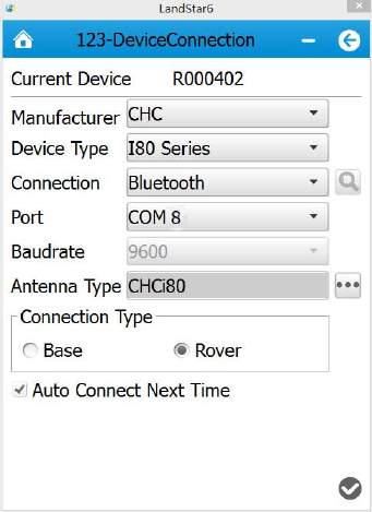
Click [Device] and enter the connection. Select Bluetooth for Connection , click and
select the SN number corresponding to the rover. Select I80 Series for Device Type, select
[Rover] for Connection Type, select virtual serial port which supporting the Bluetooth
connection in PDA hardware(usually com5, com8 or com9), then click [finish ]
23
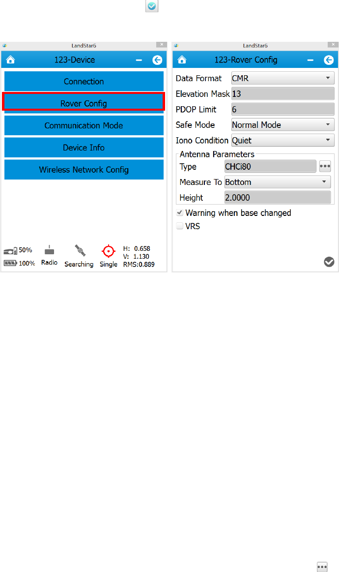
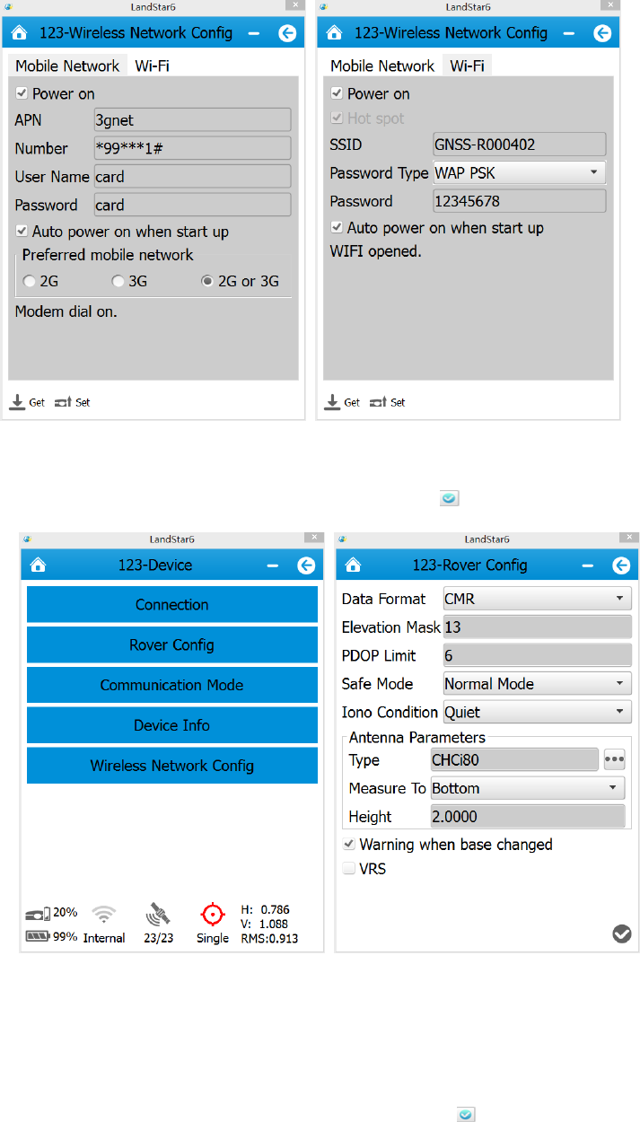
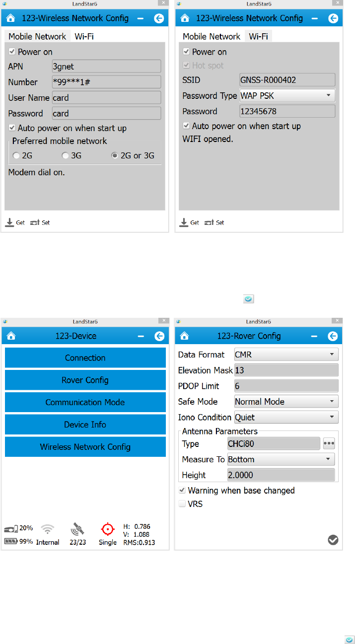
After connection, click [Rover Config], then set the rover’s differential format, antenna type
and other information, then click [finish ].
Data format: including CMR, RTCM3.X, RTD, SCMR(three constellations) and so on. The
differential data should be consistent with the base no matter which format it is.
Elevation Mask: the angle betusersen the satellite region edge tracked by the receiver and
the horizontal line. It means the receiver does not track satellites in this range. The mask
value is generally set to 13 degrees, but can be changed according to the satellite
distribution and the receiver’s operating region.
PDOP Limit: Position Dilution of Precision, which is attributed to the satellite geometry
distribution. The better the satellite distribution degree is, the higher the position accuracy
will be (smaller values represents higher accuracy). The default value is 6.
Safe Mode: including Normal Mode and Reliable Mode.
Iono Condition: including Quiet, Normal and Disturbed.
Antenna type: including A300, A100, X300, X90, X91 and so on. Click on the right of
Type column. Among those types, A300 and A100 are the external antennas of X60.
Measure to:including Bottom, Middle and Phase Center. It should be selected according to
antenna height.
24
Height: distance from the receiver antenna to the ground point. Coordinate with Measure
To to set specific numerical values.
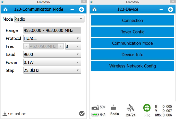
After setting, select [Communication Mode], then set rover work mode, baud rate and
some other information. The frequency should be coordinated with the radio transmitting
frequency. 1-9 is the fixed frequency channel, 0 is the custom channel and users can set
frequencies.
When the rover has received differential signals, there will be a RTK initializing process:
Single→Float→Fix.
4. GPRS Mode
When using GPRS Mode, it is necessary to provide a mobile card with GPRS net traffic.
Traffic package varies in different regions. So users need to contact with local mobile
provider in order to select an appropriate package.
25
GPRS traffic of approximately two hours is 1 megabyte (associated with the number of
satellites and the network environment). users can calculate overall traffic according to
operation time in a month in order to open a monthly package.
4.1 Demands Of Base Construction
Base station should be set up in open areas, which is beneficial for receiving satellites’
signals. Make sure that mobile communication network exists in the area.
Base station should not be set up in too low position in order to prevent human disturbance.
Base station should be leveled as much as possible( users are required to centralize and
level the instrument when the base is located in a known point).
4.2 Base Settings
1.Using WIFI to connect
Start PDA, enter the main interface→click [Settings]→[Connections]→[Wi-Fi], then find
the required receiver’s SN, input network key, the default key is 12345678, click [Finish].
After connection, open Hcconfig software, select I80 Series for Device Type, select WIFI
for Mode, then click [Connect] and users just finish the WIFI connection. ( WIFI mode is
suggested)
26
2.Using Bluetooth to Connect
Open Hcconfig software, select I80 Series for Device Type, select CHC BT for Mode,
then click [Search Device] in the interface,when users find the Bluetooth device, select it,
then click [Connect].
After connecting Bluetooth, click [RTK], select Auto Base for Mode, after selecting the
message type, click [set].
27
To enable IO option, several combinations can be applied. Four common combinations are
listed as follows: Network+Port, Port, Radio, Network.
Users need to tick the little box in front of [Network] to activate GPRS mode.
When users use Port to enable IO, usually the Baud rate is 9600 and users should select its
relevant message type.
When users choose Auto Base, then the mode is Auto Base. When users choose Not Auto,
then the mode is manual mode and users need to input the coordinates of the base station
or get current single position in order to acquire the reference coordinates of the base. Click
[set] and IO configuration is successful.
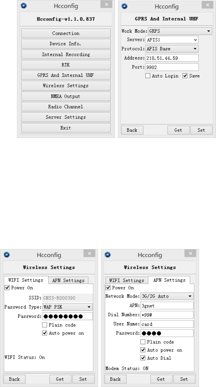
After setting the mode to Auto Base, select [GPRS and Internal UHF], set mode of the
base, select APIS for Protocol, input the server’s name, IP, port, then click [Set].
28
4.2.1 Wireless Settings
Here is network mode. Click [Wireless network Config]→[APN setting]. Set network
dialing parameters as shown below, check Auto pousersr on and Auto Dial (LandStar6
can also do the settings). When GPRS has dialed up successfully, set some network
parameters in GPRS and Internal UHF interface, then just log in successfully.
29
After setting, users need to go back to break the Bluetooth if Bluetooth is connected, then
restart the receiver. Users don’t need to do break connection if it’s WIFI connection mode.
The base will transmit differential signals automatically after searching satellites. After start
base successfully, the differential data light will flash per second.
Shanghai CHC Navigation Company offers IP addresses and port numbers to users for free.
After starting the base, the data will be forwarded via a previously set server automatically.
Therefore, once a rover is bound to the base, base data will be accessible.
Notes:
In order to guarantee that user’s data is forwarded smoothly, four common servers have
been set by CHC across the country:
211 Server IP: 211.144.120.97, Port 9902, targeted at users in southusersstern and
northusersstern regions of China.
210 Server IP: 210.51.44.26, Port 9902, targeted at users in eastern and southern regions
of China.
210 Server IP: 210.14.66.58, Port 9901-9920, targeted at users in northern and
northeastern regions of China.
210 Server IP: 210.51.44.59, Port 9901-9920, can be used nationwide.
( Some changes about the above contents can be found in the latest news given by CHC
Technical Department)
4.3 Rover Operation
In Radio mode, if the base transmits data successfully, the rover will receive differential
signals. It can be checked by the differential data light. If it flashes per second, it indicates
that the rover has received differential signals. If the PDA doesn’t show Fix or Float, users
need to reboot rover and check relevant settings.
Open Landstar6, enter Bluetooth or WIFI mode by clicking [Device] at the main menu.
30
1.using WIFI connection
Start the PDA, enter the main interface→click [Settings]→ [Connections]→ [Wi-Fi], then
find the required receiver’s SN, input WIFI password, the default password is 12345678,
click [Finish]. After connection, open Landstar6, enter WIFI connection by clicking [Device]
at the main menu. Select I80 Series for Device Type, select WIFI for Connection, select
[Rover] for Connection Type, then click [finish ] ( WIFI mode is suggested)
2. Using Bluetooth connection
Click [Device] and enter the connection. Select Bluetooth for Connection , click and
select the SN number corresponding to the rover. Select I80 Series for Device Type, select
[Rover] for Connection Type, select virtual serial port which supporting the Bluetooth
connection in PDA hardware(usually com5, com8 or com9), then click [finish ]
31
4.3.1 GPRS Status
Use Landstar6 to connect the receiver. In the process of the base or the rover using network,
if the rover’s network is not open, the sever is definitely unable to log in. So the first thing to
do is to open mobile network, the specific opening method is shown as follows:
After connecting PDA to the receiver, select [Device]→[ Wireless Network Config], check
Pousersr on , select 2G or 3G, then click [Set], there will be a prompt window showing that
the mobile network is started successfully. If using LCD panel to set the network, the
operation can be skipped. If the function does not work, users can check details in usersb
pages.( More details can be found in chapter 7.6)
32
After opening mobile network, click [Rover Config] to set the rover’s differential format,
antenna type and some other information, then click [finish ].
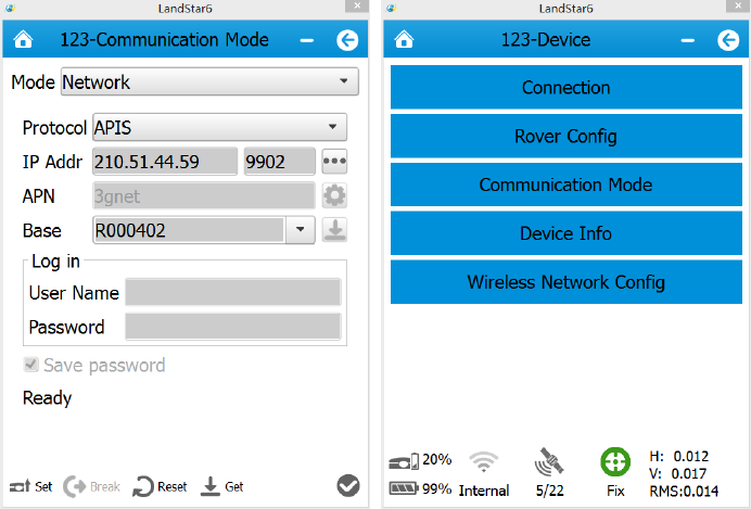
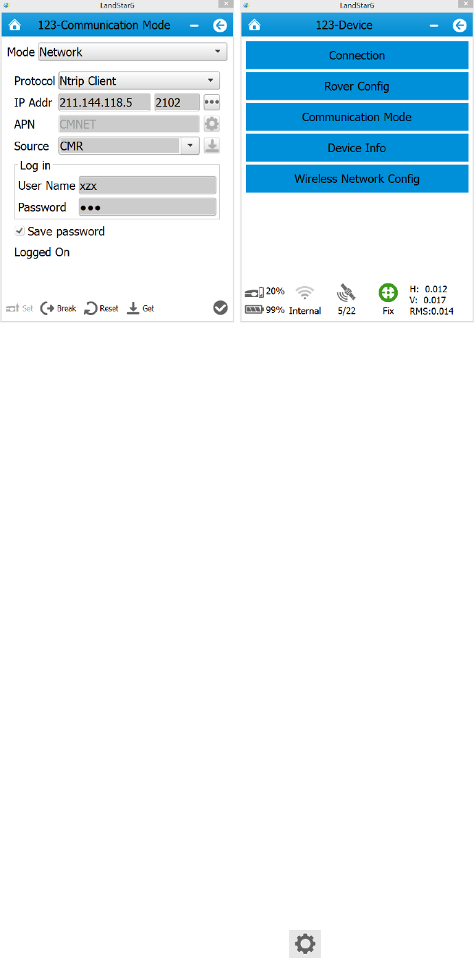
After setting differential format,select [Communication Mode], select APIS for Protocol,
input APIS server’s name, IP address, port number, click [Set] and it will log in. The status
area on the interface will show Logged On, then click [finish ].
33
Base is the S/N number of the base bound with the rover.
Return to the initial interface of LandStar6. Data light flashes normally when the rover’s
receiving , and rover has been started successfully.
5. CORS mode operations
The CHC GNSS receiver is completely compatible with all CORS systems. When accessing
local CORS system, some preparations need to be made:
1.Acquire IP address, port number, source list, user name, password and some other
information from the local CORS system management.
2.Handle a mobile card and open GPRS net traffic. GPRS traffic of approximately two hours
is 1 megabyte (associated with the number of satellites and the network environment).
users can calculate overall traffic according to the operation time in a month and have a
monthly package(some CORS centers directly provide mobile cards).
5.1 Rover operations
Open Landstar6, enter Bluetooth or WIFI mode by clicking [Device] at the main menu.
34
1.using WIFI connection
Start the PDA, enter the main interface→[Settings]→[Connections]→[Wi-Fi], then find the
required receiver’s SN, input the WIFI password, the default password is 12345678, click
[Finish]. After connection, open Landstar6, enter WIFI connection by clicking [Device] at
the main menu. Select I80 Series for Device Type, select WIFI for Connection, select
[Rover] for Connection Type, then click [finish ] ( WIFI mode is suggested)
2. Using Bluetooth connection
Click [Device]→[Connection]. Select Bluetooth for Connection Style, click and
select the SN number corresponding to the rover. Select I80 Series for Device Type, select
[Rover] for Connection, select virtual serial port which supporting the Bluetooth connection
in PDA hardware(usually com5, com8 or com9), then click [finish ].

35
5.1.1 GPRS Status
Use Landstar6 to connect the receiver. In the process of the base or the rover using network,
if the rover’s network is not open, the sever is definitely unable to log in. So the first thing to
do is to open mobile network, the specific opening method is shown as follows:
After connecting PDA to the receiver, select [Device]→[ Wireless Network Config], check
Pousersr on , select 2G or 3G, then click [Set], there will be a prompt window showing that
the mobile network is started successfully. If using LCD panel to set the network, the
operation can be skipped. If the function does not work, users can check details in usersb
pages.( More details can be found in chapter 7.6)
36
After opening mobile network, click [Rover Config] to set the rover’s differential format,
antenna type and some other information, then click [finish ].
After setting differential format,select [Communication Mode], select CORS(Ntrip Client)
for Protocol, input the source list, user name and password offered by CORS center, click
[Set]. The status area on the interface will show Logged On, then click [finish ].
37
Go back to the initial interface of Landstar6. Data light flashes normally when the rover’s
receiving, and rover has been started successfully.
6. Survey
Users can start measurement when the rover is in Fix status. Open LanStar6, click
[Survey]→[Point Survey]. In practice, users usually use local coordinates. When the rover
has got fix solution, the recorded points in LandStar6 are plane coordinates that have not
been converted. If users want to get coordinates in line with previous researches, Point
Adjust is required to be done to acquire conversion parameters or users can use 7
Parameters directly.
6.1 Assisted Measurement System
6.1.1 Bubble, Compass Calibration
If users need to use auto tilt survey(compensation point measurement), some settings need
to be done.
1. Enter Point Survey interface, then click [Set ], as shown in figure1
38
2. Ebubble Calibration
Select [Ebubble Option].( users had better carry out the operation outdoors and prepare a
level base. Centralize and level the base, set the instrument on the base. When the
instrument has searched satellites, the calibration result will be better. Besides, users had
better keep leveling in the calibration process.)
Figure 1 Figure 2
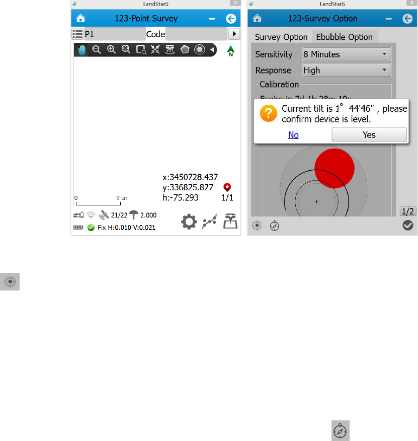
Ebubble: when clicking this button, there will be a prompt about offset
information(Figure 2). The tilt angle must be within 2 degrees or the calibration can not be
done. Then click [Yes], and Ebubble calibration starts. When the Ebubble is green in the
center, users have just finished Ebubble calibration.
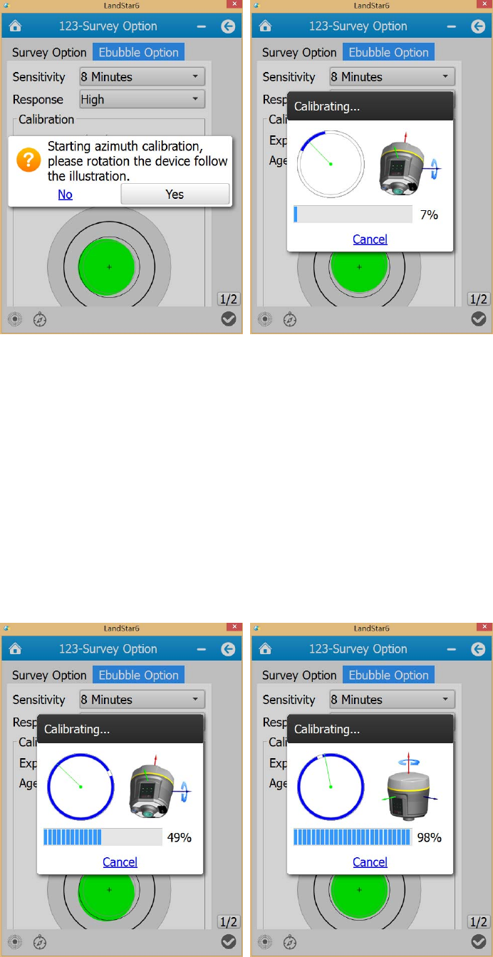
3. Compass Calibration
After finishing Ebubble Calibration, click the compass icon in the bottom-left of the
interface(as shown in figure 3). Then select [Yes], an interface will pop up (as shown in
figure 4). ( users had better do the operation outdoors)
39
Figure 3 Figure 4
Rotate the device follow the instruction of figure 4. The blue part represents directions that
have been adjusted.(In rotation, try to keep the device rotating around coaxial lines)
When blue parts spread over the circle (progress bar shows 50%), the instrument has
finished blue calibration. The interface will remind users to rotate around the red axis(as
shown in figure 6). When the progress bar shows 100%(as shown in figure 6), users have
finished the calibration.
Figure 5 Figure 6
40
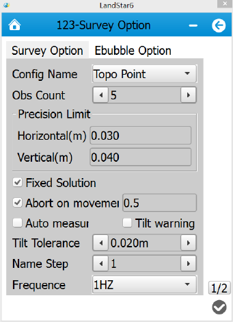
4. After bubble and compass calibration, select [Survey Option] and set relevant
parameters.
Config Name: selections of survey point types, currently it supports Topo Point, Control
Point and Quick Point.
Obs Count: By default, Topo Point is 5, Control Point is 10 and Quick Point is 1.
Precision limit: By default, Topo Point and Control Point’s horizontal precision limit is
0.03m, vertical precision limit is 0.04m. Quick Point’s horizontal precision limit is 0.1m and
vertical precision limit is 0.2m. They can be modified manually.
Fixed Solution: when users check the box of Fixed Solution, the measuring can be done
only in fix status. If users need to survey in single or float status, do on check the box.
Abort on movement: the default value is 0.5m which can be modified.
Tilt Tolerance: the default value is 0.02m which can be modified. The range is from 0.001m
to 1m.
Frequency: 1Hz, 2Hz and 5Hz.
Use PPK: it will support PPK mode when checking the box.
Save Track: after checking the box, users need to set the track file’s name and saving path.
The software will save the track data file automatically.
41
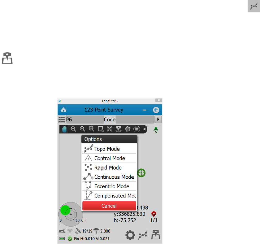
6.1.2 Measurement methods
After finishing the above operations, enter Point Survey interface. Click the diagram
and select Compensated Mode. Have the bottom of the centering rod aimed at the survey
point, tilt the centering rod(the tilt angle should be less than or equal to 30 degrees), then
click [Begin ]. The software will save the converted three-dimensional coordinates of
the correct point position.
If users want to use Auto Measure, just check the box in front of Auto Measure in [Survey
Option]. Any other operations refer to the guides.
42
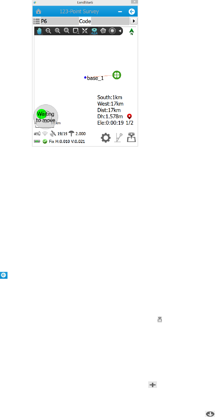
Waiting to move: tilt the centering rod (the tilt angle should be more than 5 degrees), shift
to the next point.
Waiting for level: level the receiver.
Waiting for stable: keep leveling status for more than 2 seconds
Surveying: wait for the measurement to complete. There will be prompt tone when starting
or finishing measurement.
If users want to continue to survey points, just repeat the above operations. If users want to
exit, just click [Back ].
If users do not check Auto Measure, then the mode is [Normal Measurement Mode]
which does not need to adjust Ebubble and users can click [Survey ] directly.
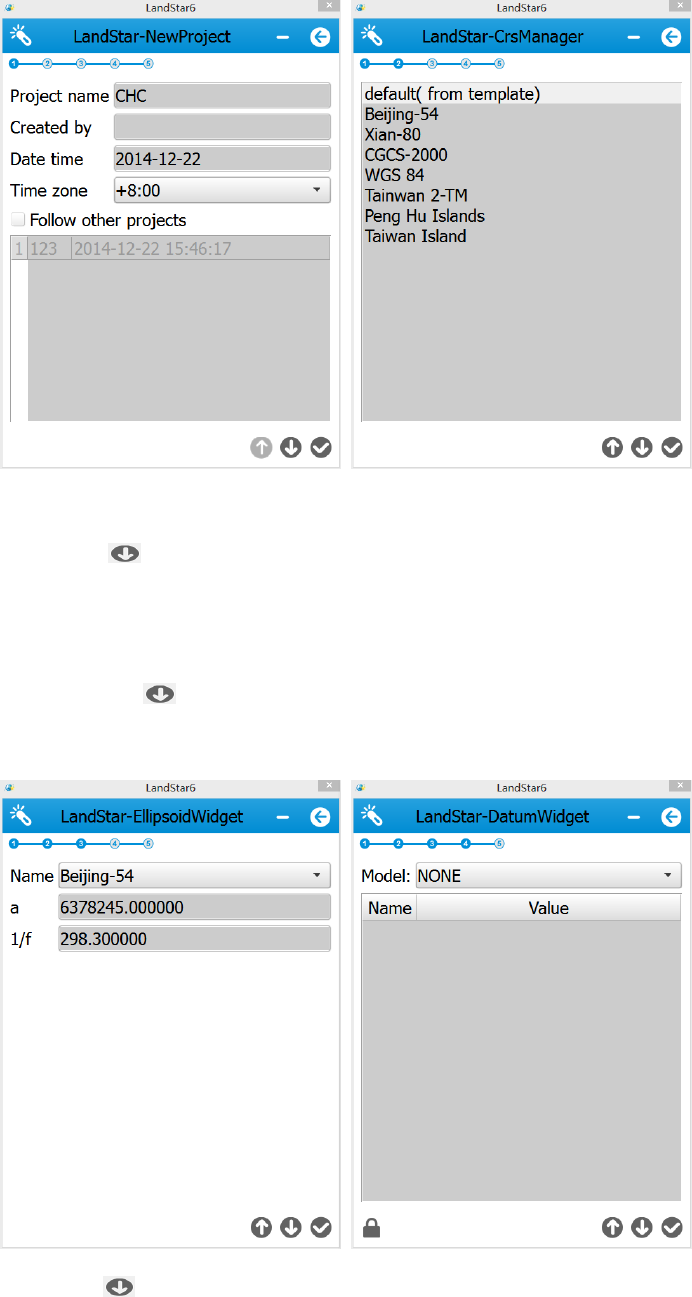
6.2 New Project
Open LandStar6.0, click [Project]→[Proj.Management]→[New ] to enter New Project
Wizard.
First step: input Project Name, Created By, Date time and so on. Then click [Next ].
Second step: access to coordinate system template and select one system. Users usually
43
can select their required coordinates in the default coordinate system list. If none of
coordinate system in the template can be used, users can select [default(from template)].
Third step: click [Next ], and set Ellipsoid parameters. Users can select Ellipsoid Name
from the drop-down list. a and 1/f are two ellipsoid parameters corresponding to the
selected ellipsoid. The displayed values are default values.
Fourth step: click [Next ], and set basic parameters by selecting one model. Model
contains three types, including NONE, Bursa 7 Parameter and Molodensky 3 Parameter.
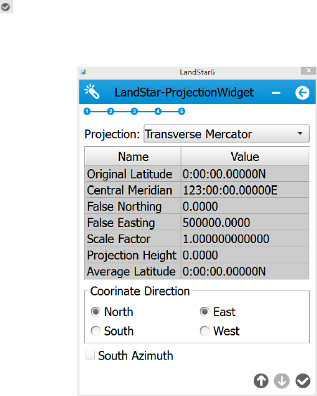
Fifth step: click [Next ], and set projection parameters. Users can select their required
44
projection from Projection drop-down list. Coordinate Direction is North and East by
default. Users can adjust coordinate direction by selecting South Azimuth.
Finally, click [Finish ], and users have finished creating a new project. Return to the main
interface.
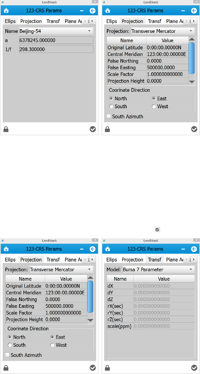
6.3 Confirm Coordinate Parameters
Open LandStar6.0, click [Project]→[CRS Params], select a required coordinate system
according to known points. Generally speaking, local coordinate system in China usually
uses Beijing-54 Ellipsoid. But all users need to do is to modify its central meridian (in
Standard Beijing-54 Ellipsoid, users must calculate 3 degree strap’s or 6 degree strap’s
central meridian according to known coordinates). users do not need to set [Transf], [Plane
Adjust] and [Height Adjust]. After point calibration, parameters will be saved automatically
Ellips interface is shown in figure 1, including Name, a and 1/f. According to different areas,
select a corresponding ellipsoid from Name drop-down list. a and 1/f are default values and
there is no necessity to change them.
Projection interface and parameters of each model are shown in figure 2. Users can select
45
different projection models. Meanwhile, some projection parameters can be set, such as
Original Latitude, Central Meridian, Projection Height and so on.
Figure 1 Figure 2
6.3.1 Bursa 7 Parameter Application
Open LandStar 6.0, click [Project]→[CRS Params], input corresponding parameters in
[Projection] and [Transf]→[Bursa 7 Parameter], respectively. In [Plane Adjust] and
[Height Adjust] options, just select None. Finally click [Finish ] button.
46
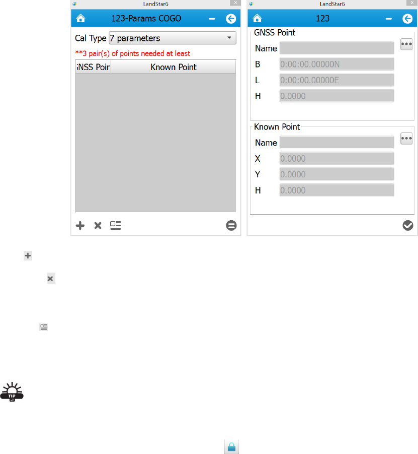
6.3.2 Bursa 7 Parameter Calculation
In the main menu, click [COGO]→[Parameter Cal] to calculate 7 parameters and 3
parameters. At least three pairs of coordinate points should be provided when calculating 7
parameters. At least one pair of coordinate points should be provided when calculating 3
parameters and 4 parameters.
Add : users are able to select GNSS coordinates and known coordinates via this button.
Remove : In coordinate data list, select one coordinate point. Then click this button, and
the point is just removed.
Details : In coordinate data list, select one coordinate point. Click this button, and users
can check specific information of GNSS points and known points.
Tip:
The software has the function of 7 parameter encryption. Before using this function, users
need to log in as an administrator. Click , the initial user name is admin, password is
123456. Only after logging in successfully, users are able to check and modify the 7
parameters.
47
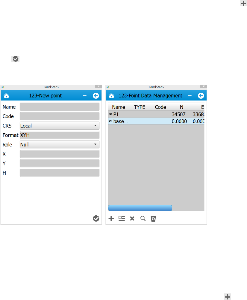
6.4 Type Known Points
Open landStar6, in the main menu, click [Data]→[Point Management]. Then click [New ]
to create new points. Some attribute values need to be set, including Name, Code, CRS
(including Local and WGS84), Format( can not be set), Role (including Null, to Stake Out
and Control), X, Y, H (or B, L, H). Among them, Code is non-mandatory. After setting above
values, click [OK ] and users have just created one point.
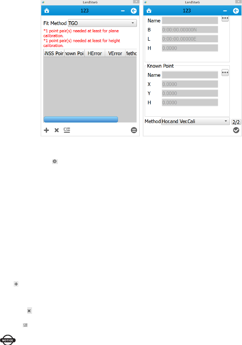
6.5 Point Adjust
Open LandStar6, in the menu, click [Survey]→[Point Adjust]. Then click [Add ] and
select GNSS points and known points. Select Hor.and Ver.Cali for Method. Fit Method is
Fixed Difference by default which can be changed according to the real situation. It is
better to add more than three pairs of points.
48
Click [Calculate ], there will be a prompt Replace the project's current calibration
parameters? If users click [Yes], current calculated calibration parameters will be applied to
the coordinate parameters, which will come into operation against the whole project. There
will also be a calibration parameter interface so that users are accessible to check plane
calibration parameters and height calibration parameters. Otherwise, if users click [NO],the
parameters will show zero results.
Fit Method: currently supporting Fixed difference, Plane fitting, Curved surface fitting and
TGO
Add : add calibration points, GNSS points and known points, as shown in figure. Besides,
select Method: Hor.Cali, Ver.Cali, Hor.Cali and Ver.Cali
Remove : remove the selected calibration point
Details : check information of the selected calibration point
Notice
1.Only when three or more than three control points are involved in the horizontal Point
Calibration, there will be horizontal residual error which is usually within 0.015m. Only when
four or more than four control points are involved in the vertical Point Calibration, there will
be vertical residual error which is usually within 0.02m.
49
2. After point calibration, users can start measuring directly.
3. Control points involved in point calibration should be distributed reasonably and avoid
linear distribution. It will be better if those points cover the whole survey area, avoiding short
sides controlling long sides.
6.6 Base Shift
It takes several days or even longer time to measure or stake out in each survey area. In
order to avoid repeated point calibration or troublesomely erecting the base on the same
known point everyday, users can do Base Shift before starting surveying everyday( at this
point, the base can be erected at random or set to Auto Base, but the rover’s operation is a
process that is finding a measured point and moving to that).
The specific explanation is shown as follows:
After users erect bases repeatedly, the software will orderly name the bases Base 1, Base
2,Base 3 and so on
The rover’s coordinates are based on the base’s original coordinates which will change as a
result of moving the base, so users need to reset local coordinates every time moving the
base.
Open LandStar6, in the main menu, click [Survey]→[Base Shift] to enter Base Shift
interface. It is necessary to shift base when the base moves or needs restarting because of
erecting on an unknown point. Users need to find a known point and measure its
coordinates to calculate the shift data. Then apply the shift data and make it function on all
survey points in current coordinate system. Make sure the two bases’ coordinates have the
same reference coordinate system.
Enter Base Shift interface, select known points from [Known Point] Library, click [GNSS
Point] Library to select the same point surveyed just now. The software will calculate the
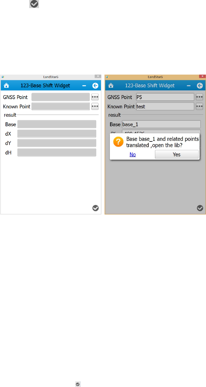
50
shift data. Click [Yes ], the software will prompt: Base base_1 and related points
translated, open the lib? Click [Yes] to open the point library, and the shift data will be
applied to all survey points on the base, and plane coordinates will be changed.
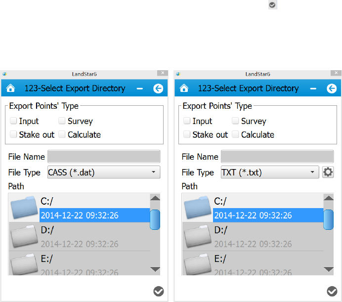
6.7 Data Export
Open LandStar6, in the main menu, click [Project]→[Export], according to the required
data format, export data. Then connect PDA with PC( users need to install Microsoft sync
software or USB Drive first), click [Mobile]→[My Windows Mobile Device]→[My
Documents], and just copy out the documents.
1.CASS Format
Export Points’ Type includes Input, Survey, Stake out and Calculate. Select an export path
and input a file name, then click [Yes ] (see figure 1).
2.Custom Format
51
Select export points’ type, file type and path(txt, csv and various fixed arrangements are for
selection, which will meet the requirements of most clients. Users can also define their own
file formats via configuration). Input file name, then click [Yes ], the software will show
whether the file has been saved successfully(see figure 2).
Figure 1 Figure 2
6.8 Receiver Registration
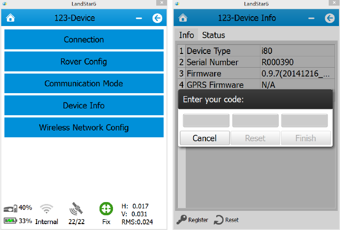
If the software prompts Registration Code Expired, users need to register the receiver.
Open LandStar6, in the main menu, click [Device]→[Device Info]→[Register], an input
box will pop up. users need to contact Shanghai CHC Navigation Company or agents to
acquire the registration code.
52
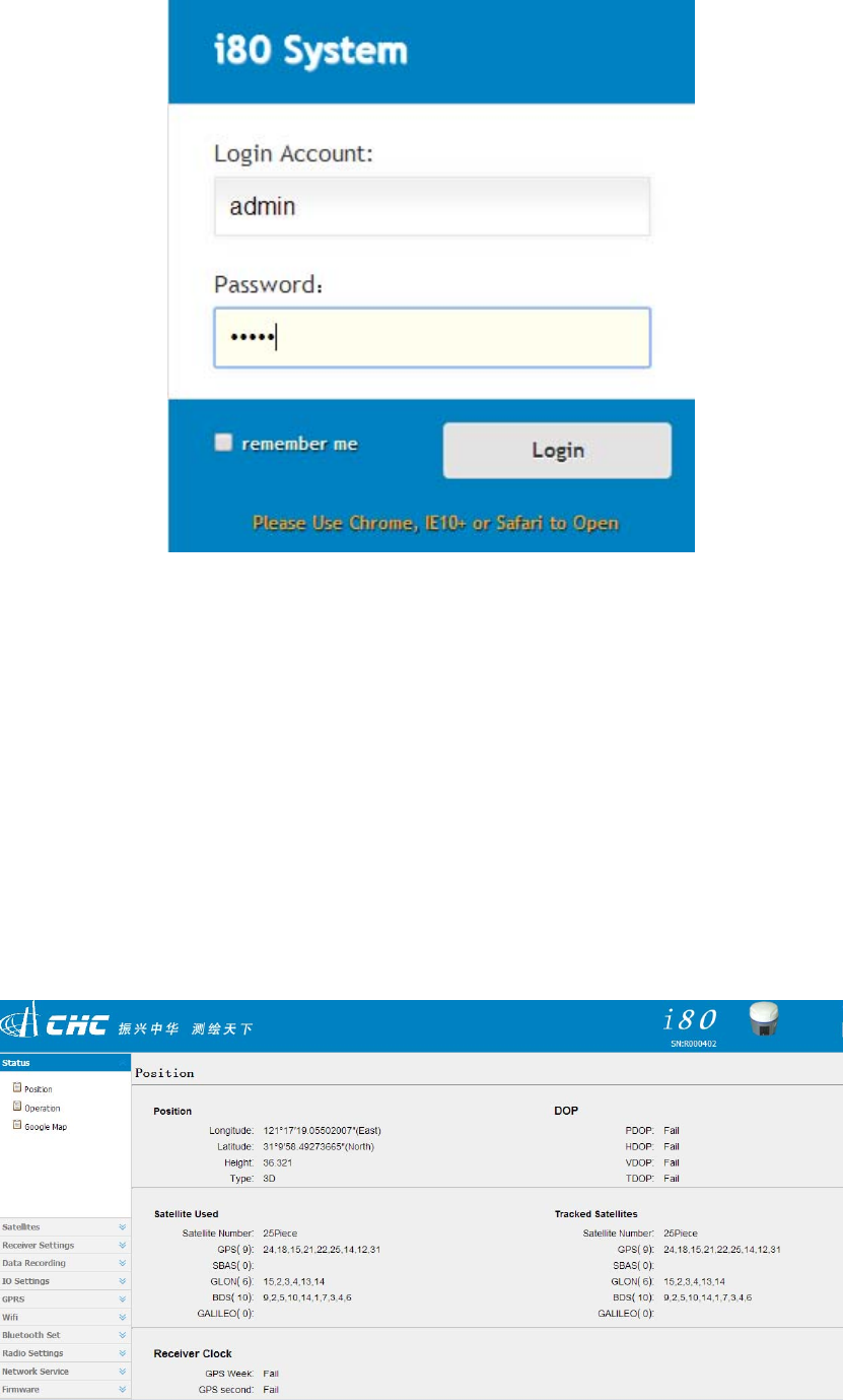
7. Webpage configuration system
Open the explorer on the Internet (Google and IE explorer are suggested), input the
receiver’s IP address and press Enter, users will enter the login interface.
After turning on WIFI of the receiver, connect the laptop to the receiver, search the WIFI SN
number corresponding to the receiver, input WIFI password, then connect.
Next, open the explorer on the Internet (Google and IE explorer are suggested), enter in the
URL: 192.168.1.1, input user name: admin, password: password, then click [Login] as
shown below.
53
After logging in, users will enter the following interface:
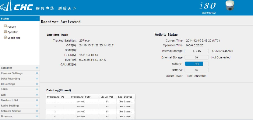
7.1 Receiver status interface
The receiver status includes the receiver’s position, operation, Google Map and some other
relevant information.
54
The receiver position interface shows the receiver’s current position, DOP values, satellites
used, tracked satellites and receiver clock.
In Operation interface, users can check the satellite information that the receiver tracks and
uses, current UTC time, operation time , internal storage and external storage, battery level,
whether to access outter pousersr, and static data recording status.
Google Map: on the interface of Google Map, it shows the current location.
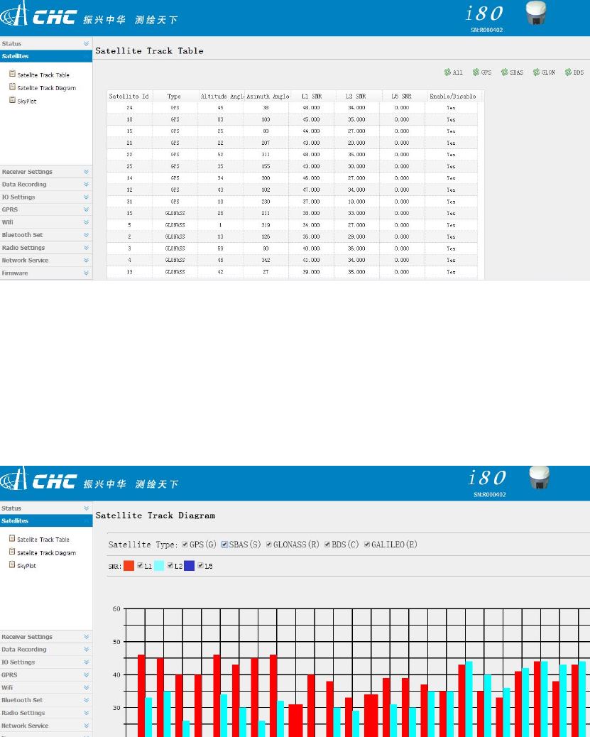
7.2 Satellite interface
On the satellite interface, users can see satellites that the receiver has tracked. Tables and
diagrams are applied to show each satellite’s relevant information,including satellite Id, type,
altitude angle, azimuth angle,L1 SNR,L2 SNR,L5 SNR, enable or disable and so on.
Satellite Track Table:
55
Satellite Track Diagram: In Satellite Track Diagram, users can check satellite information
with iconic presentation. Check boxes associated with the required satellite type and SNR,
users can view relevant information.
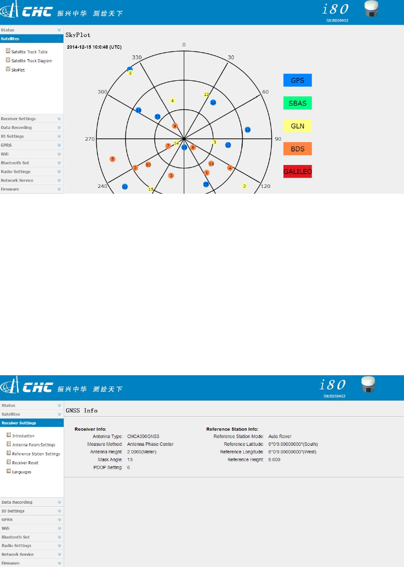
Sky Plot: The Sky Plot interface represents the distribution map of satellite categories.
56
7.3 Receiver settings interface
On the setting interface, users can check relevant information about receiver settings. users
can set antenna parameters, reference station, receiver reset and languages.
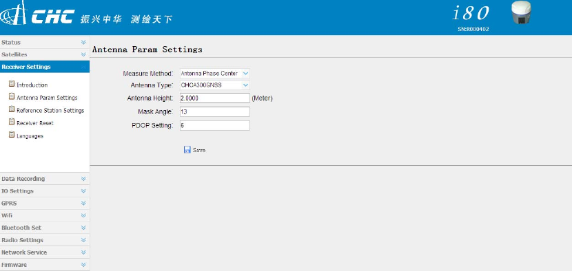
Click [Introduction], check GNSS receiver information and reference station information.
Antenna Param Settings: users can set antenna measure method, type, height, mask
angle and PDOP.
57
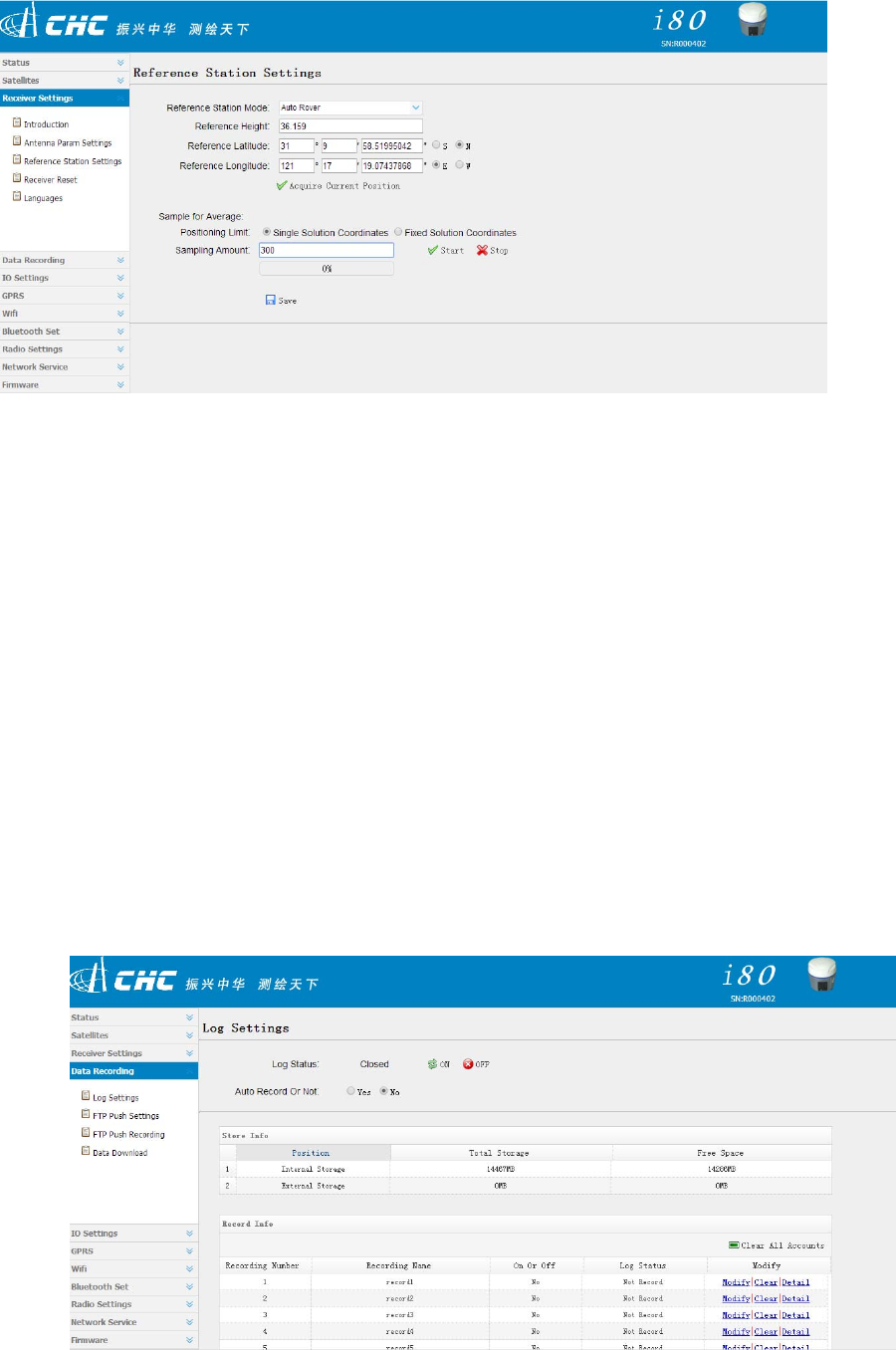
7.3.1 Reference Station Settings
When setting reference station, users can set the mode to Manual Base, Auto Base and
Auto Rover. Users can also set the coordinates of the reference station and support Sample
for Average.
Several methods can be used to input the coordinates of the reference station. Users can
click [Acquire Current Position] to set the location of the reference station, which is not
accurate because it is the coordinates of the antenna phase center measured in signal
status. If users have known the coordinates of the antenna phase center, just input the
information manually.
In Sample for Average, the positioning limits are divided into Single Solution Coordinates
and Fix Solution Coordinates. Single means users can collect reference coordinates just in
single status while Fix means users can do that only in fix status. Sample Amount is the total
amount users set to be collected. Click [start], the system will take the average of collected
data and fill into the reference position column above automatically. The progress bar
represents the percentage of current collected numbers and total numbers.Click [Save] to
save current settings.
58
Receiver reset: click [Receiver Reset], users can restart receiver, clear satellite
information, back to default setting and turn off receiver. Restart Receiver means rebooting
the receiver. Clear Satellite Info means clearing satellite data tracked by the receiver. Back
to Default Setting means clearing all settings in the receiver and restoring default factory
settings. Turn Off Receiver means shutting down the receiver.
Languages: It supports switching language on the interface. Now it supports conversion
between English and Chinese.
7.4 Data recording
Data recording is mainly used to record, download and push the receiver’s static data.
59
Log Status can turn on or turn off the whole data records. When Log Status is open, all
threads can not be edited.
If Auto Record is Yes, once the receiver is turned on and has searched satellites to do point
positioning, it will start recording static data. The storage is divided into internal and external
storage. Internal Storage means the receiver stores capacity itself and the specific value is
given by the receiver. External Storage is the inserted mobile hard disk. Total Storage and
Free Space depend on the conditions of hard disk. Recording Info has eight recording
threads and multiple threads can be set to store data at the same time.
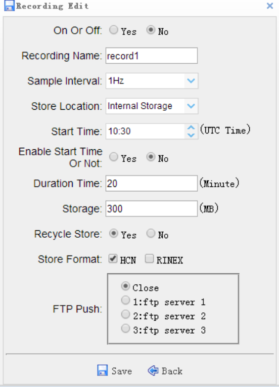
In Recording info, click [Modify] to modify any record, the interface is shown as follows:
The graphic is clicking single modify button:
60
1. On or Off: show whether this thread is on or not
2. Recording Name: show this record’s name.
3. Sample Interval: from 20Hz to 1MIN (at present, it only supports 1Hz,
5s,10s,15s,30s and 60s).
4. Store Location: internal or external storage.
5. Start Time: represent that timing can start storage.
6. Enable Start Time Or Not: [Yes] or [No] button represents whether the previous
item Start Time will function. If Yes, it will start recording according to the set time, or it will
start at once.
7. Duration Time: the duration.
8. Storage: the reserved memory space for the current thread.
9. Recycle Store: when exceeding the set memory space, it will cover the early data
of the thread automatically.
10. Storage Format: Support HCN and RINEX.
11. FTP push: the current thread data will be set to sever push.
FTP push setting: three FTP severs can be set respectively in the FTP push setting menu.
Click the pop-up window, and users can set the server IP, port, remote directory, sever
description, use name, password and so on. FTP push can set the required sever to be
pushed. If users don’t need this function, click [Back] button.
FTP Push Recording: users can see a record list of FTP push in this menu.
Data Download: In this menu, the internal storage of i80 can be accessed by means of FTP.
All the static data stored by i80 threads can be found in repo folder and can be downloaded
by users. Both of the initial user name and password are ftp and can be modified in the Web
Service→FTP service.
61
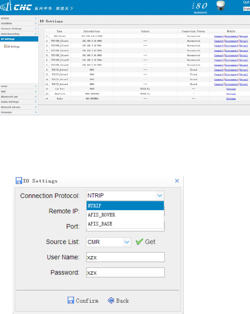
7.5 IO settings
RTK Client: In RTK Client, NTRIP, APIS_ROVER and APIS_BASE support CORS,
network 1+n rover and network 1+n base, respectively.( At this point, it is necessary to
turn on the mobile network and connect it in chapter 8.6)
In NTRIP, login CORS through stated remote IP, port, source list,user name and password.
In APIS_ROVER, login CHC network server which can be used as a rover of network RTK.
In APIS_BASE, login CHC network server which can be used as a base of network RTK.
62
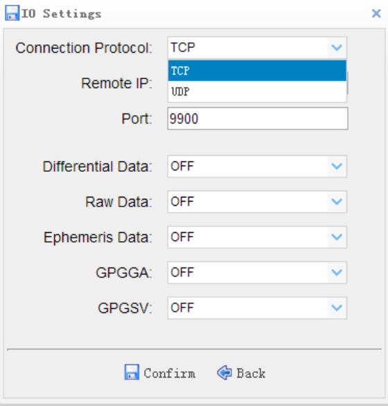
TCP/UDP_Client :
1.In TCP/UDP_Client, two protocols can be selected: TCP and UDP.
2.Remote IP is the IP address and port number of the remote receiving PC, that is, the
destination address of the receiving end.
3.In Port number, set data send ports.
4.Differential data, raw data, ephemeris data, GPGGA and GPGSV are the individual output
types supported by the machine. users can set whether to output those data and the output
frequency.
5.After setting parameters, click [Confirm] under the page to save current settings. The
data entry can not be edited in the process of sending data and users can check the details
about settings when clicking [Details] button.
63
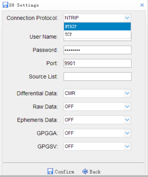
TCP/IP_Server:
Connection protocol supports Ntrip and TCP protocol. When using Ntrip protocol, users can
get data by logging in i80 directly.
Com Port: to set output baud rate. Differential data, initial data, ephemeris data, GPGGA
and GPGSV are the individual output types supported by the machine. users can set
whether to output those data and the output frequency. If exporting differential data, users
need to set the mode to Auto Base or Not Auto and set baud rate to 9600 when using
external radio.
Bluetooth: to set data output baud rate.Differential data, initial data, ephemeris data,
GPGGA and GPGSV are the individual output data types supported by the machine. users
can set whether to output those data and the output frequency. If exporting differential data,
users need to set the mode to Auto Base or Not Auto.
Radio: Internal radio sends differential data.users need to set the mode to Auto Base or
64
Not Auto. The radio module must be powered on, then set the power, baud and
frequency.(More details are available in 7.9)
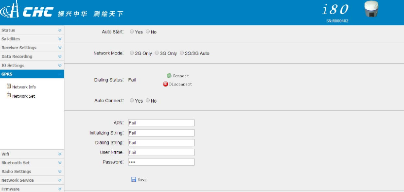
7.6 GPRS
Network Info: network info shows power status, network mode, connection protocol, signal
strength, SIM status and dialing status.
Network set:mainly to set GPRS model status, auto start, network mode ( generally users
select [2G/3G Auto]), parameter settings and so on.
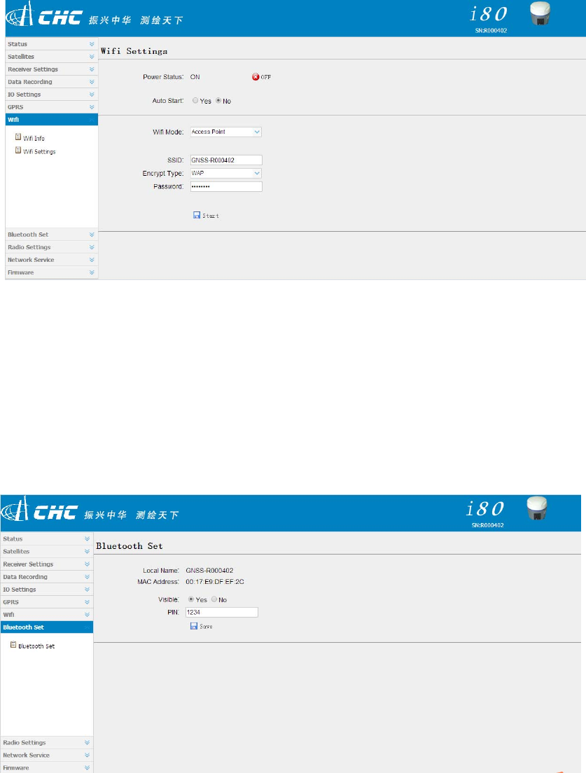
7.7Wifi
Wifi Info: show power status, password and so on.
Wifi Settings: to set power status, auto start, password and so on
65
.
7.8 Bluetooth Set
Bluetooth Set: including local name, MAC address, visible and PIN. The default PIN is
1234 (no changes)
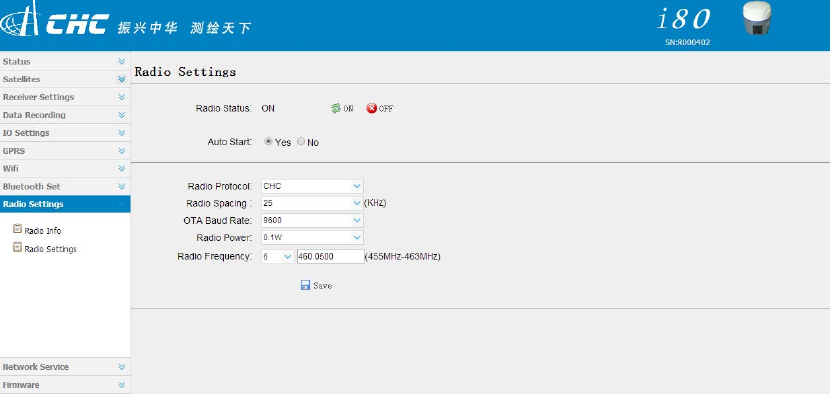
7.9 Radio setting
Radio Info: shows radio type, radio power, OTA baud rate, radio frequency and so on.
66
Radio setting: to set radio status, auto start, radio power, frequency and so on. When using
web page setting alone and the radio function is required, users need to turn on Radio
Status and Auto Start. If the radio in IO setting is required to be used, the premises are
also turning on radio status, setting appropriate frequency, power and so on.
7.10 Network service
Network service includes:
HTTP: HTTP port number is 80 by default, no changes.
FTP service: FTP service can set the machine’s FTP storage, user name and password.
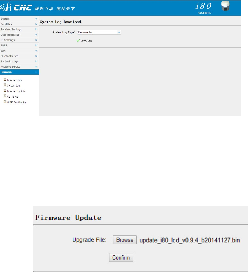
7.11 Firmware
Firmware Info: Firmware Info interface shows information about the firmware’s current
type, release time, description and so on.
System log: running log of system firmware can be downloaded, which is convenient for
developers to analyze problems.
67
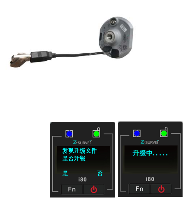
7.11.1 Firmware Update
Firmware update interface supports web firmware upgrade. Select [Browse] to add
corresponding BIN file, then click [Confirm] to upgrade.
After the completion of update, the receiver has finished the firmware upgrade.
7.11.2 USB flash disk
1.Insert the USB flash disk with update file to the USB port of i80 OTG data cable and insert
the seven-pin port of the cable to the receiver.
68
2. Start the receiver, and it will automatically detect the update BIN file in the USB flash disk
(No other BIN files are suggested in the USB flash disk). Select [Yes], and the firmware is
updating.
3. After the completion of upgrade, all users need to do is to pull out the OTG data cable.
7.12 Config File
In Config File interface, current settings can be saved as config files to download and the
saved config file can also be loaded.
7.12.1 GNSS Registration
GNSS Registration interface will realize the registration function to the receiver.
69
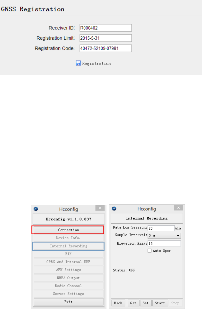
8. Static Mode Operation
8.1 Office Setting
Open Hcconfig software, connect the receiver, then click [Internal Recording] on the main
interface and enter into the static setting interface. Set several parameters as shown in the
picture, then click [Set].
Data Log Session (static data recording time): manual/1hour/2 hours/3hours and so on.
Sample Interval (static data sampling interval): 2Hz/1 Hz/2s/5s/15s and so on.

70
Elevation Mask: 13 degree by default ( can be modified)
[Back]:back to main menu
[Get]: get current receiver’s static parameters
[Set]: write current parameters to the receiver
[Start]:send orders to make the receiver start collecting static data
[Stop]: send orders to make the receiver end collection and save the data.
( Control Panel is suggested to be used to set the parameters.)
9. Main Specifications
1.GNSS characteristics
- Smallest GNSS receiver in domestic market
- MEMS precise tilt sensor for auto·compensation within 30° slant and 2m
- height
①.
- WIFI function supports 150m distance Mobile Internet② and 108Mbps GPRS
- Linux OS
- Embedded web interface, supporting MT settings
- 4G high speed network
- Dual battery auto switch seamlessly for whole·day field work
- All-satellite-system support, 220channels with simultaneously tracked satellites
signals
- Unfiltered and unsmoothed pseudorange observation data applied in low noise,
low multipath error, low time domain correlation and high dynamic response.
Within 1 Hz bandwidth, the precision is more accurate than 1mm.
- Supporting SNR in dB-Hz, reliable low-elevation SV tracking technology.
2. Measurement Accuracy
- High Static Accuracy
Horizontal accuracy:±(3+ 0.1×10⁻⁶×D) mm
71
Vertical accuracy:±(3.5+0.4×10⁻⁶×D) mm
- Static and Rapid Static accuracy
Horizontal accuracy::±(3+0.5×10⁻⁶×D) mm
Vertical accuracy:±(5 + 0.5×10⁻⁶×D) mm
- RTK Accuracy
Horizontal Accuracy:±(8 + 1.0×10⁻⁶×D) mm
Vertical Accuracy:±(15+ 1.0×10⁻⁶×D) mm
- CORS RTK Accuracy
Horizontal Accuracy:±(8 + 0.5×10⁻⁶×D) mm
Vertical Accuracy:±(15+ 0.5×10⁻⁶×D) mm
Single-point Positioning Accuracy:1.5m
Code Differential Positioning Accuracy: 0.45m
Initialization time:5s
Initialization reliability:>99.99%
3.Electrical
- Power consumption: 3.2W
- Li-ion battery capacity:6800mAh (6600mAh)
- Battery voltage: 7.4V
- Battery life: 1000 times charging and discharging process
- Battery operating time③: typical 12 hours in RTK mode, external power can be
connected,
- dual battery auto switch
- External power: 12-36VDC
4.Physical
- Size(W×H):124×140mm
- weight:<1.5kg (with battery)
- Texture: magnesium alloy
- Appearance: streamline cylinder, LED screen
- Built-in: precision MEMS tilt sensor
- Feature: waterproof and breathable membrane
72
5.Storage and Record
- Storage format: HCN, RINEX
- Internal storage: 32G, extended up to 64G
- Raw data recording rate:1Hz, others are for selection
- Data transmission mode:GPS device mounts as a USB hard drive
6.Environmental Parameter
- Operating temperature: -45℃~+75℃
- Storage temperature:-55℃~+85℃
- Humidity: 100%condensation
- Waterproof and dust proof: IP68 standard
- Shock: survive a 3-meter drop on to concrete
7.I/O port
- 1x UHF antenna port
- 1x 7-pin LEMO port,for power supply, data download, USB update.
- 1x 7-pin serial port, for power supply and correction output.
- 1x SIM slot
8.Screen
- LED screen( show satellites, battery level, host mode, static information and so on)
- Visualization setting( host mode, radio frequency, server’s IP address and differential
format)
- Indicator( one satellite light, one differential light)
9.Button
1x Power button and 1x FN button
10.Network Function
- Wifi: 802.11 B/G/N, supporting AP
- GSM: 3.75G (extended up to 4G), built-in modem, HSPA+ 21Mbps(download),
5.76Mbps(upload).
WCDMA850/900/1700/1900/2100
EDGE/GPRS/GSM 850/900/1800/1900
- Multimode Bluetooth: supporting iphone, ipad, completely compatible with

73
Android,Windows Mobile, IOS and Win7/Win8 OS
- 24-hour Shanghai, Beijing multiple networks support for free
11.UHF Radio
Built-in high performance radio(standard)
Supporting PDL radio, supporting protocols: TT450S and Transparent
12. Data Format
- RTCM2.X、RTCM3.X
- CMR、CMR+
- RTCA
- NMEA0183、PJK plane coordinates, binary code
- NTRIP protocol
Notes:
① :Tilt survey accuracy varies lightly with slant angles
② :Operating range may be affected by obstacles, magnetic field, electric field and so on
③ :Battery operating time varies with working mode
The above parameters are reserved to refer to i80 flagship version.
FCC interference statement:
This equipment has been designed to comply with the limits for a Class B digital
device, pursuant to part 15 of the FCC Rules in the Portable Mode. These limit
s are designed to provide reasonable protection against harmful interference in a
residential installation.
Operation is subject to the following two conditions: (1) this device may not caus
e harmful interference and (2) this device must accept any interference received,
including interference that may cause undesired operation.
Note:
THE GRANTEE IS NOT RESPONSIBLE FOR ANY CHANGES OR MODIFICATIO
NS NOT EXPRESSLY APPROVED BY THE PARTY RESPONSIBLE FOR COMP
74
LIANCE. SUCH MODIFICATIONS COULD VOID THE USER’S AUTHORITY TO
OPERATE THE EQUIPMENT
This product has been tested and found to comply with the limits for Part 15 of t
he FCC Rules. These limits are designed to provide reasonable protection agains
t harmful interference in a residential installation. This product generates, uses, a
nd can radiate radio frequency energy and, if not installed and used in accordan
ce with the instructions, may cause harmful interference to radio communications.
However, there is no guarantee that interference will not occur in a particular in
stallation. If this product does cause harmful interference to radio or television rec
eption, which can be determined by turning the equipment off and on, the user i
s encouraged to
try to correct the interference by one or more of the following measures:
—Reorient or relocate the receiving antenna.
—Increase the separation between the equipment and receiver.
—Connect the equipment into an outlet on a circuit different from that to which t
he receiver is connected.
—Consult the dealer or an experienced radio/TV technician for help.
RF Exposure Statement:
For the product,under normal use condition is at least 50cm away from the body of the
user,the user must keeping at least 50cm distance to the product.