Huace Navigation Technology A01010 GNSS Receiver User Manual il
Shanghai Huace Navigation Technology LTD. GNSS Receiver il
UserManual.wiki
>
Huace Navigation Technology
>
A01010 User Manual
>
user manual
Contents
1.
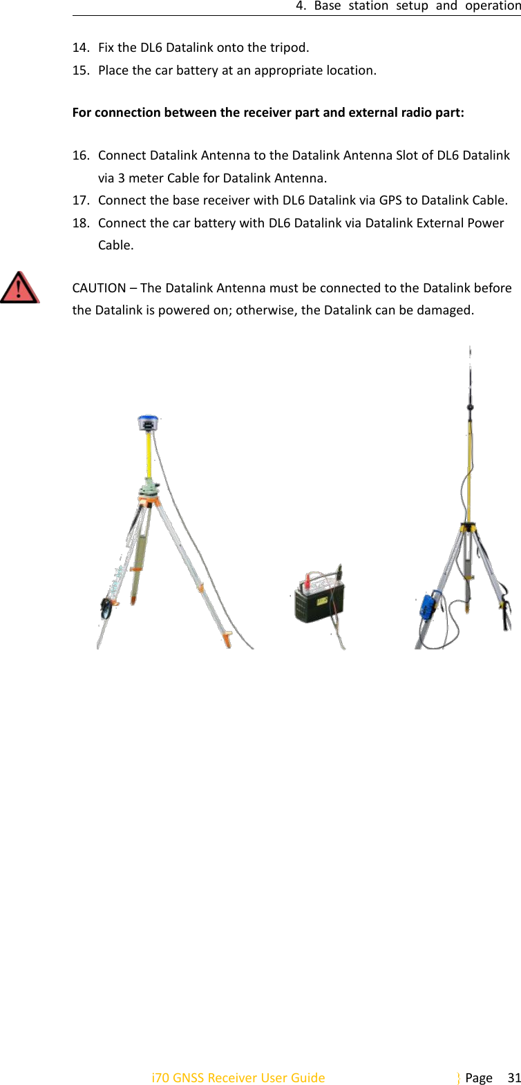
user manual
2.
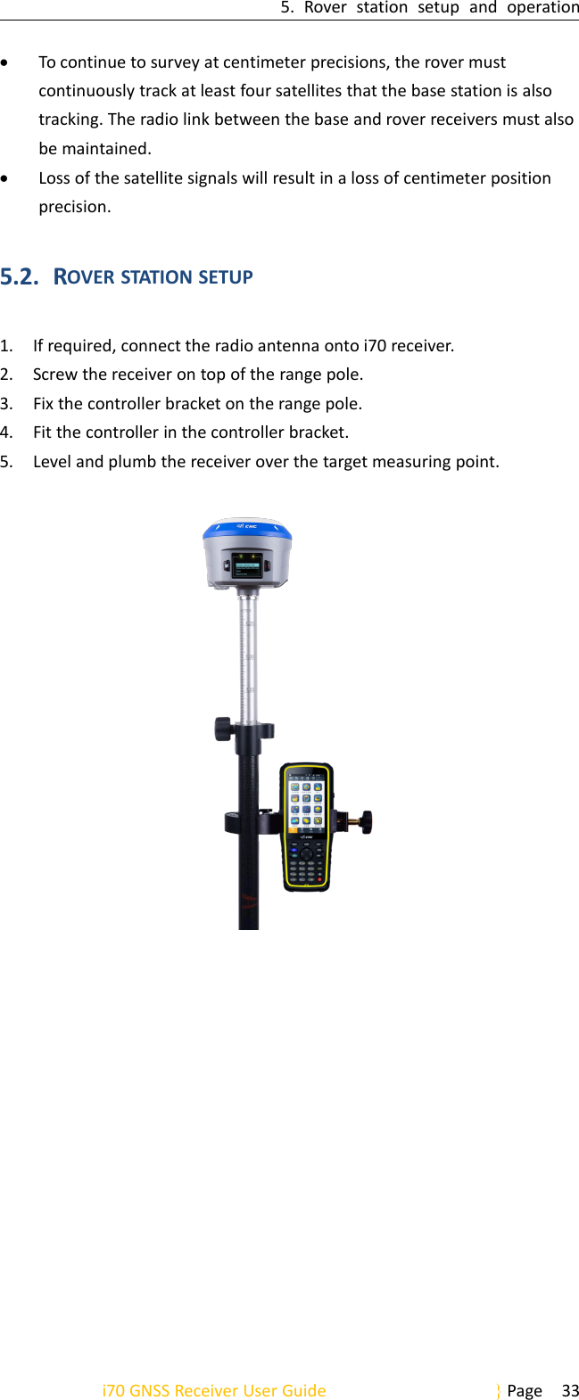
use manual
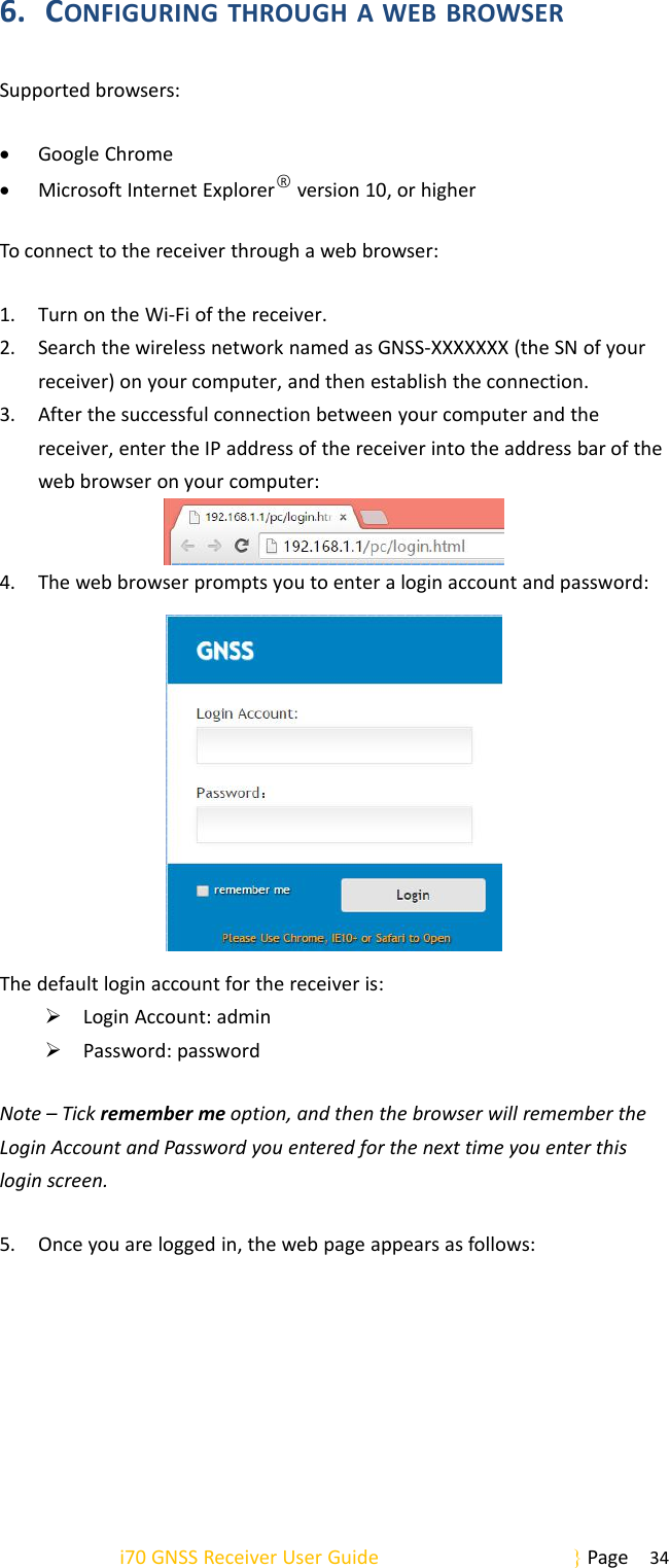
user manual
Navigation menu
Upload a User Manual
Namespaces
Wiki Guide
HTML
PDF
Info
Views
User Manual
Discussion / Help
Navigation